
Production Drilling - Tool-Smith
72
Production Drilling Assembly Tools
-
Upload
khangminh22 -
Category
Documents
-
view
0 -
download
0
Transcript of Production Drilling - Tool-Smith
Production DrillingAssembly Tools

Production Drilling Tools2
Other Air Tools
64Air Tappers
66Electrode Dressers
Find products, documents and more visit irtechpubs.com
ContentsAir Production Drills
19Modular Drills
21Feed Drills
14Angle Drills
11Inline Drills
4Pistol Grip Drills
Accessories
69Other Accessories
67, 68Spindle Accessories
G 02DQ P 20 1 ( ) ( ) D B 33 A
Handle Power Rotation Revision SpeedTool Chuck/Bit Holder
D = Drill
G = PistolL = InlineR = 90˚ AngleA = 45˚ Angle
05 = 0.5 HP # x 100 rpm
1 = Non-reversible2 = Reversible3 = Non-reversible
A = 1/4” ChuckB = 3/8” ChuckC = 3/16” Collet, 9/32”-40 Male ThreadE = 5/16”-24 Female ThreadL = 3/8” Keyless ChuckP = 3/8”-24 Male Thread (no chuck)T = 1/4”-28 Female Thread
1
50 Series Air Drills
728 Series Air Pistol Drills
728 A1J
GearRatio ChuckSeries
728 JLN
A1 = 3/8” Heavy Duty ChuckA2 = 3/8” Standard Duty ChuckA3 = 1/2” Standard Duty Chuck6K = 3/8” Keyless Chuck8K = 1/2” Keyless Chuck
ToolActivation
Gear Ratio
AngleHead
Spindle
567
4 = 3/8”-24 Male ThreadBlank = Small Head
17 L J 2A 4
Series Chuck/Bit Holder
1 = 1/4” -28 Female Thread (Small Heads)1 = 1/4” Chuck (2A Heads)2 = 3/8” Chuck3 = 3/8” Chuck4 = 1/2” Chuck
L = Lever
H MJ NJJ PK RL
1A = 90˚ Small Head1B = 45˚ Small Head2A = 90˚ Large Head3A = 90˚ Large Head
N4 A A SL PQA 011 25 S06
- -
- -
5, 6 & 7 Series Air Angle Drills
Q2 Series Air Drills
5 & 7 Series Air Screwdrivers 50 Series Air Nutrunners
QA Series Air Nutrunners
QC Air Tool Qualifiers
5 & 7 Series Air Nutrunners
1 = 1/4” Chuck2 = 3/8” Chuck3 = 3/16” Collet with 9/32”-40 Thread5 = 1/4”-28 Female Thread7 = 3/8”-24 Male Thread (no chuck)
HandleSeries Speed Chuck/ AngleHead
MemoryChiprpm Bit Holder
Gearcase
L = LongBlank = Standard
4 = 45 Degrees5 = 90 x 90 Degrees9 = 90 Degrees
5, 6 & 7 Series Air Inline & Pistol Drills
RotationSeries ToolActivation
GearRatio
Grip Chuck
567
R = ReversibleBlank = Non-reversible
A = TriggerL = Lever
D LH MJ NJJ QK R S
1 = 1/4” Chuck3 = 3/8” Chuck4 = 1/4” Chuck6 = 3/8” Chuck8 = 1/2” Chuck
ST = So� Touch SkinsulateBlank = Brushed Aluminum
65 R A L ST
- -
QC S100
ToolCompatibility
NetworkComms
Series
QC 100 = Non-shuto� Tools200 = Shuto� Tools
S = Standard I/ON = PFCS, Standard I/O
K
Kit
ToolActivation
Gear Ratio
ClutchRotation
57
C = Cushion ClutchP = Positive JawD = Stall
15 R A N C
Series Drive
1 = 1/4” Quick Change3 = 1/4” Bit Finder
R = Reversible
KLMN
A = TriggerL = Lever
Power RevisionClutchHandle
1 = Stall3 = Cushion Clutch8 = Adjustable Shuto�
RA R 05 8 A
Tool Drive
H = 1/4” Hex DetentF = 1/4” Bit FinderP = 1/4” Quick Change1 = 1/4” Square2 = 3/8” Square
R = Lever
16 2
Speed AngleHead
A = Angle NutrunnerN = Angle NutrunnerS = Angle Screwdriver 05 = 0.5 HP
B2 = 0.2 HP - Button ReverseB5 = 0.5 HP - Button Reverse
# x 100 rpm
L = Light DutyR = Regualr DutyH = Heavy Duty
ToolActivation
Gear Ratio
AngleHead
Rotation
57
C7 R L 2
Series Drive
3 = 1/4” Hex Detent5 = 1/4” Square6 = 3/8” Square
L = Lever KLMN
L 6
Clutch
R = ReversibleBlank = Non-reversible
23
C = Cushion ClutchD = Stall
ToolActivation
Mounting OutputBodyStyle
QA
Series Drive
N = 1/4” NPTB = 1/4” BSP
L = LeverR = Remote Start
Clutch
A = AngleS = InlineM = Motor
P = Standard GearcaseF = Flanged Gearcase
RevisionMotor Air Inlet
MaximumTorque (Nm)
4 = 1/2 HP6 = 3/4 HP8 = 1 HP
S = Adjustable Shuto�D = Stall
QA4 QA6 QA8 Angle Angle Angle 011 030 040 015 040 055 020 055 070 030 070 090 040 090 115 055 150 200 225 Inline Inline Inline 012 025 040 015 030 055 020 040 070 027 055 090 046 115 150 180
Angle25 = 25 mm Head28 = 28 mm Head35 = 35 mm Head43 = 43 mm Head48 = 50 mm Head56 = 60 mm Head
Inline20 = 25 mm Spindle, no float21 = 50 mm Spindle, 19 mm float41 = 100 mm Spindle, 19 mm float61 = 150 mm Spindle, 38 mm float81 = 200 mm Spindle, 38 mm float
Q04 = 1/4” Quick ChangeS04 = 1/4” SquareS06 = 3/8” SquareS08 = 1/2” SquareS12 = 3/4” Square
D = Standard Chip
05 = 50008 = 85009 = 90012 = 127015 = 150017 = 175020 = 200021 = 210027 = 270030 = 300035 = 350038 = 380051 = 5100
P PistolS InlineA Angle
Q2
Model Identification Guide

Production Drilling Tools 3
Technical Symbols For ease of use, specification tables frequently use symbols in column
headings. Please reference the chart below for exact descriptions.
Stall torque
VoltageMax chuck/
collet capacity or bit holder
Side-to- center distance Spindle length
Tool weightSpindle accessories Side-to- center distance Spindle length
Max. air consumptionDrilling Side-to-
center distance Size
Piston strokeTapping Side-to- center distance Bore
Spindle threadRiveting Side-to- center distance Electrode dressers
Max. free speed Tool length Rated powerOperation and maintenance
manual
Non-reversible models Tool length
Hose min. internal diameter
Maintenance information
manual
Reversible models Tool length Tool air inlet connection
Product information
manual
Tool lengthAngle drills Sound level Parts manual
Tool lengthStraight drills Nominal load capacity Other accessories
Square drive or bit holder
Pistol grip drills Angle head height Working stations

Production Drilling Tools4
QP151D
Service and Accessories
Accessories:Horizontal hanger: 3RA-365Chuck: R0H-99Spindle accessories
Kits:Tune-up kit: Q2-PDRILL-TK1
Features• Stall torque: 9.7 – 86.4 in-lbs (1.1 – 9.8 Nm)• Speeds: 500 – 5100 rpm• Compact and lightweight, this tool delivers more power in a smaller package to get the job
done in less time• Variable speed control allows slow starting and high speed for fast drilling• Ergonomic design reduces operator fatigue• Excellent power-to-weight ratio gets the job done with less fatigue
Manuals:
16572745
16572034
16572679
Q2 Series
Compact and light weight, Q2 drills deliver more power in a smaller package to get the job done in less time.
Model in-lbs (Nm) rpm lbs (kg) in (mm) in (mm) in (mm) cfm (L/Min)
TRIGGER START
QP511LD 9.7 (1.1) 5,100 1.4 (0.7) 6.7” (171) 1/4” (6) 0.6” (15) 16 (450)
QP381D 13.3 (1.5) 3,800 1.5 (0.7) 7.2” (184) 1/4” (6) 0.6” (15) 16 (450)
QP301LD 15.9 (1.8) 3,000 1.4 (0.7) 6.7” (171) 1/4” (6) 0.6” (15) 16 (450)
QP302LD 15.9 (1.8) 3,000 1.7 (0.8) 6.7” (171) 3/8” (10) 0.7” (18) 16 (450)
QP201D 24.8 (2.8) 2,000 1.5 (0.7) 7.2” (184) 1/4” (6) 0.6” (15) 16 (450)
QP202D 24.8 (2.8) 2,000 1.8 (0.8) 7.2” (184) 3/8” (10) 0.7” (18) 16 (450)
QP151D 30.1 (3.4) 1,500 1.5 (0.7) 7.2” (184) 1/4” (6) 0.6” (15) 16 (450)
QP152D 30.1 (3.4) 1,500 1.8 (0.8) 7.2” (184) 3/8” (10) 0.7” (18) 16 (450)
QP091D 51.3 (5.8) 900 1.5 (0.7) 7.2” (184) 1/4” (6) 0.6” (15) 16 (450)
QP051D 86.4 (9.8) 500 1.5 (0.7) 7.2” (184) 1/4” (6) 0.6” (15) 16 (450)
QP052D 86.4 (9.8) 500 1.8 (0.8) 7.2” (184) 3/8” (10) 0.7 (18) 16 (450)
Series
Q2 0.25 hp 75 dBa 1/4” NPT 1/4” (6 mm)
Air Production Drills Pistol Grip

Production Drilling Tools 5
5RANST8
Service and Accessories
Accessories:Piped away exhaust kit: 5L-K184Horizontal hanger: 5RA-A365Chuck: 6A-99Dead handle: 728N-A48, (requires 2): 5A-49
Kits:Tune-up kit: 5RA/5RL-TK1
5 Series
Durability and performance are the hallmarks of these proven winners.
Features• Stall Torque: 20 – 79.7 in-lbs (2.3 – 9.0 Nm)• Speeds: 900 – 2000 rpm• Variable speed control allows slow starting and high speed for fast drilling• Skinsulate housing for operator comfort and productivity• Excellent power-to-weight ratio gets the job done with less fatigue
Manuals:
P7092
Air Production Drills Pistol Grip
Series
5 0.40 hp 75 dBa 1/4” NPT 1/4” (6 mm)
Model in-lbs (Nm) rpm lbs (kg) in (mm) in (mm) in (mm) cfm (L/Min)
TRIGGER START
5RALST6 35.4 (4.0) 2,000 2.2 (1.0) 6.2” (157) 3/8” (10) 0.8” (21) 17 (480)
5RANST8 70.8 (8.0) 900 3.0 (1.4) 8.3” (210) 1/2” (13) 0.8” (21) 17 (480)
5RANST6 70.8 (8.0) 900 3.0 (1.4) 8.3” (210) 3/8” (10) 0.8” (21) 17 (480)
TRIGGER START
5AHST4 20 (2.3) 5,000 2.0 (0.9) 6.8” (173) 1/4” (6) 0.8” (21) 17 (480)
5AJST4 20 (2.3) 4,500 2.0 (0.9) 6.8” (173) 1/4” (6) 0.8” (21) 17 (480)
5AKST4 30.1 (3.4) 3,000 2.0 (0.9) 6.8” (173) 1/4” (6) 0.8” (21) 17 (480)
5ALST4 39.8 (4.5) 2,200 2.0 (0.9) 6.8” (173) 1/4” (6) 0.8” (21) 17 (480)
5ANST6 79.7 (9.0) 1,000 2.8 (1.3) 8.1” (207) 3/8” (10) 0.8” (21) 17 (480)

Production Drilling Tools6
6ALST4
Service and Accessories
Accessories:Horizontal hanger: 6WS-366Vertical hanger: 7L-365Dead handle: R1A-A48, (requires 2): 6A-49Chuck: R00A-99
Kits:Tune-up kit: 6-DRILLS-TK1
6 Series
Dependability and consistency have made the 6 series drills a staple in many assembly environments.
Features• Stall Torque: 7.1 – 316 in-lbs (0.8 – 35.7 Nm)• Speeds: 350 – 20,000 rpm• Skinsulate housing for operator comfort and productivity• Cantilever-mounted planetary gears are easily accessible without need to press from gear frame;
simplifies maintenance• Excellent power-to-weight ratio gets the job done with less fatigue
Manuals:
16572828
16572190
16572604
Series
6 0.51 hp 74 dBa 1/4” NPT 3/8” (10 mm)
Model in-lbs (Nm) rpm lbs (kg) in (mm) in (mm) in (mm) cfm (L/Min)
TRIGGER START
6ADST4 7.1 (0.8) 20,000 2.2 (1.0) 7.0” (178) 1/4” (6) 0.8” (21) 20 (560)
6AHST4 23 (2.6) 6,000 2.2 (1.0) 7.0” (178) 1/4” (6) 0.8” (21) 20 (560)
6AJST4 27 (3.1) 5,100 2.2 (1.0) 7.0” (178) 1/4” (6) 0.8” (21) 20 (560)
6AJJST4 35 (4.1) 3,950 2.2 (1.0) 7.0” (178) 1/4” (6) 0.8” (21) 20 (560)
6AKST4 45.1 (5.1) 3,100 2.2 (1.0) 7.0” (178) 1/4” (6) 0.8” (21) 20 (560)
6ALST4 64.6 (7.3) 2,150 2.2 (1.0) 7.0” (178) 1/4” (6) 0.8” (21) 20 (560)
6AMST6 89.4 (10.1) 1,500 2.8 (1.3) 8.0” (203) 3/8” (10) 0.8” (21) 20 (560)
6ARST6 222.2 (25.1) 500 3.0 (1.4) 8.3” (210) 3/8” (10) 0.8” (21) 20 (560)
6ASST6 316 (35.7) 350 3.0 (1.4) 8.3” (210) 3/8” (10) 0.8” (21) 20 (560)
Air Production Drills Pistol Grip

Production Drilling Tools 7
7AQST8
Service and Accessories
Accessories:Horizontal hanger: 7RA-A366Dead handle: R1A-48, (requires 2): 7A-49 Chuck: ROK-99
Kits:Tune-up kit: 7A-DRILLS-TK1
7 Series
Durability and performance are the hallmarks of these proven winners.
Features• Stall Torque: 10 – 270 in-lbs (1.13 – 30.5 Nm)• Speeds: 600 – 20,000 rpm• Skinsulate housing for operator comfort and productivity• Cantilever-mounted planetary gears are easily accessible without need to press from gear frame; simplifies
maintenance• Excellent power-to-weight ratio gets the job done with less fatigue
Manuals:
P7094
Air Production Drills Pistol Grip
Series
7 0.75 hp 82 dBa 1/4” NPT 5/16” (8 mm)
Model in-lbs (Nm) rpm lbs (kg) in (mm) in (mm) in (mm) cfm (L/Min)
TRIGGER START
7ADST4 10 (1.1) 20,000 2.2 (1.0) 7.4” (189) 1/4” (6) 0.9” (22) 25 (700)
7AHST4 33 (3.7) 6,000 2.3 (1.1) 7.4” (189) 1/4” (6) 0.9” (22) 25 (700)
7AJST4 40 (4.5) 4,800 2.3 (1.1) 7.4” (189) 1/4” (6) 0.9” (22) 25 (700)
7AJJST4 47 (5.5) 4,000 2.3 (1.1) 7.4” (189) 1/4” (6) 0.9” (22) 25 (700)
7AKST6 58 (6.6) 3,200 2.4 (1.1) 7.6” (194) 3/8” (10) 0.9” (22) 25 (700)
7ALST6 78 (8.8) 2,400 2.7 (1.2) 7.8” (198) 3/8” (10) 0.9” (22) 25 (700)
7AMST6 130.1 (14.7) 1,400 2.9 (1.3) 8.5” (216) 3/8” (10) 0.9” (22) 25 (700)
7ANST8 185.0 (20.9) 900 3.2 (1.5) 8.7” (222) 1/2” (13) 0.9” (22) 25 (700)
7AQST8 269.9 (30.5) 600 3.2 (1.5) 8.7” (222) 1/2” (13) 0.9” (22) 25 (700)

Production Drilling Tools8
Air Production Drills Pistol Grip
7846-E
Service and Accessories
Accessories:Spindle accessoriesSwivel air inlet
Manuals:
49999011
7800 Series
The 7800 series drills offer enough power for your toughest applications.
Features• Stall Torque: 48 – 654 in-lbs (5.4 – 74 Nm)• Speeds: 350 – 4500 rpm• Excellent for production-line drilling of large diameter holes• Double row ball bearing construction assures max TIR of .005” for precise,
concentric holes• Side handle on 350/600 rpm models
Series
7800 0.70 hp 88 dBa 1/4” NPT 5/16” (8 mm)
Model in-lbs (Nm) rpm lbs (kg) in (mm) in (mm) in (mm) cfm (L/Min)
TRIGGER START
7845-E 48 (5.4) 4,500 3.9 (1.8) 8.3” (210) 3/8” (10) 1.0” (25) 31 (840)
7846-E 90 (10) 2,400 3.9 (1.8) 8.3” (210) 3/8” (10) 1.0” (25) 31 (840)
7847-E 192 (22) 1,100 5.4 (2.4) 10.5” (267) 1/2” (13) 1.0” (25) 31 (840)
7848-E 354 (40) 600 5.4 (2.4) 10.5” (267) 1/2” (13) 1.0” (25) 31 (840)
7849-E 654 (74) 350 5.4 (2.4) 10.5” (267) 1/2” (13) 1.0” (25) 31 (840)
IQV20 Series™ Impactool™
Model BatteryImpacts per
Minute
No-Load Speed rpm
Nut-Busting Torque
ft-lb (Nm)
Max. Torque
ft-lb (Nm)
Tool & BatteryVoltage
DC Drive
Size, TypeWeight lb (kg)
Length in (mm)
W7150 BL2010 20 1/2" Square 2,300 0–1,900 1,100 (1,491) 780 (1,057) 6.8 (3.1) 9.4 (238)
W7250 BL2010 20 1/2", 2" Square Extension 2,300 0–1,900 1,100 (1,491) 780 (1,057) 6.9 (3.1) 11.2 (285)

Production Drilling Tools 9
Accessories:Spindle accessoriesSwivel air inlet
8500 Series Unique Quick Reverse Touch (QRT) control trigger makes this design well-adapted to applications requiring frequent reversing.
Manuals:
49999032
8506-ADB
Service and Accessories
Features• Stall Torque: 960 – 1320 in-lbs (9.1 – 12.5 Nm)• Speeds: 600 – 900 rpm• High and low speed model options
Air Production Drills Pistol Grip
Kits:Service kit: 42122-2
Series
8500 0.31 hp 82 dBa 1/4” NPT 5/16” (8 mm)
Model in-lbs (Nm) rpm lbs (kg) in (mm) in (mm) in (mm) cfm (L/Min)
TRIGGER START
8509-ADB 80 (9.1) 900 2.9” (1.3) 8.0” (203) 3/8” (10) 0.9” (23) 24 (678)
8509-ADK 80 (9.1) 900 2.9” (1.3) 8.0” (203) 1/2” (13) 0.9” (23) 24 (678)
8506-ADB 110 (12.5) 600 2.9” (1.3) 8.0” (203) 3/8” (10) 0.9” (23) 26 (732)
8506-ADK 110 (12.5) 600 2.9” (1.3) 8.0” (203) 1/2” (13) 0.9” (23) 26 (732)
IQV20 Series™ Impactool™
Model BatteryImpacts per
Minute
No-Load Speed rpm
Nut-Busting Torque
ft-lb (Nm)
Max. Torque
ft-lb (Nm)
Tool & BatteryVoltage
DC Drive
Size, TypeWeight lb (kg)
Length in (mm)
W7150 BL2010 20 1/2" Square 2,300 0–1,900 1,100 (1,491) 780 (1,057) 6.8 (3.1) 9.4 (238)
W7250 BL2010 20 1/2", 2" Square Extension 2,300 0–1,900 1,100 (1,491) 780 (1,057) 6.9 (3.1) 11.2 (285)

Production Drilling Tools10
Air Maintenance Drills Pistol Grip
728L6K
Service and Accessories
Accessories:Spindle accessories Swivel air inlet,
Kits:Tune-up kit: 728-TK3
728 Series 728 Series drills are economical general purpose
drills ideal for most maintenance applications.
Features• Stall Torque: 30 – 120 in-lbs (3.4 – 13.6 Nm)• Speeds: 950 – 3800 rpm• Power: 0.50 hp• Keyed and keyless chuck sizes: 5/16” – 1/2”• Dead handle standard on 728NA3• Economically priced for general maintenance applications
Manuals:
P6297
*Keyless chuck.
Series
MaintenanceDrills 84 dBa 1/4” NPT 1/4” (6 mm)
Model in-lbs (Nm) rpm lbs (kg) in (mm) in (mm) in (mm) cfm (L/Min)
TRIGGER START
728JA1 30 (3.4) 3,800 2.4 (1.1) 7.0” (177) 3/8” (10) 0.9” (23) 19 (538)
728J6K 30 (3.4) 3,800 2.4 (1.1) 7.0” (177) 3/8” (10)* 0.9” (23) 19 (538)
728LA2 54 (6.1) 2,100 2.5 (1.2) 7.3” (184) 3/8” (10) 0.9” (23) 19 (538)
728L6K 54 (6.1) 2,100 2.5 (1.2) 7.3” (184) 3/8” (10)* 0.9” (23) 19 (538)
728NA3 120 (14) 950 3.1 (1.4) 8.4” (212) 1/2” (13) 0.9” (23) 19 (538)
728N8K 120 (14) 950 3.1 (1.4) 8.4” (212) 1/2” (13)* 0.9” (23) 19 (538)

Production Drilling Tools 11
Air Production Drills Inline
QS151D
Service and Accessories
Q2 Series
Compact and lightweight, Q2 drills deliver more power in a smaller package to get the job done in less time.
Features• Stall Torque: 10.6 – 33.6 in-lbs (1.2 – 3.8 Nm)• Speeds: 1500 – 5100 rpm• Variable speed control allows slow starting and high speed for fast drilling• Excellent power-to-weight ratio gets the job done with less fatigue
Manuals:
16572752
16572042
16576332
Accessories:Horizontal hanger: 3RA-365Chuck: R0H-99Spindle accessories
Kits:Tune-up kit: Q2-PDRILL-TK1
Series
Q2 0.30 hp 75 dBa 1/4” NPT 1/4” (6 mm) 3/8”-24
Model in-lbs (Nm) rpm lbs (kg) in (mm) in (mm) in (mm) cfm (L/Min)
LEVER START
QS511D 10.6 (1.2) 5,100 1.4 (0.6) 8.1” (205) 1/4” (6) 0.6” (15) 16 (450)
QS381D 13.3 (1.5) 3,800 1.4 (0.6) 8.1” (205) 1/4” (6) 0.6” (15) 16 (450)
QS301D 16.8 (1.9) 3,000 1.4 (0.6) 8.1” (205) 1/4” (6) 0.6” (15) 16 (450)
QS151D 33.6 (3.8) 1,500 1.4 (0.6) 8.1” (205) 1/4” (6) 0.6” (15) 16 (450)

Production Drilling Tools12
6LJ1
5 & 6 Series
Dependability and consistency makes the 5 and 6 Series drills a staple in many assembly environments.
Features• Stall Torque: 20.4 – 222.2 in-lbs (2.3 – 25.1 Nm)• Speeds: 500 – 6,000 rpm• Variable speed control allows slow starting and high speed for fast drilling• Cantilever-mounted planetary gears are easily accessible without need to press from gear frame;
simplifies maintenance• Excellent power-to-weight ratio gets the job done with less fatigue
Service and Accessories
Manuals:
16572786 5 Series
16572828 6 Series
5 Series Accessories:Piped away exhaust kit: 5L-K184Horizontal hanger: 7RA-A366Dead handle (5LN3): 728N-A48, (requires 2): 6A-49Chuck: 6A-99Spindle accessories
6 Series Accessories:Vertical hanger: 7L-365Dead handle: R1A-A48, (requires 2): 6A-49Chuck: R00A-99Spindle accessories
Kits:Tune-up kit: 5RA-TK1 (5 Series)Tune-up kit: 6-DRILLS-TK1 (6 Series)
Series
5 0.40 hp 75 dBa 1/4” NPT 1/4” (6 mm)
6 0.51 hp 75 dBa 1/4” NPT 3/8” (10 mm)
Model in-lbs (Nm) rpm lbs (kg) in (mm) in (mm) in (mm) cfm (L/Min)
5 SERIES LEVER START
5LJ1 20.4 (2.3) 4,800 2.0 (0.9) 8.1” (205) 1/4” (6) 0.8” (20) 16 (453)
5LK1 30.1 (3.4) 3,100 2.0 (0.9) 8.1” (205) 1/4” (6) 0.8” (20) 16 (453)
5LL1 39.8 (4.5) 2,300 2.0 (0.9) 8.1” (205) 1/4” (6) 0.8” (20) 15 (425)
5LN3 79.7 (9.0) 1,000 3.3 (1.5) 9.4” (238) 3/8” (10) 0.8” (20) 15 (425)
6 SERIES LEVER START
6LH1 23 (2.6) 6,000 2.1 (1.0) 7.9” (201) 1/4” (6) 0.8” (20) 20 (560)
6LJ1 27.4 (3.1) 5,100 2.1 (1.0) 7.9” (201) 1/4” (6) 0.8” (20) 20 (560)
6LJJ1 35.4 (4.0) 3,950 2.1 (1.0) 7.9” (201) 1/4” (6) 0.8” (20) 20 (560)
6LK1 45.1 (5.1) 3,100 2.1 (1.0) 7.9” (201) 1/4” (6) 0.8” (20) 20 (560)
6LL1 64.6 (7.3) 2,150 2.1 (1.0) 7.9” (201) 1/4” (6) 0.8” (20) 20 (560)
6LR3 222.2 (25.1) 500 2.9 (1.3) 9.2” (233) 3/8” (10) 0.8” (20) 20 (560)
Air Production Drills Inline

Production Drilling Tools 13
7852-E
Service and Accessories
Accessories:Spindle accessories
7800 Series
The 7800 Series drills offer enough power for your toughest applications.
Features• Stall Torque: 12 – 654 in-lbs (1.3 – 74.0 Nm)• Speeds: 325 – 18,000 rpm• Excellent for production-line drilling of large diameter holes• Double row ball bearings construction assures max TIR of 0.005” for precise, concentric holes• Side handle on 325/600 rpm models
Manuals:
49999011
Air Production Drills Inline
Series
7800 0.70 hp 88 dBa 1/4” NPT 5/16” (8 mm) 1/2”-20
Model in-lbs (Nm) rpm lbs (kg) in (mm) in (mm) in (mm) cfm (L/Min)
LEVER START
7850-E 12 (1.3) 18,000 3.2 (1.5) 9.6” (244) 3/8” (10) 0.9” (24) 31 (878)
7851-E 48 (5.4) 4,500 3.2 (1.5) 9.6” (244) 3/8” (10) 0.9” (24) 31 (878)
7852-E 90 (10) 2,400 3.2 (1.5) 9.6” (244) 3/8” (10) 0.9” (24) 31 (878)
7853-E 192 (22) 1,100 4.7 (2.1) 11.8” (299) 3/8” (10) 0.9” (24) 31 (878)
7854-E 354 (40) 600 4.7 (2.1) 11.8” (299) 3/8” (10) 0.9” (24) 31 (878)
7855-E 654 (74) 325 4.7 (2.1) 11.8” (299) 3/8” (10) 0.9” (24) 31 (878)

Production Drilling Tools14
QA2759D
QA2755D
Q2 Series
Compact and lightweight, Q2 drills deliver more power in a smaller package to get the job done in less time.
Service and Accessories
Accessories:Vertical hanger: 7L-365Chuck: R0H-99
Kits:Tune-up kit: Q2-PDRILL-TK1
Features• Stall Torque: 14 – 110 in-lbs (1.6 – 12.5 Nm)• Speeds: 500 – 3,500 rpm • Variable speed control allows slow starting and
high speed for fast drilling
• Ergonomically designed housing provides a secure surface for operator grip
• Excellent power-to-weight ratio gets the job done with less fatigue
Manuals:
Air Production Drills Angle
1/4”-28Female Thread
9/32”-40Female Thread
3/8”-24Male Thread
16572778 16572158 16572653
Series
Q2 0.28 hp 75 dBa 1/4” NPT 1/4” (6 mm)
Model in-lbs (Nm) rpm lbs (kg) in (mm) in (mm) in (mm) in (mm) cfm (L/Min)
LEVER START (900 CHUCK)
QA2719D 19 (2.2) 2,700 2.07 (0.94) 9.35” (238) 1⁄4” (6) 3.0” (76) 0.54” (13.6) 16 (450)
QA2119D 24 (2.8) 2,100 2.07 (0.94) 9.35” (238) 1⁄4” (6) 3.0” (76) 0.54” (13.6) 16 (450)
QA1219D 43 (4.9) 1,270 2.07 (0.94) 9.35” (238) 1⁄4” (6) 3.0” (76) 0.54” (13.6) 16 (450)
LEVER START (900 SMALL ANGLE HEAD)
QA3559D 16 (1.8) 3,500 1.4 (0.6) 8.7” (221) 1/4”-28* 1.1” (27) 0.4” (10) 16 (450)
QA2739D 20 (2.3) 2,700 1.4 (0.6) 8.7” (221) 3/16”** 1.1” (27) 0.4” (10) 16 (450)
QA2759D 20 (2.3) 2,700 1.4 (0.6) 8.7” (221) 1/4”-28* 1.1” (27) 0.4” (10) 16 (450)
QA1739D 32 (3.6) 1,750 1.4 (0.6) 8.7” (221) 3/16”** 1.1” (27) 0.4” (10) 16 (450)
QA1239D 39 (4.5) 1,270 1.4 (0.6) 8.7” (221) 3⁄16”** 1.1” (27) 0.4” (10) 16 (450)
QA0859D 67 (7.6) 850 1.4 (0.6) 8.7” (221) 1/4”-28* 1.1” (27) 0.4” (10) 16 (450)
QA0539D 110 (12.5) 500 1.4 (0.6) 8.7” (221) 3/16”** 1.1” (27) 0.4” (10) 16 (450)
QA0579D 110 (12.5) 500 1.4 (0.6) 8.7” (221) 3/8”-24*** 1.1” (27) 0.4” (10) 16 (450)
QA0559D 110 (12.5) 500 1.4 (0.6) 8.7” (221) 1/4”-28* 1.1” (27) 0.4” (10) 16 (450)
LEVER START (450 SMALL ANGLE HEAD)
QA2754D 17 (1.9) 2,700 1.47 (0.67) 10.55” (268) 1/4”-28* 1.3” (34) 0.3” (8.3) 16 (450)
QA0854D 57 (6.4) 850 1.47 (0.67) 10.55” (268) 1/4”-28* 1.3” (34) 0.3” (8.3) 16 (450)
LEVER START (900 X 900 SMALL ANGLE HEAD)
QA3555D 14 (1.6) 3,500 1.6 (0.73) 9.03” (229) 1/4”-28* 1.1” (27) 0.4” ( 9.3) 16 (450)
QA2755D 19 (2.1) 2,700 1.6 (0.73) 9.03” (229) 1/4”-28* 1.1” (27) 0.4” ( 9.3) 16 (450)
Production Drilling Tools 15
Service and Accessories
Accessories:Horizontal hanger: 6WS-366Piped away exhaust kit: 7L-K284 Chuck: 6A-99
Kits:Tune-up kit: 5A/5L-TK1
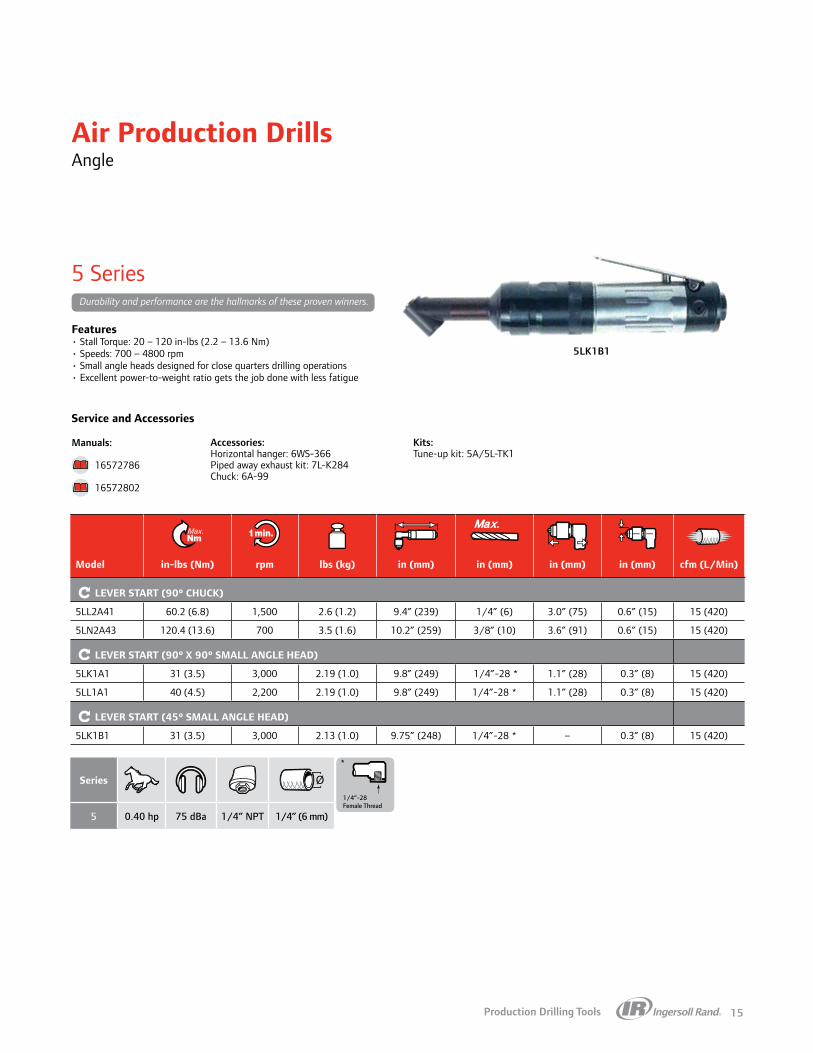
5 Series
Durability and performance are the hallmarks of these proven winners.
Features• Stall Torque: 20 – 120 in-lbs (2.2 – 13.6 Nm)• Speeds: 700 – 4800 rpm• Small angle heads designed for close quarters drilling operations• Excellent power-to-weight ratio gets the job done with less fatigue
Manuals:
16572786
16572802
5LK1B1
1/4”-28Female Thread
Air Production Drills Angle
Series
5 0.40 hp 75 dBa 1/4” NPT 1/4” (6 mm)
Model in-lbs (Nm) rpm lbs (kg) in (mm) in (mm) in (mm) in (mm) cfm (L/Min)
LEVER START (900 CHUCK)
5LL2A41 60.2 (6.8) 1,500 2.6 (1.2) 9.4” (239) 1/4” (6) 3.0” (75) 0.6” (15) 15 (420)
5LN2A43 120.4 (13.6) 700 3.5 (1.6) 10.2” (259) 3/8” (10) 3.6” (91) 0.6” (15) 15 (420)
LEVER START (900 X 900 SMALL ANGLE HEAD)
5LK1A1 31 (3.5) 3,000 2.19 (1.0) 9.8” (249) 1/4”-28 * 1.1” (28) 0.3” (8) 15 (420)
5LL1A1 40 (4.5) 2,200 2.19 (1.0) 9.8” (249) 1/4”-28 * 1.1” (28) 0.3” (8) 15 (420)
LEVER START (450 SMALL ANGLE HEAD)
5LK1B1 31 (3.5) 3,000 2.13 (1.0) 9.75” (248) 1/4”-28 * – 0.3” (8) 15 (420)

Production Drilling Tools16
6LL2A42
Service and Accessories
Accessories:Horizontal hanger: 6WS-366Piped away exhaust kit: 7L-K284 Chuck: 6A-99
Kits:Tune-up kit: 6-DRILLS-TK1
6 Series
Dependability and consistency have made the 6 Series drills a staple in many assembly environments.
Features• Stall Torque: 23 – 320 in-lbs (2.6 – 36.2 Nm)• Speeds: 400 – 6,000 rpm• Small angle heads designed for close quarters drilling operations• Excellent power-to-weight ratio gets the job done with less fatigue
Manuals:
P6784
Air Production Drills Angle
1/4”-28Female Thread
Series
6 0.51 hp 74 dBa 1/4” NPT 1/4” (6 mm)
Model in-lbs (Nm) rpm lbs (kg) in (mm) in (mm) in (mm) in (mm) cfm (L/Min)
LEVER START (900 CHUCK)
6LK2A41 64.6 (7.3) 2,000 2.8 (1.3) 9.5” (241) 1/4” (6) 3.0” (75) 0.5” (14) 20 (560)
6LL2A42 94.7 (10.7) 1,400 2.8 (1.3) 9.5” (242) 3/8” (10) 3.2” (81) 0.5” (14) 20 (560)
6LP3A43 192.1 (21.7) 600 3.7 (1.7) 10.6” (270) 3/8” (10) 3.9” (99) 0.7” (18) 20 (560)
6LR3A44 320.4 (36.2) 400 4.0 (1.8) 10.7” (272) 1/2” (13) 4.1” (105) 0.7” (18) 20 (560)
LEVER START (900 SMALL ANGLE HEAD)
6LL1A1 64 (7.3) 2,150 2.13 (0.95) 9.69” (246) 1/4”-28 * 1.1” (28) 0.3” (8) 20 (560)
Production Drilling Tools 17
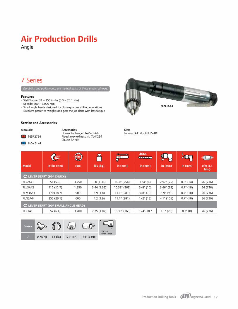
7LN3A44
Service and Accessories
Accessories:Horizontal hanger: 6WS-3P66Piped away exhaust kit: 7L-K284 Chuck: 6A-99
Kits:Tune-up kit: 7L-DRILLS-TK1
7 Series
Durability and performance are the hallmarks of these proven winners.
Features• Stall Torque: 31 – 255 in-lbs (3.5 – 28.1 Nm)• Speeds: 600 – 6,000 rpm• Small angle heads designed for close-quarters drilling operations• Excellent power-to-weight ratio gets the job done with less fatigue
Manuals:
16572794
16572174
1/4”-28Female Thread
Air Production Drills Angle
Series
7 0.75 hp 81 dBa 1/4” NPT 1/4” (6 mm)
Model in-lbs (Nm) rpm lbs (kg) in (mm) in (mm) in (mm) in (mm) cfm (L/Min)
LEVER START (900 CHUCK)
7LJ2A41 51 (5.6) 3,250 3.0 (1.36) 10.0” (254) 1/4” (6) 2.97” (75) 0.5” (14) 26 (736)
7LL3A42 112 (12.7) 1,550 3.44 (1.56) 10.38” (263) 3/8” (10) 3.66” (93) 0.7” (18) 26 (736)
7LM3A43 170 (18.7) 900 3.9 (1.8) 11.1” (281) 3/8” (10) 3.9” (99) 0.7” (18) 26 (736)
7LN3A44 255 (28.1) 600 4.2 (1.9) 11.1” (281) 1/2” (13) 4.1” (105) 0.7” (18) 26 (736)
LEVER START (900 SMALL ANGLE HEAD)
7LK1A1 57 (6.4) 3,200 2.25 (1.02) 10.38” (263) 1/4”-28 * 1.1” (28) 0.3” (8) 26 (736)
Production Drilling Tools18
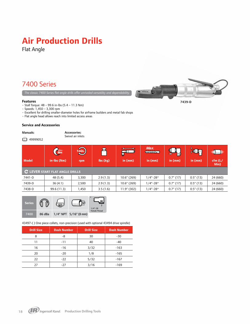
7439-D
Air Production Drills Flat Angle
Service and Accessories
Accessories:Swivel air inlets
7400 Series
The classic 7400 Series flat angle drills offer unrivaled versatility and dependability.
Features• Stall Torque: 48 – 99.6 in-lbs (5.4 – 11.3 Nm)• Speeds: 1,450 – 3,300 rpm• Excellent for drilling smaller-diameter holes for airframe builders and metal fab shops• Flat angle head allows reach into limited access areas
Manuals:
49999052
43497-( ) One piece collets, non-precision (used with optional 43494 drive spindle)
1/4”-28Female Thread
Series
7400 86 dBa 1/4” NPT 5/16” (8 mm)
Model in-lbs (Nm) rpm lbs (kg) in (mm) in (mm) in (mm) in (mm) cfm (L/Min)
LEVER START FLAT ANGLE DRILLS
7441-D 48 (5.4) 3,300 2.9 (1.3) 10.6” (269) 1/4”-28* 0.7” (17) 0.5” (13) 24 (660)
7439-D 36 (4.1) 2,500 2.9 (1.3) 10.6” (269) 1/4”-28* 0.7” (17) 0.5” (13) 24 (660)
7438-D 99.6 (11.3) 1,450 3.5 (1.6) 11.9” (302) 1/4”-28* 0.7” (17) 0.5” (13) 24 (660)
Drill Size Dash Number Drill Size Dash Number
8 -8 30 -30
11 -11 40 -40
16 -16 3/32 -163
20 -20 1/8 -165
22 -22 5/32 -167
27 -27 3/16 -169

Production Drilling Tools 19
Air Production Drills Modular
Service and Accessories
Accessories:5 modular attachments
P33 Series Motors
P33 drills with the R33 modular end effectors offer excellent power and flexibility.
Features• Stall Torque: 16.8 – 141.6 in-lbs (1.9 – 16 Nm)• Speeds: 660 – 5,400 rpm• Five unique interchangeable heads that provide the ultimate in flexibility• 0, 30, 90, and 180 degree angle heads• Variety of bit holders• Lube-free
Manuals:
80218605
80212798
P33016-PMSL P33022-DMSL
Series
P33 0.44 hp 76 dBa 1/4” NPT 3/8” (10 mm)
Model in-lbs (Nm) rpm lbs (kg) in (mm) in (mm) cfm (L/Min)
PISTOL GRIP / TRIGGER START
P33054-PMSL 16.8 (1.9) 5,400 1.8 (0.8) 5.7” (146) 0.8” (21) 21 (600)
P33032-PMSL 28.3 (3.2) 3,200 1.8 (0.8) 5.7” (146) 0.8” (21) 21 (600)
P33022-PMSL 39.8 (4.5) 2,200 1.8 (0.8) 5.7” (146) 0.8” (21) 21 (600)
P33016-PMSL 60.2 (6.8) 1,600 2.0 (0.9) 6.3” (161) 0.8” (21) 21 (600)
P33011-PMSL 84.1 (9.5) 1,100 2.0 (0.9) 6.3” (161) 0.8” (21) 21 (600)
P33006-PMSL 141.6 (16) 660 2.0 (0.9) 6.3” (161) 0.8” (21) 21 (600)
INLINE / BUTTON CONTROL
P33054-DMSL-B 16.8 (1.9) 5,400 1.4 (0.6) 6.5” (164) 0.9” (22) 21 (600)
P33032-DMSL-B 28.3 (3.2) 3,200 1.4 (0.6) 6.5” (164) 0.9” (22) 21 (600)
INLINE / LEVER CONTROL
P33054-DMSL 16.8 (1.9) 5,400 1.5 (0.7) 6.5” (164) 0.9” (22) 21 (600)
P33032-DMSL 28.3 (3.2) 3,200 1.5 (0.7) 6.5” (164) 0.9” (22) 21 (600)
P33022-DMSL 39.8 (4.5) 2,200 1.5 (0.7) 6.5” (164) 0.9” (22) 21 (600)
P33016-DMSL 60.2 (6.8) 1,600 1.7 (0.8) 7.0” (179) 0.9” (22) 21 (600)
P33011-DMSL 84.1 (9.5) 1,100 1.7 (0.8) 7.0” (179) 0.9” (22) 21 (600)
P33006-DMSL 141.6 (16) 660 1.7 (0.8) 7.0” (179) 0.9” (22) 21 (600)

Production Drilling Tools20
R33 Series Attachments
P33 drills with the R33 modular end effectors offer excellent power and flexibility.
Service and Accessories
Features• R33 Series precision drilling attachments are designed to
quickly, safely, and securely connect with an assortment of pistol and inline motors in a variety of speeds
• Patented quick-change technology allows drill attachment heads to be removed and connected safely, quickly, and securely with any motors in less than three seconds
• Interchangeable heads means you only buy the components you need and configure to the application
Manuals:
MBR33001 — 021
660 rpm1100 rpm1600 rpm2200 rpm3200 rpm5400 rpm
660 rpm1100 rpm1600 rpm2200 rpm3200 rpm5400 rpm
1 M80
2 F1/4
3 F1/4
4 M80
5 F1/4
Air Production Drills Modular
B C DReference in (mm) in (mm) in (mm) in (mm) in (mm) lbs (kg)
MODULAR ATTACHMENTS
BC
C
B
C
D
B
B
C
B
CD
17 mm
17 mm
25 mm 25 mm
17 mm
25 mm
BC
1 R33M000M80 0.3” (8.0) A + 3.2” (81) – – – 0.8 (0.4)
BC
C
B
C
D
B
B
C
B
CD
17 mm
17 mm
25 mm 25 mm
17 mm
25 mm
BC
2 R33M030D17F1/4 0.3” (6.0) A + 4.6” (118) 0.9” (24) 0.7” (18) – 0.5 (0.2)
BC
C
B
C
D
B
B
C
B
CD
17 mm
17 mm
25 mm 25 mm
17 mm
25 mm
BC
3 R33M090D17F1/4 0.3” (6.0) A + 4.1” (105) 1.4” (36) 0.7” (18) – 0.5 (0.2)B
C
C
B
C
D
B
B
C
B
CD
17 mm
17 mm
25 mm 25 mm
17 mm
25 mm
BC4 R33M090D25M80 0.3” (8.0) A + 3.2” (81) 3.9” (99) 1.2” (30) – 1.2 (0.5)
BC
C
B
C
D
B
B
C
B
CD
17 mm
17 mm
25 mm 25 mm
17 mm
25 mm
BC
5 R33M180D17F1/4 0.3” (6.0) A + 4.9” (124) 2.5” (64) 0.7” (18) 1.4” (36) 0.7 (0.3)

Production Drilling Tools 21
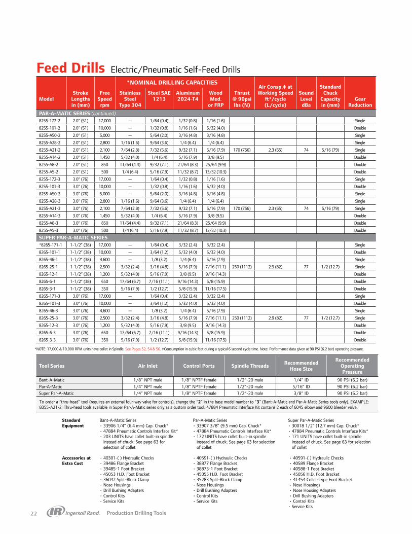
Feed DrillsElectric/Pneumatic Self-Feed Drills
Features• Built-in four-way valve enables both manual and remote operation• Double-acting air piston provides smooth, controlled forward and retract strokes• Needle valve controls allows adjustment of forward and retract strokes• Adjustment screw provides infinite stroke length settings• Ball bearing spindle support offers precision and long service life• Muffled exhaust for a quieter work environment
Bant-A-Matic, Par-A-Matic, and Super Par-A-Matic Drills provide the selection, performance, and degree of precision to automate a wide range of secondary machining applications simply and economically. They utilize compressed air for both the spindle rotation and feed / control functions. The reliable rotary-vane air motor offers high power-to-size performance which minimizes tool size and weight for added machine design flexibility. The tools are easily installed, requiring only simple pneumatic circuitry. They can be used individually or in conjunction with other electric and pneumatic tools.
*NOMINAL DRILLING CAPACITIES
Thrust@ 90psilbs (N)
Air Consp.‡ atWorking Speed
ft3/cycle(L/cycle)
StandardChuck
Capacityin (mm)
ModelStroke
Lengthsin (mm)
Free Speed rpm
Stainless Steel
Type 304
Steel SAE1213
Aluminum2024-T4
Wood Med.
or FRP
Sound LeveldBa
Gear Reduction
BANT-A-MATIC SERIES8245-203-1* 1-1/4” (32 ) 19,000 — 1/64 (0.4) 1/32 (0.8) 1/16 (1.6) Single
8245-101-1 1-1/4” (32 ) 10,000 1/64 (0.4) 1/32 (0.8) 1/16 (1.6) 1/8 (3.2) Double
8245-B45-1 1-1/4” (32 ) 4,400 1/32 (0.8) 1/16 (1.6) 1/8 (3.2) 5/32 (4.0) 90 (400) 1.5 (42) 77 1/4 (6.4) Single
8245-B30-1 1-1/4” (32 ) 2,700 1/16 (1.6) 1/8 (3.2) 3/16 (4.8) 3/16 (4.8) Single
8245-B8-1 1-1/4” (32 ) 900 3/32 (2.4) 3/16 (4.8) 1/4 (6.4) 5/16 (7.9) Double
8245-203-2 2.0” (51) 19,000 — 1/64 (0.4) 1/32 (0.8) 1/16 (1.6) Single
8245-101-2 2.0” (51) 10,000 1/64 (0.4) 1/32 (0.8) 1/16 (1.6) 1/8 (3.2) Double
8245-B45-2 2.0” (51) 4,400 1/32 (0.8) 1/16 (1.6) 1/8 (3.2) 5/32 (4.0) 90 (400) 1.5 (42) 77 1/4 (6.4) Single
8245-B30-2 2.0” (51) 2,700 1/16 (1.6) 1/8 (3.2) 3/16 (4.8) 3/16 (4.8) Single
8245-B8-2 2.0” (51) 900 3/32 (2.4) 3/16 (4.8) 1/4 (6.4) 5/16 (7.9) Double
8245-203-3 3.0” (76 ) 19,000 — 1/64 (0.4) 1/32 (0.8) 1/16 (1.6) Single
8245-101-3 3.0” (76 ) 10,000 1/64 (0.4) 1/32 (0.8) 1/16 (1.6) 1/8 (3.2) Double
8245-B45-3 3.0” (76 ) 4,400 1/32 (0.8) 1/16 (1.6) 1/8 (3.2) 5/32 (4.0) 90 (400) 1.5 (42) 77 1/4 (6.4) Single
8245-B30-3 3.0” (76 ) 2,700 1/16 (1.6) 1/8 (3.2) 3/16 (4.8) 3/16 (4.8) Single
8245-B8-3 3.0” (76 ) 900 3/32 (2.4) 3/16 (4.8) 1/4 (6.4) 5/16 (7.9) Double
PAR-A-MATIC SERIES*8255-172-1 1-1/4” (32) 17,000 — 1/64 (0.4) 1/32 (0.8) 1/16 (1.6) Single
8255-101-1 1-1/4” (32) 10,000 — 1/32 (0.8) 1/16 (1.6) 5/32 (4.0) Double
8255-A50-1 1-1/4” (32) 5,000 — 5/64 (2.0) 3/16 (4.8) 3/16 (4.8) Single
8255-A28-1 1-1/4” (32) 2,800 1/16 (1.6) 9/64 (3.6) 1/4 (6.4) 1/4 (6.4) Single
8255-A21-1 1-1/4” (32) 2,100 7/64 (2.8) 7/32 (5.6) 9/32 (7.1) 5/16 (7.9) 170 (756) 2.3 (65) 74 5/16 (79) Single
8255-A14-1 1-1/4” (32) 1,450 5/32 (4.0) 1/4 (6.4) 5/16 (7.9) 3/8 (9.5) Double
8255-A8-1 1-1/4” (32) 850 11/64 (4.4) 9/32 (7.1) 21/64 (8.3) 25/64 (9.9) Double
8255-A5-1 1-1/4” (32) 500 1/4 (6.4) 5/16 (7.9) 11/32 (8.7) 13/32 (10.3) Double
(continued next page)
Example of product identification
Controls2 = Valve-In-Head (built-in valving)3 = Thru-Head (external valving required)
Series45 = Bant-A-Matic55 = Par-A-Matic65 = Super Par-A-Matic
Stroke Length Free Speed Tool Generation
8 2 255 21A— —
BANT-A-MATIC® 45 Series3/16” (4.8 mm) Capacity, Steel • .25 HP (.20 kW)
8245-B45-2
PARA-A-MATIC® 55 Series5/16” (7.9 mm) Capacity, Steel • .50 HP (.37 kW)
8255-A14-2
SUPER PARA-A-MATIC® 65 Series
1/2” (12.7 mm) Capacity, Steel • .75 HP (.56 kW)
8265-25-3
Production Drilling Tools22
Feed Drills
Tool Series Air Inlet Control Ports Spindle Threads Recommended Hose Size
Recommended Operating Pressure
Bant-A-Matic 1/8” NPT male 1/8” NPTF female 1/2”-20 male 1/4” ID 90 PSI (6.2 bar)Par-A-Matic 1/4” NPT male 1/8” NPTF female 1/2”-20 male 5/16” ID 90 PSI (6.2 bar)Super Par-A-Matic 1/4” NPT male 1/8” NPTF female 1/2”-20 male 3/8” ID 90 PSI (6.2 bar)
To order a “thru-head” tool (requires an external four-way valve for controls), change the “2” in the base model number to “3” (Bant-A-Matic and Par-A-Matic Series tools only). EXAMPLE: 8355-A21-2. Thru-head tools available in Super Par-A-Matic series only as a custom order tool. 47884 Pneumatic Interface Kit contains 2 each of 6045 elbow and 9600 bleeder valve.
*NOMINAL DRILLING CAPACITIES
Thrust@ 90psilbs (N)
Air Consp.‡ atWorking Speed
ft3/cycle(L/cycle)
StandardChuck
Capacityin (mm)
ModelStroke
Lengthsin (mm)
Free Speed rpm
Stainless Steel
Type 304
Steel SAE1213
Aluminum2024-T4
Wood Med.
or FRP
Sound LeveldBa
Gear Reduction
PAR-A-MATIC SERIES (continued)8255-172-2 2.0” (51) 17,000 — 1/64 (0.4) 1/32 (0.8) 1/16 (1.6) Single
8255-101-2 2.0” (51) 10,000 — 1/32 (0.8) 1/16 (1.6) 5/32 (4.0) Double
8255-A50-2 2.0” (51) 5,000 — 5/64 (2.0) 3/16 (4.8) 3/16 (4.8) Single
8255-A28-2 2.0” (51) 2,800 1/16 (1.6) 9/64 (3.6) 1/4 (6.4) 1/4 (6.4) Single
8255-A21-2 2.0” (51) 2,100 7/64 (2.8) 7/32 (5.6) 9/32 (7.1) 5/16 (7.9) 170 (756) 2.3 (65) 74 5/16 (79) Single
8255-A14-2 2.0” (51) 1,450 5/32 (4.0) 1/4 (6.4) 5/16 (7.9) 3/8 (9.5) Double
8255-A8-2 2.0” (51) 850 11/64 (4.4) 9/32 (7.1) 21/64 (8.3) 25/64 (9.9) Double
8255-A5-2 2.0” (51) 500 1/4 (6.4) 5/16 (7.9) 11/32 (8.7) 13/32 (10.3) Double
8255-172-3 3.0” (76) 17,000 — 1/64 (0.4) 1/32 (0.8) 1/16 (1.6) Single
8255-101-3 3.0” (76) 10,000 — 1/32 (0.8) 1/16 (1.6) 5/32 (4.0) Double
8255-A50-3 3.0” (76) 5,000 — 5/64 (2.0) 3/16 (4.8) 3/16 (4.8) Single
8255-A28-3 3.0” (76) 2,800 1/16 (1.6) 9/64 (3.6) 1/4 (6.4) 1/4 (6.4) Single
8255-A21-3 3.0” (76) 2,100 7/64 (2.8) 7/32 (5.6) 9/32 (7.1) 5/16 (7.9) 170 (756) 2.3 (65) 74 5/16 (79) Single
8255-A14-3 3.0” (76) 1,450 5/32 (4.0) 1/4 (6.4) 5/16 (7.9) 3/8 (9.5) Double
8255-A8-3 3.0” (76) 850 11/64 (4.4) 9/32 (7.1) 21/64 (8.3) 25/64 (9.9) Double
8255-A5-3 3.0” (76) 500 1/4 (6.4) 5/16 (7.9) 11/32 (8.7) 13/32 (10.3) Double
SUPER PAR-A-MATIC SERIES*8265-171-1 1-1/2” (38) 17,000 — 1/64 (0.4) 3/32 (2.4) 3/32 (2.4) Single
8265-101-1 1-1/2” (38) 10,000 — 3/64 (1.2) 5/32 (4.0) 5/32 (4.0) Double
8265-46-1 1-1/2” (38) 4,600 — 1/8 (3.2) 1/4 (6.4) 5/16 (7.9) Single
8265-25-1 1-1/2” (38) 2,500 3/32 (2.4) 3/16 (4.8) 5/16 (7.9) 7/16 (11.1) 250 (1112) 2.9 (82) 77 1/2 (12.7) Single
8265-12-1 1-1/2” (38) 1,200 5/32 (4.0) 5/16 (7.9) 3/8 (9.5) 9/16 (14.3) Double
8265-6-1 1-1/2” (38) 650 17/64 (6.7) 7/16 (11.1) 9/16 (14.3) 5/8 (15.9) Double
8265-3-1 1-1/2” (38) 350 5/16 (7.9) 1/2 (12.7) 5/8 (15.9) 11/16 (17.5) Double
8265-171-3 3.0” (76) 17,000 — 1/64 (0.4) 3/32 (2.4) 3/32 (2.4) Single
8265-101-3 3.0” (76) 10,000 — 3/64 (1.2) 5/32 (4.0) 5/32 (4.0) Double
8265-46-3 3.0” (76) 4,600 — 1/8 (3.2) 1/4 (6.4) 5/16 (7.9) Single
8265-25-3 3.0” (76) 2,500 3/32 (2.4) 3/16 (4.8) 5/16 (7.9) 7/16 (11.1) 250 (1112) 2.9 (82) 77 1/2 (12.7) Single
8265-12-3 3.0” (76) 1,200 5/32 (4.0) 5/16 (7.9) 3/8 (9.5) 9/16 (14.3) Double
8265-6-3 3.0” (76) 650 17/64 (6.7) 7/16 (11.1) 9/16 (14.3) 5/8 (15.9) Double
8265-3-3 3.0” (76) 350 5/16 (7.9) 1/2 (12.7) 5/8 (15.9) 11/16 (17.5) Double
*NOTE: 17,000 & 19,000 RPM units have collet in Spindle. See Pages 52, 54 & 56. ‡Consumption in cubic feet during a typical 6 second cycle time. Note: Performance data given at 90 PSI (6.2 bar) operating pressure.
• 40301-( ) Hydraulic Checks• 39486 Flange Bracket• 39485-1 Foot Bracket• 45053 H.D. Foot Bracket• 36042 Split-Block Clamp• Nose Housings• Drill Bushing Adapters• Control Kits• Service Kits
• 40591-( ) Hydraulic Checks • 40589 Flange Bracket • 40588-1 Foot Bracket • 45056 H.D. Foot Bracket • 41454 Collet-Type Foot Bracket • Nose Housings • Nose Housing Adapters • Drill Bushing Adapters • Control Kits• Service Kits
• 40591-( ) Hydraulic Checks• 38877 Flange Bracket• 38875-1 Foot Bracket• 45055 H.D. Foot Bracket• 35283 Split-Block Clamp• Nose Housings• Drill Bushing Adapters• Control Kits• Service Kits
Standard Equipment
Accessories at Extra Cost
Bant-A-Matic Series • 33906 1/4” (6.4 mm) Cap. Chuck* • 47884 Pneumatic Controls Interface Kit* • 203 UNITS have collet built-in spindle instead of chuck. See page 63 for selection of collet
Par-A-Matic Series • 33907 3/8” (9.5 mm) Cap. Chuck* • 47884 Pneumatic Controls Interface Kit* • 172 UNITS have collet built-in spindle instead of chuck. See page 63 for selection of collet
Super Par-A-Matic Series• 30018 1/2” (12.7 mm) Cap. Chuck*• 47884 Pneumatic Controls Interface Kits*• 171 UNITS have collet built-in spindle instead of chuck. See page 63 for selection of collet
Electric/Pneumatic Self-Feed Drills

Production Drilling Tools 23
Feed DrillsElectric/Pneumatic Self-Feed Twin Drills
Features• Adjustable spindles allow reapplication as machining requirements change.• Comprehensive range of American and metric collets available to meet a wide variety of hole specifications.• Double-acting air piston provides smooth, controlled forward and retract strokes.• Needle valve controls allow adjustment of forward and retract strokes.• Adjustment screw provides infinite stroke length settings up to 3.0” maximum.• Muffled exhaust for a quieter work environment.
Twin Drills perform two machining operations per cycle for holes with center distances from 3/8” to 3 3/4”. They’re ideal for many close-center machining problems. But even more important, Twin Drills significantly reduce machining time and parts handling while improving quality.
Three series of standard tools are available, equipped with adjustable dual spindle heads. Like the other Automatic Production Tools, each Twin Drill is a completely self-contained unit with built-in cycle, feed rate, and motor controls. They can be operated individually or in conjunction with other tools and machine components.
*NOMINAL DRILLING CAPACITIES
Thrust@ 90psilbs (N)
Air Consp.‡ atWorking Speed
ft3/cycle(L/cycle)
StandardChuck
Capacityin (mm)
ModelStroke
Lengthsin (mm)
Free Speed rpm
Stainless Steel
Type 304
Steel SAE1213
Aluminum2024-T4
Wood Med.
or FRP
Sound LeveldBa
Gear Reduction
BANT-A-MATIC SERIES8248-B45-1 1-1/4” (32) 4,400 1/32 (.78) 1/16 (1.6) 3/32 (2.4) 3/32 (2.4) Single
8248-B30-1 1-1/4” (32) 2,700 1/16 (1.6) 3/32 (2.4) 1/8 (3.2) 1/8 (3.2) 90 (400) 1.5 (42) 77 5/32(4.0) Single
8248-B8-1 1-1/4” (32) 900 1/8 (3.2) 1/8 (3.2) 3/16 (4.8) 3/16 (4.8) Double
8248-B45-2 2.0” (51) 4,400 1/32 (.78) 1/16 (1.6) 3/32 (2.4) 3/32 (2.4) Single
8248-B30-2 2.0” (51) 2,700 1/16 (1.6) 3/32 (2.4) 1/8 (3.2) 1/8 (3.2) 90 (400) 1.5 (42) 77 5/32(4.0) Single
8248-B8-2 2.0” (51) 900 1/8 (3.2) 1/8 (3.2) 3/16 (4.8) 3/16 (4.8) Double
8248-B45-3 3.0” (76) 4,400 1/32 (.78) 1/16 (1.6) 3/32 (2.4) 3/32 (2.4) Single
8248-B30-3 3.0” (76) 2,700 1/16 (1.6) 3/32 (2.4) 1/8 (3.2) 1/8 (3.2) 90 (400) 1.5 (42) 77 5/32(4.0) Single
8248-B8-3 3.0” (76) 900 1/8 (3.2) 1/8 (3.2) 3/16 (4.8) 3/16 (4.8) Double
PAR-A-MATIC SERIES8258-C50-1 1-1/4” (32) 5,000 1/16 (1.6) 1/8 (3.2) 1/8 (3.2) Single
8258-C28-1 1-1/4” (32) 2,800 3/64 (1.2) 1/8 (3.2) 3/16 (4.5) 3/16 (4.5) Single
8258-C21-1 1-1/4” (32) 2,100 5/64 (1.9) 5/32 (4.0) 7/32 (5.6) 7/32 (5.6) 170 (756) 2.3 (65) 74 1/4 (6.4) Single
8258-C14-1 1-1/4” (32) 1,450 7/64 (2.7) 3/16 (4.5) 1/4 (6.4) 1/4 (6.4) Double
8258-C8-1 1-1/4” (32) 850 11/64 (4.3) 1/4 (6.4) 9/32 (7.1) 9/32 (7.1) Double
8258-C5-1 1-1/4” (32) 500 1/4 (6.4) 1/4 (6.4) 5/16 (7.9) 5/16 (7.9) Double
8258-C50-2 2.0” (51) 5,000 1/16 (1.6) 1/8 (3.2) 1/8 (3.2) Single
8258-C28-2 2.0” (51) 2,800 3/64 (1.2) 1/8 (3.2) 3/16 (4.5) 3/16 (4.5) Single
8258-C21-2 2.0” (51) 2,100 5/64 (1.9) 5/32 (4.0) 7/32 (5.6) 7/32 (5.6) 170 (756) 2.3 (65) 74 1/4 (6.4) Single
8258-C14-2 2.0” (51) 1,450 7/64 (2.7) 3/16 (4.5) 1/4 (6.4) 1/4 (6.4) Double
8258-C8-2 2.0” (51) 850 11/64 (4.3) 1/4 (6.4) 9/32 (7.1) 9/32 (7.1) Double
8258-C5-2 2.0” (51) 500 1/4 (6.4) 1/4 (6.4) 5/16 (7.9) 5/16 (7.9) Double
(continued next page)
Example of product identification
Controls2 = Valve-In-Head (built-in valving)
Series48 = Bant-A-Matic58 = Par-A-Matic68 = Super Par-A-Matic
Stroke Length Free Speed Tool Generation
8 2 258 21C— —
BANT-A-MATIC® 48 Series1/8” (3.2 mm) Capacity, Steel • .25 HP (.19 kW)
MODEL 8248-B30-2
PARA-A-MATIC® 58 Series1/4” (6.4 mm) Capacity, Steel • .50 HP (.37 kW)
MODEL 8258-C21-2
SUPER PARA-A-MATIC® 68 Series
3/8” (9.5 mm) Capacity, Steel • .75 HP (.56 kW)
MODEL 8268-A25-3

Production Drilling Tools24
*NOMINAL DRILLING CAPACITIES
Thrust@ 90psilbs (N)
Air Consp.‡ atWorking Speed
ft3/cycle(L/cycle)
StandardChuck
Capacityin (mm)
ModelStroke
Lengthsin (mm)
Free Speed rpm
Stainless Steel
Type 304
Steel SAE1213
Aluminum2024-T4
Wood Med.
or FRP
Sound LeveldBa
Gear Reduction
PAR-A-MATIC SERIES (continued)8258-C50-3 3.0” (76) 5,000 1/16 (1.6) 1/8 (3.2) 1/8 (3.2) Single
8258-C28-3 3.0” (76) 2,800 3/64 (1.2) 1/8 (3.2) 3/16 (4.5) 3/16 (4.5) Single
8258-C21-3 3.0” (76) 2,100 5/64 (1.9) 5/32 (4.0) 7/32 (5.6) 7/32 (5.6) 170 (756) 2.3 (65) 74 1/4 (6.4) Single
8258-C14-3 3.0” (76) 1,450 7/64 (2.7) 3/16 (4.5) 1/4 (6.4) 1/4 (6.4) Double
8258-C8-3 3.0” (76) 850 11/64 (4.3) 1/4 (6.4) 9/32 (7.1) 9/32 (7.1) Double
8258-C5-3 3.0” (76) 500 1/4 (6.4) 1/4 (6.4) 5/16 (7.9) 5/16 (7.9) Double
SUPER PAR-A-MATIC SERIES (continued)8268-A46-1 1-1/2” (38) 4,600 1/4 (6.4) 3/16 (4.8) Single
8268-A25-1 1-1/2” (38) 2,500 1/16 (1.6) 1/4 (6.4) 5/16 (7.9) 5/16 (7.9) Single
8268-A12-1 1-1/2” (38) 1,200 1/8 (3.2) 5/16 (7.9) 11/32 (8.7) 3/8 (9.5) 250 (1112) 2.9 (82) 77 3/8 (9.5) Double
8268-A6-1 1-1/2” (38) 650 13/64 (5.2) 11/32 (8.7) 3/8 (9.5) 7/16 (11.1) Double
8268-A3-1 1-1/2” (38) 350 5/16 (7.9) 3/8 (9.5) 13/32 (10.3) 15/32 (11.9) Double
8268-A46-3 3.0” (76) 4,600 1/4 (6.4) 3/16 (4.8) Single
8268-A25-3 3.0” (76) 2,500 1/16 (1.6) 1/4 (6.4) 5/16 (7.9) 5/16 (7.9) Single
8268-A12-3 3.0” (76) 1,200 1/8 (3.2) 5/16 (7.9) 11/32 (8.7) 3/8 (9.5) 250 (1112) 2.9 (82) 77 3/8 (9.5) Double
8268-A6-3 3.0” (76) 650 13/64 (5.2) 11/32 (8.7) 3/8 (9.5) 7/16 (11.1) Double
8268-A3-3 3.0” (76) 350 5/16 (7.9) 3/8 (9.5) 13/32 (10.3) 15/32 (11.9) Double
*Speed Sensitive Material ‡Consumption in cubic feet during a typical 6 second cycle time. Note: Performance data given at 90 PSI (6.2 bar) operating pressure.
*Contains (2) 6045 90˚ street elbows and (2) 9600 pilot bleeder valves. NOTE: Collets for Twin Drills must be ordered separately at extra cost. See page 28.
Tool Series Air Inlet Control Ports Spindle Adjustments
Recommended Hose Size
Recommended Operating Pressure
Bant-A-Matic 1/8” NPT male 1/8” NPTF female 3/8” to 2 1/8” centers (9.5 to 54 mm) 1/4” ID 90 PSI (6.2 bar)
Par-A-Matic 1/4” NPT male 1/8” NPTF female 1/2” to 2 1/2” centers (12.7 to 63.5 mm) 5/16” ID 90 PSI (6.2 bar)
Super Par-A-Matic 1/4” NPT male 1/8” NPTF female 3/4” to 3 3/4” centers (19 to 95 mm) 3/8” ID 90 PSI (6.2 bar)
• 47368-( ) Collets• 40301-( ) Hydraulic Checks • 39486 Flange Bracket • 39485-1 Foot Bracket • 45053 H.D. Foot Bracket • 36042 Split-Block Clamp• Control Kits• Service Kits
• 46033-( ) Collets • 40591-( ) Hydraulic Checks• 40589 Flange Bracket• 40588-1 Foot Bracket• 45056 H.D. Foot Bracket • 41454 Collet-Type Foot Bracket• Control Kits• Service Kits
• 45998-( ) Collets• 40591-( ) Hydraulic Checks• 38877 Flange Bracket• 38875-1 Foot Bracket• 45055 H.D. Foot Bracket• 35283 Split-Block Clamp• Control Kits• Service Kits
Standard Equipment
Accessories at Extra Cost
Bant-A-Matic Series • 46394 Twin Drill Head • 47884 Pneumatic Controls Interface Kit* • Necessary Wrenches
Par-A-Matic Series • 46023 Twin Drill Head • 47884 Pneumatic Controls Interface Kit*• Necessary Wrenches
Super Par-A-Matic Series• 46063 Twin Drill Head • 47884 Pneumatic Controls Interface Kit*• Necessary Wrenches
Feed DrillsElectric/Pneumatic Self-Feed Twin Drills

Production Drilling Tools 25
‡Consumption in cubic feet during a typical 6 second cycle time. Note: Performance data given at 90 PSI (6.2 bar) air pressure.
Tool Series Air Inlet Control Ports Spindle Adjustments
Recommended Hose Size
Recommended Operating Pressure
Par-A-Matic 1/4” NPT male 1/8” NPTF female 3/8”-24 male 5/16” ID 90 PSI (6.2 bar)
• 40591-( ) Hydraulic Checks • 38877 Flange Bracket • 38875-1 Foot Bracket • 45055 H.D. Foot Bracket • 35283 Split-Block Clamp• Control Kits• Service Kits
Standard Equipment
Accessories at Extra Cost
Par-A-Matic Series • 47341 3/8” (9.5 mm) Cap. Chuck • 47884 Pneumatic Controls Interface Kit — contains (2) 6045 90˚ streetelbows and (2) 9600 pilot bleeder valves
Feed DrillsPneumatic Self-Feed Offset Drills
Features•Built-in four-way valve for both manual and remote operation.•Double-acting air piston provides smooth, con trolled forward and retract strokes.•Infinite stroke length adjustment up to 2.0” maximum.•Feed rate adjustment screws for the forward and retract strokes provide optimum hole quality and cycle time.•Muffled exhaust for a more comfortable work en vironment.•Selection of mounting brackets to meet installa tion requirements.
Automatic Offset Drills are offered to accommodate unusual part or fixture configurations. They also may be grouped in a fixture to produce holes with a center-line distance as low as 1.5”.
Offset drills are easily installed, requiring only simple pneumatic circuitry. They may also be used in conjunction with other pneumatic or electric Automatic Production Tools.
NOMINAL DRILLING CAPACITIES
Thrust@ 90psilbs (N)
Air Consp.‡ atWorking Speed
ft3/cycle(L/cycle)
StandardChuck
Capacityin (mm)
ModelFree
Speed rpm
Stainless Steel
Type 304
Steel SAE1213
Aluminum2024-T4
Wood Med.
or FRP
Sound LeveldBa
Gear Reduction
PAR-A-MATIC SERIES8266-A23-2 2,300 N/A 1/16 (1.6) 1/8 (3.2) 3/16 (4.8) Double
8266-A17-2 1,700 N/A 3/32 (2.4) 5/32 (4.0) 7/32 (5.6) 170 (756) 2.3 (65) 74 3/8 (9.5) Double
8266-A12-2 1,200 N/A 5/32 (4.0) 3/16 (4.8) 1/4 (6.4) Double
8266-A7-2 700 N/A 3/16 (4.8) 7/32 (5.6) 9/32 (7.2) Double
PAR-A-MATIC® 66 Series3/16” (4.8 mm) Capacity, Steel • 50 HP (.37 kW)
MODEL 8266-A17-2

Production Drilling Tools26
Feed DrillsPneumatic Self-Feed Drills
Features• Adjustable hydraulic check provides positive feed rate control for fine adjustment of chip size or breakthrough control.• “Dead stop” and “dwell” control offer repeatable depth accuracy within .001”.• Heavy-duty cast iron housing for rigid mounting.• Constant tool length, regardless of spindle speed, allows speed change without reposition ing the tool.• Both coarse and fine stroke length adjustments enables quick, accurate setups.• Control module is a complete, replaceable unit and can be easily removed without tool disassembly.• Modular motor and gearing units enable fast, easy speed changes and servicing.• Single exterior lubrication point for entire gear train simplifies preventative maintenance.• Muffled exhaust for a more comfortable work en vironment.• Exhaust may be piped away.
Hi-Thrust Automatic Feed Drills are designed for increased material removal rates of standard alloys and non-ferrous materials. Their high power and thrust also enable the machining of even the most demanding materials, including titanium and high-nickel alloys.
Hi-Thrust Drills feature a dual piston which develops the increased thrust for fast penetration and reduced cycle times. The tools are fully automatic, with all cycle and motor functions regulated by a single control module. They are easi ly installed, requiring only simple pneumatic circuitry. Hi-Thrust Drills can also be used in conjunction with other pneumatic and electric Automatic Production Tools.
Example of product identification
SeriesFree Speed Stroke
ExhaustM = 43874-1 MufflerB = 22827 Barbed Insertfor 1/2” I.D. exhaust hose
Drive OptionsA = 45177 3/4” Cap. ChuckB = 45176 3/8” Cap. ChuckC = 46090 No. 1 Morse Taper AdapterD = 46091 No. 2 Morse Taper Adapter
86 —70 -328— —
HIGH-THRUST 8670 Series5/8” (15.9 mm) Capacity, Steel • 1.25 HP (.93 kW)
8670-28-1
NOMINAL DRILLING CAPACITIES
Thrust@ 90psilbs (N)
Air Consp.‡ atWorking Speed
ft3/cycle(L/cycle)
StandardChuck
Capacityin (mm)
ModelStroke Lengthin (mm)
Free Speed rpm
Stainless Steel
Type 304
Steel SAE1213
Aluminum2024-T4
Wood Med.
or FRP
Sound LeveldBa
HIGH THRUST SERIES8670-47-3 4,700 — 3/16 (4.75) 7/16 (11.1) 1/2 (12.7)
8670-28-3 2,800 3/16 (4.8) 1/4 (6.35) 9/16 (14.3) 5/8 (15.9)
8670-13-3AM 3.0 (76) 1,350 5/16 (7.9) 11/32 (8.73) 5/8 (15.9) 3/4 (19.0) 500 (2224) 5.0 (142) 80 3/4 (19.0)
8670-8-3AM 800 3/8 (9.5) 7/16 (11.11) 3/4 (19.0) 7/8 (22.2)
8670-4-3 450 1/2 (12.7) 5/8 (15.87) 7/8 (22.2) 1.0 (25.4)
‡Consumption in cubic feet during a typical 6 second cycle time. Note: Performance data given at 90 PSI (6.2 bar) air pressure.
Tool Series Air Inlet Control Ports Spindle Adjustments
Recommended Hose Size
Recommended Operating Pressure
Coupler/Connection F/R/L
High-Thrust 3/8” NPT male 1/8” NPTF female 5/8”-16 male 5/8” ID 90 PSI (6.2 bar) 1/2” 1/2”
• 38922-2 3.0” Hydraulic Check• 46133-( ) Twin Hydraulic Check Assembly• 45185 Foot Bracket• 45188 Nose Housing• 46093-( ) Collets
Accessories at Extra Cost
Standard Equipment
• 45177 3/4” (19 mm) Cap. Chuck• 38922-1 2.0” Hydraulic Check• 45940 Exhaust Manifold• 43874-1 Muffler or 2632 Barbed Insert• Necessary wrenches• 45176 3/8” (9.5 mm) Cap. Chuck• 46090 No. 1 Morse Taper Adapter• 46091 No. 2 Morse Taper Adapter

Production Drilling Tools 27
‡ Consumption in cubic feet during a typical 6 second cycle time. **Tapping capacity is limited by the capacity of the tap chuck.
NOTE: Performance data given at 90 PSI (6.2 bar) air pressure.
*Contains (2) 6045 90˚ street elbows and (2) 9600 pilot bleeder valves.
Tool Series Air Inlet Control Ports Spindle Thread
Recommended Hose Size
Recommended Operating Pressure
Bant-A-Matic 1/8” NPT male 1/8” NPTF female 1/2” to 20” male 1/4” ID 90 PSI (6.2 bar)
Par-A-Matic 1/4” NPT male 1/8” NPTF female 1/2” to 20” male 5/16” ID 90 PSI (6.2 bar)
Standard Equipment
Bant-A-Matic Series (Clutch-Type)• 42123-1 Tapping Head Attachment• 37431-2 No. 0-No. 10 Cap. Rubber Flex Collet Insert• 37431-3 No. 10-1/4” Cap. Rubber Flex Collet Insert• 47884 Pneumatic Controls Interface Kits*• Necessary Wrenches
Par-A-Matic Series (Clutch-Type)• 38021-4 Tapping Head Attachment• 38036 No. 0-1/4” Cap. Rubber Flex Collet Insert• 38036-1 No. 1/4-1/2” Cap. Rubber Flex Collet Insert• 47884 Pneumatic Controls Interface Kits*• Necessary Wrenches
Par-A-Matic Series (Jaw-Type)• 34000-1 Tapping Head Attachment• 31432 No. 10-5/16” Cap. Tap Chuck (See Model Identification Chart on page 20)• 31427 No. 1/4 Cap. Tap Chuck (See Model Identification Chart on page 20)• 32060 No. 1/4-5/8” Cap. Tap Chuck (See Model Identification Chart on page 20)• 47884 Pneumatic Controls Interface Kits*• Necessary Wrenches
TappersPneumatic Self-Feed Tappers
These tools are identical to the Bant-A-Matic and Par-A-Matic units described on pages 12 and 13, except that these are fitted with tapping heads. All models are completely self-contained and have an adjustable stroke length of 2.0” maximum.
These tools are ideal for low-cost, automated hole tapping in applications where high precision is not required. Also excellent for thread-chasing operations.
Clutch‑type tapping units may be used for both blind and thru‑hole applications. Jaw‑type units are for use in thru‑hole applications only.
NOMINAL TAP CAPACITIES
Thrust@ 90psilbs (N)
Air Consp.‡ atWorking Speed
ft3/cycle(L/cycle)
StandardChuck
Capacityin (mm)
ModelStroke
Lengthsin (mm)
Free Speed rpm
Stainless Steel
Type 304
Steel SAE1213
Aluminum2024-T4
Wood Med.
or FRP
Sound LeveldBa
Gear Reduction
BANT-A-MATIC SERIES8245-203-1* 1-1/4” (32 ) 19,000 — 1/64 (0.4) 1/32 (0.8) 1/16 (1.6) Single
8245-101-1 1-1/4” (32 ) 10,000 1/64 (0.4) 1/32 (0.8) 1/16 (1.6) 1/8 (3.2) Double
8245-B45-1 1-1/4” (32 ) 4,400 1/32 (0.8) 1/16 (1.6) 1/8 (3.2) 5/32 (4.0) 90 (400) 1.5 (42) 77 1/4 (6.4) Single
8245-B30-1 1-1/4” (32 ) 2,700 1/16 (1.6) 1/8 (3.2) 3/16 (4.8) 3/16 (4.8) Single
8245-B8-1 1-1/4” (32 ) 900 3/32 (2.4) 3/16 (4.8) 1/4 (6.4) 5/16 (7.9) Double
8245-203-2 2.0” (51) 19,000 — 1/64 (0.4) 1/32 (0.8) 1/16 (1.6) Single
8245-101-2 2.0” (51) 10,000 1/64 (0.4) 1/32 (0.8) 1/16 (1.6) 1/8 (3.2) Double
8245-B45-2 2.0” (51) 4,400 1/32 (0.8) 1/16 (1.6) 1/8 (3.2) 5/32 (4.0) 90 (400) 1.5 (42) 77 1/4 (6.4) Single
8245-B30-2 2.0” (51) 2,700 1/16 (1.6) 1/8 (3.2) 3/16 (4.8) 3/16 (4.8) Single
8245-B8-2 2.0” (51) 900 3/32 (2.4) 3/16 (4.8) 1/4 (6.4) 5/16 (7.9) Double
BANT-A-MATIC® SeriesClutch-Type Tapping HeadNo. 0 to 1/4” (M1.6 to M6) Capacity, Steel .25 HP (.20 kW)
8246-D8-2
PARA-A-MATIC® SeriesClutch-Type Tapping HeadNo. 0 to 1/2” (M1.6 to M12) Capacity, Steel .50 HP (.37 kW)
8256-C8-2
SUPER PARA-A-MATIC® Series
Jaw-Type Tapping HeadNo. 10 to 5/16” (M4.5 to M8) Capacity, Steel .50 HP (.37 kW)
MODEL 8257-A8-( )
Example of product identification
Series4 = Bant-A-Matic5 = Par-A-Matic
Valve-In-Head Control
Tapping Head6=Cluth Type
Engeneering GenerationSpindle SpeedStroke Length
8 2 5 6 — C 8 — 2
8 2 5 7 — C 14 — ATapping Head7=Jaw Type
Tap Chucks Options(Jaw Type Only)A = 5/16 Cap.B = 1/4 Cap.C = 5/8 Cap.
Bant-A-Matic Series• 40301-( ) Hydraulic Checks• 39486 Flange Bracket• 39485-1 Foot Bracket• 45053 H.D. Foot Bracket• 36042 Split-Block Clamp•Service Kits
Accessories at Extra Cost
Par-A-Matic Series• 40591-( ) Hydraulic Checks• 38877 Flange Bracket• 38875-1 Foot Bracket• 45055 H.D. Foot Bracket• 35283 Split-Block Clamp•Service Kits

Production Drilling Tools28
TappersPneumatic Lead Screw TappersThe Lead Screw Tapper is designed for precision hole tapping in medium and high-production machining applications. The tool is air operated and is fully automatic, with a built-in pressure-operated valve, manual controls and remote control ports for starting and retracting. Installation is easy, with only simple pneumatic cir cuitry required. It can be used individually or in conjunction with other pneumatic and electric self-feed tools and machine components.
NOMINAL TAP CAPACITIESAmerican Thread Pitch (T.P.I.)
Lead Screw and
Nut Assembly
Air Consp.‡ at
Working Speed
ft3/cycle(L/cycle)
ModelFree
Speed rpm
Steel SAE1213
Aluminum2024-T4 Standard Chuck Capacity
in (mm)
8655-B11-A 175 3/8” to 1/2 (M10 to M12) 7/16 to 5/8 (M10 to M16) 11 45453-118655-B12-A 175 3/8” to 1/2 (M10 to M12) 7/16 to 5/8 (M10 to M16) 12 45453-12
8655-B13-A 175 3/8” to 1/2 (M10 to M12) 7/16 to 5/8 (M10 to M16) 13 45453-13
8655 B14-A 175 3/8” to 1/2 (M10 to M12) 7/16 to 5/8 (M10 to M16) 14 45453-14
8655-B16-A 175 3/8” to 1/2 (M10 to M12) 7/16 to 5/8 (M10 to M16) 16 45453-16
8655-B18-A 175 3/8” to 1/2 (M10 to M12) 7/16 to 5/8 (M10 to M16) 18 45453-18
8655-B20-A 175 3/8” to 1/2 (M10 to M12) 7/16 to 5/8 (M10 to M16) 20 45453-20 3.0 (85) No. 0 to 1/2” (M4.5 to M12)
8655-B24-A 175 3/8” to 1/2 (M10 to M12) 7/16 to 5/8 (M10 to M16) 24 45453-24
8655-B27-A 175 3/8” to 1/2 (M10 to M12) 7/16 to 5/8 (M10 to M16) 27 45453-27
8655-B28-A 175 3/8” to 1/2 (M10 to M12) 7/16 to 5/8 (M10 to M16) 28 45453-28
8655-B32-A 175 3/8” to 1/2 (M10 to M12) 7/16 to 5/8 (M10 to M16) 32 45453-32
8655-B36-A 175 3/8” to 1/2 (M10 to M12) 7/16 to 5/8 (M10 to M16) 36 45453-36
8655-B40-A 175 3/8” to 1/2 (M10 to M12) 7/16 to 5/8 (M10 to M16) 40 45453-40
8655-B44-A 175 3/8” to 1/2 (M10 to M12) 7/16 to 5/8 (M10 to M16) 44 45453-44
8655-B48-A 175 3/8” to 1/2 (M10 to M12) 7/16 to 5/8 (M10 to M16) 48 45453-48
8655-B56-A 175 3/8” to 1/2 (M10 to M12) 7/16 to 5/8 (M10 to M16) 56 45453-56
8656-B11-A 325 1/4 to 7/16 (M6 to M10) 5/16 to 1/2 (M8 to M12) 11 45453-118656-B12-A 325 1/4 to 7/16 (M6 to M10) 5/16 to 1/2 (M8 to M12) 12 45453-12
8656-B13-A 325 1/4 to 7/16 (M6 to M10) 5/16 to 1/2 (M8 to M12) 13 45453-13
8656-B14-A 325 1/4 to 7/16 (M6 to M10) 5/16 to 1/2 (M8 to M12) 14 45453-14
8656-B16-A 325 1/4 to 7/16 (M6 to M10) 5/16 to 1/2 (M8 to M12) 16 45453-16
8656-B18-A 325 1/4 to 7/16 (M6 to M10) 5/16 to 1/2 (M8 to M12) 18 45453-18
8656-B20-A 325 1/4 to 7/16 (M6 to M10) 5/16 to 1/2 (M8 to M12) 20 45453-20 3.0 (85) No. 0 to 1/2” (M4.5 to M12)
8656-B24-A 325 1/4 to 7/16 (M6 to M10) 5/16 to 1/2 (M8 to M12) 24 45453-24
8656-B27-A 325 1/4 to 7/16 (M6 to M10) 5/16 to 1/2 (M8 to M12) 27 45453-27
8656-B28-A 325 1/4 to 7/16 (M6 to M10) 5/16 to 1/2 (M8 to M12) 28 45453-28
8656-B32-A 325 1/4 to 7/16 (M6 to M10) 5/16 to 1/2 (M8 to M12) 32 45453-32
8656-B36-A 325 1/4 to 7/16 (M6 to M10) 5/16 to 1/2 (M8 to M12) 36 45453-36
8656-B40-A 325 1/4 to 7/16 (M6 to M10) 5/16 to 1/2 (M8 to M12) 40 45453-40
8656-B44-A 325 1/4 to 7/16 (M6 to M10) 5/16 to 1/2 (M8 to M12) 44 45453-44
8656-B48-A 325 1/4 to 7/16 (M6 to M10) 5/16 to 1/2 (M8 to M12) 48 45453-48
8656-B56-A 325 1/4 to 7/16 (M6 to M10) 5/16 to 1/2 (M8 to M12) 56 45453-56
Example of product identification
Free Speed5 = 175 rpm6 = 325 rpm7 = 600 rpm8 = 1300 rpm9 = 2400 rpm
Tool Generation
Thread Pitch or Lead Indicator
8 6 5 5 — B 2 4 — A
2200 Series1/2” (M12) Capacity, Steel .62 HP (.47 kW)
8655-B24-A
Features•Repeatable tapping depth accuracy of ±.005” (.127 mm).•Stroke length is fully adjustable from 3/16” (4.8 mm) minimum to 2.0” (50.8 mm) maximum for use in a wide range of setups.• A built-in “no-hole” sensing system prolongs tap life by automatically retracting the spindle when a pilot hole is missing or when excessive misalign ment exists.•Modular tool design enables easy servicing of air motor and gearing, and offers convenient, economical speed and lead screw conversions as job requirements change.• Compact size requires less machine space for in creased design flexibility.• Fixed-position foot mounting requires no addi tional mounting hardware while providing added rigidity.• A wide selection of models is available for both American and metric threads.• Twin and multi-spindle tapping heads are available for close-center machining requirements.
(continued next page)

Production Drilling Tools 29
Air Inlet Control Ports Spindle Thread Recommended Hose Size Recommended Operating
Pressure
3/8” NPT (female) 1/8” NPT (female) No.1 Morse Taper (female) 1/2” ID 90 PSI (6.2 bar)
American HandTap Size
Metric Hand Tap Size
Collet ID in (mm) Collet No.
No. 0 - No. 6 M1.6 - M6 .141” (3.58) 44890-1No. 8 M4 .168” (4.27) 44890-2No. 10 M4.5 - M5 .194“ (4.93) 44890-3No. 12 — .220“ (5.59) 44890-4
No. 14 & 1/4” M6 .255“ (6.48) 44890-55/16” M7 - M8 .318“ (8.08) 44890-63/8” — .381“ (9.68) 44890-77/16” M10 .323“ (8.20) 44890-81/2” M12 .367“ (9.32) 44890-99/16” M14 .429“ (10.90) 44890-105/8” M16 .480“ (12.19) 44890-11
1/8” Small Shank Pipe — .313“ (7.95) 44890-121/8” Large Shank Pipe — .438“ (11.12) 44890-13
NOMINAL TAP CAPACITIESAmerican Thread Pitch (T.P.I.)
Lead Screw and
Nut Assembly
Air Consp.‡ at
Working Speed
ft3/cycle(L/cycle)
ModelFree
Speed rpm
Steel SAE1213
Aluminum2024-T4 Standard Chuck Capacity
in (mm)
8657-B11-A 600 No. 8 to 1/4 (M4 to M6) 1/4 to 5/16 (M6 to M8) 11 45453-118657-B12-A 600 No. 8 to 1/4 (M4 to M6) 1/4 to 5/16 (M6 to M8) 12 45453-128657-B13-A 600 No. 8 to 1/4 (M4 to M6) 1/4 to 5/16 (M6 to M8) 13 45453-138657-B14-A 600 No. 8 to 1/4 (M4 to M6) 1/4 to 5/16 (M6 to M8) 14 45453-148657-B16-A 600 No. 8 to 1/4 (M4 to M6) 1/4 to 5/16 (M6 to M8) 16 45453-168657-B18-A 600 No. 8 to 1/4 (M4 to M6) 1/4 to 5/16 (M6 to M8) 18 45453-188657-B20-A 600 No. 8 to 1/4 (M4 to M6) 1/4 to 5/16 (M6 to M8) 20 45453-20 3.0 (85) No. 0 to 1/2” (M4.5 to M12)8657 B24-A 600 No. 8 to 1/4 (M4 to M6) 1/4 to 5/16 (M6 to M8) 24 45453-248657-B27-A 600 No. 8 to 1/4 (M4 to M6) 1/4 to 5/16 (M6 to M8) 27 45453-278657-B28-A 600 No. 8 to 1/4 (M4 to M6) 1/4 to 5/16 (M6 to M8) 28 45453-288657-B32-A 600 No. 8 to 1/4 (M4 to M6) 1/4 to 5/16 (M6 to M8) 32 45453-328657-B36-A 600 No. 8 to 1/4 (M4 to M6) 1/4 to 5/16 (M6 to M8) 36 45453-368657-B40-A 600 No. 8 to 1/4 (M4 to M6) 1/4 to 5/16 (M6 to M8) 40 45453-408657-B44-A 600 No. 8 to 1/4 (M4 to M6) 1/4 to 5/16 (M6 to M8) 44 45453-448657-B48-A 600 No. 8 to 1/4 (M4 to M6) 1/4 to 5/16 (M6 to M8) 48 45453-488657-B56-A 600 No. 8 to 1/4 (M4 to M6) 1/4 to 5/16 (M6 to M8) 56 45453-56
8658-B13-A 1300 No. 2 to No. 10 (M2 to M5) No. 2 to 5/16 (M2 to M8) 13 45453-138658-B14-A 1300 No. 2 to No. 10 (M2 to M5) No. 2 to 5/16 (M2 to M8) 14 45453-148658-B16-A 1300 No. 2 to No. 10 (M2 to M5) No. 2 to 5/16 (M2 to M8) 16 45453-168658-B18-A 1300 No. 2 to No. 10 (M2 to M5) No. 2 to 5/16 (M2 to M8) 18 45453-188658-B20-A 1300 No. 2 to No. 10 (M2 to M5) No. 2 to 5/16 (M2 to M8) 20 45453-20 3.0 (85) No. 0 to 1/2” (M4.5 to M12)8658 B24-A 1300 No. 2 to No. 10 (M2 to M5) No. 2 to 5/16 (M2 to M8) 24 45453-248658-B27-A 1300 No. 2 to No. 10 (M2 to M5) No. 2 to 5/16 (M2 to M8) 27 45453-278658-B28-A 1300 No. 2 to No. 10 (M2 to M5) No. 2 to 5/16 (M2 to M8) 28 45453-288658-B32-A 1300 No. 2 to No. 10 (M2 to M5) No. 2 to 5/16 (M2 to M8) 32 45453-328658-B36-A 1300 No. 2 to No. 10 (M2 to M5) No. 2 to 5/16 (M2 to M8) 36 45453-368658-B40-A 1300 No. 2 to No. 10 (M2 to M5) No. 2 to 5/16 (M2 to M8) 40 45453-408658-B44-A 1300 No. 2 to No. 10 (M2 to M5) No. 2 to 5/16 (M2 to M8) 44 45453-448658-B48-A 1300 No. 2 to No. 10 (M2 to M5) No. 2 to 5/16 (M2 to M8) 48 45453-488658-B56-A 1300 No. 2 to No. 10 (M2 to M5) No. 2 to 5/16 (M2 to M8) 56 45453-56
8659-B24-A 2400 No. 2 to No. 8 (M2 to M4) No. 2 to No. 10 (M2 to M5) 24 45453-248659 B27-A 2400 No. 2 to No. 8 (M2 to M4) No. 2 to No. 10 (M2 to M5) 27 45453-278659-B28-A 2400 No. 2 to No. 8 (M2 to M4) No. 2 to No. 10 (M2 to M5) 28 45453-288659-B32-A 2400 No. 2 to No. 8 (M2 to M4) No. 2 to No. 10 (M2 to M5) 32 45453-328659-B36-A 2400 No. 2 to No. 8 (M2 to M4) No. 2 to No. 10 (M2 to M5) 36 45453-368659-B40-A 2400 No. 2 to No. 8 (M2 to M4) No. 2 to No. 10 (M2 to M5) 40 45453-408659-B44-A 2400 No. 2 to No. 8 (M2 to M4) No. 2 to No. 10 (M2 to M5) 44 45453-448659-B48-A 2400 No. 2 to No. 8 (M2 to M4) No. 2 to No. 10 (M2 to M5) 48 45453-488659-B56-A 2400 No. 2 to No. 8 (M2 to M4) No. 2 to No. 10 (M2 to M5) 56 45453-56
Standard Equipment
• 41376 Tap Chuck, No. 0-1/2” (M4.5 - M12) Cap.• Necessary wrenches
• 44889 Floating Tap Chuck, No. 0-5/8” (M1.6 - M16) Cap.• 44890-( ) Collets for 44889 Chuck
Accessories at Extra Cost
Metric pitches available, Special Tappers available, featuring high duty cycle, twin and multi-spindle heads, and left hand threads. Consult factory.
+Consumption in cubic feet during a typical 6 second cycle time. NOTE: Performance data given at 90 PSI (6.2 bar) air pressure.
Provides parallel float up to 0.030” (0.76 mm) to ensure the tap being driven aligns properly with
the drilled hole. Order the desired size 44890-( ) Collet separately from the chart at the right.
44889 Floating Tap Chuck
No.1 Morse Taper

Production Drilling Tools30
Spindle Accessories
* Cutting Tool Penetration in chuck varies with Cutter Shank diameter.
Chuck No.
Capacityin (mm) Thread Size
Body Length*Cutting Tool Penetration
Outside Diameter
Chuck Key No.Jaws
ClosedJaws Open
33906 0-1/4” (0-6.4) 1/2-20 R.H. 2.190 (55.6) 1.750 (44.5) 11/16 (17.5) 1.320 (33.5) 30209-K
47341 0-3/8” (0-9.5) 3/8-24 R.H. 2.47 (63) 1.930 (49) 13/16 (20.6) 1.420 (36) 30510-K
45176 0-3/8” (0-9.5) 5/8-16 R.H. 3.060 (78) 2.310 (58.7) 61/64 (24) 1.790 (45.5) 30016-K
33907 0-3/8” (0-9.5) 1/2-20 R.H. 2.500 (63.5) 1.906 (48.4) 13/16 (20.6) 1.437 (36) 30510-K
30018 5/64”-1/2” (2-13) 1/2-20 R.H. 3.090 (78.5) 2.420 (61.5) 1-9/64 (29) 1.790 (45.5) 30016-K
45177 3/16”-3/4” (4.8-19) 5/8-16 R.H. 4.120 (104.6) 3.190 (81) 1-17/32 (39) 2.550 (64.8) 45177-K
46977 5/64”-1/2” (2-13) #33 Jacobs 3.010 (76.4) 2.51 (63.4) 1-17/32 (29) 2.550 (45.5) 30016-K
Drill Chucks
Taper Shank Adapter No.
Morse Taper Thread Size Length Outside
Diameter For Use On
35211 1 1/2-20 female 3.5” (89 mm) 1.0 (25.4) Bant-A-Matic, Par-A-Matic
31394 2 1/2-20 female 4.0” (101.5 mm) 1.0 (25.4) Super Par-A-Matic, 8660 Hi-Thrust
46090 1 5/8-16 female 4.0” (101.5 mm) 1.05 (26.7) 8670 Hi-Thrust
46091 2 5/8-16 female 4.5” (114 mm) 1.17 (29.7) 8670 Hi-Thrust
46987 1 #33 Jacobs Taper 4.0” (101.5 mm) 1.05 (26.7) Series 34A, 54C & 74B
46986 2 #33 Jacobs Taper 4.5” (114 mm) 1.17 (29.7) Series 34A, 54C & 74B
Taper Shank Adapters
Taper Shank Adapters provide secure means of driving larger taper shank drills into harder materials. Sizes are
available for all automatic production drills as optional equipment at extra cost.
Tap Chucks
Chuck No.
Capacityin (mm) Mounting Style
LengthCutting Tool Penetration
Outside Diameter
Rubber Flex InsertMin Max
31427No. 0—1/4” (M1.6 - M6)
.3675” Dia. (9.3 mm)2.34
(59.4)2.51
(63.8)1.0—1-11/64
(25.4—29.8)1.07 (27.2) 31437
31432No. 10—5/16”
(M4.5 - M8).3675” Dia. (9.3 mm)
2.31 (58.7)
2.52 (64)
1.0—1-11/64
(25.4—29.8)1.07 (27.2) 31436
41374** No. 0—1/2” (M4.5 - M12)
#2 Jacobs Taper2.88
(73.2)3.13
(79.5)1-3/32—1-3/8
(27.8—35)1.46 (37.1) J440/J443
320605/16”—5/8” (M7 - M16)
.3675” Dia. (9.3 mm)2.86
(72.6)3.13
(79.5)1-3/32—1-3/8
(27.8—35)1.46 (37.1) 32061
320635/16”- 5/8” (M7 - M16)
#2 Jacobs Taper2.86
(72.6)3.13 (79.5)
1-3/32—1-3/8
(27.8—35)1.46 (37.1) 32061
Tapping Attachment Capacity Rubber Flex
InsertsMounting
ThreadLengthin (mm)
Cutting Tool Penetration
Outside Diameter
38021-4*
No. 0—1/4” (M1.6 - M6)
380361/2-20
R.H.5.78”
(146.8)1-7/32
(31)2.75 (69.9)
1/4”—1/2”(M6 - M12)
38036-1
42123-1**No. 0—1/4” (M1.6 - M6)
37431-237431-3
2.31 (58.7)
4.25”(108)
1.07 (27.2)
Tapping Head Attachment
*Includes 38020-4 Tapping Head and 38020-4 Torque Arm.
**Includes 42106-1 Tapping Head and 37601 Torque Arm. Both
attachments also include necessary wrenches.
* Cutting Tool Penetration in chuck varies with Cutter Shank diameter.

Production Drilling Tools 31
Spindle AccessoriesSeries 35069-( ) ColletsFor use on Series 8660, Par-A-Matic and Super Par-A-Matic Drills.
Collet No. Size Range - in (mm) Insert
35069-1 7/32 - 1/4 (5.5 - 6.4) 35263-135069-2 1/4 - 9/32 (6.4 - 7.1) 35263-235069-3 9/32 - 5/16 (7.1 - 7.9) 35263-335069-4 5/16 - 11/32 (7.9 - 8.7) 35263-435069-5 11/32 - 3/8 (8.7 - 9.5) 35263-535069-6 3/8 - 13/32 (9.5 - 10.3) 35263-635069-7 13/32 - 7/16 (10.3 - 11.1) 35263-735069-8 7/16 - 15/32 (11.1 - 11.9) 35263-835069-9 15/32 - 1/2 (11.9 - 12.7) 35263-935069-10 1/2 - 17/32 (12.7 - 13.5) 35263-1035069-11 17/32 - 9/16 (13.5 - 14.3) 35263-11
Sub-Assemblies• 35070 Body• 35263-( ) Insert
Specifications• Length: 3-1/4” (82.5 mm)• Thread: 1/2-20 female• Outside Dia.: 1-3/4” (44.5 mm)• Approx. Tooling Penetration: 1-3/4” (44.5 mm)
Series 35074-( ) ColletsFor use on Series 8660, Par-A-Matic and Super Par-A-Matic Drills.
Collet No. Size Range - in (mm) Insert
35074-1 7/32 - 1/4 (5.5 - 6.4) 35264-135074-2 1/4 - 9/32 (6.4 - 7.1) 35264-235074-3 9/32 - 5/16 (7.1 - 7.9) 35264-335074-4 5/16 - 11/32 (7.9 - 8.7) 35264-435074-5 11/32 - 3/8 (8.7 - 9.5) 35264-535074-6 3/8 - 13/32 (9.5 - 10.3) 35264-635074-7 13/32 - 7/16 (10.3 - 11.1) 35264-735074-8 7/16 - 15/32 (11.1 - 11.9) 35264-835074-9 15/32 - 1/2 (11.9 - 12.7) 35264-935074-10 1/2 - 17/32 (12.7 - 13.5) 35264-1035074-11 17/32 - 9/16 (13.5 - 14.3) 35264-1135074-12 9/16 - 19/32 (14.3 - 15.1) 35264-1235074-13 19/32 - 5/8 (15.1 - 15.9) 35264-1335074-14 5/8 - 21/32 (15.9 - 16.6) 35264-1435074-17 23/32 - 3/4 (18.2 - 19.0) 35264-17Sub-Assemblies• 35075 Body• 35264-( ) Insert
Specifications• Length: 3-1/4” (82.5 mm)• Thread: 1/2-20 female• Outside Dia.: 2-1/32” (51.6 mm)• Approx. Tooling Penetration: 1-7/8” (47.6 mm)
Series 35079-( ) ColletsFor use on Bant-A-Matic, Par-A-Matic and Super Par-A-Matic Drills.
Collet No. Size Range - in (mm) Insert
35079-1 3/32 - 1/8 (2.4 - 3.2) 32968-135079-2 1/8 - 5/32 (3.2 - 4.0) 32968-235079-3 5/32 - 3/16 (4.0 - 4.8) 32968-335079-4 3/16 - 7/32 (4.8 - 5.5) 32968-435079-5 7/32 - 1/4 (5.5 - 6.4) 32968-535079-6 1/4 - 9/32 (6.4 - 7.1) 32968-635079-7 9/32 - 5/16 (7.1 - 7.9) 32968-735079-8 5/16 - 11/32 (7.9 - 8.7) 32968-835079-9 11/32 - 3/8 (8.7 - 9.5) 32968-9
Sub-Assemblies• 35080 Body• 32968-( ) Insert
Specifications• Length: 2-11/16” (68.3 mm)• Thread: 1/2-20 female• Outside Dia.: 1-7/16” (36.5 mm)• Approx. Tooling Penetration: 1-3/8” (34.9 mm)
Series 39959-( ) ColletsFor use on Par-A-Matic Offset Drills.
Collet No. Size Range - in (mm) Insert
39959-2 .094 - .177 (2.4 - 4.5) 37431-239959-3 .177 - .256 (4.5 - 6.5) 37431-3
Sub-Assemblies• 39958 Body & Nut• 37431-( ) Insert
Specifications• Length: 1-15/16” (49.2 mm)• Thread: 3/8-24 female • Outside Dia.: 3/4” (19 mm)• Approx. Tooling Penetration: 1-5/16” (33.3 mm)
Series 41758-( ) ColletsFor use on Series 8660, Par-A-Matic, Super Par-A-Matic and Bant-A-Matic Drills.
SERIES 46093-( ) & 48175-( )COLLETSSeries 8670 Hi-Thrust Drills use 46093-( ).
Collet No. Size Range - in (mm) Insert
41758-1 1/64 - 3/64 (.40 - 1.2) 31812-141758-2 3/64 - 5/64 (1.2 - 2.0) 31812-241758-3 5/64- 3/32 (2.0 - 2.4) 31812-341758-4 3/32 - 1/8 (2.4 - 3.2) 31812-441758-5 1/8 - 5/32 (3.2 - 4.0) 31812-541758 6 5/32 - 3/16 (4.0 - 4.8) 31812-641758-7 3/16 - 7/32 (4.8 - 5.5) 31812-741758-8 7/32 - 1/4 (5.5 - 6.4) 31812-8
Collet No. Size Range - in (mm) Insert
46093-1 48175-1 7/32 - 1/4 (5.5 - 6.4) 35264-146093-2 48175-2 1/4 - 9/32 (6.4 - 7.1) 35264-246093-3 48175-3 9/32 - 5/16 (7.1 - 7.9) 35264-346093-4 48175-4 5/16 - 11/32 (7.9 - 8.7) 35264-446093-5 48175-5 11/32 - 3/8 (8.7 - 9.5) 35264-546093-6 48175-6 3/8 - 13/32 (9.5 - 10.3) 35264-646093-7 48175-7 13/32 - 7/16 (10.3 - 11.1) 35264-746093-8 48175-8 7/16 - 15/32 (11.1 - 11.9) 35264-846093-9 48175-9 15/32 - 1/2 (11.9 - 12.7) 35264-946093-10 48175-10 1/2 - 17/32 (12.7 - 13.5) 35264-1046093-11 48175-11 17/32 - 9/16 (13.5 - 14.3) 35264-1146093-12 48175-12 9/16 - 19/32 (14.3 - 15.1) 35264-1246093-13 48175-13 19/32 - 5/8 (15.1 - 15.9) 35264-1346093-14 48175-14 5/8 - 21/32 (15.9 -16.6) 35264-1446093-15 48175-15 21/32 - 11/16 (16.6 - 17.4) 35264-1546093-16 48175-16 11/16 - 23/32 (17.4 -18.2) 35264-1646093-17 48175-17 23/32 - 3/4 (18.2 - 19.0) 35264-17
Sub-Assemblies• 41756 Body• 32541 Nut• 31812-( ) Insert
Series 46093Sub-Assemblies• 46093 Body• 35264-( ) Insert
Series 48175Sub-Assemblies• 48091 Body• 35264-( ) Insert
Specifications• Length: 2-9/16” (65.1 mm)• Thread: 1/2-20 female• Outside Dia.: 3/4” (19 mm)• Approx. Tooling Penetration: 1-5/16” (33.3 mm)
Series 46093 Specifications• Length: 3.0” (76.2 mm)• Thread: 5/8-16 female• Outside Dia.: 1-5/8” (41.3 mm)• Approx. Tooling Penetration: 1-7/8” (47.6 mm)
Series 48175 Specifications• Length: 3-5/16” (84 mm)• Taper: No. 33 Jacobs• Outside Dia.: 1-3/4” (44 mm)• Approx. Tooling Penetration: 1-7/8” (47.6 mm)
4609348175

Production Drilling Tools32
Spindle AccessoriesAutomation Tools Standard Twin Drill/Twin Tap HeadsFor single spindle drills already in operation, twin drill Head Attachments can be ordered separately which fit directly to Bant-A-Matic, Par-A-Matic, Super Par-A-Matic, and Series 3 Electra-Feed Drills.
Twin Drill Heads have a 1:1 gear ratio and are rated for 5,000 rpm maximum. Heads come complete with necessary wrenches. Collets must be ordered separately.
5/32” (4.0 mm) Collet Capacity Model 46394
for Bant-A-Matic Drills
1/4” (6.5 mm) Collet CapacityModel 46023
for Par-A-Matic DrillsModel 47489
for Super Par-A-Matic Drills
3/8” (9.5 mm) Collet CapacityModel 46063
for Super Par-A-Matic DrillsModel 47276
for Series 34A, 54C & 74B Electra-Feed Drills
Complete Head Assembly
Head Assembly
Adapter Assembly Used On Used For
Adj. Spindle CenterDistances, in Series Part
Number
Collet Bore, inMax Tap
SizeMin Max Min Max
46394 48057-1 48056-1 Bant-A-Matic Drilling .375 2.125 47368-( ) .039 .157
48060-1 48057-1 48058-1 Bant-A-Matic Tapping .375 2.125 47368-( ) #6
46023 47980 47283 Par-A-Matic Drilling .500 2.500 45998-( ) .039 .256
48055 47980 47982 Par-A-Matic Tapping .500 2.500 45998-( ) 1/4”
46063 47768 47767 S. Par-A-Matic Drilling .750 3.750 46033-( ) .079 .375
47288 47768 47282 S. Par-A-Matic Tapping .750 3.750 46033-( ) 5/16”
47489 47980 47490 S. Par-A-Matic Drilling .500 2.500 45998-( ) .039 .256
48061-1 48057-1 48059-1 Lead Screw Tapper Tapping .375 2.125 47368-( ) #6
48054 47980 47981 Lead Screw Tapper Tapping .500 2.500 45998-( ) 1/4”
47277 47768 47785 Lead Screw Tapper Tapping .750 3.750 46033-( ) 5/16”
NOTE: Drill bits should always be operated in drill bushings for proper support and alignment.

Production Drilling Tools 33
Spindle AccessoriesMulti-Spindle Drilling/Tapping HeadsIn addition to the Twin Spindle drill and tapping heads shown on page 26, there are several other configurations available. Each configuration is offered in a head size (type) that matches the size and duty of a particular self-feed tool.
USED WITH: A=Bant-A-Matic B=Par-A-Matic C=Super Par-A-Matic D=8660 E=8670 F=FE034A G=FE054C H=FE074AFor assistance with application, dimensions, price and delivery - consult factory.
Type Max DrillCENTERS
Used With Collets UsedMin - in (mm) Max - in (mm)
400 5/32 (4.0) .750 (19.0) 2.500 (63.5) A 47368 - ( )
650 1/4 (6.5) 1.000 (12.7) 3.000 (76.2) B, F, G 45998 - ( )
950 3/8 (9.5) 1.500 (38.1) 4.500 (114.3) C, D, E, F, G 46033 - ( )
Min.
Max.
TWIN SPINDLE EXTRA REACHADJUSTABLE
Type Max DrillCENTERS
Used With Collets UsedMin - in (mm) Max - in (mm)
400 5/32 (4.0) .375 (9.5) 1.250 (31.7) A 47368 - ( )
650 1/4 (6.5) .500 (12.7) 1.500 (38.1) B, F, G 45998 - ( )
950 3/8 (9.5) .750 (19.0) 2.250 (57.1) C, D, E 46033 - ( )
Min.
Max.
THREE SPINDLEIN LINEADJUSTABLE
Type Max DrillCENTERS
Used With Collets UsedMin - in (mm) Max - in (mm)
400 5/32 (4.0) .565 (14.3) 2.320 (58.9) A 47368 - ( )
650 1/4 (6.5) .735 (18.7) 2.730 (69.3) B, F, G. 45998 - ( )
950 3/8 (9.5) 1.100 (27.9) 4.100 (104.1) C, D, E, 46033 - ( )
Min.
Max.
THREE SPINDLEADJUSTABLE
Type Max DrillCENTERS
Used With Collets UsedMin - in (mm) Max - in (mm)
400 5/32 (4.0) .890 (22.6) 2.645 (67.2) A 47368 - ( )
650 1/4 (6.5) 1.125 (28.6) 3.120 (79.2) B, F, G. 45998 - ( )
950 3/8 (9.5) 1.680 (42.7) 4.680 (118.9) C, D, E, 46033 - ( )
Min.
Max.
FOUR SPINDLEADJUSTABLE
Type Max DrillCENTERS
Used With Collets UsedMin - in (mm) Max - in (mm)
400 5/32 (4.0) .375 (9.5) 2.125 (54.0) A 47368 - ( )
650 1/4 (6.5) .500 (12.7) 2.500 (63.5) B, F, G. 45998 - ( )
950 3/8 (9.5) .750 (19.0) 3.750 (95.0) C, D, E, 46033 - ( )Max.
Min.
HeadDiameter
FIXED CENTERNON-ADJUSTABLE

Production Drilling Tools34
Spindle AccessoriesTwin Drill Collets
Bore Diameter+.000-.0035
DRILL SIZES 46394 HEAD
(Bant-A-Matic)
46023 HEAD(Par-A-Matic)47489 HEAD
46063 HEAD47276 HEAD
(Super Par-A-Matic)inch no. mm
.039” 61 1.0 47368-1 45998-1
.043” 57 1.1 47368-2 45998-2
.047” 3/64 56 1.2 47368-3 45998-3
.052” 55 1.3 47368-4 45998-4
.055” 54 1.4 47368-5 45998-5
.059” 53 1.5 47368-6 45998-6
.063” 1/16 52 1.6 47368-7 45998-7
.067” 51 1.7 47368-8 45998-8
.071” 50 1.8 47368-9 45998-9
.075” 48 1.9 47368-10 45998-10
.079” 5/64 47 2.0 47368-11 45998-11 46033-1
.083” 45 2.1 47368-12 45998-12 46033-2
.087” 44 2.2 47368-13 45998-13 46033-3
.091” 43 2.3 47368-14 45998-14 46033-4
.094” 3/32 42 2.4 47368-15 45998-15 46033-5
.098” 40 2.5 47368-16 45998-16 46033-6
.102” 38 2.6 47368-17 45998-17 46033-7
.106” 36 2.7 47368-18 45998-18 46033-8
.110” 7/64 35 2.8 47368-19 45998-19 46033-9
.114” 33 2.9 47368-20 45998-20 46033-10
.118” 32 3.0 47368-21 45998-21 46033-11
.122” 31 3.1 47368-22 45998-22 46033-12
.126” 1/8 — 3.2 47368-23 45998-23 46033-13
.130” 30 3.3 47368-24 45998-24 46033-14
.134” 29 3.4 47368-25 45998-25 46033-15
.138” — 3.5 47368-26 45998-26 46033-16
.142” 9/64 28 3.6 47368-27 45998-27 46033-17
.146” 26 3.7 47368-28 45998-28 46033-18
.150” 25 3.8 47368-29 45998-29 46033-19
.154” 23 3.9 47368-30 45998-30 46033-20
.157” 5/32 22 4.0 47368-31 45998-31 46033-21
.161” 20 4.1 45998-32 46033-22
.165” 19 4.2 45998-33 46033-23
.169” 18 4.3 45998-34 46033-24
.173” 11/64 17 4.4 45998-35 46033-25
.177” 16 4.5 45998-36 46033-26
.181” 14 4.6 45998-37 48033-27
.185” 13 4.7 45998-38 46033-28
.189” 3/16 12 4.8 45998-39 46033-29
.193” 10 4.9 45998-40 46033-30
.197” 9 5.0 45998 41 46033-31
.201” 7 5.1 45998-42 46033-32
.205” 13/64 5 5.2 45998-43 46033-33
Bore Diameter+.000-.0035
DRILL SIZES 46023 HEAD(Par-A-Matic)47489 HEAD
46063 HEAD47276 HEAD
(Super Par-A-Matic)inch no. mm
.209” 4 5.3 45998-44 46033-34
.213” 3 5.4 45998-45 46033-35
.216” — 5.5 45998-46 46033-36
.220” 7/32 2 5.6 45998-47 46033-37
.224” — 5.7 45998-48 46033-38
.228” 1 5.8 45998-49 46033-39
.232” — 5.9 45998-50 46033-40
.236” 15/64 A 6.0 45998-51 46033-41
.240” B 6.1 45998-52 46033-42
.244” C 6.2 45998-53 46033-43
.248” D 6.3 45998-54 46033-44
.252” 1/4 E 6.4 45998-55 46033-45
.256” F 6.5 45998-56 46033-46
.260” G 6.6 46033-47
.264” 17/64 — 6.7 46033-48
.268” H 6.8 46033-49
.272” I 6.9 46033-50
.276” J 7.0 46033-51
.280” 9/32 K 7.1 46033-52
.283” — 7.2 46033-53
.287” — 7.3 46033-54
.291” L 7.4 46033-55
.295” M 7.5 46033-56
.299” 19/64 — 7.6 46033-57
.303” N 7.7 46033-58
.307” — 7.8 46033-59
.311” 5/16 — 7.9 46033-60
.315” O 8.0 46033-61
.319” — 8.1 46033-62
.323” P 8.2 46033-63
.327” 21/64 — 8.3 46033-64
.331” Q 8.4 46033-65
.335” — 8.5 46033-66
.339” R 8.6 46033-67
.342” 11/32 — 8.7 46033-68
.346” — 8.8 46033-69
.350” S 8.9 46033-70
.354” — 9.0 46033-71
.358” 23/64 T 9.1 46033-72
.362” — 9.2 46033-73
.366” — 9.3 46033-74
.370” U 9.4 46033-75
.375” 3/8 — 9.5 46033-76
Tapping Head Number #0 - #6 #8 #10 #12 1/4” 5/16”
48060-1 47368-27 NA NA NA NA NA
48061-1 47368-27 NA NA NA NA NA
48054 45998-27 45998-34 45998-41 45998-47 45998-56 NA
48055 45998-27 45998-34 45998-41 45998-47 45998-56 NA
47277 46033-17 46033-24 46033-31 46033-37 46033-46 46033-62
47288 46033-17 46033-24 46033-31 46033-37 46033-46 46033-62
47908 46033-17 46033-24 46033-31 46033-37 46033-46 46033-62

Production Drilling Tools 35
Controll AccessoriesHydraulic Check UnitsFor added tool versatility and performance, Hydraulic Check Units can be used to provide posi tive feed rate or breakthrough control. Units are available in 1”, 2” and 3” stroke lengths for all electric and pneumatic feed tools. They are easily installed and never need to be refilled. Other benefits include —
• allows rapid advance to the workpiece to minimize cycle time • fully adjustable settings to achieve optimum chip size • helps prevent drill bit breakage, drill stalling and heavy burrs
Hydraulic checks are standard equipment on all Hi-Thrust Series Drills, and are available at extra cost for all Bant-A-Matic, Par-A-Matic, Super Par-A-Matic Drills and all Series 34A, 54C and 74B Electra Feed Drills.
Tool Series
1.0” (25mm) Hydraulic
Check Assem-bly*
Stroke Check Only
2.0” (51mm)Hydraulic
Check Assem-bly*
Stroke Check Only
3.0” (76mm)Hydraulic
Check Assem-bly*
Stroke Check Only
MountingBracket
Bant-A-Matic 40301-2 38922 40301-3 38922-1 40301-4 38922-2 40298
Par-A-Matic 40591-3 38922 40591-4 38922-1 40591-5 38922-2 40316
Super Par-A-Matic 40591-3 38922 40591-4 38922-1 40591-5 38922-2 40316
8670 Hi-Thrust — 38922 — 38922-1 — 38922-2 44910
*Hydraulic Check Assemblies come complete with check and mounting bracket.
Electronic Interface Kit120 VAC Kit No. 8018339524 VDC Kit No. 80183403 ELECTRICAL START SIGNAL
FROM PLCCAT VALVE
Y237-2 PIPE NIPPLE
CONTROLS AIRSUPPLY
MAIN AIRSUPPLY
*6045 90° ELBOW
*9600 BLEEDER VALVE
ELECTRICAL RETRACT SIGNAL FROM PLC
* 6045 elbow and 9600 bleeder valve is furnished
with tool as standard equipment.

Production Drilling Tools36
Control Accessories
The 41729 Dwell Control Kit is a complete, easily installed control accessory for pneumatic and electric feed drills. It provides an adjustable, precisely timed pause, or dwell, at the end of the forward stroke. The range of the dwell interval, prior to retraction, is from .10 to 10 seconds.
Depth control for automatic feed drills is achieved through the use of a positive-stop adjustment screw. The addition of the dwell control is desirable for countersinking and cleanup applications.
The 41729 Dwell Control Kit may be used on any of the drill models listed in the chart.
41729 Dwell Control Kit
The 41730 Auxiliary Control Kit provides increased flexibility to pneumatic and electric automatic feed tools in designing automated machining systems. It can be used to generate a cycle completion signal, for example, or any other desired auxiliary signal.
Each kit is furnished with a miniature, three-way limit valve having a short roller lever and instant tube fittings. Additional limit valves can be installed for other functions.
The 41730 Auxiliary Control Kit may be used on any of the tool models listed in the chart.
41730 Auxiliary Control Kit
TOOL SERIES
Bant-A-Matic Par-A-Matic Super Par-A-Matic
8245 8255 82658246 8256 82688248 8257
82588266
TOOL SERIES
Bant-A-Matic Par-A-Matic Super Par-A-Matic
8245 8255 82658248 8258 8268
8266

Production Drilling Tools 37
5/8"(15.9 mm)
1-1/2"(38.1 mm)
3/4"(19.1 mm)
1-1/4"(31.8 mm)
1/2"(12.7 mm)
1/4"(6.4 mm)
5/32" (4 mm) Dia.
1/2" (12.7 mm) Dia.
3/8" (9.5 mm) Dia. (2) Holes(Model 460 w/20975 guard only)Button removal access hole
Control Accessories
APPLICATION INFORMATION• Valves are 2-position, 3-way, manually actuated with spring return. Each valve can be plumbed to perform “normally open,” “normally closed,” “selector,” or any 2-way function.• Use as operator controls to START tools or START cycle, or to EMERGENCY RETRACT tools, etc.• Available in 1/8” NPT(F) ports and with 5/32” instant tube fittings.• Equipped with 2 1/2” (63.5 mm) buttons in four colors.• Design permits panel or side mounting.• Optional full guard available.
To order, select the model number for port size and button color. Order P/N20975 Guard separately if required.
APPLICATION EXAMPLE PANEL MTG DRILLING LAYOUT
461-X 461-X with 20975 Guard
41729 Dwell Control Kit
Outlet
Exhaust
460-3 (Green)461-3 (Green)
460-2 (Red)461-2 (Red)
Inlet
ExhaustInlet
9600
8245-( )-( )
9600
Outlet
“F” Port
“R” Port
20975 Guard (order separately)
To Start a tool
To Emergency Retract a tool
3
2
2
3
DIMENSIONS & MOUNTINGMODEL 461-X
5/64" Stroke(2 mm)
35/64"(13.9 mm)
1-13/64"(30.6 mm)
2-11/16"(68.3 mm)
1-25/32"(44.9 mm)
2-1/4"(57.2 mm)
1"(25.4 mm)
WARNING: Inappropriate or improper use, application, installation, service or maintenance of valves may
create a hazardous or dangerous condition or situation. Please refer to the warning and cautions described
in the pneumatic valves catalog or in the pneumatic logic controls catalog. Consult your distributor or
representative for specific details.
MODEL 461-X w/20975 Guard
The Circuit Accessories shown on pages 31 thru 38 are those elements most often used to control and
interlock self-feed tools. A greater range of pneumatic valves and accessory components may be found in the
pneumatic valves catalog and the pneumatic logic controls catalog.
35/64"(13.9 mm)
1-13/64"(30.6 mm)
2-3/4"(69.9 mm)
1-5/32"(29.4 mm)
2-13/32"(61.1 mm)
1"(25.4 mm)
19/64"(7.5 mm)
SPECIFICATIONS
Valve Models w/Instant Tube Fittings
Valve Modelsw/1/8” NPT(F)
PortsButton Color
461-1 460-1 Black461-2 460-2 Red461-3 460-3 Green461-4 460-4 Yellow
OPERATING PRESSURE ...............................30 to 150 PSIG (2.1 to 10.4 bar)TEMPERATURE RANGE ....................................... 32° to 160°F (0° to 71°C)FLOW CAPACITY ................4.0 SCFM (1.9 dm3/s) with instant tube fittings;..............................................7.5 SCFM (3.6 dm3/s) with 1/8” NPT(F) ports.ACTUATING FORCE .........................4 Ibs. (17.8 N) at 100 PSIG (7 bar) inlet.

Production Drilling Tools38
Control Accessories
APPLICATION INFORMATION• Valve can be plumbed to perform as “normally open,” “normally closed,” “selector,” or any 2-way valve function.• Four actuator styles available.• Lever action may be selected as clockwise, counterclockwise, or both directions.• Operating head may be adjusted to any of four positions.• Outer case seals working parts against dirt and damage.• Available with instant tube fittings for use with 5/32” (4 mm) nylon tubing, or 1/8” NPT(F) ports.
To order, specify valve model and actuator type separately.
400 Series 3-way limit valves
40X-1
450 Adjustable Roller Lever
449 Rod Lever
448 Steel Roller
447 Nylon Roller
SPECIFICATIONS
Valve Models w/Instant Tube Fittings
Valve Modelsw/1/8” NPT(F)
PortsValve Action
400-1 400 One way, clockwise OPERATING PRESSURE . . . . . . . . . . . . . . . . . .30 to 150 PSIG (2.1 to 10.4 bar)TEMPERATURE RANGE . . . . . . . . . . . . . . . . . . . . . . . .32° to 160°F (0° to 71°C)FLOW CAPACITY. . . . . . . . . . . . .3.0 SCFM (1.9 dm3/s) with instant tube fittings; 7.5 SCFM (3.6 dm3/s) with 1/8” NPT(F) ports.ACTUATING FORCE . . . . . . . . . . . . . . . . . . . . . . . . . . . . . . . . .1.5 Ib.in. (.02 Nm)
401-1 401 One way, counterclockwise
402-1 402 Clockwise &counterclockwise
ACTUATOR SPECIFICATIONS
Actuator Model Lever Type Forces Required on Lever to Actuate Valve
447 Nylon Roller 1.0 lb. (4.4 N)
448 Steel Roller 1.0 lb. (4.4 N)
449 Rod Lever 0.3 lb. (1.3 N)
450 Adj. Roller Lever 0.5 lb. (2.2 N)(At minimum Length)
Rest Position
Travel to fullyshi valve -18
Travel to fullyshi valve -18
Travel to openports -9
Travel to openports -9
Max. travel -48 7Max. travel -48 7
1-1/2"(38.1 mm)
5-1/8"(130.2 mm)
3/4" Dia. x 9/32"(19.1 mm) x (7.1 mm)
Nylon
5/16" Dia. Hole(7.9 mm)
3/4" Dia. x 1/4"(19.1 mm) x (6.4 mm)
Steel
1/8" Dia.(3.2 mm)
1/2"(12.7 mm)
1-3/16" Min.(30.2 mm)
3" Max.(76.2 mm)
5/16" Dia. Hole(7.9 mm)
3/4" Dia. x 9/32"(19.1 mm) x (7.1 mm)
Nylon 9/32"(7.1 mm)
3-27/32"(97.6 mm)
1-5/16"(33.3 mm)
2-9/16"(65.1 mm)
1-5/32"(29.4 mm)
19/64"(7.5 mm)
1-3/4"(44.5 mm)
1"(25.4 mm)
1-3/16"(30.2 mm)
3/4"(19.1 mm)
DIMENSIONS
WARNING: Inappropriate or improper use, application, installation, service or maintenance of valves
may create a hazardous or dangerous condition or situation. Please refer to the warning and cautions
described in the pneumatic valves catalog or in the pneumatic logic controls catalog. Consult your
distributor or representative for specific details.

Production Drilling Tools 39
APPLICATION INFORMATION• A low cost two-position, pilot-actuated valve with spring return. • Use for CYCLE COMPLETION for Lead Screw Tappers and tools with piston rod access (use “In N.O.” for this). • Can be plumbed to perform as “normally open,” “nor mally closed,” or as a diverter valve.• Pilot actuator has a low friction U-cup seal on piston. • Equipped with 5/32” instant tube fittings.• Mounting holes are standard 1.0” electrical centers.
Model 206-2-c 3-way miniature valve
MINIMUM PILOT PRESSURE PSIG (bar)
SUPPLY PRESSURE 25 (1.7) 50 (3.5) 75 (5.2) 100 (6.9) 125 (8.6) 150 (10.4)
Piped IN - N.N.P. 11.5 (0.8) 12.0 (0.8) 12.5 (.9) 13.0 (0.9) 13.5 (0.9) 14.0 (1.0)
Piped IN - N.P. 14.5 (1.0) 17.0 (1.2) 19.5 (1.3) 22.0 (1.5) 24.5 (1.7) 27.0 (1.9)
SUPPLY PSIG PRESSURE (bar) PULSE DURATION ms RESET TIME ms
50 (3.5) 125 16075 (5.2) 110 170100 (6.9) 105 180125 (8.6) 100 190
NOTE: For best results, outlet of the PR10 should be close to inlet port of next device. Use care not to overtighten fittings in plastic body.
WARNING: Inappropriate or improper use, application, installation, service or maintenance of valves may create a hazardous or dangerous condition or situation. Please refer to the warning and cautions described in the pneumatic valves catalog or in the pneumatic logic controls catalog. Consult your distributor or representative for specific details.
Control Accessories
9/16" Dia. 11/16" Dia.
1-3/8"(34.9 mm)
15/32-32 Thd. 1/8 NPTF
11/16"Dia. 11/16"
(17.5 mm)1/8 NPTF
1-3/8"(34.9 mm)
2-5/32"(54.8 mm)
15/32"32 Thread
THE ARO CORP. BRYAN,OH USA206C
206-2-C
3
1 3 2
PilotPilot
Circuit SymbolOutlet
InletExhaust
Outlet
Inlet
Exhaust
3
1 3 2
PilotPilot
Circuit SymbolOutlet
InletExhaust
Outlet
Inlet
Exhaust
2
For “IN, NORMALLY CLOSED” (IN N.C.)
When Inlet is ON and Pilot is ON, Outlet will be ON. When Inlet is ON and Pilot is OFF, Outlet will be OFF.
For “IN, NORMALLY OPEN” (IN N.O.)
When Inlet is ON and Pilot is OFF, Outlet will be ON.When Inlet is ON and Pilot is ON, Outlet will be OFF.
1 3206-2-C
2 1 3206-2-C
2
PilotPort
Tools #1 & #2RetractedSupply
Tool #1
Tool #2
APPLICATION INFORMATION• Converts a continuous air signal into a single air pulse according to supply pressure used (see chart at right).• Use to actuate a single device requiring momentary signals—from a limit valve supplying a continuous signal.• Output turns ON when Input turns ON.• Output turns OFF when preset time is reached (see chart at right).• Removing Input resets valve for next cycle (see chart at right).• Flow path indicated by arrow on valve body.• Has a minimum pulse pressure of 35 PSIG (2.4 bar) and an operating range of 35 to 150 PSIG (2.4 to 10.4 bar).• 1/8” NPT ports, inlet and outlet.
Model PR10 single pulse relay valvePR-10
Circuit Symbol
OutletInlet
3/8"(9.5 mm)
5/8"(15.9 mm)
1-49/64"(44.9 mm)
13/16"(20.6 mm)
1/8-27 NPTF, 2 PL
13/64" Dia. Mtg. Hole, 2 PL
23/32"(18.3 mm)
31/32"(24.6 mm)
31/64"(12.3 mm) 3/8"
(9.5 mm)
2-1/2"(63.5 mm)
1-7/32"(31 mm)
13/16"(20.6 mm)
1-3/8"(34.9 mm)

Production Drilling Tools40
Control Accessories
APPLICATION INFORMATION• Ideal for sensing position of moving machine devices, such as cylinders, slides, gates, etc.• Valve can be plumbed to perform as “normally open,” “normally closed,” or any 2-way function.• Fifteen actuator styles available—five manual and ten mechanical.• Equipped with 5/32” instant tube fittings.• Valves have zinc die cast body and stainless steel spool with Viton O-Ring Dynamic Seals / Buna-N Static Seals.
200 Series miniature 3-way Limit Valves
201-2-C
MODEL 200-2-C PLAIN LEVERActuation: Force – 20 oz. (5.6 N) Stroke – .195” (5.0 mm)
Overtravel – .055” (1.4 mm) Weight – 3.5 oz. (99 g)
2-1/32”(51.6 mm)
5/32”(4 mm)
1” (25.4 mm)
31/32”(24.6 mm)
MODEL 201-2-C FINGERTIP LEVERActuation: Force – 20 oz. (5.6 N) Stroke – .289” (7.3 mm)
Overtravel – .086” (2.2 mm) Weight – 4 oz. (113 g)
2-15/32”(62.7 mm) 5/32”
(4 mm)
1-11/64”(29.8 mm)
MODEL 202-2-C SHORT ROLLER LEVERActuation: Force – 36 oz. (10.0 N) Stroke – .086” (2.2 mm)
Overtravel – .024” (0.6 mm) Weight – 3.5 oz. (99 g)
5/32”(4 mm)
1-5/64”(27.4 mm)
1-23/64”(34.5 mm)
Roller 3/8 Dia. x 21/64
(9.5 mm x 8.3 mm)
MODEL 203-2-C LONGER ROLLER LEVERActuation: Force – 21 oz. (5.8 N) Stroke – .086” (2.2 mm)
Overtravel – .024” (0.4 mm) Weight – 3.5 oz. (99 g)
5/32”(4 mm)
1-57/64”(48 mm)
Roller 3/8 Dia. x 21/64(9.5 mm
x 8.3 mm)
1-7/16”(36.5 mm)
MODEL 204-2-C ONE WAY, SHORT LEVERActuation: Force – 34 oz. (9.5 N) Stroke – .089” (2.3 mm)
Overtravel – .027” (0.7 mm) Weight – 4 oz. (113 g)
5/32”(4 mm)
1-1/32”(26.2 mm)
Roller 3/8 Dia. x 21/64
(9.5 mm x 8.3 mm)
1-51/64”(45.6 mm)
MODEL 205-2-C ONE WAY, LONG LEVERActuation: Force – 23 oz. (6.4 N) Stroke – .164” (4.2 mm)
Overtravel – .024” (0.6 mm) Weight – 4 oz. (113 g)
5/32”(4 mm)
1-27/32”(46.8 mm)
Roller 3/8 Dia. x 21/64(9.5 mm
x 8.3 mm)
1-7/8”(47.6 mm)
MODEL 209-2-C PIN PLUNGERActuation: Force – 57 oz. (15.8 N) Stroke – .062” (1.6 mm)
Overtravel – .015” (0.4 mm) Weight – 3 oz. (85 g)
15/16”(23.7 mm)
43/64”(17.1 mm)
1/8” Dia.
MODEL 212-2-C BALL ROLLER, SHORTActuation: Force – 57 oz. (15.8 N) Stroke – .062” (1.6 mm)
Overtravel – .015” (0.4 mm) Weight – 3.5 oz. (99 g)
29/64”(11.5 mm)
15/32-32 THD.
23/64”(9.1 mm)
BALL 11/32 Dia.(8.7 mm)
MODEL 213-2-C BALL ROLLER, LONGActuation: Force – 57 oz. (15.8 N) Stroke – .062” (1.6 mm)
Overtravel – .015” (0.4 mm) Weight – 3.5 oz. (99 g)
11/16”(17.5 mm)
15/32-32 THD.
9/16 Hex. x 3/32
THICK NUT (4)
(14.3 mm x 2.4 mm)
BALL 11/32 Dia.(8.7 mm)
MODEL 215-2-C ROLLER PLUNGERActuation: Force – 57 oz. (15.8 N) Stroke – .062” (1.6 mm)
Overtravel – .089” (2.3 mm) Weight – 4 oz. (113 g)
15/32-32 THD.
1-15/64”(31.4 mm)
Roller 13/32 Dia. x 5/32
(10.3 mm x 4 mm)
9/16 HEX. x 3/32
THICK NUT (4)(14.3 mm x 2.4 mm)
MODEL 214-2-C STRAIGHT PLUNGERActuation: Force – 57 oz. (15.8 N) Stroke – .062” (1.6 mm)
Overtravel – .089” (2.3 mm) Weight – 3.5 oz. (99 g)
13/16”(20.6 mm)
5/16 Dia.(7.9 mm)
15/32-32THD.
9/16 HEX. x 3/32
THICK NUT (4)
(14.3 mm x 2.4 mm)
MODEL 216-2-C CROSS-ROLLER PLUNGERActuation: Force – 57 oz. (15.8 N) Stroke – .062” (1.6 mm)
Overtravel – .089” (2.3 mm) Weight – 4 oz. (113 g)
15/32-32 THD.
1-15/64”(31.4 mm)
Roller 13/32 Dia. x 5/32
(10.3 mm x 4 mm)
39/64”(15.5 mm)
MODEL 223-2-C RETAINED TOGGLEActuation: Force – 24 oz. (6.7 N) Stroke – 70°
Weight – 3.5 oz. (99 g)
70°
1-1/4”(31.8 mm)
15/32-32THD.
9/16 HEX. x 3/32
THICK NUT (2)
(14.3 mm x 2.4 mm)
PANEL NUT 19/32 Dia.
x 1/16(15.1 mm x 1.6 mm)
MODEL 224-2-C PANEL BUTTONActuation: Force – 57 oz. (15.4 N) Stroke – .062” (1.6 mm)
Overtravel – .015” (0.4 mm) Weight – 4 oz. (113 g)
9/16 HEX. x 3/32
THICK NUT (2)(14.3 mm x 2.4 mm)
PANEL NUT 19/32 Dia. x 1/16
(15.1 mm x 1.6 mm)
15/32-32 THD.
1-19/64”(32.9 mm)
7/8 Dia.(22.2 mm)
MODEL 222-2-C CENTERING TOGGELActuation: Force – 24 oz. (6.7 N) Stroke – 70°
Weight – 3.5 oz. (99 g)
9/16 HEX. x 3/32
THICK NUT (2)(14.3 mm x 2.4 mm)
PANEL NUT 19/32 Dia. x 1/16
(15.1 mm x 1.6 mm)
15/32-32 THD.
30° (Any Direction)
1-19/64”(32.9 mm)
WARNING: Inappropriate or improper use, application, installation, service or maintenance of valves may create a hazardous or dangerous condition or situation. Please refer to the warning and cautions described in the pneumatic valves catalog or in the pneumatic logic controls catalog. Consult your distributor or representative for specific details.
To order, specify the desired model number shown below.
Stacking Kits contain all components (except valves) and instructions necessary for assembly. Valves must be or dered separately. Specify model number of kit according to the number of valves to be stacked
QUANTITY OF VALVES
2 3 4 5 6
Kit No. 225-2 225-3 225-4 225-5 225-6
SPECIFICATIONSOPERATING PRESSURE ..........................30 to 150 PSIG (2 to 10 bar)TEMPERATURE RANGE ..............................32˚ to 160˚ F (0˚ to 71˚ C)FLOW CAPACITY................................................... 4.0 SCFM (1.9 dm3/s)ACTUATING FORCE .......... Forces listed below are for valve installed in “closed” mode. For forces in “open” mode, add 40%.
7/64”(2.8 mm)
15/16”(23.8 mm)
11/32”(8.7 mm) 11/16”
(17.5 mm)
13/32”(10.3 mm)
1-3/8”(34.9 mm)
1/2”(12.7 mm)
1-3/4”(44.5 mm)
1/4”(6.4 mm)
9/32”(7.1 mm)
1”(25.4 mm)
25/32” (19.8 mm)
1-7/32” (31 mm)
47/64”(18.7 mm)
MTG. FOR #8SCREW (2)
1, IN-NC (Non-Passing)
3, IN-NO (Passing)
2, OUT
DIMENSIONS

Production Drilling Tools 41
3/4"(19.1 mm)
1/8-27 NPTF
“2” Port(Cyl.)
1/8-27 NPTF
“1” Port(Inlet)
MTG. Holes.257 (6.5) Dia.
“3” Port(Exhaust)
1/2"(12.7 mm)
1/2"(12.7 mm)
Pilot
Circuit Symbol
Outlet
Pilot
ExhaustInlet
1-3/4"(44.5 mm)
2-1/2"(63.5 mm)
1"(25.4 mm)
1-3/8"(34.9 mm)
5-1/4"(133.4 mm)
6-1/4"(158.8 mm)
1-1/4"(31.8 mm)
1-3/8"(34.9 mm)
1-3/4"(44.5 mm)
“2” Port(Cyl.)
“4” Port(Cyl.)
MTG. Holes – .257 (6.5 mm) Dia.
1/8-27 NPTF
2-1/4"(57.2 mm)
1-1/4"(31.8 mm)
1/8-27 NPTF
1-3/4"(44.8 mm)
1/2"(12.7 mm)
2-3/4"(69.9 mm)
6-1/4"(158.8 mm)
7-1/4"(184.5 mm)
“5” Port(Exhaust)
“1” Port(Inlet)
“3” Port(Exhaust)
1/2"(12.7 mm)
1/2"(12.7 mm)
Circuit Symbol
OutletOutlet
Exhaust
ExhaustInlet
1"(25.4 mm)
1-3/8"(34.9 mm)
3/4"(19.1 )
1-3/8"(34.9 mm)
3-1/2"(88.9 mm)
E212PSE212PD
E252PSE252PD
APPLICATION INFORMATION• Converts a continuous air signal into a single air pulse of adjustable duration ranging from 0.8 to 7.5 seconds.• Use to actuate feed tools or devices requiring momentary signals from a limit valve supplying a continuous signal.• Output turns ON when Input turns ON.• Output turns OFF when adjusted time is reached.• Removing Input resets valve for next cycle.• 1/8” NPT(F) ports.
SPECIFICATIONSOPERATING PRESSURE ...............................30 to 150 PSIG (2 to 10 bar)TEMPERATURE RANGE .................................32° to 160°F (0° to 71°C)DIMENSIONS ............ 1 1/4” x 1 1/8” x 3 3/8” high (32 x 48 x 85 mm)MOUNTING HOLES ......(2) 3/16” Dia. thru base in opposite corners of a 7/8” x 1 9/16” (22 x 40 mm) rectangular pattern.
SPECIFICATIONSOPERATING PRESSURE ....................... .20 to 200 PSIG (1.4 to 13.8 bar)...............................................Minimum pilot pressure—15 PSIG (1.0 bar)TEMPERATURE RANGE ........................... -10° to 180°F (-23° to 82°C)FLOW CAPACITY .....................................................26 SCFM (12 dm3/s)
APPLICATION INFORMATION4-WAY VALVE—MODEL E212PD DOUBLE PILOT ACUATED, MODEL E212PS PILOT ACUATED SPRING RETURN• Use to power double-acting cylinders up to 2.5” piston diameter.• Use to power reversible air motors thru 0.5 HP. Motor always runs either forward or reverse rotation. Com bine with 3-way valve for ON/OFF function, or choose a three position valve.• Valves are two-position.• 1/4” NPT(F) power air ports and 1/8” NPT(F) pilot ports for remote control.
3-WAY VALVE—MODEL E252PD DOUBLE PILOT ACUATED, MODEL E252PS PILOT ACUATED SPRING RETURN• Use to power single-acting (spring return) cylinders up to 2.5” piston diameter.• Use to power single-direction air motors thru 0.5 HP (ON/OFF function).
Model 59157 adjustable, single-pulse relay valve
“E” series 3-way & 4-way pilot valves
Control Accessories
Circuit SymbolD C
59157
WARNING: Inappropriate or improper use, application, installation, service or maintenance of valves may create a hazardous or dangerous condition or situation. Please refer to the warning and cautions described in the pneumatic valves catalog or in the pneumatic logic controls catalog. Consult your distributor or representative for specific details.
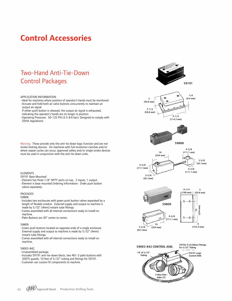
Production Drilling Tools42
Control Accessories
APPLICATION INFORMATION• Ideal for machines where position of operator’s hands must be monitored.• Actuate and hold both air valve buttons concurrently to maintain an
output air signal. If either push button is released, the output air signal is exhausted, indicating the operator’s hands are no longer in position.• Operating Pressures: 50-125 PSI (3.5-8.6 bar). Designed to comply with
OSHA regulations.
ELEMENTS59191 Base Mounted•Element has three 1/8” NPTF ports on top. 2 inputs, 1 output.•Element is base mounted.Ordering Information: Order push button valves separately.
PACKAGES59808• Includes two enclosures with green push button valves separated by a
length of flexible conduit. External supply and output to machine is made by 5/32” (4mm) instant tube fittings.
• Comes assembled with all internal connections ready to install on machine.
•Palm Buttons are 30” center to center.
59809• Green push buttons located on opposite ends of a single enclosure.
External supply and output to machine is made by 5/32” (4mm) instant tube fittings.
• Comes assembled with all internal connections ready to install on machine.
59003-842• Unassembled package.• Includes 59191 anti-tie-down block, two 461-3 palm buttons with
20975 guards, 10 feet of 5/32” tubing and fittings for 59191.• Customer can custom fit components to machine.
Warning: These provide only the anti-tie down logic function and are not stroke limiting devices. On machines with full revolution clutches and/or where repeat cycles can occur, approved safety and/or single stroke devices must be used in conjunction with the anti-tie down units.
Two-Hand Anti-Tie-Down Control Packages
10’ of 5/32”Tubing
59756-4 (3) Elbow Fittings for 5/32” Tubing
59191 Logic Control ASM.
3-Way PalmVales (2)
59003-842 CONTROL ASM.
59191
4-1/4(108 mm)
10(254 mm)
2(50.8 mm)
6(152.4 mm)
2(50.8 mm)
1-3/16(30.2 mm)
2(50.8 mm)
2(50.8 mm)
5(50.8 mm)
4-1/4(108 mm)
10(2
54 m
m)
6(152.4 mm)
2-1/2(50.8 mm)
4-1/2(114.3 mm)
4-3/8(111.1 mm)
4-3/8(111.1 mm)
4-3/8(111.1 mm)
10(254 mm)
10(254 mm)
4-3/8(111.1mm)
3-5/8(92.1mm)
3-5/8(92.1mm)
3-5/8(92.1mm)
59808
59809
1/4(6.4 mm)

Production Drilling Tools 43
Control Accessories
APPLICATION INFORMATION•Eight station distribution manifold for control circuit signals.•One 3/8” NPT(F) supply port and eight 1/8” NPT(F) signal ports.NOTE: Mounting screws not included.
Model 37750 Terminal Manifold
Tubing, Fittings & Connectors
Application exampleTo start several self-feed tools
with one signal—
Inlet
Inlet
Outlet
400 SeriesMini Valve
Exhaust
20192
122
1
1234
5
37750 Manifold
678
3
3
2
1
1 2Pilot
Outlet
InletExhaust
Male Connector Tube Size NPT
59474-4 5/32 1/859474-56 1/4 1/859474-156 1/4 1/459474-256 1/4 3/8
Expander Tube Male Tube Size NPT
59765-4 5/32 1/4
Reducer Tube Male Tube Size NPT
59765-56 1/4 5/32
Male Elbow Tube Size NPT
59756-103 5/32 #10-3259756-4 5/32 1/859756-56 1/4 1/859756-156 1/4 1/4
Male Branch Tee Tube Size NPT
59757-4 5/32 1/859757-56 1/4 1/859757-156 1/4 1/4
Y-Connector Tube Size
59482 5/32
Union Tube Size
59759-4 5/3259759-56 1/4
Union Elbow Tube Size
59760-4 5/3259760-56 1/4
Union Tee Tube Size
59761-4 5/3259761-56 1/4
Union Bulkhead Tube Size
59762-4 5/3259762-56 1/4
Tubing (100’) Tube Size
59690-4 5/32
Plug Tube Size
59763-4 5/3259763-56 1/4
37750
1"(25.4 mm)
1-1/16"(27 mm)
1-1/2"(38.1 mm)
4"(101.6 mm)
2-9/16"(65.1 mm)
3/16" Dia. thru holes(2 as shown)
3/8" N.P.T.F.1/8" N.P.T.F.
(8 outlets as shown)
Maximum Working Pressure Vacuum to 250 PSI (17 bar)Temperature Range - +5˚F to 160˚F (-15˚F to 71˚C)Tubing Material: Nylon II

Production Drilling Tools44
Control Accessories
Output
Input
Input
59914 “or” Element
Automatic Circuit Input
Operator Manual InputOutput
Output
Input
Input
59913 “and” Element
#1 Retracted
#2 Retracted
#3 Retracted
#4 Retracted
Unclamp
1.050" (26.7 mm)
1/2"(12.7 mm)
1/2"(12.7 mm)
1.000" (25.4 mm)
1/4"(6.4 mm)
1/8" Dia.(3.2 mm)
1/8"(3.2 mm)
11/16"(17.5 mm)
7/16"(11.1 mm)
Model 59914 “Or”Model 59914 “OR” function (shuttle) connects two air signals to a common output. Either input, when applied, flows directly to the output port. An internal pop pet prevents a loss of pressure from the input not in use. The 59914 “OR” function can replace many small metal shuttles and logic elements presently in use. It is light weight, corrosion-resistant and easy to install.
It can be used to allow additional input of a signal into a circuit.
Model 59913 “And”Model 59913 “AND” function also connects two air signals to a common output. Both input signals must be ON to create an output signal. A loss of pressure at either input will cause the output to go OFF. The 59913 “AND” function is used to interlock two signals for se quence or safety. It can replace larger pilot-operated valves and logic elements previously used for this pur pose. It is lightweight, corrosion-resistant and easy to install.
It can be used to sum signals to achieve an action after all signals are present.
EXAMPLE: Unclamp a part when all tools are retracted.
Inline “And” & “Or” Circuit ComponentsAPPLICATION INFORMATION•Miniature, low cost elements to provide “AND” and “OR” functions in pneu matic control circuitry.•Require #10-32 male connector for each of three ports.
SPECIFICATIONSOPERATING PRESSURE . . . . . . . . . . . . .30 to 150 PSIG (2 to 10 bar)TEMPERATURE RANGE . . . . . . . . . . . . . . .32° to 160°F (0° to 71°C)..FLOW CAPACITY *. . . . . . . . . . . . . . . . “OR” = 4.0 SCFM (1.9 dm 3/s) “AND” = 3.2 SCFM (1.5 dm 3/s)PORTS . . . . . . . . . . . . . . . . . . . . . . . . . . . . . . #10-32 Female ThreadBODY MATERIAL . . . . . . . . . . . . . . . . . . . . . . . . . . . . . .Acetal ResinINSERTS . . . . . . . . . . . . . . . . . . . . . . . . . . . . . . . . . . . . . . AluminumSHUTTLE/POPPET . . . . . . . . . . . . . . . . . . . . . . . . . . . . . . . . . Buna-N*90 PSIG (6.2 bar) supply, 75 PSIG (5.2 bar) outlet.
WARNING: Inappropriate or improper use, application, installation, service or maintenance of valves may create a hazardous or dangerous condition or situation. Please refer to the warning and cautions described in the pneumatic valves catalog or in the pneumatic logic controls catalog. Consult your distributor or representative for specific details.

Production Drilling Tools 45
Mounting Accessories
To complement its comprehensive line of automatic production tools, offers a variety of mounting options to meet countless fixture requirements. The availability of a wide assortment of standard mounting components provides the user with three important benefits:
PRECISION. All clamping devices are designed specifically for automatic production tools to provide rigid mounting.
VERSATILITY. Mounting components permit automatic production tools to be positioned vertically, horizontally, or at 3-dimensional angles in relation to the workpiece. They are also suitable for clamping other machine elements.
LOW COST. Standard components for mounting tools minimize the need to construct special holding or clamping devices. This results in low jigging costs, easier service and higher reuse value.
To select and order the proper mounting components, please consider the
following—
1. Identify the particular series of tool to be used, i.e., Bant-A-Matic, Par-A-Matic, etc.
2. From all the possible mounting options for automatic production tools illustrated below, note those available for the series tool to be used.
3. Keeping in mind the attitude of the tool to the workpiece and the amount of space in which the mount must fit, select the best available mounting accessory for the application from pages 39-46 (dimensions are shown for each mount).
NOTE: When selecting either stationary or portable nose mounting, pay particular attention to thread sizes and drill ranges.
Stationary & Portable Nose MountsBant-A-Matic and Par-A-Matic tools
Tubular Mount SystemSeries 3, Bant-A-Matic, Par-A-Matic, and Super Par-A-Matic tools
Flange BracketBant-A-Matic, Par-A-Matic, and Super Par-A-Matic tools
Standard & Heavy-Duty Foot BracketsBant-A-Matic, Par-A-Matic, and Super Par-A-Matic, and Hi-Thrust tools
Stationary & Portable Nose MountsSuper Par-A-Matic and Hi-Thrust tools
ClampsSeries 34A, 54C, 74B, Bant-A-Matic, and Par-A-Matic tools

Production Drilling Tools46
Mounting Accessories
Bant-A-Matic Series
Flange BracketP/N 39486
(Includes Nut)
Standard-dutyFoot Bracket
P/N 39485-1(Includes Nut)
Heavy-dutyFoot BracketP/N 45053
(Includes Nut)
Block ClampP/N 36042
3/8"(10 mm)
1-1/32"(29 mm)
+.0010-.0000
1.4325"(36 mm)
+.0102-1/2"(64 mm)
.203 (5 mm) Dia. thru .375 (9 mm) Dia.C’bore Depth shown (2) holes
.010 .010
.0103/16" (5 mm)
3"(76 mm)
1-15/16"(49 mm)
.0050.468" (12 mm)
1/4"(6 mm)
39476 Nut 1-7/16—18 L.H. Thread
+.0010-.0000
1.4325"(36 mm)
1/4"(6 mm)
39476 Nut 1-7/16—18 L.H. Thread
45060 Key
3/16"(5 mm)
1-7/8"(48 mm)
1-15/16"(49 mm)
.06253-1/8"(79 mm)
.0012-1/8"
(53.97 mm)
.00515/32"(12 mm)
1-7/8"(47.6 mm)
3/8"(10 mm)
1-7/8"(48 mm)
3/8"(10 mm)
+.000-.0011/2"
(12.7 mm).0103/16"(5 mm)
5/8"(15.85 mm)
.0051-1/4"
(31.7 mm)
.00527/32"
(21.4 mm)
.01011/32"(9 mm)
.203 (5 mm) Dia. thru .375 (9 mm) Dia.C’bore Depth shown (4) holes
.010 .010
Y194-95 Screw
1/4"(6 mm)
39476 Nut 1-7/16—18 L.H. Thread
+.001-.000
1.4325"(36 mm)
3"(76 mm)
45060 Key (2)
1-5/8"(41 mm)
4"(102 mm)
.0012-3/4"
(69.84 mm)
.0052"
(50.9 mm)
.0156255/16"(8 mm)
+.000-.0011/2"
(13 mm)
3-21/64"(85 mm)
5/8"(16 mm)
3/16"(5 mm)
.031252-1/8"(54 mm)
.0052"
(50.9 mm)
.01015/32"(12 mm)
.01562523/64"(9 mm)
.0107/16"
(11 mm)
.328 (8 mm) Dia. thru C’bore .500 (13 mm) Dia.Depth shown (4) holes
.010 .010
Y194-95 Screw (2)
Y154-48 Cap Screw (4)
2-3/16"(55 mm)
2-1/2"(63 mm)
17/64" (8 mm) Dia. thru 25/64" (10 mm) Dia.C’bore Depth shown (3) holes
2-5/32"(54 mm)
.0011.082"
(27.5 mm)
1/8"(3 mm)
5/32"(4 mm)
1.498" (38 mm)Dia. Bore
2-1/2"(63 mm)
1-7/8"(48 mm)
1-1/2"(38 mm)
2-3/16"(55 mm)
3/4"(19 mm)
5/16"(8 mm)
1/2"(13 mm)
1"(25 mm)
1-3/32"(28 mm)
1-1/4"(32 mm)
5/16-18 Th’d (2) holes1/2" (13 mm) deep

Production Drilling Tools 47
Mounting Accessories
Par-A-Matic Series
Flange BracketP/N 38877
(Includes Nut & Ring)
Standard-dutyFoot Bracket
P/N 38875-1(Includes Nut & Ring)
Heavy-dutyFoot BracketP/N 45055
(Includes Nut & Ring)
Block ClampP/N 35283
38878 Nut 2-3/4 (70 mm) Dia.2"-16 L.H. Thread
3/8"(10 mm)
.328 (8 mm) Dia. thru C’bore .500 (13 mm) Dia.Depth shown (4) holes
.010 .010
Y194-95 Screw (2)
45060 Key (2)
.0021/16"(2 mm)
2-3/8"(60 mm)
3-3/4"(95 mm)
38881 RetainingRing (For 2” Dia.)
.0052"
(51 mm)
+.001-.000
2.001"(50.8 mm)
+.000-.001
1/2" (13 mm)
.0053/4" (19 mm)
.0052"
(51 mm)
.0107/16" (11 mm)
3-5/8"(92 mm)
4-3/8"(111 mm)
3/16"(5 mm)
5/8"(16 mm)
.0012-3/4"
(69.8 mm)
.01565/16"(8 mm)
.265 (8 mm) Dia. thru .390 (13 mm) Dia.C’bore Depth shown (3) holes
.010 .010
Y154-59 Screw (4)
2-3/4"(70 mm)
.0011.464"
(37.18 mm)
3/16"(5 mm)
5/16"(8 mm)
2-1/2"(63 mm)
1-1/4"(32 mm)
1-3/8"(35 mm)
11/16"(17 mm)
1-7/8"(48 mm)
5/16"(8 mm)
2.604"(66 mm)
1-7/8"(48 mm)
1.302"(33 mm)
1.998(50.74 mm) Dia. Bore
.001 5-16-18 Thread1/2 (13 mm)Deep — (2) Holes
15/16"(24 mm)
38878 Nut 2-3/4 (70 mm) Dia.2"-16 L.H. Thread
3-1/4"(83 mm)
3/8"(10 mm)
.0109/32"(7 mm)
.328 (8 mm) Dia. thru C’bore .500 (13 mm) Dia.Depth shown (4) holes
.010 .010
Y194-95 Screw (2) .0053/4"
(19 mm).002
1/16"(2 mm)
2-3/4"(70 mm)
3/16" (5 mm)
.0153/16"(5 mm)
45060 Key (2)
4"(101.6 mm)
.0012-5/8"
(66.66 mm).0051-7/8"
(47.6 mm)
38881 Retaining Ring(For 2” Dia.)
.0052"
(50.79 mm)
+.001-.000
2.001"(51 mm)
+.000-.0011/2"
(13 mm)
1/2" (13 mm)
4"(102 mm)
3-1/4"(83 mm)
21/64" (8 mm) Dia. thru C’bore 1/2" (13 mm) Dia.Depth shown (2) holes
+.001-.000
2.001"(51 mm)
.0021/16" (2 mm)
.0053/4" (19 mm)
2-5/8"(67 mm)
3/8"(10 mm)
5/16"(8 mm)
5/8"(16 mm)
38881 RetainingRing(For 2" Dia.)
38878 Nut 2-3/4 (70 mm) Dia.2"-16 L.H. Thread

Production Drilling Tools48
Mounting Accessories
Super Par-A-Matic Series
Flange BracketP/N 40589
(Includes Nut & Ring)
Standard-dutyFoot Bracket
P/N 40588-1(Includes Nut & Ring)
Heavy-dutyFoot BracketP/N 45056
(Includes Nut & Ring)
.0107/16"
(11 mm)
.0053/4"
(19 mm) .0035/64"(2 mm)
3-5/8"(92 mm)
Y194-95 Screw (2)
.010 .010.328" (8 mm) Dia. thru C’bore 1/2" (13 mm)
Dia. Depth shown (4) holes
2"(50.9 mm)
.0052"
(50.9 mm)
1/2"(12.7 mm)
5/8"(16 mm)
3/16"(5 mm)
40587 Nut 3-1/4" (83 mm)Dia. 2-1/2"—16 L.H. Thread
40583 Retaining Ring(for 2-1/2" Dia.)
45060 Key (2)
3-3/4" (95 mm)
2-3/8"(60 mm)
4-3/8"(111 mm)
.0012-3/4"
(69.86 mm)
.01565/16"(8 mm)
+.000-.0011/2"
(12.7 mm)
+.001-.000
2.501"(64 mm)
45060 Key (2)
1/2" (12.7 mm)
2.501" (64 mm)
1/2"(12.7 mm)
+.000-.001
+.001-.000
3-1/4"(83 mm)
4-1/4"(108 mm)
2-5/8"(66.6 mm)
.001
.0035/64" (2 mm)
40583 Retaining Ring(For 2-1/2" dia.)
5/8"(16 mm)
3/16"(5 mm)
3-15/32"(88 mm)
40587 Nut 3-1/4" (83 mm)Dia. 2-1/2"—16 L.H. Thread
.0051-7/8"
(47.6 mm)
.0101/2"
(12.7 mm)
.0053/4"
(19 mm)
.328" (8 mm) Dia. thru C'bore 1/2" (12.7 mm)Dia. Depth shown (4) holes
2"(50.9 mm)
Y194-95 Screw (2)
.010 .010
5/16"(8 mm)
.0156
3-1/2" (88.9 mm)
.328" (8 mm) Dia. thru C'bore 1/2" (12.7 mm) Dia. Depth shown (4) holes
3-1/4" (83 mm)
4-5/8" (117 mm)
2.501"(63.5 mm)
+.001-.000
.078 (2 mm).003
40583 Retaining Ring(For 2-1/2" dia.)
3/4" (19 mm).005
40587 Nut 3-1/4" (83 mm) Dia. 2-1/2" —16 L.H. Thread
5/16" (8 mm)
1/2" (12.7 mm)

Production Drilling Tools 49
Mounting Accessories
Hi-Thrust 8670 Series
Heavy-dutyFoot BracketP/N 45185
(Includes Nut)
45179 Nut2-7/8"—16 L.H. TH'D
45060 Key (2)
3/4"(19 mm)
3/16"(5 mm) 5/16"
(8 mm)
Y194-95 Screw (2)
3/4"(19 mm)
±.0101-1/2"(38 mm)
4-3/4"(121 mm)
+.000-.0011/2"
(13 mm)
+.002-.000
2-7/8"(73.1-73.0 mm) Dia. Bore
4-1/2"(114 mm)
±.0012-3/4"
(69.9-69.8 mm)
3-13/16"(97 mm)
3-1/2"(89 mm)
±.0052"
(50.9-50.7 mm)
±.0315/8"
(16.7-15.1 mm)
.328 (8 mm) Dia. thru C'bore 1/2" (13 mm) Dia. Depth shown (4) holes
±.010 ±.010
±.0052"
(50.9-50.7 mm)

Production Drilling Tools50
Mounting Accessories
Tubular Mounting SystemThe tubular mounting system is an extremely versatile method of mounting Bant-A-Matic, Par-A-Matic, and Super Par-A-Matic Series tools. Available mounting components accommodate endless fixture requirements and permit the positioning of tools at virtually any angle to the workpiece.
The following illustrations show just a few examples of the many fixture possibilities.

Production Drilling Tools 51
Mounting Accessories
3/4"(19.1 mm)
3-7/8"(98.4 mm)3-1/4"
(825.5 mm)
4"(101.6 mm)
5-1/2"(139.7 mm)
4-3/4"(120.6 mm)
2.512"(63.8 mm)
2"(50.8 mm)
.406" (10.3 mm) Dia.Thru Hole (4) Equally Spaced on
4-3/4" (120.6 mm) Dia. Bolt Circle
.010
3.84"(97.5 mm)
+.003-.000
2.512"(63.8 mm)
3-1/8"(79.4 mm)
3-3/16"(81 mm)
7"(177.8 mm)
1-13/16"(46 mm)
1.84"(46.7 mm)
3.09"(78.5 mm)
4-3/4"(120.6 mm)
1-1/8" (20.5 mm)0 .320" (4 Holes)
(8.3 mm)
1/4"-20 UNC TND (4) PL
3.61" (91.7 mm)
2-1/2" (63.5 mm)
2-1/4" (57 mm)
1-5/8"(41 mm)
3-1/4"(82.5 mm)
11/16"(17 mm)
9/16"(14 mm)
1.805"(45 mm)
1.880"(47.8 mm)
2.215"(54 mm)
2-1/4"(57 mm)
6-5/8"(168 mm)
4-1/2"(14 mm)
3/4"(19 mm)
2.50"
(63.5 mm
)
43785-1
.0052.438"
(61.9 mm)
5/8"(15.9 mm)
3-5/8"(92.1 mm)
7.33"(186.2 mm)
2.510"(63.8 mm)
3-3/4"(95.3 mm)
.0311-3/4"
(44.5 mm)
.01015/32"
(11.9 mm)
D D
.0053/4"
(19.1 mm)
3-1/8"(79.4 mm)
43785-2 and 43785-3
43788 Base Mount Assembly
43791-( ) Mounting Tube
43790 Tee Mount
Designed to connect a Tool Mount Assembly to a Mounting Tube. Forms a right angle from the mounting tube.
04333860 Tool Mount
Accepts 49690 Clamp(for FE034A, FE054C & FE074B)
Adapts electric/pneumatic tools to tubular mounts.
43786-( ) Tool Mount Assembly
Designed to hold Bant-A-Matic, Par-A-Matic and Super Par-A-Matic Series tools. Tool Mount Assemblies come complete with a mounting bracket, lock nut and retaining ring.
Mounting Tube* Length “L”
43791-6 6.0” (152 mm)43791-12 12.0” (305 mm)43791-18 18.0” (457 mm)43791-24 24.0” (610 mm)43791-30 30.0” (762 mm)
Tool
Ser
ies
Tool
Mou
nt
Ass
embl
y
Mou
ntin
g B
rach
et
Lock
Nut
Ret
aini
ng
Rin
g
Dia
met
er“D
”
Bant-A-Matic 43786-1 43785-1 39476 None 1.432” (36.4 mm)
Par-A-Matic 43786-2 43785-2 38878 38881 2.001” (50.8 mm)
Super Par-A-Matic 43786-3 43785-3 40587 40583 2.501”
(63.5 mm)
*Longer tubes available upon request.

Production Drilling Tools52
Nose HousingStationary Bushing Adapter
Fixture Plate
Lock Nut
Mounting Accessories
Nose Housing
Portable Bushing AdapterFixture Plate
Lock Bushing
Nose Mounting With A Portable Lock BushingBant-A-Matic And Par-A-Matic Drills
Nose Mounting With A Portable Lock BushingSuper Par-A-Matic And Hi-Thrust Drills
Nose Mounting With A Stationary Lock BushingBant-A-Matic And Par-A-Matic Drills
Nose Mounting With A Stationary Lock BushingSuper Par-A-Matic And Hi-Thrust Drills
Nose Housing Nose Housing Adapter
Portable Bushing Adapter Fixture Plate
Lock Nut
Nose Housing Nose Housing Adapter
Stationary Bushing AdapterFixture Plate
Lock Bushing
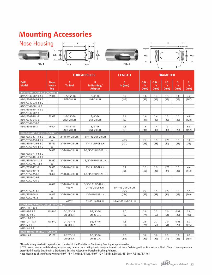
Production Drilling Tools 53
Mounting Accessories
O.D.1 O.D.2I.D.
C
A B
E D
Fig. 1 Fig. 2
O.D.1 O.D.2I.D.
C
AB
E D
THREAD SIZES LENGTH DIAMETER
DrillModel
NoseHous-
ing
ATo Tool
BTo Bushing/
Adapter
Cin (mm)
O.D. 1in
(mm)
O.D. 2in
(mm)
I.D.in
(mm)
D.in
(mm)
E.in
(mm)BANT-A-MATIC DRILLS (FIGURE 1)8245/8345-202-1 & 2 35918 1-7/16”–18 3/4”–16 5.7 1.6 1.4 1.3 1.0 4.28245/8345-B45-1 & 2 UNEF-2B L.H. UNF-2B L.H. (145) (41) (36) (33) (25) (107)8245/8345-B30-1 & 28245/8345-B8-1 & 28245/8345-101-1 & 28245/8345-202-38245/8345-101-3 35917 1-7/16”–18 3/4”–16 6.4 1.6 1.4 1.3 1.1 4.88245/8345-B45-3 UNEF-2B L.H. UNF-2B L.H. (163) (41) (36) (33) (28) (122)8245/8345-B30-38245/8345-B8-3 40804 1-7/16”–18 3/4”–16 7.5 1.6 1.4 1.3 1.1 6.0
UNEF-2B L.H. UNF-2B L.H. (191) (41) (36) (33) (28) (152)PAR-A-MATIC DRILLS* (FIGURE 1)8255/8355-171-1 & 2 35722 2”–16 UN-2B L.H. 3/4”–16 UNF-2B L.H.8255/8355-A50-1 & 2 or 4.75 2.2 1.9 1.75 1.1 3.08255/8355-A28-1 & 2 35720 2”–16 UN-2B L.H. 1”–14 UNF-2B L.H. (121) (56) (48) (44) (28) (76)8255/8355-A21-1 & 2 or
36495 2”–16 UN-2B L.H. 1-1/4”–12 UNF-2B L.H.8255/8355-A14-1 & 28255/8355-101-1 & 28255/8355-A8-1 & 2 38852 2”–16 UN-2B L.H. 3/4”–16 UNF-2B L.H.8255/8355-A5-1 & 2 or8255/8355-171-3 38853 2”–16 UN-2B L.H. 1”–14 UNF-2B L.H. 6.1 2.2 1.9 1.75 1.1 4.48255/8355-101-3 or (155) (56) (48) (44) (28) (112)8255/8355-A50-3 38854 2”–16 UN-2B L.H. 1-1/4”–12 UNF-2B L.H.8255/8355-A28-38255/8355-A21-3
40810 2”–16 UN-2B L.H. 3/4”–16 UNF-2B L.H.40810 2”–16 UN-2B L.H. 3/4”–16 UNF-2B L.H.
8255/8355-A14-3 or 7.25 2.2 1.9 1.75 1.1 5.58255/8355-A8-3 40811 2”–16 UN-2B L.H. 1”–14 UNF-2B L.H. (184) (56) (48) (44) (28) (140)8255/8355-A5-3 or
40812 2”–16 UN-2B L.H. 1-1/4”–12 UNF-2B L.H.SUPER PAR-A-MATIC DRILLS* (FIGURE 2)8265-170-1 & 38265-46-1 & 3 40584-1 2-1/2”–16 2-3/8”–16 6.0 2.9 2.7 2.0 0.88 3.98265-25-1 & 3 UN-2B L.H. UN-2B L.H. (152) (74) (69) (51) (22) (99)8265-12-1 & 38265101-1 & 3 40584-2 2-1/2”–16 2-3/8”–16 7.8 2.9 2.7 2.0 0.88 5.78265-6-1 & 3 UN-2B L.H. UN-2B L.H. (198) (74) (69) (51) (22) (145)8265-3-1 & 3HIGH-THRUST DRILLS (FIGURE 2)8670-( )-3 45188 2-7/8”–16 2-3/8”–16 9.8 3.6 3.6 2.9 1.0 6.1
UN-2B L.H. UN-2B L.H. (249) (92) (92) (74) (25) (155)
Nose Housing
*Nose housing used will depend upon the size of the Portable or Stationary Bushing Adapter needed. NOTE: Nose housing with bushing adapter may be used as a drill guide in conjunction with either a Collet-type Foot Bracket or a Block Clamp. Use appropriate press-fit drill guide bushing in a Stationary Bushing Adapter or Portable Bushing Adapter. Nose Housings of significant weight: 44971-1 = 1.0 Ibs.(.45 kg), 44971-2 = 1.5 Ibs.(.68 kg), 45188 = 7.5 Ibs.(3.4 kg).

Production Drilling Tools54
Mounting Accessories
Nose Housing Adapters*
Stationary Lock Bushings
Portable Lock Bushings
*Use with nose mounting for Super Par-A-Matic and Hi-Thrust Drills.
Note: Stationary Lock Bushing and Lock Nut must be ordered seperately.
Note: Stationary Drill Bushing and Lock Bushing must be ordered seperately.
1/4"
A B
1/4"
1/2"
C
1"F
E D
A
B
D E
F
C
THREAD SIZES
Nose HousingAdapter
A To Nose Housing
B To Stationary/
Portable Bushing
C in (mm)
D in
(mm)
E in
(mm)
F in
(mm)
33812 3/4”–16 UNF-2B L.H. 1.75 (44)
33751 1”–14 UNF-2B L.H. 1.75 (44) 1.0 0.625 1.875
33764 2-3/8”–16 UN-2A L.H.
1-1/4”–12 UNF-2B L.H. 1.75 (44) (25.4) (16) (47)
34075 1-1/2”–12 UNF-2B L.H. 2.0 (51)
46695 2”–16 UN-2B L.H. 2.75 (69)
Drill Dia Range in
Stationary Lock
Bushing Adapter, Part No.
Lock Nut Part No.
AThread Size
(To Nose Housing)
B Mounting
Thread
C Pilot
Dia. in(+.0000,-
.0005)
D Pilot
Dia. in(+000,-.002)
E - Press Fit Dia., For
Headless Press Fit Drill
Bushingin (+0005,-.0000)
F Length of Stationary
Lock Bushing Adapter
in
.0135 - .0995 36646 38850 (1-1/2 HEX) 3/4”-16 UNF-2A, L.H. 1-1/4”-12 UNF-2A .8115 1.248 .2036 2.000
.0980 - .1406 36647 38850 (1-1/2 HEX) 3/4”-16 UNF-2A, L.H. 1-1/4”-12 UNF-2A .8115 1.248 .2506 2.000
.1250 - .1935 36648 38850 (1-1/2 HEX) 3/4”-16 UNF-2A, L.H 1-1/4”-12 UNF-2A .8115 1.248 .3131 2.000
.1875 - .3160 36649 38850 (1-1/2 HEX) 3/4”-16 UNF-2A, L.H 1-1/4”-12 UNF-2A .8115 1.248 .5007 2.000
.1875 - .3160 36650 38850 (1-1/2 HEX) 1”-14 UNF-2A, L.H 1-1/4”-12 UNF-2A 1.0615 1.248 .5007 2.187
.3125 - .5312 36651 38850 (1-1/2 HEX) 1-1/4”-12 UNF-2A, L.H 1-1/4”-12 UNF-2A 1.3115 1.248 .7508 2.187
.5000 - .7656 46088 46089 (1-5/8 HEX) 1-1/2”-12 UNF-2A, L.H. 1-1/2”-12 UNF-2A 1.5710 1.498 1.0008 2.187
Drill Dia Range in
Portable Drill Bushing Adapter, Part
No.
Lock Bushing Part No.
AThread Size
(To Nose Housing)
B Lock Bushing Press Fit Dia.
in(+.000,-.001)
C Length of Press Fit
Dia. Bin
D Length of Portable
Drill Bushing
in
E - Press Fit Dia., For
Headless Press Fit Drill
Bushingin (+0005,-.0000)
.0135-.0995 35214 35215 3/4”–16 UNF-2A, L.H. 0.686 0.750 2.172 0.2036
.0980-.1406 35216 35217 3/4”–16 UNF-2A, L.H. 0.749 0.750 2.172 0.2506
.1250-.1935 35218-1 35219 3/4”–16 UNF-2A, L.H. 0.811 0.750 2.172 0.3131
.1875-.3160 35220 35221-1 1”–14 UNF-2A, L.H. 0.999 0.750 2.203 0.5007
.3125-.5312 35222-1 35223 1-1/4”–12 UNF-2A, L.H. 1.374 1.000 2.516 0.7508
.5000-.7656 35224 35225 1-1/2”–12 UNF-2A, L.H. 1.749 1.125 2.656 1.0008
Lock NutStationary
Lock Bushing
A
D
E B
CLock BushingDrill Bushing Adapter

Production Drilling Tools 55
Dimensional Data16-1/4" (413 mm) Max. Double Reduction
15-3/16" (386 mm) Max. Single Reduction
Feed RateAdjusting Valves
2-23/32" (69 mm) Max.
.0107.500" (191 mm)
.010.656" (17 mm)
+01/6 01/2" Th'd.(13 mm)
1.500" Dia. (38 mm)
2-1/64" (51 mm) Max.
3-25/32" (96 mm)Max.
Pilot Dia. 1.4320"
1-7/16" - 18 UNEF 2A L.H.
1/2-20 UNF 3A
(36 mm)
# 8-32 UNC-2B MountingHoles for Hydraulic Check
Double Reduction33/64" (13 mm) Max.
61/64"(24 mm)
Max.
3.500"(89 mm)
4-3/4"(121 mm)
1-11/16" (43 mm)
Remote Control Ports
(Approx.) 7/8"(22 mm)
Ref.1-1/2"(38 mm)
.985"(25 mm)
.594" (15 mm)
1.188" (30 mm)
+.001 -.000
.005
+.010
.005
.005
1-1/4" Stroke
+.0000 -.0005
1-1/8" (29 mm)Bit Penetration
1-1/2" (38 mm)
19/32" (15 mm)
Bant-A-Matic Drills8245-B( )-1 And 8345-B( )-1
Bant-A-Matic Drills8245-B( )-2 And 8345-B( )-2
Bant-A-Matic Drills8245-B( )-3 And 8345-B( )-3
Shows built-in-colletused on 19,000 RPM Tools.
Shows built-in-colletused on 19,000 RPM Tools.
1-17/64" (32 mm) Max.
3-1/32" MAX.(77 mm)
33/64" (13 mm) Max.Double Reduction
Feed RateAdjusting Valves
1-31/32" (50 mm) Max.
.000-.000
1.500" Dia (38 mm)
.010.656" (17 mm)
+1/16".01/2" Th'd. (13 mm)
1/2-20 UNF 3A
(5 mm)13/64"
Max.4-3/4 " (121 mm)
7/8" (22 mm)(Approx.)
Ref.1-3/4"(44 mm)
#8-32 UNC-2B MountingHoles for Hydraulic Check
1-7/16"-18 UNEF 2A L.H.
Pilot Dia. 1.4320" (36 mm)
Remote Control Ports
.01011.000" (279 mm)
21-3/4" (552 mm) Max. Double Reduction
20-11/16" (525 mm) Max. Single Reduction
1.188" (30 mm)
.594" (15 mm)1.985"
(50 mm)
5.250"(133 mm)
2-11/16" (68 mm)
.0000 -.0005
.010
.005.005
.005
R F
2-7/16"(62 mm)
1-5/8"(41 mm)
1-3/8"(35 mm)
Rear View (Typical)
1/2" (13 mm)
2.015"
3/4" (19 mm)
1-17/64" (32 mm) Max.
3-1/32" (77 mm)Max.
Double Reduction
33/64" (13 mm) Max.
1-1/8" (29 mm)Bit Penetration
1/4" (6 mm)
3/4" (19 mm)
2" and 3" Stroke
Feed RateAdjusting Valves
1-31/32" (50 mm) Max.
+.001 -.000
1.500" Dia. (38 mm)
.010.656" (17 mm)
+ 1/16 .01/2" Th'd. (13 mm)
1/2-20 UNF 3A
(5 mm)13/64"
Max.4-3/4"
(121 mm)
1-11/16" (43 mm)
(Approx.) 7/8"(22 mm)
Ref.2-3/4" (70 mm)
#8-32 UNC-2B MountingHoles for Hydraulic Check
1-7/16"-18 UNEF 2A L.H.
Pilot Dia. 1.4320" (36 mm)
Remote Control Ports
9.000" (229 mm)
16-11/16" (424 mm) Max. Single Reduction
17-3/4" (451 mm) Max. Double Reduction
1.188" (30 mm)
.594" (15 mm)
.985"(25 mm)
.0000 -.0005
4.250" (108 mm).000
.005
.005
.005
.010
Tool Weight 4.2 lbs.
Tool Weight 4.8 lbs.
Tool Weight 5.8 lbs.

Production Drilling Tools56
+
+
FR
Remote Control PortsFeed Rate
Adjusting Valves
#8-32 UNC-2B MountingHoles for Hydraulic Check
1.188" (30 mm).005
.005
.594" (15 mm)
.985(25 mm)
7/16" (11 mm)
2" (51mm)
3/8"(6 mm)
Min.
2-1/8"(54 mm)
Max.
2-27/32"(72 mm)
Front View (Typical)
AR
O
1-7/16" – 18 UNEF 2A L.H.Pilot Dia. 1.4320" (36 mm) +.0000
-.0006 +.001 -.000
.010
.010(Approx.) 7/8"
(22 mm)
1-1/2" Dia. (38 mm)
7/8" (22 mm) Bit Penetration
.656" (17 mm)
1/2" Th'd. (13 mm)
+1/16 -0
19-15/16" (506 mm) Max. Double Reduction
18-7/8" (479 mm) Max. Single Reduction
Ref.1-1/2"(38 mm)
1-11/16" (43 mm)7-1/2" (191 mm)
4-3/4 "(121 mm)
6-3/8" (162 mm) Max.
1-7/16" (189 mm) Max.
3.500(89 mm)
.010
.005
Bant-A-Matic Twin Drills8248-B( )-1
Bant-A-Matic Twin Drills8248-B( )-2
Bant-A-Matic Twin Drills8248-B( )-3
6-25/32" (172 mm) Max.
#8-32 UNC-2B MountingHoles for Hydraulic Check
1.188" (30 mm).005
.010
.005
.005
.594" (15 mm)
.985"(25 mm)
1-7/16" – 18 UNEF 2A L.H.Pilot Dia. 1.4320" (36 mm) +.0000
-.0006 +.001 -.000
.010
(Approx.) 7/8"(22 mm)
1-1/2" Dia. (38 mm)
7/8" (22 mm) Bit Penetration
.656" (17 mm)
1/2" Th'd. (13 mm)
+1/16 -0
5-23/32" (145 mm) Max.
21-1/2" (546 mm) Max. Double Reduction
20-7/16" (519 mm) Max. Single Reduction
Ref.2-3/4"(70 mm)
4-1/4" (108 mm)
1-11/16" (43 mm)9" (229 mm)
4-3/4 "(121 mm)
.010
+
+
FR
Remote Control PortsFeed Rate
Adjusting Valves
7/8" (22 mm) Bit Penetration
.656" (17 mm)
1-7/16" – 18 UNEF 2A L.H.1/2" Th'd. (13 mm)
Pilot Dia. 1.4320" (36 mm) +.0000 -.0006
+.001 -.000
.010
.010
+1/16 -0
4-3/4" (121 mm)2-11/16"(68 mm)
7/8" (22 mm)(Approx.)
5-1/4" Dia.(133 mm)
1-1/2" Dia. (38 mm)
5-23/32" (145 mm) Max. 11" (279 mm) Max.Ref.
1-3/4"(44 mm)
6-25/32" (172 mm) Max.
25-1/2" (648 mm) Max. Double Reduction
24-7/16" (621 mm) Max. Single Reduction
+
+
FR
Remote Control PortsFeed Rate
Adjusting Valves
#8-32 UNC-2B MountingHoles for Hydraulic Check
1.188" (30 mm).005
.005.005
.594" (15 mm)1.985
(50 mm)
Dimensional Data
Tool Weight 5.7 lbs.
Tool Weight 6.3 lbs.
Tool Weight 7.3 lbs.

Production Drilling Tools 57
Tool Weight 8.0 lbs.
Tool Weight 9.5 lbs.
Dimensional Data
Par-A-Matic Drills8255-A( )-1 And 8355-A( )-1
Par-A-Matic Drills8255-A( )-2 And 8355-A( )-2
Par-A-Matic Drills8255-A( )-3 And 8355-A( )-3
.010
.010
1/4-28 UNF-2B MountingHoles For Hydraulic Check
53/64" (21 mm) Max.
1.125" (29 mm)
Max.1-13/64"(31 mm)
2" (51 mm) +.001 -.000
+1/16 -0
1-11/16" (43 mm) 1-3/4" (44 mm)
27/32" (21 mm)4-3/4 "
(121 mm)
.985"(25 mm)
.7185" (18 mm)
1.437" (36 mm)
.010
.005
.005
.005
+
+
FR
Remote Control Ports
Feed RateAdjusting Valves
5/8" (16 mm) Max.
1-1/8" (29 mm) Bit Penetration
3/4" (19 mm) 1/4" (6 mm)
1/2-20 UNF-31/2" Th'd. (13 mm)
2"-16 UN-2A L.H. Th'd.
35/64"(14 mm)
Max.
(Approx.)
Ref.
18-53/64" (478 mm) Max. Double Reduction
17-1/2" (445 mm) Max. Single Reduction
4.375" (111 mm)
10.562 (268 mm)
Max.2-17/32"(64 mm)
.010
.010
1/4-28 UNF-2B MountingHoles for Hydraulic Check
53/64" (21 mm) Max.
1.125" (29 mm)
Max.1-13/64"(31 mm)
2" (51 mm) +.001 -.000
+1/16 -0
1-3/4" (44 mm)
27/32" (21 mm)4-3/4 "
(121 mm)
.7185"(18 mm)
1.437"(36 mm)
.010
.005
.005
+
+
FR
Remote Control Ports
Feed RateAdjusting Valves
5/8" (16 mm) Max.
1/2-20 UNF-31/2" Th'd. (13 mm)
2"-16 UN-2A L.H. Th'd.
35/64"(14 mm)
Max.
(Approx.)
Ref.
22-53/64" (580 mm) Max. Double Reduction
21-1/2" (546 mm) Max. Single Reduction
5.375" (137 mm)
12.562 (319 mm)
Max.2-17/32"(64 mm)
2-11/16"(68 mm)
1.985"(50 mm)
.005
R F
2-1/2"(64 mm)
2-3/8"(60 mm)
2-13/32"(61 mm)
2" Square(51 mm)
1"(25 mm)
1/2" (13 mm)
Rear View (Typical)
Shows built-in-collet used on 17,000 RPM Tools.
Shows built-in-collet used on 19,000 RPM Tools.
2” and 3” Stroke
.010
.010
1/4-28 UNF-2B MountingFor Holes Hydraulic Check
1.125 " (29 mm)
Max.1-61/64"(50 mm)
Max.5/64"(2 mm)
2" (51 mm) +.001 -.000
+1/16 -0
1-11/16" (43 mm)1-1/2" Ref.(38 mm)
27/32" (21 mm)4-3/4 "
(121 mm)
.985"(25mm)
.7185" (18 mm)
1.437" (36 mm)
.010 .005
.005
.005
+
+
FR
Remote Control Ports
Feed RateAdjusting Valves
3-9/32" (83 mm) Max.
1-3/8" (35 mm) Max.3.625" (92 mm)
1-1/8" (29 mm) Max.Bit Penetration
3/4" (19 mm)
1-1/4" Stroke
1/4" (6 mm)
1/2-20 UNF-31/2" Th'd. (13 mm)
2"-16 UN-2A L.H. Th'd.35/64"(14 mm)
Max.
(Approx.)
17-21/64" (440 mm) Max. Double Reduction
16" (406 mm) Max. Single Reduction
9.062 (230 mm)
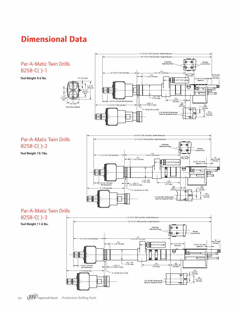
Production Drilling Tools58
Dimensional Data
Par-A-Matic Twin Drills8258-C( )-1
Par-A-Matic Twin Drills8258-C( )-2
Par-A-Matic Twin Drills8258-C( )-3
RF
7" (178 mm) Max.
+.0625, -01/2" Th’d (13 mm)
+.001, -.0002" (51 mm)
15/16" (24 mm)Bit Penetration
.0104-3/4"
(111 mm).005
.985"(25 mm)
.005.7185"
(18 mm)
.0051-7/16"(36 mm)1/4-28 UNF-2B Mounting
Holes for Hydraulic Check
2"-16 UN-2A L.H. Th’d.
RemoteControl Ports
Feed RateAdjusting Valves
5-11/16" (144 mm) Max..010
9-5/8" (244 mm).010
1-1/8" (29 mm)
23-9/32" (591 mm) Max. Double Reduction
21-31/32" (558 mm) Max. Single Reduction
4-3/4" (121 mm)
1-11/6"(43 mm)
27/32" (21 mm)(Approx.)
Ref.1-3/4"(44 mm)
1/4-28 UNF-2B MountingHoles for Hydraulic Check
.00523/32"(18 mm)
.0051-7/16"(36 mm)
RF
RemoteControl Ports
Feed RateAdjusting Valves
4-3/4" (121 mm)
2"-16 UN-2A L.H. Th’d.7" (178 mm) Max.
+.0625, -01/2" Th’d (13 mm)
+.001, -.0002" (51 mm)
15/16" (24 mm)Bit Penetration
5-11/16" (144 mm) Max..010
12-9/16" (319 mm)
.0101-1/8" (29 mm)
.0051.985"
(50 mm)
.0105-3/4"
(137 mm)
27-9/32" (693 mm) Max. Double Reduction
25-31/32" (660 mm) Max. Single Reduction
2-11/16"(68 mm) 27/32" (21 mm)
(Approx.)
Ref.1-3/4"(44 mm)
RF Remote
Control PortsFeed Rate
Adjusting Valves
7-23/32" (196 mm) Max.
6-13/32" (163 mm) Max.
+.0625, -01/2" Th’d (13 mm)
+.001, -.0002" (51 mm)
.0109-1/16" (230 mm)
.0101-1/8" (29 mm)
21-25/32" (553 mm) Max. Double Reduction
20-15/32" (520 mm) Max. Single Reduction
15/16" (24 mm) Bit Penetration
.0103-5/8"(92 mm)
4-3/4" (121 mm)
1-11/6"(43 mm)
27/32" (21 mm)(Approx.)
.005.985"
(25 mm).005
.7185"(18 mm)
.0051-7/16"(36 mm)
1/4-28 UNF-2B MountingHoles for Hydraulic Check
Ref.1-1/2"(38 mm)
3-5/16"(84 mm)
2-1/2"(64 mm)
Max.
1/2" (13 mm)
1/2"(13 mm)
Min.2"
(51 mm)
2"-16 UN-2A L.H. Th’d.
Front View (Typical)
Tool Weight 9.6 lbs.
Tool Weight 10.1lbs.
Tool Weight 11.6 lbs.

Production Drilling Tools 59
Dimensional Data
Tool Weight 13 lbs.
Super Par-A-Matic Drills8265-( )-1
Super Par-A-Matic Drills8265-( )-3
RF
.00523/32"(18 mm)
.0051-7/16"(36 mm)
.0051-5/8"(41 mm)
.0108-23/32" (221 mm)
.01012-3/8" (314 mm)
23-1/64" (585 mm) Max. Double Reduction
21-7/32" (539 mm) Max. Single Reduction
23/32 (18 mm)
19/32(15 mm)
1-7/8(48 mm)
Bit Penetration
3" Stroke
1/4-28 UNF-2B MountingHoles for Hydraulic Check
Ref.1-25/32"(45 mm)
2-3/32"(53 mm)
5-9/16" (141 mm)
RemoteControl Ports
Feed RateAdjusting Valves
Max.3-3/64"(77 mm) Max.
19/32"(15 mm)
Max.35/64"(14 mm)
+.0625-.0000
1/2" Th’d.(13 mm)
+.001-.000
2-1/2"(64 mm)
2-1/2—16UN-2AL.H. Th’d.
1/2-20 UNF-2A
Max.1-1/4"(32 mm)
Max.1-21/64"(34 mm)
Max.1-1/4"(32 mm)
Shows built-in-collet used on 17,000 RPM Tools.
R F
3.014"
2-1/2"(64 mm)
2-1/2"(64 mm)
2-15/16"(75 mm)
2-19/32"(66 mm)3/4"
(19 mm)
1/2"(13 mm)
Rear View (Typical)
RF
.00523/32"(18 mm)
.0051-7/16"(36 mm)
.0051-5/8"(41 mm).010
7-7/32" (183 mm)
+.001, -.0002-1/2" (64 mm)
.0109-3/8" (238 mm)
20-1/64" (508 mm) Max. Double Reduction
18-7/32" (463 mm) Max. Single Reduction
.0101-1/4" (32 mm)
Max.2-3/4"(70 mm)
Max.19/64"(8 mm)
Max.35/64"(14 mm)
Max.4-35/64"(115 mm)
Max.2-3/32"(53 mm)
1/2-20 UNF 2A
29/32 (23 mm)
2-3/32(53 mm)
1-7/8(48 mm)
Bit Penetration
1-1/2" Stroke
1/4-28 UNF-2B MountingHoles for Hydraulic Check
Ref.2-9/32"(58 mm)
2-3/32"(53 mm)
5-9/16" (141 mm)
RemoteControl Ports
Feed RateAdjusting Valves
Tool Weight 14 lbs.
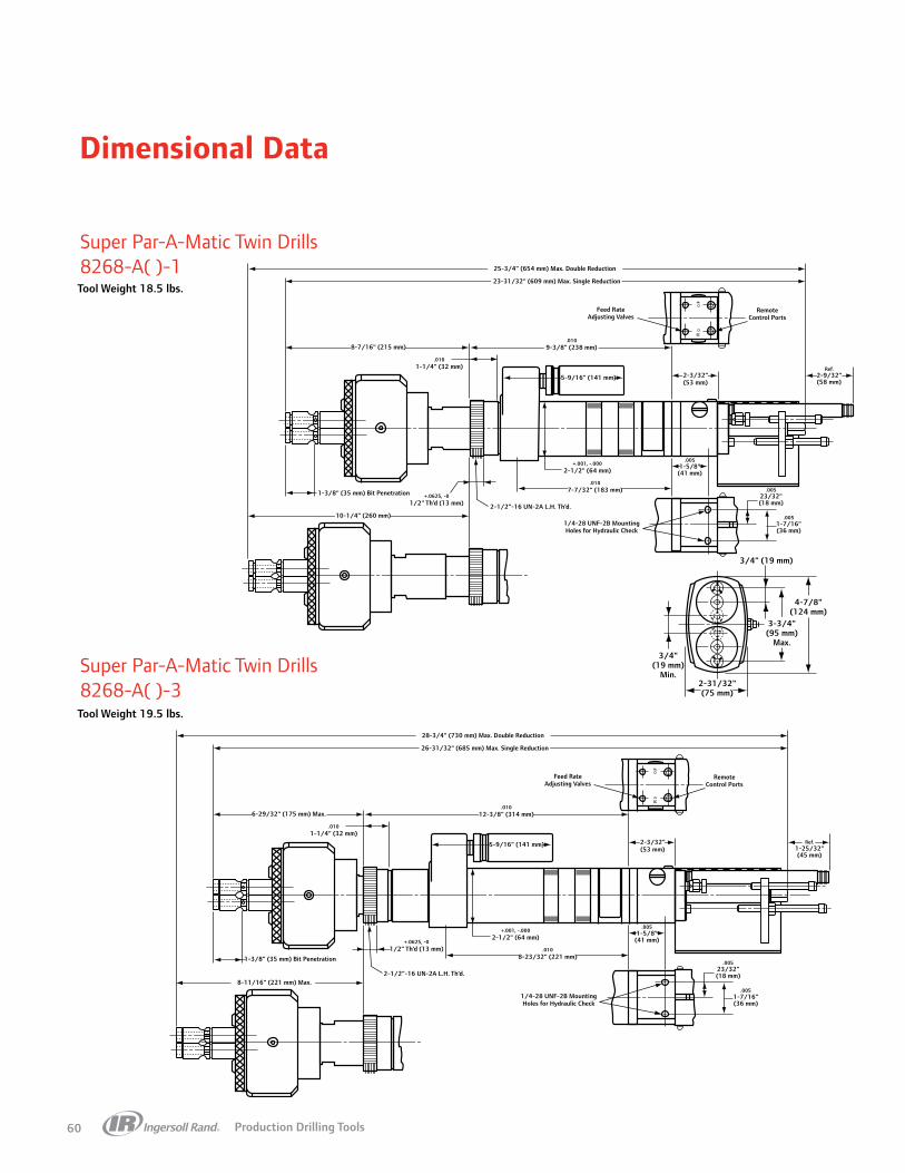
Production Drilling Tools60
Dimensional Data
RF
RemoteControl Ports
Feed RateAdjusting Valves
1/4-28 UNF-2B MountingHoles for Hydraulic Check
.00523/32"(18 mm)
.0051-7/16"(36 mm)
.0051-5/8"(41 mm)
.0107-7/32" (183 mm)
+.001, -.0002-1/2" (64 mm)
+.0625, -01/2" Th’d (13 mm) 2-1/2"-16 UN-2A L.H. Th’d.
5-9/16" (141 mm)
8-7/16" (215 mm).010
9-3/8" (238 mm)
.0101-1/4" (32 mm)
1-3/8" (35 mm) Bit Penetration
10-1/4" (260 mm)
Ref.2-9/32"(58 mm)
2-3/32"(53 mm)
25-3/4" (654 mm) Max. Double Reduction
23-31/32" (609 mm) Max. Single Reduction
Super Par-A-Matic Twin Drills8268-A( )-1
Super Par-A-Matic Twin Drills8268-A( )-3
RF
RemoteControl Ports
Feed RateAdjusting Valves
1/4-28 UNF-2B MountingHoles for Hydraulic Check
.00523/32"(18 mm)
.0051-7/16"(36 mm)
.0051-5/8"(41 mm)
.0108-23/32" (221 mm)
+.001, -.0002-1/2" (64 mm)
+.0625, -01/2" Th’d (13 mm)
2-1/2"-16 UN-2A L.H. Th’d.
5-9/16" (141 mm)
6-29/32" (175 mm) Max..010
12-3/8" (314 mm)
.0101-1/4" (32 mm)
1-3/8" (35 mm) Bit Penetration
8-11/16" (221 mm) Max.
Ref.1-25/32"(45 mm)
2-3/32"(53 mm)
28-3/4" (730 mm) Max. Double Reduction
26-31/32" (685 mm) Max. Single Reduction
4-7/8"(124 mm)
3-3/4"(95 mm)
Max.
3/4" (19 mm)
3/4"(19 mm)
Min.2-31/32"(75 mm)
Tool Weight 18.5 lbs.
Tool Weight 19.5 lbs.

Production Drilling Tools 61
Dimensional Data
Hi-Thrust Drills8670-( )-3
8670 - Specs
FEED DRILL
HYDRAULIC CHECK
3/8" NPT Air Inlet
E (Approx.)
AdjustableTrip Bracket
“Tool Retracted” Port
A (Max.)
C
T
D
UOP
QR
B (Max.)1-3/4"(44 mm)
G (Dia.)
F
S
2-7/8"—16 UN-2A Th’d (L.H.)765" (1943 mm) Min Length
Three PostionMounting Bracket
V
H
I
J
N
L
KM
W (Dia.) #10-24 ThreadExhaust
4-15/16"(125 mm)
Y
X
Remote Start Port Remote Retract Port
Manual Start Button Manual Retract Button
A3”Stroke B C D E
3”Stroke F G H I J K L
in 27-3/4 3-21/32 14 5-5/16 1-1/16 2.24-2.26 2.872-2.874 2.784 2.5 4.312 61/64 .75
mm 705 93 355 135 27 56.9-57.4 72.95-73.0 70 64 110 24 19
M N O P Q R S T
HYDROLIC CHECK
W X YU V
1” Stroke
2” Stroke
3” Stroke
1” Stroke
2” Stroke
3” Stroke
in 1.5 2.0 1.25 2.375 2.937 3.5 15/32 1.5 1.937 2.937 3.937 7.875 10.875 13.875 3.25 1.562 6.344
mm 38 51 32 60 75 89 12 38 49 75 100 200 276 352 83 40 161

Production Drilling Tools62
Dimensional Data
Par-A-Matic Offset Drills8266-A( )-2Tool Weight 8.6 Lbs.
Lead Screw Tappers8655-B Thru 8659-BTool Weight 17 Lbs.
1"(25 mm)
2.277"(58 mm)
23/32"(18 mm)
1-5/8"(41 mm)
13/16"(21 mm)
1-19/32"(40 mm) 3/4"
(19 mm)
3/8"-24 UNF-3A Th’d
RF
RemoteControl Ports
Feed Rate Adjusting Valves
.0050.985"
(25 mm)
1/4"-28 UNF-2A MountingHoles for Hydraulic Check
.0051-7/16"(36 mm)
.00523/32"(18 mm)
.0101-1/8" (29 mm)
2"-16 UN-2A Th’d.
1/2" Th’d.(13 mm)
+.001 -.0002" (51 mm) .010
4-3/8"(111 mm)
4-3/4" (121 mm)
1-11/16"(43 mm)
27/32" (21 mm)(Approx.)
Ref.1-3/4"(44 mm)
.0109-5/8" (244 mm)3-11/16" (94 mm)
19-1/16" (484 mm) Max.
LEAD SCREW TAPPERMODEL SERIAL
• 21-1/8" (536 mm) Double Reduction19-11/32" (491 mm) Single Reduction
3"(76 mm)
6-5/16"(160 mm)
Max.
• 4-27/64" (112.2 mm)Max. with Chuck at Min. Cap.
• 4-35/64" (115.4 mm) Max. with Chuck
at Max. Cap.
• With Unit Fully Retracted
6.623-6.627"(168.2-168.3 mm)
Manual Start Button
3/8" NPT Air Inlet
Primary Exhaust Exit
Access Port for Lead NutTension Adjustment
1-1/2" (38 mm)Tap Penetration
5/16-18 UNC-2B — 4 Holes as shownMax. Bolt Penetration 11/32" (8.7 mm)
2-1/8"(54 mm)
1.495-1.505" (37.9-38.2 mm)
0.745-0.755" (18.9-19.1 mm)
0.159-0.164"(4.0- 4.1 mm)
0.4998-0.5010"(12.69-12.72 mm)
1.1865-1-3/16"(30.13-30.16 mm)
Secondary Exhaust Exit

Production Drilling Tools 63
Dimensional Data
5-3/4" (146 mm)
1-7/16" – 18 UNEF 2A L.H.
Pilot Dia. 1.4320" (36 mm)+.0000-.0005
+.001-.000
.01021/32" (17 mm)
1-1/2" Dia. (38 mm)
4-1/4" (108 mm)
1-11/16" (43 mm)
.010
Feed RateAdjusting Valves
4-3/4"(121 mm)
Remote Control Ports
20-3/8" (517 mm) Max.
Ref.2-3/4" (70 mm)
(Approx.) 7/8"(22 mm)
.00563/63"(25 mm)
#8-32 UNC-2B MountingHoles for Hydraulic Check
.0051-3/16" (30 mm)
.00519/32" (15 mm)
2-7/16"(62 mm)
1-55/64" (47 mm)
1-5/8"(41 mm)
1-3/8" (35 mm)
3/4" (19 mm)
1/2" (13 mm)
+.0625 -01/2" Th'd.(13 mm)
2-3/8"(60 mm)
1-7/8"(46 mm) 15/16"
(24 mm)Front View
1/2-20 UNF-2B
4-1/2" (114 mm)
.0109" (229 mm)
5-27/32" (148 mm)
2"-16 UN-2A L.H. Th'd.
+.001 -.000
.0101-1/8" (29 mm)
2" (51 mm)4-3/8" (111 mm)
1-11/16" (43 mm)
.010
Feed RateAdjusting Valves
4-3/4"(121 mm)
Remote Control Ports
22-23/32" (577 mm) Max.
Ref.1-3/4" (44 mm)
(Approx.) 27/32"(21 mm)
.00563/64"(25 mm)
1/4-28 UNF-2B MountingHoles for Hydraulic Check
.0051-7/16" (36 mm)
.00523/32" (18 mm)
+.0625 -01/2" Th'd.(13 mm)
3/16"(5 mm)
3-7/32"(82 mm)
2-11/16"(68 mm)
1-11/32"(34 mm)
Front View 17/32" (13 mm)
1-3/4" (44 mm)
1-1/8" (29 mm)
.0109-5/8" (244 mm)
1-17/32" (39 mm)
2-1/2"(64 mm)
2-13/32"(61 mm)
2" Square(51 mm)
2-3/8"(60 mm)
1/2" (13 mm)
Rear View (Typical)
3-15/16" (100 mm)
2"-16 UN-2A L.H. Th'd.
+.001 -.000
.0101-1/8" (29 mm)
2" (51 mm)4-3/8" (111 mm)
1-11/16" (43 mm)
.010
Feed RateAdjusting Valves
4-3/4"(121 mm)
Remote Control Ports
19-5/16" (491 mm) Max.
Ref.1-3/4"(44 mm)
(Approx.) 27/32"(21 mm)
.00563/64"(25 mm)
1/4-28 UNF-2B MountingHoles for Hydraulic Check
.0051-7/16" (36 mm)
.00523/32" (18 mm)
+.0625 -01/2" Th'd.(13 mm)
“A”
2-9/16"(65 mm)
2-11/16"(68 mm)
Front View
31427, less tap31427, with 1/4" tap31432, less tap31432, with No.10 tap31432, with 5/16" tap32060, less tap32060, with 5/16" tap32060, with 3/8" tap
1.939 (49 mm)2.107 (54 mm)1.935 (49 mm)1.982 (50 mm)2.150 (55 mm)3.218 (82 mm)3.263 (83 mm)3.461 (88 mm)
1.075 (27 mm)1.075 (27 mm)1.075 (27 mm)1.075 (27 mm)1.075 (27 mm)1.460 (37 mm)1.460 (37 mm)1.460 (37 mm)
CHUCK NO. A B
1" (25 mm)
“B”
.3665"–.3670" (9 mm)
3/16" (5 mm)
.0109-5/8" (244 mm)
Bant-A-Matic Tappers8246-D( )-2
Par-A-Matic Tappers8256-C( )-2
Par-A-Matic Tappers8257-A( )-( )

Production Drilling Tools64
Tappers Pistol Grip
QP1S10D8D
7RAQT4
Service and Accessories
Accessories (Q2 Series):Torque reaction arm: QTA010Air tool oil: 10PCollet: 2U-103-1/4Accessories (7 Series):Torque reaction arm: QTA040Air tool oil: 10PCollet: 4U-103-1/2
Manuals:
04577482 Q2 Series
45587003
45587011
16572810 7 Series
16572273
16572612
Q2 and 7 Series Award-winning ergonomics coupled with proven durability and performance.
Features• Ergonomically designed for operator comfort and high production rates• Variable throttle for maximum control and minimum tap breakage• Modular design makes servicing easy and economical• Recommended for tapping applications up to 1/4” (Q2) and 1/2” (7)
Series
Q2 75 dBa 1/4” NPT 1/4” (6 mm)
7 79 dBa 1/4” NPT 5/16” (8 mm)
Model in-lbs (Nm) rpm lbs (kg) in (mm) in (mm) in (mm) cfm (L/Min)
Q2 SERIES TRIGGER START
QP1S10D8D 3.8 (5.2) 1000 1.9 (0.9) 7.2” (183) 1/4” (6) 0.6” (15) 16 (450)
QP1S05D8D 7.2 (9.8) 500 1.9 (0.9) 7.2” (183) 1/4” (6) 0.6” (15) 16 (450)
7 SERIES TRIGGER START
7RAQT4 19.9 (27) 475 3.3 (1.5) 11.8” (300) 1/2” (13) 0.9” (22) 27 (760)

Production Drilling Tools 65
7429-D
Service and AccessoriesAccessories (8500 Series):Torque reaction arm: QTA010Air tool oil: 10PCollet: 31437,31436,32061Accessories (7400 Series):Torque reaction arm: QTA040Air tool oil: 10PPiped away exhaust kit: 44360-10
Manuals:
49999053 7400 Series
49999032 8500 Series
8500 and 7400 Series Unique Quick Reverse Touch Control (QRT) trigger makes
this design well-adapted to tapping applications.Push-Pull Tapper
8500 Series Features• Quick reverse trigger for fast light-duty tapping
applications• High- and low-speed model options• Recommended for tapping applications up to 5/8”
7400 Series Features• Designed for thread-chasing applications in metal fab
shops after painting and cleanup operations• Standard #10 to 5/16” capacity tapping chuck• Available with 0 to 1/4” capacity (31427) and 5/16” to
5/8” capacity (32060) tapping chucks• Recommended for tapping applications up to 5/8”
8506-ATA
Tappers Pistol Grip
Series
8500 82 dBa 1/4” NPT 5/16” (8 mm) 1/2”-20
7400 85 dBa 1/4” NPT 5/16” (8 mm) -
Model in-lbs (Nm) rpm lbs (kg) in (mm) in (mm) in (mm) cfm (L/Min)
8500 SERIES QTR TAPPERS
8506-ATA 9.2 (12.5) 600 2.7 (1.2) 8.2” (208) No. 0 - 1/4” 0.9” (23) 24 (678)
8506-ATB 9.2 (12.5) 600 2.7” (1.2) 8.2” (208) No. 10 - 5/16” 0.9” (23) 24 (678)
8506-ATC 9.2 (12.5) 600 2.7” (1.2) 8.2” (208) 5/16” - 5/8” 0.9” (23) 24 (678)
8509-ATA 6.7 (9.1) 900 2.7” (1.2) 8.2” (208) No. 0 - 1/4” 0.9” (23) 26 (732)
8509-ATB 6.7 (9.1) 900 2.7” (1.2) 8.2” (208) No. 10 - 5/16” 0.9” (23) 26 (732)
8509-ATC 6.7 (9.1) 900 2.7” (1.2) 8.2” (208) 5/16” - 5/8” 0.9” (23) 26 (732)
7400 SERIES PUSH-PULL TAPPERS
7429-D 19 (25.8) 550 3.9” (1.8) 12.0” (305.0) 5/16” (7.0) 1.3” (34) 27 (780)

Production Drilling Tools66
8040-E
Electrode Dressers
Service and Accessories
Electrode Dressers
Economical solution to dressing worn electrode tips.
Features• Accurately dress electrodes from 5/16” to 1-1/2” diameter• Lightweight and easy to operate• Minimize downtime by quickly reconditioning tips on the machine• Properly shaped electrode tips reduce energy consumption, extend
electrode life, and maintain weld quality• Lower speed models provide more dressing power at a slower material
removal rate• Recommended for reconditioning worn electrode tips
Manuals:
49999380
49999483
7165-B
Electrode CapacityTip Diameter
Model rpm in (mm) lbs (kg) in (mm)
7165-B 1500 5/16” – 1 1/2” (7.9 – 38) 3.5 (1.6) 10-5/8” (270)
8040-E 1000 5/16” – 1 1/2” (7.9 – 38) 4.6 (2.1) 14-1/8” (359)
8039-E 450 5/16” – 1 1/2” (7.9 – 38) 5.5 (2.5) 14-1/8” (359)
8038-E 250 5/16” – 1 1/2” (7.9 – 38) 5.5 (2.5) 14 1/8” (359)
Type
Dressers 83-88 dBa 1/4” NPT 5/16” (8 mm)

Production Drilling Tools 67
*Standard equipmentOrder other available collet sizes shown above as, less 31812-8 with 31812-( ).
Order other available collet sizes shown above as, less 32968-9 with 32968-( ).
Spindle AccessoriesFeed Drills
Collet Selection For High Speed Drill UnitsCollets, built into the spindle, are furnished as standard equipment on all highest speed feed tools. This provides for superior gripping, better balance and lower runout of smaller cutters typically used at these high speeds.
For Bant-A-Matic And Par-A-Matic ToolsModels: 8245-203-( ), 8255-172-( ), 8360-172-3, 8345-203-( ) and 8355-172-( ).
For Super Par-A-Matic ToolsModels: 8265-171-( ).
.010
.010
1/4-28 UNF-2B MountingFor Holes Hydraulic Check
1.125 " (29 mm)
Max.1-61/64"(50 mm)
Max.5/64"(2 mm)
2" (51 mm) +.001 -.000
+1/16 -0
1-11/16" (43 mm)1-1/2" Ref.(38 mm)
27/32" (21 mm)4-3/4 "
(121 mm)
.985"(25mm)
.7185" (18 mm)
1.437" (36 mm)
.010 .005
.005
.005
+
+
FR
Remote Control Ports
Feed RateAdjusting Valves
3-9/32" (83 mm) Max.
1-3/8" (35 mm) Max.3.625" (92 mm)
1-1/8" (29 mm) Max.Bit Penetration
3/4" (19 mm)
1-1/4" Stroke
1/4" (6 mm)
1/2-20 UNF-31/2" Th'd. (13 mm)
2"-16 UN-2A L.H. Th'd.35/64"(14 mm)
Max.
(Approx.)
17-21/64" (440 mm) Max. Double Reduction
16" (406 mm) Max. Single Reduction
9.062 (230 mm)
1-17/64" (32 mm) Max.
3-1/32" (77 mm)Max.
Double Reduction
33/64" (13 mm) Max.
1-1/8" (29 mm)Bit Penetration
1/4" (6 mm)
3/4" (19 mm)
2" and 3" Stroke
Feed RateAdjusting Valves
1-31/32" (50 mm) Max.
+.001 -.000
1.500" Dia. (38 mm)
.010.656" (17 mm)
+ 1/16 .01/2" Th'd. (13 mm)
1/2-20 UNF 3A
(5 mm)13/64"
Max.4-3/4"
(121 mm)
1-11/16" (43 mm)
(Approx.) 7/8"(22 mm)
Ref.2-3/4" (70 mm)
#8-32 UNC-2B MountingHoles for Hydraulic Check
1-7/16"-18 UNEF 2A L.H.
Pilot Dia. 1.4320" (36 mm)
Remote Control Ports
9.000" (229 mm)
16-11/16" (424 mm) Max. Single Reduction
17-3/4" (451 mm) Max. Double Reduction
1.188" (30 mm)
.594" (15 mm)
.985"(25 mm)
.0000 -.0005
4.250" (108 mm).000
.005
.005
.005
.010
Collet Insert No.
Normal Size
Min. Cap.in (mm)
Max. Cap.in (mm)
31812-1 3/64 1/64 (0.40) 3/64 (1.19)
31812-2 5/64 3/64 (1.19) 5/64 (1.98)
31812-3 3/32 1/16 (1.59) 3/32 (2.38)
31812-4 1/8 3/32 (2.38) 1/8 (3.18)
31812-5 5/32 1/8 (3.18) 5/32 (3.97)
31812-6 3/16 5/32 (3.97) 3/16 (4.76)
31812-7 7/32 3/16 (4.76) 7.32 (5.56)
31812-8* 1/4 7/32 (5.56) 5.56 (6.35)
*Standard equipment
Collet Insert No.
Normal Size
Min. Cap.in (mm)
Max. Cap.in (mm)
32968-1 1/8 1/64 (0.40) 3/64 (1.19)
32968-2 5/32 3/64 (1.19) 5/64 (1.98)
32968-3 3/16 1/16 (1.59) 3/32 (2.38)
32968-4 7/32 3/32 (2.38) 1/8 (3.18)
32968-5 1/4 1/8 (3.18) 5/32 (3.97)
32968-6 9/32 5/32 (3.97) 3/16 (4.76)
32968-7 5/16 3/16 (4.76) 7.32 (5.56)
32968-8 11/32 7/32 (5.56) 1/4 (6.35)
32968-9* 3/8 11/32 (8.73) 8.73 (9.53)
RF
.00523/32"(18 mm)
.0051-7/16"(36 mm)
.0051-5/8"(41 mm)
.0108-23/32" (221 mm)
.01012-3/8" (314 mm)
23-1/64" (585 mm) Max. Double Reduction
21-7/32" (539 mm) Max. Single Reduction
23/32 (18 mm)
19/32(15 mm)
1-7/8(48 mm)
Bit Penetration
3" Stroke
1/4-28 UNF-2B MountingHoles for Hydraulic Check
Ref.1-25/32"(45 mm)
2-3/32"(53 mm)
5-9/16" (141 mm)
RemoteControl Ports
Feed RateAdjusting Valves
Max.3-3/64"(77 mm) Max.
19/32"(15 mm)
Max.35/64"(14 mm)
+.0625-.0000
1/2" Th’d.(13 mm)
+.001-.000
2-1/2"(64 mm)
2-1/2—16UN-2AL.H. Th’d.
1/2-20 UNF-2A
Max.1-1/4"(32 mm)
Max.1-21/64"(34 mm)
Max.1-1/4"(32 mm)
RF
.00523/32"(18 mm)
.0051-7/16"(36 mm)
.0051-5/8"(41 mm).010
7-7/32" (183 mm)
+.001, -.0002-1/2" (64 mm)
.0109-3/8" (238 mm)
20-1/64" (508 mm) Max. Double Reduction
18-7/32" (463 mm) Max. Single Reduction
.0101-1/4" (32 mm)
Max.2-3/4"(70 mm)
Max.19/64"(8 mm)
Max.35/64"(14 mm)
Max.4-35/64"(115 mm)
Max.2-3/32"(53 mm)
1/2-20 UNF 2A
29/32 (23 mm)
2-3/32(53 mm)
1-7/8(48 mm)
Bit Penetration
1-1/2" Stroke
1/4-28 UNF-2B MountingHoles for Hydraulic Check
Ref.2-9/32"(58 mm)
2-3/32"(53 mm)
5-9/16" (141 mm)
RemoteControl Ports
Feed RateAdjusting Valves

Production Drilling Tools68
Spindle Accessories
Part Number Thread Size Drive
SQUARE DRIVE ADAPTER
R0H-P212-3/8 3/8”-24 female thread 3/8”
QUICK CHANGE ADAPTER
R0H-A925-4 3/8” - 24 1/4”
Part Number Thread Size Drive
SPINDLE ADAPTERS
30629 1/2”-20 (male) 3/8”-24
30384-5 3/8” square 3/8”-24
30384-9 1/2” square 3/8”-24
40768 1/2” square 1/2”-20
Part Number Chuck Size Thread Size Key
DRILL CHUCKS
7802-99 3/8” 3/8” - 24 N/A
30016 3/8” 1/2” - 20 N/A
7803-99 1/2” 3/8” - 24 R1T-J253
R1N-99A 1/2” 1/2” - 20 N/
36953 1/4” No. 1 taper N/A
33906 1/4” 1/2” - 20 N/A
KEYLESS CHUCKS
728-99-KC5 3/8” 3/8” - 24 N/A
728-99-KC8 1/2” 3/8” - 24 N/A
STANDARD DUTY CHUCKS
7801-99-6 3/8” 3/8” - 24 728N-253
7806-99-8 1/2” 3/8” - 24 728N-253
MEDIUM DUTY CHUCKS
R0H-99 1/4” 3/8” - 24 R1H-J253
HEAVY DUTY CHUCKS
6A-99 3/8” 3/8” - 24 R0J-J253
R00A-99 1/4” 3/8” - 24 R00A-J253
R0K-99 5/64” - 1/2” 3/8” - 24 R1T-J253
Part Number Square Drive Female Hex Chuck Size Female
2U-A925-4 3/8” 1/4”
502-A925-7 3/8” 7/16”
4U-A925-7 1/2” 7/16”
Drill Adapters
General Chucks
Power Quick Change Chucks

Production Drilling Tools 69
Other Accessories
Ergo Grips / Bio Grips / Comfort Grips 360º Swivel Air Inlets
Lubricants
Polyurethane Coil Hoses
Part Number Used With:
ERGO GRIPS
SEG3A-IR Series 1
SEG4-IR Series 41 (1700 rpm or less)
SEG4H-IR Series 41 (over 1700 rpm)
REPLACEMENT FOAM GRIP KITS
SEG3A-CGK For SEG3 models
SEG4-CGK For SEG4 models
BIO BRACE
SBB4-AR41 Series 41 (1700 rpm or less)
SBB4-QE2 QE2
SBB4-VS VersaTec
COMFORT GRIPS
CG-6X8 6” x 8” sheet with tape
Part Number Used With:
CLASS 1 #10 OILS FOR AIR TOOLS
10Z4 4 oz oil
10P 1 pt oil
10G 1 gal oil
10G55 55 gal oil
GREASE
23-1 LB #23 - 1 lb - drill gearing
28 1 LB #28 - 1 lb - SD gearing and clutches
28 8 LB #28 - 8 lb - SD gearing and clutches
66 1 LB #66 - 1 lb - slow-speed angle heads
66 8 LB #66 - 8 lb - slow-speed angle heads
67-4T #67 - 4 oz tube - high-speed angle heads
GTH-1 grease gun for 4 oz tube
67-1 LB #67 - 1 lb - high-speed angle heads
67 8 LB #67 - 8 lb - high-speed angle heads
68-1LB #68 - 1 lb - Coupling splines
Part Number Inlet CFM Type
ASA-1/4 0-25 1/4” Adjustable
ASC-1/4 0-33 1/4” Non-marring
AS-3/8 0-45 3/8” Standard
AS-1/2 0-65 1/2” Standard
Part Number Description
P14-10 1/4” x 10’ polyurethane coil hose, (1) 1/4” rigid, (1) 1/4” swivel fitting
P14-20 1/4” x 20’ polyurethane coil hose, (1) 1/4” rigid, (1) 1/4” swivel fitting
P14-30 1/4” x 30’ polyurethane coil hose, (1) 1/4” rigid, (1) 1/4” swivel fitting
P38-10 3/8” x 10’ polyurethane coil hose, (1) 3/8” rigid, (1) 3/8” swivel fitting
P38-20 3/8” x 20’ polyurethane coil hose, (1) 3/8” rigid, (1) 3/8” swivel fitting
P38-30 3/8” x 30’ polyurethane coil hose, (1) 3/8” rigid, (1) 3/8” swivel fitting
P12-10R 1/2” x 10’ polyurethane coil hose, (2) 1/2” reusable swivel fittings
P12-20R 1/2” x 20’ polyurethane coil hose, (2) 1/2” reusable swivel fittings
P12-30R 1/2” x 30’ polyurethane coil hose, (2) 1/2” reusable swivel fittings
Angle Head Boots
Based on tool angle head diameter
25 mm 28 mm 35 mm 43 mm 48 mm 56 mm
131996 131995 131997 GEA40-172 GEA40-173 GEA240-173

Production Drilling Tools70
Selection ChartSuggested surface speeds for high-speed steel drills in various materials.
Note: Carbon-steel twist drills should be run at speeds of 40 to 50 percent of those given above.
Drilling Speed (rpm) = 0.75 x Free Speed (rpm)
Drilling Guide
Material Speed in SFM
Alloy steel (300 to 400 Brinnel) 20 to 30
Stainless steel 30 to 40
Automotive steel forgings 40 to 50
Tool steel, 1.2C 50 to 60
Steel, .4C to .5C 70 to 80
Mild machinery, .2C to .3C 80 to 110
Hard-chilled cast iron 30 to 40
Medium-hard cast iron 70 to 100
Soft cast iron 100 to 150
Material Speed in SFM
Malleable iron 80 to 90
Monel metal 40 to 50
High tensile-strength bronze 70 to 150
Ordinary brass and bronze 200 to 300
Aluminum and its alloys 200 to 300
Magnesium and its alloys 250 to 400
Slate, marble and stone 15 to 25
Bakelite and similar material 100 to 150
Wood 300 to 400
Surface Speed, Feet Per Minute
Hole Diameter
In 30 40 50 60 70 80 90 100 110 150 200 300 400
DRILLING SPEED, RPM (OPTIMUM OPERATING SPEED - NOT CATALOGED FREE SPEED)
1/16” 1800 2400 3000 3600 4200 4900 5500 6100 6700 9000 12,000 18,000 24,000
1/8” 900 1200 1500 1800 2100 2400 2700 3000 3400 4600 6100 9200 12,000
3/16” 600 800 100 1200 1400 1600 1800 2000 2200 3100 4100 6100 8100
1/4” 450 600 750 900 1100 1200 1400 1500 1700 2300 3100 4600 6100
5/16” 350 500 600 750 850 1000 1100 1200 1300 1800 2400 3700 4900
3/8” 300 400 500 600 700 800 900 1000 1100 1500 2000 300 4000
1/2” 200 300 400 450 550 600 650 750 850 1100 1500 2300 3000

Production Drilling Tools 71
Service kits are a convenient and economical way to perform in-house preventative maintenance and minimize tool repair downtime. Service Kits are available for nearly all model automatic machining tools. Each kit contains all of the replacement parts needed to properly perform preventative maintenance on a tool to keep it operating “like new”. They also serve as an easy method to manage and organize spare parts inventory.
Each part in the service kit is individually wrapped and identified, and packaged in an easy-to-store clearly labeled box. The appropriate tool service manual, parts list, spindle oil and grease are also included.
Service KitsFeed Drills
Bant-A-Matic SeriesModels Description Kit Number
8245-B8, 8245-B45 & 8245-202 Drills
8246-D8 Tapper
8345-B8, 8345-B45 & 8345-202 Drills 41205-1
8248-B8 & 8248-B45 Twin Drills
8245-B30 & 8245-101 Drills
8246-D5 Tapper
8345-B30 & 8345-101 Drills 41310-1
8248-B30 Twin Drill
Par-A-Matic SeriesModels Description Kit Number
All 8255-A Drills
All 8256-C Tappers
All 8257-A Tappers
All 8258-C Twin Drills
All 8266-A Offset Drills 41325
All 8355-A Drills
All 8360-A Peck Drills
Lead Screw TappersModels Description Kit Number
All 8655-B Tappers
All 8656-B Tappers
All 8657-B Tappers 45782
All 8658-B Tappers
All 8659-B Tappers 41325
Super Par-A-Matic SeriesModels Description Kit Number
All 8265 Drills
All 8268-A Twin Drills 41327
Hi-Thrust SeriesModels Description Kit Number
All 8660 Drills 45831
All 8670 Drills 45832

Production Drilling Tools72©2014 Ingersoll Rand IRITS-0714-096
Ingersoll Rand (NYSE:IR) advances the quality of life by creating comfortable, sustainable and efficient environments. Our people and our family of brands—including Club Car®, Ingersoll Rand®, Thermo King® and Trane®—work together to enhance the quality and comfort of air in homes and buildings; transport and protect food and perishables; and increase industrial productivity and efficiency. We are a $12 billion global business committed to a world of sustainable progress and enduring results.
Ingersoll Rand, IR and the IR logo are trademarks of Ingersoll Rand, its subsidiaries and/or affiliates. All other trademarks are the property of their respective owners.
Nothing contained on these pages is intended to extend any warranty or representation, expressed or implied, regarding the product described herein. Any such warranties or other terms and conditions of sale of products shall be in accordance with Ingersoll Rand’s standard terms and conditions of sale for such products, which are available upon request.
Product improvement is a continuing goal at Ingersoll Rand. Designs and specifications are subject to change without notice or obligation.
www.ingersollrandproducts.com
We are committed to using environmentally conscious print practices.
Distributed by: