
Study on a high precision drilling tool with focus on ... - DIVA
76
Study on a high precision drilling tool with focus on power source and driveline Daniel Hallberg Patrik Ringdahl Master of Science Thesis MMK 2017:100 MKN 196 KTH Industrial Engineering and Management Machine Design SE-100 44 STOCKHOLM
-
Upload
khangminh22 -
Category
Documents
-
view
1 -
download
0
Transcript of Study on a high precision drilling tool with focus on ... - DIVA

Study on a high precision drilling tool with focus on power source and driveline
Daniel Hallberg
Patrik Ringdahl
Master of Science Thesis MMK 2017:100 MKN 196
KTH Industrial Engineering and Management
Machine Design
SE-100 44 STOCKHOLM


Examensarbete MMK 2017:100 MKN196
Studie av en högprecisionsborrmaskin med fokus på kraftkälla och drivlina
Daniel Hallberg
Patrik Ringdahl
Godkänt
2017-10-16
Examinator
Ulf Sellgren
Handledare
Ellen Bergseth
Uppdragsgivare
Atlas Copco Industrial Technique
Kontaktperson
Per Törnberg

SAMMANFATTNING
Detta examensarbete utfördes vid Atlas Copco Industrial Technique i Nacka, Sverige. Atlas
Copco är världsledande leverantör av industriella verktyg till olika typer av industrier, bland
annat flygindustrin. Semi-automatiska borrmaskiner har använts inom flygindustrin i flera år och
trenden för sådana verktyg rör sig i riktning mot ökad kontroll och spårbarhet.
Syftet med arbetet var att undersöka möjligheten att ersätta den pneumatiska motorn i en
industriell semi-automatisk borrmaskin, PFD1100, med en elektrisk motor samt utforska de
fördelar som en sådan konstruktion kan medföra. De två huvudprioriteringarna var följande:
Undersöka kapaciteten hos en elmotor utvecklad av Atlas Copco och hur den lämpar sig för
en borrmaskin.
Utveckla koncept för en ny drivlina som löser de två huvudfunktionerna rotation och matning
av borrspindeln.
Examensarbetet avgränsades till att använda motorn från en befintlig mutterdragare och
grundprincipen från PFD1100 borrmaskinens mekanism för spindeldrivning.
I en bakgrundsstudie undersöktes flygindustrin i allmänhet och borrningsapplikationer i
synnerhet. Författarna gjorde ett studiebesök hos Airbus produktionsanläggning i Hamburg för
att se hur verktygen används och vilka behov som finns. Från bakgrundsstudien drogs slutsatsen
att en elektrisk maskin bör rikta in sig mot mindre hålstorlekar och tillämpningar av
stackborrning.
En prototyp konstruerades bestående av drivlina och spindeldrivning från PFD1100 och
motorpaket och styrning från en elektrisk mutterdragare. Syftet med prototypen var att verifiera
teoretiska beräkningar av den mekaniska borreffekten och få en ökad förståelse för maskinens
beteende med en elmotor. Prototypen visade lovande resultat med avseende på borrning och
kunde även utföra adaptiv borrning i viss utsträckning.
Den elektriska motorn testades i en effektprovrigg och resultatet användes för att anpassa ett
befintligt MATLAB-skript för beräkning av motorförluster. Skriptet, som tillhandahölls av Atlas
Copco, användes för att optimera utväxlingen för verktyget i syfte att minimera effektförluster i
motor och elektronik. Flertalet koncept genererades för rotation och matning där några av
koncepten skulle ge ett så kompakt verktyg som möjligt med låg komplexitet, medan andra
koncept fokuserade på utökad funktionalitet. Koncepten utvärderades med en viktad Pughs
utvärderingsmatris.
De mest lovande koncepten enligt konceptutvärderingen var de som erbjöd en kompakt och
robust lösning som tillämpar kända tekniska principer. Om resurskrav och tid till marknad ska
minimeras så kan dessa koncept utgöra en bas för fortsatt utveckling.
Keywords: ADU, Flygindustri, Adaptiv borrning, Elmotor, Drivlina

Master of Science Thesis MMK 2017:100 MKN 196
Study on a high precision drilling tool with focus on power source and driveline
Daniel Hallberg
Patrik Ringdahl
Approved
2017-10-16
Examiner
Ulf Sellgren
Supervisor
Ellen Bergseth
Commissioner
Atlas Copco Industrial Technique
Contact person
Per Törnberg

ABSTRACT
This thesis was carried out at Atlas Copco Industrial Technique in Nacka, Sweden. Atlas Copco
is a world leading manufacturer of industrial tools for a wide range of industries. One application
is semi-automatic drilling machines for the aerospace industry. The latest trend for such tools is
moving in a direction of increased control and traceability.
The purpose of this thesis was to investigate the possibility of replacing the pneumatic motor in
an industrial semi-automatic drilling machine, PFD1100, with an electric motor and explore the
possibilities such design would enable. The two main priorities for the thesis have been:
Investigate the capacity of an electric motor developed by Atlas Copco and find out if it’s
suitable for use in drilling applications.
Develop concepts for a new driveline, solving the two core functions of the drill - spindle
rotation and spindle feed.
The thesis has been limited to use the electric motor from an existing nutrunner and carry over
the design for the spindle mechanism from the PFD1100 drilling machine.
A background study was conducted of the aerospace industry in general and drilling applications
in particular. The authors made a study visit to Airbus production facilities in Hamburg to get a
better insight of where and how the tools are used. The background study supported the need for
an electric drilling machine, targeted at smaller hole sizes and stack drilling applications.
A hybrid prototype machine was designed and manufactured consisting of the driveline from the
PFD1100 drilling machine and the motor and electrics from an electric nutrunner. The purpose
of the prototype was to verify analytical calculations of the mechanical drilling power through
physical testing, and investigate how the machines would behave with an electric motor. The
prototype showed promising results with respect to drilling performance and basic adaptive
drilling.
The electric motor from the nutrunner was tested in a power test rig and the results were used to
adapt an existing MATLAB script for estimating motor and inverter losses. With the adapted
script provided by Atlas Copco, the gear ratio for the drilling machine could be optimized to
minimize losses in the motor and electrical systems.
Finally, concepts for a transmission between the electric motor and the spindle mechanism was
generated and evaluated with a weighted Pugh’s evaluation matrix. Concepts focused on
achieving a tool with minimum size and weight as well as expanding the tool functionality.
The most promising concepts according to the evaluation were those that offered a compact and
robust solution. To minimize resources and time to market, these concepts could offer a good
starting point for continued develpoment.
Keywords: ADU, Adaptive drilling, Aerospace, Electric motor, Drivetrain, Transmission

FOREWORD
This thesis was initiated by Per Törnberg and Simone Bianchi at Atlas Copco Industrial
Technique and we are very grateful for their help and input in the process to finalize this work.
We would also like to thank our supervisor Ellen Bergseth at KTH who has been a great support
and inspiration from day one.
Several employees at Atlas Copco have shown continuous support in the thesis and helped out in
numerous occasions, especially we would like to aim our gratitude to Laboratory Engineer
Anders Dolk for his support with understanding the ins and outs of the PFD-machine.
Nguyen Duc Thang – Renaissance man, thank you.
Patrik Ringdahl, Daniel Hallberg
Stockholm, June 2017

Abbreviations
ADU Advanced Drilling Unit
Al Aluminium
CCW Counter Clockwise
CFRP Carbon fibre reinforced polymer
CW Clockwise
emf Electromotive force
GLARE Glass fibre reinforced aluminium
PMSM Permanent Magnet Synchronous Machine
Ti Titanium

TABLE OF CONTENTS
1 INTRODUCTION 1
Background 1 1.1
Purpose 1 1.2
Delimitations 1 1.3
Methodology 1 1.4
Background research and customer visits 2 1.4.1
Motor and drill testing 2 1.4.2
Customer needs 2 1.4.3
Requirement specification 2 1.4.4
Function decomposition structure 3 1.4.5
Concept generation 3 1.4.6
Concept evaluation 4 1.4.7
2 FRAME OF REFERENCE 5
Aircraft structures 5 2.1
Aerospace materials 7 2.2
Aluminium 7 2.2.1
Titanium 8 2.2.2
GLARE 8 2.2.3
CFRP 9 2.2.4
Aerospace production methods - drilling 11 2.3
Hole quality 13 2.3.1
Countersinking 14 2.3.2
One-shot drilling 16 2.3.3
Stack drilling 16 2.3.4
Adaptive drilling 17 2.3.1
Peck drilling 18 2.3.2
Drilling theory 19 2.4
Transmissions 22 2.5
Planetary gears 22 2.5.1
Bevel gears 23 2.5.2
Differential 23 2.5.3
Torque limiter clutch 24 2.5.4

Manoeuvrable clutches 24 2.5.5
Freewheel couplings 25 2.5.6
Mechanical losses, Sliding, Rolling, Churning 25 2.5.7
Linear solenoids 25 2.5.8
PFD1100 26 2.6
Spindle mechanism power calculations 27 2.7
Rotational power 28 2.7.1
Feed power calculations 29 2.7.2
Atlas Copco electric nutrunner 31 2.8
The electric motor 31 2.8.1
The electric motor in tightening vs drilling operation 32 2.8.2
Torque transducer 32 2.8.1
MDPTools – Estimating electric motor losses 33 2.9
Airbus visit 34 2.10
3 REQUIREMENT SPECIFICATION 35
4 PFD1100 ELECTRIC MOTOR HYBRID PROTOTYPE TESTING 37
PFD1100 - Electric motor hybrid prototype. 37 4.1
PFD1100 - Electric motor hybrid prototype testing 38 4.2
Purpose of test 38 4.2.1
Test equipment 38 4.2.2
Test procedure 39 4.2.3
Test result 39 4.2.4
5 ELECTRIC MOTOR TESTING AND GEAR RATIO OPTIMIZATION
43
Bench testing of the electric motor 43 5.1
Purpose of testing 43 5.1.1
Test equipment 43 5.1.2
Test setup 43 5.1.3
Test procedure 44 5.1.4
Test result 44 5.1.5
Test conclusions 44 5.1.6
MDPTools – Adaptation of the script for a drilling machine 45 5.2
Gear ratio optimization in MDP-tools 46 5.3
6 CONCEPTS 48

Functional structure 48 6.1
Concepts for rotating the spindle at variable speed 48 6.2
Single reduction gear 49 6.2.1
Two speed transmission 1 50 6.2.2
Two speed transmission 2 51 6.2.3
Two speed transmission 3 51 6.2.1
Two speed transmission 4 51 6.2.1
Concepts for feeding and retracting the spindle 52 6.3
Main motor direct connection 52 6.3.1
Secondary feed motor 53 6.3.2
7 CONCEPT EVALUATION 55
Weighted Pugh’s matrix 55 7.1
Evaluation of concepts for rotating the spindle at variable speed 57 7.2
Evaluation of concepts for feeding and retracting the spindle 58 7.3
8 DISCUSSION AND CONCLUSIONS 59
Discussion 59 8.1
Conclusions 60 8.2
Further work 60 8.3
9 REFERENCES 61
APPENDIX: SUPPLEMENTARY INFORMATION 64
Appendix A: Specific cutting force 64
Appendix B: Motor temperature 65

1
1 INTRODUCTION
This chapter introduces the background, purpose, delimitations and methodology for the thesis.
Background 1.1
2009 Atlas Copco developed a drilling machine for the aerospace industry PFD1500. It is a
pneumatic drilling machine with an automatic feed mechanism. In 2011, they developed the
PFD1100 which is a more compact version with added intelligence but same overall
functionality. The aerospace industry has seen major changes in drilling technology recently.
Several electric drilling machines with increased functionality have been introduced on the
market. Atlas Copco is interested in developing a mechatronic tool with an electric motor which
benefits from the extra control possibilities of an electric tool.
Most of the holes drilled in modern aircrafts are of small diameter (<9.5mm) and the PFD1100 is
considered somewhat bulky and overpowered for these small hole applications. The marketing
department at Atlas Copco suggests that a tool which is smaller and targeted at this scope will be
more attractive to the customer.
Purpose 1.2
Main purpose of this thesis is to investigate the possibility of using the electric motor from a
handheld nutrunner provided by Atlas Copco in a power feed drilling application.
The research questions are as follows:
What are the most common applications for advanced drilling units?
In what speed and torque range can the electric motor operate with acceptable efficiency?
How can the MDP-tools script be adapted and used for optimization of the transmission?
Secondly, concepts for a new tool transmission will be generated with regards to the limits from
conducted background research and physical testing. The generated concepts should be designed
with sufficient detail to make a fair comparison.
Delimitations 1.3
Necessary delimitations have been introduced to avoid side-tracking and maintain focus on the
drilling requirements, motor capacity and development of concepts for a new transmission.
These are:
Spindle from the PFD1100 will be kept as it is and the main mechanical principles for
rotating and feeding the spindle (described in chapter 2.7) will be reused in the concepts.
Only the electric motor and inverter from existing nutrunner tool will be investigated.
Drilling will only be performed in the following materials: Titanium, Aluminium, CFRP
Effects from lubrication of the drill bit will not be investigated.
No psychical prototypes will be built to test the concepts.
Methodology 1.4
The concepts have been developed with aid of the popular V-model. It is a model where the
different product development activities and stages are visualized and connected, see Figure 1.
The left side of the V represent the customer needs, requirements and development of the
products sub systems and components. The right side represents the testing methods used to

2
verify and validate the requirements stated on the left side. The activities in this thesis will be
focused around the left part of the V-model and will be approached as follows:
1. Identify customer needs - background research and customer visit.
2. Investigation and decomposition of system functions - PFD1100, electric motor, and PFD
spindle mechanism.
3. System requirement definition - create a requirement specification based on customer
needs and system limitations.
4. System architecture - generate concepts on a subsystem level based on the requirement
specification. Focus will be on conceptual design of a new transmission solutions.
5. Concept evaluation - evaluate concepts with Pugh’s evaluation matrix.
Figure 1 - The V-model for product development (Sellgren, 2016).
Background research and customer visits 1.4.1
The background research will focus mainly on understanding the customer needs by visiting and
collecting data from the aerospace industry, as well as exploring the current technology
developed and used by Atlas Copco.
Motor and drill testing 1.4.2
Existing theoretical models can be used for estimating drill power and motor losses. To verify
the motor loss model, bench testing is performed of the electric motor and drive unit. Drill power
requirements are estimated through testing of a physical prototype PFD1100 fitted with the same
electric motor. Through testing, design boundaries and requirements can be better defined.
Customer needs 1.4.3
To identify the requirements for developing the drilling machine, it is important to gain
understanding of the customer needs (Ullman, 2010). Information on the customer needs will be
gathered through knowledge transfer from employees at Atlas Copco, a study visit to the Airbus
production plant in Hamburg and data acquired from drill bit manufacturers.
Requirement specification 1.4.4
From the understanding of main problem to solve, boundary conditions for the problem and
customer needs a requirement specification will be written. The purpose of the requirement
specification is to facilitate the evaluation of the concepts.

3
Function decomposition structure 1.4.5
By breaking down the overall function into sub-functions it can be ensured that the subtasks can
be resolved and sub-functions can later be composed into overall solutions for the technical
system. Figure 2 illustrates a generic functional structure as described by the VDI guideline 2221
(Shaeffler, 2014).
Figure 2 - Functional structure (Shaeffler, 2014).
Concept generation 1.4.6
Two main methodologies were used to develop new concepts, analogies and patent searches.
Analogies is a method of looking at other areas of technology were similar problems are solved.
Patent searches involving searching in patent data bases to find patents solving similar problems.
The concepts generated must be sufficiently described to make it possible to evaluate them in the
concept evaluation phase.

4
Concept evaluation 1.4.7
Concepts generated will be evaluated in a Pugh’s evaluation matrix (Ullman, 2010) to get an
understanding of how well they match the requirement specification. Pugh’s evaluation matrix
has proven effective for comparing different concepts. The results also form a good foundation
for further discussion of the concepts.
The method provides means for scoring each alternative concept relative to the other in its ability
to meet some certain criteria. The boxes are numbered 1-6, starting with The issue followed by
finding Alternatives, selecting Criteria, weighing the Importance of each criteria, Evaluating the
concepts, and finally interpreting the Results. The basic form for the method is shown in Figure 3.
Figure 3 - Basic structure of Pughs evaluation matrix (Ullman, 2010).
Results from the Pugh’s evaluation should not be considered as a final recommendation. Rather
they are an indication of what direction to take in continued development of the concepts. It may
be appropriate to perform the evaluation iteratively. After each step, the most promising concepts
are developed further and then get evaluated again, until only one or a few concepts remain. The
method is an excellent way to promote discussions and push the understanding of the concepts
further.

5
2 FRAME OF REFERENCE
This chapter provides background information related to the aerospace industry, the kind of
structures and materials encountered and the challenges involved in producing these. Machine
elements used in the concepts, the Atlas Copco PFD1100 drilling equipment and the Atlas Copco
electric motor will also be described.
Aircraft structures 2.1
While the very first airplanes were built with a wooden truss frame, clad in leather or fabric, the
desire to fly at higher speeds and altitudes, and carry more cargo, fuelled a never-ending search
for lighter and stronger structures and materials.
Monocoque and semi-monocoque structures, Figure 4, were first developed in the 1930s. In the
coming decades designs evolved to include pressurized cabins which improved passenger
comfort and enabled high altitude flight without breathing aids. They made use of a load
carrying aluminium skin supported by a framework of beams and ribs, all held together with
thousands of rivets (FAA, 2012).
Figure 4 - Semi-monocoque structure (FAA, 2012).
The semi-monocoque technology persisted and improvements of jet engine technology lead to
the development of jumbo-jets, making use of similar frame designs. The increased scale of
these aircrafts allowed significant weight savings to be made with innovations in materials
technology.
Implementation of sandwich structures with a strong skin (Aluminium or composite) and low-
density core (wood, foam or honeycomb) proved to be an effective way of reducing weight,
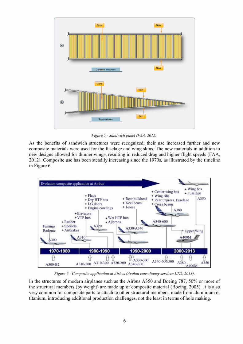
while maintaining or improving strength and stiffness. Figure 5 shows two common types of
sandwich structures. Constant thickness panels are suitable for areas like cabin floor boards
while tapered core panels are used in flight control surfaces which require a sharp trailing edge
(FAA, 2012).
6
Figure 5 - Sandwich panel (FAA, 2012).
As the benefits of sandwich structures were recognized, their use increased further and new
composite materials were used for the fuselage and wing skins. The new materials in addition to
new designs allowed for thinner wings, resulting in reduced drag and higher flight speeds (FAA,
2012). Composite use has been steadily increasing since the 1970s, as illustrated by the timeline
in Figure 6.
Figure 6 - Composite application at Airbus (Avalon consultancy services LTD, 2013).
In the structures of modern airplanes such as the Airbus A350 and Boeing 787, 50% or more of
the structural members (by weight) are made up of composite material (Boeing, 2005). It is also
very common for composite parts to attach to other structural members, made from aluminium or
titanium, introducing additional production challenges, not the least in terms of hole making.

7
Aerospace materials 2.2
This section describes some of the most important construction materials used in aerospace
technology. The aim of this section is to show their benefits and drawbacks from a design as well
as a production perspective. Figure 7 shows the distribution of materials in airframes, the
importance of aluminium alloys and the rise of composites.
Figure 7 – Material use in Airframes (Campbell, 2006).
Aluminium 2.2.1
Before the introduction of composites, aluminium was considered the first-hand material choice
for aircrafts. It’s been extensively used in the fuselage skin and structural components like cabin
floor and fuselage support frame as well as larger mounting structures. It’s a very versatile
material with low density and relatively high strength. A large selection of available alloys offer
different combinations of strength, fatigue, corrosion properties and produce-ability.
Alloys in the 2xxx and 7xxx series can achieve the highest strength of all aluminium alloys and
are the most commonly used in aerospace applications. Popular alloys include the high strength
7075, often supplied in T6 temper for continuous loading applications. This alloy is among the
strongest in pure tensile strength, but has poor fatigue strength (Campbell, 2006). Fatigue
characteristics are critical in the fuselage skin, which is subject to high cyclic loading. 2024 T3
alloy is weaker than the 7075 T6 but more fatigue resistant, making it suitable for fuselage skins
and lightweight rivets (FAA, 2012)
Use of aluminium has declined somewhat in recent years due to the rise of composites, but new
alloys have been developed for use with friction stir welding. This has spawned increased
interest in the material for fuselage applications once again. (TWI Global, 2001)
Machining of aluminium is well-established and commonly applied for components in all
industry segments, not the least in aerospace. When machining aluminium, heat can be
effectively transported away from the cutting zone since the material is such a good thermal
conductor. This enables higher cutting speeds without overheating (Campbell, 2006).
Overheating can cause changes in material properties as well as damage to the cutting tool. Most
aluminium alloys allow very high cutting speeds but some lubricant or cutting fluid is
recommended to avoid smearing or build-up of aluminium on the cutting edges. (Campbell,
2006)
Drilling of some alloys, especially more ductile, low alloyed qualities, result in long stringy
chips. Long chip formation can be prevented with tool geometry and carefully chosen cutting
parameters, high cutting speed is preferred. Peck drilling (chapter 2.3.2) will also prevent long
chip formation (Sandvik Coromant, 2015). Most aluminium alloys will not wear the cutting tool
significantly and carbide drills can be used to drill thousands of holes in aerospace alloys without
being replaced.
8
Titanium 2.2.2
With its high strength (close to hardened steels), titanium can be used in heavily stressed
components such as engine mounts and turbine blades. It can even replace steel in major parts of
the landing gear, saving a significant amount weight. High toughness and fatigue properties, as
well as superior corrosion resistance makes the metal an attractive choice for many challenging
applications (Campbell, 2006).
Titanium quickly produces a durable passive oxide layer which protects it from further corrosion.
Its galvanic potential is close to graphite, making it a good choice for layering with carbon fibre.
It is also a common material for aerospace fasteners (FAA, 2012). The most extensively used
titanium alloy for aerospace use is Ti-6Al-4V, a high strength alpha-beta alloy with excellent
corrosion resistance (FAA, 2012).
Machining of titanium with conventional material removal methods is not an easy feat. High
strength, high toughness results in long chips that don’t easily break. The long chips become
entangled in the tool and increase friction and heat. Low stiffness in relation to its yield strength
causes spring-back during cutting, resulting in vibrations and poor surface finish (Kennametal,
2016).
Titanium is also abrasive and chemically reactive (once the oxide layer is bypassed), causing
increased tool wear and high heat generation. Heat generation is problematic because of the poor
thermal conductivity of titanium. Limited heat dissipation means that heat cannot be efficiently
removed from the tool, thus low cutting speeds and liquid coolant are preferred. High feeds are
favoured to increase productivity as it will affect heat generation much less than high speeds.
Cutting tools for titanium are often coated with diamond or other hard substances to improve tool
life (Kennametal, 2016). Vibratory or peck drilling (Chapter 2.3.2) is an effective way of
reducing heat generation and thus lowers the tool temperatures significantly (Kennametal, 2016).
GLARE 2.2.3
Glass reinforced aluminium (GLARE) is a type of fibre-metal laminate (FML), built up from
multiple thin layers of aluminium and fibreglass or aramid fibre composites. The layers are
permanently bonded with epoxy and cured in a pressurized oven (autoclave). If a mould is used,
curved or more complex shapes can be produced (Mouritz, 2012).
Fibre metal laminates offer much better damage tolerance than pure aluminium, since cracks
which appear in one of the layers will not easily spread to nearby layers. Additionally, the fibre
orientation in the layers can be customized to increase strength in a specific direction (Mouritz,
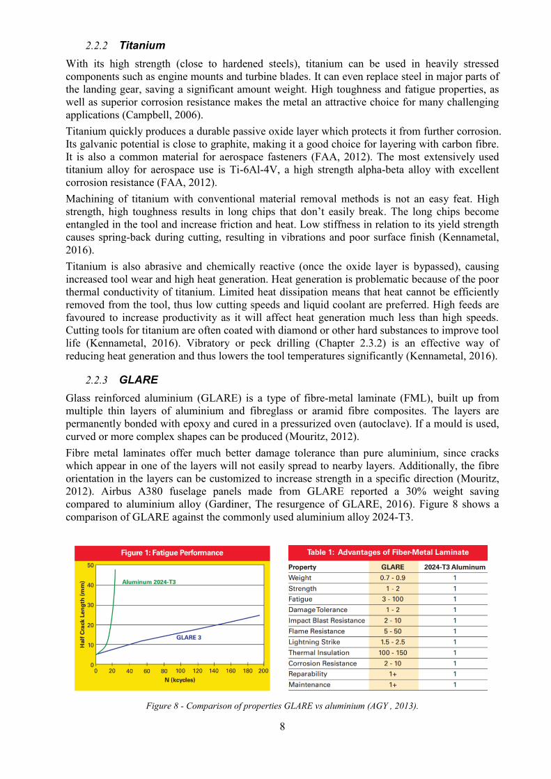
2012). Airbus A380 fuselage panels made from GLARE reported a 30% weight saving
compared to aluminium alloy (Gardiner, The resurgence of GLARE, 2016). Figure 8 shows a
comparison of GLARE against the commonly used aluminium alloy 2024-T3.
Figure 8 - Comparison of properties GLARE vs aluminium (AGY , 2013).

9
Machining of GLARE material has more in common with machining of conventional metals
than composites. Drill geometries developed for composites tend to perform worse than expected
when machining GLARE. Since the laminate can be bonded into larger structures than
aluminium it requires less fasteners and hence less drilling. However, the large sections are still
joined with conventional fastening methods. Care must be taken when drilling as the layers may
delaminate if excessive feed rates are used (Pawar, Gaikhe, Tewari, Sundaram, & Joshi, 2015).
CFRP 2.2.4
CFRP is short for carbon fibre reinforced polymer. It is a composite material made up from
many thin strands of carbon (carbon filaments) embedded in a polymer matrix. CFRP is heavily
utilized in modern aircraft structures, making up around 50% of the weight of aircrafts like
Boeing 787 and Airbus A350 (Avalon consultancy services LTD, 2013).
The carbon filaments are very strong in tension but like a rope, they will buckle under
compression. When supported by a polymer matrix the fibres ability to absorb compressive loads
improve. The composite is still an anisotropic material with most of its strength in tension, in the
direction of the fibres (Mouritz, 2012).
The main advantage of CFRP composite materials is the very high strength to weight ratio.
Specific strength is 10 times as high as alloy steel and 3 times that of titanium alloy. Yield
strength of the finished material is higher than many alloy steels (depending on what fibres are
used). It also offers good chemical resistance (limited by what polymer is used for the matrix)
and does not corrode (Mouritz, 2012).
The direction of the fibres determines the mechanical properties of the final part. Fibres should
be aligned with the expected loads for optimum performance. Sheets of CFRP are often
combined with a lightweight honeycomb or foam core to produce parts with extremely high
specific modulus (stiffness per unit weight) (Mouritz, 2012). To achieve maximum strength, the
final part is cured under high pressure and heat in an autoclave.
Some challenging applications from a manufacturing point of view (shown in Figure 9) include
the central wing box, wings, and vertical tail. The structure often includes relatively thick layers
of CFRP composite and metal (aluminium, titanium) in these areas (Sandvik Coromant, 2010).
Figure 9 – CFRP application areas, left to right: wing, central wing box, vertical tail (Sandvik Coromant, 2016).
Machining of composites rely on tools with very sharp cutting-edges to obtain good finish and
tolerances. While the epoxy matrix offers little resistance, the fibres are more difficult to cut and
highly abrasive, resulting in significant tool wear. Carbide tools are required to resist the
abrasive nature of the fibres (Campbell, 2006).
High cutting speeds can be used with consistently low drill torque and thrust force. High speed
and slow feed will produce the best quality when machining composites (note: direct opposite of
titanium). Poor thermal conductivity and low melting temperature of the resin matrix limits the
cutting speed without coolant, which may consist of water or pressurized air (Tsao, 2012).

10
In contrary to metals, composite produces no chips when cut, only a fine dust which can easily
be extracted with vacuum or pressurized air. Use of coolant makes the process of extracting the
dust more difficult since the two combined will form a slurry. Apart from making the dust
difficult to extract, the coolant may penetrate the exposed ends of fibres, potentially delaminating
the material. If coolant is used, water is preferred since, in contrary to oil, it will evaporate
naturally after the finished machining process (Korn, 2005).
A major concern when machining (especially drilling) composites is delamination. As the drill
feeds into the material, the centre of the drill barely performs any cutting (cutting speed is close
to zero), rather it presses the material ahead and to the sides (Tsao, 2012). This may cause the
layers to separate from each other, known as delamination (see Figure 10). The entry and exit
layers are especially sensitive since they are only supported from above or below.
Figure 10 - Delamination in entry and exit layer when drilling CFRP (Faraz, 2009).
This further supports the use of adaptive drilling with adjustable feed. A slower entry and exit
feed will reduce the risk of delamination. Delamination issues can also be dealt with using a drill
geometry specifically designed for composites (Korn, 2005).

11
Aerospace production methods - drilling 2.3
Although composite structures require less rivets than the previously common aluminium
constructions, over 100 000 rivets are still needed to assemble an airplane (Mapal, 2016). The
holes which accommodate the rivets are produced in different stages of the manufacturing
process. Holes are produced in prefabrication at Tier 1 or Tier 2 suppliers or during the structural
and final assembly depending on accessibility and the level of accuracy needed (Campbell,
2006).
Much of the drilling operations during pre-production allow for a high degree of automation.
Prefabricated parts are of more manageable size and can be machined with the aid of large
machining centres or industrial robots.
During structural and final assembly, more flexible machines such as hand-held or semi-
automatic machines, ADUs – Advanced Drilling Units, are needed to drill holes in hard to reach
areas. But the machines are also used to drill holes in well exposed areas of the fuselage, such as
joints between fuselage sections and around door frames.
To ensure optimal performance of the fasteners (rivets), very strict size and geometric tolerances
are required. Larger structures like sections of the fuselage may feature 1000s of holes through
multiple layers, spanning several meters. Making sure that all the holes line up during assembly
is challenging and require most of the holes to be drilled in place (Campbell, 2006). The rear
pressure bulkhead, shown in Figure 11, is a good example of a riveted assembly.
Figure 11 - Riveted assembly of the Airbus A350 rear pressure bulkhead (Airbus, 2009).
The best way to ensure proper alignment is to drill through the mating components
simultaneously after they have been assembled. A jig holds the components in the correct
position while temporary fasteners clamp them together (Campbell, 2006). Scenarios where
stacks of multiple different materials need to be drilled through are common, this is referred to as
stack drilling (chapter 2.3.4).
During pre-production, undersized holes may be drilled in one of the mating components using
automatic or semi-automatic machines. After assembly, these will act as pilot holes for hand held
machines. Successively larger holes are drilled in multiple steps until the intended diameter is
reached (FAA, 2012). Manual machines can produce good quality and accurate holes with a
skilled operator but is unsuitable for larger hole sizes and thicker stacks due to limited power and
stability.

12
Semi-automatic ADUs like the PFD1100 are larger than the hand-held machines but have the
advantage of improved control and repeatability. Machines of this type are combined with a
fixture that holds the tool in the correct position for drilling.
The drill bit itself is guided with close tolerances by a bushing, mounted in the front of the tool.
Figure 12 shows a typical ADU drilling machine setup. The drill bushing, which has a tight fit in
the fixture plate, is positioned close to the workpiece to ensure proper chip extraction by the
vacuum.
Figure 12 – Illustration of ADU machine setup
The tool is securely held in the fixture by a locking mechanism which can be fully mechanical
(twist-lock) or air-powered (concentric collet). The fixture/jig and bushing ensures accurate hole
positioning and the possibility of drilling larger diameter and thicker material with quality
comparable to a CNC machine (Campbell, 2006). Figure 13 shows production personnel
operating an ADU machine mounted to an aerospace part.
Figure 13 - Semi automatic drilling of an aerospace component (The Seattle Times, 2015).
Most semi-automatic machines are capable of drilling holes up to 1” diameter but some can drill
holes as large as 2”. More common scenarios for the semi-automatic machines involve drilling
much smaller holes (3/8”, 9.5 mm or less) in parts such as the wings, door frames, fuselage joints
etc. shown in Figure 14.

13
Figure 14 - Application areas for ADUs (www.seti-tec.com, 2015).
Hole quality 2.3.1
Aerospace fasteners tend to require very strict hole tolerances to function properly. Close
diametric tolerances are especially important for shear rivets, which rely on a close fit to transfer
loads. The general diametric tolerance for drilled holes in aerospace is H7 (+0/+15µm for a Ø10
mm hole). In the Boeing 787 program the tolerance was eventually relaxed to H9 (+0/+35µm for
a Ø10 mm hole) due to difficulties in meeting the requirements (Gardiner, Hole quality defined,
2014).
Beyond the size of the hole, surface roughness and other geometric features can be equally
important. Poor surface quality or improper alignment may lead to stress concentrations once the
fasteners have been installed (Campbell, 2006).
The closest tolerances and best quality can be achieved with rigid CNC setups, followed by
semi-automatic machines. Manual machines produce the least consistent results because of very
limited control of feed and alignment.
Holes which do not meet the tolerances can be costly. A hole which is too small can be reamed
to the correct size with relative ease, but a hole which is too large must be re-drilled with a larger
diameter and the fastener replaced with an oversized dimension. An oversized hole will affect
future repairs since the hole can only be enlarged to a limited extent before compromising the
strength of the part (FAA, 2012). Any oversized holes must be documented and may result in a
discount to the final selling price of the aircraft. Figure 15 illustrates different types of hole
quality issues which may result from faulty cutting parameters, tool wear or improper operator
handling.

14
Figure 15 – Examples of hole anomalies (Atlas Copco partner, 2017).
Despite drilling through a stack of materials in a single operation, the diameter is not always
consistent throughout the layers. Differences in thermal expansion and material stiffness will
lead to minor variations. The hole tends to be slightly larger through a composite layer since it
experiences less thermal expansion than the metal layer during drilling. This is generally solved
with reaming.
Meeting the requirements for perpendicularity can be difficult, especially when using manual
tools in cramped places. Specific add-ons in the shape of a cup fitted to a hand-held drill can
assist in stabilizing the tool and improve alignment (FAA, 2012). Perpendicularity is normally
not an issue with power feed machines since the tool fixture ensures proper alignment of the drill
bit. However, large overhangs with heavy machines may cause flexing in the fixture plate and
result in misalignment.
A common quality issue in drilling which was not mentioned in Figure 15 is burr-formation.
Burrs area built up edge which tend to form around the edge of the hole on the exit side, when
drilling metallic materials. Burrs prevent flush fastener installation and deburring each hole is
both time consuming and adds cost. Drill bit manufacturers make great efforts to ensure that
their cutting tools produce consistently burr-free holes which meet the requirements set by
aircraft manufacturers. Sharp drill bits and careful selection of cutting parameters is the best way
to avoid burr-formation (Campbell, 2006).
Countersinking 2.3.2
Countersinking is the process of machining a cone shaped recess in the material to create a
conforming mating surface for a fasteners head, without significantly weakening the material.
The cone angle, illustrated in Figure 16, can be altered to fit the type of fastener used. The most
common countersink angle for aerospace applications is 100° (FAA, 2012).
Figure 16 - Countersinking with different angle (Inductiveload, 2017).

15
Once the fastener is inserted in the hole, the head is embedded into the material and the surface
should be flush. This is crucial when riveting parts of the fuselage and wings since any
deviations from a smooth surface will disturb the airflow.
The countersink depth tolerance for these applications is very strict, usually in the order of a few
hundredths of a mm. Power tools for aerospace applications may include dedicated mechanisms
or add-ons to control the countersink depth to within 0.025 mm (FAA, 2012). Figure 17 shows
an example of a such an add-on (micro stop countersink). Modern hybrid drilling machines may
offer new solutions with the implementation of adaptive drilling technology.
Figure 17 - Micro stop countersink (FAA, 2012)

16
One-shot drilling 2.3.3
Drilling through a stack of multiple layers and materials improves productivity and ensures the
best possible alignment of the holes. With special drill bits, like the one shown in Figure 18,
countersinking can be done in the same drilling operation as the original hole, both saving time
and improving accuracy. One-shot drilling is when all operations needed to produce the final
hole, including countersinking and reaming (if necessary), are all performed in a single drilling
cycle.
Figure 18 - Drill bit for one shot drilling (Sandvik Coromant, 2010).
Stack drilling 2.3.4
The process of stack drilling involves drilling a hole through multiple layers. Stacks made up of
dissimilar materials with significantly different properties, such as titanium and CFRP, can be
very challenging to machine. Part of the difficulty lies in finding a compromise for the cutting
parameters (drill feed and speed). The recommended cutting parameters are significantly
different for different types of materials, Figure 19.
Figure 19 - Recommended cutting parameters for aerospace materials (Atlas Copco partner, 2017).
Pneumatic ADUs are typically limited to run at a single speed and feed throughout the drilling
cycle. To change the feed and/or speed, the machine would need to be reconfigured, which
usually involves replacing parts of the transmission. Since the machine cannot be reconfigured
during the drilling operation, the cutting parameters must be adapted for the “slowest” (lowest
speed & feed) material in the stack. For example, when drilling a stack of CFRP and titanium,
the speed is limited by the titanium layer and feed by the CFRP.
Thickness of the lighter material (composite / aluminium) is often much thicker than the titanium,
leading to great losses in productivity when drilling CFRP-Ti or Al-Ti stacks. Machines which
can recognize what material is being machined and adjust the cutting parameters in real time, can
provide significant time savings. This is commonly known as Adaptive drilling.

17
Managing heat when drilling stacks with composite is especially important. Due to different
materials experiencing different thermal expansion, high temperatures may lead to varying hole
size throughout the stack, see Figure 20.
Figure 20 - Thermal expansion causes varying hole size in different materials
(Atlas Copco partner, 2017).
High temperatures can also damage the polymer matrix of composites. A means of resolving this
issue is peck drilling or vibratory drilling, see 2.3.2.
Adaptive drilling 2.3.1
Adaptive drilling can be split up in two parts: adaptive speed and adaptive feed. Adaptive speed
will show the greatest productivity gains in Al-Ti or CFRP-Ti stacks, where drilling time can be
reduced by 50% or more. Other benefits include improved surface finish, especially when
drilling aluminium which desire much higher cutting speeds than what is possible in titanium.
Adaptive feed on the other hand is particularly useful when drilling composites. Due to their
sensitivity to delamination in the entry and exit layers, it can be beneficial to use a lower feed
when the drill bit is about to break through, as shown in Figure 21.
Figure 21 - Stack drilling with adaptive feed (Sandvik Coromant, 2010).
Adaptive drilling has been on a rise since the introduction of electric or hybrid ADUs. It relies on
accurate material recognition to work, so power tools must include additional intelligence and
computing power. By sensing torque and/or thrust and using real-time signal processing, the
adaptive drilling machine knows what material is currently being drilled (APEX TOOL GROUP,
2014).
Figure 22 shows an example of the variations in torque and thrust as the drill enters the
workpiece, drills through different materials and exits the workpiece. Note: the data was
obtained from drilling with constant speed and feed, hence it is not an example of adaptive
drilling.

18
Figure 22 - Drilling of a multi material stack, variations in torque and force (Guerin & Sylvain, 2015).
Because of the time it takes for the drilling machine to change speed (a few tenths of a second)
the benefits in productivity will be greater for thicker material stacks.
Peck drilling 2.3.2
When drilling materials with high ductility or toughness like titanium and some aluminium
alloys, chip formation and evacuation can be a major concern. Drilling these materials produce
long continuous chips which do not easily break and may get stuck in the drill flutes (Sandvik
Coromant, 2014). Feeds and speeds must be carefully selected to prevent chip jamming, which
can severely damage both tool and work-piece. The risk increases with thicker material stock.
An illustration of various chip shapes resulting from drilling is shown in Figure 23.
Figure 23 - Chip control when drilling (Sandvik Coromant, 2014).
Peck drilling can be used to break the chips and avoid jamming when drilling materials that
produces long chips. It involves feeding the drill in steps, where each step slightly increases the

19
depth of the hole. Between the steps the drill is retracted with high feed until it clears the hole
completely and the chips can be ejected, Figure 24 .
Figure 24 - Peck drilling (Sandvik Coromant, 2015).
A variant of peck drilling is micro-peck drilling, also referred to as vibratory drilling, in which
the drill is slightly lifted from the cutting zone once or even several times per revolution. The
micro-peck feed causes drill movement corresponding to a sine-wave. The rapid changes in feed
cause the chips to break (Aerospace manufacturing and design, 2016). The result is very fine
chips (see top left in Figure 23) which are easily flushed out by coolant (air or fluid) or extracted
by vacuum. Most ADU manufacturers include mechanisms in their tools to produce a sine-wave
feed but similar results may be achieved by independently controlling the feed with an electric
motor.
Micro-pecking will also lead to a significant reduction in heat development. This is critical when
drilling stacks of CFRP and titanium, since the heat produced when drilling titanium can damage
the composite matrix. Long titanium chips may also damage the walls of the hole through the
composite layer, resulting in poor surface finish and compromised tolerances. Figure 25
illustrates the differences in heat development when vibratory drilling is used with titanium.
Figure 25 - Heat generation from conventional and vibratory drilling in titanium (Walter Tools, 2016).
Drilling theory 2.4
Requirements for the drilling operation were obtained by taking part of industry knowledge and
using existing analytical formulas.
Models for calculating machining forces are commonly used in production engineering. The
selected model gives an approximation of the power and torque requirements depending on the
drill size and cutting parameters used.
The formulas are based around the specific cutting force Kc which is a measure of the force
required to cut a chip with a given cross-sectional area. The specific cutting force varies largely
depending on what material and grade of that material is being cut. Empirical studies performed
by cutting tool manufacturers have been compiled into tables (Appendix A: Specific cutting

20
force) which show the specific cutting force for a chip of 1 mm chip thickness and 1 mm2
cross-
sectional area. This is a material specific constant denoted Kc1.
Figure 26 shows a table graph of the specific cutting force (with 1 mm2
chip area) for the most
common metals. Not only does it depend on material group, it also varies within each group (all
alloys of one material will not behave the same). Figure 27 illustrates the different material
groups represented by the letters in Figure 26. Heat resistant alloys (class S) include steels such
as Inconel, but also titanium alloys which are widely used in aerospace engineering.
Figure 26 - Specific cutting force per material category (Sandvik Coromant, 2015).
Figure 27 - Material categories (Sandvik Coromant, 2015).
The specific cutting force Kc1 from the table (Figure 26) must then be compensated for rake
angle, γ0 (Figure 28) and chip thickness, hm.
Figure 28 - Tip angle (left) and rake angle (right) (Sandvik Coromant, 2014).
Equation (1) gives the compensated specific cutting force Kc

21
𝐾𝑐 = 𝐾𝑐1 ∙ ℎ𝑚 −𝑚𝑐 (1 −
𝛾0
100)
(1)
The parameter mc is another experimentally derived material constant which dictates the
dependence between specific cutting force and chip thickness (shown in Figure 29). This
constant is listed for different material and alloy types in tables provided by cutting tool
manufacturers (See Appendix A: Specific cutting force).
Figure 29 – Specific cutting force as a function of chip thickness. (Sandvik Coromant, 2015)
Using the specific cutting force Kc, drill diameter Dc, and the feed rate per revolution fn, the drill
torque Mc can be calculated as follows.
𝑀𝑐 =𝑘𝑐 ∙ 𝐷𝑐
2 ∙ 𝑓𝑛
8000
(2)
Multiplying the torque by the angular velocity gives the power requirement:
𝑃𝑐 = 𝑀𝑐 ∙ 𝜔𝑠𝑝𝑖𝑛𝑑𝑙𝑒 (3)
The thrust force is more approximative and depends heavily on drill geometry but an estimation
is given by
𝐹𝑓𝑒𝑒𝑑 ≈𝑘𝑐 ∙ 𝐷𝑐 ∙ 𝑓𝑛 ∙ sin(𝜅𝑟)
4 (4)
As a means of verification, physical drill tests were carried out in a testing rig, the testing
procedure and results are explained in section 4.2. Calculations and tests were performed for 3/8”
(~9.5 mm) and 1/4” (~6.35 mm) drill sizes in carbon fibre, aluminium and titanium.

22
Transmissions 2.5
When generating concepts and designing a new transmission for the drilling machine several
different types of gear configurations were of interest, the most important types are described in
this chapter.
Planetary gears 2.5.1
Planetary gears are used as reduction in the PFD1100 as well as many other tools developed by
Atlas Copco. Two main advantages of a planetary gear sets are concentric input and output
shafts and high power-density. A disadvantage of planetary gear sets are the high friction losses
experienced at high speeds due to the many simultaneous gear meshes.
The planetary gear (Figure 30) consist of four main parts: sun gear, planet gears, ring gear and
planet carrier. The planet gears are fitted to the planet carrier on shafts, offset from the axis of
the input/output, and can rotate freely. One component is used for input while another is fixed
and the remaining used for output. The most common configuration features the sun gear as
input, a locked ring gear and the carrier as output.
Figure 30 - Planetary gear transmission (Mägi & Melkersson, 2009).
Gear ratio equation for a fixed ring gear is calculated as follows:
𝑖 =𝑧𝑟𝑖𝑛𝑔
𝑧𝑠𝑢𝑛+ 1 (5)
Where Zring and Zsun is the number of teeth of the ring gear and sun gear respectively. A planetary
gear reduction can also be configured with planet gears arranged in pairs. This configuration
achieves a reversed rotational direction of the output, such that the output spins in opposite
direction of the input. Each planet gear pair is connected in series to bridge the gap between sun
and ring gear but create an opposite rotation of the carrier and sun gear. Gear ratio for a double
planet gear transmission with fixed ring gear and carrier output (to reverse output shaft) is
calculated as follows:
𝑖 =𝑧𝑟𝑖𝑛𝑔
𝑧𝑠𝑢𝑛− 1 (6)

23
Bevel gears 2.5.2
Bevel gears are used to transmit power between crossing axles, Figure 31. It can also provide
some gear reduction with ratios normally not exceeding 5:1. The gears could either be straight or
helical cut, bevel gears with a helical cut are commonly referred to as spiral bevel gears. The
main advantages of using spiral bevel gears are higher tooth bending strength and noise
reduction due to higher contact ratio. (Kohara Gear Industry Co.,Ltd., 2016)
Figure 31 – Spur bevel gear (Wikimedia, 2011).
Differential 2.5.3
A differential gear is a type of planetary gear used to split torque from a single input between
two or more outputs or vice versa. The sum of the speed of the output shafts is equal to twice the
speed of the differential drum (lock one shaft and the other will rotate twice as fast as the drum).
The most common application is in automotive, where the differential drum is used as input from
the engine and the two output shafts drive the wheels, Figure 32 (left). Since the output shafts are
not directly coupled, they can rotate at different speed, which is necessary during cornering. If
the drum is locked and one of the side-shafts is rotated, the other side-shaft will rotate in the
opposite direction.
Figure 32 - Differential gear function (Wikimedia, 2011).
The differential gear can also be configured with two inputs and a single output. This is a
common configuration in hybrid car gearboxes to utilize power from multiple power sources
(electric motor and combustion engine).

24
Torque limiter clutch 2.5.4
Torque limiter clutches or slip clutches (Figure 33) are used to avoid higher torque than intended
on a shaft. When torque is higher than maximum clutch torque the clutch will “overrun” and no
higher torque will be transmitted. Most commonly springs and balls mounted in a V-shaped
groove are used to transfer torque when the torque transferred to the balls are higher than the
springs can hold, the resulting force will make the clutch overrun.
Figure 33 - Simple torque limiter clutch (Mägi & Melkersson, 2009).
Manoeuvrable clutches 2.5.5
This group consists of clutches where torque and velocity can be decoupled with the use of
external force. One way of designing this type of clutch is to use a claw coupling or dog tooth
coupling utilizing a spring to keep the coupling engaged and an electric solenoid for decoupling
(Figure 34). Biggest disadvantage of this type of coupling is the need for synchronization during
initiation.
Figure 34 - Dog clutch actuated with a solenoid (US Patentnr US20060172852 A1, 2006).

25
Freewheel couplings 2.5.6
Roller clutches and sprag clutches are used to transfer power in one rotational direction. In a
roller clutch rollers or balls are spring-loaded and wedged in a groove when input shaft is rotated
in one direction and free rolling when input shaft is rotated in opposite direction. A ratchet
freewheel has the same function but utilizes a sprag with two diagonal lengths to either lock or
be free from wedging depending on rotational direction (Figure 35) .
Figure 35 - Sprag and Roller clutch. (Kielb, 2016)
Mechanical losses, Sliding, Rolling, Churning 2.5.7
In a mechanical system, there will always be losses in the form of heat. The main losses can be
divided into three main categories: sliding, rolling, and churning. Sliding losses occurs due to
friction between two components sliding against each other, the friction is dependent on the
relative velocity and the lubricant used. Rolling losses are the effect of hysteresis due to
deformation in the contact surfaces. Churning is the effect of lubricant entrapped in the gear
mesh, these losses depend on the viscosity of the lubricant, the peripheral velocity, operating
temperature, and the tooth module. (Millinger, 2010)
Linear solenoids 2.5.8
Linear solenoids are a type of electro mechanic linear actuators that can actuate a force and cause
movement when current is applied. Electromechanical solenoids consist of a coil wound around
a movable steel or iron shaft. Depending on the direction of the applied current the shaft will
either protrude or retract. See illustration in Figure 36.
Figure 36 - Schematic picture of a linear solenoid. (Magma, 2015)

26
PFD1100 2.6
PFD1100 is a semi-automatic drilling machine developed by Atlas Copco for use in the
aerospace industry. The machine is built on a modular concept where it is possible to rebuild the
transmission to adapt the machine for different applications. The main functionality of the
machine is to provide constant speed and constant feed to the drill bit. Air logic on top of the
machine is controlling the functions of the machine and is the operator interface. Other add-on
functionality is:
ChipLet – Enables micro-peck drilling with constant frequency (pecks per drill
revolution) and amplitude (mm).
Concentric collet or twist lock – Locks the machine to the jig.
Chip evacuation, vacuum adapter – Attach vacuum hose to suck out the chips from the
drill bit flutes to avoid jamming.
Onboard lubrication – Lubricates drill bit during drilling.
Figure 37 - PFD1100 mounted in a drill jig. (Atlas Copco 2017)

27
Spindle mechanism power calculations 2.7
The feed and rotational mechanism from the PFD1100 drilling machine is based upon three main
components: a left-hand threaded spindle (1.), a threaded feed nut (2.) and a splined “speed gear”
(3.), Figure 38. The spindle is primarily driven by rotating the speed gear, which is rotationally
locked to the spindle via a spline coupling. The spline coupling locks rotation but can slide freely
in the axial direction.
Figure 38 - Illustration of the spindle mechanism, spindle (1) with translational feed 𝑣𝑓𝑒𝑒𝑑 , feed nut (2) with
rotational speed 𝜔𝑓𝑒𝑒𝑑𝑛𝑢𝑡 , and speed gear (3) with rotational speed 𝜔𝑠𝑝𝑖𝑛𝑑𝑙𝑒.
The feed nut is coupled to the spindle with a left-hand thread. Both feed nut and “speed gear” is
fixed axially in the housing. The feed nut provides the spindle feed 𝑣𝑓𝑒𝑒𝑑 and axial force (thrust)
when rotated with an angular velocity 𝜔𝑓𝑒𝑒𝑑𝑛𝑢𝑡, dissimilar to that of the spindle 𝜔𝑠𝑝𝑖𝑛𝑑𝑙𝑒. Thus,
any relative rotational speed between the two produces a linear translation of the spindle.

28
Figure 39 shows a free body diagram of the spindle mechanism set up to illustrate loads acting
on the spindle mechanism.
Figure 39 - Spindle mechanism free body diagram.
Equilibrium of forces for the spindle mechanism in the linear direction:
↑ : 𝐹𝑓𝑒𝑒𝑑 = 𝐹𝑓𝑒𝑒𝑑𝑛𝑢𝑡 (7)
Where 𝐹𝑓𝑒𝑒𝑑 is the thrust force resulting from feeding the drill into the material and 𝐹𝑓𝑒𝑒𝑑𝑛𝑢𝑡 is
the reaction force, from the thrust bearing supporting the feed nut axially. Equilibrium of torque
loads acting on the spindle mechanism gives:
↺ : 𝑇𝑑𝑟𝑖𝑙𝑙 = 𝑇𝑓𝑒𝑒𝑑𝑛𝑢𝑡 + 𝑇𝑠𝑝𝑖𝑛𝑑𝑙𝑒 (8)
Where 𝑇𝑑𝑟𝑖𝑙𝑙 is the drilling torque, 𝑇𝑓𝑒𝑒𝑑𝑛𝑢𝑡 is the driving torque for the feed nut (resulting from
overcoming thread pitch and friction), and 𝑇𝑠𝑝𝑖𝑛𝑑𝑙𝑒 is the primary driving torque for the spindle
acting on the “Speed gear”. The left-hand threaded feed nut needs to rotate faster (clockwise)
than the spindle to provide feed and thrust. Hence any resisting torque (friction etc) between the
feed gear and spindle will assist in driving the spindle and drill.
Rotational power 2.7.1
The rotational drilling power 𝑃𝑑𝑟𝑖𝑙𝑙𝑖𝑛𝑔 is simply the drill torque times velocity:
𝑃𝑟𝑜𝑡𝑎𝑡𝑖𝑜𝑛𝑎𝑙 = 𝑇𝑑𝑟𝑖𝑙𝑙 ∙ 𝜔 𝑠𝑝𝑖𝑛𝑑𝑙𝑒 (9)
Were 𝜔 𝑠𝑝𝑖𝑛𝑑𝑙𝑒 and 𝑇𝑑𝑟𝑖𝑙𝑙 is the angular velocity and torque on the drill.

29
Feed power calculations 2.7.2
A translating motion, 𝑣𝑓𝑒𝑒𝑑 is achieved on the drill by rotating the feed nut at some speed
relative to the spindle. The feed velocity depends on the pitch of the spindle thread and the
relative rotational speed between the feed gear and the spindle.
𝜔𝑟𝑒𝑙𝑎𝑡𝑖𝑣𝑒 = 𝜔𝑓𝑒𝑒𝑑𝑛𝑢𝑡 − 𝜔𝑠𝑝𝑖𝑛𝑑𝑙𝑒 (10)
By using a left-hand thread on the spindle, retraction of the drill can be achieved by providing a
relative rotation in the clockwise direction (as shown by Figure 38). Since the drill needs to
maintain a clockwise rotation even when retracting, the retract feed is engaged either by locking
the feed nut or rotating it slower than the spindle. The linear feed rate 𝑓 (mm/rev) of the drill
depends on the spindle thread lead l and the relative rotational speed 𝜔𝑟𝑒𝑙𝑎𝑡𝑖𝑣𝑒 according to:
𝑓 =𝜔𝑟𝑒𝑙𝑎𝑡𝑖𝑣𝑒
𝜔𝑠𝑝𝑖𝑛𝑑𝑙𝑒∙ 𝑙 (11)
Actual feed velocity 𝑣𝑓𝑒𝑒𝑑 depends on the spindle rotation speed as follows:
𝑣𝑓𝑒𝑒𝑑 = 𝑓 ∙𝜔𝑠𝑝𝑖𝑛𝑑𝑙𝑒
2𝜋
(12)
In comparison, a right hand threaded spindle would require a counter clockwise relative speed
(spindle to feed nut) to enable retracting motion. This would require rotating the feed nut faster
than the spindle. In this case, simply locking the rotation of the feed nut would result in a fast
feed (mm/rev) forward equal to the lead of the spindle thread.
A general formula for estimating the power requirements of the feed mechanism was derived
based on lead screw mechanics. According to (Shigley's, 2014) the torque 𝑇𝑓𝑒𝑒𝑑𝑛𝑢𝑡 required to
feed with force 𝐹𝑓𝑒𝑒𝑑 depends on the screw geometry (diameter 𝑑𝑚, lead 𝑙, thread half angle 𝛼)
and friction coefficient 𝜇, as described by equation (13) and illustrated in Figure 40.
𝑇𝑓𝑒𝑒𝑑𝑛𝑢𝑡 =𝐹𝑓𝑒𝑒𝑑𝑑𝑚
2(
𝑙 + 𝜋𝜇𝑑𝑚 ∙ 𝑠𝑒𝑐(𝛼)
𝜋𝑑𝑚 − 𝜇𝑙 ∙ 𝑠𝑒𝑐(𝛼)) (13)
Figure 40 - Half thread angle α, mean diameter 𝑑𝑚 and lead l.
Although any thread geometry would fulfil the desired function, the smallest possible thread
angle (terminology in Figure 40) is desirable. The lower the thread angle, the lower the contact
pressure and frictional losses in the threads. Therefore, lead screw geometry such as a
trapezoidal thread is preferable.

30
Mechanical power 𝑃𝑓𝑒𝑒𝑑,𝑟𝑜𝑡𝑎𝑡𝑖𝑜𝑛𝑎𝑙 needed to drive the feed nut is given by the expression:
𝑃𝑓𝑒𝑒𝑑,𝑟𝑜𝑡𝑎𝑡𝑖𝑜𝑛𝑎𝑙 = 𝑇𝑓𝑒𝑒𝑑𝑛𝑢𝑡 ∙ 𝜔𝑓𝑒𝑒𝑑𝑛𝑢𝑡 (14)
Power needed 𝑃𝑓𝑒𝑒𝑑 to provide the thrust force Ffeed with a feed velocity 𝑣𝑓𝑒𝑒𝑑 caused by feed
rate, f, is as follows:
𝑃𝑓𝑒𝑒𝑑 = 𝐹𝑓𝑒𝑒𝑑 ∙ 𝑣𝑓𝑒𝑒𝑑 (15)
Only the torque required to overcome the thread lead goes to producing the drill thrust, denoted
Ffeed, in the expressions above. The rest of the torque goes to overcoming the friction in the
thread. However, since the torque on the feed nut coincides with the spindle drive torque
direction, it assists in rotating the drill. In a design where separate motors are used to power
spindle rotation and feed, the feed motor would relieve the spindle motor at higher feed and
thrust loads.
Total power consumption for the spindle mechanism is the drill and feed power combined.
31
Atlas Copco electric nutrunner 2.8
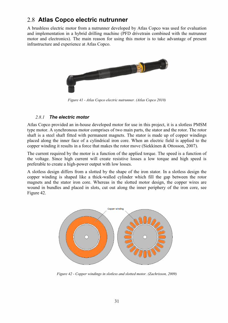
A brushless electric motor from a nutrunner developed by Atlas Copco was used for evaluation
and implementation in a hybrid drilling machine (PFD drivetrain combined with the nutrunner
motor and electronics). The main reason for using this motor is to take advantage of present
infrastructure and experience at Atlas Copco.
Figure 41 - Atlas Copco electric nutrunner. (Atlas Copco 2010)
The electric motor 2.8.1
Atlas Copco provided an in-house developed motor for use in this project, it is a slotless PMSM
type motor. A synchronous motor comprises of two main parts, the stator and the rotor. The rotor
shaft is a steel shaft fitted with permanent magnets. The stator is made up of copper windings
placed along the inner face of a cylindrical iron core. When an electric field is applied to the
copper winding it results in a force that makes the rotor move (Siekkinen & Ottosson, 2007).
The current required by the motor is a function of the applied torque. The speed is a function of
the voltage. Since high current will create resistive losses a low torque and high speed is
preferable to create a high-power output with low losses.
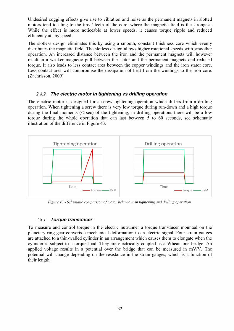
A slotless design differs from a slotted by the shape of the iron stator. In a slotless design the
copper winding is shaped like a thick-walled cylinder which fill the gap between the rotor
magnets and the stator iron core. Whereas in the slotted motor design, the copper wires are
wound in bundles and placed in slots, cut out along the inner periphery of the iron core, see
Figure 42.
Figure 42 - Copper windings in slotless and slotted motor. (Zachrisson, 2009)
32
Undesired cogging effects give rise to vibration and noise as the permanent magnets in slotted
motors tend to cling to the tips / teeth of the core, where the magnetic field is the strongest.
While the effect is more noticeable at lower speeds, it causes torque ripple and reduced
efficiency at any speed.
The slotless design eliminates this by using a smooth, constant thickness core which evenly
distributes the magnetic field. The slotless design allows higher rotational speeds with smoother
operation. An increased distance between the iron and the permanent magnets will however
result in a weaker magnetic pull between the stator and the permanent magnets and reduced
torque. It also leads to less contact area between the copper windings and the iron stator core.
Less contact area will compromise the dissipation of heat from the windings to the iron core.
(Zachrisson, 2009)
The electric motor in tightening vs drilling operation 2.8.2
The electric motor is designed for a screw tightening operation which differs from a drilling
operation. When tightening a screw there is very low torque during run-down and a high torque
during the final moments (<1sec) of the tightening, in drilling operations there will be a low
torque during the whole operation that can last between 5 to 60 seconds, see schematic
illustration of the difference in Figure 43.
Figure 43 - Schematic comparison of motor behaviour in tightening and drilling operation.
Torque transducer 2.8.1
To measure and control torque in the electric nutrunner a torque transducer mounted on the
planetary ring gear converts a mechanical deformation to an electric signal. Four strain gauges
are attached to a thin-walled cylinder in an arrangement which causes them to elongate when the
cylinder is subject to a torque load. They are electrically coupled as a Wheatstone bridge. An
applied voltage results in a potential over the bridge that can be measured in mV/V. The
potential will change depending on the resistance in the strain gauges, which is a function of
their length.

33
MDPTools – Estimating electric motor losses 2.9
MDPTools is a collection of scripts used for calculating losses in slotless electric motors. It
consists of several modules, each performing a different calculation task.
The scripts require input of material properties for the motor components (stator, windings and
magnets) and physical dimensions of the motor components. The script is then fed with a point
of operation (torque and speed for the motor) after which a detailed list of losses can be obtained.
The layout of the included scripts is shown in Figure 44.
Before the code can be run, the needed inputs are defined in the Indata module. Helpvar contains
help variables such as converted units and other derived properties, needed for the upcoming
calculations. The conversion from torque to electrical current and speed to emf (electromotive
force) is also carried out here. The corresponding current and emf at the point of operation is
required to perform the calculations in the remaining parts of the script. This is also used to
calculate resistive losses in the windings and stator switching losses. All data of interest is
compiled and printed to a file or plotted by the OutputTools.
Figure 44 - MDPTools script layout. (Zachrisson, 2009)

34
Airbus visit 2.10
Airbus facilities in Hamburg were visited to get a glimpse of how the ADU tools are used in
production and find out more about general customer needs regarding aerospace drilling. The
visit included a guided tour through the production line for the A320 and A350 aircrafts. By
interviewing and observing the staff, information was obtained regarding the customers’
expectations of the tools, which are listed below.
Size: A small and light weight ADU is very attractive. This is especially important for the
lighter duty applications such as A320 fuselage where 100,000’s of holes is drilled,
requiring the operator to move the tool often.
User interface: The interface should to be intuitive and easy to use while holding the tool
safely. Especially when drilling in the bottom of the aircraft it’s important that the release
button for concentric collet or similar can be operated while the tool is held safely with
two hands.
Countersink depth: Detection of countersink depth is very important, especially in one-
shot drilling where drilling and countersinking is done with the same drill bit.
Adaptive drilling: Detection of different materials and adaptive drilling can provide the
benefit of reduced process time and increased cutter life. With the introduction of Boeing
787 and Airbus A350 where more than 50% of the aircraft (by weight) is composite, this
has become an increasingly useful feature.
Broken drill bit detection: The ability to detect a broken or worn drill bit is very useful
since the cutter condition affects the quality of the hole. Continuous feedback of cutter
condition can support decisions on early replacement or extended use of the cutting tool,
thus maximizing the use of each cutter.

35
3 REQUIREMENT SPECIFICATION
With the knowledge gained in the background research the requirement specification for the
transmission is as follow in Table 1. The table show target measures for hole sizes, speed and
feed of the spindle as well as carry over parts and demands on ergonomics. Due to
confidentiality reasons, the values are not given in this version of the report.
Table 1 – Requirement specification
Requirement Measure Definition
Hole
Max hole diameter (CFRP, Al) - Ø mm Largest hole diameter to be drilled in CFRP and Al
Max hole diameter (Ti) - Ø mm Largest hole diameter to be drilled in Ti
Stack thickness (1/4") - mm Max stack thickness to be drilled with ¼” drill bit
Stack thickness (3/8") - mm Max stack thickness to be drilled with 3/8” drill bit
Stack disposition(s) - Compatible combinations of workpiece materials
Spindle Drive
Speed min - rpm
Minimum speed at which a hole according to above
requirements can be drilled with satisfactory results.
Speed max - rpm
Maximum speed at which a hole according to above
requirements can be drilled with satisfactory results.
Torque - Nm
Achievable drill torque for continuous operation in
above defined stack configurations (apply worst
case)
Adjustability -
Scope of drill speed which can be achieved with a set
transmission configuration.
Spindle Feed Feed rate min - mm/rev Minimum linear drill feed rate
Feed rate max - mm/rev Maximum linear drill feed rate
Thrust - N Achievable feed thrust force
Retraction rate - mm/rev Achievable drill retraction (reverse feed) rate
Adjustability -
Scope of drill feed which can be achieved without
replacing any parts of the tool.
Vibratory drilling
Desired chip breaking method to be used
Countersink depth control &
precision ± - mm Achievable depth tolerance when countersinking
Carry over
Electric motor - Tool which component is to be carried over from
Control Unit - Tool which component is to be carried over from
Spindle mechanism - Tool which component is to be carried over from
Vibratory drilling unit - Tool which component is to be carried over from
Ergonomics
Exterior temperature According to ISO 13732-1 Maximum allowed surface temperature of tool
Weight of tool - kg Maximum weight of complete tool
Size of tool - mm Maximum size of tool (H, W, L), excl. drill bit
Shape of tool - Desired exterior shape of the tool

36

37
4 PFD1100 ELECTRIC MOTOR HYBRID PROTOTYPE TESTING
This chapter describes the design and testing of a hybrid tool consisting of the front part of the
PFD1100 and the rear part of the electric nutrunner.
PFD1100 - Electric motor hybrid prototype 4.1
To better understand the electric motor behaviour in drilling applications a hybrid tool was
designed consisting of the carry overs, i.e. the motor and electronics from the nutrunner and the
front part of the PFD1100.
To be able to connect these subsystems an aluminium housing was designed connecting the
motor to the drill head (see Figure 45). Also, an adapter bushing that connect the planet carrier in
the nutrunner to the split gear of the PFD1100 was designed, see Figure 46. External air pressure
was connected directly to the air logic of the PFD1100 to be able to control the retraction of the
spindle.
Figure 45 – 1. Tool head from PFD1100 and nutrunner handle and motor. 2. Parts mounted in adapter housing.

38
Figure 46 – Designed adapter bushing (blue and red) which connects the grey planet carrier in the nutrunner to the
right with the yellow split gear of the PFD1100 to the left.
PFD1100 - Electric motor hybrid prototype testing 4.2
Purpose of test 4.2.1
The PFD1100-electric motor prototype was tested in the Atlas Copco test lab to get further
understanding of the electric motor in a real drilling application. Following was investigated:
Actual mechanical drilling power compared to calculations
Heating of the motor windings and tool electronics.
Nutrunner torque transducer behaviour.
Stack drilling behaviour.
Test equipment 4.2.2
The test equipment consists of the following instruments and tools:
PFD1100-electric motor hybrid, prototype described in chapter 4.1.
PF4000, Atlas Copco Control unit, used to set speed and torque limits when drilling.
Drill bits 6.35 mm and 9.59 mm.
Kistler drill jig, measures torque and force during drilling.
Coolant pump providing coolant to the drill bit.
Test samples of aluminium, titanium and CFRP.
PXTV, Software used to log temperature, current and torque inside the tool.
A gear ratio of 10 was used for the hybrid tool and proved sufficient for all drilling applications
within the scope.

39
Figure 47 - PFD1100-electric motor hybrid in the Kistler test-rig.
Test procedure 4.2.3
The test was divided into different parts:
Drilling in aluminium (15 mm, 2,000 RPM) and titanium (15 mm, 700 RPM) with 6.35
mm drill bit.
Drilling in aluminium (15 mm, 2,000 RPM), titanium (15 mm 700 RPM) and CFRP (15
mm 2,000 RPM) with 9.59 mm drill bit.
Consecutive drilling of 10 holes in aluminium (20 mm, 2,000 RPM), average time
between holes ~36 s with 9.59 mm drill bit.
Stack drilling CFRP and titanium with a speed change from 2,000 RPM to 700 RPM at
layer transition with 9.59 mm drill bit.
Test result 4.2.4
Mechanical power
show the measured torque, force and resulting power from the drilling tests.
Table 2 - Torque and force from drilling 3 different materials. Please note that the torque, thrust and power values
presented are only symbolic and should not be used for dimensioning purposes.
Consecutive drilling
10 holes were drilled with short and equal pauses in between, to see how much the motor and
electronics would heat up. PXTV was used to measure current and temperature on mainboard,
Nm N W Nm N W Nm N W
6.35 - - - 0.4 200 113 0.35 275 35
9.59 0.5 150 141 0.6 350 156 0.8 425 79
Torque[Nm] Thrust[N]
Power[W]
Diameter [mm]
Feed rate [mm/rev] 0.05 0.05 0.05
Cutting fluid No Yes Yes
Speed [RPM] 2700 2700 945
Chiplet amplitude [mm] 0.1 0.1 0.1
Mechanical power
Material CFRP Aluminium (7075)
Titanium Grade5
(Ti4Al6V)

40
chip and motor. The temperature rise can be seen in. Appendix B: Motor temperature shows a
graph of the temperature progression during the test.
Table 3 - Temperature rise after 10 consecutive holes. Due to confidentiality reasons, the values are changed with a
conversion factor.
Stack drilling
A stack of CFRP and titanium was drilled where the programming set (P-set) in the PF4000 was
set to change speed when reaching a certain torque level. Since there was no possibility to start
and stop cutting fluid during drilling, cutting fluid was used during the full length of the hole.
The result shows that it is possible to use the torque transducer in the tool to change speed at
transition between layers. Figure 48 and Figure 49 show the drill cycle and the transition from
CFRP to titanium after 17 s.
Figure 48 - Torque in a CFRP-titanium stack, layer transition at 17 s, were the titanium is reached.
Material
Speed [RPM]
Chiplet amplitude [mm]
Feed rate [mm/rev]
Cutting fluid
Lenght of hole [mm]
Number of holes drilled
Torque[Nm]
Thrust force[N]
Diameter[mm]
Time between holes[s]
Ambient temperature °C
Temp sensor position Motor Chip Main board
Start temperature °C 29 60 43
Temperature °C after 10 holes 37 66 48
0.55
350
9.59
36
22
0
0.05
Yes
20
10
Consecutive drilling
Aluminium (7075)
2900

41
Figure 49 - Thrust Force in a CFRP-titanium stack, layer transition at 17s, were the titanium is reached.
Figure 50 show the logged transducer values tfh_filteredTorque from the torque transducer in the
nutrunner in a similar drilling operation. At 10 seconds, the torque is changed due to the
transition from CFRP to titanium. The torque transducer value on the y-axis is negative since the
motor is running in reverse. The units are internal and used in the PXTV-software, they must be
translated to Nm with a conversion factor depending on the transmission.
Figure 50 - Torque and current logged with PXTV in a stack drilling operation, CFRP-titanium.
Test conclusions
The test using the electric motor as power source show the drilling power used was lower than
drilling data provided by Mapal and Sandvik. Using a new drill bit during drilling probably
lowered the power needed. The temperature developed during consecutive drilling was lower
than expected but it is possible that the aluminium housing containing the motor helped to keep

42
the temperature down. The low heat development also implies that a transmission with lower
ratio and higher maximum speed is possible.

43
5 ELECTRIC MOTOR TESTING AND GEAR RATIO OPTIMIZATION
This chapter describes the power testing of the electric motor and how the result is used to adapt
the MDP-tools script. MDP-tools was then used for optimizing gear ratio for the transmission.
Bench testing of the electric motor 5.1
Purpose of testing 5.1.1
To understand the behaviour of the electric motor a bench test was carried out in the Atlas Copco
test laboratory. The goal for the test was to find at what torque and speed the motor has
minimum power losses compared to its output power and the size of these power losses. The data
acquired will be used to adjust the MDP-tools script to be able to optimize the gear ratio of the
machine.
Test equipment 5.1.2
To measure input voltage and current the instrument Norma 5000 has been used. Norma 5000
has a very high accuracy and has a margin of error around 0.05% when measuring voltage and
current. The motor shaft was directly connected to an eddy current brake which is used to apply
torque to the rotor. Additional sensors measure rotational speed and torque. To control the motor
speed and ramp up, Atlas Copco control unit PF4000 and the software PXTV was used.
Test setup 5.1.3
The electric motor was connected directly to the eddy current brake. The motor is then connected
to the PF4000 via the drive unit of the electric motor. To measure the power intake to the motor
and drive-unit the Norma 5000 was connected in line with the power supply. A computer was
used to log data from the eddy current brake, Norma 5000 and the PF4000. See test-setup in
Figure 51 and Figure 52.
Figure 51 - Schematic test setup of the motor test.

44
Figure 52 – Test setup, NORMA 5000 (1), drive unit (2), electric motor (3), and eddy current brake (4).
Test procedure 5.1.4
The motor was tested in runs of 4 seconds in a matrix of 20 test points, every test point at a target
speed (4 points 5,000 RPM to 20,000 RPM) and torque (5 steps 0.2 Nm to 1.0 Nm).
Test result 5.1.5
Unfortunately, it was not possible to test torques lower than 0.2 Nm due to limitations of
accuracy in the eddy current brake. Further, analysis of the data showed that the test points at
20,000 RPM had an efficiency over 100% and due to this all data at 20,000 RPM had to be
discarded. The data was compiled in to Figure 53 and as can be seen the power losses increases
with higher speed and higher torque.
Figure 53 - Power losses at different speeds with extended polynomial trend lines.
Test conclusions 5.1.6
The test was conducted to be able to adapt the MDP-tools script. It gives some good
understanding on how big the power losses are at different operating points and could be used in
later work outside the scope for this thesis for dimensioning the cooling of the machine.

45
MDPTools – Adaptation of the script for a drilling 5.2
machine
Additional modules were added to the script to adapt it for the semi-automatic drilling machine.
The three modules handle calculations related to drilling requirements, the feed mechanism and
inverter losses. The code additions and their position (calculation order) within the main script
are shown in red in Figure 54.
Figure 54 - The three modules added to the MDPTools suite.
Apart from these additions, modifications were also made to the Indata script, introducing
additional parameters needed to mathematically describe the drilling process. The changes would
allow the script to calculate the motor and inverter losses for any operating conditions, as well as
deriving these from a given drilling scenario. Below follows a description of the three added
modules and their purposes.
DrillingReq: This part requires input of material to be drilled, drill diameter, thickness and feed
rate. It then uses the formulas in section 2.4 – Drilling theory, to calculate the torque and feed
(thrust force) requirements. Drilling torque and speed is then converted with the gear ratio to
obtain the actual torque and speed as seen by the motor.
Feedmotor: The Feedmotor script features a mathematical representation of the feed mechanism
which is described in section 2.7.2 – Feed power calculations. It is used to calculate the power
requirement of the feed nut with input of the thrust force and drill speed. This is especially useful
for dimensioning a secondary motor dedicated to powering the feed mechanism.
InverterLos: Losses occurring in the motor inverter were not included in the original MDPTools
script. An analytical study on these losses was made in 2015 by an external company. Since the
study was well documented, the formulas could be implemented in this MATLAB script. The
module requires input of motor current, power supply voltage, outputs switching, and conductive
losses occurring in the inverter.
Once all losses were accounted for the script was run for the same points of operation that had
previously been used in the motor testing (see section 5.1– Bench testing of electric motor). The
analytical results from the script were then compared to the physical test data to see how well the
MDPTools model matches reality.

46
To compensate for the mismatch found between the analytical model and the tested prototype
machine, a scaling factor for the total motor and inverter power loss was introduced. The scaling
factor was dimensioned to yield the lowest possible difference in total losses, between the
analytical and physical results. It was not possible to find one scaling factor which minimized the
losses across the entire power output range. The scaling factor was set to achieve the best
possible fit across the output power levels, at which the electric ADU machine is intended to
operate.
The extended script gives a detailed overview of the losses in the motor and inverter for any
given drilling scenario. By running the script with different gear ratios it’s possible to optimize
the gear ratio for the drilling scenario in terms of minimized losses. The results of such an
optimization can be seen in the following section.
Gear ratio optimization in MDP-tools 5.3
Adaptation of the MDP-tools script enabled the possibility for gear ratio optimization based on
the input of a drilling scenario.
A fixed reduction transmission is simple and light weight solution but limits the drill torque and
speed range. A gearbox capable of shifting gears would require additional mechanisms which
may compromise reliability, but the speed and torque range (within the power span) can be
greatly increased.
Using the drill mechanics formulas presented in section 2.4, the motor load could be simulated
for any drilling scenario, with several different gear ratios. In the example below a scenario
involving a 6.35 mm hole through a stack of 2.5 mm titanium and 10 mm aluminium, was
investigated. The MDP-tools script calculates the power losses while drilling. Since gear ratio
affects drilling time, power loss is not necessarily representative of tool heating. Instead energy
losses (J) per hole was used for comparison purposes. The resulting energy losses for different
ratios, organized by what material is drilled, is shown in Figure 55.
Figure 55 - Energy losses [J] per hole when drilling 6.35mm hole through a stack of 2.5mm Ti at 700 RPM (left)
and 10 mm Al with different gear ratios at top speed for each given ratio (right).
The results show that for a hole size of 6.35 mm, a low ratio leads to more energy lost when
drilling titanium but less energy lost when drilling aluminium. A higher ratio allows the motor to
work at high efficiency in high torque applications but more energy is wasted in low torque
applications due to the extended drilling time.
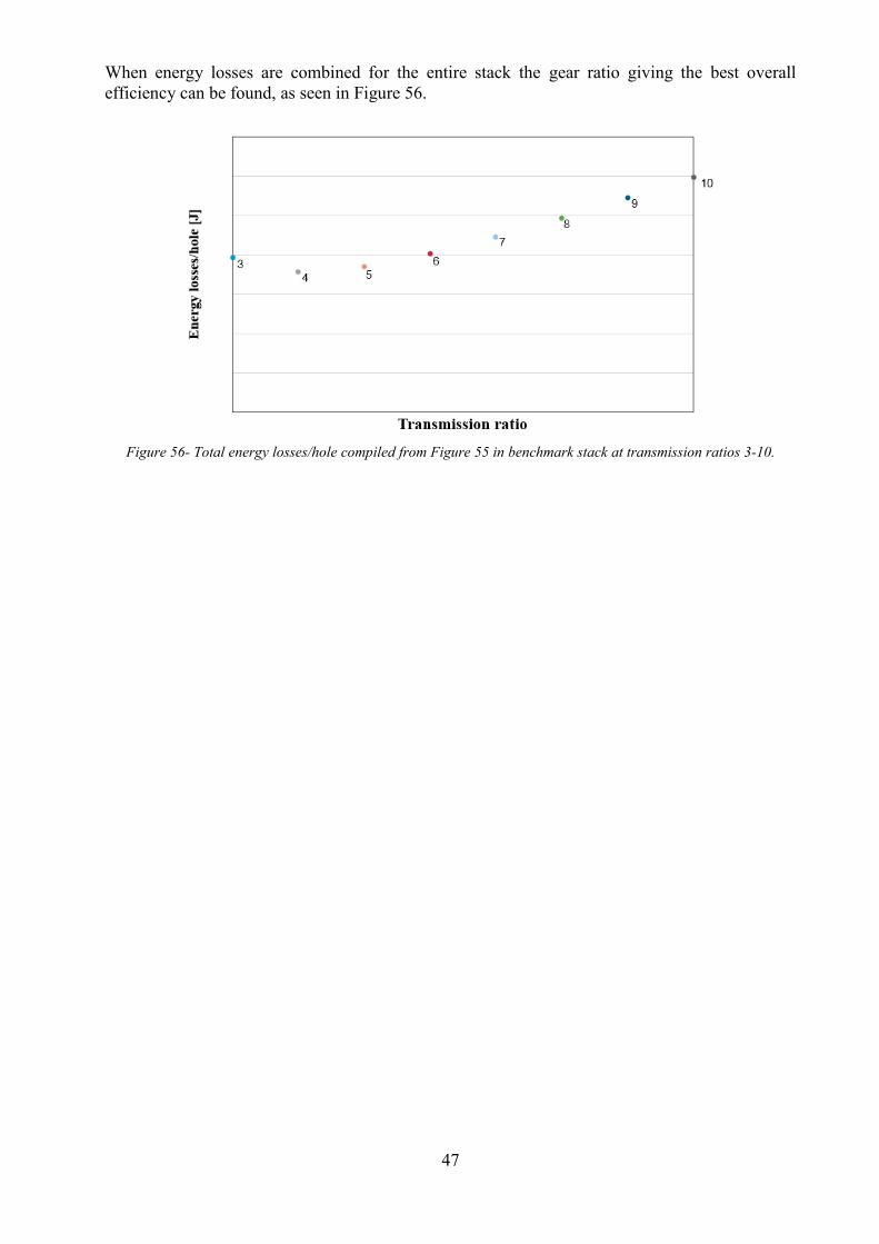
47
When energy losses are combined for the entire stack the gear ratio giving the best overall
efficiency can be found, as seen in Figure 56.
Figure 56- Total energy losses/hole compiled from Figure 55 in benchmark stack at transmission ratios 3-10.

48
6 CONCEPTS
As described in chapter 2.7 and chapter 6.1 the design problem has been divided into 2 main
functions that the transmission should be able to execute, rotate drill and feed drill. The concepts
for solving these two functions are described in this chapter.
Functional structure 6.1
By dividing the main function “drill hole” into sub-functions a functional structure can be made.
In Figure 57 and Figure 58 the functions “Rotate drill” and “Feed drill” have been divided into
sub-functions. By doing so technical solutions could be proposed for solving the different
functions and later be combined into overall concepts.
Figure 57 - Function “Rotate drill” divided into sub-functions, blue boxes represent the technical solution for the
sub-function.
Figure 58 - Function “Feed drill” divided into sub-functions, blue boxes represent the technical solution for the
sub-function.
Concepts for rotating the spindle at variable speed 6.2
Due to the characteristics of slotless electric motors it is preferred to run the motor at high speed
rather than high torque to achieve the best efficiency possible. Ideally, drill speeds from 700
RPM up to 7,000 RPM are reached with the same gear ratio. With widely varying operating
conditions for different materials, two extremes would have to be met with the same gear ratio.
The two extremes are “high torque” (drilling titanium and other tough materials) and “high speed”
(drilling lighter materials like aluminium or fiberglass)
A low gear ratio will allow a higher top speed but with a sacrifice in output torque, forcing the
motor to work at high torque levels when drilling tough materials like titanium. A high gear ratio
lets the motor run with good efficiency in high torque applications, but with a limited top speed.
Being able to adjust the gear ratio in real time, by switching between two or more modes, will
allow the motor to run at very efficient operating conditions in all applications.
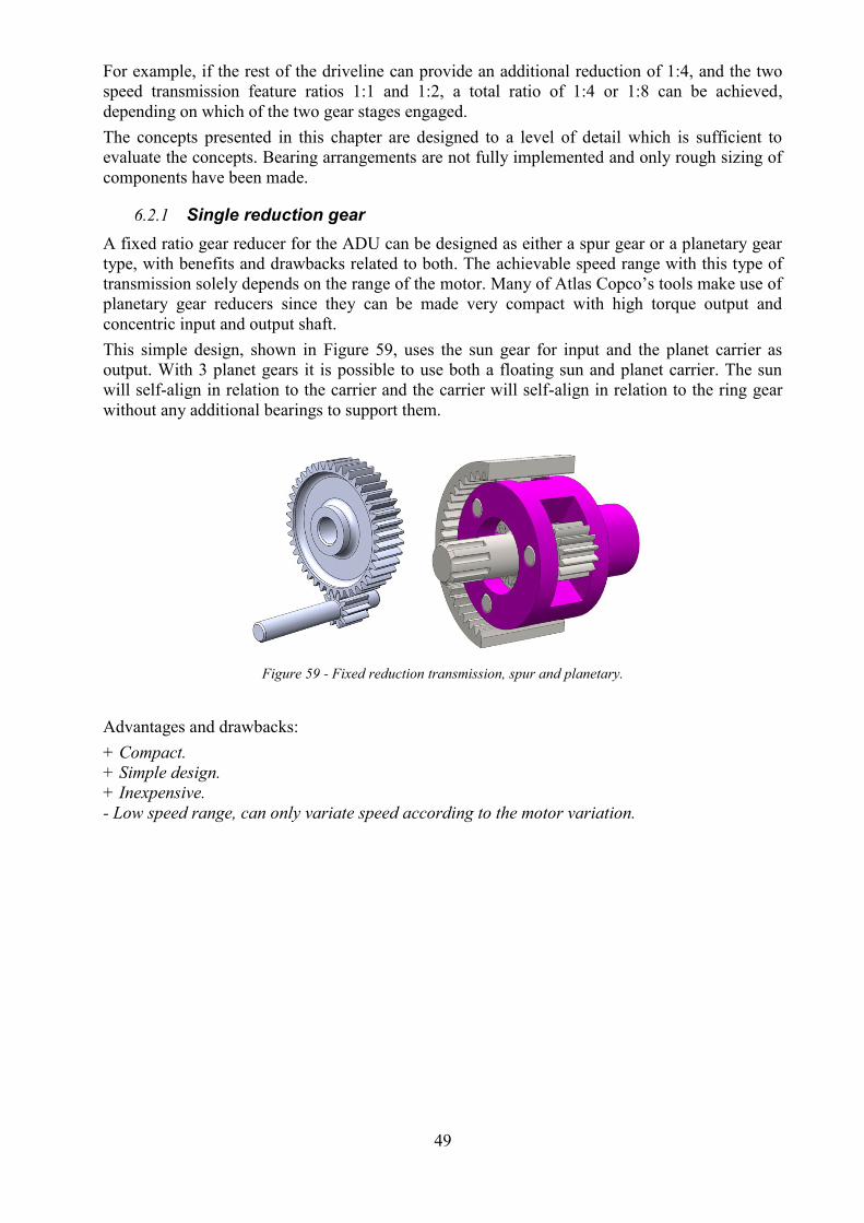
49
For example, if the rest of the driveline can provide an additional reduction of 1:4, and the two
speed transmission feature ratios 1:1 and 1:2, a total ratio of 1:4 or 1:8 can be achieved,
depending on which of the two gear stages engaged.
The concepts presented in this chapter are designed to a level of detail which is sufficient to
evaluate the concepts. Bearing arrangements are not fully implemented and only rough sizing of
components have been made.
Single reduction gear 6.2.1
A fixed ratio gear reducer for the ADU can be designed as either a spur gear or a planetary gear
type, with benefits and drawbacks related to both. The achievable speed range with this type of
transmission solely depends on the range of the motor. Many of Atlas Copco’s tools make use of
planetary gear reducers since they can be made very compact with high torque output and
concentric input and output shaft.
This simple design, shown in Figure 59, uses the sun gear for input and the planet carrier as
output. With 3 planet gears it is possible to use both a floating sun and planet carrier. The sun
will self-align in relation to the carrier and the carrier will self-align in relation to the ring gear
without any additional bearings to support them.
Figure 59 - Fixed reduction transmission, spur and planetary.
Advantages and drawbacks:
+ Compact.
+ Simple design.
+ Inexpensive.
- Low speed range, can only variate speed according to the motor variation.

50
Two speed transmission 1 6.2.2
A two-speed gear reducer features two parallel spur gear stages with different gear ratio. One of
the gear stages have a ratio of 1:2 or more while the other have a ratio of 1:1, Figure 60 shows an
overview of the concept.
Figure 60 - Two speed transmission with dog clutch.
The gear selector mechanism uses a dog clutch which is moved along a splined output shaft with
the aid of a solenoid. The gears on the output shaft can rotate freely on the shaft. Moving the dog
clutch allows it to engage with matching dogs on either of the two neighbouring gears,
connecting it to the output shaft. A disadvantage of the dog clutch is the chance of the dogs
(teeth) on the two mating halves meeting tip to tip, resulting in delayed shifting.
Figure 61 - Left: first gear pair engaged (ratio 1:2) and
right: second gear pair engaged (ratio 1:1).
Advantages and drawbacks:
+High speed range.
-Adds weight to the design.
-Adds complexity to the design.
-External mechanism which require electricity for shifting
-Might demand synchronisation.

51
Two speed transmission 2 6.2.3
The technical description of this concept is excluded due to confidentiality reasons from Atlas
Copco.
Two speed transmission 3 6.2.1
The technical description of this concept is excluded due to confidentiality reasons from Atlas
Copco.
Two speed transmission 4 6.2.1
The technical description of this concept is excluded due to confidentiality reasons from Atlas
Copco.

52
Concepts for feeding and retracting the spindle 6.3
Several concepts have been designed which solve the main functions related to feed and drill
retraction. The mechanical principle used for feeding and retracting the drill is explained in
section 2.7 – Spindle mechanism power calculations
The concepts have been divided into two groups, where the first group is a coupled design that
uses the same motor (hereafter referred to as the main motor) to power both spindle rotation and
feed. The second group of concepts make use of a dedicated motor (hereafter referred to as feed
motor) to enable a fully adaptive feed.
The concepts presented in this chapter are designed to a level of detail which is sufficient to
evaluate the concepts. Bearing arrangements are not fully implemented and only rough sizing of
components have been made.
Main motor direct connection 6.3.1
A coupled design where the feed is in direct relation to the spindle speed offers the simplest and
most compact solutions. These designs are limited to a fixed feed rate (mm/rev), which cannot be
changed without replacing parts of the transmission.
Additional technical solutions are needed for retracting the drill. Existing pneumatic tools make
use of pressurized air cylinders and valves, locking parts of the transmission to accomplish a
retract feed. In an electric tool, the same function can be achieved with the aid of solenoids or
other force-generating electronic components.
Retraction mechanism 1 - solenoid engaged retraction.
Figure 62 shows an overview of the concept. Gear selector fork (1) can move the gear (2)
between two positions (as indicated by the blue arrow) with the aid of a solenoid. Gear (2)
connects the vertical drive shaft (3) to the feed nut (4), or locks it to the machine housing (not
depicted) through the integrated dog clutch.
Figure 62 - Component overview of solenoid engaged retract, coupled feed.

53
During normal operation, the gear will sit in its lower position (A), see Figure 63. Here it
connects to the vertical drive shaft via a form locking joint. Gear (2) drives the feed nut (4) at a
speed slightly higher than the spindle speed, causing the spindle to feed with some distance per
revolution of the spindle.
Figure 63 - Selector fork in position A, normal feed engaged via shaft - gear coupling.
After completed drill cycle, the spindle is retracted by moving the gear selector to position B (see
Figure 64). In this mode, the gear (2) is disconnected from the shaft (3) and locked to the
machine housing via the dog teeth on the top side of the gear. Retract feed will be equal to the
spindle thread lead.
Figure 64 - Selector fork in position B, retract feed engaged by locking gear to housing.
Advantages and drawbacks:
+ Compact.
- Requires external mechanism for shifting.
- Shaft – gear coupling can fail to engage
(spring loading the gear selector in this direction is recommended).
- Relatively complicated components from a manufacturing point of view.
Retraction mechanism 2
The technical description of this concept is excluded due to confidentiality reasons from Atlas
Copco.
Secondary feed motor 6.3.2
To enable adaptive feed during drilling, a secondary feed motor is required. The decoupled
design enables the retraction to be started without the need of an external mechanism. Power
requirements for the dedicated feed motor is around 25-50% of the main motor power. Chapter
2.7 feature the relevant calculations. Three concepts utilizing this principle are described below.

54
Secondary motor concept 1 - Direct drive adaptive feed
By implementing a dedicated feed motor which connects directly to the feed nut, the feed can be
controlled independently from the spindle speed, allowing fully adaptive feed. Regular feed for
drilling will be active while the secondary motor spins the feed gear faster than the spindle (Feed
gear shown in blue in Figure 65. To initiate retract mode, the secondary motor is run slower than
the spindle. A greater difference in speed will result in a higher feed or retract rate.
Figure 65 - Secondary feed motor.
Advantages and drawbacks:
+ Simple
+ Adaptive feed
+ Peck drilling possible
- Bulky and heavy due to relatively large feed motor
Secondary motor concept 2
The technical description of this concept is excluded due to confidentiality reasons from Atlas
Copco
Secondary motor concept 3
The technical description of this concept is excluded due to confidentiality reasons from Atlas
Copco

55
7 CONCEPT EVALUATION
Weighted Pugh’s matrix 7.1
Evaluation of the concepts is made using a weighted Pugh’s matrix. The evaluation is based on
the decomposed system and is split in to the two main functions. One part deals with concepts
for rotating the spindle and the other deals with concepts for feeding and retracting the spindle.
Concepts from the two parts can be combined into complete system concepts. While most of the
concept combinations are feasible, the direction dependent concepts for the two functions cannot
be used together.
A set of criteria are each given an individual weight, a measure of how important they are. The
properties used as criteria and their weight are listed in Table 4. Properties are further described
where deemed necessary. Concepts are given a score for each criterion which relate to how well
the concept resolves the specific property.
Table 4 - Description of the relative importance and its weight.
Property Description Relative
importance
Weight Less weight = higher score 8
Height Smaller size = higher score 7
Width Smaller size = higher score 6
Length Smaller size = higher score 5
Normalized spatial score Weighted average of spatial scores 2
Efficiency System efficiency, less losses = higher score 7
Speed range* Greater speed range = higher score 8
Feed range** Greater feed range = higher score 4
Retract feed** Fixed retract feed = lower score
Adjustable retract feed = higher score
3
Serviceability Easier maintenance = higher score 3
Complexity Lower complexity = higher score 6
Known technology Well known tech = higher score 5
Time to market Less time required = higher score 10
Spatial properties
The physical properties which relate to size: weight, length, height, and width, have all been
granted with a relatively high importance. However, to avoid an excessive impact on the
concepts final score, they are compiled into a normalized spatial score before added to the final
score. The normalized spatial score takes the average of the weighted score from the four spatial
properties and then adds a consecutive weight of 2.
𝑆𝑛𝑜𝑟𝑚𝑎𝑙𝑖𝑧𝑒𝑑 =(𝑆𝑤𝑒𝑖𝑔ℎ𝑡 ∙ 8 + 𝑆ℎ𝑒𝑖𝑔ℎ𝑡 ∙ 7 + 𝑆𝑤𝑖𝑑𝑡ℎ ∙ 6 + 𝑆𝑙𝑒𝑛𝑔𝑡ℎ ∙ 5)
4∙ 2

56
This way of grading ensures that the spatial properties are treated with high importance, as well
as accounting for their individual weight, without dominating the total score of a concept.
Efficiency
Total system efficiency, accounting for additional friction and churning losses. Also accounts for
how efficient the electric motor can run. A two-speed transmission allows the motor to run closer
to its optimal operating parameters, when drilling significantly different materials, compared to a
fixed ratio transmission.
Speed range
The drill speed can be varied to some extent by changing the speed of the electric motor. But
with a gear ratio that enables drilling of tough materials, top speed will be limited. Two speed
transmissions provide the greatest range of usable drill speeds.
Feed range & retract feed
Some feed rate may be optimal for one material but could result in poor hole quality when
drilling another material. Appropriate feed for common aerospace materials typically lie between
0.05 and 0.2 mm. Concepts using a coupled design (constant feed – speed ratio) will offer poor
control over the feed rate and a very high, non-adjustable retract feed rate.
Serviceability & complexity
Concept complexity is proportional to the number of parts required to fulfil the desired functions.
Additional mechanisms, which may result in failure modes, further increase complexity.
Known technology & time to market
The amount of time required to fully implement a concept depend on its complexity and whether
the technology is well known and proven. If the technology is well known and proven within the
organization or it exists in similar machines already on the market, a higher score will be granted.

57
Evaluation of concepts for rotating the spindle at variable 7.2
speed
Electric motor rotation speed can be adjusted during operation but the speed and torque of the
motor can only be varied within a certain range. A fixed ratio transmission for driving the
spindle will lead to a machine capable of drilling either with high torque or with high speed. A
high gear ratio will produce the torque required when drilling larger holes in tough materials, but
a lower ratio will allow for a higher top speed and thus increased material removal rate in lighter
materials.
Therefore, concepts featuring a two-speed setup can provide an extended speed range. A low
range gear is used for drilling tough materials like titanium and the high range gear allows for a
higher material removal rate in lighter composite materials.
Table 5 shows the results of the Pugh’s matrix evaluation of the concepts which provide the
spindle rotation function.
Table 5 - Pughs evaluation of concepts for spindle rotation function
Due to the high relative importance set for the Spatial and Time to market criterion, the concept
featuring a single reduction (fixed ratio) transmission, achieved the highest score. Despite the
other concepts reaching a lower score, they might offer a better solution to the main function.
The two speed solutions enable a greater speed range and offer an increased system efficiency.
Alternatives for spindle speed transmission
FIXED REDUCTION SOLENOD SHIFTED
TWO SPEED
TWO SPEED
TRANSMISSIONS
TWO SPEED
TRANSMISSION 1
TWO SPEED
TRANSMISSION 2
TWO SPEED
TRANSMISSION 3
Criteria Imp
ort
ance
Score
Wei
ghte
d
Score
Wei
ghte
d
Score
Wei
ghte
d
Score
Wei
ghte
d
Score
Wei
ghte
d
Weight 8 5 40 2 16 3 24 3 24 3 24
Length 5 5 25 3 15 2 10 3 15 3 15
Height 7 5 35 3 21 3 21 3 21 5 35
Width 6 5 30 5 30 4 24 4 24 5 30
Normalized spatial 2 65 41 39,5 42 52
Efficiency 7 5 35 8 56 7 49 7 49 7 49
Speed range 8 5 40 10 80 10 80 10 80 10 80
Servicability 3 5 15 3 9 4 12 4 12 4 12
Complexity 6 5 30 4 24 4 24 3 18 3 18
Known technology 5 5 25 3 15 4 20 3 15 4 20
Time to market 10 5 50 3 30 4 40 4 40 4 40
Total score 260 255 265 256 271

58
Evaluation of concepts for feeding and retracting the 7.3
spindle
The most important criteria in the evaluation of the spindle feed and retract concepts are still the
spatial properties and time to market.
It is possible to make a single fixed feed rate work with multiple materials, albeit with reduced
productivity, so the relative importance of adaptive feed rate is low.
Table 6 shows the results of the Pugh’s matrix evaluation of the concepts which provide the
spindle feed and retract function.
Table 6 - Pughs evaluation of concepts for feed and retract function
High relative importance was again set for the Spatial and Time to market criterion, allowing the
simplest concepts to achieve the highest score. The solenoid engaged retract concept offer a
simple and robust way of retracting the spindle with an acceptable retraction feed, but without
adaptable feed.
Adaptable feed may still provide a significant customer value in some cases. Depending on the
end user, the weight of this criterion can be adjusted yielding a different result of the evaluation.
Alternatives for spindle feed transmission
MAIN MOTOR
(Coupled design)
SECONDARY FEED
MOTOR
(Decoupled design)
SOLENOID ENGAGED
RETRACTION
FREEWHEEL, REVERSE
ROTATION RETRACTION
SECONDARY MOTOR,
SPEED ADJUST RETRACT
SECONDARY MOTOR
CONCEPT 2
SECONDARY MOTOR
CONCEPT 3
Criteria Imp
ort
ance
Score
Wei
ghte
d
ScoreW
eigh
ted
Score
Wei
ghte
d
Score
Wei
ghte
d
Score
Wei
ghte
d
Weight 8 5 40 5 40 2 16 3 24 3 24
Length 5 5 25 5 25 5 25 4 20 4 20
Height 7 5 35 4 28 2 14 4 28 4 28
Width 6 5 30 4 24 5 30 3 18 4 24
Normalized spatial 2 65 58,5 42,5 45 48
Efficiency 7 5 35 4 28 4 28 2 14 3 21
Feed range 4 5 20 5 20 7 28 10 40 10 40
Retract feed 3 5 15 2 6 10 30 10 30 10 30
Servicability 3 5 15 6 18 8 24 5 15 5 15
Complexity 6 5 30 6 36 6 36 4 24 4 24
Known technology 5 5 25 5 25 4 20 3 15 4 20
Time to market 10 5 50 6 60 3 30 2 20 2 20
Total score 255 252 239 203 218

59
8 DISCUSSION AND CONCLUSIONS
Discussion 8.1
The overall goal of this thesis was to investigate the possibility of converting a pneumatic
drilling machine into an electric. A background study was performed to understand the basic
needs of the aerospace industry with regard to drilling machines. Perfectly understanding the
customer and their specific needs is difficult, therefore it is likely that some needs have not been
considered.
The designed prototype tool mainly consisted of carried over parts from existing products. It was
a time and cost-effective way to test the possibilities of using the electric motor for a drilling
application. However, the prototype design was very basic and not necessarily representative of a
purpose-made product, not the least from a thermal management perspective. The aluminium
housing, carrying the motor, had a relatively large mass which could absorb much of the waste
heat. In a production tool size and weight restrictions would result in a leaner and more
optimized design with lower heat capacity. A thick and heavy housing causes the tool to heat up
slower, but also increases thermal resistance and thus impedes cooling.
Further, a malfunctioning drill lubrication unit disturbed the heating test, leading to an
interrupted test after only 10 cycles, long before a steady state was reached. Since the motor
losses are temperature dependent, it had been preferable to run the tool until and at steady state
temperature to get the best understanding of the tool heating. The time-consuming workpiece
set-up in the test bench also resulted in relatively long pause times between holes, allowing the
tool to cool down somewhat in between drill cycles.
Motor testing was important in order to improve the output from the motor losses script, used to
find the most efficient gear ratio. Conclusion from the testing was that the motor should be run
as fast as possible but this was never tested properly. Due to limitations in the testing equipment
it was not possible to test the motor at its top speed of 20,000 RPM, or at torques below 0.2 Nm.
Since slotless motor designs typically perform better at higher speeds, the conclusion is still
expected to be valid.
Optimization of the gear ratio was done for a benchmark hole of 6.35 mm. Although this hole
size appears in great frequency in aerospace applications it should not be viewed as a limitation
or intended hole size for the machine.
Developing and evaluating concepts is an iterative process. The evaluation of the concepts was
based on the knowledge at the time and thus the results may give an incomplete picture. A
critical analysis of the criteria’s and respective weighting should be made before any decisions
are based on the results. With improved knowledge of the customer needs, the evaluation can be
refined to give better results.
An electric ADU with similar or smaller format than the studied pneumatic tool is possible but
will largely depend on the motor. The electric motor provided by Atlas Copco offers great
performance but its shape is adapted for a nutrunner tool. A motor with the same power rating
but larger diameter would be better suited for the electric drilling machine. A motor with higher
torque and lower speed can make use of a lower transmission ratio, possibly eliminating one
reduction stage. A larger motor could also improve the shape of the machine, making it shorter,
more compact and easier to handle.

60
Conclusions 8.2
The thesis project has been a feasibility study on the development of the transmission for an
electric ADU. Several concepts of varying complexity have been designed with a level of detail
sufficient for a first comparative evaluation. The proposed concepts offer simplicity with a direct
driven feed, or greater flexibility with increased complexity in a differential driven feed. The
most promising concepts according to the evaluation are those which offer a simple and robust
solution i.e. low complexity without any non-critical features.
The motor used in this project has proven capable of powering a semi-automatic drilling
machine with hole sizes up to 9.5 mm and the same consistency as a pneumatic machine.
The hybrid tool designed in this project proved that adaptive drilling (adaptive speed only) is
possible with existing software and PF4000 controller. During testing the tool successfully
adapted the drill speed when transitioning from a lighter material (CFRP or aluminium) to a
tougher material (titanium).
Gear ratio optimization was based on a combination of theoretical and practical, drilling and
motor performance data. It showed that if a single reduction transmission is used, a lower gear
ratio is preferred to reduce the energy losses during stack drilling. The optimization method can
be used for any motor (given an existing loss model) and drilling scenarios. Studying the energy
losses from drilling in titanium and aluminium respectively, the optimal gear ratio clearly
depends on what material is being drilled. A two-speed transmission combined with adaptive
drilling has the potential to significantly improve efficiency in stack drilling applications.
Further work 8.3
The conclusions drawn from this thesis could be used for further investigations and development
of a new electric drilling machine.
Further work to get more knowledge should include:
Investigate additional motor manufacturers to see if there are motors more appropriate for
this type of drilling applications.
Thorough investigation of the target customer group to get deeper understanding of their
needs.
Perform more drilling tests with a verified test bench setup to map the requirements of all
applicable drilling scenarios.
Further development of MDPTools to include more factors and estimate power loss with
greater precision.
Further develop and iterate the most interesting concept designs.

61
9 REFERENCES
Aerospace manufacturing and design. (2016, April 20). Composite vibration drilling. Aerospace
manufacturing and design.
AGY . (2013). GLARE® Laminate with S-2 Glass® Fiber. Retrieved from
http://www.agy.com/wp-content/uploads/2014/03/GLARE_Laminate-Aerospace.pdf
Airbus. (2009). Airbus Hamburg 2009. Retrieved from
http://www.kieboom.net/Airplanes/Airbus-Hamburg-Family-Day-2009/i-VdsCmMF:
http://www.kieboom.net/Airplanes/Airbus-Hamburg-Family-Day-2009/i-VdsCmMF
APEX TOOL GROUP. (2014). Dynamix tools. Retrieved from Quality tools for the aerospace
industry: http://www.dynamixtools.com/WEB/8888/NSF/Web/1118/aerospace.pdf
Atlas Copco partner. (2017).
Avalon consultancy services LTD. (2013). The use of composites in aerospace: Past, present
and future challenges. Retrieved from Researchgate:
https://www.researchgate.net/file.PostFileLoader.html?id=569d31f75f7f713dce8b4577&
assetKey=AS%3A319317025984512%401453142519798
Boeing. (2005, May). The Boeing 787 Dreamliner: More Than an Airplane. (Boeing, Performer)
Campbell, F. (2006). Manufacturing Technology For Aerospace Structural Materials. Oxford:
Elsevier Ltd.
Childs, P. R. (2014). Mechanical Design Engineering Handbook. Oxford: Elsevier Ltd.
Claussen, S. (2006). US Patent No. US20060172852 A1.
Dingley, A. (. (2010, february). Wikimedia Commons. Retrieved from wikmedia.org:
https://commons.wikimedia.org/wiki/File:Differential_(Manual_of_Driving_and_Mainte
nance).jpg
FAA. (2012). Aviation Maintenance Technician Handbook - Airframe. United States Department
of Transportation - Federal Aviation Administration.
Faraz, A. (2009). An innovative tool wear criterion in drilling CFRP composite laminates.
International Journal of Machine Tools and Manufacture.
Gardiner, G. (2014, 05 01). Hole quality defined. Retrieved from CompositesWorld:
http://www.compositesworld.com/articles/hole-quality-defined
Gardiner, G. (2016, 8 18). The resurgence of GLARE. Retrieved from CompositesWorld:
http://www.compositesworld.com/blog/post/the-resurgence-of-glare
Granström, M. (2016). Improving Hole Quality for Adaptive Drilling Equipment within
Aerospace. Stockholm: KTH, Industrial Engineering and Managment.
Guerin, S., & Sylvain, d. C. (2015). A Breakthrough in Handheld Smart Drilling Units: Material
Detection with Advanced Electrical Drilling. SAE.
Inductiveload. (2017, june 5). Wikimedia Commons. Retrieved from commons.wikimedia.org:
https://commons.wikimedia.org/wiki/File:Countersunk_holes.svg
Kennametal. (2016). Kennametal. Retrieved from Titanium Machining Guide:
https://www.kennametal.com/content/dam/kennametal/kennametal/common/Resources/C
atalogs-
Literature/Industry%20Solutions/Titanium_material_machining_guide_Aerospace.pdf
Kielb, C. (2016, August 3). slideshare. Retrieved from slideshare.net:
https://www.slideshare.net/CraigKielb/auto-trans

62
Kohara Gear Industry Co.,Ltd. (2016, 05 18). KHK Gears. Retrieved from Comparison Between
Spiral And Straight Bevel Gears: http://khkgears.net/gear-blog/comparison-spiral-
straight-bevel-gears/
Korn, D. (2005, 11 11). Machining Composites By Conventional Means. Retrieved from Modern
Machine Shop: http://www.mmsonline.com/articles/machining-composites-by-
conventional-means
Mägi, M., & Melkersson, K. (2009). Lärobok i maskinelement. Göteborg: EcoDev International
AB.
Magma. (2015). Magma Magnets. Retrieved from Magmamagnets.com:
http://www.magmamagnets.com/electromagnets-solenoids/solenoids/
Mapal. (2016). Mapal. Retrieved from The right tool for every material:
https://www.mapal.com/en/products/produktgruppen/tools-for-modern-lightweight-
materials/materials/
Millinger, J. (2010). Development of thermal models for electrical nutrunners. Stockholm: KTH,
Electrical Engineering.
Mouritz, A. P. (2012). Introduction to aerospace materials . Cambridge, UK : Woodhead
Publishing Limited.
Pawar, O. A., Gaikhe, Y. S., Tewari, A., Sundaram, R., & Joshi, S. S. (2015). Analysis of hole
quality in drilling GLARE fiber metal laminates. Composite Structures, 350-365.
Sandvik Coromant. (2010, March). Sandvik Coromant. Retrieved from Machining carbon fibre
materials:
http://www.sandvik.coromant.com/SiteCollectionDocuments/downloads/global/technical
%20guides/en-gb/C-2920-30.pdf
Sandvik Coromant. (2014). Sandvik coromant. Retrieved from Chip Control:
http://www.sandvik.coromant.com/en-gb/knowledge/drilling/getting_started/chip_control
Sandvik Coromant. (2014). Sandvik Coromant. Retrieved from Knowledge base - Drilling -
Formulas: http://www.sandvik.coromant.com/sv-
se/knowledge/drilling/formulas_and_definitions/formulas/pages/default.aspx
Sandvik Coromant. (2015). Sandvik Coromant. Retrieved from Specific cutting force:
http://www.sandvik.coromant.com/en-
gb/knowledge/materials/workpiece_materials/the_specific_cutting_force/pages/default.as
px
Sandvik Coromant. (2015). Sandvik Coromant. Retrieved from
http://www.sandvik.coromant.com/sv-se/knowledge/drilling/wear-and-
troubleshooting/chip_evacuation/pages/peck-drilling-%E2%80%93-corodrill-delta-
c%C2%AE-and-coromant-delta%C2%AE.aspx
Sandvik Coromant. (2016). Sandvik Coromant. Retrieved from Aerospace - Composite
solutions: http://www.sandvik.coromant.com/en-
us/industrysolutions/aerospace/composite
Sandvik Coromant. (2017). Sandvik Coromant. Retrieved from ISO N Non-ferrous materials:
http://www.sandvik.coromant.com/en-
gb/knowledge/materials/workpiece_materials/iso_n_non_ferrous_materials/pages/default
.aspx
Sandvik Coromant Kc and mc. (2016). Sandvik Coromant. Retrieved from
sandvik.coromant.com: http://www.sandvik.coromant.com/en-
gb/knowledge/materials/workpiece_materials/iso_s_hrsa_titanium/pages/default.aspx

63
Sandvik. (n.d.). Sandvik Coromant. Retrieved from sandvik.coromant.com:
http://www.sandvik.coromant.com/en-
gb/knowledge/materials/workpiece_materials/iso_s_hrsa_titanium/pages/default.aspx
Sellgren, U. (2016). Lecture 2. Systems Engineering (MF2011). Stockholm: KTH Industrial
Engineering and Management.
Shaeffler. (2014). Shaeffler Technical Pocket Guide. Herzogenaurach: Shaeffler technologies
GmbH & Co. KG.
Shigley's. (2014). Shigley's Mechanical Engineering Design. In J. K. Richard G Budynas.
Siekkinen, A., & Ottosson, R. (2007). Optimization of motor and gearbox in nutrunner systems.
Stockholm: KTH Industrial Engineering and Management.
The Seattle Times. (2015, April 18). Seattle times. Retrieved from
http://www.seattletimes.com/business/boeing-aerospace/boeing-retools-renton-plant-for-
737s-big-ramp-up/
Tsao, C. C. (2012, 11 11). Drilling processes for composites. In C. C. Tsao, Machining
Technology for Composite Materials - Principles and Practice (pp. 17-60). Woodhead
Publishing . Retrieved from Modern Machine Shop:
http://www.mmsonline.com/articles/machining-composites-by-conventional-means
TWI Global. (2001, December 11). TWI Global. Retrieved from Industrialisation of friction stir
welding for aerospace structures: http://www.twi-global.com/technical-
knowledge/published-papers/industrialisation-of-friction-stir-welding-for-aerospace-
structures-december-2001/
Ullman, D. G. (2010). The Mechanical Design Process, Fourth Edition. New York: McGraw-
Hill Education.
Walter Tools. (2016). Walter Tools. Retrieved from Machining composites intelligently:
https://www.walter-tools.com/SiteCollectionDocuments/downloads/global/brochures/en-
gb/flyer-composite-en.pdf
Wikimedia, C. (2011, november 14). Wikimedia Commons. Retrieved from wikimedia.org:
https://commons.wikimedia.org/wiki/File:Engrenage_conique_concourant_moment_equi
valent_couple.svg?uselang=sv
www.seti-tec.com. (2015, June 5). Retrieved from Seti-tec Web site: http://www.seti-
tec.com/applications.asp
Zachrisson, F. (2009). Modellering och design av elmotor för mutterdragare. Stockholm: KTH,
Industriell teknik och managment.

64
APPENDIX: SUPPLEMENTARY INFORMATION
Appendix A: Specific cutting force
Specific cutting force (Sandvik, u.d.).

65
Appendix B: Motor temperature
Temperature logged with PXTV.