REDUCING GEOTHERMAL DRILLING PROBLEMS TO ...
34
GEOTHERMAL TRAINING PROGRAMME Reports 2013 Orkustofnun, Grensasvegur 9, Number 16 IS-108 Reykjavik, Iceland 325 REDUCING GEOTHERMAL DRILLING PROBLEMS TO IMPROVE PERFORMANCE IN MENENGAI Isaac Kipkoech Makuk Geothermal Development Company – GDC P.O. Box 17700 Nakuru – 20100 KENYA [email protected], [email protected] ABSTRACT Drilling geothermal wells is one of the main construction activities of a geothermal project. The aim is to access the available steam in the production zone of a geothermal reservoir. The discharged wet steam is separated into steam that is channelled to a power plant, where it drives turbines to produce electricity, and water which is normally injected back into the reservoir. Several challenges are encountered while drilling geothermal wells. These challenges have resulted in drilling timelines not being met as well as increases in drilling costs. This report describes the causes of some of these challenges and how they can be minimized or reduced so as to improve performance. Challenges encountered in Menengai geothermal field in Kenya are the main subject of this study. These challenges are either natural or due to human error. This report found that drill string sticking accounted for 12% of the total drilling time in Menengai. Sticking is caused by poor well bore cleaning, especially when there is lost circulation and long or periodic waiting for water. Lost circulation is caused by intersecting fractures or permeable zones. Measures for mitigating problems of lost circulation so as to avoid sticking have been discussed. This report found that the most troublesome zone in Menengai is at a depth of 2100 m where the drill string got stuck in Wells MW03, MW04, MW07 and MW12. Wells MW01 and MW06 had drill string sticking at a depth of 2206 and 2202.96 m, respectively. A comparison was made with the 2104 m depth of an Iceland Deep Drilling Project well at Krafla in Iceland. An analysis indicated that the troubles were related to intersecting magma intrusions, shown by fresh glass in the cuttings that were observed at the shale shakers. The magma pushed the drill string up (large drop in hook load) and it got stuck, blocking the circulation at the same time. Temperature surveys later showed the fluid near the bottom was superheated. Metal fatigue was found to be another problem, as shown by shears that were experienced on cross-over box ends. To minimize this, the report suggests the use of drill string risk management for close monitoring of any defects. 1. INTRODUCTION Drilling is an important activity in geothermal utilization for accessing geothermal reservoirs with hot water and steam. It is also used to refine a geothermal system’s conceptual model which helps in assessment and management of the system for sustainable utilization and development. This, in turn,
-
Upload
khangminh22 -
Category
Documents
-
view
0 -
download
0
Transcript of REDUCING GEOTHERMAL DRILLING PROBLEMS TO ...

GEOTHERMAL TRAINING PROGRAMME Reports 2013 Orkustofnun, Grensasvegur 9, Number 16 IS-108 Reykjavik, Iceland
325
REDUCING GEOTHERMAL DRILLING PROBLEMS TO IMPROVE PERFORMANCE IN MENENGAI
Isaac Kipkoech Makuk Geothermal Development Company – GDC
P.O. Box 17700 Nakuru – 20100
KENYA [email protected], [email protected]
ABSTRACT
Drilling geothermal wells is one of the main construction activities of a geothermal project. The aim is to access the available steam in the production zone of a geothermal reservoir. The discharged wet steam is separated into steam that is channelled to a power plant, where it drives turbines to produce electricity, and water which is normally injected back into the reservoir. Several challenges are encountered while drilling geothermal wells. These challenges have resulted in drilling timelines not being met as well as increases in drilling costs. This report describes the causes of some of these challenges and how they can be minimized or reduced so as to improve performance. Challenges encountered in Menengai geothermal field in Kenya are the main subject of this study. These challenges are either natural or due to human error. This report found that drill string sticking accounted for 12% of the total drilling time in Menengai. Sticking is caused by poor well bore cleaning, especially when there is lost circulation and long or periodic waiting for water. Lost circulation is caused by intersecting fractures or permeable zones. Measures for mitigating problems of lost circulation so as to avoid sticking have been discussed. This report found that the most troublesome zone in Menengai is at a depth of 2100 m where the drill string got stuck in Wells MW03, MW04, MW07 and MW12. Wells MW01 and MW06 had drill string sticking at a depth of 2206 and 2202.96 m, respectively. A comparison was made with the 2104 m depth of an Iceland Deep Drilling Project well at Krafla in Iceland. An analysis indicated that the troubles were related to intersecting magma intrusions, shown by fresh glass in the cuttings that were observed at the shale shakers. The magma pushed the drill string up (large drop in hook load) and it got stuck, blocking the circulation at the same time. Temperature surveys later showed the fluid near the bottom was superheated. Metal fatigue was found to be another problem, as shown by shears that were experienced on cross-over box ends. To minimize this, the report suggests the use of drill string risk management for close monitoring of any defects.
1. INTRODUCTION Drilling is an important activity in geothermal utilization for accessing geothermal reservoirs with hot water and steam. It is also used to refine a geothermal system’s conceptual model which helps in assessment and management of the system for sustainable utilization and development. This, in turn,

Makuk 326 Report 16
insures that the reservoir and power plant are properly utilized. In drilling operations, we are in business only when we are drilling on the bottom (making a hole). Any activity, other than casing and waiting on cement to cure, is regarded as not only non-productive, but incurs undesirable costs. This is because the rig is hired at an hourly rate (or at times on a meter rate depending on the contract). Drilling problems have been encountered in the past and will continue to happen in the future. Attempts are constantly being made to avoid and reduce these problems. With technological and technical know-how advances, methods to tackle these problems should be greatly improved. Drilling costs associated with non-drilling time can be so high that it can reach 15 to 35% of the total well cost (Raja et al., 2011). Reducing these problems increases drilling performance and reduces well cost, thereby increasing the viability of a geothermal drilling project, such as Menengai (Figure 1). 2. STUCK PIPE Stuck drill pipes comprise one of the major drilling problems encountered at Menengai geothermal field in Kenya. This problem has also been experienced in Olkaria geothermal field in Kenya and almost all other drilling (oil and gas or geothermal) fields in the world. Drill pipe sticking is not only a waste of time and cost, but also may result in the loss of part of the bottom hole assembly (BHA) or drill string. When that happens, a decision may have to be made to place a cement plug in the well and sidetrack the well to bypass the “fish”, causing time delays and additional cost. Agarwal (2008) argues that 60% of sticking occurs in the drill collar section of the drill string. This is due to their higher outside diameter compared with the rest of the drill string and around the stabilizers. During normal operations, the driller desires to drill on the bottom (make a hole), pull out of the hole (to change the bit) or run in hole (a new bottom hole assembly). The driller may also wish to make a wiper trip to clear any obstructions. When not able to do this, it can result in the drill string not rotating or moving up/down the hole; the drill string is then said to be stuck. When the drill string gets stuck, drilling fluid is not usually received at the surface, although sometimes it can be. This is an observation made by the author of this report while working at rigs in Menengai. Drill string sticking is classified into three types, based on the overriding mechanism. These types are: geometry related, solids related and differential sticking (Devereux, 1998). 2.1 Geometry related sticking The hole and BHA relative geometry have an impact on the ability of the drill string to get stuck. Either an inclination or diameter of the hole relative to the BHA will restrict the drill string in its course. It has
FIGURE 1: Map showing Menengai geothermal field and wells (GDC, 2013)

Report 16 327 Makuk
been found that the greater the hole inclination, the more the chances of the drill string getting mechanically stuck. The wells described in this report at Menengai are, however, all drilled vertically. 2.1.1 Under-gauge hole Due to prolonged drilling through hard formations, the bit gets worn out and, as a result, its diameter is reduced, referred to as a loss of gauge. This implies that the hole’s diameter may not be uniform for the entire hole section. This creates a tapered or tight hole which can cause mechanical sticking due to the hole geometry when running in with a new bit. 2.1.2 Key seat Extensive work done by Lubinski (1950) indicates that doglegs cause drilling problems. As the drill string continuously rotates and rubs against one point on the wall of the hole, it finally results in the creation of a groove (key seat). This happens when the lateral force of the rotating string is higher than the formation strength at the point (or length) of contact. It is also possible for a key seat to be grooved into a casing (a metal) as opposed to a rock. As the driller pulls out of hole, a certain section of a drill string cannot get past the key seat, depending on the outside diameter. The drill pipe body will only go past the key seat but the tool joint, as well as a drill collar will not, due to their larger outside diameter. It is interesting to note that a 2° nearly vertical spiral hole, as observed by Lubinski (Murphey, 1966) causes excessive key seats while a 3° straight inclined hole with deviation all in one direction does not have severe key seats and drilling problems. Therefore, they contend, perfectly vertical holes should be avoided so as to reduce incidences of stuck pipe. Figure 2 shows how key seats are generated.
FIGURE 2: Key seat generation: a) Buckling and continuous rotation of drill pipe; b) A key seat has been generated; c) Key seat formed when going from hard to soft formation
(Grace et al., 2008; Schlumberger, 2013) 2.2 Mobile formations The mud hydrostatic pressure is meant to support the borehole wall. When this pressure is not sufficient, then the borehole wall can collapse due to the overlying overburden pressure acting on the formation as shown in Figure 3 (Pašić et al., 2007). The collapsed formation will eventually result in sticking. If there is an increase of water in the near-well bore vicinity, then the shale strength will reduce (Mody
a) b) c)

Makuk 328 Report 16
and Hale, 1993; Van Oort et al., 1994). There are several methods in which water is transported into and out of the formation in the near-well bore region (Van Oort et al., 1995). The most overriding method, argues Van Oort et al. (1996, 1997), is the chemical potential difference as well as the wellbore/formation differential pressure. Water based muds are used instead of oil based mud, mainly due to environmental and economic concerns (Van Oort, 1996). For geothermal drilling, the problem is not exactly the same. 2.3 Geo-pressured formations When fluid flows into a formation, and it is substantially restricted over long geological time, an overpressure develops (Hsu and Belaud, 1998). Additional sedimentary loading increases the pore pressure. If the mud hydrostatic pressure of a borehole is less than the pore pressure, then slivers of shale will be squeezed into the well bore due to the differential pressure. Without proper hole cleaning, this continues to the point where the drill string gets stuck. The sizes of the slivers are usually smaller at the surface than at the bottom of the hole due to breakup as it is being circulated. On the other hand, abnormally low pressured formations can be encountered, as is the usual case for geothermal reservoirs. Either an abnormally low or high pressured formation causes drilling problems. In abnormally low pressured formations, lost circulation will be experienced. Highly depleted reservoirs (probably due to over-exploitation) have also been found to be a cause of abnormally low pressured formations (Barriol et al., 2005). 2.4 Unconsolidated formation As a result of poor bonding between the rock particles, the formation becomes unconsolidated and poorly packed. This is common for sands, gravel and small river bed boulder formations at shallow depths of about 500 m (Bowes and Procter, 1997). Poor bonding makes the strength of the rocks weak and the rocks can easily yield due to overburden pressures. Any attempt to remove the previously supporting rock while drilling will cause the nearby rocks to fall into the well bore as shown in Figure 4. This eventually causes sticking of the drill string. Mud cake helps to prevent the poorly bonded rocks from collapsing into the well bore. Absence of, or too thin a mud cake will aggravate the collapse. 2.5 Naturally fractured formations In a geothermal field, there are faults and naturally fractured rock formations (Devereux, 1998). The rock pieces divided by natural fractures as shown in Figure 5 can be small or large (Pašić et al., 2007). Unlike the collapse of pieces of rock due to poor bonding in unconsolidated formations, naturally fractured formations (whose rock might have a good bond) collapse due to the impact of the drill string vibrations. Formations with faults and dips have been found to have an effect on how vertical the well bore can be. Drilling
FIGURE 3: Mobile formation (Pašić et al., 2007)
FIGURE 4: Unconsolidated formation
(Bowes and Procter, 1997)
FIGURE 5: Naturally fractured formation (Pašić et al., 2007)

Report 16 329 Makuk
through faults and dip strata leads to a crooked hole as the drill bit tends to slide off or down the dips rather than going head-on through the strata. According to Gow (2005), crooked holes are also facilitated by drilling through different formations with alternating strength and resistance, with the bit deflecting from the perpendicular particularly when encountering hard formations. 2.6 Junk Any material that is not drillable and finds its way into the well bore is regarded as junk. It may be part of the fishing tool that gets worn out and drops into the hole. Poor housekeeping at the rig floor, or around the cellar, can results in some junk getting into the hole. Items that are regarded as junk are: tong jaws or pins, broken pieces of guide shoe or milled fish fragments, bearings, and bolts falling down from the top drive. Bolts that were used for some repair and forgotten up the mast could also fall during vibrations. The junk can fall into the hole either during normal drilling or momentarily when there is no drilling, and the hole is open, and the rig floor men forget to cover the rotary table opening. If the mud pump screens are worn out and not replaced, they may allow pieces of metal dropped in the mud tanks to be sucked by the mud pumps and pumped all the way through the drill string to the bit. Small pieces of junk can also fall into the drill pipe bore when applying dope. Bit cones can also break off in the hole and become junk. Naturally occurring strong materials can also be regarded as junk. 2.7 Cement blocks After setting the casing and the cement has cured, drilling out the cement follows. Devereux (1998) suggested that there is a possibility of a large pocket below the casing shoe. Cement in the pocket could fracture due to a lack of support. Upon resuming drilling on the bottom, the fractured cement can fall onto the drill string and cause the BHA to get stuck. The fallen heavy cement blocks will overwhelm the drilling fluid and will not be transported to the surface, as desired. This will, in effect, make cuttings accumulate in the annulus and contribute further to stuck pipe problems. 2.8 Green cement Running in hole with a drill string too soon after cementing can be problematic. If a drill string is run into the hole at a high rate, it will cause a surge which results in a sudden pressure increase. This sudden pressure increase causes the green cement to flash set (Bowes and Procter, 1997). Consequently, the drill string gets stuck. Even if the speed of running in hole is not fast, and the cement has not fully set, then there is a high possibility of the drill string getting stuck in the cement. The weight on bit (WOB) indicator will not be able to detect wet cement when trying to tag on cement. This will result in the assumption that the top of cement has not been reached. 2.9 Collapsed casing A properly designed casing should withstand the collapse pressures at the depth at which it is set. The burst pressure is the internal pressure inside the casing and assumes full reservoir pressure all along the wellbore. Collapse of the casing occurs when the external pressure is greater than the internal pressure. The external pressure is mainly due to the cement column while cementing the casing. A worst case scenario of collapse occurs when the casing has been cemented and the inside is completely empty. Research done by Skúlason et al. (2011) established that water pockets trapped in the casing-casing annulus after a cement job causes a casing collapse as shown in Figure 6 (drawn using ANSYS 11.0 finite element analysis software). The casing fails or collapses when its yield strength or collapse resistance is exceeded. However, the value of yield strength and collapse resistance reduces when these material properties change due to the effect of axial loading. Very high velocity steam can erode the

Makuk 330 Report 16
casing, thereby compromising its strength due to reduced wall thickness. Corrosion caused by chemical properties of the well also reduces the strength and collapse resistance of the casing. Poor workmanship and aggressive running procedures can buckle the casing. Collapsed casing can not only jam the drill string, it can also reduce the wells output and can even render it non-productive. 2.10 Tectonically stressed formations Geological studies have shown the existence of plate tectonic movements. The movements can either be separation, collision or shear. These create the formation of faults or folds. These crustal movements, due to plate tectonic activity,
induce stresses on the formation. Simulations and research done by Luo (2004) indicate that formation pore pressure increased as tectonic stress increased. The mechanism behind this increase is two-fold. Firstly, the lateral tectonic stress creates an increase in the compaction rate of the pores, leading to a volume decrease. Due to this, there will be disequilibrium between pore fluid expulsion and formation compaction, thereby facilitating natural over-pressuring. Secondly, due to compaction, the rock porosity will decrease and, correspondingly, permeability decreases. As formation permeability decreases, the formation pressure correspondingly increases (Osborne et al., 1997; He, 1999). Drilling into highly tectonic stressed formations, argued Bowes and Procter (1997), causes the rocks to fall into the well bore. This is due to the substantial difference between the near wellbore stress and the mud hydrostatic pressure which is supposed to support and counteract the near wellbore pressure and prevent formation fluid or cuttings from coming in. These tectonically stressed formations occur on or around mountainous areas. 2.11 Reactive formations Several mechanisms behind rock and fluid interaction have been advanced. They include: swelling pressure, osmosis, fractured shale, hydraulic, pressure diffusion, mechanical, fluid penetration and capillary pressure (Manohar, 1999). The water in the drilling fluid migrates to the formation and with time, causes swelling. Van Oort (2003) explained that this migration takes place in three phases. From the centre of the well bore (Figure 7), the mud pressure front goes out into the formation. This is followed by a solute/ion invasion front. The ions could be K+, Ca2+, or Mg2+ or any other that are used as a swelling pressure inhibitor. The last phase of the fluid/formation interaction is the filtrate invasion front. Formation swelling, if not checked, can create stuck pipe problems.
FIGURE 6: Casing collapse due to water pocket (Skulason et al., 2011)
FIGURE 7: Drilling fluid invasion of a shale

Report 16 331 Makuk
2.12 Balling up While drilling, the formation or mud may become sticky. Due to adhesive forces, the mud accumulates on the bit or drill assembly. When pulling out of hole, the accumulated mud becomes compacted and can cause sticking of the pipe. Problems associated with balling up have been encountered when drilling at high rates of penetration (Warren, 1940). This happens because the clay cuttings do not get sufficient time to hydrate to mud. Continuous drilling at this rate results in continuous accumulation of natural clay or sticky mud. If the mud filter cake is too thick, it may eventually reduce the well bore’s diameter. As the drill string is being pulled out of the hole, it scrapes off the filter cake and, with time, it accumulates resulting in balling up. 2.13 Differential sticking During drilling, either for oil and gas or geothermal steam, drilling fluid is used. The main purpose of drilling fluid is to maintain a well’s hydrostatic pressure for well control and transport of cuttings from the bottom hole to the surface. This is made possible by the addition of materials that improve, among other properties, the viscosity and density of the drilling fluid. As the density of the drilling fluid is increased, the well hydrostatic pressure increases to a value that exceeds that of the formation pressure. On reaching this value, mud and filtrate are lost into the permeable formation due to the pressure gradient. This is followed by the formation of a filter cake as solids, present in the drilling fluid, are accumulated at the permeable wall. For geothermal drilling, a low density water-based mud made with bentonite is normally used, having a density of only 1.05 g/cm3. The onset and development of filter cake is dependent upon the solids content of the mud. Figure 8 shows the stages through which a mud cake filter develops. At the beginning (Figure 8a), the drill string, ideally, rotates about the wellbore centre. With time, the dynamic or static mud and filtrate pass through the permeable wall of the well bore as described earlier. Concurrently, solids are deposited in the well, eventually forming a filter cake, as shown in Figure 8b. If efforts are not taken to immediately free the stuck pipe then, with time, the filter cake’s thickness will increase, as shown in Figure 8c. The cake’s thickness will increase with the square root of time as predicted by Darcy’s law (Murrilo et al., 2009). Studies have shown that the probability of differential sticking increases with time, due to an increase in filter cake thickness. Differential sticking is dependent on mud cake filtration properties that include: thickness, shear strength and lubricity. These properties, in turn, are dependent on the following variables:
Mud solids content (either low or high-gravity solids); Fluid loss; Mud differential pressure; and Mud type.
An increase in the development of filter cake and its thickness can be interrupted by drill string rotation. Mud filter cake erosion can be experienced depending upon drill string rotation eccentricity. Due to this eccentricity, a section of the well bore’s circumference is scrapped off. There are three scenarios of filter cake erosion. Figure 9a shows drill pipe erosion, which is caused by the lateral movement of the
FIGURE 8: Development of a filter cake (Grace et al., 2008)
a)
c)
b)

Makuk 332 Report 16
drill pipe. Figure 9b shows filter cake erosion caused by wiper trip. The third type of filter cake erosion is caused by reaming operations. The reaming erosion, as shown in Figure 9c, is more uniform than the other two types, because most of the cake has been scrapped off. If the drill string is left for some time without rotating it, then the filter cake will start to surround the drill collar as shown in Figure 9d. This results in bridging between the drill collar, or drill pipe, and the filter cake. Bridging, which increases the drill collar and filter cake contact area, further increases the differential sticking force.
2.13.1 Mechanism of differentially stuck pipe For differential sticking to occur, there has to be ‘differential pressure’. This is a phrase that is sometimes referred to in other literature as overbalance. Differential pressure is the amount of mud hydrostatic pressure less that of the formation pressure. A significant amount of differential pressure forces the drill string (either drill pipe or drill collars) against the well bore wall, due to the pressure gradient. 2.13.2 Permeable zone Depending on drilling fluid properties, the permeable zone provides favourable conditions for the formation of mud cake. The thicker the mud cake, the higher the chances of getting differentially stuck. If the fluid loss (mud property) is high, then there are high chances of getting differentially stuck. This is because more fluid is lost to the formation as filtrate while more solids are deposited at the wall. The deposited solids are responsible for sticking. 2.13.3 Contact area As shown in Figure 8a, sticking will not occur if there is no contact between the drill string and the well bore wall. The larger the arc length contact area, the higher the degree of differential sticking. The longer the depth of the contact area between the drill string and the mud cake, the higher the degree of sticking. This is because frictional forces associated with larger surface areas are higher compared to those of smaller surface areas. The size and shape of the pipe also affects the contact area. Spiral and small outside diameter drill collars have a smaller contact area with the mud cake compared to un-spiralled larger outside diameter drill collars. 2.13.4 Stationary drill string There are higher chances of getting stuck if the drill string is stationary, as shown in Figure 9d, as explained earlier. This is caused by too much time spent during connection/disconnection, especially when working with the Kelly system rig. Many stoppages when making connections of single joints increase the number of times and length of time of a stationary drill string. This is also common in the Kelly system rigs. An abrupt repair on a crucial rig component like the drawworks makes the drill string stationary. If the top drive motors fails, then the driller will not be able to rotate the drill string, thus
b) d)
FIGURE 9: Mud cake erosion (Schlumberger, 1997): a) Drill pipe erosion; b) Wiper trip erosion; c) Reaming erosion; d) Bridging due to stationary drill collar
a) c)

Report 16 333 Makuk
making it stationary for as long as he waits on repairs. Getting stuck also makes the drill string stationary. 2.13.5 Differential pressure This is caused by high mud hydrostatic pressure compared to the formation pressure. Usually, the formation pressure is known by using pressure gradients determined in logs from other wells within the field. The driller or mud engineer has no control over the formation pressure. But he has control over the mud hydrostatic pressure. The only way to reduce the differential pressure to within safe limits is by reducing the mud hydrostatic pressure. This is achieved through mud density reduction. Mud or water used for geothermal drilling is always of low density. Figure 10 shows the process of differential sticking.
FIGURE 10: The process of differential sticking (Matanovic, 2011) Mathematically, differential sticking is given by:
∆ (1)
where ∆ = The differential pressure; = The mud pressure; and = The formation pressure. When the pipe is stuck, then a pull out force is required to free it. This is mathematically given by the following equation:
∆ μ (2)
where F = Pull out force (N); ΔP = Differential pressure (Pa); Ac = Contact area between the pipe and the mud cake; and µ = Coefficient of friction between the pipe and the mud cake.

Makuk 334 Report 16
The contact area depends on the arc length and length (depth) of the pipe in contact with the mud cake. The contact area is given by:
(3)
where = Arc length; and Lep = Embedded pipe length.
The arc length is given by:
where 2tmc ≤ Dop ≤ (Dh- tmc).
, and represent the hole diameter, mud cake thickness and pipe outside diameter, respectively. Murrilo et al. (2009) studied the effect of the coefficient of friction and mud cake thickness on the pulling force of a stuck pipe. This he did by using the different coefficient of friction between the pipe and the mud cake as well as changing the length of the pipe embedded. He also studied the effect of mud cake thickness on the pulling force of a stuck pipe. He did this by changing the different mud cake thickness and lengths of embedded pipe for comparison purposes. The different parameters used are shown in Tables 1 and 2. When the parameters in Tables 1 and 2 were inserted in the various equations, the resulting stuck pipe pull out force was as shown in the graphs in Figures 11 and 12, respectively (Murrilo et al., 2009). Note that the shape of Figure 12 is a typical square root function graph.
TABLE 1: Different friction coefficient and embedded pipe length
TABLE 2: Different cake thickness and embedded pipe length
Dh 9 in Dop 6 in tmc 1/32 in Lep 20,30,40 ft
Dh 9 in Dop 6 in µ 0.25
Lep 20,30,40 ft
FIGURE 11: Effect of friction coefficient on pulling force (Murrilo et al., 2009)
FIGURE 12: Effect of mud cake thickness on pulling force (Murrilo et al., 2009)
22 2
(4)

Report 16 335 Makuk
3. LOST CIRCULATION Lost circulation is one of the major contributors to non-productive time in geothermal drilling. Attempts geared to cure lost circulation are costly because of the consumption of lost circulation materials and sometimes cement. Cost increase is also attributed to lost man hours while waiting cement to become hard. Studies done by Mohammed et al. (2012) found out that lost circulation was between 36% and 39% of non-productive time when drilling in Lobo field in South Texas, USA. Lost circulation refers to the loss of drilling fluid or cement slurry, partially or completely, to highly permeable zones, cavernous and naturally or induced fractured formations as shown in Figure 13. This occurs while drilling or doing a cementing job. Lost circulation is caused by either poor drilling practices, or natural factors that are associated with the type of formation that is being drilled into (Shaker, 2008). Usually, the drilling fluid hydrostatic pressure is maintained at slightly higher than the formation pressure so as to prevent formation fluids from entering the well bore. That is also a key item in well control for avoiding blow-outs. Induced fractures occur whenever the drilling fluid hydrostatic pressure and pump pressure is much greater than the fracture gradient of the formation, as shown in Figure 13 (Cook et al., 2012). The green arrows in the Figure show the path taken by the drilling fluid back to the surface during normal drilling. The white arrows, on the other hand, show the path taken by the drilling fluid into the “thief zones” where fractures have been induced. If immediate remedial action is not taken to cure the loss, then larger and longer fractures will be created. This is because the pressure needed to propagate a fracture is usually less than that needed to initiate it. It should be noted that losses are caused by both original and induced porosities. In geothermal wells, cooling of the well during drilling often induces thermal fracturing which contributes to fluid loss. 3.1 Types of lost circulation 3.1.1 Seepage loss This is a type of lost circulation in which the rate of loss is less than 4 m3/hr for water based mud (Abbas et al., 2003). The rate of this fluid loss depends on a number of factors that are either real, or apparent. High rates of penetration may seem, apparently, to be having seepage losses when they are actually not. Displacement of solids with fluids is a known cause of seepage loss. The nature of the formation dictates whether a fluid loss is seepage or not. The amount of overbalance also determines if a fluid loss is seepage or not.
FIGURE 13: Lost circulation (Schlumberger, 2011)
Makuk 336 Report 16
Once the cause of seepage loss has been identified, then a solution is sought. If the losses are not severe, then the operator can drill ahead and hope that all will be fine. This is a strategy that has been used by other operators (Finger and Blankenship, 2010). This can save cost and time, especially when nearing casing setting depth. The low rates of fluid loss can be identified by trip tank measurements, smart electronic flow meters, or by looking at the returns flowing into the shale shakers. Another solution to address seepage loss is to pull out of the hole and up past the diagnosed loss zone and shutting down the mud pumps. This is followed by giving the hole ample time to heal. As the hole is healing with time, other rig operations are carried out such as cut and slip, or preventive maintenance on the top drive system. This is done for about two hours and is intended to reduce non-productive time. The most appropriate solution is to anticipate the loss and prepare for it in advance. This is done by preparing drilling mud with the proper properties. These properties are discussed in the ‘Mud section’ of this research. As drilling progresses, changes may occur in the formation that were not anticipated, and can lead to more losses than expected. When this happens, a reactive approach is applied as opposed to a proactive approach in managing lost circulation problems. This is done by the addition of lost circulation materials, discussed in the ‘lost circulation materials’ section. 3.1.2 Partial loss Partial loss occurs when the losses are more than 4 m3/hr for water based mud. The partial loss is considered moderate if the rates of flow are less than 16 m3/hr. These losses are higher than seepage losses but some drilling fluid returns are still received on the surface. If remedial action is not taken to cure the losses, then this can lead to total loss. One of the causes of partial loss is surge pressure. These (abnormal) pressures are exerted on the well bore wall when the drill (or casing) string is suddenly run into the hole and exceeds the formation fracture gradient thereby opening up fractures. These fractures are routes through which drilling fluids are lost. Partial losses are also caused by a considerable mud pressure overbalance that fractures the formation and enhances fluid loss. Most of the fractures or loss zones encountered while drilling geothermal wells are natural and cannot be avoided. 3.1.3 Total loss Total loss occurs when no drilling fluid returns to the surface. The worst case is when there is no fluid column in the well bore after the mud pumps have been shut down. Losses of drilling fluids at the rate of more 16 m3/hr are accounted as total losses. Then formation fluids can flow into the well bore and may be difficult to control. Total loss is caused by the inability of the drilling mud to form a sufficient filter cake to seal off the zone. This may be a result of very high permeable formations. Another contributing factor to total loss is the use of too high a mud density. Other factors include excessive yield point (YP) and gel strength of the mud as they contribute to surge and swab pressures. Increasing pump pressure too quickly contributes to lost circulation. Total losses encountered in the production zone of geothermal wells are welcome, indicating a good production potential of the well, but can cause drilling problems. 3.2 Types of lost circulation zones Lost circulation zones are classified as either vertical or horizontal zones. Vertical loss zones have fractures that are induced or natural. Horizontal loss zones, on the other hand, have fractures that are porous sand and gravel or cavernous. Horizontal loss zones can also have induced or natural fractures.

Report 16 337 Makuk
Porous sands and gravel zone This type of loss zone is associated with a gradual drop in mud tank levels. Continuous drilling may lead to total loss. Induced fractured zone This loss zone is identified with a decrease in pump pressure. The loss is abrupt and may be followed by a complete loss. These fractures are induced when the mud weight exceeds 1.25 g/cm3. Induced fractures are also formed when there is a loss of circulation even though adjacent wells have not experienced losses. Microfractures are also induced by thermal contraction of the rock upon cooling by the drilling fluid. Naturally fractured zone This loss zone can be found in any type of formation. The loss can progress from partial to total loss if the same kind of formation is drilled through. An increase in loss is a result of more fractures being intersected. Cavernous zone This type of zone is usually associated with fractures of large proportions. Rough drilling followed by sudden and even total loss of returns is an indicator of this type of zone. The drill string can go down several feet followed by abrupt lost circulation. Underground blowout zone In this zone, fluids migrate from a lower active zone to an overlying zone. Underground blowouts are associated with fluctuating pressure readings as well as mud tank levels. Underground blowouts in a geothermal well can be quite dangerous and difficult to control. The well section in a blowout condition is ready to rush steam to the surface if the hydrostatic head cannot be maintained above the steam pressure. Effects of lost circulation:
Contributes to non-productive time which increases cost; Insufficient well hydrostatic pressure leading to kicks; Loss of mud and lost circulation material (LCM), thereby increasing costs; Drilling with aerated water (compressors) which is more expensive; Drilling with water and high viscosity polymer pills; Well collapse, sticking problems; Poor hole cleaning of cuttings and well fill-in, sticking problems, and Lack of formation information, no cuttings.
3.3 Mitigating lost circulation Drilling fluid design is done with special considerations to specific parameters that will prevent lost circulation. These fluid parameters include rheology, density, fluid loss, solids content, and chemical parameters. The use of well bore strengthening materials and mechanisms is another strategy that is used to prevent and reduce lost circulation. In this method, fracture propagation is restricted by particles that enter into the fracture and create a ‘barrier’. This is implemented through the use of a particularly designed shape and size of particulate materials. Well bore strengthening mechanisms are also aimed at increasing the pressures at which lost circulation starts. This increases the drilling margin (Cook et al., 2012). The last effort to solve lost circulation is to cure. This is done through the use of lost circulation materials (LCM) or by cementing the loss zone.

Makuk 338 Report 16
3.3.1 Wellbore strengthening mechanisms Fracture propagation resistance Fracture propagation resistance is a mechanism in which lost circulation material goes into the fracture opening and forms a ‘barrier’ in the form of an external filter cake that seals off the fracture propagation
tip (Figure 14). Rfluid is the radial distance between the well bore’s centre and the beginning of the filter cake wall. Rcake is the filter cake thickness and is the distance between the filter cake and the start of the fracture tip. Rtip is the distance between the end of cake thickness to the outer edge where the drilling fluid meets the formation. This enables the formation to resist further encroachment of the fracture. While rock strength is still the same, its ability to withstand fracturing has been increased. This is usually possible until new higher mud pressures start opening up a new fracture again after which the LCM penetration starts
the same process of fracture tip isolation. Stopping further fracture opening and propagation helps in preventing (any further) lost circulation. Well bore isolation This is a strengthening mechanism in which all efforts are made to ensure that the well bore is isolated when drilling. In order to achieve this, well bore strengthening materials (with strengths equal to or greater than that of the rock) have been designed with the aim of reducing rock permeability and hence ‘plastering’ it (Cook et al., 2012). This ‘plastering’ effect cuts off the pressure communication between the well bore and the rock (formation) as well as preventing drilling fluids from invading the formation. Other strategies of well bore isolation include the use of nano particles that help in a substantial reduction of permeability. These methods are generally not applied during geothermal drilling. Hoop stress mechanism: The stress cage concept The stress cage concept suggests that by adding a suitable well bore strengthening material (WSM) to a drilling fluid, it is possible to increase the hoop stress at the edge of the well bore. In dealing with lost circulation in this mechanism, an overbalanced WSM drilling fluid is circulated in an overbalanced state with the intention of creating shallow fractures. These fractures are then immediately filled and sealed
by WSM present in the drilling fluid. These WSM materials form small balls (shown in Figure 15) that accumulate, block, seal and form a bridge at the mouth of the fracture. This will, in essence, prevent further fracture propagation. The fluid in the fracture leaks of to the nearby rocks leading to pressure dissipation. The reduced pressure in the fracture opening causes it to close. However, this is limited by the bridge and wedge at the mouth of the fracture. When this happens, hoop stress (or stress cage) is established. Several shallow fractures formed by the hoop stress mechanism increase the rock’s compressive strength.
FIGURE 14: Fracture propagation (Cook et al., 2012)
FIGURE 15: Stress cage concept (Schlumberger, 2011)
Report 16 339 Makuk
This means that a higher well bore pressure is needed to fracture the rock. This helps in preventing formation collapse. Fracture closure stress The fracture closure stress mechanism is similar to that of the stress cage concept. The fracture propagation inhibition theory and the way it creates hoop stress in the well bore vicinity is the same. The difference is, while a fracture is initiated in the hoop stress mechanism, the fracture close stress mechanism acts on existing fractures. Mud treatment is used as high fluid-loss pills. The high fluid loss mud property that is desired allows the carrier fluid to be drained leaving behind a plug that breaks pressure communication between the fracture tip and the formation. The WSM used should be large particles of similar sizes. The similarity in sizes enables it to have higher permeability and hence higher fluid loss. It should also be noted that the larger the size, the greater the permeability. 4. DRILLING FLUIDS: FUNCTIONS AND TYPES 4.1 Functions of drilling fluids Cuttings removal A well bore is good to drill only if the cuttings removal is good. Drilling problems are aggravated if there is poor cuttings removal from the well. As the bit continues to drill into the formation, cuttings are generated and can accumulate. One of the major functions of drilling fluid is to transport these cuttings from the bit and other foreign objects in the annulus to the surface and finally to the solids control system. If this is not done properly, then these cuttings and foreign objects, if any, will accumulate around the bit or drill string, thereby increasing torque and eventually leading to a stuck pipe. By increasing the lifting capacity of the drilling fluid, the annular velocity will be able to lift the cuttings out of the hole. The main factor affecting hole cleaning is the upward annular velocity of the drilling fluid. When water is used it should be at a minimum 0.5-1.0 m/s but can be half of that while drilling mud is used. It has been shown that by increasing mud viscosity and reducing its weight, there will be substantial cost savings while achieving hole cleaning as if a heavier mud was used (Grace et al., 2008). Bit cooling and cleaning As the bit rotates and cuts the formation during drilling, heat is generated through friction. In addition, as the well is drilled deeper, temperature increases, depending on the formation temperature profile. High temperatures can damage the elastomer seals of a bit leading to loss of bearing lubricant and will, in the long run, lead to bearing failure and seizure of the bit. In order to avoid this problem, drilling fluid is used to cool the bit, as well as other downhole tools such as mud motors and MWD tools. It is important to maintain the circulation as during stops the well heats up. While running in hole the bit can be cooled at all times by circulation, if the rig has a top drive. The balling up (or bit balling) problem was described earlier in Section 2.13. To offset this problem, the drilling fluid cleans the cuttings that have been accumulated around the bit and BHA. This is facilitated by the mechanical energy of the mud pump. Wellbore stability The drilling mud helps to keep the well bore stable. This is because it builds up a mud cake that supports the well bore wall. This will, in effect, prevent the formation from collapsing. The drilling fluid, due to its hydrostatic pressure, prevents formation fluids from flowing into the well and probably damaging well control and surface equipment if it leads to a blow-out. A proper drilling fluid keeps the well bore stable by preventing the formation from swelling.

Makuk 340 Report 16
Suspend cuttings When the mud pumps are switched off, circulation stops and this means that particle (or annular) velocity falls to zero. A good drilling fluid will be able to prevent the cuttings from falling down (by gravity) because of its thixotropic properties, and will keep the cuttings in suspension. If the drilling fluid is not able to do this, then cuttings will accumulate around the bit and stabilizers and, if this continues unchecked, then stuck pipe problems can be encountered. Water does not have the same capacity to support the cuttings during no flow and, thus, the well needs to be cleaned prior to adding a new drill pipe. This is done by circulating water for ~10 minutes or to circulate a high viscosity polymer pill, especially if there is loss of circulation in the well. Drill string lubrication Lubrication can help a lot, especially in deviated wells and those with dog leg severity. Of particular concern is when the drill string is lying on the well bore wall. This is because drag and torque increase with an increase in the length of contact between the drill string and the well bore wall. The addition of lubricant reduces the coefficient of friction between the two surfaces in contact, but usually the mud or water provides enough lubrication. Grace et al. (2008) have, however, argued that mistakes have been made when something is added to the drilling fluid instead of removing it. Torque and drag are symptoms of poor hole cleaning and, instead of treating the problem, we are treating the symptom. The problem was poor cuttings removal, not torque and drag. Therefore, before a strategy is applied, the underlying problem ought to be critically analysed with an intention of coming up with the best option. It should be borne in mind that the application of a particular ‘good’ solution can result in an even bigger problem. Assist in formation evaluation A considerable source of drilling problems is related to the geological formations. This was discussed at length in Section 2. The best way to understand the well is by getting information on the geology. One of the functions of drilling mud is to provide us with this information. As the mud is circulated from the bit to the surface, it transports the generated cuttings. The cuttings are screened off at the solids control equipment and dumped appropriately to the mud pit. A small quantity of these cuttings is collected at a geologist’s sampling point at 2-5 meter intervals for analysis. These analyses give useful information regarding the formation being drilled. Apart from refining the field geological model, this information gives insight into potential drilling problems. This helps in better planning in dealing with formation related drilling problems. Support of drill and casing strings Drilling deep wells requires long drill strings and the longer the drill string the heavier the total weight. Surface equipment for handling drill strings is designed for a certain maximum load (hookload). By increasing the mud density, it is possible to increase its buoyancy factor, thereby increasing the buoyancy force. This will, in effect, reduce the drill string (apparent) weight. As geothermal wells use water and low density mud, the buoyancy factor stays virtually the same and most geothermal drilling employs rigs with ample hook load ratings (tonnes).
, 17.85 / 3
(5)
(6) Lowering of floating casing When running in a casing string, there are occasions when it ‘floats’, if it is not filled up with water. This is indicated by lower than normal hook load as shown on the weight indicator. The driller and the rig floor men can see this quickly by looking at the elevator. As the casing string is lowered, it reaches a point where the elevator is coming down while the casing string is not moving. The cause of this is either the casing has hit an obstruction or it has ‘floated’. The solution to the ‘floating’ problem is to
Report 16 341 Makuk
completely fill up the casing with drilling fluid to counteract and overcome the buoyancy. If the problem is due to an obstruction, then the time-consuming solution is to pull out of hole and drill out or ream the obstruction. Other functions of drilling fluids are:
Cool the formation, particularly prior to cementing casings; Powering down-hole tools, mud motor and measurements while drilling (MWD); Retard or prevent corrosion; Assist in cementation; and Prevent adverse effects of H2S and CO2.
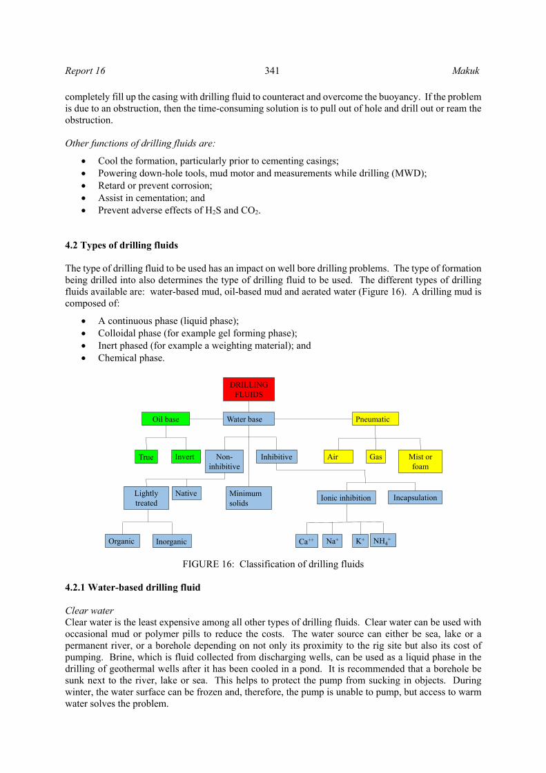
4.2 Types of drilling fluids The type of drilling fluid to be used has an impact on well bore drilling problems. The type of formation being drilled into also determines the type of drilling fluid to be used. The different types of drilling fluids available are: water-based mud, oil-based mud and aerated water (Figure 16). A drilling mud is composed of:
A continuous phase (liquid phase); Colloidal phase (for example gel forming phase); Inert phased (for example a weighting material); and Chemical phase.
FIGURE 16: Classification of drilling fluids 4.2.1 Water-based drilling fluid Clear water Clear water is the least expensive among all other types of drilling fluids. Clear water can be used with occasional mud or polymer pills to reduce the costs. The water source can either be sea, lake or a permanent river, or a borehole depending on not only its proximity to the rig site but also its cost of pumping. Brine, which is fluid collected from discharging wells, can be used as a liquid phase in the drilling of geothermal wells after it has been cooled in a pond. It is recommended that a borehole be sunk next to the river, lake or sea. This helps to protect the pump from sucking in objects. During winter, the water surface can be frozen and, therefore, the pump is unable to pump, but access to warm water solves the problem.
Water base
DRILLING FLUIDS
PneumaticOil base
Mist or foam
GasAirNon-inhibitive
InhibitiveInvertTrue
Minimum solids
NativeLightly treated
InorganicOrganic
IncapsulationIonic inhibition
Na+Ca++ NH4+K+

Makuk 342 Report 16
When mixed with bentonite, water acts as the continuous phase with its main function being to provide the initial viscosity. This viscosity can be modified to suit desired rheological properties. The water liquid phase also helps to suspend the colloidal solids, like bentonite or other inert solids like weighting material (for example, barite). Clear water has a poor lubrication property which can increase the torque. The other weakness of clear water is that there is no control over fluid loss and, consequently, there is no control over the filter cake. Clear water does not have good cuttings suspension capacity. This means that when the mud pumps are shut down, cuttings will fall down into the annulus and settle, causing a problem that it ought to have prevented. Fortunately, water is the least expensive drilling fluid and its poor suspension capacity can be improved by occasional mud sweeps. In spite of these disadvantages, drilling with water using the proper precautions is safe and it is the preferred drilling fluid for the open hole section of geothermal wells. Water-based mud To improve the cuttings suspension property of clear water, naturally occurring clay is added. The most common type of clay used is bentonite which is a member of the montmorillonite group. Bentonite mixed with water, 5-7% by weight, has a viscosity higher than that of clear water. It will also have better cuttings suspension capacity and can form a thin mud filter cake with very low permeability (US Army Corps, 2001). Water-based mud is classified either as non-inhibitive or inhibitive. Non-inhibitive mud, unlike inhibitive mud, has no chemical additives that would otherwise prevent the formation from absorbing water. Inhibited mud This type of mud is either ionically inhibited or encapsulated. Ionically inhibited mud has a chemical composition that is designed to reduce or prevent (inhibit) swelling of the formation. Dispersion can be improved using chemical dispersant additives (that de-flocculate the mud) so as to achieve high density muds with good rheological properties. However, care must be taken because solids-laden mud reduces the drilling rate of penetration and can cause well bore erosion. This erosion can cause well bore stability problems. Encapsulated mud has polymers that coat the cuttings and well bore wall to form a barrier. This barrier slows down water diffusion and, as a result, slows down hydration and disintegration. 4.2.2 Oil-based mud Oil based muds are never used for geothermal drilling. If there is a desire to try them, these are the issues. Oil-based mud has oil as the continuous phase. The oil phase helps in the formation of thin walled mud cake which lowers the chances of getting a differentially stuck pipe. Its enhanced lubrication property reduces the drag and torque of the drill string. Oil-based mud must not be used where temperatures exceed their flash and fire points. Reduced water content in water-based mud ensures that swelling up of the well bore well is greatly reduced. Compared with inhibitive water-based mud, oil-based mud is more inhibitive. An oil continuous phase should be maintained at all times. This is because water wetting of weighting materials like barite can cause it to settle (Mohammed and Mohammed, 2009). The main disadvantage of oil-based mud is that it is not environmentally friendly. 4.2.3 Pneumatic drilling fluids The use of aerated water and foam mixtures are highly recommended when drilling potentially productive formations. This is because, unlike mud, they don’t plug and block the wellbore with filter cakes and cuttings (if an underbalance is properly maintained). This is beneficial in the sense that formation permeability and fissures are left open to allow producing fluid to pass through. For this reason, among others, compressed air has been incorporated as a drilling fluid to reduce geothermal drilling problems.

Report 16 343 Makuk
Aerated drilling fluids are divided into four types, as shown in Figure 17, depending on the percentage of air present in the mixture. Straight air has been used in dry steam dominated reservoirs like the Geysers in the United States. Its use has also been extended to high pressure reservoirs by the addition of denser fluids (Russell, 1987). To achieve this, air is injected into either water or mud at the standpipe with the purpose of reducing the drilling fluid density. This is desired so as to achieve an underbalance or pressure balance with the formation. This helps to reduce differential pressure which, in turn, prevents formation damage. Russell (1987) suggested that the use of aerated water fluid in a water-sensitive formation is possible because the high rates of penetration associated with aerated fluid enables faster drilling and casing before hydration of the formation takes place. Aerated drilling is a preventive measure for differential sticking because it balances the formation pressure. Hole (2008) argues that many geothermal reservoirs are found in areas where geothermal and sedimentary rocks are interlayered. These reservoirs are associated with local as well as regional faults and fractures. This makes these zones permeable and, as a result, lost circulation is a common problem. To counter this problem, aerated fluids are used that ensure drilling fluids as well as cuttings are circulated out of the hole to the surface. This helps in avoiding stuck pipe problems and prevents formation damage. In addition, aerated fluids reduce skin damage caused by cuttings blocking up permeable zones. Aerated fluids, compared with those that are non-aerated, also help in improving reservoir production. In his study on a drilling campaign in Kenya, Hole (2008) found that the productivity of wells drilled using aerated fluids was on average, more than double that of wells drilled without air. 4.3 Lost circulation solutions The problem of lost circulation was discussed in Section 3. When preventive measures are not successful, then curative measures are applied. These measures are divided into three categories and include: (1) bridging agents, (2) surface-mixed systems, and (3) down hole-mixed systems. 4.3.1 Bridging agents Bridging agents, also referred to as lost circulation materials (LCM), are used to stop fluid flow by physically blocking the path through which fluid passes into the formation during the course of drilling, or when it is temporarily suspended. Different types of LCM are available and depend on sizes. These are: (1) Granular, (2) Flakes, (3) Fibrous and (4) Encapsulated. Granular Granular LCMs are chunky in shape and are prepared in different sizes. These types of LCM form a bridge either at the formation face, or inside the formation matrix. As drilling continues, there is axial as well as lateral movement of the drill string which, occasionally or continuously, rubs against the well bore wall. This causes abrasion of granular bridges deposited on the formation wall and finally its
FIGURE 17: Types of air drilling fluids

Makuk 344 Report 16
function is reduced. On the other hand, bridges deposited inside the formation matrix are more permanent since they are not affected by pipe movements. The effectiveness of the bridge formed by granular LCM in curing lost circulation depends on the shape, size and distribution of its particles, as shown in Figure 18a and 18b. The large particles first form a bridge which is followed by smaller sizes that fill the gap between them. This process continues until lost circulation is stopped or greatly reduced when the spaces between the particles become smaller than the sizes of solids in the mud. Using many different sizes of particles
improves the chances of eliminating lost circulation. Examples of granular LCM are mica flakes, nut shells, cotton hulls and wood. Flakes This is a type of lost circulation material whose particles are thin and flat in shape, with a large surface area. They are not soluble in the mud which they are mixed in, and are available in different sizes. Examples of flake LCM are mica and plastic cellophane. Fibrous Where the formation is porous and highly permeable, fibrous LCM (with slender, long and flexible particles) are used to cure fluid losses because of their ability to form mat-like bridges. This helps the mud to form a filter cake since permeability is reduced. Fibrous LCM are also available in different sizes and lengths of fibre. Examples of fibrous LCM are cedar bark, shredded cane stalks, mineral fibre and hair. 4.3.2 Surface-mixed systems These are systems that involve the use of cement slurries to stop lost circulation. Because of its thixotropic nature, cement slurry is pumped as a liquid and as it enters into a lost circulation zone the velocity of the leading edge reduces. This is followed by the forming of a gel that strengthens and starts to offer flow resistance. After pumping has stopped, resistance increases until the gel hardens, thereby preventing fluid loss. LCM, such as mica flakes, can be added to the cement slurry depending on lost circulation severity. 4.3.3 Down hole-mixed systems These are systems in which two or more fluids are mixed in the well bore or in the lost circulation zone, after which it forms a viscous plug or a precipitate that seals the zone. One such method is the Flo-Check method where a solution of sodium silicate reacts with a calcium chloride brine to form a plug of calcium silicate down-hole. The mixing is delayed until the fluids are just in front of the loss zone. This is done by either pumping a spacer or simultaneously pumping one fluid through the string and the other through the annulus. 5. BOTTOM HOLE ASSEMBLY (BHA) DESIGN Drill string contact with the well bore wall is not desired as it causes wear and key seats which can happen during buckling. Lubinski (1950) suggested that to counter this problem, efforts should be made to ensure that the drill string is subjected to tensile loading and the BHA be subjected to compressive loading. This is made possible by ensuring that the buoyed weight of the BHA (drill collars and heavy weight drill pipes) exceeds the maximum weight on the bit. This can be represented mathematically as follows:
FIGURE 18: Effect of particle size distribution on porosity:
a) Two sizes packing, porosity = 14%; b) Similar size packing, porosity = 48%
a) b)

Report 16 345 Makuk
(7)
where = Well bore inclination. The safety factor should be at least 1.1 to allow for any drag due to friction. 6. FISHING – A BALANCE OF DECISIONS After all the preventative and corrective measures have been applied, sticking can still occur. This is the time to unstick the stuck drill string. The most important thing to know is the depth of the free drill string to the stuck point (free point) as shown in Figure 19. This is determined mathematically, according to Hooke’s law, as shown in Equation 8.
(8)
where = Length from the surface to the stuck point (m); = Cross-sectional area of pipe body (m2); = Young’s modulus of steel (200 GPa); = Length of stretch (m); = Force applied when pipe is in tension (N); and = Force applied to stretch pipe by “ ” (N). The parameter , the stretch distance used for calculating the stuck point location, is determined using the following procedure that is normally done on the rig floor:
Ensure that the entire string is in tension, an upward force, greater than the total weight, is applied to the drill string;
A datum line is drawn on the drill pipe, usually at the top of rotary table; and Another upward force, that is greater than is applied which causes the pipe to stretch by
an amount “ ” above the drawn datum in accordance with Hooke’s law.
Having measure , the stuck point location (SPL) can be easily calculated using Equation 8 and its value used as the first point for locating the free point indicator tool which gives a more exact value. Another method that is used to locate a fish is a drill pipe recovery log which uses an acoustical survey. This method is usually employed when the fish is very long. There are situations where unsticking is unsuccessful and time consuming. In such cases, a decision may be made to terminate and abandon the well or plug and side-track. Such a decision requires that the SPL be known. This is because it is the point at which the pipe will be backed-off and, if not possible, cut either mechanically, chemically or by use of explosives. Mechanical cutting of pipes is hydraulically activated to make cutting arms contract and cut the pipe. Electrically driven cutting tools have also been developed. Chemical cutting, on the other hand, uses a strong acid that oxidises and cuts the pipe. When backing-off using the explosive method, the drill string is given a left-hand torque while locating the explosive at a tool joint closest to the SPL. This is followed by detonating the explosive causing the tool joint to unscrew. Backing off operations by explosives is the most common method and usually works on the first try. After establishing the SPL, it is important to evaluate the next course of action, as shown in Figure 20. This decision is guided by economics. It should be noted that each decision made has an associated cost. If the equipment that is stuck has a large cost, then more fishing time should be allowed compared
FIGURE 19: Stuck point location

Makuk 346 Report 16
to a shorter time for low cost equipment. It has been found that the maximum fishing time that should be allocated is given by Equation 9 below (Johnson et al., 2013).
(9)
where = Number of days allocated for fishing; = Value of the fish; = Estimated cost of side tracking the well; = Daily fishing tool rental and personnel charges; and = Daily rig operating charges. The steps one goes through when making a decision to free a stuck pipe are illustrated in Figure 20, adapted from Bowes and Procter (1997). The decision making process is triggered by a stuck pipe. The first line of action is to find out the SPL using the available method. This is followed by working the drill string up and down the hole. However, there is a limit on the amount of force used to pull up the sting. This is important since there is a pulling force beyond which the weakest member of the drill string will fail, leading to a loss. This limiting force is known as maximum overpull and its value is calculated using Equation 10 below:
0.9 (10)
(11)
The allowable tensile loading in practice is 90% (safety factor) of the pipe’s yield strength value which is obtained from API RP7G or drilling data handbooks. If, after working, the pipe is free, normal drilling operations resume and, if not, another decision is made. This could either be continuously working up the drill string or trying alternative methods which could be spotting diesel (‘black magic’) or corn oil. The addition of diesel or oil reduces torque and drag. A decision can also be made at this stage to cut the pipe. The most effective method to cut the drill string is by high-energy explosives lowered on a wireline to the point of detonation. If all decisions made are not successful, then it is high time the well is plugged and side-tracked or terminated. 6.1 Fishing tools A number of fishing tools are available that are intended to engage the fish internally or externally. They come in a number of sizes, shapes and with different material properties. Other fishing tools are meant to trap and collect foreign objects that have either fallen into the well bore or that have broken in the course of fishing, drilling or logging. Fishing tools are mainly available commercially although they may also be fabricated to suit particular needs or in order to reduce time delays associated with procurement procedures. Some of the most commonly used fishing tools are illustrated in Figure 21. Figure 21a shows a junk mill that is used to grind junk into smaller pieces so that it can be lifted by the
FIGURE 20: Freeing stuck pipe flow chart (Bowes and Procter, 1997)

Report 16 347 Makuk
circulating fluid. The material of the grinding surface at the bottom of the mill is made of tungsten carbide. Different designs and sizes of junk mills are available depending on the application. The flat surface mills have concavity that guide and centre the junk below the mill (Johnson et al., 2013). Figure 21b shows an impression block whose purpose is to help in knowing the dimensions of the upper part of the fish in the well bore. This tool also shows the fish’s position with respect to the well bore. Knowing the fish’s dimensions and its position, the fisherman selects the best size of catching accessories and tools. For example, if the fish is leaning on the wall of the well bore, then a wall hook guide will be required to pull the fish and guide it to a catching tool. The material of the bottom of an impression block is made of soft lead. An impression block is connected at the bottom of a fishing string then lowered to contact the fish, thereby creating a dent (or impression) on the soft lead. It is then pulled back to the surface for examination. Figure 21c shows a junk magnet which is used to attract and remove ferrous materials that are too heavy to be lifted by the circulating fluid. At the top of this tool is a box joint that is connected to the drill string while a magnet is attached to its bottom. Figure 21d shows a taper tap. A smaller variation of its design is the pin tap. A taper (or pin) tap is used in catching a fish internally. This is done by connecting it at the end of a fishing string and lowering it to contact the fish. This is followed by applying a small weight (recommended by the manufacturer) and rotating it to wedge the tap threads into the fish. A guide can be attached to the tap if the well bore diameter is considerably larger than that of the fish. This helps in preventing the tap from bypassing the fish. A safety joint is normally used to enable the fishing string to be backed off, just in case the tap and fish become permanently stuck. Figure 21e shows an overshot which is an external tool. This is the most common tool used to fish a broken drill string. It is used in a conjunction basket or spiral grapple that latches onto the fish externally. The overshot is lowered while washing over the top of the fish until there is a slight reduction in weight which shows the overshot has contacted the fish. A guide shoe at the bottom, directs the overshot to engulf the fish. This is followed by rotating the overshot to the right which makes the grapple open to engage the fish. Pulling the fish without rotating it causes the grapple to retract inside the tapered bowl and latch onto the fish. A mill control packer may be used in conjunction with the overshot to grind any flared fish top before it is directed to the grapple. After this, the fish is pulled out of the well bore (Johnson et al., 2013). Figure 21f shows a reverse circulating junk basket which is used after a fishing operation. While fishing, metal fragments either from the overshot guide or from grinding of the flared fish top may fall down the well bore. Also, other ferrous materials may have not been picked up by the junk magnet. As the circulating fluid is pumped, it flushes fragments at the bottom hole and carries them through the reverse circulating junk basket where the fragments are deposited on a catcher as the fluid exits the basket on its way to the surface. The basket is finally pulled out of the well bore and the fragments in the barrel are disposed of.
FIGURE 21: Commonly used fishing tools, a) Junk mill (Schlumberger, 2012);
b) Impression block; c) Junk magnet (Schlumberger, 2012);
d) Taper tap (Nov, 2013); e) Overshot (Matanovick, 2011); f) Reverse circulating junk basket
(Pioneer Oil Tools Ltd, 2013)
b)
e)
f)
a)
c) d)

Makuk 348 Report 16
7. THE CASE OF MENENGAI Several wells have been drilled in Menengai geothermal field where serious sticking related problems have been encountered. Table 3 shows a series of activities that occurred before and during sticking in different wells. The activities were looked into with a view to correlating them with subsequent drill string sticking. The knowledge of possible causes of sticking helps in strategizing the most appropriate
TABLE 3: Activities related to sticking of different wells in Menengai
Well Activity
MW01 114.37 to 124.5 m drilled using water with partial returns. String stuck at 124.5 m. Freed after 3 hrs. Drilled from 137.8 to 400.5 m using water, no returns. Got stuck while pulling out of hole (POOH) when sounding hole. Got free. Got stuck at 378 m while running in hole (RIH) 13 3/8 casing (csg), but successfully landed. Drilled from 2184 to 2206 m. Pressures then went up and got stuck. Pipe freed after 8 hrs. Some pipes bent and twisted.
MW02 Wait on water for 4 days. Reaming 88 to 132 m without returns. Major obstruction at 116 and 131 m. Got stuck at 133 m but freed. Experienced total loss at 206.5 m then followed by stuck drill string which was freed. No returns from 206.5 to 213 m then got stuck again but pipe freed. Reamed from 168 to 218 m then got stuck during connection. Stuck for 3 days.
MW03 Drilled from 95.18 to 113 m using water with returns. Got stuck for 45 min. Drilled from130 to 167.2 m with no returns. Got stuck for 30 min. Reamed from 2064 m to 2093.54 m while experiencing high torque. Then POOH and got stuck for 9 days.
MW04 There were no lost circulation problems. However drill string, without warning, got stuck at 2117 m. Then freed after 9 days.
MW06 2036-2039, 2097, 2124 to 2137, 2143-2151, 2164.5, 2132, 2143-2151, 2164 and 2186 m no returns received on surface. Drilling ahead using aerated water and foam at 2202.96 m while receiving returns on surface, then got stuck.
MW07 Drilled from 112.6 to 120.11 m using brine with returns. On lifting bit off bottom, got stuck at 105 m but pipe was freed. Drilled from 120.11 to 149.25 m with intermittent partial/full returns. Drilled from 134 to 138 m and experienced drilling break with cuttings fully flowing out. Circulated hole at 149 m. While lifting string off the bottom, got stuck with high torque and SPP. Worked string up and down, then introduced air. A tension of 160kN applied. Thereafter, no rotation and circulation. Then no SPP. All fluids pumped got lost into the formation. Pumped LCM repeatedly and introduced air. SPP rose to 800 psi and pipe got free. Drilled from 149.25 to 150.56 m using brine with no returns. Suddenly torque and SPP increased followed by stuck pipe which was freed. POOH from 1205 to 1184 m while back reaming. Pump went off while trying to connect back a stand that had been removed. Saver sub got damaged then installed circulating head. On connecting back saver sub, realised string got stuck but with returns. After 3 days it was freed. Drilled from1996.98 to 2135.93 m using aerated brine and foam with no returns. This was followed by stuck pipe at 2135.93 m which was then freed.
MW08 Drilled from 150 to 178.7 m using water and mud sweeps then 6⅝ × 4½ cross-over sheared at the box end. Drilled from 179 to 210 m using water and mud sweeps then POOH to inspect bit. It was found out that an 8” drill collar sheared at the box end of its tool joint. Wait on water for 17 days due to failed transformer at the pump station. Then drilled out cement from 378.9 to 407.1 m. Continued to drill ahead to 458.77 m. On POOH, it was realised part of the BHA was left down hole which was successfully fished out on the 7th
day. Drilled ahead from 2162 to 2355.56 m using aerated brine and foam with returns. POOH to RIH liners. It was realised part of the BHA was left down hole.

Report 16 349 Makuk
TABLE 3 cont.: Activities related to sticking of different wells in Menengai
Well Activity
MW09 Drilled from 701 to 706 m and encountered soft formation. Returns ok. Drilled ahead from 706 to 812.8 6 m using mud with returns. Drastic decrease in SPP and hook load noted with increase in WOB. Then POOH from 812.86 m to inspect drill string. It was noted the DP that joins HWDP had sheared 1.05 m from the box end of the tool joint. The fish wassuccessfully retrieved on the 4th day. Most of the collars showed defects on the box end. Drilling ahead from 1741.81 to 1950 m with partial returns (partial), then got stuck but freed after 1 hr.
MW10 Drilled from 113.26 to 310 m with water and occasional mud sweeps with no returns. Then sudden hook load drop POOH to inspect drill string. It was noted that a 6⅝ × 4½ cross over sub had parted leaving fish down hole which was freed after 4 days. Drilled from 392 to 740.77 m using water and occasional mud sweeps and periodic wait on water for 8 hrs. This took place over a period of 10 days. Then hook load dropped followed by POOH to inspect drill string. It was noted a 6⅝ × 4½ cross over sub between HWDP and 8” DC had parted.
MW11 At 574.78 m, pulled drill string to the shoe for repairs. Tried to circulate through the bit but unsuccessful. Then POOH and found the bit clogged to the bit sub. 1842.37 m. Wait on water for 3 days. Got stuck while reaming at 1842.37 m then did fishing for 26 days.
MW12 Drilled from 49 m using water without returns. Then waited 3 hrs for repairs. Resumed drilling to 57.14 m when there was a power failure followed by stuck pipe after which it was freed. Drilled from 1912 to 2054 m using aerated water and foam with returns. Then got stuck suddenly due to an increase in WOB and torque. The string was freed on the 5th day.
measures to avoid them. In doing so, time spent in unsticking or fishing will be minimized. This will further avoid BHA (or parts of drill pipe) losses in the hole. As a result, drilling costs will be reduced and drilling performance increased. Table 4 shows the break-down of drilling wells in Menengai. Table 5 shows the average rate of penetration used to drill a section of a well which is also shown graphically in Figure 22. Table 5 shows the average rate of penetration in meters per day to drill each section. Table 6 shows the depths where sticking occurred in different wells and Figure 23 shows the average sticking time per section. Well MW10 was only drilled to a depth of 740.77 m and then abandoned due to drilling problems. Figure 24 shows the actual drilling progress for 11 wells in Menengai.
TABLE: 4: Time break-down of drilling wells in Menengai (days)
Section Well
MW01 MW02 MW03 MW04 MW06 MW07 MW08 MW09 MW10 MW11 MW12 AverageSurface 10 14 16 12 24 12 12 16 12 15 14 14 Intermed. 17 41 16 18 19 33 37 25 21 26 33 26 Production 22 12 12 18 14 37 28 24 100 41 19 30 Main hole 27 54 56 33 38 50 46 39 48 27 42 Total 76 121 100 81 95 132 123 104 133 130 93
TABLE: 5: Average rate of penetration per section (m/day)
Section Well
MW01 MW02 MW03 MW04 MW06 MW07 MW08 MW09 MW10 MW11 MW12 AverageSurface 8 6 5 7 3 5 5 4 5 5 4 5 Intermed. 19 8 20 18 17 9 8 12 13 8 9 13 Production 20 34 58 39 49 23 20 21 4 15 26 28 Main 50 44 18 31 29 19 31 31 20 44 27

Makuk 350 Report 16
TABLE: 6: Sticking depth (m) per section
MW01 MW02 MW03 MW04 MW06 MW07 MW08 MW09 MW10 MW11 MW12Surface hole
59 58 57 Intermediate hole
114 109 113 105 310 176 367 125 133 167 149 378 135 151
207 213 218
Production hole 1184 458 813 741
Main hole 2206 1187 2117 2203 1957 1950 1842 2054
2112 2136
FIGURE 22: Average rate of penetration in different hole sections (m/day)
FIGURE 23: Average sticking time for each section of the well (days)
FIGURE 24: Drilling progress curves showing the most troublesome zone in Menengai at ~2100 m
The most troublesome zone
2100

Report 16 351 Makuk
8. DISCUSSION 8.1 Changes in drilling parameters Zooming in to the Easy View program graph display, whose screenshot is shown in Figure 25, shows that drill string sticking in Well MW06 took place at around 02:40 hrs on the 13th of January, 2012. The drilling parameters, shortly before and after sticking occurred in this well, are shown in Table 7. The possible causes of changes in drilling parameters shortly before sticking occurred include, but are not limited to the following reasons: Hook load The hook load was reduced suddenly from 888.1 to 748.3 kN at the time the drill string got stuck. This shows that there is a sudden force acting upwards on the string which is opposite to the direction of the hook load. This upward acting force could probably be due to magma being thrust up into the well before being rapidly quenched. Hook load drop due to a sheared pipe is usually accompanied by a standpipe pressure drop. In this case, there was a hook load drop accompanied by a standpipe pressure increase, meaning the pipe did not shear. However, after 11 days of fishing, the fish was retrieved and part of the drill string was found to have sheared due to the fishing effort. The pipe sheared above the free point and the upper part of the drill string was recovered. After sticking occurred, hook load increased (Figure 25) upon hoisting, which is an indication of the sticking. A drastic drop in hook load due to shear was also confirmed in Well MW09, as described in Table 3.
FIGURE 25: Easy View programme screenshot showing drilling parameters shortly before and after sticking took place in Well MW06
TABLE 7: Drilling parameters shortly before and after
sticking of Well MW06
Parameter Shortly before
sticking Just before
sticking Drilled depth (m) 2202.91 2202.91 Rotary Torque (kNm) 14.7 0.3 Pipe pressure (MPa) 6.18 7.06 Hook load (kN) 888.1 748.3 Rotation (RPM) 61.36 6.51 Weight on bit (kN) 54.6 186.2

Makuk 352 Report 16
Rotary torque The rotary torque decreased from 14.7 to 0.3 kNm, as shown in Table 7. This happened as the drill string rotation stopped due to the sticking. The rotary torque then went up when rotation was attempted and there was no circulation of drilling fluid as the jets got plugged. Standpipe pressure In Table 7, it can be seen that the standpipe pressure increased from 6.18 to 7.06 MPa. The pressure increase was a result of the drill bit being blocked. The mud pump was cut off shortly after. Weight on bit The weight on bit increased from 54.6 to 186.2 kN as shown in Table 7. Weight on bit is given by drill string weight minus hook load. Due to conservation of mass, the drill string weight is constant. Hook load keeps changing depending on the weight on bit and upthrust due to buoyancy or, in this special case, magma being thrust up the well. This means that if the hook load decreases, then the weight on bit increases, as shown in Figure 25. 8.2 Fatigue Depending on the well bore curvature, part of the drill string can be subjected to a bending moment. As the drill string is being rotated, it wobbles as it revolves around inside the well bore. This causes changes in forces acting on a particular point in the drill string from compressive to tensile. This is repeated many times until the drill string is lowered, or the well bore geometry changes. This cyclic loading compromises the mechanical strength of the drill string. Fatigue failure is, in the initial stages, initiated by the formation of crystallographic defects. If these defects grow and increase their density, then it will reach a critical stage where slip movement of the defective planes takes place, resulting in the formation of microscopic cracks. As the number of cracks increase, the fatigue life of the drill string point reduces. If crack propagation is accelerated, for example due to vibrations, the drill string component will experience fatigue failure. On pulling out of hole the last joint of heavy weight drill pipe in Well MW09, it was found that the 6⅝×4½ cross-over sub had parted, with 120 mm of the box side coming out of the hole and the rest remaining inside the hole. Note that the box length of a shouldered connection is 130 mm (Gabolde and Nguyen, 2006). This shows that the crossover sub most probably parted at the last thread, which happens to be the point with the lowest fatigue life, as observed in finite element analysis (FEA) and discussed by Ellis et al. (2008). There were three similar occasions in which 6⅝×4½ cross-overs failed. Apart from the cross-overs, there were instances in which the drill collars sheared, for example in Well MW08 as described in Table 3. In order to minimize fatigue failure, the following measures should be applied:
Avoid prolonged fishing operations by repeated overpull and rotation of a stuck drill string; Minimize curvature and buckling; Apply proper thread compound to protect critical areas; Optimize well trajectory; and Regular non-destructive testing (NDT) of drill string and its risk management that ensures close
monitoring of running hours and any defect(s). Especially important is frequent ultrasonic inspection of the box and pin on the drill collars and subs.
8.3 Rotary slip setting position After a drop in standpipe pressure and hook load occurred in Well MW09, indicating a brake, the drill string was pulled out of hole to inspect it. It was observed that a drill pipe joining the heavy weight drill pipe had sheared 1.05 m from the tool joint as described in Table 3. This happens to be the rotary slip setting position on the drill pipe. Rotary slips are used to hold the drill pipe when making or breaking a

Report 16 353 Makuk
connection. Continuous gripping of the drill pipe at the same position by slip could have initiated a point of weakness through ‘small creep loading’. This could have been made worse by poor handling, for example, setting the slip before the pipe was stopped which results in pipe deformation. Pulling out of well with drag could have caused a sufficient force to propagate a fracture and the final shear of the drill pipe at the slip setting position. To avoid this scenario, the drill pipe slip setting position should be changed on a rotational basis. This could be done by removing one joint, then pulling out of hole the rest of the joints in stands. 8.4 The top section Low average rates of penetration were experienced in the surface top section of wells in Menengai, as shown in Figure 22. This is attributed to the hard and fractured rock in this section. The severe vibrations encountered led to waiting for repairs which further reduced the drilling rate. Top drive rigs have been mostly affected in the surface casing section of the well because of mechanical breakdowns and failures due to vibrations. Top drive guide rails have to be realigned to ensure the well bore is maintained vertically. To minimize the wait on repairs and increase the average rates of penetration, the top surface has been drilled using the Kelly system rather than the top drive. The use of air hammers (DTH) should also be investigated for this section as they would work well in very hard and fractured formations near the surface. The rigs have air compressors and pumps for the drilling soap, so only the 26" bit and DTH hammer are required. 8.5 The 2100 m depth The 2100 m depth in Menengai is the most troublesome zone, as shown by the concentration of flat spots in Figure 24. This is not surprising as the wells intersected magma. Well MW16 (not shown in Figure 24) also got stuck at a depth of 2084 m after which the fish was retrieved. On average, sticking time takes 12% of the total drilling time in Menengai. The troublesome zone is the main contributor to the high sticking time of the main hole, as shown in Figure 23. Interestingly, there was also a 2100 m troublesome zone during the drilling of an Icelandic Deep Drilling Project (IDDP I) well at Krafla in Iceland, as shown in Figure 26. The problem at this depth was
FIGURE 26: Drilling progress showing a troublesome 2104 m depth for IDDP I at a well in Krafla, Iceland (Hólmgeirsson et al., 2010)
Makuk 354 Report 16
attributed to intersecting magma which the drill bit drilled into at 2104 m depth. That was followed by the observation of quenched glass cuttings at the shale shakers, whose temperature was estimated to have been at 1050°C before cooling (Hólmgeirsson et al., 2010). However, previous interpretation of magnetotelluric data suggested that a magma chamber was located deeper than 4.5 km. The magma intrusion that was drilled into at IDDP 1 showed that the geophysical methods used did not have sufficient resolution to identify it (Elders and Fridleifsson, 2009). While drilling Wells MW04 and MW06 in Menengai, fresh glass was found in the cuttings at depths of 2082 and 2174 m, respectively, indicating a possible intersection of magma intrusions. Since glass is susceptible to alteration and especially at such depths and in a high temperature geothermal system, it ought to have been completely altered. The fresh glass, therefore, is believed to have been rapidly chilled magma by the drilling fluid. Extremely high temperatures, as well as sticking problems, were recorded at these depths for these wells (Mibei, 2012). To avoid problems associated with intersecting magma intrusions, the drill string should immediately be pulled out of hole whenever glass cuttings are seen at the shakers and further drilling stopped, but the experience is that there is no advance warning. 8.6 Reddish soils Over a long period of time, soil forms on the ground. When a volcanic eruption occurs, the lava flows over the soil and bakes it, thereby changing its colour to an anomalous red colour. After another long period of time, soil forms again on top of the lava and the cycle continues as long as the eruptions do. This forms a sequence of layers of reddish soil and lava. While drilling Well MW06, reddish sample cuttings were collected between 1614 and 1638 m, depicting the presence of reddish soils in Menengai. These soils, when they come into contact with drilling fluid, disintegrate rapidly and lead to the formation of huge cavities in the well bore (Mibei, 2012). These cavities enhance the formation collapse as well as compromise efficient circulation and the transport of cuttings. This results in the accumulation of cuttings which increases torque and subsequent sticking problems. This is believed to have happened in Well MW01 when reddish brownish returns were seen shortly before sticking. To avoid this, whenever reddish returns are seen at the shakers, the drill string should immediately be pulled out by one stand and run in hole slowly while rotating and cleaning the hole with a mud or high-viscosity pill and checking for torque increase. Should torque increase, the drill string should be pulled out again the same way until the well bore is safe. 8.7 Fishing operation in Menengai Fishing operations have been successfully carried out in Menengai, but there are also cases of losing a part of the drill string. Several fishing tools have been used including an overshot dressed with a spiral or basket grapple, complete with a mill control packer. Other tools include a junk mill, a junk magnet, a junk basket and an impression block. More fishing equipment is needed. This includes a sufficient assortment of spiral and basket grapples as well as taper taps. Problems were experienced while trying to back off a stuck drill string in Well MW10. The problems were both technical and time delays. Waiting on fishing tools was a contributing factor to time delays. This was because tools needed for backing off and cutting the drill string were not available on site. Acquisition of these tools was time consuming due to procurement procedures. It is recommended that backing off tools, including explosives, be availed in abundance. Legal, security and safety problems associated with the storage of explosives at the rig site can be solved by acquiring and storing them in a police station or military barracks closest to Menengai. This idea is borrowed from fishing operations at rigs in Iceland where backing off explosives are under the custody of the Coast Guard that avail them whenever needed. This will reduce the time of backing off a stuck drill string and contribute to better performance. In addition to fishing equipment, directional drilling equipment should also be available in abundance to allow for quick side tracking. Subcontracting of fishing and directional services will help in quick solutions to these problems. This is because, the more time a drill string is stuck, the less chance of unsticking it.

Report 16 355 Makuk
9. CONCLUSIONS This report identified that 12% of drilling time was spent on drill string sticking activities in Menengai. This increases drilling costs and reduces drilling operations performance because of the extended drilling time spent in fishing activities. The sticking occurrences were caused by formation challenges that included lost circulation and collapses. Most unexpected and extreme was intersecting magma at 2100 m which resulted in the drill string getting stuck and blocking the circulation, without any advanced warning. Well bore geometry related to sticking, like key holes, was also encountered in Menengai. In addition, differentially stuck pipe was experienced. To reduce time spent on fishing activities and subsequently improving drilling performance, a number of suggestions have been given. Sufficient well bore cleaning is the best way to avoid sticking. This is achieved through the use of proper drilling fluids. Different types of drilling fluids were discussed. Mud is used when drilling a large diameter hole to achieve good cleaning and the mud cake is beneficial in the cased sections of the well as it stops small losses. The effectiveness of this can be improved through the addition of lost circulation materials. When this is still not sufficient, then cement plugs can be placed to heal the loss. The emphasis on avoiding lost circulation is to have drilling fluid all the time that ensures the hole is cleaned properly to avoid the accumulation of cuttings that cause sticking. It should be noted that mud should not be used in the production zone since this will adversely affect the permeability. In the open hole section of the well, it is important to have large losses as it indicates good future production. Cuttings find their way into formation fractures when returns are not received on the surface and, to counteract that, air is added to the drilling fluid for pressure balance. Very high rates of penetration should be avoided to give cuttings time to be carried up to the surface and to avoid sticking. Menengai geothermal field has a troublesome zone at 2100 m depth in Wells MW03, MW04, MW07 and MW12 that is traced to probable intersecting magma, just as in the IDDP well at Krafla. The sequence of getting stuck, the fresh glass cuttings and superheated steam above the critical temperature once the well had heated up, are all indications. Reddish soils were also found to contribute to sticking, due to their formation collapsing tendencies. Suggestions have been made to immediately pull out of hole whenever reddish brownish returns are received and run in hole slowly while ensuring good circulation. It is also recommended that the drill string be pulled out of hole immediately if glass cuttings are seen on the shale shakers and to terminate drilling operations, as the cuttings may indicate proximity to magma. To save time and cost, a formula for calculating the maximum allowable time spent on fishing based on economics has been highlighted in this report as a basis for making a decision as to whether to continue with fishing operations or not.
ACKNOWLEDGEMENTS I wish to sincerely thank Mr. Lúdvík S. Georgsson, the director of the United Nations University Geothermal Training Programme and Dr. Ingvar Birgir Fridleifsson, the former director, as well as the management of the geothermal development company (GDC) for giving me an opportunity to come and study here in Iceland. I thank the United Nations University and the government of Iceland for providing funds for my study. I am grateful to Mr. Ingimar G. Haraldsson, Ms. Thórhildur Ísberg, Ms. Málfrídur Ómarsdóttir and Mr. Markús A. G. Wilde who made my stay in the office and home here in Iceland very comfortable and conducive for learning. I am greatly indebted to my supervisor, Mr. Sverrir Thórhallsson, who was always eager to give me knowledge of drilling technology in class, and his huge support and guidance in my project. I thank all the UNU lecturers who taught me and the UNU Fellows for their good company and support. I thank my wife Mercy and son Maurice for their moral support and for accepting my being away from them for six months. I thank the Almighty God for loving and caring for me.

Makuk 356 Report 16
REFFERENCES Abbas, R., Jarouj, H., Dole, S., Junaidi, E.H., El-Hassan, H., Francis, L., Hornsby, L., McCraith, S., Shuttleworth, N., van der Plas, K., Messier, E., Munk, T., Nødland, N., Svendsen, R.K., Therond, E., and Taoutaou, S., 2003: A safety net for controlling lost circulation. Oilfield Review, 15-4, 20-27. Agarwal, N., 2008: Drill collars with auto-release sleeves. Paper presented at IADC/SPE Asia Pacific Drilling Technology Conference and Exhibition, Jakarta, Indonesia, 7 pp. Barriol, Y., Glaser, S.K., Pop, J., Bartman, B., Corbiell, R., Eriksen, O.K., Laastad, H., Laidlaw, J., Manin, Y., Morrison, K., Sayers, M.C., Romero, T.M., and Volokitin, Y., 2005: The pressures of drilling and production. Oilfield Review, 17-5, 22-41. Bowes, C., and Procter, R., 1997: 1977 drillers stuck pipe handbook. Procter & Collins Ltd., Ballater, Scotland, 71 pp. Cook, J., Growcock, F., Quan, G., Hodder, M., and Van Oort, E., 2012: Stabilizing the wellbore to prevent lost circulation. Oilfield Review 23-4, 26-35. Devereux, S., 1998: Practical well planning and drilling. Pennwell, Oklahoma, OK, United States, 524 pp. Elders, W., and Fridleifsson, G.Ó., 2009: Iceland deep drilling project finds magma. GRC Bulletin, July/August 2009, 31-32. Ellis, S., Wadswort, T., Lee, K., Gerdes, M., Altizer, S., 2008: Connection fatigue index (CFI): An engineered solution for connection selection and a replacement for BSR. Paper presented at the 2008 IADC/SPE Drilling Conference, Orlando, FL, United States, 8 pp. Finger, J., and Blankenship, D., 2010: Handbook of best practices for geothermal. Sandia National Laboratories, report SAND2010-6048, 84 pp. Gabolde, G., and Nguyen, J.P., 2006: Drilling data handbook (8th edition). Institut Francais P´etrole Publications Paris, France, 576 pp. Gow, A., 2005: Roughnecks, rock bits and rigs: the evolution of oil well drilling technology in Alberta, 1880-1970. University of Calgary press, Alberta, Canada, 674 pp. Grace, D., Shursen, J., and Carden, R., 2008: Drilling practices. Petroskills, Oklahoma, OK, USA, 774 pp. He, J., 1999: Multiple tectono-thermal modelling of Liaohe basin in the Cenozoic. Chinese J. Geophysics, 42-1, 62-68. Hole, H. 2008: Drilling fluids for drilling of geothermal wells. Paper presented at “Petroleum Engineering Summer School”, Workshop 26, Dubrovnik, Croatia, 8 pp. Hólmgeirsson, S., Gudmundsson, Á., Pálsson, B., Bóasson, H., Ingason, K., and Thórhallsson S., 2010: Drilling operations of the first Iceland deep drilling well (IDDP). Proceedings of the World Geothermal Congress 2010, Bali, Indonesia, 10 pp. Hsu, K., and Belaud, D., 1998: Integration application of real-time LWD sonic for overpressure detection and seismic. Overpressure Proceedings Workshop 1998, Pau, France, 221-226.

Report 16 357 Makuk
Johnson, E., Lee, M., and Robertson, R., 2013: Landing the big one – The art of fishing. Oilfield Review, 24-4, 26-35. Lubinski, A., 1950: A study of the buckling of rotary drilling strings. Drilling and Production Practice, American Petroleum Institute, 37 pp. Luo, X., 2004: Quantitative analysis on overpressuring mechanism resulted from tectonic stress. Chinese J. Geophysics, 47-6, 1223-1224 (in Chinese). Manohar, L., 1999: Shale stability: Drilling fluid interaction and shale strength. Proceedings of SPE Asia Pacific Oil and Gas Conference and Exhibition 1999, Jakarta, Indonesia, 10 pp. Mibei, G., 2010: Geology and hydrothermal alteration of Menengai geothermal field. Case study: wells MW-04 and MW-05. Report 21 in: Geothermal training in Iceland 2012. UNU-GTP, Iceland, 437-465. Mody, F.K., and Hale, A.H., 1993: A borehole stability model to couple the mechanics and chemistry of drilling fluid/shale interaction. J. Petr. Technol., 1093-1101. Mohammed, A., Abolle-Okoyeagu, I., and Okeke, C., 2012: A comparative analysis of the trouble time for conventional and casing drilling wells: A case study on the Lobo Trend. Internat. J. Science & Technology, 1-11, 584-588. Mohammed, M., and Mohammed, S., 2009: Effect of additives on rheological properties of invert emulsions. Iraqi J. Chemical & Petroleum Engineering, 10-3, 31-39. Murphey, C., 1966: Hole deviation and drill string behaviour. SPE Journal, 6-1, 44-54. Murrilo, A., Neuman, J., and Samuel, R., 2009: Pipe sticking and avoidance using adaptive fuzzy logic and neural network modelling. Proceedings of SPE Production and Operation Symposium, 2009, Oklahoma, OK, United States, 244-258. Osborne, J., Swarbrick, E., 1997: Mechanisms for generating overpressure in sedimentary basins: A re-evaluation. AAPG Bull, 81-6, 1023-1041. Pašić, B., Gaurina-Međimurec, N., and Matanović, D., 2007: Wellbore instability: Causes and consequences. Rudarsko-Geološko-Naftni Zbornik, 19, 87-98. Raja, H., Sørmo, F., and Morten, L., 2011: Case-based reasoning: Predicting real-time drilling problems and improving drilling performance. Proceedings of SPE Middle East Oil and Gas Show and Conference, Manama, Bahrain, 12 pp. Russell, M., 1987: The use of aerated fluids in geothermal drilling. Proceedings of 9th Geothermal Workshop, Auckland, NZ, 153-157. Schlumberger, 1997: Stuck-pipe prevention. Self learning course. Schlumberger Anadrill, 65 pp. Schlumberger, 2013: Keyseat. Schlumberger Ltd., website: http://www.glossary.oilfield.slb.com/en/ Terms.aspx?LookIn=term%20name&filter=keyseat Shaker, S., 2008: Loss of circulation: Causes and consequences in geopressured systems. Paper presented at AADE Fluids Conference and Exhibition, 2008, Houston, TX, United States 5 pp.

Makuk 358 Report 16
Skúlason, G.K., Johnsson., M.T., Pálsson, H., Karlsdóttir S.N., and Thorbjörnsson, I.O., 2011: Load history and buckling of the production casing in a high temperature geothermal well. Proceedings of the 36th Workshop on Geothermal Reservoir Engineering, Stanford University, Stanford, CA, United States, 9 pp. U.S. Army Corps of Engineers, 2001: Geotechnical investigations. U.S. Army Corps of Engineers, Engineering and Design, website: publications.usace.army.mil/publications/eng-manuals/EM_1110-1-1804_sec/EM_1110-1-1804.pdf Van Oort, E., 1997: Physico-chemical stabilisation of shales. Proceedings of SPE International Symposium on Oilfield Chemistry 1997, Houston, TX, United States, 523–538. Van Oort, E., 2003: On the physical and chemical stability of shales. J. Petroleum Sci. & Engineering, 38, 213-235. Van Oort, E., Hale, A.H., and Mody, F.K., 1994: Critical parameters in modelling the chemical aspects of borehole stability in shales and in designing improved water-based shale drilling fluids. Proceedings of SPE Annual Technical Conference and Exhibition 1994, New Orleans, LA, United States, 25-28. Van Oort, E., Hale, A.H., and Mody, F.K., 1995: Manipulation of coupled osmotic flows for stabilisation of shales exposed to water-based drilling fluids. Proceedings of SPE Annual Technical Conference and Exhibition 1995, Dallas, TX, United States, 497-509. Van Oort, E., Ripley, D., Ward, I., Chapman, J.W., Williamson, R., and Aston, M., 1996: Silicate-based drilling fluids: Competent, cost-effective and benign solutions to wellbore stability problems. Proceedings of IADC/SPE Drilling Conference, 1996, New Orleans, LA, United States, 189-204. Warren, E., 1940: Causes, preventions, and recovery of stuck drill pipe. Paper presented at the Drilling and Production Practice Conference, New York, NY, United States, 10 pp.