
Geothermal Power Generation Project: Environmental Monitoring ...
Upload
khangminh22Category
view
0download
0
Titolo presentazione
sottotitolo
Milano, XX mese 20XX
Geothermal Electric Power PlantsPaola Bombarda
International School on Geothermal Development
Trieste, December 7-12, 2015

Paola Bombarda - International School on Geothermal Development, Trieste 2015
Presentation overview
Presentations outlining basic aspects of geothermal power
generation, sketching similarities and differences with conventional
power generation technology
Outline:
- plant schemes
- main design aspects
- main operating parameters

Paola Bombarda - International School on Geothermal Development, Trieste 2015
Choice of the power generation technology

Paola Bombarda - International School on Geothermal Development, Trieste 2015
Geothermal power plants
• Wellhead installations and gathering system
• Geothermal fluid treatment
• Power station (and emissions treatment)
• Heat rejection system

Paola Bombarda - International School on Geothermal Development, Trieste 2015
Geothermal steam power plants: the turbogenerator

Paola Bombarda - International School on Geothermal Development, Trieste 2015
Nesjavellir Power Plant
Separation
station
Steam vent
station
Steam
pipelines
Two phase
flow
Power
Plant
Well
Cooling towers
Source: E. Hallgrímsdóttir Postdam, 2013GEOELEC Training Course on Geothermal Electricity

Paola Bombarda - International School on Geothermal Development, Trieste 2015
Two phase flow
Steam separators
Geothermal
water
Steam
Re-injection wells
Pressure
reliefProduction wells
Turbines
Generators
Mist separators
Cooling
towers
Condensers
Steam Supply - Preliminary P&ID
emergency exhaust
Source: E. Hallgrímsdóttir Postdam, 2013GEOELEC Training Course on Geothermal Electricity

Come funziona un pozzo geotermico
curva caratteristica
Source:Sinistra:Pritchett , electrical generating capacity of geothermal slim holes, DOE/ID/13455Destra: GEOELEC course, Mechanical equipment and operation and maintenance,session VI, Potsdam, 2013
© 2000 Geothermal Education Office

Paola Bombarda - International School on Geothermal Development, Trieste 2015
Geothermal fluid
Geofluid contains dissolved salts and gases
Chemical composition is site dependent
LIQUID phase GASEOUS phase
H2O H2O
Na+, Ca++, Cl-, HCO3-, SO4— CO2
Fe, Mn, Pb, Zn, Hg, Cu, A s H2S
SiO2, CH4, N2, HN3, He, H2
Others Others
=> Geothermal fluid: usually chemically aggressive and corrosive

Paola Bombarda - International School on Geothermal Development, Trieste 2015
Typical productivity curves
Source: F. Sabatelli, Pisa, 2013GEOELEC Training Course on Geothermal Electricity
Total mass flow=Liquid + steam flow

Paola Bombarda - International School on Geothermal Development, Trieste 2015
Pipeline design
Constant load
– Weight
– Pressure
Variable load (depending on location)
– Wind
– Snow
– Earthquake
– Ash
Other loads
– Thermal expansion
– Dynamic loads (esp.two‐phase flow)
– Friction on supports300
400
500
600
700
800
900
1000
0 20 40 60 80 100 120 140 160
Pip
e d
iam
ete
r [m
m]
Flow [kg/s]
7 bar-a
20 bar-a

Paola Bombarda - International School on Geothermal Development, Trieste 2015
Pipeline design
Pipeline optimization
• CapEx increases with diameter (approx. linear)
and thermal insulation thickness
• Thermal loss increases with external diameter
and decreases with insulation thickness
• Pressure drop (power loss) decreases with
diameter (5th power: Δp = 4fLρu2/d)
• Optimum at the lowest total lifecycle cost
(strongly dependent on electricity FIT)

Paola Bombarda - International School on Geothermal Development, Trieste 2015
Steam Supply - Layout
• Central separation station
• Satellite separation stations
• Individual separators
Central Satellite Individual
Source: Di Pippo
Separation at wellhead– Separate steam and(saturated) water flows
• Separation at satellite stations– Two‐phase flow + separate flows
• Separation at the power plant– Two‐phase flow

Paola Bombarda - International School on Geothermal Development, Trieste 2015
Steam gathering system – route selection
• Public safety
• Environmental impact
• Restriction on land
• Cost efficiency
The Hellisheiði Power PlantAdapted from : E. Hallgrímsdóttir Postdam, 2013GEOELEC Training Course on Geothermal Electricity

Paola Bombarda - International School on Geothermal Development, Trieste 2015
Steam pipelines

Paola Bombarda - International School on Geothermal Development, Trieste 2015
Steam Supply - Separators
• Cyclone separators
• Gravity separators
• Efficiency
• Steam separator and moisture separator should together achieve 99,99 % bw. liquid removal or better

Paola Bombarda - International School on Geothermal Development, Trieste 2015
Separation station

Paola Bombarda - International School on Geothermal Development, Trieste 2015
Atmospheric discharge steam power Plant
Steamseparator
Turbine Generator
G
Production wells Reinjection wells
Phigh
Plow
2 phase flow Vapor
Liquid
Turbine inlet pressure=separator pressureTurbine outlet pressure=atmospheric pressure
Feasible only for special applications

Paola Bombarda - International School on Geothermal Development, Trieste 2015
Fonte:UGI, La Geotermia ieri, oggi, domani
Condensing dry steam power plant
(with direct contact condenser)
Turbine inlet pressure=wellhead pressureTurbine outlet pressure=sub-atmospheric pressure

Paola Bombarda - International School on Geothermal Development, Trieste 2015
Steam Power Plant with Condenser
(with surface condenser)
G
Production wells
Geothermalfluid
Steamseparator
Turbine
Condenser
SteamGenerator
Silencer
Mist eliminator
Water
Condensate
Condensate
Cooling tower
Reinjection wells
Vacuum pump
Turbine inlet pressure=separator pressureTurbine outlet pressure=Sub-atmospheric pressure
Widespread application

Paola Bombarda - International School on Geothermal Development, Trieste 2015
Condensing steam plants
Advantages
• Higher work extraction
• Power size about 20-120 MW
• Partial or full reinjection feasible, depending on the condensation system
Disadvantages
• Condensing system required
• Noncondensable Gas (NCG) removal system required

Paola Bombarda - International School on Geothermal Development, Trieste 2015
Single flash Steam power plants
• Steam is fed to the turbine
from a surface separator
• The power plant scheme is
roughly the same
This is by far the most common
technology, developed in New
Zealand in the 1950s Source: Di Pippo, Geothermal power plants
Hot water “flashes” as a consequence of an imposed pressure drop

Paola Bombarda - International School on Geothermal Development, Trieste 2015
Single flash Steam power plants
G
Production wells
Geothermalfluid
FlashChamber
Turbine
Condenser
SteamGenerator
Silencer
Mist eliminator
Water
Condensate
Condensate
Cooling tower
Reinjection wells
Vacuum pump

Paola Bombarda - International School on Geothermal Development, Trieste 2015
Steam Power Plant – Double Flash
Production wells Reinjection wells
G
Steam supply system Turbine - generatorPrimary steam
Secondary steam
Condenser Tcw
Cooling system
G
LP Turbine - generator
Tcw
Cooling system
Steamseparator
LP Steamseparator

Paola Bombarda - International School on Geothermal Development, Trieste 2015
Double flash steam power plants
Source: Di Pippo, Geothermal power plants

Paola Bombarda - International School on Geothermal Development, Trieste 2015
Nga Awa Purua, New Zealand

Paola Bombarda - International School on Geothermal Development, Trieste 2015
Flash optimization: flash pressure is a key parameter
• Steam mass flow (kg/s) decreases with increasing flash pressure• Specific work extraction (J/kg), at constant condensing pressure, increases with
flash pressure
=> optimum flash pressure maximizes the power produced (W)
Note that T=Tsat(pflash)
Source: Di Pippo, Geothermal power plants

Paola Bombarda - International School on Geothermal Development, Trieste 2015
Flash optimization

Paola Bombarda - International School on Geothermal Development, Trieste 2015
Flash optimization

Paola Bombarda - International School on Geothermal Development, Trieste 2015
Other plant schemes:
tailored on the geothermal source and the application
– Double Pressure - Steam Power Plant
G
Production wells
Two phase flow Turbine - generatorHP steam
LP steam
Reinjection wells
Condenser Tcw
Cooling system
Steamseparator
LP Steamseparator
Two phase flow

Paola Bombarda - International School on Geothermal Development, Trieste 2015
Other plant schemes:
tailored on the geothermal source and the application
Steam Power Plant w. District Heating


Paola Bombarda - International School on Geothermal Development, Trieste 2015
Impianto a vapore

Paola Bombarda - International School on Geothermal Development, Trieste 2015
Steam turbine features
• Wet (saturated) steam at turbine inlet– Vane‐type demister to minimize erosion– Efficient water removal system in the turbine– Blade coating/protection (erosion)– Bla\de materials (corrosion)– Entrained water contains dissolves salts that may precipitate after expansion (first stage nozzles, HP shaft labyrinth seals)– Double steam inlet (inlet valve testing)– Low p & T (no creep, low efficiency)

Source Toshiba website


Paola Bombarda - International School on Geothermal Development, Trieste 2015
Double flash steam power plant with NCG extraction system

Estrattori di gas

Estrattori di gas


Paola Bombarda - International School on Geothermal Development, Trieste 2015
AMIS abatment system: abatement of H2S and Hg
AMIS process, developed by
Enel, is suitable for:
• Direct‐contact condensers
• NCG with low calorific value
(over 95% w. CO2)
• Unattended operation (sulfur
sludge filtration,
chemistry control)
• Small size units: low O&M
requirements,
reliable operation

Paola Bombarda - International School on Geothermal Development, Trieste 2015
Binary technology
Main features:
Power generation by means of closed thermodynamic
cycle (binary cycle)
Geotherml fluid loop and power cycle are completely
separated
Nearly zero emission plant (for all-liquid geofluid)
Suitable for integration with other energy sources
(solar, biomass, waste....)

Paola Bombarda - International School on Geothermal Development, Trieste 2015
The geothermal fluid loop
Power plant
Paola Bombarda - International School on Geothermal Development, Trieste 2015
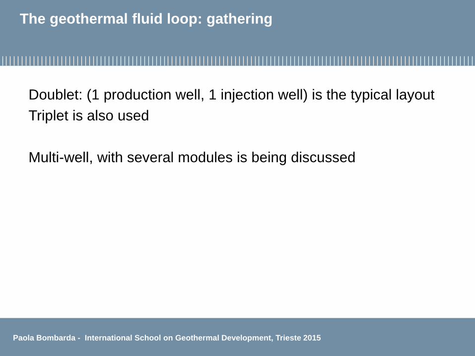
The geothermal fluid loop: gathering
Doublet: (1 production well, 1 injection well) is the typical layout
Triplet is also used
Multi-well, with several modules is being discussed

Paola Bombarda - International School on Geothermal Development, Trieste 2015
The downhole pump:lineshaft (LSP), submersible (ESP),
hydraulically driven (HTP)
Main issues: depth, pumping head, temperature, reliability and availability
Source: TP-Geoelec “Strategic Research Priorities for Geothermal Electricity»

Paola Bombarda - International School on Geothermal Development, Trieste 2015
The geothermal fluid loop: pressure change in the
production well
Rif. Frick et al., 2011

Paola Bombarda - International School on Geothermal Development, Trieste 2015
The power cycle – remind from thermodynamics
Sorgente BT
Sorgente AT
M
LQAT
QBT
ATQ
L
AT
BTCid
T
T1,
Cid ,
Only for Carnot cycles with constant temperatures

Paola Bombarda - International School on Geothermal Development, Trieste 2015
Power cycle: the reference ideal cycle for all liquid heat source, with constant heat capacity
Entropy
LINQP Geothermal fluid
reinjection
temperature
Ambient
temperature
T
Geothermal
fluid inlet
temperature
OUTQ
INQ
Lorenz cycleREMIND: the cycleefficiency depends onlyon the geothermalsource and ambienttemperatures
L

Paola Bombarda - International School on Geothermal Development, Trieste 2015
Case study: Soultz, ideal cycle
Nominal conditions: ambient 10°C; geothermal fluid salt content 100 g/l
inlet temperature 175 °C, reinjection 70 °C
Thermal power: 𝑄𝐼𝑁 = 𝑚 ∙ 𝑐 ∙ ∆𝑇 𝑄𝐼𝑁 = 33.57 𝑘𝑔
𝑠∙ 3. 7 𝑘𝐽
𝑘𝑔𝐾∙ 175 − 79.1 𝐾 = 13𝑀𝑊
η = 1 −283.15175 −70,1
𝑙𝑛175+273,15
70.1+273.15
=0.28
𝑃𝐼𝐷𝐸𝐴𝐿 = 𝑄𝐼𝑁 ∙ η = 13𝑀𝑊 ∙ 0.28 = 3.64𝑀𝑊
L
L
Paola Bombarda - International School on Geothermal Development, Trieste 2015
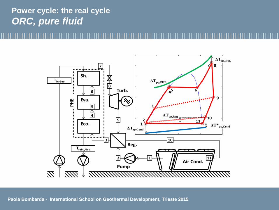
Power cycle: the real cycle
ORC, pure fluid
Turb.
Reg.1000 1500 2000 2500 3000
20
40
60
80
100
120
140
160
Entropy, J/(kg K)
Tem
pera
ture
, °C
0 20 40
20
40
60
80
100
120
140
160
Power, MW
Tem
pera
ture
, °C
Pump
Eva.
Eco.
Sh.
Air Cond.
4
3
2 1
6
7
8
9
10
5
11
2
ΔTap,Cond
3
45 6
7 8
9
1011
PHE
Tin,Geo
Treinj,Geo
ΔT*pp,Cond
ΔTap,PHE
ΔTpp,PHE
ΔTpp,Reg
1

Paola Bombarda - International School on Geothermal Development, Trieste 2015
Concepts for binary cycle design
Objectives:
-high efficiency
-=> second law analisys: minimize second law losses
-low cost, €/kW
-=> optimize component design
-Critical choice: the cycle working fluid

Paola Bombarda - International School on Geothermal Development, Trieste 2015
Concepts for binary cycle design
The heat introduction process

Paola Bombarda - International School on Geothermal Development, Trieste 2015
ORC working fluid selection
The fluid must be suitable for the selected geothermal sourceand plant size (Fluid critical temperature and pressure,molecular complexity and mass are relevant)
Hydrocarbons
Refrigerants
Others
Important issues: environmental, toxicity, flammability,material and lubricant compatibility, cost

Paola Bombarda - International School on Geothermal Development, Trieste 2015
ORC, pure fluid, simple cycle optimization:
the evaporation temperature is a key parameter
• Introduced thermal power decreases
when evaporation temperature
increases
• Cycle efficiency increases when
evaporation temperature increases
=> Maximum cycle power for the
optimum evaporation temperature

Paola Bombarda - International School on Geothermal Development, Trieste 2015
Cycle selection: simple or recuperativesubcritical or supercritical

Paola Bombarda - International School on Geothermal Development, Trieste 2015
Kalina cycleworking fluid: ammonia-water mixture

Paola Bombarda - International School on Geothermal Development, Trieste 2015
Cost & component sizing
• Turbine cost depends mainly on turbine size, and, therefore, on
the working fluid selected
• Heat exchangers: selection of ∆Tpinch point for the heat
exchangers is crucial : the smaller the ∆Tpinch point , the higher
the efficiency but also the heat exchanger surface and cost

Paola Bombarda - International School on Geothermal Development, Trieste 2015
Binary plant performance

Paola Bombarda - International School on Geothermal Development, Trieste 2015
The plant power balanceNet plant power = (turbine power – pump power) -auxiliaries power consumption

Paola Bombarda - International School on Geothermal Development, Trieste 2015
Binary power plant schemes and main features
The plant comprises two separate section: the geothermal fluid loop
and the power cycle
NCG and dissolved minerals are confined in geofluid loop
Power cycle arrangement depends on thermodynamic cycle
selected
Conventional heat rejection (water/ air cooled condenser or hybrid
system)
Cogeneration application and/or hybrid configuration is eligible
Plant scheme tailored on the geofluid also possible

Paola Bombarda - International School on Geothermal Development, Trieste 2015
Mixed steam-binary plant

Paola Bombarda - International School on Geothermal Development, Trieste 2015
High enthalpy geofluid binary plant scheme
G
cooling system
separator
evaporator
preheater
pump
turbine-generator
production well reinjection well
STEAM
LIQUID
NONCONDENSABLES

Paola Bombarda - International School on Geothermal Development, Trieste 2015
Main machinery
Heat exchangers (pre-heater, evaporator, condenser,
recuperator)
Turbine
Generator
Feed pump
Down-hole pump

Paola Bombarda - International School on Geothermal Development, Trieste 2015
Power plant view

Paola Bombarda - International School on Geothermal Development, Trieste 2015
Turbine
Turbine requirements:
Work extraction
Suitability to accomodate increasing volumetric flow rate
High efficiency
Low cost (=> reduced stage number)
Remark: dry vapour expansion, no erosion of blades

Paola Bombarda - International School on Geothermal Development, Trieste 2015
Binary power plant – turbine
Axial, possibly multistage
most common
Radial, inflow, usually single stage
sometimes used
Radial, outflow, multistage
recently proposed again

Turbine, axial, single stage
By courtesy of Turboden
Low rotational speedLow peripheral speed, low mechanical stressNo reduction gear

Turbine, radial inflow - Soultz case study:
single stage, rotational speed 12400 rpm
High rotational speed with reduction gearHigh work extraction per stage (centrifugal force potential increases work extraction)
Adapt to accommodate variable inlet nozzles

Turbine, radial inflow - Soultz case study

Binary plant – power cycle pump
• Centrifugal, multistage pump
• Operated at variable speed

Power Plant - Heat Exchangersshell and tube or plate – possibly with phenolic coating
Soultz heat exchangers

Paola Bombarda - International School on Geothermal Development, Trieste 2015
Bibliography
• Di Pippo, Ronald: Geothermal Power Plants: Principles, Applications, Case Studies and Environmental Impact, Elsevier Science, Dartmouth, Massachusetts, (2012).
• Technology Platform on Geothermal Electricity (TP-Geoelec) “Strategic Research Priorities for Geothermal Electricity» available on the Internet at: www.egec.org Technology Roadmap “Geothermal Heat and Power”, © OECD/IEA, 2011 International Energy Agency, www.iea.org
• Bombarda, P., Invernizzi, C., Pietra C., “Heat recovery from Diesel engines: A thermodynamic comparison between Kalina and ORC cycles” Applied Thermal Engineering 30 (2010) 212–219
• Di Pippo, R.: Second Law assessment of binary plants generating power from low-temperature geothermal fluids, Geothermics, 33, (2004), 565-586.

Paola Bombarda - International School on Geothermal Development, Trieste 2015
Thank you for attention Paola Bombarda
Gecos Group - http://www.gecos.polimi.it/
Politecnico di Milano
Copyright © 2022 FDOKUMEN