
Study of Additive Manufacturing Applications to Geothermal ...
130
ORNL/TM-2019/1408 Approved for public release. Distribution is unlimited. Study of Additive Manufacturing Applications to Geothermal Technologies Final Project Report Yarom Polsky (ORNL) Kristina Armstrong (ORNL) Phillip Chesser (ORNL) Brian Post (ORNL) Chris Price (ORNL) Jian-Cherng Su (SNL). Annie Wang (Senvol) November 2020
-
Upload
khangminh22 -
Category
Documents
-
view
0 -
download
0
Transcript of Study of Additive Manufacturing Applications to Geothermal ...
ORNL/TM-2019/1408
Approved for public release. Distribution is unlimited.
Study of Additive Manufacturing Applications to Geothermal Technologies Final Project Report
Yarom Polsky (ORNL) Kristina Armstrong (ORNL) Phillip Chesser (ORNL) Brian Post (ORNL) Chris Price (ORNL) Jian-Cherng Su (SNL). Annie Wang (Senvol)
November 2020

DOCUMENT AVAILABILITY Reports produced after January 1, 1996, are generally available free via US Department of Energy (DOE) SciTech Connect. Website www.osti.gov Reports produced before January 1, 1996, may be purchased by members of the public from the following source: National Technical Information Service 5285 Port Royal Road Springfield, VA 22161 Telephone 703-605-6000 (1-800-553-6847) TDD 703-487-4639 Fax 703-605-6900 E-mail [email protected] Website http://classic.ntis.gov/ Reports are available to DOE employees, DOE contractors, Energy Technology Data Exchange representatives, and International Nuclear Information System representatives from the following source: Office of Scientific and Technical Information PO Box 62 Oak Ridge, TN 37831 Telephone 865-576-8401 Fax 865-576-5728 E-mail [email protected] Website http://www.osti.gov/contact.html
This report was prepared as an account of work sponsored by an agency of the United States Government. Neither the United States Government nor any agency thereof, nor any of their employees, makes any warranty, express or implied, or assumes any legal liability or responsibility for the accuracy, completeness, or usefulness of any information, apparatus, product, or process disclosed, or represents that its use would not infringe privately owned rights. Reference herein to any specific commercial product, process, or service by trade name, trademark, manufacturer, or otherwise, does not necessarily constitute or imply its endorsement, recommendation, or favoring by the United States Government or any agency thereof. The views and opinions of authors expressed herein do not necessarily state or reflect those of the United States Government or any agency thereof.
ORNL/TM-2019/1408
Electrical and Electronic Systems Research Division
Study of Additive Manufacturing Applications to Geothermal Technologies Final Project Report
Yarom Polsky
Kristina Armstrong Phillip Chesser
Brian Post Chris Price
Jian-cherng Su (Sandia National Laboratories) Annie Wang (Senvol)
Date Published: October, 2020
Prepared by OAK RIDGE NATIONAL LABORATORY
Oak Ridge, TN 37831-6283 managed by
UT-BATTELLE, LLC for the
US DEPARTMENT OF ENERGY under contract DE-AC05-00OR22


iii
CONTENTS
CONTENTS ................................................................................................................................................. iii LIST OF FIGURES ....................................................................................................................................... 1 LIST OF TABLES ......................................................................................................................................... 3 ACKNOWLEDGMENTS ............................................................................................................................. 4 EXECUTIVE SUMMARY ........................................................................................................................... 4 1. INTRODUCTION ................................................................................................................................. 7 2. Industry assessment and industry workshop ......................................................................................... 9
2.1 Industry Assessment Summary .................................................................................................... 9 2.1.1 Drivers for pursuing AM ................................................................................................ 9 2.1.2 Typical Manufacturing Processes ................................................................................. 10 2.1.3 Materials Considerations .............................................................................................. 10 2.1.4 Quality and Certification Considerations ..................................................................... 11
2.2 Industry Workshop Summary .................................................................................................... 11 3. MANUFACTURABILITY ASSESSMENT ....................................................................................... 13
3.1 Overview .................................................................................................................................... 13 3.2 Description of parts and assemblies .......................................................................................... 13 3.3 Part and assembly evaluations ................................................................................................... 14
3.3.1 Part DWG-001 .............................................................................................................. 14 3.3.2 Part DWG-0101 ............................................................................................................ 18 3.3.3 Part DW-0201 ............................................................................................................... 24 3.3.4 Part DW-0202 ............................................................................................................... 31 3.3.5 Assembly HTCA-001-OP ............................................................................................. 38 3.3.6 Part PRT-0011006 ........................................................................................................ 43 3.3.7 Part PRT-0011009 ........................................................................................................ 47 3.3.8 Assembly ASM-00100 ................................................................................................. 60 3.3.9 Concluding Remarks .................................................................................................... 69 3.3.10 Concluding Remarks Following Re-evaluation ........................................................... 69
4. TECHNOECONOMIC COMPARISON OF CONVENTIONAL AND ADDITIVE MANUFACTURING .......................................................................................................................... 71 4.1 Overview .................................................................................................................................... 71 4.2 TEA Methodology ..................................................................................................................... 71 4.3 Machining time and cost estimation .......................................................................................... 72
4.3.1 Cost vs. Mass Removed ................................................................................................ 72 4.3.2 Cost vs. Time to Machine ............................................................................................. 73 4.3.3 Machining Time for Generic Geothermal Part ............................................................. 74 4.3.5 Cost Estimation Workflow for Conventional Machining ............................................. 78
4.4 AM Technologies Overview ...................................................................................................... 79 4.5 Selective Laser Melting Time and Cost Estimation .................................................................. 80
4.5.1 SLM Mass & Materials ................................................................................................ 80 4.5.2 Factors Affecting SLM Print Time ............................................................................... 81 4.5.3 Pre- and Post- Printing Activities Time and Costs ....................................................... 83 4.5.4 Post-AM Build Machining Time and Cost ................................................................... 83 4.5.5 Total SLM Build Time and Cost .................................................................................. 83
4.6 Directed Energy Deposition Time and Cost Estimation ............................................................ 85 4.7 Geothermal tool CM and AM time and cost calculator ............................................................. 87
5. TEA APPROACH ACCURACY EVALUATION ............................................................................. 89 5.1 CM Machining Time and Cost Accuracy .................................................................................. 89 5.2 AM Cost Accuracy .................................................................................................................... 90
iv
5.3 Improving Calculation Accuracy ............................................................................................... 90 6. COMPARISON OF CONVENTIONAL AND ADDITIVE MANUFACTURING .......................... 91
6.1 Single Part Production ............................................................................................................... 91 6.2 Economy of Scale: Production of Multiple Parts ...................................................................... 92 6.3 Maximizing utilization of the Slim Build Process ..................................................................... 95 6.4 Factors that Influence AM Cost ................................................................................................. 96
7. TEA SUMMARY .............................................................................................................................. 100 8. CHALLENGES AND OPPORTUNITIES FOR AM IN GEOTHERMAL APPLICATIONS ........ 101
8.1 Tolerance Considerations ........................................................................................................ 101 8.2 Complex Geometries ............................................................................................................... 101 8.3 Materials .................................................................................................................................. 102 8.4 Mechanical Properties ............................................................................................................. 102 8.5 Part Size ................................................................................................................................... 102 8.6 Design for Manufacturing ........................................................................................................ 103 8.7 Geometries That Cannot be Fabricated Conventionally .......................................................... 103
9. CONCLUSION ................................................................................................................................. 105 10. REFERENCES .................................................................................................................................. 106 11. APPENDIX A ................................................................................................................................... 109
1
LIST OF FIGURES
Figure 1: Manufacturability assessment process flow ................................................................................ 13 Figure 2: Part DWG-001 ............................................................................................................................ 14 Figure 3: Part DW-001 Section View ......................................................................................................... 16 Figure 4: Views of Part DWG-0101 ........................................................................................................... 18 Figure 5: Transparent and Solid Views of Part DWG-0101 ...................................................................... 22 Figure 6: Part DW-0201 ............................................................................................................................. 24 Figure 7: Tolerance adjustments for part DW-0201. Green indicates must be maintained, yellow
indicates on the order of 0.01 inches or above, and pink indicates that dimension is not critical. ............................................................................................................................................ 26
Figure 8: Recommended AM build orientation for DW-0201 ................................................................... 28 Figure 9: Part DW-0202 ............................................................................................................................. 31 Figure 10: Tolerance adjustments for part DW-0202. Green indicates must be maintained, yellow
indicates on the order of 0.01 inches or above, and pink indicates that dimension is not critical. ............................................................................................................................................ 33
Figure 11: Preferred AM build orientation for DW-0202 .......................................................................... 35 Figure 12: Cross sectional view of part DW-0202 ..................................................................................... 36 Figure 13: Assembly HTCA-001-OP ......................................................................................................... 38 Figure 14: Conceptual monolithic part for assembly HTCA-001-OP ........................................................ 40 Figure 15: Part PRT-0011006 ..................................................................................................................... 43 Figure 16: Feature that prevents gun drilling of part .................................................................................. 46 Figure 17: Op 60 feature consideration related to stiffness reduction ........................................................ 47 Figure 18: Part PRT-0011009 ..................................................................................................................... 47 Figure 19: Tolerance adjustments for part PRT-0011009. Green indicates must be maintained,
yellow indicates on the order of 0.01 inches or above, and pink indicates that dimension is not critical. .................................................................................................................................. 50
Figure 20: FEA residual stress simulation of PRT-0011009 following additive manufacturing including recommended support structures. ................................................................................... 53
Figure 21: Meshes used to analyze PRT-0011009 ..................................................................................... 54 Figure 22: Worst case stress locations for PRT-0011009 .......................................................................... 55 Figure 23: Example considerations summary table from Renishaw design for additive
manufacturing (DfAM) manual ...................................................................................................... 56 Figure 24: Assembly ASM-00100 .............................................................................................................. 60 Figure 25: Concept for integrated additively manufactured assembly combing receptacle parts .............. 63 Figure 26: Part PRT-0011001 ..................................................................................................................... 63 Figure 27: Part PRT-0011002 ..................................................................................................................... 64 Figure 28: Part PRT-0011003 ..................................................................................................................... 65 Figure 29: Part PRT-0011004 ..................................................................................................................... 66 Figure 30: Part PRT-001007 ....................................................................................................................... 67 Figure 31: Relationship of mass removed by machining and cost quotes from multiple vendors. ............ 73 Figure 32. Relationship between estimated time to machine and cost quotes from multiple
vendors. ........................................................................................................................................... 73 Figure 33: Relationship between total mass removed and estimated time to machine for all parts. .......... 74 Figure 34: Distribution of time to machine for each manufacturing operation type. ................................. 75 Figure 35: Distribution of mass removed for each manufacturing operation type. .................................... 75 Figure 36: Model fit for bulk discount machining based on number of parts produced. ........................... 77 Figure 37: Calculation flow for machining time and cost estimation. ....................................................... 78 Figure 38: Calculation flow for CM total time and cost estimation. .......................................................... 78 Figure 39: Comparison of two methods of calculating initial AM part mass ............................................ 81
2
Figure 40: Effect of the economy of scale for SLM parts. ......................................................................... 82 Figure 41: Calculation flow for SLM time and cost estimation. ................................................................ 84 Figure 42: Effect of deposition rate on DED production costs. ................................................................. 85 Figure 43: Calculation flow for DED time and cost estimation. ................................................................ 86 Figure 44: Summary tab of conventional vs. additive manufacturing cost calculator. .............................. 88 Figure 45: Comparison of cost quotes to calculated for CM ...................................................................... 89 Figure 46: Comparison of cost quotes to calculated for AM from 3D Hubs and Xometry. ...................... 90 Figure 47: Calculated AM and CM total manufacturing costs for selection of geothermal parts. ............. 91 Figure 48: Calculated AM and CM total manufacturing time for selection of geothermal parts. .............. 92 Figure 49: Effect of economy of scale for assembly parts with CM, DED, and SLM. .............................. 93 Figure 50: Effect of economy of scale for connector parts with CM, DED, and SLM. ............................. 93 Figure 51: Effect of economy of scale for motor and frame parts with CM, DED, and SLM. .................. 94 Figure 52: Top (left) and side (right) view of possible configuration to print all 17 analyzed
geothermal well parts in a single SLM build box. .......................................................................... 95 Figure 53: Cost breakdown by material, printing, pre/post-printing operations, and post
machining for all parts. ................................................................................................................... 96 Figure 54: Effect of powder cost on overall part cost. Points represent the default value of $20/lb
and lines the range of $20-$50/lb of powder. ................................................................................. 97 Figure 55: Manufacturing time breakdown by printing, pre/post-printing operations, and post
machining for all parts. ................................................................................................................... 98 Figure 56: Effect of total SLM print time on overall part cost. Lines represent 50-150% of
default print time shown by the square. .......................................................................................... 98 Figure 57: Effect of DED deposition rate on overall part cost. Lines represent the range 6.5-15
lb/hr and squares represent the default 7.5 lb/hr. ........................................................................... 99 Figure 59: (a) Original and (b) Redesigned rotor part .............................................................................. 104

3
LIST OF TABLES
Table 1: Parts List and Details for Geothermal TEA. ................................................................................. 72 Table 2: Example machining steps and their classifications. ..................................................................... 76 Table 3: Average time (hours) required to machine each precision level and machining step type. ......... 76 Table 4: Least Expensive Manufacturing Technology by Order Size. ....................................................... 94 Table 6: Largest Metal Printers by Technology [18]. ............................................................................... 103

4
ACKNOWLEDGMENTS
Research supported by the Geothermal Technologies Office, Office of Energy Efficiency and Renewable Energy, U.S. Department of Energy under contract DE-AC05-00OR22725, Oak Ridge National Laboratory, managed and operated by UT-Battelle, LLC.
EXECUTIVE SUMMARY
Background
Geothermal reservoir characterization, field construction, and reservoir operations are very technology-intensive activities that contribute significantly to the cost of delivering electricity produced from geothermal resources. Many geothermal technologies, such as downhole tools and drilling equipment, have unusual material, design, and manufacturing considerations dictated by the harsh geothermal environment and extreme aspect ratios required for deployment in a borehole. An additional challenge that faces geothermal applications is the low tool production volume needed to support the industry. Whereas tens of thousands of oil & gas wells are drilled and completed in the U.S. annually, there are typically only tens of geothermal wells that are drilled and completed. If a tool typically used in oil & gas applications cannot be directly used for geothermal, then the cost associated with making the tool suitable for geothermal is often prohibitive. There is therefore a much smaller inventory of technologies available to the geothermal industry as compared to oil & gas and the level of efficiency and sophistication associated with field practice suffers accordingly.
A number of advanced manufacturing methods, such as additive manufacturing (AM), have received increased R&D as well as commercial attention in recent years because of their ability to rapidly prototype complex parts. Additive manufacturing in particular provides an opportunity to increase the technology available to the geothermal industry by either reducing fabrication costs associated with complex components or enabling economic production of low volume parts where specialized tooling is often required. Additional potential benefits of additive manufacturing include increased design freedom to make higher performing parts that cannot be made conventionally, the ability to integrate components into assemblies without joining operations, and the ability to economically fabricate variations on design in cases, such as casting molds, where there are large up-front costs associated with tooling.
Scope
This report documents a study that was performed to investigate technology needs, representative use cases, manufacturability, and a techno-economic (TEA) framework for comparing conventional to additive manufacturing methods for geothermal applications. Limitations of current AM technologies and development needs are discussed in both the manufacturability assessment and TEA. The TEA effort involved the development of a calculator tool for estimating costs and times of fabrication for both conventional and additive manufacturing methods. The TEA calculator was used to quantitatively explore and compare a variety of manufacturing scenarios for a representative geothermal downhole tool set and identify the dominant factors driving manufacturing time and cost. The study as a whole assesses the feasibility of using additive manufacturing for geothermal technology applications from a manufacturing perspective, identifies the limitations of relevant AM technologies, highlights potential benefits of AM for geothermal tool development from both a manufacturing and design perspective, and identifies design considerations and development needs in the context of how parts are manufactured to help guide the evolution of AM technology to better meet the needs of the geothermal industry.
5
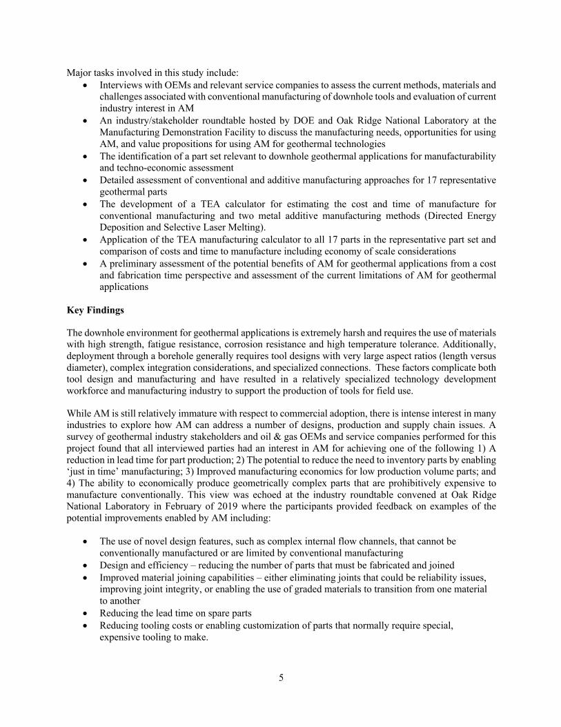
Major tasks involved in this study include: • Interviews with OEMs and relevant service companies to assess the current methods, materials and
challenges associated with conventional manufacturing of downhole tools and evaluation of current industry interest in AM
• An industry/stakeholder roundtable hosted by DOE and Oak Ridge National Laboratory at the Manufacturing Demonstration Facility to discuss the manufacturing needs, opportunities for using AM, and value propositions for using AM for geothermal technologies
• The identification of a part set relevant to downhole geothermal applications for manufacturability and techno-economic assessment
• Detailed assessment of conventional and additive manufacturing approaches for 17 representative geothermal parts
• The development of a TEA calculator for estimating the cost and time of manufacture for conventional manufacturing and two metal additive manufacturing methods (Directed Energy Deposition and Selective Laser Melting).
• Application of the TEA manufacturing calculator to all 17 parts in the representative part set and comparison of costs and time to manufacture including economy of scale considerations
• A preliminary assessment of the potential benefits of AM for geothermal applications from a cost and fabrication time perspective and assessment of the current limitations of AM for geothermal applications
Key Findings
The downhole environment for geothermal applications is extremely harsh and requires the use of materials with high strength, fatigue resistance, corrosion resistance and high temperature tolerance. Additionally, deployment through a borehole generally requires tool designs with very large aspect ratios (length versus diameter), complex integration considerations, and specialized connections. These factors complicate both tool design and manufacturing and have resulted in a relatively specialized technology development workforce and manufacturing industry to support the production of tools for field use.
While AM is still relatively immature with respect to commercial adoption, there is intense interest in many industries to explore how AM can address a number of designs, production and supply chain issues. A survey of geothermal industry stakeholders and oil & gas OEMs and service companies performed for this project found that all interviewed parties had an interest in AM for achieving one of the following 1) A reduction in lead time for part production; 2) The potential to reduce the need to inventory parts by enabling ‘just in time’ manufacturing; 3) Improved manufacturing economics for low production volume parts; and 4) The ability to economically produce geometrically complex parts that are prohibitively expensive to manufacture conventionally. This view was echoed at the industry roundtable convened at Oak Ridge National Laboratory in February of 2019 where the participants provided feedback on examples of the potential improvements enabled by AM including:
• The use of novel design features, such as complex internal flow channels, that cannot be conventionally manufactured or are limited by conventional manufacturing
• Design and efficiency – reducing the number of parts that must be fabricated and joined • Improved material joining capabilities – either eliminating joints that could be reliability issues,
improving joint integrity, or enabling the use of graded materials to transition from one material to another
• Reducing the lead time on spare parts • Reducing tooling costs or enabling customization of parts that normally require special,
expensive tooling to make.

6
Specific components of interest identified by roundtable participants included:
• Bit bodies with complex flow paths and cutter angles • Downhole tools with actuation mechanisms, complex flow manifolds or multipart assemblies • Nozzles for downhole cleanout tools • Impellers and diffusers for pumps • Rotors and stators for mud motors • Heat exchangers
A manufacturability assessment performed on the geothermal downhole tool part set as part of this study provided a highly detailed description of how the parts would be made both conventionally and using AM. This assessment was used as the basis for developing TEA calculators and provided some of the inputs to the calculators for quantitative comparison of AM and CM manufacturing of the 17 downhole tool parts selected for evaluation. It was generally concluded that all parts in the set could be made using a combination of AM and CM but, from a qualitative perspective, there were very few cases where there was an obvious benefit of using AM over exclusive use of CM. This is not surprising given that all of the parts evaluated in the manufacturability assessment were designed to be manufactured using conventional methods. A key finding of the assessment was that design for additive manufacturing should be used in order to take advantage of AM benefits. An additional finding was that material substitutions would have to be made for many parts due to a lack of availability of AM feedstock powders. This material issue is expected to be less relevant as the AM industry evolves and demand for high performance materials in AM grows. In spite of the qualitative expectation that there would be little benefit to fabricating most of the parts using AM, application of the TEA calculators developed for the project indicated that there could be substantial benefits to using AM over CM. Application of the TEA calculator to the downhole tool set found that if a single part is fabricated, Directed Energy Deposition AM was less expensive than CM in 9 cases out of 17. When economy of scale factors are incorporated into the evaluation, the calculators showed that Selective Laser Melting (SLM) AM was less expensive in 13 cases out of 17. An additional finding of the study was that significant reductions in time to manufacture could potentially be achieved if multiple parts could be incorporated in a single build using the SLM AM method. These results are based on a model of the manufacturing process incorporated into the calculator, as opposed to actual fabrication data, but they nonetheless provide a clear indication that there is a strong potential for substantial improvements in cost and time to manufacture geothermal tool parts using AM methods. The TEA also identified important parameters in both AM and CM processes that drive fabrication cost and time, and, in the case of AM, can provide a quantitative basis for setting targets to improve AM technology to further drive down costs and fabrication time. Challenges and opportunities for utilizing AM in geothermal applications were discussed in the final section of this report. This section summarized the most relevant issues that affect the viability of using AM for geothermal technology applications, but also highlighted how to best take advantage of AM to benefit the fabrication of geothermal tools. Another topic briefly touched upon in this report is the use of AM to improve the performance of geothermal technologies. This was not a focus of this study, but a simple example of an optimized drilling part designed for AM with significantly improved performance was provided for perspective. This part could not be manufactured conventionally and highlights the need to further investigate how tool performance improvement can be enabled by emerging manufacturing methods.
7
1. INTRODUCTION
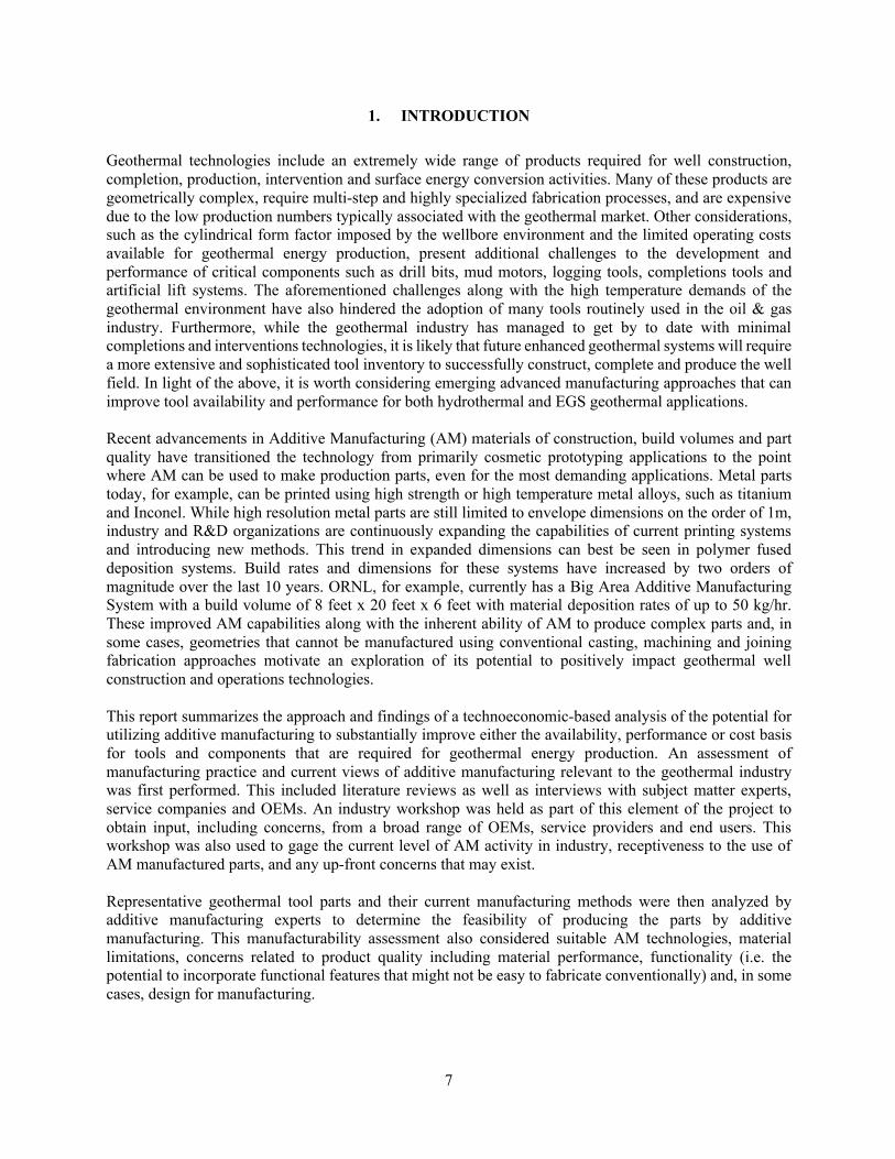
Geothermal technologies include an extremely wide range of products required for well construction, completion, production, intervention and surface energy conversion activities. Many of these products are geometrically complex, require multi-step and highly specialized fabrication processes, and are expensive due to the low production numbers typically associated with the geothermal market. Other considerations, such as the cylindrical form factor imposed by the wellbore environment and the limited operating costs available for geothermal energy production, present additional challenges to the development and performance of critical components such as drill bits, mud motors, logging tools, completions tools and artificial lift systems. The aforementioned challenges along with the high temperature demands of the geothermal environment have also hindered the adoption of many tools routinely used in the oil & gas industry. Furthermore, while the geothermal industry has managed to get by to date with minimal completions and interventions technologies, it is likely that future enhanced geothermal systems will require a more extensive and sophisticated tool inventory to successfully construct, complete and produce the well field. In light of the above, it is worth considering emerging advanced manufacturing approaches that can improve tool availability and performance for both hydrothermal and EGS geothermal applications. Recent advancements in Additive Manufacturing (AM) materials of construction, build volumes and part quality have transitioned the technology from primarily cosmetic prototyping applications to the point where AM can be used to make production parts, even for the most demanding applications. Metal parts today, for example, can be printed using high strength or high temperature metal alloys, such as titanium and Inconel. While high resolution metal parts are still limited to envelope dimensions on the order of 1m, industry and R&D organizations are continuously expanding the capabilities of current printing systems and introducing new methods. This trend in expanded dimensions can best be seen in polymer fused deposition systems. Build rates and dimensions for these systems have increased by two orders of magnitude over the last 10 years. ORNL, for example, currently has a Big Area Additive Manufacturing System with a build volume of 8 feet x 20 feet x 6 feet with material deposition rates of up to 50 kg/hr. These improved AM capabilities along with the inherent ability of AM to produce complex parts and, in some cases, geometries that cannot be manufactured using conventional casting, machining and joining fabrication approaches motivate an exploration of its potential to positively impact geothermal well construction and operations technologies. This report summarizes the approach and findings of a technoeconomic-based analysis of the potential for utilizing additive manufacturing to substantially improve either the availability, performance or cost basis for tools and components that are required for geothermal energy production. An assessment of manufacturing practice and current views of additive manufacturing relevant to the geothermal industry was first performed. This included literature reviews as well as interviews with subject matter experts, service companies and OEMs. An industry workshop was held as part of this element of the project to obtain input, including concerns, from a broad range of OEMs, service providers and end users. This workshop was also used to gage the current level of AM activity in industry, receptiveness to the use of AM manufactured parts, and any up-front concerns that may exist. Representative geothermal tool parts and their current manufacturing methods were then analyzed by additive manufacturing experts to determine the feasibility of producing the parts by additive manufacturing. This manufacturability assessment also considered suitable AM technologies, material limitations, concerns related to product quality including material performance, functionality (i.e. the potential to incorporate functional features that might not be easy to fabricate conventionally) and, in some cases, design for manufacturing.

8
The analysis of the AM subject matter experts was then used by techno-economic analysts (TEA) to perform a comparative economic evaluation of the manufacturing of select technologies by AM and conventional manufacturing (CM) approaches. This activity leveraged ORNL TEA expertise and prior experience in other AM applications. Elements of the study as a whole are intended to be forward thinking in the sense that evaluations in some cases will be performed considering both current and projected AM capabilities based on the evolution of capabilities in the AM industry. The results of this project are intended to represent a systematic, focused and rigorous evaluation of the potential value of additive manufacturing applied to geothermal applications. It is expected that this study will serve as the preliminary basis for future R&D needed to advance additive manufacturing capabilities in order to maximize impact for geothermal applications.
9
2. INDUSTRY ASSESSMENT AND INDUSTRY WORKSHOP
2.1 INDUSTRY ASSESSMENT SUMMARY
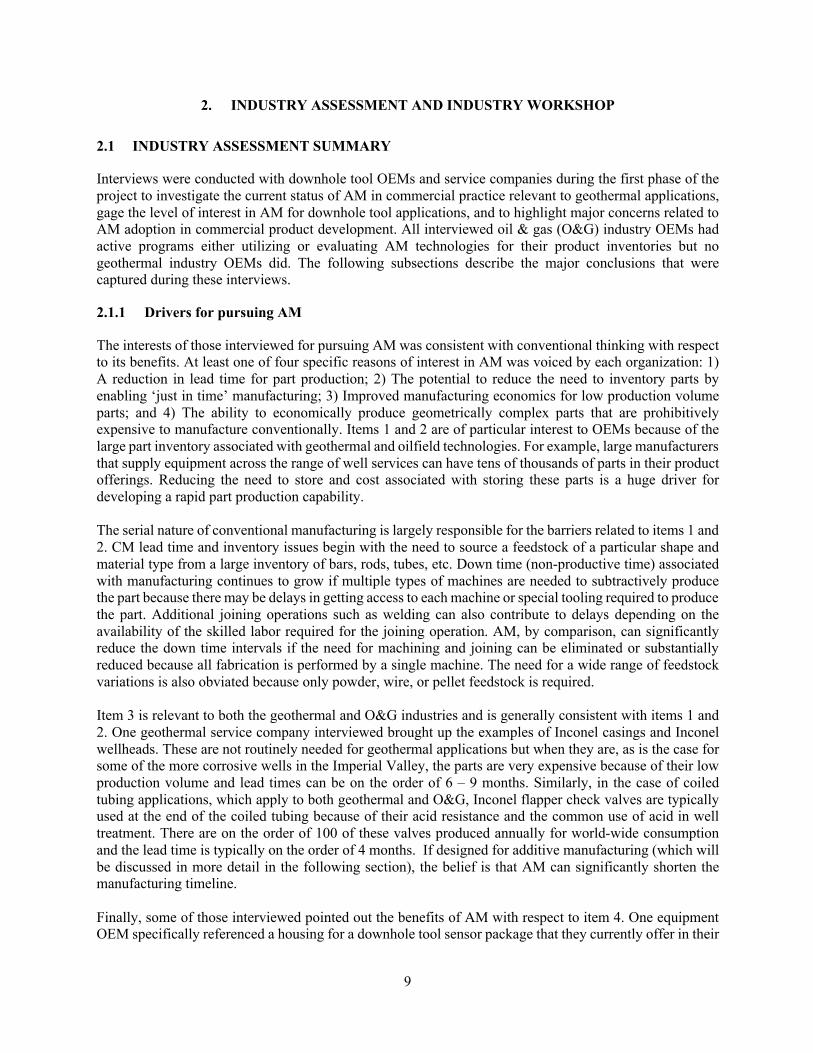
Interviews were conducted with downhole tool OEMs and service companies during the first phase of the project to investigate the current status of AM in commercial practice relevant to geothermal applications, gage the level of interest in AM for downhole tool applications, and to highlight major concerns related to AM adoption in commercial product development. All interviewed oil & gas (O&G) industry OEMs had active programs either utilizing or evaluating AM technologies for their product inventories but no geothermal industry OEMs did. The following subsections describe the major conclusions that were captured during these interviews.
2.1.1 Drivers for pursuing AM
The interests of those interviewed for pursuing AM was consistent with conventional thinking with respect to its benefits. At least one of four specific reasons of interest in AM was voiced by each organization: 1) A reduction in lead time for part production; 2) The potential to reduce the need to inventory parts by enabling ‘just in time’ manufacturing; 3) Improved manufacturing economics for low production volume parts; and 4) The ability to economically produce geometrically complex parts that are prohibitively expensive to manufacture conventionally. Items 1 and 2 are of particular interest to OEMs because of the large part inventory associated with geothermal and oilfield technologies. For example, large manufacturers that supply equipment across the range of well services can have tens of thousands of parts in their product offerings. Reducing the need to store and cost associated with storing these parts is a huge driver for developing a rapid part production capability. The serial nature of conventional manufacturing is largely responsible for the barriers related to items 1 and 2. CM lead time and inventory issues begin with the need to source a feedstock of a particular shape and material type from a large inventory of bars, rods, tubes, etc. Down time (non-productive time) associated with manufacturing continues to grow if multiple types of machines are needed to subtractively produce the part because there may be delays in getting access to each machine or special tooling required to produce the part. Additional joining operations such as welding can also contribute to delays depending on the availability of the skilled labor required for the joining operation. AM, by comparison, can significantly reduce the down time intervals if the need for machining and joining can be eliminated or substantially reduced because all fabrication is performed by a single machine. The need for a wide range of feedstock variations is also obviated because only powder, wire, or pellet feedstock is required. Item 3 is relevant to both the geothermal and O&G industries and is generally consistent with items 1 and 2. One geothermal service company interviewed brought up the examples of Inconel casings and Inconel wellheads. These are not routinely needed for geothermal applications but when they are, as is the case for some of the more corrosive wells in the Imperial Valley, the parts are very expensive because of their low production volume and lead times can be on the order of 6 – 9 months. Similarly, in the case of coiled tubing applications, which apply to both geothermal and O&G, Inconel flapper check valves are typically used at the end of the coiled tubing because of their acid resistance and the common use of acid in well treatment. There are on the order of 100 of these valves produced annually for world-wide consumption and the lead time is typically on the order of 4 months. If designed for additive manufacturing (which will be discussed in more detail in the following section), the belief is that AM can significantly shorten the manufacturing timeline. Finally, some of those interviewed pointed out the benefits of AM with respect to item 4. One equipment OEM specifically referenced a housing for a downhole tool sensor package that they currently offer in their

10
product line. This housing is much simpler and more economical to fabricate using AM than CM. Manufacturers are only beginning to explore opportunities related to item 4 in the geothermal and O&G technology communities. It was pointed out that design engineers often design parts with conventional manufacturing methods in mind. This limits their design latitude because the part geometry is constrained by available manufacturing methods and the addition of features requires additional manufacturing operations with associated costs. As will be discussed in subsequent sections, the additional time and cost associated with increased complexity using AM is very modest. On the other hand, taking advantage of this capability requires design engineers also understand the limitations of AM and a different set of design principles related to part manufacturing.
2.1.2 Typical Manufacturing Processes
The typical manufacturing processes for geothermal downhole tool applications primarily involve metal and other material shaping processes. Examples include machining operations such as turning, milling, drilling, gun drilling, wire EDM, laser cutting water jet cutting, and mechanical cutting. Forging and casting are also common metal forming methods used for this industry although it was pointed out by several OEMs that casting is rarely used for downhole tools and high pressure applications because the strength of cast parts is typically lower and they are of poorer quality than machined and forged parts. The aggressive environment and application conditions of geothermal and O&G, such as high stress, shock and vibration, often require surface conditioning of materials. This includes operations such as heat treatment, hard facing, laser cladding, carburizing, anodizing, phosphate coating and others. These operations would likely continue to be required for AM built parts because of the performance requirements of the application and the limitations of the parent material. There are emerging AM methods that enable tailored microstructure, multi-material deposition and compositional grading that may address some of these challenges. Additional operations commonly employed in manufacturing include joining operations such as welding and brazing. These operations are used to combine parts to produce complex shapes, are highly dependent on the skill of the fabricator, and can result in major quality and reliability issue if not performed properly. The AM method in particular holds the potential to address many of the challenges associated with this class of manufacturing operations. Finally, it was noted that tolerances and surface finishes are critical in downhole tool applications. For machined parts, tolerances on the order of 0.005 inches or less are often required for precision fit of assemblies. Welded assemblies generally have tolerances of 1/16 inch or less. Surface finishes vary depending on the application but 125 microinches is typical for most applications. Sealing surfaces may require les roughness.
2.1.3 Materials Considerations
The materials needs for downhole tools are diverse and are driven by a combination of material property and cost considerations. It is noted that Appendix A contains significant discussion of material needs from the industry workshop described in the next section. Because most tools used in the downhole geothermal industry are produced by O&G OEMs and service companies, the following discussion derives largely from interviews with this latter group. A more exhaustive set of lists produced by workshop participants is found in Appendix A of this report. The following list of common materials, processing details and context was compiled during the interviews. This largely reflects O&G application uses, but it generally overlaps with geothermal needs.

11
• 4140 (quenched and tempered) , 4340, 4145 and, in less demanding instances, 1018 alloy steels are commonly used for downhole tools because of their high strength and fatigue resistance.
• 4330V is used in cases where additional fatigue resistance is required • 17-4 PH stainless steel, with H11 heat treat, is often substituted for the above when corrosion
resistance is required • 13-8 PH stainless steel is an upgrade to 17-4 and is sometimes used for mud motors, rotors and
bearing housings • Inconel 718 and Monel K500 are often used when acid and H2S resistance are required • MP35N can also be used when corrosion resistance, high strength and toughness are required but
is often cost prohibitive • Less demanding applications, such as chassis for downhole tools, may employ lower weight
medium strength materials such as Aluminum 6061-T6 • Carburizing is commonly employed to case harden downhole tools • Laser cladding is also employed for hard facing purposes • Phosphate coating is commonly employed for corrosion resistance • Many logging tools require non-magnetic materials with high strength and strain limit. Beryllium
copper is sometimes used in these tools • Because most downhole tools contained threaded assemblies, galling is a major issue. Dissimilar
materials are often used to mitigate galling potential. • Bits and other rock reduction components are often made by casting carbide powders. • Non-metallic parts are primarily used for non-structural applications such as sealing or electrical
isolation. Elastomeric sealing above 300 degrees C is in particular challenge.
2.1.4 Quality and Certification Considerations
Quality and certification are especially important for OEMs for meeting regulatory requirements and producing parts with consistent performance in the field. For O&G applications, there are often standards that dictate material requirements. For example, API 6A, which applies to well control equipment, requires that non-standard materials have a yield stress of at least 75 ksi and requires material certificates from the supplier as part of the product certification package. The methods typically employed to produce this certification of properties are based on the establishment of predictable and consistent material manufacturing methods, i.e. if the material is made according to a standardized process, it will produce properties meeting the specified performance criteria. These standards cannot be currently applied to AM because the material is thermally modified during the deposition process or during a sintering process. For metal AM in particular, the large temperature gradients imposed on the part during the build can produce residual stresses or microstructural variation in the part depending on the energy deposition strategy used with a significant impact on final mechanical properties. While there is an ongoing area of R&D focused on developing certification of AM built parts, there are currently no recognized standards that manufacturers can employ to satisfy regulatory or customer expectations with respect to material properties of the final part produced. This was noted by all OEMs and service companies as a concern.
2.2 INDUSTRY WORKSHOP SUMMARY
Following the initial set of industry interviews, the DOE Geothermal Technologies Office (GTO) and ORNL hosted the Additive Manufacturing for Geothermal Technologies Roundtable in February 2019 to focus on AM applications for geothermal energy in well construction, production and intervention equipment. Researchers, operators, services companies and OEMs reviewed and discussed the state of the art in advanced manufacturing for geothermal activities. Focus areas included:
12
• Understanding the needs of industry users and manufacturers for the use of AM in subsurface industries such as geothermal
• Identifying the value proposition, opportunities, future needs, and technical challenges for a range of AM techniques for geothermal tool, equipment, and component applications
• Summarizing the state of the art in addition to identifying gaps and future needs Both opportunities and challenges were identified in the workshop. While existing manufacturing approaches are adequate to meet most needs for subsurface energy applications, tool and material properties such as strength, fatigue resistance, and corrosion resistance were noted as being particularly critical for the high-temperature, high-corrosion environments present in geothermal applications. These conditions markedly increase the potential for tool failure if conventional O&G tools are used. The redesign of conventional O&G gas tools for geothermal applications requires mitigation of these risks through either alternative material selection or tool re-design and is often prohibitively expensive. This limits the availability of the O&G tool inventory for geothermal applications. Additionally, lead times for tools or spare parts may add significant costs for geothermal projects, particularly for those in resource development stages. Another challenge noted by participants is constraint of the design process by the limitations of conventional manufacturing. This limitation can in some cases result in the rejection of designs with novel features or superior performance characteristics because they are too expensive to manufacture, the complexity of the conventional manufacturing process is too risky, or the design cannot be manufactured at all using conventional manufacturing methods. Approaches using AM could address many of these risks and challenges, and participants identified particular classes of tools that may be good candidates for AM incorporation. Examples include:
• Bit bodies with complex flow paths and cutter angles • Downhole tools with actuation mechanisms, complex flow manifolds, or multipart assemblies • Nozzles for downhole cleanout tools • Impellers and diffusers for pumps • Rotors and stators for mud motors • Heat exchangers • Tools requiring graded materials • Tools requiring casting molds (for rapid component prototyping) • Tools with multiple components that can be unified through DfAM
However, participants noted particular gaps in current printing capabilities for certain steel alloys (e.g., 4145), beryllium copper, fluoroelastomer materials for seals, as well as exotic alloys (e.g., Nitronic 60), as well as the form factor concerns for meeting design dimensions and resolution. An important driver for adoption, particularly for risk averse industries like geothermal and oil and gas, are the development of quality assurance/manufacturing standards. For AM applications, participants discussed how such manufacturing standards are still in nascent development. Please see Appendix A for further information.
13
3. MANUFACTURABILITY ASSESSMENT
3.1 OVERVIEW
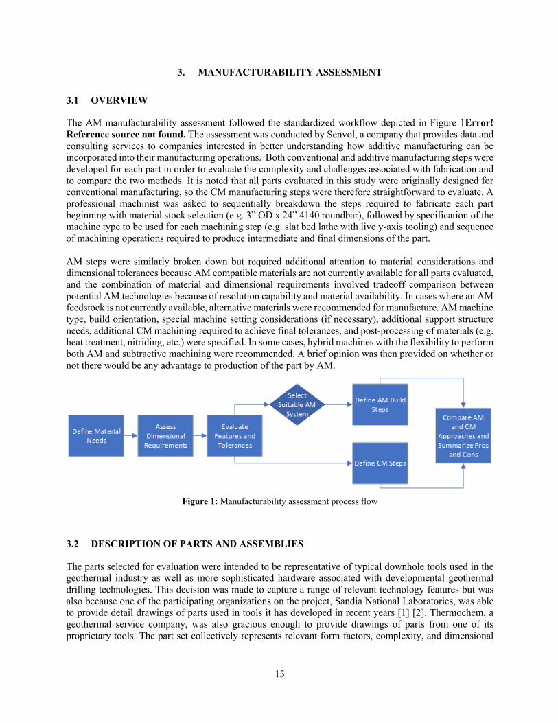
The AM manufacturability assessment followed the standardized workflow depicted in Figure 1Error! Reference source not found. The assessment was conducted by Senvol, a company that provides data and consulting services to companies interested in better understanding how additive manufacturing can be incorporated into their manufacturing operations. Both conventional and additive manufacturing steps were developed for each part in order to evaluate the complexity and challenges associated with fabrication and to compare the two methods. It is noted that all parts evaluated in this study were originally designed for conventional manufacturing, so the CM manufacturing steps were therefore straightforward to evaluate. A professional machinist was asked to sequentially breakdown the steps required to fabricate each part beginning with material stock selection (e.g. 3” OD x 24” 4140 roundbar), followed by specification of the machine type to be used for each machining step (e.g. slat bed lathe with live y-axis tooling) and sequence of machining operations required to produce intermediate and final dimensions of the part. AM steps were similarly broken down but required additional attention to material considerations and dimensional tolerances because AM compatible materials are not currently available for all parts evaluated, and the combination of material and dimensional requirements involved tradeoff comparison between potential AM technologies because of resolution capability and material availability. In cases where an AM feedstock is not currently available, alternative materials were recommended for manufacture. AM machine type, build orientation, special machine setting considerations (if necessary), additional support structure needs, additional CM machining required to achieve final tolerances, and post-processing of materials (e.g. heat treatment, nitriding, etc.) were specified. In some cases, hybrid machines with the flexibility to perform both AM and subtractive machining were recommended. A brief opinion was then provided on whether or not there would be any advantage to production of the part by AM.
Figure 1: Manufacturability assessment process flow
3.2 DESCRIPTION OF PARTS AND ASSEMBLIES
The parts selected for evaluation were intended to be representative of typical downhole tools used in the geothermal industry as well as more sophisticated hardware associated with developmental geothermal drilling technologies. This decision was made to capture a range of relevant technology features but was also because one of the participating organizations on the project, Sandia National Laboratories, was able to provide detail drawings of parts used in tools it has developed in recent years [1] [2]. Thermochem, a geothermal service company, was also gracious enough to provide drawings of parts from one of its proprietary tools. The part set collectively represents relevant form factors, complexity, and dimensional
14
challenges associated with the manufacturing of downhole tools. In total, 17 parts were evaluated. These parts came from two drilling motor assemblies, a seismic monitoring tool and a logging tool.
3.3 PART AND ASSEMBLY EVALUATIONS
3.3.1 Part DWG-001
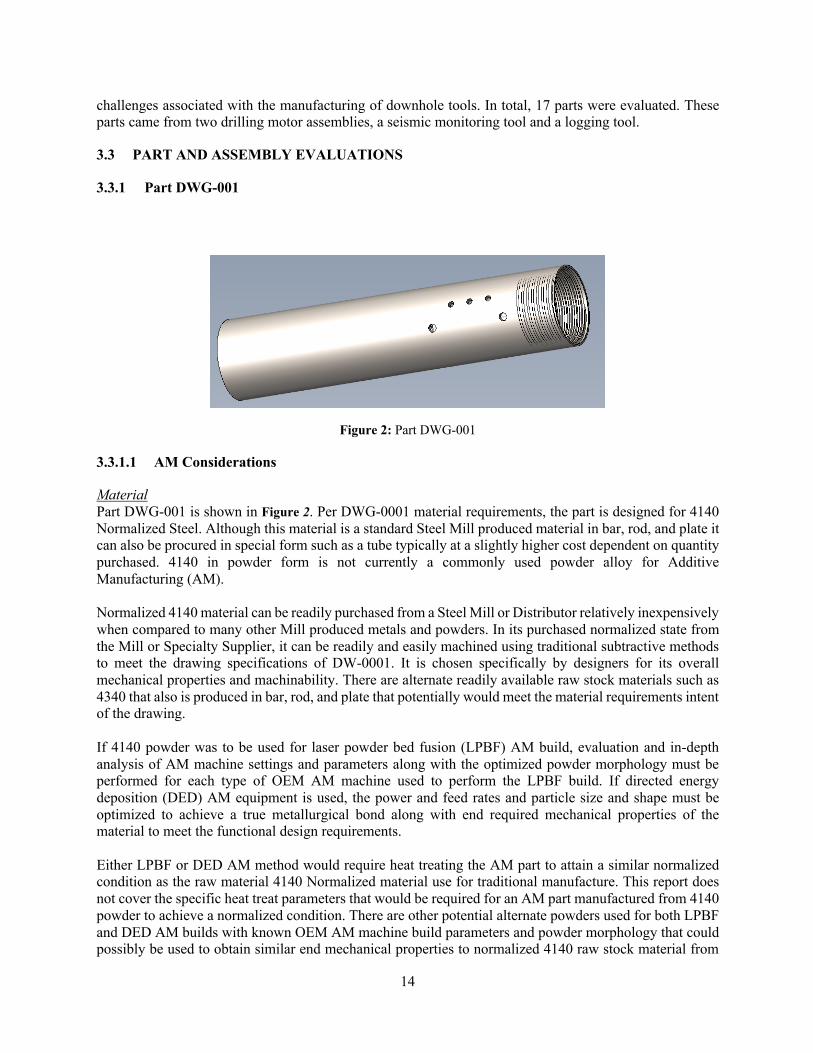
Figure 2: Part DWG-001
3.3.1.1 AM Considerations
Material Part DWG-001 is shown in Figure 2. Per DWG-0001 material requirements, the part is designed for 4140 Normalized Steel. Although this material is a standard Steel Mill produced material in bar, rod, and plate it can also be procured in special form such as a tube typically at a slightly higher cost dependent on quantity purchased. 4140 in powder form is not currently a commonly used powder alloy for Additive Manufacturing (AM). Normalized 4140 material can be readily purchased from a Steel Mill or Distributor relatively inexpensively when compared to many other Mill produced metals and powders. In its purchased normalized state from the Mill or Specialty Supplier, it can be readily and easily machined using traditional subtractive methods to meet the drawing specifications of DW-0001. It is chosen specifically by designers for its overall mechanical properties and machinability. There are alternate readily available raw stock materials such as 4340 that also is produced in bar, rod, and plate that potentially would meet the material requirements intent of the drawing. If 4140 powder was to be used for laser powder bed fusion (LPBF) AM build, evaluation and in-depth analysis of AM machine settings and parameters along with the optimized powder morphology must be performed for each type of OEM AM machine used to perform the LPBF build. If directed energy deposition (DED) AM equipment is used, the power and feed rates and particle size and shape must be optimized to achieve a true metallurgical bond along with end required mechanical properties of the material to meet the functional design requirements. Either LPBF or DED AM method would require heat treating the AM part to attain a similar normalized condition as the raw material 4140 Normalized material use for traditional manufacture. This report does not cover the specific heat treat parameters that would be required for an AM part manufactured from 4140 powder to achieve a normalized condition. There are other potential alternate powders used for both LPBF and DED AM builds with known OEM AM machine build parameters and powder morphology that could possibly be used to obtain similar end mechanical properties to normalized 4140 raw stock material from
15
the Mills. This report does not extend further into researching alternate available AM powders that could possibly meet the functional material intent of DWG-0001. For ongoing AM build, individual piece part qualification per machine and optimized powder for each type of OEM machine would be recommended for each part. Geometry The dimensional requirements of the part require an AM machine that can handle a build diameter of up to 5.50” and an overall length of 23 .00”. Wall thicknesses vary from .125” to approximately .750” nominally in thickness. These wall thickness dimensions are on the completed finished machined part and consider the major machined diameter of thee Stub Acme threads called out on the drawing. An AM build to near net shape via AM will require additional material be added to then remove material via traditional machining methods to meet the finished machined dimensions as called out on the drawing. End size requirements for all dimensions involves the removal via traditional machining. The internal bore has multiple sizes with associated tolerances. These will require to be machined. The outside of the part will most likely also require to be machined or possibly shot peened depending upon the required surface finish and if the method of AM build requires external support structures. Features / Tolerances Almost all features present tolerances that would require machining. Threading, finishing the holes on the side of the tube and defining the chamfers would all require machining. The outer surface of the tube may not require any machining. It appears that the inside of the tube demands much greater accuracy. Potential AM Steps Due to its layer-by-layer additive manufacturing technique, the Selective Laser Melting (SLM) process, used in LBPF, enables the production of metallic parts with complex features and internal cavities. Part number DWG-0001 is not a complex part and becomes much more difficult to build via AM build than through traditional subtractive measures. The added complexity in this case is related to substantial support removal if built horizontally, requiring the need for support structure removal both external and internal, in addition to all the necessary subtractive machining operations to meet the drawing specifications, which cannot be achieved by AM build alone regardless of what AM build method is used. This is mainly due to the requirement of machining all the various bores to meet the final tolerances, the concentricity and diameter callouts such as in zone B3 of the drawing for diameter 4.500 +/- .002 inches, the required 4.75 Stub Acme thread machining in detail B and machining of the 4.25-3 Stub Acme thread in Detail C. The tight tolerance 3.937 +.000 / -.001 inch diameter in zone B2 along with the concentricity requirement must also be machined in after the AM build. To attain concentric bores throughout the various specified part diameters and meet tolerances, machining boring operations are required to meet the final drawing diameter tolerances. All part surfaces, even if built near net shape, will need to be built oversized anywhere from .030”-.100” , depending upon machine set-up, to ensure enough material availability to remove to perform all necessary subtractive machining to meet drawing dimensional requirements. If this part were to be built via AM, both the LPBF or DED methods could be used. A vertical build would involve the least amount of supports, however there are build size Z axis (height) constraints. Very few OEM LBPF machines are available that can build in the Z axis to over 28 inches as would be required for this part after adding additional AM build material to machine the part to end drawing specifications. Release of other commercial machines that will eventually be able to build to 39 + inches and greater may become commercialized in the future. DED removes the need for virtually all supports and removes the AM build size constraint, but, would make for a very labor intensive, costly and time-consuming build.

16
There also remains the option to manufacture the part via AM LPBF method where the part could be built at an angle to fit inside the build plate area of several AM machine commercially available today. The optimal angle of the part to achieve the least amount of required support structures can be determined by OEM machine software and other independent applications software. These software tools enable the generation of support structures and can distinguish from internal and external supports when orienting the part for AM build in LPBF machines. In addition to interrogating part volume and surface data from the 3D model, the manipulation of the part’s AM build orientation allows the AM user to concurrently estimate build time, feedstock requirements, and optimize the part for AM build. Performing the AM build on an angle adds many more supports than a vertical build and will require support removal via machining post AM build. This adds complexity and additional costs. Regardless of the AM build method used, unless an alternate powder material to 4140 Normalized steel is found to be acceptable, a post AM build heat treat potentially may be required which will increase lead time and overall cost to build this part via AM. The part can only be built via AM to the near net shape. All the required conventional machining and set-ups as described below would be necessary to be performed for the part to meet all dimensional drawing specifications and tolerances. The use of a hybrid machine where DED and multi-axis machining is combined is certainly a possibility to explore. In a hybrid system the AM build would occur simultaneously with machining the part to meet all dimensional requirements. There may be an additional lead time advantage over straight DED and then traditional machining in time savings associated with traditional conventional work holding fixtures and machining set-ups. Even a hybrid machine using DED would in all likelihood not be as cost effective as a LBPF AM build with subsequent traditional machining. The intent of this report is not to delve further into the comparison of these various potential AM methods of manufacture only to bring awareness to the need to further analyze the costs associated with the various possible AM methods of manufacture for further AM build justification.
3.3.1.2 Conventional Manufacturability Considerations
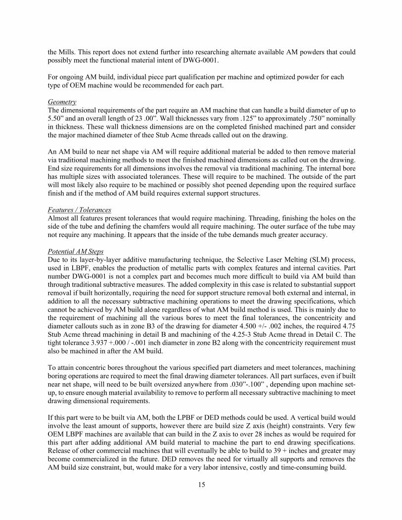
Figure 3: Part DW-001 Section View
Material 4140 5” diameter tube with .75” wall. Geometry This part is a 22.75” long tube with acme threaded ends and internal bore step features. Vent or lubrication holes .375” dia are drilled radially on the left side through the part on center. Two additional .5” diameter holes are drilled 30° off center through one wall of the part. Features / Tolerances The part is a relatively long part with tight internal bore (cylindricity .005) requirements that dictate specialized work holding (collet or six jaw chuck) to prevent excessive clamping while boring the ID. The boring process will require rigid boring bar and spring passes to create a uniform profile.

17
Conventional Manufacturing Steps The raw material for this part is available in normalized 4140 tube stock. This reduces roughing machining time dramatically from using solid round bar. The material will start as 5.00” diameter tube (.75 thick wall) cut to 23.0 inch length. The straightness callout of .010 will be provide by the mill and is accomplished through the straightening step after drawing process. The outside diameter (OD) will not be turned since it is already provided to size in accordance with the note. This part is well suited to a slat bed lathe with live y axis tooling. Example: Mori NL3000Y The manufacturing process is as follows: Op 10 – Face both sides to length 22.71” ±.02 Op 20 – Bore right side 3.937 ID Op 30 – Bore minor diameter 4.050 for Acme 4.25 thread (right side) Op 40 – Cut Acme thread major diameter. Op 50 – Chamfer end 0.10 and provide thread relief chamfer of 14.50° Op 60 – Rotate part in spindle, Bore 3.937 ID +.000-.001 use spring pass. Check with plug gage Op 70 – Cut 20° Chamfer, Bore 4.400 ID ±.005, Bore 4.300 ID ±.005, Bore 4.500 ID ±.002 use spring pass Op 80 – Bore minor diameter to 4.550 ID for Acme 4.75 thread (left side) Op 90 – Chamfer end .010 and provide thread relief chamfer 30° Op 100 – Spot drill holes for .375 ID through and .500 ID. Op 110 – Drill .375” ID holes through both sides (deburr after drill) Op 120 – Drill .500” ID holes through one side. (deburr after drill) Op 130 – Wash and preserve to prevent corrosion prior to packaging
3.3.1.3 Summary
This part is not a good candidate for AM – it is not recommended that ORNL perform a deep dive of AM vs. conventional manufacturing cost-benefit analysis. This part is ideally suited for conventional subtractive machining operations. The current traditional designed DWG-0001 uses 4140 Normalized material to meet functional requirements. The shape and size of the part would likely not be cost effective nor substantially reduce lead time to AM build a part to near net shape, perform required traditional machining to meet drawing specifications and then also post heat treat to meet the required mechanical properties of the material called out in DW-0001. As discussed above, there potentially are AM powder materials available that can be used to further reduce lead time and cost if the part were built using an AM method. This report does not cover the activities and specific investigations/analysis required to determine alternate metal powder materials available in powder form that meet the drawing material requirement of 4140 Normalized material.
18
3.3.2 Part DWG-0101
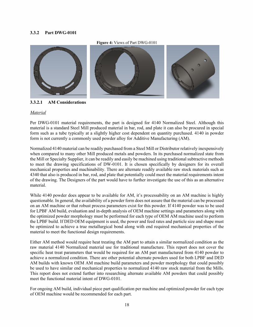
Figure 4: Views of Part DWG-0101
3.3.2.1 AM Considerations
Material
Per DWG-0101 material requirements, the part is designed for 4140 Normalized Steel. Although this material is a standard Steel Mill produced material in bar, rod, and plate it can also be procured in special form such as a tube typically at a slightly higher cost dependent on quantity purchased. 4140 in powder form is not currently a commonly used powder alloy for Additive Manufacturing (AM).
Normalized 4140 material can be readily purchased from a Steel Mill or Distributor relatively inexpensively when compared to many other Mill produced metals and powders. In its purchased normalized state from the Mill or Specialty Supplier, it can be readily and easily be machined using traditional subtractive methods to meet the drawing specifications of DW-0101. It is chosen specifically by designers for its overall mechanical properties and machinability. There are alternate readily available raw stock materials such as 4340 that also is produced in bar, rod, and plate that potentially could meet the material requirements intent of the drawing. The Designers of the part would have to further investigate the use of this as an alternative material.
While 4140 powder does appear to be available for AM, it’s processability on an AM machine is highly questionable. In general, the availability of a powder form does not assure that the material can be processed on an AM machine or that robust process parameters exist for this powder. If 4140 powder was to be used for LPBF AM build, evaluation and in-depth analysis of OEM machine settings and parameters along with the optimized powder morphology must be performed for each type of OEM AM machine used to perform the LPBF build. If DED OEM equipment is used, the power and feed rates and particle size and shape must be optimized to achieve a true metallurgical bond along with end required mechanical properties of the material to meet the functional design requirements.
Either AM method would require heat treating the AM part to attain a similar normalized condition as the raw material 4140 Normalized material use for traditional manufacture. This report does not cover the specific heat treat parameters that would be required for an AM part manufactured from 4140 powder to achieve a normalized condition. There are other potential alternate powders used for both LPBF and DED AM builds with known OEM AM machine build parameters and powder morphology that could possibly be used to have similar end mechanical properties to normalized 4140 raw stock material from the Mills. This report does not extend further into researching alternate available AM powders that could possibly meet the functional material intent of DWG-0101.
For ongoing AM build, individual piece part qualification per machine and optimized powder for each type of OEM machine would be recommended for each part.

19
Geometry
Per drawing dimensional specifications, this part requires an AM machine that can handle a build diameter of up to 5.5” and an overall length of 4.20”. Wall thicknesses vary around the part due to the offset internal bore diameter from .125” to .750” nominally in thickness. These wall thickness dimensions are on the completed finished machined part. The outside diameter (OD) is tightly controlled on the drawing and additional material will need to be added during AM build to machine to the drawing final specification.
The overall envelope dimensions allow this part to be readily AM built on several commercially available AM machines both LPBF and DED equipment.
An AM build to near net shape via AM, will always require additional material be added to then remove material via traditional machining methods to meet the finished machined dimensions as called out on the drawing. Final drawing specified dimensional requirements and tolerances necessitates the removal of material via conventional machining. The internal bore has multiple sizes with associated tolerances. These will require machining as outlined in the Conventional Manufacturing section below. The outside of the part will most likely also require to be machined or possibly shot peened depending upon the required surface finish and if the method of AM build requires external support structures.
Features / Tolerances
All part surfaces and specified features, if built via AM, would require to be touched with machining. Any tolerances that are tighter than +/- .005 will have to be machined since the near net shape cannot meet the finish dimensional requirements. The tighter drawing tolerances on this part are +.002-/-.000 inches, +.000/ -.002 inches and +.005/-.000 inches. These will all require to be final machined involving several machine set-ups and machining process steps. These tolerances cannot be held in the as-built condition via AM.
Potential AM Steps
The part would have to be overbuilt to near net shape of .050-.100” to allow for final machining to drawing specifications. All tapped holes will not be able to be built via AM. These will have to be machined in and tapped. Prior to any final machining post AM build, the near net shape part will have to be stress relieved off the build plate and then subsequently most likely heat treated to meet the material requirements of the drawing.
If this part were to be built via AM, both the LPBF or DED methods could be used. A vertical build would involve the least amount of supports. There is sufficient wall thickness for an AM build with no required supports except supports between the part and the build plate if building in vertical Z axis direction. As mentioned above, the length and diameter of the part allows the part to be built in quite a number of readily available LPBF OEM machines.
3.3.2.2 AM Considerations Reevaluation
After additional design inputs and drawing mark-ups were provided, Senvol re-analyzed this part for AM manufacturability. Unfortunately, despite the relaxing of tolerances in certain areas, these changes did not impact the overall number of machining steps that would be required post AM build.
Material
The use of 17-4 powder to AM build this part is a good alternate material that is readily available from many AM Powder Suppliers if the Cylinder were to be pursued for AM build. It has proven mechanical
20
properties, after DMLM or DED AM processing, similar to what is produced in standard plate, bar, rod and tube stock shapes available from steel mills.
17-4PH is a precipitation-hardening martensitic Stainless Steel, which has corrosion resistance comparable to austenitic varieties, but can be precipitation hardened to even higher strengths than the other martensitic grades. The strength and hardness of this material is developed through heat treating, making 17-4 Stainless ideal for applications requiring ease of fabrication with reliable strength and relative hardness. 17-4PH laser powder bed fusion AM built parts as-built and stress relieved typically result in an H1075- H1150 condition. After subsequent heat treat and hot isostatic pressing (HIP) a H1150 condition is readily achieved. 17-4 PH can only be heat treated to about a Rockwell 32-35 C. To achieve a harder surface finish of HRc 50 or greater, additional processing such as the use of Boriding or Nitriding can be employed.
If it is determined that a higher hardness is required than what the AM as-built condition and any subsequent heat treat will provide to meet functional operating requirements, there are other alternative processes that can meet and exceed the 57-60HRc requirement currently called out on the existing drawing. It is recommended to further evaluate diffusing boron (known as the “Borofuse” process or boriding) into the part substrate, or Nitriding to meet/exceed current drawing hardness requirements.
The boron diffusion layer, or case, that forms can be characterized by depth, hardness and internal stresses. The depth of the boron diffusion layer is typically between 0.0003” – 0.007”. The hardness of a typical boride application readily exceeds 80 HRc having similar hardness to tungsten carbide. The key features of case thickness, hardness, and internal stresses make boriding a robust surface modification for many downhole geothermal/oil and gas applications.
If hardness requirements are not met by heat treatment, boriding or nitriding of 17-4 PH, then an alternative AM material would be recommended. Inconel 625 and Inconel 718 are both commonly available AM materials that offer greater hardness. However, it is important to note that any AM material selected should be reviewed to ensure that material performance requirements are met.
Geometry
No change from the previous section.
Features / Tolerances
In short, there was no relief from the drawing specified GD&T, which causes this part to still require a substantial amount of machining. The part can be built to near net shape on a LPBF AM system if desired and if there was a reason for further AM investigation.
While the additional notes provided do not provide any relief to the drawing requirements and specified GD&T, the notation provided does bring up a traditional machining concept that may possibly be helpful with the alignment of the subsequent assembly of the End Plate Covers and the Rotor and Shaft Assembly that possibly could further ensure alignment amongst critical piece parts.
The End Covers could be held in place on the Cylinder through fixturing and the End Cover Plate holes and Cylinder holes could be simultaneously matched drilled to ensure the best possible alignment. This would require that each match drilled End Plate would have to be marked and always only assembled onto its match drilled Cylinder end.
21
Not knowing all the design requirements, end functionality and integrated assembly requirements, no further detailed information or analysis of other alternate methods of manufacture can be further extrapolated.
Based on this design analysis no substantial benefit will be realized related to functionality, lead time or cost to AM build the Cylinder to near net shape since all surfaces will still require traditional machining to meet the drawing requirements along with the machining of all holes and machined slot.
AM should only be used if the part cannot be easily be made using some other manufacturing technology. The principle reason for this is speed, which translates to cost. Comparatively speaking, AM is relatively slow compared to almost all other manufacturing technologies. Therefore, from a cost point of view, it will almost always be more economical to manufacture geometrically simple parts using traditional technologies if they are faster than AM. When the complexity of a part reaches a point where it cannot be manufactured conventionally, that’s when AM can be of benefit. This is not the case with this Cylinder.
Potential AM Steps
It would be recommended to use a laser power bed fusion AM machine, such as a 3D Systems ProX 320 or an EOS M290 machine. Due to the small size of the part, several parts could be laid out on one build bed, which would decrease cost per part. Furthermore, due to the small size of the part and the selection of a standard AM material, 17-4 PH, a very large number of laser powder bed fusion AM machines would be suitable for building this part. A quick search of the Senvol Database (www.senvol.com/database) of PBF machines that process steel materials and that are larger than the overall dimensions of the part showed that nearly 100 AM machines would potentially be suitable for making this part.
It would also be recommended that the part be built on the Z axis or vertical axis to avoid the need for support structures other than at the interface of the part to the build plate. As indicated by the earlier analysis, additional material of .050-.100” would have to be added all around on the part.
After the build is complete, the entire build plate with the parts attached would be stress relieved. One standard stress relief recipe to follow would be to stress relief at 1150°F for 3-4 hours, then oven cool to room temperature.
After stress relief, all surfaces would require machining to meet drawing requirements. This means that all the machining steps that were outlined for the conventional manufacturing of this part would apply in this AM case.
Overall, there would not be any substantial advantage to manufacturing this part by AM due to the required machining in all faces and surfaces to meet drawing tolerance requirements.

22
3.3.2.3 Conventional Manufacturing Considerations
Figure 5: Transparent and Solid Views of Part DWG-0101
Material
4140 Normalized to HRC 50
Normalized, Quench and Tempered – HRC 50 has extremely high hardness for “normalized” 4140. It is recommended to use 4340 with additional molybdenum to achieve Rc50 requirement. Note: material in the CAD file is 4340, the drawing changes it to 4140.
Geometry
The part geometry is an eccentric bore through a round bar approximately 5” in diameter. Both ends have counter grooves with alignment holes, threads, and slots. This part is symmetrical on each side. A key way or groove extends axially through the part.
Features / Tolerances
The offset bore on the part adds additional setups to machining of the part depending on machine shop capability. The positional location of dowel holes of .001 @ maximum material is the highest precision requirement of the part. Other features including OD and hole diameters include a .002 size tolerance with good manufacturing techniques. The surface finish of 32 rms is not a problem with quality boring techniques.
Conventional Manufacturing Steps
Green Machine
The part will likely start out in the round bar billet form 5.25” OD and cut to length using a horizontal saw with a feeder. The length should not exceed more than 4.125. The part will be faced on each side and turned to an OD of 5.05 ±.010. A 2.75” bore will be removed from ID with a drill and boring bar to prepare the part for normalize, quench and temper.
Heat Treat

23
The heat treat will remove stresses resulting from green machining and provide a uniform austenitic grain structure for finish machining. This can easily be done with conventional heat treat furnaces. A reducing atmosphere to minimize carbon loss with a medium fast oil quench should suffice.
Finish Machining
Depending on the machine shops capabilities and expertise this part could require as few as 2-3 setups to as many as 6-8 setups.
Ideal method and equipment method: An opposing spindle multifunction lathe similar to a Mori NTX or NT or a Mazak Integrex would allow this part to done in 2 to 3 setups. The operation sequence below is ideal for this part.
Op 10 – Hold part from OD and face both sides and counter bore 4.390/4.010 overall length. – requires handoff from one spindle to the other spindle. Op 20 – True up ID bore 2.75” with boring bar. Resize to 2.85” Op 30 – Grab part from 2.85” ID bore and turn the OD to finish dimension of 4.495 ±.002 Op 40 – Mill counter groove on side A. Op 50 - Mill .186 slots. Op 60 - Drill minor diameter for 8-32 threads and thread mill for 2B fit. Op 70 – Drill holes for .250 alignment holes to .2485. Ream to .250 +.002 -.000 Op 80 – Drill three vent holes .375 on top Op 90 - Mill .378 wide groove through the part. Op 100 – Rough out eccentric ID to 3.45 with a milling cutter. Op 110 – Move to Mill and locate of Datum A. Find Center of Datum B. Find Center line axis by locating slot and two dowel holes. Change to boring head and complete boring of .560 offset from center line of established axis. Note: This part could require many setups depending on shop capability. Every new setup has the potential to introduce error in the final part geometry.
3.3.2.4 Summary
This part is not a good candidate for AM – it is not recommended that ORNL perform a deep dive of AM vs. conventional manufacturing cost-benefit analysis. This part is ideally suited for conventional subtractive machining operations.
In summary, due to the tight tolerances on the part, an as-built AM part would have to be extensively machined assuming that a 4140 powder or an acceptable alternate to meet all material mechanical property requirements of the design could be found. The set-ups as indicated in the Conventional machining steps would have to take place even though a near net shape part would require less machining. Given the likelihood of potential post AM build heat treat, the necessity to perform all the required machining and AM build time, cost and time benefits would be unlikely derived by building this part via AM.
There is another issue in that the drawing calls out 4140 but the CAD file indicates 4340 material. A decision would have to be made as to what material powder currently available can meet the mechanical properties for one of these two materials for an AM build if an AM build was to be pursued. Neither 4140 nor 4340 are materials that are currently readily available in AM.
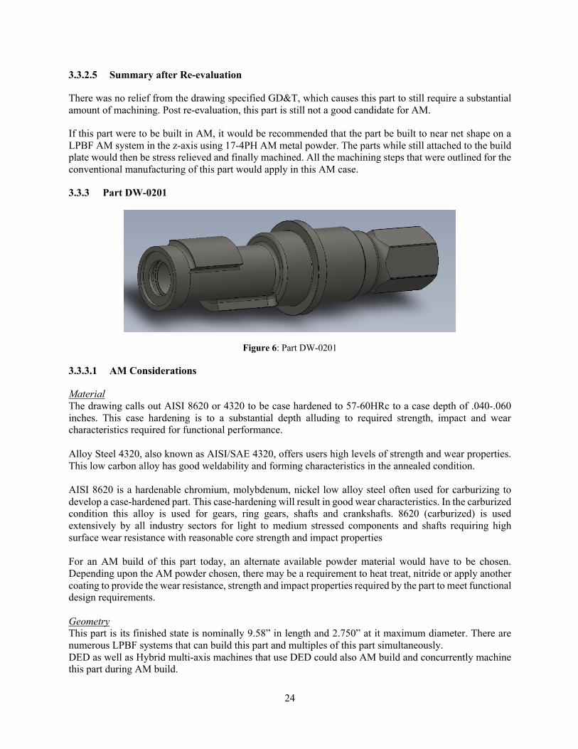
24
3.3.2.5 Summary after Re-evaluation
There was no relief from the drawing specified GD&T, which causes this part to still require a substantial amount of machining. Post re-evaluation, this part is still not a good candidate for AM.
If this part were to be built in AM, it would be recommended that the part be built to near net shape on a LPBF AM system in the z-axis using 17-4PH AM metal powder. The parts while still attached to the build plate would then be stress relieved and finally machined. All the machining steps that were outlined for the conventional manufacturing of this part would apply in this AM case.
3.3.3 Part DW-0201
Figure 6: Part DW-0201
3.3.3.1 AM Considerations
Material The drawing calls out AISI 8620 or 4320 to be case hardened to 57-60HRc to a case depth of .040-.060 inches. This case hardening is to a substantial depth alluding to required strength, impact and wear characteristics required for functional performance. Alloy Steel 4320, also known as AISI/SAE 4320, offers users high levels of strength and wear properties. This low carbon alloy has good weldability and forming characteristics in the annealed condition. AISI 8620 is a hardenable chromium, molybdenum, nickel low alloy steel often used for carburizing to develop a case-hardened part. This case-hardening will result in good wear characteristics. In the carburized condition this alloy is used for gears, ring gears, shafts and crankshafts. 8620 (carburized) is used extensively by all industry sectors for light to medium stressed components and shafts requiring high surface wear resistance with reasonable core strength and impact properties For an AM build of this part today, an alternate available powder material would have to be chosen. Depending upon the AM powder chosen, there may be a requirement to heat treat, nitride or apply another coating to provide the wear resistance, strength and impact properties required by the part to meet functional design requirements. Geometry This part is its finished state is nominally 9.58” in length and 2.750” at it maximum diameter. There are numerous LPBF systems that can build this part and multiples of this part simultaneously. DED as well as Hybrid multi-axis machines that use DED could also AM build and concurrently machine this part during AM build.

25
Features / Tolerances The +.001/-.000 inch diameter internal through bore is the tightest tolerance feature on the part and can only be held through conventional final machining of the bore. The +.003/-.000 inch dimension down inside the bore of Detail C is also a tightly tolerance feature on the part and will require conventional machining. A majority of the outer part features could possibly be used in the as-built condition except for the surfaces specified to be a 32 finish if LPBF AM build is utilized. The areas specified with a 32 finish would have to be machined to meet the drawing requirements. The Corner Break callout of R.005 inches will also have to be machined to meet drawing specification since this will be too tight to meet in the as-built AM condition. Potential AM Steps Internal stresses during build, support structure strategy and the parts other geometry may cause deviation in tolerances. Expected surface roughness for LPBF systems are typically 150-400 micro-inch RA, depending upon the build orientation and material used for the build. All these can be compensated for by adding additional material and machining operations as outlined in the Conventional machining section below. The concentricity callouts relative to Datum A can also be easily machined within the tolerances called out. If the .020” radius fillet tolerance or dimension could be increased, this could also be an as-built AM feature reducing machining time. If the part is built in the Z axis or vertical build orientation using a LPBF system, support structures would be minimized, but, the actual AM build time will be longer and will have greater cost. If the part is built horizontally, there would be support structures running the length of the part that would have to be removed either by machining or some other method. If the support structures are to be machined off, this would not be difficult to do on the outside of the part. There are support removal methods involving chemical etching that are in use for AM parts. Minimizing the amount of support structure required will decrease design time, build time and post-processing required. For a horizontal build, the support structures off the build plate would be attached to the AM built part in the areas where there are concentricity callouts as part of the GD&T. Removing these via machining would be a simple task as these concentric outside diameters need to be machined to meet the concentricity callouts to datum A on the drawing.
3.3.3.2 AM Considerations Reevaluation
Design relief provided: • Material Change to 17-4PH • Dimensional Tolerance Relief as indicated in the below pictorials was provided
Color Legend for highlighted dimensions in drawings below:
• Green dimensions are important/firm and will likely have to be machined • Yellow dimensions are loose, i.e. on the order of 0.01 or greater, not critical and can be near net
shape produced by AM • Pink dimensions are not critical
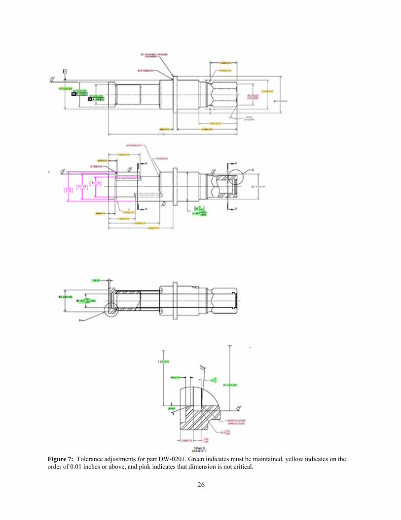
26
Figure 7: Tolerance adjustments for part DW-0201. Green indicates must be maintained, yellow indicates on the order of 0.01 inches or above, and pink indicates that dimension is not critical.
27
Material The use of 17-4 powder to AM build the Anvil Shaft is an advantageous alternate material choice that is readily available from many AM Powder Suppliers around the world. It can achieve H900-H1150 mechanical properties, after LPBF or DED AM processing, similar to what is produced in standard plate, bar, rod and tube stock shapes available from steel mills after HIP and heat treat. It is also very cost effective, has good weldability and machining characteristics. 17-4PH is used for applications where ductility, high strength and corrosion resistance are of key concern. 17-4PH is a precipitation-hardening martensitic Stainless Steel, which has corrosion resistance comparable to austenitic varieties. In the case of 17-4PH AM parts, the resultant hardness and mechanical properties can vary from OEM AM machine to machine mainly due to laser power and other machine characteristics. The 17-4 as-built AM material condition and after heat treat will provide a hardness of 32-35 HRc, based on this author’s experience with 17-4PH AM part and test sample builds across various OEM AM LPBF machines. If it is determined that a higher hardness is required than what the AM as-built condition and any subsequent heat treat will provide to meet functional operating requirements, there are other alternative processes that can meet and exceed the 57-60HRc requirement currently called out on the existing drawing. It is recommended to further evaluate diffusing boron (known as the “Borofuse” process or boriding) into the part substrate, or Nitriding to meet/exceed current drawing hardness requirements. The boron diffusion layer, or case, that forms can be characterized by depth, hardness and internal stresses. The depth of the boron diffusion layer is typically between 0.0003” – 0.007”. The hardness of a typical boride application readily exceeds 80 HRc having similar hardness to tungsten carbide. The key features of case thickness, hardness, and internal stresses make boriding a robust surface modification for many downhole geothermal/oil and gas applications. If hardness requirements are not met by heat treatment, boriding or nitriding of 17-4 PH, then an alternative AM material would be recommended. Inconel 625 and Inconel 718 are both commonly available AM materials that offer greater hardness. However, it is important to note that the author does not know the material requirements (e.g. tensile strength, ductility, corrosion) as defined by the engineer or designer of this part, so any AM material selected should be reviewed to ensure that material requirements are met. Geometry No change from the previous section. Features / Tolerances The relaxing of tolerances from the original drawings combined with selecting 17-4 PH as a material has made a significant difference in the AM manufacturability analysis. Specifically, this has reduced the number of machining steps needed post AM build. The below AM analysis will only consider the 17-4 part to being built in the as-built AM condition. No dimensional changes for application of a boron diffusion layer was considered since this process is not expected to increase or affect the dimensional stability of the as AM built part. Potential AM Steps It is recommended that the Anvil Shaft be AM built in the Z axis of orientation on the build plate as indicated in Figure 8. Due to the relative small size of the part (z-height is not excessive) and the selection of a common AM material, 17-4 PH, the number of laser powder bed fusion AM machines that could potentially manufacture this part is quite large. A quick search of the Senvol Database (www.senvol.com/database) of LPBF machines that process steel materials and that are larger than the overall dimensions of the part

28
showed that about 80 AM machines would potentially be suitable for making this part. Specifically, some machines for further investigation might be Concept Laser (now part of GE Additive) M1 or M2, EOS M290, Renishaw AM 250 and SLM Solutions SLM 280, 500 or 800. Multiple parts can be built on one built plate. The z-orientation of build minimizes the number of overhangs that require support structures. This helps to reduce build time and the amount of 17-4 PH powder used for the actual AM build. To ensure concentricity and perpendicularity of later required machining, additional material of .020” to .030” on either end is recommended to be added. This will be machined off later to true up the part and provide well defined surface datums for subsequent required conventional machining.
Figure 8: Recommended AM build orientation for DW-0201
By controlling the size and shape of the support structures as indicated, they can be easily removed and deburred by hand. A hand polish of these surfaces via the use of a Dremel tool or Pencil Grinder (pneumatic tool with light sand paper) would be more than sufficient to clean up these areas and any surface artifacts from the AM build where the support structures were necessary to complete the build of the part features. In addition to the hand removal of these supports, a light glass bead blast of the outside surfaces to further clean up all outside surfaces is recommended. Not shown are the support structure required to anchor the part to the build plate. These support structure would be attached around the base of the Hex Head feature of the Anvil Shaft. The support structures extending from the build plate to the bottom surface of the Anvil Shaft Hex head can be either saw cut off the base plate or removed from the base plate via wire EDM after stress relieving the Anvil Shaft on the build plate.
Build Plate
Supports to anchor part to build plate
Support structures (red and blue coloring has no meaning)
29
An AM built clearance hole running through the center of the Anvil Shaft throughout its entire length is recommended. This will speed up build time, allow for the use of much less powder to complete the build and will help with controlling residual stress buildup over the length of the part due to the smaller mass. Depending upon the AM Service Provider and their understanding of AM and Conventional machining, holding features can be AM built into the part down inside the ID of the part to accommodate required machining and to maintain concentricity. An experienced AM Supplier with good machining capabilities or access to good experienced machinists, can decrease the inner bore diameter .020-.030” and put in a chamfer in the as-built AM condition that matches the Stock chamfer of the lathe to accommodate the necessary machining of all tight tolerance areas and help maintain concentricity between centers on each end of the Anvil Shaft. This inside the bore chamfer would become an AM built-in holding fixture. It is recommended that this type of AM built-in fixturing be utilized to its fullest extent to accommodate the final machining of the green highlighted tighter tolerance dimensions described in the updated drawings. After the build is complete, the entire build plate with the parts attached would be stress relieved. One standard stress relief recipe to follow would be to stress relief at 1150°F for 3-4 hours, then oven cool to room temperature. All pink and yellow highlighted dimensions, as noted in the dimensional tolerance relief section, can be achieved in the as-built AM condition. A Mazak Integrex or a Mori NTX or NT with opposing spindles would be ideal to perform the required post AM build final machining. Op 10- The Anvil Shaft will be ready for conventional machining as a near net shaped AM built part. After the part has been fully cleaned and bead blasted, the first operation would be to fully inspect the as-built condition to ensure concentricity and that all dimension where relief was provided are within the new allowable tolerances. Face both ends. Op 20 – Turn OD to 2.75 ±.003. Op 30 – Turn OD (left side) to 2.165 ±.005 Op 30 – Turn OD (right side) to 2.1654 +.0000 /-.0005 (requires hand off to other spindle). Op 40 – Gun drill 1.002 +.001-.000 through part using high pressure coolant. (Verify bore diameter). Op 50 – Turn 1.875 diameter OD with R.125 radius (not called out on the drawing) Op 60 – Use grooving tools to cut internal bores 1.187 dia & 1.066 dia – right hand side Op 70 – Turn 1.875 OD ±.005 Op 80 – Turn counter bore 1.600 ±.005 Op 90 – Use grooving tool to cut internal bore 1.187 dia Op 100 – Deburr any sharp edges by hand from any machining as necessary. Op 110 – Final dimensional inspection, clean and package to prevent damage. If a higher hardness is required than what is produced in the as-built AM condition, then it is recommended that a boriding or nitriding step be added at the end. These processes do not affect final part dimensions, features or tolerances.
3.3.3.3 Conventional Manufacturing Considerations
Material 8620 or 4320 – Both materials are good for carburizing. Case depth is considered a medium case 0.04-0.06. Suggest Vacuum carburization to minimize distortion after heat treat. Core hardness is not called out on drawing. Geometry

30
The part is a drive or a cam lock shaft design with a bore through the middle. A hex drive is machined on one side of the part. Features / Tolerances The part includes a tight tolerance center bore 1.002 +.001-.000 with a 10:1 length to bore ratio. This is ideally suited for a gun drilling operation. Conventional Manufacturing Steps The part will begin with fully annealed 3” diameter bar stock cut to 9.83 ±.010 inches in length. This part is ideal for multifunction equipment. A Mazak Integrex or a Mori NTX or NT with opposing spindles would be ideal. It will require high pressure coolant (800-1000psi) to accommodate the gun drilling operation. Op 10 – Face both sides Op 20 – Turn OD to 2.75 ±.003. The tighter tolerance from drawing requirements is needed for growth in heat treat. Op 30 – Turn OD (left side) to 2.165 ±.005 Op 40 – Turn OD (right side) to 2.1654 +.0000 -.0005 (requires hand off to other spindle). Op 50 – Gun drill 1.002 +.001-.000 through part using high pressure coolant. (Verify bore diameter). Op 60 – Turn 1.875 diameter OD with R.125 radius (not called out on the drawing) Op 70 – Turn R.290 on right hand side for relief on hex Op 80 – Mill 60° hex feature right hand side Op 90 – Use grooving tools to cut internal bores 1.187 dia & 1.066 dia – right hand side Op 100 – Transfer to opposite spindle and mill cam feature with .250” dia ball end mill Op 110 – Turn 1.875 OD ±.003 Op 120 – Turn counter bore 1.600 ±.003 Op 130 – Use grooving tool to cut internal bore 1.187 dia Shot Peen to increase fatigue strength and develop deep compressive stress – minimizing surface initiated cracks. Shot size and method to be determined based on part needs and geometry. Heat Treat The final step for this part is vacuum carburization. The benefit of using a vacuum method is to minimize distortion from quenching. A short temper cycle after carb is recommended. Once complete the part should get a quick tumble to remove any scale, cleaned and preserved for packaging.
3.3.3.4 Summary
In summary, this part can be easily machined conventionally with wrought alloy materials that are readily available that also can be carburized to meet the drawing specifications. That said, it might be worthwhile for ORNL to perform a deep dive of AM vs. conventional manufacturing cost-benefit analysis. If this part is AM built, an alternate acceptable material would need to be determined along with any required heat treating or subsequent coating application for wear and to achieve all required mechanical properties. If an acceptable alternate AM powder material is found, further analysis regarding the cost of conventional machining versus AM will need to be considered. The AM build time regardless of orientation, required heat treating, machining and application of wear coating may make an AM part more expensive than a conventionally machined part. If this part is currently being forged or cast then machined, it would make it even more difficult for AM to compete against the conventional methods of manufacture.
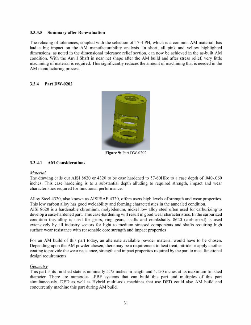
31
3.3.3.5 Summary after Re-evaluation
The relaxing of tolerances, coupled with the selection of 17-4 PH, which is a common AM material, has had a big impact on the AM manufacturability analysis. In short, all pink and yellow highlighted dimensions, as noted in the dimensional tolerance relief section, can now be achieved in the as-built AM condition. With the Anvil Shaft in near net shape after the AM build and after stress relief, very little machining of material is required. This significantly reduces the amount of machining that is needed in the AM manufacturing process.
3.3.4 Part DW-0202
Figure 9: Part DW-0202
3.3.4.1 AM Considerations
Material The drawing calls out AISI 8620 or 4320 to be case hardened to 57-60HRc to a case depth of .040-.060 inches. This case hardening is to a substantial depth alluding to required strength, impact and wear characteristics required for functional performance. Alloy Steel 4320, also known as AISI/SAE 4320, offers users high levels of strength and wear properties. This low carbon alloy has good weldability and forming characteristics in the annealed condition. AISI 8620 is a hardenable chromium, molybdenum, nickel low alloy steel often used for carburizing to develop a case-hardened part. This case-hardening will result in good wear characteristics. In the carburized condition this alloy is used for gears, ring gears, shafts and crankshafts. 8620 (carburized) is used extensively by all industry sectors for light to medium stressed components and shafts requiring high surface wear resistance with reasonable core strength and impact properties For an AM build of this part today, an alternate available powder material would have to be chosen. Depending upon the AM powder chosen, there may be a requirement to heat treat, nitride or apply another coating to provide the wear resistance, strength and impact properties required by the part to meet functional design requirements. Geometry This part is its finished state is nominally 5.75 inches in length and 4.150 inches at its maximum finished diameter. There are numerous LPBF systems that can build this part and multiples of this part simultaneously. DED as well as Hybrid multi-axis machines that use DED could also AM build and concurrently machine this part during AM build.

32
Features / Tolerances This part has several tight tolerance dimensions that can only be manufactured through conventional methods as outlined in the Conventional section below. The tightest tolerance is a +.0000/-.0005 inch dimension on an outside end which can be readily achieved via conventional machining. There are other features such as the sprockets that have a +.002/-.000 inch tolerance. There is a +.005/-,000 inch tolerance on an inside bore. All of these can only be accomplished via conventional machining methods. All threads must be machined into the part using conventional methods. The set-ups described in the Conventional section below are all required to achieving these tight tolerances on the part even if a near net shape part is built via AM first. Potential AM Steps As outlined above in the Feature / Tolerances section, even with a near net shape AM built part, conventional machining is required to meet drawing specifications. Internal stresses during the build, support structure strategy and the part’s geometry may cause deviation in tolerances. Expected surface roughness for LPBF systems is typically 150-400 micro-inch RA, depending upon the build orientation and material used for the build. All these can be compensated for by adding additional material and machining operations as outlined in the Conventional machining section below. If the part is built in the Z axis or vertical build orientation using a LPBF system, support structures would be minimized, but, the actual AM build time will be longer and will have greater cost. If the part is built horizontally, there would be support structures running the length of the part that would have to be removed either by machining or some other method. If the support structures are to be machined off, this would not be difficult to do on the outside of the part. There are support removal methods involving chemical etching that are in use for AM built parts. Minimizing the amount of support structure required will decrease design time, build time and post-processing required. Either AM build orientation would require additional material to be added onto the part in multiple areas to be able to conventionally machine to final specified drawing dimensions and tolerances. If built in the vertical Z axis dimension, the hollowed-out sections would still require supports and therefore post AM build support structure removal. Some of the support structure required could be minimized by building the part on an angle. However, doing so would not be enough to totally remove most of the supports.
3.3.4.2 AM Considerations Re-evaluation
Design relief provided: • Material Change to 17-4PH • Dimensional Tolerance Relief as indicated in the below pictorials was provided
Color Legend for highlighted dimensions in below pictorials: • Green dimensions are important/firm and will likely have to be machined • Yellow dimensions are loose, i.e. on the order of 0.01 or greater, not critical and can be near net
shape produced by AM • Pink dimensions are not critical

33
Figure 10: Tolerance adjustments for part DW-0202. Green indicates must be maintained, yellow indicates on the order of 0.01 inches or above, and pink indicates that dimension is not critical.
Material The use of 17-4 powder to AM build the Hammer Frame is an advantageous alternate material choice that is readily available from many AM Powder Suppliers around the world. It can achieve H900-H1150 mechanical properties, after LPBF or DED AM processing, similar to what is produced in standard plate, bar, rod and tube stock shapes available from steel mills after HIP and heat treat. It is also very cost effective, has good weldability and machining characteristics. 17-4PH is used for applications where ductility, high strength and corrosion resistance are of key concern. 17-4PH is a precipitation-hardening martensitic Stainless Steel, which has corrosion resistance comparable to austenitic varieties. In the case of 17-4PH AM parts, the resultant hardness and mechanical properties can vary from OEM AM machine to machine mainly due to laser power and other machine characteristics. The 17-4 as-built AM material condition and after heat treat will provide a hardness of 32-35 HRc, based on this author’s experience with 17-4PH AM part and test sample builds across various OEM AM LPBF machines. If it is determined that a higher hardness is required than what the AM as-built condition and any subsequent heat treat will provide to meet functional operating requirements, there are other alternative processes that can meet and exceed the 57-60HRc requirement currently called out on the existing drawing. It is

34
recommended to further evaluate diffusing boron (known as the “Borofuse” process or boriding) into the part substrate, or Nitriding to meet/exceed current drawing hardness requirements. The boron diffusion layer, or case, that forms can be characterized by depth, hardness and internal stresses. The depth of the boron diffusion layer is typically between 0.0003” – 0.007”. The hardness of a typical boride application readily exceeds 80 HRc having similar hardness to tungsten carbide. The key features of case thickness, hardness, and internal stresses make boriding a robust surface modification for many downhole geothermal/oil and gas applications. If hardness requirements are not met by heat treatment, boriding or nitriding of 17-4 PH, then an alternative AM material would be recommended. Inconel 625 and Inconel 718 are both commonly available AM materials that offer greater hardness. However, it is important to note that the author does not know the material requirements (e.g. tensile strength, ductility, corrosion) as defined by the engineer or designer of this part, so any AM material selected should be reviewed to ensure that material requirements are met. Geometry No change from the previous section. Features / Tolerances The relaxing of tolerances from the original drawings combined with selecting 17-4 PH as a material has made a significant difference in the AM manufacturability analysis. Specifically, this has reduced the number of machining steps needed post AM build. The below AM analysis will only consider the 17-4 part to being built in the as-built AM condition. No dimensional changes for application of a boron diffusion layer was considered since this process is not expected to increase or affect the dimensional stability of the as AM built part. Potential AM Steps Due to the relative small size of the part and the selection of a common AM material, 17-4 PH, the number of laser powder bed fusion AM machines that could potentially manufacture this part is quite large. It would be recommended to use a laser power bed fusion AM machine, such as a 3D Systems ProX 320 or an EOS M290 machine. Due to the small size of the part, several parts could be laid out on one build bed, which would decrease cost per part. Furthermore, due to the small size of the part and the selection of a standard AM material, 17-4 PH, a very large number of laser powder bed fusion AM machines would be suitable for building this part. A quick search of the Senvol Database (www.senvol.com/database) of PBF machines that process steel materials and that are larger than the overall dimensions of the part showed that nearly 100 AM machines would potentially be suitable for making this part. It is recommended that the Hammer Frame be AM built in the Z axis of orientation on the build plate as indicated in Figure 11. The z-orientation of build minimizes the number of overhangs that require support structures. This helps to reduce build time and the amount of 17-4 PH powder required to perform the AM build. The Hammer Frame larger mass is recommended to be AM built closer to the build plate as shown in the below pictorial to help provide additional control of residual stress buildup as the part is AM built. To ensure concentricity and perpendicularity of the part and to machine the “sprocket” hole, additional material of .020” to .030” on either end is recommended to be added. This will be machined off later to true up the part and provide well defined surface datums for subsequent required conventional machining.

35
Figure 11: Preferred AM build orientation for DW-0202
By controlling the size and shape of the support structures as indicated, they can be easily removed and deburred by hand. A hand polish of these surface via the use of a Dremel tool or Pencil Grinder (pneumatic tool with light sand paper) would be more than sufficient to clean up these areas and any surface artifacts from the AM build where the support structures were necessary to complete the build of the part features. In addition to the hand removal of these supports, a light glass bead blast of the outside surfaces to further clean up all outside surfaces is recommended. The support structures depicted in the pictorial would be repeated on the AM build of top end of the Hammer Frame as this top surface is an overhanging surface. It is recommended that a 1.31” diameter center hole be AM built into the part in its top section for later conventional machining to the final “sprocket” dimensions as indicated in Detail B of drawing DW-0202. The 2.20” diameter on the opposite end of the 1.31” diameter AM built hole can be AM built and be considered a finished as-built dimension due to the dimensional relief provided. Not shown in the above pictorial are the support structure required to anchor the part to the build plate. These support structure would be attached around the base of the Hammer Frame. The support structures extending from the build plate to the bottom surface of the Hammer Frame can be either saw cut off the base plate or removed from the base plate via wire EDM after stress relieving the Hammer Frame on the build plate. After the build is complete, the entire build plate with the parts attached would be stress relieved. One standard stress relief recipe to follow would be to stress relief at 1150°F for 3-4 hours, then oven cool to room temperature. All pink and yellow highlighted dimensions, as noted in the dimensional tolerance relief section, can be achieved in the as-built AM condition. Not having to machine and bevel the edges of the outside surface edges of the slots removes several machine set-ups and required machining saving both time and cost. All other features (those in green, sprockets and all threaded hole) will be required to be machined into the near net shape AM built Hammer Frame by following the steps below. A Mazak Integrex or a Mori NTX or NT with opposing spindles would be ideal to perform the required post AM build final machining. Op 10 – The Hammer Frame will be ready for conventional machining as a near net shaped AM built part. After the part has been fully cleaned and bead blasted, the first operation would be to fully inspect
Build Plate
Supports to anchor part to build plate
There will be support structures on both cutout sections. The bottom cutout section shows “tree like supports” which are very efficient and uses minimal material. These supports will be repeated in the top cutout section as well.
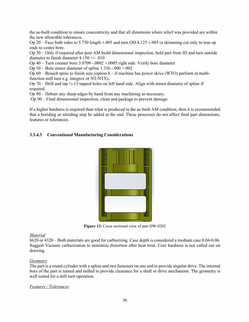
36
the as-built condition to ensure concentricity and that all dimension where relief was provided are within the new allowable tolerances. Op 20 – Face both sides to 5.750 length ±.005 and turn OD 4.125 ±.005 (a skimming cut only to true up ends to center bore. Op 30 – Only if required after post AM build dimensional inspection, hold part from ID and turn outside diameter to finish diameter 4.150 +/- .010 Op 40 – Turn counter bore 3.0709 -.0002 +.0005 right side. Verify bore diameter Op 50 – Bore minor diameter of spline 1.356 -.000 +.002 Op 60 – Broach spine to finish size (option b – if machine has power skive (WTO) perform in multi- function mill turn e.g. integrex or NT/NTX). Op 70 – Drill and tap ½-13 tapped holes on left hand side. Align with minor diameter of spline if required. Op 80 – Deburr any sharp edges by hand from any machining as necessary. Op 90 – Final dimensional inspection, clean and package to prevent damage. If a higher hardness is required than what is produced in the as-built AM condition, then it is recommended that a boriding or nitriding step be added at the end. These processes do not affect final part dimensions, features or tolerances.
3.3.4.3 Conventional Manufacturing Considerations
Figure 12: Cross sectional view of part DW-0202
Material 8620 or 4320 – Both materials are good for carburizing. Case depth is considered a medium case 0.04-0.06. Suggest Vacuum carburization to minimize distortion after heat treat. Core hardness is not called out on drawing. Geometry The part is a round cylinder with a spline and two fasteners on one end to provide angular drive. The internal bore of the part is turned and milled to provide clearance for a shaft or drive mechanism. The geometry is well suited for a mill turn operation. Features / Tolerances

37
The part includes a spline feature with no spline table requirements (e.g. pressure angle, pitch diameter, major/minor diameters). The part includes a counter bore 3.0709 on the right side with a -.0000 +.0005. This feature could shrink after carburize and heat treat should be taken into consideration during machining processes. All other features and tolerances are well within conventional machining practices. Note: shot peen will only support external features that can be impacted with the specified shot size. No requirement is called out for compressive stress depth resulting from shot peening. An excessively long tapped feature – no tapped thread is called out for this feature (.375 dia to 5.340 depth) is shown above in the cut away. Partial threads don’t serve a purpose for fastening. The depth of this thread to the diameter is another 10:1 feature requiring high pressure coolant to clear the chips during drilling and tapping operations. Conventional Manufacturing Steps The part will start out with fully annealed 4.5” bar stock cut to 5.875 in length. This is also a good part for multifunction equipment. The manufacturing sequence is as follows: Op 10 - Face both sides to 5.750 length ±.005 and turn OD 4.125 ±.005 Op 20 - Drill 1.25” diameter hole through the part. Op 30 – Grab part from ID and turn outside diameter to finish diameter 4.150 with R.15 radius Op 40 – Grab OD and bore ID features, requires tooling change for left and right radius’ Op 50 – Turn counter bore 3.0709 -.0002 +.0005 right side. Verify bore diameter. Op 60 – Bore minor diameter of spline 1.356 -.000 +.002 Op 70 – Broach spine to finish size (option b – if machine has power skive (WTO) perform in multi- function mill turn e.g. integrex or NT/NTX). Op 80 – Return to Lathe with milling capability and mill pockets. Finish radius feature with radius tool. Op 90 – Drill and tap ½-13 tapped holes on left hand side. Align with minor diameter of spline if required. Shot Peen to increase fatigue strength and develop deep compressive stress – minimizing surface initiated cracks. Shot size and method to be determined based on part needs and geometry. Heat Treat The final step for this part is vacuum carburization. The benefit of using a vacuum method is to minimize distortion from quenching. A short temper cycle after carb is recommended. Once complete the part should get a quick tumble to remove any scale, cleaned and preserved for packaging.
3.3.4.4 Summary
It might be worthwhile for ORNL to perform a deep dive of AM vs. conventional manufacturing cost-benefit analysis for this part. Given the amount of conventional machining required since the as-built AM condition cannot meet the drawing specifications, there is little reason to not AM build the part with the majority of the part as a solid slug with only hollowed out middle sections. Because of the required conventional machining part holding and set-up steps, it is advantageous from a dimensional and tolerance standpoint to perform as many of the multiple conventional machining steps to conventionally machine in as many required part features as possible that can be accomplished once the part holding and process machining step set-up has been accomplished in a specific axis of orientation. There is no real advantage to separately have the center bore on the sprocket/internal gear end and the tight counterbore on the opposite end not machined and aligned

38
once the conventional machining set-ups discussed below are achieved and accomplished. All threads of course must also be conventionally machined. Manufacturing via AM assumes that a suitable AM material be found as the material called out on this drawing is not readily available in AM. Regardless of an AM build or even conventional manufacture of this part, there will be additional processing for carburization and potential heat treat of the material to meet all functional design requirements. This report does not discuss the details regarding alternate AM powder materials to meet the drawing requirements or specific recipe for heat treat or alternate coating applications to achieve the design intent for wear.
3.3.4.5 Summary after Re-evaluation
The relaxing of tolerances, coupled with the selection of 17-4 PH, which is a common AM material, has had a big impact on the AM manufacturability analysis. In short, all pink and yellow highlighted dimensions, as noted in the dimensional tolerance relief section, can now be achieved in the as-built AM condition. All other features (those in green, sprockets and all threaded hole) will be required to be machined into the near net shape AM built Hammer Frame. Overall, this significantly reduces the amount of machining that is needed in the AM manufacturing process.
3.3.5 Assembly HTCA-001-OP
This part is an assembly comprised of multiple manufactured parts and purchased parts as listed on the Bill of Material on the drawing.
Figure 13: Assembly HTCA-001-OP
3.3.5.1 AM Considerations
NOTE: For an AM integrated option, only piece part numbers HTCA002, HTCA004 and HTCA034 are being considered as a potential AM integrated build option. Material All of the three part numbers listed above being considered for an integrated AM built part are designed to be manufactured from 17-4PH material. 17-4PH powder is prevalently used throughout the AM industry and readily available for LPBF and DED AM applications.

39
Geometry An integrated part body as mentioned below would have a build envelope requirement of 16.3 inches in length and 3.25 inches in diameter. There are LPBF machines that can build AM parts to accommodate this required volume of AM build. Note that most LPBF machines have X, Y or Z dimensions that are less than 16.3 inches, so only a few LBPF machines are suitable for this part. Available DED machines can quite easily handle this size part as can available Hybrid DED Multi-Axis CNC machines. Features / Tolerances The AM integrated part will have the following associated tolerances across the entire part necessitating the use of conventional machining operations and set-up operations to accomplish the dimensions and GD&T called out on the drawings. HCTA002 has the following tolerances on features: +.000/ -.001 inch, +.000/-.002 inches, +/-.002 inches, +/- .001 inch along with specific thread callouts. All of these above mentioned critical feature tolerances and the internal thread features will require conventional machining operations. HCTA004 has the following tolerances on features: +/-.001 inch, +.002/-.000 inches. All of these above mentioned critical feature tolerances will require conventional machining operations. HTCA034 has the following tolerances on features: +/-.001 inch, +/-.002 inches, +.005/-.000 inches, 10 Ra finish requirement, internal threads. All of these above mentioned critical feature tolerances will require conventional machining operations. Potential AM Steps HTCA-001-OP currently is comprised of three major conventionally manufactured piece parts that could be manufactured into one integrated AM or conventionally machined part:
• HTCA002 • HTCA004 • HTCA034
An assumption of integrating these three piece parts is being made without knowledge of the design functional requirements. It is being assumed that, if necessary, additional access hole for cable routing/installation and any other pertinent part features can be added either by AM build or conventionally machining to achieve an integrated manufactured functional part meeting essential design requirements. The Aluminum 6061 T6 Expansion Piston HTS035, Shaft Seal Retainer HTCS047 and the Lead Screw Sleeve Bushing can be conventionally machined separately and installed after all final conventional finished machining is performed on the AM integrated part body post AM build. As called out on the HCTA-0010OP Assembly, all other locating Gauge Pins Part number 91251A342 can be installed onto the integrated AM part. Additional material of .050-.100 inches of material would have to be added to the build all around on the integrated single part to machine the part to match current drawing requirements. The required .375 inch diameter hole through the integrated AM part can be built undersized to save build time and powder, if it is determined that this is not a required conventional machining operation to achieve a surface finish due to functional requirements. If a 150-400 Ra surface finish is sufficient, this hole can be AM built which will save time and cost of performing a final machining operation to finish out the hole. If vibration and cable assembly movement chafing will be a concern during functional operation and deployment, this hole can easily be conventionally machined while performing other required conventional machining operations in the same axis of part holding orientation.

40
The integrated AM part can be built in either X or Z axis of orientation. A Z axis build would require a greater built time, and there are limited suitable LPBF machines. If a LPBF system is used, internal hole geometry could be better controlled and might not require support structures during the AM build. If a monolithic combined one-part build can be built via AM and still meet all functional design requirements, there can be a substantial reduction in final machining operations resulting in reduced cost and lead time. This concept should be analyzed and investigated further with those who have a full understanding of the design functional requirements for feasibility. The image below is representative of a drawing for the monolithic assembly created for LPBF AM. It is critical to point out that this draw below was created with no understanding of the functional requirements of the part and may need to be modified heavily if functional part requirements were known.
Figure 14: Conceptual monolithic part for assembly HTCA-001-OP
3.3.5.2 Integrated Monolithic AM Part Post AM Build Required Conventional Machining
Op 10 – Chuck part with four jaw chuck. Turn right side end diameter. Face, drill and tap holes threaded holes. Turn O-ring groove. Op 20 – Rotate part and turn left side end diameter. Face, drill and tap threaded holes. Turn O-ring groove. Op 30 – Chuck on opposing twin spindle mill turn machine (e.g. Integrex or NT/NTX). Mill all four sides to desired dimensions and surface finish. Drill and tap 1/16 NPT holes Op 40 - Transfer to mill with high pressure coolant and specialized work holding. Drill, spot face and reverse spot face, tap 7/8-14 threads. Drill 3/8” hole thru and reverse spot face. Op 50 – Change to right angle attachment. Drill and tap 4-40 holes. NOTES:
• A new one part drawing combining all parts would be required with the necessary GD&T requirements applied in order to provide a full representation of post AM build conventional machining operational process steps.
41
• Subtractive machining steps become less extensive but require specialized work holding. Cutting tools and right-angle drill head are specific for application. Alternative solutions to the above process could be explored depending on functional requirements of application.
3.3.5.3 Conventional Manufacturing Considerations
Conventional Manufacturing Steps for HTCA002 HTCA002 – This part comprises cylindrical and prismatic features which lend itself to mill-turn multifunction equipment with opposing spindles to maintain clocked features. The material is well suited for conventional machining practices. The part will start out 3.25” round bar stock cut to 8” length. Op 10 – Face both sides to overall length of 7.906” – Excess stock required for work holding. Op 20 - Turn OD 3.000 -.000 +.010, flip part and complete OD Op 30 – Grab part from OD and mill prismatic left side features including 1.685 width 1.51” thick Op 40 – Mill 90° intersection as shown in view A-A. Op 50 – Spot Drill all tapped holes and location for through bore. Op 60 – Drill minor diameters for tapped holes 10-32, ¼-20, 1/16 NPT, 4-40 Op 70 – Use form taps to tap threaded holes from Op 60 Op 80 – Drill .75” dia hole through part with gun drill attachment and high pressure coolant. Op 90 - Turn .997 ID and minor diameter 7/8-14 thread. Op 100 – Thread mill 7/8-14 thread Op 110 – Machine 45° chamfers Op 120 – Spot face .500 dia counter bore (Section A-A) Op 130 – Hand part off to subspindle, Turn OD 2.672 +.000 -.003. Cut thread relief for UNJ thread Op 140 – Part of excess stock to 7.000 overall length Op 150 – Face right side to Overall length of 6.906 Op 160 – Spot drill holes 10-32, .188, .38 Op 170 – Drill .38 dia hole through Op 180 – Drill and tap (roll tap) holes right side 10-32 Op 190 – Drill and ream .188 dia holes +.000 -.001 Op 200 – Turn ID 1.060 diameter and min thread diameter for 7/8-14 thread Op 210 – Cut thread for 7/8-14 UNF (Right side) Note: This part is complex and is best suited for multi-function equipment. Conventional Manufacturing Steps for HTCA004 HTCA004 – This part is made from .250 thick 17-4 Stainless steel. The material should be bought ground to finished thickness requirements. Op 10 – Mill both ends to overall length 14.03” Op 20 – Spot drill all hole locations Op 30 – Drill 8X .221-.226 dia through and spot face .190 deep Op 40 – Flip part and interpolate mill 4X .313 dia counter bores -.000 +.002 Op 50 – Specialized fixture or 5th axis mill required – Machine 45° degree angle Op 60 – Flip part and mill 50° angle Note: this part can be done with 3 axis milling equipment and specialized work holding or 5 axis milling techniques. Conventional Manufacturing Steps for HTSA016

42
HTSA016 – This part made from brass can be made in 2 or 3 setups depending on shop capability. The raw material will be cut from 1” diameter round bar cut. A screw machine or lathe with a bar feeder could be used to make this part, depending on volume. Op 10 – Face side A Op 20 - Drill 0.627 diameter hole Op 30 - Turn OD to Major Diameter 7/8-14 thread Op 40 - Cut thread 7/8-14 thread Op 50 - Chamfer both sides Op 60 - Part off .38 width Op 70 – Move to mill with collet – mill .06 wide slots Conventional Manufacturing Steps for HTCA034 HTCA034 Cable Housing – This is a prismatic part made from 17-4 stainless steel. The part is can be made on 3 axis milling equipment with specialized work holding for cutting the beveled edges. A machine with high pressure coolant and a gun drill (through tooling coolant) is required to drill the .375 dia hole through the part. The part can be made from 1” X 2” wide 17-4 bar stock. Op 10 – Cut bar stock to length 12.125 ±.010 Op 20 – Face side A, Flip and face Side B to thickness of 1.69 ±.02 Op 30 – Rotate Part 90° and Face Side C, Flip and face side D to thickness .969 -.000 +.010 Op 40 – Spot drill 8X holes (side D), Drill .218-.216 dia holes thru, spot face to depth on drawing Op 50 – rotate part 180° to side C and mill 4X slots .876 X .313 Op 60 – rotate part 90° to side A and drill and tap 10-32 blind holes Op 70 – Cut slots 1.05 wide both sides Op 70 – rotate part 180° to side B and drill and tap 10-32 blind holes Op 80 – Cut slots 1.05” wide both sides Op 90 –Rotate part in long axis (12.050) and gun drill with high pressure coolant. This operation may require flipping to achieve cylindricity. Op 100 – Spot drill, drill .26 dia holes and spot face .490 counter bore concentric to .375 dia through bore. Op 110 – Flip part 180° and spot face .490 counterbore concentric to .375 dia bore Op 120 – Place part in specialized for holding fixture to mill .24-.25 angle relief alongside A Op 130 – Flip part 180° in specialized fixture to mill side B to .24-.25 relief Conventional Manufacturing Steps for HTCA035 HTCA035 Expansion Piston – This part made from 6061-T6 is an easily machined part on a lathes with a bar feeder or in higher volume with a screw machine. The raw material is .75” diameter round bar. Op 10 – Face and turn OD to .738 - .005 + .000 Op 20 – Cut groves 2X .093-.098 Op 30 –Radius both sides and part off Conventional Manufacturing Steps for HTS047 HTS047 Shaft Seal Retainer – This part made from stainless steel (not specified) can be made in made using a conventional 3 axis mill or specialized machinery depending on volume. The raw material will start off as 1.5” cold rolled round bar. Op 10 – Locate off OD and drill .126-.134 dia holes Op 20 – Counter sink 82° concentric to .126 dia holes in Op 10 Op 30 – Rotate part 180° and mill .688 hole through and 1.00 counter bore Op 40 – Register in tooling off flat, id bore and hold down with .126-.134 holes – mill flat – both sides
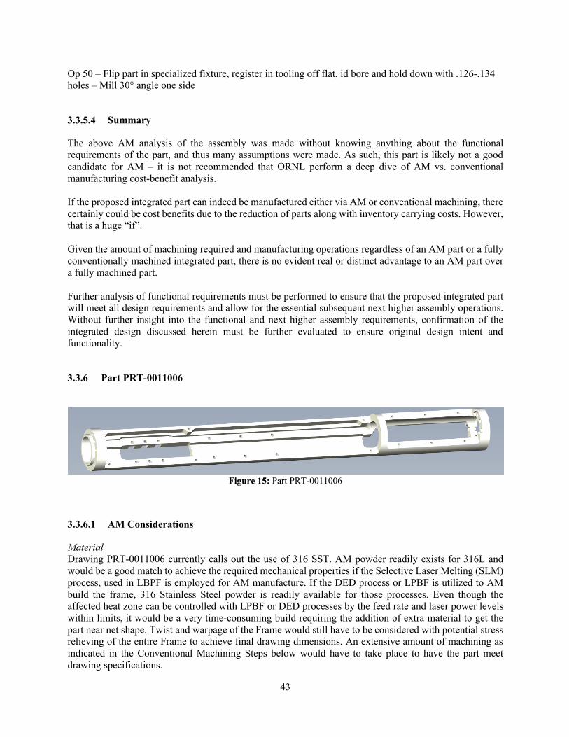
43
Op 50 – Flip part in specialized fixture, register in tooling off flat, id bore and hold down with .126-.134 holes – Mill 30° angle one side
3.3.5.4 Summary
The above AM analysis of the assembly was made without knowing anything about the functional requirements of the part, and thus many assumptions were made. As such, this part is likely not a good candidate for AM – it is not recommended that ORNL perform a deep dive of AM vs. conventional manufacturing cost-benefit analysis. If the proposed integrated part can indeed be manufactured either via AM or conventional machining, there certainly could be cost benefits due to the reduction of parts along with inventory carrying costs. However, that is a huge “if”. Given the amount of machining required and manufacturing operations regardless of an AM part or a fully conventionally machined integrated part, there is no evident real or distinct advantage to an AM part over a fully machined part. Further analysis of functional requirements must be performed to ensure that the proposed integrated part will meet all design requirements and allow for the essential subsequent next higher assembly operations. Without further insight into the functional and next higher assembly requirements, confirmation of the integrated design discussed herein must be further evaluated to ensure original design intent and functionality.
3.3.6 Part PRT-0011006
Figure 15: Part PRT-0011006
3.3.6.1 AM Considerations
Material Drawing PRT-0011006 currently calls out the use of 316 SST. AM powder readily exists for 316L and would be a good match to achieve the required mechanical properties if the Selective Laser Melting (SLM) process, used in LBPF is employed for AM manufacture. If the DED process or LPBF is utilized to AM build the frame, 316 Stainless Steel powder is readily available for those processes. Even though the affected heat zone can be controlled with LPBF or DED processes by the feed rate and laser power levels within limits, it would be a very time-consuming build requiring the addition of extra material to get the part near net shape. Twist and warpage of the Frame would still have to be considered with potential stress relieving of the entire Frame to achieve final drawing dimensions. An extensive amount of machining as indicated in the Conventional Machining Steps below would have to take place to have the part meet drawing specifications.

44
Geometry Per drawing PRT-0011006, the overall nominal part dimensions after all finished machining are 15 inches in length with a 1.50-inch diameter. Several current existing LPBF machines can build this part in both the X and Y orientation, however, few LBPF machines is able to build this part in the Z orientation. This Frame could also be AM built using DED. There are many more DED machines than LPBF machines that are able to accommodate a part of this bounded box size. Features / Tolerances The drawing block tolerances are +/- .003 inches for all three place decimal dimensions. All part dimensions have three place decimal dimensions. There are several Frame features that have even tighter tolerances such as +.005/-.000, +.000/-.005 and +.006/-.000 inches. The dimensions with these tolerances let alone the amount of material movement that can occur when the part is removed from a build plate even after stress relief calls for extensive machining of any AM near net shape part involving all traditional machine set-ups and machining steps as indicated in the conventional subtractive manufacture of the part. Potential AM Steps Due to its layer-by-layer additive manufacturing technique, the Selective Laser Melting (SLM) process, used in LBPF, enables the production of metallic parts with complex features For a Z orientation vertical build on LPBF the least amount of support structures would be required. Any support during the AM build would require machining post AM build to meet the tolerances of the drawing in addition to the other required machining to meet drawing dimensions since the part will have to be overbuilt dimensionally for support and final machining. If building in the X-Y direction of orientation, underlying support structure across the entire length of the part along the chamber build plate would be required, in addition to a substantial amount of support structure for all rails and inside diameters on each end of the Frame. This build orientation would lead to an additional amount of post AM build support structure removal from a near net shape part and would add time and cost. Regardless of AM build orientation for LPBF build, material up to .060-.150 inches should be added across the entire part. This is to account for some potential twist and movement of the part after being stress relieved off the build plate. It will be necessary to perform all the necessary traditional machining as outlined in the conventional machining steps below. All set-up steps would be applicable, however, due to the near net shape AM build, far less material would have to be machined from the part. Direct Energy Deposition (DED) also known as Laser Deposition Technology (LDT) can readily be used for Free Form Fabrication of this part. Even though the affected heat zone can be controlled with this process by the feed rate and laser power levels within limits, it would be a very time-consuming build still requiring the addition of extra material to get the part near net shape. Twist and warpage of the Frame would still have to be considered with potential stress relieving of the entire Frame to achieve final drawing dimensions. An extensive amount of machining as indicated in the Conventional Machining Steps below would have to take place to have the part meet drawing specifications. If DED were to be employed on a Hybrid DED/Multi-Axis CNC machine, the two manufacturing processes combined could be used to control and possibly reduce some of the warpage and twist during removal of material. Material removal via strategic machining intermittently in real time as material is being deposited could provide a means to generate many of the specified final features and meet drawing tolerances.
45
Another potential AM method of manufacture could be to additively manufacture the Mold to generate an Investment Casting. The part could be cast to near net shape and then apply the conventional machining steps as indicated below to achieve final part dimensional specifications. 316 SST can be readily cast. An AM mold could be printed to the near net shape. The casting could be made via the 3D printing of the mold using various dissolvable materials. Depending upon the accuracy of the 3D printer used, this method could still involve quite a bit of machining especially on tight tolerance features and of course the required conventional machining of all threads in the part. If the radii called out on the part can increase, this would further facilitate the AM build of the mold and could preclude the necessity of having to final machine these radii. Part features such as the radii should be further increased and optimized for the 3D printing of the mold and subsequent resultant casting. High precision 3D printers can build ultra-accurate, directly castable wax patterns for any industrial application. Complex geometries take shape quickly and reliably. Dissolvable supports melt away to reveal solid wax patterns with excellent surface finish. Wax burns out cleanly to produce smooth, high integrity metal parts. If 3D printers with high feature accuracy are used for example to build the wax pattern for the frame, the part could be directly castable in stainless steel and many other castable alloys. This method of AM manufacture may have the highest degree of cost savings providing repeatable fabrication resulting in high integrity castings ready for final machining.
3.3.6.2 Conventional Manufacturability Considerations
Material The material is corrosion resistant 316 SST in the annealed state. 316 tends to work harden during machining. Machining practice requires excellent cooling and small chip loading to prevent hardening. Sharp carbide end mills with 4-5 flutes are necessary for milling. Geometry The part is a cylindrical 1.5” diameter with a cutaway on the left side to the centerline of the part and a two-sided cutaway on the right side 180° apart. Both the left and right side have milled slots through the part which will have to be accounted for through stress relief practices prior to the finish machine steps. Features / Tolerances This part is well suited for multifunction equipment. Many of the threaded features can be completed in a final setup, which will assure perfect registration between mating assemblies. We recommend a twin spindle Mazak Integrex, Mori NT or NTX or Okuma Multis machining centers for this type of work. The part tolerances are well within conventional subtractive machining capabilities. The surface finish of 125 Ra does not require and successive operations beyond edge break of sharp corners and burrs. Conventional Manufacturing Steps This part can begin with 1.625” diameter bar stock approximately 19” long. The part will be held between opposing spindles (Intergrex opposing twin spindle or NT-X) with a conventional 3 jaw chuck. Each chuck will swallow approximately 2” of material for good work holding. An alternate method is a single spindle lathe with a tail stock and steady rest could also be used for the beginning turning operations, but it will need to move to a mill with multiple setups for finish operations. Op 10 – Hold part from each side with three jaw chucks. Turn OD to 1.5: dia. X 14.875 long. Turn left side shoulder to 1.125 -.000 +.002. .123 wide.

46
Op 20 – Rechuck part in spindle and swallow approximately 9.6” into the spindle. Bore right hand side ID .969 to 4.376 deep. Note: Feature in red ledge (Figure 16) prevents gun drilling of part for optimal processing.
Figure 16: Feature that prevents gun drilling of part
Op 30 – Rotate part 180° and swallow right side 9.6” into the spindle. Bore left hand side ID .969 to .500 deep. Op 40 – Re-chuck part between spindles swallowing 2” in each chuck. Positioning in the primary spindle is critical to maintain counterbore location accuracy. Recommend probing part for accuracy of placement. Mill off left hand flat to .625” deep. Leave 1/8” material for finish operations. Rotate part 180° and remove .100 material.On the right side remove .400 deep from each side x 4.578 long. Op 50 – Stress relieve part @ atmospheric oven baked at 410 ± 15°F for 2 hours. May not be required…. Op 60 – Re-chuck part between centers. Probe part for X axis location and probe to fine orientation of machined flats. Finish flats on left and right side of part to specified distance (Center Line, .120 deep on right side, and .500 deep each side on right side). Mill flats on left side of part 10.375 long. Remove opening .886 wide x 4.578 long on right side of part. Remove opening on left hand side of part .578 wide x 2.695 long. Mill counter bores on left hand side of part. Drill and roll form tapped holes. Note: Cross sectional area (Blue Shade in Figure 17) on left hand side after removing .578 wide x 2.695 opening reduces overall stiffness and limits final operations to drill and tapping during Op 60.
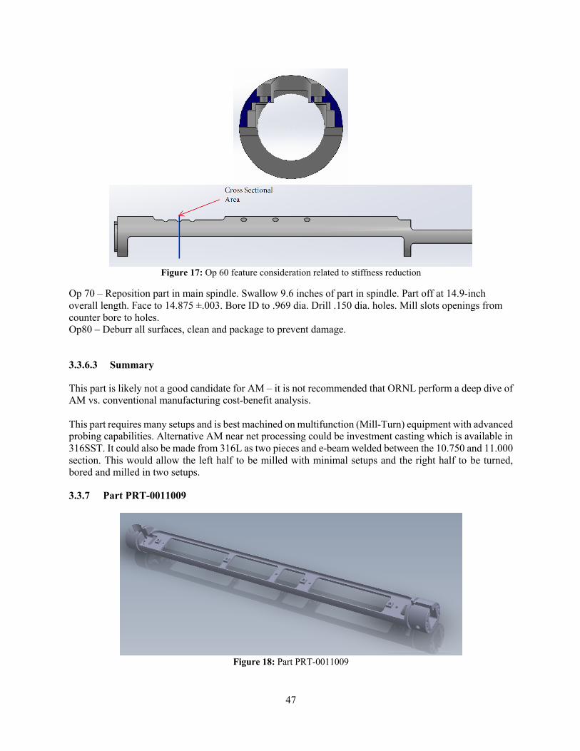
47
Figure 17: Op 60 feature consideration related to stiffness reduction
Op 70 – Reposition part in main spindle. Swallow 9.6 inches of part in spindle. Part off at 14.9-inch overall length. Face to 14.875 ±.003. Bore ID to .969 dia. Drill .150 dia. holes. Mill slots openings from counter bore to holes. Op80 – Deburr all surfaces, clean and package to prevent damage.
3.3.6.3 Summary
This part is likely not a good candidate for AM – it is not recommended that ORNL perform a deep dive of AM vs. conventional manufacturing cost-benefit analysis. This part requires many setups and is best machined on multifunction (Mill-Turn) equipment with advanced probing capabilities. Alternative AM near net processing could be investment casting which is available in 316SST. It could also be made from 316L as two pieces and e-beam welded between the 10.750 and 11.000 section. This would allow the left half to be milled with minimal setups and the right half to be turned, bored and milled in two setups.
3.3.7 Part PRT-0011009
Figure 18: Part PRT-0011009
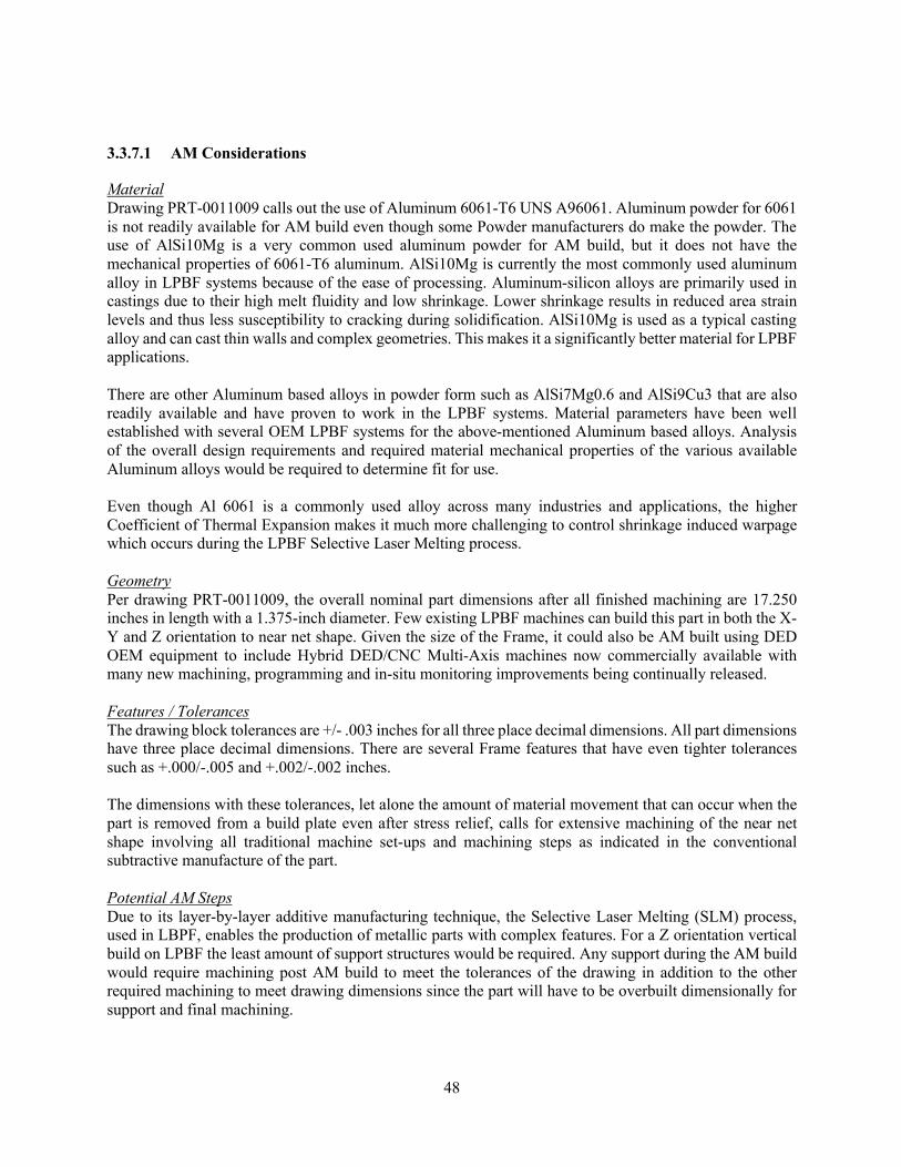
48
3.3.7.1 AM Considerations
Material Drawing PRT-0011009 calls out the use of Aluminum 6061-T6 UNS A96061. Aluminum powder for 6061 is not readily available for AM build even though some Powder manufacturers do make the powder. The use of AlSi10Mg is a very common used aluminum powder for AM build, but it does not have the mechanical properties of 6061-T6 aluminum. AlSi10Mg is currently the most commonly used aluminum alloy in LPBF systems because of the ease of processing. Aluminum-silicon alloys are primarily used in castings due to their high melt fluidity and low shrinkage. Lower shrinkage results in reduced area strain levels and thus less susceptibility to cracking during solidification. AlSi10Mg is used as a typical casting alloy and can cast thin walls and complex geometries. This makes it a significantly better material for LPBF applications. There are other Aluminum based alloys in powder form such as AlSi7Mg0.6 and AlSi9Cu3 that are also readily available and have proven to work in the LPBF systems. Material parameters have been well established with several OEM LPBF systems for the above-mentioned Aluminum based alloys. Analysis of the overall design requirements and required material mechanical properties of the various available Aluminum alloys would be required to determine fit for use. Even though Al 6061 is a commonly used alloy across many industries and applications, the higher Coefficient of Thermal Expansion makes it much more challenging to control shrinkage induced warpage which occurs during the LPBF Selective Laser Melting process. Geometry Per drawing PRT-0011009, the overall nominal part dimensions after all finished machining are 17.250 inches in length with a 1.375-inch diameter. Few existing LPBF machines can build this part in both the X-Y and Z orientation to near net shape. Given the size of the Frame, it could also be AM built using DED OEM equipment to include Hybrid DED/CNC Multi-Axis machines now commercially available with many new machining, programming and in-situ monitoring improvements being continually released. Features / Tolerances The drawing block tolerances are +/- .003 inches for all three place decimal dimensions. All part dimensions have three place decimal dimensions. There are several Frame features that have even tighter tolerances such as +.000/-.005 and +.002/-.002 inches. The dimensions with these tolerances, let alone the amount of material movement that can occur when the part is removed from a build plate even after stress relief, calls for extensive machining of the near net shape involving all traditional machine set-ups and machining steps as indicated in the conventional subtractive manufacture of the part. Potential AM Steps Due to its layer-by-layer additive manufacturing technique, the Selective Laser Melting (SLM) process, used in LBPF, enables the production of metallic parts with complex features. For a Z orientation vertical build on LPBF the least amount of support structures would be required. Any support during the AM build would require machining post AM build to meet the tolerances of the drawing in addition to the other required machining to meet drawing dimensions since the part will have to be overbuilt dimensionally for support and final machining.

49
If building in the X-Y direction of orientation, underlying support structure across the entire length of the part along the chamber build plate would be required, in addition to a substantial amount of support structure for all rails and inside diameters on each end of the Frame. This build orientation would lead to an additional amount of post AM build support structure removal from a near net shape part and would add time and cost. Regardless of AM build orientation for LPBF build, material up to .060-.150 inches should be added across the entire part. This is to account for some potential twist and movement of the part after being stress relieved off the build plate prior to performing the necessary traditional machining as outlined in the conventional machining steps below to meet drawing dimensional requirements. All set-up steps would be applicable, however, due to the near net shape AM build, and far less material would have to be machined from the part. Direct Energy Deposition (DED) also known as Laser Deposition Technology (LDT) can readily be used for Free Form Fabrication of this part. Even though the affected heat zone can be controlled with this process by the feed rate and laser power levels within limits, it would be a very time-consuming build still requiring the addition of extra material to get the part near net shape. Twist and warpage of the Frame would still have to be considered with potential stress relieving of the entire Frame to achieve final drawing dimensions. An extensive amount of machining as indicated in the Conventional Machining Steps below would have to take place to have the part meet drawing specifications. If DED were to be employed on a Hybrid DED/Multi-Axis CNC machine, the two manufacturing processes combined could be used to control and possibly reduce some of the warpage and twist during removal of material. Material removal via strategic machining intermittently real time as material is being deposited could provide a means to generate many of the specified final features and meet drawing tolerances. Another potential AM method of manufacture could be through additive manufacturing of the Mold to generate an Investment Casting. Aluminum AlSi10Mg can be readily cast as mentioned above in the Material Analysis section. An AM mold could be printed to the near net shape. This, however, depending upon the 3D printed method, could still involve a tremendous amount of machining especially on tight tolerance areas and of course the required machining of all threads in the part. High precision 3D printers can build ultra-accurate, directly castable wax patterns for any industrial application. Complex geometries take shape quickly and reliably. Dissolvable supports melt away to reveal solid wax patterns with excellent surface finish. Wax burns out cleanly to produce smooth, high integrity metal parts. If appropriate AM machines with high feature accuracy are used for example to build the wax pattern for the frame, the part could be directly castable in Aluminum and many other castable alloys.
3.3.7.2 AM Considerations Deep-Dive Analysis
Based on dimensional reliefs provided, the deep-dive recommendations for the Frame to be built in AM are discussed in the following below sections of this report. Design relief provided:
• Material Change to 316L • Dimensional Tolerance Relief as indicated in the below pictorials was provided
Color Legend for highlighted dimensions in below pictorials:
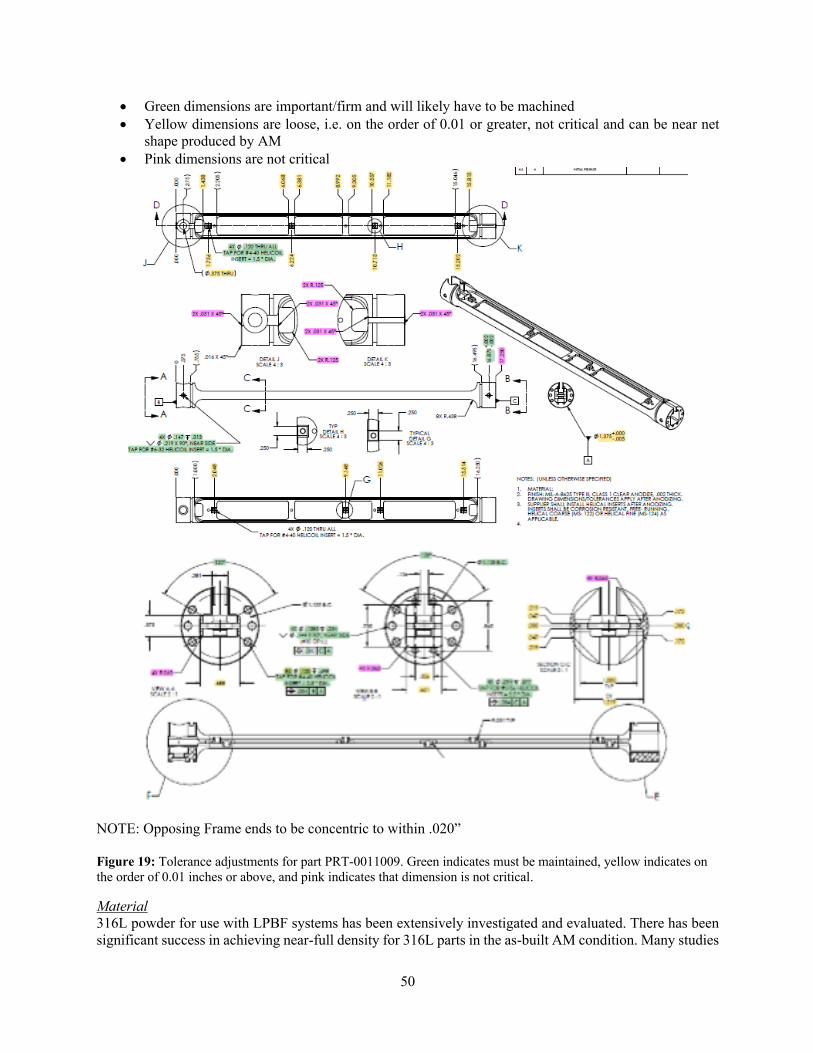
50
• Green dimensions are important/firm and will likely have to be machined • Yellow dimensions are loose, i.e. on the order of 0.01 or greater, not critical and can be near net
shape produced by AM • Pink dimensions are not critical
NOTE: Opposing Frame ends to be concentric to within .020” Figure 19: Tolerance adjustments for part PRT-0011009. Green indicates must be maintained, yellow indicates on the order of 0.01 inches or above, and pink indicates that dimension is not critical.
Material 316L powder for use with LPBF systems has been extensively investigated and evaluated. There has been significant success in achieving near-full density for 316L parts in the as-built AM condition. Many studies
51
have been performed and there has been substantial collaboration amongst 316L powder manufacturers and OEM AM machine suppliers from around the world in the selection of appropriate process parameters that result in parts with desired mechanical properties to include density. Reaching near full density requires balancing laser power, scan speed, beam size, and layer thickness to ensure on one hand that the layer fully melts and on the other hand that the melting does not result in the development of voids. 316L AM powder is readily available from numerous powder manufacturers around the world and is easy to obtain for AM production use. Cost of 316L AM powder if fairly standardized and there are no huge differences between various suppliers. The material properties of an AM part are dependent on both the raw powder material, the machine type and the process parameters used for printing. The material supplier will give estimates of material properties such as Young’s modulus, Poisson’s ratio, yield strength, elongation at break, etc. in different orientations. However, the part geometry, process parameters and characteristics of each machine type will also affect the resulting material properties. The challenge in this process is the selection of appropriate AM machine process parameters that result in parts with desired properties. For crucial applications, printing test specimens and characterizing the as-printed material properties might be necessary. Due to the inherent anisotropy of the as-printed material, it will often be necessary to include this in the material model and to specify the build orientation of the part. Material properties are also dependent on the heat distribution in the part during the print, and, although post-processing heat treatment reduces these effects, residual stresses and deformations must be considered during the actual AM build process. Surface finish is highly dependent on orientation and location in the build chamber. In summary, the choices of material (which 316L powder to use from which supplier), machine (which machine model from which manufacturer) and process parameters (what laser power, scan speed, hatch spacing, layer thickness etc.) have a very strong impact on the material properties and performance of the end part. It is out of scope for this report to offer a definitive selection of these three choices. Every AM project must make these selections through trial and error (i.e. making builds of test specimens, testing them, analyzing the data and honing in on the ideal combination of material, machine and process parameters). It is also important to emphasize that these selections will change if any one of these three factors change. For example, if an AM project has been building parts using a Concept Laser X Line 2000R machine using 316L powder from supplier A, and using process parameter set B, then if the AM user switches to a different machine, for example, the SLM Solutions SLM 800, then it is likely that to achieve the same material property and performance as before a different powder supplier and/or a different process parameter set will need to be used. Geometry No change from the previous section. Features / Tolerances LPBF Design Guidelines for the Z orientation AM build of the Frame: Standard layer thickness for each AM build layer:
• .0012” - .0016” (~0.030 - 0.040mm) thick layers depending on material Minimum recommended feature size:
• .030” (.75mm) for cosmetic features • .060” (1.5mm) for structural features
Tolerance: • +/- 0.005” for the first inch is typical, plus +/- 0.002” for every inch thereafter.
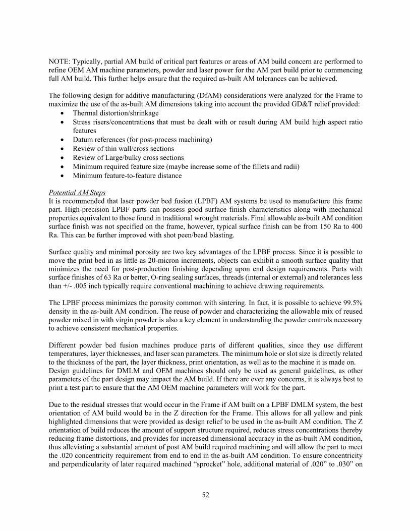
52
NOTE: Typically, partial AM build of critical part features or areas of AM build concern are performed to refine OEM AM machine parameters, powder and laser power for the AM part build prior to commencing full AM build. This further helps ensure that the required as-built AM tolerances can be achieved. The following design for additive manufacturing (DfAM) considerations were analyzed for the Frame to maximize the use of the as-built AM dimensions taking into account the provided GD&T relief provided:
• Thermal distortion/shrinkage • Stress risers/concentrations that must be dealt with or result during AM build high aspect ratio
features • Datum references (for post-process machining) • Review of thin wall/cross sections • Review of Large/bulky cross sections • Minimum required feature size (maybe increase some of the fillets and radii) • Minimum feature-to-feature distance
Potential AM Steps It is recommended that laser powder bed fusion (LPBF) AM systems be used to manufacture this frame part. High-precision LPBF parts can possess good surface finish characteristics along with mechanical properties equivalent to those found in traditional wrought materials. Final allowable as-built AM condition surface finish was not specified on the frame, however, typical surface finish can be from 150 Ra to 400 Ra. This can be further improved with shot peen/bead blasting. Surface quality and minimal porosity are two key advantages of the LPBF process. Since it is possible to move the print bed in as little as 20-micron increments, objects can exhibit a smooth surface quality that minimizes the need for post-production finishing depending upon end design requirements. Parts with surface finishes of 63 Ra or better, O-ring sealing surfaces, threads (internal or external) and tolerances less than +/- .005 inch typically require conventional machining to achieve drawing requirements. The LPBF process minimizes the porosity common with sintering. In fact, it is possible to achieve 99.5% density in the as-built AM condition. The reuse of powder and characterizing the allowable mix of reused powder mixed in with virgin powder is also a key element in understanding the powder controls necessary to achieve consistent mechanical properties. Different powder bed fusion machines produce parts of different qualities, since they use different temperatures, layer thicknesses, and laser scan parameters. The minimum hole or slot size is directly related to the thickness of the part, the layer thickness, print orientation, as well as to the machine it is made on. Design guidelines for DMLM and OEM machines should only be used as general guidelines, as other parameters of the part design may impact the AM build. If there are ever any concerns, it is always best to print a test part to ensure that the AM OEM machine parameters will work for the part. Due to the residual stresses that would occur in the Frame if AM built on a LPBF DMLM system, the best orientation of AM build would be in the Z direction for the Frame. This allows for all yellow and pink highlighted dimensions that were provided as design relief to be used in the as-built AM condition. The Z orientation of build reduces the amount of support structure required, reduces stress concentrations thereby reducing frame distortions, and provides for increased dimensional accuracy in the as-built AM condition, thus alleviating a substantial amount of post AM build required machining and will allow the part to meet the .020 concentricity requirement from end to end in the as-built AM condition. To ensure concentricity and perpendicularity of later required machined “sprocket” hole, additional material of .020” to .030” on

53
either end is recommended to be added. This will be machined off later to true up the part and provide well defined surface datums for subsequent required conventional machining. As part of the deep-dive AM analysis, a simulation of residual stresses was conducted using commercially available simulation software. This simulation took approximately 8 hours to complete. In this simulation, a “worse case” scenario was investigated, which long full-length support materials were added in order to support the top of the frame. These full-length supports are not recommended, and instead gusset supports are recommended.
Figure 20: FEA residual stress simulation of PRT-0011009 following additive manufacturing including recommended support structures.
As indicated by the thermal stress analysis and stress concentration pictorials, the Z axis orientation of build clearly provides distinct advantages related to minimizing distortion/twist in the Frame. The Z axis of orientation of AM build is the recommended orientation to be used to AM build the Frame using 316L powder. Proper use of gusset support structures will further minimize stress concentration and allow for the AM build of the overhang features, which are the horizontal features in the center of the Frame and the overhang of the Frame round end section with the Frame in the Z orientation of build. The first two pictorials below represent the “mesh modeling” employed to analyze the Frame in the Z orientation of build. Zooming in on the pictorials, one can see the modeled mesh patterns on these Frame pictorials. Not all the required support structures that would run the length of the part during AM build are indicated in these views. These views are for illustration purposes. As stated earlier, using these number of support structures running the length of the part was performed as a “worse case” and costliest AM build scenario in the Z orientation of AM build.
Gusset supports at 45°angles would be added at the top and below each “rung” of the frame.
Supports that run the length of the part are not ideal, however, they were used in the “worst-case” stress simulation.
That the support look “wavy” is an artifact of zooming into the image on the simulation. These supports would be built straight.
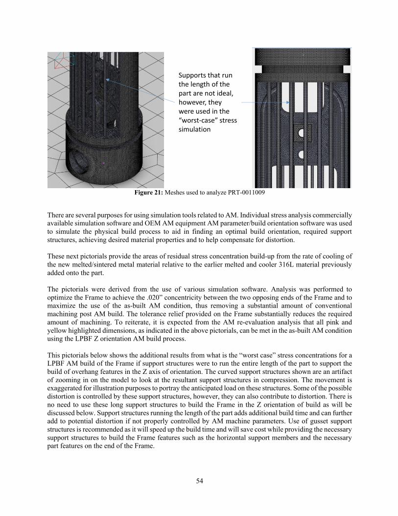
54
Figure 21: Meshes used to analyze PRT-0011009
There are several purposes for using simulation tools related to AM. Individual stress analysis commercially available simulation software and OEM AM equipment AM parameter/build orientation software was used to simulate the physical build process to aid in finding an optimal build orientation, required support structures, achieving desired material properties and to help compensate for distortion. These next pictorials provide the areas of residual stress concentration build-up from the rate of cooling of the new melted/sintered metal material relative to the earlier melted and cooler 316L material previously added onto the part. The pictorials were derived from the use of various simulation software. Analysis was performed to optimize the Frame to achieve the .020” concentricity between the two opposing ends of the Frame and to maximize the use of the as-built AM condition, thus removing a substantial amount of conventional machining post AM build. The tolerance relief provided on the Frame substantially reduces the required amount of machining. To reiterate, it is expected from the AM re-evaluation analysis that all pink and yellow highlighted dimensions, as indicated in the above pictorials, can be met in the as-built AM condition using the LPBF Z orientation AM build process. This pictorials below shows the additional results from what is the “worst case” stress concentrations for a LPBF AM build of the Frame if support structures were to run the entire length of the part to support the build of overhang features in the Z axis of orientation. The curved support structures shown are an artifact of zooming in on the model to look at the resultant support structures in compression. The movement is exaggerated for illustration purposes to portray the anticipated load on these structures. Some of the possible distortion is controlled by these support structures, however, they can also contribute to distortion. There is no need to use these long support structures to build the Frame in the Z orientation of build as will be discussed below. Support structures running the length of the part adds additional build time and can further add to potential distortion if not properly controlled by AM machine parameters. Use of gusset support structures is recommended as it will speed up the build time and will save cost while providing the necessary support structures to build the Frame features such as the horizontal support members and the necessary part features on the end of the Frame.
Supports that run the length of the part are not ideal, however, they were used in the “worst-case” stress simulation

55
Figure 22: Worst case stress locations for PRT-0011009
Gusset supports are recommended to be used for the AM build of the Frame using the guidelines as illustrated in the below pictorial. For the Frame, gusset supports should be built in process at each overhang feature on the Frame as it is being AM built in the Z direction. The overhang features on the Frame requiring gussets are minimal due to the recommended Z orientation of build. The Frame features requiring gussets are the horizontal Frame members and at the very top of the Frame on the circular round end section that creates an overhang condition due to the prescribed AM build orientation. Gusset supports are typically .040” thick or less spaced approximately 040-.060” apart. These gusset supports will have to be removed, which can easily be performed by hand. Since these are overhang surfaces, the surface finish roughness will be 200 Ra or greater. These areas can be easily deburred by hand during gusset removal. If deemed necessary, these areas along with any of the cutout AM built pockets of the Frame can easily and in very little time be profiled in as other required machining features are being machined in when the Frame is situated in the horizontal position. These gusset support structures will reduce the AM build time, reduce the cost of required powder to perform the build due to smaller and minimal support structures, will reduce post AM build processing time and will help further control distortion during build helping with heat dissipation. The pictorial below is an extract from a Renishaw design for additive manufacturing (DfAM) manual, which is included when purchasing an AM machine.
Supports that run the length of the part are not ideal, however, they were used in the “worst-case” stress simulation
Gusset supports at 45° angles, in blue above, would be recommended since they use the minimal amount of material
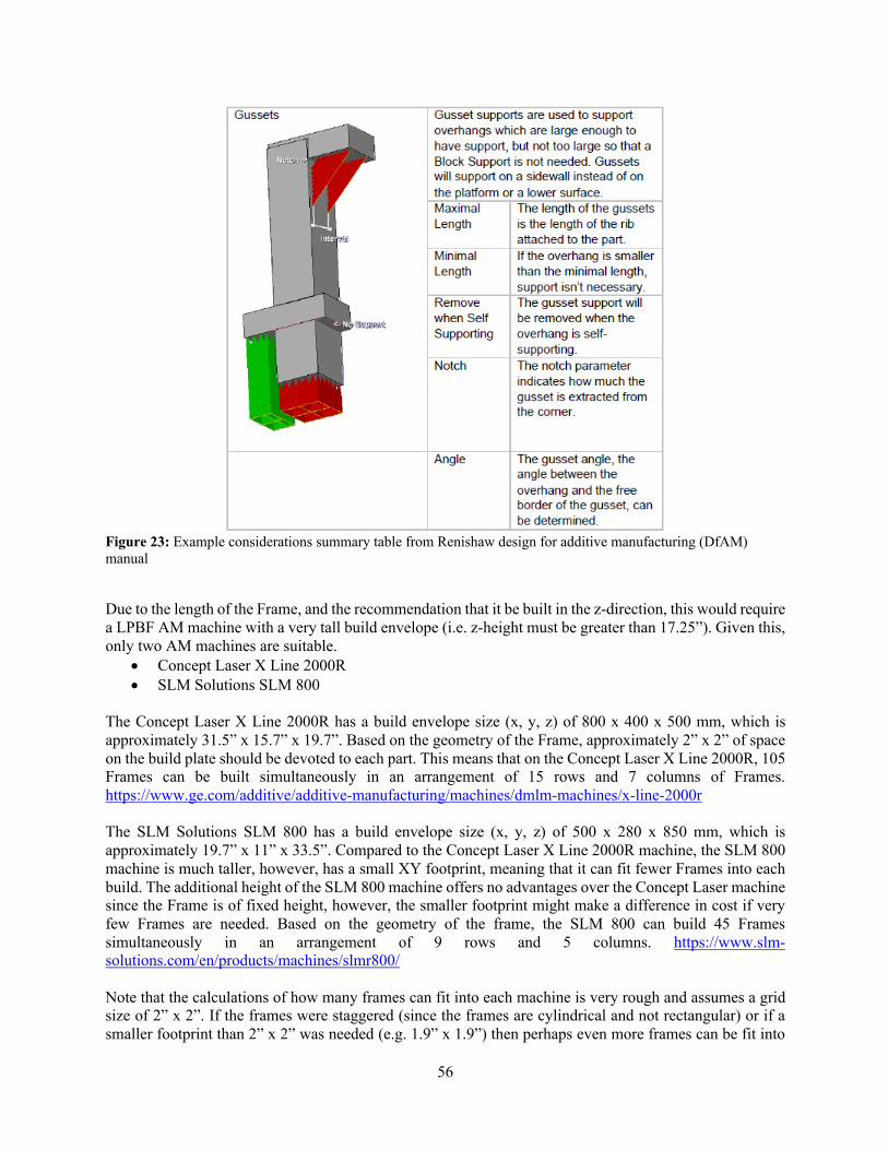
56
Figure 23: Example considerations summary table from Renishaw design for additive manufacturing (DfAM) manual
Due to the length of the Frame, and the recommendation that it be built in the z-direction, this would require a LPBF AM machine with a very tall build envelope (i.e. z-height must be greater than 17.25”). Given this, only two AM machines are suitable.
• Concept Laser X Line 2000R • SLM Solutions SLM 800
The Concept Laser X Line 2000R has a build envelope size (x, y, z) of 800 x 400 x 500 mm, which is approximately 31.5” x 15.7” x 19.7”. Based on the geometry of the Frame, approximately 2” x 2” of space on the build plate should be devoted to each part. This means that on the Concept Laser X Line 2000R, 105 Frames can be built simultaneously in an arrangement of 15 rows and 7 columns of Frames. https://www.ge.com/additive/additive-manufacturing/machines/dmlm-machines/x-line-2000r The SLM Solutions SLM 800 has a build envelope size (x, y, z) of 500 x 280 x 850 mm, which is approximately 19.7” x 11” x 33.5”. Compared to the Concept Laser X Line 2000R machine, the SLM 800 machine is much taller, however, has a small XY footprint, meaning that it can fit fewer Frames into each build. The additional height of the SLM 800 machine offers no advantages over the Concept Laser machine since the Frame is of fixed height, however, the smaller footprint might make a difference in cost if very few Frames are needed. Based on the geometry of the frame, the SLM 800 can build 45 Frames simultaneously in an arrangement of 9 rows and 5 columns. https://www.slm-solutions.com/en/products/machines/slmr800/ Note that the calculations of how many frames can fit into each machine is very rough and assumes a grid size of 2” x 2”. If the frames were staggered (since the frames are cylindrical and not rectangular) or if a smaller footprint than 2” x 2” was needed (e.g. 1.9” x 1.9”) then perhaps even more frames can be fit into

57
the build plate. Generally, a minimum of 4mm must be kept between parts on a LPBF machine, though it is up to the manufacturer how to lay out the builds. The goal of this estimate of how many frames can fit into one build plate is to demonstrate that the Concept Laser machine has approximately double the capacity compared to the SLM Solutions machine. This will be important for the cost calculation since it is most cost effective to build completely full builds. This means that if 40-50 Frames are needed at one time, the SLM 800 machine would be more effective than filling a Concept Laser machine only half full, whereas if 100-110 Frames are needed at one time, then the Concept Laser machine would likely be more cost effective. Since no information about the number of Frame parts is provided, it is not possible to make a definitive recommendation whether the SLM Solutions machine or the Concept Laser machine would be better. In this case, both machines are very similar in capabilities so the decision driver is more economics than technical capabilities. Other OEM AM machines that can build to a Z height of 18” or greater are on the horizon and are expected to become commercially available in the next 12-18 months. Customized LPBF machines that can build 1M X 1M x 1M could be specially ordered and manufactured by at least one AM Machine Manufacturer today. However, for the purposes of this deep-dive AM manufacturability analysis, recommendations have only focused on currently commercially available, non-custom built, AM machines. After the build is complete, the entire build plate with the parts attached would be stress relieved. One standard stress relief recipe to follow would be as follows: processing of parts in inert atmosphere in the range of 705°F to 755°F; hold at selected temperature +/-15°F for 300 minutes +/-15 minutes, inert gas cool. After stress relief, the near net shape part would be bead blasted and then machined using the following steps: Op 10 – After the part has been fully cleaned and bead blasted, the first operation would be to fully inspect the as-built condition to ensure concentricity and that all dimension where relief was provided are within the new allowable tolerances. To ensure concentricity of later required machined holes, additional material of .020” to .030” on either end is recommended to be added during AM build. This will be machined off later to true up the part and provide well defined surface datums for subsequent required conventional machining. Note: Due to the near net shape condition of the AM built Frame, the Operations for conventional machining Ops 30, 40, 50, 60, 70, 80 and 90 are superfluous since these have been addressed with the allowable dimensional tolerance relief provided that facilitated these features to be accomplished in the as-built AM condition. Op 20 – Remove all supports from the Frame by hand using hand tools. Rough remaining areas can be further deburred by hand using a Dremel tool Note: Previous machining Ops 100-150 are now replaced by the below Ops 30-60. Anodization of the Frame is not required as it is now being made from 316L material. Installation of Helicoils are not required since all threads can be directly tapped into the 316L AM built Frame. Op 30 – Load the Frame into a fixture laying horizontally and machine each end (skim machine). This now will ensure the ends are concentric. With the Frame in the fixture, if the grooves on either end are O-ring grooves, these can be easily machined. Even if there were support structures removed and deburring of these grooves performed earlier, these grooves can be further readily machined if necessary while the Frame is in the fixture. Op 40 – Place the Frame in a Vertical machine Center and machine all critical green highlighted features (all counterbore and tapped holes) as indicated in the below pictorial). Note: Since the AM built Frame is 316L material, no Helicoils are necessary to be installed. The Frame can be directly tapped to the finish threaded fastener hole required dimensions. If no Helicoils are installed, all thread callouts will have to be changed to the final required tapped hole dimension.
58
Op 50 – Deburr any sharp edges by hand from any machining as necessary. Op 60 – Final dimensional inspection, clean and package to prevent damage.
3.3.7.3 Conventional Manufacturing Considerations
Material Material is 6061 T-6 and is a highly desirable aircraft aluminum for machining purposes. High speed milling practices support rapid removal of material. Geometry The part is a cylindrical 1.375” diameter with an open cutaway section through the middle of the part. Stress relieving and specialized working will need to be designed to support this part during manufacturing. Minor straightening may be necessary after stress relieving. Features / Tolerances The part requires a type 3 anodize after machining. This process will add material (penetration 50% in part/50% out of part) to inside diameters and should require running a test piece for anodizing to verify and or adjust machined dimensions prior to production processing. All screw thread inserts must be inserted after anodizing. STI inserts are very small. We are concerned that breaking taps after hard anodizing is a high probability. Recommend drilling holes for 4-40 and 2-56 STI’s get done with carbide drills after anodizing. Conventional Manufacturing Steps The part could start out as a precision ground rod @ 1.375 +.000-.005 which would eliminate turning the OD to size. Overall cut length 17.50 ±.010. This part will start out on a lathe with y-axis live tooling to mill, and drill features. The lathe acts as an ideal work holding device for a long part over doing all operations on a mill. Aluminum has a strong tendency to warp after milling which will require a rough milling operation followed by a stress relieve prior to finishing out the center pocketing of the part. Op 10 – Chuck part in spindle with approximately 7” extending from chuck. Face right side of part and chamfer end. Mill rectangular opening in end and radius opening. Drill .1285 dia. holes .234 deep on 1.125 B.C., countersink 90° to .144 dia. (allow for growth at hard anodize). Turn .115 wide slot .102 deep at .755 from end. Mill slot .156 wide x 1.00 deep. Chamfer slot ends .031 x 45°. Drill hole at 16.875 for 6-32 STI tap. Note: This hole will be chased after anodizing to size prior to tap process. Chamfer 90° .219 dia. Op 20 – Rotate part in spindle with 7” extending from chuck. Face left side to overall length of 17.250. Mill rectangular opening in end and radius opening. Drill .1285 dia. holes .234 deep on 1.125 B.C., countersink 90° to .144 dia. (allow for growth at hard anodize). Turn .115 wide slot .102 deep at .755 from end. Drill .375 dia. hole through part on y-axis. Counter bore .675 dia. to XX depth (not noted on drawing). Mill .281 wide slot x 1.00 deep. Chamfer slot ends .010 x 45°. Drill hole at 16.875 for 6-32 STI tap. Note: This hole will be chased after anodizing to size prior to tap process. Chamfer 90° .219 dia. Op 30 – Move part to rough milling operation of body. Use specialized tooling to secure the part Y axis plane. Mill pocket on 1 side to .408 deep. Radius ends with ball end mill .875. Leave .06 clearance from finish dimension. Op 40 – Rotate part 180° in work holding. Mill pocket on 1 side to .408 deep. Radius ends with ball end mill .875. Leave .06 clearance from finish dimension.
59
Op 50 – Stress relieve part – Atmospheric oven baked at 250 ± 15°F for 2 hours. “Do not exceed 300°F” Op 60 – Position part into specialized work holding and mill pocket. Chamfer around raised bosses R.031 Finish radius on right side. Op 70 – Rotate part 180° in work holding and mill side b pocket. Mill slots through part. Chamfer around raised bosses R.031 Op 80 – Deburr, detail and clean Op 90 – Anodize per MIL-A-8625 Type 3, Class 1 Op 100 – Chuck in to lathe with 7” protruding from chuck. Touch-off with probe to find end and orientate part. Drill holes for 2-56 and 4-40 STI’s. Tap to depth. Op 110 – Rotate part in lathe with 7” protruding from chuck. Touch-off with probe to find end and orientate part. Drill holes for 2-56 and 4-40 STI’s. Tap to depth. Op 120 – Mount part in mill utilizing specialized work holding. Drill holes for 4-40 STI’s. Break edge of hole with counter sink. Tap holes to through part. Op 130 – Rotate part in specialized work holding. Drill holes for 4-40 STI’s. Break edge of hole with counter sink. Tap holes to through part. Op 140 – Install all Helicoils in to part 2-56, 4-40, 6-32. Break tangs and check thread for free running thread. Op 150 – Check for burrs, clean and package to prevent damage.
3.3.7.4 Summary
This part is likely not a good candidate for AM – it is not recommended that ORNL perform a deep dive of AM vs. conventional manufacturing cost-benefit analysis. This part requires many setups, but the majority of the machining process steps can be quickly accomplished. Near net casting would not benefit this part significantly over machining from solid. Near net shaped parts would require all the same conventional machining set-ups to attain drawing specification final dimensions and tolerances with less material removal. The time and cost for near net shape AM build or AM printing of Molds to generate castings would have to be justified with a large quantity build or ongoing inventory demand.
3.3.7.5 Summary after Deep Dive AM Manufacturability Analysis
The selection of 316L material, coupled with the relief from the design tolerances have made a big difference in the AM manufacturability analysis. 316L is a commonly available AM material with known material properties and performance characteristics. Given the current tolerance requirements, it is recommended that laser powder bed fusion (LPBF) be used to manufacture the part in AM. Commercially available simulation software was used to understand the areas of stress concentration to minimize distortion of the frame during AM build. The pictorials in the AM Considerations Deep-Dive Analysis section represent an initial first “worst case” look at building the Frame in the Z orientation with support members running the entire length of the 17.25” Frame. However, it is recommended that gusset supports be used instead. The results of the simulation showed that the Z axis orientation resulted in the least amount of distortion. Given the tall z-height of the part, only two LPBF AM machines would be capable of making this part. They are the Concept Laser X Line 2000R and the SLM Solutions SLM 800. Both machines have similar technical capabilities so the decision of which one to use hinges on the number of parts that would be demanded.
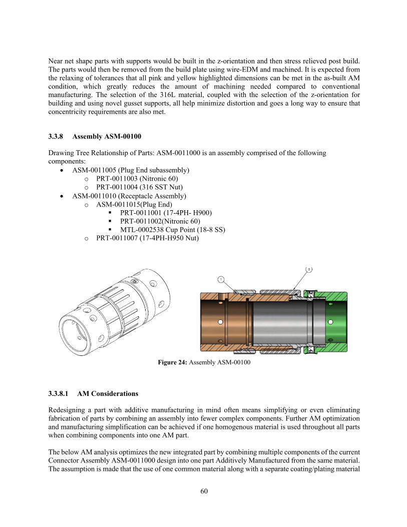
60
Near net shape parts with supports would be built in the z-orientation and then stress relieved post build. The parts would then be removed from the build plate using wire-EDM and machined. It is expected from the relaxing of tolerances that all pink and yellow highlighted dimensions can be met in the as-built AM condition, which greatly reduces the amount of machining needed compared to conventional manufacturing. The selection of the 316L material, coupled with the selection of the z-orientation for building and using novel gusset supports, all help minimize distortion and goes a long way to ensure that concentricity requirements are also met.
3.3.8 Assembly ASM-00100
Drawing Tree Relationship of Parts: ASM-0011000 is an assembly comprised of the following components:
• ASM-0011005 (Plug End subassembly) o PRT-0011003 (Nitronic 60) o PRT-0011004 (316 SST Nut)
• ASM-0011010 (Receptacle Assembly) o ASM-0011015(Plug End)
§ PRT-0011001 (17-4PH- H900) § PRT-0011002(Nitronic 60) § MTL-0002538 Cup Point (18-8 SS)
o PRT-0011007 (17-4PH-H950 Nut)
Figure 24: Assembly ASM-00100
3.3.8.1 AM Considerations
Redesigning a part with additive manufacturing in mind often means simplifying or even eliminating fabrication of parts by combining an assembly into fewer complex components. Further AM optimization and manufacturing simplification can be achieved if one homogenous material is used throughout all parts when combining components into one AM part. The below AM analysis optimizes the new integrated part by combining multiple components of the current Connector Assembly ASM-0011000 design into one part Additively Manufactured from the same material. The assumption is made that the use of one common material along with a separate coating/plating material
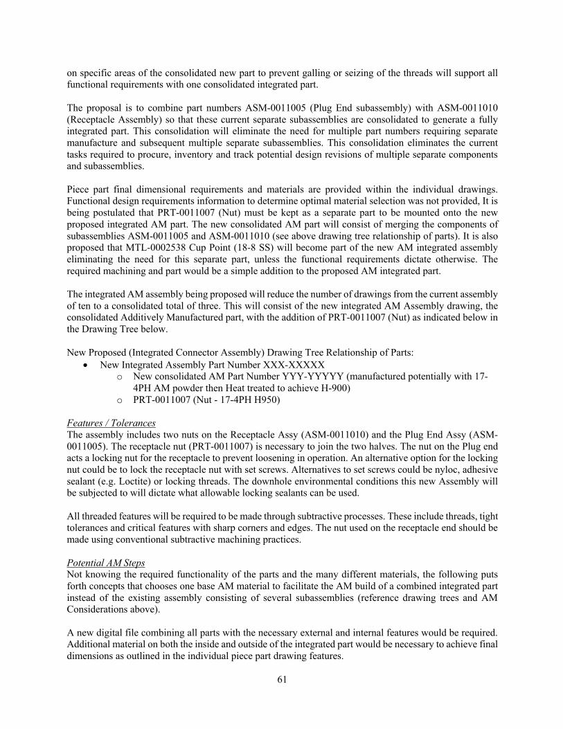
61
on specific areas of the consolidated new part to prevent galling or seizing of the threads will support all functional requirements with one consolidated integrated part. The proposal is to combine part numbers ASM-0011005 (Plug End subassembly) with ASM-0011010 (Receptacle Assembly) so that these current separate subassemblies are consolidated to generate a fully integrated part. This consolidation will eliminate the need for multiple part numbers requiring separate manufacture and subsequent multiple separate subassemblies. This consolidation eliminates the current tasks required to procure, inventory and track potential design revisions of multiple separate components and subassemblies. Piece part final dimensional requirements and materials are provided within the individual drawings. Functional design requirements information to determine optimal material selection was not provided, It is being postulated that PRT-0011007 (Nut) must be kept as a separate part to be mounted onto the new proposed integrated AM part. The new consolidated AM part will consist of merging the components of subassemblies ASM-0011005 and ASM-0011010 (see above drawing tree relationship of parts). It is also proposed that MTL-0002538 Cup Point (18-8 SS) will become part of the new AM integrated assembly eliminating the need for this separate part, unless the functional requirements dictate otherwise. The required machining and part would be a simple addition to the proposed AM integrated part. The integrated AM assembly being proposed will reduce the number of drawings from the current assembly of ten to a consolidated total of three. This will consist of the new integrated AM Assembly drawing, the consolidated Additively Manufactured part, with the addition of PRT-0011007 (Nut) as indicated below in the Drawing Tree below. New Proposed (Integrated Connector Assembly) Drawing Tree Relationship of Parts:
• New Integrated Assembly Part Number XXX-XXXXX o New consolidated AM Part Number YYY-YYYYY (manufactured potentially with 17-
4PH AM powder then Heat treated to achieve H-900) o PRT-0011007 (Nut - 17-4PH H950)
Features / Tolerances The assembly includes two nuts on the Receptacle Assy (ASM-0011010) and the Plug End Assy (ASM-0011005). The receptacle nut (PRT-0011007) is necessary to join the two halves. The nut on the Plug end acts a locking nut for the receptacle to prevent loosening in operation. An alternative option for the locking nut could be to lock the receptacle nut with set screws. Alternatives to set screws could be nyloc, adhesive sealant (e.g. Loctite) or locking threads. The downhole environmental conditions this new Assembly will be subjected to will dictate what allowable locking sealants can be used. All threaded features will be required to be made through subtractive processes. These include threads, tight tolerances and critical features with sharp corners and edges. The nut used on the receptacle end should be made using conventional subtractive machining practices. Potential AM Steps Not knowing the required functionality of the parts and the many different materials, the following puts forth concepts that chooses one base AM material to facilitate the AM build of a combined integrated part instead of the existing assembly consisting of several subassemblies (reference drawing trees and AM Considerations above). A new digital file combining all parts with the necessary external and internal features would be required. Additional material on both the inside and outside of the integrated part would be necessary to achieve final dimensions as outlined in the individual piece part drawing features.
62
Similar to the Frame parts, this connector assembly could be manufactured using Laser Melting (SLM) process, used in LBPF. The overall dimensions of this assembly allows it to be manufactured in a wide variety of AM machines in either the vertical or horizontal position, both of which will require substantial support structures, which will need to be removed in the machining steps. Due to the features and tolerance requirements of this part, most of the conventional machining steps described in the conventional manufacturing considerations sections below would apply. Material The materials used in the assembly indicate they are selected for corrosion inhibiting, anti-galling and in the case of the 17-4, strength after heat treatment. Alternative options for anti-galling could include dry film lubricant instead of Nitronic 60 or electro plating solution (a compatible dissimilar material meeting environmental conditions that will adhere) to prevent galling from occurring. Geometry The Assembly includes two halves with nuts that provide different requirements. The receptacle nut is necessary to join the receptacle and plug end. The plug end includes a locking nut than could be replaced with an alternate new design integrated part (see below Conventional machined part features below). Additional Proposed (Integrated/Modified Connector Assembly) Drawing Tree Relationship of Parts:
• New Integrated Assembly Part Number ZZZ-ZZZZZ (see below sketches of concept) o New Modified Receptacle Assembly 001010 (manufactured potentially with 17-4PH AM
powder then Heat treated to achieve H-900) o Combined PRT 0011001 & 0011002

63
Figure 25: Concept for integrated additively manufactured assembly combing receptacle parts
3.3.8.2 Conventional Manufacturing Considerations for PRT-0011001
Figure 26: Part PRT-0011001
Material Material is 17-4PH H950. This is a stainless steel that is easily heat treated to a martensitic condition, providing high strength and moderate corrosion protection. Geometry The part is a cylindrical tube with external threads and an external shoulder for nut retention. The threaded end includes a slot that extends radially through one side of the part. Features / Tolerances The part is thin walled in the finished condition. Work holding requires the use of collets and mandrels to minimize over clamping which could distort the part.

64
Conventional Manufacturing Steps The part could start out as a precision ground rod @ 1.000 +.000-.002 which would eliminate turning the OD to size. Overall cut length 1.50 ±.010. A lathe with y-axis milling capability is preferred. Op 10 – Chuck part in collet. Face right hand side. Drill and bore ID to .783 dia. Op 20 – Use Mandrel to hold part from ID. Turn left hand OD to .900 dia. Turn right hand .9359 dia. feature. Turn Major OD of 15/16-32 thread. Cut 15/16-32 thread. Chamfer right hand side. Op 30 – Chuck on OD using collet. Turn ID .783 dia. and ID .825 diameters. Op 40 – Hold part 0.9359 diameter OD with collet. Take precaution not to over clamp or damage threads. Mill slot 0.068 wide shoulder. Op 50 – Deburr, clean, and package to prevent damage.
3.3.8.3 Conventional Manufacturing Considerations for PRT-0011002
Figure 27: Part PRT-0011002
Material Material is Nitronic 60 that was most likely chosen for its anti-gall and possibly limited corrosion inhibiting capability. Nitronic 60 does work harden quickly and lower surface speed should be employed during subtractive manufacturing methods. Geometry The part is a cylindrical tube with internal threads. The assembly drawing indicates that the part drawing and solid model are incomplete. The drawing and model are missing the two set screws protruding radially 180° apart. The part is also missing the countersunk threads as witnessed in assembly drawing ASM-0011015. Features / Tolerances The part as drawn does not present any tight tolerances. Machining of Nitronic 60 can be a problem if proper surface speeds are not satisfied. Conventional Manufacturing Steps The part could start out as 1.25” diameter solid round bar fully annealed cut to 0.900 long. This part could be made with conventional 2 axis turning and milling operations using an indexing head or could be made with multifunction mill-turn or lathe with tooling options. The process below will describe a method using a lather with live tooling. Collet style work holding would be a preferred way to hold the workpiece. Op 10 – Chuck part in collet. Face the left side. Drill ID and bore to .781 diameter. Op 20 – Hold part on ID using a mandrel. Face part to finished length 0.813. Turn OD diameters to 1.188 and 1.116. Op 30 – Chuck part with Mandrel on 1.116 dia. Provide undercut for thread. Thread 15/16-32 ID thread. Op 40 – (machining of features not included on drawing) Drill minor diameter of two threaded set screws. Thread 6-32 holes and spot face outside of holes to .19 dia. x .016 deep.

65
Op 50 - (machining of features not included on drawing) Drill minor diameter of two threaded set screws. Thread 6-32 holes and spot face outside of holes to .19 dia. x .016 deep.
3.3.8.4 Conventional Manufacturing Considerations for PRT-0011003
Figure 28: Part PRT-0011003
Material Material is Nitronic 60 that probably was chosen for its anti-gall and possibly limited corrosion inhibiting capability. Nitronic 60 does work harden quickly and lower surface speed should be employed during subtractive manufacturing methods. Geometry The part is a cylinder with radial countersunk holes on one end. Internal and external steps and grooves provide mating surfaces and possibly features for snap rings or next assembly needs. The part includes a raised key for preventing rotation with the receptacle assembly (ASM-0011010). This key required plunge EDM processing to create the feature. Features / Tolerances The part contains a raised discontinuous slot/key that prevents the feature from being made with a wire EDM. An alternative method of using an internal snap ring could provide the mechanical stop while the inside diameter could stay as one diameter allowing a Wire Electrical Discharge Machining (EDM) method to be employed. An alternate method could also consider removing the slot (eliminate EDM processing) and using threaded or pressed in alignment/locating pin to align the two assemblies. Conventional Manufacturing Steps The part could start out as 1.25” diameter solid round bar fully annealed cut to 1.875 long. This part could be made with conventional 2 axis turning and milling operations using an indexing head or could be made with multifunction mill-turn or lathe with live tooling options. The process below will describe a method using a lather with live tooling. Collet style work holding (Hainbuch, SMW, Rohm) would be a preferred way to hold the workpiece. Op 10 – Mount part in a mandrel with approximately 2/3 of the part protruding. Face left side and turn OD to major diameter of 1 1/16 thread. Turn tapered nose to .995 diameter. Op 20 – Rotate part in the collet chuck. Hold from 1.061 diameter OD. Face part to finished length 1.713. Add chamfer to outside edge. Drill and bore out center of part to 0.766 through. Bore .828 dia. to .523 deep. Create groove 0.886 x .046 wide. Drill 6x major diameter 4-40 threaded holes 60° apart. Add 82° countersink for each hole drilled. Drill .188 diameter hole. Turn OD undercut to 1.057. Op 30 – Rotate part in collet chuck and hold part from 1.088 OD. Turn ID groove .901 dia. x .050 wide @ .810 deep. Mill ID to .901 dia. leaving the raised key .047 wide. Note: The key has radiused edges that will need to be removed with plunge EDM process. Turn OD Thread 1 1/16-18 . Turn undercut relief at end of thread (note: this feature is not dimensioned on drawing). Op 40 – Wire EDM short key way to .828 diameter (see image below).

66
Op 50 – Plunge EDM long key to create sharp corners.
Op 60 – Deburr part, clean, package to prevent damage to part.
3.3.8.5 Conventional Manufacturing Considerations for PRT-0011004
Figure 29: Part PRT-0011004
Material Material is 316 stainless steel and is susceptible to work hardening. Geometry The part is a cylindrical threaded nut with axial grooves on the OD for a tightening tool.

67
Features / Tolerances The part includes a tight tolerance ID bore (1.0587 +.0000 - .0012) for registering concentrically to the Plug OD. This feature can easily be achieved with quality work holding (collet) and a well-maintained lathe. Conventional Manufacturing Steps The part could start out as a precision ground rod @ 1.188 -.000-.003 which would eliminate turning the OD to size. Overall cut length 0.50 ±.010 . This part is best performed on a lathe with y-axis live tooling to mill the axial slots on the outside. Slots could be milled on the outside using an indexing head for positioning the slots. Op 10 – Chuck part in collet. Face right side of part and chamfer od. Drill hole through part and bore to minor diameter of 1 1/16-18 thread. Op 20 – Rotate part in collet. Face left hand side to overall length of .406 and chamfer edges. Op 30 – Hold part on ID using a mandrel. Mill 9X .06 wide grooves on outside using y-axis milling capability. Op 40 – Hold part on OD with collet. Cut 1 1/16-18 thread. Bore critical ID bore 1.0587 to .125 deep. Check with bore gage. Op 50 – Deburr, clean and package part.
3.3.8.6 Conventional Manufacturing Considerations for PRT-0011007
Figure 30: Part PRT-001007
Material Material is 17-4PH H950. This is a stainless steel that is easily heat treated to a martensitic condition, providing high strength and moderate corrosion protection. Geometry The part is a cylindrical threaded nut with axial grooves on the OD for a tightening tool. Features / Tolerances The part contains tolerance and features that are easy to make with modern subtractive turning and milling techniques. Conventional Manufacturing Steps The part could start out as a precision ground rod @ 1.188 -.000-.003 which would eliminate turning the OD to size. Overall cut length 0.900 ±.010 . This part is best performed on a lathe with y-axis live tooling to mill the axial slots on the outside. An alternative method could mill the slots on the outside using an indexing head. Op 10 – Chuck part in collet, face, drill and bore the ID to 0.938 dia. Op 20 – hold part with mandrel and mill outside axial grooves.
68
Op 30 – Chuck part in collet. Bore minor diameter of 1 1/16 – 18 thread. Cut thread relief. Cut thread 1 1/16-18 thread. Chamfer id left side. Op 40 – Deburr, clean and package.
3.3.8.7 Summary
This part is likely not a good candidate for AM – it is not recommended that ORNL perform a deep dive of AM vs. conventional manufacturing cost-benefit analysis. In theory, an integrated consolidated part can be manufactured via Conventional Machining or AM build using one common material on all consolidated parts, but overall, it is more efficient to manufacture these parts conventionally and assemble them together, than manufacture parts or subassembly near net shape parts via AM and then perform significant machining steps afterwards. The time and cost to machine one integrated part will be as effective as, if not more effective than, doing one AM build of the part. The time and cost of conventional machining an integrated part and then performing any subsequent required heat treat and necessary plating or application of other anti-galling compound, is most likely going to be more cost effective than AM overbuilding dimensions on the inside and outside to near net shape. An AM built part will require a substantial amount of final conventional machining to meet functional requirements. There may be a few features that can be altered to utilize some as-built AM conditions. All +/-.003-inch tolerances or tighter will require post AM build conventional machining. It is unlikely that an AM built part would be any faster or more cost effective than an integrated conventionally machined part. Consolidating Receptacle PRT-001-0011001 into an integrated part helps with the challenge of the thin .038-inch-thick wall. This wall thickness is challenging as a conventional build and even more so as an AM build. The walls for an AM build would have to be increased in thickness and final machined. The consolidation into an integrated part along with the other Connector parts certainly is an advantage to address the thin wall thickness requirement as a singular component. A further in-depth evaluation would have to be performed, taking into consideration the functional requirements of the entire Connector Assembly, to verify the cost, feasibility and functionality of the proposed integrated consolidated part. Without an understanding of functional requirements it is not possible to have high confidence that the integrated part would successfully address all functional requirements. The proposed Connector Assembly combines parts into two separate assemblies to accommodate the manufacture of the internal Key. Functional design requirements are not known. The proposal in combining and modification of parts is to preserve the integrity of the original design without fully knowing the design rationale for the internal Key and its importance to the Connector Assembly. This proposed assembly possibility attempts to ensure that the Key can be properly manufactured via AM or Conventional machining. Analyzing the available combination of assemblies both AM and Conventional, there is no real evident major impact to enhanced manufacturability, lead time reduction or cost to manufacturing these assemblies using AM methods. Further Engineering analysis and design investigation is recommended if the proposed integrated assemblies are pursued. The dissimilar materials and potentially required coating part application would further add to cost and manufacture complexity if deemed necessary to meet functional requirements.

69
Overall, the AM concepts put forth herein are not deemed to provide substantial benefit without having further information regarding functional requirements.
3.3.9 Concluding Remarks
Of all the parts analyzed in this document, only two can be recommended for further analysis by ORNL. They are DW-0201 and DW-0202. The other are not good candidates for manufacturing via AM for a variety of reasons below:
• Compared to conventional manufacturing, AM materials are still very limited. The vast majority of the materials that are called out on the drawings are not readily available in AM. Even if the material is advertised as being available in metal powder for AM that does not mean that there are known or validated AM process parameters to process that material. In other words, availability of metal powder does not equate manufacturability in AM. The number of AM candidate parts would increase if there was an expansion in the number of AM materials, particularly materials that are commonly used for geothermal applications.
• In addition to having more AM materials available, an understanding of how post-processing steps such as stress relief or heat treatment would affect material properties is needed in order make more detailed recommendations on AM process steps. This is not such an issue for conventional manufacturing as material properties are already well defined and post-processing steps are also well known. The number of AM candidate parts would increase if AM materials had well documented relationships between material properties/performance and AM processing steps and post-processing steps.
• There are a wide variety of AM processes but for metal, the most common are LPBF and DED. Hybrid is also a possibility but that technology is less proven. In general LPBF machines are best suited for making small precise parts, whereas DED machines are best suited for making large but more imprecise or near net shape parts. However, despite the precision that’s achieved by LPBF that is still not sufficient to avoid post-processing or machining. Hence, production of a near net shape in AM does not diminish in any significant way the number of machining steps that are needed to achieve tolerances. The number of AM candidate parts would increase if AM could increase its accuracy and surface finish and reduce the amount of support materials needed.
• An understanding of the functional requirements is critical in attempting to consolidate parts into a monolithic assembly that could be made via AM. Since the current parts have already been optimized for manufacturing via conventional manufacturing techniques, it is very unlikely that such a part could be more suited for AM, since AM is often at odds with conventional manufacturing techniques. Hence, in order for parts to be more appropriate for AM than for conventional, a re-design is often necessary. But without an understanding of the functional requirements a re-design is not within the scope of this document nor possible. The number of AM candidate parts would increase if functional design requirements were known and the parts could be redesigned for AM.
3.3.10 Concluding Remarks Following Re-evaluation
Many attempt to utilize AM with the idea that they can simply use it to replace the conventional manufacturing technologies they currently use, without re-designing the part. This is almost always a mistake as none of the benefits offered by AM are being exploited. A production part that was designed for multi-axis CNC machining will generally be more expensive to manufacture using AM and is likely to still require CNC machining to give it the required surface quality and achieve tight tolerance dimensional accuracy that cannot be obtained with AM alone. There is general agreement that, for AM to offer maximum value, the parts must be designed for additive manufacturing (DfAM).

70
The dimensional relief provided for the AM build re-evaluation of the DW-0201, DW-0202 and the Frame part has substantially improved the benefits and feasibility that an AM as-built condition part can provide. For these three parts, all pink and yellow highlighted dimensions, as noted in the dimensional tolerance relief section, can now be achieved in the as-built AM condition, whereas prior to relaxing the tolerances, nearly every single conventional machining step also needed to be applied to the AM case. Unfortunately, DW-0101 there was no relief from the drawing specified GD&T, which causes this part to still require a substantial amount of machining. Post re-evaluation, this part is still not a good candidate for AM. Taking DfAM even further, if true design intent was known or DfAM was incorporated from the start for more complex parts such as PRT-001009, both the geometry and functionality could be optimized by leveraging the strengths of AM. As an example, the supports and gussets added for PRT-001009 as shown in Figure 20 and Figure 21 could be eliminated with modifications to the geometry that better support both the mechanical functions of the part and the AM build support and warpage mitigation functions required for AM construction. These modifications require additional design time, but there is little associated AM build cost because, unlike CM, the addition of geometric complexity for AM only marginally increases build cost.
71
4. TECHNOECONOMIC COMPARISON OF CONVENTIONAL AND ADDITIVE MANUFACTURING
4.1 OVERVIEW
Using results from Section 3, a Techno-economic analysis (TEA) was conducted to analyze the feasibility of Additive Manufacturing (AM) to produce parts for geothermal applications. There are numerous examples of TEAs used to compare Conventional Manufacturing (CM) and AM for commercial applications. AM has the potential to reduce supply chain and inventory issues, enable just-in-time manufacturing and has provided design benefits, as well as energy and cost savings for numerous industries including airlines and oil and gas [3],[4]. For industries where AM has yet to be adopted, such as geothermal, TEA can provide preliminary insights into the potential for AM to benefit current manufacturing approaches used by the industry. The TEA performed for this project focused on a cost and manufacturing time comparison of CM and AM for the representative parts analyzed in Section 3 as a baseline for future cost improvements and to identify features of geothermal tool parts for which AM is economically favorable. This section describes the methodology used to conduct the TEA, a cost model calculator that was developed to analyze the manufacturing of tool parts, an assessment of the accuracy of the calculator, and a discussion of the applicability and benefits of AM for geothermal tools.
4.2 TEA METHODOLOGY
The first phase of the TEA reviewed the manufacturability assessment performed by Senvol (Section 3 of this report) in order to identify fundamental drivers that influence construction and cost of AM in geothermal parts. These fundamental drivers include:
• Material – The specification provided by the manufacturing drawing for the CM part and that material’s availability and suitability for AM.
• Geometry – The CM work piece (i.e. stock) starting dimensions and features that require specialized machining or AM build envelope and support structure considerations necessitated by design/AM fabrication method.
• Features & Tolerances – Final dimensional requirements and the potential need for post-print machining (of AM parts).
• Manufacturing Technology – The suitable CM and AM technology needed to fabricate part. As part of the manufacturability assessment, Senvol provided step-by-step descriptions of how each part could be conventionally manufactured. These fabrication breakdowns were produced by a machinist contracted to support the study. Steps include a sequential breakdown of the machining operations, approximate overall machining time, and estimates for final CM part cost. The next phase of the TEA involved the development of calculation methodologies for estimating AM and CM part costs. Cost estimate procedures were developed for different manufacturing technologies using a parametric breakdown of the fundamental drivers described above. Interviews with CM and AM fabrication subject matter experts were also conducted to obtain more specific CM and AM data on cost-impacting parameters. A TEA calculator was then developed and applied to the seventeen geothermal parts analyzed in the manufacturability assessment (see Table 1). Costs and fabrication time were calculated for both CM and AM for all parts. Cost quotes from two online machine shops ( [5] and [6]), two machinists, ORNL subject
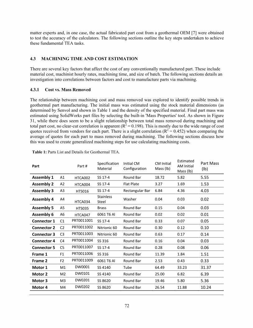
72
matter experts and, in one case, the actual fabricated part cost from a geothermal OEM [7] were obtained to test the accuracy of the calculators. The following sections outline the key steps undertaken to achieve these fundamental TEA tasks.
4.3 MACHINING TIME AND COST ESTIMATION
There are several key factors that affect the cost of any conventionally manufactured part. These include material cost, machinist hourly rates, machining time, and size of batch. The following sections details an investigation into correlations between factors and cost to manufacture parts via machining.
4.3.1 Cost vs. Mass Removed
The relationship between machining cost and mass removed was explored to identify possible trends in geothermal part manufacturing. The initial mass was estimated using the stock material dimensions (as determined by Senvol and shown in Table 1 and the density of the specified material. Final part mass was estimated using SolidWorks part files by selecting the built-in 'Mass Properties' tool. As shown in Figure 31, while there does seem to be a slight relationship between total mass removed during machining and total part cost, no clear-cut correlation is apparent (R2 = 0.198). This is mostly due to the wide range of cost quotes received from vendors for each part. There is a slight correlation (R2 = 0.452) when comparing the average of quotes for each part to mass removed during machining. The following sections discuss how this was used to create generalized machining steps for use calculating machining costs.
Table 1: Parts List and Details for Geothermal TEA.
Part Part # Specification Material
Initial CM Configuration
CM Initial Mass (lb)
Estimated AM Initial Mass (lb)
Part Mass (lb)
Assembly 1 A1 HTCA002 SS 17-4 Round Bar 18.72 5.82 5.55 Assembly 2 A2 HTCA004 SS 17-4 Flat Plate 3.27 1.69 1.53 Assembly 3 A3 HTS016 SS 17-4 Rectangular Bar 6.84 4.36 4.03
Assembly 4 A4 HTCA034 Stainless Steel Washer 0.04 0.03 0.02
Assembly 5 A5 HTS035 Brass Round Bar 0.15 0.04 0.03 Assembly 6 A6 HTCA047 6061 T6 Al Round Bar 0.02 0.02 0.01 Connector 1 C1 PRT0011001 SS 17-4 Round Bar 0.33 0.07 0.05 Connector 2 C2 PRT0011002 Nitrionic 60 Round Bar 0.30 0.12 0.10 Connector 3 C3 PRT0011003 Nitrionic 60 Round Bar 0.63 0.17 0.14 Connector 4 C4 PRT0011004 SS 316 Round Bar 0.16 0.04 0.03 Connector 5 C5 PRT0011007 SS 17-4 Round Bar 0.28 0.08 0.06 Frame 1 F1 PRT0011006 SS 316 Round Bar 11.39 1.84 1.51 Frame 2 F2 PRT0011009 6061 T6 Al Round Bar 2.53 0.43 0.33 Motor 1 M1 DW0001 SS 4140 Tube 64.49 33.23 31.37 Motor 2 M2 DW0101 SS 4140 Round Bar 25.00 6.82 6.39 Motor 3 M3 DW0201 SS 8620 Round Bar 19.46 5.80 5.36 Motor 4 M4 DW0202 SS 8620 Round Bar 26.54 11.88 10.24

73
Figure 31: Relationship of mass removed by machining and cost quotes from multiple vendors.
4.3.2 Cost vs. Time to Machine
Time to machine is a major factor in determining the cost of a machined part. An ORNL machinist [8] provided time estimates for each of the machining steps identified in the Senvol analysis for all 17 parts. This allowed for the calculation of total time to machine for each part. Individual production step time estimates are used in a later section for developing a cost estimate calculator for CM machining. Figure 32 shows a stronger relationship (R2 = 0.874) between estimated time to machine and average cost quote for each part, though only R2 = 0.445 if comparing all quotes to machine time.
Figure 32. Relationship between estimated time to machine and cost quotes from multiple vendors.
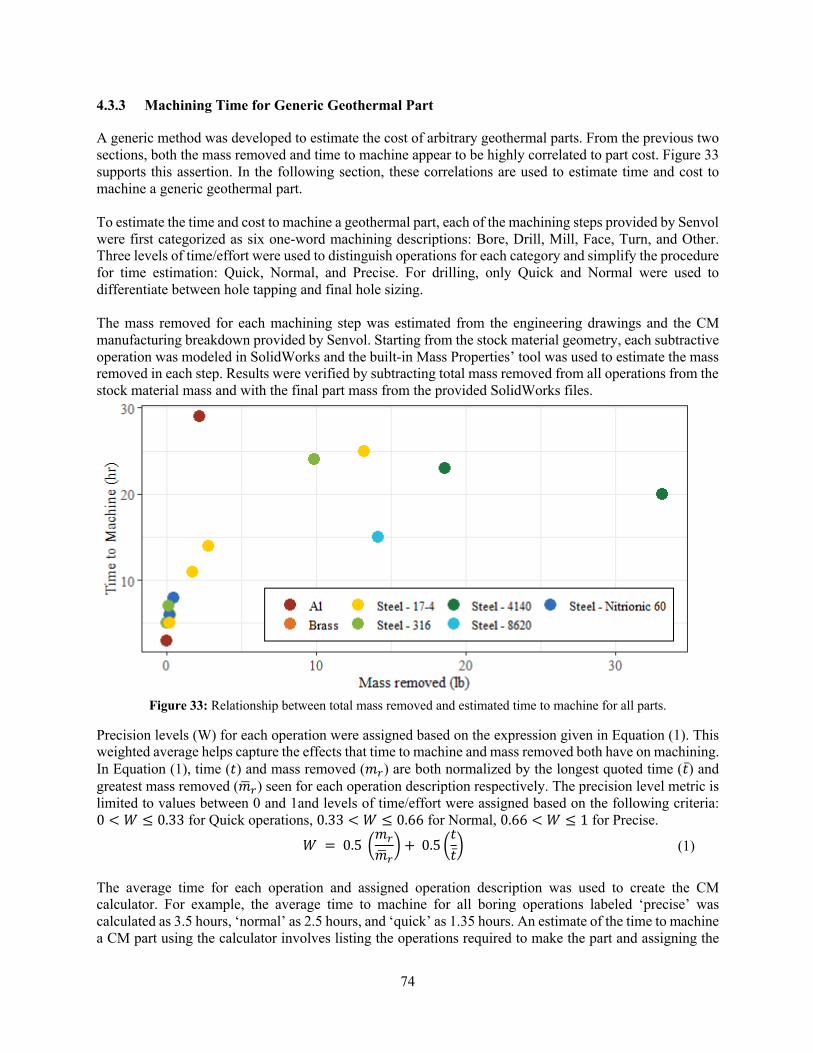
74
4.3.3 Machining Time for Generic Geothermal Part
A generic method was developed to estimate the cost of arbitrary geothermal parts. From the previous two sections, both the mass removed and time to machine appear to be highly correlated to part cost. Figure 33 supports this assertion. In the following section, these correlations are used to estimate time and cost to machine a generic geothermal part. To estimate the time and cost to machine a geothermal part, each of the machining steps provided by Senvol were first categorized as six one-word machining descriptions: Bore, Drill, Mill, Face, Turn, and Other. Three levels of time/effort were used to distinguish operations for each category and simplify the procedure for time estimation: Quick, Normal, and Precise. For drilling, only Quick and Normal were used to differentiate between hole tapping and final hole sizing. The mass removed for each machining step was estimated from the engineering drawings and the CM manufacturing breakdown provided by Senvol. Starting from the stock material geometry, each subtractive operation was modeled in SolidWorks and the built-in Mass Properties’ tool was used to estimate the mass removed in each step. Results were verified by subtracting total mass removed from all operations from the stock material mass and with the final part mass from the provided SolidWorks files.
Figure 33: Relationship between total mass removed and estimated time to machine for all parts.
Precision levels (W) for each operation were assigned based on the expression given in Equation (1). This weighted average helps capture the effects that time to machine and mass removed both have on machining. In Equation (1), time (𝑡) and mass removed (𝑚!) are both normalized by the longest quoted time (𝑡̅) and greatest mass removed (𝑚$!) seen for each operation description respectively. The precision level metric is limited to values between 0 and 1and levels of time/effort were assigned based on the following criteria: 0 < 𝑊 ≤ 0.33 for Quick operations, 0.33 < 𝑊 ≤ 0.66 for Normal, 0.66 < 𝑊 ≤ 1 for Precise.
The average time for each operation and assigned operation description was used to create the CM calculator. For example, the average time to machine for all boring operations labeled ‘precise’ was calculated as 3.5 hours, ‘normal’ as 2.5 hours, and ‘quick’ as 1.35 hours. An estimate of the time to machine a CM part using the calculator involves listing the operations required to make the part and assigning the
𝑊 = 0.5 0𝑚!
𝑚$!1 + 0.5 0
𝑡𝑡̅1
(1)

75
labels to each step. The total time to machine is calculated and multiplied by the machinist and overhead rate to calculate the final part cost. Example machining steps and their classifications are given in Table 2. Figure 34 and Figure 35 show the number of machining steps in different categories of time and mass removed. Low times and mass removed cases mostly correspond to Quick steps, whereas Precision steps mostly correspond to higher end of time and mass removed cases. The weighted average metric ‘W’ enables more automated analysis of the CM steps provided by Senvol by capturing nuances of operations (e.g. variations in time required to remove the same amount of mass) where using mass removed or time alone as parameters fail to capture cost impacts.
Figure 34: Distribution of time to machine for each manufacturing operation type.
Figure 35: Distribution of mass removed for each manufacturing operation type.

76
Table 2: Example machining steps and their classifications.
The average time, in hours, required for each operation type and level of machining is given in Table 3. The time to manufacture a part with traditional machining is then reduced to creating a list of steps, assigning a step type label and precision level to each step (e.g. precise bore), using Table 3 to find average times per step, and summing for the total time to manufacture. Table 3: Average time (hours) required to machine each precision level and machining step type.
Step Description Time (hr)
Mass Removed (lb) Step Score Level
Rotate part 180° and swallow right side 9.6” into the spindle. Bore left hand side ID .969 to .500 deep.
2 0.522 Bore 0.27 Quick
Bore right side 3.937 ID 2 3.90 Bore 0.39 Normal Cut 20° Chamfer, Bore 4.400 ID ±.005, Bore 4.300 ID ±.005, Bore 4.500 ID ±.002 use spring pass
3 14.5 Bore 0.88 Precise
Drill three vent holes .375 on top 1 0.080 Drill 0.27 Quick Drill holes for .250 alignment holes to .2485. Ream to .250 +.002 -.000 2 0.022 Drill 0.51 Normal
Face and turn OD to .738 - .005 + .000 1 0.006 Face 0.25 Quick Rotate Part 90° and Face Side C, Flip and face side D to thickness .969 -.000 +.010 1 0.179 Face 0.33 Normal
Face side A, Flip and face Side B to thickness of 1.69 ±.02 1 1.060 Face 0.75 Precise
Rotate part 180° to side C and mill 4X slots .876 X .313 1 0.059 Mill 0.17 Quick
Mill 60° hex feature right hand side 2 1.30 Mill 0.44 Normal Grab part from OD and mill prismatic left side features including 1.685 width 1.51” thick 3 6.07 Mill 1.00 Precise
Hold part on ID using a mandrel. Face part to finished length 0.813. Turn OD diameters to 1.188 and 1.116.
1 0.202 Turn 0.18 Quick
Hold part from each side with three jaw chucks. Turn OD to 1.5: dia. X 14.875 long. Turn left side shoulder to 1.125 -.000 +.002. .123 wide.
3 1.357 Turn 0.60 Normal
Grab part from 2.85” ID bore and turn the OD to finish dimension of 4.495 ±.002 2 6.57 Turn 0.83 Precise
Bore Drill Face Mill Turn Other Quick 1.35 1 1 1 1 1 Normal 2.5 2 1 2.25 1.5 2 Precise 3.5 --- 1.5 2.4 2 3
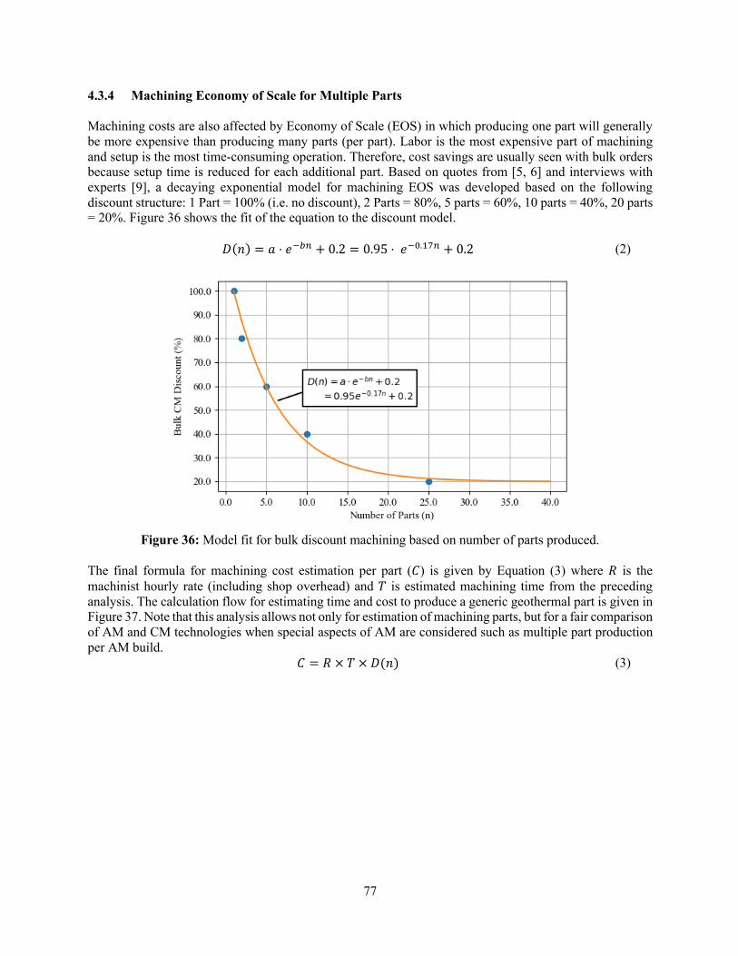
77
4.3.4 Machining Economy of Scale for Multiple Parts
Machining costs are also affected by Economy of Scale (EOS) in which producing one part will generally be more expensive than producing many parts (per part). Labor is the most expensive part of machining and setup is the most time-consuming operation. Therefore, cost savings are usually seen with bulk orders because setup time is reduced for each additional part. Based on quotes from [5, 6] and interviews with experts [9], a decaying exponential model for machining EOS was developed based on the following discount structure: 1 Part = 100% (i.e. no discount), 2 Parts = 80%, 5 parts = 60%, 10 parts = 40%, 20 parts = 20%. Figure 36 shows the fit of the equation to the discount model.
Figure 36: Model fit for bulk discount machining based on number of parts produced.
The final formula for machining cost estimation per part (𝐶) is given by Equation (3) where 𝑅 is the machinist hourly rate (including shop overhead) and 𝑇 is estimated machining time from the preceding analysis. The calculation flow for estimating time and cost to produce a generic geothermal part is given in Figure 37. Note that this analysis allows not only for estimation of machining parts, but for a fair comparison of AM and CM technologies when special aspects of AM are considered such as multiple part production per AM build.
𝐷(𝑛) = 𝑎 ⋅ 𝑒"#$ + 0.2 = 0.95 ⋅ 𝑒"%.'($ + 0.2 (2)
𝐶 = 𝑅 × 𝑇 × 𝐷(𝑛) (3)

78
Figure 37: Calculation flow for machining time and cost estimation.
4.3.5 Cost Estimation Workflow for Conventional Machining
The details of time estimation and volume discounts were described in the previous section. The only additional variables in the cost analysis for workflow CM are raw material cost and machining cost per unit time. Material costs were obtained using online quotes [10] for the materials specified in the original part specifications. The flow diagram for estimating total CM time and cost is given in Figure 38. Inputs include the number of parts, a list of manufacturing steps, the machinist hourly rate including overhead, and total material cost. For analysis in this report, the initial machinist rate was assumed to be $30/hr ($60,000/yr) which corresponds to the average salary of a journeyman machinist [11]. An overhead rate, which covers additional operating expenses and CAPEX amortization, was added to the base machinist rate to more accurately reflect typical machine shop rates. An average hourly rate of $75/hour was used to produce cost estimates that are reasonably close to the quotes for most parts (See the Section 5.1 for more details). Frame parts F1 and F2 (Figure 15 and Figure 18) required an hourly rate $100/hr for good agreement. These parts are geometrically complex with slender features, highly susceptible to warping during fabrication and require specialized fixtures during the CM machining process.
Figure 38: Calculation flow for CM total time and cost estimation.

79
4.4 AM TECHNOLOGIES OVERVIEW
AM is a broad field with a very active research and development space. In general, there are seven different categories for AM technologies [12]: 1) binder jet printing, 2) direct energy deposition (DED), 3) material extrusion, 4) material jetting, 5) powder bed fusion, 6) sheet lamination, and 7) vat photo-polymerization. As all parts considered in this study are composed of metal, this TEA analysis focuses only on the three metal production techniques recommended by Senvol and ORNL AM experts. Interviews were conducted with these experts to determine the parameters that time and cost as well as reasonable assumptions for each technology. A brief description of each technology is given in the following sections. 4.4.1 Binder Jet Printing
In binder jet printing, a bed of fine powder is spread uniformly over a build platform and a liquid binder material is selectively sprayed onto the powder bed to fuse the powder particles. The bed is lowered, more powder applied, and binder is again selectively applied until, layer-by-layer, a full part is formed. After parts have been removed, heat treatments are required to remove the binder material and sinter the bound powder to form the final part. The binder jet process has several advantages over other AM technologies. This process is versatile and can be applied to a wider range of materials than any other AM method. Binder jet can be applied to metal, polymer and ceramic materials. The ability to manufacture complex shapes made of ceramics is of particular interest for geothermal tool applications that require hardened surfaces, such as drilling, pumping, and completions. Unlike AM methods requiring intense energy deposition to fuse materials, there are no large local thermal gradients that cause thermally induced warpage of the printed part during the build process. Disadvantages of binder jet include larger part porosity and lower part strength resulting from the void space between bound particles. The voids can be infiltrated with materials possessing melting points below the sintering temperature; however, the part typically has a strength and stiffness that is lower than a similar part with homogeneous material composition. This is particularly true for metal parts. Additionally, because post-build thermal processing is typically required to sinter the bound powders, densification and part shrinkage is a common occurrence and can limit the dimensional precision that can be achieved using this process [13]. All 17 parts evaluated in this study were composed of metals with high strength and fatigue requirements. Therefore, binder jetting was not investigated further for the TEA. It is noted that if future work evaluates non-metal tools for geothermal environments, such as matrix bit bodies or cutting structures composed of tungsten carbide, binder jet is a suitable and possibly the only AM technique available. 4.4.2 Selective Laser Melting (SLM)
Selective Laser Melting (SLM), also called Direct Metal Laser Sintering (DMLS), utilizes a high-power laser to selectively melt or fuse regions near the surface of a level bed of fine metallic powder. The height and level of the powder bed is progressively adjusted between heating steps to build the part geometry using a layered approach. Layer thicknesses are generally very thin, typically less than 0.1 mm, to obtain high resolution parts and ensure fusion with the material layers immediately underneath the heated surface locations. The following steps are typical for SLM:
1) Preparation of the machine: Adding powder, slicing the part file, and loading the file into the printer programming (3-4 hours).
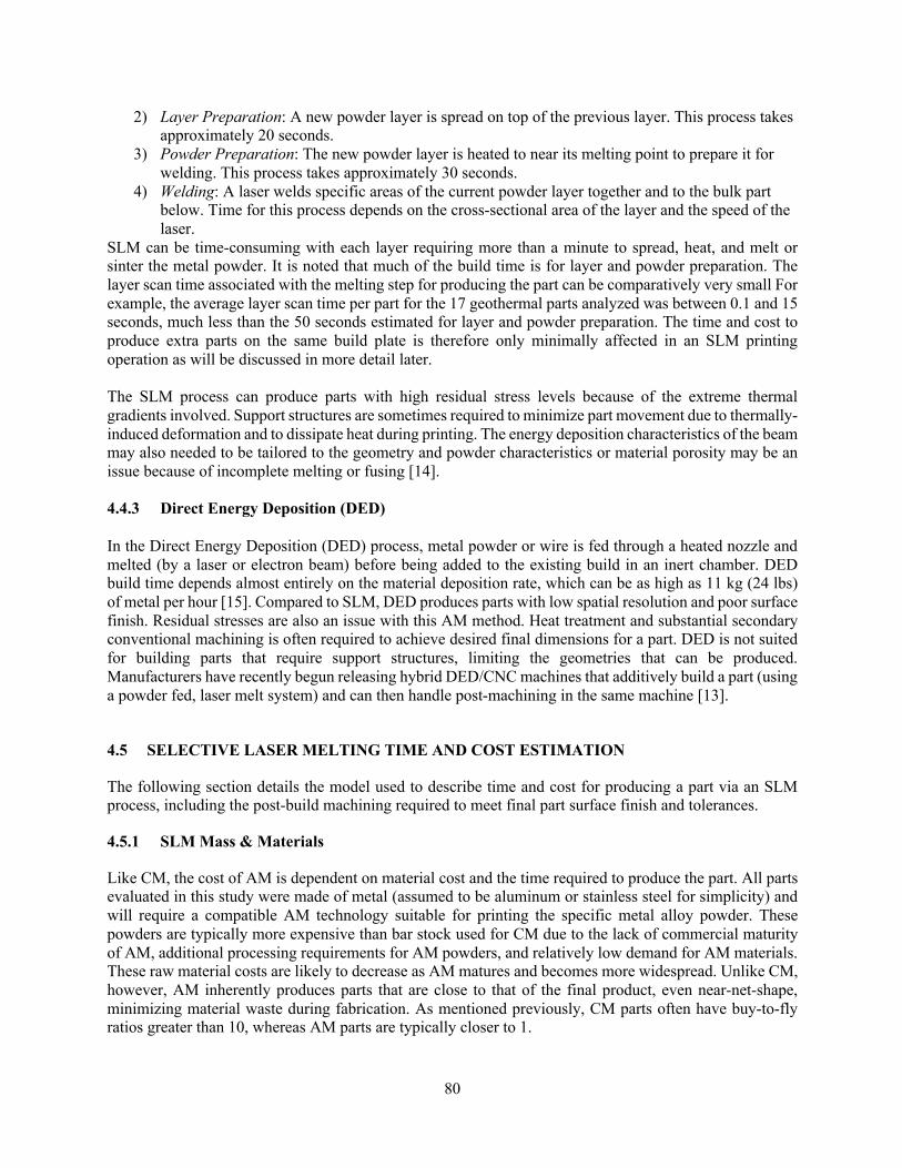
80
2) Layer Preparation: A new powder layer is spread on top of the previous layer. This process takes approximately 20 seconds.
3) Powder Preparation: The new powder layer is heated to near its melting point to prepare it for welding. This process takes approximately 30 seconds.
4) Welding: A laser welds specific areas of the current powder layer together and to the bulk part below. Time for this process depends on the cross-sectional area of the layer and the speed of the laser.
SLM can be time-consuming with each layer requiring more than a minute to spread, heat, and melt or sinter the metal powder. It is noted that much of the build time is for layer and powder preparation. The layer scan time associated with the melting step for producing the part can be comparatively very small For example, the average layer scan time per part for the 17 geothermal parts analyzed was between 0.1 and 15 seconds, much less than the 50 seconds estimated for layer and powder preparation. The time and cost to produce extra parts on the same build plate is therefore only minimally affected in an SLM printing operation as will be discussed in more detail later. The SLM process can produce parts with high residual stress levels because of the extreme thermal gradients involved. Support structures are sometimes required to minimize part movement due to thermally-induced deformation and to dissipate heat during printing. The energy deposition characteristics of the beam may also needed to be tailored to the geometry and powder characteristics or material porosity may be an issue because of incomplete melting or fusing [14]. 4.4.3 Direct Energy Deposition (DED) In the Direct Energy Deposition (DED) process, metal powder or wire is fed through a heated nozzle and melted (by a laser or electron beam) before being added to the existing build in an inert chamber. DED build time depends almost entirely on the material deposition rate, which can be as high as 11 kg (24 lbs) of metal per hour [15]. Compared to SLM, DED produces parts with low spatial resolution and poor surface finish. Residual stresses are also an issue with this AM method. Heat treatment and substantial secondary conventional machining is often required to achieve desired final dimensions for a part. DED is not suited for building parts that require support structures, limiting the geometries that can be produced. Manufacturers have recently begun releasing hybrid DED/CNC machines that additively build a part (using a powder fed, laser melt system) and can then handle post-machining in the same machine [13].
4.5 SELECTIVE LASER MELTING TIME AND COST ESTIMATION
The following section details the model used to describe time and cost for producing a part via an SLM process, including the post-build machining required to meet final part surface finish and tolerances.
4.5.1 SLM Mass & Materials
Like CM, the cost of AM is dependent on material cost and the time required to produce the part. All parts evaluated in this study were made of metal (assumed to be aluminum or stainless steel for simplicity) and will require a compatible AM technology suitable for printing the specific metal alloy powder. These powders are typically more expensive than bar stock used for CM due to the lack of commercial maturity of AM, additional processing requirements for AM powders, and relatively low demand for AM materials. These raw material costs are likely to decrease as AM matures and becomes more widespread. Unlike CM, however, AM inherently produces parts that are close to that of the final product, even near-net-shape, minimizing material waste during fabrication. As mentioned previously, CM parts often have buy-to-fly ratios greater than 10, whereas AM parts are typically closer to 1.
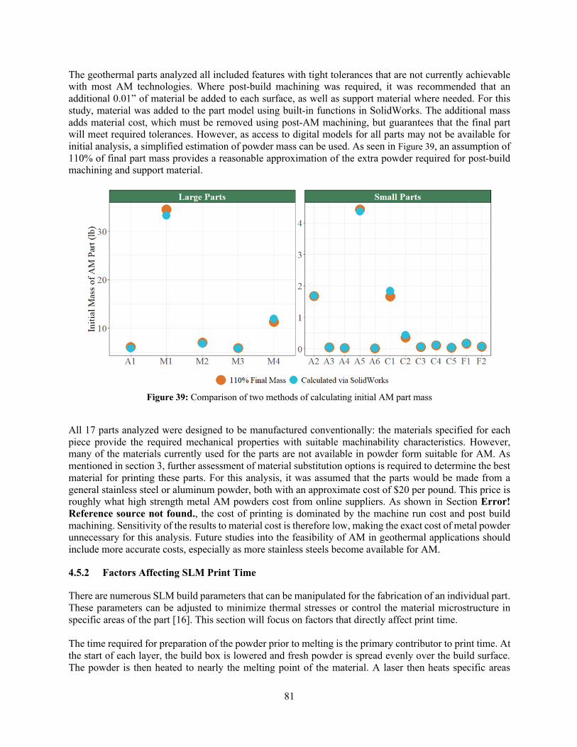
81
The geothermal parts analyzed all included features with tight tolerances that are not currently achievable with most AM technologies. Where post-build machining was required, it was recommended that an additional 0.01” of material be added to each surface, as well as support material where needed. For this study, material was added to the part model using built-in functions in SolidWorks. The additional mass adds material cost, which must be removed using post-AM machining, but guarantees that the final part will meet required tolerances. However, as access to digital models for all parts may not be available for initial analysis, a simplified estimation of powder mass can be used. As seen in Figure 39, an assumption of 110% of final part mass provides a reasonable approximation of the extra powder required for post-build machining and support material.
Figure 39: Comparison of two methods of calculating initial AM part mass
All 17 parts analyzed were designed to be manufactured conventionally: the materials specified for each piece provide the required mechanical properties with suitable machinability characteristics. However, many of the materials currently used for the parts are not available in powder form suitable for AM. As mentioned in section 3, further assessment of material substitution options is required to determine the best material for printing these parts. For this analysis, it was assumed that the parts would be made from a general stainless steel or aluminum powder, both with an approximate cost of $20 per pound. This price is roughly what high strength metal AM powders cost from online suppliers. As shown in Section Error! Reference source not found., the cost of printing is dominated by the machine run cost and post build machining. Sensitivity of the results to material cost is therefore low, making the exact cost of metal powder unnecessary for this analysis. Future studies into the feasibility of AM in geothermal applications should include more accurate costs, especially as more stainless steels become available for AM.
4.5.2 Factors Affecting SLM Print Time
There are numerous SLM build parameters that can be manipulated for the fabrication of an individual part. These parameters can be adjusted to minimize thermal stresses or control the material microstructure in specific areas of the part [16]. This section will focus on factors that directly affect print time. The time required for preparation of the powder prior to melting is the primary contributor to print time. At the start of each layer, the build box is lowered and fresh powder is spread evenly over the build surface. The powder is then heated to nearly the melting point of the material. A laser then heats specific areas

82
corresponding to the current cross section of the part, melting the powder to make a part layer. This process is repeated, layer-by-layer, for the entire build height of the print. For SLM machines, the total print time is governed by five main parameters corresponding to directional variables and timing: layer height (h), hatch distance (d), scan rate (R)*+), and layer preparation time (T,-), and heating times (T,.). Layer height is the vertical distance between powder layers and is a machine setting that is usually between 50 and 100 microns [17, 18]. Hatch distance is the distance between passes as the laser rasters across the powder layer and scan rate is speed of the laser as it moves across the powder bed. The final two variables, layer preparation and heating times, are dependent on the SLM machine used and are typically fixed during a build. T,- captures the lowering the build plate and adding a layer of powder while T,. captures the time required to heat the powder. Based on interviews with ORNL experts, the assumed values for these parameters are 20 and 30 seconds respectively. The model for SLM printing time is given in Equation (4) below. Note that each of these parameters may be adjusted to alter the printing time.
For SLM, the time required to print additional parts is only slightly greater than printing a single part. For example, the laser scan time per layer for printing one M1 part is 3.3 seconds compared to the 50 seconds for layer preparation and heating. Printing a single part therefore takes approximately 53 seconds per layer. If 10 parts can be spatially arranged to fit on the build plate, then the total layer print time becomes 83 seconds per layer. Packing of the build box with additional parts can therefore optimize the machine operating time and lead to cost savings when more than 1 part is produced in a build. Printing cost for SLM parts is approximated as printing time (T/0+1) multiplied by the machine hourly run cost (R/0+1). This rate accounts for the electricity required to power the machine, maintenance, depreciation, and consumables such as inert gases and filters. This affect can be seen in Error! Reference source not found. for several of the geothermal parts.
Figure 40: Effect of the economy of scale for SLM parts.
T)*+ = (n × A)/(d × R)*+) T/0+1 = (H/h) × (T)*+ + T,- + T,.)
(4)

83
4.5.3 Pre- and Post- Printing Activities Time and Costs
For both SLM and DED, total print cost is determined by the previously discussed print time and the machine run-time costs. In addition to the actual time to print, AM technologies have associated machine preparation and post-build activities. Machine preparation includes loading the material (powder or wire), converting part files to STL format, uploading CAD files into the machine software, optimizing the build box, and machine warm-up procedures. The total machine preparation time was approximated to be 4 hours. Post-build time includes powder recovery and recycling, machine cleaning (together estimating to take about 2 hours), part removal from the build plate (this typically involves machining and takes about an hour), and heat treatment. As these activities are costed using the same technician rate (R12*3), for the purpose of this study, they were combined into a single value and assumed to take 7 hours total of time. Time estimates and the associated technician rate were also obtained from interviews [17, 19, 20] and literature sources [15]. Many AM parts require post-process machining to improve surface finish and achieve tight tolerances, which is accounted for separately in the next section.
4.5.4 Post-AM Build Machining Time and Cost
Post-build machining parameters for AM parts were determined based on fabrication drawing tolerances and evaluation of the CM operations required to achieve those tolerances. As the AM build is near-net shape, long duration machining steps are not typically required. Intermediate steps, such as such as repeated bores and turns to different diameters are also often unnecessary and, when present, were condensed into a single step at the final diameter. In general, finishing operations for the rough AM shape were assumed to be quick operations due to the minimal amount of material needing to be removed. Some finishing operations were classified as “Normal” or “Precise” due to their complexity. New finishing operations were added by identifying all internal/external surfaces that required machining due to tolerance requirements. Tolerances on some features were within the capabilities of the AM system and required no further post-processing. In some cases, tolerances were found to be over-specified in the drawing based on design intent and were relaxed in order to eliminate unnecessary post-processing.
4.5.5 Total SLM Build Time and Cost
These factors and how they affect the calculated SLM printing time and cost estimate can be seen in Figure 41 that shows the calculation flow of the SLM analysis.
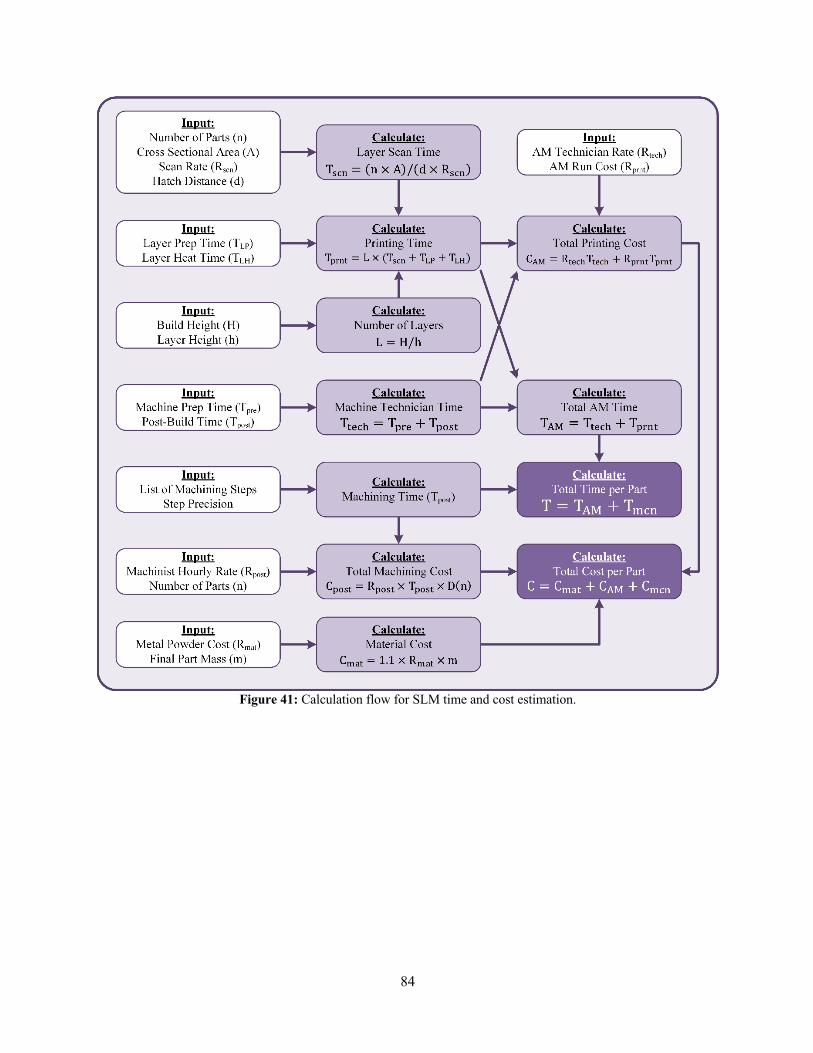
84
Figure 41: Calculation flow for SLM time and cost estimation.

85
4.6 DIRECTED ENERGY DEPOSITION TIME AND COST ESTIMATION
The DED process uses an energy beam to melt or weld blown metal powder or wire that is directed through a nozzle to deposit material and build the part. The part geometry is produced by either moving the nozzle or a build plate. Modeling of the time and cost to produce a part using DED AM manufacturing is simpler than with SLM, as build time depends almost entirely on the material deposition rate, which is an adjustable machine property. The following section details the model used to estimate time and cost for producing a part via an DED process, including the required post-build machining to meet final part surface finish and tolerances. Note that the same assumption for required powder mass from Section 4.5.1 was made for analyzing DED production (i.e. 110% of the final part mass). Post-build machining steps for each part were assumed to be the same for parts produced using DED or SLM (Section 4.5.4). 4.6.1 Factors Affecting DED Print Time
For DED machines, the material deposition rate will determine the print time. Deposition rates typically vary between 6.5 and 11 lbs/hr [15], though some machines can achieve up to 25 lbs/hr [21]. Increasing the deposition rate has a diminishing return for the 17 parts evaluated, as their mass generally falls below 2 lbs. In Figure 42, for example, four of the evaluated parts approach their nominal asymptotic limit at deposition rates of less than 1-2 lb/hr.
Figure 42: Effect of deposition rate on DED production costs.
As with SLM, there will be pre- and post-DED build time required to prepare the machine, remove parts, and perform heat treatment. In this analysis, this time was assumed to be the same for all parts but future analysis could provide more detailed estimates of these time inputs (Section 4.5.3). 4.6.2 Total DED Build Time and Cost The DED time and cost calculation flow diagram is shown in Figure 43. The only AM machine specification required is a material deposition rate, although as with SLM, post-build machining steps are required to meet specifications.

86
Figure 43: Calculation flow for DED time and cost estimation.
Equating the DED cost formula with the CM cost formula facilitates determination of the number of parts for which fabrication costs will be equivalent (Equation (5)). Note that ⌈∗⌉ (ceiling brackets) is the ceiling operator for rounding up to the nearest integer (e.g., ⌈0.3⌉ = 1) and C is cost per part. Subscripts 𝑏𝑙𝑑, 𝑚𝑎𝑡, and 𝑚𝑐ℎ denote build cost, material cost, and machining costs for CM and DED.
N = R−1bln V
Da⋅C45,789 − C:5,;<1C:5,;*3 − C45,;*3
− 0.2YZ (5)
There is no layer preparation step that dominates the time to print a single layer for the DED process and the time required to move the print nozzle or build stage is significantly greater than the time required to raster a laser beam or electron beam using mirrors or magnetic fields. For a single print nozzle, there is no formulaic EOS benefit to having multiple builds on a single build plate because the total print time is proportional to only the time required to move the print nozzle. It is theoretically possible to optimize build time for multiple builds by minimizing the motion of the print head, but improvements will be modest because of the significantly lower speed of motion. Further investigation can be taken by the user to determine the potential for breakeven cost for multiple part fabrication using DED in comparison to CM by considering setup costs and path optimization, but for this TEA it was assumed that there is no EOS benefit for DED (outside of the benefit from the post-build machining).

87
4.7 GEOTHERMAL TOOL CM AND AM TIME AND COST CALCULATOR
The CM and AM cost estimate methodologies developed in the previous sections were used to create an Excel-based calculator for analyzing the manufacturing of geothermal parts. Users can enter specifics to produce a geothermal part into various tabs based on the desired manufacturing methods. The structure of the calculator includes: • Summary Tab: This tab is where users enter common inputs and view results from the CM and AM
calculator pages (shown in Figure 44). Inputs include information on the build (material, number of parts, mass, dimensions, etc.), cost variables (rates and material costs), and the AM technology (either SLM or DED). Results are displayed once data is entered in the corresponding tabs including total time to manufacture and cost per part for both CM and AM. A breakeven calculation is included to indicate the point where costs for each technology are equal.
• CM Calculator: This tab estimates the time and cost of producing a part using the generic machining steps and levels described in Section 4.3.3. The only user input for this tab is the machining steps required to create the part.
• SLM Calculator: The SLM calculator tab estimates the total time and cost to produce a part using SLM, including the post-process machining needed to meet tolerance and surface finish requirements. User input includes AM machine specifications and post-process machining steps. Results are broken down by AM steps, machining steps, and total production steps. Total time and cost for multiple parts is provided as well as time and cost per part.
• DED Calculator: The DED calculator tab estimates the total time and cost to produce a part using a DED process, including the post-process machining required to meet tolerance and surface finish requirements. The only AM machine specification required on this tab is a material deposition rate, usually between 5 and 25 lbs/hr. As in the SLM tab, the required post-build CM steps to meet specifications are also required.
The calculator was used to analyze multiple scenarios for the feasibility of manufacturing geothermal parts using an AM process. Formalizing the calculations in a spreadsheet allowed for automation of this process. The following sections look at several scenarios and how they affect the feasibility of AM to produce geothermal parts.
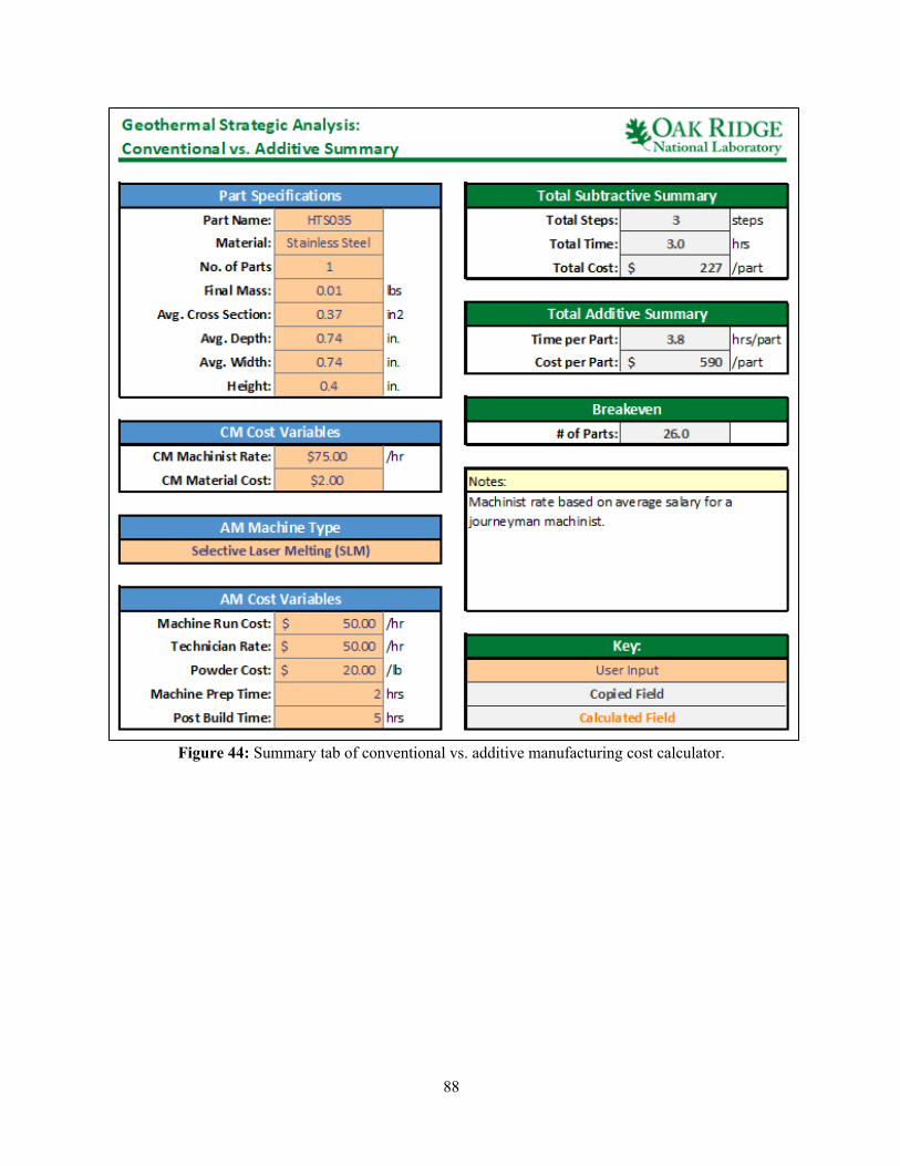
88
Figure 44: Summary tab of conventional vs. additive manufacturing cost calculator.
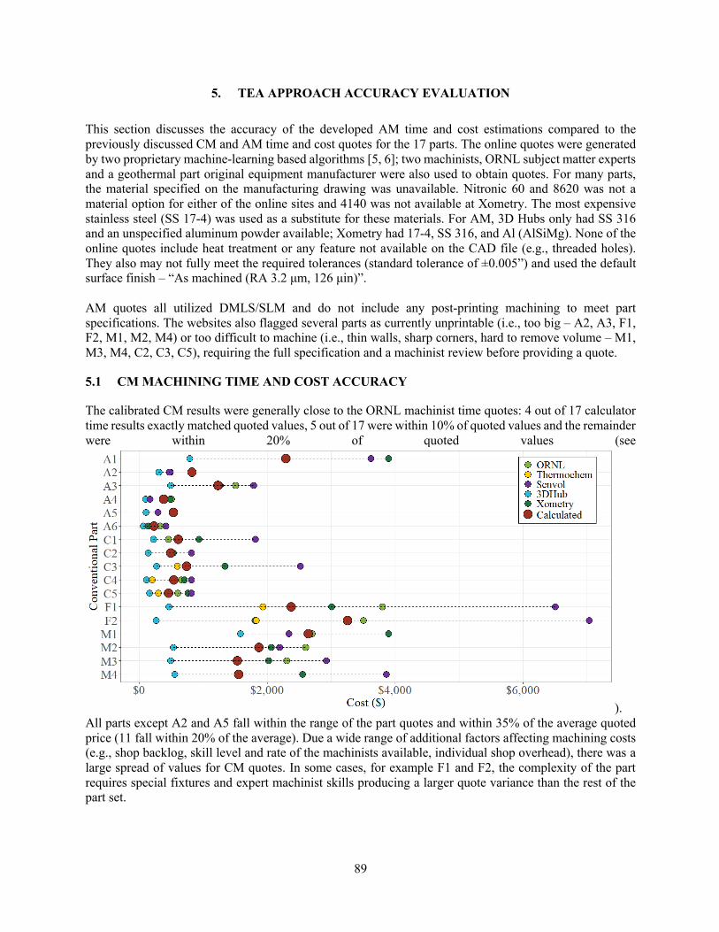
89
5. TEA APPROACH ACCURACY EVALUATION
This section discusses the accuracy of the developed AM time and cost estimations compared to the previously discussed CM and AM time and cost quotes for the 17 parts. The online quotes were generated by two proprietary machine-learning based algorithms [5, 6]; two machinists, ORNL subject matter experts and a geothermal part original equipment manufacturer were also used to obtain quotes. For many parts, the material specified on the manufacturing drawing was unavailable. Nitronic 60 and 8620 was not a material option for either of the online sites and 4140 was not available at Xometry. The most expensive stainless steel (SS 17-4) was used as a substitute for these materials. For AM, 3D Hubs only had SS 316 and an unspecified aluminum powder available; Xometry had 17-4, SS 316, and Al (AlSiMg). None of the online quotes include heat treatment or any feature not available on the CAD file (e.g., threaded holes). They also may not fully meet the required tolerances (standard tolerance of ±0.005”) and used the default surface finish – “As machined (RA 3.2 μm, 126 μin)”. AM quotes all utilized DMLS/SLM and do not include any post-printing machining to meet part specifications. The websites also flagged several parts as currently unprintable (i.e., too big – A2, A3, F1, F2, M1, M2, M4) or too difficult to machine (i.e., thin walls, sharp corners, hard to remove volume – M1, M3, M4, C2, C3, C5), requiring the full specification and a machinist review before providing a quote.
5.1 CM MACHINING TIME AND COST ACCURACY
The calibrated CM results were generally close to the ORNL machinist time quotes: 4 out of 17 calculator time results exactly matched quoted values, 5 out of 17 were within 10% of quoted values and the remainder were within 20% of quoted values (see
). All parts except A2 and A5 fall within the range of the part quotes and within 35% of the average quoted price (11 fall within 20% of the average). Due a wide range of additional factors affecting machining costs (e.g., shop backlog, skill level and rate of the machinists available, individual shop overhead), there was a large spread of values for CM quotes. In some cases, for example F1 and F2, the complexity of the part requires special fixtures and expert machinist skills producing a larger quote variance than the rest of the part set.
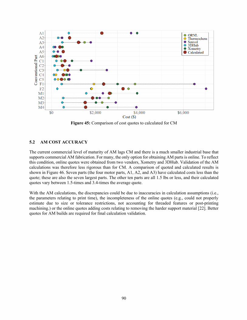
90
Figure 45: Comparison of cost quotes to calculated for CM
5.2 AM COST ACCURACY
The current commercial level of maturity of AM lags CM and there is a much smaller industrial base that supports commercial AM fabrication. For many, the only option for obtaining AM parts is online. To reflect this condition, online quotes were obtained from two vendors, Xometry and 3DHub. Validation of the AM calculations was therefore less rigorous than for CM. A comparison of quoted and calculated results is shown in Figure 46. Seven parts (the four motor parts, A1, A2, and A3) have calculated costs less than the quote; these are also the seven largest parts. The other ten parts are all 1.5 lbs or less, and their calculated quotes vary between 1.5-times and 3.4-times the average quote. With the AM calculations, the discrepancies could be due to inaccuracies in calculation assumptions (i.e., the parameters relating to print time), the incompleteness of the online quotes (e.g., could not properly estimate due to size or tolerance restrictions, not accounting for threaded features or post-printing machining.) or the online quotes adding costs relating to removing the harder support material [22]. Better quotes for AM builds are required for final calculation validation.

91
Figure 46: Comparison of cost quotes to calculated for AM from 3D Hubs and Xometry.
5.3 IMPROVING CALCULATION ACCURACY
One of the CM calculation’s biggest shortcomings is only having one source for the estimation of the initial machining steps used to calibrate the generic machining steps. Additional references would provide more confidence in the estimated time allotted to the generalized steps that form the core of the machining calculations and possibly allow a more accurate range for the machining cost. For the AM calculator results, an in-depth analysis of each individual part would allow for more accurate AM printing parameters and post-printing machining estimates. For example, currently it is assumed that each part will take 7 hours of technician preparation and post-printing time, regardless of part. Finally, additional and more detailed cost quotes for both CM and AM would allow further refinements of the default values and identify any missing cost contributions.
6. COMPARISON OF CONVENTIONAL AND ADDITIVE MANUFACTURING
The time and cost of manufacturing geothermal parts using two AM technologies (SLM and DED) was compared with traditional CM production using the developed calculation tools described in the previous section. This section explores several scenarios that affect the feasibility of AM compared to CM for geothermal parts including economy of scale, deposition rate, print time, and printing optimization.
6.1 SINGLE PART PRODUCTION
When producing a single part, CM has traditionally had an advantage over most AM technologies. This is particularly true of SLM with its long layer preparation times because print time is a significant component of part cost. Improvements in DED technology have increased deposition rates for printing metal parts for individual parts and the comparisons in this study indicates that DED may already be competitive with CM in some cases. As DED deposition rates further increase, it may become even more competitive. For

92
example, large DED machines like the Big Area Additive Manufacturing (BAAM) system at ORNL can achieve feed rates approaching 80 lbs/hour for large polymer-based parts. Figure 47 compares estimated total production costs for CM, SLM AM, and DED AM. For larger parts where more than 1 lb of mass must be removed via machining (the four motor parts, the two frame parts, and A1, A2 and A3), Table 4 shows that DED is the less expensive than CM. This is because the steps required to remove the bulk mass from the starting material take longer (and therefore cost more) than the printing process using DED.
Figure 47: Calculated AM and CM total manufacturing costs for selection of geothermal parts.
Similarly, Figure 48 shows DED will usually be the quicker option for large parts. For smaller or simpler parts (the connector parts and the remaining assembly parts), CM is the faster and less expensive option to produce a single part. It is noted that the calculators do not incorporate lead time and machine availability for the individual machining operations into the estimates. These can significantly increase CM machining time. They also do not consider hours of operation. AM technologies in most cases can operate unattended. This can result in a faster overall production time for AM when compared to CM. Depending on the project, decreased lead time could be worth the additional cost of producing a part with AM.
Figure 48: Calculated AM and CM total manufacturing time for selection of geothermal parts.
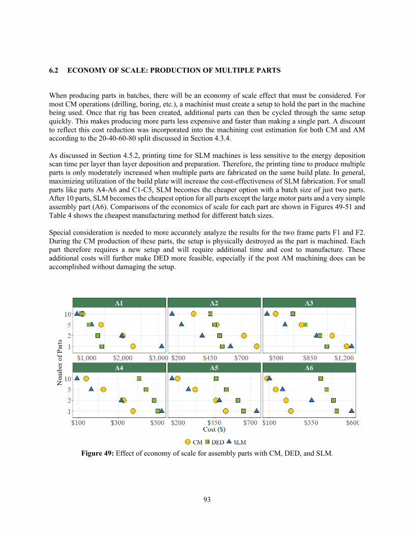
93
6.2 ECONOMY OF SCALE: PRODUCTION OF MULTIPLE PARTS
When producing parts in batches, there will be an economy of scale effect that must be considered. For most CM operations (drilling, boring, etc.), a machinist must create a setup to hold the part in the machine being used. Once that rig has been created, additional parts can then be cycled through the same setup quickly. This makes producing more parts less expensive and faster than making a single part. A discount to reflect this cost reduction was incorporated into the machining cost estimation for both CM and AM according to the 20-40-60-80 split discussed in Section 4.3.4. As discussed in Section 4.5.2, printing time for SLM machines is less sensitive to the energy deposition scan time per layer than layer deposition and preparation. Therefore, the printing time to produce multiple parts is only moderately increased when multiple parts are fabricated on the same build plate. In general, maximizing utilization of the build plate will increase the cost-effectiveness of SLM fabrication. For small parts like parts A4-A6 and C1-C5, SLM becomes the cheaper option with a batch size of just two parts. After 10 parts, SLM becomes the cheapest option for all parts except the large motor parts and a very simple assembly part (A6). Comparisons of the economics of scale for each part are shown in Figures 49-51 and Table 4 shows the cheapest manufacturing method for different batch sizes. Special consideration is needed to more accurately analyze the results for the two frame parts F1 and F2. During the CM production of these parts, the setup is physically destroyed as the part is machined. Each part therefore requires a new setup and will require additional time and cost to manufacture. These additional costs will further make DED more feasible, especially if the post AM machining does can be accomplished without damaging the setup.
Figure 49: Effect of economy of scale for assembly parts with CM, DED, and SLM.
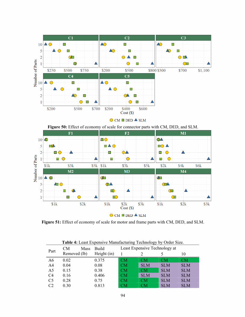
94
Figure 50: Effect of economy of scale for connector parts with CM, DED, and SLM.
Figure 51: Effect of economy of scale for motor and frame parts with CM, DED, and SLM.
Table 4: Least Expensive Manufacturing Technology by Order Size.
Part CM Mass Removed (lb)
Build Height (in)
Least Expensive Technology at 1 2 5 10
A6 0.02 0.375 CM CM CM CM A4 0.04 0.08 CM SLM SLM SLM A5 0.15 0.38 CM CM SLM SLM C4 0.16 0.406 CM SLM SLM SLM C5 0.28 0.75 CM CM SLM SLM C2 0.30 0.813 CM CM SLM SLM

95
6.3 MAXIMIZING UTILIZATION OF THE SLIM BUILD PROCESS
The nature of the geothermal industry is such that 25 copies of the same geothermal part are not often needed. The economy of scale advantages of SLM printing described in the previous section may therefore be less beneficial when fewer parts of one type are needed. There is, however, no reason why all parts in the SLM build box must be identical. An analysis of printing all 17 analyzed parts in a single build box was conducted, including duplicates (i.e. A1, A2, A4, and A5) required to completely populate the build box, in order to evaluate this economy of scale approach that is unique to AM. While this scenario may not be completely feasible as most parts are made of different materials, it does highlight the flexibility of AM for producing multiple parts as part of the same AM build for industrial sectors with low part volume demand. Figure 52 shows the footprint of each part strategically placed to fill a single 19.75x11x33.5" build box. Unlike in the analysis from the previous sections, a constant cross-sectional area across the build box was not used for cost calculations. Instead, the build was broken down into segments for each part height, and the cross-sectional area was the sum of all the part cross-sectional areas that were equal or greater in height than that part. This allows for only the uncompleted parts to be included in the cross-section as the build height increases and more accurately capture the time required to build all parts. Parts were arranged so that parts of similar heights are grouped together so that as parts are completed, the active area requiring energy deposition shrinks. In general, tall parts were arranged in the back-left of the build box and short parts in the front-right.
C1 0.33 1.348 DED CM SLM SLM C3 0.63 1.713 CM CM SLM SLM F2 2.53 17.25 DED DED DED SLM A2 3.27 0.25 DED SLM SLM SLM A3 6.84 0.969 DED SLM SLM SLM F1 11.39 15 DED DED DED SLM A1 18.72 6.906 DED DED DED SLM M3 19.46 9.58 DED DED CM CM M2 25.00 4.06 DED DED SLM SLM M4 26.54 5.75 CM CM CM CM M1 64.49 22.71 DED DED DED CM CM Least Expensive 8 7 3 4 DED Least Expensive 9 6 4 0 SLM Least Expensive 0 4 10 13
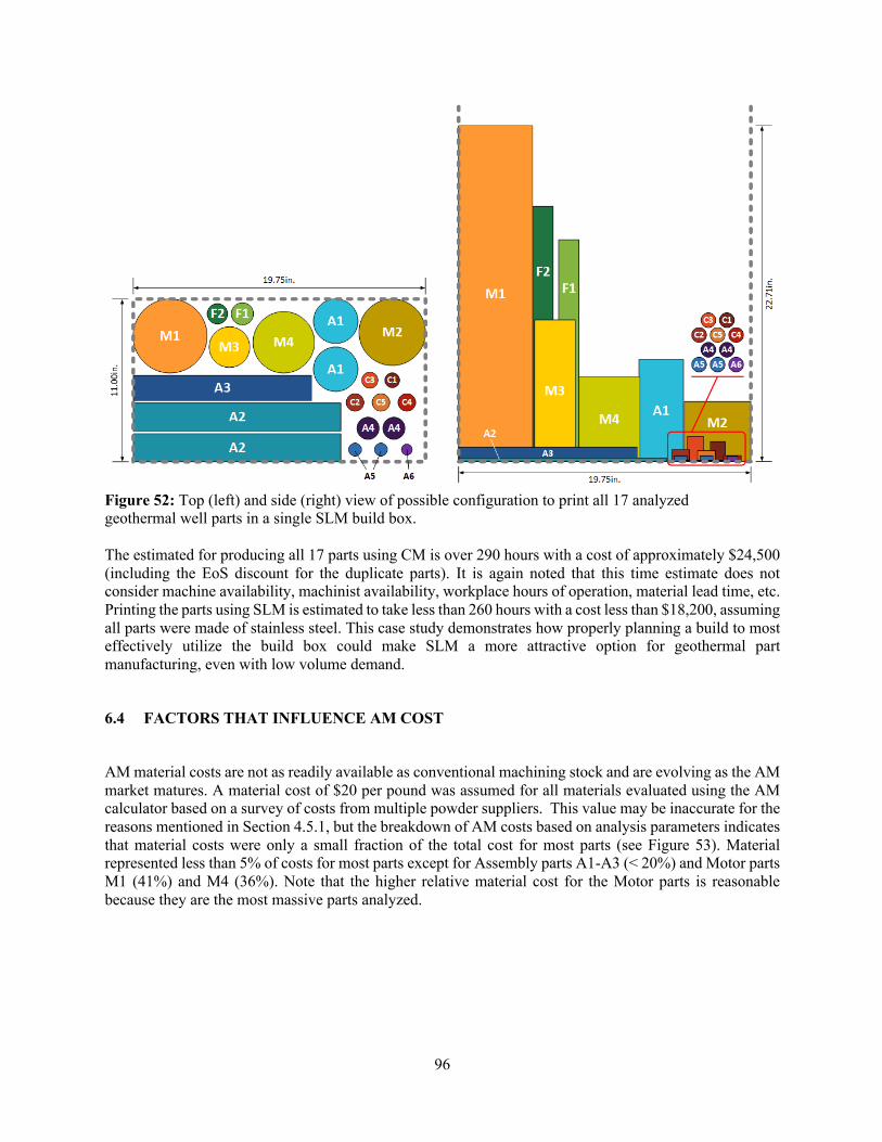
96
Figure 52: Top (left) and side (right) view of possible configuration to print all 17 analyzed geothermal well parts in a single SLM build box. The estimated for producing all 17 parts using CM is over 290 hours with a cost of approximately $24,500 (including the EoS discount for the duplicate parts). It is again noted that this time estimate does not consider machine availability, machinist availability, workplace hours of operation, material lead time, etc. Printing the parts using SLM is estimated to take less than 260 hours with a cost less than $18,200, assuming all parts were made of stainless steel. This case study demonstrates how properly planning a build to most effectively utilize the build box could make SLM a more attractive option for geothermal part manufacturing, even with low volume demand.
6.4 FACTORS THAT INFLUENCE AM COST
AM material costs are not as readily available as conventional machining stock and are evolving as the AM market matures. A material cost of $20 per pound was assumed for all materials evaluated using the AM calculator based on a survey of costs from multiple powder suppliers. This value may be inaccurate for the reasons mentioned in Section 4.5.1, but the breakdown of AM costs based on analysis parameters indicates that material costs were only a small fraction of the total cost for most parts (see Figure 53). Material represented less than 5% of costs for most parts except for Assembly parts A1-A3 (< 20%) and Motor parts M1 (41%) and M4 (36%). Note that the higher relative material cost for the Motor parts is reasonable because they are the most massive parts analyzed.
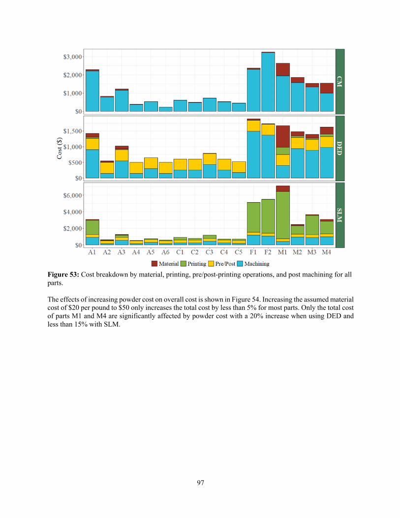
97
Figure 53: Cost breakdown by material, printing, pre/post-printing operations, and post machining for all parts. The effects of increasing powder cost on overall cost is shown in Figure 54. Increasing the assumed material cost of $20 per pound to $50 only increases the total cost by less than 5% for most parts. Only the total cost of parts M1 and M4 are significantly affected by powder cost with a 20% increase when using DED and less than 15% with SLM.

98
Figure 54: Effect of powder cost on overall part cost. Points represent the default value of $20/lb and lines the range of $20-$50/lb of powder. Printing time was the dominant factor in SLM costs, particularly for parts with either a large mass or build height. This again underscores the importance of optimizing the SLM build box when printing a part with this technology. With DED, deposition rates for most machines will make printing time very short which leads to pre/post-machine preparation and post-machining being the dominant contributors. This trend is also true for smaller parts (e.g. Connector and most Assembly parts) where printing the part contributes little to the overall manufacturing time. Instead machine preparation (e.g. loading powder, preparing STL files, recycling powder, removing parts, etc.) and post build-machining will dominate the total time (see Figure 55). Post machining of printed parts is necessary to achieve required surface finish and feature tolerances but, as shown, contributes significant time and cost to the overall process. Decreased machining time can be accomplished in a few different ways that will affect CM and AM differently. Loosening tolerances of certain features for each part would not only decrease the intensity of machining required, but in some cases may remove the need for post AM build machining entirely. Because features always need to be machined in the CM process, this would only affect the intensity of the operation (i.e. normal vs. precise) and not greatly decrease the overall machining time. Post-build operations can also be reduced by increasing the resolution of the printing process. Machine settings could be altered to prioritize precision, taking longer to print each layer or decreasing the height between layers, increasing the numbers of layers to print and smoothing the final surface. There is a trade-off, however, as higher precision will shift the costs from post machining to printing time. Ideally, future improvements in DED and SLM technology, such as reduced scan and layer preparation time, would improve final part tolerances and surface finish without increasing print time. The effects of SLM layer preparation time and DED deposition rate are explored in Figure 56 and 57.

99
Figure 55: Manufacturing time breakdown by printing, pre/post-printing operations, and post machining for all parts.
Figure 56: Effect of total SLM print time on overall part cost. Lines represent 50-150% of default print time shown by the square.

100
Figure 57: Effect of DED deposition rate on overall part cost. Lines represent the range 6.5-15 lb/hr and squares represent the default 7.5 lb/hr. The time for machine care operations (Pre/Post in Figure 55) was assumed to be 7 hours for all additively manufactured parts in this analysis, as described in Section 4.5.3. While these times likely vary depending on the part and repeated printings, the total cost for these operations was estimated at only $350 per build. Reducing this time would have a larger relative impact on smaller parts due to their fast print times and low mass, however the contribution is negligible for any of the larger and more expensive parts. Finally, this analysis considered only parts that were designed to be manufactured using CM. As mentioned in previous sections, re-designing parts to be built for AM may result in designs that are easier to print, require less material, and are less expensive that the conventional part. There are also value-added opportunities that are only available with AM such as internal chambers, complex geometries, and single part construction. Future analysis could compare CM costs with redesigned geothermal tool parts that properly exploit the benefits of the AM process.

101
7. TEA SUMMARY
This report details a comparison of manufacturing 17 geothermal parts using conventional subtractive techniques with production using two AM technologies. Using machining steps provided by Senvol to manufacture each part, time estimates for each operation were leveraged to create a CM time and cost calculator. The calculations use generalized manufacturing steps (e.g., milling and boring) and intensity levels (e.g., quick/normal/precise) to estimate required time to machine. Cost is estimated using an hourly rate composed of both a machinist's hourly rate and shop overhead. A discount model for multiple parts was developed to capture the economics of scale for CM. Two metal AM calculators were also developed using standard machine parameters (e.g., deposition rate, layer height, scan rate, etc.) to model the operation of DED and SLM printers that are representative of currently available machines. The AM calculators estimate printing costs and leverage the CM calculator to estimate the post-print machining operations required to meet final part specifications. The accuracy of the calculators was assessed and determined to be reasonable compared to several obtained quotes. The CM calculator predicted machining times within 33% of expert estimates and cost were within the range provided by the quotes. The AM cost calculator provided estimates near the quotes for smaller parts, but under-predicted cost for larger parts. In part, this is due to discrepancies in estimates for quantity and difficulty of removing support material, as well as disregarding smaller operations such as threading, deburring, or inspection. For single part production, either CM or DED AM were the least expensive options. However, SLM can become less expensive when printing duplicate parts or optimizing the fill of the build box. SLM will become more feasible as advancements increase scan rate, reduce powder preparation time, and decrease layer heating time. Additionally, considerations for AM technology can further reduce AM costs such as reducing required post-printing machining either through improved printing resolution or design choices. This report has identified several key features that make a part an attractive candidate for AM production. Ideally, the part should be made of a material currently available in AM grade powder. New metal powders are constantly being developed and existing materials may be suitable substitutes provided characteristics and cost allow. Although resolution and final print tolerances are improving, parts with moderate dimensional tolerances (±0.005-0.01” for powder bed fusion and ±0.01” for DED) would be ideal for AM. Such features would not require post-build machining, making AM costs more competitive. Parts with complex geometries or composed of difficult to machine materials are also excellent candidates for AM as it can greatly reduce and/or eliminate machining entirely. To optimize for the benefits of AM, geothermal parts should be redesigned specifically for AM. Combining multi-part assemblies into a single part, minimizing required support material, and creating value-added features such as internal cooling can all be accomplished. Even if no new features are added, redesign would likely reduce printing time and overall cost. Additionally, properly preparing for an SLM print by fully utilizing the machine build box can greatly reduce AM costs. With respect to time to manufacture, AM could have significant advantages over CM if the need for post-build machining is eliminated or significantly reduced. This is not directly apparent from the direct time comparison in Figure 55, but if one considers manufacturing time elements not included in this analysis (e.g., the lead time for ordering material, daily work shifts for machinists, time associated with moving the part to a different machine and its availability, etc.) it is likely that procurement the actual fabrication time for a CM part will be much greater than direct machining time. This could be of great benefit to the supply chain for the geothermal industry.

102
8. CHALLENGES AND OPPORTUNITIES FOR AM IN GEOTHERMAL APPLICATIONS
The analyses in this report and discussions at the February Geothermal Roundtable identified several key characteristics of parts that would lead to an increased viability of AM over CM. With respect to the manufacturability assessment, the detailed evaluation of AM manufacturing considerations for the downhole tool part set revealed the specific design and manufacturing challenges associated with directly fabricating parts designed for CM using AM methods and highlighted the need to implement design for additive manufacturing practices to truly take advantage of the potential benefits of AM. The following sections outline some of the major reoccurring key findings from the Roundtable and the analyses described in this report. Addressing these issues is critical for enabling the adoption of additively manufactured parts in geothermal tool applications
8.1 TOLERANCE CONSIDERATIONS
All AM machines have limited resolution at this time (±0.004" for SLM, ±0.008” for binder jetting [23] and ±0.01” for DED [24]). Parts with tolerances tighter than the geometric resolution of an AM technology require additional post-build machining. While these operations are generally less intensive than fabrication solely by CM, they can add substantial time and cost. Parts that have tolerances within the abilities of currently available AM printers are therefore better candidates for AM over CM. Design intent and practice are critical considerations in this regard. Many parts today are dimensioned using default tolerances based on conventional machining assumptions. These dimensions are convenient because they can be standardized and are easily achieved using CM, but they are often not required for design purposes (i.e., they can be relaxed because they do not affect functionality). Redesign or future design of geothermal tool parts should consider this aspect of dimensional tolerancing to fully realize the benefits of AM.
8.2 COMPLEX GEOMETRIES
AM can produce complex geometries at lower cost than conventional subtractive techniques. In addition, AM can produce parts that are impossible to create with standard tooling operations. For costs comparable to a simple CM manufactured part, AM can produce parts with features such as internal honeycomb structures for weight savings or internal channels for part cooling. AM is therefore frequently a better choice when part geometry is complex. This is evident for the frame parts (F1 and F2) evaluated in this TEA, particularly when considering the EOS and destructive setup techniques required during manufacturing. Many geothermal downhole tool parts have complex geometries that are based on the high aspect ratio characteristics of tools that are deployed in a borehole and need to fit within intricate mechanical assemblies of a tool body. These features can be easily created with AM techniques at costs lower than with CM techniques. Complex parts that are difficult to machine due to warpage or specialized fixturing are also better candidates for AM. In such cases, the level of skill required by a machine shop or prior fabrications experience may limit which shops are able to produce the part. This leads to additional, significant lead time and expenses to produce the part. By comparison an AM part can be produced by any AM machine without additional operator expertise or expense once a build file is created. Lastly, joining or assembly of parts is sometimes required because the part cannot be conventionally manufactured as a single piece. Re-design of assemblies as a single AM part would allow for the elimination of joining, weight savings, and improved reliability by reducing key points of failure. While not explored
103
in this TEA, there could be significant advantages for geothermal AM when tool assemblies can be redesigned to reduce part count.
8.3 MATERIALS
Many common geothermal tool materials are not currently available as AM quality powder (e.g., 4140 and 4145 Steel, Beryllium Copper, Nitronic 60 steel). In some cases, material substitutions that enable AM can be found without compromising tool performance. For example, many downhole tools are typically composed of 4140 alloys which is not available for AM. A potential substitution is 17-4 PH stainless steel that is widely available for AM and has improved corrosion resistance without compromising strength. On the other hand, the inventory of AM powder materials is constantly growing and if the appropriate market conditions arise these materials could be developed.
8.4 MECHANICAL PROPERTIES
The mechanical properties of an AM part may differ from those produced by machining and often depend greatly on material, additive manufacturing method, and post-processing [25]. For example, parts produced by binder jet AM systems have a higher porosity, resulting in mechanical properties similar to metal injection molding and not suitable for high-end applications [26]. The mechanical properties of parts produced by DED can be anisotropic (direction-dependent), but in specific directions can be very similar to wrought parts and even optimized by adjusting laser power and scan speed [25]. A study conducted in 2015 found little difference between 17-4 PH stainless steel parts produced by DMLS (SLM) and CM with respect to ultimate tensile strength, yield strength and percent elongation. Additionally, little variability in the mechanical and material properties was found due to build orientation, layer thickness, or chamber atmospheres [27]. Other sources have found that DMLS parts have higher strength/hardness and can be more flexible than CM parts but are more prone to fatigue [28]. Researchers at ORNL are exploring control of printed metal microstructures within parts [16], but further development is needed to guarantee the required mechanical properties. The ability to simulate the additive manufacturing process and predict the final material and mechanical properties of the part is one approach to enhancing confidence in the quality of AM parts [28]. Certification of the part before deployment should also be considered as it can represent a significant portion of overall cost.
8.5 PART SIZE
All parts analyzed in this report will fit within commonly available printers, but part size is still a factor that must be considered when using AM. Many current downhole technologies can be tens of feet long and exceed the envelope capabilities of current metal powder bed AM systems. There are DED systems in use and under development, particularly those employing wire feed methods, that could potentially be suitable for producing parts of this type but they currently have low resolution and would require significant post-build machining. The use of AM to produce long geothermal parts therefore is currently in an early-stage developmental phase. Table 5 shows the largest (in the x-direction) printers available for each technology along with cost. Binder Jet and Powder Bed Fusion (which includes SLM) are roughly equal in terms of largest, but the binder jetting machine is much less expensive [18]. Additionally, binder jetting machines are, on average, larger than SLM beds [28]. DED has, by far, the largest build dimensions of the technologies discussed.

104
Table 5: Largest Metal Printers by Technology [18].
8.6 DESIGN FOR MANUFACTURING
Properly planning for an AM build can have a huge impact on the cost, especially for SLM. The direction of the build should be determined to minimize the support structures required, reducing the material and post-print machining costs. For long parts, printing at an angle should be considered to reduce SLM build height (the driving cost factor); generally, SLM does not require support structures for any overhang angle less than 45° [14, 29, 30]. For example, the two frame parts could be printed at a 45° angle from the build plate, instead of straight up (which was chosen to reduce internal support structures). The build height for Frame 1 reduces from 15” to 11.7”, reducing the cost for a single part to approximately $4,330, compared to $5,120, saving about 15%, though this is still more expensive than CM ($2,370). Similarly, Frame 2 would be $4,540 reduced from $5,500 (though only $3,250 via CM). While in these cases, printing at an angle does not make SLM the least expensive option, it can reduce the cost of SLM. Additionally, re-designing the parts for AM could reduce post-machining. All the parts analyzed in this work were designed to be produced via conventional subtractive means; this inherently puts AM at a disadvantage. Parts with the same functionality could be re-designed with AM in mind (e.g., reducing the necessity of support structures by redesigning overhangs, angles, and holes [14, 29, 30]) allowing for more complex geometries, combining parts, and significantly reducing the difficult mass removal in the machining process.
8.7 GEOMETRIES THAT CANNOT BE FABRICATED CONVENTIONALLY
AM can create complex geometries that cannot be fabricated using conventional subtractive techniques. This allows for the introduction of more complex parts that can have value-added features not possible with CM. In some cases these parts may have functionality or performance benefits over CM-designed parts. To illustrate an example of the potential benefit of performance improvement enabled by AM, one part was selected for enhanced performance evaluation following the in-depth face-to-face design analyses of geothermal tools developed by Sandia National Laboratory (SNL) researchers. Figure 58 shows an original version of a rotor that is part of a vane motor in a drilling tool and a version of the part redesigned for AM. The objective of this design exercise was to improve the power transmission characteristics of the rotor by significantly reducing its polar moment of inertia. The part redesign utilized topological optimization to develop a rotor configuration with a polar moment of inertia that is roughly half of the original. With this redesign, the rotational speed of the rotor increases by 27% and the maximum speed of the motor assembly increases by 5% without significant compromise of rotor rotational stiffness. The topologically optimized rotor shown in Figure 58 could not be practically manufactured conventionally. Optimization of the other components in the drive train could lead to additional performance improvements but are beyond the scope of this simple exercise. The improvement of component functionality and performance enabled by novel
Technology X (in) Y (in) Z (in) Volume (ft3) Price Range
DED 240 55 54 412.5 + $1M
Binder Jet 31.5 19.7 15.85 5.65 $100k – $250k
Powder Bed Fusion (includes SLM) 31.5 15.7 19.7 5.63 + $1M

105
manufacturing capabilities such a AM has tremendous potential for impact that is likely to grow as old design constraints imposed by manufacturing limitations are eliminated and new design methodologies such as topological optimization and generative design become more widely used by the design community.
Figure 58: (a) Original and (b) Redesigned rotor part
106
9. CONCLUSION
This report summarized the details of an in-depth manufacturability and techno-economic assessment (TEA) of the potential benefits of additive manufacturing for advancing geothermal tool development. The manufacturability assessment found that many of the materials used in the evaluated part set are not currently available for AM systems that utilize powder as a feedstock material. This is primarily a consequence of the relative immaturity of the metal AM industry and is likely to change as the industry grows and builds its material inventory. It was also initially found that in many cases there was not an obvious advantage to fabricating the part using AM because the part had been designed for CM and did not utilize the advantages of AM. Design for Additive Manufacturing (DfAM) was recommended as a practice to more fairly compare CM and AM approaches. In some cases, dimensional tolerances of parts were relaxed without compromising design intent and AM was found to be potentially favorable from a cost and production time perspective. The TEA portion of this study developed a set of calculators that broke down the manufacturing processes and estimated cost and production times for CM and two AM processes (selective laser melting and directed energy deposition). These calculators were used to quantitatively compared the three manufacturing methods. It found that CM and DED AM were each more cost-effective for roughly half of the analyzed part set. When economy of scale was considered for up to 10 parts it was found the SLM AM was more cost-effective for 13 of 17 of the parts. While a complete geothermal tool was not evaluated in the study, the potential benefits of simultaneously fabricating multiple parts in a single SLM build was explored (by building all of the parts evaluated in the study on a single build plate) and a 25% percent reduction in the cost and a 10% reduction in the machining/printing time was found compared to fabricating all the parts using CM. The results of the manufacturability assessment and TEA confirm that while there are improvements needed to make metal AM in particular more viable for fabrication of geothermal tools, there is great potential for improving the economics and production time of geothermal tool production using this emerging advanced manufacturing method.
107
10. REFERENCES
[1] J. R. D. a. P. S. Su, "Advanced Percussive Drilling Technology for Geothermal Exploration and Development," Sandia Report SAND2017-4612, 2017.
[2] D. Raymond, "Develoment of a Downhole Piston Motor Power Section for Improved Directional Drilling: Part I Design, Modeling & Analysis," in GRC Trans., 2018.
[3] S. Singamneni, L. V. Yifan, A. Hewitt, R. Chalk, W. Thomas and D. Jordison, "Additive Manufacturing for the Aircraft Industry: A Review," Journal of Aeronautics & Aerospace Engineering, vol. 8, 2019.
[4] M. Sireesha, J. Lee, A. S. Kranthi Kiran, V. J. Babu, B. B. T. Kee and S. Ramakrishna, "A Review on Additive Manufacturing and Its Way Into the Oil and Gas Industry," RSC Advances, vol. 8, no. 40, pp. 22460-22468, 2018.
[5] 3D Hubs, "New Quote," [Online]. Available: https://www.3dhubs/manufacture. [Accessed 24 06 2019].
[6] Xometry, "New Quote," Xometry, [Online]. Available: https://get.xometry.com/quote. [Accessed 24 06 2019].
[7] M. Broaddus, "RE: AM Workshop", Email to Yarom Polsky on 25 06 2019.
[8] S. Whitted, "RE: Economic comparison of conventional versus AM fabrication approaches", Email to Kristina Armstrong 25 06 2019.
[9] S. Whitted, "RE: Economic Comparison of Cenventional vs. AM Fabrication", Email to Kristina Armstrong 10 10 2019.
[10] Online Metals, "Raw Metal Materials Quote," [Online]. Available: https://onlinemetals.com. [Accessed 01 01 2019].
[11] Payscale Inc., "Payscale, Salary for Certification: Journeyman Machinist 2015," [Online]. Available: https://www.payscale.com/research/US/Certification=Journeyman_Machinist/Salary. [Accessed 24 06 2019].
[12] T. T. Wohers, Wohlers Report 2019: 3D Printing and Additive Manufacturing State of the Industry, Fort Collins, CO: Wohlers Associates, 2019.
[13] M. Zenou and L. Grainger, "3 - Additive manufacturing of metallic materials," in Additive Manufacturing: Materials, Processes, Quantifications and Applications, J. Zhang and Y. Jung, Eds., Butterworth-Heinemann, 2018, pp. 53-103.
108
[14] B. Redwood, "How to Design Parts for Metal 3D Printing," [Online]. Available: https://www.3dhubs.com/knowledge-base/how-design-parts-metal-3d-printing/. [Accessed 14 11 2019].
[15] Autonomous Manufacturing Ltd., "Metal 3D Printing: What is Direct Energy Deposition?," 2018. [Online]. Available: https://amfg.ai/2018/09/27/metal-3d-printing-what-is-direct-energy-deposition/. [Accessed 14 11 2019].
[16] R. D. Dehoff, M. M. Kirka, W. J. Sames, H. Bilheux, A. S. Tremsin, L. E. Lowe and S. S. Babu, "Site Specific Control of Crystallographic Grain Orientation Through Electron Beam Additive Manufacturing," Materials Science and Technology, vol. 31, no. 8, pp. 931-938, 2015.
[17] L. Love, Interviewee, Personal Interview with Christopher Price. [Interview]. 06 08 2019.
[18] Senvol LLC, "Machine Search," [Online]. Available: http://senvol.com/machine-search/. [Accessed 14 11 2019].
[19] A. Elliot, Interviewee, Personal Interview with Kristina Armstrong and Christopher Price. [Interview]. 13 03 2019.
[20] B. Post, Interviewee, Personal Interview with Kristina Armstrong. [Interview]. 19 06 2019.
[21] Sciaky Inc., "Benefits of Wire vs. Powder Metal 3D Printing," [Online]. Available: https://www.sciaky.com/additive-manufacturing/wire-vs-powder. [Accessed 14 11 2019].
[22] A. Riney, "RE: Xometry Quote", Email to Kristina Armstrong 30 09 2019.
[23] A. B. Varotsis, "3D Printing vs. CNC machining," [Online]. Available: https://www.3dhubs.com/knowledge-base/3d-printing-vs-cnc-machining/. [Accessed 27 01 2020].
[24] 3Diligent Coporation, "Directed Energy Deposition: 3D Printing Service," [Online]. Available: https://www.3diligent.com/3d-printing-service/directed-energy-deposition/. [Accessed 15 11 2019].
[25] Y. Zhang, L. Wu, X. Guo, S. Kane, Y. Deng, Y.-G. Jung, J.-H. Lee and J. Zhang, "Additive Manufacturing of Metallic Materials: A Review," Journal of Materials Engineering and Performance, vol. 27, pp. 1-13, 2018.
[26] A. B. Varotsis, "Introduction to Binder Jetting 3D printing," [Online]. Available: https://www.3dhubs.com/knowledge-base/introduction-binder-jetting-3d-printing/. [Accessed 15 11 2019].
[27] K. Mozurkewich and E. Meyer, "New Research Advancing Additive Manufacturing Viability," Additive Manufacturing Magizine, December 2019.
[28] A. B. Varotsis, "Introduction to Metal 3D Printing," [Online]. Available: https://www.3dhubs.com/knowledge-base/introduction-metal-3d-printing/. [Accessed 15 11 2019].

109
[29] G. Paulson, "How to Design for 3D Printing with Direct Metal Laser Sintering," 10 2017. [Online]. Available: https://www.machinedesign.com/3d-printing-cad/article/21836072/how-to-design-for-3d-printing-with-direct-metal-laser-sintering. [Accessed 05 12 2019].
[30] Stratasys Direct Manufacturing, "3D Printing with Metal: Design Considerations," [Online]. Available: https://www.stratasysdirect.com/technologies/direct-metal-laser-sintering/3d-printing-metal-dmls-design-considerations. [Accessed 05 12 2019].

110
11. APPENDIX A
Additive Manufacturing for Geothermal Technologies Workshop: Applications for Well Construction, Production and Intervention Equipment. February 20-21, 2019. NTRC-3.
Background: The Geothermal Technologies Office (GTO) has a mission of lowering costs and risks for geothermal development associated with these technologies. GTO is exploring a burgeoning and potentially game-changing opportunity to rapidly produce tools and components necessary for geothermal drilling and operations at low cost and out of more resilient, widely available materials.
Purpose: DOE and ORNL hosted the Additive Manufacturing for Geothermal Technologies Roundtable to focus on applications for geothermal energy in well construction, production and intervention equipment. Researchers, operators, services companies and OEMs reviewed and discussed the state of the art in advanced manufacturing for geothermal activities. Focus areas included:
• Understanding the needs of industry users and manufacturers for the use of AM in subsurface industries such as geothermal
• Identifying opportunities, future needs and challenges for a range of AM techniques in a geothermal equipment applications context
• Summarizing the state of the art in addition to identifying gaps and future needs • Touring the MDF to learn about latest additive developments and first-hand applications of
advanced manufacturing
A tour of NTRC-2 and NTRC-3 high bays took place and the following presentations and breakout sessions occurred: Presentations:
Overview and Goals of Roundtable: Yarom Polsky, ORNL
Overview of DOE Geothermal Technologies Office and Geothermal Applications: Sean Porse, DOE
Advanced Manufacturing Office Overview- Bill Peter, ORNL
MDF Overview and Research Areas- Bill Peter, ORNL
ORNL Work in Large-scale Metal AM- Mark Noakes, ORNL
Leveraging Lessons Learned from Standardization, Qualification and Testing of AM Parts for Subsurface and Maritime Uses- Chris Taylor, DNV
ORNL Work on Polymer Composite AM Tooling- Alex Roschli, ORNL
Tungsten Carbide Cobalt AM Work- Peeyush Nandwana, ORNL
Breakout Sessions:
Topic 1: Geothermal Technologies of Interest for AM- Value Proposition
• What are current manufacturing challenges? • How could additive improve manufacturability? • Tool/technology candidates
111
111
Topic 2: Technical Hurdles and Considerations for AM Use for Geothermal Applications
• State of the art in AM • Upcoming developments in AM, R&D trends and partnering • Current capabilities and future trends that may address geothermal technical challenges (informed
by Topic 1) • Technical challenges to addressing geothermal needs
Topic 3: Most Promising Technology Pathways for AM in Geothermal
• Tool and technology categories • Needed advancements for existing AM processes • Technology development timelines • Necessary funding, partnerships, data gathering and sharing
The roundtable concluded with open discussions on future directions needed for AM equipment to support geothermal applications.
Session Summaries
Breakout Session 1 Summary:
Topic 1: Geothermal Technologies of interest for AM - Value Proposition
Participants were asked to answer three questions - 1) What are current manufacturing challenges in industry? 2) How might additive improve manufacturability issues?, and 3) What tool/technology candidates do you recommend for additive manufacturing?
Summary of major challenges:
• Machining costs and assemblies with many or complex parts that are difficult to manufacture due to space constraints. Examples include flow manifold and tools with actuation mechanisms
• Space constraints and manufacturing methods limit designs based on manufacturing considerations. • Properties such as strength, fatigue resistance and corrosion can be a challenge – these properties
sometimes involve materials that are difficult to shape, such as tungsten carbide for drill bits. • There can be a significant lead time for tools or spare parts, or there can be a large spares inventory
needed to meet operational needs because of the time required to manufacture replacement parts.
Summary of potential improvements enabled by AM:
• The use of novel design features, such as complex internal flow channels, that cannot be conventionally manufactured or are limited by conventional manufacturing
• Design and efficiency – reducing the number of parts that must fabricated and joined • Improved material joining capabilities – either eliminating joints that could be reliability issues,
improving joint integrity, or enabling the use of graded materials to transition from one material to another
• Reducing the lead time on spare parts; Reducing tooling costs or enabling customization of parts that normally require special, expensive tooling to make.

112
112
Summary of recommended tool/technology candidates: Many of the recommendations of the group referred to generic classes of tools or parts that apply to many potential variations of a technology. Highlighted examples include:
• Bit bodies with complex flow paths and cutter angles • Downhole tools with actuation mechanisms, complex flow manifolds or multipart assemblies • Nozzles for downhole cleanout tools • Impellers and diffusers for pumps • Rotors and stators for mud motors • Heat exchangers
Breakout Session 2 Summary:
Topic 2: Technical Hurdles to Adopting AM for Geothermal Technologies
Participants were asked to address the three subtopics - 1) Define the needs and issues for the following categories: Materials, property requirements, build dimensions/tolerances, integration/assembly issues, market acceptance concerns 2) What successful analogue examples can we highlight, and 3) What timeline are expected/anticipated for these advancements? Is industry already tackling these challenges? Summary of Needs and Issues:
There was significant detail provided by workshop participants related to material, property, design, market acceptance and other needs and issues. Not all materials needed for downhole applications are currently amenable to printing. Notable gaps today include 4145, Beryllium Copper, Fluoroelastomers (for seals), and perhaps more exotic steels such as Nitronic 60. Suitable powder or pellet feedstocks and printing procedures may have to be developed for some of these materials. There was also concern expressed among the group that 3D printed part properties may not meet the performance requirements of conventionally manufactured parts, particularly with respect to strength, ductility, fatigue, and corrosion resistance. In some cases, tools that are temporarily deployed for example, this may not be as much of an issue compared to permanent installations. The maximum build dimensions of systems today also require advancement to meet geothermal needs. This is particularly the case for downhole tools where lengths in the tens of feet may be needed. Market acceptance was highlighted as a major concern. The lack of an accepted process for qualification, testing and certification of AM produced parts were deemed to be a barrier.
Summary of What Successful Analogue Examples Can We Highlight:
Representative examples include gas turbine nozzles, impellers, rotors, stators, heat exchangers, customized beams and retainers for dentistry, and casting molds for injection molding and sand casting. Some of these technologies – such as nozzles, impellers, rotors and casts – have direct use in geothermal applications. Summary of What timeline are expected/anticipated for these advancements? Is industry already tackling these challenges:
The general consensus was that while there is considerable activity in both the R&D and commercial deployment spaces, there are still many issues related to concerns ranging from powder quality (feedstock material quality control) to final part certification that must be addressed. Some third-party standards and certification bodies are beginning to consider these issues, but, to the group’s knowledge, there is no known timeline for developing the standards and best practices for AM.
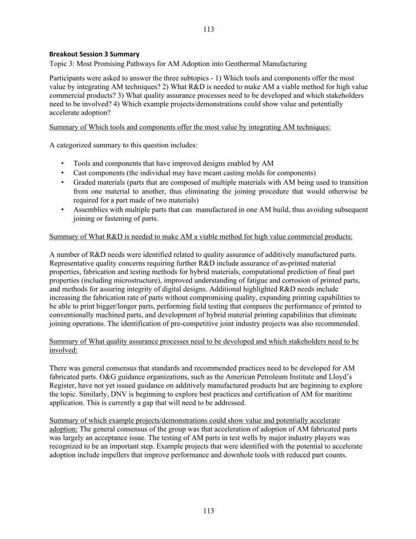
113
113
Breakout Session 3 Summary Topic 3: Most Promising Pathways for AM Adoption into Geothermal Manufacturing
Participants were asked to answer the three subtopics - 1) Which tools and components offer the most value by integrating AM techniques? 2) What R&D is needed to make AM a viable method for high value commercial products? 3) What quality assurance processes need to be developed and which stakeholders need to be involved? 4) Which example projects/demonstrations could show value and potentially accelerate adoption?
Summary of Which tools and components offer the most value by integrating AM techniques:
A categorized summary to this question includes:
• Tools and components that have improved designs enabled by AM • Cast components (the individual may have meant casting molds for components) • Graded materials (parts that are composed of multiple materials with AM being used to transition
from one material to another, thus eliminating the joining procedure that would otherwise be required for a part made of two materials)
• Assemblies with multiple parts that can manufactured in one AM build, thus avoiding subsequent joining or fastening of parts.
Summary of What R&D is needed to make AM a viable method for high value commercial products:
A number of R&D needs were identified related to quality assurance of additively manufactured parts. Representative quality concerns requiring further R&D include assurance of as-printed material properties, fabrication and testing methods for hybrid materials, computational prediction of final part properties (including microstructure), improved understanding of fatigue and corrosion of printed parts, and methods for assuring integrity of digital designs. Additional highlighted R&D needs include increasing the fabrication rate of parts without compromising quality, expanding printing capabilities to be able to print bigger/longer parts, performing field testing that compares the performance of printed to conventionally machined parts, and development of hybrid material printing capabilities that eliminate joining operations. The identification of pre-competitive joint industry projects was also recommended.
Summary of What quality assurance processes need to be developed and which stakeholders need to be involved:
There was general consensus that standards and recommended practices need to be developed for AM fabricated parts. O&G guidance organizations, such as the American Petroleum Institute and Lloyd’s Register, have not yet issued guidance on additively manufactured products but are beginning to explore the topic. Similarly, DNV is beginning to explore best practices and certification of AM for maritime application. This is currently a gap that will need to be addressed.
Summary of which example projects/demonstrations could show value and potentially accelerate adoption: The general consensus of the group was that acceleration of adoption of AM fabricated parts was largely an acceptance issue. The testing of AM parts in test wells by major industry players was recognized to be an important step. Example projects that were identified with the potential to accelerate adoption include impellers that improve performance and downhole tools with reduced part counts.

114
114
Next Steps: Moving forward, Yarom Polsky and others will prepare a meeting summary and have discussions with GTO on how to move forward with respect to applying additive manufacturing to geothermal technologies.
Attendees: 18 (non-ORNL) attendees from 12 different organizations participated. Name Affiliation Name Affiliation Jason Czapla Controlled
Thermal Resources
Sachin Nimbalkar ORNL
Christopher Taylor
DNV GL Corson Cramer ORNL
Sean Johnson DOE Office of Chief Counsel
Bill Peter ORNL
Mark Meyer GE Yarom Polsky ORNL Abraham Samuel Geothermal Resource
Group Inc.
Douglas Blankenship
Sandia
Richard Ornelaz Halliburton Jiann Su Sandia Xiaoguang Allan Zhong Halliburton Joseph Lenhardt Schlumberger
Technology Corporation
Peeyush Nandwana ORNL Annie Wang Senvol
Kristina Armstrong
ORNL Kenneth Kort DOE AMO
Craig Blue ORNL Susan Hamm DOE, Geothermal Technologies Office
Mark Noakes ORNL Sean Porse DOE, Geothermal Technologies Office
Lonnie Love ORNL Maher John Vermeer Alex Roschli ORNL Jeffrey Johnston Welltec Inc. Brian Post ORNL Blaine Stainfield WellTec Inc. Lauren Boyd DOE

115
115
Breakout Session 1 Details:
Question 1: What are current manufacturing challenges in industry?
To address the first question, an exercise was performed where participants were asked to individually write manufacturing challenges associated with the categories of Well Construction, Well Intervention and Production equipment on sticky note pads and place them on poster boards and place them on poster boards for each category. The input below was provided by participants.
Well Construction (summary all sticky notes typed out and listed below)
• Machining cost of drill bits • Drill bit button inserts and their wearability/resilience for geothermal drilling

116
116
• PDC bits • Brazing cutters in place • Final grinding for bit diameter • Drill pipe • Welding joints • Threading • Drill bits – casting of bit bodies limits ability of making complex flow patterns that could improve
bit performance • Drill bits • High wear resistant, low cost materials • Complex manifold passages (time and money, electric and fluid) • Flow manifold for flow control • Sleeves – manufacture products using virgin raw materials to prevent imperfections • Completions – often incorporate complicated flow patterns or actuation mechanisms; lots of
machining required • Qualification of AM well components • Well completions with hard-to-manufacture internal channels/designs; joints • Motors • Material Properties • Fatigue life • Dimensional tolerances • Corrosion resistance • Internal flow channels • Multi-part assemblies • Dependency on multiple supply chain part manufacture • How can we as a company provide adequate documentation to clients? • Tubes for sleeves (compliance issues) • HT tolerance – materials and electronics • Consumer appetite for risty new ideas • Well construction • Failure of tools is a major source of downtime. Tools designed for high-temp have not proven
reliable over 250°C • Geothermal wells tend to have Co2; requires special additives to be resistant; additives are
expensive and can affect properties • Alloy casing for corrosive geothermal brines are $1500-2000 per foot • Geothermal wells tend to be designed on the fly; geologists on site determine setting depths and
direction; need better geophysical data before drilling; fracture maps • Lost circulation when encountered can add days of downtime and loss of expensive drilling mud • Space constraints • Part formation • Material properties • Fatigue • Lifetime • Hard-to-manufacture internal designs • To summarize, drill bits and complex flow paths mentioned multiple times; material considerations;
machining costs
117
117
Well Intervention (all sticky notes typed out and listed below)
• Multiple joint interfaces required on tool strings • Lack of available HPHT electronics to meet requirements • Manufacture of internal flow lines on large parts • Heat exchanger (cooling in hole components) • Proper heat shielding for downhole telemetry tools • HT Tolerance: materials including elastomers, circuit boards, solders AND electronics • Overall tool length • Significant lead times for spare parts and large inventory • NACE and corrosion resistant materials • Metallurgical bond of dissimilar materials meeting all mechanical property requirements • Geothermal tend to be open hole. This makes selective stimulation very difficult. Need packers or
diversion methods for high temp • Ability to build materials to increase procure vats (? Illegible)
Production (all sticky notes typed out and listed below)
• Scale is a primary cause for production decline. Cost effective inhibitors for geothermal would be beneficial
• Weld operations are involved to put on right end connection • Erosion resistance • Materials selection in extreme environments (h2S, co2, t1ph) • HT Tolerance in materials and electronics • Cost of high alloy components and machinability • Metallurgical bond of dissimilar materials meeting all mechanical properties requirements • Adding bosses/flanges • Tooling • Wellheads: very long lead times. Made from large metal stock and machined is wasteful • Repair • Cooling of high temp electronics for well monitors • Materials/components are ‘dumb’ could benefit from materials health sensing • Adding cooling and/or sensors to mining bits • NACE and corrosion resistant materials • Corrosion of mining bits during operation • Ensuring corrosion resistance over economic timeframes of casting/surface piping • For many flowback components, a variety of end connections are available. Some parts can be
forged but much machining still requires the production of final features. • Making cutting tools and mining bits in fewer steps • Risers, etc.: for many tool/part shapes – machining produces excessive waste for simple forms
(i.e. tubes)
Notes During Open Discussion:
• Surface and operating costs can be even more than the subsurface costs. However, everyone did not agree with this point. Scaling creates the challenge in the manufacturing of geothermal plants. • Casings that go into the well are made of expensive materials

118
118
• The manufacturing process is so specialized and made of so many different materials that bits and pieces of it have to manufactured and shipped from place to place until it’s complete and this greatly increases the cost of the casing and well per foot.
• Corrosion resistance is a big theme that needs improvement • Question 2: How might additive improve manufacturability issues?
• An open group discussion was held to address question 2. A summary of the group’s views is presented in bullet form below.
• Internal channels, such as the injection molding tool made by ORNL; can be replicated • Process efficiency • Joining materials • We must enhance corrosion resistance; a lot is focused on complexity as well as fundamental
material properties for structural applications • Directed energy deposition is best for multi-materials for now, but binder jet is getting further on
this • How gradient materials are qualified is the issue; quality standards also vary depending on the
application • API is the certification standard for geothermal; are they looking into AM? Probably at least five
years away; practically, this is a new frontier of research • End products must meet specifications; there are guidelines but there’s a question of certifying
something yourself by your own standards or by industry-specified standards; anyone would have their own specifications. There are standards for certain aspects, but the rest is decided internally. You can say what tests you’ve done and call something a prototype for someone to try; if money/time becomes an issue, testing is the first to go
• Average drill bit manufacturing time: not very long; design can be modified on the fly; may have limited complexity though
• The goal is to go bigger and bigger (the bigger the well, the better) • With AM, can I make an O-ring out of titanium that will compress without collapsing w/ rebound
capability, corrosion resistance – can that be made in a way with AM that is better? Such as, add porosity, change material properties; you can build in whatever you want with AM
• Many current products are manufactured with specialized dies or molds. This limits the ability to adapt designs because it increases cost of tooling needed for manufacturing. AM could be used to make more cost effective tooling or to produce customized parts without the additional tooling expenses.
Question 3: What tool/technology candidates do you recommend for additive manufacturing?
Well construction Well Intervention Production
Bit body with complex flow paths and cutter angles
Impellers Impellers
Impellers and diffusers diffusers Diffusers
Block-large Block-large Blocks-large
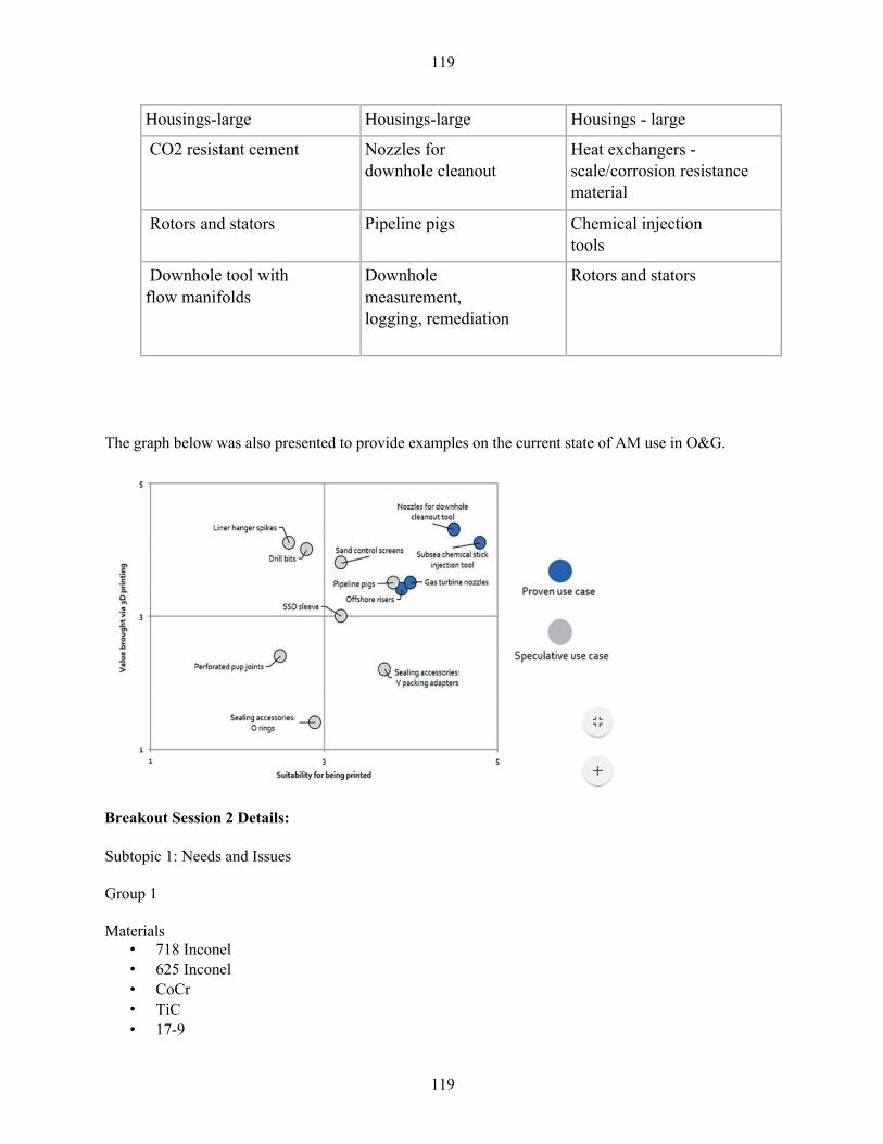
119
119
Housings-large Housings-large Housings - large
CO2 resistant cement Nozzles for downhole cleanout
Heat exchangers - scale/corrosion resistance material
Rotors and stators Pipeline pigs Chemical injection tools
Downhole tool with flow manifolds
Downhole measurement, logging, remediation
Rotors and stators
The graph below was also presented to provide examples on the current state of AM use in O&G.
Breakout Session 2 Details:
Subtopic 1: Needs and Issues
Group 1
Materials • 718 Inconel • 625 Inconel • CoCr • TiC • 17-9
120
120
• SS 316 • Ti6Al4V • The above are commercially available now • 4140 • 4145 • Al • BeCu • Nitronic 60
Property requirements • Yield strength • Tensile • Charpy toughness • Ductility • Reduction in area • Fatigue • Fracture • Corrosion • Hardness • Material degradation • Density/porosity • Magnetic versus nonmagnetic
Build dimensions/tolerances • Thin wall (0.25”) • Surface finish (RA) • Drilling tools, perforating tools o 2000 mm horizontal (illegible) o 8”x8”x8” build area • (wish) ±.0001” • -100:1 aspect ratio • Straightness/cylindricity .001 • Integration/assembly issues • Thread fit/class connections
Market acceptance concerns • Cost (each and initial investment)
Consistency • Build-to-build and machine-to-machine variability and reliability • Corrosion of AM metal parts • Lack of knowledge about process of certification • Are the current testing paradigms applicable to AM – will they find the same failures when applied
to AM parts (internal defects, etc.)? You could have porosity, etc. • The part has to be qualified, not just the AM process; how do you build a qualification system for
parts? One you have a machine that’s calibrated, you can be sure that you have consistent parts; like a raster pattern (with directed energy)
Group 2
Materials • BeCu • 17-4 • 4140 (can print today)
121
121
• 4145 • Inconel 625 (can print today) • Inconel 718 (can print today) • Titanium (can print today) • Peek (can print today) • Kalrez • Kapton • FRP • Cement • Ceramics • Multi-layered PCBs >300 C
Property requirements • Thermal stability and degradation resistance • HT corrosion resistance • Mechanical properties • Thermal conductivity • Thermal expansion coefficient
Dimensional requirements/tolerances • > 1 m height in z direction • Typical wellbore envelopes • Up to 10 feet for casing/downhole tool applications • 120 foot diameter for tanks at surface Integration/Assembly issues • Many small components • Machining complexity • Transport (can AM parts be printed on site?) • Prototype assembly • Supply chain • Just in time manufacturing
Market acceptance concerns • Cost
Certifications • Material specs • In situ proof of concept • Social acceptance • Risk aversion
Subtopic 2: What successful analogues can we highlight?
Group 1
• Drilling and completion tools • Wellhead valves • 3D printing molds and casts • Hi-eta o Laser parts and heat exchangers • Offshore risers • Gas turbine nozzles • Subsea chemical injection tools

122
122
• Nozzles for downhole cleanout • Impellers • Rotors and stators • Binder jet o Impellers for pumps o Heat exchangers • Customized beams and retainers – dentistry • Shoes • Tooling for electronic encapsulation • Seals w internal features • Porous structures for medical • Part consolidation/integration • Electric package support structures • AM parts that have helped any industry?
Group 2
• Casting molds for injection molded parts • High expansion bridge plug • Printing sand casts • Prototype development
• Well monitors
Subtopic 3: What timeline are expected/anticipated for these advancements? Is industry already tackling these challenges?
Group 1 • DNV GL
o JP on sour service and seawater testing • Binder jet AM of WC-Co
o Global Tungsten o ExOne o Kennametal o ORNL o General Carbide
• Different universities actively working on material issues Group 2
• Cement printing = 1.5 years from idea to system that prints concrete Group Debriefings How do you handle powder quality? Not a lot of science around this topic. Recyclability on E-beam powders? Depends on powder chemistry; Ti6Al4V isn’t good to reuse but Inconel 718 can work and stays within specifications. AM can be financially beneficial for recyclability Thermal stability and corrosion resistance are primary concerns; thermal conductivity, elasticity capability. Lead time and supply chain are important. Printing horizontally would be particularly
123
123
interesting. Downhole monitoring – if you could print casing and embed sensors to monitor, it would have merit. Breakout Session 3 Details:
Subtopic 1: Which tools and components offer the most value by integrating AM techniques?
• Better, not cheaper bits including improved hydraulics • Heat exchangers (fractal geometries, compositionally graded) • Fused deposition/weld to repair parts or tools • 120 foot retention facilities • Alternatives to 30 ft gun drilling • Graded materials for casing, tubing,liners • Low risk components • Casted components such as diffusers • Parts with AM integrated electronics • Packers (novel geometries) • Downhole tools with multiple parts that must currently be welded or fastened together (reduced
labor and failure points ) Subtopic 2: What R&D is needed to make AM a viable method for high value commercial products?
• Testing different materials or combinations of materials • Producing high quality parts faster • Consolidating parts to reduce supply chain • Field testing integration/run history • Bigger/longer parts
Isotropic printed material • Computational modeling of green vs final part geometry, microstructure, performance, etc. • Fatigue and corrosion of printed material • In situ downhole printing • Integrity of digital designs • Infiltrating and sintering effectiveness of ceramics (e.g. Tungsten cobalt)
Subtopic 3: What quality assurance processes need to be developed and which stakeholders need to be involved?
• Standards bodies, regulators, recommended practices, 3rd parties (e.g. DNV GL) • Risk assessment/tech qualification • Need more data, testing, statistics and tracking of pilot/earl case projects • Pre-competitive joint industry projects • Powder/feedstock and machine vendors • Operators (O&G companies) • Service companies • Lloyds/Insurance groups

124
124
Subtopic 4: Which example projects/demonstrations could show value and potentially accelerate adoption?
• Part count optimized downhole tools • Impellers or other rotating parts with improved manufacturing cost or performance • Identify early adopters to seed/catalyze industry interest • Involve big names to test in test wells.