
Additive Manufacturing Technology
76
www.3trpd.co.uk Additive Manufacturing Technology November 2012 Phil Kilburn DMLS Sales Manager
Transcript of Additive Manufacturing Technology
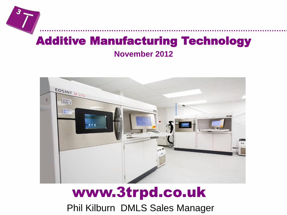
www.3trpd.co.uk
Additive Manufacturing Technology November 2012
Phil Kilburn DMLS Sales Manager
Agenda
• About 3T RPD Ltd
• Overview of Additive Manufacturing
• Manufacturing directly in metals
• Arcam - Electron Beam Melting
• EOS - Direct Metal Laser Sintering
• Applications
• Polymer Additive Manufacturing
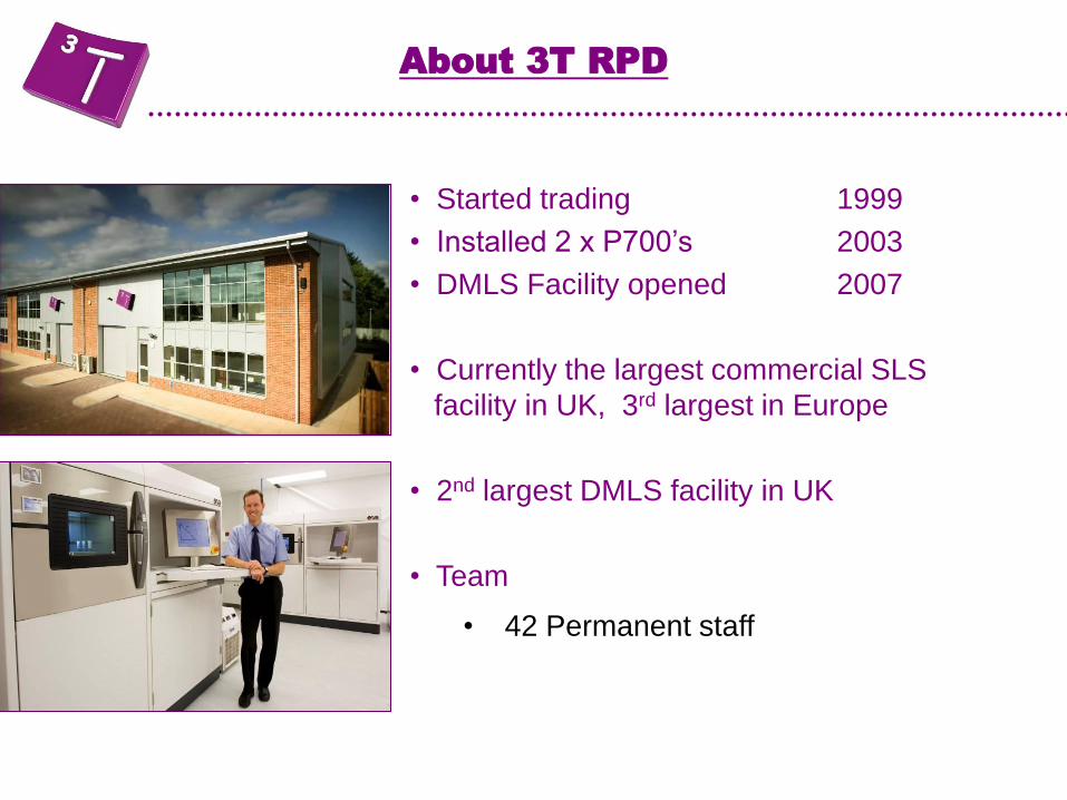
• Started trading 1999
• Installed 2 x P700’s 2003
• DMLS Facility opened 2007
• Currently the largest commercial SLS
facility in UK, 3rd largest in Europe
• 2nd largest DMLS facility in UK
• Team
• 42 Permanent staff
About 3T RPD
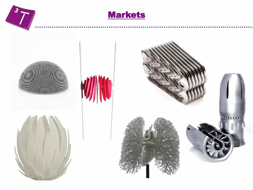
Markets
Quality control
AS 9100 Rev. C
ISO 9001:2008
ISO 13485:2003
• 3T Quality
standards
Overview of Additive Manufacturing
• The process of creating 3D objects, layer by layer
• As opposed to subtractive manufacturing methods
Definition of Additive Manufacturing
Overview of Additive Manufacturing
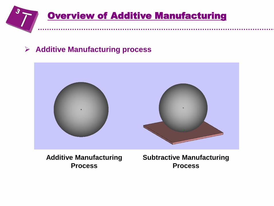
Additive Manufacturing process
Overview of Additive Manufacturing
Additive Manufacturing
Process
Subtractive Manufacturing
Process

Overview of Additive Manufacturing
Additive Manufacturing process
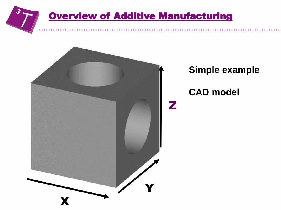
Parts are built up from a large number of very thin two-
dimensional cross sections (layers)
By convention the cross sectional layers are the X-Y plane
and the model is built up in the Z axis
Overview of Additive Manufacturing
X
Y
Z
Simple example
CAD model
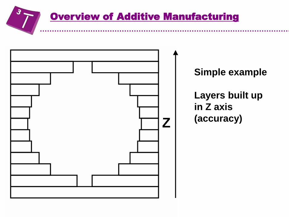
Simple example
Layers built up
in Z axis
(accuracy)
Overview of Additive Manufacturing

Overview of Additive Manufacturing

Overview of Additive Manufacturing
Additive Manufacturing process
Parts are built up from a large number of very thin two-
dimensional cross sections (layers)
By convention the cross sectional layers are the X-Y plane
and the model is built up in the Z axis
All processes used in layer manufacturing use STL files
(Standard Triangle Language) • This is the file format used in open systems
• Surface is represented by triangles
• X,Y,Z for each point on triangle and a vector to outside
• Tolerance of the original surface in relation to triangles is critical
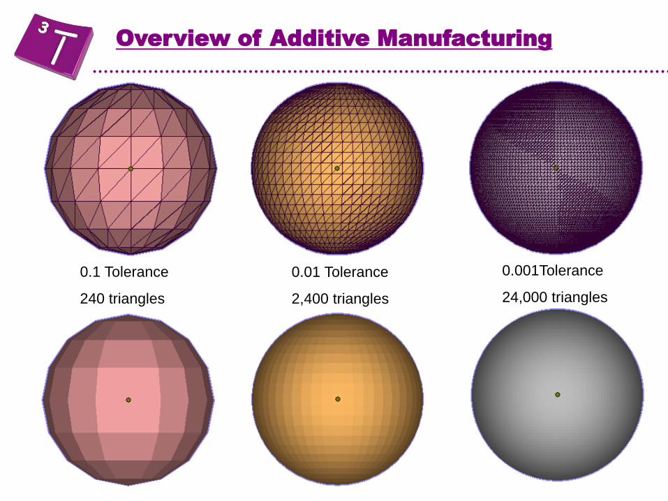
0.01 Tolerance
2,400 triangles
0.001Tolerance
24,000 triangles
0.1 Tolerance
240 triangles
Overview of Additive Manufacturing
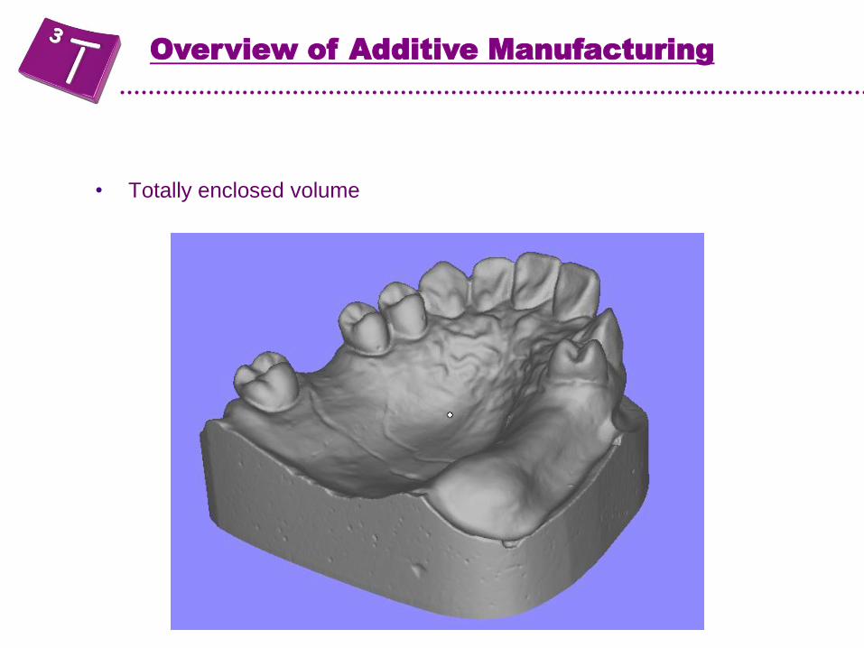
• Totally enclosed volume
Overview of Additive Manufacturing
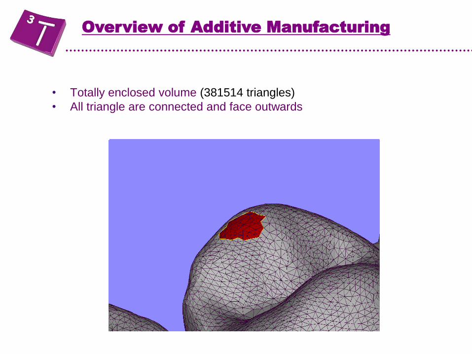
• Totally enclosed volume (381514 triangles)
• All triangle are connected and face outwards
Overview of Additive Manufacturing
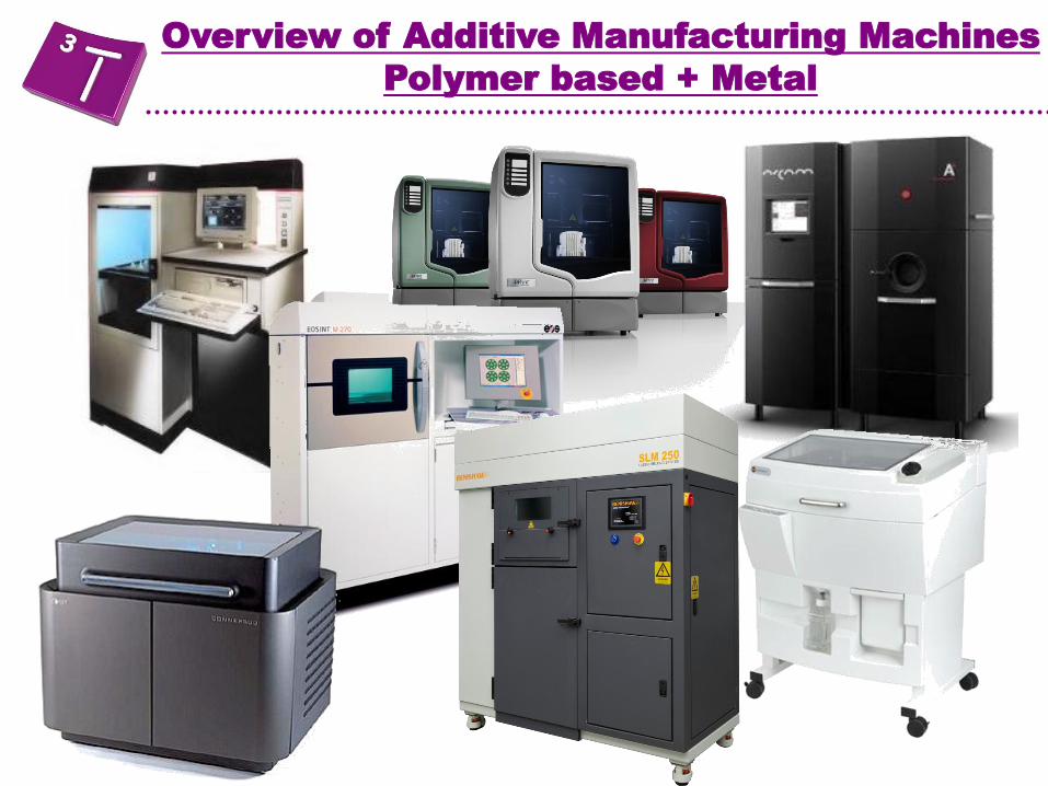
Overview of Additive Manufacturing Machines
Polymer based + Metal
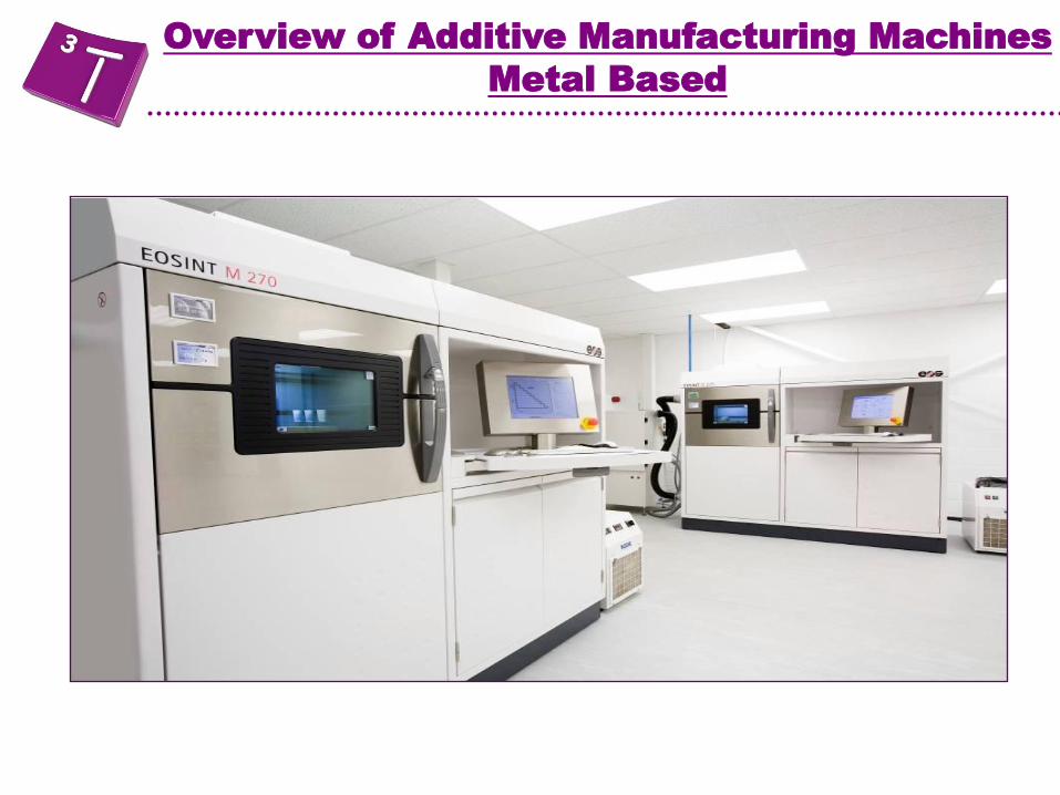
Overview of Additive Manufacturing Machines
Metal Based

Additive Manufacturing of Metal products
Arcam – Electron Beam Welding
Renishaw – Selective Laser Melting
Concept Laser – LaserCUSING® materials
EOS – Direct Metal Laser Sintering
A range of materials are currently available – but not on all machines
Stainless Steel
Cobalt Chrome
Titanium 6Al 4V
Inconel
Tool Steel
Aluminium
Gold
Silver
……
Overview of Additive Manufacturing - Metal

• A high energy beam is generated in the Electron Beam Gun
• The beam melts each layer of metal powder to the desired geometry
• Extremely fast beam translation with no moving parts
• Vacuum process eliminates impurities and yields excellent material
properties
• High build temperature gives form stability and low residual stress
• Low operating costs
Arcam – Electron Beam Welding
Overview of Additive Manufacturing - Arcam

ARCAM EBM TECHNICAL DATA (Hot process)
• Build envelope 200 x 200 x 350 mm (W x D x H) or 300 x 200 mm (Ø x H)
• Build speed Up to 60 cm3/h
• Layer thickness 50 – 200µm
• Vacuum pressure <5 x 10⁻⁴ mBar
• Electron Beam power Up to 4000 W
• Electron Beam accuracy ±0.05 mm
• Electron Beam scan speed ~1000 m/s
Overview of Additive Manufacturing - Arcam
• Materials available
– Ti6Al4V
– Ti6Al4V ELI
– Titanium Grade 2
– CoCrMo ASTM F75
Overview of Additive Manufacturing - Arcam

Overview of Additive Manufacturing - Arcam
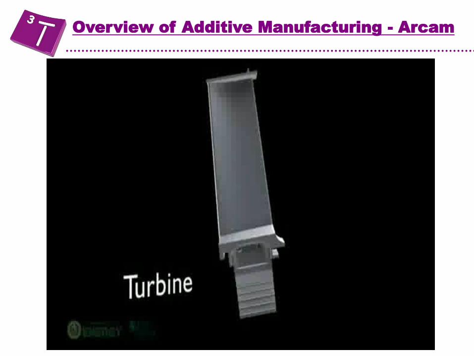
Overview of Additive Manufacturing - Arcam

Overview of Additive Manufacturing - Arcam
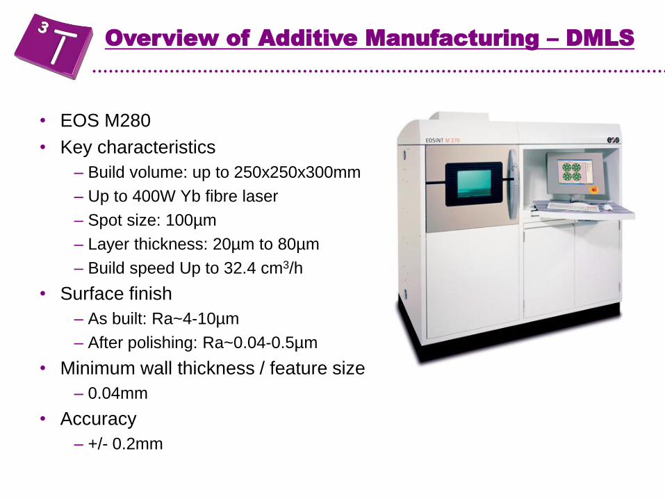
• EOS M280
• Key characteristics
– Build volume: up to 250x250x300mm
– Up to 400W Yb fibre laser
– Spot size: 100µm
– Layer thickness: 20µm to 80µm
– Build speed Up to 32.4 cm3/h
• Surface finish
– As built: Ra~4-10µm
– After polishing: Ra~0.04-0.5µm
• Minimum wall thickness / feature size
– 0.04mm
• Accuracy
– +/- 0.2mm
Overview of Additive Manufacturing – DMLS

Definition: Direct Metal Laser Sintering
Melting and not sintering
Overview of Additive Manufacturing – DMLS
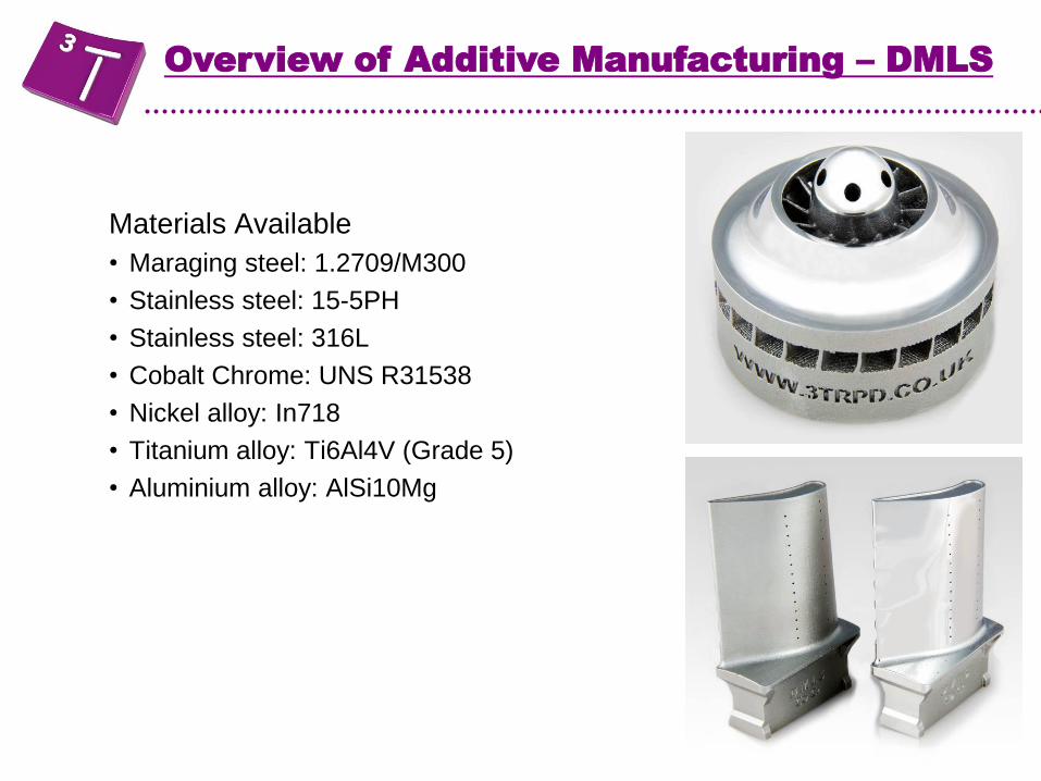
Materials Available
• Maraging steel: 1.2709/M300
• Stainless steel: 15-5PH
• Stainless steel: 316L
• Cobalt Chrome: UNS R31538
• Nickel alloy: In718
• Titanium alloy: Ti6Al4V (Grade 5)
• Aluminium alloy: AlSi10Mg
Overview of Additive Manufacturing – DMLS
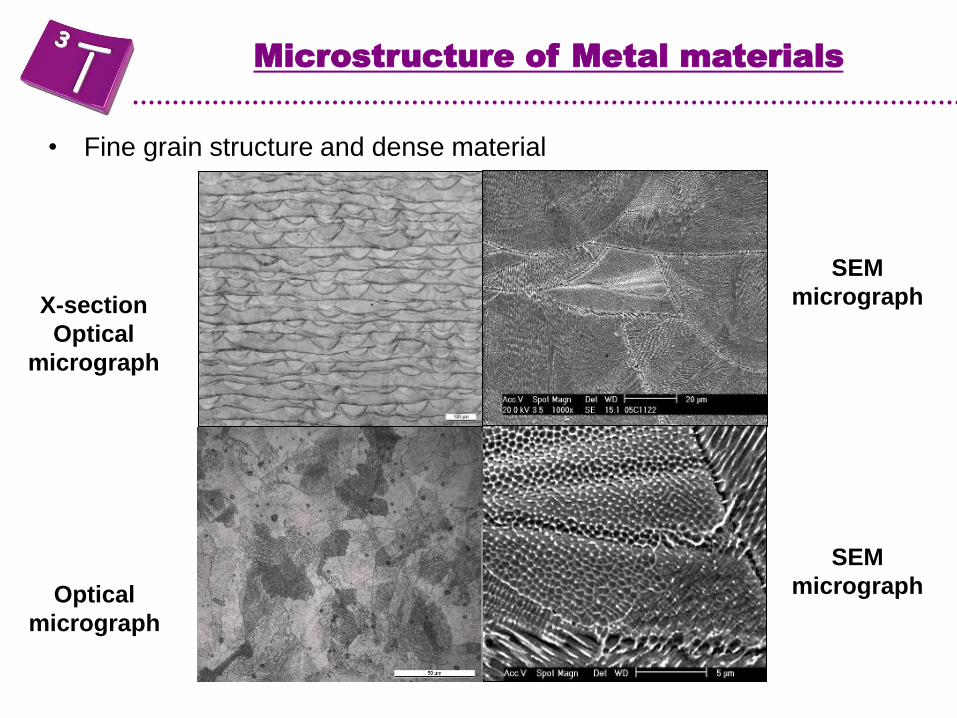
• Fine grain structure and dense material
X-section
Optical
micrograph
SEM
micrograph
SEM
micrograph Optical
micrograph
Microstructure of Metal materials

• Fine grain structure in Ti6Al4V
X-section
Optical
micrograph
Fully dense
α/α'-β structure
Microstructure of Metal materials
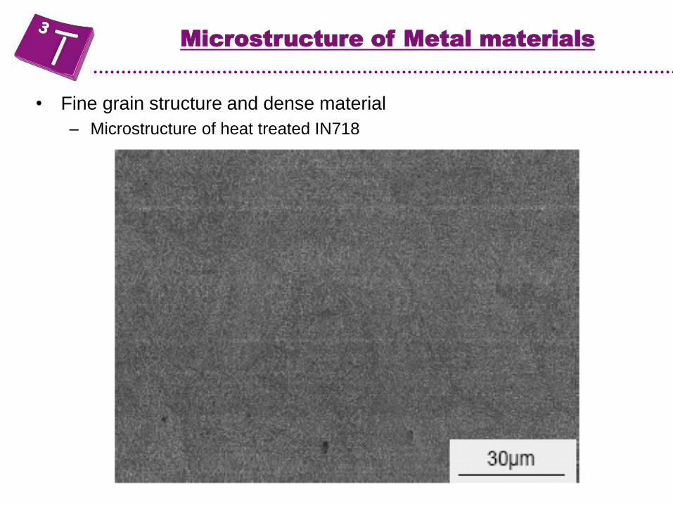
• Fine grain structure and dense material
– Microstructure of heat treated IN718
Microstructure of Metal materials
Overview of Additive Manufacturing - DMLS

General comments about DMLS materials
• Full melting process = ~100% density
• Properties of as-built DMLS parts: close to or better than cast
• Final properties dependent on heat treatment
• Can be processed like any other conventionally produced
alloys
• Can be used for prototyping applications as well as
manufacturing applications
Overview of Additive Manufacturing - DMLS

Basic principles of DMLS

• Powder is not self supporting
• Parts have to be attached to the platform
• Post-finishing needed
Basic principles of DMLS
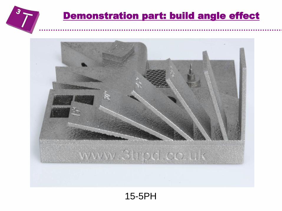
15-5PH
Demonstration part: build angle effect
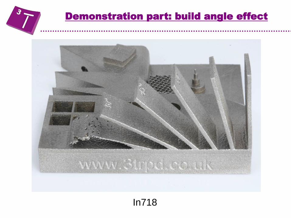
In718
Demonstration part: build angle effect

• Process
– Orientate part
– Add finishing stock (+0.1- 0.5mm)
– Automatic creation of support structure in Magics
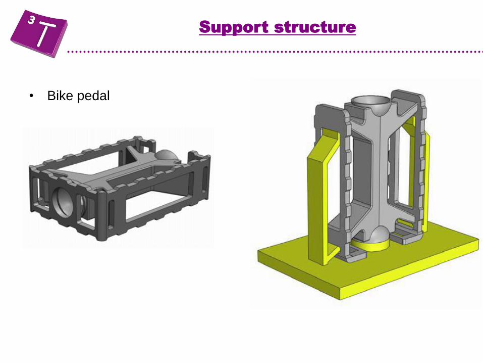
Support structure
• OK for prototyping work but not for manufacturing
Support structure
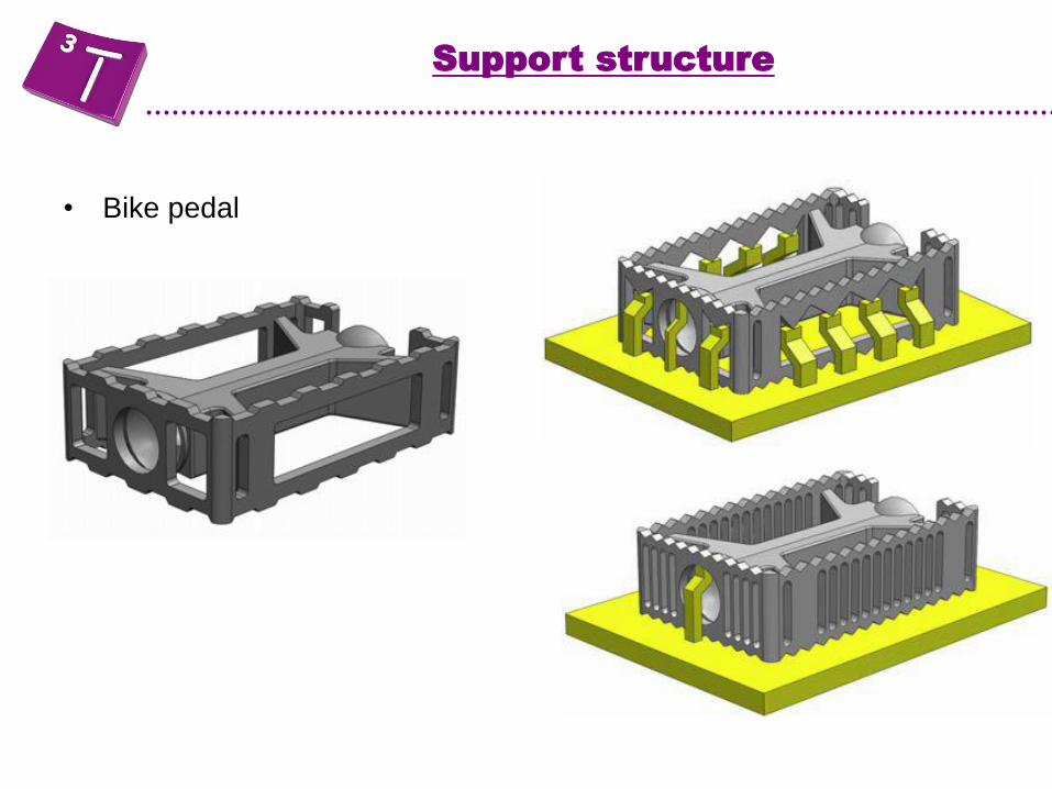
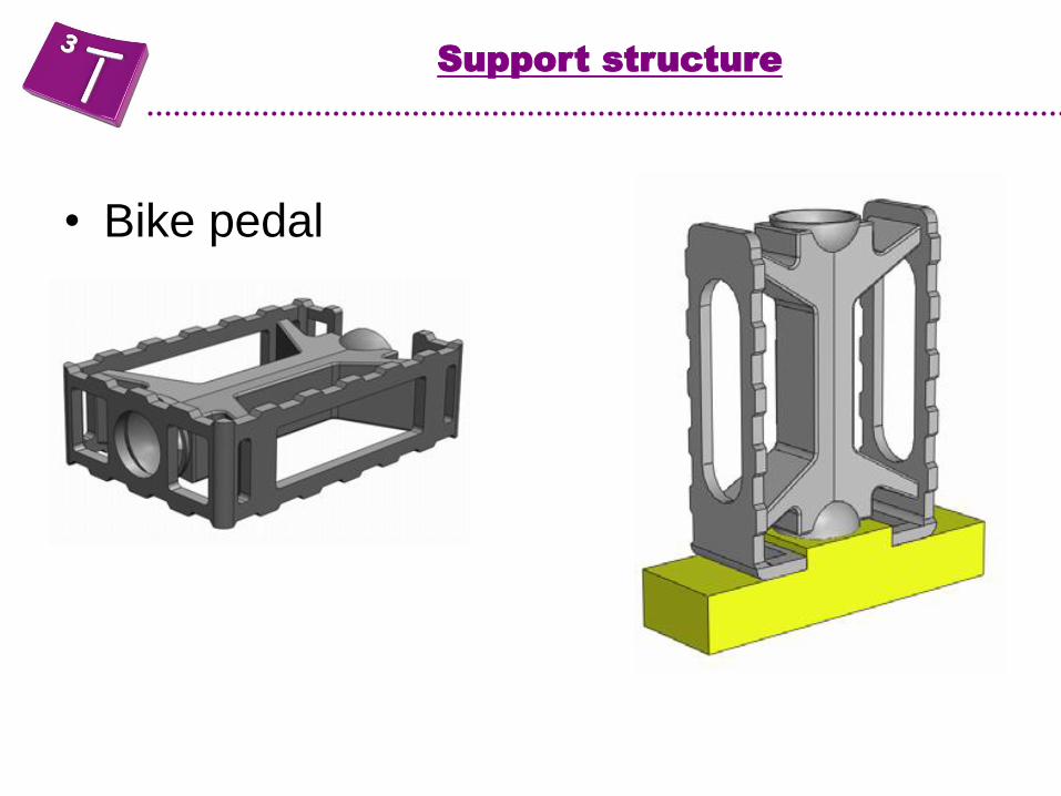
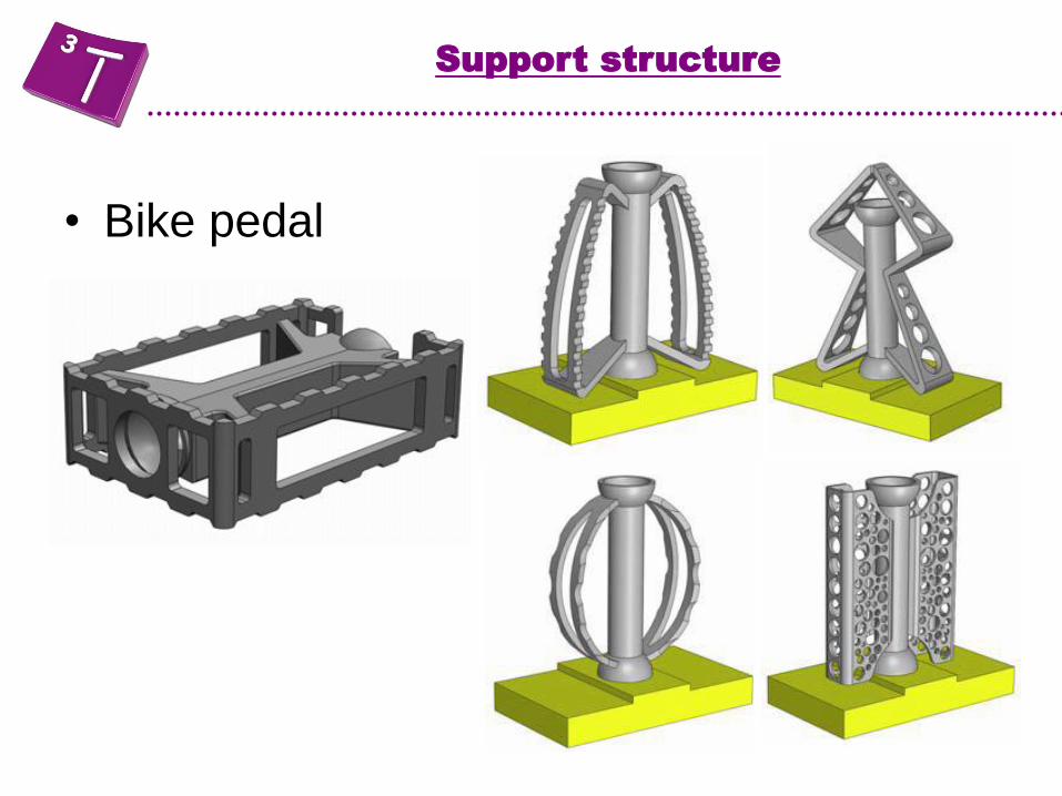
• Bike pedal
Support structure
• Bike pedal
Support structure
• Bike pedal
Support structure

• Bike pedal
Support structure
• Bike pedal
Support structure

• Stator Ring
– Material: Cobalt chrome
– Dimensions: dia160mm x H60mm
– Layer thickness: 40micron
– Build time: 40h
– Finishing (including polishing): 50h
– Polishing: First Surface (Micro
Machining Process)
• Cost: ~£4500
Aerospace application
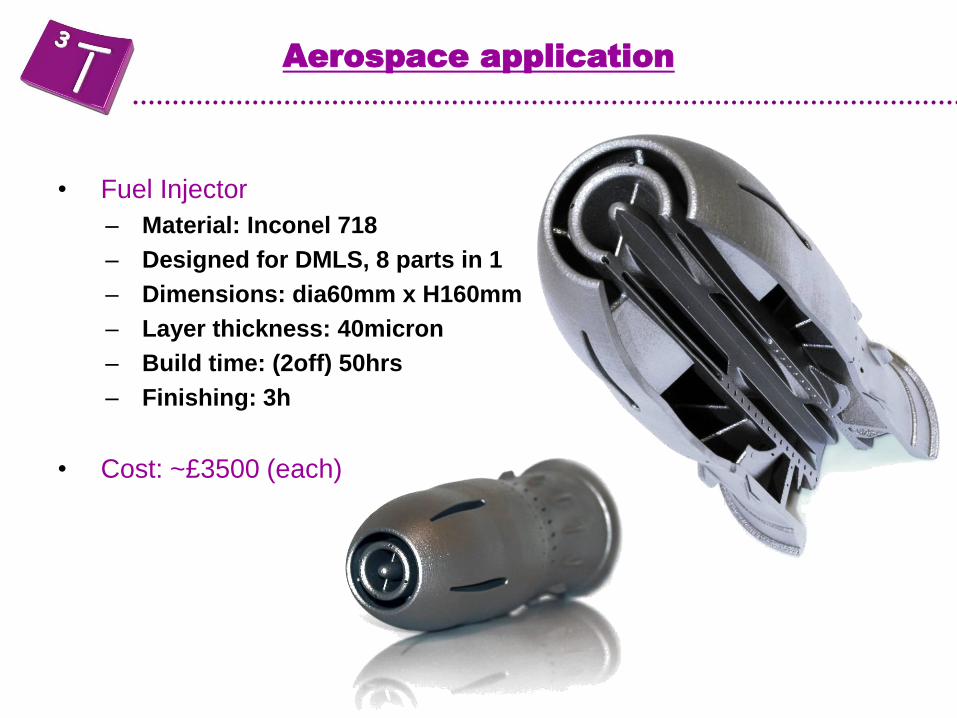
• Fuel Injector
– Material: Inconel 718
– Designed for DMLS, 8 parts in 1
– Dimensions: dia60mm x H160mm
– Layer thickness: 40micron
– Build time: (2off) 50hrs
– Finishing: 3h
• Cost: ~£3500 (each)
Aerospace application

• Swirler
– Material: Cobalt Chrome
– Dimensions: dia27mm x H30mm
– Layer thickness: 20micron
– Build time: 90h (45 parts)
– Finishing (including polishing):
30h
Aerospace application
Cost: ~£300 (unit cost for 45 parts)
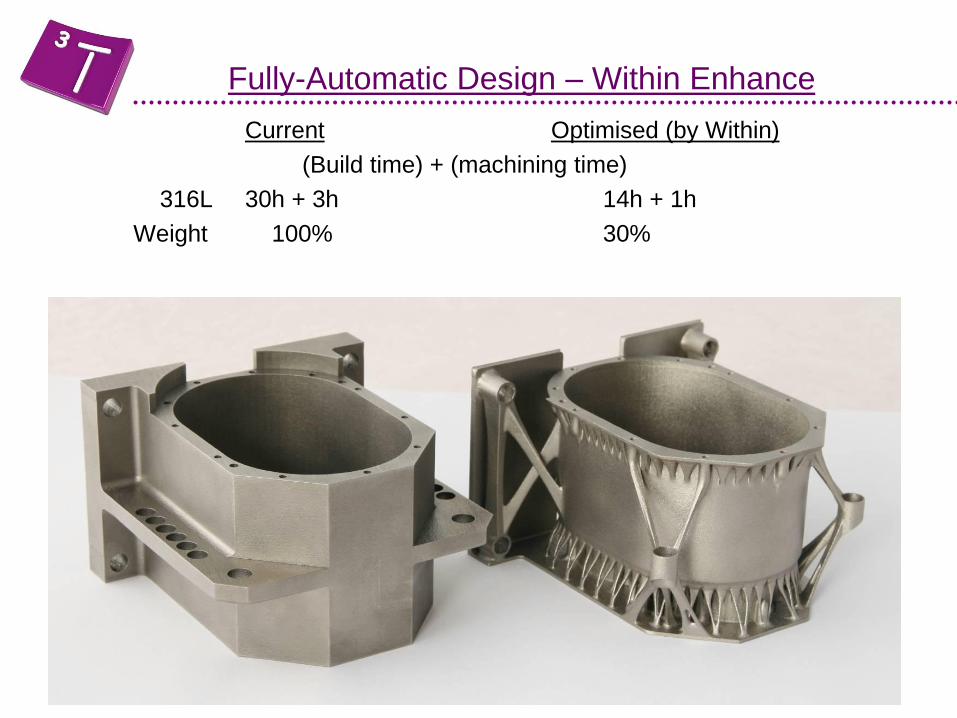
Current Optimised (by Within)
(Build time) + (machining time)
316L 30h + 3h 14h + 1h
Weight 100% 30%
Fully-Automatic Design – Within Enhance
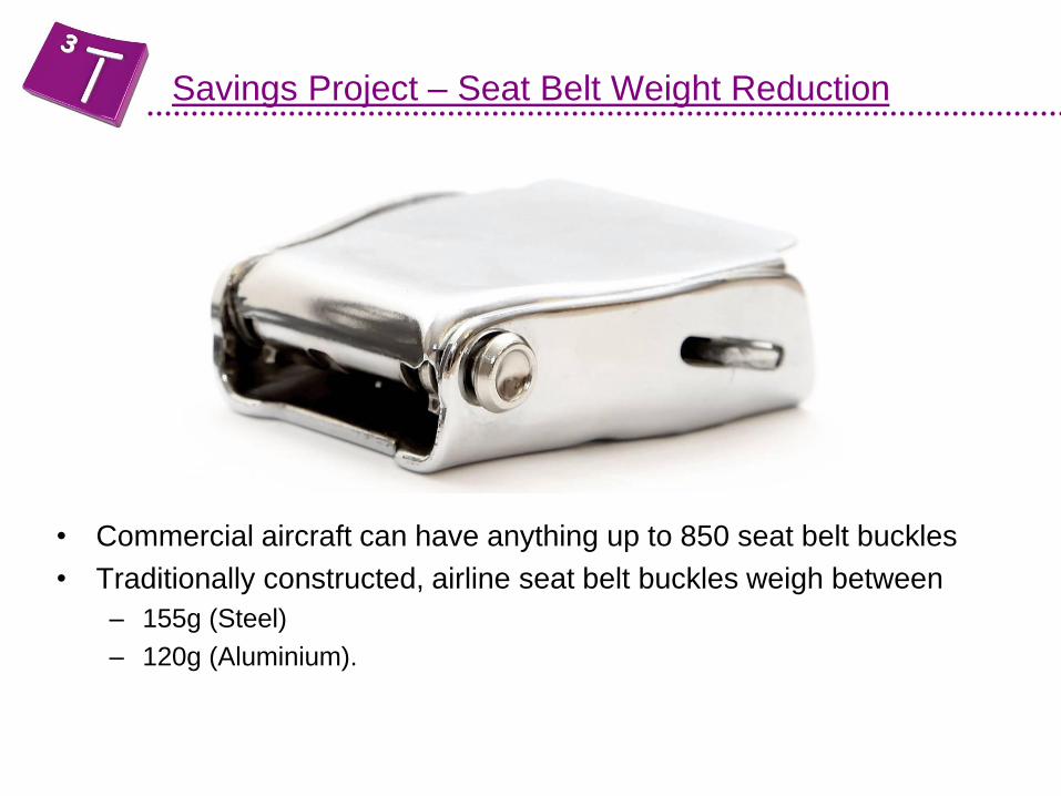
Savings Project – Seat Belt Weight Reduction
• Commercial aircraft can have anything up to 850 seat belt buckles
• Traditionally constructed, airline seat belt buckles weigh between
– 155g (Steel)
– 120g (Aluminium).
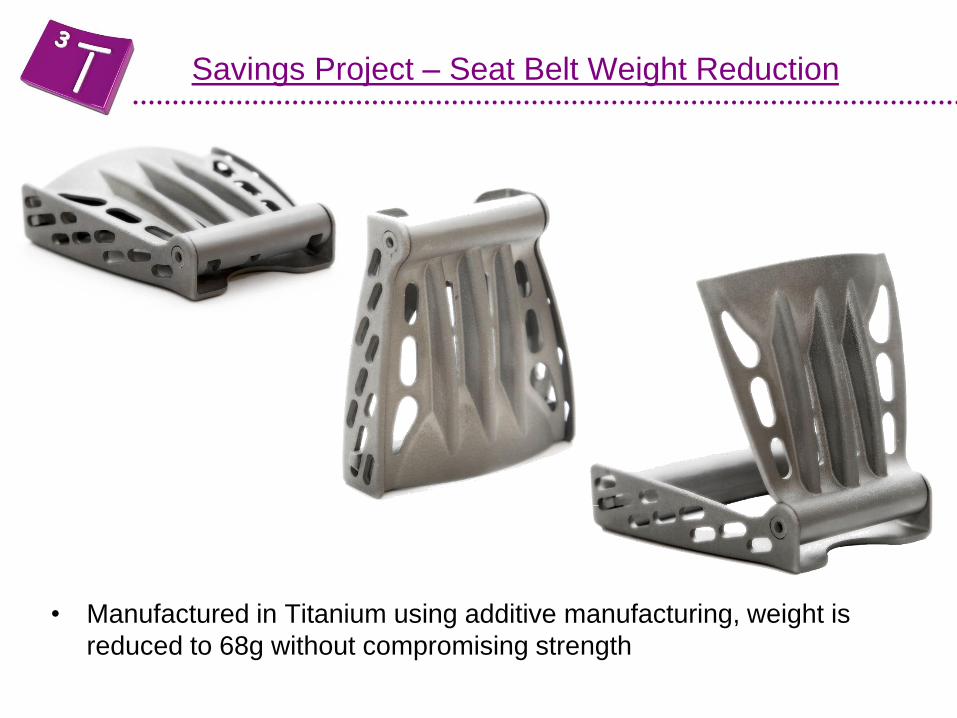
• Manufactured in Titanium using additive manufacturing, weight is
reduced to 68g without compromising strength
Savings Project – Seat Belt Weight Reduction
Several processes are readily available in the UK
Stereolithography – SLA
Fused Deposition Modelling – FDM
3D Printing – Z Corp
Selective Laser Sintering – SLS
A range of materials are currently available – but not on all machines
Epoxy based materials
Nylon
ABS
Wax
Polystyrene
Overview of Additive Manufacturing Machines
Polymer Based
Several processes are readily available in the UK
Stereolithography – SLA
Fused Deposition Modelling – FDM
3D Printing – Z Corp
Overview of Additive Manufacturing Machines
Polymer based
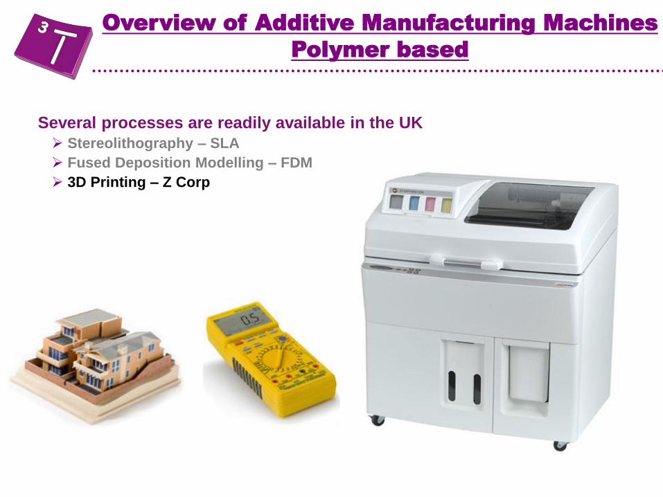
Several processes are readily available in the UK
Stereolithography – SLA
Fused Deposition Modelling – FDM
3D Printing – Z Corp
Overview of Additive Manufacturing Machines
Polymer based
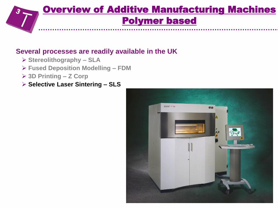
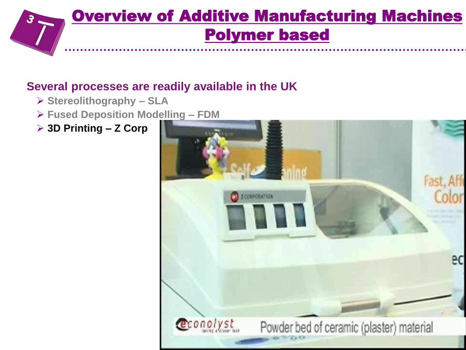
Several processes are readily available in the UK
Stereolithography – SLA
Fused Deposition Modelling – FDM
3D Printing – Z Corp
Selective Laser Sintering – SLS
Overview of Additive Manufacturing Machines
Polymer based

Nylon 11
Plastic AM Materials
* Standard at 3T
Nylon 12 (Polyamide PA2200) *
Glass Filled Nylon 12 (Polyamide PA3200) *
Alumide (Aluminium Fleck/Nylon 12)
Polystyrene (PrimeCast 101)
Carbon Filled
Flexible
Flame Retardant
PEK
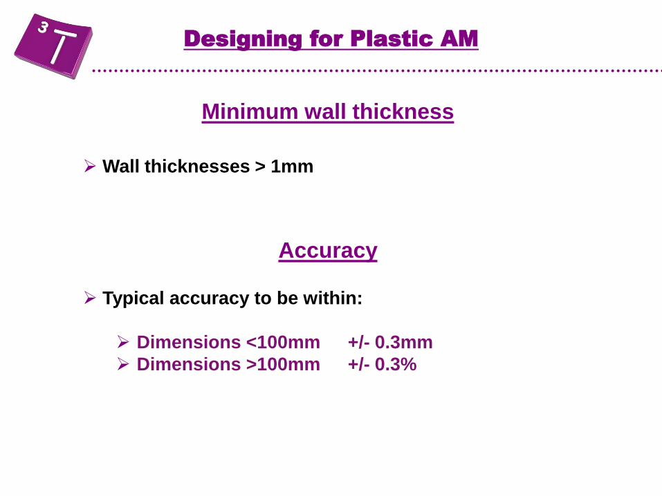
Minimum wall thickness
Wall thicknesses > 1mm
Accuracy
Typical accuracy to be within:
Dimensions <100mm +/- 0.3mm
Dimensions >100mm +/- 0.3%
Designing for Plastic AM
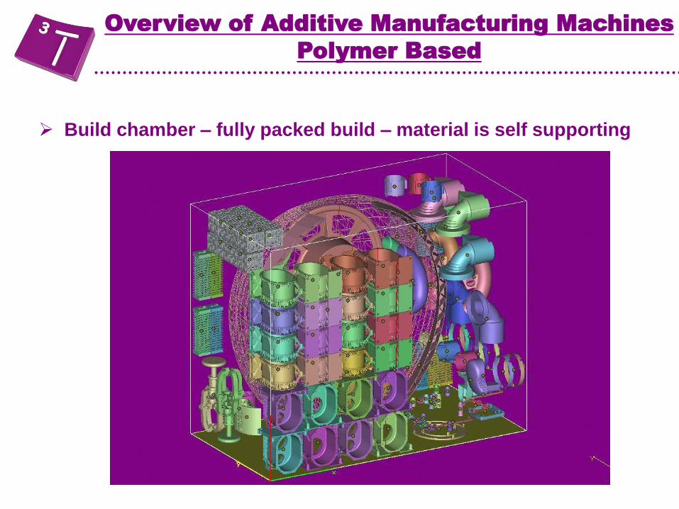
Build chamber – fully packed build – material is self supporting
Overview of Additive Manufacturing Machines
Polymer Based
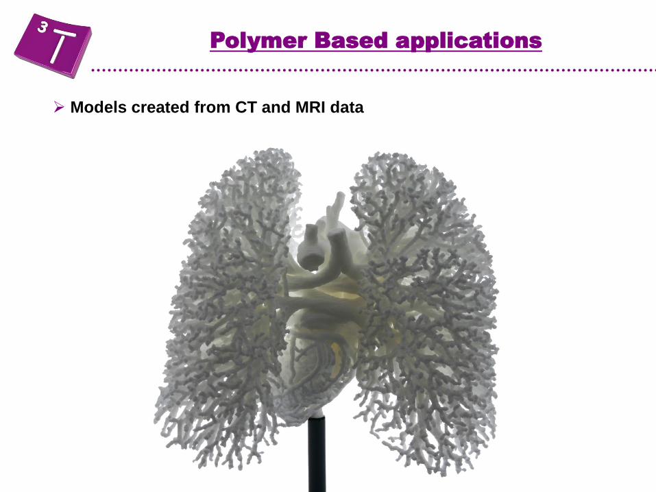
Polymer Based applications
Models created from CT and MRI data

Source - Econolyst
Polymer Based applications
Integration of several parts into a single component

Polymer Based applications
Living hinges and assemblies built in one

Polymer Based applications
Secondary finishing
Brass inserts for small diameter
threads
Larger pars welded together

Finishing for Plastic AM
Special Finishes
Plating

Finishing for Plastic AM
Effects of adding 100 micron nickel layer to SLS Pa bars
0
20
40
60
80
0 5 10 15 20
Strain %
Str
ess M
Pa 1 Pa Control
2 Pa Control
3 100micron Ni
3 100micron Ni

Finishing for Plastic AM
Permanent Surface Colouring
Finishing for Plastic AM
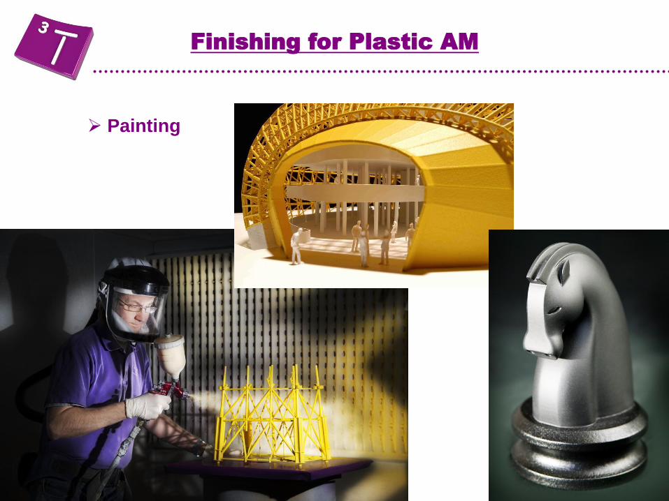
Painting
Finishing for Plastic AM
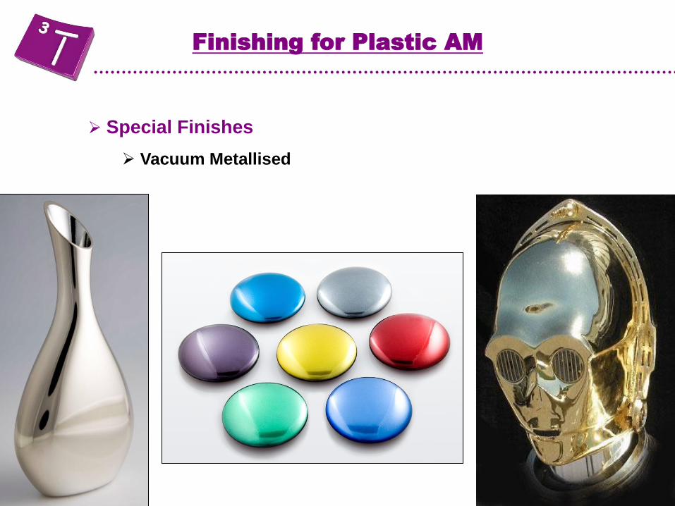
Special Finishes
Vacuum Metallised
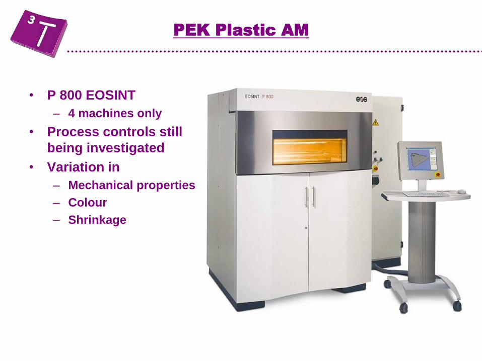
• P 800 EOSINT
– 4 machines only
• Process controls still
being investigated
• Variation in
– Mechanical properties
– Colour
– Shrinkage
PEK Plastic AM

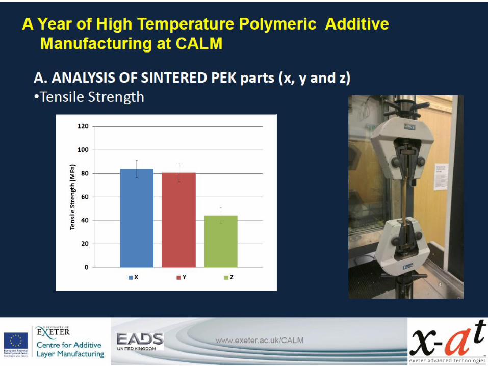
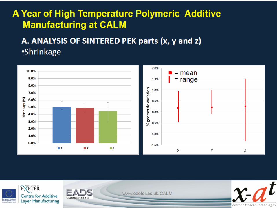
A. ANALYSIS OF SINTERED PEK parts (x, y and z) Conclusions
•Ultimate Tensile strength in Z direction is 50% of that in X and Y
•Colour variation is a surface property
•Darker colours are produced closer to the centre and bottom of the build chamber
•There is no observed link between colour and tensile strength
•There is more variation in shrinkage in Z direction than in X and Y
•In Z direction pale samples show less shrinkage


Open Coil Surface Support Development.
30% open to Helium in XYZ
Yield Stress at ~600MPa
0.5mm thick sheet.
Hole Dia. ~ 0.12mm

3D printed Ti End Spacers