Micromechanical Studies of 4N Gold Wire for fine Pitch Wire-Bonding
Upload
khangminh22Category
view
0download
0
metals
Review
Wire Arc Additive Manufacturing: Review on Recent Findingsand Challenges in Industrial Applications andMaterials Characterization
Mukti Chaturvedi 1, Elena Scutelnicu 2,* , Carmen Catalina Rusu 2 , Luigi Renato Mistodie 2,Danut Mihailescu 2 and Arungalai Vendan Subbiah 1
�����������������
Citation: Chaturvedi, M.; Scutelnicu,
E.; Rusu, C.C.; Mistodie, L.R.;
Mihailescu, D.; Subbiah, A.V. Wire
Arc Additive Manufacturing: Review
on Recent Findings and Challenges in
Industrial Applications and Materials
Characterization. Metals 2021, 11, 939.
https://doi.org/10.3390/met11060939
Academic Editors: Elena Gordo and
Reza Ghomashchi
Received: 19 May 2021
Accepted: 7 June 2021
Published: 9 June 2021
Publisher’s Note: MDPI stays neutral
with regard to jurisdictional claims in
published maps and institutional affil-
iations.
Copyright: © 2021 by the authors.
Licensee MDPI, Basel, Switzerland.
This article is an open access article
distributed under the terms and
conditions of the Creative Commons
Attribution (CC BY) license (https://
creativecommons.org/licenses/by/
4.0/).
1 Department of Electronics and Communication, School of Engineering, Dayananda Sagar University,Bangalore 560114, India; [email protected] (M.C.); [email protected] (A.V.S.)
2 Manufacturing Engineering Department, Faculty of Engineering, “Dunarea de Jos” University of Galati,800008 Galati, Romania; [email protected] (C.C.R.); [email protected] (L.R.M.);[email protected] (D.M.)
* Correspondence: [email protected]
Abstract: Wire arc additive manufacturing (WAAM) is a fusion manufacturing process in which theheat energy of an electric arc is employed for melting the electrodes and depositing material layers forwall formation or for simultaneously cladding two materials in order to form a composite structure.This directed energy deposition-arc (DED-arc) method is advantageous and efficient as it produceslarge parts with structural integrity due to the high deposition rates, reduced wastage of raw material,and low consumption of energy in comparison with the conventional joining processes and otheradditive manufacturing technologies. These features have resulted in a constant and continuousincrease in interest in this modern manufacturing technique which demands further studies topromote new industrial applications. The high demand for WAAM in aerospace, automobile, nuclear,moulds, and dies industries demonstrates compatibility and reflects comprehensiveness. This paperpresents a comprehensive review on the evolution, development, and state of the art of WAAM fornon-ferrous materials. Key research observations and inferences from the literature reports regardingthe WAAM applications, methods employed, process parameter control, optimization and processlimitations, as well as mechanical and metallurgical behavior of materials have been analyzed andsynthetically discussed in this paper. Information concerning constraints and enhancements of thewire arc additive manufacturing processes to be considered in terms of wider industrial applicabilityis also presented in the last part of this paper.
Keywords: WAAM; additive manufacturing; heat sources; materials characterisation; optimiza-tion models
1. Introduction
Considered to be a derivative of the additive manufacturing process, the wire arcadditive manufacturing (WAAM) method adopts some of the prominent features of arcwelding to implement additive manufacturing (AM) and shows superior performanceover conventional joining techniques. WAAM performs layer by layer deposition of weldbeads, resulting in a metallic wall with a minimum width of 1–2 mm [1], followed by buildmachining to obtain a smooth surface. This resembles cladding in which the successivedeposition of the wire feedstock is carried out over a substrate that may be a part of thefinal build or may be removed by the machining process. The welding technology that canbe employed in WAAM is MIG, TIG or plasma arc welding [2,3] respectively illustrated inFigure 1. The automated WAAM process involves a sequence of steps for obtaining therequired build characteristics (Figure 2). WAAM is characterised by high deposition rates,capacity to manufacture larger geometries, compatibility with different arc heat sources, aswell as weld torch movements and alignments [4,5]. Nevertheless, the residual stress and
Metals 2021, 11, 939. https://doi.org/10.3390/met11060939 https://www.mdpi.com/journal/metals

Metals 2021, 11, 939 2 of 39
the distortion developed are evident in the WAAM samples, similar to the ones generatedduring additive manufacturing (AM) or welding.
Figure 1. Wire Arc Additive Manufacturing. Principle of WAAM with: (a) MIG; (b) TIG; (c) PlasmaArc Welding. Reprinted from Ref. [6].
Figure 2. Automated Planning Sequence for WAAM.
WAAM shows feasibility for component manufacturing with a wide range of materials,such as Ti-based alloys, stainless steel, Ni, bronze, Ta, and Al. WAAM in its basic formcomprises the arc generation and its movement, a wire feed system, and a substrateclamped to hold its position in order to enable precise deposition. This is accomplishedeither by applying the cold metal transfer (CMT) technique for the gas tungsten arc welding(GTAW) process or by using plasma transfer [2,3].
Research on WAAM may explore new design techniques aiming to extend processfeasibility for functional material grading and making parts with embedded features. Pre-cise control and automation may be executed through controlled mechanisms, parametricoptimization incorporating in-situ monitoring, and examination by non-destructive testing.Various design opportunities that can be explored and implemented with WAAM includelightweight construction using Ti and Al alloys as filler material, steel as base material forpipe couplings and flanges, nodal joints, and beam reinforcements. Multi-axis depositioncould be employed for managing the change in build direction during deposition with theuse of a part rotator [7]. The integration of WAAM process and assessments, which areunder constant investigation by researchers for further improvements, are illustrated inFigure 3.

Metals 2021, 11, 939 3 of 39
Figure 3. WAAM basics and potential domains of study advancements.
WAAM is also preferred for the minimum resource and energy requirements. Allthese conducive features promote the applicability of WAAM in the aerospace, aviation,automobile and medical industries. Furthermore, the high deposition rate leads to lowerresolution and wavy surface finish, respectively. Caution and preparedness are mandatorywhile working with WAAM, because of the high heat input that determines a limitationin choosing the materials. Material testing and characterization, performed by appro-priate investigation techniques [8,9], as indicated in Figure 4, facilitate the selection ofoptimal parameters range to achieve higher efficiency of the process and good quality ofcomponents fabricated by WAAM. Moreover, the residual stresses and distortion in thestructures must be mitigated through a well-designed monitoring and control mechanism.The accumulation of residual stresses is reduced [10] by preheating, heat input decrease,and by increasing the welding speed. It is generally observed that thick substrates increasestress at the substrate-deposit interface. Engineering structures with residual stresses areprone to the initiation of cracks or accelerated growth of pre-existing insignificant cracksduring service. Accuracy and surface roughness are other factors which limit the integrityof the WAAM builds. Guidelines, mechanisms, and material selection criteria need to bedevised and followed to address the technical shortcomings of WAAM.

Metals 2021, 11, 939 4 of 39
Figure 4. Investigations on WAAM—The Entirety.
2. WAAM Applications
This section introduces the investigations reported on WAAM for different materials,design configurations, and application components. WAAM techniques are suitable formaterials with high melting points. This section describes the various procedures applied toachieve appropriate mechanical properties in any WAAM application-based components.
Bushachi et al. [11] developed a process map for the implementation of WAAM as acompact system for manufacturing applications for defense platforms which operate in po-tentially hostile environments that may be restrained due to mission criticality. The authorsreported the use of plasma torch with localized shielding, argon recovery equipment, heattreatment mechanism, and a fixed gas distribution system. They addressed the modulesynchronization to deal with the trade-off between the size of the component and the jigsize and suggested the use of anti-vibration bushes to mitigate the issues of vibration.
Lockett et al. [12] proposed a set of design guidelines for WAAM to fabricate aerostruc-ture components. An assessment method was also framed to identify the optimum buildorientation. The assessment criteria included substrate waste, deposited material mass,number of deposition operations, build complexity and symmetry. Their experiment witha thicker substrate plate with track flanges, built up using two sided WAAM deposition,yielded favorable results. Rounded corners for continuous deposition and elimination ofstress induced at the corners were suggested. They concluded that the WAAM process isnot adequate for complex 3D lattices and long thin unsupported members.
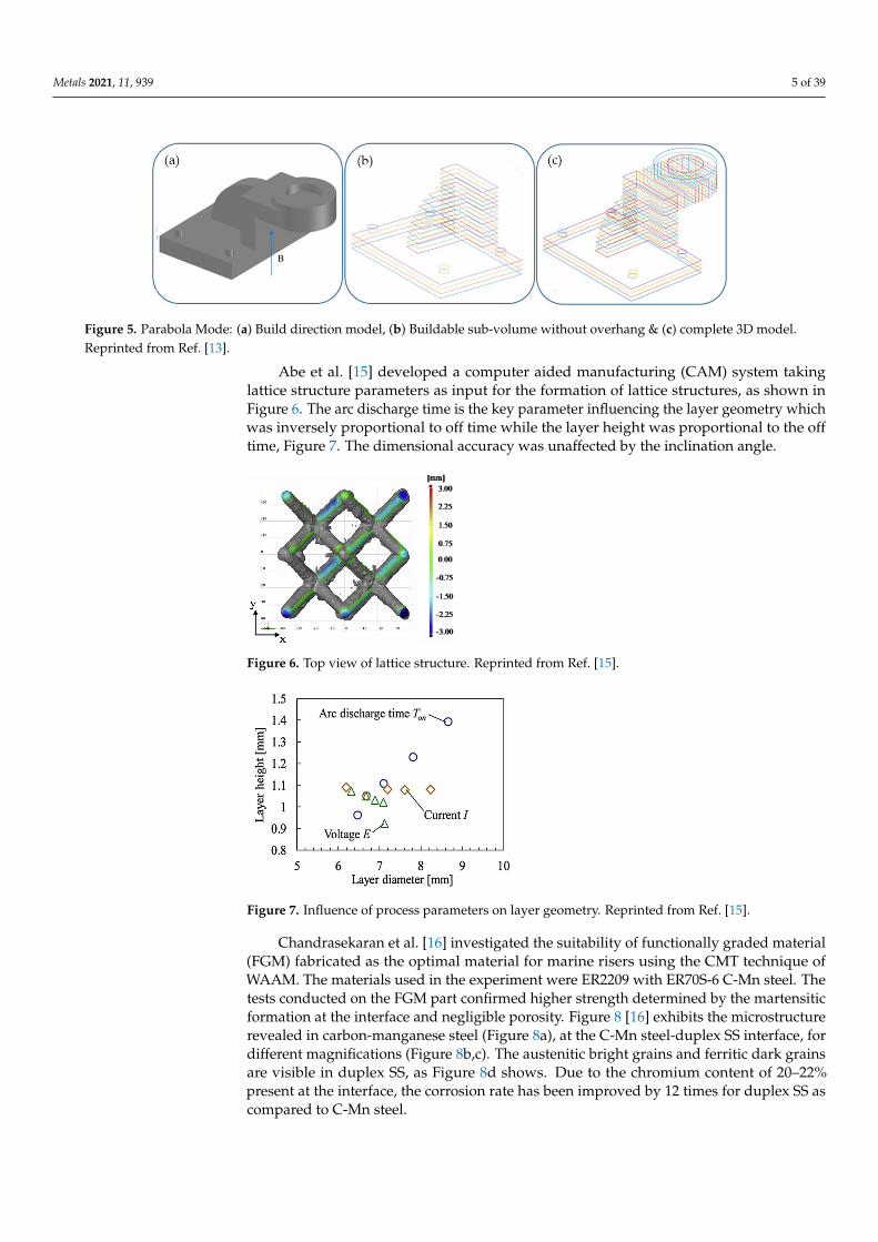
Yuan et al. [13] proposed architecture for a multidirectional WAAM system focused onpositional bead modelling, multi directional slicing and deposition process optimizationstrategy. Parabola model was used to obtain optimum welding parameters and desiredbead geometry (Figure 5). Based on the experiments, they concluded that a low power andlow value of WFS and TS will yield higher quality and improved productivity.
Muller et al. [14] compared gas metal arc weld (GMAW), cold metal transfer (CMT),and cold metal transfer-pulse (CMT-P) processes and proposed a mechanical test approachin which the WAAM built bar was TIG fillet welded between two cylindrical tensile testspecimens. This was done to avoid the sample bar banding when it was fixed in the tensiletesting equipment. Applying the GMAW method, the highest build up rate and the thickestbar diameter have been achieved. CMT-P yielded favorable results for surface topography,as well as the highest hardness levels, with minimal spatter ignition and lower heat input.
Metals 2021, 11, 939 5 of 39
Figure 5. Parabola Mode: (a) Build direction model, (b) Buildable sub-volume without overhang & (c) complete 3D model.Reprinted from Ref. [13].
Abe et al. [15] developed a computer aided manufacturing (CAM) system takinglattice structure parameters as input for the formation of lattice structures, as shown inFigure 6. The arc discharge time is the key parameter influencing the layer geometry whichwas inversely proportional to off time while the layer height was proportional to the offtime, Figure 7. The dimensional accuracy was unaffected by the inclination angle.
(mm]
" 3.00
225
1.50
0.75
0.00
-0.75
-1.50
-225
-3.00
Figure 6. Top view of lattice structure. Reprinted from Ref. [15].
Figure 7. Influence of process parameters on layer geometry. Reprinted from Ref. [15].
Chandrasekaran et al. [16] investigated the suitability of functionally graded material(FGM) fabricated as the optimal material for marine risers using the CMT technique ofWAAM. The materials used in the experiment were ER2209 with ER70S-6 C-Mn steel. Thetests conducted on the FGM part confirmed higher strength determined by the martensiticformation at the interface and negligible porosity. Figure 8 [16] exhibits the microstructurerevealed in carbon-manganese steel (Figure 8a), at the C-Mn steel-duplex SS interface, fordifferent magnifications (Figure 8b,c). The austenitic bright grains and ferritic dark grainsare visible in duplex SS, as Figure 8d shows. Due to the chromium content of 20–22%present at the interface, the corrosion rate has been improved by 12 times for duplex SS ascompared to C-Mn steel.

Metals 2021, 11, 939 6 of 39
Figure 8. Microstructure of carbon-manganese and duplex stainless steel joint achieved by CMT technique: (a) in C-Mnsteel; (b) at C-Mn steel—duplex SS interface (100 µm); (c) at C-Mn steel—duplex SS interface (50 µm); (d) in duplex SS.Reprinted with permission from Ref. [16]. Copyright 2020 Elsevier.
Lin et al. [17] studied the tensile properties and elongation of Ti-6Al-4V componentsmanufactured with a high energy density variant of the WAAM process, known as theecontinuous plasma arc process. These components are predominantly adopted in structuralmodules of aircrafts, such as disks and blades of gas turbines.
The WAAM technique is suitable for a number of applications that demand near-netshape, economical manufacturing [18] of large-scale metal parts with design freedom, andrelatively high deposition rates. Reduced material waste and fabrication time, as comparedto the conventional methods of manufacturing, are additional advantages and open upopportunities for hybrid manufacturing, functionally graded materials, and the productionof moderately complex parts with overhangs and integrated functionality. Further researchwork is imperative to devise methodologies for in-situ process monitoring and control,and to mitigate some of the drawbacks in terms of high heat input rate, residual stress,and porosity.
3. WAAM Methods3.1. Heat Sources Employed for WAAM
Researchers have investigated WAAM with a variety of heat sources and customizedthe heat input mechanism depending on the requirement of the application which arebriefly presented in this section. Cold metal transfer (CMT) is the method commonlyemployed, due to the controlled and efficient heat transfer, and it is implemented in variousconfigurations [19–21]. Prado et al. [19] proposed the integration of CMT and a three-axisCNC machine to improve the surface quality. An AC servo motor equipped guns withoutgears led to a high material deposition rate. The current intensity and deposition speed havea great influence on the weld width, but the effect on weld height was considerably less, dueto greater amount of material supplied with increased intensity. Zhang et al. [3] analyzedthe effect of variable polarity-CMT (VP-CMT) mode on the microstructure and mechanicalproperties of WAAM Al alloys. Pure CMT mode was found to create equiaxed grains inthe YOZ plane and columnar grains in XOZ plane, whereas CMT-P mode had a largerproportion of columnar grains. VP-CMT mode yielded uniform distribution of smallerequiaxed grains having equiaxed dendrites structure. Random value of grain boundarymisorientation angle leads to anisotropy of ultimate tensile strength (UTS) in CMT andCMT-P modes. Shukla et al. [20] conducted investigations on the arc behavior in CMTWAAM and highlighted that the welding current is proportional to the plasma distributionwidth that widens the arc. The variation of the welding arc intensity in the initial layersaffects the bead consistency, which is influenced by the reduced thermal gradient in upperlayers and the thermal balance between supplied heat input and heat losses.
Xiong et al. [21] investigated a flat position deposition mechanism for inclined thinwall parts, employing a multi-layer single pass GMAW system. The dependence of theinclination angle on the offset distance, wire feed rate, and travel speed were analyzed.The results revealed that the inclination angle is inversely proportional to the field rate anddirectly proportional to travel speed.

Metals 2021, 11, 939 7 of 39
Researchers also focused on the performance of pulsed [22] or non-pulsed arc [23] onthe build performance. Luo et al. [22] analyzed the effect of pulse on arc and droplet transfer.Higher droplet transfer frequency with smaller droplet size was achieved with pulsed arc,which indicated a higher manufacturing efficiency. The tandem torch arrangement wasfound to be suitable to maintain process stability at high deposition rates. A comparativestudy of pulsed and non-pulsed arc, made by Zhu et al. [23], showed that pulsed arc andpulsed droplet transfer modes are suitable for the WAAM process. The globular transferand the spray transfer mode were found to give maximum output power. The pulsed arcand pulsed droplet transfer mode (Figure 9) yielded higher strength, thermal properties,and a high height to width ratio, thereby achieving higher forming efficiency and improvedlayer deposition.
Figure 9. Pulsed arc and Pulsed droplet transfer Mode: (a) Arc power signal and corresponding AEsignal and (b) breakup of time T1. Reprinted with permission from Ref. [22]. Copyright 2018 Elsevier.
Rios et al. [2] characterized the plasma transferred arc (PTA) WAAM with respect tovarious transfer modes depending on the droplet growth time, contact time and weld poolshapes. They concluded that convex weld pool with wire, either in permanent contact orfor the time equaling the growth time, generates a stable transfer. This is attributed to theminimization of undesirable fleeting mode having inconsistent droplet transfer. The arcwandering issue in GMAW-WAAM was eliminated in plasma WAAM.
Guo et al. [24] controlled the excessive heat input during the process and introducedthe compulsively constricted WAAM. They analyzed the forces acting on the dropletsand identified the gravity and the electromagnetic pinch responsible for detachment,while the arc blow and the Lorentz force caused deviation in the droplet’s trajectory.Marinelli et al. [25] noticed that the rolling load caused a compressive strain within thepreviously deposited layers of refractory materials. At the point of peak compressive strain,recrystallisation of the structure was noticed for the depth of three layers below the lastdeposited layer. This yielded a larger area of equiaxed grains after a number of inter-passrolling steps. Abe et al. [26] evaluated a lower heat input condition to achieve the desiredheight to width ratio, by controlling the voltage and monitoring the build temperature.
Huang et al. [27] worked on control of wire feed speed in bypass coupled GMAWWAAM and highlighted the bridging transfer mode, demonstrating fewer fluctuationsthan the free droplet mode. Besides, the droplet is only subjected to the surface tensionwhen it is in contact with the molten pool. They noticed that an increase in bypasscurrent alters the arc length and shape because of varying the heat input introduced in theworkpiece (Figure 10). This phenomenon caused a variation of the droplet diameter andtransfer period. The wire feed height is proportional to wire feed speed and this variationdetermines the droplet transfer mode and changes from the free transfer to the bridgingmode (Figure 11).

Metals 2021, 11, 939 8 of 39
Figure 10. Effect of bypass current on the arc shape. Reprinted from Ref. [27].
Figure 11. Schematic of force distribution on the droplet: (a) Bridging Transfer; (b) force transfer.Reprinted from Ref. [27].
Li et al. [28] examined WAAM with GMAW heat source for 6366-AA thin wall samples.The effect of shielding gas on weld geometry, mechanical properties and microstructuralbehavior were recorded. The average voltage used for welding in Ar gas protection washigher than for N2, while the current during short circuiting transfer was reported to belower for nitrogen. The average microhardness value was seen to be higher when usingN2 as shielded gas, but generated an anisotropy in material. The use of argon determineda higher UTS and elongation, while the yield strength was higher when using nitrogen.Because of the presence of flaky nitrides, generated by the reaction of N2 with Al, adecrease of strength and plasticity was noticed, while in the case of using Ar, which doesnot react with Al, the properties were not affected. N2, as shielding gas, triggers a desirablelarge height to width ratio, limited penetration, roughness in the weld beads and smallergrain size. The smaller weld penetration was attributed to the heat absorption, breakingand further ionizing of the N-N bond causing temperature decrease. The roughness wasattributed to poor stability of the droplet transfer. Yang et al. [29] proposed a doubleelectrode gas metal arc welding (DE-GMAW) for the fabrication of narrow thin wall metalcomponents with high deposition rate and efficiency in comparison to conventional GMAW(Figure 12). For the same deposition rate, the width of the deposited layer was noticed to bedirectly proportional, while the layer height is inversely proportional to the bypass current.
The studies presented in this section provides significant information, useful for choos-ing the appropriate WAAM heat source employed for specific applications. The selectioncriteria are based on the key factors described in the following comparative analysis.
GMAW based WAAM provides various modes of metal transfer, starting with theglobular transfer, short-circuiting, spray, and ending with the pulsed-spray transfer. Thestability of the electric arc is poor in this process, but the average rate of deposition isabout 3–4 kg/h. The high deposition rate makes this process a suitable choice for thelarge-scale industry.

Metals 2021, 11, 939 9 of 39
CMT based WAAM is characterized by better electric arc stability and higher qualitydeposition of material, but the average rate of deposition is more reduced (2–3 kg/h).Applying this process, the heat input is significantly lower, the distortion is reduced, andthe material spatter is eliminated. Based on these features, this method could be a goodchoice in fabricating thin-walled components.
Plasma based WAAM is a process that uses separate feeding wires, but the fabricationcost is more expensive compared to the methods mentioned above. The average depositionrate is about 2–4 kg/h and it is recommended for producing width-walled structures withnegligible spatter.
Laser-based AM is characterized by good performances, such as high precision,deposit quality, and appropriate morphology. The average deposition rate is around10–12 kg/h that makes this method to be a high efficiency process.
Electron beam (EB) assisted AM process can be employed for a large range of metals,including highly reflective alloys, such as copper and aluminum. The average depositionrate achieved during the process is up to 10–14 kg/h. Even if it is a fast-manufacturingmethod, the process is carried out in a high-vacuum chamber that limits the size of theparts to be printed.
Various modes of arc generation and transfer, i.e., pulsed/non-pulsed arc or droplet/bridgetransfer, result in variation of the WAAM builds. The use of different shielding has alsoan effect on the tensile properties of the builds. The appropriate selection of heat inputsystems and shielding gases plays a significant role in the design of the WAAM techniquesfor specific applications.
Figure 12. Schematic of double electrode GMAW based WAAM system. Reprinted with permissionfrom Ref. [29]. Copyright 2016 Elsevier.
3.2. Process Monitoring and Control for Optimizing the WAAM
WAAM, being an autonomous system, is governed by its monitoring and controlmodules. This section covers the research works carried out in the related domain. EfficientWAAM builds can be manufactured with precise control of the process parameters, withdifferent configurations of heat input or by controlling the thermal gradients in the process.To achieve quality samples, careful control of the WAAM process parameters and variouscombinations are needed [30–35].

Metals 2021, 11, 939 10 of 39
Mok et al. [30] reported that front and side feeding provided a smoother surface, ascompared to back feeding, and a proportional relation between the deposition rate andthe wire feed rate was noticed. Traverse speed influences the deposit height more thanlaser power. If the angle of inclination is maintained 31–68◦, then a dense deposition withnegligible porosity is achieved. The deposits exhibit a columnar structure, and the coolingdirection has a great influence on the grain structure.
Dinovitzer et al. [31] analyzed the effects of the process parameters on the TIG basedWAAM product of HastelloyX alloy and 304 SS plate. They noticed that the melting depthand the roughness depend on the current and are independent of wire feed rate and beadwidth. The travel speed has a proportional influence on the bead height, but a converseone on the bead width. Molybdenum carbide structures formed were influenced by thethermal gradient and deposition rate.
Wahsh et al. [32] utilized Robot’s synergic operations for optimized large-scale produc-tion of Al walls using CMT-P WAAM process with constant heat input and predeterminedcurrent. The meso-structure revealed minimized spherical gas porosity in the build direc-tion for low heat input in CMT-P mode. This also minimized the diffusivity of hydrogeninto aluminum. The decreased rate of heat dissipation and the preheating led to thermalbalance, causing solidification of dendritic grains. Kumar et al. [33] employed Taguchimethod for optimization of welding speed, wire feed speed and voltage for a specific weldgeometry. Weld bead width was proportional to the voltage and wire feed speed andinversely proportional to the welding speed. The welding speed is altered by increasingthe heat input, while the variation in arc length affects the voltage. Su et al. [34] pointedout an increase in the effective wall width of Al-Mg products with an increase in wirefeed speed (WFS) and decrease in tool speed. The increase in tool speed promotes theAl (111) orientation and the wire feed speed opposes the Al (200) peaks. Modifying the toolspeed and the wire feed speed, the texture of the samples during the deposition process isconsequently altered.
Zhou et al. [35] concluded that an increase in tool speed has no implications on the heatinput per unit time, but reduces the energy obtained per unit area, causing a decrease ofthe samples’ width and height. Low tool speed caused more weld ripples, while high toolspeed increased the solidification rate and, consequently, the grain size was smaller withrefined dendrite formation. However, the tensile properties improved with the tool speedup to a certain value, beyond which it declined owing to the increasing the electric field.
Researchers are constantly involved in innovative designs and the development of moni-toring and control mechanisms [36–38] in order to maintain the distance unchanged betweennozzle and surface, between layers, or to monitor the thermal gradients, so that the processparameters applied are optimal to build certain structures with the required characteristics.
Xiong et al. [36] developed a passive vision control system of the GMAW-AM process,meant to monitor the nozzle to the deposition surface distance. The authors also designedan adaptive control system to maintain constant the distance and they obtained resultswith a precision range of ±0.5 mm.
To monitor the process, Artaza et al. [37] proposed the use of a five-axis gantry machineand a height adaptive control mechanism for the complex parts fabrication. The heightadaptive control required enabling communication protocols between the PC, gantrymachine, laser scanner, and the plasma control. This allows for the manufacturing ofidentical parts in a controlled environment.
Anikin et al. [38] proposed a software and hardware architecture for robotic controlsystem of the WAAM process (Figure 13) that includes thermal feedback devices. TheCNC system is designed to control the motion system (determining speed and trajectory),the power source (switching on/off, amperage, impulse, arc length, wire feed-speed), thepattern, and the shielding gas system.

Metals 2021, 11, 939 11 of 39
Figure 13. Software and hardware architecture for robotic control system of the WAAM. Reprintedfrom Ref. [38].
Silva et al. [39] proposed AM with plasma welding by developing a controlled me-chanical welding torch holder to generate the required pulsed arc velocity and maintain theoptimum position on the displacement axis for continuity and controlled height variationor defects in the weld. The supply frequency and operating voltage may be controlledfor deposition rate adjustment. Differential thermal gradients, determined by repeatedheating and cooling, are seen to be the major cause for the generation of residual stressesand distortion. Various mechanisms have been investigated [40–42] on preheating, controlthat governs the thermal gradient or the interpass temperature or the arc energy. Thetemperature field reduces the residual stresses in WAAM builds. Xiong et al. [40] exploredsubstrate preheating to minimize the temperature gradient as a solution to reduce thecracking and thermal stress in GMAW based AM products. The reduced thermal gradientin turn reduces the deposition height.
Radel et al. [41] proposed an auto-controlled system using six-axis robot for producingcomplex truss structures. They also designed computer aided manufacturing (CAM)software for avoiding the torch-structure collision and to control the intersection of materialdepositions. The correction of the geometry for the following deposition was enabled byvideo imaging of the bead deposition contour.
Ali et al. [42] studied the impact of the arc energy and of the temperature field onthe mechanical properties of the hot work tool steel structures. They employed a four-roll drive system for feeding the welding wire. It was noticed that if the temperature ismaintained above the martensite start temperature, then uniform hardness is achievedalong the structure height.
Derekar et al. [43] investigated the DC pulsed GMAW process on the Al5356 alloyand reported that the formation of large pores is a function of solubility limit, temperatureand heat dissipation rate. Rate of heat extraction facilitates the movement of entrappeddissolved hydrogen through the pipes. Different solidification rates cause hydrogen en-trapment of varying intensity, with a higher interpass temperature in horizontal specimensthat led to a reduction in the size of pores while the strength increased. Ortega et al. [44]focused on the formation of defect-free multilayer thin metallic walls with CMT for Al5Si.

Metals 2021, 11, 939 12 of 39
Irregular product dimensions could be avoided with constant deposit rate and increasingthe travel speed.
Ryan et al. [45] examined the AA2319 WAAM panels on the batch variability of wiresand reported that the surface finish of the wires affects the hydrogen content and the arcstability. Hydrogen entrapment led to the spherical pore formation caused by the shrinkageduring solidification.
Quality improvement in WAAM products requires optimization of process parametersand the torch tool path to obtain near-perfect bead geometry. To address the optimizationissues, a variety of factors such as the wire feed speed, tool speed, the effect of inter-passtemperature, the dependency of hardness on heat input for specific materials, the formationof intracrystalline precipitates and their influence on the build properties have been takeninto consideration. Complete understanding of the dependency of build properties onthe process parameters will generate reduced defects, surface irregularities, and residualstresses. Studies focused on in-situ monitoring, control and testing have been performedby researchers, as they bring about appropriate build properties with reduced wastage andproduction times. Several strategies have been proposed to optimize the microstructureand mechanical properties, which are based upon required testing, and can be adapted asstandard practices for acceptance in the industry.
During the deposition process, as the number of the deposited layers increases, thecontrol of the deposited layer size, as well as the morphology that governs the geometricalaccuracy, seems to be a complicated task. When the melt pool is close to the boundariesof the layer deposited, the control of the bead shape would be intricate due to the heataccumulation. Hence, the loop feedback control of the WAAM process is vital in makingreliable products by this technique.
Several control algorithms, such as fuzzy control, predictive control, iterative learningcontrol, proportional-integral-derivative (PID), fuzzy-PID, inverse ANFIS model-basedcontrol, and adaptive control, have been developed for controlling and monitoring theWAAM process. The adaptive controller is observed to be effective for the layer heightadjustment, due to maintaining constant the distance between the nozzle and the topsurface (NTSD). Moreover, the adaptive process control is useful for maintaining theuniformity of the bead geometry. Based on the dynamic constraint, the optimal/suitablewire-feed rates are dynamically selected by this method. Other controllers, mentioned inthis section, have been developed for the control of layer height, temperature and width ofthe melt pool. Nevertheless, the dynamic self-assessment and control are quite ineffective,because the time constant is high and reasonable results are mostly yielded only for thelinear parametric variations.
The mathematical model accuracy may not be significant for Fuzzy logic-based con-troller, but needs wider knowledge and experience to be implemented. It is obvious thatthe PID parameters need to be customized to function adaptively, and to accommodatetime varying system with the fuzzy logic support. These adaptive control models fa-cilitate the development of relationships between the temperature, and traverse speed,melt rate, deposition rate and layer height. It may conclude that the implementation ofthe mechanism-based adaptive control would provide a breakthrough for new WAAMversatile applications in industry.
4. Discussion on Materials Behavior during WAAM
This section presents the behavioral aspects expressed in terms of the variations of theWAAM process parameters. This includes heat source, processing conditions, wire feed,rolling, heating mechanisms, and other enhancements deployed to optimize the manufac-turing process. Various research groups are working on different materials to understandthe technical challenges when the materials are subjected to WAAM process. This sectionprovides valuable information in terms of perspectives, applications of advanced tools,interpretations, and standards specific to the materials approached.

Metals 2021, 11, 939 13 of 39
4.1. Ti-6Al-4V Alloy
Ti-6Al-4V has been a popular choice for a number of industrial applications owingto its suitability in the aerospace industry, which is oriented towards more enhancementsfor optimum performance. WAAM with laser as energy source was experimented [46]and it was found that the globular grain size and column grain width are proportionalto laser beam power and wire feed speed, but inversely proportional to weld speed,while the epitaxially grown columnar resulting from nucleation in the microstructure haslarger width. Increased weld speed also caused constriction due to rapid solidification.The mechanical properties showed an anisotropic trend, while the characterization ofhorizontal builds revealed a higher fatigue strength and ultimate tensile strength (UTS)with lower ductility, compared to the wrought materials. The microstructures revealedan anisotropy with columnar grain structure in alignment with the build direction. Themicrostructural transformations showed coarsening of grains and the gradual formation ofa fine equiaxed structure with nucleation that results in epitaxial grain growth.
When the PLASMA source is used as a technique of reversed deposition, a highdeposition rate and efficiency, as well as an increase of UTS by 12% and a wider wallwidth have been obtained. Banding was recorded with an increase in alpha lamellar sizebetween the bands. The enhancement of PLASMA source WAAM, i.e., continuous plasmaWAAM with high energy density, was analyzed [17] by reducing the heat input layer bylayer. The energy accumulation in the molten pool is diminished and that allows for aneasy nucleation, prevents the air oxidation phenomenon and the development of multiplethermal cycles. Equiaxed rectangular grid, representing martensite, new alpha plates,representing basket weave structure, and formation of horizontal bands determined bythermal cycle were also highlighted. These bands show low hardness with formation ofalpha colonies.
Due to the impact on the cooling rate, by reducing it, and, further, reflected in high heatfluxes at higher temperature, the variation of interpass temperature during WAAM [47]needed studying. Though the hardness value reduces up to the interpass temperature, itresults in finer and lesser dendrites and interdendritic areas in top portions compared tothe middle, thus showing anisotropy. In the latest research studies [48], the WAAM processwas modified by adding N2 along with the shielding gas, which led to the modification ofthe arc shape and to the hardening of TiN layer deposition over the Ti6Al4V substrate calledsurface cladding. The friction coefficient and wear resistant property were improved withthe N2 addition in the shielding gas. The resulting TiN phases showed coarse dendrites andirregularities caused by the moisture on the cladding layers. The mechanical properties, onthe contrary, improve and the microhardness increases with increasing the N2 flow rate.Another study of the WAAM process [49] revealed that an increased dwell time resultedin an increased yield strength and hardness and reduced width of alpha lath in the layerband region. Microstructures showed equiaxed beta grains and tilted layer band due tobidirectional travel mode. Ti-Al alloys were subjected to dual-wire arc AM [50], the wirefeed rate being controlled to obtain different phase compositions (Ti-45Al and Ti-55Al)and microstructures. Microhardness, yield strength (YS) and ultimate tensile strength(UTS) were seen to decrease with the increase in Al content, while the elongation was notconsistently affected. As regards the microstructure, the modification of the Al percentagepromoted the development of gamma dendritic structures with four-fold symmetry.
4.2. Aluminum Alloys
Geng et al. [51] explored the geometric limitations and tensile characteristics byinvestigating the WAAM of 5A06 Aluminum Alloy with 1.2 mm thickness. It was noticedthat the tensile properties are obviously influenced by the build direction and the textureorientation, showing isotropy in the build direction, but anisotropy with respect to thetexture orientation. Because of the weld bead overlapping that may occur owing to thelarge molten pool and to the effect of surface tension, WAAM with a layer width of7.2 mm cannot be applied for plane shapes with certain geometrical features, such as

Metals 2021, 11, 939 14 of 39
sharp angles less than 20◦ or curvatures greater than 10 mm. In the case of axial loading,acting perpendicular to the texture orientation, a large number of grain boundaries becomeresistant to deformation, while on parallel loading to texture orientation, a sliding of grainboundary occurred in the bounding region, determining the tensile strength decrease.
Horgar et al. [52] studied the feasibility of WAAM for 1.2 mm diameter AA5183 alloyused as wire and AA6082-T6 plates of 20 mm thickness as base material. It was noticed thatthe tensile and hardness properties were anisotropic with the plane orientation and thedeposition direction. The macro inspection of the weld showed intergranular hot cracksin the high temperature part of the reheated area with equiaxed grains. The dilution ofAA5183 with AA6082 generates the formation of hot cracking, which can be reduced withaddition of Ti, B, Sc, Er, or Zr in the composition of the wire material. Due to the grainrefinement effect of nanoparticles, the additives have a positive effect on the tensile andductile properties and minimize the cracking tend.
Qi et al. [53] developed the double-wire plasma system for WAAM of Al-6.3Cu alloyand added Mg into Al-Cu alloy with the aim of improving the mechanical properties. Theamount of Cu and Mg was adjusted with the wire feed speed. The tensile strength andelongation were noticed to be isotropic in both directions. The microstructure showed anon-uniform distribution of coarse columnar and fine equiaxed grains in the inner layer,while the inter-layer region had equiaxed grains, as illustrated in Figure 14.
Figure 14. Optical microscopic images of WAAM Al-Cu-Mg alloy: (a) Al-3.6Cu-2.2Mg, (b) inner-layerof Al-3.6Cu-2.2Mg, (c) inter-layer of Al-3.6Cu-2.2Mg. Reprinted from Ref. [53].
Gu et al. [54] proposed the hybrid technique of WAAM, incorporating the rollingand heat treatment, to control the porosity and to optimize the process parameters. Theynoticed that, by increasing the interlayer rolling loads, the tensile properties of the WAAMalloy were improved, while the elongation was altered. During the heat treatment, thesamples were exposed to homogenization temperature and then to cold water quenching toenable micro segregation. After the heat treatment, the vacant voids generated an increasednumber of irregular micropores.
Li et al. [55] reported a growth of the secondary dendrite arm spacing and of the Fe-phase when the heat input, generated by the WAAM with CMT process for Al-7Si-0.6Mg,increased. The increase of the heat input, with corresponding decrease in welding speed,has determined an increase of thickness and layer height, as well as an increase of thesize of primary alpha-Al grain size and eutectic Al-Si grains. As regards the mechanical

Metals 2021, 11, 939 15 of 39
properties, such as UTS, YS, and elongation, it was pointed out that the heat input has acrucial role in modifying them.
Qi et al. [56] investigated the double-wire WAAM process, the AA2024 samples beingsubjected to heat treatment with the aim of overcoming the restrictions of building thecomponents with single-wire WAAM. The T4 and T6 heat treatments involve solutionheat treatment, followed by natural and artificial aging respectively, to attain a substantialstable condition. After heat treatment, the microstructural analysis revealed that thedendrite morphology changed from α-Al + Al2Cu + Al2CuMg to α-Al + Al2Cu. Thesolid wires ER2319 (Al-6.3Cu) and ER5087 (Al-5Mg) of 1.2 mm diameter were used asfiller materials in the WAAM of AA2024 plate of 12 mm thickness. It was found that themicrohardness significantly increased after the T4 and T6 heat treatment process. Heattreatment determined a strength increase, while the elongation increased in horizontaldirection and diminished in vertical direction and, consequently, an improvement of tensileproperties in the horizontal direction has been achieved. Intergranular and trans-granularfractures with some dimples were pre-dominantly noticed (Figure 15).
Figure 15. Fracture morphology for WAAM 2024 alloy in T4 condition: (a) horizontal direction;(b) vertical direction. Reprinted from Ref. [56].
Ünsal et al. [57] used the alloy EN AW 6016, as the wire for WAAM, to manufacturebulk material with less than 1% porosity and no lack of fusion. The hardness of the as-build sample was not comparable to the conventional material due to high temperatureimpact. The heat-treated material shows hardness comparable to or even larger than theconventional material. During the initial layer deposition, heat input was controlled withhigh amperage (110–140 A). For higher layer depositions, weld velocity was varied tocontrol the heat input.
Wang et al. [58] investigated the WAAM of Al-Cu-Sn alloy and noticed that by in-creasing the heat input, the molten pool widens, the grain size grows and defects suchas pores are developed in the deposited material. The porosity phenomenon is relatedto the increase of hydrogen solubility in Al solution with temperature and to the fasternucleation of pores determined by the larger heat input. The uniformity of grains decreasedwith temperature and the number and the size of undissolved θ phases increase after thesolution treatment, altering the mechanical properties.
Yang et al. [59] studied the CMT-based WAAM for manufacturing the AZ31 wallsand they reported an enhancement of tensile properties in the metal deposition direction.The microstructural analysis revealed vertical dendrites and alignment of changed colum-nar dendrites in sequence as well as equiaxed grains in the top layer. The thin-walleddeposit comprises of columnar dendritic arrays, including alpha Mg matrix, inter-dendriticeutectics, and some dispersive Al-Mg phases. The tensile properties depend on the solidi-fication direction of dendrites and on the volume fraction of the inter-dendritic eutectic.Due to the growth of epitaxial columnar dendrites, an anisotropy has been noticed in thedeposit direction.

Metals 2021, 11, 939 16 of 39
4.3. Chromium
Ge et al. [60] investigated the WAAM process of 2Cr13 parts and noticed that theCMT-based WAAM process develops a stable liquid metal transfer, as indicated in the buildstructure (Figure 16a). The microstructure, presented in Figure 16b, reveals no-austeniteformation and defects between adjacent layers. The top layer is characterized by elongatedferrite grains, as reported in [60] (Figure 16c). The microstructures consisted of thermallydecomposed martensite and block shaped ferrite caused by repeated heating-cooling cycles.Besides, the ferrite content decreased towards the base metal due to the microstructurevariation noticed in the middle zone of the metal deposit (Figure 16d).
Figure 16. WAAM process of 2Cr13 alloy: (a) macroscopic morphology; (b) cross section; (c) topzone; (d) middle zone. Reprinted from Ref. [60].
High UTS and reduced ductility were noticed in the WAAM samples due to higherdislocations density and finer martensite laths, resulting in dislocation pile-up at grainboundaries during the mechanical testing.
4.4. Inconel
Xu et al. [61] studied the microstructure and aging response of Inconel 718 alloy deter-mined by the WAAM processes for IN718. The strength of the weld was found to be lowerthan the strength of the forged material. They proposed the use of inter-pass rolling with theaim of improving the mechanical properties. The thermomechanical processing serves toenhance the strength and reduce the material anisotropy and the aging response generatedby the WAAM process. The macrostructure of the sample, which was subjected to inter-passrolling, exhibits smaller columnar grains aligned to the wall sides and duplex grain structurewith re-crystallized core that extends up to half the wall thickness (Figure 17).
As Figure 18 shows, the microstructure of the rolled sample achieved after solutionplus aging treatment presents fewer dendrite structures grown in random directions,in comparison with the unrolled sample, that determines the improvement of tensile,elongation, and ductility properties.
Seow et al. [62] investigated the issues generated by the WAAM deposition processin the IN718 material, such as micro-segregation, that caused undesirable Laves-phaseformation in the inter-dendritic regions, and proposed a modified heat treatment. Thismethod aims at dissolving the Laves-phase and at reducing the anisotropy in the grainstructure, achieving isotropic tensile properties at high temperature. The heat treatmentphases consist of homogenization at 1100 ◦C for 1 h, air cooling, and then solution treat-ment at 980 ◦C for 1 h followed by air cooling, according to AMS 5383 and modifiedhomogenization treatment at 1186 ◦C for 40 min, air cooling.

Metals 2021, 11, 939 17 of 39
Figure 17. Macrostructure of unrolled and rolled samples. Reprinted from Ref. [61].
Figure 18. Microstructure of IN718 through WAAM: (a) unrolled; (b) rolled. Reprinted from Ref. [61].
The high temperature treatment enables the dissolution of Laves-phase by diffusioninto the matrix. This dissolution could develop Nb-enriched regions where delta phasemay precipitate. Because of the precipitation of gamma particles in the matrix, promotedby the aging treatment, the hardening effect could be enhanced. On the other hand, thedevelopment of coarsened grains determines lower hardness and tensile properties in thesamples subjected to the modified heat treatment proposed [62].
Yangfan et al. [63] investigated the effects of the torch travel speed on the microstruc-ture and mechanical properties of the Inconel 625 alloy deposited by a CMT-based WAAMtechnique. The analysis revealed a modification of the microstructure in different layers.

Metals 2021, 11, 939 18 of 39
The deposition direction was reversed after each layer and this resulted in a well-definedbead and layer interface, Figure 19.
Figure 19. Microstructure in the interlayer of sample. Reprinted from Ref. [63].
Due to the slower heat dissipation in the middle region, a cellular dendritic structurewith some secondary dendrite was developed, while a coarser dendritic structure was gen-erated in the top region because of the continuous accumulation of heat in this area. Thus,the microstructure achieved is finer and the microhardness increases with increasing torchtravel speed. Consequently, the yield strength (YS), ultimate tensile strength (UTS), and theelongation of the manufactured samples gradually increased as the torch speed increased.
4.5. Tungsten
Tungsten is a high-performance component and finds application in nuclear fusionreactors and other high temperature energy generation and conversion systems. Some ofthe physical characteristics, such as high recrystallization temperature and low fracturetoughness, raise difficulties in the conventional manufacturing of tungsten components.WAAM process modularity and configurable process parameters and ability to producefunctionally graded elements enable the development of required features in Tungstenstructures. Marinelli et al. [64] studied the influence of WAAM process parameters on thelinear structures of unalloyed tungsten. A precise substrate orientation and an appropriateclamping system design led to the elimination of lateral cracks that can be developedduring the deposition process. In comparison to the front wire feeding mechanism, the sidewire feeding has created splatter, voids, cracks, and a lack of fusion, as shown in Figure 20.
Figure 20. WAAM process parameters on the linear structures of unalloyed tungsten: (a) microstruc-ture defects using side wire feed; (b–d) details of the defects located on the side facing the wire feeder;(e) detail of the microstructure at the base of the linear structure. Reprinted with permission fromRef. [64]. Copyright 2019 Elsevier.

Metals 2021, 11, 939 19 of 39
Kelvin-Helmholtz instability was noticed in the side wire deposition process due tothe difference between the densities of liquid tungsten and helium plasma that causesthe breakup of melted surfaces and the splitting of particles in fine droplets. The fastsolidification and the relatively high thermal conductivity of Tungsten led to developmentof equiaxed grains. The upper part of the structure had large and elongated grains becausethermal conductivity decreased at high temperatures.
4.6. Tantalum
Marinelli et al. [65] developed large-scale unalloyed Tantalum parts using WAAMwith two different Ta wires and highlighted that the deposited walls have high geometricalstiffness and no distortion.
Conventional TIG technique was employed for Ta deposition in a single bead. Theunidirectional deposition was maintained at each layer with side wire feed to the weldpool. The wall structure had no distortions due to high geometrical stiffness and a localizedplastic deformation at the substrate-wall interface. The microstructure analysis revealedthat the columnar grains grew epitaxially in the deposition direction during solidification(Figure 21).
Figure 21. Microstructure showing epitaxial growth of columnar grains in build direction. Reprintedwith permission from Ref. [65]. Copyright 2019 Elsevier.
Due to repeated heating cycles that further caused localized change of α-grains insuccessive layers, the development of macroscopic banding was noticed in each layer.However, for the unalloyed Ta, sub-grain structures did not develop in the reheatingprocess of successive layers and the bands could be attributed to the regular dispersion ofTa oxide particles. The hardness analysis revealed a variation in the build direction becauseof the thermal cycles which induced the hardening effect on the lower part of the build. Itwas found that the deposited structures were characterized by higher yield strength dueto oxygen content and by reduced elongation caused by different grains size and shapebetween substrate and samples. In comparison with other manufacturing techniques, thismanufacturing method has the advantage of reduced cost and time to produce large scaleTa structures.
4.7. Copper
Wang et al. [66] studied the CMT-based WAAM of 10 mm thick copper plate withwires containing Cu or Al and Si (CuSi3, AlSi5-ER4043). The experiment setup included awire feeder machine feeding the two wires into a single molten pool. The percentage ofcomponents deposited on the 10 mm copper plate is controlled by the variation of the wire

Metals 2021, 11, 939 20 of 39
feed rate. It was noticed that the addition of Si enables the uniform metal intermixing andthe reduction of intermetallic phases formation.
Due to solid solubility with Cu and Al, Si increases the fluidity of the molten metal.Al was maintained at 4.3. It was noticed that, increasing the Al content, an increase of theUTS and YS properties was achieved, while adding Si to Cu-Al alloy, an improvement ofhardness, tensile strength and offset yield strength was obtained. Frequent heating-coolingcycles and the thermal stresses cause poor bonding between the base deposited layerand the substrate. The stabilized thermal gradient controls the wall width increase in thebuild direction. The layer height was noticed to diminish in the build direction. Besides,the increased hardness is caused by the solid solution strengthening effect of Al, by theformation of intermetallic phases, and by Si addition.
The interlayer structure showed a mixed and disordered structure where twinned,coarse columnar and fine lamellar crystals coexist. The effect of oxidation is visible in theform of black columnar crystals in microstructure, as Figure 22 shows. Modifying theheat dissipation rates, a different morphology of deposited layers is obtained in the builddirection and across the structure.
Figure 22. Microstructure of sample: (a) bottom section; (b) middle section. Reprinted from Ref. [66].
4.8. Steel Alloys
Though the paper focuses on the characterization of non-ferrous behavior duringthe WAAM process, the technique is widely adopted for steel alloys, too. However, thediscussion on this type of alloys may give insights into the research possibilities that couldbe extended to other non-ferrous materials.
Haden et al. [67] studied the mechanical properties of the SS304 and ER70S compo-nents achieved by WAAM. In the case of SS304, the yield and tensile strength were foundto be isotropic along the direction of deposition. Similarly, for the ER70S mild steel, theanisotropy was observed in the vertical and horizontal directions. A grain refinementwas also noticed in the SS build, as Hall-Petch strengthening under the wear scars. TheYS increased both in the direction of the weld deposition and in the Z direction. Themicrostructure of SS304 showed a variation from the austenitic to mixed ferrite morphol-ogy, due to the influence of local thermal gradients (Figure 23). As regards the ER-70S, itexhibited a typical ferrite microstructure with small regions of pearlite at grain boundaries(Figure 24).

Metals 2021, 11, 939 21 of 39
Figure 23. Microstructural shifts in SS304. Reprinted from Ref. [67].
Figure 24. ER70S: Ferrite microstructure with small regions of perlite at the grain boundaries.Reprinted from Ref. [67].
Feng et al. [68] observed an improvement in terms of bead appearance, deposit rate,microstructures and mechanical properties of the weld when the manufacturing processis plasma induced arc-based WAAM process with double wire feeding. The macroscopicanalysis, performed on different samples, showed a diminution of deposited wall’s height,surface forming and waviness, due to the deposition speed increase. It was also noticedthe presence of ferrite phase in the finer austenite matrix. By increasing the depositionspeed, the complete grown equiaxed ferrite (CGEF) grains’ structure and, subsequently,mechanical properties have been improved. The double wire feed process was found to bean appropriate process for fabricating the Cr-Ni stainless steel components.
Wang [69] studied the influence of the arc modes, namely speed pulse and speedarc, used in the WAAM manufacturing of SS316L stainless steel. The cross-sectional mor-phology of components showed a structure without defects for both methods. The X-rayphotograph of tensile specimens did not exhibit cracking or porosity defects. The mi-crostructure revealed austenite distribution in the primary phase of the WAAM build. Thedifference in terms of Vickers hardness, for both arc modes, is negligible in the bottomlayers. However, because the heat amount increases with subsequent deposition of layers,heat dissipation propagates more slowly. This phenomenon leads to the reduction of sec-ondary dendrite arm spacing (SDAS) and, further, to achieving higher Vickers hardness forspeed arc-based WAAM method (Figure 25). The authors reported that UTS and elongationproperties are higher for the speed arc method in comparison to the conventional method.

Metals 2021, 11, 939 22 of 39
Figure 25. Hardness Characteristics. Reprinted with permission from Ref. [69]. Copyright 2019 Elsevier.
Dirisu et al. [70] analyzed the WAAM fabricated parts of ER70S-6 and establishedthe impact of the rolling process on reducing the surface waviness of the deposited ma-terial. It was reported that the compressive stresses, induced by the rolling, reduced thesurface waviness and stress concentration, and, consequently, an improved fatigue life wasobtained. It was also pointed out that the surface waviness was reduced with increasingthe rolling load. As regards the tensile strength, it was found that it is proportional to therolling load. For instance, applying maximum rolling load, a maximum tensile strengthwith the least percentage elongation is achieved. The plastic deformation, determined bythe rolling process, supports the work-hardening effect that causes the elongation reduc-tion. The hardness is also proportional to the rolling load. It was found that rolling of thedeposited surface generates dislocations which cause work-hardening and a reduction ofgrain size. Moreover, the rolling triggers the austenite nucleation that causes the grainsize reduction.
4.9. Technical Recommendations
Based on the discussions from the previous sections, it is obvious that the capabilityto process a wide range of materials is one of the main distinct features of the WAAMprocess. Due to the great advantage of producing large structural parts in a short time, thismanufacturing technique has become more attractive for the manufactures. On the otherhand, there are significant issues that can be solved by taking into account the technicalsolutions specific to the materials approached in this work.
Even if the Ti-based alloys have been found suitable for aerospace applications, withthe build parts having a low buy-to-fly ratio, an important issue caused by the developmentof columnar β grains may be the generation of anisotropic properties. The adjustmentof the wire feed speed and use of interpass rolling can be the optimal solution to reducethe anisotropy phenomenon. Because of the various thermal histories, recorded duringdepositing layer by layer, this issue can occur in the WAAM steel alloys parts, too. Theanisotropy can be mitigated or completely eliminated by applying pre-heating and post-heating treatments, according to the chemical composition of the steel.
An important challenge in the WAAM process of Al is the existance of the surfaceoxide film that can be removed by employing an AC supply. However, the polarity reversalleads to generation of turbulence in the melt pool and, consequently, the componentsachieved may be improper. The use of Ti inoculant or selection of VP-CMT or CMT pulseadvanced as heat source, combined with the interlayer rolling, lead to grain refinementand to mitigating the problems in terms of gas pores in Al build parts.
Ni based alloys, like Inconel 718 or Inconel 625, having a high alloying level, have thetendency to segregate in the interdendritic spaces during the cooling phase. Besides, themechanical properties can be affected by the formation of δ phases, but applying a heattreatment, the characteristics of the built parts will be improved.

Metals 2021, 11, 939 23 of 39
In conclusion, the mechanical properties of the build products are governed by thegrain’s size and structure, as response to the various thermal cycles recorded in the materialdeposited layer by layer through the WAAM technique. The significant thermal gradients,combined with the epitaxial growth generated in the build parts substrate, determine thedevelopment of large columnar grains and, consequently, the occurrence of the anisotropyphenomenon in the deposited material. The main technical measures that can be appliedto mitigate this significant issue are the heat treatments and use of inoculants to refine thegrain structure.
In conclusion, further advancements in the WAAM process are required in order toimprove the knowledge in terms of input heat adjustment and optimization of processparameters by integrating the thermomechanical processing mechanism developed duringthe deposition process.
5. Models Developed for Quality Improvement and Process Optimization
Due to the process dynamics and design difficulties, the optimization and analyticalmodelling of multi-variable WAAM process parameters are complex and demand goodknowledge in the manufacturing field. Nevertheless, the optimization of multi-variableprocess parameters and thermo-mechanical effects, caused by high deposition rates, isinvestigated worldwide and more results with varying ranges accuracy were reported.Several mathematical models, described in this chapter, have been developed by researchersworldwide and employed for the analysis of parameters’ influence and optimization of theWAAM process. According to the previous discussions on the applications, heat sourcesand materials used in the WAAM process, the parameters identified to have the mostinfluence on the build parts properties are the material deposition rate, current intensity,wire feed rate, pulsed or continuous mode of electric arcing, and the droplet transfer mode.
Based on the experimental data obtained, Suryakumar et al. [71] developed a second-degree regression model in which the bead geometry is described as a function of wireand torch speeds and the bead’s geometry is assumed to resemble a parabola, as shown inFigure 26. This function was extended to a multi bead deposition model to describe layerthickness and yield in terms of process parameters.
Figure 26. Multi bead profile. Reprinted with permission from Ref. [71]. Copyright 2011 Elsevier.
According to the derived dependency, it was recommended to use minimum wirespeed, maximum possible torch speed, and two-thirds of the bead height, as a step overincrement for obtaining the required build properties. Because the additional material inthe overlapping zone has not been considered in the model, the results were inaccurate andnon-reliable. The proposed model was improved with the introduction of a fillet betweenconsecutive beads, Figure 27. The model was validated with varying torch and wire speedexperiments on ER70S6 wire of 0.8 mm diameter and MS substrate with a welding currentof 60–120 A. Layered wire deposition was performed with GMAW followed by subtractiveCNC machining to obtain the required design features.

Metals 2021, 11, 939 24 of 39
Figure 27. Overlapping parabolic field and fillet. Reprinted with permission from Ref. [71]. Copyright2011 Elsevier.
Ding et al. [72] developed a single bead model using parabola, cosine and arc functions.Based on the curve fitting of experimental measurements to these models, it was foundthat the single weld bead could be optimally represented by the parabola and cosinemodels. Further, the researchers proposed the tangent overlapping model (TOM) shownin Figure 28 which incorporates the concept of critical valley in the multi-bead system,and could predict the critical centre distance for achieving a stable overlapping depositionprocess with improved accuracy. To obtain and analyse this model, several experimentswere conducted using pulsed spray GMAW mode for copper coated steel wire of 1.2 mmdiameter. Varying welding speed in the range of 200–550 mm/min, a laser profile scannerwas used to analyse the profile of the weld beads in the welding direction.
1
(a) (b)
Figure 28. Tangent Overlapping Model: (a) two weld beads; (b) the overlapped profile. Reprintedfrom Ref. [72].
Geng et al. [73] developed a theoretical model in order to determine the impact ofinterpass temperature on the layers depositions. The WAAM process was discretizedas a solidifying succession of a series of molten pools. Using the Rosenthal heat model,they derived the maximum temperature at any position to reach the required interpasstemperature. The design of the WAAM procedure should be based on the minimumnumber of layers and the maximum temperature limit to further be used in determiningthe interpass temperature. Experiments were conducted using a Tungsten inert gas (TIG)machine with a Tetrix Synergic AC/DC wire feeder. A four-axis machine tool was usedas a welding manipulator. The wire material used was 5A06 Aluminum alloy of 1.2 mmdiameter. The effect of interpass temperature on the deposited layer surface was studiedby preheating the substrate in the temperature range of 50–150 ◦C. Discontinuous sphereswere detected along the weld pass when the interpass temperature was low and smoothlayer deposition was achieved when the temperature increased (Figure 29). Figure 30shows the substrate temperature profile versus time and the stability deposition processafter performing 18 layers.

Metals 2021, 11, 939 25 of 39
Figure 29. Effect of varying substrate preheating temperature. Reprinted with permission fromRef. [73]. Copyright 2017 Taylor &Francis Ltd.
Figure 30. Measured temperature curve. Reprinted with permission from Ref. [73]. Copyright 2017 Taylor &Francis Ltd.
Guo et al. [74] proposed a classification system for monitoring the quality of WAAMbuilds. The spectrum technique was used to detect the weld defects and to evaluate theweld pool status. Using an integrated circuit, namely the field programmable gate array(FPGA) and spectrum technique, it was possible to collect the parameters data at the peakcurrent. The classification methods employed in the research were the priori-threshold andk-nearest neighbor (KNN) based on the local preserving projection. The authenticity ofthe monitoring process with algorithms was established by comparing the experimentalresults obtained with three different wires. The spectrum method was also applied tomonitor the shielding gas flow rate which has significant influence on the weld strength, aswell as the impact of the new material deposition (doping-in the form of rust or oil) on theweld quality. Experiments for quality monitoring involved a CMT single pass multi-layerwelding machine with 130 A current and three types of welding wires-stainless steel, highstrength steel and high nitrogen steel were used. Figure 31 presents the experimentalresults obtained by applying the spectrum method to detect the defects and to analyze theweld appearance achieved in the case of single pass multi-layer welding of SS.
Figure 31. Spectral data of defects in weld: (a) base metal with or without rust; (b) base metal withor without oil stain. Reprinted with permission from Ref. [74]. Copyright 2019 Elsevier.

Metals 2021, 11, 939 26 of 39
Based on the measurement of the temperature field, generated by a moving point heatsource, Rios et al. [75] developed a thermo-capillary model for predicting the layer heightand the wall width of the Ti-6Al-4V alloy deposited by plasma and pulsed-TIG WAAMtechniques. In the pulsed-TIG technique, independent variables were average current,travel speed, and wire feed speed. In the plasma deposition method, the experimentalvariables were nozzle design, current and plasma flow rate. Forces acting on the moltenpool affect the shape of the pool surface. The weld pool was assumed to be a prismaticliquid body (Figure 32), with hydrostatic pressure and capillary pressure acting on thesurface. The model was based on the layer geometry and on the prismatic approximation ofthe dependence between the net heat input and the deposition dimensions (Figure 33). Thepredictions, based on the capillarity theory, have been validated by experimental results. Itwas found that the deposits with radii equal to or smaller than 6 mm have a cylindricalshape due to surface tension forces. The power requirement was also predicted, with anaccuracy of ±20%.
Figure 32. Molten pool surface under the action of forces. Reprinted from Ref. [75].
Figure 33. Effect of process parameters on deposit dimensions. Reprinted from Ref. [75].
Based on the response surface methodology (RSM), Tian et al. [76] predicted the sur-face roughness of the 10 mm plate of Al2219 alloy builds and explored the feasibility ofthermal machining after WAAM. The researchers used a two robots system for implement-ing WAAM with a GMAW power source and for the milling tool. The RSM was applied tounderstand the dependency of spindle speed, feed rate and workpiece temperature and,further, to define the machinability in terms of these variables, as Equation (1) shows. TheANOVA method for surface analysis revealed that higher spindle speed and lower feedrate generate a smooth surface.
Y = f ( fz, n, T) + eij (1)
where Y is the machinability aspect, n the spindle speed, fz the feed rate, and T theworkpiece temperature.
Teja et al. [77] employed the grey-based Taguchi method to optimize the mechanicalproperties of components built from Al6061 substrate and ER4043 MIG wire of 1.2 mm.Several workpieces were CMT fabricated, by varying the gas pressure, current and nozzleto tip distance, based on the L9 orthogonal array. Taguchi analysis was performed for the

Metals 2021, 11, 939 27 of 39
maximization of UTS and to improve the hardness of WAAM samples, and the percentagecontribution of each parameter was found by ANOVA analysis. The ANOVA results indi-cated that the nozzle tip distance significantly affects the WAAM build tensile properties,while the current influences the WAAM build hardness.
Lee et al. [78] employed Gaussian process regression (GPR) to improve both theproductivity and the build quality. The wire feed speed, travel speed, and interpass timewere considered as input parameters. Based on the input parameters variation, theychecked the validity of the GPR model approach, by analyzing the deposition of Ti-6Al-4Vstraight wall of length 975 mm using TIG enabled WAAM process. The deposition wireused was 1.2 mm M-316L and ten wall layers were deposited on AH36 Steel substrate. Theyreported a wide effective area ratio, minimum height differences, and deposition angleclose to 90 degrees (Figure 34). The wire feed rate, travel speed and inter-pass time wereconsidered the main process parameters while the practical value ranges were consideredthe constraints in the optimization process.
Figure 34. Output values of GPR vs. wire feed rate, travel speed and interpass time: (a) EA ratio;(b) height difference; (c) deposition angle. Reprinted from Ref. [78].
Based on the machine learning algorithms, Wu et al. [10] developed a mechanicalmodel for identifying and ranking the process parameters and the thermo-mechanicalvariables which are responsible for the development of stress and strain fields during theWAAM process. The researchers analyzed the data sets for single layer deposits of IN718,SS316 and 800H. Among the main influence factors, the substrate preheat temperature wasfound to be the key process parameter in comparison to the arc power, substrate thickness,and scanning speed (Figure 35).
Figure 35. Feature importance of the process parameters. Reprinted with permission from Ref. [10].Copyright 2020 Elsevier.
The causal parameters are the difference between the solidus and the preheat temper-ature, liquid pool volume, heat input, substrate rigidity, and the stress developed per unitversus temperature. The process parameter distribution over a large range and the compli-cated thermomechanical system do not indicate clear dependencies of build properties on

Metals 2021, 11, 939 28 of 39
the parameters. The contribution of the causative parameters responsible for developingthe stress and strain is shown in Figure 36.
Figure 36. Feature importance of causative parameters. Reprinted with permission from Ref. [10].Copyright 2020 Elsevier.
Based on the Eulerian frame of reference and on the Lagrangian frame of reference,Ding et al. [1] developed two 3D models for simulating the steady state of the WAAMprocess and the transient behavior, respectively. The experimental setup for validatingthe models involved producing walls with mild steel S35JR-AR. Modified MIG (metalinert gas) welding was used based on controlled dip transfer mode powered by CMT heatsource. This variant of MIG process enables a high deposition rate with reduced heat inputrequirement. The FEM models were used to predict the stresses induced in the workpiecesby the process. The authors reported an uneven distribution of stresses that can cause highdistortions of the structures after the removal of clamps.
Hejripour et al. [79] investigated the mass transport, heat transfer and fluid flowin the dissimilar substrates by modifying the arc travel speed and the feed rate. Theexperimental set up employed a TIG welding power source with direct current electrodenegative (DCEN) for a deposition of 1 mm diameter Inconel 718 wire on SS substrate. Theresults revealed that, by increasing the wire feed rate, a higher mixing in the additive layerhas been observed. Figure 37 presents the dissipation of heat that generates the compressedand expanded isotherms whose distribution and shape are dependent on the arc travelspeed. Due to Marangoni convection and Lorentz forces, the local thermal gradients causedthe fluid flow to be inward around the wire inlet and outward at distances far from thefiller inlet. The strong whirl creates a well-mixed region at the rear of the weld pool whichsolidifies as the cladding layer (Figure 37).
Figure 37. Three-dimensional view of the numerical prediction of the temperature field, velocity field and mass distribution:(a) temperature isoterms; (b) velocity field; (c) mixing phenomena (iron mixture) in the weld pool. Reprinted from Ref. [79].
Hejripour et al. [80] explored the WAAM based directed energy deposition (DED)process employed to build two parts, namely the tube and the wall, from 2209 DuplexStainless Steel. The system used in this study is a semi-automatic MIG system with2209 DSS wire of 0.9 mm at a deposition rate of 2.38 kg/hr. The direction of layer deposition

Metals 2021, 11, 939 29 of 39
was reversed for each layer with no inter layer idle time. The aim of the research wasto promote the ferrite phase formation by monitoring the process parameters and thecooling rate. To control the formation of ferrite phase, 3D transient thermal models of theadditive manufactured (AM) parts for the simulation of thermal cycles and prediction oftemperature distribution were developed. The correlation between the cooling rate andthe ferrite phase formation revealed that slow cooling rates of the built layers, at elevatedtemperatures, promote austenite formation in the ferrite matrix, as shown in Figure 38.The investigation of the microstructural and mechanical behavior showed good fusion andcomparable material properties, such as tensile strength, flexural strength, and stiffness, towrought counter-parts.
Figure 38. SEM image of one of the middle layer: (a) magnification ×500; (b) magnification ×1000;(c) magnification ×2000. Reprinted from Ref. [80].
Li et al. [81] proposed a method, based on an enhanced Beads Overlapping Model(BOM), for planning the deposition paths (Figure 39). The model simulates the spreadingof the melted weld beads caused by the weld pool surface tension that deviates the weldbead center from the wire feed center. The experimental setup comprised a six-axis robotbased WAAM system for deposition of 1.2 mm copper coated steel wire on Q235 substrate.Substrate material dimensions were 200 mm × 150 mm × 10 mm and a mixture of Ar andCO2 at the flow rate of 18 L/min was used as shielding gas. Stable deposition process wasmaintained with nozzle to substrate distance of 12 ± 0.3 mm. Based on the artificial neuralnetwork (ANN), a closed loop iteration algorithm was created to predict the offset distancefor a particular weld bead.
Figure 39. Enhanced bead overlapping model Reprinted with permission from Ref. [80]. Copyright2018 Elsevier.
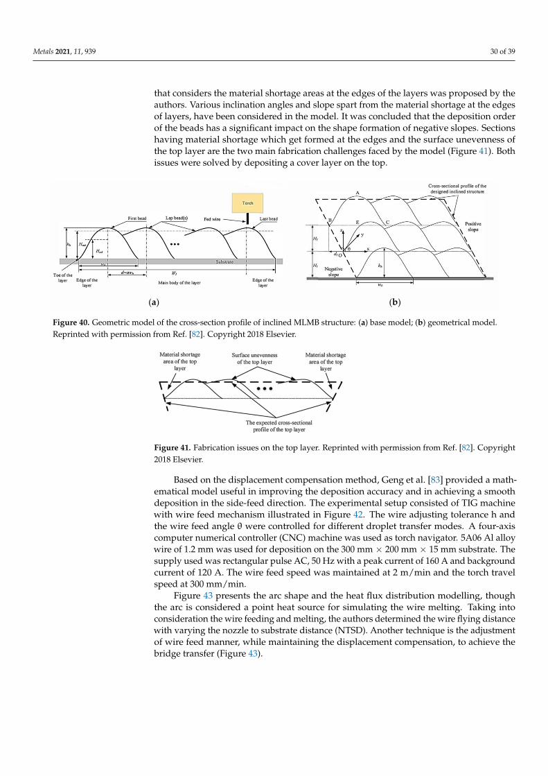
Li et al. [82] presented more information on the layer overlapping process of inclinedmulti-layer multi-bead (MLMB) parts which was performed by WAAM without requiringface milling after each layer deposition (Figure 40). The concept of rotating the deposit-ing torch and the supporting table was utilized for inclined structure fabrication. Theexperimental setup for evaluating the model consisted of a six-axis robot, GMAW powersupply, wire feeding machine and YD500R welding machine. The wire used for depositionis the 1.2 mm diameter copper coated steel wire and Q235 was used as substrate material.Experiments were designed with different parameters and orientations of the deposit onthe first and the last beads of the layers. A mathematical model for layer-overlapping
Metals 2021, 11, 939 30 of 39
that considers the material shortage areas at the edges of the layers was proposed by theauthors. Various inclination angles and slope spart from the material shortage at the edgesof layers, have been considered in the model. It was concluded that the deposition orderof the beads has a significant impact on the shape formation of negative slopes. Sectionshaving material shortage which get formed at the edges and the surface unevenness ofthe top layer are the two main fabrication challenges faced by the model (Figure 41). Bothissues were solved by depositing a cover layer on the top.
Toe of the layer Edge of the
layer
First bead
Main body ofthc layer
(a)
Tocch
Last bead
Edge of the layer
H,
H,
(b)
Cross•sectional profile of the designed inclined structure
Figure 40. Geometric model of the cross-section profile of inclined MLMB structure: (a) base model; (b) geometrical model.Reprinted with permission from Ref. [82]. Copyright 2018 Elsevier.
Figure 41. Fabrication issues on the top layer. Reprinted with permission from Ref. [82]. Copyright2018 Elsevier.
Based on the displacement compensation method, Geng et al. [83] provided a math-ematical model useful in improving the deposition accuracy and in achieving a smoothdeposition in the side-feed direction. The experimental setup consisted of TIG machinewith wire feed mechanism illustrated in Figure 42. The wire adjusting tolerance h andthe wire feed angle θ were controlled for different droplet transfer modes. A four-axiscomputer numerical controller (CNC) machine was used as torch navigator. 5A06 Al alloywire of 1.2 mm was used for deposition on the 300 mm × 200 mm × 15 mm substrate. Thesupply used was rectangular pulse AC, 50 Hz with a peak current of 160 A and backgroundcurrent of 120 A. The wire feed speed was maintained at 2 m/min and the torch travelspeed at 300 mm/min.
Figure 43 presents the arc shape and the heat flux distribution modelling, thoughthe arc is considered a point heat source for simulating the wire melting. Taking intoconsideration the wire feeding and melting, the authors determined the wire flying distancewith varying the nozzle to substrate distance (NTSD). Another technique is the adjustmentof wire feed manner, while maintaining the displacement compensation, to achieve thebridge transfer (Figure 43).

Metals 2021, 11, 939 31 of 39
Figure 42. Schematic of Wire feed unit. Reprinted with permission from Ref. [83]. Copyright2017 Elsevier.
Figure 43. Mechanism for wire feed variation for bridge transfer: (a) arc modelling; (b) wire feed optimisation anddisplacement compensation. Reprinted with permission from Ref. [83]. Copyright 2017 Elsevier.
Oyama et al. [84] simulated the WAAM process for the Al-5Mg and Al-3Si alloyswith the aim of optimizing the layers deposition sequence and the deposition parameters.The experiment procedure involved the construction of separate 200 mm walls with CMTpowered WAAM system. Open circuit voltage was maintained at 15–18 V with and thetravel speed at 6–8 mm/sec. Semi-automatic deposition mode was adopted to have consid-erable delay between the inter layer depositions to ensure a lowering of the temperaturebefore the deposition. The authors reported that by changing the direction of every layerdeposition, a symmetric distribution of stress field was achieved. This was attributed to theuninterrupted deposition process that entails modification of the heat input for each layerand to the heat source staying longer on the wall structure edges. It was further noticedthat the size of the molten pool was stabilized when the heat adjustment and the interlaceddepositions were applied.
Montevecchi et al. [85] proposed a technical solution to solve the issue of heat accumu-lation, by impinging air jet through a vortex that cools the workpiece. A numerical modelof jet impingement cooling was applied to a finite element thermal model of the WAAMprocess, with the aim of assessing the effectiveness of this cooling system. The numericalmodel was validated through the thermography method using an Exair vortex tube fedby a compressed air flow to cool a S235JR plate. Based on the comparative analysis ofnumerical and experimental results, illustrated in Figure 44, the authors reported a goodaccuracy of the model. The research outcomes highlight that the heat accumulation couldbe prevented by controlling the inter-pass temperature across the layers and the size of themolten pool.
The approach on the predictive models, developed for the simulation of the WAAMprocess, demonstrates the effectiveness of their employing in improving the process per-formances which are strongly dependent on the multiple process parameters, materialsand workpieces shape. Various statistical methods have been applied to determine theoptimal parameters and the influential factors for the desired multiple responses. Themathematical models provide information on the correlation between the responses andthe process parameters at confidence level of almost 95%. The main aim of the modellingis to facilitate the complex design, testing in different conditions of static and dynamicloading, reproducibility in the geometry of materials and to check the interdependencies be-tween different interdisciplinary parameters. Moreover, the modelling method minimizes
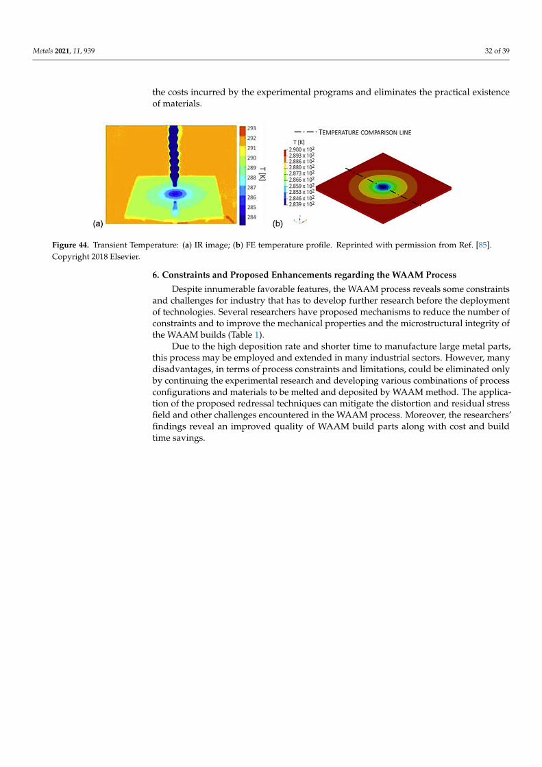
Metals 2021, 11, 939 32 of 39
the costs incurred by the experimental programs and eliminates the practical existenceof materials.
Figure 44. Transient Temperature: (a) IR image; (b) FE temperature profile. Reprinted with permission from Ref. [85].Copyright 2018 Elsevier.
6. Constraints and Proposed Enhancements regarding the WAAM Process
Despite innumerable favorable features, the WAAM process reveals some constraintsand challenges for industry that has to develop further research before the deploymentof technologies. Several researchers have proposed mechanisms to reduce the number ofconstraints and to improve the mechanical properties and the microstructural integrity ofthe WAAM builds (Table 1).
Due to the high deposition rate and shorter time to manufacture large metal parts,this process may be employed and extended in many industrial sectors. However, manydisadvantages, in terms of process constraints and limitations, could be eliminated onlyby continuing the experimental research and developing various combinations of processconfigurations and materials to be melted and deposited by WAAM method. The applica-tion of the proposed redressal techniques can mitigate the distortion and residual stressfield and other challenges encountered in the WAAM process. Moreover, the researchers’findings reveal an improved quality of WAAM build parts along with cost and buildtime savings.

Metals 2021, 11, 939 33 of 39
Table 1. Constraints and limitations in the WAAM process.
Ref No. WAAM Constraint Addressed Proposed Redressal Scheme Effect on Microstructure/MechanicalProperties Demerits/Limitations
Raw Material
[86] Limited availability of feedstock wires Production of AA6061 byfriction extrusion
Microstructure-strength and hardnesscomparable to standard WAAM with
AA6061 base metal
Presence of voids and bends in extrudedwires. To eliminate twisting, drawing wire
more than once required
[87] Feasibility and crack sensitivity ofhybrid parts manufacturing
Production of Nickel AluminumBronze-Stainless Steel hybrid parts
Fine equiaxed alpha dendrites, goodsurface properties
Inter-metallics formation, penetration ofNAB along the HAZ cracks, rosette like
particles due to dilution defects-negativelyaffecting toughness and ductility
Deposition Method
[41]
To overcome freeform manufacturingissues of collision, deposited materialcausing obstruction and overlapping
points at intersections.
Local control on geometry of depositionby on-line adaptive slicing and depositionstrategies to manage branch intersections
Yielded appropriate positioning ofskeleton freeform branches in intersection.
In-situ monitoring enables onlinegap-checking and required weld torch
orientation.
-
[83] Deposition Accuracy inside feedorientation
Displacement compensation & wire feedangle manipulation
Consistent layer deposition, control ofdroplet landing position
Chance of wire getting flexed through thearc column
[88] Residual Stress, manual control for thesame layer height
Deposition path definition forT-cross builds
Increased utilization, increased failure of?free parts, deposition efficiency
Balance between productivity and materialusage efficiency
Stress & Distortion
[89] Residual stresses and distortion Inter-pass rolling Increase in wall width, uniformlayer height Increased manufacturing time
[90] High porosity, coarse microstructure,low mechanical performance Workpiece vibration
Dendrite breakage and grain refinement,reduced porosity, improved
tensile properties
Elongation and anisotropynegatively affected
[91] Tensile stresses Interpass rolling and thermal stress relief Improved mechanical properties withreduced grain size
Dominant thermal history, no significantdifference to final residual stress
[92] Part DistortionInter-pass cooling using compressed CO2.
To be considered in the path planningstrategy for improved geometry
Improved dimensional accuracy
Change in CO2 gas flow rate may causein-homogenous stress and distortion to the
build. Unrestrained shrinkage preventscomplete distortion elimination

Metals 2021, 11, 939 34 of 39
Table 1. Cont.
Ref No. WAAM Constraint Addressed Proposed Redressal Scheme Effect on Microstructure/MechanicalProperties Demerits/Limitations
Heat Source Design
[85] Heat Accumulation Impinging air jets through a vortex toincrease convective heat transfer
Effective control of the inter-passtemperature, excessive increase in molten
pool size
Needs to be investigated for complexconfigurations
[93]Surface Cracking because of various
factors such as alloy composition, highwire feed speed
Influence of composition, heat input,mechanical properties studied
Proposed model can predict solidificationcracking tendency, higher microhardness
reduces crack susceptibilityInsufficient feed causes crack initiation
[94] Dimensional inaccuracy Laser assisted WAAM-leading/trailinglaser beam
Improved surface topology, densesamples with no porosity
Increased experimentation and simulationtrials, excessive melting may cause
premature deposition
[95] Process instability, inaccuratebuild geometry Magnetic arc oscillation
Homogenous thin wall depositionsachieved, reduced power density,
reduced volume and weight of weld pool,reduced solidification time
Surface variation due to varyingarc position
[96] Irregularities in the build structurebecause of thermal gradients
Multilayer laser assisted WAAM to studyimpact of different lead angles and
interlayer temperatures. Also studiedeffect of variation in dragging and
pushing WAAM process
Wider melt pool, better track wetting onthe substrate, optimum lead angle
identified as 10 degrees
Fluctuations observed at lead angles otherthan 10 degrees and at higher interlayer
temperatures in dragging WAAMprocesssmakal
[97] Slow manufacturing Speed because ofcooling techniques
Aerosol cooling during themanufacturing
No porosity or weld defects highlighted,Weld seam shape and dendritic structureare similar, smaller dendrites and higher
hardness compared to uncooled weld
Unsteady drops in temperature,asymmetric weld seam shape

Metals 2021, 11, 939 35 of 39
7. Conclusions
Based on a large number of recent articles published in the wire arc additive man-ufacturing field, this review article provides an overall view of the progress made andinformation useful to researchers worldwide interested in obtaining new findings. Toenhance the acceptability and the applicability of the WAAM process for a wide varietyof custom-made large size metallic builds performed from materials such as Ti-6Al-4Valloy, Inconel, Chromium, having properties close to the wrought or cast parts, moreexperimental research to improve the knowledge is needed. Besides, exploring the pos-sible applicability of the WAAM process for repairing large metallic structures would beadvantageous in terms of maintenance and service costs.
Currently, there is a lack of WAAM benchmark indicators, in comparison with othermanufacturing techniques, but the potential in terms of digital fabrication versus thetraditional manufacturing process is evident. The mass and high-quality production ofWAAM is achievable if the issues related to high levels of heat input are mitigated andconstraints and limitations are eliminated.
The residual stress and distortion are the primary limiting factors affecting the accept-ability and adaptability of the WAAM process in major industries. Advanced computationaltechniques based on data learning can be explored for development of efficient techniques.
With the integration of possible enhancements, in-situ monitoring, and non-destructiveinline evaluation, this process can be an attractive option for producing a large range ofprototype constructions. Besides, the process promises significant reduction in materialwastage and cost, as well as an increased freedom of design, customization and compo-nents complexity. The precise design can facilitate an accurate optimization of the process,while the investigation of depositing different metals wires by WAAM method increasesthe knowledge level in the fields of materials optimization and multi-material componentsfabrication. By integrating the machining platform with the AM process, the creation andfabrication of complexed shapes can become more and more easily performed. Presently,the WAAM process is under continuous investigation with the aim to identify the feasi-bility for various materials, shapes, and applications. Neither a net-shape nor automatedprocess are complete until the commercial AM CAD/CAM software is available in its fullydeveloped version. The entire fabrication process, from the conception of part modelsand interpretation to the design and preparation of a manufacturing procedure, demandsskilled operators. Nevertheless, in comparison to the conventional welding, cladding, orsubtractive manufacturing techniques, the WAAM process provides a high degree of flexi-bility, high economic efficiency, and a high rate of using the additional material. Further,the capability to fabricate large metal 3D printed components and deployment for lightmaterials increase the attention paid by industry towards the WAAM technique.
Author Contributions: Conceptualization, M.C. and A.V.S.; methodology, M.C. and A.V.S.; formalanalysis, M.C. and L.R.M.; investigation, M.C. and A.V.S.; resources, M.C., A.V.S., D.M., and L.R.M.;writing—original draft preparation, M.C. and A.V.S.; writing—review and editing, E.S., C.C.R.,and D.M.; visualization, E.S. and C.C.R.; supervision, E.S. All authors have read and agreed to thepublished version of the manuscript.
Funding: This research received no external funding.
Institutional Review Board Statement: Not applicable.
Informed Consent Statement: Not applicable.
Data Availability Statement: Not applicable.
Acknowledgments: The authors gratefully acknowledge the support received from DayanandaSagar University, India and “Dunarea de Jos” University of Galati, Romania.
Conflicts of Interest: The authors declare no conflict of interest.

Metals 2021, 11, 939 36 of 39
References1. Ding, J.; Colegrove, P.; Mehnen, J.; Ganguly, S.; Almeida, P.S.; Wang, F.; Williams, S. Thermo-mechanical analysis of Wire and Arc
Additive Layer Manufacturing process on large multi-layer parts. Comput. Mater. Sci. 2011, 50, 3315–3322. [CrossRef]2. Ríos, S.; Colegrove, P.A.; Williams, S.W. Metal transfer modes in plasma Wire + Arc additive manufacture. J. Mater. Process.
Technol. 2019, 264, 45–54. [CrossRef]3. Zhang, C.; Li, Y.; Gao, M.; Zeng, X. Wire arc additive manufacturing of Al-6Mg alloy using variable polarity cold metal transfer
arc as power source. Mater. Sci. Eng. A 2018, 711, 415–423. [CrossRef]4. Bekker, A.C.; Verlinden, J.C.; Galimberti, G. Challenges in assessing the sustainability of wire+ arc additive manufacturing for
large structures. In Proceedings of the Solid Freeform Fabrication Symposium, Austin, TX, USA, 8–10 August 2016; pp. 406–418.5. Michel, F.; Lockett, H.; Ding, J.; Martina, F.; Marinelli, G.; Williams, S. A modular path planning solution for Wire + Arc Additive
Manufacturing. Robot. Comput. Integr. Manuf. 2019, 60, 1–11. [CrossRef]6. Li, J.L.Z.; Alkahari, M.R.; Rosli, N.A.B.; Hasan, R.; Sudin, M.N.; bin Ramli, F.R. Review of Wire Arc Additive Manufacturing for
3D Metal Printing. Int. J. Autom. Technol. 2019, 13, 346–353. [CrossRef]7. Zhang, J.; Liou, F.W. Multi-Axis Planning of a Hybrid Material Deposition and Removal Combined Process. J. Mach. Manuf.
Autom. 2013, 2, 46–57.8. Challenges & Latest Developments in Wire + Arc Additive Manufacturing. Available online: https://www.tctmagazine.com/
additive-manufacturing-3d-printing-news/challenges-latest-developments-wire-arc-additive-manufacturing (accessed on 25December 2020).
9. Cunningham, C.; Flynn, J.; Shokrani, A.; Dhokia, V.; Newman, S. Invited review article: Strategies and processes for high qualitywire arc additive manufacturing. Addit. Manuf. 2018, 22, 672–686. [CrossRef]
10. Wu, Q.; Mukherjee, T.; De, A.; DebRoy, T. Residual stresses in wire-arc additive manufacturing—Hierarchy of influential variables.Addit. Manuf. 2020, 35, 101355. [CrossRef]
11. Busachi, A.; Erkoyuncu, J.; Colegrove, P.; Martina, F.; Ding, J. Designing a WAAM Based Manufacturing System for DefenceApplications. Procedia CIRP 2015, 37, 48–53. [CrossRef]
12. Lockett, H.; Ding, J.; Williams, S.; Martina, F. Design for Wire + Arc Additive Manufacture: Design rules and build orientationselection. J. Eng. Des. 2017, 28, 568–598. [CrossRef]
13. Yuan, L.; Ding, D.; Pan, Z.; Yu, Z.; Wu, B.; Van Duin, S.; Li, H.; Li, W. Application of Multidirectional Robotic Wire Arc AdditiveManufacturing Process for the Fabrication of Complex Metallic Parts. IEEE Trans. Ind. Inform. 2019, 16, 454–464. [CrossRef]
14. Müller, J.; Grabowski, M.; Müller, C.; Hensel, J.; Unglaub, J.; Thiele, K.; Kloft, H.; Dilger, K. Design and Parameter Identificationof Wire and Arc Additively Manufactured (WAAM) Steel Bars for Use in Construction. Metals 2019, 9, 725. [CrossRef]
15. Abe, T.; Sasahara, H. Layer geometry control for the fabrication of lattice structures by wire and arc additive manufacturing.Addit. Manuf. 2019, 28, 639–648. [CrossRef]
16. Chandrasekaran, S.; Hari, S.; Amirthalingam, M. Wire arc additive manufacturing of functionally graded material for marinerisers. Mater. Sci. Eng. A 2020, 792, 139530. [CrossRef]
17. Lin, J.; Lv, Y.; Liu, Y.; Sun, Z.; Wang, K.; Li, Z.; Wu, Y.; Xu, B. Microstructural evolution and mechanical property of Ti-6Al-4V walldeposited by continuous plasma arc additive manufacturing without post heat treatment. J. Mech. Behav. Biomed. Mater. 2017, 69,19–29. [CrossRef] [PubMed]
18. Priarone, P.C.; Pagone, E.; Martina, F.; Catalano, A.R.; Settineri, L. Multi-criteria environmental and economic impact assessmentof wire arc additive manufacturing. CIRP Ann. 2020, 69, 37–40. [CrossRef]
19. Prado-Cerqueira, J.; Diéguez, J.; Camacho, A. Preliminary development of a Wire and Arc Additive Manufacturing system(WAAM). Procedia Manuf. 2017, 13, 895–902. [CrossRef]
20. Shukla, P.; Dash, B.; Kiran, D.V.; Bukkapatnam, S. Arc Behavior in Wire Arc Additive Manufacturing Process. Procedia Manuf.2020, 48, 725–729. [CrossRef]
21. Xiong, J.; Lei, Y.; Chen, H.; Zhang, G. Fabrication of inclined thin-walled parts in multi-layer single-pass GMAW-based additivemanufacturing with flat position deposition. J. Mater. Process. Technol. 2017, 240, 397–403. [CrossRef]
22. Luo, Y.; Li, J.; Xu, J.; Zhu, L.; Han, J.; Zhang, C. Influence of pulsed arc on the metal droplet deposited by projected transfer modein wire-arc additive manufacturing. J. Mater. Process. Technol. 2018, 259, 353–360. [CrossRef]
23. Zhu, L.; Luo, Y.; Han, J.; Zhang, C.; Xu, J.; Chen, D. Energy characteristics of droplet transfer in wire-arc additive manufacturingbased on the analysis of arc signals. Measurement 2019, 134, 804–813. [CrossRef]
24. Guo, M.; Jia, C.; Zhou, J.; Liu, W.; Wu, C. Investigating the generation process of molten droplets and arc plasma in the confinedspace during compulsively constricted WAAM. J. Mater. Process. Technol. 2020, 275, 116355. [CrossRef]
25. Marinelli, G.; Martina, F.; Ganguly, S.; Williams, S. Grain refinement in an unalloyed tantalum structure by combining Wire+Arcadditive manufacturing and vertical cold rolling. Addit. Manuf. 2020, 32, 101009. [CrossRef]
26. Abe, T.; Kaneko, J.; Sasahara, H. Thermal sensing and heat input control for thin-walled structure building based on numericalsimulation for wire and arc additive manufacturing. Addit. Manuf. 2020, 35, 101357. [CrossRef]
27. Huang, J.; Yuan, W.; Yu, S.; Zhang, L.; Yu, X.; Fan, D. Droplet transfer behavior in bypass-coupled wire arc additive manufacturing.J. Manuf. Process. 2020, 49, 397–412. [CrossRef]

Metals 2021, 11, 939 37 of 39
28. Li, S.; Zhang, L.-J.; Ning, J.; Wang, X.; Zhang, G.-F.; Zhang, J.-X.; Na, S.-J.; Fatemeh, B. Comparative study on the microstructuresand properties of wire+arc additively manufactured 5356 aluminium alloy with argon and nitrogen as the shielding gas. Addit.Manuf. 2020, 34, 101206. [CrossRef]
29. Yang, D.; He, C.; Zhang, G. Forming characteristics of thin-wall steel parts by double electrode GMAW based additive manufac-turing. J. Mater. Process. Technol. 2016, 227, 153–160. [CrossRef]
30. Mok, S.H.; Bi, G.; Folkes, J.; Pashby, I. Deposition of Ti–6Al–4V using a high power diode laser and wire, Part I: Investigation onthe process characteristics. Surf. Coat. Technol. 2008, 202, 3933–3939. [CrossRef]
31. Dinovitzer, M.; Chen, X.; Laliberte, J.; Huang, X.; Frei, H. Effect of wire and arc additive manufacturing (WAAM) processparameters on bead geometry and microstructure. Addit. Manuf. 2019, 26, 138–146. [CrossRef]
32. Wahsh, L.M.; ElShater, A.E.; Mansour, A.K.; Hamdy, F.A.; Turky, M.A.; Azzam, M.O.; Salem, H.G. Parameter Selection for WireArc Additive Manufacturing (Waam) Process. Mater. Sci. Technol. 2018. [CrossRef]
33. Kumar, C.B.; Anandakrishnan, V. Experimental investigations on the effect of wire arc additive manufacturing process parameterson the layer geometry of Inconel 825. Mater. Today Proc. 2020, 21, 622–627. [CrossRef]
34. Su, C.; Chen, X.; Gao, C.; Wang, Y. Effect of heat input on microstructure and mechanical properties of Al-Mg alloys fabricated byWAAM. Appl. Surf. Sci. 2019, 486, 431–440. [CrossRef]
35. Zhou, Y.; Lin, X.; Kang, N.; Huang, W.; Wang, J.; Wang, Z. Influence of travel speed on microstructure and mechanical propertiesof wire + arc additively manufactured 2219 aluminum alloy. J. Mater. Sci. Technol. 2020, 37, 143–153. [CrossRef]
36. Xiong, J.; Zhang, G. Adaptive control of deposited height in GMAW-based layer additive manufacturing. J. Mater. Process. Technol.2014, 214, 962–968. [CrossRef]
37. Artaza, T.; Alberdi, A.; Murua, M.; Gorrotxategi, J.; Frías, J.; Puertas, G.; Melchor, M.; Mugica, D.; Suárez, A. Design andintegration of WAAM technology and in situ monitoring system in a gantry machine. Procedia Manuf. 2017, 13, 778–785.[CrossRef]
38. Anikin, P.; Shilo, G.; Kulykovskyi, R.; Molochkov, D. Wire+ Arc Additive Manufacturing Automation Control System Architecture.In Proceedings of the Measuring and Computing Technology in Technological Processes Conference, Odessa, Ukraine, 26–29June 2020; pp. 7–9.
39. Silva, R.; Barbosa, G.; Carvalho, J. Additive Manufacturing of Metal Parts by Welding. IFAC-PapersOnLine 2015, 48, 2318–2322.[CrossRef]
40. Xiong, J.; Lei, Y.; Li, R. Finite element analysis and experimental validation of thermal behavior for thin-walled parts inGMAW-based additive manufacturing with various substrate preheating temperatures. Appl. Therm. Eng. 2017, 126, 43–52.[CrossRef]
41. Radel, S.; Bordreuil, C.; Soulie, F.; Company, O. CAM for On-line Control for Wire Arc Additive Manufacturing. Comput. Des.Appl. 2018, 16. [CrossRef]
42. Ali, Y.; Henckell, P.; Hildebrand, J.; Reimann, J.; Bergmann, J.; Barnikol-Oettler, S. Wire arc additive manufacturing of hot worktool steel with CMT process. J. Mater. Process. Technol. 2019, 269, 109–116. [CrossRef]
43. Derekar, K.S.; Addison, A.; Joshi, S.S.; Zhang, X.; Lawrence, J.; Xu, L.; Melton, G.; Griffiths, D. Effect of pulsed metal inert gas(pulsed-MIG) and cold metal transfer (CMT) techniques on hydrogen dissolution in wire arc additive manufacturing (WAAM) ofaluminium. Int. J. Adv. Manuf. Technol. 2020, 107, 311–331. [CrossRef]
44. Ortega, A.G.; Galvan, L.C.; Deschaux-Beaume, F.; Rouquette, S. Effect of welding parameters on the quality of multilayerdeposition of aluminum alloy. Adv. Mater. Process. Technol. Conf. 2017, 23, 316–332. [CrossRef]
45. Ryan, E.; Sabin, T.; Watts, J.; Whiting, M. The influence of build parameters and wire batch on porosity of wire and arc additivemanufactured aluminium alloy 2319. J. Mater. Process. Technol. 2018, 262, 577–584. [CrossRef]
46. Brandl, E.; Michailov, V.; Viehweger, B.; Leyens, C. Deposition of Ti–6Al–4V using laser and wire, part I: Microstructural propertiesof single beads. Surf. Coat. Technol. 2011, 206, 1120–1129. [CrossRef]
47. Ma, Y.; Cuiuri, D.; Shen, C.; Li, H.; Pan, Z. Effect of interpass temperature on in-situ alloying and additive manufacturing oftitanium aluminides using gas tungsten arc welding. Addit. Manuf. 2015, 8, 71–77. [CrossRef]
48. Huang, J.; Liu, S.; Yu, S.; Yu, X.; Chen, H.; Fan, D. Arc deposition of wear resistant layer TiN on Ti6Al4V using simultaneousfeeding of nitrogen and wire. Surf. Coatings Technol. 2020, 381, 125141. [CrossRef]
49. Wang, J.; Lin, X.; Li, J.; Hu, Y.; Zhou, Y.; Wang, C.; Li, Q.; Huang, W. Effects of deposition strategies on macro/microstructure andmechanical properties of wire and arc additive manufactured Ti6Al4V. Mat Sci. Eng. A. 2019, 754, 735–749. [CrossRef]
50. Wang, J.; Pan, Z.; Cuiuri, D.; Li, H. Phase constituent control and correlated properties of titanium aluminide intermetallic alloysthrough dual-wire arc additive manufacturing. Mater. Lett. 2019, 242, 111–114. [CrossRef]
51. Geng, H.; Li, J.; Xiong, J.; Lin, X.; Zhang, F. Geometric Limitation and Tensile Properties of Wire and Arc Additive Manufacturing5A06 Aluminum Alloy Parts. J. Mater. Eng. Perform. 2016, 26, 621–629. [CrossRef]
52. Horgar, A.; Fostervoll, H.; Nyhus, B.; Ren, X.; Eriksson, M.; Akselsen, O. Additive manufacturing using WAAM with AA5183wire. J. Mater. Process. Technol. 2018, 259, 68–74. [CrossRef]
53. Qi, Z.; Cong, B.; Qi, B.; Sun, H.; Zhao, G.; Ding, J. Microstructure and mechanical properties of double-wire + arc additivelymanufactured Al-Cu-Mg alloys. J. Mater. Process. Technol. 2018, 255, 347–353. [CrossRef]
54. Gu, J.; Yang, S.; Gao, M.; Bai, J.; Zhai, Y.; Ding, J. Micropore evolution in additively manufactured aluminum alloys under heattreatment and inter-layer rolling. Mater. Des. 2020, 186, 108288. [CrossRef]

Metals 2021, 11, 939 38 of 39
55. Li, C.; Gu, H.; Wang, W.; Wang, S.; Ren, L.; Wang, Z.; Ming, Z.; Zhai, Y. Effect of Heat Input on Formability, Microstructure, andProperties of Al–7Si–0.6Mg Alloys Deposited by CMT-WAAM Process. Appl. Sci. 2019, 10, 70. [CrossRef]
56. Qi, Z.; Qi, B.; Cong, B.; Sun, H.; Zhao, G.; Ding, J. Microstructure and mechanical properties of wire + arc additively manufactured2024 aluminum alloy components: As-deposited and post heat-treated. J. Manuf. Process. 2019, 40, 27–36. [CrossRef]
57. Ünsal, I.; Hirtler, M.; Sviridov, A.; Bambach, M. Material Properties of Features Produced from EN AW 6016 by Wire-Arc AdditiveManufacturing. Procedia Manuf. 2020, 47, 1129–1133. [CrossRef]
58. Wang, S.; Gu, H.; Wang, W.; Li, C.; Ren, L.; Wang, Z.; Zhai, Y.; Ma, P. The Influence of Heat Input on the Microstructure andProperties of Wire-Arc-Additive-Manufactured Al-Cu-Sn Alloy Deposits. Metals 2020, 10, 79. [CrossRef]
59. Yang, X.; Liu, J.; Wang, Z.; Lin, X.; Liu, F.; Huang, W.; Liang, E. Microstructure and mechanical properties of wire and arc additivemanufactured AZ31 magnesium alloy using cold metal transfer process. Mater. Sci. Eng. A 2020, 774, 138942. [CrossRef]
60. Ge, J.; Lin, J.; Chen, Y.; Lei, Y.; Fu, H. Characterization of wire arc additive manufacturing 2Cr13 part: Process stability,microstructural evolution, and tensile properties. J. Alloy Compd. 2018, 748, 911–921. [CrossRef]
61. Xu, X.; Ganguly, S.; Ding, J.; Seow, C.E.; Williams, S. Enhancing mechanical properties of wire + arc additively manufacturedINCONEL 718 superalloy through in-process thermomechanical processing. Mater. Des. 2018, 160, 1042–1051. [CrossRef]
62. Seow, C.E.; Coules, H.; Wu, G.; Khan, R.H.; Xu, X.; Williams, S. Wire + Arc Additively Manufactured Inconel 718: Effect ofpost-deposition heat treatments on microstructure and tensile properties. Mater. Des. 2019, 183, 108157. [CrossRef]
63. Yangfan, W.; Xizhang, C.; Chuanchu, S. Microstructure and mechanical properties of Inconel 625 fabricated by wire-arc additivemanufacturing. Surf. Coatings Technol. 2019, 374, 116–123. [CrossRef]
64. Marinelli, G.; Martina, F.; Ganguly, S.; Williams, S. Development of Wire + Arc additive manufacture for the production oflarge-scale unalloyed tungsten components. Int. J. Refract. Met. Hard Mater. 2019, 82, 329–335. [CrossRef]
65. Marinelli, G.; Martina, F.; Ganguly, S.; Williams, S. Microstructure, hardness and mechanical properties of two different unalloyedtantalum wires deposited via wire + arc additive manufacture. Int. J. Refract. Met. Hard Mater. 2019, 83, 104974. [CrossRef]
66. Wang, Y.; Chen, X.; Konovalov, S.; Su, C.; Siddiquee, A.N.; Gangil, N. In-situ wire-feed additive manufacturing of Cu-Al alloy byaddition of silicon. Appl. Surf. Sci. 2019, 487, 1366–1375. [CrossRef]
67. Haden, C.V.; Zeng, G.; Carter, F.M., III; Ruhl, C.; Krick, B.A.; Harlow, D.G. Wire and arc additive manufactured steel: Tensile andwear properties. Addit. Manuf. 2017, 16, 115–123. [CrossRef]
68. Feng, Y.; Zhan, B.; He, J.; Wang, K. The double-wire feed and plasma arc additive manufacturing process for deposition in Cr-Nistainless steel. J. Mater. Process. Technol. 2018, 259, 206–215. [CrossRef]
69. Wang, L.; Xue, J.; Wang, Q. Correlation between arc mode, microstructure, and mechanical properties during wire arc additivemanufacturing of 316L stainless steel. Mater. Sci. Eng. A 2019, 751, 183–190. [CrossRef]
70. Dirisu, P.; Supriyo, G.; Martina, F.; Xu, X.; Williams, S. Wire plus arc additive manufactured functional steel surfaces enhanced byrolling. Int. J. Fatigue 2020, 130, 105237. [CrossRef]
71. Suryakumar, S.; Karunakaran, K.; Bernard, A.; Chandrasekhar, U.; Raghavender, N.; Sharma, D. Weld bead modeling and processoptimization in Hybrid Layered Manufacturing. Comput. Des. 2011, 43, 331–344. [CrossRef]
72. Ding, D.; Pan, Z.; Cuiuri, D.; Li, H. A multi-bead overlapping model for robotic wire and arc additive manufacturing (WAAM).Robot. Comput. Manuf. 2015, 31, 101–110. [CrossRef]
73. Geng, H.; Li, J.; Xiong, J.; Lin, X. Optimisation of interpass temperature and heat input for wire and arc additive manufacturing5A06 aluminium alloy. Sci. Technol. Weld. Join. 2017, 22, 472–483. [CrossRef]
74. Guo, Y.; Zhao, Z.; Han, J.; Bai, L. Quality Monitoring in Wire-Arc Additive Manufacturing Based on Spectrum. In Proceedings ofthe 2018 the 2nd International Conference on Video and Image Processing, ICVIP 2018, Hong Kong, China, 18–21 December 2018;pp. 240–244.
75. Ríos, S.; Colegrove, P.; Martina, F.; Williams, S.W. Analytical process model for wire + arc additive manufacturing. Addit. Manuf.2018, 21, 651–657. [CrossRef]
76. Tian, H.; Lu, Z.; Li, F.; Chen, S. Predictive Modeling of Surface Roughness Based on Response Surface Methodology after WAAM; AtlantisPress: Paris, France, 2019; pp. 47–50.
77. Teja, K.; Tokala, S.C.V.; Reddy, Y.P.; Narayana, K.L. Optimization of mechanical properties of wire arc additive manufacturedspecimens using grey-based taguchi method. J. Crit. Rev. 2020, 7, 808–817.
78. Lee, S.H. Optimization of Cold Metal Transfer-Based Wire Arc Additive Manufacturing Processes Using Gaussian ProcessRegression. Metals 2020, 10, 461. [CrossRef]
79. Hejripour, F.; Valentine, D.T.; Aidun, D.K. Study of mass transport in cold wire deposition for Wire Arc Additive Manufacturing.Int. J. Heat Mass Transf. 2018, 125, 471–484. [CrossRef]
80. Hejripour, F.; Binesh, F.; Hebel, M.; Aidun, D.K. Thermal modeling and characterization of wire arc additive manufactured duplexstainless steel. J. Mater. Process. Technol. 2019, 272, 58–71. [CrossRef]
81. Li, Y.; Sun, Y.; Han, Q.; Zhang, G.; Horváth, I. Enhanced beads overlapping model for wire and arc additive manufacturing ofmulti-layer multi-bead metallic parts. J. Mater. Process. Technol. 2018, 252, 838–848. [CrossRef]
82. Li, Y.; Huang, X.; Horváth, I.; Zhang, G. GMAW-based additive manufacturing of inclined multi-layer multi-bead parts withflat-position deposition. J. Mater. Process. Technol. 2018, 262, 359–371. [CrossRef]
83. Geng, H.; Li, J.; Xiong, J.; Lin, X.; Zhang, F. Optimization of wire feed for GTAW based additive manufacturing. J. Mater. Process.Technol. 2017, 243, 40–47. [CrossRef]

Metals 2021, 11, 939 39 of 39
84. Oyama, K.; Diplas, S.; M’Hamdi, M.; Gunnæs, A.E.; Azar, A.S. Heat source management in wire-arc additive manufacturingprocess for Al-Mg and Al-Si alloys. Addit. Manuf. 2019, 26, 180–192. [CrossRef]
85. Montevecchi, F.; Venturini, G.; Grossi, N.; Scippa, A.; Campatelli, G. Heat accumulation prevention in Wire-Arc-Additive-Manufacturing using air jet impingement. Manuf. Lett. 2018, 17, 14–18. [CrossRef]
86. Li, X.; Reynolds, A.P.; Baoqiang, C.; Jialuo, D.; Williams, S. Production and properties of a wire-arc additive manufacturing partmade with friction extruded wire. In Proceedings of the TMS 2015 144th Annual Meeting & Exhibition, Orlando, FL, USA, 15–19March 2015; Springer: Cham, Germany, 2015; pp. 445–452.
87. Dharmendra, C.; Shakerin, S.; Ram, G.J.; Mohammadi, M. Wire-arc additive manufacturing of nickel aluminum bronze/stainlesssteel hybrid parts – Interfacial characterization, prospects, and problems. Materialia 2020, 13, 100834. [CrossRef]
88. Venturini, G.; Montevecchi, F.; Scippa, A.; Campatelli, G. Optimization of WAAM Deposition Patterns for T-crossing Features.Procedia CIRP 2016, 55, 95–100. [CrossRef]
89. Martina, F.; Roy, M.J.; Szost, B.A.; Terzi, S.; Colegrove, P.A.; Williams, S.W.; Withers, P.J.; Meyer, J.; Hofmann, M. Residual stressof as-deposited and rolled wire+ arc additive manufacturing Ti–6Al–4V components. Mater. Sci. Technol. 2016, 32, 1439–1448.[CrossRef]
90. Zhang, C.; Gao, M.; Zeng, X. Workpiece vibration augmented wire arc additive manufacturing of high strength aluminum alloy. J.Mater. Process. Technol. 2019, 271, 85–92. [CrossRef]
91. Hönnige, J.; Colegrove, P.; Ahmad, B.; Fitzpatrick, M.; Ganguly, S.; Lee, T.; Williams, S. Residual stress and texture control inTi-6Al-4V wire + arc additively manufactured intersections by stress relief and rolling. Mater. Des. 2018, 150, 193–205. [CrossRef]
92. Wu, B.; Pan, Z.; Chen, G.; Ding, D.; Yuan, L.; Cuiuri, D.; Li, H. Mitigation of thermal distortion in wire arc additively manufacturedTi6Al4V part using active interpass cooling. Sci. Technol. Weld. Join. 2019, 24, 484–494. [CrossRef]
93. Gu, J.; Bai, J.; Ding, J.; Williams, S.; Wang, L.; Liu, K. Design and cracking susceptibility of additively manufactured Al-Cu-Mgalloys with tandem wires and pulsed arc. J. Mater. Process. Technol. 2018, 262, 210–220. [CrossRef]
94. Näsström, J.; Brueckner, F.; Kaplan, A.F.H. Laser enhancement of wire arc additive manufacturing. J. Laser Appl. 2019, 31, 022307.[CrossRef]
95. Corradi, D.R.; Bracarense, A.Q.; Wu, B.; Cuiuri, D.; Pan, Z.; Li, H. Effect of Magnetic Arc Oscillation on the geometry of single-passmulti-layer walls and the process stability in wire and arc additive manufacturing. J. Mater. Process. Technol. 2020, 283, 116723.[CrossRef]
96. Hauser, T.; Da Silva, A.; Reisch, R.T.; Volpp, J.; Kamps, T.; Kaplan, A.F. Fluctuation effects in Wire Arc Additive Manufacturing ofaluminium analysed by high-speed imaging. J. Manuf. Process. 2020, 56, 1088–1098. [CrossRef]
97. Reisgen, U.; Sharma, R.; Mann, S.; Oster, L. Increasing the manufacturing efficiency of WAAM by advanced cooling strategies.Weld. World 2020, 64, 1409–1416. [CrossRef]
Copyright © 2022 FDOKUMEN