
WIRE ROPES - BRUGG Lifting
64
WIRE ROPES TRAINING MATERIAL 4 MODULES
-
Upload
khangminh22 -
Category
Documents
-
view
0 -
download
0
Transcript of WIRE ROPES - BRUGG Lifting

WIRE ROPESTRAINING MATERIAL
4 MODULES

TRAINING MATERIAL
Wire ropes belong to the most important elements in conveyor technology.
Wire ropes transmit very high tensile forces with a small rope cross-section.
Wire ropes cannot transmit compressive forces, which means that they cannot be used for bumping.
The variety of possible rope constructions allows for adapting the wire rope to the specific application.
Due to the moveability of the wires in the rope structure, ropes feature a good bendability.Wire ropes have no fatigue strength and must be replaced after a specified service life.
Wires will break due to fatigue after a certain service life not together, but by and by.
As a result of the stranding, a broken wire is fully load-bearing again just behind the breakage.
Wire ropes are sensitive to exter-nal influences. The properties of wire ropes is preserved at temperatures of -30°C to +100°C.
Safely and reliably when correctly applied, serviced and monitored.
1
TRAINING MATERIAL
1 CLASSIFICATION2 STRUCTURE3 STRAND STRUCTURE4 LENGTH OF LAY LENGTH / TYPES OF LAY5 RESIDUAL STRESS / ROTATIONAL BEHAVIOR6 CALCULATION BASES7 DESIGNATION
WIRE ROPES MODULE 1
MODULE 1 brugglifting.com

2
WIRE ROPES 1 MODULE 1
MODULE 1
CLASSIFICATION
Running wire ropes are ropes run-ning over rope pulleys (rope shea-ves), traction sheaves, sheaves and drums, following the bend of the sheave.
Examples: Lifting ropes, luffing ropes, elevator ropes, pull ropes, etc.
Running wire ropes
Stationary ropes are ropes that do not run over pulleys and the ends of which are mounted in ancho-rages.
Examples: Guy ropes for poles and booms.
Stationary wire ropes
Suspension ropes are ropes on which pulleys of conveyors are running. They have a similar function like rails.
Examples:Suspension ropes for cable cars, cable cranes.
Suspension ropes
Rope slings serve to attach and sling a load.
Rope slings

3
WIRE ROPES
MODULE 1
2STRUCTURE
Core(fiber core or steel core)
WireRr = 1570–2160 N/mm2
(Structural steel St37, ca. 400 N/mm2)
Center wire
Strand
MODULE 1
brugglifting.com
4
WIRE ROPES
MODULE 1
2
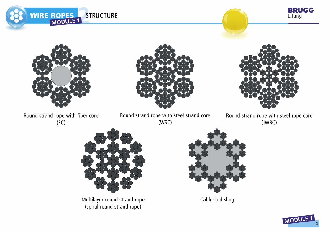
Round strand rope with fiber core (FC)
Round strand rope with steel strand core (WSC)
Round strand rope with steel rope core (IWRC)
Multilayer round strand rope(spiral round strand rope)
Cable-laid sling
MODULE 1 STRUCTURE

5
WIRE ROPES
MODULE 1
33.1 Standard stranding
Point contact
STRAND STRUCTURE MODULE 1
brugglifting.com
6
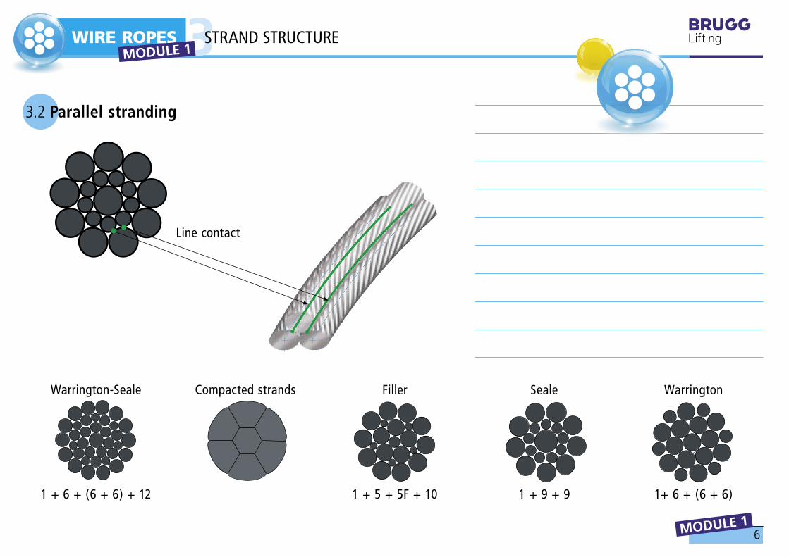
1 + 5 + 5F + 101 + 6 + (6 + 6) + 12 1 + 9 + 9 1+ 6 + (6 + 6)
WIRE ROPES
MODULE 1
3
Compacted strandsWarrington-Seale WarringtonSealeFiller
3.2 Parallel stranding
Line contact
MODULE 1 STRAND STRUCTURE

7
D
d
α
d . π
WIRE ROPES
MODULE 1
44.1 Lay length of rope / strand
Strand /Rope
Length of lay lengthWire / Strand
LENGTH OF LAY LENGTH / TYPES OF LAY MODULE 1
brugglifting.com

8
WIRE ROPES
MODULE 1
44.2 Ordinary lay 4.3 Lang lay
right-hand sZ
left-hand zS
right-hand zZ
left-hand sS
MODULE 1 LENGTH OF LAY LENGTH / TYPES OF LAY

9
WIRE ROPES
MODULE 1
5RESIDUAL STRESS / ROTATIONAL BEHAVIOR
5.1 Low-tension rope
A rope is considered as low-tension (or low-twist), if its strands and wires do not or do only barely pop out of the rope structure after the serving has been removed from the end of the rope. A low-tension rope does not tend to form bends or kinks, as it “lies dead”. Low-tension ropes are manufactured according to specific stranding processes.
preformed strand
MODULE 1
brugglifting.com

10
WIRE ROPES
MODULE 1
55.1 Rotation-free or low-rotation rope
A rope is considered as rotation-free or low-rotation, if it under the influence of an unguided load does not, or does barely, rotates around its longitudinal axis and exerts a very low torque on the end connections.
The rotation-free or low-rotation feature of the rope is caused by its specific construction and the type of stranding (multilayer round strand rope, flattened strand rope, braided rope and other special constructions).
Opposite torques of a rotation-free rope
RESIDUAL STRESS / ROTATIONAL BEHAVIOR MODULE 1
11
π d2
4Ac =
π D 2
4 . Ac
ƒ =
WIRE ROPES
MODULE 1
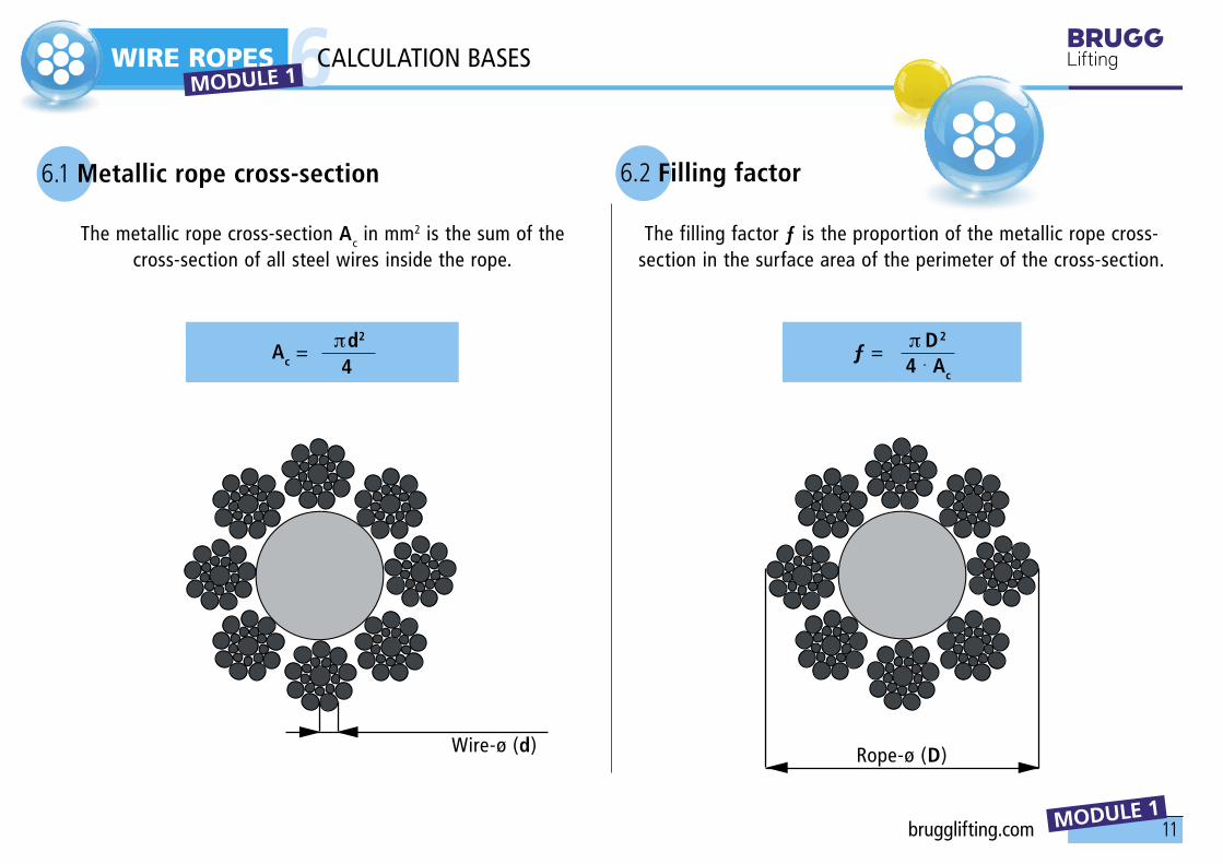
66.1 Metallic rope cross-section 6.2 Filling factor
The metallic rope cross-section Ac in mm2 is the sum of the cross-section of all steel wires inside the rope.
Wire-ø (d)
The filling factor ƒ is the proportion of the metallic rope cross-section in the surface area of the perimeter of the cross-section.
Rope-ø (D)
CALCULATION BASES MODULE 1
brugglifting.com

12
WIRE ROPES
MODULE 1
66.3 Rope grade
The rope grade Rr in N/mm2 is the underlying minimum tensile strength of the wire.
The rope grade according to which the steel wires for wire ropes are delivered and the limit deviations in the individual nominal wire diameter ranges are shown in the table below.
Rope grade in N/mm2 1180 to 2160
Nominal wire-ø Limit deviations
d1mm N/mm2
0,2 to < 0,5 +3900,5 to < 1,0 +3501,0 to < 1,5 +3201,5 to < 2,0 +2902,0 to ≤ 3,5 +260
1 MPa = 1 N/mm2
CALCULATION BASES MODULE 1
13
Fe,min = Ac . Rr Fmin = Fe,min
. k
WIRE ROPES
MODULE 1
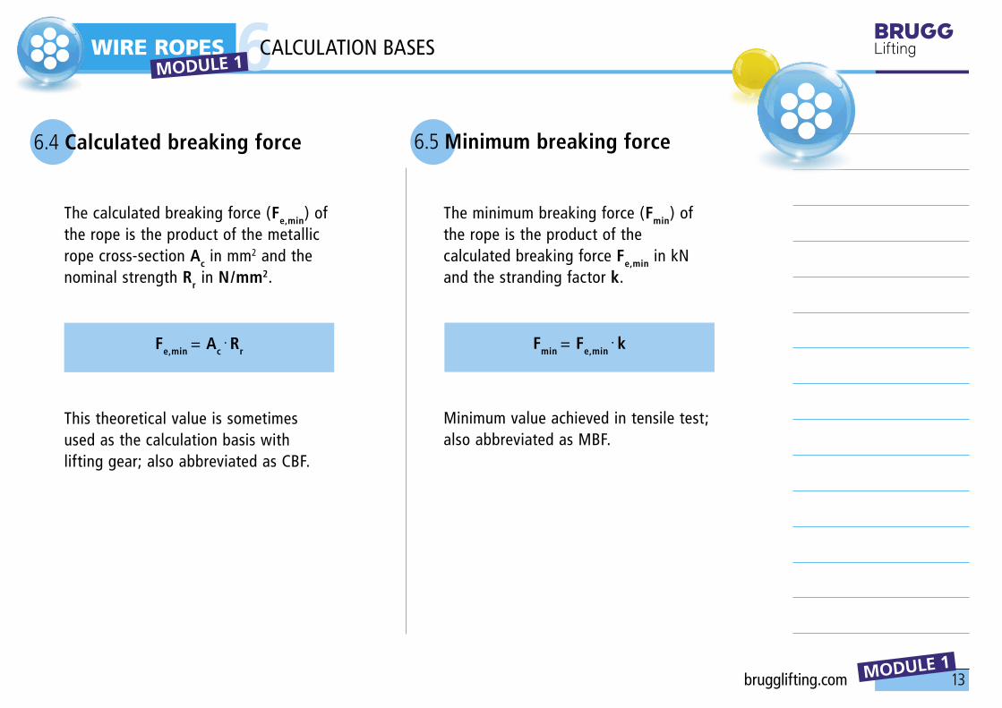
6.4 Calculated breaking force 6.5 Minimum breaking force
The calculated breaking force (Fe,min) of the rope is the product of the metallic rope cross-section Ac in mm2 and the nominal strength Rr in N/mm2.
This theoretical value is sometimes used as the calculation basis with lifting gear; also abbreviated as CBF.
The minimum breaking force (Fmin) of the rope is the product of the calculated breaking force Fe,min in kN and the stranding factor k.
Minimum value achieved in tensile test;also abbreviated as MBF.
6CALCULATION BASES MODULE 1
brugglifting.com

14
Zp = 5 [–]
WIRE ROPES
MODULE 1
7
Nominal rope diameter d1
Permissible deviation %
Rope tolerance acc. to DIN 15061, Part 1 / EN 12385
bis 3
+ 8 0
3 - 6
+ 7 0
6 - 7
+ 6 0
> 7
+ 5 0
7.4 Minimum breaking force of the rope
7.5 Construction of the rope
7.6 Type of the core
See catalogue page
• Standard no. (E.g. DIN 3058, EN 12385)• Braiding formula (E.g. 6 × 19)• Brand name (E.g. DQ/UNI)
• Natural fiber core• Chemical fiber core• Steel core, etc.
7.1 Length of the rope in meter (m)
7.2 Intended application EN 12385-4
Length tolerances:≤ 400 m 0% to +5%> 400 bis + 20 m per 1,000 m or part thereof> 1000 m 0% to +2%
Description of the rope application; in particular, references to low-rotation or rotation-free rope constructions are required.
7.3 Nominal rope diameter of the rope in mm
DESIGNATION MODULE 1

15
WIRE ROPES
MODULE 1
7
7.7 Surface finish of the wires
7.10 Low-tension or rotation-free designs of the rope
7.8 Nominal strength of the wires
• spa
• blank, galvanized, etc.
• 1570, 1770, 1960, etc.
• sZ, zS, etc.
7.9 Type of lay and direction of lay
7.11 Lubrication
7.12 Operating temperatures EN 12385-3
If not ordered otherwise, the type and quantity of the lubricant is left to the manufacturer’s discretion.
Strand ropes with fiber core FC - 40° bis 100°C (100% Fmin)Strand ropes with steel core WC - 40° bis 200% (90% Fmin)
MODULE 1 DESIGNATION
brugglifting.com

16
DIN/EN 12385
FE
FEN
FEC
SE
SES
SEL
bk
zn k
di zn
1570
1770
z
s
sZ
zS
zZ
sS
spa
FC
UFC
SFC
WC
IWRC
WSC
U
B
B
1570
1770
Z
S
sZ
zS
zZ
sS
K
WIRE ROPES
MODULE 1
7
Feature
Nominal diameter
Construction
Short descriptions
Type of core
Surface finish of the wires
Nominal strength of the wires
Type of lay and direction of layFiber core
Natural fiber core
Chemical fiber core
Steel core
Steel rope core
Steel strand core
blank
drawn galvanized
heavily galvanized
1570 N/mm2 (160 kp/mm2)
1770 N/mm2 (180 kp/mm2)
Right-hand
Left-hand
Right-hand ordinary lay
Left-hand ordinary lay
Right-hand lang lay
Left-hand lang lay
Low-tension design
Strand compacted
Abbreviations
in mm
DIN 3051
DESIGNATION MODULE 1

1
TRAINING MATERIAL
WIRE ROPES MODUL 1
1 HOISTING, DRIVING AND SPECIAL ROPES2 ROPE SELECTION3 ROPE PULLEYS4 ROPE DRUM5 ROPE END CONNECTIONS
MODULE 2
MODULE 2 brugglifting.com

2
WIRE ROPES 1 MODULE 2
MODULE 2
B 55• Blank steel wire, conserved, strands compacted• Nominal wire strength 1960 N/mm2 • Right-hand lang lay• Rotation-free
Use of swivel recommendedAs a hoisting rope for self-erecting cranes, for truck-mounted cranes, rotating tower cranes, excavators, drills, in case of multi-layer coiling, etc.
HOISTING, DRIVING AND SPECIAL ROPES
3
WIRE ROPES 1 MODULE 2
MODULE 2
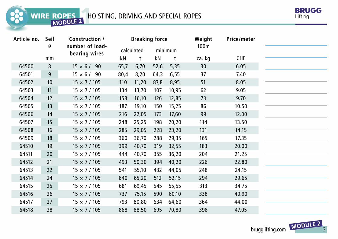
Article no. Seil ø
mm
Construction / number of load-
bearing wires
Breaking force Weight100m
ca. kg
Price/meter
CHFcalculated minimumkN t kN t
64500 8 15 × 6 / 90 65,7 6,70 52,6 5,35 30 6.0564501 9 15 × 6 / 90 80,4 8,20 64,3 6,55 37 7.4064502 10 15 × 7 / 105 110 11,20 87,8 8,95 51 8.0564503 11 15 × 7 / 105 134 13,70 107 10,95 62 9.0564504 12 15 × 7 / 105 158 16,10 126 12,85 73 9.7064505 13 15 × 7 / 105 187 19,10 150 15,25 86 10.5064506 14 15 × 7 / 105 216 22,05 173 17,60 99 12.0064507 15 15 × 7 / 105 248 25,25 198 20,20 114 13.5064508 16 15 × 7 / 105 285 29,05 228 23,20 131 14.1564509 18 15 × 7 / 105 360 36,70 288 29,35 165 17.3564510 19 15 × 7 / 105 399 40,70 319 32,55 183 20.0064511 20 15 × 7 / 105 444 40,70 355 36,20 204 21.2564512 21 15 × 7 / 105 493 50,30 394 40,20 226 22.8064513 22 15 × 7 / 105 541 55,10 432 44,05 248 24.1564514 24 15 × 7 / 105 640 65,20 512 52,15 294 29.6564515 25 15 × 7 / 105 681 69,45 545 55,55 313 34.7564516 26 15 × 7 / 105 737 75,15 590 60,10 338 40.9064517 27 15 × 7 / 105 793 80,80 634 64,60 364 44.0064518 28 15 × 7 / 105 868 88,50 695 70,80 398 47.05
HOISTING, DRIVING AND SPECIAL ROPES
brugglifting.com

4
WIRE ROPES
MODULE 2
2
Rotation-free rope – DIEPA D 1315 CZ
0 – 1 /1000xd / 0,2x Fmin
must be selected when:
• Lifting an unguided load on a single rope line.• Lifting an unguided load on several rope lines at great lifting heights.
Rotation-free ropes can be used with or without a swivel.
2.1 «A rotation-free or a non-rotation-free rope?»
2.2 Rotation-free ropes
This decision must be made very carefully. There is no room for error. Short rope life, changes to the structure of the rope, abrupt and unexpected failure of the rope, etc. could result from a wrong choice.
ROPE SELECTION MODULE 2

5
WIRE ROPES
MODULE 2
22.3 Low-rotation ropes
2.4 Non-rotation-free ropes
Non-rotation-free ropes – DIEPA PZ 371
≥ 4 / 1000xd / 0,2x Fmin (low-tension)
must be selected when:
• Lifting guided loads.• Lifting unguided loads on several rope lines at small lifting heights (e.g. electric hoists).• Lifting loads with right-hand and left-hand ropes operating in pairs .
Non-rotation-free ropes must not be used with a swivel.
1 – 4 / 1000xd / 0,2x Fmin (low-rotation)
These ropes are subject to the same constraints as non-rotation-free ropes.
MODULE 2 ROPE SELECTION
brugglifting.com

6
α
ø D Nø D N
ø D W
R =
0.53
ø D
N
WIRE ROPES
MODULE 2
33.1 Rope pulley selection 3.2 Signs of wear
The grove radius should be at least 0.53 x nominal rope-ø
(DIN 15020, Sheet 1).
Change of the groove shape and the rope-ø during the rope
service life.
ø DN: ø of new or reworked groove
ø D: Ropes with set rope-ø in worn groove
Worn-out groove on one side Rope mark on the groove bottom
ROPE PULLEYS MODULE 2

7
α
WIRE ROPES
MODULE 2
33.3 Oblique pull in rope pulleys
The maximum oblique pull acc. to DIN 15061 amounts to 4° or 1.5° for rotation-free/
low-rotation ropes (also applies to rope drums).
4° (resp. 1,5°)
Rope running at an oblique angle rolls off to the bottom of the grooves
MODULE 2 ROPE PULLEYS
brugglifting.com

8
WIRE ROPES
MODULE 2
33.4 Straightening the hook block 3.5 Loosening ropes
Empty runs at the rotating tower crane
Turn end of the rope inside or outside
Rope spacing in the block
ROPE PULLEYS MODULE 2
9
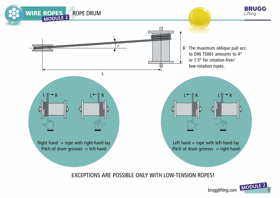
αB
L
L R L R L R L R
WIRE ROPES
MODULE 2
4
The maximum oblique pull acc. to DIN 15061 amounts to 4° or 1.5° for rotation-free/ low-rotation ropes.
EXCEPTIONS ARE POSSIBLE ONLY WITH LOW-TENSION ROPES!
Left hand = rope with left-hand layPitch of drum grooves = right-hand
Right hand = rope with right-hand layPitch of drum grooves = left-hand
ROPE DRUM MODULE 2
brugglifting.com

10
p2 p1
h
r2r1
Rt = 25
p1
2
130°
25°
r2r2
50°
WIRE ROPES
MODULE 2
4Groove/
rope radiusr1
mm
Allowed variation
mm
Groove spacing
p1
mm
Groove depth
h* min.mm
r2** min.mm
Groove width
p2
mm1,6 4 1,2 0,5 32,2 5 1,5 0,5 42,7 6 1,9 0,5 53,2 +0,1 7 2,3 0,5 63,7 8 2,7 0,5 74,2 9,5 3,0 0,5 84,8 10,5 3,5 0,5 95,3 11,5 4 0,8 106 13 4,5 0,8 116,5 14 4,5 0,8 127 15 5 0,8 137,5 16 5,5 0,8 148 17 6 0,8 158,5 18 6 0,8 169 19 6,5 0,8 179,5 20 7 0,8 18
10 21 7,5 0,8 1910,5 +0,2 22 7,5 0,8 2011 24 8 0,8 2112 25 8,5 0,8 2212,5 26 9 0,8 23
Designation of a groove profile for rope drums of groove radius
r1 = 16 and pitch p1 = 33;groove profile DIN 15061 – 16 × 33
rotated
* h ≥ 0,375 p2 due to the rope skip** r2 applies up to h ≤ 0,4 p2
ROPE DRUM MODULE 2

11
p2 p1
h
r2r1
Rt = 25
p1
2
130°
25°
r2r2
50°
p2 p1
h
r2r1
Rt = 25
p1
2
130°
25°
r2r2
50°
WIRE ROPES
MODULE 2
4rotated
Groove/rope radius
r1
mm
Allowed variation
mm
Groove spacing
p1
mm
Groove depth
h* min.mm
r2** min.mm
Groove width
p2
mm13 27 9 0,8 2413,5 28 9,5 0,8 2514 29 10 0,8 2615 30
3110,510,5
0,80,8
2728
16 3334
1111,5
1,31,3
2930
17 3536
1212
1,31,3
3132
18 3738
12,513
1,31,3
3334
19 3940
13,513,5
1,31,3
3536
20 +0,4 414244
1414,515
1,31,61,6
373839
21 44 15 1,6 4022 45 15,5 1,6 4123 47
471616,5
1,61,6
4243
24 4950
16,517
1,62
4445
ROPE DRUMMODULE 2
Designation of a groove profile for rope drums of groove radius
r1 = 16 and pitch p1 = 33;groove profile DIN 15061 – 16 × 33
* h ≥ 0,375 p2
due to the rope skip** r2 applies up to h ≤ 0,4 p2
brugglifting.com

12
WIRE ROPES
MODULE 2
5
90% Pressed loop
90 % Pressed thimbles 90 % Spliced loop. Loops must be secured against untwisting.80% EN 13414-1
85% Loop with thimble
90% Clamp head with thread (inside-outside-thread)
90 % Clamp head with eye
90 % Clamp head with clevis
100 % Cast head with clevis
100 % Cast head with eye
Most end connections reduce the minimum breaking strength of the ropes.
The overview shows some com-mon designs with the remaining minimum breaking strength of the rope in %.
Do not produce rope end connec-tions by knots, as the working load limit of the rope is strongly redu-ced by high surface pressure and kinks.
The strands and wires will be compressed as much that the rope structure is not warranted any longer. Rope suspensions should be set so as to allow the rope to absorb the 2.5-fold tensile force of the rope without a permanent deformation.
90% Spliced thimble. Loops must be secured against untwisting.80% EN 13414-1
ROPE END CONNECTIONS MODULE 2
13
WIRE ROPES
MODULE 2
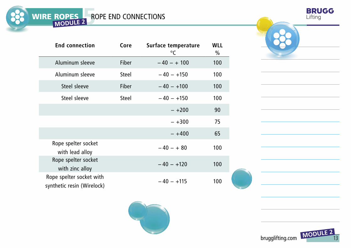
5End connection Core Surface temperature
°CWLL
%
Aluminum sleeve Fiber − 40 − + 100 100
Aluminum sleeve Steel − 40 − +150 100
Steel sleeve Fiber − 40 − +100 100
Steel sleeve Steel − 40 − +150 100
− +200 90
− +300 75
− +400 65
Rope spelter socket
with lead alloy − 40 − + 80 100
Rope spelter socket
with zinc alloy− 40 − +120 100
Rope spelter socket with
synthetic resin (Wirelock)− 40 − +115 100
ROPE END CONNECTIONS MODULE 2
brugglifting.com

14
≤ 30
°
≥1,5-3t t
WIRE ROPES
MODULE 2
5
80% Loop/thimble with stirrup rope clamps acc. to EN 13411-5. Do not use for sling ropes!
Clamp always on loose end
Required number of clamps with loops/thimbles with clamps: EN 13411-5
Refer to the instructions for use!
Rope-ømm
Rope clamps per loop
4,0 – 5,0 3
5,5 – 6,5 3
7,0 – 8,0 4
8,5 – 10,0 4
11,0 – 13,0 4
14,0 – 16,0 4
17,0 – 19,0 4
20,0 – 22,0 5
23,0 – 26,0 5
27,0 – 30,0 6
31,0 – 34,0 6
35,0 – 40,0 6
MODULE 2 ROPE END CONNECTIONS

15
LK
max
. 0,7
5 L K*
max
. 0,4
LK*
EN 13411- 5 (DIN 1142)
WIRE ROPES
MODULE 2
5
* EN 13411-6
LK
80% Rope lock with wedge 80% Rope lock with wedge
DIN 43148
10 % Tensile force of the rope
2,5 · FSeil
Frope Frope
DIN 15315
MODULE 2 ROPE END CONNECTIONS
brugglifting.com

16
EN 13411-5
WIRE ROPES
MODULE 2
5DIN 43148
MODULE 2 ROPE END CONNECTIONS

1
TRAINING MATERIAL
WIRE ROPES MODUL 1
1 HANDLING2 RE-LUBRICATION3 MONITORING / DISCARD CRITERIA4 DETERMINATION OF THE ROPE
MODULE 3
MODULE 3 brugglifting.com
2
WIRE ROPES 1 MODULE 3
MODULE 3
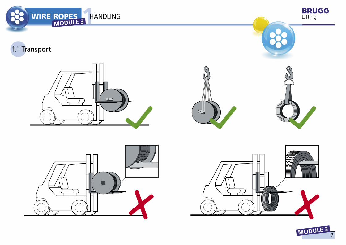
1.1 Transport
1HANDLING

3
WIRE ROPES 1 MODULE 3
MODULE 3
1.2 Storage 1.3 Unwinding
HANDLING
brugglifting.com

4
WIRE ROPES 1 MODULE 3
MODULE 3
HANDLING
1.4 Unwinding 1.5 Drawing in

5
WIRE ROPES
MODULE 3
2RE-LUBRICATION
Guideline for the lubricating interval• Wire ropes in the open air
As needed with dry rope surface
• Protected wire ropes As needed with dry rope surface
Guideline for the lubricant consumption• 0.2 liter of wire rope oil
for rope ø of 10 mm over a rope length of 100 m
• 0.4 liter of wire rope oil for rope ø of 20 mm over a rope length of 100 m
Requirements for the lubricant• Compatible with the
original lubricant
• Resistant against environmental influences (e.g. UV radiation, temperature, oxidation, dust, etc.)
• Fluid, without solvents if possible
• Largely temperature-independent in the viscosity (fluidity)
• Good adherence
• Used oils and greases are not suitable
Reasons for cleaning• Dust, oxidation, UV radiation and temperatures make the lubricant age.• In addition, mechanical
influences result in blank spots on the rope.• The influence of the rope lubrication on the rope service life may be up to factor 10.
Principles of re-lubrication• A lubrication in the open air
requires dry weather.• Every cleaning must be immediately followed by re-lubrication.• Apply the lubricant after the
drive rollers and guide rollers.• Re-lubricate as often as possible,
but sparingly.• Disperse the lubricant on the
entire rope surface.• Wire ropes that come into
contract with gravel, sand and soil must not be lubricated.
MODULE 3
brugglifting.com
6
WIRE ROPES
MODULE 3
3 MODULE 3
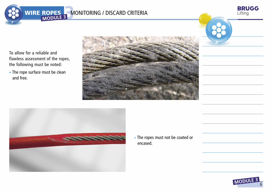
To allow for a reliable and flawless assessment of the ropes, the following must be noted:
• The rope surface must be clean and free.
• The ropes must not be coated or encased.
MONITORING / DISCARD CRITERIA
7
WIRE ROPES
MODULE 3
3
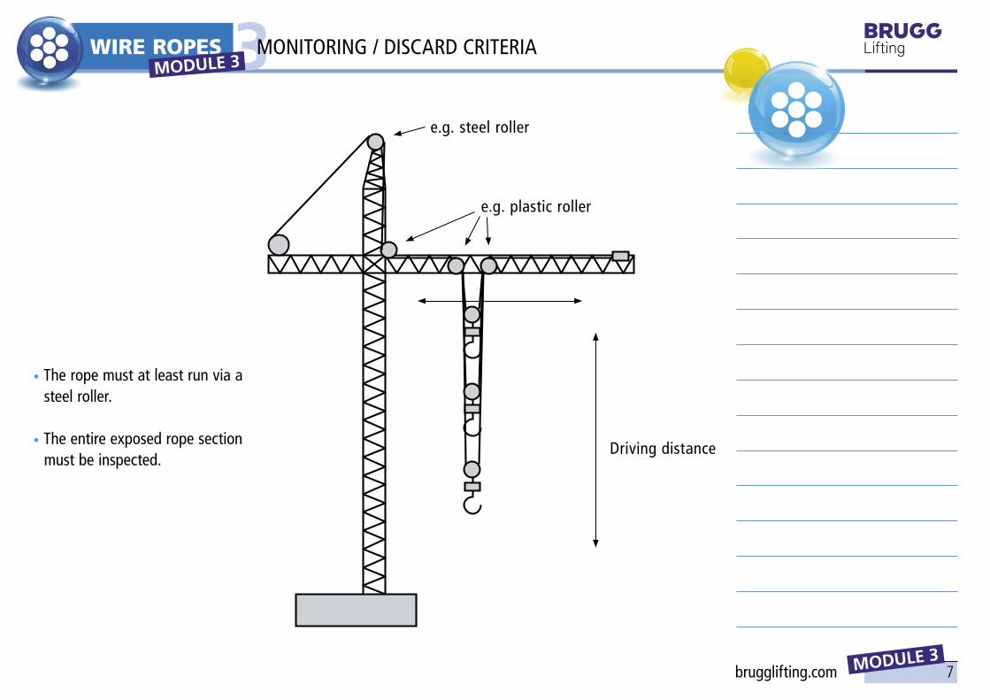
Driving distance
e.g. plastic roller
e.g. steel roller
• The rope must at least run via a steel roller. • The entire exposed rope section must be inspected.
MODULE 3 MONITORING / DISCARD CRITERIA
brugglifting.com
8
WIRE ROPES
MODULE 3
3
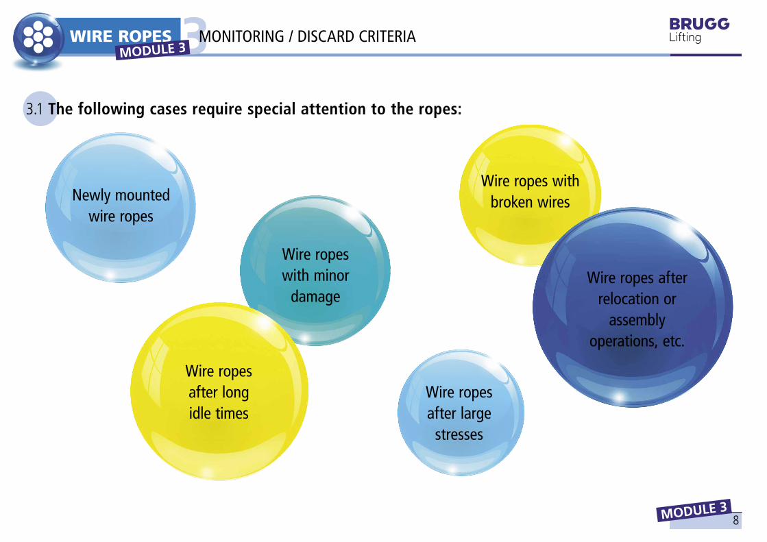
Newly mounted wire ropes
Wire ropes with broken wires
Wire ropes after large
stresses
Wire ropes with minor
damage
Wire ropes after long idle times
Wire ropes after relocation or
assembly operations, etc.
3.1 The following cases require special attention to the ropes:
MODULE 3 MONITORING / DISCARD CRITERIA
9
d
min. 0,9 d
1.
WIRE ROPES
MODULE 3
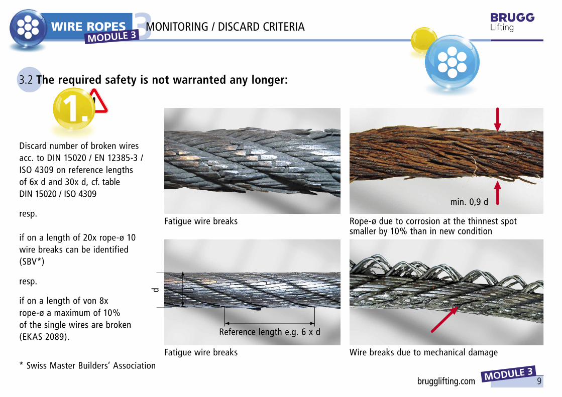
33.2 The required safety is not warranted any longer:
Discard number of broken wires acc. to DIN 15020 / EN 12385-3 / ISO 4309 on reference lengths of 6x d and 30x d, cf. table DIN 15020 / ISO 4309
resp. if on a length of 20x rope-ø 10 wire breaks can be identified (SBV*)
resp.
if on a length of von 8x rope-ø a maximum of 10% of the single wires are broken (EKAS 2089).
Fatigue wire breaks Rope-ø due to corrosion at the thinnest spot smaller by 10% than in new condition
Wire breaks due to mechanical damageFatigue wire breaks
Reference length e.g. 6 x d
* Swiss Master Builders’ Association
MODULE 3 MONITORING / DISCARD CRITERIA
brugglifting.com

10
2. 3. 4.
WIRE ROPES
MODULE 3
3
Wire break nests at ordinary lay round strand rope
Strand break at ordinary lay round strand rope
In case of wire break nests. In case of broken strand or strand just before breaking.
Rope-ø d due to wear at the thinnest spot is smaller by 10% or with multilayer
hoist ropes by 3% or due to structural changes by 15% than in the new
condition.
If the rope-ø d due to corrosion or wear falls below by more than 10% or with multilayer hoist ropes by 3% or due to
structural changes like constriction, flattening, curly deformations and
crushes by more than 15%.
MONITORING / DISCARD CRITERIA MODULE 3
11
5.
WIRE ROPES
MODULE 3
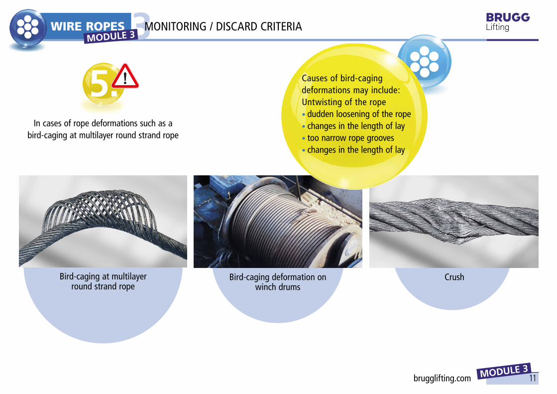
3Causes of bird-caging deformations may include:Untwisting of the rope• dudden loosening of the rope• changes in the length of lay• too narrow rope grooves• changes in the length of lay
Bird-caging deformation on winch drums
Bird-caging at multilayer round strand rope
In cases of rope deformations such as a bird-caging at multilayer round strand rope
Crush
MODULE 3 MONITORING / DISCARD CRITERIA
brugglifting.com

12
6.
WIRE ROPES
MODULE 3
3
A kink is caused by a rope sling being contracted.The sling may result from a torque existing in the rope or from a torque allied externally, e.g. by falsely pulling off the ropes from rings or drums.
Causes of loop formations may include:
• Insufficient lubrication of the rope• Too narrow rope groves• Too large lateral drops of the rope• Too short a distance between two
guide rollers• Untwisting of the rope• Small stroke and large
pulsating load
Loop formation of wires or loose wires
Kinks, bends, knots
MONITORING / DISCARD CRITERIA MODULE 3
13
7.
WIRE ROPES
MODULE 3
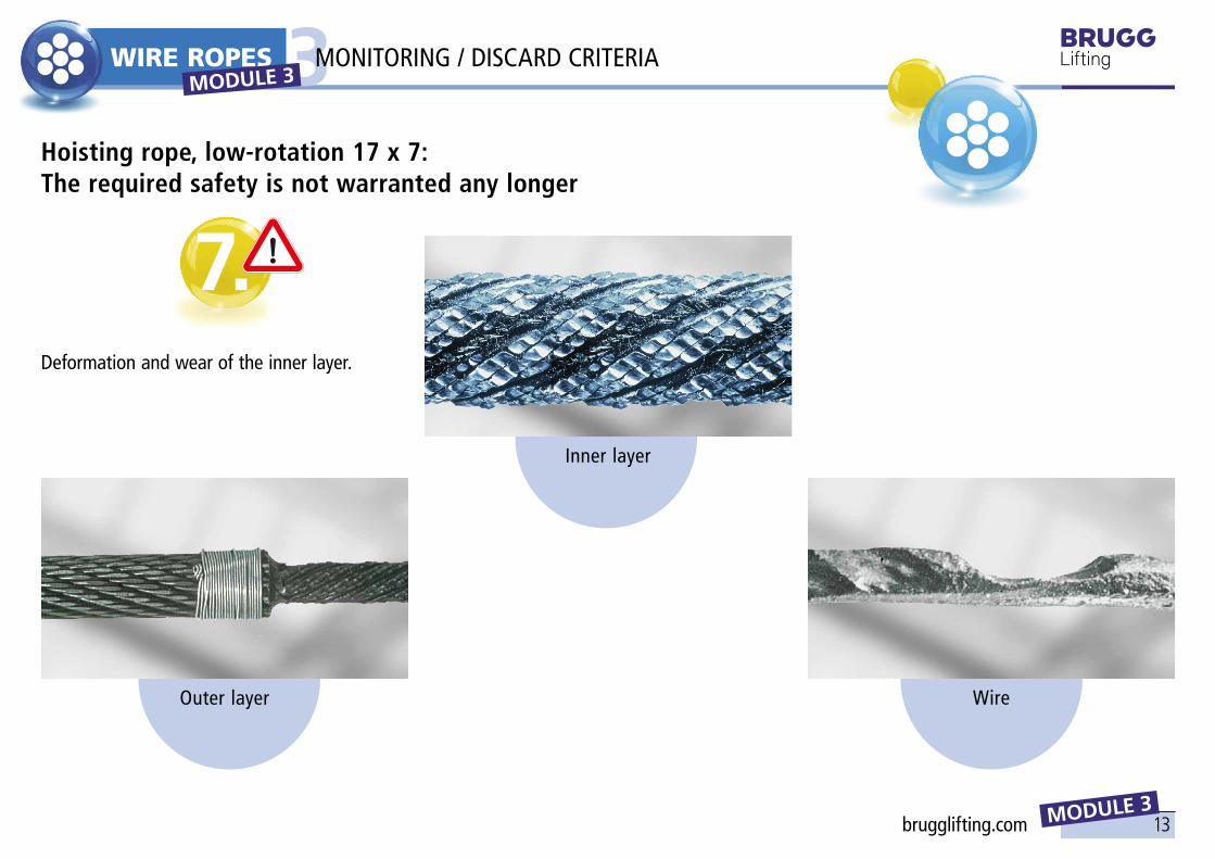
3Hoisting rope, low-rotation 17 x 7: The required safety is not warranted any longer
Outer layer
Inner layer
Wire
Deformation and wear of the inner layer.
MODULE 3 MONITORING / DISCARD CRITERIA
brugglifting.com

14
9524
1641 29
503950 50
70
2100
2740
A
2865
2930
1524
80006900
1118013026
9870788
1
2
3
4
5
6
7
8910
11
12
1314
1 2 3 4 5 6 7 8 91011121314
WIRE ROPES
MODULE 3
44.1 Crawler crane (crawler excavator)
Crawler tracks Centerpiece Counterweight Boom with universal tip Sub-hook block Neck rope: X 53 Luffing ropes: X 53 Upper carriage with rope winches Slewing rings Straightening cylinder A-support Hoisting ropes: C 45 (D 915 CZ), B 55 (D 1315 CZ) Boom foot Driver cab
e.g.: maximum carrying capacity of 450 t at outreach of 5.0 mnet weight of 350 t
DETERMINATION OF THE ROPE MODULE 3

15
13.10 m
16.15 m
3.875 m 6.375 m3.20 m
2.50 m
3.45 m
3.8 m · 3.8 m
24.5 m
0.9 m
2.8 m
28.8 m
R 2.3 m
1.6 m
1
2
WIRE ROPES
MODULE 3
44.2 Rotating tower crane in operating and transporting position
1 Assembly rope: X 53 (PZ 371), DQS/WSS 2 Hoisting rope: Super4, C 45 (D 915 CZ)
Carrying capacities: four-leg rope protection, 3ttwo-leg rope protection, 1,5 t
DETERMINATION OF THE ROPE MODULE 3
brugglifting.com

16
45.0 m
9.6
m9
· 4.1
4 m
4.3
m
4.5 m
5600
4000
2800
1000
15.0 21.0 27.6 33.4 39.2 45.0
1
23
WIRE ROPES
MODULE 3
44.3 Rotating tower crane with carrying capacity curves for different boom lengths
1 Retaining rope: X 53 (PZ 371), DQS/WSS 2 Trolley rope: DQS/WSS 3 Hoisting rope: C 45 (D 915 CZ), B 55 (D 1315 CZ)
Outreach m
Carr
ying
cap
acity
kg
DETERMINATION OF THE ROPE MODULE 3

17
1800 6000 15000 5500 1000
1164
7
8000
1800 1800
2300
9578
8568
38002500200 15000 5000 200
30026700
1
4
23
5 6
4
7
8
9
11
12
1315
4
14
WIRE ROPES
MODULE 3
44.4 Tubular truss portal crane, corridor-controlled, carrying capacity of 16 t
1 Trailing cable 2 Bridge girder 3 Fixed support 4 Crane drive 5 Electric hoist of trolley
6 Hinged support 7 Workplace lamp 8 Cable drum 9 Undercarriage support10 Rail tongs
11 Maintenance platform12 Ballast weight13 Fixed ladder14 Buffer15 Hoisting rope: DQS/WSS, X 53 (PZ 371), X 43 (P 825)
DETERMINATION OF THE ROPE MODULE 3
brugglifting.com

18
1
1
WIRE ROPES
MODULE 3
44.5 Basic constructions of overhead cranes
1 Hoisting rope: DQS/WSS, WSH, X 53 (PZ 371), X 43 (P 825), H 43 (SKZ 8P)
Bottom flange carriage of crane bridge and trolley
DETERMINATION OF THE ROPE MODULE 3
19
165
10
9
11
8
4
3
2
7
WIRE ROPES
MODULE 3
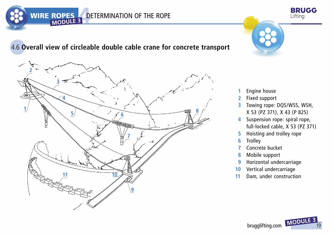
44.6 Overall view of circleable double cable crane for concrete transport
1 Engine house 2 Fixed support 3 Towing rope: DQS/WSS, WSH, X 53 (PZ 371), X 43 (P 825) 4 Suspension rope: spiral rope,
full-locked cable, X 53 (PZ 371) 5 Hoisting and trolley rope 6 Trolley 7 Concrete bucket 8 Mobile support 9 Horizontal undercarriage10 Vertical undercarriage11 Dam, under construction
DETERMINATION OF THE ROPE MODULE 3
brugglifting.com
20
1 2
1 2
3
3
4
4
WIRE ROPES
MODULE 3
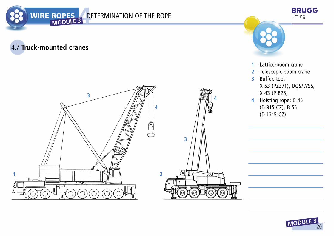
44.7 Truck-mounted cranes
1 Lattice-boom crane 2 Telescopic boom crane 3 Buffer, top:
X 53 (PZ371), DQS/WSS, X 43 (P 825)
4 Hoisting rope: C 45 (D 915 CZ), B 55 (D 1315 CZ)
MODULE 3 DETERMINATION OF THE ROPE

21
max
. 16
000
min. 950min.750
max
. 15
200
ca. 3000
6
4
5
3
21
7
8
9
10
11
121314151617
WIRE ROPES
MODULE 3
4
1 Ceiling rail 2 Guide rollers, top 3 Buffer, top 4 Deflection rope pulley 5 Hoisting rope: WSH, DQS/WSS,
X 43 (P 825), X 53 (PZ 371) 6 Lift truck 7 Pillar 8 Hoist 9 Ladder10 Control cabinet11 Buffer, bottom12 Guide rollers, bottom13 Floor rail14 Impeller15 Drive16 Cross beam17 Telescopic
4.8 Storage and retrieval vehicle, remotely controlled, or automatically driven
DETERMINATION OF THE ROPE MODULE 3
brugglifting.com

22
NOTES

1
HEBEMITTEL
LIFTING GEAR
TRAINING MATERIAL
1 THE BRUGG LIFTING APP2 THE BRUGG LIFTING PRO APP
MODULE 4
MODULE 4 brugglifting.com

2
1.1 The main functions
MODULE 4
1LIFTING GEAR MODULE 4
THE BRUGG LIFTING APP
• Load & WLL/size Calculate whether the selected lif-ting equipment may safely lift the load on hand.
• SlingsDetermine the required working length of the sling or, in case of a predefined working length, the resulting angle of the sling.

3
β
During data entry, the user can retrieve explanatory information via the info buttons.
Sling length and width
Stop angle and sling width
Stop angle and sling length
1.2 Calculation of the sling length and width and of the stop angle
MODULE 4
1LIFTING GEAR MODULE 4
THE BRUGG LIFTING APP
brugglifting.com

4
WLL / øβ
1.3 Calculation of load, WLL and size for rope slings, chain slings & lifting straps
USING THE EXAMPLE OF CHAIN SLINGS
Load calculation WLL and size calculation
F
MODULE 4
1LIFTING GEAR MODULE 4
THE BRUGG LIFTING APP

5
Calibration of the goniometer
General application notes & tips for EN 818, EN 1492 & EN 13414
1.4 Calibration 1.5 Assistance
MODULE 4
1LIFTING GEAR MODULE 4
THE BRUGG LIFTING APP
brugglifting.com

6
2.1 The PRO VERSION
• add images to the application situation
• add the location via GPS
• store and share your calculations in the BRUGG.Cloud or as a PDF document• and view the saved calculations [cannot be modified subsequently] at any time
in addition to the features of the Basis Version, you may:
MODULE 4
2LIFTING GEAR THE BRUGG LIFTING APP PRO MODULE 4

7
NOTES
brugglifting.com

BRUGG Lifting AGWydenstrasse 365242 Birr, Switzerland
T +41 56 464 42 [email protected]
BRUGG Lifting AGChemin de la Forêt 121024 Ecublens, Switzerland
T +41 (0)21 634 20 [email protected]
brugglifting.com