Development of an Integrated Toggle Jack for Lifting ... - Iiste.org
Upload
khangminh22Category
view
2download
0
Catalogue No. 3
Lifting experience.

2
Yale is the leading brand for standard manual hoisting equipment in Europe. As early as 1877, Yale produced the first spur-geared hand chain hoist incorporating the Weston screw-and-disc type load brake – a design principle which is still used today. In 1936, hoist manu-facture started in Velbert with the production of the world renowned PUL-LIFT®.
The product range as well as all new and further develop-ments of Yale in the individual product sectors constantly raise the benchmark for quality, reliability and safety.
The comprehensive range of products includes hoists, cranes, load hoisting tackles and crane weighers, balancers, textile lifting and lashing equipment, material handling equipment and load moving systems, hydraulic tools, bolting technology as well as workshop equipment.
The prominently yellow products, which are delivered ready for operation, are used world-wide for the most varied industrial and commercial applications.
www.yale.de
Pfaff-silberblau – the name of this company with its long-standing tradition and history of more than 140 years has become the synonym for power, dynamics and safety.
Material handling equipment as well as rope winches and rack and pinion jacks of the Pfaff-silberblau brand are used wherever high loads need to be lifted, turned or moved in an environment with demanding safety require-ments.
In logistics, industrial production or outdoor applications, the innovative products and application-specific designs provide the solution to numerous lifting applications – as standard products, tailor made solutions or as complete systems.
www.pfaff-silberblau.de

3
The brand Yale has already been a successful partner within the international corporate network of Columbus McKinnon Corporation for more than ten years. Since 2008, the brand Pfaff-silberblau has extended the portfolio of products and services of the company.
Today, the two trademarks of Yale and Pfaff-silberblau are combined under the name of Columbus McKinnon. This enables us to offer a comprehensive product pallet for many challenging applications.
Experience, know-how and innovative strength combined with a far-reaching understanding of user requirements is the formula for success on which our portfolio of hoisting and material handling equipment products has been based for a long time.
Our tradition of close customer relationships and customer services as well as our constant striving for optimisation provide the basis for all new and further developments of the Yale and Pfaff-silberblau brands.
As a premium supplier of two leading brands, we have set ourselves the target of offering our customers high-quality hoisting and material handling equipment that is designed for moving, lifting, positioning and securing heavy loads both ergonomically and safely.
Columbus McKinnon Corporation is the World Leader for products and application know-how that supports custom-ers with lifting, moving and positioning of loads. The company group is the leading manufacturer and supplier of products and service in the area of materials handling, cranes and rigging attachments. With its 140 year tradition, the company concentrates on commercial and industrial application, by which safety and security are always at the forefront.
Columbus McKinnon CorporationCorporate Headquarters 140 John James Audubon Parkway Amherst, New York 14228-1197 www.cmworks.com

Electric Chain Hoist
Model CPV/FCapacity 250 kg - 2.000 kg
Translated Operating- and Maintenance Manual
Columbus McKinnon Industrial Products GmbHPostfach 10 13 24 • D-42513 Velbert, Germany
Am Lindenkamp 31 • D-42549 Velbert, Germany
+49 20 51/600-0 • Fax +49 20 51/600-127
Ident.-No.: 09901076/08.2011 WLL 500-20.000kg
StirnradflaschenzugHandchainhoistPalansàmain
Original Betriebsanleitung(Gilt auch für Sonderausführungen)
Translated Operating Instructions(Also applicable for special versions)
Traduction de mode d’emploi(Cela s’applique aussi aux autres versions)
DE
EN
FR
COLUMBUS McKINNON Industrial Products GmbHP. O. Box 11 01 53 • D-42301 Wuppertal, GermanyYale-Allee 30 • D-42329 Wuppertal, GermanyPhone +49 (0) 202/6 93 59-0 • Fax + 49 (0) 202 / 6 93 59-127
Ident.-No.: 09901068/07.2013
4
Industrial Products GmbH
TrainingWe know what we are doing - As a manufacturer, we have decades of experience in inspecting and repairing prod-ucts for the area of lifting technology. We are happy to share this knowledge with our clients and offer seminars at our training centre in Wuppertal.
The centres offer not only product training but also seminars providing up-to-date insider information and a consolidated knowledge in the usage of rope, lifting and lashing practices.
Modern communication technologies, hands-on experi-ence and well designed training documentation guarantee a quick and lasting training success.
• to become a “competent person“ for the inspection of Yale and Pfaff-silberblau hoisting equipment according DGUV Vorschrift 54 (BGV D8)
• to become a competent person to annually inspect PPE height safety equipment according to the German DGUV Grundsatz 312-906 and EN 365
• carry out annual high rescue training and instruction in correctly using PPE equipment of fall and rescue systems
Certified securityYou are in safe hands - Every unit is supplied with operating instructions, CE declaration of conformity resp. manufactures works test certificate, which confirms the perfect tested status of the product. Additional documentation, e.g. spare parts manuals or maintenance and repair instructions are available on request or at our homepage.
www.yale.de
INFO
As required all training seminars can also be held at other locations.
5
EN ISO 9001Columbus McKinnon Industrial Products GmbH manufac-tures world wide according to uniform, controlled standards of EN ISO 9001. This is a guarantee for our business partners that given standards in design and development, manufacturing, assembly and service are complied with.
Special documentationAdditional inspections with test report 2.2 resp. inspection certificate 3.1.B according to EN 10204, GOST R certifi-cates or specific pre-shipment inspections e.g. by DNV or GL can be carried out at cost on request.
Offering adviceOur qualified personnel are there for you around the globe at all our locations, as well as specialised dealers who provide competent know-how and service.
Business hours:Monday - Thursday 08:00 a.m. - 04:30 p.m.Friday 08:00 a.m. - 03:30 p.m.
Shipping:
Monday - Thursday 06:30 a.m. - 04:30 p.m.Friday 06:30 a.m. - 03:00 p.m.
Certified since November 1991

HOISTING EQUIPMENT TIGRIP® TEXTILE LIFTING SLINGS MATERIAL HANDLING EQUIPMENT
ATEX
6
Industrial Products GmbH
Hoisting EquipmentRatchet lever hoistsHand chain hoistsCorrosion protectionTrolleys & Trolley clampsElectric & Pneumatic chain hoistsChains & AccessoriesManual winchesCable puller & AccessoriesElectric & Pneumatic winchesRack & Pinion jacks
Crane SystemsWall-mounted jib cranesFloor-mounted jib cranesMoveable gantry cranesLight crane systems
Power supply
Tigrip® Load Hoisting TackleGrabs & ClampsPermanent load lifting magnetsLifting lugs & C-hooksBarrel grabs & Crate grabsLoad hoisting tackle forunderground constructionClamps & Tine hooksSpreader beamsCrane forks
Tigrip® Crane WeighersCrane weighersLoad indicator
Spring Balancers
Spring tensionersSpring balancers
Textile Lifting SlingsRound slingsRound sling assemblyWebbing slings
Lashing SystemsLashingsSpecial lashings
Material Handling EquipmentHand pallet trucksHand pallet trucks with weighing systemScissor pallet trucksPallet lift trucksManual drive stackersElectric pedestrian stackersElevating platforms
Load Moving Systems
Information about explosion protection can be found on pages 428 - 441.
ATEXPneumatic chain hoistsHand chain hoistsTrolleysElectric winchesSheave blocks for rope guidanceManual winchesRack & Pinion jacksRatchet lever hoistsHand pallet trucksLoad moving systems

HYDRAULIC JACKS & TOOLS WORKSHOP EQUIPMENT
7
Hydraulic Jacks & ToolsHydraulic cylinders, single-actingHydraulic cylinders, double-actingHand pumps 700 barHand pumps up to 2000 barFoot pump 700 barElectric & Pneumatic motor-pumpsElectric hydraulic power packsHydraulic valves & AccessoriesHydraulic puller & JacksHydraulic jacks & toolsTest rig for hoisting equipmentWorkshop presses
Workshop EquipmentJacksWorkshop pressesService jacksSupporting standRepair setsWorkshop cranes
Table of contents
Page
Hoisting Equipment 8 - 125Crane Systems & Power supply 126 - 141
Tigrip®
Load Hoisting Tackle 142 - 211Crane Weighers 212 - 217
Spring Balancers 218 - 225
Textile Lifting Slings 226 - 245Lashing Systems 246 - 263
Material Handling Equipment 264 - 315Load Moving Systems 316 - 321
Hydraulic Jacks & Tools 322 - 411
Workshop Equipment 412 - 425
ATEX 426 - 471
Returns 473
INFO
Please note our user instructions at the beginning ofeach chapter.

8
Hoisting Equipment Table of contents
Page Ratchet lever hoists 14 - 21
Hand chain hoists 22 - 35
Corrosion protection 36
Trolleys & Trolley clamps 35, 37 - 43
Electric & Pneumatic chain hoists 48 - 65
Chains & Accessories 66 - 68
Manual winches 69 - 79
Cable puller & Accessories 80 - 87
Electric & Pneumatic winches 91 - 107
Rack & Pinion jacks 108 - 123
Crane Systems 128 - 139
Power supply 140 - 141
INFO
Please note our user instructions at the beginning of each chapter.
Yale and Pfaff-silberblau hoisting equipment products are reliable and proven equipment renowned world-wide for applications in industry, trade and services. The comprehensive range includes manual and powered hoisting equipment for a safe lifting and handling of loads ranging from 125 kg to 20000 kg. The products feature a long service life as well as easy and quick maintenance or repair. Yale and Pfaff-silberblau hoisting equipment products comply with national and international regulations such as the EC Machinery Directive 2006/42/EC and corresponding supplements. In order to meet our high quality standard, the devices are subjected to an overload test in the factory and provided with a test certificate and operating instructions with a declaration of conformity or a manufacturer’s declaration.

9
HOISTING EQUIPMENT
10
Hoisting Equipment User information
This user information presents a general review regarding the operation of hoisting equipment and does not substitute the existing operating instruc-tions for the specific hoist product.
Lifting operations with hoisting equipment may be carried out by competent users (trained in theory and practice) only. When operated correctly, our hoist products will offer the highest degree of safety in line with long life expectancy and avoid damage to the product and people.
Modification of delivery conditionDesign and construction of the hoist may not be altered, e.g. by installation of outside supplied parts, bending, welding, grinding, removal of safety relevant components like locking devices, locking pins, safety latches etc.
Limitations of operationLoadingOur hoists have been designed for lifting and transporting of loads. Some models (e.g. ratchet lever hoists) may also be used for pulling and lashing purposes, if admitted in the operating instructions. The indicated capacities refer to loading in straight line and must not be exceeded. Lifting media (e.g. lifting chain or rope) must not be slung over edges and must not be used for the attachment of the load.
TemperatureHoists may normally be operated at ambient tempera-tures between -10 °C up to + 50 °C.
These values are approximate and may deviate from the specific givings of the hoist product. The accurate data are given in the current operating instructions. Special models are available on request for higher or lower temperature ranges.
Attention: At temperatures below 0 °C the brake should be checked for freezing. (Check lifting function prior to starting work and refer to “Inspection prior to initial opera-tion“).
Shock loadingThe indicated capacities are based on shock-free loading of the hoist. Light bumps as occurred during lifting and lowering as well as transporting of load are admitted. Heavier shock loadings, e.g. falling of the load, are strictly forbidden.
ChemicalsHoists and attachments may not be operated without hesitation in the area of chemicals or chemical vapours – consult our specialists for advice. Hoists which have been subject to chemicals or vapours must be taken out of service and inspected by us.
Transport of peopleTransport of people with hoisting equipment is generally forbidden! Transport of people may only by carried out with specially authorized products (e.g. Yaletrac, Mtrac).
Operation in danger zonesLifting or transport of loads must be avoided while personnel are in the danger zone. People are not allowed to pass over or under a suspended load.
Electrical hazards Load carrying hoist components (e.g. load chain) must not be subject to electric current and must never be used as a ground connection during welding. Further electrical hazards, e.g. with powered hoists, are indicated in the specific operating instructions!Electric connections may only be performed by authorized persons resp. companies.
INFO
INFO
For information on training please see page 4.

11
• Before lifting make sure that the load can move freely.
• After lifting or tensioning, a load must not be left unat-tended for a longer period of time.
• Chain stops, slipping clutches etc. are overload protec-tion devices and may not be used as regular load limiters.
• Do not throw the hoist down. Always place it properly on the ground.
Labelling (Example)
Rated capacity
Grade and dimension of load chain
Manufacturer or supplier
Year of manufacture
Serial or model number
Lifting height (not mandatory)
Hoisting Equipment User information
INFO
Application advices• Hoists must always be in perfect condition and pro-
vided with a legible identity plate.
• Prior to starting work, the hoist including load carrying devices, equipment, supporting structure and suspen-sion must be inspected for obvious deficiencies and failures. In addition, the function of the brake and the correct attachment of hoist and load have to be checked by carrying out a short work cycle of lifting/pulling or tensioning and releasing.
• Inspect the load chain for sufficient lubrication and visually check for external defects, deformations, super-ficial cracks, wear or corrosion marks. A defective chain must be replaced prior to operation of the hoist.
• Units equipped with two chain falls should be inspected for twisted or kinked chains prior to being put into operation. The chains of multiple fall hoists may be twisted if the bottom block was turned over.
• Inspect top and bottom hooks for deformations, damage, cracks, wear or corrosion marks. A safety latch must be available and work effectively.
• Hoists with obvious defects and units which have been subject to overload or other dangerous influences have to be taken out of service and may only be operated after test and repair if so required.
• When selecting the proper product, make sure that the hoist is suitable to accept transportation, suspension, type of lashing devices and lashing points safely and without unintended movement (e.g. slipping).
• Load chains must not be used in kinked or knotted condition.
• The load must always be seated in the saddle of the hook. Never attach the load on the tip of the hook. This applies to top and bottom hooks.
• The operator must ensure that the load is attached in a manner that does not expose himself or other person-nel to danger by the hoist, chain(s) or the load.
• During lifting operations the load and suspension hook of the hoist must be perpendicular to the load center to prevent pendle motion of the load.
• The operator may start moving the load only after it has been attached correctly and all personnel are off the danger zone.

12
Hoisting Equipment User information

13
Hoisting Equipment User information
INFO
Maintenance and repair• To ensure safe operation, all hoisting equipment must
be subjected to regular inspections according to the maintenance instructions given by the manufacturer.
• Hoists which are due for maintenance (normally once per year, unless adverse working conditions dictate shorter periods) or products with obvious defects may be returned to us for inspection and repair.
• Inspections and tests must be performed by competent persons or specialist workshops that use original spare parts.
Inspections• According to German laws and standards all hoist-
ing equipment must be subjected to a mandatory inspection at least once a year. The inspection must be performed by a competent person.
• On building sites hoists have to be inspected every time before operation.
• Hoist and supporting components have to be cleaned prior to inspection. The cleaning procedure must not cause chemical damages (e.g. no acid-embrittlement). Do not expose the hoist and supporting components to unallowed temperatures by e.g. flame cleaning avoid concealment of cracks and excessive material loss (sand blasting). We shall be pleased to consult you in this respect. Please submit your hoists for inspection in clean condi-tion. This will reduce inspection costs considerably.
Criteria for hoist disposalHoists must no longer be operated if e.g.:
• The identification (identity plate) is missing or illegible.
• Security relevant components like brake, slipping clutch, ratchet pawls etc. do not properly function any longer.
• Housing, control units and suspension of the hoist present obvious deficiencies, i.e. - cuts, grooves, cracks - excessive corrosion - staining due to heat - signs of subsequent welding resp. spatters which cannot be easily removed and leave stains.
• Ropes show breakage of wires resp. bruises (criteria for disposal of ropes are given in classification DIN 15020), damages to the rope sleeve and similar failures.
• The load chain presents twisted or distorted links or shows an elongation of 5 % of one chain link or a reduc-tion in diameter of more than 10 % (average of two measurings (longitudinal and transverse) compared to the nominal diameter).
• The opening (C) of suspension and/or load hooks is stretched by more than 10 % compared with the nominal dimension, or if the hook mouth shows a wear of more than 5 % of either dimension B or D.
• Detrimental impacts by e.g. overloading, shock loading, chemical influences or heat have occurred, the hoist may only be returned to service after careful inspection and repair.

14
Hoisting Equipment Ratchet lever hoists
Ratchet lever hoist with roller chain model C 85Capacity 750 - 10000 kg
Ratchet lever hoist with link chain model D 85Capacity 750 - 10000 kgAlmost unlimited applications in maintenance, mining, construction, steel fabrication, shipbuilding and utility work. Ideal for moving and positioning heavy machines and securing heavy loads, simplifies setting pipes etc. in manholes and trenches.
Features• Enclosed housing with housing cover, handlever and
bottom block made from high tensile white malleable cast iron for overall rugged construction.
• The graphite cast iron load sheave for the link chain has precision machined chain pockets for accurate fit and durability of the load chain.
• The roller chain sprocket is made from heat treated chromium-molybdenum steel with precision machined teeth to ensure smooth chain movement.
• Alloyed steel link chain with zinc-plated resp. yellow chromated finish, in accordance with national and international standards and regulations.
Options• All models can be equipped with an overload protection
device in the form of a slip clutch which is factory preset to approx. 25 % ± 15 % overload.
• Free chaining device to quickly attach the load or to pull the chain through the hoist in both directions.
• Hoist with sling chain.
INFO
Since 1936 more than 1 million units have been built in Velbert.
All ratchet lever hoists with a capacity exceeding 750 kg can be used for load attachment according to EN 12195.
Yale hoists and trolleys are not designed for passenger elevation applications and must not be used for this purpose.

15
Hoisting Equipment Ratchet lever hoists
Technical data model C 85
Model EAN-No. 4025092*
Capacity
kg
Number of chain falls
Chain dimensions
d x pInch
Lift with one full lever turn
mm
Handle pull at WLL
daN
Weight at standard lift
(1.5 m)kg
PUL-LIFT C 85 750 *050173 750 1 5/8" x 3/8" 115 38 8.7PUL-LIFT C 85 1500 *050180 1500 1 1" x 1/2" 45 31 17.0PUL-LIFT C 85 3000 *050197 3000 1 1 1/4" x 5/8" 36 40 22.2PUL-LIFT C 85 6000 *050203 6000 2 1 1/4" x 5/8" 18 44 38.0PUL-LIFT C 85 10000 *050326 10000 3 1 1/4" x 5/8" 12 44 67.0
Dimensions model C 85
Model PUL-LIFT C 85 750
PUL-LIFT C 85 1500
PUL-LIFT C 85 3000
PUL-LIFT C 85 6000
PUL-LIFT C 85 10000
A min., mm 322 389 403 560 785B, mm 21 27 35 48 61C, mm 27 30 34 46 54D, mm 15 20 25 40 40D1, mm 17 23 25 40 45E, mm 443 443 570 570 570F, mm 112 189 197 197 305G, mm 56 134 142 142 163H, mm 56 55 55 55 142J, mm 142 171 179 218 218K, mm 39 72 76 76 76L, mm 103 99 103 142 142
Dimensions model D 85
Model PUL-LIFT D 85 750
PUL-LIFT D 85 1500
PUL-LIFT D 85 3000
PUL-LIFT D 85 6000
PUL-LIFT D 85 10000
A min., mm 322 389 403 532 805B, mm 21 27 35 48 61C, mm 27 30 34 46 54D, mm 15 20 25 40 40D1, mm 17 23 25 40 45E, mm 443 443 570 570 570F, mm 112 189 197 197 305G, mm 56 134 142 142 163H, mm 56 55 55 55 142J, mm 142 171 179 218 218K, mm 39 72 76 76 76L, mm 103 99 103 142 142
Technical data model D 85
Model EAN-No. 4025092*
Capacity
kg
Number of chain falls
Chain dimensions
d x pmm
Lift with one full lever turn
mm
Handle pull at WLL
daN
Weight at standard lift
(1.5 m)kg
PUL-LIFT D 85 750 *050548 750 1 6 x 18.5 111 38 8.2PUL-LIFT D 85 1500 *050555 1500 1 9 x 27 45 31 16.3PUL-LIFT D 85 3000 *050562 3000 1 11 x 31 33 40 19.6PUL-LIFT D 85 6000 *050579 6000 2 11 x 31 17 42 32.9PUL-LIFT D 85 10000 *050784 10000 3 11 x 31 11 37 60.0
F
G H
C
BB
A
E
C
J
LK
D
D
D1
D1
Option:
Overload protection for C/D 85.

16
Hoisting Equipment Ratchet lever hoists
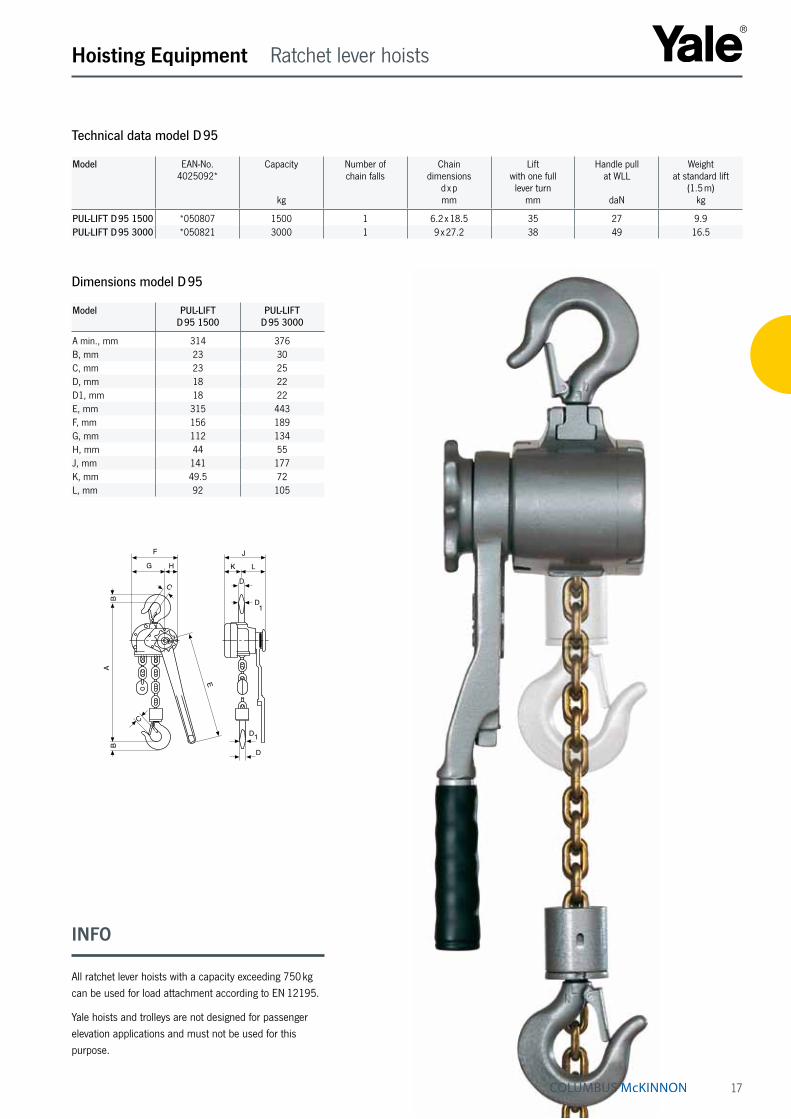
Ratchet lever hoist with link chain model D 95Capacity 1500 - 3000 kgThe D 95 in its cast malleable iron design has taken key technical features from the proven D 85 but excels due to low tare weight and an extremely small measurement between suspension and load hooks. A versatile unit for moving, positioning and securing loads.
Features• Enclosed housing with housing cover, handlever and
bottom block made from high tensile malleable cast iron for overall rugged construction.
• The short handlever is fitted with an ergonomic rubber grip.
• It has an automatically acting load pressure brake which works on the self-locking principal. For example, when used to secure loads an uninten-tional loosening of the brake is prevented when the load vibrates.
• Standard free chaining device to quickly attach the load or to pull the chain through the hoist in both directions.
• Alloyed steel link chain with zinc-plated resp. yellow chromated finish, in accordance with national and international standards and regulations.
Options• All models can be equipped with an overload protection
device in the form of a slip clutch which is factory preset to approx. 25 % ± 15 % overload.
• Hoist with sling chain.
Hoist with sling chain
17
Hoisting Equipment Ratchet lever hoists
Technical data model D 95
Model EAN-No. 4025092*
Capacity
kg
Number of chain falls
Chain dimensions
d x pmm
Lift with one full lever turn
mm
Handle pull at WLL
daN
Weight at standard lift
(1.5 m)kg
PUL-LIFT D 95 1500 *050807 1500 1 6.2 x 18.5 35 27 9.9PUL-LIFT D 95 3000 *050821 3000 1 9 x 27.2 38 49 16.5
Dimensions model D 95
Model PUL-LIFT D 95 1500
PUL-LIFT D 95 3000
A min., mm 314 376B, mm 23 30C, mm 23 25D, mm 18 22D1, mm 18 22E, mm 315 443F, mm 156 189G, mm 112 134H, mm 44 55J, mm 141 177K, mm 49.5 72L, mm 92 105
F
G H
C
BB
A
E
C
J
LK
D
D
D1
D1
INFO
All ratchet lever hoists with a capacity exceeding 750 kg can be used for load attachment according to EN 12195.
Yale hoists and trolleys are not designed for passenger elevation applications and must not be used for this purpose.
18
Hoisting Equipment Ratchet lever hoists
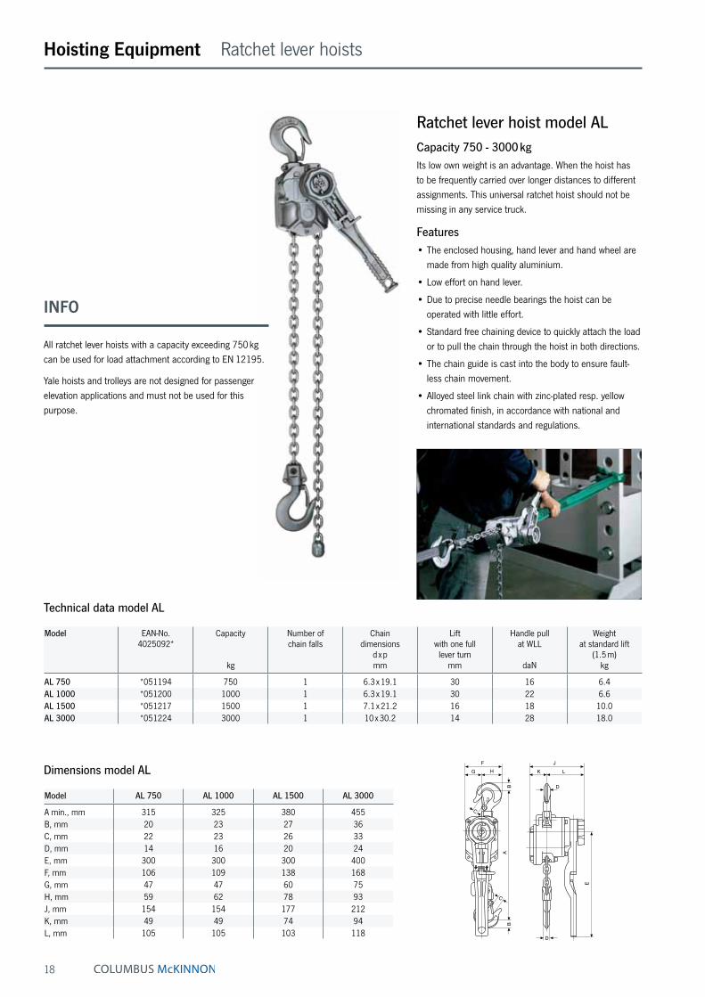
Ratchet lever hoist model ALCapacity 750 - 3000 kgIts low own weight is an advantage. When the hoist has to be frequently carried over longer distances to different assignments. This universal ratchet hoist should not be missing in any service truck.
Features• The enclosed housing, hand lever and hand wheel are
made from high quality aluminium.
• Low effort on hand lever.
• Due to precise needle bearings the hoist can be operated with little effort.
• Standard free chaining device to quickly attach the load or to pull the chain through the hoist in both directions.
• The chain guide is cast into the body to ensure fault-less chain movement.
• Alloyed steel link chain with zinc-plated resp. yellow chromated finish, in accordance with national and international standards and regulations.
Technical data model AL
Model EAN-No. 4025092*
Capacity
kg
Number of chain falls
Chain dimensions
d x pmm
Lift with one full lever turn
mm
Handle pull at WLL
daN
Weight at standard lift
(1.5 m)kg
AL 750 *051194 750 1 6.3 x 19.1 30 16 6.4AL 1000 *051200 1000 1 6.3 x 19.1 30 22 6.6AL 1500 *051217 1500 1 7.1 x 21.2 16 18 10.0AL 3000 *051224 3000 1 10 x 30.2 14 28 18.0
Model AL 750 AL 1000 AL 1500 AL 3000
A min., mm 315 325 380 455B, mm 20 23 27 36C, mm 22 23 26 33D, mm 14 16 20 24E, mm 300 300 300 400F, mm 106 109 138 168G, mm 47 47 60 75H, mm 59 62 78 93J, mm 154 154 177 212K, mm 49 49 74 94L, mm 105 105 103 118
Dimensions model ALF
G H
B
C
A
C
B
JK L
D
E
D
INFO
All ratchet lever hoists with a capacity exceeding 750 kg can be used for load attachment according to EN 12195.
Yale hoists and trolleys are not designed for passenger elevation applications and must not be used for this purpose.

19
Hoisting Equipment Ratchet lever hoists
Ratchet lever hoist model PTCapacity 800 - 6300 kgRatchet lever hoists model PT features improved tech-niques and ergonomical styling. The advantages of the predecessor range have been maintained and further optimized. A good, versatile, all round ratchet lever hoist for demand-ing conditions.
Features• The proven stamped steel housing provides extremely
low weight without limiting the reliability and sturdiness of the unit.
• The short handlever is fitted with an ergonomic rubber grip.
• Standard free chaining device to quickly attach the load or to pull the chain through the hoist in both directions.
• Alloyed steel link chain with zinc-plated resp. yellow chromated finish, in accordance with national and international standards and regulations.
• Drop forged suspension and load hooks are made from non-aging, high tensile steel and fitted with robust safety latches.
Option• All models can be equipped with an overload protection
device in the form of a slip clutch which is factory preset to approx. 25 % ± 15 % overload. Option:
Overload protection device
Technical data model PT
Model EAN-No. 4025092*
Capacity
kg
Number of chain falls
Chain dimensions
d x pmm
Lift with one full lever turn
mm
Handle pull at WLL
daN
Weight at standard lift
(1.5 m)kg
PT 800 *076463 800 1 5.6 x 17.1 24 26 5.5PT 1600 *076470 1600 1 7.1 x 21.2 23 30 9.6PT 3200 *076487 3200 1 9 x 27.2 16 38 16.0PT 6300 *076494 6300 2 9 x 27.2 8 39 31.0
Model PT 800 PT 1600 PT 3200 PT 6300
A min., mm 290 330 430 580B, mm 21 27 36 53C, mm 24 31 35 46D, mm 13 20 24 43E, mm 235 370 370 370F, mm 120 138 177 259G, mm 38 41 53 85H, mm 82 97 124 174J, mm 142 163 185 185K, mm 52 65 83 83L, mm 90 98 102 102
Dimensions model PT
N
D
D
L K
JF
G H
BB
E
A
C
C
INFO
All ratchet lever hoists with a capacity exceeding 750 kg can be used for load attachment according to EN 12195.
Yale hoists and trolleys are not designed for passenger elevation applications and must not be used for this purpose.

20
Hoisting Equipment Ratchet lever hoists
Technical data model UNOplus
Model EAN-No. 4025092*
Capacity
kg
Number of chain falls
Chain dimensions
d x pmm
Lift with one full lever turn
mm
Handle pull at WLL
daN
Weight at standard lift
(1.5 m)kg
UNOplus 750 *168342 750 1 6 x 18 20 20 7.2UNOplus 1500 *168359 1500 1 8 x 24 22 35 12.5UNOplus 3000 *168366 3000 1 10 x 30 17 40 21.5UNOplus 6000 *168380 6000 2 10 x 30 9 40 32.0
Model UNOplus 750 UNOplus 1500 UNOplus 3000 UNOplus 6000
A min., mm 340 410 510 690B, mm 22 28 36 45C, mm 26 32 40 44D, mm 16 21 27 33E, mm 250 330 380 380F, mm 150 170 220 220G, mm 70 80 100 100H, mm 80 90 120 120J, mm 150 180 210 210K, mm 60 80 90 90L, mm 90 100 120 120
Dimensions model UNOplus
Ratchet lever hoist model UNOplusCapacity 750 - 6000 kgFurther technical development turns the ratchet lever hoist into the successor of our proven UNO model. The versatile tool for lifting, pulling and securing of loads is characterised by its compact design and robust stamped steel construction.
Features• Due to optimized gearing and improved bearings in the
housing cover a minimum effort is required to operate the short hand lever.
• Steel hand wheel as standard.
• Automatic screw-and-disc type load brake with corro-sion protected components.
• Standard free chaining device to quickly attach the load or to pull the chain through the hoist in both directions.
• Robust chain guide rollers eliminate fouling and jam-ming of chain on the load sheave.
• Sturdy bottom block with encapsulated bolt connections
• Alloyed steel link chain with zinc-plated resp. yellow chromated finish, in accordance with national and international standards and regulations.
• Drop forged suspension and load hooks are made from non-aging, high tensile steel and fitted with robust safety latches.
INFO
All ratchet lever hoists with a capacity exceeding 750 kg can be used for load attachment according to EN 12195.
Yale hoists and trolleys are not designed for passenger elevation applications and must not be used for this purpose.
Available in explosion proof version (please see page 463).

21
Hoisting Equipment Ratchet lever hoists
Ratchet lever hoist model YalehandyCapacity 250 - 500 kgThe extreme low own weight and the very compact design make the hoist easy to use even in confined working conditions. Due to the multitude of application possibili-ties e.g. in industry, trade and service this ratchet lever hoist is indispensable.
Features• The enclosed design protects the internal parts from
contamination.
• The short handlever is fitted with an ergonomic rubber grip.
• All parts of the disc type load brake are manufactured from high quality materials and are corrosion protected.
• Standard free chaining device to quickly attach the load or to pull the chain through the hoist in both directions.
• Alloyed steel link chain with zinc-plated resp. yellow chromated finish, in accordance with national and international standards and regulations.
• Drop forged suspension and load hooks are made from non-aging, high tensile steel and fitted with robust safety latches.
Technical data model Yalehandy
Model EAN-No. 4025092*
Capacity
kg
Number of chain falls
Chain dimensions
d x pmm
Lift with one full lever turn
mm
Handle pull at WLL
daN
Weight at standard lift
(1.5 m)kg
Yalehandy 250 *075039 250 1 4 x 12 80 25 2.2Yalehandy 500 *077675 500 1 4 x 12 40 25 2.8
Model Yalehandy 250 Yalehandy 500
A min., mm 240 282B, mm 20 17C, mm 21 24D, mm 14 12E, mm 160 160F, mm 72 104G, mm 33 38H, mm 39 66J, mm 98 116K, mm 21 36L, mm 77 80
Dimensions model Yalehandy
INFO
Yale hoists and trolleys are not designed for passenger elevation applications and must not be used for this purpose.

22
Hoisting Equipment Hand chain hoists
Hand chain hoist model Yalelift 360Capacity 500 - 20000 kgAreas of operation as well as operator conditions have been improved far beyond those of a classical hand chain hoist.
Features• The enclosed robust stamped steel housing protects all
internal components even in the toughest conditions.
• The extremely low headroom allows maximum use of the lifting height.
• The revolutionary 360° rotating hand chain guide allows the operator to work from virtually any position, in confined spaces or above the load. The Yalelift can even be operated from the side of the load which also makes it possible to use the hoist for horizontal pulling or tensioning. Due to the additional flexibility, the opera-tor is no longer forced to work in the danger zone near the load.
• The brake system is extremely quiet and guarantees operational safety and improved serviceability due to omission of the vulnerable ratchet pawls. All parts are made of high quality materials, additionally zinc-plated or yellow-chromated to increase corrosion prevention.
• Chain guide and gearbox are almost totally enclosed. Even under the toughest conditions the internal gear-box remains protected.
• The hardened load sheave with four precision ma-chined pockets ensures accurate movement of the load chain.
• The surface protected zinc-plated alloy steel load chains fulfil all requirements of current national and international standards and regulations.
• Drop forged load and suspension hooks that yield under overload instead of breaking, are made of high tensile steel. The hooks are fitted with robust safety latches and rotate 360°.
Options• Adjustable overload protection device.
• Chain container
• Corrosion resistant version
Chain guide High quality encapsulated ball bearings and sliding bushes for smooth and ef-fortless operation.
INFO
Easy modification from Yalelift 360 to Yalelift IT is possible.
Yale hoists and trolleys are not designed for passenger elevation applications and must not be used for this purpose.
Patented!
Rotating hand
chain guide
Available in explosion proof version (please see page 448).

23
Hand chain hoist model Yalelift 360 20 tCapacity 20000 kgThe brake system used in the Yalelift series is also employed in the Yalelift 360 20 t, setting standards in terms of operational safety and serviceability. The brake is extremely quiet and wear resistant. In spite of its high capacity, the Yalelift 360 20 t features a compact design.
Features• All components are made of high quality materials,
some components are zinc-plated or yellow-chromated for added corrosion protection. This ensures that also heaviest loads are held reliably.
• The enclosed robust stamped steel body resists in the toughest conditions and allows outside operation.
• The hardened load sheave with five precision machined pockets ensures accurate movement of the load chain.
• The low headroom (hook-to-hook dimension 1010 mm) allows maximum use of the lifting height.
• The Yalelift 360 20 t is equipped with six chain falls only which results in higher speed and lower weight.
Options• Adjustable overload protection device.
• Chain container
• Corrosion resistant version
Hoisting Equipment Hand chain hoists
The robust stamped steel housing with four stay bolts is resistant to the toughest working conditions.
The precisely machined load sheave ensures accurate movement of the load chain.

24
Hoisting Equipment Hand chain hoists
Technical data model Yalelift
Model EAN-No. 4025092*
Capacity
kg
Number of chain falls
Chain dimensions
d x pmm
Lift per 1 m hand chain overhaul
mm
Handle pull at WLL
daN
Weight at standard lift
(3 m)kg
YL 500 *288545 500 1 5 x 15 33 21 9YL 1000 *288552 1000 1 6 x 18 20 30 13YL 2000 *288569 2000 1 8 x 24 14 32 20YL 3000 *941129 3000 1 10 x 30 12 38 29YL 5000 *941143 5000 2 10 x 30 6 34 38YL 10000 *291842 10000 3 10 x 30 4 44 71YL 20000 *292153 20000 6 10 x 30 2 2 x 44 196
25
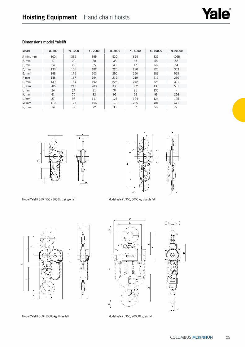
Hoisting Equipment Hand chain hoists
Model YL 500 YL 1000 YL 2000 YL 3000 YL 5000 YL 10000 YL 20000
A min., mm 300 335 395 520 654 825 1065B, mm 17 22 30 38 45 68 85C, mm 24 29 35 40 47 68 64D, mm 133 156 182 220 220 220 303E, mm 148 175 203 250 250 383 555F, mm 148 167 194 219 219 219 250G, mm 139 164 192 225 242 326 391H, mm 206 242 283 335 352 436 501I, mm 24 24 31 34 21 136 –K, mm 61 70 83 95 95 95 396L, mm 87 97 111 124 124 124 125M, mm 110 125 156 178 285 401 471N, mm 14 19 22 30 37 50 56
Dimensions model Yalelift
Model Yalelift 360, 10000 kg, three fall Model Yalelift 360, 20000 kg, six fall
Model Yalelift 360, 500 - 3000 kg, single fall Model Yalelift 360, 5000 kg, double fall
26
Hoisting Equipment Hand chain hoists
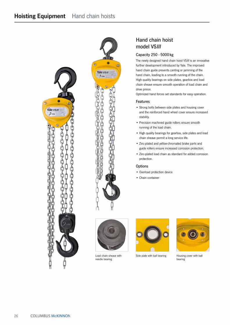
Hand chain hoist model VSIIICapacity 250 - 5000 kgThe newly designed hand chain hoist VSIII is an innovative further development introduced by Yale. The improved hand chain guide prevents canting or jamming of the hand chain, leading to a smooth running of the chain. High quality bearings on side plates, gearbox and load chain sheave ensure smooth operation of load chain and drive pinion. Optimized hand forces set standards for easy operation.
Features• Strong bolts between side plates and housing cover
and the reinforced hand wheel cover ensure increased stability.
• Precision machined guide rollers ensure smooth running of the load chain.
• High quality bearings for gearbox, side plates and load chain sheave permit a long service life.
• Zinc-plated and yellow-chromated brake parts and guide rollers ensure increased corrosion protection.
• Zinc-plated load chain as standard for added corrosion protection.
Options• Overload protection device
• Chain container
Housing cover with ball bearing
Load chain sheave with needle bearing
Side plate with ball bearing

27
Hoisting Equipment Hand chain hoists
Option: Chain container
Technical data model VSIII
Model EAN-No. 4025092*
Capacity in kg/
number of chain falls
Chain dimensions
d x pmm
Lift per 1 m hand chain overhaul
mm
Handle pull at WLL
daN
Weight at standard lift
(3 m)kg
VSIII 0,25/1 *665322 250/1 4 x 12 50 20 3.9VSIII 0,5/1 *949545 500/1 5 x 15 26 21 9.0VSIII 1,0/1 *949927 1000/1 6 x 18 24 24 11.5VSIII 1,5/1 *593854 1500/1 8 x 24 17 30 17.5VSIII 2,0/1 *949934 2000/1 8 x 24 19 32 19.0VSIII 2,0/2 *949941 2000/2 6 x 18 15 29 17.3VSIII 3,0/1 *949958 3000/1 10 x 30 12 40 31.0VSIII 3,0/2 *949965 3000/2 8 x 24 10 37 27.0VSIII 5,0/2 *949972 5000/2 10 x 30 8 41 43.0
Dimensions model VSIII
Model VSIII 0,25/1 VSIII 0,5/1 VSIII 1,0/1 VSIII 1,5/1 VSIII 2,0/1 VSIII 2,0/2 VSIII 3,0/1 VSIII 3,0/2 VSIII 5,0/2
A min., mm 290 350 380 450 460 490 570 580 700B, mm 12 21 27 33 37 37 46 46 56C, mm 26 28 32 37 41 41 44 44 50D, mm 11 16 19 22 27 27 31 31 37E, mm 118 145 158 180 205 170 240 220 250F, mm 113 140 155 175 180 155 210 175 190G, mm 65 80 87 85 94 87 110 94 95H, mm 48 60 68 90 86 68 100 81 95K, mm 190 240 270 300 320 285 370 340 410
Model VSIII, 250 - 3000 kg, single fall Model VSIII, 2000 - 5000 kg, double fall
INFO
Yale hoists and trolleys are not designed for passenger elevation applications and must not be used for this purpose.

28
Hoisting Equipment Hand chain hoists
Depicted rubber buffers are available optionally.
Available in explosion proof version (please see page 452).
Hand chain hoist with integrated push or geared type trolley model Yalelift ITCapacity 500 - 20000 kgThe combination of the Yalelift 360 with a low headroom manual trolley provides even more flexibility in the ap-plication of the Yalelift 360.
Features• All units of this series up to a capacity of 3000 kg are
provided with single chain fall and the min. headroom (Dim. A) has been further reduced. Ideal for applica-tions with low ceilings and limited headroom.
• The proven and almost stepless adjustment system allows quick and easy assembly of the trolley.
• Trolleys up to 5 t are offered for two beam ranges. Range A for a flange width up to 180 mm is standard and covers approx. 80 % of all applications. Conversion to range B for beam width up to 300 mm can be easily accomplished.
• The trolley wheels are designed for a max. beam profile incline of 14 % (DIN 1025 - part 1), excellent rolling features are guaranteed by prelubricated, encapsulated ball bearings.
• Anti-drop and anti-tilt devices as standard.
Options• Adjustable overload protection device.
• Chain container
• Rubber buffers
• Corrosion resistant version
• Beam locking device to secure the unloaded trolley in a fixed position on the beam (park position e.g. on ships). Available up to a capacity of 5000 kg.

29
Hoisting Equipment Hand chain hoists
Technical data model Yalelift ITP/G
Model EAN-No. 4025092*
Capacity in kg/
number of chain falls
Size Beam flange width
b
mm
Beam flange thickness
t max.
mm
Curve radius min.
m
Weight at standard lift
(3 m) - P
kg
Weight at standard lift
(3 m) - G
kg
Weight at standard lift
(3 m) with
locking device - Pkg
Weight at standard lift
(3 m) with
locking device - Gkg
YLIT 500 *288255 500/1 A 50 - 180 19 0.9 20 24 26 31YLIT 500 – 500/1 B 180 - 300 19 0.9 21 25 27 32YLIT 1000 *292221 1000/1 A 50 - 180 19 0.9 27 32 35 40YLIT 1000 – 1000/1 B 180 - 300 19 0.9 29 33 37 41YLIT 2000 *291798 2000/1 A 58 - 180 19 1.15 44 49 52 57YLIT 2000 – 2000/1 B 180 - 300 19 1.15 46 50 54 58YLIT 3000 *291804 3000/1 A 74 - 180 27 1.5 77 82 86 91YLIT 3000 – 3000/1 B 180 - 300 27 1.4 79 84 88 93YLIT 5000 *291828 5000/2 A 98 - 180 27 2.0 125 130 135 140YLIT 5000 – 5000/2 B 180 - 300 27 1.8 129 134 139 144YLIT 10000 *080996 10000/3 B 125 - 310 40 1.8 – 202 – 212YLIT 20000 ¹ *172325 20000/6 B 180 - 310 40 9.5 – on request – on request
¹ Dimensions on requestP in connection with weight = with push trolley G in connection with weight = with geared trolley
Chain guide High quality encapsulated ball bearings and sliding bushes for smooth and ef-fortless operation.
The robust stamped steel housing with four stay bolts is resistant to the toughest working conditions.
The precisely machined load sheave ensures accurate movement of the load chain.
INFO
Yale hoists and trolleys are not designed for passenger elevation applications and must not be used for this purpose.

30
Hoisting Equipment Hand chain hoists
Dimensions model Yalelift IT
Model YLIT 500 YLIT 1000 YLIT 2000 YLIT 3000 YLIT 5000 YLIT 10000
A min., mm 245 272 323 382 550 784A1, mm 158 178 205.5 252 260.5 380A2, mm – – – – – –B, mm 17 22 30 38 45 68C, mm 24 29 35 40 47 68D, mm 14 19 22 30 37 50F (Geared trolley), mm 92 92 91 107 149.5 113H1, mm 24.5 24 23.5 32 30.5 55I (Push trolley), mm 71.5 71.5 95.5 131 142.5 169I (Geared trolley), mm 76.5 76.5 98 132.5 148.5 169L, mm 270 310 360 445 525 430L1, mm 130 130 150 180 209 200L2, mm 159 175 207 256 283 261L3, mm – – – – – –L4, mm – – – – – –M, mm M 18 M 22 M 27 M 30 M 42 M 48O, mm 60 60 80 112 125 150P (Geared trolley), mm 108 110 112 112 117 158T (Area A), mm 280 290 305 320 364 –T (Area B), mm 400 410 425 440 484 540
Model Yalelift ITG, 500 - 3000 kg, single fall Model Yalelift ITG, 10000 kg, three fall
Model Yalelift ITP, 500 - 3000 kg, single fall Model Yalelift ITP/ITG, 5000 kg, double fall
31
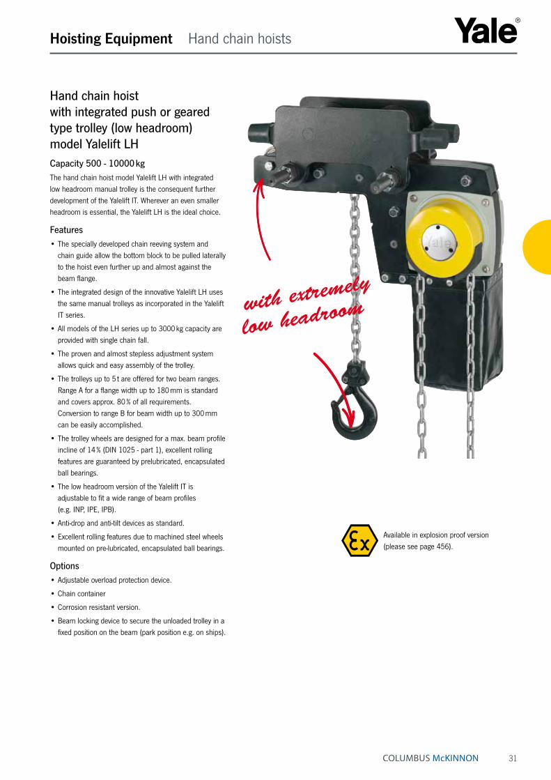
Hand chain hoist with integrated push or geared type trolley (low headroom) model Yalelift LHCapacity 500 - 10000 kgThe hand chain hoist model Yalelift LH with integrated low headroom manual trolley is the consequent further development of the Yalelift IT. Wherever an even smaller headroom is essential, the Yalelift LH is the ideal choice.
Features• The specially developed chain reeving system and
chain guide allow the bottom block to be pulled laterally to the hoist even further up and almost against the beam flange.
• The integrated design of the innovative Yalelift LH uses the same manual trolleys as incorporated in the Yalelift IT series.
• All models of the LH series up to 3000 kg capacity are provided with single chain fall.
• The proven and almost stepless adjustment system allows quick and easy assembly of the trolley.
• The trolleys up to 5 t are offered for two beam ranges. Range A for a flange width up to 180 mm is standard and covers approx. 80 % of all requirements. Conversion to range B for beam width up to 300 mm can be easily accomplished.
• The trolley wheels are designed for a max. beam profile incline of 14 % (DIN 1025 - part 1), excellent rolling features are guaranteed by prelubricated, encapsulated ball bearings.
• The low headroom version of the Yalelift IT is adju stable to fit a wide range of beam profiles (e.g. INP, IPE, IPB).
• Anti-drop and anti-tilt devices as standard.
• Excellent rolling features due to machined steel wheels mounted on pre-lubricated, encapsulated ball bearings.
Options• Adjustable overload protection device.
• Chain container
• Corrosion resistant version.
• Beam locking device to secure the unloaded trolley in a fixed position on the beam (park position e.g. on ships).
Hoisting Equipment Hand chain hoists
with extremely
low headroom
Available in explosion proof version (please see page 456).
32
Hoisting Equipment Hand chain hoists
Model Yalelift LHG, 500 - 3000 kg, single fall
Model Yalelift LHP, 500 - 3000 kg, single fall
Technical data model Yalelift LH
Model EAN-No. 4025092*
Capacity in kg/
number of chain falls
Size Beam flange width
b
mm
Beam flange thickness
t max.
mm
Curve radius min.
m
Weight at standard lift
(3 m) - P
kg
Weight at standard lift
(3 m) - G
kg
Weight at standard lift
(3 m) with
locking device - Pkg
Weight at standard lift
(3 m) with
locking device - Gkg
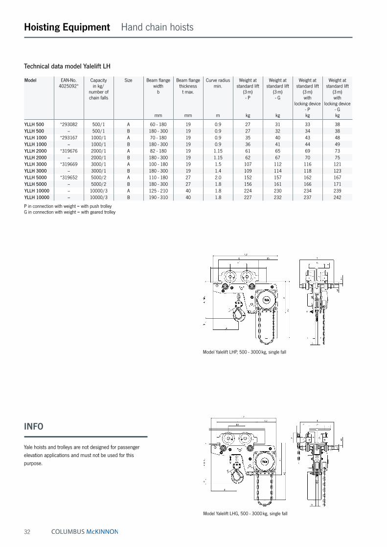
YLLH 500 *293082 500/1 A 60 - 180 19 0.9 27 31 33 38YLLH 500 – 500/1 B 180 - 300 19 0.9 27 32 34 38YLLH 1000 *293167 1000/1 A 70 - 180 19 0.9 35 40 43 48YLLH 1000 – 1000/1 B 180 - 300 19 0.9 36 41 44 49YLLH 2000 *319676 2000/1 A 82 - 180 19 1.15 61 65 69 73YLLH 2000 – 2000/1 B 180 - 300 19 1.15 62 67 70 75YLLH 3000 *319669 3000/1 A 100 - 180 19 1.5 107 112 116 121YLLH 3000 – 3000/1 B 180 - 300 19 1.4 109 114 118 123YLLH 5000 *319652 5000/2 A 110 - 180 27 2.0 152 157 162 167YLLH 5000 – 5000/2 B 180 - 300 27 1.8 156 161 166 171YLLH 10000 – 10000/3 A 125 - 210 40 1.8 224 230 234 239YLLH 10000 – 10000/3 B 190 - 310 40 1.8 227 232 237 242
P in connection with weight = with push trolley G in connection with weight = with geared trolley
INFO
Yale hoists and trolleys are not designed for passenger elevation applications and must not be used for this purpose.

33
Hoisting Equipment Hand chain hoists
Model Yalelift LHG, 10000 kg, three fall
Model Yalelift LHP/LHG, 5000 kg, double fall
Dimensions model Yalelift LH
Model YLLH 500 YLLH 1000 YLLH 2000 YLLH 3000 YLLH 5000 YLLH 10000
A min., mm 188 211 264 316 425 565A1, mm 223 250 289 346 345 365A2, mm 381 427 511 614 612 665B, mm 17 22 30 38 45 68C, mm 24 29 35 40 47 68D, mm 14 19 22 30 37 50F (Geared trolley), mm 92 92 91 107 150 150H1, mm 24 24 24 32 31 45I (Push trolley), mm 72 72 96 131 143 170I (Geared trolley), mm 77 77 98 133 149 170L, mm 270 310 360 445 525 485L1, mm 130 130 150 180 209 225L2, mm 444 488 582 690 720 805L3, mm 124 135 172 203 175 215L4, mm 184 201 230 265 283 348M, mm M 18 M 22 M 27 M 30 M 42 M 48O, mm 60 60 80 112 125 150P (Geared trolley), mm 108 110 112 112 117 165T (Area A), mm 280 290 305 320 364 440T (Area B), mm 400 410 425 440 484 540

34
Hoisting Equipment Hand chain hoists
Swivel truck low headroom trolley hoist suitable for extreme curve radius model VLRP and model VLRGCapacity 250 - 6000 kgThe hand chain hoist series VLR with integrated manual trolley drive features extremely low headroom capabilities and provides optimal usage of the available storage space in confined areas. Hand wheel and gear case are positioned outside the reach of the bottom flange, thus allowing the bottom block to be raised almost until the underside of the beam. The swivel truck feature of the trolley suspension enables travelling on extremely short radius curves.
Features• All-steel construction with zinc-plated load and hand
chains.
• The integrated swivel truck trolley suspension permits application on runways with extremely narrow radii.
• All units are built to order for a predetermined beam dimension. They cannot be adjusted retro-actively to other beam sizes.
• Anti-drop and anti-tilt devices as standard.
• The rotating hand chain guide allows side-pull of the trolley hand chain in travel direction.
Options• Overload protection device
• Chain container
• Buffers
INFO
Yale hoists and trolleys are not designed for passenger elevation applications and must not be used for this purpose.
Beam profile and dimension as well as curve radius must always be specified when ordering.

35
Hoisting Equipment Hand chain hoists & manual trolleys
Compact low headroom trolley hoist with integrated manual trolley model VNRP and model VNRGCapacity 1500 - 24000 kgOn account of a special chain reeving system and cor-responding chain guide the trolley hoist series VNR offers minimum headroom and maximum usage of the available room height. These hoists have been specially designed for heavy industrial applications.
Features• All-steel construction with zinc-plated load and hand
chains.
• All units are built to order for a predetermined beam dimension. They cannot be adjusted retro-actively to other beam sizes.
• Anti-drop and anti-tilt devices as standard.
Options• Chain container
• Buffers
extremely low headroom
for confined spaces
Swivel truck trolley with low headroom and extremely short curve radius model VLHP and model VLHGCapacity 250 - 6000 kgThe manual trolley series VLH features extremely low headroom. The swivel truck construction allows negotia-tion of very short curve radius.
Features• All-steel construction with low headroom
• All units are built to order for a predetermined beam dimension. They cannot be adjusted retro-actively to other beam sizes.
• Anti-drop and anti-tilt devices as standard.
Options• Buffers
• Large variety of special versions.

36
Hoisting Equipment Corrosion protection CR & Accessories
Corrosion protection CRMore life expectancy.All models of the Yalelift programme can be supplied with corrosion resistant features which include zinc-plated load chain and stainless steel hand chain as standard.
Corrosion protectionCorrosion starts on the surface of components due to reaction of environmental influences. This affects the mechanical properties of the components, e.g. breaking load and total ultimate elongation. Many components are supplied in black (unmachined), bright (machined) or painted condition. This offers certain protection but after only a short period of time corrosion can begin. With the application of a protective coating, the develop-ment of corrosion can be reduced and delayed, thus extending the service life of the treated components.
ApplicationsCompletely corrosion resistant units with either zinc-plated or stainless steel hand and load chains should be used in all conditions with increased requirements towards corro-sion protection. Typical applications are in food processing (e.g. dairy, abattoir, etc.), chemical industries (e.g. paper, dye indus-tries), farming and sewage treatment.
Locking deviceMore grip.Yale trolleys can be delivered with a locking device to secure the unit (Parking position, e.g. shipping industry).
Chain containerMore comfort.The chain containers for the Yalelift programme consist of a robust, powder-coated steel frame with a flexible chain bag made from high tensile Cordura textile fabric. Available in different sizes. Special sizes on request.
Overload protectionMore control.The overload protection device of the Yalelift programme reliably prevents excessive load take-up of the hoist during operation. The overload protection device provides addi-tional safety with regard to possible false estimation of the load weight and thus increases the lifetime of the hoist.
Available in explosion proof version (see page 452).
37
Hoisting Equipment Beam clamp
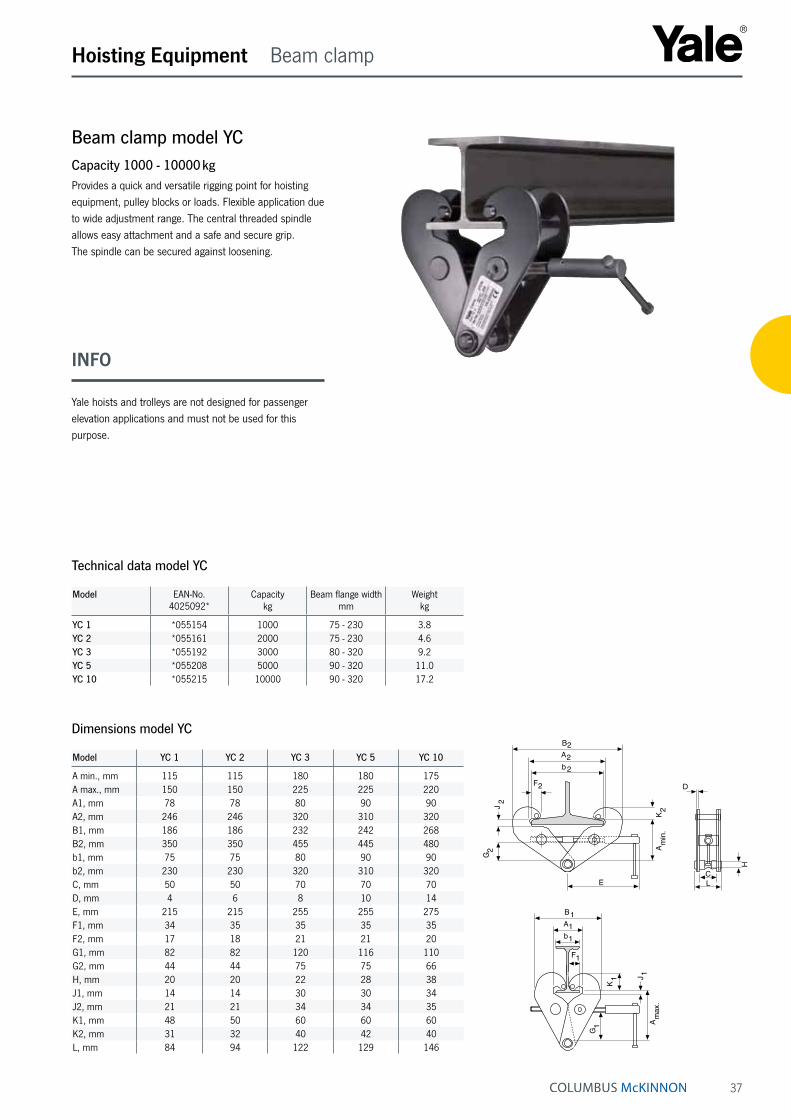
Beam clamp model YCCapacity 1000 - 10000 kgProvides a quick and versatile rigging point for hoisting equipment, pulley blocks or loads. Flexible application due to wide adjustment range. The central threaded spindle allows easy attachment and a safe and secure grip. The spindle can be secured against loosening.
Technical data model YC
Model EAN-No. 4025092*
Capacitykg
Beam flange widthmm
Weightkg
YC 1 *055154 1000 75 - 230 3.8YC 2 *055161 2000 75 - 230 4.6YC 3 *055192 3000 80 - 320 9.2YC 5 *055208 5000 90 - 320 11.0YC 10 *055215 10000 90 - 320 17.2
Model YC 1 YC 2 YC 3 YC 5 YC 10
A min., mm 115 115 180 180 175A max., mm 150 150 225 225 220A1, mm 78 78 80 90 90A2, mm 246 246 320 310 320B1, mm 186 186 232 242 268B2, mm 350 350 455 445 480b1, mm 75 75 80 90 90b2, mm 230 230 320 310 320C, mm 50 50 70 70 70D, mm 4 6 8 10 14E, mm 215 215 255 255 275F1, mm 34 35 35 35 35F2, mm 17 18 21 21 20G1, mm 82 82 120 116 110G2, mm 44 44 75 75 66H, mm 20 20 22 28 38J1, mm 14 14 30 30 34J2, mm 21 21 34 34 35K1, mm 48 50 60 60 60K2, mm 31 32 40 42 40L, mm 84 94 122 129 146
Dimensions model YC
E
Am
in.
K2
G2
J2
B2A2b2
F2
max
.
b1
A1
B1
F1
K1
G1
JA
1
C
H
D
L
E
Am
in.
K2
G2
J2
B2A2b2
F2
max
.
b1
A1
B1
F1
K1
G1
JA
1
C
H
D
L
INFO
Yale hoists and trolleys are not designed for passenger elevation applications and must not be used for this purpose.

38
Hoisting Equipment Trolleys
Push and geared type trolley model HTP and model HTGCapacity 500 - 20000 kgThe trolley enables the exact positioning or easy travers-ing of large loads with either manual or powered hoisting equipment.
Features• It has excellent rolling features due to machined steel
wheels mounted on prelubricated, encapsulated ball bearings.
• Adjustable to fit a wide range of beam widths and profiles (e.g. INP, IPE and IPB).
• Adjustments are made by rotating the clevis load bar which also ensures the centred positioning of the hoist in the clevis – no creeping to the left or the right.
• The trolley wheels are designed for a max. beam profile incline of 14 % (DIN 1025 - part 1).
Options• Rotating hand chain guide.
• Stainless steel hand chains.
• Buffers
• Corrosion resistant version.
• Locking device to secure the trolley in position on the beam (park position e.g. on ships).
INFO
Yale hoists and trolleys are not designed for passenger elevation applications and must not be used for this purpose.

39
Hoisting Equipment Trolleys
Technical data model HTP
Model EAN-No. 4025092*
Capacity
kg
Size Beam flange width
bmm
Beam flange thickness
t max.mm
Curve radius min.
m
Hand effort at WLL
daN
Weight
kg
Weight with
locking devicekg
HTP 500 *054874 500 A 50 - 220 25 0.9 – 8.0 14.5HTP 1000 *054881 1000 A 50 - 220 25 0.9 – 9.0 17.0HTP 2000 *054898 2000 A 66 - 220 25 1.15 – 16.0 24.0HTP 3000 *054904 3000 A 74 - 220 25 1.4 – 32.0 41.2HTP 5000 *054911 5000 A 90 - 220 25 1.8 – 48.0 58.5HTP 500 *054928 500 B 160 - 300 40 0.9 – 10.6 17.1HTP 1000 *054935 1000 B 160 - 300 40 0.9 – 12.0 20.0HTP 2000 *054942 2000 B 160 - 300 40 1.15 – 19.3 27.3HTP 3000 *054959 3000 B 160 - 300 40 1.4 – 35.8 45.0HTP 5000 *054966 5000 B 180 - 300 40 1.8 – 52.2 62.7
Technical data model HTG
Model EAN-No 4025092*
Capacity
kg
Size Beam flange width
bmm
Beam flange thickness
t max.mm
Curve radius min.
m
Hand effort at WLL
daN
Weight ¹
kg
Weight ¹ with
locking devicekg
HTG 500 *074711 500 A 50 - 220 25 0.9 3 9.7 16.2HTG 1000 *074728 1000 A 50 - 220 25 0.9 6 11.2 19.2HTG 2000 *074735 2000 A 66 - 220 25 1.15 7 18.0 26.0HTG 3000 *074742 3000 A 74 - 220 25 1.4 7 35.4 44.6HTG 5000 *074759 5000 A 90 - 220 25 1.8 9 51.8 62.3HTG 500 *074766 500 B 160 - 300 40 0.9 3 12.6 19.1HTG 1000 *074841 1000 B 160 - 300 40 0.9 6 14.1 22.1HTG 2000 *074773 2000 B 160 - 300 40 1.15 7 21.3 29.3HTG 3000 *074780 3000 B 160 - 300 40 1.4 7 39.2 48.4HTG 5000 *074797 5000 B 180 - 300 40 1.8 9 56.0 66.5HTG 8000 *074803 8000 B 125 - 310 40 1.8 14 104.0 –HTG 10000 *074810 10000 B 125 - 310 40 1.8 14 104.0 –HTG 15000 *074827 15000 B 125 - 310 40 5.0 29 230.0 –HTG 20000 *074834 20000 B 125 - 310 40 5.0 29 230.0 –
¹ Weight HTG: without hand chain
Available in explosion proof version (see page 460).

40
Hoisting Equipment Trolleys
Dimensions model HTP
Model HTP 500-A
HTP 1000-A
HTP 2000-A
HTP 3000-A
HTP 5000-A
HTP 500-B
HTP 1000-B
HTP 2000-B
HTP 3000-B
HTP 5000-B
A, mm 77 82.5 98.5 114 132.5 92 97.5 113.5 129 147.5D, mm 16 17 22 26 33 16 17 22 26 33D1, mm 25 30 40 48 60 25 30 40 48 60D2, mm 30 35 47 58 70 30 35 47 58 70F1, mm 46 46 46 46 45.5 46 46 46 46 45.5H1, mm 30.5 30.5 30.5 30 30 45.5 45.5 45.5 45 45I (HTP), mm 71.5 71.5 95.5 131 142.5 71.5 71.5 95.5 131 142.5L, mm 260 260 310 390 450 260 260 310 390 450L1, mm 130 130 150 180 209 130 130 150 180 209O, mm 60 60 80 112 125 60 60 80 112 125P1, mm 168 168 168 168 168 168 168 168 168 168P2, mm 146 150 155 160 167.5 187 187 189.5 191.5 191.5L3, mm 346 346 396 476 556 346 346 396 476 556
Dimensions model HTG
Model HTG 500-A
HTG 1000-A
HTG 2000-A
HTG 3000-A
HTG 5000-A
HTG 500-B
HTG 1000-B
HTG 2000-B
HTG 3000-B
HTG 5000-B
HTG 8000-B
HTG 10000-B
HTG 15000-B
HTG 20000-B
A, mm 77 82.5 98.5 114 132.5 92 97.5 113.5 129 147.5 276 276 270 270B, mm – – – – – – – – – – 52 52 70 70D, mm 16 17 22 26 33 16 17 22 26 33 30 30 35 35D1, mm 25 30 40 48 60 25 30 40 48 60 80 80 110 110D2, mm 30 35 47 58 70 30 35 47 58 70 114 114 155 155F (HTG), mm 91.5 91.5 90.5 107.5 149.5 91.5 91.5 90.5 107.5 149.5 113 113 113 113F1, mm 46 46 46 46 45.5 46 46 46 46 45.5 77 77 – –H1, mm 30.5 30.5 30.5 30 30 45.5 45.5 45.5 45 45 45 45 45 45I (HTG), mm 76.5 76.5 98 132.5 148.5 76.5 76.5 98 132.5 148.5 170 170 170 170L, mm 260 260 310 390 450 260 260 310 390 450 430 430 870 870L1, mm 130 130 150 180 209 130 130 150 180 209 200 200 200 200L2, mm – – – – – – – – – – – – 115 115O, mm 60 60 80 112 125 60 60 80 112 125 150 150 150 150P (HTG), mm 110 110 110 110 110 110 110 110 110 110 163 163 163 163P1, mm 168 168 168 168 168 168 168 168 168 168 193 193 – –P2, mm 146 150 155 160 167.5 187 187 189.5 191.5 191.5 – – – –T, mm – – – – – – – – – – 270 270 270 270L3, mm 346 346 396 476 556 346 346 396 476 556 536 536 976 976P3, mm 194 194 194 195 195 194 194 194 195 195 – – – –
P
P
b
D1
2
2
H1
A
t
OIF
D
D
L 1
LP b
F
P1
H1
t
F 1
P2
O I
L
L1
D1
D2
B
L2
Model HTG 500 - 5000 kg with rotating hand chain guide and buffers Model HTP/G 500 - 5000 kg Model HTP/G 500 - 5000 kg,
with locking device
Model HTG 10000 kg, locking device Model HTG 10000 kg Model HTG 20000 kg
P bT
t
F O IA
H1
D
L
L1
D1
D2
B

41
Trolley clamp model CTPCapacity 1000 - 3000 kgEasy fitting to overhead beams for the attachment and transport of loads.
Features• Central threaded spindle provides quick adjustment to
the required beam width.
• Threaded spindle and clevis are zinc-plated for added corrosion protection.
Hoisting Equipment Trolley clamps
Technical data model CTP
Model EAN-No. 4025092*
Capacity
kg
Beam flange width b
mm
Curve radius min.m
Weight
kg
CTP 1-A *063012 1000 60 - 150 0.6 2.5CTP 2-A *055437 2000 75 - 200 0.9 9.9CTP 2-B *055444 2000 200 - 300 0.9 10.3CTP 3-A *055451 3000 75 - 200 1.15 17.5CTP 3-B *055468 3000 200 - 320 1.15 19.5
Model CTP 1-A CTP 2-A CTP 2-B CTP 3-A CTP 3-B
A, mm 82 - 109 106 - 155 136 - 191 128 - 171 150 - 212D, mm 26 42 42 50 50E, mm 22 20 20 22 22H1, mm 20 24 24 30.5 30.5I, mm 53 71.5 71.5 95.5 95.5L, mm 160 260 260 310 310L1, mm 75 130 130 150 150M, mm M12 M18 M18 M24 M24O, mm 46 60 60 80 80P, mm 153 205 255 220 280T, mm 105 139 189 155 215tmax., mm 15 25 25 25 25
Dimensions model CTP
D
E
A
L
L 1
H1
M
OI
b
P T
t
INFO
Yale hoists and trolleys are not designed for passenger elevation applications and must not be used for this purpose.

42
Electric trolley model VTE-UCapacity 1000 - 5000 kgSpecially recommended for loads over 1000 kg, for trans-porting over long distances and/or when used frequently. Suitable for almost all hoists with suspension hook due to universal shackle connection. Travel motor with worm gear transmission ensures smooth start and self braking – a separate motor brake is not required.
Features• Standard operating voltage:
Euro-voltage 400 V, 3-phase, 50 Hz. Single speed motors can be reconnected to 230 V, 3-phase, 50 Hz.
• Motor protected to IP 55 against dust and water jets. Push-button pendant control IP 65.
• Compact, robust frame with low overall height.
• Wheels manufactured from fracture-proof steel. Smooth running due to machined surfaces and ball bear-ing mounting. Cambered profile suitable for flat and inclined beam profiles.
• Anti-drop and anti-tilt devices as standard.
• Easy adjusted to fit to a wide range of beam widths and profiles due to threaded spindles.
Options• Low voltage control (42 V)
• Rubber buffers
• 230 V, 1-phase, 50 Hz
Hoisting Equipment Trolleys
Wheel with cambered profile
Threaded spindle Anti-drop device with option to fit buffers.
INFO
Yale hoists and trolleys are not designed for passenger elevation applications and must not be used for this purpose.

43
Hoisting Equipment Trolleys
Technical data model VTE-U
Model EAN-No. 4025092*
Capacity
kg
Travel speed
m/min
Motor
kW
Beam flange widthmm
Beam flange thickness t max.
mm
Curve radius min.m
Weight
kg
VTE 1-A-18/U ¹ *073547 1000 18 or 18/4.5 0.18 or 0.18/0.06 58 - 180 19 0.9 19.5VTE 1-B-18/U ¹ *073585 1000 18 or 18/4.5 0.18 or 0.18/0.06 180 - 300 19 0.9 25.2VTE 2-A-18/U ¹ *073561 2000 18 or 18/4.5 0.18 or 0.18/0.06 58 - 180 19 1.15 26.0VTE 2-B-18/U ¹ *073608 2000 18 or 18/4.5 0.18 or 0.18/0.06 180 - 300 19 1.15 30.2VTE 3-A-11/U *073424 3000 11 or 11/2.8 0.37 or 0.3/0.09 74 - 180 27 1.5 51.0VTE 3-B-11/U *073509 3000 11 or 11/2.8 0.37 or 0.3/0.09 180 - 300 27 1.4 53.0VTE 5-A-11/U *073448 5000 11 or 11/2.8 0.37 or 0.3/0.09 98 - 180 27 2.0 77.0VTE 5-B-11/U *073523 5000 11 or 11/2.8 0.37 or 0.3/0.09 180 - 300 27 1.8 80.0
¹ 11 or 11/2.8 m/min. travel speed on request
Dimensions model VTE-U
Model VTE 1-A-18/U VTE 1-B-18/U VTE 2-A-18/U VTE 2-B-18/U VTE 3-A-11/U VTE 3-B-11/U VTE 5-A-11/U VTE 5-B-11/U
A, mm 113 113 115 115 139 139 161 161B, mm b + 50 b + 50 b + 54 b + 54 b + 60 b + 60 b + 70 b + 70C, mm 49 49 47 47 57 57 60 60D, mm 16 16 16 16 19 19 22 22E, mm 187 187 187 187 202 202 202 202F, mm 94 94 94 94 94 94 94 94G, mm 43 43 43 43 51 51 58 58H, mm 129 129 128 128 144 144 178 178H1, mm 24 24 24 24 32 32 32 32I, mm 77 77 98 98 133 133 149 149L1, mm 130 130 150 150 180 180 209 209M, mm 155 155 180 180 208 208 263 263N single speed, mm 255 255 255 255 292 292 292 292N double speed, mm 263 263 263 263 296 296 296 296O, mm 60 60 80 80 112 112 125 125P, mm 123 123 123 123 129 129 121 121Q, mm 145 205 153 213 160 220 182 242
L1
1
M N
D
I
OA
C
G
P
bFBE
H
t
Q
H
44
Hoisting Equipment User information
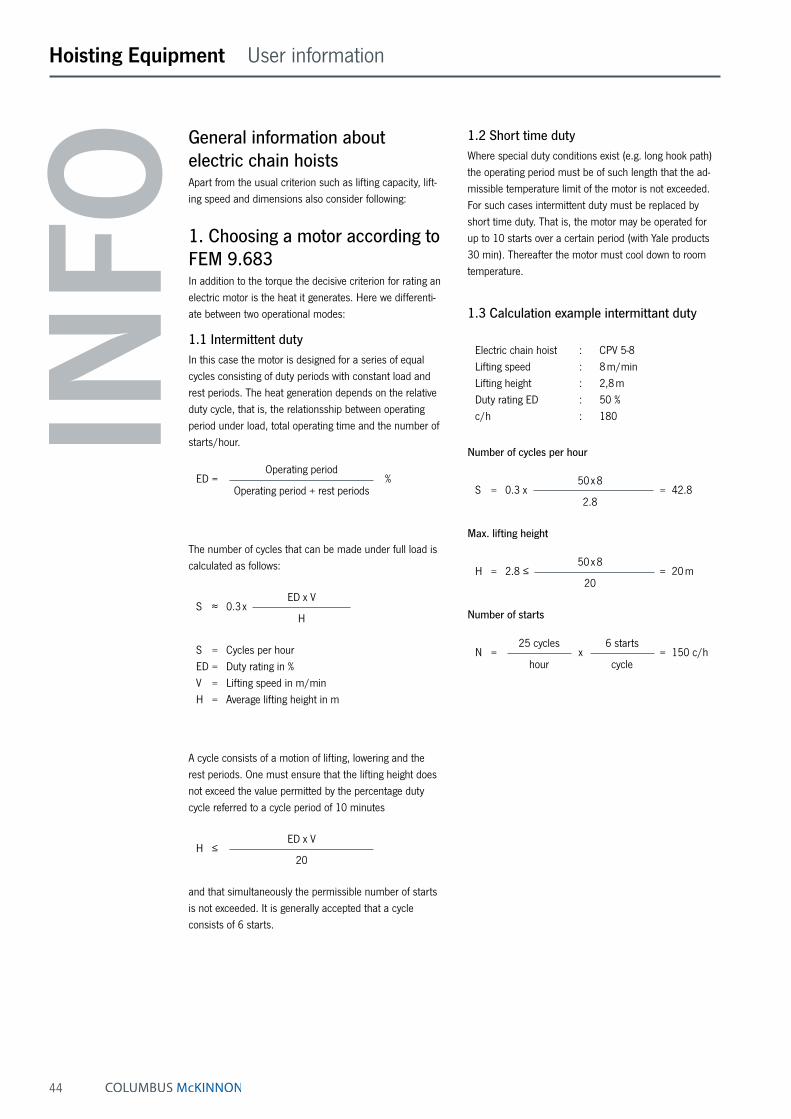
General information about electric chain hoistsApart from the usual criterion such as lifting capacity, lift-ing speed and dimensions also consider following:
1. Choosing a motor according to FEM 9.683In addition to the torque the decisive criterion for rating an electric motor is the heat it generates. Here we differenti-ate between two operational modes:
1.1 Intermittent dutyIn this case the motor is designed for a series of equal cycles consisting of duty periods with constant load and rest periods. The heat generation depends on the relative duty cycle, that is, the relationsship between operating period under load, total operating time and the number of starts/hour.
Operating period ED = % Operating period + rest periods
The number of cycles that can be made under full load is calculated as follows:
ED x V S ≈ 0.3 x H
S = Cycles per hour ED = Duty rating in % V = Lifting speed in m/min H = Average lifting height in m
A cycle consists of a motion of lifting, lowering and the rest periods. One must ensure that the lifting height does not exceed the value permitted by the percentage duty cycle referred to a cycle period of 10 minutes
ED x V H ≤ 20
and that simultaneously the permissible number of starts is not exceeded. It is generally accepted that a cycle consists of 6 starts.
1.2 Short time dutyWhere special duty conditions exist (e.g. long hook path) the operating period must be of such length that the ad-missible temperature limit of the motor is not exceeded. For such cases intermittent duty must be replaced by short time duty. That is, the motor may be operated for up to 10 starts over a certain period (with Yale products 30 min). Thereafter the motor must cool down to room temperature.
1.3 Calculation example intermittant duty Electric chain hoist : CPV 5-8 Lifting speed : 8 m/min Lifting height : 2,8 m Duty rating ED : 50 % c/h : 180
Number of cycles per hour
50 x 8 S = 0.3 x = 42.8 2.8
Max. lifting height
50 x 8 H = 2.8 ≤ = 20 m 20
Number of starts
25 cycles 6 starts N = x = 150 c/h hour cycle
INFO

45
2. Classification of hoisting equip-ment according to FEM 9.511To choose an optimal hoist the lifting capacity and also the classification group must be known. The classifica-tion group indicates the theoretical operating time of the mechanical components under full load:
FEM 1 Bm 1 Am 2 m 3 mClassification group ISO M3 M4 M5 M6
Operating time in h 400 800 1600 3200
If the hoist is operated as classified an actual operating time of around 10 years can be expected. After this period a general overhaul is necessary.
To define the classification group following values must be determined:
2.1 Average operating time per dayThe average operating time can be estimated or calcu-lated as follows: 2 x average cycles/ operating hook path x hour x time/dayOperating = time/day 60 x lifting speed
2.2 Load spectrumThe load spectrum indicates to what extent a hoist or part thereof is subject to maximal stress or whether it is subject to smaller loads only. It can be calculated or estimated according to the diagrams on the right:
1 light
Load
small partial load
small deadload
Operating time Hoists or parts thereof usually subject to very small loads and in exceptional cases only to maximum loads.
2 medium
Load
large partial loadmed. partial loadmed. deadload
Operating time Hoists or parts thereof usually subject to small loads but rather often to maximum loads.
3 heavy
Load
large deadload
Operating time Hoists or parts thereof usually subject to medium loads but frequently to maximum loads.
4 very heavy
Load
very large deadload
Operating time Hoists or parts thereof usually subject to maximum or almost maximum loads.
2.3 ClassificationThe classification group is defined by operating hours and load spectrum:
Load spectrum Aver. op. hours per working day
1 light up to 2 2-4 4-8 2 medium up to 1 1-2 2-4 3 heavy up to 0.5 0.5-1 1-2 4 very heavy up to 0.25 0.25-0.5 0.5-1
Classification group acc. to FEM/ISO 1 Bm/M3 1 Am/M4 2 m/M5
Hoisting Equipment User information
INFO

46
Hoisting Equipment User information
IP protection according to EN 60529Depending on the operating and environmental conditions the damag-ing effect of water, foreign particles and dust and the contact with live or moving parts inside a motor is to be prevented by choosing a suitable protection. The marking used to indicate the degree of protection consists of the letters IP followed by two characteristic numerals. The marking applies to the unit as it is supplied and the defined or usual location of the unit. The protection can change if the unit is located or fitted differently.
Protection against contact and solid foreign particles
First digit 0 No protectionNo protection of persons against contact with live or moving parts inside the enclo-sure. No protection of equipment against ingress of solid foreign particles.
First digit 1 Protection against large solid foreign particlesProtection against accidental or inadvertent contact with live or moving parts inside the enclosure by a large surface of the human body, e.g. hand, but not protected against deliberate access to such parts.
First digit 2 Protection against med. size solid foreign particlesProtection against contact with live or moving parts inside the enclosure by fingers. Protection against ingress of medium size solid foreign particles of diameter greater than 12 mm.
First digit 3 Protection against small solid foreign particlesProtection against contact with live or moving parts inside the enclosure by tools, wires or such objects of thickness greater than 2.5 mm. Protection against ingress of small solid foreign particles of diameter greater than 2.5 mm.
First digit 4 Protection against granular structured foreign particlesProtection against contact with live or moving parts inside the enclosure by tools, wires or such objects of thickness greater than 1 mm. Protection against ingress of granular structured solid foreign particles of diameter greater than 1 mm.
First digit 5 Protection against dust depositsComplete protection against contact with live or moving parts inside the enclosure. Protection against harmful deposits of dust. The ingress of dust is not totally prevent-ed, but dust cannot enter in an amount sufficient to interfere with the satisfactory operation of the equipment enclosed.
First digit 6 Complete protectionComplete protection against contact with live or moving parts inside the enclosure. Protected against the ingress of dust.
Protection against liquids
Second digit 0 No protectionNo particular protection
Second digit 1 Protection against vertical water dropsDroplets of condensed water falling on the enclosure shall have no harmful effects.
Second digit 2 Protection against diagonal falling water dropsProtection against dripping liquids. Droplets of falling liquid shall have no harmful effect when the enclosure is tilted at any angle up to 15° from the vertical.
Second digit 3 Protection against spray waterProtection against dripping liquids. Water falling as rain at an angle equal to or smaller than 60° in respect to the vertical shall have no harmful effect.
Second digit 4 Protection against splashingLiquid splashed from any direction shall have no harmful effect.
Second digit 5 Protection against water jetsWater projected by a nozzle from any direction under stated conditions shall have no harmful effect.
Second digit 6 Protection against floodingProtection against conditions on ships decks (deck watertight equipment). Water from heavy seas shall not enter the enclosure under prescribed conditions2.
Second digit 7 Protection against immersion in waterIt shall not be possible for water to enter the enclosure under stated conditions of pressure and time2.
Second digit 8 Protection against indefinite immersionProtection against indefinite immersion in water. Under specific pressure it shall not be possible for water to enter the enclosure2).2) In certain cases water should not ingress. As required this is defined on the follow-on page of the unit in question.
Motor surface cooled
Protection 1st digit 2nd digit
Contact protection Ingress of solid foreign particles Ingress of liquid
IP 44 contact with tools or similar against solid foreign bodies over 1 mm Ø splashing from all directions
IP 50 complete protection against contact damaging dust deposits no protection
IP 54 contact with tools or similar against solid foreign bodies over 1 mm Ø splashing from all directions
IP 55 complete protection against contact damaging dust deposits water jets from all directions
IP 56 complete protection against contact damaging dust deposits momentarily flooding
IP 65 complete protection against contact against ingress of dust water jets from all directions
INFO

47
Technical questionnaire to identify a suitable electric chain hoist
Company: Date:
Contact: e-Mail:
Phone: Fax:
Details about intended use
Required capacity
Lifting height
Ambient conditions
Normal
Humidity
Dust
Dirt
Particular temperatures °C
Increased rel. humidity %
Other
How long is the hoist in operation
Load cycles per hour
Hours per day
Days per week
Distance covered per lifting cycle
Unusual operating conditions that could be important for the choice and function of the electric chain hoist:
Type of load
Permanent
Changing
Shocks
Vibration
Static
Trolley drive Hook suspension Other
Motor
Manual
Operating voltage
400 V
230 V
3-phase a.c.
1-phase a.c.
Power frequency
50 Hz
60 Hz
Protection
IP 54
Other
Hoisting Equipment Questionnaire

48
Hoisting Equipment Electric chain hoists
Electric chain hoist with suspension hook model CPSCapacity 125 - 500 kgThe model CPS is the smallest and lightest model within the range of Yale electric chain hoists. Reliability and compact design make it ideal for numerous applications in the construction industry, service companies and many industrial areas for moving small and medium loads.
Features• Classification: 1 Am/M4 resp. 1 Bm/M3 at 230 V,
1-phase, 50 Hz. On request, the classification can be modified by derating the capacity and duty cycle.
• The standard version comes with direct control.
• Two year warranty (excluding wear parts).
• Thermal overload protection as standard.
• Duty cycle 30 % ED resp. 25 % ED at 230 V, 1-phase, 50 Hz.
• Safe hold of the load even in case of electric failure due to electromagnetic spring pressure brake.
• Standard operating voltage: Euro-voltage 400 V, 3-phase, 50 Hz resp. 125 kg also as 230 V, 1-phase, 50 Hz version.
• Motor protected to IP 54, against ingression of dust and splashing.
• Push-button pendant control, IP 65 against ingress of dust and water jets from all directions.
• The overload protection (slip clutch) avoids overloading and extends the lifetime of the hoist.
• Robust aluminium housing, powder coated.
• Extremely low headroom for use in applications with limited room.
• The standard case hardened and zinc-plated link chain is matched perfectly to the load chain to guarantee smooth and precise chain motion. All requirements of national and international standards and regulations are fulfilled.
• The 10-pocket load sheave ensures smooth running of the chain and minimizes chain wear.
• Drop forged suspension and load hooks are made from non-aging, high tensile steel and fitted with robust safety latches.
Options• Stainless steel load chain
(no reduction of working load limit).
• Robust chain container.
• Low voltage control 48 V
• Manual and electric trolleys.
• Connection to festooned cable systems.
INFO
Festooned cable systems please see pages 140 -141.

49
Hoisting Equipment Electric chain hoists
Technical data model CPS
Model EAN-No. 4025092*
Capacity in kg/
number of chain falls
Standard lifting height
m
Chain dimensions
d x pmm
Classification
FEM/ISO
Lifting speed
m/min
Hoist motor
kW
Weight
kg
Operating voltage
CPS 1-4 *076654 125/1 3 4 x 12.2 1 Bm/M3 4 0.10 11.5 230 V/1 Ph/50 HzCPS 1-10 *076661 125/1 3 4 x 12.2 1 Am/M4 10 0.25 11.5 400 V/3 Ph/50 HzCPS 2-6 *076678 250/1 3 4 x 12.2 1 Am/M4 6 0.28 11.5 400 V/3 Ph/50 HzCPS 5-3 *076685 500/2 3 4 x 12.2 1 Am/M4 3 0.28 12.5 400 V/3 Ph/50 Hz
Dimensions model CPS
Model CPS 1-4 CPS 1-10 CPS 2-6 CPS 5-3
A, mm 276 276 276 303B, mm 98 98 98 146C, mm 159 159 159 159D, mm 75 75 75 60E, mm 76 76 76 91F, mm 160 160 160 160G, mm 227 227 227 227H, mm 103 103 103 103I, mm 52 52 52 52J ¹, mm 1905 1905 1905 1905X, mm 25 25 25 25Y, mm 14 14 14 14Z, mm 21 21 21 21
¹ Dimensions at standard lift (3 m).
INFO
Yale hoists and trolleys are not designed for passenger elevation applications and must not be used for this purpose.
Smallest and lightest electric chain hoist for a great number of applications.
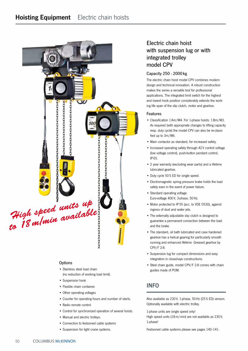
50
Hoisting Equipment Electric chain hoists
Electric chain hoist with suspension lug or with integrated trolley model CPVCapacity 250 - 2000 kgThe electric chain hoist model CPV combines modern design and technical innovation. A robust construction makes the series a versatile tool for professional applications. The integrated limit switch for the highest and lowest hook position considerably extends the work-ing life span of the slip clutch, motor and gearbox.
Features• Classification 1 Am/M4. For 1-phase hoists: 1 Bm/M3.
As required (with appropriate changes to lifting capacity resp. duty cycle) the model CPV can also be re-classi-fied up to 3m/M6.
• Main contactor as standard, for increased safety.
• Increased operating safety through 42 V control voltage (low voltage control), push-button pendant control, IP 65.
• 2 year warranty (excluding wear parts) and a lifetime lubricated gearbox.
• Duty cycle 50 % ED for single speed.
• Electromagnetic spring pressure brake holds the load safely even in the event of power failure.
• Standard operating voltage: Euro-voltage 400 V, 3-phase, 50 Hz.
• Motor protected to IP 55 (acc. to VDE 0530), against ingress of dust and water jets.
• The externally adjustable slip clutch is designed to guarantee a permanent connection between the load and the brake.
• The standard, oil bath lubricated and case hardened gearbox has a helical gearing for particularly smooth running and enhanced lifetime. Greased gearbox by CPV/F 2-8.
• Suspension lug for compact dimensions and easy integration in closed-eye constructions.
• Steel chain guide, model CPV/F 2-8 comes with chain guides made of POM.
Options• Stainless steel load chain
(no reduction of working load limit).
• Suspension hook
• Flexible chain container.
• Other operating voltages
• Counter for operating hours and number of starts.
• Radio remote control
• Control for synchronized operation of several hoists.
• Manual and electric trolleys.
• Connection to festooned cable systems
• Suspension for light crane systems.
High speed units up
to 18 m/min available
INFO
Also available as 230 V, 1-phase, 50 Hz (25 % ED) version. Optionally available with electric trolley.
1-phase units are single speed only! High speed units (18 m/min) are not available as 230 V, 1-phase!
Festooned cable systems please see pages 140 -141.

51
Hoisting Equipment Electric chain hoists
Increased operating safety through 42 V control voltage
Externally adjustable slip clutch
Integrated limit switch Option: radio remote control
Depicted suspension hook and chain container optionally available.
Technical data model CPV/CPVF
Model EAN-No. 4025092* 4053981**
Capacity in kg/
number of chain falls
Chain dimensions
d x p
mm
Classification
FEM/ISO
Lifting speed⁴ main lift
m/min
Lifting speed fine lift
m/min
Hoist motor
kW
Motor rating
ED %
Weight ¹ suspension
lug
kg
Weight ¹ push
trolley ²
kg
Weight ¹ electric trolley ³
kg
CPV 2-8 – 250/1 4 x 12.2 1 Am/M4 8 – 0.37 50 on request on request on requestCPVF 2-8 **874067 250/1 4 x 12.2 1 Am/M4 8 2 0.37/0.09 33/17 19 28 33CPVF 2-18 *925341 250/1 5 x15.1 1 Am/M4 18 4.5 0.75/0.18 33/17 27 42 50CPV 5-4 – 500/2 4 x 12.2 1 Am/M4 4 – 0.37 50 on request on request on requestCPVF 5-4 **874074 500/2 4 x 12.2 1 Am/M4 4 1 0.37/0.09 33/17 19 28 33CPV 5-8 *173766 500/1 5 x 15.1 1 Am/M4 8 – 0.75 50 26 41 49CPVF 5-8 *173803 500/1 5 x 15.1 1 Am/M4 8 2 0.75/0.18 33/17 27 42 50CPVF 5-18 *303729 500/1 7.1 x 20.5 1 Am/M4 18 4.5 1.5/0.37 33/17 59 78 85CPV 10-4 *174473 1000/2 5 x 15.1 1 Am/M4 4 – 0.75 50 28 43 51CPVF10-4 *174725 1000/2 5 x 15.1 1 Am/M4 4 1 0.75/0.18 33/17 29 44 52CPV 10-8 *173797 1000/1 7.1 x 20.5 1 Am/M4 8 – 1.5 50 58 77 84CPVF10-8 *173780 1000/1 7.1 x 20.5 1 Am/M4 8 2 1.5/0.37 33/17 59 78 85CPV 20-4 *174480 2000/2 7.1 x 20.5 1 Am/M4 4 – 1.5 50 63 82 89CPVF 20-4 *174459 2000/2 7.1 x 20.5 1 Am/M4 4 1 1.5/0.37 33/17 64 83 90
¹ Weight at standard lift (3 m). Other lifting heights on request. ² For trolleys type A and B: Additional weight for geared trolley (VTG): 2.5 kg ³ For electric trolley (VTE) with 2 speeds +2.0 kg ⁴ Lifting speed CPV 10-8 at 230 V, 1-phase, 50 Hz = 4 m/min Lifting speed CPV 20-4 at 230 V, 1-phase, 50 Hz = 2 m/min
Technical data trolleys
Suitable for model Capacity
kg
Size Beam flange width
bmm
Beam flange thickness
t max.mm
Curve radius min.
m
Electric trolley travel speed
m/min at 50 Hz
Electric trolley motor
kW at 50 Hz
CPV/CPVF 2-8 up to CPVF 5-4 500 A 58 - 180 12 0.9 11 or 18 0.09CPV/CPVF 2-8 up to CPVF 5-4 500 B 180 - 300 19 0.9 18 or 18 0.09CPV 5-8 up to CPVF 10-4 1000 A 58 - 180 19 0.9 18 or 18/4.5 0.18 or 0.18/0.06CPV 5-8 up to CPVF 10-4 1000 B 180 - 300 19 0.9 18 or 18/4.5 0.18 or 0.18/0.06CPV 10-8 up to CPVF 20-4 2000 A 58 - 180 19 1.15 18 or 18/4.5 0.18 or 0.18/0.06CPV 10-8 up to CPVF 20-4 2000 B 180 - 300 19 1.15 18 or 18/4.5 0.18 or 0.18/0.06
INFO
Yale hoists and trolleys are not designed for passenger elevation applications and must not be used for this purpose.

52
Hoisting Equipment Electric chain hoists
Model CPV/CPVF with suspension lug, 250 - 1000 kg, single fall
Model CPV/CPVF with suspension lug, 500 - 2000 kg, double fall
Model CPV/CPVF with suspension hook, 250 - 2000 kg
Dimensions model CPV/CPVF
Model CPV 2-8/ CPVF 2-8
CPV 5-4/ CPVF 5-4
CPVF 2-18 CPV/CPVF 5-8
CPV/CPVF 10-4 CPVF 5-18 CPV/CPVF 10-8
CPV/CPVF 20-4
A, mm 357/327 357/327 357 430 431 528A1, mm 196/163 196/163 196 196 234 234A2 (Size I), mm 476/343 476/343 476 476 564 564A2 (Size II), mm 526/413 526/413 526 526 644 644A2 (Size III), mm 606/483 606/483 606 606 734 734A2 (Size IV), mm 798/553 798/553 798 798 934 934B, mm 22/23 22/23 22 29 29 37B1, mm 15/12 15/12 15 15 20 20C, mm 29/30 29/30 29 35 35 40C1, mm 38/30 38/30 38 38 45 45C2, mm 105 105 105 105 154 154D, mm 15/16 15/16 15 21 21 26D1, mm 15/12 15/12 15 15 15 15E, mm 277/205 277/205 277 277 326 326G, mm 120/102 120/102 120 144 140 173G1 (Size I), mm 142/124 142/124 142 166 175 208G1 (Size II), mm 162/124 162/124 162 186 175 208G1 (Size III), mm 162/124 162/124 162 186 175 208G1 (Size IV), mm 162/124 162/124 162 186 175 208H, mm 157/99 157/99 157 133 186 154H2, mm 158/92 158/92 158 158 186 186K, mm 208/215 208/215 208 208 285 285M (Size I), mm 162/157 162/157 162 162 209 209M (Size II), mm 197/157 197/157 197 197 209 209M (Size III), mm 197/157 197/157 197 197 209 209M (Size IV), mm 197/157 197/157 197 197 209 209N ¹, mm 219/159 219/159 219 219 274 274
¹ for 230 V, 1-phase, 50 Hz: +35 mm
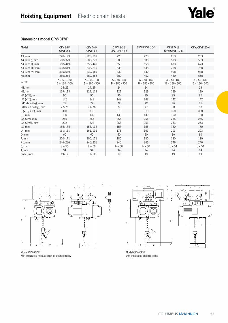
53
Hoisting Equipment Electric chain hoists
Model CPV/CPVF with integrated manual push or geared trolley
Model CPV/CPVF with integrated electric trolley
Dimensions model CPV/CPVF
Model CPV 2-8/ CPVF 2-8
CPV 5-4/ CPVF 5-4
CPVF 2-18 CPV/CPVF 5-8
CPV/CPVF 10-4 CPVF 5-18 CPV/CPVF 10-8
CPV/CPVF 20-4
A3, mm 228/199 228/199 228 228 263 263A4 (Size I), mm 508/379 508/379 508 508 593 593A4 (Size II), mm 558/449 558/449 558 558 673 673A4 (Size III), mm 638/519 638/519 638 638 768 768A4 (Size IV), mm 830/589 830/589 830 830 968 968A5, mm 389/365 389/365 389 462 460 558
b, mm A = 58 - 180 B = 180 - 300
A = 58 - 180 B = 180 - 300
A = 58 - 180 B = 180 - 300
A = 58 - 180 B = 180 - 300
A = 58 - 180 B = 180 - 300
A = 58 - 180 B = 180 - 300
H1, mm 24/25 24/25 24 24 23 23H3, mm 129/113 129/113 129 129 129 129H4 (VTG), mm 95 95 95 95 95 95H4 (VTE), mm 142 142 142 142 142 142I (Push trolley), mm 72 72 72 72 96 96I (Geared trolley), mm 77/76 77/76 77 77 98 98L (VTP/VTG), mm 310 310 310 310 360 360L1, mm 130 130 130 130 150 150L2 (CPV), mm 255 255 255 255 255 255L2 (CPVF), mm 222 222 263 263 263 263L3, mm 155/135 155/135 155 155 180 180L4, mm 161/131 161/131 173 161 203 203O, mm 60 60 60 60 80 80P, mm 200/171 200/171 180 180 180 180P1, mm 246/236 246/236 246 246 246 246S, mm b + 50 b + 50 b + 50 b + 50 b + 54 b + 54T, mm 94 94 94 94 94 94tmax., mm 19/12 19/12 19 19 19 19

54
Electric chain hoist with suspension hook or with integrated trolley model CPECapacity 1600 - 10000 kgThe CPE series is a range of high quality products for professional applications. They are highly efficient and en-gineered for a long working life. The hoists are composed of three main component parts which makes service easy and inexpensive.
Features• Classification 1 Am/M4, except models CPE(F) 20-8,
CPE(F) 30-5 and CPE(F) 40-4, with classification 1 Bm/M3. On request, the classification can be modi-fied by derating the capacity and duty cycle.
• Direct control or 42 V low voltage control.
• 2 year warranty (excluding wear parts) as well as a lifetime lubricated gear box.
• Motor fitted with a bimetallic thermal protection (useable in connection with low voltage control).
• Duty cycle 40 % at one operating speed.
• The heavy duty squirrel cage motor has an adjustable spring pressure brake that holds the load secure even in the event of a power failure.
• Standard operating voltage: Euro-voltage 400 V, 3-phase, 50 Hz.
• Motor protected to IP 54, insulation class F.
• Encapsulated pendant control protected to IP 65, against ingress of dust and water jets.
• The 5-pocket load chain sheave, manufactured from wear resistant case hardening steel, is matched perfectly to the load chain to guarantee smooth and precise chain motion.
• The standard, oil bath lubricated planetary gearbox is particularly smooth running.
• Drop forged suspension and load hooks are made from non-aging, high tensile steel and fitted with robust safety latches.
• The standard case hardened and zinc-plated link chain is matched perfectly to the load chain to guarantee smooth and precise chain motion. All requirements of national and international standards and regulations are fulfilled.
Options• Stainless steel load chain.
• Suspension hook rotated 90°.
• Flexible chain container.
• Other operating voltages.
• Limit switches for highest and lowest hook positions (in combination with low voltage control).
• Motor with stainless steel brake.
• Radio remote control.
• Control for synchronized operation of several hoists.
• Manual and electric trolleys.
• Integrated low headroom trolley.
• Festooned cable system.
Hoisting Equipment Electric chain hoists

55
Twin hoist model CPE 100-2Capacity 10000 kgThe model CPE 100-2 consists of two CPE 50-2 units. They are connected by a framework. Hook suspension, geared or electric trolleys are available. Integrated limit switches for highest and lowest hook posi-tions are standard. 42 V low voltage control as standard.
Options• Stainless steel load chain.
• Flexible chain container.
• Other operating voltages.
• Motor with stainless steel brake.
• Radio remote control.
• Festooned cable system.
Hoisting Equipment Electric chain hoists
5-pocket load chain
sheave machined for smooth, precise chain motion.
Universal connection
to suspension hook, trolley or steel structures.
Double fall bottom block
for capacities between 3200 up to 5000 kg.
Hoist connected directly to trolley
with electric drive. Manual pull and geared trolleys also available.
Option:
Flexible chain container made from wear resistant textile fabric.
INFO
The units are certified by the employer‘s liability insur-ance association (Berufsgenossenschaft) and fulfil the requirements of the machinery directive 2006/42/EG.
Festooned cable systems please see pages 140 -141.

56
Hoisting Equipment Electric chain hoists
Compact planetary gearbox
Zinc-plated Yale load chain
Electric chain hoist
with
low headroom
integrated trolley
Push-button pendant control, IP 65
INFO
The low headroom hoist CPE LH is available on request in capacities up to 5 t with the resp. standard speeds.
Yale hoists and trolleys are not designed for passenger elevation applications and must not be used for this purpose.

57
Model Weight ¹ suspension
hookkg
Weight ¹ push trolley
kg
Weight ¹ geared trolley
kg
Weight ¹ electric trolley ²
kg
CPE 16-8 88 150 154 164CPEF 16-8 93 155 159 169CPE 20-8 88 150 154 164CPEF 20-8 93 155 159 169CPE 25-5 88 150 154 164CPEF 25-5 93 155 159 169CPE 30-5 88 150 154 164CPEF 30-5 93 155 159 169CPE 32-4 107 169 173 182CPEF 32-4 112 174 178 187CPE 40-4 107 169 173 182CPEF 40-4 112 174 178 187CPE 50-2 107 169 173 182CPEF 50-2 112 174 178 187CPE 75-1,6 220 320 320 340CPEF 75-1,6 226 326 326 346CPE 100-2 ³ 282 – 385 406CPEF 100-2 ³ 287 – 390 411
¹ Weight at standard lift (3 m). Other lifting heights on request.² Additional weight for 2 speed version 2.0 kg³ Limit switches for highest and lowest hook positions – 42 V low voltage control
Technical data trolleys
Capacity
kg
Size Beam flange widthb
mm
Beam flange thickness t max. mm
Curve radius min.m
Electric trolley travel speed
m/min at 50 Hz
Electric trolley motor
kW at 50 Hz
1600 - 5000 A 98 - 180 27 2.0 11 or 11/2.8 0.37 or 0.3/0.091600 - 5000 B 180 - 300 27 1.8 11 or 11/2.8 0.37 or 0.3/0.097500 - 10000 B 125 - 310 40 1.8 5 or 5/1.25 0.55 or 0.55/0.12
Model EAN-No. 4025092*
Capacity in kg/
number of chain falls
Chain dimensions
d x pmm
Classification
FEM/ISO
Lifting speed
main liftm/min
Lifting speed fine liftm/min
Hoist motor
kW
Motor rating
ED %
CPE 16-8 *073240 1600/1 11 x 31 1 Am/M4 8 – 2.3 40CPEF 16-8 *073257 1600/1 11 x 31 1 Am/M4 8 2 2.3/0.58 40/20CPE 20-8 *073264 2000/1 11 x 31 1 Bm/M3 8 – 2.8 25CPEF 20-8 *073271 2000/1 11 x 31 1 Bm/M3 8 2 2.8/0.7 25/15CPE 25-5 *073288 2500/1 11 x 31 1 Am/M4 5 – 2.3 40CPEF 25-5 *073295 2500/1 11 x 31 1 Am/M4 5 1.25 2.3/0.58 40/20CPE 30-5 *073301 3000/1 11 x 31 1 Bm/M3 5 – 2.8 25CPEF 30-5 *073318 3000/1 11 x 31 1 Bm/M3 5 1.25 2.8/0.7 25/15CPE 32-4 *073325 3200/2 11 x 31 1 Am/M4 4 – 2.3 40CPEF 32-4 *073332 3200/2 11 x 31 1 Am/M4 4 1 2.3/0.58 40/20CPE 40-4 *073349 4000/2 11 x 31 1 Bm/M3 4 – 2.8 25CPEF 40-4 *073356 4000/2 11 x 31 1 Bm/M3 4 1 2.8/0.7 25/15CPE 50-2 *073363 5000/2 11 x 31 1 Am/M4 2.5 – 2.3 40CPEF 50-2 *073370 5000/2 11 x 31 1 Am/M4 2.5 0.6 2.3/0.58 40/20CPE 75-1,6 *079907 7500/3 11 x 31 1 Am/M4 1.6 – 2.8 40CPEF 75-1,6 *079914 7500/3 11 x 31 1 Am/M4 1.6 0.4 2.8/0.58 40/20CPE 100-2 *060585 10000/4 11 x 31 1 Am/M4 2.5 – 2 x 2.3 40CPEF 100-2 *060592 10000/4 11 x 31 1 Am/M4 2.5 0.6 2 x 2.3/0.58 40/20
Technical data model CPE/CPEF
Hoisting Equipment Electric chain hoists
INFO
Festooned cable systems please see pages 140 -141.

58
Hoisting Equipment Electric chain hoists
Model CPE/CPEF 16-8
CPE/CPEF 20-8
CPE/CPEF 25-5
CPE/CPEF 30-5
CPE/CPEF 32-4
CPE/CPEF 40-4
CPE/CPEF 50-2
CPE/CPEF 75-1,6
CPE/CPEF 100-2
A, mm 516 516 516 516 681 681 681 950 1068A1, mm 286 286 286 286 428 428 428 479 651A2 (13 m), mm 430 430 430 430 430 430 430 – –A2 (21 m), mm 530 530 530 530 530 530 530 530 555B, mm 35 35 35 35 45 45 45 60 60C, mm 37 37 37 37 46 46 46 52 52D, mm 24 24 24 24 30 30 30 40/45 40/45E, mm 24 24 24 24 24 24 24 – –F1, mm 160 160 160 160 160 160 160 160 160F2, mm 178 178 178 178 178 178 178 178 178G, mm 220 220 220 220 220 220 220 220 –G1, mm 180 180 180 180 140 140 140 268 315G2 (13 m), mm 257 257 257 257 218 218 218 – –G2 (21 m), mm 277 277 277 277 238 238 238 345 408H1, mm 110 110 110 110 110 110 110 110 135H2, mm 135 135 135 135 135 135 135 307 256K1, mm 100 100 100 100 100 100 100 92 92K2, mm 51 51 51 51 51 51 51 62 62M, mm 50 50 50 50 10 10 10 138 –N, mm 84 84 84 84 124 124 124 136 390Q1, mm 280 280 280 280 280 280 280 280 280Q2 (CPE), mm 362 362 362 362 362 362 362 362 362Q2 (CPEF), mm 417 417 417 417 417 417 417 417 417
Dimensions model CPE/CPEF
F 2F 1
K1K2
Q1 Q2D
C
N G2
EM
G
N G1
B
C
A
A1
B
H1
H2
A2
Model CPE/CPEF 75-1,6 with suspension hook, 7500 kg Model CPE/CPEF 100-2 with suspension hook, 10000 kg
Model CPE/CPEF with suspension hook, 1600 - 3000 kg, single fall Model CPE/CPEF with suspension hook, 3200 - 5000 kg, double fall
F 2F 1
K1K2
Q1 Q2D
C
N G2
EM
G
N G1
B
C
A
A1
B
H1
H2
A2

59
Model CPE/CPEF 16-8
CPE/CPEF 20-8
CPE/CPEF 25-5
CPE/CPEF 30-5
CPE/CPEF 32-4
CPE/CPEF 40-4
CPE/CPEF 50-2
CPE/CPEF 75-1,6
CPE/CPEF 100-2
A3, mm 121 121 121 121 121 121 121 – 110A4, mm 465 465 465 465 615 615 615 855 965A5, mm 298 298 298 298 298 298 298 477 450A6, mm 178 178 178 178 178 178 178 – 170
b, mm A = 98 - 180/ B = 180 - 300
A = 98 - 180/ B = 180 - 300
A = 98 - 180/ B = 180 - 300
A = 98 - 180/ B = 180 - 300
A = 98 - 180/ B = 180 - 300
A = 98 - 180/ B = 180 - 300
A = 98 - 180/ B = 180 - 300 125 - 310 125 - 310
F, mm 150 150 150 150 150 150 150 113 113I, mm 142.5 142.5 142.5 142.5 142.5 142.5 142.5 170 170L1, mm 209 209 209 209 209 209 209 200 200L2, mm 262.5 262.5 262.5 262.5 262.5 262.5 262.5 215 215L3 (VTE), mm 292 292 292 292 292 292 292 – 335L3 (VTEF), mm 296 296 296 296 296 296 296 – 335L4, mm 213 213 213 213 253 253 253 215 390L5, mm 312 312 312 312 272 272 272 215 215L6 (VTE), mm 342 342 342 342 342 342 342 – –L6 (VTEF), mm 346 346 346 346 306 306 306 – –O, mm 125 125 125 125 125 125 125 150 150P (VTE), mm 197 197 197 197 197 197 197 – 273P (VTEF), mm 205 205 205 205 205 205 205 – 280P1, mm 229 229 229 229 229 229 229 – 110S, mm b + 70 b + 70 b + 70 b + 70 b + 70 b + 70 b + 70 b + 98 b + 98T, mm 94 94 94 94 94 94 94 – 94tmax., mm 27 27 27 27 27 27 27 40 40
Dimensions model CPE/CPEF
Hoisting Equipment Electric chain hoists
L 4
L 1
A5
A4
B
Q
P 1 Sb
t
L 2 L 2
OI
2
T 1
F
L 5
Model CPE/CPEF with integrated geared or electric trolley, 7500 kg Model CPE/CPEF with integrated electric trolley, 10000 kg
Model CPE/CPEF with integrated manual push or geared trolley Model CPE/CPEF with integrated electric trolley
L 4
L 1A
5
A4
P Sbt
L 2 L 3
A6
A3
T
OI
L 5
L 6

60
Hoisting Equipment Pneumatic chain hoists
Pneumatic chain hoist model CPACapacity 125 - 980 kgPneumatic chain hoists are characterized by high durabil-ity in a great number of industrial applications. The robust but light weight housing allows an easy transport.
Features• Working pressures 5 - 7 bar.
• Rotating piston motor with 100 % duty rating and an unlimited number of starts for continuous operation.
• Integrated limit switches for highest and lowest hook position as standard.
• Self-adjusting automatic disc brake.
• Extremely sensitive control with emergency-stop for a precise positioning of the load.
• Air release for brake as standard for models CPA 2-31, CPA 5-17 and CPA 10-9
Options• All models available with push or geared trolley.
• Models CPA 2-31, CPA 5-17 and CPA 10-9 also available with chain control.
• Maintenance unit for main air supply pipe (pressure regulator, manometer, lubricator and support).
• Chain container
ApplicationsAutomobile and aircraft industries, shipyards, on ships and docks. Foundries, on-/offshore, paint factories and paint shops, refineries, oil depots, galvanizing. Printing, textile and food industries, pulp, paper and cement mills. Glass and ceramic industries, wood working industries, chemical industries, heat treatment and power plants etc.
INFO
To ensure faultless operation the compressed air supply must be filtered and oiled!
Also suitable for operation with nitrogen.
Yale hoists and trolleys are not designed for passenger elevation applications and must not be used for this purpose.
Available in explosion proof version (please see page 442).

61
Model EAN-No. 4025092*
Capacity in kg/
number of chain falls
Chain dimensions
d x pmm
Classification
FEM/ISO
Lifting speed with
rated load ¹m/min
Lifting speed without load ¹
m/min
Lowering speed with
rated load ¹m/min
Air consumption with
rated load ¹m³/min
Hoist motor
kW
Weight at standard lift
(3 m)kg
CPA 1-13 *911795 125/1 4 x 12.2 1 Am/M4 13.1 17.1 11.3 0.9 0.4 15.4CPA 2-10 *911788 250/1 4 x 12.2 1 Am/M4 9.8 17.1 13.7 0.9 0.4 15.4CPA 2-31 *911801 250/1 6.3 x 19.5 1 Bm/M3 31.0 52.0 36.0 2.1 1.33 21.8CPA 5-5 *911818 500/2 4 x 12.2 1 Am/M4 4.6 7.9 6.7 0.9 0.4 17.2CPA 5-17 *911825 500/1 6.3 x 19.5 1 Bm/M3 16.8 32.3 29.6 2.1 1.33 21.8CPA 10-9 *911832 980/2 6.3 x 19.5 1 Bm/M3 8.5 16.2 14.9 2.1 1.33 27.7
¹ Values for 6.3 bar (flow pressure) and 2 m control drop. Speeds will be reduced in case of longer control length.Model CPA 1-13, CPA 2-10 and CPA 5-5 hose length max. 12 m, air supply 3/8" NPT Model CPA 2-31, CPA 5-17 and CPA 10-9 hose length max. 20 m, air supply 1/2" NPT.
Technical data model CPA
Hoisting Equipment Pneumatic chain hoists
Model CPA 1-13 CPA 2-10 CPA 2-31 CPA 5-5 CPA 5-17 CPA 10-9
A, mm 292 292 457 324 457 457A1, mm 410 410 483 410 483 508B, mm 21 21 25 14 25 27C, mm 20 20 24 24 24 28D, mm 16 16 26 14 26 28F1, mm 90 90 130 90 130 130F2, mm 120 120 180 120 180 180K, mm 103 103 146 103 146 165L, mm 57 57 102 57 102 83M, mm 120 120 114 120 114 135N, mm 50 50 54 50 54 25Q1, mm 142 142 162 142 162 162Q2, mm 183 183 181 183 181 181
Dimensions model CPA
Model CPA 1-13 / 2-10 / 5-5 Model CPA 2-31 / 5-17 / 10-9

62
Hoisting Equipment Pneumatic chain hoists
Pneumatic chain hoist with suspension hook or with integrated trolley model CPACapacity 2000 - 10000 kgThe conception is in accordance with the design of the model CPE. With 100 % duty rating and an unlimited number of starts the model CPA is suitable for heavy duty applications. It is insusceptible to contamination, humidity and aggres-sive mediums from the outside. The hoists are composed of three main components which makes service easy and inexpensive.
Features• Working pressures 4 - 6 bar.
• Robust rotating piston motor has an adjustable spring pressure brake that holds the load secure even in the event of an air failure.
• The standard, oil bath lubricated planetary gearbox is particularly smooth running and enables a low overall height.
• High starting torque due to switching valves in the motor body.
• Low noise emission due to large dimension silencer.
• Sensitive control by means of 2 resp. 4 button pendant control with emergency-stop.
• Up to 3000 kg only one chain fall, leading to a low overall height.
• The 5-pocket load chain sheave, manufactured from wear resistant case hardening steel, is matched perfectly to the load chain to guarantee smooth and precise chain motion.
• Drop forged suspension and load hooks are made from non-aging, high tensile steel and fitted with robust safety latches.
• The standard case hardened and zinc-plated link chain is matched perfectly to the load chain to guarantee smooth and precise chain motion. All requirements of national and international standards and regulations are fulfilled.
Options• Manual and pneumatic trolleys.
• Rope control
• Stainless steel load chain.
INFO
To ensure faultless operation the compressed air supply must be filtered and oiled!
Also suitable for operation with nitrogen.
Yale hoists and trolleys are not designed for passenger elevation applications and must not be used for this purpose.
Other capacities on request.
Available in explosion proof version (see page 444).

63
Hoisting Equipment Pneumatic chain hoists
Technical data model CPA
Model EAN-No. 4025092*
Capacity in kg/
number of chain falls
Chain dimensions
d x pmm
Classification
FEM/ISO
Lifting speed with
rated load ¹m/min
Lifting speed without load ¹
m/min
Lowering speed with
rated load ¹m/min
Hoist motor
kW
CPA 20-8 *073868 2000/1 11 x 31 1 Bm/M3 7.4 9.9 11.0 2.6CPA 30-6 *073875 3000/1 11 x 31 1 Bm/M3 6.0 9.9 13.0 3.2CPA 40-4 *073882 4000/2 11 x 31 1 Bm/M3 3.7 5.0 5.5 2.6CPA 50-3 *073899 5000/2 11 x 31 1 Am/M4 3.4 5.0 6.0 3.0CPA 60-3 *073905 6000/2 11 x 31 1 Am/M4 3.0 5.0 6.5 3.2CPA 75-2 *056915 7500/3 11 x 31 1 Am/M4 2.0 3.3 4.3 3.2CPA 100-3 *075701 10000/4 11 x 31 1 Am/M4 3.4 5.0 6.0 2 x 3.0
¹ Values for 6 bar (flow pressure), air consumption with rated load 4.7 m³/min. CPA 100-3: 9.4 m³/min.
Technical data trolleys
Capacity
kg
Size Beam flange width
b
mm
Beam flange thickness
t max.
mm
Curve radius min.
m
Pneumatic trolley
travel speed
m/min
Pneumatic trolley motor
kW
2000 - 6000 A 98 - 180 27 2.0 18 0.552000 - 6000 B 180 - 300 27 1.8 18 0.557500 - 10000 B 125 - 310 40 1.8 – –
Values for 6 bar (flow pressure), air consumption with rated load 0.75 m³/min.
Application with pneumatic trolley
Model EAN-No. 4025092*
Weight ² suspension
hookkg
Weight ² push trolley
kg
Weight ² geared trolley
kg
Weight ² pneumatic
trolleykg
CPA 20-8 *073868 121 184 188 199CPA 30-6 *073875 121 184 188 199CPA 40-4 *073882 140 202 206 218CPA 50-3 *073899 140 202 206 218CPA 60-3 *073905 140 202 206 218CPA 75-2 *056915 – – – –CPA 100-3 *075701 – – – –
² Weight at standard lift (3 m). Other lifting heights on request.
Available in explosion proof version (please see page 444).

64
Hoisting Equipment Pneumatic chain hoists
Dimensions model CPA
Model CPA 20-8 CPA 30-6 CPA 40-4 CPA 50-3 CPA 60-3 CPA 75-2 CPA 100-3
A, mm 516 516 681 681 681 950 1068A1, mm 286 286 428 428 428 479 651B, mm 35 35 45 45 47 60 60C, mm 37 37 46 46 42 52 52D, mm 24 24 30 30 30 40/45 40/45F1, mm 160 160 160 160 160 160 160F2, mm 165 165 165 165 165 165 165G, mm 220 220 220 220 220 220 581G1, mm 180 180 140 140 140 268 311G2 (13 m), mm 258 258 218 218 218 – –G2 (21 m), mm 278 278 238 238 238 345 408H1, mm 110 110 110 110 110 110 110H2, mm 135 135 135 135 135 307 256H3, mm 115 115 115 115 115 115 115K1, mm 100 100 100 100 100 92 92K2, mm 51 51 51 51 51 62 62M, mm 50 50 9.6 9.6 9.6 139 181N, mm 60 60 100 100 100 136 291Q1, mm 272 272 272 272 272 272 272Q2, mm 325 325 325 325 325 325 325
Model CPA with suspension hook, 4000 - 5000 kg, double fall Model CPA with suspension hook, 10000 kg, four fall
Model CPA with suspension hook, 2000 - 3000 kg, single fall Model CPA with suspension hook, 7500 kg, three fall

65
Hoisting Equipment Pneumatic chain hoists
Dimensions model CPA
Model CPA 20-8 CPA 30-6 CPA 40-4 CPA 50-3 CPA 60-3 CPA 75-2 CPA 100-3
A2 (13 m), mm 430 430 430 430 430 – –A2 (21 m), mm 530 530 530 530 530 530 530A4, mm 465 465 615 615 615 855 965A5, mm 298 298 298 298 298 477 425A6, mm 190 190 190 190 190 182 182
b, mm A = 98 - 180/ B = 180 - 300
A = 98 - 180/ B = 180 - 300
A = 98 - 180/ B = 180 - 300
A = 98 - 180/ B = 180 - 300
A = 98 - 180/ B = 180 - 300 125 - 310 125 - 310
F, mm 150 150 150 150 150 113 113I, mm 142.5 142.5 142.5 142.5 142.5 130 130L1, mm 209 209 209 209 209 200 200L2, mm 262.5 262.5 262.5 262.5 262.5 215 215L3, mm 265 265 265 265 265 265 265L4, mm 213 213 253 253 253 291 291L5, mm 312 312 272 272 272 – –L6, mm 315 315 275 275 275 – –O, mm 125 125 125 125 125 150 150P, mm 208 208 208 208 208 208 208P1, mm 284 284 284 284 284 284 284S, mm b + 70 b + 70 b + 70 b + 70 b + 70 b + 98 b + 98t, mm 27 27 27 27 27 40 40T1 size A 182 182 182 182 182 – –T1 size B 242 242 242 242 242 270 270
Model CPA with integrated manual push or geared trolley Model CPA with integrated pneumatic trolley

66
Hoisting Equipment Chains & Accessories
for EAN-No. 4025092*
Capacity
kg
Number of chain falls
Chain dimensions
d x p mm
Chain stop
Model D85 *050920 750 1 6 x 18.5 •*050937 1500 1 9 x 27 •*050951 3000 1 11 x 31 •*050951 6000 2 11 x 31 •*050951 10000 3 11 x 31 •
Model D95 *051002 1500 1 6.2 x 18.5 •*051422 3000 1 9 x 27.2 •
Model AL *051323 750 1 6.3 x 19.1 •*051323 1000 1 6.3 x 19.1 •*051347 1500 1 7.1 x 21.2 •*051378 3000 1 10 x 30.2 •
Model PT *051415 800 1 5.6 x 17.1 •*051347 1600 1 7.1 x 21.2 •*051422 3200 1 9 x 27.2 •*051422 6300 2 9 x 27.2 •
Model UNOplus *053846 750 1 6 x 18 •*053860 1500 1 8 x 24 •*053884 3000 1 10 x 30 •*053884 6000 2 10 x 30 •
Model Yalehandy *051316 250 1 4 x 12 –*051316 500 1 4 x 12 –
Model Yalelift 360 *075244 500 1 5 x 15 –*053846 1000 1 6 x 18 •*053860 2000 1 8 x 24 •*053884 3000 1 10 x 30 •*053884 5000 2 10 x 30 •*077002 10000 3 10 x 30 •*077002 20000 6 10 x 30 •
Model VSIII *051316 250 1 4 x 12 –*075244 500 1 5 x 15 –*053846 1000 1 6 x 18 •*053860 1500 1 8 x 24 •*053846 2000 2 6 x 18 •*053860 2000 1 8 x 24 •*053860 3000 2 8 x 24 •*053884 3000 1 10 x 30 •*053884 5000 2 10 x 30 •
Model CPS *076074 125 - 250 1 4 x 12.2 –*076074 500 2 4 x 12.2 –
Model CPV *076074 250 1 4 x 12.2 –*076074 500 2 4 x 12.2 –*081030 500 1 5 x 15.1 –*081030 1000 2 5 x 15.1 –*081047 1000 1 7.1 x 20.5 •*081047 2000 2 7.1 x 20.5 •
Model CPA *076074 125 - 250 1 4 x 12.2 –*076074 500 2 4 x 12.2 –*890649 250 - 500 1 6.3 x 19.5 •*890649 980 2 6.3 x 19.5 •
Model CPE/CPA *056489 1600 - 3000 1 11 x 31 •*056489 3200 - 6000 2 11 x 31 •*056489 7500 3 11 x 31 •*056489 10000 4 11 x 31 •
Yale link chains, zinc-plated

67
Hoisting Equipment Chains & Accessories
for EAN-No. 4025092*
Capacity
kg
Capacity max. per
chain hoist kg
Number of chain falls
Chain dimensions
d x p mm
Chain stop
Model D85 *050944 1500 1500 1 9 x 27 •
Model D95 – 1500 1500 1 6.2 x 18.5 •
Model AL *051330 750 750 1 6.3 x 19.1 •*051330 1000 1000 1 6.3 x 19.1 •*051354 1500 1250 1 7.1 x 21.2 •*051385 3000 2000 1 10 x 30.2 •
Model PT *051354 1600 1250 1 7.1 x 21.2 •
Model UNOplus *053853 750 750 1 6 x 18 •*053877 1500 1250 1 8 x 24 •*053891 3000 2000 1 10 x 30 •*053891 6000 4000 2 10 x 30 •
Model Yalelift 360 *058506 500 500 1 5 x 15 –*053853 1000 900 1 6 x 18 •*053877 2000 1250 1 8 x 24 •*053891 3000 2000 1 10 x 30 •*053891 5000 4000 2 10 x 30 •
Model VSIII *058506 500 500 1 5 x 15 –*053853 1000 900 1 6 x 18 •*053877 1500 1250 1 8 x 24 •*053853 2000 1800 2 6 x 18 •*053877 2000 1250 1 8 x 24 •*053877 3000 2500 2 8 x 24 •*053891 3000 2000 1 10 x 30 •*053891 5000 4000 2 10 x 30 •
Model CPV *077330 250 250 1 4 x 12.2 –*077330 500 500 2 4 x 12.2 –*166546 500 500 1 5 x 15.1 –*166546 1000 1000 2 5 x 15.1 –*166553 1000 1000 1 7.1 x 20.5 •*166553 2000 2000 2 7.1 x 20.5 •
Model CPA *077330 125/250 125/250 1 4 x 12.2 –*077330 500 500 2 4 x 12.2 –*890656 250/500 250/500 1 6.3 x 19.5 •*890656 980 980 2 6.3 x 19.5 •
Model CPE/CPA *056410 1600/2000 1600/2000 1 11.3 x 31 •*056410 2500/3000 2000 1 11.3 x 31 •*056410 3200/4000 3200/4000 2 11.3 x 31 •*056410 5000/6000 4000 2 11.3 x 31 •*056410 7500 6000 3 11.3 x 31 •*056410 10000 8000 4 11.3 x 31 •
for EAN-No. 4025092*
Capacity in kg/
number of chain falls
Chain dimensions
d x p Inch
Chain stop
Model C 85 *050449 750/1 5/8" x 3/8" •*050456 1500/1 1" x 1/2" •*050463 3000/1 1 1/4" x 5/8" •*050463 6000/2 1 1/4" x 5/8" •*050463 10000/3 1 1/4" x 5/8" •
Yale roller chains
Yale link chains, stainless steel
INFO
For Yale hand chains see page 68.

68
Hoisting Equipment Chains & Accessories
Yale chain stop for round link and roller chains model YKSTThe Yale chain stop is designed to be used as an ad-ditional fall arrester for round link and roller chains. The chain stop can be moved along the load chain of the hoist by actuating the safety device and pressing the slider at the same time. When the slider is released, it automatically locks in the load chain and the safety lock blocks the system. In order to ensure safe functioning of the chain stop, the distance between the chain stop and the hoist must not exceed 15 - 20 mm. After the use of the hoist, the chain stop must be repositioned, as required.
Chain stop attached to roller chain
Chain stop attached to link chain
Model EAN-No. 4025092*
Capacity
kg
Suitable for chain diameter
mm
Dimensions L x W x D
mm
YKST 16 *425940 1600 5.6 - 8 75 x 56 x 15YKST 32 *425919 3400 9 - 11 105 x 82 x 24
Yale chain stop for link chains model YKST
Yale hand chains, zinc-platedfor model EAN-No.
4025092*Chain dimensions
d x p in mm
HTG, VSIII, CPV, CPE, CPA, Yalelift 360 *053907 5 x 26VSIII 250 *067148 3 x15Connection link for hand chain *014946 5 x 26
Yale hand chains, stainless steelfor model EAN-No.
4025092*Chain dimensions
d x p in mm
HTG, VSIII, CPV, CPE, CPA, Yalelift 360 *053914 5 x 26Connection link for hand chain *955690 5 x 26
Model EAN-No. 4025092*
Capacitykg
Suitable for chain dimensions
YKST 7,5 *292818 750 5/8" x 3/8"YKST 15 *292542 1500 1" x 1/2"YKST 34 *292801 3400 1 1/4" x 5/8"
The use for different chain dimensions is not permitted.
Yale chain stop for roller chains model YKST
INFO
The nominal load which is marked on the chain stop is the max. load, that each single chain fall can lift, for example model D 85, 10 t, three chain falls, satisfy 3.334 kg per chain fall.

69
Wall-mounted winch model SW-WCapacity 80 - 750 kgWall-mounted rope winches of the SW-W model range are intended for fixed stationary mounting inside a building. The steel wire rope is guided to the required suspension point of the load by means of deflection sheaves.
Features• Robust aluminium housing for models SW-W 80
and SW-W 125, proven steel plate design for models SW-W 300 - 750.
• Spur gear drive for optimal efficiency and comfortable handling. Direct drive for loads up to 125 kg.
• The low-noise safety spring brake safely holds the load in every position.
• Removable hand crank for models SW-W 80 and SW-W 125, foldable crank for models SW-W 300 - 750.
• Easy and quick mounting onto walls.
Technical data model SW-W
Model EAN-No. 4025092*
Capacity 1st layer
kg
Capacity top layer
kg
Drum diameter
mm
Rope diameter
mm
Useable rope length
1st layerm
Useable rope length top layer
m
Lift per crank
rotationmm
Required crank effort
daN
Weight without
ropekg
SW-W 80 *984638 80 45 51 3 ¹ 2.4 30 170 12 3SW-W 125 *686235 125 65 40 4 ¹ 2 12 138 13 3SW-W 300 *990509 300 220 108 5 ² 2.1 15 68 15 10SW-W 500 *984669 500 350 108 6 ² 2.4 15 35 13 11SW-W 750 *984508 750 550 108 7 ² 2 10 35 20 11
¹ recommended rope: DIN 3055 FE-znk 1770 sZ-spa ² recommended rope: DIN 3060 FE-znk 1770 sZ-spa
Model SW-W 80 SW-W 125 SW-W 300 SW-W 500 SW-W 750
EAN-No. *984638 *686235 *990509 *984669 *984508A, mm 110 110 250 250 250B, mm 110 110 250 250 250C, mm 130 130 290 290 290D, mm 130 130 290 290 290Ø E, mm 9 9 14.5 14.5 14.5F, mm 15 15 2 2 2H, mm 121 121 85 85 85I, mm 55 55 138 138 138J, mm – – 117 117 117K, mm 250 250 250 250 250L, mm 130 130 130 130 130M, mm 68 68 39 39 39O, mm 60 60 50 50 50P, mm 275 275 192 192 192
Dimensions model SW-W
80 - 125 kg
300 - 750 kg
Hoisting Equipment Manual winches

70
Hoisting Equipment Manual winches
Wall-mounted winch model SW-W ALPHACapacity 300 - 1000 kgA versatile wall-mounted winch for an easy lifting of loads.
Features• Light weight robust stamped steel housing and com-
pact design.
• Spur gear drive for optimal efficiency and comfortable handling.
• Rope lead-offs to all directions.
• All parts are zinc-plated for increased corrosion protec-tion, drum with additional special coating.
• Integrated crank with load pressure brake for safe hold-ing of the load.
• Easy and quick mounting onto walls.
Technical data model SW-W ALPHA
Model EAN-No. 4050939***
Capacity 1st layer
kg
Capacity top layer
kg
Drum length
mm
Rope diameter
mm
Useable rope length
1st layerm
Useable rope length top layer
m
Lift per crank
rotationmm
Required crank effort
daN
Weight without
ropekg
SW-W ALPHA 300 ***050917 300 130 50 5 ² 1.3 28 57 13 10SW-W ALPHA 500 ***051037 500 230 50 6 ² 1 20 55 17 10SW-W ALPHA 750 ***051181 750 270 50 7 ² 1 26 45 17 16SW-W ALPHA 1000 ***051228 1000 360 50 7 ² 1 26 45 18 16
² recommended rope: DIN 3060 FE-znk 1770 sZ-spa
Model SW-W ALPHA 300
SW-W ALPHA 500
SW-W ALPHA 750
SW-W ALPHA 1000
Art.-No. ***050917 ***051037 ***051181 ***051228A, mm 234 234 306 306B, mm 262 262 337 337C, mm 274 274 357 357D, mm 203 203 265 265E, mm 107 107 107 107F, mm 194 194 194 194G, mm 183 183 255 255Ø H, mm 63 63 63.5 63.5I, mm 200 250 250 320J, mm 58.6 58.6 92.5 92.5K, mm 109.5 109.5 107 107
Dimensions model SW-W ALPHA
Rope feeding
Lifting Lowering
View x
M 1:2.5
Fastening screwsto be fastened with M12 bolts quality class 8.8 (not included)
INFO
For a better guiding of the rope to the suspension point we recommend the use of sheaves or sheave blocks, please see page 79.

71
Wall-mounted winch with worm gear drive model SW-W-SGOCapacity 250 - 5000 kgWall-mounted winch with worm gear drive and load pres-sure brake for efficient lifting of heavy loads.
Features• Housing and rope drums made out of robust steel
plate.
• Worm gear drive with additional load pressure brake for safe holding of the load.
• Roller bearings ensure smooth running of the rope and increased lifetime of the winch.
• Second speed for fast lifting of smaller loads, resulting in lowest possible handle effort and rapid winding of the rope (for capacitites of 2000 kg and above).
• Wide rope drum for a large rope capacity with two rope attachment points.
• Easy and quick mounting.
Hoisting Equipment Manual winches
Model SW-W-SGO Capacity 1500 kg
Dimensions model SW-W-SGO
Model SGO 250 SGO 500 SGO 1000 SGO 1500 SGO 2000 SGO 3000 SGO 5000
EAN-No. ***049263 ***049270 ***051464 ***051563 ***050443 ***050481 ***050818A, mm 238 269 302 302 410 436 436B, mm 145 160 195 250 310 365 460C, mm 100 115 141 178 196 251 316D, mm 192 223 254 254 360 386 386G, mm 106 107 110 111 137 137 137H, mm 102 131 160 160 176 204 200Ø J, mm 48 70 102 102 133 165 219Ø K, mm 14 14 17 17 25 25 25Ø L, mm 160 190 240 240 312 376 437M, mm 191 221 266 278 383 443 495N, mm 15 15 15 15 45 47 60O, mm 354 384 429 441 – – –P, mm 280 325 350 350 380 380 380R, mm 171 192 264 306 420 527 604S, mm 130 130 130 130 220 220 220
Technical data model SW-W-SGO
Model EAN-No. 4050939***
Capacity 1st layer
kg
Capacity top layer
kg
Rope diameter
mm
Useable rope length
1st layerm
Useable rope length top layer
m
Lift per crank
rotationmm
Required crank effort
daN
Weight without
rope kg
SGO 250 ***049263 250 100 5 ² 2.3 44 29 6 13SGO 500 ***049270 500 238 6 ² 3.7 54 30 11 16SGO 1000 ***051464 1000 500 9 ² 4.5 46 21 10,6 26SGO 1500 ***051563 1500 850 10 ² 4.5 38 18 16 28SGO 2000 ***050443 2000 1100 13 ² 4 37 8/16 ³ 9/18 ³ 60SGO 3000 ***050481 3000 2000 16 ² 5 34.5 7/14 ³ 12/24 ³ 78SGO 5000 ***050818 5000 3300 20 ² 4.5 33.8 8/16 ³ 25.2/50.4 ³ 105
² recommended rope: DIN 3060 FE-znk 1770 sZ-spa ³ 1st/2nd speed

72
Hoisting Equipment Manual winches
Manual winch with spur gear drive model MWSCapacity 150 - 1500 kgFor the operation where no electricity is available or in a dirty environment.
Recommended rope diameter according to DIN 3060 FE-znk 1770 sZ-spa.
Features• Enclosed gear drive for protection of internal parts,
even under tough working conditions.
• Spur gears on roller bearings, rope drum on plain bearings.
• Compact design.
• Easy and quick mounting onto walls, poles etc.
• They have a self-locking, anti-kickback and adjustable crank handle for fast lifting of smaller loads, resulting in lowest possible handle effort and rapid winding of the rope.
• Automatic load pressure brake for safe holding and extremely sensitive lowering of the load. Unintentional brake release is prevented even with swinging loads.
• They are suitable for operation in ambient temperatures of - 20 °C up to + 40 °C.
Option• Corrosion resistant version.
INFO
For a better guiding of the rope to the suspension point we recommend the use of sheaves or sheave blocks, please see page 79.
Pfaff winches are not designed for passenger elevation applications and must not be used for this purpose.

73
Hoisting Equipment Manual winches
Technical data model MWS
Model EAN-No. 4025092* 4053981**
Capacity 1st layer
kg
Capacity top layer
kg
Crank effort 1st layer
daN
Lift per crank
rotation 1st layer
mm
Lift per crank
rotation top layer
mm
Weight without
rope
kg
Rope diameter
mm
Useable rope
length 1st layer
m
Useable rope
length max.
m
Number of
layers max.
MWS 150 *635356 150 68 11 122 210 4 4 ² 0.8 13 8MWS 300 *635363 300 166 6 32 44 10 5 ² 1.8 21 7MWS 600 *635370 600 308 10 28 41 11 6 ² 1.2 12 6MWS 1000 **790718 1000 587 11 20 27 27 9 ² 3.0 25 5MWS 1500 **790732 1500 844 12 14 19 27.5 10 ² 2.7 21 5
² recommended rope: DIN 3060 FE-znk 1770 sZ-spa
Model MWS 150 MWS 300 MWS 600 MWS 1000 MWS 1500
A, mm 65 200 200 219 219B, mm 168 300 300 250 250C, mm 128 268 268 212 212D, mm 40 168 168 150 150E, mm 303 318 318 484 484F, mm – – – 250 250G, mm 26 – – 30 30H, mm 41 55 55 113 113I, mm – – – 170 170Ø J, mm 35 70 60 102 102K, mm 9 12 12 17 17Ø L, mm 102 145 145 212 212M, mm 168 182 182 130 130N, mm 89 199 199 338 338O, mm 92 96 96 44 44P, mm – – – 104 104Q, mm – – – 190 190S, mm 129 129 129 129 129
Dimensions model MWS
Model MWS, capacity 150 kg
Model MWS, capacity 300 - 600 kg Model MWS, capacity 1000 - 1500 kg
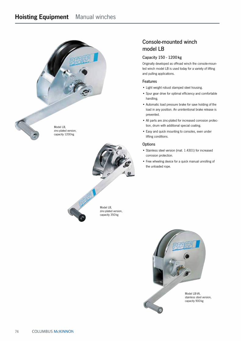
74
Hoisting Equipment Manual winches
Model LB-VA, stainless steel version, capacity 900 kg
Model LB, zinc-plated version, capacity 1200 kg
Model LB, zinc-plated version, capacity 350 kg
Console-mounted winch model LBCapacity 150 - 1200 kgOriginally developed as offroad winch the console-moun-ted winch model LB is used today for a variety of lifting and pulling applications.
Features• Light weight robust stamped steel housing.
• Spur gear drive for optimal efficiency and comfortable handling.
• Automatic load pressure brake for save holding of the load in any position. An unintentional brake release is prevented.
• All parts are zinc-plated for increased corrosion protec-tion, drum with additional special coating.
• Easy and quick mounting to consoles, even under lifting conditions.
Options• Stainless steel version (mat. 1.4301) for increased
corrosion protection.
• Free wheeling device for a quick manual unrolling of the unloaded rope.

75
Hoisting Equipment Manual winches
Model LB 650 - 1200 kg
Model LB 150 - 350 kg
Technical data model LB
Model EAN-No. 4025092*
4050939***Zinc-plated
version
EAN-No. 4025092*
4050939***Free wheeling
device
EAN-No. 4025092*
4050939***Stainless
steel version
Capacity 1st layer
kg
Capacity top layer
kg
Rope diameter
mm
Useable rope length
1st layer
m
Useable rope length top layer
m
Lift per crank
rotation
mm
Required crank effort
daN
Weight without
rope
kg
LB 150 VZ ***050542 – – 150 75 4 ² 0.8 11 125 17 4.2LB 350 VZ ***050559 – – 350 170 4 ² 1.8 20 125 25 4.8LB 650 VZ *994736 – – 650 290 6 ² 1 20 55 22 7.3LB 900 VZ/ARA *994859 *992251 – 900 400 7 ² 0.8 14 58 24 10LB 1200 VZ/ARA *561655 ***049249 – 1200 430 7 ³ 1 26 45 24 12.1LB 250 VA – – *441964 250 125 4 ² 1.8 19.5 125 20 4.8LB 650 VA – – *284875 650 290 6 ² 1 20 55 22 7.6LB 900 VA – – *562461 900 320 7 ² 1 26 45 24 12.1
² recommended rope: DIN 3060 FE-znk 1770 sZ-spa ³ recommended rope: DIN 3069 SE-znk 2160 sZ-spa
Dimensions model LB
Model LB 150 VZ LB 350 VZ LB 650 VZ LB 900 VZ LB 900 ARA
LB 1200 VZ LB 1200 ARA
LB 250 VA LB 650 VA LB 900 VA
EAN-No. Zinc-plated version ***050542 ***050559 *994736 *994859 *561655 – – –EAN-No. Free wheeling device – – – *992251 ***049249 – – –EAN-No. Stainless steel version – – – – – *441964 *284875 *562461A, mm – – 232 232 273 – 232 273B, mm 155 155 192 192 266 155 192 266C, mm 175 175 210 210 240 175 210 240Ø D, mm 36 36 63.5 63.5 63.5 36 63.5 63.5Ø E, mm 100 100 183 183 255 100 183 255F, mm – – 100 100 78 – 100 78G, mm 75 75 58 58 75 75 58 75H, mm – – 100 100 138 – 100 138K, mm 159 189 192 192/226* 192/226* 191.5 190 190L, mm – – 25 25 35 – 25 35M, mm 45 75 38 38 30 75 38 30N, mm – – – – 53 – – 53O, mm 200 320 250 320 320 320 250 250P, mm 260 290 293 293/303* 293/303* 292.5 291 291Q, mm 81 111 95 95 95 111 95 95R, mm 50 80 50 50 50 80 50 50S, mm 48 63 55 55 55 65.5 55 55
*Free wheeling device

76
Hoisting Equipment Manual winches
Console-mounted aluminium rope winch model SW-K GAMMACapacity 200 - 800 kgDue to its rugged design, the aluminium rope winch is suitable for operation outdoors.
Features• Compact aluminium housing and enclosed sprocket
wheel drive. From a capacity of 500 kg with speed increasing ratio for small loads and quicker winding and unwinding of the unloaded rope.
• Spur gear drive for optimal efficiency and comfortable handling.
• Enclosed gear for the protection of parts inside, also for arduous applications.
• Low-friction shaft sliding bearings for improved rope lead-off and a longer service life of the winch.
• Wide rope drum for a large rope capacity with two rope attachment points.
• Easy and quick mounting.
• With integrated safety spring brake system and remov-able crank. The winches can be operated from either side.
Technical data model SW-K GAMMA
Model EAN-No. 4025092*
Capacity 1st layer
kg
Capacity top layer
kg
Rope diameter
mm
Useable rope length
1st layerm
Useable rope length top layer
m
Lift per crank
rotationmm
Required crank effort
daN
Ratio Weight without
ropekg
GAMMA 200 *984690 200 110 4 ² 3.6 40 195 19 – 6GAMMA 500 *983808 500 200 6 ² 4.2 50 60/400 ³ 12 6.57:1 14GAMMA 800 *441346 800 350 7 ² 5.3 78 36/280 ³ 18 7.57:1 16
² recommended rope: DIN 3060 FE-znk 1770 sZ-spa ³ load/speed increasing ratio
Model GAMMA 200 GAMMA 500 GAMMA 800
EAN-No. *984690 *983808 *441346A, mm 120 120 200B, mm 160 220 326C, mm 192 330 336D, mm 152 100 180E, mm 165 267 327F, mm 135 125 250Ø G, mm 9.5 11 14Ø H, mm 50 60 70L, mm 320 250 320M, mm 207 165 207
Dimensions model SW-K GAMMA
Model SW-K GAMMA capacity 800 kg
Model SW-K GAMMA capacity 500 kg

77
Compact aluminium rope winch with free-wheeling device model SW-KALCapacity 750 - 1120 kgConsole-mounted rope winches are used for super-structures on vehicles and trailers and when lifting and lowering loads.
Features• Self-locking worm gear, free-wheeling device for ease of
operation.
• Enclosed gear for the protection of internal parts, also for arduous applications.
• Low-friction shaft bearings for a longer service life of the winch.
• Easy and quick mounting.
Hoisting Equipment Manual winches
Technical data model SW-KAL
Model EAN-No. 4050939***
Capacity 1st layer
kg
Capacity top layer
kg
Drum diameter
mm
Rope diameter
mm
Useable rope length
1st layer
m
Useable rope length
max.
m
Lift per crank
rotation
mm
Lift per crank
rotationtop layer
mm
Required crank effort
daN
Weight without
rope
kg
KAL 750 ***051242 750 600 100 6 ² 1.3 10 15 17 20 7KAL 1120 ***051389 1120 600 63 7 ² 0.5 10 11 16 22 7
² recommended rope: DIN 3060 SE-znk 1770 sZ-spa
Model KAL 750 KAL 1120
Art.-No. 030207004 030208000A, mm 165 165B, mm 168 168C, mm 170 170Ø D, mm 100 63E, mm 180 180F, mm 135 135G, mm 60 60H, mm 56 50J, mm 160 160Ø K, mm 13 13L, mm 85 85
Dimensions model SW-KAL
INFO
Pfaff winches are not designed for passenger elevation applications and must not be used for this purpose.

78
Hoisting Equipment Manual winches
Console-mounted rope winch model SW-K LAMBDA (DGUV Vorschrift 17 [BGV C1])Capacity 300 kgThe compact rope winch for applications on stages, in studios, theatres, etc.
Features• State-of-the-art design with galvanized side sections for
easy handling.
• Grooved drum for single-layer winding of the steel rope. An 18:1 ratio between drum and rope diameter increases the service life of the rope substantially.
• With spring-loaded rope pressure roller to prevent the unloaded rope from jumping off the drum.
• Gear rated for twice the nominal load.
• Spur gear drive for optimal efficiency and comfortable handling.
• The fitted safety crank with two spring brakes acting independently of each other for safe holding of the load in any position.
• Complies with DGUV Vorschrift 17 (BGV C1) and DIN 56925-1.
Options• Drum extension for a larger rope capacity.
• Special grooves (several layers)
Technical data model SW-K LAMBDA (DGUV Vorschrift 17 [BGV C1])
Model EAN-No. 4050939***
Capacity
kg
Rope diameter
mm
Useable rope length max.
1st layerm
Lift per crank
rotationmm
Required crank effort
daN
Ratio Weight without
ropekg
SW-K LAMBDA ***050382 300 6 ⁴ 10 50 18 8.83:1 30SW-K LAMBDA ***050405 300 6 ⁴ 15 50 18 8.83:1 36
⁴ recommended steel rope: 6 DIN 3069 SE-znk 1960 sZ-spa (breaking load of the rope min. 30.4 kN)
Rope pressure drum
EAN-No. ***050382 ***050405
A, mm 379 469B, mm 310 310C, mm 340 340Ø D, mm 139.4 139.4E, mm 180 270F, mm 280 280G, mm 175 265Ø H, mm 13 13J, mm 250 250K, mm 130 130
Dimensions model SW-K LAMBDA (DGUV Vorschrift 17 [BGV C1])
INFO
Certified by the German committee for lifting equipment (GS-approval-tested safety).
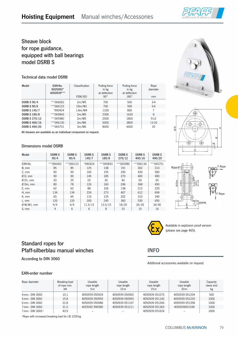
79
Hoisting Equipment Manual winches/Accessories
Model EAN-No. 4025092*
4050939***
Classification
FEM/ISO
Pulling force in kg
at deflection 90°
Pulling force in kg
at deflection 180°
Rope diameter
mm
DSRB S 90/4 ***066062 2m/M5 700 500 3-4DSRB S 90/6 ***066123 1Dm/M1 700 500 5-6DSRB S 145/7 *990424 1 Am/M4 1100 800 7DSRB S 185/8 ***065843 2m/M5 2300 1630 8DSRB S 270/12 ***065980 2m/M5 2500 1800 9-12DSRB S 400/16 ***066130 3m/M6 5000 3800 13-16DSRB S 490/20 ***065751 3m/M6 8000 6000 20
All sheaves are available as an individual component on request.
Technical data model DSRB
Model DSRB S 90/4
DSRB S 90/6
DSRB S 145/7
DSRB S 185/8
DSRB S 270/12
DSRB S 400/16
DSRB S 490/20
EAN-No. ***066062 ***066123 *990424 ***065843 ***065980 ***066130 ***065751B, mm 85 85 125 138 191 302 313C, mm 90 90 160 195 290 430 580Ø D, mm 90 90 145 185 270 400 490Ø D1, mm 20 25 25 30 40 50 65Ø Dm, mm 80 78 126 160 246 368 450E, mm 62 62 88 106 138 212 220H, mm 134 134 224 273 407 612 694K, mm 65 65 110 135 202 310 340L, mm 120 120 200 245 360 530 650Ø M/M1, mm 9/9 9/9 11.5/13 13.5/15 18/20 26/30 34/40S, mm 4 6 6 8 10 15 16
Dimensions model DSRB
Rope diameter Breaking load of rope min.
kN
Useable rope length
5 m
Useable rope length
10 m
Useable rope length
15 m
Useable rope length
20 m
Capacity clevis end
kg
4 mm - DIN 3060 10.1 4050939 050924 4050939 050962 4050939 051075 4050939 051204 5005 mm - DIN 3060 15.8 4050939 050955 4050939 050993 4050939 051143 4050939 051235 10006 mm - DIN 3060 22.8 4050939 050986 4050939 051167 4050939 051266 4050939 051358 10007 mm - DIN 3060 31.0 4025092 990585 4050939 051211 4050939 051365 4050939051549 10007 mm - DIN 3069 ¹ 43.9 – – 4050939 051624 – 1600
¹ Rope with increased breaking load for LB 1200 kg
EAN-order number
Sheave block for rope guidance, equipped with ball bearings model DSRB S
Standard ropes for Pfaff-silberblau manual winchesAccording to DIN 3060
F Rope
F Rope
Rope-Ø
INFO
Additional accessories available on request.
Available in explosion proof version (please see page 465).

80
Hoisting Equipment Cable puller
Cable puller model Yaletrac STPulling force 1000 - 3200 daNCable pullers model Yaletrac ST feature a housing of dimensionally stable deep-drawn steel plates ensuring a compact, robust design in combination with optimised weight. The benefits of the previous Yaletrac range have been maintained and supplemented to the needs of the market. The hand operating forces have been noticeably optimised for the user by the application of axial ball bearings.
Features• Stable upright positioning of the unit due to the combi-
nation of handle and foot.
• Space-saving telescopic hand lever that can be safely attached to the unit by means of a hook-and-pile fastener.
• Increased service life of the unit due to the use of rub-ber sleeves which prevent dirt and dust from penetrat-ing into the mechanical equipment of the unit.
• Positioning of the forward and reversing levers in tandem provides a slim design and ensures optimal power transfer.
• Overload protection is provided by a shearing pin. Spare shear pins are conveniently located in the car-rying handle. A broken pin can be replaced without removing the load.
• A lever disengages the rope clamp system allowing easy and smooth installation of the rope.
• Yaletrac ST uses a special flexible rope. It has six strands with a steel core and is identified by an orange strand. The rope is tapered at one end for easy thread-ing and is fitted with an eye sling hook with safety latch on the other end.
• The parallel arrangement of the clamping system protects the rope by distributing the clamping forces evenly. A long rope advance per each lever stroke increases the working speed.
• The large opening in the top of the unit allows easy cleaning: simply flush the unit with water and apply motor oil for lubrication and the Yaletrac ST is again ready for use.
Options• Eye sling hook with safety latch
• Longer ropes
• Drum reel
• Storage box
Option: Yaletrac storage box made from steel plate, approx. 74 x 26 x 45 cm
Option: Eye sling hook with safety latch

81
INFO
Yale hoists and trolleys are not designed for passenger elevation applications and must not be used for this purpose.
Hoisting Equipment Cable puller
Foot for stable positioning of the unit
Telescopic hand lever – connected to the unit safely for transportation
Rubber sleeves prevent dirt from penetrating into the mechanical equipment and thus increase the service life
Axial ball bearings for optimised hand operating forces
Rope clamp disengagement lever for easy installation of the rope
Model Y 10 ST Model Y 16 ST Model Y 32 ST
L
H
B
H1
LB
B 1
H1
H
L B
B 1H
1
H
Technical data model Yaletrac ST
Model EAN-No. 4025092*
Capacity WLLkg
Rope advance per double stroke
mm
Lever pull at WLL
daN
Lever length
mm
Rope diameter
mm
Weight without rope
kg
Rope weight kg/m
Y 10 ST *422901 1000 60 23 800 8.4 8.5 0.29Y 16 ST *422925 1600 60 28 790/1190 11.5 15.8 0.53Y 32 ST *422963 3200 40 46 790/1190 16 27.2 1.0
Dimensions model Yaletrac ST
Model Y 10 ST Y 16 ST Y 32 ST
L, mm 435 560 664H, mm 178 205 240H1, mm 235 280 350B, mm 61 86 96B1, mm 94 125 123

82
Hoisting Equipment Cable puller
Cable puller model YaletracPulling force 800 - 3200 daNIt has a light weight, compact, high tensile aluminium al-loy housing with a large flat bottom surface for increased stability in horizontal as well as vertical working position.
Features• Forward and reversing levers in tandem provide slim
design and assure power transfer along the centre line.
• Overload protection is by a shearing pin in the forward lever. Spare shear pins are conveniently located in the carrying handle or operating lever. A broken pin can be replaced without removing the load.
• A lever disengages the rope clamp system allowing easy, smooth installation of the rope.
• Yaletrac uses a special flexible rope. It has six strands with a steel core and is identified by an orange strand. The rope is tapered at one end for easy threading and fitted with an eye sling hook with safety latch on the other end.
• The parallel arrangement of the clamping system protects the rope by distributing the clamping forces evenly. A long rope advance per each lever stroke increases the working speed.
• The large opening in the top of the unit allows easy cleaning: simply flush the unit with water, apply motor oil for lubrication and the Yaletrac is again ready for use.
Options• Eye sling hook with safety latch
• Longer ropes
• Drum reel
• Storage box
Opening for cleaning
Rope clamp disengagement lever
Aluminium housing
Special wire rope
Tandem clamping system Operating handlever
Anchor pin
Overload protection (shear pin)
Forward and reversing levers

83
Hoisting Equipment Cable puller
Technical data model Yaletrac
Model EAN-No. 4025092*
Capacity WLLkg
Rope advance per double stroke
mm
Lever pull at WLL
daN
Lever length
mm
Rope diameter
mm
Weight without rope
kg
Rope weight kg/m
Y 08 *051811 800 60 24 800 8.4 7 0.29Y 16 *051828 1600 60 30 790/1190 11.5 14 0.53Y 32 *078870 3200 40 50 790/1190 16 21 1
Dimensions model Yaletrac
Model Y 08 Y 16 Y 32
L, mm 430 545 680H, mm 168 190 230H1, mm 240 270 330B, mm 60 72 91B1, mm – 97 110
Option: Yaletrac storage box made from steel plate, approx. 74 x 26 x 45 cm
Option: Eye sling hook with safety latch
Model Y 08 Model Y 16 Model Y 32
L
H
B
H1
LB
B 1
H1
H
L B
B 1H
1
H
INFO
Yale hoists and trolleys are not designed for passenger elevation applications and must not be used for this purpose.
Complementary products available like cable grips (see page 87), pulley blocks (see page 86) and textile slings (see pages 232 - 235).

84
Hoisting Equipment Cable puller
Cable puller model LPCapacity 500 kgA practical aid for pulling, lifting, tensioning and lowering in many applications in- and outdoors. A compact, handy tool – ideal for service and assembly, for workshops and recreation.
Features• The stamped steel housing is lightweight and resistant.
• The complete set comprises of a cable puller with anchor bolt and eye sling hook, telescopic operating lever, 10 metres of wire rope, carrying handle and a webbing sling of 1 metre length which can be used as a rigging point.
Technical data model LP
Model EAN-No. 4025092*
Capacity WLLkg
Rope advance per double stroke
mm
Lever pull at WLL
daN
Lever length
mm
Rope diameter
mm
Weight without rope and lever
kg
LP 500 *051804 500 35 15 600 8.3 4
14,
434
6590 277 875137
46
6
5113
321
5
14,5
INFO
Yale hoists and trolleys are not designed for passenger elevation applications and must not be used for this purpose.

85
Cable puller model LMPulling force 500 - 1800 daNThe use of aluminium alloy castings provide a lightweight, corrosion resistant unit for pulling and tensioning ap-plications. The double interlocking pawl system ensures safe function, all load bearing shafts are mounted on prelubricated bearings to reduce wear.
Features• All springs and shafts are manufactured from stainless
steel. The lifting medium is a non-twisting, galvanized, special steel wire rope.
• The hooks are fitted with safety latches and are free to rotate 360°.
• The cable puller LM can be used in single or double legged configuration. In double legged configuration the pulling force is doubled and the lifting height is halved.
Hoisting Equipment Cable puller
Technical data model LM
Model EAN-No. 1 legged design 2 legged design Weight Lever Hook Rope4025092* pulling force
daNhook path
mheadroom
mmpulling force
daNhook path
mheadroom
mm
kglength mm
openingmm
diametermm
115 DV-B *077293 500 4.6 550 1000 2.3 700 4.5 420 22 4.8202 WN-VB *077309 500 6.0 525 1000 3.0 690 5.2 520 22 4.8434 WN-VB *077316 500 9.0 550 1000 4.5 710 5.8 530 22 4.8S 434 WN-VB *077491 700 6.0 565 1400 3.0 725 6.0 530 22 5.6S 404 WN-VB *077323 900 5.2 575 1800 2.6 720 5.9 635 22 6.4
Rigging configurations - Attention! reduced capacity!
β max. 60°
INFO
Yale hoists and trolleys are not designed for passenger elevation applications and must not be used for this purpose.
The units may only be used for pulling and tensioning. Lifting and lowering of loads is not permitted.

86
Hoisting Equipment Cable puller/Accessories
Pulley blocks, hinged, with single steel sheaveCapacity 1000 - 6400 kgOne side of the Yale pulley blocks is hinged and can be opened for easy and quick positioning of the wire rope on the sheave. It can also provide a quick and versatile rigging point or redirect a wire rope.
Features• Swinging the hook in the direction of pull securely locks
the pulley block.
• The high quality cast steel sheaves have machined grooves and are fitted with Permaglide® bushes.
• When choosing and classifying pulley blocks, take the “Principles for Rope Drives“ DIN 15020 into considera-tion.
Model EAN-No. 4025092*
Capacitykg
Rope diametermm
Weightkg
Pulley blocks 1000 *455817 1000 7 3.3Pulley blocks 2000 *455794 2000 13 8.9Pulley blocks 3200 *455800 3200 15 15.5Pulley blocks 6400 *455824 6400 18 26.5
Technical data pulley blocks
Model Kloben 1000
Kloben 2000
Kloben 3200
Kloben 6400
B, mm 118 199 230 270B1, mm 76 92 108 116B2, mm 17 24 28 35C, mm 23 27 31 42Ø D1, mm 85 150 180 210Ø D2, mm 105 190 220 260L, mm 305 425 496 655L1, mm 200 263 295 375L2, mm 23 30 40 47R, mm 4 7 9 10
Dimensions pulley blocks
B
L
C
R
L1
L2
B 1
B2
øD2
øD1
INFO
Yale hoists and trolleys are not designed for passenger elevation applications and must not be used for this purpose.

87
Cable grip model LMGPulling force 2000 - 5000 daNThe LITTLE MULE® cable grip is a device for gripping, pulling and tensioning uncoated wire ropes, cables and metal rods in all forms up to a tensile strength of 1770 N/mm2 but is dependant on the diameter and surface condition.
The parallel jaws provide a firm, non-slip grip without causing damage to the wire rope. A special spring-loaded guide prevents the grip from dropping off the wire rope and allows instant release without jamming.
The model LMG II-X is supplied with grooved jaws and is suitable for wire ropes with a tensile strength of up to 1960 N/mm2, but is dependant on the rope diameter and surface condition.
Hoisting Equipment Cable puller/Accessories
Technical data model LMG
Model EAN-No. 4025092*
Pulling force
daN
For rope diameter
mm
Eye opening
mm
Weight
kg
LMG I *052214 2000 5 - 15 31 x 44 1.6LMG II *052221 3000 8 - 20 31 x 44 2.9LMG II-X *052245 3000 8 - 20 31 x 44 2.9LMG III *052238 5000 18 - 32 66 x 93 9.5
INFO
Yale hoists and trolleys are not designed for passenger elevation applications and must not be used for this purpose.

88
Hoisting Equipment User information
Steel rope for manual and electric winchesAll Pfaff-silberblau electric winches are supplied without load bearing mechanisms as standard. To ensure safe operation an optimum rope design, optimum length and associated fastening elements (hooks, shackles) are selected.
We recommend to choose wire ropes on the basis of design, type of construction and strength to suit the intended use and frequency of use. The features of the different types of rope design are as follows:
Breaking load→ Load bearing capacity, strength of the rope
Bending fatigue + flexibility → Service life
External wear → Stability of the outer strands
Torsion characteristics → Lifting of guided or unguided loads
Handling
Our product range includes winches for lifting, pulling and moving of loads. In combination to our winches the follow-ing rope types apply:
Standard design 6 x 19 + FE 1770 N/mm²Manual winch rope with fiber inlay 3 - 12 mm Ø
Galvanized or stainless steel in mat. 1.4401 Nominal strength 1570 N/mm² (low breaking load)
• not non-twisting
• crosslay type of construction
• low-tension
• lifting rope for infrequent actuation
• rugged and widely resistant
Warrington-Seale 6 x 36 WS + SES (FE) 1770 N/mm²Manual and electric winch rope in parallel type of construction 10 - 28 mm Ø
Galvanized, with fiber or steel inlays as options
• highly flexible
• high breaking load
• average number of reversed bending stresses
Non-rotating special rope SE-znk - 1960 N/mm²Standard rope for electric winches, non-rotating spiral strand rope 3 - 13 mm Ø
Galvanized
• balanced characteristics
• lifting rope for unguided single rope suspension ele-ments
• lifting rope for large lifting heights with multiple rope suspension elements
• not to be used with a swivel
• high strength
• high bending fatigue characteristics
Heavy duty winch ropeElectric winch rope with plastic-coated steel core in double-parallel type of construction 6 - 30 mm Ø
Bright and greased, not non-twisting
• special rope for frequent bending stress reversals and long use
• to be used only with matching rope sheaves and drums
• optimized break loads due to higher fill factor
INFO
The use of plastic-coated steel wire ropes with lifting equipment is not permitted.
To meet individual requirements we can provide assist-ance for the selection of length, diameter and type of the rope, as well as a fastening equipment (thimbles, hooks, rope clips, etc.).

89
Hoisting Equipment User information
Rope fasteners/rope connectionsThe safe functioning of the rope drive depends to a large extent on the rope fastenings on the winch and on the load. Rope connections and ropes themselves have to be checked at regular intervals by competent persons. The following rope connections are permissible for use with lifting equipment:
Non-releasable rope connectionsAluminium press-on connection with thimbles
in combination with safety eye hooks or screw shackles provide a simple and safe means of suspending loads.
Splice connections (uncoated)in combination with thimbles, hooks, etc.
In the most unfavourable situation, splice connections can lead to a reduction in the breaking load of the rope line of up to 40 %.
Releasable rope connectionsRope clips
• The end which is not under load must never be fas-tened to the load-bearing line.
• The length of the unloaded rope end should be at least 20 times the diameter of the rope and not less than 150 mm.
• Clips may no longer be used once the rope has worn by more than 10 %.
• Wire rope clamps may not be used for rope con-nections for lifting equipment, with the exception of fastening equipment which is manufactured for none-recuring, special purposes!
Handling of ropes – Unwinding
RIGHT
WRONG
Care of ropes“Running ropes“ in particular will only offer optimum service lives if they are well lubricated. The use of steel ropes without grease will cause them to wear quickly and the load bearing mechanism will have to be replaced early.
INFO
Pressed and splice connections may only be produced by specialist firms or rope manufacturers.
Notes on the installation of winches
The distance between rope drum and sheave must be selected in a way that the maximum deflection angle for the type of rope used is not exceeded:
Standard rope – Deflection angle < 3° (Minimum distance = Drum width x 10)
Special rope - Deflection angle < 1.5° (Minimum distance = Drum width x 20)
• To prevent the wire rope from becoming slack when un-loaded it should always have an additional rope weight when used with lifting equipment
• Guided loads must be monitored with a slack rope cut-out.
• To prevent the rope from becoming damaged, steel wire ropes must never be guided - over edges - over deflection radii which are too small or - over rope sheaves with grooves which are too small.
• High dynamic forces can lead to sudden breaks or crashes of the load. It is therefore imperative that loads are never brought to a dead stop (“on block“) and that loads are never allowed to drop into the rope.

90
Hoisting Equipment Electric & Pneumatic winches
Applications of electric winchesPfaff-silberblau and Yale winches are versatile tools made to lift, lower, pull or position loads. All winches are characterized by high-quality components and drive mo-tors, irrespective of the design as standard or customized version. All products are differentiated by long lifetimes and a reli-able operational safety.
Capacities between 250 kg up to 7500 kg make them a versatile tool for a great number of applications: general industry, aviation and maritime industries, construction, theatres and studios, distributors, retailing and trade, furniture and department stores as well as passenger elevation.
Königsgalerie Duisburg (Image top left)
A number of BETA winches are used to provide visitors to the Königsgalerie shopping centre with an attractive spectacle suspended up high.In continuous operation, the individual segments of a crown are moved so as to form the impression of a complete crown at regular intervals following various lifting paths.
Tiblisi Centre of Music and Culture (Image left)
Thanks to the immense load of three redundant DELTA theatre winches, a heavy sound element weighing approx. 35 t is moved above the heads of the audience. Two redundantly arranged gear motors with a brake on each winch are also used to guarantee maximum safety.
Flood defence in Dresden
Ready for action at all times – this is the most important feature of the BETA traversing winch, which, in an emergency in Dresden, ensures that a flood defence barrier is pulled across the road in good time, thus protecting the city against flood waters from the river Elbe.

91
Electric construction winch model EBW 200Capacity 200 kgFor easy and quick lifting and lowering of loads on con-struction sites.
Features• Extending slewing frame and clips for tube racks up to
max. 45 mm, quickly ready for use.
• Operating cable (length: 1 m) and push-button pendant control with emergency stop.
• Standard operating voltage: 230 V, 1-phase, 50 Hz
Hoisting Equipment Electric & Pneumatic winches
Technical data model EBW 200
Model Art.-No. Capacitykg
Lifting heightm
Lifting speedm/min
Weight without ropekg
EBW 200 031100030 200 25 19.2 48.5
INFO
Pfaff winches are not designed for passenger elevation applications and must not be used for this purpose.

92
Hoisting Equipment Electric & Pneumatic winches
Electric winch model RPECapacity 250 - 1000 kgWinches series RPE and RPA are designed explicitly for performance, efficiency and safety and offer many advan-tages and options. RPE‘s and RPA‘s extremely compact, practical cube design and universal rope lead-offs allow individual applications in almost any position and make them powerful aids for lifting and pulling loads. The winches are designed to DIN 15020, classification 1 Bm/M3, safety regulation DGUV Vorschrift 52 (BGV D8) and, of course, the EC machinery directives.
Every winch is factory tested with overload. The units are supplied with a test certificate showing the unit‘s serial-no. and an operating instructions manual which contains a manufacturer‘s declaration.
Features• Compact dimensions due to internal brake motor.
• Voltage 400 V/230 V, 3-phase, 50 Hz, protected to IP 54, insulation class F.
• Adjustable slip clutch to protect the winch from over-loading standard for model RPE 10-6.
• Spur gear transmission with helical first gear ensures smooth motion. Lubricated by grease and can, there-fore, be used in any position.
• Spring pressure disc brake incorporated in the motor holds the load secure even in the event of a power failure.
• Plain rope drum standard.
• The rope is secured to the drum in a recess so that the rope can be wound onto the drum in several layers without damage.
• Direct control or 42 V low voltage control (incl. push-button with emergency-stop and 2 m control cable).
Rope attachment Spring pressure disc brake Brake motor
INFO
When selecting the length of the rope please bear in mind that a minimum of 2-3 windings have to remain on the drum.
Yale hoists and trolleys are not designed for passenger elevation applications and must not be used for this purpose.

93
Hoisting Equipment Electric & Pneumatic winches
Single-phase A.C. motor Geared limit switches Gearbox with slip clutch Different drum designs
Options• Different drum designs, e.g. extended to accommodate
longer rope, machined grooves for exact reeling, with separation web and 2nd rope outlet for working with two ropes.
• Geared limit switches to limit rope motion in both direc-tions (in combination with 42 V low voltage control).
• Single-phase A.C. motor 230 V, 50 Hz, 42 V low voltage control.
• Slack rope switch to automatically stop the winch when rope tension eases e.g. when the load touches down (only in combination with low voltage control).
• Frequency converter for stepless speed control.
• Adjustable slip clutch to protect the winch from over-loading for models RPE 2-13, RPE 5-6 and RPE 5-12.
• Special design according to DGUV Vorschrift 17 (BGV C1) for theater stage applications available.
• Radio remote control
• Other operating voltages
• Stainless brake INFO
Special design for wind energy as well as customised constructions on request!
Also available as zinc-plated version on request!

94
Hoisting Equipment Electric & Pneumatic winches
Model Capacity top layer
kg
Drum size Useable rope length max.
m
RPE 2-13 L 250 2 80RPE 5-6 L 500 2 58RPE 9-6/10-6 L 990/1000 2 56RPE 2-13 XL 250 3 200RPE 5-6 XL 500 3 140RPE 5-12 XL 500 3 140RPE 9-6/10-6 XL 990/1000 3 100
Plain drum (longer useable rope length)
Technical data model RPE
Model EAN-No. 4025092*
Capacity
kg
Lifting speed
1st layer
m/min
Lifting speed
top layer
m/min
Rope diameter
mm
Motor
kW
ED
%
Useable rope length
1st layer
m
Useable rope length top layer
m
Weight without
rope
kg
RPE 2-13 *071796 250 10.2 13.2 4 0.55 40 11.2 54.5 31.8RPE 5-6 *071857 500 4.6 6.6 6 0.55 40 7.0 38.8 32.8RPE 5-12 *071918 500 8.7 12.6 6 1.1 40 11.0 55.4 41.0RPE 9-6 *071956 990 5.1 6.5 8 1.1 40 10.2 37.4 76.0RPE 10-6 ¹ *072014 1000 5.1 6.5 8 1.1 40 10.2 37.4 76.9
¹ With slip clutch
Model Capacity top layer
kg
Drum size Useable rope length 1st layer
m
Useable rope length max.
m
RPE 2-13 R 250 1 8.8 43RPE 5-6 R 500 1 6.2 33RPE 9-6/10-6 R 990/1000 1 8.2 30RPE 2-13 LR 250 2 13.3 64RPE 5-6 LR 500 2 9.5 49RPE 5-12 LR 500 2 9.5 49RPE 9-6/10-6 LR 990/1000 2 12.9 47RPE 2-13 XLR 250 3 35.3 165RPE 5-6 XLR 500 3 25.7 128RPE 5-12 XLR 500 3 25.7 128RPE 9-6/10-6 XLR 990/1000 3 25.2 89
Grooved drum (recommended for single layer operation)
INFO
When selecting the length of the rope please bear in mind that a minimum of 2-3 windings have to remain on the drum.
Yale hoists and trolleys are not designed for passenger elevation applications and must not be used for this purpose.
Winches with drums for longer useable rope lengths have partly other dimensions than those shown on page 95.

95
Hoisting Equipment Electric & Pneumatic winches
α 1
α 2α 3
Dmax.
β 2β 3
β 1
Dmax.
Rope lead-offs for electric winch RPE
Dimensions model RPE (400 V direct control, standard drum)
Model RPE 2-13 RPE 5-6 RPE 5-12 RPE 9-6 RPE 10-6
A, mm 405 405 405 525 525B, mm 375 375 375 485 485C, mm 18 18 18 25 25DTR, mm 76 76 76 108 108D max, mm 104 118 118 148 148DA, mm 150 150 150 180 180E, mm 338 338 428 450 450F, mm 210 210 300 270 270G, mm 260 260 350 345 345H, mm 290 290 380 380 380I, mm 11 11 11 13 13K, mm 250 250 250 340 340L, mm 125 125 125 170 170M, mm 6 6 6 10 10N, mm 33 33 33 47.5 47.5O, mm 194 194 284 250 250P, mm 19 19 19 24 24Q, mm 13 13 13 19 19R, mm 125 125 125 170 170S, mm 4 6 6 8 8α 1, ° 130 130 130 145 145α 2, ° 110 110 110 125 125α 3, ° 40 40 40 50 50β 1, ° 150 150 150 155 155β 2, ° 90 90 90 100 100β 3, ° 80 80 80 83 83
Dimensions for s with optional features are available on request!

96
Hoisting Equipment Electric & Pneumatic winches
Pneumatic winch model RPACapacity 250 - 500 kgThe conception is in accordance with the design of the model RPE. With 100 % duty rating and an unlimited number of starts the model RPA is suitable for heavy duty applications. It is insusceptible to contamination, humidity and aggressive mediums from the outside.
Features• Robust rotating piston motor with high starting torque,
designed for operating pressures 4 to 6 bar.
• Spring pressure disc brake incorporated in the motor holds the load secure even in the event of an air failure.
• Sensitive control by means of direct acting valves in the control switch.
Options• Different drum designs, e.g. extended to accommodate
longer rope, machined grooves for exact reeling, with separation web and 2nd rope outlet for working with two ropes.
• Control including 2.5 m hose and air coupler.
• Maintenance unit for main air supply pipe (pressure regulator, manometer, lubricator and support).
Rope attachment Different drum designs
INFO
To ensure faultless operation the compressed air supply must be filtered and oiled!
Available in corrosion proof version on request!
Yale hoists and trolleys are not designed for passenger elevation applications and must not be used for this purpose.

97
Hoisting Equipment Electric & Pneumatic winches
Technical data model RPA
Model EAN-No. 4025092*
Capacity
daN
Lifting speed with
rated load ¹m/min
Lifting speed without load ¹
m/min
Lowering speed with
rated load ¹m/min
Rope diameter
mm
Motor
kW
Useable rope length top layer
m
Weight without
rope
kg
RPA 2-13 *072397 250 12.5 20 22 4 0.55 54.5 36.7RPA 5-6 *072458 500 6.2 10 11 6 0.55 38.8 36.7
¹ Values in the top layer for 6 bar, air consumption 0.75 m³/min
Model RPA 2-13 RPA 5-6
A, mm 405 405B, mm 375 375C, mm 18 18DTR, mm 76 76Dmax, mm 104 118DA, mm 150 150E, mm 336 336F, mm 210 210G, mm 260 260H, mm 290 290I, mm 11 11K, mm 250 250L, mm 125 125M, mm 6 6N, mm 33 33O, mm 194 194P, mm 19 19Q, mm 13 13R, mm 125 125S, mm 4 6α 1, ° 130 130α 2, ° 90 90α 3, ° 20 20β 1, ° 150 150β 2, ° 70 70β 3, ° 60 60
Dimensions model RPA
Rope lead-offs for pneumatic rope winch RPA
INFO
When selecting the length of the rope please bear in mind that a minimum of 2-3 windings have to remain on the drum.

98
Hoisting Equipment Electric & Pneumatic winches
Electric winch model BETA SLCapacity 250 - 2000 kgElectric winches of the BETA SL range are used for lifting, towing and positioning of loads. The proven technology and specified equipment features make the winch the ideal product for standard applica-tions.
Features• The electrically released spring pressure disc brake
safely holds the load also in the event of a power failure.
• Powerful three-phase AC drives for multi-range voltage 380 - 420 V, 50 Hz or 440 - 460 V, 60 Hz. Motor type of enclosure IP 55, duty factor 40 % ED.
• Electronic overload protection from 1000 kg lifting load as standard.
• The maintenance-free, oil lubricated gearbox has quiet running characteristics due to milled and ground gears with helical teeth.
• Standard rope drum of grooved design, with large rope capacity.
• Variable rope lead-in.
• Contactor control (incl. gear limit switch).
• Complies DGUV Vorschrift 54 (BGV D8).
Also availabl
e at
short notice w
ith the
following op
tions:
• Rope pressure roll Supports the tidy coiling of the rope, especially with high lifting heights.
• Slack rope switch Prevents unwanted uncoiling if the wire rope is not under load.
• Control switch with 3 m control cable Greater freedom of movement for the user, better view of the working area of the wire rope winch.
• Frequency converter (SL 1 - SL 3) Infinitely variable rope speed controlled via potentiom-eter, control range 20-87 Hz (SL 3 = 20-50 Hz). The frequency converter allows loads to be moved gently and sensitively.
Optional: Frequency converter (For infinitely variable speed regulation)

99
Hoisting Equipment Electric & Pneumatic winches
Technical data model BETA SL
EAN-No. 4053981** 4050939***
Size Capacity 1st layer
kg
Lifting speed
1st layerm/min
Rope diameter ³
mm
Motor
kW
Classification
FEM/ISO
Useable rope length1st layer
m/min
top layer
m/min
**011912 SL 0 250 2.5 4 0.25 1Bm/M3 7 46.7***050498 SL 0 250 4.7 4 0.37 1Bm/M3 7 46.7 **011929 SL 1 500 6.8 6 0.75 1Am/M4 6.7 48.9 **011936 SL 1 630 6.8 6 0.75 1Bm/M3 6.7 48.9 **011943 SL 2 980 6.0 9 1.1 1Am/M4 11 77.5 **011950 SL 2 1250 6.0 9 1.1 1Am/M4 11 77.5 **011967 SL 3 2000 6.8 12 2.2 1Bm/M3 10 74.5
³ recommended rope: DIN 3069 FE-znk 1960 sZ-spa
EAN-No. **011912 ***050498 **011929 **011936 **011943 **011950 **011967
A, mm 185 185 215 215 270 270 320B, mm 170 170 300 300 400 400 510Ø C, mm 12 12 13.5 13.5 18 18 22F, mm 389 389 740 750 920 930 1070G, mm 200 200 340 340 465 465 570H, mm 241 241 340 345 475 480 614K, mm 432 – – – – – –L, mm 180 180 200 200 250 250 300Ø M, mm 64 64 86 86 175 175 175
Dimensions model BETA SL
INFO
Additional options and an adaptation for special applications are offered exclusively for model BETA EL (see page 100).
Pfaff winches are not designed for passenger elevation applications and must not be used for this purpose.
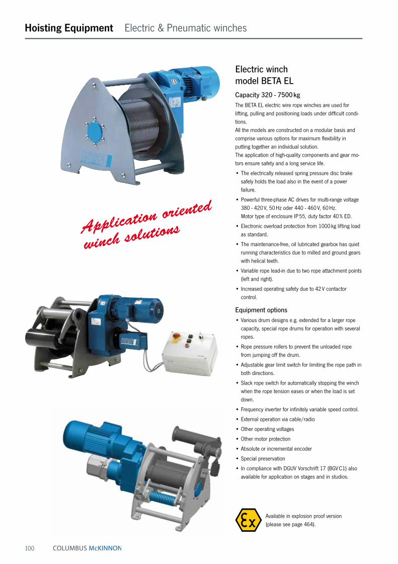
100
Hoisting Equipment Electric & Pneumatic winches
Electric winch model BETA ELCapacity 320 - 7500 kgThe BETA EL electric wire rope winches are used for lifting, pulling and positioning loads under difficult condi-tions. All the models are constructed on a modular basis and comprise various options for maximum flexibility in putting together an individual solution. The application of high-quality components and gear mo-tors ensure safety and a long service life.
• The electrically released spring pressure disc brake safely holds the load also in the event of a power failure.
• Powerful three-phase AC drives for multi-range voltage 380 - 420 V, 50 Hz oder 440 - 460 V, 60 Hz. Motor type of enclosure IP 55, duty factor 40 % ED.
• Electronic overload protection from 1000 kg lifting load as standard.
• The maintenance-free, oil lubricated gearbox has quiet running characteristics due to milled and ground gears with helical teeth.
• Variable rope lead-in due to two rope attachment points (left and right).
• Increased operating safety due to 42 V contactor control.
Equipment options• Various drum designs e.g. extended for a larger rope
capacity, special rope drums for operation with several ropes.
• Rope pressure rollers to prevent the unloaded rope from jumping off the drum.
• Adjustable gear limit switch for limiting the rope path in both directions.
• Slack rope switch for automatically stopping the winch when the rope tension eases or when the load is set down.
• Frequency inverter for infinitely variable speed control.
• External operation via cable/radio
• Other operating voltages
• Other motor protection
• Absolute or incremental encoder
• Special preservation
• In compliance with DGUV Vorschrift 17 (BGV C1) also available for application on stages and in studios.
Application oriented
winch solutions
Available in explosion proof version (please see page 464).
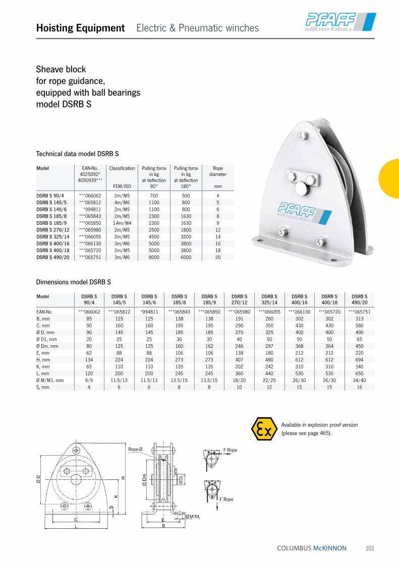
101
Hoisting Equipment Electric & Pneumatic winches
Sheave block for rope guidance, equipped with ball bearings model DSRB S
Dimensions model DSRB S
Model DSRB S 90/4
DSRB S 145/5
DSRB S 145/6
DSRB S 185/8
DSRB S 185/9
DSRB S 270/12
DSRB S 325/14
DSRB S 400/16
DSRB S 400/18
DSRB S 490/20
EAN-No. ***066062 ***065812 *994811 ***065843 ***065850 ***065980 ***066055 ***066130 ***065720 ***065751B, mm 85 125 125 138 138 191 260 302 302 313C, mm 90 160 160 195 195 290 350 430 430 580Ø D, mm 90 145 145 185 185 270 325 400 400 490Ø D1, mm 20 25 25 30 30 40 50 50 50 65Ø Dm, mm 80 125 125 160 162 246 297 368 364 450E, mm 62 88 88 106 106 138 180 212 212 220H, mm 134 224 224 273 273 407 490 612 612 694K, mm 65 110 110 135 135 202 242 310 310 340L, mm 120 200 200 245 245 360 440 530 530 650Ø M/M1, mm 9/9 11.5/13 11.5/13 13.5/15 13.5/15 18/20 22/25 26/30 26/30 34/40S, mm 4 6 6 8 8 10 12 15 15 16
Model EAN-No. 4025092*
4050939***
Classification
FEM/ISO
Pulling force in kg
at deflection 90°
Pulling force in kg
at deflection 180°
Rope diameter
mm
DSRB S 90/4 ***066062 2m/M5 700 500 4DSRB S 145/5 ***065812 4m/M6 1100 800 5DSRB S 145/6 *994811 2m/M5 1100 800 6DSRB S 185/8 ***065843 2m/M5 2300 1630 8DSRB S 185/9 ***065850 1 Am/M4 2300 1630 9DSRB S 270/12 ***065980 2m/M5 2500 1800 12DSRB S 325/14 ***066055 2m/M5 4500 3200 14DSRB S 400/16 ***066130 3m/M6 5000 3800 16DSRB S 400/18 ***065720 2m/M5 5000 3800 18DSRB S 490/20 ***065751 3m/M6 8000 6000 20
Technical data model DSRB S
F Rope
F Rope
Rope-Ø
Available in explosion proof version (please see page 465).

102
Hoisting Equipment Endless winches
Mobile
endless winch
up to 300 kg!
Endless winch, mobile model YaleMtracCapacity 100 - 300 kgThe new compact and light weight mobile Yale-Endless winch, model YaleMtrac combines modern industry design with technical innovation. During the development stage, focus was set on simple and safe operation for mobile applications. The winch is capable of lifting loads up to 300 kg over long distances at high speed. The highlight of the YaleMtrac winch is the increased ef-ficiency as it can be operated bi-directionally. The Yale Mtrac winch can lift, lower and pull loads at rated capacity in either direction. Depending on the ap-plication unnecessary waiting time to return the load hook to its start position may be eliminated. A wide range of ropes and accessories (eye sling hooks, self-locking hooks, shackles ) ensure that YaleMtrac winch can be used in many different applications.
Features• The robust, precisely machined housing of die-cast
aluminium with impact resistant plastic cover ensures a low deadweight and outstanding rigidity.
• The externally adjustable slip clutch is designed to guarantee a permanent connection between the load and the brake.
• High speed versions available to increase efficiency for high lifts.
• Easy access to all wearing parts due to modular design.
• The standard, oil bath lubricated and case hardened gearbox has a helical gearing for particularly smooth running and enhanced lifetime.
• Drive sheave made of specially hardened steel to minimize wear of the components.
• The standard version is supplied with an eye sling hook with safety latch.
• Multiple fixing points in the housing allow the YaleMtrac to be suspended in various positions.
• Classification: 1Bm/M3 acc. to FEM/ISO.
• Motor protected to IP 55 (acc. to VDE 0530), against ingress of dust and water jets.
• Standard operating voltage: Euro-voltage: 400 V, 3-phase, 50 Hz and 230 V, 1-phase, 50 Hz.
• Rubber buffers ensure no surface contact damage.
• Push-button pendant control, IP 65 against ingress of dust and water jets from all directions.
• Limit switch for upward and downward travel.
Options• Radio remote control with high range.
• Other operating voltages on request.
• Non-rotating steel wire ropes.
• Manual and electric trolleys.
• Frequency converter
• Transport and carrying frames for various applications.
• Counters for operating hours.
New!

103
Hoisting Equipment Endless winches
Technical data model YaleMtrac
Model Capacity
kg
Lifting speedm/min
Rope diameter
mm
Motor
kW
Operating voltage
YMT 1-15 100 15 6.5 0.25 230 V/1 Ph/50 HzYMT 3-5 300 5 6.5 0.25 230 V/1 Ph/50 Hz
YMTF 0,6-30 66 30/7.5 6.5 0.37 400 V/3 Ph/50 HzYMT 1-30 100 30 6.5 0.55 400 V/3 Ph/50 HzYMTF 2-10 200 10/2.5 6.5 0.37 400 V/3 Ph/50 HzYMT 3-10 300 10 6.5 0.55 400 V/3 Ph/50 Hz
Dimensions
A, mm 385A1, mm 287A2, mm 272A3, mm 221A4, mm 119B, mm 22C, mm 29D, mm 19E, mm 202E1, mm 92F, mm 132F1, mm 93F2, mm 147G, mm 100G1, mm 84G2, mm 103H, mm 201K, mm M8L, mm 426L1, mm 159L2, mm 147
F2
HG1
G
K
D
FF1
G2
LL1 L2E
A1
A2
A
A4
E1
C
BA3
Option:
Equipment based on transport frame and/or ergonomic handles facilitate handling and transport.
INFO
Yale hoists and trolleys are not designed for passenger elevation applications and must not be used for this purpose.
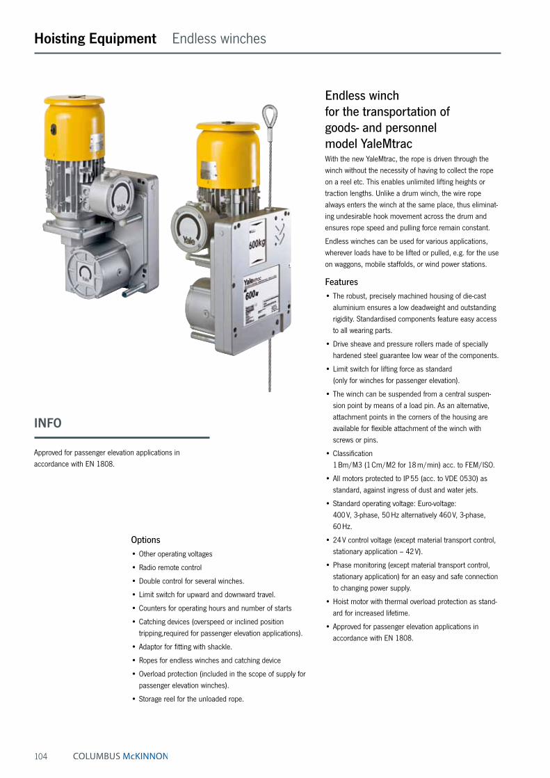
104
Hoisting Equipment Endless winches
Endless winch for the transportation of goods- and personnel model YaleMtracWith the new YaleMtrac, the rope is driven through the winch without the necessity of having to collect the rope on a reel etc. This enables unlimited lifting heights or traction lengths. Unlike a drum winch, the wire rope always enters the winch at the same place, thus eliminat-ing undesirable hook movement across the drum and ensures rope speed and pulling force remain constant.
Endless winches can be used for various applications, wherever loads have to be lifted or pulled, e.g. for the use on waggons, mobile staffolds, or wind power stations.
Features• The robust, precisely machined housing of die-cast
aluminium ensures a low deadweight and outstanding rigidity. Standardised components feature easy access to all wearing parts.
• Drive sheave and pressure rollers made of specially hardened steel guarantee low wear of the components.
• Limit switch for lifting force as standard (only for winches for passenger elevation).
• The winch can be suspended from a central suspen-sion point by means of a load pin. As an alternative, attachment points in the corners of the housing are available for flexible attachment of the winch with screws or pins.
• Classification 1 Bm/M3 (1 Cm/M2 for 18 m/min) acc. to FEM/ISO.
• All motors protected to IP 55 (acc. to VDE 0530) as standard, against ingress of dust and water jets.
• Standard operating voltage: Euro-voltage: 400 V, 3-phase, 50 Hz alternatively 460 V, 3-phase, 60 Hz.
• 24 V control voltage (except material transport control, stationary application – 42 V).
• Phase monitoring (except material transport control, stationary application) for an easy and safe connection to changing power supply.
• Hoist motor with thermal overload protection as stand-ard for increased lifetime.
• Approved for passenger elevation applications in accordance with EN 1808.
Options• Other operating voltages
• Radio remote control
• Double control for several winches.
• Limit switch for upward and downward travel.
• Counters for operating hours and number of starts
• Catching devices (overspeed or inclined position tripping,required for passenger elevation applications).
• Adaptor for fitting with shackle.
• Ropes for endless winches and catching device
• Overload protection (included in the scope of supply for passenger elevation winches).
• Storage reel for the unloaded rope.
INFO
Approved for passenger elevation applications in accordance with EN 1808.

105
Hoisting Equipment Endless winches
Technical data model YaleMtrac Winches for material transport
Model EAN-No. 4025092*
for stationary
application ¹
EAN-No. 4025092*
for mobile
application ²
Capacity
kg
Lifting speed
m/min
Rope diameter
mm
Motor
kW
Weight for
stationary application ¹
kg
Weight for
mobile application ²
kg
YMT 5-9-M8 *668569 *668644 500 9 8.4 1.1 54 62YMT 5-18-M8 *668576 *668651 500 18 8.4 2.0 54 62YMT 6-9-M8 *668583 *668668 600 9 8.4 1.1 55 63YMT 6-18-M8 *668590 *668675 600 18 8.4 2.0 55 63YMT 8-9-M8 *668606 *668682 800 9 8.4 1.8 55 63YMT 8-18-M8 *668613 *668699 800 18 8.4 3.6 56 64YMTF 8-18-M8 – – 800 18/9 8.4 2.0/3.6 58 66YMT 10-9-M9 *668620 *668712 980 9 9.0 1.8 55 63YMT 10-18-M9 *668637 *668705 980 18 9.0 3.6 56 64YMTF 10-18-M9 – – 980 18/9 9.0 2.0/3.6 58 66
¹ incl. control voltage 400 V, 3-phase, 50 Hz, directly attached to the winch, pendant control with emergency-stop (length of control cable 3 m) ² incl. control cabinet with integrated CE-connector, pendant control with emergency-stop (length of control cable 3 m)
Contactor control for material transport applications (stationary application)• Control cabinet (260 x 124 x 95 mm)
• Protected to IP 55 (acc. to EN 60 529)
• Temperature range - 20 °C up to + 40 °C
• Increased operating safety through 42 V control voltage
• Master control relay/emergency-stop contactor as standard for a high degree of safety.
• Easily accessible strip terminal
• Cable entry point by cable sleeves
• Motor connected with control cable
Control cabinet for material transport applications (mobile application)• Control cabinet (300 x 400 x 150 mm)
• Protected to IP 55 (acc. to EN 60 529)
• Temperature range - 20 °C up to + 40 °C
• Increased operating safety through 24 V control voltage
• Master control relay/emergency-stop contactor as standard for a high degree of safety.
• Phase-sequence relay for monitoring the direction of rotation
• Control transformer according to EN 61558-2, input and output separately fused.
• Warning buzzer for signalling an overload
• Easily accessible strip terminal
• Cable entry point by screwed cable glands
• Motor connected with connector plug
• Power supply connection with phase-changing switch
• Connection for UP emergency limit switch provided
Hoist motor & brake
Special motor with classifica-tion 1 Bm/M3 (1 Cm/M2 for 18 m/min) according to FEM/ISO 4301-1, protected to IP 55.
Flexible attachment points
Central load pin suspension or alternatively screws or pins on four corners.
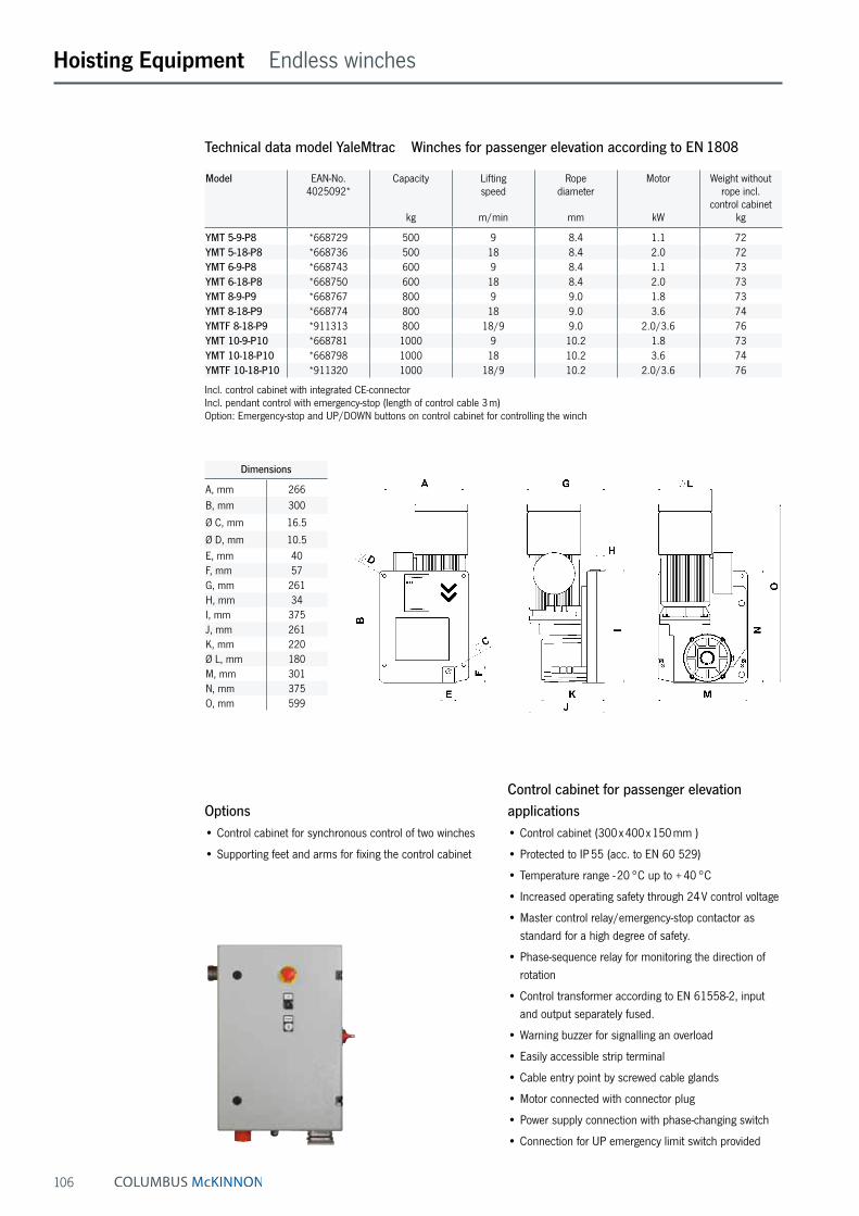
106
Hoisting Equipment Endless winches
Control cabinet for passenger elevation applications• Control cabinet (300 x 400 x 150 mm )
• Protected to IP 55 (acc. to EN 60 529)
• Temperature range - 20 °C up to + 40 °C
• Increased operating safety through 24 V control voltage
• Master control relay/emergency-stop contactor as standard for a high degree of safety.
• Phase-sequence relay for monitoring the direction of rotation
• Control transformer according to EN 61558-2, input and output separately fused.
• Warning buzzer for signalling an overload
• Easily accessible strip terminal
• Cable entry point by screwed cable glands
• Motor connected with connector plug
• Power supply connection with phase-changing switch
• Connection for UP emergency limit switch provided
Technical data model YaleMtrac Winches for passenger elevation according to EN 1808
Model EAN-No. 4025092*
Capacity
kg
Lifting speed
m/min
Rope diameter
mm
Motor
kW
Weight without rope incl.
control cabinetkg
YMT 5-9-P8 *668729 500 9 8.4 1.1 72YMT 5-18-P8 *668736 500 18 8.4 2.0 72YMT 6-9-P8 *668743 600 9 8.4 1.1 73YMT 6-18-P8 *668750 600 18 8.4 2.0 73YMT 8-9-P9 *668767 800 9 9.0 1.8 73YMT 8-18-P9 *668774 800 18 9.0 3.6 74YMTF 8-18-P9 *911313 800 18/9 9.0 2.0/3.6 76YMT 10-9-P10 *668781 1000 9 10.2 1.8 73YMT 10-18-P10 *668798 1000 18 10.2 3.6 74YMTF 10-18-P10 *911320 1000 18/9 10.2 2.0/3.6 76
Incl. control cabinet with integrated CE-connector Incl. pendant control with emergency-stop (length of control cable 3 m) Option: Emergency-stop and UP/DOWN buttons on control cabinet for controlling the winch
Dimensions
A, mm 266B, mm 300
Ø C, mm 16.5
Ø D, mm 10.5E, mm 40F, mm 57G, mm 261H, mm 34I, mm 375J, mm 261K, mm 220Ø L, mm 180M, mm 301N, mm 375O, mm 599
Options• Control cabinet for synchronous control of two winches
• Supporting feet and arms for fixing the control cabinet

107
Hoisting Equipment Endless winches
Safety hand wheel
In an emergency (power failure), upward movement with released brake is pos-sible by means of the hand wheel included in the supply (standard delivery scope only for winches for passenger elevation application).
Safety lowering mechanism
In the event of a power failure, the electro-mechan-ical brake can be released manually in order to ensure safe and controlled lowering of the load. Safe lowering is guaranteed by the integrated centrifugal force brake.
Safety for passenger elevationIn accordance with the requirements of EN 1808, each winch used for passenger elevation must feature a safety system on an independent safety rope. The product offer-ing provides two different safety catching devices for two common applications.
Both types have been approved for passenger elevation and comply with standard EN 1808 “Safety requirements on suspended access equipment”. In addition, the catching devices have been approved.
Model EAN-No. 4025092*
Capacitykg
For rope diametermm
YOSL6-8 *582803 500 8.4YOSL6-8 *582803 600 8.4YOSL8-9 *582742 800 9.0YOSL10-10 *582766 1000 10.2
Model EAN-No. 4025092*
Capacitykg
For rope diametermm
YISL6-8 *582827 500 8.4YISL6-8 *582827 600 8.4YISL8-9 *582759 800 9.0YISL10-10 *582797 1000 10.2
Overspeed safety catching device (YOSL)This overspeed catching device is automatically tripped when the lowering speed exceeds 30 m/min (0.5 m/s). The integrated clamping jaw mechanism of hardened steel stops the lowering movement of the system within a few centimetres.
Inclined position safety catching device (YISL)This inclined position catching device is automatically tripped when the angle of the rope or the platform exceeds 5°. The integrated clamping jaw mechanism holds the rope and immediately stops the movement of the system.
• Robust sheet-steel enclosure
• Clamping mechanism of hardened steel
• Attachment with two screws (M12) or load pins (12 mm)

108
Hoisting Equipment Crank design
Safety crank, zinc-plated Siku• With one-sided braking effect.
• The load is held safely at every height.
• With folding handle.
Safety ratchet crank, zinc-plated Raku• Lifting or lowering movement adjustable by turning
a lever.
• The load is held safely at every height.
• With folding handle.
Ratchet pawl kit, zinc-plated
for crank execution Siku and Raku
P13 EAN-No. 4025092 655811P14 EAN-No. 4053981 827698
Technical data safety crank Siku
Model EAN-No. 4025092*4053981**
Capacity
kg
Length of crank
mm
Square drive
mm
Drive torque max.Nm
Siku 1,5 **022703 1500 200 14 60Siku 3 *562553 3000 250 14 60Siku 5 *562553 5000 250 14 60Siku 10 *993036 10000 300 17 120
Pfaff design
Siku 1,5 *441469 1500 250 17 60Siku 3 *441469 3000 250 17 60Siku 5 *441469 5000 250 17 60
Technical data safety ratchet crank Raku
Model EAN-No. 4025092*4053981**
Capacity
kg
Length of crank
mm
Square drive
mm
Drive torque max.Nm
Raku 1,5 **022697 1500 200 14 60Raku 3 *915649 3000 250 14 60Raku 5 *915649 5000 250 14 60Raku 10 *997492 10000 300 17 120
Pfaff design
Raku 1,5 *655743 1500 250 17 60Raku 3 *655743 3000 250 17 60Raku 5 *655743 5000 250 17 60

109
Hoisting Equipment Crank design
Crank with folding handle for model ZWW-L (only optional)• Crank with collapsible handle, length of crank = 200 mm
for ZWW-L 250 and 1000 EAN-No. 4025092 652025
• Crank with collapsible handle, length of crank = 250 mm for ZWW-L 500 EAN-No. 4025092 651882
Spring loaded safety crank Sifeku• Without pawl.
• Silent
• Recoil proof
• Maintenance-free
• Enclosed housing
• Weather and temperature resistant.
• Braking effect at both ends.
• The load is held safely at every height, in the pushing and pulling direction.
• Approved by the TÜV as an independent crank.
• With folding handle.
Safety spring-lock with plug crank Sifespe• Plug crank removable
• No ratchet pawls in use
• Silent
• Maintenance-free
• Housing
• Weather and temperature resistant
• Braking effect at both ends
• The load is held safely at every height
• Handle not folding
Arm length 250 mm
• Square drive 14 mm or 17 mm
Safety spring-lock EAN-No. 4053981 022680Plug crank EAN-No. 4053981 001968
Technical data spring loaded safety crank Sifeku
Model EAN-No. 4025092*
Capacity
kg
Length of crank
mm
Square drive
mm
Drive torque max.Nm
Sifeku 1,5 *562522 1500 250 14 60Sifeku 3 *562522 3000 250 14 60Sifeku 5 *562522 5000 250 14 60
Pfaff design
Sifeku 1,5 *984041 1500 250 17 60Sifeku 3 *984041 3000 250 17 60Sifeku 5 *984041 5000 250 17 60
INFO
For ordering the crank of the models STW-F, STW-V, STW-FvB, KHB and SCH-W it takes note to specify the manufacture year, capacity and the dimension of the square!

110
Steel jack acc. to DIN 7355 model SJCapacity 1500 - 10000 kgMechanical steel jacks can basically be used to lift almost all kinds of loads in maintenance and repair, ship build-ing, construction as well as agriculture.
Features• The precisely machined gear box with optimal gear ra-
tio ensures a minimum of effort and smooth operation.
• The load is supported either on the claw or the head of the steel jack.
• By turning the operating lever the jack moves smoothly and conveniently up and down along the rack.
• The self-locking, anti-kickback operating lever reduces the risk of injuries. The handle can be tilted for use in confined spaces.
• The load is held securely in any position. Inside the load brake the axial brake pressure is generated by the load itself, thus, it is proportional to the size of the load.
• No reduction of capacity on the claw.
Hoisting Equipment Rack & Pinion jacks
Model SJ 15 SJ 30 SJ 50 SJ 100
A, mm 725 735 730 800B, mm 164 200 190 252C mm 140 140 170 170D, mm 76 83 108 124E, mm 38 38 52 65F, mm 70 70 80 85G, mm 60 65 71 86N, mm 225 249 275 300
Dimensions model SJ
Technical data model SJ Siku
Model EAN-No. 4025092*
Siku
Capacity
kg
Height A
mm
Height of lift ¹mm
Hand effort at WLL
daN
Weight
kg
SJ 15 *080897 1500 725 360 28 17SJ 30 *079877 3000 735 360 28 20SJ 50 *079884 5000 730 350 28 27SJ 100 *080903 10000 800 410 56 43
¹ Height of lift = Height + Lift
Lift

111
Hoisting Equipment Rack & Pinion jacks
Steel jacks acc. to DIN 7355 with fixed lifting claw model STW-FCapacity 1500 - 10000 kgSteel jacks are traditional hoisting equipment for universal application in the forest and agricultural sector, in the industrial sector for assembly activities and many other fields of application.
Features• The robust steel design and a toothed rack of solid
material increase the service life of the jack.
• Low wear owing to hardened gearing parts and precisely machined teething.
• The precisely machined gears with a high degree of efficiency guarantees low crank forces.
• The load is supported either on the claw or the head of the steel jack.
• Robust base plate for a high level of stability.
• No reduction of capacity on the claw.
Model STW-F
with fixed lifting claw and Sifeku
Technical data model STW-F Raku
Model EAN-No.4025092*
Raku
Capacity
kg
HeightA
mm
Height of lift ¹mm
Hand effort at WLL
daN
Weight
kg
STW-F 15 *563093 1500 720 350 28 12STW-F 30 *563116 3000 720 350 28 21STW-F 50 *563147 5000 720 300 28 26STW-F 100 *563161 10000 792 300 28 42
¹ Height of lift = Height + Lift
Technical data model STW-F Sifeku
Model EAN-No. 4025092*
4050939***Sifeku
Capacity
kg
HeightA
mm
Height of lift ¹
mm
Hand effort at WLL
daN
Weight
kg
STW-F 15 *563024 1500 720 350 28 12STW-F 30 ***055493 3000 720 350 28 21STW-F 50 *562645 5000 720 300 28 26
¹ Height of lift = Height + Lift
Technical data model STW-F Siku
Model EAN-No.4025092*
Siku
Capacity
kg
HeightA
mm
Height of lift ¹mm
Hand effort at WLL
daN
Weight
kg
STW-F 15 *994132 1500 720 350 28 12STW-F 30 *440875 3000 720 350 28 21STW-F 50 *996334 5000 720 300 28 26STW-F 100 *562690 10000 792 300 40 42
¹ Height of lift = Height + Lift
Model STW-F 15 STW-F 30 STW-F 50 STW-F 100
A, mm 720 720 720 792B, mm 130 130 145 145C, mm 140 140 155 155D, mm 90 90 110 125E, mm 50 50 68 80F, mm 60 61 62 85G, mm 60 65 70 85N, mm 250 250 250 300
Dimensions model STW-F
Lift

112
Model STW-V 1,5 t/3,0 t/5,0 t
Steel jacks acc. to DIN 7355 with adjustable lifting claw model STW-VCapacity 3000 - 10000 kg
The design of the steel jack allows for loads to be picked up and lowered from different heights over the entire length of the steel jack. The adjustable claw is simply set to the appropriate ap-plication height in the load bar for this purpose.
Features• The claw can be moved to any position on the
adjusting rail.
• The load is supported either on the claw or the head of the steel jack.
• Robust base plate for a high level of stability.
• No reduction of capacity on the claw.
Model STW-V 10,0 t
Hoisting Equipment Rack & Pinion jacks
Model EAN-No.4025092*
Sifeku
Capacity
kg
HeightA
mm
Height of lift ¹mm
Hand effort at WLL
daN
Weight
kg
STW-V 15 *347624 1500 725 350 28 17STW-V 30 *347631 3000 725 350 28 23STW-V 50 *347693 5000 725 300 28 29
¹ Height of lift = Height + Lift
Technical data model STW-V Sifeku
Model EAN-No.4025092*
Siku
Capacity
kg
HeightA
mm
Height of lift ¹mm
Hand effort at WLL
daN
Weight
kg
STW-V 15 *347327 1500 725 350 28 17STW-V 30 *347365 3000 725 350 28 23STW-V 50 *347389 5000 725 300 28 29STW-V 100 *347426 10000 792 300 40 46
¹ Height of lift = Height + Lift
Technical data model STW-V Siku
Model EAN-No.4025092*
Raku
Capacity
kg
HeightA
mm
Height of lift ¹mm
Hand effort at WLL
daN
Weight
kg
STW-V 15 *347402 1500 725 350 28 17STW-V 30 *347440 3000 725 350 28 23STW-V 50 *347549 5000 725 300 28 29STW-V 100 *347570 10000 792 300 40 46
¹ Height of lift = Height + Lift
Technical data model STW-V Raku
Model STW-V 15 STW-V 30 STW-V 50 STW-V 100
A, mm 725 725 725 800B, mm 130 130 140 140C, mm 140 140 160 160D, mm 90 100 110 140E, mm 50 50 68 76F, mm 70 70 70 70G, mm 80 80 80 95H, mm
Claw freely adjustable on load bar
(55 mm steps)
201J, mm 307K, mm 413L, mm 519M, mm 625N, mm 250 250 250 300
Dimensions model STW-V

113
Hoisting Equipment Rack & Pinion jacks
Steel jacks acc. to DIN 7355 with fixed lifting claw shortened design model STW-FvBCapacity 1500 - 5000 kgWherever low headroom dimensions are required, the steel jack of shortened design is used.
Features• The robust steel design and a toothed rack of solid
material increase the service life of the jack.
• Low wear owing to hardened gearing parts and precisely machined teething.
• The precisely machined gears with a high degree of efficiency guarantees low crank forces.
• The load is supported either on the claw or the head of the steel jack.
• Robust base plate for a high level of stability.
• No reduction of capacity on the claw.
Model EAN-No.4050939***
Siku
Capacity
kg
HeightA
mm
Height of lift ¹mm
Hand effort at WLL
daN
Weight
kg
STW-FvB 15 ***055363 1500 600 300 32 11STW-FvB 30 ***055424 3000 600 300 32 16STW-FvB 50 ***055585 5000 600 300 32 22
¹ Height of lift = Height + Lift
Technical data model STW-FvB Siku
Model EAN-No.4050939***
Raku
Capacity
kg
HeightA
mm
Height of lift ¹mm
Hand effort at WLL
daN
Weight
kg
STW-FvB 15 ***055431 1500 600 300 32 11STW-FvB 30 ***055516 3000 600 300 32 16STW-FvB 50 ***055646 5000 600 300 32 22
¹ Height of lift = Height + Lift
Technical data model STW-FvB Raku
Model EAN-No.4050939***
Sifeku
Capacity
kg
HeightA
mm
Height of lift ¹mm
Hand effort at WLL
daN
Weight
kg
STW-FvB 15 ***055530 1500 600 300 28 11STW-FvB 30 ***055639 3000 600 300 28 16STW-FvB 50 ***055752 5000 600 300 28 22
¹ Height of lift = Height + Lift
Technical data model STW-FvB Sifeku
Model STW-FvB 15 STW-FvB 30 STW-FvB 50
A, mm 600 600 600B, mm 130 130 145C, mm 140 140 155D, mm 90 90 110E, mm 50 50 68F, mm 60 61 62G, mm 60 65 70N, mm 200 250 250
Dimensions model STW-FvB
Lift
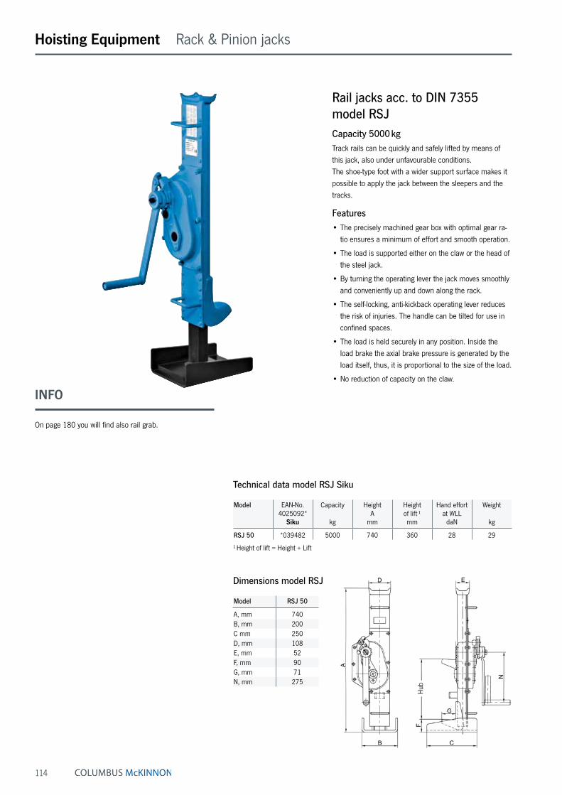
114
Rail jacks acc. to DIN 7355 model RSJCapacity 5000 kgTrack rails can be quickly and safely lifted by means of this jack, also under unfavourable conditions. The shoe-type foot with a wider support surface makes it possible to apply the jack between the sleepers and the tracks.
Features• The precisely machined gear box with optimal gear ra-
tio ensures a minimum of effort and smooth operation.
• The load is supported either on the claw or the head of the steel jack.
• By turning the operating lever the jack moves smoothly and conveniently up and down along the rack.
• The self-locking, anti-kickback operating lever reduces the risk of injuries. The handle can be tilted for use in confined spaces.
• The load is held securely in any position. Inside the load brake the axial brake pressure is generated by the load itself, thus, it is proportional to the size of the load.
• No reduction of capacity on the claw.
Hoisting Equipment Rack & Pinion jacks
Model EAN-No.4025092*
Siku
Capacity
kg
HeightA
mm
Height of lift ¹mm
Hand effort at WLL
daN
Weight
kg
RSJ 50 *039482 5000 740 360 28 29
¹ Height of lift = Height + Lift
Technical data model RSJ Siku
Dimensions model RSJ
Model RSJ 50
A, mm 740B, mm 200C mm 250D, mm 108E, mm 52F, mm 90G, mm 71N, mm 275
Hub
INFO
On page 180 you will find also rail grab.

115
Hoisting Equipment Rack & Pinion jacks
Ratchet jack model YaletaurusCapacity 10000 kgMechanical ratchet jacks with lifting claw are designed for operation in confined areas where space below the load is restricted, thus preventing the use of traditional lifting equipment. The Yaletaurus is the ideal unit for lifting, posi-tioning or transportation of machines resp. heavy objects as well as for repair and assembly jobs in cramped areas and under toughest conditions. In spite of its capacity of 10000 kg the Yaletaurus has a weight of just 30 kg and the integrated carrying handle makes it a portable, versatile tool. With a hand force of 45 kg on the detachable hand lever, the Yaletaurus will lift, press, push or lower a load of 10000 kg in any direction. A standard crank wheel will bring the jack quickly to the required position.
Features• Automatic screw-and-disc type load brake.
The axial brake pressure is generated by the load itself and is, therefore, proportional to the size of the load. The load is held secure in any position.
• Single part housing made from spheroidal cast iron with integrated lifting claw.
• The screw-and-disc type load brake originates from the Yale PUL-LIFT® (spare parts are easily available).
• Low lever pull and long life endurance due to optimum gearing and high quality materials.
Technical data model Yaletaurus
Model EAN-No. 4025092*
Capacity on the head
kg
Capacity on the claw
kg
Height A
mm
Height of lift ¹mm
Hand effort at WLL
daN
Weight
kg
Yaletaurus *076043 10000 7000 505 295 45 30
¹ Height of lift = Height + Lift
Dimensions model Yaletaurus
Model Yaletaurus
A, mm 505B, mm 170C mm 125D, mm 95E, mm 65F, mm 75G, mm 75H, mm 238J, mm 217N, mm 647

116
Model ZWW-L capacity 250 kg and 500 kg
Model ZWW-L capacity 1000 kgModel ZWW
capacity 1500 kg
Model ZWW capacity 10000 kg
Hoisting Equipment Rack & Pinion jacks
Wall-mounted rack and pinion jacks model ZWW-L and model ZWWCapacity 250 - 10000 kgWall-mounted rack and pinion jacks are used for lifting, lowering, pulling and pushing of loads.
Features• Robust steel design with precisely machined worm and
spur gears for smooth and easy manual operation.
• Solid steel rack with additional bore hole for fastening of the load.
• Low wear owing to hardened gearing parts and pre-cisely machined teething.
• Up to 1000 kg lifting load for pushing or pulling loads are equal.
• Suitable for a lifting load from 1500 kg - 10000 kg for pushing or pulling loads.
• Rigid wall mounting.
Options• Improved corrosion protection owing to zinc-plating or
special coating of rack.
• Different rack length on request possible.
• Symmetrical toothing for model ZWW on request pos-sible.
• Crank with folding handle for model ZWW-L suitable.
• Assembly plate (EAN 4053981283401) for model ZWW-L 250 and ZWW-L 500 with old hole separation suitable (165 mm). Thereby a one by one replacement between old model ZWW 250/500 kg and new model ZWW-L is warranted.
Assembly plate – available forfollowing models only: ZWW-L 250 and ZWW-L 500
Technical data model ZWW-L
Model EAN-No. 4025092*
Worm gear
Tensile orpressure
loadkg
Rack length
mm
Lift
mm
Lift per crank rotation
mm
Hand effort at WLL
daN
Weight
kg
ZWW-L 250/400 *437592 250 600 400 11 10 5.4ZWW-L 500/400 *437752 500 600 400 11 15 6.0ZWW-L 250/600 *383707 250 800 600 11 10 5.9ZWW-L 500/600 *383806 500 800 600 11 15 6.5ZWW-L 1000/600 *383967 1000 800 600 3.6 14 8.9ZWW-L 250/800 *383448 250 1000 800 11 10 6.4ZWW-L 500/800 *383837 500 1000 800 11 15 7.0ZWW-L 1000/800 *383981 1000 1000 800 3.6 14 10.0ZWW-L 250/1000 *383745 250 1200 1000 11 10 6.9ZWW-L 500/1000 *383844 500 1200 1000 11 15 7.5ZWW-L 1000/1000 *384018 1000 1200 1000 3.6 14 11.3ZWW-L 250/1200 *383783 250 1400 1200 11 10 5.4ZWW-L 500/1200 *383899 500 1400 1200 11 10 6.0ZWW-L 1000/1200 *384025 1000 1400 1200 3.6 14 12.4ZWW-L 1000/1400 *437868 1000 1600 1400 3.6 14 13.6
Available in explosion proof version (see page 467).
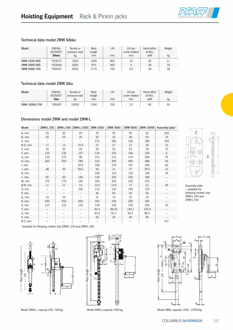
117
Hoisting Equipment Rack & Pinion jacks
Model EAN-No. 4025092*
Sifeku
Tensile orpressure load
kg
Rack lengthmm
Lift
mm
Lift per crank rotation
mm
Hand effort at WLL
daN
Weight
kg
ZWW 1500/800 *654272 1500 1090 800 14 28 11ZWW 3000/565 *653640 3000 975 565 9 28 19ZWW 5000/700 *995931 5000 1170 700 4.5 28 28
Technical data model ZWW Sifeku
Model EAN-No. 4025092*
Siku
Tensile orpressure load
kg
Rack lengthmm
Lift
mm
Lift per crank rotation
mm
Hand effort at WLL
daN
Weight
kg
ZWW 10000/700 *285087 10000 1240 700 3.2 40 55
Technical data model ZWW Siku
Model ZWW-L 250 ZWW-L 500 ZWW-L 1000 ZWW 1500 ZWW 3000 ZWW 5000 ZWW 10000 Assembly plate ¹
A, mm 20 20 25 35 45 50 60 200B, mm 20 25 35 25 30 40 50 10C, mm – – – 215 280 330 380 165Ø D, mm 11 13 16.5 21 21 21 30 13E, mm 16 20 20 20 25 25 30 15F, mm 130 130 127 135 165 140 160 6G, mm 119 119 98 151 212 219 269 75H, mm 200 200 180 310 395 400 480 50I, mm – – 34.5 168 179 197 200 60J, mm 38 35 29.5 26 31 37 39.5 13K, mm – – – 100 120 120 140 34L, mm 60 60 140 130 160 160 180 –M, mm 170 170 140 260 305 320 410 –Ø N, mm 11 11 13 12.5 14.5 17 21 20O, mm – – 100 110 120 105 125 –P, mm – – – 40 50 50 60 –Q, mm 10 10 – 8 10 10 10 –R, mm 200 250 200 250 250 250 300 –S, mm 110 110 110 130 130 130 250 10T, mm – – – 42.4 86.25 109.1 150.4 –U, mm – – – 43.3 53.1 69.5 88.3 –X, mm – – – 20 25 45 30 –Ø Z, mm – – – – – – – 8.2
¹ available for following models only ZWW-L 250 and ZWW-L 500
Dimensions model ZWW and model ZWW-L
Assembly plate – available forfollowing models only: ZWW-L 250 and ZWW-L 500
Model ZWW, capacity 1500 - 10000 kgModel ZWW-L,capacity 1000 kgModel ZWW-L, capacity 250 - 500 kg
Rack
leng
thLi
ft
Rack
leng
thLi
ft
Rack
leng
thLi
ft

118
Hoisting Equipment Rack & Pinion jacks
Model ZWW-L combinationsCapacity 1000 kgWall-mounted rack and pinion jacks can also be coupled if it is necessary that both racks have to lift a load uniform. Thereby the direction - depending on the model - plays no matter. The wall mounted rack and pinion jacks can be combine about ¾" and/or 1" pipes (DIN 2440). When connecting pipes over a length of 2 m, we recommend the pipes to stabilize so that it does not droop in the middle.
We like to advise you in this case.
On systems with several racks in line to the crank axis
• Self-locking action in every gear unit
• Crank force = 15 kg with a total load of 1000 kg
• Connection to ¾" tube (DIN 2440) on building side
On systems with several racks in line at 90° to the crank axis
• Self-locking action only gear unit with crank
• Crank force = 15 kg, at a maximum total load of 1000 kg
• Connection to 1" tube (DIN 2440) on building side
• This combination is also possible for model ZWW-L 250 and model ZWW-L 500.
On systems with several racks across a surface area
• Self-locking action in all gear units in the crank axis
• Crank force = 15 kg with a total load of 1000 kg
• Connection ¾" and 1" tube (DIN 2440) on building side

119
Hoisting Equipment Rack & Pinion jacks
Gearbox with rack and pinion shaft acc. to 7355 model GmZCapacity 1500 - 5000 kgThe gearbox with rack and pinion shaft show exactly what it can do in the areas of plant engineering/construction, agriculture and workshops.
Features• The robust steel design and a toothed rack of solid
material increase the service life of the jack.
• Low wear owing to hardened gearing parts and precisely machined teething.
• The precisely machined gears with a high degree of efficiency guarantees low crank forces.
Model EAN-No. 4025092*
4050939***Sifeku
Tensile orpressure load
kg
Rack length
mm
Lift
mm
Lift per crank rotation
mm
Hand effort at WLL
daN
Weight
kg
GmZ 1500/350 ***055356 1500 675 350 14 28 9GmZ 3000/350 ***055448 3000 670 350 8 28 18GmZ 5000/300 *005714 5000 628 300 4 28 22
Technical data model GmZ Sifeku
Model GmZ 1500/350
GmZ 3000/350
GmZ 5000/300
A, mm 35 45 50B, mm 25 30 40C, mm 295 275 275D, mm 125 204 189E, mm 78 92 100F, mm 33.5 39.5 51G, mm 270 260 260H, mm 655 655 655I, mm 42 86 109J, mm 43 53 70K, mm 250 250 250L, mm 130 130 130M, mm 142 148 160N, mm 173 183 202O, mm 337 361 384
Dimensions model GmZ

120
Supporting roller (option)
Hoisting Equipment Rack & Pinion jacks
Lifting jack model HB-WCapacity 1500 kgThe stable lifting jack with integrated 1,5 t steel jack for supporting tube and bar material.
Features• Load will be fixed in each position safely by a load
brake system.
• Large base plate for a high level of stability.
• Wheels for easy transport.
Option• The removable supporting roller facilitates sliding of
heavy loads.
Model EAN-No. 4053981**
Siku
Capacity
kg
Height
mm
Lift ¹
mm
Hand effort at WLL
daN
Lift per crank rotation
mm
Weight
kg
HB-W 1500 **745879 1500 650 350 28 15 40
¹ Lifting height = Height + Lift
Technical data model HB-W
Model EAN-No.4050939***
Capacity
kg
Height with supporting roller
mm
Weight
kg
Supporting roller ***055264 1500 705 5
Technical data supporting roller HB-A
Model HB-W 1500
A, mm 300B, mm 500Cein, mm 650Daus, mm 1000E, mm 100F, mm 320G, mm 300H, mm 385
Dimensions model HB-W
Crank
in special design on request
EAN-No. 4053981 964942

121
Hoisting Equipment Rack & Pinion jacks
Truck body lifting jack model KHBCapacity 5000 and 8000 kgTruck body lifting jacks are used for supporting vehicle bridges, swap bodies and trailers; they are also used in vehicle construction and freight forwarding applications.
Features• High-quality, torsionally stiff steel design with large
base plate for a high level of stability.
• Hardened gearing parts and precisely machined teeth-ing for improved handling and low wear.
• The load can either be supported on the head or on the adjustable claw.
Model KHB 8 capacity 8000 kg
Model EAN-No. 4050939***
Siku
Capacity
kg
Height
mm
Lift ¹
mm
Hand effort at WLL
daN
Dim. B
mm
Dim. C
mm
Dim. D
mm
Dim. E
mm
Dim. F
mm
Dim. O/Pmm
Weight
kg
KHB 5000/500 ***055110 5000 1100 500 18 540 500 80 140 250 70/70 80KHB 8000/500 ***055196 8000 1100 500 26 540 500 100 170 300 150/180 111
¹ Lifting height = Height + Lift
Technical data model KHB Siku
Model KHB 5 capacity 5000 kg
Model KHB 5000 KHB 8000
1. step, mm 175 2902. step, mm 230 3963. step, mm 285 5024. step, mm 340 6085. step, mm 395 7146. step, mm 450 8207. step, mm 505 9268. step, mm 560 10329. step, mm 615 –10. step, mm 670 –11. step, mm 725 –12. step, mm 780 –13. step, mm 835 –14. step, mm 890 –
Step height of adjustable lifting claw
Hei
ght
Spring loaded safety crank
Figure looks similar

122
Hoisting Equipment Rack & Pinion jacks
Worm gear drive unit model S 20 and model S 24The worm gear drives are suitable for a large variety of ap-plications in construction for moving or turning loads, as gears for rope drums or chain sprockets or slewing drives.
Features• Enclosed housing for the protection of parts inside.
• Enclosed and precisely machined gear for little effort and a long service life.
Technical data model S 20 and model S 24
Model EAN-No. 4050939***
Ratio Drive torque
daNm
Required crank effort
daN
Shaft lengthmm
Shaft diameter
mm
S 20 ***055257 20:1 12 11 196 25S 24 ***055462 24:1 36 22 200 36
Key A 10 x 8 x 45 - DIN 6885
Model S 20 Model S 24

123
Hoisting Equipment Rack & Pinion jacks
Model SCH-W 15 SCHW-30 SCHW-50 SCH-W 100
A, mm 35 45 50 60B, mm 25 30 40 50C, mm 140 160 145 165D, mm 85 60 45 65E, mm 125 204 189 235F, mm 78 92 100 112G, mm 175 230 260 320H, mm 310 395 400 480I, mm 33.5 39.5 51 59J, mm 43.3 53.1 69.5 88.3K, mm 121 138 81 84L, mm 230 230 230 290M, mm 90 90 90 115N, mm 153 158 173 183O, mm 52.5 55 61 66P, mm 52.5 55 64 70Ø Q, mm 14 14 14 14R, mm 7 7 7 8S, mm 76.5 85.5 88 100T, mm 100.5 108.5 120 140U, mm 113 121 132 185V, mm 86 94 105 –W, mm 136 144 155 –X, mm 130 130 130 250Y, mm 250 250 250 300
Dimensions model SCH-W
Sluice gate jack model SCH-WCapacity 1500 - 10000 kgThe reliable sluice gate jack for opening and closing gates in sluices.
Features• The spring loaded safety crank permanently holds the
sluice gate closed with pressure.
• Hardened gearing parts and precisely machined teeth-ing for improved handling and low wear.
Model EAN-No. 4025092*
Sifeku
Tensile orpressure load ¹
kg
Rack length
mm
Lift
mm
Hand effort at WLL
daN
Weight
kg
SCH-W 15 *915175 1500 1200 800 28 18SCH-W 30 *991698 3000 1250 800 28 23SCH-W 50 *915182 5000 1350 900 28 32
¹ The pressure force is reduced with a larger lift (loading case II to Euler)
Technical data model SCH-W Sifeku
Model EAN-No. 4025092*
Siku
Tensile orpressure load*
kg
Rack length
mm
Lift
mm
Hand effort at WLL
daN
Weight
kg
SCH-W 100 *911481 10000 1550 1000 40 56
Technical data model SCH-W Siku INFO
Please fill in the questionnaire on the next page for sluice gate jack systems.

124
Hoisting Equipment Questionnaire
Technical questionnaire to identify a suitable sluice gate jack systems
Company: Date:
Contact: e-Mail:
Phone: Fax:
Manual drive
Manual operating force kN
Sluice gate
Thickness mm
Material
Wood
Steel
Weight kg
Friction coefficient
Steel/Wood
Steel/Rubber
Roller gate
Indicate local conditions and water levels
Motor drive with manual emergency drive
Lifting speed Standard
m/min
Operating voltage V
Hz
230/400 V, 50 Hz three-phase current
Motor rating
Load cycles per hour
Lift per load cycle
Surrounding temperature
Remark
Quantity
Accessories
Lifting motion limitation
Electrical cut-out by safety clutch
Auma rotary drive
H =
without water below
H =
h =
with water below
H =
l =
completely in water above
H =
l =
h =
completely in water above, partly in water below
H =
l =
h =
i =
completely in water above and in water below

125
Hoisting Equipment Questionnaire
Arrangement
Crank version
(Retaining springs not possible for 10 t model)
Date
Name
Application
Technical questionnaire to identify a suitable sluice gate jack systems
Arrangement Crank version
Safety crank Spring loaded safety crank
Safety retaining spring with removable
crankArrangement I
Arrangement II
Arrangement II.1
Arrangement II.2
Arrangement III

126
Hoisting Equipment User information
INFO
This user information presents a general review regarding the application of cranes and does not substitute the existing operating instructions for specific products!
Lifting and slewing operations may be carried out by competent users (trained in theory and practice) only. When operated correctly, our cranes will offer the highest degree of safety in line with long life ex-pectancy and avoid damage to products and people.
Yalesystems cranes are manufactured in accordance with the machinery directive 2006/42/EC and the latest DIN 15018 H2 B2 (gantry cranes H2 B3) and correspond to the VDE regulations.
All components are mechanically shot blast, then primed and coated with RAL 1023 (yellow) paint, D.F.T. approx. 60 micron.
Modification of delivery conditionDesign and finish of the cranes may not be modified by e.g. installation of outside supplied parts, bending, welding, grinding, removal of parts, added bores, removal of safety devices like locking mechanisms, locking pins, safety latches etc.
Limitations of operationTemperatureCranes may normally be operated at ambient tempera-tures between - 10 °C up to + 50 °C. These values are approximate and may deviate from the specific givings of the product concerned. The accurate data are given in the current operating instructions.
Chemicals
Cranes may not be operated without hesitation in the area of chemicals or chemical vapours – consult our specialists for advice. Cranes which have been subject to chemicals or vapours must be taken out of service and inspected by us.
Transport of peopleTransport of people with cranes is generally forbidden!
Operation in danger zonesLifting or transport of loads must be avoided while personnel are in the danger zone. People are not allowed to pass over or under a suspended load.
Electrical hazards Please consult the specific operating instructions for pos-sible electrical hazards. Electrical connections may only be performed by authorized persons resp. companies!
Maintenance and repairTo ensure safe operation, all cranes must be subjected to regular inspections according to the maintenance instruc-tions given by the manufacturer (for legal obligations refer to DGUV Vorschrift 52 [BGV D6]).
Depending on the frequency and impact of applications, the crane has to be maintained, at least once per year or in case of obvious damages, by competent persons resp. inspectors.
Repairs and inspections may only be carried out by competent persons resp. inspectors who use original spare parts. Repairs and inspections must be recorded consecutively.
InspectionsThe contractor has to make sure that powered cranes are inspected prior to initial operation and after significant modifications by a competent person. This is also ap-plicable for hand operated cranes with a capacity of more than 1000 kg.
For cranes according to § 3a para. 3 DGUV Vorschrift 52 (BGV D6) the inspection before initial operation consists of advance survey, inspection of building and quality acceptance.
The inspection prior to initial operation is not required for cranes, which are delivered ready-to-use and with certifi-cate of a type approval or EC declaration of conformity.
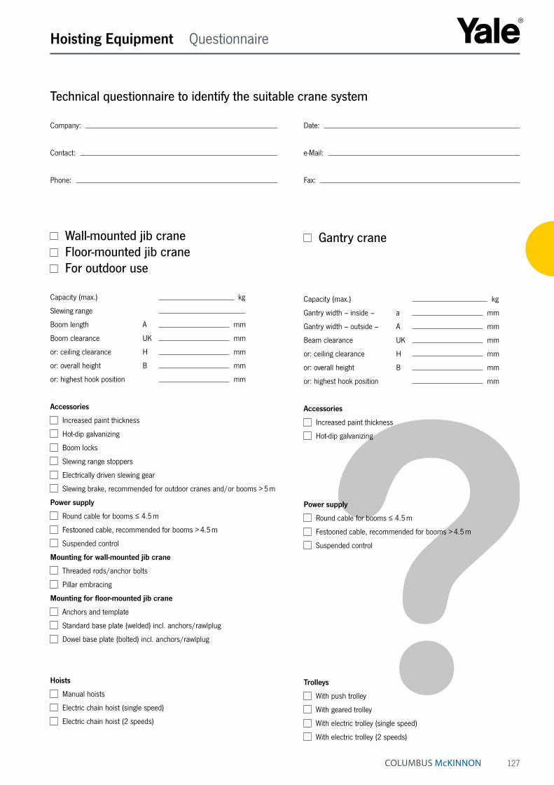
127
Hoisting Equipment Questionnaire
Gantry crane
Capacity (max.) kg
Gantry width – inside – a mm
Gantry width – outside – A mm
Beam clearance UK mm
or: ceiling clearance H mm
or: overall height B mm
or: highest hook position mm
Accessories
Increased paint thickness
Hot-dip galvanizing
Power supply
Round cable for booms ≤ 4.5 m
Festooned cable, recommended for booms > 4.5 m
Suspended control
Trolleys
With push trolley
With geared trolley
With electric trolley (single speed)
With electric trolley (2 speeds)
Technical questionnaire to identify the suitable crane system
Company: Date:
Contact: e-Mail:
Phone: Fax:
Wall-mounted jib crane Floor-mounted jib crane For outdoor use
Capacity (max.) kg
Slewing range
Boom length A mm
Boom clearance UK mm
or: ceiling clearance H mm
or: overall height B mm
or: highest hook position mm
Accessories
Increased paint thickness
Hot-dip galvanizing
Boom locks
Slewing range stoppers
Electrically driven slewing gear
Slewing brake, recommended for outdoor cranes and/or booms > 5 m
Power supply
Round cable for booms ≤ 4.5 m
Festooned cable, recommended for booms > 4.5 m
Suspended control
Mounting for wall-mounted jib crane
Threaded rods/anchor bolts
Pillar embracing
Mounting for floor-mounted jib crane
Anchors and template
Standard base plate (welded) incl. anchors/rawlplug
Dowel base plate (bolted) incl. anchors/rawlplug
Hoists
Manual hoists
Electric chain hoist (single speed)
Electric chain hoist (2 speeds)

128
Hoisting Equipment Wall-mounted jib cranes
Wall-mounted jib crane model PMSElevated boom with optimal height, slewing range 180°Lightweight, twist-free steel girder construction with low headroom. The boom is fitted with a bearing and a wall bracket for anchoring the crane to a concrete wall.
Mounting a jib crane to a wall, in combination with a festooned cable system, may lead to restrictions in the slewing range of the boom. This being the case, slew stoppers (buffers) should be fitted accordingly.
Mounting• Wall mounting, using threaded rods that go through the
wall and that are bolted to the wall with counter plates and nuts.
• Pillar embracing with anchor bolts and wall bracket. Bracket plate max. 500 mm, anchor bolts (threaded rods) max. 1000 mm.
• Alternative mounting systems on request.
Options• Slew stoppers (buffers) can be fitted on building site for
a pre-determined fixed slewing range.
• Slewing brake, to control the boom speed during slew-ing. Recommended for a boom length of more than 5 m or a headroom of more than 4 m. This prevents uncontrolled movement of the boom.
• Increased paint layer (120 µm) or hot-dip galvanisation for outdoor use.
• Manual locking device, to hold the boom in a fixed posi-tion (wind protection).
• Hoist cover for outdoor use.
Scope of delivery• The electrical system is equipped with a lockable main
switch, round cable power supply with cable support pipes for booms up to 4000 mm.
• From 4500 mm upwards, the boom is equipped with a festooned cable power supply. Due to cable sag on low cranes, we recommend the use of festooned cables even on short booms.
• Trolley stoppers at the front and at the back.
• Cranes are supplied with an operating manual and complete manufacturer‘s documentation.
Standard delivery programme model PMS
Model Capacity Boom length in mmkg 2000 2500 3000 3500 4000 4500 5000 5500 6000 6500 7000
PMS 50 50 • • • • • • • • • • •PMS 80 80 • • • • • • • • • • •PMS 125 125 • • • • • • • • • • •PMS 200 200 • • • • • • • • • • •PMS 250 250 • • • • • • • • • • •PMS 400 400 • • • • • • • • • • •PMS 500 500 • • • • • • • • • • •PMS 800 800 • • • • • • • • • • •PMS 1000 1000 • • • • • • • • • – –PMS 1600 1600 • • • • • • • – – – –PMS 2000 2000 • • • • • – – – – – –PMS 2500 2500 • • • – – – – – – – –
INFO
Mounting supports and walls are within the re-sponsibility of the user.

129
Hoisting Equipment User information
Mounting systems wall-mounted jib cranes
Wall mounting, using threaded rods going through the wall and being fixed to the wall with counter plates and nuts.
Pillar embracing with anchor bolts and wall bracket (bracket plate max. 500 mm, anchor bolts max. 1000 mm)
INFO
If wall-mounted jib cranes are mounted directly on the wall and festooned cable power supply is used, the slew-ing range may be limited depending on the size of the hoist.
Further fastening possibilities such as weld-on brackets, ceiling mounting etc. on request.

130
Floor-mounted jib crane model PFSPElevated boom with optimal height, slewing range 270°Lightweight, twist-free steel girder construction with low headroom. The boom is fitted with a bearing, pillar made from reinforced steel pipe.
Depending on the size of the hoist and in combination with festooned power cables, restrictions in the slewing range of the boom may be possible.
Mounting• Base flange with anchor bolts and template.
• Anchoring the base plate (welded) including mortar cartridges, anchor studs (complete with nuts, locknuts and washers).
• Anchoring the dowel base plate (bolted) including mortar cartridges, anchor studs (complete with nuts, locknuts and washers).
• Mobile unit for changeable location.
Options• Slew stoppers (buffers) can be fitted on building site for
a pre-determined fixed slewing range.
• Slewing brake, to control the boom speed during slew-ing. Recommended for a boom length of more than 5 m or a headroom of more than 4 m. This prevents uncontrolled movement of the boom.
• Increased paint layer (120 µm) or hot-dip galvanisation for outdoor use.
• Manual locking device, to hold the boom in a fixed posi-tion (wind protection).
• Hoist cover for outdoor use.
Hoisting Equipment Floor-mounted jib cranes
Scope of delivery• The electrical system is equipped with a lockable main
switch, round-cable power supply with cable support pipes for booms up to 4000 mm.
• From 4500 mm upwards, the boom is equipped with a festooned cable power supply. Due to cable sag on low cranes, we recommend the use of festooned cables even on short booms.
• Trolley stoppers at the front and at the back.
• Cranes are supplied with an operating manual and complete manufacturer‘s documentation.
Standard delivery programme model PFSP
Model Capacity Boom length in mmkg 2000 2500 3000 3500 4000 4500 5000 5500 6000 6500 7000
PFSP 50 50 • • • • • • • • • • •PFSP 80 80 • • • • • • • • • • •PFSP 125 125 • • • • • • • • • • •PFSP 200 200 • • • • • • • • • • •PFSP 250 250 • • • • • • • • • • •PFSP 400 400 • • • • • • • • • • •PFSP 500 500 • • • • • • • • • • •PFSP 800 800 • • • • • • • • • • •PFSP 1000 1000 • • • • • • • • • – –PFSP 1600 1600 • • • • • • • – – – –PFSP 2000 2000 • • • • • – – – – – –PFSP 2500 2500 • • • – – – – – – – –
INFO
Mounting systems, please see pages 133 -134.

131
Hoisting Equipment Floor-mounted jib cranes
Floor-mounted jib crane model PFMElevated boom with optimal height, slewing range 360°Lightweight, twist-free steel girder construction with low headroom. Compact rotating head for ideal construction dimensions; access from above ensures easy assembly. The boom is fitted with a roller bearing, pillar made from reinforced steel pipe.
Depending on the size of the hoist and in combination with festooned power cables, restrictions in the slewing range of the boom may be possible.
Mounting• Base flange with anchor bolts and template.
• Anchoring the base plate (welded) including mortar cartridges, anchor studs (complete with nuts, locknuts and washers).
• Anchoring the dowel base plate (bolted) including mortar cartridges, anchor studs (complete with nuts, locknuts and washers).
• Mobile unit for changeable location.
Options• Slew stoppers (buffers) can be fitted on building site for
a pre-determined fixed slewing range.
• Slewing brake, to control the boom speed during slew-ing. Recommended for a boom length of more than 5 m or a headroom of more than 4 m. This prevents uncontrolled movement of the boom.
• Increased paint layer (120 µm) or hot-dip galvanisation for outdoor use.
• Manual locking device, to hold the boom in a fixed posi-tion (wind protection).
• Hoist cover for outdoor use.
Scope of delivery• The electrical system is equipped with a lockable main
switch, round-cable power supply with cable support pipes for booms up to 4000 mm.
• From 4500 mm upwards, the boom is equipped with a festooned cable power supply. Due to cable sag on low cranes, we recommend the use of festooned cables even on short booms.
• Trolley stoppers at the front and at the back.
• Cranes are supplied with an operating manual and complete manufacturer‘s documentation.
Standard delivery programme model PFM
Model Capacity Boom length in mmkg 2000 2500 3000 3500 4000 4500 5000 5500 6000 6500 7000
PFM 50 50 • • • • • • • • • • •PFM 80 80 • • • • • • • • • • •PFM 125 125 • • • • • • • • • • •PFM 200 200 • • • • • • • • • • •PFM 250 250 • • • • • • • • • – –PFM 400 400 • • • • • • • – – – –PFM 500 500 • • • • • • – – – – –PFM 800 800 • • • – – – – – – – –PFM 1000 1000 • • – – – – – – – – –
INFO
Mounting systems, please see pages 133 -134.

132
Hoisting Equipment Floor-mounted jib cranes
Floor-mounted jib crane model PFPElevated boom with optimal height, slewing range 360°Heavy, robust twist-free steel girder construction. Structural steel crane-boom. Compact rotating head for ideal construction dimensions; access from above ensures easy assembly. The boom is fitted with a roller bearing, pillar made from reinforced steel pipe.
Depending on the size of the hoist and in combination with festooned power cables, restrictions in the slewing range of the boom may be possible.
Mounting• Base flange with anchor bolts and template.
• Anchoring the dowel base plate (bolted) including mortar cartridges, anchor studs (complete with nuts, locknuts and washers).
Options• Electrically driven slewing gear.
• Slew stoppers (buffers) can be fitted on building site for a pre-determined fixed slewing range.
• Limit switches to limit the boom slewing range (before hitting a fixed object the motor switches off automatically).
• Increased paint layer (120 µm) or hot-dip galvanisation for outdoor use.
• Manual locking device, to hold the boom in a fixed posi-tion (wind protection).
• Hoist cover for outdoor use.
Scope of delivery• The electrical system is equipped
with a lockable main switch, round-cable power supply with cable support pipes for booms up to 4000 mm.
• From 4500 mm upwards, the boom is equipped with a festooned cable power supply. Due to cable sag on low cranes, we recommend the use of festooned cables even on short booms.
• Trolley stoppers at the front and at the back.
• Cranes are supplied with an operat-ing manual and complete manufac-turer‘s documentation.
Standard delivery programme model PFP
Model Capacity Boom length in mmkg 2000 2500 3000 3500 4000 4500 5000 5500 6000 6500 7000
PFP 500 500 • • • • • • • • • • •PFP 800 800 • • • • • • • • • • •PFP 1000 1000 • • • • • • • • • • •PFP 1600 1600 • • • • • • • • • • –PFP 2000 2000 • • • • • • • • • – –PFP 2500 2500 • • • • • • • – – – –PFP 3200 3200 • • • • • – – – – – –

133
Hoisting Equipment User information
Mounting systems for floor-mounted jib cranes
Anchor bolts with template for preparation of the foundation through the customer.
Standard base plate (welded) for anchor-bolt connection on existing concrete floor instead of welded-on base flange (only for operation inside a building) incl. HVZ dynamic anchor bolts.
Dowel base plate for anchor-bolt connection on existing concrete floor (only for operation inside a building) incl. HVZ dynamic anchor bolts.
Com
pone
nt
thic
knes
s m
in.
Com
pone
nt
thic
knes
s m
in.INFO
Further capacities and boom lengths on request.
Further fastening possibilities such as weld-on brackets, ceiling mounting etc. on request.
Safety distances in accordance with the accident prevention regulations for cranes DGUV Vorschrift 52 (BGV D6) § 11 and § 32The following safety distances are only valid for floor-controlled cranes, without platforms, walkways or similar, on the jib with a load capacity of less than 10 t.
Movement manual
Safety distance
So = Top
Ss = Side
Su = Bottom
Lifting 100* 100* 100*
Movement power-driven, floor-controlled
Safety distance
So = Top
Ss = Side
Su = Bottom
Lifting 100* 100* 100*Lifting and travelling 100* 100* 500Lifting, travelling and slewing 100* 100* (500) 500
Safety distances for cranes with a load capacity up to 10000 kg *No regulation (100 mm recommended)Ss… for power-driven slewing motion, the safety distance must be complied with, if the possible crushing point is within the traffic and working area.In general, the traffic and working area ranges from the upper edge of the ground up to 2.5 m room height.

134
Hoisting Equipment User information
INFO
INFO
Plate dimensions, quantity, dimension and position of the chemical anchors depend on the crane type, load capac-ity and boom length of the crane (details and technical data according to the relevant crane data sheet).
Due to cable sag, we recommend that on low cranes festooned cables be used, even for a short boom length.
Operating conditions for standard and intermediate base plates• The thickness of the concrete floor slab for M 12 x 95
HVC dynamic anchor bolts must be min. 190 mm.
• The thickness of the concrete floor slab for M 16 x 105 HVC dynamic anchor bolts must be min. 210 mm.
• The concrete floor slab must be horizontal and even.
• The concrete quality must meet min. B25 or C20/25.
• Mounting with through bolts consisting of base plate, through bolts and counter plates (for ceiling thick-nesses up to 350 mm).
• Floor/wall mounting or floor/ceiling mounting on request.
Base plate for fastening pillar-mounted slewing jibs and slewing cranes without foundationSome pillar-mounted slewing jibs and slewing cranes can be mounted by means of a standard base plate or an dowel base plate. No foundation is required, easy and quick assembly on the customer’s existing reinforced concrete slab is possible. Potential tripping hazard by protruding locknuts, unmarked or unsecured plate edges must be clearly marked.
• The installation location of the crane must be selected in such a way that the base plate is mounted outside of traffic routes according to the German regulations for workplaces AStV para. 2. If this is not possible, the plate must be secured or marked in such a way that a hazard is avoided (e.g. by warning hatching along the edge of the plate).
• The base plate with tripping points must not protrude into escape routes or limit their prescribed min. widths.
• The measures for reducing hazards caused by tripping points must be taken by the operating company in cooperation with the safety expert.
• A warning sign as hazard reduction is a minimal measure and may not be sufficient in certain cases (e.g. in spite of warning signs, tripping incidences occur frequently, the warning sign is not recognised sufficiently in advance).
The smallest possible projection of the chemical anchor
over the crane base plate “X” with an M12 anchor is approx. 33 mm, with M16 approx. 37 mm. This dimen-sion can only be reached, if the concrete floor slab ex-ceeds the above-mentioned min. thickness. The max. projection of the chemical anchor, measured from floor level “Y”, is approx. 73 mm for M12 anchors
and approx. 86 mm for M16 anchors, with the relevant min. floor slab thickness.

135
Hoisting Equipment Moveable gantry cranes
Boom clearance (UK): Standard 2500 mm, other dimensions on request.
Gantry width - inside (dimension a): TDL-500/TDL-1000: Boom length A less 455 mm TDL-2000/TDL-3200: Boom length A less 500 mm
Standard delivery programme model TDL
Model Capacity Boom length in mmkg 2500 3000 3500 4000 4500 5000 5500 6000
TDL 500 500 • • • • • • • •TDL 1000 1000 • • • • • • • •TDL 2000 2000 • • • • • • • •TDL 3200 3200 • • • • • • • •
INFO
Further capacities and boom lengths on request.
Moveable gantry crane model TDLYalesystems gantry crane for use in all areas, from crafts-man‘s workshops, garages and industrial use. They are suitable for low to medium weight capacities and are also for outdoor use.
The cranes are moved by hand and are not dependant on a rail system. The guidelines for moving Yalesystems gantry cranes and transporting loads should be strictly followed.
Options• Increased paint layer (120 µm) or hot-dip galvanisation
for outdoor use.
• Hoist cover for outdoor use.
Scope of delivery• 3-part construction with 2 robust rectangular steel-bar
supports and 1 load carrier beam.
• Manually moveable, parking brake by threaded spindle.
• Power supply by festooned cables incl. flat cables, C type mounting rail, cable trolley, support arms and towing trolleys.
• Cranes are supplied with an operating manual and complete manufacturer‘s documentation.

136
Hoisting Equipment Light crane systems
Light crane system model YSKProfilesThe YSK-light crane system is based on three optimised steel profiles suitable for load ranges up to 2000 kg. A good weight vs. carrying capacity ratio ensures maxi-mum suspension distances leading to a reduced number of supporting structure and less suspension components.
The closed profile construction ensures increased durabil-ity of the YSK-light crane system as it protects the system agains dust. All profiles are surface treated with impact resistant powder coating and can be delivered in full 1-8 meters lengths. Other colours and surface treatments are available on request.
For easy and quick installation all connections are bolt-connections.
The patented trolley is characterized by an extraordinarly low noise level and a rolling resistance of approx 1 % of the moved load. YSK-light crane system brings ergonomic and quality to the working environment.
LOAD CAPACITY (deflection 1:350) Profile 125
8000
7000
6000
5000
4000
3000
2000
1000 50 80 125 250 320 500 630 1000 1250 1500 1600 2000 kg
6700
8000mm
47004200
2900
LOAD CAPACITY (deflection 1:350) Profile 200
8000
7000
6000
5000
4000
3000
2000
1000 50 80 125 250 320 500 630 1000 1250 1500 1600 2000 kg
3600
6500
4500
73008000
mm
3000 28002300
LOAD CAPACITY (deflection 1:350) Profile 260
8000
7000
6000
5000
4000
3000
2000
1000 50 80 125 250 320 500 630 1000 1250 1500 1600 2000 kg
5600
6900
8000mm
47004400
3600
Light crane system model YSKHoist trackThe YSK-hoist track is a versatile solution for one-way moving and lifting applications up to max. capacities of 1500 kg.
The YSK-hoist track is designed for easy assembly with standard joint connections and suspensions. It can be easily reconfigured to be adapted for changing conditions.
Hoist track – Suspension distance Tmax. in m
Capacity in kgProfile 50 80 125 250 320 500 630 1000 1250 1500
YSK-125 8 7.8 6.6 4.7 4.1 – – – – –YSK-200 8 8 8 8 8 7.2 6.2 4.4 3.6 3.1YSK-260 8 8 8 8 8 8 8 7.1 5.5 4.9
8 m is the max. profile standard length
Track length L
Suspension distance T

137
Hoisting Equipment Light crane systems
Light crane system model YSKSingle and double girder crane Low headroom raised constructionYSK-single or double girder cranes with raised construc-tion help are especially suitable for applications where the lifting height has to be maximized. Raised constructions are designed for locations with limited headroom or where a standard construction would not bring the required lifting height.
A system with a raised bridge can be suspended either from existing ceiling construction or from freestanding support frames.
Raised single girder crane
Profile mmTrack/Bridge C D E
YSK-125 199 159 264YSK-200 269 223 335YSK-260 329 283 395
Raised double girder crane
Profile mmTrack/Bridge B D E
YSK-125 57 159 264YSK-200 69 223 335YSK-260 69 283 395
E
c D
E
B D

138
Span S
Suspension distance T
Hoisting Equipment Light crane systems
Standard single girder crane
a b Smax. / Tmax. in meters at load capacity (kg)Profile mm mm 50 80 125 250 320 500 630 1000 1250 1500
YSK-125 150 294 8/8 7.8/7.4 6.6/6.6 4.0/4.3 3.0/3.8 – – – – –YSK-200 222 385 8/8 8/8 8/8 8/8 8/8 7.1/6.8 6.2/6 4.4/4.3 3.6/3.4 3.1/2.9YSK-260 282 445 8/8 8/8 8/8 8/8 8/8 8/8 8/8 6.6/6.2 5.5/5.7 4.7/4.4
8 m is the max. profile standard length
a b B Smax. / Tmax. in meters at load capacity (kg)Profile mm mm mm 80 125 250 320 500 630 1000 1250 1500 1600 2000
YSK-125 150 294 294 8/6.5 8/5.1 6.0/4 5.0/3.5 4.7/– – – – – – –YSK-200 222 385 392 8/8 8/8 8/8 8/8 8/6.4 8/5.7 7.2/4.3 6.5/3.7 5.3/3.2 5/3.1 4.0/2.7YSK-260 282 445 375 8/8 8/8 8/8 8/8 8/8 8/8 8/6.1 8/5.2 8/4.6 7.6/4.4 6.4/3.8
8 m is the max. profile standard length
Standard double girder crane
a
b
b
Ba
Light crane systemmodel YSKSingle and double girder craneYSK-single and double girder cranes are user friendly work station cranes. Their coverage is extensive and swinging of the load is minimized as the loaded push trolley centralises itself automatically to the right lifting position.
YSK-single girder crane is the most ergonomic solution due to its three dimensional construction and light own weight. With a double girder crane the load capacity is doubled and lifting height increased as the hoistis suspended from a hoist saddle locatedbetween the bridge profiles.
Span S
Suspension distance T

139
DSConcrete beam suspension
ESSide suspension
HSSuspension to inclined I-girder
LSDistance suspensionto I-girder
JSCollar suspension to I-girder
ASI-girder suspension
BSCeiling suspension
CSDistance suspension
FSU-shape suspension
HDDistance suspension to inclined I-girder
Hoisting Equipment Light crane systems
Light crane system model YSKFreestanding support framesYSK-freestanding support frames are designed for loca-tions where the ceiling is not designed to support the load of the crane. This type of crane is also a professional solution for applications where the crane systems need to be repositioned to suit changes in the layout of the shopfloor.
Standard suspensions
Suspension type, distance DProfile AS BS CS DS ES FS HS HD LS JS
YSK-125 123 ± 15 123 ± 15 < 500 ¹ 218 ± 15 104 ± 15 105 ± 15 210 ± 15 < 260 ¹ < 500 ¹ –YSK-200 167 ± 16 167 ± 16 < 500 ¹ 271 ± 16 136 ± 16 139 ± 16 248 ± 16 < 200 ¹ < 500 ¹ 176 ± 16YSK-260 167 ± 16 167 ± 16 < 500 ¹ 271 ± 16 136 ± 16 139 ± 16 248 ± 16 < 200 ¹ < 500 ¹ 176 ± 16
¹ for longer distances side support must be used.
Freestanding support frames
Load capacity, kg 50 - 2000Total width G, m 4.5 - 8.56Total height H, m 3 - 4 - 5Frame width J, m 4.18 - 8.16Single or double bridge width W, m 2 - 8
G
W
J
H
DDD
DD D D
D
DD
Light crane systemmodel YSKArticulating supensionsYSK-light crane systems include various types of articulat-ing standard suspensions to mount the crane to the ceiling construction.
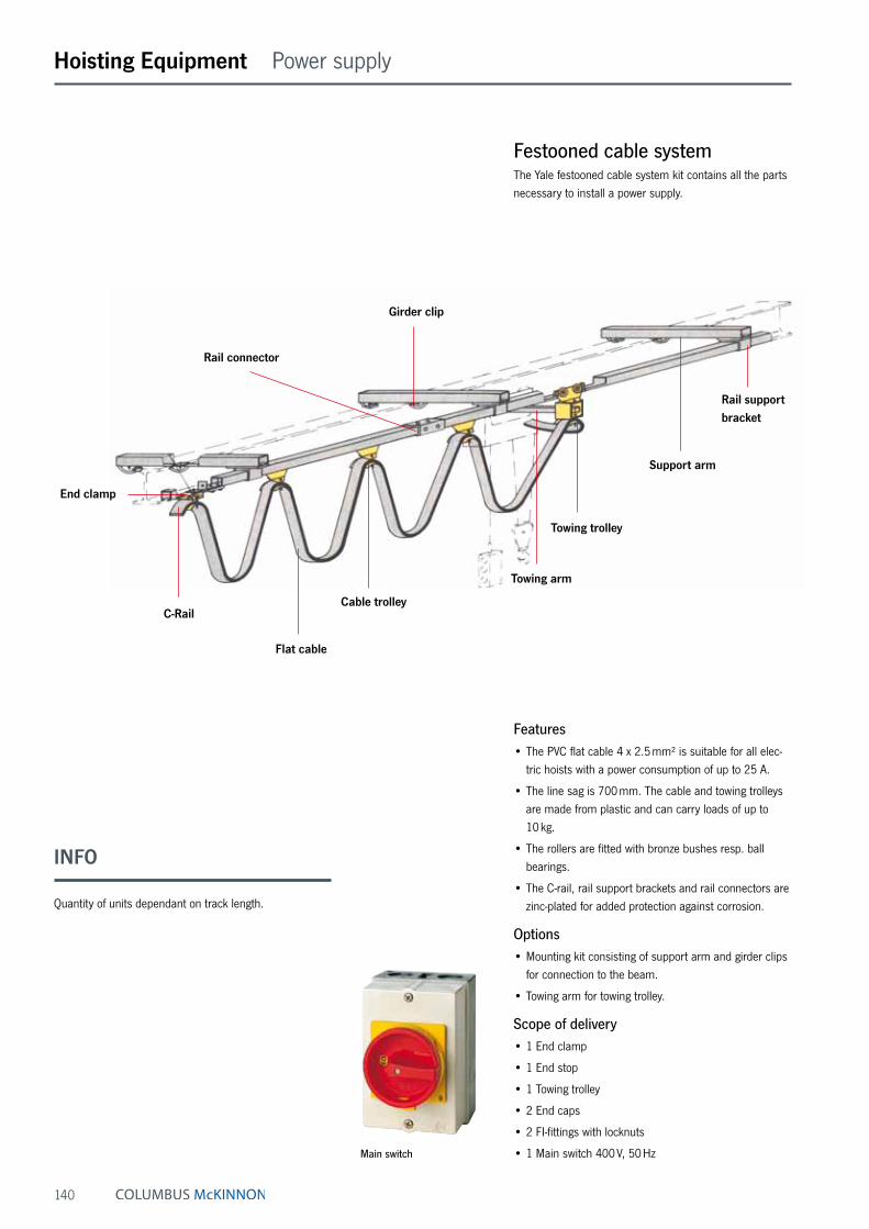
140
Hoisting Equipment Power supply
Festooned cable systemThe Yale festooned cable system kit contains all the parts necessary to install a power supply.
Features• The PVC flat cable 4 x 2.5 mm² is suitable for all elec-
tric hoists with a power consumption of up to 25 A.
• The line sag is 700 mm. The cable and towing trolleys are made from plastic and can carry loads of up to 10 kg.
• The rollers are fitted with bronze bushes resp. ball bearings.
• The C-rail, rail support brackets and rail connectors are zinc-plated for added protection against corrosion.
Options• Mounting kit consisting of support arm and girder clips
for connection to the beam.
• Towing arm for towing trolley.
Scope of delivery• 1 End clamp
• 1 End stop
• 1 Towing trolley
• 2 End caps
• 2 FI-fittings with locknuts
• 1 Main switch 400 V, 50 Hz
C-Rail
Rail support bracket
Rail connector
Girder clip
Support arm
Cable trolley
Towing trolley
End clamp
Towing arm
Flat cable
Main switch
INFO
Quantity of units dependant on track length.

141
Hoisting Equipment Power supply
C-RailGirder clip Support arm
60
max. 40
max. 20
60
500 mm
Scope of delivery festooned cable systems
Model EAN-No. 4025092*
EAN-No. Mounting kit4025092*
C-rails track length
m
Transport distance max.
m
PVC flat cable
m
Numbers of
cable trolleys
Rail support bracket
Rail connector
Festooned cable 4 m C-rail track length *059305 *059398 4 3.5 9 2 4 0Festooned cable 6 m C-rail track length *059312 *059404 6 5.4 11 3 5 1Festooned cable 8 m C-rail track length *059329 *059411 8 7.3 13 5 6 1Festooned cable 10 m C-rail track length *059336 *059428 10 9.2 15 6 7 2Festooned cable 12 m C-rail track length *059343 *059435 12 11.0 17 8 8 2Festooned cable 14 m C-rail track length *059350 *059442 14 12.9 19 9 9 3Festooned cable 16 m C-rail track length *059367 *059459 16 14.8 21 11 10 3Festooned cable 18 m C-rail track length *059374 *059466 18 16.7 23 12 11 4Festooned cable 20 m C-rail track length *059381 *059473 20 18.5 25 14 12 4
Cable trolley Towing trolley Rail support bracket Rail connector C-Rail
54
8025
80
50
2415
125
36123
53
15
75
100333
31
M8
4084
60
15
32
30
3
I32
1,5
12
26
30
100333
31
I32
1,5
12
26
30
INFO
Optional: Mounting kit consisting of support arm and girder clips for connection to the beam.
Special applications e.g. for curves or cable trolley for round cables on request.
Rail support bracket

142
Table of contents
Page Grabs & Clamps 148 - 153 156 - 181
Permanent load lifting magnets 154 - 155
Lifting lugs & Clamps & C-hooks 182 - 186
Barrel grabs & Crate grabs 187 - 193
Load hoisting tackle for underground construction 194 - 197
Spreader beams 198 - 207
Crane forks 210 - 211
Crane weighers 212 - 215
Load indicator 216 - 217
INFO
Please note our user instructions at the beginning of each chapter.
Tigrip® Load Hoisting Tackle
Lifting clamps and attachments have a reputation for reli-ability, quality and safety going back more than 35 years. For transportation and handling of loads with a hoist the Tigrip® programme offers the optimum connection between hook and load for almost any application.
Tigrip® Crane Weighers
Also renown for many years are our precise crane weigh-ers. Wherever weight has to be measured or forces have to be assessed the reliable and robust units can be used. Areas of application are practically unlimited.
TIGRIP® - your first choice!

143
TIGRIP®

144
Tigrip® Load Hoisting Tackle & Crane Weighers User information
This user information presents a general overview re-garding the operation of some plate clamps and does not substitute the existing operating instructions for specific load hoisting tackle!
Lifting operations with load hoisting tackle may be carried out by competent persons (trained in theory and practice) only. When operated correctly, our Tigrip products will offer the highest degree of safety, avoid damage to products and people and present a long life expect-ancy.
Modification of delivery conditionDesign and construction of the load hoisting tackle may not be altered without authorization of the manufacturer, e.g. by bending, welding, grinding, cutting-off parts, adding boreholes, removal of safety devices like locking mechanisms, bolts, shear pins etc. Otherwise the validity of the declaration of conformity will be void and any liabil-ity and warranty of the manufacturer ceased.
Limitations of operationLoadingThe rated capacity (WLL) indicated on the tackle is the maximum load which must not be exceeded.
TemperatureClamps without protective lining may normally (depending on manufacturer) be operated at ambient temperatures of - 40 °C up to +100 °C without capacity reduction. Clamps with protective lining may be subject to reduced temperature areas due to application of affixed linings, e.g. model TBP and TSB, which can be operated from - 20 °C up to + 40 °C.
Shock loading, swinging of loadThe indicated capacities are based on shock-free loading of the tackle. Light bumps as occurred during lifting and lowering as well as transporting of load with the crane are admitted. Heavier shock loadings (e.g. crashing against obstacles during transport) as well as swinging of the load are strictly forbidden!
ChemicalsLoad hoisting tackle may not be operated without hesita-tion in the area of chemicals or chemical vapours – con-sult our specialists beforehand. Hoisting tackle which has been subject to chemicals or vapours must be taken out of service and should be returned to us for inspection.
Transport of peopleTransport of people with hoisting equipment and tackle is generally forbidden!
Operation in danger zonesLifting or transport of loads must be avoided while personnel are in the danger zone. When using clamps or grabs without a positive fit but with force fit or friction fit the load must not be suspended above people – see AMVO §18(6)!
Lifting productsLoad hoisting tackle have been designed for specific applications and must not be used for other jobs without prior authorization of the manufacturer. This refers e.g. to the thickness of material (jaw capacity of the clamp), surface condition, hardness* and temperature of material. Relative information is given in the respective operating instructions. These have to be available to the operator to ensure safe handling of the product.
*Please observe that for special steel plates the surface hardness may deviate substantially from the core hard-ness, e.g. for cold work steel.
Inspection before initial operation• Ensure that the surface of the steel plate, in the area
where the clamp is to be attached, is dry and free from grease, paint, dirt and scale and is not coated, so that the teeth resp. the protective lining on the moving jaw can make good contact with the surface of the load.
• Check the fixed jaw and the moving jaw for wear and defects. Both jaws must have clean profiles and teeth must not be heavily worn (observe respective advice given in the operating instruction, guiding value max. 30% wear). Protective linings must not be contami-nated, damaged, uneven or heavily worn.
• The entire hoisting tackle has to be checked for dam-age, corrosion, cracks or deformations.
• It should be easy to open and close the clamp.
• Check the function of the spring. In the CLOSED posi-tion this must present a noticeable spring pressure force when the hook ring is pressed down.
INFO
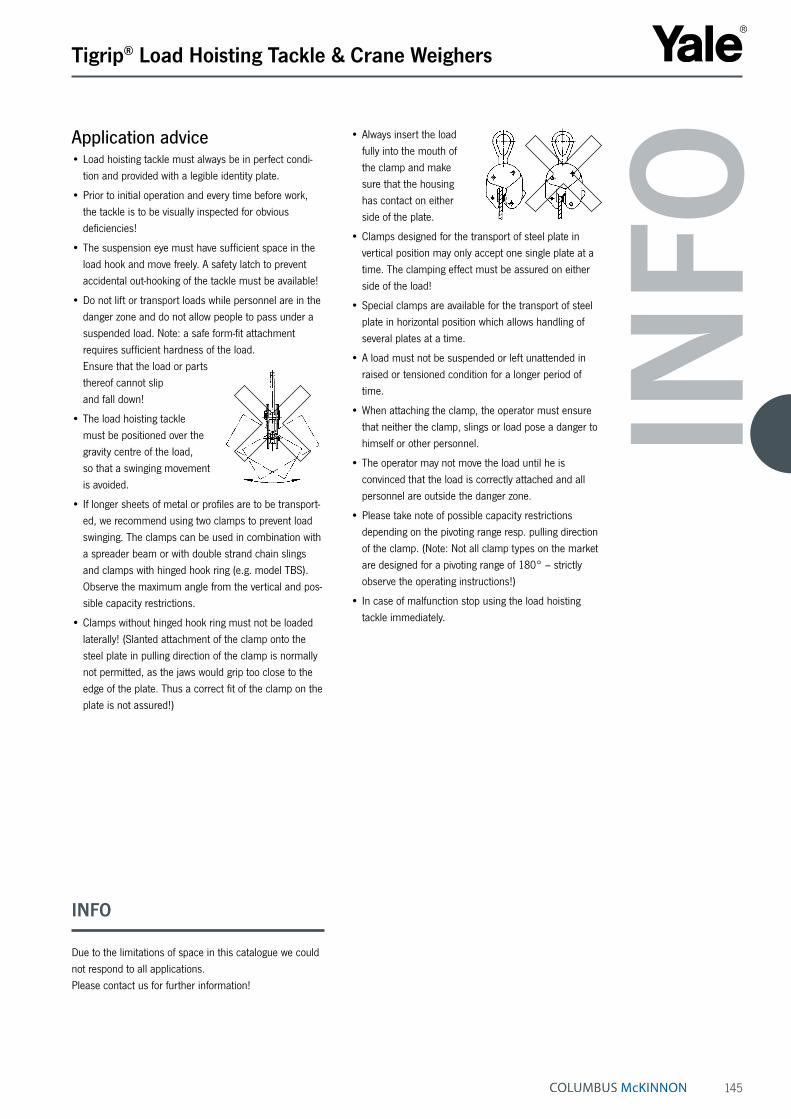
145
Application advice• Load hoisting tackle must always be in perfect condi-
tion and provided with a legible identity plate.
• Prior to initial operation and every time before work, the tackle is to be visually inspected for obvious deficiencies!
• The suspension eye must have sufficient space in the load hook and move freely. A safety latch to prevent accidental out-hooking of the tackle must be available!
• Do not lift or transport loads while personnel are in the danger zone and do not allow people to pass under a suspended load. Note: a safe form-fit attachment requires sufficient hardness of the load. Ensure that the load or parts thereof cannot slip and fall down!
• The load hoisting tackle must be positioned over the gravity centre of the load, so that a swinging movement is avoided.
• If longer sheets of metal or profiles are to be transport-ed, we recommend using two clamps to prevent load swinging. The clamps can be used in combination with a spreader beam or with double strand chain slings and clamps with hinged hook ring (e.g. model TBS). Observe the maximum angle from the vertical and pos-sible capacity restrictions.
• Clamps without hinged hook ring must not be loaded laterally! (Slanted attachment of the clamp onto the steel plate in pulling direction of the clamp is normally not permitted, as the jaws would grip too close to the edge of the plate. Thus a correct fit of the clamp on the plate is not assured!)
• Always insert the load fully into the mouth of the clamp and make sure that the housing has contact on either side of the plate.
• Clamps designed for the transport of steel plate in vertical position may only accept one single plate at a time. The clamping effect must be assured on either side of the load!
• Special clamps are available for the transport of steel plate in horizontal position which allows handling of several plates at a time.
• A load must not be suspended or left unattended in raised or tensioned condition for a longer period of time.
• When attaching the clamp, the operator must ensure that neither the clamp, slings or load pose a danger to himself or other personnel.
• The operator may not move the load until he is convinced that the load is correctly attached and all personnel are outside the danger zone.
• Please take note of possible capacity restrictions depending on the pivoting range resp. pulling direction of the clamp. (Note: Not all clamp types on the market are designed for a pivoting range of 180° – strictly observe the operating instructions!)
• In case of malfunction stop using the load hoisting tackle immediately.
Tigrip® Load Hoisting Tackle & Crane Weighers
INFO
INFO
Due to the limitations of space in this catalogue we could not respond to all applications. Please contact us for further information!

146
Tigrip® Load Hoisting Tackle & Crane Weighers User information
Maintenance and repair• To ensure safe operation, all load hoisting tackle must
be subjected to regular inspections according to the maintenance instructions given by the manufacturer.
• Load hoisting tackle which are due for maintenance (normally once per year, unless adverse working condi-tions dictate shorter periods) or products with obvious defects may be returned to us for inspection and repair.
• Inspections and tests must be performed by competent persons or specialist workshops that use original spare parts.
Inspections• Inspections are visual and functional and shall estab-
lish that the load hoisting tackle is safe and has not been damaged by incorrect transport or storage. In addition check for damage, wear, corrosion and other deficiencies as well as completeness and function of safety devices. Inspections are instigated by the user.
• All load hoisting tackle has to be cleaned prior to inspection. The cleaning procedure must not cause chemical damages (e.g. no acid – embrittlement), no incorrect temperature stress by e.g. flame cleaning or possible concealment of cracks due to excessive material loss (sand blasting)! We shall be pleased to consult you in this respect. Please submit your load hoisting tackle for inspection in clean condition. This will reduce inspection costs considerably!
Criteria for disposal of load hoisting tackleLoad hoisting tackle must no longer be operated if e.g.:
• The identification (identity plate) is missing or illegible.
• Housing, components and suspension of the tackle present obvious deficiencies, e.g. cuts, grooves, cracks, excessive corrosion, staining due to heat, signs of sub-sequent welding resp. spatters (which cannot be easily removed) and leave stains.
• Ropes show breakages of wires resp. bruises (criteria for disposal of ropes are given in classification DIN 15020), damages to the rope sleeve and similar failures.
• The load chain presents twisted or distorted links or shows an elongation of 5 % resp. undergoes the aver-aged nominal thickness of the link by more than 10 %.
• The opening (C) of either suspension or load hook has increased/deformed by more than 10 % of the nominal dimension or shows wear in the hook mouth (dimensions B resp. D) of more than 5 %.
• If the inspection revealed that the tackle has been over-loaded or deteriorated it can only be used again after careful inspection and repair – if necessary.
INFO

147
Technical questionnaire to identify the suitable TIGRIP® load hoisting tackle
Company: Date:
Contact: e-Mail:
Phone: Fax:
Clamps and grabsInformation about the load:What will be transported?
Weight min. kg - max. kg
Length min. mm - max. mm
Width min. mm - max. mm
Height min. mm - max. mm
External diameter min. mm - max. mm
Internal diameter min. mm - max. mm
Material Steel Concrete Wood Paper Others
Surface hardness for steel: HRC
Surface condition Oiled Greasy Dry Scales Others
How should/may the load be grabbed/clamped:
Grabbed from Jaws Protective lining Others underneath
Information about the clamp/grab:What kind of grab will be needed?
Type of crane hook or dimensions A - B
Model: A =
B =
Other restrictions:
Tigrip® Load Hoisting Tackle Questionnaire

148
Tigrip® Load Hoisting Tackle Grabs & Clamps
Technical data model TBL/TBL plus
Model EAN-No. 4025092*4053981**
Capacity
kg
Jaw capacity Z
mm
Weight
kg
TBL 0,5 *550000 500 0 - 16 1.5TBL 1,5 plus **522265 1500 0 - 20 3.0TBL 2,0 plus **526232 2000 0 - 32 9.3TBL 3,0 plus **526249 3000 0 - 32 9.3
INFO
The surface hardness of the material must not exceed HRC 30/Brinell 300.
The min. load is 10 % of the nominal WLL. Except for model TBL 1,5 plus, the min. load here is 100 kg!
Plate clamp with safety lock model TBL/TBL plusCapacity 500 - 3000 kgThis clamp is primarily used for transporting single steel plates in the vertical position, as well as lifting and turning through 180°. This clamp can also be used for transport-ing steel constructions and profiles. It is recommended to use a pair of plate clamps in conjunction with a spreader beam for large sized sheets and long materials which have a tendency to sag.
The jaw can be opened and closed with the locking lever (except for the TBL 0.5 t which uses a positive spring-loaded cam). The safety lock overrides the spring-loaded cam, preventing the clamp from opening even when there is no load.
This plate clamp is service-friendly, making it easy to exchange parts, which are available individually or in kits. Clamp repair is available by the factory, or can be done by certified and experienced staff.
The TBL 0.5 is equipped with a safety lock (positive spring-loaded cam), but comes without locking lever.
Dimensions model TBL/TBL plus
Model TBL 0,5 TBL 1,5 plus TBL 2,0 plus TBL 3,0 plus
A, mm 99 126 192 192B, mm 195 225 312 312Ø C, mm 29 50 80 80D, mm 33 49 75 75E, mm 47 70 96 96F, mm 50 82 100 100G, mm 48 55 81 81H, mm 11 12 20 20I, mm 16 20 24 24

149
Plate clamp with safety lock model TBLCapacity 4000 - 30000 kgThis clamp is primarily used for transporting single steel plates in the vertical position, as well as lifting and turning through 180°. This clamp can also be used for transport-ing steel constructions and profiles. It is recommended to use a pair of plate clamps in conjunction with a spreader beam for large sized sheets and long materials which have a tendency to sag.
These plate clamps have the same design and applica-tions as the clamp model TBL with a capacity from 500 - 3000 kg.
Tigrip® Load Hoisting Tackle Grabs & Clamps
Technical data model TBL
Model EAN-No. 4025092*
Capacity kg
Jaw capacity Z mm
Weight kg
TBL 4,0 S *556545 4000 0 - 32 11.2TBL 4,0 L *556569 4000 30 - 60 11.9TBL 6,0 S *557221 6000 0 - 50 20.6TBL 6,0 L *556583 6000 50 - 100 23.2TBL 8,0 S *557245 8000 0 - 50 24.2TBL 8,0 L *557269 8000 50 - 100 28.8TBL 10,0 S *557283 10000 0 - 50 29.5TBL 10,0 L *557306 10000 50 - 100 35.1TBL 12,0 S *557320 12000 0 - 50 52.1TBL 12,0 L *557344 12000 50 - 100 63.0TBL 15,0 S *552936 15000 0 - 50 76.0TBL 15,0 L *552943 15000 50 - 100 86.0TBL 20,0 S *552950 20000 0 - 65 123.0TBL 20,0 L *551892 20000 65 - 130 135.0TBL 30,0 S *552967 30000 0 - 65 195.0TBL 30,0 L *552974 30000 65 - 130 256.0
Model TBL 4,0 S
TBL 4,0 L
TBL 6,0 S
TBL 6,0 L
TBL 8,0 S
TBL 8,0 L
TBL 10,0 S
TBL 10,0 L
TBL 12,0 S
TBL 12,0 L
TBL 15,0 S
TBL 15,0 L
TBL 20,0 S
TBL 20,0 L
TBL 30,0 S
TBL 30,0 L
A, mm 197 228 293 362 293 362 293 362 360 460 360 460 462 560 462 560B, mm 339 339 442 482 450 482 503 503 550 615 550 615 674 724 667 732Ø C, mm 80 80 89 89 89 89 110 110 130 130 130 130 130 130 60 60D, mm 68 68 95 114 95 114 95 114 125 175 125 175 165 195 165 195E, mm 93 100 143 143 143 143 143 143 162 162 162 162 210 210 210 210F, mm 110 110 129 129 129 129 139 139 154 154 204 204 235 235 295 295G, mm 20 20 20 20 20 20 25 25 30 30 45 45 45 45 65 65H, mm 32 32 35 35 42 42 45 45 55 55 55 55 65 65 66 67
Dimensions model TBL
INFO
The surface hardness of the material must not exceed HRC 30/Brinell 300.
The min. load is 10 % of the nominal WLL!

150
Tigrip® Load Hoisting Tackle Grabs & Clamps
Technical data model TBS plus
Model EAN-No. 4053981**
Capacitykg
Jaw capacity Z mm
Weight kg
TBS 1,0 plus **526157 1000 0 - 20 4.6TBS 2,0 plus **526195 2000 0 - 32 14.3TBS 3,0 plus **526201 3000 0 - 32 14.3
Model TBS 1,0 plus TBS 2,0 plus TBS 3,0 plus
A, mm 126 192 192B, mm 270 382 382Ø C, mm 50 80 80D, mm 49 75 75E, mm 70 96 96F, mm 95 132 132G, mm 63 92 92H, mm 12 20 20I, mm 23 30 30
Dimensions model TBS plus
Plate clamp with hinged hook ring and safety lock model TBS plusCapacity 1000 - 3000 kgThe TBS plate clamp with hinged hook ring can be used for the safe handling of plates at various angles. It can lift plates from the horizontal and put down in the vertical or alternatively lift it over the edge by gripping it from the side. The hinged hook ring ensures adequate clamping force in every position. Depending on the angle of usage capacity restrictions have to be taken into account, as shown in the diagram below.
The hinged hook ring has the added advantage of provid-ing enough clamping force to hold a plate safely. Even when transporting large-sized plates with the 2-legged lifting system slipping of the load and damage to the clamp is avoided.
In addition to transporting plates, this clamp is suitable for turning steel structures and welded constructions.
INFO
The surface hardness of the material must not exceed HRC 30/Brinell 300.
The min. load is 10 % of the nominal WLL!

151
Plate clamp with pivoting shackle and safety lock model TBSCapacity 4500 - 10000 kg
Tigrip® Load Hoisting Tackle Grabs & Clamps
Technical data model TBS
Model EAN-No. 4025092*
Capacitykg
Jaw capacity Z mm
Weight kg
TBS 4,5 *550352 4500 0 - 50 34.4TBS 6,0 S *550383 6000 0 - 50 38.0TBS 6,0 L *551250 6000 50 - 100 42.0TBS 8,0 S *552578 8000 0 - 50 39.0TBS 8,0 L *557528 8000 50 - 100 42.4TBS 10,0 S *552516 10000 0 - 50 68.0TBS 10,0 L *557542 10000 50 - 100 80.0
Model TBS 4,5 TBS 6,0 S TBS 6,0 L TBS 8,0 S TBS 8,0 L TBS 10,0 S TBS 10,0 L
A, mm 292 292 367 292 367 360 446B, mm 675 737 785 737 785 903 921C, mm 90 95 98 98 98 110 112D, mm 180 176 180 176 180 195 195Ø E, mm 27.8 27.8 27.8 27.8 27.8 33 33F, mm 95 95 115 95 115 125 168G, mm 143 143 143 143 143 162 162H, mm 135 137 135 136 136 170 170I, mm 185 188 188 210 210 223 223
Dimensions model TBS
INFO
The surface hardness of the material must not exceed HRC 30/Brinell 300.
The min. load is 10 % of the nominal WLL!

152
Tigrip® Load Hoisting Tackle Grabs & Clamps
Universal grab model TAGCapacity 350 - 10000 kg
- with modified side plates model TWG Capacity 350 - 2000 kgThe universal grabs TAG and TWG save time, as it does not require chains, cables etc. when hoisting and loading material. The large jaw capacity allows to tackle a variety of sizes with only one clamp. It can be used for loading machine tools, lifting steel constructions, welding and assembly jobs as well as for concrete and prefabricated pieces.
The universal grab with a small outside measurement is a specially designed grab for use on hard to reach places (e.g. lathe machine).
Features• The automatic clamping force is retained by a positive
tension spring, even if there is slack in the chain.
• The “Quick-Open“ type universal grab opens by lifting and simultaneously pulling the lever out against the tension spring. The jaw is closed by the spring.
• Universal grabs up to 2.0 t capacity are equipped with round chains, clamps with increased capacities are delivered with roller chains.
Option• Model TAG up to 1.25 t WLL is available with protective
lining on the clamping jaws on request. This results in a decrease of the jaw capacity by 10 mm.
Model TWG with modified side plates for use in confined spaces (e.g. lathe machine).
INFO
The surface hardness of the material must not exceed HRC 30/Brinell 300.
The min. load is 10 % of the nominal WLL!

153
Tigrip® Load Hoisting Tackle Grabs & Clamps
Technical data model TAG
Model EAN-No. 4025092*
Capacitykg
Jaw width mm
Jaw capacity mm
Weight kg
TAG 0,35/100 *550413 350 100 0 - 100 8.7TAG 0,35/200 *551724 350 200 90 - 200 16.3TAG 0,75/100 *550253 750 100 0 - 100 8.6TAG 0,75/200 *552806 750 200 90 - 200 16.6TAG 1,25/100 *550468 1250 100 0 - 100 14.9TAG 1,25/200 *551502 1250 200 90 - 200 24.3TAG 2,0/100 *550642 2000 100 0 - 100 20.8TAG 2,0/200 *551366 2000 200 90 - 200 29.1TAG 3,0/90 *550840 3000 90 5 - 90 26.5TAG 5,0/90 *550345 5000 90 5 - 90 30.5TAG 5,0/170 *551915 5000 170 80 - 170 43.8TAG 10,0/100 *552059 10000 100 0 - 100 70.0TAG 10,0/200 *553001 10000 200 100 - 200 105.0
Model TAG 0,35/100
TAG 0,35/200
TAG 0,75/100
TAG 0,75/200
TAG 1,25/100
TAG 1,25/200
TAG 2,0/100
TAG 2,0/200
TAG 3,0/90
TAG 5,0/90
TAG 5,0/170
TAG 10,0/100
TAG 10,0/200
A, mm 264 382 264 382 320 382 328 375 297 297 354 405 440B, mm 259 434 259 434 289 434 415 515 290 290 423 423 562C, mm 128 195 128 195 128 195 135 195 136 136 180 160 200D, mm 100 156 100 156 100 156 115 165 106 106 155 130 175E, mm 100 200 100 200 100 200 100 200 90 90 170 100 200F, mm 85 120 85 120 85 120 105 160 91 91 118 160 183G, mm 550 760 550 760 570 760 571 750 570 570 620 720 840H, mm 75 75 75 75 75 75 75 75 82 82 82 102 102I, mm 121 121 121 121 121 121 121 121 111 111 111 144 144J, mm 20 20 20 20 20 20 20 20 32 32 32 40 40K, mm 78 90 83 90 83 90 105 105 137 147 147 208 208
Dimensions model TAG
Model TWG 0,35/100
TWG 0,75/100
TWG 1,25/100
TWG 1,25/200
TWG 2,0/100
A, mm 264 264 320 382 328B, mm 209 209 255 374 383C, mm 129 128 128 195 135D, mm 100 100 100 156 115E, mm 100 100 100 200 100F, mm 35 35 51 60 73G, mm 550 550 570 760 571H, mm 75 75 75 75 75I, mm 121 121 121 121 121J, mm 20 20 20 20 20K, mm 78 83 83 90 105
Dimensions model TWG
Technical data model TWG
Model EAN-No. 4025092* 4053981**
Capacity
kg
Jaw width
mm
Jaw capacity
mm
Weight
kg
TWG 0,35/100 *558952 350 100 30 - 100 11.0TWG 0,75/100 *558969 750 100 30 - 100 11.0TWG 1,25/100 *558976 1250 100 30 - 100 16.0TWG 1,25/200 **926445 1250 200 100 - 200 23.0TWG 2,0/100 – 2000 100 30 - 100 23.0
Only for model TAG and TWG up to 2.0 t.

154
Tigrip® Load Hoisting Tackle Permanent load lifting magnets
Permanent load lifting magnets model TPMCapacity 100 - 3000 kg (Flat material), 50 - 1500 kg (Round material)TPM load lifting magnets are ideal tools for easy, quick and thus economical transport of heavy objects made of ferro-magnetic material. Typical operating areas are workshops and warehouses, loading and unloading of machines as well as construction of jigs and fixtures.
Compact design of the units for a large number of applications.
The load is not affected mechanically which allows lifting of flat as well as round material. The efficient magnet body provides strong lifting capacity at low dead weight. The permanent magnets do not require electric energy and will leave only minor residual magnetism on the material after use.
The magnets are activated /deactivated easily by turning a locking lever. In activated condition the hand lever will be safely locked and thus prevent unintended demagnetising.
The selection of the appropriate magnet model should be made under consideration of the varying conditions of the contact surface, kind of material alloy and plate thick-ness /bar diameter (see table).
INFO
In order to achieve a maximum capacity, the contact surface should be bright and free from dirt, oil, grease, scale, corrosion, paint etc.

155
Tigrip® Load Hoisting Tackle Permanent load lifting magnets
Technical data model TPM
Model EAN-No. 4025092* 4053981**
Flat material capacity ¹
max.
kg
Material thickness min.
at max. capacity
mm
Flat material length of material
max.mm
Round material capacity¹
max.
kg
Round material diameter
mm
Round material length of material
max.mm
Test load
kg
Weight
kg
TPM 0,1 *558853 100 14 2000 50 40 - 300 2000 300 5.3TPM 0,3 *558860 300 20 2500 150 60 - 300 2500 900 13.5TPM 0,5 *558877 500 24 3000 250 60 - 400 3000 1500 27.5TPM 0,8 *558884 800 34 3500 400 60 - 400 3500 2400 52.0TPM 1,0 *558891 1000 40 3500 500 80 - 400 3500 3000 57.0TPM 2,0 *190367 2000 55 3500 1000 100 - 400 3500 6000 125.0TPM 3,0 **022628 3000 65 3500 1500 200 - 500 3500 9000 195.0
¹ Measured on bright drawn material St 37
Reduction of capacity % of capacity
Temperature ≤ 60 °C 100 %Humidity ≤ 80 % 100 %St 52 95 %Alloy steel 80 %High carbon steel 70 %Cast iron 45 %Nickel 45 %Austenitic, stainless steel 0 %Brass 0 %Aluminium 0 %
Model TPM 0,1 TPM 0,3 TPM 0,5 TPM 0,8 TPM 1,0 TPM 2,0 TPM 3,0
A, mm 122 192 232 302 332 392 497B, mm 69 95 120 154 154 196 220C, mm 185 225 270 320 320 420 453D, mm 160 250 250 450 450 450 600
Dimensions model TPM
Diagram: WLL/air gap Diagram: WLL/material thickness Model TPM
Correct use On/Off
Pe
rce
nt
of m
ax.
ca
pa
city
Air gap in mm
0 0,5 1,0 1,5
100 %
75 %
50 %
25 %
0 %
TPM 3000TPM 2000TPM 1000TPM 800TPM 500TPM 300TPM 100
Pla
te t
hic
kn
ess
in
mm
Percent of max. capacity
100 % 75 % 50 % 0 %
TPM 3000TPM 2000TPM 1000TPM 800TPM 500TPM 300TPM 100
85
80
75
70
65
60
55
50
45
40
35
30
25
20
15
10
5
0

156
Tigrip® Load Hoisting Tackle Grabs & Clamps
Non-marring grab model TBPCapacity 500 - 1500 kgThe TBP non-marring grab is suitable for lifting, turning and transporting of plates with a sensitive surface without leaving behind indentations.
It can be used for aluminium and stainless steel plate or those with an extremely hard surface.
Technical data model TBP
Model EAN-No. 4025092*
Capacitykg
Jaw capacity Z mm
Weight kg
TBP 0,5 *556378 500 0 - 10 3.0TBP 1,5 *556392 1500 0 - 20 12.6
Dimensions model TBP
Model TBP 0,5 TBP 1,5
A, mm 127 215B, mm 200 345D, mm 52 75E, mm 69 135F, mm 87 131G, mm 76 118H, mm 13 20I, mm 20 24Ø C, mm 55 85
INFO
The surface of the plate must be free of oil, grease or any other liquid to ensure safe transport.
The min. load is 10 % of the nominal WLL!

157
Non-marring grab with chain model TSBCapacity 350 - 1250 kgThe TSB grab has parallel-facing jaws that equally distrib-ute the clamping pressure over a relatively large surface area. This makes the grab attractive for plate material with sensitive surfaces. The protective lining “Bremsit“ offers an outstanding friction coefficient, thereby enhanc-ing the grip of the jaws. This lining can be easily replaced when worn.
Similar to the universal grab, this grab has a large jaw capacity and the security of a safety lock device with a hold-open/hold-closed feature.
Tigrip® Load Hoisting Tackle Grabs & Clamps
Technical data model TSB
Model EAN-No. 4025092*
Capacitykg
Jaw capacity Z mm
Weight kg
TSB 0,35/65 *550772 350 0 - 65 11.6TSB 0,75/65 *550826 750 0 - 65 11.8TSB 1,25/65 *550727 1250 0 - 65 16.7
Dimensions model TSB
Model TSB 0,35/65 TSB 0,75/65 TSB 1,25/65
A, mm 270 270 270B, mm 260 260 260C, mm 128 128 128D, mm 100 100 100E, mm 65 65 65F, mm 78 78 78
INFO
The surface of the plate must be free of oil, grease or any other liquid to ensure safe transport.
The min. load is 10 % of the nominal WLL!

158
Tigrip® Load Hoisting Tackle Grabs & Clamps
Girder grab for horizontal transport model TTGCapacity 500 - 7500 kgThe girder grab TTG is designed for the horizontal transport of girders, metal plates, profiles etc. The offset suspension lug ensures that the flange of the girder will be kept practically horizontal during transport.
The positive safety lock keeps the clamp safely locked, even before the lift begins. This allows the operator to place the clamp, lock it closed and move away from the load. The lever ensures easy opening and closing of the clamping jaw and has a “lock open“ feature.
Technical data model TTG
Model EAN-No. 4025092*
Capacitykg
Jaw capacity mm
Weight kg
TTG 0,5 *557931 500 0 - 20 2.9TTG 1,5 *550239 1500 0 - 30 6.8TTG 3,0 *550192 3000 0 - 35 11.3TTG 4,5 *550451 4500 0 - 40 14.8TTG 7,5 *551205 7500 0 - 45 30.0
Dimensions model TTG
Model TTG 0,5 TTG 1,5 TTG 3,0 TTG 4,5 TTG 7,5
Ø A, mm 50 70 80 90 110B, mm 36 43 55 60 64C, mm 25 35 42 46 55D, mm 148 140 180 196 222E, mm 200 180 214 248 304F, mm 27 40 40 40 50G, mm 20 30 32 35 42H, mm 95 155 190 207 237I, mm 110 230 284 314 367J, mm 10 15 20 20 22K, mm 56 50 60 64 90L, mm 85 100 114 117 143M, mm 13 16 20 25 30
INFO
When transporting long girders, it is recommended to use a pair of clamps in conjunction with a spreader beam.

159
Girder grab for vertical transport model TTRCapacity 750 - 3000 kgThe girder grab TTR is designed for vertical transport, especially for lifting and stacking of girders. The unique position of the offset suspension lug keeps the girder virtually in a vertical position during transport.
The positive safety lock keeps the clamp safely locked, even before the lift begins. This allows the operator to place the clamp, lock it closed and move away from the load. The lever ensures easy opening and closing of the clamping jaw and has a “lock open“ feature.
Tigrip® Load Hoisting Tackle Grabs & Clamps
Technical data model TTR
Model EAN-No. 4025092*
Capacitykg
Jaw capacity mm
Weight kg
TTR 0,75 *550499 750 5 - 16 3.1TTR 1,50 *550246 1500 5 - 25 6.8TTR 3,00 *550550 3000 5 - 28 10.9
Dimensions model TTR
Model TTR 0,75 TTR 1,50 TTR 3,00
A, mm 24 33 37B, mm 40 53 56C, mm 132 176 194D, mm 62 76 78E, mm 145 190 208F, mm 118 152 163Ø G, mm 50 70 80H, mm 12 15 20I, mm 12 17 23K, mm 53 69 85
INFO
When transporting long girders, it is recommended to use a pair of clamps in conjunction with a spreader beam.

160
Tigrip® Load Hoisting Tackle Grabs & Clamps
Girder grab for horizontal transport model TTTCapacity 750 - 4500 kgThe girder grab TTT is used for the horizontal transport of steel girders. Due to the split fixed jaw, it can be posi-tioned centrally on the end of the beam. The grab should only be used in pairs.
The safety lock with positive spring tension holds the grab in position on the end of the girder even without load tension.
The lever is used to engage and disengage the jaw and to keep it open.
Technical data model TTT
Model EAN-No. 4025092*
Capacitykg
Jaw capacity mm
Weight kg
TTT 0,75 *558501 750 0 - 20 3TTT 1,5 *558518 1500 0 - 35 6TTT 3,0 *558525 3000 0 - 40 10TTT 4,5 *558532 4500 0 - 45 16
Dimensions model TTT
Model TTT 0,75 TTT 1,5 TTT 3,0 TTT 4,5
A, mm 30 38 50 60B, mm 70 70 75 90C, mm 100 155 195 222D, mm 142 150 195 222Ø E, mm 50 70 80 90F, mm 16 19 19 22G, mm 16 20 25 30H, mm 225 335 400 450I, mm 45 45 80 90J, mm 200 210 214 248K, mm 106 120 125 147L, mm 52 66 80 88
INFO
The angle from the vertical must not exceed 30°!

161
Horizontal lifting gear model TCHCapacity 1000 - 10000 kgThe TCH horizontal lifting gear consists of two clamps with a two-legged chain sling. It is especially suited for the transport of single plates with a minimum thickness of approx. 5 mm as well as for plate bundles.
The two-legged version is appropriate for normal sized plates. For extra large or long plates, it is recommended to use two sets of the two-legged lifting gears in conjunc-tion with a spreader beam.
In the standard version, the lifting clamp is suitable for plates up to 1500 mm width. Lifting gears with longer chains for larger plate widths are available on request. The capacity applies to a pair of lifting clamps. Single clamps are also available.
Tigrip® Load Hoisting Tackle Grabs & Clamps
Dimensions model TCH
Model TCH 1,0
TCH 2,0
TCH 4,0
TCH 6,0
TCH 8,0
TCH 10,0/1
TCH 10,0/2
A, mm 135 160 180 200 260 300 300B, mm 75 90 100 110 140 160 160Ø C, mm 18 22 26 32 36 40 40D, mm 15 32 44 58 56 70 66E, mm 82 83 114 172 170 216 218F, mm 65 61 75 97 100 116 116G, mm 100 100 99 129 128 149 150H, mm 32 49 62 90 90 113 113I, mm 44 72 89 127 130 113 113Ø J, mm 13 19 26 36 37 50 50
Technical data model TCH
Model EAN-No. 4025092*
for lifting gear two-legged
EAN-No. 4025092*
single clamp
Capacity ¹
kg
Jaw capacity
mm
Weight ²
kg
TCH 1,0 *551625 *558778 1000 0 - 50 13.0TCH 2,0 *551991 *551168 2000 5 - 32 17.7TCH 4,0 *551755 *550895 4000 5 - 50 31.0TCH 6,0 *553230 *550888 6000 5 - 75 69.0TCH 8,0 *553247 *552097 8000 5 - 75 72.0TCH 10,0/1 *553254 *551465 10000 5 - 100 93.8TCH 10,0/2 *552042 *552738 10000 50 - 150 108.6
¹ Per pair, up to an angle of 45° from the vertical ² Weight for two single clamps with chain
INFO
The angle from the vertical must not exceed 45°!

162
Tigrip® Load Hoisting Tackle Grabs & Clamps
Horizontal lifting gear model TGFCapacity 350 - 6650 kgThe TGF horizontal lifting gear consists of two clamps with a two-legged chain sling and is especially suited for the transport of plate bundles.
The clamps are easily adjusted to the height of the plate by a special ratcheting lever.
The lifting clamps are available in special versions for bundle thicknesses up to 400 mm.
Scope of delivery for horizontal lifting gear2 clamps and two-legged chain sling for plate width 1500 mm.
Dimensions model TGF
Model TGF 0,3/150
TGF 0,6/150
TGF 1,3/150
TGF 2,3/150
TGF 3,3/150
TGF 5,0/150
TGF 6,6/150
TGF 0,3/250
TGF 0,6/250
TGF 1,3/250
TGF 2,3/250
TGF 3,3/250
TGF 5,0/250
TGF 6,6/250
A, mm 298 298 298 321 321 405 405 448 448 448 417 417 495 495B, mm 122 122 122 130 130 185 185 122 122 122 130 130 185 185C, mm 160 160 160 160 160 210 210 140 140 140 160 160 210 210D, mm 41 41 41 50 50 82 82 41 41 41 60 60 82 82Ø E, mm 20 20 20 23 23 30 30 20 20 20 23 23 30 30F, mm 80 80 80 80 80 100 100 80 80 80 80 80 100 100G, mm 20 20 20 25 25 30 30 20 20 20 25 25 30 30Ø H, mm 25 25 25 25 25 40 40 25 25 25 25 25 40 40
Technical data model TGF
Model EAN-No. 4025092*
for lifting gear two-legged
EAN-No. 4025092*
single clamp
Capacity ¹
kg
Jaw capacity Z
mm
Weight ²
kg
TGF 0,3/150 *553087 *553216 350 0 - 150 21TGF 0,6/150 *553094 *553223 650 0 - 150 22TGF 1,3/150 *552745 *552554 1300 0 - 150 23TGF 2,3/150 *551731 *551809 2300 0 - 150 33TGF 3,3/150 *551342 *550833 3300 0 - 150 39TGF 5,0/150 *553100 *553322 5000 0 - 150 59TGF 6,6/150 *553117 *551885 6650 0 - 150 65TGF 0,3/250 *552882 *553339 350 0 - 250 21TGF 0,6/250 *553124 *552387 650 0 - 250 22TGF 1,3/250 *552608 *553346 1300 0 - 250 23TGF 2,3/250 *552363 *552622 2300 0 - 250 33TGF 3,3/250 *553131 *551540 3300 0 - 250 39TGF 5,0/250 *552189 *553353 5000 0 - 250 59TGF 6,6/250 *553148 *551656 6650 0 - 250 87
¹ Complete two-legged lifting gear, angle from the vertical max. 45° ² Complete two-legged lifting gear
INFO
The angle from the vertical must not exceed 45°!
Capacity ratings are valid for a complete two-legged chain system. Also available as single clamp (without shackle).

163
Horizontal lifting hook model BVHCapacity 500 - 7500 kgThe BVH horizontal lifting hooks are used in pairs with chain or wire rope slings to lift plate bundles that are relatively close to the ground.
The high tensile hooks have a serrated lifting surface.
Tigrip® Load Hoisting Tackle Grabs & Clamps
Dimensions model BVH
Model BVH 0,5 BVH 1,12 BVH 1,5 BVH 2,0 BVH 2,5 BVH 3,2 BVH 4,0 BVH 5,0 BVH 6,0 BVH 7,5
A, mm 180 210 240 280 340 400 530 660 800 980B, mm 50 60 70 80 100 120 160 200 250 300C, mm 80 95 105 115 120 140 180 210 250 300D, mm 18 20 22 26 32 32 36 40 50 60E, mm 150 170 200 220 270 320 420 520 640 760
Technical data model BVH
Model EAN-No. 4025092*
Capacity ¹ kg
Weight kg
BVH 0,5 *557023 500 1.2BVH 1,12 *557047 1120 1.4BVH 1,5 *557061 1500 2.4BVH 2,0 *557085 2000 3.9BVH 2,5 *557108 2500 8.2BVH 3,2 *557122 3200 8.3BVH 4,0 *557146 4000 13.6BVH 5,0 *557160 5000 21.0BVH 6,0 *557184 6000 39.0BVH 7,5 *557207 7500 60.0
¹ Per unit
INFO
The angle from the vertical must be 30 - 45°.
The chain has to be in line with the crank of the lifting hooks.

164
Tigrip® Load Hoisting Tackle Grabs & Clamps
Lifting clamp with safety lock model THSCapacity 750 - 4500 kgThe THS lifting clamp is normally used in pairs especially for the horizontal transport of plates. The transport of slightly sagging plates is also possible. Individually, it can be used to load presses shears, and other machines. The safety lock is preventing the clamp from opening, even when there is no load. The jaws can be opened and closed with the safety lock lever. This clamp has a lock-open feature.
Option• The models THS 1.5 and THS 3.0 are available with a
hinged hook ring on request.
Technical data model THS
Model EAN-No. 4025092*
Capacity ¹ kg
Jaw capacity mm
Weight kg
THS 0,75 *551267 750 0 - 20 3.2THS 1,5 *550734 1500 0 - 35 6.1THS 3,0 *551373 3000 0 - 40 12.7THS 4,5 *553483 4500 0 - 40 16.5
¹ Per unit
Dimensions model THS
Model THS 0,75 THS 1,5 THS 3,0 THS 4,5
A, mm 30 38 45 47B, mm 70 80 95 110C, mm 130 165 205 235D, mm 97 120 160 196Ø E, mm 50 70 80 90F, mm 12 15 20 20G, mm 15 17 25 30H, mm 255 335 400 450I, mm 15 20 30 59J, mm 135 165 195 230K, mm 80 90 100 110L, mm 40 50 60 64
INFO
When used in pairs the angle from the vertical must not exceed 30°.

165
Lifting clamp model TWHCapacity 1500 - 5000 kgThe TWH lifting clamp, when used in pairs, is well-suited for horizontal transport of individual and bundled plates. The clamp is not suited for thin plates that have a ten-dency to sag during transport.
It is normally used in combination with a two-legged chain sling.
The capacity (WLL) applies to a pair of lifting clamps.
Option• Protective lining
Tigrip® Load Hoisting Tackle Grabs & Clamps
Technical data model TWH
Model EAN-No. 4025092*
Capacity ¹ kg
Jaw capacity mm
Weight ² kg
TWH 30 with rollers *550529 1500 5 - 60 5.6TWH 50 with rollers *551441 2500 10 - 70 10.3TWH 70 with rollers *551380 3500 10 - 80 13.4TWH 100 with rollers *551618 5000 10 - 102 27.7TWH 30 with plate *555654 1500 5 - 60 5.7TWH 50 with plate *555661 2500 10 - 70 10.3TWH 70 with plate *555678 3500 10 - 80 13.5TWH 100 with plate *555685 5000 10 - 102 27.8
¹ Per pair, angle from the vertical max. 45° ² Per unit
Dimensions model TWH
Model TWH 30 with
rollers
TWH 50 with
rollers
TWH 70 with
rollers
TWH 100 with
rollers
TWH 30 with plate
TWH 50 with plate
TWH 70 with plate
TWH 100 with plate
A, mm 5 10 10 10 5 10 10 10B, mm 60 70 80 102 60 70 80 102C, mm 60 75 90 110 60 75 90 110D, mm 105 130 162 170 105 130 162 170E, mm 250 315 345 425 250 315 345 425F, mm 200 275 292 345 200 275 292 345G, mm 31 45 55 57 22 38 48 45H, mm 30 30 30 45 30 30 30 45J, mm 12 12 15 20 12 12 15 20K, mm 50 64 64 89 50 64 64 89L, mm 73 92 92 130 73 92 92 130Ø M, mm 18 25 25 35 18 25 25 35N, mm 36 58 65 80 36 58 65 80P, mm 65 77 105 120 65 77 105 120R, mm 120 150 185 210 120 150 185 210S, mm 100 100 100 120 100 100 100 120T, mm 10 10 10 12 10 10 10 12
Model TWH with rollers
Model TWH with plate
INFO
The angle from the vertical must not exceed 45°!

166
Tigrip® Load Hoisting Tackle Grabs & Clamps
Lifting clamp model THKCapacity 750 - 9000 kgThe THK lifting clamp, when used in pairs, is especially well-suited for horizontal transport of thin plates that have a tendency to sag.
It is normally used in combination with a two-legged chain sling.
The capacity applies to a pair of lifting clamps.
Technical data model THK
Model EAN-No. 4025092*
Capacity ¹ kg
Jaw capacity mm
Weight ² kg
THK 0,75 *550628 750 0 - 25 1.7THK 1,5 *550284 1500 0 - 35 3.2THK 3,0 *550390 3000 0 - 35 5.7THK 4,5 *551120 4500 0 - 45 8.4THK 6,0 *551038 6000 0 - 60 11.6THK 9,0 *551960 9000 0 - 60 17.9
¹ Per pair, angle from the vertical max. 30° ² Per unit
Dimensions model THK
Model THK 0,75 THK 1,5 THK 3,0 THK 4,5 THK 6,0 THK 9,0
A, mm 25 36 38 48 63 65B, mm 72 80 93 103 124 113C, mm 118 135 168 183 214 223D, mm 81 102 119 140 176 188Ø E, mm 20 25 30 30 35 40F, mm 161 198 227 238 284 317G, mm 12 15 20 25 30 35H, mm 86 102 110 122 110 148I, mm 12 15 20 20 20 20
INFO
The angle from the vertical must not exceed 30°!
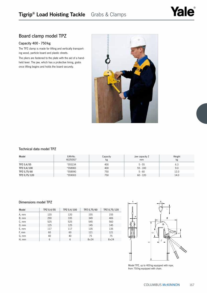
167
Board clamp model TPZCapacity 400 - 750 kgThe TPZ clamp is made for lifting and vertically transport-ing wood, particle board and plastic sheets.
The pliers are fastened to the plate with the aid of a hand-held lever. The jaw, which has a protective lining, grabs once lifting begins and holds the board securely.
Tigrip® Load Hoisting Tackle Grabs & Clamps
Technical data model TPZ
Model EAN-No. 4025092*
Capacitykg
Jaw capacity Z mm
Weight kg
TPZ 0,4/55 *555234 400 5 - 55 6.3TPZ 0,4/100 *558983 400 55 - 100 9.0TPZ 0,75/60 *558990 750 5 - 60 12.0TPZ 0,75/120 *559003 750 60 - 120 14.0
Dimensions model TPZ
Model TPZ 0,4/55 TPZ 0,4/100 TPZ 0,75/60 TPZ 0,75/120
A, mm 120 120 155 155B, mm 290 335 349 406C, mm 525 525 545 560D, mm 125 125 145 145E, mm 117 117 135 135F, mm 60 60 121 121G, mm 40 40 75 75H, mm 6 6 8 x 24 8 x 24
Model TPZ, up to 400 kg equipped with rope, from 750 kg equipped with chain.

168
Tigrip® Load Hoisting Tackle Grabs & Clamps
Manual claw, magnetic model THMCapacity 120 - 170 kgThe THM manual magnetic claw is used for transporting steel sheets horizontally and vertically, lifting plates from racks, pulling steel sheets out of shelving, as well as transporting flat pieces of magnetizable steel. The clamp, depending on the type, can be used for plate thicknesses from 1 to 5 mm.
Pressing down on the handle activates a cam which releases the magnetic claw from the workpiece.
This manual claw is maintenance-free and keeps the magnetic force for an unlimited period of time.
Technical data model THM
Model EAN-No. 4025092*
Capacity ¹ kg
Pulling capacity ¹ kg
Weight kg
THM 120 *550963 120 70 2THM 170 *550437 170 100 2
¹ Measured at a safety factor 2:1 on bright drawn material St37 k
Dimensions model THM
Model THM 120 THM 170
A, mm 90 116B, mm 140 140C, mm 130 130D, mm 25 25E, mm 172 172
INFO
In order to achieve a maximum capacity,the contact sur-face should be bright and free from dirt, oil, grease, scale, corrosion, paint etc.

169
Hand clamp model THGCapacity 250 kgThe THG hand clamp is suited for the individual transport of light and thin plates. Pressing down on the hand grip releases the tension spring, allowing the clamp to open and slide onto the plate.
The plate can be transported by holding onto the ergo-nomically designed hand grip.
The positive spring pressure prevents the plate from accidental slipping out of the clamp.
Tigrip® Load Hoisting Tackle Grabs & Clamps
Technical data model THG
Model EAN-No. 4025092*
Capacitykg
Jaw capacity mm
Weight kg
THG *556057 250 0 - 10 1.4
Dimensions model THG
Model THG
A, mm 184B, mm 105C, mm 12D, mm 53Thickness, mm 40
Attaching Transport
INFO
The plate surface of the material must not exceed a hard-ness of HRC 30.

170
Tigrip® Load Hoisting Tackle Grabs & Clamps
Screw clamp for vertical and horizontal pulling model TSHCapacity 750 - 5000 kgThe screw clamp offers many possible applications. It is particularly useful for lifting, turning and pulling steel plates, girders and steel constructions.
The spindle is closed only finger tight.
Once the screw clamp is tightened and lifting begins, the pivoting pad clamping system produces a wedging action against the material, holding it securely.
Technical data model TSH
Model EAN-No. 4025092*
Capacitykg
Jaw capacity Z mm
Weight kg
TSH 0,75 *559027 750 0 - 28 3.1TSH 1,5 *550123 1500 0 - 32 7.4TSH 2,0 *120302 2000 90 - 140 14.8TSH 2,0 S *426756 2000 50 - 100 14.5TSH 3,0 *550154 3000 0 - 50 11.4TSH 5,0 *550215 5000 0 - 80 27.6
Dimensions model TSH
Model TSH 0,75 TSH 1,5 TSH 2,0 TSH 2,0 S TSH 3,0 TSH 5,0
A, mm 190 255 318 318 290 470B, mm 52 65 74 74 74 130Ø C, mm 19 26 30 30 30 50D, mm 43 75 90 90 85 135E, mm 113 130 286 246 170 225F, mm 35 44 60 60 50 72X, mm 15 40 38 38 40 50
Pawl
Safety spring
Ball Pad Pivoting bearing
Functional drawing pivoting pad
INFO
The plate surface of the material must not exceed a hard-ness level of HRC 50.

171
Screw clamp for lifting and pulling model TSDCapacity 1500 - 7500 kgThe TSD screw clamp is a valuable asset when lifting, pulling and fitting sheet material as well as steel construc-tions.
The spindle is closed only finger tight.
When the screw clamp is tightened and lifting begins, the pivoting pad clamping system produces a wedging action against the material, holding it securely.
Tigrip® Load Hoisting Tackle Grabs & Clamps
Technical data model TSD
Model EAN-No. 4025092*
Capacitykg
Jaw capacity Z mm
Weight kg
TSD 1,5 *550598 1500 0 - 35 4.8TSD 3,0 *550864 3000 0 - 35 8.1TSD 5,0 *551717 5000 0 - 40 14.5TSD 7,5 *550987 7500 0 - 40 18.1
Dimensions model TSD
Model TSD 1,5 TSD 3,0 TSD 5,0 TSD 7,5
A, mm 191 235 275 295Ø B, mm 35 46 55 65C, mm 24 34 40 50D, mm 16 17 18 22E, mm 60 67 85 92F, mm 105 120 150 162G, mm 50 60 75 80
Pawl
Safety spring
Ball Pad Pivoting bearing
Functional drawing pivoting pad
INFO
The plate surface of the material must not exceed a hard-ness level of HRC 50.

172
Tigrip® Load Hoisting Tackle Grabs & Clamps
Screw clamp for three-dimensional pulling model TSZCapacity 500 - 7500 kgThe TSZ screw clamp is designed to pull in three direc-tions. It offers many different possibilities for transporting steel constructions, feeding machining centres, etc.
The spindle is closed only finger tight.
When the screw clamp is tightened and lifting begins, the pivoting pad clamping system produces a wedging action against the material, holding it securely.
Technical data model TSZ
Model EAN-No. 4025092*
Capacitykg
Jaw capacity mm
Weight kg
TSZ 0,5 *555739 500 0 - 28 2.3TSZ 1,5 *555746 1500 0 - 35 5.6TSZ 3,0 *555753 3000 0 - 35 8.8TSZ 5,0 *555760 5000 0 - 40 16.2TSZ 7,5 *555777 7500 0 - 40 20.9
Dimensions model TSZ
Model TSZ 0,5 TSZ 1,5 TSZ 3,0 TSZ 5,0 TSZ 7,5
A, mm 28 35 35 40 40B, mm 43 60 67 85 92C, mm 45 55 65 75 75D, mm 125 158 195 230 240E, mm 72 93 114 133 143F, mm 83 99 120 150 162Ø G, mm 26 35 46 55 65H, mm 16 24 34 40 50I, mm 12 16 17 18 23J, mm 35 50 60 75 80
Safety spring
Ball Pad Pivoting bearing
Functional drawing pivoting pad
Pawl
INFO
The plate surface of the material must not exceed a hard-ness level of HRC 50.

173
Roundstock grab model TRUCapacity 100 - 4000 kgThe TRU roundstock grab picks up roundstock and pipe material up to 600 mm in diameter quickly and safely. With its optional protective lining, it can also pick up materials with sensitive surfaces.
Tigrip® Load Hoisting Tackle Grabs & Clamps
Technical data model TRU
Model EAN-No. 4025092*
EAN-No. 4025092*
with protective lining
Capacity
kg
Jaw capacity Z
mm
Weight
kg
TRU 0,1/150 *550918 *551632 100 50 - 150 4.2TRU 0,5/200 *550475 *551151 500 35 - 200 13.6TRU 1,0/200 *550949 *552165 1000 35 - 200 13.6TRU 1,5/300 *550505 *550512 1500 80 - 300 27.0TRU 3,0/300 *550758 *550536 3000 80 - 300 49.0TRU 4,0/600 *551526 *550406 4000 200 - 600 204.0
Dimensions model TRU
Model TRU 0,1/150
TRU 0,5/200
TRU 1,0/200
TRU 1,5/300
TRU 3,0/300
TRU 4,0/600
A, mm 270 503 509 720 740 1420B min., mm 292 417 437 520 582 930B max., mm 458 723 745 937 960 1815C, mm 97 150 178 204 220 318D, mm 43 56 82 84 125 205E, mm 8 15 15 20 20 30F, mm 17 17 30 25 30 35
Locking pawl
Hook ring
Model TRU, hook ring for grabs for 2000 kg and above.Locking pawl keeps the grab in the open position.
INFO
When using protective lining, it is important that the surfaces are dry, clean and free of oil and grease.

174
Tigrip® Load Hoisting Tackle Grabs & Clamps
Pipe grab model TRCapacity 200 - 3000 kgThe TR pipe grab for rolls and pipes up to 1050 mm in diameter offers a large variety of different applica-tions. Apart from pipe and drums laid on their side, this lightweight pipe grab will also handle rolls of paper, fabric, sheet metal and tubes.
The grab can be ordered with a protective lining made of “Bremsit“ or hard rubber for extra protection in lifting loads with sensitive surface.
Technical data model TR
Model EAN-No. 4025092*
EAN-No. 4025092*
with protective lining
Capacity
kg
Jaw capacity
mm
Weight
kg
TR 0,2/550 *553506 *552585 200 350 - 550 34TR 0,2/650 *553513 *554978 200 450 - 650 41TR 0,3/750 *553520 *554985 300 500 - 750 47TR 0,5/750 *553537 *551700 500 500 - 750 47TR 0,5/900 *553544 *552400 500 650 - 900 54TR 0,75/1050 *552561 *554992 750 700 - 1050 56TR 1,0/750 *553551 *555005 1000 500 - 750 55TR 1,0/1050 *553568 *555012 1000 700 - 1050 71TR 2,0/1050 *553575 *555029 2000 700 - 1050 135TR 3,0/1050 *553582 *555036 3000 700 - 1050 154
Dimensions model TR
Model TR 0,2/550 TR 0,2/650 TR 0,3/750 TR 0,5/750 TR 0,5/900 TR 0,75/105 TR 1,0/750 TR 1,0/1050 TR 2,0/1050 TR 3,0/1050
A, mm 800 900 1100 1100 1150 1300 1000 1350 1350 1350B, mm 565 615 665 665 765 815 665 815 815 815Ø D, mm 550 650 750 750 900 1050 750 1050 1050 1050E, mm 550 550 550 550 550 550 550 550 800 800F, mm 35 35 35 35 35 35 35 35 45 45G, mm 20 20 20 20 20 20 20 20 30 30Ø C, mm 350 450 500 500 650 700 500 700 700 700
Model TR, hook ring for grabs for 2000 kg and above.Locking pawl keeps the grab in the open position.
Locking pawl
Hook ring
The picture shows a customized grab. Standard delivery without rollers as shown in technical drawing.
INFO
When using protective lining, it is important that the surfaces are dry, clean and free of oil and grease.

175
Profile steel grab model TPRCapacity 500 - 3000 kgThe TPR steel grab is designed for transport of girders, profile steel, etc. It boasts a large jaw capacity, which makes it useful for various flange widths.
The clamping jaws press securely with a positive fit to the girder.
Tigrip® Load Hoisting Tackle Grabs & Clamps
Dimensions model TPR
Technical data model TPR
Model EAN-No. 4025092*
Capacitykg
Jaw capacity Z mm
Weight kg
TPR 0,5/200 *551496 500 0 - 200 15.0TPR 1,5/300 *551045 1500 0 - 300 22.6TPR 3,0/300 *553490 3000 0 - 300 41.7
Model TPR 0,5/200
TPR 1,5/300
TPR 3,0/300
A, mm 510 710 720B min., mm 390 495 525B max., mm 625 830 920C, mm 200 200 220D, mm 15 15 20E, mm 30 30 43
Locking pawl
Hook ring
Model TPR, hook ring for grabs for 2000 kg and above.Locking pawl keeps the grab in the open position.

176
Tigrip® Load Hoisting Tackle Grabs & Clamps
Block grab model TVBCapacity 250 and 500 kgThe TVB block grab is useful for the transport of stone and concrete blocks and other materials with parallel surfaces. The grab has a protective lining to ensure a safe and non-marring transport.
The clamping jaw and the center of gravity are easily and quickly adjustable by means of the locking pin.
Technical data model TVB
Model EAN-No. 4025092*
Capacitykg
Jaw capacity Z mm
Weight kg
TVB 500 *556989 250/500 0 - 240 13
Dimensions model TVB
Model TVB 500
A, mm 537B, mm 296C, mm 112D, mm 80E, mm 75F, mm 85Ø G, mm 22Ø H, mm 10
INFO
It is important that the surfaces are dry, clean and free of oil and grease.

177
Stone/concrete grab with small jaw capacity model TBGCapacity 200 - 2500 kgThe TBG block grabs are suited for the transport of all materials with parallel surfaces that can withstand a clamping pressure twice as high as the load being lifted.
The grabs are delivered with a replaceable hard rubber protective lining as standard.
Tigrip® Load Hoisting Tackle Grabs & Clamps
Technical data model TBG with small jaw capacity
Model EAN-No. 4025092*
Capacitykg
Jaw capacity Z mm
Weight kg
TBG 0,2/150 *552141 200 0 - 150 24TBG 0,3/150 *553599 300 0 - 150 27TBG 0,5/150 *552455 500 0 - 150 27TBG 1,0/250 *552356 1000 50 - 250 50TBG 1,5/250 *552394 1500 50 - 250 50TBG 2,5/250 *551571 2500 50 - 250 79
Dimensions model TBG with small jaw capacity
Model TBG 0,2/150 TBG 0,3/150 TBG 0,5/150 TBG 1,0/250 TBG 1,5/250 TBG 2,5/250
A, mm 815 815 815 1050 1050 1050B min., mm 420 420 420 460 460 460B max., mm 760 760 760 980 980 980C, mm 200 200 200 250 250 250D, mm 160 160 160 160 160 160E, mm 30 30 30 29 29 29F, mm 15 15 15 20 20 25
INFO
When using rubber protective lining it is important that the surfaces are dry, clean and free of oil and grease.

178
Tigrip® Load Hoisting Tackle Grabs & Clamps
Stone/concrete grab with large jaw capacity model TBGCapacity 200 - 5000 kgThe units are delivered with protective linings as standard.
Technical data model TBG with large jaw capacity
Model EAN-No. 4025092*
Capacity kg
Jaw capacity Z mm
Weight kg
TBG 0,2/500 *551489 200 200 - 500 49TBG 0,3/700 *551816 300 400 - 700 52TBG 0,5/900 *552288 500 600 - 900 55TBG 1,0/400 *553612 1000 100 - 400 51TBG 1,0/1100 *552134 1000 800 - 1100 72TBG 1,5/1300 *553605 1500 1000 - 1300 128TBG 2,0/500 *553629 2000 200 - 500 126TBG 3,0/500 *553636 3000 200 - 500 160TBG 4,0/500 *553643 4000 200 - 500 240TBG 5,0/500 *553650 5000 200 - 500 270
Dimensions model TBG with large jaw capacity
Model TBG 0,2/500
TBG 0,3/700
TBG 0,5/900
TBG 1,0/400
TBG 1,0/1100
TBG 1,5/1300
TBG 2,0/500
TBG 3,0/500
TBG 4,0/500
TBG 5,0/500
A ¹, mm 1040 1040 1120 1040 1320 1520 1100 1100 1100 1100B min., mm 390 390 390 390 390 390 530 530 600 600B max., mm 840 840 840 840 840 840 1120 1120 1190 1190C, mm 275 275 275 250 275 275 250 250 250 250D, mm 160 160 160 160 160 160 160 160 160 160E, mm 300 300 300 300 300 300 350 350 350 350F, mm 35 35 35 35 35 35 36 42 48 48G, mm 20 20 20 20 20 20 25 30 35 35
¹ Scissor dimensions
Model TBG with large jaw capacity, lug suspension for grabs with 2000 kg and above
INFO
When using rubber protective lining it is important that the surfaces are dry, clean and free of oil and grease.

179
Bale grab model TBACapacity 200 - 1000 kgThe TBA bale grab transports bales of fiber, wool, fabric, paper, pressed straw and various types of shavings up to a width of 1.3 m. Bales are gripped safely yet gently, and where applicable, the clamps are lined with a soft and pliable material.
The locking pawl only engages if the grab is opened without manual intervention.
Tigrip® Load Hoisting Tackle Grabs & Clamps
Technical data model TBA
Model EAN-No. 4025092*
Capacitykg
Jaw capacity Z mm
Weight kg
TBA 0,2/700 *553667 200 250 - 700 40TBA 0,3/900 *552080 300 450 - 900 42TBA 0,5/1100 *552776 500 650 - 1100 45TBA 0,75/1300 *552035 750 850 - 1300 62TBA 1,0/1300 *553674 1000 850 - 1300 62
Dimensions model TBA
Model TBA 0,2/700
TBA 0,3/900
TBA 0,5/1100
TBA 0,75/1300
TBA 1,0/1300
A, mm 890 1090 1290 1550 1550B, mm 420 420 420 420 420C, mm 500 500 500 500 500D, mm 35 35 35 35 35E, mm 20 20 20 20 20
Model TBA 0.2-1 t with serrated jaw
INFO
The standard grab is equipped with protective linings.
Serrated jaws available on request.

180
Tigrip® Load Hoisting Tackle Grabs & Clamps
Rail grab with safety lock model TCRCapacity 1000 - 2000 kgThe TCR rail grab transports rails, as used by railways, easily and safely. A safe grip is ensured by the lever operated safety lock. For long rails, two grabs must be attached to a spreader beam to avoid sagging.
Since the rails are primarily grabbed with positive fit, it is important that the clamp stays in a vertical position during initial lift.
Technical data model TCR
Model EAN-No. 4025092*
Capacitykg
Weight kg
TCR 1,0 *550802 1000 12.4TCR 2,0 *551076 2000 13.9
Model TCR 1,0 TCR 2,0
A ¹, mm 144 144B, mm 152 163C, mm 350 350D, mm 90 90E, mm 46 46Ø F, mm 20 20G, mm 25 25
¹ Scissor dimensions
Dimensions model TCR
INFO
For special sizes please advise rail type and profile!
A TCR multiple rail system is also available for the simul-taneous transport of up to 12 rails.
For rail jacks please see page 114.

181
Inside grab model TDICapacity 100 - 5000 kgInside grabs are available in three versions for the handling of cylindrical and rectangular hollow bodies. The clamping jaws are available with optional steel jaws, hard manganese serrated jaws or jaws with protective lining, which are designed to grab a variety of shapes and materials. These inside grabs can be equipped with an automatic opening and closing device.
Ideal especially for wire coils and hollow bodies.
Tigrip® Load Hoisting Tackle Grabs & Clamps
Technical data model TDI
Model EAN-No. 4025092*
Capacitykg
Jaw capacity mm
Weight kg
TDI 0,1/420 *551410 100 220 - 420 17TDI 0,5/600 *552066 500 400 - 600 51TDI 1,0/600 *553704 1000 400 - 600 53TDI 2,0/800 *553711 2000 550 - 800 150TDI 3,0/800 *553728 3000 550 - 800 175TDI 5,0/800 ¹ *553735 5000 550 - 800 220
¹ with hard manganese serrated jaws
Model TDI 0,1/420
TDI 0,5/600
TDI 1,0/600
TDI 2,0/800
TDI 3,0/800
TDI 5,0/800
A, mm 790 1200 1200 1400 1450 1450B, mm 455 610 600 830 920 795C, mm 550 800 900 1100 1000 1000D, mm 80 100 100 120 160 160E, mm 90 160 160 220 220 65F, mm – – – 124 151 151G, mm Ø 60 Ø 92 Ø 92 83 107 107H, mm 15 15 15 30 30 35I, mm 22 30 30 42 42 42
Dimensions model TDI
INFO
For inside grabs with jaws with protective lining, the inside surface of the material must be free of oil and grease!
When ordering, please advise the requested version!

182
Tigrip® Load Hoisting Tackle Container lifting lugs
Container lifting lugs model TCO and model TCUCapacity 32000 - 56000 kgThese container lifting lugs are offered in a set of 4 pieces with a total weight capacity of 56 t.
The lugs serve as flexible attachment points for the transport of containers. Two types are available which can be fastened to either the “top“ or to the “bottom” of the container.
Model TCO is vertically mounted in the hole at the top of the container. Turning the TCO 90°, locks it securely in place.
Model TCU is mounted on the bottom fixing hole on the container and has a spring-loaded bolt to prevent an ac-cidental release.
Transport is done with the use of a spreader beam in conjunction with wire rope, chain or textile slings making sure the load is suspended vertically.
Technical data model TCO and model TCU
Model EAN-No. 4025092*
Capacity ¹ kg
Weight ¹ kg
Angle from the vertical
TCU 32 *556927 32000 19.5 50°TCU 40 *556927 40000 19.5 36°TCO 56 *556965 56000 30.1 vertical
¹ set of 4 pieces
Model TCU 32 TCU 40 TCO 56
A, mm 152 152 123B, mm 181 181 217Ø C, mm 45 45 45D, mm 37 37 39E, mm 73 73 57F, mm 75 75 101G, mm 40 40 121
Dimensions model TCO and model TCU
Container lifting lugs model TCO
Model TCU
Model TCO
Model TCO
Model TCU

183
Tigrip® Load Hoisting Tackle Clamps
Clamps for cable drums model TKBCapacity 5000 kgSpecifically designed for the transport of cable drums, these clamps are used in pairs together with a two-legged chain sling.
By the spreading of the clamp, it locks inside the drum.
The clamps can be held in place by a locking lever.
Easy handling, light-weight design, and the size of the clamp contribute to a safe transport of all types of cable drums.
Technical data model TKB
Model EAN-No. 4025092*
Capacity ¹ kg
Weight kg
TKB *556606 5000 11
¹ Per pair
Model TKB
A, mm 277B, mm 277Ø C, mm 82D, mm 85Ø E, mm 50
Dimensions model TKB
INFO
Various sizes are available on request. Please supply dimensions C and D!

184
Tigrip® Load Hoisting Tackle C-Hooks
C-Hook model TCKCapacity 500 - 10000 kgCoils, rolls, rings and similar items are transported safely with the Tigrip C-Hooks. Tine length and usable height with the most frequently encountered coil sizes are listed in the table below.
Other working loads, measurements, and models, such as C-Hooks with automatic balancing device, are available on request.
Technical data model TCK
Model EAN-No. 4025092*
Capacitykg
Weight kg
TCK 0,5/300 *554800 500 21TCK 0,5/500 *552417 500 30TCK 0,5/800 *554817 500 46
TCK 1,0/300 *554824 1000 28TCK 1,0/500 *554831 1000 40TCK 1,0/800 *552783 1000 95
TCK 2,0/300 *554848 2000 45TCK 2,0/500 *551830 2000 90TCK 2,0/800 *552615 2000 140TCK 2,0/1000 *552479 2000 180
TCK 3,0/300 *554855 3000 68TCK 3,0/500 *554862 3000 127TCK 3,0/800 *552431 3000 165TCK 3,0/1000 *554879 3000 215
TCK 5,0/500 *551298 5000 184TCK 5,0/800 *554886 5000 238TCK 5,0/1000 *554893 5000 286TCK 5,0/1250 *554909 5000 364
TCK 7,5/800 *555043 7500 390TCK 7,5/1000 *551984 7500 520TCK 7,5/1250 *551878 7500 650TCK 7,5/1500 *554916 7500 767
TCK 10,0/1000 *554923 10000 772TCK 10,0/1250 *551670 10000 810TCK 10,0/1500 *554930 10000 980
INFO
Illustration shows tines with 4/4 the length of the coil width (special).

185
Tigrip® Load Hoisting Tackle C-Hooks
Dimensions model TCK
Model TCK 0,5/300
TCK 0,5/500
TCK 0,5/800
TCK 1,0/300
TCK 1,0/500
TCK 1,0/800
TCK 2,0/300
TCK 2,0/500
TCK 2,0/800
TCK 2,0/1000
Coil width A, mm 300 500 800 300 500 800 300 500 800 1000Usable height B, mm 400 400 400 450 450 450 500 500 500 500C, mm 570 580 580 620 630 630 700 700 720 720D, mm 60 60 60 60 60 60 75 75 75 75E, mm 120 120 120 120 120 120 150 150 150 150F, mm 20 20 25 25 20 30 25 30 30 20G, mm 25 23 23 23 23 23 38 38 38 35H, mm 20 20 25 20 25 30 25 30 30 40I, mm 50 65 70 70 80 90 90 110 125 125
Model TCK 3,0/300
TCK 3,0/500
TCK 3,0/800
TCK 3,0/1000
TCK 5,0/500
TCK 5,0/800
TCK 5,0/1000
TCK 5,0/1250
TCK 7,5/800
TCK 7,5/1000
Coil width A, mm 300 500 800 1000 500 800 1000 1250 800 1000Usable height B, mm 500 500 500 500 550 550 550 550 600 600C, mm 700 700 720 720 800 800 820 820 900 900D, mm 75 75 75 75 100 100 100 100 110 110E, mm 150 150 150 150 200 200 200 200 220 220F, mm 30 20 25 20 25 30 30 30 35 35G, mm 38 40 40 40 45 45 45 45 50 50H, mm 30 30 40 40 40 50 50 50 50 60I, mm 105 125 140 155 145 160 180 200 200 200
Model TCK 7,5/1250
TCK 7,5/1500
TCK 10,0/1000
TCK 10,0/1250
TCK 10,0/1500
Coil width A, mm 1250 1500 1000 1250 1500Usable height B, mm 600 600 650 650 650C, mm 900 920 980 1000 1000D, mm 110 110 130 130 130E, mm 220 220 250 250 250F, mm 35 35 40 45 45G, mm 45 50 50 55 55H, mm 60 70 70 70 80I, mm 220 220 220 240 240

186
Tigrip® Load Hoisting Tackle C-Hooks
Coil hook model TCSCapacity 500 - 3000 kgThe TCS coil hook is an universal C-Hook. Due to its tip-ping feature, it can lift or lower the coil, whether the coil is lying flat or is in an upright position. With this tipping device, the coil is tipped safely through 90°.
The slow and safe movement of the tipping device ensures a continuous flowing movement when lifting or lowering the coil. At the same time, the tipping device serves the purpose of preventing accidental slipping of the load during transport.
Dimensions model TCS
Model TCS 0,5/120
TCS 0,5/200
TCS 1,0/200
TCS 1,0/300
TCS 2,0/200
TCS 2,0/300
TCS 3,0/200
TCS 3,0/300
Coil width A min, mm 50 100 100 200 100 200 100 200Coil width A max., mm 120 200 200 300 200 300 200 300B, mm 10 10 10 10 12 12 15 15C, mm 60 60 80 80 90 90 100 100D, mm 330 330 460 460 420 420 610 610E, mm 470 470 600 600 600 600 820 820F, mm 20 20 20 20 30 30 40 40G, mm 110 110 110 110 135 135 160 160H, mm 60 60 60 60 75 75 90 90K, mm 50 50 60 60 80 80 100 100L, mm 45 50 65 70 85 95 100 110T, mm 20 20 25 25 30 30 35 35Ø I , mm 220 300 300 400 300 400 300 400
Model EAN-No. 4025092*
Capacitykg
Weight kg
TCS 0,5/120 *554947 500 6.9TCS 0,5/200 *552257 500 9.6TCS 1,0/200 *552264 1000 15.4TCS 1,0/300 *552875 1000 20.0TCS 2,0/200 *551977 2000 24.8TCS 2,0/300 *551908 2000 33.4TCS 3,0/200 *552011 3000 45.0TCS 3,0/300 *552714 3000 51.0
Technical data model TCS
INFO
Other sizes and models available on request.

187
Barrel grab for transport of upright barrels model TFACapacity 300 kgThis unit grabs upright barrels and sets them down in the same position. Although the clamping jaws are fitted with a hard rubber lining to provide a friction hold, it is the positive fit on the rim that provides extra safety. This additional feature is indispensable if the surface of the barrels is stained with oil or grease.
The clamping jaws fitted with a protective lining enable the non-marring and secure grab around the circumfer-ence of the barrel. The clamp is suitable for standard type barrels.
Tigrip® Load Hoisting Tackle Barrel grabs & Crate grabs
Technical data model TFA
Model EAN-No. 4025092*
Capacity
kg
Jaw capacity Z diameter
mm
Weight
kg
TFA 0,3/600 *557009 300 400 - 600 57
Model TFA 0,3/600
A, mm 600B, mm 1040C, mm 950Ø D, mm 90E, mm 34F, mm 15G, mm 200H, mm 400I, mm 400
Dimensions model TFA
INFO
For barrels according to EN ISO 15750-2.

188
Tigrip® Load Hoisting Tackle Barrel grabs & Crate grabs
Barrel grab with tipping device model TFA DCapacity 300 kgThe grab with tipping device is suited to lift, transport as well as tipping and emptying the barrel.
In order to tip the barrel easily, it must be picked up at the correct center of gravity.
Technical data model TFA D
Model EAN-No. 4025092*
Capacity
kg
Jaw capacity Z diameter
mm
Weight
kg
TFA 0,3/600 D *557917 300 400 - 600 83
Model TFA 0,3/600 D
A, mm 600B, mm 1150C, mm 1525Ø D, mm 90E, mm 34F, mm 15G, mm 200H, mm 400
Dimensions model TFA D
INFO
For barrels according to EN ISO 15750-2.

189
Barrel grab model TFA 0,35/700 R and TFA 0,35/700 TRCapacity 350 kgThese barrel grabs are designed for transport of steel barrels. The clamping jaws press securely with a positive fit underneath the rim of the barrel.
Tigrip® Load Hoisting Tackle Barrel grabs & Crate grabs
Technical data model TFA R/TR
Model EAN-No. 4025092*
Capacity
kg
Jaw capacity Z diameter
mm
Weight
kg
TFA 0,35/700 R *551014 350 420 - 700 5.7TFA 0,35/700 TR *551472 350 420 - 700 9.2
Model TFA-R Model TFA-TR
Model TFA-R Model TFA-TR
Relevant barrel dimensions
INFO
TFA 0,35/700 TR is a combination unit for the transport of barrels that can be used with either an overhead crane or forklift.
For barrels according to EN ISO 15750-2.

190
Tigrip® Load Hoisting Tackle Barrel grabs & Crate grabs
Barrel rim clamp model TFRKCapacity 500 kgThe TFRK barrel rim clamp can be used individually, as a pair, or as a multi-legged chain sling.
The clamp grabs under the rim of the barrel. A spring-loaded cam prevents the accidental opening of the clamp.
Model EAN-No. 4025092*
Capacitykg
Weight kg
TFRK *556415 500 1.5
Technical data model TFRK
Model TFRK 0,5
A, mm 152B, mm 150C, mm 127D, mm 30E, mm 21F, mm 41G, mm 17Ø H, mm 40
Dimensions model TFRK
INFO
For barrels according to EN ISO 15750-2.
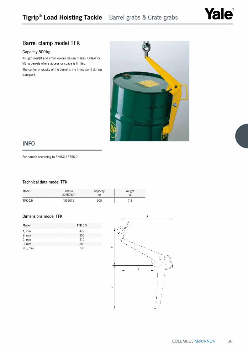
191
Barrel clamp model TFKCapacity 500 kgIts light weight and small overall design makes it ideal for lifting barrels where access or space is limited.
The center of gravity of the barrel is the lifting point during transport.
Tigrip® Load Hoisting Tackle Barrel grabs & Crate grabs
Technical data model TFK
Model EAN-No. 4025092*
Capacity kg
Weight kg
TFK 0,5 *556071 500 7.3
Model TFK 0,5
A, mm 479B, mm 350C, mm 410D, mm 300Ø E, mm 50
Dimensions model TFK
INFO
For barrels according to EN ISO 15750-2.

192
Tigrip® Load Hoisting Tackle Barrel grabs & Crate grabs
Crate grab with tipping device model TKA/dCapacity 150 kgThe crate grab with tipping device is an absolutely safe unit, which not only securely transports stacking boxes, but can empty them in mid-air as well.
A safety lever system prevents the accidental opening of the grab.
The clamping jaws tightly grab under the rim of the crate without damaging the crate. To engage the tipping mo-tion in order to empty the crate, the safety lock must be manually unlocked. The tipping motion is limited to 100°. This prevents the crate from flipping completely over while emptying, thereby reducing the risk of injury.
Option• Grabs for other sizes of crates.
Technical data model TKA/d
Model EAN-No. 4025092*
Capacitykg
Weight kg
TKA 0,15/330d *551519 150 25.8TKA 0,15/480d *552103 150 26.0
Model TKA 0,15/330d TKA 0,15/480d
A, mm 200 - 300 300B, mm 315 - 330 470 - 480L, mm 465 - 540 550 - 660
Dimensions model TKA/d
INFO
Please provide the crate dimensions or a sample crate when ordering.

193
Crate grab model TKA a/iCapacity 250 kgThe easy-handling crate grab, which grabs on the side plates or the front sides of the crate, transports crates safely and without damaging them.
The moveable jaws press the edge of the crate gently against the outside grab support rails. Stacking boxes made of steel or plastic will not get deformed. After the box has been set down, the safety device holds the grab open.
When lifting the crate and grabbing the support rails, the safety device must be manually pulled back until it lies over the safety bolt. With further lifting, the jaws grab under the outer top edge of the crate and lift it up safely.
The crate grab is available as an external or internal operating grab.
Tigrip® Load Hoisting Tackle Barrel grabs & Crate grabs
Technical data model TKA a/i
Model EAN-No. 4025092*
Capacitykg
Weight kg
Jaw capacity mm
TKA 0,25/320a *558082 250 9.3 320TKA 0,25/480a *558044 250 9.3 480TKA 0,25/600a *558099 250 9.3 600TKA 0,25/320i *558051 250 8.5 320TKA 0,25/480i *558068 250 8.5 480TKA 0,25/600i *558075 250 8.5 600
Model TKA.../...i internal operating Model TKA.../...i internal operating
Model TKA.../...a external operating
Model TKA.../...a external operating Model TKA.../...i internal operating
INFO
Please provide the crate dimensions or a sample crate when ordering.

194
Tigrip® Load Hoisting Tackle for underground construction
Concrete pipe lifting gear model BTGCapacity 1500 - 3000 kgLifting gear for the vertical transport of concrete pipe and culverts must be very versatile. Most important, it must be absolutely safe and easy to handle under even the harshest conditions.
The Tigrip concrete pipe lifting gear meets all these requirements. It is a three legged lifting system for the safe and non-marring transport of concrete pipes up to a diameter of Ø 2000 mm and a load of up to 3 t. The jaw capacity is designed for concrete pipe thick-nesses from 40 - 220 mm. Attachment and removal of the clamps can be done easily due to the handles that have been incorporated into each clamp.
Features• Solid design
• Safety factor 4:1
• Simple and safe handling
• Large jaw capacity
• For the toughest operating conditions
• Lightweight design
• Service-friendly
Technical data model BTG
Model EAN-No. 4025092*
Capacity ¹ kg
Jaw capacity Z mm
Mouth depth E mm
Pressure line F mm
Weight kg
BTG 1,5/120 *550147 1500 40 - 120 165 100 35BTG 3,0/180 TM-N *551199 3000 50 - 180 245 175 90BTG 3,0/220 TM-N *550819 3000 90 - 220 245 175 94
¹ Per lifting gear - three legged
Model BTG 1,5/120
BTG 3,0/180 TM-N
BTG 3,0/220 TM-N
A, mm 135 180 180B, mm 75 100 100Ø C, mm 18 26 26D, mm 180 310 310
Dimensions model BTG
INFO
For concrete pipes according to DIN 4034.
Lifting gear for concrete pipe up to a diameter of Ø 3000 mm available on request!

195
Trench shield grab model TCPCapacity 1500 - 5500 kgThe TCP grab is suitable for vertical positioning and transportation of trench shields.
Once the grab is set onto the trench shield, a spring- loaded bolt locks itself into the hole of the shield. Releas-ing the bolt is done with the 15 m pull cord attached to the grab.
Tigrip® Load Hoisting Tackle for underground construction
Technical data model TCP
Model EAN-No. 4025092*
Capacitykg
Weight kg
TCP 1,5 *555807 1500 12.2TCP 3,0 *555791 3000 19.5TCP 5,5 *555784 5500 26.7
Model TCP 1,5 TCP 3,0 TCP 5,5
A, mm 207 226 269B, mm 488 517 575C, mm 218 218 218D, mm 90 100 120E, mm 18 24 24Ø F, mm 20 24 30G, mm 180 180 180Ø H, mm 50 63 89
Dimensions model TCP

196
Tigrip® Load Hoisting Tackle for underground construction
Trench shield clamp model TPPCapacity 3000 - 12000 kgThe TPP trench shield clamp is similar to a regular plate clamp in its construction but has a much deeper jaw.
The compact construction combined with a high capacity makes it ideal for pulling trench shields out of the ground. A safety lock prevents the accidental opening of the clamp.
Technical data model TPP
Model EAN-No. 4025092*
Capacitykg
Jaw capacity mm
Weight kg
TPP 3 *556255 3000 0 - 20 16.0TPP 8 *556217 8000 0 - 30 27.8TPP 12 *556231 12000 0 - 30 53.0
Model TPP 3 TPP 8 TPP 12
A, mm 224 294 361B, mm 325 445 486Ø C, mm 20 30 40D, mm 88 109 145E, mm 147 194 190F, mm 25 42 41G, mm 123 146 167H, mm 60 72 90I, mm 20 25 30J, mm 18 26 32
Dimensions model TPP

197
Pipe hook model TROCapacity 2000 - 10000 kgThe pipe hooks are used in pairs for the safe transport of pipes.
Scope of deliveryThe shackles are included with the hooks.
Tigrip® Load Hoisting Tackle for underground construction
Technical data model TRO for 60° - 90° chain-top angle
Model EAN-No. 4025092*
Capacity ¹ kg
Weight ¹ kg
TRO 2/90 *556729 2000 3.1TRO 4/90 *556743 4000 5.6TRO 6/90 *556767 6000 10.5TRO 8/90 *556781 8000 17.8TRO 10/90 *556804 10000 22.0
¹ Per pair
Model TRO 2/90 TRO 4/90 TRO 6/90 TRO 8/90 TRO 10/90
t, mm 20 30 30 40 40A, mm 0 - 40 0 - 50 0 - 60 0 - 70 0 - 80B, mm 35 40 51 55 69C, mm 40 48 62 67 80D, mm 62 77 90 105 115E, mm 62 77 90 105 115F, mm 116 142 173 190 221Ø G, mm 16.3 24.3 24.3 30.3 30.3H, mm 47.6 72.2 72.2 95.3 95.3Ø I , mm 12.7 19 19 25.4 25.4J, mm 30.2 44.5 44.5 58.7 58.7
Dimensions model TRO for 60° - 90° chain-top angle
Model EAN-No. 4025092*
Capacity ¹ kg
Weight ¹ kg
TRO 2/120 *556828 2000 3.5TRO 4/120 *556842 4000 8.8TRO 6/120 *556866 6000 14.9TRO 8/120 *556880 8000 18.6TRO 10/120 *556903 10000 23.0
¹ Per pair
Technical data model TRO for 90° - 120° chain-top angle
Model TRO 2/120 TRO 4/120 TRO 6/120 TRO 8/120 TRO 10/120
t, mm 20 30 40 40 50A, mm 0 - 30 10 - 40 20 - 50 30 - 65 30 - 75B, mm 34 39 43 54 60C, mm 40 50 55 65 70D, mm 82 95 106 119 143E, mm 75 80 95 100 125F, mm 106 131 153 185 208Ø G, mm 16.3 24.3 30.3 30.3 36.3H, mm 30.2 44.5 58.7 58.7 73Ø I , mm 12.7 19 25.4 25.4 31.8J, mm 47.6 72.2 95.3 95.3 117
Dimensions model TRO for 90° - 120° chain-top angle

198
Suspension variantsEyelet suspensionStandard suspension for use with single hooks according to DIN 15401
Possible for defined load centre of gravity for symmetrical but also asymmetrical loads.
Spreader beam rangeBulkier or heavier loads must be carried on multiple points to ensure safe weight distribution and less sagging. The extensive TIGRIP® range provides a vast choice of load capacities, working widths, adjustment ranges and hook types to cater for the great majority of applica-tions. In addition to our quality-engineered, robust and cost-effective standard range, we can also provide special designs to meet individual, bespoke customer require-ments.
Options include side welding hooks (so-called cow horns), that take rope loops or lifting bands’ crane eye for car-rying pipes. Rolls or rollers on two or more points; star crossbars for carrying cylindrical items, or transverse crossbars for four point suspension, a further version of the reliable, easy to use and safe TIGRIP® crane hook spreader beams.
Spreader beams can be used for a diverse range of shapes and designs, and can be individually designed to meet specific applications. The following illustrations provide a short overview of the many designs available. Suspension and load carrying variants can be easily combined with most designs.
Tigrip® Load Hoisting Tackle Spreader beams
Bracket suspensionFor use with double hooks according to DIN 15402
Double eyelet suspension for two crane operationAllows the spreader beam to be used on two cranes at the same time
Each suspension variant can be operated as a double suspension.
Internal bolt suspensionTo reduce the build height
Fixed welded-on but also plug-in variants possible.
Chain suspensionTo stabilise swinging movements
Multitude of options in combination with our chain programme. Lifting ring for single hooks but also double hooks Shortening hooks allow the centre of gravity to be adjusted for asymmetrical loads.
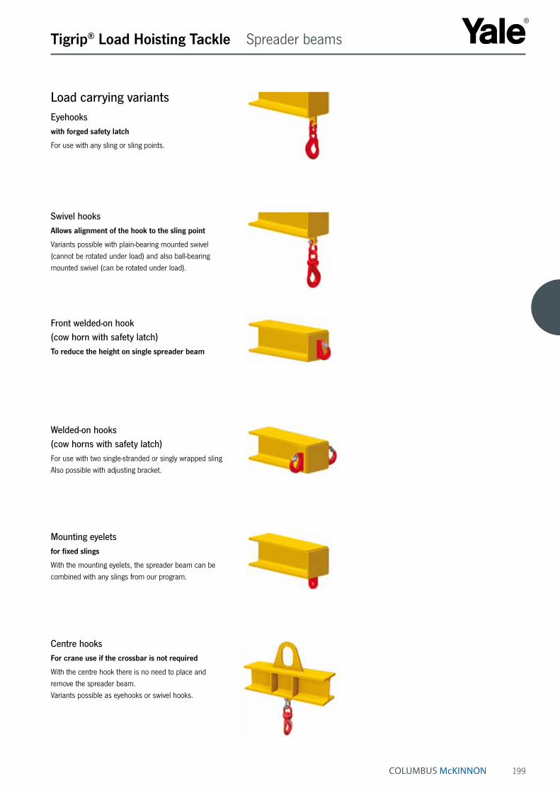
199
Load carrying variantsEyehookswith forged safety latch
For use with any sling or sling points.
Centre hooksFor crane use if the crossbar is not required
With the centre hook there is no need to place and remove the spreader beam. Variants possible as eyehooks or swivel hooks.
Mounting eyeletsfor fixed slings
With the mounting eyelets, the spreader beam can be combined with any slings from our program.
Welded-on hooks (cow horns with safety latch)For use with two single-stranded or singly wrapped sling Also possible with adjusting bracket.
Front welded-on hook (cow horn with safety latch)To reduce the height on single spreader beam
Swivel hooksAllows alignment of the hook to the sling point
Variants possible with plain-bearing mounted swivel (cannot be rotated under load) and also ball-bearing mounted swivel (can be rotated under load).
Tigrip® Load Hoisting Tackle Spreader beams
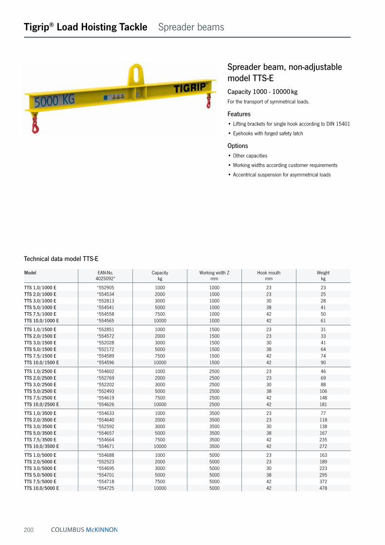
200
Tigrip® Load Hoisting Tackle Spreader beams
Spreader beam, non-adjustable model TTS-ECapacity 1000 - 10000 kgFor the transport of symmetrical loads.
Features• Lifting brackets for single hook according to DIN 15401
• Eyehooks with forged safety latch
Options• Other capacities
• Working widths according customer requirements
• Accentrical suspension for asymmetrical loads
Technical data model TTS-E
Model EAN-No. 4025092*
Capacitykg
Working width Z mm
Hook mouth mm
Weight kg
TTS 1,0/1000 E *552905 1000 1000 23 23TTS 2,0/1000 E *554534 2000 1000 23 25TTS 3,0/1000 E *552813 3000 1000 30 28TTS 5,0/1000 E *554541 5000 1000 38 41TTS 7,5/1000 E *554558 7500 1000 42 50TTS 10,0/1000 E *554565 10000 1000 42 61
TTS 1,0/1500 E *552851 1000 1500 23 31TTS 2,0/1500 E *554572 2000 1500 23 33TTS 3,0/1500 E *552028 3000 1500 30 41TTS 5,0/1500 E *552172 5000 1500 38 64TTS 7,5/1500 E *554589 7500 1500 42 74TTS 10,0/1500 E *554596 10000 1500 42 90
TTS 1,0/2500 E *554602 1000 2500 23 46TTS 2,0/2500 E *552769 2000 2500 23 69TTS 3,0/2500 E *552202 3000 2500 30 88TTS 5,0/2500 E *552493 5000 2500 38 106TTS 7,5/2500 E *554619 7500 2500 42 148TTS 10,0/2500 E *554626 10000 2500 42 181
TTS 1,0/3500 E *554633 1000 3500 23 77TTS 2,0/3500 E *554640 2000 3500 23 118TTS 3,0/3500 E *552592 3000 3500 30 138TTS 5,0/3500 E *554657 5000 3500 38 167TTS 7,5/3500 E *554664 7500 3500 42 235TTS 10,0/3500 E *554671 10000 3500 42 272
TTS 1,0/5000 E *554688 1000 5000 23 163TTS 2,0/5000 E *552523 2000 5000 23 189TTS 3,0/5000 E *554695 3000 5000 30 223TTS 5,0/5000 E *554701 5000 5000 38 295TTS 7,5/5000 E *554718 7500 5000 42 372TTS 10,0/5000 E *554725 10000 5000 42 478

201
Tigrip® Load Hoisting Tackle Spreader beams
Model TTS 7,5/1500 E
TTS 10,0/1500 E
TTS 1,0/2500 E
TTS 2,0/2500 E
TTS 3,0/2500 E
TTS 5,0/2500 E
TTS 7,5/2500 E
TTS 10,0/2500 E
TTS 1,0/3500 E
TTS 2,0/3500 E
B, mm 740 820 405 470 560 655 780 860 435 490C, mm 200 260 110 135 160 180 200 260 110 135D, mm 60 70 25 30 35 40 60 70 25 30E, mm 130 130 60 75 90 100 130 130 60 75
Model TTS 3,0/3500 E
TTS 5,0/3500 E
TTS 7,5/3500 E
TTS 10,0/3500 E
TTS 1,0/5000 E
TTS 2,0/5000 E
TTS 3,0/5000 E
TTS 5,0/5000 E
TTS 7,5/5000 E
TTS 10,0/5000 E
B, mm 580 695 800 880 475 510 600 715 820 920C, mm 160 180 200 260 110 135 160 180 200 260D, mm 35 40 60 70 25 30 35 40 60 70E, mm 90 100 130 130 60 75 90 100 130 130
Model TTS 1,0/1000 E
TTS 2,0/1000 E
TTS 3,0/1000 E
TTS 5,0/1000 E
TTS 7,5/1000 E
TTS 10,0/1000 E
TTS 1,0/1500 E
TTS 2,0/1500 E
TTS 3,0/1500 E
TTS 5,0/1500 E
B, mm 405 430 500 615 720 800 405 430 520 635C, mm 110 135 160 180 200 260 110 135 160 180D, mm 25 30 35 40 60 70 25 30 35 40E, mm 60 75 90 100 130 130 60 75 90 100
Dimensions model TTS-E
INFO
The spreader beams can be combined with the different suspension types (see pages 198 -199).

202
Tigrip® Load Hoisting Tackle Spreader beams
Technical data model TTS
Model EAN-No. 4025092*
Capacitykg
Working width Z mm
Hook mouth mm
Weight kg
TTS 1,0/1500 *552646 1000 700 - 1500 18 40TTS 2,0/1500 *552295 2000 700 - 1500 18 41TTS 3,0/1500 *553988 3000 700 - 1500 21 53TTS 5,0/1500 *551281 5000 700 - 1500 23 79TTS 7,5/1500 *553995 7500 700 - 1500 32 98TTS 10,0/1500 *552219 10000 700 - 1500 32 117TTS 12,5/1500 *554008 12500 700 - 1500 40 116TTS 15,0/1500 *554015 15000 700 - 1500 40 137TTS 20,0/1500 *554022 20000 700 - 1500 50 180TTS 25,0/1500 *554039 25000 700 - 1500 50 226
TTS 1,0/2500 *554046 1000 1500 - 2500 18 58TTS 2,0/2500 *552158 2000 1500 - 2500 18 84TTS 3,0/2500 *552448 3000 1500 - 2500 21 105TTS 5,0/2500 *552424 5000 1500 - 2500 23 127TTS 7,5/2500 *554053 7500 1500 - 2500 32 178TTS 10,0/2500 *554060 10000 1500 - 2500 32 215TTS 12,5/2500 *554077 12500 1500 - 2500 40 198TTS 15,0/2500 *554084 15000 1500 - 2500 40 237TTS 20,0/2500 *554091 20000 1500 - 2500 50 287TTS 25,0/2500 *554107 25000 1500 - 2500 50 342
TTS 1,0/3500 *552684 1000 1700 - 3500 18 95TTS 2,0/3500 *554114 2000 1700 - 3500 18 137TTS 3,0/3500 *554121 3000 1700 - 3500 21 162TTS 5,0/3500 *554138 5000 1700 - 3500 23 228TTS 7,5/3500 *554145 7500 1700 - 3500 32 278TTS 10,0/3500 *554152 10000 1700 - 3500 32 317TTS 12,5/3500 *554169 12500 1700 - 3500 40 295TTS 15,0/3500 *551403 15000 1700 - 3500 40 340TTS 20,0/3500 *554176 20000 1700 - 3500 50 451TTS 25,0/3500 *554183 25000 1700 - 3500 50 512
TTS 1,0/5000 *554367 1000 2000 - 5000 18 190TTS 2,0/5000 *554374 2000 2000 - 5000 18 219TTS 3,0/5000 *554381 3000 2000 - 5000 21 260TTS 5,0/5000 *554398 5000 2000 - 5000 23 372TTS 7,5/5000 *554404 7500 2000 - 5000 32 423TTS 10,0/5000 *554411 10000 2000 - 5000 32 531TTS 12,5/5000 *554428 12500 2000 - 5000 40 449TTS 15,0/5000 *554435 15000 2000 - 5000 40 568TTS 20,0/5000 *554442 20000 2000 - 5000 50 691
TTS 1,0/8000 *554459 1000 3000 - 8000 18 342TTS 2,0/8000 *554466 2000 3000 - 8000 18 458TTS 3,0/8000 *554473 3000 3000 - 8000 21 547TTS 5,0/8000 *554480 5000 3000 - 8000 23 788TTS 7,5/8000 *554497 7500 3000 - 8000 32 883TTS 10,0/8000 *554503 10000 3000 - 8000 32 1319TTS 12,5/8000 *554510 12500 3000 - 8000 40 979TTS 15,0/8000 *554527 15000 3000 - 8000 40 1046
Spreader beam, adjustable model TTSCapacity 1000 - 25000 kgFor the transport of symmetrical and asymmetrical loads.
Features• Lifting brackets for single hook according to DIN 15401
• Adjustment with grids
• Adjustable bracket with handle and swivel hook (cannot be rotated under load)

203
Tigrip® Load Hoisting Tackle Spreader beams
Dimensions model TTS
Model TTS 1,0/1500
TTS 2,0/1500
TTS 3,0/1500
TTS 5,0/1500
TTS 7,5/1500
TTS 10,0/1500
TTS 12,5/1500
TTS 15,0/1500
TTS 20,0/1500
TTS 25,0/1500
B, mm 440 470 570 655 740 835 865 910 1020 1230C, mm 110 135 160 180 200 260 260 260 260 300D, mm 25 30 35 40 60 70 75 85 90 100E, mm 60 75 90 100 130 130 140 140 160 160
Model TTS 1,0/2500
TTS 2,0/2500
TTS 3,0/2500
TTS 5,0/2500
TTS 7,5/2500
TTS 10,0/2500
TTS 12,5/2500
TTS 15,0/2500
TTS 20,0/2500
TTS 25,0/2500
B, mm 440 505 610 675 785 880 915 955 1060 1255C, mm 110 135 160 180 200 260 260 260 260 300D, mm 25 30 35 40 60 70 75 85 90 100E, mm 60 75 90 100 130 130 140 140 160 160
Model TTS 1,0/3500
TTS 2,0/3500
TTS 3,0/3500
TTS 5,0/3500
TTS 7,5/3500
TTS 10,0/3500
TTS 12,5/3500
TTS 15,0/3500
TTS 20,0/3500
TTS 25,0/3500
B, mm 440 530 635 715 810 905 935 980 1115 1300C, mm 110 135 160 180 200 260 260 260 260 300D, mm 25 30 35 40 60 70 75 85 90 100E, mm 60 75 90 100 130 130 140 140 160 160
Model TTS 1,0/5000
TTS 2,0/5000
TTS 3,0/5000
TTS 5,0/5000
TTS 7,5/5000
TTS 10,0/5000
TTS 12,5/5000
TTS 15,0/5000
TTS 20,0/5000
B, mm 495 550 655 740 830 950 980 1025 1155C, mm 110 135 160 180 200 260 260 260 260D, mm 25 30 35 40 60 70 75 85 90E, mm 60 75 90 100 130 130 140 140 160
Model TTS 1,0/8000
TTS 2,0/8000
TTS 3,0/8000
TTS 5,0/8000
TTS 7,5/8000
TTS 10,0/8000
TTS 12,5/8000
TTS 15,0/8000
B, mm 515 590 700 785 895 1010 1045 1085C, mm 110 135 160 180 200 260 260 260D, mm 25 30 35 40 60 70 75 85E, mm 60 75 90 100 130 130 140 140
INFO
The spreader beams can be combined with the different suspension types (see pages 198 -199).

204
H-frame spreader beam model TTS-HECapacity up to 10000 kgFor the transport of symmetrical loads.
Features• Lifting brackets for single hook according to DIN 15401
• Eyehooks with forged safety latch
Option• Accentrical suspension for asymmetrical loads
H-frame spreader beam model TTS-HCapacity up to 25000 kgFor the transport of symmetrical and asymmetrical loads.
Features• Lifting brackets for single hook according to DIN 15401
• Adjustment with grids
• Adjustable bracket with handle and swivel hook (cannot be rotated under load)
Tigrip® Load Hoisting Tackle Spreader beams
INFO
Capacity, working length and width designed on individual customer requirements.
The spreader beams can be combined with the different suspension types (see pages 198 -199).
INFO
Capacity, working length and width designed on individual customer requirements.
The spreader beams can be combined with the different suspension types (see pages 198 -199).
Technical questionnaireCapacity kg
Working length, min. mm
Working length, max. mm
Working width, min. mm
Working width, max. mm
Technical questionnaireCapacity kg
Working length mm
Working width mm

205
Tigrip® Load Hoisting Tackle Spreader beams
Spreader beam for box pallets model TTSCapacity 1000 - 3000 kgBox pallets with DIN 15155 specifications, are usually moved around with a forklift, but are so sturdy that they can be picked up and transported with a spreader beam grab and an overhead crane hooked up to the top of the box pallet‘s frame.
Thanks to these spreader beams, the shipping and receiv-ing area is no longer entirely dependent on floor-level material handling equipment such as forklifts.
The version designed for the individual transport of box pallets is equipped with two fixed yokes and two pivoted ones, interconnected with a control bar. The load tackling gear is fixed and unfixed by only one person.
Technical data model TTS
Model EAN-No. 4025092*
Capacitykg
Weight kg
TTS 1,0/1240 - 810 *551595 1000 38TTS 2,0/1240 - 810 *551236 2000 61TTS 3,0/1240 - 810 *553742 3000 80
Model TTS 1,0/1240 - 810 TTS 2,0/1240 - 810 TTS 3,0/1240 - 810
B, mm 600 600 600C, mm 410 495 520D, mm 195 215 215E, mm 125 180 205F, mm 100 150 170G, mm 80 100 130H, mm 28 30 40I, mm 15 20 25Z, mm 1175 1175 1175
Dimensions model TTS

206
Spreader beam for Big-Bags model TTBCapacity 1000 - 2000 kgThis four-point spreader beam in a fixed frame construc-tion with weld-on hooks and safety latch is designed for lifting and transporting of Big-Bags.
Tigrip® Load Hoisting Tackle Spreader beams
Technical data model TTB
Model EAN-No. 4025092*
Capacity kg
Working width Z mm
Weight kg
TTB 1,0/1090 - 1090 *556293 1000 750 - 800 27TTB 1,0/1320 - 1320 *556316 1000 900 - 970 33TTB 2,0/1090 - 1090 *556330 2000 750 - 800 42TTB 2,0/1320 - 1320 *556354 2000 900 - 970 44
Model TTB 1,0/1090 - 1090
TTB 1,0/1320 - 1320
TTB 2,0/1090 - 1090
TTB 2,0/1320 - 1320
B, mm 210 210 240 240C, mm 60 60 75 75D, mm 110 110 135 135
Dimensions model TTB

207
Tine hook model TZHCapacity 1500 - 10000 kgFor fastening hoisting equipment and loads to single forklift tines. The TZH are pushed onto the forklift tines and are fastened with two spindles. The pivoting as well as swivelling hook with safety latch ensures safety while lifting.
Tigrip® Load Hoisting Tackle Spreader beams
Technical data model TZH
Model EAN-No. 4025092*
Capacity kg
Weight kg
TZH 1,5/150 *557566 1500 7.2TZH 3,0/150 *557580 3000 10.8TZH 5,0/150 *557603 5000 17.3TZH 5,0/200 *557627 5000 24.7TZH 10,0/200 *557641 10000 43.0
Model TZH 1,5/150 TZH 3,0/150 TZH 5,0/150 TZH 5,0/200 TZH 10,0/200
A, mm 100 100 100 150 150B, mm 150 150 150 200 200C min., mm 310 350 350 440 440C max., mm 360 400 400 490 490D, mm 260 270 295 320 420E, mm 74 74 74 94 94F, mm 120 120 120 180 180G, mm 25 28 34 34 45
Dimensions model TZH
Model TZH, swivel hooks, pivoting and swivelling
Fork lift cross beam model TTS-ZCapacity 2000 - 5300 kgThe model TTS-Z with two bags is used for forklift tines and has one centered, pivoting eye hook (do not pivot under load). The fork lift cross beam is fastened with two spindles and ensures safety while lifting.
Option• The fork lift cross beam is also available with dimen-
sions for individual customer requirements.
Model Capacity kg
Height Bmm
Cmm
Dmm
Emm
Weight kg
TTS 2,0/Z 2000 246 70 160 150 14.0TTS 3,15/Z 3150 274 84 160 184 19.0TTS 5,3/Z 5300 310 84 160 184 20.0
Technical data model TTS-Z
INFO
Attention must be paid to the working load limit of the single forklift tines.

208
Special spreader beams
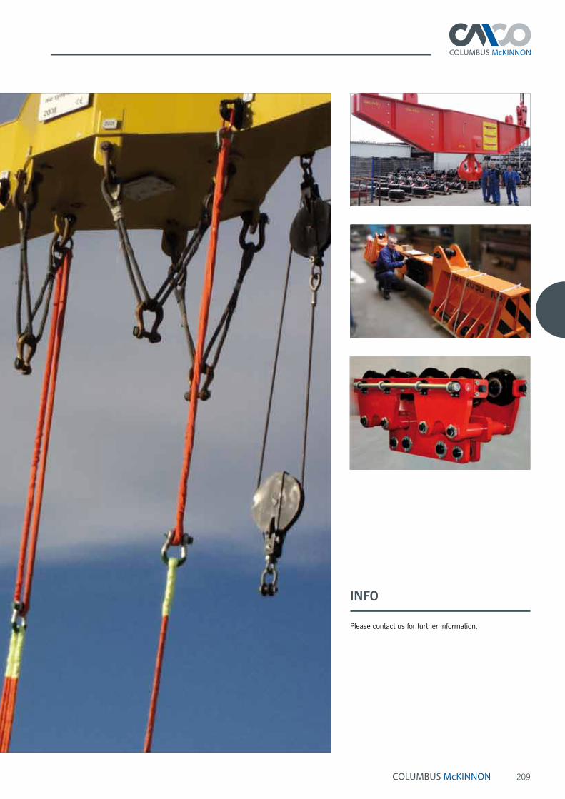
209
INFO
Please contact us for further information.

210
Tigrip® Load Hoisting Tackle Crane forks
Crane forks model TKG vhsCapacity 200 - 5000 kgThese crane forks are equipped with adjustable tines, height adjustability and an automatic balancing system. Crane forks with automatic balancing* tend to point their tines upward when being transported. This prevents the load from unintentionally slipping off the tines.
The shackle is movable and runs on a track depending on the load. The automatic balancing engages by a pres-surized gas spring once the forks are loaded. The load will always be in the center of gravity of the forks, ensuring a safe transport.
*The automatic balancing system requires a mini-mum load of 20 % of the crane forks‘ working load limit!
Features• All crane forks comply with the latest standards and
CE-directives.
• Safety factor 4:1
• Maintenance-free
• Highly visible safety colour
• For the transport of rings or coils, the fork tines are simply pushed together.
• Easily adjustable tines for all pallet sizes.
Scope of deliveryChain for load securing
Technical data model TKG vhs
Model EAN-No. 4025092*
Capacity kg
Weight kg
TKG 1,0 vhs *552233 200 - 1000 128TKG 1,5 vhs *551113 300 - 1500 158TKG 2,0 vhs *550666 400 - 2000 203TKG 3,0 vhs *551090 600 - 3000 260TKG 5,0 vhs *554794 1000 - 5000 413
Model TKG 1,0 vhs TKG 1,5 vhs TKG 2,0 vhs TKG 3,0 vhs TKG 5,0 vhs
Adjustment of tines A, mm 350 - 900 350 - 900 400 - 900 450 - 900 500 - 1000Usable height B, mm 1100 - 1600 1300 - 2000 1300 - 2000 1300 - 2000 1300 - 2000Length of tines C, mm 1000 1000 1000 1000 1000Section of tines D, mm 100 x 30 100 x 40 120 x 40 120 x 50 150 x 60Overall height E, mm 1420 - 1920 1650 - 2350 1655 - 2355 1720 - 2420 1710 - 2410
Dimensions model TKG vhs
INFO
For the transport of loads above persons (e.g. on construction sites) appropriate security measures against falling loads or parts must be taken.
The load must not exceed the fork length.
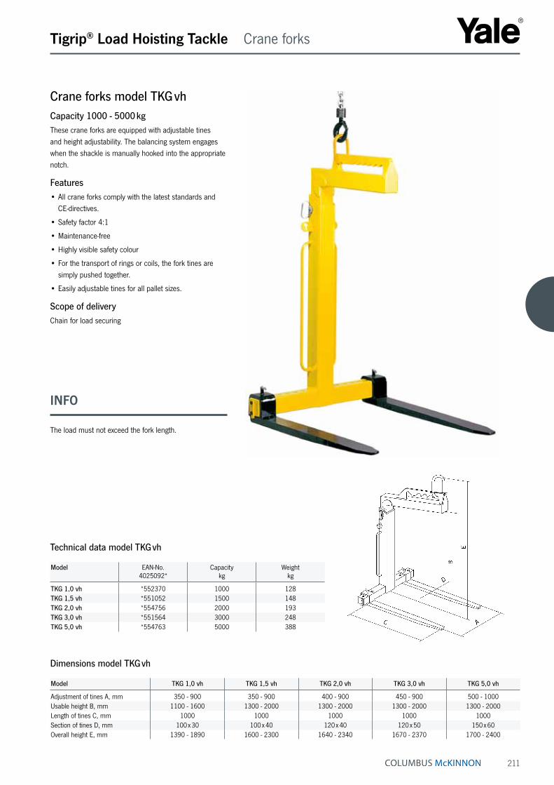
211
Crane forks model TKG vhCapacity 1000 - 5000 kgThese crane forks are equipped with adjustable tines and height adjustability. The balancing system engages when the shackle is manually hooked into the appropriate notch.
Features• All crane forks comply with the latest standards and
CE-directives.
• Safety factor 4:1
• Maintenance-free
• Highly visible safety colour
• For the transport of rings or coils, the fork tines are simply pushed together.
• Easily adjustable tines for all pallet sizes.
Scope of deliveryChain for load securing
Tigrip® Load Hoisting Tackle Crane forks
Technical data model TKG vh
Model EAN-No. 4025092*
Capacitykg
Weight kg
TKG 1,0 vh *552370 1000 128TKG 1,5 vh *551052 1500 148TKG 2,0 vh *554756 2000 193TKG 3,0 vh *551564 3000 248TKG 5,0 vh *554763 5000 388
Model TKG 1,0 vh TKG 1,5 vh TKG 2,0 vh TKG 3,0 vh TKG 5,0 vh
Adjustment of tines A, mm 350 - 900 350 - 900 400 - 900 450 - 900 500 - 1000Usable height B, mm 1100 - 1600 1300 - 2000 1300 - 2000 1300 - 2000 1300 - 2000Length of tines C, mm 1000 1000 1000 1000 1000Section of tines D, mm 100 x 30 100 x 40 120 x 40 120 x 50 150 x 60Overall height E, mm 1390 - 1890 1600 - 2300 1640 - 2340 1670 - 2370 1700 - 2400
Dimensions model TKG vh
INFO
The load must not exceed the fork length.

212
Tigrip® Crane Weighers
Crane weighersMeasuring range 0 - 9.5 tThe crane weighers TKE and TKI are compact measuring devices for the weighing of loads. Due to the compact design and robust steel housing the crane weighers are suitable for a wide range of applica-tions. The crane weighers have a liquid crystal display (LCD), which can tare as well as show either the gross or the net load. Both models TKE and TKI are fitted with an infrared remote control with a range of 8 m.
- with digital display model TKEFeatures• High accuracy: ± 0,03 % of the weighing range
• Lightweight design
• Easy-to-read display
• Easy to use
• Robust design
• Retains the peak value to memory.
• Operating time of about 40 hours (without radio frequency communication)
• Automatic setting to zero when load indicator is switched on.
• Display of maximum weight (gross/net).
• Display of measuring units on the load indicator.
• Measuring units g, kg, t and lbs.
• Automatic stand-by for a prolonged battery lifetime.
Option• Lower hook
Scope of delivery• Crane weigher with with infrared remote control
• 4 x 1.5 V AA batteries
• Carrying case
• Test certificate
• Upper and lower shackle
- with digital display and radio control model TKIThe crane weigher can be operated by radio control. The displayed values can be taken off the remote control device and can be transferred to a PC. Several measured values can be totalled and saved. Various functions like piece counting, maximum weight (gross/net) can be realized.
Features• TKI crane weigher has the same features like the
model TKE.
• Remote control and data exchange via radio transmission.
• USB interface
• Accumulation memory
Options• User software for data processing
• PC cable
• Lower hook
Scope of delivery• Crane weigher with infrared remote control
• Remote control and data exchange via radio transmission.
• 8 x 1.5 V AA batteries
• Carrying case
• Test certificate
• Upper and lower shackle

213
Tigrip® Crane Weighers
Technical data model TKE and model TKI
Model TKE 1,5 TKI 1,5
TKE 6,0 TKI 6,0
TKE 9,5 TKI 9,5
EAN-No. model TKE 4053981** **801995 **802008 **802015EAN-No. model TKI 4053981** **841540 **856179 **841557Measuring range, t 0 - 1.5 0 - 6.0 0 - 9.5Breaking load, t ≥ 4.5 ≥ 24.0 ≥ 38.0Weight with lifting accessories, kg 6 10 15
Resolution step, kg (partition) up to 300 0.1
up to 600 0.2
up to 1500 0.5
up to 1500 0.5
up to 3000 1.0
up to 6000 2.0
up to 3000 1.0
up to 6000 2.0
up to 9500 5.0
Operation time, approx., h ¹ 40Temperature range (operation) - 10 °C up to + 40 °CTemperature range (storage) - 10 °C up to + 40 °CProtection IP 40Display (LCD 25 mm high) 5 ½ digitsTare range 100 % of rated capacityOverload warning The crane weigher switches off when exceeding the rated load.
¹ with 4 x 1.5 V AA batteries (without radio frequency communication)
Dimensions model TKE and model TKI
Model TKE 1,5 TKI 1,5
TKE 6,0 TKI 6,0
TKE 9,5 TKI 9,5
A, mm 193 226 246B, mm 175 175 175C, mm 49 59 80D, mm 24 37 46E, mm 44 58 74F, mm 133 133 133G, mm 104 104 104H, mm 330 363 430I, mm 153 170 180
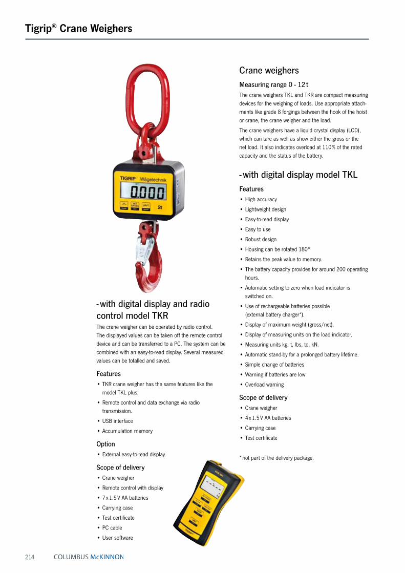
214
Tigrip® Crane Weighers
Crane weighersMeasuring range 0 - 12 tThe crane weighers TKL and TKR are compact measuring devices for the weighing of loads. Use appropriate attach-ments like grade 8 forgings between the hook of the hoist or crane, the crane weigher and the load.
The crane weighers have a liquid crystal display (LCD), which can tare as well as show either the gross or the net load. It also indicates overload at 110 % of the rated capacity and the status of the battery.
- with digital display model TKLFeatures• High accuracy
• Lightweight design
• Easy-to-read display
• Easy to use
• Robust design
• Housing can be rotated 180°
• Retains the peak value to memory.
• The battery capacity provides for around 200 operating hours.
• Automatic setting to zero when load indicator is switched on.
• Use of rechargeable batteries possible (external battery charger*).
• Display of maximum weight (gross/net).
• Display of measuring units on the load indicator.
• Measuring units kg, t, lbs, to, kN.
• Automatic stand-by for a prolonged battery lifetime.
• Simple change of batteries
• Warning if batteries are low
• Overload warning
Scope of delivery• Crane weigher
• 4 x 1.5 V AA batteries
• Carrying case
• Test certificate
* not part of the delivery package.
- with digital display and radio control model TKRThe crane weigher can be operated by radio control. The displayed values can be taken off the remote control device and can be transferred to a PC. The system can be combined with an easy-to-read display. Several measured values can be totalled and saved.
Features• TKR crane weigher has the same features like the
model TKL plus:
• Remote control and data exchange via radio transmission.
• USB interface
• Accumulation memory
Option• External easy-to-read display.
Scope of delivery• Crane weigher
• Remote control with display
• 7 x 1.5 V AA batteries
• Carrying case
• Test certificate
• PC cable
• User software

215
Tigrip® Crane Weighers
Technical data model TKL and model TKR
Model TKL 1,0 TKR 1,0
TKL 2,0 TKR 2,0
TKL 3,2 TKR 3,2
TKL 5,0 TKR 5,0
TKL 8,0 TKR 8,0
TKL 12,0 TKR 12,0
EAN-No. model TKL 4025092* *382878 *382922 *382984 *383059 *383073 *383097EAN-No. model TKR 4025092* *382915 *382946 *382779 *383066 *383080 *383103Measuring range, t 0 - 1.0 0 - 2.0 0 - 3.2 0 - 5.0 0 - 8.0 0 - 12.0Nominal load, t 1.0 2.0 3.2 5.0 8.0 12.0Limit load, t 1.1 2.2 3.5 5.5 8.8 13.2Breaking load, t ≥ 4.0 ≥ 8.0 ≥ 13.0 ≥ 20.0 ≥ 32.0 ≥ 48.0Weight without lifting accessories, kg 1.85 1.99 2.5 2.7 3.6 3.9Weight with lifting accessories, kg 3.0 3.5 6.0 7.5 10.5 20.0Accuracy of the end value 0.1 % 0.1 % 0.1 % 0.1 % 0.1 % 0.1 %Resolution step, kg (partition) 0.5 1.0 1.0 1.0 2.0 5.0Operation time, approx., h ¹ 200Temperature range (operation) -10 °C up to + 50 °CTemperature range (storage) - 20 °C up to + 70 °CProtection IP 54Display (LCD 20.5 mm high) 4 ½ digitsTare range 100 % of rated capacityOverload warning Overload warning at 110 % of the rated capacity
¹ with 4 x 1.5 V AA batteries
Model TKL 1,0 TKR 1,0
TKL 2,0 TKR 2,0
TKL 3,2 TKR 3,2
TKL 5,0 TKR 5,0
TKL 8,0 TKR 8,0
TKL 12,0 TKR 12,0
A, mm 389 417 488 571 657 804B, mm 356 379 441 514 588 709C, mm 60 60 75 90 100 140D, mm 110 110 135 160 180 260E, mm 13 16 18 22 26 35F, mm 20 25 32 40 49 45G, mm 70 81 103 126 152 190H, mm 128 136 140 148 158 176J, mm 77.4 77.4 84.4 84.4 97.4 97.4
Dimensions model TKL and model TKR
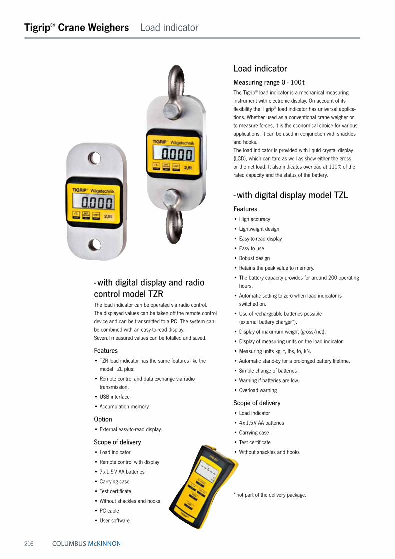
216
Tigrip® Crane Weighers Load indicator
Load indicatorMeasuring range 0 - 100 tThe Tigrip® load indicator is a mechanical measuring instrument with electronic display. On account of its flexibility the Tigrip® load indicator has universal applica-tions. Whether used as a conventional crane weigher or to measure forces, it is the economical choice for various applications. It can be used in conjunction with shackles and hooks. The load indicator is provided with liquid crystal display (LCD), which can tare as well as show either the gross or the net load. It also indicates overload at 110 % of the rated capacity and the status of the battery.
- with digital display model TZLFeatures• High accuracy
• Lightweight design
• Easy-to-read display
• Easy to use
• Robust design
• Retains the peak value to memory.
• The battery capacity provides for around 200 operating hours.
• Automatic setting to zero when load indicator is switched on.
• Use of rechargeable batteries possible (external battery charger*).
• Display of maximum weight (gross/net).
• Display of measuring units on the load indicator.
• Measuring units kg, t, lbs, to, kN.
• Automatic stand-by for a prolonged battery lifetime.
• Simple change of batteries
• Warning if batteries are low.
• Overload warning
Scope of delivery• Load indicator
• 4 x 1.5 V AA batteries
• Carrying case
• Test certificate
• Without shackles and hooks
* not part of the delivery package.
- with digital display and radio control model TZRThe load indicator can be operated via radio control. The displayed values can be taken off the remote control device and can be transmitted to a PC. The system can be combined with an easy-to-read display. Several measured values can be totalled and saved.
Features• TZR load indicator has the same features like the
model TZL plus:
• Remote control and data exchange via radio transmission.
• USB interface
• Accumulation memory
Option• External easy-to-read display.
Scope of delivery• Load indicator
• Remote control with display
• 7 x 1.5 V AA batteries
• Carrying case
• Test certificate
• Without shackles and hooks
• PC cable
• User software
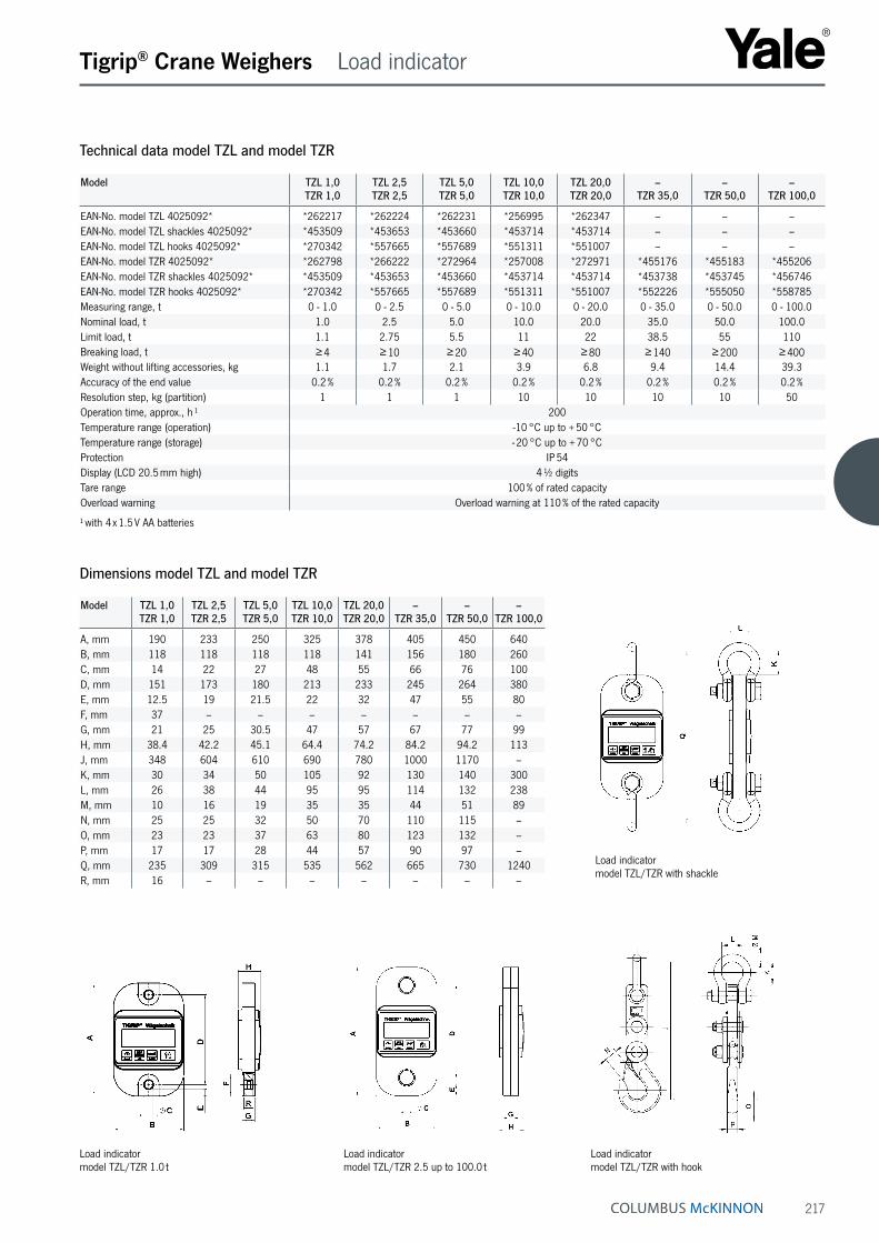
217
Load indicator model TZL/TZR with shackle
Load indicator model TZL/TZR 2.5 up to 100.0 t
Load indicator model TZL/TZR 1.0 t
Load indicator model TZL/TZR with hook
Tigrip® Crane Weighers Load indicator
Technical data model TZL and model TZR
Model TZL 1,0 TZR 1,0
TZL 2,5 TZR 2,5
TZL 5,0 TZR 5,0
TZL 10,0 TZR 10,0
TZL 20,0 TZR 20,0
– TZR 35,0
– TZR 50,0
– TZR 100,0
EAN-No. model TZL 4025092* *262217 *262224 *262231 *256995 *262347 – – –EAN-No. model TZL shackles 4025092* *453509 *453653 *453660 *453714 *453714 – – –EAN-No. model TZL hooks 4025092* *270342 *557665 *557689 *551311 *551007 – – –EAN-No. model TZR 4025092* *262798 *266222 *272964 *257008 *272971 *455176 *455183 *455206EAN-No. model TZR shackles 4025092* *453509 *453653 *453660 *453714 *453714 *453738 *453745 *456746EAN-No. model TZR hooks 4025092* *270342 *557665 *557689 *551311 *551007 *552226 *555050 *558785Measuring range, t 0 - 1.0 0 - 2.5 0 - 5.0 0 - 10.0 0 - 20.0 0 - 35.0 0 - 50.0 0 - 100.0Nominal load, t 1.0 2.5 5.0 10.0 20.0 35.0 50.0 100.0Limit load, t 1.1 2.75 5.5 11 22 38.5 55 110Breaking load, t ≥ 4 ≥ 10 ≥ 20 ≥ 40 ≥ 80 ≥ 140 ≥ 200 ≥ 400Weight without lifting accessories, kg 1.1 1.7 2.1 3.9 6.8 9.4 14.4 39.3Accuracy of the end value 0.2 % 0.2 % 0.2 % 0.2 % 0.2 % 0.2 % 0.2 % 0.2 %Resolution step, kg (partition) 1 1 1 10 10 10 10 50Operation time, approx., h ¹ 200Temperature range (operation) -10 °C up to + 50 °CTemperature range (storage) - 20 °C up to + 70 °CProtection IP 54Display (LCD 20.5 mm high) 4 ½ digitsTare range 100 % of rated capacityOverload warning Overload warning at 110 % of the rated capacity
¹ with 4 x 1.5 V AA batteries
Model TZL 1,0 TZR 1,0
TZL 2,5 TZR 2,5
TZL 5,0 TZR 5,0
TZL 10,0 TZR 10,0
TZL 20,0 TZR 20,0
– TZR 35,0
– TZR 50,0
– TZR 100,0
A, mm 190 233 250 325 378 405 450 640B, mm 118 118 118 118 141 156 180 260C, mm 14 22 27 48 55 66 76 100D, mm 151 173 180 213 233 245 264 380E, mm 12.5 19 21.5 22 32 47 55 80F, mm 37 – – – – – – –G, mm 21 25 30.5 47 57 67 77 99H, mm 38.4 42.2 45.1 64.4 74.2 84.2 94.2 113J, mm 348 604 610 690 780 1000 1170 –K, mm 30 34 50 105 92 130 140 300L, mm 26 38 44 95 95 114 132 238M, mm 10 16 19 35 35 44 51 89N, mm 25 25 32 50 70 110 115 –O, mm 23 23 37 63 80 123 132 –P, mm 17 17 28 44 57 90 97 –Q, mm 235 309 315 535 562 665 730 1240R, mm 16 – – – – – – –
Dimensions model TZL and model TZR

218
Spring Balancers Spring tensioners
Spring tensioners model YFSCapacity 0.5 - 10.0 kg
Spring tensioners with ratchet locking device model YFS-ACapacity 2 - 10.0 kgSpring tensioners are designed to retract the cable when no force is applied. An amount of downward force must be continually applied to keep the suspended object at its extended position. The torque output of the rewind spring increases as the cable is extended, retracting the suspended object to the uppermost adjusted position when released.
Features• Stamped steel construction, powder-coated housing.
• Automatic drumlock according to DIN 15112.
• Additional hanger for the attachment of secondary safety chains according to DIN 15112.
• Rope guide made of wear-resistant nylon for reduced wear of rope and body.
• Declaration of EC-conformity.
• Adjustable cable stop to fix the spring tensioner in the desired position.
• Series YFS-A with ratchet-locking device. Locks the out-retracting rope for unrestricted tool movement. This de-vice can be switched ON/OFF, so the spring tensioner can be used with or without the ratchet-locking device.
ApplicationsPneumatic power-tools, assembly tools, paint spraying guns, riveting machines, nut runners, grinding and polishing machines.
Adjustment of spring tension model YFS-03/04/05
with central shaft and spring lever
Adjustment of spring tension model YFS-01/02
with central turning wheel and spring lever

219
Spring Balancers Spring tensioners
Technical data model YFS and model YFS-A
Model EAN-No. 4025092*
Capacity min.kg
Capacity max.kg
Working range
m
Weight
kg
YFS-01 *514491 0.5 1.5 1.6 0.35YFS-02 *514521 1.5 3.0 1.5 0.35YFS-03 *514552 2.0 5.0 2.4 3.9YFS-04 *514569 4.0 6.0 2.4 4.5YFS-05 *514590 6.0 10.0 2.4 4.5
YFS-03-A *514606 2.0 5.0 2.4 3.9YFS-04-A *514613 4.0 6.0 2.4 4.5YFS-05-A *514668 6.0 10.0 2.4 4.5
Dimensions model YFS and model YFS-A
Model YFS-01 YFS-02 YFS-03 YFS-04 YFS-05 YFS-03-A YFS-04-A YFS-05-A
A, mm 231 231 423 423 423 423 423 423B, mm 224 224 214 214 214 214 214 214C, mm 97 97 191 191 191 191 191 191Ø D, mm 12 12 19 19 19 19 19 19E, mm 48 48 79 79 79 91 91 91F, mm 25 25 43 43 43 55 55 55G, mm – – 71 71 71 71 71 71H, mm 39 39 80 80 80 80 80 80

220
Spring Balancers
Spring assembly
as separate unit in a closed steel housing. All models with capacities more than 5 kg.
Rope guide
for models YBF-09 up to YBF-200 YBF-09L up to YBF-130L YBA-15 up to YBA-70
Load indicator
for models YBF-09 up to YBF-70 YBF-22L up to YBF-70L YBA-15 up to YBA-70 YBA-22L up to YBA-70L
Spring balancers model YBFCapacity 0.5 - 200 kg
Spring balancers with extended rope length model YBF-LCapacity 1.5 - 130 kgSpring balancers are used to relieve the operator from the weight of hand-tools. By using a tapered rope drum the weight of the attached load is compensated, loads up to 200 kg can be moved effortlessly in vertical axis.
Features• Spring balancers model YBF are designed in
accordance with DIN 15112.
• The housing is manufactured from high-tensile alu-minium pressure die casting for maximum resistance to impact.
• Manual drum lock for an easy exchange of rope or for changing the attached load.
• The special spring-assembly inside the balancer guarantees a consistent counterbalance throughout the complete working range.
• Easy exchange of wire rope. A small slot in the body facilitates the removal and re-installation of the rope without any need to disassemble the unit.
• Spring assemblies as separate units in a closed steel housing for improved handling during assembly and disassembly. Reduced risk of injuries.
• Rope guide made of wear-resistant nylon for reduced wear of rope and body. Lifetime of the spring balancer is increased. The rope guide can be removed and installed on site without disassembling the rope.
• Load indicator allows easy reading of the capacity set.
• Upper and lower suspension eyes are provided for the attachment of secondary safety chains. Providing ad-ditional safety and preventing the spring balancer and load from falling accidentally.
ApplicationsSpot-welding guns, riveting-machines, slaughterhouse equipment, multiple nut-runners etc.
INFO
Capacities up to 300 kg available on request.
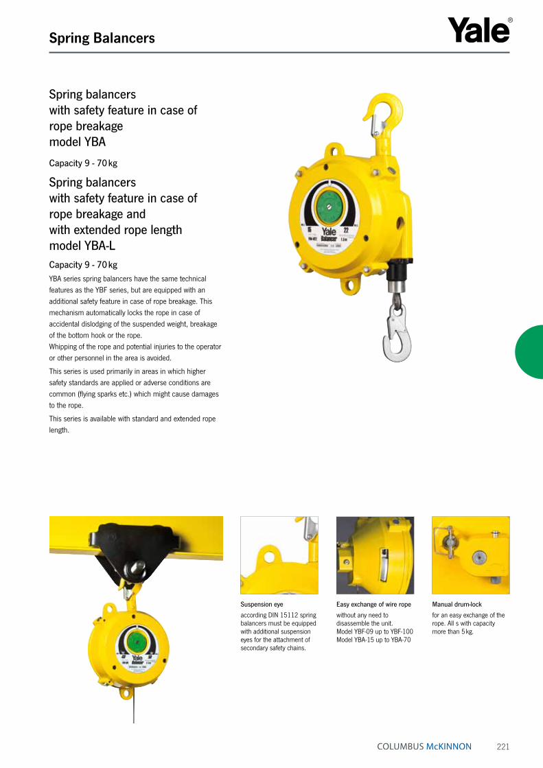
221
Spring Balancers
Suspension eye
according DIN 15112 spring balancers must be equipped with additional suspension eyes for the attachment of secondary safety chains.
Easy exchange of wire rope
without any need to disassemble the unit. Model YBF-09 up to YBF-100 Model YBA-15 up to YBA-70
Manual drum-lock
for an easy exchange of the rope. All s with capacity more than 5 kg.
Spring balancers with safety feature in case of rope breakage model YBA
Capacity 9 - 70 kg
Spring balancers with safety feature in case of rope breakage and with extended rope length model YBA-LCapacity 9 - 70 kgYBA series spring balancers have the same technical features as the YBF series, but are equipped with an additional safety feature in case of rope breakage. This mechanism automatically locks the rope in case of accidental dislodging of the suspended weight, breakage of the bottom hook or the rope. Whipping of the rope and potential injuries to the operator or other personnel in the area is avoided.
This series is used primarily in areas in which higher safety standards are applied or adverse conditions are common (flying sparks etc.) which might cause damages to the rope.
This series is available with standard and extended rope length.

222
Spring Balancers
Model Suspension eyes
top (T) and
bottom (B)
Adjustment of
spring tension V=Vertikal
H=Horizontal
Tapered rope drum
Manual drum lock
Automatic drum-locking
device
Load indicator
Spring assembly enclosed
Closed body Rope guide, nylon
Rope exchange without
disassambly
YBA-15 T V • • • • • • • •YBA-22 T + B V • • • • • • • •YBA-30 T + B V • • • • • • • •YBA-40 T + B V • • • • • • • •YBA-50 T + B V • • • • • • • •YBA-60 T + B V • • • • • • • •YBA-70 T + B V • • • • • • • •
YBA-15L T + B V • • • – • • • –YBA-22L T + B V • • • • • • • –YBA-30L T + B V • • • • • • • –YBA-40L T + B V • • • • • • • –YBA-50L T + B V • • • • • • • –YBA-60L T + B V • • • • • • • –YBA-70L T + B V • • • • • • • –
Technical data model YBA and model YBA-L
Technical data model YBF and model YBF-L
Model Suspension eyes
top (T) and
bottom (B)
Adjustment of
spring tension V=vertical
H=horizontal
Tapered rope drum
Manual drum lock
Automatic drum-locking
device
Load indicator
Spring assembly enclosed
Closed body Rope guide, nylon
Rope exchange without
disassambly
YBF-01 T H • – – – – • – –YBF-02 T H • – – – – • – –YBF-03 T H • – – – – • – –YBF-05 T H • – – – – • – –YBF-09 T H • • • • • • • •YBF-15 T H • • • • • • • •YBF-22 T + B V • • • • • • • •YBF-30 T + B V • • • • • • • •YBF-40 T + B V • • • • • • • •YBF-50 T + B V • • • • • • • •YBF-60 T + B V • • • • • • • •YBF-70 T + B V • • • • • • • •YBF-85 T + B V • • • – • • • •YBF-100 T + B V • • • – • • • •YBF-120 T H • • • – • • • –YBF-140 T H • • • – • • • –YBF-170 T H • • • – • • • –YBF-200 T H • • • – • • • –
YBF-03L T H • – • – – • – –YBF-05L T H • – • – – • – –YBF-09L T V • • • – • • • –YBF-15L T V • • • – • • • –YBF-22L T V • • • • • • • –YBF-30L T V • • • • • • • –YBF-40L T + B V • • • • • • • –YBF-50L T + B V • • • • • • • –YBF-60L T + B V • • • • • • • –YBF-70L T + B V • • • • • • • –YBF-85L T + B V • • • – • • • –YBF-100L T H • • • – • • • –YBF-120L T H • • • – • • • –YBF-130L T H • • • – • • • –

223
Spring Balancers
Model EAN-No. 4025092*
Capacity min.
kg
Capacity max.
kg
Working range
m
Weight with rope
kg
YBF-01 *485654 0.5 1.5 1.0 1.0YBF-02 *485661 1 2 1.0 1.0YBF-03 *485685 1.5 3 1.3 1.8YBF-05 *485692 3 5 1.3 1.9YBF-09 *485777 4.5 9 1.3 4.0YBF-15 *485784 9 15 1.3 4.0YBF-22 *485791 15 22 1.5 8.0YBF-30 *485807 22 30 1.5 8.0YBF-40 *485814 30 40 1.5 10.5YBF-50 *485821 40 50 1.5 10.5YBF-60 *485838 50 60 1.5 11.0YBF-70 *485845 60 70 1.5 11.5YBF-85 *485968 70 85 1.5 12.0YBF-100 *485975 85 100 1.5 12.5YBF-120 *485999 100 120 1.5 28.0YBF-140 *485982 120 140 1.5 29.0YBF-170 *486002 140 170 1.5 35.0YBF-200 *486019 170 200 1.5 36.0
YBF-03L *485708 1.5 3 2.5 3.9YBF-05L *485753 3 5 2.5 4.0YBF-09L *486026 4.5 9 2.3 7.0YBF-15L *486033 9 15 2.3 7.5YBF-22L *486040 15 22 2.3 8.5YBF-30L *486057 22 30 2.3 8.5YBF-40L *486064 30 40 2.3 11.0YBF-50L *486071 40 50 2.3 11.0YBF-60L *486088 50 60 2.3 11.5YBF-70L *486095 60 70 2.3 12.0YBF-85L *486101 70 85 2.5 26.5YBF-100L *486217 85 100 2.5 27.0YBF-120L *486231 100 120 2.5 34.0YBF-130L *486255 120 130 2.5 35.0
Technical data model YBF and model YBF-L
Model EAN-No. 4025092*
Capacity min.
kg
Capacity max.
kg
Working range
m
Weight with rope
kg
YBA-15 *486279 9 15 1.3 5.5YBA-22 *486286 15 22 1.5 8.5YBA-30 *486293 22 30 1.5 9.0YBA-40 *486309 30 40 1.5 11.5YBA-50 *486316 40 50 1.5 12.0YBA-60 *486330 50 60 1.5 13.0YBA-70 *486323 60 70 1.5 13.5
YBA-15L *486347 9 15 2.3 8.5YBA-22L *486354 15 22 2.3 9.0YBA-30L *486361 22 30 2.3 9.5YBA-40L *486378 30 40 2.3 12.0YBA-50L *486385 40 50 2.3 12.5YBA-60L *486392 50 60 2.3 13.5YBA-70L *486408 60 70 2.3 14.0
Technical data model YBA and model YBA-L
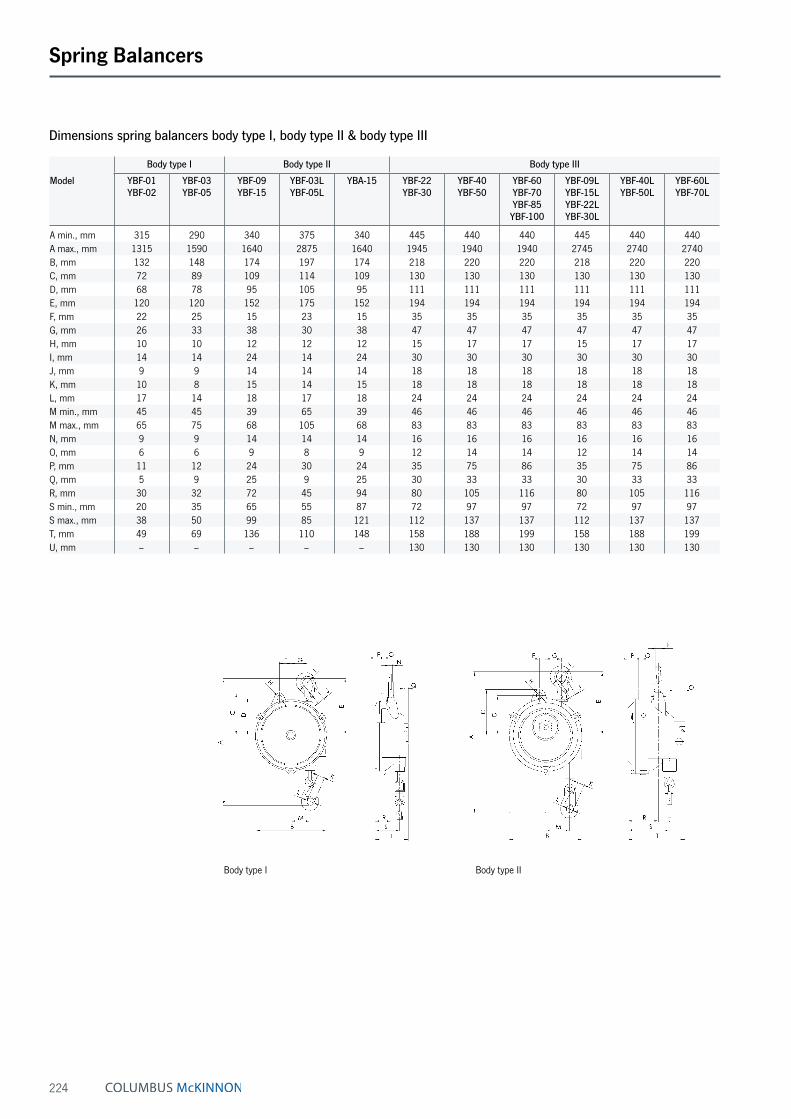
224
Spring Balancers
Body type I Body type II
Body type I Body type II Body type III
Model YBF-01 YBF-02
YBF-03 YBF-05
YBF-09 YBF-15
YBF-03L YBF-05L
YBA-15 YBF-22 YBF-30
YBF-40 YBF-50
YBF-60 YBF-70 YBF-85
YBF-100
YBF-09L YBF-15L YBF-22L YBF-30L
YBF-40L YBF-50L
YBF-60L YBF-70L
A min., mm 315 290 340 375 340 445 440 440 445 440 440A max., mm 1315 1590 1640 2875 1640 1945 1940 1940 2745 2740 2740B, mm 132 148 174 197 174 218 220 220 218 220 220C, mm 72 89 109 114 109 130 130 130 130 130 130D, mm 68 78 95 105 95 111 111 111 111 111 111E, mm 120 120 152 175 152 194 194 194 194 194 194F, mm 22 25 15 23 15 35 35 35 35 35 35G, mm 26 33 38 30 38 47 47 47 47 47 47H, mm 10 10 12 12 12 15 17 17 15 17 17I, mm 14 14 24 14 24 30 30 30 30 30 30J, mm 9 9 14 14 14 18 18 18 18 18 18K, mm 10 8 15 14 15 18 18 18 18 18 18L, mm 17 14 18 17 18 24 24 24 24 24 24M min., mm 45 45 39 65 39 46 46 46 46 46 46M max., mm 65 75 68 105 68 83 83 83 83 83 83N, mm 9 9 14 14 14 16 16 16 16 16 16O, mm 6 6 9 8 9 12 14 14 12 14 14P, mm 11 12 24 30 24 35 75 86 35 75 86Q, mm 5 9 25 9 25 30 33 33 30 33 33R, mm 30 32 72 45 94 80 105 116 80 105 116S min., mm 20 35 65 55 87 72 97 97 72 97 97S max., mm 38 50 99 85 121 112 137 137 112 137 137T, mm 49 69 136 110 148 158 188 199 158 188 199U, mm – – – – – 130 130 130 130 130 130
Dimensions spring balancers body type I, body type II & body type III

225
Spring Balancers
Body type III Body type V
Body type IV
Body type IV Body type V
Model YBF-120 YBF-140
YBF-170 YBF-200
YBF-85L YBF-100L
YBF-120L YBF-130L
YBA-22 YBA-30
YBA-40 YBA-50
YBA-60 YBA-70
YBA-15L YBA-22L YBA-30L
YBA-40L YBA-50L
YBA-60L YBA-70L
A min., mm 550 550 550 550 445 440 440 445 440 440A max., mm 2050 2050 3050 3050 1945 1940 1940 2745 2740 2740B, mm 247 247 247 247 218 220 220 218 220 220C, mm 156 156 156 156 130 130 130 130 130 130D, mm 128 128 128 128 111 111 111 111 111 111E, mm 265 265 265 265 194 194 194 194 194 194F, mm 40 40 40 40 35 35 35 35 35 35G, mm 65 65 65 65 47 47 47 47 47 47H, mm 17 17 17 17 15 17 17 15 17 17I, mm 26 26 26 26 30 30 30 30 30 30J, mm 15 15 15 15 18 18 18 18 18 18K, mm 24 24 24 24 18 18 18 18 18 18L, mm 27 27 27 27 24 24 24 24 24 24M min., mm 54 54 54 54 46 46 46 46 46 46M max., mm 95 95 95 95 83 83 83 83 83 83N, mm 18 18 18 18 16 16 16 16 16 16O, mm 16 16 16 16 12 14 14 12 14 14P, mm 142 185 142 185 55 95 105 55 95 105Q, mm 37 37 37 37 30 33 33 30 33 33R, mm 155 193 155 193 115 140 140 115 140 140S min., mm 175 215 175 215 107 132 132 107 132 132S max., mm 205 248 205 248 147 172 172 147 172 172T, mm 268 268 268 310 180 208 218 180 208 218U, mm 156 156 156 156 130 130 130 130 130 130
Dimensions spring balancers body type IV & body type V
INFO
Yale hoists and trolleys are not designed for passenger elevation applications and must not be used for this purpose.

226
Textile Lifting Slings Table of contents
Page Round slings 232 - 235
Round sling assembly 235 - 237
Webbing slings 238 - 241
Textile lifting slings accessories 242 - 245
Page Textile lashings 250 - 257
Special textile lashings 258 - 259
Lashing systems accessories 260 - 263
INFO
Please note our user instructions at the beginning of each chapter.
Yale webbing slings and round slings are produced from high-tensile quality polyester (PES) in accordance with EN 1492, parts 1 and 2. The highly flexible and versatile material exerts evenly distributed pressure on pressure-sensitive and tension-sensitive loads; it is not subject to material ageing or brittleness and is heat-resistant up to +100 °C.
Lashing Systems
Yale lashing belts are produced from polyester (PES) according to EN 12195-2. The extremely resilient belt ma-terial is resistant to stretching and abrasion; it guarantees a high load bearing capacity and a long service life. All Yale lashing belts are stretched belts, thermally fixed and protected against abrasion.

227
TEXTILE LIFTING SLINGS

228
Textile Lifting Slings User information
This user information presents a general overview regarding the application of textile lifting slings and does not substitute the existing operating instruc-tions for specific products!
Lifting operations with textile slings may be car-ried out by competent users (trained in theory and practice) only. When operated correctly, our textile slings offer the highest degree of safety in line with long life expect-ancy and avoid damage to products and people.
Limitations of useLoadingTextile lifting slings must not be overloaded. The capaci-ties for the most important lifting/slinging methods are indicated on the identity label. Always observe the maxi-mum angle from the vertical (angle β)!
TemperatureTextile lifting slings made from polyester are admitted for applications at temperatures between - 40 °C and + 100 °C. This temperature area may change in chemi-cal environments. The woven structure of the drenched textiles at temperatures below 0 °C are susceptible to damage due to the formation of ice. Ice will reduce the flexibility of the lifting sling! At tempera-tures below 0 °C, dry lifting equipment should be used only! In dry condition, polyester features a high electrical resistance and provides an insulating effect between load and crane hook (e.g. during welding jobs – observe temperatures!).
Shock loadingTextile lifting and lashing equipment should not be subjected to sharp jerks and jolts in order to avoid heavy forces which may be considerably higher than the actual load weight!
ChemicalsParticular caution is required when using textile lifting equipment in areas where chemicals are present. Polyester has good resistance against mineral acids but will be destroyed by alkaline – consult our experts for advice in your specific application!
Acid may cause material brittleness to steel fittings of tex-tile lifting slings! Harmless acid solutions may concentrate by evaporation to an extent that they provoke damages. Affected textile lifting equipment must be thoroughly rinsed in cold water, dried in open air and inspected by a competent person.
Transport of peopleTransport of people with textile lifting equipment is generally forbidden!
Operation in danger zonesLifting or transport of loads must be avoided while personnel are in the danger zone. People are not allowed to pass over or under a suspended load!
Application advices • The operator may start moving the load only after it
has been correctly attached and all personnel are clear of the danger zone.
• Loads must not be left unattended in raised or ten-sioned condition for a longer period of time.
• Flat webbing or round slings must not be used in knot-ted, tied or twisted condition and may only be used for the attachment of loads.
• Prior to every use, textile lifting and lashing equipment must be examined with regard to obvious defects. Ensure that their identity and dimensions are correct and that they are provided with a legible capacity label. Never use lifting equipment which is defective or not labelled!
• Damage of the capacity label can be avoided by keeping it away from the load, the hook or choke hitch operations!
• The angle of the eye must not exceed 20° in order to avoid inadmissible strain on the seams! This will be ensured when the eye length is approx. 4 times the width of the hook.
• Hooks or other lifting devices in loaded condition must not be attached in the area of sewn overlaps or at the seam of the round sling sleeve. Make sure that the seams are positioned in the straight part of the lifting device!
INFO

229
Textile Lifting Slings User information
• Hooks should be provided with sufficient radius. The contact area of the web sling must be straight, so that the entire cross section of the sling is loaded equally. If the carrying width of flat webbing sling is below 75 mm, the radius curve of the lifting device must be at least ¾ of the width of the webbing sling.
• Take care that round slings do not overlap in the crane hook. They must have sufficient space in the hook mouth as well as at the load, so they can assume their natural, flattened profile and provide even loading over the full width of the round sling.
• Flat webbing slings should be applied in such a way that they can carry the load over the full sling width. Greater angles from the vertical will strain the edges of the slings and possibly lead to breakage!
• Textile lashing equipment must be protected against sharp edges, friction and abrasion at both load and lifting device. A radius edge is classed as sharp, if it is less than the thickness of the flat webbing or round sling (in flat, loaded condition).
• Never push or place the load onto the lifting device! Never pull the load over rough surfaces or edges and do not drag from underneath a load!
• In “choke hitch” the textile sling should be positioned so that it can form a natural angle of 60° and that heat due to friction is avoided. Never re-adjust the choke hitch and prevent heat development by friction (slipping of load). In order to lift loads with plain or slippery surface we recommend double choke hitch.
• Round slings and flat webbing slings will stretch under load by approx. 3 - 5 %. This has to be strictly considered as it may cause abrasion resp. damages at sensible surfaces. As prevention we recommend the use of protective sleeves and edge protectors. In case of (intended) load movements during lifting operations and resulting friction, e.g. during assembling or turning of goods, the surface or edges of the load must be se-cured by protective sleeves or corner protectors, which will safeguard the lashing device and leave sufficient space for movement and alignment without greater friction (see dim. B in the following drawing).
• If more than one sling is used to lift a load, these should be of same type with preferably same length in order to avoid different elongation behaviour and allow carrying ability over the full width (employ smallest angle from the vertical or use spreader beam instead).
• Textile lifting equipment must be stored in a clean, dry and well ventilated area. Avoid exposure to direct sun-light and other sources of UV. Keep them away from other heat sources, chemicals, fumes and corroded surfaces as they will have a negative effect on the life expectancy of the sling. Slings should not be dried near open fires or other hot places.
• Textile slings with obvious damages, overloading or other detrimental influences must be taken out of use and may be returned to service after inspection and possible repair only.
INFO
230
Textile Lifting Slings User information
Maintenance and repairInspections and tests must be performed by competent persons or specialist workshops only.
InspectionsDepending on application, textile lifting equipment must be subjected to regular inspections by competent persons, at least once per year. The inspection must be visual and extended to the following deficiencies:
• Complete and legible identity label.
• Damages by chemical influence, e.g. local soaking, chipping of yarns or heat (hardening).
• Steel links must not show deformations, grooves or reduction to the cross section of more than 10 %. Check for cracks; possible welding points must be visible and not covered by the webbing.
• Inspections have to be recorded.
• Defective slings have to be taken out of service immediately and must be stored separately!
Criteria for disposalTextile slings must not be used any longer if e.g.:
• The marking (identity label) is missing or illegible.
• Detrimental impacts have occurred, e.g. overloading, shock loading, chemical influence or heat.
Flat webbing slings:
• Damages of selvage, defects of the woven structure by abrasion, cuts or yarn breakages have occured. If 10 % or more of the webbing sling cross section is damaged the sling must be discarded.
• Heavy deformation or melting of yarns due to heat (shiny surface and/or hardened webbing) can be recognized.
• Load bearing seams are defective.
Round slings:
• The outside (sleeve) is damaged by cuts or abrasion.
• The inside (polyester yarns) of the sling is visible.
• The seams of the sleeve are damaged.INFO
INFO
Yale hoists and trolleys are not designed for passenger elevation applications and must not be used for this purpose.

231
Textile Lifting Slings User information
Webbing slings Rated capacities for different slinging methods
WLL (kg) with one webbing sling WLL (kg) with two webbing slings
straight pull
choke hitch
basket angle β
straight angle β
choke hitch angle β
up to 7° 7°- 45° 45°- 60° 7°- 45° 45°- 60° 7°- 45° 45°- 60°
Factor 1.0 0.8 2.0 1.4 1.0 1.4 1.0 1.12 0.8
1000 kg violet 1000 800 2000 1400 1000 1400 1000 1120 800
2000 kg green 2000 1600 4000 2800 2000 2800 2000 2240 1600
3000 kg yellow 3000 2400 6000 4200 3000 4200 3000 3360 2400
4000 kg grey 4000 3200 8000 5600 4000 5600 4000 4480 3200
5000 kg red 5000 4000 10000 7000 5000 7000 5000 5600 4000
6000 kg brown 6000 4800 12000 8400 6000 8400 6000 6720 4800
8000 kg blue 8000 6400 16000 11200 8000 11200 8000 8960 6400
10000 kg orange 10000 8000 20000 14000 10000 14000 10000 11200 8000
Round slings Rated capacities for different slinging methods
WLL (kg) with one round sling WLL (kg) with two round slings
straight pull
choke hitch
basket angle β
straight angle β
choke hitch angle β
up to 7° 7°- 45° 45°- 60° 7°- 45° 45°- 60° 7°- 45° 45°- 60° 7°- 45° 45°- 60°
Factor 1.0 0.8 2.0 1.4 1.0 0.7 0.5 1.4 1.0 1.12 0.8
1000 kg violet 1000 800 2000 1400 1000 700 500 1400 1000 1120 800
2000 kg green 2000 1600 4000 2800 2000 1400 1000 2800 2000 2240 1600
3000 kg yellow 3000 2400 6000 4200 3000 2100 1500 4200 3000 3360 2400
4000 kg grey 4000 3200 8000 5600 4000 2800 2000 5600 4000 4480 3200
5000 kg red 5000 4000 10000 7000 5000 3500 2500 7000 5000 5600 4000
6000 kg brown 6000 4800 12000 8400 6000 4200 3000 8400 6000 6720 4800
8000 kg blue 8000 6400 16000 11200 8000 5600 4000 11200 8000 8960 6400
10000 kg orange 10000 8000 20000 14000 10000 7000 5000 14000 10000 11200 8000

232
Textile Lifting Slings Round slings
Round sling with duplex sleeve model RSDMade from polyester (PES), EN 1492-2 with double stich-less protection sleeve, with capacity label.
Features• With double protection sleeve, PU-starched,
thermally fixed.
• Colour coding of the protective sleeve.
• Printed-on capacities.
• Woven tonnage stripes, per ton capacity 1 stripe (applies only to round slings up to 10 t).
• Low weight allows easy handling.
• Protection against hand injuries.
• Protection against cargo surface damage.
• Highly flexible and adaptable to given shapes.
• UV-resistant, eliminating material ageing or embrittlement.
• Heat resistant up to +100 °C.
• Moisture-resistant fabric, thus preventing frost damage (up to approx. -40 °C).
Technical data model RSD
Model Colour code EN 1492
Capacity WLL, with
one sling, straight pull
kg
Capacity WLL, with
one sling, basket, angle βup to 7°
kg
Capacity WLL, with
one sling, basket, angle β7°- 45°
kg
Capacity WLL, with
one sling, basket, angle β
45°- 60°kg
Capacity WLL, with
one sling, choke hitch
kg
Width approx.
under load
mm
Thickness approx.
under load
mm
Shortest possible length
for special makes
mm
RSD-01000 violet 1000 2000 1400 1000 800 52 5 500
RSD-02000 green 2000 4000 2800 2000 1600 57 6 500
RSD-03000 yellow 3000 6000 4200 3000 2400 71 9 500
RSD-04000 grey 4000 8000 5600 4000 3200 76 9 1000
INFO
Further capacities and special lengths available on request.

233
Textile Lifting Slings Round slings
XL-Round sling model RSXMade from polyester (PES), EN 1492-2 with extra strong stichless protection sleeve, with capacity label.
Features• Optimized woven structure, PU-starched,
thermally fixed.
• Easy identification of the annually required UVV tests through an additional label showing a check list.
• Colour coding of the protective sleeve.
• Printed-on capacities.
• Woven tonnage stripes, per ton capacity 1 stripe (applies only to round slings up to 10 t).
• Low weight allows easy handling.
• Protection against hand injuries.
• Protection against cargo surface damage.
• Highly flexible and adaptable to given shapes.
• UV-resistant, eliminating material ageing or embrittlement.
• Heat resistant up to +100 °C.
• Moisture-resistant fabric, thus preventing frost damage (up to approx. -40 °C).
Technical data model RSX
Model Colour code EN 1492
Capacity WLL, with
one sling, straight pull
kg
Capacity WLL, with
one sling, basket, angle βup to 7°
kg
Capacity WLL, with
one sling, basket, angle β7°- 45°
kg
Capacity WLL, with
one sling, basket, angle β
45°- 60°kg
Capacity WLL, with
one sling, choke hitch
kg
Width approx.
under load
mm
Thickness approx.
under load
mm
Shortest possible length
for special makes
mm
RSX-01000 violet 1000 2000 1400 1000 800 52 10 500
RSX-02000 green 2000 4000 2800 2000 1600 57 10 500
RSX-03000 yellow 3000 6000 4200 3000 2400 71 15 500
RSX-04000 grey 4000 8000 5600 4000 3200 76 15 1000
RSX-05000 red 5000 10000 7000 5000 4000 86 20 1000
RSX-06000 brown 6000 12000 8400 6000 4800 96 20 2000
RSX-08000 blue 8000 16000 11200 8000 6400 112 25 2000
RSX-10000 orange 10000 20000 14000 10000 8000 130 30 2000
INFO
Further capacities (up to 100 t) and special lengths available on request.

234
Textile Lifting Slings Round slings
Round sling with single sleeve model RSEMade from polyester (PES), EN 1492-2 with stichless protection sleeve, with capacity label.
Features• With single sleeve, PU-starched, thermally fixed.
• Colour coding of the protective sleeve.
• Printed-on capacities.
• Woven tonnage stripes, per ton capacity 1 stripe (applies only to round slings up to 10 t).
• Low weight allows easy handling.
• Protection against hand injuries.
• Protection against cargo surface damage.
• Highly flexible and adaptable to given shapes.
• UV-resistant, eliminating material ageing or embrittlement.
• Heat resistant up to +100 °C.
• Moisture-resistant fabric, thus preventing frost damage (up to approx. -40 °C).
Technical data model RSE
Model Colour code EN 1492
Capacity WLL, with
one sling, straight pull
kg
Capacity WLL, with
one sling, basket, angle βup to 7°
kg
Capacity WLL, with
one sling, basket, angle β7°- 45°
kg
Capacity WLL, with
one sling, basket, angle β
45°- 60°kg
Capacity WLL, with
one sling, choke hitch
kg
Width approx.
under load
mm
Thickness approx.
under load
mm
Shortest possible length
for special makes
mm
RSE-01000 violet 1000 2000 1400 1000 800 50 10 500
RSE-02000 green 2000 4000 2800 2000 1600 55 10 500
RSE-03000 yellow 3000 6000 4200 3000 2400 60 15 500
RSE-04000 grey 4000 8000 5600 4000 3200 75 15 1000
RSE-05000 red 5000 10000 7000 5000 4000 85 20 1000
RSE-06000 brown 6000 12000 8400 6000 4800 90 20 2000
RSE-08000 blue 8000 16000 11200 8000 6400 100 25 2000
RSE-10000 orange 10000 20000 14000 10000 8000 120 30 2000
INFO
Special lengths available on request.

235
Textile Lifting Slings Round sling assembly
20 RSE - Round slings, EN 1492-2with different working loads and lengths.With each sport bag you receive:
2 x RSE 01000, WLL 1000 kg, 0.5 m length
4 x RSE 01000, WLL 1000 kg, 1.0 m length
2 x RSE 01000, WLL 1000 kg, 1.5 m length
4 x RSE 01000, WLL 1000 kg, 2.0 m length
2 x RSE 02000, WLL 2000 kg, 1.0 m length
2 x RSE 02000, WLL 2000 kg, 2.0 m length
2 x RSE 02000, WLL 2000 kg, 3.0 m length
2 x RSE 03000, WLL 3000 kg, 2.0 m length
EAN-No.: 4025092360555 Minimum purchase: 3 bags
Round sling assembly Rated capacities for different slinging methods
single legged double legged three and four legged
straight pull choke hitch straight pull choke hitch straight pull choke hitch straight pullangle β angle β angle β0°- 45° 45°- 60° 0°- 45° 45°- 60°
Factor 1.0 0.8 1.4 1.1 1.0 0.8 2.1 1.5
1000 kg 1000 800 1400 1100 1000 800 2100 15002000 kg 2000 1600 2800 2200 2000 1600 4200 30003000 kg 3000 2400 4200 3300 3000 2400 6300 45005000 kg 5000 4000 7000 5500 5000 4000 10500 75008000 kg 8000 6400 11200 8800 8000 6400 16800 12000
Including
sports bag

236
Textile Lifting Slings Round sling assembly
Round sling assembly single legged model RSGEN 1492-2 with high tensile forgings EN 1677.
Round sling assembly double legged model RSGEN 1492-2 with high tensile forgings EN 1677.
Technical data model RSG single legged
Model Capacity WLL straight pull
kg
RSG-01000-1-SIKA 1000RSG-02000-1-SIKA 2000RSG-03000-1-SIKA 3000RSG-05000-1-SIKA 5000RSG-08000-1-SIKA 8000
Technical data model RSG double legged
Model Capacity WLL, straight pull
angle β0°- 45°
kg
Capacity WLL, straight pull
angle β45°- 60°
kg
RSG-01000-2-SIKA 1400 1000RSG-02000-2-SIKA 2800 2000RSG-03000-2-SIKA 4200 3000RSG-05000-2-SIKA 7000 5000RSG-08000-2-SIKA 11200 8000
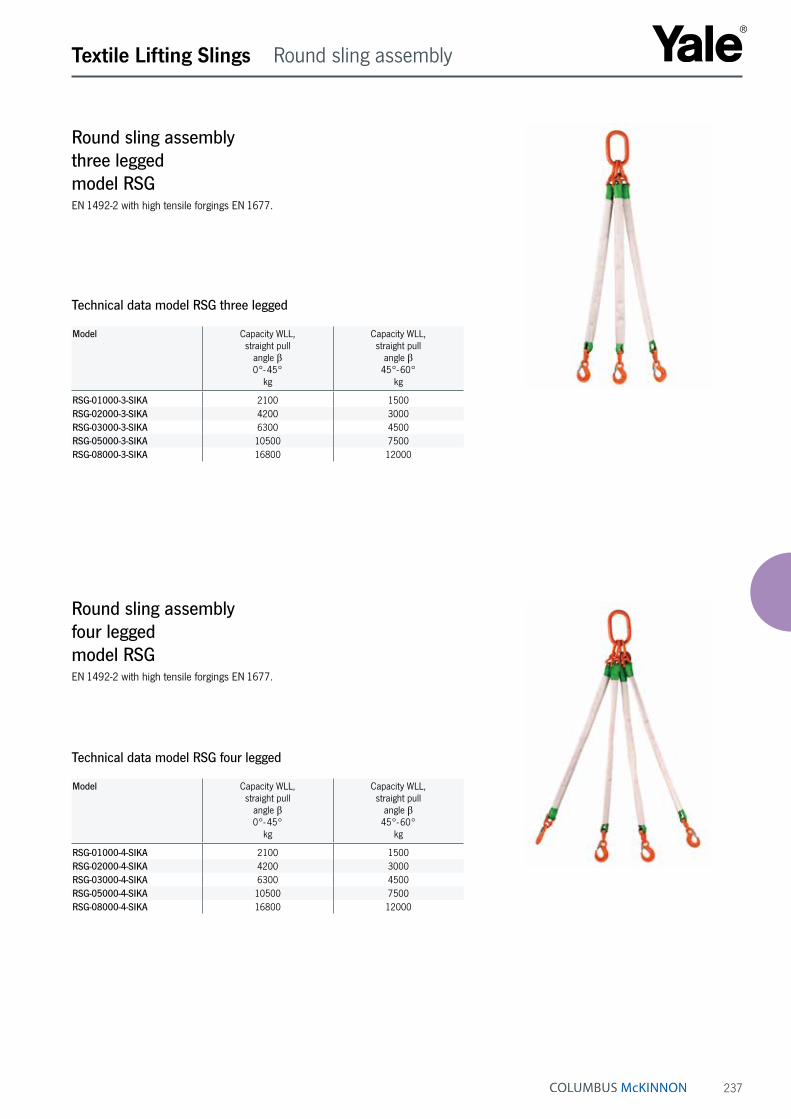
237
Textile Lifting Slings Round sling assembly
Round sling assembly three legged model RSGEN 1492-2 with high tensile forgings EN 1677.
Round sling assembly four legged model RSGEN 1492-2 with high tensile forgings EN 1677.
Technical data model RSG three legged
Model Capacity WLL, straight pull
angle β0°- 45°
kg
Capacity WLL, straight pull
angle β45°- 60°
kg
RSG-01000-3-SIKA 2100 1500RSG-02000-3-SIKA 4200 3000RSG-03000-3-SIKA 6300 4500RSG-05000-3-SIKA 10500 7500RSG-08000-3-SIKA 16800 12000
Technical data model RSG four legged
Model Capacity WLL, straight pull
angle β0°- 45°
kg
Capacity WLL, straight pull
angle β45°- 60°
kg
RSG-01000-4-SIKA 2100 1500RSG-02000-4-SIKA 4200 3000RSG-03000-4-SIKA 6300 4500RSG-05000-4-SIKA 10500 7500RSG-08000-4-SIKA 16800 12000

238
Textile Lifting Slings Webbing slings
Endless flat webbing sling, single plymodel HSEMade from polyester (PES), EN 1492-1 form A2, with capacity label.
Features• Single ply, PU-starched, thermally fixed.
• Colour coded webbing (only model HSE).
• Woven tonnage stripes (only model HSE).
• Low weight allows easy handling.
• Protection against hand injuries.
• Protection against cargo surface damage.
• Consistent pressure distribution onto pressure- and pull sensitive loads.
• UV-resistant, eliminating material ageing or embrittlement.
Technical data model HSE
Model Colour code EN 1492
Capacity WLL, with
one sling, straight pull
kg
Capacity WLL, with
one sling, basket, angle βup to 7°
kg
Capacity WLL, with
one sling, basket, angle β7°- 45°
kg
Capacity WLL, with
one sling, basket, angle β
45°- 60°kg
Capacity WLL, with
one sling, choke hitch
kg
Webbing width
mm
Shortest possible length
for special makes
mm
HSE-01000 violet 1000 2000 1400 1000 800 30 500
HSE-02000 green 2000 4000 2800 2000 1600 60 500
HSE-03000 yellow 3000 6000 4200 3000 2400 90 500
HSE-04000 grey 4000 8000 5600 4000 3200 120 1000
Model Capacity WLL, with
one sling, straight pull
kg
Capacity WLL, with
one sling, basket, angle βup to 7°
kg
Capacity WLL, with
one sling, basket, angle β7°- 45°
kg
Capacity WLL, with
one sling, basket, angle β
45°- 60°kg
Capacity WLL, with
one sling, choke hitch
kg
Webbing width
mm
Shortest possible length
for special makes
mm
HSE-E-00500 one-way-sling 500 1000 700 500 400 25 200HSE-E-00750 one-way-sling 750 1500 1050 750 600 48 200HSE-E-01000 one-way-sling 1000 2000 1400 1000 800 35 200HSE-E-01500 one-way-sling 1500 3000 2100 1500 1200 50 250
Technical data model HSE-E one-way-sling
Endless flat webbing sling, single ply, one-way model HSE-EMade from polyester (PES), DIN 60005, with capacity label.
• Heat resistant up to +100 °C.
• Moisture-resistant fabric, thus preventing frost damage (up to approx. - 40 °C).
• Low elongation (< 4 %).
INFO
Further capacities (up to 20 t) and special lengths available on request.
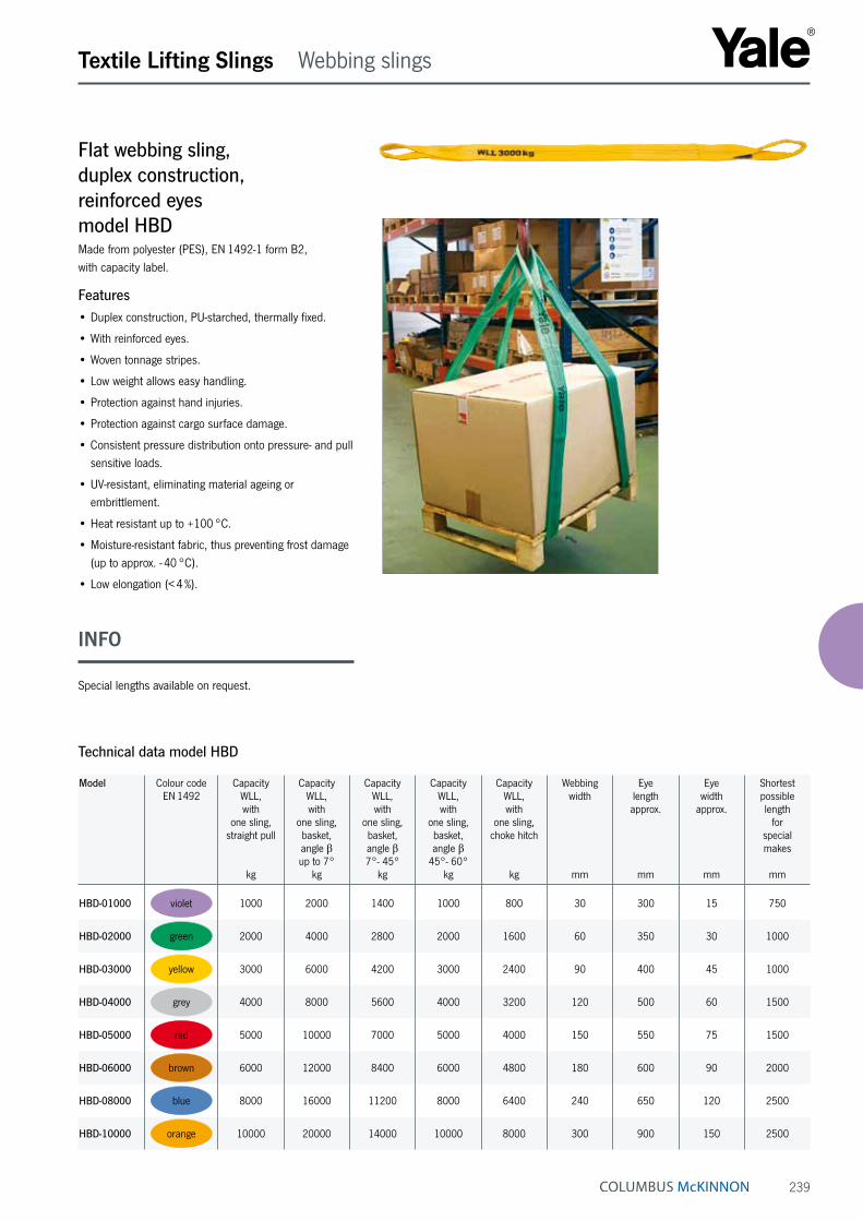
239
Textile Lifting Slings Webbing slings
Flat webbing sling, duplex construction, reinforced eyes model HBDMade from polyester (PES), EN 1492-1 form B2, with capacity label.
Features• Duplex construction, PU-starched, thermally fixed.
• With reinforced eyes.
• Woven tonnage stripes.
• Low weight allows easy handling.
• Protection against hand injuries.
• Protection against cargo surface damage.
• Consistent pressure distribution onto pressure- and pull sensitive loads.
• UV-resistant, eliminating material ageing or embrittlement.
• Heat resistant up to +100 °C.
• Moisture-resistant fabric, thus preventing frost damage (up to approx. - 40 °C).
• Low elongation (< 4 %).
Technical data model HBD
Model Colour code EN 1492
Capacity WLL, with
one sling, straight pull
kg
Capacity WLL, with
one sling, basket, angle βup to 7°
kg
Capacity WLL, with
one sling, basket, angle β7°- 45°
kg
Capacity WLL, with
one sling, basket, angle β
45°- 60°kg
Capacity WLL, with
one sling, choke hitch
kg
Webbing width
mm
Eye length approx.
mm
Eye width
approx.
mm
Shortest possible length
for special makes
mm
HBD-01000 violet 1000 2000 1400 1000 800 30 300 15 750
HBD-02000 green 2000 4000 2800 2000 1600 60 350 30 1000
HBD-03000 yellow 3000 6000 4200 3000 2400 90 400 45 1000
HBD-04000 grey 4000 8000 5600 4000 3200 120 500 60 1500
HBD-05000 red 5000 10000 7000 5000 4000 150 550 75 1500
HBD-06000 brown 6000 12000 8400 6000 4800 180 600 90 2000
HBD-08000 blue 8000 16000 11200 8000 6400 240 650 120 2500
HBD-10000 orange 10000 20000 14000 10000 8000 300 900 150 2500
INFO
Special lengths available on request.

240
Textile Lifting Slings Webbing slings
Flat webbing sling, four ply, reinforced eyes model HBQMade from polyester (PES), EN 1492-1 form B4, with capacity label. Colour coding up to 16000 kg not according to EN 1492-1.
Features• Four-layed stitched, PU-starched, thermally fixed.
• With reinforced eyes.
• Low weight allows easy handling.
• Protection against hand injuries.
• Protection against cargo surface damage.
• Consistent pressure distribution onto pressure- and pull sensitive loads.
• UV-resistant, eliminating material ageing or embrittlement.
• Heat resistant up to +100 °C.
• Moisture-resistant fabric, thus preventing frost damage (up to approx. - 40 °C).
• Low elongation (< 4 %).
Technical data model HBQ
Model Capacity WLL, with
one sling, straight pull
kg
Capacity WLL, with
one sling, basket, angle βup to 7°
kg
Capacity WLL, with
one sling, basket, angle β7°- 45°
kg
Capacity WLL, with
one sling, basket, angle β
45°- 60°kg
Capacity WLL, with
one sling, choke hitch
kg
Webbing width
mm
Eye length approx.
mm
Eye width
approx.
mm
Shortest possible length
for special makes
mm
HBQ-04000 4000 8000 5600 4000 3200 60 350 30 1000
HBQ-06000 6000 12000 8400 6000 4800 90 400 45 1000
HBQ-08000 8000 16000 11200 8000 6400 120 500 60 1500
HBQ-10000 10000 20000 14000 10000 8000 150 550 75 1500
HBQ-12000 12000 24000 16800 12000 9600 180 600 90 2000
HBQ-16000 16000 32000 22400 16000 12800 240 650 120 2500
HBQ-20000 20000 40000 28000 20000 16000 300 900 150 2500
HBQ-25000 25000 50000 35000 25000 20000 300 900 150 2500

241
Textile Lifting Slings Webbing slings
Webbing sling, duplex construction, steel links on both ends model HBD-SN and model HBD-SDMade from polyester (PES), EN 1492-1 form C2 and Cr2, with capacity label.
Features• Duplex construction, PU-starched, thermally fixed.
• With steel D- and DP-links (reevable).
• Woven tonnage stripes.
• Low weight allows easy handling.
• Protection against hand injuries.
• Protection against cargo surface damage.
• Consistent pressure distribution onto pressure- and pull sensitive loads.
• UV-resistant, eliminating material ageing or embrittlement.
• Heat resistant up to +100 °C.
• Moisture-resistant fabric, thus preventing frost damage (up to approx. - 40 °C).
• Low elongation (< 4 %).
Technical data model HBD-SN and model HBD-SD
Model Colour code EN 1492
Capacity WLL, with
one sling, straight pull
kg
Capacity WLL, with
one sling, basket, angle βup to 7°
kg
Capacity WLL, with
one sling, basket, angle β7°- 45°
kg
Capacity WLL, with
one sling, basket, angle β
45°- 60°kg
Capacity WLL, with
one sling, choke hitch
kg
Webbing width
mm
Link dimension HBD-SNb x d x t
t
bd
mm
Link dimension HBD-SDb x d x t
t
bd
mm
HBD-01000 violet 1000 2000 1400 1000 800 30 35 x 13 x 100 30 x 13 x 145
HBD-02000 green 2000 4000 2800 2000 1600 60 75 x 16 x 130 60 x 16 x 165
HBD-03000 yellow 3000 6000 4200 3000 2400 90 105 x 18 x 140 90 x 18 x 190
HBD-04000 grey 4000 8000 5600 4000 3200 120 130 x 22 x 130 120 x 22 x 240
HBD-05000 red 5000 10000 7000 5000 4000 150 170 x 26 x 170 150 x 26 x 300
HBD-06000 brown 6000 12000 8400 6000 4800 180 190 x 26 x 220 180 x 26 x 320
HBD-08000 blue 8000 16000 11200 8000 6400 240 250 x 26 x 230 240 x 26 x 360
HBD-10000 orange 10000 20000 14000 10000 8000 300 300 x 40 x 290 300 x 40 x 435
INFO
Model HBD-SD - links are reevable, webbing sling also applicable for use in choke hitch.

242
Textile Lifting Slings Accessories
PU-protection sleeve, single and double-sided model PU-SCMade from cut resistant polyurethane
With inner fabric insert to ease sliding of the sleeve on the webbing. Standard length 2 and 4 m.
Double PU sleeves cannot be fitted subsequently on web-bing slings with steel links. If required, state sleeve length when placing the webbing sling order.
Technical data model PU-SC, single-sided
Model EAN-No. 4025092*
Webbing width
mm
Dimensions outside /inside
mm
Height
mm
PU-SC1-030 *357906 30 50 / 40 22PU-SC1-050 *352680 50 70 / 60 22PU-SC1-060 *352697 60 80 / 70 22PU-SC1-090 *352710 90 110 / 100 22PU-SC1-120 *357951 120 145 / 135 22PU-SC1-150 *357876 150 170 / 160 22PU-SC1-180 *357869 180 200 / 190 22PU-SC1-240 *357883 240 260 / 250 31PU-SC1-300 *357890 300 330 / 320 31
Model EAN-No. 4025092*
Webbing width
mm
Dimensions outside / inside
mm
Height
mm
PU-SC2-030 *357944 30 50 / 40 22PU-SC2-050 *352741 50 70 / 60 22PU-SC2-060 *352758 60 80 / 70 22PU-SC2-090 *352772 90 110 / 100 22PU-SC2-120 *352802 120 145 / 135 22PU-SC2-150 *352826 150 170 / 160 22PU-SC2-180 *357913 180 200 / 190 22PU-SC2-240 *357920 240 260 / 250 31PU-SC2-300 *357937 300 330 / 320 31
Technical data model PU-SC, double-sided
PU-protection sleeve single-sided, model PU-SC-1
PU-protection sleeve double-sided, model PU-SC-2
INFO
Lengths over 4 m on request.
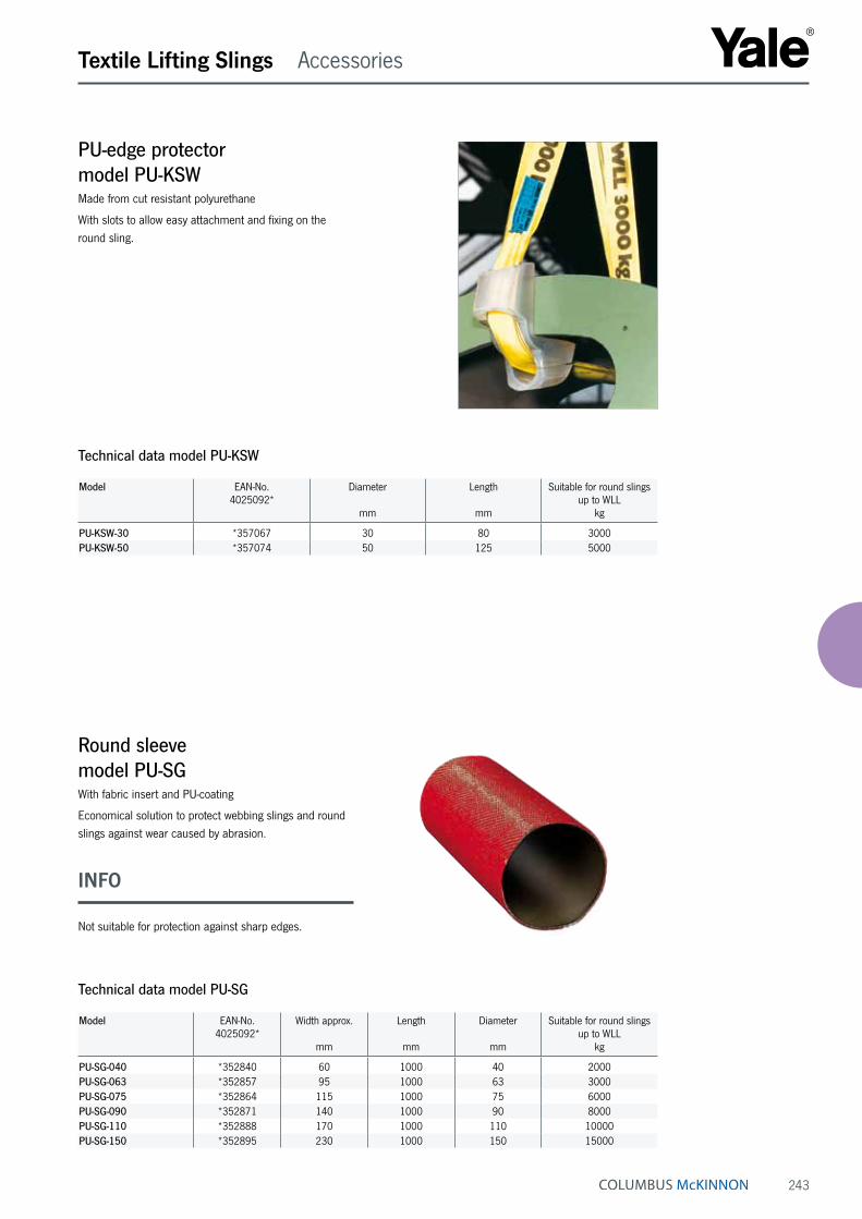
243
Textile Lifting Slings Accessories
PU-edge protector model PU-KSWMade from cut resistant polyurethane
With slots to allow easy attachment and fixing on the round sling.
Round sleeve model PU-SGWith fabric insert and PU-coating
Economical solution to protect webbing slings and round slings against wear caused by abrasion.
Technical data model PU-KSW
Model EAN-No. 4025092*
Diameter
mm
Length
mm
Suitable for round slings up to WLL
kg
PU-KSW-30 *357067 30 80 3000PU-KSW-50 *357074 50 125 5000
Technical data model PU-SG
Model EAN-No. 4025092*
Width approx.
mm
Length
mm
Diameter
mm
Suitable for round slings up to WLL
kg
PU-SG-040 *352840 60 1000 40 2000PU-SG-063 *352857 95 1000 63 3000PU-SG-075 *352864 115 1000 75 6000PU-SG-090 *352871 140 1000 90 8000PU-SG-110 *352888 170 1000 110 10000PU-SG-150 *352895 230 1000 150 15000
INFO
Not suitable for protection against sharp edges.

244
Textile Lifting Slings Accessories
Edge protection profile, with and without magnets model PU-KSEFrom colour coded polyurethane, extremely abrasive and cut resistant.
Technical data model PU-KSE
Model EAN-No. 4025092*
Colour
mm
Webbing width
mm
Number of magnets
PU-KSE-065 *912303 green 60 –
PU-KSE-100 *912310 yellow 90 –
PU-KSE-125 *912327 grey 120 –
PU-KSE-150 *912389 red 150 –
PU-KSE-200 *912396 black 180 –
PU-KSE-300 *912402 orange 300 –
Technical data model PU-KSE-MAG
Model EAN-No. 4025092*
Colour
mm
Webbing width
mm
Number of magnets
PU-KSE-065-MAG *912419 green 60 2
PU-KSE-100-MAG *912426 yellow 90 4
PU-KSE-125-MAG *912433 grey 120 4
PU-KSE-150-MAG *912440 red 150 4
PU-KSE-200-MAG *912457 black 180 6
PU-KSE-300-MAG *912464 orange 300 8

245
Textile Lifting Slings Accessories
PU-coating, single and double-sided model PU-FBMade from transparent polyurethane
Extremely wear and cut resistant. The coating is perma-nently fixed to the webbing and cannot be lost during usage.
Technical data model PU-FB, single-sided
Model EAN-No. 4025092*
Webbing widthmm
Widthmm
Lengthmm
PU-FB1-030 *358620 30 40 1000PU-FB1-050 *352529 50 60 1000PU-FB1-060 *352536 60 70 1000PU-FB1-090 *352543 90 100 1000PU-FB1-120 *352550 120 130 1000PU-FB1-150 *352567 150 160 1000PU-FB1-180 *352574 180 190 1000PU-FB1-240 *352581 240 250 1000PU-FB1-300 *352598 300 310 1000
Model EAN-No. 4025092*
Webbing widthmm
Widthmm
Lengthmm
PU-FB2-030 *358637 30 40 1000PU-FB2-050 *352604 50 60 1000PU-FB2-060 *352611 60 70 1000PU-FB2-090 *352628 90 100 1000PU-FB2-120 *352635 120 130 1000PU-FB2-150 *352642 150 160 1000PU-FB2-180 *352659 180 190 1000PU-FB2-240 *352666 240 250 1000PU-FB2-300 *352673 300 310 1000
Technical data model PU-FB, double-sided
Coating double-sided, model PU-FB 2
Coating single-sided, model PU-FB 1

246
Lashing Systems User information
General information about load securityThe varying forces, which can result in slipping, roll-ing, tilting or even lift-off of loads during transport, are regularly underestimated. Possible consequences are e.g. that the vehicle gets out of control, the driving cab is damaged, the vehicle even overturns and the falling load endangers others! The common assumption that very heavy loads do not require lashing security, is a fatal error. Lashing of loads may be performed by competent users (trained in theory and practice) only.
Some basic rules about load security with ratchet lashings
• Depending on the cargo, consideration shall be given to select an appropriate vehicle with adequate structures and lashing points.
• The load centre of gravity should be as low as possible and ideally positioned according to the load distribution plan of the vehicle.
• The permissible gross weight and loads per axle must not be exceeded.
• The load should be stored as close and low as possible and should not leave free space between load, front wall or side walls. Free spaces between the outer walls and the load should be stuffed where possible.
• Depending on the type of cargo, the driving speed should be conform to the road and traffic situation as well as to the driving quality of the vehicle.
• Adverse friction values between cargo and loading area (oily metals, wet areas etc.) will considerably increase the requirement for a correct security of the load. Slip restraining mats will contribute to achieve a more economic and efficient load lashing security.
• Unstable cargo is very susceptible to tilting and in most cases has to be lashed extensively (calculation against slipping and tilting).
• Positive load lashing (e.g. supporting the cargo at front and side walls or with wedges or scantlings fixed on the loading platform) will contribute substantially to the stabilisation of the cargo and to reduction of additional lashing requirement.
Forces on cargo loads (EN 12195)Truck and trailer loading (road transport) – Acceleration coefficients
During road transport the heaviest stresses on the load security equipment will occur during braking, lift-off of the load by vibration and impact as well as centrifugal forces in narrow curves.
* The value for the longitudinal acceleration in combined traffic (lorry and/or trailer during rail transport) has to be calculated with 1G.
** 0.7 for tilting of instable cargo loads
Lashing methodsOver top lashingOver top lashing consists of tensioning the lashings to the tension force so as to increase the friction force at the contact surface of the load to avoid any sliding of the load. Influence factors are the dimensions of the load, the acceleration values, the dynamic friction factors as well as the lashing angle. The calculation of lashing forces will give the required tension force of the lashing devices.
INFO

247
Lashing Systems User information
This user information presents a general overview regarding the application of web lashings and does not substitute the existing operating instructions for specific products! Lashing operations with textile lashing equipment may be carried out by competent users (trained in theory and practice) only. When operated correctly, our textile lashings offer the highest degree of safety in line with long life expectancy and avoid damage to material and people.
Limitations of useTemperatureTextile lashings in accordance with this part of the Euro-pean standard EN 12195 are suitable for the following temperature areas:
a) - 40 °C up to + 80 °C for polypropylene (PP)
b) - 40 °C up to +100 °C for polyamide (PA)
c) - 40 °C up to +120 °C for polyester (PES)
These temperature areas may change in chemical environments. In this case consult the manufacturer or supplier for advice.
A change of the ambient temperature during transport may influence the tension force of the textile lashing. The tension force should be checked after entering warm regions.
ChemicalsThe resistance against chemical influences varies depend-ing on the materials used for the textile lashing. Please observe the advice of the manufacturer, if the textile lashings are subjected to chemicals. Also consider that the effect of the chemical influence will increase with ris-ing temperatures. The resistance of synthetic fibre against chemical influences is summarised as follows:
a) Polyamides are resistant against alkaline but affected by mineral acids.
b) Polyester is resistant against mineral acids but af-fected by alkaline solutions.
c) Polypropylene is hardly affected by acids and alkaline and is suited for applications that require high resistance against chemicals (except some organic solvents).
d) Harmless acid or alkaline solutions may be concentrat-ed by evaporation and lead to damages. Affected textile lashings have to be taken out of service immediately, thoroughly rinsed in cold water and dried in the open-air.
Operation in danger zonesDuring loading and unloading observe low hanging aerial contact lines.
Application advices
• Selection and use of textile lashings depend on the required tensioning force as well as the mode of ap-plication and type of cargo to be lashed. Size, form and weight of the cargo determine the correct choice in addition to the intended usage. For stability reasons, at least two lashing systems should be used for over top lashing and two pairs of lashing straps for diagonal lashing.
• The selected web lashing must be strong enough for the intended job and have the correct length for the type of lashing. Always consider adequate lashing practice: Attachment and removal of lashings should be planned before the start of the journey. In case of longer trips, partial unloadings must be considered. The number of lashings must be calculated as per EN 12195-1:2000. Over top lashing requires systems, which are labelled STF for over top lashing.
• On account of different characteristics and change of length under load, different lashings (e.g. lashing chains and web lashings) may not be used for lashing the same load. When using additional fittings or lashing devices, make sure that these correspond to the exist-ing web lashing.
• During operation, flat hooks must be in contact with the full width of the hook mouth.
INFO
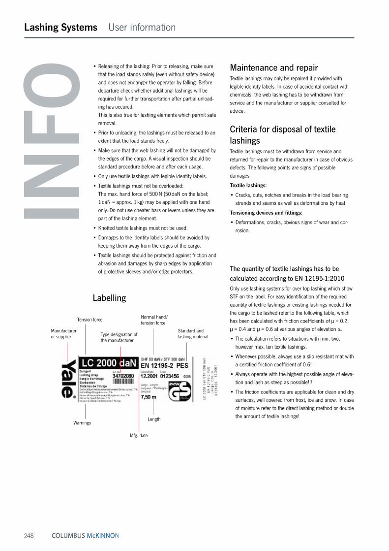
248
Lashing Systems User information
Maintenance and repairTextile lashings may only be repaired if provided with legible identity labels. In case of accidental contact with chemicals, the web lashing has to be withdrawn from service and the manufacturer or supplier consulted for advice.
Criteria for disposal of textile lashingsTextile lashings must be withdrawn from service and returned for repair to the manufacturer in case of obvious defects. The following points are signs of possible damages:
Textile lashings:
• Cracks, cuts, notches and breaks in the load bearing strands and seams as well as deformations by heat;
Tensioning devices and fittings:
• Deformations, cracks, obvious signs of wear and cor-rosion.
The quantity of textile lashings has to be calculated according to EN 12195-1:2010Only use lashing systems for over top lashing which show STF on the label. For easy identification of the required quantity of textile lashings or existing lashings needed for the cargo to be lashed refer to the following table, which has been calculated with friction coefficients of µ = 0.2, µ = 0.4 and µ = 0.6 at various angles of elevation α.
• The calculation refers to situations with min. two, however max. ten textile lashings.
• Whenever possible, always use a slip resistant mat with a certified friction coefficient of 0.6!
• Always operate with the highest possible angle of eleva-tion and lash as steep as possible!!!
• The friction coefficients are applicable for clean and dry surfaces, well covered from frost, ice and snow. In case of moisture refer to the direct lashing method or double the amount of textile lashings!
• Releasing of the lashing: Prior to releasing, make sure that the load stands safely (even without safety device) and does not endanger the operator by falling. Before departure check whether additional lashings will be required for further transportation after partial unload-ing has occured. This is also true for lashing elements which permit safe removal.
• Prior to unloading, the lashings must be released to an extent that the load stands freely.
• Make sure that the web lashing will not be damaged by the edges of the cargo. A visual inspection should be standard procedure before and after each usage.
• Only use textile lashings with legible identity labels.
• Textile lashings must not be overloaded: The max. hand force of 500 N (50 daN on the label; 1 daN = approx. 1 kg) may be applied with one hand only. Do not use cheater bars or levers unless they are part of the lashing element.
• Knotted textile lashings must not be used.
• Damages to the identity labels should be avoided by keeping them away from the edges of the cargo.
• Textile lashings should be protected against friction and abrasion and damages by sharp edges by application of protective sleeves and/or edge protectors.
Labelling
Tension force
Type designation of the manufacturer
Manufacturer or supplier
Normal hand/ tension force
Standard and lashing material
WarningsLength
Mfg. date
INFO

249
Lashing Systems User information
Number of required textile lashings for different cargo weights• at different friction factors
• at different angles
Tension force of ratchet 300 daN at standard hand force of 50 daN according to EN 12195
Applicable to textile lashings ZGR-50-2500 with LC 2500 daN and ZGR-50-2000 with LC 2000 daN
Friction factor µ 0.20 Top angle
Friction factor µ 0.40 Top angle
Friction factor µ 0.60 Top angle
Cargo weight 30° 60° 90° 30° 60° 90° 30° 60° 90°
1000 kg 10 9 7 4 3 3 2 2
2000 kg 8 7 6 3 3
3000 kg 10 9 5 4
4000 kg 7 6
5000 kg 8 7
6000 kg 10 9
7000 kg 10
8000 kg
9000 kg
10000 kg
Cells without indication require more than 10 web lashings. In these cases a reasonable cargo securing can only be obtained by direct lashing method. Obstruction forces by cargo boards and form-fit locking devices have not been considered.
Friction factors according to EN 12195-1:2010Combination of materials in the contact surface Friction factor µ when using a
slip resistant mat
Cut timber against fabric base laminate/plywood 0.5 0.6Cut timber against grooved aluminium 0.4 0.6Cut timber against steel sheets 0.4 0.6Cut timber against shrink films 0.3 0.6
Shrink films against fabric base laminate/plywood 0.4 0.6Shrink films against grooved aluminium 0.4 0.6Shrink films against steel sheets 0.4 0.6Shrink films against shrink films 0.4 0.6
Cardboard box against cardboard box 0.5 0.6Cardboard box against wooden pallet 0.5 0.6
Big bags against wooden pallet 0.4 0.6
Flat steel bars against cut timber 0.5 0.6
Unpainted corregated sheets against cut timber 0.5 0.6Painted corregated sheets against cut timber 0.4 0.6Unpainted corregated sheets against unpainted corregated sheets 0.3 0.6Painted corregated sheets against painted corregated sheets 0.2 0.6 IN
FO

250
Lashing Systems Textile lashing
Cambuckle lashing model ZGK-25-125Made from polyester (PES), EN 12195-2 25 mm - lashing capacity LC 125 daN.
Features• Standard tension force STF 30 daN at standard hand
force SHF 50 daN.
• Standard lenghts 4 m and 6 m.
Technical data model ZGK-25-125
Model EAN-No. 4025092*
Version Permissible ratchet force LC
daN
Webbing width
mm
Webbing length
mm
ZGK-25-125-1 *352505 1 piece 125 25 4000ZGK-25-125-1 *352512 1 piece 125 25 6000
INFO
Other lengths on request.

251
Lashing Systems Textile lashing
Ratchet lashing model ZGR-25-250Made from polyester (PES), EN 12195-2 25 mm - lashing capacity LC 250 daN.
Features• Standard tension force STF 50 daN at standard hand
force SHF 50 daN.
• Standard lenghts 4 m and 6 m.
Ratchet lashing model ZGR-25-500Made from polyester (PES), EN 12195-2 25 mm - lashing capacity LC 500 daN.
Features• Standard tension force STF 100 daN at standard hand
force SHF 50 daN.
• Standard lenghts 4 m and 6 m.
Technical data model ZGR-25-250
Model EAN-No. 4025092*
Version Permissible ratchet force LC
daN
Webbing width
mm
Webbing length
mm
ZGR-25-250-1 *352017 1 piece 250 25 4000ZGR-25-250-1 *352024 1 piece 250 25 6000ZGR-25-250-2-SPH *352383 2 part - with claw hook 250 25 4000ZGR-25-250-2-SPH *352390 2 part - with claw hook 250 25 6000
Technical data model ZGR-25-500
Model EAN-No. 4025092*
Version Permissible ratchet force LC
daN
Webbing width
mm
Webbing length
mm
ZGR-25-500-1 *352031 1 piece 500 25 4000ZGR-25-500-1 *352048 1 piece 500 25 6000ZGR-25-500-2-SPH *352406 2 part - with claw hook 500 25 4000ZGR-25-500-2-SPH *352413 2 part - with claw hook 500 25 6000
INFO
Other lengths on request.
INFO
Other lengths on request.

252
Lashing Systems Textile lashing
Ratchet lashing model ZGR-35-1000Made from polyester (PES), EN 12195-2 35 mm - lashing capacity LC 1000 daN.
Features• Standard tension force STF 150 daN at standard hand
force SHF 50 daN.
• Standard lenghts 6 m and 8 m.
Technical data model ZGR-35-1000
Model EAN-No. 4025092*
Version Permissible ratchet force LC
daN
Webbing width
mm
Webbing length
mm
ZGR-35-1000-1 *352055 1 piece 1000 35 6000ZGR-35-1000-1 *352062 1 piece 1000 35 8000ZGR-35-1000-2-GKH *352147 2 part - with snap hook 1000 35 6000ZGR-35-1000-2-GKH *352154 2 part - with snap hook 1000 35 8000ZGR-35-1000-2-KLH *352208 2 part - with chassis hook 1000 35 6000ZGR-35-1000-2-KLH *352215 2 part - with chassis hook 1000 35 8000ZGR-35-1000-2-SPH *352420 2 part - with claw hook 1000 35 6000ZGR-35-1000-2-SPH *352437 2 part - with claw hook 1000 35 8000
GKH - with twisted snap hook SPH - with claw hook KLH - with chassis hook
INFO
Other end fittings (hooks) and individual prints on web-bing are available on request.
Other lengths on request.

253
Lashing Systems Textile lashing
Ratchet lashing model ZGR-50-2000Made from polyester (PES), EN 12195-2 50 mm - lashing capacity LC 2000 daN.
Features• Standard tension force STF 300 daN at standard hand
force SHF 50 daN.
• Standard lenghts 8 m and 10 m.
Technical data model ZGR-50-2000
Model EAN-No. 4025092*
Version Permissible ratchet force LC
daN
Webbing width
mm
Webbing length
mm
ZGR-50-2000-1 *352086 1 piece 2000 50 8000ZGR-50-2000-1 *352079 1 piece 2000 50 10000ZGR-50-2000-2-GKH *352178 2 part - with snap hook 2000 50 8000ZGR-50-2000-2-GKH *352161 2 part - with snap hook 2000 50 10000ZGR-50-2000-2-KLH *352239 2 part - with chassis hook 2000 50 8000ZGR-50-2000-2-KLH *352222 2 part - with chassis hook 2000 50 10000ZGR-50-2000-FE-KLH *356640 Fixed end with ratchet 2000 50 400ZGR-50-2000-2-SPH *352451 2 part - with claw hook 2000 50 8000ZGR-50-2000-2-SPH *352444 2 part - with claw hook 2000 50 10000ZGR-50-2000-FE-SPH *356657 Fixed end with ratchet 2000 50 400
GKH - with twisted snap hook SPH - with claw hook KLH - with chassis hook
INFO
Other end fittings (hooks) and individual prints on web-bing are available on request.
Other lengths on request.

254
Lashing Systems Textile lashing
Ratchet lashing model ZGR-50-2500Made from polyester (PES), EN 12195-2 50 mm - lashing capacity LC 2500 daN.
Features• Standard tension force STF 300 daN at standard hand
force SHF 50 daN.
• Standard lenghts 8 m and 10 m
Technical data model ZGR-50-2500
Model EAN-No. 4025092*
Version Permissible ratchet force LC
daN
Webbing width
mm
Webbing length
mm
ZGR-50-2500-1 *352109 1 piece 2500 50 8000ZGR-50-2500-1 *352093 1 piece 2500 50 10000ZGR-50-2500-2-GKH *352192 2 part - with snap hook 2500 50 8000ZGR-50-2500-2-GKH *352185 2 part - with snap hook 2500 50 10000ZGR-50-2500-2-KLH *352253 2 part - with chassis hook 2500 50 8000ZGR-50-2500-2-KLH *352246 2 part - with chassis hook 2500 50 10000ZGR-50-2500-FE-KLH *356664 Fixed end with ratchet 2500 50 400ZGR-50-2500-2-SPH *352475 2 part - with claw hook 2500 50 8000ZGR-50-2500-2-SPH *352468 2 part - with claw hook 2500 50 10000ZGR-50-2500-FE-SPH *356671 Fixed end with ratchet 2500 50 400
GKH - with twisted snap hook SPH - with claw hook KLH - with chassis hook
INFO
Other end fittings (hooks) and individual prints on web-bing are available on request.
Other lengths on request.

255
Lashing Systems Textile lashing
Ratchet lashing model ZGR-75-5000Made from polyester (PES), EN 12195-2 75 mm - lashing capacity LC 5000 daN.
Features• Standard tension force STF 500 daN at standard hand
force SHF 50 daN.
• Standard lenghts 2 m and 4 m.
Technical data model ZGR-75-5000
Model EAN-No. 4025092*
Version Permissible ratchet force LC
daN
Webbing width
mm
Webbing length
mm
ZGR-75-5000-1 *352116 1 piece 5000 75 2000ZGR-75-5000-1 *352123 1 piece 5000 75 4000ZGR-75-5000-2-SPH *352482 2 part - with claw hook 5000 75 2000ZGR-75-5000-2-SPH *352499 2 part - with claw hook 5000 75 4000
SPH - with claw hook
INFO
Other end fittings (hooks) and individual prints on web-bing are available on request.
Other lengths on request.

256
Lashing Systems Textile lashing
Ratchet lashing with long lever ratchet model ZGR-XL-50-2000 or model ZGR-XLZ-50-2000Made from polyester (PES), EN 12195-2 50 mm - lashing capacity LC 2000 daN.
Features• Standard tension force STF 500 daN at standard hand
force SHF 50 daN.
• Long lever ratchet with precise interlocking.
• Long lever push ratchet model ZGR-XL with device for controlled release.
• Long lever pull ratchet model ZGR-XLZ, ergonomic design.
• Standard lengths 8 m and 10 m.
Long lever ratchet
with precise interlocking. Device for controlled release.
GKH - with twisted snap hook SPH - with claw hook KLH - with chassis hook
Technical data model ZGR-XLZ-50-2000 ergonomic design
Model EAN-No. 4025092*
Version Permissible ratchet force LC
daN
Webbing width
mm
Webbing length
mm
ZGR-XLZ-50-2000-1 *646260 1 piece 2000 50 8000ZGR-XLZ-50-2000-1 *646284 1 piece 2000 50 10000ZGR-XLZ-50-2000-2-GKH *646352 2 part - with snap hook 2000 50 8000ZGR-XLZ-50-2000-2-GKH *646369 2 part - with snap hook 2000 50 10000ZGR-XLZ-50-2000-2-KLH *646390 2 part - with chassis hook 2000 50 8000ZGR-XLZ-50-2000-2-KLH *646406 2 part - with chassis hook 2000 50 10000ZGR-XLZ-50-2000-2-SPH *475549 2 part - with claw hook 2000 50 8000ZGR-XLZ-50-2000-2-SPH *475556 2 part - with claw hook 2000 50 10000
Technical data model ZGR-XL-50-2000 with device for controlled release
Model EAN-No. 4025092*
Version Permissible ratchet force LC
daN
Webbing width
mm
Webbing length
mm
ZGR-XL-50-2000-1 *360579 1 piece 2000 50 8000ZGR-XL-50-2000-1 *360562 1 piece 2000 50 10000ZGR-XL-50-2000-2-GKH *360593 2 part - with snap hook 2000 50 8000ZGR-XL-50-2000-2-GKH *360586 2 part - with snap hook 2000 50 10000ZGR-XL-50-2000-2-KLH *360616 2 part - with chassis hook 2000 50 8000ZGR-XL-50-2000-2-KLH *360609 2 part - with chassis hook 2000 50 10000ZGR-XL-50-2000-2-SPH *360630 2 part - with claw hook 2000 50 8000ZGR-XL-50-2000-2-SPH *360623 2 part - with claw hook 2000 50 10000
INFO
Other end fittings (hooks) and individual prints on web-bing are available on request.
Other lengths on request.

257
Lashing Systems Textile lashing
Ratchet lashing with long lever ratchet model ZGR-XL-50-2500 or model ZGR-XLZ-50-2500Made from polyester (PES), EN 12195-2 50 mm - lashing capacity LC 2500 daN.
Features• Standard tension force STF 500 daN at standard hand
force SHF 50 daN.
• Long lever ratchet with precise interlocking.
• Long lever push ratchet model ZGR-XL with device for controlled release.
• Long lever pull ratchet model ZGR-XLZ, ergonomic design.
• Standard lengths 8 m and 10 m.
Technical data model ZGR-XL-50-2500 with device for controlled release
Model EAN-No. 4025092*
Version Permissible ratchet force LC
daN
Webbing width
mm
Webbing length
mm
ZGR-XL-50-2500-1 *360654 1 piece 2500 50 8000ZGR-XL-50-2500-1 *360647 1 piece 2500 50 10000ZGR-XL-50-2500-2-GKH *360678 2 part - with snap hook 2500 50 8000ZGR-XL-50-2500-2-GKH *360661 2 part - with snap hook 2500 50 10000ZGR-XL-50-2500-2-KLH *360692 2 part - with chassis hook 2500 50 8000ZGR-XL-50-2500-2-KLH *360685 2 part - with chassis hook 2500 50 10000ZGR-XL-50-2500-2-SPH *360715 2 part - with claw hook 2500 50 8000ZGR-XL-50-2500-2-SPH *360708 2 part - with claw hook 2500 50 10000
Long lever ratchet
with precise interlocking. Device for controlled release.
GKH - with twisted snap hook SPH - with claw hook KLH - with chassis hook
Technical data model ZGR-XL-50-2500 ergonomic design
Model EAN-No. 4025092*
Version Permissible ratchet force LC
daN
Webbing width
mm
Webbing length
mm
ZGR-XLZ-50-2500-1 *646291 1 piece 2500 50 8000ZGR-XLZ-50-2500-1 *646321 1 piece 2500 50 10000ZGR-XLZ-50-2500-2-GKH *646376 2 part - with snap hook 2500 50 8000ZGR-XLZ-50-2500-2-GKH *646383 2 part - with snap hook 2500 50 10000ZGR-XLZ-50-2500-2-KLH *646413 2 part - with chassis hook 2500 50 8000ZGR-XLZ-50-2500-2-KLH *646420 2 part - with chassis hook 2500 50 10000ZGR-XLZ-50-2500-2-SPH *475563 2 part - with claw hook 2500 50 8000ZGR-XLZ-50-2500-2-SPH *475570 2 part - with claw hook 2500 50 10000
INFO
Other end fittings (hooks) and individual prints on web-bing are available on request.
Other lengths on request.

258
Lashing Systems Special lashings/Accessories
Truck lashing model ZGR-SLEMade from polyester, EN 12195-2
With rail anchor suitable for fixing rails.
Ratchet base model ZGZB-RUManufactured from cut resistant polyurethane. Can also be used as edge protector.
Technical data model ZGR-SLE
Model EAN-No. 4025092*
Version Permissible ratchet force LC
daN
Webbing width
mm
Length fixed end LGF
mm
Length loose end LGL
mm
ZGR-50-1000-2-SLE *356527 2 part 1000 50 500 3500
Container lashing model ZGR-CZRMade from polyester, EN 12195-2
Container lashing with ratchet and round sling with rein-forced loop and protection hose.
Only suitable for empty containers.
Technical data model ZGR-CZR
Model EAN-No. 4025092*
Version Permissible ratchet force LC
daN
Webbing width
mm
Round sling 3000 kg,
useable lengthmm
Length fixed end LGF
mm
Length loose end LGL
mm
ZGR-50-2500-2-CZR *356534 2 part 2500 50 1250 400 600
Technical data model ZGZB-RU
Model EAN-No. 4025092*
For webbing widthmm
ZGZB-RU-PU-50 *352901 35 - 50ZGZB-RU-PU-75 *352918 75
INFO
Other lengths on request.

259
Lashing Systems Special lashings
Car-Lashing (wheel-lashing) model ZGR-CLMade from polyester, EN 12195-2
Scope of delivery• Ratchet with integrated swivel hook
• Belt with single J-hook
• Single J-hook loosely attached to belt
• Protective tyre sleeve (one side coated with special rubber), length 0.75 m
Technical data model ZGR-CL
Model EAN-No. 4025092*
Version Permissible ratchet force LC
daN
Webbing width
mm
Webbing length
mm
ZGR-35-1500-1-EWR *928373 1 piece 1500 35 2500ZGR-35-1500-2-E-E-E *928359 2 part 1500 35 2500ZGR-50-2500-1-EWR *928380 1 piece 2500 50 2500ZGR-50-2500-2-E-E-E *928366 2 part 2500 50 2500
Ratchet with swivel hook Single J-hook Protective tyre sleeve
Automatic ratchet lashing model ZGAMade from polyester, EN 12195-2
Features• With automatic ratchet.
• Quick and precise fixing of load.
• Stepless adjustment.
• Easy rolling of webbing strap.
• PVC coated S-Hook to protect the loading space.
Technical data model ZGR-DSPH
Model EAN-No. 4053981**
Version Permissible ratchet force LC
daN
Webbing width
mm
Webbing length
mm
ZGA-25-300 **022536 2 part - with S-hook 300 25 3000ZGA-50-750 **022543 2 part - with claw hook 750 50 3000

260
Lashing Systems Accessories
Edge protector model ZGZB-KSEdge protector for lashing sensitive loads (cardboard boxes etc.).
Technical data model ZGZB-KS
Model EAN-No. 4025092*
For webbing widthmm
ZGZB-KS-PP-50 *352949 50
Edge protector profile model ZGZB-KSPManufactured from polypropylene or recycled cardboard, to protect edges of loads. Length up to 6 m.
Technical data model ZGZB-KSP
Model EAN-No. 4025092*
Dimensionsmm
ZGZB-KSP-PP *356688 190 x 190 x 20
Edge protector model ZGZB-KS-60Inherently stable edge protection, protects both load and ratchet lashing.
Leg lengths 135 x 170 mm.
Technical data model ZGZB-KS
Model EAN-No. 4053981**
For webbing widthmm
ZGZB-KS-PP-60 **022598 up to 70

261
Lashing Systems Accessories
Slip restraining mats model ZGZB-ARMEven if an emergency stop or evasive action is being taken – the cargo trucks or train wagons must not move. But only in very few cases the vehicle structure alone will offer sufficient load security. For this reason, slip restraining devices should belong to the standard equipment of every professional transport. Slip restraining mats will decrease the danger which emanates from plain loading platforms. They will reduce the required total pre-tensioning forces during over top lashing of loads and will contribute – together with the textile lashings – that the loads will form a single unit with the vehicle or wagon. The slip restraining effect will benefit especially those products, which do not stand a high surface pressure. The dangers resulting from incorrect load lashing prac-tices are often underestimated. Acceleration forces in standard driving situations are close to the dead weight of the load.
The friction force FW of a slip restraining mat impedes load displacement and is physically explained as follows:
FW = m x G
G = Weight force
m = Friction value
The difference between inertial force F and friction force FW is called securing force FS.
FS = F - FW
The securing force FS is the strength which has to be absorbed by the safety devices.
Technical data model ZGZB-ARM
Model EAN-No. 4025092*
Dimensionsmm
ZGZB-ARM-250-8 *352963 1000 x 250 x 8

262
Lashing Systems Accessories
Load binders model RLSPLashing capacity 4000 - 10600 daNThe load binder is a universal tool to restrain and secure loads and freight. Manual operation of the binder lever extends or retracts the threaded spindles. Tension is upheld by the self-locking threads.
The load binder is fitted with shortening hooks for direct attachment to chains or with clevis ends for use with exist-ing fastening devices.
Technical data model RLSP
Model EAN-No. 4025092*
Version Lashing capacity LCdaN
Weightkg
RLSP-08-ÖÖ *457880 Clevis 4000 3.6RLSP-10-ÖÖ *457897 Clevis 6300 3.6RLSP-13-ÖÖ *457903 Clevis 10600 3.8RLSP-08-HH *457859 Shortening hooks 4000 4.5RLSP-10-HH *457866 Shortening hooks 6300 5.5RLSP-13-HH *457873 Shortening hooks 10600 8.4
L
B1
B2
E
B1
B2
Model RLSP-08-ÖÖ RLSP-10-ÖÖ RLSP-13-ÖÖ RLSP-08-HH RLSP-10-HH RLSP-13-HH
Chain size, mm 8 10 13 8 10 13B1, mm 250 250 250 250 250 250B2 min., mm 360 360 366 588 630 722B2 max., mm 510 510 516 738 780 872Ø E, mm 20 20 25 – – –L, mm 230 230 360 190 230 360
Dimensions model RLSP
Load binder with protection against unscrewing,
clevis acc. to EN 12195-3 on both ends.
Load binder with protection against unscrewing,
clevis or shortening hook acc. to EN 12195-3 on both ends.

263
Lashing Systems Accessories
Weld-on hooks model ASHCapacity 1000 - 8000 kgWeld-on hooks model ASH are universal attachments for use on trucks, excavators, low loaders and spreader beams, etc. The forged safety latch has high lateral stability and an ergonomic shape. Every weld-on hook has an identification number so that its history can be traced back through forging to the origin of the material.
The hook can be welded without any special preparation, e.g. prewarming.
The hook and safety latch are epoxy resin coated for added corrosion protection, the return spring is made from stainless steel.
Technical data model ASH
Model EAN-No. 4025092*
Capacitykg
Weightkg
ASH 1 *453073 1000 0.5ASH 3 *453011 3000 1.3ASH 5 *453028 5000 2.4ASH 8 *453035 8000 3.6
Model ASH 1 ASH 3 ASH 5 ASH 8
Seam density, a 4 6 7 8 - 9L1 x B1, mm 90 x 25 130 x 35 160 x 45 170 x 50B2, mm 19 26 30 40C, mm 24 32 40 51H1, mm 6 10 12 12H2, mm 76 117 121 142L2, mm 22 29 47 52
Dimensions model ASH
�������
��
��
�
��
��
�
��

264
Table of contents
Page Hand pallet trucks 270 - 281
Hand pallet trucks with weighing system 282 - 283
Scissor pallet trucks 284 - 285
Electric pallet trucks 286 - 289
Manual drive stackers 290 - 297
Electric pedestrian stackers 298 - 304
Elevating platforms 305 - 315
Load moving systems 316 - 320
INFO
Please note our user instructions at the beginning of each chapter.
Material Handling Equipment
Pfaff-silberblau industrial trucks are ideal for transporting and stacking loads on pallets in factories. The comprehensive range of products offers the correct model for numerous applications; be it for different route lengths or degrees of utilization, gradients and ramps or areas with a corrosion hazard.
From pallet trucks, manual stackers to electric stackers and elevating platforms – you will find the appropriate solution.
Load Moving Systems
Yale heavy load moving systems for the safe transporta-tion of heavy loads of up to 100 t.
Products range from separately used load moving skates to complete systems.

265
MATERIAL HANDLING EQUIPMENT

266
Material Handling Equipment User information
This user information presents a general review regarding the application of material handling equip-ment and does not substitute the existing operating instructions for specific industrial trucks and elevat-ing platforms!
Operating industrial trucks as well as lifting opera-tions must be carried out by competent persons. When operated correctly, our products will offer the highest degree of safety, avoid damage to products and people and present a long life expectancy.
Modification of delivery conditionDesign and construction of material handling products must not be altered by e.g. assembly of outside supplied components, bending, welding, grinding, cutting-off parts, adding boreholes, removal of safety devices or fitting of attachments.
Limitations of operationLoadingThe rated capacity (WLL) indicated on the product is the maximum load which must not be exceeded.
Transport of peopleTransport of people with industrial trucks is generally forbidden!
Operation in danger zonesLifting or transport of loads must be avoided while personnel are in the danger zone. Do not allow people to stay on or below a raised load. Do not place hands or feet under the raised fork frame or load on account of the imminent danger of crushing or shearing.
Inspection before starting work• Prior to starting work, the unit must be inspected for
obvious deficiencies and failures. Operational checks must be performed to ensure lifting, lowering and travel operate correctly.
• Check the parking brake is effective and the key switch operates correctly to protect against unauthorised use.
• Load carriage and forks must not show obvious defects (deflections, cracks or other wearing).
• Wheels and tires must not be defective.
• The hydraulic system must be in perfect order (lifting, lowering, density).
• The functional capability of the collision protective device should be checked.
• Battery charging status, fastening and cable connec-tions of the battery as well as battery plug must be inspected for appropriate status as well as the battery cell lids (dry, clean). IN
FO
267
Material Handling Equipment User information
Application advices• Our material handling equipment must be operated on
in-plant areas only.
• Only use industrial trucks in perfect condition and with legible identity plate.
• Industrial trucks may only be operated by skilled peo-ple, who have been instructed (in theory and practice) by the responsible user.
• The travel speed must conform to local conditions.
• Industrial trucks must be operated on flat, level and even ground.
• The operator must make sure that the load unit is in perfect condition and safely attached.
• Pallets may be transported individually only.
• Industrial trucks must not be used as car jacks.
• Industrial trucks must not be used in areas which are not illuminated suffiently.
• Forks may not be used as levers.
• Loading of just one fork, e.g. for lifting of a machine, is strictly forbidden.
• Industrial trucks may not be operated in direct contact with foodstuffs.
• Never turn the hand lever 90° in order to stop the truck.
• The industrial truck must not be operated in explosive atmospheres (special versions on request).
Maintenance and repair• To ensure safe operation, all material handling
equipment must be subjected to regular inspections according to the maintenance instructions provided by the manufacturer.
• Material handling equipment, which is due for mainte-nance normally at least once per year, unless adverse working conditions dictate shorter periods.
• Inspections and repairs must be performed by competent persons or specialist workshops that use original spare parts. Inspections and repairs have to be recorded consecutively.
Inspections• Inspections are visual and functional and shall
establish that the product has not been damaged by incorrect transport or storage. In addition check for damage, wear, corrosion or other deficiencies as well as completeness and function safety devices. Inspections are instigated by the user.
• Material handling products have to be cleaned prior to inspection. The cleaning procedure must not cause chemical damages (e.g. no acid – embrittlement) no incorrect temperature stress by e.g. flame cleaning or possible concealment of cracks due to excessive mate-rial abrasion (sand blasting). We shall be pleased to consult you in this respect!
• Inspection of fork frame The fork frame has to be checked regularly for obvious defects, deformations and cracks as well as wear and corrosion.
• Inspection of control handleThe control handle must be checked regularly for obvious defects, deformations, cracks. Moreover, check screws for fixed seat.
• Inspection of oil levelCheck oil level every six months (oil viscosity 30 Cst at 40 °C). At ambient temperature around 0 °C we recommend AVILUB RSL 22.
• Inspection of lubrication and densityBolts, axles and push rods should be cleaned and lubricated depending on application with e.g. Shell FD or comparable grease.
• The hydraulic unit has to be checked regularly for density.
INFO
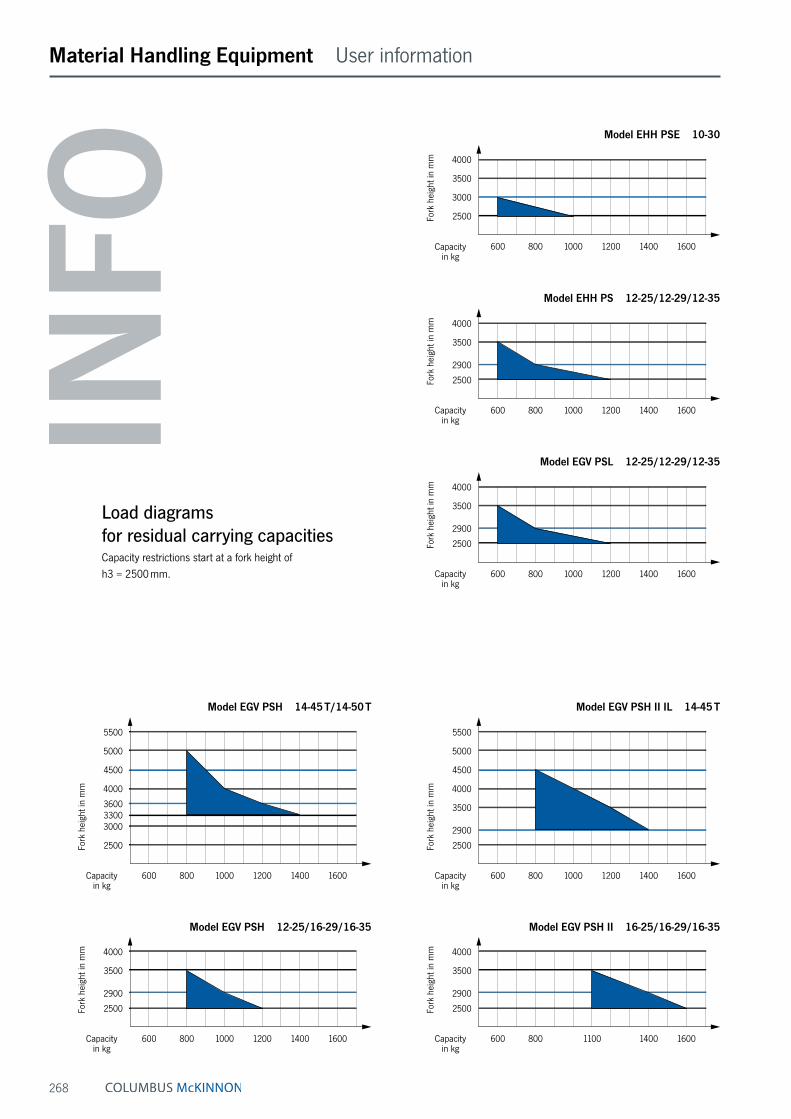
268
Material Handling Equipment User information
INFO
Model EHH PSE 10-30
Fork
hei
ght i
n m
m
Capacity in kg
4000 3500 3000 2500
600 800 1000 1200 1400 1600
Model EHH PS 12-25/12-29/12-35
Fork
hei
ght i
n m
m
Capacity in kg
4000 3500 2900 2500
600 800 1000 1200 1400 1600
Model EGV PSL 12-25/12-29/12-35
Fork
hei
ght i
n m
m
Capacity in kg
4000 3500 2900 2500
600 800 1000 1200 1400 1600
Model EGV PSH II IL 14-45 T
Fork
hei
ght i
n m
m
Capacity in kg
5500 5000 4500 4000 3500 2900 2500
600 800 1000 1200 1400 1600
Model EGV PSH II 16-25/16-29/16-35
Fork
hei
ght i
n m
m
Capacity in kg
4000 3500 2900 2500
600 800 1100 1400 1600
Load diagrams for residual carrying capacitiesCapacity restrictions start at a fork height of h3 = 2500 mm.
Model EGV PSH 14-45 T/14-50 T
5500 5000 4500 4000 3600 3300 3000 2500
600 800 1000 1200 1400 1600
Fork
hei
ght i
n m
m
Capacity in kg
Model EGV PSH 12-25/16-29/16-35
4000 3500 2900 2500
600 800 1000 1200 1400 1600
Fork
hei
ght i
n m
m
Capacity in kg

269
Material Handling Equipment Questionnaire
Technical questionnaire to identify a suitable material handling product
Company: Date:
Contact: e-Mail:
Phone: Fax:
Capacity kg
Fork height max. mm
Free lift mm
Required residual lifting
capacity mm
At fork height mmHeadroom with mast retracted mm
Lifting
manual-hydraulic
electric-hydraulic
Drive
manual
electric
Transport and stacking of:
palletised goods
long goods
loading lorries
Special requests
Lengths of application per shift
up to 2 hours
up to 4 hours
up to 6 hours
up to 8 hours
Shifts per day
Drivers platform
yes
no

270
Material Handling Equipment Hand pallet trucks
Hand pallet truck model HU 26-115 TMt PROLINE MOTIONCapacity 2600 kgFor the professional transportation of palletised goods and box pallets under demanding conditions.
Features• Ergonomic safety control handle for one-hand operation
of lifting, driving and lowering.
• Ergonomic designed control handle for safe handling.
• Low maintenance high performance hydraulic pump with hard chromium plated piston and pressure relief valve.
• Frame and forks in robust steel construction, adjust-able connecting rods, especially hardened axles and the high quality powder coating ensure a long life expectancy.
• Apron with shock absorbing rubber buffer in Pfaff-design.
• Steering angle of 105 degree to each side for easy handling in confined spaces.
• Entry rollers facilitate entry into bottom boarded pallets.
Hand pallet truck model HU 26-115 TMt PROLINE MOTIONHand pallet truck model HU 25-115 TS und ES SILVERLINE
Technical data model HU 26-115 TMt PROLINE MOTION
Model HU 26-115 TMt HU 26-115 TMt
Art.-No. 040009215 040009873Capacity, kg 2600 2600Load center c, mm 600 600Weight, kg 86 86Tyre type ¹ VG/PUR PUR/PURSteering rollers, mm 200 x 50 200 x 50Load rollers, mm 84 x 70 84 x 70Number of wheels/load rollers 2/4 2/4Stroke h3, mm 115 115Height of control handle h14, mm 1200 1200Fork height lowered h13, mm 85 85Overall length L1, mm 1535 1535Fork height s, mm 45 45Fork width e, mm 160 160Fork length l, mm 1150 1150Outside dimension of forks b1, mm 540 540Inside dimension of forks b3, mm 220 220Ground clearance m1, mm 40 40Aisle width pallet Ast, mm 1815 1815Turning circle radius Wa, mm 1330 1330
¹ PUR … Polyurethane, VG … Solid rubber
Option: Parking brake

271
Material Handling Equipment Hand pallet trucks
Hand pallet truck model HU 25-115 TS SILVERLINE (Tandem rollers)
model HU 25-115 ES SILVERLINE (Single rollers)Capacity 2500 kgFor the professional transportation of palletised goods and box pallets under demanding conditions.
Features• Ergonomic safety control handle for one-hand operation
of lifting, driving and lowering.
• Ergonomic rubber control handle for safe handling.
• Low maintenance hydraulic pump with hard chromium plated piston.
• Frame and forks in robust steel construction, adjust-able connecting rods, especially hardened axles and the high quality powder coating ensure a long life expectancy.
Technical data model HU 25-115 TS SILVERLINE and model HU 25-115 ES SILVERLINE
Model HU 25-115 TS HU 25-115 TS HU 25-115 TS HU 25-115 TS HU 25-115 TS HU 25-115 ES
Art.-No. 21225460 21225461 21225462 21225463 21225464 21225220Capacity, kg 2500 2500 2500 2500 2500 2500Load center c, mm 600 600 600 600 600 600Weight, kg 70 68 69 65 70 67Tyre type ¹ VG/PA VG/PUR PUR/PUR PA/PA PUR/PA VG/PURSteering rollers, mm 200 x 50 200 x 50 200 x 50 200 x 50 200 x 50 200 x 50Load rollers, mm 80 x 70 80 x 70 80 x 70 80 x 70 80 x 70 80 x 93Number of wheels/load rollers 2/4 2/4 2/4 2/4 2/4 2/2Stroke h3, mm 115 115 115 115 115 115Height of control handle h14, mm 1230 1230 1230 1230 1230 1230Fork height lowered h13, mm 85 85 85 85 85 85Overall length L1, mm 1555 1555 1555 1555 1555 1555Fork height s, mm 48 48 48 48 48 48Fork width e, mm 160 160 160 160 160 160Fork length l, mm 1150 1150 1150 1150 1150 1150Outside dimension of forks b1, mm 540 540 540 540 540 540Inside dimension of forks b3, mm 220 220 220 220 220 220Ground clearance m1, mm 37 37 37 37 37 37Aisle width pallet Ast, mm 1793 1793 1793 1793 1793 1793Turning circle radius Wa, mm 1275 1275 1275 1275 1275 1275
¹ PA … Polyamidee, PUR … Polyurethane, VG … Solid rubber
Option: Parking brake

272
Material Handling Equipment Hand pallet trucks
Hand pallet truck SILVERLINE with a smaller or a wider loading widthCapacity 1500 - 2500 kgFor the professional transportation of special pallets, e.g. brickyard pallets or american pallets.
Features• Ergonomic safety control handle for one-hand operation
of lifting, driving and lowering.
• Ergonomic rubber control handle for safe handling.
• Low maintenance high performance hydraulic pump with hard chromium plated piston and pressure relief valve.
• Frame and forks in robust steel construction, adjust-able connecting rods, especially hardened axles and the high quality powder coating ensure a long life expectancy.
• Steering angle of 105 degree to each side for easy handling in confined spaces.
Technical data hand pallet truck SILVERLINE
Model HU 15-115 TP HU 20-115 BTS HU 25-115 BTS
Art.-No. 040006498 034527132 21225457Capacity, kg 1500 2000 2500Weight, kg 80 86 73Tyre type ¹ PUR/PUR VG/PUR VG/PURSteering rollers, mm 200 x 50 200 x 50 200 x 50Load rollers, mm 82 x 70 82 x 70 80 x 70Stroke h3, mm 115 115 115Height of control handle h14, mm 1200 1200 1230Fork height lowered h13, mm 85 85 85Fork width e, mm 160 160 160Fork length l, mm 1150 1150 1150Outside dimension of forks b1, mm 450 850 685
¹ PUR … Polyurethane, VG … Solid rubber
Option: Parking brake

273
Material Handling Equipment Hand pallet trucks
Hand pallet truck with low height forks model HU 15-115 FTP PROLINECapacity 1500 kgFor the professional transportation of particularly low pallets.
Features• Ergonomic safety control handle for one-hand operation
of lifting, driving and lowering.
• Ergonomic rubber control handle for safe handling.
• Low maintenance high performance hydraulic pump with hard chromium plated piston and pressure relief valve.
• Frame and forks in robust steel construction, adjust-able connecting rods, especially hardened axles and the high quality powder coating ensure a long life expectancy.
• Pallet entry height of only 51 mm for easy entry in particularly low pallets.
• Steering angle of 105 degree to each side for easy handling in confined spaces.
Model HU 15-115 FTP
Art.-No. 034527124Capacity, kg 1500Weight, kg 84Tyre type ¹ PUR/PASteering rollers, mm 180 x 50Load rollers, mm 50 x 70Stroke h3, mm 115Height of control handle h14, mm 1200Fork height lowered h13, mm 51Fork width e, mm 160Fork length l, mm 1150Outside dimension of forks b1, mm 540
¹ PUR … Polyurethane, PA … Polyamide
Technical data model HU 15-115 FTP

274
Material Handling Equipment Hand pallet trucks
Hand pallet truck PROLINE with short forksCapacity 2500 kgFor the professional transportation of short palletised goods and box pallets under demanding conditions.
Features• Ergonomic safety control handle for one-hand operation
of lifting, driving and lowering.
• Ergonomic rubber control handle for safe handling.
• Low maintenance high performance hydraulic pump with hard chromium plated piston and pressure relief valve.
• Frame and forks in robust steel construction, adjust-able connecting rods, especially hardened axles and the high quality powder coating ensure a long life expectancy.
• Fork lenghts from 600 up to 1000 mm for transportation of small loads.
• Steering angle of 105 degree to each side for easy handling in confined spaces.
• Available with tandem (TP) or single rollers (EP).
Technical data hand pallet truck PROLINE with short forks
Model HU 25-60 EP HU 25-80 EP HU 25-90 EP HU 25-100 EP HU 25-80 TP HU 25-90 TP HU 25-100 TP
Art.-No. 040011694 21225221 21225224 21225223 21225450 21225451 21225452Capacity, kg 2500 2500 2500 2500 2500 2500 2500Weight, kg 59 63 66 66 64 67 66Tyre type ¹ VG/PA VG/PUR VG/PUR VG/PUR VG/PUR VG/PUR VG/PURSteering rollers, mm 200 x 50 200 x 50 200 x 50 200 x 50 200 x 50 200 x 50 200 x 50Load rollers, mm 82 x 70 80 x 93 80 x 93 80 x 93 80 x 70 80 x 70 80 x 70Stroke h3, mm 115 115 115 115 115 115 115Height of control handle h14, mm 1200 1230 1230 1230 1230 1230 1230Fork height lowered h13, mm 85 85 85 85 85 85 85Fork width e, mm 160 160 160 160 160 160 160Fork length l, mm 600 800 900 1000 800 900 1000Outside dimension of forks b1, mm 540 540 540 540 540 540 540
¹ PA … Polyamide, PUR … Polyurethane, VG … Solid rubber

275
Material Handling Equipment Hand pallet trucks
Hand pallet truck PROLINE for heavy loadsCapacity 3000 - 5000 kgFor the professional transportation of heavy loads.
Features• Ergonomic safety control handle for one-hand operation
of lifting, driving and lowering.
• Ergonomic rubber control handle for safe handling (only model HU 30-115 TP).
• Low maintenance high performance hydraulic pump with hard chromium plated piston and pressure relief valve.
• Frame and forks in robust steel construction, adjust-able connecting rods, especially hardened axles and the high quality powder coating ensure a long life expectancy.
Model HU 30-115 TP HU 50-115 TP HU 50-200 TP
Art.-No. 21230415 034527058 034527056Capacity, kg 3000 5000 5000Weight, kg 69 240 300Tyre type ¹ PUR/PUR steel/steel steel/steelSteering rollers, mm 200 x 50 200 x 50 200 x 50Load rollers, mm 80 x 70 82 x 80 82 x 80Stroke h3, mm 115 110 110Height of control handle h14, mm 1230 1220 1220Fork height lowered h13, mm 85 90 105Fork width e, mm 160 210 210Fork length l, mm 1150 1150 2000Outside dimension of forks b1, mm 540 580 700
¹ PUR … Polyurethane
Technical data hand pallet truck PROLINE for heavy loads
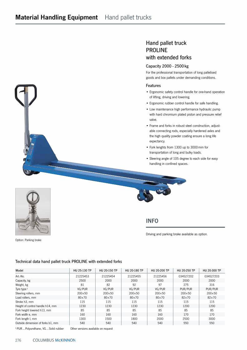
276
Material Handling Equipment Hand pallet trucks
Technical data hand pallet truck PROLINE with extended forks
Model HU 25-130 TP HU 20-150 TP HU 20-180 TP HU 20-200 TP HU 20-250 TP HU 20-300 TP
Art.-No. 21225453 21225454 21225455 21225456 034527202 034527203Capacity, kg 2500 2000 2000 2000 2000 2000Weight, kg 81 82 92 97 275 316Tyre type ¹ VG/PUR VG/PUR VG/PUR VG/PUR PUR/PUR PUR/PURSteering rollers, mm 200 x 50 200 x 50 200 x 50 200 x 50 200 x 50 200 x 50Load rollers, mm 80 x 70 80 x 70 80 x 70 80 x 70 82 x 70 82 x 70Stroke h3, mm 115 115 115 115 115 115Height of control handle h14, mm 1230 1230 1230 1230 1200 1200Fork height lowered h13, mm 85 85 85 85 85 85Fork width e, mm 160 160 160 160 170 170Fork length l, mm 1300 1500 1800 2000 2500 3000Outside dimension of forks b1, mm 540 540 540 540 550 550
¹ PUR … Polyurethane, VG … Solid rubber Other versions available on request
Hand pallet truck PROLINE with extended forksCapacity 2000 - 2500 kgFor the professional transportation of long palletised goods and box pallets under demanding conditions.
Features• Ergonomic safety control handle for one-hand operation
of lifting, driving and lowering.
• Ergonomic rubber control handle for safe handling.
• Low maintenance high performance hydraulic pump with hard chromium plated piston and pressure relief valve.
• Frame and forks in robust steel construction, adjust-able connecting rods, especially hardened axles and the high quality powder coating ensure a long life expectancy.
• Fork lenghts from 1300 up to 3000 mm for transportation of long and bulky loads.
• Steering angle of 105 degree to each side for easy handling in confined spaces.
Option: Parking brake
INFO
Driving and parking brake available as option.

277
Material Handling Equipment Hand pallet trucks
Hand pallet truck PROLINE with extended forks and increased capacityCapacity 3000 - 3500 kgFor the professional transportation of long palletised goods and box pallets under demanding conditions.
Features• Ergonomic safety control handle for one-hand operation
of lifting, driving and lowering.
• Ergonomic rubber control handle for safe handling.
• Low maintenance high performance hydraulic pump with hard chromium plated piston and pressure relief valve.
• Frame and forks in robust steel construction, adjust-able connecting rods, especially hardened axles and the high quality powder coating ensure a long life expectancy.
• Fork lenghts from 1500 up to 2000 mm for transportation of long goods.
• Steering angle of 105 degree to each side for easy handling in confined spaces.
Technical data hand pallet truck PROLINE with extended forks and increased capacity
Model HU 30-150 TP HU 30-180 TP HU 35-200 TP
Art.-No. 034527204 034527205 034527206Capacity, kg 3000 3000 3500Weight, kg 121 139 148Tyre type ¹ PUR/PUR PUR/PUR PUR/PURSteering rollers, mm 200 x 50 200 x 50 200 x 50Load rollers, mm 82 x 70 82 x 70 82 x 70Stroke h3, mm 115 115 115Height of control handle h14, mm 1200 1200 1200Fork height lowered h13, mm 85 85 85Fork width e, mm 160 170 170Fork length l, mm 1500 1800 2000Outside dimension of forks b1, mm 540 550 550
¹ PUR … Polyurethane
Hand pallet truck PROLINE with extended forksHand pallet truck PROLINE with extended forks and increased capacity
INFO
With extended forks up to 2000 mm and increased capacity up to 3500 kg.

278
Material Handling Equipment Hand pallet trucks
Hand pallet truck with quick-lift model HU 20-115 QLTP PROLINECapacity 2000 kgFor quick lifting and professional transportation of palletised goods and box pallets under demanding condi-tions.
Features• Ergonomic safety control handle for one-hand operation
of lifting, driving and lowering.
• Ergonomic rubber control handle for safe handling.
• Low maintenance high performance hydraulic pump with hard chromium plated piston and pressure relief valve.
• Quick-lift function for loads up to 200 kg for quick lifting of the load.
• Frame and forks in robust steel construction, adjust-able connecting rods, especially hardened axles and the high quality powder coating ensure a long life expectancy.
• Steering angle of 105 degree to each side for easy handling in confined spaces.
Technical data model HU 20-115 QLTP
Model HU 20-115 QLTP
Art.-No. 034527125Capacity, kg 2000Weight, kg 86Tyre type ¹ VG/PURSteering rollers, mm 200 x 50Load rollers, mm 82 x 70Stroke h3, mm 115Height of control handle h14, mm 1200Fork height lowered h13, mm 85Fork width e, mm 160Fork length l, mm 1150Outside dimension of forks b1, mm 540
¹ PUR … Polyurethane, VG … Solid rubber

279
Material Handling Equipment Hand pallet trucks
Hand pallet truck with driving and parking brake model HU 25-115 FBTP PROLINE
Capacity 2500 kgFor the professional transportation of palletised goods and box pallets, on ramps, ascending slopes and on lorries.
Features• Ergonomic safety control handle for one-hand operation
of lifting, driving and lowering.
• Ergonomic rubber control handle for safe handling.
• Driving and park brake comfortably operated from the control handle.
• Low maintenance high performance hydraulic pump with hard chromium plated piston and pressure relief valve.
• Frame and forks in robust steel construction, adjust-able connecting rods, especially hardened axles and the high quality powder coating ensure a long life expectancy.
• Steering angle of 105 degree to each side for easy handling in confined spaces.
Technical data model 25-115 FBTP
Model HU 25-115 FBTP
Art.-No. 034527135Capacity, kg 2500Weight, kg 86Tyre type ¹ VG/PURSteering rollers, mm 200 x 50Load rollers, mm 82 x 70Stroke h3, mm 115Height of control handle h14, mm 1200Fork height lowered h13, mm 85Fork width e, mm 160Fork length l, mm 1150Outside dimension of forks b1, mm 540
¹ PUR … Polyurethane, VG … Solid rubber

280
Material Handling Equipment Hand pallet trucks
Hand pallet truck stainless steel version model HU 20-115 VATP PROLINECapacity 2000 kgFor the professional transportation of palletised goods in corrosive areas.
Features• Ergonomic safety control handle for one-hand operation
of lifting, driving and lowering.
• Low maintenance high performance hydraulic pump with hard chromium plated piston and pressure relief valve. Hydraulic unit made of V4A – 316 stainless steel.
• Frame, adjustable connecting rods, bolts and the tor-sion tube are made of high quality V4A – 316 stainless steel.
• Steering angle of 105 degree to each side for easy handling in confined spaces.
Technical data model HU 20-115 VATP
Model HU 20-115 VATP
Art.-No. 040005740Capacity, kg 2000Weight, kg 86Tyre type ¹ PA/PASteering rollers, mm 200 x 50Load rollers, mm 82 x 70Stroke h3, mm 115Height of control handle h14, mm 1200Fork height lowered h13, mm 85Fork width e, mm 160Fork length l, mm 1150Outside dimension of forks b1, mm 540
¹ PA … Polyamide
INFO
The operator is responsible for an analysis of the working conditions in order to assess the suitability of the hand pallet truck.
Available in explosion proof version (see page 468).

281
Material Handling Equipment Hand pallet trucks
Hand pallet truck galvanized version model HU 25-115 GAL PROLINECapacity 2500 kgFor the professional transportation of palletised goods in corrosive areas.
Features• Ergonomic safety control handle for one-hand operation
of lifting, driving and lowering.
• Low maintenance high performance hydraulic pump with hard chromium plated piston and pressure relief valve.
• Galvanized frame with a layer of 100 µm, cold galva-nized control handle and hydraulic system, stainless steel running gear, ball bearings and axles ensure high chemical resistance.
• Steering angle of 105 degree to each side for easy handling in confined spaces.
Technical data model HU 25-115 GAL
Model HU 25-115 GAL
Art.-No. 034527170Capacity, kg 2500Weight, kg 86Tyre type ¹ PA/PASteering rollers, mm 200 x 50Load rollers, mm 82 x 70Stroke h3, mm 115Height of control handle h14, mm 1200Fork height lowered h13, mm 85Fork width e, mm 160Fork length l, mm 1150Outside dimension of forks b1, mm 540
¹ PA … Polyamide
INFO
The operator is responsible for an analysis of the working conditions in order to assess the suitability of the hand pallet truck.

282
Material Handling Equipment Hand pallet trucks with weighing system
Hand pallet truck with weighing system model HU W-20 SL SILVERLINECapacity 2000 kgFor transportation and weighing of palletised goods and box pallets. For simple weighing jobs and a rough calculation of total weights, e.g. when loading lorries.
Features• The basic truck is the model Silverline HU 25-115.
• Ergonomic safety control handle for one-hand operation of lifting, driving and lowering.
• Ergonomic rubber control handle for safe handling.
• Measuring range from 0 up to 2000 kg in 5 kg steps.
• Easy to read LCD display.
• Accuracy: 0 - 500 kg → +/- 10 kg500 - 1000 kg → +/- 20 kg1000 - 2000 kg → +/- 30 kg
• The weighing system is calibrated at the factory.
Scope of delivery• 2 x 1.5 V AA batteries
(sufficient for approx. 3000 weighing operations)
Model HU W 20 SL
Art.-No. 040048616Capacity, kg 2000Load center c, mm 600Weight, kg 76Tyre type ¹ VG/PURSteering rollers D, mm 200 x 50Load rollers D1, mm 82 x 70Number of wheels/load rollers 2/4Stroke h2, mm 115Lifting height h3, mm 200Height of control handle h14, mm 1200Fork height lowered h13, mm 85Overall length L1, mm 1535Fork height s, mm 45Fork width e, mm 160Fork length l, mm 1150Outside dimension of forks b1, mm 540Ground clearance m1, mm 40Turning circle radius, mm 1330Ambient temperature -5 °C up to + 40 °C
¹ VG … Solid rubber, PUR … Polyurethane
Technical data model HU W-20 SL

283
Material Handling Equipment
Hand pallet truck with weighing system model HU W-20 S SILVERLINECapacity 2000 kgFor transportation and weighing of palletised goods and box pallets.
Features• Ergonomic safety control handle for one-hand operation
of lifting, driving and lowering.
• Ergonomic rubber control handle for safe handling.
• Measuring range from 0 up to 2000 kg in 1 kg steps.
• Easy to read LCD display.
• Accuracy +/- 0.1 % of the end value.
• The readings start at 1.0 kg.
• The weighing system is calibrated at the factory.
• The system is designed for simple weighing jobs, such as batching or filling processes.
• Low maintenance hydraulic pump with hard chromium plated piston and pressure relief valve.
• Frame and forks in robust steel construction, adjustable connecting rods, especially hardened axles and the high quality powder coating ensure a long life expectancy.
• Steering angle of 105 degree to each side for easy handling in confined spaces.
Scope of delivery• 4 x 1.5 V batteries
Technical data model HU W-20 S
Model HU W 20 S
Art.-No. 040016431Capacity, kg 2000Load center c, mm 600Weight, kg 129Tyre type ¹ PUR/PURSteering rollers D, mm 180 x 50Load rollers D1, mm 74 x 70Number of wheels/load rollers 2/4Stroke h2, mm 110Lifting height h3, mm 195Height of control handle h14, mm 1210Fork height lowered h13, mm 85Overall length L1, mm 1580Fork height s, mm 50Fork width e, mm 180Fork length l, mm 1150Outside dimension of forks b1, mm 570Inside dimension of forks b3, mm 210Ground clearance m1, mm 35Turning circle radius, mm 1330Ambient temperature -10 °C up to + 40 °C
¹ PUR … Polyurethane

284
Material Handling Equipment Scissor pallet trucks
Scissor pallet truck with manual-hydraulic lift model HU HS 10 BCapacity 1000 kg, fork height max. 800 mmA combination of hand pallet truck and elevating platform for the transport and raising of palletised loads to various departments.
Features• Safety control handle with the functions:
Quick-lift - lifting - lowering.
• Lowering speed can be finely metered for sensitive lowering of the load.
• One-stage hydraulic for increased robustness.
• Quick-lift for loads up to 250 kg.
• Overload protection by pressure relief valve.
• Safety supports guarantee sure standing when the forks are raised.
• Low noise and smooth running with standard tyres: steer rollers and load rollers – polyurethane.
Technical data model HU HS 10 B
Model HU HS 10 B
Art.-No. 26600020Capacity Q, kg 1000Load center c, mm 600Weight, kg 122Tyre type¹ PUR/PURSteering rollers, mm 180 x 50Load rollers, mm 75 x 50Number of wheels/load rollers 2/2Stroke h3, mm 715Height of control handle max. h14, mm 1254Fork height lowered h13, mm 85Overall length L1, mm 1725Overall width b1/b2, mm 575Fork height s, mm 45Fork width e, mm 160Fork length l, mm 1170Outside dimension of forks b5, mm 540Ground clearance, wheelbase centre m2, mm 18Aisle width pallet Ast, mm 1986Turning circle radius Wa, mm 1564
¹ PUR … Polyurethane
h 3l
h 13
h 14
y
l1l2
Q
x
c
sm2
e
b 5
e
Ast
Wa
b 1/b
2

285
Material Handling Equipment Scissor pallet trucks
Scissor pallet truck with electric-hydraulic lift model HU ES 10 BCapacity 1000 kg, fork height max. 800 mmThe model HU ES 10 B increases the usefulness of the HU HS 10 B by saving operating time for demanding ap-plications with frequent lifting and lowering operations.
Features• Ergonomic control button for the hydraulic unit fitted in
the handle.
• In case of a battery failure the manual use of lifting and lowering is still guaranteed.
• Quick electric-hydraulic lifting of the load, pressure relief valve protects against overloading.
• Low noise and smooth running due to polyurethane steering and load rollers as standard.
• Additional tilting protection for the load rollers.
Scope of delivery• Battery and integrated battery charger
Model HU ES 10 B
Art.-No. 26900020Capacity Q, kg 1000Load center c, mm 600Weight, kg 152Tyre type ¹ PUR/PURSteering rollers, mm 180 x 50Load rollers, mm 75 x 50Number of wheels/load rollers 2/2Stroke h3, mm 715Height of control handle max. h14, mm 1254Fork height lowered h13, mm 85Overall length L1, mm 1715Overall width b1/b2, mm 575Fork height s, mm 45Fork width e, mm 160Fork length l, mm 1170Outside dimension of forks b5, mm 540Ground clearance, wheelbase centre m2, mm 18Aisle width pallet Ast, mm 1986Turning circle radius Wa, mm 1564Battery charger, V/A 220/6Battery voltage, capacity K5, V/Ah 12/52
¹ PUR … Polyurethane
Technical data model HU ES 10 B
h 3
l
h 13
h 14
y
l1l2
Q
x
c
sm2
e
b 5
e
Ast
Wa
b 1/b
2
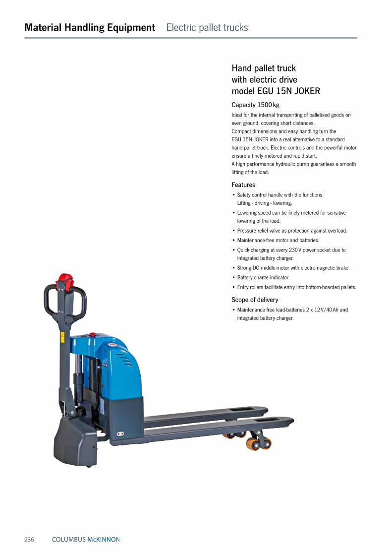
286
Material Handling Equipment Electric pallet trucks
Hand pallet truck with electric drive model EGU 15N JOKERCapacity 1500 kgIdeal for the internal transporting of palletised goods on even ground, covering short distances. Compact dimensions and easy handling turn the EGU 15N JOKER into a real alternative to a standard hand pallet truck. Electric controls and the powerful motor ensure a finely metered and rapid start. A high performance hydraulic pump guarantees a smooth lifting of the load.
Features• Safety control handle with the functions:
Lifting - driving - lowering.
• Lowering speed can be finely metered for sensitive lowering of the load.
• Pressure relief valve as protection against overload.
• Maintenance-free motor and batteries.
• Quick charging at every 230 V power socket due to integrated battery charger.
• Strong DC middle-motor with electromagnetic brake.
• Battery charge indicator
• Entry rollers facilitate entry into bottom-boarded pallets.
Scope of delivery• Maintenance free lead-batteries 2 x 12 V/40 Ah and
integrated battery charger.

287
Material Handling Equipment Electric pallet trucks
Model EGU 15N JOKER
Art.-No. 192008984Actuation electricCapacity, kg 1500Load center c, mm 600Wheelbase Y, mm 1279Weight (with battery), kg 165Tyre type ¹ PUR/PUR Steering rollers, mm 220 x 70Load rollers, mm 80 x 70Number of wheels/load rollers (x=driven) 2+1x /4Stroke h3, mm 115Height of control handle min./max. h14, mm 850/1295Fork height lowered h13, mm 85Overall length L1, mm 1666Length incl. apron L2, mm 516Overall width b1, mm 560Fork height s, mm 48Fork width e, mm 160Fork length l, mm 1150Outside dimension of forks b5, mm 540Ground clearance m2, mm 37Aisle width pallet Ast, mm 1961Turning circle radius Wa, mm 1507Actuation manual-hydraulicTravel speed with/without load, m/s 4.2/4.6Lowering speed with/without load, m/s meteredGradient with/without load, m/s 4/10Service brake electricDrive motor rating S2 60 min, kW 0.45Battery starterBattery voltage, V/Ah 2 x 12/40Battery weight, kg 30Type of control MOSFET
¹ PUR … Polyurethane
Technical data model EGU 15N JOKER
Q
h 13h 3
S
C
m2
Y
h 14
l1
l2
l2
100100
X
AST
Wa
b 11 b 5b 1
e

288
Material Handling Equipment Electric pallet trucks
Electric pallet truck model EGU PS 15Capacity 1500 kgElectrical drive, electrical lifting
Ideal for the transportation of palletized goods within a warehouse environment. Due to the extremely small turn-ing circle it is also ideal for working on ramps or taking along on a lorry. The powerful motor allows fast operation.
Features• 80 Ah Semi-Traction battery for long working cycles.
• Creep speed button for pin-point work in confined spaces.
• Reliable impulse control for stepless regulation of driving speed.
• Integrated battery charger for charging on a 230 V plug socket.
• Digital display for battery status
Scope of delivery• Battery and integrated charger included
Technical data model EGU PS 15
Model EGU PS 15
Art.-No. 040052452Actuation electricOperation pedestrianCapacity, kg 1500Load center c, mm 600Wheelbase Y, mm 1217Weight (with battery), kg 286Tyre type ¹ PUR/PURSteering rollers l x d, mm 252 x 89Load rollers l x d, mm 84 x 70Number of wheels/load rollers (x=driven) 1x +2/4Stroke h3, mm 120Fork height max. h15, mm 205Height of control handle max. h14, mm 1235Fork height lowered h13, mm 85Overall length L1, mm 1590Length incl. apron L2, mm 440Overall width B, mm 700Fork height s, mm 47Fork width e, mm 160Fork length l, mm 1150Outside dimension of forks b1, mm 520Aisle width pallet Ast, mm 1944Turning circle radius Wa, mm 1480Travel speed with/without load, m/s 5.0/5.2Lifting speed with/without load, m/s 0.27/0.35Lowering speed with/without load, m/s 0.42/0.27Gradient with/without load, m/s 5/8Service brake electricDrive motor rating, kW 1.0Hoist motor rating, kW 0.8Battery semi-tractionBattery voltage, capacity at 20 h, V/Ah 2 x 12/80Type of control Curtis
¹ PUR … Polyurethane
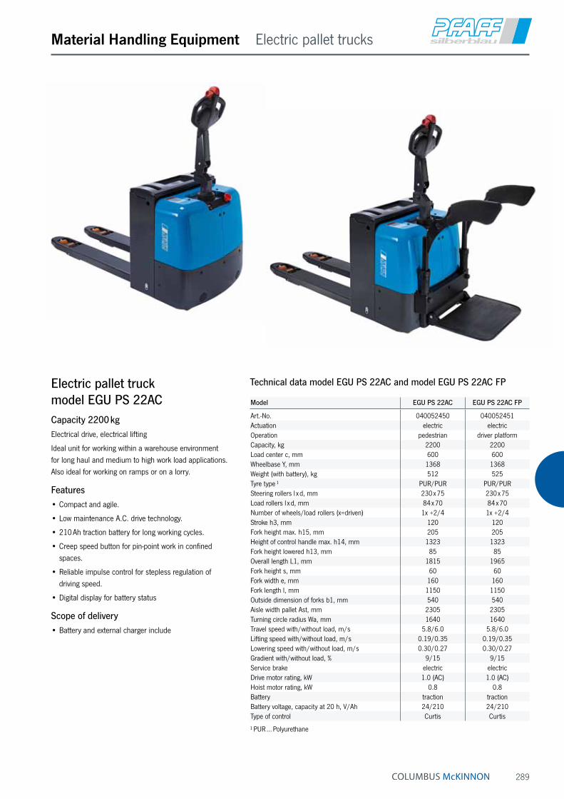
289
Material Handling Equipment Electric pallet trucks
Electric pallet truck model EGU PS 22ACCapacity 2200 kgElectrical drive, electrical lifting
Ideal unit for working within a warehouse environment for long haul and medium to high work load applications. Also ideal for working on ramps or on a lorry.
Features• Compact and agile.
• Low maintenance A.C. drive technology.
• 210 Ah traction battery for long working cycles.
• Creep speed button for pin-point work in confined spaces.
• Reliable impulse control for stepless regulation of driving speed.
• Digital display for battery status
Scope of delivery• Battery and external charger include
Technical data model EGU PS 22AC and model EGU PS 22AC FP
Model EGU PS 22AC EGU PS 22AC FP
Art.-No. 040052450 040052451Actuation electric electricOperation pedestrian driver platformCapacity, kg 2200 2200Load center c, mm 600 600Wheelbase Y, mm 1368 1368Weight (with battery), kg 512 525Tyre type ¹ PUR/PUR PUR/PURSteering rollers l x d, mm 230 x 75 230 x 75Load rollers l x d, mm 84 x 70 84 x 70Number of wheels/load rollers (x=driven) 1x +2/4 1x +2/4Stroke h3, mm 120 120Fork height max. h15, mm 205 205Height of control handle max. h14, mm 1323 1323Fork height lowered h13, mm 85 85Overall length L1, mm 1815 1965Fork height s, mm 60 60Fork width e, mm 160 160Fork length l, mm 1150 1150Outside dimension of forks b1, mm 540 540Aisle width pallet Ast, mm 2305 2305Turning circle radius Wa, mm 1640 1640Travel speed with/without load, m/s 5.8/6.0 5.8/6.0Lifting speed with/without load, m/s 0.19/0.35 0.19/0.35Lowering speed with/without load, m/s 0.30/0.27 0.30/0.27Gradient with/without load, % 9/15 9/15Service brake electric electricDrive motor rating, kW 1.0 (AC) 1.0 (AC)Hoist motor rating, kW 0.8 0.8Battery traction tractionBattery voltage, capacity at 20 h, V/Ah 24/210 24/210Type of control Curtis Curtis
¹ PUR … Polyurethane

290
Material Handling Equipment Manual drive stackers
Hand stacker model HGCapacity 300 and 500 kgIdeal for the occasional, internal application of stacking and transporting of palletised goods.
Features• Manual winch for exact positioning of the height.
• Handlebar for easy operation.
• C-profile mast with maintenance free pulley and guide rollers with ball bearings.
• Steering roller with brake for safe parking of the hand stacker.
Technical data model HG
Model HG 0315 HG 0515
Art.-No. 034518016 034518017Capacity, kg 300 500Load center c, mm 400 400Wheelbase y, mm 850 1050Weight, kg 80 90Tyre type ¹ PA/PA PA/PASteering rollers, mm 125 x 40 125 x 40Load rollers, mm 75 x 30 75 x 30Number of wheels/load rollers 2/2 2/2Height, mast retracted h1, mm 1840 1840Free lift h2, mm 1410 1410Stroke h3, mm 1410 1410Height, mast extended h4, mm 1840 1840Lifting height max. h3 + h13, mm 1500 1500Fork height lowered h13, mm 90 90Overall length L1, mm 1020 1320Length incl. apron L2, mm 362 362Overall width B, mm 710 710Fork height s, mm 50 50Fork width e, mm 160 160Fork length l, mm 600 900Outside dimension of forks b1, mm 580 580Ground clearance m1, mm 30 30Turning circle radius Wa, mm 855 1155Lift per one crank rotation with/without load, mm 25 25
¹ PA … Polyamide
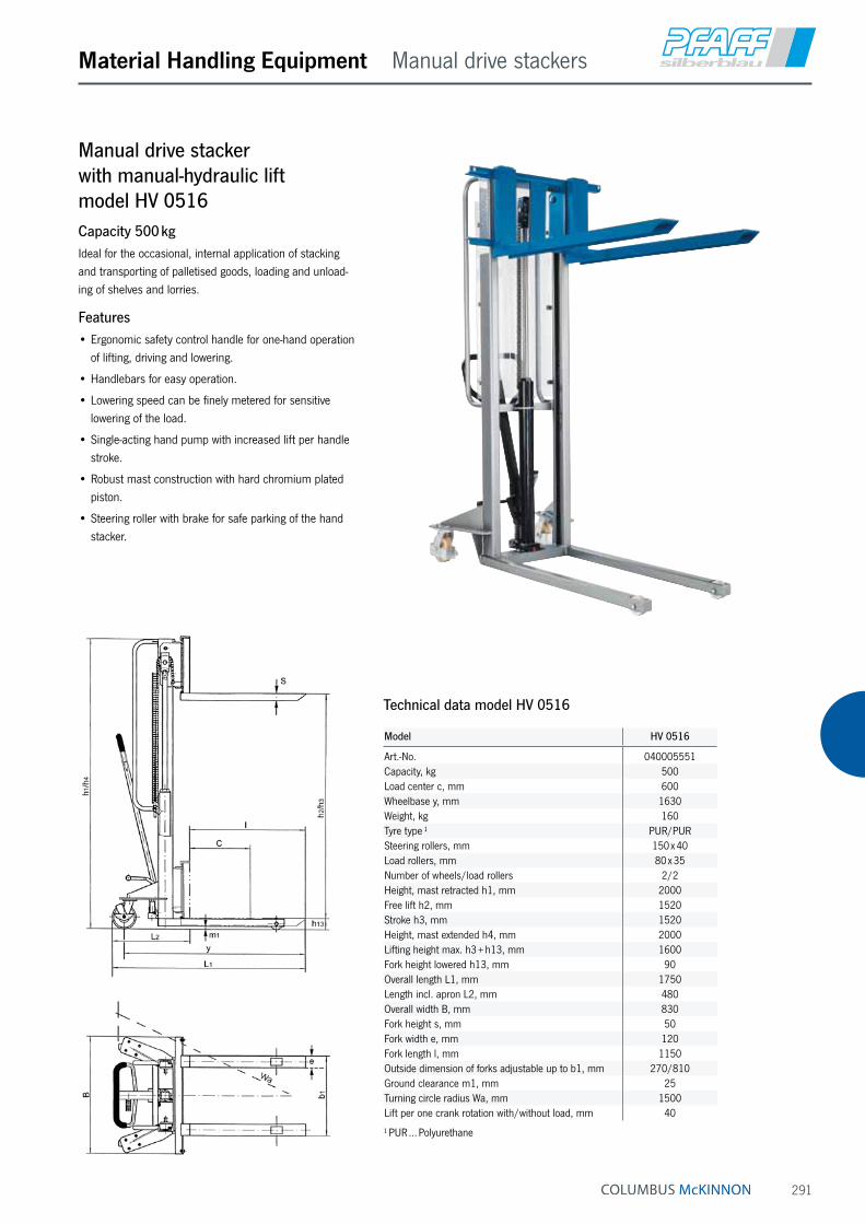
291
Material Handling Equipment Manual drive stackers
Manual drive stacker with manual-hydraulic lift model HV 0516Capacity 500 kgIdeal for the occasional, internal application of stacking and transporting of palletised goods, loading and unload-ing of shelves and lorries.
Features• Ergonomic safety control handle for one-hand operation
of lifting, driving and lowering.
• Handlebars for easy operation.
• Lowering speed can be finely metered for sensitive lowering of the load.
• Single-acting hand pump with increased lift per handle stroke.
• Robust mast construction with hard chromium plated piston.
• Steering roller with brake for safe parking of the hand stacker.
Technical data model HV 0516
Model HV 0516
Art.-No. 040005551Capacity, kg 500Load center c, mm 600Wheelbase y, mm 1630Weight, kg 160Tyre type ¹ PUR/PURSteering rollers, mm 150 x 40Load rollers, mm 80 x 35Number of wheels/load rollers 2/2Height, mast retracted h1, mm 2000Free lift h2, mm 1520Stroke h3, mm 1520Height, mast extended h4, mm 2000Lifting height max. h3 + h13, mm 1600Fork height lowered h13, mm 90Overall length L1, mm 1750Length incl. apron L2, mm 480Overall width B, mm 830Fork height s, mm 50Fork width e, mm 120Fork length l, mm 1150Outside dimension of forks adjustable up to b1, mm 270/810Ground clearance m1, mm 25Turning circle radius Wa, mm 1500Lift per one crank rotation with/without load, mm 40
¹ PUR … Polyurethane

292
Material Handling Equipment Manual drive stackers
Manual drive stacker model HV 1008
Manual drive stacker model HV 1016Capacity 1000 kgIdeal for the occasional, internal application of stacking and transporting of palletised goods.
Features• Ergonomic safety control handle for one-hand operation
of lifting, driving and lowering.
• Easy handling due to forced steering rollers.
• Lowering speed can be finely metered for sensitive lowering of the load.
• Single-acting hand pump with increased lift per handle stroke.
• Quick-lift for loads up to 100 kg.
• Robust mast construction with hard chromium plated piston.
• Steering roller with brake for safe parking of the hand stacker.

293
Material Handling Equipment Manual drive stackers
Technical data model HV 1008 and model HV 1016
Model HV 1008 HV 1016
Art.-No. 034518032 034518030Capacity, kg 1000 1000Load center c, mm 600 600Wheelbase y, mm 1075 1075Weight, kg 179 205Tyre type ¹ PUR/PUR PUR/PURSteering rollers, mm 180 x 50 180 x 50Load rollers, mm 80 x 55 80 x 55Number of wheels/load rollers 2/2 2/2Height, mast retracted h1, mm 1300 1965Free lift h2, mm 810 1510Stroke h3, mm 810 1510Height, mast extended h4, mm 1300 1965Lifting height max. h3 + h13, mm 900 1600Fork height lowered h13, mm 90 90Overall length L1, mm 1675 1675Length incl. apron L2, mm 552 552Overall width B, mm 765 765Fork height s, mm 60 60Fork width e, mm 60 60Fork length l, mm 1122 1122Outside dimension of forks b1, mm 570 570Ground clearance m1, mm 25 25Aisle width pallet Ast, mm 1875 1875Turning circle radius Wa, mm 1445 1445Lift per one crank rotation with/without load, mm 17/50 17/50
¹ PUR … Polyurethane
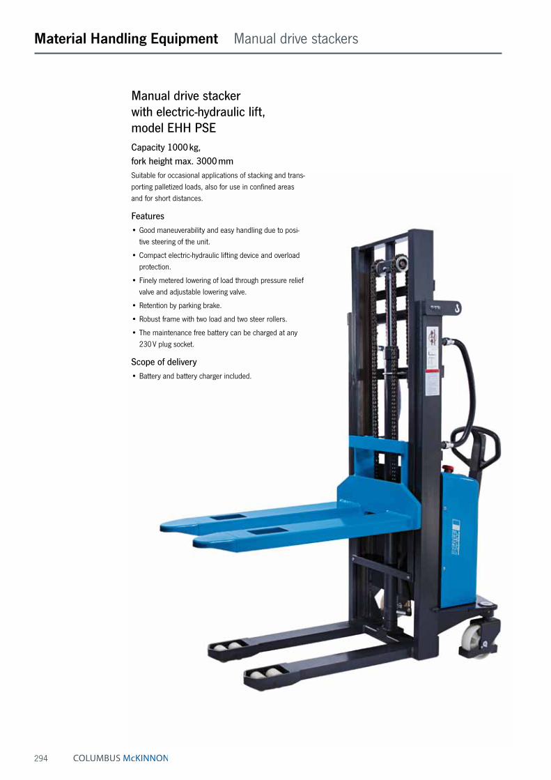
294
Material Handling Equipment Manual drive stackers
Manual drive stacker with electric-hydraulic lift, model EHH PSECapacity 1000 kg, fork height max. 3000 mmSuitable for occasional applications of stacking and trans-porting palletized loads, also for use in confined areas and for short distances.
Features• Good maneuverability and easy handling due to posi-
tive steering of the unit.
• Compact electric-hydraulic lifting device and overload protection.
• Finely metered lowering of load through pressure relief valve and adjustable lowering valve.
• Retention by parking brake.
• Robust frame with two load and two steer rollers.
• The maintenance free battery can be charged at any 230 V plug socket.
Scope of delivery• Battery and battery charger included.

295
Material Handling Equipment Manual drive stackers
Technical data model EHH PSE
Model EHH PSE 1016 EHH PSE 1025 EHH PSE 1030
Art.-No. 040050660 040050661 040050662Capacity (up to 2.5 m lift), kg 1000 1000 1000Load center c, mm 600 600 600Wheelbase y, mm 1160 1160 1160Weight (with battery), kg 395 455 475Tyre type ¹ PA/PUR PA/PUR PA/PURSteering rollers, mm 180 x 50 180 x 50 180 x 50Load rollers, mm 74 x 70 74 x 70 74 x 70Number of wheels/load rollers 2/4 2/4 2/4Height, mast retracted h1, mm 1980 1830 2080Free lift h2, mm 1415 – –Stroke h3, mm 1515 2415 2915Height, mast extended h4, mm 2030 3020 3515Lifting height max. h3 + h13, mm 1600 2500 3000Fork height lowered h13, mm 85 85 85Overall length L1, mm 1720 1720 1720Length incl. apron L2, mm 555 555 555Overall width b1/b2, mm 765 765 765Fork height s, mm 60 60 60Fork width e, mm 180 180 180Fork length l, mm 1100 1100 1100Outside dimension of forks b5, mm 570 570 570Ground clearance m2, mm 25 25 25Aisle width pallet Ast, mm 2145 2145 2145Turning circle radius Wa, mm 1280 1280 1280Lifting speed with/without load, m/s 0.08/0.13 0.08/0.13 0.08/0.13Lowering speed with/without load, m/s 0.42/0.19 0.42/0.19 0.42/0.19Hoist motor rating, kW 1.5 1.5 1.5Battery according to DIN 43531 semi traction battery semi traction battery semi traction batteryBattery charger, V/A 12/20 A 12/20 A 12/20 ABattery voltage, capacity, V/Ah 12/150 12/150 12/150
¹ PA … Polyamide, PUR … Polyurethane
Ast
b 1/b
2
Wa
e
b 5
e
b 3
Q
l
c
h 13
h 3
h 1
h 4
h 14 h 2
s
m2
l1l2
y
x

296
Material Handling Equipment Manual drive stackers
Manual drive stacker with electric-hydraulic lift, model EHH PSCapacity 1000 - 1200 kg, fork height max. 3500 mmSuitable for occasional to medium applications of stacking and transporting palletised loads, also in confined areas.
Features• Easy to operate via tie-rod guides to both steer wheels.
• Compact electric-hydraulic lifting device and overload protection.
• Finely metered lowering of load through pressure relief valve and adjustable lowering valve.
• Mast welded from precision profiles, fork carriage with maintenance free guide rollers.
• Retention by parking brake.
• Robust frame with two load and two steer rollers.
Scope of delivery• Battery and battery charger included.
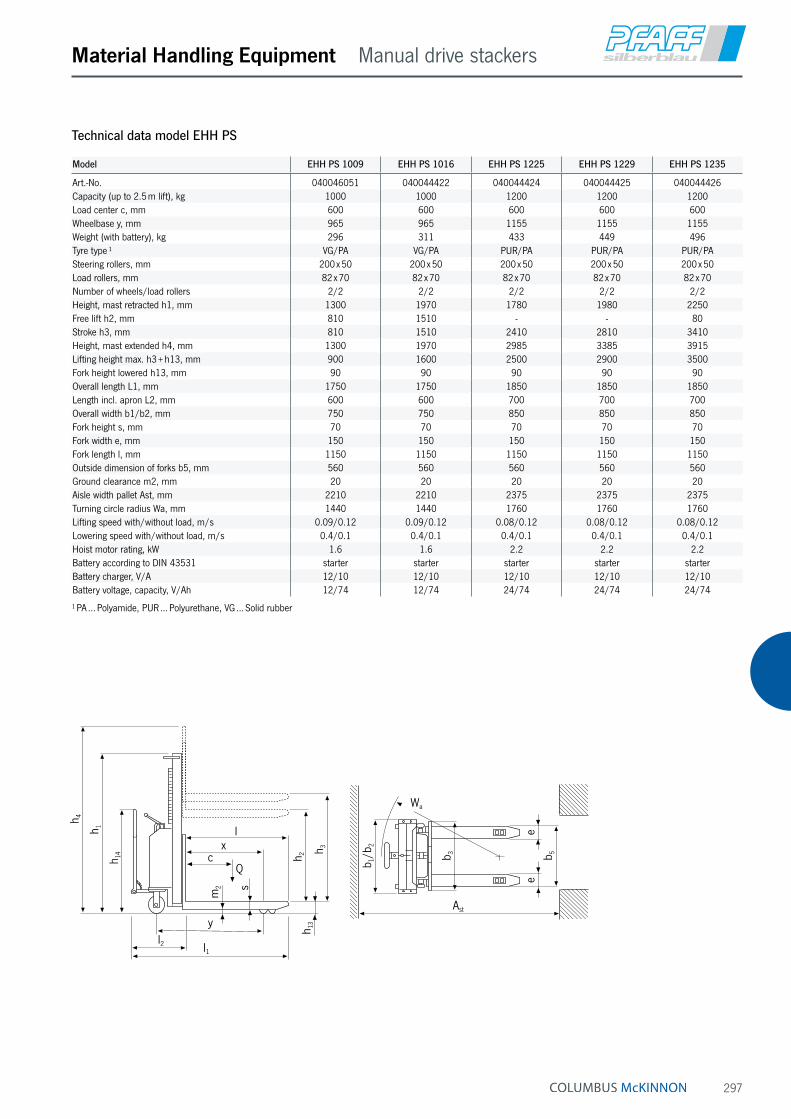
297
Material Handling Equipment Manual drive stackers
Q
l
c
h 13
h 3
h 1
h 4
h 14 h 2
s
m2
l1l2
y
x
Ast
b 1/b
2
Wa
e
b 5
e
b 3
Technical data model EHH PS
Model EHH PS 1009 EHH PS 1016 EHH PS 1225 EHH PS 1229 EHH PS 1235
Art.-No. 040046051 040044422 040044424 040044425 040044426Capacity (up to 2.5 m lift), kg 1000 1000 1200 1200 1200Load center c, mm 600 600 600 600 600Wheelbase y, mm 965 965 1155 1155 1155Weight (with battery), kg 296 311 433 449 496Tyre type ¹ VG/PA VG/PA PUR/PA PUR/PA PUR/PASteering rollers, mm 200 x 50 200 x 50 200 x 50 200 x 50 200 x 50Load rollers, mm 82 x 70 82 x 70 82 x 70 82 x 70 82 x 70Number of wheels/load rollers 2/2 2/2 2/2 2/2 2/2Height, mast retracted h1, mm 1300 1970 1780 1980 2250Free lift h2, mm 810 1510 - - 80Stroke h3, mm 810 1510 2410 2810 3410Height, mast extended h4, mm 1300 1970 2985 3385 3915Lifting height max. h3 + h13, mm 900 1600 2500 2900 3500Fork height lowered h13, mm 90 90 90 90 90Overall length L1, mm 1750 1750 1850 1850 1850Length incl. apron L2, mm 600 600 700 700 700Overall width b1/b2, mm 750 750 850 850 850Fork height s, mm 70 70 70 70 70Fork width e, mm 150 150 150 150 150Fork length l, mm 1150 1150 1150 1150 1150Outside dimension of forks b5, mm 560 560 560 560 560Ground clearance m2, mm 20 20 20 20 20Aisle width pallet Ast, mm 2210 2210 2375 2375 2375Turning circle radius Wa, mm 1440 1440 1760 1760 1760Lifting speed with/without load, m/s 0.09/0.12 0.09/0.12 0.08/0.12 0.08/0.12 0.08/0.12Lowering speed with/without load, m/s 0.4/0.1 0.4/0.1 0.4/0.1 0.4/0.1 0.4/0.1Hoist motor rating, kW 1.6 1.6 2.2 2.2 2.2Battery according to DIN 43531 starter starter starter starter starterBattery charger, V/A 12/10 12/10 12/10 12/10 12/10Battery voltage, capacity, V/Ah 12/74 12/74 24/74 24/74 24/74
¹ PA … Polyamide, PUR … Polyurethane, VG … Solid rubber

298
Electric pedestrian stacker model EGV PSLCapacity 1000 - 1200 kg, fork height max. 3500 mmIdeal for stacking and transportation of palletised goods within a warehouse environment for short haul and medium work load applications.
Features• Multifunctional control handle for easy handling.
The electric pallet lift truck will automatically be slowed down if the control handle is no longer in the users hand.
• Reliable impulse control for stepless regulation of drive speed.
• Compact electric-hydraulic lifting device and overload protection.
• Finely metered lowering of load through pressure relief valve and adjustable lowering valve.
• Mast welded from precision profiles, fork carriage with maintenance free guide rollers.
• Solid frame with one drive wheel and two load and two guide rollers.
Scope of delivery• Battery and battery charger included.
Material Handling Equipment Electric pedestrian stackers

299
Material Handling Equipment Electric pedestrian stackers
Q
h 13
l
l2
h 14
h 3
l1
h 1
h 2
y
x
s
m2
c
h 4
eb 5
Ast
b 1/b
2
Wa
b 3
e
Technical data model EGV PSL
Model EGV PSL 1016 II EGV PSL 1225 EGV PSL 1229 EGV PSL 1235
Art.-No. 192021784 040040503 040040504 040044421Actuation electric electric electric electricOperation pedestrian pedestrian pedestrian pedestrianCapacity (up to 2.5 m lift), kg 1000 1200 1200 1200Load center c, mm 600 600 600 600Wheelbase y, mm 1165 1190 1190 1190Weight (with battery), kg 363 481 496 531Tyre type ¹ PUR/VG+PUR PUR+VG/PUR PUR+VG/PUR PUR+VG/PURSteering rollers, mm 186 x 50+125 x 45 250 x 76+150 x 40 250 x 76+150 x 40 250 x 76+150 x 40Load rollers, mm 82 x 70 82 x 70 82 x 70 82 x 70Number of wheels/load rollers (x=driven) 1x+1 /2 2+1x /2 2+1x /2 2+1x /2Height, mast retracted h1, mm 1970 1780 1980 2250Free lift h2, mm 1510 – – 80Stroke, mm 1510 2410 2810 3410Height, mast extended h4, mm 1970 2985 3385 3915Fork height max. h3, mm 1600 2500 2900 3500Height of control handle max. h14, mm 1365 1390 1390 1390Fork height lowered h13, mm 90 90 90 90Overall length L1, mm 1675 1825 1825 1825Length incl. apron L2, mm 522 675 675 675Overall width b1/b2, mm 794 850 850 850Fork height s, mm 60 70 70 70Fork width e, mm 150 150 150 150Fork length l, mm 1153 1150 1150 1150Clearance fork tip-roller, x 365 365 365 365Outside dimension of forks b5, mm 560 560 560 560Ground clearance m2, mm 20 20 20 20Aisle width pallet Ast, mm 2120 2075 2075 2075Turning circle radius Wa, mm 1344 1460 1460 1460Travel speed with/without load, km/h 3.7/4.3 4.0/5.0 4.0/5.0 4.0/5.0Lifting speed with/without load, m/s 0.11/0.18 0.08/0.12 0.08/0.12 0.08/0.12Lowering speed with/without load, m/s 0.18/0.18 0.4/0.1 0.4/0.1 0.4/0.1Gradient with/without load, % 9/25 5/10 5/10 5/10Service brake electric electric electric electricDrive motor rating, kW 0.35 0.7 0.7 0.7Hoist motor rating, kW 2.2 2.2 2.2 2.2Battery starter starter starter starterBattery charger, V/A 24/12 24/12 24/12 24/12Battery voltage, V/Ah 24/70 24/92 24/92 24/92Type of control impulse impulse impulse impulse
¹ PUR … Polyurethane, VG … Solid rubber
new

300
Material Handling Equipment Electric pedestrian stackers
Electric pedestrian stacker model EGV PSH IICapacity 1200 - 1600 kg, fork height max. 5000 mmThe revised edition of the model range EGV PSH II is the professional solution for indoor transportation and stack-ing of palletized loads over longer distances and higher capacity utilization.
Features• Multifunctional control handle with integrated drive
switches and lifting and lowering functions directly on the control handle.
• Proportionally controllable lifting and lowering functions for better positioning of the loads.
• Compact overall dimensions, only 800 mm wide allows operations in narrow corridors.
• Ultra-slow drive function enables exact driving in very tight spaces.
• Drive and lifting speeds have been increased for this revised model.
Options• Drivers platform
• Free lift
• Initial lift
INFO
Battery and battery charger are to be ordered separately.

301
Material Handling Equipment Electric pedestrian stackers
Technical data model EGV PSH 12 II
Model EGV PSH 12-16 II EGV PSH 12-25 II EGV PSH 12-29 II EGV PSH 12-35 II
Art.-No. 25412161 25412251 25412291 25412351Actuation electric electric electric electricOperation pedestrian pedestrian pedestrian pedestrianCapacity (up to 2.5 m lift), kg 1200 1200 1200 1200Load center c, mm 600 600 600 600Wheelbase y, mm 1307 1307 1307 1307Weight (with battery 180 Ah), kg 841 900 915 937Tyre type ¹ PUR/VG+PUR PUR/VG+PUR PUR/VG+PUR PUR/VG+PURSteering rollers, mm 250 x 101+100 x 38 250 x 101+100 x 38 250 x 101+100 x 38 250 x 101+100 x 38Load rollers, mm 82 x 70 82 x 70 82 x 70 82 x 70Number of wheels/load rollers (x=driven) 1x +2/4 1x +2/4 1x +2/4 1x +2/4Height, mast retracted h1, mm 1965 1785 1987 2265Free lift h2, mm 1510 – – 80Stroke, mm 1510 2410 2810 3410Height, mast extended h4, mm 1965 2990 3392 3970Fork height max. h3, mm 1600 2500 2900 3500Height of control handle max. h14, mm 1390 1390 1390 1390Fork height lowered h13, mm 90 90 90 90Overall length L1, mm 1920 1920 1920 1920Length incl. apron L2, mm 770 770 770 770Overall width b1/b2, mm 800 800 800 800Fork height s, mm 70 70 70 70Fork width e, mm 150 150 150 150Fork length l, mm 1150 1150 1150 1150Outside dimension of forks b5, mm 560 560 560 560Ground clearance, mm 20 20 20 20Aisle width pallet Ast, mm 2169 2169 2169 2169Turning circle radius Wa, mm 1550 1550 1550 1550Travel speed with/without load, km/h 6/6 6/6 6/6 6/6Lifting speed with/without load, m/s 0.12/0.17 0.12/0.17 0.12/0.17 0.12/0.17Lowering speed with/without load, m/s 0.22/0.12 0.22/0.12 0.22/0.12 0.22/0.12Gradient max. with/without load, % 5/10 5/10 5/10 5/10Service brake electric electric electric electricDrive motor rating, kW 1.2 1.2 1.2 1.2Hoist motor rating, kW 3.2 3.2 3.2 3.2Battery ² PzS PzS PzS PzSBattery voltage, V/Ah 24/225-300 24/225-300 24/225-300 24/225-300Battery weight, kg 270 270 270 270Type of control impulse impulse impulse impulse
¹ PUR … Polyurethane, VG … Solid rubber ² PzS … Traction battery
204 (y)
l1l2 l
cQ
h14 h2
h13
h4h1
h3
S
m2
x
Wa
b11
b5b1
e
b10
16Ast
a/2=100 a/2=100

302
Material Handling Equipment Electric pedestrian stackers
Technical data model EGV PSH 14 II and initial lift
Model EGV PSH 14-45T II EGV PSH 14-45TF II EGV PSH 14-50T II EGV PSH 14-25 IL II EGV PSH 14-45 IL II
Art.-No. 25414453 25414455 25414503 25414257 25414457Actuation electric electric electric electric electricOperation pedestrian pedestrian pedestrian pedestrian pedestrianCapacity (up to 2.5 m lift), kg 1400 1400 1400 1400 1400Load center c, mm 600 600 600 600 600Wheelbase y, mm 1370 1370 1370 1555 1555Weight (with battery 180 Ah), kg 1190 1223 1229 1055 1232Tyre type ¹ PUR/VG+PUR PUR/VG+PUR PUR/VG+PUR PUR/VG+PUR PUR/VG+PURSteering rollers, mm 250 x 101+100 x 38 250 x 101+100 x 38 250 x 101+100 x 38 250 x 101+100 x 38 250 x 101+100 x 38Load rollers, mm 82 x 70 82 x 70 82 x 70 78 x 78 78 x 78Number of wheels/load rollers (x=driven) 1x +2/4 1x +2/4 1x +2/4 1x +2/4 1x +2/4Height, mast retracted h1, mm 2080 2089 2285 1765 2099Free lift h2, mm – 1470 – – –Stroke, mm 4410 4410 5025 2410 4410Height, mast extended h4, mm 5020 5029 5635 2970 5039Fork height max. h3, mm 4500 4500 5115 2500 4500Height of control handle max. h14, mm 1390 1390 1390 1390 1390Fork height lowered h13, mm 90 90 90 90 90Overall length L1, mm 1966 1966 1966 2110 2110Length incl. apron 816 816 816 960 960Overall width b1/b2, mm 800 800 800 800 800Fork height s, mm 70 70 70 70 70Fork width e, mm 170 170 170 200 200Fork length l, mm 1150 1150 1150 1150 1150Outside dimension of forks b5, mm 560 560 560 560 560Ground clearance, mm 20 20 20 17/137 17/137Aisle width pallet Ast, mm 2389 2389 2389 2446 2446Turning circle radius Wa, mm 1613 1613 1613 1694 1694Travel speed with/without load, km/h 6/6 6/6 6/6 5.5/6 5.5/6Lifting speed with/without load, m/s 0.14/0.28 0.14/0.28 0.14/0.28 0.08/0.12 0.08/0.12Lowering speed with/without load, m/s 0.34/0.40 0.34/0.40 0.34/0.40 0.34/0.40 0.34/0.40Gradient max. with/without load, % 5/10 5/10 5/10 5/10 5/10Service brake electric electric electric electric electricDrive motor rating, kW 1.2 1.2 1.2 1.2 1.2Hoist motor rating, kW 3.2 3.2 3.2 3.2 3.2Battery ² PzS PzS PzS PzS PzSBattery voltage, V/Ah 24/300 ³ 24/300 ³ 24/300 ³ 24/225-300 24/225-300Battery weight, kg 270 270 270 270 270Type of control impulse impulse impulse impulse impulse
¹ PUR … Polyurethane, VG … Solid rubber ² PzS … Traction battery ³ Unit only supplied with 300 Ah battery
204 (y)
l1l2 l
cQ
h14 h2
h13
h4h1
h3
S
m2
x
Wa
b11
b5b1
e
b10
16Ast
a/2=100 a/2=100
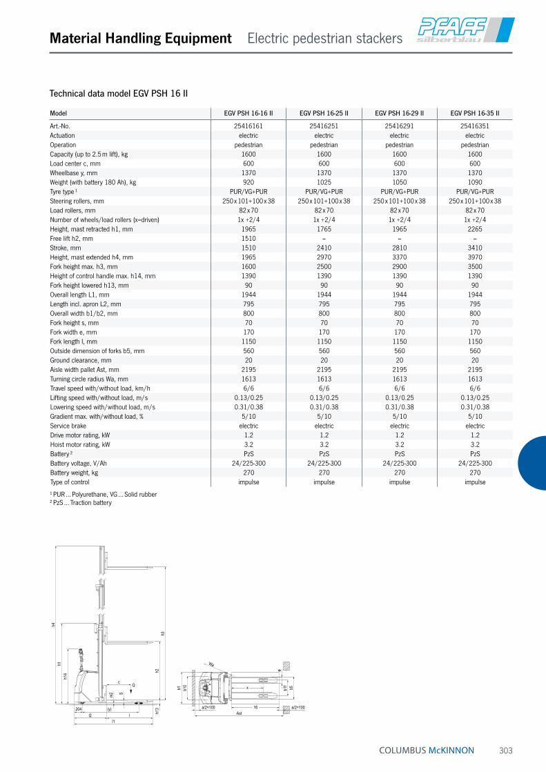
303
Material Handling Equipment Electric pedestrian stackers
Technical data model EGV PSH 16 II
Model EGV PSH 16-16 II EGV PSH 16-25 II EGV PSH 16-29 II EGV PSH 16-35 II
Art.-No. 25416161 25416251 25416291 25416351Actuation electric electric electric electricOperation pedestrian pedestrian pedestrian pedestrianCapacity (up to 2.5 m lift), kg 1600 1600 1600 1600Load center c, mm 600 600 600 600Wheelbase y, mm 1370 1370 1370 1370Weight (with battery 180 Ah), kg 920 1025 1050 1090Tyre type ¹ PUR/VG+PUR PUR/VG+PUR PUR/VG+PUR PUR/VG+PURSteering rollers, mm 250 x 101+100 x 38 250 x 101+100 x 38 250 x 101+100 x 38 250 x 101+100 x 38Load rollers, mm 82 x 70 82 x 70 82 x 70 82 x 70Number of wheels/load rollers (x=driven) 1x +2/4 1x +2/4 1x +2/4 1x +2/4Height, mast retracted h1, mm 1965 1765 1965 2265Free lift h2, mm 1510 – – –Stroke, mm 1510 2410 2810 3410Height, mast extended h4, mm 1965 2970 3370 3970Fork height max. h3, mm 1600 2500 2900 3500Height of control handle max. h14, mm 1390 1390 1390 1390Fork height lowered h13, mm 90 90 90 90Overall length L1, mm 1944 1944 1944 1944Length incl. apron L2, mm 795 795 795 795Overall width b1/b2, mm 800 800 800 800Fork height s, mm 70 70 70 70Fork width e, mm 170 170 170 170Fork length l, mm 1150 1150 1150 1150Outside dimension of forks b5, mm 560 560 560 560Ground clearance, mm 20 20 20 20Aisle width pallet Ast, mm 2195 2195 2195 2195Turning circle radius Wa, mm 1613 1613 1613 1613Travel speed with/without load, km/h 6/6 6/6 6/6 6/6Lifting speed with/without load, m/s 0.13/0.25 0.13/0.25 0.13/0.25 0.13/0.25Lowering speed with/without load, m/s 0.31/0.38 0.31/0.38 0.31/0.38 0.31/0.38Gradient max. with/without load, % 5/10 5/10 5/10 5/10Service brake electric electric electric electricDrive motor rating, kW 1.2 1.2 1.2 1.2Hoist motor rating, kW 3.2 3.2 3.2 3.2Battery ² PzS PzS PzS PzSBattery voltage, V/Ah 24/225-300 24/225-300 24/225-300 24/225-300Battery weight, kg 270 270 270 270Type of control impulse impulse impulse impulse
¹ PUR … Polyurethane, VG … Solid rubber ² PzS … Traction battery
204 (y)
l1l2 l
cQ
h14 h2
h13
h4h1
h3
S
m2
x
Wa
b11
b5b1
e
b10
16Ast
a/2=100 a/2=100

304
Material Handling Equipment Electric pedestrian stackers
Electric pedestrian stacker model EGV PSL 1016 II Capacity 1000 kg fork height max. 1600 mmThe revised edition of the model EGV PSL 1016 II is the ideal solution for indoor transportation and of palletized goods within a warehouse environment for short haul and medium work load applications.
Features• The slim single mast and the laterally, ergonomic tiller
ensure a free view onto the goods as in front of the stacker.
• The fork thickness of 60 mm enables an easier en-trance inside pallets, while working in elevation.
• Easy maintenance – the convenient access opening at the bottom of the forklift allows an immediate disas-sembly of motor wheel, portal and tiller without lifting the machine.
• The reduced overall width of 794 mm improves the handling of goods in narrow spaces and corridors.
• Ultra-slow drive function enables exact driving in very tight spaces.
New!
INFO
Specifications see page 299.

305
Material Handling Equipment Elevating platform, mobile
Platformlift model PRAKTIKUS HPCapacity 400 kg, platform height max. 1200 mmFor the occasional, internal application of lifting and transporting of goods.
Features• Easy lifting by tiltable foot pedal.
• Lowering speed can be finely metered for sensitive lowering of the load.
• Ergonomic handlebar for easy operation.
• Steering roller with brake for safe parking of the hand stacker.
• Robust construction with chrome plated chassis, hard chromium plated piston and pressure relief valve.
• Covered chain deflection for increased safety.
Technical data model PRAKTIKUS HP
Model HP 0485 HP 0412
Art.-No. 040008778 040008779Capacity, kg 400 400Platform height max. h3 + h13, mm 850 1200Platform height min. h13, mm 200 200Free lift h2, mm 650 1000Stroke h3, mm 650 1000Lifting height per pump stroke, mm 23 23Overall height h1, mm 960 1310Overall length L1, mm 1037 1037Overall width b1, mm 590 590Platform length P1, mm 650 650Platform width P2, mm 550 550Tyre type ¹ VG/VG VG/VGSteering rollers, mm 150 x 45 150 x 45Load rollers, mm 150 x 45 150 x 45Number of wheels/load rollers 2/2 2/2Ground clearance m1, mm 50 50Wheelbase y, mm 785 785Weight, kg 66 71
¹ VG … Solid rubber
Lowering valve
Pump lever

306
Material Handling Equipment Scissor elevating platform, mobile
Scissor elevating platform, mobile with single scissor model HXCapacity 150 - 750 kg, platform height max. 1000 mmFor the independant lifting and supplying of loads within a warehouse environment.
Features• Hydraulic lifting of the load with foot pedal.
• Lowering speed can be finely metered for sensitive lowering of the load.
• Ergonomic handlebar for easy operation, tiltable for model HX 150.
• Steering roller with brake for safe parking of the hand stacker.
• Robust construction with hard chromium plated piston and pressure relief valve.
Technical data model HX
Model HX 150 HX 300 HX 500 HX 750
Art.-No. 034600020 040057357 040057358 040057360Capacity, kg 150 300 500 750Platform height max. h3 + h13, mm 720 880 880 1000Platform height min. h13, mm 220 285 285 420Stroke h3, mm 500 595 595 580Lifting height per pump stroke, mm 27 31 31 15Overall height h1, mm 960 984 984 990Overall length L1, mm 908 1093 1093 1330Overall width b1, mm 450 500 500 600Platform length P1, mm 700 850 850 1000Platform width P2, mm 450 500 500 510Tyre type ¹ PUR/PUR PUR/PUR PUR/PUR PUR/PURRollers, mm 100 x 36 128 x 40 128 x 40 147 x 50Number of wheels/load rollers 2/2 2/2 2/2 2/2Weight, kg 49 78 82 120
¹ PUR … Polyurethane
Model HX 150
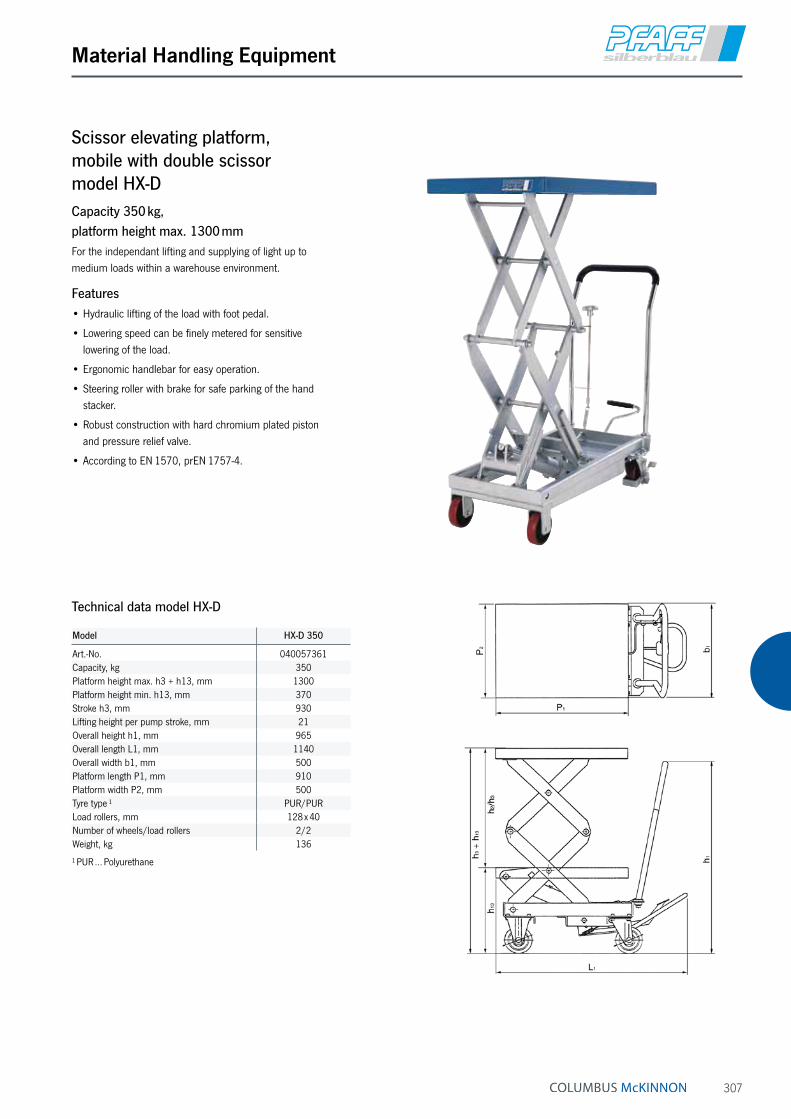
307
Material Handling Equipment
Scissor elevating platform, mobile with double scissor model HX-DCapacity 350 kg, platform height max. 1300 mmFor the independant lifting and supplying of light up to medium loads within a warehouse environment.
Features• Hydraulic lifting of the load with foot pedal.
• Lowering speed can be finely metered for sensitive lowering of the load.
• Ergonomic handlebar for easy operation.
• Steering roller with brake for safe parking of the hand stacker.
• Robust construction with hard chromium plated piston and pressure relief valve.
• According to EN 1570, prEN 1757-4.
Technical data model HX-D
Model HX-D 350
Art.-No. 040057361Capacity, kg 350Platform height max. h3 + h13, mm 1300Platform height min. h13, mm 370Stroke h3, mm 930Lifting height per pump stroke, mm 21Overall height h1, mm 965Overall length L1, mm 1140Overall width b1, mm 500Platform length P1, mm 910Platform width P2, mm 500Tyre type ¹ PUR/PURLoad rollers, mm 128 x 40Number of wheels/load rollers 2/2Weight, kg 136
¹ PUR … Polyurethane

308
Material Handling Equipment Scissor elevating platform, mobile
Scissor elevating platform, mobile with single scissor and- manual hydraulic model HF…SMCapacity 150 - 1250 kg, platform height max. 1050 mm
- electric hydraulic system model HF…SECapacity 300 - 1250 kg, platform height max. 1050 mmFor lifting and supplying goods independent of the location.
Features• Manual hydraulic system with pedal or electric hydrau-
lic system with dead man function – a main current connection is not required.
• High safety due to pressure relief and lowering valve.
• Robust single scissor construction, above 300 kg with solid steer scissor.
• Pivoting platform with mechanic adjustment for safe maintenance work.
• Compact design with low OAH.
• Steering and fixed rollers with service-free roller bear-ings. One steer roller can be locked in position for parking.
• According to EN 1570 and machinery directive 2006/42/EG.
Scope of delivery• Models with electric-hydraulic pump are supplied
complete with battery and charger.

309
Material Handling Equipment
Model HF 015-078 SM HF 030-084 SM HF 050-090 SM HF 080-105 SM HF 100-105 SM HF 125-105 SM
Art.-No. 24501078 24503084 24505090 24508105 24510105 24512105Capacity, kg 150 300 500 800 1000 1250Platform height max. h2, mm 780 840 900 1050 1050 1050Platform height min. h1, mm 255 335 340 360 360 360Stroke h3, mm 525 505 560 690 690 690Overall length L1, mm 990 1050 1320 1650 2350 1650Overall width b1, mm 450 500 610 860 1000 860Platform length l, mm 760 840 1030 1350 2000 1350Platform width b1, mm 450 500 610 840 1000 840Tyre type ¹ VG PUR PUR PA PA PAService brake manual manual manual manual manual manualNumber of strokes for max. lift 14 18 29 40 80 80Weight (with battery and battery charger), kg 41 83 109 222 350 230
¹ PA … Polyamide, PUR … Polyurethane, VG … Solid rubber
Technical data model HF/SM
Model HF 030-084 SE HF 050-090 SE HF 080-105 SE HF 100-105 SE HF 125-105 SE
Art.-No. 24603084 24605090 24608105 24610105 24612105Capacity, kg 300 500 800 1000 1250Platform height max. h2, mm 840 900 1050 1050 1050Platform height min. h1, mm 335 340 360 360 360Stroke h3, mm 505 560 690 690 690Overall length L1, mm 1130 1330 1650 2350 1650Overall width b1, mm 500 610 860 1000 860Platform length l, mm 840 1030 1350 2000 1350Platform width b1, mm 500 610 840 1000 840Tyre type ¹ PUR PUR PA PA PAService brake manual manual manual manual manualNumber of strokes for max. lift electric electric electric electric electricWeight (with battery and battery charger), kg 120 158 270 397 278
¹ PA … Polyamide, PUR … Polyurethane
Technical data model HF/SE
h 1h 3
h 2
Q
I
I1
b 1

310
Material Handling Equipment Scissor elevating platform, mobile
Scissor elevating platform, mobile with double vertical scissor and- manual hydraulic model HF…DM
- electric hydraulic system model HF…DECapacity 125 - 800 kg, platform height max. 1900 mmFor lifting and supplying goods independent of the location.
Features• Manual hydraulic system with pedal or electric hydrau-
lic system with dead man function – a main current connection is not required.
• High safety due to pressure relief and lowering valve.
• Robust single scissor construction, above 300 kg with solid steer scissor.
• Pivoting platform with mechanic adjustment for safe maintenance work.
• Compact design with low OAH.
• Steering and fixed rollers with service-free roller bear-ings. One steer roller can be locked in position for parking.
• According to EN 1570 and machinery directive 2006/42/EG.
Scope of delivery• Models with electric-hydraulic pump are supplied
complete with battery and charger.

311
Material Handling Equipment
Technical data model HF/DM
Model HF 012-142 DM HF 045-155 DM HF 050-190 DM HF 080-190 DM
Art.-No. 24701142 24704155 24705190 24708190Capacity, kg 125 450 500 800Platform height max. h2, mm 1420 1550 1900 1900Platform height min. h1, mm 430 295 490 490Stroke h3, mm 990 1255 1410 1410Overall length L1, mm 1090 1350 1650 1650Overall width b1, mm 500 665 860 860Platform length l, mm 840 1030 1350 1350Platform width b1, mm 500 610 840 840Tyre type ¹ PUR PUR PA PAService brake manual manual manual manualNumber of strokes for max. lift 19 71 80 160Weight (with battery and battery charger), kg 100 143 306 315
¹ PA … Polyamide, PUR … Polyurethane
Technical data model HF/DE
Model HF 012-142 DE HF 045-155 DE HF 050-190 DE HF 080-190 DE
Art.-No. 24801142 24804155 24805190 24808190Capacity, kg 125 450 500 800Platform height max. h2, mm 1420 1550 1900 1900Platform height min. h1, mm 430 295 490 490Stroke h3, mm 990 1255 1410 1410Overall length L1, mm 1090 1350 1650 1650Overall width b1, mm 500 665 860 860Platform length l, mm 840 1030 1350 1350Platform width b1, mm 500 610 840 840Tyre type ¹ PUR PUR PA PAService brake manual manual manual manualNumber of strokes for max. lift electric electric electric electricWeight (with battery and battery charger), kg 147 190 352 363
¹ PA … Polyamide, PUR … Polyurethane
Q
h 1
h 2
I
I1
b 1

312
Mobile elevating work bench model HWCapacity 1000 kg, platform height max. 1270 mmFor lifting and transporting of heavy loads in manufactur-ing and assembly processes.
Features• Hydraulic lifting and lowering of the load with
foot pedal.
• Lowering speed can be finely metered for sensitive lowering of the load.
• Ergonomic handlebar for easy operation.
• Steering roller with brake for safe parking of the hand stacker.
• Robust construction with hard chromium plated piston and pressure relief valve.
Material Handling Equipment Scissor elevating platform, mobile
Model HW 10
Art.-No. 040007617Capacity, kg 1000Platform height max. h3 + h13, mm 1270Platform height min. h13, mm 600Overall height h1, mm 950Free lift h2, mm 670Stroke h3, mm 670Overall length L1, mm 947Platform length P1, mm 750Platform width P2, mm 600Overall width b1, mm 600Tyre type ¹ PA/PASteering rollers, mm 175 x 50Load rollers, mm 175 x 50Number of wheels/load rollers 2/2Wheelbase y, mm 772Weight, kg 160Ground clearance m1, mm 25Lifting height per pump stroke, mm 9
¹ PA … Polyamide
Technical data model HW 10
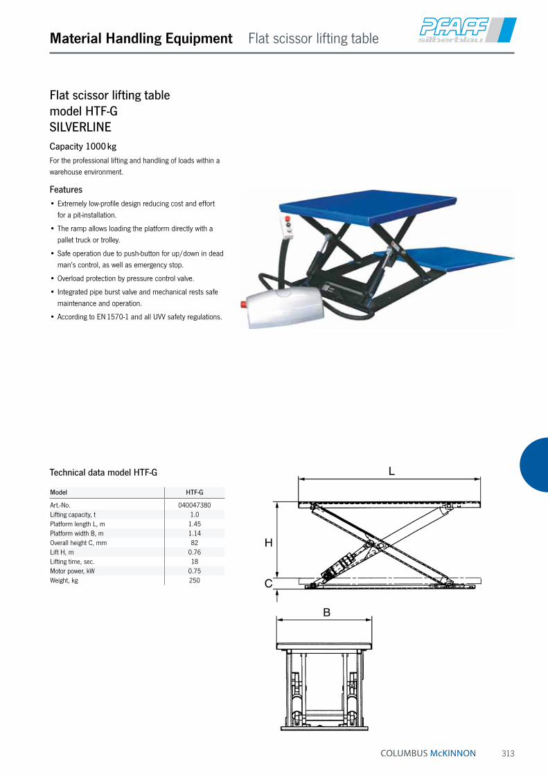
313
Material Handling Equipment Flat scissor lifting table
Flat scissor lifting table model HTF-G SILVERLINECapacity 1000 kgFor the professional lifting and handling of loads within a warehouse environment.
Features• Extremely low-profile design reducing cost and effort
for a pit-installation.
• The ramp allows loading the platform directly with a pallet truck or trolley.
• Safe operation due to push-button for up/down in dead man’s control, as well as emergency stop.
• Overload protection by pressure control valve.
• Integrated pipe burst valve and mechanical rests safe maintenance and operation.
• According to EN 1570-1 and all UVV safety regulations.
Model HTF-G
Art.-No. 040047380Lifting capacity, t 1.0Platform length L, m 1.45Platform width B, m 1.14Overall height C, mm 82Lift H, m 0.76Lifting time, sec. 18Motor power, kW 0.75Weight, kg 250
Technical data model HTF-G

314
Material Handling Equipment Flat scissor lifting table
Flat scissor lifting table model HTF-U SILVERLINECapacity 1000 kgFor the professional lifting and handling of loads within a warehouse environment.
Features• Extremely low-profile design lowering the cost and
effort for a pit installation.
• U-design for direct access of industrial trucks.
• Safe operation due to push-button for up/down in dead man’s control, as well as emergency stop.
• Overload protection by pressure control valve.
• Integrated pipe burst valve and mechanical rests safe maintenance and operation.
• According to EN 1570-1 and all UVV safety regulations.
Model HTF-U
Art.-No. 040047381Lifting capacity, t 1.0Platform B2, mm 585Platform length L, m 1.45Platform width B, m 1.14Overall height C, mm 80Lift H, m 0.76Lifting time, sec. 18Motor, kW 0.75Weight, kg 235
Technical data model HTF-U

315
Material Handling Equipment Handling table
Handling table model HTH-E SILVERLINECapacity 500 - 3000 kgFor the professional lifting and handling of heavy loads and palletized goods at workplaces
Features• Smooth hydraulic ram action of working height for
ergonomic working conditions.
• Safe operation due to push-button for up/down in dead man’s control, as well as emergency stop.
• Overload protection by pressure control valve.
• Integrated pipe burst valve and mechanical rests safe maintenance and operation.
• According to EN 1570-1 and all UVV safety regulations.
Model HTH-E HTH-E HTH-E HTH-E
Art.-No. 040049470 040049471 040049472 040049473Lifting capacity, t 0.5 1.0 2.0 3.0Platform length L, m 1.3 1.3 1.3 1.3Platform width B, m 0.8 0.8 0.8 0.8Overall height C, mm 190 190 190 220Lift H, m 0.82 0.82 0.82 0.80Lifting time, sec. 15.0 25 40 26Motor, kW 0.75 0.75 0.75 1.50Weight, kg 160 220 280 320
Technical data model HTH-E SILVERLINE

316
Load Moving Systems
Steerman® Heavy load moving systems model SX and model SCapacity 10 - 100 tThese universal heavy load moving systems have been designed for the safe and cost saving transport of loads up to 100 tons. Individual configuration of steering and rear skates also allows higher capacities. Transport of heavy loads (e.g. machines, construction parts, steel structures) is normally made with a stable three point loading system.
Transport of extremely bulky or heavy loads with an unfavourable center of balance, may also be executed with a four point loading system. The robust towing bar in connection with the unique turntable on large diameter thrust bearings allows effortless steering of the load. The rear skates are aligned parallel by means of a tie rod and kept in position, thus ensuring time saving and smooth transportation of the load.
The skates are powder coated and all connecting ele-ments corrosion-resistant. Highest safety requirements have been considered.
Chassis from ductile graphite iron
Ball bearing for turning plate
Rollers with ball bearing
Model SX-10

317
Load Moving Systems
Features• The modular design ensures an extremely simple
operation and simultaneously offers a wider range of combinations.
• The construction of the load moving systems is extremely robust and resistant to distortion.
• The skates are smooth-running and provide an incredibly low rolling resistance even with the heaviest loads.
• Twin rollers (instead of one wide roller) ensure low roll-ing resistance even at a narrow curve radius.
• The universal joint suspension of the roller groups contributes to a positive contact when travelling over uneven floors.
• The roller wheels are manufactured with abrasion-resistant, elastic polyamide. They are protected against breakage and have high chemical resistance.
• Each individual roller is made from high tensile material which ensures extremely quiet running.
• The rollers are suitable for all in-plant floors and will not damage normal floor covering.
• The load moving systems can be easily dismantled and facilitate transport even in small trucks.
• The load moving systems have been developed for professional applications and are practically maintenance-free.
• All rollers are provided with two encapsulated, lifetime lubricated ball bearings.
• The front steering skate is equipped with an amply dimensioned axial ball bearing underneath the turntable.
• From SX-10 the front and rear skates are available individually.
Technical data model SX and model S
Model EAN-No. 4025092*
Capacity
t
Overall height
mm
Number of rollers
Roller diameter
mm
Colour of rollers
Weight
kg
SX-10 *158503 10 102 16 82 black 54SX-20 *158541 20 102 32 82 black 76SX-30 *158589 30 110 48 82 black 136S-60 *161930 60 170 48 115 black 302S-100 *158664 100 210 48 150 black 525
Model S-60
Available in explosion proof version (see page 469).

318
Load Moving Systems
Load moving skates and systems with fixed wheels model LFCapacity 1 - 6 tThe components of the load moving skates can be universally combined and are ideal for the transport of medium heavy loads of all kinds. The components can be used individually or adapted to a load moving system. The units are maintenance-free.
Features• Solid forged steel construction.
• Anti-slip rubber lining.
• Abrasion-resistant nylon wheels.
• Models LF-2,5 and above are provided with two enclosed ball bearings per wheel.
Technical data model LF
Model EAN-No. 4025092*
Capacity
t
Wheels Number of rollers
Wheels diameter x width
mm
Dimensions L x W x H
mm
Weight
kg
LF-1 *163828 1.0 fixed 4 100 x 35 400 x 228 x 120 7.0LF-2 *163835 2.0 fixed 8 100 x 35 400 x 228 x 120 8.0LF-2,5 *163842 2.5 fixed 2 85 x 90 275 x 120 x 100 4.0LF-3 *163859 3.0 fixed 4 85 x 85 400 x 228 x 100 9.5LF-6 *163866 6.0 fixed 6 85 x 85 415 x 210 x 100 12.0
Model LF-1
Model LF-2,5 Model LF-6Model LF-3Model LF-2

319
Load Moving Systems
Load moving skates and systems with steerable wheels model LFLCapacity 1 tThe components of the load moving skates can be universally combined and are ideal for the transport of medium heavy loads of all kinds. The components can be used individually or adapted to a load moving system. The units are maintenance-free.
Features• Solid forged steel construction.
• Anti-slip rubber lining.
• Abrasion-resistant nylon wheels.
• Model LFL-1-2 uses two steerable and two fixed wheels.
• Model LFL-1-4 uses four steerable wheels.
Technical data model LFL
Model EAN-No. 4025092*
Capacity
t
Wheels Number of rollers
Swivel roller diameter x width
mm
Fixed roller diameter x width
mm
Dimensions L x W x H
mm
Weight
kg
LFL-1-2 *163873 1.0 2 x fixed, 2 x steerable 4 75 x 46 100 x 35 430 x 340 x 120 13.0LFL-1-4 *163880 1.0 4 x steerable 4 75 x 46 – 430 x 340 x 120 14.0
Model LFL-1-2
Model LFL-1-4

320
Load Moving Systems
Heavy load moving system model LXCapacity 6 t and 12 tThese three point loading systems comprise of a steerable front and a pair of adjustable rear skates.
The heavy load moving systems are supplied ready-to-use.
The steerable front skates (LX-6F and LX-12F) are provided with an appropriate towing bar. The rear skates (LX-12R) are identical in construction and are equipped with two adjustable tie rods.
The wheels are made of hardwearing nylon.
The front and rear skates can accept each 50 % of the total capacity.
Technical data model LX
Model EAN-No. 4025092*
Capacity
t
Number of wheels front skate
Number of wheels rear skate
Wheels diameter x width
mm
Load area front skate
mm
Load area rear skate
mm
Adjustment range
rear skatesmm
Height
mm
Weight
kg
LX-6 *163781 6.0 4 8 85 x 90 185 x 150 300 x 250 500 - 1400 115 45.0LX-12 *163798 12.0 8 8 85 x 90 400 x 220 300 x 250 500 - 1400 115 80.0
Model LX-12
Model LX-6

321
Load Moving Systems

322
Table of contents
Page Hydraulic cylinders, single-acting 328 - 337 346 - 349
Hydraulic cylinders, double-acting 338 - 345
Accessories for hydraulic cylinders 350 - 353
Hand pumps 700 bar 354 - 359
Hand pumps up to 2000 bar 360
Foot pump 700 bar 361
Electric & Pneumatic motor pumps 362 - 363
Electric hydraulic power packs 364 - 369
Valves & Accessories 370 - 383
Puller 384 - 389
Jacks 390 - 397
Hydraulic jacks & tools 398 - 399
Test rigs 400 - 401
Presses 402 - 404
Selection & Speed charts 405 - 409
INFO
Please note our user instructions at the beginning of each chapter.
Hydraulic jacks & tools
A characteristic of this “force-oriented“ hydraulic program is the operating pressure which can be as high as 700 bar. This guarantees a simple and safe generation of highest forces. In spite of this the units remain compact, portable and easy to operate. High-pressure hydraulic systems of this type are used in universal assembly and repair operations whereby their application in day-to-day operations is almost unlimited. The component program allows the individual configuration of simple and also complex system solutions.
They are used in the following main industrial areas:
Heavy industry, mining, shipbuilding, offshore, aviation in-dustries, power stations, steel construction, steel making and processing, building construction, bridge and tunnel construction, heavy steel and tank construction, metal processing workshops, and many more.

323
HYDRAULIC JACKS & TOOLS
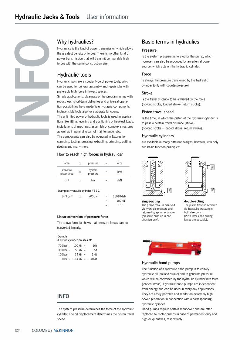
324
Hydraulic Jacks & Tools User information
Why hydraulics?Hydraulics is the kind of power transmission which allows the greatest density of forces. There is no other kind of power transmission that will transmit comparable high forces with the same construction size.
Hydraulic toolsHydraulic tools are a special type of power tools, which can be used for general assembly and repair jobs with preferably high force in lowest spaces. Simple applications, clearness of the program in line with robustness, short-term deliveries and universal opera-tion possibilities have made Yale hydraulic components indispensible tools also for elaborate functions. The unlimited power of hydraulic tools is used in applica-tions like lifting, levelling and positioning of heaviest loads, installations of machines, assembly of complex structures as well as in general repair of maintenance jobs. The components can also be operated in fixtures for clamping, testing, pressing, extracting, crimping, cutting, riveting and many more.
How to reach high forces in hydraulics?
area x pressure = force
effective piston area x system
pressure = force
cm² x bar = daN
Example: Hydraulic cylinder YS-10/
14.3 cm² x 700 bar = 10010 daN= 100 kN= 10 t
Linear conversion of pressure force
The above formula shows that pressure forces can be converted linearly.
Example:A 10 ton cylinder presses at:
700 bar - 100 kN = 10 t350 bar - 50 kN = 5 t100 bar - 14 kN = 1.4 t
1 bar - 0.14 kN = 0.014 t
Basic terms in hydraulicsPressureis the system pressure generated by the pump, which, however, can also be produced by an external power source, which acts on the hydraulic cylinder.
Forceis always the pressure transferred by the hydraulic cylinder (only with counterpressure).
Strokeis the travel distance to be achieved by the force (no-load stroke, loaded stroke, return stroke).
Piston travel speedIs the time, in which the piston of the hydraulic cylinder is to pass a certain travel distance (stroke) (no-load stroke + loaded stroke, return stroke).
Hydraulic cylindersare available in many different designs, however, with only two basic function principles:
single-actingThe piston travel is achieved via hydraulic pressure and returned by spring activation (pressure build-up in one direction only).
double-actingThe piston travel is achieved via hydraulic pressure in both directions. (Push forces and pulling forces are possible).
Hydraulic hand pumpsThe function of a hydraulic hand pump is to convey hydraulic oil (no-load stroke) and to generate pressure, which will be converted by the hydraulic cylinder into force (loaded stroke). Hydraulic hand pumps are independent from energy and can be used in every-day applications. They are easily portable and render an extremely high power generation in connection with a corresponding hydraulic cylinder. Hand pumps require certain manpower and are often replaced by motor pumps in case of permanent duty and high oil quantities, respectively.
INFO
INFO
The system pressure determines the force of the hydraulic cylinder. The oil displacement determines the piston travel speed.

325
Hydraulic Jacks & Tools User information
Hand pumps are distinguished by:
1. oil displacement volume (1st stage /2nd stage).
2. the function of the hydraulic cylinder: single-acting /double-acting.
Motor pumpstransmit an oil flow as soon as the pump unit is driven by the electric motor. Contrary to hand pumps, the oil flow is also available when the hydraulic cylinder is not activated (e.g. during work breaks).
Hydraulic valvesValves are used in hydraulics to control the oil flow (generated by either hand or motor pump) in terms of direction, pressure and oil volume.
Directional valvesare required to control the direction of the oil flow and thus the work motions of the connected hydraulic cylinder (advance – stop – retract). Depending on the type of pump and cylinder, 2-, 3- or 4-way valves may be employed.
3/3-way valves for single-acting cylinders
4/3-way valves for double-acting cylinders
Controls are available with either manual or electro- magnetic valves (the latter with remote cable control).
Pressure valvesare employed to limit the system pressure in a hydraulic system or within a part of the oil circuit. Pressure valves or pressure relief valves are also installed as safety devices in order to avoid excessive increase of the system pressure beyond a given value.
Shut-off and throttle valvesare used to easily shut-off hydraulic lines by hand. On account of their sensible control mode, these valves can also be applied to throttle an oil flow and thus to control the piston advance at both lifting or lowering of the load.
Safety check valvesare used for those applications where pressure drops must be avoided.
Pressure switchcan be set to any pressure value in order to switch on/off parts of the hydraulic circuit.
For your safetyHydraulic units are extremely robust and durable. Never-theless you should observe the following instructions for your own safety and to increase the life expectancy of the product:
• Never exceed the max. pressure (capacity) of the hydraulic units.
• Avoid eccentric loading of the piston.
• The load must always be positioned centric and parallel on the piston. Avoid point loading!
• Never pass under a raised load, if this is not supported additionally.
• Hydraulic units must be kept clear of heat (e.g. during welding).
• Protect hydraulic hoses against damage and strong kinks. Hydraulic hoses should lie freely in a wide curve. Avoid tensile load.
Eccentric loadingIn order to obtain a long life expectancy, hydraulic cylinders series YS, YLS, YFS, YCS, YCH, YH and YPL are manufactured from chromium-molybdenum steel, the cylinder housings and piston rods are hardened and tempered and provided with bronze guides. Generally, hydraulic cylinders should not be loaded eccen-trically, as this can lead to reduced lifetime. In practice, a lateral loading cannot be fully avoided. In this case the maximum system pressure and the stroke of the cylinder should only be used by 50 %. Ensure that the load always rests on the total area of the steel saddle and the piston, respectively. Also ensure that the entire bottom area of the hydraulic cylinder always stands on a level, sustain-able ground surface. This applies especially to flat cylinders!
RepairsRepair and maintenance should be performed by qualified personnel only. Make sure to use original spare parts only.
INFO

326
Hydraulic Jacks & Tools User information
Hydraulic cylinders with Yale Chro-Mo-DesignYale hydraulic tools are designed for professional opera-tion. A tool is only as good as its basic material. There-fore, our cylinders are manufactured from high quality chromium-molybdenum steel and are heat-treated.
Double bronze bearingsPractice has shown that hydraulic cylinders used as a tool in workshops or on construction sites are frequently subjected to eccentric loading. Yale hydraulic cylinders are provided with double bronze bearings on the plunger, which minimizes friction between plunger and body during lateral loading.
Hard chromium-plated pistonOffers excellent protection against mechanical damage and corrosion. Excellent sliding characteristics in conjunc-tion with the upper bronze bearing in the stop ring.
Metric mounting threads and standard partsTo facilitate the installation of hydraulic cylinders in jigs and fixtures and auxiliary structures. The metric standard throughout the entire series simplifies service operations and repairs. Cylinders carry the full load even under maximum operating pressure.
Stop ring carries full pressureAs a safety factor the stop ring on all Yale hydraulic cylin-ders carries the full load even under maximum operating pressure.
Delivered ready to useYale Hydraulic cylinders are delivered ready to use incl. female coupler half, hardened saddle and mounting threads; larger cylinders come with carrying handle or transportation lugs. This also applies to customised com-binations which are always supplied fully assembled.
Two bronze bearings minimize friction even in cases of eccentric loading
Hardened alloy steel saddle
Metric mounting threads in cylinder base, plunger and cylinder collar (depending on series)IN
FO

327
Hydraulic Jacks & Tools User information
Female coupler half CFY-1 (incl. dust cap)
Piston and ...
Hard chromium-plated plunger
Stop ring prevents over-stroking of the piston up to full operating pressure
Dirt wiper protects against dirt
... cylinder housing are made from chromium-molybdenum steel and are heat-treated.
INFO
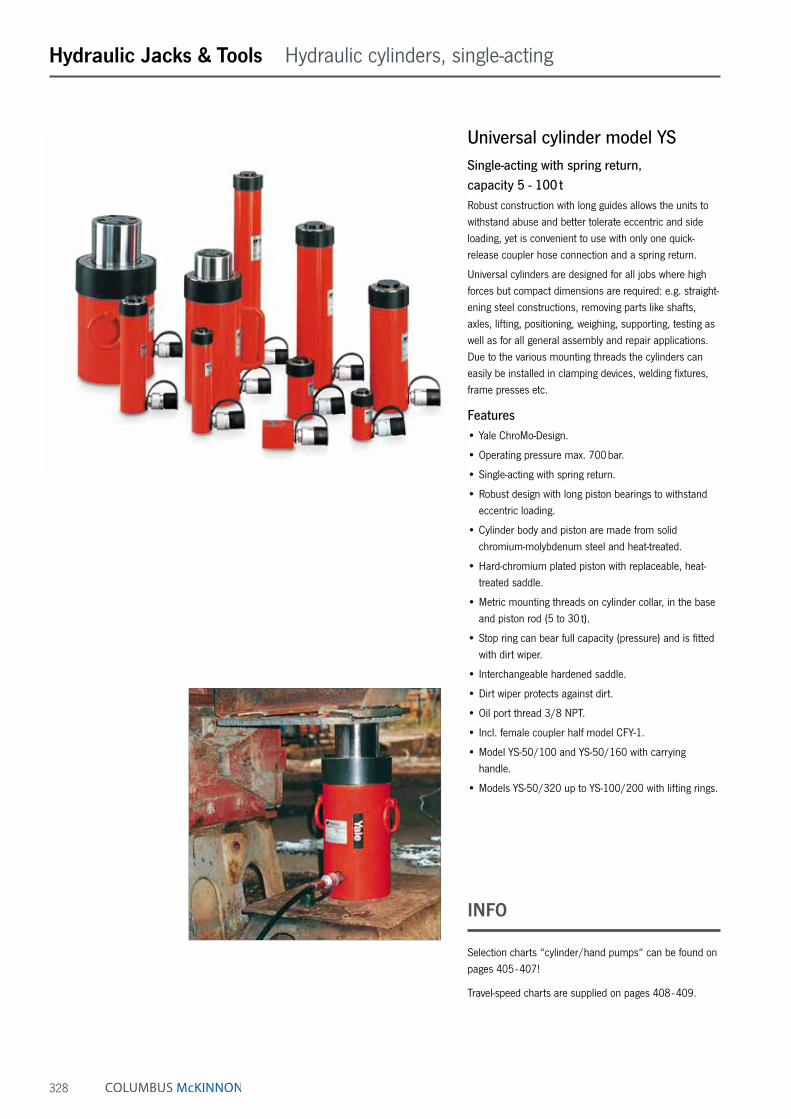
328
Hydraulic Jacks & Tools Hydraulic cylinders, single-acting
Universal cylinder model YSSingle-acting with spring return, capacity 5 - 100 tRobust construction with long guides allows the units to withstand abuse and better tolerate eccentric and side loading, yet is convenient to use with only one quick-release coupler hose connection and a spring return.
Universal cylinders are designed for all jobs where high forces but compact dimensions are required: e.g. straight-ening steel constructions, removing parts like shafts, axles, lifting, positioning, weighing, supporting, testing as well as for all general assembly and repair applications. Due to the various mounting threads the cylinders can easily be installed in clamping devices, welding fixtures, frame presses etc.
Features• Yale ChroMo-Design.
• Operating pressure max. 700 bar.
• Single-acting with spring return.
• Robust design with long piston bearings to withstand eccentric loading.
• Cylinder body and piston are made from solid chromium-molybdenum steel and heat-treated.
• Hard-chromium plated piston with replaceable, heat-treated saddle.
• Metric mounting threads on cylinder collar, in the base and piston rod (5 to 30 t).
• Stop ring can bear full capacity (pressure) and is fitted with dirt wiper.
• Interchangeable hardened saddle.
• Dirt wiper protects against dirt.
• Oil port thread 3/8 NPT.
• Incl. female coupler half model CFY-1.
• Model YS-50/100 and YS-50/160 with carrying handle.
• Models YS-50/320 up to YS-100/200 with lifting rings.
INFO
Selection charts “cylinder/hand pumps“ can be found on pages 405 - 407!
Travel-speed charts are supplied on pages 408 - 409.

329
Hydraulic Jacks & Tools Hydraulic cylinders, single-acting
Accessories for cylinders series YS like lifting claws, piston plates, extension tubes, support plates and threaded flanges are also available on request
Support plates are available as accessories
Threaded flanges are available as accessories
INFO
For accessories for cylinders series YS please see pages 350 - 352!
Technical data model YS
Cylinder size
t
Model EAN-No. 4025092*
Capacity
kN
Stroke
mm
Effective plunger area
cm²
Oil volume max.
cm³
Closed height
mm
Cylinder outside
diametermm
Weight
kg
5 YS-5/15 *150002 50 15 7.2 11 45 41 0.95 YS-5/25 *150019 50 25 7.2 18 97 42 1.05 YS-5/75 *150026 50 75 7.2 53 157 42 1.55 YS-5/127 *150033 50 127 7.2 90 214 42 2.05 YS-5/180 *150040 50 180 7.2 127 267 42 2.4
10 YS-10/25 *150057 100 25 14.3 37 90 57 1.610 YS-10/50 *150064 100 50 14.3 73 125 57 2.110 YS-10/100 *150071 100 100 14.3 146 178 57 2.810 YS-10/150 *150088 100 150 14.3 218 250 57 4.110 YS-10/200 *150095 100 200 14.3 291 300 57 4.710 YS-10/250 *150101 100 250 14.3 363 352 57 5.510 YS-10/300 *150118 100 300 14.3 436 407 57 6.3
15 YS-15/25 *150125 150 25 21.5 53 110 67 2.715 YS-15/50 *150132 150 50 21.5 106 140 67 3.315 YS-15/100 *150149 150 100 21.5 213 190 67 4.315 YS-15/150 *150156 150 150 21.5 319 260 67 5.815 YS-15/200 *150163 150 200 21.5 425 310 67 7.015 YS-15/250 *150170 150 250 21.5 531 365 67 8.015 YS-15/300 *150187 150 300 21.5 637 420 67 9.015 YS-15/350 *150194 150 350 21.5 744 472 67 10.0
23 YS-23/25 *150200 230 25 32.9 83 116 85 5.023 YS-23/50 *150217 230 50 32.9 166 150 85 6.023 YS-23/100 *150224 230 100 32.9 332 202 85 7.523 YS-23/160 *150231 230 160 32.9 531 277 85 10.023 YS-23/210 *150248 230 210 32.9 697 330 85 12.023 YS-23/250 *150255 230 250 32.9 830 376 85 13.523 YS-23/300 *150262 230 300 32.9 996 428 85 15.023 YS-23/345 *150279 230 345 32.9 1145 477 85 16.5
30 YS-30/125 *150286 300 125 42.9 552 245 102 13.030 YS-30/200 *150293 300 200 42.9 884 325 102 17.0
50 YS-50/50 *150309 500 50 71.5 355 170 125 15.050 YS-50/100 *150316 500 100 71.5 709 220 125 19.050 YS-50/160 *150323 500 160 71.5 1135 285 125 24.050 YS-50/320 *150330 500 320 71.5 2269 460 125 37.0
70 YS-70/150 *150347 700 150 100.0 1478 285 146 32.070 YS-70/330 *150354 700 330 100.0 3252 490 146 52.0
100 YS-100/100 *150378 1000 100 143.0 1432 275 180 43.0100 YS-100/200 *150361 1000 200 143.0 2863 375 180 64.0
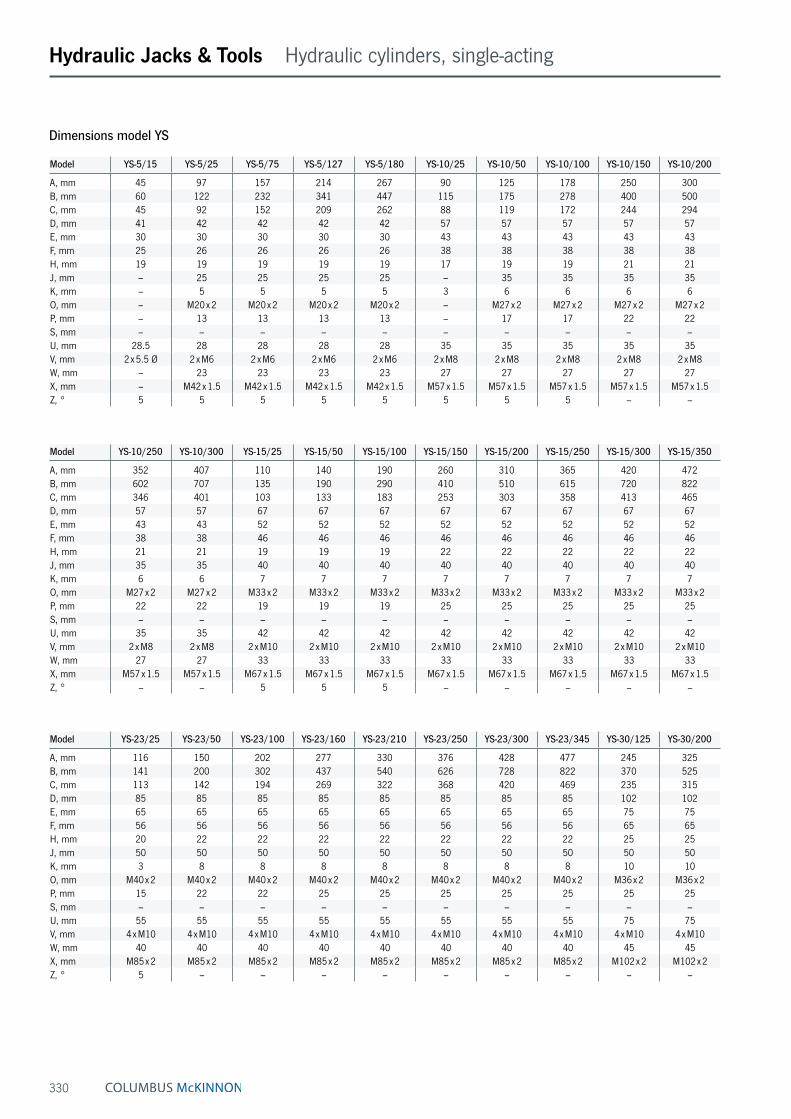
330
Hydraulic Jacks & Tools Hydraulic cylinders, single-acting
Dimensions model YS
Model YS-5/15 YS-5/25 YS-5/75 YS-5/127 YS-5/180 YS-10/25 YS-10/50 YS-10/100 YS-10/150 YS-10/200
A, mm 45 97 157 214 267 90 125 178 250 300B, mm 60 122 232 341 447 115 175 278 400 500C, mm 45 92 152 209 262 88 119 172 244 294D, mm 41 42 42 42 42 57 57 57 57 57E, mm 30 30 30 30 30 43 43 43 43 43F, mm 25 26 26 26 26 38 38 38 38 38H, mm 19 19 19 19 19 17 19 19 21 21J, mm – 25 25 25 25 – 35 35 35 35K, mm – 5 5 5 5 3 6 6 6 6O, mm – M20 x 2 M20 x 2 M20 x 2 M20 x 2 – M27 x 2 M27 x 2 M27 x 2 M27 x 2P, mm – 13 13 13 13 – 17 17 22 22S, mm – – – – – – – – – –U, mm 28.5 28 28 28 28 35 35 35 35 35V, mm 2 x 5.5 Ø 2 x M6 2 x M6 2 x M6 2 x M6 2 x M8 2 x M8 2 x M8 2 x M8 2 x M8W, mm – 23 23 23 23 27 27 27 27 27X, mm – M42 x 1.5 M42 x 1.5 M42 x 1.5 M42 x 1.5 M57 x 1.5 M57 x 1.5 M57 x 1.5 M57 x 1.5 M57 x 1.5Z, ° 5 5 5 5 5 5 5 5 – –
Model YS-10/250 YS-10/300 YS-15/25 YS-15/50 YS-15/100 YS-15/150 YS-15/200 YS-15/250 YS-15/300 YS-15/350
A, mm 352 407 110 140 190 260 310 365 420 472B, mm 602 707 135 190 290 410 510 615 720 822C, mm 346 401 103 133 183 253 303 358 413 465D, mm 57 57 67 67 67 67 67 67 67 67E, mm 43 43 52 52 52 52 52 52 52 52F, mm 38 38 46 46 46 46 46 46 46 46H, mm 21 21 19 19 19 22 22 22 22 22J, mm 35 35 40 40 40 40 40 40 40 40K, mm 6 6 7 7 7 7 7 7 7 7O, mm M27 x 2 M27 x 2 M33 x 2 M33 x 2 M33 x 2 M33 x 2 M33 x 2 M33 x 2 M33 x 2 M33 x 2P, mm 22 22 19 19 19 25 25 25 25 25S, mm – – – – – – – – – –U, mm 35 35 42 42 42 42 42 42 42 42V, mm 2 x M8 2 x M8 2 x M10 2 x M10 2 x M10 2 x M10 2 x M10 2 x M10 2 x M10 2 x M10W, mm 27 27 33 33 33 33 33 33 33 33X, mm M57 x 1.5 M57 x 1.5 M67 x 1.5 M67 x 1.5 M67 x 1.5 M67 x 1.5 M67 x 1.5 M67 x 1.5 M67 x 1.5 M67 x 1.5Z, ° – – 5 5 5 – – – – –
Model YS-23/25 YS-23/50 YS-23/100 YS-23/160 YS-23/210 YS-23/250 YS-23/300 YS-23/345 YS-30/125 YS-30/200
A, mm 116 150 202 277 330 376 428 477 245 325B, mm 141 200 302 437 540 626 728 822 370 525C, mm 113 142 194 269 322 368 420 469 235 315D, mm 85 85 85 85 85 85 85 85 102 102E, mm 65 65 65 65 65 65 65 65 75 75F, mm 56 56 56 56 56 56 56 56 65 65H, mm 20 22 22 22 22 22 22 22 25 25J, mm 50 50 50 50 50 50 50 50 50 50K, mm 3 8 8 8 8 8 8 8 10 10O, mm M40 x 2 M40 x 2 M40 x 2 M40 x 2 M40 x 2 M40 x 2 M40 x 2 M40 x 2 M36 x 2 M36 x 2P, mm 15 22 22 25 25 25 25 25 25 25S, mm – – – – – – – – – –U, mm 55 55 55 55 55 55 55 55 75 75V, mm 4 x M10 4 x M10 4 x M10 4 x M10 4 x M10 4 x M10 4 x M10 4 x M10 4 x M10 4 x M10W, mm 40 40 40 40 40 40 40 40 45 45X, mm M85 x 2 M85 x 2 M85 x 2 M85 x 2 M85 x 2 M85 x 2 M85 x 2 M85 x 2 M102 x 2 M102 x 2Z, ° 5 – – – – – – – – –

331
Hydraulic Jacks & Tools Hydraulic cylinders, single-acting
Dimensions model YS
Model YS-50/50 YS-50/100 YS-50/160 YS-50/320 YS-70/150 YS-70/330 YS-100/100 YS-100/200
A, mm 170 220 285 460 285 490 275 375B, mm 220 320 445 780 435 820 375 575C, mm 165 215 280 455 280 485 270 370D, mm 125 125 125 125 146 146 180 180E, mm 95 95 95 95 112 112 135 135F, mm 85 85 85 85 95 95 115 115H, mm 29 29 29 29 30 30 60 60J, mm 70 70 70 70 80 80 100 100K, mm 5 5 5 5 5 5 5 5O, mm 4 x M8 4 x M8 4 x M8 4 x M8 4 x M8 4 x M8 4 x M10 4 x M10P, mm – – – – – – – –S, mm – 51 51 24 24 24 24 24U, mm 95 95 95 95 110 110 145 145V, mm 4 x M12 4 x M12 4 x M12 4 x M12 4 x M12 4 x M12 4 x M12 4 x M12W, mm 50 50 50 50 60 60 70 70X, mm M125 x 2 M125 x 2 M125 x 2 M125 x 2 M146 x 3 M146 x 3 M180 x 3 M180 x 3Z, ° – – – – – – – –
Z 3/8-18 NPT
S
3/8-18 NPT
C A B120
ø14
H
U
WK
X
J
O
D
F
E
VV
C A B
WK
X
D
H
F
E
V U
P
3/8-18 NPT
V
J
O
Z
U
V
6521 44
25
DA
B
H
F
E
3/8-18 NPT
Model YS-5/15 Model YS-5/25 up to YS-30/200 Model YS-50/50 up to YS-100/200
INFO
Subject to changes.

332
Hydraulic Jacks & Tools Hydraulic cylinders, single-acting
Low-height and flat cylinders model YLS and model YFSSingle-acting with spring return, capacity max. 10 - 100 tLow-height cylinders are recommended for all lifting, pushing, levelling, pressing applications especially in tight working areas.
These very compact hydraulic cylinders are designed for lifting and positioning jobs as well as all general mainte-nance applications, where low height, portability and light weight are needed. These versatile cylinders are found in all industrial areas like steel mills, civil engineering, heavy construction industry, power plants, off-shore industries etc. Due to their short strokes flat cylinders should not be subjected to side loading.
Features• Yale ChroMo-Design.
• Operating pressure max. 700 bar.
• Single-acting with spring return.
• Low height for tight working areas.
• Cylinder body and piston are made from solid chromium-molybdenum steel and heat-treated.
• Stop ring can bear full capacity (pressure) and is fitted with dirt wiper.
• Oil port thread 3/8 NPT.
• Incl. female coupler half model CFY-1.
• Model YLS-100/55 is equipped with two lifting rings, model YFS-100/15 comes with a carrying handle.
YLS
YFS
INFO
Selection charts “cylinder/hand pumps“ can be found on pages 405 - 407!
Travel-speed charts are supplied on pages 408 - 409.

333
Hydraulic Jacks & Tools Hydraulic cylinders, single-acting
Technical data model YLS
Cylinder size
t
Model EAN-No. 4025092*
Capacity max.
kN
Stroke
mm
Effective plunger area
cm²
Oil volume max.
cm³
Closed height
mm
Cylinder outside
diametermm
Weight
kg
10 YLS-10/35 *150804 100 35 14.3 51 86 70 2.520 YLS-20/45 *150811 200 45 28.6 128 100 85 4.030 YLS-30/60 *150828 300 60 42.9 266 120 100 6.550 YLS-50/60 *150835 500 60 71.5 426 122 125 10.4100 YLS-100/55 *150842 1000 55 143.0 788 141 170 24.0
Technical data model YFS
Cylinder size
t
Model EAN-No. 4025092*
Capacity max.
kN
Stroke
mm
Effective plunger area
cm²
Oil volume max.
cm³
Closed height
mm
Cylinder outside
diametermm
Weight
kg
10 YFS-10/11 *150750 100 11 14.3 16 43 56 1.520 YFS-20/15 *150767 200 15 28.6 31 60 76 3.030 YFS-30/15 *150774 300 15 44.2 66 60 96 4.250 YFS-50/15 *150781 500 15 71.5 107 70 145 8.7100 YFS-100/15 *150798 1000 15 143.0 215 91 170 16.0
Dimensions model YLS and model YFS
Model YLS-10/35 YLS-20/45 YLS-30/60 YLS-50/60 YLS-100/55 YFS-10/11 YFS-20/15 YFS-30/15 YFS-50/15 YFS-100/15
A, mm 86 100 120 122 141 43 60 60 70 91B, mm 121 145 180 182 196 54 75 75 85 106D, mm 70 85 100 125 170 56 76 96 145 170D1, mm – – – – – 83 95 115 – –E, mm 43 60 75 95 135 43 60 75 95 135F, mm 38 50 57 75 120 38 50 57 75 120H, mm 16 17 19 19 26 16 19 19 19 22M, mm – – – – 148 – – – – 85Q, mm – – – – – 28 38 48 – –R, mm 54 54 54 54 54 54 54 54 54 54S, mm – – – – 25 – – – – 55Z, ° 10 10 5 5 – 10 5 5 5 5
Q
D
Ø 32
D1 R
0,5
B
A
F
E
H
Z
G
D R
0,5
B
A
F
E
H
Z
G
E
F
0,5
B
A
D R
H
S
M
G
YLS YFS

334
Hydraulic Jacks & Tools Hydraulic cylinders, single-acting
Pull cylinder model YPLSingle-acting with spring return, capacity max. 10 - 51 tPull cylinders are able to produce extremely high pulling forces and can be controlled precisely by the use of hand pumps or power packs. In neutral position pull cylinders are fully extended. As soon as the cylinders are pressu-rized the forged links are drawn together. A built-in return spring extends the piston again as soon as the pressure is released.
Shipbuilding, heavy-vessel construction, steel construc-tion, civil engineering as well as general repair and maintenance applications.
Features• Yale ChroMo-Design.
• Operating pressure max. 700 bar.
• Single-acting with spring return.
• Can be operated in all positions (except model YPPS).
• Cylinder body and piston are made from solid chromium-molybdenum steel and heat-treated.
• Hard-chromium plated piston with replaceable, heat-treated saddle.
• Stop ring can bear full capacity (pressure) and is fitted with dirt wiper.
• Forged, replaceable links.
• With carrying handle and piston protection cover.
• Oil port thread 3/8 NPT.
• Incl. female coupler half model CFY-1.
• The pull cylinder model YPPS-10/150 is equipped with an integrated hand pump similar to model HPS-2/0,7 A.
INFO
Selection charts “cylinder/hand pumps“ can be found on pages 405 - 407!
Travel-speed charts are supplied on pages 408 - 409.

335
Hydraulic Jacks & Tools Hydraulic cylinders, single-acting
Technical data model YPL
Cylinder size
t
Model EAN-No. 4025092*
Capacity max.
kN
Stroke
mm
Effective plunger area
cm²
Oil volume max.
cm³
Length between
linksmm
Weight
kg
10 YPL-10/150 *152822 100 150 14.2 213 750 920 YPL-20/150 *152839 200 150 30.6 459 795 2230 YPL-30/150 *152846 300 150 42.6 639 875 2951 YPL-51/150 *157858 510 150 74.6 1120 955 5910 YPPS-10/150 *161909 100 150 14.2 213 750 19
Dimensions model YPL
Model YPL-10/150 YPL-20/150 YPL-30/150 YPL-51/150 YPPS-10/150
A, mm 749 795 875 955 749B, mm 78 95 120 150 78C, mm 32 35 56 70 32D, mm 68 105 121 156 68E, mm 120 120 150 150 120G, mm 23 30 32 40 23H, mm M24 x 1.5 M45 x 2 M50 x 2 M60 x 2 M24 x 1.5
A
D
3/8-18 NPT
C
E
B
G
H

336
Hydraulic Jacks & Tools Hydraulic cylinders, single-acting
Hollow cylinders model YCSSingle-acting with spring return, capacity 12 - 93 tDue to the centre hole design a threaded rod can be placed through the hollow cylinders so that extremely high pulling forces can be achieved.
Hollow cylinders are used as the power component within hydraulic puller sets, for prestressing anker bolts, remov-ing axles, shafts, bushings, extracting tubes, as well as for heavy-duty pulling applications.
Features• Yale ChroMo-Design.
• Operating pressure max. 700 bar.
• Single-acting with spring return.
• With large centre hole diameter.
• Cylinder body and piston are made from solid chromium-molybdenum steel and heat-treated.
• Hard-chromium plated piston with replaceable, heat-treated saddle.
• Metric mounting threads at cylinder body and inside of piston.
• Stop ring prevents overtravel of the piston up to full operating pressure.
• Interchangeable hardened saddle.
• With inner and outer dirt wipers.
• Oil port thread 3/8 NPT.
• Incl. female coupler half model CFY-1.
• From model YCS-21/150 with carrying handle.
• From model YCS-57/70 with two lifting rings.
Function principal of the hollow cylindersIn connection with threaded rods hollow cylinders can pro-duce extremely high forces which are helpful for various repair or assembly applications like removing press-fitted parts, prestressing anchors etc. In addition, hollow cylinders are used as power source in puller sets and test rigs. By the use of long threaded rods and by readjusting the nut larger distances can be pulled even when using short cylinder strokes.
INFO
Selection charts “cylinder/hand pumps“ can be found on pages 405 - 407!
Travel-speed charts are supplied on pages 408 - 409.

337
Hydraulic Jacks & Tools Hydraulic cylinders, single-acting
Technical data model YCS
Cylinder size
t
Model EAN-No. 4025092*
Capacity
kN
Stroke
mm
Effective plunger area
cm²
Oil volume max.
cm³
Closed height
mm
Centre hole
diametermm
Cylinder outside
diametermm
Weight
kg
12 YCS-12/40 *150873 120 40 17.2 71 142 20 70 3.512 YCS-12/75 *150880 120 75 17.2 132 195 20 70 4.521 YCS-21/50 *150897 214 50 30.5 153 173 27 100 8.521 YCS-21/150 *150903 214 150 30.5 458 335 27 100 15.033 YCS-33/60 *150910 335 60 47.9 287 193 33 114 12.033 YCS-33/150 *150927 335 150 47.9 716 343 33 114 21.057 YCS-57/70 *150934 567 70 81.0 562 242 42 150 25.062 YCS-62/150 *150941 618 150 88.3 1330 335 55 163 38.093 YCS-93/75 *150958 930 75 133 990 280 80 214 55.0
Dimensions model YCS
Model YCS-12/40 YCS-12/75 YCS-21/50 YCS-21/150 YCS-33/60 YCS-33/150 YCS-57/70 YCS-62/150 YCS-93/75
A, mm 135 188 163 325 183 333 230 323 265B, mm 175 263 213 475 243 483 300 473 340C, mm 20 20 27 27 33 33 42 55 80D, mm 70 70 100 100 114 114 150 163 214E, mm 55 55 73 73 90 90 118 130 170F, mm 40 40 53 53 65 65 90 100 136J, mm 38 38 50 50 62 62 85 96 132K, mm 3 3 3 3 3 3 3 3 5M, mm – – – 120 – 120 – – –O, mm M30 x 1.5 M30 x 1.5 M40 x 1.5 M40 x 1.5 M48 x 1.5 M48 x 1.5 M65 x 2 M78 x 2 M115 x 2P, mm 20 20 25 25 30 30 35 40 45R, mm 4 4 5 5 5 5 5 5 –S, mm – – – 51 – 51 24 24 24T, mm – – – – – – 155 200 170U, mm 58 58 82 82 92 92 120 135 180V, mm 2 x M8 2 x M8 2 x M10 2 x M10 4 x M10 4 x M10 4 x M12 4 x M12 4 x M16W, mm 30 30 35 35 40 40 50 60 –X, mm M70 x 2 M70 x 2 M100 x 2 M100 x 2 M110 x 2 M110 x 2 M150 x 3 M160 x 3 –Y, mm 7 7 10 10 10 10 12 12 15
VV
NPT
3/8
UD
T
A
B
NPT 3/8
J
K
Y
X
R
WM
S
F
E
O
P
VV
NPT
3/8
UD
T
A
B
J
K
Y
X
R
WM
S
F
E
O
P
C C
C C

338
Hydraulic Jacks & Tools Hydraulic cylinders, double-acting
Hollow cylinders model YCHDouble-acting with hydraulic return, capacity 33 - 140 tBasically, the applications are the same as for the single-acting hollow cylinders shown on the opposite page, but for this model range the return of the piston is done hydraulically by means of the second oil port. These double-acting hollow cylinders are used when the piston needs to be retracted quickly e.g. with high-cycle pulling applications.
Features• Yale ChroMo-Design.
• Operating pressure max. 700 bar.
• Double-acting with hydraulic return.
• With large centre hole diameter.
• Cylinder body and piston are made from solid chromium-molybdenum steel and heat-treated.
• Hard-chromium plated piston with replaceable, heat-treated saddle.
• Metric mounting threads at cylinder body and inside of piston.
• Stop ring prevents overtravel of the piston up to full operating pressure.
• Interchangeable hardened saddle.
• With inner and outer dirt wipers.
• Oil port thread 3/8 NPT.
• Incl. 2 female coupler halves model CFY-1.
• All cylinders with carrying handle, from model YCH-62/250 with 2 lifting rings.
INFO
On request we supply special hollow cylinders with pulling capacities up to 600 tons.
Selection charts “cylinder/hand pumps“ can be found on pages 405 - 407!
Travel-speed charts are supplied on pages 408 - 409.

339
Hydraulic Jacks & Tools Hydraulic cylinders, double-acting
Technical data model YCH
Cylinder size
t
Model EAN-No. 4025092*
Capacity push
kN
Capacity pull
kN
Stroke
mm
Effective plunger area
cm²
Oil volume max.
cm³
Closed height
mm
Centre hole
diameter
mm
Cylinder outside
diameter
mm
Weight
kg
33 YCH-33/150 *150965 335 180 150 47.9 716 310 33 114 1933 YCH-33/250 *150972 335 180 250 47.9 1200 415 33 114 2562 YCH-62/250 *150989 618 300 250 88.3 2220 452 55 163 5593 YCH-93/250 *150996 930 450 250 133.0 3320 465 55 193 82100 YCH-100/40 *151009 1000 500 40 143.0 578 190 55 200 38140 YCH-140/200 *151016 1400 700 200 200.2 4080 383 80 253 115
For double-acting hollow cylinders the “capacity push“ is equivalent to the max. pulling force achieved with tensioning anchor or threaded spindle.
Dimensions model YCH
Model YCH-33/150 YCH-33/250 YCH-62/250 YCH-93/250 YCH-100/40 YCH-140/200
A, mm 300 405 440 450 175 365B, mm 450 655 690 700 215 565C, mm 33 33 55 55 55 80D, mm 114 114 163 193 200 253E, mm 90 90 130 150 155 195F, mm 67 67 105 120 125 160J, mm 62 62 96 110 110 145K, mm 3 3 5 5 5 5M, mm 120 120 – – – –O, mm M48 x 1.5 M48 x 1.5 M78 x 2 M85 x 2 M85 x 2 M115 x 2P, mm 30 30 40 45 45 50R, mm 5 5 5 5 – –S, mm 51 51 24 30 24 30T, mm – – 290 290 115 240U, mm 92 92 135 160 165 210V, mm 4 x M10 4 x M10 4 x M12 4 x M16 4 x M16 4 x M16W, mm 40 40 50 65 – –X, mm M110 x 2 M110 x 2 M160 x 3 M190 x 3 – –Y, mm 10 10 12 15 15 18
VV
NPT
3/8
UD
T
A
B
NPT 3/8
J
K
Y
X
R
WM
S
F
E
O
P
VV
NPT
3/8
UD
T
A
B
J
K
Y
X
R
WM
S
F
E
O
P
C C
C C

340
Hydraulic Jacks & Tools Hydraulic cylinders, double-acting
Universal cylinders model YHDouble-acting with hydraulic return, capacity 5 - 200 tThese extremely robust double-acting cylinders are especially designed for universal heavy-duty lifting and positioning applications as well as for industrial produc-tion and assembly jobs. The cylinders offer high pushing and pulling forces. The double-acting design assures a high piston retraction speed.
Major areas of application are bridge building and civil engineering, off-shore, ship building, etc. They can also be used as power source in frame presses, stamping fixtures and other industrial uses where high pushing and pulling forces are required.
Features• Yale ChroMo-Design.
• Operating pressure max. 700 bar.
• Double-acting with hydraulic return.
• Long bronze piston guidings.
• Piston strokes from 30 up to 500 mm.
• Cylinder body and piston are made from solid chromium-molybdenum steel and heat-treated.
• Double bronze bearing of the hard chromium plated piston.
• Metric mounting threads on cylinder housing, in the bottom of the cylinder body and in the piston rod.
• Stop ring can bear full capacity (pressure) and is fitted with dirt wiper.
• Interchangeable hardened saddle.
• Dirt wiper protects against dirt.
• Oil port thread 3/8 NPT.
• Incl. 2 female coupler halves model CFY-1.
• From model YH-30/200 with carrying handle.
• From model YH-50/350 with 2 lifting rings.
INFO
For cylinders series YH accessories please see pages 352 - 353.
Selection charts “cylinder/hand pumps“ can be found on pages 405 - 407!
Travel-speed charts are supplied on pages 408 - 409.

341
Hydraulic Jacks & Tools Hydraulic cylinders, double-acting
Technical data model YH
Cylinder size
t
Model EAN-No. 4025092*
Capacity push
kN
Capacity pull
kN
Stroke
mm
Effective plunger area
push
cm²
Effective plunger area
pull
cm²
Oil volume max.
cm³
Closed height
mm
Cylinder outside
diameter
mm
Weight
kg
5 YH-5/30 *150408 50 22 30 7.2 3.1 21 160 55 2.55 YH-5/80 *150415 50 22 80 7.2 3.1 57 210 55 3.35 YH-5/150 *150422 50 22 150 7.2 3.1 106 280 55 4.4
10 YH-10/30 *150439 100 45 30 14.3 6.4 44 175 67 4.010 YH-10/80 *150446 100 45 80 14.3 6.4 116 225 67 5.010 YH-10/150 *150453 100 45 150 14.3 6.4 218 295 67 6.710 YH-10/250 *150460 100 45 250 14.3 6.4 363 395 67 9.0
20 YH-20/50 *150477 200 100 50 28.6 14.3 142 195 85 7.020 YH-20/150 *150484 200 100 150 28.6 14.3 424 310 85 11.020 YH-20/250 *150491 200 100 250 28.6 14.3 707 410 85 14.0
30 YH-30/200 *150507 300 140 200 42.9 20.0 884 355 102 19.030 YH-30/350 *150514 300 140 350 42.9 20.0 1547 510 102 27.0
50 YH-50/150 *150521 500 220 150 71.5 31.5 1064 325 125 27.050 YH-50/350 *150538 500 220 350 71.5 31.5 2481 525 125 42.050 YH-50/500 *150545 500 220 500 71.5 31.5 3544 685 125 52.0
70 YH-70/150 *150552 700 330 150 100.0 47.2 1478 335 146 37.070 YH-70/350 *150569 700 330 350 100.0 47.2 3449 540 146 56.0
100 YH-100/50 *150576 1000 450 50 143.0 64.4 716 265 180 49.0100 YH-100/150 *150583 1000 450 150 143.0 64.4 2148 365 180 64.0100 YH-100/350 *150590 1000 450 350 143.0 64.4 5010 565 180 94.0100 YH-100/500 *150606 1000 450 500 143.0 64.4 7157 725 180 118.0
200 YH-200/150 *150613 2000 900 150 286.0 128.7 4253 410 250 137.0200 YH-200/350 *150620 2000 900 350 286.0 128.7 9924 620 250 198.0200 YH-200/500 *150637 2000 900 500 286.0 128.7 14177 780 250 244.0

342
Hydraulic Jacks & Tools Hydraulic cylinders, double-acting
Dimensions model YH
Model YH- 5/30
YH- 5/80
YH- 5/150
YH- 10/30
YH- 10/80
YH- 10/150
YH- 10/250
YH- 20/50
YH- 20/150
YH- 20/250
YH- 30/200
YH- 30/350
A, mm 160 210 280 175 225 295 395 195 310 410 355 510B, mm 190 290 430 205 305 445 645 245 460 660 555 860C, mm 138 188 258 150 200 270 370 167 282 382 345 500D, mm 55 55 55 67 67 67 67 85 85 85 102 102E, mm 30 30 30 43 43 43 43 60 60 60 75 75F, mm 22.4 22.4 22.4 32 32 32 32 42 42 42 55 55H, mm 31 31 31 35 35 35 35 22 37 37 46 46I, mm 44 44 44 50 50 50 50 59 59 59 64 64J, mm – – – – – – – – – – 50 50K, mm 4 4 4 5 5 5 5 5 5 5 10 10L, mm 17 17 17 20 20 20 20 – 22 22 28 28O, mm M18 x 1.5 M18 x 1.5 M18 x 1.5 M27 x 2 M27 x 2 M27 x 2 M27 x 2 M36 x 2 M36 x 2 M36 x 2 M36 x 2 M36 x 2P, mm 18 18 18 20 20 20 20 23 23 23 28 28S, mm – – – – – – – – – – 51 51U, mm – – – – – – – – – – – –V, mm M27 x 2 M27 x 2 M27 x 2 M36 x 2 M36 x 2 M36 x 2 M36 x 2 – M45 x 2 M45 x 2 M36 x 2 M36 x 2W, mm 27 27 27 33 33 33 33 40 40 40 45 45X, mm M55 x 1.5 M55 x 1.5 M55 x 1.5 M67 x 1.5 M67 x 1.5 M67 x 1.5 M67 x 1.5 M85 x 2 M85 x 2 M85 x 2 M102 x 2 M102 x 2
Model YH- 50/150
YH- 50/350
YH- 50/500
YH- 70/150
YH- 70/350
YH- 100/50
YH- 100/150
YH- 100/350
YH- 100/500
YH- 200/150
YH- 200/350
YH- 200/500
A, mm 325 525 685 335 540 265 365 565 725 410 620 780B, mm 475 875 1.185 485 890 315 515 915 1.225 560 970 1.280C, mm 313 513 673 321 526 250 350 550 710 391 601 761D, mm 125 125 125 146 146 180 180 180 180 250 250 250E, mm 95 95 95 112 112 135 135 135 135 190 190 190F, mm 70 70 70 80 80 100 100 100 100 140 140 140H, mm 55 55 55 58 58 66 66 66 66 80 80 80I, mm 70 70 70 79 79 90 90 90 95 105 105 105J, mm 65 65 65 75 75 90 90 90 90 127 127 127K, mm 12 12 12 14 14 15 15 15 15 19 19 19L, mm 31 31 31 35 35 – – – – – – –O, mm M45 x 2 M45 x 2 M45 x 2 M50 x 3 M50 x 3 M65 x 3 M65 x 3 M65 x 3 M65 x 3 M90 x 3 M90 x 3 M90 x 3P, mm 31 31 31 35 35 40 40 40 40 55 55 55S, mm 51 24 24 24 24 24 24 30 30 30 30 30U, mm – – – – – 110 110 110 110 160 160 160V, mm M45 x 2 M45 x 2 M45 x 2 M50 x 3 M50 x 3 4 x M12 4 x M12 4 x M12 4 x M12 4 x M16 4 x M16 4 x M16W, mm 50 50 50 60 60 70 70 70 70 80 80 80X, mm M125 x 2 M125 x 2 M125 x 2 M146 x 3 M146 x 3 M180 x 3 M180 x 3 M180 x 3 M180 x 3 M250 x 4 M250 x 4 M250 x 4
P
K
X3/
8-18
NPT
C A B
W
D
H
F
E
O
3/8-18 NPT
C A B
H
U
WK
D
F
E
VV
J
I
OP
S
120
ø14
X
3/8-18 NPT
3/8-18 NPT
C A B
HW
K
D
F
E
J
I
O
V
L
XI
3/8-
18 N
PT3/
8-18
NPT
V
L
P
Model YH-5/30 up to YH 20/250 Model YH-30/200 up to YH 70/350 Model YH-100/50 up to YH 200/500
P
K
X3/
8-18
NPT
C A B
W
D
H
F
E
O
3/8-18 NPT
C A B
H
U
WK
D
F
E
VV
J
I
OP
S
120
ø14
X
3/8-18 NPT
3/8-18 NPT
C A B
HW
K
D
F
E
J
I
O
V
L
XI
3/8-
18 N
PT3/
8-18
NPT
V
L
P P
K
X3/
8-18
NPT
C A B
W
D
H
F
E
O
3/8-18 NPT
C A B
H
U
WK
D
F
E
VV
J
I
OP
S
120
ø14
X
3/8-18 NPT
3/8-18 NPT
C A B
HW
K
D
F
E
J
I
O
V
L
XI
3/8-
18 N
PT3/
8-18
NPT
V
L
P

343
Hydraulic Jacks & Tools

344
Hydraulic Jacks & Tools Hydraulic cylinders, double-acting
High-tonnage cylinders model YEHADouble-acting with hydraulic return, capacity max. 140 - 1100 tCylinders of series YEHA are normally used for lifting, positioning or handling heavy loads. The double-acting function allows a faster piston return, even with longer hydraulic hoses.
Lifting and moving of large machinery, steel construc-tion, bridges or similar loads, supporting of buildings and foundations.
Further applications are positioning, weighing, through pressing, stress testing or jacking of all kinds of loads.
Features• Operating pressure max. 700 bar.
• Double-acting with hydraulic return.
• Generous guiding bands ensure a robust piston guiding.
• Hard chromium-plated piston.
• Stop ring as piston end stop.
• Interchangeable hardened saddle.
• Dirt wiper protects against dirt.
• Oil port thread 3/8 NPT.
• Incl. 2 female coupler halves model CFY-1.
• Mounting threads on request.
• All cylinders have lifting rings.
INFO
Selection charts “cylinder/hand pumps“ can be found on pages 405 - 407!
Travel-speed charts are supplied on pages 408 - 409.

345
Hydraulic Jacks & Tools Hydraulic cylinders, double-acting
Technical data model YEHA
Cylinder size
t
Model EAN-No. 4025092*
Capacity max.
kN
Stroke
mm
Effective plunger area
cm²
Oil volume max.
cm³
Closed height
mm
Cylinder outside
diametermm
Weight
kg
140 YEHA-140/50 *162937 1400 50 201 1005 201 200 44140 YEHA-140/100 *162920 1400 100 201 2010 251 200 51140 YEHA-140/150 *162944 1400 150 201 3015 306 200 59140 YEHA-140/200 *162951 1400 200 201 4020 356 200 66140 YEHA-140/300 *162975 1400 300 201 6030 461 200 81
220 YEHA-220/50 *162982 2200 50 314 1570 216 250 75220 YEHA-220/100 *162999 2200 100 314 3140 266 250 86220 YEHA-220/150 *163002 2200 150 314 4710 326 250 101220 YEHA-220/300 *163033 2200 300 314 9425 486 250 139
340 YEHA-340/50 *163125 3430 50 491 2453 231 310 127340 YEHA-340/100 *163132 3430 100 491 4906 281 310 148340 YEHA-340/150 *163149 3430 150 491 7360 341 310 175340 YEHA-340/300 *163170 3430 300 491 14700 501 310 243
430 YEHA-430/50 – 4226 50 616 3079 248 340 164430 YEHA-430/100 – 4226 100 616 6158 294 340 188430 YEHA-430/150 *118347 4226 150 616 9236 353 340 215430 YEHA-430/250 – 4226 300 616 18474 508 340 293
560 YEHA-560/50 – 5620 50 804 4019 268 390 234560 YEHA-560/100 *163446 5620 100 804 8038 318 390 286560 YEHA-560/150 *163439 5620 150 804 12058 373 390 301560 YEHA-560/300 – 5620 300 804 24130 538 390 406
670 YEHA-670/50 – 6603 50 962 4811 283 430 304670 YEHA-670/100 *188791 6603 100 962 9621 333 430 343670 YEHA-670/150 *474771 6603 150 962 14432 398 430 400670 YEHA-670/300 – 6603 300 962 28866 558 430 529
880 YEHA-880/50 – 8790 50 1257 6280 310 490 434880 YEHA-880/100 – 8790 100 1257 12560 360 490 485880 YEHA-880/150 – 8790 150 1257 18840 420 490 551880 YEHA-880/300 – 8790 300 1257 37700 580 490 719
1100 YEHA-1100/50 – 11000 50 1590 7949 330 550 5841100 YEHA-1100/100 – 11000 100 1590 15896 380 550 6481100 YEHA-1100/150 *570893 11000 150 1590 23845 440 550 7311100 YEHA-1100/300 *918442 11000 300 1590 47700 600 550 943
INFO
For tilt saddles for cylinders please see pages 348 - 349.

346
Hydraulic Jacks & Tools Hydraulic cylinders, single-acting
Hydraulic cylinders with safety lock nut model YELASingle-acting, gravity return capacity max. 30 - 1100 tHydraulic cylinders with safety lock nut are recommended when loads have to remain in the lifted position over a period of time. The safety lock nut ensures a positive load hold in any position, and work can be carried out beneath the lifted load. Hydraulic pressure can be released so that cylinders work like mechanical supports. Pumps can be separated from cylinders.
Lifting and moving of large machinery, steel construc-tion, bridges or similar loads, supporting of buildings and foundations.
For all heavy-duty jacking applications where a special safety factor is appropriate like lifting and lowering bridges, supporting buildings and foundations, jacking up heavy machines, steel sections, ship modules or similar loads.
Features• Operating pressure max. 700 bar.
• Single-acting, gravity return.
• Generous guiding bands ensure a robust piston guiding.
• Hard chromium-plated piston with trapezoidal thread.
• Overflow hole ensures a definite piston end stop.
• Interchangeable hardened saddle.
• Oil port thread 3/8 NPT.
• Incl. female coupler half model CFY-1.
• All cylinders have lifting rings.
INFO
Further piston strokes are quoted on request.
For tilt saddles for cylinders please see pages 348 - 349.
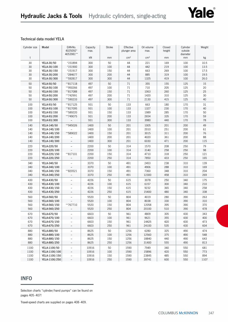
347
Hydraulic Jacks & Tools Hydraulic cylinders, single-acting
Technical data model YELA
Cylinder size
t
Model EAN-No. 4025092* 4053981**
Capacity max.
kN
Stroke
mm
Effective plunger area
cm²
Oil volume max.
cm³
Closed height
mm
Cylinder outside
diametermm
Weight
kg
30 YELA-30/50 *151894 300 50 44 221 169 100 10.530 YELA-30/100 *151900 300 100 44 442 219 100 13.530 YELA-30/150 *151917 300 150 44 663 269 100 17.530 YELA-30/200 *284677 300 200 44 885 319 100 19.530 YELA-30/300 **592817 300 300 44 1325 419 100 26.0
50 YELA-50/50 **817118 497 50 71 355 155 125 1550 YELA-50/100 **950266 497 100 71 710 205 125 2050 YELA-50/150 **817088 497 150 71 1063 260 125 2550 YELA-50/200 **742991 497 200 71 1420 310 125 3050 YELA-50/300 **590233 497 300 71 2130 415 125 40
100 YELA-93/50 **817125 931 50 133 663 180 170 31100 YELA-93/100 **817095 931 100 133 1327 230 170 40100 YELA-93/150 **589220 931 150 133 1989 285 170 50100 YELA-93/200 **749075 931 200 133 2654 335 170 59100 YELA-93/300 – 931 300 133 3980 440 170 78
140 YELA-140/50 **945026 1400 50 201 1005 201 200 49140 YELA-140/100 – 1400 100 201 2010 251 200 61140 YELA-140/150 **589022 1400 150 201 3015 311 200 76140 YELA-140/200 – 1400 200 201 4020 361 200 88140 YELA-140/300 – 1400 300 201 6030 471 200 115
220 YELA-220/50 – 2200 50 314 1570 208 250 79220 YELA-220/100 – 2200 100 314 3140 258 250 98220 YELA-220/150 **817101 2200 150 314 4710 318 250 121220 YELA-220/250 – 2200 250 314 7850 433 250 165
340 YELA-340/50 – 3370 50 491 2453 238 310 139340 YELA-340/100 – 3370 100 491 4906 288 310 169340 YELA-340/150 **820521 3370 150 491 7360 348 310 204340 YELA-340/250 – 3370 250 491 12300 458 310 269
430 YELA-430/50 – 4226 50 615 3078 250 340 175430 YELA-430/100 – 4226 100 615 6157 300 340 210430 YELA-430/150 – 4226 150 615 9232 365 340 258430 YELA-430/250 – 4226 250 615 15400 480 340 338
560 YELA-560/50 – 5520 50 804 4019 280 390 263560 YELA-560/100 – 5520 100 804 8038 330 390 310560 YELA-560/150 **767710 5520 150 804 12058 395 390 370560 YELA-560/250 – 5520 250 804 20100 510 390 478
670 YELA-670/50 – 6603 50 961 4809 305 430 343670 YELA-670/100 – 6603 100 961 9621 355 430 400670 YELA-670/150 – 6603 150 961 14425 420 430 473670 YELA-670/250 – 6603 250 961 24100 535 430 604
880 YELA-880/50 – 8625 50 1256 6280 325 490 474880 YELA-880/100 – 8625 100 1256 12560 375 490 548880 YELA-880/150 – 8625 150 1256 18840 440 490 643880 YELA-880/250 – 8625 250 1256 31400 555 490 813
1100 YELA-1100/50 – 10916 50 1590 7949 340 550 6811100 YELA-1100/100 – 10916 100 1590 15896 420 550 7731100 YELA-1100/150 – 10916 150 1590 23845 485 550 8941100 YELA-1100/250 – 10916 250 1590 39741 600 550 1107
INFO
Selection charts “cylinder/hand pumps“ can be found on pages 405 - 407!
Travel-speed charts are supplied on pages 408 - 409.

348
Hydraulic Jacks & Tools Hydraulic cylinders, single-acting
High-tonnage cylinders model YEGASingle-acting, gravity return capacity max. 140 - 1100 tThese inexpensive cylinders of series YEGA are used for all general lifting applications in any area of industry where heavy loads need to be lifted, lowered, levelled, positioned or supported.
Lifting and moving large machinery, steel construction, bridges or similar loads, supporting buildings and founda-tions.
For all heavy-duty jacking applications where a special safety factor is appropriate like lifting and lowering bridges, supporting buildings and foundations, jacking up heavy machines, steel sections, ship modules or similar loads.
Features• Operating pressure max. 700 bar.
• Plunger in special piston guiding bands.
• Hard chromium-plated piston.
• Overflow hole ensures a definite piston end stop.
• Interchangeable hardened saddle.
• Oil port thread 3/8 NPT.
• Incl. female coupler half model CFY-1.
• All cylinders have lifting rings.
Tilt saddles for cylinders model AYLTilt saddles should be used with YELA and YEGA cylinders in cases where cylinders are operated on non-parallel surfaces.
The saddles minimize inner friction caused by eccentric loading of the cylinders. The upper part of the saddle can pivot up to 5° in all directions. Tilt saddles are fixed in the piston by means of an O-ring.
INFO
Further piston strokes are quoted on request.
The use of tilt saddles is recommended.
For tilt saddles for cylinders please see pages 348 - 349.
Selection charts “cylinder/hand pumps“ can be found on pages 405 - 407!
Travel-speed charts are supplied on pages 408 - 409.
INFO
Available for all cylinder series YELA, YEGA and YEHA up to 1100 t.
Also available for cylinder series YS from 10 - 50 t.

349
Hydraulic Jacks & Tools Hydraulic cylinders, single-acting
Technical data model YEGA
Cylinder size
t
Model EAN-No. 4025092*
Capacity max.
kN
Stroke
mm
Effective plunger area
cm³
Oil volume max.
cm³
Closed height
mm
Cylinder outside
diametermm
Weight
kg
140 YEGA-140/50 *163385 1380 50 201 1005 155 200 38140 YEGA-140/100 *163194 1380 100 201 2010 205 200 51140 YEGA-140/150 *163200 1380 150 201 3015 255 200 63140 YEGA-140/200 *163217 1380 200 201 4020 305 200 75140 YEGA-140/300 *163231 1380 300 201 6030 405 200 100
220 YEGA-220/50 *163248 2200 50 314 1570 170 250 64220 YEGA-220/100 *163255 2200 100 314 3140 220 250 85220 YEGA-220/150 *163262 2200 150 314 4710 270 250 104220 YEGA-220/250 *163286 2200 250 314 7850 370 250 143
340 YEGA-340/50 *163309 3370 50 491 2453 210 310 123340 YEGA-340/100 *163319 3370 100 491 4906 260 310 154340 YEGA-340/150 *163323 3370 150 491 7360 310 310 184340 YEGA-340/250 *163347 3370 250 491 12300 410 310 243
430 YEGA-430/50 *163484 4226 50 616 3079 215 340 125430 YEGA-430/100 *163491 4226 100 616 6158 265 340 157430 YEGA-430/150 *163507 4226 150 616 9236 315 340 190430 YEGA-430/250 – 4226 250 616 15394 415 340 255
560 YEGA-560/50 *163927 5520 50 804 4019 240 390 223560 YEGA-560/100 *366823 5520 100 804 8038 290 390 272560 YEGA-560/150 *535281 5520 150 804 12058 340 390 319560 YEGA-560/250 – 5520 250 804 20100 440 390 413
670 YEGA-670/50 – 6603 50 962 4811 265 430 298670 YEGA-670/100 – 6603 100 962 9621 315 430 355670 YEGA-670/150 – 6603 150 962 14432 365 430 412670 YEGA-670/250 – 6603 250 962 24053 465 430 525
880 YEGA-880/50 – 8625 50 1257 6280 290 490 423880 YEGA-880/100 – 8625 100 1257 12560 340 490 503880 YEGA-880/150 – 8625 150 1257 18840 390 490 577880 YEGA-880/250 – 8625 250 1257 31400 490 490 725
1100 YEGA-1100/50 *163569 10916 50 1590 7949 415 550 7661100 YEGA-1100/100 *163576 10916 100 1590 15896 465 550 8671100 YEGA-1100/150 – 10916 150 1590 23845 515 550 9601100 YEGA-1100/250 *163743 10916 250 1590 39741 615 550 1147
Technical data model AYL
Model EAN-No. 4025092*
Suitable for cylinder groups Weightkg
AYL-30 *156837 YELA-30… 0.4AYL-50 *156844 YELA-50… 0.8AYL-100 *156851 YELA-93… 2.0AYL-150 *156868 YELA-140… and YEGA-140… 3.4AYL-200 *156875 YELA-220… and YEGA-220… 5.8AYL-340 – YELA-340… and YEGA-340… 13.0AYL-430 – YELA-340… and YEGA-340… 19.5
Other sizes on request
Dimensions model AYL
Model AYL-30 AYL-50 AYL-100 AYL-150 AYL-200 AYL-340 AYL-430
A, mm 45 61 88 111 131 178 200B, mm 36 39 47 52 57 67 79C, mm 28 30 36 40 45 47 57
A
BC
5°

350
Hydraulic Jacks & Tools Accessories
Lifting claws, piston plates, base adaptors and extension tubes, load-spreading plates model AYSLifting clawsIn connection with the corresponding hydraulic cylinder a lifting claw represents a compact, lightweight and versatile lifting unit. The lifting claws are screwed onto the collar thread of cylinder series YS. Claws can be placed under loads with minimum clearance.
When operating lifting claws, the following aspects have to be considered:
The hydraulic cylinders need to be able to support them-selves against the load. The max. force of the cylinder is reduced by 50 %.
Piston platesPiston plates can be screwed into the piston thread of cylinder series YS. They reduce the surface pressure and prevent the pistons from sinking into the ground. Also when using a piston plate in connection with a lifting claw the cylinder must be supported against the load.
Base adaptors and extension tubesExtension tubes are mounted onto the bottom of cylinders series YS by means of the base adaptor and two hexagon socket screws (screws are included with the base adap-tor). The use of extension tubes adds to the versatility of the standard cylinders.
Load-spreading platesThese load-spreading plates are recommended when slim cylinders are used for lifting operations. They prevent the cylinders from falling over and sinking into the ground. Robust steel design with carrying handle.
Straightening of a container box by use of a hydraulic cylinder YS-10/100, extension tube AYS-106, base adaptor AYS-103 and electric power pump PY-04/2/5/2 M.
Lifting of a container by use of an hydraulic cylinder YS-23/160, lifting claw AYS-23 and piston plate AYS-232 powered by a two-stage hand pump HPS-2/2 with base frame.
AYS-101 151 231

351
Hydraulic Jacks & Tools Accessories
Technical data model AYS
Model EAN-No. 4025092*
Description Suitable for cylinder Weightkg
AYS-10 *156721 Lifting claw, permissible capacity 5 t YS-10/… 0.9AYS-15 *156738 Lifting claw, permissible capacity 8 t YS-15/… 1.3AYS-23 *156745 Lifting claw, permissible capacity 12 t YS-23/… 3.8
AYS-53 *157049 Base adaptor, 5 t YS-5/… 0.5AYS-54 *157056 Extension tube 125 mm, 5 t YS-5/… 0.9AYS-55 *157063 Extension tube 250 mm, 5 t YS-5/… 1.5AYS-56 *157070 Extension tube 500 mm, 5 t YS-5/… 2.8
AYS-101 *157100 Load-spreading plate 10 t YS-10/… 10.5AYS-102 *156752 Piston plate, round YS-10/… 1.5AYS-103 *156783 Base adaptor, 10 t YS-10/… 0.7AYS-104 *156790 Extension tube 125 mm, 10 t YS-10/… 1.2AYS-105 *156806 Extension tube 250 mm, 10 t YS-10/… 2.2AYS-106 *156813 Extension tube 500 mm, 10 t YS-10/… 3.9AYS-107 *156820 Extension tube 750 mm, 10 t YS-10/… 5.9
AYS-151 *157131 Load-spreading plate 15 t YS-15/… 10.5AYS-152 *156769 Piston plate, round YS-15/… 1.8AYS-153 *156929 Base adaptor, 15 t YS-15/… 0.9AYS-154 *156936 Extension tube 125 mm, 15 t YS-15/… 1.6AYS-155 *156943 Extension tube 250 mm, 15 t YS-15/… 2.9AYS-156 *156950 Extension tube 500 mm, 15 t YS-15/… 4.9AYS-157 *156967 Extension tube 750 mm, 15 t YS-15/… 7.9
AYS-231 *157162 Load-spreading plate 23 t YS-23/… 10.5AYS-232 *156776 Piston plate, round YS-23/… 2.2
Dimensions model AYS
Model AYS-10 AYS-15 AYS-23 AYS-53 AYS-54 AYS-55 AYS-56 AYS-101 AYS-102 AYS-103 AYS-104 AYS-105
A, mm 90 110 125 53 125 250 500 230 140 58 125 250B, mm 90 110 125 50 – – – 120 12 60 – –C, mm 30 30 30 – – – – 58 – – – –D, mm 29 34 40 – – – – – – – – –E, mm 22 25 35 – – – – – – – – –F, mm M57 x 1.5 M67 x 1.5 M85 x 2 M42 x 1.5 M42 x 1.5 M42 x 1.5 M42 x 1.5 – M27 x 2 M50 x 2 M50 x 2 M50 x 2
Model AYS-106 AYS-107 AYS-151 AYS-152 AYS-153 AYS-154 AYS-155 AYS-156 AYS-157 AYS-231 AYS-232
A, mm 500 750 230 140 70 125 250 500 750 230 160B, mm – – 120 12 73 – – – – 120 15C, mm – – 68 – – – – – – 86 –D, mm – – – – – – – – – – –E, mm – – – – – – – – – – –F, mm M50 x 2 M50 x 2 – M33 x 2 M60 x 2 M60 x 2 M60 x 2 M60 x 2 M60 x 2 – M40 x 2
Lifting claws Piston plates Base adaptors Extension tubesLoad-spreading plates
F B
EC A
D
A
F
BF B
A
F
A
C A
B

352
Hydraulic Jacks & Tools Accessories
Threaded flanges model AYPIn case hydraulic cylinders have to be inserted into fixtures, press frames or similar devices, these steel flanges can be very handy. Material: weldable steel.
Technical data model AYP
Model EAN-No. 4025092*
Suitable for cylinder Weightkg
AYP-1010 *157407 YS-10/… 9.7AYP-1510 *157414 YS-15/… and YH-10/… 12.6AYP-2310 *157421 YS-23/… and YH-20/… 12.1AYP-5010 *159531 YS-50/… and YH-50/… 19.6AYP-10010 *159548 YS-100/… and YH-100/… 46.0AYP-20010 *159555 YH-200/… 97.0
Dimensions model AYP
Model AYP-1010 AYP-1510 AYP-2310 AYP-5010 AYP-10010 AYP-20010
A, mm M57 x 1.5 M67 x 1.5 M85 x 2 M125 x 2 M180 x 3 M250 x 4B, mm 220 220 220 250 330 450C, mm 200 200 200 250 330 450D, mm 30 40 40 50 70 80E, mm 120 120 120 225 300 400F, mm 150 150 150 225 300 400G, mm M12 M12 M12 Ø 13.5 Ø 17.5 Ø 17.5H, mm M8 M8 M8 M8 M8 M8
Model AYP

353
Hydraulic Jacks & Tools Accessories
Clevis eye mountings model AYHClevis eye mountings are screwed onto the piston and bottom of the hydraulic cylinder whenever mounting conditions require a pivoting of the cylinder.
Technical data model AYH
Model EAN-No. 4025092*
Suitable for cylinder Suitable for Weightkg
AYH-5-1 *157179 YH-5/30, YH-5/80, YH-5/150 Cylinder base 0.3AYH-5-2 *157186 YH-5/30, YH-5/80, YH-5/150 Piston 0.3AYH-10-1 *157193 YH-10/30, YH-10/80, YH-10/150, YH-10/250 Cylinder base 0.6AYH-10-2 *157209 YH-10/30, YH-10/80, YH-10/150, YH-10/250 Piston 0.6AYH-20-1 *157216 YH-20/150, YH-20/250 Cylinder base 2.1AYH-20-2 *157223 YH-20/150, YH-20/250 Piston 2.1
Dimensions model AYH
Model AYH-5-1 AYH-5-2 AYH-10-1 AYH-10-2 AYH-20-1 AYH-20-2
A, mm M27 x 2 M18 x 1.5 M36 x 2 M27 x 2 M45 x 2 M36 x 2B, mm – 35 – 40 – 70C, mm 35 35 38 38 50 50D, mm 35 35 42 42 65 65E, mm 15 15 25 25 35 35F, mm 16 16 20 20 30 30G ¹, mm M35 x 1.5 – M40 x 1.5 – M70 x 2 –H, mm – – – 21 – 24J, mm 18 – 21 – 23 –
¹ G = retainer nut DIN 981
Model AYH-…-1 for cylinder base Model AYH-…-2 for piston

354
Hydraulic Jacks & Tools Hand pumps 700 bar
Build-up and description of Yale hand pumpsHand pumps are the most common power source within the area of “High-Pressure Hydraulic Tools“. For this reason our hand pumps have been carefully designed and equipped with many details which make the pumps very versatile and handy in every-day applications.
Relief valve/hand wheelThe fine-adjustment relief valve in connection with the large hand wheel allows millimeter increments when lifting and lowering even highest loads. The fact that sometimes hundreds of tons are controlled by this hand wheel underlines the importance of this feature.
Sturdy “all-metal-design“The robust pump head and the absence of any plastic parts result in a long service life and easy maintenance over many years. Plastic reservoirs filled with oil may present a fire risk in connection with welding or similar work!
Carrying handleA handy carrying handle on all our hand pumps facilitates transportation enormously.
Pressure relief valvesAll hand pumps are equipped with two pressure relief valves. They are easily adjustable from outside if pumps must be re-adjusted or a lower operating pressure should not be exceeded.
Reservoir ventilationAll hand pumps are equipped with a reservoir ventilation plug. This ensures perfect suction of hydraulic oil and allows you to use the total oil capacity of the reservoir.
Two-stage outputAll hand pumps have two-stage design (except HPS-1/0,7). This allows an increased speed and efficient working during unloaded conditions of the hydraulic cylinder. The switch-over from the low pressure to the high pressure stage is done automatically.
Reservoir ventilation
Carrying handle
Base frame as option
Additional return port
Fine-adjustment relief valve
Pressure relief valves and suction valves
Pressure port 3/8 NPT
Pressure gauge set as option
INFO

355
Hydraulic Jacks & Tools Hand pumps 700 bar
Delivered ready to useAll hand pumps are supplied ready to use incl. hydraulic oil.
Easy-maintenance-designThere is no need to disassemble the hand pumps in case of service work. All parts like suction and pressure valves, seals, packings etc. are accessible from the outside.
All hand pumps have the same designThe same design (build-up) for all hand pumps with the exception of the reservoirs allows the interchangeability of all components. Therefore spare part stocks can be kept to an absolute minimum. Only one spare part kit is neces-sary to service all hand pumps.
Excellent suction propertiesHand pumps suck and displace 100 % of their volume per stroke. This results both in a high efficiency as well as a rapid cylinder movement.
InterchangeabilityAll hydraulic cylinders, hand pumps and other compo-nents are fully interchangeable and can be combined with all other 700 bar hydraulic lines. All components have the standard oil port and same coupler parts.
Additional return oil portAll hand pumps are equipped with a return port to the reservoir. This detail is very advantageous as many hand pumps are integrated in more complex hydraulic circuits.
Base frameOn request you can get base frames for the most com-mon hand pumps. These base frames add to the stability and protection of the hand pumps, in particular when used in the field or on a construction site.
Pressure gaugeAppropriate pressure gauges with the corresponding adaptors are shown.
Hand pump model: HPH-…
With integrated pressure gauge GGY-631 and gauge adaptor set GA-704.
Hand pumps for double-acting cylinders with relief valve and 4/2-way directional valveUnlike conventional pumps, all hand pumps of the model HPH (with 4/2-way directional valve for double-acting cylinders) include a precision relief valve in addition to the directional control valve. Manual directional control valves switch over abruptly, thus causing undesired pressure surges in the system under load. The additional relief valve in all HPH-hand pumps allows a precise lowering of the load without any pressure shocks. All components have the standard oil port and same coupler parts.
Further advantage of this design:
The pressure gauge shows the pressure as pushing and as pulling force. The combination of a 4-way directional valve with a sensitive relief valve allows a controlled pres-sure relief without pressure shocks.
INFO
INFO
Selection charts “cylinder/hand pumps“ can be found on pages 405 - 407!

356
Hydraulic Jacks & Tools Hand pumps 700 bar
Hand pumps for single-acting cylinders model HPSHand pumps are easy to use and operate independently of any external energy source. They are designed for a maximum 700 bar system pressure and will allow each hydraulic cylinder to utilize its maximum capacity.
The two-stage system reduces pumping time. Stage 1 allows rapid piston travel under no load or light load conditions. The pump automatically switches to stage 2 when the piston is loaded and a higher force is required from top. The hand pump is an all-steel construc-tion designed for rough use and has a high-efficiency pumping action. The handle can be locked for easy carrying.
The large and easy-to-control return valve allows the operator to precisely control the return stroke. Other standard features include a large and easy-to-control hand wheel, air bleeding and oil filling plug, large support feet for stability, tilted tank to increase usable oil volume and ergonomic handle grip.
Features• Operating pressure max. 700 bar.
• Two-stage operation with automatic switch-over (except HPS-1/0,7 A).
• Large reservoir volumes.
• With pressure relief valves, adjustable from the outside.
• Precision-adjustable relief valve (handwheel).
• Robust all-steel construction.
• HPH-pumps are equipped with a 4-way control valve plus a precision-adjustable relief valve.
• Oil port thread 3/8 NPT.
• Incl. oil filling.
• Pressure gauges with corresponding adaptors are also available as accessories.
HPS-2/4 A
HPS-2/0,3 A
HPS-2/0,7 A
HPS-2/2 A
INFO
Hydraulic hoses are the connection between hand pump and hydraulic cylinders and need to be selected sepa-rately. Please see page 381.

357
Hydraulic Jacks & Tools Hand pumps 700 bar
Technical data model HPS
Model EAN-No. 4025092*
Displacement Reservoir volume
cm³
Displacement 1st stage
cm³
Displacement 2nd stage
cm³
Weight
kg
HPS-1/0,7 A *159081 single-stage 700 – 2 7.0HPS-2/0,3 A *160148 two-stage 300 5 1 3.5HPS-2/0,7 A *159098 two-stage 700 11 2 7.0HPS-2/2 A *159104 two-stage 2000 11 2 10.0HPS-2/4 A *159111 two-stage 4000 11 2 13.0HPS-2/6 A *159128 two-stage 6000 11 2 21.0HPS-2/10 A *159135 two-stage 10000 11 2 27.0
Dimensions model HPS
Model HPS-1/0,7 A HPS-2/0,3 A HPS-2/0,7 A HPS-2/2 A HPS-2/4 A HPS-2/6 A HPS-2/10 A
A, mm 505 410 505 520 645 645 800B, mm 85 100 85 70 65 65 65C, mm 135 105 135 145 160 215 250D, mm 150 125 150 150 150 180 190E, mm 43 35 43 43 43 43 43F, mm 52 35 52 52 52 52 52
Dimensions approx.

358
Hydraulic Jacks & Tools Hand pumps 700 bar
Hand pumps for double-acting hydraulic cylinders model HPHWith 4-way valve and relief valve (hand wheel)All hand pumps of type HPH are designed as double-acting cylinders. Basically, they do not differ from series HPS, but are equipped with a 4/3-way directional valve.
The precision-adjustable relief valve remains unaffected and permits a sensitive pressure relief. Pressure gauge and adaptor can be delivered as accessories.
Technical data model HPH
Model EAN-No. 4025092*
Displacement Reservoir volume
cm³
Displacement 1st stage
cm³
Displacement 2nd stage
cm³
Weight
kg
HPH-2/0,7 A *159159 two-stage 700 11 2 8HPH-2/2 A *159166 two-stage 2000 11 2 11HPH-2/4 A *159173 two-stage 4000 11 2 14HPH-2/6 A *159180 two-stage 6000 11 2 22HPH-2/10 A *159197 two-stage 10000 11 2 28
Dimensions model HPH
Model HPH-2/0,7 A HPH-2/2 A HPH-2/4 A HPH-2/6 A HPH-2/10 A
A, mm 590 595 715 715 880B, mm 95 65 65 65 65C, mm 160 160 160 200 160D, mm 165 165 180 180 190E, mm 55 55 55 55 55F, mm 80 80 80 80 80G, mm 85 85 85 85 85
Dimensions approx.
HPH-2/4 A
HPH-2/2 A
HPH-2/0,7 A

359
Hydraulic Jacks & Tools Hand pumps 700 bar
Base frames for hand pumps model HPBThese base frames add to the stability of your hand pump, in particular when used in the field or on a con-struction site where hand pumps are frequently operated on uneven and soft ground.
At the same time, the hand pumps are protected from sand, humidity and possible damage.
The assembly of the base frames is very easy; just three holes have to be bored to mount the frame to the hand pump.
Technical data model HPB
Model EAN-No. 4025092*
Suitable for hand pump Weightkg
HPB-2 *156684 HPS-1/0,7 A + HPS-2/0,7 A + HPS-2/2 A + HPH-2/0,7 A + HPH-2/2 A 1.3HPB-4 *156691 HPS-2/4 A + HPS-2/6 A + HPH-2/4 A + HPH-2/6 A 1.8
Dimensions model HPB
Model HPB-2 HPB-4
A, mm 765 885B, mm 190 190
A
B

360
Hydraulic Jacks & Tools Hand pumps up to 2000 bar
Hand pumps model TWAZOperating pressure max. 2000 barThese high-performance hand pumps allow a very rapid pressure build-up due to their two-stage design. Both pressure stages are equipped with a limiting valve which can easily be adjusted from outside.
High-pressure hand pumps are used for special applica-tions like pressurizing hydraulic nuts and safety couplings, hydrostatic testing, bolt tensioners, high-pressure oil injec-tion for bushing removal, pretensioning anchors, for test applications in laboratories and as a power source within test stands and propeller press systems.
Technical data model TWAZ
Model EAN-No. 4025092*
Pressure max.
bar
Reservoir volume
cm³
Displace-ment
1st stagecm³
Displace-ment
2nd stagecm³
Oil port Pressure gauge
Pressure gauge model
Gauge adaptor model
Pressure relief valve
Weight
kg
TWAZ-0,7 *159920 2000 700 8 0.6 M22 x 1.5 option GGY-2500 GA-2000 yes 7.0TWAZ-1,3 *159937 2000 1300 13 1.0 M22 x 1.5 option GGY-2500 GA-2000 yes 9.0TWAZ-2,3 *159951 2000 2300 31 1.6 M22 x 1.5 option GGY-2500 GA-2000 yes 16.0
Option: pressure gauge, model: GGY-2500.
Option: pressure gauge-adaptor, model GA-2000.
Option: adaptor, model: FY-201 (M22 x 1.5 on G 1/4).
Option: hydraulic hoses, model: HH-2001-20, max. pressure: 2000 bar.
Accessories for hand pumps model TWAZ
TWAZ-1,3
TWAZ-0,7

361
Hydraulic Jacks & Tools Foot pumps 700 bar
Foot pump model FPSOperating pressure 700 barUsed to operate single-acting hydraulic cylinders, especial-ly for repeated applications, such as checking of welding samples, pressing of connection components (crimping), actuating of clamping devices, as well as for all applica-tions, where it is necessary to keep hands free.
The pump can be used everywhere, as it is independent of an external energy source and is easily portable. An extremely good stability guarantees a comfortable and safe operation up to the highest pressure. It is a “real“ foot operated pump, as the return stroke of the connected hydraulic cylinder is released by foot control.
Features• Operating pressure max. 700 bar.
• Absolute stability due to large base plate.
• Minimized labour fatigue.
• Operating pressure adjustable. Valves accessible from the outside.
• Return stroke of cylinder also controlled by foot operation.
• Oil port 3/8 NPT.
Options• Pressure gauges and suitable adaptors.
• Hydraulic hoses
Technical data model FPS
Model EAN-No. 4025092*
Operating pressure max.bar
Displacement 1st stage
cm³
Displacement 2nd stage
cm³
Reservoir volume useable
cm³
Weight
kg
FPS-2/0,5 A *160155 700 11 2 500 7

362
Hydraulic Jacks & Tools Electric motor pumps
Electric motor pumps, portable model PY-04Operating pressure max. 700 barThese light-weight but powerful two-stage pumps are particulary designed for maintenance and repair jobs. Depending on their type, they can either operate single-acting or double-acting hydraulic cylinders.
The ideal combination of manually operated valve and remote pendant control provides the operator with ample freedom of motion and ensures a safe “holding of the load“.
The remote pendant control (1.5 m) is used to start the motor even under full load. The function for both manual valves is as follows: – advance – stop – return – With their light weight and convenient carrying handle, these pumps can be easily transported. Pumps are equipped with thermal overload protection and are sup-plied with hydraulic oil.
Operation of the power pump PY-04/2/5/2M:The 2/2-way manual valve operates together with a pilot operated unloading valve, so that the two valve positions result in the following two control possibilities:
1. Cylinder holds pressure after motor stop.
2. Cylinder automatically retracts after motor stop.
Operation of the power pump PY-04/2/5/2E:By activating push-button number 1, the motor starts and the cylinder advances. In the neutral position the pressure is held. By activating push-button number 2, the solenoid valve is activated, the pressure decreases and the hydrau-lic cylinder retracts.
Technical data model PY-04
Model EAN-No. 4025092*
Control valve Operating pressure
max.bar
No load stroke
l/min up to 30 bar
Under load stroke
l/min up to 700 bar
Useable reservoir volume
l
Connecting value
Cable remote control
m
Speed
rpm
Protection standard
Weight, without oil,
approx.kg
PY-04/2/5/2 M *153263 2/2-way manual valve 700 4.0 0.23 5.0 0.37 kW -
230 V-1Ph 1.5 2800 IP 50 24
PY-04/2/5/4 M *153294 4/3-way manual valve 700 4.0 0.23 5.0 0.37 kW -
230 V-1Ph 1.5 2800 IP 50 26
PY-04/2/5/2 E *163392 2/2-way solenoid 700 4.0 0.23 5.0 0.37 kW -
230 V-1Ph 1.5 2800 IP 50 28
PY-04/2/5/2M PY-04/2/5/4M
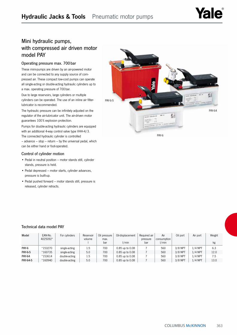
363
Hydraulic Jacks & Tools Pneumatic motor pumps
Mini hydraulic pumps, with compressed air driven motor model PAYOperating pressure max. 700 barThese mini-pumps are driven by an air-powered motor and can be connected to any supply source of com-pressed air. These compact low-cost pumps can operate all single-acting or double-acting hydraulic cylinders up to a max. operating pressure of 700 bar.
Due to large reservoirs, large cylinders or multiple cylinders can be operated. The use of an inline air filter-lubricator is recommended.
The hydraulic pressure can be infinitely adjusted on the regulator of the air-lubricator unit. The air-driven motor guarantees 100 % explosion protection.
Pumps for double-acting hydraulic cylinders are equipped with an additional 4-way control valve type VHH-4/3. The connected hydraulic cylinder is controlled – advance – stop – return – by the universal pedal, which can be either hand or foot-operated.
Control of cylinder motion• Pedal in neutral position – motor stands still, cylinder
stands, pressure is held.
• Pedal depressed – motor starts, cylinder advances, pressure is built-up.
• Pedal pushed forward – motor stands still, pressure is released, cylinder retracts.
Technical data model PAY
Model EAN-No. 4025092*
For cylinders Reservoir volume
l
Oil pressure max.bar
Oil-displacement
l/min
Required air pressure
bar
Air consumption
l/min
Oil port Air port Weight
kg
PAY-6 *153270 single-acting 1.5 700 0.85 up to 0.08 7 560 3/8 NPT 1/4 NPT 6.3PAY-6-5 *160735 single-acting 5.0 700 0.85 up to 0.08 7 560 3/8 NPT 1/4 NPT 12.0PAY-64 *153614 double-acting 1.5 700 0.85 up to 0.08 7 560 3/8 NPT 1/4 NPT 7.5PAY-64-5 *160940 double-acting 5.0 700 0.85 up to 0.08 7 560 3/8 NPT 1/4 NPT 13.0
PAY-6-5
PAY-6
PAY-64
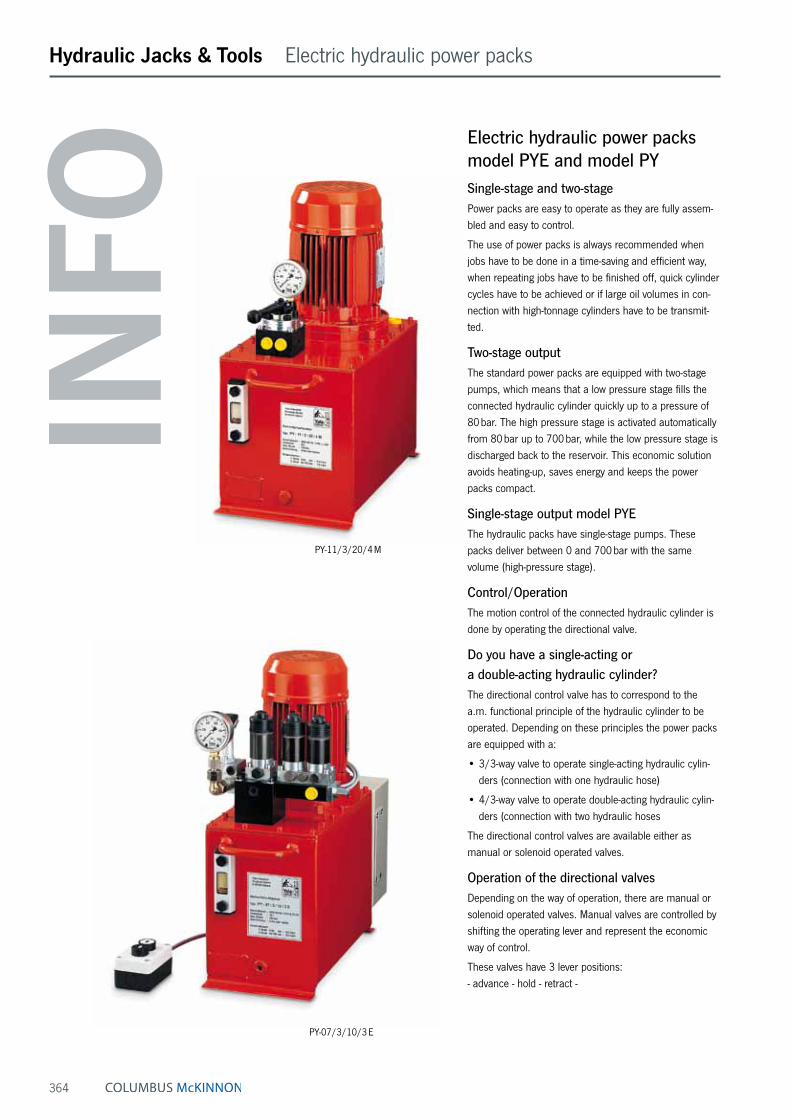
364
Hydraulic Jacks & Tools Electric hydraulic power packs
Electric hydraulic power packs model PYE and model PYSingle-stage and two-stagePower packs are easy to operate as they are fully assem-bled and easy to control.
The use of power packs is always recommended when jobs have to be done in a time-saving and efficient way, when repeating jobs have to be finished off, quick cylinder cycles have to be achieved or if large oil volumes in con-nection with high-tonnage cylinders have to be transmit-ted.
Two-stage outputThe standard power packs are equipped with two-stage pumps, which means that a low pressure stage fills the connected hydraulic cylinder quickly up to a pressure of 80 bar. The high pressure stage is activated automatically from 80 bar up to 700 bar, while the low pressure stage is discharged back to the reservoir. This economic solution avoids heating-up, saves energy and keeps the power packs compact.
Single-stage output model PYEThe hydraulic packs have single-stage pumps. These packs deliver between 0 and 700 bar with the same volume (high-pressure stage).
Control/OperationThe motion control of the connected hydraulic cylinder is done by operating the directional valve.
Do you have a single-acting or a double-acting hydraulic cylinder?The directional control valve has to correspond to the a.m. functional principle of the hydraulic cylinder to be operated. Depending on these principles the power packs are equipped with a:
• 3/3-way valve to operate single-acting hydraulic cylin-ders (connection with one hydraulic hose)
• 4/3-way valve to operate double-acting hydraulic cylin-ders (connection with two hydraulic hoses
The directional control valves are available either as manual or solenoid operated valves.
Operation of the directional valvesDepending on the way of operation, there are manual or solenoid operated valves. Manual valves are controlled by shifting the operating lever and represent the economic way of control.
These valves have 3 lever positions: - advance - hold - retract -
PY-11/3/20/4 M
PY-07/3/10/3 E
INFO
365
Hydraulic Jacks & Tools Electric hydraulic power packs
Solenoid valvesSolenoid valves have the advantage that they are con- trolled by a pendant remote control box which makes the operator independent from the power pack, making it easier for him to monitor the job.
The solenoid valves are controlled by two push-buttons – advance – hold – retract – In neutral position – hold – the valves rest in pressure-less circuit. Pressure and force of the connected cylinder are held without pressure drop. The complete electrical set-up (with 24 V control) belongs to the scope of delivery. Solenoid valves allow a very ergonomic operation and offer a quick and precise switching (millimeterwise) of the connected hydraulic cylinder.
Pressureless circuitIn neutral position all directional valves rest in pressure-less circuit which means that the oil flow coming from the rotating pump is guided back to the reservoir without creating any pressure build-up.
Special solenoid valve configurationsSome applications require a special valve configuration, e.g. the independent control of several hydraulic cylinders from a single power pack. In such cases the complete valve build-up and electrical control is designed according to customer‘s requirements.
Pressure-Guard power packsBy using an electro-hydraulic pressure switch and a special electric control, power packs automatically control their pre-adjusted pressure. In applications where the pressure (load) should be applied over a very long period, the connected power pack is switched on and off automatically and replaces the pre-set pressure in case a pressure drop has occured.
TrolleysFor all power packs we offer a cart-frame for flexible movement from job to job. Cart-frames are equipped with 2 fixed and 2 swivel castors.
Oil coolerFor certain applications, especially when power packs are continuously operated and the oil temperature could exceed 60 °C, the use of an oil cooler is recommended.
Hydraulic oil
All power packs are designed for an operation with stand-ard hydraulic oil (specification ISO VG 32). For certain operating conditions the viscosity class of the hydraulic fluid can be varied. All power packs are supplied including oil.
Features• Robust packs, also capable for contiuous applications.
• Suitable for all jobs in workshops and on construction sites where hydraulic force is required; supplied ready to use.
• On-off motor switch and 3 m motor connecting cable.
• With carrying handles, oil level gauge, oil filler/resevoir ventilation plug.
• Incl. pressure gauge GGY-631.
• Two-stage displacement, which means a rapid advance without load, as well as an automatic switch into the 2. phase by a congruous load.
• Low noise level due to standard motors with 1450 rpm.
• Futher motor voltage and oil resevoirs on request.
• With manual or solenoid operated directional valves.
• Solenoid valves with 3 m remote control box (with 2 push-buttons) and pressure set valve as stand-ard. Adjustable from 0-700 bar.
• 24 V - low voltage control includes a sturdy metal electric control box and ready to use set up.
INFO

366
Hydraulic Jacks & Tools Electric hydraulic power packs
Two-stage electric hydraulic power packs, 700 bar
Code explanation
Directional valve : 3 = for single-acting, 4 = for double-acting cylinder, M = manual valve, E = solenoid valveReservoir size : in liters (other reservoir sizes on request)Motor voltage : 3 = 380-420 V, 3-phase (Euro-voltage), 2 = 230 V, 1-phase, (other voltages on request)Hoist motor : 07 = 0.75 kW, 11 = 1.1 kW, 22 = 2.2 kW, 30 = 3 kW, 55 = 5.5 kW, 75 = 7.5 kW, 110 = 11 kWType of motor : PY = electric motor, PAY = air motor, PGY = petrol driven motor (4 cycle)
Model Reservoir size Control valve (directional valve) Motor- Displacement, two-stagemanual valve solenoid valve power approx. l/min approx. l/min
10 l 20 l 30 l 50 l 3/3-way 4/3-way 3/3-way 4/3-way kw 0 - 80 bar 80 - 700 bar
PY-07/3/10/3 M • – – – • – – – 0.75 6.0 0.6PY-07/3/10/4 M • – – – – • – – 0.75 6.0 0.6PY-07/3/20/3 M – • – – • – – – 0.75 6.0 0.6PY-07/3/20/4 M – • – – – • – – 0.75 6.0 0.6PY-07/3/20/3 E – • – – – – • – 0.75 6.0 0.6PY-07/3/20/4 E – • – – – – – • 0.75 6.0 0.6
PY-11/3/20/3 M – • – – • – – – 1.1 8.5 1.0PY-11/3/20/4 M – • – – – • – – 1.1 8.5 1.0PY-11/3/30/3 M – – • – • – – – 1.1 8.5 1.0PY-11/3/30/4 M – – • – – • – – 1.1 8.5 1.0PY-11/3/20/3 E – • – – – – • – 1.1 8.5 1.0PY-11/3/20/4 E – • – – – – – • 1.1 8.5 1.0PY-11/3/30/3 E – – • – – – • – 1.1 8.5 1.0PY-11/3/30/4 E – – • – – – – • 1.1 8.5 1.0
PY-22/3/30/3 M – – • – • – – – 2.2 18.0 2.1PY-22/3/30/4 M – – • – – • – – 2.2 18.0 2.1PY-22/3/50/3 M – – – • • – – – 2.2 18.0 2.1PY-22/3/50/4 M – – – • – • – – 2.2 18.0 2.1PY-22/3/30/3 E – – • – – – • – 2.2 18.0 2.1PY-22/3/30/4 E – – • – – – – • 2.2 18.0 2.1PY-22/3/50/3 E – – – • – – • – 2.2 18.0 2.1PY-22/3/50/4 E – – – • – – – • 2.2 18.0 2.1
Single-stage electric hydraulic power packs, 700 bar
Model Reservoir size Control valve (directional valve) Motor Displacementmanual valve solenoid valve power l/min
10 l 20 l 30 l 50 l 3/3-way 4/3-way 3/3-way 4/3-way kw 0 - 700 bar
PYE-03/3/10/3 M • – – – 0.35 0.3PYE-03/3/10/4 M • – – – 0.35 0.3PYE-07/3/10/3 M • – – – 0.75 0.6PYE-07/3/10/4 M • – – – 0.75 0.6PYE-07/3/20/4 M – • – – 0.5 0.6PYE-11/3/20/3 M – • – – 1.1 1.0PYE-11/3/20/4 M – • – – 1.1 1.0PYE-11/3/30/4 M – – • – 1.1 1.0PYE-22/3/20/3 M – • – – 2.2 2.1PYE-22/3/20/4 M – • – – 2.2 2.1PYE-22/3/30/4 M – – • – 2.2 2.1PYE-22/3/50/4 M – – – • 2.2 2.1
All valve and reservoir combinations
available.
High-performance electric hydraulic power packs, 700 bar, single-stage
Model Reservoir size Control valve (directional valve) Motor Displacementmanual valve solenoid valve power l/min
50 l 100 l 150 l 3/3-way 4/3-way 3/3-way 4/3-way kw 0 - 700 bar
PYE-40/3/50/4 M • – – 4.0 2.7PYE-55/3/70/4 M • – – 5.5 4.0PYE-75/3/100/4 M – • – 7.5 6.0PYE-110/3/150/4 M – – • 11.0 8.0PYE-180/3/150/4 M – – • 18.0 12.0
All valve and reservoir combinations
available.

367
Hydraulic Jacks & Tools Special power pack solutions
Hydraulic power pack with protection cageThis power pack is specially designed for general lifting applications in construction areas. Equipped with an optimized valve configuration, including 4-way manual directional valve VHP-4/3-1, safety-check valve VSM-21, pressure relief valve VPR-1 and 2 pressure gauges for permanent load control.
Hydraulic power pack with 4-way manifold MY-44-GYAThe most economic way for a pressure-independent and individual control of 4 single-acting hydraulic cylinders. The additionally mounted safety-check valve VSM-21 avoids uncontrolled pressure drops, and the built-in throttle valve allows a precise (millimeterwise) lowering even of the highest loads. Four pressure gauges allow a permanent reading of the individual loads. On request, the power packs can be equipped with a handy cart-frame to make the operation flexible. This type of power pack can be supplied in all sizes of the PY and PYE series.
Hydraulic power pack with 4-times solenoid valveThe quadruple solenoid valve block ensures a pressure-independent and individual control of 4 double-acting hydraulic cylinders. Solenoid valves offer several well-known advantages such as: ergonomic and safe control by pendant remote control, exact load hold, precise and quick switch characteristics and many more.
Double-hydraulic power packIn order to realise very high oil flows, two independent pump systems can be combined in one large reservoir. A gear pump ensures an extremely high oil flow up to 250 bar while the high-pressure stage is generated by a high-performance radial piston pump. Each pump is equipped with its own solenoid control valve so that the individual oil flows can be generated or discharged on request.

368
Hydraulic Jacks & Tools Electric hydraulic power packs
Multiple-flow hydraulic power packs model PMFMultiple-flow hydraulic pumps can advance 4 cylinders with the same speed at the same time by injecting equal amounts of hydraulic oil into each individual cylinder. This principle allows a synchronized lifting of machines or similar loads from a central point. Even under different loading conditions the cylinders advance in synchronisa-tion.
Levelling of a lopsided load is easily possible by an indi-vidual control of each single cylinder. The lifting phase is initiated by a push-button remote control box and can be interrupted and continued at any time.
Lowering of the load is done by operating the directional valve in connection with the throttle valve individually for each circuit. The multiple-flow pumps can drive all kinds of hydraulic cylinders, machine jacks or stage lifts.
Features• 4-point synchronized lift due to 4 equal, independent
and individual oil flows.
• 4 manually operated directional valves, or 4 solenoid directional valves allow an individual or joint control of all 4 connected cylinders (easy levelling of loads).
• Safe load hold due to check valve in each circuit.
• One-man central operation.
• Motor on-off switch by means of a pendant remote control box in connection with manual valves
• A complete remote control box to operate the solenoid valves.
Options• All pump packs are also available with 4/3 direction-
valves (for controlling the double-acting hydraulic cylinders).
• All power packs can be supplied with a protection frame suitable for on-site operation. Also cart-frames with 2 fixed and 2 swivel castors are available on request.
Scope of deliveryFor each of the four circuits the ready-to-use supply includes: glycerine-damped pressure gauge, 3-way control valve, safety-check valve, a female coupler-half as connecting port. Furthermore: hydraulic oil, carrying handles, motor on-off switch, motor connecting cable, pendant remote control, electro-box with transformer and motor relais, oil level gauge and oil-filler/ventilation plug. All multiple-flow power packs are also available with 4-way directional valves in order to operate double-acting hydraulic cylinders.
PMF-15/3/40/4 x 3 M
INFO
All extra loads can be meter-read permanently.

369
Hydraulic Jacks & Tools Electric hydraulic power packs
4-multiple-flow power packs with solenoid directional valves model PMF4-multiple-flow power packs with solenoid directional valves to advance 4 hydraulic cylinders independently and in a synchronized way by means of solenoid valves with a pendant remote control box. The solenoid valves in connection with safety-throttle valves allow a precise control of all connected hydraulic cylinders.
Technical data model PMF
Model EAN-No. 4025092*
Operating pressure max.
bar
Displacement
l/min
Manual valve
Solenoid valve
Motor remote control
Reservoir size
l
E-motor
PMF-07/3/20/2 x 3 M *163521 2 x 700 2 x 0.3 • – • 20 0.75 kW-400 V-3 PhPMF-07/3/20/2 x 3 E – 2 x 700 2 x 0.3 – • – 20 0.75 kW-400 V-3 PhPMF-15/3/20/2 x 3 M – 2 x 700 2 x 0.6 • – • 20 1.5 kW-400 V-3 PhPMF-15/3/20/2 x 3 E – 2 x 700 2 x 0.6 – • – 20 1.5 kW-400 V-3 PhPMF-15/3/40/4 x 3 M *157827 4 x 700 4 x 0.3 • – • 40 1.5 kW-400 V-3 PhPMF-15/3/40/4 x 3 E *160681 4 x 700 4 x 0.3 – • – 40 1.5 kW-400 V-3 PhPMF-30/3/40/4 x 3 M *160957 4 x 700 4 x 0.6 • – • 40 3.0 kW-400 V-3 PhPMF-30/3/40/4 x 3 E *160902 4 x 700 4 x 0.6 – • – 40 3.0 kW-400 V-3 PhPMF-55/3/100/4 x 3 M – 4 x 700 4 x 1.0 • – • 100 5.5 kW-400 V-3 PhPMF-55/3/100/4 x 3 E – 4 x 700 4 x 1.0 – • – 100 5.5 kW-400 V-3 PhPMF-110/3/100/4 x 3 M *163972 4 x 700 4 x 2.1 • – • 100 11.0 kW-400 V-3 PhPMF-110/3/100/4 x 3 E *162128 4 x 700 4 x 2.1 – • – 100 11.0 kW-400 V-3 Ph
PMF-15/3/40/4 x 4 E
INFO
All multiple-flow power packs are also available with 4-way directional valves in order to operate double-acting hydraulic cylinders model PMF.

370
Hydraulic Jacks & Tools Valves
Directional valves, 700 bar model VHP and model VHHManually operatedThese directional valves control the oil flow in combination with hydraulic power packs (YHH-4/3 with hand pumps).
All valves have 3 lever positions to control movement of the connected hydraulic cylinder:
1. left: cylinder advance. 2. middle: cylinder neutral (pressureless circuit). 3. right: cylinder retracts.
In the middle position (hold) the piston of the cylinder stops and the oil flow is guided in a circuit back to the reservoir (P to T). The valves can be flanged directly onto power packs but can also be connected by using hydraulic piping. In addition, all valves are equipped with a second pres-sure oil port P at the back of the valve base.
This port can easily be used to connect a pressure gauge and a pressure relief valve (e.g. VPR-1). The oil port T shall always be connected to the reservoir without any back pressure.
Technical data model VHP and model VHH
Model EAN-No. 4025092*
Pressure max.l/min
Size Oil ports Hydraulic symbol Applications
VHP-3/3-1 *155175 8 - 16 1 3/8 NPT3/3-way valve with “open centre“ in middle position
(pressureless circuit) to control single-acting hydraulic cylinders, standard valve for smaller power packs, size 1.
VHP-3/3-2 *155199 20 - 40 2 3/8 NPT3/3-way valve with “open centre“ in middle position
(pressureless circuit) to control single-acting hydraulic cylinders, standard valve for larger power packs, size 2.
VHP-3/3-1 CC *155182 8 - 16 1 3/8 NPT3/3-way valve with “closed centre“ in middle position
to control single-acting hydraulic cylinders, only for specific multiple valve configuration, size 1.
VHP-3/3-2 CC *155205 20 - 40 2 3/8 NPT3/3-way valve with “closed centre“ in middle position
to control single-acting hydraulic cylinders, only for a multitude of valve operations, size 2.
VHP-4/3-1 *154857 8 - 16 1 3/8 NPT4/3-way valve with “open centre“ in middle position
(pressureless circuit) to control double-acting hydraulic cylinders, standard valve for smaller power packs, size 1.
VHP-4/3-2 *154864 20 - 40 2 3/8 NPT4/3-way valve with “open centre“ in middle position
(pressureless circuit) to control double-acting hydraulic cylinders, standard valve for larger power packs, size 2.
VHP-4/3-1 CC *154932 8 - 16 1 3/8 NPT4/3-way valve with “closed centre“ in middle position
to control double-acting hydraulic cylinders, only for specific multiple valve configuration, size 1.
VHP-4/3-2 CC *154956 20 - 40 2 3/8 NPT4/3-way valve with “closed centre“ in middle position
to control double-acting hydraulic cylinders, only for specific multiple valve configuration, size 2.
VHH-4/3 *154840 2 - 3small
special design
1/4 NPT
4/3-way valve with “open centre“ in middle position (pressureless circuit) to control double-acting hydraulic cylinders.
Special design to be mounted directly to all HPS hand pumps (with connecting set FY-703).
Also suitable for small hydraulic power packs.
A
P T
A
P T
A B
P T
A B
P T
A B
P T
VHP-4/3-1VHP-4/3-2
VHP-3/3-1 VHH-4/3
VHP-4/3-1 with VSM-21

371
Hydraulic Jacks & Tools Valves
Solenoid directional valves model VEP700 bar incl. pressure set valveSolenoid operated valves are used to control the con-nected hydraulic cylinder by means of a pendant remote control or further electrical controls like pressure switches or limit switches.
Control principleAll solenoid valves have 3 positions: - advance - stop - retract -
In neutral position (stop) the valves switch to “pressure-less circuit“ so that the oil flow is guided back to the reservoir while the connected cylinder is safely held under pressure.
Normally, solenoid valves are mounted directly onto power packs but can also be connected by using hydraulic piping.
DesignLong-life, direct-control ball seal valves with leak-free “load hold function“ in neutral position. The solenoids guarantee a very quick reaction of the valves so that cylinders can be controlled millimeterwise. The valves are suitable for continuous operation (100 % on/off duration).
Modular designThe modular principle allows special valve configurations e.g. control of multiple cylinder systems or specific control sequences.
Pressure adjustmentAll solenoid valves are equipped with a precision- adjustable pressure set valve which allows the system pressure (force of cylinder) to be limited to any value from 0 to 700 bar.
Pressure gaugeA glycerine-damped pressure gauge GGY-631 is standard with solenoid valves, 0-1000 bar, Ø 63 mm.
Mounting flangeThe valve flanges are designed in a way that valves (with pressure connector) can easily be mounted onto power packs.
OptionThe connector model FY-905 is to be ordered separately.
Technical data model VEP
Model EAN-No. 4025092*
Control For cylinders Operating pressure max.bar
Size Oil flow max.l/min
Control voltage
Oil portsP T
Pressure relief valve
Weight
kg
VEP-3/3-1 *154994 3/3-way single-acting 700 1 12 24 V = 3/8 NPT yes 4.1VEP-3/3-2 *155007 3/3-way single-acting 700 2 25 24 V = 3/8 NPT yes 7.9VEP-4/3-1 *154987 4/3-way double-acting 700 1 12 24 V = 3/8 NPT yes 4.1VEP-4/3-2 *155014 4/3-way double-acting 700 2 25 24 V = 3/8 NPT yes 7.9
S1 S2 S3
PT
AS1 S2 S3
B A
PT
VEP-3/3-1 VEP-4/3-1
VEP-3/3-1 and VEP-3/3-2 for single-acting cylinders
VEP-4/3-1 and VEP-4/3-2 for double-acting cylinders
INFO
If oil ports A and B should have 3/8 NPT the adaptor model FY-30 is to be ordered separately.
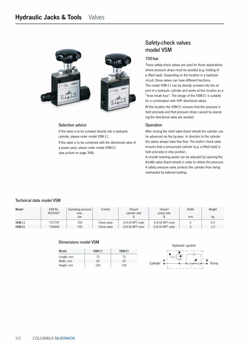
372
Hydraulic Jacks & Tools Valves
Safety-check valves model VSM700 barThese safety-check valves are used for those applications where pressure drops must be avoided (e.g. holding of a lifted load). Depending on the location in a hydraulic circuit, these valves can have different functions. The model VSM-11 can be directly screwed into the oil port of a hydraulic cylinder and works at this location as a “hose break fuse“. The design of the VSM-21 is suitable for a combination with VHP directional valves.
At this location the VSM-21 ensures that the pressure is held precisely and that pressure drops caused by operat-ing the directional valve are avoided.
OperationAfter closing the relief valve (hand wheel) the cylinder can be advanced via the by-pass. In direction to the cylinder the valves always have free flow. The built-in check valve ensures that a pressurized cylinder (e.g. a lifted load) is held precisely in stop position. A smooth lowering speed can be adjusted by opening the throttle valve (hand wheel) in order to relieve the pressure. A safety pressure valve protects the cylinder from being overloaded by external loading.
Selection adviceIf the valve is to be screwed directly into a hydraulic cylinder, please order model VSM-11.
If the valve is to be combined with the directional valve of a power pack, please order model VSM-21. (see picture on page 368).
Technical data model VSM
Model EAN-No. 4025092*
Operating pressure max.bar
Control Oil-port cylinder side
A
Oil-port pump side
B
Width
mm
Weight
kg
VSM-11 *157797 700 Check valve 3/8-18 NPT outer 3/8-18 NPT inner 6 0.9VSM-21 *158442 700 Check valve 3/8-18 NPT inner 3/8-18 NPT outer 6 1.0
Dimensions model VSM
Model VSM-11 VSM-21
Length, mm 75 75Width, mm 25 25Height, mm 100 100
A B
Hydraulic symbol
Cylinder Pump

373
Hydraulic Jacks & Tools Valves
Throttle-/Shut-off valves model VHM700 barThese valves are used to shut-off hydraulic lines especially in multiple cylinder systems. The needle valve VHM-1 also allows to throttle an oil flow especially in connection with lifting applications.
Technical data model VHM
Model EAN-No. 4025092*
Operating pressure max.bar
Control Oil ports both ends
Width
mm
Weight
kg
VHM-1 *154819 700 Needle 3/8-NPT inner 6 0.4VHM-2 *154963 700 Ball 3/8-NPT inner 6 0.9
Dimensions model VHM
Model VHM-1 VHM-2
Length, mm 75 75Width, mm 28 45Height, mm 100 75
VHM-2VHM-1
P
Hydraulic symbol
Pressure switch model VPSAdjustable between 100 - 800 barAs soon as the pressure has reached the set value, a micro-switch (altering contact) is activated.
This signal can be used:
• For automatic pressure limiting.
• To report a certain pressure value.
• As an automatic motor on/off switch with pressure guard power packs.
As soon as the pressure has reached the set value, a micro-switch (alternating contact) is activated. Should the pressure drop, the micro-switch starts the pump again in order to rebuild the pressure.
Technical data model VPS
Model EAN-No. 4025092*
Control range
bar
Electric data Oil ports Difference of switch point
bar
Repeat accuracy
bar
Weight
kg
VPS-1 *155090 100 - 800 5 A/250 V 3/8 NPT 25 - 70 10 0.5
Dimensions model VPS
Model VPS-1
Height x width, mm 130 x 85
Hydraulic symbol

374
Hydraulic Jacks & Tools Valves
Pressure relief valves model VPR0 - 700 barPressure relief valves are used it the system pressure (force of the connected hydraulic cylinder) should not exceed a certain value. These precision valves can be easily adjusted and are characterized by precise repeti-tion. The question of a pressure relief valve only depends on the displacement of the high pressure stage of the power pack.
After achieving the set pressure value, the excessive oil is guided back to the reservoir (pressureless).
Technical data model VPR
Model EAN-No. 4025092*
Control rangebar
Oil ports P Oil ports T Oil flow max.l/min
Weightkg
VPR-1 *155212 0-700 G3/8 G 1/4 10 0.8
Dimensions model VPR
Model VPR-1
Length, mm 120Ø, mm 40
P
Hydraulic symbol

375
Hydraulic Jacks & Tools Accessories
Manifolds model MY700 barManifolds are used when several hydraulic cylinders have to be connected to one hydraulic pump. All manifolds are equipped with 3/8 NPT inner oil ports, so that fittings, hydraulic hoses and couplers can easily be attached. To connect a manifold directly to a hand pump a FY-1 double nipple is recommended. Each manifold is supplied with three steel blind plugs in case not all the oil ports are required.
Technical data model MY
Model EAN-No. 4025092*
Oil ports Weightkg
MY-1 *154789 6 x 3/8-NPT inner 0.5MY-2 *154895 4 x 3/8-NPT inner 0.6MY-4 *154833 7 x 3/8-NPT inner 1.4
Dimensions model MY
Model MY-1 MY-2 MY-4
A, mm 40 150 330B, mm 50 40 40C, mm – 90 90D, mm – 30 30
MY-2
MY-4
MY-1
A BC DA
B
C DA
B

376
Hydraulic Jacks & Tools Accessories
Manifolds model MYWith shut-off valve, 700 barManifolds with shut-off valves are used when different pressures must be maintained in each hydraulic line and therefore allow the lifting of unequal loads. The manifolds are fully assembled and can be screwed directly to a hand pump or power pack. Depending on the way of assembly a short hose HHC-10 and a coupler half CFY-1 can be helpful.
Manifolds models MY ... GYA are equipped with the cor-responding number of shut-off valves plus pressure gauge sets (GYA-63) which allow a permanent reading of each individual load.
Technical data model MY
Model EAN-No. 4025092*
Version Weightkg
MY-22 *155045 Manifold with 2 shut-off valves 1.8MY-44 *155052 Manifold with 4 shut-off valves 3.7MY-66 *159517 Manifold with 6 shut-off valves 5.5MY-22-GYA *159210 Manifold with 2 shut-off valves and 2 pressure gauges 2.8MY-44-GYA *159227 Manifold with 4 shut-off valves and 4 pressure gauges 5.7MY-66-GYA *159524 Manifold with 6 shut-off valves and 6 pressure gauges 8.5
Hand pump HPS - 2/2 with MY - 44
Electric hydraulic pump PY - 07/3/20/3 M with VSM - 21 and MY - 44
MY-44-GYA
MY-22-GYA
MY-44
MY-22
Assembly examples:

377
Hydraulic Jacks & Tools Accessories
Transportation box model HPK-10For hand pumps, hydraulic cylinders and accessoriesFor easy transportation and protection of your valuable tools. Large enough to take a hand pump with pressure gauge and hydraulic hose plus several hydraulic cylinders.
The sturdy sheet metal box is equipped with a solid handle and two clasps.
Model HPK-10 Dimensions (L x W x H): 800 x 300 x 170 mm, weight: approx. 7.8 kg.
Hydraulic oil model HFYFor all hand pumps and power packsThe high quality of the Yale hydraulic oil guarantees a long service life for your equipment.
The high grade HLP oil has the following features:
Features• Class of viscosity ISO VG 32.
• High lubrication index.
• High pressure resistance
• Favourable temperature/viscosity index.
• Protection against corrosion and cavitation.
• Minimizes the formation of foam and sludge.
• Good derivation of temperature.
• No aging problems
• Good compatibility with all sealing materials.
• Fulfills all requirements of DIN 51524 part 2.
Technical data model HFY
Model EAN-No. 4025092*
Contentl
HFY-1 *156622 1HFY-5 *156639 5HFY-10 *159562 10HFY-20 *159579 20

378
Hydraulic Jacks & Tools Accessories
Pressure gauges model GGYThe use of pressure gauges is recommended when the operating pressure (the force of the connected cylinder) should be monitored. Yale pressure gauges are equipped with a stainless steel housing and an acrylic plastic face cover plate.
To absorb pressure shocks gauges are glycerine-filled, thus contributing to a long service life. Also, when fitted to a motor pump, the pointer will stay jitterfree.
For the calculation of applied cylinder forces correspond-ing converting charts (pressure vs. force) can be supplied for all Yale hydraulic cylinders free of charge.
Pressure gauge model GYA-63Consisting of pressure gauge GGY-632 (diameter Ø 63 mm, glycerine-damped) and correspond- ing gauge adaptor. This pressure gauge set is suitable for connection to all HPS hand pumps.
Assembled ready to use, compact design with 45° inclination for easy reading.
Technical data model GGY
Model EAN-No. 4025092*
Pressure range
bar
Scale diameter
mm
Glycerine- damped
Oil port DIN 16288
Spanner size
Accuracy class
%
GGY-631 *154796 0 - 1000 63 yes G 1/4 14 1.6GGY-632 *155120 0 - 1000 63 yes 1/4 NPT 14 1.6GGY-633 *155274 0 - 160 63 yes G 1/4 14 1.6GGY-634 *155281 0 - 250 63 yes G 1/4 14 1.6GGY-635 *155298 0 - 400 63 yes G 1/4 14 1.6GGY-636 *155304 0 - 600 63 yes G 1/4 14 1.6GGY-1001 *154802 0 - 1000 100 yes G 1/2 22 1.0GGY-1001 SZ ¹ *155168 0 - 1000 100 yes G 1/2 22 1.0GGY-1004 *155151 0 - 700 100 yes G 1/2 22 1.0GGY-1005 *159203 0 - 160 100 yes G 1/2 22 1.0GGY-1002 *155137 0 - 250 100 yes G 1/2 22 1.0GGY-1003 *155144 0 - 400 100 yes G 1/2 22 1.0GGY-2500 *155113 0 - 2500 100 yes G 1/2 22 1.6
¹ GGY-1001 SZ = with maximum pointer
Technical data model GYA-63
Model EAN-No. 4025092*
Pressure gaugebar
Oil port pump Oil port hose Weightkg
GYA-63 *156103 0 - 1000 bar, Ø 63 mm, glycerine-damped 3/8-NPT outer 3/8-NPT inner 0.5

379
Hydraulic Jacks & Tools Accessories
Pressure gauge adaptor model GAGauge connection with sleeve nut and 30° inclination for easy reading.
Suitable for all hand pumps series HPS.
Pressure gauge adaptor model GAFor double-acting hand pumps model HPH, for mounting between 4/2-directional valve and hand pump.
Features• Advantage: shows both the pushing force and the pull-
ing force of the connected hydraulic cylinder.
• 30° inclination for easy reading.
• Pressureless return line by means of telescopic double nipple.
Pressure gauge adaptor model GA-2000This pressure gauge adaptor is suitable for connection to all TWAZ hand pumps (2000 bar). Suitable for pressure gauge GGY-2500.
Technical data model GA
Model EAN-No. 4025092*
Oil port gauge Oil port pump Oil port hose
GA-700 *155557 G 1/4 3/8-NPT outer 3/8-NPT innerGA-701 *155588 G 1/2 3/8-NPT outer 3/8-NPT inner
Technical data model GA
Model EAN-No. 4025092*
Oil port gauge Oil port Telescopic nipple
GA-703 *155564 G 1/2 2 x 3/8-NPT outer 2 x 1/4-NPT outerGA-704 *156172 G-1/4 2 x 3/8-NPT outer 2 x 1/4-NPT outer
Technical data model GA-2000
Model EAN-No. 4025092*
Operating pressure max. bar
Oil port gauge Oil port pump Oil port hose
GA-2000 *155915 2000 G 1/2 M22 x 1.5 outer (with seal cone) M22 x 1.5 inner (for FY - 201)

380
Hydraulic Jacks & Tools Accessories
Hydraulic couplers models CFY, CMY, CCYYale hydraulic couplers are self-sealing which means that the coupler halves only have to be closed hand-tight. Both female and male parts have inner balls which seal the coupler halves in uncoupled condition, so that no hydraulic fluid will leak.
Please note that all Yale hydraulic cylinders are equipped with the standard female coupler half CFY-1 and dust cap CDF-9.
Technical data models CFY, CMY and CCY
Model EAN-No. 4025092*
Description Connection thread Pressure max.bar
CFY-1 *155489 Coupler half, female (standard) 3/8-NPT, outer 700CFY-2 *155960 Coupler half, female 3/8-NPT inner 700CFY-18 *155922 Coupler half, female M18 x 1.5 outer 700CFY-10-S *156400 Coupler half, female Pipe Ø 10 mm 700CMY-1 *155496 Coupler half, male 3/8-NPT, inner 700CCY-1 *155472 Coupler halves, female + male 3/8-NPT 700CDF-9 ¹ *155885 Dust cap, rubber – –
¹ fits to female and male coupler halves (standard with all female coupler halves)
Dimensions models CFY, CMY and CCY
Model CFY-1 CFY-2 CFY-18 CFY-10-S CMY-1 CCY-1
A, mm – – – – – 85B, mm 72 78 72 72 – –C, mm – – – – 38 –D, mm 35 35 35 35 – –E, mm 24 27 24 24 – –F, mm – – – – 32 –
CDF-9
CFY-2
CMY-1
CFY-18
CFY-10 S
CFY-1
A B
D
EC
F
Coupler complete CCY-1 Coupler half, male CMY-1 Coupler half, female CFY-1
INFO
Hydraulic couplers must always be completely closed, since otherwise the circulation cannot be released.

381
Hydraulic Jacks & Tools Accessories
How to order
Hydraulic hoses model HHCDurable but highly flexible thermoplast hydraulic hoses guarantee a very long life.
The 4-layer build-up includes 2 layers of high tensile steel fabric and robust fitting with 19 mm hexagon.
The volumetric expansion is very low. Hydraulic hoses model HHC... are equipped with a male coupler half as standard.
Standard length are as per the chart below, further lengths or hoses with larger diameters are quoted on request.
Hydraulic hose for all standard combinations (- pump - hose - cylinder -):
Order a standard hose with female coupler half model HHC... (e.g. HHC-20).
Hydraulic hose for coupling connections on both sides (both ends with CMY-1):
Order a complete coupler CCY-1 in addition to a standard hose model HHC... (recommended for long hydraulic hoses).
Hydraulic extension hose (one male coupler half, one female coupler half):
Order a female coupler half CFY-2 (inner thread) in addition to a standard hose model HHC.
Hydraulic hose without any coupler parts (both ends with threaded nipples):
Order model HH... (both ends 3/8-NPT outer).
Technical data model HHC
Model EAN-No. 4025092*
Length
m
Width
mm
Operating pressure
bar
Burst pressure
bar
Connection 2 male coupler
half CMY-1
Connection 1 thread nipple
3/8-NPT, outer
External diameter approx.
mm
Bend radius min.
mm
Width
mm
HHC-5 *155786 0.5 6.3 700 2800 14 100 6.3HHC-10 *155687 1 6.3 700 2800 14 100 6.3HHC-20 *155380 2 6.3 700 2800 14 100 6.3HHC-30 *155793 3 6.3 700 2800 14 100 6.3HHC-40 *155397 4 6.3 700 2800 14 100 6.3HHC-60 *155595 6 6.3 700 2800 14 100 6.3HHC-80 *155731 8 6.3 700 2800 14 100 6.3HHC-100 *155809 10 6.3 700 2800 14 100 6.3HHC-120 *156370 12 6.3 700 2800 14 100 6.3HHC-150 *156387 15 6.3 700 2800 14 100 6.3

382
Hydraulic Jacks & Tools Accessories
Fittings, reducers, connectors model FYFittings are useful for versatile combinations of hydraulic cylinders.
Yale high pressure fittings have been designed to give a variety of connections, extensions and combinations. The fittings are designed for a max. system pressure of 700 bar.
For improved sealing of 3/8 NPT connections use 2 lay-ers of teflon tape and tighten accordingly.
Technical data model FY
Model EAN-No. 4025092*
Description Figures Connection 1 Connection 2
FY-1FY-1L
*155403*156219
Double nippleDouble nipple, long
3/8 NPT outer3/8 NPT outer
––
FY-13FY-17FY-18
*155656*155816*155823
Double nipple1/4 NPT outer3/8 NPT outer3/8 NPT outer
R 1/4 outerM14 x 1.5 (for sleeve nut)
R 1/4 outer
FY-2 *155410 Elbow 3/8 NPT outer 3/8 NPT inner
FY-3 *155427 Elbow – 3/8 NPT inner
FY-6 *155458 Cross – 3/8 NPT inner
FY-4 *155434 Tee – 3/8 NPT inner

383
Hydraulic Jacks & Tools Accessories
Technical data model FY
Model EAN-No. 4025092*
Description Figures Connection 1 Connection 2
FY-5 *155441 Tee 3/8 NPT outer 3/8 NPT inner
FY-7FY-11
*155465*155649 Connection – 3/8 NPT inner
1/4 NPT inner
FY-8FY-9
*155540*155632 Adaptor 3/8 NPT outer
1/4 NPT outerR 1/2 inner
3/8 NPT inner
FY-10FY-12
*155663*155670 Adaptor 3/8 NPT outer
1/2 NPT outer1/4 NPT inner3/8 NPT inner
FY-16FY-19FY-20FY-30FY-33
*155748*155830*155847*156318*156592
Adaptor
3/8 NPT outerM18 x 1.5 outer
M14 outerG 3/8 outer
3/8 NPT outer
M18 x 1.5 inner3/8 NPT inner3/8 NPT inner3/8 NPT innerM14 x 1.5 inner
FY-26FY-27
*156196*156202 Double nipple 3/8 NPT outer
G 3/8 outerG 3/8 outerG 3/8 outer
FY-31FY-32
*156325*156332 Connection 3/8 NPT inner
3/8 NPT innerM18 x 1.5 innerM20 x 1.5 inner
FY-35 *156608 Double nipple M14 outer –
FY-703 *155571
Connecting set for 4/3-way valve to HPS hand pumps (telescopic nipple)
3/8 NPT outer 1/4 NPT outer
FY-201 *156011Adaptor
for TWAZ hand pumps 2000 bar
R1/4 outer M22 x 1.5 outer (with seal cone)

384
Hydraulic Jacks & Tools Puller
Hydraulic puller with integrated hydraulics model BMZPulling force max. 6, 8 and 11 tHydraulic pullers are a valuable tool for the maintenance engineer. The pullers allow time and cost savings as they offer high working safety and can be operated in all posi-tions. Hydraulic pullers are used in all kinds of industries, workshops and in many repair and assembly jobs to remove or install interference fit parts, such as: gears, couplings, bearings, wheels, pulleys, axles, shafts, break drums and many other press fit components. Damage to parts is minimized through the use of controlled hydraulic power, whilst machine down-time can be reduced drasti-cally.
Features• Drop-forged alloy steel jaws.
• Hard chromium plated piston, spring return.
• No radial moment of torsion.
• No spindle wear.
• Integrated hydraulic cylinder and pump.
• Quick adjustment with trapezoid speed nut.
• 3 and 2-jaw design.
• Pump lever can rotate through 360°.
• Piston with durable, spring loaded centering tip.
• Supplied in a sturdy plastic box.
Technical data model BMZ
Model EAN-No. 4025092*
Pulling force max.t
Strokemm
Weightkg
BMZ-6 *154499 6 82 4.9BMZ-8 *154505 8 82 6.6BMZ-11 *154512 11 82 8.0
Dimensions model BMZ
Model BMZ-6 BMZ-8 BMZ-11
Reach max. A, mm 160 200 230Diameter Ø max. B, mm 200 250 280Length C, mm 320 320 345
A
B
C

385
Hydraulic Jacks & Tools Puller
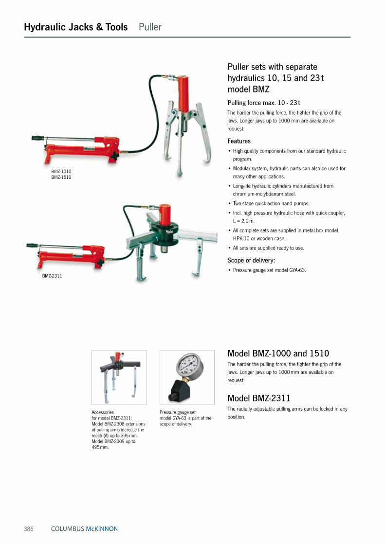
386
Hydraulic Jacks & Tools Puller
Puller sets with separate hydraulics 10, 15 and 23 t model BMZPulling force max. 10 - 23 tThe harder the pulling force, the tighter the grip of the jaws. Longer jaws up to 1000 mm are available on request.
Features• High quality components from our standard hydraulic
program.
• Modular system, hydraulic parts can also be used for many other applications.
• Long-life hydraulic cylinders manufactured from chromium-molybdenum steel.
• Two-stage quick-action hand pumps.
• Incl. high pressure hydraulic hose with quick coupler, L = 2.0 m.
• All complete sets are supplied in metal box model HPK-10 or wooden case.
• All sets are supplied ready to use.
Scope of delivery:• Pressure gauge set model GYA-63.
Model BMZ-1000 and 1510The harder the pulling force, the tighter the grip of the jaws. Longer jaws up to 1000 mm are available on request.
Model BMZ-2311The radially adjustable pulling arms can be locked in any position.
Accessories for model BMZ-2311: Model BMZ-2308 extensions of pulling arms increase the reach (A) up to 395 mm.Model BMZ-2309 up to 495 mm.
Pressure gauge set model GYA-63 is part of the scope of delivery.
BMZ-1010 BMZ-1510
BMZ-2311
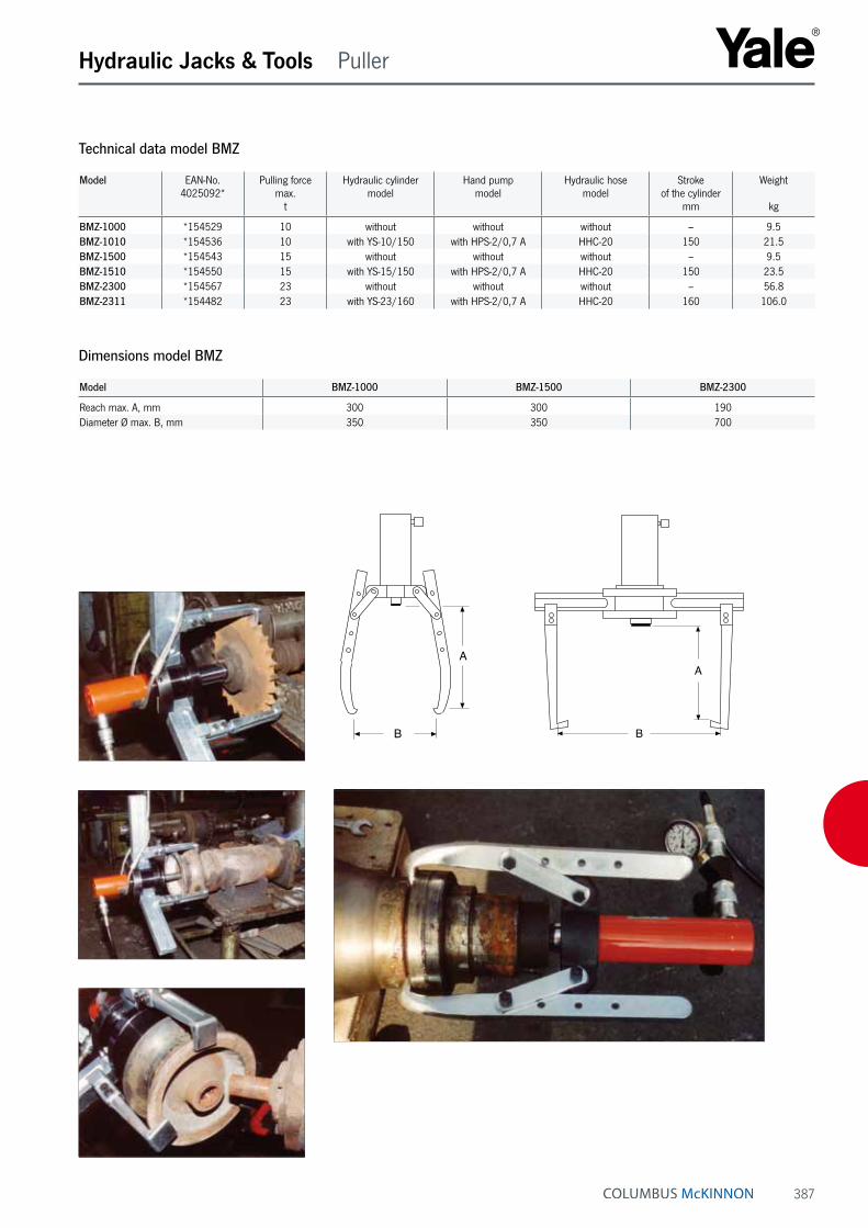
387
Hydraulic Jacks & Tools Puller
Technical data model BMZ
Model EAN-No. 4025092*
Pulling force max.
t
Hydraulic cylinder model
Hand pump model
Hydraulic hose model
Stroke of the cylinder
mm
Weight
kg
BMZ-1000 *154529 10 without without without – 9.5BMZ-1010 *154536 10 with YS-10/150 with HPS-2/0,7 A HHC-20 150 21.5BMZ-1500 *154543 15 without without without – 9.5BMZ-1510 *154550 15 with YS-15/150 with HPS-2/0,7 A HHC-20 150 23.5BMZ-2300 *154567 23 without without without – 56.8BMZ-2311 *154482 23 with YS-23/160 with HPS-2/0,7 A HHC-20 160 106.0
Dimensions model BMZ
Model BMZ-1000 BMZ-1500 BMZ-2300
Reach max. A, mm 300 300 190Diameter Ø max. B, mm 350 350 700
A
B
A
B

388
Hydraulic Jacks & Tools Puller
Hydraulic puller sets model YHPPulling force max. 10 - 50 tThese professional puller sets are designed for removing and installing press-fitted or heat-fitted parts. Hydraulic puller sets eliminate time-consuming and costly repairs as they avoid the damage of parts and reduce machine downtimes. All parts are manufactured from high quality drop-forged steel.
Scope of deliveryThe complete sets are supplied ready to use and include all necessary components such as hollow cylinder, hydraulic hand pump, pressure gauge (to control the pull-ing force) and 2 meter hydraulic hose with quick-connect coupler.
3-Grip puller setsFor all pulling jobs where solid parts have to be removed, e.g. gears, belt pulleys, sprockets, flywheels, couplers, shafts, axles etc. The sets can be used as both 3-jaw and 2-jaw puller.
Model EAN-No. 4025092*
Pulling force max.t
YHP-252 G *161992 20YHP-352 G *162005 30YHP-552 G *162012 50
Cross-bearing puller setsFor all pulling jobs where multi-segmented parts have to be removed: ball bearings, roller bearings and similar parts. Puller sets are supplied complete with bearing puller attachment and bearing cup puller.
Model EAN-No. 4025092*
Pulling force max.t
YHP-262 G *162029 10YHP-362 G *162036 20YHP-562 G *162043 25
Multi-purpose puller setsThese multi-purpose puller sets are universal combina-tions of both a.m. sets and include all necessary parts from 3-grip puller set and crosshead puller set.
Model EAN-No. 4025092*
Pulling force max.t
YHP-2752 G *161787 20/10YHP-3752 G *161824 30/20YHP-5752 G *162050 50/25
INFO
The set “Cross-bearing puller” have reduced max. pulling forces.

389
Hydraulic Jacks & Tools Puller
Type of puller set
3-grip puller set Crosshead puller set Multi purpose puller setModel YHP-252 G YHP-352 G YHP-552 G YHP-262 G YHP-362 G YHP-562 G YHP-2752 G YHP-3752 G YHP-5752 G
EAN-No. 4025092* *161992 *162005 *162012 *162029 *162036 *162043 *161787 *161824 *162050Capacity, t 20 30 50 10 20 25 20/10 30/20 50/25Hand pump, model HPS-1/07 A (part 1) • • – • • – • • –Hand pump, model HPS-2/2 A (part 1) – – • – – • – – •Pressure gauge set, model GYA-63 (part 2) • • • • • • • • •Hydraulic hose, model HHC-20 (part 3) • • • • • • • • •Hollow cylinder (part 4), model YCS-21/50 YCS-33/60 YCS-57/70 YCS-21/50 YCS-33/60 YCS-57/70 YCS-21/50 YCS-33/60 YCS-57/70Triple crosshead (part 5) • • • – – – • • •Double crosshead (part 6) • • • – – – • • •Grip arm, 3 pcs. (part 8) • • • – – – • • •Spindle (part 9) • • • • • • • • •Strap, 6 pcs. (part 10) • • • – – – • • •Strap screws + strap nuts, 6 pcs. (part 11) • • • – – – • • •Mounting screws, 2 pcs. (part 13a) • • • – – – • • •Mounting screws, 2 pcs. (part 13b) – – – • • • • • •Saddle with internal thread (part 14) • • • • • • • • •Smooth saddle (part 15) • • • • • • • • •Slotted crosshead (part 16) – – – • • • • • •Slide plate, 2 pcs. (part 17) – – – • • • • • •Nut, 2 pcs. (part 18) – – – • • • • • •Washer, 2 pcs. (part 19) – – – • • • • • •Pulling leg, short, 2 pcs. (part 20), mm – – – 280 255 455 280 255 455Pulling leg, long, 2 pcs. (part 21), mm – – – 460 505 773 460 505 773Leg end, 2 pcs. (part 24) – – – • • • • • •Leg connector, 2 pcs. (part 25) – – – • • • • • •Bearing puller attachment (part 26) – – – • • • • • •Bearing cup pulling attachment (part 27) – – – • • • • • •Storage case (part 29) • • • • • • • • •Weight, kg 40 65 120 46 86 156 91 172 295
The symbols stand for: • including complete set, – not included
Dimensions hydraulic puller set model YHP
Model 20 t 30 t 50 t
3-grip A, mm 300 520 700C, mm 0 - 817 0 - 977 0 - 12333-grip B, mm 500 900 1200D, mm 25 - 155 30 - 250 75 - 3302-grip A, mm 300 520 700E, mm 152 250 3302-grip B, mm 420 700 1000F, mm 140 150 150G, mm 30 - 180 75 - 230 75 - 230

390
Hydraulic Jacks & Tools Jacks
Aluminium hydraulic jacks model AJH and model AJSCapacities from 6.5 - 100 tAluminium jacks combine light weight with high lifting capacity. The use of high tensile aluminium alloy allows lifting capacities of up to 100 tons resulting in a very favourable 1.8 tons lifting capacity per 1 kg weight ratio. Operation of Yale hydraulic jacks is very simple. Jacks are supplied ready for use, i.e. including hydraulic oil, operating lever and, where applicable, carrying handle and lifting claw.
Aluminium jacks with lifting clawJacks from 20 tons are available with a lifting claw. In this case the jacks are provided with an elongated base plate. The max. permissible working load of the lifting claws is 40 % of the jack capacity.
Aluminium jacks with safety lock nutJacks from 20 tons can be supplied with a safety lock nut. This device allows absolute safe jacking over a long period. In this case the hydraulic jack can be operated like a mechanical support and the hydraulic system can be totally released.
ApplicationHydraulic jacks are universally popular tools for use in workshops or on site for all kinds of lifting and assembly applications, for construction, shipbuilding, power plants, general engineering, metal fabrication and many more. Applications are unlimited. Standard jacks with plain pis-ton and jacks with safety lock nuts cannot be used with a lifting claw. To increase stability, all jacks with long stroke (305 mm) are equipped with an elongated base plate.
Features• Strokes from 75 - 305 mm.
• Extremely low weight.
• The 6.5 and 10 tons jacks can be operated in any posi-tion (also upside down) and are equipped with spring return piston and stop ring.
• The 20 to 100 tons jacks can be operated vertically or with front face in horizontal position.
• All jacks are provided with an overload protection valve.
• From 20 tons capacity with additional mechanical stroke limiter.
• All jacks with hardened alloy steel saddle and sensitive lowering valve which is activated by the operating lever.
AJH-630 SR
AJH-620AJS-65
AJS-104

391
Hydraulic Jacks & Tools Jacks
Technical data model AJH and model AJS
Model EAN-No. 4025092*
Capacity
t
Capacity of lifting claw max.
t
Stroke
mm
Overall height
mm
Base plate
mm
Height of lifting claw min.
mm
Weight
kg
AJS-65 *157995 6.5 – 75 131 159 x 76 – 3.6AJS-104 *158015 10 – 115 182 171 x 76 – 6.3
AJH-620 *158046 20 – 152 265 180 x 120 – 10.9AJH-1220 *158107 20 – 305 440 250 x 120 – 16.7AJH-630 *158169 30 – 152 265 200 x 140 – 15.4AJH-1230 *158220 30 – 305 452 275 x 140 – 23.4AJH-660 *158282 60 – 152 293 250 x 190 – 27.4AJH-1260 *158343 60 – 305 500 340 x 190 – 43.7AJH-6100 *158404 100 – 152 315 305 x 250 – 49.0
Model EAN-No. 4025092*
Capacity
t
Capacity of lifting claw max.
t
Stroke
mm
Overall height
mm
Base plate
mm
Height of lifting claw min.
mm
Weight
kg
AJH-620 C *158060 20 8 152 280 250 x 120 67 14.5AJH-1220 C *158121 20 8 305 452 250 x 120 67 22.2AJH-630 C *158183 30 12 152 284 275 x 140 72 20.3AJH-1230 C *158244 30 12 305 472 275 x 140 72 31.0AJH-660 C *158305 60 24 152 327 340 x 190 72 43.1AJH-1260 C *158367 60 24 305 533 340 x 190 72 64.9
Jacks with lifting claw
Model EAN-No. 4025092*
Capacity
t
Capacity of lifting claw max.
t
Stroke
mm
Overall height
mm
Base plate
mm
Height of lifting claw min.
mm
Weight
kg
AJH-620 SR *158084 20 – 152 291 180 x 120 – 10.9AJH-1220 SR *158145 20 – 305 464 250 x 120 – 16.7AJH-630 SR *158206 30 – 152 294 200 x 140 – 15.4AJH-1230 SR *158268 30 – 305 480 275 x 140 – 23.4AJH-660 SR *158329 60 – 152 330 250 x 190 – 27.4AJH-1260 SR *158381 60 – 305 536 340 x 190 – 43.7AJH-6100 SR *158428 100 – 152 366 305 x 250 – 53.0
Jacks with safety lock nut

392
Hydraulic Jacks & Tools

393
Hydraulic Jacks & Tools Jacks
Machine jacks with lifting claw model YAMCapacity 2 - 15 tMachine jacks with lifting claw are used in applications where space below the load is restricted, thus preventing the use of traditional lifting equipment.
Typical applications for machine jacks are lifting, positioning and transportation of machines, heavy steel constructions or similar loads, as well as general repair and assembly applications.
The jacks are also useful for applications like leveling of high-rise warehouses, heavy-duty scaffolds, large frame-works etc.
Features• Offers safe lifting of machines with an extremely low
clearance.
• Incl. safety pressure valve to prevent overload.
• Large base offers increased stability under load.
• Pump lever can rotate through 270° (excluding YAM-2).
• Same load can be lifted on either the head or the claw of jack.
• Spring return of the lifting claw (only YAM-5 and YAM-10).
• Precision-adjustable lowering valve.
• Jacks are supplied ready to use incl. pump lever, and are filled with oil.
Technical data model YAM
Model EAN-No. 4025092*
Capacity on the claw
t
Stroke
mm
Weight
kg
YAM-2 *157711 2 113 8YAM-5 *153997 5 120 19YAM-10 *154000 10 145 38YAM-15.1 *338851 15 140 53
Dimensions model YAM
Model YAM-2 YAM-5 YAM-10 YAM-15.1
A, mm 235 290 325 344B, mm 180 257 280 321C, mm 125 182 240 258D, mm 50 75 100 110E, mm 50 57 60 60F, mm 85 117 150 168G, mm 16 26 33 33
A
E
G
F
D C
B
A
E
G
F
D C
B

394
Hydraulic Jacks & Tools Jacks
Hydraulic machine jacks model YAPCapacity 4.5 - 50 tHydraulic machine jacks are designed for the safe lifting and positioning of machines and similar heavy equip-ment.
Features• These jacks are operated with external pumps, e.g.
hand or motor pumps but also with synchronous power packs.
• The compact construction allows operation even in extremely confined areas.
• 3 hook-in positions of the lifting claw provide high flex-ibility (model YAP-5130 4 hook-in positions).
• The load can be lifted with either the lifting claw or with the head of the jack.
• Welded, distortion-proof steel construction.
• High quality, durable hydraulic components.
• The flat lifting claw allows low jacking height.
• Safe stability due to swivel-mounted support feet.
• The connection between jack and pump is made by a hydraulic hose.
• The jacks are delivered ready-to-use inclusive of carry-ing handles and coupling half.
Technical data model YAP
Model EAN-No. 4025092*
Capacityt
Strokemm
Height for applicationsmin. in mm
Pressure max.bar
Weight approx.kg
YAP-5130 *160018 4.5 133 15 700 13.5YAP-10150 *160025 10 155 20 700 23.0YAP-15150 *160032 15 155 25 700 40.0YAP-25150 *160049 23 155 30 700 60.0YAP-50150 *160056 50 155 35 700 165.0
Dimensions model YAP
Model YAP- 5130
YAP- 10150
YAP- 15150
YAP- 25150
YAP- 50150
A min., mm 15 20 25 30 35A max., mm 232 273 291 300 375B, mm 228 277 328 387 540H, mm 252 283 316 330 405L, mm 161 194 245 278 375

395
Hydraulic Jacks & Tools Jacks
Hydraulic machine jacks model YASCapacity 3 - 25 tHydraulic machine jacks are designed for the safe lifting and positioning of machines and similar heavy equip-ment.
Features• Integrated hydraulic pump.
• Pump lever swivel mounted 270° for operation even in extremely confined areas.
• Same load can be lifted on either the head or the claw of jack.
• Welded, distortion-proof steel construction.
• High quality, durable hydraulic components.
• The flat lifting claw allows low jacking height.
• The additional connect coupler (10 t capacity and larger) for external pump operation, allows connection of hand, motor or synchronous lifting pumps (max. pressure 520 bar).
• Safe stability due to swivel-mounted support feet.
• Sensitive lowering valve for slow lowering of loads without jerks.
• When operating the jack with an external pump the installation of a manometer is mandatory.
• The integrated hydraulic pump is protected by a pressure-limiting valve.
• The jacks are delivered ready-to-use inclusive of carry-ing handles, hydraulic oil filling and pump lever.
Technical data model YAS
Model EAN-No. 4025092*
Capacityt
Strokemm
Height for applicationsmin. in mm
Pressure max.bar
Weight approx.kg
YAS-3 *160063 3 140 12 520 15.0YAS-5 *160070 5 140 15 520 19.0YAS-10 *160087 10 140 20 520 28.0YAS-15 *160094 15 140 25 520 50.0YAS-25 *160100 25 140 30 520 72.0
Dimensions model YAS
Model YAS-3 YAS-5 YAS-10 YAS-15 YAS-25
A min., mm 12 15 20 25 30A max., mm 230 232 300 291 300B, mm 207 228 277 328 387H, mm 250 252 252 316 330L, mm 198 216 271 345 388

396
Hydraulic Jacks & Tools Jacks
Hydraulic stage lifts model STCapacity 50 - 200 tFor compact, low-headroom and universal applications. Stage lifts are hydraulic lifting devices which are designed to lift and lower loads over high distances.
Stage lifts overcome the usual limitations of their lifting height imposed by stroke length. Stage lifts operate with “double-acting“ hydraulic cylinders (return stroke by hydraulic pressure) and are equipped with a load spread-ing plate and a piston support plate.
OperationA stage lift operates inverted and lifts the load via the bottom of the cylinder whilst it climbs on a pile of support bars (wood or aluminium). In principle, the load can be lifted to any height although stage lifts are still compact and versatile for low-headroom lifting applications.
The simple “3-step operation“ eliminates the need for additional holding arrangements and the repositioning or replacing of cylinders which are normally required for a higher lifting distance. A stage lift climbs up and down on its own.
ControlDepending on the power pack, selected stage lifts can be controlled individually (by hand or motor pump) or together in a synchronized arrangement with multi-flow pumps.
Features• Yale ChroMo-Design.
• Low-cost lifting systems possible, (3-point resp. 4-point).
• Low weight (e.g. 60 kg for a 50 t unit).
• Stage lift body made from high-grade aluminium.
• Hydraulic cylinders are made from robust chromium-molybdenum steel with double bronze bearings ensure a longlife service system.
• Large-diameter tilt saddle.
• Incl. coupler halves and carrying handles on request.

397
Hydraulic Jacks & Tools Jacks
Technical data model ST
Model EAN-No. 4025092*
Capacity max.
t
Stroke
mm
Overall height
mm
Load-spreading plate Ø
mm
Piston plate Ø
mm
Weight approx.
kg
ST-5015 *157810 50 150 396 425 x 425 160 60ST-10015 – 100 150 455 525 x 525 180 115ST-20015 – 200 150 510 600 x 600 210 196
Pads
Tilt saddle
Hydraulic cylinder
Carrying handle
Load-spreading plate
Piston plate
A A
A A A AB A AB
A
BA AB
A
B
A A
A AB
B
A
B
A A
A A
B
B
1. Stage: Initial position, stage lift rests on the ground under the load.
2. Stage: Step 1, load is raised.
3. Stage: Two support bars type “A“ are positioned in place.
4. Stage: Piston is retracted and load rests on support bars type “A“.
5. Stage: Broader middle bar type “B“ is inserted.
6. Stage: Step 2, load raised on broader middle bar “B“.
7. Stage: Two bars “A“ are inserted and rotated at 90°, piston is retracted and mid-dle bar is inserted.
8. Stage: Load is lifted on middle bar (3rd step), two support bars type “A“ are positioned at 90° and load rests on support bars “A“.
9. Stage: Piston is retracted, middle bar type “B“ is inserted and lifts the 4th step on middle bar “B“ and so on...
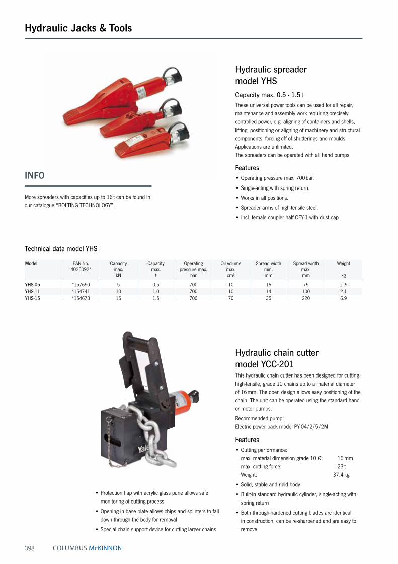
398
Hydraulic Jacks & Tools
Hydraulic spreader model YHSCapacity max. 0.5 - 1.5 tThese universal power tools can be used for all repair, maintenance and assembly work requiring precisely controlled power, e.g. aligning of containers and shells, lifting, positioning or aligning of machinery and structural components, forcing-off of shutterings and moulds. Applications are unlimited. The spreaders can be operated with all hand pumps.
Features• Operating pressure max. 700 bar.
• Single-acting with spring return.
• Works in all positions.
• Spreader arms of high-tensile steel.
• Incl. female coupler half CFY-1 with dust cap.
Hydraulic chain cutter model YCC-201This hydraulic chain cutter has been designed for cutting high-tensile, grade 10 chains up to a material diameter of 16 mm. The open design allows easy positioning of the chain. The unit can be operated using the standard hand or motor pumps.
Recommended pump: Electric power pack model PY-04/2/5/2M
Features• Cutting performance:
max. material dimension grade 10 Ø: 16 mm max. cutting force: 23 t Weight: 37.4 kg
• Solid, stable and rigid body
• Built-in standard hydraulic cylinder, single-acting with spring return
• Both through-hardened cutting blades are identical in construction, can be re-sharpened and are easy to remove
• Protection flap with acrylic glass pane allows safe monitoring of cutting process
• Opening in base plate allows chips and splinters to fall down through the body for removal
• Special chain support device for cutting larger chains
Technical data model YHS
Model EAN-No. 4025092*
Capacity max.kN
Capacity max.
t
Operating pressure max.
bar
Oil volume max.cm³
Spread width min.mm
Spread width max.mm
Weight
kg
YHS-05 *157650 5 0.5 700 10 16 75 1,.9YHS-11 *154741 10 1.0 700 10 14 100 2.1YHS-15 *154673 15 1.5 700 70 35 220 6.9
INFO
More spreaders with capacities up to 16 t can be found in our catalogue “BOLTING TECHNOLOGY”.

399
Hydraulic Jacks & Tools
Hydraulic propeller press system model PPSOperating pressure max. 2000 barThe hydraulic propeller press system is used to press-fit large propellers onto the drive shaft of ships. To this end the special flat cylinders can be linked together to build a chain of any length and press force. The cylinders are provided with appropriate link eyes at both sides.
The max. operating pressure of 2000 bar ensures high pressure forces up to 1600 t or more.
A complete hydraulic propeller press system with 12 cylinders with a total capacity of 1200 tons. The system is complete with appropriate connecting hoses with quick-release couplers, pressure gauge up to 2500 bar and hand pump TWAZ-2.3. All parts are designed for a maximum operating pressure of 2000 bar.
Special flat hydraulic cylinderWith link connections at both sides and 2 male quick connect coupler halves
Capacity max. 100 t.
Stroke 10 mm.
Pressure max. 2000 bar.
Diameter 127 mm.
Closed height 50 mm.
(Couplungs do not belong to the scope of supply and must be ordered seperately)
Link plates and lifting hooksThey are used to connect the cylinders and to handle the complete chain with a crane. 2 pieces of link plates and lifting hooks as well as the corresponding number of high-pressure hoses (with female quick connect couplers at both ends) belong to a complete set.
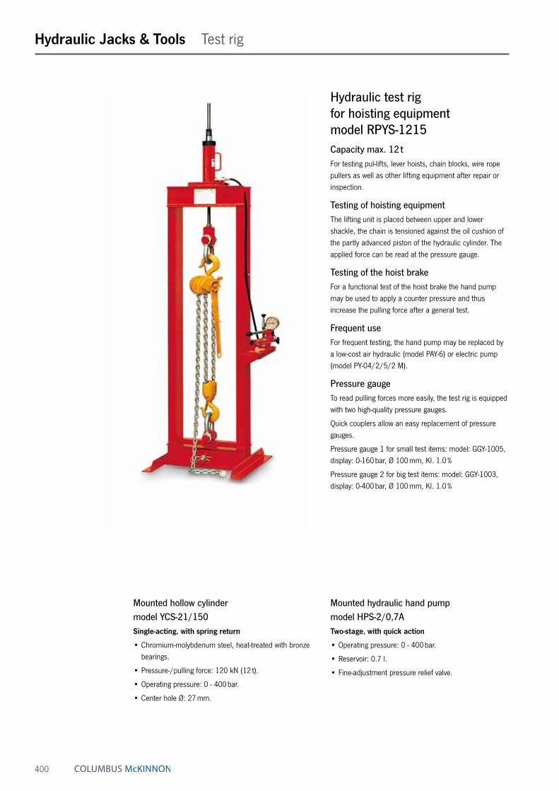
400
Hydraulic Jacks & Tools Test rig
Hydraulic test rig for hoisting equipment model RPYS-1215Capacity max. 12 tFor testing pul-lifts, lever hoists, chain blocks, wire rope pullers as well as other lifting equipment after repair or inspection.
Testing of hoisting equipmentThe lifting unit is placed between upper and lower shackle, the chain is tensioned against the oil cushion of the partly advanced piston of the hydraulic cylinder. The applied force can be read at the pressure gauge.
Testing of the hoist brakeFor a functional test of the hoist brake the hand pump may be used to apply a counter pressure and thus increase the pulling force after a general test.
Frequent useFor frequent testing, the hand pump may be replaced by a low-cost air hydraulic (model PAY-6) or electric pump (model PY-04/2/5/2 M).
Pressure gaugeTo read pulling forces more easily, the test rig is equipped with two high-quality pressure gauges.
Quick couplers allow an easy replacement of pressure gauges.
Pressure gauge 1 for small test items: model: GGY-1005, display: 0-160 bar, Ø 100 mm, Kl. 1.0 %
Pressure gauge 2 for big test items: model: GGY-1003, display: 0-400 bar, Ø 100 mm, Kl. 1.0 %
Mounted hollow cylinder model YCS-21/150Single-acting, with spring return
• Chromium-molybdenum steel, heat-treated with bronze bearings.
• Pressure-/pulling force: 120 kN (12 t).
• Operating pressure: 0 - 400 bar.
• Center hole Ø: 27 mm.
Mounted hydraulic hand pump model HPS-2/0,7ATwo-stage, with quick action
• Operating pressure: 0 - 400 bar.
• Reservoir: 0.7 l.
• Fine-adjustment pressure relief valve.

401
Hydraulic Jacks & Tools Test rig
Features• Fully welded, low-strain press-frame.
• Upper and lower hook suspension by means of shackles, incl. two 5 tons pull-rings for smaller test units.
• Lateral pump table.
• Infinite adjustment of the pulling force.
• Chart for easy determination of test force.
• Removable lower suspension e.g. for testing of plate clamps.
• Base pre-drilled for mounting.
• High-quality hydraulic components.
• Hollow cylinder made from chromium-molybdenum steel, heat-treated, inside and outside with dirt wipers.
• Long cylinder stroke of 150 mm, piston hard chromium-plated with bronze bearings.
• High-strength threaded bar M27.
• Two-stage quick action hand pump.
• Fine-adjustment pressure valve.
Hydraulic test rig for steel winches model RPYS-1535Capacity max. 15 tFor the testing of steel winches or similar lifting devices we offer a specific test rig.
Features• Max. capacity 15 t.
• With hydraulic cylinder model YS-15/350.
• Stroke: 350 mm.
Scope of delivery• Incl. two-stage hand pump model: HPS-2/2 A.
• Fine-adjustment pressure valve 0-700 bar.
• Hydraulic hose 2 m, model: HHC-20.
• Pressure gauge model: GGY-1004, display: 0-700 bar, Ø 100 mm, Kl. 1.0 %.
Technical data model RPYS
Model EAN-No. 4025092*
RPYS-1215 *157469
Dimensions model RPYS
Model RPYS-1215
A, mm 2580 - 2730B, mm 2160C, mm 1840D, mm 500E, mm 630F, mm 760G ¹, mm 1030 - 1425H, mm 750J, mm 150Weight, kg 225
¹ 700 mm with 5 t pull-rings
INFO
The test rigs are delivered complete and ready to use.
DEF
JA B C G
H
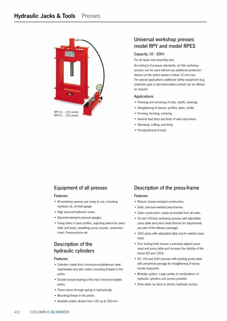
402
Hydraulic Jacks & Tools Presses
Universal workshop presses model RPY and model RPESCapacity 10 - 200 tFor all repair and assembly jobs.
According to European standards, all Yale workshop presses can be used without any additional protection devices as the piston speed is below 10 mm/sec. For special applications additional safety equipment (e.g. protection grid or two-hand-safety-control) can be offered on request.
Applications• Pressing and removing of bolts, shafts, bearings.
• Straightening of beams, profiles, axles, shafts.
• Forming, bending, crimping.
• General load tests and tests of weld specimens.
• Stamping, cutting, punching.
• Pre-adjustment of tools.
Equipment of all pressesFeatures• All workshop presses are ready to use, including
hydraulic oil, oil level gauge.
• High pressure-hydraulic hoses.
• Glycerine-damped pressure gauges.
• Fixing holes in base profiles, adjusting device for press table and head, swivelling pump console, conversion chart: Pressure-force etc.
Description of the hydraulic cylindersFeatures• Cylinders made from chromium-molybdenum steel,
heat-treated and with metric mounting threads in the piston.
• Double bronze bearing of the hard chromium-plated piston.
• Piston return through spring or hydraulically.
• Mounting thread in the piston.
• Available piston strokes from 150 up to 500 mm.
Description of the press-frameFeatures• Robust, torsion-resistant construction.
• Solid, precision-welded press-frames.
• Open construction, easily accessible from all sides.
• 50 and 100 tons workshop presses with adjustable press table and press head (frames for adjustments are part of the delivery package).
• 200 t press with adjustable table and fix welded press head.
• Four locking bolts ensure a precisely aligned press head and press table and increase the stability of the frame (50 and 100 t).
• 50, 100 and 200 t presses with pivoting pump table with peripheral passage for straigthening of excep-tionaly long parts.
• Modular system: Large variety of combinations of hydraulic cylinders and pumps possible.
• Drive either by hand or electric hydraulic pumps.
RPY-10 … (10 t press) RPY-23 … (23 t press)
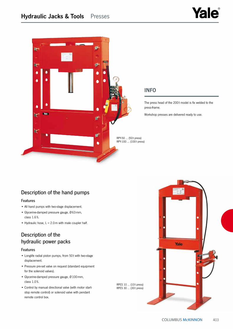
403
Hydraulic Jacks & Tools Presses
Description of the hand pumpsFeatures• All hand pumps with two-stage displacement.
• Glycerine-damped pressure gauge, Ø 63 mm, class 1.6 %.
• Hydraulic hose, L = 2.0 m with male coupler half.
Description of the hydraulic power packsFeatures• Longlife radial piston pumps, from 50 t with two-stage
displacement.
• Pressure pre-set valve on request (standard equipment for the solenoid valves).
• Glycerine-damped pressure gauge, Ø 100 mm, class 1.0 %.
• Control by manual directional valve (with motor start-stop remote control) or solenoid valve with pendant remote control box.
RPY-50 … (50 t press) RPY-100 … (100 t press)
RPES 10 … (10 t press) RPES 30 … (30 t press)
INFO
The press head of the 200 t model is fix welded to the press-frame.
Workshop presses are delivered ready to use.

404
BCD
A
E
F
F
LGIK
H
Hydraulic Jacks & Tools Presses
Technical data model RPY and model RPES
Model EAN-No. 4025092*
Frame design
Capacityt
Cylinder model
Cylinder stroke in mm
Piston return
Type of pump
Valve control
Pump model
RPY-1015 M-2 *157346 bench press 10 YS-10/150 150 spring manual manual HPS-2/0,7 ARPY-1025 EM-PYE 07 *250214 bench press 10 YS-10/250 250 spring electric manual PYE-07/3/10/3M-RPYRPY-2316 M-2 *157360 bench press 23 YS-23/160 160 spring manual manual HPS-2/0,7 ARPY-2325 M-2 *157384 bench press 23 YS-23/250 250 spring manual manual HPS-2/2 ARPY-2325 EM-PYE 07 *651059 bench press 23 YS-23/250 250 spring electric manual PYE-07/3/10/3M-RPYRPES-1015 M-2 *160766 floor press 10 YS-10/150 150 spring manual manual HPS-2/0,7 ARPES-1025 EM-PYE 07 *651059 floor press 10 YS-10/250 250 spring electric manual PYE-07/3/10/3M-RPYRPES-2316 M-2 *160780 floor press 23 YS-23/160 160 spring manual manual HPS-2/0,7 ARPES-2325 M-2 *160797 floor press 23 YS-23/250 250 spring manual manual HPS-2/2 ARPES-2325 EM-PYE 07 *243728 floor press 23 YS-23/250 250 spring electric manual PYE-07/3/10/3M-RPYRPY-5015 EM *158992 floor press 50 YH-50/150 150 hydraulic electric manual PY-04/2/5/4MRPY-5035 EM *157575 floor press 50 YH-50/350 350 hydraulic electric manual PY-04/2/5/4MRPY-5035 EE *157582 floor press 50 YH-50/350 350 hydraulic electric solenoid PYS-07/3/10/4 ERPY-5050 EE *159012 floor press 50 YH-50/500 500 hydraulic electric solenoid PYS-07/3/10/4 ERPY-10035 EM *157599 floor press 100 YH-100/350 350 hydraulic electric manual PY-07/3/20/4 M-RPYRPY-10035 EE *157605 floor press 100 YH-100/350 350 hydraulic electric solenoid PY-07/3/20/4 ERPY-10050 EM *157612 floor press 100 YH-100/500 500 hydraulic electric manual PY-07/3/20/4 M-RPYRPY-10050 EE *158978 floor press 100 YH-100/500 500 hydraulic electric solenoid PY-07/3/20/4 ERPY-20035 EM *157629 floor press 200 YH-200/350 350 hydraulic electric manual PY-11/3/20/4 M-RPYRPY-20035 EE *157636 floor press 200 YH-200/350 350 hydraulic electric solenoid PY-11/3/20/4 ERPY-20050 EM *157643 floor press 200 YH-200/500 500 hydraulic electric manual PY-11/3/20/4 M-RPYRPY-20050 EE *159142 floor press 200 YH-200/500 500 hydraulic electric solenoid PY-11/3/20/4 E
Dimensions model RPY and model RPES (only frame)
Model RPY-10 RPY-23 RPES-10 RPES-23 RPY-50 RPY-100 RPY-200
A min., mm – – 50 50 280 270 320A max., mm 440 440 930 930 1120 830 1000B, mm 380 380 700 700 820 1000 1000C, mm 510 510 650 650 1020 1300 1400D, mm – – 500 500 1200 1480 1580E, mm 180 180 – – 920 860 1040F, mm – – 150 150 140 140 170G, mm – – 240 240 255 335 450H, mm 840 840 1695 1695 2000 2000 2430I, mm 300 300 245 245 315 395 550K, mm – – – – 1000 1000 1000L, mm – – – – 383 333 400Weight approx., kg 77 77 94 94 450 950 2380
Code explanation
Valve control : M = manual pump, E = solenoid valve with pendant remote controlPump : M = manual pump, E = electric pumpPiston stroke : 15 = 150 mm, 16 = 160 mm, 25 = 250 mm, 35 = 350 mm, 50 = 500 mmCapacity max. : 10 = 10 t, 23 = 23 t, 50 = 50 t, 100 = 100 t, 200 = 200 tModel
A
BC
E
H
I
RPY-50, 100 and 200
RPES-10 up to 30RPY-10 up to 23

405
Hydraulic Jacks & Tools Selection charts
Selection chart for single-acting systemsWhich hand pump is suitable for which hydraulic cylinder?The appropriate hand pump model basically depends on the oil volume of the selected hydraulic cylinders. To assist you in your choice please find proposals for the most common cylinders in our range.
How to find the right hand pump in the following charts?The chosen hydraulic cylinder can be found in the first column.
Several hydraulic cylinders connected to one hand pump:In those cases where several hydraulic cylinders are connected to one hand pump, the oil volume must be multiplied by the number of connected cylinders. The reservoir of the hand pump must be at least equal to the required total oil volume (plus reserve). If the reserve is very small it may be necessary to top up the reservoir after the air-bleeding procedure, depending on the length of the hydraulic hose. During further operation there is no need to consider the volume of the connected hydraulic hose (regardless of the length) because hoses always remain filled.
Double-acting systems:Please note that while advancing a double-acting cylinder, about 1/3 of the cylinder’s oil volume flows back to the reservoir (coming from the piston chamber). After the air-bleeding procedure both oil chambers will remain filled.
INFO
Please contact us for any questions regarding the con-figuration of complex systems according to your specific requirement.

406
Hydraulic Jacks & Tools Selection charts
Selection chart for single-acting systems
Model Oil volume
cm³
Hand pumpssingle-stageHPS-1/0,7 A
700 cm³
Hand pumpstwo-stage
HPS-2/0,3 A300 cm³
Hand pumpstwo-stage
HPS-2/0,7 A700 cm³
Hand pumpstwo-stageHPS-2/2 A2000 cm³
Hand pumpstwo-stageHPS-2/4 A4000 cm³
Hand pumpstwo-stage
HPS-2/6,5 A6500 cm³
YS-5/15 11 +++ +++ – – – –YS-5/25 18 +++ +++ +++ – – –YS-5/75 53 +++ +++ +++ – – –YS-5/127 90 +++ +++ +++ – – –YS-5/180 127 +++ +++ +++ – – –
YS-10/25 37 +++ ++ +++ – – –YS-10/50 73 +++ ++ +++ – – –YS-10/100 146 +++ ++ +++ – – –YS-10/150 218 +++ – +++ – – –YS-10/200 291 +++ – +++ – – –YS-10/250 363 +++ – +++ ++ – –YS-10/300 463 ++ – +++ +++ – –
YS-15/25 53 +++ ++ +++ – – –YS-15/50 106 +++ ++ +++ – – –YS-15/100 213 +++ – +++ ++ – –YS-15/150 319 +++ – +++ +++ – –YS-15/200 425 ++ – +++ +++ – –YS-15/250 531 ++ – +++ +++ – –YS-15/300 637 – – – +++ – –YS-15/350 744 – – – +++ – –
YS-23/25 83 +++ – +++ ++ – –YS-23/50 166 +++ – +++ ++ – –YS-23/100 332 +++ – +++ ++ – –YS-23/160 531 ++ – +++ +++ – –YS-23/210 697 – – – +++ – –YS-23/250 830 – – – +++ – –YS-23/300 996 – – – +++ – –YS-23/345 1145 – – – +++ – –
YS-30/125 552 ++ – +++ +++ – –YS-30/200 884 – – – +++ – –YS-50/50 355 ++ – +++ +++ – –YS-50/100 709 – – – +++ – –YS-50/160 1135 – – – +++ – –YS-50/320 2269 – – – – +++ ++
YS-70/150 1478 – – – +++ +++ ++YS-70/330 3252 – – – – ++ +++YS-100/100 1432 – – – +++ ++ ++YS-100/200 2863 – – – – +++ ++
YLS-10/35 51 +++ +++ +++ – – –YLS-20/45 128 +++ ++ +++ – – –YLS-30/60 266 ++ ++ +++ – – –YLS-50/60 426 ++ – +++ +++ – –YLS-100/55 788 – – – +++ – –
YFS-10/11 16 +++ +++ +++ – – –YFS-20/15 31 +++ +++ +++ – – –YFS-50/15 107 +++ ++ +++ – – –YFS-100/15 215 +++ – +++ – – –
YCS-12/40 71 +++ +++ +++ – – –YCS-12/75 132 +++ +++ +++ – – –YCS-21/50 153 +++ ++ +++ ++ – –YCS-21/150 458 +++ – +++ +++ – –YCS-33/60 287 +++ – +++ – – –YCS-33/150 716 – – – +++ – –YCS-57/70 562 ++ – +++ +++ – –YCS-62/150 1330 – – – +++ +++ –YCS-93/75 990 – – – +++ – –
+++ recommended hand pump++ these combinations can also be used, but the oil volume of the hand pump is quite small– these combinations should not be chosen, because the oil volumes of the hand pumps are too small to fill the selected cylinder(too large and bulky, respectively)
+++ – – –+++ – – –+++ – – –+++ +++ – –
– +++ – –
+++ – – –+++ – – –+++ – – –+++ – – –
+++ – – –+++ – – –+++ ++ – –+++ +++ – –+++ – – –
– +++ – –+++ +++ – –
– +++ +++ –– +++ – –
++ these combinations can also be used, but the oil volume of the hand pump is quite small– these combinations should not be chosen, because the oil volumes of the hand pumps are too small to fill the selected cylinder

407
Hydraulic Jacks & Tools Selection charts
Selection chart for double-acting systems
Model Oil volume
cm³
Hand pumpstwo-stage
HPH-2/0,7 A700 cm³
Hand pumpstwo-stage
HPH-2/2 A2000 cm³
Hand pumpstwo-stage
HPH-2/4 A4000 cm³
Hand pumpstwo-stage
HPH-2/6,5 A6500 cm³
Hand pumpstwo-stage
HPH-2/10 A10000 cm³
YCH-33/150 716 ++ +++ – – –YCH-33/250 1200 – +++ ++ – –YCH-62/250 2220 – +++ +++ – –YCH-93/250 3320 – – +++ ++ –YCH-100/40 578 +++ +++ – – –YCH-140/200 4080 – – +++ ++ –
YH-5/30 21 +++ – – – –YH-5/80 57 +++ – – – –YH-5/150 106 +++ – – – –
YH-10/30 44 +++ – – – –YH-10/80 116 +++ – – – –YH-10/150 218 +++ – – – –YH-10/250 363 +++ ++ – – –
YH-20/50 142 +++ ++ – – –YH-20/150 424 +++ +++ – – –YH-20/250 707 ++ +++ – – –
YH-30/200 884 – +++ – – –YH-30/350 1547 – +++ – – –
YH-50/150 1064 – +++ – – –YH-50/350 2481 – ++ +++ – –YH-50/500 3544 – – +++ ++ –
YH-70/150 1478 – +++ – – –YH-70/350 3449 – – +++ ++ –
YH-100/50 716 +++ +++ – – –YH-100/150 2148 – +++ +++ – –YH-100/350 5010 – – ++ +++ –YH-100/500 7157 – – – ++ +++
YH-200/150 4253 – – +++ +++ –YH-200/350 9924 – – – ++ +++YH-200/500 14177 – – – – +++
+++ recommended hand pump++ these combinations can also be used, but the oil volume of the hand pump is quite small– these combinations should not be chosen, because the oil volumes of the hand pumps are too small to fill the selected cylinder(too large and bulky, respectively)
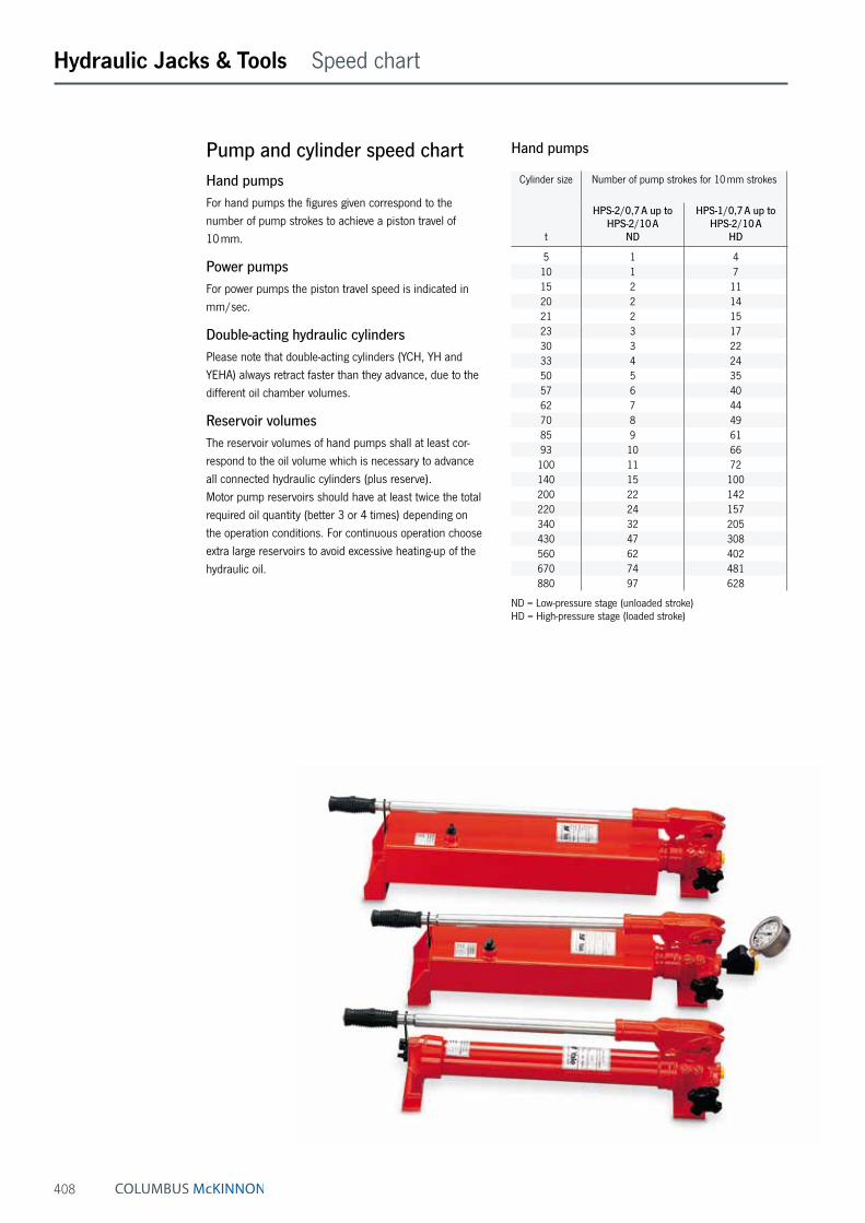
408
Hydraulic Jacks & Tools Speed chart
Pump and cylinder speed chartHand pumpsFor hand pumps the figures given correspond to the number of pump strokes to achieve a piston travel of 10 mm.
Power pumpsFor power pumps the piston travel speed is indicated in mm/sec.
Double-acting hydraulic cylindersPlease note that double-acting cylinders (YCH, YH and YEHA) always retract faster than they advance, due to the different oil chamber volumes.
Reservoir volumesThe reservoir volumes of hand pumps shall at least cor-respond to the oil volume which is necessary to advance all connected hydraulic cylinders (plus reserve). Motor pump reservoirs should have at least twice the total required oil quantity (better 3 or 4 times) depending on the operation conditions. For continuous operation choose extra large reservoirs to avoid excessive heating-up of the hydraulic oil.
Hand pumps
Cylinder size Number of pump strokes for 10 mm strokes
t
HPS-2/0,7 A up to HPS-2/10 A
ND
HPS-1/0,7 A up to HPS-2/10 A
HD
5 1 410 1 715 2 1120 2 1421 2 1523 3 1730 3 2233 4 2450 5 3557 6 4062 7 4470 8 4985 9 6193 10 66100 11 72140 15 100200 22 142220 24 157340 32 205430 47 308560 62 402670 74 481880 97 628
ND = Low-pressure stage (unloaded stroke) HD = High-pressure stage (loaded stroke)

409
Hydraulic Jacks & Tools Speed chart
Power pumps
Cylinder size Piston travel speed in mm/sec
t
PY-04
ND
PY-04
HD
PY-07
ND
PY-07
HD
PY-11
ND
PY-11
HD
PY-22
ND
PY-22
HD
PYE-40
HD
PYE-55
HD
PYE-75
HD
PYE-110
HD
PYE-180
HD
5 99.9 5.4 155.9 14.2 – – – – 63.8 – – – –10 48.7 2.6 75.9 6.9 103.5 11.5 – – 31.1 46 69 – –15 33.3 1.8 51.9 4.7 70.8 7.9 – – 21.2 31.5 47.2 62.9 –20 25.0 1.4 39.0 3.5 53.2 5.9 106.9 12.4 15.9 23.6 35.4 47.3 75.021 23.2 1.3 36.1 3.3 49.3 5.5 99.1 11.5 14.8 21.9 32.8 43.8 69.523 21.3 1.2 33.2 3.0 45.3 5.0 91.1 10.6 13.6 20.1 30.2 40.3 63.930 16.0 0.9 24.9 2.3 34.0 3.8 68.4 7.9 10.2 15.1 22.7 30.2 48.033 14.8 0.8 23.1 2.1 31.5 3.5 63.4 7.4 9.5 14 21 28.0 44.550 10.0 0.5 15.6 1.4 21.2 2.4 42.6 4.9 6.4 9.4 14.1 18.8 29.957 8.8 0.5 13.7 1.2 18.7 2.1 37.7 4.4 5.6 8.3 12.5 16.7 26.462 8.0 0.4 12.4 1.1 17.0 1.9 34.1 4.0 5.1 7.5 11.3 15.1 24.070 7.2 0.4 11.2 1.0 15.3 1.7 30.7 3.6 4.6 6.8 10.2 13.6 21.585 5.8 0.3 9.0 0.8 12.3 1.4 24.7 2.9 3.7 5.4 8.2 10.9 17.393 5.4 0.3 8.4 0.8 11.4 1.3 22.9 2.7 3.4 5.1 7.6 10.1 16.1100 4.9 0.3 7.7 0.7 10.5 1.2 21.1 2.5 3.2 4.7 7.0 9.3 14.8140 3.5 0.2 5.5 0.5 7.5 0.8 15.0 1.7 2.2 3.3 5.0 6.7 10.6200 2.5 0.1 3.9 0.4 5.3 0.6 10.7 1.2 1.6 2.4 3.5 4.7 7.5220 2.2 0.1 3.5 0.3 4.8 0.5 9.6 1.1 1.4 2.1 3.2 4.3 6.8340 – – 2.7 0.2 3.7 0.4 7.4 0.9 1.1 1.6 2.4 3.3 5.2430 – – 1.8 0.2 2.4 0.3 4.9 0.6 0.7 1.1 1.6 2.2 3.4560 – – 1.4 0.1 1.9 0.2 3.8 0.4 0.6 0.8 1.2 1.7 2.6670 – – 1.1 0.1 1.6 0.2 3.1 0.4 0.5 0.7 1.0 1.4 2.2880 – – 0.9 0.1 1.2 0.1 2.4 0.3 0.4 0.5 0.8 1.1 1.7
ND = Low-pressure stage (unloaded stroke) HD = High-pressure stage (loaded stroke) – = combination not recommended or not possible

410

BOLTING TECHNOLOGYwww.cmco.eu
411
Yale bolting technology is the general term of reliable and proven equipment renowned world-wide for controlled tight-ening or loosening of bolted connections. Special features of these products are their long service life, easy and quick maintenance and repair. All products from the bolting technology sector fulfil national and international regulations such as e.g. the EC Machinery Directive 2006/42/EC including corresponding supple-ments. It goes without saying that all torque wrenches are provided with a calibration certificate and operating instruc-tions with a declaration of conformity or a manufacturer’s declaration.
INFO
You would like to know more?Simply ask for our catalogue“BOLTING TECHNOLOGY”.
BOLTING TECHNOLOGY
Hydraulic torque wrenches (up to 78.000 Nm)
Pneumatic torque wrenches (up to 8.000 Nm)
Hydraulic nut splitters (up to SW 136 mm)
Flange spreaders (up to 10 t)
Hydraulic lifting & spreading wedges (10 t/16 t)
Torque multipliers (up to 47.000 Nm)
Torque wrenches (up to 3.000 Nm)
Hydraulic bolt tensioners (up to M150)
Impact sockets (up to SW 225)

412
Workshop Equipment Table of contents
Page Jacks 414 - 417
Workshop presses 418 - 420
Workshop presses/Accessories 421
Service jacks 422 - 423
Accessories 424
Workshop cranes 425
The Product division Workshop equipment compromises a modern, high performance system, which, due to its versatility and flexibility, ensures that a multitude of ap-plications in workshops are significantly simplified.
Mobile workshop cranes with capacities up to 1 t, hydraulic car jacks up to 50 t and hydraulic trolley jacks up to 50 t and many other products make daily working life easier and more ergonomic. Workshop presses with a capacity of up to 100 t are an indispensible tool when removing or inserting bearings or bushes etc.
The following applies also to our workshop equipment: dependability is ensured through a combination of high quality, functionality and safety.

413
WORKSHOP EQUIPMENT
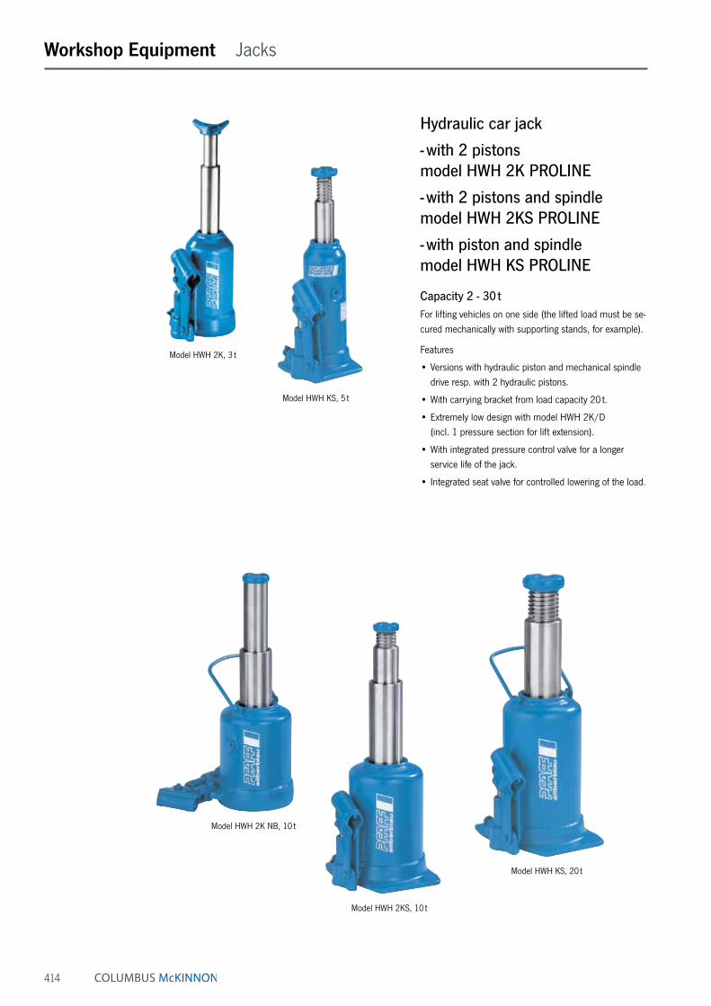
414
Workshop Equipment Jacks
Hydraulic car jack
- with 2 pistons model HWH 2K PROLINE
- with 2 pistons and spindle model HWH 2KS PROLINE
- with piston and spindle model HWH KS PROLINE
Capacity 2 - 30 tFor lifting vehicles on one side (the lifted load must be se-cured mechanically with supporting stands, for example).
Features
• Versions with hydraulic piston and mechanical spindle drive resp. with 2 hydraulic pistons.
• With carrying bracket from load capacity 20 t.
• Extremely low design with model HWH 2K/D (incl. 1 pressure section for lift extension).
• With integrated pressure control valve for a longer service life of the jack.
• Integrated seat valve for controlled lowering of the load.
Model HWH 2K, 3 t
Model HWH KS, 5 t
Model HWH 2K NB, 10 t
Model HWH 2KS, 10 t
Model HWH KS, 20 t
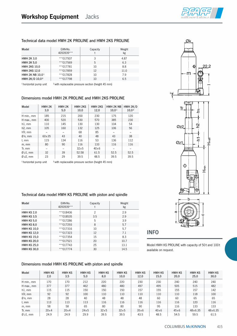
415
Workshop Equipment Jacks
Technical data model HWH 2K PROLINE and HWH 2KS PROLINE
Model EAN-No. 4050939***
Capacityt
Weightkg
HWH 2K 3,0 ***017507 3 4.87HWH 2K 5,0 ***017569 5 6.3HWH 2KS 10,0 ***017781 10 8.8HWH 2KS 12,0 ***017859 12 11.0HWH 2K NB 10,0 ¹ ***017828 10 7.9HWH 2K/D 10,0 ² ***017798 10 6.5
¹ horizontal pump unit ² with replaceable pressure section (height 45 mm)
Model HWH KS 2,0
HWH KS 3,5
HWH KS 5,0
HWH KS 8,0
HWH KS 10,0
HWH KS 12,0
HWH KS 15,0
HWH KS 20,0
HWH KS 25,0
HWH KS 30,0
H min., mm 170 170 212 220 220 230 230 240 240 240H max., mm 377 377 462 480 480 497 495 505 515 482h1, mm 115 115 150 150 150 157 155 155 157 142hTr, mm 92 92 100 110 110 110 110 110 118 100Ø k, mm 28 28 40 48 48 48 60 60 65 65I, mm 113 113 113 116 116 116 116 116 120 116m, mm 58 58 65 80 80 90 95 116 133 133Tr, mm 20 x 4 20 x 4 24 x 5 32 x 5 32 x 5 35 x 6 40 x 6 45 x 6 48 x 6.35 48 x 6.35Ø z1, mm 24.9 24.9 29.9 39.5 39.5 43.5 48.5 54.5 59.5 61.5
Dimensions model HWH KS PROLINE with piston and spindle
Model HWH 2K 3,0
HWH 2K 5,0
HWH 2KS 10,0
HWH 2KS 12,0
HWH 2K NB 10,0 ¹
HWH 2K/D 10,0 ²
H min., mm 185 215 200 230 175 120H max., mm 400 520 530 570 385 230h1, mm 110 145 130 130 104 54h2, mm 105 160 132 125 106 56hTr, mm – – 68 85 – –Ø k, mm 60 x 35 43 40 48 43 38I, mm 115 134 116 53 136 112m, mm 80 90 116 133 116 116Tr, mm – – 32 x 5 40 x 6 – –Ø z1, mm 32 39 52.58 61.5 52.5 52.5Ø z2, mm 23 29 39.5 48.5 39.5 39.5
¹ horizontal pump unit ² with replaceable pressure section (height 45 mm)
Dimensions model HWH 2K PROLINE and HWH 2KS PROLINE
Model EAN-No. 4050939***
Capacityt
Weightkg
HWH KS 2,0 ***018436 2 2.9HWH KS 3,5 ***018535 3.5 2.9HWH KS 5,0 ***017286 5 3.9HWH KS 8,0 ***017293 8 5.7HWH KS 10,0 ***017316 10 5.7HWH KS 12,0 ***017323 12 7.1HWH KS 15,0 ***017354 15 8.3HWH KS 20,0 ***017521 20 10.7HWH KS 25,0 ***017743 25 13.1HWH KS 30,0 ***017774 30 14.5
Technical data model HWH KS PROLINE with piston and spindle
INFO
Model HWH KS PROLINE with capacity of 50 t and 100 t available on request.

416
Workshop Equipment Jacks
Universal jacks model JHCapacity 2 - 50 tUniversal jacks supply high forces for general operations like lifting, pushing, moving, supporting of all kind of loads.
Features• Robust, long life design.
• Pressure relief valve
• Precise controlled lowering.
• Additional screw extension of the piston (up to 20 t).
• Grooved saddle.
• Large base plates for increased stability.
• Model JH-50-2 with two-stage pump.
• Incl. operating lever.
Technical data model JH
Model EAN-No. 4025092*
Capacity
t
Lift
mm
Additional screw extension
mm
Closed height
mm
Base plate
mm
Pump Weight
kg
JH-2 B *162722 2 115 50 181 90 x 95 1st stage 2.7JH-4 B *162739 4 126 60 205 115 x 110 1st stage 3.7JH-6 B *162746 6 130 75 219 115 x 110 1st stage 4.7JH-8 B *162753 8 152 70 225 120 x 120 1st stage 5.7JH-12 B *162760 12 153 80 240 140 x 130 1st stage 8.0JH-20 B *162777 20 153 80 240 160 x 155 1st stage 11.0JH-30 *154352 30 180 – 280 210 x 180 1st stage 22.0JH-50-2 *154376 50 178 – 305 255 x 190 2nd stage 53.0
JH-50-2

417
Workshop Equipment Jacks
Machine jack model MHCapacity 5 - 25 tFor lifting heavy machinery and other loads.
Features• Can be used in every position.
• Lifting by means of a hand pump.
• Lowering by means of a precision lowering valve.
• With carrying handle for models MH 50 and MH 100.
• With carriage for model MH 250.
• Pressure control valve for a longer service life of the jack.
• Integrated lifting limitation.
• Low application height of the claw.
• Slewing claw (models MH 50 and MH 100)
• Large base plate for a high level of stability.
• Stable construction with hard-chromium plated piston rod.
Technical data model MH
Model EAN-No. 4025092*
4050939***
Capacity t
Lift
mm
Application height min. with claw
mm
Application height min. with head
mm
Pump lever force with full load
daN
Weight
kg
MH 50 *983815 5 205 25 ≤ 368 38 25MH 100 *983730 10 230 30 ≤ 420 40 35MH 250 ***005269 25 215 58 ≤ 505 40 109
Model MH 50 MH 100 MH 250
A, mm 393 449 –B, mm 320 325 459C, mm 213 205 420D, mm 115 120 220E, mm 53 55 90G, mm 25 30 58H, mm 368 420 505H1, mm 573 650 720H2, mm 205 230 215J, mm 77 74,5 142,5K, mm 93 108 175L, mm 520 520 920/840M, mm 740 745 1305/1225N, mm 140 170 210/283Ø Z, mm 76 91 155
Dimensions model MH
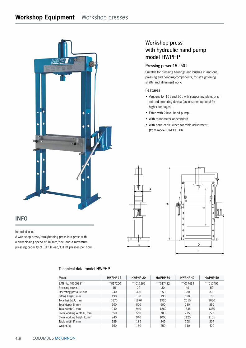
418
Workshop Equipment Workshop presses
Workshop press with hydraulic hand pump model HWPHPPressing power 15 - 50 tSuitable for pressing bearings and bushes in and out, pressing and bending components, for straightening shafts and alignment work.
Features• Versions for 15 t and 20 t with supporting plate, prism
set and centering device (accessories optional for higher tonnages).
• Fitted with 2-level hand pump.
• With manometer as standard.
• With hand cable winch for table adjustment (from model HWPHP 30).
Technical data model HWPHP
Model HWPHP 15 HWPHP 20 HWPHP 30 HWPHP 40 HWPHP 50
EAN-No. 4050939*** ***017200 ***017262 ***017422 ***017439 ***017491Pressing power, t 15 20 30 40 50Operating pressure, bar 240 320 250 330 330Lifting height, mm 190 190 190 190 190Total height A, mm 1870 1870 1920 2010 2030Total depth B, mm 500 500 600 780 850Total width C, mm 940 940 1260 1335 1350Clear working width D, mm 550 550 700 775 775Clear working height E, mm 940 940 1000 1125 1155Table width F, mm 185 185 245 258 304Weight, kg 160 160 250 310 420
INFO
Intended use: A workshop press/straightening press is a press with a slow closing speed of 10 mm/sec. and a maximum pressing capacity of 10 full load/full lift presses per hour.

419
Workshop Equipment Workshop presses
Workshop press with hydraulic electric pump model HWPEPPressing power 30 - 100 tCompressed productivity in press form for repair and as-sembly work. This is what the workshop press offers with its reliable 1- or 2-level electric pump and pressing power of up to 100 metric tons. Whether you are pressing bear-ings and bushes in and out, straightening axles, beams and shafts, or bending, pressing or setting up tools … The high performance of this press is based on optimized technology. For example, the press comes with a high pressure unit with a manometer, a control valve and three-way valve, an adjustable pick-up table and high-quality pistons made of chrome-plated hardened and tempered special steel.
Features• Fitted with 1- or 2-level electric pump.
• With manometer as standard.
• With hand cable winch for table adjustment.
With hand cable winch for table adjustment
At all models HWPHP and HWPEP as of 30 t as standard
INFO
Accessories available as options (please see page 421).
Units with pressing power of 150/200/300 t on request

420
Workshop Equipment Workshop presses
Technical data model HWPEP with 2-level electric pump
Model HWPEP-2 30 HWPEP-2 40 HWPEP-2 50 HWPEP-2 100
EAN-No. 4050939*** ***017729 ***017972 ***018061 ***018337Pressing power, t 30 40 50 100Operating pressure, bar 250 330 330 320Lifting height, mm 260 260 260 300Total height A, mm 1880 2010 2030 2170Total depth B, mm 660 780 850 1000Total width C, mm 1240 1315 1460 1700Clear working width D, mm 700 775 775 1000Clear working height E, mm 1.000 1125 1155 1075Table width F, mm 245 258 300 415Closing speed, mm/s – 1st stage 25 25 25 25Closing speed, mm/s – 2nd stage 4.2 4.2 3.3 2.9Motor 400 V/2.2 kW 400 V/3 kWED, % S 3-30 % ¹Weight, kg 280 340 450 920
¹ maximum pressing capacity of 10 full load/full lift presses per hour
Technical data model HWPEP with 1-level electric pump
Model HWPEP-1 30 HWPEP-1 40 HWPEP-1 50 HWPEP-1 100
EAN-No. 4050939*** ***017644 ***017712 ***017873 ***018238Pressing power, t 30 40 50 100Operating pressure, bar 250 330 330 320Lifting height, mm 260 260 260 300Total height A, mm 1880 2010 2030 2170Total depth B, mm 660 780 850 1000Total width C, mm 1240 1315 1410 1700Clear working width D, mm 700 775 775 1000Clear working height E, mm 1000 1125 1155 1075Table width F, mm 245 258 300 415Closing speed, mm/s 5.1 5.1 4.1 2.9Motor 400 V/1.5 kW 400 V/3 kWED, % S 3-30 % ¹Weight, kg 280 340 450 920
INFO
Intended use: A workshop press/straightening press is a press with a slow closing speed of 10 mm/sec. and a maximum pressing capacity of 10 full load/full lift presses per hour.

421
Workshop Equipment Workshop presses/Accessories
Technical data accessories - supporting plate
EAN-No. 4050939***
suitable for workshop press
Length
mm
Width
mm
Bore hole diameter
mm
– 15/20 t ¹ 240 240 20/25/35***018498 30/40 t 240 290 20/25/35***018504 50 t 350 320 20/25/35***017330 100 t 420 300 20/25/35
¹ included in scope of delivery
EAN-No. 4050939***
suitable for workshop press
Lengthmm
Widthmm
– 15/20 t ¹ 195 110***017019 30/40 t 265 140***017026 50 t 300 160***017033 100 t 425 240
¹ included in scope of delivery
Technical data accessories - prism set
EAN-No. 4050939***
suitable for workshop press
Lengthmm
– 15/20 t ¹ 650***017538 30 t 650***017545 40/50 t 900***017552 100 t 1200
¹ included in scope of delivery
Technical data accessories - centering device
EAN-No. 4053981** 4050939***
suitable for workshop press
Version Diameter
mm
***017040 15 - 40 t 6-part 12, 14, 16, 18, 20, 22***017057 15 - 40 t 8-part 12, 14, 16, 18, 20, 22, 25, 30 **008547 50 - 100 t 6-part 12, 14, 16, 18, 20, 22 **008554 50 - 100 t 8-part 12, 14, 16, 18, 20, 22, 25, 30
Technical data accessories - pressing pin set
Accessories for workshop presses model HWPHP and HWPEP

422
Workshop Equipment Service jacks
Hydraulic service jack model HRH P PROLINECapacity 1.5 - 15 tFor lifting vehicles on one side (the lifted load must be se-cured mechanically with supporting stands, for example) and for lifting vehicles with a small ground clearance.
Features• Quick-lift function as standard
• Controlling, lifting and lowering via the draw bar
• Integrated pressure control valve for a longer service life of the jack.
Technical data model HRH P PROLINE
Model EAN-No. 4050939***
Quick lift Capacity t
Height min.
mm
Height max.
mm
Dimensions max L x W x H
mm
Weight
kg
HRH P 1,5 H ¹ ***018429 X 1.5 98 800 1095 x 440 x 169 48HRH P 2,0 ***018047 X 2 80 500 730 x 340 x 160 36HRH P 2,0 L ² ***018252 X 2 90 500 950 x 340 x 126 41HRH P 3,0 H ¹ ***017088 X 3 130 860 1620 x 460 x 210 88HRH P 4,0 ***018542 X 4 145 560 1270 x 465 x 200 70HRH P 6,0 ***017125 X 6 155 570 1395 x 470 x 210 90HRH P 8,0 H ¹ ***012809 X 8 180 960 1830 x 475 x 350 160HRH P 10,0 ***017248 X 10 170 670 1700 x 470 x 280 136HRH P 15,0 ***017408 X 15 200 600 1790 x 475 x 325 162
H ¹ = Lift-up jack L ² = long

423
Workshop Equipment Service jacks
Hydraulic service jack model HRH S SILVERLINECapacity 2 - 5 tFor lifting vehicles on one side (the lifted load must be se-cured mechanically with supporting stands, for example).
Features• Quick-lift function as standard
(except model HRH S 2,0 K)
• Model HRH S 2,0 K with handy plastic case for ease of transport.
• Integrated pressure control valve for a longer service life of the jack.
• Version L – lockable pump lever.
Technical data model HRH S SILVERLINE
Model EAN-No. 4025092*
4050939***
Quick lift Capacity t
Height min.
mm
Height max.
mm
Dimensions max. L x W x H
mm
Weight
kg
HRH S 2,0 L ***017804 X 2 140 800 1350 x 430 x 190 75HRH S 3,0 L *985482 X 3 125 605 1310 x 320 x 185 70HRH S 5,0 L *985499 X 5 145 560 1420 x 350 x 198 95

424
Workshop Equipment Accessories
Supporting stand model UBCapacity 2 - 12 tFor mechanical support of lifted loads and for jacking-up loads which must be held for a long period of time.
Features• Stamp with 6 height adjustments, locking with pin
and cotter pin. For capacities above 12 t adjustment through threaded spindle.
• High level of stability.
Hydraulic repair set model HAW SPressing power 4 and 10 tA useful tool for repairs on car/truck bodies for quick planishing, spreading and pressing with high loads.
Features• Available in two versions for 4 t and 10 t.
• All parts are packed in a stable plastic case.
Technical data model UB
Model EAN-No. 4053981**
Capacityt
Height min.mm
Height max.mm
Height adjustmentmm
Raster points Spread angle Weightkg
UB 2 H **022437 2 430 740 310 6 3 x 120° 5.8UB 3 **022444 3 315 540 225 6 3 x 120° 3.9UB 5 **022451 5 365 605 240 6 3 x 120° 6.5UB 8 **022468 8 370 600 230 6 3 x 120° 9.7UB 8 H **022475 8 550 970 420 6 3 x 120° 13.8UB 12 S **022482 12 320 500 180 spindle 3 x 120° 11.6UB 12 HS **022499 12 475 725 250 spindle 3 x 120° 15.0
Technical data model HAW
Model EAN-No. 4050939***
Pressing power
t
Cylinder strokemm
Weight
kg
HAW S 4,0 ***010768 4 127 20.5HAW S 10,0 ***011185 10 152 34.5

425
Workshop Equipment Workshop cranes
Hydraulic workshop crane model HWK KL S SILVERLINECapacity 500 and 1000 kgFor fitting and removing engines and for loading and unloading pallets.
Features• With slewing hydraulic system and
sensitive lowering valve, as standard.
• With folding device for space-saving storage of the crane.
• Chassis variants: V-shaped or parallel.
• With speed increasing ratio
Technical data model HWK KL S SILVERLINE
Model HWK KLS 0,5 HWK KLS 0,5 HWK KLS 1,0 HWK KLS 1,0
EAN-No. 4050939*** ***018313 ***018276 ***018412 ***018405Chassis form parallel V-shaped parallel V-shapedCapacity with crane arm length A1, kg/mm 500/1130 500/1130 1000/1130 1000/1130Capacity with crane arm length A2, kg/mm 400/1230 400/1230 800/1230 800/1230Capacity with crane arm length A3, kg/mm 350/1330 350/1330 700/1330 700/1330Capacity with crane arm length A4, kg/mm 250/1430 250/1430 500/1430 500/1430Hook height at max. outermost position B, mm 2200 2200 2200 2200Hook height at max. innermost position C, mm 2080 2080 2080 2080Hook height at max. outermost position E, mm 770 770 770 770Hook height at max. innermost position D, mm 940 940 940 940Lifting height per pump stroke with/without load, mm 20/80 20/80 20/80 20/80Operating pressure, bar 150 150 290 290Hand effort at WLL, daN 16 16 32 32Drive-through height G, mm 1680 1680 1680 1680Underclearance height M, mm 160 160 160 160Chassis length, total H, mm 1820 1820 1820 1820Chassis width, inside/outside I/J, mm 850/990 850/990 850/990 850/990Weight, kg 138 132 156 150

426
ATEX Table of contents
Page General information 428 - 441
ATEX Pneumatic chain hoists 442 - 447
ATEX Hand chain hoists 448 - 459
ATEX Trolleys 460 - 462
ATEX Ratchet lever hoist 463
ATEX Electric winch & Accessories 464 - 465
ATEX Manual winch 466
ATEX Rack & Pinion jack 467
ATEX Hand pallet truck 468
ATEX Load moving system 469
INFO
Apart from electric explosion protection regulation, there are standards on mechanical explosion proof. Please consider these standards!
General information on explosion protection.
Some products from our standard range have been modi-fied for use in potentially explosive atmospheres (areas).
The products of this field have been approved by the TÜV Rheinland and DEKRA EXAM. The corresponding documentation is deposited by the notified bodies.

427
ATEX

428
Why explosion protection?Explosion protection for electrical and mechanical machinery is an important precautionary measure to ensure the safety of persons and all kinds of production, storage and distribution systems, when explosive mixtures of combustible gases, dusts and air may occur.
What does explosion protection achieve?Explosion protection can mean to generally prevent the occurrence of an explosive mixture. Explosion protection can also be achieved by eliminating potential ignition sources in advance, e.g. high temperatures and sparking by designing components accordingly and by permanent monitoring of operation, or by using a flame-proof enclo-sure for the source of ignition to protect the surrounding area against possible effects of an internal explosion.
Examples of explosion hazards in various industries:Chemical industryIn the chemical industry, combustible gases, liquids and solids are converted and processed in various procedures. Explosive mixtures may be created during these processes.
Waste disposal sitesAt waste disposal sites, combustible gases may form. Comprehensive technical measures are required to pre-vent their uncontrolled escaping and possible ignition.
Energy production companiesCoal dust, which may form explosive dust/air mixtures, may occur during production, breaking and drying from coal lumps which themselves are not explosive with air.
Waste management companiesThe fermentation gases released during treatment of waste water in waste water treatment plants may form explosive gas/air mixtures.
Gas suppliersIf natural gas escapes through leakages or similar, explosive gas/air mixtures may be created.
Metal processing companiesDuring the production of formed metal parts, explosive metal dusts may occur during surface treatment (grind-ing). This applies in particular to light metals. These metal dusts may cause an explosion risk in separators.
Wood-processing companiesWhen processing wood workpieces, wood dust occurs, which may form explosive dust/air mixtures in filters or silos for example.
Paint shopsOverspray, which may occur during painting of surfaces using spray guns as well as any released solvent vapours, may form an explosive atmosphere with air.
AgricultureSome agricultural facilities operate systems for the production of biogas. If biogas escapes as a consequence of leakages, for example, explosive biogas/air mixtures may form.
Food and feeding-stuffs industryDuring the transportation and storage of grain, sugar, etc. explosive dusts may occur. When these are evacuated and separated using filters, an explosive atmosphere may occur in the filter.
Pharmaceutical industryIn pharmaceutical production, alcohols are frequently used as solvents. Furthermore, active and auxiliary sub- stances with a dust explosion hazard may also be used.
RefineriesThe hydrocarbons processed in refineries are all com-bustible and, depending on their flash point, are capable of causing an explosive atmosphere even at ambient temperatures.
Recycling companiesWhen processing recycling waste, explosion hazards may be caused by cans which are not completely empty or other containers with combustible gases and/or liquids; explosion hazards may also be caused by paper or plastic dust.
ATEX General information on explosion protection

429
Cooperation of parties involvedObligations of user, installer and manufacturerClose cooperation of all parties involved is essential for the safety in potentially explosive areas. The user is responsible for the safety of the installation. He has to assess possible explosion hazards and assign zones accordingly. In addition, he is also responsible for ensuring that the equipment is installed in accordance with regulations and is tested before it is put into service for the first time. The equipment must be kept in appropriate condition by regular inspections and maintenance. The installer must observe the relevant installation require-ments and select and install the equipment correctly for its intended use.
Manufacturers of explosion-proof equipment must ensure that each device manufactured complies with the type-tested design.
Legal basisThe acronym ATEX is the abbreviation of the French term “Atmosphères explosibles”, which means explosive atmospheres. This designation is currently still used as a synonym for these two directives of the European Union: 2014/34/EU and 99/92/EC. Directive 2014/34/EU is primarily intended for manufac-turers of explosion-proof equipment. Directive 99/92/EC is primarily intended for users of installations with a potentially explosive atmosphere.
Risk assessmentFor taking efficient measures in areas with an explosion hazard, a risk assessment ‒ in accordance with national health and safety regulations taking into account national industrial safety acts as well as hazardous substances ordinances must be carried out first. If this risk assess-ment shows that the formation of explosive atmospheres is not safely prevented, the likelihood that explosive atmospheres will occur based on their frequency and persistence, the likelihood that ignition sources will be present and become active and effective and the scale of the anticipated effects of explosions must be determined. The results of the risk assessment must be recorded in the form of an explosion protection document.
User Installer Manufacturer Inspection Standardisation authority Authorities
ATEX General information on explosion protection

430
Categories and zones
Requirements from the ATEX directives to be fulfilled by manufacturer and user
Essential requirements to be fulfilled by the manufacturer according to 2014/34/EU
Essential requirements to be fulfilled by the user according to 99/92/EG
Definition of the area for the use of equipment, specifications of equipment group II/category
Definition of zones in an installation; selection of the appropriate equipment
The equipment must comply with the essential safety and health requirements or the relevant standards
Compliance with the relevant requirements for installation, putting into service and maintenance
Category 1 Category 2 Category 3
Zone 0/20 Zone 1/21 Zone 2/22
Performance of a risk/ignition source assessment for the relevant equipment
Performance of a hazard analysis for the operating area; need for coordination
Compilation of a declaration of conformity Compilation of an explosion protection document
Appropriate quality assurance Regular updating
Technical basisIn Directive 2014/34/EU, equipment for areas with an explosion hazard is assigned to groups, categories and temperature classes. This is necessary as the requirements for equipment need not be the same for every application and for every hazard classification.
Equipment group I (mines, firedamp and combustible dusts)
Category M1 Category M2
Very high level of protection: Equipment must feature integrated explosion protection measures
High level of protection: Protection measures must ensure the required level of safety during normal operation also under arduous conditions and in particular heavy handling
and under changing ambient conditions
The equipment must continue to operate in an explosive atmosphere even in the event of rare faults
It must be possible to switch off the equipment if an explosive atmosphere occurs
Equipment group II (explosive atmospheres caused by mixtures of gas/air or dust/air, vapours or mists)
Category Zone Equipment safety Explosive atmosphereG [Gas] D [Dust]
1 0 20 Equipment which ensures a very high level of safety.
In the event of rare equipment faults.
Intended for use in areas in which explosive atmospheres caused by mixtures of air and gases,
vapours or mists or by air/dust mixtures are present continuously, for long periods or frequently.
2 1 21 Equipment which ensures a high level of safety.
If equipment faults are to be expected.
Intended for use in areas in which explosive atmospheres caused by mixtures of air and gases, vapours or mists or by air/dust mixtures are likely
to occur occasionally.
3 2 22 Equipment which ensures a normal level of safety.
For normal operation.
Intended for use in areas in which explosive atmospheres caused by gases, vapours or mists or
whirled up dust are unlikely to occur or, if they do occur, are likely to do so only
infrequently and for a short period.
ATEX General information on explosion protection

Product
Ignition source assessment for the product and the location of application (user)
Equipment group I Equipment group II
Category M1 Category M2 Category 1 Category 2 Category 3
Cat. 1G Cat. 1D Cat. 2G Cat. 2D Cat 3G Cat 3D Zone 0 Zone 20 Zone 1 Zone 21 Zone 2 Zone 22
Zone 0/20 Zone 1/21 Zone 2/22
Time Time Time
Permanent Ex hazard Occasional Ex hazard Rare Ex hazard
431
Conc
entra
tion
Conc
entra
tion
Conc
entra
tion
ATEX General information on explosion protection

432
Preconditions for an explosionExplosive atmospheres may occur wherever combustible gases, vapours, mists or dusts can form. These are mixtures which produce a chemical reaction when they meet the oxygen in the air; this reaction may trigger an explosion, even if only an extremely small spark occurs.
Combustible material + Oxidizing agent + Ignition source • Gases • Oxygen in the air • e.g. sparks, of electrical or • Vapours mechanical origin • Mists (aerosols) • Hot surfaces • Combustible dusts (whirled up) • Electrostatic charges • Flames
Explosive atmospheres Mixture in the range between the lower and the upper explosion limit
Explosion
ATEX General information on explosion protection

433
Primary explosion protection Secondary explosion protection Tertiary explosion protection
Prevent the formation of potentially explosive atmospheres
Prevent the ignition of potentially explosive atmospheres
Restrict the effects of an explosion
Inerting ¹ Open flames Explosion-pressure resistant design
Limit concentration under the lower explosion limit
Hot gases Pressure compensation surfaces for buildings
Hot surfaces Explosion suppression
Electrical sparks
Atmospheric discharge
¹ Inerting substancesInerting substances means their transformation or processing into slow-reacting (inert) substances. Inert substances are, for example, inert gases, glass and porcelain. In refuse dump systems, inerting is used, for example, to render hazardous waste substances harmless. Substances containing heavy metal, which are radioactive or other-wise detrimental, are, for example, often glazed in order to make it possible to finally dispose of them.Inerting roomsInerting rooms means to displace the oxygen contents in the air or potentially reactive or explosive gases or gas mixtures in rooms by adding inert gases or vapours. When inerting as a protection against fire and explosion (industry example: chemicals storage or production facilities), the oxygen contents in the air are displaced by adding inert gas (e.g. argon, nitrogen, carbon dioxide) in order to prevent an explosive atmosphere. In fire protection, this is also called “active fire prevention by permanent inerting”.
Explosion limits of selected gases and vapours
Substance designation Explosion limits in airlower volumes % upper volumes %
Acetone 2.5 13.0
Benzol 1.2 8.0
Methane 5.0 15.0
City gas 4.0 30.0
Hydrogen 4.0 75.6
Explosion limitsIn order to prevent an explosion, the relevant key data of combustible substances must be observed.
Mixtures can only cause an explosive ignition within a specific range. This is defined by the lower and the upper explosion limit.
Minimum ignition energyThe minimum ignition energy is an explosion related parameter. It describes the ignition sensitivity compared to the discharge of static electricity.
Examples for minimum ignition energy
Substance designation Min. ignition energy
Mustard seed oil 3.8 mJ
Methane 0.29 mJ
Ethylene 0.082 mJ
Hydrogen 0.017 mJ
Explosion pressure Ideal mixture Ignition energy Most ignitable mixture P
max
Lean Rich mixture mixture
Pred
Min. ignition energy
Lower explosion limit Upper explosion limit
ATEX General information on explosion protection

434
Temperature classesThe ignition temperature is the lowest temperature of a heated surface at which the gas/air or vapour/air mixture ignites. In other words, it represents the lowest temperature value at which a hot surface is capable of igniting the corresponding explosive atmosphere. Thus the highest surface temperature of any equipment must always be less than the ignition temperature of the gas/air or vapour/air mixture.
Temperature classes
Temperature classes Permissible max. surface temperature of the equipment
Ignition temperature range of the mixtures
T1 450 °C > 450 °C
T2 300 °C > 300… ≤ 450 °C
T3 200 °C > 200… ≤ 300 °C
T4 135 °C > 135… ≤ 200 °C
T5 100 °C > 100… ≤ 135 °C
T6 85 °C > 85… ≤ 100 °C
Explosion groupsEquipment of group II, for appropriate use in explosive gas atmospheres may also be classified by the type of explosive area.
Explosion groups
Explosion group of the explosive atmosphere Equipment with marking of the explosion group which may be used in these atmospheres
IIA IIA, IIB, IIC
IIB IIB, IIC
IIC IIC
Explosion groups and maximum experimental safe gap
Explosion group Maximum experimental safe gap
IIA > 0.9 mm
IIB ≤ 0.9 - ≥ 0.5 mm
IIC < 0.5 mm
This classification is based on the Maximum Experimental Safe Gap (MESG) and the Minimum Ignition Current (MIC) of the gas mixture (see IEC 60079-12) or the explosion groups can also be used for classification of the equipment based on their inflammability.
ATEX General information on explosion protection

435
Classification of combustible gases, vapours and mistsExplosion groups and temperature classes of some gases and vapours (selection)
Classification of combustible gases, vapours, mists
Ex group Temperature classes
T1 T2 T3 T4 T5 T6
Ignition temperature range of the mixtures
> 450 °C > 300 ≤ 450 °C > 200 ≤ 300 °C >135 ≤ 200 °C >100 ≤ 135 °C >85 ≤ 100 °C
Permissible max. surface temperature of the equipment
450 °C 300 °C 200 °C 135 °C 100 °C 85 °C
IIA Acetone Ethanol Petrol (general) Acetaldehyde
Ammonium i-Amyl acetate Diesel fuels
Benzene (pure) n-Butane Aircraft fuels
Acetic acid n-Butanol Fuel oil DIN 51603
Ethane Cyclohexan n-Hexane
Ethyl acetate Acetic anhydride
Ethyl chloride
Carbon monoxide
Methane
Methanol
Methyl chloride
Naphthalene
Phenol
Propane
Toluene
IIB City gas Ethylene Ethylene glycol Ethyl ether
Ethylene oxide Hydrogen sulfide
IIC Hydrogen Acetylene Carbon disulphide
ATEX General information on explosion protection

436
Dust-explosion protectionToday, in many industries, powder or dust-like products are processed or are by-products of the production process. The vast majority of all dust-like substances pose a dan-ger of fire or – under certain conditions – even explosion. A dust layer of only 1 mm in a closed room is already sufficient to trigger an explosion when the dust is whirled up and ignited. The graphic shows that many different industries are affected by the hazard of dust, ranging from the food-stuffs and wood-processing industries, paper and plastic material production to the pharmaceutical industry. Compared with gas explosions, dust explosions have a different process of propagation which may in some cases be much more devastating. If a gas/air mixture is ignited, the pressure of the resulting explosion causes the gas cloud to dissipate rapidly and thus finally dilutes the gas/air mixture to a concentration lower than that necessary for further combustion. If no further gas is added, the explosion is over after several milliseconds. With combustible dusts it is different: If, for example, a draft of air whirls up a layer of dust, the dust, together with oxygen, forms a combustible dust/air mixture. If this mixture is ignited by an ignition source, an explosion is triggered. The resulting blast wave whirls up further dust layers, which are in turn also ignited. This process continues, and, under adverse conditions, “chain reactions” such as these sweep through entire buildings or facilities and destroy them. As is the case with gases, there are various ignition sources for dusts, such as sparks generated by electrical or mechanical processes, electric arcs, open flames, elec-trostatic discharges, electromagnetic waves and others.
Definitions in dust explosion protection
Term Definition Remarks
Explosive dust atmosphere
Mixture with air, under atmospheric conditions, of combustible substances in the form of dust or fibres in which, after ignition,
combustion spreads throughout the entire unconsumed mixture. (EN 50281-1-1,3.4)
The condition is that the process ends only after one reactant has been entirely consumed.
Atmospheric condition
Range of pressure between 0.8 and 1.1 bar Temperature range between -20 °C and +60 °C
Hazardous explosive
atmospheres
Explosive atmosphere in hazardous amount. The presence of a hazardous explosive atmosphere must be assumed if
ignition causes an exothermal reaction that endangers persons, domestic animals and property
A thickness of a dust layer of less than 1 mm on the floor of a normal room is sufficient to fill it with a hazardous
explosive atmosphere.
Wood 34 %
Grain 24 %
Other 6 %Plastics 14 %
Paper 2 %
Coal/peat 10 % Metals 10 %
Permissible equipment IP code ¹ by zones and type of dust
Zone 20
Zone 21Zone 22 electrically
conductive dust
Zone 22
IP 6X IP 6X IP 5X
Marking II 1 D
Marking II 2 D
Marking II 3 D
¹ IP code = International protection code: EN 60529; VDE 0470-1 degrees of protection provided by enclosures (IP code)
ATEX General information on explosion protection
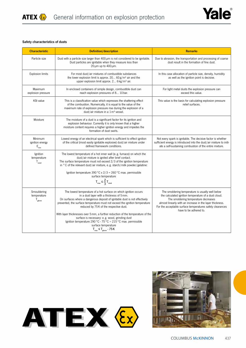
437
Safety characteristics of dusts
Characteristic Definition/description Remarks
Particle size Dust with a particle size larger than 400 µm is not considered to be ignitable. Dust particles are ignitable when they measure less than
20 µm up to 400 µm.
Due to abrasion, the transportation and processing of coarse dust result in the formation of fine dust.
Explosion limits For most dust/air mixtures of combustible substances the lower explosion limit is approx. 20… 60 g/m³ air and the
upper explosion limit approx. 2… 6 kg/m³ air.
In this case allocation of particle size, density, humidity as well as the ignition point is decisive.
Maximum explosion pressure
In enclosed containers of simple design, combustible dust can reach explosion pressures of 8… 10 bar.
For light metal dusts the explosion pressure can exceed this value.
KSt value This is a classification value which expresses the shattering effect of the combustion. Numerically, it is equal to the value of the
maximum rate of explosion pressure rise during the explosion of a dust/air mixture in a 1 m³ vessel.
This value is the basis for calculating explosion pressure relief surfaces.
Moisture The moisture of a dust is a significant factor for its ignition and explosion behaviour. Currently it is only known that a higher
moisture content requires a higher ignition energy and impedes the formation of dust swirls.
Minimum ignition energy
Emin
Lowest energy of an electrical spark which is sufficient to effect ignition of the critical (most easily ignitable explosive) dust/air mixture under
defined framework conditions.
Not every spark is ignitable. The decisive factor is whether sufficient energy is introduced into the dust/air mixture to initi-
ate a self-sustaining combustion of the entire mixture.
Ignition temperature
Tzünd
The lowest temperature of a hot inner wall (e. g. furnace) on which the dust/air mixture is ignited after brief contact.
The surface temperature must not exceed 2/3 of the ignition temperature in ° C of the relevant dust/air mixture, e. g. starch/milk powder/gelatine:
Ignition temperature 390 °C x 2/3 = 260 °C max. permissible surface temperature
2Tmax
≤ — Tzünd 3
Smouldering temperature
Tglimm
The lowest temperature of a hot surface on which ignition occurs in a dust layer with a thickness of 5 mm.
On surfaces where a dangerous deposit of ignitable dust is not effectively prevented, the surface temperature must not exceed the ignition temperature
reduced by 75 K of the respective dust.
With layer thicknesses over 5 mm, a further reduction of the temperature of the surface is necessary: e. g. wood, grinding dust
Ignition temperature 290 °C - 75 °C = 215 °C max. permissible surface temperatureT
max ≤ T
glimm - 75 K
The smoldering temperature is usually well below the calculated ignition temperature of a dust cloud.
The smoldering temperature decreases almost linearly with an increase in the layer thickness.
For the acceptable surface temperatures safety clearances have to be adhered to.
ATEX General information on explosion protection

438
Example II 2 G d IIB T3
Identification for protectionagainst explosions (ATEX 100a)
Equipment group II = Non-mining application
Category 1 = extremely high safety 2 = high safety 3 = normal safety
Ex atmosphere G = Gas D = Dust
Protection type p = pressurized enclosure d = flame-proof enclosure e = increased safety nA = non-sparking i = intrinsic safety c = design safety b = ignition source monitoring k = liquid immersion
Explosion group IIA IIB IIC
Temperature class Limit temperature T1 = max. 450 °C T2 = max. 300 °C T3 = max. 200 °C T4 = max. 135 °C T5 = max. 100 °C T6 = max. 85 °C
Examples of explosion characteristics of dusts
Substance Tzünd [°C] Tglimm [°C] ØEmin [mJ] min [mJ]
Wood ≥ 410 ≥ 200 ≥ 100 6
Lignite ≥ 380 ≥ 225 – 5
Coal ≥ 500 ≥ 240 ≥ 1000 13
PVC ≥ 530 ≥ 340 ≥ 5 < 1
Aluminium ≥ 560 ≥ 270 ≥ 5 < 1
Sulphur ≥ 240 ≥ 250 10 5
Lycopodium ≥ 410 – – –
Explosion characteristics of dustsGenerally applicable values for dust-specific characteristics cannot be specified. The table shows some limit values for selected products:
Marking key
ATEX General information on explosion protection

439
International comparison of zones in areas with an explosion hazard
Country Standard Zone/division
AS AS 2430.2:1986 Class II
GB BS6467.2:1988 Z Y
DE VDE 0165:1991 10 11
USA NEC 500-6: 2002 Div. 1 Div.2
EU EN50281-3:2002 20 21 22
INT IEC 61241-10:2004 20 21 22
EU EN 61241-10:2005
Area in which an explosive atmosphere in the form of a cloud of combustible
dust in air is present continuously, or for long periods or frequently.
Area in which an explosive atmosphere in the form of a cloud of combustible
dust in air is likely to occur occasionally in normal operation.
Area in which during normal operation, it is not to be expected that an explosive
atmosphere occurs in the form of a cloud of combustible dust in the air, if it does occur, however, only for a
brief time.
ATEX General information on explosion protection
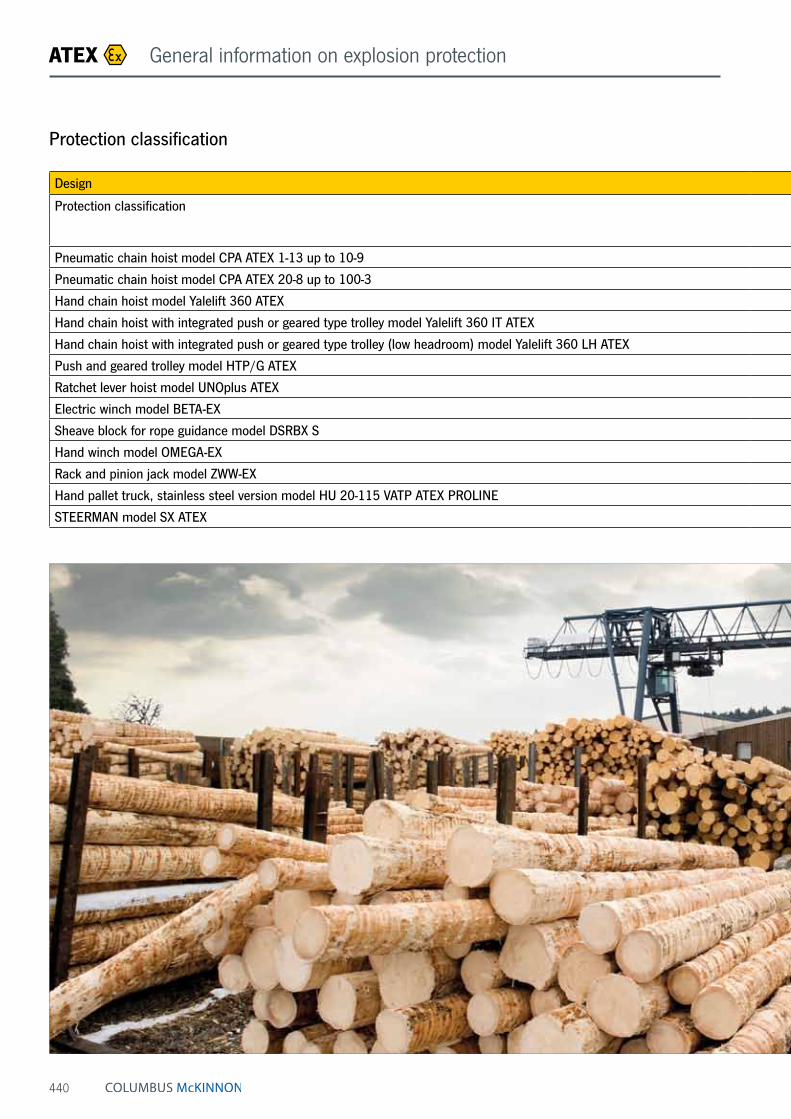
440
Protection classification
ATEX General information on explosion protection
Design BASIC MEDIUM HIGH SPECIAL
Protection classification II 3 GD c IIB T4/ II 2 GD c IIA T4
II 2 GD c (de) (ck) IIB T4 II 2 GD c IIC T4 I M2
only for mining
Pneumatic chain hoist model CPA ATEX 1-13 up to 10-9 only II 3 GD c IIB T4 on request (see hint page 442)
Pneumatic chain hoist model CPA ATEX 20-8 up to 100-3 X X X
Hand chain hoist model Yalelift 360 ATEX X X X
Hand chain hoist with integrated push or geared type trolley model Yalelift 360 IT ATEX X X X
Hand chain hoist with integrated push or geared type trolley (low headroom) model Yalelift 360 LH ATEX X X X
Push and geared trolley model HTP/G ATEX X X
Ratchet lever hoist model UNOplus ATEX only II 3 GD c IIB T4 X
Electric winch model BETA-EX X (de)
Sheave block for rope guidance model DSRBX S X
Hand winch model OMEGA-EX X (ck)
Rack and pinion jack model ZWW-EX X
Hand pallet truck, stainless steel version model HU 20-115 VATP ATEX PROLINE II 2 GD c IIC T6
STEERMAN model SX ATEX II 2 GD c IIB T4

441
Design BASIC MEDIUM HIGH SPECIAL
Protection classification II 3 GD c IIB T4/ II 2 GD c IIA T4
II 2 GD c (de) (ck) IIB T4 II 2 GD c IIC T4 I M2
only for mining
Pneumatic chain hoist model CPA ATEX 1-13 up to 10-9 only II 3 GD c IIB T4 on request (see hint page 442)
Pneumatic chain hoist model CPA ATEX 20-8 up to 100-3 X X X
Hand chain hoist model Yalelift 360 ATEX X X X
Hand chain hoist with integrated push or geared type trolley model Yalelift 360 IT ATEX X X X
Hand chain hoist with integrated push or geared type trolley (low headroom) model Yalelift 360 LH ATEX X X X
Push and geared trolley model HTP/G ATEX X X
Ratchet lever hoist model UNOplus ATEX only II 3 GD c IIB T4 X
Electric winch model BETA-EX X (de)
Sheave block for rope guidance model DSRBX S X
Hand winch model OMEGA-EX X (ck)
Rack and pinion jack model ZWW-EX X
Hand pallet truck, stainless steel version model HU 20-115 VATP ATEX PROLINE II 2 GD c IIC T6
STEERMAN model SX ATEX II 2 GD c IIB T4
BASIC• Load chain galvanic zinc-plated, stainless steel hand chain
• Trolleys with buffers
• Brake with cooling element (only for Yalelift range)
MEDIUM• Load chain galvanic zinc-plated, stainless steel hand chain
• Top and load hook copper-plated
• Trolley equipped with buffers and bronze trolley wheels
• Brake with cooling element (only for Yalelift range)
HIGH• Stainless steel load and hand chain
• Load and top hook copper-plated
• Trolley equipped with buffers and bronze trolley wheels
• Brake with cooling element (only for Yalelift range)
• Conductive load rollers (only hand pallet truck)
SPECIAL• Only for mining industry
ATEX General information on explosion protection
INFO
Due to the use of stainless steel load chains for the HIGH design a reduction of the load capacity is necessary. Please see the table "technical data" for the appropriate values.
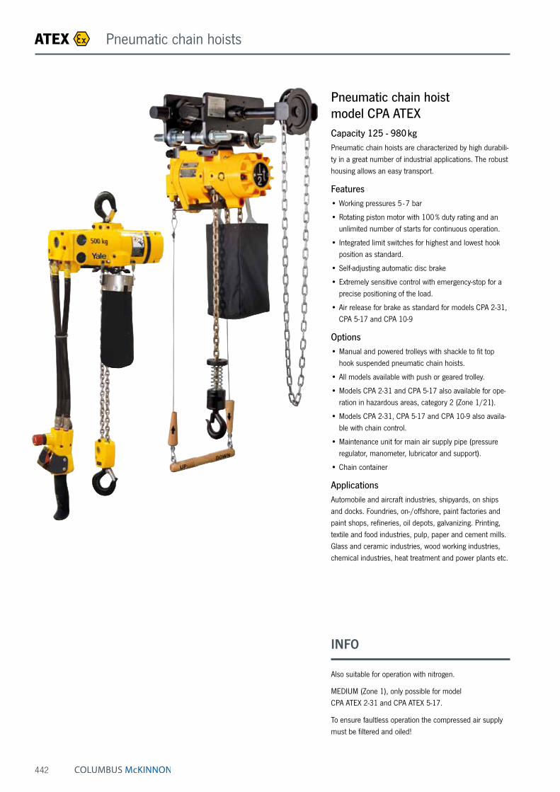
442
Pneumatic chain hoist model CPA ATEXCapacity 125 - 980 kgPneumatic chain hoists are characterized by high durabili-ty in a great number of industrial applications. The robust housing allows an easy transport.
Features• Working pressures 5 - 7 bar
• Rotating piston motor with 100 % duty rating and an unlimited number of starts for continuous operation.
• Integrated limit switches for highest and lowest hook position as standard.
• Self-adjusting automatic disc brake
• Extremely sensitive control with emergency-stop for a precise positioning of the load.
• Air release for brake as standard for models CPA 2-31, CPA 5-17 and CPA 10-9
Options• Manual and powered trolleys with shackle to fit top
hook suspended pneumatic chain hoists.
• All models available with push or geared trolley.
• Models CPA 2-31 and CPA 5-17 also available for ope-ration in hazardous areas, category 2 (Zone 1/21).
• Models CPA 2-31, CPA 5-17 and CPA 10-9 also availa-ble with chain control.
• Maintenance unit for main air supply pipe (pressure regulator, manometer, lubricator and support).
• Chain container
ApplicationsAutomobile and aircraft industries, shipyards, on ships and docks. Foundries, on-/offshore, paint factories and paint shops, refineries, oil depots, galvanizing. Printing, textile and food industries, pulp, paper and cement mills. Glass and ceramic industries, wood working industries, chemical industries, heat treatment and power plants etc.
ATEX Pneumatic chain hoists
INFO
Also suitable for operation with nitrogen.
MEDIUM (Zone 1), only possible for model CPA ATEX 2-31 and CPA ATEX 5-17.
To ensure faultless operation the compressed air supply must be filtered and oiled!

443
Model EAN-No. 4025092*
Capacity in kg/
number of chain falls
Lifting speed with
rated load ¹m/min.
Lifting speed without load ¹
m/min.
Lowering speed with
rated load ¹m/min.
Air consumption with
rated load ¹m³/min.
Hoist motor
kW
Weight at 3 m lift
kg
CPA ATEX 1-13 *911795 125/1 13.1 17.1 11.3 0.9 0.4 15.4CPA ATEX 2-10 *911788 250/1 9.8 17.1 13.7 0.9 0.4 15.4CPA ATEX 2-31 *911801 250/1 31.0 52.0 36.0 1.98 1.33 21.8CPA ATEX 5-5 *911818 500/2 4.6 7.9 6.7 0.9 0.4 17.2CPA ATEX 5-17 *911825 500/1 16.8 32.3 29.6 1.27 1.33 21.8CPA ATEX 10-9 *911832 980/2 8.5 16.2 14.9 1.27 1.33 27.7
¹ Values for 6.3 bar (flow pressure) and 2 m control drop. Speeds will be reduced in case of longer control length.Model CPA 1-13, CPA 2-10 and CPA 5-5 max. hose length 12 m, air supply 3/8" NPT Model CPA 2-31, CPA 5-17 and CPA 10-9 max. hose length 20 m, air supply 1/2" NPT.
Technical data model CPA ATEX BASIC II 3 GD c IIB T4
Model CPA ATEX 1-13 CPA ATEX 2-10 CPA ATEX 2-31 CPA ATEX 5-5 CPA ATEX 5-17 CPA ATEX 10-9
A, mm 292 292 457 324 457 457A1, mm 410 410 483 410 483 508B, mm 21 21 25 14 25 27C, mm 20 20 24 24 24 28D, mm 16 16 26 14 26 28F1, mm 90 90 130 90 130 130F2, mm 120 120 180 120 180 180K, mm 103 103 146 103 146 165L, mm 57 57 102 57 102 83M, mm 120 120 114 120 114 135N, mm 50 50 54 50 54 25Q1, mm 142 142 162 142 162 162Q2, mm 183 183 181 183 181 181
Dimensions model CPA ATEX
Model CPA ATEX 1-13 / 2-10 / 5-5 Model CPA ATEX 2-31 / 5-17 / 10-9
ATEX Pneumatic chain hoists

444
Pneumatic chain hoist with suspension hook or with integrated trolley model CPA ATEXCapacity 2000 - 10000 kgWith 100 % duty rating and an unlimited number of starts the model CPA is suitable for heavy duty applications. It is insusceptible to contamination, humidity and aggressive mediums from the outside. The hoists are composed of three main components which makes service easy and inexpensive.
Features• Working pressures 4 - 6 bar.
• Robust rotating piston motor has an adjustable spring pressure brake that holds the load secure even in the event of an air failure.
• The standard, oil bath lubricated planetary gearbox is particularly smooth running and enables a low overall height.
• High starting torque due to switching valves in the motor body.
• Low noise emission due to large dimension silencer.
• Sensitive control by means of 2 resp. 4 button pendant control with emergency stop.
• The assembly of component parts result in a low ove-rall height (up to 3000 kg only one chain fall).
• The 5-pocket load chain sheave, manufactured from wear resistant case hardening steel, is matched perfectly to the load chain to guarantee smooth and precise chain motion.
• Drop forged suspension and load hooks are made from non-aging, high tensile steel and fitted with robust safety latches.
• The standard case hardened and zinc-plated link chain is matched perfectly to the load chain to guarantee smooth and precise chain motion. All requirements of national and international standards and regulations are fulfilled.
• Copper-coated suspension and load hooks for MEDIUM design or higher.
• Stainless steel load chain for HIGH design.
Options• Trolley for suspension hook version or integrated
trolleys for all three designs (BASIC, MEDIUM, HIGH).
• Rope control
• Limit switch
• Chain container
Image shows BASIC design
Image shows MEDIUM design incl. rope control
ATEX Pneumatic chain hoists
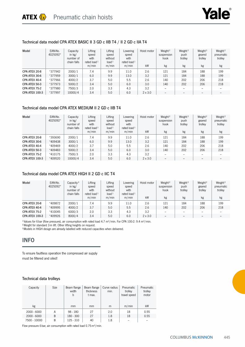
445
Technical data model CPA ATEX BASIC II 3 GD c IIB T4 / II 2 GD c IIA T4
Model EAN-No. 4025092*
Capacity in kg/
number of chain falls
Lifting speed with
rated load ¹m/min
Lifting speed without load ¹
m/min
Lowering speed with
rated load ¹m/min
Hoist motor
kW
Weight ² suspension
hook
kg
Weight ² push trolley
kg
Weight ² geared trolley
kg
Weight ² pneumatic
trolley
kg
CPA ATEX 20-8 *377942 2000/1 7.4 9.9 11.0 2.6 121 184 188 199CPA ATEX 30-6 *377959 3000/1 6.0 9.9 13.0 3.2 121 184 188 199CPA ATEX 40-4 *377966 4000/2 3.7 5.0 5.5 2.6 140 202 206 218CPA ATEX 50-3 *377973 5000/2 3.4 5.0 6.0 3.0 140 202 206 218CPA ATEX 75-2 *377980 7500/3 2.0 3.3 4.3 3.2 – – – –CPA ATEX 100-3 *377997 10000/4 3.4 5.0 6.0 2 x 3.0 – – – –
Technical data trolleys
Capacity
kg
Size Beam flange width
b
mm
Beam flange thickness
t max.
mm
Curve radius min.
m
Pneumatic trolley
travel speed
m/min
Pneumatic trolley motor
kW
2000 - 6000 A 98 - 180 27 2.0 18 0.552000 - 6000 B 180 - 300 27 1.8 18 0.557500 - 10000 B 125 - 310 40 1.8 – –
Flow pressure 6 bar, air consumption with rated load 0.75 m³/min.
Technical data model CPA ATEX HIGH II 2 GD c IIC T4
Model EAN-No. 4025092*
Capacity ³ in kg/
number of chain falls
Lifting speed with
rated load ¹m/min
Lifting speed without load ¹
m/min
Lowering speed with
rated load ¹m/min
Hoist motor
kW
Weight ² suspension
hook
kg
Weight ² push trolley
kg
Weight ² geared trolley
kg
Weight ² pneumatic
trolley
kg
CPA ATEX 20-8 *409872 2000/1 7.4 9.9 11.0 2.6 121 184 188 199CPA ATEX 40-4 *409995 4000/2 3.7 5.0 5.5 2.6 140 202 206 218CPA ATEX 75-2 *410045 6000/3 2.0 3.3 4.3 3.2 – – – –CPA ATEX 100-3 *409926 8000/4 3.4 5.0 6.0 2 x 3.0 – – – –
¹ Values for 6 bar (flow pressure), air consumption with rated load 4.7 m³/min. For CPA 100-2: 9.4 m³/min. ² Weight for standard 3 m lift. Other lifting heights on request. ³ Models in HIGH design are already labelled with reduced capacities when delivered.
Technical data model CPA ATEX MEDIUM II 2 GD c IIB T4
Model EAN-No. 4025092*
Capacity in kg/
number of chain falls
Lifting speed with
rated load ¹m/min
Lifting speed without load ¹
m/min
Lowering speed with
rated load ¹m/min
Hoist motor
kW
Weight ² suspension
hook
kg
Weight ² push trolley
kg
Weight ² geared trolley
kg
Weight ² pneumatic
trolley
kg
CPA ATEX 20-8 *393690 2000/1 7.4 9.9 11.0 2.6 121 184 188 199CPA ATEX 30-6 *409438 3000/1 6.0 9.9 13.0 3.2 121 184 188 199CPA ATEX 40-4 *409469 4000/2 3.7 5.0 5.5 2.6 140 202 206 218CPA ATEX 50-3 *409483 5000/2 3.4 5.0 6.0 3.0 140 202 206 218CPA ATEX 75-2 *410175 7500/3 2.0 3.3 4.3 3.2 – – – –CPA ATEX 100-3 *409520 10000/4 3.4 5.0 6.0 2 x 3.0 – – – –
ATEX Pneumatic chain hoists
INFO
To ensure faultless operation the compressed air supply must be filtered and oiled!

446
Dimensions model CPA ATEX
Model CPA ATEX 20-8 CPA ATEX 30-6 CPA ATEX 40-4 CPA ATEX 50-3 CPA ATEX 75-2 CPA ATEX 100-3
A, mm 516 516 681 681 950 1.068A1, mm 286 286 428 428 479 651B, mm 35 35 45 45 60 60C, mm 37 37 46 46 52 52D, mm 24 24 30 30 40/45 40/45F1, mm 160 160 160 160 160 160F2, mm 165 165 165 165 165 165G, mm 220 220 220 220 220 581G1, mm 180 180 140 140 268 311G2 (13 m), mm 258 258 218 218 – –G2 (21 m), mm 278 278 238 238 345 408H1, mm 110 110 110 110 110 110H2, mm 135 135 135 135 307 256H3, mm 115 115 115 115 115 115K1, mm 100 100 100 100 92 92K2, mm 51 51 51 51 62 62M, mm 50 50 9,6 9,6 139 181N, mm 60 60 100 100 136 291Q1, mm 272 272 272 272 272 272Q2, mm 325 325 325 325 325 325
Model CPA ATEX with suspension hook, 4000 - 5000 kg, double fall Model CPA ATEX with suspension hook, 10000 kg, four fall
Model CPA ATEX with suspension hook, 2000 - 3000 kg, single fall Model CPA ATEX with suspension hook, 7500 kg, three fall
ATEX Pneumatic chain hoists

447
Dimensions model CPA ATEX
Model CPA ATEX 20-8 CPA ATEX 30-6 CPA ATEX 40-4 CPA ATEX 50-3 CPA ATEX 75-2 CPA ATEX 100-3
A2 (13 m), mm 430 430 430 430 – –A2 (21 m), mm 530 530 530 530 530 530A4, mm 465 465 615 615 855 965A5, mm 298 298 298 298 477 425A6, mm 190 190 190 190 182 182
b, mm A = 98 - 180/ B = 180 - 300
A = 98 - 180/ B = 180 - 300
A = 98 - 180/ B = 180 - 300
A = 98 - 180/ B = 180 - 300 125 - 310 125 - 310
F, mm 150 150 150 150 113 113I, mm 142.5 142.5 142.5 142.5 130 130L1, mm 209 209 209 209 200 200L2, mm 262.5 262.5 262.5 262.5 215 215L3, mm 265 265 265 265 265 265L4, mm 213 213 253 253 291 291L5, mm 312 312 272 272 – –L6, mm 315 315 275 275 – –O, mm 125 125 125 125 150 150P, mm 208 208 208 208 208 208P1, mm 284 284 284 284 284 284S, mm b + 70 b + 70 b + 70 b + 70 b + 98 b + 98t, mm 27 27 27 27 40 40T1 size A 182 182 182 182 – –T1 size B 242 242 242 242 270 270
Model CPA ATEX with integrated manual push or geared trolley Model CPA ATEX with integrated pneumatic trolley
ATEX Pneumatic chain hoists

448
Image shows MEDIUM design
Hand chain hoist model Yalelift 360 ATEXCapacity 500 - 20000 kgThe hand chain hoist model Yalelift 360 ATEX once again prooves its worth in an environment that far exceeds the requirements of a classical hand chain hoist. On the basis of the European Directive 2014/34/EU this model series has been further developed for the use in potentially explosive atmospheres (ATEX zones).
Features• The enclosed robust stamped steel housing protects all
internal components even in the toughest conditions.
• The extremely low headroom allows maximum use of the lifting height.
• The revolutionary 360° rotating hand chain guide allows the operator to work from virtually any position, in confined spaces or above the load. The Yalelift can even be operated from the side of the load which also makes it possible to use the hoist for horizontal pulling or tensioning. Due to the additional flexibility, the operator is no longer forced to work in the danger zone near the load.
• The brake system is extremely quiet and guarantees operational safety and improved serviceability due to omission of the vulnerable ratchet pawls. All parts are made of high quality materials, additionally zinc-plated or yellow-chromated to increase corrosion prevention.
• Chain guide and gearbox are almost totally enclosed. Even under the toughest conditions the internal gear-box remains protected.
• The hardened load sheave with four precision ma-chined pockets ensures accurate movement of the load chain.
• The surface protected zinc-plated alloy steel load chains fulfil all requirements of current national and international standards and regulations. They are mat-ched perfectly to the load chain sheave and guarantee smooth and precise chain motion.
• Drop forged load and suspension hooks that yield under overload instead of breaking, are made of high tensile steel. The hooks are fitted with robust safety latches and rotate 360°.
• Explosion protected version with spark resistant coating.
• Copper-coated suspension and load hooks for MEDIUM design or higher.
• Stainless steel load chain for HIGH design.
Options• Adjustable overload protection device
• Chain container
Patented!
Rotating
hand chain
guide!
ATEX Hand chain hoists
INFO
Easy modification from Yalelift 360 ATEX to Yalelift IT ATEX is possible.

449
Technical data model Yalelift 360 ATEX BASIC II 3 GD c IIB T4 / II 2 GD c IIA T4
Model EAN-No. 4025092*
Capacity in kg/
number of chain falls
Chain dimensions
d x pmm
Load chain grade
Lift per 1 m hand chain overhaul
mm
Handle pull at WLL
daN
Weight at standard lift
(3 m)kg
YL ATEX 500 *194969 500/1 5 x 15 T 33 21 9YL ATEX 1000 *198196 1000/1 6 x 18 T 20 30 13YL ATEX 2000 *199872 2000/1 8 x 24 T 14 32 20YL ATEX 3000 *210522 3000/1 10 x 30 T 12 38 29YL ATEX 5000 *218672 5000/2 10 x 30 T 6 34 38YL ATEX 10000 *224611 10000/3 10 x 30 V 4 44 71YL ATEX 20000 *225625 20000/6 10 x 30 V 2 2 x 44 196
Technical data model Yalelift 360 ATEX MEDIUM II 2 GD c IIB T4
Model EAN-No. 4025092*
Capacity in kg/
number of chain falls
Chain dimensions
d x pmm
Load chain grade
Lift per 1 m hand chain overhaul
mm
Handle pull at WLL
daN
Weight at standard lift
(3 m)kg
YL ATEX 500 *206365 500/1 5 x 15 T 33 21 9YL ATEX 1000 *206419 1000/1 6 x 18 T 20 30 13YL ATEX 2000 *206426 2000/1 8 x 24 T 14 32 20YL ATEX 3000 *206440 3000/1 10 x 30 T 12 38 29YL ATEX 5000 *206464 5000/2 10 x 30 T 6 34 38YL ATEX 10000 *239547 10000/3 10 x 30 V 4 44 71YL ATEX 20000 *251846 20000/6 10 x 30 V 2 2 x 44 196
Technical data model Yalelift 360 ATEX HIGH II 2 GD c IIC T4
Model EAN-No. 4025092*
Capacity ³ in kg/
number of chain falls
Chain dimensions
d x pmm
Load chain grade
Lift per 1 m hand chain overhaul
mm
Handle pull at WLL
daN
Weight at standard lift
(3 m)kg
YL ATEX 500 *929806 500/1 5 x 15 S 33 21 9YL ATEX 1000 *929790 900/1 6 x 18 S 20 30 13YL ATEX 2000 *929783 1250/1 8 x 24 P 14 32 20YL ATEX 3000 *929776 2000/1 10 x 30 P 12 38 29YL ATEX 5000 *929769 4000/2 10 x 30 P 6 34 38YL ATEX 10000 *929752 6000/3 10 x 30 P 4 44 71YL ATEX 20000 *929745 12000/6 10 x 30 P 2 2 x 44 196
³ Models in HIGH design are already labelled with reduced capacities when delivered.
ATEX Hand chain hoists

450
Model YL 500 YL 1000 YL 2000 YL 3000 YL 5000 YL 10000 YL 20000
A min., mm 300 335 395 520 654 825 1010B, mm 17 22 30 38 45 68 85C, mm 24 29 35 40 47 68 64D, mm 133 156 182 220 220 220 303E, mm 148 175 203 250 250 383 555F, mm 148 167 194 219 219 219 250G, mm 139 164 192 225 242 326 391H, mm 206 242 283 335 352 436 501I, mm 24 24 31 34 21 136 –K, mm 61 70 83 95 95 95 396L, mm 87 97 111 124 124 124 125M, mm 110 125 156 178 285 401 471N, mm 14 19 22 30 37 50 56
Dimensions model Yalelift 360 ATEX
Model Yalelift 360 ATEX, 10000 kg, three fall
Model Yalelift 360 ATEX, 500 - 3000 kg, single fall
Model Yalelift 360 ATEX, 20000 kg, six fall
Model Yalelift 360 ATEX, 5000 kg, double fall
ATEX Hand chain hoists

451
ATEX Hand chain hoists
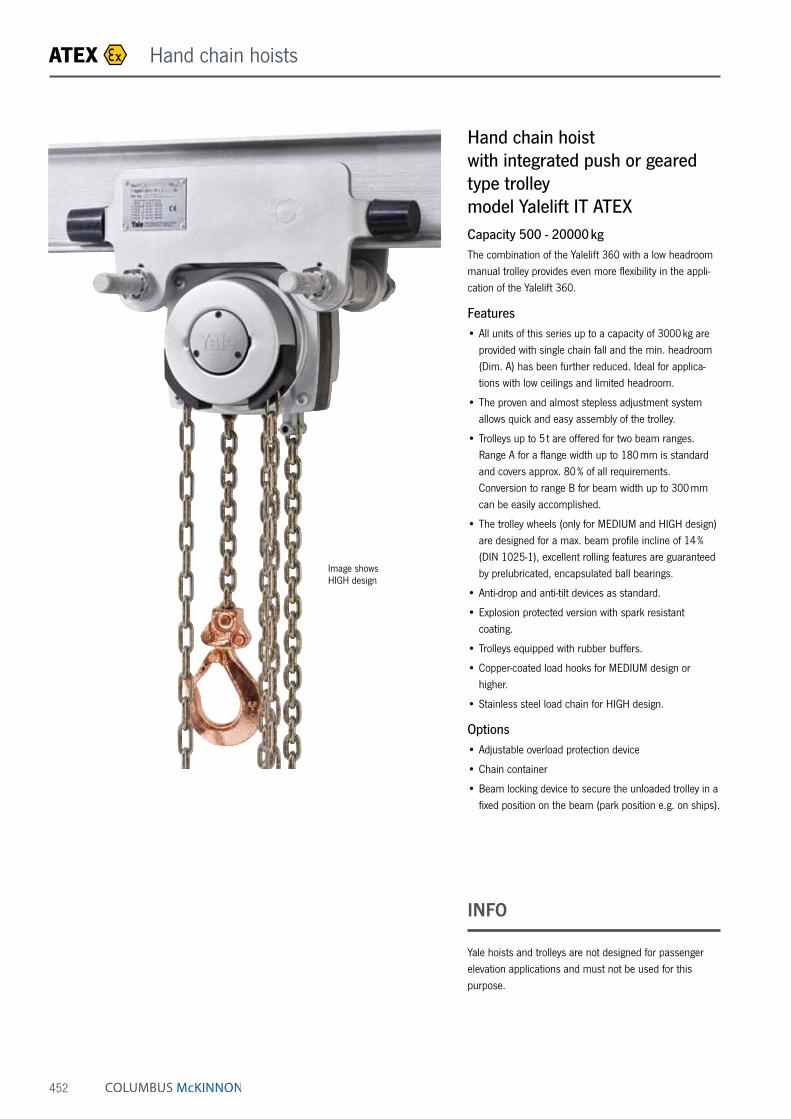
452
Hand chain hoist with integrated push or geared type trolley model Yalelift IT ATEXCapacity 500 - 20000 kgThe combination of the Yalelift 360 with a low headroom manual trolley provides even more flexibility in the appli-cation of the Yalelift 360.
Features• All units of this series up to a capacity of 3000 kg are
provided with single chain fall and the min. headroom (Dim. A) has been further reduced. Ideal for applica-tions with low ceilings and limited headroom.
• The proven and almost stepless adjustment system allows quick and easy assembly of the trolley.
• Trolleys up to 5 t are offered for two beam ranges. Range A for a flange width up to 180 mm is standard and covers approx. 80 % of all requirements. Conversion to range B for beam width up to 300 mm can be easily accomplished.
• The trolley wheels (only for MEDIUM and HIGH design) are designed for a max. beam profile incline of 14 % (DIN 1025-1), excellent rolling features are guaranteed by prelubricated, encapsulated ball bearings.
• Anti-drop and anti-tilt devices as standard.
• Explosion protected version with spark resistant coating.
• Trolleys equipped with rubber buffers.
• Copper-coated load hooks for MEDIUM design or higher.
• Stainless steel load chain for HIGH design.
Options• Adjustable overload protection device
• Chain container
• Beam locking device to secure the unloaded trolley in a fixed position on the beam (park position e.g. on ships).
Image shows HIGH design
ATEX Hand chain hoists
INFO
Yale hoists and trolleys are not designed for passenger elevation applications and must not be used for this purpose.

453
Technical data model Yalelift ITP ATEX BASIC with integrated push type trolley II 3 GD c IIB T4 / II 2 GD c IIA T4
Model EAN-No. 4025092*
Capacity in kg/
number of chain falls
Size ¹ Beam flange width
bmm
Beam flange thickness
t max.mm
Curve radius min.
m
Weight ²
kg
Weight ² with
locking devicekg
YLITP ATEX 500 *237253 500/1 A 50 - 180 19 0.9 20 26YLITP ATEX 1000 *237864 1000/1 A 50 - 180 19 0.9 27 35YLITP ATEX 2000 *243131 2000/1 A 58 - 180 19 1.15 44 52
Technical data model Yalelift ITP ATEX MEDIUM with integrated push type trolley II 2 GD c IIB T4
Model EAN-No. 4025092*
Capacity in kg/
number of chain falls
Size ¹ Beam flange width
bmm
Beam flange thickness
t max.mm
Curve radius min.
m
Weight ²
kg
Weight ² with
locking devicekg
YLITP ATEX 500 *205177 500/1 A 50 - 180 19 0.9 20 26YLITP ATEX 1000 *205382 1000/1 A 50 - 180 19 0.9 27 35YLITP ATEX 2000 *206310 2000/1 A 58 - 180 19 1.15 44 52
Technical data model Yalelift ITP ATEX HIGH with integrated push type trolley II 2 GD c IIC T4
Model EAN-No. 4025092*
Capacity ³ in kg/
number of chain falls
Size ¹ Beam flange width
bmm
Beam flange thickness
t max.mm
Curve radius min.
m
Weight ²
kg
Weight ² with
locking devicekg
YLITP ATEX 500 *257688 500/1 A 50 - 180 19 0.9 20 26YLITP ATEX 1000 *257787 900/1 A 50 - 180 19 0.9 27 35YLITP ATEX 2000 *258760 1250/1 A 58 - 180 19 1.15 44 52
¹ Size B on request² Weight for standard 3 m lift. Other lifting heights available.³ Models in HIGH design are already labelled with reduced capacities when delivered.
ATEX Hand chain hoists

454
Technical data model Yalelift ITG ATEX BASIC with integrated geared type trolley II 3 GD c IIB T4 / II 2 GD c IIA T4
Model EAN-No. 4025092*
Capacity in kg/
number of chain falls
Size ¹ Beam flange width
bmm
Beam flange thickness
t max.mm
Curve radius min.
m
Weight ²
kg
Weight ²with
locking devicekg
YLITG ATEX 500 *253055 500/1 A 50 - 180 19 0.9 24 31YLITG ATEX 1000 *929844 1000/1 A 50 - 180 19 0.9 32 40YLITG ATEX 2000 *929837 2000/1 A 58 - 180 19 1.15 49 57YLITG ATEX 3000 *929820 3000/1 A 74 - 180 27 1.5 82 91YLITG ATEX 5000 *929813 5000/2 A 98 - 180 27 2.0 130 140YLITG ATEX 10000 *941112 10000/3 B 125 - 310 40 1.8 on request on requestYLITG ATEX 20000 *941556 20000/6 B 180 - 310 40 5.0 on request on request
Technical data model Yalelift ITG ATEX MEDIUM with integrated geared type trolley II 2 GD c IIB T4
Model EAN-No. 4025092*
Capacity in kg/
number of chain falls
Size ¹ Beam flange width
bmm
Beam flange thickness
t max.mm
Curve radius min.
m
Weight ²
kg
Weight ²with
locking devicekg
YLITG ATEX 500 *206334 500/1 A 50 - 180 19 0.9 24 31YLITG ATEX 1000 *206341 1000/1 A 50 - 180 19 0.9 32 40YLITG ATEX 2000 *206358 2000/1 A 58 - 180 19 1.15 49 57YLITG ATEX 3000 *206549 3000/1 A 74 - 180 27 1.5 82 91YLITG ATEX 5000 *206563 5000/2 A 98 - 180 27 2.0 130 140YLITG ATEX 10000 *520072 10000/3 B 125 - 310 40 1.8 on request on requestYLITG ATEX 20000 *419765 20000/6 B 180 - 310 40 5.0 on request on request
Technical data model Yalelift ITG ATEX HIGH with integrated geared type trolley II 2 GD c IIC T4
Model EAN-No. 4025092*
Capacity ³ in kg/
number of chain falls
Size ¹ Beam flange width
bmm
Beam flange thickness
t max.mm
Curve radius min.
m
Weight ²
kg
Weight ²with
locking devicekg
YLITG ATEX 500 *273626 500/1 A 50 - 180 19 0.9 24 31YLITG ATEX 1000 *273633 900/1 A 50 - 180 19 0.9 32 40YLITG ATEX 2000 *273640 1250/1 A 58 - 180 19 1.15 49 57YLITG ATEX 3000 *273657 2000/1 A 74 - 180 27 1.5 82 91YLITG ATEX 5000 *273664 4000/2 A 98 - 180 27 2.0 130 140YLITG ATEX 10000 *941938 6000/3 B 125 - 310 40 1.8 on request on requestYLITG ATEX 20000 *941945 12000/6 B 180 - 310 40 5.0 on request on request
¹ Size B on request² Weight for standard 3 m lift. Other lifting heights available.³ Models in HIGH design are already labelled with reduced capacities when delivered.
ATEX Hand chain hoists

455
Dimensions model Yalelift IT ATEX
Model YLIT ATEX 500 YLIT ATEX 1000 YLIT ATEX 2000 YLIT ATEX 3000 YLIT ATEX 5000 YLIT ATEX 10000
A min., mm 245 272 323 382 550 784A1, mm 158 178 205.5 252 260.5 380A2, mm – – – – – –B, mm 17 22 30 38 45 68C, mm 24 29 35 40 47 68D, mm 14 19 22 30 37 50F (Geared trolley), mm 92 92 91 107 149.5 113H1, mm 24.5 24 23.5 32 30.5 55I (Push trolley), mm 71.5 71.5 95.5 131 142.5 169I (Geared trolley), mm 76.5 76.5 98 132.5 148.5 169L, mm 270 310 360 445 525 430L1, mm 130 130 150 180 209 200L2, mm 159 175 207 256 283 261M, mm M 18 M 22 M 27 M 30 M 42 M 48O, mm 60 60 80 112 125 150P (Geared trolley), mm 108 110 112 112 117 158T (Area A), mm 280 290 305 320 364 –T (Area B), mm 400 410 425 440 484 540
Model Yalelift ITG ATEX, 500 - 3000 kg, single fall
Model Yalelift ITP ATEX, 500 - 3000 kg, single fall
Model Yalelift ITG ATEX, 10000 kg, three fall
Model Yalelift ITP/ITG ATEX, 5000 kg, double fall
ATEX Hand chain hoists

with
extremely
low headroom
456
Hand chain hoist with integrated push or geared type trolley (low headroom) model Yalelift LH ATEXCapacity 500 - 10000 kgThe hand chain hoist model Yalelift LH with integrated low headroom manual trolley is the consequent further development of the Yalelift IT. Wherever an even smaller headroom is essential, the Yalelift LH is the ideal choice.
Features• The specially developed chain reeving system and
chain guide allow the bottom block to be pulled laterally to the hoist even further up and almost against the beam flange.
• The integrated design of the innovative Yalelift LH uses the same manual trolleys as incorporated in the Yalelift IT series.
• All models of the LH series up to 3000 kg capacity are provided with single chain fall.
• The proven and almost stepless adjustment system allows quick and easy assembly of the trolley.
• The trolleys up to 5 t are offered for two beam ranges. Range A for a flange width up to 180 mm is standard and covers approx. 80 % of all requirements. Conversion to range B for beam width up to 300 mm can be easily accomplished.
• The trolley wheels (only for MEDIUM and HIGH design) are designed for a max. beam profile incline of 14 % (DIN 1025-1), excellent rolling features are guaranteed by prelubricated, encapsulated ball bearings.
• The low headroom version of the Yalelift IT is adju stable to fit a wide range of beam profiles (e. g. INP, IPE, IPB).
• Anti-drop and anti-tilt devices as standard.
• Explosion protected version with spark resistant coating.
• Trolleys equipped with rubber buffers.
• Copper-coated load hooks for MEDIUM design or higher.
• Stainless steel load chain for HIGH design.
Options• Adjustable overload protection device
• Chain container
• Beam locking device to secure the unloaded trolley in a fixed position on the beam (park position e.g. on ships).
Image shows HIGH design
ATEX Hand chain hoists

457
Technical data model Yalelift LHP ATEX BASIC with integrated push type trolley II 3 GD c IIB T4 / II 2 GD c IIA T4
Model EAN-No. 4025092*
Capacity in kg/
number of chain falls
Size ¹ Beam flange width
bmm
Beam flange thickness
t max.mm
Curve radius min.
m
Weight ²
kg
Weight ² with
locking devicekg
YLLHP ATEX 500 *377522 500/1 A 60 - 180 19 0.9 27 33YLLHP ATEX 1000 *377539 1000/1 A 70 - 180 19 0.9 35 43YLLHP ATEX 2000 *377546 2000/1 A 82 - 180 19 1.15 61 69
Technical data model Yalelift LHP ATEX MEDIUM with integrated push type trolley II 2 GD c IIB T4
Model EAN-No. 4025092*
Capacity in kg/
number of chain falls
Size ¹ Beam flange width
bmm
Beam flange thickness
t max.mm
Curve radius min.
m
Weight ²
kg
Weight ² with
locking devicekg
YLLHP ATEX 500 *592291 500/1 A 60 - 180 19 0.9 27 33YLLHP ATEX 1000 *592314 1000/1 A 70 - 180 19 0.9 35 43YLLHP ATEX 2000 *592321 2000/1 A 82 - 180 19 1.15 61 69
Technical data model Yalelift LHP ATEX HIGH with integrated push type trolley II 2 GD c IIC T4
Model EAN-No. 4025092*
Capacity ³ in kg/
number of chain falls
Size ¹ Beam flange width
bmm
Beam flange thickness
t max.mm
Curve radius min.
m
Weight ²
kg
Weight ² with
locking devicekg
YLLHP ATEX 500 *377799 500/1 A 60 - 180 19 0.9 27 33YLLHP ATEX 1000 *377829 900/1 A 70 - 180 19 0.9 35 43YLLHP ATEX 2000 *377836 1250/1 A 82 - 180 19 1.15 61 69
¹ Size B on request² Weight for standard 3 m lift. Other lifting heights available.³ Models in HIGH design are already labelled with reduced capacities when delivered.
ATEX Hand chain hoists

458
Technical data model Yalelift LHG ATEX BASIC with integrated geared type trolley II 3 GD c IIB T4 / II 2 GD c IIA T4
Model EAN-No. 4025092*
Capacity in kg/
number of chain falls
Size ¹ Beam flange width
bmm
Beam flange thickness
t max.mm
Curve radius min.
m
Weight ²
kg
Weight ² with
locking devicekg
YLLHG ATEX 500 *377744 500/1 A 60 - 180 19 0.9 31 38YLLHG ATEX 1000 *377768 1000/1 A 70 - 180 19 0.9 40 48YLLHG ATEX 2000 *378697 2000/1 A 82 - 180 19 1.15 65 73YLLHG ATEX 3000 *377782 3000/1 A 100 - 180 19 1.5 112 121YLLHG ATEX 5000 *378703 5000/2 A 110 - 180 27 2.0 157 167YLLHG ATEX 10000 *378727 10000/3 B 190 - 310 40 1.8 232 on request
Technical data model Yalelift LHG ATEX MEDIUM with integrated geared type trolley II 2 GD c IIB T4
Model EAN-No. 4025092*
Capacity in kg/
number of chain falls
Size ¹ Beam flange width
bmm
Beam flange thickness
t max.mm
Curve radius min.
m
Weight ²
kg
Weight ² with
locking devicekg
YLLHG ATEX 500 *594592 500/1 A 60 - 180 19 0.9 31 38YLLHG ATEX 1000 *594608 1000/1 A 70 - 180 19 0.9 40 48YLLHG ATEX 2000 *594615 2000/1 A 82 - 180 19 1.15 65 73YLLHG ATEX 3000 *594622 3000/1 A 100 - 180 19 1.5 112 121YLLHG ATEX 5000 *594639 5000/2 A 110 - 180 27 2.0 157 167YLLHG ATEX 10000 *941549 10000/3 B 190 - 310 40 1.8 232 on request
Technical data model Yalelift LHG ATEX HIGH with integrated geared type trolley II 2 GD c IIC T4
Model EAN-No. 4025092*
Capacity ³ in kg/
number of chain falls
Size ¹ Beam flange width
bmm
Beam flange thickness
t max.mm
Curve radius min.
m
Weight ²
kg
Weight ² with
locking devicekg
YLLHG ATEX 500 *377843 500/1 A 60 - 180 19 0.9 31 38YLLHG ATEX 1000 *377867 900/1 A 70 - 180 19 0.9 40 48YLLHG ATEX 2000 *377874 1250/1 A 82 - 180 19 1.15 65 73YLLHG ATEX 3000 *377898 2000/1 A 100 - 180 19 1.5 112 121YLLHG ATEX 5000 *377911 4000/2 A 110 - 180 27 2.0 157 167YLLHG ATEX 10000 *377928 6000/3 B 190 - 310 40 1.8 232 on request
¹ Size B on request² Weight for standard 3 m lift. Other lifting heights available.³ Models in HIGH design are already labelled with reduced capacities when delivered.
Copper-coated for MEDIUM design or higher!
ATEX Hand chain hoists
INFO
Yale hoists and trolleys are not designed for passenger elevation applications and must not be used for this purpose.

459
Dimensions model Yalelift LH ATEX
Model YLLH ATEX 500 YLLH ATEX 1000 YLLH ATEX 2000 YLLH ATEX 3000 YLLH ATEX 5000 YLLH ATEX 10000
A min., mm 188 211 264 316 425 565A1, mm 223 250 289 346 345 365A2, mm 381 427 511 614 612 665B, mm 17 22 30 38 45 68C, mm 24 29 35 40 47 68D, mm 14 19 22 30 37 50F (Geared trolley), mm 92 92 91 107 150 150H1, mm 24 24 24 32 31 45I (Push trolley), mm 72 72 96 131 143 170I (Geared trolley), mm 77 77 98 133 149 170L, mm 270 310 360 445 525 485L1, mm 130 130 150 180 209 225L2, mm 444 488 582 690 720 805L3, mm 124 135 172 203 175 215L4, mm 184 201 230 265 283 348M, mm M 18 M 22 M 27 M 30 M 42 M 48O, mm 60 60 80 112 125 150P (Geared trolley), mm 108 110 112 112 117 165T (Area A), mm 280 290 305 320 364 440T (Area B), mm 400 410 425 440 484 540
Model Yalelift LHG ATEX, 500 - 3000 kg, single fall
Model Yalelift LHP ATEX, 500 - 3000 kg, single fall
Model Yalelift LHG ATEX, 10000 kg, three fall
Model Yalelift LHP/LHG ATEX, 5000 kg, double fall
ATEX Hand chain hoists

460
Technical data model HTP ATEX BASIC II 3 GD c IIB T4 / II 2 GD c IIA T4
Model EAN-No. 4025092*
Capacity
kg
Size Beam flange width
bmm
Beam flange thickness
t max.mm
Curve radius min.
m
Hand effort at WLL
daN
Weight
kg
Weight with
locking devicekg
HTP ATEX 500 *362504 500 A 50 - 220 25 0.9 – 8.0 14.5HTP ATEX 1000 *362535 1000 A 50 - 220 25 0.9 – 9.0 17.0HTP ATEX 2000 *362542 2000 A 66 - 220 25 1.15 – 16.0 24.0HTP ATEX 500 *362559 500 B 160 - 300 40 0.9 – 10.6 17.1HTP ATEX 1000 *362573 1000 B 160 - 300 40 0.9 – 12.0 20.0HTP ATEX 2000 *362580 2000 B 160 - 300 40 1.15 – 19.3 27.3
Technical data model HTP ATEX HIGH II 2 GD c IIC T4
Model EAN-No. 4025092*
Capacity
kg
Size Beam flange width
bmm
Beam flange thickness
t max.mm
Curve radius min.
m
Hand effort at WLL
daN
Weight
kg
Weight with
locking devicekg
HTP ATEX 500 *573894 500 A 50 - 220 25 0.9 – 8.0 14.5HTP ATEX 1000 *573900 1000 A 50 - 220 25 0.9 – 9.0 17.0HTP ATEX 2000 *573917 2000 A 66 - 220 25 1.15 – 16.0 24.0HTP ATEX 500 *362764 500 B 160 - 300 40 0.9 – 10.6 17.1HTP ATEX 1000 *362771 1000 B 160 - 300 40 0.9 – 12.0 20.0HTP ATEX 2000 *362788 2000 B 160 - 300 40 1.15 – 19.3 27.3
Push and geared type trolley model HTP/G ATEXCapacity 500 - 20000 kgThe trolley enables the exact positioning or easy traver-sing of large loads with either manual or powered hoisting equipment.
Features• The trolley wheels (only for HIGH design) are designed
for a max. beam profile incline of 14 % (DIN 1025-1), excellent rolling features due to prelubricated and encapsulated ball bearings.
• Adjustable to fit a wide range of beam widths and profiles (e. g. INP, IPE and IPB).
• Adjustments are made by rotating the clevis load bar which also ensures the centred positioning of the hoist in the clevis – no creeping to the left or the right.
• Explosion protected version with spark resistant coating.
• Trolleys equipped with rubber buffers.
• Stainless steel hand chain for model HTG.
Option• Locking device to secure the trolley in position on the
beam (park position e.g. on ships).
Image shows HIGH design
ATEX Trolleys

461
Technical data model HTG ATEX BASIC II 3 GD c IIB T4 / II 2 GD c IIA T4
Model EAN-No. 4025092*
Capacity
kg
Size Beam flange width
bmm
Beam flange thickness
t max.mm
Curve radius min.
m
Hand effort at WLL
daN
Weight*
kg
Weight* with
locking devicekg
HTG ATEX 500 *362597 500 A 50 - 220 25 0.9 3 9.7 16.2HTG ATEX 1000 *362603 1000 A 50 - 220 25 0.9 6 11.2 19.2HTG ATEX 2000 *362610 2000 A 66 - 220 25 1.15 7 18.0 26.0HTG ATEX 3000 *362627 3000 A 74 - 220 25 1.4 7 35.4 44.6HTG ATEX 5000 *362634 5000 A 90 - 220 25 1.8 9 51.8 62.3HTG ATEX 500 *362641 500 B 160 - 300 40 0.9 3 12.6 19.1HTG ATEX 1000 *362658 1000 B 160 - 300 40 0.9 6 14.1 22.1HTG ATEX 2000 *362665 2000 B 160 - 300 40 1.15 7 21.3 29.3HTG ATEX 3000 *362672 3000 B 160 - 300 40 1.4 7 39.2 48.4HTG ATEX 5000 *362689 5000 B 180 - 300 40 1.8 9 56.0 66.5HTG ATEX 8000 *362719 8000 B 125 - 310 40 1.8 14 104.0 –HTG ATEX 10000 *362726 10000 B 125 - 310 40 1.8 14 104.0 –HTG ATEX 15000 *377577 15000 B 125 - 310 40 5.0 29 230.0 –HTG ATEX 20000 *377584 20000 B 125 - 310 40 5.0 29 230.0 –
Technical data model HTG ATEX HIGH II 2 GD c IIC T4
Model EAN-No. 4025092*
Capacity
kg
Size Beam flange width
bmm
Beam flange thickness
t max.mm
Curve radius min.
m
Hand effort at WLL
daN
Weight ¹
kg
Weight ¹ with
locking devicekg
HTG ATEX 500 *573948 500 A 50 - 220 25 0.9 3 9.7 16.2HTG ATEX 1000 *573955 1000 A 50 - 220 25 0.9 6 11.2 19.2HTG ATEX 2000 *573962 2000 A 66 - 220 25 1.15 7 18.0 26.0HTG ATEX 3000 *573979 3000 A 74 - 220 25 1.4 7 35.4 44.6HTG ATEX 5000 *573986 5000 A 90 - 220 25 1.8 9 51.8 62.3HTG ATEX 500 *362825 500 B 160 - 300 40 0.9 3 12.6 19.1HTG ATEX 1000 *362795 1000 B 160 - 300 40 0.9 6 14.1 22.1HTG ATEX 2000 *362801 2000 B 160 - 300 40 1.15 7 21.3 29.3HTG ATEX 3000 *377591 3000 B 160 - 300 40 1.4 7 39.2 48.4HTG ATEX 5000 *362818 5000 B 180 - 300 40 1.8 9 56.0 66.5HTG ATEX 8000 *573702 8000 B 125 - 310 40 1.8 14 104.0 –HTG ATEX 10000 *573719 10000 B 125 - 310 40 1.8 14 104.0 –HTG ATEX 15000 *573726 15000 B 125 - 310 40 5.0 29 230.0 –HTG ATEX 20000 *573733 20000 B 125 - 310 40 5.0 29 230.0 –
¹ Weight HTG without hand chain
ATEX Trolleys
INFO
Yale hoists and trolleys are not designed for passenger elevation applications and must not be used for this purpose.

462
Dimensions model HTP ATEX
Model HTP ATEX 500-A
HTP ATEX 1000-A
HTP ATEX 2000-A
HTP ATEX 3000-A
HTP ATEX 5000-A
HTP ATEX 500-B
HTP ATEX 1000-B
HTP ATEX 2000-B
HTP ATEX 3000-B
HTP ATEX 5000-B
A, mm 77 82.5 98.5 114 132.5 92 97.5 113.5 129 147.5D, mm 16 17 22 26 33 16 17 22 26 33D1, mm 25 30 40 48 60 25 30 40 48 60D2, mm 30 35 47 58 70 30 35 47 58 70F1, mm 46 46 46 46 45.5 46 46 46 46 45.5H1, mm 30.5 30.5 30.5 30 30 45.5 45.5 45.5 45 45I (HTP ATEX), mm 71.5 71.5 95.5 131 142.5 71.5 71.5 95.5 131 142.5L, mm 260 260 310 390 450 260 260 310 390 450L1, mm 130 130 150 180 209 130 130 150 180 209O, mm 60 60 80 112 125 60 60 80 112 125P1, mm 168 168 168 168 168 168 168 168 168 168P2, mm 146 150 155 160 167.5 187 187 189.5 191.5 191.5L3, mm 346 346 396 476 556 346 346 396 476 556
Dimensions model HTG ATEX
Model HTG ATEX 500-A
HTG ATEX
1000-A
HTG ATEX
2000-A
HTG ATEX
3000-A
HTG ATEX
5000-A
HTG ATEX 500-B
HTG ATEX
1000-B
HTG ATEX
2000-B
HTG ATEX
3000-B
HTG ATEX
5000-B
HTG ATEX
8000-B
HTG ATEX
10000-B
HTG ATEX
15000-B
HTG ATEX
20000-B
A, mm 77 82.5 98.5 114 132.5 92 97.5 113.5 129 147.5 276 276 270 270B, mm – – – – – – – – – – 52 52 70 70D, mm 16 17 22 26 33 16 17 22 26 33 30 30 35 35D1, mm 25 30 40 48 60 25 30 40 48 60 80 80 110 110D2, mm 30 35 47 58 70 30 35 47 58 70 114 114 155 155F (HTG ATEX), mm 91.5 91.5 90.5 107.5 149.5 91.5 91.5 90.5 107.5 149.5 113 113 113 113F1, mm 46 46 46 46 45.5 46 46 46 46 45.5 77 77 – –H1, mm 30.5 30.5 30.5 30 30 45.5 45.5 45.5 45 45 45 45 45 45I (HTG ATEX), mm 76.5 76.5 98 132.5 148.5 76.5 76.5 98 132.5 148.5 170 170 170 170L, mm 260 260 310 390 450 260 260 310 390 450 430 430 870 870L1, mm 130 130 150 180 209 130 130 150 180 209 200 200 200 200L2, mm – – – – – – – – – – – – 115 115O, mm 60 60 80 112 125 60 60 80 112 125 150 150 150 150P (HTG ATEX), mm 110 110 110 110 110 110 110 110 110 110 163 163 163 163P1, mm 168 168 168 168 168 168 168 168 168 168 193 193 – –P2, mm 146 150 155 160 167.5 187 187 189.5 191.5 191.5 – – – –T, mm – – – – – – – – – – 270 270 270 270L3, mm 346 346 396 476 556 346 346 396 476 556 536 536 976 976P3, mm 194 194 194 195 195 194 194 194 195 195 – – – –
P
P
b
D1
2
2
H1
A
t
OIF
D
D
L 1
LP b
F
P1
H1
t
F 1
P2
O I
L
L1
D1
D2
B
L2
Model HTP/HTG ATEX 500 - 5000 kg Model HTP/HTG ATEX 500 - 5000 kg, with locking device
Model HTG ATEX 10000 kg, locking device Model HTG ATEX 10000 kg Model HTG ATEX 20000 kg
P bT
t
F O IA
H1
D
L
L1
D1
D2
B
ATEX Trolleys

463
Technical data model UNOplus ATEX BASIC II 3 GD c IIB T4 und I M2
Model EAN-No. 4025092*
Capacity in kg/
number of chain falls
Chain dimensions
d x pmm
Load chain grade
Lift with one full lever turn
mm
Handle pull at WLL
daN
Weight at standard lift
(1.5 m)kg
UNOplus ATEX 750 *336536 750/1 6 x 18 T 20 20 7.2UNOplus ATEX 1500 *336543 1500/1 8 x 24 T 22 35 12.5UNOplus ATEX 3000 *336550 3000/1 10 x 30 T 17 40 21.5UNOplus ATEX 6000 *336567 6000/2 10 x 30 T 9 40 32.0
Model UNOplus ATEX 750 UNOplus ATEX 1500 UNOplus ATEX 3000 UNOplus ATEX 6000
A min., mm 340 410 510 690B, mm 22 28 36 45C, mm 26 32 40 44D, mm 16 21 27 33E, mm 250 330 380 380F, mm 150 170 220 220G, mm 70 80 100 100H, mm 80 90 120 120J, mm 150 180 210 210K, mm 60 80 90 90L, mm 90 100 120 120
Dimensions model UNOplus ATEX
Ratchet lever hoist model UNOplus ATEXCapacity 750 - 6000 kgFurther technical development turns the ratchet lever hoist into the successor of our proven UNO model. The versatile tool for lifting, pulling and securing of loads is characterised by its compact design and robust stam-ped steel construction.
Features• Due to optimized gearing and improved bearings in the
housing cover a minimum effort is required to operate the short hand lever.
• Steel hand wheel as standard.
• Automatic screw-and-disc type load brake with corrosion protected components.
• Standard free chaining device to quickly attach the load or to pull the chain through the hoist in both directions.
• Robust chain guide rollers eliminate fouling and jamming of chain on the load sheave.
• Sturdy bottom block with encapsulated bolt connections.
• Alloyed steel link chain in accordance with national and international standards and regulations.
• Drop forged suspension and load hooks are made from non-aging, high tensile steel and fitted with robust safety latches.
ATEX Ratchet lever hoists
INFO
Yale hoists and trolleys are not designed for passenger elevation applications and must not be used for this purpose.

464
ATEX Electric winches
Electric winch model BETA-EXCapacity 320 - 7500 kgElectric winches of the series BETA-EX are designed according to the EU Directives 2014/34/EU and MRL 2006/42/EG. The models are usable in any place, where the risk of igni-tion of explosive atmosphere exists (mixture of air, gases, fumes and dust/air-mixture, respectively) e.g. chemical or petrochemical industry, biogas plants, paint shops. Due to a specially-tailored modular system, the suitable winch for each individual application can be put together easily. The BETA-EX is characterized by the excellent workman-ship in connection with the reliable and stable gear
motors.
• Special surface coating
• The electrically releasing spring-operated disc brake keeps the load safe even if the power fails.
• Powerful three-phase drives for multi-range voltage 380 - 420 V, 50 Hz or 440 - 460 V, 60 Hz. Insulation class F, duty cycle 40 % ED.
• From a load capacity of 1000 kg equipped as standard with an overload protection.
• The maintenance-free spur gear running in an oil bath, with helical gearing, milled and polished gearwheels, ensures particularly smooth running.
• Two rope fixings (left and right) for variable rope feed.
Equipment options• Electric control incorporated in a flame-proof housing
Ex II 2 GD de IIB T4 T 135 °C
• Electric control not ATEX-compliant (Mounting outside of ATEX-area)
• A range of drum designs, e.g. extended for greater wire rope capacity, special rope drums for multi-rope operation.
• Rope pressure rolls to prevent springing open of the unloaded rope on the drum.
• Adjustable gear limit switch to limit the rope path in both directions.
• Other operating voltages on request.
• Hand-actuated auxiliary switch in ATEX-design with Up/Down and emergency stop for an enhanced operat-ing safety.
• Special ropes with copper-plated load hook.
• Sheaves, pulley blocks (ATEX-compliant Ex II 2 GD IIB T4 135 °C IP 65).
Application-oriented
winch solutions
INFO
Customer-specific winch adjustments are possible after consultation.
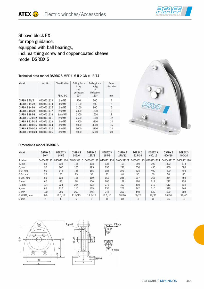
465
Sheave block-EX for rope guidance, equipped with ball bearings, incl. earthing screw and copper-coated sheave model DSRBX S
Dimensions model DSRBX S
Model DSRBX S 90/4
DSRBX S 145/5
DSRBX S 145/6
DSRBX S 185/8
DSRBX S 185/9
DSRBX S 270/12
DSRBX S 325/14
DSRBX S 400/16
DSRBX S 400/18
DSRBX S 490/20
Art.-No. 0400431113 0400431114 0400431115 0400431117 0400431118 0400431121 0400431123 0400431124 0400431125 0400431126B, mm 85 125 125 138 138 191 260 302 302 313C, mm 90 160 160 195 195 290 350 430 430 580Ø D, mm 90 145 145 185 185 270 325 400 400 490Ø D1, mm 20 25 25 30 30 40 50 50 50 65Ø Dm, mm 80 125 125 160 162 246 297 368 364 450E, mm 62 88 88 106 106 138 180 212 212 220H, mm 134 224 224 273 273 407 490 612 612 694K, mm 65 110 110 135 135 202 242 310 310 340L, mm 120 200 200 245 245 360 440 530 530 650Ø M/M1, mm 9/9 11.5/13 11.5/13 13.5/15 13.5/15 18/20 22/25 26/30 26/30 34/40S, mm 4 6 6 8 8 10 12 15 15 16
Model Art.-No. Classification
FEM/ISO
Pulling force in kg
at deflection
90°
Pulling force in kg
at deflection
180°
Rope diameter
mm
DSRBX S 90/4 0400431113 2m/M5 700 500 4DSRBX S 145/5 0400431114 4m/M6 1100 800 5DSRBX S 145/6 0400431115 2m/M5 1100 800 6DSRBX S 185/8 0400431117 2m/M5 2300 1630 8DSRBX S 185/9 0400431118 1 Am/M4 2300 1630 9DSRBX S 270/12 0400431121 2m/M5 2500 1800 12DSRBX S 325/14 0400431123 2m/M5 4500 3200 14DSRBX S 400/16 0400431124 3m/M6 5000 3800 16DSRBX S 400/18 0400431125 2m/M5 5000 3800 18DSRBX S 490/20 0400431126 3m/M6 8000 6000 20
Technical data model DSRBX S MEDIUM II 2 GD c IIB T4
F Rope
F Rope
Rope-Ø
ATEX Electric winches/Accessories

466
Manual winch with load pressure brake model OMEGA-EXCapacity 1000 daNThe hand winch OMEGA-EX is a complete new construc-tion and was developed especially for the high safety requirements in potentially explosive atmospheres. All components of the OMEGA-EX are designed to avoid effectively an inadmissible heating of the surfaces. Carefully selected materials and the sophisticated construction of the winch prevent the occurrence of mechanically caused sparks, for example by intrusion of foreign materials.
Features• Winch housing made of aluminum permanent mold
casting for a low own weight, rope drum made of steel, chemically nickel-plated for a high versatility.
• Integrated load pressure brake
• Closed gear with oil bath lubrication. The large oil volume ensures a high cooling effect.
• Equipotential bonding to avoid electrostatic charging.
• Pivotable crank handle
• Suitable for ambient temperatures of -20 °C up to +40 °C.
Model OMEGA-EX 10
A, mm 345B, mm 300C, mm 110D, mm 65E, mm 156F, mm 424G, mm 90H, mm 95I, mm 126J, mm 320Ø K, mm 17L, mm 85M, mm 116N, mm 88O, mm 310.5P, mm 56Q, mm 56R, mm 117.5Ø S, mm 100T, mm 200
ATEX Manual winches
Model EAN-No. 4053981**
Capacity 1st layer
kg
Capacity top layer
kg
Rope diameter
mm
Lift per crank rotation
mm
Required crank effort
daN
Weight without
ropekg
OMEGA-EX 10 **004570 1000 692 8 ⁵ 29 17 38
⁵ recommended rope: EN 12385-2
Technical data model OMEGA-EX MEDIUM II 2 GD ck IIB T4
Application areasChemical or petrochemical industry, biogas plants, paint shops

467
Wall-mounted rack and pinion jacks model ZWW-EXCapacity 250 kgThe rack and pinion jack is suitable for lifting, lowering, pulling and pushing, for horizontal displacement, supporting, adjusting or fixing of heavy components or whole appliances and equipment in hazardous areas.
Features• Carefully selected materials and a high-grade coating
prevent the occurrence of mechanically caused sparks.
• No inadmissible heating of the surfaces due to the intelligent design of the individual parts.
• Equipotential bonding and limited surface area to avoid electrostatic charging.
• The grease-lubricated, self-locking worm gear is set into operation by rotations on the crank. It provides not only for easy movement of the load, but also for a reliable safety in every position.
Application areasPlant construction, shipping, wastewater treatment plants, chemical industry and food industry.
Technical data model ZWW-EX MEDIUM II 2 GD c IIB T4
Model Art.-No. Capacity
kg
Rack length
mm
Lift
mm
Weight
kg
ZWW-EX 250 040052648 250 735 530 5.7
30 20
735
20
35
200
175
175
225
20
60
123
8
Ø11
Ø11
Ø10
.5
5050
90
28
313
1193226.4
530
Lift
Rack
leng
th
Earthing screw
ATEX Rack & Pinion jacks

468
Hand pallet truck, stainless steel version model HU 20-115 VATP ATEX PROLINECapacity 2000 kgThe hand pallet truck is designed for the use in explosive environments (zone 1 and 2).
Features• Ergonomic safety control handle for one-hand operation
of lifting, driving and lowering.
• Low maintenance high performance hydraulic pump with hard chromium plated piston and pressure relief valve. Hydraulic unit made of V4A-316 stainless steel.
• Frame, adjustable connecting rods, bolts and the tor-sion tube are made of high quality V4A-316 stainless steel.
• Steering angle of 105 degree to each side for easy handling in confined spaces.
• Conductive steering rollers (antistatic).
Technical data HU 20-115 VATP ATEX PL HIGH II 2 GD c IIC T6
Model HU 20-115 VATP ATEX PL
Art.-No. 040054147Capacity, kg 2000Weight, kg 86Tyre type ¹ PA/VGSteering rollers, mm 200 x 50Load rollers, mm 82 x 70Stroke h3, mm 115Height of control handle h14, mm 1200Fork height lowered h13, mm 85Fork width e, mm 160Fork length l, mm 1150Outside dimension of forks b1, mm 540
¹ PA … Polyamide, VG … Solid rubber
ATEX Hand pallet trucks
INFO
Before the use in explosive environments the operator has to create an explosion protection document acc. to the machinery directive 1999/92/EG!

469
ATEX Load moving systems
• The universal joint suspension of the roller groups contributes to a positive contact when travelling over uneven floors.
• Conductive load wheels (antistatic).
• Each individual roller is made from high tensile mate-rial which ensures extremely quiet running.
• The rollers are suitable for all in-plant floors and will not damage normal floor covering.
• The load moving systems can be easily dismantled and facilitate transport even in small trucks.
• The load moving systems have been developed for professional applications and are practically mainte-nance-free.
• All rollers are provided with two encapsulated, lifetime lubricated ball bearings.
• The front steering skate is equipped with an amply di-mensioned axial ball bearing underneath the turntable.
• The front and rear skates are available individually.
Technical data model SX ATEX II 2 GD c IIB T4
Model EAN-No. 4053981**
Capacity
t
Overall height
mm
Number of rollers
Roller diameter
mm
Colour of rollers
Weight
kg
SX-10 ATEX **534107 10 102 16 82 black 54SX-20 ATEX **814063 20 102 32 82 black 76SX-30 ATEX **325163 30 110 48 82 black 136
Model SX-20 ATEX
Steerman® Heavy load moving system model SX ATEXCapacity 10 - 30 tThese universal heavy load moving systems have been designed for the safe and cost saving transport of loads. Transport of heavy loads (e.g. machines, construction parts, steel structures) is normally made with a stable three point loading system. Transport of extremely bulky or heavy loads with an unfavourable center of balance, may also be executed with a four point loading system. The robust towing bar in connection with the unique turn-table on large diameter thrust bearings allows effortless steering of the load. The rear skates are aligned parallel by means of a tie rod and kept in position, thus ensuring time saving and smooth transportation of the load.
The skates are powder coated and all connecting ele-ments corrosion-resistant. Highest safety requirements have been considered.
Features• The modular design ensures an extremely simple
operation and simultaneously offers a wider range of combinations.
• The construction of the load moving systems is ex-tremely robust and resistant to distortion.
• The skates are smooth-running and provide an incred-ibly low rolling resistance even with the heaviest loads.
• Twin rollers (instead of one wide roller) ensure low roll-ing resistance even at a narrow curve radius.

Pfaff-silberblau Hebezeugfabrik GmbHAm Silberpark 2-8, 86438 KissingPhone +49 / 83 33 / 21 21-800, Fax +49 / 83 33 / 21 21-805 E-Mail: [email protected], Internet: www.pfaff-silberblau.com
Questionnaire - Page 1
5.2CHECKLISTforexplosionprotectiondata
■Devicegroup,devicecategoryandzoneallocation(seeItem2.1)
Pleaseenteracross
Notavailable
Devicegroup
Device group I
DevicegroupII X
Pleasecomplete
Ignitiontemperatureofthedust/airmixture
Max.surfacetemperaturefordust[°C]
Firm: __________________________________________________________________________________________________________________________
Address: __________________________________________________________________________________________________________________________
Department: ____________________________________________________________________________ Phone: _______________________________________
Fax: ____________________________________________________________________________ E-mail: _______________________________________
Name: __________________________________________________________________________________________________________________________
ToenablePfaff-silberblauliftingunits/driveelementstobedesignedinaccordancewithECdirective94/9/ECitisimperativethatthischecklistis
completedandalloutstandingquestionsregardingexplosionprotectionbeansweredconscientiously.
Temp.class Max.surfacetemperatureoftheequipment[°C] Ignitiontemperatureofthecombustible
substances[°C]
T1 450 > 450
T2 300 > 300... < 450
T3 200 > 200... < 300
T4 135 > 135... < 200
T5 100 > 100... < 135
T6 85 > 85... < 100
■Temperatureclassesandexplosiongroups(seeItem2.4)
Pleaseenteracross
Notavailable
Notavailable
Category/Zone Ex-atmosphere....
Category1(=Zone0/20) ...is the permanent, long-term or frequent situation.
Category2(=Zone1/21) ...isanoccasionaloccurrence.
Category3(=Zone2/22) ...isarareoccurrenceandthenonlytemporarily.
Notavailable
the equipment
explosion
2 WhatkindofpotentiallyexplosiveareasdowesupplyPfaff-silberblaudriveelementsfor?
• Our customer undertakes to provide us with all the required data. • Our customer must check the applicability based on the information provided by us. • The operator is responsible for - complying with the maximum capacity of the drive mechanism/lifting system - avoiding explosive atmospheres - minimizing or limiting the time of the explosion hazard - observing the information in the operating instructions supplied by us. Iftheoperatinginstructionsarenotadheredto,thedeclarationofconformitywillceasetobevalidin accordancewith94/9/EC. • During the offer/order stage, Pfaff-silberblau creates a checklist, which subsequently forms part of the order documentation.
1Responsibility
2.2Devicecategory
Category 2 includes Category 3.2.3Zoning Zonesinpotentiallyexplosiveatmospheres
Zone Probability of occurrence of a potentially explosive atmosphere
Gas Dust
0 20 Permanent,long-term,frequent(prevailingsituation)
1 21 Occasional,duringnormaloperations
2 22 Seldom,temporary
Pfaff-silberblau drive elements are designed on the basis of an D housing temperature of 80 °C, such that if the room temperature is 40 °C the surface temperature
will be 120 °C. This results in a safety factor of 1.12 relative to the max. surface temperature of 135 °C.
For explosion-proofing in respect of dust, the operator is required to provide information on the maximum ignition temperature of the air/dust mixture.
2.4Temperatureclassesandexplosiongroups Temperature Max.surfacetemperature Ignitiontemperatureof Explosiongroup
class oftheequipment[°C] thecombustiblesubstances[°C] IIA IIB IIC
T1 450 > 450 Ammonia, acetone-benzole, Coke oven gas, Hydrogen
ethane, ethyl acetate, carbon water gas (enriched)
monoxide, methane, methanol,
methyl benzene, propane
T2 300 > 300... < 450 n-butane, n-butanol, Butadiene 1,3 Acetylene
cyclohexanone, ethanol, ethylene,
acetic anhydride, ethylene oxide
natural gas, liquid gas
T3 200 > 200... < 300 Petrol, diesel, heating oil, Crude oil, isoprene,
aircraft fuel, n-hexane hydrogen sulphide
T4 135 > 135... < 200 Acetaldehyde ether Ethyl ether
T5 100 > 100... < 135
T6 85 > 85... < 100 Carbon bisulphide
2.1Deviceclass
Devicegroup Use Remarks
I Mining Not available
II All other devices Available
DevicegroupII
Safety Zone
Category1
(=Zone0/20)
Category2
(=Zone1/21)
Category3
(=Zone2/22)
Devices providing an ultra-highlevel of
safety.
In association with infrequentdrivefaults!
Devices providing a highlevel of safety.
In association with expecteddevicefaults!
Devices providing a normallevel of safety.
In association with normaloperation!
Designed for use in areas in which there is a permanent,long-termorfrequentpresence of
a potentially explosive atmosphere consisting of a mixture of air and gases, vapors or mist or of
dust/air mixtures.
Designed for use in areas in which there is an occasionalpresence of a potentially explosive
atmosphere consisting of a mixture of air and gases, vapors or mist or of dust/air mixtures.
Designed for use in areas in which a potentially explosive atmosphere caused by gases, vapors,
mist or raised dust can be ruled out or, where such an atmosphere should nevertheless occur,
the likelihoodofsuchoccurrenceisveryrareandwillbeforashorttimeonly.
2 What kind of potentially explosive areas do we supply Pfaff-silberblau
• Our customer undertakes to provide us with all the required data. • Our customer must check the applicability based on the information provided by us. • The operator is responsible for
- complying with the maximum capacity of the drive mechanism/lifting system- avoiding explosive atmospheres- minimizing or limiting the time of the explosion hazard- observing the information in the operating instructions supplied by us.If the operating instructions are not adhered to, the declaration of conformity
accordance with 94/9/EC. • During the offer/order stage, Pfaff-silberblau creates a checklist, which subsequently forms part of the order
documentation.
1 Responsibility
2.2 Device category
2.3 ZoningZones Zones in potentially explosive atmospheres
Zone Probability of occurrence of a potentially explosive atmosphere
Gas Dust
0 20 Permanent, long-term, frequent (prevailing situation)
1 21 Occasional, during normal operations
2.1 Device class
Device Device Device group Use Remarks
I Mining Not available
II All other devices Available
Device group II
Safety Zone
Category 1
(= Zone 0/20)
Category 2
(= Zone 1/21)
Category 3
(= Zone 2/22)
Devices providing an ultra-high level of
safety.
In association with infrequent drive faults!
Devices providing a high level of safety.
In association with expected device faults!
Devices providing a normal level of safety.
In association with normal operation!
Designed for use in areas in which there is a permanent,
a potentially explosive atmosphere consisting of a mixture of air and gases, vapors or mist or of
dust/air mixtures.
Designed for use in areas in which there is an occasional
atmosphere consisting of a mixture of air and gases, vapors or mist or of dust/air mixtures.
Designed for use in areas in which a potentially explosive atmosphere caused by gases, vapors,
mist or raised dust can be ruled out or, where such an atmosphere should nevertheless occur,
the likelihood of such occurrence is very rare
3Whichcertificationorcheckisrequiredforwhichzone?
Directive 94/9/EC Chapter II Item 8 and Appendix VII
*G = Gas / D = Dust
Category 2 3
Zone 1 21 2 22
Explosiveatmosphere* G D G D
Motor
EC type examination EC type examination
certificate from a nominated office certificate from a nominated office
Internal process control by manufacturer (Directive 94/9/EC Appendix VIII)
Drive Declaration of conformity from the manufacturer and filing of the explosion
prevention documentation with a nominated office
Internal process control by manufacturer
(Directive 94/9/EC Appendix VIII)
Declaration of conformity
from the manufacturer
Questionnaire - Page 1
2.5Typeofprotection
• Pfaff-silberblau drive elements are designed in accordance with typeofprotection„c-Protectionbyconstructionalsafety“.
• Drive elements produced for use in Zones1and2(gas) are designed in accordance with typeofprotection„k-Protectionbyliquidimmersion“
(drive elements with oil lubrication).
• Typeofprotection„b-Protectionbycontrolofignitionsource“ can be provided by means of control of motor performance.
EN13463-2 Protection by flow restricting enclosure „fr“
EN13463-3 Protection by flameproof enclosure „d“
EN13463-4 Protection by inherent safety „g“
EN13463-5 Protection by constructional safety „c“
EN13463-6 Protection by control of ignition source „b“
EN13463-7 Protection by pressurization „p“
EN13463-8 Protection by liquid immersion „k“
for non-electrical equipment for use in potentially explosive areas:
4HazardanalysisaccordingtoDINEN1127
The purpose of the hazard analysis is to establish which risks of ignition apply to Pfaff-silberblau drive elements and the
safety precautions to be taken to provide the level of safety required.
Hot surface
Mechanically generated sparks caused by friction, impact and degradation
Riskofignitionfrom: Electrostatic charging
Chemical reaction
Improper assembly/installation
5Documentationforsecuringprotectionagainstexplosion
• Checklist for provision of all data of relevance to explosion
protection.
• Questionnaire for the specification of technical data.
• Written order contract for the design of the drive elements.
• Documented calculations for the specification of the
thermal limits and the life of the bearings.
• Production checklist for testing the components: Sealing faces, roughness of the spindle and
bearing nuts, bearing face of the gearing.
• Operating manual with 94/9/EC declaration of conformity.
• Rating plate.
5.1Identifyingmarkings
Ex-marking
Device group
Category
Ex-atmosphere
Type of protection
Temperature class
Max. surface temperature on which 5 mm of dust can settle
II 2 G/D ckT4/100°C
Please complete
temperature of the dust/air mixture
temperature for dust [°C]
> 200... < 300
> 135... < 200
> 100... < 135
> 85... < 100
Not available
Not available
temperature
surface temperature
Category 2 includes Category 3.
housing temperature of 80 °C, such that if the room temperature is 40 °C the surface temperature
Carbon bisulphide
of
a potentially explosive atmosphere consisting of a mixture of air and gases, vapors or mist or of
of a potentially explosive
Designed for use in areas in which a potentially explosive atmosphere caused by gases, vapors,
mist or raised dust can be ruled out or, where such an atmosphere should nevertheless occur,
Checklist
Worm gear screw jacks/Linear Drivesaccording to 94/9/EC (ATEX)for use in potentially explosive areas
Safety - Made by Pfaff-silberblau
470
ChecklistPfaff-silberblau develops, produces and sets up system solutions and complete actuator units according to indivi-dual customer requirements for different applications: product technique, transport technique, foundry technique, mining, hydraulic engineering, shipbuilding, research, building service, etc.Of course, also available in accordance with regulation 2014/34/EU (ATEX) for the use in areas with an explosi-on hazard.
Simply ask for our checklist for screw jacks and linear drives!
ATEX Screw jacks and linear drives

471
Technical questionnaireTo enable us to design lifting units/drive elements in accordance with EU-directive 2014/34/EU it is essential that this checklist is completed and all open questions regarding explosion protection are answered carefully.
Equipment group, categories and zones
Equipment group I Equipment group II
(only for mining fire damp protection)
Category - Zone Ex-atmosphere ...
— Category 1 - Zone 0/20 … is present continuously for long periods or frequently (not available)
Category M1 Category 2 - Zone 1/21 … is present occasionally in normal operation
Category M2 Category 3 - Zone 2/22 … is unlikely to be present except for a short period of time.
Ex-atmosphere
Medium? If dusts are involved - please specify Surrounding temperature (only permiss- able between
-20 up to +40 °C)
Zone Explosion group
Gases/Vapours G Dust D
— 0 — 20 IIA
1 21 IIB
2 22 IIC
Temperature classes
Temperature class Max. surface temperature of the equipment [°C]
Max. ignition temperature of combustible substances [°C]
Max. surface temperature for dust [°C]
T1 450 > 450 Ignition temperature …….……….Smouldering temperature ……………
T2 300 > 300... < 450
T3 200 > 200... < 300
T4 135 > 135... < 200
— T5 100 > 100... < 135
— T6 85 > 85... < 100
T1 up to T4 available, T5 and T6 not available
Place, Date Signature
ATEX Questionnaire

472
Industrial Products GmbH
473
Returns – We need your support!
Dear Sirs,
COLUMBUS McKINNON Industrial Products GmbH manufactures worldwide according to uniform, controlled standards of EN ISO 9001. This is a guarantee for our business partners that given standards in design and development, manufacturing, assembly and service are complied with. In spite of all our efforts, should there still be a reason to complain about one of our products, we kindly ask you to inform before you return the goods to us. We will be happy to help you!
To organize returns as quickly and easy as possible we summarize the process in three steps:
Call us to receive a CMCO return delivery note
Print out CMCO return delivery note
Stick CMCO return delivery note on the outside of the package
This easy sequence will be valid for warranty returns, for service returns and for oth-er return deliveries. In case the goods should be shipped directly from your end user we appreciate that you forward the CMCO return delivery note to your customer.
Please note that products can only be returned with our prior approval and must beaccompanied by a CMCO return delivery note. Goods arriving without the returndelivery note will not be accepted by our goods-in department.
In case of potential transport damage, a damage confirmation report provided by the forwarder is required by our insurance company. Please indicate potential transport damages immediately to your logistics partner and refuse acceptance.
If the reason for the return delivery is not within CMCO’s responsibility or in case of unjustified complaint we - much to our regret - will have to pass on the costs to the customer. For costs arising for equipment being returned to stock and the necessary inspection, we will levy a restocking charge of 20 %. The amount will be deducted from our credit memo after inspection and acceptance of the goods.
We thank you for your understanding! Our sales team is available for any further questions.
Best regards,
COLUMBUS McKINNON Industrial Products GmbH
This easy sequence will be valid for warranty returns, for service returns and for oth-er return deliveries. In case the goods should be shipped directly from your end user
COLUMBUS McKINNON IndustrialProducts GmbHYale-Allee 30D-42329 Wuppertal DE
Received FromMax MustermannMusterstr. 1D-12345 MUSTERSTADTContact:
Phone:
Fax:
COLUMBUS McKINNON Industrial Products GmbH Yale-Allee 30 D-42329 Wuppertal
Ship ToCOLUMBUS McKINNONIndustrial Products GmbHYale-Allee 30D-42329 WUPPERTAL
InformationRGA No.
50004751Customer POInvoice No.Orig. Sales Order 50004751Authorized By Sebastian Jöris
Phone:20269359Fax:20269359Email:[email protected]
Page 1 of 109.01.2015 09:01:30
Item MaterialDescription
Quantity
10000 192011508Werksreparatur
1,00 ST
10100 N21225461Gabelhubwagen HU 25-115 TS
1,00 ST
---------------------------------------------------------------------------------------------------------------------------------------------------------------------
----Service Notification 300005216----Hand Pallet Truck HU 25-115 TS
COLUMBUS McKinnon Industrial Products GmbHYale-Allee 30, 42329 WuppertalReg. Amtsgericht Wuppertal HRB 17550Ust.-IDNr. DE121543086Telefon +49 202 693590Telefax +49 202 69359-193
Geschäftsführer:Hans-H. [email protected]
COLUMBUS McKINNON Industrial Products GmbHYale-Allee 30 · D-42329 Wuppertal · Phone +49 (0) 202/693 59-0 · Fax +49 (0) 202/693 59-127 · www.cmco.eu · e-mail: [email protected]

474
Industrial Products GmbH

475

476
Industrial Products GmbH

477

478
Industrial Products GmbH

479

480
Industrial Products GmbH

481

482
Industrial Products GmbH

483
COLUMBUS McKINNON Industrial Products GmbH
Yale-Allee 30 42329 Wuppertal
Phone: +49 (0) 202/693 59-0 Fax: +49 (0) 202/693 59-127 Web Site: www.cmco.eu, www.yale.de e-mail: [email protected]
COLUMBUS McKINNON Engineered Products GmbH
Am Silberpark 2-8 86438 Kissing
Phone: +49 (0) 82 33/21 21-800 Fax: +49 (0) 82 33/21 21-805 Web Site: www.cmco.eu, www.pfaff-silberblau.com e-mail: [email protected]
Subject to engineering changes and improvements. No warranty for printing errors or mistakes.
Effective October 2015. Reproduction or reprinting of this catalogue can only be carried out with written permission from COLUMBUS McKINNON Industrial Products GmbH.

CMCO
No.
3 G
B 98
9999
99 2
015
Copyright © 2022 FDOKUMEN