Micromechanical Studies of 4N Gold Wire for fine Pitch Wire-Bonding
Upload
khangminh22Category
view
4download
0
TOOLMAKER SOLUTIONS
Wire Drawing Guide
Your full-line of wire drawing solutions


WIR
E D
RAW
ING
APP
LICA
TIO
NS
& FA
ILU
RE
MO
DES
CU
STO
MER
SU
PPO
RT
MAT
ERIA
LS
WELCOME TO HYPERION
COMPLETE DRAWING SOLUTIONS
PCD AND VERSIMAX: MATERIAL & PROCESS
- PCD MATERIAL & PROCESS
- PCD CATALOGUE
- VERSIRION AND VERSIMAX MATERIAL
- PCD MATERIAL ISSUES
CEMENTED CARBIDE: MATERIAL & PROCESS
- CEMENTED CARBIDE MATERIAL & PROCESS
- CEMENTED CARBIDE MATERIAL DEFECTS
- CEMENTED CARBIDE CATALOGUE
- WEAR PARTS
DIAMOND COMPOUNDS
- SLURRIES
- PASTES
- MICRON POWDER GRADES
APPLICATIONS
- APPLICATION KNOWLEDGE
- APPLICATIONS GUIDELINES
- BEST PRACTICES
- FAILURE MODES
- WIRE DEFECTS
FAQ’S
INTERNATIONAL STANDARDS
CONVERSION TABLES AND FORMULAS
RECYCLING AND SUSTAINABILITY
WORDS INDEX
06
10
14
14
22
24
25
27
27
36
39
45
47
47
48
49
52
52
55
57
59
66
70
71
72
73
74
TABLE OF CONTENTS
3WIRE DRAWING GUIDE

WIRE DRAWING

WIRE DRAWING

CVD diamond
Corrosion resistant seal rings
CIC integral rolls introduced
Submicron grade H3F for wire drawing
Grade DZ05 for flow control
Diffusion bonding of CC bodies for
wear parts
Grade DZ10 for can tooling
HPHT gem diamonds
Coated diamond for precision wire sawing
V-Series PCBN grades, new
for steel turning
Grade AM60 for CFRP machining & Grade AM70 for titanium
machining
Intelligent rotary cutters, quick anvil change
PBA rotary cutters concept
Grade TC03/C3D for drawing die nibs
1st diamond synthesis
1st PCD cutters (for oil & gas)
Introduction of grade H10F
6 WIRE DRAWING GUIDE
OUR HERITAGEPROUD PAST, PROMISING FUTURE

CVD diamond
Corrosion resistant seal rings
CIC integral rolls introduced
Submicron grade H3F for wire drawing
Grade DZ05 for flow control
Diffusion bonding of CC bodies for
wear parts
Grade DZ10 for can tooling
HPHT gem diamonds
Coated diamond for precision wire sawing
V-Series PCBN grades, new
for steel turning
Grade AM60 for CFRP machining & Grade AM70 for titanium
machining
Intelligent rotary cutters, quick anvil change
PBA rotary cutters concept
Grade TC03/C3D for drawing die nibs
1st diamond synthesis
1st PCD cutters (for oil & gas)
Introduction of grade H10F
7
WIR
E D
RAW
ING
WIRE DRAWING
8 WIRE DRAWING GUIDE
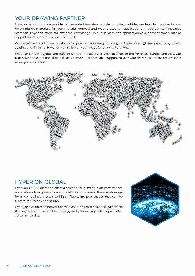
YOUR DRAWING PARTNERHyperion is your full-line provider of cemented tungsten carbide, tungsten carbide powders, diamond and cubic boron nitride materials for your material-removal and wear-protection applications. In addition to innovative materials, Hyperion offers our extensive knowledge, unique services and application development capabilities to support our customers’ competitive needs.
With advanced production capabilities in powder processing, sintering, high-pressure high-temperature synthesis, coating and finishing, Hyperion can satisfy all your needs for drawing solutions.
Hyperion is truly a global and fully integrated manufacturer, with locations in the Americas, Europe and Asia. Our expansive and experienced global sales network provides local support, so your wire drawing solutions are available when you need them.
HYPERION GLOBAL Hyperion’s MBG® diamond offers a solution for grinding high performance materials such as glass, stone and electronic materials. The shapes range from well-defined crystals to highly friable, irregular shapes that can be customized for any application.
Hyperion’s worldwide network of manufacturing facilities offers customers the very latest in material technology and productivity with unparalleled customer service.

9WIRE DRAWING
WIR
E D
RAW
ING
DRAWING THEORY AND DRAWING LINEDrawing process refers to reduction of metals section by the application of stress in tension.
Drawing die is a tool with a specially shaped hole through which wire is pulled to reduce its diameter.
Traction force σd pulls the wire through the reduction cone. The reaction σb, decomposes in force P (compress the wire deforming its material under ratio r) and the friction µP. Friction stresses are reduced with better lubrication.
When a wire is drawn (reduced), the material grains deform and elongate, causing the wire to be harder and less ductile.
To return the material to its original hardness and ductility, the material is annealed. During annealing, grains recrystallize and grain growth can occur.
After annealing, the wire can again be drawn.
Starting stock
Final work sizeα
αDf
A0 A1σm
μP
μP
σb σd
P
P
D0F
L C
r = 1 - A1 A0
FERRITIC STEEL
AUSTENITIC STEEL
AUSTENITIC-FERRITIC STEEL
InternalResidual
Stress
Strength,Hardness& Ductility
Microstructureand Grain Size
Recovery(Grains recover
slightly fromcold-working)
InternalResidual Stress
Strength
DuctilityHardness
GrainGrowth
Grain Growth(Larger grains grow
at the expense of the smaller grains)
Recrystallization(New grains form)
TUNGSTEN CARBIDE
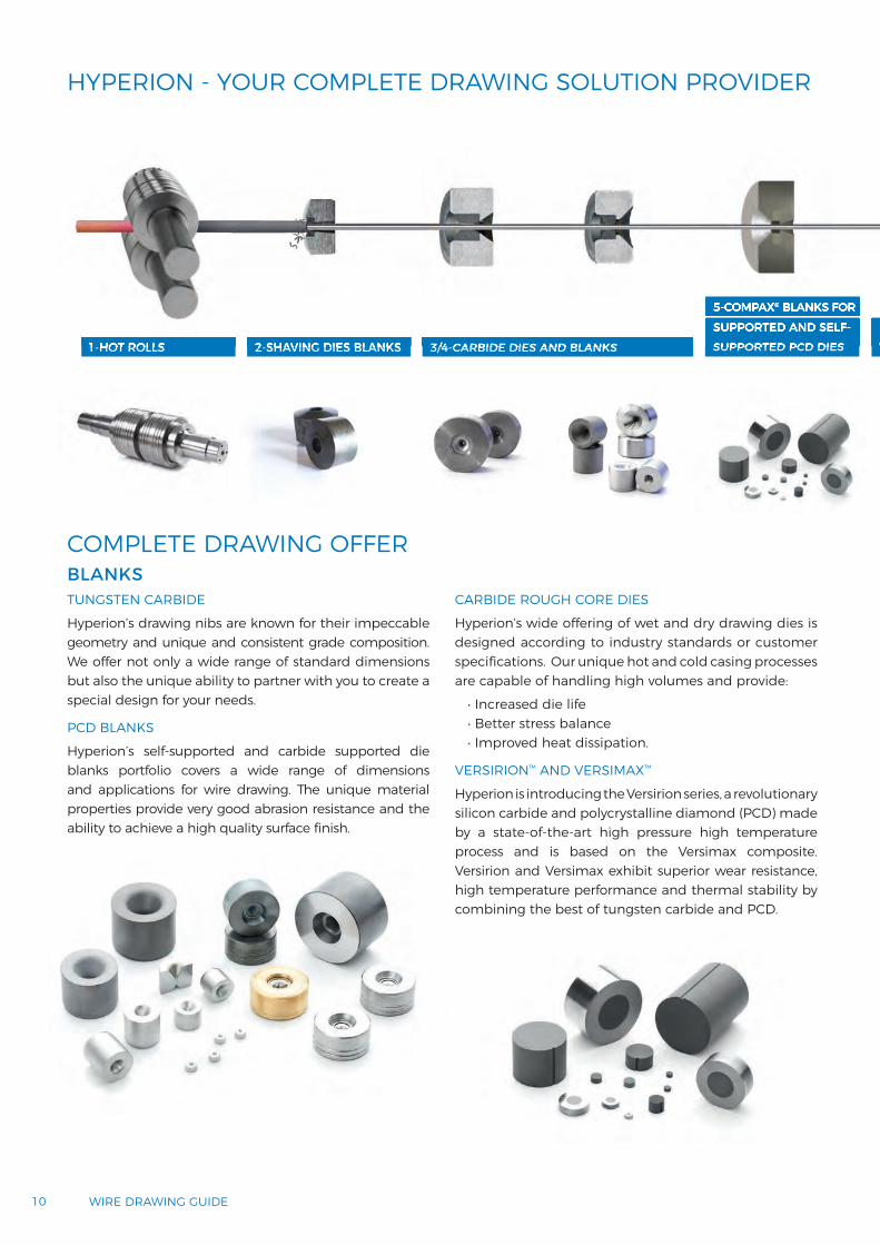
Hyperion’s drawing nibs are known for their impeccable geometry and unique and consistent grade composition. We offer not only a wide range of standard dimensions but also the unique ability to partner with you to create a special design for your needs.
PCD BLANKS
Hyperion’s self-supported and carbide supported die blanks portfolio covers a wide range of dimensions and applications for wire drawing. The unique material properties provide very good abrasion resistance and the ability to achieve a high quality surface finish.
CARBIDE ROUGH CORE DIES
Hyperion’s wide offering of wet and dry drawing dies is designed according to industry standards or customer specifications. Our unique hot and cold casing processes are capable of handling high volumes and provide:
• Increased die life• Better stress balance• Improved heat dissipation.
VERSIRION™ AND VERSIMAX™
Hyperion is introducing the Versirion series, a revolutionary silicon carbide and polycrystalline diamond (PCD) made by a state-of-the-art high pressure high temperature process and is based on the Versimax composite. Versirion and Versimax exhibit superior wear resistance, high temperature performance and thermal stability by combining the best of tungsten carbide and PCD.
10 WIRE DRAWING GUIDE
HYPERION - YOUR COMPLETE DRAWING SOLUTION PROVIDER
COMPLETE DRAWING OFFER
1-HOT ROLLS 2-SHAVING DIES BLANKS 3/4-CARBIDE DIES AND BLANKS
5-COMPAX® BLANKS FOR SUPPORTED AND SELF-SUPPORTED PCD DIES
6-VERSIRION™ AND VERSIMAX™ BLANKS1-HOT ROLLS 2-SHAVING DIES BLANKS 3/4-CARBIDE DIES AND BLANKS
5-COMPAX® BLANKS FOR SUPPORTED AND SELF-SUPPORTED PCD DIES
6-VERSIRIONVERSIMAX
BLANKS
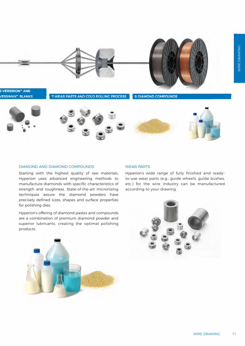
DIAMOND AND DIAMOND COMPOUNDS
Starting with the highest quality of raw materials, Hyperion uses advanced engineering methods to manufacture diamonds with specific characteristics of strength and toughness. State-of-the-art micronizing techniques assure the diamond powders have precisely defined sizes, shapes and surface properties for polishing dies.
Hyperion’s offering of diamond pastes and compounds are a combination of premium diamond powder and superior lubricants, creating the optimal polishing products.
WEAR PARTS
Hyperion’s wide range of fully finished and ready-to-use wear parts (e.g., guide wheels, guide bushes, etc.) for the wire industry can be manufactured according to your drawing.
11WIRE DRAWING
WIR
E D
RAW
ING
HYPERION - YOUR COMPLETE DRAWING SOLUTION PROVIDER
7-WEAR PARTS AND COLD ROLLING PROCESS 8-DIAMOND COMPOUNDS
6-VERSIRION™ AND VERSIMAX™ BLANKS 7-WEAR PARTS AND COLD ROLLING PROCESS 8-DIAMOND COMPOUNDS
6-VERSIRION™ AND VERSIMAX™ BLANKS

MATERIALS

MATERIALS

120Shock wavesynthesis
LiquidcarbonDiamond
Pres
sure
(GPa
)
Temperature (K)
HPHTsynthesisCatalytic
HPHT synthesis
MetastableCVD diamond
Graphite
30
25
20
15
10
5
00 1000 2000 3000 4000 5000
PCD SINTERING
Residual Cobalt(etched)
Diamond Powder Blend
Cemented WCCobalt
HYPERION - COMPAX® PCD FROM START TO FINISH
CONSISTENCY THROUGH SIX SIGMA QUALITY CONTROL
WHAT IS PCD?
Hyperion’s diamond micron powders are created in a single, continuous manufacturing process. Starting with the highest quality of raw materials, Hyperion uses advanced engineering methods to manufacture diamonds with specific characteristics of strength and toughness. State-of-the-art micronizing techniques assure the diamond micron powders have precisely defined sizes, shapes and surface properties. The result is unprecedented consistency and uniformity from the initial diamond source to the final product.
Hyperion’s micron powders offer consistency and repeatability derived from the engineering invested in our proprietary Six Sigma controlled manufacturing processes.
CARBON-DIAMOND PHASE DIAGRAM
At high temperature and pressure, cobalt melts and “sweeps” into
the powder bed
The cobalt promotes carbon-carbon bonding between
diamond crystals
14 WIRE DRAWING GUIDE

Fine Grain
Medium Grain
Coarse Grain
Fine surface finish requirements
• Tough to draw wire
• Small/medium die sizes
• Tire cord and wire saw.
General purpose applications
• Moderate surface finish and abrasion requirements
• Medium die sizes
• Stainless steel and welding wire.
Intermediate and rod breakdown
• Non-critical finish requirements
• Larger die sizes
• Stranding, bunching and cabling.
SUBMICRON
25 MICRON
12 MICRON
5 MICRON
50 MICRON
PCD GRAIN SIZESPCD GRADE APPLICATION
15MATERIALS
MAT
ERIA
LS

BlendBuild
capsule
Cemented WC ring Metal cup
Buildcell
Inspection,packaging& shipping
A
B
Finishing
Steel coverA/BPCD blank
Brazingmedia
Steel case
HPHT sintering
Highpressure
Hightemperature
Diamond feedSealed capsule (cup)
Sintered wire die compact
Finished wire die
Brazing the PCD blank
Machining entrance & exit
core
Laser inner die shape Ultrasonic polishing
Blended powder
Cell
MBS®/Borazon® crystals
Loading
Milling
Pressing
Grading
Wire EDM cutting
Cleaning
Finishing
Blending
Quality control
This process is fully integrated within Hyperion, from powder to finished parts.
HYPERION‘S PCD MANUFACTURING PROCESS
PCD BLANK MANUFACTURING PROCESS
SELF-SUPPORTED PCD BLANK MANUFACTURING
TUNGSTEN CARBIDE SUPPORTED PCD BLANK MANUFACTURING
16 WIRE DRAWING GUIDE

Pressure ≤ 55 kbar
Temperature > 1300ºC
Time < 1 hour
Pressure at the center of the earth
Pressure of powder metal forming
Pressure of current successful synthesis of diamond
Pressure at which pressure washers function as a water jet cutter
Pressure at which pressure washers force out water
Atmospheric pressure at earth’s sea level
Pressure of near earth outer space
3,600,000 bar 52,000,000 psi
1,200 bar 30,000 psi
55,000 bar 800,000 psi
600 bar 8,700 psi
100 bar 1,500 psi
1 bar 15 psi
1 x 10⁻⁹ bar 1.5 x10⁻⁸ psi
HYPERION‘S PCD MANUFACTURING PROCESS
PCD BLANK MANUFACTURING PROCESS
17MATERIALS
HPHT PROCESS DETAILS
MAT
ERIA
LS

WIRESURFACE
FINISH
WEAR RESISTANCE +
+
MFU
/TSU
(0.9
μm
)
MF/
TS/S
uppo
rted
(5 μ
m)
Supp
orte
d (2
5 μm
)
Supp
orte
d (3
μm
)
Supp
orte
d (1
2 μm
)
Supp
orte
d (5
0 μm
)
18 WIRE DRAWING GUIDE
HYPERION‘S PCD BLANKS PRODUCT MAP

SUB-MICRON PROPERTY MEASUREMENT
CURRENT SUB-MICRON PRODUCT
% W% Co
Wea
r Res
ista
nce
Wea
r Rat
e (m
g/m
in)
Hyperion Supplier B Supplier A0
4
8
2
6
10
1214
% C
o or
W
Comp. Grd 2 Comp. Grd 1 Hyperion0
10
20
5
15
25
30
ABRASION TEST RESULTS X-RAY FLUORESCENCE RESULTS FOR METAL CONTENT
Target applicationsBrass-plated wire (tire cord, saw wire)Welding wireFine finishing applicationsGlass scribing
Typical diamond grain size 0.9 μm
Typical diamond content 91%
STANDARD PRODUCT OFFERINGS
ADDMA No. Product Dimensions (mm)diameter x thickness Metal Filled Thermally
StableMaximum Recommended
Hole Size (mm)
D6 3.1 x 1.00 5010-MFU 5010-TSU 0.5
D12 3.1 x 1.5 5015-MFU 5015-TSU 1.0
The unique material properties provide very good abrasion resistance and the ability to achieve a high quality surface finish.
19MATERIALS
HYPERION‘S PCD BLANKS PRODUCT MAP SUB-MICRON PCDSUB-MICRON MICROSTRUCTURES
MAT
ERIA
LS
Wear Resistance Wear Rate
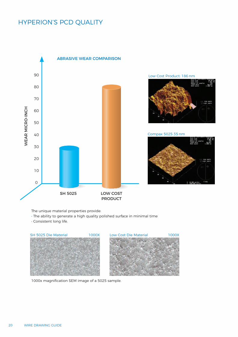
The unique material properties provide: • The ability to generate a high quality polished surface in minimal time• Consistent long life.
1000x magnification SEM image of a 5025 sample.
WEA
R M
ICR
O-IN
CH
SH 5025 LOW COST PRODUCT
0
10
50
30
70
20
60
40
80
90
ABRASIVE WEAR COMPARISON
SH 5025 Die Material Low Cost Die Material1000X 1000X
Low Cost Product: 186 nm
Compax 5025 35 nm
20 WIRE DRAWING GUIDE
HYPERION‘S PCD QUALITY
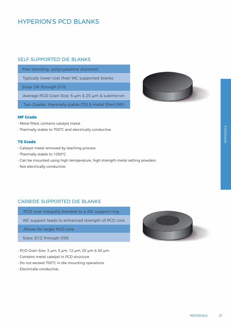
MF Grade • Metal filled, contains catalyst metal
• Thermally stable to 700ºC and electrically conductive.
TS Grade • Catalyst metal removed by leaching process
• Thermally stable to 1050ºC
• Can be mounted using high temperature, high strength metal setting powders
• Not electrically conductive.
• PCD Grain Size: 3 µm, 5 µm, 12 µm, 25 µm & 50 µm
• Contains metal catalyst in PCD structure
• Do not exceed 700ºC in die mounting operations
• Electrically conductive.
Free standing polycrystalline diamond
Typically lower cost than WC supported blanks
Sizes: D6 through D18
Average PCD Grain Size: 5 µm & 25 µm & submicron
Two Grades: thermally stable (TS) & metal filled (MF)
PCD core integrally bonded to a WC support ring
WC support leads to enhanced strength of PCD core
Allows for larger PCD core
Sizes: D12 through D36
21MATERIALS
HYPERION‘S PCD QUALITY HYPERION‘S PCD BLANKS
SELF-SUPPORTED DIE BLANKS
CARBIDE SUPPORTED DIE BLANKS
MAT
ERIA
LS

22 WIRE DRAWING GUIDE
HYPERION‘S PCD BLANKS CATALOGUE
TUNGSTEN CARBIDE-SUPPORTED DIE BLANKS
ADDMA
NOMINAL DIAMOND
DIAMETER X THICKNESS
(mm)
GRAIN SIZE PRODUCT DIMENSIONS [mm]
3 µm 5 µm 12 µm 25 µm 50 µm TOOL BLANK DIAMETER
DIAMOND DIAMETER
DIAMONDTHICKNESS
RECOM-MENDED
BORE SIZE (mm)*
D12 1.5 x 1.5 5235 3.99 ± 0.013 1.4 1.5 ± 0.10 0.05 0.01 0.05 0.20 0.8
D15 4.0 x 2.3 5823 5123 5223 5430 8.12 ± 0.013 3.8 2.24 ± 0.05 0.05 0.01 0.08 0.40 1.8
D18 4.0 x 2.9 5829 5129 5229 5435 8.12 ± 0.013 3.8 2.84 ± 0.05 0.05 0.01 0.10 0.40 2.3
D21 7.0 x 4.0 5840 5240 5530 13.65 ± 0.013 6.8 3.86 ± 0.05 0.05 0.01 0.14 0.50 3.5
D24 7.0 x 5.313.0 x 7.0
5853 52535225
55355725
13.65 ± 0.01324.13 ± 0.025
6.812.7
5.13 ± 0.056.98 ± 0.25
0.050.10
0.0100.050
0.180.30
0.500.60
4.65.2
D27 13.0 x 8.7 5108 5208 5730 24.13 ± 0.025 12.7 8.70 ± 0.25 0.10 0.05 0.30 0.60 5.8
D30 13.0 x 11.618.6 x 13.5
5111 52115913
5735 24.13 ± 0.02534.00 ± 0.025
12.718.2
11.60 ± 0.2513.5 ± 0.50
0.100.10
0.0500.050
0.400.45
0.600.75
7.611.2
D33 18.6 x 15.518.6 x 17.5
59155917
34.00 ± 0.02534.00 ± 0.025
18.218.2
15.50 ± 0.5017.5 ± 0.50
0.100.10
0.0500.050
0.520.59
0.750.75
12.012.5
D36 18.6 x 18.5 5918 34.00 ± 0.025 18.2 18.50 ± 0.50 0.10 0.05 0.62 0.75 12.7
* Maximum recommended bore size for non-ferrous wire. Hard-ferrous wire die size normally should not exceed 65% of this diameter.
SELF-SUPPORTED DIE BLANKS
ADDMA
NOMINAL DIAMOND
DIAMETER X THICKNESS
(mm)
GRAIN SIZE PRODUCT DIMENSIONS [mm]
Sub µm 5 µm 25 µm DIAMOND DIAMETER
DIAMONDTHICKNESS
RECOMMENDEDBORE SIZE
(mm)*
D6 3.1 x 1.0 5010-MFU 5010-TSU 5010-MF 5010-TS 5010-MFC 5010-TSC 3.1 ± 0.38 1.0 ± 0.13 0.08
(within diameter
limits)
0.13 0.5
D12 3.1 x 1.5 5015-MFU 5015-TSU 5015-MF 5015-TS 5015-MFC 5015-TSC 3.1 ± 0.38 1.5 ± 0.13 0.08 0.13 1.0
D15 5.2 x 2.5 5025-MF 5025-TS 5025-MFC 5025-TSC 5.2 ± 0.64 2.5 ± 0.13 0.08 0.25 1.5
D18 5.2 x 3.5 5035-MF 5035-TS 5035-MFC 5035-TSC 5.2 ± 0.64 3.5 ± 0.13 0.08 0.25 2.0
D21 7.0 x 4.0 7040-MF 7040-MFC 7 ± 0.64 4 ± 0.13 0.08 0.25 3.5
D247.0 x 5.3 7053-MF 7053-MFC 7 ± 0.64 5.3 ± 0.13 0.08 0.25 4.6
13.0 x 7.0 1370-MF 1370-MFC 13 ± 0.64 7 ± 0.13 0.08 0.25 5.2
D27 13.0 x 8.7 1387-MF 1387-MFC 13 ± 0.64 8.7 ± 0.13 0.08 0.25 5.8
D30 13.0 x 11.6 1311-MF 1311-MFC 13 ± 0.64 11.6 ± 0.13 0.08 0.25 7.6
18.6 x 13.5 1813-MF 1813-MFC 18.6 ± 0.64 13.5 ± 0.13 0.08 0.25 11.2
To view the complete catalog, please visit www.HyperionMT.com.

23MATERIALS
HYPERION‘S PCD BLANKS CATALOGUE VERSIRION™
Hyperion is introducing the Versirion™ series, a revolutionary silicon carbide and polycrystalline diamond (PCD) composite with increased wear property and thermal stability. Versirion™ is made by a state-of-the-art high pressure high temperature process and is based on the Versimax™ composite developed for wire drawing and wear application.
VERSIRION™ AND VERSIMAX™
Versirion and Versimax exhibit superior wear resistance, high temperature performance and high strength approaching that of Co-sintered PCD, with the addition of superior thermal stability. Versirion exhibits the most superior corrosion resistance.
MAIN ADVANTAGES- Superior thermal stability compared to that of PCD- Significantly reduced coeºcient of thermal expansion (CTE) mismatch- Thermally stable up to 1400°C, which creates less risk of failures during application - Easy to process:
- Electrically conductive: EDM processability allows flexibility in cutting various geometries- Larger sizes than unsupported PCD: diameter - 35 mm, height - 35 mm- Does not require polishing of the bore to achieve the surface finish of the wire- Ability to be easily brazed or shrink fitted into casing
- Versatility: ferrous and non-ferrous wires - Wear resistance comparable to that of PCD and corrosion resistance slightly better than that of PCD.
MAIN APPLICATIONS FOR FERROUS AND NON-FERROUS WIRES- Drawing - Bunching - Compacting - Wear applications - Stranding - Extrusion
MATERIALS
Microstructure M
ATER
IALS
WEAR RESISTANCE TEST RESULTS
Nor
mal
ized
Wea
r Rat
e
PCD5 VMX20 VRW10 VRW50.0
0.2
0.6
0.4
0.8
1.0
1.2
1.4

24 WIRE DRAWING GUIDE
VERSIRION™ AND VERSIMAX™ PRODUCT OFFERING
VERSIRION™ AND VERSIMAX™ BLANK SIZESVersirion and Versimax wire die blanks are self-supported and do not have carbide support rings. Both are available in custom sizes and shapes and are prepared according to customer specifications.
Simple shapes (cylinders, rectangular or triangular prisms, etc.) and more complicated geometries (conical shapes, hollow cylinders, negative features, etc.) can be produced.
Versimax can be attached to tungsten carbide or steel by furnace brazing. Tools can also be produced by press fitting, heat shrink fitting, adhesive bonding or mechanical fixturing.
Contact your Hyperion account manager to review your application and determine the best fabrication method for your needs.
GRADE APPLICATION(S) AVERAGE GRAIN SIZE
Versirion™ (VRW5) Fine Grain
- Low carbon steel- Tire cord- Aluminum- Copper with higher surface finish requirement
Versirion™ (VRW10) Medium Grain
- Low carbon steel- Coated steel- Aluminum- Copper with lower surface finish requirement
Versimax™ Coarse Grain
- Bunching- Stranding- Wear application- Compacting- High pressure - High temperature
ADDMA DIAMETER (mm) THICKNESS (mm)PARALLELISM
PERPENDICULARITYROUNDNESS
D6 3.1 1.0 0.08 0.13 0.05
D12 3.1 1.5 0.08 0.13 0.05
D15 5.2 2.5 0.08 0.25 0.05
D18 5.2 3.5 0.08 0.25 0.05
D21 7.0 4.0 0.08 0.25 0.05
D24 13.0 7.0 0.10 0.3 0.05
D27 13.0 8.7 0.10 0.3 0.05
D30 18.6 13.5 0.10 0.4 0.05
D33 18.6 15.5 0.10 0.5 0.05
D36 18.6 18.5 0.10 0.6 0.05
TM 23.0 15.0 0.10 0.38 0.05
TM 25.0 20.0 0.10 0.51 0.05
TM 30.0 22.0 0.10 0.56 7.6
TM 35.0 25.0 0.10 0.64 11.2
TM = Tailor-madeUnless otherwise specified all parts are cut with an EDM external hook.

25MATERIALS
PCD MATERIAL ISSUES- Generating properly processed PCD blanks requires special processing of feedstock, blend and cell components, as
well as careful control of the HPHT process and finishing methods.
- Errors or issues with any of the above will result in failure of parts or result in parts out of specification for strength and microstructure properties.
- Our 100% Product Inspection Process and the Cross Functional Production Team ensures the best quality product.
- Following is the typical inspection criteria:
HPHT PROCESS ISSUES
- Visible effects: diamond growth - Nominal cause: HPHT process temperature
above request.
- Visible effects: delamination - Nominal cause: HPHT process temperature
below request.
- Visible effects: horizontal cracking - Nominal cause: HPHT process temperature
below request.
X-RAY (TS BLANKS) PCD SINTER QUALITY
DiameterThicknessParallelismPerpendicularityConcentricityRoundness
Edge ChipsPits & Depressions
Finish & Color
CracksMetal InclusionsOversize Control
MAT
ERIA
LS
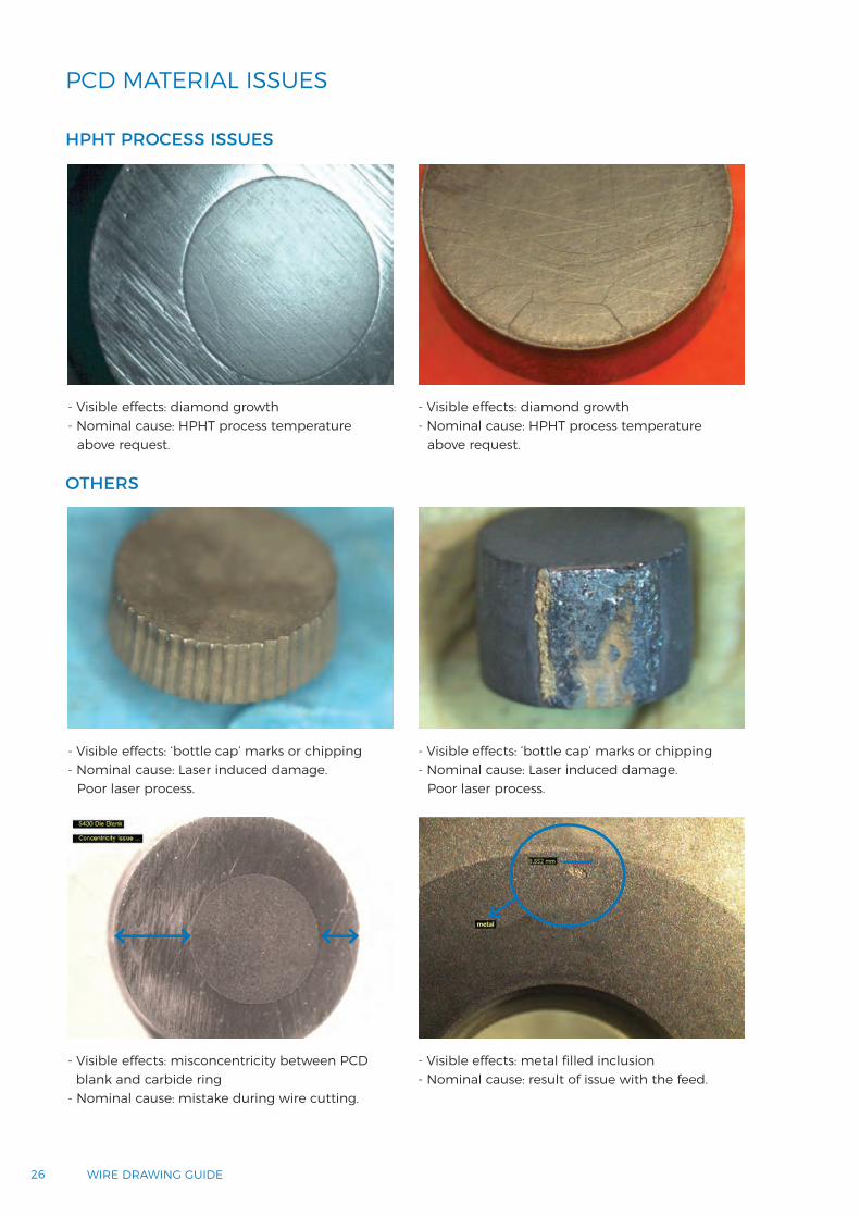
- Visible effects: diamond growth - Nominal cause: HPHT process temperature
above request.
- Visible effects: diamond growth - Nominal cause: HPHT process temperature
above request.
- Visible effects: misconcentricity between PCDblank and carbide ring
- Nominal cause: mistake during wire cutting.
- Visible effects: metal filled inclusion - Nominal cause: result of issue with the feed.
- Visible effects: ‘bottle cap’ marks or chipping - Nominal cause: Laser induced damage.
Poor laser process.
- Visible effects: ‘bottle cap’ marks or chipping - Nominal cause: Laser induced damage.
Poor laser process.
26 WIRE DRAWING GUIDE
PCD MATERIAL ISSUES
HPHT PROCESS ISSUES
OTHERS

2727MATERIALS
CEMENTED CARBIDECemented carbide is one of the most successful composite engineering materials ever produced. Cemented carbide’s unique combination of strength, hardness and toughness satisfies the most demanding applications.
A key feature of the cemented carbide is the potential to vary its composition so that the resulting physical and chemical properties ensure maximum resistance to wear, deformation, fracture, corrosion and oxidation. In addition, the wide variety of shapes and sizes that can be produced using modern powder metallurgical processing offers tremendous scope to design cost-effective solutions to many of the problems of component wear and failure encountered in both the engineering and domestic environment.
MAT
ERIA
LS
To view the complete catalog, please visit www.HyperionMT.com.
28 WIRE DRAWING GUIDE
THE MATERIAL WITH STAYING POWERThe most valuable property of cemented carbide is that it offers a safer and more dependable solution than any other known material to one of the toughest problems which engineers have to contend with – reliability.
Reliability is often a problem of wear. Wear resistance is the most outstanding feature of cemented carbide. Cemented carbide can also withstand deformation, impact, heavy load, high pressure, corrosion and high temperature. Cemented carbide is often the only material that can fulfill these requirements.
It has long been a well-known fact that the use of cemented carbide provides an optimal solution in the case of tools for metal cutting and rock drilling. Over the years, cemented carbides have also proven their superiority in a great number of other tooling and engineering applications.
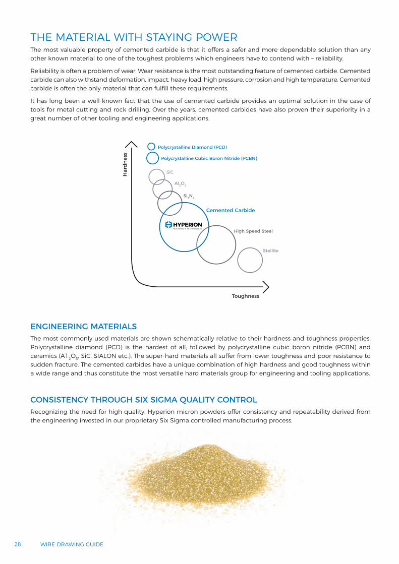
Polycrystalline Diamond (PCD)
Polycrystalline Cubic Boron Nitride (PCBN)
Toughness
Har
dnes
s
High Speed Steel
Stellite
Cemented Carbide
SiC
Al2O3
Si3N4
The most commonly used materials are shown schematically relative to their hardness and toughness properties. Polycrystalline diamond (PCD) is the hardest of all, followed by polycrystalline cubic boron nitride (PCBN) and ceramics (A12O3, SiC, SIALON etc.). The super-hard materials all suffer from lower toughness and poor resistance to sudden fracture. The cemented carbides have a unique combination of high hardness and good toughness within a wide range and thus constitute the most versatile hard materials group for engineering and tooling applications.
Recognizing the need for high quality, Hyperion micron powders offer consistency and repeatability derived from the engineering invested in our proprietary Six Sigma controlled manufacturing process.
ENGINEERING MATERIALS
CONSISTENCY THROUGH SIX SIGMA QUALITY CONTROL
2929MATERIALS
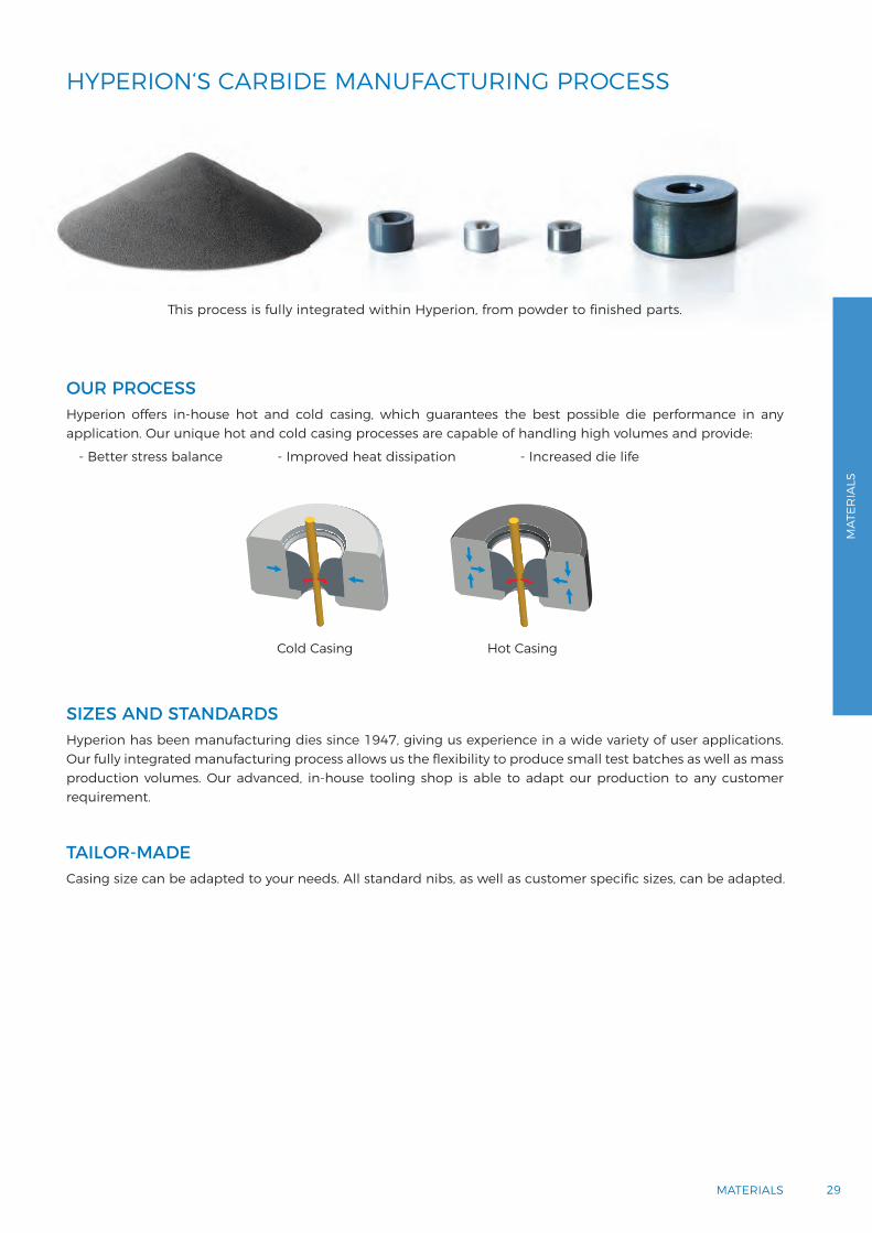
Hyperion offers in-house hot and cold casing, which guarantees the best possible die performance in any application. Our unique hot and cold casing processes are capable of handling high volumes and provide:
- Better stress balance - Improved heat dissipation - Increased die life
OUR PROCESS
HYPERION‘S CARBIDE MANUFACTURING PROCESS
Cold Casing Hot Casing
Hyperion has been manufacturing dies since 1947, giving us experience in a wide variety of user applications. Our fully integrated manufacturing process allows us the flexibility to produce small test batches as well as mass production volumes. Our advanced, in-house tooling shop is able to adapt our production to any customer requirement.
SIZES AND STANDARDS
Casing size can be adapted to your needs. All standard nibs, as well as customer specific sizes, can be adapted.
TAILOR-MADE
This process is fully integrated within Hyperion, from powder to finished parts.
MAT
ERIA
LS

Ultrafine< 0.5 µm
Extra fine0.5 - 0.9 µm
Fine1.0 - 1.3 µm
Medium1.4 - 2.0 µm
Medium coarse2.1 - 3.4 µm
Coarse3.5 - 5.0 µm
Extra coarse> 5.0 µm
5 µm
Grades for WD
HYPERION CARBIDE GRAIN SIZE CLASSIFICATION
Hyperion uses the following grain size classification for all standard grades.
30 WIRE DRAWING GUIDE

HV30
ULTRAFINE
EXTRA FINE
MEDIUM
H3F
C3D
H11N
RS1T
6UD
H15F
H6F
H6N
2000
1500
1000
0 5 15 Co (wt%)10
H10F
WET
DRY
EXC
ELLE
NT
NO
TR
ECO
MM
END
ED
TOUGHNESS GALLING RESISTANCE WEAR RESISTANCE CORROSION RESISTANCE
C3D
6UD
RS1TH11N
H15F
C3D
H3F
6UD
GO
OD
C3D
6UD
H3F
H6F
H6N
H6F
H10FH6F
H10F
H11N
H15F
H3F
C3D
6UD
RS1T
H15F
H6N/ H11N
H10F
H15F
H6N/ H11N
HYPERION CARBIDE GRADES
3131MATERIALS
MAT
ERIA
LS

Welding Wire
Sawing Wire
Tire Cord
Ø 9 mm 5 2.5 0.5 0.3 0.14 0.12 Ø 0.08 mm
DRY WET
H10F / H6N
H10F / H6N
H10F
H3F/6UD
H3F/C3D
H3F / 6UDH6F
H6F
H6F
PCD
RS1T
H3F/6UD
Standard
H11N
H15F
H6N
H10F
H6F
RS1T
H3F
6UD
C3D
1 20 3 54 6 7 98 10 11 12 1413 15 16 1817 2019 21 22 23 2524INNER DIAMETER (mm)
DRY
WET
Standard for large diameters d1 > 11 mm.
Cold drawn bars, tubes and shapes large diameters.
Dry drawing. Standard grade for d1 > 3 mm.
Dry drawing of tire cord, welding wire and high carbon wire.
Wet and dry drawing of welding wire, dry drawing tire cord. Standard grade for d1 > 3 mm.
Wet drawing of coated high carbon steels (Zn & brass). Dry drawing of stainless steel.
Wet drawing of high carbon, tire cord, welding wire and sawing wire.
Wet drawing of high carbon, tire cord, welding wire and sawing wire.
Wet drawing of high carbon, tire cord, welding wire and sawing wire.
Dry drawing. Standard grade for d1 > 3 mm.
Dry drawing of tire cord, welding wire and high carbon wire.
Wet and dry drawing of welding wire, dry drawing tire cord. Standard grade for d
Wet drawing of coated high carbon steels (Zn & brass). Dry drawing of stainless steel.RS1T
H3F Wet drawing of high carbon, tire cord, welding wire and sawing wire.
Wet drawing of high carbon, tire cord, welding wire and sawing wire.
Wet drawing of coated high carbon steels (Zn & brass). Dry drawing of stainless steel.
32 WIRE DRAWING GUIDE
CARBIDE GRADE APPLICATION EXAMPLES

3333MATERIALS
HYPERION 6UD
Hyperion 6UD is the high performance grade for fine wire wet drawing. It is an ultrafine cemented carbide in combination with special additives that maximizes corrosion resistance without loosing toughness. The Hyperion Sinter-HIP process guarantees premium carbide quality.
HIGH PERFORMANCE
Hyperion 6UD is used in high performance drawing processes for:- Saw wires- Tire cords - All ultra tensile wires - Finest wire diameters.
Hyperion 6UD prevents:- Corrosion wear- Friction- Wear in small bores.
Hyperion 6UD benefits include:- Increased die life- Less energy consumption- Longer batch sizes- Lower quality rods quality can be used.
HYPERION GRADE 6UD
GRADE PREVENTS
GRADE BENEFITS
PERFORMANCE CHART
Low Medium High
Wear resistance
Toughness
Corrosion resistance
Hardness
Available in standard ISO, JIS and DIN or tailor-made to your design.
MAT
ERIA
LS

34 WIRE DRAWING GUIDE
HYPERION C3D
Hyperion C3D is the new super performance grade with never-before-seen properties for tungsten carbide. It is an ultrafine cemented carbide in combination with special additives that maximizes corrosion resistance and exhibits extreme wear resistance. The Hyperion sinter-HIP process guarantees premium carbide quality.
SUPER PERFORMANCE
Hyperion C3D is used in super performance drawing processes for:- Welding wire- Low and high carbon steel - PC strand.
HYPERION GRADE C3D
Hyperion C3D prevents corrosion and wear out by: - Very low Co leaching- Integrity of the carbide matrix ensures
the material wear resistance.
Performance improvements:- Die life increased up to 5 times vs those of standard grades- Less machine downtime- Lower quality rods can be used- High polishing speed.
GRADE PREVENTS
GRADE IMPROVEMENTS
PERFORMANCE CHART
Low Medium High
Wear resistance
Thermal conductivity
Corrosion resistance
Hardness
Available in standard ISO, JIS and DIN or tailor-made to your design.

3535MATERIALS
HYPERION C3D SUPER PERFORMANCE
Available in standard ISO, JIS and DIN or tailor-made to your design.
HYPERION C3D STANDARD GRADES
Corrosion testing with commonly used emulsions in the markets has shown the following results:
CORROSION RESULTS
HYPERION GRADE C3DHyperion C3D corrosion results:- Very low Co leaching- WC grain sharp edges - Integrity of the carbide matrix
ensures the material wear resistance.
STANDARD GRADESStandard carbides corrosion results: - Massive Co leaching- WC etched away leaving the Co exposure - Structure heavily attacked which could lead to grain drop out.
MAT
ERIA
LS
36 WIRE DRAWING GUIDE
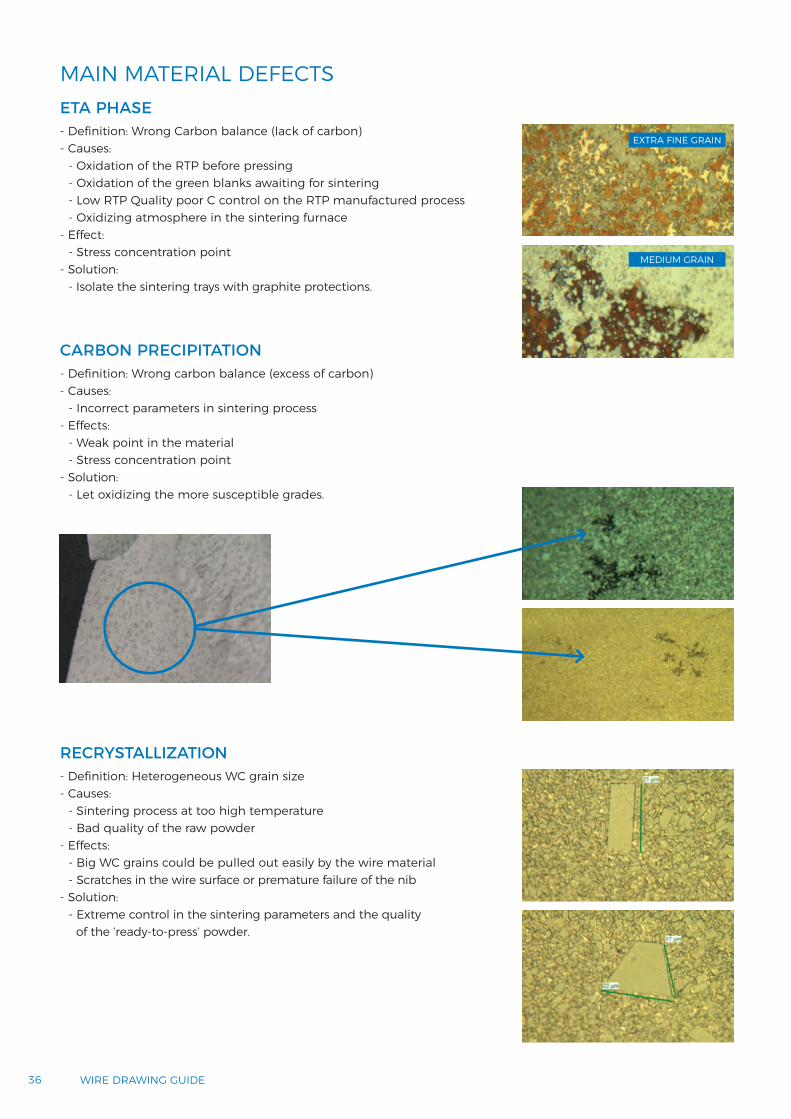
MAIN MATERIAL DEFECTSETA PHASE
RECRYSTALLIZATION
CARBON PRECIPITATION
- Definition: Wrong Carbon balance (lack of carbon) - Causes:
- Oxidation of the RTP before pressing- Oxidation of the green blanks awaiting for sintering- Low RTP Quality poor C control on the RTP manufactured process- Oxidizing atmosphere in the sintering furnace
- Effect: - Stress concentration point
- Solution: - Isolate the sintering trays with graphite protections.
- Definition: Heterogeneous WC grain size - Causes:
- Sintering process at too high temperature- Bad quality of the raw powder
- Effects: - Big WC grains could be pulled out easily by the wire material- Scratches in the wire surface or premature failure of the nib
- Solution: - Extreme control in the sintering parameters and the quality
of the ‘ready-to-press’ powder.
- Definition: Wrong carbon balance (excess of carbon) - Causes:
- Incorrect parameters in sintering process- Effects:
- Weak point in the material- Stress concentration point
- Solution: - Let oxidizing the more susceptible grades.
EXTRA FINE GRAIN
MEDIUM GRAIN

3737MATERIALS
MAIN MATERIAL DEFECTSPOROSITY
Co LAKE
- Definition (according to ISO4504): - PorosityA: pores < 10 µm- PorosityB: pores between 10 and 25 µm- Macroporosity: pores > 25 µm
- Causes: - Lack of force during pressing- Impurities or contamination of powder- Low sintering temperatures- Lack of vacuum/pressure during sintering- Not using HIP
- Effect: - Premature failure of die or scratches in the wire surface
- Solutions: - SinterHIP- RTP quality control.
- Definition: Co accumulation- Depending on the customer, Co accumulations can be up to 25 µm
- Cause: - Wrong sintering parameters
- Effects:- Weak point in the material - Stress concentration point.
MAT
ERIA
LS
38 WIRE DRAWING GUIDE
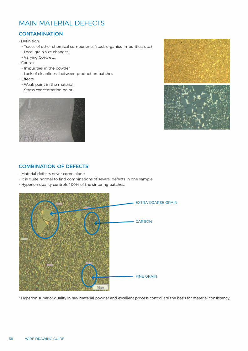
MAIN MATERIAL DEFECTSCONTAMINATION• Definition:
- Traces of other chemical components (steel, organics, impurities, etc.)- Local grain size changes- Varying Co%, etc.
- Causes: - Impurities in the powder- Lack of cleanliness between production batches
- Effects: - Weak point in the material- Stress concentration point.
COMBINATION OF DEFECTS- Material defects never come alone- It is quite normal to find combinations of several defects in one sample- Hyperion quality controls 100% of the sintering batches.
* Hyperion superior quality in raw material powder and excellent process control are the basis for material consistency.
EXTRA COARSE GRAIN
CARBON
FINE GRAIN

3939MATERIALS
* Hyperion superior quality in raw material powder and excellent process control are the basis for material consistency.
HYPERION NIBS FOR WIRE DRAWING DIES
CARBIDE NIBS FOR WIRE DRAWING DIES - HYPERION STANDARD ISO
Hyperion cemented carbide drawing nibs are known for their impeccable geometry and unique and consistent grade composition. We offer not only a huge range of standard dimensions but also a superior quality in special designs.
10x8 to 20x17 NibISO
TOLERANCES FOR d2 AND h2
TOLERANCES FOR d1 d1 From To Tolerance
0.10 0.29 0/-0.03
0.30 0.49 0/-0.04
0.50 0.69 0/-0.05
0.70 0.99 0/-0.06
1.00 1.50 0/-0.07
1.51 3.00 0/-0.08
3.01 5.09 0/-0.09
CASING CHAMFER
h2 εº bz Tolerance
≤ 8 15º 12% h2 ±3% h2
10, 12, 13 15º 11% h2 ±3% h2
17 15º 8% h2 ±3% h2
l3 From To Tolerance
< 0.51 +0.25/0
0.51 1.02 +0.30/0
1.03 1.50 +0.40/0
1.51 2.50 +0.50/0
> 2.50 +0.60/0
TOLERANCES FOR 2α AND 2γ
Angle Tolerance
2α ± 1º
2γ ± 5º
* Faces will not be ground.
Nibd2 x h2
As Sintered d2 h2
Ground*d2
Nominal Tolerance Nominal Tolerance Nominal Tolerance
10x8 9.65 ±0.15 8.00±0.20
9.55 +0.015/0
12x10 12.00 +0.040/+0.010 10.00 12.00
+0.018/014x12 13.91 ±0.10 12.00
±0.30
13.70
16x13 15.80 ±0.15 13.00 15.54
20x17 19.75 ±0.15 17.00 19.50 +0.021/0
TOLERANCES FOR l3(nibs with round bearing)
MAT
ERIA
LS

40 WIRE DRAWING GUIDE
HYPERION NIBS FOR WIRE DRAWING DIESCARBIDE NIBS FOR WIRE DRAWING DIES - HYPERION STANDARD ISO
NIB ORDERING CODE
d2 x h2 Code / Grade 2α d1 l2 l3 l4 2β R ∅E 2γ
10x8 WDINR10...126F / H6F 12º
0.20 0.601.201.301.401.501.601.701.80
0.250.70
_______
0.300.80
_______
0.350.90
_______
0.401.00
_______
0.501.10
_______
0
1.801.801.751.661.731.751.601.661.55
5.75.75.7555
5.24.74.8
6.86.87.17.17.17.17.36.97.1
90º
12x10 WDINR12...126F / H6F 12º1
0.650,25
0.90.60.2
0.80.5_
0.750.4_
0.70.3_
___
1.9522
8.68.98.9
8 90º
14x12 WDINR14...126F / H6F 12º
0.600.901.001.101.201.301.701.802.452.60
0.70____
1.40_
1.90_
2.90
0.80____
1.50_
2.00__
_______
2.20__
_______
2.40__
__________
0
2.402.582.402.592.402.552.532.403.212.40
10.510.310.510.310.51010
10.510
10.5
101010
10.210101010
10.410
75º
16x13
WDINR16...12F / H6F 12º
0.250.350.400.700.800.901.101.301.501.601.902.252.402.803.40
0.30_
0.45__
1.001.201.40
_1.70
__
2.50__
__
0.50____________
__
0.55____________
__
0.60____________
_______________
0
3333333
2.902.902.902.902.85
333
10.610.610.610.610.610.310.31010109.79.79.29
8.6
12.112.212.312.512
12.212.412
12.212.312
12.412
11.711.8
75º
WDINR16...14F / H6F 14º 2.502.60
__
__
__
__
__ 0.64
0.663.13
38
8.111.712 75º
WDINR16...16F / H6F 16º 3.00 _ _ _ _ _ 0.78 3.12 7.7 11.7 75º
WDINR16...16F / H6F 16º 3.97 _ _ _ _ _ 0.99 3 8.1 13.4 75º
20x17 WDINR20...12F / H6F 12º
0.700.800.901.001.101.301.401.601.802.002.402.652.703.053.203.60
____
1.20___________
________________
________________
________________
________________
0
4.254.254.254.24.24.24.24.2
4.154.14.1
4.054.05
444
13.513.513.513.213.213.213.213.212.912.612.612.312.31212
11.7
15.115.215.314.915
15.215.315.515.114.815.214.915
14.815
14.9
60º
With outer diameter as sintered or ground. All dimensions in mm.
To view the complete catalog, please visit www.HyperionMT.com.
4141MATERIALS
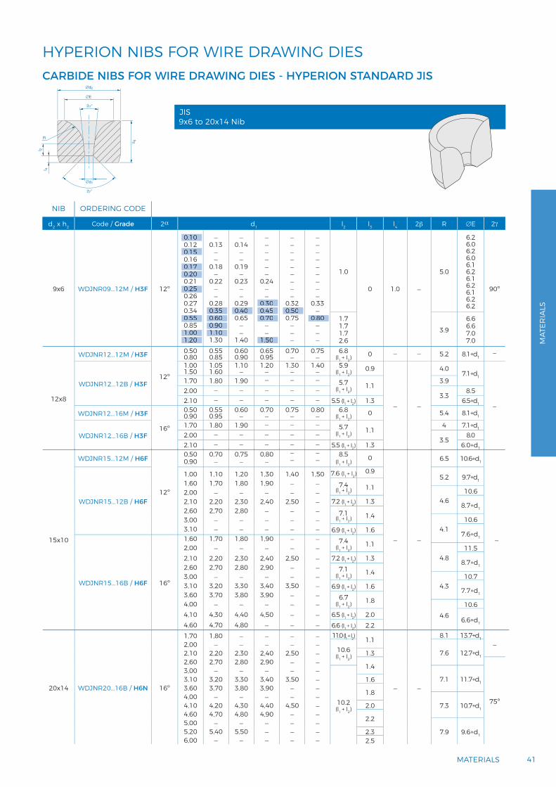
HYPERION NIBS FOR WIRE DRAWING DIESCARBIDE NIBS FOR WIRE DRAWING DIES - HYPERION STANDARD JIS
NIB ORDERING CODE
d2 x h2 Code / Grade 2α d1 l2 l3 l4 2β R ∅E 2γ
9x6 WDJNR09...12M / H3F 12º
0.100.120.150.160.170.200.210.250.260.270.340.550.851.001.20
_0.13
__
0.18_
0.22__
0.280.350.600.901.101.30
_0.14
__
0.19_
0.23__
0.290.400.65
__
1.40
______
0.24__
0.300.450.70
__
1.50
_________
0.320.500.75
___
_________
0.33_
0.80___
1.0
0 1.0 _
5.0
6.26.06.26.06.16.26.16.26.16.26.2
90º
1.71.71.72.6
3.96.66.67.07.0
12x8
WDJNR12...12M / H3F
12º
0.500.80
0.550.85
0.600.90
0.650.95
0.70_ 0.75_ 6.8(l1 + l2)
0 _ _ 5.2 8.1+d1_
WDJNR12...12B / H3F
1.001.50
1.051.60
1.10_ 1.20_ 1.30_ 1.40_ 5.9(l1 + l2)
0.9
_ _
4.07.1+d1
_
1.70 1.80 1.90 _ _ _5.7
(l1 + l2)1.1
3.92.00 _ _ _ _ _
3.38.5
2.10 _ _ _ _ _ 5.5 (l1 + l2) 1.3 6.5+d1
WDJNR12...16M / H3F
16º
0.500.90
0.550.95
0.60_ 0.70_ 0.75_ 0.80_ 6.8(l1 + l2)
0 5.4 8.1+d1
WDJNR12...16B / H3F1.70 1.80 1.90 _ _ _
5.7(l1 + l2)
1.14 7.1+d1
2.00 _ _ _ _ _3.5
8.02.10 _ _ _ _ _ 5.5 (l1 + l2) 1.3 6.0+d1
0.10
0.15
0.170.20
0.25
0.550.35 0.40 0.45
1.001.20 1.50
0.600.901.10
0.800.700.50
0.30
15x10
WDJNR15...12M / H6F
12º
0,500,90
0,70_
0,75_
0,80_
__
__ 8.5
(l1 + l2)0
_ _
6.5 10.6+d1
_
WDJNR15...12B / H6F
1,001,602,002,102,603,003,10
1,101,70
_
2,202,70
__
1,201,80
_
2,302,80
__
1,301,90
_
2,40___
1,40__
2,50___
1,50______
7.6 (l1 + l2)0.9
5.2 9.7+d17.4
(l1 + l2)1.1
4.610.6
7.2 (l1 + l2) 1.3 8.7+d17.1
(l1 + l2)1.4
4.110.6
6.9 (l1 + l2) 1.6 7.6+d1
WDJNR15...16B / H6F 16º
1,602,002,102,603,003,103,604,004,104,60
1,70_
2,202,70
_
3,203,70
_
4,304,70
1,80_
2,302,80
_
3,303,80
_
4,404,80
1,90_
2,402,90
_
3,403,90
_
4,50_
__
2,50__
3,50____
__________
7.4(l1 + l2)
1.1
4.811.5
7.2 (l1 + l2) 1.3 8.7+d17.1(l1 + l2)
1.4
4.310.7
6.9 (l1 + l2) 1.6 7.7+d16.7
(l1 + l2)1.8
4.610.6
6.5 (l1 + l2) 2.06.6+d16.6 (l1 + l2) 2.2
20x14 WDJNR20...16B / H6N 16º
1,702,002,102,603,003,103,604,004,104,605,005,206,00
1,80_
2,202,70
_3,203,70
_4,204,70
_5,40
_
__
2,302,80
_3,303,80
_4,304,80
_5,50
_
__
2,402,90
_3,403,90
_4,404,90
___
__
2,50__
3,50__
4,50____
_____________
11.0 (l1 + l2) 1.1
_ _
8.1 13.7+d1 _10.6(l1 + l2)
7.6 12.7+d11.3
1.4
75º10.2(l1 + l2)
7.1 11.7+d11.6
1.8
7.3 10.7+d12.0
2.2
7.9 9.6+d12.32.5
9x6 to 20x14 NibJIS
MAT
ERIA
LS

42 WIRE DRAWING GUIDE
HYPERION NIBS FOR WIRE DRAWING DIESCARBIDE NIBS FOR WIRE DRAWING DIES - HYPERION STANDARD DIN
NIB ORDERING CODE
d2 x h2 Code / Grade 2α d1 l2 l3 l4 2β R ∅E 2γ
12x10
WDSNR12...12M / H6F 12º
_
0.350.40
0.20_
0.50
0.30_
0.60
__
0.70
__
0.80
__
0.902.9 0
2.12.22.1
90º 6.57.06.87.0
90º
WDSNR12...14M / H6F 14º
1.001.601.802.40
1.101.701.902.50
1.20_
2.00_
1.30_
2.10_
1.40_
2.20_
1.50_
2.30_3.6 0 1.9 90º 6.5
7.67.68.28.2
90º
16x13
WDSNR16...08M / H6F 8º
0.700.800.901.001.101.201.30
____
1.15_
1.50
_______
_______
_______
_______
2.82.82.83.42.8
3.642.8
0
2.62.72.62.52.62.52.6
60º 8.0
8.58.08.57.98.57.88.5
75º
WDSNR16...12M / H6F 12º
0.200.601.001.601.702.903.603.80
0.300.701.10_
1.80___
0.400.801.20_
1.90___
0.500.901.30_
2.10___
__
1.40_
2.25___
__
1.50_____
2.53.03.33.33.63.94.54.0
0
2.92.92.62.62.62.32.32.3
60º 8.0
8.28.28.78.78.7
10.010.010.0
75º
WDSNR16...14M / H6F 14º 1.001.60
1.101.70
1.20_ 1.30_ 1.40_ 1.50_ 3.4 0 2.6 60º 8.0 8.7 75º
WDSNR16...14B / H6F 14º1.802.302.90
1.902.40_
2.002.50_
2.102.60_
2.202.70_
_
2.80_
3.02.82.8
50% d1
2.3 60º 8.0 9.3 75º
WDSNR16...16B / H6N 16º
3.003.604.204.80
3.203.804.405.00
3.404.004.605.20
____
____
____
3.5
1.51.61.71.8
2.3 60º 8.0 10.5 75º
0.20 0.30
0.40 0.50 0.60
1.00 1.10 1.201.601.80 2.00 2.20
1.70
0.70 0.80 0.90
1.30 1.40 1.50
0.20
0.70
0.90
0.601.001.601.70 1.80 1.90 2.10 2.25
1.10 1.20 1.30 1.40 1.50
1.00
3.00
4.203.60
4.80
1.60
2.302.90
2.502.40 2.60 2.70 2.80
1.70
1.901.80 2.00 2.10 2.20
1.10
1.30 1.50
1.15
0.30
1.10
3.20
4.403.80
5.00
0.40
1.20
3.40
4.604.00
5.20
0.50
1.30 1.40 1.50
0.70 0.80 0.90
20x17
WDSNR20...12M / H6N 12º
1.201.402.003.053.954.254.90
1.301.50_
3.20_
4.40_
_
1.60_
3.35_
4.55_
_
1.802.603.50_
4.70_
__
2.703.65_
__
__
2.90____
4.95.77.06.46.47.26.2
0
3.93.93.13.13.13.1
3.97
60º 8.0
10.410.410.412.312.312.312.5
60º
WDSNR20...14B / H6N 14º
1.802.002.503.003.65
__
2.60_
3.85
_
2.202.70_
_
_
2.302.80_
_
_
2.40___
_____
5.66.25.85.05.0
50% d150% d150% d1
1.51.6
3.52.82.82.82.8
60º 8.0
10.310.310.312.212.2
60º
WDSNR20...16B / H6N 16º
3.203.604.205.006.007.207.40
3.403.804.405.206.20_
7.60
_
4.004.605.406.40_
7.80
__
4.805.606.60_
_
___
5.806.80_
_
____
7.00__
5.35.76.26.26.26.26.2
1.51.61.71.82.02.02.0
2.8 60º 8.0
12.212.212.213.013.813.815.2
60º
1.802.002.50
5.00
7.206.00
7.40
4.20
3.00
3.60
3.65
3.20
2.202.70
5.406.40
7.80
4.604.00
2.60
5.206.20
7.60
4.403.80
3.85
3.40
2.302.80
5.606.60
4.80
2.40
5.806.80 7.00
1.201.402.003.053.954.25
1.301.50 1.60
3.20
4.40 4.55 4.70
3.35 3.50
1.802.60 2.70 2.90
12x10 to 30x24 NibDIN

4343MATERIALS
CARBIDE NIBS FOR WIRE DRAWING DIES - HYPERION STANDARD DIN
With outer diameter as sintered or ground. All dimensions in mm. Standard HYPERION stock
NIB ORDERING CODE
d2 x h2 Code / Grade 2α d1 l2 l3 l4 2β R ∅E 2γ
25x20
WDSNR25...12M / H6N 12º
2.202.402.602.803.003.253.653.80
________
________
________
________
________
6.777
7.55.87.57
6.5
0 4.2 60º 8.0
12.812.812.812.812.812.814
14.5
60º
WDSNR25...16B / H6N 16º
3.804.004.404.80_
_
5.806.207.007.608.60
_
4.20____
6.006.40_
7.808.80
____
5.40__
6.607.408.009.00
_______
6.80_
8.20_
_________
8.40_
___________
5.35.66.54.95.95.96.96.36.86.87.8
1.51.61.61.71.71.81.82.02.02.02.0
4.04.04.04.04.04.03.73.73.43.43.4
60º 8.0
14.515.015.015.015.015.015.016.316.317.317.3
60º
30x24 WDSNR30...16B / H6N 16º
2.502.803.203.503.804.004.204.404.605.00_
6.006.807.407.80_
8.80_
9.6010.00_
_
11.80
_________
5.205.80_
_
7.60__
9.00__
10.20_
11.4012.00
___________
6.40___
8.60_______
___________
6.60________
11.00__
_______________________
_______________________
5.806.405.806.305.805.706.005.207.008.47.46.98.49.08.19.3
10.411.29.5
10.09.6
10.69.9
1.61.61.61.61.61.61.61.61.61.71.82.02.02.02.02.02.02.02.22.22.32.42.4
6.15.85.85.65.45.25.25.04.84.64.64.64.64.64.64.64.64.64.64.64.64.64.6
60º 8.0
14.915.016.016.017.017.517.517.517.517.218.718.718.718.718.718.718.718.719.819.821.221.221.2
60º
4.40
5.806.207.00
6.40 6.607.40
6.806.00
5.40
7.608.60
5.005.80
6.006.807.407.80
10.00
8.80
9.60
11.80
10.20
11.40
9.00
12.00
11.00
8.60
7.60
6.40 6.60
5.20
4.80
3.00
4.003.80
2.20
8.009.00
7.808.80
4.20
8.20 8.40
HYPERION NIBS FOR WIRE DRAWING DIES
MAT
ERIA
LS
44 WIRE DRAWING GUIDE
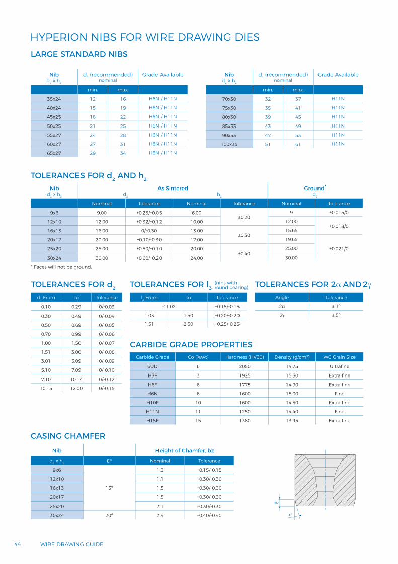
HYPERION NIBS FOR WIRE DRAWING DIESLARGE STANDARD NIBS
CASING CHAMFER
TOLERANCES FOR d2 AND h2
Nibd2 x h2
d1 (recommended)nominal
Grade Available
min. max.
35x24 12 16 H6N / H11N
40x24 15 19 H6N / H11N
45x25 18 22 H6N / H11N
50x25 21 25 H6N / H11N
55x27 24 28 H6N / H11N
60x27 27 31 H6N / H11N
65x27 29 34 H6N / H11N
Nibd2 x h2
d1 (recommended)nominal
Grade Available
min. max.
70x30 32 37 H11N
75x30 35 41 H11N
80x30 39 45 H11N
85x33 43 49 H11N
90x33 47 53 H11N
100x35 51 61 H11N
TOLERANCES FOR d2 TOLERANCES FOR l3
l3 From To Tolerance
< 1.02 +0.15/-0.15
1.03 1.50 +0.20/-0.20
1.51 2.50 +0.25/-0.25
TOLERANCES FOR 2α AND 2γ
Angle Tolerance
2α ± 1º
2γ ± 5º
(nibs with round bearing)
d1 From To Tolerance
0.10 0.29 0/-0.03
0.30 0.49 0/-0.04
0.50 0.69 0/-0.05
0.70 0.99 0/-0.06
1.00 1.50 0/-0.07
1.51 3.00 0/-0.08
3.01 5.09 0/-0.09
5.10 7.09 0/-0.10
7.10 10.14 0/-0.12
10.15 12.00 0/-0.15
CARBIDE GRADE PROPERTIESCarbide Grade Co (%wt) Hardness (HV30) Density (g/cm3) WC Grain Size
6UD 6 2050 14.75 Ultrafine
H3F 3 1925 15.30 Extra fine
H6F 6 1775 14.90 Extra fine
H6N 6 1600 15.00 Fine
H10F 10 1600 14.50 Extra fine
H11N 11 1250 14.40 Fine
H15F 15 1380 13.95 Extra fine
Nibd2 x h2
As Sintered d2 h2
Ground*d2
Nominal Tolerance Nominal Tolerance Nominal Tolerance
9x6 9.00 +0.25/+0.05 6.00±0.20
9 +0.015/0
12x10 12.00 +0.32/+0.12 10.00 12.00+0.018/0
16x13 16.00 0/-0.30 13.00±0.30
15.65
20x17 20.00 +0.10/-0.30 17.00 19.65
+0.021/025x20 25.00 +0.50/+0.10 20.00±0.40
25.00
30x24 30.00 +0.60/+0.20 24.00 30.00
* Faces will not be ground.
Nib Height of Chamfer, bz
d2 x h2 εº Nominal Tolerance
9x6
15º
1.3 +0.15/-0.15
12x10 1.1 +0.30/-0.30
16x13 1.5 +0.30/-0.30
20x17 1.5 +0.30/-0.30
25x20 2.1 +0.30/-0.30
30x24 20º 2.4 +0.40/-0.40

4545MATERIALS
TOLERANCES FOR 2α AND 2γ
WEAR PARTSENGINEERED PRODUCTSTailor-made according to your drawing. Fully finished parts ready-to-use or blanks are available.
- Straightening rollers- Wire guides- Cabling dies- Shaving dies- Die blanks with starter holes- Plugs and mandrels- Injection nozzles / extrusion tools- Calibrating pins - Gauges / measuring pins? - Flattening rollers- Profiling rolls.
MAT
ERIA
LS

46 WIRE DRAWING GUIDE
SHAVING DIES
-Y0 +Y0
β0
α0
WC shaving dieSteel housing
Chips
D (mm) H (mm) d (mm) 2a (º) 2b (º) 2g (º) GRADE
16,18+/-0,01 7,4+/-0,12 5,95 13 18 0 MP1016,18+/-0,01 7,4+/-0,12 5,35 13 18 0 MP1016,18+/-0,01 7,4+/-0,12 6,95 13 18 0 MP1016,18+/-0,01 7,4+/-0,12 7,95 13 18 0 MP1016,18+/-0,01 7,4+/-0,12 3,95 13 18 0 MP1016,18+/-0,01 7,4+/-0,12 4,35 13 18 0 MP1016,18+/-0,01 7,4+/-0,12 3,60 13 18 0 MP1016+0,7/+0,3 12+0,6/0,3 5,35 13 18 0 ES3516,19+/-0,01 7,0+0,55/+0,3 5,80 13 18 0 ES3516,19+/-0,01 7,0+0,55/+0,3 7,40 13 18 0 ES3516,19+/-0,01 7,0+0,55/+0,3 6,40 13 18 0 ES3516,19+/-0,01 7,0+0,55/+0,3 8,40 13 18 0 ES35
Pr
SHAVING DIE ANGLE
Pr Tool reference plane±Y0 Tool orthogonal chip angle
β0 Tool orthogonal key angleα0 Tool orthogonal clearance angle
Draw-peeling – also known as shaving – is a cutting procedure. The cutting edge in this case is a draw-peeling tool/shaving die. This is a static tool with a circular blade. The geometry is similar to that of a regular drawing die in the wire industry. The main difference is that, in contrast to the transformative geometry of the drawing die, there is a cutting edge in the draw-peeling tool. A descaling and a coating that is usually required for steel wire is not necessary in front of this cutting operation.
Shaving operation shall guarantee:- To remove continuously a uniform thickness of metal - At high speed- Separating the removed layer into a plurality of strips and said strips being removed radially from the rod - Produce a smooth surface thereon.
Hyperion offers a wide range of shaving rough blanks made of two Cemented Carbide grades MP10 and ES35.

4747MATERIALS
SLURRY FORMULAS SUSPENSION FORMULAS
K285T Water soluble K285T Water solubleK400 Oil soluble K1500 Oil solubleK450 Water / Oil soluble
DIAMOND POWDERS DESCRIPTION SUGGESTED APPLICATION INDUSTRY
SJK-5 A monocrystal, diamond powder used in slurries and suspensions Lapping
AerospaceCeramics
GlassLensesOptics
SapphireSemi-conductorSilicon carbide
Tungsten carbide
RJK-1 A multi-crystal, more friable than a monocrystal Lapping and polishing
Poly Polycrystalline diamond available in sizes < 10 μm Polishing
HYPERION DIAMOND COMPOUNDSSLURRIES
DIAMOND SIZE AVAILABILITY
LIGHT CONCENTRATION MEDIUM CONCENTRATION HEAVY CONCENTRATION
Finishing
125 mL 500 mL 1 gallon250 mL 1.000 mL 5 gallon bucket
Removal
Micron0-1/2
Mesh100.000
Micron1-3
Mesh11,000
Micron4-8
Mesh3.000
Micron0-2
Mesh14.000
Micron3-5
Mesh6.500
Micron6-12
Mesh1.800
Micron20-30
Mesh800
Micron30-60
Mesh400
Micron8-12
Mesh1.700
Micron20-40
Mesh575
Micron50-70
Mesh270
Micron0-1
Mesh60.000
Micron2-4
Mesh8.000
Micron5-10
Mesh2.500
Micron10-20
Mesh1.200
YOU CHOOSE THE FORMULA
YOU CHOOSE THE CONCENTRATION
YOU CHOOSE THE CONTAINER SIZE
WE ADD SUPERIOR DIAMOND POWDERS
MAT
ERIA
LS

48 WIRE DRAWING GUIDE
1/4m
icron
0-1/2
mes
h 100.0
00
4m
icron
3-5
mes
h 6.50
0
15m
icron
10-20
mes
h 1.20
0
1/2m
icron
0-1
mes
h 60.00
0
6m
icron
4-8
mes
h 3.00
0
25m
icron
20-30
mes
h 600
1m
icron
0-2
mes
h 14.00
0
7.5m
icron
5-10
mes
h 2.50
0
30m
icron
20-40
mes
h 575
2m
icron
1-3
mes
h 11.00
0
9m
icron
6-12
mes
h 1.80
0
45m
icron
30-60
mes
h 400
3m
icron
2-4
mes
h 8.00
0
10m
icron
8-12
mes
h 1.70
0
60m
icron
50-70
mes
h 270
HYPERION DIAMOND COMPOUNDSPASTES: DIAMOND POWDER + CARRIER
PRODUCT IDENTIFICATION DESCRIPTION RECOMMENDED USES
K700 WS Products Water soluble- When exceptional cleaning is required- When petroleum contamination is prohibited- Specimen preparation
K210 OS Products Oil soluble- Controlled lapping for carbide drawing dies
and cold heading dies- Numerous other polishing applications
G400 WOS Products Water / Oil soluble- Compliments the use of oil and water for achieving
more productive results- Facilitates cleaning
5 gram
5 gram
18 gram
50 gram
50 gram
200 gram
10 gram
25 gram
25 gram
100 gram
TUBE SIZES
JAR SIZES

4949MATERIALS
HYPERION DIAMOND COMPOUNDSDIAMOND MICRON POWDER GRADESHYPERION SLURRY
GRM DIAMOND
DIAMOND (FOR COMPOUND MANUFACTURING)
Retains sizeMaintains effectivenessReadily availableNot easily crushed
HYPERION DIAMOND
GRM (Standard Grade) UNCOATED
Few cutting points
Susceptible to crushing
Becomes smaller with use
Limited availability
MONOCRYSTALLINE MICRON DIAMOND
POLYCRYSTALLINE MICRON DIAMOND
Hyperion slurry is comprised of diamond particles containing more surface cutting points than a typical monocrystalline micron and polymicron diamond.
Hyperion slurry achieves higher material removal rates and better surface finish due to the surface characteristics of the diamond.
The diamond surface is covered with small cutting points, which reduce surface roughness of the workpiece.
In addition to the diamond characteristics, the slurry formulation can be tailored to optimize performance for specific operating conditions and workpieces.
GRM diamond satisfies a broad range of size, shape and surface demands while providing a satisfactory surface finish. GRM diamond is a desirable option if tight tolerances are not mandatory.
APPLICATIONSPolishing of wire dies, stones and gems.
DIAMOND SIZES AND STANDARDS
- Standard size offering ranges from 0.5 μm to 80 μm (mean size)- Available in metal or resin bond diamond grades- Sold in 50 to 5,000 carat containers- Custom particle size distributions are available upon request.
MAT
ERIA
LS

APPLICATIONS & FAILURE MODES

APPLICATIONS & FAILURE MODES
52 WIRE DRAWING GUIDE
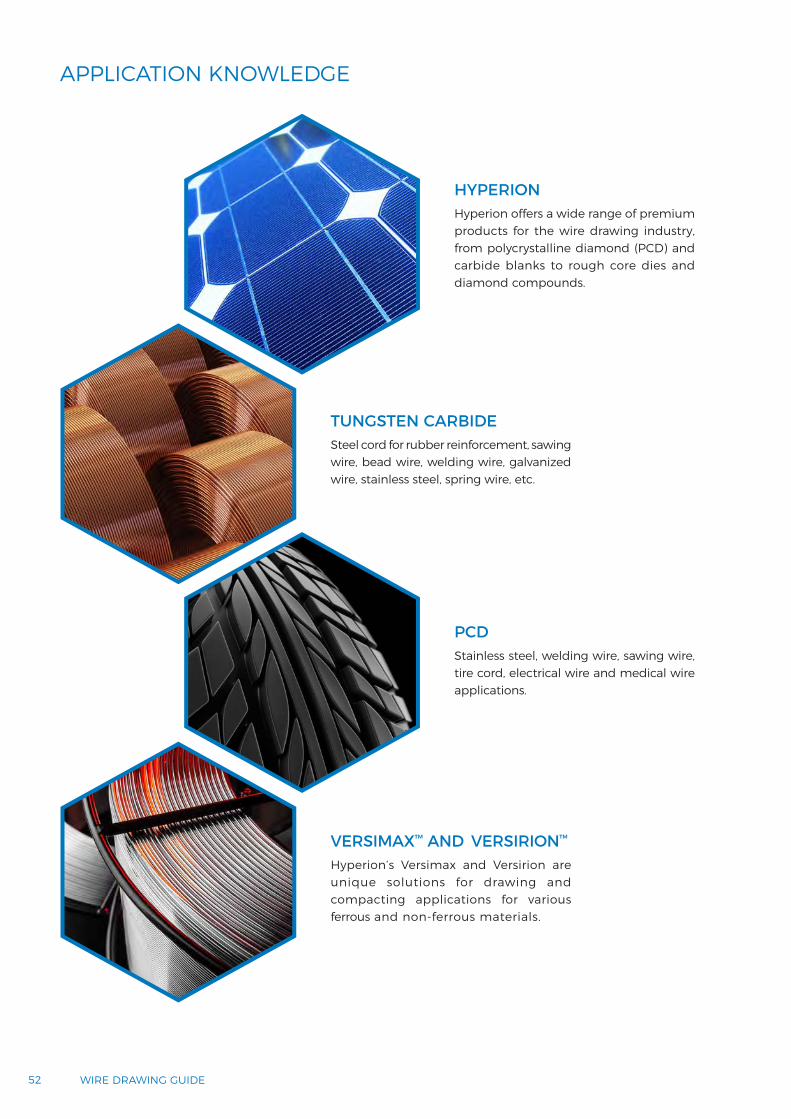
APPLICATION KNOWLEDGE
HYPERION
PCD
Hyperion offers a wide range of premium products for the wire drawing industry, from polycrystalline diamond (PCD) and carbide blanks to rough core dies and diamond compounds.
TUNGSTEN CARBIDESteel cord for rubber reinforcement, sawing wire, bead wire, welding wire, galvanized wire, stainless steel, spring wire, etc.
Stainless steel, welding wire, sawing wire, tire cord, electrical wire and medical wire applications.
VERSIMAX™ AND VERSIRION™
Hyperion’s Versimax and Versirion are unique solutions for drawing and compacting applications for various ferrous and non-ferrous materials.

APP
LICA
TIO
NS
& FA
ILU
RE
MO
DES
5353APPLICATIONS & FAILURE MODES
CUSTOMER COST SPLIT
COST SPLIT FOR STEEL CORD
60%25%
7%3%5% 0.5%
Rod material
Power (water, gas & electricity)
Packaging & transport
Drawing dies
Others
Auxiliary material (lubricants, etc.)

54 WIRE DRAWING GUIDE
RADIAL CAR TIRE COMPOSITION (WEIGHT)
RADIAL TIRE COMPOSITION
Nylon Overlays Gum StripsUndertread
Belt Wedge
Sidewall
Cushion
Body Plies
Halobutyl Liner
Apex
Toe Guard
Beads
ChaferPly Turn Up
Steel Belts
Tread
22%
29%
25%
6%
10%
3%5%
Natural rubber
Synthetic rubber
Reinforcing agent
Textile cord
Bead wire
Ingredients
Steel cord

APP
LICA
TIO
NS
& FA
ILU
RE
MO
DES
5555APPLICATIONS & FAILURE MODES
PCD APPLICATION GUIDELINE
WIRE DRAWING APPLICATION GUIDELINES
WIRE TYPEWIRE AREAWIRE SIZE
Range (mm)
PERCENT REDUCTION
DIE GEOMETRYDRAWING
SPEED(m/min)
RELATIVE PERFORMANCE
VERSUS
REDUCTIONANGLE
BEARINGLENGTH
(%)
TUNGSTENCARBIDE
SINGLE CRYSTAL
DIAMOND
NON-FERROUS• Copper
• Aluminum
• AluminumMagnesium Alloy
• Tin-Plated Copper(electroplated)
• Nickel 200• Tungsten• Molybdenum
1.84 - 7.600.05 - 2.051.84 - 7.600.20 - 2.05
1.84 - 4.760.20 - 1.80
0.33 - 1.650.12 - 0.620.12 - 1.02
20 - 3518 - 2118 - 3015 - 21
18 - 2215 - 26
20 - 3018 - 2218 - 22
16 - 2516 - 2016 - 2516 - 20
16 - 2018 - 22
16 - 2012 - 1612 - 16
10 - 2510 - 2510 - 2510 - 25
15 - 3010 - 25
15 - 3020 - 4020 - 40
600 - 2500600 - 3300600 - 1500600 - 2000
350 - 650300 - 1000
200 - 50030 - 8030 - 80
200 - 500X-
100 - 200X-
100 - 200X100 - 200X
--
50 - 80X
-5 - 15X
-3 - 5X
-5 - 10X
6 - 10X3 - 6X3 - 6X
FERROUS• Galvanized High
Carbon Steel• Brass-Plated High
Carbon Steel Tire Cord• Stainless Steel 316• Stainless Steel 302• Ni-Cr-Fe Alloy
(60:15:25)• Low Carbon Steel
0.24 - 1.05
0.17 - 0.400.18 - 1.600.24 - 1.600.20 - 1.20
0.88 - 2.10
15 - 20
18 - 2118 - 2118 - 2118 - 26
18 - 21
10 - 14
10 - 1610 - 1410 - 1410 - 14
8 - 14
20 - 40
20 - 4020 - 4020 - 4020 - 40
20 - 40
400 - 800
600 - 1000200 - 600200 - 600200 - 600
400 - 800
30 - 50X
10 - 30X10 - 20X8 - 15X30 - 50X
30 - 70X
-
-4 - 8X2 - 4X4 - 6X
-
Dimensional recommendation for round standard nibs:

MATERIAL DRAWING CONDITIONS
PERCENTAGE OF REDUCTION
5-8 8-12 12-16 16-25 25-35 35-45
• Lead• Zinc• Aluminum• Silver• Gold
Dry - - - - - -
Wet 14º 16º 18º 21º 24º -
• Cupper• Stainless Steel
Dry - - - - - -
Wet 12º 14º 16º 19º 22º -
• Aluminum Alloys• Nickel• Ni-Cr Alloys
Dry - - - - - -
Wet 10º 12º 14º 17º 20º -
• Brass• Bronze• Nickel-Silver• Non Alloyed Carbon
Steels (%C<0,4)
Dry 7º 9º 11º 14º 17º 20º
Wet 9º 11º 13º 16º 19º -
• Non Alloyed CarbonSteels (%C<0,4)
• Alloyed Steels• Ni-Cr Alloys for
electrical resistances • Molibdenum
Dry 6º 8º 10º 12º 15º 18º
Wet 8º 10º 12º 15º 18º -
• Tungsten Dry 10º 10º 12º 12º 14º -
NIB CASE
d2 h2
d1 sl4 2β 2γ d3 h3 l5
min max min
8 4 0,1 1 3,5 1
90º 90º 28
12
310 8 0,2 2 4 2 16
12 10 0,3 3 4,5 2,5 20
14 12 0,4 4 5 360º 75º
2822 3
43
16 13 0,5 5 5,5 3,5 43 25 4
20 17 1,5 6,5 6,75 4,5
60º 60º
43 325
25 20 2,5 9 8 553
3575
30 24 3,5 12 9 6 75 40 6
Dimensions in mm unless otherwise noted.
56 WIRE DRAWING GUIDE
WC APPLICATION GUIDELINE
Dimensional recommendation for round standard nibs:

CAR
BID
E
STEE
L CA
SIN
G
DIRECTION OF SLOW CRACK
GROWTH
WIRECAP
PCDCORE
WIREENTRY
WIREEXIT
FRACTURE INITIATION
5757APPLICATIONS & FAILURE MODES
APP
LICA
TIO
NS
& FA
ILU
RE
MO
DES
PCD BEST PRACTICES- Recut or repolish die on observation of wear ring in area of wire contact to maximize die life.
- Filtrate lubricant to remove metal fines to maximize lubricant flow, wire finish and die life.
- Do not exceed maximum die size recommendation for blank size.
- Decrease bearing length for higher speed drawing.
- Use finer grain die blanks for improved wire surface finish and in drawing ferrous and plated wires.
- Use coarser grain die blanks for drawing larger size non-ferrous wire to provide longer die life and improved wire dimensional control.
- In high temperature drawing of tungsten and molybdenum wire, maintain reducing atmosphere in drawing zone to minimize detrimental oxidation effects and maximize die life.
- Use matched elongation die sets in multi-wire drawing machines.

VISIBLE EFFECTS NOMINAL CAUSE POSSIBLE SOLUTIONS
58 WIRE DRAWING GUIDE
CARBIDE BEST PRACTICES
FAILURE MODE DRAWING DIES
- Ensure correct wire section reduction by calculation. Verify actual wire reduction vs theoretical.
- Consistency in the die set drawing progression.
- Back relief between the hearing and the exit prevents wire production against machine vibration and spring back.
- Use the correct cemented carbide in accordance with the type of drawing process, wire material and reduction.
- Use harder grades for fine wire diameters, and tougher grades for big diameters and big reduction.
- Do not exceed maximum base size recommendation per nib size. Recutting more than 10 times must be avoided.
- Every recut must ensure that any wear ring or mark from previous drawing process is removed.
- Hot casing gives the end user high and tight range of pre-stresses, close contact case ID and nib, and better balance of radial and axial pre-stresses.
VISUAL EFFECTS. DIE ANALYSIS
FAILURE CAUSES
To be taken into consideration when die failure analysis:
- Cause of failure is never absolute. Several factors play together, interacting and creating confusing effects.- It is advisable to judge based in several dies assessment.
Die breakage is usually caused by:
- Lack of mechanical support for the insert (hoop failure).
- Abnormal reduction.
- Inadequate lubrication.
- Inadequate tool material for the amount of reduction and speed (too hard or too tough).
- Tool misalignment, miscoaxiality, etc.
Some wear resistance must be always sacrificed to minimize breakage.
5959APPLICATIONS & FAILURE MODES
APP
LICA
TIO
NS
& FA
ILU
RE
MO
DES
PCD FAILURE MODE ANALYSISHyperion has over 30 years of experience in PCD and cemented carbide wire dies. Hyperion provides the customers with full root-cause analysis for the failures in wire drawing dies.
Hyperion has a fully equipped Materials Analysis Laboratory to investigate failures and determine the failure mode. We provide our customers with a full report containing possible root cause and failure mode and possible solutions based on the findings. We also provide supporting data in terms of micrographs and physical, chemical and mechanical dimensional properties information.
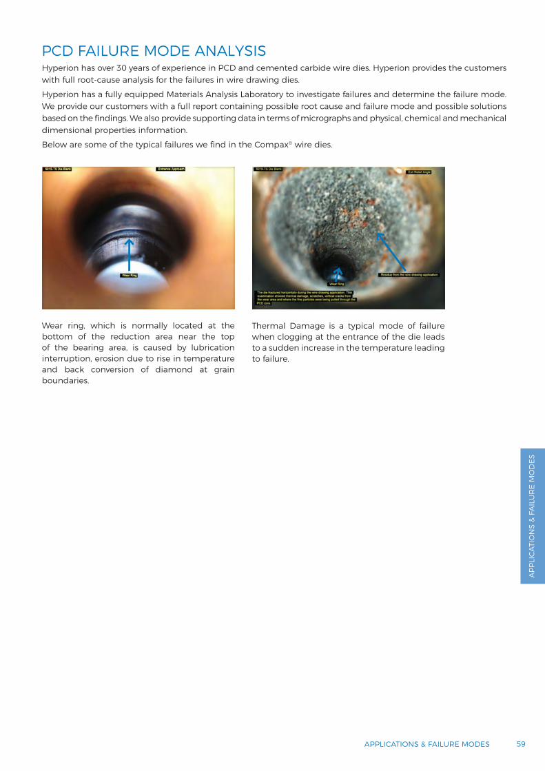
Below are some of the typical failures we find in the Compax® wire dies.
Wear ring, which is normally located at the bottom of the reduction area near the top of the bearing area, is caused by lubrication interruption, erosion due to rise in temperature and back conversion of diamond at grain boundaries.
Thermal Damage is a typical mode of failure when clogging at the entrance of the die leads to a sudden increase in the temperature leading to failure.

60 WIRE DRAWING GUIDE
PCD FAILURE MODE ANALYSISDIE OR BLANK MISALIGNMENT
VERTICAL STRESS CRACKS
VISIBLE EFFECTSDie fractures in a slight U-shaped pattern.
NOMINAL CAUSEDie blank is not resting flat against the steel casing.The blank is not level when an uneven compression load is applied across the diamond surface. Mechanical stress force is applied to one side of the die blank creating a bending moment.
POSSIBLE SOLUTIONEnsure blank is well aligned when assembled on the case.
VISIBLE EFFECTSEqually spaced large vertical cracks. Usually more than two cracks.
NOMINAL CAUSEExcessive mechanical and/or thermal forces being applied to the diamond core. It is being stretched during the wire drawing application or the sizing process.
POSSIBLE SOLUTIONSGood wire reduction design, controlled brazing process between PCD blank and core, lubrication control, etc.
6161
APP
LICA
TIO
NS
& FA
ILU
RE
MO
DES
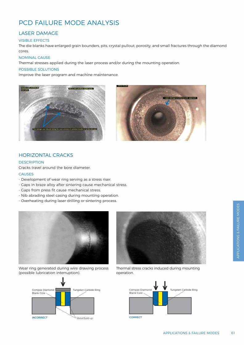
PCD FAILURE MODE ANALYSISLASER DAMAGE
HORIZONTAL CRACKS
VISIBLE EFFECTSThe die blanks have enlarged grain bounders, pits, crystal pullout, porosity, and small fractures through the diamond cores.
NOMINAL CAUSEThermal stresses applied during the laser process and/or during the mounting operation.
POSSIBLE SOLUTIONSImprove the laser program and machine maintenance.
DESCRIPTIONCracks travel around the bore diameter.
CAUSES- Development of wear ring serving as a stress riser.- Gaps in braze alloy after sintering cause mechanical stress.- Gaps from press fit cause mechanical stress.- Nib abrading steel casing during mounting operation.- Overheating during laser drilling or sintering process.
Wear ring generated during wire drawing process (possible lubrication interruption).
Thermal stress cracks induced during mounting operation.
APPLICATIONS & FAILURE MODES
CORRECT
Compax Diamond Blank Core
Tungsten Carbide Ring
INCORRECT
Compax Diamond Blank Core
Tungsten Carbide Ring
Metal Build-up
62 WIRE DRAWING GUIDE
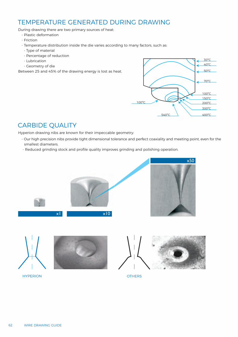
TEMPERATURE GENERATED DURING DRAWING
CARBIDE QUALITY
30ºC40ºC
50ºC
70ºC
100ºC
100ºC150ºC200ºC
300ºC
400ºC540ºC
x10x1
x50
HYPERION OTHERS
During drawing there are two primary sources of heat:- Plastic deformation- Friction- Temperature distribution inside the die varies according to many factors, such as:
- Type of material- Percentage of reduction- Lubrication- Geometry of die
Between 25 and 45% of the drawing energy is lost as heat.
Hyperion drawing nibs are known for their impeccable geometry:
- Our high precision nibs provide tight dimensional tolerance and perfect coaxiality and meeting point, even for the smallest diameters.
- Reduced grinding stock and profile quality improves grinding and polishing operation.

6363
APP
LICA
TIO
NS
& FA
ILU
RE
MO
DES
CARBIDE DIES FAILURE MODE ANALYSIS
APPLICATIONS & FAILURE MODES
Hyperion collaborates with our customers to provide a complete solution from grade selection to failure mode analysis and continuously works to provide better performing products to improve the e®ciency.
HOOP FAILURE can be identified by crack runs lengthwise through the nib. Casing balances the tensile stresses over the carbide nib due to drawing forces. Failure is caused when the force required to deform the wire is greater than the strength of the die material and its mounting. Close casing with absence of oxides and cavities is advised.
BURST DIE is a result of circumferential crack at the bottom of the wear ring propagates by splitting the nib in two (also breakage can be in the form of a cone). It usually occurs when a die is left in the machine too long and the stress concentration makes that the wear ring became too deep. It is easily noticeable because the crack evolution is in the radial direction.

64 WIRE DRAWING GUIDE
CARBIDE DIES FAILURE MODE ANALYSISBURST DIE
BACK CHIPPING
VISIBLE EFFECTSCircumferential crack at the bottom of the wear ring propagates by splitting the nib in two (also breakage can be in the form of a cone).
NOMINAL CAUSEIt usually occurs when a die is left in the machine too long and the stress concentration makes that the wear ring became too deep. It is easily noticeable because the crack evolution is in the radial direction.
POSSIBLE SOLUTIONSMost tension failures can be avoided with a good die maintenance program.
VISIBLE EFFECTSShows chipping in the intersection of the bearing and the back relief.
NOMINAL CAUSECaused by an improperly shaped back relief.
POSSIBLE SOLUTIONSCan be easily repaired by removing the edge of the intersection.
6565
APP
LICA
TIO
NS
& FA
ILU
RE
MO
DES
CARBIDE DIES FAILURE MODE ANALYSIS
APPLICATIONS & FAILURE MODES
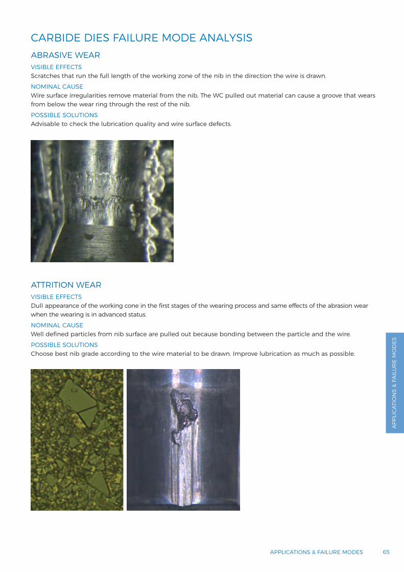
ABRASIVE WEAR
ATTRITION WEAR
VISIBLE EFFECTSScratches that run the full length of the working zone of the nib in the direction the wire is drawn.
NOMINAL CAUSEWire surface irregularities remove material from the nib. The WC pulled out material can cause a groove that wears from below the wear ring through the rest of the nib.
POSSIBLE SOLUTIONSAdvisable to check the lubrication quality and wire surface defects.
VISIBLE EFFECTSDull appearance of the working cone in the first stages of the wearing process and same effects of the abrasion wear when the wearing is in advanced status.
NOMINAL CAUSEWell defined particles from nib surface are pulled out because bonding between the particle and the wire.
POSSIBLE SOLUTIONSChoose best nib grade according to the wire material to be drawn. Improve lubrication as much as possible.
66 WIRE DRAWING GUIDE
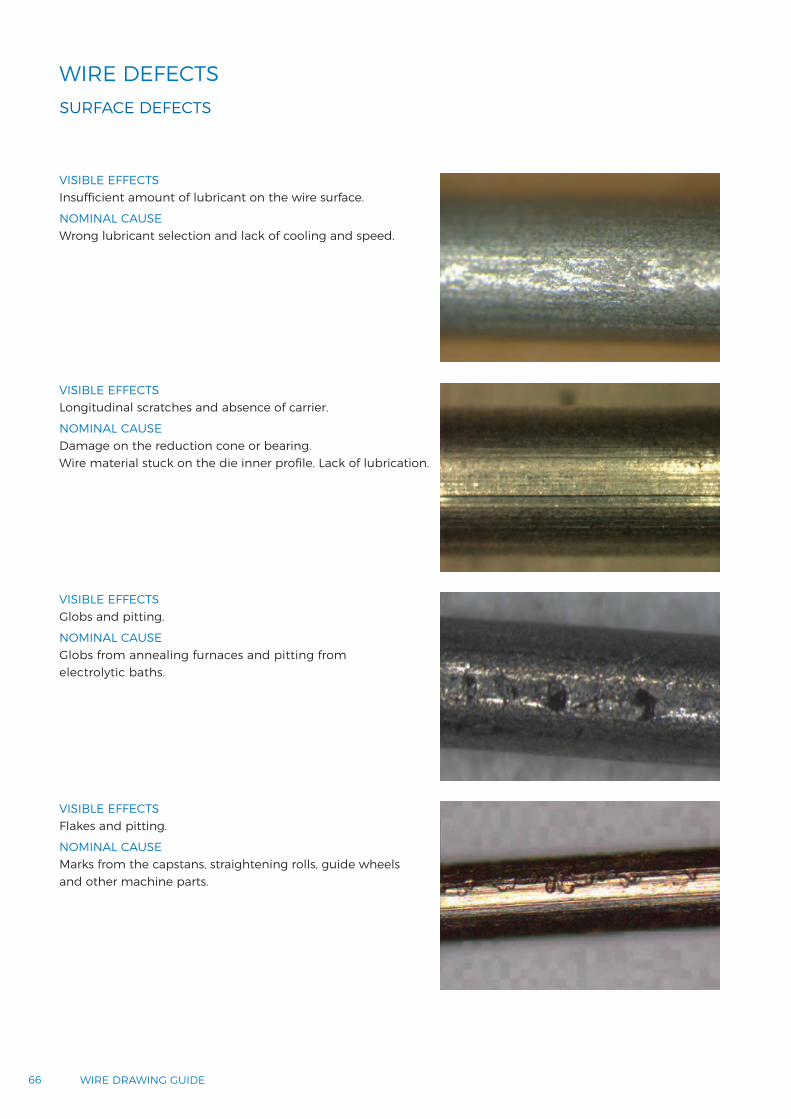
WIRE DEFECTSSURFACE DEFECTS
VISIBLE EFFECTSInsu®cient amount of lubricant on the wire surface.
NOMINAL CAUSEWrong lubricant selection and lack of cooling and speed.
VISIBLE EFFECTSLongitudinal scratches and absence of carrier.
NOMINAL CAUSEDamage on the reduction cone or bearing. Wire material stuck on the die inner profile. Lack of lubrication.
VISIBLE EFFECTSGlobs and pitting.
NOMINAL CAUSEGlobs from annealing furnaces and pitting from electrolytic baths.
VISIBLE EFFECTSFlakes and pitting.
NOMINAL CAUSEMarks from the capstans, straightening rolls, guide wheels and other machine parts.

b
a
6767
APP
LICA
TIO
NS
& FA
ILU
RE
MO
DES
APPLICATIONS & FAILURE MODES
WIRE DEFECTSDEFECTS FROM DRAWING
CRACKS
V-FRACTURE
SHAPE/CAST ERRORS
WIRE QUALITY
SHAPE/CAST ERRORS
VISIBLE EFFECTSSurface or internal cracks.
NOMINAL CAUSEPoor rod quality.Surface defects on the incoming wire.Unbalanced stresses in the wire due to incorrect drawing series, bad cooling or improper drawing speed.
VISIBLE EFFECTSWire fracture in V-shape during drawing.
NOMINAL CAUSELack of lubrication / wrong area reduction.
VISIBLE EFFECTSCamber (Øa) or helix cast out of specs.
NOMINAL CAUSEProblems in wire guiding or straightening device. Incorrect capstans geometry.
VISIBLE EFFECTSWire section becomes oval or not circular.
NOMINAL CAUSEDie misalignment in the machine.
VISIBLE EFFECTSWeave wire.
NOMINAL CAUSEVibration marks: vibration dampening tools are not set correctly.Problems with straightening device.

CUSTOMER SUPPORT

CUSTOMER SUPPORT
70 WIRE DRAWING GUIDE
FAQ
QWhat happens if a customer changes the grade for an existing nib pressing tool?
ADifferent grades could have different shrinkages. This effect could affect the final nib dimensions.
QIs hot casing better than cold casing?
A
The nib after hot casing is under compression not only in the radial but also in the axial direction. This leads to a better stress balance during the drawing process and increases the die life.
QCan Versimax and Versirion be brazed like PCD?
AYes, Versimax and Versirion can be brazed, hot cased and cold cased into the case.
QWhat is the difference between rough core die and nib? Any advantage?
AHyperion’s hot casing process and geometry guarantee perfect between case and nib. Consequently, better balance of stress and better heat conductivity are achieved. These two parameters directly increase die life.
QCan we order a small number of Hyperion WC rough core die PCD blanksto evaluate in our facility to see if it improves our productivity?
AHyperion maintains a large stock of blanks to allow customers to order small test batches. In addition, we offer our application expertise to our customers to help increase productivity.

INCH
TYPENIB CASING
Dla. Ht. Dla. Ht.
R2 .325 .330 1 .563
R3 .450 .380 1.5 .750
R4 .500 .450 1.5 .875
R5 .625 .600 2 .875
R6 .710 .700 3 1.125
R7 .768 .768 3 1.375
R8 1.000 .820 3 1.750
R9 1.187 .820 3 1.750
R10 1.500 1.000 3 2
R11 1.830 1.250 4 2.250
R12 2.185 1.375 4 2.375
R14 2.560 1.375 6 2.500
R15 3.000 1.375 6 2.500
R16 3.500 1.375 7 2.500
R17 4.000 1.500 7 2.500
R18 5.500 2.125 9 4.500
R19 6.500 2.125 11 4.500
MILLIMETER
DIN 1547 TYPE
NIB CASING
Dla. Ht. Dla. Ht.
D10-0804 8 4 28 12
D10-1008 10 8 28 16
D10-1210 12 10 28 20
D10-1412 14 12 28 22
D10-1613 16 13 43 25
D10-2017 20 17 43 32
D10-2520 25 20 53 35
D10-3024 30 24 75 40
MILLIMETER
TYPENIB CASING
Dla. Ht. Dla. Ht.
B 13 10 30 16
C 16 14 32 20
G 22 18 40 26
H 30 21 66 35
K 40 25 95 40
L 50 28 95 48
M 60 35 114 60
N 75 35 114 70
0 90 35 145 70
MILLIMETER
JIS TYPE
NIB CASING
Dla. Ht. Dla. Ht.
W101 6 4 24 7
W102 9 6 24 12
W103 12 8 30 15
W104 15 10 42 20
W105 20 14 55 24
W106 25 18 60 28
W107 30 22 70 35
W108 35 25 85 40
W109 40 27 100 45
W110 50 30 125 50
W111 60 35 145 60
W112 70 40 175 70
W113 80 45 195 80
W114 90 50 215 90
W115 100 50 230 90
W116 110 50 230 90
W117 120 55 250 100
W118 130 55 275 100
W119 140 60 295 110
W120 150 60 315 110
7171CUSTOMER SUPPORT
INTERNATIONAL STANDARDS ROUND DIE SPECIFICATION
CU
STO
MER
SU
PPO
RT

A [% of elongation]
V [volume of a given wire length]
e [miscoaxiality]
R = 1 - (d/D)2 x 100%
V = 1/4πD2L
R = x 100%Se - Ss
Se
e = • tg • [ tg (α) + tg (β) ]d1 2α
2 2β
Se Ss
A = 100 x R100 - R
100 cm 100 - A cm
h
d1
e
72 WIRE DRAWING GUIDE
CONVERSION TABLE
COMMONLY USED FORMULAS
LENGTH
1 inch = 25.4 mm
MASS
1 Kg = 2.205 pounds
DENSITY
1 g/cm3 = 0.036 lb/inch3
VOLUME
1 US gallon = 3.785 liters
SPEED
1 inch/min = 0.0254 m/min
1 m/s = 60 m/min
R [% of reduction]
73CUSTOMER SUPPORT
HYPERION - RECYCLING AND SUSTAINABILITYTIME TO THINK DIFFERENTLYHyperion, through our Carbide Recycling Program, purchases used carbide tools and products from our customers to convert them into usable raw materials for future production. We use a controlled, certified chemical recycling process that ensures these “new” materials are identical to materials produced from mined ore.
Hyperion is committed to sustainability, and recycling is a great example of how we are reducing the company’s environmental footprint.
This is how you recycle your carbide (short version): you call us, we send a barrel, you fill the barrel, we pick it up, you get paid. Easy! We recycle all types of carbide (only carbide).
Please contact [email protected] or your sales agent for more information.
CU
STO
MER
SU
PPO
RT
Helps maintain raw material
resources
Supports environmental
efforts
ISO 9000, 18000 and
14001 certified
A
Abrasion 10,15,19,65Abrasive 20,65ADDMA 19,22,24Annealing 9,66
B
Back relief 58,64Bunching 15,23,24Burst 63,64
C
Cabling 15,45Casing 10,23,29,39,44,57
58,60,61,63,70,71Ceramic 28,47Co-lake 37Concentration 36,37,38,47,63,64Conductive 21,23Corrosion 23,27,28
31,33,34,35Craking 25
D
Delamination 25
E
EDM 16,23,24
Electrical 52,56Environment 27Erosion 59
F
Flakes 66Friction 9,33,62
G
Galling 31Galvanized 52,55Globs 66Grains 9,36
I
Inclusion 25,26
L
Lapping 47,48Laser 16,26,61
M
Micron powder 11,14,28,49Misalignment 58Misconcentricity 26
O
Oxidation 27,36,57
P
Pull out 36,65Pitting 66Polishing 11,16,23,34
47,48,49,62Porosity 37,61
R
Recrystallization 9,36Recut 57,58Repolish 57
S
Sawing 32,52Scratches 36,65,66Self-supported 10,16,21,22,24Slurry 47,49Spring back 58Stainless steel 32,52,55,56Stranding 15,23,24Sub-micron 19Supported 10,16,18,21Surface 15,18,20,57,60,65,66,67Suspension 47
T
Thermally stable 21,23Tire 15,19,24,32,33,52,54,55
W
Wear 8,10,11,18,19,20,23,2427,28,31,33,34,35,45,57
58,59,61,63,64,65Wear ring 57,58,59,61,63,64,65Welding 15,19,32,34,52
74 WIRE DRAWING GUIDE
WORDS INDEX


www.HyperionMT.com
TS-W
D 1
809-
001
ENG
A4
Copy
right
© H
yper
ion
Mat
eria
ls &
Tec
hnol
ogy
– A
ll rig
hts
rese
rved
Copyright © 2022 FDOKUMEN