Manual 2-wire - ADATIS
14
Adatis GmbH & Co.KG Page 1from 14 Manual 2-wire PLC converter 5.2 and 5.3 Version 1.5 Author lbittner Date 19.07.2021 Log
-
Upload
khangminh22 -
Category
Documents
-
view
0 -
download
0
Transcript of Manual 2-wire - ADATIS

Adatis GmbH & Co.KG Page 1from 14
Manual 2-wire
PLC converter 5.2 and 5.3
Version 1.5
Author lbittner
Date 19.07.2021
Log

Adatis GmbH & Co.KG Page 2from 14
Content
1 ABOUT THIS PRODUCT 3
1.1 Features 3
1.2 Scope of delivery 3
1.3 Type Distinction PD and PSE box 3
1.4 Device overview 4
1.5 Version distinction 5.2 and 5.3 4
2 MECHANICAL ASSEMBLY 5
2.1 Version 5.2 5
2.2 Version 5.3 5
3 ELECTRICAL CONNECTION 6
3.2 2-wire connection on ADATIS terminal 6
3.3 Ethernet connection 6
4 POWER SUPPLY 7
4.1 2Wire set Power supply via PoE switch 7
4.2 2Wire set Power supply via power supply unit 8
4.3 2Wire option Power supply 8
5 CONFIGURATION 9
5.1 Pairing 9
5.2 Master/slave - switch (version 5.2 only) 9
6 LED INDICATORS 10
6.1 LED indicators for Power-over-Ethernet Plus ( PoE+ ) and Ethernet communication 10
6.2 LEDs of the Ethernet socket Fehler! Textmarke nicht definiert.
6.3 LED indicators for the 2-wire interface 11
7 GLOSSARY 13

Adatis GmbH & Co.KG Page 3from 14
1 About this product
1.1 Features
Ethernet connection for remote devices: The Adatis 2Wire converter provides a 100Mbit/s
Ethernet connection at locations where no structured cabling exists. The connection is made
via any unused wire pair of an existing cabling. Distances of up to 1000 m can be bridged.
The use of the 2Wire converter is therefore also appropriate when distances have to be
bridged that exceed the permissible cable length of structured cabling, which is typically
limited to 100 meters. Since power is supplied to the converter and connected devices via
the same pair of wires, the wires must be voltage-free.
Use as PD or PSE: Depending on which type is selected, the Ethernet port of the converter
box behaves in terms of Power-over-Ethernet (PoE) either as a "Powered Device (PD)" which
is supplied with PoE by an Ethernet switch or power injector, or as "Power Sourcing
Equipment (PSE)" which provides Power-over-Ethernet with up to 20 W for connected
devices.
AES encryption: Another advantage of connecting devices via the 2Wire converter is the
built-in encryption technology according to the AES standard with 128 bit.
1.2 Scope of delivery
1x 2Wire Box - Type PD
1x 2Wire Box - type PSE
1.3 Type distinction PD and PSE box
1.3.1 PD Box:
The PD box is either connected to a PoE switch or used in conjunction with a 48-56VDC
plug-in power supply and a non-PoE switch.
On the output side, both the data and the power supply are transmitted from the PD box via
the 2-wire line to the PSE box or an Adatis door station with 2Wire option.
1.3.2 PSE Box:
On the input side, the PSE box is supplied with power via the 2-wire line from the PD box.
The PSE box provides both PoE and 12VDC (max. 0.8A) on the output side at a hollow
connector for the supply of the end devices.

Adatis GmbH & Co.KG Page 4from 14
1.4 Device overview
1.4.1 PLC converter 5.2
1.4.2 PLC converter 5.3
1.5 Version distinction 5.2 and 5.3
The functional range of the PLC converter version 5.2 and 5.3 is almost identical:
These differ in the mounting method: While the V5.2 is designed for DIN rail mounting, the
V5.3 is intended for table or wall mounting.
The V5.2 also has a master/slave switch - see section 5.2.

Adatis GmbH & Co.KG Page 5from 14
2 Mechanical assembly
When selecting the installation location, ensure that the device is sufficiently
ventilated via the ventilation slots in the side of the box. If the installation location is
difficult to access, pairing must be carried out before final installation.
2.1 Version 5.2
DIN rail mounting: The converter box (V5.2) is designed for mounting on a DIN carrier rail
and can either be slid onto the rail from the side or clipped onto the rail from the front.
2.2 Version 5.3
Setting up or screwing on the device: The converter box (v5.3) does not require any
special mounting. The housing is designed in such a way that the device can either be
placed on a flat surface as a desktop housing or screwed onto a wall or other surface using
the side lugs. When screwing, make sure that the housing is not mechanically damaged
and, in particular, that it is not distorted by excessive forces during screwing. Distortion
could damage the circuit board inside.
Adatis GmbH & Co.KG Page 6from 14
3 Electrical connection
3.1 2-wire connection
The 2-wire connection is made via a plug-in terminal with a pitch of 3.5 mm. This allows a
convenient installation to be carried out. The terminal is suitable for wires and stranded
wires and is designed for wire cross-sections of 0.13-1.5 mm² (corresponding to AWG 26-
16). Cables should be stripped to a length of approximately 6-7 mm. The M2 screw of the
clamp may only be tightened by hand. The maximum torque is 0.34 Nm.
It is essential to ensure that the lines used are voltage-free. Connecting live lines to
the 2-wire connection can destroy the device.
Polarity: The 2-wire line is polarity-free, i.e. the transmission and power supply works with
any polarity of the lines.
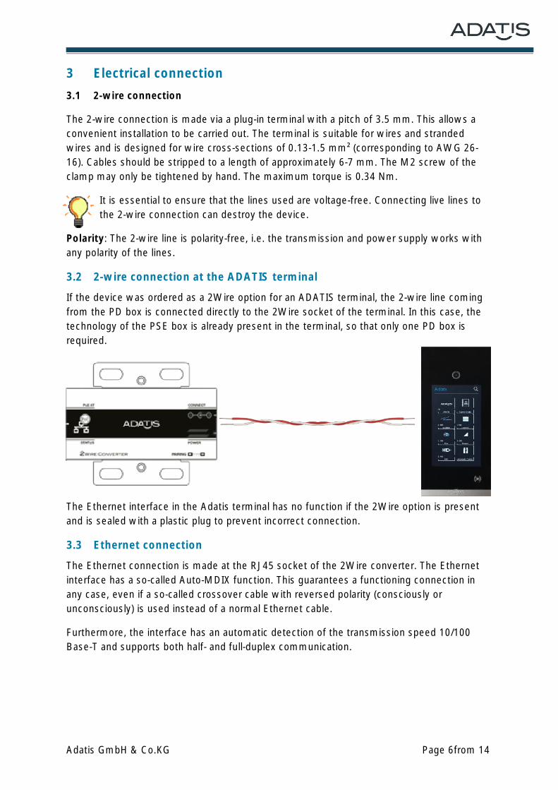
3.2 2-wire connection at the ADATIS terminal
If the device was ordered as a 2Wire option for an ADATIS terminal, the 2-wire line coming
from the PD box is connected directly to the 2Wire socket of the terminal. In this case, the
technology of the PSE box is already present in the terminal, so that only one PD box is
required.
The Ethernet interface in the Adatis terminal has no function if the 2Wire option is present
and is sealed with a plastic plug to prevent incorrect connection.
3.3 Ethernet connection
The Ethernet connection is made at the RJ45 socket of the 2Wire converter. The Ethernet
interface has a so-called Auto-MDIX function. This guarantees a functioning connection in
any case, even if a so-called crossover cable with reversed polarity (consciously or
unconsciously) is used instead of a normal Ethernet cable.
Furthermore, the interface has an automatic detection of the transmission speed 10/100
Base-T and supports both half- and full-duplex communication.

Adatis GmbH & Co.KG Page 7from 14
4 Power supply
The 2Wire set is two converter boxes that can be used completely independently of other
ADATIS products to provide an Ethernet connection even without the presence of structured
cabling.
For illustration purposes, the side to which the network switch is connected is referred to as
the local side and the converter box on the other side of the 2-wire connection is referred to
as the remote side in the following:
(For a better overview version 5.3 is used - but these connection possibilities are also valid
for version 5.2).
4.1 2Wire set Power supply via a PoE switch
Connection on the local side:
As shown in the figure, power is supplied via the PoE network switch. From the point of
view of the PoE switch, the converter box is a "Powered Device" (PD), which is supplied with
12.5W (802.3af) or 25W (802.3at) of electrical power.
The power supply is used on the one hand for the PD converter box, which requires approx.
1.5 W of its own power. The remaining power is passed on via the 2-wire connection to the
remote PSE converter box, which is supplied with it and also requires approx. 1.5 W of its
own power.
After subtracting the self-consumption of the two converter boxes, the remaining power is
available to supply a connected device (via PoE or 12V hollow plug) on the remote side.

Adatis GmbH & Co.KG Page 8from 14
4.2 2Wire set Power supply via power supply unit
Connection on the local side:
As shown in the figure, the power supply is realized via a plug-in power supply (48 - 56VDC).
For the network connection, the PD box is connected to an Ethernet switch without PoE.
The power supply is used on the one hand for the PD converter box, which requires approx.
1.5 W of its own power. The remaining power is fed via the 2-wire connection to the remote
PSE converter box, which is supplied with it and also requires approx. 1.5 W of its own
power.
After subtracting the self-consumption of the two converter boxes, the remaining power is
available to supply a connected device (via PoE or 12V hollow plug) on the remote side.
4.3 2Wire option Power supply
The 2Wire option is an ordering option for Adatis terminals so that these devices can be
operated via any 2-wire lines. For this purpose, a plug-on board is mounted inside the
housing of the respective device, which takes over the functionality of a converter box. The
plug-on board must be mounted ex works. Subsequent installation by the customer is not
provided for. Either a PoE-capable switch (see point 4.1) or a power supply unit with a non-
PoE switch (see point 4.2) can be used as power supply for the PD box.

Adatis GmbH & Co.KG Page 9from 14
5 Configuration
5.1 Pairing
Pairing is the process of setting up a transmission link by matching the two converter boards
involved and establishing an encrypted connection between the two converters.
No password entry: The transmission of data via the 2-wire line is AES-128 encrypted. In
order to secure a transmission path with encryption, it is usually necessary to enter a
password on both sides. So that the converters do not have to be parameterized or
configured separately, a possibility of establishing an encrypted connection via a so-called
"pairing" button has been provided.
Position of the button in a converter box: The pairing button can be reached via the hole
in the lid below the "Pairing" lettering using a paper clip.
When operating the pushbutton in the converter box, care must be taken to ensure
that no small metal parts enter the interior of the device. The paper clip used should
be inserted as straight as possible to hit the button. Under no circumstances should a
longer thin wire be used.
Pairing procedure: The pairing buttons in both boxes or in one box and on the back of the
Adatis terminal are pressed in quick succession so that the respective green 2Wire power
LED flashes. This is best done before mounting the boxes. The flashing of the LEDs
indicates that the devices are performing a pairing procedure, during which an exchange of
the password takes place. After the pairing process is completed, this LED will light up
constantly again. The devices are now connected to each other and the data transfer is
encrypted.
Retaining the password: The pairing process only has to be performed once during
installation. Even after the supply voltage is removed, the two boxes or the box and Adatis
device remain assigned to each other, i.e. they retain the password once configured. If it is
necessary to replace a box, or - in the case of the 2Wire option - the device equipped with a
2Wire option, pairing must be performed again to enable communication and connect the
devices. Pairing can be repeated as often as required.
5.2 Master/slave - switch (version 5.2 only)
Unlike version 5.3, where the PD box is automatically the master in the 2Wire network, you
have to set this in version 5.2.
For this purpose, there is a small switch in the lid, which
can be set to the values
Master and Slave.
There may only ever be one master in the network. All other devices must be
configured as slaves.

Adatis GmbH & Co.KG Page 10from 14
6 LED indicators
6.1 LED indicators for Power-over-Ethernet Plus ( PoE+) and Ethernet
communication
PSE status LED code Blink pattern
No PD connected OFF LED off
PSE port active AN LED permanently on
Short circuit on PoE port 1 x flash LED flashes 1 x for 100 ms
Overload 2 x flash LED flashes 2 x for 100 ms
The PoE+ LED lights up red when there is a connection via
PoE+.
The Ethernet port can also be used as a power source for
connected PoE-capable devices according to the 802.3af
standard. The PSE LED provides information about the status of
the supply of connected devices and possible error states by
means of various flashing sequences. The LED is always off
when there is no power supply to a connected device.
Conversely, this LED lights up when the connected device is
actively supplied with power via PoE. The possible error states
are signaled via the blink codes listed in the table:

Adatis GmbH & Co.KG Page 11from 14
6.2 LEDs of the Ethernet socket
The Ethernet socket in the RJ45 design is used to connect the network cable. There are 2
LEDs built into the socket.
LED - yellow
The LED lights up when a link is active, i.e. the connection is established.
LED - green
The LED flashes when data is transmitted (Receive and Transmit) via the
Ethernet interface.
6.3 LED indicators for the 2-wire interface
Power - green
The illumination of this LED signals that the converter section
within the device is supplied with power. If this LED does not
light up, although the device is supplied with power and the
PoE+ LED lights up, there is a device error and the device must
be sent in.
Connection - green/yellow/red
The quality of the 2-wire line and the connection status via the
2-wire line are signaled via traffic light colors:
Connection status LED
No connection OFF
Active connection - good line quality AN green
Active connection - medium line quality AN yellow

Adatis GmbH & Co.KG Page 12from 14
Active connection - poor line quality AN red
Data transmission flashes green or yellow
Poor line quality: If poor line quality is signaled, either the cable is too long or the device
may not have been connected correctly. In these cases, the installation must be checked,
otherwise the connection and thus the data transmission will be aborted.

Adatis GmbH & Co.KG Page 13from 14
7 Glossary
10Base-T Older Ethernet standard according to IEEE standard 802.3 since 1991 for transmission over one twisted pair each for sending and receiving at a speed of 10 Mbits/s.
100Base-TX Standard Ethernet via so-called structured cabling according to Cat-5 (one twisted pair of wires per transmission direction) with a speed of 100 Mbits/s.
1000Base-T Ethernet with 1 Gigabit/s over copper cables, which must correspond to the category Cat-5 UTP or better Cat-5e or Cat-6. The distance is limited to 100m as with 10Base-T and 100Base-TX.
802.3af The extension of the Ethernet standard to include a power supply for the devices. Power-over- Ethernet (PoE) refers to a method by which network-capable devices can be supplied with power via the 8-core Ethernet cable. The maximum power is 12.5 W.
802.3at Newer Power-over-Ethernet standard, also known as PoE+ or PoE plus, with increased power up to 25 W.
AES The Advanced Encryption Standard is currently the most secure encryption method, which has been announced as a standard by the National Institute of Standards and Technology (NIST) since 2000 as the successor to the older DES and 3DES methods.
Auto-MDIX
Devices with Auto-MDIX function have the ability to independently detect the transmit and receive lines of the connected device and adjust to them. Here, the use of the cable type (crossed or uncrossed) is irrelevant.
AWG American Wire Gauge is a coding for wire diameter and is mainly used in North America. It identifies stranded and solid wire electrical conductors and is used primarily in electrical engineering to designate the cross-section of cores.
Crossover cable In computer network technology, a crossover cable is an eight-core cable in which certain cable wires are interchanged in one of the two RJ45 connectors (to cross). While a non-crossed (straight through) network cable connects computers to switches, a crossover cable can be used to connect two computers (or two switches) directly to each other. With the spread of Auto-MDIX, crossover cables are no longer necessary, as network devices can automatically cross wires electronically as needed.

Adatis GmbH & Co.KG Page 14from 14
Full-Duplex Today's Ethernet standards have one wire pair each for the send and receive direction. This allows independent and simultaneous transmission and reception. This is referred to as full-duplex operation.
Half-Duplex Early Ethernet networks used only one cable for both transmitting and receiving. This meant that it was not possible to send and receive simultaneously. This alternating sending and receiving is called half-duplex in communications engineering. For compatibility reasons with any existing technology, this form is still supported today if required.
Pairing Pairing is the process of assigning two devices to each other. During the pairing process, keys are exchanged so that an encrypted connection can then be established between the devices involved without having to enter a password on each device.
PD A Powered Device is an end device that is supplied with power via the Ethernet.
PoE Plus see 802.3at
Power Injector A Power Injector or PoE Injector is a so-called midspan device that is inserted between the network switch and the PD and which supplies power to the respective wires. This may be necessary if switches without PoE function are used.
PSE The Power Sourcing Equipment is a component of the PoE architecture that determines whether a PoE-compatible device, a PoweredDevice (PD), is connected and needs to be supplied with power. If the PSE device detects such a device, it supplies power to it over the existing data line. For the determination, the PSE device regularly sends out a short pulse via which a signature resistor is searched for.
RJ45 RJ45 is the name of a standardized 8-pin modular connector that is used worldwide for Ethernet networks. Shielded sockets and plugs are used in the Ethernet sector. The unshielded variant is also used for ISDN.
Signature Resistance
In the PoE architecture, the signature resistor designates the characteristic impedance for the devices to be supplied. The PSE device uses the signature resistor to determine whether a device connected to the network is a PD and which power class this PD corresponds to.