Additive Manufacturing of AlSi10Mg and Ti6Al4V Lightweight ...
Upload
khangminh22Category
view
2download
0
�����������������
Citation: Garcia-Cardosa, M.;
Granados-Ortiz, F.-J.;
Ortega-Casanova, J. A Review on
Additive Manufacturing of
Micromixing Devices. Micromachines
2022, 13, 73. https://doi.org/
10.3390/mi13010073
Academic Editor: Kwang-Yong Kim
Received: 16 November 2021
Accepted: 29 December 2021
Published: 31 December 2021
Publisher’s Note: MDPI stays neutral
with regard to jurisdictional claims in
published maps and institutional affil-
iations.
Copyright: © 2021 by the authors.
Licensee MDPI, Basel, Switzerland.
This article is an open access article
distributed under the terms and
conditions of the Creative Commons
Attribution (CC BY) license (https://
creativecommons.org/licenses/by/
4.0/).
micromachines
Review
A Review on Additive Manufacturing of Micromixing DevicesMarina Garcia-Cardosa, Francisco-Javier Granados-Ortiz * and Joaquín Ortega-Casanova
Fluid Mechanics Group, School of Industrial Engineering, University of Málaga, 29071 Malaga, Spain;[email protected] (M.G.-C.); [email protected] (J.O.-C.)* Correspondence: [email protected]
Abstract: In recent years, additive manufacturing has gained importance in a wide range of researchapplications such as medicine, biotechnology, engineering, etc. It has become one of the mostinnovative and high-performance manufacturing technologies of the moment. This review aims toshow and discuss the characteristics of different existing additive manufacturing technologies forthe construction of micromixers, which are devices used to mix two or more fluids at microscale.The present manuscript discusses all the choices to be made throughout the printing life cycle ofa micromixer in order to achieve a high-quality microdevice. Resolution, precision, materials, andprice, amongst other relevant characteristics, are discussed and reviewed in detail for each printingtechnology. Key information, suggestions, and future prospects are provided for manufacturing ofmicromixing machines based on the results from this review.
Keywords: additive manufacturing; mechanical micromixer; microfluidic devices; 3D printing; fluidmechanics
1. Introduction
As stated on the ASTM ISO/ASTM52900:15 Standard Terminology for Additive Man-ufacturing (AM) [1], “Additive manufacturing is the general term for those technologiesthat based on a geometrical representation create physical objects by successive addition ofmaterial”. This technology offers great solutions in cases where traditional manufacturingreaches its technological limits [2]. One of the main advantages of use is that it provides theopportunity to produce an object with complex geometry in a short time period. Therefore,AM is often applied to Rapid Prototyping (RP), which is crucial for the assessment andtesting of products [3]. It is important to point out that depending on the literature, theremay exist some confusion about whether AM is RP or not. The authors of the presentreview suggest to read, for instance, [4] for further clarification. Thus, 3D printing is agroup of AM technologies in which a 3D object is created by the superposition of successivelayers of a specific material [5]. It is often said that this is the key of this technology, due tothe fact that each layer is a thin cross-section of the object derived from the computer-aideddesign (CAD) data. The term RP is used in several fields to describe a process about thecreation of a system or a piece before it has been released to commercialisation [6]. In otherwords, it is the process of creating an object in a faster way with the aim of obtaining a basemodel from which other models will be derived, including the final model or prototype.These terminologies are used by both engineers and consultants to refer to a developmentprocess with the goal of finding a solution, testing ideas, and getting feedback during thedevelopment process. Having said that, by generating a model using a three-dimensionalCAD system, a 3D object can be manufactured without the need to have planned theprocess in advance [7]. In addition, this manufacturing technology has a great advantageover others, namely that it does not require complex and detailed analysis of the geometrythat makes up the part. The user will have an advantage if they know the tools that canbe used, that processes that should be followed, and additional methods to promote thecorrect finishing of the desired piece. However, AM technology simplifies the process of
Micromachines 2022, 13, 73. https://doi.org/10.3390/mi13010073 https://www.mdpi.com/journal/micromachines
Micromachines 2022, 13, 73 2 of 35
creating and producing 3D objects from CAD data [4]. Thus, researchers have been inter-ested in applying AM technology in tissue engineering, anatomical modelling, prosthetics,medicine, pharmaceuticals [8–11], aerospace and automotive engineering [4,12], and thefabrication of fluidic devices for various applications [13–16].
This review aims to compile all the necessary information based on a deep literaturereview to understand the most well-known technologies used to print 3D fluidic micromix-ers with AM and what aspects must be taken into account throughout the AM process.Additionally, the considerations and decisions that the researcher needs to make will beexplained with the aim of achieving optimal printing according to certain requirements.These will be in relation to measurements of the design process, how to achieve goodprecision and resolution, what materials to use, and available printers, amongst others.The manuscript is structured into different sections as follows. Section 2 introduces thewide range of AM techniques in 3D printing and outlines the most popular for printingat microscale. Section 3 describes aspects to take into account to print a fluid-based staticmicromixers. Section 4 specifies current and near-future tendencies in AM to play a keyrole in the manufacture of micromixers. Finally, the conclusions drawn from this revieware given in Section 5.
2. Printing Technologies in AM
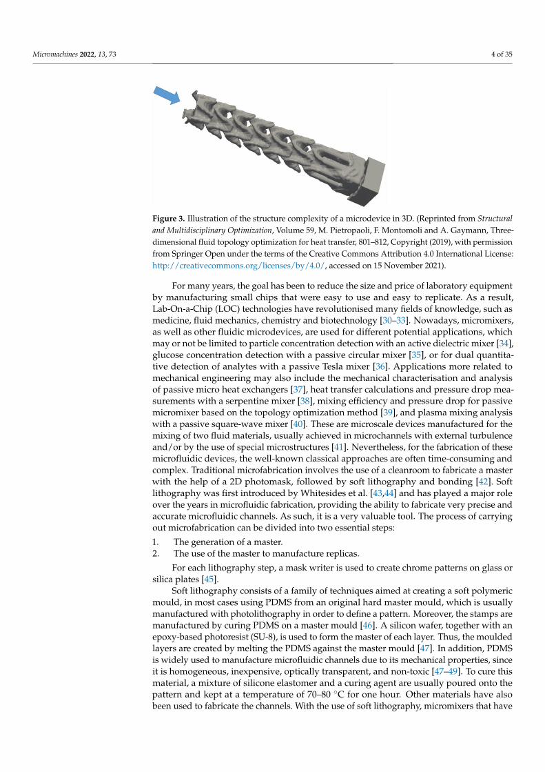
According to the American Society for Testing and Materials (ASTM) [17], the availableAM technologies are classified into seven categories (Table 1), such that each category isdeveloped under different processes [18,19]. All these processes share a common factor: theprinciple used of the modelling of layers. Moreover, depending on the type of technologyused, one type of material or another may be used, such as polymers, metals, ceramics, andcomposites [5]. In recent years, AM has proven to be of great interest to society, as it can beseen in the graph in Figure 1. The figure illustrates how the number of investigations using3D printing for microfluidic applications over the last few years has increased dramatically.However, in prototype microfabrication research, soft lithography is the most widely usedand well-known technique [20], because it has enabled studies with low infrastructure costsand some ease of fabrication. Nevertheless, 3D printers capable of producing structures froma few microns to several centimetres are starting to stay one step ahead of soft lithography,because these printers have the ability to print in different materials with different properties.In addition, 3D printers offer the possibility to print a microfluidic micromixers in minutesand then make a model quickly and test its performance. For this reason, AM coupledwith 3D printing has radically changed the way in which microdevices are manufactured.Figures 2 and 3 show different designs of mixers for mass/heat exchange, and the complexityof their channels can be observed. Due to the complex shapes, AM is a relevant technologyfor their development, being often the only possibility.
Microfluidic devices offer a wide range of different applications, especially in bothindustrial and healthcare fields [21]. They comprise the science and technology of systemsthat handle and control small quantities of fluids. To perform their function, they make useof microscale structures [22]. There have been numerous investigations focused on usingmicrofluidic devices fabricated by soft lithography, by using polydimethylsiloxane (PDMS)material, and even by micromoulding and injection moulding [23–26]. Soft lithography,however, is only capable of producing microdevices in 2.5D, so microscale parts to be used in3D microfluidic applications are difficult to manufacture [27]. However, 3D printing offersmany advantages over the aforementioned techniques. This is because the manufacturingof the model is done in a single step [28], so models can be manufactured with differentmaterials which have different properties, depending on the potential application. In addi-tion, this more rapid prototyping leads to a decrease in manufacturing time and also the fastintegration capability of the manufactured products designs’ life cycles [29].

Micromachines 2022, 13, 73 3 of 35
Table 1. Classification of 3D printing technologies according to the ASTM [17].
Categories Technologies Materials
Binder jetting 3D printing Metal, Polymer,Ceramic, Sand
Direct energy deposition Laser Engineered Net Shaping, Metal powder:Electron Beam Additive Manufacture steel, titanium, ...
Material extrusion Fused Deposition Modeling, Polymer, Hydrogel,Direct Ink Writing Alloy, Pure metal
Material jetting Polyjet, Multijet, Photopolymer, Wax,NanoParticle Jetting Metal, Ceramic
Powder bed fusion
Selective Laser Sintering, Selective LaserMelting, Direct Metal Laser Metal, Polymer,
Sintering, Electron Beam Melting, CeramicSelective Heat Sintering
Sheet lamination Ultrasonic Consolidation, Hybrids, Metal,Laminated Object Manufactured Ceramic
Vat photopolymerization
Stereolithography, Digital Light Processing,Liquid Crystal Display, Photopolymer,
Continuous Liquid Interface Production, CeramicTwo-Photon Polymerization
2001
2002
2003
2004
2005
2006
2007
2008
2009
2010
2011
2012
2013
2014
2015
2016
2017
2018
2019
2020
Year
0
200
400
600
800
1000
1200
1400
1600
Pu
blica
tio
ns
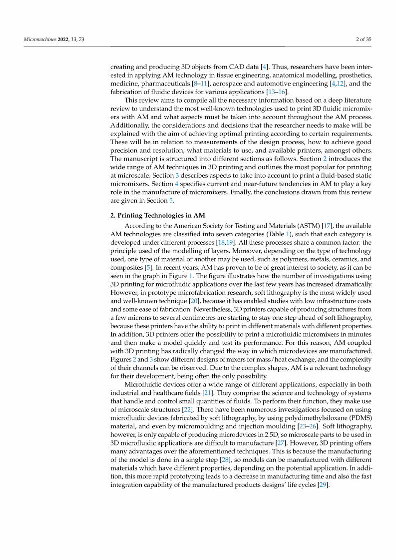
Figure 1. Publication trends. The bar graph shows the total number of publications per year from 2001to 2020 (in Google Scholar: https://scholar.google.com/, accessed on 26 July 2021) with keywords:“3D printing”, “microfluidic” and “additive manufacturing”.
(a) (b)
Figure 2. (a,b) Illustration of the structure complexity of different microdevices. (Reprinted fromChemical Physics Letters, Volume 734, Yao Chen and Xueye Chen, An improved design for passivemicromixer based on topology optimization method, 136706, Copyright (2019), with permissionfrom Elsevier).
Micromachines 2022, 13, 73 4 of 35
Figure 3. Illustration of the structure complexity of a microdevice in 3D. (Reprinted from Structuraland Multidisciplinary Optimization, Volume 59, M. Pietropaoli, F. Montomoli and A. Gaymann, Three-dimensional fluid topology optimization for heat transfer, 801–812, Copyright (2019), with permissionfrom Springer Open under the terms of the Creative Commons Attribution 4.0 International License:http://creativecommons.org/licenses/by/4.0/, accessed on 15 November 2021).
For many years, the goal has been to reduce the size and price of laboratory equipmentby manufacturing small chips that were easy to use and easy to replicate. As a result,Lab-On-a-Chip (LOC) technologies have revolutionised many fields of knowledge, such asmedicine, fluid mechanics, chemistry and biotechnology [30–33]. Nowadays, micromixers,as well as other fluidic microdevices, are used for different potential applications, whichmay or not be limited to particle concentration detection with an active dielectric mixer [34],glucose concentration detection with a passive circular mixer [35], or for dual quantita-tive detection of analytes with a passive Tesla mixer [36]. Applications more related tomechanical engineering may also include the mechanical characterisation and analysisof passive micro heat exchangers [37], heat transfer calculations and pressure drop mea-surements with a serpentine mixer [38], mixing efficiency and pressure drop for passivemicromixer based on the topology optimization method [39], and plasma mixing analysiswith a passive square-wave mixer [40]. These are microscale devices manufactured for themixing of two fluid materials, usually achieved in microchannels with external turbulenceand/or by the use of special microstructures [41]. Nevertheless, for the fabrication of thesemicrofluidic devices, the well-known classical approaches are often time-consuming andcomplex. Traditional microfabrication involves the use of a cleanroom to fabricate a masterwith the help of a 2D photomask, followed by soft lithography and bonding [42]. Softlithography was first introduced by Whitesides et al. [43,44] and has played a major roleover the years in microfluidic fabrication, providing the ability to fabricate very precise andaccurate microfluidic channels. As such, it is a very valuable tool. The process of carryingout microfabrication can be divided into two essential steps:
1. The generation of a master.2. The use of the master to manufacture replicas.
For each lithography step, a mask writer is used to create chrome patterns on glass orsilica plates [45].
Soft lithography consists of a family of techniques aimed at creating a soft polymericmould, in most cases using PDMS from an original hard master mould, which is usuallymanufactured with photolithography in order to define a pattern. Moreover, the stamps aremanufactured by curing PDMS on a master mould [46]. A silicon wafer, together with anepoxy-based photoresist (SU-8), is used to form the master of each layer. Thus, the mouldedlayers are created by melting the PDMS against the master mould [47]. In addition, PDMSis widely used to manufacture microfluidic channels due to its mechanical properties, sinceit is homogeneous, inexpensive, optically transparent, and non-toxic [47–49]. To cure thismaterial, a mixture of silicone elastomer and a curing agent are usually poured onto thepattern and kept at a temperature of 70–80 ◦C for one hour. Other materials have alsobeen used to fabricate the channels. With the use of soft lithography, micromixers that have
Micromachines 2022, 13, 73 5 of 35
structures lower than 10 nm in size can be manufactured [50]. Nevertheless, the need forexperienced staff and the mechanical properties that the microdevices experience duringtheir lifespan have limited the use of other materials [20].
It should be noted that a device will be considered readily manufacturable when itcan be brought to market not only at low cost (meaning with cost such that including theincurred costs in terms of resources up to its final manufacture) but also when the manufac-turing process is relatively fast and does not require investing in prohibitive technology orexpensive handling [51]. However, it is difficult to achieve the above by making use of softlithography, as there are obstacles that have made this technique less marketable:
• Many manual steps are needed to obtain the PDMS mould, making it difficult to fullyautomate the whole process.
• Chip inputs and outputs are prone to leakage and are not easy to connect [49,51].• Control systems involve engineering skills and equipment that are not present in all
laboratories.
This process includes various steps, in which labour-intensive processes are needed,making it difficult to rapidly innovate and these are crucial for new applications. Thesetypes of difficulties are found in each iteration of the manufacturing process, which requirefor instance printing a new photomask and lithography to produce a new master [52]. Dueto this, in order to maximize manufacturing and minimize the total cost of the developmentof a micromixer, AM is leading new technological advances in this field [51].
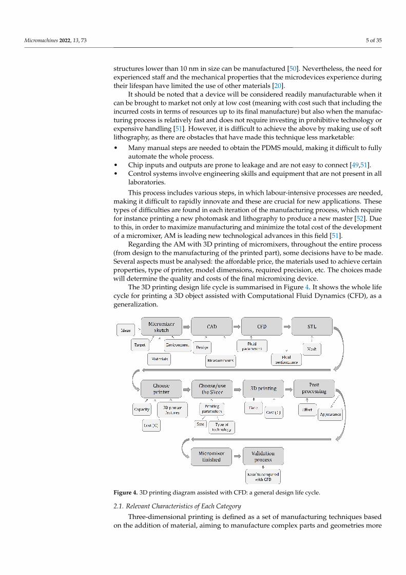
Regarding the AM with 3D printing of micromixers, throughout the entire process(from design to the manufacturing of the printed part), some decisions have to be made.Several aspects must be analysed: the affordable price, the materials used to achieve certainproperties, type of printer, model dimensions, required precision, etc. The choices madewill determine the quality and costs of the final micromixing device.
The 3D printing design life cycle is summarised in Figure 4. It shows the whole lifecycle for printing a 3D object assisted with Computational Fluid Dynamics (CFD), as ageneralization.
Figure 4. 3D printing diagram assisted with CFD: a general design life cycle.
2.1. Relevant Characteristics of Each Category
Three-dimensional printing is defined as a set of manufacturing techniques basedon the addition of material, aiming to manufacture complex parts and geometries more
Micromachines 2022, 13, 73 6 of 35
effectively and optimally than traditional methods. However, not all 3D printing tech-niques are suitable for the proper fabrication of microfluidic devices, such as micromixers.Nowadays, world-leading industrial countries are promoting 3D printing or AM as thetechnological basis for the manufacturing of the future, as the emergence of new materialsand technological advances with AM has made it possible to manufacture 3D componentspreviously unthinkable [4], developing printers that even allow the printing of severalmaterials at the same time (multi-material) [53].
Despite new developments, as shown in Table 1, seven AM categories are currentlycommercially available on the market, each one with its own advantages and limitations,depending on the technology chosen and its corresponding purpose. In recent years,technological advances have helped AM to improve the ability to fabricate microfluidicdevices [54,55]. Nowadays, microfluidic devices can be printed in a single step. In thisway, AM replaces traditional cleanroom steps, making manufacturing more efficient andreducing costs. This facilitates rapid prototyping, making microfluidic technology moreaccessible for research in a variety of applications. In addition, innovation is sped up [56].
Within the above-mentioned categories, the most widely used technologies in themicrofluidic field to print micromixers, so far, are the ones discussed in this review. Thesetechnologies belong to five different categories: material extrusion, vat photopolymeriza-tion, material jetting, powder bed fusion and binder jetting, as shown in Figure 5.
Figure 5. Five 3D printing categories with their respective technologies.
2.1.1. Material Extrusion
In the late 1980s, Scott Crump invented the Fused Deposition Modelling (FDM) as amaterial extrusion technique [57]. This method was patented in 1989 [58], and it startedto be commercialised in the early 1990s by Stratasys [59], which is a world leader inFDM technology and the leading manufacturer of industrial FDM systems. Stratasys wasfounded by Crump [60] and their wife, and due to the expiration of Crump’s patent, thediffusion of this technology boomed through the development of a wide variety of low-costFDM machines [61,62].
For unfamiliar readers, FDM consists of extruding a molten filament of polymericmaterial to be deposited afterwards. The material used in the FDM process is a filament ofpolymeric material that is softened and melted with the help of heat and then extruded.The filament is pushed and fed through a nozzle with a specific small diameter and thendeposited layer by layer on the printing bed [63]. The filament has a standard diameter,which can be either 1.75 mm or 2.85 mm, and is supplied on spools. The most commonFDM printers have a standard Cartesian structure and an extrusion head. The filament isunwound from the spool with the help of a motor and a set of gears, knurled pulleys, andclamping screws that press and drive the filament in order to push it through a guide tube
Micromachines 2022, 13, 73 7 of 35
into the extrusion head. This process is performed as more material is needed to continuethe construction of the 3D part. The extrusion head can have several extruders, each ofthem with a chamber that is heated, thus achieving the objective of softening the filamentinside up to a certain viscosity, and then passing through the nozzle when pressure isapplied [4]. The nozzle is interchangeable and also has standard-size diameters, which canvary from 0.3 mm to 0.6 mm, depending on the machine and/or the chosen manufacturingcompany [64,65]. It should be noted that the gap between the nozzle and the printer bedalso corresponds to the thickness of the build layer, which is a factor to be taken intoaccount when performing the calibration process before starting to print a part, as it is veryimportant to establish the correct nozzle height and level the bed [66,67].
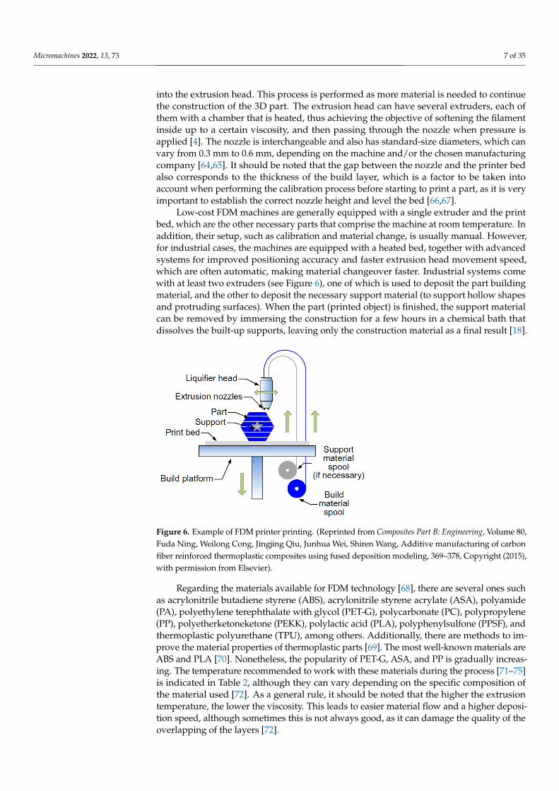
Low-cost FDM machines are generally equipped with a single extruder and the printbed, which are the other necessary parts that comprise the machine at room temperature. Inaddition, their setup, such as calibration and material change, is usually manual. However,for industrial cases, the machines are equipped with a heated bed, together with advancedsystems for improved positioning accuracy and faster extrusion head movement speed,which are often automatic, making material changeover faster. Industrial systems comewith at least two extruders (see Figure 6), one of which is used to deposit the part buildingmaterial, and the other to deposit the necessary support material (to support hollow shapesand protruding surfaces). When the part (printed object) is finished, the support materialcan be removed by immersing the construction for a few hours in a chemical bath thatdissolves the built-up supports, leaving only the construction material as a final result [18].
Figure 6. Example of FDM printer printing. (Reprinted from Composites Part B: Engineering, Volume 80,Fuda Ning, Weilong Cong, Jingjing Qiu, Junhua Wei, Shiren Wang, Additive manufacturing of carbonfiber reinforced thermoplastic composites using fused deposition modeling, 369–378, Copyright (2015),with permission from Elsevier).
Regarding the materials available for FDM technology [68], there are several ones suchas acrylonitrile butadiene styrene (ABS), acrylonitrile styrene acrylate (ASA), polyamide(PA), polyethylene terephthalate with glycol (PET-G), polycarbonate (PC), polypropylene(PP), polyetherketoneketone (PEKK), polylactic acid (PLA), polyphenylsulfone (PPSF), andthermoplastic polyurethane (TPU), among others. Additionally, there are methods to im-prove the material properties of thermoplastic parts [69]. The most well-known materials areABS and PLA [70]. Nonetheless, the popularity of PET-G, ASA, and PP is gradually increas-ing. The temperature recommended to work with these materials during the process [71–75]is indicated in Table 2, although they can vary depending on the specific composition ofthe material used [72]. As a general rule, it should be noted that the higher the extrusiontemperature, the lower the viscosity. This leads to easier material flow and a higher deposi-tion speed, although sometimes this is not always good, as it can damage the quality of theoverlapping of the layers [72].
Micromachines 2022, 13, 73 8 of 35
Table 2. Temperatures for the processing of the common FDM materials.
Materials Bed Temperature [ºC] Extrusion Temperature [ºC]
PLA 60–90 175–220ABS 80–100 230–260PET-G 50–80 220–260ASA 90–110 250–280PP 60–110 220–260
The surface roughness of FDM-fabricated parts can be profoundly affected by layerheight, shape of the piece, and surface curvature with respect to the build orientation [76–79].The ideal layer thickness will depend on the piece to be printed and its future application.For example, if the aim is to manufacture large parts and the final quality is not a priority, thechoice will be to choose thick layers, and consequently the printing time will be shorter [80,81].
One of the great advantages of FDM technology is that it is one of the few AM technolo-gies that allows the manufacture of parts with different materials in a single constructionprocess through the use of more than one extruder [82,83]. This can be done with the useof an extruder containing soluble material to place supports that allow the manufacture ofjoint parts that have relative movement to form a system or assembly. This provides thecorrect tolerances and appropriate clearances to the coupled parts in the CAD model [84].Moreover, the quality of the final result will depend on the orientation and layer thicknesschosen for printing the CAD model, as well as its size [85,86].
The price of FDM machines can be less than EUR 1000, some being somewhat rudi-mentary but very affordable at EUR 90 or EUR 120, but, if the user desires to work withmachinery for an industrial system with a working volume of half a cubic metre, which alsooffers a much higher quality, precision and accuracy, the price of FDM machines could exceedEUR 20,000 [87,88]. On the contrary, the commercial price of FDM materials is generallylower [89–91] than the price of materials used in other printing techniques. In addition, it isobvious that the expected price can vary depending on whether a specific composition orcertain properties desired, for instance, if the required printing material is translucent.
In conclusion, FDM technology can be summarised as having the following advantages(+) and drawbacks (−):
+ FDM technology is the most cost-effective method when it comes to manufacturingcustomised thermoplastic parts and prototypes.
+ Manufacturing times are usually short.+ There is a wide range of materials available, which are suitable for both industrial
prototypes and some non-commercial functional applications.− It has the lowest dimensional accuracy and resolution compared to other 3D printing
technologies, so it is not suitable for parts with complex details. However, its cost islower in comparison to other available technologies. It is used for products wheredetails are not so important.
− Printed parts will have layer lines that will be visible, hence, if a smooth finish is de-sired, the piece will require a post-processing [92]. In addition, the bonding mechanismof the layers will make the parts inherently anisotropic. Therefore, this technology isnot recommended for manufacturing parts that will be used as mechanically criticalcomponents.
Since 2009, this technology has had a great boom due to the expiration of a patent thatboosted a significant increase in the use of this technology in industry, as for instance in theconsumer market [93].
2.1.2. Vat Photopolymerization
Following the development of photopolymers around 1960, Charles Hull began toinvestigate materials that were UV-cured by exposing them to a scanning laser, which wassimilar to the system currently used in laser printers. At the begining of the decade of the
Micromachines 2022, 13, 73 9 of 35
1980, he found out that he could produce solid polymer patterns, and more importantly, hediscovered that, by curing one layer on top of another, a solid 3D object could be producedwithin a few hours. This discovery led to the stereolithography (SLA/SL). He registered apatent, and when it was granted, he put the first stereolithography device on the market,together with the company called 3D Systems [94,95]. The term “stereolithography” wasdefined as a method for manufacturing solid objects by successively printing thin layers ofa curable material using ultraviolet (UV) laser irradiation [96]. Regarding the stereolithog-raphy process, a platform located inside a tank containing the photopolymer moves thesolid part downwards and the laser traces the next layer of uncured photopolymer. Thisprocess is called polymerization and is carried out until all the layers are finished formingthe complete structure of the piece [97]. Stereolithography and other related processes areencompassed by the term “vat photopolymerization”.
The vat photopolymerization can be divided into two different process configurationsthat will determine how the printer works, plus an additional one that has attracted someresearch interest [94]:
• Vector/spot scanning: typical of SLA printers.• Layer projection: irradiate entire layers.• Two-photon approaches: high-resolution point-by-point approaches.
As mentioned above, vat photopolymerization is the term used to refer to a range of3D printing technologies that work with laser or light that can come from different sources,to cure a polymer or polymerize a resin [98]. These technologies in the production of devicesare characterised by their manufacturing process. The process they use is based on theconversion of liquid to solid, using computer spatially controlled photopolymerization tocreate solid objects from a vat of liquid resins under light irradiation [99]. The differentresins used can have different light absorption spectra, and they have different penetrationdepths. Therefore, the same exposure parameters may lead to different results when usingnon-identical resins, and completely different structural behaviours may be observed [100].The most common vat photopolymerization processes are stereolithography (SLA), digitallight processing (DLP), liquid crystal display (LCD), continuous light interface production(CLIP), and two-photon polymerization (2PP).
The main differences amongst these vat photopolymerization technologies are asfollows:
• SLA works with the light source of a laser beam. It is the most commonly used amongthe vat photopolmerization technologies. The laser can be located under or above theresin tank, and if the laser is located under the tank, this technology provides betterresults for small build volumes [101].
• DLP works with the light source of a digital light projector. DLP is similar to SLA,but the printing speed is faster due to the use of the projector, which cures each layersequentially. This technology can make use of a Digital Micromirror Device (DMD)for the illumination [100], making it possible to rotate in a rapid way and reflect light.
• LCD works with Light-Emitting Diodes (LED). This technique is also called DaylightPolymer Printing (DPP), since it uses unmodified LCD screens and a daylight polymer.The main difference with DLP lies in the imaging system, because of the fact that thistechnology uses a liquid crystal display, which prevents light from passing through.Thus, the resolution of the liquid crystal display is very high; however, the accuracyof LCD is lower than that of DLP [102]. It is also faster than SLA technology.
• CLIP works with LEDs and oxygen. Thanks to the continuous liquid interface produc-tion method, this technology increases the printing speed and the resolution [103]. Itworks similarly to DLP. It has a “dead zone” to prevent the adhesion of the piece tothe window, and this region is located between an oxygen permeable window andthe curing part surface, which targets the inhibition of free radical photopolymeriza-tion [104,105].
• 2PP works with the light source of a titanium sapphire femtosecond laser. This methodaims to achieve a resolution below the diffraction limit [106]. The fabrication process
Micromachines 2022, 13, 73 10 of 35
is defined by an objective lens focusing the laser onto the photosensitive resin [107],and inside the resin, the polymerization process takes place [108]. It is widely used insystems where there is a need to use nano and micro elements [109], because it has asubdiffraction-limit resolution down to 100 nm [110].
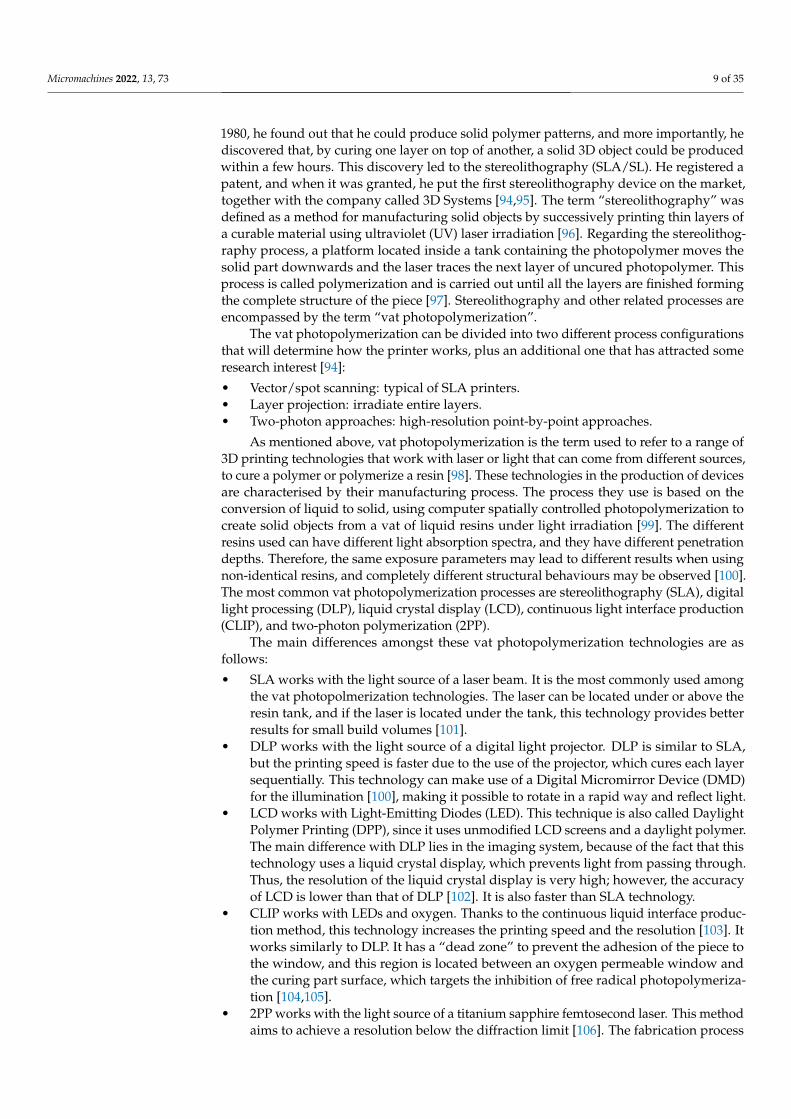
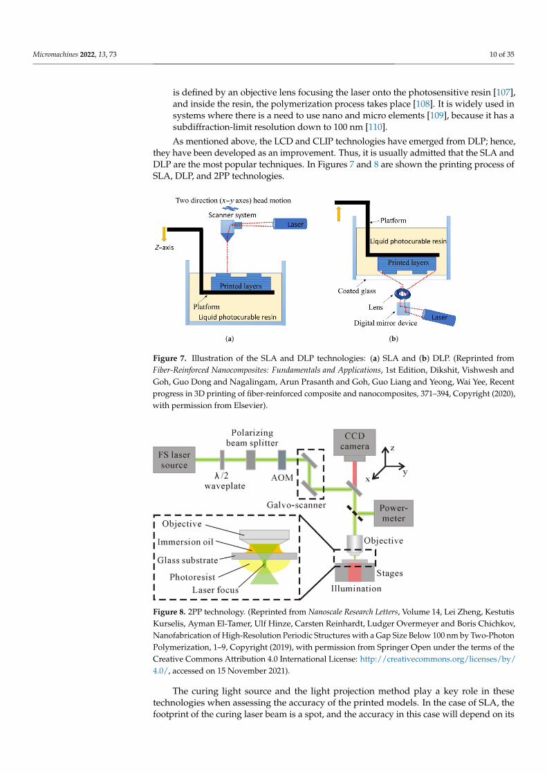
As mentioned above, the LCD and CLIP technologies have emerged from DLP; hence,they have been developed as an improvement. Thus, it is usually admitted that the SLA andDLP are the most popular techniques. In Figures 7 and 8 are shown the printing process ofSLA, DLP, and 2PP technologies.
(a) (b)
Figure 7. Illustration of the SLA and DLP technologies: (a) SLA and (b) DLP. (Reprinted fromFiber-Reinforced Nanocomposites: Fundamentals and Applications, 1st Edition, Dikshit, Vishwesh andGoh, Guo Dong and Nagalingam, Arun Prasanth and Goh, Guo Liang and Yeong, Wai Yee, Recentprogress in 3D printing of fiber-reinforced composite and nanocomposites, 371–394, Copyright (2020),with permission from Elsevier).
Figure 8. 2PP technology. (Reprinted from Nanoscale Research Letters, Volume 14, Lei Zheng, KestutisKurselis, Ayman El-Tamer, Ulf Hinze, Carsten Reinhardt, Ludger Overmeyer and Boris Chichkov,Nanofabrication of High-Resolution Periodic Structures with a Gap Size Below 100 nm by Two-PhotonPolymerization, 1–9, Copyright (2019), with permission from Springer Open under the terms of theCreative Commons Attribution 4.0 International License: http://creativecommons.org/licenses/by/4.0/, accessed on 15 November 2021).
The curing light source and the light projection method play a key role in thesetechnologies when assessing the accuracy of the printed models. In the case of SLA, thefootprint of the curing laser beam is a spot, and the accuracy in this case will depend on its
Micromachines 2022, 13, 73 11 of 35
diameter. However, for DLP, LCD, and CLIP, the accuracy is provided by the pixel matrix,which is given by the resolution of the digital projector employed in these technologies [111].Therefore, DLP, LCD, and CLIP technologies produce parts with lower accuracy than SLA.Thus, it can be seen that SLA technology can deliver higher accuracy but with longerproduction times. In addition, CLIP technology provides more accuracy than DLP [112], aswas mentioned above, thanks to the continuous motion of its platform and the existenceof the dead zone [113]. In micro-stereolithography technology, the conditions that areconsidered to be of greatest importance are the laser power, scanning speed, and exposuretime [114]. They will influence the curing time and printing resolution [115].
If high precision and resolution are required, the most recommended technologyis SLA printing, as it enables the fabrication of complex internal structures in detail. Inaddition, it has the ability to produce a larger number of objects in an estimated time frame.The advantages (+) and disadvantages (−) of said vat photopolymerization technologiesare those specified below:
• SLA:
+ It is able to print large models with a high accuracy and surface finish.+ The printing size is not limited.− High elapsed times.
• DLP:
+ Higher print speed in comparison to SLA.+ Lower cost (low price) of printers.+ Very good precision.− High cost of materials.− The projection size is limited.
• LCD:
+ Lower cost (low price) of printers.+ Good resolution.− Short lifespan.− The intensity of the light is weak.− The liquid tank must be cleaned regularly (requires continuous maintenance).
• CLIP:
+ Higher print speed in comparison to DLP.− To achieve rapid printing, a low viscosity resin and a hollow model are necessary.− Efficiency is not high.− The use of the permeable oxygen membrane is expensive.
• 2PP:
+ It provides a high spatial resolution.+ The laser is able to penetrate deeply into the material.− Expensive (price) printers.− Limited building area.− Errors in voxels affect the accuracy.− Low building speed.
After the curing process, the printed objects can be stable, hard, and even elastic, beingable to withstand very low and high temperatures. This is because, depending on the typeof chosen resin, the object will have different mechanical and chemical properties, whichwill make it suitable for specific applications. In general, photopolymer materials can bestandard, structural, strong and durable, flexible, and elastic. Despite this, the standardresins that are commonly used have not been manufactured to meet certain specificationsthat are necessary in the engineering world, as others have, and the most common coloursare black, grey, white, and transparent [116]. In addition, within the resins that encompassthe standard resins, there is a draft resin, which can cure faster than the conventionalone [117]. Durable resins are made of polyethylene (PE) or polypropylene (PP), which have
Micromachines 2022, 13, 73 12 of 35
high ductility and resistance to both deformation and impact. However, resins made withelastomeric polyurethane (EPU) provide elasticity and flexibility. Biocompatible resins arealso available, which must undergo cytotoxicity testing and biological evaluation to ensurethat they do not cause problems when they are in contact with the human body. Finally, ifceramic resin is desired, a photopolymer must be filled with silica [111].
One of the features that these technologies present is that many printing structures donot require any support material, since the unpolymerised material acts as support [118].However, the printers can use perforated support structures, which are easily removed whenthe print is finished [119], and they are used to prevent deflection or movement of the piececaused by the gravity and the printing [120]. When the printing is finished, a post-processingmust be carried out, and the first step is to remove the excess of resin by immersing thepiece in a bath of isopropanol, and then the mechanical removal of the support structuresis done. The last step of this post-processing will be to accomplish a final curing [121].Nevertheless, if it has been used a draft resin, this final curing is not necessary. It shouldbe noted that the materials used by these printers are not sealed, whereas the materials ofPolyjet printers are. Hence, prior to curing, these materials are slightly toxic, owing to thefact that manufacturers recommend taking protective measures, such as wearing gloves anda mask when handling these resins [120].
In relation to the printer prices depending on the technology chosen, LCD 3D printersuse components that are cheaper than other vat photopolymerization technologies, makingthem inexpensive resin 3D-printing solutions. This enables the user to have a wider rangeof manufacturers. Therefore, if the level of the resin 3D printer is for beginners, the LCDscreen will be a good choice. However, if highest accuracy is desired in terms of details andgood printing speeds, a professional DLP or SLA printer is recommended. In addition, if theobjective is nanoscale printing, the best technology will be 2PP, but its price is the highestone amongst these technologies. The price range of vat photopolymerization printers isfrom EUR 115 [122] to more than EUR 250,000 [123,124].
2.1.3. Material Jetting
Material Jetting (MJ) is a printing process included within AM, which is capable ofprinting on multiple materials during the same print job [125]. The method to create 3Dobjects is similar to a 2D jet printer (standard home/office printers) where the printingmaterial is ink. The creation of 3D models is accomplished through the use of movable inkjetprint heads. These heads inject a photopolymer onto a building platform. The photopolymeris injected by droplets that are selectively ejected as the heads move over the build area [126].In inkjet printers, the material is injected using the Drop On Demand (DOD) or ContinuousInk Jet (CIJ) process. In the case of CIJ, lower viscosity fluids are used at a higher drop speedthan in DOD, so it is often used when a high print speed is required. However, if higherprecision is desired, it is better to use DOD [127].
MJ processes allow the printing of multi-material and degraded material structures.The printheads include several separate nozzles to be fed with different materials and tobe controlled individually. The material, deposited initially as droplets in a liquid state,eventually solidifies. For this purpose, the most common method of carrying out this processis to cure the photopolymer ink with UV light, with each photopolymer layer being curedimmediately after it has been injected, resulting in fully cured multi-material 3D parts [97].
There are several factors that can affect the quality of MJ, one of which is the shape ofthe deposited droplet, as this can affect resolution, precision, and even accuracy. Anotherfactor is that, in order to get a correct print head sweep speed, the droplet splash and jettingfrequency must be coordinated. Moreover, certain conditions must be taken into accountfor 3D printing with MJ [128–130]:
• Jetting parameters: frequency, magnitude, and width of the signal.• Ink properties: surface tension and viscosity.• Environment: pressure, humidity, and temperature.
Micromachines 2022, 13, 73 13 of 35
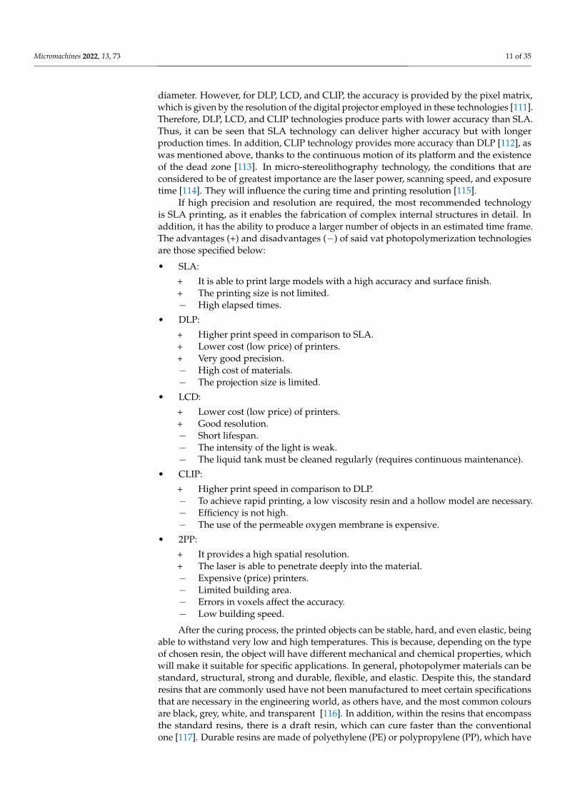
Thanks to the use of this technology, it is possible to obtain 3D models or objects ofdifferent colours and hardnesses, with different properties and characteristics obtainedwithin the same manufactured device [131–133]. During the manufacturing of these parts,it is necessary to use construction and support materials [132,134], although the latter maybe removed. This action belongs to the post-processing and can be done manually (a fewat the beginning, if it is possible) with the help of a water jet or by means of a chemicalbath [135–137]. As with other AM technologies, the support material is not part of the finalresult, but it is necessary to use it because the building material must be properly depositedin voids or overhanging areas; see Figure 9. Furthermore, in MJ, the support material is adense structure, and, most of the time, the amount of support material used is almost equalto the amount of building material, which makes this technology more expensive thanother AM technologies [96]. MJ enables the manufacturing of parts with high resolution of10–30 µm in layer thickness; hence, individual layers are not very visible [96,97,134] andare 42 µm in-plane [138].
(a) (b)
Figure 9. Examples of Polyjet and Multijet printers printing: (a) Polyjet and (b) Multijet. (Reprintedimages from Korean Journal of Radiology, Volume 17, Kim, Guk Bae and Lee, Sangwook and Kim, Haekangand Yang, Dong Hyun and Kim, Young-Hak and Kyung, Yoon Soo and Kim, Choung-Soo and Choi, SeHoon and Kim, Bum Joon and Ha, Hojin and others, Three-Dimensional Printing: Basic Principles andApplications in Medicine and Radiology, 182–197, Copyright (2016), with permission from The KoreanSociety of Radiology under the terms of the Creative Commons Attribution Non-Commercial License:http://creativecommons.org/licenses/by-nc/3.0, accessed on 15 November 2021).
The knowledge of the benefits provided by lithographic methods together with thoseobtained from MJ have led to the emergence of two major technologies that combine allthese advantages: Polyjet and Multijet [97]. Both technologies are very similar; however,by analysing the post-processing, a remarkable difference can be found between Polyjetand Multijet. While Polyjet technology uses a photocurable material as support material,Multijet uses a wax. Due to this difference, the removal process of the support materialdiffers between these two technologies [139]. Polyjet post-processing is shorter and simplerthan that of Multijet [140].
The principal advantages (+) and disadvantages (−) of MJ technologies are:
+ Capability of printing multi-material in different colours and gradient structures.+ Printers are able to build large structures with complex shapes and smooth finishes.+ It provides high resolution: it is an attractive technology for microfluidic applications.+ Polyjet printers are user-friendly.− Printed devices need some post-processing.− Ink deposition time is short, so several requirements in relation to viscosity and surface
tension must be taken into account.− Printers are expensive and proprietary.
Micromachines 2022, 13, 73 14 of 35
Another type of MJ printing technology is NanoParticle Jetting (NPJ), a technologydeveloped by XJet [141]. It uses metal or ceramic powder suspensions to build parts. UnlikePolyjet or Multijet, NPJ injects a liquid containing the nanoparticles of the material atthe same time as the support material. With NPJ, high and superfine detail parts can bemanufactured. This is accomplished in a heated bed; thus, particles adhere in all directionsbecause of the evaporation of the liquid injected [141,142]. Additionally, the removal ofthe support material is effortless [143]. The greatest disadvantage of this technology is thehigh cost, which is more than EUR 250,000 [144]. Prices of Polyjet and Multijet technologiesvary more: there are printers that are cheaper than those for NPJ. Nevertheless, they areexpensive compared to aforementioned 3D categories in previous subsections, as pricesrange from EUR 19,000 [145] to more than EUR 250,000 [146].
2.1.4. Powder Bed Fusion
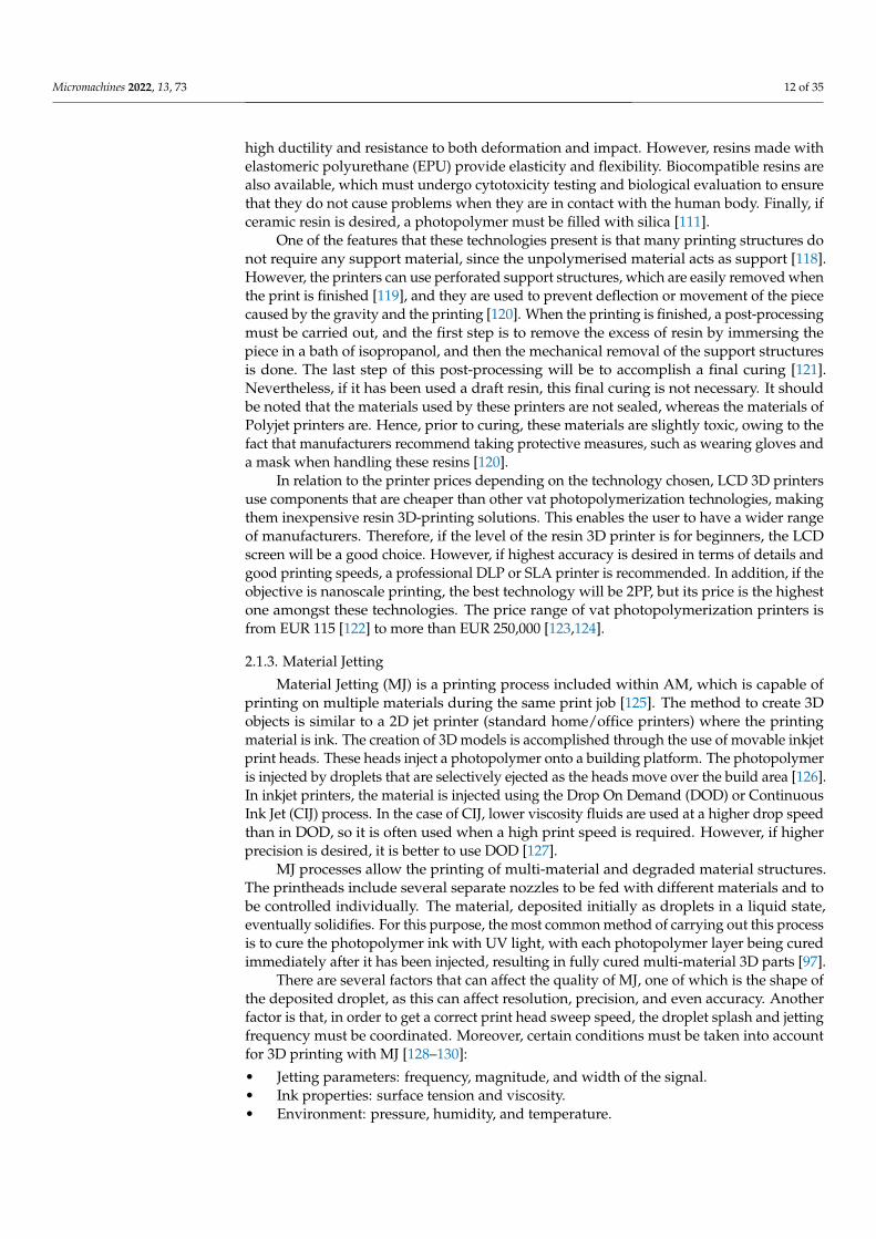
Powder Bed Fusion (PBF) encompasses a set of technologies that can be used for themanufacture of parts based on the concept of layer-by-layer addition [147]. In order to carryout the manufacturing process, lasers or electron beams are used as thermal energy sourcesfor irradiation, fusion, and melting of powder particles [148]; see Figure 10. The materialspopularly used in PBF printing processes are polymer [149] and metal powders [150].
Figure 10. Illustration of the general PBF printing process. (Reprinted from Metals, Volume 9, Long Bai,Cheng Gong, Xiaohong Chen, Yuanxi Sun, Junfang Zhang, Lecai Cai, Shengyan Zhu and Sheng QuanXie, Additive Manufacturing of Customized Metallic Orthopedic Implants: Materials, Structures, andSurface Modifications, 1004, Copyright (2019), with permission from Metals, MDPI, Basel, Switzerland,under the terms of the Creative Commons Attribution License: http://creativecommons.org/licenses/by/4.0/, accessed on 15 November 2021).
In 1984, Carl Deckard, a student at the University of Texas, invented the first PBFtechnique, the Selective Laser Sintering (SLS) [151]. Deckard developed a machine thatcould create solid entities by fusing powder particles with the use of a powerful laser. Thiswork was carried out under the supervision of Professor Beaman [152], and the technologywas patented in 1990 [153]. Furthermore, the patent specified that the laser used would beless expensive than the CO2 laser [151]. Following this, the other PBF technologies wereinvented: selective laser melting (SLM), direct metal laser sintering (DMLS), selective heatsintering (SHS) and electron beam melting (EBM). The characteristics of each technologyare specified as follows.
SLS is usually associated with polymer laser sintering. The powder is spread on theplatform with the help of the roller mechanism when the piston moves upwards. The laserbeam scans the powders selectively to synthesise the powder particles. In this way, thefirst layer is formed. The building area of the part moves downwards (according to thedesired thickness), and the second layer is built on top of the already-synthesised firstlayer [154]. SLS technology provides an impression with a porous material recommended
Micromachines 2022, 13, 73 15 of 35
only for medical implants or non-wetted objects [155]. In the SLM, the manufacturingprocess is similar to the SLS one. When using metal powders or ceramics, SLM is usuallyapplied [156]. It provides excellent mechanical properties and good precision [157]. Themain difference between SLS and SLM is that SLS uses the laser to fuse small particles ofraw material to build a 3D part, whereas SLM completely melts the powdered material withthe laser, resulting in local melt pools, thus obtaining very dense parts (>99% density) [158].The DMLS procedure is similar to the SLM working process. A laser is used, which isdirectly exposed onto the metal powder during liquid phase sintering. Parts are createdby selectively melting thin layers with the use of the scanning laser beam [159]. SLM andDMLS differ in the powder bed temperature used to synthesise or melt the material [160].Regarding SHS, this AM technology uses a heated head (touching the powder) to melt theplastic powder particles [161]. Finally, in EBM, the source of thermal energy for fusing metalpowders is an electron beam [162]. Moreover, the electrons are emitted from a tungstenfilament that is heated at high speed [163].
Support structures are essential for proper building of the objects, especially in certainareas that are critical during printing process, such as overhang areas. Support structuresprovide greater geometric integrity and aid the component to bond better to the substratewhile layers are built up [164]. Nevertheless, the removal process of support structures canbe tedious [165].
The principal advantages (+) and drawbacks (−) of PBF technologies are:
+ Solvent-free process: the unsintered powder acts as support.+ SLS can produce 3D parts with high controlled porosity and high pore connectivity [166].+ The unsintered powder material can be recycled and reused.+ EBM provides better microstructural control.+ They can be used to manufacture complex parts with little effort.− A large quantity of powder is required to complete the printing process.− A post-processing process may be required.− The quality of metal parts printed with SLS is lower than that of parts printed with
EBM.− EBM technology is expensive because it requires vacuum operation.− High power usage is required.
The price of PBF printers is very high. A SLS printer containing a small printingarea (printing with thermoplastic polymer powder) can cost around 6000 € [167]. If a largeprinting area is necessary, then the price can go up to 444,000 € [168]. However, PBF printerscan be even more expensive if the material for printing is metal or alloy powder.
2.1.5. Binder Jetting
Binder Jetting (BJ), is an additive manufacturing process developed at the MassachusettsInstitute of Technology (MIT) during the 1990s [169], which was originally named Three-Dimensional Printing process (3DP) [170]. However, its commercialisation started in 2010 [171].The materials handled by BJ are metals, alloys, ceramics, and even sand and glass [172].Generally speaking, BJ employs two materials, the material from which the part is built (solidpowder material) and the material that is used as a binder (liquid material) that helps thepowder material to stick. In [173], a criterion is specified regarding what to pay attention towhen selecting the binder:
• How the powders interact with the binder, taking into account wettability and pene-tration.
• The amount of binder residue in the cleaning process.
In addition, some BJ printers contain nozzles that can print in colour, from a colorcartridge, allowing the production of multi-colour parts [4].
The 3DP concept that belongs to BJ can be compared to PBF, in which a laser meltspowder particles to gradually generate the layers of a part. The 3DP printing process consistsin spreading the material to build the part with the use of a roller to achieve a thin layer of

Micromachines 2022, 13, 73 16 of 35
powder material so that a layer of the binder material can then be deposited where needed(as dictated by the STL obtained from the CAD model). This process is repeated till thepart is complete[174]; see Figure 11. Nevertheless, in BJ printing processes, post-processingis performed after printing. This process can be related to curing, dust removal, or finishing,among others [172,175]. Post-processing is time-consuming, and a good example is that thepowder structure is not strong enough to be used directly, so it needs to be infiltrated bya resin in order to densify the matrix [176]. This infiltration provides an improvement incolour definition and mechanical behaviour [177].
Figure 11. Illustration of the general BJ printing process. (Reprinted from Additive Manufacturing,Volume 28, Mohsen Ziaee and Nathan B. Crane, Binder jetting: A review of process, materials, andmethods, 781–801, Copyright (2019), with permission from Elsevier).
The principal advantages (+) and disadvantages (−) of BJ technology are:
+ The process has a very high speed compared to others.+ It is able to process different kinds of materials.+ 3D objects can be made in different colours.+ With the two-material method, the printing can obtain different binder-powder com-
binations, as well as several mechanical properties.− It is high in cost.− It is not suitable for any structural parts because of the use of binder material.− The post-processing could considerably increase the time of the whole process.
During printing, the height of the powder bed along the z-axis determines the layerthickness. In the case of BJ, the thickness can be between 15 and 300 µm. Therefore, thelayer thickness is given by the desired resolution and ultimately by the powder size [178].It should be noted that BJ has lower mechanical properties than SLS and DMLS parts [179].However, BJ can manufacture complex lattice structures at much higher speeds [180].
As in PBF printers, the price of BJ printers is very high. The lowest price for a BJ printercan be around EUR 24,000 [181], and the highest price can be around EUR 500,000 [182].Depending on the brand, the size of the construction area, and the type of material to workwith, prices may also vary notably.
3. Important Features during the AM Process
AM has been a revolution in the field of fluid micromechanics, because it has managedto move away from the use of laborious techniques, such as soft lithography, which requiresprevious knowledge, several machines, expert manpower, many hours of work, and highinvestments of money for the correct manufacture of fluidic microdevices. Therefore,soft lithography lacks marketability due to the complexity of the whole process. The 3Dprinting technologies mentioned in the previous section, which include AM, proposean improvement in these disadvantages and offer machinery in different price rangesdepending on the desired objectives along with the manufacturing of fluidic micromixers.Table 3, shows a collection of some of the fluidic microdevices that have been manufacturedaccording to the literature.
Micromachines 2022, 13, 73 17 of 35
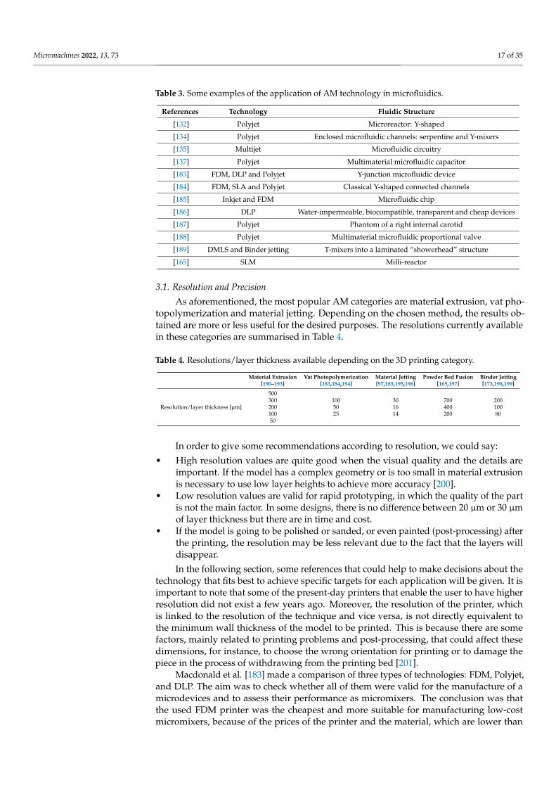
Table 3. Some examples of the application of AM technology in microfluidics.
References Technology Fluidic Structure
[132] Polyjet Microreactor: Y-shaped
[134] Polyjet Enclosed microfluidic channels: serpentine and Y-mixers
[135] Multijet Microfluidic circuitry
[137] Polyjet Multimaterial microfluidic capacitor
[183] FDM, DLP and Polyjet Y-junction microfluidic device
[184] FDM, SLA and Polyjet Classical Y-shaped connected channels
[185] Inkjet and FDM Microfluidic chip
[186] DLP Water-impermeable, biocompatible, transparent and cheap devices
[187] Polyjet Phantom of a right internal carotid
[188] Polyjet Multimaterial microfluidic proportional valve
[189] DMLS and Binder jetting T-mixers into a laminated “showerhead” structure
[165] SLM Milli-reactor
3.1. Resolution and Precision
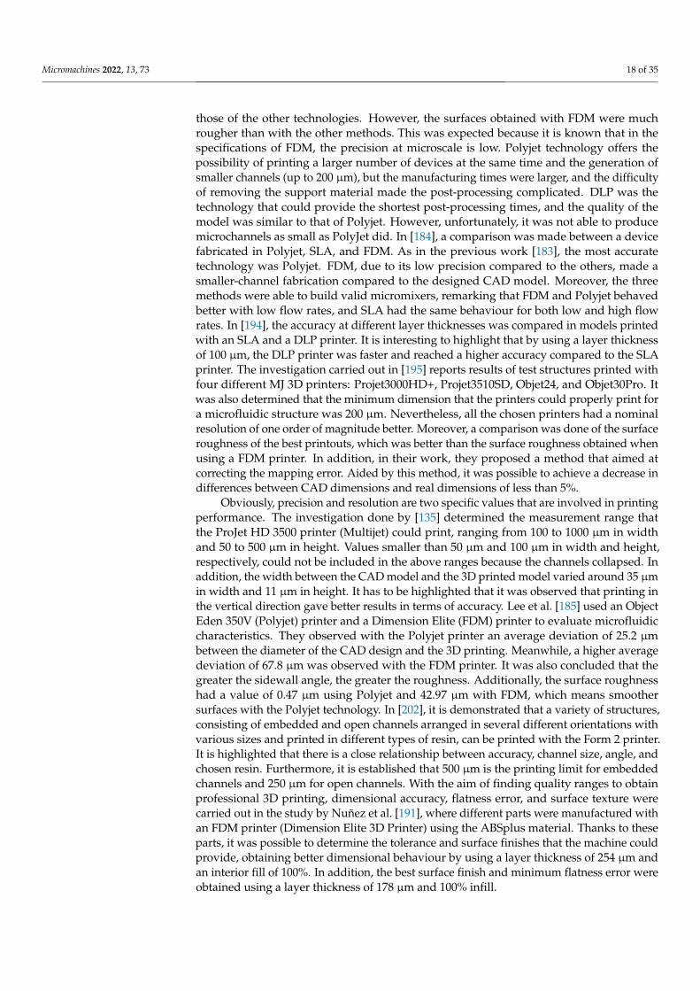
As aforementioned, the most popular AM categories are material extrusion, vat pho-topolymerization and material jetting. Depending on the chosen method, the results ob-tained are more or less useful for the desired purposes. The resolutions currently availablein these categories are summarised in Table 4.
Table 4. Resolutions/layer thickness available depending on the 3D printing category.
Material Extrusion Vat Photopolymerization Material Jetting Powder Bed Fusion Binder Jetting[190–193] [183,184,194] [97,183,195,196] [165,197] [173,198,199]
500300 100 30 700 200
Resolution/layer thickness [µm] 200 50 16 400 100100 25 14 200 8050
In order to give some recommendations according to resolution, we could say:
• High resolution values are quite good when the visual quality and the details areimportant. If the model has a complex geometry or is too small in material extrusionis necessary to use low layer heights to achieve more accuracy [200].
• Low resolution values are valid for rapid prototyping, in which the quality of the partis not the main factor. In some designs, there is no difference between 20 µm or 30 µmof layer thickness but there are in time and cost.
• If the model is going to be polished or sanded, or even painted (post-processing) afterthe printing, the resolution may be less relevant due to the fact that the layers willdisappear.
In the following section, some references that could help to make decisions about thetechnology that fits best to achieve specific targets for each application will be given. It isimportant to note that some of the present-day printers that enable the user to have higherresolution did not exist a few years ago. Moreover, the resolution of the printer, whichis linked to the resolution of the technique and vice versa, is not directly equivalent tothe minimum wall thickness of the model to be printed. This is because there are somefactors, mainly related to printing problems and post-processing, that could affect thesedimensions, for instance, to choose the wrong orientation for printing or to damage thepiece in the process of withdrawing from the printing bed [201].
Macdonald et al. [183] made a comparison of three types of technologies: FDM, Polyjet,and DLP. The aim was to check whether all of them were valid for the manufacture of amicrodevices and to assess their performance as micromixers. The conclusion was thatthe used FDM printer was the cheapest and more suitable for manufacturing low-costmicromixers, because of the prices of the printer and the material, which are lower than
Micromachines 2022, 13, 73 18 of 35
those of the other technologies. However, the surfaces obtained with FDM were muchrougher than with the other methods. This was expected because it is known that in thespecifications of FDM, the precision at microscale is low. Polyjet technology offers thepossibility of printing a larger number of devices at the same time and the generation ofsmaller channels (up to 200 µm), but the manufacturing times were larger, and the difficultyof removing the support material made the post-processing complicated. DLP was thetechnology that could provide the shortest post-processing times, and the quality of themodel was similar to that of Polyjet. However, unfortunately, it was not able to producemicrochannels as small as PolyJet did. In [184], a comparison was made between a devicefabricated in Polyjet, SLA, and FDM. As in the previous work [183], the most accuratetechnology was Polyjet. FDM, due to its low precision compared to the others, made asmaller-channel fabrication compared to the designed CAD model. Moreover, the threemethods were able to build valid micromixers, remarking that FDM and Polyjet behavedbetter with low flow rates, and SLA had the same behaviour for both low and high flowrates. In [194], the accuracy at different layer thicknesses was compared in models printedwith an SLA and a DLP printer. It is interesting to highlight that by using a layer thicknessof 100 µm, the DLP printer was faster and reached a higher accuracy compared to the SLAprinter. The investigation carried out in [195] reports results of test structures printed withfour different MJ 3D printers: Projet3000HD+, Projet3510SD, Objet24, and Objet30Pro. Itwas also determined that the minimum dimension that the printers could properly print fora microfluidic structure was 200 µm. Nevertheless, all the chosen printers had a nominalresolution of one order of magnitude better. Moreover, a comparison was done of the surfaceroughness of the best printouts, which was better than the surface roughness obtained whenusing a FDM printer. In addition, in their work, they proposed a method that aimed atcorrecting the mapping error. Aided by this method, it was possible to achieve a decrease indifferences between CAD dimensions and real dimensions of less than 5%.
Obviously, precision and resolution are two specific values that are involved in printingperformance. The investigation done by [135] determined the measurement range thatthe ProJet HD 3500 printer (Multijet) could print, ranging from 100 to 1000 µm in widthand 50 to 500 µm in height. Values smaller than 50 µm and 100 µm in width and height,respectively, could not be included in the above ranges because the channels collapsed. Inaddition, the width between the CAD model and the 3D printed model varied around 35 µmin width and 11 µm in height. It has to be highlighted that it was observed that printing inthe vertical direction gave better results in terms of accuracy. Lee et al. [185] used an ObjectEden 350V (Polyjet) printer and a Dimension Elite (FDM) printer to evaluate microfluidiccharacteristics. They observed with the Polyjet printer an average deviation of 25.2 µmbetween the diameter of the CAD design and the 3D printing. Meanwhile, a higher averagedeviation of 67.8 µm was observed with the FDM printer. It was also concluded that thegreater the sidewall angle, the greater the roughness. Additionally, the surface roughnesshad a value of 0.47 µm using Polyjet and 42.97 µm with FDM, which means smoothersurfaces with the Polyjet technology. In [202], it is demonstrated that a variety of structures,consisting of embedded and open channels arranged in several different orientations withvarious sizes and printed in different types of resin, can be printed with the Form 2 printer.It is highlighted that there is a close relationship between accuracy, channel size, angle, andchosen resin. Furthermore, it is established that 500 µm is the printing limit for embeddedchannels and 250 µm for open channels. With the aim of finding quality ranges to obtainprofessional 3D printing, dimensional accuracy, flatness error, and surface texture werecarried out in the study by Nuñez et al. [191], where different parts were manufactured withan FDM printer (Dimension Elite 3D Printer) using the ABSplus material. Thanks to theseparts, it was possible to determine the tolerance and surface finishes that the machine couldprovide, obtaining better dimensional behaviour by using a layer thickness of 254 µm andan interior fill of 100%. In addition, the best surface finish and minimum flatness error wereobtained using a layer thickness of 178 µm and 100% infill.
Micromachines 2022, 13, 73 19 of 35
In [197], it is specified that the ability to fabricate thin walls is crucial for the perfor-mance of heat exchangers. Therefore, the fabrication of thin walls using the EOS M 290printer is studied by PBF printing. The minimum wall thickness achieved was 100 µmin Ti-6Al-4V, Inconel 718 and AlSi10Mg. On the other hand, in [173] printing with BJ, re-searchers determined that a large particle size is beneficial for powder spreading. However,if the size is smaller, this is good for sinterability, and it has the advantage of improving theresolution and surface quality of the part.
3.2. Material
The used material is another important feature. In particular, the choice of the buildingmaterial will be of a great importance if it is necessary to visualize the fluid mixing in amicromixer. Despite choosing a transparent material, the ability to work well as a transparentmedium for fluid visualisation depends on the chosen technology and the desired surfacefinish. Device surfaces have to be smooth and free of defects, even with a transparent andcolorless material. On the contrary, a 3D model printed with rough surfaces will appeartranslucent [186]. Notwithstanding, the appearance of the devices could be enhanced bytreating devices during the post-processing stage [203], but when dealing with microdevices,this work can be cumbersome. One of the major limitations of all SLA printers is that theycannot use more than one printing material at a time. Thus, Choi et al. [204] developed aprinter model with SLA technology that provided the multi-material printing using fourdifferent resin baths. Nonetheless, the process was complex and inefficient, as each layerof each resin required multiple exposures. In relation to the process of the removal of thesupport material, since this may influence the final result; this is another important featureto take it into account when selecting a printing method. It can be done in different ways:
• Material extrusion provides two options to remove supports:
– Using a soluble support material [205]: an automated support-material process.– Breaking support material [85]: a manual process involving twisting, scrapping,
and breaking support material from the printed part—it is useful to have pliers.
• Vat photopolymerization uses less support material than the others. Support materialcan be easily removed with water jets [120].
• Material jetting has different possibilities depending on the selected printer [195]:
– Polyjet: use of a water jet to remove the support material.– Multijet: used to melt away support material at approximately 60 ◦C.
• Powder bed fusion uses support structures that, ideally, should be weak enough to beremoved easily with minimal effort for cutting, breaking, or machining [206] but stillprovide stability to the part during printing.
• Binder jetting does not need support structures, since the remaining loose powder inthe bed acts as support structure for the overhanging structures [207].
Moreover, the technologies associated with material extrusion do not always needto use support material. This depends on the design of the 3D model and on the modelorientation that has been established with the slicer software. It is the same with thevat photopolymerization category. On the contrary, material jetting always uses supportmaterial. Therefore, Polyjet technology always has costs related to processing of supportmaterial removal. Consequently, for 3D printing of micromixers, Polyjet printers havelimitations when manufacturing channels of a certain size, since the support materialused to deposit the desired construction material must be removed. Material removalcan be affected by the complex design of the micromixer model (right angles or evenserpentine channels) [187]. If support material is not removed entirety, blockages in thechannel can occur while the device is being tested [134]. Stratasys is a company that offersdifferent types of support material, although not all of them are compatible with all Polyjetprinters. However, amongst other options, it allows choosing a soluble support material,e.g., SUP706, when the printed model is introduced in a specific solution [137]. This avoids
Micromachines 2022, 13, 73 20 of 35
the risk of breaking certain delicate parts of the micromixer due to its size, instead of havingthe only option of using waterjets to remove the support material.
The aforementioned research has discussed printed microdevices in a single step touse them for different applications. Despite this, in [132], the authors tried to fabricate amicroreactor with Polyjet, but instead of fabricating it in a single step, it was done in twosteps, with one of the parts manufactured with a transparent material in order to ensurevisible control. The printing process was completed in three hours, significantly shorterthan the traditional approach with metal machining. The use of Polyjet made it possible tocreate channels up to 0.25 mm in diameter, as well as to create non-straight and zig-zagchannels, extending the length of the channel, and increasing the fluid mixing. Furthermore,it is mentioned that using Polyjet, the roughness is usually approximately 1 µm, but in thiscase, due to the contact between the two printed parts, the contact surface was made glossywith the finishing parameters of the Polyjet machine, resulting in a reduction in roughnessof 0.566 µm.
Additionally, a showerhead mixer was 3D printed in [189] with BJ in a matrix materialof 316 stainless and bronze, and with DMLS in 316L stainless steel. Results show that themixer enables high mixing performance.
3.3. Properties
Material properties are another important feature in AM of micromixers. Each tech-nology offers different materials, some of which may be common in different technologies.On the one hand, the most well-known FDM technologies are ABS and PLA. ABS providesstrength and some flexibility. PLA is biodegradable and shrinks less than ABS when cooled.However, PLA is less durable than ABS, is susceptible to heat, and, like ABS, is degraded bymoisture in the air. Thus, for engineering parts, using ABS is more recommended. Anotherinteresting material that can be used with this technology is ULTEM [208], which is afamily of PEIs that are biocompatible and highly durable and have good thermomechanicalproperties (heat and wear resistant). Additionally, the authors of [192] assessed how theused angle and layer thickness could affect the results of the mechanical properties of the3D piece printed with PEEK material. The optimal mechanical properties were found witha layer thickness of 300 µm and an angle of 0º/90º, which had a great impact on tensile,compressive, and three-point bending properties. Moreover, it was observed that the pieceprinted with the PEEK material had better mechanical properties than the ABS one. Itis shown that PEEK could be a promising material for many industrial applications. Inaddition, Torres et al. [193] studied how the heat treatment could affect material propertiesand reliability in a FDM printing with PLA material. It was proven that with this treatmenttype, an increase in strength and a loss in ductility could be achieved. However, if lowlevels of heat treatment are used, the strength is , there is no loss of ductility, and reliabilityis preserved. Furthermore, tensile properties were investigated in [190] by observing whateffects the chosen layer thickness could have in pieces printed with PLA. They finally statedthat the layer thickness had an impact on tensile strength and modulus, since when thelayer thickness increases, the aforementioned properties decrease. On the other hand, vatphotopolymerization technologies offer smooth finishes with different types of resins [111].Each resin has different mechanical and chemical properties: standard, structural, toughand durable, elastic, flexible, etc. Additionally, if it is necessary to improve the properties ofthese resins, additives can be incorporated into the photopolymer resin [209] . In addition,to obtain more advanced material properties, an interesting application of vat is multimate-rial vat polymerization, which can provide materials with higher impact absorption andresistance to fracture [210]. An example is [211], where methacrylate-based commercialresins with carbon fibre additives are used, obtaining microlattices of high stiffness but alsoenergy dissipative as elastomers.
In Polyjet, the properties that the material can achieve are less limited, as the numberof combinations of printing materials is greater in order to create new materials with betterproperties. This results in materials with smooth surfaces and enhanced properties. A
Micromachines 2022, 13, 73 21 of 35
good example of this is shown in [188], where authors successfully printed 3D microfluidicvalves. All valves were printed with the Objet500 Connex (Polyjet) printer, which had thecapability of multimaterial printing. The valves were manufactured by combining a veryflexible material and a rigid one: TangoPlus, a translucent material that is similar to rubber,and VeroWhitePlus, an opaque white material that is rigid. Several valve impressionswere made using different ratios, achieving different values of tensile/tear strength andtranslucency for each device. The printed valves were demonstrated to work correctly.
In addition, in [198], with BJ technology, an optimization method was used to find theoptimal parameters to improve the transverse rupture strength by determining the bindersaturation (70%), layer thickness (100 µm), roller speed (6 mm/s), and feed-to-powderratio (3). Moreover, in [212], also using BJ technology, alumina parts were fabricated, andparameters such as layer thickness, particle size, and sintering profile were alternated,resulting in parts with a relative density of 96%. Furthermore, it was determined that theuse of increased powder distribution and lower layer thickness provided better results.In [213], the influence of layer thickness and part orientation on the mechanical propertieswas assessed and tested with tensile tests. The results showed that the thickness of the layersaffects the mechanical properties during bonding to a greater extent than the orientation.However, after bonding and curing, the density directly affects the properties. On the otherhand, in [214], eleven PBF printings were carried out, in which the properties of the recycledpowder were evaluated. In the results, they found that the recycled powder did not showsignificant changes in its particle size. However, the density of the powder bed increased.
3.4. Capacity and Leakage
Regarding printing capacity, if printer investment is not a problem (more thanEUR 50,000), all the described categories can offer the user a medium–large printingarea. However, if this is not the case, as illustrated in [215], while spending less amount ofmoney (between EUR 10,000 and EUR 50,000), it will be possible to achieve a larger printingcapacity with material extrusion and material jetting printers than with vat photopoly-merization printers. Meanwhile, if the investment has to be reduced, around EUR 3000,the only available options are material extrusion or vat photopolymerization, and takinginto account the available dimensions of the printing area, material extrusion is the best,even though the dimensions will be similar between both if the printer cost is lower thanEUR 3000. Furthermore, in relation to leakages, the technology that has greater risk ofsuffering this problem is generally material extrusion. This is so due to the way in whichlayers of the material extrusion printers are printed.
3.5. Cost
In reference to costs, in [216], the feasibility, versatility, and configurability of 3Dprinting was demonstrated during the fabrication of milli- and microreactors. In just oneday, by means of a material extrusion printer, a 3D geometry was designed, printed, andused for synthesis reactions. The material used for printing was cheap and inert in order toavoid undesired reactions. This study demonstrated that this fabrication method is costeffective and affordable, which enables the design (inputs, outputs, and dimensions) toto be modified. Moreover, in [217], it was demonstrated that microfluidic devices thatenable the incorporation of electrodes can be fabricated with a low-cost 3D printer. Printingwas carried out by a Form1+ printer, which is a type of stereolithography technology,and a transparent resin was used for printing, which facilitated the visualisation of theelectrodes located inside the channels. This investigation can be considered as a basisfor the fabrication of other more sophisticated, but low-cost, devices. A good example ofcomparison between technologies in the literature is [205]. In this work, a comparison ofprinting accuracy between a FDM and a Polyjet printer is made. They observed that Polyjetis the one that exhibited higher accuracy to reproduce the desired replica. Although thedifferences are not so great with respect to the replica obtained with the FDM printer, itshould be noted that the investment made in the FDM printer is greater than in Polyjet.
Micromachines 2022, 13, 73 22 of 35
For example, the price of Fortus 250mc is higher [218] than that of Objet30 Pro [219].Nevertheless, in the case in which the price range has to be lowered, e.g., between EUR 600and EUR 2500, Valentin et al. [220] presented a printing process that enables the creationof transparent devices with FDM. The aim was to correctly visualise fluid interactions,along with an attempt to achieve an efficient microfluidic device using low-cost printers.Furthermore, it was noted that despite achieving maximum resolution, corners forminga 90º angle were impossible to recreate with the chosen configuration, due to the circularshape of the nozzle, which led to rounded profiles. Regardless of that issue, an efficientmixing and water-free leakage was obtained. The resolution limit assessed using differentFDM printers in [220,221] agreed on the specified value, about 400 µm.
3.6. Assessment of Specifications
In order for the user to have an idea of how different specifications (which the authorsthink are of great interest) can be reached with each category, qualitative information isgiven in Table 5. It must be noted that the specifications shown in Table 5 are general,and some of them are adjusted to the maximum possibilities that the printers in eachcategory can offer. Additionally, Table 6 shows some references classified according to theinformation provided on certain specific topics.
Table 5. 3D printing category specifications that best suit (? ? ?), (? ?) intermediate suit or not (?)the uses.
SpecificationsCategories
Material Extrusion Vat Photopolymerization Material Jetting Powder Bed Fusion Binder Jetting
Printing time [222] ? ? ? ? ? ? ? ? ?
Precision ? ? ? ? ? ? ? ? ? ? ? ?
Resolution ? ? ? ? ? ? ? ?
Materials (variety) ? ? ? ? ? ? ? ? ? ? ?
Material (transparency issues) ? ? ? ? ? ? ? ?
Capacity of the printing bed ? ? ? ? ? ? ? ? ? ? ? ? ?
Leakage [165] ? ? ? ? ? ? ? ? ? ? ? ? ?
Printer price ? ? ? ? ? ? ? ?
Material price ? ? ? ? ? ? ? ?
Table 6. Classification of references used in the text according to certain topics covered.
SpecificationsCategories
Material Extrusion Vat phOtopolymerization Material Jetting Powder Bed Fusion Binder Jetting
Resolution, precision [190–193] [183,184] [97,135,183] [165] [173,178]and accuracy [183,184,200,220,221] [194,202] [184,185,195] [197] [198,199]
Materials [85,190,192] [111,116,120] [132] [149,150,165] [4,172,173][187,193,205,208] [186,204,223] [137,188] [189,206] [189,207]
Prices [88,89,216,220] [122] [123,217] [96,145,146] [167,168] [181,182]
3.7. Slicers
Apart from the decision of the printing technology and the printer, it is necessary toselect the software of the 3D slicer, because within the 3D printing workflow, it is essentialto use not only a CAD program but also a 3D slicer software. This is the intermediarybetween the 3D model and the printer; see Table 7. A wide variety of CAD programs arenow available to create multiple designs and to specify their corresponding dimensions.The same happens with slicer software; there are a large range of options that offer manypossibilities to set down the printing parameters with which it is desired to print the designmade. Slicers are not strictly classified as Computer Aided Manufacturing (CAM) sys-tems [224]. However, they work to achieve the same objective in the process of 3D printing:they convert its inputs in digital files that contain detailed instructions for printers. Thus,when the design is completely finished in the CAD program, the file is saved in StandardTessellation Language or Stereolithography (STL) format and is used as input [225] for thechosen slicer software. Moreover, the STL file is a triangle mesh that represents the 3Dobject that has been designed. Data of this triangular mesh are suitable for providing a
Micromachines 2022, 13, 73 23 of 35
3D model description [226]. Next, when different print parameters have been specifiedto the slicer, as a final step, the piece is sliced and is saved in G-code format. The G-codewill give the instructions to the printer: indications on where to move, how fast, and evenwhat trajectory to follow [227]. There is a large variety of slicers in the market, and manyare available for free [228]. One of the most popular is Cura, which is free, and it enablesusers to develop external plugins. It is suggested to beginners and semi-professionals,but there is a professional version for companies, which has an annual cost. Furthermore,PrusaSlicer is a valid software for FDM, SLA, and DLP technologies, and it is also free.ChiTuBox and PreForm are also free. Nevertheless, common slicer softwares of popularmaterial jetting printers are not free, since these kinds of printers are usually found forindustrial processes. Normally, when using an industrial printer, 3D models have to besliced by a specific proprietary software [229,230].
Table 7. Printer brands with popular slicer softwares.
Categories
Material Extrusion Vat Photopolymerization Material Jetting Powder Bed Fusion Binder Jetting
Popular Ultimaker, bq, MakerBot, 3D Systems, Nexa3D Stratasys, 3D Systems, ExOne,printer brands BCN3D, Creality, Stratasys, etc. Formlabs, Miicraft, etc. 3D Systems EOS VoxelJet
Popular slicers Cura, PrusaSlicer PrusaSlicer, ChiTuBox, GrabCAD Print, 3D Sprint, 3DXpert, EOSPRINT 2 3DPrinterOSPreForm 3DXpert
There are many slicers with different advantages; however, they also have disadvan-tages. This tool has a major impact on the final result of the printed model. Therefore, agood slicer should not only calculate each layer individually but also take into accountthe top and bottom layers. Furthermore, having good slicers is of great importance forcomplicated structures and areas with overhangs [231,232].
The authors of [196] assessed and compared the cost and print time estimation for six3D printers with their corresponding slicer softwares. When using Cura LulzBot Edition3.6.20 for LulzBot TAZ 6 (FDM), PrusaSlicer 2.2.0 for Prusa i3 MK3S (FDM), GrabCADPrint—Version 1.43 for Stratasys F370 (FDM), PreForm 3.4.6 for Formlabs Form 2 (SLA),and PrusaSlicer 2.2.0 for Prusa i3 MK3S (SLA), the models to be printed are automaticallyplaced in the centre of the printing bed. However, for GrabCAD Print—Version 1.43,used with the Stratasys J750 Digital Anatomy (Polyjet), and PreForm 3.4.6, used with theFormlabs Form 3 (SLA), the models to be printed are automatically placed in the cornerof the printing bed. The location of the models does not influence the printing time andthe amount of used material, but in the case of the Stratasys J750 Digital Anatomy it does,because GrabCAD Print—Version 1.43 places the models so as to minimize printing timeand material used . Moreover, it was observed that a horizontal orientation of the modelminimizes the printing time, whereas a vertical orientation minimizes the cost, althoughhorizontal orientation o the Stratasys J750 Digital Anatomy minimizes the cost. In addition,if low values of layer height are used, the printing time increases, but the cost decreases(with the exception of the Stratasys F370). Baumann et al. [231] and Šljivic et al. [233] testedhow different slicers for FDM technology could influence the final result of the printedmodel. All the tests were developed using the same setting, and slicers were evaluatedaccording to the smoothness of the surfaces, the achievement of fine structures, the qualityof the overhangs, the precision, the speed, and the usability. On top of that, it is specifiedin [231] that the results obtained could be different if a different printer is used than theone used in this research.
In [221], a comparison was made between different types of slicers to determine thefidelity and performance in relation to the printing of a micromixer. During their investi-gation, researchers used an FDM low-cost printer, and its limitations were also evaluated.Additionally, Tamburrino et al. [83] specified the effect of slicing parameters on the printingperformance with an Ultimaker 3 printer and the Cura 3.1.0 software as the slicer.
Micromachines 2022, 13, 73 24 of 35
4. Future Prospects in AM of Micromixers
As AM is poised to become the most widely used technology for the manufacturingof micromixers and other microfluidic devices, as well as for many other applications inother fields, it must continue enhancing the possibilities currently offered by the differenttechnologies available on the market.
Each 3D printing technology has some room for improvement. For instance, FDMtechnique, which is widely used for multiscale and multimaterial printing of polymercomposites, has a limited structural fidelity and mechanical properties of the printed compo-nents. PolyJet has high costs in terms of equipment, as do PBF and BJ categories. SLA, DLP,and even CLIP, although capable of rapidly producing structures with good resolution, theycan print only with a limited number of materials and for small printing volumes. Moreover,fabrication of multimaterial structures using vat photopolymerization techniques remainsa challenge [234]. Other 3D printing specifications will also need to be improved, such asachieving smaller levels of resolution, as well as higher levels of precision and accuracy, toenable the manufacturing of closed microchannels down to 10 µm, which can be producedin a wide range of materials [93]. Furthermore, researchers are committed to continuing toadvance the development of other polymeric materials for AM technologies. This allowsthem to achieve better functionalities in both electrical and thermal conductivity, and inbiocompatibility. Moreover, it is of strong interest to further develop multifunctionality [235]and localised functionality capabilities with the help of shape-changing and smart materi-als [209] such as piezoelectric, electro-rheological fluid, and shape memory alloy, amongothers [236]. In addition to the above, the use of AM technologies is still too costly in manycases [237], and the post-processing process sometimes becomes tedious.
It is interesting to think about the extended use of smart materials for printing purposes.Smart materials are materials that respond to external stimuli such as heat, moisture, stress,pH, or magnetic fields, and they can be 3D printed. This type of printing is called 4Dprinting [238]. 4D printing would be very useful in advanced micromixing applicationsdeveloped in computational studies to date. Clear examples of advanced applicationsonly feasible in AM by means of 4D printing are shown as follows. Shoele and Mittal [239]placed a flexible reed inside a heated channel, whose movement followed a flutteringmotion due to the flow that goes throughout the channel. This was used to study therelationship between the aeroelastic vibration of the reed and heat-transfer enhancement.Gallegos and Sharma [240] enhanced heat transfer using “flags” for the generation ofvortices within a channel, demonstrating that it was a successful technique. However, it isremarked in [240] that the used mechanism has not been tested very much and that there isa need for experimental studies to validate the theoretical results already obtained, whichcould be only addressed in AM by means of 4D printing. In [241], instead of using one flag,two flexible flags were used in order to analyse and study the dynamics of the flags and theeffects they had on the enhancement of heat transfer, even on the resulting vortices. Theflag flutter dynamics and heat transfer properties were also analysed. These flags were alsolocated inside a heated channel as well as in the research mentioned above. Additionally,the authors of [242] assessed a channel that has a cylinder with a flexible plate. Hence,the vortex shedding created by the cylinder in the channel results in the plate oscillatingdownstream. In this way, Vortex Induced Vibration (VIV) is introduced with the aim ofaltering the thermal boundary layer to increase heat transfer rate.
In conclusion, it is of growing interest in the AM field to continue evolving to fillthose gaps in micromixing applications where there is a lack of experimental studies due tomanufacturing restrictions and further expand the applicability of this manufacturing tech-nology. This of course can be extendable to other aspects such as quality, post-processing,and cost, as discussed above, which also need further improvement.
5. Conclusions
AM of microdevices such as micromixers has gained a lot of interest in recent years.However, this manufacturing field is still unknown for many researchers, as it is a relatively
Micromachines 2022, 13, 73 25 of 35
new technology. The present review has been focused on the discussion of the pros andcons of existing 3D printing technologies, as well as a deep discussion of their individualcharacteristics in terms of price, resolution, precision, and materials for the development ofmicromixing machines.
In this work, it has been concluded that the material extrusion category is the cheapest,as opposed to material jetting, powder bed fusion, and binder jetting categories, which arethe most expensive. The quality of the printed micromixer in terms of precision and resolu-tion are the best, with vat photopolymerization and material jetting categories. Regardingthe materials used to construct micromachines, the best one is material jetting because ofthe fact that material jetting printers have the capacity to print with different materials atthe same time and to combine them to obtain specific colours, textures, and properties.Moreover, all the categories offer printers with huge capacity, although this is not the casewhen considering leakages, in which the worst category is the material extrusion technol-ogy. In addition, when working with fluids at microscale to manufacture micromixers, it isimportant to highlight other aspects such as resolution, material (transparent materials forvisualisation), leakage, and the support material removal procedure (especially for embed-ded microchannels). Hence, by considering all these aspects, the technology that may be thebest is Polyjet if more importance is attributed to resolution and material. However, if priceis of greater concern, then FDM technology is the best, whereas if speed and resolution arerelevant, SLA or DLP technologies are better options for printing the desired micromixer.Additionally, in the event that the desired material is metal, the best option would be touse 3DP technology, since it is not necessary to remove the support structure as it does notneed any. Hence, there is no concern regarding post-processing times. Notwithstanding,the size of the micromixer cannot be very small due to the minimum layer thickness thatthis technology can print. In addition, the technology chosen cannot be the SLS, because ofthe fact that it does not work well with wet parts.
From all the information reviewed in this work, it can be stated that there is no singlebest technology for fabrication of fluidic micromixers. The best technology to be used willdepend on the design of the device, the desired performance, and requirements of each case.However, as AM is becoming more and more widely used, the authors of this review foreseean increasing importance and applicability of AM in the construction of microdeviceswith advanced performance. Thus, there will be continuous major advances in order tomeet certain needs that will continue to improve manufacturing of micromixers: higherresolutions, smart materials with enhanced properties, easier post-processing methods, etc.
Author Contributions: Conceptualization, M.G.-C., F.-J.G.-O., and J.O.-C.; methodology, M.G.-C.,F.-J.G.-O.; formal analysis, M.G.-C.; investigation, M.G.-C.; resources, M.G.-C.; writing—original draftpreparation, M.G.-C.; writing—review and editing, F.-J.G.-O., and J.O.-C.; supervision, F.-J.G.-O., andJ.O.-C.; project administration, F.-J.G.-O., and J.O.-C.; funding acquisition, F.-J.G.-O., and J.O.-C. Allauthors have read and agreed to the published version of the manuscript.
Funding: The authors want to acknowledge the financial support from the UMA18-FEDERJA-184grant, and The Andalusian Research, Development and Innovation Plan (PAIDI—Junta de Andalucia)fundings.
Conflicts of Interest: The authors declare no conflict of interest.
Abbreviations
3D Three-dimensionalAM Additive ManufacturingCAD Computer-Aided DesignRP Rapid PrototypingASTM American Society for Testing and MaterialsPDMS PolydimethylsiloxaneABS Acrylonitrile Butadiene Styrene
Micromachines 2022, 13, 73 26 of 35
PA PolyamidePC PolycarbonatePEKK PolyetherketoneketonePLA Polylactic AcidPPSF PolyphenylsulfoneTPU Thermoplastic PolyurethaneSLA/SL StereolithographyUV UltravioletDLP Digital Light ProcessingLCD Liquid Crystal DisplayCLIP Continuous Light Interface Production2PP Two-Photon PolymerizationPE PolyethylenePP PolypropyleneEPU Elastomeric PolyurethaneMJ Material JettingDOD Drop On DemandCIJ Continuous Ink JetNPJ NanoParticle JettingCAM Computer Aided ManufacturingSTL Standard Tessellation LanguageCCD Charge-Coupled DevicePEI PolyetherimideLOC Lab-On-a-ChipVIV Vortex Induced VibrationPET-G Polyethylene Terephthalate with GlycolPP PolypropyleneASA Acrylonitrile Styrene AcrylateCFD Computational Fluid DynamicsPBF Powder Bed FusionSLS Selective Laser SinteringSLM Selective Laser MeltingDMLS Direct Metal Laser SinteringSHS Selective Heat SinteringEBM Electron Beam MeltingBJ Binder Jetting3DP Three Dimension Printing
References1. ISO/ASTM 52900:2015(en). Additive Manufacturing—General Principles—Terminology. Available online: https://www.iso.
org/obp/ui/#iso:std:iso-astm:52900:ed-1:v1:en (accessed on 22 December 2021).2. Pietropaoli, M.; Montomoli, F.; Gaymann, A. Three-dimensional fluid topology optimization for heat transfer. Struct. Multidiscip.
Optim. 2019, 59, 801–812. [CrossRef]3. Cicconi, P.; Mandolini, M.; Favi, C.; Campi, F.; Germani, M. Metal Additive Manufacturing for the Rapid Prototyping of Shaped
Parts: A Case Study. Comput. Des. Appl. 2021, 18, 1061–1079. [CrossRef]4. Gibson, I.; Rosen, D.W.; Stucker, B.; Khorasani, M. Additive Manufacturing Technologies; Springer: Berlin/Heidelberg, Germany,
2021; Volume 17.5. Guo, N.; Leu, M.C. Additive manufacturing: Technology, applications and research needs. Front. Mech. Eng. 2013, 8, 215–243.
[CrossRef]6. Kruth, J.P.; Leu, M.C.; Nakagawa, T. Progress in additive manufacturing and rapid prototyping. Cirp Ann. 1998, 47, 525–540.
[CrossRef]7. Pham, D.T.; Gault, R.S. A comparison of rapid prototyping technologies. Int. J. Mach. Tools Manuf. 1998, 38, 1257–1287. [CrossRef]8. Ventola, C.L. Medical applications for 3D printing: Current and projected uses. Pharm. Ther. 2014, 39, 704.9. Klein, G.T.; Lu, Y.; Wang, M.Y. 3D printing and neurosurgery–ready for prime time? World Neurosurg. 2013, 80, 233–235. [CrossRef]10. van der Linden, P.J.; Popov, A.M.; Pontoni, D. Accurate and rapid 3D printing of microfluidic devices using wavelength selection
on a DLP printer. Lab Chip 2020, 20, 4128–4140. [CrossRef]
Micromachines 2022, 13, 73 27 of 35
11. Mitsouras, D.; Liacouras, P.; Imanzadeh, A.; Giannopoulos, A.A.; Cai, T.; Kumamaru, K.K.; George, E.; Wake, N.; Caterson, E.J.;Pomahac, B.; et al. Medical 3D printing for the radiologist. Radiographics 2015, 35, 1965–1988. [CrossRef]
12. Moon, S.K.; Tan, Y.E.; Hwang, J.; Yoon, Y.J. Application of 3D printing technology for designing light-weight unmanned aerialvehicle wing structures. Int. J. Precis. Eng. Manuf.-Green Technol. 2014, 1, 223–228. [CrossRef]
13. Erkal, J.L.; Selimovic, A.; Gross, B.C.; Lockwood, S.Y.; Walton, E.L.; McNamara, S.; Martin, R.S.; Spence, D.M. 3D printedmicrofluidic devices with integrated versatile and reusable electrodes. Lab Chip 2014, 14, 2023–2032. [CrossRef] [PubMed]
14. Anderson, K.B.; Lockwood, S.Y.; Martin, R.S.; Spence, D.M. A 3D printed fluidic device that enables integrated features. Anal.Chem. 2013, 85, 5622–5626. [CrossRef]
15. Chen, C.; Wang, Y.; Lockwood, S.Y.; Spence, D.M. 3D-printed fluidic devices enable quantitative evaluation of blood componentsin modified storage solutions for use in transfusion medicine. Analyst 2014, 139, 3219–3226. [CrossRef]
16. Wang, L.; Pumera, M. Recent advances of 3D printing in analytical chemistry: Focus on microfluidic, separation, and extractiondevices. TrAC Trends Anal. Chem. 2021, 135, 116151. [CrossRef]
17. International Organization for Standardization. Additive Manufacturing—General Principles—Terminology; ISO/ASTM 52900:2015;ASTM International: West Conshohocken, PA, USA, 2015.
18. Calignano, F.; Manfredi, D.; Ambrosio, E.P.; Biamino, S.; Lombardi, M.; Atzeni, E.; Salmi, A.; Minetola, P.; Iuliano, L.; Fino, P.Overview on additive manufacturing technologies. Proc. IEEE 2017, 105, 593–612. [CrossRef]
19. Petrovic, V.; Vicente Haro Gonzalez, J.; Jordá Ferrando, O.; Delgado Gordillo, J.; Ramón Blasco Puchades, J.; Portolés Griñan, L.Additive layered manufacturing: Sectors of industrial application shown through case studies. Int. J. Prod. Res. 2011, 49, 1061–1079.[CrossRef]
20. Kim, P.; Kwon, K.W.; Park, M.C.; Lee, S.H.; Kim, S.M.; Suh, K.Y. Soft lithography for microfluidics: A review. Biochip J. 2008,2, 1–11.
21. McDonald, J.C.; Duffy, D.C.; Anderson, J.R.; Chiu, D.T.; Wu, H.; Schueller, O.J.; Whitesides, G.M. Fabrication of microfluidicsystems in poly (dimethylsiloxane). Electrophor. Int. J. 2000, 21, 27–40. [CrossRef]
22. Whitesides, G.M. The origins and the future of microfluidics. Nature 2006, 442, 368–373. [CrossRef]23. Quake, S.R.; Scherer, A. From micro-to nanofabrication with soft materials. Science 2000, 290, 1536–1540. [CrossRef] [PubMed]24. Becker, H.; Locascio, L.E. Polymer microfluidic devices. Talanta 2002, 56, 267–287. [CrossRef]25. Attia, U.M.; Marson, S.; Alcock, J.R. Micro-injection moulding of polymer microfluidic devices. Microfluid. Nanofluid. 2009, 7, 1.
[CrossRef]26. Abgrall, P.; Gue, A. Lab-on-chip technologies: Making a microfluidic network and coupling it into a complete microsystem—A
review. J. Micromech. Microeng. 2007, 17, R15. [CrossRef]27. He, Y.; Wu, Y.; Fu, J.Z.; Gao, Q.; Qiu, J.J. Developments of 3D printing microfluidics and applications in chemistry and biology: A
review. Electroanalysis 2016, 28, 1658–1678. [CrossRef]28. Balakrishnan, H.K.; Badar, F.; Doeven, E.H.; Novak, J.I.; Merenda, A.; Dumee, L.F.; Loy, J.; Guijt, R.M. 3D printing: An alternative
microfabrication approach with unprecedented opportunities in design. Anal. Chem. 2020, 93, 350–366. [CrossRef]29. Gross, B.; Lockwood, S.Y.; Spence, D.M. Recent advances in analytical chemistry by 3D printing. Anal. Chem. 2017, 89, 57–70.
[CrossRef]30. Barry, R.; Ivanov, D. Microfluidics in biotechnology. J. Nanobiotechnol. 2004, 2, 1–5. [CrossRef] [PubMed]31. Beebe, D.J.; Mensing, G.A.; Walker, G.M. Physics and applications of microfluidics in biology. Annu. Rev. Biomed. Eng. 2002,
4, 261–286. [CrossRef]32. Guo, L.; Feng, J.; Fang, Z.; Xu, J.; Lu, X. Application of microfluidic “lab-on-a-chip” for the detection of mycotoxins in foods.
Trends Food Sci. Technol. 2015, 46, 252–263. [CrossRef]33. Thorsen, T.; Maerkl, S.J.; Quake, S.R. Microfluidic large-scale integration. Science 2002, 298, 580–584. [CrossRef] [PubMed]34. Schertzer, M.J.; Mrad, R.B.; Sullivan, P.E. Automated detection of particle concentration and chemical reactions in EWOD devices.
Sens. Actuators B Chem. 2012, 164, 1–6. [CrossRef]35. Hou, H.H.; Wang, Y.N.; Chang, C.L.; Yang, R.J.; Fu, L.M. Rapid glucose concentration detection utilizing disposable integrated
microfluidic chip. Microfluid. Nanofluid. 2011, 11, 479–487. [CrossRef]36. Ibarlucea, B.; Munoz-Berbel, X.; Ortiz, P.; Büttgenbach, S.; Fernández-Sánchez, C.; Llobera, A. Self-validating lab-on-a-chip for
monitoring enzyme-catalyzed biological reactions. Sens. Actuators B Chem. 2016, 237, 16–23. [CrossRef]37. Granados-Ortiz, F.J.; Ortega-Casanova, J. Mechanical Characterisation and Analysis of a Passive Micro Heat Exchanger.
Micromachines 2020, 11, 668. [CrossRef] [PubMed]38. Abed, W.M.; Whalley, R.D.; Dennis, D.J.; Poole, R.J. Experimental investigation of the impact of elastic turbulence on heat transfer
in a serpentine channel. J. Non–Newton. Fluid Mech. 2016, 231, 68–78. [CrossRef]39. Chen, Y.; Chen, X. An improved design for passive micromixer based on topology optimization method. Chem. Phys. Lett. 2019,
734, 136706. [CrossRef]40. Kuo, J.N.; Li, Y.S. Centrifuge-based micromixer with three-dimensional square-wave microchannel for blood plasma mixing.
Microsyst. Technol. 2017, 23, 2343–2354. [CrossRef]41. Cai, G.; Xue, L.; Zhang, H.; Lin, J. A review on micromixers. Micromachines 2017, 8, 274. [CrossRef]42. Amin, R.; Knowlton, S.; Hart, A.; Yenilmez, B.; Ghaderinezhad, F.; Katebifar, S.; Messina, M.; Khademhosseini, A.; Tasoglu, S.
3D-printed microfluidic devices. Biofabrication 2016, 8, 022001. [CrossRef] [PubMed]
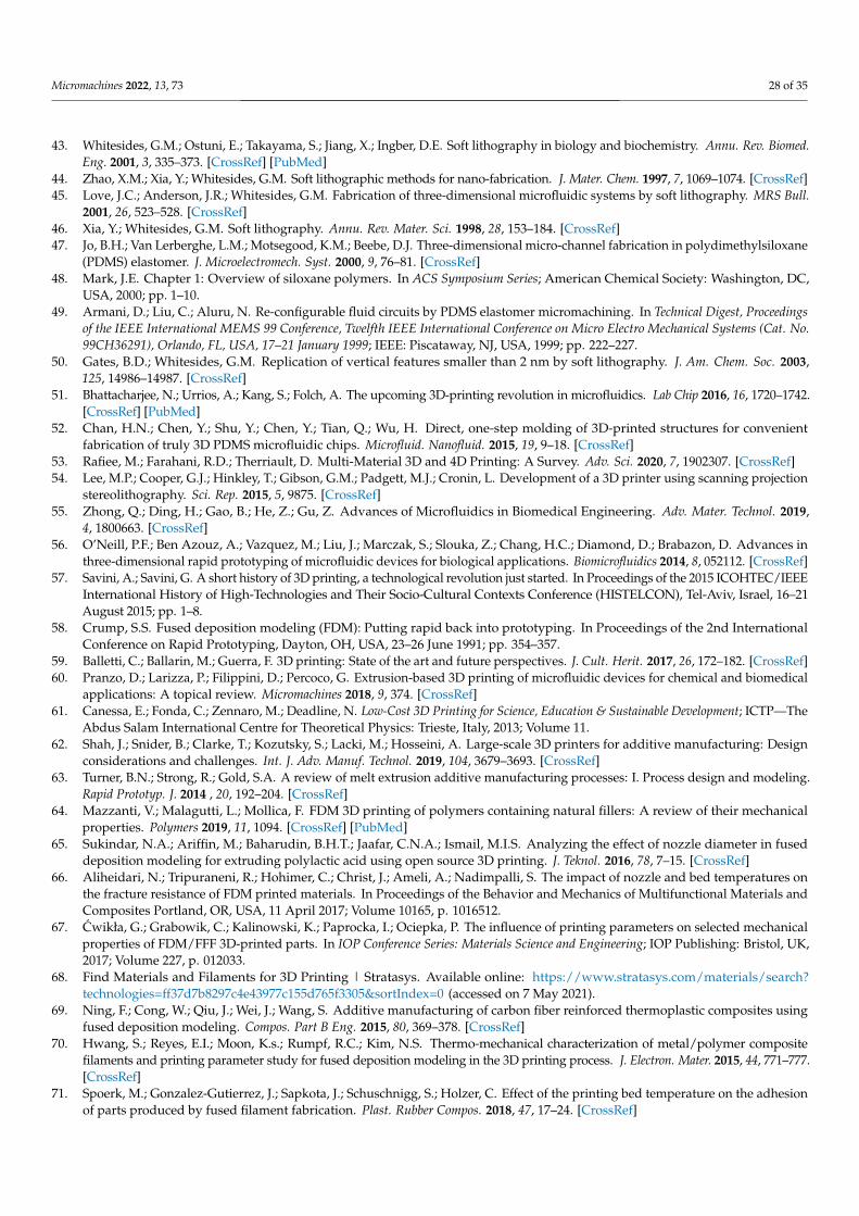
Micromachines 2022, 13, 73 28 of 35
43. Whitesides, G.M.; Ostuni, E.; Takayama, S.; Jiang, X.; Ingber, D.E. Soft lithography in biology and biochemistry. Annu. Rev. Biomed.Eng. 2001, 3, 335–373. [CrossRef] [PubMed]
44. Zhao, X.M.; Xia, Y.; Whitesides, G.M. Soft lithographic methods for nano-fabrication. J. Mater. Chem. 1997, 7, 1069–1074. [CrossRef]45. Love, J.C.; Anderson, J.R.; Whitesides, G.M. Fabrication of three-dimensional microfluidic systems by soft lithography. MRS Bull.
2001, 26, 523–528. [CrossRef]46. Xia, Y.; Whitesides, G.M. Soft lithography. Annu. Rev. Mater. Sci. 1998, 28, 153–184. [CrossRef]47. Jo, B.H.; Van Lerberghe, L.M.; Motsegood, K.M.; Beebe, D.J. Three-dimensional micro-channel fabrication in polydimethylsiloxane
(PDMS) elastomer. J. Microelectromech. Syst. 2000, 9, 76–81. [CrossRef]48. Mark, J.E. Chapter 1: Overview of siloxane polymers. In ACS Symposium Series; American Chemical Society: Washington, DC,
USA, 2000; pp. 1–10.49. Armani, D.; Liu, C.; Aluru, N. Re-configurable fluid circuits by PDMS elastomer micromachining. In Technical Digest, Proceedings
of the IEEE International MEMS 99 Conference, Twelfth IEEE International Conference on Micro Electro Mechanical Systems (Cat. No.99CH36291), Orlando, FL, USA, 17–21 January 1999; IEEE: Piscataway, NJ, USA, 1999; pp. 222–227.
50. Gates, B.D.; Whitesides, G.M. Replication of vertical features smaller than 2 nm by soft lithography. J. Am. Chem. Soc. 2003,125, 14986–14987. [CrossRef]
51. Bhattacharjee, N.; Urrios, A.; Kang, S.; Folch, A. The upcoming 3D-printing revolution in microfluidics. Lab Chip 2016, 16, 1720–1742.[CrossRef] [PubMed]
52. Chan, H.N.; Chen, Y.; Shu, Y.; Chen, Y.; Tian, Q.; Wu, H. Direct, one-step molding of 3D-printed structures for convenientfabrication of truly 3D PDMS microfluidic chips. Microfluid. Nanofluid. 2015, 19, 9–18. [CrossRef]
53. Rafiee, M.; Farahani, R.D.; Therriault, D. Multi-Material 3D and 4D Printing: A Survey. Adv. Sci. 2020, 7, 1902307. [CrossRef]54. Lee, M.P.; Cooper, G.J.; Hinkley, T.; Gibson, G.M.; Padgett, M.J.; Cronin, L. Development of a 3D printer using scanning projection
stereolithography. Sci. Rep. 2015, 5, 9875. [CrossRef]55. Zhong, Q.; Ding, H.; Gao, B.; He, Z.; Gu, Z. Advances of Microfluidics in Biomedical Engineering. Adv. Mater. Technol. 2019,
4, 1800663. [CrossRef]56. O’Neill, P.F.; Ben Azouz, A.; Vazquez, M.; Liu, J.; Marczak, S.; Slouka, Z.; Chang, H.C.; Diamond, D.; Brabazon, D. Advances in
three-dimensional rapid prototyping of microfluidic devices for biological applications. Biomicrofluidics 2014, 8, 052112. [CrossRef]57. Savini, A.; Savini, G. A short history of 3D printing, a technological revolution just started. In Proceedings of the 2015 ICOHTEC/IEEE
International History of High-Technologies and Their Socio-Cultural Contexts Conference (HISTELCON), Tel-Aviv, Israel, 16–21August 2015; pp. 1–8.
58. Crump, S.S. Fused deposition modeling (FDM): Putting rapid back into prototyping. In Proceedings of the 2nd InternationalConference on Rapid Prototyping, Dayton, OH, USA, 23–26 June 1991; pp. 354–357.
59. Balletti, C.; Ballarin, M.; Guerra, F. 3D printing: State of the art and future perspectives. J. Cult. Herit. 2017, 26, 172–182. [CrossRef]60. Pranzo, D.; Larizza, P.; Filippini, D.; Percoco, G. Extrusion-based 3D printing of microfluidic devices for chemical and biomedical
applications: A topical review. Micromachines 2018, 9, 374. [CrossRef]61. Canessa, E.; Fonda, C.; Zennaro, M.; Deadline, N. Low-Cost 3D Printing for Science, Education & Sustainable Development; ICTP—The
Abdus Salam International Centre for Theoretical Physics: Trieste, Italy, 2013; Volume 11.62. Shah, J.; Snider, B.; Clarke, T.; Kozutsky, S.; Lacki, M.; Hosseini, A. Large-scale 3D printers for additive manufacturing: Design
considerations and challenges. Int. J. Adv. Manuf. Technol. 2019, 104, 3679–3693. [CrossRef]63. Turner, B.N.; Strong, R.; Gold, S.A. A review of melt extrusion additive manufacturing processes: I. Process design and modeling.
Rapid Prototyp. J. 2014 , 20, 192–204. [CrossRef]64. Mazzanti, V.; Malagutti, L.; Mollica, F. FDM 3D printing of polymers containing natural fillers: A review of their mechanical
properties. Polymers 2019, 11, 1094. [CrossRef] [PubMed]65. Sukindar, N.A.; Ariffin, M.; Baharudin, B.H.T.; Jaafar, C.N.A.; Ismail, M.I.S. Analyzing the effect of nozzle diameter in fused
deposition modeling for extruding polylactic acid using open source 3D printing. J. Teknol. 2016, 78, 7–15. [CrossRef]66. Aliheidari, N.; Tripuraneni, R.; Hohimer, C.; Christ, J.; Ameli, A.; Nadimpalli, S. The impact of nozzle and bed temperatures on
the fracture resistance of FDM printed materials. In Proceedings of the Behavior and Mechanics of Multifunctional Materials andComposites Portland, OR, USA, 11 April 2017; Volume 10165, p. 1016512.
67. Cwikła, G.; Grabowik, C.; Kalinowski, K.; Paprocka, I.; Ociepka, P. The influence of printing parameters on selected mechanicalproperties of FDM/FFF 3D-printed parts. In IOP Conference Series: Materials Science and Engineering; IOP Publishing: Bristol, UK,2017; Volume 227, p. 012033.
68. Find Materials and Filaments for 3D Printing | Stratasys. Available online: https://www.stratasys.com/materials/search?technologies=ff37d7b8297c4e43977c155d765f3305&sortIndex=0 (accessed on 7 May 2021).
69. Ning, F.; Cong, W.; Qiu, J.; Wei, J.; Wang, S. Additive manufacturing of carbon fiber reinforced thermoplastic composites usingfused deposition modeling. Compos. Part B Eng. 2015, 80, 369–378. [CrossRef]
70. Hwang, S.; Reyes, E.I.; Moon, K.s.; Rumpf, R.C.; Kim, N.S. Thermo-mechanical characterization of metal/polymer compositefilaments and printing parameter study for fused deposition modeling in the 3D printing process. J. Electron. Mater. 2015, 44, 771–777.[CrossRef]
71. Spoerk, M.; Gonzalez-Gutierrez, J.; Sapkota, J.; Schuschnigg, S.; Holzer, C. Effect of the printing bed temperature on the adhesionof parts produced by fused filament fabrication. Plast. Rubber Compos. 2018, 47, 17–24. [CrossRef]
Micromachines 2022, 13, 73 29 of 35
72. Valerga, A.P.; Batista, M.; Salguero, J.; Girot, F. Influence of PLA filament conditions on characteristics of FDM parts. Materials2018, 11, 1322. [CrossRef] [PubMed]
73. Mehta, V.; Vilikkathala Sudhakaran, S.; Rath, S.N. Facile Route for 3D Printing of Transparent PETg-Based Hybrid BiomicrofluidicDevices Promoting Cell Adhesion. ACS Biomater. Sci. Eng. 2021, 7, 3947–3963. [CrossRef] [PubMed]
74. Vesely, P. Nozzle Temperature Effect on 3D Printed Structure Properties, 2019. Available online: https://www.researchgate.net/profile/Petr-Vesely-9/publication/333396106_Nozzle_Temperature_Effect_on_3D_Printed_Structure_Properties/links/5d70df99299bf1cb80886140/Nozzle-Temperature-Effect-on-3D-Printed-Structure-Properties.pdf (accessed on 7 December 2021).
75. Aumnate, C.; Limpanart, S.; Soatthiyanon, N.; Khunton, S. PP/organoclay nanocomposites for fused filament fabrication (FFF)3D printing. Express Polym. Lett. 2019, 13, 898–909. [CrossRef]
76. Bakar, N.S.A.; Alkahari, M.R.; Boejang, H. Analysis on fused deposition modelling performance. J. Zhejiang Univ. Sci. A 2010,11, 972–977. [CrossRef]
77. Perez, C.L. Analysis of the surface roughness and dimensional accuracy capability of fused deposition modelling processes. Int.J. Prod. Res. 2002, 40, 2865–2881. [CrossRef]
78. Thrimurthulu, K.; Pandey, P.M.; Reddy, N.V. Optimum part deposition orientation in fused deposition modeling. Int. J. Mach.Tools Manuf. 2004, 44, 585–594. [CrossRef]
79. Singh, R. Process capability analysis of fused deposition modelling for plastic components. Rapid Prototyp. J. 2014, 20, 69–76..[CrossRef]
80. Elkaseer, A.; Schneider, S.; Scholz, S.G. Experiment-based process modeling and optimization for high-quality and resource-efficient FFF 3D printing. Appl. Sci. 2020, 10, 2899. [CrossRef]
81. Pandey, P.M.; Reddy, N.V.; Dhande, S.G. Real time adaptive slicing for fused deposition modelling. Int. J. Mach. Tools Manuf.2003, 43, 61–71. [CrossRef]
82. Espalin, D.; Ramirez, J.A.; Medina, F.; Wicker, R. Multi-material, multi-technology FDM: Exploring build process variations.Rapid Prototyp. J. 2014, 20, 236–244. [CrossRef]
83. Tamburrino, F.; Graziosi, S.; Bordegoni, M. The influence of slicing parameters on the multi-material adhesion mechanisms ofFDM printed parts: An exploratory study. Virtual Phys. Prototyp. 2019, 14, 316–332. [CrossRef]
84. Minetola, P.; Iuliano, L.; Bassoli, E.; Gatto, A. Impact of additive manufacturing on engineering education–evidence from Italy.Rapid Prototyp. J. 2015, 21, 535–555. [CrossRef]
85. Turner, B.N.; Gold, S.A. A review of melt extrusion additive manufacturing processes: II. Materials, dimensional accuracy, andsurface roughness. Rapid Prototyp. J. 2015 21, 250–261. [CrossRef]
86. Anitha, R.; Arunachalam, S.; Radhakrishnan, P. Critical parameters influencing the quality of prototypes in fused depositionmodelling. J. Mater. Process. Technol. 2001, 118, 385–388. [CrossRef]
87. Stratasys F170 Review—Industrial—Grade 3D Printer for Professionals. Available online: https://www.aniwaa.com/product/3d-printers/stratasys-f170/ (accessed on 7 December 2021).
88. Industrial 3D Printers—3D Printing. Available online: https://3dprinting.com/product-category/industrial-3d-printer/?min_price=157050&max_price=190000&filter_technology=fff-fdm (accessed on 7 May 2021).
89. Gordeev, E.G.; Galushko, A.S.; Ananikov, V.P. Improvement of quality of 3D printed objects by elimination of microscopicstructural defects in fused deposition modeling. PLoS ONE 2018, 13, e0198370. [CrossRef] [PubMed]
90. Hofmann, M. 3D printing gets a boost and opportunities with polymer materials. ACS Macro Lett. 2014, 3, 382–386. [CrossRef]91. Ten Kate, J.; Smit, G.; Breedveld, P. 3D-printed upper limb prostheses: A review. Disabil. Rehabil. Assist. Technol. 2017, 12, 300–314.
[CrossRef]92. Valerga, A.P.; Batista, M.; Fernandez-Vidal, S.R.; Gamez, A.J. Impact of chemical post-processing in fused deposition modelling
(FDM) on polylactic acid (PLA) surface quality and structure. Polymers 2019, 11, 566. [CrossRef]93. Waheed, S.; Cabot, J.M.; Macdonald, N.P.; Lewis, T.; Guijt, R.M.; Paull, B.; Breadmore, M.C. 3D printed microfluidic devices:
Enablers and barriers. Lab Chip 2016, 16, 1993–2013. [CrossRef]94. Gibson, I.; Rosen, D.; Stucker, B. Vat photopolymerization processes. In Additive Manufacturing Technologies; Springer: Berlin/Heidelberg,
Germany, 2015; pp. 63–106.95. Melchels, F.P. Celebrating three decades of stereolithography. Virtual Phys. Prototyp. 2012, 7, 173–175. [CrossRef]96. Ligon, S.C.; Liska, R.; Stampfl, J.; Gurr, M.; Mulhaupt, R. Polymers for 3D printing and customized additive manufacturing.
Chem. Rev. 2017, 117, 10212–10290. [CrossRef]97. Vaezi, M.; Chianrabutra, S.; Mellor, B.; Yang, S. Multiple material additive manufacturing—Part 1: A review. Virtual Phys. Prototyp.
2013, 8, 19–50. [CrossRef]98. Medellin, A.; Du, W.; Miao, G.; Zou, J.; Pei, Z.; Ma, C. Vat photopolymerization 3D printing of nanocomposites: A literature
review. J. Micro- Nano-Manuf. 2019, 7, 031006. [CrossRef]99. Xu, X.; Awad, A.; Martinez, P.R.; Gaisford, S.; Goyanes, A.; Basit, A.W. Vat photopolymerization 3D printing for advanced drug
delivery and medical device applications. J. Control. Release 2020, 329, 743–757. [CrossRef] [PubMed]100. Au, A.K.; Huynh, W.; Horowitz, L.F.; Folch, A. 3D-printed microfluidics. Angew. Chem. Int. Ed. 2016, 55, 3862–3881. [CrossRef]
[PubMed]101. Martinez, P.R.; Basit, A.W.; Gaisford, S. The history, developments and opportunities of stereolithography. In 3D Printing of
Pharmaceuticals; Springer: Berlin/Heidelberg, Germany, 2018; pp. 55–79.
Micromachines 2022, 13, 73 30 of 35
102. Quan, H.; Zhang, T.; Xu, H.; Luo, S.; Nie, J.; Zhu, X. Photo-curing 3D printing technique and its challenges. Bioact. Mater. 2020,5, 110–115. [CrossRef]
103. Kuang, X.; Zhao, Z.; Chen, K.; Fang, D.; Kang, G.; Qi, H.J. High-speed 3D printing of high-performance thermosetting polymersvia two-stage curing. Macromol. Rapid Commun. 2018, 39, 1700809. [CrossRef]
104. Bagheri, A.; Jin, J. Photopolymerization in 3D printing. ACS Appl. Polym. Mater. 2019, 1, 593–611. [CrossRef]105. Johnson, A.R.; Caudill, C.L.; Tumbleston, J.R.; Bloomquist, C.J.; Moga, K.A.; Ermoshkin, A.; Shirvanyants, D.; Mecham, S.J.; Luft,
J.C.; DeSimone, J.M. Single-step fabrication of computationally designed microneedles by continuous liquid interface production.PLoS ONE 2016, 11, e0162518. [CrossRef]
106. Zheng, L.; Kurselis, K.; El-Tamer, A.; Hinze, U.; Reinhardt, C.; Overmeyer, L.; Chichkov, B. Nanofabrication of high-resolutionperiodic structures with a gap size Below 100 nm by two-photon polymerization. Nanoscale Res. Lett. 2019, 14, 1–9. [CrossRef]
107. Xing, J.F.; Zheng, M.L.; Duan, X.M. Two-photon polymerization microfabrication of hydrogels: An advanced 3D printingtechnology for tissue engineering and drug delivery. Chem. Soc. Rev. 2015, 44, 5031–5039. [CrossRef] [PubMed]
108. Paz, V.F.; Emons, M.; Obata, K.; Ovsianikov, A.; Peterhänsel, S.; Frenner, K.; Reinhardt, C.; Chichkov, B.; Morgner, U.; Osten,W. Development of functional sub-100 nm structures with 3D two-photon polymerization technique and optical methods forcharacterization. J. Laser Appl. 2012, 24, 042004. [CrossRef]
109. Rajkumari, K.; Chandra, P.; Balaji, P. Three-Dimensional Printing—A Revolutionary Technology. J. Clin. Diagn. Res. 2018, 12, 12–18.110. Zhou, X.; Hou, Y.; Lin, J. A review on the processing accuracy of two-photon polymerization. AIP Adv. 2015, 5, 030701. [CrossRef]111. Pagac, M.; Hajnys, J.; Ma, Q.P.; Jancar, L.; Jansa, J.; Stefek, P.; Mesicek, J. A Review of Vat Photopolymerization Technology:
Materials, Applications, Challenges, and Future Trends of 3D Printing. Polymers 2021, 13, 598. [CrossRef]112. Rungrojwittayakul, O.; Kan, J.Y.; Shiozaki, K.; Swamidass, R.S.; Goodacre, B.J.; Goodacre, C.J.; Lozada, J.L. Accuracy of 3D
printed models created by two technologies of printers with different designs of model base. J. Prosthodont. 2020, 29, 124–128.[CrossRef]
113. Wang, B.; Zhang, Z.; Pei, Z.; Qiu, J.; Wang, S. Current progress on the 3D printing of thermosets. Adv. Compos. Hybrid Mater. 2020,3, 462–472. [CrossRef]
114. Cho, Y.; Lee, I.; Cho, D.W. Laser scanning path generation considering photopolymer solidification in micro-stereolithography.Microsyst. Technol. 2005, 11, 158–167. [CrossRef]
115. Dikshit, V.; Goh, G.D.; Nagalingam, A.P.; Goh, G.L.; Yeong, W.Y. Recent progress in 3D printing of fiber-reinforced composite andnanocomposites. In Fiber-Reinforced Nanocomposites: Fundamentals and Applications; Elsevier: Amsterdam, The Netherlands, 2020;pp. 371–394.
116. Choosing the Right Material. Available online: https://support.formlabs.com/s/article/Choosing-the-Right-Material?language=en_US (accessed on 29 June 2021).
117. Using Draft Resin. Available online: https://support.formlabs.com/s/article/Using-Draft-Resin?language=en_US (accessed on13 May 2021).
118. Layani, M.; Wang, X.; Magdassi, S. Novel materials for 3D printing by photopolymerization. Adv. Mater. 2018, 30, 1706344.[CrossRef]
119. Mele, M.; Campana, G.; D’Avino, G. Life cycle impact assessment of desktop stereolithography. J. Clean. Prod. 2020, 244, 118743.[CrossRef]
120. Groth, C.; Kravitz, N.D.; Jones, P.E.; Graham, J.W.; Redmond, W.R. Three-dimensional printing technology. J. Clin. Orthod. 2014,48, 475–85.
121. Miedzinska, D.; Gieleta, R.; Małek, E. Experimental study of strength properties of SLA resins under low and high strain rates.Mech. Mater. 2020, 141, 103245. [CrossRef]
122. 3D Printers LONGER |Most Affordable 3D Printer. Available online: https://www.longer3d.com/collections/3d-printers?sort_by=price-ascending (accessed on 13 May 2021).
123. Industrial 3D Printers—3D Printing. Available online: https://3dprinting.com/product-category/industrial-3d-printer/?filter_technology=sla (accessed on 13 May 2021).
124. 3D Printers Comparison—Aniwaa. Available online: https://www.aniwaa.com/comparison/3d-printers/?filter_price_minimum&filter_price_maximum&filter_build_size_width&filter_build_size_height&filter_build_size_depth&filter_temperature_extruder&filter_temperature_chamber&filter_temperature_plate&save_manufacturer=Nanoscribe&filter_manufacturers%5B0%5D=Nanoscribe&filter_manufacturers%5B1%5D=UpNano (accessed on 18 May 2021).
125. Agrawaal, H.; Thompson, J. Additive manufacturing (3D printing) for analytical chemistry. Talanta Open 2021, 3, 100036. [CrossRef]126. Kiania, N.; Babak, L. 3D Printing and Additive Manufacturing State of the Industry Annual Worldwide Progress Report; Wohlers
Associates, Inc.: Fort Collins, CO, USA, 2014.127. Vaezi, M.; Seitz, H.; Yang, S. A review on 3D micro-additive manufacturing technologies. Int. J. Adv. Manuf. Technol. 2013,
67, 1721–1754. [CrossRef]128. Ko, S.H.; Chung, J.; Hotz, N.; Nam, K.H.; Grigoropoulos, C.P. Metal nanoparticle direct inkjet printing for low-temperature 3D
micro metal structure fabrication. J. Micromech. Microeng. 2010, 20, 125010. [CrossRef]129. Gao, F.; Sonin, A.A. Precise deposition of molten microdrops: The physics of digital microfabrication. Proc. R. Soc. London. Ser. A
Math. Phys. Sci. 1994, 444, 533–554.
Micromachines 2022, 13, 73 31 of 35
130. Reis, N.; Seerden, K.; Derby, B.; Halloran, J.; Evans, J. Direct inkjet deposition of ceramic green bodies: II—Jet behaviour anddeposit formation. MRS Online Proc. Libr. (OPL) 1998, 542, 147. [CrossRef]
131. Pilipovic, A.; Raos, P.; Šercer, M. Experimental analysis of properties of materials for rapid prototyping. Int. J. Adv. Manuf.Technol. 2009, 40, 105–115. [CrossRef]
132. Šercer, M.; Rezic, T.; Godec, D.; Oros, D.; Pilipovic, A.; Ivušic, F.; Rezic, I.; Andlar, M.; Ludwig, R.; Šantek, B. Microreactorproduction by PolyJet matrix 3D-printing technology: Hydrodynamic characterization. Food Technol. Biotechnol. 2019, 57, 272–281.[CrossRef]
133. Jacquet, J.R.; Ossant, F.; Levassort, F.; Grégoire, J.M. 3-D-Printed phantom fabricated by photopolymer jetting technology forhigh-frequency ultrasound imaging. IEEE Trans. Ultrason. Ferroelectr. Freq. Control 2018, 65, 1048–1055. [CrossRef]
134. Castiaux, A.D.; Pinger, C.W.; Hayter, E.A.; Bunn, M.E.; Martin, R.S.; Spence, D.M. PolyJet 3D-printed enclosed microfluidicchannels without photocurable supports. Anal. Chem. 2019, 91, 6910–6917. [CrossRef]
135. Sochol, R.; Sweet, E.; Glick, C.; Venkatesh, S.; Avetisyan, A.; Ekman, K.; Raulinaitis, A.; Tsai, A.; Wienkers, A.; Korner, K.; et al. 3Dprinted microfluidic circuitry via multijet-based additive manufacturing. Lab Chip 2016, 16, 668–678. [CrossRef]
136. Lee, K.G.; Park, K.J.; Seok, S.; Shin, S.; Park, J.Y.; Heo, Y.S.; Lee, S.J.; Lee, T.J.; et al. 3D printed modules for integrated microfluidicdevices. RSC Adv. 2014, 4, 32876–32880. [CrossRef]
137. Childs, E.H.; Latchman, A.V.; Lamont, A.C.; Hubbard, J.D.; Sochol, R.D. Additive Assembly for PolyJet-Based Multi-Material 3DPrinted Microfluidics. J. Microelectromech. Syst. 2020, 29, 1094–1096. [CrossRef]
138. Gaynor, A.T.; Meisel, N.A.; Williams, C.B.; Guest, J.K. Multiple-material topology optimization of compliant mechanisms createdvia PolyJet three-dimensional printing. J. Manuf. Sci. Eng. 2014, 136, 061015. [CrossRef]
139. Yang, H.; Lim, J.C.; Liu, Y.; Qi, X.; Yap, Y.L.; Dikshit, V.; Yeong, W.Y.; Wei, J. Performance evaluation of projet multi-materialjetting 3D printer. Virtual Phys. Prototyp. 2017, 12, 95–103. [CrossRef]
140. Kim, G.B.; Lee, S.; Kim, H.; Yang, D.H.; Kim, Y.H.; Kyung, Y.S.; Kim, C.S.; Choi, S.H.; Kim, B.J.; Ha, H.; et al. Three-dimensionalprinting: Basic principles and applications in medicine and radiology. Korean J. Radiol. 2016, 17, 182. [CrossRef]
141. Levi, H. Additive Manufacturing in Technical Ceramics. Interceram-Int. Ceram. Rev. 2018, 67, 12–13. [CrossRef]142. Oh, Y.; Bharambe, V.; Mummareddy, B.; Martin, J.; McKnight, J.; Abraham, M.A.; Walker, J.M.; Rogers, K.; Conner, B.; Cortes,
P.; et al. Microwave dielectric properties of zirconia fabricated using NanoParticle Jetting™. Addit. Manuf. 2019, 27, 586–594.[CrossRef]
143. Zhang, R.; Lu, C.; Yin, Y.; Liu, P.; Li, Z.; Xiao, M.; Cai, W.; Qu, Y. An overview of metallic additive manufacturing: Technologies,barriers and future trends. Available online: http://www.toweld.com/attachment/2017/0705/20170705093520855.pdf (accessedon 7 December 2021).
144. 3D Printers Comparison—Aniwaa. Available online: https://www.aniwaa.com/comparison/3d-printers/?filter_price_minimum&filter_price_maximum&filter_build_size_width&filter_build_size_height&filter_build_size_depth&filter_temperature_extruder&filter_temperature_chamber&filter_temperature_plate&filter_technology%5B0%5D=material_jetting&filter_manufacturers%5B0%5D=XJet (accessed on 18 May 2021).
145. PolyJet 3D Printers (Comparison Guide). Available online: https://www.treatstock.com/machines/3d-printers/technology-PolyJet (accessed on 17 May 2021).
146. 3D Printers Comparison—Aniwaa. Available online: https://www.aniwaa.com/comparison/3d-printers/?sort=price&order=desc&filter_price_minimum&filter_price_maximum&filter_build_size_width&filter_build_size_height&filter_build_size_depth&filter_temperature_extruder&filter_temperature_chamber&filter_temperature_plate&filter_technology%5B0%5D=material_jetting&save_manufacturer=3D%20Systems%2CStratasys%2CXJet&filter_manufacturers%5B0%5D=3D%20Systems&filter_manufacturers%5B1%5D=Stratasys. (accessed on 18 May 2021).
147. Kok, Y.; Tan, X.P.; Wang, P.; Nai, M.; Loh, N.H.; Liu, E.; Tor, S.B. Anisotropy and heterogeneity of microstructure and mechanicalproperties in metal additive manufacturing: A critical review. Mater. Des. 2018, 139, 565–586. [CrossRef]
148. Singh, D.D.; Mahender, T.; Reddy, A.R. Powder bed fusion process: A brief review. Mater. Today Proc. 2021, 46, 350–355. [CrossRef]149. Miron-Borzan, C.S.; Dudescu, M.C.; Berce, P. Bending and compression tests for PA 2200 parts obtained using Selective Laser
Sintering method. MATEC Web Conf. 2017, 94, 03010. [CrossRef]150. Vanderesse, N.; Ky, I.; González, F.Q.; Nuño, N.; Bocher, P. Image analysis characterization of periodic porous materials produced
by additive manufacturing. Mater. Des. 2016, 92, 767–778. [CrossRef]151. Shellabear, M.; Nyrhilä, O. DMLS-Development history and state of the art. In Proceedings of the 4th Laser Assisted Netshape
Engineering, Erlangen, Germany, 21–24 September 2004; pp. 21–24.152. Fina, F.; Gaisford, S.; Basit, A.W. Powder bed fusion: The working process, current applications and opportunities. In 3D Printing
of Pharmaceuticals; Springer: Berlin/Heidelberg, Germany, 2018; pp. 81–105.153. Deckard, C.R.; Beaman, J.J., Jr. Selective Laser Sintering with Assisted Powder Handling. U.S. Patent 4 938 816, 3 July 1990.154. Launhardt, M.; Wörz, A.; Loderer, A.; Laumer, T.; Drummer, D.; Hausotte, T.; Schmidt, M. Detecting surface roughness on SLS
parts with various measuring techniques. Polym. Test. 2016, 53, 217–226. [CrossRef]155. Harding, M.J.; Brady, S.; O’Connor, H.; Lopez-Rodriguez, R.; Edwards, M.D.; Tracy, S.; Dowling, D.; Gibson, G.; Girard, K.P.;
Ferguson, S. 3D printing of PEEK reactors for flow chemistry and continuous chemical processing. React. Chem. Eng. 2020,5, 728–735. [CrossRef]
Micromachines 2022, 13, 73 32 of 35
156. Yap, C.Y.; Chua, C.K.; Dong, Z.L.; Liu, Z.H.; Zhang, D.Q.; Loh, L.E.; Sing, S.L. Review of selective laser melting: Materials andapplications. Appl. Phys. Rev. 2015, 2, 041101. [CrossRef]
157. Bai, L.; Gong, C.; Chen, X.; Sun, Y.; Zhang, J.; Cai, L.; Zhu, S.; Xie, S.Q. Additive manufacturing of customized metallic orthopedicimplants: Materials, structures, and surface modifications. Metals 2019, 9, 1004. [CrossRef]
158. Papazoglou, E.L.; Karkalos, N.E.; Karmiris-Obratanski, P.; Markopoulos, A.P. On the Modeling and Simulation of SLM and SLSfor Metal and Polymer Powders: A Review. Arch. Comput. Methods Eng. 2021, 1–33. [CrossRef]
159. Bineli, A.R.R.; Peres, A.P.G.; Jardini, A.L.; Maciel Filho, R. Direct metal laser sintering (DMLS): Technology for design andconstruction of microreactors. In Proceedings of the 6º Congress Obrasileiro de Engenharia de Fabrica ÇÃO, Caxias do Sul, Brazil,11–15 April 2011; Volume 11.
160. Delgado, J.; Ciurana, J.; Rodríguez, C.A. Influence of process parameters on part quality and mechanical properties for DMLSand SLM with iron-based materials. Int. J. Adv. Manuf. Technol. 2012, 60, 601–610. [CrossRef]
161. Mahamood, R.M.; Akinlabi, E.T. Additive Manufacturing of Funtionally Graded Materials. In Functionally Graded Materials;Springer: Berlin/Heidelberg, Germany, 2017; pp. 47–68.
162. Karlsson, J.; Snis, A.; Engqvist, H.; Lausmaa, J. Characterization and comparison of materials produced by Electron Beam Melting(EBM) of two different Ti–6Al–4V powder fractions. J. Mater. Process. Technol. 2013, 213, 2109–2118. [CrossRef]
163. Parthasarathy, J.; Starly, B.; Raman, S.; Christensen, A. Mechanical evaluation of porous titanium (Ti6Al4V) structures withelectron beam melting (EBM). J. Mech. Behav. Biomed. Mater. 2010, 3, 249–259. [CrossRef]
164. Cloots, M.; Spierings, A.; Wegener, K. Assessing new support minimizing strategies for the additive manufacturing technologySLM. In Proceedings of the 24th International SFF Symposium—An Additive Manufacturing Conference, Austin, TX, USA, 12–14August 2013; pp. 631–643.
165. Capel, A.J.; Edmondson, S.; Christie, S.D.; Goodridge, R.D.; Bibb, R.J.; Thurstans, M. Design and additive manufacture for flowchemistry. Lab Chip 2013, 13, 4583–4590. [CrossRef]
166. Leong, K.; Cheah, C.; Chua, C. Solid freeform fabrication of three-dimensional scaffolds for engineering replacement tissues andorgans. Biomaterials 2003, 24, 2363–2378. [CrossRef]
167. Sintratec Kit Review—Affordable Desktop SLS 3D Printer (under $6000). Available online: https://www.aniwaa.com/product/3d-printers/sintratec-sintratec-kit/ (accessed on 21 December 2021).
168. TPM3D S600DL Review—An Industrial SLS 3D Printer. Available online: https://www.aniwaa.com/product/3d-printers/tpm3d-s600dl/ (accessed on 21 December 2021).
169. Meteyer, S.; Xu, X.; Perry, N.; Zhao, Y.F. Energy and material flow analysis of binder-jetting additive manufacturing processes.Procedia Cirp 2014, 15, 19–25. [CrossRef]
170. Garzón, E.O.; Alves, J.L.; Neto, R.J. Post-process influence of infiltration on binder jetting technology. In Materials Design andApplications; Springer: Berlin/Heidelberg, Germany, 2017; pp. 233–255.
171. Sachs, E.; Cima, M.; Cornie, J. Three-dimensional printing: Rapid tooling and prototypes directly from a CAD model. CIRP Ann.1990, 39, 201–204. [CrossRef]
172. Xu, X.; Meteyer, S.; Perry, N.; Zhao, Y.F. Energy consumption model of Binder-jetting additive manufacturing processes. Int. J.Prod. Res. 2015, 53, 7005–7015. [CrossRef]
173. Bai, Y.; Williams, C.B. An exploration of binder jetting of copper. Rapid Prototyp. J. 2015, 21, 177–185. [CrossRef]174. Gokuldoss, P.K.; Kolla, S.; Eckert, J. Additive manufacturing processes: Selective laser melting, electron beam melting and binder
jetting—Selection guidelines. Materials 2017, 10, 672. [CrossRef]175. Ziaee, M.; Crane, N.B. Binder jetting: A review of process, materials, and methods. Addit. Manuf. 2019, 28, 781–801. [CrossRef]176. Moon, J.; Caballero, A.C.; Hozer, L.; Chiang, Y.M.; Cima, M.J. Fabrication of functionally graded reaction infiltrated SiC–Si
composite by three-dimensional printing (3DP™) process. Mater. Sci. Eng. A 2001, 298, 110–119. [CrossRef]177. Gardan, J. Method for characterization and enhancement of 3D printing by binder jetting applied to the textures quality. Assem.
Autom. 2017, 37, 162–169. [CrossRef]178. Mostafaei, A.; Elliott, A.M.; Barnes, J.E.; Li, F.; Tan, W.; Cramer, C.L.; Nandwana, P.; Chmielus, M. Binder jet 3D printing—Process
parameters, materials, properties, modeling, and challenges. Prog. Mater. Sci. 2021, 119, 100707. [CrossRef]179. Tang, Y.; Zhou, Y.; Hoff, T.; Garon, M.; Zhao, Y. Elastic modulus of 316 stainless steel lattice structure fabricated via binder jetting
process. Mater. Sci. Technol. 2016, 32, 648–656. [CrossRef]180. Dimitrov, D.; Schreve, K.; de Beer, N. Advances in three dimensional printing–state of the art and future perspectives. Rapid
Prototyp. J. 2006, 12, 136–147. [CrossRef]181. ComeTrue M10 Review—Industrial Ceramic 3D Printer. Available online: https://www.aniwaa.com/product/3d-printers/
cometrue-m10/ (accessed on 22 December 2021).182. Luxexcel VisionEngine Review—3D Printed Lens Platform. Available online: https://www.aniwaa.com/product/3d-printers/
luxexcel-visionengine/ (accessed on 22 December 2021).183. Macdonald, N.P.; Cabot, J.M.; Smejkal, P.; Guijt, R.M.; Paull, B.; Breadmore, M.C. Comparing microfluidic performance of
three-dimensional (3D) printing platforms. Anal. Chem. 2017, 89, 3858–3866. [CrossRef]184. Zeraatkar, M.; Filippini, D.; Percoco, G. On the impact of the fabrication method on the performance of 3D printed mixers.
Micromachines 2019, 10, 298. [CrossRef]

Micromachines 2022, 13, 73 33 of 35
185. Lee, J.M.; Zhang, M.; Yeong, W.Y. Characterization and evaluation of 3D printed microfluidic chip for cell processing. Microfluid.Nanofluid. 2016, 20, 5. [CrossRef]
186. Urrios, A.; Parra-Cabrera, C.; Bhattacharjee, N.; Gonzalez-Suarez, A.M.; Rigat-Brugarolas, L.G.; Nallapatti, U.; Samitier, J.;DeForest, C.A.; Posas, F.; Garcia-Cordero, J.L.; et al. 3D-printing of transparent bio-microfluidic devices in PEG-DA. Lab Chip2016, 16, 2287–2294. [CrossRef] [PubMed]
187. Ionita, C.N.; Mokin, M.; Varble, N.; Bednarek, D.R.; Xiang, J.; Snyder, K.V.; Siddiqui, A.H.; Levy, E.I.; Meng, H.; Rudin, S.Challenges and limitations of patient-specific vascular phantom fabrication using 3D Polyjet printing. In Proceedings of theMedical Imaging 2014: Biomedical Applications in Molecular, Structural, and Functional Imaging, San Diego, CA, USA, 16–18February 2014; Volume 9038, p. 90380M.
188. Keating, S.J.; Gariboldi, M.I.; Patrick, W.G.; Sharma, S.; Kong, D.S.; Oxman, N. 3D printed multimaterial microfluidic valve. PLoSONE 2016, 11, e0160624. [CrossRef] [PubMed]
189. Zhang, H.; Kopfmüller, T.; Achermann, R.; Zhang, J.; Teixeira, A.; Shen, Y.; Jensen, K.F. Accessing multidimensional mixing via3D printing and showerhead micromixer design. AIChE J. 2020, 66, e16873. [CrossRef]
190. Ezoji, M.; Razavi-Nouri, M.; Rezadoust, A.M. Influence of Layer Thickness on the Tensile Properties of the Samples Manufacturedby Fused Deposition Modelling. In Proceedings of the 12th International Seminar on Polymer Science and Technology, IslamicAzad University, Tehran, Iran, 2–5 November 2016.
191. Nuñez, P.; Rivas, A.; García-Plaza, E.; Beamud, E.; Sanz-Lobera, A. Dimensional and surface texture characterization in fuseddeposition modelling (FDM) with ABS plus. Procedia Eng. 2015, 132, 856–863. [CrossRef]
192. Wu, W.; Geng, P.; Li, G.; Zhao, D.; Zhang, H.; Zhao, J. Influence of layer thickness and raster angle on the mechanical propertiesof 3D-printed PEEK and a comparative mechanical study between PEEK and ABS. Materials 2015, 8, 5834–5846. [CrossRef]
193. Torres, J.; Cotelo, J.; Karl, J.; Gordon, A.P. Mechanical property optimization of FDM PLA in shear with multiple objectives. JOM2015, 67, 1183–1193. [CrossRef]
194. Zhang, Z.c.; Li, P.l.; Chu, F.t.; Shen, G. Influence of the three-dimensional printing technique and printing layer thickness onmodel accuracy. J. Orofac. Orthop. Kieferorthopädie 2019, 80, 194–204. [CrossRef]
195. Walczak, R.; Adamski, K. Inkjet 3D printing of microfluidic structures—On the selection of the printer towards printing yourown microfluidic chips. J. Micromech. Microeng. 2015, 25, 085013. [CrossRef]
196. Chen, J.V.; Dang, A.B.; Dang, A. Comparing cost and print time estimates for six commercially-available 3D printers obtainedthrough slicing software for clinically relevant anatomical models. 3D Print. Med. 2021, 7, 1–14. [CrossRef] [PubMed]
197. Wu, Z.; Narra, S.P.; Rollett, A. Exploring the fabrication limits of thin-wall structures in a laser powder bed fusion process. Int. J.Adv. Manuf. Technol. 2020, 110, 191–207. [CrossRef]
198. Shrestha, S.; Manogharan, G. Optimization of binder jetting using Taguchi method. JOM 2017, 69, 491–497. [CrossRef]199. Li, S.J.; Cao, S. Print Parameters Influence on Parts’ Quality and Calibration with 3DP-Part I: Print Parameters Influence on Parts’
Surface Topography. Adv. Mater. Res. 2012, 399, 1639–1645. [CrossRef]200. Wu, J. Study on optimization of 3D printing parameters. In IOP Conference Series: Materials Science and Engineering; IOP Publishing:
Bristol, UK, 2018; Volume 392, p. 062050.201. Lemu, H.G.; Kurtovic, S. 3D printing for rapid manufacturing: Study of dimensional and geometrical accuracy. In IFIP
International Conference on Advances in Production Management Systems; Springer: Berlin/Heidelberg, Germany, 2011; pp. 470–479.202. Heidt, B.; Rogosic, R.; Bonni, S.; Passariello-Jansen, J.; Dimech, D.; Lowdon, J.W.; Arreguin-Campos, R.; Steen Redeker, E.; Eersels,
K.; Diliën, H.; et al. The liberalization of microfluidics: Form 2 benchtop 3D printing as an affordable alternative to establishedmanufacturing methods. Phys. Status Solidi A 2020, 217, 1900935. [CrossRef]
203. Ian Gibson, I.G. Additive Manufacturing Technologies 3D Printing, Rapid Prototyping, and Direct Digital Manufacturing,Springer: Berlin/Heidelberg, Germany, 2015.
204. Choi, J.W.; Kim, H.C.; Wicker, R. Multi-material stereolithography. J. Mater. Process. Technol. 2011, 211, 318–328. [CrossRef]205. Lee, K.Y.; Cho, J.W.; Chang, N.Y.; Chae, J.M.; Kang, K.H.; Kim, S.C.; Cho, J.H. Accuracy of three-dimensional printing for
manufacturing replica teeth. Korean J. Orthod. 2015, 45, 217. [CrossRef] [PubMed]206. Wei, C.; Chueh, Y.H.; Zhang, X.; Huang, Y.; Chen, Q.; Li, L. Easy-To-Remove composite support material and procedure in
additive manufacturing of metallic components using multiple material laser-based powder bed fusion. J. Manuf. Sci. Eng. 2019,141, 071002. [CrossRef]
207. Kumar, A.; Bai, Y.; Eklund, A.; Williams, C.B. Effects of hot isostatic pressing on copper parts fabricated via binder jetting. ProcediaManuf. 2017, 10, 935–944. [CrossRef]
208. Fischer, F. Thermoplastics: The Best Choice for 3D Printing; White Paper; Stratasys Inc.: Edn Prairie, MN, USA, 2011.209. Tan, L.J.; Zhu, W.; Zhou, K. Recent progress on polymer materials for additive manufacturing. Adv. Funct. Mater. 2020, 30, 2003062.
[CrossRef]210. Sampson, K.L.; Deore, B.; Go, A.; Nayak, M.A.; Orth, A.; Gallerneault, M.; Malenfant, P.R.; Paquet, C. Multimaterial vat
polymerization additive manufacturing. ACS Appl. Polym. Mater. 2021, 3, 4304–4324. [CrossRef]211. Xu, Z.; Ha, C.S.; Kadam, R.; Lindahl, J.; Kim, S.; Wu, H.F.; Kunc, V.; Zheng, X. Additive manufacturing of two-phase lightweight,
stiff and high damping carbon fiber reinforced polymer microlattices. Addit. Manuf. 2020, 32, 101106. [CrossRef]212. Gonzalez, J.; Mireles, J.; Lin, Y.; Wicker, R.B. Characterization of ceramic components fabricated using binder jetting additive
manufacturing technology. Ceram. Int. 2016, 42, 10559–10564. [CrossRef]

Micromachines 2022, 13, 73 34 of 35
213. Doyle, M.; Agarwal, K.; Sealy, W.; Schull, K. Effect of layer thickness and orientation on mechanical behavior of binder jet stainlesssteel 420+ bronze parts. Procedia Manuf. 2015, 1, 251–262. [CrossRef]
214. Jacob, G.; Jacob, G.; Brown, C.U.; Donmez, M.A.; Watson, S.S.; Slotwinski, J. Effects of Powder Recycling on Stainless Steel Powder andBuilt Material Properties in Metal Powder Bed Fusion Processes; US Department of Commerce, National Institute of Standards andTechnology: Gaithersburg, MD, USA, 2017.
215. 3D Printers Comparison—Aniwaa. Available online: https://www.aniwaa.com/comparison/3d-printers/?filter_price_minimum&filter_price_maximum&filter_build_size_width&filter_build_size_height&filter_build_size_depth&filter_temperature_extruder&filter_temperature_chamber&filter_temperature_plate (accessed on 3 June 2021).
216. Kitson, P.J.; Rosnes, M.H.; Sans, V.; Dragone, V.; Cronin, L. Configurable 3D-Printed millifluidic and microfluidic ‘lab on a chip’reactionware devices. Lab Chip 2012, 12, 3267–3271. [CrossRef]
217. Bishop, G.W.; Satterwhite-Warden, J.E.; Bist, I.; Chen, E.; Rusling, J.F. Electrochemiluminescence at bare and DNA-coated graphiteelectrodes in 3D-printed fluidic devices. ACS Sens. 2016, 1, 197–202. [CrossRef] [PubMed]
218. Stratasys Fortus 250mc Review—3D Printer. Available online: https://www.aniwaa.com/product/3d-printers/stratasys-fortus-250mc/ (accessed on 26 May 2021).
219. Stratasys Object30 Pro Review—3D Printer. Available online: https://www.aniwaa.com/product/3d-printers/stratasys-objet30-pro/ (accessed on 26 May 2021).
220. Romanov, V.; Samuel, R.; Chaharlang, M.; Jafek, A.R.; Frost, A.; Gale, B.K. FDM 3D printing of high-pressure, heat-resistant,transparent microfluidic devices. Anal. Chem. 2018, 90, 10450–10456. [CrossRef]
221. Santana, H.S.; Rodrigues, A.C.; Lopes, M.G.; Russo, F.N.; Silva, J.L., Jr.; Taranto, O.P. 3D printed millireactors for processintensification. Chin. J. Chem. Eng. 2020, 28, 180–190. [CrossRef]
222. Koprnicky, J.; Šafka, J.; Ackermann, M. Using of 3D Printing Technology in Low Cost Prosthetics. Mater. Sci. Forum 2018, 919,199–206. [CrossRef]
223. Ho, C.M.B.; Ng, S.H.; Li, K.H.H.; Yoon, Y.J. 3D printed microfluidics for biological applications. Lab Chip 2015, 15, 3627–3637.[CrossRef]
224. Elser, A.; Königs, M.; Verl, A.; Servos, M. On achieving accuracy and efficiency in Additive Manufacturing: Requirements on ahybrid CAM system. Procedia CIRP 2018, 72, 1512–1517. [CrossRef]
225. Mikolajczyk, T.; Malinowski, T.; Moldovan, L.; Fuwen, H.; Paczkowski, T.; Ciobanu, I. CAD CAM System for ManufacturingInnovative Hybrid Design Using 3D Printing. Procedia Manuf. 2019, 32, 22–28. [CrossRef]
226. Szilvsi-Nagy, M.; Matyasi, G. Analysis of STL files. Math. Comput. Model. 2003, 38, 945–960. [CrossRef]227. Kim, S.; Yang, S.O. Transforming algorithm of 3D model data into G-code for 3D printers in Distributed Systems. In Advances in
Computer Science and Ubiquitous Computing; Springer: Berlin/Heidelberg, Germany, 2016; pp. 1074–1078.228. Slicer 3D: Los Mejores Softwares de Corte de 2021|All3DP. Available online: https://all3dp.com/es/1/slicer-3d-programa-corte-
impresora-3d/ (accessed on 25 May 2021).229. 3DXpert 3D Additive Manufacturing Software. Available online: https://www.3dsystems.com/software/3dxpert?smtNoRedir=
1&_ga=2.214088855.1675556437.1640305702-1223579234.1640305702 (accessed on 22 December 2021).230. 3D Printing Software Data Preparation for 3D Printing. Available online: https://www.eos.info/en/additive-manufacturing/
software-3d-printing/data-preparation-3d-printing (accessed on 22 December 2021).231. Baumann, F.; Bugdayci, H.; Grunert, J.; Keller, F.; Roller, D. Influence of slicing tools on quality of 3D printed parts. Comput.-Aided
Des. Appl. 2016, 13, 14–31. [CrossRef]232. Dhore, G.; Jagtap, R.; Bhakad, S.; Yadav, P.; Sutar, M.A.; Sawrate, M.S. Exploring 3D Printing using CURA: A Slicing software. Int.
J. 2021, 5, 212–222.233. Šljivic, M.; Pavlovic, A.; Kraišnik, M.; Ilic, J. Comparing the accuracy of 3D slicer software in printed enduse parts. In IOP
Conference Series: Materials Science and Engineering; IOP Publishing: Bristol, UK, 2019; Volume 659, p. 012082.234. Falahati, M.; Ahmadvand, P.; Safaee, S.; Chang, Y.C.; Lyu, Z.; Chen, R.; Li, L.; Lin, Y. Smart polymers and nanocomposites for 3D
and 4D printing. Mater. Today 2020, 40, 215–245.. [CrossRef]235. Espalin, D.; Muse, D.W.; MacDonald, E.; Wicker, R.B. 3D Printing multifunctionality: Structures with electronics. Int. J. Adv.
Manuf. Technol. 2014, 72, 963–978. [CrossRef]236. Bahl, S.; Nagar, H.; Singh, I.; Sehgal, S. Smart materials types, properties and applications: A review. Mater. Today Proc. 2020,
28, 1302–1306. [CrossRef]237. Jiménez, M.; Romero, L.; Domínguez, I.A.; Espinosa, M.d.M.; Domínguez, M. Additive manufacturing technologies: An overview
about 3D printing methods and future prospects. Complexity 2019, 2019, 9656938. [CrossRef]238. Ashima, R.; Haleem, A.; Bahl, S.; Javaid, M.; Mahla, S.K.; Singh, S. Automation and manufacturing of smart materials in Additive
Manufacturing technologies using Internet of Things towards the adoption of Industry 4.0. Mater. Today Proc. 2021, 45, 5081–5088.[CrossRef]
239. Shoele, K.; Mittal, R. Computational study of flow-induced vibration of a reed in a channel and effect on convective heat transfer.Phys. Fluids 2014, 26, 127103. [CrossRef]
240. Gallegos, R.K.B.; Sharma, R.N. Flags as vortex generators for heat transfer enhancement: Gaps and challenges. Renew. Sustain.Energy Rev. 2017, 76, 950–962. [CrossRef]

Micromachines 2022, 13, 73 35 of 35
241. Lee, J.B.; Park, S.G.; Sung, H.J. Heat transfer enhancement by asymmetrically clamped flexible flags in a channel flow. Int. J. HeatMass Transf. 2018, 116, 1003–1015. [CrossRef]
242. Shi, J.; Hu, J.; Schafer, S.R.; Chen, C.L.C. Numerical study of heat transfer enhancement of channel via vortex-induced vibration.Appl. Therm. Eng. 2014, 70, 838–845. [CrossRef]
Copyright © 2022 FDOKUMEN