Additive Manufacturing Along Principal Stress Lines
21
Additive Manufacturing Along Principal Stress Lines The MIT Faculty has made this article openly available. Please share how this access benefits you. Your story matters. Citation Tam, Kam-Ming Mark and Caitlin T. Mueller. “Additive Manufacturing Along Principal Stress Lines.” 3D Printing and Additive Manufacturing 4, 2 (June 2017): 63–81 © 2017 Mary Ann Liebert, Inc As Published http://dx.doi.org/10.1089/3DP.2017.0001 Publisher Mary Ann Liebert Inc Version Final published version Citable link http://hdl.handle.net/1721.1/116338 Terms of Use Article is made available in accordance with the publisher's policy and may be subject to US copyright law. Please refer to the publisher's site for terms of use.
-
Upload
khangminh22 -
Category
Documents
-
view
0 -
download
0
Transcript of Additive Manufacturing Along Principal Stress Lines

Additive Manufacturing Along Principal Stress Lines
The MIT Faculty has made this article openly available. Please share how this access benefits you. Your story matters.
Citation Tam, Kam-Ming Mark and Caitlin T. Mueller. “AdditiveManufacturing Along Principal Stress Lines.” 3D Printing andAdditive Manufacturing 4, 2 (June 2017): 63–81 © 2017 Mary AnnLiebert, Inc
As Published http://dx.doi.org/10.1089/3DP.2017.0001
Publisher Mary Ann Liebert Inc
Version Final published version
Citable link http://hdl.handle.net/1721.1/116338
Terms of Use Article is made available in accordance with the publisher'spolicy and may be subject to US copyright law. Please refer to thepublisher's site for terms of use.

Dow
nloa
ded
by M
ASS
AC
HU
SET
TS
INST
ITU
TE
OF
TE
CH
NO
LO
GY
fro
m o
nlin
e.lie
bert
pub.
com
at 1
1/06
/17.
For
per
sona
l use
onl
y.

ORIGINAL ARTICLE
Additive Manufacturing Along Principal Stress Lines
Kam-Ming Mark Tam and Caitlin T. Mueller
Abstract
Optimization techniques developed for additive manufacturing (AM) to maximize the structural stiffness ofprinted parts are often computationally expensive reformulations of classical procedures that do not typicallyconsider the mechanical behavior introduced to the printed part by the AM fabrication process, which is layer-based, and result in pieces with significant anisotropy. The misalignment of filament orientation and structuralaction negates the potential benefits of optimization. Addressing this problem, this article presents a two-partresearch approach exploring a new method of material deposition called Stress Line Additive Manufacturing(SLAM), which deposits filament along paths derived from principal stress lines. The proposed method unifiesthe design and optimization of the geometry and filament layout of AM-produced parts, and is compatible to theoperational characteristics of fused deposition modeling (FDM). Experimentally validating the structural sig-nificance of oriented filament, the first part of the research implements SLAM on a commercial platform forplanar design cases. Ongoing research to adapt SLAM for complex 2.5D surface geometries using a six-axisindustrial robot arm and a custom-designed heated extruder is then presented in Implementation 2: Robot-EnabledSLAM for 2.5-D Cases. The presented research opens new possibilities for structurally performative fabrication.
Keywords: additive manufacturing, anisotropy, fused deposition modeling, principal stress lines, structuraloptimization, toolpath planning
Introduction
Often described as a disruptive technology1,2 or innova-tion,3 additive manufacturing (AM) is characterized by processesthat are built up layer-by-layer, in contrast to traditional fabri-cation methods based on material removal.4 The manufacturingapproach, which has now been applied in the aerospace,5 auto-motive,6 and medical7 industries, allows parts of greater com-plexity to be produced without significant effects to costs.4 Forengineers and designers seeking to capitalize the critical rela-tionship between geometry and performance, the potential of thefabrication method, where ‘‘complex geometry is no longer alimiting factor,8,9’’ is significant; using AM, it may now bepossible to materialize high-performing optimal structures thatachieve strength through intelligent, but complex, geometries—structures that were once considered merely theoretical idealsbecause they were too complicated to be produced.
While AM holds significant promise, a number of mechanicalchallenges intrinsic to conventional AM fabrication processesand design characterization limit the structural performance and,by extension, the end-use application of AM-produced elements.As Figure 1 illustrates, the design of AM-produced parts canbe conceived in three scales: (1) global geometry; (2) to-pology, or material distribution; and (3) layer pattern, or fil-ament layout. However, current performance-oriented AMdesign and optimization methods do not simultaneouslyconsider all three scales. These methods largely borrow fromearlier techniques based on traditional manufacturing pro-cesses; there is a lack of structurally informed methods forincorporating AM-specific manufacturing considerations.4
Consequently, a general disconnect exists between the designand optimization of the printed element’s global geometryand the printing instructions for the mechanical extrusionprocess, leading to inconsistent structural behavior at the
Massachusetts Institute of Technology, School of Architecture and Planning, Department of Architecture, Building Technology Program,Cambridge, Massachusetts.
Opposite page: To validate the capacity of the robotic adaptation of Stress Line Additive Manufacturing (SLAM) in producing high-performingcomplex 2.5-D surface geometries, the research presented here generated and fabricated four SLAM specimens based on the stress line information ofa form-found four-support gridshell analyzed under various loading conditions. As the figure shows, these load cases include distributed load (labeledSL-DL), point load (SL-PL), asymmetrically distributed load (SL-ADL), and lateral load (SL-LL). Structural load testings were subsequently carriedout on SL-DL and SL-PL—showing that the SLAM cases registered improvement in stiffness, ultimate strength capacity and ductility after initialfailure in comparison to specimens produced using commercial additive manufacturing platforms. Photo credit: Digital Structures.
3D PRINTING AND ADDITIVE MANUFACTURINGVolume 4, Number 2, 2017ª Mary Ann Liebert, Inc.DOI: 10.1089/3dp.2017.0001
63
Dow
nloa
ded
by M
ASS
AC
HU
SET
TS
INST
ITU
TE
OF
TE
CH
NO
LO
GY
fro
m o
nlin
e.lie
bert
pub.
com
at 1
1/06
/17.
For
per
sona
l use
onl
y.
three scales. The problem is particularly pronounced whenanisotropy-causing AM techniques such as fused depositionmodeling (FDM) are used.10 Addressing this gap, this articledevelops a novel method of structurally informed materialdeposition compatible with the operational characteristics ofFDM called Stress Line Additive Manufacturing (SLAM).
Literature Review and Related Works
Anisotropic limitation and deposition orientation
The structural challenges of existing AM processes areattributed to the three-axis layer-based paradigm of conven-
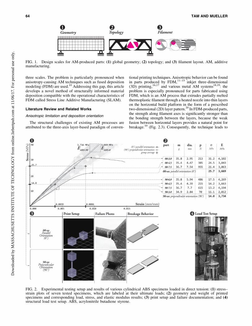
tional printing techniques. Anisotropic behavior can be foundin parts produced by FDM,11–15 inkjet three-dimensional(3D) printing,16,17 and various metal AM systems18,19: theproblem is especially pronounced for parts fabricated usingFDM, which is an AM process that extrudes partially meltedthermoplastic filament through a heated nozzle into thin layerson the horizontal build platform in the form of a prescribedtwo-dimensional (2D) layer pattern.20 In FDM-produced parts,the strength along filament axes is significantly stronger thanthe bonding strength between the layers, because the weakfusion between horizontal layers provides a natural point forbreakage.10 (Fig. 2.3). Consequently, the technique leads to
FIG. 1. Design scales for AM-produced parts: (1) global geometry; (2) topology; and (3) filament layout. AM, additivemanufacturing.
FIG. 2. Experimental testing setup and results of various cylindrical ABS specimens loaded in direct tension: (1) stress–strain plots of seven tested specimens, which are labeled at their ultimate loads; (2) geometry and weight of printedspecimens and corresponding load, stress, and elastic modulus results; (3) print setup and failure documentation; and (4)structural load test setup. ABS, acrylonitrile butadiene styrene.
64 TAM AND MUELLERD
ownl
oade
d by
MA
SSA
CH
USE
TT
S IN
STIT
UT
E O
F T
EC
HN
OL
OG
Y f
rom
onl
ine.
liebe
rtpu
b.co
m a
t 11/
06/1
7. F
or p
erso
nal u
se o
nly.

anisotropic manufactured parts with strength and ductilityproperties that vary significantly depending on the orientationof the applied forces. The inconsistent material property re-duces the structural strength of the printed object.
As Table 1 shows, numerous researchers have experi-mentally quantified the anisotropic limitation of FDM-produced parts. Their findings show that the tensilecapacity of FDM-produced parts when loaded perpendic-ular to filament orientation (transverse or out of plane) isbetween 55% and 64%11–14 the tensile capacity achievablewhen load is applied parallel to the print layers (axial or inplane)—depending on the AM technique used. Experi-ments conducted by the authors also corroborate thesefindings: Figure 2.1 and 2.2 summarize structural load testresults on FDM-produced acrylonitrile butadiene styrene(ABS) plastic in direct tension, showing that the tensilecapacity of specimens loaded perpendicular to filamentorientation is 45% weaker than a specimen loaded parallel.This anisotropy negatively affects the durability of theprinted specimen and limits the end-use application of AMtechnologies.21,22
Manufacturability centric AM topology optimization
Despite the well-established documentation of materialanisotropy, an assumption of material isotropy is implied inconventional strategies for optimizing geometries to be pro-duced using FDM. As Figure 3 summarizes, AM-orientedoptimization strategies are commonly defined along twogoals: (1) methods for modifying global geometry to improvestructural and fabrication efficiency (Fig. 3.1); and (2)fabrication-efficient methods for decomposing the horizontallayers of a print geometry into the filament layout (Fig. 3.2).
Strategies of the first goal reformulate classical methodsused in structural optimization, where the primary objectivefunction is the minimization of strain energy given a fixedmaterial volume, or in other words, the maximization ofthe structural stiffness-to-weight ratio. For manufacturabilityand fabrication efficiency, the objective is to minimize therequirement of scaffolding or support structure. The re-
quirement for scaffolding is determined by the interaction ofthe printed parts’ geometry and the technical fabricationconstraints of the FDM platform in use, which include themaximum bridging distance and minimum inclination angleof overhanging parts that can be printed without the use ofsupport material.23,24 Brackett et al.’s framework typifies oneapproach that utilizes single objective design optimization toscalarize structural and fabrication objectives into oneweighted sum, adapting a bidirectional evolutionary struc-tural optimization (BESO) to include a penalty function ac-counting the geometrical features requiring supports.4 Usingsimilar geometric criteria, Leary et al. alternatively proposeda postprocessing strategy that modifies the infeasible geom-etries of an initially optimized geometry.25
In research explicitly considering the filament layout,the objective is to optimize the tool-path planning strategyto improve the precision, surface quality, and strengthof prototypes, and reduce the building time and formingmaterial requirements. Tool-path planning encompassesboth boundary filling and path sequencing strategies,which, respectively, seek to minimize the number of sub-paths required for decomposing a printed geometry, andthe nonprinting time expended for relocating the printhead to connect discontinuous subpaths. Relevant work inthe first category include Jin et al., who proposed a mixedtool-path generation algorithm to hybridize the advan-tages of the two boundary filling techniques commonlyused by today’s platform, which include direction-parallelpath (DPP; contour-parallel path [CPP]; as illustrated at alater section by Fig. 4.1) and CPP (Fig. 4.2) planning.26
Expanding on the work, Han et al. developed a path opti-mization framework that additionally optimized the in-clination of referenced axis for creating parallel paths, thegeneration and grouping tool-path segments into individ-ual subpaths, and the linking of subpaths based on specificrequirements.27 Outside of research, developers of com-mercial platforms have also devised their own proprietary,unpublished algorithms.
Table 1. Summary of Experimental Load
Testing Results by Various Researchers
Showing Anisotropy in Fused-Deposition
Modeling Produced Parts
Studies Material
Normalized tensilestrength of parts
loaded perpendicularlyto filament orientation (%)
Bagsik et al.11 ULTEMResin
64
Rodrıguez et al.12 ABS 56Ahn et al.13 ABS 57Ziemian et al.14 ABS 56Results by authors
presented aboveABS 55
The percentage figures in the rightmost column indicates the tensilecapacity of FDM-produced parts when loaded perpendicular to filamentorientation (transverse or out of plane) normalized by the capacity of theparts when loaded parallel to filament orientation (axial or in plane).
ABS, acrylonitrile butadiene styrene; FDM, fused depositionmodeling.
1 2
Brackett et al.(2011)
Leary et al.(2014)
Jin et al.(2013)
He et al.(2014)
Proposed methodStress line additive manufactring (SLAM)(2015)
StructuralStiffness
Considerations
Target
Geometry Topology FilamentLayout
Manufactur-ability
FabricationEfficiency
FIG. 3. Diagram mapping current research on AM opti-mization methods: (1) methods for modifying global geo-metry to improve structural and fabrication efficiency; and(2) fabrication-efficient methods for decomposing the hor-izontal layers of a print geometry into the filament layout.
STRUCTURALLY INFORMED MATERIAL DEPOSITION AND TOOLPATH PLANNING 65D
ownl
oade
d by
MA
SSA
CH
USE
TT
S IN
STIT
UT
E O
F T
EC
HN
OL
OG
Y f
rom
onl
ine.
liebe
rtpu
b.co
m a
t 11/
06/1
7. F
or p
erso
nal u
se o
nly.

Problem statement and article outline
The literature review reveals that AM-specific optimiza-tion research is generally agnostic to the extrusion mecha-nism; the design and optimization of AM-produced parts’global geometry is divorced from the filament layout gener-ated by the tool-pathing strategies that comprise the printgeometry. The compartmentalized workflow consists of thefollowing: (1) topology optimization; (2) global geometryprocessing; and (3) slicing followed by the decomposition ofglobal geometry into tool-paths. Since structural and fabri-cation objectives are not well integrated in the design gen-eration of the printed part, most approaches require themodification of initially optimized geometries. With struc-tural guidance only utilized in the beginning, the determiningrole that the filament layout has on both the printed parts’material and global structural performance is ignored, con-tributing to an inconsistency in structural behavior at thescale of the geometry, topology, and filament layout thatnegate the potential gains of geometrical optimization. Evenin techniques engaging both structural and fabrication ob-jectives, there is a lack of numerical and experimental data tovalidate the structural performance of design generated usingthese techniques, or studies of the trade-off in performancebetween structural stiffness and manufacturability.
Recognizing that the structural challenge intrinsic to exist-ing optimization approaches for AM is primarily caused bypoor design-fabrication-performance integration or more pre-cisely, a lack of structural consideration in tool-path planning,this research presents a novel FDM method unifying structuralperformance considerations at the scale of global geometry,topology, and filament layout. Oriented material deposition
along 3D principal stress vectors is identified as the candidatefor developing a structurally informed tool-path planningstrategy that integrates both manufacturability and structuralobjectives, maximizing the structural strength-to-weight ratiofor structural prints. In this regard, this research expands onexisting works attempting similar approaches, most notablyChen et al.’s framework for subdividing planar surfaces toapproximate Michell’s optimal structure using stress line in-formation.8,9 The research presented in this study addresseslimitation found in the early adaptation of the stress linemethod in AM, which includes a lack of consideration of thefabrication process and the material structure of FDM-produced parts, and the lack of physical results for comparativeevaluation of printed geometries.
To motivate the research that is premised on the need toalign structural behavior at the scale of geometry and materialstructure, this article began with an introduction of the problemof FDM-induced anisotropy in commercial platforms usingexperimental results. Fundamental structural mechanics prin-ciples that form the basis of the stress line-based techniques arethen reviewed: Principal Stress Lines Derivation Review sec-tion, Stress Line Geometric Properties and Applicability inFDM section, System, Scope, and General Framework sec-tion, and Stress Line Generation Process section, respectively,summarize the theory of principle stress lines, identify thegeometrical compatibility of stress line-based topologies toFDM processes, outline the general framework of SLAM, anddescribe the process for generating and adapting stress lines.Finally, this article provides results for the implementation ofSLAM on two different platforms: methods and results ana-lyzing the performance of printed parts produced with SLAMare shown in Implementation 1: SLAM for Planar Cases onCommercial Platform section for planar geometries using acommercial FDM platform, and in Implementation 2: Robot-Enabled SLAM for 2.5D Cases section for 2.5-D surfaces us-ing an experimental robotic process.
Stress Line Theory and Applications
Principal stress lines derivation review
Principal stress lines are numerical integrations of princi-pal stress directions over a design domain. Mohr’s circles canbe constructed to obtain the information required for con-structing principle stress lines. Visually, stress lines indicatethe directions of space where stress is purely axial. As aconsequence, any elementary section (for 2D) or volume (for3D) orientated along lines of principal stress will not besubjected to any shear (or bending) stress. Architecturaland structural designers have routinely used stress lines to
LinksFilament / fill path
Slice outline
Start pointEnd point
1 2 3Direction-parallel Contour-parallel Hybrid strategy
FIG. 4. Conventional tool-path filling techniques: (1) direction-parallel; (2) contour-parallel; and (3) hybrid path planning.
FIG. 5. Convergence of optimization results obtained from (2–3) classical optimization methods and both the (1) Michellstructures and the (4) principal stress lines of the corresponding design domain.
66 TAM AND MUELLERD
ownl
oade
d by
MA
SSA
CH
USE
TT
S IN
STIT
UT
E O
F T
EC
HN
OL
OG
Y f
rom
onl
ine.
liebe
rtpu
b.co
m a
t 11/
06/1
7. F
or p
erso
nal u
se o
nly.

visualize the natural force flow of an applied load through astructural system,28 which approximately indicates the de-sirable material continuity for a given design domain.29
The study of stress lines is related to Michell’s classicalstudies on structural optimization.30 Michell’s theory statesthat a framework S within a region of space R resisting aloading Q will be of minimal volume if (1) any of its membersare stressed up to their maximal allowable compression ortension stress; and (2) members of S are subjected to the samestrain e in absolute value, with e defined as the maximumallowable strain within R. As denoted by Chen,8 Hemp,31 orStrang and Kohn,32 such conditions imply that the membersof S will lie along the lines of principal strains within R. Sincestress and strain have the same principal directions, asHooke’s law in linear elasticity for isotropic material indi-cates, the structures derived from principle stress line meth-ods are related to the optimal structures theorized by Michell,providing an explanation to the design convergence that istypically evident between the results of classical optimizationmethods (Fig. 5.2, 5.3) and both the principal stress lines(Fig. 5.4) and the Michell structures (Fig. 5.1) of the corre-sponding design domain.33
Stress line geometric properties and applicabilityin FDM
While previous research has provided theoretical supportfor the use of principle stress lines to generate high-performingtopologies that approximate optimal-like structures for thesame boundary condition, this article has identified stress lineproperties that suggest significant compatibility with FDM-based operations:
Geometrically compatible path planning. Since stressdistribution for elastic continuum bodies are also continuous,stress lines create contour-like and near-parallel fields of cur-vatures traversing from one design boundary to another,thereby producing geometric properties consistent with fila-ment layouts generated by conventional FDM path fillingtechniques, such as CPP (Fig. 4.1) or DPP (Fig. 4.2) planning.34
In common with CPP, which uses successive offsets of theboundary curves as tool-paths, stress line-based filament lay-out encourages articulated and smooth finishing because stresslines are geometrically similar to the design boundary ofprinted parts in general, as Figure 6.3 shows. Similarly, theparallel-like geometry of stress line-based filament layout al-lows efficient zigzag-like path linkage with low jump distances(Fig. 6.2), thereby contributing to the fabrication efficiencycommonly associated with DPP, which is characterized by theline-by-line filling of an area at a specified orientation.
Computational ease. As illustrated by Figure 7.2 and 7.3,conventional numerical optimization methods tend to pro-duce complex results that are computationally expensive tosolve and geometrically difficult to manipulate and adapt4;there is, in fact, no guarantee that the structure generated willbe reasonable because numerical computation can becomeunstable when large number of design variables are present,35
as is frequently required in complex designs. Conversely,stress line methods produce discrete curvatures that canreadily be converted to tool-paths (Fig. 7.1). Computationalease of SLAM is also notable: existing path filling strategiesrely on geometric operations that are more computationallycomplicated and expensive than the Finite Element Analysis(FEA) relied by the stress line method.
FIG. 6. General geometrical properties of stress line-based filament layout illustrated on a (1) funicular 4-support shellstructure: (2) parallel-like curve geometries allowing efficient zigzag-like path linkages; and (3) geometrical similaritiesbetween stress lines and design boundaries.
FIG. 7. Diagram showing the (1) adaptability of stress line results as printing tool-paths, in contrast to the geometricallycomplex and noisy results typically produced by classical optimization approaches using (2) ground structure and (3)homogenization method.
STRUCTURALLY INFORMED MATERIAL DEPOSITION AND TOOLPATH PLANNING 67D
ownl
oade
d by
MA
SSA
CH
USE
TT
S IN
STIT
UT
E O
F T
EC
HN
OL
OG
Y f
rom
onl
ine.
liebe
rtpu
b.co
m a
t 11/
06/1
7. F
or p
erso
nal u
se o
nly.

Stress Line Additive Manufacturing
The proposed SLAM method is motivated by the objectiveto develop FDM as a high-performance fabrication methodcapable of producing specimens that accurately convey bothgeometry and the structural performance expected of thespecimens’ geometry and intended application, such thatFDM can be reliably used to create mechanically meaningfulpieces that can be comparatively tested at the prototypingscale, or end-use functional parts at full scale like buildingcomponents. The workflow to implement SLAM consists ofthe following steps: (1) stress line computation, which en-compasses initialization, generation, and adaptation of stresslines for AM; (2) digital fabrication, which includes struc-turally informed methods for converting stress line-basedgeometries into fabrication instructions; and (3) experimentalload testing. Presented are two implementations of SLAM:using a commercial platform and a custom extrusion moduleattached to a robotic arm.
System, scope, and general framework
The SLAM method works with FDM for several reasons: itis cost-effective, widely used by designers, and produces partsthat are relatively strong and durable.36 With fewer fabricationprocessing parameters of relevance compared to other AMprocesses, such as selective laser melting (SLM),37–39 unex-pected performance interactions due to fabrication idiosyn-crasies are also minimized.
To maximize the design relevance of the proposedframework among architects and engineers, the research wasdeveloped using the popular 3D modeling tool Rhinoceros3D,40 within the parametric visual programming languageenvironment of Grasshopper 3D.41 Structural analyses wereconducted using the FEA plug-in Karamba.42 This researchalso utilizes Goat,43 which is an optimization solver that re-lies on gradient-free optimization algorithms found in theNLopt library.44
Geometrically, the implementation demonstrated in thisarticle focuses on both planar and form-found 2.5D mem-brane structures. Since these systems are subjected only toin-plane stresses, normal stresses in discretized membersare primarily axial-only with negligible bending, therebycreating a suitable design test case to validate the advan-tages of the proposed technique in addressing FDM-inducedanisotropy.
Stress line generation process. Stress line constructionmethods are primarily numerical and iterative because ana-lytical versions are often difficult to formulate. Consequently,the qualities and usability of stress lines vary widely ac-cording to the various construction and calculation parame-ters. The computation of stress lines in this research follows amethodology outlined in the author’s previous work,45 whichwas built on the foundational research conducted by Chenet al.,8,9 and Michalatos and Kaijima.29 The proposed approachaddresses known problems in commercially available ap-proaches, such as (1) low stress line resolution, (2) poor stressdirection interpolation, and (3) stress line discontinuities.46
Contrasting existing approaches focused on force visualization;the method developed by the authors seek to generate optimal-like frame topologies with proper connectivity that can be easilyfabricated through AM.
The fundamental procedure has been broken into the threestages of initialization, generation, and processing.45 The pur-pose of initialization is to characterize the design domain withproper meshing and conduct structural analysis on the designdomain to obtain data needed for stress line construction.Following initialization is generation: given a seeding point,the principal stress directions are extracted from the under-lying FEA data and interpolated for that point. A line segmentis then drawn along these directions and its endpoint becomesthe starting point for the subsequent iteration. This processrepeats until the stress line reaches the design boundaries; theconclusion of the stress line for one seed leads to stress lineconstruction for the next seed in the sequence.46
Obtaining a uniformly spaced base stress line field, struc-turally informed methods are used to process and select stresslines for AM since the theoretically optimized Michell-likeoptimum structure, which has an infinite number of infinitelysmall bars with infinitely low stress, is neither manufactur-able nor significantly superior in structural performancesthan those at lower density.47 Modifications have been in-troduced to the methods developed in previous research toconsider the fabrication constraints that are particular to eachimplementation presented, encompassing both selection andcorrection methods.
To measure structural efficiency, this article uses theminimization of strain energy as the objective function, alsoreferred to as the minimization of compliance, or the maxi-mization of stiffness.48,49 Performance comparison of stressline-based structures is enabled by normalizing strain energywith the total member length and by holding constant the totalmagnitude of external loads applied, loads that are then re-distributed to each node according to its respective tributaryarea estimated using a Voronoi-based method.50
Implementation 1: SLAM for Planar Caseson Commercial Platform
Developed in the first implementation is a method forenabling SLAM on existing commercial FDM platforms tocreate high-performance planar structures such as beams.The two-part investigation seeks to provide confirmation thatstructural performance is maximized when continuous ma-terial deposition is parallel to the primary plane of structuralaction and when in-plane filament layout is aligned to stressline-based topology.
Hardware setup, and design and planningof comparative structural load testing
The specimens are produced in ABS plastic with a Stra-tasys Dimension sst 1200es 3D printer,51 using the ‘‘Solid’’interior density setting, which ensures tight filament packingto facilitate force transfer, and the ‘‘SMART’’ setting, whichensures support material is assigned to only the most criticallocations. The fabrication of the specimen relies on the fila-ment layout generated by CatalystEX,51 which is the Stra-tasys software package for converting the CAD-generatedStandard Tessellation Language (STL) output into the fila-ment layout and printing instructions. Three identical printsand tests are conducted for each design case.
Figure 8 illustrates the standard naming conventionadopted in this article to describe the element’s orientationand parts. All test cases were designed and specified as
68 TAM AND MUELLERD
ownl
oade
d by
MA
SSA
CH
USE
TT
S IN
STIT
UT
E O
F T
EC
HN
OL
OG
Y f
rom
onl
ine.
liebe
rtpu
b.co
m a
t 11/
06/1
7. F
or p
erso
nal u
se o
nly.

simply supported beam trusses with load applied at mid-spans, providing a complex and realistic comparative struc-tural configuration for understanding the effects of anisot-ropy and topology (Fig. 8.1). The span of the structure isthe maximum printable span achievable with the print bedof the Dimension, which is 150 mm. To prevent out-of-planebuckling, all trusses are provided with 30.5 mm in width. Alltest designs are encased within a rectangular enclosure. Aplatform is provided both at the area of supports and loadapplication for force distribution (Fig. 8.2).
Strategies for member and filament orientation align-ment. In cases where print layers are parallel to the plane ofstructural action, two general fabrication-driven geometricaldesign strategies were devised to ensure parallel alignment of thefilament and the internal members of the beam trusses. The firststrategy sets the thickness of the internal members as integermultiples of the filament resolution (Fig. 8.3) to encourage thedefault CatalystEX path filling algorithm to achieve filamentmember alignment by creating paths through simple offsetting ofinternal members. The second strategy involves the reduction ofin-plane member intersections as the default algorithm generatesunaligned filament layouts in areas near members’ intersections.
Organizationally, since all design cases include two dis-tinct classes of members, in-plane intersections can be miti-gated by modeling the beam trusses as stackings of twoalternating topology layers (Fig. 8.2). This article also pro-poses a two-step processing method for generating stressline-based designs, which incorporate Dimensions’ fabrica-tion constraints, from an initial base dense stress line field.The first step begins with the selection of a starting stress line,followed by the incremental evaluation of adjacent stresslines for their maximum point-to-point distance with the se-lected starting stress line. The first stress line that fulfills themaximum spacing target (See Row PR1 in Fig. 9), which isuser defined according to material quantity and aestheticconstraints, and is measured according to the maximumpoint-to-point distance between adjacent stress lines is se-lected. The iterative search process then repeats again for the
newly selected line. With all stress lines in the base stress linefield evaluated, the second iterative procedure then removes,according to a target minimum point-to-point distance, theremaining stress lines that are causing in-plane intersections(see row PR2 in Fig. 9). In ensuring that the selection of stresslines will fulfill basic maximum and minimum spacing crite-rion, the outlined approach provides indirect mechanisms foraffecting the density of the stress line-based system. However,because of variations in the resolution of the base dense stressline field and discrepancies between the overall spacing ofadjacent stress lines and their maximum point-to-point
FIG. 8. Diagram showing the orientation, labeling terminologies, and geometric attributes of test cases at the scale of the(1) global geometry; the (2) alternating topology layers; and (3) the members within the layers.
FIG. 9. Rule-based corrections for adapting SLAM to com-mercial FDM platforms. The figure illustrates the first threesteps applied for each rule (PR1-2), which consists of (1) se-lection of starting line; (2) stress line evaluation and selectionfor inclusion (X) or removal (·); and (3) line removal. FDM,fused deposition modeling; SLAM, Stress Line AdditiveManufacturing.
STRUCTURALLY INFORMED MATERIAL DEPOSITION AND TOOLPATH PLANNING 69D
ownl
oade
d by
MA
SSA
CH
USE
TT
S IN
STIT
UT
E O
F T
EC
HN
OL
OG
Y f
rom
onl
ine.
liebe
rtpu
b.co
m a
t 11/
06/1
7. F
or p
erso
nal u
se o
nly.

distances, this indirect strategy cannot guarantee consistentand uniform spacing in the produced stress line-based designs.Future implementation will develop computational selectionmethods based directly on overall density considerations.
Test cases designs. As described in Table 2, the firstinvestigation fabricates an identical stress line-based geom-etry at two print orientations. SLAM-XY, which serves as thecontrol case for both investigations, has layers that are par-allel to the plane of structural action formed by the depth andspan of the beam truss and a filament layout that generallymaintains parallel filament member alignment, thereby en-abling the effective utilization of the material yield strength.Conversely, in SLAM-XZ, internal members are constructedthrough layer-by-layer material deposition, such that thestructural performance of the beam truss is controlled by itslayers’ fusion strength.
To test the effects of topology on structural performance,the second investigation implements an alternative 2DVierendeel-like grid frame topology (GRID-XY), which ischaracterized by beam truss discretization as frames with
rectangular and untriangulated openings, as Table 2 illus-trates. An attempt was made to calibrate the member widthand density to equalize the volume and weight of all designcases. Three identical specimens were produced from each ofthe three cases, resulting in nine tested specimens.
Documentation, analysis and discussion of results
Table 3 includes the fabrication instruction generated forthe Dimension printer, and Table 4 provides quantitativeand photographic documentation of all fabricated results. Asexpected, the finishing quality is superior in test cases that areprinted parallel to the plane of the beam truss topology, asdemonstrated in the comparison of SLAM-XY and SLAM-XZ in Table 4. In the latter case, an undulating variation incross-sectional diameter along the internal members’ lengthis noticeable due to the length-wise layer-based materialdeposition. Discrepancies in mass have also been observeddespite the use of identical print settings, and the equalizationof volume for all cases, the difference, which is quantified bythe mass-to-volume ratio, or density, suggests inconsistency
Table 2. Digital Modeling and Design of Test Specimens Used in Investigation One
Case SLAM-XY SLAM-XZ Grid-XY
MemberCenter lines
Fabrication instructionsin Standard Tessellation Language (STL) geometry
Bounding box dimensions 151.9 · 37.6 · 30.5 mm (6.0 · 1.5 · 1.2 in)Volume V (mm3) 35,260 36,270
SLAM, Stress Line Additive Manufacturing.
Table 3. Documentation of Fabrication Setup and Instructions
Case SLAM-XY SLAM-XZ GRID-XY
Print model space setup
Layer pattern or filament layout
Fabrication time 9 h: 11 min 143 h: 35 min 19 h: 08 minModel and support material requirement (mm3) 55,060.5; 64,565.0 46,867.0; 67,842.4 58,378.0; 67,187.0
70 TAM AND MUELLERD
ownl
oade
d by
MA
SSA
CH
USE
TT
S IN
STIT
UT
E O
F T
EC
HN
OL
OG
Y f
rom
onl
ine.
liebe
rtpu
b.co
m a
t 11/
06/1
7. F
or p
erso
nal u
se o
nly.

in the packing intensity of the filament material by the Di-mension platform. All results are normalized according to thespecimen mass to account for these discrepancies.
Load testing and load-displacement plot results of thecomparative load testing for both investigations are respec-tively summarized in Table 5 and Figures 10 and 11. As Table 5shows, the normalized ultimate and yield load-to-weight ratiosfor SLAM-XY are respectively 3.5 and 4.7 times higher thanSLAM-XZ’s ratios. In addition, SLAM-XZ behaves with
considerably more ductility (Fig. 10), with yield capacity sus-tained through extensive plastic deformation. The significantperformance difference indicates that the print orientation has acritical impact on structural behavior, thereby reaffirming theproblem of anisotropy in specimen printed using layer-basedprocesses. Support for this interpretation is also evident in thespecimens’ failure mode, whereas SLAM-XY experiencedsimultaneous gross section tensile failure along the memberwhere the greatest tensile stress is expected; the failures of
Table 4. Documentation of Fabricated Test Specimen
Case SLAM-XY SLAM-XZ Grid-XY
Fabricated resultsOverall viewDetailed elevation view
Mass, m (g) 46.5 54.2 62.6
Density, D = m/V (kg/m3) 1317.6 1536.3 1726.0
Table 5. Documentation of Failure Modes and Comparison of Predicted
and Actual Load Testing Results Normalized According to the Specimen Mass
Case SLAM-XY SLAM-XZ Grid-XY
Predicted normalizedyield load and displacement
2495.1 N/N at 0.79 mm 2250.1 N/N at 5.12 mm
Average normalized yieldload and displacement
2537.7 N/N at 2.26 mm 541.6 N/N at 0.64 mm 1783.0 N/N at 2.93 mm
Average normalized ultimateload and displacement
2847.8 N/N at 2.92 mm 810.9 N/N at 2.46 mm 2799.9 N/N at 7.54 mm
Average elastic stiffnessnormalized by specimen mass
1111.8 (N/N)/mm 836.4 (N/N)/mm 601.6 (N/N)/mm
Failure mode description Simultaneous grosssection failures (tension)at concentrated location
Delamination betweenlayers (tension) alongY axis, progressive failureat multiple locations
Gross section (tension),multiple locations
Failure type Brittle Ductile Brittle
Failure profilesGlobal geometryMember view
STRUCTURALLY INFORMED MATERIAL DEPOSITION AND TOOLPATH PLANNING 71D
ownl
oade
d by
MA
SSA
CH
USE
TT
S IN
STIT
UT
E O
F T
EC
HN
OL
OG
Y f
rom
onl
ine.
liebe
rtpu
b.co
m a
t 11/
06/1
7. F
or p
erso
nal u
se o
nly.

SLAM-XZ are progressive and numerous, characterized bydelamination of the layers composing the length of internalmembers. The results of the second investigation are consistentwith the initial prediction that stress line-based topologies arestronger than grid-based topologies (Fig. 11). Although thedifference in ultimate load-to-weight ratio is subtler, with onlyan 8% difference between SLAM-XY and GRID-XY, a cleargain in yield strength is noticeable for SLAM-XY, as its yieldload-to-weight ratio is 1.6 times GRID-XY’s ratio. Figure 11further shows higher stiffness for SLAM-XY through the load-displacement slope, which is 1.9 times steeper compared withGRID-XY. This indicates that the stress line-based structuresexhibit truss-like behavior, whereas the grid-based structurebehaves mostly in bending, which consequently uses the ma-terial less efficiently.
With an average normalized yield strength capacity of2537.7 N/N, the experimental result for SLAM-XY is con-sistent with an FEA prediction of 2495.1 N/N (linear elasticassumption, yield is considered to occur when the first memberfails). This closeness in yield capacity contrasts with the dis-crepancy observed for the GRID-XY specimen, where an18% difference in yield capacity is noticeable. Two factorsmay explain the difference in performance for the GRID-XYspecimen. First, geometric discrepancies have been identified
between the digital and fabricated model, discrepancies causedby idiosyncrasies of the default printer software used to convertthe CAD-generated STL output into the filament layout andprinting instructions. Measurements show that the horizontalmembers of GRID-XY were printed with reduced depth.Second, the numerical prediction relies on idealized structuralassumptions, such as the in-plane coincidence of members’center lines at the joint intersections and the characterization ofjoints as fixed connections. These assumptions do not account,respectively, for the eccentricities introduced by the stackingstrategy of alternating topology layers and the weakening ofthe joint connection as a result of structural action needing totransverse the weak bonds between the alternating layers.Consequently, GRID-XY has underperformed by 20.8% incomparison to its expected performance predicted using FEA;since the structural action of the topology is bending domi-nated, the reduced capacity of the joints would likely have agreater impact than is the case for SLAM-XY, which is pre-dominately governed by axial forces.
Regardless of the discrepancies identified above, it isclear from both investigations that filament alignment playsan important role in determining the structural performanceof AM-produced parts. Significantly, there is validation thatthe SLAM method achieves parts with higher strength and
ESLAM-XY E
SLAM-XZ
Displacement (mm)
SLAM-XZSLAM-XY
group average
Yie
ldU
ltim
ate
500
1000
2.932.460.65
5.32
7.94
24.85
27.92
1500
2000
2500
3000
3500 834.6-837.41073.0-1149.5N
orm
aliz
ed S
tren
gth
to W
eigh
t (N
/N)
0 1 2 3 4 5 6
FIG. 10. Load-displacement plot for investigation one’s test cases.
ESLAM-XY E
GRID-XY
Displacement (mm)
GRID-XY SLAM-XY
group average
Yie
ldU
ltim
ate
500
1000
1500
2000
2500
3000
3500
45.739.22.46
2537.7
1783.0
2847.82847.8
583.4-628.31703.0-1149.5
0 1 2 3 4 5 6 7 8 9 10
Nor
mal
ized
Str
engt
h to
Wei
ght (
N/N
)
FIG. 11. Load-displacement plot for investigation two’s test cases.
72 TAM AND MUELLERD
ownl
oade
d by
MA
SSA
CH
USE
TT
S IN
STIT
UT
E O
F T
EC
HN
OL
OG
Y f
rom
onl
ine.
liebe
rtpu
b.co
m a
t 11/
06/1
7. F
or p
erso
nal u
se o
nly.

stiffness. However, the encouraging results seen in theplanar implementation will not be reproducible for highlycomplex 3D geometries, because their structural behaviorcannot be reduced to a single planar orientation to be par-allel with the print bed. This means that conventionalmonolithic printing methods, which are configured to be
able to achieve only continuous filament deposition intwo directions, will produce 3D geometries that are affectedby anisotropy, and therefore cannot be used to manufac-ture 3D structurally isotropic prototypes, or end-use partsthat accurately model the structural behavior of the finalgeometry.
FIG. 12. Robotic fabrication work-cell setup. Photographic documentation of the robotic-enabled stress line additivemanufacturing process: (1) robotic work cell; (2) oriented filament deposition of stress lines on substrate built from medium-density fiberboard; and (3) close-up detail of extruded filament.
FIG. 13. Components of custom FDM printing module. (1) Custom FDM printing module; and (2) extruder head poweredby Signstek stepper motor.
STRUCTURALLY INFORMED MATERIAL DEPOSITION AND TOOLPATH PLANNING 73D
ownl
oade
d by
MA
SSA
CH
USE
TT
S IN
STIT
UT
E O
F T
EC
HN
OL
OG
Y f
rom
onl
ine.
liebe
rtpu
b.co
m a
t 11/
06/1
7. F
or p
erso
nal u
se o
nly.

Implementation 2: Robot-Enabled SLAMfor 2.5-D Cases
Problem and objective
The current challenges of AM techniques in aligning fil-ament deposition to the directions of structural action forcomplex 3D design are due to the limited capacity of aconventional layer-based extruder to achieve varied orien-tations. In response, this article proposes a new adaptation ofSLAM that combines stress line-based computation withmultiaxis robot machining. The proposed method aims toallow for oriented filament deposition along the networks ofaxial structural actions on complexly curved surfaces.
Software and hardware framework
This second implementation uses the KUKA KR6 R900sixx small robot,52 which is mounted with a custom extrusionmodule, and is centrally located inside a contained work cell.As shown in Figure 12.1, the medium-density fiberboard(MDF) surface printing bed is clamped to the metal worktable at an eccentricity from the robot to minimize roboticjoint rotational issues.
Custom FDM printing module. Based on research intoconsumer-grade extrusion devices, the custom extruder iscomposed of a waterjet-cut aluminum frame that is me-
chanically coupled to the robot by a pneumatic tool changer.The aluminum frame (Fig. 13.1) holds a commerciallyavailable extruder sold by Signstek53 and control electronics(Fig. 13.2). The Signstek extruder accepts 1.75 mm PLAand is composed of a 1.8� stepper motor, heating element,thermistor, and cooling fan. Using an Arduino Uno54 mi-crocontroller and an N Type MOSFET, the closed looptemperature control of the extruder nozzle was utilized. TheKUKA’s 24 V signal outputs were monitored by the on-board Arduino and were used to start and stop the steppermotor/extrusion. Control of the stepper motor was achievedwith an EasyDriver55 board that uses an Allegro A3967motor driver chip.
FIG. 14. Diagram showing the clustering of stress line-based paths into individual tool-path chains (2–3), based on the (1)positioning of the substrate; and (2) geometrical similarities of the individual paths.
FIG. 15. Surface geometry used in implementation 2.Uniformly loaded four-support grid shell geometry used inimplementation 2: (1) plan; and (2) axonometric view; and(3) printing substrate.
74 TAM AND MUELLERD
ownl
oade
d by
MA
SSA
CH
USE
TT
S IN
STIT
UT
E O
F T
EC
HN
OL
OG
Y f
rom
onl
ine.
liebe
rtpu
b.co
m a
t 11/
06/1
7. F
or p
erso
nal u
se o
nly.

Robotic programming. The KUKA KR6 Robot arm isprogrammed with KRL code, and the robot instructions aregenerated in RobotMaster,56 which is a plugin to MasterCAM.57
The typical workflow consists of the following iterative and trialand error procedure: (1) import of print surface and stress linedata from CAD into CAM software; (2) specimen positioning inthe workspace; (3) print surface calibration in the CAM modelspace; (4) clustering of paths based on robot work volume andreach limitations trajectory (Fig. 14); (5) assigning stress line-based geometry for tool-path generation; (6) iteration of possiblejoint configurations in CAM and RobotMaster interface; (7)optimization and simulation of robot; and (8) export KRL codeand run program in KUKA.
Design and planning of comparativestructural load testing
The research of robot-enabled SLAM focuses on 2.5-Dsurface structures: the Kangaroo58 plug-in was used to form-find a uniformly loaded basic grid shell with four supports, asdemonstrated in Figure 15.1–15.3, the form-found printingsubstrate milled from a wood block consisted of laminatedMDF layers.
Adaptation for robot-enabled fabrication. As in the ap-proach taken in the first implementation, a series of rule-basedcorrections are specifically designed for the robot-enabled
FIG. 16. Rule-based system developed to correct fabrication paths: (1) specific correction rules addressing fabrication orstructural concerns; (2–3) application of various correction rules on the bisymmetrical region of a four-support grid shelldesign case; and (4) photograph of the fabricated specimen.
STRUCTURALLY INFORMED MATERIAL DEPOSITION AND TOOLPATH PLANNING 75D
ownl
oade
d by
MA
SSA
CH
USE
TT
S IN
STIT
UT
E O
F T
EC
HN
OL
OG
Y f
rom
onl
ine.
liebe
rtpu
b.co
m a
t 11/
06/1
7. F
or p
erso
nal u
se o
nly.

extrusion platform, and iteratively applied to the initiallyobtained evenly spaced stress line field to achieve additionalimprovements in fabrication ease and quality (Fig. 16.2, 16.3).These include the removal of line segments in areas withsignificant stress line overlap, or the realignment of otherwiseconverging stress lines in highly stressed areas (Fig. 16.1,FR#). General structural rules include modification of stressline curvatures to facilitate force transfers at intersectionnodes and the insertion of bracing members (Fig. 16.1, SR#).Although the initial implementation of the rule-based system
required some manual operations, the process can be auto-mated in future developments.
Design of test cases. To validate that SLAM-producedspecimens perform better than conventionally 3D-printedparts, a comparative load test was completed on a num-ber of specimens: four printed using the SLAM methodand three printed using a conventional layer-based 3Dprinter. MakerBot Replicator 259 was selected as thetechnology to be compared to the SLAM method, as it is
Table 6. Documentation of 2.5-D Fabricated Test Specimen
Case MB-CT MB-UDL SL-DL SL-PL SL-ADL SL-LL
Description Constant surfacethickness
Uniformly distributed vertical load Central verticalpoint load
Asymmetricallydistributedvertical load
Asymmetricallydistributedhorizontal load
Domain specification
Principle stress lineresults
Postprocessed stressline-based memberCenter lines
Layer-1Layer-2
n/a
Fabrication instructions
*Standard TessellationLanguage (STL)geometry
**Clustering ofstress line-basedpaths
ManufacturingMethod
MakerBot Replicator 2Horizontally layered
deposition
Robot-enabled SLAM Oriented material deposition for memberfilament alignment
Fabricated result
Overall viewDetail
Copies tested 2 1 2 2 0
ADL, asymmetrically distributed load; CT, constant thickness; LL, lateral load; PL, point load.
76 TAM AND MUELLERD
ownl
oade
d by
MA
SSA
CH
USE
TT
S IN
STIT
UT
E O
F T
EC
HN
OL
OG
Y f
rom
onl
ine.
liebe
rtpu
b.co
m a
t 11/
06/1
7. F
or p
erso
nal u
se o
nly.

one of the most popular consumer-grade 3D printingplatform available to designers using PLA plastic. Aneffort was made to ensure that all specimens have similartotal material volume. Table 6 describes the design andfabrication of the small-scale specimens for the four-support shell structure.
For the SLAM specimen, four loading cases were usedto generate stress line-based topologies: (1) distributedload (labeled SL-DL); (2) point load (SL-PL); (3) asym-metrically distributed load (SL-ADL); and (4) lateral load(SL-LL). The resulting specimens produced from these loadcases are shown in Figure 17. The MakerBot MB prints
FIG. 17. Detailed photographic documentation of SLAM specimen.
FIG. 18. Load testing setup. (1) Structural load testing setup showing (2) loading application and the (3) failure profile of aSLAM-produced specimen.
STRUCTURALLY INFORMED MATERIAL DEPOSITION AND TOOLPATH PLANNING 77D
ownl
oade
d by
MA
SSA
CH
USE
TT
S IN
STIT
UT
E O
F T
EC
HN
OL
OG
Y f
rom
onl
ine.
liebe
rtpu
b.co
m a
t 11/
06/1
7. F
or p
erso
nal u
se o
nly.

included both a solid constant-thickness shell (labeled MB-CT) and a stress line-based topology based on SL-DL.
Results
The load test consists of a single centralized vertical pointload that was applied until a peak load was reached (Fig. 18);Table 7 shows the load testing results for the four caseswith symmetrical vertical loading (MB-CT, MB-UD, SL-DL, and SL-PL). While the number of tests conducted isnot high enough to be statistically conclusive, the prelimi-nary results nevertheless suggest that the robot-enabled SLAMmethod can also lead to improved structural behavior comparedto parts produced using commercial FDM platforms. Both nu-merical and experimental results demonstrate the benefit ofmaterial redistribution by stress lines, as seen in the improvedstrength performance of MB-UD over MB-CT. Similarly,the combined benefits of topology and filament-memberalignment, which eliminate the problem of anisotropicbehavior, are demonstrated by the improved performance
of SL-DL over both MB cases. The experimental resultsshow that the SLAM cases registered a 25% improvementin stiffness, and a 76% and 27% improvement, respec-tively, in ultimate strength capacity and ductility afterinitial failure. The potential gain is particularly prominentin comparison to MB-CT, where intralayer bond failuresoccurred in areas where tensile stresses were predicted tooccur (see ‘‘Failure profiles: Corner’’ in Table 7). Moresignificant advantages for the SLAM method are expectedin complex geometries and loadings that induce moretension.
Although the initial robot-enabled implementation isable to demonstrate the strength and ductility advantagesachievable using SLAM for 2.5-D design cases, the com-parison of the experimental and numerical results nonethe-less show that all physically produced specimens haveunderperformed with regard to their initial yield capacities.For the MB specimen, the lowered experimental yieldstrength is expected because the layer-based extrusion of theconventional platform creates an anisotropic specimen with
Table 7. Documentation of Failure Modes and Comparison of Predicted and Actual
Load Testing Results Normalized According to the Specimen Mass
Specimen name MB-CT MB-UD SL-DL SL-PL
Mass (g) 39.8 37.2 40.7 49.9
Normalized predictedinitial yield load
1890.5 N/N 2411.2 N/N 3038.3 N/N
Normalized initialyield load
1685.1 N/N 1547 N/N 1817.5 N/N 1609.1 N/N
Normalized ultimateload
2045 N/N 2756 N/N 3603 N/N 2896 N/N
Peak elastic stiffnessnormalized byspecimen mass
449.9 (N/N)/mm 647.3 (N/N)/mm 822.2 (N/N)/mm 736.8 (N/N)/mm
Failure mode description Intralayer bond Filament crushing,local fracture,
intralayer bond
Filamentcrushing/bending,
global fracture
Filamentcrushing/bending
Failure type Brittle Brittle Ductile Ductile
Failure profilesTopCorner
UD, distributed load.
78 TAM AND MUELLERD
ownl
oade
d by
MA
SSA
CH
USE
TT
S IN
STIT
UT
E O
F T
EC
HN
OL
OG
Y f
rom
onl
ine.
liebe
rtpu
b.co
m a
t 11/
06/1
7. F
or p
erso
nal u
se o
nly.

reduced strength capacity, such that the ultimate yieldstrength for the MB specimen has barely exceeded theirexpected yield capacity (a paltry margin of 8–12% is ob-served). Conversely, the underperformance in yield strengthfor the SLAM specimen is largely the result of the fab-rication technique’s inconsistent quality control, incon-sistencies such as fluctuating filament thickness, and widththat may have led to premature initial failure of the specimen.This interpretation is supported by the capacity for allSLAM specimens to achieve some additional 80–100%increase in strength capacity following their initial failures,despite their underperforming initial yield loads. Additionalevidences are found in the photographic documentation ofSL-PL, whereby an unanticipated acceleration in printingspeed due to robotic constraints has led to a narrowing ofthe filament extrusion near the corners where significantload paths converged (see ‘‘Failure: profiles: Corner forSL-PL’’ in Table 7), resulting in substantial discrepancybetween the predicted and actual yield loads of SL-PL. It isclear that significant improvements to the fabrication tech-nique are still needed; future improvements will allow theSLAM-produced specimens to better realize the potentialstrength and stiffness gain associated with stress line-basedtool-path planning.
Conclusion
Summary of contributions
The research pursued in this article presents and validatesa new approach to AM that synthesizes the design and opti-mization of FDM-produced part, where unlike conventionalapproaches, structural behavior of the printed parts is si-multaneously considered at the scale of the geometry, to-pology, and filament layout. Structural load testing of twoimplementations provided initial verification that the pro-posed method outperforms methods using the conventionallayer-based paradigm
Future work
The success of the second implementation in achiev-ing complexly curved 3D designs suggests that thegreatest potential of the SLAM technique is to be gainedby expanding the robot-enabled methods. In that area,there are several important directions for future devel-opment: (1) extensive experimental testing that incor-porate the variations of both topology generation andfabrication parameter to better understand the materialand strength behavior of SLAM-produced specimens; (2)standardization and improvement of the SLAM methodsto achieve better precision and surface quality; (3) im-proved computational automation for integrating thestress line and robotic path generation and computationalframework to automate the generating stress line-basedstructures and robot paths; and (4) expansion of the de-sign applications of SLAM to enable the fabrication ofprinted parts with greater diversity of geometries andfunctionalities. Specifically, modification on the designboundaries and loading and support conditions of thedesign can produce test cases that offer a better under-standing on the expected tensile strength improvement ofSLAM-produced parts. Significant future milestones also
include the development of computational techniques forvolume-filling 3D solids, such as by ongoing research toextend Michell’s theory for 3D structural applications,60
the elimination of the requirement of a printing support,61
and the expansion of the extrusion module’s hardware cap-abilities, such as the incorporation of sensors to allow ex-trusion parameters to vary intelligently according toemergent conditions of the as-built specimen. These ad-vances will open possibilities for free-form and real-timeAM, thus allowing the technique to be implemented formore complexly curve 3D surface design and full-scaleconstruction.
Acknowledgments
The authors wish to thank the following students whoassisted with various aspects of this research: JonathanMackaman, Akshat Bubna, Elizabeth Bianchini, NicholasFine, James Coleman, Katie Gertz, Colin Poler, Xinyi Ma,Mitchell Gu, Chrystal Chern, Benjamin Jacot, and YijiangHuang. Also, the authors acknowledge MIT fabrication lab-oratory coordinators Justin Lavallee, Chris Dewart, JenO’Brien, shop monitors Ines Ariza, and James Addison, andtesting laboratory technician Stephen Rudolph.
Author Disclosure Statement
No competing financial interests exist.
References
1. Christensen C. The ongoing process of building a theory ofdisruption. JPIM 2006;23:39–55.
2. Hopkinson N, Hague R, Dickens P, eds. Rapid manufactur-ing: An industrial revolution for the digital age. Chichester,England: John Wiley & Sons, 2006.
3. Schmidt G, Druehl C. When is a disruptive innovationdisruptive? JPIM 2008;25:347–369.
4. Brackett D, Ashcroft I, Hague R. Topology optimizationfor additive manufacturing. Proceedings of the FreeformFabrication (SFF) Symposium. Austin, TX: SFF, 2011;pp.348–362.
5. Brandt M, Sun S, Leary M, et al. High-value SLM Aero-space components: From design to manufacture. Adv MaterRes 2013;633:135–147.
6. Cooper DE, Stanford M, Kibble KA, et al. Additivemanufacturing for product improvement at Red BullTechnology. Mater Des 2012;41:226–230.
7. Ventola CL. Medical applications for 3D printing: Currentand projected uses. PT 2014;39:704–711.
8. Chen Y, Li Y. Beam Structure Optimization for additivemanufacturing based on principal stress lines. Proceedingsof the 21st Solid Freeform Fabrication (SFF) Symposium.Austin, TX: SFF, 2011; pp.666–678.
9. Chen Y, Kwok T-H, Li Y. A structural topology designmethod based on principal stress line. Comput Aided Des2016;80:19–31.
10. Mueller CT, Irani A, Jenett BE. Additive manufacturing ofstructural prototypes for conceptual design. Proceedings ofthe 55th International Association of Shell and SpatialStructures (IASS) Symposium: Shells, Membranes andSpatial Structures. Brasilia, BRA: IASS, 2014.
11. Bagsik A, Schoeppner V, Klemp E. FDM part qualitymanufactured with Ultem*9085. 14th International Scientific
STRUCTURALLY INFORMED MATERIAL DEPOSITION AND TOOLPATH PLANNING 79D
ownl
oade
d by
MA
SSA
CH
USE
TT
S IN
STIT
UT
E O
F T
EC
HN
OL
OG
Y f
rom
onl
ine.
liebe
rtpu
b.co
m a
t 11/
06/1
7. F
or p
erso
nal u
se o
nly.

Conference on Polymeric Materials, 2010, Halle (Saale),Germany.
12. Rodrıguez JF, Thomas JP, Renaud JE. Mechanical behaviorof acrylonitrile butadiene styrene (ABS) fused depositionmaterials. Experimental investigation. Rapid Prototyping J2001;7:148–158.
13. Ahn SH, Montero M, Odell D, et al. Anisotropic materialproperties of fused deposition modelling ABS. Rapid Pro-totyping J 2002;8:248–257.
14. Ziemian C, Sharma M, Ziemian S. Anisotropic mechanicalproperties of ABS parts fabricated by fused depositionmodelling. In: Gokcek M (Ed). Mechanical Engineering.InTech, Rijeka, HRV, 2012; pp.59–180.
15. D’Amico A, Debaie A, Peterson AM. Effect of layerthickness on irreversible thermal expansion and interlayerstrength in fused deposition modeling. Rapid Prototyping J2017;5:23.
16. Mueller J, Shea K, Daraio C. Mechanical properties of partsfabricated with inkjet 3D printing through efficient exper-imental design. Mater Des 2015;85:902–912.
17. Kesy A, Kotlinski J. Mechanical properties of parts pro-duces by using polymer jetting technology. Arch Civ MechEng 2010;3:37–50.
18. Zhu Y, Tian X, Li J, et al. The anisotropy of laser meltingdeposition additive manufacturing Ti–6.5Al–3.5Mo–1.5Zr–0.3Si titanium alloy. Mater Des 2015;67:538–542.
19. Frazier WEJ. Metal additive manufacturing: A review.J Mater Eng Perform 2014;23:1917–1928.
20. Sun Q, Rizvi GM, Bellehumeur CT, et al. Effect of pro-cessing conditions on the bonding quality of FDM polymerfilaments. Rapid Prototyping J 2008;14:72–80.
21. Tam K-MM, Coleman JR, Mueller CT, et al. Stress LineAdditive Manufacturing (SLAM) for 2.5-D shells. J IASS2016;190:249–259.
22. Tam K-MM, Coleman JR, Mueller CT, et al. Robotics-enabledstress line additive manufacturing. Proceedings of the 3rd Ro-botic Fabrication in Architecture, Art and Design (RobjArch)Conference. Cham, CH: Springer, 2016; pp.351–362.
23. Leary M, Merli L, Torti F, et al. Optimal topology for ad-ditive manufacture: A method for enabling additive manu-facture of support-free optimal structures. Mater Des 2014;63:678–690.
24. Bablani M, Bagchi A. Quantification of errors in rapidprototyping processes,and determination of preferred ori-entation of parts. Transactions of the 23rd North AmericanManufacturing Research Conference (NAMRC). Hought-on, MI: NAMRC SME, 2015; pp.319–324.
25. Leary M, Babaee M, Brandt M, et al. Feasible build ori-entations for self-supporting fused deposition manufacture:A novel approach to spacefilling tessellated geometries.Adv Mater Res 2013;633:148–168.
26. Jin GQ, Li WD, Gao L. An adaptive process planning ap-proach of additive manufacturing and manufacturing. Ro-bot Comput Integr Manuf 2013;29:23–38.
27. Han W, Jafari MA, Seyed K. Process speeding upvia deposition planning in fused deposition-based lay-ered manufacturing processes. Addit Manuf 2003;9:212–218.
28. Fonseca J. The loadpath-a way to understand the quality ofstructures. J (IASS) 1997;38:129–135.
29. Michalatos P, Kaijima S. Eigenshells: Structural patternson modal forms. In: Shell Structures for Architecture: FormFinding and Optimization. Routledge, New York City, NY,2014; pp.195–210.
30. Michell AGM. LVII The limits of economy of material inframe-structures. Philos Mag Ser 6 1904;47:589–597.
31. Hemp WS. Optimum Structures. Oxford: Oxford Uni-versity Press, 1973, p.71.
32. Strang G, Kohn R. Hencky-Prandtl nets and constrainedMichell trusses. Comput Methods Appl Mech Eng 1983;36:207–222.
33. Boresi AP, Schmidt RJ, Sidebottom OM. Advanced Me-chanics of Materials. Wiley, New York City, NY, 2013.
34. Jin YA, He Y, Fu JZ. An adaptive tool path generationfor fused deposition modeling. Adv Mater Res 2013;819:7–12.
35. Burns SA. Recent Advances in Optimal Structural Design.Institute of the American Society of Civil Engineers, Re-ston, VA, 2002.
36. Gibson I, Rosen DW, Stucker B. Additive Manufactur-ing Technologies: Rapid Prototyping to Direct DigitalManufacturing. New York: Springer Science & BusinessMedia, 2010.
37. Baufield B, Biest OVD, Gault R. Additive manufacturingof Ti–6Al–4V components by shaped metal deposition:Microstructure and mechanical properties. Mater Des 2010;31:106–111.
38. Krauss H, Zaeh MF. Investigations on manufacturabilityand process reliability of selective laser melting. PhysProcedia 2013;41:808–815.
39. Krauss H, Eschey C, Zaeh MF. Thermography for moni-toring the selective laser melting process. Proceedingsof the 23rd annual international solid freeform fabrica-tion symposium. Austin, TX: The University of Texas atAustin, 2012.
40. Robert McNeel & Associates. Rhinoceros. www.rhino3d.com (accessed September 1, 2016).
41. Rutten D. Back home. In I eat bugs for breakfast. https://ieatbugsforbreakfast.wordpress.com/2013/11/10/back-home/(accessed September 1, 2016).
42. Preisinger C. Karamba 3D. www.karamba3d.com/ (accessedSeptember 1, 2016).
43. Flory S, Schmiedhofer H, Reis M. Rechenraum – Overview.www.rechenraum.com/en/goat/overview.html (accessed Sep-tember 1, 2016).
44. MIT License. NLopt–AbInito. http://ab-initio.mit.edu/wiki/index.php/NLopt (accessed September 1, 2016).
45. Tam K-MM, Mueller CT. Stress line generation for struc-turally performative architectural design. Proceedings ofthe 35th Annual Conference of the Association for Com-puter Aided Design in Architecture (ACADIA): Compu-tational Ecologies: Design in the Anthropocene. Cincinnati,OH. New York City, NY: Blurb, Incorporated, 2016;pp.95–109.
46. Halpern AB, Billington DP, Adriaenssens S. The ribbedfloor slab systems of Pier Luigi Nervi. Proceedings of the54th International Association of Shell and Spatial Struc-tures (IASS) Symposium: Future Visions. Wroclaw, PL:Wroclaw University of Technology: IASS, 2013.
47. Mazurek A, Baker W, Tort C. Geometrical aspects of opti-mum truss like structures. Struct Multidisc Optim 2011;45:231–242.
48. Rozvany GIN, Bendsøe MP, Kirsch U. Layout optimizationof structures. Appl Mech Rev 1995;48:41–119.
49. Achtziger W. Topology optimization of discrete structures:An introduction in view of computational and nonsmoothaspects. In: Topology Optimization in Structural Me-chanics. Springer Vienna, Wien, AUT; pp.57–100.
80 TAM AND MUELLERD
ownl
oade
d by
MA
SSA
CH
USE
TT
S IN
STIT
UT
E O
F T
EC
HN
OL
OG
Y f
rom
onl
ine.
liebe
rtpu
b.co
m a
t 11/
06/1
7. F
or p
erso
nal u
se o
nly.

50. Adriaenssens S, Richardson JN, Coelbo RF, et al. Discretetopology optimization. In: Shell Structures for Archi-tecture: Form Finding and Optimization. Routledge, NewYork City, NY, 2014; pp.171–180.
51. Stratasys. Dimension 1200es 3D modeling printers j Stratasys.www.stratasys.com/3d-printers/design-series/dimension-1200es (accessed September 1, 2016).
52. KUKA. KUKA industrial robots – KR 6 R900 sixx(KR AGILUS). www.kuka-robotics.com/usa/en/products/industrial_robots/small_robots/kr6_r900_sixx (accessedSeptember 1, 2016).
53. Signstek. Signstek 3D Reprap printer CNC 40 mm Nema171.7A 3.4 V 3400 g.cm 2 phase resistance 4 leads electricstepper motor fan motor control. www.amazon.com/Signstek-Printer-3400g-cm-Resistance-Electric/dp/B00H96G5M0/(accessed September 1, 2016).
54. Arduino. Arduino–ArduinoBoardUno. www.arduino.cc/en/Main/ArduinoBoardUno (accessed September 1, 2016).
55. SparkFun, Schmalz B. EasyDriver – Stepper motor driver.www.sparkfun.com/products/12779 (accessed September 1,2016).
56. RobotMaster. Robotmaster CAD/CAM for robots (off-lineprogramming). www.robotmaster.com/en (accessed Septem-ber 1, 2016).
57. Mastercam. Mastercam CAD/CAM Software > Home.www.mastercam.com/en-us (accessed September 1, 2016).
58. Piker D. Kangaroo: Form finding with computationalphysics. Architectural Design 2013;2:136–137.
59. MakerBot. MakerBot 3D printers j MakerBot. www.makerbot.com/products/3d-printers (accessed September 1,2016).
60. Jacot BP, Caitlin TM. A strain tensor method for three-dimensional Michell structures. Struct Multidisc Optim2016;54:1–11.
61. Huang YJ, Zhang JY, Hu X, Song GX, Liu ZY, Yu L, et al.FrameFab: Robotic fabrication of frame shapes. J ACMTransact Graph 2016;35:224.
Address correspondence to:Kam-Ming Mark Tam
Massachusetts Institute of Technology77 Massachusetts Avenue
MIT Room 5-418Cambridge, MA 02139
E-mail: [email protected]
STRUCTURALLY INFORMED MATERIAL DEPOSITION AND TOOLPATH PLANNING 81D
ownl
oade
d by
MA
SSA
CH
USE
TT
S IN
STIT
UT
E O
F T
EC
HN
OL
OG
Y f
rom
onl
ine.
liebe
rtpu
b.co
m a
t 11/
06/1
7. F
or p
erso
nal u
se o
nly.