AIRA: Additive Increase Rate Accelerator
28
1 AIRA: Additive Increase Rate Accelerator Ioannis Psaras and Vassilis Tsaoussidis Dept. of Electrical and Computer Engineering Democritus University of Thrace Vas. Sofias 12 Str., 67100 Xanthi, Greece Email: (ipsaras, vtsaousi)@ee.duth.gr November 7, 2007 DRAFT
Transcript of AIRA: Additive Increase Rate Accelerator

1
AIRA: Additive Increase Rate Accelerator
Ioannis Psaras and Vassilis Tsaoussidis
Dept. of Electrical and Computer Engineering
Democritus University of Thrace
Vas. Sofias 12 Str., 67100
Xanthi, Greece
Email: (ipsaras, vtsaousi)@ee.duth.gr
November 7, 2007 DRAFT

2
Abstract
We propose AIRA, an Additive Increase Rate Accelerator. AIRA extends AIMD functionality
towards adaptive increase rates, depending on the level of network contention and bandwidth avail-
ability. In this context, acceleration grows when resourceavailability is detected by goodput/throughput
measurements and slows down when increased throughput doesnot translate into increased goodput as
well. Thus, the gap between throughput and goodput determines the behavior of the rate accelerator.
We study the properties of the extended model and propose, based on analysis and simulation,
appropriate rate decrease and increase rules. Furthermore, we study conditional rules to guarantee oper-
ational success even in the presence of symptomatic, extra-ordinary events. We show that analytical rules
can be derived for accelerating, either positively or negatively, the increase rate of AIMD in accordance
with network dynamics. Indeed, we find that the ”blind”, fixedAdditive Increase rule can become
an obstacle for the performance of TCP, especially when contention increases. Instead, sophisticated,
contention-aware additive increase rates may preserve system stability and reduce retransmission effort,
without reducing the goodput performance of TCP.
I. INTRODUCTION
We introduce a new paradigm for the responsive behavior of flows when bandwidth availability
changes due to varying network contention. We call this paradigm, Additive Increase Rate
Accelerator (AIRA), to reflect its operational perspective, namely to adjust the transmission rate
of flows to current conditions of network contention. More precisely, we propose an algorithm,
which progressively adjusts the Additive Increase factor of AIMD according to the current level
of network contention. Typical systems adjust their rate, inevitably, only when contention leads
to congestion; then, timeouts and multiplicative decreases force flows to reduce their windows.
However, the transmission policy itself (i.e., increase/decrease rules) is not adjusted according to
network contention. That is, although systems are adaptiveto network dynamics, this adaptivity
is limited: window size can be regulated but the window increase rate (i.e., Additive Increase
factor) cannot. This is similar to a car regulating its velocity scale but with fixed acceleration.
By and large, the impact of contention on network dynamics, as well as the need for ad-
justing network parameters accordingly, is known to the networking community. Indeed, the
conclusion is straightforward if we consider that the aggregate system rate increase is different
in a system with 2 or 200 flows, which increases with a fixed rateof 1 packet per window for
every successfully-acknowledged window. Consequently, our sample system with the same fixed
November 7, 2007 DRAFT

3
increase/decrease parameters exhibits significantly different properties: it may reach stability
or fail; it may exploit bandwidth rapidly or waste availableresources; it may require major
retransmission effort or minimize overhead.
In this context, we rely on two major concepts, to move beyondthe confined perspective of
predetermined and inflexible network parameters: (i) effort-based contention estimation and (ii)
contention-oriented adaptive Additive Increase transmission. Effort, which is expressed as the
ratio of Throughput over Goodput, reflects the efficiency of transmission strategy; when both
throughput and goodput increase, bandwidth availability is clearly indicated, otherwise, as their
gap widens, transmission effort is wasted. Consequently, increased contention will be reflected
by higher protocol effort. In simple terms, a protocol that monitors transmission effort could
approximate the dynamics of contention. That said, responses can be triggered accordingly. We
investigate precisely the responsive strategies that correspond to various contention dynamics.
The proposed paradigm requires a number of issues to be addressed, prior to deployment.
How accurately can we estimate changes of contention? What is practically the gain from a
hypothetical transition to AIRA paradigm? What is the adaptation scheme of choice to varying
contention? Are the properties of stability and fairness violated in favor of efficiency?
We address the aforementioned issues based on analysis and simulation experiments. In
particular, we show that (i) contention can be estimated coarsely; coarse estimation suffices
to enhance system properties; (ii) system fairness and stability can be preserved if we retain
the Multiplicative Decrease response to congestion; and (iii) system efficiency can be increased
if we adopt an adaptive Additive Increase response to available bandwidth. Adaptive increase
allows for more sophisticated utilization of bandwidth, through more aggressive increase, when
contention is low and less retransmission effort when contention is high. Furthermore, we go
beyond conclusive statements to investigate the particular responsive strategy that corresponds
to varying contention. By the same token, AIRA satisfies the requirements of both low- and
high-speed networks.
During our investigation, we uncovered a number of dynamicsassociated with heterogeneous
RTTs, as well as with long- and short-lived flows. We show thatadaptive increase favors short-
lived flows, which is a desirable property if we consider a utilization-oriented (i.e., time-oriented)
notion of fairness. Also, flows that experience long propagation delays tend to decrease their rate
slower than flows that experience short propagation delays,which is another desirable property.
November 7, 2007 DRAFT

4
Therefore, our proposal demonstrates high potential for deployment.
However, a number of issues remain open. For example, we do not discuss, here, the impact
of the granularity of measurements and its association withthe dynamics of network changes.
Also, although we show that flows with different increase rates eventually converge to the same,
approximately, contention-aware rate acceleration scheme, we do not report here the convergence
properties of such scenarios. Finally, we do not present results with the whole spectrum of
potential behaviors; for example, we do not investigate theimpact of transmission schemes that
are more aggressive than the typical TCP transmission strategy.
We organize the remaining paper as follows: In Section II, wediscuss related studies; in
Section III, we justify our research perspective and motives; in Section IV, we define our system
model, which includes definitions, observations on the dynamics of Additive Increase with diverse
rates and proposed solution framework. We present AIRA in Section V; we propose adjustments
to the proposed algorithm, due to practical constraints in Section VI; we provide justification
towards algorithm deployability in Section VII. Sections V, VI and VII include corresponding
simulation results as well. In Section VIII, we discuss openissues that need further investigation
and, finally, in Section IX, we conclude the paper.
II. BACKGROUND AND RELATED WORK
TheTransmission Control Protocol(TCP) [16] is the most widely used protocol that incorpo-
rates AIMD [3] to control data transmission over the Internet. TCP operates under a closed-loop,
binary-feedback policy, in order to guarantee reliable data transfer. The sending host uses the
congestion window (cwnd) to confine the maximum number of in-flight bytes transmitted. Upon
positive feedback (i.e., ACK arrival) the sender increasesits cwnd additively:
cwnd← cwnd +a
cwnd(1)
while, negative feedback (i.e., duplicate ACKs), which is interpreted as network congestion,
triggersmultiplicative cwnddecrease:
cwnd← cwnd− b ∗ cwnd (2)
The goal of AIMD is twofold [3]:
November 7, 2007 DRAFT

5
1) to utilize resources efficiently, which further means:
a) to avoid congestive collapse,
b) to continuously probe for available bandwidth.
2) to converge to fairness (i.e., allocate resources equally among participating flows).
Researchers have recently focused on the optimization of AIMD targeting either bandwidth
exploitation (e.g., [5], [9], [8], [24], [25], [21], [4], [22], [10], [2]) or convergence to fairness
(e.g., [11], [12], [13]).
Moreover, the evolution of real-time Internet applications, such as audio and video streaming
that require smooth transmission rate, have motivated research towards the suitability of AIMD
for time-sensitive data transfer (e.g., [27], [23]). A trade-off between smoothness and agressive-
ness has been exploited in [27], [23], since higher smoothness results in lower aggressiveness.
For example, several recent TCP-friendly congestion control schemes like [7], [20], [1], [26]
achieve higher smoothness at the cost of responsiveness.
None of the above studies, however, have incorporatedthe level of contentionas a decisive
factor for rate adjustment. In this paper, we associate network stability with Retransmission Effort
(i.e., not with congestive collapses). Our perspective is mainly justified by modern infrastructures
and sophisticated protocols of today’s Internet.
More precisely, we propose an adaptive Additive Increase rate, a, according to the level of
network contention. For example, when contention increases a should decrease, in order to
reduce the retransmission effort of the transport protocol; otherwise, when the number of flows
increase, the frequency of congestion events (per flow) increases as well. We try to assess the
cost of ”blind” Additive Increase i) on the performance of transport protocols (i.e., retransmission
overhead / effort), and ii) on network stability (i.e., frequency of congestion events or drastic
transmission rate adjustments).
III. M OTIVATION
Deployment of AIMD is associated with two operational standards: (i) the fixed increase rate
and decrease ratio and (ii) the corresponding selection of appropriate values.
Recent research has focused on altering the values fora and b (Equations (1) and (2)) but
has not questioned really the validity and efficiency of fixedrates throughout the lifetime of
participating flows. In this context, research efforts cannot address questions such as: Why do
November 7, 2007 DRAFT

6
flows increase their rate bya packets instead of2a packets, even when half users of a system
leave and bandwidth becomes available?
One possible justification for not highlighting that research direction is that:
The Additive Increase factor of AIMD does not contribute to the long-term Goodput performance
of TCP.
In Figure 1, we present thecwnd evolution for two TCP flavors: Figure 1(a), wherea = 1
(regular TCP) and Figure 1(b), wherea = 0.5. The area underneath the solidcwnd lineplot
(Area 1 and 2) represents the Goodput1 performance of the protocols. In Figure 1(c), we show
that both protocols achieve the same Goodput performance, since A1 = A2 andA3 = A42.
However,
Additive Increase affects significantly the Retransmission Effort of flows, which impacts overall
system behavior, as well.
For example, TCPa = 1, in Figure 1, experiences 4 congestion events, while TCPa = 0.5
experiences only 2. Assuming that each congestion event is associated with a fixed number
of lost packets, regular TCP (i.e.,a = 1) will retransmit twice as many packets as TCP with
a = 0.5, without any gain in Goodput performance.
We verify the above observations through simulations (using ns-2 [15]). We simulate 2
TCP-SACK [14] flows, for 200 seconds, over a single bottleneck dumbbell network topology
(Figure 2); the backbone link transmits 1Mbps, its propagation delay is 20ms and the Drop Tail
Router has buffer capacity equal to 15 packets.
Clearly, there is a tradeoff betweenAggressivenessand Retransmission Effort(see Table I).
1We define the system Goodput asOriginal Data
Connection Time, whereOriginal Data is the number of bytes delivered to the high level
protocol at the receiver (i.e., excluding retransmissionsand the TCP header overhead) andConnection T ime is the amount
of time required for the data delivery. Instead, system Throughput includes retransmitted packets and header overhead(i.e.,Total Data
Connection Time).
2In Figure 1(c) grey areas are common for both protocols; white areas are equal (A1 is similar toA2 andA3 is similar to
A4).
November 7, 2007 DRAFT

7
Time
cwnd_
a = 1
t0 t1
R1 R2 R3 R4
Congestion Events
Area 1
(a) Increase Factor = 1
Time
cwnd_
a = 0.5
t0 t1
R1 R2
Congestion Events
Area 2
(b) Increase Factor = 0.5
Time
cwnd_
t0 t1
A1A2
A3A4
(c) Difference
Fig. 1. Different Increase Factors
Router 1 Router 2
Source 1
Source n
Sink 1
Sink n
20Mbps10ms
20Mbps10ms
bw_backbonedelay_backbone
Fig. 2. Dumbbell Network Topology
TABLE I
TCP PERFORMANCE- DIFFERENTINCREASEFACTORS
Goodput Retransmissions
2/4 flows 2 flows 4 flows
a = 2 118.9 KB/s 742 pkts 1653 pkts
a = 1.5 118.9 KB/s 548 pkts 1777 pkts
a = 1 118.8 KB/s 278 pkts 704 pkts
a = 0.5 118.9 KB/s 172 pkts 452 pkts
a = 0.2 118.9 KB/s 86 pkts 229 pkts
Delayed ACKs 118.6 KB/s 163 pkts 515 pkts
November 7, 2007 DRAFT

8
The degree ofAggressivenessthat a transport protocol can achieve is tightly associatedwith
its Retransmission Effort. The higher the Additive Increase factor, the more the retransmission
effort of the transport protocol.
We repeat the above scenario with 4 participating flows to observe the goodput performance
and the retransmission effort of the transport protocol (Table I). We find that the level of
contention severely impacts the retransmission overhead of the transport protocol. For example,
we see in Table I that doubling the network load (i.e., 100% increase), results approximately in
160% increase of the retransmission overhead. In all cases,we observe no goodput performance
gain.
Note that further increasing the level of contention may even degrade the system Goodut
performance, due to timeout expirations [19], [18], [17], which are not considered in Figure 1.
Corollary 1. From a point onwards, when contention increases, fixed Additive Increase causes
more retransmissions, with zero gains in system Goodput.
IV. SYSTEM MODEL
The initial study that investigated the operational properties of AIMD is [3]. In that study,
the authors assume a feedback model, where all flows become aware of congestion events
synchronously. In the current study, we extend this model toreflect more realistic situations.
For example, in our model, different flows may become aware ofcongestion events at different
points in time (i.e., congestion feedback is received asynchronously). A synchronous model,
inherently assumes that flows do not experience queuing delays and hence, the duration of a
Round (which is defined here as the interval between twocwnd multiplicative decreases) is
in-varying for all flows. Instead, we allow for the possibility of queuing delays, which further
means that the duration of aRoundmay differ among flows. Finally, we also allow for the
possibility of multiple packet losses at the end of aRound.
A. Definitions
We define the following terms:
November 7, 2007 DRAFT

9
1) A steps is delimited by thecwndupdate function, each timecwndnumber of packets are
successfully delivered to the receiver.
2) A Roundis defined as the interval between twocwnd multiplicative decreases.
3) Round Loss Rate (pi) is the ratio of the lost packets over the total number of sent packets,
within Round i. The Round Loss Rateis calculated at the end of eachRound.
4) TheThroughput Slopewithin a Round is defined asacwnd
. Obviously, theThroughput Slope
is identical to thecwnd Slope(see Figure 3).
5) Assuming aRound Loss Ratepi and aRound durationti, the Desired Throughput Slope
within a Round is defined as thehypothetical cwnd Slope, which would result in zero packet
losses, withinti, but without causing bandwidth underutilization. TheDesired Throughput
Slopeis, therefore, determined byacwnd· (1− pi) (see Figure 3).
W/2
W
Time
cwnd_a/W
Packets Lost
Packets Sent
t _i
Round i-1Round i
W
PacketsDelivered
ThroughputDesired Throughput
Lost
Sent= p_i
a(1-p_i)/W
Fig. 3. Throughput / Desired Throughput Slopes at Roundi
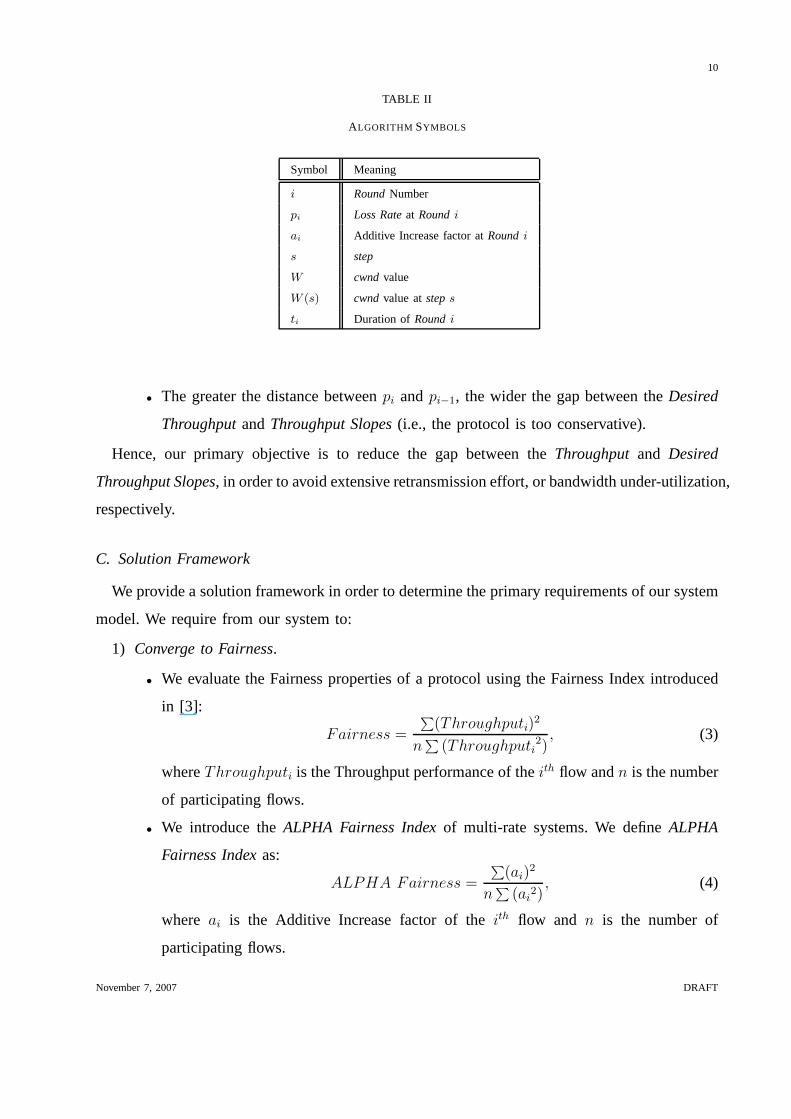
For ease of illustration, we summarize, in Table II, the symbols used throughout the rest of
the paper.
B. Observations on the dynamics of Additive Increase with Diverse Rates
1) Whenpi > pi−1 then theThroughput Slopeexceeds theDesired Throughput Slope, for
Roundi.
• The greater the distance betweenpi andpi−1, the wider the gap between theThroughput
andDesired Throughput Slopes(i.e., the protocol is too aggressive).
2) Whenpi < pi−1 then theThroughput Slopeis underneath theDesired Throughput Slope,
for Roundi.
November 7, 2007 DRAFT
10
TABLE II
ALGORITHM SYMBOLS
Symbol Meaning
i RoundNumber
pi Loss Rateat Roundi
ai Additive Increase factor atRoundi
s step
W cwnd value
W (s) cwnd value atsteps
ti Duration ofRoundi
• The greater the distance betweenpi andpi−1, the wider the gap between theDesired
ThroughputandThroughput Slopes(i.e., the protocol is too conservative).
Hence, our primary objective is to reduce the gap between theThroughputand Desired
Throughput Slopes, in order to avoid extensive retransmission effort, or bandwidth under-utilization,
respectively.
C. Solution Framework
We provide a solution framework in order to determine the primary requirements of our system
model. We require from our system to:
1) Converge to Fairness.
• We evaluate the Fairness properties of a protocol using the Fairness Index introduced
in [3]:
Fairness =
∑(Throughputi)
2
n∑
(Throughputi2)
, (3)
whereThroughputi is the Throughput performance of theith flow andn is the number
of participating flows.
• We introduce theALPHA Fairness Indexof multi-rate systems. We defineALPHA
Fairness Indexas:
ALPHA Fairness =
∑(ai)
2
n∑
(ai2)
, (4)
where ai is the Additive Increase factor of theith flow and n is the number of
participating flows.
November 7, 2007 DRAFT

11
The ALPHA Fairness Index has the following properties: In a homogeneous/synchronous
static (contention-wise) system, increased ALPHA Fairness Index leads to increased
System Fairness Index as well. In a heterogeneous/asynchronous dynamic system,
however, the properties of ALPHA Fairness Index are not straightforward. For example,
in a diverse-RTT system, reduced ALPHA Fairness Index may correspond to either
increased or decreased system Fairness (i.e., reduced Additive Increase factor for
longer-RTT flows results in reduced Fairness, while increased Additive Increase factor
for longer-RTT flows results in increased system Fairness).We explore the above
properties through simulations in the following sections.
2) Guarantee Stability.
Stability is a quality measure, which we attempt to simplify and furthermore quantify by
measuring the frequency of congestion events. Therefore, aprotocol is said to achieve
higherStability, when it minimizes retransmission overhead.
3) Exploit available resources efficiently, which means:
• faster (i.e., aggressively) when contention is low (i.e., utilizehigh percentage of
available bandwidth).
• slower(i.e., conservatively) when contention is high (i.e., minimize overhead/transmission
effort).
Efficiencyis achieved through high resource utilization (i.e., high goodput performance)and
minimal retransmission overhead.
V. AIRA: A DDITIVE INCREASE RATE ACCELERATOR
We assume that a flow can adjust its rate at the end of eachRound, which is indicated by
packet loss(es). The flow at the end ofRoundi can determine the rate for roundi+1 exploiting,
recursively, the behavior of the rate duringRoundi− 1. In particular, the Decrease rule applies
whenpi > pi−1.
November 7, 2007 DRAFT

12
A. The Decrease Rule
- Decrease Rule.In order to reduce the gap between the Throughput and DesiredThroughput
Slopes, the Additive Increase factor should decrease, according to Equation:
ai+1 = ai · (1− pi). (5)
Justification. Equation (1) reveals that the slope of thecwnd, within a round, is aW (s−1)
, where
s is thestep. Considering the Round Loss Rate of the previous round, the slope of the Desired
Throughput can be approximated byλ, whereλ < acwnd
(see Figure 4).
W/2
W(t)
W(Dt)
Time
cwnd_
a/W(s-1)
lambda
m
k
t_i
Round i-1Round iW
Fig. 4. Throughput/Desired Throughput (Dt) Slopes of thecwnd at Roundi
From Figure 4 we derive that:
Throughput Slope = tan(throughput) =k
ti(6)
and
DesThr Slope = tan(DesThr) =k −m
ti. (7)
Dividing Equations (6) and (7) by parts, we get:
tan(thr)
tan(DesThr)=
k
k −m. (8)
From Equation (1) we know that:
tan(thr) =a
cwnd=
ai
W (s− 1). (9)
November 7, 2007 DRAFT

13
.
From Equations (8) and (9) we get:
tan(DesThr) =ai · (k −m)
W (s− 1) · k. (10)
From Figure 4 we derive the values fork andm as follows:
k =W (s)
2(11)
and
m =W (s)
2· pi, (12)
From Equations (10), (11) and (12) we get that:
tan(DesThr) =ai ·W (s) · (1− pi)
W (s− 1) ·W (s)=
ai · (1− pi)
W (s− 1)(13)
Or,
λdecrease =ai · (1− pi)
W (s− 1). (14)
Hence, the Additive Increase factor for roundi+1, is adjusted according to Equation (5) (see
Figure 5).
W/2
W(t)
W(Dt)
Time
cwnd_
a/W(s-1)
lambda
t_i
Round i-1Round i
W
Round i+1
lambda
Fig. 5. cwnd Slope at Roundi + 1
November 7, 2007 DRAFT

14
B. The Increase Rule
According to theDecrease Rule, the Additive Increase factor of TCP (i.e., AIRA) may get
non-increasing values. In that case, however, the system may never reach equilibrium; flows
already existing in the system, possibly transmitting witha < 1, will not have the opportunity
to compete (fairly) with new, incoming flows. Therefore, we introduce anIncrease Rule, which
applies whenpi < pi−1.
- Increase Rule.In order to reduce the gap between the Desired Throughput - Throughput
Slopes, the Additive Increase factor should increase, according to Equation:
ai+1 = ai · (1 + pi−1 − pi). (15)
Justification.
t_i
W(t)
W(Dt)
Time
cwnd_ a/W(s-1)
lambda
Round i-1 Round i
lambda
km
Previous Throughput Slope
Current Throughput Slope
Desired Throughput Slope
Fig. 6. Throughput / Desired Throughput Slopes of thecwnd at Roundi
From Figure 6 we get theCurrent Throughput Slope:
Throughput Slope = tan(throughput) =k
ti(16)
and theDesired Throughput Slope(DesThr):
DesThr Slope = tan(DesThr) =m
ti. (17)
Dividing Equations (16) and (17) by parts, we get:
tan(thr)
tan(DesThr)=
k
m. (18)
November 7, 2007 DRAFT

15
From Equations (9) and (18) we get:
tan(DesThr) =ai ·m
W (s− 1) · k. (19)
.
From Figure 6 we derive the values fork andm as follows:
k =W (s)
2(20)
and
m =W (s)
2+
W (s)
2· φ, (21)
whereφ depicts the angle difference between theCurrent and theDesired Throughput Slopes.
From Equations (19), (20) and (21) we get that:
λincrease =ai · (1 + φ)
W (s− 1). (22)
For the purpose of the current study we setφ to be the difference between the loss rate
experienced in the previous round and the one experienced atthe end of the currentRound:
φ = pi−1 − pi. (23)
Hence, in roundi+1 the Additive Increase factor is adjusted according to Equation (15) (see
Figure 7). Finally, we note that in casepi = pi−1, no adjustments take place (i.e.,ai = ai−1).
t_i
W(t)
W(Dt)
Time
cwnd_ a/W(s-1)
lambda
Round i-1 Round i
lambda
W(t)/2
Round i+1
Fig. 7. cwnd at Roundi + 1
November 7, 2007 DRAFT

16
We provide the pseudocode of the proposed algorithm below and its flow-diagram in Figure 8.
initial a = 1
initial loss rate = 0
initial loss rate 1 =0 // loss rate of the previous round
/* open cwnd function */
lambda = a i/cwnd
cwnd = cwnd + lambda
/* upon loss or triple-duplicate ack */
/* close cwnd function */
cwnd = cwnd *(1 - b) // b=0.5
loss rate = number of packets lost at the end of the round / total
number of packets transmitted within this round
if (loss rate 1 < loss rate)
then apply the decrease rule:
a i+1 = a i*(1 - loss rate)
else apply the increase rule:
a i+1 = a i*(1 + [loss rate 1 - loss rate])
C. Results: Decrease/Increase Rules
We present simulation results to depict the operational properties of the Decrease/Increase
Rules of AIRA. We use a contention increase scenario in orderto monitor rate fluctuation in
case of dynamic network contention. Four flows participate in the experiment, each of which
enters the system 50 seconds after the previous flow. The backbone link carries 2Mbps with
20ms propagation delay (Figure 2); the buffer of Router 1 holds 10 packets.
In Figure 9, we present the Additive Increase factor of the participating flows during the
November 7, 2007 DRAFT

17
Round 1: a(1) = 1End of Round 1:Loss Rate = x1
Round 2: a(2) = a(1)*(1-x1) End of Round 2:Loss Rate = x2
if x2 > x1or generallyx(i) > x(i-1)
Apply Decrease Rulea(i+1) = a(i)*(1 - x(i))
if x2 < x1or generallyx(i) < x(i-1)
Apply Increase Rulea(i+1) = a(i)*(1 + [x(i-1) -x(i)])
Round 3 or generallyRound i:a(i+1)
Fig. 8. AIRA Flow Diagram
simulation. Initially, the Additive Increase factor of thefirst flow stabilizes to a value very close
to 1, since theLoss Rateat that time has a very low and fixed value. As contention increases,
the Loss Rateincreases as well, causing gradual reduction of the Additive Increase factor. Note,
however, that the rate reduction per flow varies: new flows, which operate with greater Additive
Increase factors, experience greater rate reduction. Moreover, in Figures 10 and 11, we present
the cwnd evolution of AIRA and AIMD when the second and third flow enters the system.
We notice that: i) the incoming AIRA flows exploit transmission opportunities as fast as regular
AIMD flows do, ii) the AIRA system mayonly temporarilyexperience un-fairness (e.g.,86−88th
second in Figure 10(a)) and iii) AIRA breaks flow synchronization. Flow de-synchronization,
in turn, increases system fairness, as we have also shown in [18]. This is further verified by
the results presented in Table III, where we see that AIRA increases system Goodput, Fairness
and Stability. Furthermore, convergence to system Fairness is guaranteed by the Multiplicative
Decrease response of AIMD. Hence, un-fairness side-effects are canceled by i) the Multiplicative
Decrease response to congestion and ii) AIRA inherent properties of de-synchronization.
We extend the above scenario to include more flows. The bandwidth of the backbone link is
now 20Mbps and the buffer capacity at Router 1 is 100 packets.Along the lines of the previous
November 7, 2007 DRAFT

18
0
0.2
0.4
0.6
0.8
1
0 50 100 150 200 250 300
Add
itive
Incr
ease
Fac
tor
Time (s)
flow 1flow 2flow 3flow 4
Fig. 9. Additive Increase Factor
0
5
10
15
20
25
30
35
50 60 70 80 90 100
cwnd
Time (s)
flow 1flow 2
(a) Second Flow Enters the Link
0
5
10
15
20
25
95 100 105 110 115 120 125 130 135 140
cwnd
Time (s)
flow 1flow 2flow 3
(b) Third Flow Enters the Link
Fig. 10. AIRA cwnd in Contention Increase Scenario
0
5
10
15
20
25
30
35
50 60 70 80 90 100
cwnd
Time (s)
flow 1flow 2
(a) Second Flow Enters the Link
0 2 4 6 8
10 12 14 16 18
95 100 105 110 115 120 125 130 135 140
cwnd
Time (s)
flow 1flow 2flow 3
(b) Third Flow Enters the Link
Fig. 11. AIMD cwnd in Contention Increase Scenario
TABLE III
PERFORMANCEDIFFERENCE- CONTENTION INCREASESCENARIO
Goodput Retransmissions Fairness a Fairness
AIMD 222.3 KB/s 1065 pkts 0.8162 1
AIRA 227.1 KB/s 748 pkts 0.85 0.98
scenario, flows are divided into quarters; each team enters the system 50 seconds after the
previous one. The results are presented in Figure 12. Again,we see that AIRA increases system
Goodput, Stability and occasionaly system Fairness. The ALPHA Fairness Index (Figure 12(d))
November 7, 2007 DRAFT

19
reveals that in all cases the Additive Increase factor of allflows converges to (approximately)
the same value.
Number of Flows20 40 60 80 100 120
Goo
dput
(B
/s)
0
1e+06
2e+06
3e+06
4e+06
5e+06
AIMD AIRA
(a) System Goodput
Number of Flows20 40 60 80 100 120R
etra
nsm
itted
Pac
kets
05000
10000150002000025000300003500040000
AIMD AIRA
(b) Retransmission Overhead
Number of Flows20 40 60 80 100 120
Fai
rnes
s
0
0.1
0.2
0.3
0.4
0.5
0.6
AIMD AIRA
(c) Fairness Index
Number of Flows40 60 80 100 120
ALP
HA
Fai
rnes
s0
0.2
0.4
0.6
0.8
1
AIMD AIRA
(d) ALPHA Fairness Index
Fig. 12. Contention Increase Scenario
VI. A DJUSTMENTS DUE TOPRACTICAL CONSTRAINTS
A. Lower Bounds
We set lower bounds for AIRA for the following reason: Progressive reduction of the Additive
Increase factor may result in transmission rate stabilization (i.e., a = 0). This, however, will
inevitably cause system in-stability, protocol in-efficiency and flow starvation. We, therefore,
bound a to 0.1, attempting to avoid the above un-desirable system property. That said, the
greatest possible reduction of the Additive Increase factor is 0.9 (i.e.,agreatest reduction = 0.9,
whena = 0.1).
Furthermore, we complement this absolute bound with another, dynamically-adjustable lower
bound, which depends on the number of completedRoundsand is calledMinimum Additive
Increase Limit (MAIL). The reason is twofold:
1) A flow may lose several back-to-back packets, due to suddentraffic-bursts or symptomatic
events. In order to limit drastic and systematic responses to symptomatic events, lower
November 7, 2007 DRAFT

20
bounds need to be introduced. Otherwise, recovery from suchsymptomatic events may
require significant effort and time or may even become impossible.
2) When contention reaches extra-ordinary levels, AIRA lower bound (i.e.,a = 0.1) dominates
and the rest of AIRA functionality is practically suspended. In that case, MAIL will prevent
short-flow starvation, adhering to a time-oriented notion of Fairness (e.g., a flow at the
secondRoundoperating witha = 0.1). That is, assuming that short3 flows need to be
favored over long, time-insensitive ones,MAIL is designed to provide more opportunities
for data transmission to short, probably time-sensitive flows.
Minimum Additive Increase Limit (MAIL). We use the following equation to adjust MAIL:
MAIL = amin = 1− agreatest reduction · RN%, (24)
where,RN is the number of completedRoundsandagreatest reduction = 0.9 (see Figure 13).
0
0.2
0.4
0.6
0.8
1
0 20 40 60 80 100 120 140 160 180
MA
IL
Round
Fig. 13. Minimum Additive Increase Limit (MAIL)
In Figure 13, we demonstrate how MAIL evolves in time (i.e.,Rounds). The duration of a
Round, however, depends on the path RTT as well as the link speed. Wesimulate a single AIRA
flow over various link speeds and propagation delay paths, inorder to observe: i) the amount
of data transferred as the number ofRoundsincreases and ii) the number of completedRounds
as time elapses. Without loss of generality, we consider a 5MByte file size as an experimental
threshold between short and long flows. We see in Figure 14 that in all cases 5MBytes are
3We assume short flows as flows that carry files smaller than 5MBytes (e.g., large pdf documents, presentations or software
updates). Web flows, on the contrary, which are considered asshort flows in the related literature, are not of interest in the
current study, since such flows will finish their task either in the Slow-Start phase or within the first rounds, where the Additive
Increase factor is still very close (if not equal) to 1 (i.e.,a content-rich web page is rarely larger than 100KB).
November 7, 2007 DRAFT

21
transfered within the first 50Rounds(Figure 14(a)), which correspond to less than 50 seconds
(Figure 14(b)). Hence, MAIL allows for increased transmission rates for short flows and slower
transmission rates for longer ones (i.e.,a may equal to 0.1 only after completion of 10MB
transfers).
0
10
20
30
40
50
60
70
0 50 100 150 200 250
Dat
a T
rans
ferr
ed (
MB
)
Round
0.5Mbps, 40ms1Mbps, 30ms1Mbps, 40ms5Mbps, 40ms5Mbps, 70ms
(a) Data vs. Rounds
0
50
100
150
200
250
0 50 100 150 200 250 300
Rou
nd
Time (s)
0.5Mbps, 40ms1Mbps, 30ms1Mbps, 40ms5Mbps, 40ms5Mbps, 70ms
(b) Rounds vs. Time
Fig. 14. Correlations between file size, number ofRoundsand duration
Secondary Effect.MAIL exhibits one desirable property, which was not an initial design goal:
it favors long-RTT flows over shorter-RTT ones. That is, short-RTT flows complete aRoundfaster
than long-RTT flows. Therefore, MAIL will get a lower value (i.e., Additive Increase factor)
for a short-RTT flow faster than for a longer-RTT one. Hence, in case of moderated or high
contention the short-RTT flows will operate with lower Additive Increase factor, avoiding this
way starvation of long-RTT flows.
B. Results: Lower Bounds
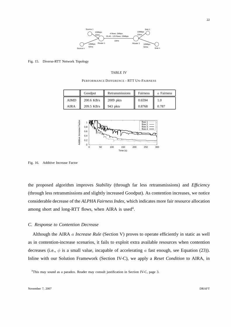
We verify the above hypothesis by simulation. Initially, wesimulate 4 flows over the ”Diverse-
RTT Network Topology” (Figure 15). We use Drop Tail routers,with buffer sizes equal to the
Bandwidth-Delay Product of the outgoing links. We note thatresults are similar in case of Active
Queue Management schemes, like RED [6], for example. The round trip propagation delay for
flows 1 and 2 is 60ms, while for flows 3 and 4 is 220ms. Simulationtime is 300 seconds.
Figure 16 depicts the Additive Increase factor for each flow.We see that MAIL provides more
transmission opportunities to long-RTT flows (see FairnessIndex in Table IV).
We extend the above scenario to include more flows. The results are presented in Figure 17.
In all cases (i.e., 4-flow scenario, Table IV and extended scenario, Figure 17), we see that
November 7, 2007 DRAFT
22
Router 1 Router 2
Source 1
Source n
Sink 1
Sink n
10Mbps10ms
10Mbps10ms �4 flows: 2Mbps
20,40...120 flows: 20Mbps
10Mbps50ms
10Mbps50ms
10ms
Fig. 15. Diverse-RTT Network Topology
TABLE IV
PERFORMANCEDIFFERENCE- RTT UN-FAIRNESS
Goodput Retransmissions Fairness a Fairness
AIMD 200.6 KB/s 2009 pkts 0.6594 1.0
AIRA 209.5 KB/s 943 pkts 0.8768 0.787
0
0.2
0.4
0.6
0.8
1
0 50 100 150 200 250 300
Add
itive
Incr
ease
Fac
tor
Time (s)
flow 1flow 2flow 3flow 4
Fig. 16. Additive Increase Factor
the proposed algorithm improvesStability (through far less retransmissions) andEfficiency
(through less retransmissions and slightly increased Goodput). As contention increases, we notice
considerable decrease of theALPHA Fairness Index, which indicates more fair resource allocation
among short and long-RTT flows, when AIRA is used4.
C. Response to Contention Decrease
Although the AIRAa Increase Rule(Section V) proves to operate efficiently in static as well
as in contention-increase scenarios, it fails to exploit extra available resources when contention
decreases (i.e.,φ is a small value, incapable of acceleratinga fast enough, see Equation (23)).
Inline with our Solution Framework (Section IV-C), we applya Reset Conditionto AIRA, in
4This may sound as a paradox. Reader may consult justificationin Section IV-C, page 3.
November 7, 2007 DRAFT

23
Number of Flows20 40 60 80 100 120
Goo
dput
(B
/s)
0
500000
1e+06
1.5e+06
2e+06
AIMD AIRA
(a) System Goodput
Number of Flows20 40 60 80 100 120R
etra
nsm
itted
Pac
kets
0
5000
10000
15000
20000
25000
30000
AIMD AIRA
(b) Retransmission Overhead
Number of Flows20 40 60 80 100 120
Fai
rnes
s
00.10.20.30.40.50.60.70.8
AIMD AIRA
(c) Fairness Index
Number of Flows20 40 60 80 100 120
ALP
HA
Fai
rnes
s
0
0.2
0.4
0.6
0.8
1
AIMD AIRA
(d) ALPHA Fairness Index
Fig. 17. RTT Un-Fairness Scenario
order to prevent bandwidth wastage in case of contention decrease.
AIRA Reset Condition. Assuming that a flow’scwndoscillates betweenW/2 andW before
the contention decrease event, the flow will have the opportunity to expand itscwndto W+ 12W =
32W after 1
3of the participating flows leave the system. When this happens, AIRA resetsa to
15.
Analysis. A flow’s window expansion speed depends on its Additive Increase factor. The
greater the Additive Increase factor, the faster the bandwidth will be exploited. Given aRound
Duration RDa, for a flow with Additive Increase factor equal toa, the flow will need0.3 ·RDa
to expand its window toW + 12W , according toAIRA Reset Condition. Provided that the fastest
possible window expansion speed is achieved whena = 1, a general rule that captures the extra
window expansion time needed by a flow with smallera is given in Equation (25):
5System-wise, we assume that AIRAshouldexploit bandwidth fastlyiff n−xn
≤2
3, wheren is the total number of participating
flows andx is the number of flows who end their task and leave the system. In this case (i.e., whenx ≥1
3n), AIRA resetsa
to 1.
November 7, 2007 DRAFT

24
ax : Tx = 0.3 ·RDx = 0.3 ·a1
ax
· RD1, (25)
wherex is the Additive Increase factor (i.e.,a0.6 = 0.6). We plotTx in Figure 18(a). Obviously,
a flow operating withax < a1 will complete aRound later than thea1 flow (i.e., it will needa1
ax· RD1 extraRounds). Hence, the total time needed by a flow withax < a1 is:
ax : Total Tx = 1.3 ·RDx = 1.3 ·a1
ax
· RD1. (26)
We plot Total Tx in Figure 18(b). Note that, since MAIL is responsible for progressively
regulating the AIRA lower bound,Total Tx depends on MAIL as well. We depict theRound
Number- Total Tx interdependence in Figure 18(c). The Number of Extra Roundsincreases
as the Number ofTotal Rounds increases. That is, a new flow (e.g., a flow within the first 10
Rounds) will become aware of the extra bandwidth after less than 2Rounds. We regard this
delay as acceptable, inline with ourSolution Framework(see Section IV-C).
0
0.2
0.4
0.6
0.8
1
0 0.5 1 1.5 2 2.5 3
AIR
A
Extra Time in Rounds Relative to RD1 (x*RD1)
(a) Extra Rounds Needed
0
0.2
0.4
0.6
0.8
1
0 2 4 6 8 10 12
AIR
A
Total Time in Rounds Relative to RD1 (x*RD1)
(b) Total Rounds Needed
0
2
4
6
8
10
12
14
0 20 40 60 80 100 120 140 160
Num
ber
of E
xtra
Rou
nds
Number of Rounds
(c) Total Rounds with regard to the Round Number
Fig. 18. AIRA Bandwidth Exploitation Properties
D. Results: Response to Contention Decrease
We repeat the simulation presented in Section V-C; in the current setup, 2 out of the 4
participating flows leave the system at the205th second. We see in Figure 19 that the remaining
November 7, 2007 DRAFT
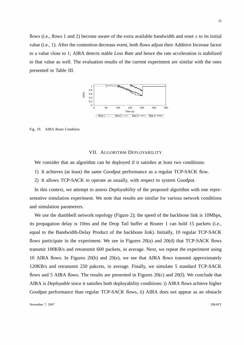
25
flows (i.e., flows 1 and 2) become aware of the extra available bandwidth and reseta to its initial
value (i.e., 1). After the contention decrease event, both flows adjust their Additive Increase factor
to a value close to 1; AIRA detects stableLoss Rateand hence the rate acceleration is stabilized
to that value as well. The evaluation results of the current experiment are similar with the ones
presented in Table III.
0
0.2
0.4
0.6
0.8
1
0 50 100 150 200 250 300
AIR
A
Time (s)
flow 1 flow 2 flow 3 flow 4
Fig. 19. AIRA Reset Condition
VII. A LGORITHM DEPLOYABILITY
We consider that an algorithm can be deployed if it satisfies at least two conditions:
1) It achieves (at least) the same Goodput performance as a regular TCP-SACK flow.
2) It allows TCP-SACK to operate as usually, with respect to system Goodput.
In this context, we attempt to assessDeployabilityof the proposed algorithm with one repre-
sentative simulation experiment. We note that results are similar for various network conditions
and simulation parameters.
We use the dumbbell network topology (Figure 2); the speed ofthe backbone link is 10Mbps,
its propagation delay is 10ms and the Drop Tail buffer at Router 1 can hold 15 packets (i.e.,
equal to the Bandwidth-Delay Product of the backbone link).Initially, 10 regular TCP-SACK
flows participate in the experiment. We see in Figures 20(a) and 20(d) that TCP-SACK flows
transmit 100KB/s and retransmit 600 packets, in average. Next, we repeat the experiment using
10 AIRA flows. In Figures 20(b) and 20(e), we see that AIRA flowstransmit approximately
120KB/s and retransmit 250 pakcets, in average. Finally, wesimulate 5 standard TCP-SACK
flows and 5 AIRA flows. The results are presented in Figures 20(c) and 20(f). We conclude that
AIRA is Deployablesince it satisfies both deployability conditions: i) AIRA flows achieve higher
Goodput performance than regular TCP-SACK flows, ii) AIRA does not appear as an obstacle
November 7, 2007 DRAFT

26
for TCP-SACK flows that achieve the same Goodput performanceas in the first experiment
(Figure 20(a)). AIRA takes advantage of the reduced retransmission overhead and allocates
network resources to successful data transmission.
Flow Number0 1 2 3 4 5 6 7 8 9G
oodp
ut p
er F
low
(B
/s)
0
20000
40000
60000
80000
100000
AIMD
(a) AIMD Goodput
Flow Number0 1 2 3 4 5 6 7 8 9G
oodp
ut p
er F
low
(B
/s)
0
20000
40000
60000
80000
100000
120000
AIRA
(b) AIRA Goodput
Flow Number0 1 2 3 4 5 6 7 8 9G
oodp
ut p
er F
low
(B
/s)
0
20000
40000
60000
80000
100000
120000
AIMD AIRA
(c) Goodput Both
Flow Number0 1 2 3 4 5 6 7 8 9R
etra
nsm
issi
ons
per
Flo
w
0
100
200
300
400
500
600
AIMD
(d) AIMD Retransmitted Packets
Flow Number0 1 2 3 4 5 6 7 8 9R
etra
nsm
issi
ons
per
Flo
w
0
50
100
150
200
250
300
AIRA
(e) AIRA Retransmitted Packets
Flow Number0 1 2 3 4 5 6 7 8 9R
etra
nsm
issi
ons
per
Flo
w
0
100
200
300
400
500
600
AIMD AIRA
(f) Retransmitted Packets Both
Fig. 20. Algorithm Deployability
VIII. O PEN ISSUES ANDFUTURE WORK
The Additive Increase Rate Accelerator proposed here, increases the operational complexity
of networked systems. This fact alone is a negative system attribute; however, the proposed
algorithm does not increase the complexity of flow engineering. That is, the flows will operate
on predetermined rules, which will apply in diverse conditions. The conditions however, exhibit
different properties: some are certain and precise (e.g. packet loss) but some others need to
be evaluated. For instance, progressive contention is hereestimated and is not explicitly com-
municated by some central network authority. The accuracy and precision of this estimation
depends on two main factors: (i) the granularity of measurements and (ii) the accuracy of
the monitoring functions. For example, the way throughput is calculated and the frequency of
calculating throughput may have some impact. Higher (e.g.,per packet) measurement granularity
will probably increase precision, but it will also increasesystem entropy, leading to reduced
system stability. This observation calls for further investigation.
November 7, 2007 DRAFT

27
By the same token, even when contention/congestion estimation is accurate indeed, the re-
sponsive behavior of flows, does not have a sole corresponding pattern. That is, aggressiveness
can be adjusted in order to balance overhead, efficiency or stability. An optimal balance has not
been investigated here.
Finally, responses can be implemented rapidly or smoothly;the efficiency of each strategy
depends on system dynamics. This is another issue that callsfor further investigation. In con-
clusion, the interdependency of granularity, aggressiveness and responsiveness of AIRA has not
been studied in depth.
IX. CONCLUSIONS
We have shown that analytical rules can be derived for accelerating, either positively or
negatively, the increase rate of AIMD in accordance with network dynamics. Indeed, we found
that the ”blind” Additive Increase rule can become an obstacle for the performance of TCP, espe-
cially when contention increases. Instead, sophisticated, contention-aware additive increase rates
may preserve system stability and reduce retransmission effort, without reducing the goodput
performance of TCP.
Based on specific criteria, namely efficiency, fairness and stability, we proposed and evaluated
an adaptive additive increase rate scheme, which we call Additive Increase Rate Accelerator
(AIRA). We have shown two major results: (i) fairness is possible even in the context of varying
increase rates within the same system. Furthermore, the problematic balance among short and
long flows, as well as long- and short-RTT flows, can be better handled. (ii) Efficiency can be
improved. Efficiency is judged not only on the basis of goodput performance but mainly against
retransmission effort and overhead.
REFERENCES
[1] Deepak Bansal and Hari Balakrishnan. Binomial congestion control algorithms. InINFOCOM, pages 631–640, 2001.
[2] L. Brakmo, S. O’Malley, and L. Peterson. TCP Vegas: New techniques for congestion detection and avoidance. In
Proceedings of SIGCOMM, 1994.
[3] D.-M. Chiu and R. Jain. Analysis of the Increase and Decrease Algorithms for Congestion Avoidance in Computer
Networks. Computer Networks and ISDN Systems, 17(1):1–14, 1989.
[4] G.McCullagh D.J. Leith, R.N.Shorten. Experimental Evaluation of Cubic-TCP. InProceedings of PFLDnet, 2007.
[5] S. Floyd. HighSpeed TCP for Large Congestion Windows, RFC 3649, December 2003.
November 7, 2007 DRAFT

28
[6] S. Floyd and V. Jacobson. Random Early Detection gateways for Congestion Avoidance.IEEE/ACM Transactions on
Networking, 1(4):397–413, 1993.
[7] Sally Floyd and Eddie Kohler. Tcp friendly rate control (tfrc): the small-packet (sp) variant, rfc 4828, experimental, april
2007.
[8] S. Jin, L. Guo, I. Matta, and A. Bestavros. Tcp-friendly simd congestion control and its convergence behavior. InProc.
9th IEEE International Conference on Network Protocols (ICNP’01), Riverside, CA, November 2001. 5, 2001.
[9] Tom Kelly. Scalable TCP: Improving Performance in Highspeed Wide Area Networks.ACM SIGCOMM Computer
Communication Review, 33(2):83–91, 2003.
[10] R. King, R. Baraniuk, and R. Riedi. Tcp-africa: An adaptive and fair rapid increase rule for scalable tcp. InProceedings
of INFOCOM 2005, volume 3, pages 1838–1848, 2005.
[11] Adrian Lahanas and Vassilis Tsaoussidis. Exploiting the efficiency and fairness potential of aimd-based congestion
avoidance and control.Computer Networks, 43(2):227–245, 2003.
[12] Adrian Lahanas and Vassilis Tsaoussidis.τ -aimd for asynchronous receiver feedback. InProceedings of the Eighth IEEE
International Symposium on Computers and Communications,ISCC, 2003.
[13] Gustavo Marfia, Claudio Palazzi, Giovanni Pau, Mario Gerla, M.Y. Sanadidi, and Marco Roccetti. TCP Libra: Exploring
RTT-Fairness for TCP.UCLA Computer Science Department Technical Report TR050037, 2005.
[14] M. Mathis, J. Mahdavi, S. Floyd, and A. Romanow. TCP Selective Acknowledgement Options, RFC 2018, April 1996.
[15] ns 2. The Network Simulator - ns - 2, http://www.isi.edu/nsnam/ns/.
[16] J. Postel. Transmission Control Protocol, RFC 793, September 1981.
[17] Ioannis Psaras and Vassilis Tsaoussidis. WB-RTO: A Window-Based Retransmission Timeout for TCP. InIn Proc. of the
49th IEEE Global Telecommunications Conference GLOBECOM 2006, Control and Management of High Performance
Networks, San Francisco, USA, November 2006.
[18] Ioannis Psaras and Vassilis Tsaoussidis. Why tcp timers (still) don’t work well. Computer Networks, 51(8):2033–2048,
2007.
[19] Ioannis Psaras, Vassilis Tsaoussidis, and Lefteris Mamatas. CA-RTO: A Contention-Adaptive Retransmission Timeout. In
Proceedings of ICCCN, October 2005.
[20] I. Rhee, V. Ozdemir, and Y. Yi. Tear: Tcp emulation at receivers – flow control for multimedia streaming.Apr. 2000.
NCSU Technical Report., 2000.
[21] Injong Rhee and Lisong Xu. CUBIC: A New TCP-Friendly High-Speed TCP Variant. InProceedings of PFLDnet, 2005.
[22] Kun Tan, Jingmin Song, Qian Zhang, and Murari Sridharan. A compound tcp approach for high-speed and long distance
networks.
[23] Vassilis Tsaoussidis and Chi Zhang. The dynamics of responsiveness and smoothness in heterogeneous networks.IEEE
Journal on Selected Areas in Communications, (JSAC), 23(6):1178–1189, 2005.
[24] D. X. Wei, C. Jin, S. H. Low, and S. Hegde. FAST TCP: motivation, architecture, algorithms, performance.IEEE/ACM
Transactions on Networking, to appear, 2007.
[25] Lisong Xu, K. Harfoush, and Injong Rhee. Binary increase congestion control (bic) for fast long-distance networks. In
Proceedings of INFOCOM 2004, volume 4, pages 2514–2524, March 2004.
[26] Y. R. Yang and S. S. Lam. General aimd congestion control. In Proceedings of ICNP 2000, October 2000.
[27] Chi Zhang and Vassilis Tsaoussidis. Tcp smoothness andwindow adjustment strategy.IEEE Transactions on Multimedia,
8(3):600–609, 2006.
November 7, 2007 DRAFT