18 Electrostatic-Accelerator Free-Electron Lasers - Inspire HEP
14
18 Electrostatic-Accelerator Free-Electron Lasers A. Gover 1 and Y. Pinhasi 2 1 Tel Aviv University, School of Engineering, Physical Electronics Dept., Tel Aviv, Israel [email protected] 2 The College of Judea and Samaria, Dept. of Electrical and Electronic Engineering, Ariel, Israel [email protected] 18.1 Introduction Free-electron lasers (FELs) are high-power sources of electromagnetic radi- ation that utilize accelerated electrons which are oscillating transverse to their propagation axis. The name “free-electron laser” was chosen to distin- guish this device from conventional quantum lasers (light amplification by stimulated emission of radiation), where the radiation is a consequence of transitions of bound electrons between atomic energy states. The foundations of FELs go back to the early investigations of stimu- lated Thomson and Compton scattering carried out by Kapitza and Dirac in 1933 [1]. Motz, at Stanford, in 1951, studied theoretically [2] and experi- mentally [3] the radiation emitted when an accelerated electron beam passes through a succession of magnetic fields of alternating polarity. This “syn- chrotron undulator radiation” is a common source of X-ray and UV radia- tion in synchrotron facilities. It is, of course, a spontaneous-emission radiation source. The FEL is, in fact, the stimulated-emission version of synchrotron undulator radiation. In 1957, Phillips of the General Electric Microwave Laboratory invented the Ubitron (undulating-beam interaction) [4, 5]. This mm-wavelength elec- tron tube may be regarded as the first version of an FEL or, rather an FEM (free-electron maser). Both an amplifier and an oscillator version were built. However, the full potential of this device was not recognized, and the research work was terminated in 1964. The interest in interaction between an undulating e-beam and electromag- netic field as related to generation of coherent radiation, arose again when Madey proposed in 1971 his idea [6] of the free-electron laser [7]. Two suc- cessive experiments were performed at Stanford in the infrared (IR) regime. First, an amplifier at 10.6 µm was announced in 1976 [8], and laser oscillation at 3.4 µm was obtained the following year [9]. These experiments utilized a relativistic electron beam from a linear accelerator (Linac).
-
Upload
khangminh22 -
Category
Documents
-
view
1 -
download
0
Transcript of 18 Electrostatic-Accelerator Free-Electron Lasers - Inspire HEP

18 Electrostatic-AcceleratorFree-Electron Lasers
A. Gover1 and Y. Pinhasi2
1 Tel Aviv University, School of Engineering, Physical Electronics Dept.,Tel Aviv, [email protected]
2 The College of Judea and Samaria, Dept. of Electrical and ElectronicEngineering, Ariel, [email protected]
18.1 Introduction
Free-electron lasers (FELs) are high-power sources of electromagnetic radi-ation that utilize accelerated electrons which are oscillating transverse totheir propagation axis. The name “free-electron laser” was chosen to distin-guish this device from conventional quantum lasers (light amplification bystimulated emission of radiation), where the radiation is a consequence oftransitions of bound electrons between atomic energy states.
The foundations of FELs go back to the early investigations of stimu-lated Thomson and Compton scattering carried out by Kapitza and Diracin 1933 [1]. Motz, at Stanford, in 1951, studied theoretically [2] and experi-mentally [3] the radiation emitted when an accelerated electron beam passesthrough a succession of magnetic fields of alternating polarity. This “syn-chrotron undulator radiation” is a common source of X-ray and UV radia-tion in synchrotron facilities. It is, of course, a spontaneous-emission radiationsource. The FEL is, in fact, the stimulated-emission version of synchrotronundulator radiation.
In 1957, Phillips of the General Electric Microwave Laboratory inventedthe Ubitron (undulating-beam interaction) [4, 5]. This mm-wavelength elec-tron tube may be regarded as the first version of an FEL or, rather an FEM(free-electron maser). Both an amplifier and an oscillator version were built.However, the full potential of this device was not recognized, and the researchwork was terminated in 1964.
The interest in interaction between an undulating e-beam and electromag-netic field as related to generation of coherent radiation, arose again whenMadey proposed in 1971 his idea [6] of the free-electron laser [7]. Two suc-cessive experiments were performed at Stanford in the infrared (IR) regime.First, an amplifier at 10.6 µm was announced in 1976 [8], and laser oscillationat 3.4 µm was obtained the following year [9]. These experiments utilized arelativistic electron beam from a linear accelerator (Linac).
18 Electrostatic-Accelerator Free-Electron Lasers 379
18.2 Fundamentals of Free-Electron Laser Operation
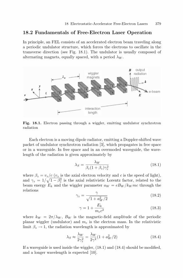
In principle, an FEL consists of an accelerated electron beam traveling alonga periodic undulator structure, which forces the electrons to oscillate in thetransverse direction (see Fig. 18.1). The undulator is usually composed ofalternating magnets, equally spaced, with a period λW .
Fig. 18.1. Electron passing through a wiggler, emitting undulator synchrotronradiation
Each electron is a moving dipole radiator, emitting a Doppler-shifted wavepacket of undulator synchrotron radiation [3], which propagates in free spaceor in a waveguide. In free space and in an overmoded waveguide, the wave-length of the radiation is given approximately by
λS =λW
βz(1 + βz)γ2z
(18.1)
where βz = vz/c (vz is the axial electron velocity and c is the speed of light),and γz = 1/
√1 − β2
z is the axial relativistic Lorentz factor, related to thebeam energy Ek and the wiggler parameter aW = eBW /kW mc through therelations
γz =γ√
1 + a2W /2
(18.2)
γ = 1 +Ek
mec2(18.3)
where kW = 2π/λW , BW is the magnetic-field amplitude of the periodicplanar wiggler (undulator) and me is the electron mass. In the relativisticlimit βz → 1, the radiation wavelength is approximated by
λS ≈ λW
2γ2z
=λW
2γ2(1 + a2
W /2) (18.4)
If a waveguide is used inside the wiggler, (18.1) and (18.4) should be modified,and a longer wavelength is expected [10].
380 A. Gover and Y. Pinhasi
In stimulated-emission devices (an FEL amplifier or oscillator), a radia-tion wave enters the undulator collinearly with the e-beam. The beating ofthe transverse electromagnetic-field components of the radiation wave withthe wiggler-induced periodic transverse velocity of the electrons creates amoving “ponderomotive force wave”, directed in the axial (z) direction. Thispropagates synchronously with the electrons and modulates their axial ve-locity, forming density bunching in the beam at the radiation frequency. Ifthe ponderomotive wave is slightly slower than the electron velocity, the elec-trons lose energy to the wave. As a result, the electrons generate radiationby stimulated emission, and amplification occurs.
18.3 Electrostatic-Accelerator FELs
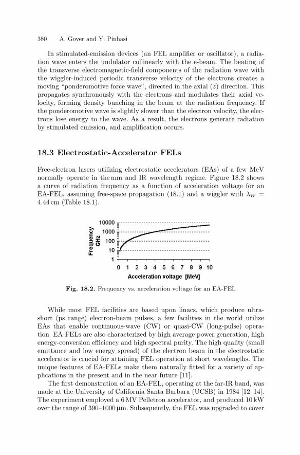
Free-electron lasers utilizing electrostatic accelerators (EAs) of a few MeVnormally operate in the mm and IR wavelength regime. Figure 18.2 showsa curve of radiation frequency as a function of acceleration voltage for anEA-FEL, assuming free-space propagation (18.1) and a wiggler with λW =4.44 cm (Table 18.1).
Fig. 18.2. Frequency vs. acceleration voltage for an EA-FEL
While most FEL facilities are based upon linacs, which produce ultra-short (ps range) electron-beam pulses, a few facilities in the world utilizeEAs that enable continuous-wave (CW) or quasi-CW (long-pulse) opera-tion. EA-FELs are also characterized by high average power generation, highenergy-conversion efficiency and high spectral purity. The high quality (smallemittance and low energy spread) of the electron beam in the electrostaticaccelerator is crucial for attaining FEL operation at short wavelengths. Theunique features of EA-FELs make them naturally fitted for a variety of ap-plications in the present and in the near future [11].
The first demonstration of an EA-FEL, operating at the far-IR band, wasmade at the University of California Santa Barbara (UCSB) in 1984 [12–14].The experiment employed a 6 MV Pelletron accelerator, and produced 10 kWover the range of 390–1000 µm. Subsequently, the FEL was upgraded to cover
18 Electrostatic-Accelerator Free-Electron Lasers 381
Table 18.1. Parameters of an EA-FEL
Accelerator
Electron beam energy Ek = 1−3 MeVBeam current I0 = 1−2 A
Undulator
Type Magnetostatic planar wigglerMagnetic induction BW = 0.2 TPeriod length λW = 4.444 cmNumber of periods NW = 20
Resonator
Waveguide Curved parallelTransverse mode TE01
Round-trip length LC = 2.62 mOut-coupling coefficient T = 7%Total round-trip reflectivity R = 65%
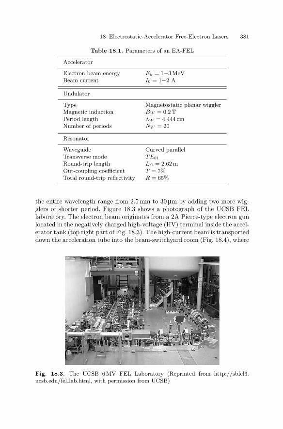
the entire wavelength range from 2.5 mm to 30 µm by adding two more wig-glers of shorter period. Figure 18.3 shows a photograph of the UCSB FELlaboratory. The electron beam originates from a 2A Pierce-type electron gunlocated in the negatively charged high-voltage (HV) terminal inside the accel-erator tank (top right part of Fig. 18.3). The high-current beam is transporteddown the acceleration tube into the beam-switchyard room (Fig. 18.4), where
Fig. 18.3. The UCSB 6 MV FEL Laboratory (Reprinted from http://sbfel3.ucsb.edu/fel lab.html, with permission from UCSB)
382 A. Gover and Y. Pinhasi
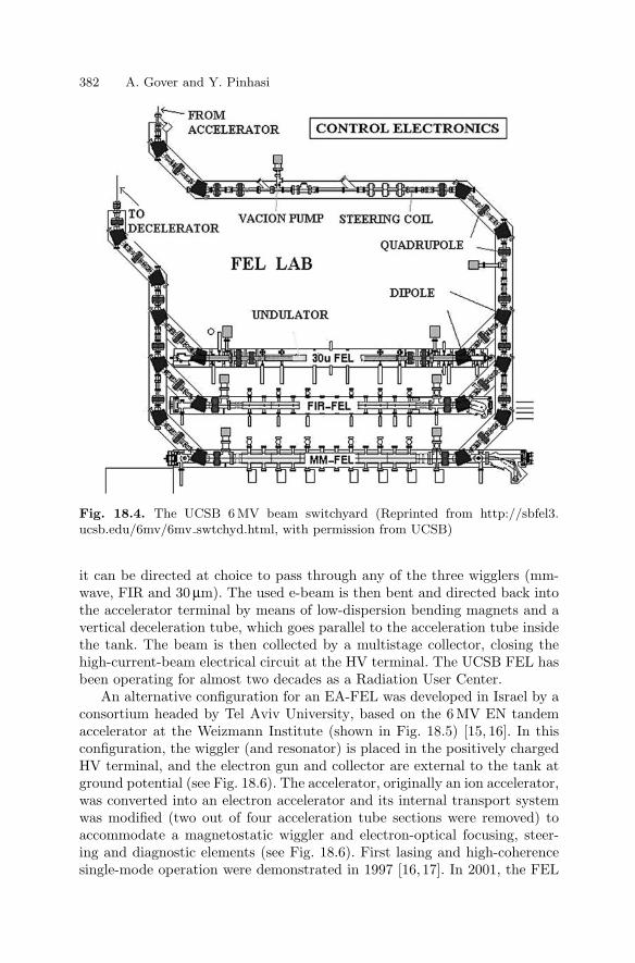
Fig. 18.4. The UCSB 6 MV beam switchyard (Reprinted from http://sbfel3.ucsb.edu/6mv/6mv swtchyd.html, with permission from UCSB)
it can be directed at choice to pass through any of the three wigglers (mm-wave, FIR and 30 µm). The used e-beam is then bent and directed back intothe accelerator terminal by means of low-dispersion bending magnets and avertical deceleration tube, which goes parallel to the acceleration tube insidethe tank. The beam is then collected by a multistage collector, closing thehigh-current-beam electrical circuit at the HV terminal. The UCSB FEL hasbeen operating for almost two decades as a Radiation User Center.
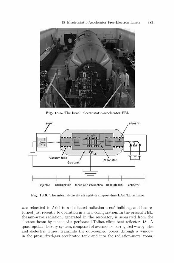
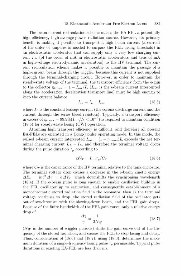
An alternative configuration for an EA-FEL was developed in Israel by aconsortium headed by Tel Aviv University, based on the 6 MV EN tandemaccelerator at the Weizmann Institute (shown in Fig. 18.5) [15, 16]. In thisconfiguration, the wiggler (and resonator) is placed in the positively chargedHV terminal, and the electron gun and collector are external to the tank atground potential (see Fig. 18.6). The accelerator, originally an ion accelerator,was converted into an electron accelerator and its internal transport systemwas modified (two out of four acceleration tube sections were removed) toaccommodate a magnetostatic wiggler and electron-optical focusing, steer-ing and diagnostic elements (see Fig. 18.6). First lasing and high-coherencesingle-mode operation were demonstrated in 1997 [16, 17]. In 2001, the FEL
18 Electrostatic-Accelerator Free-Electron Lasers 383
Fig. 18.5. The Israeli electrostatic-accelerator FEL
Fig. 18.6. The internal-cavity straight-transport-line EA-FEL scheme
was relocated to Ariel to a dedicated radiation-users’ building, and has re-turned just recently to operation in a new configuration. In the present FEL,the mm-wave radiation, generated in the resonator, is separated from theelectron beam by means of a perforated Talbot-effect bent reflector [18]. Aquasi-optical delivery system, composed of overmoded corrugated waveguidesand dielectric lenses, transmits the out-coupled power through a windowin the pressurized-gas accelerator tank and into the radiation-users’ room,

384 A. Gover and Y. Pinhasi
across a 1.3 m radiation protection concrete wall (see the horizontal aluminumwaveguide tube at the top right corner of Fig. 18.5). The Israeli FEL wasbuilt to serve as a radiation-user facility. In recent experiments [19], 0.5 kWRF power at 100 GHz was delivered to the users’ rooms. It is now beingfurther developed to operate at high average power (1 kW) in the range of70–130 GHz.
The capability of the EA-FEL to produce almost continuous high averagepower at mm wavelengths with wide-range tunability (by varying the beamenergy) has aroused interest in applying it for electron cyclotron resonanceheating (ECRH) of magnetically confined plasmas for controlled thermonu-clear fusion. Such an FEM was suggested and constructed by the DutchFOM Institute for Plasma Physics [20,21], and attained a record high powerof 730 kW in a few ms at 206 GHz, and pulses of 80 kW tens of ms longin the 200–300 GHz range. Single-mode operation and real-time, wide-rangestep frequency tuning, which is needed for the fusion application, were alsodemonstrated. The accelerator used in this case was charged by a 2 MV 20 mAinsulated-core transformer HV power supply.
Two other noteworthy experiments have been carried out in Korea and atCREOL (University of Central Florida). In 2001, the Korean FEM demon-strated first lasing in a straight-line-transport, positively-charged-terminalconfiguration. No accelerator was used; rather, an open-air-insulation trans-port system, based on a 500 kV power supply and an e-gun, were used todemonstrate lasing at 35 GHz at an RF power of 1 kW [22]. At CREOL, acompact FEL based on a mini-wiggler (λW = 8 mm) and a Pelletron acceler-ator has been developed [23]. In 2000, lasing in the FIR region (λ = 400 µm,P = 100 W) was demonstrated with it for the first time. This FEL was trans-ported recently to the University of Hawaii and is being reassembled there.
18.4 EA-FEL Design Considerations
The EA-FEL is inherently an energy retrieval (current recirculation) device.This means that the entire high current (Ib) of the accelerated electron beam(in the order of amperes), except for a small interception current Iint, must betransported after passing through the wiggler (where it transfers part of itskinetic energy to the radiation field), and decelerated down to the moderate(tens of kV) voltages of the collector high-current power supplies. Throughthe collector power supplies, the e-beam electric circuit closes back to theelectron gun. Because the electron-beam energy distribution spreads out dur-ing the interaction with the radiation wave inside the wiggler, it is desirableto collect the decelerated electrons with a multiple-electrode collector. Thismeans that each electron-beam energy class hits the corresponding collectorelectrode with minimal kinetic energy, and consequently minimal heat wasteand secondary-electron emission. This technology of a “multistage depressedcollector” was developed before in the field of microwave tubes.
18 Electrostatic-Accelerator Free-Electron Lasers 385
The beam current recirculation scheme makes the EA-FEL a potentiallyhigh-efficiency, high-average-power radiation source. However, its primarybenefit is making it possible to transport a high beam current (a currentof the order of amperes is needed to surpass the FEL lasing threshold) inan electrostatic accelerator that can supply only a very low charging cur-rent Ich (of the order of mA in electrostatic accelerators and tens of mAin high-voltage electrodynamic accelerators) to the HV terminal. The cur-rent recirculation scheme makes it possible to maintain the passage of ahigh-current beam through the wiggler, because this current is not suppliedthrough the terminal-charging circuit. However, in order to maintain thesteady-state voltage of the terminal, the transport efficiency from the e-gunto the collector ηtrans = 1 − Iint/Ib (Iint is the e-beam current interceptedalong the acceleration–deceleration transport line) must be high enough tokeep the current balance
Ich = IL + Iint (18.5)
where IL is the constant leakage current (the corona discharge current and thecurrent through the series bleed resistors). Typically, a transport efficiencyin excess of ηtrans = 99.9%(Iint/Ib < 10−3) is required to maintain condition(18.5) for steady-state lasing (CW) operation.
Attaining high transport efficiency is difficult, and therefore all presentEA-FELs are operated in a (long-) pulse operating mode. In this mode, thepulsed e-beam current intercepted Iint = (1 − ηtrans)Ib exceeds the net ter-minal charging current Ich − IL, and therefore the terminal voltage dropsduring the pulse duration τp according to
∆VT = Iintτp/CT (18.6)
where CT is the capacitance of the HV terminal relative to the tank enclosure.The terminal voltage drop causes a decrease in the e-beam kinetic energy∆Ek = mc2 ∆γ = e∆VT , which downshifts the synchronism wavelength(18.4). If the e-beam pulse is long enough to enable oscillation buildup inthe FEL oscillator up to saturation, and consequently establishment of amonochromatic stored radiation field in the resonator, then as the terminalvoltage continues to drop, the stored radiation field of the oscillator getsout of synchronism with the slowing-down beam, and the FEL gain drops.Because of the finite bandwidth of the FEL gain curve, only a relative energydrop of
∆γ
γ=
12NW
(18.7)
(NW is the number of wiggler periods) shifts the gain curve out of the fre-quency of the stored radiation, and causes the FEL to stop lasing and decay.Thus, consideration of (18.6) and (18.7), using (18.3), determines the maxi-mum duration of a single-frequency lasing pulse τp permissible. Typical pulsedurations in existing EA-FEL are less than ms.

386 A. Gover and Y. Pinhasi
The possibility of obtaining long-pulse operation (and potentially CWoperation) demonstrates an important feature of the EA-FEL – high temporalcoherence. Because the FEL is essentially a homogeneously broadened laser,the mode competition process in the resonator during the oscillation buildupperiod winds up with single-mode operation [14, 17, 24]. Figure 18.7 showsthe spectrum of the single-mode radiation measured for the Israeli FEL [17].It shows an FWHM emission bandwidth of ∆f = 1 MHz that corresponds toa relative linewidth of ∆f/f ∼= 10−5, still Fourier-transform-limited by thefinite pulse duration (τp = 20 µs).
Fig. 18.7. Spectrum of the coherent single-mode radiation emitted from the tan-dem EA-FEL [17]. The FWHM bandwidth is ∆f = 1 MHz (the intensity scale islogarithmic)
The saturation radiative extraction power for the FEL is given by
∆Pext = ηextEkIb/e (18.8)
where the extraction efficiency ηextr∼= 1/2NW can be understood as a result
of the electrons getting out of synchronism owing to their energy loss inthe resonator (compare (18.7)). The power coupled out of the resonator atsaturation depends on the power transmission T of the out-coupling mirrorand the total round-trip loss factor 1 − R (R is the resonator round-trip
18 Electrostatic-Accelerator Free-Electron Lasers 387
reflectivity):
Pout =T
1 − R∆Pext (18.9)
As in any laser, there is always an optimal transmission factor T , for whichPout is maximized. Its determination requires numerical solution of the FELequations in the nonlinear (saturation) regime [25].
The design of the resonator is a difficult part of EA-FEL design. Becauseof the long wavelength of operation, diffraction is significant, and usually anover-moded waveguide resonator is used. If the electron beam can be bent intoand out of the resonator axis (as in [13,23]) then slit out-coupling can be usedin the output mirror. In [17,19,21] Talbot-effect reflector configurations [18]were used, enabling out-coupling of the radiation to the side of the resonatoraxis. The e-beam is injected, and then enters and leaves the resonator throughholes in the mirrors, keeping a straight trajectory along the coaxial acceleratorand resonator.
An example of EA-FEL construction, some parameters based on theIsraeli EA-FEL are given in Table 18.1. For these parameters, an extrac-tion efficiency ηextr = 2.5% and an output power Pout/Ib = 7 kW/A areexpected at saturation, according to (18.8) and (18.9). So far, Pout = 5 kW(0.5 kW at the users’ room) has been measured in this device at Ib = 1.8 A,which is before saturation.
In conclusion in relation to the design considerations, an important noteshould be made concerning the choice of accelerator polarity and configura-tion. A configuration with an external resonator and wiggler is advantageousfor application in a radiation-users’ facility, mostly because it leaves room forthe design of extended and multiple wigglers and resonators, and the radia-tion can be coupled easily out of the resonator directly into the user rooms(see the horizontal aluminum pipe in the bottom left corner of Fig. 18.3).However, for future specific short-wavelength and high-power applications,an internal-cavity configuration is advantageous. Because of voltage break-down considerations, it is possible to build high-voltage electrostatic acceler-ators (which are needed for short-wavelength operation) only with a positive-polarity terminal. Furthermore, in this configuration, the e-gun and collectorpower supplies are placed at ground potential. At the high average powerlevels (of the order of MW) at which EA-FELs can potentially operate, itwould be inconceivable to place the large power supplies in the terminal andtransfer the grid power to them mechanically, as is done in the negative-polarity terminal configuration. In addition, the simple straight geometry ofthe electron beam transport in the internal-cavity configuration (Fig. 18.6)promises better transport efficiency and consequently higher-average-poweroperation.
388 A. Gover and Y. Pinhasi
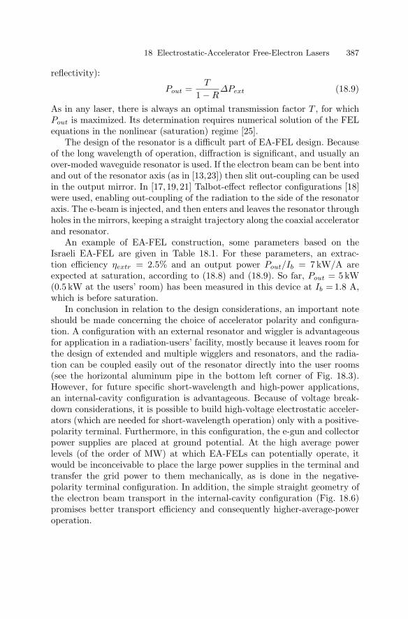
Fig. 18.8. Conceptual scheme of a radiation user facility based on an EA-FEL
18.5 EA-FEL Applications
The main application of the EA-FEL at present (as with most other kinds ofFELs) is as a radiation user facility for scientific studies. In this connection,the main feature taken advantage of is the wide-range tunability in a wave-length region (from mm-wave to IR) which is deficient in tunable sources. Forsome studies, the high power and narrow spectrum of the radiation sourceare also important characteristics. Figure 18.8 depicts a conceptual designof some radiation exposure stations in a radiation user facility based on anEA-FEL [26].
The EA-FEL, as an intense tunable FIR source, is a useful study tool incondensed-matter physics research. It has been used in linear and non-linearspectroscopy of elementary excitations in materials: phonons, magnons, exci-tons and shallow impurity levels in semiconductors, small-energy-gap mate-rials such as high-temperature superconductors (HTSCs), quantum wells, su-perlattices, and various mesoscopic semiconductor structures and devices [27].In biological research, such a source can be useful in spectroscopic investiga-tions of vibrational levels in proteins and DNA molecules. It can be used alsofor studies of damaging or therapeutic effects of mm-wave or FIR radiationinteracting with biological tissues.
The potential of the EA-FEL for high average power and high effi-ciency holds promise for the development of energy-related industrial and
18 Electrostatic-Accelerator Free-Electron Lasers 389
commercial applications. The MW-level design and the partial demonstra-tion of operation of the FOM FEL indicate that such high-power applica-tions are feasible with further investment in technological development. Thefusion application (ECRH heating of magnetically confined plasmas in toka-maks) requires a few MW of power at shortmm wavelengths, step-tunableby 35% on a timescale of seconds. More moderate average power levels (kWto tens of kW) are required for applications in thermal material processing(ceramic sintering, surface treatments, cutting, curing, drying etc.) [28]. Inter-esting applications and schematic designs have been proposed for compactEA-FEL systems to be used in free-space atmospheric beam propagation.These include the concept of radiative energy transmission to atmospheric orionospheric unmanned airborne vehicles through atmospheric transmissionwindows (35 GHz and 94 GHz) [26, 29]. Other such applications include ex-tremely high frequency (30–300 GHz) mm-wave radars and high-resolutionimaging systems, communication (to satellite) systems, and remote sensingof gases and aerosols in the atmosphere [26].
Acknowledgments
This work was performed in the Israeli FEL National Knowledge Centersupported by the Ministry of Science, Israel, and was supported in part bythe Ministry of Infrastructure.
References
1. P. L. Kapitza, P. A. M. Dirac: Proc. Camb. Phil. Soc. 29, 247 (1933)2. H. Motz: J. Appl. Phys. 2, 527 (1951)3. H. Motz, W. Thon, R. N. Whitehurst: J. Appl. Phys. 24, 826 (1953)4. R. M. Phillips: IRE Trans. Electron. Dev. ED-7, 231 (1960)5. R. M. Phillips: Nucl. Instr. Meth. A 272, 272 (1988)6. J. M. J. Madey: J. Appl. Phys. 42, 1906 (1971)7. J. M. J. Madey, H. A. Schwettman, W. M. Fairbank: IEEE Trans. Nucl. Sci.
NS-20, 980 (1973)8. L. R. Elias, W. M. Fairbank, J. M. J. Madey, H. A. Schwettman, T. L. Smith:
Phys. Rev. Lett. 36, 717 (1976)9. D. A. G. Deacon, L. R. Elias, J. M. J. Madey, G. J. Ramian, H. A. Schwettman,
T. L. Smith: Phys. Rev. Lett. 38, 892 (1977)10. E. Jerby, A. Gover: J. Quantum Electron. QE-21, 1041 (1984)11. A. Gover, A. Friedman, A. Drobot: Laser Focus World, pp. 95–104 (October
1990)12. L. R. Elias et al.: Nucl. Instr. Meth. A 237, 203 (1985)13. L. R. Elias: IEEE J. Quantum Electron. QE-23, 1470 (1987)14. L. R. Elias, G. Ramian, R. J. Hu, A. Amir: Phys. Rev. Lett. 57, 424 (1986)
390 A. Gover and Y. Pinhasi
15. A. Gover, E. Jerby, H. Kleinman, I. Ben-Zvi, B. V. Elkonin, A. Fruchtman, J.S. Sokolowski, B. Mandelbaum, A. Rosenberg, J. Shiloh, G. Hazak, O. Shahal:Nucl. Instr. Meth. A 296, 720 (1990)
16. A. Abramovich et al.: Appl. Phys. Lett. 71, 3776 (1997)17. A. Abramovich, M. Canter, A. Gover, J. S. Sokolovski, Y. M. Yakover, Y.
Pinhasi, I. Schnitzer, J. Shiloh: Phys. Rev. Lett. 82, 6774 (1999)18. I. M. Yakover, Y. Pinhasi, A. Gover: Nucl. Instr. Meth. A 358, 323 (1995)19. A. Gover, A. Faingersh, A. Eliran, M. Volshonok, H. Kleinman, S. Wolowelsky,
B. Kapilevich, Y. Lesser, Z. Seidov, M. Kanter, A. Zinigrad, M. Einat, Y. Lurie,A. Abramovich, A. Yahalom, Y. Pinhasi, E. Weisman, J. Shiloh: “RadiationMeasurements in the New Tandem Accelerator FEL”, Nucl. Instr. Meth. Phys.Res. A 528, 23 (2004)
20. P. W. van Amersfroot, W. H. Urbanus, A. G. A. Verhoven, A. Verheul, A. B.Sterk, A. M. van Ingen, M. J. van der Wiel: Nucl. Instr. Meth. A 304, 168(1991)
21. W. H. Urbanus et al.: Phys. Rev. Lett. 89, 214801-1 (2002)22. B. C. Lee, S. K. Kim, Y. U. Jeong, S. O. Cho, B. H. Cha, J. Lee: Nucl. Instr.
Meth. 375, 28 (1996)23. L. R. Elias, I. Kimel, D. Larson, D. Anderson, M. Tecimer, Z. Zhesu: Nucl.
Instr. Meth. A 304, 219 (1991)24. B. G. Danly et al.: Phys. Rev. Lett. 65, 2251 (1990)25. A. Abramovich, Y. Pinhasi, A. Yahalom, D. Bar-Lev, S. Efimov, A. Gover:
Nucl. Instr. Meth. Phys. Res. A 475, 579 (2001)26. Y. Pinhasi, I. M. Yakover, A. Eichenbaum, A. Gover: IEEE Trans. Plasma Sci.
24, 1050 (1996)27. J. Allen et al.: Nucl. Instr. Meth. Phys. Res. A 358, 536 (1995)28. A. Gover, A. L. Eichenbaum, S. Efimov, J. Sokolowski, M. Tecimer, Y. Yakover,
A. Abramovich, M. Canter, Y. Pinhasi, A. Yahalom, I. Schnitzer, Y. Shiloh:“User Application for the TAU Tandem Electrostatic Accelerator FEL at LongWavelengths”, FEL User Workshop at 22nd Int. FEL Conf., Durham, N.C.,Aug. 2000
29. I. Kimel, L. R. Elias: Nucl. Instr. Meth. A 358, 186 (1995)
Part III
Research Fieldsand Their Technical Requirements