EMERGENCY RESPONSE PLAN - Puna Geothermal Project
312
EMERGENCY RESPONSE PLAN Revision Date 5/19/2021
-
Upload
khangminh22 -
Category
Documents
-
view
0 -
download
0
Transcript of EMERGENCY RESPONSE PLAN - Puna Geothermal Project
EMERGENCY
RESPONSE
PLAN Revision Date 5/19/2021
1
EMERGENCY RESPONSE PLAN
January 1, 2021
Geothermal Resource Permit: GRP 87-2 TMK: 1-4-01: por. 2, 3, por. 19 & 58
Puna, Hawaii
Island of Hawaii Puna District
Puna Geothermal Venture P.O. Box 30
Pahoa, Hawaii 96778 808.965.6233

2
TABLE OF CONTENTS
1 INTRODUCTION
1.1 Objective………………………………………………………………………………………..3
1.2 Scope ..................................................................................................................................... ..…3
2 REGULATORY AUTHORITY AND DEFINITIONS……………………….……………….………8
2.1 Regulatory Authority ................................................................................................................. 9
2.2 Definitions ................................................................................................................................ 10
3 NOTIFICATION AND CHAIN-OF-COMMAND……………………………………………….…...12
3.1 Internal Call List………………………………………………………………………………...13
3.2 External Call list………………………………………………………………………………...14
3.3 PGV Emergency Response Organization……………………………………………………….15
3.3.1 Puna Geothermal Operations Staff Responsibilities during Emergency
Situations……………………………………………………….……………………….16
3.4 Notification………………………………………………………………………………….......17
3.4.1Public Notification During Nuisance/Disturbance Situations…………………….……..18
4 RESPONSE FACILITIES……………………………………………………………………………...19
4.1 Off-Site Response Facilities ...................................................................................................... 20
4.1.1 Off- Site Response Facilities Map .......................................................................................... 20
4.2 On-Site Emergency and Safety Equipment ............................................................................. 21
4.2.1 On-Site Emergency and Safety Equipment Map .................................................................. 21
4.3 On-Site Meeting Points
5 PGV EVACUATION PLAN……………………………………………………………………….…..22
5.1 Evacuation of Persons On-Site ................................................................................................. 23
5.1.1 Evacuation of Persons On-Site Map ...................................................................................... 23
5.2 Evacuation of Nearby Residents ............................................................................................... 24
5.3 Removal of Equipment ............................................................................................................ 25
6 PGV PERSONNEL TRAINING…………………………………………….…………………….…...26

3
6.1 Drilling………………………………………………………………………………………….27
6.1.1 H2S Safety Training………………………………………………..………….....…...28
6.1.2 H2S Emergency Response Drills…………………………………………………......29
6.1.3 Blowout Prevention Training…………………………………………………………30
6.2 Blowout Emergency Response Drill (Drilling Operations Only)………………………………31
6.3 Power Plant Construction……………………………………………………………………….32
6.4 Power Plant Operation…………………………………………………………………………..33
7 PGV EMERGENCY DRILL…………………………………………………………………………...34
8 HAZARD ANALYSIS AND PGV RESPONSE PROCEDURES TO POTENTIAL EMERGENCY
SITUATIONS………………………………………………………………………….…………..35
8 Natural Hazards……………………………………………….………………………………………...36
8.1.1 Volcanic Activity…………………………………………………………………......37
8.1.2 Magma Intrusion……………………………………………………………………...38
8.1.2.1 Lava Interruption
8.1.2.2 Lava Intrusion
8.1.3 Earthquake…………………………………………………………………………….39
8.1.4 Severe Weather Systems……………………………….………………………….….40
8.1.5 Lightning………………………………………………………………………….…..41
8.1.6 Brush Fire…………………………………………………………….…………….…42
8.1.7 General Response……………………………………………………………….….....43
9 Off Site Emergency Procedures………………………..…………..…………………………….…….44
9.1 Upset Site Release Tables……………………………………………………………….44
9.1.1 Geothermal Steam and Fluid Releases………………………………………………..46
9.1.2 Fire Hazard……………………………………………………………………………47
9.1.3 Noise Hazard………………………………………………………………………….48
9.1.4 Spills and Leaks……………………………………………………………………….49
10 On Site Emergency Procedures…....……………...……….………...……...…………………………50
10.1 Grid Upsets……………………………………………………………………….……51
10.2 Auxiliary Upsets……………………………………….…………………………..…..52
10.3 Plant Upsets………………………………………………………….…….…………..53

4

3
INTRODUCTION
Puna Geothermal Venture (PGV) is a geothermal powered electric generating project within a
designated area of about 500 acres located on State Highway 132 and Pahoa-Pohoiki Roads
(Figure 1-1 and Figure 1-2) . The project occupies about 25 acres of surface area consisting of
production and injection wells and a power plant. A detailed description of the project facilities
and operations is presented in Appendix A.
1.1 Objective
This Facility Emergency Response Plan (ERP) has been developed to comply with Condition #26
of Geothermal Resource Permit GRP 87-2, approved by the County of Hawaii Planning
Commission on October 3, 1989, and in conformance with discussions with the County of Hawaii
Civil Defense Agency (CDA), Hawaii Department of Health (HDOH), and the staff of the Hawaii
State Emergency Response Commission (ERC). This ERP is specifically required to provide a
plan of action to deal with facility emergency situations which may threaten the health, safety, and
welfare of the employees and other persons in the vicinity of the project site. This plan is the
basis of all actions by PGV's personnel and management staff in responding to these situations,
and is updated appropriately when necessary. Site personnel also follow related site Safety,
Environmental and Operating Procedures.
Any change to the plan is the responsibility of:
Puna Geothermal Venture
P.O. Box 30
Pahoa, Hawaii 96778
1.2 Scope
The required Scope of the ERP, as in Condition #26 of the GRP, items a through k, requires that
the following elements be included as a minimum:
a. A description of the project facilities and operations, with site plans
identifying areas of potential hazards, such as high pressure piping and the
presence, storage and transportation of flammable or hazardous materials,
such as lubrication or fuel oil, pentane, hydrogen sulfide, and sodium
hydroxide;
b. A description of emergency services available off-site to respond to any
emergency;
c. A description of the current on-site chain-of-command and responsibilities of
project personnel in the event of an emergency; and,

3
d. A description of potential project emergency situations, such as loss of
well control, chemical spills, hydrogen sulfide exposure, pipeline
rupture, fires, contaminated solids, etc. identifying;
(i) technical data on the nature of the hazard (for example, the
concentrations of hydrogen sulfide in the various areas and the hazard
associated with these concentrations, the corrosive characteristics of
the abatement chemicals), or any data regarding the possible aerial
extent of each potential emergency situation;
(ii) the warning systems (such as hydrogen sulfide detectors) used
to alert personnel of the hazard;
(iii) the location and use of equipment used to control the hazard
(such as fire protection equipment or isolation valves) or
repair hazardous equipment (such as welding equipment or
casing sleeves), and safety equipment for personnel (such as
respiratory packs), including identification of the personnel
trained in the use of that equipment; and
(iv) provisions for the monitoring, detection, and inspection of
wells and plant facilities for the prevention of emergency
situations.
e. Provisions to address natural hazards (such as lava flows,
earthquakes, and storms) that identify warning systems, control
options, steps for securing and shutting down the facility,
personnel evacuation, and notification to appropriate agencies;
f. The location and capabilities of available medical services and
facilities and plans for treating and transporting injured persons;
g. Evacuation plans, including meeting points, personnel rosters, and
escape routes;
h. Training requirements for personnel, including procedures for
emergency shutdown, handling of emergency equipment, spill
prevention, first aid and rescue, fire fighting procedures, and
evacuation training;
i. Provisions for periodic emergency preparedness drills for
personnel;

3
j. Detailed procedures to be used to facilitate coordination with
appropriate federal, state, and county officials during and after any
emergency situation; and,
k. Procedures to be used to identify and inform all residents within
applicable distances of the project of the possible emergency situations,
warnings, and responses in advance of commencement of project
operation and the methods by which all individuals affected by a given
emergency will be notified and evacuated, as necessary.

3
Table 1-1 identifies where the components of each of these GRP requirements are located in this
document.
Table 1-1 Index of GRP Condition #26 Requirements in the Emergency Response Plan
a
A description of the project facilities and operations, with site plans
identifying areas of potential hazards, such as high pressure piping and
the presence, storage and transportation of flammable or hazardous
materials such as lubrication or fuel oil, n-pentane, hydrogen sulfide,
and sodium hydroxide;
Appendix A
(A.1 - A.10.1)
Section 4.2
b
A description of emergency services available off-site to respond to any
emergency;
Section 4
c
A description of the current on-site chain-of-command and
responsibilities of project personnel in the event of an emergency; and
Section 3
d
A description of potential project emergency situations, such as loss of
well control, chemical spills, hydrogen sulfide exposure, pipeline
rupture, fires, contaminated solids, etc. identifying;
Section 8
(i) technical data on the nature of the hazard (for example, the
concentrations of hydrogen sulfide in the various areas and the
hazard associated with these concentrations, the corrosive
characteristics of the abatement chemicals), or any data regarding
the possible aerials extent of each potential emergency situation;
Section 8, Appendix F,
Appendix G, Appendix
H, Attachments 1-3
(ii) the warning systems (such as hydrogen sulfide detectors) used to
alert personnel of the hazard;
Section 4
Section 5
Section 6
Section 8
Appendix A
(iii) the location and use of equipment used to control the hazard
(such as fire protection equipment or isolation valves) or repair
hazardous equipment (such as welding equipment or casing
sleeves), and safety equipment for personnel (such as respiratory
packs), including identification of the personnel trained in the use of
that equipment; and
Section 4
Section 8
(iv) provisions for the monitoring, detection, and inspection of wells
and plant facilities for the prevention of emergency situations.
Appendix A
Section 4 e
Provisions to address natural hazards (such as lava flows, earthquakes,
and storms) that identify warning systems, control options, steps for
securing and shutting down the facility, personnel evacuation, and
Section 5
Section 8

3
notification to appropriate agencies; f
The location and capabilities of available medical services and facilities
and plans for treating and transporting injured persons;
Section 4
g
Evacuation plans, including meeting points, personnel rosters, and
escape routes;
Section 5
h
Training requirements for personnel, including procedures for
emergency shutdown, handling of emergency equipment, spill
prevention, first aid and rescue, fire fighting procedures, and evacuation
training;
Section 6, Appendix B, C
i
Provisions for periodic emergency preparedness drills for personnel; Section 6
Section 7 j
Detailed procedures to be used to facilitate coordination with
appropriate federal, state, and county officials during and after any
emergency situation; and,
Section 3, Appendix D
k
Procedures to be used to identify and inform all residents within
applicable distances of the project of the possible emergency situations,
warnings, and responses in advance of commencement of project
operation and the methods by which all individuals affected by a given
emergency will be notified and evacuated, as necessary.
Section 3.3


9
2 REGULATORY AUTHORITY AND DEFINITIONS
2.1 Regulatory Authority
As discussed above in Chapter, this ERP has been developed specifically to satisfy Condition
No. 26 of GRP 87-2, which requires a plan of action to deal with emergency situations which
may threaten the health, safety, or welfare of the employees and other persons in the vicinity
of the proposed project site. GRP 87_2 presents fifty other conditions of approval which,
among other things, set limits on the amount of several pollutants that PGV may emit into the
environment, and also set limits on the ambient (environmental) concentrations of these
pollutants which result from PGV's operations. So that the PGV Project will not become a
nuisance to the community, these permitted emission limits and ambient concentrations are
intentionally set at very low levels.
PGV has also been issued three permits by the Hawaii State Department of Health (HDOH).
They limit the emissions of several pollutants, principally hydrogen sulfide, and limit the
concentration levels that these pollutants can reach in the ambient environment as a result of
PGV's operations. The operation of the PGV well field is regulated by the Permit to Operate,
(PTO) # P833-1524, issued by the HDOH. PTO # P834-1582 has been issued by HDOH to
regulate the operation of the Project Power Plant. Well construction, when underway, is
regulated by a Non-covered Source Permit (NSP) # 0008-01-N issued by HDOH.
Exceeding either the emission limits or ambient concentrations set in these permits, either
during otherwise permitted operations or during upset conditions, would be considered a
violation of the permits and would subject the permit holder (PGV) to the penalties described
in the permits and applicable laws and regulations. PGV is generally also required to
immediately respond to exceedances of the permitted emission limits or ambient
concentrations by reducing or eliminating the source of the exceedance, so that the project
permitted operations are reduced to within permitted limits.
Some upset conditions, although they do not result in the emission or ambient concentration
of any pollutant above the permitted level and do not pose any threat to the health, safety, or
welfare of the persons in the vicinity of the community, may nonetheless result in the need
for one or more of the County normal emergency response organizations (police, fire
department, etc.) to respond to the site. The County of Hawaii Plan for Emergency
Preparedness, Vol. III, Disaster Preparedness and Response, recognizes these as "everyday"
emergency situations, the type of emergency situations which frequently arise in a
community and which are handled routinely by normal emergency services. However,
should the exceedance of the permitted limits or concentrations during an upset or accident be
so great as to endanger, or potentially endanger, the public health, safety, or welfare, an
emergency response by the Hawaii County Civil Defense Agency (CDA) and/or other
County emergency response organizations would likely occur.

9
2.2 Definitions
Normal Plant Operations As defined in the Non-covered Source Permit (NSP), a
condition when both the power plant and geothermal well
field are operating normally, that is, when the power plant
is operating without any upsets, equipment failure,
malfunction or which is otherwise operating normally and
when no well drilling, flow testing, or venting activities are
occurring and where the completed wells are not
experiencing any equipment failure or malfunction and are
either shut-in, being used as an injection well, or connected
to a sound geothermal resource distribution system.
Routine Operations Those operations over and above normal operations,
including, but not limited to, periods of well drilling, well
flow testing, well or pipe clean out, but not including
periods of well or power plant upset, failure or malfunction.
Upset Conditions Those situations which are not normal or routine
operations.
Permitted Operations Those normal, routine, and upset operations and/or
conditions which are permissible under permits granted by
the Hawaii County Planning Commission (Geothermal
Resource Permit GRP 87-1) and the Hawaii Department of
Health (Permit to Operate Permits No. P-833-1524 and
No. P-834-1582), whether by explicit statement or through
producing impacts which do not exceed stated limits.
Permitted Upset Conditions Those situations which are not normal or routine
operations, but which are otherwise anticipated and
approved by the appropriate regulatory agencies, such as
steam release through the emergency steam release facility;
or those circumstances, such as turbine trips, minor leaks,
component malfunctions, etc., which are not expressly
approved in any permits, but the impacts of which fall
within permitted limits and do not have the potential to
produce emergency situations which could threaten the
health, safety, or welfare of the employees and other
persons in the vicinity of the proposed project site.
Ambient Level That concentration of a pollutant, such as hydrogen sulfide,
or level of an environmental factor, such as noise, which is
measured or predicted at a specified point or points in the
air or environment.
9
Emission Level That quantity of a pollutant or environmental factor which
is, or could be, discharged into the environment.
Facility Emergency Situation An upset condition which results in the need for immediate
action by facility operation personnel to restore normal or
routine operations.
Everyday Emergency Situation As defined by the County of Hawaii Plan for Emergency
Preparedness, Vol. III, Disaster Preparedness and
Response, those emergency situations which are handled
routinely by project personnel and/or normal emergency
services such as police, fire, emergency medical service,
public works, or utilities.
Hazard Any situation that has the potential for causing damage to
life, property, or the environment.
12
1 NOTIFICATION AND CHAIN-OF-COMMAND
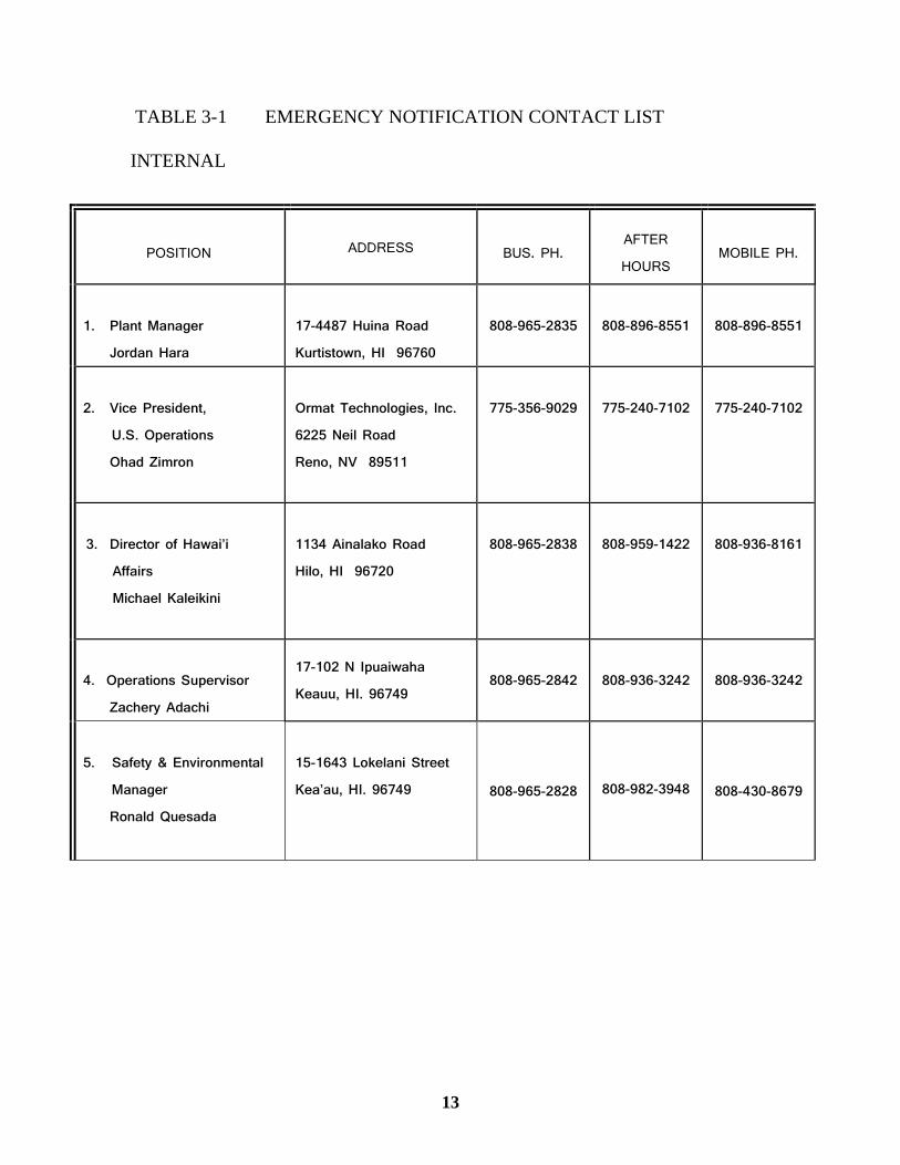
1.1 Notification Lists
Table 3-1 provides phone contacts for County, State, and Federal government agencies, PGV
staff, and the project 24-hour information line.
1.2 PGV Emergency Response Organization
Table 3-2 illustrates the chain of command and emergency response team that is in effect to
deal with site emergencies and summarizes the responsibilities of the site staff during an
emergency situation.
13
TABLE 3-1 EMERGENCY NOTIFICATION CONTACT LIST
INTERNAL
POSITION ADDRESS
BUS. PH.
AFTER
HOURS
MOBILE PH.
1. Plant Manager
Jordan Hara
17-4487 Huina Road
Kurtistown, HI 96760
808-965-2835
808-896-8551
808-896-8551
2. Vice President,
U.S. Operations
Ohad Zimron
Ormat Technologies, Inc.
6225 Neil Road
Reno, NV 89511
775-356-9029
775-240-7102
775-240-7102
3. Director of Hawai’i
Affairs
Michael Kaleikini
1134 Ainalako Road
Hilo, HI 96720
808-965-2838
808-959-1422
808-936-8161
4. Operations Supervisor
Zachery Adachi
17-102 N Ipuaiwaha
Keauu, HI. 96749 808-965-2842 808-936-3242 808-936-3242
5. Safety & Environmental
Manager
Ronald Quesada
15-1643 Lokelani Street
Kea’au, HI. 96749 808-965-2828 808-982-3948 808-430-8679
14
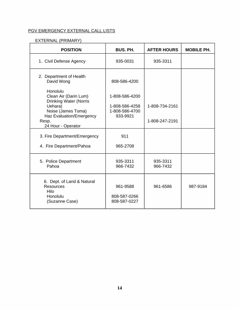
PGV EMERGENCY EXTERNAL CALL LISTS
EXTERNAL (PRIMARY) POSITION
BUS. PH.
AFTER HOURS
MOBILE PH.
1. Civil Defense Agency
935-0031
935-3311
2. Department of Health
David Wong Honolulu
Clean Air (Darin Lum) Drinking Water (Norris Uehara) Noise (James Toma)
Haz Evaluation/Emergency Resp. 24 Hour - Operator
808-586-4200
1-808-586-4200
1-808-586-4258 1-808-586-4700
933-9921
1-808-734-2161
1-808-247-2191
3. Fire Department/Emergency 4. Fire Department/Pahoa
911
965-2708
5. Police Department Hilo
Pahoa
935-3311 966-7432
935-3311 966-7432
6. Dept. of Land & Natural Resources
Hilo Honolulu (Suzanne Case)
961-9588
808-587-0266 808-587-0227
961-6586
987-9184

15
EXTERNAL (SECONDARY)
POSITION
BUS. PH.
AFTER HOURS
MOBILE PH.
1. Security: Ron Quesada
808-965-
2848
808-965-
2848
808-430-
8679 2. Monitoring: Matthew
Seymour
1-808-371-
2560
3. HELCO
969-0411
969-0411
4. *PGV Response Line
965-8843
5. **PGV Information Line
934-9072
934-9072
6. For reportable quantities: (H2S
> 100 lbs; caustic > 1,000 lbs.)
a. Hawaii State Emergency Response Commission (HSERC) b. Hawaii County Fire Department c. Hawaii County Division of Industrial Safety (LEPC) d. National Response Center
1-808-586-4249
961-6022
936-0858
1-800-424-8802
1-247-2191
961-6022
1-800-424-8802
* Call this number to give current information to the operators at the response line answering service.
** PGV Information Line: CSC will change message to update situation.
*** For emergencies, call 911

16

16
3.3 EMERGENCY RESPONSE TEAM
PRIMARY
ALTERNATES
Incident Commander
(Emergency Coordinator)
Ron Quesada Jordan Hara
Fire Department
Zach Adachi
Hazardous Materials Specialists
Ron Quesada
Jordan Hara
Zach Adachi
Guy Ha
Gary Dahl
Stan Magnuson
Hazardous Material Technicians
Zach Adachi Josh Serrao Paul Fernandez Guy Ha Alberto Velazquez Randy Teeples Mark Nakasato Lyle Olivar Todd Gaskin Joseph Andrade
Gary Dahl
Jack “Kaliko” Lee
Media Coordinator/Spokesperson
Mike Kaleikini
First Responder
Awareness Level
All Personnel
Post Emergency Responder
Ron Quesada
Jordan Hara
Outside Contractors
Environmental Firms
Safety Official Ron Quesada

17
TABLE 3.3.1 PUNA GEOTHERMAL OPERATIONS STAFF RESPONSIBILITIES
DURING EMERGENCY SITUATIONS
Should an emergency situation occur, specific management personnel will assume leadership roles
in the emergency response scenario. These key positions and basic responsibilities are as follows:
PLANT AND WELL FIELD OPERATIONS: (No Well Drilling)
MANAGEMENT POSITION EMERGENCY TITLE RESPONSIBILITIES
Plant Manager Incident Commander
-Will oversee broad implementation of the
Emergency Plan.
-Will oversee effective
and timely communications with
Government Agencies, Civil
Defense and other key
personnel.
-Assures site personnel are prepared
and trained to respond to emergency
situations as identified in the plan.
-Reviews assessments of response actions
and assures modification of plan as
necessary.
-Manages the site emergency response
activities and related personnel/responders. -
Implements the Emergency Response
Plan
-Will assess danger/situation and account for
personnel.
-Assures first aid/medical attention is given. -
Will establish command center
-Will assure all non-essential personnel are out
of danger zone.
-Coordinates and directs response actions and
response personnel.
-Coordinates actions, as applicable, with
outside support groups (fire, police,
ambulance/medical, cleanup teams etc.)
-Advises General Manager.
-Arranges transportation of personnel.
-Confirms reporting/notifications are
implemented timely.
-Directs contractor support

18
-Assures shut off of all unnecessary electricity,
flammable fluid pipes etc.
-Directs removal, control, or relocation of at
risk chemicals.
-Directs security forces and assures traffic and
property control.
-Arranges removal of equipment, records etc.
-Assures only trained and qualified personnel
respond and conduct themselves in accordance
with safety and environmental procedures.
-Determines when emergency is under control.
-Arranges and directs additional air
monitoring, where pertinent.
-Assesses response actions and modifies
procedures as needed.
Production & Support to Incident Commander
Maintenance Manager
Safety and Environmental
Coordinator
Manage personnel actions within in their
departments and Manager assures they follow
incident directives.
-Serve as an alternate Incident Commander, if
pre-qualified.
Hazardous Material Specialists/Technicians
Providing ongoing monitoring of local environmental
conditions during Task Force operations.
• Providing an initial and ongoing survey for and
identification of the presence of hazardous materials at
search and rescue sites.
• Implementing defensive mitigation practices when
indicated.
• Directing emergency decontamination procedures for any
Task Force member or victim.
• Provide assistance to medical personnel for information
regarding chemical exposure and injuries.
• Documenting all related information.
• Adhering to all safety procedures.
• Providing accountability, maintenance, and minor repairs
for all issued equipment.
• Performing additional tasks or duties as assigned during a
mission.
• Ensuring Safety Data Sheets (SDS) are provided for all
hazardous materials carried or used by the Task Force; and
• Ensuring all specialized equipment is maintained and

19
calibrated according to the manufacturer’s specifications.
Safety and Environmental Coordinator
-Assure required government notifications have
been made and aid.
-Conduct response actions as directed by IC.
-Assist incident commander
-Direct actions to mitigate spills or releases of
chemicals/hazardous substances.
-Direct decontamination procedures.
-Assists IC with level of response
determination.

20
Plant Engineer
Selected Maintenance First Responders
-Follow the emergency plan as
trained.
Operations Personnel Operations Level or
HazMat. Technicians
-Follow directives of the IC and Haz Mat
Specialist
-Assure all Personal Protection Equipment is
inspected prior to use and donned as
required.
-Conduct additional monitoring as requested
and make initial verbal notifications as plan
designates
FOR DRILLING EMERGENCY RESPONSE
During drilling activities, designated Well field personnel will take the required actions as
directed by the emergency plan, drilling plans, procedures and as per technical training. The
General Manager and Site Manager will assure drilling personnel are informed and trained.
Drilling Superintendent -
Assure response procedures
are current and relevant.
-Assure personnel are trained
and assigned to response
tasks.
-Supervise drilling response.
-Coordinate drilling crew
response.
-Initiate additional
monitoring as appropriate.
-Assure all required
notifications are made
immediately.

21
-Assure personnel don
appropriate personal
protective equipment.
-Inspect wells and related
equipment for damage.
Well field Management Consultant
-Coordinate plan activities
with Drilling Superintendent.

1
TABLE 3.3.2 PLANT PERSONNEL MEDICAL DUTIES
All PGV response team members are trained to provide CPR/AED and basic first-aid in a medical emergency up to their level of training while awaiting arrival of emergency medical service (EMS) personnel.
17
3.4 Notification to Public
GRP Condition #26 (k) requires PGV to outline:
1. "Procedures to be used to identify and inform all residents within
applicable distances of the project of the possible emergency situations,
warnings, and responses, in advance of commencement of the project,
and,"
2. "The methods by which all individuals affected by a given emergency will be
notified and evacuated, as necessary."
PGV considers that within the context of this condition that:
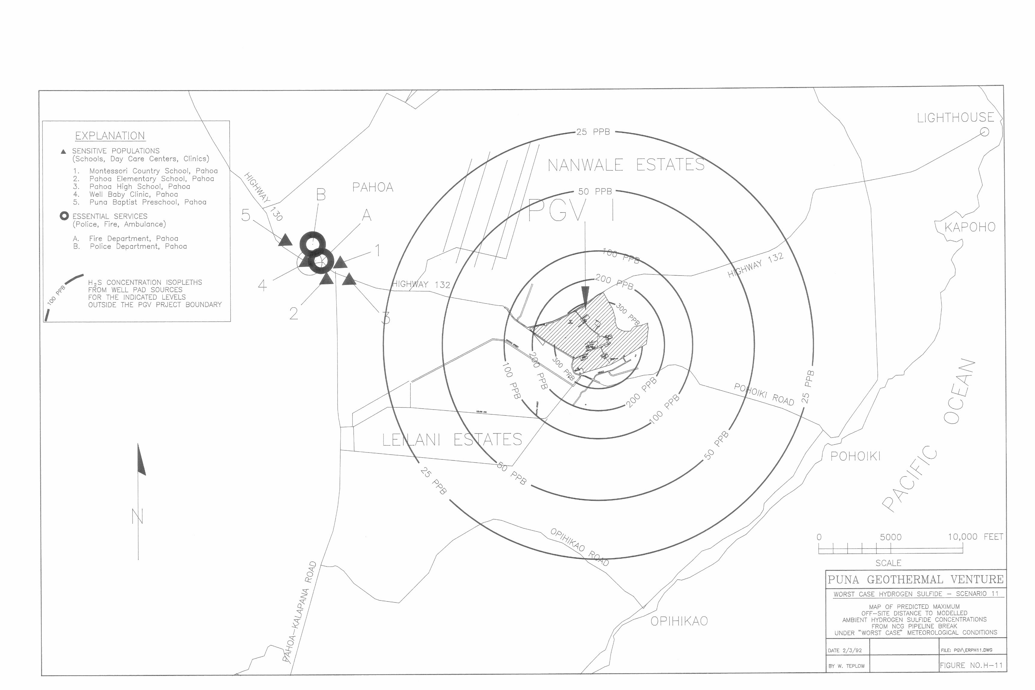
1. The applicable distances from the project to be the 3,500 feet from the
Project’s 500 acres leasehold boundary, as specified in the GRP.
2. Commencement of project operation is considered as the beginning of
drilling of the first geothermal well on the site,
3. The CDA will have the responsibility for, and be in charge of, any
notification and evacuation of the public arising from emergency
conditions existing at the site,
4. This ERP identifies the possible emergency situations, warnings and
responses and the methods by which all individuals affected by a given
emergency will be notified and evacuated, as necessary, and,
5. Informing all residents within applicable distances of the project of the
presence of the ERP constitutes compliance with Condition #26 (k), and,
6. The public will be informed of the presence of the ERP by (1)
announcement in the local newspapers, and (2) receipt of written letters to
all residents within the applicable distance as noted above.
7. These notification events will occur within one week after the CDA has
provided approval of this ERP in advance of commencement of project
operation.

18
3.3.1 Public Notification During Nuisance/Disturbance Situations
PGV, in conformance with conditions of the GRP and the Power Plant and Well Field PTOs,
has established a 24-hour information line for use by the public. PGV recognized that, at
times, nearby residents may have questions or concerns related to facility activities. In some
situations, these conditions could be perceived by the public as potentially related to an
emergency condition. In these instances, individuals may call the PGV 24-HOUR
INFORMATION LINE. The caller will hear recorded information on current plant activities.
If this information is not sufficient the individual may call PGV’s 24-hour response line. The
caller will be asked to provide the following information:
1) The general description of the situation, location and any other relevant
information.
2) The caller's name and contact phone number and/or address.
All calls and their respective conversations will be logged. The PGV person-in-charge will
be immediately notified of an inquiry or complaint that could be related to a facility
emergency situation. Corrective actions, if any, will be taken to appropriately rectify any
condition which is in violation of the GRP or NSP conditions or could potentially magnify
into an emergency situation.
Table 3-3 identifies the response PGV will take to deal with requests for information and
complaints when they come from the public either in writing or over the 24-hour response
line.
PGV will not contact CDA when a complaint is received unless there is a potential
emergency condition at the site.

19
4.0 RESPONSE FACILITIES
4.1 Emergency Facilities Available Off-Site
Figure 4-1 shows the location of facilities available in Pahoa, Keaau, and Hilo that can
respond during on-site or off-site emergencies. Table 4-1 lists the emergency response
and medical facilities that could reasonably be expected to provide support if a facility
emergency arose.
4.2 On-Site Safety Facilities
Figures 4-2 and 4-3 show the power plant and wellpad potential hazard areas,
respectively. Locations of on-site safety equipment relative to the hazard areas are
clearly marked. All response and safety facilities have been located so as to be close to
the potential hazard area yet isolated from the immediate impact of the hazard during a
facility emergency situation (such as placing air packs in elevated areas where H2S would
not collect). Table 4-2 lists the types and numbers of safety and first aid equipment
located in the wellpad, power plant and staging areas of the project. Table 4-3 lists the
on-site hydrogen sulfide detection equipment. More detailed descriptions of the on-site
safety equipment are presented in Appendix A.
4.3 On-Site Meeting Points
On-site meeting points are described in Section 5.1 and shown in Figure 5-1. The
primary on-site meeting place will be the control building. This site is located upwind
from well field and power plant operations under prevailing wind conditions. The
control building will contain primary communications equipment (telephones, radio base
station, etc.) and other emergency equipment along with the plant process controls.
These factors make it the logical meeting area. If the control building cannot be used for
any reason, site personnel will proceed along the emergency route entrance guard shack
through the entrance road. If this area is inaccessible or unsafe, site personnel will
proceed by way of alternate emergency route to the clearing at the intersection of
Kapoho and Pohoiki Roads.

20
OFF-SITE EMERGENCY FACILITY CAPABILITIES LOCATION
DISTANCE FROM
SITE
FIRE
POLICE
MEDICAL
PAHOA
3 MILES
1 ENGINE
1 TANKER
6 FIREFIGHTERS
2 POLICE OFFICERS
1 AMBULANCE
KEAAU
14 MILES
1 ENGINE
1 TANKER
6 FIRE FIGHTERS
1 RANKING OFFICER
6 POLICE OFFICERS
1 AMBULANCE
HILO
20 MILES
KAWAILANI STATION
1 ENGINE
4 FIREFIGHTERS
10 OFFICERS
HILO HOSPITAL
12 EMERGENCY ROOMS
8 OPERATING ROOMS
166 BEDS
1 DOCTOR (24 HOURS)
2 AMBULANCES
CENTRAL STATION
1 ENGINE
1 TANKER
11 FIREFIGHTERS
WAIAKEA STATION
1 ENGINE
1 HEAVY RESCUE RIG
1 HELICOPTER
5 FIREFIGHTERS
DOES NOT HANDLE
SERIOUS BURNS
PUNA DISTRICT
HAWAIIAN PARADISE
PARK
1 ENGINE
FIREFIGHTERS ON CALL
HAWAIIAN BEACHES
1 ENGINE
FIREFIGHTERS ON CALL

20
ON-SITE EMERGENCY AND SAFETY EQUIPMENT
LOCATION
S
FIRST
AID
SCBA
FIRE
EXTINGUISHERS
EYE
WASH
O2
KITS Wellpad A
0
2
2
1
2
Wellpad E
1
2
2
1
1
Expansion
Plant
1
2
8
1
1
Power Plant
3
8
54
3
4
LOCATION
S
FIRST
AID
AIR
PACKS
FIRE
EXTINGUISHERS
EYE
WASH
O2
KITS Wellpad
(during
drilling
activity)
3
12*
10
7
2
*Three additional air packs are located as follows:
One each in CSC, Training Unit in CSC and operation truck.
**Hoses, special/protective clothing, extra breathing cylinders and spill/leak response
equipment are located at various points throughout the plant and well field area.

20
ON-SITE HYDROGEN SULFIDE DETECTION EQUIPMENT
Locations Jerome 631-X
Industrial
Scientific
ITX
Industrial
Scientific
PMP
Det-Tronics
U/88
Monitor
Labs
Well Pad A
8
Well Pad E
2
Power Plant
4
1
17
25
Project
Boundary
3
1. Jerome 631-X Portable H2S Monitor
2. Industrial Scientific ITX - Portable H2S Monitor
4. Det-Tronics U88/U8000 Fixed H2S Monitor
5. Monitor Labs Model 8780 H2S Detector
20
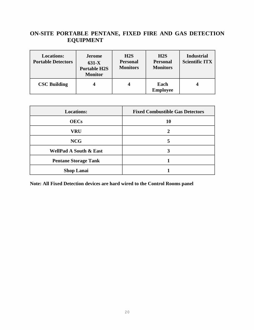
ON-SITE PORTABLE PENTANE, FIXED FIRE AND GAS DETECTION
EQUIPMENT
Locations:
Portable Detectors
Jerome
631-X
Portable H2S
Monitor
H2S
Personal
Monitors
H2S
Personal
Monitors
Industrial
Scientific ITX
CSC Building
4
4
Each
Employee
4
Locations:
Fixed Combustible Gas Detectors
OECs
10
VRU
2
NCG
5
WellPad A South & East
3
Pentane Storage Tank
1
Shop Lanai
1
Note: All Fixed Detection devices are hard wired to the Control Rooms panel

rquesada
Line
rquesada
Line
rquesada
Line
rquesada
Line
rquesada
Line
rquesada
Line
rquesada
Line
rquesada
Line
rquesada
Line
rquesada
Line
rquesada
Line
rquesada
Line
rquesada
Line
rquesada
Line
rquesada
Line

21
ON-SITE EMERGENCY AND SAFETY EQUIPMENT
LOCATION
S
FIRST
AID
AIR
PACKS
FIRE
EXTINGUISHERS
EYE
WASH
O2
KITS Wellpads
0
4
3
1
2
Power Plant
3
8
54
3
4
LOCATION
S
FIRST
AID
AIR
PACKS
FIRE
EXTINGUISHERS
EYE
WASH
O2
KITS Wellpad
(during
drilling
activity)
3
12*
10
7
2
*Three additional air packs are located as follows:
One each in CSC, Training Unit in CSC and operation truck.
**Hoses, special/protective clothing, extra breathing cylinders and spill/leak response
equipment are located at various points throughout the plant and well field area.

21
ON-SITE HYDROGEN SULFIDE DETECTION EQUIPMENT
Locations Jerome 631-X
Industrial
Scientific
ITX
Industrial
Scientific
PMP
Det-Tronics
U/88
Monitor
Labs
Well Pad A
8
Well Pad E
2
Power Plant
4
1
17
25
Project
Boundary
3
1. Jerome 631-X Portable H2S Monitor
2. Industrial Scientific ITX - Portable H2S Monitor
3. Industrial Scientific PMP - Portable H2S Monitor
4. Det-Tronics U88/U8000 Fixed H2S Monitor
5. Monitor Labs Model 8780 H2S Detector

21
ON-SITE PORTABLE PENTANE, FIXED FIRE AND GAS DETECTION
EQUIPMENT
Locations:
Portable Detectors
MSA
Exsplosivmeter
AIM
3-300 (3 Gas)
Sensit HXG-3
Industrial
Scientific ITX
CSC Building
3
1
2
1
Locations:
Fixed Combustible Gas Detectors
Fixed Fire Detectors UV/IR
OECs
10
10
VRU
2
1
Diesel Fire Pump
1
Emergency Diesel
Generator
1
Pentane Storage Tank
1
2
Shop Lanai
1
Note: All Fixed Detection devices are hard wired to the Control Rooms Supervisory panel

FIRST AIDSELF CONTAINED BREATHING APPARATUSEYE WASH STATIONOXYGEN KIT
4.2A SAFETY EQUIPMENT MAP
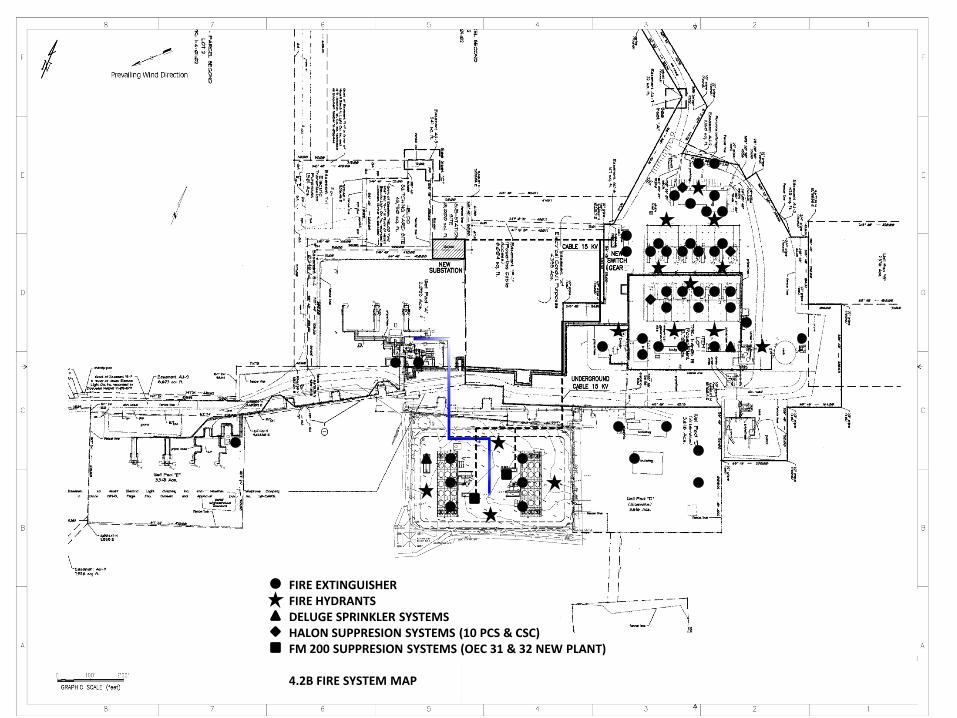
FIRE EXTINGUISHERFIRE HYDRANTSDELUGE SPRINKLER SYSTEMSHALON SUPPRESION SYSTEMS (10 PCS & CSC)FM 200 SUPPRESION SYSTEMS (OEC 31 & 32 NEW PLANT)
4.2B FIRE SYSTEM MAP

H2S DETECTIONLEL DETECTIONUVIR DETECTION
4.2C GAS DETECTION MAP


22
5 PGV EVACUATION PLAN
This section outlines what will be done to prepare for and implement the evacuation of people
from the site and the surrounding area, as necessary, and equipment from the site, in the event
that an evacuation is necessary.

23
5.1 Evacuation of Persons On-site
The following are the on-site features which will be in place in preparation for evacuating
persons that are on site at the time that an evacuation is required from the site:
• PGV Chain-of-Command:
The PGV chain-of-command (Chapter 3) will be implemented when an emergency
response condition exists at the site.
• On-site Warning:
A loud siren is located on top of the Control Building. This siren alarm will sound
continuously in the event that a facility emergency situation exists requiring evacuation
of the site. The alarm will be turned off after all personnel are accounted for and control
measures have been initiated.
• On-site meeting points (see Figure 5-1):
In the event of a facility emergency at the site requiring evacuation, all on-site PGV, staff
contractor personnel and visitors, except those designated to deal with an emergency
response at the site, are to proceed to one of three possible meeting points. The first
response meeting point will be in front of Admin I. If that site is not suitable, the second
will be at the staging area for the site on the Pahoa-Kapoho Road.
If neither of those sites are suitable, the third will be on the project property near the
intersection of the Pahoa-Kapoho Road and the Pahoa-Pohoiki Road.
On-site Personnel:
All personnel entering the site are logged in by the security guard, lead operator, or the
automated security access system. In an emergency, these logs will allow head counts to
determine if all personnel have been accounted for.
Evacuation Routes:
Primary and secondary evacuation routes from the active wellpad and the power plant
will be posted and clearly marked. There are two main entries into the site (Figure 5-1).
These routes will be clearly marked as the primary evacuation routes away from the
power plant and wellpad areas. The two secondary alternative evacuation routes will be
marked from both the wellpad and the power plant according to the road access on the
site.

23
Orientation of PGV, Contractor Staff, and Other On-site Persons:
All persons entering the site will be given an orientation regarding safety at the site,
and the location of facility emergency response evacuation routes and meeting points.
Site Command Post:
A command post will be established at one of the designated meeting areas to deal with a
facility emergency situation. Additional details related to the command post are in
Section 8.

24
5.2 Evacuation of Nearby Residents
The Civil Defense Agency (CDA) has the responsibility of providing the warning to, and to
effect the implementation of, the evacuation of any residents or other members of the public
from the appropriate hazard area surrounding the site, as necessary. Warning to these
residences is also provided by the CDA. PGV will provide assistance in this regard, as
directed by the CDA. PGV anticipates no project_created situation which would not provide
sufficient time for the CDA to warn or evacuate the public, as appropriate.
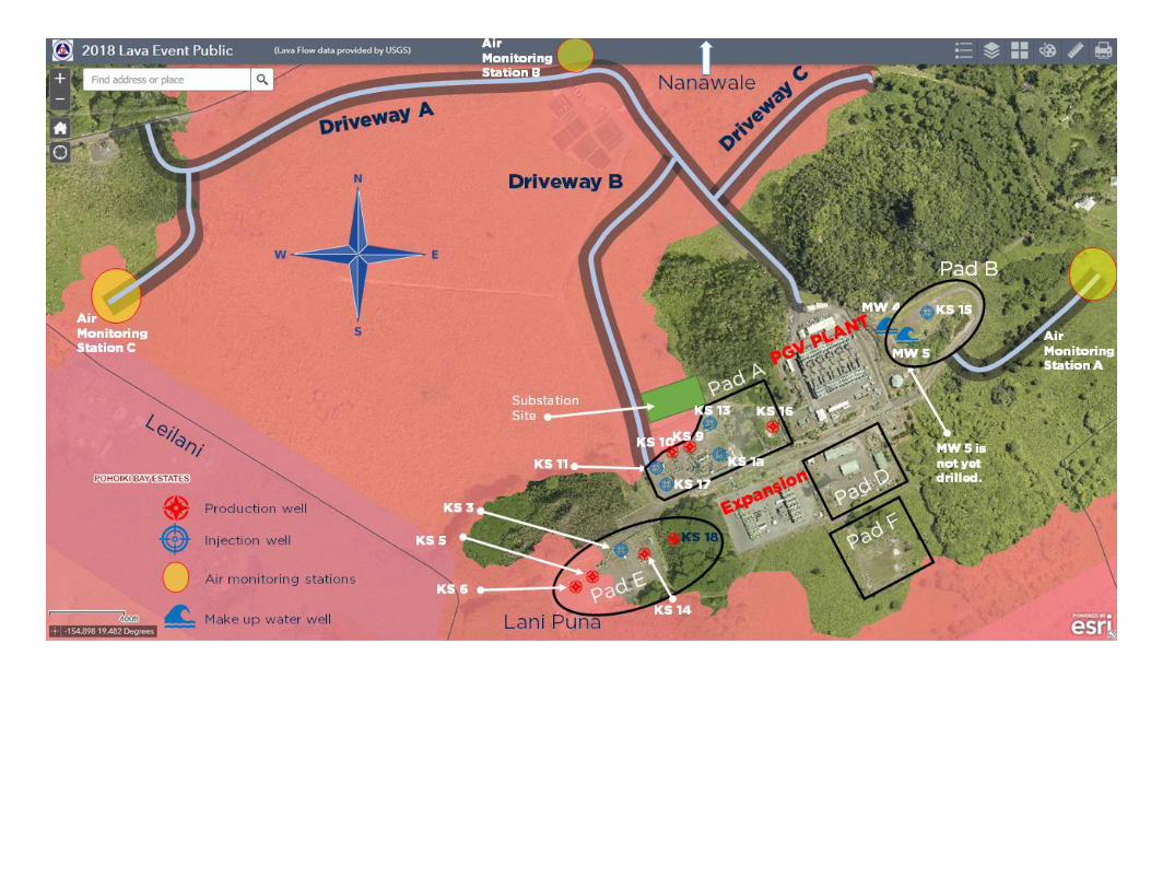
PGV has prepared for, and submitted to, the Hawaii County Planning Department, a map
showing residences located within 3,500 feet of the project boundary as specified by the
Geothermal Resource Permit. PGV has updated this map and previously submitted a copy to
CDA.

25
5.3 Removal of Equipment
Should any of the natural hazards discussed in Section 8.1 threaten project facilities, PGV
may elect to remove portable construction and drilling rig equipment or other critical
equipment from the project site, providing adequate time exists for this to be done without
endangering the health or safety of staff undertaking the actions. In general, the equipment
to be removed and the procedures to be used will be similar to those presented in Table 5-1.
TABLE 5-1 EQUIPMENT REMOVAL ACTIVITIES AND PROCEDURES
During Well Drilling
• Place 100 foot cement plug at bottom of well casing, remove drill pipe and laydown.
• Shut-in Blow-Out Preventer (BOP), including master valve.
• Evacuate all mobile and portable equipment (drill pipe, trailers, air compressor, mud
logging trailer, etc.).
• Remove BOP and install blind flange on wellhead valve.
• Fill well cellar with cinders.
• Laydown rig, remove engine-generators, Silicon Control Rectifier (SCR) unit, tool
shed and mud house.
• Disassemble and remove mast and sub-structure, mud tanks, fuel tanks, tracking
system and other rig equipment from site.

25
During Plant Construction or Operation
WELLPADS
• Shut off well flow by closing the electro-pneumatic control valve that supplies
geothermal fluid to the wellpad separator.
• Close the manual upper and lower master valves on production wells KS-9, KS-10, KS-
5, KS-6, KS-14, KS-16, KS-17 and KS-18 and injection wells KS1A, KS3, KS-11, KS-
13 and KS-15.
• Remove pipes around the wellhead.
• Disassemble wellhead down to the top of the upper master valve.
• Place a blind flange on top of the master valve.
• Fill the well cellar with cinders to the surface.
POWER PLANT
• Remove all other portable and construction equipment as time permits.
• Drain tanks holding chemicals into chemical tanker trucks (one tanker per caustic tank)
and remove from site.
• If access to the site is cut off or if there is insufficient time to complete removal of
caustic, drain tanks into ESRF pit and fill tanks with water to prevent vaporization of
residue caustic solution.
In case of threat of lava flow drain pentane from Ormat Energy Converters (OECs) units 11-15
and 21-25 and Bottoming Unit OECs 31 and 32 to the storage tanks and, if necessary, from
storage tanks into tanker trucks and remove from site to a designated safe area.

26
6 PGV PERSONNEL TRAINING
PGV personnel and subcontractors will be trained and educated on the relevant elements of the
facility emergency response plan and on emergency equipment and related procedures. During
any shift, there will be at least three PGV employees on-site familiar with the facility emergency
plans and the use of the emergency rescue equipment (i.e., Scott Air Pack, fire extinguisher, etc.)
and trained to administer first aid in case of injuries.
All contractors at the site have the responsibility to ensure that their staff has had adequate
training and orientation related to the safety and potential hazards associated with conditions and
potential conditions at the site. PGV will provide all site contractors with a copy of the
Emergency Action Plan for their own use in orientation and training of their staff. PGV will
consult with contractors/consultants to assure they are familiar with emergency response and
evacuation procedures.

27
6.1 Drilling
There will be at least three (3) persons fully trained in the handling of hydrogen sulfide (H2S)
emergencies during each shift of drilling work.
28
6.1.1 H2S Safety Training
All drilling staff and contractor personnel are required to be trained and knowledgeable in
H2S hazards and emergency response action. H2S safety training will be provided, if they are
not currently trained and certified, to PGV drilling staff and drilling contractor personnel
prior to the start of drilling operations. All Plant operators and maintenance personnel will
be trained and the training will be administered by a certified H2S safety instructor. The
course content is described in Appendix B. The course will cover the following topics:
DESCRIPTION OF H2S SOURCES DURING DRILLING OPERATIONS
PHYSIOLOGY OF H2S TOXICITY
USE OF DETECTION EQUIPMENT
USE OF BREATHING APPARATUS
EMERGENCY PROCEDURES
FIRST AID FOR H2S POISONING
In addition, all drilling staff and drilling contractor personnel will be trained in the importance of
vertically directing and abating (for H2S and brine particulates and aerosols) any releases of
geothermal steam or brine, and in use of breathing apparatus as personal protection against any
ambient brine particulates or aerosols.
29
6.1.2 H2S Emergency Response Drills
Unannounced H2S emergency response drills will be executed monthly during drilling
operations. The drilling superintendent, certified in H2S safety, will administer the drills.
The drills will include:
• SIMULATE DRILLING OPERATION SHUT DOWN PROCEDURES
• EVACUATION PROCEDURES
• USE OF 5 MINUTE AIR PACKS
• USE OF DETECTION EQUIPMENT TO IDENTIFY SOURCE
• SIMULATE REMEDIAL ACTIONS TO ELIMINATE SOURCE
• USE OF H2S AND GEOTHERMAL BRINE PARTICULATE AND AEROSOL
ABATEMENT PROCEDURES AND EQUIPMENT

30
6.1.3 Blowout Prevention Training
Drilling personnel, drilling contractor's tool pushers and drillers will be trained in “well
control equipment and procedures.” The course content is shown in Appendix C. The
training will include the following main topics:
DESCRIPTION OF TYPES OF WELL CONTROL LOSS
EARLY DETECTION OF INCIPIENT LOSS OF WELL CONTROL
WELL CONTROL EQUIPMENT
WELL CONTROL PROCEDURES
TRAINING USING WELL CONTROL SIMULATOR
In addition, all drilling staff and drilling contractor personnel will be trained in the
importance of vertically directing and abating (for H2S and brine particulates and aerosols)
any releases of geothermal steam or brine.

31
6.2 Blowout Emergency Response Drill (Drilling Operations Only)
A function test of hydril and pipe ram blow out prevention (BOP) equipment in use on the rig
will be performed on a daily basis during drilling operations. A function test for blind rams
will be executed during trips with drill pipe out of hole.
The drilling superintendent, certified in well control, will administer monthly blow out
prevention and well control drills. These drills will consist of:
IDENTIFICATION OF INCIPIENT BLOW OUT INDICATORS
EMERGENCY DRILLING OPERATIONS IN PREPARATION FOR
OPERATION OF BLOW OUT PREVENTION EQUIPMENT
OPERATION OF BLOW OUT PREVENTION EQUIPMENT
SIMULATION OF PROCEDURES TO KILL WELL
USE OF H2S AND GEOTHERMAL BRINE PARTICULATE AND AEROSOL
ABATEMENT PROCEDURES AND EQUIPMENT
AT LEAST ONE PERSON ON EACH SHIFT WILL BE TRAINED TO
ADMINISTER FIRST AID IN CASE OF INJURIES.

32
6.3 Power Plant Construction
During any power plant construction or modification activities, there will be at least three (3)
persons on-site that are trained to respond to H2S releases.
During a facility emergency requiring on-site evacuation, a siren (one located at drill rig and
one at the power plant staging area) will sound. Employees will be evacuated to the meeting
point. Once at the meeting point, the situation will be assessed by trained supervising
personnel. If the situation worsens, all non-essential personnel will be sent out of the area
and only authorized, trained personnel will remain.

33
6.4 Power Plant Operation
During each shift of plant operations, there are at least three (3) people fully trained in
handling hydrogen sulfide emergencies. A power plant personnel will be trained on the
Emergency Response Plan. Additionally, plant personnel assigned to the Emergency
Response Team will be trained in the use of all required personnel protection equipment and
procedures. Plant Operators and Maintenance personnel will be trained on fire system and
monitoring equipment as well as appropriate First Aid and CPR training.

34
7 PGV EMERGENCY DRILL
In addition to the H2S emergency response and blowout emergency response drills described
in Chapter 6, the facility operations and maintenance personnel will participate in a general
drill at least semi-annually to respond to emergency situations. More frequent drills will be
conducted where observations of the semi-annual drill response activities indicate a need.
Drills will focus on response to all possible scenarios as outlined in this plan.

35
8.0 PGV HAZARD ANALYSIS AND PGV RESPONSE PROCEDURES TO
POTENTIAL EMERGENCY SITUATIONS
The purpose of this section is to evaluate the hazards which could occur or develop at the
project site and could cause an emergency response to be taken at the site and to
generally describe PGV's planned responses. These are presented in three parts. The first
part (8.0) discusses the 9 natural hazards that could affect the PGV project site. The
second part (9.0) describes potential hazards which could arise from upset conditions at
the site. The third (10) are special upset conditions which could arise from site equipment
malfunction or power grid interruptions.

8.0 NATURAL HAZARDS

36
8. 1 Natural Hazards
Notification:
The Hawaii Volcano Observatory (HVO) or the CDA will commonly notify the public,
including PGV, that these types of hazards threaten the general area where the PGV facility
is located. Immediate verbal notifications will be made by PGV to the appropriate agencies,
as applicable, and as per the PGV Notification Guidelines.
PGV General Response:
Once notified that a natural hazard situation may affect or has affected the site, PGV will:
1. Turn on a battery-powered radio to listen for Emergency Broadcast Systems (EBS)
announcements.
2. Notify the CDA (Table 3-1) immediately should the situation cause a facility emergency
situation that could threaten public health and safety.
3. Establish a Command Post at the site.
4. Implement the Chain-of-Command (Table 3-2) including verification of the status of all
on-site persons.
5. Implement the Evacuation Plan (Chapter 5), as appropriate.
6. Take the appropriate follow-up actions that are listed in detail in the following sections.
Reporting:
All reporting related to emergencies created by these types of hazards will be done as soon as
possible during the emergency and afterwards according to the Post Emergency Response
Procedure presented in Appendix D.
37
8.1.1 Volcanic Activity
Nature of Hazard:
Volcanic activity on the Big Island of Hawaii has been severe enough to have caused the loss
of life and property damage due to lava flows. The majority of Hawaiian volcanic eruptions
are gentle with the lava moving no more than several miles per day. There is generally
adequate time for warnings of impending or actual eruptions to allow time to evacuate both
people and equipment.
Potential dangers at the PGV site in the event of lava flow are explosion and fire, principally
at the OEC units, pentane and diesel storage tanks, power rooms and substation areas. Refer
to Section 9.2.2 for the discussion on the hazard from fire and explosion. As discussed in
Section 5.3, PGV believes that essentially all of the drilling equipment (if on-site) could be
removed from the site if this type of threat developed, and that any producing or drilling
wells could be suspended to eliminate the possibility of any release of H2S from a well
during lava flow. However, Section 9.2. discusses the hazard from uncontrolled releases of
steam should this occur.
Response Actions:
Upon notification or determination, PGV will take the following actions, as appropriate,
supplemental to those listed at the beginning of Section 8.1:
1. Prepare to cease all activities at the project site.
2. Notify the CDA (Table 3-1) immediately should the volcanic activity cause a facility
emergency situation that could threaten public health and safety.
3. Alert service suppliers (Appendix E) to assist with removal of supplies and equipment.
4. Shut down all facilities and secure all wells as per Chapter 5.
5. Remove equipment and materials as time permits and the situation allows, as per Chapter
5.3.
6. Await instructions from CDA.
7. Make other required notifications.
If a determination is made that there is an imminent threat to the facility, PGV will
independently take the actions needed to complete the evacuation of personnel and, if time
permits, to remove equipment and fluids according to the list in Chapter 5, Table 5-0.

38
8.1.2 Magma Intrusion
Nature of Hazard:
Magma intrusion in the immediate vicinity of the site (within 1/2 mile) could result in a well
on the property acting as a conduit for lava to flow to the surface at the project site. Were
this to actually occur, and lava flowed through the well to the surface, the hazard would be
similar to the discussion under Section 8.1.1 regarding lava flows.
Response Actions:
Upon notification or determination, PGV will take the following actions, as appropriate,
supplemental to those listed at the beginning of Section 8.1 to prevent any magma from
entering the wellbore:
1. Determine the availability of service personnel and equipment and request stand-by of
same (Appendix E).
2. Notify the CDA (Table 3-1) immediately should the magma intrusion cause a facility
emergency situation that could threaten public health and safety.
3. Notify the State Department of Land and Natural Resources (DLNR) and Hawaii County
Planning Department (Table 3-1) regarding the status of the geothermal wells.
4. Monitor the geothermal fluid pH at intervals recommended by Resource Consultant on
the basis of proximity of the intrusion to the PGV wells.
5. If the fluid is being impacted by volcanic gases, drilling or power generation will be
terminated.
6. Shut-in all wells immediately.
7. Inject water into the well within 48 hours of the shut-in pressure in the well declining to
less than atmospheric pressure.
8. Await instructions from CDA and DLNR.
9. Make other required verbal notifications to regulatory agencies (Hawaii County, State of
Hawaii and Environmental Protection Agency).
If no evidence of fluid acidification is evident, sampling will be terminated and the facility
would resume normal operations once the emergency condition had been withdrawn by the
responsible agencies.
If a determination is made that there is an imminent threat to the facility, PGV will
independently take the actions needed to complete the evacuation of personnel and, if time
permits, to remove equipment and fluids according to the list in Chapter 5, Table 5-0.
8.1.2.1 Lava Interruption
Nature of Hazard:
Lava interruption to electrical transmission lines 8700 and 6500 can effect power plant operation.
The majority of Hawaiian volcanic eruptions are gentle with the lava moving no more than
several miles per day. There is generally adequate time for warnings of impending threat to
transmission lines to allow time to safely shutdown plant operation and evacuate personnel and
to remove equipment according to the list in Chapter 5, Table 5-0.
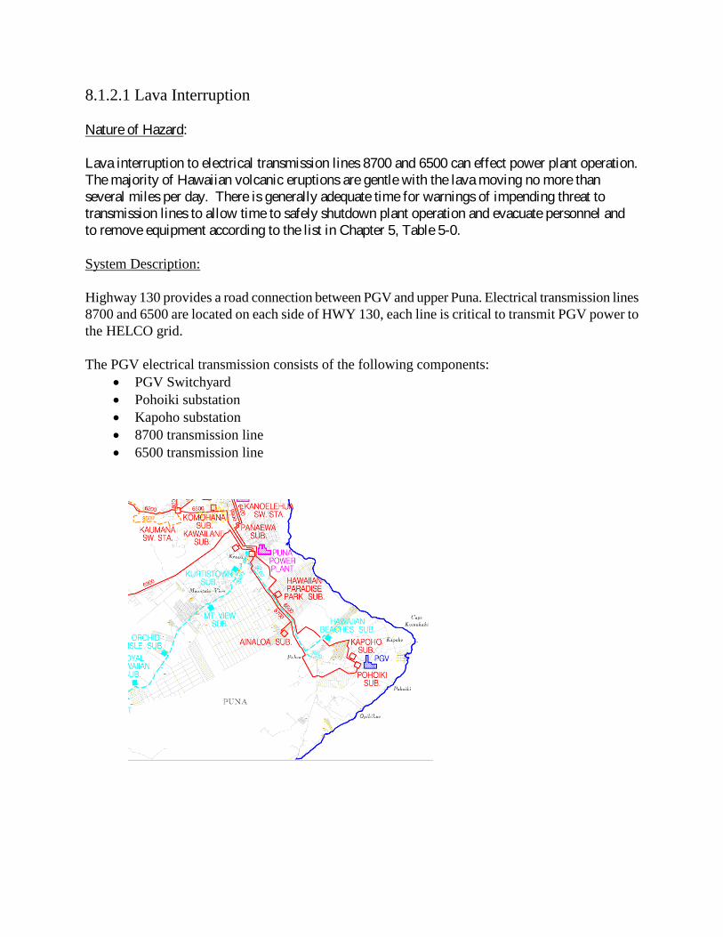
System Description: Highway 130 provides a road connection between PGV and upper Puna. Electrical transmission lines 8700 and 6500 are located on each side of HWY 130, each line is critical to transmit PGV power to the HELCO grid.
The PGV electrical transmission consists of the following components:
• PGV Switchyard • Pohoiki substation • Kapoho substation • 8700 transmission line • 6500 transmission line

Response Actions:
Upon notification or determination, PGV will take the following appropriate actions in the event
lava interruption is imminent, supplemental to those listed at the beginning of Section 8.1:
Loss of Transmission Lines
1. If one transmission line is lost or removed from service due to lava interruption, contact the HELCO/System dispatcher for status of the grid.
a. Reduce Main Steam Pressure (MSP) to 120psi approximately 5-7 MW. b. If HELCO/System is working on putting the line back in service, continue plant
status. i. Contact HELCO/System dispatch every 30 minutes for line status.
c. If HELCO/System is UNABLE to work on returning the line back into service and lava continues to flow to second transmission line, a controlled shutdown of the plant in coordination with HELCO/System will be performed.
Controlled Plant Shutdown
NOTE: If possible, the following steps will be done prior to losing plant operation.
1. Prepare to cease all activities at the project site.
2. Notify the CDA (Table 3-1) immediately should the volcanic activity cause a facility
emergency situation that could threaten public health and safety.
3. Alert service suppliers (Appendix E) to assist with removal of supplies and equipment.
4. Shut down all facilities and secure all wells as per Chapter 5.
5. Ensure all production wells are under layup/recirculation per PGV procedures. 6. Maintain communication with CDA and await instruction. 7. Make other required notifications.
8.1.2.1 Lava Intrusion
PGV LAVA INTRUSION PROCEDURES
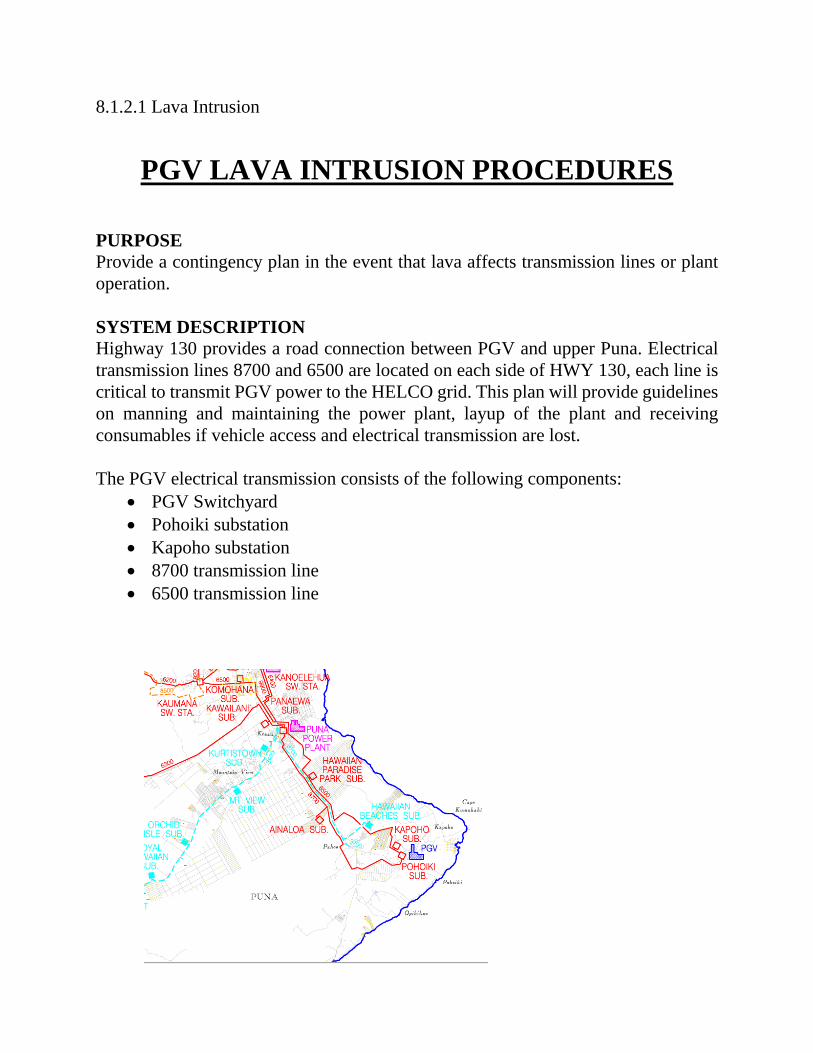
PURPOSE Provide a contingency plan in the event that lava affects transmission lines or plant operation. SYSTEM DESCRIPTION Highway 130 provides a road connection between PGV and upper Puna. Electrical transmission lines 8700 and 6500 are located on each side of HWY 130, each line is critical to transmit PGV power to the HELCO grid. This plan will provide guidelines on manning and maintaining the power plant, layup of the plant and receiving consumables if vehicle access and electrical transmission are lost.
The PGV electrical transmission consists of the following components:
• PGV Switchyard • Pohoiki substation • Kapoho substation • 8700 transmission line • 6500 transmission line

Loss of Transmission Lines
1. If one transmission line is lost, contact the HELCO/System dispatcher for status of the grid.
a. If HELCO/System is working on putting the line back in service, continue idling at 120 psi MSP approximately 5-7MW.
i. Contact HELCO/System dispatch every 30 minutes for line status b. If HELCO/System is UNABLE to work on returning the line back into service and
lava continues to flow to second transmission line, a controlled shutdown of the plant in coordination with HELCO/System will be performed.
i. Start water well 10-P-5 with portable diesel generator to maintain water supply for bleeds.
2. Ensure all production wells are under layup/recirculation per PGV procedures.
Lava Intrusion Near Plant NOTE: If possible, the following steps will be done prior to losing plant operation.
Controlled Plant Shutdown
1. Prepare to cease all activities at the project site.
2. Notify the CDA (Table 3-1) immediately should the volcanic activity cause a facility
emergency situation that could threaten public health and safety.
3. Alert service suppliers (Appendix E) to assist with removal of supplies and equipment.
4. Shut down all facilities and secure all wells as per Chapter 5.
5. Remove equipment and materials as time permits and the situation allows, as per Chapter
5.3.
6. Secure wellfield and power blocks. 7. Ensure all production wells are under layup/recirculation per PGV procedures. 8. Maintain communication with CDA and await instruction. 9. Make other required notifications
If a determination is made that there is an imminent threat to the facility, PGV will
independently take the actions needed to complete the evacuation of personnel and, if time
permits, to remove equipment according to the list in Chapter 5, Table 5-0.

39
8.1.3 Earthquake
Nature of Hazard:
Earthquakes occur suddenly, without warning, and can cause numerous casualties, severe
damage, and loss of public and private property. The actual movement of the ground is less
hazardous than partial or total building collapse, falling objects, debris and shattering glass.
After shocks are usually smaller than the main quake but may be large enough to cause
additional damage to structures weakened during the main shock.
Although by PGV choice, all PGV project facilities are being constructed to the Seismic Zone 4
criteria of the Uniform Building Code, which is more conservative than the required Seismic
Zone 3, major earthquakes near the project site could cause buildings and tall structures to
collapse (e.g., drilling rig), utility poles to collapse (creating loss of power and/or setting fires),
pipeline cracks, breaks above and below ground, and loss of well integrity. Resulting hazards,
with a potential to produce situations which could threaten the health, safety, or welfare of the
public, are H2S releases and fire, which are discussed in Sections 8.2.1 and 8.2.2, respectively.
Response Procedures:
Upon notification, or if an earthquake could be felt strongly at the project site, PGV will take the
following actions supplemental to those listed at the beginning of Section 8.1:
1. Check for injuries and render first aid as appropriate.
2. Notify the CDA immediately should the earthquake cause a facility emergency situation that
could threaten public health and safety, notify the CDA immediately.
3. Depending on the size of the earthquake, the power plant may be tripped. If so, emergency
steam may be released through the rock muffler and abatement of hydrogen sulfide would
start simultaneously. Respondents to an emergency will approach the site from an upwind
direction and have air rescue packs, resuscitators and monitors as a precaution for failure of
the H2S abatement system. Notify both CDA and HDOH, Clean Air Branch (Table 3-1) if
steam is released to emergency steam release facility.
4. Check water and electrical lines.
5. Switch off electrical power if there is damage to power sources or wiring.
6. Check buildings, pipelines and tanks for cracks and damage.
7. Inspect the rig (if applicable) and all wells.
8. Move diesel water pump to any damaged wellpad and notify DLNR (Table 3-1).

39
9. Request stand-by of well drilling contractors and suppliers (Appendix E).
10. Await instructions from CDA.
11. Make other required verbal notifications.

8.1.4 SEVERE WEATHER SYSTEMS Updated 8/30/2016 Jordan Hara Nature of Hazards:
Hurricanes (winds of 74 miles per hour or more) and Tropical Storms (winds of 39-73 miles
per hour) can cause death, extensive damage to lightly-built buildings and tall structures,
uproot trees, snap utility poles, and make destructive missiles of flying debris. However,
because of the design and construction of the PGV project, there is little potential for severe
weather systems to produce facility emergency situations which could threaten the health,
safety, or welfare of the public. Flooding produced by severe weather system rainfall and
storm surf generated by high wind should not pose a threat to the project facilities since the
project site is on high ground.
PGV General Preparedness:
Once notified that a natural hazard situation may affect or has affected the site, PGV will:
1. Turn on a battery-powered radio to listen for Emergency Broadcast Systems (EBS)
announcements.
2. Notify HELCO and CDA immediately should the situation cause a facility emergency
situation that could threaten public health and safety.
3. Establish a Command Post at the site.
4. Implement the Incident Command System, including verification of the status of all on-
site persons.
5. Implement the Evacuation Plan, as appropriate.
PGV Response Actions:
Upon notification or determination, beginning 72 hours prior to a hurricane and/or severe
weather system making landfall, PGV will take the following actions supplemental to those
listed above.
1. Secure loose objects around project site and, if appropriate, cease drilling or plant
operations.
2. (4-3) hours prior to the severe weather system making landfall, notify HELCO and CDA
prior to reducing Main Steam Pressure (MSP) to 180 psi (Estimated at 25-28 MW) and
communicate to CDA all safety protocols and PGV’s plan for the severe weather
systems.
3. Depending on the size and strength of the severe weather system, the power plant may be
tripped. If so, steam is released through the rock muffler and abatement of hydrogen
sulfide should start simultaneously. Responders to an emergency should approach the
site from an upwind direction and have personal monitors and self-contained breathing
apparatus (SCBA). Notify both CDA, HDOH (Clean Air Branch), County, and DLNR, if
steam is released to the emergency steam release facility.
4. Ensure Monitoring Stations are recording meteorological data. Check propane tanks and
top off if necessary.
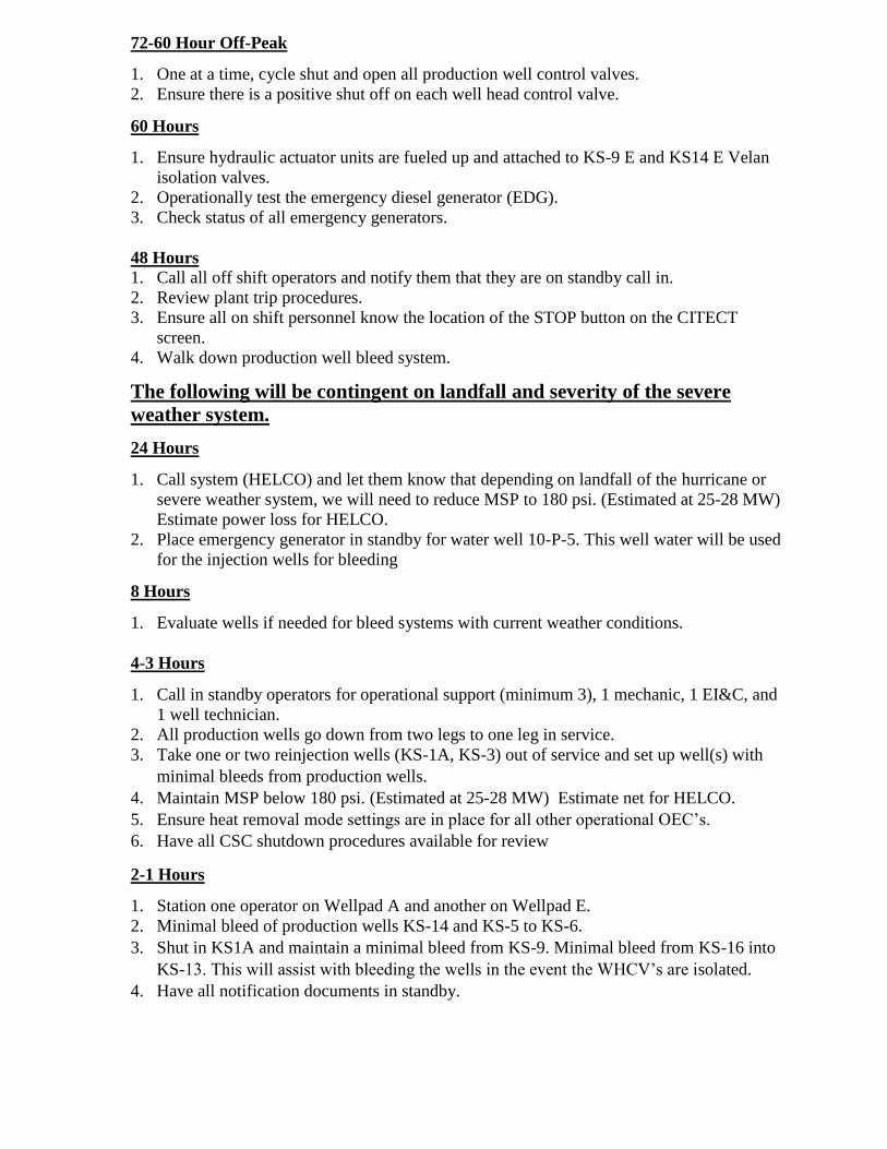
72-60 Hour Off-Peak
1. One at a time, cycle shut and open all production well control valves.
2. Ensure there is a positive shut off on each well head control valve.
60 Hours
1. Ensure hydraulic actuator units are fueled up and attached to KS-9 E and KS14 E Velan
isolation valves.
2. Operationally test the emergency diesel generator (EDG).
3. Check status of all emergency generators.
48 Hours
1. Call all off shift operators and notify them that they are on standby call in.
2. Review plant trip procedures.
3. Ensure all on shift personnel know the location of the STOP button on the CITECT
screen.
4. Walk down production well bleed system.
The following will be contingent on landfall and severity of the severe
weather system.
24 Hours
1. Call system (HELCO) and let them know that depending on landfall of the hurricane or
severe weather system, we will need to reduce MSP to 180 psi. (Estimated at 25-28 MW)
Estimate power loss for HELCO.
2. Place emergency generator in standby for water well 10-P-5. This well water will be used
for the injection wells for bleeding
8 Hours
1. Evaluate wells if needed for bleed systems with current weather conditions.
4-3 Hours
1. Call in standby operators for operational support (minimum 3), 1 mechanic, 1 EI&C, and
1 well technician.
2. All production wells go down from two legs to one leg in service.
3. Take one or two reinjection wells (KS-1A, KS-3) out of service and set up well(s) with
minimal bleeds from production wells.
4. Maintain MSP below 180 psi. (Estimated at 25-28 MW) Estimate net for HELCO.
5. Ensure heat removal mode settings are in place for all other operational OEC’s.
6. Have all CSC shutdown procedures available for review
2-1 Hours
1. Station one operator on Wellpad A and another on Wellpad E.
2. Minimal bleed of production wells KS-14 and KS-5 to KS-6.
3. Shut in KS1A and maintain a minimal bleed from KS-9. Minimal bleed from KS-16 into
KS-13. This will assist with bleeding the wells in the event the WHCV’s are isolated.
4. Have all notification documents in standby.

Landfall
1. Notify system that you are reducing load to 120 psi MSP, which is approximately 5-7MW.
2. Throttle shut production wellhead control valves to maintain 120 psi MSP.
3. Make all attempts to keep as many OEC’s online to reduce MSP and consume steam if
plant trips.
Single Transmission from PGV
1. If one transmission line is lost, contact the HELCO/System dispatcher for status of the
grid.
a. If HELCO/System is working on putting the line back in service, continue idling at
120 psi MSP approximately 5-7MW.
i. Contact HELCO/System dispatch every 30 minutes for line status
b. If HELCO/System is UNABLE to work on returning the line back into service and
weather conditions continue to worsen, perform a controlled shutdown of the plant
in coordination with HELCO/System.
i. Start water well 10-P-5 with portable diesel generator to maintain water
supply for bleeds.
Plant Trip
1. Notify the CDA immediately should the severe weather system cause a facility emergency
situation.
2. Start water well 10-P-5 with portable diesel generator to maintain raw water supply for
bleeds.
3. Monitor communications on emergency radio channel from CDA.
4. Make other required verbal notifications.
5. Secure wellfield and power blocks.
6. Ensure all production wells (KS-5, KS-6, KS-9, KS-14 and KS-16) are bleeding per chart
below.
PRODUCTION WELL BLEEDS:
WELLPAD E
KS-14 bleed to KS-6
KS-5 bleed to KS-6
ALTERNATE BLEED will be to KS-3/ may need to bleed to multiple wells
WELLPAD A
KS-9- bleed to KS1A
KS16- bleed to KS13
ALTERNATE BLEED- May need to bleed to multiple wells
7. Once the severe weather system has passed, if needed, perform testing on all auxiliary,
wellfield, and powerblock systems prior to plant startup.

41
8.1.5 Lightning
Nature of Hazard:
The power plant is designed to operate in all types of weather conditions, even in severe
thunderstorms. Grounding is provided in the power plant, wellpads, substation, and
switchyard. There is also a grounded lightning rod on top of the drilling rig. Though the
plant is equipped with lightning protection systems lightning could trip the whole plant and
activate the emergency steam release system with power coming from the emergency diesel
generator. There is little potential for lightning to produce any facility emergency situations
which could threaten the health, safety, or welfare of the public, although ignition of a fire
within the plant is a remote possibility (see Section 8.2.2).
Response Action:
In this instance, there may not be advance notification to PGV regarding this hazard. In the
event that a lightning storm should threaten the project facilities, PGV will take the following
supplemental actions in addition to those listed at the beginning of Section 8.1:
1. Assess the conditions.
2. Notify the CDA immediately should lightning cause an facility emergency situation that
could threaten public health and safety.
3. Prepare to extinguish small fires and cut (or reduce) all power sources.
4. If there is a fire, implement Brush Fire Response actions as outlined in Section 8.1.6 or
the actions in Section 8.2.2 if it is in the plant site.
5. Depending on the nature of the lightning strike, the power plant may be tripped. If so,
steam may be released through the rock muffler and abatement of hydrogen sulfide
would start simultaneously. Respondents to an emergency should approach the site
from an upwind direction and have personal monitors and SCBAs. Notify both CDA
and HDOH, Clean Air Branch (Table 3-1), if steam is released to the emergency steam
release facility.
6. Await instructions from CDA.

42
8.1.6 Brush Fire
Nature of Hazard:
A runaway brush fire reaching the power plant could cause an explosion or fire at the OEC
Units, pentane and diesel storage tanks, power rooms, and substation areas. Similar dangers
could also exist in the vicinity of the well pads and could threaten the rig and support
facilities. PGV's responses to fires involving actual project components are presented in
Section 8.2.2.
Response Actions:
In this instance, the CDA may not provide advance notification to PGV regarding this
hazard. In the event that a brush fire should threaten the project facilities, PGV will take the
general actions outlined at the beginning of Section 8.1 and the following supplemental
actions:
1. Call Fire Department and the CDA (Table 3-1).
2. Notify the CDA immediately should the fire hazard cause a facility emergency situation
that could threaten public health and safety.
3. Instruct on-site personnel to proceed immediately with fire fighting using the existing
on-site fire protection systems (see Section 4 and Appendix A, Section A-8-3).
4. Prepare to cease all activities at the project site.
5. Prepare to shut down facilities and secure wells as outlined in Table 5-1.
6. If time permits, remove drilling equipment as per Evacuation Plan (Chapter 5).
7. Establish temporary blockades for all access roads leading into the fire.
8. Await instructions from the Fire Department and CDA.
43
8.1.7 PGV General Response:
Once a facility emergency situation occurs or is indicated which could threaten the health,
safety, or welfare of the persons in the vicinity of the project site, PGV will:
1. Immediately notify CDA and other appropriate agencies of the nature and anticipated
impacts and duration of the emergency situation in accordance with Table 3-1.
2. Turn on a battery-powered radio for Emergency Broadcast Systems (EBS)
announcements, if appropriate.
3. Establish a Command Post at the site.
4. Implement the Chain-of-Command (Tables 3-1, Table 3-2), including verification of the
status of all on-site persons.
5. Implement the Evacuation Plan (Chapter 5), as appropriate.
6. Provide environmental monitoring data to the Department of Health and to the County
Civil Defense.
7. Take whatever follow-up appropriate actions are necessary to deal with the facility
emergency situation.
Reporting:
All post-notification reporting related to these type of emergencies will be done as soon as
possible during the emergency, and afterwards according to the Post Emergency Response
Procedure identified in Appendix D.
The following sections describe the specific actions that will be followed if the following
upset conditions requiring emergency response arise:
1. Geothermal steam and fluid releases from the reservoir or power plant.
2. Fire that threatens the site facilities and has the potential for moving off-site.
3. Any event creating very high continuous noise levels.
4. Chemical spills which could move off-site.
44
9.0 UPSET CONDITIONS
Upsets
Notification:
Upsets can occur during the life of the project, whether caused by natural or man-made
events. Table 9-1 presents a summary of the specific routine and upset conditions that could
occur at the project site. PGV will immediately notify the CDA when any facility emergency
situation occurs or is indicated which could threaten the health, safety, or welfare of persons
in the vicinity of the project site. In addition, PGV will notify the CDA (and appropriate
other governmental agencies) when the routine and upset conditions indicated in Table 9-8
occur at the site so that these governmental agencies are kept informed of the site status.
Finally, PGV has the responsibility under its permits and other regulatory authorities to
notify various regulatory agencies related to the operation of the project and when certain
upset conditions occur at the site.

44

TABLE 9-2 SITE RELEASES UNDER ROUTINE AND UPSET CONDITIONS
TABLE 9-1. SITE RELEASES UNDER ROUTINE AND UPSET CONDITIONS
CHEMICAL/ MATERIAL
SOURCE
QUANTITY (lb/hr)
ESTIMATED DURATION
NOTICE TO CDA
MITIGATION AND OTHER ACTIONS
1.
WELLPAD ACTIVITIES
1.1
ROUTINE ACTIVITIES
1.1.1
DRILLING
A
DRILLING
H2S
MUD PIT
NONE
N/A
MAINTAIN pH 11 IN TANK
B
TRIPPING
H2S
WELL
NONE
N/A
KEEP HOLE FILLED WITH MUD
C
RUNNING CASING
H2S
WELL
NONE
N/A
KEEP HOLE FILLED WITH MUD
D
CIRCULATING
H2S
MUD PIT
NONE
N/A
MAINTAIN pH 11 IN TANK
1.2.1
WELL TESTING
A
PIPED DISCHARGE
H2S
RESERVOIR
13
10 DAYS-1x/WELL
YES
ABATE TO 95% THRU FLOW LINE
BRINE
RESERVOIR
100,000
10 DAYS-1x/WELL
B
WELL SHUTIN
H2S
RESERVOIR
<1
1 TO 2 DAYS
YES
BLEED H2S THRU CAUSTIC BUILDUP OVER MONTHS
1.2
UPSET CONDITIONS
1.2.1
DRILLING
A
WELL BLOWOUT
H2S
RESERVOIR
448
HOURS OR WEEKS
YES
KILL THRU SIDE VALVES OR DRILL OFFSET WELL
BRINE RESERVOIR
100,000
HOURS OR WEEKS
YES
B
CASING BLOWOUT
H2S
RESERVOIR
448
SECONDS TO DAYS
YES
SHUTIN PIPE OR BLIND RAMS AND KILL WELL THRU SIDE VALVES
BRINE
RESERVOIR
100,000
SECONDS TO DAYS
YES
C
STRING BLOWOUT
H2S
RESERVOIR
448
SECONDS TO MINUTES
YES
USE FAST-COUPLING SHUTOFF VALVE ON STANDBY
BRINE
RESERVOIR
100,000
SECONDS TO MINUTES
YES
D
TANK RUPTURE
DIESEL
TANK
11,000 GAL
<2 HR TO CONTAIN
PUMP REMAINING TO FRAC TANK
CAUSTIC
TANK
3,000 GAL
<2 HR TO CONTAIN
PUMP REMAINING TO FRAC TANK
E
SITE SPILL
DIESEL
TANK/LINE
11,000 GAL
<2 HR TO CONTAIN
SHUT VALVE AND CLEANUP
CAUSTIC
TANK/LINE
3,000 GAL
<2 HR TO CONTAIN
SHUT VALVE AND CLEANUP
F
TRANSPORTATION SPILL
DIESEL
TRUCK
8,000 GAL
@ DAY<6 HR-SURFACE
TRANSFER AND CLEANUP SPILL
CAUSTIC
TRUCK
5,000 LB
@ MON<6 HR-SURFACE
TRANSFER AND CLEANUP SPILL
G
FIRE
FUEL
VARIOUS
N/A
<12 HR
YES
SITE FIRE PROTECTION SYSTEM
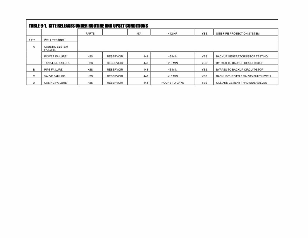
TABLE 9-1. SITE RELEASES UNDER ROUTINE AND UPSET CONDITIONS PARTS
N/A
<12 HR
YES
SITE FIRE PROTECTION SYSTEM
1.2.2
WELL TESTING
A
CAUSTIC SYSTEM FAILURE
POWER FAILURE
H2S
RESERVOIR
448
<5 MIN
YES
BACKUP GENERATORS/STOP TESTING
TANK/LINE FAILURE
H2S
RESERVOIR
448
<15 MIN
YES
BYPASS TO BACKUP CIRCUIT/STOP
B
PIPE FAILURE
H2S
RESERVOIR
448
<5 MIN
YES
BYPASS TO BACKUP CIRCUIT/STOP
C
VALVE FAILURE
H2S
RESERVOIR
448
<15 MIN
YES
BACKUP/THROTTLE VALVE>SHUTIN WELL
D
CASING FAILURE
H2S
RESERVOIR
448
HOURS TO DAYS
YES
KILL AND CEMENT THRU SIDE VALVES

TABLE 9-1. SITE RELEASES UNDER ROUTINE AND UPSET CONDITIONS (continued)
CHEMICAL/ MATERIAL
SOURCE
QUANTITY (lb/hr)
ESTIMATED DURATION
NOTICE TO CDA
MITIGATION AND OTHER ACTIONS
2
POWER PLANT
2.1
ROUTINE ACTIVITIES
A
OPERATIONS
H2S
FUGITIVES
<1
CONTINUAL
SITE SURVEYS/ROUTINE MAINTENANCE
2.2
UPSET CONDITIONS
A
PLANT SHUTDOWN
ABATED-ALL WELLS
H2S
RESERVOIR
22
MINUTES TO HR
YES
ABATEMENT TO 96% THRU ESRF
BRINE
RESERVOIR
114,000
MINUTES TO HR
YES
DISPOSAL THRU HOLDING POND
B
MAIN PIPE FAILURE
H2S
RESERVOIR
560
MINUTES TO HR
YES
CLOSE VALVES/SHUTIN WELLS
BRINE
RESERVOIR
114,000
MINUTES TO HR
YES
C
WELL PIPELINE
H2S
RESERVOIR
448
MINUTES TO HR
YES
CLOSE VALVES/SHUTIN WELLS
BRINE
RESERVOIR
100,000
MINUTES TO HR
YES
D
TANK RUPTURE
PENTANE
TANKS
35,600 GAL
<2 HR TO CONTAIN
YES
TRANSFER AND CLEANUP SPILL
PENTANE
TURBINES
17,500 GAL
<2 HR TO CONTAIN
YES
TRANSFER AND CLEANUP SPILL
CAUSTIC 50%
TANK
14,700 GAL
<2 HR TO CONTAIN
TRANSFER AND CLEANUP SPILL
CAUSTIC 10%
TANK
13,200 GAL
<2 HR TO CONTAIN
TRANSFER AND CLEANUP SPILL
DIESEL
TANK
1,500 GAL
<2 HR TO CONTAIN
TRANSFER AND CLEANUP SPILL
E
SITE SPILL
PENTANE
TANKS
35,600 GAL
<2 HR TO CONTAIN
YES
SHUT VALVE/TRANSFER AND CLEANUP
PENTANE
TURBINES
17,500 GAL
<2 HR TO CONTAIN
YES
SHUT VALVE/TRANSFER AND CLEANUP
CAUSTIC 50%
TANK
14,700 GAL
<2 HR TO CONTAIN
YES
SHUT VALVE/TRANSFER AND CLEANUP
CAUSTIC 10%
TANK
13,200 GAL
<2 HR TO CONTAIN
YES
SHUT VALVE/TRANSFER AND CLEANUP
DIESEL
TANK
1,500 GAL
<2 HR TO CONTAIN
YES
SHUT VALVE/TRANSFER AND CLEANUP
F
TRANSPORTATION SPILL
PENTANE
TRUCK
10,000 GAL
1x/YR-<6 HR
TRANSFER AND CLEANUP SPILL
CAUSTIC
TRUCK
5,000 LB
1x/YR-<6 HR
TRANSFER AND CLEANUP SPILL
DIESEL
TRUCK
8,000 GAL
1x/YR-<6 HR
TRANSFER AND CLEANUP SPILL
G
FIRE
PENTANE
TANK/LINES
44,600 GAL
<12 HR
YES
SITE FIRE PROTECTION SYSTEM
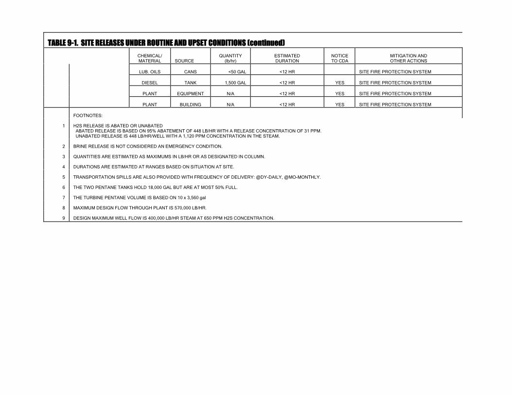
TABLE 9-1. SITE RELEASES UNDER ROUTINE AND UPSET CONDITIONS (continued)
CHEMICAL/ MATERIAL
SOURCE
QUANTITY (lb/hr)
ESTIMATED DURATION
NOTICE TO CDA
MITIGATION AND OTHER ACTIONS
LUB. OILS
CANS
<50 GAL
<12 HR
SITE FIRE PROTECTION SYSTEM
DIESEL
TANK
1,500 GAL
<12 HR
YES
SITE FIRE PROTECTION SYSTEM
PLANT
EQUIPMENT
N/A
<12 HR
YES
SITE FIRE PROTECTION SYSTEM
PLANT
BUILDING
N/A
<12 HR
YES
SITE FIRE PROTECTION SYSTEM
FOOTNOTES:
1
H2S RELEASE IS ABATED OR UNABATED ABATED RELEASE IS BASED ON 95% ABATEMENT OF 448 LB/HR WITH A RELEASE CONCENTRATION OF 31 PPM. UNABATED RELEASE IS 448 LB/HR/WELL WITH A 1,120 PPM CONCENTRATION IN THE STEAM.
2
BRINE RELEASE IS NOT CONSIDERED AN EMERGENCY CONDITION.
3
QUANTITIES ARE ESTIMATED AS MAXIMUMS IN LB/HR OR AS DESIGNATED IN COLUMN.
4
DURATIONS ARE ESTIMATED AT RANGES BASED ON SITUATION AT SITE.
5
TRANSPORTATION SPILLS ARE ALSO PROVIDED WITH FREQUENCY OF DELIVERY: @DY-DAILY, @MO-MONTHLY.
6
THE TWO PENTANE TANKS HOLD 18,000 GAL BUT ARE AT MOST 50% FULL.
7
THE TURBINE PENTANE VOLUME IS BASED ON 10 x 3,560 gal
8
MAXIMUM DESIGN FLOW THROUGH PLANT IS 570,000 LB/HR.
9
DESIGN MAXIMUM WELL FLOW IS 400,000 LB/HR STEAM AT 650 PPM H2S CONCENTRATION.


46
9.2 Geothermal Steam and Fluid Releases
Nature of Hazard:
The geothermal resource produced from the reservoir through the wells drilled by PGV consists
principally of high-temperature steam. When produced to the surface, the wells also bring
geothermal "brine", consisting of numerous chemical and metallic salts, and "noncondensible"
gases, such as carbon dioxide, hydrogen sulfide (H2S), nitrogen and hydrogen. Appendix H
contains a discussion of the chemistry of the geothermal fluids contained in the geothermal
reservoir. During an uncontrolled release of steam from the reservoir, the geothermal brine and
noncondensible gases would most likely also be released from the reservoir and into the
environment.
Because of its toxicity and concentration, of all the components of the geothermal resource the
H2S gas is the component of most significant concern. H2S gas is a colorless gas with a "rotten
egg" odor which is slightly heavier than air. H2S is acutely toxic in high concentrations (in the
range of 400,000 to 700,000 ppb). H2S at 10,000 ppb is considered the acceptable limit for
worker exposure for 8 hours per day, 40 hours per week. At 10,000 ppb, H2S is documented to
be an eye irritant. It is readily detectible down to levels of about 5 ppb.
GENERAL CHARACTERISTICS OF HYDROGEN SULFIDE
Concentration (ppb)
Characteristics
400,000 to 700,000
Acutely toxic
10,000
Acceptable worker exposure for 40 hours per week -
documented eye irritant 1,000
Hawaii Department of Health concentration limit for
required evacuation to protect public health and defined
"Warning" level (one-hour average)1 25
Hawaii Department of Health concentration limit for
routine PGV project operations and defined "Watch" level
(one-hour average) 5
Generally recognized level of odor delectability
1. The decision to actually order an evacuation is typically made in the field by the appropriate responsible agency(ies) based not on
waiting on field measurements to document that the established one-hour average "Warning" level has been exceeded, but on the
professional judgement of the agency(ies), based on all the data available at that time, as to whether or not the incident has the
potential to exceed the established one-hour average "Warning" level.
HDOH has set a one-hour average ambient air concentration of 25 ppb H2S as the lower limit for
requiring notification to the CDA, and set a one-hour average ambient air concentration of 1,000 ppb
H2S as the lower limit for requiring evacuation. For the purposes of this PGV ERP, these levels have
been designated as follows: 25 ppb = "Watch" and 1,000 ppb = "Warning". The decision to actually
order an evacuation is typically made in the field by the appropriate responsible agency(ies) based not
on waiting for field measurements to document that the established one-hour average "Warning" level
has been exceeded, but on the professional judgement of the agency(ies), based on all the data available

46
at that time, as to whether or not the incident has the potential to exceed the established one-hour
average "Warning" level.
As stated above, because of its toxicity and concentration in the geothermal fluid, H2S is the component
of the geothermal fluid of greatest significance. Other components, such as acidic aerosols and total
particulates which may be formed in the atmosphere once the geothermal fluid is discharged during a
well uncontrolled flow event, may also be potential health hazards if produced in sufficiently high
concentrations, as may other components which are typically associated with geothermal fluids but
which have not yet been quantified from samples of the PGV geothermal fluid. The HDOH-established
"Watch" and "Warning" levels for H2S have been set at levels to protect public health from H2S and all
other non-H2S components of the geothermal fluid. Appendix H contains a more complete discussion
of the current understanding of the chemistry of the PGV geothermal resource, including these other
components.
The release of high temperature steam containing H2S gas into the atmosphere may occur under
different scenarios. To determine the "worst case" conditions under which such emissions could occur
during an uncontrolled flow event at any wellpad, or during specified power plant upset conditions,
PGV conducted a simplified hazard analysis of the possible well-related uncontrolled flow event and
power plant upset scenarios to determine the range of credible situations under which hydrogen sulfide
and other contaminants could be released from any well or the power plant (see Appendix H). On the
basis of the available existing information, the "worst case" credible parameters of the geothermal
resource (geochemistry [hydrogen sulfide and other chemical constituents], likely maximum credible
productivity [flow rate], temperature [enthalpy], etc.) which would be used as the emitted (released)
constituents in conducting a hazard analysis for these emissions (see Appendix H).
In order to determine the maximum ("worst case") impacts which could result from each of these 12
different emission scenarios, PGV conducted an impact analysis utilizing a standard air dispersion
model (ISCST) accepted by the U.S. Environmental Protection Agency using a standard screening set
of 33 different meteorological conditions to ensure that the "worst case" meteorological conditions for
each emission scenario and receptor point was evaluated (see Appendix H). The results of this air
dispersion modelling are presented in Appendix H. Table 9-2 summarizes the results of the modelling
for each of the 12 release scenarios, organized on the basis of the air dispersion modelling are presented
in Appendix H. Table 9-2 summarizes the results of the modelling for each of the 12 release scenarios,
organized on the basis of the maximum distance at which each of the HDOH-specified threshold levels
are predicted to be exceeded under the "worst case" meteorological conditions, and the point and
concentration of maximum impact. Table 8-2 has further categorized each release scenario by which, if
any, of the HDOH-specified threshold levels is exceeded by the maximum predicted concentration, thus
ensuring that each release scenario is categorized by the highest estimated modelling impact.

46
TABLE 9-2. SUMMARY OF MODELED H2S EMISSIONS
TABLE 6: SUMMARY OF MODELED HYDROGEN SULFIDE IMPACTS
RELEASE
SCENARIO
MAXIMUM OFF-SITE (>0.3 km) DISTANCE FROM SOURCE
(km) TO IDENTIFIED ACTION LEVEL
POINT OF MAXIMUM PREDICTED
OFF-SITE IMPACT (>0.3 km)
WATCH” LEVEL
(25 ppb)
“WARNING” LEVEL
(1,000 ppb)
CONCENTRATION
(ppb)
DISTANCE
FROM SOURCE
(km)
TYPE “1" (EVENTS (EXCEED ONLY THE “WATCH” ACTION LEVEL)
1. Abated vertical flow
through diverter/muffler
0.9 km
N/A
40.3
0.4
9. Abated vertical flow
from the mud sump
2.8 km
N/A
57.1
0.4
8. Abated vertical flow
from the mud tanks
4.5 km
N/A
253.1
0.4
11. Unabated
noncondensible gas flow
5.5 km
N/A
935.7
0.4
4. Unabated vertical flow
through 13-3/8" casing
25. + km
N/A
146.0
0.6
5. Unabated vertical flow
through 9-5/8" casing
25. + km
N/A
146.0
0.6
12. Unabated vertical flow
through power plant
steam release facility
25. + km
N/A
150.6
0.8
6. Unabated vertical flow
through drill rig subbase
25. + km
N/A
246.8
0.5
2. Unabated vertical flow
through diverter/muffler
25. + km
N/A
403.4
0.4
7. Unabated vertical flow
through area of fractured
rock
25. + km
N/A
789.4
0.4
TYPE “2" EVENTS (EXCEED THE “WATCH” AND “WARNING” ACTION LEVELS)
10. Unabated horizontal flow
through a 4" choke
25. + km
3.7 km
6,3951
0.4
3. Unabated horizontal flow
through diverter
25. + km
6.7 km
12,7861
0.4
1Note that these scenarios can and will be quickly controlled through closing valves to shut in the well, resulting in a significantly reduced emission rate over any one hour
period. The decision to actually order an evacuation is typically made in the field with the appropriate responsible agency(ies) based not on waiting for field measurements to
document that the established one-hour average “Warning” level has been exceeded, but on the professional judgement of the agency(ies) based on all the data available at that
time, as to whether or not the incident has the potential to exceed the established one-hour average “Warning” level.

46
As shown in Table 9-2, ten (10) of the modelled release scenarios result in predicted ambient air
concentrations in excess of the HDOH-established one-hour 25 ppb H2S notification "Watch" action
limit, but do not produce predicted results in excess of the HDOH-established one-hour 1,000 ppb H2S
"Warning" action limit. These include all of the uncontrolled well-related releases (scenarios 1-2 and 4-
9) and the continuous power plant-related release (scenario 12). The short-term, or "puff", release of
hydrogen sulfide and other noncondensible gases from the power plant also falls in this category.
Figure 9-1 has been drawn to show the predicted maximum off-site distance to the specified ambient
hydrogen sulfide concentrations from each PGV wellpad and the plant site from all of these "Type 1"
scenarios; that is, Figure 9-1 shows the worst of the worst case impacts predicted from all of the
scenarios which maximum impact did not exceed the HDOH 1,000 ppb one-hour average "Warning"
level. Thus, Figure 9-1 serves as the single worst case emergency planning and response map for all of
these ten (10) listed "Type 1" scenarios; all predicted impacts were not greater than those shown on
Figure 9-1 from any of the ten (10) scenarios.
The two well-related releases (scenarios 3 and 10) which have been modelled to exceed the HDOH-
established "Warning" levels for one-hour hydrogen sulfide averages ("Type 2" events) are unique from
all the other well-related discharges in more than predicted maximum impacts. First, the high predicted
impacts result from the horizontal nature of the discharge of the geothermal fluid; that is, the horizontal
discharge of geothermal steam and noncondensible gases creates an impact significantly larger in a
directly downwind direction than the same flow would if directed in a vertical direction. Second, each
of these upset discharges can each be stopped or redirected vertically by either manually or remotely
shutting in one of the upstream control valves even after the discharge occurs. Thus, although these
two discharges have been modelled as if the discharge of geothermal steam and hydrogen sulfide would
continue in a horizontal direction for more than an hour, through this modelling PGV has recognized
that horizontal discharges of the geothermal fluid can produce unacceptably high impacts, and PGV can
and will immediately terminate any such discharge if it occurs. Thus, any impact resulting from the
short-term horizontal discharge of geothermal fluid will be short-term, and the actual hydrogen sulfide
impact will be much less than that predicted in Table 9-2, and directly proportionate to the time the
horizontal discharge continues.
The horizontal discharge of geothermal fluid modelled in scenarios 3 and 10 is directional (that is, the
magnitude of the impact depends upon the direction of the discharge and the direction of the wind).
Table 9-2 has been prepared to graphically show the focused nature of the emissions and impacts (a
"Type 2" event) for scenario 3 from a single source if the emission were to continue for an entire hour
under the worst case conditions. However, as stated above, PGV will immediately terminate any
created horizontal discharge and the actual impact will be proportionally less.
A preliminary analysis of the possible impacts and health hazards which could result from the
uncontrolled emission of the geothermal brine and noncondensible gases was also conducted by PGV
and HDOH (see Appendix H). Based on this preliminary analysis, none of the non-H2S components of
the geothermal fluid appear to be released to, or formed in, the environment in concentrations high
enough to significantly increase the level of health hazard created by the simultaneous emission of the
H2S. As a result, the levels of H2S described above are used exclusively herein as the emergency
response planning criterion. However, PGV, under the review of HDOH, will be undertaking a more
detailed sampling and analysis program for these non-H2S components during the first well flow test
following acceptance of this revision of the ERP.

46
Response Actions:
PGV will immediately notify the CDA, HDOH - Clean Air Branch, and HDOH - Hazard Evaluation
and Emergency Response Branch, in the event that any of PGV's operations result in an
uncontrolled steam release which produces, or has the potential to produce, an exceedance of the
appropriate ambient H2S concentrations established by the HDOH - Clean Air Branch and HDOH -
Hazard Evaluation and Emergency Response Branch.
In the event of an uncontrolled steam release, PGV will take the following actions to supplement the
ones outlined at the beginning of Section 9.2:
1. Determine the nature (estimated duration and emissions, etc.) and "type" of release (Type "1"
[Figure 8-1] or Type "2" [Figure 9-2]) and immediately communicate this information to CDA,
HDOH - Clean Air Branch, and HDOH - Hazard Evaluation and Emergency Response Branch
(Table 3-1).
2. Immediately implement perimeter monitoring with portable H2S meters.
3. Maintain constant coordination with CDA, providing all assistance as requested.
4. Act to control and/or abate and vertically direct the uncontrolled source of the H2S, as below:
For most types of well blowouts, where control of the well is lost, the equipment and expertise
will be immediately available to bring the well back under control. In parallel with any attempts
to bring the well under control, PGV will work to ensure that any releases of geothermal fluid
and/or steam are vertically directed and that emissions of H2S and/or brine particulates or
aerosols are abated to the extent consistent with equipment and worker health and safety. If
initial attempts at well control are unsuccessful, PGV, in consultation with DLNR, will decide
whether further attempts using available personnel are likely to be successful. If not, outside
well control experts will be called in. This decision will be based on the severity and magnitude
of the uncontrolled release, the hazard it represents to surrounding life and property, the
experience and training of on-site personnel, and the availability of necessary well control
equipment.
If local expertise is unable to control the steam release, well control specialists from the
mainland will be immediately contracted for assistance (see Appendix E). If it is determined
that additional equipment and services are needed for the control of the steam release, PGV will
obtain the required assistance and begin repair work immediately.
As appropriate, the area around the uncontrolled well or point of discharge will be cleared of all
loose materials and any unnecessary equipment and machinery. As feasible, giving first
consideration to personal safety, PGV will attempt to control the release at the wellhead. Any
on-site contractor personnel involved in well operations will have expertise and training in well
control and should be consulted by the Project Manager.
The well site will be immediately evacuated if there is any danger of the rig toppling. If not,
water will be pumped into the well through the kill line or drilling pipe until the steam release is
under control and stopped. Arrangements will then be made to pump cement into the well and
plug the well as appropriate.
An earthen berm and dikes may be constructed to divert and contain released brine in on-site
well sumps and brine pits.

46
5. Report releases of H2S in excess of reportable quantities (100 pounds over 24 hours) to
the National Response Center, State Emergency Response Commission, and the Local
Emergency Planning Committee (Table 3-1).

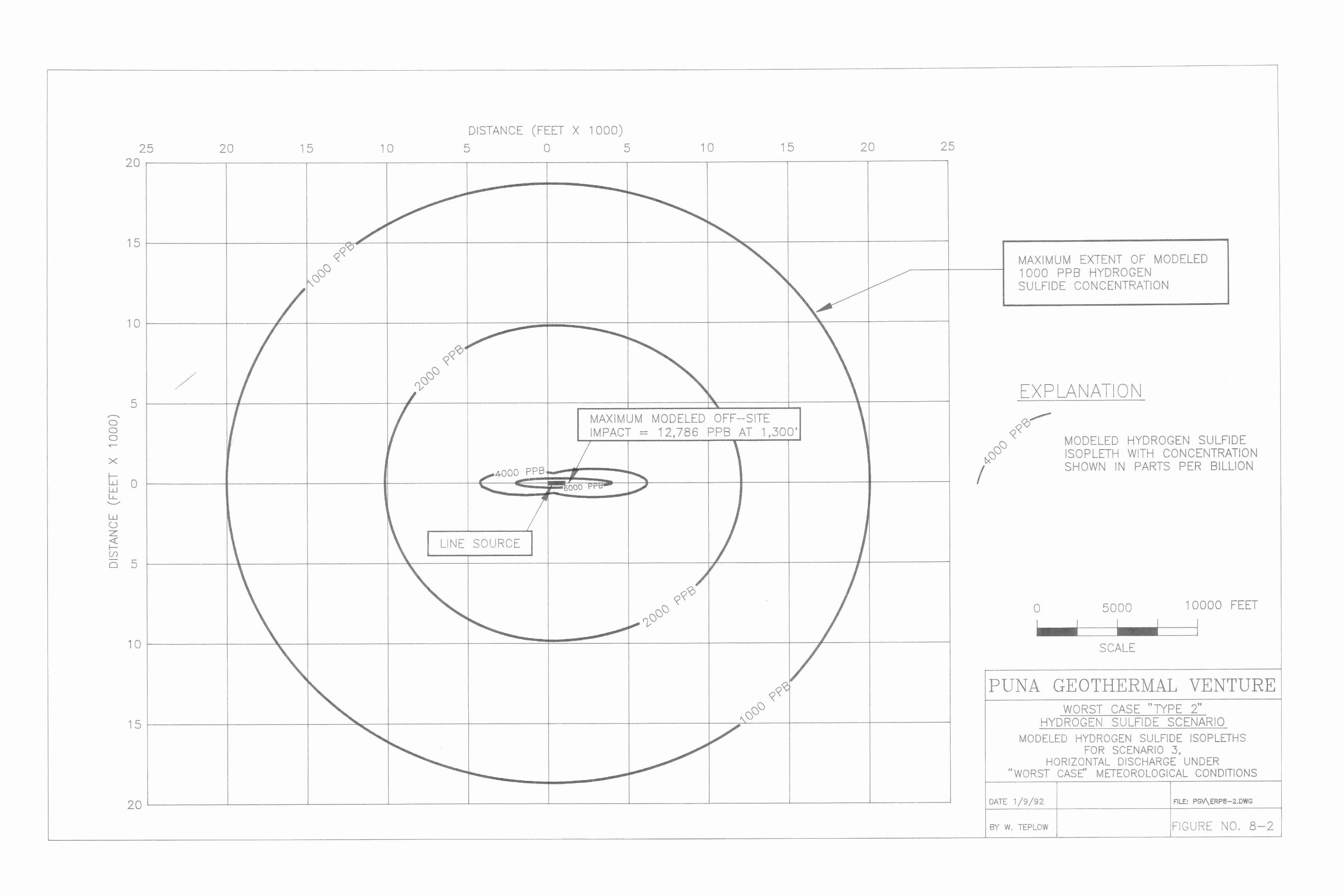
47
9.2.2 Fire Hazard
Nature of Hazard:
The most probable location for a fire at the PGV plant site is within the electrical power rooms or
any of the pentane heat exchangers. Fires may also occur in the control room, diesel fuel storage/or
unleaded gas tanks, or the pentane storage tanks (see Table 8-1). Figures 4-2 and 4-3 show the
location of most of the potential fire locations. Most fires will be limited in size and extent,
identical to fires involving the same materials at any other facility or location. However, as
described in Chapter 4 and Appendix A, all portions of the project which are potentially subject to a
fire are protected by specific fire protection systems designed to prevent the occurrence and spread
of a fire.
Of special interest is the presence of pentane on the power plant site. As indicated on Table 8-1 and
Figure 4-3, a maximum of 11,000 gallons (approximately 56,000 pounds) of pentane is stored in
two reserve tanks in the power block and one reserve tank with a maximum of 12,472 gallons
(approximately 65,478 pounds) at the expansion plant. There are ten (10) OEC Units that hold
approximately 3,560 gallons (approximately 18,700 pounds) and (2) OEC Bottom End Units located
at the expansion plant that hold approximately 10,500 gallons each (approximately 55,545 pounds).
Pentane is a flammable liquid (boiling point equals 97oF) with flammable limits between 1.5 and 7.8
percent (by volume) in air. By comparison, because of its lower volatility, pentane is less
flammable than propane.
To evaluate the hazard limits of a catastrophic fire involving pentane at the site, the fireball hazard
was modelled. This modelling predicted that the maximum injury zone radius for a fireball
involving 56,000 pounds of pentane would be approximately 1,350 feet. As shown on Table 8-1,
this is substantially less than the 2,000-foot minimum distance from the storage tank to the project
boundary/nearest residence. In addition, the catastrophic release of pentane was modelled to
evaluate the possible movement offsite of a potentially flammable cloud of pentane under various
meteorological conditions. As shown also on Table 8-1, the cloud of pentane was no longer
flammable (that is, the concentration of pentane in the cloud was diluted below the lower limit
flammability of pentane (1.5 percent) within approximately 1,000 feet of the source, again well
within the boundary of the project site.
Initial Action:
PGV will immediately notify both the Fire Department and CDA (Table 3-1) in the event of a fire at
the site.
47
Response Actions:
In the event that a fire threatens major components of the project facilities, PGV will
immediately implement the evacuation plan (Chapter 5) and notify the CDA (Table 3-1)
that site evacuation is underway and request the presence of one of their staff at the site.
The on-site fire protection system (see Appendix A) will be automatically triggered in
the power plant area in the event of any fire at the site. Different kinds of fires in the
site area may also require use of different manual systems for control. The following
are the actions to be taken when handling different kinds of fires at the site:
(1) Electrically Caused Fire
Extinguish with a class C fire extinguisher (ABC or BC extinguisher are also
sufficient).
(2) Solvent/Petroleum/Pentane Fire
Water from hydrants will be used to cool the surrounding areas. Extinguish
with a Class B fire extinguisher (ABC and BC extinguisher are also sufficient).
PGV will implement the general response conditions identified in Section 8.2 above, and
thereafter evaluate the situation on a case-by-case basis. PGV will also notify the
Hawaii County Planning Department regarding the fire.


48
9.3 Noise Hazard
Nature of Hazard:
Noise is not commonly considered a hazardous condition in any situation other than the workplace,
although it is a nuisance and can, following repeated exposures at high energy levels, result in a
degradation of hearing acuity. The Occupational Safety and Health Administration (OSHA) has set
the permissible noise exposure at 90 dBA for an eight-hour day. The HDOH has recently suggested
that a noise level of 85 dBA (1-minute Leq) be used for establishing when to recommend voluntary
evacuation to protect public health. For the purpose of this PGV ERP, this level has been
designated as the noise "Warning" level.
The most probable sources of high level noises during upset conditions would be a steam release
through a pipe or pipe rupture and/or during a well blowout. In most cases, such a high noise level
would result from a short-term steam release from a pipe that had ruptured or a valve or seal that
had broken. Any of these conditions could produce noise levels similar to that produced from
vertical well venting or steam pipeline clean out, from 75 dBA to 125 dBA 50 feet from the source.
Figure 8-4 has been prepared to show the possible noise levels which would result off of the project
site from these 75 dBA to 125 dBA sources, based upon a noise level drop of 6 dBA for each
doubling of the distance, as discussed in the Geothermal Noise Guidelines of the Hawaii County
Planning Department. Although this assumption (6 dBA reduction for each doubling of the
distance) is reasonable at the closer distances, this usually underestimates the reduction in noise
levels as the distance from the source increases (that is, the predicted noise level would be too high).

48
Initial Action:
PGV will immediately notify the CDA, Hawaii County Planning Department, and HDOH -
Noise and Radiation Branch (Table 3-1) in the event that any upset of PGV's operations
leads to an exceedance of the appropriate ambient noise levels (Figure 8-4).
Response Actions:
The site situation will be continuously monitored to establish the actual noise levels, and
actions will be taken at the site to stop the source of the noise. PGV will continue to
coordinate with the CDA and other agencies to advise them of the anticipated duration of the
upset and high noise level situation.

9.4 Spills and Leaks
Nature of Hazard:
Spills or leaks of chemicals, including hydrocarbons, at the site could occur related to transfer or
storage of pentane, caustic soda, treatment chemicals, diesel fuel, or unleaded gasoline. Of these,
only the catastrophic spill of pentane could result in an emergency situation off-site, and this only as
a result of the potential flammability of the cloud (see Section 9.1.2). Pentane is not toxic (see
Appendix F), and is not hazardous outside of its flammability characteristics. Caustic soda is
considered hazardous because of its corrosivity, but is otherwise not toxic, and the quantity stored
on site will not be able to move off site under any upset condition (see Appendix G).
Spills of geothermal brine may also occur over the life of the project. However, the geothermal
brine expected from the wells that will feed the PGV plant does not contain levels of constituents
which necessitate its classification as hazardous waste. Brine chemistry will be evaluated
analytically each year to monitor any changes in brine characteristics.
Response Actions:
The following are the general procedures that will be used to control and contain a spill:
1. Close all valves in pipelines leading to and from the source of the spill, giving first
consideration to personnel safety in all attempts to control the release at its source.
2. The release should be contained within the smallest area possible. This may be accomplished
by:
construction of an earthen berm around the spill and earthen dams across any drainage
channels or swales in the spill area.
diversion of the spill to sump areas, if possible.
if needed, call an outside emergency cleanup contractor (Appendix E) according to the
chemical nature and magnitude of the spill, the experience and training of available on-site
personnel, and the availability of cleanup materials and equipment.
The facility response plan (Hazwoper) will be followed by employees when responding to
spills or releases.
For small-scale spills or leaks of pentane, caustic soda or diesel fuel (less than reportable quantities),
the following cleanup procedure will be followed:
1. Provide personnel with the proper protection as appropriate and according to the nature of
chemicals involved. Appendices F & G have the Material Safety Data Sheets for pentane and
50% caustic soda, respectively.
2. After completion of activities that require the use of personal health and safety equipment, the
equipment will be cleaned.
For spills larger than reportable quantities, actions taken will be similar to those provided above and
in PGV’s Hazwoper Program. Also, other reporting and on-site cleanup actions shall adhere to the
direction required by agencies involved with compliance at the site. This shall include reporting any
release of more than 100 pounds of pentane or H2S per 24 hours to the National Response Center,

Hawaii State Emergency Response Commission, and the Local Emergency Response Commission
(Table 3-1).
For spills of geothermal brine:
1. Personnel assigned to spill containment, control, and cleanup will be provided with adequate
protection equipment.
2. After completion of all activities that require the use of personal health and safety equipment as
described above, the equipment will be properly cleaned.
49

10.0 SPECIAL UPSET CONDITIONS
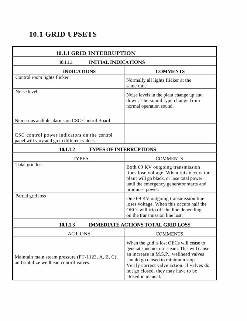
10.1 GRID UPSETS
10.1.1 GRID INTERRUPTION
10.1.1.1 INITIAL INDICATIONS
INDICATIONS COMMENTS
Control room lights flicker Normally all lights flicker at the
same time.
Noise level Noise levels in the plant change up and
down. The sound type change from
normal operation sound.
Numerous audible alarms on CSC Control Board
CSC control power indicators on the control
panel will vary and go to different values.
10.1.1.2 TYPES OF INTERRUPTIONS
TYPES COMMENTS
Total grid loss Both 69 KV outgoing transmission
lines lose voltage. When this occurs the
plant will go black, or lose total power
until the emergency generator starts and
produces power.
Partial grid loss One 69 KV outgoing transmission line
loses voltage. When this occurs half the
OECs will trip off the line depending
on the transmission line lost.
10.1.1.3 IMMEDIATE ACTIONS TOTAL GRID LOSS
ACTIONS COMMENTS
Maintain main steam pressure (PT-1123, A, B, C)
and stabilize wellhead control valves.
When the grid is lost OECs will cease to
generate and not use steam. This will cause
an increase in M.S.P., wellhead valves
should go closed to minimum stop.
Verify correct valve action. If valves do
not go closed, they may have to be
closed in manual.

Verify diesel generator start .Call HELCO
dispatcher and verify grid conditions and
determine grid problem cause.
After the OECs come to a complete stop,
switch selected OECs to heat removal. This will facilitate steam usage and keep the
wells at a normal operating temperature until
power generation can be restarted.
10.1.1.4 SUPPLEMENTARY ACTIONS FOR TOTAL
GRID LOSS
ACTIONS COMMENTS
Check electrical equipment in the field for
any flags that could have occurred during
grid loss.
Check plant operation during power
outage.
Call appropriate personnel
10.1.1.5 IMMEDIATE ACTIONS PARTIAL GRID LOSS
ACTIONS COMMENTS
Maintain main steam pressure (PT-1123 A,
B, C) and stabilize wellhead control valves.
With a partial grid loss, half the OECs will
cease to generate, and not use steam. This will
cause an increase in M.S.P., wellhead valves
should go closed, to control M.S.P.
Call and notify HELCO dispatching.
10.1.1.6 SUPPLEMENTARY ACTIONS FOR PARTIAL
GRID LOSS
ACTIONS COMMENTS
Check plant for proper operation.
Call the appropriate personnel.
Check electrical equipment in the field for any
flags that could have occurred during grid loss.
Check Cytec single line diagram for partial
grid loss indications.

10.2 AUXILIARY UPSETS
10.2.1 LOSS OF NCG COMPRESSORS
10.2.1.1 INITIAL INDICATIONS
INDICATIONS COMMENTS
Compressor failure at CSC. Indicator light at compressor green
OFF/RUN switch will blink.
Failure alarm will indicate on alarm print
out.
NV-4145 CLOSE/OPEN/AUTO switch will
activate and open-by-passing OEC NCG to
mixing spool.
Valve opens at 25 psig NCG header
pressure.
10.2.1.2 IMMEDIATE ACTIONS
ACTIONS COMMENTS
Dispatch operator to the NCG compressor and
attempt a restart as soon as possible.
Lower reinjection header pressure as low as
possible.
If NV-4152 is operating, open to rock muffler,
or sulfa treat system. If NV-4152 is opened to rock muffler,
abatement water, and caustic system will
have to be activated.
10.2.1.3 SUPPLEMENTARY ACTIONS
ACTIONS COMMENTS
Call HELCO and advise that power cut back may
occur.
Call management and advise of situation.
If unable to re-establish NCG compressor operation
begin cutting back plant power production.
Cut production back to a point where NCG
can be handled without compressors.
Facilitate NCG compressor repair.

10.2.2 LOSS OF PLANT AIR
10.2.2.1 SYMPTOMS/INDICATIONS
INDICATIONS COMMENTS
Both plant air compressors running continuously for
extended periods of time.
Loud hissing noise.
Plant air pressure low alarm. It alarms at
80 psig.
Plant shut down sequence started. This is set in the
control logic to start at 100 psig. When this occurs
the plant will begin to ramp down.
10.2.2.2 POSSIBLE CAUSES
INDICATIONS COMMENTS
Loss of one or both plant air compressors.
Unauthorized use of plant air by contract labor, or
personnel not familiar with the plant air system.
Line rupture.
Air dryer plugging.
10.2.2.3 IMMEDIATE ACTIONS
INDICATIONS COMMENTS
If rupture has been identified shut the appropriate
component isolation valves. Before closing the valve,
consult with the valve FAIL/OPEN/CLOSE list to anticipate
component isolation.

Connect portable air compressor to the plant air
system and augment the system using this air. It
should be noted that air
from a portable compressor is not dried and
could contain traces of oil. This would depend on
the location chosen for connection.
Verify that there are no unauthorized uses of the
system.
Verify proper operation of PV-6201. This valve
regulates air to the service air header.
Located between OEC’s 15 & 25
10.2.2.4 SUPPLEMENTARY ACTIONS
INDICATIONS COMMENTS
Notify appropriate personnel. PGV management, agencies etc.
Inspect the plant air system piping within the plant,
including all components. If the
site of the rupture is located, isolate if possible.
If the leak is outside the power plant in the well pad
areas, inspect all distribution piping, and isolate
the leak if possible.
Once located, isolate the rupture as close to the
source as possible. Restore the system then start
effected equipment.

10.3 PLANT UPSETS
10.3.1 ESRF RELEASE
10.3.1.1 INITIAL INDICATIONS
INDICATIONS COMMENTS
Rising steam pressure on main steam header
As indicated on PT-2123 A,B,C
Increasing pressure to 245 PSIG on main steam will
activate ESRF. Lights at Mimic Panel in CSC for
ESRF will activate.
Lights located at top section of Mimic
Panel and are on valve switches.
ESRF activation will open NV-4204 Jamesbury Valve.
At increasing steam pressure other valves in the
ESRF begin to activate.
Power plant output will increase at rising steam
pressure.
10.3.1.2 IMMEDIATE ACTIONS
ACTIONS COMMENTS
Check main steam pressure. Reduce main steam
pressure by any means.
Well control valves may have to be taken
to manual and closed.
Verify correct wellhead control valve action.
Correct if necessary.
Check main steam pressure indications. Correct if
necessary.
Check functions of PT-2123 A,B,C
Verify stable OEC operations. Send portable H2S
monitor downwind of ESRF to check for any H2S
release indications.
Verify proper operation of the reinjection system.
High system pressure may cause back up
of steam pressure.
10.3.1.3 SUPPLEMENTARY ACTIONS
ACTIONS COMMENTS
Call management and appropriate
government agencies.

Verify correct and appropriate government
agencies. Correct problem at ESRF system.

10.3.2 PENTANE LEAK RUPTURE
10.3.2.1 GENERAL
INDICATIONS COMMENTS
A Pentane rupture could result in serious personnel
injuries and/or equipment damage. Pentane at high
temperatures will vaporize immediately upon being
released to atmosphere. This resultant vapor will make it
almost impossible to distinguish the location of a rupture.
Operator knowledge of system piping and component
orientation will play an important role in differentiating
a pentane rupture from a rupture within another
high temperature, pressurized system.
Extreme care should be taken to ensure personnel safety
when combatting this casualty. Operator safety shall take
precedence over plant operability at all times. Rapid
identification and isolation of any major leak or rupture
will aid in minimizing its effects on the distribution
system as well as on other plant system and
equipment. Pentane leaking can greatly increase the
extent of the casualty by enlarging the size of The
rupture. Additionally, the Pentane flow emitting from the
rupture can cause serious damage to any equipment in
its path. Electrical shock hazards are greatly
increased due to the proximity of electrical
equipment in the vapor.
Subsequent to isolation of the rupture, a careful
evaluation of plant conditions should be made in order to
restore customer services in a timely manner. Re-entry to
an evacuated area of the plant should be attempted only
when deemed safe by supervisory personnel. Restore
unaffected parts of the plant and realign systems as
necessary to regain plant operability as soon as
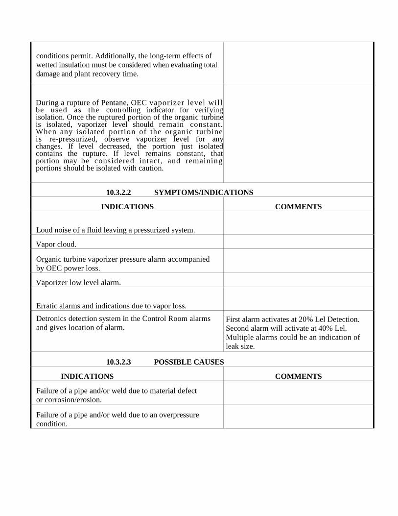
conditions permit. Additionally, the long-term effects of
wetted insulation must be considered when evaluating total
damage and plant recovery time.
During a rupture of Pentane, OEC vaporizer level will be used as the controlling indicator for verifying isolation. Once the ruptured portion of the organic turbine is isolated, vaporizer level should remain constant. When any isolated portion of the organic turbine is re-pressurized, observe vaporizer level for any changes. If level decreased, the portion just isolated contains the rupture. If level remains constant, that portion may be considered intact, and remaining portions should be isolated with caution.
10.3.2.2 SYMPTOMS/INDICATIONS
INDICATIONS COMMENTS
Loud noise of a fluid leaving a pressurized system.
Vapor cloud.
Organic turbine vaporizer pressure alarm accompanied
by OEC power loss.
Vaporizer low level alarm.
Erratic alarms and indications due to vapor loss.
Detronics detection system in the Control Room alarms
and gives location of alarm. First alarm activates at 20% Lel Detection.
Second alarm will activate at 40% Lel.
Multiple alarms could be an indication of
leak size.
10.3.2.3 POSSIBLE CAUSES
INDICATIONS COMMENTS
Failure of a pipe and/or weld due to material defect
or corrosion/erosion.
Failure of a pipe and/or weld due to an overpressure
condition.

Physical damage to system piping or valves caused by
external forces.
Failure of fin fan tubes due to corrosion of fin fan
malfunction.
10.3.2.4 IMMEDIATE ACTIONS
INDICATIONS COMMENTS
Pentane vapors and l iquids are very hazardous
due to flammability. When the rupture or leak is
identified, do the following:
Shut down all equipment around the leak.
NOTE: The only exception would be if
the leaks are in the fin tubes. In this case
maintain fan operation until OEC is
depressurized and vapor free.
Notify all plant personnel so that any equipment
being used (tools, lifts, etc.) can be shut down.
Flag off effected area.
Set up all firefighting equipment for immediate
response to a fire (train monitors, charge hoses,
etc.)
Isolation of Pentane leak may have to be done under
a water blanket. This depends on the size of the leak.
Personal protection is of utmost importance when
dealing with a Pentane leak. Electrical equipment may
have to be isolated if water protection is used.
If the rupture is known to be within the plant, and
can be readily located and isolated:
SHUT down the affected OEC.
STOP any affected OEC pumps.
Isolate the effected piece of equipment on the OEC.
Take supplementary actions to restore system
operability.
If the rupture location is not readily identifiable:
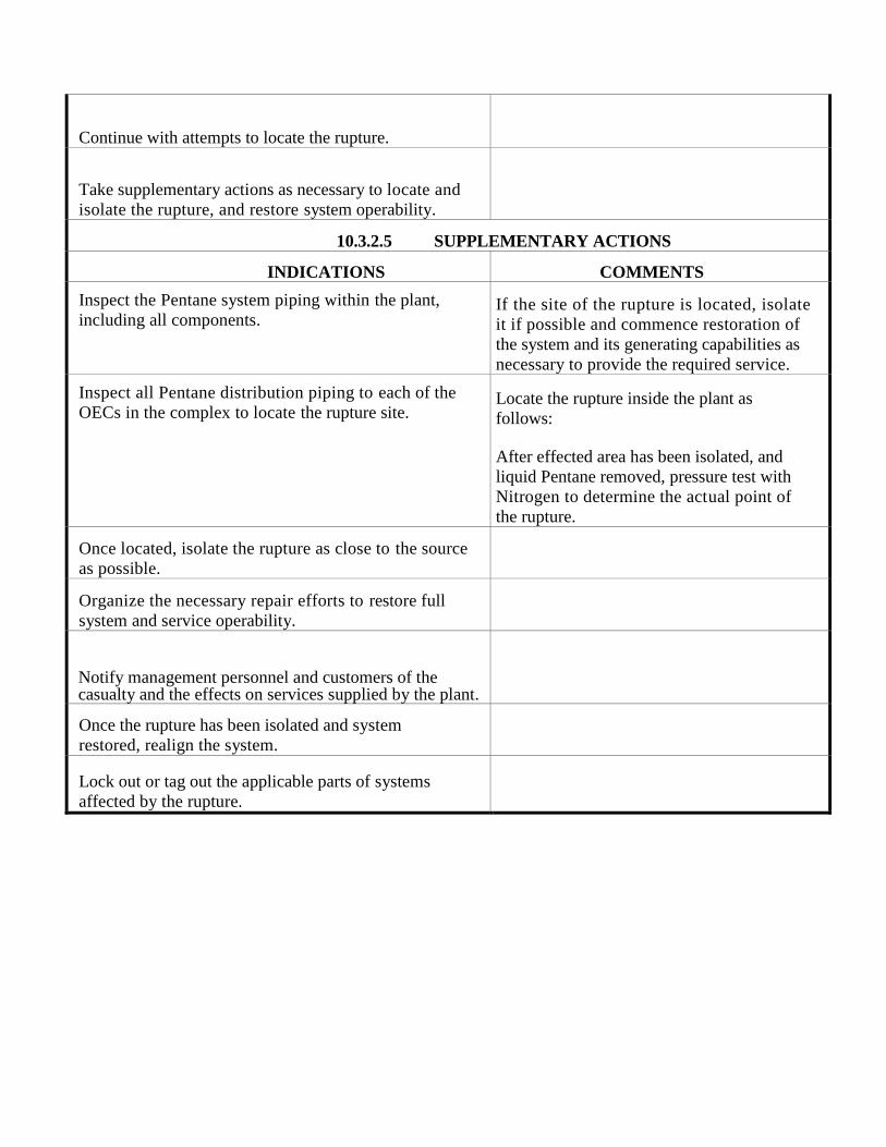
Continue with attempts to locate the rupture.
Take supplementary actions as necessary to locate and
isolate the rupture, and restore system operability.
10.3.2.5 SUPPLEMENTARY ACTIONS
INDICATIONS COMMENTS
Inspect the Pentane system piping within the plant,
including all components. If the site of the rupture is located, isolate
it if possible and commence restoration of
the system and its generating capabilities as
necessary to provide the required service.
Inspect all Pentane distribution piping to each of the
OECs in the complex to locate the rupture site. Locate the rupture inside the plant as
follows:
After effected area has been isolated, and
liquid Pentane removed, pressure test with
Nitrogen to determine the actual point of
the rupture.
Once located, isolate the rupture as close to the source
as possible.
Organize the necessary repair efforts to restore full
system and service operability.
Notify management personnel and customers of the casualty and the effects on services supplied by the plant.
Once the rupture has been isolated and system
restored, realign the system.
Lock out or tag out the applicable parts of systems
affected by the rupture.

10.3.3 HYDROGEN SULFIDE
10.3.3.1 GENERAL
INDICATIONS COMMENTS
An H2S release may best be described as an unplanned
leak of major proportion. It is a very serious casualty as
it could result in personnel injury, equipment damage,
the possibility of an extended outage of the power
plant, and in the most extreme case, it may require the
evacuation of all plant, personnel and area residents
living in the vicinity of the plant perimeter. This
procedure, therefore, does not address H2S leaks of a
minor nature which is addressed as part of the plants
continuing maintenance plan.
The key to reducing the effects of an H2S release is
the timely identification and isolation of the source
of the release. Efforts to locate and isolate the leak
must, however, not take precedence over personal
safety. Only events as they occur will determine whether
operators can remain and attempt to localize the
source, or whether it is best to abandon the area or
even whole parts of the plant.
10.3.3.2 INDICATIONS
INDICATIONS COMMENTS
Audible alarm in CSC coming from any of the Fixed
H2S detectors located strategically throughout the plant.
Audible and printed alarm generated from any of the
Fixed Monitoring Stations near the plants perimeter or
in the residential areas surrounding the plant site.
Abnormally high H2S levels as reported by The
Environmental Company (TEC).

NCG Compressors failure due to loss of pressure on
the discharge piping (logic control assuming a leak).
Odor complaints from area residents.
10.3.3.3 POSSIBLE CAUSES
INDICATIONS COMMENTS
Failure of a pipe and/or weld due to material
defect or corrosion/erosion.
Failure of a pipe and/or weld due to an over
pressurization condition.
Failure of a sealing gasket located between flanged
piping.
Mechanical damage to system
piping/valving.
Safety/pressure relief valve fails in the OPEN
position.
10.3.3.4 IMMEDIATE ACTIONS
INDICATIONS COMMENTS
Clear the affected area of all personnel and barricade the
affected area.
Implement the ERP guidelines.
Notify the Civil Defense Agency.
Inform CDA of H2S levels internally and as
noted on perimeter monitoring stations. CDA is
the lead agency to determine community
evacuation requirements.
Notify the Department of Health (Clean Air Branch)
Notify County Planning Department Director
Notify PGV Management.
Notify HELCO of plant availability and status.

If the source of the leak is isolatable, personnel must
don SCBA's prior to entering the affected area to
isolate the leak.

If the source of the leak cannot be isolated while the
plant is in operation, it may be necessary to shut in the
Production Wells.
NOTE: It will be necessary to implement
steps 1 through 8 in a safe an expedient
manner.
10.3.3.5 SUPPLEMENTARY ACTIONS
INDICATIONS COMMENTS
If the source of the leak has been successfully
isolated, carefully evaluate the effects of the release in
respect to the overall operability of the plant.
If the source of the leak has been successfully
isolated, continue area monitoring of any residual
H2S levels.
Ensure that H2S levels continue to
decrease.
If the Production Wells were shut in, it may be
necessary to allow minimum steam flow by bypassing
the flash separators and directing steam flow directly into
the reinjection header.
Inform HELCO of the current plant status, and
expected duration of the current situation.
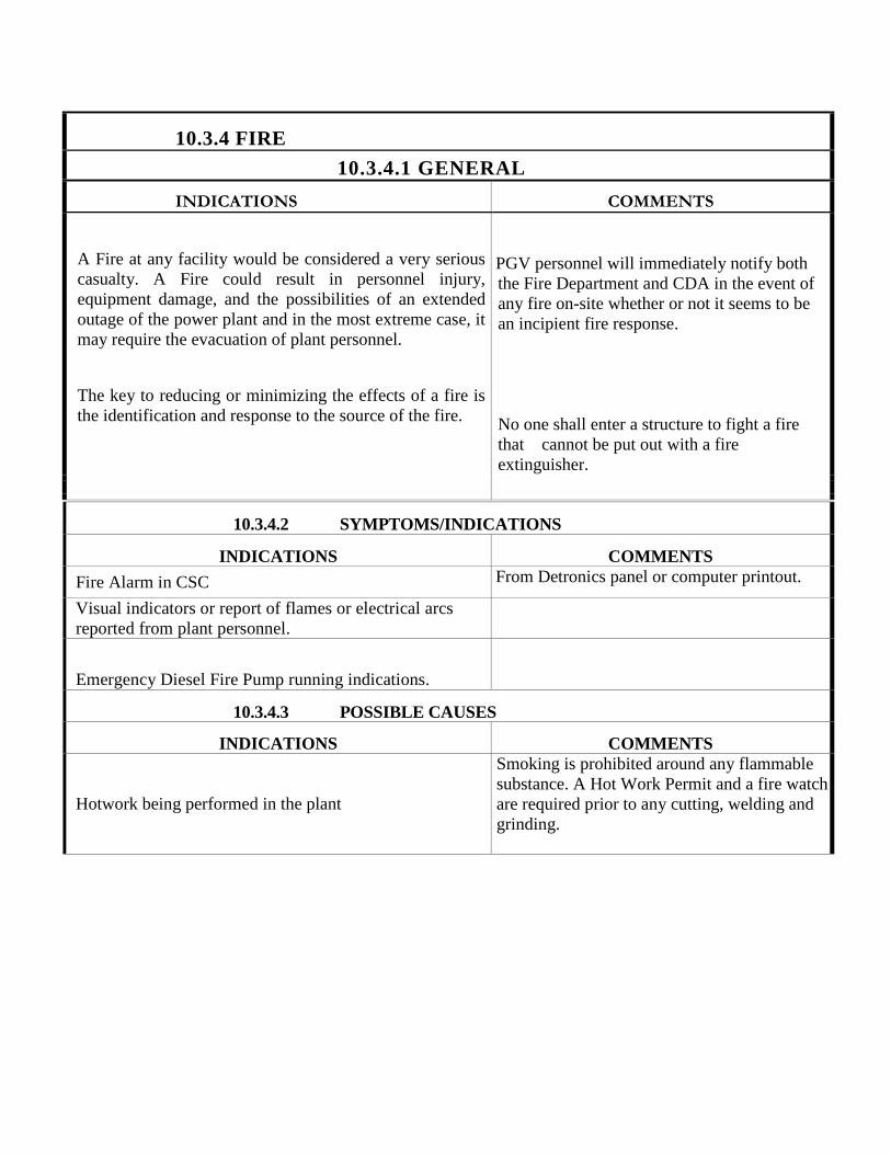
10.3.4 FIRE
10.3.4.1 GENERAL
INDICATIONS COMMENTS
A Fire at any facility would be considered a very serious
casualty. A Fire could result in personnel injury,
equipment damage, and the possibilities of an extended
outage of the power plant and in the most extreme case, it
may require the evacuation of plant personnel.
The key to reducing or minimizing the effects of a fire is
the identification and response to the source of the fire.
PGV personnel will immediately notify both
the Fire Department and CDA in the event of
any fire on-site whether or not it seems to be
an incipient fire response.
No one shall enter a structure to fight a fire
that cannot be put out with a fire
extinguisher.
10.3.4.2 SYMPTOMS/INDICATIONS
INDICATIONS COMMENTS
Fire Alarm in CSC From Detronics panel or computer printout.
Visual indicators or report of flames or electrical arcs
reported from plant personnel.
Emergency Diesel Fire Pump running indications.
10.3.4.3 POSSIBLE CAUSES
INDICATIONS COMMENTS
Hotwork being performed in the plant
Smoking is prohibited around any flammable
substance. A Hot Work Permit and a fire watch
are required prior to any cutting, welding and
grinding.

Flammable product making contact with hot
surfaces
All flammables i.e.…Spray lubricants solvents
shall be stored in the flammable locker located
east of the maintenance shop in a approved
flammable i.e.… Pentane and fuels shall be
stored in approved storage container. All
containers shall be grounded inside of a
containment berm.
Electrical malfunctions/failures causing class “C” fire Only trained personnel shall fight a fire at an
incipient response level.
10.3.4.4 IMMEDIATE ACTIONS
INDICATIONS COMMENTS
If a fire occurs at the facility, activate the Emergency Response
Plan (ERP) and institute the Incident Command System (ICS).
Once the Fire Department arrives, the PGV incident
commander shall turnover the ICS duties of the IC to the
Hawaii County Fire Department. PGV's Incident
Commander shall act as an assistant to the HCFD.
Trained personnel shall also utilize the AFFF fire monitors to extinguish a fire as long as no additional PPE is required, and the Fire Department has been notified. See Organization structure in the
ERP/HAZWOPER training procedures
If required, evacuate all non-essential personnel.
The Alarm Siren System is located on top of the
CSC control building. This siren is tested each month at
11:45 am on the first working day. The siren is a steady
tone alarm with a red beacon light attached. This
alarm is to be used in the event of an emergency that
requires potential evacuation of personnel or the
activation of the Incident Command System
(ICS).
Secure all operating equipment as required.
All Emergency Responders shall remain on-site to
perform critical operations of the facility. As a
rule, the CSC operator and Plant Technicians shall
remain on-site to secure the operation of the facility.
All other Emergency Response Personnel will report to
their designated area to help with the evacuation
of all non-essential personnel and with the
emergency.

Shutdown all non-essential equipment adjacent to fire to
prevent possible spreading of fire.
Annual training required to utilize, fire
equipment. Refer to Safety training
package.
10.3.4.5 SUPPLEMENATRY ACTIONS
INDICATIONS COMMENTS
Verify that all non-essential personnel are evacuated from
the plant and accounted for by name.
All plant personnel shall strictly follow the Emergency Escape Procedures which is referred to in the ERP/EAP/HAZWOPER procedures.
All PGV personnel have been issued an
electronic gate key that will log employees in and
out. Contractors and Visitors will be logged in
and out from the CSC log. In the event of an
emergency, the admin 2 personnel have been
trained to print out an entry report and provide it
to the Incident Commander.
Assist with first aid if required.
All Operations and Maintenance personnel have been trained in CPR and basic First-aid. Employees that have been trained will provide Basic First-aid to employee in the event of an emergency.
If necessary CSC operator will immediately notify 1011 in the event an employee is injured. All injured employees are not to be moved unless they're located in a life threatening situation. All injured employees will be transported to Hilo Medical Center for treatment.
Notify appropriate personnel. PGV management, agencies, etc.
Inspect plant equipment when applicable.
Restore from casualty as situation allows.

10.3.5 EARTHQUAKE
10.3.5.1 GENERAL
INDICATIONS COMMENTS
An earthquake, whether large or small in magnitude
and duration, presents many
situations requiring operator attention. It is
the operator's responsibility at the onset of an
earthquake to first ensure his/her personal safety is
established. After the immediate physical effects of
the earthquake have passed, operators can further
enhance their safety through evacuation of the plant.
Then, existing plant conditions are evaluated and
balanced against personnel/plant safety requirements
to determine if re-entry is appropriate.
Structures that have shaken loose and falling objects
(missile hazards) present the highest danger during and
after an earthquake. Operators should utilize an
inherently stable structure for protection from missile
hazards, i.e. desk, table and doorway.
Consideration should be given to the proximity of the
protection chosen in relation to high
pressure/temperature fluid systems and electrical
systems. In all cases, protection should be utilized
quickly and movement through the plant suspended
until the earthquake cases. Once the earthquake has
stopped, immediate evacuation of personnel should
commence with subsequent steps taken to ensure all
personnel are present and/or accounted for at this point
in time.
Attention should be directed at this point to the
integrity of the plant and collateral damage
suffered by systems and structures from the
earthquake. Actions to restore service systems to the
Power Plant may be impractical due to damage to the
distribution system and the rest of the complex.
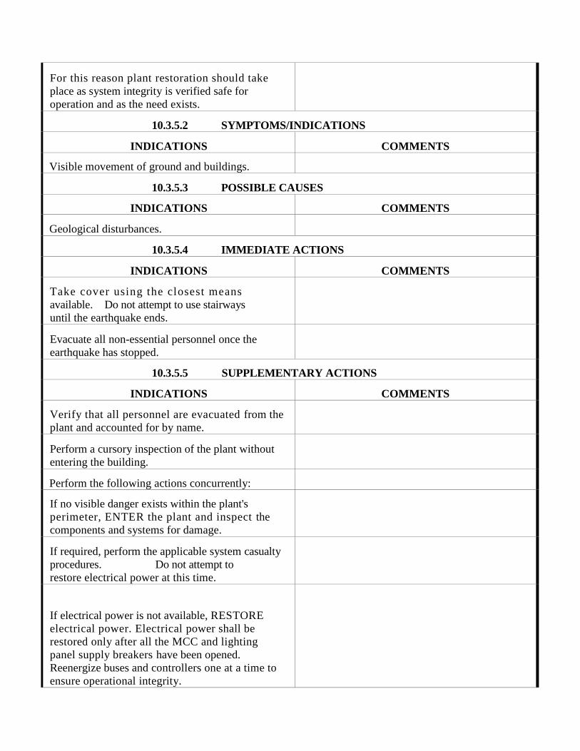
For this reason plant restoration should take
place as system integrity is verified safe for
operation and as the need exists.
10.3.5.2 SYMPTOMS/INDICATIONS
INDICATIONS COMMENTS
Visible movement of ground and buildings.
10.3.5.3 POSSIBLE CAUSES
INDICATIONS COMMENTS
Geological disturbances.
10.3.5.4 IMMEDIATE ACTIONS
INDICATIONS COMMENTS
Take cover using the closest means
available. Do not attempt to use stairways
until the earthquake ends.
Evacuate all non-essential personnel once the
earthquake has stopped.
10.3.5.5 SUPPLEMENTARY ACTIONS
INDICATIONS COMMENTS
Verify that all personnel are evacuated from the
plant and accounted for by name.
Perform a cursory inspection of the plant without
entering the building.
Perform the following actions concurrently:
If no visible danger exists within the plant's
perimeter, ENTER the plant and inspect the
components and systems for damage.
If required, perform the applicable system casualty
procedures. Do not attempt to
restore electrical power at this time.
If electrical power is not available, RESTORE
electrical power. Electrical power shall be
restored only after all the MCC and lighting
panel supply breakers have been opened.
Reenergize buses and controllers one at a time to
ensure operational integrity.

Inspect the distribution systems for leaks or other damage as well as the conditions of all control buildings.

10.4 WELLFIELD UPSET
10.4 Loss of Mechanical Integrity Injection Wells
INITIAL INDICATIONS
INDICATIONS COMMENTS
Loss of mechanical integrity would be indicated by loss
of nitrogen pressure within the well annulus.
PGV Monitors annulus pressures 24/7 locally
and remotely in CSC.
Hangdown liner failure, increase in injection pressure.
Well casing failure, decrease in annulus pressure.
IMMEDIATE ACTIONS
ACTIONS COMMENTS
A loss of nitrogen pressure triggers PGV to
implement additional tests and possible shut in the
injection well.
The injection well will be shut in when
exhibiting an unacceptable loss of
nitrogen pressure (10% in 5 hours) in the
annulus.
Steps to perform:
• Make operational changes to the plant and
shut in the injection well.
• Notify Wellfield Technician and the EH&S
Manager.
• Check surface piping and wellhead for
leaks
• Perform nitrogen pressure test using the
procedure for annual nitrogen pressure
test.
• Confirm water level in the annulus with
Echo meter.

Additional testing will include:
• Temperature survey
• Pressure survey
• Echo meter testing
• Sinker bar or feeler gauge runs
• Caliper runs
• Video inspection
• Electric casing inspection logs
Refer to System Operating Procedures
(SOP)
• 10.4.1 PGV Injection Testing of
Wells
• 10.4.2 PGV Mechanical
Integrity Testing
• 10.4.3 PGV Loss of Mechanical
Integrity
• 10.4.4 PGV Echo meter Testing
SUPPLEMENTARY ACTIONS
ACTIONS COMMENTS
Call management and appropriate
government agencies.


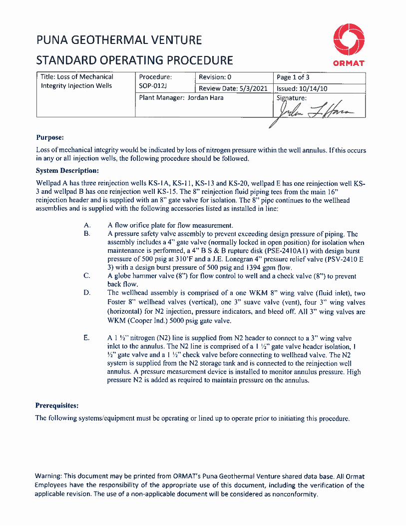

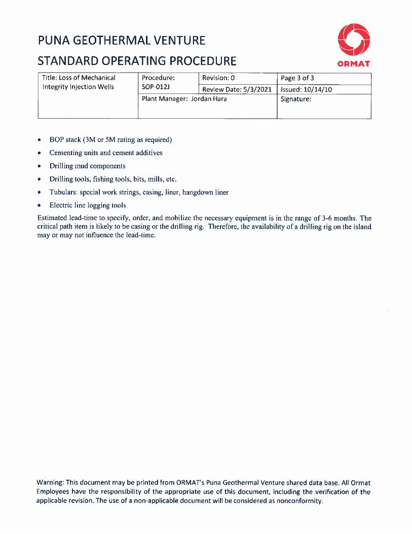


APP-1
APPENDICES
TABLE OF CONTENTS
APPENDIX ADESCRIPTION OF PROJECT FACILITIES AND OPERATIONS .. . . . . . . . . . . . . . . . . . . . . . . . . . . . . . . . . . . . . . . . . . . . . . . 3
A.1 Geothermal Wellfield Facilities . . . . . . . . . . . . . . . . . . . . . . . . . . . . . . . . . . . . . . . . . . . . . . . . . . . . . . . . . . . . . . . . . . . . . . . . . . . . . . . . . . . . . . . . . 3
A.2 Well Control and Safety Equipment During Drilling . . . . . . . . . . . . . . . . . . . . . . . . . . . . . . . . . . . . . . . . . . . . . . . . . . . . . . . . . . . . . . 4
A.3 Turbine Generator System .. . . . . . . . . . . . . . . . . . . . . . . . . . . . . . . . . . . . . . . . . . . . . . . . . . . . . . . . . . . . . . . . . . . . . . . . . . . . . . . . . . . . . . . . . . . . . . 4
A.4 Non-Condensable Gas Control . . . . . . . . . . . . . . . . . . . . . . . . . . . . . . . . . . . . . . . . . . . . . . . . . . . . . . . . . . . . . . . . . . . . . . . . . . . . . . . . . . . . . . . . . . 5
A.5 Steam Release Facility.. . . . . . . . . . . . . . . . . . . . . . . . . . . . . . . . . . . . . . . . . . . . . . . . . . . . . . . . . . . . . . . . . . . . . . . . . . . . . . . . . . . . . . . . . . . . . . . . . . . . 6
A.6 Electrical Systems .. . . . . . . . . . . . . . . . . . . . . . . . . . . . . . . . . . . . . . . . . . . . . . . . . . . . . . . . . . . . . . . . . . . . . . . . . . . . . . . . . . . . . . . . . . . . . . . . . . . . . . . . . 6
A.7 Control Systems .. . . . . . . . . . . . . . . . . . . . . . . . . . . . . . . . . . . . . . . . . . . . . . . . . . . . . . . . . . . . . . . . . . . . . . . . . . . . . . . . . . . . . . . . . . . . . . . . . . . . . . . . . . . 7
A.7.1 Wellhead Control Subsystem .. . . . . . . . . . . . . . . . . . . . . . . . . . . . . . . . . . . . . . . . . . . . . . . . . . . . . . . . . . . . . . . . . . . . . . . . . . . . . . . 7
A.7.2 OEC and ITLU Control Subsystem .. . . . . . . . . . . . . . . . . . . . . . . . . . . . . . . . . . . . . . . . . . . . . . . . . . . . . . . . . . . . . . . . . . . . . . . 7
A.7.3 Power Plant Control . . . . . . . . . . . . . . . . . . . . . . . . . . . . . . . . . . . . . . . . . . . . . . . . . . . . . . . . . . . . . . . . . . . . . . . . . . . . . . . . . . . . . . . . . . . 8
A.8 Auxiliary Systems .. . . . . . . . . . . . . . . . . . . . . . . . . . . . . . . . . . . . . . . . . . . . . . . . . . . . . . . . . . . . . . . . . . . . . . . . . . . . . . . . . . . . . . . . . . . . . . . . . . . . . . . . . 9
A.8.1 Compressed Air System... . . . . . . . . . . . . . . . . . . . . . . . . . . . . . . . . . . . . . . . . . . . . . . . . . . . . . . . . . . . . . . . . . . . . . . . . . . . . . . . . . . . . 9
A.8.2 HVAC Systems .. . . . . . . . . . . . . . . . . . . . . . . . . . . . . . . . . . . . . . . . . . . . . . . . . . . . . . . . . . . . . . . . . . . . . . . . . . . . . . . . . . . . . . . . . . . . . . . . . 9
A.8.3 Fire Protection System .. . . . . . . . . . . . . . . . . . . . . . . . . . . . . . . . . . . . . . . . . . . . . . . . . . . . . . . . . . . . . . . . . . . . . . . . . . . . . . . . . . . . . . . 9
A.8.4 Service and Supplemental Water . . . . . . . . . . . . . . . . . . . . . . . . . . . . . . . . . . . . . . . . . . . . . . . . . . . . . . . . . . . . . . . . . . . . . . . . . .10
A.8.5 Vapor Recovery Systems .. . . . . . . . . . . . . . . . . . . . . . . . . . . . . . . . . . . . . . . . . . . . . . . . . . . . . . . . . . . . . . . . . . . . . . . . . . . . . . . . . . .10
A.8.6 H2S Abatement System (Sulfa Treat) . . . . . . . . . . . . . . . . . . . . . . . . . . . . . . . . . . . . . . . . . . . . . . . . . . . . . . . . . . . . . . . . . . . . .11
A.8.7 Plant H2S Monitoring System .. . . . . . . . . . . . . . . . . . . . . . . . . . . . . . . . . . . . . . . . . . . . . . . . . . . . . . . . . . . . . . . . . . . . . . . . . . . . .11
A.9 Process Flow Monitoring Systems .. . . . . . . . . . . . . . . . . . . . . . . . . . . . . . . . . . . . . . . . . . . . . . . . . . . . . . . . . . . . . . . . . . . . . . . . . . . . . . . . . . . .11
A.10 Power Plant Structures and Facilities . . . . . . . . . . . . . . . . . . . . . . . . . . . . . . . . . . . . . . . . . . . . . . . . . . . . . . . . . . . . . . . . . . . . . . . . . . . . . . . .11
A.10.1 Chemical Storage Facilities . . . . . . . . . . . . . . . . . . . . . . . . . . . . . . . . . . . . . . . . . . . . . . . . . . . . . . . . . . . . . . . . . . . . . . . . . . . . . . . . .11
A.10.2 Fencing .. . . . . . . . . . . . . . . . . . . . . . . . . . . . . . . . . . . . . . . . . . . . . . . . . . . . . . . . . . . . . . . . . . . . . . . . . . . . . . . . . . . . . . . . . . . . . . . . . . . . . . . . .13
A.11 Construction Yard .. . . . . . . . . . . . . . . . . . . . . . . . . . . . . . . . . . . . . . . . . . . . . . . . . . . . . . . . . . . . . . . . . . . . . . . . . . . . . . . . . . . . . . . . . . . . . . . . . . . . . . .13
A.12 Operation and Maintenance . . . . . . . . . . . . . . . . . . . . . . . . . . . . . . . . . . . . . . . . . . . . . . . . . . . . . . . . . . . . . . . . . . . . . . . . . . . . . . . . . . . . . . . . . . . .13
A.13 Plant Start Up and Shutdown .. . . . . . . . . . . . . . . . . . . . . . . . . . . . . . . . . . . . . . . . . . . . . . . . . . . . . . . . . . . . . . . . . . . . . . . . . . . . . . . . . . . . . . . . .14
A.14 Hydrologic Monitoring .. . . . . . . . . . . . . . . . . . . . . . . . . . . . . . . . . . . . . . . . . . . . . . . . . . . . . . . . . . . . . . . . . . . . . . . . . . . . . . . . . . . . . . . . . . . . . . . . . .15
A.15 Air Quality and Meteorological Monitoring... . . . . . . . . . . . . . . . . . . . . . . . . . . . . . . . . . . . . . . . . . . . . . . . . . . . . . . . . . . . . . . . . . . . . . .15
A.16 Noise Monitoring .. . . . . . . . . . . . . . . . . . . . . . . . . . . . . . . . . . . . . . . . . . . . . . . . . . . . . . . . . . . . . . . . . . . . . . . . . . . . . . . . . . . . . . . . . . . . . . . . . . . . . . . . .16
A.17 Monitoring Procedures While Drilling . . . . . . . . . . . . . . . . . . . . . . . . . . . . . . . . . . . . . . . . . . . . . . . . . . . . . . . . . . . . . . . . . . . . . . . . . . . . . . .16
A.17.1 H2S Releases . . . . . . . . . . . . . . . . . . . . . . . . . . . . . . . . . . . . . . . . . . . . . . . . . . . . . . . . . . . . . . . . . . . . . . . . . . . . . . . . . . . . . . . . . . . . . . . . . . . .16
A.17.2 Well Casing Problems .. . . . . . . . . . . . . . . . . . . . . . . . . . . . . . . . . . . . . . . . . . . . . . . . . . . . . . . . . . . . . . . . . . . . . . . . . . . . . . . . . . . . . . .16
Figure A-1 Air Quality and Meteorological Monitoring Sites . . . . . . . . . . . . . . . . . . . . . . . . . . . . . . . . . . . . . . . . . . . . . . . . . . . . . . . . .
Figure A-2 Noise Monitoring Locations . . . . . . . . . . . . . . . . . . . . . . . . . . . . . . . . . . . . . . . . . . . . . . . . . . . . . . . . . . . . . . . . . . . . . . . . . . . . . . . . . . . .
APPENDIX B .. . . . . . . . . . . . . . . . . . . . . . . . . . . . . . . . . . . . . . . . . . . . . . . . . . . . . . . . . . . . . . . . . . . . . . . . . . . . . . . . . . . . . . . . . . . . . . . . . . . . . . . . . . . . . . . . . . . . . . . . . . . . . . . . . . . . .17
COURSE CONTENT - HYDROGEN SULFIDE SAFETY TRAINING ... . . . . . . . . . . . . . . . . . . . . . . . . . . . . . . . . . . . . . . . . . . . . . . . . . . . . . . . . . .17
B1 - Drilling Operations Program .. . . . . . . . . . . . . . . . . . . . . . . . . . . . . . . . . . . . . . . . . . . . . . . . . . . . . . . . . . . . . . . . . . . . . . . . . . . . . . . . . . . . . . . . . . . . . . . .17
B2 - PGV Personnel Training Program .. . . . . . . . . . . . . . . . . . . . . . . . . . . . . . . . . . . . . . . . . . . . . . . . . . . . . . . . . . . . . . . . . . . . . . . . . . . . . . . . . . . . . . . . .17
APPENDIX C .. . . . . . . . . . . . . . . . . . . . . . . . . . . . . . . . . . . . . . . . . . . . . . . . . . . . . . . . . . . . . . . . . . . . . . . . . . . . . . . . . . . . . . . . . . . . . . . . . . . . . . . . . . . . . . . . . . . . . . . . . . . . . . . . . . . . .18
COURSE CONTENT - BLOWOUT PREVENTION TRAININGFOR DRILLING OPERATIONS .. . . . . . . . . . . . . . . . . . . . . . . . .18
APPENDIX D .. . . . . . . . . . . . . . . . . . . . . . . . . . . . . . . . . . . . . . . . . . . . . . . . . . . . . . . . . . . . . . . . . . . . . . . . . . . . . . . . . . . . . . . . . . . . . . . . . . . . . . . . . . . . . . . . . . . . . . . . . . . . . . . . . . . . .19
POST EMERGENCY RESPONSE PROCEDURES .. . . . . . . . . . . . . . . . . . . . . . . . . . . . . . . . . . . . . . . . . . . . . . . . . . . . . . . . . . . . . . . . . . . . . . . . . . . . . . . . . . . . .19
APPENDIX E .. . . . . . . . . . . . . . . . . . . . . . . . . . . . . . . . . . . . . . . . . . . . . . . . . . . . . . . . . . . . . . . . . . . . . . . . . . . . . . . . . . . . . . . . . . . . . . . . . . . . . . . . . . . . . . . . . . . . . . . . . . . . . . . . . . . . .21
EQUIPMENT AND SERVICE CONTRACTORS .. . . . . . . . . . . . . . . . . . . . . . . . . . . . . . . . . . . . . . . . . . . . . . . . . . . . . . . . . . . . . . . . . . . . . . . . . . . . . . . . . . . . . . .21
APPENDIX F .. . . . . . . . . . . . . . . . . . . . . . . . . . . . . . . . . . . . . . . . . . . . . . . . . . . . . . . . . . . . . . . . . . . . . . . . . . . . . . . . . . . . . . . . . . . . . . . . . . . . . . . . . . . . . . . . . . . . . . . . . . . . . . . . . . . . .22
PENTANE SAFETY DATA SHEET .. . . . . . . . . . . . . . . . . . . . . . . . . . . . . . . . . . . . . . . . . . . . . . . . . . . . . . . . . . . . . . . . . . . . . . . . . . . . . . . . . . . . . . . . . . . . . . . . . . . . . . . .22

APP-2
APPENDIX G .. . . . . . . . . . . . . . . . . . . . . . . . . . . . . . . . . . . . . . . . . . . . . . . . . . . . . . . . . . . . . . . . . . . . . . . . . . . . . . . . . . . . . . . . . . . . . . . . . . . . . . . . . . . . . . . . . . . . . . . . . . . . . . . . . . . . .23
50% CAUSTIC SODA SAFETY DATA SHEET .. . . . . . . . . . . . . . . . . . . . . . . . . . . . . . . . . . . . . . . . . . . . . . . . . . . . . . . . . . . . . . . . . . . . . . . . . . . . . . . . . . . . . . . . .23
APPENDIX H .. . . . . . . . . . . . . . . . . . . . . . . . . . . . . . . . . . . . . . . . . . . . . . . . . . . . . . . . . . . . . . . . . . . . . . . . . . . . . . . . . . . . . . . . . . . . . . . . . . . . . . . . . . . . . . . . . . . . . . . . . . . . . . . . . . . . .24
HAZARD ANALYSIS OF THE POSSIBLE WELL-RELATED UNCONTROLLEDFLOW EVENT AND POWER
PLANT UPSET EMISSION SCENARIOSPUNA GEOTHERMAL VENTURE PROJECT .. . . . . . . . . . . . . . . . . . . . . . .25
TABLE 1WELL-RELATED UNCONTROLLED FLOW EVENT AND POWER PLANT UPSET EMISSION
SCENARIOS .. . . . . . . . . . . . . . . . . . . . . . . . . . . . . . . . . . . . . . . . . . . . . . . . . . . . . . . . . . . . . . . . . . . . . . . . . . . . . . . . . . . . . . . . . . . . . . . . . . . . . . . . . . . . . .27
TABLE 2EMITTED GEOTHERMAL RESOURCE CHARACTERISTICSASSUMED FOR THE PGV
PROJECT EMERGENCY RESPONSE PLAN .. . . . . . . . . . . . . . . . . . . . . . . . . . . . . . . . . . . . . . . . . . . . . . . . . . . . . . . . . . . . . . . . . . .28
TABLE 333 WIND SPEED/STABILITY COMBINATIONS ANALYZED BY SCREEN AND USED FOR THE
PGV PROJECT EMERGENCY RESPONSE PLAN .. . . . . . . . . . . . . . . . . . . . . . . . . . . . . . . . . . . . . . . . . . . . . . . . . . . . . . . . . . . .29
TABLE 4EMISSION CHARACTERISTICS FOR WELL-RELATED UNCONTROLLED FLOW EVENT
AND POWER PLANT UPSET SCENARIOS FOR THE PGV EMERGENCY RESPONSE PLAN ..30
TABLE 5ABATEMENT ESTIMATES FOR EMITTED NON-HYDROGEN SULFIDE PRODUCTSFOR
WELL UNCONTROLLED FLOW EVENT AND POWER PLANT UPSET EMISSION SCENARIOS
FOR THE PGV EMERGENCY RESPONSE PLAN... . . . . . . . . . . . . . . . . . . . . . . . . . . . . . . . . . . . . . . . . . . . . . . . . . . . . . . . . . . .37
TABLE 6: SUMMARY OF MODELLED HYDROGEN SULFIDE IMPACTS .. . . . . . . . . . . . . . . . . . . . . . . . . . . . . . . . . . . . . .39
TABLE 7: SUMMARY OF MODELED GEOTHERMAL VAPOR PHASE EMISSION IMPACTS .. . . . . . . . . . .40
TABLE 8: SUMMARY OF MODELED GEOTHERMAL BRINE AEROSOL IMPACTS .. . . . . . . . . . . . . . . . . . . . . . . .41
ATTACHMENT 1 .. . . . . . . . . . . . . . . . . . . . . . . . . . . . . . . . . . . . . . . . . . . . . . . . . . . . . . . . . . . . . . . . . . . . . . . . . . . . . . . . . . . . . . . . . . . . . . . . . . . . . . . . . . . . . . . . . . . . . . . . . . . . . . .42
ATTACHMENT 2 .. . . . . . . . . . . . . . . . . . . . . . . . . . . . . . . . . . . . . . . . . . . . . . . . . . . . . . . . . . . . . . . . . . . . . . . . . . . . . . . . . . . . . . . . . . . . . . . . . . . . . . . . . . . . . . . . . . . . . . . . . . . . . . .43
ISCST-MODELED HYDROGEN SULFIDE IMPACTS FOR THE WELL-RELATEDUNCONTROLLED FLOW
EVENT AND POWER PLANT UPSET SCENARIOSPUNA GEOTHERMAL VENTURE PROJECT .. . . . . . . .43
ATTACHMENT 3 .. . . . . . . . . . . . . . . . . . . . . . . . . . . . . . . . . . . . . . . . . . . . . . . . . . . . . . . . . . . . . . . . . . . . . . . . . . . . . . . . . . . . . . . . . . . . . . . . . . . . . . . . . . . . . . . . . . . . . . . . . . . . . . .44
PENTANE HAZARD ASSESSMENTS .. . . . . . . . . . . . . . . . . . . . . . . . . . . . . . . . . . . . . . . . . . . . . . . . . . . . . . . . . . . . . . . . . . . . . . . . . . . . . . . . . . . . . . . . . . . . . . . . . . . . .44

3
APPENDIX A
DESCRIPTION OF PROJECT FACILITIES AND OPERATIONS
The PGV Project is located approximately 21 miles southeast of the city in Hilo in the Puna
district of the Island of Hawaii (see attached map Figure 1.1 and 1.2). The Project occupies
about 25 acres of surface area within a 500 acre project area in the Kapoho section of the
Kilauea Lower East Rift Geothermal Resource Subzone
The PGV Project is designed to generate electrical energy from geothermal fluids produced
from the Puna geothermal field. The project, which is planned for an operating life of 35
years, currently consists of:
Ten (10) integrated back pressure steam turbine and air cooled binary cycle
turbine power generating modules;
Two (2) integrated Two Level Units (ITLU)
Up to fourteen geothermal wells drilled from up to three or more wellpads;
Brine, steam and other process pipelines;
Pollution control equipment;
Brine separators and accumulators;
Switchyard;
Office, warehouse, workshop, control building, visitors room, and related
facilities;
Access roads; and
Auxiliary facilities such as air compressors, H2S abatement, vapor recovery and
chemical systems, fire protection equipment, etc.
Figure 1.2 shows the locations of the major project facilities. The Project delivers its electrical
energy to the HELCO energy grid system.
A.1 Geothermal Wellfield Facilities
The PGV Project currently uses the geothermal wellpads A & E shown in Figure 1.2.
Presently there are two production wells and two injection well on wellpad A and three
production wells and two injection wells on wellpad E.
Each wellpad contains a wellpad piping subsystem. The subsystem begins downstream of the
master shutoff valves at each wellhead and includes production, throttling, and isolation
valves, and instrumentation required for local or remote monitoring and control of each well.
A rock catcher is installed immediately downstream of each production wellhead. The
subsystem includes a flash separator that flashes the geothermal fluids into steam and brine
fractions.
4
A.2 Well Control and Safety Equipment During Drilling
Blowout Prevention Equipment (BOP) will be installed on the wellhead during all phases of
drilling below depths of 800 - 1000 feet (i.e., below depth of surface casing). The BOP
equipment will permit the remote shut-in of the well whether the drilling assembly is inside the
well or not. Also, a kill line will be hooked up to the well during drilling in order to permit
kill mud or water to be pumped into the well at anytime during drilling.
During drilling operations which could result in a steam or H2S release, the BOP will be
connected to a cyclonic muffler (for noise and brine particulate and aerosol abatement) and H2S
abatement equipment. This equipment will also be used during abated well clean out.
The BOP equipment will be operated and pressure tested after installation on each casing string
per Hawaii State Department of Land and Natural Resources (DLNR) requirements.
Subsequently, the BOP assembly will be tested daily during drilling.
H2S emission sensors will be installed on the rig floor, well cellar, and mud outlets (shaker)
during drilling. These sensors will activate an alarm in the drilling logging unit if ambient H2S
concentrations exceed 10 parts per million (ppm).
A wind sock will be erected at the rig in order to determine the wind drift direction in the
event of an uncontrolled steam or H2S release.
A total of 12 portable breathing air packs with a minimum 30-minute capacity will be
maintained at the drilling rig for use by the drilling crew and supervisory personnel.
A.3 Turbine Generator System
The back pressure steam turbine and binary cycle power generating unit known as Ormat
Energy Converter (OEC) is a closed system that, during normal operations, does not release
any H2S or other gases to the atmosphere. The steam, after expanding and passing through the
steam turbine and OEC unit heat exchanger, respectively, will condense. The steam
condensate is recombined with geothermal brine from initial separation and noncondensible
gases produced from the reservoir. All of the produced fluids and gases are injected into the
geothermal reservoir. Each steam turbine is equipped with a bypass system so that its binary
unit can operate even during turbine upset conditions or plant start-up. When a steam turbine
bypass system is actuated, the steam turbine bypass valves are opened and the binary unit,
which is capable of operating with high temperature steam, will continue to operate. The

5
steam flow from the wells is reduced as necessary to accommodate the reduced production
capacity of the power plant.
Expansion Plant
The ITLU consists of two turbines, each turbine is coupled to a synchronous generator.
Geothermal fluid is diverted into the unit, where the brine flows through the tube section of
the vaporizer (of level 1), then through the tube section of the vaporizer (of level 2) and the
tube section of the preheaters of level1 and level 2, heating the organic liquid that flows
through the shell section of the preheaters and then of the vaporizer, to its boiling point.
Before entering the turbine, the motive fluid vapors pass through a liquid separator located
on top of the vaporizer. In the separator, drops of liquid, which are still present in the
vapors, are separated to prevent impingement on turbine blades.
The liquid level in the vaporizers is regulated by level control valves (which are controlled
by a level control system.
Under normal operation, organic vapor flows through turbine main valves and injection
valves and enters the turbines.
In some operational modes the turbine bypass line allows vapor to bypass the turbine
assembly through turbine bypass control valves and to flow directly to the condenser.
The exhausted vapor from the level I turbine flows through a recuperator to an air-cooled
condenser. In level II the exhaust vapors flow directly to an air-cooled condenser. In the
condensers, the vapors are cooled and condensed into liquid.
Multistage centrifugal pumps are designed to supply motive fluid to the vaporizers at
vaporizing pressure.
Under normal operation conditions the entire motive fluid system is sealed and no motive
fluid is lost in the process.
A.4 Non-Condensable Gas Control
Under normal operating conditions, there are no emissions of H2S other than negligible
fugitive emissions from piping joints, which are minimized through proper design, ongoing
maintenance procedures, and monitoring by plant operators.
Almost all of the noncondensible gases produced from the geothermal reservoir with the
geothermal fluids are partitioned with the steam in the flash separators and will pass through

6
the steam turbines. As the low pressure steam leaving the steam turbines is condensed in the
OEC vaporizers, the noncondensible gases and residual water vapor will remain under low
pressure.
These gases are piped to gas compressors which compress the gases prior to injection into the
condensate. This mix is combined with the brine and ultimately, injected into the geothermal
reservoir.
A.5 Steam Release Facility
Under certain relatively uncommon upset conditions of the power plant generating units, such
as failure of the electrical transmission line(s) out of the power plant, complete upset of the
geothermal fluid injection system, or if pressure in the steam line exceeds design set points, a
steam release facility is used to release steam treated with sodium hydroxide (NaOH) to
remove 96 percent of the H2S through two rock mufflers (which will reduce noise levels) while
the wellfield production rate is being reduced or shutoff. The rock muffler system is designed
to handle the 100 percent of the maximum total plant flow. After this reduction, the power
plant will emit less than 2 percent of full flow uncontrolled H2S (90 percent flow control).
After an upset condition is brought under control, a minimum steam/geo flow, as required to
maintain an appropriate wellhead temperature, will be directed to injection wells until the plant
can resume normal operation.
A.6 Electrical Systems
The power plant contains several electrical systems. The major electrical equipment includes
the main power, auxiliary power, station service, and current and potential transformers;
generator circuit breakers; high voltage switchgear; load centers; motor control centers; and
station batteries.
The power from each of the ten (10) 13.8 KV generators feeds to the 13.8 KV busbars, with a
switchgear for each generator. Each 13.8 KV busbar connects to a 13.8/69 KV step up
transformer and power feeds into the HELCO switching and metering yard at a voltage of 69
KV. The 13.8 KV/480 V step down transformers supply 480 V power for all the power plant
internal requirements and for the auxiliary systems.
A 1400 KW diesel generator unit is installed at the plant site to produce power for essential
electrical services at the PGV site under emergency conditions, if needed. The power that
would be generated from the diesel generator is sufficient to support one air compressor; the
battery chargers; the heating, ventilating, and air conditioning (HVAC) system; control room
systems; steam release facility H2S abatement system; and emergency lighting.
7
Expansion Plant
Each of the two turbines is coupled to a synchronous generator. The generator is air-to-water
cooled with a maximal output power of 8 MW, at 10 MVA, 60 Hz, 13.8 kV. The three-phase
power output is distributed through the high voltage switch gear.
A.7 Control Systems
The control system consists of three control subsystems:
Wellhead control subsystem
OEC control subsystem
ITLU control subsystem
Power plant control subsystem
A.7.1 Wellhead Control Subsystem
The wellhead control subsystem includes the individual wellheads, the wellpads, the gathering
systems, and the emergency steam release facility.
All wellheads are equipped with temperature and pressure gauges on the well casing below the
master valves. Flow from each wellhead can be automatically controlled by plant’s steam
pressure. The steam flow leaving each wellpad is measured. Control valves at the steam
release facility will have air and pneumatic piston operators that respond automatically to
signals from the plant control room or upon sensing over pressure in the steam pipeline. The
H2S abatement system at the steam release facility operates automatically when steam is
released through the rock mufflers.
A.7.2 OEC Control Subsystem
The OEC control, housed in an individual OEC control shelter located adjacent to each OEC
module, controls both turbines and the entire OEC operation.
A programmable controller is used to record, process, and signal steam and working fluid
pressures, voltage levels, speed, kilowatt output, and current of each OEC unit. The
programmable controller provides diagnostic as well as control functions and allows the
operator to isolate an individual unit for testing or repairs and then automatically restart it after
the failure condition has been rectified.

8
The individual OEC control shed will also house the high power, high voltage components of
the OEC units including the circuit breakers, magnetic contacts, fuses, transformers, power
capacitors, metering instruments, overload, short circuit asymmetry, and reverse power
protective devices.
ITLU Control Subsystem
The ITLU control, housed in an individual ITLU control shelter located adjacent to each ITLU
module controls each turbine and the entire ITLU operation.
A programmable controller is used to record, process brine and working fluid pressures,
voltage levels, speed, kilowatt output, and current of each ITLU unit. The programmable
controller provides diagnostic as well as control functions and allows the operator to isolate an
individual unit for testing or repairs and then automatically restart it after the failure condition
has been rectified.
The individual ITLU control shelter will also house the high power, high voltage components
of the a ITLU units including the circuit breakers, magnetic contacts, fuses, transformers,
power capacitors, metering instruments, overload, short circuit asymmetry, and reverse power
protective devices.
ITLU control, housed in an individual ITLU control shelter located adjacent to each ITLU
module, controls each turbine and the entire ITLU operation.
A.7.3 Power Plant Control
The entire power plant is designed with a computerized automatic control system that will
require a minimum number of personnel to operate the plant. The plant operators monitor the
plant during operation from the central control station (CSC) with regular on site monitoring of
all equipment. Individual and plant-wide control systems operate automatically to prevent
injuries to plant personnel or equipment and to protect public health and safety. Standby
equipment will start automatically to avoid tripping a turbine unit during normal operations.
Monitoring data will be logged and stored in the programmable controller. Information and
control signals from the individual OEC controllers will be recorded and controlled from the
main power plant control room.

9
A.8 Auxiliary Systems
The primary auxiliary systems will be the compressed air system, HVAC system, service
water system, fire protection system, vapor recovery system, H2S abatement system and H2S
monitoring system.
A.8.1 Compressed Air System
Compressed air is required for instrumentation, control, and plant maintenance (service air)
requirements. Compressed air at 100 psig is distributed throughout the plant from a central
compression system that includes air compressors, desiccant type dryers, and dry air storage
tanks.
A.8.2 HVAC Systems
Air conditioning will be provided for the electrical equipment and CSC. The system is
designed to prevent heat buildup and maintain a positive pressure in the rooms. The air
conditioning includes a sealed refrigeration system and coil, outside air supply duct, and an air
distribution fan.
A.8.3 Fire Protection System
Facility safety considerations played a significant role in the plant design. The fire protection
system is designed in accordance with applicable National Fire Protection Association (NFPA)
and Hawaii State and local fire standards and major components of the plant' s safety features
include the following:
Fire Fighting: The plant is equipped with an underground fire main system, which completely
encircles the OEC units. Strategically placed hydrant/monitors permit full coverage of the
plant' s components, including the OEC' s, air coolers, control room, utility building, motor
control center rooms, noncondensible gas, compressors, and pentane storage tanks. The fire
main is maintained under continuous pressure by an electric jockey pump. Whenever the fire
main is utilized, the system pressure momentarily drops, activating a diesel driven 2500 gpm
centrifugal fire pump. The fire pump is supplied by a 500,000 gallon water storage tank
located adjacent to the pump house.
Flame and Combustible Gas Detection: The entire installation of OEC' s, air coolers, and
pentane storage tanks are continuously monitored by a series of flame and gas detectors tied
into a centralized control/alarm panel located in the plant' s control room.
10
Halon: The plant' s control room and all the OEC control shelters are protected by halon
flooding systems.
FM 200: The ITLU expansion plant control shelters are protected by FM 200 flooding
systems.
Sprinkler Systems: The pentane storage tanks in the power block (existing plant) and storage
tank on Pad D extension (new plant) are protected by a deluge type water sprinkler system.
Portable Extinguisher: Portable extinguishers are located throughout the plant (see Figure 4.3
and Table 4.2)
A.8.4 Service and Supplemental Water
Service water is used for general purpose cleaning and maintenance of the power plant. A
250,000 gallon supply from the upper half of a 500,000 gallon tanks provides the service water
for the facility.
Supplemental water may need to be added to the fluid injection system during periods of
operation at low load or during start-up to ensure maintenance of the water column in the
injection system, which is necessary for proper operation of the gas control system. Make-up
is obtained from one of three sources. Two on-site wells with a capacity of 1,450 gallons per
minute are available as the project’s primary water source. A connection to the County water
system has been made and is a back-up water source for the Project.
A.8.5 Vapor Recovery System
Operational and maintenance considerations require the purging of non-condensable gases (O2,
N2) from the pentane condensers. These NCGs also contain pentane vapor. To reduce pentane
emissions, these purges are routed through a Vapor Recovery Unit (VRU) or Vapor Recovery
Maintenance Unit (VRMU)
Vapor Recovery Unit (VRU)
Uses a two stage refrigeration cycle
Vapor Recovery Maintenance Unit (VRMU)
Uses a 4-step recovery and an activated carbon filtration system.
Both units achieve a 95% or better recovery of pentane. The pentane recovered is returned to
the pentane storage vessels in power block.
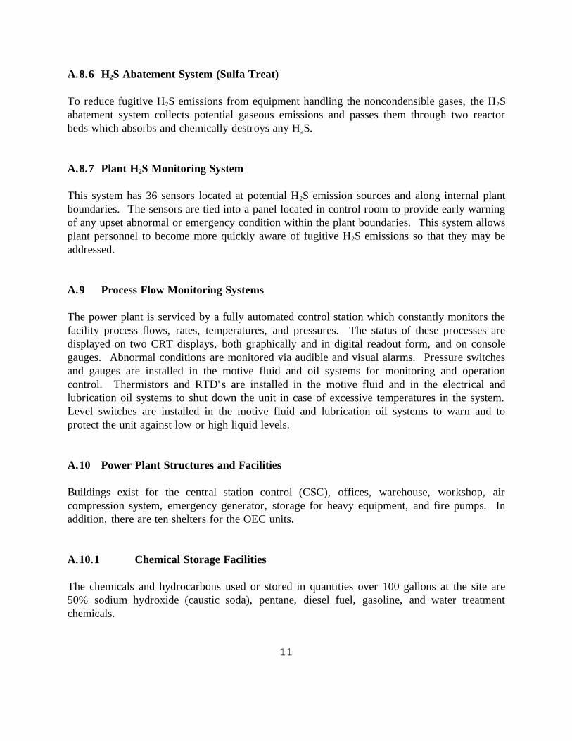
11
A.8.6 H2S Abatement System (Sulfa Treat)
To reduce fugitive H2S emissions from equipment handling the noncondensible gases, the H2S
abatement system collects potential gaseous emissions and passes them through two reactor
beds which absorbs and chemically destroys any H2S.
A.8.7 Plant H2S Monitoring System
This system has 36 sensors located at potential H2S emission sources and along internal plant
boundaries. The sensors are tied into a panel located in control room to provide early warning
of any upset abnormal or emergency condition within the plant boundaries. This system allows
plant personnel to become more quickly aware of fugitive H2S emissions so that they may be
addressed.
A.9 Process Flow Monitoring Systems
The power plant is serviced by a fully automated control station which constantly monitors the
facility process flows, rates, temperatures, and pressures. The status of these processes are
displayed on two CRT displays, both graphically and in digital readout form, and on console
gauges. Abnormal conditions are monitored via audible and visual alarms. Pressure switches
and gauges are installed in the motive fluid and oil systems for monitoring and operation
control. Thermistors and RTD' s are installed in the motive fluid and in the electrical and
lubrication oil systems to shut down the unit in case of excessive temperatures in the system.
Level switches are installed in the motive fluid and lubrication oil systems to warn and to
protect the unit against low or high liquid levels.
A.10 Power Plant Structures and Facilities
Buildings exist for the central station control (CSC), offices, warehouse, workshop, air
compression system, emergency generator, storage for heavy equipment, and fire pumps. In
addition, there are ten shelters for the OEC units.
A.10.1 Chemical Storage Facilities
The chemicals and hydrocarbons used or stored in quantities over 100 gallons at the site are
50% sodium hydroxide (caustic soda), pentane, diesel fuel, gasoline, and water treatment
chemicals.

12
Pentane is a colorless liquid that vaporizes at 97F. It is non-toxic or corrosive, but is
flammable at concentrations between 1.5 percent and 7.8 percent (volume) in air (see
Appendix F). Pentane is similar to propane (bottle gas), which is used for heating and cooking
in many rural locations, but is much less hazardous than propane because of its higher boiling
point and lower vapor pressure.
Each OEC unit in the power block will contain approximately 3,560 gallons of pentane.
Additional pentane, as much as 9,000 gallons is stored on site in two tanks which also have
sufficient capacity to receive the entire pentane contents of one OEC unit. The tanks have a
design temperature of 250F and design pressure of 150 psig. Working fluid pumps are used
to transfer pentane to and from the tanks to recharge the systems or remove the pentane from
OEC units requiring maintenance.
Each ITLU unit on Pad D will contain approximately 12,000 gallons of pentane. Additional
pentane, as much as 6000 gallons, is stored on Wellpad D in one tank which also have
sufficient capacity to receive the entire pentane contents of one ITLU unit. The tanks have a
design temperature of 250F and design pressure of 150 psig.
Caustic soda (NaOH) is a corrosive material that is toxic if ingested and can cause skin and eye
irritation upon contact. It is soluble in water and used in households as a cleaning agent.
Sodium hydroxide will be delivered to the site as a 50 percent solution and stored in two tanks;
one with a 50 percent solution as delivered and the other tank with a 15 percent solution,
diluted for use in the abatement system.
Sulfuric acid is a corrosive material that is toxic if ingested and can cause skin and eye
irritation upon contact. It is soluble in water and used in households as a cleaning agent.
Sodium hydroxide will be delivered to the site as a 50 percent solution and stored in two tanks;
one with a 50 percent solution as delivered and the other tank with a 15 percent solution,
diluted for use in the abatement system.
Secondary containment structures such as dikes or berms are constructed around the sodium
hydroxide storage tanks, gasoline, diesel, and bulk treatment chemical day tanks. These tanks
are segregated by distance from any incompatible materials. Applicable federal regulations
(e.g., OSHA and EPA) and Hawaii regulations (e.g., DOSH and HDOH) will be incorporated
into procedures and standard policies of the facility. Applicable Department of Transportation
(DOT) regulations (Title 49 CFR, Section 171-178) are incorporated into the procedures for
delivery of any hazardous materials used on site.

13
A.10.2 Fencing
A six-foot high chain link fence is installed around the power plant site boundary and each of
the wellpads. A gate at each entrance to the facility restricts unauthorized access.
A.11 Construction Yard
During construction a temporary yard of about 5 acres is used next to the main entrance road
to the plant, off State Highway 132. The construction yard is used for the temporary storage
of construction materials and fabrication of some project components. The construction yard
perimeter is fenced.
A.12 Operation and Maintenance
The operational life of the PGV Project facilities is estimated to be 35 years. The power plant
and wellfield are operated in a manner that protects human health and the environment. The
facility staff operates equipment, oversees production, and responds to emergency conditions.
An important part of the operational phase of the project is regular maintenance and
monitoring of both the power plant and the wellfield.

14
The power plant and wellfield operate continuously 24 hours per day, seven days per week.
Qualified operators are on site at all times. Routine maintenance is conducted by workers
during the normal daytime work shift. If repair work is required because of malfunction of
part of the power plant modules, the maintenance work may continue 24 hours per day, seven
days per week, until full power output can be resumed.
Scheduled power plant maintenance is conducted for each generating module, as needed.
Thorough maintenance procedures, such as turbine disassembly and inspection, may be
conducted during this scheduled maintenance, and is coordinated with HELCO to ensure the
maintenance of a reliable power system.
A.13 Plant Start Up and Shutdown
The modular nature of the power plant allows a gradual start up process as relatively small
increments of power are synchronized to the grid, one at a time. The total process is relatively
rapid due to that small moment of inertia and small volume to be heated during each step of the
start up process.
The start up of the generating modules typically begins with energizing the auxiliary systems
needed for starting one OEC unit. These auxiliary systems include the air compressor, OEC
lube and sealing oil pumps, condenser fans for one OEC unit, and working fluid circulation
pump. The power for the auxiliary systems can be supplied either from the 1400 KW diesel
generator or from the utility grid.
To start an OEC unit, the steam turbine bypass is opened, and the steam gradually let into the
OEC vaporizer until it reaches full flow. After the start up and synchronization of the first
OEC unit, the power plant supplies its own power and also supply power to the grid. As more
OEC units are started and synchronized, the wells will be opened up to allow more steam to
flow from the wellfield.
The steam turbine paired with each OEC unit can be started as soon as its OEC unit is in
operation. The steam is gradually introduced into the steam turbines and increased until full
load steam turbine operation is achieved.
Shutdown of each OEC/steam turbine module is handled in reverse order, i.e, first the steam
flow to the steam turbine is gradually reduced while the steam turbine bypass is gradually
opened. After the steam turbine is shut down, the steam to the OEC unit is gradually closed.
Finally, either the diesel generator or the utility grid supplies the power to the auxiliaries after
the last OEC unit has been shutdown.

15
A.14 Hydrologic Monitoring
The hydrologic monitoring program consists of the following activities:
Review and update, with field measurements, the data for existing non-
geothermal wells in the site area;
Permit, drill, and sample two on-site monitoring wells;
Obtaining background samples and water levels from existing well locations;
and,
Continue the monitoring program with quarterly water level measurements and
water quality sampling and analyses at selected locations.
PGV will immediately notify the County Planning Department, State Department of Health,
and the Department of Land and Natural Resources in situations when a change in any
geothermal well conditions indicates there is a leak or failure in the production or injection
well casing. PGV will take the appropriate steps to test the production/injection system and
evaluate the related well and casing downhole conditions. If leakage of geothermal waters to
the shallow aquifer is demonstrated, any leaking well would be shut-in, and an assessment of
the potential impact would be made by the monitoring contractor or other qualified consultants.
In addition, steps would be identified to evaluate the impact as it relates to down gradient water
users.
A.15 Air Quality and Meteorological Monitoring
A total of three fixed locations are operated by PGV for the continuous off-site monitoring of
ambient H2S in accordance with the Hawaii County Geothermal Resource Permit (GRP) and
the Hawaii State Department of Health Permit to Operate (PTO) permit conditions (Figure A-
1). Each station contains support equipment to accumulate and average the data and a real-
time alarm system in the event that ambient H2S concentrations exceed the levels specified in
the permit conditions.
The first location (southwest) is in an area in the prevailing downwind direction from most of
the project activities including the power plant.
The second location (southeast) is in topographically down gradient from the power plant in an
area where ambient H2S concentrations associated with night-time drainage flow of air to the
southeast from the plant site area would likely occur. In addition, this location is downwind
from the plant site when the winds are from the northeast as occurs frequently in the project
area in the daytime.
The third location is in an area northwest of the power plant which generally would not be
directly downwind but is topographically down gradient.
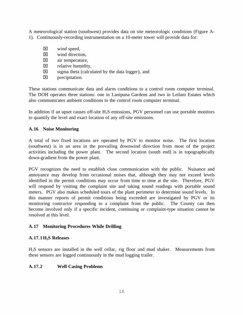
16
A meteorological station (southwest) provides data on site meteorologic conditions (Figure A-
1). Continuously-recording instrumentation on a 10-meter tower will provide data for:
wind speed,
wind direction,
air temperature,
relative humidity,
sigma theta (calculated by the data logger), and
precipitation.
These stations communicate data and alarm conditions to a control room computer terminal.
The DOH operates three stations: one in Lanipuna Gardens and two in Leilani Estates which
also communicates ambient conditions to the control room computer terminal.
In addition if an upset causes off-site H2S emissions, PGV personnel can use portable monitors
to quantify the level and exact location of any off-site emissions.
A.16 Noise Monitoring
A total of two fixed locations are operated by PGV to monitor noise. The first location
(southwest) is in an area in the prevailing downwind direction from most of the project
activities including the power plant. The second location (south end) is in topographically
down-gradient from the power plant.
PGV recognizes the need to establish close communication with the public. Nuisance and
annoyance may develop from occasional noises that, although they may not exceed levels
identified in the permit conditions may occur from time to time at the site. Therefore, PGV
will respond by visiting the complaint site and taking sound readings with portable sound
meters. PGV also makes scheduled tours of the plant perimeter to determine sound levels. In
this manner reports of permit conditions being exceeded are investigated by PGV or its
monitoring contractor responding to a complaint from the public. The County can then
become involved only if a specific incident, continuing or complaint-type situation cannot be
resolved at this level.
A.17 Monitoring Procedures While Drilling
A.17.1 H2S Releases
H2S sensors are installed in the well cellar, rig floor and mud shaker. Measurements from
these sensors are logged continuously in the mud logging trailer.
A.17.2 Well Casing Problems

17
Mud circulating temperature in and out are logged continuously during drilling. A rapid
increase in the mud out temperature could indicate a casing problem. If this occurs, mud or
water is pumped continuously into the well to keep it cool. The well can then be surveyed
with temperature, caliper or sonic measurement tools to investigate the casing integrity.
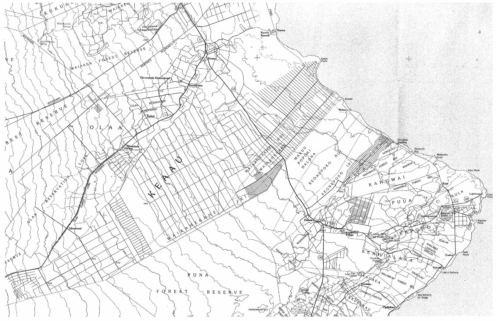
rquesada
Line
rquesada
Line
rquesada
Line
rquesada
Line
rquesada
Line
rquesada
Line

MONITORING STATION A
MONITORING STATION BMONITORING STATION C

APPENDIX B
COURSE CONTENT - HYDROGEN SULFIDE SAFETY TRAINING
B1 --- H2S Summit Training Program
B2 - PGV Training Program

PGV TRAINING PROGRAM


APPENDIX C
COURSE CONTENT - BLOWOUT PREVENTION TRAINING
FOR DRILLING OPERATIONS

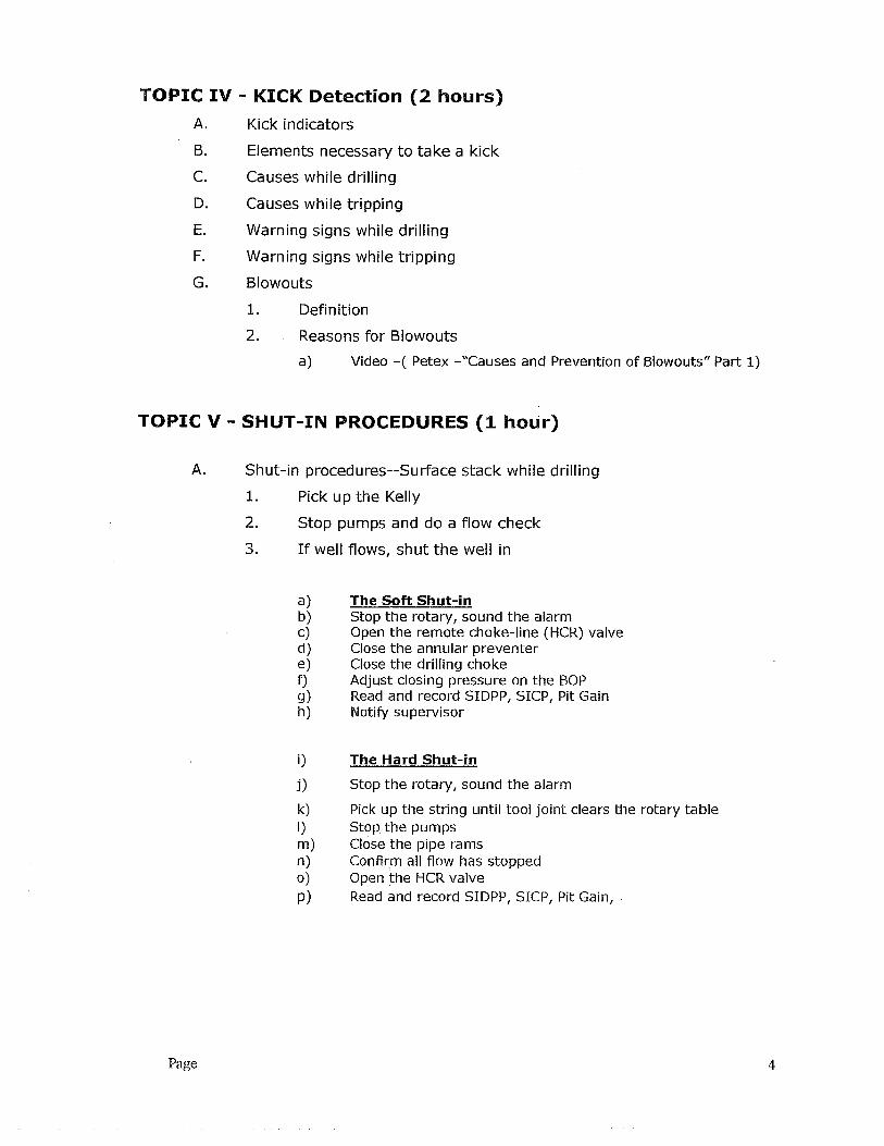

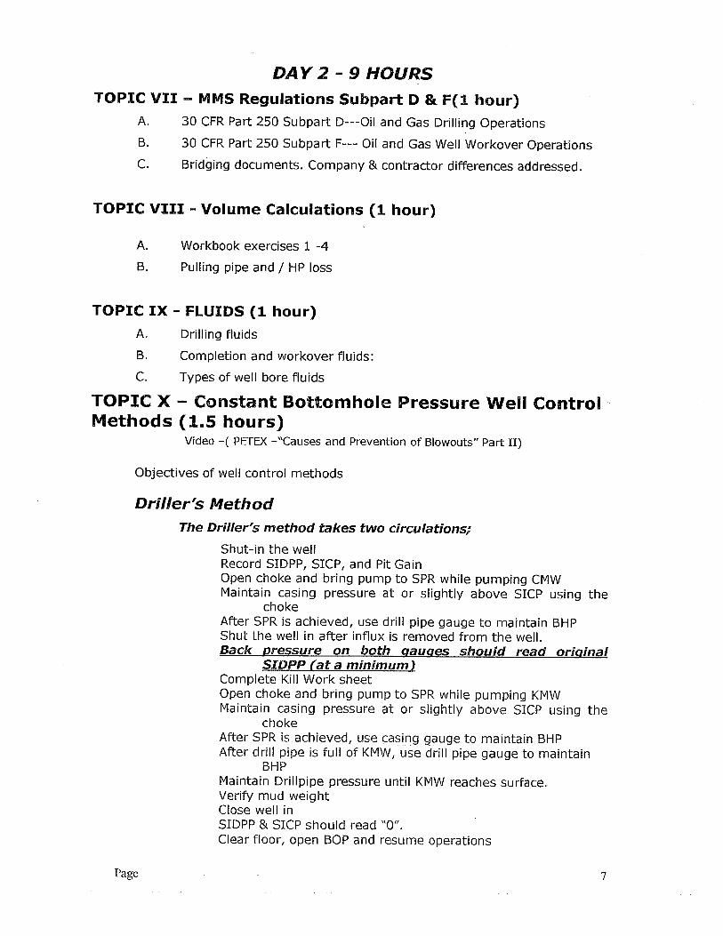


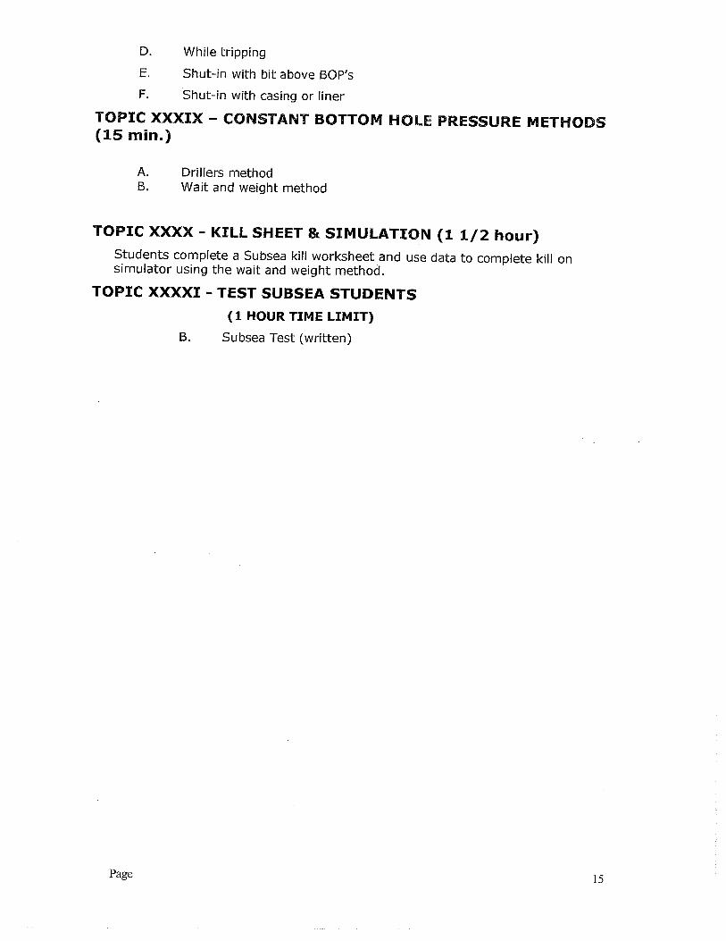


19
APPENDIX D
POST EMERGENCY RESPONSE PROCEDURES
WRITTEN CONFIRMATION OF RELEASES/INCIDENTS
Following the occurrence of a release of a reportable quantity or any emergency situations
described in this plan and in compliance with the GRP, PTO and other County or State
requirements, a report will be prepared by the PGV environmental representative or designee
of the incident and the appropriate report will be transmitted after review by PGV management
to the appropriate individuals and agencies listed below:
Federal National Response Center
Hawaii County Civil Defense Agency
Hawaii County Planning Commission
Hawaii State Department of Health, Clean Air Branch
Hawaii State Emergency Response Commission
Hawaii State Department of Land and Natural Resources
Local Emergency Planning Commission
The written notification will include an update of verbal notification information plus the
following:
Actions taken to respond to and contain the release.
Any known or anticipated acute or chronic health risks associated with the release; and
Where appropriate, advice regarding medical attention necessary for exposed
individuals.

19
FOLLOW UP INVESTIGATION
PGV’s Incident Investigation Team shall compile all documentation and perform a post-
incident investigation. Using the following procedure from PGV’s Incident Investigation and
Reporting Program:
An incident report shall be submitted before the end of the work shift.
PGV shall initiate an investigation no later than 48 hours following the incident.
To guide and document this effort, PGV has developed an incident and investigation
form which includes the following:
Date of incident
Date investigation began
A detailed description of the incident
Factors that contributed to the incident
Recommendations resulting from the investigation
All investigations shall be completed in an efficient and timely fashion, and the results
of the investigation distributed for recommendation follow-up and review with
personnel.
The Plant Engineer shall be responsible for follow-up and issuance of monthly status
reports until all recommendations are completed.

21
APPENDIX E
EQUIPMENT AND SERVICE CONTRACTORS
CRANES AND TRUCKS Yamada Trucking Office 933-8400 Industrial Crane Keaau Services Office/Fax:
966-9373 Justin Alonzo 960-1238 PROPANE REMOVAL Hawaii Gas Office 935-0021 Darrell Ramos 491-3098 WELDERS/CUTTERS Curt Neil 1-903-931-1899 Denali Welding 217-2379 MACHINING SERVICES Pacifica Services Office Trent Bateman 345-6600

22
APPENDIX F PENTANE SAFETY DATA SHEET

1. PRODUCT AND COMPANY IDENTIFICATION
2. COMPOSITION/INFORMATION ON INGREDIENTS
EMERGENCY OVERVIEW24 Hour Emergency Telephone Numbers:Spill, Leak, Fire or AccidentCall CHEMTRECNorth America: (800)424-9300Others: (703)527-3887 (collect)
Physical Hazards/Precautionary Measures: Extremely flammable liquid and vapor. Vapor can cause flash fire.Keep away from heat, sparks, flames, static electricity or other sources of ignition.
600 ppm ACGIH TWA 1000 ppm OSHA TWA
Agency Type
n-Pentane 99.7
% WEIGHTHAZARDOUS COMPONENTS EXPOSURE GUIDELINE
California Poison Control System: (800) 356-3129
Limits
MATERIAL SAFETY DATA SHEETn-Pentane (Pure Grade)
(MSDS: 003459)
Health Hazards/Precautionary Measures:
NFPA Hazard Class: HMIS Hazard Class
Physical form: LiquidOdor: Mild, gasoline-like
Appearance: Colorless
Health: 1 (Slight) Health: 1 (Slight)Flammability:4 (Extreme) Flammability: 4 (Extreme)Reactivity: 0 (Least) Physical Hazard: 0 (Least)
Product Name: n-Pentane (Pure Grade)Synonyms: Normal Pentane
PentaneIntended Use: SolventChemical Family: Aliphatic hydrocarbon
Responsible Party: ConocoPhillips Specialty SolventsBorger, Texas79007
For Additional MSDSs (800) 762-0942
Technical Information: (832) 486-3339The intended use of this product is indicated above. If any additional use is known, please contact us at the Technical Information number listed.
Aspiration hazard if swallowed. Can enter lungs and cause damage.Use with adequate ventilation. Avoid contact with eyes, skin and clothing. Do not taste or swallow. Washthoroughly after handling.
Page 1 of 7

3. HAZARDS IDENTIFICATION
Inhalation (Breathing): Low degree of toxicity by inhalation.
Skin: Contact may cause mild skin irritation including redness, and a burning sensation. Prolonged orrepeated contact can worsen irritation by causing drying and cracking of the skin leading to dermatitis(inflammation). No information available on skin absorption. Studies of other exposure routes suggest alow degree of hazard by skin absorption.
Eye: Contact may cause mild eye irritation including stinging, watering, and redness.
Ingestion (Swallowing): Low to moderate degree of toxicity by ingestion. ASPIRATIONHAZARD - This material can enter lungs during swallowing or vomiting and cause lung inflammation anddamage.
Signs and Symptoms: Effects of overexposure may include irritation of the nose and throat,irritation of the digestive tract, nausea, vomiting, diarrhea, transient excitation followed by signs ofnervous system depression (e.g., headache, drowsiness, dizziness, loss of coordination, disorientationand fatigue) and abdominal pain.
Potential Health Effects:
No data available.Cancer:
Target Organs: Inadequate data available for this material.
Developmental: Inadequate data available for this material.
Other Comments: Reports have associated repeated and prolonged occupational overexposureto solvents with permanent brain and nervous system damage (sometimes referred to as Solvent or Painters'Syndrome). Intentional misuse by deliberately concentrating and inhaling this material may be harmful orfatal.
Pre-Existing Medical Conditions: Conditions aggravated by exposure may include skindisorders and respiratory (asthma-like) disorders.
Exposure to high concentrations of this material may increase the sensitivity of the heart to certaindrugs. Persons with pre-existing heart disorders may be more susceptible to this effect (see Section 4 -Note to Physicians).
4. FIRST AID MEASURES
Eye: If irritation or redness develops, move victim away from exposure and into fresh air. Flush eyeswith clean water. If symptoms persist, seek medical attention.
Skin: Remove contaminated shoes and clothing and cleanse affected area(s) thoroughly by washing with mildsoap and water. If irritation or redness develops and persists, seek medical attention.
1500 ppm NIOSH IDLHCAS# 109-66-0
Note: State, local or other agencies or advisory groups may have established more stringent limits.Consult an industrial hygienist or similar professional, or your local agencies, for further information.
1%=10,000 PPM.
All components are listed on the TSCA inventory.
(MSDS: 003459) Page 2 of 7

Inhalation (Breathing): First aid is not normally required. If breathing difficulties develop, move victim away fromsource of exposure and into fresh air. Seek immediate medical attention.
Ingestion (Swallowing): Aspiration hazard: Do not induce vomiting or give anything by mouth because thismaterial can enter the lungs and cause severe lung damage. If victim is drowsy or unconscious andvomiting, place on the left side with the head down. If possible, do not leave victim unattended and observeclosely for adequacy of breathing. Seek medical attention.
Note To Physicians: Epinephrine and other sympathomimetic drugs may initiate cardiacarrhythmias in persons exposed to high concentrations of hydrocarbon solvents (e.g., in enclosedspaces or with deliberate abuse). The use of other drugs with less arrhythmogenic potential shouldbe considered. If sympathomimetic drugs are administered, observe for the development of cardiacarrhythmias.
5. FIRE FIGHTING MEASURES
Fire Fighting Instructions: For fires beyond the incipient stage, emergency responders in the immediate hazardarea should wear bunker gear. When the potential chemical hazard is unknown, in enclosed or confined spaces, orwhen explicitly required by DOT, a self contained breathing apparatus should be worn. In addition, wear otherappropriate protective equipment as conditions warrant (see Section 8).
Isolate immediate hazard area, keep unauthorized personnel out. Stop spill/release if it can be done with minimalrisk. Move undamaged containers from immediate hazard area if it can be done with minimal risk.
Water spray may be useful in minimizing or dispersing vapors and to protect personnel. Cool equipment exposed tofire with water, if it can be done with minimal risk. Avoid spreading burning liquid with water used for coolingpurposes.
6. ACCIDENTAL RELEASE MEASURES
Extremely flammable. Keep all sources of ignition and hot metal surfaces away from spill/release. The use ofexplosion-proof equipment is recommended.
Stay upwind and away from spill/release. Notify persons down wind of the spill/release, isolate immediate hazardarea and keep unauthorized personnel out. Stop spill/release if it can be done with minimal risk. Wearappropriate protective equipment including respiratory protection as conditions warrant (see Section 8).
Prevent spilled material from entering sewers, storm drains, other unauthorized drainage systems, and naturalwaterways. Dike far ahead of spill for later recovery or disposal. Use foam on spills to minimize vapors (seeSection 5). Spilled material may be absorbed into an appropriate absorbent material.
LEL%: 1.42 / UEL%: 7.8Autoignition Temperature: 588°F/309°C
Flammable Properties: Flash Point: -56.2°F/-49°C (TCC, ASTM D56) Flammable LiquidOSHA Flammability Class:
(MSDS: 003459)
Unusual Fire & Explosion Hazards:
Extinguishing Media: Dry chemical, carbon dioxide, or foam is recommended. Water spray is recommended tocool or protect exposed materials or structures. Carbon dioxide can displace oxygen. Use caution when applyingcarbon dioxide in confined spaces. Water may be ineffective for extinguishment, unless used under favorableconditions by experienced fire fighters.
This material is extremely flammable and can be ignited by heat, sparks,flames, or other sources of ignition (e.g., static electricity, pilot lights, mechanical/electrical equipment, andelectronic devices such as cell phones, computers, calculators, and pagers which have not been certified asintrinsically safe). Vapors may travel considerable distances to a source of ignition where they can ignite, flashback, or explode. May create vapor/air explosion hazard indoors, in confined spaces, outdoors, or in sewers.Vapors are heavier than air and can accumulate in low areas. If container is not properly cooled, it can rupture inthe heat of a fire.
Page 3 of 7

Notify fire authorities and appropriate federal, state, and local agencies. Immediate cleanup of any spill isrecommended.
7. HANDLING AND STORAGE
Handling:
Storage:
Open container slowly to relieve any pressure. Bond and ground all equipment whentransferring from one vessel to another. Can accumulate static charge by flow or agitation. Can be ignitedby static discharge. The use of explosion-proof equipment is recommended and may be required (seeappropriate fire codes). Refer to NFPA-704 and/or API RP 2003 for specific bonding/grounding requirements.
Do not enter confined spaces such as tanks or pits without following proper entry procedures such as ASTMD-4276 and 29CFR 1910.146. The use of appropriate respiratory protection is advised when concentrationsexceed any established exposure limits (see Sections 2 and 8).
Wash thoroughly after handling. Do not wear contaminated clothing or shoes. Keep contaminated clothingaway from sources of ignition such as sparks or open flames. Use good personal hygiene practices.
High pressure injection of hydrocarbon fuels, hydraulic oils or greases under the skin may have seriousconsequences even though no symptoms or injury may be apparent. This can happen accidentally when usinghigh pressure equipment such as high pressure grease guns, fuel injection apparatus or from pinhole leaks intubing of high pressure hydraulic oil equipment.
"Empty" containers retain residue and may be dangerous. Do not pressurize, cut, weld, braze, solder, drill,grind, or expose such containers to heat, flame, sparks, or other sources of ignition. They may explode andcause injury or death. "Empty" drums should be completely drained, properly bunged, and promptly shipped tothe supplier or a drum reconditioner. All containers should be disposed of in an environmentally safemanner and in accordance with governmental regulations.
Before working on or in tanks which contain or have contained this material, refer to OSHA regulations, ANSIZ49.1 and other references pertaining to cleaning, repairing, welding, or other contemplated operations.
Keep container(s) tightly closed. Use and store this material in cool, dry, well-ventilatedareas away from heat, direct sunlight, hot metal surfaces, and all sources of ignition. Post area "NoSmoking or Open Flame." Store only in approved containers. Keep away from any incompatible material (seeSection 10). Protect container(s) against physical damage. Outdoor or detached storage is preferred.Indoor storage should meet OSHA standards and appropriate fire codes.
Engineering controls:
Respiratory:
Personal Protective Equipment (PPE):
If current ventilation practices are not adequate to maintain airborne concentrations belowthe established exposure limits (see Section 2), additional engineering controls may be required. Where explosivemixtures may be present, electrical systems safe for such locations must be used (see appropriate electricalcodes).
A NIOSH certified air purifying respirator with an organic vapor cartridge maybe used under conditions where airborne concentrations are expected to exceed exposurelimits (see Section 2).
Protection provided by air purifying respirators is limited (see manufacturer's respiratorselection guide). Use a NIOSH approved self-contained breathing apparatus (SCBA) orequivalent operated in a pressure demand or other positive pressure mode if there ispotential for an uncontrolled release, exposure levels are not known, or any othercircumstances where air purifying respirators may not provide adequate protection.
A respiratory protection program that meets OSHA's 29 CFR 1910.134 and ANSI Z88.2requirements must be followed whenever workplace conditions warrant a respirator's use.
8. EXPOSURE CONTROLS/PERSONAL PROTECTION
(MSDS: 003459) Page 4 of 7

Skin:
Eye/Face:
Other Protective Equipment:
The use of gloves impervious to the specific material handled is advised to prevent skincontact, possible irritation, and absorption. Examples of approved materials are nitrile,or Viton® (see glove manufacturer literature for information on permeability).
Approved eye protection to safeguard against potential eye contact, irritation, orinjury is recommended. Depending on conditions of use, a face shield may be necessary.
A source of clean water should be available in the workarea for flushing eyes and skin. Impervious clothing should be worn as needed.
Suggestions for the use of specific protective materials are based on readily available publisheddata. Users should check with specific manufacturers to confirm the performance of their products.
9. PHYSICAL AND CHEMICAL PROPERTIES
10. STABILITY AND REACTIVITY
Stability:
Conditions To Avoid:
Hazardous Decomposition Products:
Hazardous Polymerization:
Avoid all possible sources of ignition (see Sections 5 and 7).
Stable under normal ambient and anticipated storage and handling conditions of temperature andpressure. Extremely flammable liquid and vapor. Vapor can cause flash fire.
Combustion can yield carbon dioxide and carbonmonoxide. Will not occur.
11. TOXICOLOGICAL INFORMATION
Appearance: ColorlessPhysical State: LiquidOdor: Mild, gasoline-likepH: Not applicable Vapor Pressure (mm Hg): 15.6 psia @100°F (37.8°C)Vapor Density (air=1): 2.49Boiling Point/Range: 98°F / 37°CFreezing/Melting Point: -129.7°CSolubility in Water: Negligible Specific Gravity: 0.63 @60/60°F (15.6/15.6°C)Percent Volatile: 100 vol.%Evaporation Rate (nBuAc=1): >1Viscosity: 0.23 cp @ 68°F (20°C)Bulk Density: 5.25 lbs/gal
Chronic Data: No definitive information available on carcinogenicity, mutagenicity, target organ, or developmentaltoxicity.
Acute Data:Pentane: Dermal LD50=No data availableLC50>6,106 ppm (4-hr., Rat)Oral LD50>2,000 mg/kg (Rat).
Flash Point: -56.2°F / -49°C (TCC, ASTM D56) LEL: 1.42 / UEL: 7.8Flammable/Explosive Limits (%):
Note: Unless otherwise stated, values are determined at 20°C (68°F) and 760 mm Hg (1 atm).
(MSDS: 003459)
Materials to Avoid (Incompatible Materials): Avoid contact with strong acids,selected amines, strong bases and oxidizing agents.
Page 5 of 7

13. DISPOSAL CONSIDERATIONS
This material, if discarded as produced, would be a RCRA "characteristic" hazardous waste due to thecharacteristic(s) of ignitability (D001). If the spilled or released material impacts soil, water, or othermedia, characteristic testing of the contaminated materials may be required prior to their disposal. Further,this material, once it becomes a waste, is subject to the land disposal restrictions in 40 CFR 268.40 and mayrequire treatment prior to disposal to meet specific standards. Consult state and local regulations todetermine whether they are more stringent than the federal requirements.
Container contents should be completely used and containers should be emptied prior to discard. Containerrinsate could be considered a RCRA hazardous waste and must be disposed of with care and in full compliancewith federal, state and local regulations. Larger empty containers, such as drums, should be returned to thedistributor or to a drum reconditioner. To assure proper disposal of smaller empty containers, consult withstate and local regulations and disposal authorities.
14. TRANSPORT INFORMATION
--None--
SARA 313 and 40 CFR 372:This material contains the following chemicals subject to the reporting requirements of SARA 313 and 40CFR 372:
Warning: This material contains the following chemicals which are known to the State of California to cause cancer,birth defects or other reproductive harm, and are subject to the requirements of California Proposition 65 (CA Health& Safety Code Section 25249.5): --None Known--
EPA (CERCLA) Reportable Quantity: --None--
EPA SARA 311/312 (Title III Hazard Categories):
15. REGULATORY INFORMATION
California Proposition 65:
Carcinogen Identification:
12. ECOLOGICAL INFORMATION
(MSDS: 003459)
DOT Shipping Description:
Bulk Package Placard/Marking:
Packaging References 49 CFR 173.150, 173.202,173.242
Flammable/1265
Hazardous Substance/RQ None
This material has not been identified as a carcinogen by NTP, IARC, or OSHA.
Acute Health: YesChronic Health: No
Fire Hazard: YesPressure Hazard: No
Reactive Hazard: No
Not evaluated at this time
Emergency Response Guide: 128
Pentanes,3,UN1265,I
Page 6 of 7

16. OTHER INFORMATION
Disclaimer of Expressed and Implied Warranties:
The information presented in this Material Safety Data Sheet is based on data believed to be accurate as of the date this Material Safety DataSheet was prepared. HOWEVER, NO WARRANTY OF MERCHANTABILITY, FITNESS FOR ANY PARTICULAR PURPOSE, OR ANY OTHERWARRANTY IS EXPRESSED OR IS TO BE IMPLIED REGARDING THE ACCURACY OR COMPLETENESS OF THE INFORMATIONPROVIDED ABOVE, THE RESULTS TO BE OBTAINED FROM THE USE OF THIS INFORMATION OR THE PRODUCT, THE SAFETY OFTHIS PRODUCT, OR THE HAZARDS RELATED TO ITS USE. No responsibility is assumed for any damage or injury resulting from abnormaluse or from any failure to adhere to recommended practices. The information provided above, and the product, are furnished on the conditionthat the person receiving them shall make their own determination as to the suitability of the product for their particular purpose and on thecondition that they assume the risk of their use. In addition, no authorization is given nor implied to practice any patented invention without alicense.
Issue Date: 01/08/03Previous Issue Date: 03/21/02Revised Sections: 1, 2, 8, 11, 13, 16Previous Product Code: MultipleMSDS Number: 003459
Canada - Domestic Substances List:
WHMIS Class:
(MSDS: 003459)
Listed
Status: Final
B2-Flammable LiquidD2B-Materials causing other toxic effects - Toxic Material
This product has been classified in accordance with the hazard criteria of the Controlled Products Regulations(CPR) and the MSDS contains all the information required by the CPR.
Page 7 of 7

APPENDIX G 50% S MATERIAL SAFETY DATA SHEET

15185 Main Street Lemont, IL 60439
630-257-3900
Material Safety Data Sheet
50 % Caustic Soda ____________________________________________________________
Section 1: Product Identification ____________________________________________________________ PRODUCT NAME EVISION DATE 50% Caustic Soda - Liquid April 1, 2002 SYNONYM ID NUMBER Sodium Hydroxide Solution UN 1824 CHEMICAL FORMULA CAS NUMBER NaOH 1310-73-2 EMERGENCY NUMBERS 24 Hour Emergency : CHEMTREC 1-800-424-9300 Product Information: Lemont, IL 1-630-257-3900 ____________________________________________________________
Section 2: Physical Data & Ingredients ____________________________________________________________ APPEARANCE ODOR Colorless to slightly grey solution Virtually Odorless VAPOR PRESSURE BOILING POINT 1 mm Hg. @ 68º F ( 20º C) 288º F ( 142 C) SPECIFIC GRAVITY SOLUBILITY 1.53 @ 60º F Complete in water DENSITY pH OF SOLUTIONS 12.76 lbs/gal @ 60º F. Strongly Basic ( 14) HEAT OF SOLUTION Exothermic INGREDIENTS % Materials : Sodium Hydroxide Approx. 50%
Water Balance ____________________________________________________________
Section 3: Fire & Explosion Information ____________________________________________________________ FIRE EXTINGUISHING MEDIA FIRE Not Applicable Not Flammable EXPLOSION - Contact with some metals, particularly magnesium, aluminum and zinc ( galvanized), can generate hydrogen rapidly, which is explosive.
____________________________________________________________
Section 4: Reactivity Data ____________________________________________________________ STABILITY - Stable under ordinary conditions of use and storage. HAZARDOUS DECOMPOSITION PRODUCTS - Reaction with various food sugars may form carbon monoxide. HAZARDOUS POLYMERIZATION - This substance does not polymerize. INCOMPATIBILITY: ( MATERIALS TO AVOID) - May react violently with water, acids and a number of organic compounds. Reacts rapidly with aluminum, tin and zinc. Also reacts with bronze and brass. ____________________________________________________________
Section 5: Leak, Spill, Disposal Information ____________________________________________________________ STEPS TO BE TAKEN IF MATERIAL IS SPILLED OR RELEASED Dike area to contain spill. Only trained personnel equipped with NIOSH/MSHA approved, full face combination dust/mist respirators should be permitted in this area. Reclaim spilled material if possible or dilute material with a large quantity of water, then neutralize with dilute acid. Properly neutralize liquid residues ( pH 6-9 ) may be disposed of in waste water treatment facilities which allow the discharge of neutral salt solutions. Neutralized material can be recovered by vacuum truck for disposal. After all visible traces have been removed, flush area with large amounts of water. WASTE DISPOSAL METHOD Dispose of neutralized material in an approved hazardous waste management facility. Care must be taken when using or disposing of chemical materials and/or their containers to prevent environmental contamination. It is your duty to dispose of chemical materials and/or their containers in accordance with all federal, state and local regulations. ____________________________________________________________
Section 6: Health & Hazard Data ____________________________________________________________ IS CHEMICAL LISTED AS A CARCINOGEN OR POTENTIAL CARCINOGEN? NTP - NO IARC - NO OSHA - NO MEDICAL CONDITION GENERALLY AGGRAVATED BY EXPOSURE: None Known PERMISSIBLE EXPOSURE LIMIT -OSHA 2mg./m3 ceiling

ACUTE TOXICITY PRIMARY ROUTES OF EXPOSURE - Skin and eyes contact, inhalation INHALATION - Respiratory tract irritant. Severe injury is usually avoided by the self-limiting coughing and sneezing symptoms. INGESTION - CORROSIVE ! Ingestion of caustic soda liquid can cause perforation of the esophagus and stomach. Abdominal pain, nausea, vomiting and general gastro-intestinal upset can be expected. SKIN CONTACT - CORROSIVE ! Will cause severe chemical burns and tissue destruction. Immediately flush with water. Seek medical attention. EYE CONTACT - Will cause severe and possible permanent eye damage. Continuously flush eyes with large amounts of water for at least 15 minutes. Seek medical attention. CHRONIC TOXICITY- No Data Found ____________________________________________________________
Section 7: Emergency & First Aid Procedures ____________________________________________________________ INHALATION - Move person to fresh air. If not breathing, give artificial respiration, preferably mouth-to-mouth. If breathing is difficult, give oxygen. Call a physician. EYE OR SKIN CONTACT - In case of contact, immediately flush eyes and skin with plenty of water ( soap and water for skin) for at least 15 minutes, while removing contaminated clothing and shoes. Hold eyelids open during this flushing with water. Call a physician. If skin feels slippery, caustic may still be present in sufficient quantities to cause rash or burn. Continue washing until slick skin feeling is gone. Thoroughly clean contaminated clothing and shoes before reuse or discard. INGESTION - If swallowed, give at least 3-4 glasses of water or acidic beverages ( tomato or orange juice, carbonated soft drinks). Do not induce vomiting. Do not give anything by mouth to an unconscious or convulsing person. Get medical attention. NOTES TO PHYSICIAN - Treat symptomatically. ____________________________________________________________
Section 8: Occupational Control Measures ____________________________________________________________ VENTILATION REQUIREMENTS - Local exhaust - to meet the exposure requirements and avoid mist. PERSONAL RESPIRATORS: ( NIOSH APPROVED) - Dust/mist respirators recommended for all personnel working in or about an area of potential mist exposure. SKIN PROTECTION REQUIREMENTS - Wear impervious protective clothing; including boots; gloves; lab coat; apron or coveralls to prevent skin contact. Preferred Materials: Nitrile, Neoprene, PVC EYE PROTECTION REQUIREMENTS - Use chemical safety goggles impervious to product. Contact lenses should not be worn when working with this material. Maintain eye wash fountain and quick-drench facilities in immediate work area. NOTE: ALL PROTECTIVE EQUIPMENT MUST CONFORM WITH 29 CFR 1910.132.
____________________________________________________________
Section 9: Handling & Storage ____________________________________________________________ Store and handle only in containers suitably lined with or constructed of materials specified for this product. Keep separate from incompatibles. ____________________________________________________________
Section 10: Regulatory Information ____________________________________________________________ DOT HAZARD CLASS DOT PLACARD REQUIRED 8 Corrosive - UN 1824 DOT LABEL Corrosive - 8 REPORTABLE QUANTITY
1,000 lbs -/ 454 Kgs. NFPA / HMIS RATINGS Health - 3 Flammability - 0 Reactivity - 1 TSCA - Sodium Hydroxide is on the TSCA inventory under CAS. NO.1310-73-2. OSHA - Listed as a “Hazardous Chemical” as defined in 29 CFR 1910.1200 ( Hazcom). CERCLA Listed in table 302.4 of 40 CFR part 302 as a hazardous substance with a reportable quantity of 1,000 pounds. Release to air, land or water which exceed the RQ must be reported to the National Response Center, 1-800-424-8802. EUROPE EINECS This product is listed on EINECS. ( 204-825-9) CANADA DSL This product is listed on the Canadian DSL. AUSTRALIA AIC KOREA ECL This product is listed on AICS This product is listed
on MITI. JAPAN MITI ( ENCS) This product is listed on MITI. SARA TITLE III SARA ( 311,312) HAZARD CLASS: Acute Health Hazard. Reactive Hazard. SARA ( 313) CHEMICALS: Not Listed SARA Section 302: Not listed as an Extremely Hazardous Substance/ CANADIAN REGULATIONS (WHMIS) a.) Class E - Corrosive Material. b.) Sensitization to product - None known. c.) Reproductivity Toxicity - None known. d.) Odor Threshold - No Odor. e.) Product Use - Neutralization, chemical processing. The information contained herein is provided in good faith and is believed to be correct as of the date hereof. However, K.A. Steel Chemicals makes no representation as to the comprehensiveness or accuracy of the information. It is expected that individuals receiving information will exercise their independent judgement in determining its appropriateness for a particular purpose. Accordingly, K.A. Steel Chemicals will not be responsible for damages of any kind resulting from the use of or reliance upon such information. No representation, or warranties, either express or implied, of merchantability fitness for a particular purpose or of any nature are made hereunder with respect to the information set forth herein or to the product to which the information refers.