Journal of PETROLEUM AND GEOTHERMAL Technology ...
13
[JOURNAL OF PETROLEUM AND GEOTHERMAL TECHNOLOGY (JPGT)] Vol.1 No. 1 2020 15 Squeeze Cementing Using Braden Head Squeeze Method On ‘Dsr-29’ Well Tarakan Field PT. Medco E&P Indonesia Ristiyan Ragil P. 1*) , Dafa Surya Ramadhan 1) Petroleum Engineering Department, UPN “Veteran” Yogyakarta * email: [email protected] ABSTRACT Squeeze cementing is an operation in which a cement slurry is pressed to a certain pressure on an oil or gas well. The purpose of doing squeeze cementing is to block water or gas flow and oil zones, close certain zones to produce other productive zones, repair damaged casing, and as a continuation of primary cementing work. Squeeze Cementing is done when workover a well. Workover and well service operations in a well, is a type of activity in the oil industry aimed to maintain wells so that they can continue to produce optimally and increase productivity back wells due to production problems. Squeeze Cementing Project on Tarakan field, DSR-29 well serves to block perforation that is no longer needed or open hole section at a depth of 630 - 635 m (670 MZ) so that a reservoir can be isolated and the casing can be firm or strong against pressure. Squeeze cementing method used in the well is the Braden Head Squeeze method. In the middle of workover process, there are problems such as existence of remaining perforating gun, and gas traps. Certain procedure is applied so that the cementing process has been carried out successfully. Keyword: work over, well service, squeeze cementing, braden head squeeze. I. FIELD REVIEW 1.1. Company History PT. Medco E&P Indonesia, the company that took over PT. Stanvac Indonesia was owned by Exxon Mobil Oil at the end of 1995. The founder of Medco Energi was Arifin Panigoro. Whereat first the company which was founded in 1980 was a company engaged in the field of drilling, but now it has been transformed into a company engaged in the field of energy that focuses on exploration and production of oil and gas. PT. Medco E&P Indonesia was once named PT. Expan Nusantara. P.T Medco E&P Indonesia was first established by the Nederlands Koninklijk Petroleum Maaschaappij (NKPM) in Indonesia in 1912 which is the oldest petroleum company in Indonesia with Indonesian legal entity. At that time, oil and gas exploration and mining rights in Indonesia could only be granted to companies registered in the Netherlands. 1.2. Working Areas of PT. Medco E&P Indonesia At this time PT. Medco E&P Indonesia has a working area that includes 16 block areas spread across 8 provinces: a. South Sumatra which are South Sumatra Block, Lematang Block, Rimau Block in Musi Banyuasin, Musi Rawas, Banyuasin, Lahat, and Muara Enim Regencies. b. North Kalimantan which are Tarakan Block, Simenggaris Block, in Kutai Kertanegara Regency, Tarakan. c. Central Sulawesi which are the Tomori Block in Luwuk and Morowali Regencies. d. Aceh which is Block A in East Aceh District. e. Riau Islands which is Block B in Natuna. II. LITERATURE REVIEW 2.1. Squeeze Cementing Squeeze cementing is the process of applying hydraulic pressure to force cement slurry into the formation or against a porous zone. Its main purpose is to make seals in the casing-wellbore annulus. The most common squeeze cementing goals are: Repairs to the work of primary cementing which failed because of cement which was passed by mud (channeling) or insufficient cement height (fill up) in the annulus. Removal of water intrusion from above, below, or within the hydrocarbon producing zone commonly called block squeezing. Reduction of the producing gas/oil ratio by isolating the gas zone from adjacent oil intervals. Repairs to casing leaks caused by corrosion or broken pipes. Block production zones that are depleted or no longer in production.
-
Upload
khangminh22 -
Category
Documents
-
view
0 -
download
0
Transcript of Journal of PETROLEUM AND GEOTHERMAL Technology ...

[JOURNAL OF PETROLEUM AND GEOTHERMAL TECHNOLOGY (JPGT)] Vol.1 No. 1 2020
15
Squeeze Cementing Using Braden Head Squeeze Method On ‘Dsr-29’ Well Tarakan Field
PT. Medco E&P Indonesia
Ristiyan Ragil P. 1*)
, Dafa Surya Ramadhan1)
Petroleum Engineering Department, UPN “Veteran” Yogyakarta *email: [email protected]
ABSTRACT
Squeeze cementing is an operation in which a cement slurry is pressed to a certain pressure on an oil or gas well. The
purpose of doing squeeze cementing is to block water or gas flow and oil zones, close certain zones to produce other
productive zones, repair damaged casing, and as a continuation of primary cementing work. Squeeze Cementing is done
when workover a well. Workover and well service operations in a well, is a type of activity in the oil industry aimed to
maintain wells so that they can continue to produce optimally and increase productivity back wells due to production
problems. Squeeze Cementing Project on Tarakan field, DSR-29 well serves to block perforation that is no longer
needed or open hole section at a depth of 630 - 635 m (670 MZ) so that a reservoir can be isolated and the casing can be
firm or strong against pressure. Squeeze cementing method used in the well is the Braden Head Squeeze method. In the
middle of workover process, there are problems such as existence of remaining perforating gun, and gas traps. Certain
procedure is applied so that the cementing process has been carried out successfully.
Keyword: work over, well service, squeeze cementing, braden head squeeze.
I. FIELD REVIEW
1.1. Company History
PT. Medco E&P Indonesia, the company that took over PT. Stanvac Indonesia was owned by Exxon Mobil Oil at the
end of 1995. The founder of Medco Energi was Arifin Panigoro. Whereat first the company which was founded in 1980
was a company engaged in the field of drilling, but now it has been transformed into a company engaged in the field of
energy that focuses on exploration and production of oil and gas. PT. Medco E&P Indonesia was once named PT.
Expan Nusantara. P.T Medco E&P Indonesia was first established by the Nederlands Koninklijk Petroleum
Maaschaappij (NKPM) in Indonesia in 1912 which is the oldest petroleum company in Indonesia with Indonesian legal
entity. At that time, oil and gas exploration and mining rights in Indonesia could only be granted to companies
registered in the Netherlands.
1.2. Working Areas of PT. Medco E&P Indonesia
At this time PT. Medco E&P Indonesia has a working area that includes 16 block areas spread across 8 provinces:
a. South Sumatra which are South Sumatra Block, Lematang Block, Rimau Block in Musi Banyuasin, Musi
Rawas, Banyuasin, Lahat, and Muara Enim Regencies.
b. North Kalimantan which are Tarakan Block, Simenggaris Block, in Kutai Kertanegara Regency, Tarakan.
c. Central Sulawesi which are the Tomori Block in Luwuk and Morowali Regencies.
d. Aceh which is Block A in East Aceh District.
e. Riau Islands which is Block B in Natuna.
II. LITERATURE REVIEW
2.1. Squeeze Cementing
Squeeze cementing is the process of applying hydraulic pressure to force cement slurry into the formation or against a
porous zone. Its main purpose is to make seals in the casing-wellbore annulus.
The most common squeeze cementing goals are:
Repairs to the work of primary cementing which failed because of cement which was passed by mud
(channeling) or insufficient cement height (fill up) in the annulus.
Removal of water intrusion from above, below, or within the hydrocarbon producing zone commonly called
block squeezing.
Reduction of the producing gas/oil ratio by isolating the gas zone from adjacent oil intervals.
Repairs to casing leaks caused by corrosion or broken pipes.
Block production zones that are depleted or no longer in production.

[JOURNAL OF PETROLEUM AND GEOTHERMAL TECHNOLOGY (JPGT)] Vol.1 No. 1 2020
16
2.2. Squeeze Cementing Technique
1) Braden Head Squeeze
This method is used by placing the cement slurry in front of the perforation and is called "balancing-the plug". After the
slurry is mixed, the slurry is then pumped into the tubing and followed by the amount of fluid that has been calculated
to form a balance (high equality) of the slurry column in the tubing and annulus. The tubing is then lifted above the
cement slurry and the tubing is recirculated to clean up excess cement. This step is also important to ensure that the
cement has been deposited at the bottom of the well not above it through a tubing leak that might occur.
Then squeeze pressure is applied to press the slurry into the perforation. After the final squeeze pressure is obtained, the
tubing is then lowered to recirculate excess cement, until the cement plug is still a few feet above the perforation. The
term "Braden head squeeze" comes from the fact that the wellhead or Braden Head is exposed to pressure during the
squeeze process as well as the entire casing.
Benefits of Braden Head Squeeze:
a. No special equipment is needed.
b. The risk of casing rupture is avoided.
c. Can do squeeze jobs on a small diameter casing.
Losses of Braden Head Squeeze:
a. Tubing test required.
b. Can’t test the casing leak.
c. The casing is squeeze pressure.
Figure 1. Braden Head Squeeze Method
2) Low Pressure Squeeze
Low-pressure technique or also known as low fluid loss cement is a squeeze cementing technique by applying less
pressure than the formation fracture gradient. The purpose of this operation is to fill the perforation cavity and voids
interconnected with dehydrated semen. Usually, the slurry volume used in this operation is small, and precise control of
the hydrostatic pressure of the cement column is important because excessive pressure can result in the formation of
cementing being not as expected.
Figure 2. Low-Pressure Squeeze Method

[JOURNAL OF PETROLEUM AND GEOTHERMAL TECHNOLOGY (JPGT)] Vol.1 No. 1 2020
17
3) High Pressure Squeeze
For high-pressure techniques, this pressure involves fracturing the formation and pumping the cement slurry into the
fracture until a certain pressure is reached and is carried out without leakage. Clean cement is usually used with very
high fluid loss.
Figure 3. High-Pressure Squeeze Cementing
2.3. Cement Slurry Design
To design a good cement slurry, must be the composition or content contained in the cement itself based on the
characteristics of the formation that will be carried out secondary cementing work, and also following the method used.
1) Fluid Loss Control
Filtration loss is the phenomenon of liquid loss from a cement suspension into a permeable formation in its path. This
liquid is often called the filtrate. If the filtrate is lost too much it will cause a suspension of cement lacking water.
Which can cause the amount of cement slurry water to be smaller than the minimum level. As a result, friction in the
annulus rises. When this happens the formation will break and not be held back. Therefore the formation through which
the cement slurry is a porous and permeable formation and needs to add the appropriate additive before the cement
slurry is pumped. Based on API, the recommended fluid-loss value for each cementation job is for primary cementing
of 150-250 cc/30 min/1000 psi and for secondary 55-65 cc/30 min/1000 psi.
2) Cement Volume
The accuracy of the volume of cement slurry depends on the length of the cementation interval, and also on the
cementing technique used. In the low-pressure squeeze technique, the amount of cement slurry is usually used only to
form a filter cake made of cement in the perforation hole. Whereas in high-pressure squeeze work, which is usually
done for formations that have high permeability values, large volumes are required, which also includes the extent and
length of the existing permeability.
3) Thickening Time
As in primary cementing work, temperature and pressure are very important factors that are the basis for determining
the placement time for cement slurry. Even the temperature in secondary cementing work is usually higher than during
primary cementing work, because the total circulation fluid before the secondary cementing work is done is small.
The properties of the cement slurry is very necessary, because the pumping time of the cement slurry must be less than
the thickening time. If it doesn't, the cement slurry won't get to the desired place and this is a fatal event that shouldn't
happen. For deep wells with a long time of pumping cement slurry, a longer thickening time is needed. Conversely,
shallow wells need to shorten the thickening time.
4) Compressive Strength and Shear Strength
Compressive Strength is defined as the strength of the cement to withstand the pressures originating from the formation
and the casing, while Shear Strength is defined as the strength of the cement in holding the weight of the casing.
However, although high compressive strength values are needed to withstand the pressure or disturbance of formation
and subsurface equipment, it turns out that it is not a major concern in slurry design. And the formation of cement filter
cake will gradually be able to produce sufficient compressive strength.

[JOURNAL OF PETROLEUM AND GEOTHERMAL TECHNOLOGY (JPGT)] Vol.1 No. 1 2020
18
5) Cement Viscosity
The viscosity referred here is the ability of the slurry cement itself to flow into a channel or a hole that is proportional to
other fluids to flow. Therefore, slurry cement which has a low viscosity usually contains dispersant additives in it.
2.4. Cement Classification
1) Class A
This cement can be used in cementation with surface depth (0 ft) to 6000 ft. This type of cement is not
resistant to sulfate.
2) Class B
This cement can be used in cementation with surface depth (0 ft) to 6000 ft. This type of cement is resistant
to sulfate.
3) Class C
This cement can be used in cementation with a surface depth (0 ft) to 6000 ft, is resistant to sulfates and has a
high initial strength.
4) Class D
This cement can be used in cementing with a depth of 6000-10000 ft, for temperatures and pressures of
medium to high formation, available for cement that is not resistant to sulfate.
5) Class E
This cement can be used in cementing with a depth of 10000-14000 ft, for high temperature and pressure,
available for types that are not sulfate resistant and which are resistant to high pressure.
6) Class F
This cement can be used in cementing with a depth of 10000-16000 ft, for high temperature and pressure.
7) Class G
This cement can be used in cementing with a surface depth (0 ft) to 8000 ft and is a basic cement, if desired
for other conditions an appropriate additive can be added.
8) Class H
H class cement is also a basic cement, sulfate resistant type is available for moderate levels. This cement can
be used at surface depths (0 ft) to 8000 ft.
2.5. Additive Types
1) Accelerator
Additives used to speed up the hardening process of the cement suspension. Besides, it can also accelerate the
increase in strength of the cement and compensate for other additives so as not to delay the hardening position
of the cement suspension. The concentration used in the use of an accelerator is between 1 - 4% BWOC, but
the concentration that is generally used is 2%.
2) Retarder
It is an additive that can slow the hardening process of the cement suspension, so that the cement suspension
has a sufficient amount of time to reach the desired target depth. Examples are lignosulfonate, organic acid
compounds and CMHEC (Carboxymethyl Hydroxymethyl Cellulose).
3) Extender
The additive serves to increase the volume of the cement suspension, which is related to reducing the density
of the cement suspension. Examples are bentonite, attapulgite, sodium silicate, pozzolan, perlite, and
gilsonite.
4) Weighting Agents
It is an additive that works to increase the density of cement, usually used in wells that have high formation
pressure. Examples are hematite, ilmenite, barite, and sand.

[JOURNAL OF PETROLEUM AND GEOTHERMAL TECHNOLOGY (JPGT)] Vol.1 No. 1 2020
19
5) Dispersant
Dispersant works on cement slurry by separating and slowing the overall performance of cement particles in
mix water. Separation of cement particles results in good mobility so that the viscosity of the cement slurry
decreases (dilutes the cement slurry). Additives included in the dispersant include polymelamine sulfonate,
polynapthatalena sulfonate.
6) Fluid-Loss Control Agent
It is an additive that serves to prevent the loss of the liquid phase of cement into the formation, so that the
liquid content is maintained in the cement suspension. Additives included in fluid-loss control agents include
polymer, CMHEC, and latex.
7) Loss Circulation Control Agent
Lost Circulation Control Agents are additives that control the loss of a cement suspension into a weak or
fractured formation. Additives which are included in loss circulation control agents include gilsonite,
cellophane flakes, gypsum, bentonite, and nutshells.
8) Anti-Foam
To remove the foam that is the result of cement and mix water when the cement slurry mix is done. A little
concentration of anti-foam will prevent problems when mixing. The concentration range used in the use of
Anti Foam is 0.01 - 0.05 gps.
2.6. Calculation of Cementing Operation
1) Cement Slurry Capacity and Volume
The capacity or area of a room to be cemented and the annular volume must be known, the amount of annular
volume to be cemented is equal to the amount of cement slurry needed. The volume of cement slurry can be
calculated by the equation:
a. Casing Volume
b. Annulus Volume
Where:
ID = inside diameter casing, inch
OD = outside diameter casing, inch
1029.4 = conversion in units of volume, bbl
V = cement slurry volume, bbl
Depth = depth/ft
2) Yield and Amount of Cement
The number of sacks of cement can be defined as the number of sacks of cement needed in a cementing
process. The amount of cement sacks varies in each suspension, depending on the desired cement yield. The
weight of cement in one sack is generally 94 lb. So that the amount of sack of cement and cement yield can be
calculated with the following formula:
Where:
7.481 = unit conversion from gallon volume to cuft volume
3) Mixing Water
Mixing water is the amount of water needed by a mixture of cement and additives to become cement slurry.
Calculation of mixing water is determined by the equation:
4) Displacement Volume

[JOURNAL OF PETROLEUM AND GEOTHERMAL TECHNOLOGY (JPGT)] Vol.1 No. 1 2020
20
The displacement volume is the volume of the driving fluid needed to push the cement suspension from inside
the casing to come out into the annulus. The amount of displacement volume is the volume of the casing from
the surface to the collar. The displacement volume is determined by the equation:
Where:
C = casing capacity, bbl
H = depth, ft
2.7. Cementing Equipment
In secondary cementing operation, the equipment used in the process is also very necessary in addition to making the
design of the cement slurry, as well as determining the techniques used. Because this equipment is directly related to
making and also transferring slurry both from the tank to the cementing unit and from the cementing unit to the well.
1) Cementing Unit
Cementing Unit is a pump unit that is useful for pumping a suspension of cement or driving fluid in the
cementing process. Cementing units can be trucks (Long Vehicles) or skids in which there are cementing
equipment, including Slurry Tubs, Displacement Tanks, Tornadoes, Pumps, Engines, etc.
The tornado or commonly PSM is a stirrer which is also inside the cementing unit. Batch Mixer is a place to
store/store water, or cement slurry, or also displacement fluid in large volumes. Water Tank is a tank for
storing liquid (Freshwater) that is needed as a mixture of dry cement, or as a place for mixing the resulting
fluid. An air compressor is an engine that produces pressure, typically used to deliver dry cement from the
cutting bottle to gravity silos, pneumatic/pressurized silos, and surge tanks through the hose.
Figure 4. Cementing Unit
Figure 5. Pumping Unit

[JOURNAL OF PETROLEUM AND GEOTHERMAL TECHNOLOGY (JPGT)] Vol.1 No. 1 2020
21
III. DISCUSSION
In DSR-29 well, Tarakan field will do squeeze cementing which is useful to close the perforation zone that is no longer
in production. Some data has been provided to carry out squeeze cementing such as the depth of the wellbore (TVD),
Reservoir Pressure, BHST, BHCT, Cement Formula, and Well Sketch.
Well Conditions:
Vertical well
Temperature
Est. 216 deg F @ 2106-m (2200MZ)
Est. 204 deg F @ 626-m (670MZ)
Reservoir pressure
Est. Reservoir Pressure: 1035-psi @ 670MZ
Est. Reservoir Pressure: 1450-psi @ 2200MZ
Brine
10.7-ppg CaCl2 brine for 670 MZ
9.3-ppg CaCl2 brine for 2200 MZ
Figure 6. Cement Formula

[JOURNAL OF PETROLEUM AND GEOTHERMAL TECHNOLOGY (JPGT)] Vol.1 No. 1 2020
22
Figure 7. Well Sketch
Figure 8. Test Results for Cement Formulation Samples by LEMIGAS
In the sample test results of the cement formulation by LEMIGAS above it can be seen that there are significant
differences in results with what is desired by PT. Medco E&P Indonesia. This is due to problems with the cement and
additives used such as storage and storage when the cement & additives expire. Then LEMIGAS was assigned to find
the right cement formula so that the results match those needed in the DSR-29 well. Following are the results of cement
formulations made by LEMIGAS:
Figure 9. The formula of Cement 1 and Cement 2

[JOURNAL OF PETROLEUM AND GEOTHERMAL TECHNOLOGY (JPGT)] Vol.1 No. 1 2020
23
Figure 10. The formula result of Cement 1 and Cement 2
The next step is to plan operations to be carried out on the DSR-29 well. The steps to be carried out are as follows:
RECOMMENDED OPERATION PROCEDURES
Time Hours
Plan Actual
1. MIRU WO-WS Rig and equipment. Conduct safety talk prior to the
job. Report to Production Dept. to disconnect production line. 72
2. Prepare and mixing 250-bbls 10.7-ppg CaCl2 brine as killing fluid
(will be overbalance +/- 107psi @ 670MZ).
Note: Est. Pressure on 670MZ: 1035psi; 850MZ: 1150-psi;
2200MZ:1450-psi
10
3. Check Well Head Pressure (SITP & SICP); bleed off pressure at LS
and SS tubing and casing if any until 0-psi or until stable to poor boy
separator and flare line.
6
4. Ensure the well is killed prior to continue to the next step (check
SITP = SICP = 0-psig). If the well still flows, recalculate and
increase density of killing fluid as per recalculation. If the well is
taking fluid, combat loss with LCM.
1
5. Install BPV on LS tubing hanger, N/D dual 11” x 5k X-tree. N’U 11”
x 5K BOP stacks (with 2-7/8” pipe ram install). Retrieve SAU BPV.
Install test plug on LS tubing hanger. Test BOP function and
pressure 500-psi to 1500-psi, hold for 10-minute each. Bleed off
pressure to 0-psi. Retrieve test plug.
6
6. POOH and L/D tubing hanger. Lower down tubing 5-jts, or until OE
tubing est. @638-m. Circulate well for 2 x BTU.
Note: During circulation, ensure SW in = SW out = 10.7-ppg
4
7. POOH OE 2-7/8” tubing as tail pipe to surface.
Note: Keep well full at all time with killing fluid. 4
8. RIH OE 2-7/8” tubing and set until 638-mKBMD.
Note: Keep well full at all time. Check tubing condition. Drift tubing
prior to RIH.
4
[JOURNAL OF PETROLEUM AND GEOTHERMAL TECHNOLOGY (JPGT)] Vol.1 No. 1 2020
24
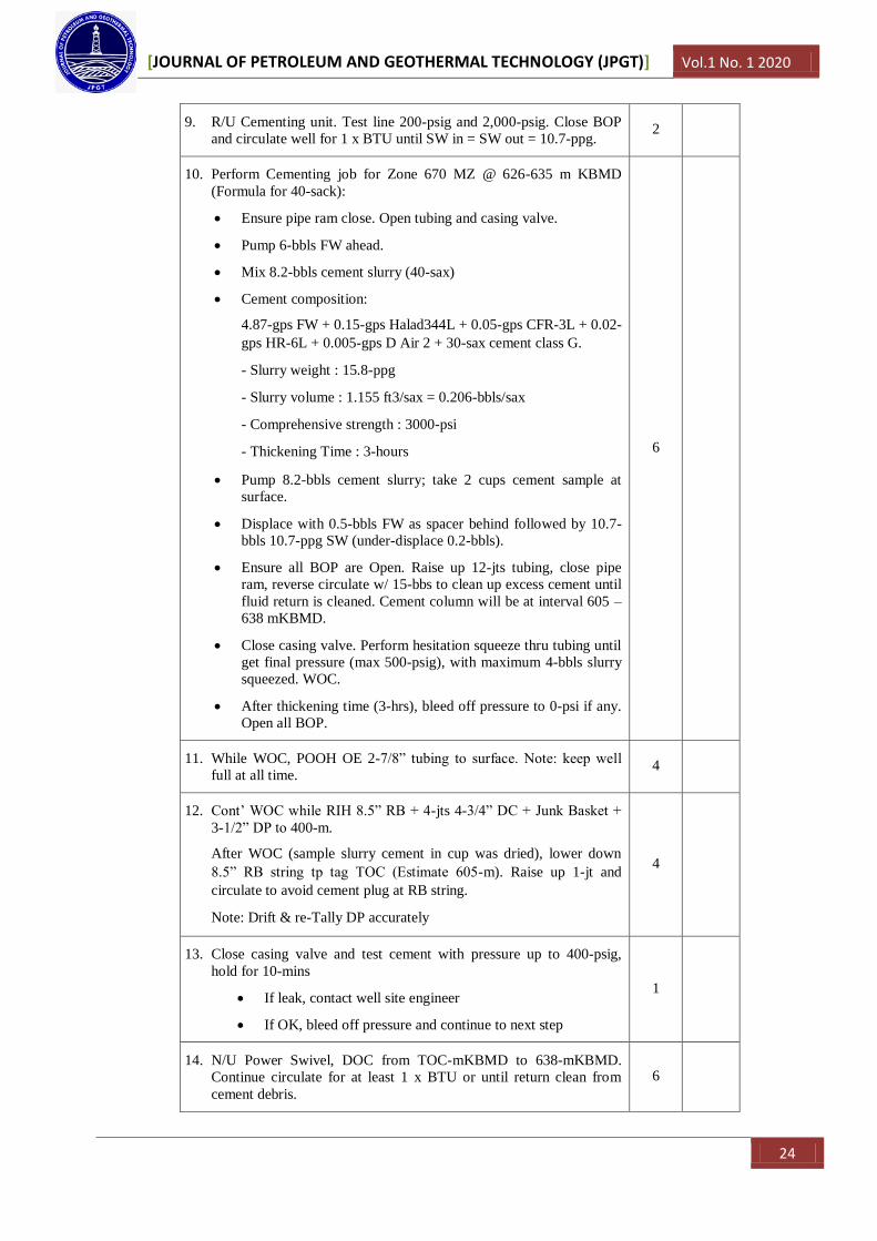
9. R/U Cementing unit. Test line 200-psig and 2,000-psig. Close BOP
and circulate well for 1 x BTU until SW in = SW out = 10.7-ppg. 2
10. Perform Cementing job for Zone 670 MZ @ 626-635 m KBMD
(Formula for 40-sack):
Ensure pipe ram close. Open tubing and casing valve.
Pump 6-bbls FW ahead.
Mix 8.2-bbls cement slurry (40-sax)
Cement composition:
4.87-gps FW + 0.15-gps Halad344L + 0.05-gps CFR-3L + 0.02-
gps HR-6L + 0.005-gps D Air 2 + 30-sax cement class G.
- Slurry weight : 15.8-ppg
- Slurry volume : 1.155 ft3/sax = 0.206-bbls/sax
- Comprehensive strength : 3000-psi
- Thickening Time : 3-hours
Pump 8.2-bbls cement slurry; take 2 cups cement sample at
surface.
Displace with 0.5-bbls FW as spacer behind followed by 10.7-
bbls 10.7-ppg SW (under-displace 0.2-bbls).
Ensure all BOP are Open. Raise up 12-jts tubing, close pipe
ram, reverse circulate w/ 15-bbs to clean up excess cement until
fluid return is cleaned. Cement column will be at interval 605 –
638 mKBMD.
Close casing valve. Perform hesitation squeeze thru tubing until
get final pressure (max 500-psig), with maximum 4-bbls slurry
squeezed. WOC.
After thickening time (3-hrs), bleed off pressure to 0-psi if any.
Open all BOP.
6
11. While WOC, POOH OE 2-7/8” tubing to surface. Note: keep well
full at all time. 4
12. Cont’ WOC while RIH 8.5” RB + 4-jts 4-3/4” DC + Junk Basket +
3-1/2” DP to 400-m.
After WOC (sample slurry cement in cup was dried), lower down
8.5” RB string tp tag TOC (Estimate 605-m). Raise up 1-jt and
circulate to avoid cement plug at RB string.
Note: Drift & re-Tally DP accurately
4
13. Close casing valve and test cement with pressure up to 400-psig,
hold for 10-mins
If leak, contact well site engineer
If OK, bleed off pressure and continue to next step
1
14. N/U Power Swivel, DOC from TOC-mKBMD to 638-mKBMD.
Continue circulate for at least 1 x BTU or until return clean from
cement debris.
6

[JOURNAL OF PETROLEUM AND GEOTHERMAL TECHNOLOGY (JPGT)] Vol.1 No. 1 2020
25
Estimated drilling parameter: WOB 2,500 lbs, rate 5 bbl/min, RPM
70, torque 8,000ft.lb.
15. RIH 8.5” RB + 4-jts 4-3/4” DC + Junk Basket + 3-1/2” DP to TOC
@ 900-mKBMD, raise up 0.5-m. Circulate well. 4
16. N/U Power Swivel. DOC from TOC-mKBMD to bottom of cement.
Continue circulate for at least 1 x BTU or until return clean from
cement debris.
Estimated drilling parameter: WOB 2,500 lbs, rate 5 bbl/min, RPM
70, torque 8,000ft.lb.
Lower down string to tag 7” TOL @ 1182-m.
6
17. POOH 8.5” RB string to surface. Fill up wellbore with trip tank. 12
18. RIH OE 2-7/8” tubing and set unti 2,110-mKBMD.
Note: Keep well full at all time. Check tubing condition. Drift tubing
prior to RIH
12
19. R/U Cementing unit. Test line 200-psig and 2,,000-psig. Close BOP
and circulate well for 1 x BTU.
Note: Check density of SW, fluid in = fluid out. Do not increase
density of SW.
2
20. Perform Cementing job for Zone 2200 MZ @ 2106-2107 m KBMD
(Formula for 30-sack)
Displace with 1-bbls FW as spacer behind followed by 37.3-
bbls SW (under-displace 0.7-bbls).
Ensure all BOP are Open. Raise up 12-jts tubing, close pipe
ram, reverse circulate w/ 15-bbs to clean up excess cement until
fluid return is cleaned. Cement column will be at interval 2062
- 2110 mKBMD.
Close casing valve. Perform hesitation squeeze thru tubing until
get final pressure (max 500-psig), with maximum 4-bbls slurry
squeezed. WOC.
After thickening time (3-hrs), bleed off pressure to 0-psi if any.
Open all BOP.
3
21. While WOC, POOH OE 2-7/8” tubing to surface. Note: Keep well
full at all time. 4
22. Cont’ WOC while RIH 6” RB + 4-jts 4-3/4” DC + Junk Basket + 3-
1/2” DP to 1,900-m.
After WOC (sample slurry cement in cup was dried), lower down 6”
RB string tp tag TOC (Estimate 2062-m). Raise up 1-jt and circulate
to avoid cement plug at RB string.
Note: Drift & re-Tally DP accurately
12
23. Close casing valve and test cement with pressure up to 400-psig,
hold for 10-mins 1

[JOURNAL OF PETROLEUM AND GEOTHERMAL TECHNOLOGY (JPGT)] Vol.1 No. 1 2020
26
If leak, contact well site engineer
If OK, bleed off pressure and continue to next step
24. N/U Power Swivel, DOC from TOC-mKBMD to 2110-mKBMD.
Continue circulate for at least 1 x BTU or until return clean from
cement debris.
Estimated drilling parameter: WOB 2,500 lbs, rate 5 bbl/min, RPM
70, torque 8,000ft.lb.
6
25. Close casing valve and test cement with pressure up to 400-psig,
hold for 10-mins
If leak, contact well site engineer
If OK, bleed off pressure and continue to next step
1
In the squeeze cementing stage, the depth of 626 - 635 m changes the use of cement sacks from 40 sacks to 60 sacks. At
this stage the cement experiences a total loss which results in a squeeze cementing that must be done at the same depth
as the cement composition as follows:
35 sacks
Water = 4.1 bbl
HALAD = 10.6 kg
DAIR = 0.7 Liter
CFR = 6.6 Liters
HR = 2.7 Liter
The next stage is the Drill Out Cement (DOC) from the Top of Cement (TOC) to the bottom of cement. At this stage,
there are obstacles caused by the remaining perforation gun which causes the rock bit can’t increase the depth of
drilling. The solution is to provoke the remaining perforation gun with the first way is to circulate it with brine and to
the DP series, junk basket is added. The second way is to lure it with a magnet tool that is stretched using a sand line
until the remaining perforation gun is used up.
After all the remaining perforation gun is raised to the surface, the Drill Out Cement is resumed. When they want to
penetrate the bottom of cement, there is an increase of water in the storage tank. This is an indication that there is
pressure under the cement layer caused by trapped gas (Gas Trap). The next step is to set the BOP and prepare a brine
with a density of 8.6 ppg to be circulated. Then drilling continues until there is a break in the cement which causes the
gas to rise to the surface through the annulus and directly into the flare.
Drilling continues until it reaches the Top of Liner (TOL). After drilling reaches the Top of Liner (TOL), raise the drill
string. After a series of drilling pipes are lifted to the surface, install the 9-5 / 8 in scrapper tool which is useful for
cleaning casing IDs that may still be contaminated by residual squeeze cementing. Then run again the series of drilling
pipes by circulating 8.7 ppg brine to the Top of Liner (TOL). After that, lift the drilling pipe series again and replace the
scrapper tool with a size of 7 in, then run again the drilling pipe circuit by circulating the brine to a depth of 2110 m.
After the maintenance process is complete, lift the drilling pipe series. Then running GR-CNL logging from a depth of
2164 m to 600 m.
The next stage is the cementing plug at a depth of 2106 - 2107 m with cement composition as in stage No. 20, the
difference is that the use of sack cement increases to 40 sacks from 30 sacks and does not need to be squashed to find
the final pressure. The cement column will be at intervals of 2050 - 2115 m. The last stage is a cementing plug at a
depth of 1059 - 1100 m with the following cement composition:
50 sacks
Water = 5.7 bbl
HALAD = 32.0 kg
DAIR = 0.9 Liter
CFR = 47.3 Liters
HR = 3.8 Liter
Then pump 10.37 bbl cement slurry, followed by 1 bbl freshwater as a spacer and 18.7 bbl saltwater. After that, do a
reverse circulate until the pumped fluid returns to the surface with a clean state followed by Waiting on Cement
(WOC). The cement column will be at a depth of 1059 - 1100 m.

[JOURNAL OF PETROLEUM AND GEOTHERMAL TECHNOLOGY (JPGT)] Vol.1 No. 1 2020
27
IV. CONCLUSION
1. Squeeze cementing is the process of applying hydraulic pressure to force cement slurry into the formation or
against a porous zone.
2. There is a significant difference in yield due to problems with the cement and additives used such as in storage
(warehouses) and when the cement & additives expire.
3. At the squeeze cementing stage, the depth is 626 - 635 m, the cement experiences a total loss which results in
having to do another squeeze cementing.
4. At the Drill Out Cement (DOC) stage there is an obstacle caused by the remaining perforation gun. The solution is
to provoke the remaining perforation gun by circulating it with brine and in the DP circuit, an additional junk
basket or magnet tool is used using a sand line.
5. When penetrating the bottom of cement there is an increase of water in the storage tank. This is an indication that
there is pressure under the cement layer caused by trapped gas (Gas Trap).
6. Scrapper tool works to clean the casing ID which is still contaminated by the remaining squeeze cementing.
7. At the cementing plug stage, there is no need to hesitate squeeze the cement to find the final pressure.
REFERENCES
Nelson, Erik B. 1990 “Well Cementing”. Saint-Etienne, France.
Rubiandini, Rudi. 2005 “Teknik Pemboran Dan Praktikum”. ITB: Indonesia.
Suman, George O. 1977 “World Oil’s Cementing Hand Book”. World Oil: Huston, Texas.
_____. 1995 “Drilling Engineering Workbook”. Baker Huges: Huston, Texas.
Program Kerja Sumur DSR-29.