
002000MAN-03 - ATF-Series.pub - Maritime Geothermal
118
Maritime Geothermal Ltd. P.O. Box 2555, 170 Plantation Road Petitcodiac, NB E4Z 6H4 (506) 756-8135 ATF-Series Triple Function Central Air Source Heat Pump Two-stage R410a 60Hz Model Sizes 45-75 [email protected] www.nordicghp.com 002000MAN-03 ECO 000275: 15-Oct-2021 Installation and Service Manual
-
Upload
khangminh22 -
Category
Documents
-
view
2 -
download
0
Transcript of 002000MAN-03 - ATF-Series.pub - Maritime Geothermal

ECO 000275: 15-Oct-2021 Page 1 002000MAN-03
Maritime Geothermal Ltd. P.O. Box 2555, 170 Plantation Road Petitcodiac, NB E4Z 6H4 (506) 756-8135
ATF-Series Triple Function Central Air Source Heat Pump
Two-stage R410a 60Hz
Model Sizes 45-75
[email protected] www.nordicghp.com
002000MAN-03
ECO 000275: 15-Oct-2021
Installation and Service Manual

ECO 000275: 15-Oct-2021 Page 2 002000MAN-03
ACE—75—P—1/6—KDE—xx
WARNING: Ensure all access panels are in place and properly secured before applying power to the unit. Failure to do so may cause electrical shock.
WARNING: Before performing service or maintenance on the system, ensure all power sources are DISCONNECTED. Electrical shock can cause serious personal injury or death.
WARNING: Refrigeration systems contain refrigerant under high pressure and as such can be hazardous to work on. Only qualified service personnel should install, repair, or service the heat pump.
CAUTION: Safety glasses and work gloves should be worn at all times whenever the system is serviced. A fire extinguisher and proper ventilation should be present whenever brazing is performed.
CAUTION: Venting refrigerant to atmosphere is illegal. A proper refrigerant recovery system must be employed whenever repairs require removal of refrigerant from the equipment.
SAFETY PRECAUTIONS
Model Nomenclature
Series: ACE = All weather Condenser / Evaporator (air source outdoor unit)
Nominal Size: 45 = for AT_-45 55 = for AT_-55 65 = for AT_-65 75 = for AT_-75
Voltage Code: 1/6 = 220~277-1-50/60
Air Coil: S = Standard K = Coated
Blower Type: D = Direct Drive
Blower Motor: E = ECM (Variable Speed)
Revision: 01, 02 etc.
ATF—75—HACW—P—1T—C—SDELF—xx
Series: ATF = Air to Triple Function
Nominal Size: 45 = 030 compressor 55 = 040 compressor 65 = 051 compressor 75 = 060 compressor
Functions: H = Heating AC = Active Cooling W = Domestic Hot Water
Refrigerant: P = R410a
Voltage Code: 1 = 230-1-60 2 = 208-3-60 4 = 460-3-60 6 = 220-1-50 7 = 380-3-50
Compressor: S = 1 Stage Scroll T = 2 Stage Scroll
Hydronic Coil: C = Copper Y = CuNi coil & piping Z = CuNi coil only
Air Coil: S = Standard K = Coated
Blower Type: D = Direct Drive
Blower Motor: E = ECM (Variable Speed)
Air Return Orientation: L = Left Return R = Right Return
Air Outlet Orientation: F = Field Configurable (top or side)
Revision: 01, 02 etc.

ECO 000275: 15-Oct-2021 Page 3 002000MAN-03
Maritime Geothermal Ltd. has a continuous improvement policy and reserves the right to modify specification data at any time without prior notice .
APPLICATION TABLE - INDOOR UNIT
MODEL REFRIGERANT VOLTAGE COMPRESSOR HYDRONIC COIL
AIR COIL/BLOWER/AIR
RETURN
AIR RETURN REVISIONS
ATF-45 P 1 2 4
T C Y Z
S D E L R 04
ATF-55 P 1 2 4
T C Y Z
S D E L R 04
ATF-65 P 1 2 4
T C Y Z
S D E L R 04
ATF-75 P 1 2 4
T C Y Z
S D E L R 04
This manual applies only to the models and revisions listed in this table.
FUNCTION
H A C W
H A C W
H A C W
H A C W
AIR OUTLET
F
F
F
F
APPLICATION TABLE - OUTDOOR UNIT
MODEL REFRIGERANT VOLTAGE AIR COIL BLOWER TYPE BLOWER MOTOR REVISIONS
ACE-45 P 1/6 S K D E 03 04
ACE-55 P 1/6 S K D E 03 04
ACE-65 P 1/6 S K D E 08
ACE-75 P 1/6 S K D E 08
This manual applies only to the models and revisions listed in this table.
APPLICATION TABLE - FIRMWARE AND PC APP
Firmware Version Associated PC APP Version
MGT GEN2 Bootload Firmware V3.60+ MGT GEN2 PC APP V2.00+

ECO 000275: 15-Oct-2021 Page 4 002000MAN-03
Tables & Documents ........................................... 5
ATF System Description ..................................... 6 General Overview ................................................................................. 6 1. Air Heating Mode .............................................................................. 6 Auxiliary Air Heat ............................................................................ 6 Defrost Operation ............................................................................ 6 2. Hydronic (Water) Heating Mode ....................................................... 6 Auxiliary Hydronic Heat .................................................................. 6 3. Air Cooling Mode .............................................................................. 6 Factory Options .................................................................................... 6 Mode & Priority Selection ..................................................................... 7
ATF Sizing ............................................................ 8 Air Source Heat Pumps ........................................................................ 8 Heat Pump Sizing ................................................................................. 8 Plenum Heater Sizing ........................................................................... 8
Installation Basics ............................................... 9 Sample Bill of Materials ........................................................................ 9 Unpacking the unit ................................................................................ 9 Indoor Unit Placement .......................................................................... 9 Placement of Tanks .............................................................................. 9 Indoor Unit Air Outlet Orientation & Air Return Orientation ................. 10 Plenum Heater Installation .................................................................. 10 001915INF - Internal Plenum Heater Installation ................................ 11 Outdoor Unit Placement ..................................................................... 12 Outdoor Fan Speed Reduction ........................................................... 12 Outdoor Unit Mounting Height ............................................................ 12 Average Max. Snow Depth Map - Canada ......................................... 13
Wiring .................................................................. 14 Indoor Unit Power Supply Connections .............................................. 14 Outdoor Unit: Power Connections ...................................................... 14 Plenum Heater: Power Connections .................................................. 14 Plenum Heater: Signal Connections ................................................... 14 Indoor Loop Circulator Pump Wiring .................................................. 14 Disable Switch (field installed) ............................................................ 14 Control Transformer ........................................................................... 15 BACnet Connections .......................................................................... 15 Airflow Reduction for Zoning .............................................................. 15 Setpoint Control (Hydronic Control) Connections ............................... 15 Setpoint Control: Aux. Connections .................................................... 15 Outdoor Unit: Signal Connections ...................................................... 16 Domestic Hot Water (Desuperheater) ................................................ 16 Defrost Indicator (field installed) .......................................................... 16 Air Thermostat Connections ................................................................ 16 Aquastat Connections (Optional) ........................................................ 16 002071CDG - Typical GEN2 Thermostat Connections ....................... 17 002304CDG - Typical ATF Wiring ....................................................... 18 002375QSS - AltSource Tanks: Getting Started ................................. 19 002067CDG - Typ. Heating Only Zone Wiring (Setpoint) .................... 20 002069CDG - Typ. Htg. Only Zone Wiring (Hardwired) ...................... 21
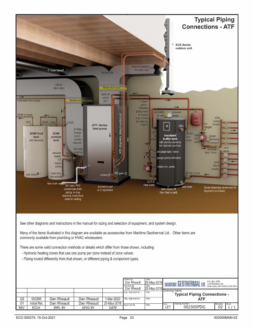
Piping ................................................................... 22 Indoor Loop Water Lines ..................................................................... 22 Condensate Drain ............................................................................... 22 Domestic Hot Water (Desuperheater) Connections ........................... 22 002305PDG - Typical Piping Connections - ATF ................................ 23 002366PDG - Recommended Buffer Tank Piping ............................... 24 002528PDG - Buffer Tank Piping - Multiple Units ............................... 25 002367PDG - Auxiliary Boiler Piping ................................................... 26 000530PDG - Typical Zone Types ...................................................... 27 001055PDG - Connection to On-Demand DHW Tank ........................ 28 000970PDG - Desup. Conn. to DHW Pre-Heat Tank .......................... 29 002384PDG - DHW Pre-Heat Tank - Multiple Units ............................ 30
Outdoor Unit Line Set ........................................ 31 Line Set Interconnect Tubing ............................................................... 31 Indoor Unit Connections ...................................................................... 31 Outdoor Unit Connections ................................................................... 31 Oil Traps .............................................................................................. 31 Filter-Dryer ........................................................................................... 31 Pipe Insulation .................................................................................... 32 Silver Soldering Line Sets .................................................................. 32 Pressure Testing ................................................................................ 32 Vacuuming the System ........................................................................ 32 Charging the System ........................................................................... 32 002250CDG - Typical Line Set Connections ....................................... 33
Table of Contents
Ductwork .............................................................. 34 Indoor Unit Blower Motor .................................................................... 34 Air Duct Zoning ................................................................................... 34 Duct Systems - General ...................................................................... 34 Duct Systems - Grill Layout ................................................................. 34 Thermostat Location ........................................................................... 34 Plenum Heater ..................................................................................... 34 002249PDG - Typical Duct & Condensate Connections ..................... 35 Duct Sizing Guide ................................................................................ 36
Operation ............................................................. 37 BACnet Control ................................................................................... 37 Air Thermostat Operation ................................................................... 37 Hydronic Temperature Control ........................................................... 37 1. Hydronic Heating: Setpoint Control ................................................ 37 Setpoint Control Method 1 - Indoor Loop (ICR) ............................ 37 Setpoint Control Method 2 - External HTS/CTS .......................... 37 Top Up S1 Function ..................................................................... 38 Summer Setback ......................................................................... 38 Outdoor Reset ............................................................................. 39 2. Hydronic Heating: Signals Control .................................................. 39
PC Application (PC App) .................................... 40
LCD Interface & Menus ....................................... 52
BACnet Interface .................................................. 54
Startup Procedure ............................................... 58 Startup Record .................................................................................... 60
Routine Maintenance .......................................... 61
Troubleshooting Guide ...................................... 62
Repair Procedures .............................................. 75 Pumpdown Procedure ........................................................................ 75 General Repair Procedure .................................................................. 75 Vacuuming & Charging Procedure ..................................................... 75 Compressor Replacement Procedure ................................................ 76 Outdoor Fan Replacement Procedure ................................................ 76 Control Board Replacement Procedure .............................................. 77 LCD Interface (Display) Board Replacement Procedure .................... 78
Model Specific Information ................................ 79 Shipping Information ........................................................................... 79 Refrigerant Charge ............................................................................. 79 Indoor Loop Flow Rates ...................................................................... 79 Operating Temperature Limits ............................................................ 79 Sound Levels (dBA) ............................................................................ 79 Pressure Drop Data ............................................................................. 80 Standard Capacity Ratings ................................................................. 80 Performance Tables ............................................................................ 81 Electrical Specifications ...................................................................... 89 Plenum Heater Electrical Specifications ............................................. 89 Indoor Airflow Data ............................................................................. 90 Wiring Diagram (208/230-1-60) .......................................................... 91 Electrical Box Layout (208/230-1-60) ................................................. 92 Wiring Diagram (208-3-60) ................................................................. 93 Electrical Box Layout (208-3-60) ........................................................ 94 Wiring Diagram (460-3-60) .................................................................. 95 Electrical Box Layout (460-3-60) ........................................................ 96 ACE (Outdoor Unit) Wiring Diagrams .................................................. 97 Refrigeration Circuit - Air Heating Mode .............................................. 98 Refrigeration Circuit - Air Cooling / Defrost Mode ................................ 99 Refrigeration Circuit - Hydronic Heating Mode .................................. 100 Dimensions ........................................................................................ 101
Appendix A: Control Board Description ..... 109
Appendix B: USB Driver Installation ............. 113
Appendix C: PC App Installation ................... 114
Appendix D: Updating Firmware ..................... 115
Warranty ........................................................................ 118

ECO 000275: 15-Oct-2021 Page 5 002000MAN-03
Tables & Documents Table 1 - Heat Pump Size vs. Heated Area .................................................................................................................... 8 Table 2 - Plenum Heater Sizing ..................................................................................................................................... 8 Table 3 - Power Supply Connections .......................................................................................................................... 14 Table 4 - Outdoor Unit Power Supply Connections ..................................................................................................... 14 Table 5 - Plenum Heater Signal Connections .............................................................................................................. 14 Table 6 - Indoor Loop Circulator Connections ............................................................................................................. 14 Table 7 - Control Transformer ..................................................................................................................................... 15 Table 8 - BACnet Connections .................................................................................................................................... 15 Table 9 - Setpoint Control: Aux. Connections .............................................................................................................. 15 Table 10 - Outdoor Unit Signal Connections ............................................................................................................... 16 Table 11 - Air Thermostat Connections ....................................................................................................................... 16 Table 12 - Aquastat Connections (Optional) ................................................................................................................ 16 Table 13 - Buffer Tank Size ......................................................................................................................................... 22 Table 14 - Line Set Sizing ............................................................................................................................................ 31 Table 15a - 3-way Service Valve Tooling .................................................................................................................... 31 Table 15b - 3-way Service Valve Torques ................................................................................................................... 31 Table 16 - Extra Charge for Model Sizes 25-45 .......................................................................................................... 32 Table 17 - Extra Charge for Model Sizes 55-75 .......................................................................................................... 32 Table 18 - Number of Air Grills .................................................................................................................................... 34 Table 19 - Duct Sizing Guide ....................................................................................................................................... 36 Table 20 - Typical Temperature Setpoints ................................................................................................................... 38 Table 21 - Maximum Output Temperature ................................................................................................................... 38 Table 22 - BACnet Objects - Control Signals (Read/Write) .......................................................................................... 54 Table 23 - BACnet Objects - Operation Mode Description (Read Only) ....................................................................... 54 Table 24 - BACnet Objects - Data (Read Only) ............................................................................................................ 55 Table 25 - BACnet Objects - Alarm Descriptions (Read Only) ..................................................................................... 56 Table 26 - BACnet Objects - Fault Descriptions (Read Only) ....................................................................................... 57 Table 27 - Shipping Information - Indoor Unit .............................................................................................................. 79 Table 28 - Shipping Information - Outdoor Unit ........................................................................................................... 79 Table 29 - Refrigerant Charge ..................................................................................................................................... 79 Table 30 - Indoor Loop Flow Rates ............................................................................................................................. 79 Table 31 - Operating Temperature Limits .................................................................................................................... 79 Table 32 - Outdoor Unit Sound Levels (dBA) .............................................................................................................. 79 Table 33 - Indoor Unit Sound Levels (dBA) ................................................................................................................. 79 Table 34 - Hydronic Loop Pressure Drop Data ............................................................................................................ 80 Table 35 - Standard Capacity Ratings - Air Heating (60 Hz) ....................................................................................... 80 Table 36 - Standard Capacity Ratings - Air Cooling (60 Hz) ....................................................................................... 80 Table 37 - Standard Capacity Ratings - Hydronic Heating (60 Hz) ............................................................................. 80 Table 38 - ATF-Series Electrical Specifications ........................................................................................................... 89 Table 39 - Plenum Heater Electrical Specifications ..................................................................................................... 89 Table 40 - Airflow Range for Stage 2 (Full Load) ........................................................................................................ 90 Table 41 - Airflow Range for Stage 1 (Part Load) ........................................................................................................ 90 Table 42 - Airflow Range for Stage 3 (Auxiliary) .......................................................................................................... 90 Table 43 - Airflow Range for Fan Recirculation ........................................................................................................... 90 Table 44 - Airflow Range for Emergency ..................................................................................................................... 90 Table 45 - Indoor Airflow Reduction for Outdoor Temperature ..................................................................................... 90 Table A1 - Control Board Connector Descriptions (Top) ............................................................................................ 110 Table A2 - Control Board Connector Descriptions (Left Side) .................................................................................. 110 Table A3 - Control Board Connector Descriptions (Bottom) ...................................................................................... 111 Table A4 - Control Board Connector Descriptions (Right Side) ................................................................................. 112 001915INF - Internal Plenum Heater Installation .......................................................................................................... 11 002071CDG - Typical Thermostat Connections to GEN2 Board .................................................................................. 17 002304CDG - Typical ATF Outdoor Unit, Auxiliary Heat, and Indoor Circulator Wiring ............................................... 18 002375QSS - AltSource Tanks: Getting Started .......................................................................................................... 19 002067CDG - Typical Zone and Auxiliary Wiring with GEN2 Setpoint Control (Heating Only) .................................... 20 002069CDG - Typical Zone and Auxiliary Wiring with GEN2 Hardwired Option (Heating Only) .................................. 21 002305PDG - Typical Piping Connections - ATF ......................................................................................................... 23 002366PDG - Recommended Hydronic Buffer Tank Piping ........................................................................................ 24 002528PDG - Buffer Tank Piping - Multiple Units ....................................................................................................... 25 002367PDG - Auxiliary Boiler Piping ........................................................................................................................... 26 000530PDG - Typical Zone Types for Hydronic Applications ....................................................................................... 27 001055PDG - Single Unit Connection to On-Demand DHW Pre-Heat Tank................................................................ 28 000970PDG - Desuperheater Connection to DHW Pre-Heat Tank ............................................................................. 29 002384PDG - Desuperheater Connection to DHW Pre-Heat Tank - Multiple Units .................................................... 30 002250CDG - Typical ATA/ATF to Outdoor Unit Line Set Connections ....................................................................... 33 002249PDG - Typical Duct & Condensate Connections ............................................................................................. 35 001956SCH - ATF-Series Schematic Diagram 208/230-1-60 ..................................................................................... 91 001957ELB - ATF-Series Electrical Box Diagram 208/230-1-60 ................................................................................. 92 001958SCH - ATF-Series Schematic Diagram 208-3-60 ............................................................................................ 93 001959ELB - ATF-Series Electrical Box Diagram 208-3-60 ........................................................................................ 94 001960SCH - ATF-Series Schematic Diagram 460-3-60 ............................................................................................ 95 001961ELB - ATF-Series Electrical Box Diagram 460-3-60 ........................................................................................ 96 001951SCH - ACE Outdoor Unit Schematic Diagram ................................................................................................. 97 002014SCH - ACE 4-Fan Outdoor Unit Schematic Diagram ...................................................................................... 97 001844RCD - ATF-Series Refrigeration Circuit - Air Heating Mode ............................................................................ 98 001845RCD - ATF-Series Refrigeration Circuit - Air Cooling / Defrost Mode ............................................................. 99 001846RCD - ATF-Series Refrigeration Circuit - Hydronic Heating Mode ................................................................ 100
Tables Documents

ECO 000275: 15-Oct-2021 Page 6 002000MAN-03
General Overview
The ATF-Series heat pump is an air source heat pump that can heat or cool via a forced air duct system, as well as heat water for hydronic application like in-floor heating.
Being an air source heat pump, it does not require a ground loop, instead using an outdoor fan unit to exchange heat with the outdoor air. Unlike most air source outdoor units on the market, this outdoor unit contains only an air coil, ECM hub mo-tor fan, expansion valve (EEV), and outdoor temperature sen-sor. The remaining components, including the compressor and all electronics, are located in the indoor unit. This has several advantages: minimal installation and service work must be per-formed outdoors, important components are in the conditioned space for longevity, antifreeze is not required in the hydronic loop, no electric compressor heater is required, and heating domestic hot water is possible (through a desuperheater circuit) since water lines are inside and will never freeze.
The air heating and cooling functions are controlled by a standard 3H/2C 24V room thermostat. The hydronic heating control is done by an internal routine that maintains the buffer tank temperature, without external sensors (’Setpoint Control’). BACnet or an external aquastat can also be used.
In additional to the main hydronic water heating function, there is a double-wall desuperheater for pre-heating domestic hot water with ~5% of the heat pump’s capacity. This function is only active when the heat pump is running for space heating or cooling purposes. An energy-efficient bronze head ECM circ pump for the desuperheater circuit is built in, along with a tem-perature control to turn the pump off when the DHW tempera-ture reaches 140°F (60°C).
A two-stage scroll compressor is standard. The outdoor air coil is e-coated for corrosion protection, and the coaxial hy-dronic heat exchanger is copper / steel with optional CuNi inner tube available. The cabinet is powder coated galvanized sheet metal. Control is overseen by the Nordic GEN2 programmable control board, which has many advanced features like laptop connectivity via the free PC App software, data logging & gra-phing, and real time readout from electronic temperature & pres-sure sensors. A premium electrically commutated (ECM) blow-er motor with adjustable airflow is standard. 1. Air Heating Mode
In air heating mode, heat is extracted from the outdoor air and transferred to the air duct system. This causes the air coil to eventually frost up to the point that a defrost cycle is required; refer to the Defrost Operation section below. Refrigerant flow is controlled by the EEV located in the outdoor unit while the EEV in the indoor unit is fully open.
If the outdoor temperature is above 34°F(1°C), the outdoor unit fan starts and stops when the heat pump starts and stops. If the temperature is below 34°F(1°C), the outdoor fan will re-main on at a very slow speed when the heat pump is off to mini-mize the chance of a fan freeze up, and to prevent snow from entering the unit. The outdoor fan will slowly ramp up to the required speed upon start.
Auxiliary Air Heat
An electric resistance plenum heater, placed inside the heat pump but ordered separately, is required. This is because the capacity of air source heat pumps fall as the outdoor tem-perature drops and the heating load increases. This output re-duction can be seen in the performance charts later in this man-ual, and is common to all air source heat pumps. The plenum heater will be sized to satisfy all of the heat load if the outdoor
ATF System Description temperature falls below the minimum for heat pump operation: -7°F (-22°C).
A second important function of the plenum heater is to provide heat to the indoor air steam during defrost mode (described below), to avoid cold air blowing into the space.
The room air thermostat controls when the plenum heater is activated, normally due to a drop in the room temperature. The heater is installed inside the indoor unit, unless the blower is installed in the side discharge position, in which case it is in-stalled in the air discharge ductwork outside the heat pump.
Defrost Operation
The heat pump has an advanced defrost control algorithm, using outdoor temperature and suction pressure to determine when a defrost cycle should occur and how long it should be. Precise fan control allows the defrost heat to rise quickly and then be maintained at a setpoint for quick defrosting.
The outdoor unit has a unique physical arrangement for combatting the ice build up that is a common problem with air source heat pumps. The air coil is installed on a 15° angle and the area below the coil is open (no drip tray). The angle causes the melting frost/snow to run down the back of the coil to a sin-gle point of runoff rather than along the entire bottom side of the coil. It is not possible for runoff to remain between coil pipes and re-freeze between them, which a common cause of air coil failure in air source heat pumps. 2. Hydronic (Water) Heating Mode
In hydronic heating mode, the heat pump heats hot water in the buffer tank. EEV, outdoor fan, and defrost operation are the same as in air heating mode.
Auxiliary Hydronic Heat
Optionally, hydronic auxiliary heat may be installed, to keep the floor warm no matter what the outdoor temperature. This can consist of electric elements in the buffer tank, or an existing boiler may be retained and piped in parallel with the heat pump.
Auxiliary hydronic heat will be controlled by the heat pump via dry contacts. Buffer tanks with elements rated for space heating duty are available as accessories.
3. Air Cooling Mode
In air cooling mode, heat is extracted from the air duct system and rejected to the outdoor air. Refrigerant flow is con-trolled by the EEV located in the indoor unit while the EEV in the outdoor unit is fully open. There is no defrost cycle in cooling mode.
The outdoor fan is controlled based on the discharge pres-sure and will slowly ramp up to the required speed when the system starts. During operation, the fan speed will automatical-ly adjust up or down to in order to maintain the discharge pres-sure setpoint value. Two stage units will drop down to the first stage to reduce the discharge pressure at very high outdoor temperatures.
Factory Options
Looking at the main service panel, the indoor unit can be ordered as a left or right hand air return from the factory. This must be specified at time of order as the physical construction of the two configurations is different. See Installation Basics chap-ter.

ECO 000275: 15-Oct-2021 Page 7 002000MAN-03
Mode and Priority Selection
The heat pump can be set to Air or Hydronic priority. Units are shipped set up for air priority. This is often a good setting, since drops in the household air temperature normally occur sooner if there is a lag in the ducted air system than if there is a drop in the hydronic water temperature.
However, if there is only an auxiliary air plenum heater installed (no hydronic auxiliary heat), the heat pump can be set to hydronic priority, so that the heat pump will heat in-floor water first and any shortfall in heating capacity on cold days will be covered by the air plenum heater.
Whenever there is a stage 1 demand from both the air thermostat and aquastat, the unit steps up to stage 2 of the pri-ority mode in order to satisfy the priority demand quickly and get to the non-priority mode. If this functionality was not present, the unit could run in stage 1 of the priority mode (67% compres-sor capacity) for a long time with a ‘call waiting’, allowing the overall supply of heat to the building to fall behind the load.
SINGLE MODE OPERATION:
If there is only one mode being called for, the unit operates in the mode and stage that is called for.
SIMULTANEOUS DEMANDS - AIR PRIORITY:
If there is a call for: both stage 1 air and stage 1 hydronic
both stage 2 air and stage 1 hydronic
both stage 1 air and stage 2 hydronic both stage 2 air and stage 2 hydronic
The unit operates in air mode in stage 2.
SIMULTANEOUS DEMANDS - HYDRONIC PRIORITY:
If there is a call for: both stage 1 air and stage 1 hydronic
both stage 2 air and stage 1 hydronic
both stage 1 air and stage 2 hydronic both stage 2 air and stage 2 hydronic
The unit operates in hydronic mode in stage 2.
* See Piping chapter for an annotated copy of this diagram

ECO 000275: 15-Oct-2021 Page 8 002000MAN-03
ATF Sizing
This is an estimate of which unit size is required for a typi-cal two-level home (main level and below grade basement) with R-20 walls, R-40 ceiling and average size and number of win-dows. The Heated Area is the area of the main level. The table accounts for a basement the same size as the heated area.
It is highly recommended that a heat loss/gain analy-sis be performed by a qualified person with software using the CSA F-280 or Manual J methods before selecting a heat pump size. The analysis will result in a heat load for the cold-est day, which is influenced by, for example, the number of lev-els, the size of the windows, the orientation of the home, at-tached garage, bonus rooms, walk-out basement, and coldest outdoor temperature for the region.
In northern climates, a heat pump model size can be se-lected by matching the calculated heat load to the heat pump’s heating capacity at an outdoor temperature of 35°F (1.7°C) and an indoor water temperature of 105°F (40.5°C) for concrete in-floor heating or 120°F (49°C) for other heating types. These numbers can be found in the detailed performance tables in the Model Specific Information section later in this manual. This sizing will result in a good compromise between covering as much of the cold weather heat load as possible without utiliz-ing backup heat, while minimizing excessive cycling (turning on and off frequently) during moderate outdoor temperatures.
It should be noted that sizing an air source heat pump is always a compromise between covering coldest-day heat load and minimizing cycling due to over-capacity in warm weather.
In cooling dominant climates, the heat pump should be similarly sized, by matching the calculated cooling load to the standard capacity rating at an outdoor temperature that matches the local maximum outdoor temperature. The difference here is that it is necessary to cover all of the cooling load, since there is no backup cooling.
Air Source Heat Pumps
Since it is harder to extract heat from colder outdoor air, any air source heat pump will have its lowest heating capacity on cold days when building heat load is the highest. It is not generally possible to oversize an air source heat pump to cover 100% of the coldest day heat load, since this would mean ex-cessive compressor short-cycling during moderate outdoor weather when heat pump capacity is much higher and heat load is much lower, and also poor dehumidification during cooling mode.
Therefore, it should be expected that any air source heat pump will need auxiliary heat on the coldest days. An air side plenum heater is required; see reasons in previous chapter. Hydronic side auxiliary can also be implemented (tank elements or auxiliary boiler). Heat Pump Sizing
The table shows the size of home each air source heat pump model size is generally suitable for, in northern climates.
TABLE 1 - Heat Pump Size vs. Heated Area
Model sq.ft. m2
45 1,400 130
55 2,000 185
65 2,600 240
75 3,100 290
Plenum Heater Sizing
The required plenum heater is available as an accessory in 5, 7, 10, 15 and 20kW sizes. Choose a size that covers 100% of the coldest day heat load, according to the heat loss analysis mentioned in the last section. If that is not availa-ble, use the following recommendation: TABLE 2 - Plenum Heater Sizing
Model Plenum Heater Size (kW)
Recommended Internally Possible 45 10 5, 7, 10
55 10 5, 7, 10, 15, 20
65 15 5, 7, 10, 15, 20
75 20 5, 7, 10, 15, 20
Two styles of plenum heater are available; the first is for internal installation (inside the indoor unit). Note limit for size 45 in above table.
The second has a wider element profile for installation outside the unit, in the ductwork. If field-installing the fan in the convertible side discharge position, this type of plenum heater will need to be used.
Even in northern heating dominant climates, it should be ensured that 100% of the cooling load will be covered when sizing the heat pump.

ECO 000275: 15-Oct-2021 Page 9 002000MAN-03
Installation Basics Unpacking the Unit
When the 2-piece heat pump reaches its destination it should be unpacked to determine if any damage has occurred during shipment. Any visible damage should be noted on the carrier's freight bill and a suitable claim filed at once.
Indoor Unit Placement
Ducted or forced air heat pumps should be centrally located in the home with respect to the conditioned space. This provides the best in economy and comfort and usually can be accomplished in harmony with the design of the home. A heating system cannot be expected to produce an even temper-ature throughout the building when it is located at one end of the structure and the heated or cooled air is transmitted with uninsulated metal ductwork.
If possible the front access panel and side access panel opposite the air return should remain clear of obstruction for a distance of 2 ft (0.7 m) to facilitate servicing and general maintenance. No access is required on the back side. Ensure the unit is level to eliminate any possible condensate draining issues.
The heat pump comes equipped with an air filter rack which can be installed with the removable end (where the filter is in-serted) on either side to facilitate changing the filter. Be careful not to run piping in front of the filter rack access cover, since access is required in order to change the air filter.
Raising the indoor unit off the floor a few inches is generally a good practice since this will prevent rusting of the bottom panel of the unit and deaden vibrations. An anti-vibration pad, available as an accessory, or a piece of 2” styrofoam should be placed under the unit.
Placement of Tanks
See ATF System Description and Piping chapters for ex-ample placements of the hydronic buffer tank and domestic hot water preheat and final tanks.
WARNING: Pool chemicals should be stored in a different room from the PC unit to pre-vent premature corrosion problems.
WARNING: Pool chemicals should be inject-ed downstream of the PC unit.
Sample Bill of Materials Although not exhaustive, following is a list of materials needed for a typical installation: FROM MARITIME GEOTHERMAL • ATF SERIES HEAT PUMP (L OR R RETURN)
W/ACE OUTDOOR UNIT • PLENUM HEATER __kW • AIR THERMOSTAT (WIFI OR STD) • SHIELDED 18-8 WIRE FOR OUTDOOR UNIT • BUFFER TANK W/ELEMENTS __kW OPTIONAL FROM MARITIME GEOTHERMAL • ANTI-VIBRATION PAD FOR UNDER UNIT • SOUND JACKET • COMPRESSOR SECURE START • ELECTROSTATIC (CLEANABLE) AIR FILTER DUCTWORK • OUTLET PLENUM ADAPTER W/ FLEXIBLE COLLAR • RETURN AIR ADAPTER W/ FLEXIBLE COLLAR • FIBREGLASS INSULATION (FOR NOISE, IF REQ’D) • TRUNK DUCT W/ JOINERS (IF NOT EXISTING) • 6” ROUND DUCT W/ADAPTERS (IF NOT EXISTING) • ALUMINUM TAPE • SHEET METAL SCREWS DHW: • PREHEAT TANK, 40 OR 60 GAL • ½” COPPER PIPE • ½” FITTINGS, BALL VALVES, BOILER DRAINS, CV ELECTRICAL • HEAT PUMP SERVICE WIRE: 6-2/3 OR 8-2/3 • PLENUM HEATER SERVICE WIRE • 14-2 OUTDOOR RATED WIRE W/ DISCONNECT
SWITCH FOR OUTDOOR UNIT • HEAT PUMP BREAKER • PLENUM HEATER BREAKER • THERMOSTAT WIRE 18-8 • THERMOSTAT WIRE 18-3 (PLENUM HEATER) • FORK TERMINALS FOR TSTAT WIRE (6) • CONDENSATE PUMP & HOSE (IF REQUIRED) REFRIGERATION • 1/2” & 7/8” (OR 3/8” & 3/4”) ACR TUBING • PIPE ISULATION • EXTRA R410A REFRIGERANT FOR LINESETS >25 FT HYDRONIC ZONES • CIRCULATOR: HEAT PUMP TO TANK • 1” PIPE & FITTINGS: HEAT PUMP TO TANK • ZONE CIRCULATOR(S) • ZONE TRANSFORMER & CIRC CONTACTOR • ZONE VALVES (IF NOT INDIVIDUAL PUMPS) • IN-FLOOR PIPING • ZONE THERMOSTATS • RELAYS OR ZONE CONTROLLER • ZONE SUPPLY & RETURN HEADERS: 1” COPPER PIPE & FITTINGS
• PIPE & FITTINGS TO ZONES • EXPANSION TANK • 2” STYROFOAM INSUL. (IF PAD NOT PURCHASED)
ECO 000275: 15-Oct-2021 Page 10 002000MAN-03
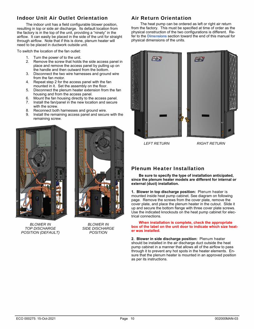
Indoor Unit Air Outlet Orientation
The indoor unit has a field configurable blower position, resulting in top or side air discharge. Its default location from the factory is in the top of the unit, providing a “ninety” in the airflow. It can easily be placed in the side of the unit for straight through airflow. Note that if this is done, plenum heater will need to be placed in ductwork outside unit.
To switch the location of the fan outlet:
1. Turn the power of to the unit. 2. Remove the screw that holds the side access panel in
place and remove the access panel by pulling up on the handle and then outward from the bottom.
3. Disconnect the two wire harnesses and ground wire from the fan motor.
4. Repeat step 2 for the access panel with the fan mounted in it. Set the assembly on the floor.
5. Disconnect the plenum heater extension from the fan housing and from the access panel.
6. Mount the fan housing directly to the access panel. 7. Install the fan/panel in the new location and secure
with the screw. 8. Reconnect both harnesses and ground wire. 9. Install the remaining access panel and secure with the
remaining screw.
Air Return Orientation The heat pump can be ordered as left or right air return
from the factory. This must be specified at time of order as the physical construction of the two configurations is different. Re-fer to the Dimensions section toward the end of this manual for physical dimensions of the units.
LEFT RETURN RIGHT RETURN
BLOWER IN TOP DISCHARGE
POSITION (DEFAULT)
BLOWER IN SIDE DISCHARGE
POSITION
Plenum Heater Installation
Be sure to specify the type of installation anticipated, since the plenum heater models are different for internal or external (duct) installation.
1. Blower in top discharge position: Plenum heater is mounted inside heat pump cabinet. See diagram on following page. Remove the screws from the cover plate, remove the cover plate, and place the plenum heater in the cutout. Slide it up and secure the bottom flange with three cover plate screws. Use the indicated knockouts on the heat pump cabinet for elec-trical connections.
When installation is complete, check the appropriate box of the label on the unit door to indicate which size heat-er was installed.
2. Blower in side discharge position: Plenum heater should be installed in the air discharge duct outside the heat pump cabinet in a manner that allows all of the airflow to pass through it to prevent any hot spots in the heater elements. En-sure that the plenum heater is mounted in an approved position as per its instructions.

ECO 000275: 15-Oct-2021 Page 11 002000MAN-03

ECO 000275: 15-Oct-2021 Page 12 002000MAN-03
Outdoor Unit Placement The ACE unit must be placed outdoors, with the fan point-
ing away from the building. It should be mounted where mois-ture or ice under the unit will not be considered to be unsightly, as might be the case on a paved walkway to the front door for example.
For ACE-65/75, there is a detachable cover for the piping and wiring which automatically places the unit 12 inches (30 cm) away from the building, which is the recommended spacing. If necessary, the unit can be placed 8 inches (20 cm) from the building: the cover can be shortened by cutting the tabs and removing one section. Be aware that if mounted at less than 12 inches from building, there is a risk of frost forming on the wall during defrost under certain conditions. Be sure there are no obstructions around the perimeter of the back, so that return airflow is unimpeded.
There should be little or no obstruction in the fan (front) direction for at least 10 ft (3 m), and preferably 16 ft (5 m), other-wise airflow and therefore overall performance will be reduced.
In addition, there should be at least two feet (0.6 m) of clearance on the electrical box and refrigeration piping side of the unit to facilitate servicing and general maintenance.
The outdoor unit must be bolted down to prevent a tipping hazard. See next section.
Note that no field installed filter-dryer is required.
Leg Kit Installation
Outdoor Unit Mounting Height The outdoor unit must remain clear of snow and ice at all
times. Good performance depends on good airflow, which of course cannot be achieved if the unit is buried in snow and re-frozen defrost condensate.
There are several ways to accomplish this. First, look up how much snowfall is expected in your area, either from local knowledge or weather data. The snowfall map included on next page can be used as a rough guide for Canada.
1. If there is less than ~4” (10 cm) of snow accumulation expected, the unit could be mounted directly on a con-crete pad. This is not recommended in cold climates, since ongoing care would be required to ensure re-frozen condensate does not build up under unit.
2. The unit can be mounted on angle brackets attached to the side of a building. Be sure to adhere to the minimum clearance requirement of 8-12” (20-30 cm), and use brackets designed for twice the unit weight.
3. Two leg kits which add either 15” (38 cm) or 30” (76 cm) of additional height are available as an acces-sory. For ATWC-65 and larger which use a larger outdoor unit, only the shorter leg kit is available.
To attach the legs:
ACE-25/45/55 - first remove the three bolts with flat washers that hold each foot plate in place. Leaving the foot plate in place on the inside of the cabinet panel, slide the leg over the outside of the panel and re-install the three bolts and flat washers.
ACE-65/75 -slide the leg over the outside of the two existing cabinet legs and affix with the kit’s three SS bolts and flat wash-ers.
Whether or not a foot kit is used, be sure to mount the unit using the 4 rubber grommets included with the unit, to dampen any vibration. The unit must be fastened to its mounting surface with four bolts through these grommets to prevent a tipping hazard due to impact or high wind.
IMPORTANT NOTE: The line set between the indoor and outdoor units must not exceed 70 ft (21 m) in length.
Outdoor Fan Speed Reduction Should fan noise be a concern, for example if the outdoor
unit is mounted near a frequently open window, the outdoor fan speed can be reduced (up to a maximum of 25%). This should only be done if necessary, since a small loss in efficiency will result.
The fan speed can be reduced via the LCD (see LCD In-terface & Menus section) or PC App (see PC Application section).
Outdoor Unit Fan Orientation
piping & wiring
connections inside unit

ECO 000275: 15-Oct-2021 Page 13 002000MAN-03
Average Maximum Snow Depth - Canada (1979-1997) Source: Natural Resources Canada

ECO 000275: 15-Oct-2021 Page 14 002000MAN-03
Wiring
IMPORTANT NOTE: A properly qualified electrician should be retained for all connections to the heat pump and associat-ed controls. The connections to the unit MUST CONFORM TO LOCAL CODES.
TABLE 3 - Power Supply Connections
Line Description Voltages
L1 Line 1 All
L2 Line 2 All
L3 Line 3 3-phase only
GND Ground All (connect to ground lug)
* Only required if connecting 115VAC circulators.
N Neutral 208/230-1-60*, 208-3-60*, 460-3-60, 380-3-50
Indoor Unit Power Supply Connections
Power supply for the heat pump from the breaker panel is supplied to the indoor unit. The unit has a concentric 1.093” / 0.875” knockout for main power supply connection to the electri-cal box. There are also two 7/8” knockouts and a 1/2” opening with plastic grommet (grommet hole is 3/8”) for connections to the air thermostat, indoor loop circulator, optional aquastat, and power and signal connections to the outdoor unit.
A schematic diagram (SCH) and electrical box layout diagram (ELB) can be found on the electrical box cover of the unit as well as in the Model Specific Information section of this manual. The Electrical Tables in the Model Specific Information section contain information about the wire and breaker size.
Indoor Loop Circulator Pump Wiring The indoor unit has provisions for connecting the indoor
circulator pump (between the heat pump and buffer tank) so that it will be turned on whenever the compressor operates. Con-nect the circulator pump module to the appropriate two terminals (115V & 115/230 or 230V & 115/230) of the terminal strip marked Indoor Circulator Pumps. Ground wires should be con-nected to the ground lug in the electrical box. Ensure that the total current draw does not exceed the value indicated on the label in the heat pump electrical box.
For 460VAC models, only 277VAC circulators may be powered directly from the heat pump. If other voltage circulators are used, they must be powered using an external contactor actuated by the ICR terminal on the left side of the control board and the C (24V ground) terminal.
TABLE 6 - Indoor Loop Circulator Connections
Signal Description
115V
230V
Use a 2-conductor 14ga cable.
Connection for 115V circulator
Connection for 230V circulator
115/230 Connection for 115V or 230V circulator
TABLE 4 - Outdoor Unit Power Supply Connections
Line Description
L1 Supply line
L2 Supply line
GND Ground
Use a 2-conductor outdoor rated 14ga cable.
IMPORTANT NOTE: According to most codes, a disconnect switch visible and/or reachable from the outdoor unit must be in-stalled in the power supply cable. If the switch has fuses or breakers they must be no more than 10A.
Outdoor Unit: Power Connections The ACE outdoor unit is powered from the indoor unit.
The power supply for the ACE unit is 208 to 277VAC, 50/60Hz. The ATF and ACE units have matching terminal strips for these connections. Use a two conductor, minimum 14ga outdoor rat-ed cable for this connection. Refer to diagram.
Plenum Heater: Power Connections Auxiliary air heat will usually be provided by an electric
duct heater (plenum heater). These are available as accesso-ries in 5, 7, 10, 15, and 20 kW sizes, and are installed as previ-ously noted in this manual. The plenum heater will have its own breaker and power supply wire. The Electrical Tables in the Model Specific Information section contain information about the size of wire for the connections, as well as the recommend-ed breaker size.
Plenum Heater: Signal Connections The ATF unit has two dry contacts to control the 2 stages
of the plenum heater. These dry contacts can also be used to control other types of auxiliary air heat. Note that dry contacts are intended to activate equipment that has its own 24VAC transformer; if equipment does not have its own transformer, one will need to be installed in an external electrical box.
Connect the terminals on the ATF’s terminal strip to the matching terminals on the plenum heater’s control board using an 18-3 cable.
TABLE 5 - Plenum Heater Signal Connections
Signal Description
CP Common
1
2
Use a 3-conductor 18ga cable.
Dry contact for auxiliary heat stage 1
Dry contact for auxiliary heat stage 2
OUTDOOR DISCONNECT SWITCH IS A SAFETY DEVICE ONLY. Turn off breaker to indoor unit before servicing to avoid costly damage to electronic control board.
IMPORTANT NOTE FOR 3-PHASE UNITS: If on startup compressor is noisy and not pumping, reverse L1 and L2 supply wires.
Disable Switch (field installed) A switch to disable demand from the control system may
be installed. On control board, jumper COM_IN to GND, and toggle 12VDC to IN_SPARE to disable. See the main wiring diagram in the Model Specific Information section.

ECO 000275: 15-Oct-2021 Page 15 002000MAN-03
BACnet Connections If using BACnet for external control of heating/cooling de-
mand and/or monitoring of status, use a shielded twisted pair to the connector at the bottom left of control board. There is an optional termination jumper located above the connector.
See the BACnet Interface section for details.
TABLE 8 - BACnet Connections
Line Description
A Communication + B Communication -
GND Ground
Use a shielded twisted pair cable.
Control Transformer
The low voltage controls, including the control board, are powered by a 100VA class II transformer. 208/230-1-60 and 208-3-60 models have a resettable breaker on the secondary side for circuit protection. If the breaker trips, locate and correct the problem and then reset the breaker by pressing in on it.
All other voltage models have primary and secondary fus-es for circuit protection.
IMPORTANT NOTE: For 208/230VAC-1-60 units, if connecting to 208VAC power supply move the red wire connected to the 240 ter-minal of the transformer to the 208 terminal of the transformer.
Setpoint Control (Hydronic Control) Connections
If using the on-board Setpoint Control routine with sam-pling to control buffer tank temperature, no external temperature probe or aquastat is required.
Note that an external buffer tank temperature sensor may be used to replace the internal water OUT line temperature sen-sor for use with the Setpoint Control routine. This is called Ex-ternal HTS/CTS Setpoint Control. See Operation chapter.
TABLE 9 - Setpoint Control: Aux. Connections
Signal Description
C 24VAC common (ground)
1A Hydronic Auxiliary (hot)
D1 Hydronic Auxiliary dry contacts
D2
Use a 2-conductor 18ga cable.
Setpoint Control: Aux. Connections When using Setpoint Control, there are 2 methods for acti-
vating hydronic auxiliary heat. See diagram on a following page.
First, a 24VAC signal on terminal 1A (with C as ground/common) is available to power the coil of an external contactor to operate hydronic auxiliary heat. Choose this method if using a heating device that doesn’t have its own electronic controller or control transformer, e.g. a bare heating element in the buffer tank. This signal can provide a maximum of 500mA at 24VAC. 1A defaults to OFF when heat pump is powered off.
Second, a dry contact on terminals D1 and D2 is available, to actuate a heating device that has its own controller and trans-former. In general, these types of devices will have their own electronic temperature controller. Connection will be made to that device’s E-E terminals or similar. D1-D2 defaults to ON when heat pump is powered off. Therefore, it is necessary to set the temperature control on the external heating device to a limiting value, e.g. 125°F, and adjust its settings so it is only activated by the heat pump’s controller. This method should be used for the Thermo2000 AltSource tank that is available from Maritime Geothermal as an accessory; see the setup instruction sheet that comes with tank and on following page.
D1-D2 defaults to ON and so must be used with an auxiliary heating device that has a HIGH TEM-PERATURE LIMITER to avoid a serious safety hazard.
If it is not desired to have D1-D2 default to ON when heat pump is powered off, make the following wiring changes in the heat pump’s electrical box, while referring to the Wiring/Schematic diagram in the Model Specific Information chap-ter. Find the light brown wire connected between terminal strip
terminal D1 and the Elec. Aux. Relay. Move it from pin 5 to pin 2 of the relay.
Find the purple wire connected between the left side of the control board and the Elec. Aux. Relay. Move if from termi-nal L4 (NOT_HYD_AUX) to DO_2 (HYD_AUX) on the con-trol board. [It will share DO_2 with a brown wire.]
Now D1-D2 will work as before, but will default to OFF when heat pump is off.
High Temperature Hydronic Auxiliary Heat
If using a high temperature hydronic auxiliary device that can only be activated when heat pump compressor is off (for example because the outdoor temperature is too cold), an SPDT relay may be connected to provide a dry contact for high temperature device activation by the heat pump’s control board.
Refer to diagram 002304CDG on a following page and wiring/schematic diagram in the Model Specific Information sec-tion. Connect the external relay’s coil (normally relay pins 1 and 3) to DO_3 (AUX ONLY) and LC at the left side of control board.
Then use the COM and NC relay contacts (normally pins 4 and 5) to enable the high temperature heating device when the DO_3 (AUX_ONLY) pin is off, meaning compressor is off and auxiliary heat is being called for.
Airflow Reduction for Zoning For air zoning, airflow may be reduced by a switch or dry
contact using the connections on the right side of the control board. The dry contact may be from a relay and interconnected thermostats, or more commonly a zone controller.
The default reduction is 15%, but it may be adjusted from 5%-20% using the View-->Indoor Fan window in the PC App. See PC Application chapter. For airflow values including the reduction, see the Indoor Airflow Data table in the Model Specific Information chapter.
TABLE 5 - Control Transformer
Voltage Low Voltage Circuit Protection
(1) 208/230-1-60 Resettable breaker on transformer
(2) 208-3-60
(4) 460-3-60 (6) 220-1-50
(7) 380-3-50 Primary / Secondary fuses

ECO 000275: 15-Oct-2021 Page 16 002000MAN-03
TABLE 11 - Air Thermostat Connections
Signal Description
C 24VAC common (ground)
R 24VAC hot
G Fan low speed (for air recirculation)
Y1 Compressor ON (part load)
Y2 Compressor bump up to stage 2 (full load)
W2 Heating stage 3 (plenum heater)
O Cooling mode (reversing valve)
E Emergency heat (plenum heater)
L Fault (24VAC when fault condition)
AR Airflow reduction: connect AR1 to AR2 with a dry contact to reduce the airflow for zoning. Con-nections located on control board. 24VAC
TABLE 12 - Aquastat (Signals Control) Connections
Signal Description
C/CA 24VAC common (ground)
R/RA 24VAC hot
Y1A Compressor ON (part load)
Y2A Compressor bump up to stage 2 (full load)
Air Thermostat Connections A three-stage heating and two stage cooling heat pump
configurable thermostat is required. The stages are S1 = stage 1 compressor, S2 = stage 2 compressor and S3 = electric auxil-iary (in heating mode only). One can be ordered with the unit, or other heat pump thermostats with the same number of stages can be used. The air thermostat connections are located on a terminal strip in the indoor unit. Refer to diagram on a following page for connections between the thermostat and the heat pump.
The airflow can be reduced by an adjustable amount be-tween 5 and 20% (value set in PC App) by making a dry contact across 24VAC and AR on the right side middle terminal strip of the control board. This can be used for applications that have multiple air zones.
Care should be taken to ensure that the unit does not trip a safety control in heating or cooling mode if the AR reduction is used in conjunction with lower air flow settings.
Aquastat Connections (Optional) Most installations will use the internal Setpoint Control
routine to control buffer tank temperature, in which case no aq-uastat is required. However, an aquastat or aquastats can be used if required, for example if heating two loops with different setpoint temperatures. This is called Signals Control.
The wiring connections are at the top right of the ATF’s control board, on the screw terminal connector section marked AQUASTAT. This is shown on the wiring (SCH) diagram in the Model Specific Information section. The external device needs to send the 24VAC signal from RA back to the Y1A and Y2A terminals to call for the two stages of hydronic heating. C or CA is the common or ground terminal for powering the external device.
Outdoor Unit: Signal Connections The speed of the fan and the heating mode expansion
valve (EEV) in the outdoor unit are controlled by the control board in the indoor ATF unit, and a temperature sensor is read. Therefore, communication wiring is required.
Connect the supplied 8 conductor shielded outdoor rated cable between the terminal strips in the indoor and outdoor units. The shield ground wire is connected only to the indoor unit; do not connect the shield ground to the outdoor unit (there is no terminal for it). Cut the shield ground wire short at the cable sheath in the outdoor unit.
TABLE 10 - Outdoor Unit Signal Connections
Signal Description
EEVR Electronic Expansion Valve (Red)
EEVG Electronic Expansion Valve (Green)
EEVW Electronic Expansion Valve (White)
EEVB Electronic Expansion Valve (Black)
TR Outdoor Temperature Sensor (Power)
TG Outdoor Temperature Sensor (Signal)
TB Outdoor Temperature Sensor (Ground)
PWM+ Outdoor Fan Control
Shield GND* Shielded cable ground wire
* Connect only to the indoor unit. In the outdoor unit, leave this wire unconnected and cut it short at the cable sheath.
Domestic Hot Water (Desuperheater) The desuperheater function for domestic hot water heating
is pre-wired and no field connections are necessary.
After the desuperheater is filled with water and purged of air, activate the built-in DHW circulator by connecting the brown wire with the blue insulated terminal to L1 of the compressor contactor as shown on the wiring diagram in the Model Specific Information section. Ensure the power is off when connect-ing the wire. Also, turn on the DHW ON/OFF switch.
Defrost Indicator (field installed) A 24VAC signal is available for an externally installed
indicator, which is active when the heat pump is in defrost mode. This may be useful for the building operator or home-owner, to know when buffer tank is being cooled instead of heat-ed.
The indicator may be installed between terminals SH and C(SH) at the lower left side of control board.
AVOID INSULATION NICKS ON INDIVIDUAL OUTDOOR UNIT SIGNAL WIRES
SLICE A LINE ALONG WIRE SHEATHING TO-WARDS THE END, THEN PULL IT AWAY FROM THE WIRES BEFORE CUTTING OFF.
DO NOT CUT A CIRCLE WITH UTILITY KNIFE BEFORE SEPARATING SHEATHING FROM BUN-DLED SIGNAL WIRES.

ECO 000275: 15-Oct-2021 Page 17 002000MAN-03

ECO 000275: 15-Oct-2021 Page 18 002000MAN-03

ECO 000275: 15-Oct-2021 Page 19 002000MAN-03

ECO 000275: 15-Oct-2021 Page 20 002000MAN-03

ECO 000275: 15-Oct-2021 Page 21 002000MAN-03

ECO 000275: 15-Oct-2021 Page 22 002000MAN-03
Indoor Loop Water Lines The connections for the Indoor Loop circuit are 1”
brass FNPT. They are labelled as INDOOR IN and INDOOR OUT. The ports are located on the front of the unit.
Recommended buffer tank piping is shown in diagrams on following pages. They show all of the recommended compo-nents as well as where they should be placed. If other types of components are used or connected differently, this is done at user’s discretion with the caution that heat pump may or may not work properly. NOTE: It is recommended that the water lines between the heat pump and the buffer tank be copper or other high tempera-ture piping. NOTE: Care should be taken when routing the water lines to ensure that adequate access to the heat pump is maintained so as to not compromise ease of serviceability.
The minimum buffer tank size should follow the rule of 8 US gallons per ton of heat pump capacity. The following table shows the minimum buffer tank size for each heat pump along with the recommended size. The recommended size will mini-mize the number of starts per hour and provide longer runtimes for improved efficiency.
Piping
TABLE 13 - Buffer Tank Size
Heat Pump Size Minimum Size gallons (Litres)
Recommended Size gallons (Litres)
45 24 (91) 50 (190)
55 32 (121) 70 (265)
65 40 (151) 70 (265)
75 48 (182) 70 (265)
If a tank size is not available, use the next size larger tank.
Condensate Drain
The unit comes equipped with one 3/4” female PVC socket drain connection. This drain allows the condensate which forms during the air conditioning cycle to be removed from the unit. The drain should be connected and vented as per local codes. During high humidity weather, there could be as much as 25 gallons of water formed per day.
The condensate drain is internally trapped and does not require an external trap. An external condensate pump may be installed if there is not sufficient slope to drain condensate under gravity to its destination.
To avoid overflow of the condensate pan, the drain line and trap should be inspected periodically to ensure they are not plugged with accumulated debris. There may be an alarm for condensate overflow, which will disable unit operation.
See also the Ductwork section for a diagram showing con-densate drain connection.
Domestic Hot Water (Desuperheater) Connections
The connections for the DHW circuit are 1/2” brass FPT fittings. They are marked as DHW IN and DHW OUT.
A typical piping diagram for a pre-heat tank configuration
can be found in document 000970PDG at the end of this sec-tion. Be sure to note the position of the check valve and the direction of water flow. Other configurations are possible, and there may be multiple units tied together in larger buildings.
Ensure the tank is filled with water and under pressure before activating the built-in DHW circulator as described below. First, slightly loosen the boiler drain on the DHW Out pipe to allow air to escape from the system. This step will make certain that the domestic hot water circulator in the unit is flooded with water when it is started.
Activate the built-in DHW circulator by connecting the brown wire with the blue insulated terminal to L1 of the com-pressor contactor. Ensure the power is off when connecting the wire. Once connected the DHW switch on the front of the unit may be used to enable/disable the domestic hot water circu-lator.
The DHW loop may have to be purged of air several times before good circulation is obtained. A temperature difference between the DHW In and DHW Out can be felt by hand when the circulator pump is operating properly.
For the pre-heat tank setup, the final tank should be set to 140°F (60°C), which is required by most codes. The pre-heat tank does not require electric elements. This setup takes full advantage of the desuperheater as it is the sole heat provid-er to the pre-heat tank. The desuperheater remains active dur-ing the compressor runtime until the pre-heat tank has been completely heated by the desuperheater alone. This setup is more energy efficient than a single tank setup, and eliminates the possibility of reverse heating of the refrigerant gas under low condensing temperature operating conditions.
WARNING: USE ONLY COPPER LINES TO CONNECT THE DESUPERHEATER. TEMPERA-TURES CAN BE >200°F NEAR THE UNIT WITH DESUPERHEATER TURNED OFF, POTENTIALLY MELTING & RUPTURING PLASTIC PIPING.
CAUTION: the domestic hot water pump is water lubricated; damage will occur to the pump if it is run dry for even a short period of time.
CAUTION: If two (2) shut-off valves are located on the domestic hot water ines as shown in the diagram, a pressure relief valve must be in-stalled to prevent possible damage to the do-mestic hot water circulator pump should both valves be closed.
Note that connection and use of the desuperheater is op-tional, and there is no problem for the heat pump if desuperheat-er is left unconnected.
ECO 000275: 15-Oct-2021 Page 23 002000MAN-03

ECO 000275: 15-Oct-2021 Page 24 002000MAN-03

ECO 000275: 15-Oct-2021 Page 25 002000MAN-03

ECO 000275: 15-Oct-2021 Page 26 002000MAN-03

ECO 000275: 15-Oct-2021 Page 27 002000MAN-03

ECO 000275: 15-Oct-2021 Page 28 002000MAN-03

ECO 000275: 15-Oct-2021 Page 29 002000MAN-03

ECO 000275: 15-Oct-2021 Page 30 002000MAN-03

ECO 000275: 15-Oct-2021 Page 31 002000MAN-03
Outdoor Unit Line Set
Outdoor Unit Connections The outdoor unit has capped off (soldered) pipes from the
factory and is charged with 15 - 25 psig of nitrogen. Remove the side cover from the outdoor unit so that the piping is accessible. There is an illustration for a typical installation on a following page.
Oil Traps
If the line set has a vertical rise of over 20 ft (6 m), then an oil trap must be placed in the line set every 20 ft (6 m) of rise as shown in diagram.
Filter-Dryer
Note that no field installed filter-dryer is required, since one is included in the indoor unit.
TABLE 15a - 3-way Service Valve Tooling
Nominal Size
Hex key to open/close
Valve cap wrench
Charging port cap wrench
3/8” 5 mm (3/16”)
19 mm (3/4”)
14 mm (9/16”)
1/2” 5 mm (3/16”)
19 mm (3/4”)
14 mm (9/16”)
3/4” 5 mm (3/16”)
30 mm (1-1/4”)
14 mm (9/16”)
7/8” 8 mm (5/16”)
42 mm (1-3/4”)
14 mm (9/16”)
Line set connection nut wrench
22 mm (7/8”)
24 mm (1”)
32 mm (1-3/8”)
38 mm (1-1/2”)
Line Set Interconnect Tubing Once both the indoor and outdoor units have been
mounted, the line set may be run between them. The line set consists of a liquid line and a vapour line.
The tubing used for this procedure must be ACR refrigeration tubing (cleaned & dehydrated). Every effort must be made to insure that the tubing does not become contaminated during installation. It is recommended that caps be placed on the open ends of tubing immediately after cuts are made and that these caps are only removed after all bends have been made and the pipe fixed in its permanent location ready to make the silver soldered joints. It is very important to keep a refrigeration system perfectly clean and dry. Removing the caps just prior to silver soldering or flaring will ensure minimum exposure to humidity in the atmosphere.
IMPORTANT NOTE: The line set between the indoor and outdoor units must not exceed 70 ft. (21 m) in length.
TABLE 14 - Line Set Sizing
ATA-25/45 Vapour line O.D. 3/4”
Liquid line O.D. 3/8”
Vapour line O.D. 7/8”
Liquid line O.D. 1/2” ATA-55/65/75
Indoor Unit Connections The indoor unit connections for the interconnect line set
are 3-way brass service valves with flare connections. After the line set is installed, the tubing can be vacuumed through the Schrader charging port on the 3-way valve, then the valve opened to let refrigerant contained in the indoor unit into the line set and outdoor unit.
The indoor unit comes pre-charged with enough refrigerant for a 20 ft. (6.1 m) line set. Longer line sets will require added charge; see next page.
Copper flare to solder adapters are included with the indoor unit, to remove the requirement to do an accurate flare in the field, especially on the larger 7/8” pipe. These are shipped along with the mounting feet for the outdoor unit and shielded 18-8 wire near the compressor in the indoor unit.
line set connection nut
valve cap (hex key to open/close underneath)
charging port
TABLE 15b - 3-way Service Valve Torques
Nominal Size
Line set connection nut torque
Valve cap torque
Charging port cap torque
3/8” 30-35 N.m (22-26 ft.lb)
20-25 N.m (15-18 ft.lb)
10-12 N.m (7-9 ft.lb)
1/2” 40-45 N.m (30-33 ft.lb)
25-30 N.m (18-22 ft.lb)
10-12 N.m (7-9 ft.lb)
3/4” 60-65 N.m (44-48 ft.lb)
35-40 N.m (26-29 ft.lb)
10-12 N.m (7-9 ft.lb)
7/8” 110-120
N.m (81-88 ft.lb)
47-53 N.m (35-39 ft.lb)
10-12 N.m (7-9 ft.lb)
Hex key torque
5-7 N.m (4-5 ft.lb)
7-9 N.m (5-7 ft.lb)
11-13 N.m (8-10 ft.lb)
28-32 N.m (21-24 ft.lb)

ECO 000275: 15-Oct-2021 Page 32 002000MAN-03
TABLE 16 - Extra Charge for Model Sizes 25-45
Extra charge for line
sets >20 ft (6 m)
1.1 oz per ft
OR
0.10 kg per m
Line set length
(ft)
Extra Charge
(oz) (lb) (kg)
22 2 0.1 0.06
24 4 0.3 0.12
26 7 0.4 0.19
28 9 0.6 0.25
30 11 0.7 0.31
32 13 0.8 0.37
34 15 1.0 0.44
36 18 1.1 0.50
38 20 1.2 0.56
40 22 1.4 0.62
42 24 1.5 0.69
44 26 1.7 0.75
46 29 1.8 0.81
48 31 1.9 0.87
50 33 2.1 0.94
52 35 2.2 1.00
54 37 2.3 1.06
56 40 2.5 1.12
58 42 2.6 1.19
60 44 2.8 1.25
62 46 2.9 1.31
64 48 3.0 1.37
66 51 3.2 1.43
68 53 3.3 1.50
70 55 3.4 1.56
Charging the System The indoor unit is pre-charged for line sets up to 20 ft long.
Once the system has been vacuumed, if extra refrigerant is required due to the length of the line set, it may be added before opening the access valves. Close off the charge valve on the refrigeration manifold set and disconnect the vacuum pump. Connect the charge (yellow) hose to the liquid port of a refrigerant tank and place the tank on a scale. Open the liquid valve of the refrigerant tank and then slightly loosen the charge (yellow) hose at the manifold until liquid comes out, then quickly re-tighten the hose. This will ensure that no air enters the system. Zero the scale and then add the amount of refrigerant calculated from the tables below.
Once the additional charge (if any) has been added, disconnect both hoses from the service ports of the access valves and place the caps back on them, tighten with a wrench.
Remove the caps from the access valves and open both valves with a hex key. Open the valves (counter-clockwise) until they stop turning. Replace the caps and tighten with a wrench.
The system is now ready for startup. Clean up the area, and install all access panels except the one which gives access to the electrical box. Proceed to the Startup Section of the manual before turning the power on to the unit.
TABLE 17 - Extra Charge for Model Sizes 55-75
Extra charge for line
sets >20 ft (6 m)
Line set length
(ft)
Extra Charge
(oz) (lb) (kg)
22 4 0.3 0.12
24 8 0.5 0.24
26 13 0.8 0.36
28 17 1.1 0.48
30 21 1.3 0.60
32 25 1.6 0.71
34 29 1.8 0.83
36 34 2.1 0.95
38 38 2.4 1.07
40 42 2.6 1.19
42 46 2.9 1.31
44 50 3.2 1.43
46 55 3.4 1.55
48 59 3.7 1.67
50 63 3.9 1.79
52 67 4.2 1.91
54 71 4.5 2.02
56 76 4.7 2.14
58 80 5.0 2.26
60 84 5.3 2.38
62 88 5.5 2.50
64 92 5.8 2.62
66 97 6.0 2.74
68 101 6.3 2.86
70 105 6.6 2.98
2.1 oz per ft
OR
0.18 kg per m
Pipe Insulation All line set piping between the indoor and outdoor units
should be insulated with 3/8” thick closed cell pipe insulation to prevent condensation and dripping onto floors or walls during the heating season. It can be slid onto the capped tubing without having to slice it down the side for the most part. Ensure that any joints in in the line sets are accessible for leak testing.
Liquid and vapour ports and any remaining exposed tubing should be insulated with 3/8” thick closed cell pipe insulation once the silver soldering and pressure testing is complete. Ensure that all individual pieces of pipe insulation are glued to each other so there are no air gaps.
Silver Soldering Line Sets
All joints are to be silver soldered with 5% silver solder. It is absolutely required that dry nitrogen be bled through the system during all silver soldering procedures so that no oxidation occurs on the inside of the copper tubing. Connect a set of refrigeration gauges to the service ports (Schrader ports) on the access valves of the indoor unit, the low side (blue hose) to the vapour line and the high side (red hose) to the liquid line. Connect the charge line (yellow hose) to a nitrogen source. Disconnect the high side (red) hose at the manifold so that nitrogen may flow freely though the line set. Adjust the nitrogen pressure through the low side (blue hose) so that it can be very lightly felt when a finger is placed on the disconnected high side (red) hose.
A wet rag may be wrapped around each of the outdoor unit ports to prevent melting the grommet when silver soldering; however this should may not be necessary for a skilled welder due to the distance from the grommet. Ensure that no water enters any of the ports or tubing.
Pressure Testing
Once all connections are complete, the system should be pressure tested to a final test pressure of 125 psig (860 kPa) with dry nitrogen. Reconnect the high side (red) hose to the manifold and pressurize the line set. It is recommended to pressure test in stages, listening and inspecting for leaks along the way. For example, 10 psig (70 kPa) , 25 psig (170kPa), 75 psig (520kPa) and then finally 125PSIG (860kPa). Check all joints at the unit and any made in the interconnect tubing for leaks using soap suds, Spray Nine, etc. It is important not to bypass this step as vacuuming the system with a leak will be impossible and attempting to do so will introduce moisture into the system, making the vacuum process take much longer than if the leak had been found and repaired first. It is recommended that the system be left under pressure for a minimum of two hours to ensure there are no small leaks that were undetected.
Vacuuming the System
Remove the pressure from the system and connect the vacuum pump to the charge line (yellow hose) of the refrigeration manifold. Tighten all hose connections, open the valves on the manifold and start the vacuum pump.
Vacuum the system until the reading on an electronic vacuum gauge remains below 500 microns for a period of 5 minutes after the vacuum pump is shut off and the system sealed.

ECO 000275: 15-Oct-2021 Page 33 002000MAN-03

ECO 000275: 15-Oct-2021 Page 34 002000MAN-03
Ductwork Indoor Unit Blower Motor
The indoor unit is equipped with a direct drive ECM blower. The motor features a soft start function, and will maintain the programmed airflow up to the maximum external static value.
The airflow can be set in increments of 100cfm within an allowed range using the Indoor Fan page of the PC App. Airflow will be reduced with decreasing outdoor temperature, to avoid progressively cooler heated air being delivered as heat pump capacity decreases due to cold weather.
Air Duct Zoning Air zoning can be done with heat pumps that have 2-stage
compressors, but only to a limited extent. It is recommended that heating zoning be done with the hydronic side instead. With ducted air zoning, no zone should be less than 1/3 the total area, to avoid problems of high airflow and noise through one zone or safety control trips due to capacity mismatch between heat pump and zones.
The airflow can be reduced by an adjustable amount be-tween 5 and 20% (value set in PC App) by making a dry contact across 24VAC and AR on the right side middle terminal strip of the control board, as show in Wiring chapter.
When only one zone of 50% or less is calling for heating or cooling, the compressor should be limited to stage 1 operation by the zone controller by sending only a Y1 (without Y2) control signal. Stage 1 corresponds to ~67% compressor capacity and ~80% airflow.
Refer to the Indoor Airflow Data in the Model Specific Infor-mation section for actual airflows with the various reductions.
Duct Systems - General
Ductwork layout for a heat pump will differ from traditional hot air furnace design in the number of leads and size of main trunks required. Air temperature leaving the heat pump is normally 95º-105ºF (35-40ºC), much cooler than that of a conventional fossil fuel furnace. To compensate for this, larger volumes of lower temperature air must be moved and consequently duct sizing must be able to accommodate the greater airflow without creating a high static pressure or high velocity at the floor diffusers.
A duct system capable of supplying the required airflow is of utmost importance. Maritime Geothermal Ltd. recommends that the external static pressure from the duct system be kept below 0.2 inches of water total. In some instances the number of floor diffusers will actually double when compared to the number that would be used for a hot air oil-fired furnace. Refer to following tables.
1. Generally allow 100 cfm for each floor grill. 2. All leads to the grills should be 6'' in diameter (28sq.in. each). 3. The main hot air trunks should be at least 75% of the square surface area of leads being fed at any given point. 4. Return air grills should have a minimum of the same total square surface area as the total of the supply grills. 5. The square surface area of the return trunks should equal the square surface area of the grills being handled at any given point along the trunk.
It is VERY IMPORTANT that all turns in both the supply trunks and the return trunks be made with TURNING RADII. Air act like a fluid and, just like water, pressure drop is increased when air is forced to change direction rapidly around a sharp or irregular corner.
Flexible collars should be used to connect the main trunks to the heat pump. This helps prevent any vibrations from travel-
ling down the ductwork. If a plenum heater is installed, the col-lar should be at least 12” away from the heater elements.
If desired, the first 5-10 feet of the main supply trunks can be insulated internally with acoustical duct insulation to further inhibit any noise from the unit from travelling down the ductwork. If a plenum heater is installed, insulation should not be placed within 12” of the heater elements.
Duct Systems - Grill Layout
Most forced air heating systems in homes have the floor grills placed around the perimeter of the room. Supply grills should be placed under a window when possible to help prevent condensation on the window. Supply grill leads should be 6'' in diameter (28 square inches each) to allow 100 cfm of airflow.
In a typical new construction, there should be one supply grill for every 100 square feet of area in the room. When rooms require more than one grill, they should be placed in a manner that promotes even heat distribution, such as one at each end of the room. It is a good idea to place a damper in each grill sup-ply or place adjustable grills so that any imbalances in the heat distribution can be corrected.
The total number of supply grills is based on the heat pump’s nominal airflow. The table shows the number of grills recommended per heat pump size.
Return grills should be mounted on the floor. At minimum they should be the same size as the supply grill, it is highly rec-ommended that they be 25% to 50% larger than the total supply. They should be placed opposite the supply grills when possible to ensure distribution across the room. For rooms requiring more than one supply grill, it may be possible to use one larger return grill if it can be centrally positioned oppo-site of the supply grills, however it is preferred to have one re-turn for each supply to optimize heat distribution across the room.
Thermostat Location
Most homes are a single ducted air zone with one thermo-stat. The thermostat should be centrally located within the home, typically on the main floor. It should be placed away from any supply grills, and should not be positioned directly above a return grill. Most installations have the thermostat located in a hallway, or on the inner wall of the living room. It should be not-ed that most homes do not have any supply ducts in the hall-way. This can lead to a temperature lag at the thermostat if there is very little air movement in the hallway, causing the home to be warmer than indicated by the thermostat.
Plenum Heater
The plenum heater will be usually installed inside the heat pump, as described in the Installation Basics section. If the blower is installed in the side discharge position, the plenum heater will be installed in the discharge ductwork outside the unit, at least 12” away from any flexible duct collars. There is an accessory plenum heater with a wider cage profile available that is more suitable for duct installation.
TABLE 18 - Number of Air Grills
Model Size # of Grills (@100 cfm)
45 12
55 15
65 19
75 21

ECO 000275: 15-Oct-2021 Page 35 002000MAN-03

ECO 000275: 15-Oct-2021 Page 36 002000MAN-03
Airflow (cfm)
Diameter (in) Rectangular Equivalents (in)
Return Air Diameter
(in)
Airflow (L/s)
37 5 2.25 x 10 3 x 8 3.5 x 6 4 x 5.5 5 x 5 ` 5 17
63 5 2.25 x 10 3 x 8 3.5 x 6 4 x 5.5 5 x 5 6 30
100 6 3.25 x 10 4 x 8 5 x 6 5.5 x 5.5 6 x 6 7 47
152 7 3.25 x 14 4 x 11 5 x 8.5 6 x 7 6.5 x 6.5 8 72
212 8 4 x 15 5 x 12 6 x 10 7 x 8 8 x 8 9 100
226 8 4 x 15 5 x 12 6 x 10 7 x 8 8 x 8 10 107
277 9 5 x 15 6 x 12 7 x 10 8 x 9 8.5 x 8.5 10 131
304 9 5 x 15 6 x 12 7 x 10 8 x 9 8.5 x 8.5 12 143
393 10 6 x 15 7 x 13 8 x 11 9 x 10 9.5 x 9.5 12 185
411 12 7 x 18 8 x 16 9 x 14 10 x 12 11 x 11 12 194
655 12 7 x 18 8 x 16 9 x 14 10 x 12 11 x 11 14 309
680 14 8 x 22 9 x 19 10 x 17 11 x 15 12 x 14 13 x 13 14 321
995 14 8 x 22 9 x 19 10 x 17 11 x 15 12 x 14 13 x 13 16 470
1325 16 8 x 30 10 x 22 12 x 18 14 x 16 15 x 15 18 625
1450 16 8 x 30 10 x 22 12 x 18 14 x 16 15 x 15 20 684
1750 18 8 x 40 10 x 30 12 x 24 14 x 20 16 x 17 16.5 x 16.5 20 826
2000 18 8 x 40 10 x 30 12 x 24 14 x 20 16 x 17 16.5 x 16.5 22 944
2250 20 10 x 38 12 x 30 14 x 26 16 x 22 18 x 19 18.5 x 18.5 22 1062
2600 20 10 x 38 12 x 30 14 x 26 16 x 22 18 x 19 18.5 x 18.5 24 1227
2900 22 12 x 36 14 x 30 16 x 26 18 x 23 20 x 20 24 1369
3400 22 12 x 36 14 x 30 16 x 26 18 x 23 20 x 20 26 1605
3600 24 14 x 38 16 x 32 18 x 28 20 x 25 22 x 22 26 1699
4300 24 14 x 38 16 x 32 18 x 28 20 x 25 22 x 22 28 2029
5250 26 16 x 38 18 x 32 20 x 30 22 x 24 24 x 24 30 2478
6125 28 18 x 38 20 x 34 22 x 30 24 x 28 26 x 26 32 2891
6500 28 18 x 38 20 x 34 22 x 30 24 x 28 26 x 26 34 3068
7250 30 20 x 40 22 x 38 24 x 32 26 x 30 28 x 28 34 3422
7800 30 20 x 40 22 x 38 24 x 32 26 x 30 28 x 28 36 3681
8500 32 22 x 40 24 x 38 26 x 34 28 x 32 30 x 30 36 4012
9200 32 22 x 40 24 x 38 26 x 34 28 x 32 30 x 30 38 4342
9800 34 24 x 42 25 x 40 26 x 38 28 x 34 30 x 32 31 x 31 38 4625
10900 34 24 x 42 25 x 40 26 x 38 28 x 34 30 x 32 31 x 31 40 5144
28 x 40 30 x 36 32 x 34 33 x 33
30 x 42 32 x 38 34 x 36 35 x 35
30 x 45 34 x 40 36 x 38 37 x 37
TABLE 19 - Duct Sizing Guide (external static of 0.20” H2O)
Minimum Duct Area
(sq.in)
20
20
28
38
50
50
64
64
79
113
113
154
154
201
201
254
254
314
314
380
380
452
452
531
616
616
707
707
804
804
908
908

ECO 000275: 15-Oct-2021 Page 37 002000MAN-03
BACnet Control If controlling the system via the BACnet interface, skip the
entire Operation section. In this case, see the BACnet Interface section later in this manual for network specification and BACnet object names. Air Thermostat Operation
Demand for room heating or cooling through the ducted air system will come from a 24V 3H/2C room thermostat, described in the Wiring section. Refer to the thermostat’s manual to set it up for 2-stage heat pump with electric backup, and for details on thermostat operation.
In heating dominant climates, better cooling mode dehu-midification can be achieved by disabling compressor stage 2 in cooling. Then cooling mode will always operate at 67% com-pressor capacity, and longer run times will result. This setting must be made through the PC App’s Control Panel; see PC Application (PC App) section.
Hydronic Temperature Control
One of the features of the ATF’s GEN2 Control Board is built in aquastat functionality known as “Setpoint Control”. This is an internal routine to sample the water OUT temperature to determine if hydronic heat is required; both water IN and OUT temperatures are measured using sensors on water lines inside the unit. The indoor circulator pump is turned on at regular in-tervals to refresh the water temperature. If sampling is not de-sired, there is the option to use an external accessory tempera-ture sensor.
There is also provision to connect an external aquastat or controller instead of using this routine, for example if two water loops with different setpoints are being heated. 1. Hydronic Heating: Setpoint Control
It is recommended that this method be used to control the system’s hydronic heat demand since it eliminates the need for an external temperature sensor or aquastat.
There are two options for Setpoint Control, Indoor Loop (ICR) method and HTS/CTS method.
Setpoint Control Method 1 - Indoor Loop (ICR)
This is the default method and uses the Indoor OUT tem-perature probe inside the unit for temperature control. Its value
Operation is displayed in the Hot Tank box on the PC App’s View --> Set-point Control screen. If this temperature shows NC, then either the probe is not connected to the board or there is a prob-lem with it.
The heat pump will cycle the indoor circulator on and off when the unit is idle or in air heating/cooling mode, in order to sample the water temperature. When hydronic heating mode ends, the indoor circulator will continue to run for 30 seconds. It will then cycle with an OFF time and ON time as set by the Set ICR Sampling popup which appears when SET is clicked on the View --> Setpoint Control screen. The timer counts down the time remaining before the next switch between ON/OFF. The indoor circulator indicator will indicate when the circu-lator is ON, OFF or SAMPLING. The default sampling times are 2 minutes ON and 6 minutes OFF. The LCD interface will also indicate when the ICR is sampling (ON). The Timer Override button will reduce the countdown timer to 10 seconds. When sampling is done, stage 1/2/AUX water heating will be initiated if water temperature is below the corresponding activation point.
See below, and also the PC Application (PC App) section for full screenshots of the various windows.
Setpoint Control Method 2 - External HTS/CTS
When this method is used, no indoor circulator control for temperature sampling will occur. It requires an external temper-ature sensor placed in a dry well in the top of the buffer tank. Its value is displayed in the Hot Tank box on the PC App’s View --> Setpoint Control screen. If this temperature shows NC, then either the probe is not connected to the board or there is a problem with it.
A 10K Type 7 (or Type 3) NTC thermistor along with a 10K 1% or better resistor must be connected to the control board in order to use the External HTS/CTS method. Connect the sen-sor to the AI_5 input as shown above and on the wiring diagram (SCH) in the Model Specific Information section. Remove the AI_5 jumper on the control board.
For both setpoint control methods, hydronic temperature setpoints are controlled through the LCD interface or PC App (View-->Setpoint Control).
PC APP: Tools-->Configuration
LCD Interface: Configuration
PC APP: Tools-->Configuration
LCD Interface: Configuration

ECO 000275: 15-Oct-2021 Page 38 002000MAN-03
The maximum water temperature setpoint is 120°F / 49°C. This is de-rated at cold outdoor temperatures according to the following table, to keep the compressor operating within its en-velope. The de-rated setpoint will be shown as “Actual SP” in the Setpoint Control window. (Actual SP will also be reduced by the Outdoor Reset feature, described shortly.)
Set indoor circulator ON/OFF sampling intervals
Set units (STANDARD or METRIC)
Click up/down arrows to adjust values
Measured water temperature
The Setpoint Control screen looks like this for both Method 1 (Indoor Loop) and Method 2 (HTS/CTS).
WARNING: When switching to Manual Override mode, the Activation no longer responds to the Setpoint Con-trol values (i.e. if a stage is on it will not turn off when the setpoint is reached . Go to the Control Panel to turn demand ON/OFF with the Stage buttons when in Manual Override Mode .
Top Up S1 Function Enabling this feature allows the stage 1 setpoint to be
reached when the actual setpoint is de-rated due to the outdoor temperature being cold (refer to previous table). When disa-bled, the two compressor stages and stage 3 auxiliary operate normally and shut off at their actual setpoints. When enabled, the heat pump will shut off the compressor at its actual setpoint as usual. The auxiliary will now turn on (if already on, it will con-tinue to be on) and continue up to the stage 1 setpoint. This creates a hybrid system that can maintain the stage1 setpoint even when the heat pump is in de-rated mode for systems that need hotter water than 105°F (41°C) at all times (although it may result in a significant portion of heat load on a cold day being met by auxiliary heat only).
IMPORTANT NOTE: Do not enable unless auxiliary is oper-ational, since if no auxiliary the compressor will never be re re-enabled (as the setpoint will never be reached).
Summer Setback The hydronic heating system may be idle for several
months in the summer. In this case, the heat pump may be put in Summer Setback mode via the PC App’s Tools--> Configura-tion window or the LCD interface. It may also be activated by a field-installed switch; see Wiring chapter and the wiring (schematic) diagrams in the Model Specific Information chapter.
Summer Setback disables stage 3 (AUX), drops set-points to 70°F (21°C), and decreases temperature sampling frequency to 2 days. This minimizes electric power usage while keeping cast iron head circulation pumps operational.
TABLE 20 - Typical Temperature Setpoints
Stage 1 Stage 2 Stage 3 Item °F °C °F °C °F °C
Setpoint 108 42 105 41 102 39
Delta 8 4 8 4 8 4
Activation * 100 38 97 37 94 35
Delay 10 minutes
*Activation is determined by the Setpoint and Delta values
Indicators will turn on when a demand is active
Reduce countdown timer to 10s
Outdoor reset table only appears when enabled by button at top of screen
If using well-designed in-concrete-floor heating, the heat-ing setpoints may be able to be lowered. Lower heating set-points will translate directly into a higher COP (efficiency). Heat-ing setpoints should be set to the lowest values that still main-tain an acceptable temperature in the building on the coldest day of the year; this may take some trial and error. Increasing Delta values will also increase efficiency due to longer runtimes, and lead to less wear on compressor due to a reduced number of compressor starts.
TABLE 21 - Maximum Output Temperature
Outdoor temp. °F
Max. output temp. °F
Outdoor temp. °C
Max. output temp.°C
above 15°F 120°F above -9°C 49°C
11 to 15°F 115°F -11 to -9°C 46°C
6 to 10°F 110°F -15 to -12°C 43°C
below 6°F 105°F below -15°C 40°C

ECO 000275: 15-Oct-2021 Page 39 002000MAN-03
2. Hydronic Heating: Signals Control
Similar to BACnet control, with Signals Control the heat pump will turn the 2 compressor stages on and off and activate cooling mode when it is told to by 24VAC signals. These are provided via external dry contacts, most often from a 2-stage aquastat or aquastats (available as accessories). See Wiring section. The heat pump’s internal control logic will not be used, except to limit temperatures and report operating data and alarms.
Most installations will instead use Setpoint Control; howev-er, Signals Control provides control flexibility for certain situa-tions, for example if two water loops with different setpoints are being heated. Temperature settings similar to those outlined in the previous Setpoint Control section should be used.
When using Signals Control, the backup tank element ther-mostat can be set to maximum, allowing the electric elements to be controlled by an external contactor placed in the power sup-ply connections (see diagrams in Wiring section). The contactor can be connected to stage 2 of the heating aquastat via an op-tional 0-2 hour timer. Alternatively, tanks with their own pro-grammable controller can be set to run independently with a lower temperature setpoint than the aquastat(s).
Outdoor Reset As mentioned earlier, lower heating setpoints will translate
directly into a higher COP (efficiency).
When Control Source HYD is set to Setpoints, an optional Outdoor Reset control algorithm is available for heating mode, which reduces the heating temperature setpoints at warmer outdoor temperatures as measured by the outdoor unit. To ena-ble it, simply click on the Outdoor Reset button at the top of the Setpoint Control window. The button will change to say Enabled, the indicator will come on and the Outdoor Reset Ta-ble will appear.
The table is created by subtracting the value of the Out-door Reset Factor from the original setpoints once for each table row . The user-selected Hot Setpoints are located in the top row(<5°F), and the next row down equals the row above minus the Outdoor Reset Factor. The table row in use based on current outdoor temperature is shown in red.
It can be seen that as outdoor temperature rises and heat-ing load falls, the heating mode buffer tank temperature will be decreased and a higher seasonal efficiency will result.
See screenshot on previous page.
PC APP: Tools-->Configuration
LCD Interface: Configuration
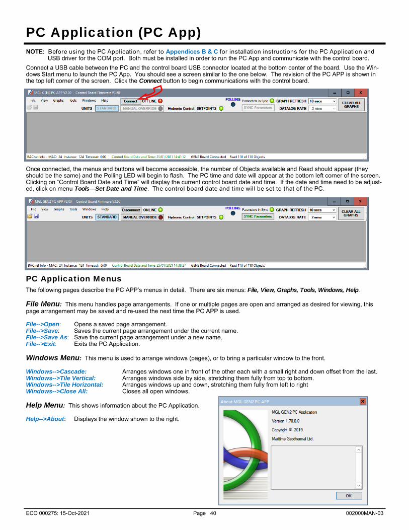
ECO 000275: 15-Oct-2021 Page 40 002000MAN-03
PC Application (PC App) NOTE: Before using the PC Application, refer to Appendices B & C for installation instructions for the PC Application and USB driver for the COM port. Both must be installed in order to run the PC App and communicate with the control board.
Connect a USB cable between the PC and the control board USB connector located at the bottom center of the board. Use the Win-dows Start menu to launch the PC App. You should see a screen similar to the one below. The revision of the PC APP is shown in the top left corner of the screen. Click the Connect button to begin communications with the control board.
PC Application Menus
The following pages describe the PC APP’s menus in detail. There are six menus: File, View, Graphs, Tools, Windows, Help. File Menu: This menu handles page arrangements. If one or multiple pages are open and arranged as desired for viewing, this page arrangement may be saved and re-used the next time the PC APP is used. File-->Open: Opens a saved page arrangement. File-->Save: Saves the current page arrangement under the current name. File-->Save As: Save the current page arrangement under a new name. File-->Exit: Exits the PC Application. Windows Menu: This menu is used to arrange windows (pages), or to bring a particular window to the front. Windows-->Cascade: Arranges windows one in front of the other each with a small right and down offset from the last. Windows-->Tile Vertical: Arranges windows side by side, stretching them fully from top to bottom. Windows-->Tile Horizontal: Arranges windows up and down, stretching them fully from left to right Windows-->Close All: Closes all open windows. Help Menu: This shows information about the PC Application. Help-->About: Displays the window shown to the right.
Once connected, the menus and buttons will become accessible, the number of Objects available and Read should appear (they should be the same) and the Polling LED will begin to flash. The PC time and date will appear at the bottom left corner of the screen. Clicking on “Control Board Date and Time” will display the current control board date and time. If the date and time need to be adjust-ed, click on menu Tools—Set Date and Time. The control board date and time will be set to that of the PC.

ECO 000275: 15-Oct-2021 Page 41 002000MAN-03
Operational status of the heat pump system
Manual controls are enabled when in MANUAL OVER-RIDE mode.
Indicators show the demand from the control system.
Click to disable the unit and fully open both EEV’s to allow work to be done to the refrigeration system.
Stage run timers.
Indoor EEV. Status light indicates when in use.
Outdoor EEV. Status light indicates when in use.
Outdoor temperature (sensor located in Outdoor Unit)
Refrigeration system pressure data, along with alarm indicators
Refrigeration system temperature data
Defrost data: start pressure at which defrost will be trig-gered, timer for defrost cycle and defrost disabled cycle. Override button for when unit is being serviced.
Short Cycle timer and over-ride button for when unit is being serviced.
Clear the defrost history log
Refresh button reloads the defrost log
Number of defrosts since history was last erased.
Defrost history log
Heat pump model information
Real-time display of defrost state
Export the history as tab delimited
Selectable temperature at which compressor is disabled.
Force a defrost cycle to occur immediately.
Reversing valves. Status light indicates when in use.
Indoor fan information. Click SET to adjust (same as clicking View--> Indoor Fan; see later page)
Auxiliary information, air and hydronic. Status lights indicates when in use.
Click to change from Air to Hydronic priority Click to enable or disable stage
2 air cooling (disable for better dehumidification)
View Menu:
This menu handles all of the operational viewing screens. Clicking on the View submenus will open the page in the PC APP’s frame. The next few pages of the manual show screenshots of each of the pages along with some descriptions of what is on each page. View-->Control Panel: The main control panel window will open, shown below.
Compressor status
Outdoor fan speed, setpoint suction pressure (heating mode) or setpoint discharge pressure (cooling mode) and current pressure
History button opens Defrost History window (also from menu View-->Defrost History)
View-->Setpoint Control:
Shows the on-board temperature control screen. This screen is only available when Control Source HYD on the Configuration Page is set to Setpoints (not Signals or BACnet).
Refer to the Operation section earlier in this manual for details.

ECO 000275: 15-Oct-2021 Page 42 002000MAN-03
View-->Alarms, Limits and Faults
The alarms page has four tabs:
1. ALARMS - Current alarm status, alarm count, high and low refrigeration alarm cutout values, and short cycle timer.
2. ALARMS LIST - List of alarms that have occurred since the PC APP has been operating (this will be lost when the PC is discon-nected from the control board.)
3. LIMITS - Limits in effect which prevent compressor operation but that do not cause an alarm.
4. FAULTS - List of board hardware faults.
View-->Alarms, Limits and Faults (ALARMS Tab):
NOTE: Greyed out Alarms in the PC APP are not applicable to the system setup and are not monitored by the control board. NOTE: Refer to Alarms and Faults screenshot below to see which alarms have a count. Alarms without a count: These alarms only occur one time at which point they immediately create a Permanent Alarm.
Alarms with a count: When an alarm occurs the compressor will stop, the alarm count will increase and the Short Cycle Timer will start. When the SC Timer expires the compressor will re-start. If no further alarms occur within Count Reduce Time, the alarm count will be reduced by 1. If another alarm occurs within Count Reduce Time (see Configuration Page) the count will increase by 1. If alarms continue to occur, when the alarm count reaches the Maximum Count value a Permanent Alarm will occur.
Master Alarm: This alarm occurs when any permanent alarm occurs. It is used to simply indicate that there is an alarm.
Permanent Alarm: The compressor will be locked out until the Permanent Alarm is manually reset either by cycling the power or clicking on the RESET button
Low Pressure: A low pressure alarm occurs when the suction pressure drops to or below the Low Pressure Cutout value. The low pressure is checked just before a compressor start; if it is OK the compressor will start, otherwise an alarm will occur. When the compressor starts, low pressure alarm will be ignored for the number of seconds that Low Pressure Ignore is set to, after which the low pressure alarm will be re-enabled. This allows a dip in suction pressure below the cutout point during startup without causing a nuisance alarm.
High Pressure: A high pressure alarm occurs when the discharge pressure rises to or above the High Pressure Cutout Value.
Comp. Not Pumping: Discharge pressure is less than 30 psi higher than suction pressure after 1 minute run time. It indicates leaking reversing valve, manual high pressure control trip, bad contactor, or defective compressor.
Low Charge: This alarm occurs if the EEV has been at >99% for 20 minutes within first hour of a cycle.
LOC (Loss of Charge): This alarm occurs if both the low pressure and high pressure sensors are below 30 psig (207kPa).
Condensate Drain: This alarm occurs if fluid level in the condensate tray rises to the level of the sensor (if equipped).
Multiple Defrosts: This alarm occurs if a second defrost occurs immediately after the defrost disabled timer expires from a previous defrost cycle. It indicates abnormally low suction pressure.
Go the Alarms Troubleshooting section of the Troubleshooting section of the manual to address alarm issues.
This button will erase all alarms and alarm counters, including a permanent alarm.
Low Pressure cut out High Pressure cut out
This button will reduce the short cycle timer value to 10 seconds.
Greyed out alarms are not applicable to the system.
Master Alarm occurs when any alarm occurs.
Short Cycle Timer counts down time until the next compressor start is allowed.
WARNING: Repeated resets can freeze and rupture heat exchang-ers, ruining the heat pump and voiding the warranty. The source of the alarm should be determined before re-setting the unit if pos-sible or during opera-tion after a reset.

ECO 000275: 15-Oct-2021 Page 43 002000MAN-03
View-->Alarms, Limits and Faults (ALARMS LIST Tab):
This tab show a history of alarms that have occurred since the PC APP was connected to the control board. This list will be lost when the PC APP is disconnected.
Each alarm that occurs while the PC APP is connected to the control board will appear here. The alarm type and a time stamp will be shown. The alarms list will be erased when the PC APP is disconnected from the control board.
This button will erase the alarm events in the Alarm List.
View-->Alarms, Limits and Faults (LIMITS Tab):
This tab shows temperatures that are out of limits but have not caused an alarm. These limits are shown on the Tools-->Configuration page.

ECO 000275: 15-Oct-2021 Page 44 002000MAN-03
View-->Alarms, Limits and Faults (FAULTS tab):
This tab shows hardware faults that could occur. If one of these faults occurs there may be a problem with the control board hard-ware, with LCD Display and buttons, or with a sensor.
If a fault occurs, some things to try: Turn the power to the heat pump off for 20 seconds and then back on again. Use the menu item Tools-->Reset to Factory Defaults. If this clears the fault then the system configuration will have to be
set up again. For LCD Display or Menu Button faults, turn off the power, disconnect and reconnect the cable between the LCD interface board
and the control board, then turn the power back on again. If the fault persists then there is most likely a hardware problem, and the sensor, control board, or LCD interface board will need to be replaced. IMPORTANT NOTE: If the Indoor OUT (I_OUT) probe is faulty or disconnected, neither hydronic heating nor the auxiliary will operate
if using Setpoint Control. They will continue to operate under Signals or BACnet control.
Greyed out do not apply.
Fault Indicators
Erase the com-pressor statistics (only for if a compressor should need to be replaced).
View-->Stage Stats:
The compressor information: number of starts, run hours and starts per hour.
View-->Set Stage 2 Delay:
Sets the delay before stage 2 is engaged on a stage 1 demand. Set to “0” for no stage 2 en-gaged on a stage-1-only demand from thermostat.
View-->Defrost History:
Same as clicking on HISTORY button in Control Panel window (see previous page).

ECO 000275: 15-Oct-2021 Page 45 002000MAN-03
View-->Set Air Auxiliary Delays
Sets the delay before auxiliary air heat (plenum heater) is engaged on a stage 1 or stage 2 demand. Set to “0” for no auxiliary heat engaged on a compressor-only demand from thermostat.
View-->Digital Inputs
Shows the digital inputs and their individual status (ON/OFF). They may be individually controlled when in Manual Override Mode in order to facilitate troubleshooting.
View-->Digital Outputs
Shows the digital outputs and their individ-ual status (ON/OFF). They may be individ-ually controlled when in Manual Override Mode in order to facilitate troubleshooting. .
View-->Analog Inputs
Shows the Analog inputs and their individu-al settings and values.
Click on the EDIT button to modify the blue boxes (button will now say SAVE). For each channel a name may be selected (up to 16 characters), and the multiplier and Offset values may be set to accommo-date the connected sensor scaling. Sig-nals may be 4-20mA (channel jumper on board ON) or 0-10VDC (channel jumper on board OFF). A variety of units are also available for selection of common meas-urement types. Click on SAVE to save the changes. Values are kept even when pow-er is removed from the unit.
View-->PWM Channels
Shows the PWM channels and their indi-vidual status (0-100%). They may be indi-vidually controlled when in Manual Over-ride Mode in order to facilitate trouble-shooting.
View-->Indoor Fan
Shows the settings screen for the indoor fan/blower. Airflow may be adjusted up or down by the user within the allowed range. See Indoor Airflow Data section in the Model Specific Information chapter for airflow ranges.
NOTE: This screen may also be accessed from the SET button of the Indoor Fan section of the Control Panel screen.
View-->Water Lines
Shows the water line temperatures.

ECO 000275: 15-Oct-2021 Page 46 002000MAN-03
Graphs Menu:
This menu is a list of the available graphs. Graphs are real-time and show a time stamp of when the recording started as well as a current time which will show up if the graph is screen captured. Each graph has a CLEAR button which will erase the stored data and restart the graph. There is also a master CLEAR ALL GRAPHS button at the top right of the PC APP; this will clear all open graphs and re-start them all simultaneously to keep them in sync with each other. The refresh rate for the graphs is also located at the top right of the PC APP.
ON/OFF status of the system control signals (demands)
ON/OFF status of air heating, water heating, and air cooling modes ON/OFF status of digital outputs
EEV position and resulting superheat Suction temperature
Suction and discharge pressures, evaporating and condensing temperatures
Suction (heating) or discharge (cooling/defrost) pressure vs. outdoor fan speed Suction (heating) or discharge (cooling/defrost) pressure vs. outdoor temperature
Indoor IN/OUT temperatures and delta T
Discharge pressure vs tank temperature
All analog input channels (0-10VDC or 4-20mA). All PWM / 0-10VDC output channels and one PWM / 0-10VDC input channel. For troubleshooting synchronization with 3rd party BACnet controllers.
Graph Name
CLEAR button erases all graph data
Check boxes to select which items are graphed
Current values
Graph start time
X axis = Number of samples.
Elapsed time = Number of Samples x Refresh Rate.
e.g. 20 samples x 1 second refresh = elapsed time of 20 seconds.
Graph printed time
Refresh Rate
Primary Y axis on the left, secondary Y axis on the right.
An example of a typical graph screen. Items that are checked will be plotted, unchecked items will not. The graph screens show the time the graph started as well as the current time to time stamp the graph when screen printed.
TIP: To screen print a graph and save it as a picture, hold down the Windows key and press Print Screen on the key-board. The image on the screen will be saved to the folder C:\Users\Username\Pictures\Screenshots.

ECO 000275: 15-Oct-2021 Page 47 002000MAN-03
Fluid selection determines the low pressure cut-out value. Out-door is preset to air for this series. There is no selec-tion for the Hy-dronic Indoor Loop since there is no cooling mode for it.
Tools Menu:
This is where various tools for system setup and monitoring are located. Tools-->Configuration (System Configuration tab):
This is where the system setup is done. Settings should only be changed by a person who has a good understanding of system oper-ation. Improper settings could cause the system to operate poorly or not at all.
Selects whether or not compressor stage 2 is auto-matically activated whenever there is a simultaneous demand for air and water heat, so that the priority de-mand can be satis-fied as soon as possible.
Outdoor fan reduction: outdoor fan speed can be reduced if fan noise is a concern.
Air or Hydronic priority. Can also be set from button on Con-trol Panel screen.
The Enabled indicators show which alarms are enabled
If an alarm is mandatory or not available, the Enable button will be greyed out. For optional alarms (requiring Phase Monitor or Current Sensor accessories) the Enable button will be available; click to enable.
Firmware update: see Appendix Green when pa-rameters have been updated, red during the update
Firmware revision can also be seen on the LCD during power up
Model Configu-ration section to select the system type
Jumper configu-ration section to select system options. Greyed out means N/A.
High pressure cutout determined by refrigerant type
Enable/Disable the compressor (does not affect auxiliary heat). Units are shipped as Disabled to prevent an unintentional compressor startup.
POR: reset control system as would be done by cycling power
Temperature limits determined by Model Series and Fluid Type/Mixture
greyed out = automatically selected
Select model series & size (refer to unit nameplate; will be set from factory)
Compressor: 2 stage (“T” in unit model number) or 1 stage (“S” in unit model num-ber)
When Summer Setback is ena-bled: disables stage 3 (AUX), drops setpoints to 70°F (21°C), and decreases temperature sampling fre-quency to 2 days. Can also be set through LCD.
If Control Source HYD is set to BACnet, set communication parameters. Disconnect PC App and cycle unit power to register changes to BACnet parameters.
Selects how the hydronic heating demand will be controlled: BACnet, Setpoints, or Signals.
Selects whether to use the inter-nal temp sensor (Indoor Loop/ ICR) or external sensor (External HTS/CTS). This is for Setpoint Control opera-tion only.
Selects how the air heating/cooling demand will be controlled: thermostat (Signals) or BACnet

ECO 000275: 15-Oct-2021 Page 48 002000MAN-03
Tools-->Configuration (Alarms and Delays tab):
Click on the UP/DOWN arrows to change the value, noting that values have both a low and high limit.
Items that do not apply to the model are greyed out.
Maximum Count is the number of alarms al-lowed before a perma-nent lockout occurs.
Count Reduce Time is the number of hours after which the alarm count is reduced by 1 if no other alarm occurred within the timeframe.
The number of minutes before the unit can start again after a normal shutdown
The number of minutes before the unit can start again after various alarm shutdowns
Ignore On Start is the number of seconds an alarm will not be moni-tored after a compressor start occurs.
The minimum off time when switching between heating and cooling cycles: can be set from 0 (switch on the fly) to 60 minutes

ECO 000275: 15-Oct-2021 Page 49 002000MAN-03
Tools-->Calibration:
Generally there is no need for calibration.
The suction and discharge pressures may be calibrated in increments of 1 psi if there is a discrepancy in the readings when compared to a known good reference.
Temperature sensors may be adjusted in increments of 0.1°F. There is an AUTO CALIBRATION routine in the program that continu-ally calibrates the temperatures sensors against an on board reference resistor by applying an offset to the temperature sensors. Calibration adjustments made here are in addition to the Auto Calibration routine.
Tools-->Reset to Factory Defaults:
This will reset all parameters to default values.
THE SYSTEM MUST BE RECONFIGURED AFTER A RESET IS PERFORMED.
A reset will default the system to a two stage ATW Series Size 65 with Signals as the control source. Calibrations, alarm delays, analog configurations, compressor statistics, and Setpoint Control values will be returned to defaults as well.
Calibration adjustments
Current values in standard and metric.
Temperature Auto Calibra-tion information. The offset is applied to all temperature sensors. Calibration adjust-ments made to each sensor are in addition to the Auto Calibration values.
Click on the RESET ALL CALIBRATIONS button to clear all calibration data. A popup window will ap-pear for confirmation.
Tools-->Set Date and Time:
This will synchronize the date and time of the control board with the computer’s date and time, and will be necessary for new units or units that have been powered off for several days or more.
The date and time of both the computer and the control board are shown in the status bar at the bottom of the PC App.

ECO 000275: 15-Oct-2021 Page 50 002000MAN-03
Tools-->Datalogging (Datalog tab):
The datalog rate is set via the dropdown box at the top right of the PC App main window. A log will be recorded at the datalog rate whenever the heat pump is powered on, making it easy to compare datalogs from multiple units . The maximum number of datalog records is 32,224, which will take 45 days to fill up at the default recording rate of 2 minutes.
Note that loading datalogs is time-consuming. It is suggested to leave the # of LOGS at 25 until it is shown that the start date selected is suitable.
Loads the # of LOGS beginning from the earliest date
Loads the # of LOGS beginning from the se-lected date.
Erases the screen only
Erases all logged data in the control board and resets the log count to 0.
Exports the data to a file.
Clicking anywhere on a row will update all LEDs to show the status at the time of that log record.
Tools-->Datalogging (Enable/Disable tab):
Click on the checkboxes to customize which columns are shown/hidden in the datalog table.
Tools-->MODBUS:
For future use. Tools-->Objects:
This is a window to display the runtime data, which is not stored when the power is turned off. No changes are possible.

ECO 000275: 15-Oct-2021 Page 51 002000MAN-03
Tools-->Parameters:
WARNING! The Parameters page is for advanced use only. Changing parameter values can cause the system to stop functioning properly.
The parameters page shows all configurable memory spaces with their name and current value and allows them to be edited directly. To change a parameter value type in the new value and press ENTER.
Clicking on menu item Tools-->Parameters will display this warning. Click on YES to open the parameters page.
Type in the new value and press ENTER, the confirmation popup will appear, click on OK.
Click this button to reload the table with the values from the control board memory.
Tools-->SYSTEM TIMERS:
This page shows all internal timers by name along with their current values.
Tools-->Jumpers:
This page shows internal jumper configurations, for developers.

ECO 000275: 15-Oct-2021 Page 52 002000MAN-03
These are examples of the unit status and operating data displayed when at the message display level (top level). Pressing ENTER will enter into the menu levels beginning with the Main Menu.
2x16 LCD
UP button: Use this to scroll up through the items availa-ble at a menu level.
OK/EXIT button: Use this to come back up one menu level. Also saves value if at parame-ter menu level.
ENTER button: Use this to push down to the next menu level. Also saves value if at parameter menu level.
DOWN button: Use this to scroll down through the items availa-ble at a menu level.
LCD Interface & Menus
Menu Tree: This is a list of the various tools are used for system setup and monitoring. The table shows what is displayed based on each press of the ENTER button starting at the Main Menu level.
ENTER (From Main)
ENTER (First Press)
ENTER (Second Press)
ENTER (Third Press) Description
Setpoint Control (only if using Setpoint Control)
— Setpoints — Heating — Stage 1 Setpoint Stage 1 stops when water temperature
rises to this point.
— Stage 1 Delta Stage 1 starts when water temperature drops below setpoint by this amount.
— Stage 2 Setpoint Stage 2 stops when water temperature rises to this point.
— Stage 2 Delta Stage 2 starts when water temperature drops below setpoint by this amount.
— AUX (S3) Setpoint Stage 3 stops when water temperature rises to this point.
— AUX (S3) Delta
Stage 3 time delay starts when water tem-perature drops below setpoint by this amount. (Stage 3 starts immediately if time delay is set to 0).
— AUX (S3) Delay Delays Stage 3 start by timer amount.
— Outdoor Reset (only if enabled)
Temperature factor to use in the outdoor reset table.
continued on next page...

ECO 000275: 15-Oct-2021 Page 53 002000MAN-03
...continued from previous page
ENTER (From Main)
ENTER (First Press)
ENTER (Second Press)
ENTER (Third Press) Description
Summer Setback (only if using Setpoint Control)
— Enable Setback? — Enable Enable summer setback.
— Disable Disable summer setback.
System EN/DIS — Enable System? — Disable Disable compressor, auxiliary and ICR.
— Enable Enable compressor, auxiliary and ICR.
Service Mode — Service Mode? — No Do not enter Service Mode.
— Yes Enter into Service Mode.
EEV Control — EEV1 (Local) — Auto/Manual — Auto Puts EEV in Auto mode
— Manual Puts EEV in Manual mode
— Manual Position — EEV Position (%) Sets EEV to manual position
— EEV2 (Remote) — Auto/Manual — Auto Puts EEV in Auto mode
— Manual Puts EEV in Manual mode
— Manual Position — EEV Position (%) Sets EEV to manual position
Configuration — Priority — Air Sets the priority to air modes.
— Hydronic Sets the priority to hydronic mode.
— Control AIR — Signals Hardwired air thermostat control.
— BACnet BACnet control - see BACnet section
— Control HYD — Setpoints On-board water temperature control - see Setpoint Control section.
— Signals Hardwired / aquastat control.
— BACnet BACnet control - see BACnet section
— Outdoor Reset (only if using Setpoint Control)
— Enable Enables Outdoor Reset functionality
— Disable Disables Outdoor Reset functionality
— Setpoints Method (only if using Setpoint Control)
— ICR Use Indoor Circulator Relay sampling
— HTS/CTS Use external hot tank temperature sensor
— OD Fan Reduction — Reduction (%) Outdoor fan speed reduction in %.
— Time Delays — Short Cycle — Delay (min) Short-cycle timer delay in minutes
— Heat/Cool — Delay (min) Heat / Cool timer delay in minutes
— Units — Standard Standard units
— Metric Metric units (does not affect calibration units)
— Set Time — Hours — Hours value Set the system hours.
— Minutes — Minutes value Set the system minutes.
— Set Date — Day — Day value Set the system day.
— Month — Month value Set the system month.
— Year — Year value Set the system year.
Calibration — Suction 1 — calibration adj. Calibration in 1PSI intervals.
— Discharge 1 — calibration adj. Calibration in 1PSI intervals.
— Vapour Line 1 — calibration adj. Calibration in 0.1°F intervals
— Outdoor Ambient — calibration adj. Calibration in 0.1°F intervals
— Indoor IN Temp — calibration adj. Calibration in 0.1°F intervals
— Indoor OUT Temp — calibration adj. Calibration in 0.1°F intervals
NOTE: Calibration is generally not required. Pressure sensors may be calibrated against a known source if needed. All temperature sensors have an Auto Calibration feature.

ECO 000275: 15-Oct-2021 Page 54 002000MAN-03
BACnet Interface
TABLE 22 - BACnet OBJECTS - CONTROL SIGNALS (READ/WRITE)
Name Data Type ID Property Description
SYSTEM_O Binary Value BV2 Present Value Switch to air cooling mode (RV#1). Inactive=HEATING, Active=COOLING
SYSTEM_Y1 Binary Value BV3 Present Value Demand for air heating or cooling (active is on)
SYSTEM_Y2 Binary Value BV4 Present Value Demand for stage 2 air heating or cooling (active is on)
SYSTEM_W2 Binary Value BV5 Present Value Demand for air auxiliary heat / plenum heater (active is on)
SYSTEM_G Binary Value BV6 Present Value Demand for air recirculation (active is on)
BACnet_Units Binary Value BV9 Present Value Select the units to use for the BACnet objects
Note: object names may be subject to change without prior notice.
SYSTEM_AR Binary Value BV7 Present Value Demand for airflow reduction (active is on)
SYSTEM_Y1A Binary Value BV0 Present Value Demand for hydronic (water) heating (active is on)
SYSTEM_Y2A Binary Value BV1 Present Value Demand for stage 2 hydronic (water) heating (active is on)
TABLE 23 - BACnet OBJECTS - OPERATION MODE Description (Read Only)
Name Data Type ID Present Value Description
Operation Mode Analog Value AV5 - Integer value represents operating mode.
0 Air heating
1 Air cooling
2 Hydronic (water) heating
9 Air heating off
11 Hydronic (water) heating off
Note: Object is type Analog Value but value will always be an integer value. Note: Objects may be subject to change without prior notice.
10 Air cooling off
The BACnet interface is an MS/TP connection via RS-485 twisted pair. Recommended wire: 22-24 AWG single twisted pair, 100-120 Ohms impedance, 17pF/ft or lower capacitance, with braided or aluminum foil shield, such as Belden 9841 or 89841. The connector on the control board is a three wire removable screw connector. The signals are as follows: A: Communications line (+) (right pin) B: Communications line (-) (middle pin) C: Ground connection (left pin) If connecting multiple units to one RS-485 connection point, connect the signal cable from the master building controller to the first unit. Connect the second unit to the first unit (in same connector), connect the third unit to the second unit, and so on until all units are connected (daisy-chain). Remove the TERM jumper (located just above the BACnet connector on control board) from all units except the last one. The shield ground should be connected only to the GND pin of the unit for single unit installations. For multiple units, the shield ground should only be connected to the GND pin of the last unit. The shield grounds for intermediate units should be connected together. The shield ground should be left unconnected at the building controller end for all cases. Vendor: Maritime Geothermal Ltd. Vendor ID: 260 Model Name: MGT GEN2 Control Board
The following parameters can be set via the PC APP Configuration Page: 1) Baud rate 2) MAC address 3) Instance number
The data is available regardless of the selected control method. In order to control the unit via the BACnet interface, set the Control Source to BACnet either by using the PC APP configuration page or the display menus.
The following tables provide a list of the objects applicable to this model series, along with a description of each. Note that there may be other objects available that do not apply to this model.

ECO 000275: 15-Oct-2021 Page 55 002000MAN-03
TABLE 24 - BACnet OBJECTS - DATA (Read Only)
Name ID Property Units Description
AI0 (Comp1_Current) AI0 Present Value Amps Compressor current draw (AI0) - requires accessory
AI1 (Comp2_Current) AI1 Present Value User User defined (0-5VDC or 4-20mA)
AI2 AI2 Present Value User User defined (0-5VDC or 4-20mA)
AI3 AI3 Present Value User User defined (0-5VDC or 4-20mA)
AI4 (CTS) AI4 Present Value degF (degC) User defined (0-5VDC or 4-20mA)
AI5 (HTS) AI5 Present Value degF (degC) Hot tank temperature from sensor - requires accessory
LPS1 AI6 Present Value PSIG (kPa) Low pressure value (suction pressure)
HPS1 AI7 Present Value PSIG (kPa) High pressure value (discharge pressure)
EVAP1 AI8 Present Value degF (degC) Evaporating Temperature
COND1 AI9 Present Value degF (degC) Condensing Temperature
Suction Line 1 AI10 Present Value degF (degC) Suction line temperature
Superheat 1 AI11 Setpoint Value degF (degC) Superheat
EEV1 Position AI12 Present Value % EEV1 position (% open)
LPS2 AI13 Present Value PSIG (kPa) N/A
HPS2 AI14 Present Value PSIG (kPa) N/A
EVAP2 AI15 Present Value degF (degC) N/A
COND2 AI16 Present Value degF (degC) N/A
Suction Line 2 AI17 Present Value degF (degC) N/A
Superheat 2 AI18 Setpoint Value degF (degC) N/A
EEV2 Position AI19 Present Value % EEV2 position (% open)
Outside Ambient AI20 Present Value degF (degC) Outdoor Ambient temperature
O_IN AI21 Present Value degF (degC) N/A
O_OUT AI22 Present Value degF (degC) N/A
I_IN AI23 Present Value degF (degC) Indoor IN temperature
I_OUT AI24 Present Value degF (degC) Indoor OUT temperature
Data Type—Analog Value
PWM_IN AV0 Present Value % PWM input (from external source)
PWM1 (OD Fan) AV1 Present Value % Outdoor fan speed
PWM2 AV2 Present Value % PWM output value (spare)
PWM3 (OV2) AV3 Present Value % PWM output value (spare)
PWM4 (IV2) AV4 Present Value % PWM output value (spare)
Operation Mode AV5 Present Value N/A Unit operation mode - refer to Operation Mode Table
Data Type—Binary Output
STAGE1 BO0 Present Value N/A Compressor contactor
STAGE2 BO1 Present Value N/A Compressor stage 2 solenoid
ICR (Indoor Circ) BO2 Present Value N/A Indoor circulator control
DO0 (OV1) BO3 Present Value N/A N/A
DO1 (IV1)) BO4 Present Value N/A IV1 (to 24VAC Indoor Loop water valve)
DO2 (HYD_AUX) BO5 Present Value N/A Hydronic Auxiliary
DO3 (AUX_ONLY) BO6 Present Value N/A Hydronic Auxiliary Only (without compressor)
PHS1 BO7 Present Value N/A Air plenum heater stage 1
PHS2 BO8 Present Value N/A Air plenum heater stage 2
Data Type—Binary Value
CONTROLS (LOC/REM) BV9 Present Value N/A Control Indicator, 0 = Local (manual override), 1 = Remote
Outdoor Flow BV10 Present Value N/A N/A
Indoor Flow BV11 Present Value N/A N/A
Phase Monitor1 BV12 Present Value N/A Phase Monitor Stage 1 - requires accessory
Phase Monitor2 BV13 Present Value N/A N/A Comp Monitor1 BV14 Present Value N/A N/A Comp Monitor2 BV15 Present Value N/A N/A
Note: available objects may be subject to change without prior notice.
Data—Type Analog Input

ECO 000275: 15-Oct-2021 Page 56 002000MAN-03
TABLE 25 - BACnet OBJECTS - ALARM Descriptions (Read Only)
Name Data Type ID Description
AI0 (Comp1 Current) Analog Input AI0 Stage 1 Status alarm (Start / Stop Failure) - requires accessory
AI1 (Comp2 Current) Analog Input AI1 N/A
LPS1 Analog Input AI6 Low pressure alarm
HPS1 Analog Input AI7 High pressure alarm
LPS2 Analog Input AI13 N/A
HPS2 Analog Input AI14 N/A
Outdoor Flow Binary Value BV10 N/A
Indoor Flow Binary Value BV11 N/A
Phase Monitor1 Binary Value BV12 Phase Monitor alarm - requires accessory
Phase Monitor2 Binary Value BV13 N/A
Comp Monitor1 Binary Value BV14 N/A
Comp Monitor2 Binary Value BV15
Name ID BIT # DECIMAL VALUE* Description
Permanent Alarms 1 AV6 - - Bit description is given below.
(Present Value) 0 1 Master permanent alarm (occurs when any alarm occurs)
1 3 Low pressure heating mode alarm (suction pressure)
2 5 Low pressure cooling mode alarm (suction pressure)
3 9 High pressure heating mode alarm (discharge pressure)
4 17 High pressure cooling mode alarm (discharge pressure)
5 33 Loss of charge alarm
6 65 Phase monitor alarm - requires accessory
7 129 Compressor monitor alarm - N/A
8 257 Status alarm - N/A
14 16,385 N/A
15* 32,769 N/A
Permanent Alarms 2 AV7 - - N/A
(Present Value)
Note: Permanent Alarm objects are type Analog Value but values are bit coded and may be decoded as such (integer value). Note * : Value is for a single alarm and reference only. Value includes + 1 for Master Alarm Note: Objects may be subject to change without prior notice.
N/A

ECO 000275: 15-Oct-2021 Page 57 002000MAN-03
TABLE 26 - BACnet OBJECTS - FAULT Descriptions (Read Only)
Name Data Type ID Description
AI4 (Cold Tank) Analog Input AI0 N/A
AI5 (Hot Tank) Analog Input AI1 Hot tank temperature sensor faulty or disconnected - requires accessory
LPS1 Analog Input AI6 Low pressure sensor faulty or disconnected
HPS1 Analog Input AI7 High pressure sensor faulty or disconnected
LPS2 Analog Input AI13 N/A
HPS2 Analog Input AI14 N/A
Suction Line1 Analog Input AI10 Suction line 1 temperature sensor faulty or disconnected.
Suction Line2 Analog Input AI17 N/A
Outside Ambient Analog Input AI20 Outside temperature sensor faulty or disconnected
O_IN Analog Input AI21 N/A
O_OUT Analog Input AI22 N/A
I_IN Analog Input AI23 Indoor IN temperature sensor faulty or disconnected.
I_OUT Analog Input AI24
Name ID BIT # DECIMAL VALUE* Description
Board Faults AV8 - - Bit description is given below.
0 1 Digital inputs
1 2 Digital outputs
2 4 PWM outputs
3 8 Analog to digital conversion
4 16 Real time clock
5 32 EEPROM memory
6 64 Menu buttons
7 128 LCD Interface
Sensor Faults AV9 - - Indicates sensor failures. Bit description is given below.
0 1 Suction line 1 temperature
1 2 N/A
2 4 Outdoor Ambient temperature
3 8 Calibration temperature
4 16 Indoor IN temperature
5 32 Indoor OUT temperature
6 64 N/A
7 128 N/A
8 256 N/A
9 512 N/A
Note: Board and Sensor Fault objects are type Analog Value but values are bit coded and may be decoded as such (integer value). Note * : Value is for a single fault and reference only. Note: Objects may be subject to change without prior notice.
Indoor OUT temperature sensor faulty or disconnected.

ECO 000275: 15-Oct-2021 Page 58 002000MAN-03
Startup Procedure The ATF-Series Two-Stage R410a Startup Record located in this manual is used in conjunction with this startup procedure to
provide a detailed record of the installation. A completed copy should be left on site, a copy kept on file by the installer and a copy should be sent to Maritime Geothermal Ltd.
Check the boxes or fill in the data as each step is completed. For data boxes, circle the appropriate units.
Pre-Start Inspection
Outdoor Unit: 1. Ensure the system has been pressure tested, vacuumed to 500 microns and any extra charge required has been added. 2. Ensure both access valves have been fully opened and the caps have put been back on and tightened. Check the caps for leaks. 3. Ensure the outdoor unit is securely mounted in place. 4. Ensure the power and controls signals to the outdoor unit are properly connected, neat, and securely fastened. 5. Ensure fan outlet is clear of obstructions.
Ductwork: 1. Verify that all ductwork has been completed and is firmly attached to the unit. Verify that any dampers or diverters are properly set for operation of the heat pump. 2. Verify that all registers are open and clear of any objects that would restrict the airflow. 3. Verify that a new air filter is installed and the cover is secured. 4. Verify the condensate drain is connected, properly vented, and free of debris. 5. If a plenum heater has been installed, verify that it is securely fastened.
Indoor Loop (Hydronic Loop): 1. Verify that all shutoff valves are fully open and there are no restrictions in the piping from the heat pump to the indoor loop, and that full flow is available to the heat pump. 2. Verify that the entire system has been flooded and all the air has been purged as much as possible. Further purging may be required after the system has been operating for a while. 3. Verify that the loop contains the proper mix of antifreeze (if used) for the intended application. If applicable, record the type of antifreeze and the mixture value on the startup sheet; circle % vol. or % weight. 4. Record the static loop pressure on the startup sheet.
Domestic Hot Water: 1. Verify that all shutoff valves are fully open and there are no restrictions in the piping from the heat pump to the domestic hot water tank. 2. Verify that the entire system has been flooded and all the air has been purged as much as possible. Further purging may be required after the system has been operating for a while. 3. Verify that the brown wire with the insulated terminal is disconnected in the electrical box. Refer to the schematic diagram for more information.
Electrical: 1. Ensure the power to the unit is off. 2. Verify all high voltage connections. Ensure that there are no stray wire strands, all connections are tight, and the ground wire is connected tightly to the ground connector.
3. Record the circuit breaker size and wire gauge for the heat pump. 4. Verify that the control connections to the unit are properly connected and all control signals are off, so that the unit will not start up when the power is turned on. 5. Verify that the circulator pumps are connected to the proper voltage terminals in the heat pump. Record the voltages of the circulator pumps.
6. Ensure all access panels except the one that provides access to the electrical box are in place. Unit Startup
The unit is now ready to be started. The steps below outline the procedure for starting the unit and verifying proper operation of the unit. It is recommended that safety glasses be worn during the following procedures.
IMPORTANT NOTE: The unit is shipped with the compressor DISABLED in order to prevent the unit from starting when the power is first turned on. Follow the instructions below in the Preparation section to enable the compressor.
The LCD interface will show the outdoor temperature, low (suction) pressure, high (discharge) pressure, superheat, EEV position and water in/out temperatures.
Preparation:
1. Turn the power on to the heat pump with the air thermostat OFF. All LED’s on the control board should turn on, the LCD inter-face should say “MGT GEN2 VERx.xx” on line 1 and “Zeroing EEV’s” on line 2. You should be able to hear the EEV moving (a clicking sound).
2. Measure the following voltages on the compressor contactor and record them on the startup sheet: L1-L2, L2-L3, L1-L3. 3. Connect a USB cable between the USB connector on the board and a laptop with the PC App installed (recommended but op-
tional). 4. Select the desired Control Source HYD via the PC APP Configuration Page or via the LCD interface Configuration Menu. Set
the water setpoints to a low value (e.g. 50°F) to prevent the compressor from coming on on water heating mode. 5. Enable the system either with the PC App’s Configuration Page System Enable/Disable button or via the LCD interface.

ECO 000275: 15-Oct-2021 Page 59 002000MAN-03
Air Heating Mode: 1. Set the thermostat to heating mode and adjust the setpoint to activate stage 1 and stage 2. The fan should slowly ramp up to speed after the time delay of the thermostat expires (if applicable) and the compressor will start. 2. Check the PC App or LCD interface. The suction and discharge pressures will vary based on the outdoor temperature and in-
door air temperature, but they should be 90-110PSIG and 260-360PSIG respectively for a typical start-up. 3. Monitor the unit via the PC APP or LCD while the unit runs, and record the following after 10 minutes of run time:
1. Suction pressure 2. Discharge pressure 3. Duct Return temperature (poke a small hole in the flex collar and insert probe in airstream) 4. Duct Supply temperature (poke a small hole in the flex collar and insert probe in airstream) 5. Duct Delta T (should be between 22-32°F, 12-18°C) 6. Outdoor air temperature 7. Compressor L1(C) current (black wire, place meter between electrical box and compressor)
4. Adjust the thermostat setpoint to the desired room temperature and let the unit run through a cycle. 5. For units with a desuperheater, turn the power off to the unit. Connect the brown wire with the blue insulated terminal to the compressor contactor as shown in the electrical box diagram. Turn the DHW Switch in the unit post on. Turn the power to the unit on. 6. Verify the DHW IN and DHW OUT temperatures (if applicable) by hand (caution: pipes get hot). If the DHW OUT line does not
become hotter than the DHW IN line the circulator is air locked. Bleed the air from the system and check the temperature differ-ential again to ensure there is flow from the circulator.
7. Remove the electrical cover from the plenum heater. Place a current clamp meter around one of the supply wires. Turn on the power to the plenum heater. Adjust the thermostat setpoint to 85°F (29°C). Verify that the current draw increase as each electric heat stage is activated. (10kW has 2 stages, 15kW has 3 stages and 20kW has 4 stages). Air Cooling Mode: 1. Set the thermostat to cooling mode and adjust the setpoint to activate stage 1 and stage 2. 2. Monitoring the unit via the PC APP or LCD Interface while the unit runs, record the following after 10 minutes of run time:
1. Suction pressure 2. Discharge pressure 3. Duct Return temperature 4. Duct Supply Out temperature 5. Duct Delta T 6. Outdoor air temperature
3. Adjust the thermostat setpoint to the desired room temperature if possible, otherwise set it just low enough to allow the unit to run(e.g. 1°F / 0.5°C less than room temperature) and let the unit run through a cycle.
Water Heating Mode: 1. Set air thermostat to “off”. Adjust the Setpoint Control settings via the the PC App or LCD (or adjust aquastat if used) to activate
stage 1 and stage 2. The EEV will begin to open and the compressor will start, as will the circulator pumps. 2. Check the PC App or LCD interface. The suction and discharge pressures will vary based on the outdoor temperature and the indoor loop temperature, but they should be 90-110PSIG and 260-360PSIG respectively for a typical start-up. 3. Monitor the unit via the PC APP or LCD interface while the unit runs, and record the following after 10 minutes of run time:
1. Suction pressure 2. Discharge pressure 3. Indoor Loop In temperature 4. Indoor Loop Out temperature 5. Indoor Delta T (should be 8-12°F, 4-6°C) 6. Outdoor air temperature 7. Compressor L1(C) current (black wire, place meter between electrical box and compressor)
4. Adjust the control setpoints to the desired buffer tank temperature and let the unit run through a cycle. Final Inspection:
1. Turn the power off to the unit (and plenum heater if installed) and remove all test equipment. 2. Install the electrical box cover and the access panel on the heat pump. Install the service port caps securely to prevent refrigerant loss. Install the electrical cover on the plenum heater if applicable. 3. Do a final check for leaks/spills and ensure the area is clean. 4. Turn the power on to the unit and the plenum heater if installed. Set the thermostat and water heat to the final settings.
Startup Record: 1. Sign and date the Startup Record and have the homeowner sign as well. Leave the Startup Record with the homeowner, retain
a copy for filing and send a copy to Maritime Geothermal Ltd. for warranty registration.

ECO 000275: 15-Oct-2021 Page 60 002000MAN-03
Startup Record Sheet - ATF-Series Two-Stage R410a
Installation Site Startup Date Installer
City Company
Province Check boxes unless asked to record data.
Circle data units.
Model
Country Serial #
Homeowner Name Customer Phone #
PRE-START INSPECTION Outdoor Unit Unit is securely mounted at least 8” from building, fans facing out
Fan outlet is clear of obstructions
Line Set Line set length, extra charge added (only if needed) ft. m lb kg
System is pressure tested, vacuumed
All inter-connect piping is insulated and properly supported
Wiring is neat and securely fastened
Service valves are open and caps installed with torque wrench
Ductwork Ductwork completed, dampers adjusted, registers open
Air filter and end cap are installed
Condensate drain is connected, properly vented, & free of debris
Plenum heater is securely fastened (if applicable)
Indoor Loop (Hydronic)
All shut-off valves are open, loop is full and purged of air
Loop static pressure psig kPa
Domestic Hot Water
All shut-off valves are open, lines are full and purged
Desuperheater pump wire is disconnected
Electrical High/low voltage connections are correct and securely fastened
Circuit breaker size and wire gauge for heat pump A Ga.
Circuit breaker size, wire gauge, and size for Plenum Heater A Ga. kW
STARTUP DATA
Preparation Voltage across L1 and L2, L1 and L3, L2 and L3 VAC
Suction Pressure / Discharge Pressure psig kPa
Duct Return, Duct Supply, and Delta T In Out °F °C
Outdoor Air Temperature °F °C
Compressor L1 (black wire) current A
Domestic Hot Water functioning
Air Cooling Mode (10 minutes)
Suction Pressure / Discharge Pressure psig kPa
Duct Return, Duct Supply, and Delta T In Out °F °C
Outdoor Air Temperature °F °C
Water Heating Mode (10 minutes)
Suction Pressure / Discharge Pressure psig kPa
Indoor In (Hot In), Indoor Out (Hot Out), and Delta T In Out °F °C
Outdoor Air Temperature °F °C
Compressor L1 (black wire) current A
Air Heating Mode (10 minutes)
Date: Startup Personnel Signature:
Witness/Site Signature:
A total of three copies are required, one for the site, one for the installer/startup and one to be sent to Maritime Geothermal Ltd.

ECO 000275: 15-Oct-2021 Page 61 002000MAN-03
Routine Maintenance
MAINTENANCE SCHEDULE Item Interval Procedure
Outdoor Unit Weekly Inspect for and clear away debris or leaves in air coil intake, and ice buildup under unit that is approaching air coil.
Indoor Air Filter 6 months Inspect for dirt. Replace if necessary.
Compressor Contactor
1 year Inspect for pitted or burned points. Replace if necessary.
Condensate Drain
1 year Inspect for clogs. Clean if necessary.
LCD Interface or PC App
When heat pump problem is suspected
Check for alarms and faults (only necessary if alarms not reported through a BACnet system). Rectify problem if alarms found. See Troubleshooting chap-ter.
Coaxial Heat Exchanger
When experiencing performance degrada-tion that is not ex-plained by a refrigera-tion circuit problem or low loop flow rate
Disconnect the indoor loop and flush heat exchanger with a calcium removing solution. Generally not re-quired for closed loop or cold water open loop sys-tems or closed indoor loops; whenever system perfor-mance is reduced for hot water open indoor loop sys-tems (unusual).

ECO 000275: 15-Oct-2021 Page 62 002000MAN-03
Troubleshooting Guide
POWER SUPPLY TROUBLESHOOTING
Fault Possible Cause Verification Recommended Action
No power to the heat pump
Disconnect switch open (if installed).
Verify disconnect switch is in the ON position.
Determine why the disconnect switch was opened; if all is OK close the switch.
Fuse blown / breaker tripped.
At heat pump disconnect box, voltmeter shows 230VAC on the line side but not on the load side.
Reset breaker or replace fuse with proper size and type. (Time-delay type “D”)
Faulty Control Board. 24VAC is present across 24VAC and COM of the control board.
Replace the control board.
Faulty wiring between heat pump and thermo-stat.
24VAC is not present across R and C of the thermostat.
Correct the wiring.
Faulty thermostat. 24VAC is present across R and C of the thermostat but thermostat has no display.
Replace thermostat .
No display on air thermostat
No power from transform-er.
See No Heartbeat on control board.
Faulty transformer. Transformer breaker is not tripped (or fuse not blown), 230VAC is present across L1 and L3 of the compressor contactor but 24VAC is not present across 24VAC and COM of the control board.
Replace transformer.
No heartbeat on control board
Transformer breaker tripped (or fuse blown for those without breaker).
Breaker on transformer is sticking out (or fuse looks burnt).
Push breaker back in. If it trips again locate cause of short circuit and correct (or replace fuse) .
The following steps are for troubleshooting the heat pump. If the problem is with the domestic hot water or the plenum heat-er, proceed to those sections at the end of the troubleshooting guide. Repair procedures and reference refrigeration circuit diagrams can be found later in this manual. STEP 1: Verify that the LCD Interface is functioning . If it is not, proceed to POWER SUPPLY TROUBLE SHOOTING, otherwise
proceed to STEP 2.
STEP 2: Record the alarm shown on the LCD Interface or use the PC APP Alarms page to determine the alarm type. Proceed to the ALARMS TROUBLESHOOTING section.
STEP 3: If there are no alarms and STAGE1 is showing ON (LCD Interface, PC APP or LED on control board) but the compressor is not operating, does not attempt to start, attempts to start but cannot, starts hard, or starts but does not sound normal, pro-ceed to the COMPRESSOR TROUBLESHOOTING section.
STEP 4: If the compressor starts and sounds normal, the compressor is most likely OK. Proceed to the OPERATION TROUBLE-SHOOTING section.
NOTE: To speed up the troubleshooting process, if using the PC Application, click on SC Override to reduce the short cycle timer to
10 seconds.
WARNING: WHEN SERVICING THE OUTDOOR UNIT, BE SURE TO TURN OFF POWER TO THE INDOOR UNIT. The outdoor disconnect switch will not cut low voltage power, and damage to the control board will occur if the main heat pump breaker is not turned off during service.

ECO 000275: 15-Oct-2021 Page 63 002000MAN-03
ALARM TROUBLESHOOTING
Alarm/Fault Description Recommended Action
The data logging function of the GEN2 Control Board is a very useful tool for troubleshooting alarms. It provides a histo-ry of the unit operation up to and including the time at which the alarm(s) occurred. Note that some alarms require ac-cessory components.
Low Pressure A low pressure alarm occurs when the suction pressure drops to or below the Low Pressure Cutout value. The low pressure is checked just before a compressor start; if it is OK the compres-sor will start, otherwise an alarm will occur. When the compres-sor starts, the low pressure alarm will be ignored for the number of seconds that Low Pressure Ignore is set to, after which the low pressure alarm will be re-enabled. This allows a dip in suction pressure below the cutout point during startup without causing a nuisance alarm.
Go to the Low Pressure sec-tion of the mode the unit was operating in at the time of the alarm. (In practice, low pres-sure in heating mode will re-sult in a Multiple Defrosts alarm, since a defrost will oc-cur before the unit trips on a low pressure alarm.)
High Pressure A high pressure alarm occurs when the discharge pressure rises to or above the High Pressure Cutout value.
Go to the High Pressure sec-tion of the mode the unit was operating in at the time of the alarm.
Compressor Status (accessory)
This alarm occurs when there is a current draw on the compres-sor but no call for the compressor to be on (welded contactor) or when there is a call for the compressor to be on but there is no compressor current draw (manual high pressure control is open or contactor failure). Requires current sensor accessory.
Check contactor if compres-sor is staying on when it should be off. Go to Com-pressor section if compressor is not on when it should be. Also check for tripped manual high pressure control.
Comp. Not Pumping Discharge pressure is less than 30 psi higher than suction pres-sure after 1 minute run time. It indicates leaking reversing valve, manual high pressure control trip, bad contactor, or defective compressor.
Check for reversing valve not seated properly, tripped man-ual high pressure control, or a contactor or compressor problem.
Low Charge / EEV EEV position has been above 99% for 20 minutes within the first hour of cycle.
Check system for refrigerant leak. Also check that EEV for proper operation (see EEV Troubleshooting section)
LOC (Loss of Charge)
This alarm occurs if the low pressure and/or high pressure sen-sors are below 30 psig (207 kPa).
Check system for refrigerant leak. Check for incorrect pressure sensor reading.
Multiple Defrosts This alarm occurs if a second defrost occurs immediately after the defrost disabled timer expires from a previous defrost cycle.
Go to Low suction pressure or Outdoor temperature read-ing incorrect in the Opera-tion Troubleshooting - Heating Mode section.
Condensate Drain Water level in the condensate tray has risen to sensor level (if present), indicating condensate drain is blocked.
Check condensate drain.

ECO 000275: 15-Oct-2021 Page 64 002000MAN-03
FAULT TROUBLESHOOTING
Alarm/Fault Description Recommended Action
Digital Inputs
A failure has occurred and the indicated section of the control board may no longer work properly.
Cycle the power a few times; if the fault persists replace the control board.
Digital Outputs
Analog Inputs
MODBUS Comms
Real Time Clock
Flash Memory A failure has occurred and stored data may be corrupt. It may be possible to correct this by using the menu item Tools—Reset to Factory Defaults. If this clears the fault then the system configuration will have to be set up again.
Menu Buttons A failure has occurred and the control board may no longer respond to menu button key presses.
Try turning off the power, disconnect-ing and reconnecting the cable be-tween the LCD Interface board and the Control Board, and then turning the power back on again. If this does not work then either the LDC Display board, the cable, or the driver section of the Control Board may be faulty.
LCD Interface A failure has occurred and display may show erratic da-ta, no data or may not turn on at all.
Temperature Sensors
The sensor is reading outside of the acceptable range. Check to ensure connector is on securely.
Replace the temperature sensor. If this does not rectify the problem, re-place the control board.
PWM Outputs
BACnet Comms BACnet communications experienced a timeout. Verify BACnet parameters in the PC App’s Tools-->Configuration
Pressure Sensors The sensor is reading outside of the acceptable range. Check to ensure connector is on securely.
Replace the pressure sensor. If this does not rectify the problem, replace the control board.

ECO 000275: 15-Oct-2021 Page 65 002000MAN-03
COMPRESSOR TROUBLESHOOTING
Fault Possible Cause Verification Recommended Action
Compressor will not start
Faulty control board. No 24vac output on STAGE1 when compressor should be operating.
Replace control board.
Faulty run capacitor. (Single phase only)
Check value with capacitance meter. Should match label on capacitor. Compressor will hum while trying to start and then trip its overload.
Replace if faulty.
Loose or faulty wiring. Check all compressor wiring, includ-ing inside compressor electrical box.
Fix any loose connections. Re-place any damaged wires.
Faulty compressor contactor.
Voltage on line side with contactor held closed, but no voltage on one or both terminals on the load side. Points pitted or burned. Or, 24VAC across coil but contactor will not engage.
Replace contactor.
Thermal overload on compressor tripped.
Ohmmeter shows reading when placed across R and S terminals and infinity between C & R or C & S. A valid resistance reading is present again after the compressor has cooled down.
Proceed to Operation Trouble-shooting to determine the cause of the thermal overload trip.
Burned out motor (open winding)
Remove wires from compressor. Ohmmeter shows infinite resistance between any two terminals. Note: Be sure compressor overload has had a chance to reset. If compressor is hot this may take several hours.
Replace the compressor.
Burned out motor (shorted windings)
Remove wires from compressor. Resistance between any two termi-nals is below the specified value.
Replace the compressor.
Motor shorted to ground. Remove wires from compressor. Check for infinite resistance be-tween each terminal and ground.
If any terminal to ground is not infinite replace the compressor.
Seized compressor due to locked or damaged mechanism.
Compressor attempts to start but trips its internal overload after a few seconds. (Run capacitor already verified)
Attempt to “rock” compressor free. If normal operation cannot be established, replace compressor.
Compressor starts hard
Start capacitor faulty. (Single phase only)
Check with capacitance meter. Check for black residue around blowout hole on top of capacitor.
Replace if faulty. Remove black residue in electrical box if any.
Potential relay faulty. (Single phase only)
Replace with new one and verify compressor starts properly.
Replace if faulty.
Compressor is “tight” due to damaged mechanism
Compressor attempts to start but trips its internal overload after a few seconds. Run capacitor has been verified already.
Attempt to “rock” compressor free. If normal operation cannot be es-tablished, replace compressor.
Compressor stage 2 will not activate
Faulty stage 2 plug (solenoid coil is in plug).
Verify if 24VAC is present across Y2 and C of the terminal strip.
Replace module if signal is pre-sent. Check wiring if signal is not present.

ECO 000275: 15-Oct-2021 Page 66 002000MAN-03
OPERATION TROUBLESHOOTING - WATER HEATING MODE
Fault Possible Cause Verification Recommended Action
High or low suc-tion or discharge pressure
Faulty sensor Compare pressure sensor reading against a known reference such as a new refrigeration manifold set.
Check wiring, replace sensor. If problem persists, replace control board.
High discharge pressure
Low indoor loop flow rate Verify that indoor delta T is 8-12°F (4-7°C)
Increase flow rate if new installa-tion, check for fouled heat ex-changer if existing installation.
Temperature setpoint(s) too high (if using external Signals or BACnet control)
Use PC APP to verify that Indoor OUT does not exceed 120°F (49°C)
Reduce setpoint(s).
Outdoor unit’s EEV stuck almost closed or partially blocked by foreign object.
Manually adjusting the outdoor EEV does not affect the superheat or the suction pressure. High superheat, low suction pressure.
Go to EEV troubleshooting sec-tion.
Filter-dryer plugged
Feel each end of the filter-dryer; they should be the same temperature. If there is a temperature difference then it is plugged. Also causes low suc-tion pressure.
Replace filter-dryer.
Unit is overcharged
High subcooling, low Indoor Loop delta T.
Remove 1/2 lb of refrigerant at a time and verify that the discharge pressure reduces.
Low suction pressure
Indoor OUT temperature too cold (on startup or if unit has been off for ex-tended period)
Ensure Indoor OUT temperature is above the low limit indicated in the Model Specific Information chapter.
Reduce flow temporarily until In-door OUT temperature has risen sufficiently.
Low or no outdoor unit airflow
Visually check outdoor fan to see if it is operating.
Go to Outdoor Fan Troubleshoot-ing section.
TS1 temperature sensor not reading properly
If the sensor is reading low it will cause the superheat to appear high, which causes the EEV to continually close.
Verify EEV position is low com-pared to normal. Check tempera-ture sensor, replace if necessary.
Filter-dryer plugged
Feel each end of the filter-dryer; they should be the same temperature. If there is a temperature difference then it is plugged. Also causes high dis-charge pressure.
Replace filter-dryer.
Outdoor unit’s EEV stuck almost closed or partially blocked by foreign object
Manually adjusting the outdoor EEV does not affect the superheat or the suction pressure. High superheat and high discharge pressure.
Go to EEV troubleshooting sec-tion.
Low refrigerant charge Superheat is high, outdoor EEV posi-tion is high.
Locate the leak and repair it. Spray Nine, a sniffer, and/or dye are common methods of locating a leak.
Outdoor temper-ature reading is incorrect by a large amount
Outdoor EEV is mechani-cally faulty and causing electromagnetic interfer-ence
Verify EEV operation (EEV2) - see EEV Troubleshooting section
Replace outdoor EEV if faulty.
Faulty outdoor tempera-ture sensor
Outdoor EEV verified to be good, no loose connections in indoor to out-door control wiring
Replace outdoor temperature sensor.

ECO 000275: 15-Oct-2021 Page 67 002000MAN-03
OPERATION TROUBLESHOOTING - WATER HEATING MODE
Fault Possible Cause Verification Recommended Action
Compressor frosting up
See Low Suction Pressure in this section
Outdoor unit EEV frosting up
Outdoor unit’s EEV stuck almost closed or partially blocked by foreign object
Manually adjusting the outdoor EEV does not affect the superheat or the suction pressure. High superheat, low suction pressure.
Go to EEV troubleshooting sec-tion.
Random high pressure trip (may not occur while on site)
Faulty indoor circulator relay
Using the PC APP, manually turn the ICR on/off several times and ensure the circulator(s) start and stop.
Replace relay.
Random manual high pressure trip (may not oc-cur while on site)
Faulty compressor contac-tor
Points pitted or burned. Contactor sometimes sticks causing the com-pressor to run when it should be off.
Replace contactor.
Faulty compressor, not pumping
Pressures change only slightly from static values when compressor is started.
Replace compressor.
Leaking reversing valve Reversing valve is the same temper-ature on both ends of body, com-mon suction line is warm, compres-sor is running hot, low compressor discharge pressure.
Replace reversing valve.
High suction pressure (may appear to not be pumping)
Outdoor unit’s EEV stuck open
Manually adjusting the outdoor EEV does not affect the superheat or the suction pressure. Low superheat and low discharge pressure.
Go to EEV troubleshooting sec-tion.

ECO 000275: 15-Oct-2021 Page 68 002000MAN-03
OPERATION TROUBLESHOOTING - AIR HEATING MODE
Fault Possible Cause Verification Recommended Action
High or low suc-tion or discharge pressure
Faulty sensor Compare pressure sensor reading against a known reference such as a new refrigeration manifold set.
Check wiring, replace sensor. If problem persists, replace control board.
High discharge pressure
Low indoor unit airflow See Indoor Fan Troubleshooting sec-tion
Correct the problem.
Outdoor unit’s EEV stuck almost closed or partially blocked by foreign object
Manually adjusting the outdoor EEV does not affect the superheat or the suction pressure. High superheat, low suction pressure.
Go to EEV troubleshooting sec-tion.
Filter-dryer plugged
Feel each end of the filter-dryer; they should be the same temperature. If there is a temperature difference then it is plugged. Also causes low suc-tion pressure.
Replace filter-dryer.
Unit is overcharged.
High subcooling, low air delta T. Remove 1/2 lb of refrigerant at a time and verify that the discharge pressure reduces.
Low suction pressure
Entering indoor air tem-perature too cold (e.g. on startup, or if unit has been off for extended period)
Ensure entering air temperature is above the low limit indicated in the Model Specific Information section.
Reduce airflow temporarily until Indoor Out temperature has risen sufficiently. This can be done by partially blocking off the return duct.
Low or no outdoor unit airflow
Visually check outdoor fan to see if it is operating.
Go to Outdoor Fan Troubleshoot-ing section.
TS1 temperature sensor not reading properly.
If the sensor is reading low it will cause the superheat to appear high, which causes the EEV to continually close.
Verify EEV position is low com-pared to normal. Check tempera-ture sensor, replace if necessary.
Filter-dryer plugged
Feel each end of the filter-dryer; they should be the same temperature. If there is a temperature difference then it is plugged. Also causes high dis-charge pressure.
Replace filter-dryer.
Outdoor unit’s EEV stuck almost closed or partially blocked by foreign object.
Manually adjusting the outdoor EEV does not affect the superheat or the suction pressure. High superheat and high discharge pressure.
Go to EEV troubleshooting sec-tion.
Low refrigerant charge. Superheat is high, outdoor EEV posi-tion is high.
Locate the leak and repair it. Spray Nine, a sniffer, and/or dye are common methods of locating a leak.
Faulty outdoor tempera-ture sensor
Outdoor EEV verified to be good, no loose connections in indoor to out-door control wiring
Replace outdoor temperature sensor.
Outdoor temper-ature reading is incorrect by a large amount
Outdoor EEV is mechani-cally faulty and causing electromagnetic interfer-ence
Verify EEV operation (EEV2) - see EEV Troubleshooting section
Replace outdoor EEV if faulty.

ECO 000275: 15-Oct-2021 Page 69 002000MAN-03
OPERATION TROUBLESHOOTING - DEFROST & AIR COOLING MODES
Fault Possible Cause Verification Recommended Action
Heating instead of cooling
Thermostat or zone con-troller not set up properly.
Verify that there is 24VAC across O and C of the terminal strip when calling for cooling.
Correct setup.
Faulty reversing valve so-lenoid coil.
Verify solenoid by removing it from the shaft while the unit is running. There should be a loud “whoosh” sound when it is removed.
Replace solenoid if faulty.
Faulty reversing valve. A click can be heard when the coil is energized but the unit continues to heat instead of cool.
Replace reversing valve.
High discharge pressure
Low or no outdoor unit airflow
Visually check fan to see if it is op-erating.
Go to Outdoor Fan Troubleshoot-ing section.
Filter-dryer plugged
Feel each end of the filter-dryer; they should be the same tempera-ture. If there is a temperature dif-ference then it is plugged. Also causes low suction pressure.
Replace filter-dryer.
Unit is overcharged.
High subcooling. Remove 1/2 lb of refrigerant at a time and verify that the discharge pressure reduces.
OPERATION TROUBLESHOOTING - AIR HEATING MODE
Fault Possible Cause Verification Recommended Action
Compressor frosting up
See Low Suction Pressure in this section
Outdoor unit EEV frosting up
Outdoor unit’s EEV stuck almost closed or partially blocked by foreign object
Manually adjusting the outdoor EEV does not affect the superheat or the suction pressure. High superheat, low suction pressure.
Go to EEV troubleshooting sec-tion.
Random high pressure trip (may not occur while on site)
Faulty indoor fan Go to Indoor Fan troubleshooting section.
Go to Indoor Fan troubleshooting section.
Random manual high pressure trip (may not oc-cur while on site)
Faulty compressor contac-tor
Points pitted or burned. Contactor sometimes sticks causing the com-pressor to run when it should be off.
Replace contactor.
Faulty compressor, not pumping
Pressures change only slightly from static values when compressor is started.
Replace compressor.
Leaking reversing valve Reversing valve is the same temper-ature on both ends of body, com-mon suction line is warm, compres-sor is running hot, low compressor discharge pressure.
Replace reversing valve.
High suction pressure (may appear to not be pumping)
Outdoor unit’s EEV stuck open
Manually adjusting the outdoor EEV does not affect the superheat or the suction pressure. Low superheat and low discharge pressure.
Go to EEV troubleshooting sec-tion.

ECO 000275: 15-Oct-2021 Page 70 002000MAN-03
OPERATION TROUBLESHOOTING - DEFROST & COOLING MODES
Fault Possible Cause Verification Recommended Action
Low suction pressure
Low indoor unit airflow See Indoor Fan Troubleshooting section. Note: low airflow will cause the air coil to ice up once the suction drops below 90PSIG.
Correct the problem.
Indoor unit’s EEV stuck almost closed or partially blocked by foreign object
Manually adjusting the indoor EEV does not affect the superheat or the suction pressure. High superheat and high discharge pressure.
Go to EEV troubleshooting section.
Filter-dryer plugged
Feel each end of the filter-dryer; they should be the same tempera-ture. If there is a temperature dif-ference then it is plugged. Also causes high discharge pressure.
Replace filter-dryer.
Low refrigerant charge Indoor airflow is good but suction is still low. Check static refrigeration pressure of unit for a low value.
Locate the leak and repair it. Spray Nine, a sniffer, and dye are common methods of locating a leak.
Compressor frosting up
See Low Suction Pressure in this section
Indoor unit’s EEV frosting up
Indoor unit’s EEV stuck almost closed or partially blocked by foreign object
Manually adjusting the indoor EEV does not affect the superheat or the suction pressure. High superheat and high discharge pressure.
Go to EEV troubleshooting section.
Random manual high pressure trip (may not oc-cur while on site)
Faulty compressor contac-tor
Points pitted or burned. Contactor sometimes sticks causing the com-pressor to run when it should be off.
Replace contactor.
High suction pressure (may appear to not be pumping)
Indoor unit’s EEV stuck open
Manually adjusting the indoor EEV does not affect the superheat or the suction pressure. Low superheat and low discharge pressure.
Go to EEV troubleshooting section.
Leaking reversing valve Reversing valve is the same tem-perature on both ends of body, common suction line is warm, com-pressor is running hot, low com-pressor discharge pressure.
Replace reversing valve.
Faulty compressor, not pumping
Pressures change only slightly from static values when compressor is started.
Replace compressor.
TS1 temperature sensor not reading properly
If the sensor is reading low it will cause the superheat to appear high, which causes the EEV to con-tinually close.
Verify EEV position is low com-pared to normal. Check tempera-ture sensor, replace if necessary.
Outdoor temper-ature reading is incorrect by a large amount
Outdoor EEV is mechani-cally faulty and causing electromagnetic interfer-ence
Verify outdoor EEV operation (EEV2) - see EEV Troubleshooting section
Replace outdoor EEV if faulty.
Faulty outdoor tempera-ture sensor
Outdoor EEV verified to be good, no loose connections in indoor to outdoor control wiring
Replace outdoor temperature sen-sor.
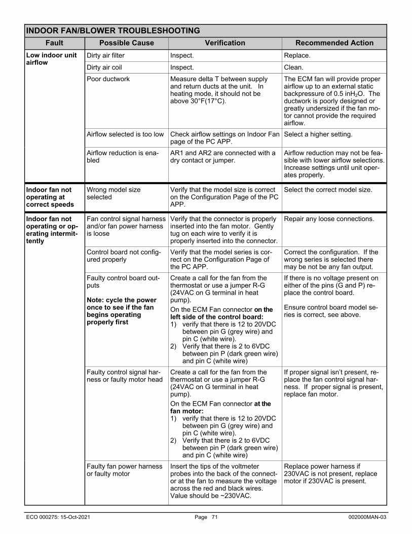
ECO 000275: 15-Oct-2021 Page 71 002000MAN-03
INDOOR FAN/BLOWER TROUBLESHOOTING
Fault Possible Cause Verification Recommended Action
Low indoor unit airflow
Dirty air filter Inspect. Replace.
Dirty air coil Inspect. Clean.
Poor ductwork Measure delta T between supply and return ducts at the unit. In heating mode, it should not be above 30°F(17°C).
The ECM fan will provide proper airflow up to an external static backpressure of 0.5 inH2O. The ductwork is poorly designed or greatly undersized if the fan mo-tor cannot provide the required airflow.
Airflow selected is too low Check airflow settings on Indoor Fan page of the PC APP.
Select a higher setting.
Airflow reduction is ena-bled
AR1 and AR2 are connected with a dry contact or jumper.
Airflow reduction may not be fea-sible with lower airflow selections. Increase settings until unit oper-ates properly.
Indoor fan not operating at correct speeds
Wrong model size selected
Verify that the model size is correct on the Configuration Page of the PC APP.
Select the correct model size.
Indoor fan not operating or op-erating intermit-tently
Fan control signal harness and/or fan power harness is loose
Verify that the connector is properly inserted into the fan motor. Gently tug on each wire to verify it is properly inserted into the connector.
Repair any loose connections.
Control board not config-ured properly
Verify that the model series is cor-rect on the Configuration Page of the PC APP.
Correct the configuration. If the wrong series is selected there may be not be any fan output.
Faulty fan power harness or faulty motor
Insert the tips of the voltmeter probes into the back of the connect-or at the fan to measure the voltage across the red and black wires. Value should be ~230VAC.
Replace power harness if 230VAC is not present, replace motor if 230VAC is present.
Faulty control board out-puts Note: cycle the power once to see if the fan begins operating properly first
Create a call for the fan from the thermostat or use a jumper R-G(24VAC on G terminal in heat pump).
On the ECM Fan connector on the left side of the control board: 1) verify that there is 12 to 20VDC
between pin G (grey wire) and pin C (white wire).
2) Verify that there is 2 to 6VDC between pin P (dark green wire) and pin C (white wire)
If there is no voltage present on either of the pins (G and P) re-place the control board. Ensure control board model se-ries is correct, see above.
Faulty control signal har-ness or faulty motor head
Create a call for the fan from the thermostat or use a jumper R-G(24VAC on G terminal in heat pump).
On the ECM Fan connector at the fan motor: 1) verify that there is 12 to 20VDC
between pin G (grey wire) and pin C (white wire).
2) Verify that there is 2 to 6VDC between pin P (dark green wire) and pin C (white wire)
If proper signal isn’t present, re-place the fan control signal har-ness. If proper signal is present, replace fan motor.

ECO 000275: 15-Oct-2021 Page 72 002000MAN-03
OUTDOOR FAN TROUBLESHOOTING
Fault Possible Cause Verification Recommended Action
Outdoor fan not operating or operating intermittently
Fan power connections. Check for 230VAC across L1 and L2 of the outdoor unit. Proceed to next step if voltage present.
If no voltage present, verify that the connections are tight in both the indoor and outdoor units. Gently tug on each wire to verify connection is good. Repair any loose connections.
Faulty PWM signal on GEN2 control board.
Use manual mode of the PC APP to set the outdoor fan to 50%. Using a multi-meter set to VDC, measure PWM1 to GND of the GEN2 control board in the indoor unit. It should be ~5VDC. Proceed to next step if volt-age present.
If signal is not present the control board may be faulty. Try cycling the power and retesting. If this does not correct the problem re-place the control board.
Fan PWM signal connec-tions.
Use manual mode of PC APP to set the outdoor fan to 50%. Using a multi-meter set to VDC, measure PWM to ground in the outdoor unit. It should be ~5VDC. Proceed to next step if voltage present.
If signal is not present, check connections of PWM wire and ground wire. Replace wiring if connections are good.
Faulty fan motor. All of the above checks have been performed and everything is OK.
Replace fan motor.
EEV TROUBLESHOOTING
If there is a refrigeration problem such as low charge, plugged filter-dryer, EEV stuck, or any other kind of restriction in the refrigera-tion system, the apparent EEV position will work its way towards 100% (full open). High superheat is also a symptom. If an EEV is not working and is stuck partway open, the apparent EEV position will work its way either to 100% or to the 10% mini-mum. If there is low suction and the EEV position is also low then the problem is generally not in the refrigeration system; check the water or air flow of the indoor or outdoor loop, whichever is currently being used as the source (evaporator). To determine if an EEV is working, use the PC APP and put the system in manual override mode. Manually adjust the EEV position by at least 25% either up or down and check to see that the suction pressure, discharge pressure and superheat react to the change. If there is no reaction, then it is likely that the EEV is not working or is stuck. There are 3 possibilities: the control board is not working properly, the cable is faulty, or the EEV is faulty. Set the EEV back to AUTO and then turn the heating or cooling demand off (but leave power on). Once the demand is off, if the EEV is working then the discharge pressure should remain significantly higher than the suction pressure, i.e. the system will not equalize (since EEV’s are closed when there is no demand). If the system does equalize it is likely that the EEV is not working and is partially open. Manually set the EEV to 25% and wait for it to stop. Set the EEV to –1, this will cause it to overdrive. You should hear the valve clicking and then the clicking should change and get louder when the valve bottoms out. If there is no clicking sound then either the control board is faulty, or the cable is faulty. The simplest method to check this is to con-nect a new EEV and cable to the control board and visually check the EEV so see if it opens and closes by setting the position o 0 and 100% If the new EEV works then the EEV in the unit needs to be replaced. 1) Connect a test EEV and test cable to the control board. 2) Set the EEV position to 0%. 3) Set the EEV position to 100% and then listen for clicking and watch to see if the pintle in the EEV moves open. 4) Set the EEV position to 0% and then listen for clicking and watch to see if the pintle in the EEV moves closed. 5) If the EEV does not move in one or both directions then the control board must be replaced. 6) If the test EEV moves in both directions then then either the cable or the EEV in the unit is faulty. 7) Disconnect the test EEV from the test cable and connect it to the cable in the unit. 8) Repeat steps 2 to 4. 9) If the test EEV moves in both directions then the EEV in the unit is faulty and must be replaced. 10) If the test EEV does not move in one or both directions then the cable must be replaced.

ECO 000275: 15-Oct-2021 Page 73 002000MAN-03
PLENUM HEATER TROUBLE SHOOTING
Fault Possible Cause Verification Recommended Action
No 230VAC across plenum heater L1 and L2
Disconnect switch open. (if installed)
Verify disconnect switch is in the ON position.
Determine why the disconnect switch was opened, if all is OK close the switch.
Fuse blown / breaker tripped
At plenum heater disconnect box (if installed), voltmeter shows voltage on the line side but not on the load side. Check if breaker is tripped.
Reset breaker or replace fuse at plenum heater disconnect box. Replace fuse with proper size and type. (Time-delay type “D”)
Same “Line” to L1 and L2 Measuring L1 to ground and L2 to ground both yield 115VAC, but L1 to L2 yields 0VAC.
Correct wiring.
No W2 signal at heat pump termi-nal strip
No call for auxiliary or emergency heat from ther-mostat
Verify that the thermostat is indicating that auxiliary or emergency heat should be on.
Set thermostat to engage auxilia-ry or emergency heat. (Note that some thermostats require a jump-er between auxiliary and emer-gency. Check the thermostat manual.)
Faulty thermostat Thermostat doesn’t indicate a call for auxiliary or emergency when it should. Or thermostat indicates aux-iliary or emergency but no 24VAC signal present across C and the auxil-iary and/or emergency pin at the ther-mostat.
Replace thermostat.
Faulty thermostat wiring 24VAC signal is present across C and the auxiliary and/or emergency pin at the thermostat but no 24VAC signal is present across W2 and C at the heat pump terminal strip.
Correct wiring.
No 24VAC signal from C to ground at the plenum heater control board
Plenum heater transform-er is burned out
Voltmeter does not show 24VAC across transformer secondary wind-ing.
Replace transformer.
Plenum heater control board is faulty
Transformer tested OK in previous step.
Replace control board.
No 24VAC signal from 1 to ground at the plenum heater control board
Faulty wiring 24VAC present across C and ground at the plenum heater, but not across ground of the plenum heater and CP of the heat pump terminal strip.
Correct wiring.
Faulty wiring If previous step tested OK, 24VAC is present across ground of the plenum heater and 1 of the heat pump termi-nal strip, but not across ground of the plenum heater and 1 of the plenum heater.
Correct wiring.
Indoor fan not operating See Indoor Fan/Blower Troubleshoot-ing section.
Correct problem. Reset thermal overload.
Plenum heater is not posi-tioned so that majority of airflow passes over heat-ing elements (only if in-stalled in ductwork outside heat pump)
Plenum heater meant for internal heat pump installation is installed in a larger duct outside heat pump, or is positioned after duct elbow.
Reposition plenum heater, or ob-tain a plenum heater model with a wider element cage (contact Maritime Geothermal).
Faulty overload Reset thermal overload. Replace if faulty.
Plenum heater thermal overload is tripped.

ECO 000275: 15-Oct-2021 Page 74 002000MAN-03
DOMESTIC HOT WATER (DESUPERHEATER) TROUBLE SHOOTING Fault Possible Cause Verification Recommended Action
Insufficient hot water (tank problem)
Thermostat on final hot water tank set too low. Should be set at 120°F to 140°F
Visually inspect the setting. Adjust the setting.
Breaker tripped, or fuse blown in electrical supply to hot water tank
Check both line and load sides of fuses. If switch is open determine why (possible shorted element).
Correct problem, and replace blown fuse or reset breaker.
Reset button tripped on hot water tank
Check voltage at elements with multimeter.
Push reset button.
DHW switch is turned off Inspect switch, located on heat pump cabinet post.
Turn switch on.
Blockage or restriction in the water line or hot water heat exchanger
Check water flow and power to pump. Check water lines for obstructions.
Remove obstruction in water lines. Acid treat the domestic hot water coil.
Faulty DHW cutout (failed open)
Check contact operation. Should close at 120°F and open at 140°F.
Replace DHW cutout if faulty.
Heat pump not running enough hours to make sufficient hot water
Note the amount of time the heat pump runs in any given hour.
Temporarily turn up the tank thermostats until colder weather creates longer run cycles.
Water is too hot. Faulty DHW cutout (failed closed)
Check contact operation. Should close at 120°F and open at 140°F.
Replace DHW cutout if faulty.
Thermostat on hot water tank set too high. Should be set at 120°F to 140°F
Visually inspect the setting. Adjust the setting.
Insufficient hot water preheat (heat pump problem)
Circulator pump seized or motor failed
Use an amprobe to measure current draw.
Replace if faulty.
Brown wire with blue insu-lated terminal at compres-sor contactor not connect-ed during installation
Inspect wire with insulated terminal as shown on electrical diagrams.
Connect wire as instructed on electrical box diagram and/or wir-ing schematic diagram.

ECO 000275: 15-Oct-2021 Page 75 002000MAN-03
Repair Procedures
Pumpdown Procedure
1. Place the unit in SERVICE mode via the PC App or LCD interface; this will open the EEVs and start the indoor circu-lator (as long that circulator is powered and controlled by the heat pump). DO NOT turn off electrical power at the breaker panel, since the coaxial coil must have full water flow during refrigerant recovery.
2. Connect the refrigerant recovery unit to the heat pump’s internal service ports via a refrigeration charging manifold and to a recovery tank as per the instructions in the recovery unit manual. Plan to dispose of refrigerant if there was a compressor burnout.
3. All refrigerant to water heat exchangers (coaxial coils, brazed plates) must either have full flow or be completely drained of fluid before recovery begins. Failure to do so can freeze and rupture the heat exchanger, voiding its warranty. (Note that this does not apply to desuperheater coils.)
4. Ensure all hose connections are properly purged of air. Start the refrigerant recovery as per the instructions in the recovery unit manual.
5. Allow the recovery unit suction pressure to reach a vacuum. Once achieved, close the charging manifold valves. Shut down, purge and disconnect the recovery unit as per the instructions in its manual. Ensure the recovery tank valve is closed before disconnecting the hose to it.
6. Connect a nitrogen tank to the charging manifold and add nitrogen to the heat pump until a positive gauge pressure of 5-10 psig is reached. This prevents air from being sucked into the unit by the vacuum when the hoses are discon-nected.
Turn off power to heat pump. The heat pump is now ready for repairs.
General Repair Procedure
1. Perform repairs to system.
Always ensure nitrogen is flowing through the system at the lowest flow rate that can be felt at the discharge dur-ing any brazing procedures to prevent soot buildup inside the pipes.
It is recommended to replace the liquid line filter-dryer any time the refrigeration system has been exposed to the atmosphere.
Place a wet rag around any valves being installed, as almost all valve types have non-metallic seats or seals that will be damaged by excessive heat, and aim the torch flame away from the valve body. Solder only one joint at a time and cool joints down in between.
2. Pressure test the system with nitrogen. It is recommended to check for leaks using leak detection spray, Spray
Nine, or soapy water. Check at 10, 25, 50 and 100 psig. Allow the system to sit at 100 psig for at least an hour, then re-check.
Vacuuming & Charging Procedure
After completion of repairs and nitrogen pressure testing, the refrigeration circuit is ready for vacuuming.
1. Release the nitrogen pressure and connect the vacuum pump to the charging manifold. Start the vacuum pump and open the charging manifold valves. Vacuum until the vacuum gauge remains at less than 500 microns for at least 1 minute with the vacuum pump valve closed.
2. Close the charging manifold valves then shut off and disconnect the vacuum pump. Place a refrigerant tank with the proper refrigerant on a scale and connect it to the charging manifold. Purge the hose to the tank.
3. Weigh in the appropriate amount and type of refrigerant through the low pressure (suction) service port. Refer to the nameplate label on the unit for the proper refrigerant type and charge amount.
4. If the unit will not accept the entire charge, the remainder can be added through the low pressure service port after the unit has been restarted.
WARNING: WHEN SERVICING THE OUTDOOR UNIT, BE SURE TO TURN OFF POWER TO THE INDOOR UNIT. The outdoor disconnect switch will not cut low voltage power, and damage to the control board will occur if the main heat pump breaker is not turned off during service.

ECO 000275: 15-Oct-2021 Page 76 002000MAN-03
Compressor Replacement Procedure
1. Pump down the unit as per the Pumpdown Procedure above. If there was a compressor burn out (motor failure), the refrigerant cannot be reused and must be disposed of according to local codes.
2. Disconnect piping.
3. Replace the compressor. Replace the liquid line filter-dryer. Always ensure nitrogen is flowing through the system at the lowest flow rate that can be felt at the discharge during any brazing procedures to prevent soot buildup inside the pipes.
4. Vacuum the unit as per above procedure.
5. If there was a compressor burnout:
a) Charge the unit with new refrigerant and operate it for continuously for 2 hours. Pump down the unit and replace the filter-dryer. Vacuum the unit as per above procedure.
b) Charge the unit (refrigerant can be re-used) and operate it for 2-3 days. Perform an acid test. If it fails, pump down the unit and replace the filter-dryer.
c) Charge the unit (refrigerant can be re-used) and operate it for 2 weeks. Perform and acid test. If it fails, pump down the unit and replace the filter-dryer.
6. Charge the unit a final time. Unit should now be clean and repeated future burn-outs can be avoided.
Outdoor Fan Replacement Procedure
1. Turn of the power to the Indoor Unit. This will ensure that power and control signals are off in the outdoor unit.
2. Remove the two screws that hold the electrical box cover in place and remove the cover.
3. Remove the two bolts that secure the front cover in place.
4. Loosen the four bolts that hold the fan guard in place.
5. Swing the front cover open.
6. For the fan signal cable: remove the YELLOW wire from the PWM terminal and remove the BLACK wire from the GND terminal.
7. For the fan power cable: remove the BLUE wire from L1, the RED wire from L2 and the YELLOW/GREEN wire from GND.
8. Pull the cables out of the electrical box, noting the path for installation of the new fan. Cut wire ties if necessary.
9. Remove the four fan guard bolts and remove the fan and guard as one.
10. Installation is the reverse of removal.

ECO 000275: 15-Oct-2021 Page 77 002000MAN-03
Control Board Replacement Procedure
1. Turn the power off to the unit.
2. Take a picture of the control board and connectors for reference. The picture in Appendix A may also be helpful.
3. Carefully remove all green terminal strips on the left side, the right side and the bottom of the control board. They pull straight off the board, with no need to disconnect wires from their screw terminals. You may need to wiggle them from both ends for the 8 pin ones.
4. Remove the red six pin display board connector from the left side of the control board (marked DISPLAY on the board).
5. Remove all connectors from the top of the control board. Each connector (or wire) should be marked already from the factory, e.g. HPS1, LP1, TS1, etc.. This matches the marking on the control board.
6. The control board is held in place at its four corners. Squeeze each standoff by hand or with needle nose pliers if necessary and carefully pull the corner of the board off of the standoff.
7. Once the control board has been removed, if there are any other standoffs left (they have the bottom snap cut off) remove them as well.
8. Carefully remove the new control board from the static bag it was shipped in. Place any cut off standoffs from the old board into the same locations on the new board.
9. Align the control board with the four corner standoffs in the electrical box then push on each corner until they snap in place.
10. Connect the top connectors to the control board. Refer to the Step 2 picture if necessary for proper locations.
Note that the connector with the resistor (no cable) goes on CTS. Note that the connector to the left of CTS is marked HTS on older boards, and ODTS on newer boards.
11. Check each of the connectors from Step 10 to ensure they are properly aligned and that no pins are showing.
12. Connect the green terminal strips to the left side, right side and bottom of the control board. Refer to the Step 2 pic-ture if necessary for locations.
13. Turn the power on to the heat pump. Ensure the LCD Interface comes on. Note the firmware version. After EEV zeroing and Random Start countdown the display should begin alternating data.
14. If the replacement control board was pre-configured for this unit at the factory then the system is ready for operation. If it was not then use the PC App corresponding to the unit’s firmware version to configure the unit. Refer to the Tools -> Configuration menu in the PC APP section.

ECO 000275: 15-Oct-2021 Page 78 002000MAN-03
LCD Interface (Display) Board Replacement Procedure
1. Turn the power off to the unit.
2. Remove the display board cable connector from the control board.
3. Using a sharp utility knife with a long blade, slice each of the display board standoff heads off, taking care to not damage the lexan cover.
4. Pull the display board from the unit.
5. Remove the display board cable connector from the back of the display board.
6. Place a new display board standoff into each of the four holes in the cabinet.
7. Remove the new display board from the static bag it was shipped in.
8. Connect one end of the display board cable to the back of the display board. Ensure the connector is properly aligned and that no pins are showing.
9. Place the display board in position and align the four standoffs into the four holes of the board.
10. Push on each corner of the board until each standoff snaps in place, while pushing on the front of the standoff to keep it from popping out of the cabinet hole.
11. Connect the other end of the display board cable to the control board, ensuring the connector is aligned properly and that no pins are showing.
12. Turn the power on to the unit and verify the display works.
13. Once the display begins to scroll data, test each of the buttons to ensure they work. Push the Arrow button to enter the Main Menu, then use the Up and Down to move through the list, then push the OK button to exit again. If any of the buttons seem hard to press, repeat Step 10 and then test the buttons again.

ECO 000275: 15-Oct-2021 Page 79 002000MAN-03
Model Specific Information
Table 29 - Refrigerant Charge
MODEL lb kg Refrigerant Oil Type
ATF-45 7.5 3.4 R410a POE
ATF-55 11.0 5.0 R410a POE
ATF-65 12.0 5.5 R410a POE
ATF-75 13.0 5.9 R410a POE
- Oil capacity is marked on the compressor label. - Refrigerant charge is subject to revision; actual charge is indicated on the unit nameplate.
Table 27 - Shipping Information - Indoor Unit
MODEL WEIGHT DIMENSIONS in (cm)
lb. (kg) L W H
ATF-45 450 (205) 44 (112) 36 (91) 66 (167)
ATF-55 490 (223) 44 (112) 36 (91) 66 (167)
ATF-65 505 (230) 44 (112) 36 (91) 66 (167)
ATF-75 530 (240) 44 (112) 36 (91) 66 (167)
Table 28 - Shipping Information - Outdoor Unit
MODEL WEIGHT DIMENSIONS in (cm)
lb. (kg) L W H
ACE-45 230 (104) 36 (91) 70 (178) 45 (114)
ACE-55 230 (104) 36 (91) 70 (178) 45 (114)
ACE-65 295 (134) 36 (91) 70 (178) 56 (142)
ACE-75 295 (134) 36 (91) 70 (178) 56 (142)
Table 30 - Indoor Loop Flow Rates
MODEL gpm L/s
ATF-45 10 0.63
ATF-55 12 0.76
ATF-65 14 0.88
ATF-75 16 1.0
Table 32 - Outdoor Unit Sound Levels (dBA)*
MODEL 1 ft distance 3 ft distance 5 ft distance 10 ft distance
Front Side Front Sides Front Sides Front Sides
ACE-45 68.0 61.1 66.4 59.7 63.5 57.4 59.3 56.7
ACE-55 72.4 66.8 71.1 64.8 68.0 62.9 64.6 61.1
ACE-65 70.3 62.9 65.9 60.5 62.2 58.1 56.6 54.0
ACE-75 71.7 66.8 68.7 63.7 65.7 61.2 60.0 57.1
* At maximum fan speed. This occurs in heating mode, or in cooling mode with outdoor greater than ~27°C.
Table 31 - Operating Temperature Limits
Loop Mode Parameter (°F) (°C) Note
INDOOR
AIR Heating Minimum EAT 60 15
AIR Heating Maximum EAT 100 38
AIR Cooling Minimum EAT 50 10
AIR Cooling Maximum EAT 100 38
OUTDOOR Heating Minimum EAT -7 -22 Compressor automatically stops below this outdoor temperature.
Cooling Maximum EAT 120 49 Compressor automatically stops above this outdoor temperature.
WATER Heating Maximum LLT 120 49
WATER Heating Minimum ELT 60 15
Table 33 - Indoor Unit Sound (dBA)*
MODEL 1 ft distance 3 ft distance
ATF-45 58.4 56.6
ATF-55 60.7 59.8
ATF-65 61.4 59.7
ATF-75 65.5 64.8
* With all doors installed.

ECO 000275: 15-Oct-2021 Page 80 002000MAN-03
Standard Capacity Ratings Standard CSA C656 (ARI 210-240). < Preliminary >
Table 35 - Standard Capacity Ratings - Air Heating 60 Hz Indoor Air
70°F (21°C) db / 60°F (15.6°C) wb H12 - Outdoor Air 47°F (8.3°C) H22 - Outdoor Air 35°F (1.7°C) H32- Outdoor Air 17°F (-8.3°C)
Model Indoor Airflow Stage
Input Energy Capacity COPH Input
Energy Capacity COPH Input Energy Capacity COPH
cfm L/s Watts Btu/hr kW W/W Watts Btu/hr kW W/W Watts Btu/hr kW W/W
45 1200 566 2 2,290 30,100 8.8 3.85 2,240 25,500 7.5 3.34 2,100 19,600 5.8 2.74
55 1500 708 2 3,110 40,700 11.9 3.83 3,030 34,400 10.1 3.33 2,760 25,700 7.5 2.72
65 1900 897 2 3,955 51,800 15.2 3.84 3,810 43,200 12.7 3.32 3,560 32,800 9.6 2.70
75 2100 991 2 4,550 59,400 17.4 3.83 4,485 50,700 14.9 3.31 4,295 39,000 11.4 2.66
Table 36 - Standard Capacity Ratings - Air Cooling 60 Hz Indoor Air
80°F (26.7°C) db / 67°F (19.4°C) wb B2 - Outdoor Air 82°F (27.8°C) A2 - Outdoor Air 95°F (35°C)
Model Indoor Airflow Stage
Input Energy Capacity EER COPC Input
Energy Capacity EER COPC
cfm L/s Watts Btu/hr kW Btu/W-hr W/W Watts Btu/hr kW Btu/W-hr W/W
45 1200 566 2 2,235 34,100 10.0 15.2 4.47 2,605 31,400 9.2 12.1 3.53
55 1500 708 2 2,925 44,000 12.9 15.0 4.41 3,410 40,600 11.9 11.9 3.49
65 1900 897 2 3,725 55,400 16.2 14.9 4.36 4,310 51,200 15.0 11.9 3.48
75 2100 991 2 4,385 64,600 18.9 14.7 4.31 5,010 59,200 17.4 11.8 3.46
Table 37 - Standard Capacity Ratings - Hydronic Heating 60 Hz
Indoor Loop ELT 104°F (40°C) H12 - Outdoor Air 47°F (8.3°C) H22 - Outdoor Air 35°F (1.7°C) H32- Outdoor Air 17°F (-8.3°C)
Model Indoor Liquid Flow
Pressure Drop Stage Input
Energy Capacity COPH Input Energy Capacity COPH Input
Energy Capacity COPH
gpm L/s psi kPa Watts Btu/hr kW W/W Watts Btu/hr kW W/W Watts Btu/hr kW W/W
45 10.0 0.63 3.8 26 2 2518 33,600 9.9 3.91 2581 29,200 8.6 3.32 2742 22,000 6.5 2.35
55 12.0 0.76 4.1 28 2 3270 43,400 12.7 3.89 3320 37,400 11.0 3.30 3615 28,700 8.4 2.32
65 14.0 0.88 5.0 34 2 3866 51,000 14.9 3.86 3837 43,400 12.7 3.31 4272 33,900 9.9 2.33
75 16.0 1.01 4.0 36 2 4417 58,600 17.2 3.88 4527 50,200 14.7 3.25 4893 38,400 11.2 2.30
Water 104°F
ATF-45 ATF-55 ATF-65 ATF-75
gpm L/s psi kPa psi kPa psi kPa psi kPa
5 0.32 1.1 7.6
6 0.38 1.6 11 1.1 7.6 1.1 7.6 1.1 7.6
7 0.44 1.9 13 1.5 10 1.5 10 1.4 10
8 0.50 2.6 18 1.8 12 1.8 12 1.8 12
9 0.57 3.2 22 2.2 15 2.2 15 2.1 14
10 0.63 3.8 26 2.7 19 2.7 19 2.4 17
11 0.69 4.3 30 2.8 19 2.8 19 2.9 20
12 0.76 5.2 36 3.4 23 3.4 23 3.6 25
13 0.82 5.9 41 4 28 4 28 4.1 28
14 0.88 6.7 46 4.7 32 4.7 32 4.7 32
15 0.95 8.0 55 5.6 39 5.6 39 5.5 38
16 1.01 6.1 42 6.1 42 6.3 43
Table 34: Hydronic Loop Pressure
Drop Data
Pressure Drop Data

ECO 000275: 15-Oct-2021 Page 81 002000MAN-03
METRIC
OUTDOOR LOOP (Air) ELECTRICAL INDOOR LOOP (Air)
Outdoor Air Temperature
Condensing Temperature
Heat Rejected (Btu/hr)
Compressor Current (A)
Fan (W)
Input Power (W)
EAT Evap. Temp.
Airflow (cfm)
LAT (°F)
Delta T (°F)
Latent (Btu/hr)
Sensible (Btu/hr)
Cooling (Btu/hr)
EER
50°F 61 47,054 6.4 170 1,739
80°F
46 1,200 56 24 12,370 28,455 40,825 23.5 60°F 71 45,268 6.8 170 1,852 47 1,200 58 23 11,712 26,941 38,653 20.9 70°F 82 43,764 7.5 170 2,018 47 1,200 59 21 11,085 25,499 36,583 18.1 80°F 92 42,248 8.3 170 2,191 47 1,200 60 20 10,446 24,030 34,476 15.7 90°F 103 41,028 9.4 170 2,456 48 1,200 61 19 9,679 22,691 32,370 13.2
100°F 113 39,667 10.6 170 2,703 48 1,200 62 18 9,020 21,147 30,167 11.2 110°F 124 38,322 12.2 170 2,993 49 1,200 64 16 8,322 19,510 27,832 9.3 120°F 135 36,960 14.1 170 3,319 49 1,200 65 15 7,581 17,774 25,356 7.6
ATF-45-HACW-P-1T R410a, 60 Hz, ZPS30K5E-PFV OUTDOOR LOOP (Air) ELECTRICAL INDOOR LOOP (Air)
Outdoor Air Temperature
Evaporating Temperature
Heat Absorbed (Btu/hr)
Compressor Current (A)
Fan (W)
Input Power (W)
EAT Cond. Temp.
Airflow (cfm)
LAT (°F)
Delta T (°F)
Heating (Btu/hr)
COPH
-5°F -16 6,563 8.3 175 2,109
70°F
92 1,200 82 12 13,763 1.91 5°F -8 9,208 8.7 175 2,073 96 1,200 84 14 16,282 2.30
15°F 0 11,862 9.2 175 2,097 100 1,200 86 16 19,018 2.66 25°F 8 14,780 9.7 175 2,164 104 1,200 89 19 22,167 3.00 35°F 16 17,901 10.2 175 2,241 108 1,200 91 21 25,548 3.34 45°F 25 21,314 10.7 175 2,293 112 1,200 94 24 29,141 3.72 55°F 32 24,824 11.2 175 2,365 116 1,200 97 27 32,894 4.08 65°F 40 28,562 11.7 175 2,454 120 1,200 101 31 36,936 4.41
HE
AT
ING
C
OO
LIN
G
Air Heating/Cooling Performance
OUTDOOR LOOP (Air) ELECTRICAL INDOOR LOOP (Air)
Outdoor Air Temperature
Condensing Temperature
Heat Rejected (W)
Compressor Current (A)
Fan (W)
Input Power (W)
EAT Evap. Temp.
Airflow (L/s)
LAT (°C)
Delta T (°C)
Latent (W)
Sensible (W)
Cooling (W)
COPC
10°C 16.1 13,787 6.4 170 1,739
27°C
7.9 566 13.5 13.2 3,624 8,337 11,962 6.88 16°C 21.7 13,263 6.8 170 1,852 8.1 566 14.2 12.5 3,432 7,894 11,325 6.11 21°C 27.8 12,823 7.5 170 2,018 8.3 566 14.9 11.8 3,248 7,471 10,719 5.31 27°C 33.3 12,379 8.3 170 2,191 8.6 566 15.5 11.1 3,061 7,041 10,101 4.61 32°C 39.4 12,021 9.4 170 2,456 8.8 566 16.2 10.5 2,836 6,649 9,484 3.86 38°C 45.0 11,622 10.6 170 2,703 9.0 566 16.9 9.8 2,643 6,196 8,839 3.27 43°C 51.1 11,228 12.2 170 2,993 9.2 566 17.6 9.0 2,438 5,716 8,155 2.72 49°C 57.2 10,829 14.1 170 3,319 9.4 566 18.4 8.2 2,221 5,208 7,429 2.24
OUTDOOR LOOP (Air) ELECTRICAL INDOOR LOOP (Air)
Outdoor Air Temperature
Evaporating Temperature
Heat Absorbed (W)
Compressor Current (A)
Fan (W)
Input Power (W)
EAT Cond. Temp.
Airflow (L/s)
LAT (°C)
Delta T (°C)
Heating (W)
COPH
-21°C -26.7 1,923 8.3 175 2,109
21°C
33.3 566 27.5 6.4 4,032 1.91 -15°C -22.2 2,698 8.7 175 2,073 35.6 566 28.6 7.5 4,770 2.30 -9°C -17.8 3,475 9.2 175 2,097 37.8 566 29.9 8.8 5,572 2.66 -4°C -13.4 4,331 9.7 175 2,164 40.0 566 31.4 10.3 6,495 3.00 2°C -8.8 5,245 10.2 175 2,241 42.2 566 32.9 11.8 7,486 3.34 7°C -3.9 6,245 10.7 175 2,293 44.4 566 34.6 13.5 8,538 3.72
13°C 0.2 7,273 11.2 175 2,365 46.7 566 36.3 15.2 9,638 4.08 18°C 4.6 8,368 11.7 175 2,454 48.9 566 38.2 17.1 10,822 4.41
HE
AT
ING
C
OO
LIN
G
< Preliminary >

ECO 000275: 15-Oct-2021 Page 82 002000MAN-03
METRIC
OUTDOOR LOOP (Air) ELECTRICAL INDOOR LOOP (Water)
Outdoor Air Temperature
Evaporating Temperature
Heat Absorbed (W)
Compressor Current (A)
Input Power (W)
ELT Condensing Temperature
Liquid Flow (L/s)
LLT Delta T Heating
(W) COPH
-21°C -27°C 1620 13.5 3290 39°C 43°C
0.63 40.5°C
1.8°C 4,860 1.48
-15°C -22°C 2780 11.5 2830 38°C 43°C 2.1°C 5,560 1.96
-9°C -18°C 3700 10.5 2620 38°C 43°C 2.4°C 6,270 2.39
-4°C -13°C 5020 10.1 2520 38°C 43°C 2.8°C 7,480 2.97
2°C -8°C 6280 9.7 2430 37°C 43°C 3.3°C 8,660 3.56
7°C -4°C 7400 9.4 2360 37°C 43°C 3.7°C 9,700 4.12
13°C 1°C 8440 9.1 2270 37°C 43°C 4.0°C 10,700 4.70
18°C 6°C 9580 8.8 2180 36°C 42°C 4.4°C 11,700 5.38
-21°C -27°C - - - - -
0.63 49°C
-15°C -22°C - - - - -
-9°C -18°C 3180 13.0 3180 47°C 51°C 2.4°C 6,240 1.98
-4°C -13°C 4370 12.3 3040 46°C 51°C 2.8°C 7,350 2.42
2°C -8°C 5530 11.8 2920 46°C 51°C 3.2°C 8,390 2.88
7°C -4°C 6560 11.4 2820 45°C 51°C 3.5°C 9,320 3.30
13°C 1°C 7530 11.0 2710 45°C 51°C 3.9°C 10,200 3.76 18°C 6°C 8590 10.6 2600 4°C 51°C 4.2°C 11,100 4.28
LLT is limited to 40.5°C at these outdoor temperatures
OUTDOOR LOOP (Air) ELECTRICAL INDOOR LOOP (Water)
Outdoor Air Temperature
Evaporating Temperature
Heat Absorbed (Btu/hr)
Compressor Current (A)
Input Power (W)
ELT Condensing Temperature
Liquid Flow (gpm)
LLT Delta T Heating (Btu/hr)
COPH
-5°F -16°F 5,530 13.5 3290 102°F 110°F
10 105°F
3°F 16,600 1.48
5°F -8°F 9,490 11.5 2830 101°F 110°F 4°F 19,000 1.96
15°F 1°F 12,600 10.5 2620 101°F 109°F 4°F 21,400 2.39
25°F 9°F 17,100 10.1 2520 100°F 109°F 5°F 25,500 2.97
35°F 17°F 21,400 9.7 2430 99°F 109°F 6°F 29,500 3.56
45°F 26°F 25,200 9.4 2360 98°F 109°F 7°F 33,100 4.12
55°F 34°F 28,800 9.1 2270 98°F 109°F 7°F 36,400 4.70
65°F 43°F 32,700 8.8 2180 97°F 108°F 8°F 39,900 5.38
-5°F -16°F - - - - -
10 120°F
5°F -8°F - - - - -
15°F 1°F 10,900 13.0 3180 116°F 124°F 4°F 21,300 1.98
25°F 9°F 14,900 12.3 3040 115°F 124°F 5°F 25,100 2.42
35°F 17°F 18,900 11.8 2920 114°F 124°F 6°F 28,600 2.88
45°F 26°F 22,400 11.4 2820 114°F 124°F 6°F 31,800 3.30
55°F 34°F 25,700 11.0 2710 113°F 123°F 7°F 34,800 3.76
65°F 43°F 29,300 10.6 2600 112°F 123°F 8°F 38,000 4.28
LLT is limited to 105°F at these outdoor temperatures H
EA
TIN
G
HE
AT
ING
Hydronic Performance
ATF-45-HACW-P-1T R410a, 60 Hz, ZPS30K5E-PFV

ECO 000275: 15-Oct-2021 Page 83 002000MAN-03
METRIC
OUTDOOR LOOP (Air) ELECTRICAL INDOOR LOOP (Air)
Outdoor Air Temperature
Condensing Temperature
Heat Rejected (Btu/hr)
Compressor Current (A)
Fan (W)
Input Power (W)
EAT Evap. Temp.
Airflow (cfm)
LAT (°F)
Delta T (°F)
Latent (Btu/hr)
Sensible (Btu/hr)
Cooling (Btu/hr)
EER
50°F 62 58,709 8.7 195 2,164
80°F
46 1,500 56 24 15,432 35,499 50,931 23.5 60°F 72 57,478 9.4 195 2,367 46 1,500 57 23 14,849 34,157 49,006 20.7 70°F 83 56,122 10.5 195 2,613 46 1,500 58 22 14,184 32,627 46,811 17.9 80°F 93 54,638 11.8 195 2,853 47 1,500 59 21 13,486 31,022 44,508 15.6 90°F 104 53,224 13.4 195 3,194 47 1,500 60 20 12,535 29,388 41,923 13.1
100°F 114 51,622 15.0 195 3,538 48 1,500 62 18 11,705 27,442 39,146 11.1 110°F 125 50,123 17.2 195 3,968 48 1,500 63 17 10,818 25,362 36,180 9.1 120°F 135 48,394 19.4 195 4,383 48 1,500 65 15 9,878 23,159 33,037 7.5
ATF-55-HACW-P-1T R410a, 60 Hz, ZPS40K5E-PFV OUTDOOR LOOP (Air) ELECTRICAL INDOOR LOOP (Air)
Outdoor Air Temperature
Evaporating Temperature
Heat Absorbed (Btu/hr)
Compressor Current (A)
Fan (W)
Input Power (W)
EAT Cond. Temp.
Airflow (cfm)
LAT (°F)
Delta T (°F)
Heating (Btu/hr)
COPH
-5°F -17 7,655 12.1 185 2,552
70°F
91 1,500 81 11 16,367 1.88 5°F -8 11,495 12.6 185 2,651 95 1,500 84 14 20,542 2.27
15°F 0 15,352 13.1 185 2,765 99 1,500 87 17 24,789 2.63 25°F 8 19,493 13.7 185 2,891 103 1,500 90 20 29,359 2.98 35°F 17 23,987 14.3 185 3,028 107 1,500 93 23 34,321 3.32 45°F 25 29,148 14.9 185 3,114 111 1,500 97 27 39,777 3.74 55°F 33 34,697 15.5 185 3,241 115 1,500 101 31 45,758 4.14 65°F 41 40,532 16.1 185 3,368 119 1,500 105 35 52,027 4.53
HE
AT
ING
C
OO
LIN
G
Air Heating/Cooling Performance
OUTDOOR LOOP (Air) ELECTRICAL INDOOR LOOP (Air)
Outdoor Air Temperature
Condensing Temperature
Heat Rejected (W)
Compressor Current (A)
Fan (W)
Input Power (W)
EAT Evap. Temp.
Airflow (L/s)
LAT (°C)
Delta T (°C)
Latent (W)
Sensible (W)
Cooling (W)
COPC
10°C 16.7 17,202 8.7 195 2,164
27°C
7.6 708 13.5 13.1 4,522 10,401 14,923 6.90 16°C 22.2 16,841 9.4 195 2,367 7.8 708 14.0 12.7 4,351 10,008 14,359 6.07 21°C 28.3 16,444 10.5 195 2,613 8.0 708 14.6 12.1 4,156 9,560 13,715 5.25 27°C 33.9 16,009 11.8 195 2,853 8.2 708 15.2 11.5 3,951 9,089 13,041 4.57 32°C 40.0 15,594 13.4 195 3,194 8.4 708 15.8 10.9 3,673 8,611 12,283 3.85 38°C 45.6 15,125 15.0 195 3,538 8.7 708 16.5 10.2 3,429 8,040 11,470 3.24 43°C 51.7 14,686 17.2 195 3,968 8.9 708 17.3 9.4 3,170 7,431 10,601 2.67 49°C 57.2 14,179 19.4 195 4,383 9.1 708 18.1 8.6 2,894 6,785 9,680 2.21
OUTDOOR LOOP (Air) ELECTRICAL INDOOR LOOP (Air)
Outdoor Air Temperature
Evaporating Temperature
Heat Absorbed (W)
Compressor Current (A)
Fan (W)
Input Power (W)
EAT Cond. Temp.
Airflow (L/s)
LAT (°C)
Delta T (°C)
Heating (W)
COPH
-21°C -26.9 2,243 12.1 185 2,552
21°C
32.8 708 27.2 6.1 4,795 1.88 -15°C -22.3 3,368 12.6 185 2,651 35.0 708 28.7 7.6 6,019 2.27 -9°C -17.8 4,498 13.1 185 2,765 37.2 708 30.3 9.2 7,263 2.63 -4°C -13.3 5,711 13.7 185 2,891 39.4 708 32.0 10.9 8,602 2.98 2°C -8.6 7,028 14.3 185 3,028 41.7 708 33.8 12.7 10,056 3.32 7°C -3.9 8,540 14.9 185 3,114 43.9 708 35.8 14.7 11,654 3.74
13°C 0.7 10,166 15.5 185 3,241 46.1 708 38.1 16.9 13,407 4.14 18°C 4.9 11,876 16.1 185 3,368 48.3 708 40.4 19.3 15,244 4.53
HE
AT
ING
C
OO
LIN
G
< Preliminary >

ECO 000275: 15-Oct-2021 Page 84 002000MAN-03
METRIC
OUTDOOR LOOP (Air) ELECTRICAL INDOOR LOOP (Water)
Outdoor Air Temperature
Evaporating Temperature
Heat Absorbed (W)
Compressor Current (A)
Input Power (W)
ELT Condensing Temperature
Liquid Flow (L/s)
LLT Delta T Heating
(W) COPH
-21°C -27°C 2,000 16.7 3870 39°C 43°C
0.76 40.5°C
1.8°C 5,800 1.50
-15°C -22°C 3,460 15.7 3670 38°C 43°C 2.2°C 7,070 1.93
-9°C -18°C 4,750 14.8 3470 38°C 43°C 2.6°C 8,160 2.35
-4°C -13°C 6,270 14.0 3290 38°C 43°C 3.0°C 9,510 2.89
2°C -8°C 8,040 13.2 3120 37°C 43°C 3.5°C 11,100 3.56
7°C -4°C 9,540 12.8 3050 37°C 42°C 4.0°C 12,500 4.11
13°C 1°C 11,000 12.5 2960 36°C 42°C 4.4°C 13,900 4.69
18°C 6°C 12,500 12.2 2870 36°C 42°C 4.8°C 15,300 5.34
-21°C -27°C - - - - -
0.76 49°C
-15°C -22°C - - - - -
-9°C -18°C 3,900 17.6 4120 46°C 51°C 2.5°C 7,950 1.93
-4°C -13°C 5,350 16.6 3920 46°C 51°C 2.9°C 9,210 2.35
2°C -8°C 7,010 15.8 3730 46°C 51°C 3.4°C 10,700 2.87
7°C -4°C 8,430 15.4 3640 45°C 51°C 3.8°C 12,000 3.30
13°C 1°C 9,810 15.1 3550 45°C 51°C 4.2°C 13,300 3.75 18°C 6°C 11,200 14.7 3440 44°C 51°C 4.6°C 14,600 4.23
LLT is limited to 40.5°C at these outdoor temperatures
OUTDOOR LOOP (Air) ELECTRICAL INDOOR LOOP (Water)
Outdoor Air Temperature
Evaporating Temperature
Heat Absorbed (Btu/hr)
Compressor Current (A)
Input Power (W)
ELT Condensing Temperature
Liquid Flow (gpm)
LLT Delta T Heating (Btu/hr)
COPH
-5°F -16°F 6,810 16.7 3870 102°F 110°F
12 105°F
3°F 19,800 1.50
5°F -8°F 11,800 15.7 3670 101°F 109°F 4°F 24,100 1.93
15°F 1°F 16,200 14.8 3470 100°F 109°F 5°F 27,800 2.35
25°F 9°F 21,400 14.0 3290 100°F 109°F 5°F 32,400 2.89
35°F 17°F 27,400 13.2 3120 99°F 109°F 6°F 37,900 3.56
45°F 26°F 32,600 12.8 3050 98°F 108°F 7°F 42,800 4.11
55°F 34°F 37,500 12.5 2960 97°F 108°F 8°F 47,500 4.69
65°F 43°F 42,600 12.2 2870 96°F 108°F 9°F 52,200 5.34
-5°F -16°F - - - - -
12 120°F
5°F -8°F - - - - -
15°F 1°F 13,300 17.6 4120 115°F 124°F 5°F 27,100 1.93
25°F 9°F 18,300 16.6 3920 115°F 124°F 5°F 31,400 2.35
35°F 17°F 23,900 15.8 3730 114°F 123°F 6°F 36,400 2.87
45°F 26°F 28,800 15.4 3640 113°F 123°F 7°F 41,000 3.30
55°F 34°F 33,500 15.1 3550 112°F 123°F 8°F 45,400 3.75
65°F 43°F 38,200 14.7 3440 111°F 123°F 9°F 49,800 4.23
LLT is limited to 105°F at these outdoor temperatures H
EA
TIN
G
HE
AT
ING
(M
ET
RIC
) Hydronic Performance
ATF-55-HACW-P-1T R410a, 60 Hz, ZPS40K5E-PFV

ECO 000275: 15-Oct-2021 Page 85 002000MAN-03
ATF-65-HACW-P-1T R410a, 60 Hz, ZPS51K5E-PFV
Air Heating/Cooling Performance < Preliminary >
METRIC
OUTDOOR LOOP (Air) ELECTRICAL INDOOR LOOP (Air)
Outdoor Air Temperature
Condensing Temperature
Heat Rejected (Btu/hr)
Compressor Current (A)
Fan (W)
Input Power (W)
EAT Evap. Temp.
Airflow (cfm)
LAT (°F)
Delta T (°F)
Latent (Btu/hr)
Sensible (Btu/hr)
Cooling (Btu/hr)
EER
50°F 62 75,605 11.5 325 2,827
80°F
46 1,900 56 24 19,831 45,618 65,449 23.2 60°F 72 73,150 12.3 325 3,038 46 1,900 57 23 18,869 43,404 62,272 20.5 70°F 83 71,046 13.5 325 3,339 46 1,900 58 22 17,920 41,222 59,142 17.7 80°F 93 68,938 14.9 325 3,640 47 1,900 60 21 16,970 39,037 56,008 15.4 90°F 104 67,066 16.8 325 4,050 47 1,900 61 20 15,773 36,980 52,753 13.0
100°F 114 65,053 18.8 325 4,469 48 1,900 62 18 14,743 34,566 49,309 11.0 110°F 125 63,253 21.4 325 5,009 48 1,900 63 17 13,654 32,011 45,664 9.1 120°F 135 61,121 24.1 325 5,549 48 1,900 65 15 12,465 29,225 41,690 7.5
OUTDOOR LOOP (Air) ELECTRICAL INDOOR LOOP (Air)
Outdoor Air Temperature
Evaporating Temperature
Heat Absorbed (Btu/hr)
Compressor Current (A)
Fan (W)
Input Power (W)
EAT Cond. Temp.
Airflow (cfm)
LAT (°F)
Delta T (°F)
Heating (Btu/hr)
COPH
-5°F -17 10,119 15.3 300 3,456
70°F
91 1,900 82 12 21,916 1.86 5°F -8 14,899 15.6 300 3,467 95 1,900 84 14 26,734 2.26
15°F 0 19,721 16.2 300 3,563 99 1,900 87 17 31,882 2.62 25°F 8 24,813 16.8 300 3,681 103 1,900 90 20 37,378 2.97 35°F 17 30,197 17.5 300 3,812 107 1,900 93 23 43,209 3.32 45°F 25 36,696 18.3 300 3,953 111 1,900 96 26 50,188 3.72 55°F 34 43,231 19.1 300 4,122 115 1,900 100 30 57,299 4.07 65°F 42 49,827 20.0 300 4,300 119 1,900 104 34 64,503 4.40
HE
AT
ING
C
OO
LIN
G
OUTDOOR LOOP (Air) ELECTRICAL INDOOR LOOP (Air)
Outdoor Air Temperature
Condensing Temperature
Heat Rejected (W)
Compressor Current (A)
Fan (W)
Input Power (W)
EAT Evap. Temp.
Airflow (L/s)
LAT (°C)
Delta T (°C)
Latent (W)
Sensible (W)
Cooling (W)
COPC
10°C 16.7 22,152 11.5 325 2,827
27°C
7.6 900 13.3 13.3 5,810 13,366 19,176 6.78 16°C 22.2 21,433 12.3 325 3,038 7.8 900 14.0 12.7 5,528 12,717 18,246 6.01 21°C 28.3 20,816 13.5 325 3,339 8.0 900 14.6 12.1 5,251 12,078 17,328 5.19 27°C 33.9 20,199 14.9 325 3,640 8.2 900 15.3 11.4 4,972 11,438 16,410 4.51 32°C 40.0 19,650 16.8 325 4,050 8.4 900 15.9 10.8 4,622 10,835 15,457 3.82 38°C 45.6 19,060 18.8 325 4,469 8.7 900 16.6 10.1 4,320 10,128 14,447 3.23 43°C 51.7 18,533 21.4 325 5,009 8.9 900 17.3 9.4 4,000 9,379 13,379 2.67 49°C 57.2 17,908 24.1 325 5,549 9.1 900 18.1 8.5 3,652 8,563 12,215 2.20
OUTDOOR LOOP (Air) ELECTRICAL INDOOR LOOP (Air)
Outdoor Air Temperature
Evaporating Temperature
Heat Absorbed (W)
Compressor Current (A)
Fan (W)
Input Power (W)
EAT Cond. Temp.
Airflow (L/s)
LAT (°C)
Delta T (°C)
Heating (W)
COPH
-21°C -26.9 2,965 15.3 300 3,456
21°C
32.8 900 27.5 6.4 6,421 1.86 -15°C -22.3 4,365 15.6 300 3,467 35.0 900 28.9 7.8 7,833 2.26 -9°C -17.8 5,778 16.2 300 3,563 37.2 900 30.4 9.3 9,341 2.62 -4°C -13.3 7,270 16.8 300 3,681 39.4 900 32.0 10.9 10,952 2.97 2°C -8.6 8,848 17.5 300 3,812 41.7 900 33.7 12.6 12,660 3.32 7°C -3.9 10,752 18.3 300 3,953 43.9 900 35.8 14.7 14,705 3.72
13°C 0.9 12,666 19.1 300 4,122 46.1 900 37.9 16.8 16,788 4.07 18°C 5.3 14,599 20.0 300 4,300 48.3 900 40.0 18.9 18,899 4.40
HE
AT
ING
C
OO
LIN
G
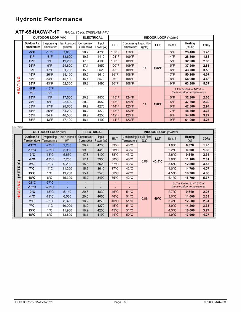
ECO 000275: 15-Oct-2021 Page 86 002000MAN-03
METRIC
OUTDOOR LOOP (Air) ELECTRICAL INDOOR LOOP (Water)
Outdoor Air Temperature
Evaporating Temperature
Heat Absorbed (W)
Compressor Current (A)
Input Power (W)
ELT Condensing Temperature
Liquid Flow (L/s)
LLT Delta T Heating
(W) COPH
-21°C -27°C 2,230 20.7 4730 39°C 43°C
0.88 40.5°C
1.9°C 6,870 1.45
-15°C -22°C 3,980 19.3 4410 38°C 43°C 2.2°C 8,300 1.88
-9°C -18°C 5,630 17.8 4100 38°C 43°C 2.6°C 9,640 2.35
-4°C -13°C 7,250 17.1 3950 38°C 43°C 3.0°C 11,100 2.81
2°C -8°C 9,290 15.5 3620 37°C 43°C 3.5°C 12,800 3.55
7°C -4°C 11,200 15.5 3610 37°C 42°C 4.0°C 14,700 4.07
13°C 1°C 13,200 15.4 3570 36°C 42°C 4.5°C 16,700 4.68
18°C 6°C 15,300 15.2 3490 36°C 42°C 5.1°C 18,700 5.37
-21°C -27°C - - - - -
0.88 49°C
-15°C -22°C - - - - -
-9°C -18°C 5,140 20.8 4830 46°C 51°C 2.7°C 9,610 2.05
-4°C -13°C 6,560 20.0 4650 46°C 51°C 3.0°C 11,000 2.39
2°C -8°C 8,370 18.2 4270 46°C 51°C 3.4°C 12,500 2.94
7°C -4°C 10,000 18.2 4270 45°C 51°C 3.9°C 14,200 3.33
13°C 1°C 11,900 18.2 4250 45°C 51°C 4.3°C 16,000 3.77 18°C 6°C 13,800 18.1 4190 44°C 50°C 4.9°C 17,900 4.27
LLT is limited to 40.5°C at these outdoor temperatures
OUTDOOR LOOP (Air) ELECTRICAL INDOOR LOOP (Water)
Outdoor Air Temperature
Evaporating Temperature
Heat Absorbed (Btu/hr)
Compressor Current (A)
Input Power (W)
ELT Condensing Temperature
Liquid Flow (gpm)
LLT Delta T Heating (Btu/hr)
COPH
-5°F -16°F 7,600 20.7 4730 102°F 110°F
14 105°F
3°F 23,400 1.45
5°F -8°F 13,600 19.3 4410 101°F 109°F 4°F 28,300 1.88
15°F 1°F 19,200 17.8 4100 100°F 109°F 5°F 32,900 2.35
25°F 9°F 24,800 17.1 3950 100°F 109°F 5°F 37,900 2.81
35°F 17°F 31,700 15.5 3620 99°F 109°F 6°F 43,700 3.55
45°F 26°F 38,100 15.5 3610 98°F 108°F 7°F 50,100 4.07
55°F 34°F 45,100 15.4 3570 97°F 108°F 8°F 56,900 4.68
65°F 43°F 52,300 15.2 3490 96°F 108°F 9°F 63,900 5.37
-5°F -16°F - - - - -
14 120°F
5°F -8°F - - - - -
15°F 1°F 17,500 20.8 4830 115°F 124°F 5°F 32,800 2.05
25°F 9°F 22,400 20.0 4650 115°F 124°F 5°F 37,600 2.39
35°F 17°F 28,600 18.2 4270 114°F 123°F 6°F 42,800 2.94
45°F 26°F 34,200 18.2 4270 113°F 123°F 7°F 48,500 3.33
55°F 34°F 40,500 18.2 4250 112°F 123°F 8°F 54,700 3.77
65°F 43°F 47,100 18.1 4190 111°F 123°F 9°F 61,000 4.27
LLT is limited to 105°F at these outdoor temperatures H
EA
TIN
G
HE
AT
ING
(M
ET
RIC
) Hydronic Performance
ATF-65-HACW-P-1T R410a, 60 Hz, ZPS51K5E-PFV

ECO 000275: 15-Oct-2021 Page 87 002000MAN-03
ATF-75-HACW-P-1T R410a, 60 Hz, ZPS60K5E-PFV
Air Heating/Cooling Performance < Preliminary >
METRIC
OUTDOOR LOOP (Air) ELECTRICAL INDOOR LOOP (Air)
Outdoor Air Temperature
Condensing Temperature
Heat Rejected (Btu/hr)
Compressor Current (A)
Fan (W)
Input Power (W)
EAT Evap. Temp.
Airflow (cfm)
LAT (°F)
Delta T (°F)
Latent (Btu/hr)
Sensible (Btu/hr)
Cooling (Btu/hr)
EER
50°F 63 88,261 14.0 450 3,311
80°F
46 2,100 55 25 23,167 53,291 76,458 23.1 60°F 73 85,697 15.5 450 3,593 46 2,100 56 24 22,098 50,834 72,932 20.3 70°F 83 83,316 17.0 450 3,984 46 2,100 57 23 20,973 48,244 69,217 17.4 80°F 93 80,444 18.7 450 4,290 47 2,100 58 22 19,786 45,514 65,300 15.2 90°F 104 77,778 20.8 450 4,733 47 2,100 60 20 18,261 42,813 61,074 12.9
100°F 114 74,910 23.0 450 5,194 47 2,100 61 19 16,933 39,699 56,632 10.9 110°F 124 72,324 25.6 450 5,801 47 2,100 63 17 15,541 36,435 51,976 9.0 120°F 134 69,726 28.6 450 6,447 47 2,100 64 16 14,105 33,068 47,173 7.3
OUTDOOR LOOP (Air) ELECTRICAL INDOOR LOOP (Air)
Outdoor Air Temperature
Evaporating Temperature
Heat Absorbed (Btu/hr)
Compressor Current (A)
Fan (W)
Input Power (W)
EAT Cond. Temp.
Airflow (cfm)
LAT (°F)
Delta T (°F)
Heating (Btu/hr)
COPH
-5°F -17 12,161 18.6 410 4,028
70°F
92 2,100 82 12 25,910 1.88 5°F -8 17,560 19.4 410 4,159 96 2,100 85 15 31,754 2.24
15°F 0 23,143 20.2 410 4,293 100 2,100 88 18 37,797 2.58 25°F 8 29,197 21.1 410 4,387 104 2,100 91 21 44,171 2.95 35°F 17 35,401 21.9 410 4,486 108 2,100 94 24 50,710 3.31 45°F 25 42,073 22.8 410 4,552 112 2,100 97 27 57,608 3.71 55°F 34 48,649 23.7 410 4,657 116 2,100 101 31 64,544 4.06 65°F 42 55,597 24.6 410 4,807 120 2,100 104 34 72,005 4.39
HE
AT
ING
C
OO
LIN
G
OUTDOOR LOOP (Air) ELECTRICAL INDOOR LOOP (Air)
Outdoor Air Temperature
Condensing Temperature
Heat Rejected (W)
Compressor Current (A)
Fan (W)
Input Power (W)
EAT Evap. Temp.
Airflow (L/s)
LAT (°C)
Delta T (°C)
Latent (W)
Sensible (W)
Cooling (W)
COPC
10°C 17.2 25,860 14.0 450 3,311
27°C
7.8 990 12.6 14.1 6.788 15,614 22,402 6.77 16°C 22.8 25,109 15.5 450 3,593 7.9 990 13.2 13.4 6,475 14,894 21,369 5.95 21°C 28.3 24,411 17.0 450 3,984 8.0 990 13.9 12.8 6,145 14,135 20,280 5.09 27°C 33.9 23,570 18.7 450 4,290 8.1 990 14.6 12.0 5,797 13,336 19,133 4.46 32°C 40.0 22,789 20.8 450 4,733 8.2 990 15.3 11.3 5,350 12,544 17,895 3.78 38°C 45.6 21,948 23.0 450 5,194 8.3 990 16.2 10.5 4,961 11,632 16,593 3.19 43°C 51.1 21,191 25.6 450 5,801 8.4 990 17.0 9.6 4,553 10,675 15,229 2.63 49°C 56.7 20,430 28.6 450 6,447 8.6 990 17.9 8.7 4,133 9,689 13,822 2.14
OUTDOOR LOOP (Air) ELECTRICAL INDOOR LOOP (Air)
Outdoor Air Temperature
Evaporating Temperature
Heat Absorbed (W)
Compressor Current (A)
Fan (W)
Input Power (W)
EAT Cond. Temp.
Airflow (L/s)
LAT (°C)
Delta T (°C)
Heating (W)
COPH
-21°C -27.1 3,563 18.6 410 4,028
21°C
33.3 990 28.0 6.9 7,592 1.88 -15°C -22.4 5,145 19.4 410 4,159 35.6 990 29.5 8.4 9,304 2.24 -9°C -17.8 6,781 20.2 410 4,293 37.8 990 31.1 10.0 11,074 2.58 -4°C -13.2 8,555 21.1 410 4,387 40.0 990 32.8 11.7 12,942 2.95 2°C -8.6 10,372 21.9 410 4,486 42.2 990 34.5 13.4 14,858 3.31 7°C -3.8 12,327 22.8 410 4,552 44.4 990 36.4 15.2 16,879 3.71
13°C 0.9 14,254 23.7 410 4,657 46.7 990 38.2 17.1 18,911 4.06 18°C 5.8 16,290 24.6 410 4,807 48.9 990 40.2 19.0 21,097 4.39
HE
AT
ING
C
OO
LIN
G

ECO 000275: 15-Oct-2021 Page 88 002000MAN-03
METRIC
OUTDOOR LOOP (Air) ELECTRICAL INDOOR LOOP (Water)
Outdoor Air Temperature
Evaporating Temperature
Heat Absorbed (W)
Compressor Current (A)
Input Power (W)
ELT Condensing Temperature
Liquid Flow (L/s)
LLT Delta T Heating
(W) COPH
-21°C -27°C 2,320 23.1 5140 39°C 43°C
1.0 40.5°C
1.7°C 7,350 1.43
-15°C -22°C 4,360 21.5 4820 38°C 43°C 2.2°C 9,070 1.88
-9°C -18°C 6,320 20.9 4690 38°C 43°C 2.6°C 10,900 2.32
-4°C -13°C 8,520 19.6 4440 38°C 43°C 3.0°C 12,900 2.89
2°C -8°C 10,700 18.8 4270 37°C 43°C 3.5°C 14,800 3.48
7°C -4°C 12,900 18.1 4120 37°C 42°C 4.0°C 16,900 4.09
13°C 1°C 15,100 17.5 3980 36°C 42°C 4.5°C 19,000 4.77
18°C 6°C 17,600 16.9 3820 36°C 42°C 5.1°C 21,300 5.58
-21°C -27°C - - - - -
1.0 49°C
-15°C -22°C - - - - -
-9°C -18°C 5,590 24.3 5540 46°C 51°C 2.6°C 10,900 1.99
-4°C -13°C 7,580 22.9 5250 46°C 51°C 3.0°C 12,700 2.42
2°C -8°C 9,530 22.0 5050 45°C 51°C 3.4°C 14,500 2.86
7°C -4°C 11,500 21.2 4890 45°C 51°C 3.9°C 16,300 3.33
13°C 1°C 13,600 20.6 4730 45°C 51°C 4.3°C 18,200 3.85 18°C 6°C 15,900 19.8 4540 44°C 50°C 4.8°C 20,300 4.47
LLT is limited to 40.5°C at these outdoor temperatures
OUTDOOR LOOP (Air) ELECTRICAL INDOOR LOOP (Water)
Outdoor Air Temperature
Evaporating Temperature
Heat Absorbed (Btu/hr)
Compressor Current (A)
Input Power (W)
ELT Condensing Temperature
Liquid Flow (gpm)
LLT Delta T Heating (Btu/hr)
COPH
-5°F -16°F 7,910 23.1 5140 102°F 110°F
16 105°F
3°F 25,100 1.43
5°F -8°F 14,900 21.5 4820 101°F 109°F 4°F 30,900 1.88
15°F 1°F 21,600 20.9 4690 100°F 109°F 5°F 37,200 2.32
25°F 9°F 29,100 19.6 4440 100°F 109°F 5°F 43,900 2.89
35°F 17°F 36,500 18.8 4270 99°F 109°F 6°F 50,600 3.48
45°F 26°F 43,900 18.1 4120 98°F 108°F 7°F 57,600 4.09
55°F 34°F 51,700 17.5 3980 97°F 108°F 8°F 64,900 4.77
65°F 43°F 60,100 16.9 3820 96°F 108°F 9°F 72,800 5.58
-5°F -16°F - - - - -
120°F
LLT is limited to 105°F at these outdoor temperatures 5°F -8°F - - - - -
15°F 1°F 19,100 24.3 5540 115°F 124°F 5°F 37,100 1.99
25°F 9°F 25,900 22.9 5250 115°F 124°F 5°F 43,400 2.42
35°F 17°F 32,500 22.0 5050 114°F 123°F 6°F 49,400 2.86
45°F 26°F 39,300 21.2 4890 113°F 123°F 7°F 55,600 3.33
55°F 34°F 46,400 20.6 4730 112°F 123°F 8°F 62,100 3.85
65°F 43°F 54,100 19.8 4540 111°F 123°F 9°F 69,300 4.47
16
HE
AT
ING
H
EA
TIN
G (
ME
TR
IC)
Hydronic Performance
ATF-75-HACW-P-1T R410a, 60 Hz, ZPS60K5E-PFV

ECO 000275: 15-Oct-2021 Page 89 002000MAN-03
Electrical Specifications TABLE 38 - ATF-Series Electrical Specifications
Code Power Supply Compressor Indoor
Fan MCA Max. Breaker
Min. Wire
V-ø-Hz MIN MAX RLA LRA RLA Amps Amps ga
ATF-45
1 230-1-60 187 253 15.6 83 3.5 28.4 40 #8-2*
2 208-3-60 187 229 11.6 73 3.5 23.4 30 #10-3*
4 460-3-60 414 506 5.7 38 3.5 16.0 20 #12-4
Indoor Circulators
Max A
3.0
3.0
3.0
FLA
Amps
24.5
20.5
14.6
Outdoor Unit
Max A
1.6
1.6
1.6
TABLE 39 - Plenum Heater Electrical Specifications
(230-1-60) (208-1-60) (208-3-60)
Actual (kW)
FLA (A)
MCA (A)
Breaker (A)
Wire Size
Actual (kW)
FLA (A)
MCA (A)
Breaker (A)
Wire Size
Actual (kW)
FLA (A)
MCA (A)
Breaker (A)
Wire Size
5 5 20.8 26.0 30 #10 3.8 18.1 22.6 30 #10 5 13.9 17.4 30 #10
7 7 29.2 36.5 40 #8 5.3 25.3 31.6 40 #8 7 19.5 24.3 30 #10
10 10 41.7 52.1 60 #6 7.5 36.1 45.1 50 #6 10 27.8 34.7 40 #8
15 15 62.5 78.1 80 #4 11.3 54.2 67.7 80 #4 15 41.7 52.1 60 #6
20 20 83.3 104.2 100 #3 15.0 72.2 90.3 100 #3 - - - - -
Size (kW)
ATF-55
1 230-1-60 187 253 21.2 104 4.0 4.0 1.6 31.6 36.9 50 #8-2*
2 208-3-60 187 229 14.0 83 4.0 4.0 1.6 24.4 27.9 40 #8-3*
4 460-3-60 414 506 6.4 41 4.0 4.0 1.6 16.8 18.4 20 #12-4
ATF-65
1 230-1-60 187 253 27.1 153 4.0 4.0 1.6 40.4 47.2 60 #6-2*
2 208-3-60 187 229 16.5 110 4.0 4.0 1.6 29.8 33.9 50 #8-3*
4 460-3-60 414 506 7.2 52 4.0 4.0 1.6 20.5 22.3 30 #10-4
ATF-75
1 230-1-60 187 253 29.7 179 4.0 4.0 1.6 44.0 51.4 60 #6-2*
2 208-3-60 187 229 17.6 136 4.0 4.0 1.6 31.9 36.3 50 #8-3*
4 460-3-60 414 506 9.4 66 4.0 4.0 1.6 23.7 26.1 30 #10-4
* If connecting 115V indoor circulator, additional conductor required for NEUTRAL connection.

ECO 000275: 15-Oct-2021 Page 90 002000MAN-03
Maximum external static pressure: 0.50in H2O
To obtain the AR airflow values, use a dry con-tact to connect AR to 24VAC on the right side of control board. Airflow reduction % is set through PC App.
Indoor Airflow Data TABLE 40 - Indoor Airflow Range for STAGE 2 (Full Load)
Model Size
Nominal Range Airflow Reduction
- 20% Airflow Reduction
- 15% Airflow Reduction
- 10% Airflow Reduction
- 5%
cfm L/s cfm L/s cfm L/s cfm L/s cfm L/s cfm L/s
25 750 350 600-900 280-425 600 280 640 300 680 320 710 340
45 1150 540 900-1400 430-660 920 430 980 460 1040 490 1090 520
55 1500 710 1200-1800 570-850 1200 570 1280 600 1350 640 1430 670
65 1900 900 1500-2300 710-1090 1520 720 1620 760 1710 810 1810 850
75 2200 1040 1750-2500 830-1180 1760 830 1870 880 1980 940 2090 990
TABLE 41 - Indoor Airflow Range for STAGE 1 (Part Load)
Model Size
Nominal Range Airflow Reduction
- 20% Airflow Reduction
- 15% Airflow Reduction
- 10% Airflow Reduction
- 5%
cfm L/s cfm L/s cfm L/s cfm L/s cfm L/s cfm L/s
25 600 280 500-700 240-330 480 230 510 240 540 250 570 270
45 900 430 700-1100 330-520 720 340 770 360 810 380 860 400
55 1200 570 950-1450 450-680 960 450 1020 480 1080 510 1140 540
65 1500 710 1200-1800 570-850 1200 570 1280 600 1350 640 1430 670
75 1750 830 1400-2100 660-990 1400 660 1490 700 1580 740 1660 790
TABLE 42 - Indoor Airflow Range for STAGE 3 (Auxiliary)
Model Size
Nominal Range Airflow Reduction
- 20% Airflow Reduction
- 15% Airflow Reduction
- 10% Airflow Reduction
- 5%
cfm L/s cfm L/s cfm L/s cfm L/s cfm L/s cfm L/s
25 750 350 600-900 280-425 600 280 640 300 680 320 710 340
45 1150 540 900-1400 430-660 920 430 980 460 1040 490 1090 520
55 1500 710 1200-1800 570-850 1200 570 1280 600 1350 640 1430 670
65 1900 900 1700-2300 800-1090 1520 720 1620 760 1710 810 1810 850
75 2200 1040 2000-2500 940-1180 1760 830 1870 880 1980 940 2090 990
TABLE 43 - Indoor Airflow Range for Fan Recirculation
Model Size
Nominal Range Airflow Reduction
- 20% Airflow Reduction
- 15% Airflow Reduction
- 10% Airflow Reduction
- 5%
cfm L/s cfm L/s cfm L/s cfm L/s cfm L/s cfm L/s
25 425 201 325-525 153-248 340 160 360 170 380 180 400 190
45 650 310 500-800 240-380 520 250 550 260 590 280 620 290
55 850 400 700-1000 330-470 680 320 720 340 770 360 810 380
65 1100 520 900-1300 430-610 880 420 940 440 990 470 1050 490
75 1250 590 1000-1500 470-710 1000 470 1060 500 1130 530 1190 560
TABLE 44 - Indoor Airflow Range for Emergency Heat
Model Size cfm L/s
25/45 1200 566
55/65/75 2000 940
TABLE 45 - Indoor Airflow Reduction for Outdoor Temperature
Outdoor Temperature Airflow Reduction Airflow
> 45°F > 7°C 0% 100%
30 to 45°F -1 to 7°C -5% 95%
25 to 30°F -4 to -1°C -10% 90%
20 to 25°F -7 to -4°C -15% 85%
< 0°F < -18°C -40% 60%
15 to 20°F -9 to -7°C -20% 80%
10 to 15°F -12 to -9°C -25% 75%
5 to 10°F -15 to -12°C -30% 70%
0 to 5°F -18 to -15°C -35% 65%

ECO 000275: 15-Oct-2021 Page 91 002000MAN-03

ECO 000275: 15-Oct-2021 Page 92 002000MAN-03

ECO 000275: 15-Oct-2021 Page 93 002000MAN-03

ECO 000275: 15-Oct-2021 Page 94 002000MAN-03

ECO 000275: 15-Oct-2021 Page 95 002000MAN-03

ECO 000275: 15-Oct-2021 Page 96 002000MAN-03

ECO 000275: 15-Oct-2021 Page 97 002000MAN-03
ACE-25/45/55 Wiring Diagram ACE-65/75 Wiring Diagram

ECO 000275: 15-Oct-2021 Page 98 002000MAN-03

ECO 000275: 15-Oct-2021 Page 99 002000MAN-03

ECO 000275: 15-Oct-2021 Page 100 002000MAN-03
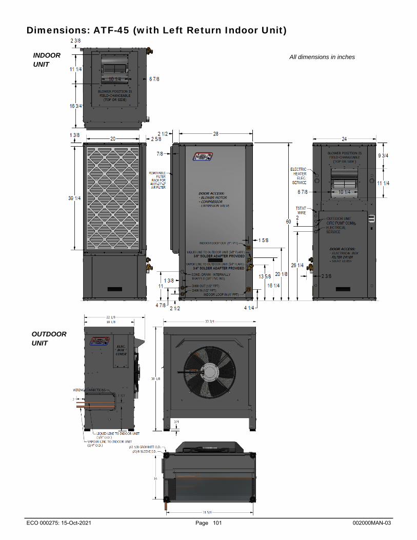
ECO 000275: 15-Oct-2021 Page 101 002000MAN-03
Dimensions: ATF-45 (with Left Return Indoor Unit)
INDOOR UNIT
OUTDOOR UNIT
All dimensions in inches

ECO 000275: 15-Oct-2021 Page 102 002000MAN-03
Dimensions: ATF-45 (with Right Return Indoor Unit)
OUTDOOR UNIT
All dimensions in inches INDOOR UNIT

ECO 000275: 15-Oct-2021 Page 103 002000MAN-03
Dimensions: ATF-55 (with Left Return Indoor Unit)
INDOOR UNIT
OUTDOOR UNIT
All dimensions in inches

ECO 000275: 15-Oct-2021 Page 104 002000MAN-03
Dimensions: ATF-55 (with Right Return Indoor Unit)
OUTDOOR UNIT
All dimensions in inches INDOOR UNIT

ECO 000275: 15-Oct-2021 Page 105 002000MAN-03
Dimensions: ATF-45/55 (Leg Kit for Outdoor Unit)
All dimensions in inches

ECO 000275: 15-Oct-2021 Page 106 002000MAN-03
Dimensions: ATF-65/75 (with Left Return Indoor Unit)
INDOOR UNIT
OUTDOOR UNIT
All dimensions in inches

ECO 000275: 15-Oct-2021 Page 107 002000MAN-03
Dimensions: ATF-65/75 (with Right Return Indoor Unit)
All dimensions in inches INDOOR UNIT
OUTDOOR UNIT

ECO 000275: 15-Oct-2021 Page 108 002000MAN-03
Dimensions: ATF-65/75 (Leg Kit for Outdoor Unit)
All dimensions in inches

ECO 000275: 15-Oct-2021 Page 109 002000MAN-03
WiFi Connector
Suction Line1 Temperature
Probe Connector
Heartbeat (flashes once per second)
The picture below shows the locations of the connectors and LED indicators of the control board. The control board offers many fea-tures such as short circuit protection on all digital outputs, Real Time Clock with super capacitor for backup power, WiFi capability, relay outputs for plenum heater control (if equipped), USB port, PIC32 microcontroller, etc.
Appendix A - GEN2 Control Board Description
High Pressure1
Sensor Connector
Remote (Outdoor)
EEV2 Connector
Local (Indoor) EEV1
Connector
Temperature Auto
Calibration Connector
High Pressure1
Fault Indicator
Low Pressure1
Sensor Connector
Temperature Connectors INDOOR OUTDOOR
IN OUT IN OUT
Short Circuit
Protectors
24VAC Power
Indicator
USB Connector
5VCD 12VDC 24VDC power indicators
Fault Indicator
BACnet MS/TP
Connector
PW
M C
hann
els
(4
out
1 in
)
Analog Inputs
AI0 to AI5
Power supplies for external sensors
for use with Analog Inputs
AI0 to AI5
Dig
ital O
utpu
ts
Indo
or F
an
Con
nect
or
The
rmos
tat
Con
nect
ions
Aqu
asta
t
Con
nect
ions
D
igita
l Inp
uts
Flo
w
Sw
itche
s P
hase
Mo
nito
rs
Plenum Heat
Airflow Reduction
Digital Outputs
MODBUS MS/TP
Connector
Low Pressure1
Fault Indicator
High Pressure2
Sensor Connector
High Pressure2
Fault Indicator
Low Pressure2
Sensor Connector
Low Pressure2
Fault Indicator
Suction Line2 Temperature
Probe Connector
Outdoor Temperature
Probe Connector
LCD Display
Connector

ECO 000275: 15-Oct-2021 Page 110 002000MAN-03
The tables describe the connections starting with the top of the board and working around the board counter clock-wise.
TABLE A1 - Control Board Connector Descriptions (Top)
Name Description
HPS1/HI1 High Pressure Sensor 1 Mounted in Indoor Unit, measures discharge pressure.
LPS1/LO1 Low Pressure Sensor 1 Mounted in Indoor Unit, measures suction pressure.
EEV1 Local EEV Mounted in Indoor Unit, used in cooling mode.
TS1 Suction Line Temperature 1 Mounted to suction line inside unit.
EEV2 Remote EEV Mounted in Outdoor Unit, used in heating mode.
TS2 Suction Line Temperature 2 Unused.
HPS2/HI2 High Pressure Sensor 2 Unused.
LPS2/LO2 Low Pressure Sensor 2 Unused.
HTS Outdoor Temperature Mounted in Outdoor Unit.
CTS Auto Calibration Resistor in connector for auto-calibration reference (32°F—0°C).
I_IN Indoor Loop IN Mounted to pipe inside unit.
I_OUT Indoor Loop OUT Mounted to pipe inside unit.
O_IN Outdoor Loop IN Unused.
O_OUT Outdoor Loop OUT Unused.
TABLE A2 - Control Board Connector Descriptions (Left Side)
Name Description
PWM_IN Signal for PWM IN Unused.
IN_SPARE Spare digital input Switch or dry contact from 12VDC to disable unit (also COM_IN to GND). COM_IN Common for PWM IN Jumper to GND for disable functionality. PWM4 PWM / 0-10VDC output Unused.
PWM3 PWM / 0-10VDC output Unused.
PWM2 PWM / 0-10VDC output Unused.
PWM1 PWM / 0-10VDC output Outdoor Fan PWM control signal.
GND Ground Ground for PWM channels.
HZC Hot Zone Circulator Unused.
CZC Cold Zone Circulator Unused.
ICR Internal Circulator Relay Operates the Indoor Circulator.
DO_3 Auxiliary Only Output when hydronic auxiliary to be run without compressor.
DO_2 Hydronic Auxiliary Operates the hydronic auxiliary, pin 1A (Setpoint Control only).
DO_1 Digital output Unused.
DO_0 Digital output Unused.
LC Loop common (ground) Unused.
L6 Loop6 Unused.
L5 Loop5 Unused.
L4 NOT_HYD_AUX Output OFF when auxiliary heat required; operates D1-D2 dry contacts.
L3 Loop3 Unused.
L2 Loop2 Unused.
L1 Loop1 ON when outdoor fan is operating.
C(SH) Soaker Hose common Ground for SH pin.
SH Soaker Hose Defrost indicator: ON when unit in defrost mode.

ECO 000275: 15-Oct-2021 Page 111 002000MAN-03
TABLE A3 - Control Board Connector Descriptions (Bottom)
Name Description
GND BACnet MS/TP Ground for shield if required.
B BACnet MS/TP RS-485.
A BACnet MS/TP RS-485.
STAGE1 Compressor Stage 1 Starts / stops the compressor.
STAGE2 Compressor Stage 2 Turns the compressor Stage 2 solenoid on/off.
RV_#1 Reversing Valve#1 Off in heating modes, on in air cooling mode.
RV_#2 Reversing Valve#2 Off in air heating or cooling modes, on in water heating mode.
SOL#1 Solenoid#1 Unused.
SOL#2 Solenoid#2 Unused.
24VAC Power supply for board 24VAC power for control board.
COM Power supply for board GND for control board.
AI_5 Analog In Channel 5 Optional type 3/7 10k hot tank temperature sensor for HTS/CTS Setpoint Control.
AI_4 Analog In Channel 4 0 to 5VDC or 4-20mA user settable with board jumper.
AI_3 Analog In Channel 3 0 to 5VDC or 4-20mA user settable with board jumper.
AI_2 Analog In Channel 2 Condensate sensor.
AI_1 Analog In Channel 1 0 to 5VDC or 4-20mA user settable with board jumper.
AI_0 Analog In Channel 0 Optional compressor current sensor.
GND Ground pin Ground for analog sensors.
GND Ground pin Ground for analog sensors.
5VDC Power for analog sensors Provides 5VDC power supply for sensors.
12VDC Power for analog sensors Provides 12VDC power supply for sensors.
24VDC Power for analog sensors Provides 24VDC power supply for sensors.
A MODBUS RS-485.
B MODBUS RS-485.
GND MODBUS Ground for shield if required.

ECO 000275: 15-Oct-2021 Page 112 002000MAN-03
TABLE A4 - Control Board Connector Descriptions (Right Side)
Name Description
DI_1 Digital Input1 Unused.
DI_0 Digital Input0 Unused.
PM2 Phase Monitor2 Switch or dry contact from R to activate Summer Setback mode.
PM1 Phase Monitor1 Accessory for 3 phase models.
Y2A* Aquastat Stage2 Optional water heat stage 2 24VAC input for use with Signals/Hardwired control.
RA* Aquastat Power (24VAC) Optional 24VAC output for aquastat used with Signals/Hardwired control.
Y1A* Aquastat Stage1 Optional water heat stage 1 24VAC input for use with Signals/Hardwired control.
CA* Aquastat Power (Ground) Optional 24VAC ground for aquastat used with Signals/Hardwired control.
2 Plenum Heat Stage2 Dry contact output to activate air plenum heater stage 2.
1 Plenum Heat Stage1 Dry contact output to activate air plenum heater stage 1.
C Plenum Heat Common Common terminal for air plenum heater dry contacts.
AR Airflow Reductions Digital input to reduce airflow for zoning applications.
24VAC Power Power to external dry contact for AR terminal.
ODFLO Outdoor Flow Switch Unused.
IDFLO Indoor Flow Switch Unused.
L Thermostat Lockout Indicator 24VAC to external trouble indicator.
E Thermostat Emergency Heat 24VAC input from air thermostat.
O Thermostat Heat/Cool 24VAC input from air thermostat.
W2 Thermostat Auxiliary Heat 24VAC input from air thermostat.
Y2 Thermostat Stage2 24VAC input from air thermostat.
Y1 Thermostat Stage1 24VAC input from air thermostat.
G Thermostat Fan Recirculation 24VAC input from air thermostat.
R Thermostat Power (24VAC) 24VAC to air thermostat.
C Thermostat Power (Ground) 24VAC ground for air thermostat.
*NOTE: There is no need for an external aquastat for most systems, since the Setpoint Control Method provides built in aquastat functionality.

ECO 000275: 15-Oct-2021 Page 113 002000MAN-03
The first step in connecting a Windows laptop computer to the control board is to install the USB driver. Any version of Win-dows from XP and onwards should be compatible, but Windows 10 (as found on any recent laptop computer) is recommended.
The easiest way to install the USB driver is from the USB drive included with the unit. Insert the USB stick into a Windows computer, and open a File Explorer window to view its contents: Double click on the SOFTWARE folder to show its contents:
Double click on Step 1 to install the USB driver, clicking “allow” or “yes” as required.
If the USB stick drive is not available, the same file can be downloaded from the web page.
1. Go to www.nordicghp.com, Download Software page:
Appendix B - USB Driver Installation
7. You will see a message indicating the driver was installed successfully.
2. Click on MGL GEN2 USB Driver Installer to download it:
4. In the window that is displayed, click and hold down the mouse button on the folder name, and drag to your desktop:
5. Double click on the folder you just dragged onto the desktop, then double click on the “USBDriverInstaller” file:
6. In the next window, click on “Install Drivers”:
3. Choose “Open with Windows Explorer”, and hit “OK”:
8. You are now ready to install the PC App.

ECO 000275: 15-Oct-2021 Page 114 002000MAN-03
Appendix C - PC App Installation
Then go back to step 5. 7. The PC App will open when it is finished installing. You are
now ready to connect a USB cord between the laptop com-puter and GEN2 control board, and connect.
The PC App allows detailed interfacing with the control board using a Windows laptop computer. Any Windows from XP and onwards should be compatible, but Windows 10 (as found on any recent laptop computer) is recommended. First, install the USB driver as per the previous appendix.
The easiest way to install the Pc App is from the USB drive in-cluded with the unit. Insert the USB stick into a Windows computer, and open a File Explorer window to view its contents: Double click on the SOFTWARE folder to show its contents:
Double click on Step 2 and follow the prompts, clicking “allow” or “yes” as required. If you get a warning that .NET framework is required, go back and double click on step z, then try Step 2 again.
5. Double click on the folder you just dragged onto the desktop, then double click on the “setup” file:
If the USB stick drive is not available, the same file can be downloaded from the web page.
1. Go to www.nordicghp.com, Download Software page:
2. Click on MGL GEN2 PC APP V2__ to download it:
3. Choose “Open with Windows Explorer”, and hit “OK”:
4. In the window that is displayed, click and hold down the mouse button on the folder name, and drag to your desktop:
6. Click “Yes”, “Run”, “Install”, or similar on any warning win-dows which pop up. If an error message is encountered regarding .NET framework, exit the installation and use the link on the Download Software page to install the missing item:

ECO 000275: 15-Oct-2021 Page 115 002000MAN-03
Appendix D: Updating Firmware
This method can be used when updating post-2017 control boards with bootloader version 2.0. This method will not work for older control boards with bootloader version 1.0 (approx. unit serial numbers -17 and lower); for those, see METHOD 2. Note that METHOD 2 will work for all control boards. The firmware comes as a .ZIP file named: MGL GEN2 Bootload Firmware Vxxx.zip where xxx is the version reference, e.g. 360 (version 3.60). This file can be downloaded from www.nordicghp.com, menu For Dealers --> Download Software. 1. Download the file to your PC. When prompted, “Open” the
zip file. If the zip file is Saved instead of Opened, find it in the web browser’s Downloads list or at the bottom of brows-er window and click on it to open. In the window that comes up, drag the folder containing the required files onto your desktop so that it can be found easily, e.g.:
\Desktop\MGL GEN2 Bootload Firmware V360
Also be sure the latest PC App version is installed, which is listed alongside the firmware on the web page. If needed, install a new version as per those instructions, and uninstall older PC App versions to avoid their accidental use (which can corrupt control board parameters).
2. In that folder on the Desktop, there will be three files:
MGL_GEN2_V360.production.hex (firmware file) PIC32UBL.exe (the programmer) USB Bootloader Instructions.pdf (these instructions)
Note that on most computers, the file extensions (.exe, .pdf) will be hidden.
3. Connect a USB (printer) cable between computer and control
board. 4. Launch the PC App version that matches the firmware (e.g.
PC App 2.00 for firmware V3.60). After it is installed, the PC App can be started using the entry found under the “M” sec-tion in the Windows START menu, which is accessed using the 4-rectangles icon normally found at the bottom left corner of the computer screen.
5. In the PC App, click on the Connect button to connect to the
9. Click on OK. The control board is now in bootloader mode and is ready to be programmed.
6. Go to menu Tools --> Update Firmware. The following message box will appear:
7. Click on YES. The following message box will appear:
8. Click on OK. After a minute, the following message box will appear:
10. Double click on the downloaded file PIC32UBL.exe to run it. In the window that opens, click on the USB Enable check box.
METHOD 1: Updating Firmware Using PC App
If device fails to connect and an error message is displayed, the board’s bootloader may be older than v2.0. It will be necessary to instead update the firm-ware via jumper pins (METHOD 2), as per the next section.
11. Click on Connect.

ECO 000275: 15-Oct-2021 Page 116 002000MAN-03
13. Click on Erase—Program—Verify. Programming…. Wait while status bar shows progress. The messages should read as below when finished:
11. “Programming completed. Verification successful.” Click on Run Application. This will take the control board out of bootloader mode and back into normal operational mode, so that the PC App can connect again.
16. Close the PIC32 program. 17. WAIT APPROXIMATELY 10 SECONDS. This gives the
control board time to reset, initialize and re-connect to the PC USB port.
18. Go back to the PC APP and click on the Connect button.
Verify that the firmware version, shown in the title bar after connection, has been updated. Perform any configuration needed.
15. Wait until the programmer disconnects itself. The messages should read as follows:
NOTE: Updating the firmware does not affect the configu-ration settings.
12. Click on Load Hex File. Select the MGL_GEN2_V360.production.hex (or higher version num-ber) file, which is in the folder you created on the Desktop.
Reset to Defaults? When updating from firmware V3.58 or earlier, the following steps must be taken after the update as there are significant differences in the internal parameters used to operate the sys-tem. These steps may also be performed for troubleshooting, when the control system is not acting as it should.
Note that if the firmware on a heat pumps is 2.45 or earlier, chances are that it will have an older bootloader version that requires the use of METHOD 2 to update the firmware (see fol-lowing page). 1. With PC App connected, go to menu Tools --> Configura-
tion and note all settings. They will need to be re-set later.
2. Go to menu Tools --> Reset To Factory Defaults. Click YES in the pop up window, and OK in the next window.
3. Go back to menu Tools --> Configuration. Re-select the Model Series even if it already indicates the proper series, as clicking on it will load the parameters for that series.
4. Select the Model Size and make any other changes that apply to the particular system setup such as number of stag-es, control method, etc.

ECO 000275: 15-Oct-2021 Page 117 002000MAN-03
Borrow any one of these jumpers (however many are present)
This method should be used when updating older control boards that have bootloader version 1.0, or where the PC App has trou-ble connecting to older firmware. This method will work for all control boards and can be used on all units.
The firmware comes as a .ZIP file named: MGL GEN2 Bootload Firmware Vxxx.zip where xxx is the version reference, e.g. 360 (version 3.60). This file can be downloaded from www.nordicghp.com, menu For Dealers --> Download Software.
1. Download the file to your PC. When prompted, “Open” the zip file. If the zip file is Saved instead of Opened, find it in the web browser’s Downloads list or at the bottom of browser window and click on it to open. In the window that comes up, drag the folder containing the required files onto your desk-top so that it can be found easily, e.g.:
\Desktop\MGL GEN2 Bootload Firmware V360
2. In that folder on the Desktop, there will be three files:
MGL_GEN2_V360.production.hex (firmware file) PIC32UBL.exe (the programmer) USB Bootloader Instructions.pdf (these instructions)
Note that on most computers, the file extensions (.exe, .pdf) will be hidden.
3. Connect a USB (printer) cable between computer and control board.
4. Turn power off to the heat pump.
5. Remove one of the black pin jumpers from just below the USB connector on the board and place in on the center pin pair of the EXPANSION header as shown below.
Place jumper here
6. Turn the power back on. The control board is now in boot loader mode and is ready to be programmed. 7. Double click on the downloaded PIC32UBL.exe to run it. In
the window that opens, click on the USB Enable check box.
8. Click on Connect.
9. Click on Load Hex File. Select the MGL_GEN2_V360.production.hex (or higher version num-ber) file, which is in the folder you creat-ed on the Desktop.
10. Click on Erase— Program—Verify
Programming…
11. “Programming completed. Verifi-cation successful.” Click on Disconnect and close the program.
14. Turn the power back on. Check that the LCD Display shows e.g. MGL GEN2 V3.60 on the top line during power up.
12. Turn power off to the heat pump again.
13. Move the jumper back to where it was taken from.
METHOD 2: Updating Firmware Using Jumper Pins

ECO 000275: 15-Oct-2021 Page 118 002000MAN-03
LIMITED RESIDENTIAL WARRANTY
MARITIME GEOTHERMAL LTD. warrants that the heat pumps
manufactured by it shall be free from defects in materials and workmanship for a period of (5) FIVE YEARS after the date of installation or for a period of (5) FIVE YEARS AND (60) SIXTY DAYS after the date of shipment, whichever occurs first. In addition MARITIME GEOTHERMAL LTD. warrants that the compressor shall be free of defects in materials and workmanship for an additional period of (2) TWO YEARS from said date.
MARITIME GEOTHERMAL LTD. shall, at its option repair or replace any part or parts covered by this warranty which shall be returned to MARITIME GEOTHERMAL LTD., transportation charges prepaid, which, upon examination proves to be defective in materials or workmanship. Replacement or repaired parts and components are warranted only for the remaining portion of the original warranty period.
This warranty is subject to the following conditions: 1. The NORDIC® heat pump must be properly installed and maintained in
accordance with MARITIME GEOTHERMAL LTD.'s installation and maintenance instructions.
2. The installer must complete the “Installation Data Sheet”, have it endorsed by the owner and return it to Maritime Geothermal Ltd. within 21 days of installation of the unit.
3. It is the responsibility of the building or general contractor to supply temporary heat to the structure prior to occupancy. These heat pumps are designed to provide heat only to the completely finished and insulated structure. Start-up of the unit shall not be scheduled prior to completion of construction and final duct installation for validation of this warranty.
4. It is the customer's responsibility to supply the proper quantity and quality of water.
If the heat pump, manufactured by MARITIME GEOTHERMAL LTD., fails to
conform to this warranty, MARITIME GEOTHERMAL LTD.'s sole and exclusive liability shall be, at its option, to repair or replace any part or component which is returned by the customer during the applicable warranty period set forth above, provided that (1) MARITIME GEOTHERMAL LTD. is promptly notified in writing upon discovery by the customer that such part or component fails to conform to this warranty. (2) The customer returns such part or component to MARITIME GEOTHERMAL LTD., transportation charges prepaid, within (30) thirty days of failure, and (3) MARITIME GEOTHERMAL LTD.'s examination of such component shall disclose to its satisfaction that such part or component fails to meet this warranty and the alleged defects were not caused by accident, misuse, neglect, alteration, improper installation, repair or improper testing.