
Fingerprint Classification by Directional Image Partitioning
20
402 IEEE TRANSACTIONS ON PATTERN ANALYSIS AND MACHINE INTELLIGENCE, VOL. 21, NO. 5, MAY 1999 Fingerprint Classification by Directional Image Partitioning Raffaele Cappelli, Alessandra Lumini, Dario Maio, Member, IEEE, and Davide Maltoni Abstract—In this work, we introduce a new approach to automatic fingerprint classification. The directional image is partitioned into “homogeneous” connected regions according to the fingerprint topology, thus giving a synthetic representation which can be exploited as a basis for the classification. A set of dynamic masks, together with an optimization criterion, are used to guide the partitioning. The adaptation of the masks produces a numerical vector representing each fingerprint as a multidimensional point, which can be conceived as a continuous classification. Different search strategies are discussed to efficiently retrieve fingerprints both with continuous and exclusive classification. Experimental results have been given for the most commonly used fingerprint databases and the new method has been compared with other approaches known in the literature: As to fingerprint retrieval based on continuous classification, our method gives the best performance and exhibits a very high robustness. Index Terms—Fingerprint classification, directional image, partitioning algorithms, continuous classification, biometric systems. ——————————F—————————— 1 INTRODUCTION INGERPRINT recognition is the basic task of the Inte- grated Automated Fingerprint Identification Service (IAFIS) of the most famous police agencies. Ten-print based identification and latent fingerprint recognition are the two main concerns of an IAFIS. In the former, the system should identify a person by the whole sequence of his/her 10 fin- gerprints; in the latter, it has to identify a person through a latent fingerprint found on a crime scene. The huge amount of data of the large fingerprint databases seriously com- promises the efficiency of the identification task, although the fastest minutiae matching algorithms take only a few tens of milliseconds per matching [15]. Adopting a classifi- cation approach, based on common typology of finger- prints, is a valid strategy in order to reduce the amount of matching during fingerprint retrieval and, consequently, to improve the identification process efficiency. Most IAFISs use exclusive classification, i.e., fingerprints are partitioned into some predefined classes according to their macro-features. The first scientific studies on finger- print classification were made by Galton [7], who divided the fingerprints into three major classes. Later, Henry [8] refined Galton’s classification by increasing the number of the classes. All the classification schemes currently used by police agencies are variants of the so-called Henry’s classifi- cation scheme. The scheme adopted by the FBI defines three major classes, each of which can be divided into two or more subclasses, making the total number eight: Plain Arch, Tented Arch, Radial Loop, Ulnar Loop, Plain Whorl, Cen- tral Pocket, Double Loop and Accidental Whorl (Fig. 1). The performance of the exclusive classification-based IAFISs strongly depends on the number of classes and on the distribution of fingerprints; unfortunately, the number of classes is often small, the fingerprints are nonuniformly distributed (in the most famous classification schemes, ap- proximately 90 percent of fingerprints belong to only three classes), and there are many “ambiguous” fingerprints, whose exclusive membership cannot be reliably stated even by human experts. Nevertheless, exclusive classification allows for the efficiency of the 10-print based identification to be improved, since the knowledge of the classes of the ten fingerprints can be used as a code for reducing the number of comparisons at minutiae level. On the other hand, an exclusive classification approach does not confer sufficient selectivity to latent fingerprint searching. A continuous classification approach characterizes each fin- gerprint with a numerical vector, whose components de- note the similarity degree with respect to a predefined set of class prototypes. A continuous approach enables both am- biguous fingerprints to be dealt with and the efforts during fingerprint retrieval to be balanced. The advantages of a continuous versus an exclusive classification approach are discussed in [16], where some continuous retrieval strate- gies were compared with the corresponding exclusive ones. In this work, we present a new fingerprint classification method which uses dynamic masks for directional image partitioning. The new approach is translation and rotation invariant and it does not require the singularities [25] to be detected. A directional image is a discrete matrix whose elements represent the local average directions of the fin- gerprint ridge lines. A directional image effectively summa- rizes the information contained in a fingerprint pattern and it can be reliably computed also on noisy fingerprints. Fur- thermore, the local directions within a damaged area can be 0162-8828/99/$10.00 © 1999 IEEE ²²²²²²²²²²²²²²²² R. Cappelli is with Corso di Laurea in Scienze dell’Informazione, Univer- sità di Bologna, via Sacchi 3, 47023 Cesena, Italy. E-mail: [email protected]. A. Lumini, D. Maio, and D. Maltoni are with DEIS, CSITE-CNR, Univer- sità di Bologna, viale Risorgimento 2, 40136 Bologna, Italy. E-mail: {alumini, dmaio, dmaltoni}@deis.unibo.it. Manuscript received 31 July 1998; revised 9 Feb. 1999. Recommended for accep- tance by K. Bowyer. For information on obtaining reprints of this article, please send e-mail to: [email protected], and reference IEEECS Log Number 107372. F
-
Upload
independent -
Category
Documents
-
view
1 -
download
0
Transcript of Fingerprint Classification by Directional Image Partitioning

402 IEEE TRANSACTIONS ON PATTERN ANALYSIS AND MACHINE INTELLIGENCE, VOL. 21, NO. 5, MAY 1999
Fingerprint Classificationby Directional Image Partitioning
Raffaele Cappelli, Alessandra Lumini,Dario Maio, Member, IEEE, and Davide Maltoni
Abstract—In this work, we introduce a new approach to automatic fingerprint classification. The directional image is partitioned into“homogeneous” connected regions according to the fingerprint topology, thus giving a synthetic representation which can beexploited as a basis for the classification. A set of dynamic masks, together with an optimization criterion, are used to guide thepartitioning. The adaptation of the masks produces a numerical vector representing each fingerprint as a multidimensional point,which can be conceived as a continuous classification. Different search strategies are discussed to efficiently retrieve fingerprintsboth with continuous and exclusive classification. Experimental results have been given for the most commonly used fingerprintdatabases and the new method has been compared with other approaches known in the literature: As to fingerprint retrieval basedon continuous classification, our method gives the best performance and exhibits a very high robustness.
Index Terms—Fingerprint classification, directional image, partitioning algorithms, continuous classification, biometric systems.
——————————���F���——————————
1 INTRODUCTION
INGERPRINT recognition is the basic task of the Inte-grated Automated Fingerprint Identification Service
(IAFIS) of the most famous police agencies. Ten-print basedidentification and latent fingerprint recognition are the twomain concerns of an IAFIS. In the former, the system shouldidentify a person by the whole sequence of his/her 10 fin-gerprints; in the latter, it has to identify a person through alatent fingerprint found on a crime scene. The huge amountof data of the large fingerprint databases seriously com-promises the efficiency of the identification task, althoughthe fastest minutiae matching algorithms take only a fewtens of milliseconds per matching [15]. Adopting a classifi-cation approach, based on common typology of finger-prints, is a valid strategy in order to reduce the amount ofmatching during fingerprint retrieval and, consequently, toimprove the identification process efficiency.
Most IAFISs use exclusive classification, i.e., fingerprintsare partitioned into some predefined classes according totheir macro-features. The first scientific studies on finger-print classification were made by Galton [7], who dividedthe fingerprints into three major classes. Later, Henry [8]refined Galton’s classification by increasing the number ofthe classes. All the classification schemes currently used bypolice agencies are variants of the so-called Henry’s classifi-cation scheme. The scheme adopted by the FBI defines threemajor classes, each of which can be divided into two ormore subclasses, making the total number eight: Plain Arch,
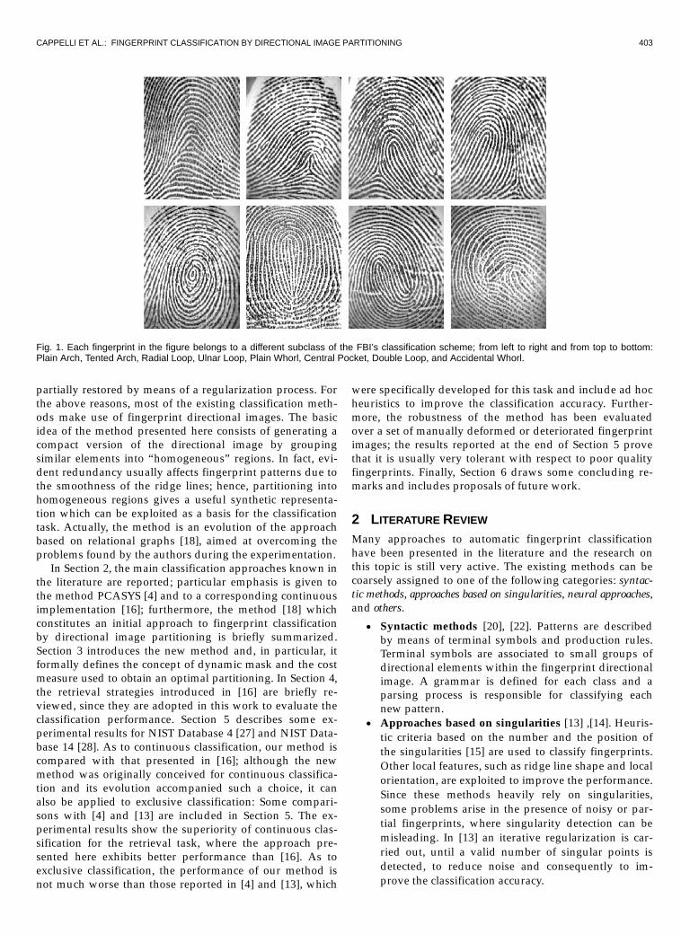
Tented Arch, Radial Loop, Ulnar Loop, Plain Whorl, Cen-tral Pocket, Double Loop and Accidental Whorl (Fig. 1).
The performance of the exclusive classification-basedIAFISs strongly depends on the number of classes and onthe distribution of fingerprints; unfortunately, the numberof classes is often small, the fingerprints are nonuniformlydistributed (in the most famous classification schemes, ap-proximately 90 percent of fingerprints belong to only threeclasses), and there are many “ambiguous” fingerprints,whose exclusive membership cannot be reliably stated evenby human experts. Nevertheless, exclusive classificationallows for the efficiency of the 10-print based identificationto be improved, since the knowledge of the classes of theten fingerprints can be used as a code for reducing thenumber of comparisons at minutiae level. On the otherhand, an exclusive classification approach does not confersufficient selectivity to latent fingerprint searching.
A continuous classification approach characterizes each fin-gerprint with a numerical vector, whose components de-note the similarity degree with respect to a predefined setof class prototypes. A continuous approach enables both am-biguous fingerprints to be dealt with and the efforts duringfingerprint retrieval to be balanced. The advantages of acontinuous versus an exclusive classification approach arediscussed in [16], where some continuous retrieval strate-gies were compared with the corresponding exclusive ones.
In this work, we present a new fingerprint classificationmethod which uses dynamic masks for directional imagepartitioning. The new approach is translation and rotationinvariant and it does not require the singularities [25] to bedetected. A directional image is a discrete matrix whoseelements represent the local average directions of the fin-gerprint ridge lines. A directional image effectively summa-rizes the information contained in a fingerprint pattern andit can be reliably computed also on noisy fingerprints. Fur-thermore, the local directions within a damaged area can be
0162-8828/99/$10.00 © 1999 IEEE
²²²²²²²²²²²²²²²²
�� R. Cappelli is with Corso di Laurea in Scienze dell’Informazione, Univer-sità di Bologna, via Sacchi 3, 47023 Cesena, Italy.E-mail: [email protected].
�� A. Lumini, D. Maio, and D. Maltoni are with DEIS, CSITE-CNR, Univer-sità di Bologna, viale Risorgimento 2, 40136 Bologna, Italy.�E-mail: {alumini, dmaio, dmaltoni}@deis.unibo.it.
Manuscript received 31 July 1998; revised 9 Feb. 1999. Recommended for accep-tance by K. Bowyer.For information on obtaining reprints of this article, please send e-mail to:[email protected], and reference IEEECS Log Number 107372.
F
CAPPELLI ET AL.: FINGERPRINT CLASSIFICATION BY DIRECTIONAL IMAGE PARTITIONING 403
partially restored by means of a regularization process. Forthe above reasons, most of the existing classification meth-ods make use of fingerprint directional images. The basicidea of the method presented here consists of generating acompact version of the directional image by groupingsimilar elements into “homogeneous” regions. In fact, evi-dent redundancy usually affects fingerprint patterns due tothe smoothness of the ridge lines; hence, partitioning intohomogeneous regions gives a useful synthetic representa-tion which can be exploited as a basis for the classificationtask. Actually, the method is an evolution of the approachbased on relational graphs [18], aimed at overcoming theproblems found by the authors during the experimentation.
In Section 2, the main classification approaches known inthe literature are reported; particular emphasis is given tothe method PCASYS [4] and to a corresponding continuousimplementation [16]; furthermore, the method [18] whichconstitutes an initial approach to fingerprint classificationby directional image partitioning is briefly summarized.Section 3 introduces the new method and, in particular, itformally defines the concept of dynamic mask and the costmeasure used to obtain an optimal partitioning. In Section 4,the retrieval strategies introduced in [16] are briefly re-viewed, since they are adopted in this work to evaluate theclassification performance. Section 5 describes some ex-perimental results for NIST Database 4 [27] and NIST Data-base 14 [28]. As to continuous classification, our method iscompared with that presented in [16]; although the newmethod was originally conceived for continuous classifica-tion and its evolution accompanied such a choice, it canalso be applied to exclusive classification: Some compari-sons with [4] and [13] are included in Section 5. The ex-perimental results show the superiority of continuous clas-sification for the retrieval task, where the approach pre-sented here exhibits better performance than [16]. As toexclusive classification, the performance of our method isnot much worse than those reported in [4] and [13], which
were specifically developed for this task and include ad hocheuristics to improve the classification accuracy. Further-more, the robustness of the method has been evaluatedover a set of manually deformed or deteriorated fingerprintimages; the results reported at the end of Section 5 provethat it is usually very tolerant with respect to poor qualityfingerprints. Finally, Section 6 draws some concluding re-marks and includes proposals of future work.
2 LITERATURE REVIEW
Many approaches to automatic fingerprint classificationhave been presented in the literature and the research onthis topic is still very active. The existing methods can becoarsely assigned to one of the following categories: syntac-tic methods, approaches based on singularities, neural approaches,and others.
�� Syntactic methods [20], [22]. Patterns are describedby means of terminal symbols and production rules.Terminal symbols are associated to small groups ofdirectional elements within the fingerprint directionalimage. A grammar is defined for each class and aparsing process is responsible for classifying eachnew pattern.
�� Approaches based on singularities [13] ,[14]. Heuris-tic criteria based on the number and the position ofthe singularities [15] are used to classify fingerprints.Other local features, such as ridge line shape and localorientation, are exploited to improve the performance.Since these methods heavily rely on singularities,some problems arise in the presence of noisy or par-tial fingerprints, where singularity detection can bemisleading. In [13] an iterative regularization is car-ried out, until a valid number of singular points isdetected, to reduce noise and consequently to im-prove the classification accuracy.
Fig. 1. Each fingerprint in the figure belongs to a different subclass of the FBI’s classification scheme; from left to right and from top to bottom:Plain Arch, Tented Arch, Radial Loop, Ulnar Loop, Plain Whorl, Central Pocket, Double Loop, and Accidental Whorl.

404 IEEE TRANSACTIONS ON PATTERN ANALYSIS AND MACHINE INTELLIGENCE, VOL. 21, NO. 5, MAY 1999
�� Neural approaches [1], [9], [12], [21]. Neural networkapproaches are mostly based on multilayer percep-trons or Kohonen self-organizing networks. In par-ticular, in [12], Kamijo presented an interesting py-ramidal architecture constituted by several multilayerperceptrons, each of which was trained to recognizefingerprints belonging to different classes.
�� Others [5], [23]. Chong et al. based the classificationon the ridge-line geometrical shape [5]. B-splinecurves were used to model fingerprint ridge lines;adjacent curves were merged to limit noise artifacts.Classification was performed by tracing the resultingcurves in order to detect turns (i.e., complete directionexchanges). Senior proposed in [23] a hidden Markovmodel classifier whose input features are the meas-urements (ridge angle, separation, curvature, etc.)taken at the intersection points between some hori-zontal-vertical fiducial lines and the fingerprint ridgelines.
2.1 The PCASYS Approach by NISTThe PCASYS approach (Pattern-level Classification Auto-mation SYStem) proposed by Candela et al. at NIST [3], [4]assigns fingerprints to six nonoverlapping classes and is, inour opinion, the most promising approach for exclusiveclassification.
Before computing the directional images, the ridge-linearea is separated from the background and an enhancement isperformed in the frequency domain. The computation ofthe directions is carried out by the method reported in [26].The directional image is then registered with respect to thecore position which corresponds to the fingerprint center.The dimensionality of the directional image, considered asa vector of 1,680 elements, is reduced to 64 elements by us-ing the principal component analysis (KL transform) [10], [11].At this stage, a PNN (Probabilistic Neural Network) [24] isused for assigning each 64-element vector to one class of
the classification scheme. In order to improve the classifica-tion reliability, especially for whorl fingerprints, the authorsalso implemented an auxiliary module (called pseudoridgetracer), which works by analyzing the ridge-line concavityunder the core position. Fig. 2 shows a functional scheme ofthe NIST classification approach.
In [16], a continuous classification method is derivedfrom PCASYS. In particular, the vectors obtained after thedimensionality reduction step are directly used for indexinga fingerprint database through a spatial data structure. Inthe experiments the authors found that the best resultscould be obtained by using a five-dimensional space (in-stead of 64) and by linearly rescaling the vector componentsin the range [0, 1].
2.2 A Structural Approach Based on RelationalGraphs
In [18], a structural approach for fingerprint classificationwas presented, whose functional schema is shown in Fig. 3.
The basic idea is to perform a directional image parti-tioning into several homogeneous regular-shaped regions,which are used to build a relational graph summarizing thefingerprint macro-features. The whole approach can be di-vided into four main steps: computation of the directionalimage, segmentation of the directional image, constructionof the relational graph, and inexact graph matching. Thedirectional image is computed, over a discrete grid 32 � 32,by means of a robust technique proposed by Donahue andRokhlin [6]. A dynamic clustering algorithm [19] is adoptedto segment the directional image according to well-suitedoptimality criteria. In particular, with the aim of creatingregions as homogeneous as possible, the algorithm worksby minimizing the variance of the element directions withinthe regions and, simultaneously, by maintaining the regu-larity of the region shape. Starting from the segmentation ofthe directional image, a relational graph is built by creatinga node for each region and an arc for each pair of adjacent
Fig. 2. A functional scheme of the PCASYS for exclusive classification.

CAPPELLI ET AL.: FINGERPRINT CLASSIFICATION BY DIRECTIONAL IMAGE PARTITIONING 405
regions. By appropriately labeling the nodes and arcs of thegraph, the authors obtain a structure which summarizes thetopological features of the fingerprint and which is invari-ant with respect to displacement and rotation. An inexactgraph matching technique derived from [2] is used to com-pute a “distance” vector between the graph and each class-prototype graph. This distance is considered to be a con-tinuous classification of the fingerprint, since it describeshow close the fingerprint is to each class; if the applicationneeds to assign a fingerprint to a single class, the vectorobtained can be given as input to a general purpose classi-fier. It is worth noting that this technique does not requireany position alignment or normalization and, in principle,can be directly used for the classification of partial finger-prints (i.e., matching a graph with a subgraph).
3 DYNAMIC MASKS
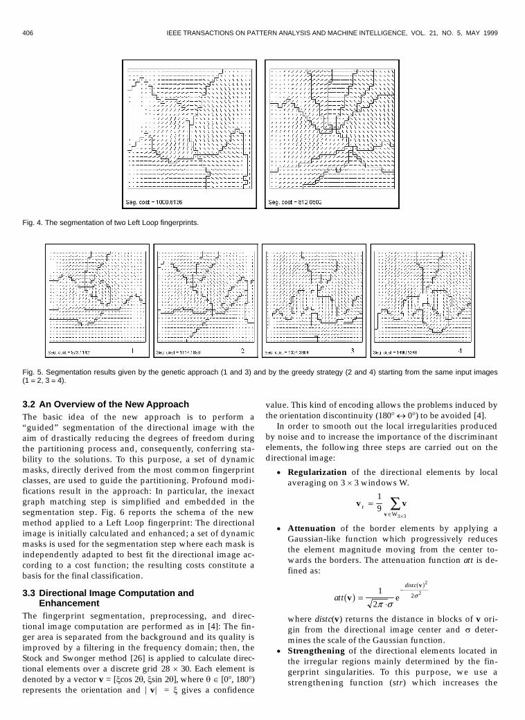
3.1 From Relational Graphs to Dynamic MasksA preliminary analysis of the experimental results pro-duced by the relational graph approach described in Sec-tion 2.2 pointed out that some problems arise from the diffi-culty in obtaining analogous segmentation from similardirectional images. In fact, although the greedy clustering
algorithm adopted usually produces a good segmentation(that is, characterized by regular-shaped and homogeneousregions), it is too influenced by local ridge-line orientationchanges, by the starting point of the clustering routines,and by some specific parameters; as a result, similar inputscan give rise to different outputs (Fig. 4). In such cases, sev-eral problems are encountered by the inexact graphmatching algorithm in finding the hidden similarities. Anattempt was made to overcome these drawbacks by imple-menting a global clustering strategy, with the aim of im-proving the segmentation robustness. A genetic algorithmderived from the approach [17], where reproduction andmutation operators were redesigned to deal with the clus-tering problem, was used instead of the greedy technique.Better results were obtained both in qualitative and nu-merical terms (obviously with a higher computational cost)and a greater robustness was noted (see Fig. 5 for an exam-ple); anyway, some problems still persisted: In fact, the out-puts produced by the genetic optimization in the presenceof different initial populations were sometimes very differ-ent from each other, even if their fitness was closed. Thisclearly means that the directional image partitioning task isan ill-posed problem.
Fig. 3. The main steps of the approach in [18]. The intermediate results produced during the classification of a Left Loop fingerprint are shown.
406 IEEE TRANSACTIONS ON PATTERN ANALYSIS AND MACHINE INTELLIGENCE, VOL. 21, NO. 5, MAY 1999
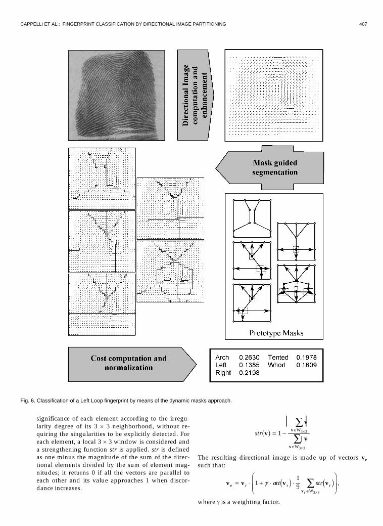
3.2 An Overview of the New ApproachThe basic idea of the new approach is to perform a“guided” segmentation of the directional image with theaim of drastically reducing the degrees of freedom duringthe partitioning process and, consequently, conferring sta-bility to the solutions. To this purpose, a set of dynamicmasks, directly derived from the most common fingerprintclasses, are used to guide the partitioning. Profound modi-fications result in the approach: In particular, the inexactgraph matching step is simplified and embedded in thesegmentation step. Fig. 6 reports the schema of the newmethod applied to a Left Loop fingerprint: The directionalimage is initially calculated and enhanced; a set of dynamicmasks is used for the segmentation step where each mask isindependently adapted to best fit the directional image ac-cording to a cost function; the resulting costs constitute abasis for the final classification.
3.3 Directional Image Computation andEnhancement
The fingerprint segmentation, preprocessing, and direc-tional image computation are performed as in [4]: The fin-ger area is separated from the background and its quality isimproved by a filtering in the frequency domain; then, theStock and Swonger method [26] is applied to calculate direc-tional elements over a discrete grid 28 � 30. Each element isdenoted by a vector v = [xcos 2q, xsin 2q], where q ³ [0�, 180�)represents the orientation and |v| = x gives a confidence
value. This kind of encoding allows the problems induced bythe orientation discontinuity (180� � 0�) to be avoided [4].
In order to smooth out the local irregularities producedby noise and to increase the importance of the discriminantelements, the following three steps are carried out on thedirectional image:
�� Regularization of the directional elements by localaveraging on 3 � 3 windows W.
v vv
rW
=³ �
Ê19
3 3
�� Attenuation of the border elements by applying aGaussian-like function which progressively reducesthe element magnitude moving from the center to-wards the borders. The attenuation function att is de-fined as:
att
distc
v
v
0 50 5
=¼
-1
2
2
22
p sse
where distc(v) returns the distance in blocks of v ori-gin from the directional image center and s deter-mines the scale of the Gaussian function.
�� Strengthening of the directional elements located inthe irregular regions mainly determined by the fin-gerprint singularities. To this purpose, we use astrengthening function (str) which increases the
Fig. 4. The segmentation of two Left Loop fingerprints.
Fig. 5. Segmentation results given by the genetic approach (1 and 3) and by the greedy strategy (2 and 4) starting from the same input images(1 � 2, 3 � 4).
CAPPELLI ET AL.: FINGERPRINT CLASSIFICATION BY DIRECTIONAL IMAGE PARTITIONING 407
significance of each element according to the irregu-larity degree of its 3 � 3 neighborhood, without re-quiring the singularities to be explicitly detected. Foreach element, a local 3 � 3 window is considered anda strengthening function str is applied. str is definedas one minus the magnitude of the sum of the direc-tional elements divided by the sum of element mag-nitudes; it returns 0 if all the vectors are parallel toeach other and its value approaches 1 when discor-dance increases.
str v
v
vv
v
0 5 = - ³
³
�
�
ÊÊ
1 3 3
3 3
| || |
W
W
The resulting directional image is made up of vectors vesuch that:
v v v vv
e r r rWr
= ¼ + ¼ ¼����
����
³ �
Ê119
3 3
g att str2 7 2 7 ,
where g is a weighting factor.
Fig. 6. Classification of a Left Loop fingerprint by means of the dynamic masks approach.

408 IEEE TRANSACTIONS ON PATTERN ANALYSIS AND MACHINE INTELLIGENCE, VOL. 21, NO. 5, MAY 1999
Fig. 7 shows a sample directional image before and afterthe enhancement process.
3.4 Dynamic Mask DefinitionDynamic masks have been introduced in order to decreasethe degrees of freedom during the partitioning process; theapplication of a particular mask to a directional image canbe viewed as a “guided” segmentation, where the regionnumber and their coarse shape are fixed a priori. Each maskis characterized by a set of vertices defining the borders ofthe regions which determine the segmentation. Some verti-ces can be locally moved to best fit the fingerprint imagesingularities, which can occupy different positions withinfingerprints of the same class (Fig. 8).
Formally, a dynamic mask is defined as a 6-tuple M =(V, P, 5D, $, fwin, fmov), where:
�� V = VF VM VD is a set of vertices p, each of whichis characterized by an initial position (px, py); VF de-notes the fixed vertices; VM denotes the mobile verticeswhose position can be independently adjusted duringthe mask adaptation; finally, VD denotes the dependentvertices whose position is anchored to that of onemobile vertex. The three vertex subsets are disjointed:VF ¬ VM = «, VF ¬ VD = «, VD ¬ VM = «.
�� P = {P1, P2, …, Pn} is a set of polygonal regions whosevertices are in V; each region Pi = {pa, pb, pc, …} isbounded by the polygon defined by the verticespa, pb, pc, … taken in the given order; hence, P is asubset of the power set of V: P ± ¨(V).
�� 5D ² VD � VM is a relation encoding the dependencyof the dependent vertices from the mobile ones. Eachdependent vertex is anchored to exactly one mobilevertex; during the mask adaptation, the movement ofa mobile vertex determines a corresponding move-ment in all the vertices anchored to it.
�� $ ² P � P � Dq encodes a relation between some re-gion pairs, which are associated to angles represent-ing the “ideal” values of their mean orientation dif-ference. Dq denotes the domain of the orientation dif-ferences. For each pair Pi, Pj, whose orientation differ-ence qij ³ Dq is significant,1 the triplet (Pi, Pj, qij) ³ $.
�� fwin : VM � Dxmax � Dymax is a function which associatesto each mobile vertex a mobility window which limitsthe vertex movements during the mask adaptation.Dxmax and Dymax represent the domain of maximumdisplacements along the x and y axes, respectively.
�� fmov : 5D � Dx � Dy � Dx � Dy is a function which indi-cates, for each pair in 5D, the dependent vertexmovement on the basis of the corresponding mobilevertex movement. Dx and Dy represent the domain ofdisplacements along x and y axes, respectively.
Fig. 9 shows an example.
1. An orientation difference is significant if it is useful to discriminate fin-gerprints belonging to different classes.
Fig. 7. Enhancement of a directional image: the map in the arrow-box shows the most irregular regions as revealed by the str function. The pa-rameters are: s = 9.6 and l = 112.
Fig. 8. The singularity positions in three different Left Loop fingerprints.

CAPPELLI ET AL.: FINGERPRINT CLASSIFICATION BY DIRECTIONAL IMAGE PARTITIONING 409
3.5 Directional Image Partitioning With DynamicMasks
Let MT,Q be the steady mask obtained by the dynamic maskM as a result of the following transformations:
�� a global rotation-displacement T = (dx, dy, j), where dxand dy denote the global mask displacement and jdenotes the global mask rotation.
�� a set of mobile vertex displacements Q = { (dx1, dy1),(dx2, dy2), ... }; (dxi, dyi) denotes the displacement of thevertex pi with respect to its initial position.
The application of a steady mask MT,Q to a directional im-age D consists in superimposing MT,Q on D and deriving asegmentation R = {R1, R2, ..., Rn} where each region Ri is madeup of the directional elements internal to the polygon Pi.
A steady mask MT,Q well fits a directional image D whenthe segmentation R obtained by the application of MT,Q to Dis such that the orientations of the directional elementswithin each region Ri are homogeneous and the orientationdifferences in $ are close to the corresponding ones in-duced by R. Hence, the cost Csm(MT,Q, D) of the applicationof MT,Q to D is given by the sum of two terms:
Csm T,Q ii
n
i j ijP ,P
M , D C
R , R
i j ij
3 8 2 73 8
1 6 4 94 94 9
= + +
¼ ¼
=
³
Ê
Ê
01
1
Var
cardabs dir
5
m qq
$$
D D , ,,
where:
�� As to the first term, Var(Ri) is proportional to the vari-ance of the directional elements in Ri (see the Appen-dix) and C0 is a parameter which introduces a penaltyproportional to the number of regions in M in order tobalance the possibility of obtaining lower costs bysegmenting the directional image into several smallregions. This cost coincides with the segmentationcost used in the relational graph approach in [18], ex-cept for the region-shape term which is now ne-glected due to the region shape fixed a priori.
�� As to the second term, Ddir(Ri, Rj) ³ [-90�, 90�) returnsthe difference between the average orientations qi, qj ³[-90�, 90�) of the regions Ri and Rj:
Ddir R Ri j,4 9 =-- + �- - �
- � � - < �- < - �- � �
%&K'K
if 90 if if
i j
i j
i j
i j
i j
i j
q qq qq q
q qq qq q
180180
9090
90
and Dabs(qi, qj) ³ [0�, 90�] returns the difference be-tween qi, qj ³ [-90�, 90�):
Dabs q qq qq q
q qi j
i j
i j
i j | if | otherwise
,| |
| | ||4 9 = -
- - �- < �%&' 180
90
m is the weight of the orientation difference contribu-tion, and card($) returns the number of triplets in $.The orientation difference evaluation is the only con-tribution inherited by the inexact graph matching stepin [18]. Actually, only a few orientation differences aretaken into account, since most of them are nondis-criminant (e.g., in the upper portion of each finger-print, the ridge lines describe a semi-circle, causingvery similar orientation differences among the distincttypologies).
The application cost of a dynamic mask M to a direc-tional image D is computed by determining the minimumcost Csm(MT*,Q* , D) over all the possible steady masks MT,Q:
C ,dm M D C C0 5 3 84 9= �� �� =sm T ,Q T,Q sm T,QM , D M , D* * min .
Fig. 10 shows the adaptation of the same mask to three dif-ferent images of the same fingerprint.
In order to determine the application cost Cdm(M, D) weadopt a heuristic strategy which sequentially attempts tooptimize the parameters involved, according to the fol-lowing steps:
1)�Selection of the best global rotation-displacement T*
by means of an exhaustive search over a range of dis-crete rotation-displacements of M, fixing Q = {(0, 0),(0, 0), ...}.
Fig. 9. An example of dynamic mask definition. Fixed vertices are denoted by empty circles, the mobile ones by black circles, and the dependentones by gray circles. The dashed boxes denote the mobility windows associated to the mobile vertices. An arrow from a mobile vertex pi to adependent vertex pj indicates the dependence of pj on pi.

410 IEEE TRANSACTIONS ON PATTERN ANALYSIS AND MACHINE INTELLIGENCE, VOL. 21, NO. 5, MAY 1999
Fig. 10. Adaptation of the mask defined in Fig. 9 to three different images of the same Left Loop fingerprint.
Fig. 11. Prototype mask creation. The mask area is larger than the directional image to allow the border elements to be considered during themask displacement.

CAPPELLI ET AL.: FINGERPRINT CLASSIFICATION BY DIRECTIONAL IMAGE PARTITIONING 411
Fig. 12. The five prototype masks derived from the classes Arch, Left Loop, Right Loop, Tented Arch, and Whorl and an example of application ofeach mask to a fingerprint belonging to the corresponding class. The vertex positions, the mobility windows, and the dependencies on mobilevertices are graphically shown; the orientation differences are: $Arch = {(P1, P2, 37�), (P2, P3, 37�)}, $Left Loop = {(P1, P6, 36�)}, $Right Loop ={(P4, P5, -36�)}, $Tented Arch = {(P1, P4, -38�)}, $Whorl = {(P1, P9, -30�), (P4, P9, 30�)}.

412 IEEE TRANSACTIONS ON PATTERN ANALYSIS AND MACHINE INTELLIGENCE, VOL. 21, NO. 5, MAY 1999
Fig. 13. The figure shows the segmentation obtained by applying the prototype masks defined in Fig. 12 to some sample fingerprints (only oneexample is provided for each class); the corresponding normalized feature vectors are shown on the right in the form of histograms.

CAPPELLI ET AL.: FINGERPRINT CLASSIFICATION BY DIRECTIONAL IMAGE PARTITIONING 413
2)�For each mobile vertex pi ³ VM, selection of the best
displacement (dx*i, dy
*i) with respect to the initial po-
sition, by means of an exhaustive search over a rangeof discrete positions within the window fwin(pi), being
T = T* and Q = {(dx*1, dy
*1), ..., (dx
*i-1, dy
*i-1), (dx i, dy i), ...,
(0, 0)}; the mobile vertices already considered are main-tained in the optimal positions found, whereas those notyet considered are placed in the initial positions.
The sequential optimization and the discretizationadopted for global mask displacement, global mask rota-tion, and mobile vertex positions allow the number ofevaluations of the segmentation cost to be reduced, thusobtaining several computational advantages; on the otherhand, the final cost is not guaranteed to be the optimum.
3.6 Generation of a Set of Prototype MasksThe creation of prototype masks is performed once and forall. For each possible fingerprint pattern, at least one well-fitting dynamic mask should be created. Hence, a reason-able solution is to derive the masks from the classes of onewell-known classification scheme. The approach summa-rized in Fig. 11 has been adopted to create each dynamicmask. The set of masks used in our experimentation is re-ported in Fig. 12.
3.7 ClassificationLet Mi, i = 1..s be the prototype masks and D the directionalimage to be classified; the feature vector wD resulting fromthe mask application is:
wD = [Cdm(M1, D), Cdm(M2, D), ..., Cdm(Ms, D)],
where low component values denote high similarity withthe corresponding prototype mask. wD can be normalizedas:
~wD = [Cdm(M1, D)/CS , Cdm(M2, D)/CS, ..., Cdm(Ms, D)/CS]
CS = Cdm(M1, D) + Cdm(M2, D) + ...+ Cdm(Ms, D)
The normalization enables:
�� working within the fixed range [0, 1]; this makes fin-gerprint indexing through spatial data structureseasier.
�� dealing with differently contrasted images: The imagecontrast is related to the magnitude of the directionalelements; hence, it can determine an increase or a re-duction of all the costs.
If an exclusive classification is required, a neural net-work or a statistical classifier can be used to properly clas-sify vectors ~wD . In a continuous approach, ~wD itself can beused as an access key for similarity searches; in fact, it isreasonable to assume that similar directional images giveanalogous segmentation costs and therefore the corre-sponding vectors are close to each other in the s-dimensional space. Fig. 13 shows the feature vectors ~wDextracted from fingerprints belonging to different classes.
4 FINGERPRINT RETRIEVAL
Several strategies for fingerprint retrieval can be defined ac-cording to the application requirements: accuracy/efficiencyneeded, the kind of minutiae matching algorithm used, thepresence of a human supervisor, etc. For example, Seniorproposed in [23] a retrieval technique based on exclusiveclassification, where more than one class are searched incase of classification uncertainty; the trade-off between re-trieval efficiency against error rate can be tuned accordingto the user requirements. In order to evaluate the efficiencyof continuous vs. exclusive classification for latent finger-print retrieval, two different methodologies were proposedin [16]. The two methodologies (named A and B) are appli-cable to both the classification approaches, thus obtainingfour different strategies (respectively, AE, AC, BE, BC ). Inany case, the classification enables reducing the number offingerprints which have to be considered for minutiaematching; the matching step produces a small list of candi-date fingerprints and the final decision of real correspon-dence is taken by a human expert who analyzes the candi-date fingerprints only.
4.1 Methodology AMethodology A assumes an error-free classification, so thesearch is restricted to the database fingerprints resemblinganalogous classification characteristics. The strategy AE canbe implemented by searching the whole correspondingclass of the latent fingerprint; the strategy AC, by searchingamong those fingerprints which are less far from the featurevector w of the latent fingerprint than a fixed tolerance r.The average portion of database considered and the aver-age retrieval error can be formally stated as:
AE : Given an exclusive classification scheme with s classes,let Pd(i), i = 1..s be the probability that a fingerprint be-longs to the class i according to the database class distri-bution and let Pc(i), i = 1..s be the probability that a latentfingerprint is assigned to the class i; then, the averageportion of database considered C(AE) is:
C(A ) = P (i) P (i) E c di=1
s
¼Êwhere Pd(i) represents the database fraction involved inthe retrieval of a fingerprint of class i and Pc(i) is theweighting factor representing the probability to classify alatent fingerprint as i. Let Pd|c(j|i) be the conditionalprobability that a database fingerprint, corresponding toa latent fingerprint classified as i, has been classified j inthe database; then, the average retrieval error E(AE) canbe calculated by weighting the average retrieval errors ofthe single classes by the probabilities Pc(i):
E(A ) = P (i) E (A ) E Ec ii=1
s
¼Ê
E (A ) = P (j|i)i d|cj=1, j i
s
E�
ÊAC : Given a fixed tolerance r, the average portion of data-
base considered Cr(AC) is determined by the averagenumber of fingerprints inside the hyper-sphere with ra-

414 IEEE TRANSACTIONS ON PATTERN ANALYSIS AND MACHINE INTELLIGENCE, VOL. 21, NO. 5, MAY 1999
dius r centered in the latent fingerprint. The average re-trieval error Er(AC) is determined by the average num-ber of missed retrievals inside the search area.
4.2 Methodology BMethodology B allows for misclassification to be taken intoaccount; to this aim, the search is carried out incrementallyover the whole database, avoiding any possible retrievalerror. This methodology requires the search to be termi-nated when a human expert finds a real correspondencebetween the latent fingerprint and a database fingerprintthat has already been considered. If the latent fingerprinthas no correspondence in the database the search is alwaysextended to the whole database. The strategy BE can be im-plemented by starting the search from the latent fingerprintclass, and incrementally extending it to the other classes;the strategy BC can be carried out by processing finger-prints according to their distance from the latent fingerprintfeature vector w.
BE : Let qi = <q1i, q2
i, ... qsi> be a permutation defining a
class sequence for the retrieval of an i fingerprint. On av-erage, half a class has to be scanned to find the finger-print corresponding to the latent one, if it exists; and thewhole class has to be scanned, otherwise. Therefore,when a correspondence exists in the database, the aver-age portion of database considered C(BE) is:
C(B ) = P (i) C (B ) E Ec ii=1
s
¼Ê
C (B ) = P (q |i) P (q ) + P (q ) i d|c ji
d ji
d ki
k=1
j 1
j=1
s
E ¼�!
"$##
����
����
-
ÊÊ 12 ,
where the term between the square brackets representsthe average portion of database considered when thecorresponding fingerprint of an i latent fingerprint be-longs to the jth class (qj
i); in fact, this term includes thescan of all the fingerprints belonging to the classes whichprecede qj
i in qi and the scan of half the fingerprints be-longing to qj
i. The optimum sequence q*i can be deter-mined according to the following ordering rule. Let a and bbe two adjacent classes in the optimum sequence q*i,then a precedes b if and only if Pd|c(b|i) ¼ Pd(a) <Pd|c(a|i) ¼ Pd(b); in fact, it can be simply proven that, byexchanging the order of a and b, the correspondingCi(BE) values differ only for the above-considered terms.Furthermore, the transitive property for the class prece-dence rule can be proved.
BC: The average portion of database considered C(BC) isdetermined by the average number of fingerprints insidethe hyper-sphere centered in w and with radius r givenby the distance between w and v, where v is the featurevector relative to the database fingerprint correspondingto the searched one.
5 EXPERIMENTAL RESULTS
This section reports some experimental results obtained bythe dynamic mask method and compares it with other clas-sification approaches, using two fingerprint databases
commonly adopted by the scientific community. In the fol-lowing, we denote with MASK the dynamic mask methodintroduced here, with LUMINI the continuous classificationapproach described in [16], with PCASYS the exclusive ap-proach by NIST [4], and with KARU the exclusive approachby Karu and Jain [13].
5.1 DatabasesThe experimentation has been performed on NIST SpecialDatabase 4 (Db4) [27] and NIST Special Database 14 (Db14)[28]. Both databases consist of 256 gray-level images; twodifferent fingerprint instances (F = First, S = Second) arepresent for each finger. Each fingerprint was manuallyanalyzed by a human expert and assigned to one of thefollowing five classes: Arch (A), Left Loop (L), Right Loop(R), Tented Arch (T), and Whorl (W). Actually, some am-biguous fingerprints have an additional reference to one ormore classes (cross-referenced fingerprints).
�� Db4 contains 2,000 fingerprint pairs, uniformly dis-tributed in the five classes; in order to resemble a realdistribution (A = 3.7 percent, T = 2.9 percent, L = 33.8percent, R = 31.7 percent, W = 27.9 percent), we re-duced the cardinality of the less frequent classes, ob-taining 1,204 pairs (the first fingerprints from each classhave been chosen according to the right proportion).
�� Db14 contains 27,000 fingerprint pairs randomlytaken, thus approximating the real fingerprint distri-bution; only the last 2,700 fingerprint pairs have beenemployed in our simulation, since these constitute thetest set used in [4].
The first 2,000 fingerprints of Db14 have been used as“training set” to derive the set of prototype masks and tooptimize the parameters of our method. Actually, since themask construction concerns macroscopic features of thefingerprints, it can be verified that prototypes createdstarting from different training sets (provided they are suf-ficiently large) are almost identical. The parameter valuesused for the tests are: s = 9.6, l = 112, m = 1.6, C0 = 10; therange of global mask displacements is [-8, 8] for both x andy axes, with discrete steps of two blocks; the range of globalmask rotation is [-20°, 20°] with steps of 5°.
5.2 Continuous Classification for FingerprintRetrieval
In order to compare the performance of the two continuousapproaches MASK and LUMINI, some fingerprint retrievaloperations have been simulated, according to strategies AC
and BC described in Section 4, by indexing the fingerprint in-stances F through their feature vectors and by searching thecorresponding instances S. Moreover, the retrieval results ofPCASYS are evaluated in the context of strategies AE and BE,and compared with those given by the continuous approaches.
5.2.1 Methodology AIn methodology A, continuous classification allows defin-ing the reliability level a priori by tuning r (i.e., increasingthe time spent for retrieval to decrease the average retrievalerror). Fig. 14 reports the results produced by MASK as tothe average retrieval error Er(AC) and the average portionof database considered Cr(AC).

CAPPELLI ET AL.: FINGERPRINT CLASSIFICATION BY DIRECTIONAL IMAGE PARTITIONING 415
The graphs in Fig. 15 summarize MASK performance by
plotting each pair Er(AC), Cr(AC) relative to the same r as asingle point; LUMINI performance and PCASYS perform-ance are also reported. MASK performance is considerablybetter than LUMINI at low error rate (see Table 1); as theerror increases, the difference between the two methodsprogressively disappears and, for error rates beyond 14percent, the two methods behave similarly.
In order to compare the two continuous approaches withPCASYS, which determines just one operating point in thegraphs in Fig. 15, the abscissa or the ordinate value should
be fixed. Table 2 reports the average errors E(AE), Er(AC)
obtained by fixing the ordinate value Cr(AC) = C(AE) =C(A). It should be noted that MASK error is considerablylower than the others.
Fig. 14. MASK results over Db4 (a) and Db14 (b); the average portion of database considered Cr(AC) and the average retrieval error Er(AC) areplotted as a function of r.
Fig. 15. Trade-off Cr(AC)/Er(AC) varying r for the two continuous approaches MASK and LUMINI. The point denotes C(AE)/E(AE) for the ex-clusive classification approach PCASYS.
TABLE 1STRATEGY AC: COMPARISON BETWEEN LUMINI AND MASK

416 IEEE TRANSACTIONS ON PATTERN ANALYSIS AND MACHINE INTELLIGENCE, VOL. 21, NO. 5, MAY 1999
5.2.2 Methodology BTable 3 reports the average portions of database consideredfor the retrieval of a given fingerprint. Two slightly differ-ent optimum sequences have been adopted to determineC(BE) for the method PCASYS on Db4 and Db14. In fact, themarginal and conditional probabilities have been derivedfrom the experimental confusion matrices, which were dif-ferent in the two cases.
Db4: q*A=<A,T,R,L,W>, q*L=<L,T,A,W,R>,
q*R=<R,A,T,W,L>, q*T=<T,A,L,R,W>, q*W=<W,L,R,T,A>
Db14: q*A=<A,T,R,L,W>, q*L=<L,A,T,W,R>,
q*R=<R,T,A,W,L>, q*T=<T,A,R,L,W>, q*W=<W,L,R,T,A>
For LUMINI and MASK, C(BC) has been experimentallydetermined by counting, for each instance S, how manyinstances F were closer to S than its corresponding finger-print, and by averaging the results. Table 3 shows thatMASK performs slightly better than LUMINI and, espe-cially, that both the continuous approaches outperform theexclusive approach PCASYS.
5.3 Exclusive ClassificationAlthough MASK was conceived for continuous classification,its prototype masks derive from the classes {A, L, R, T, W}and, therefore, it is reasonable to expect good performanceeven for exclusive classification. On the other hand, thedevelopment of a neural or statistical classifier capable ofimproving exclusive classification performance is out of theaim of this work and a simple minimum cost criterion hasjust been adopted here.
Exclusive classification has been performed both on Db4(1,204 fingerprints) and Db14 (2,700 fingerprints), with norejection. In case of cross-referenced fingerprints, only the“first” class has been considered. A comparison with PCA-SYS is provided for Db4 and Db14 and with KARU for Db4.Table 4 summarizes the percentage errors of the methodsconsidered. Actually, KARU performance, as reported in[13], has been calculated under slightly different conditions:In fact, the authors initially computed the percentage errorsassociated to the five classes over the whole database andthen weighed them according to the class distribution. Asto PCASYS, (aux) denotes the use of the pseudoridge tracerauxiliary module.
Both PCASYS and KARU give better results than MASK(even if the performance is near the same for Db4); on theother hand, it is worth noting that MASK does not use anyheuristic rule or additional criteria to improve class separa-tion in case of uncertainty, since the continuous classifica-tion itself provides a solution to this problem.
5.4 RobustnessSome experiments have been carried out to evaluate MASKrobustness in case of relevant disturbances (i.e., which usu-ally affect latent fingerprints). Table 5 shows the results ob-tained by applying MASK and PCASYS to some fingerprintimages taken from Db4 (see Fig. 16) and submitted to: rota-tions, partial deletion, and artificial noise addition. For eachimage in Fig. 16, Table 5 reports the kind of perturbation,the real class, and the classification output given by the twomethods; the confidence score produced by PCASYS andthe minimum cost obtained by MASK are also provided(within parentheses).
Generally, MASK exhibits a more robust behavior thanPCASYS. In fact, PCASYS is based on the dimensionalityreduction via the Karhunen-Loève transform, whose accu-racy strictly relies on a correct pattern alignment which isnot always assured by the initial processing steps; moreo-ver, the KL transform is very sensitive to partial deletionand corruption of the singularities since these regions en-code large sources of variance. On the contrary, MASKinvolves a global optimization process which generally
TABLE 2COMPARISON AMONG PCASYS, LUMINI, AND MASK FIXING THE AVERAGE PORTION OF DATABASE READ
TABLE 3COMPARISON BETWEEN THE AVERAGE PERCENTAGES OF DATABASE SEARCHED (METHODOLOGY B)
TABLE 4EXCLUSIVE CLASSIFICATION PERCENTAGE ERRORS

CAPPELLI ET AL.: FINGERPRINT CLASSIFICATION BY DIRECTIONAL IMAGE PARTITIONING 417
proved to be very tolerant with respect to the above-mentioned perturbations.
5.5 Rejection and Error Analysis in MASKThe following simple rejection criterion, based on the over-all quality of the directional image, can be adopted to rejectfingerprints in the case of high uncertainty.
Let R = {Rs} be the partitioning of the directional im-age D in a single region Rs; then, a quality measure Q isgiven by the variance Var(Rs) (see the Appendix): In fact,Var(Rs) measures the directional element variance withinthe whole directional image, weighing each element byits magnitude. Since the magnitudes of elements within anoisy fingerprint are always low and the element direc-tions corresponding to low-contrasted images are usu-ally “flat,” in both cases, Q = Var(Rs) returns low values(see Fig. 17). Therefore, the rejection criterion simplyconsists in rejecting fingerprints with Q lower than afixed threshold.
As far as strategy AC is concerned, the two graphs inFig. 18 show the average retrieval error Er(AC) as a functionof the rejected fingerprint percentage, fixing the portions ofdatabase searched Cr(AC).
As to strategy BC, Table 6 reports C(BC) for different re-jection percentages.
Finally, we analyzed the 120 worst mated pairs from Db4(i.e., whose F and S fingerprints were the least similar toeach other according to MASK) in order to figure out themain error causes:
1)�poor quality fingerprints discarded by the rejectioncriterion (10 percent rejection),
2)�other poor quality fingerprints not rejected,3)� fingerprints with one or more written words,4)� fingerprints with one or more lines,5)�other.
Each of the 120 pairs has been assigned to one of the abovecategories; precedence has been given to the category withthe lowest index (e.g., a fingerprint with both words andlines is assigned to Category 3). Fig. 19 shows some finger-prints assigned to Categories 3 and 4 which appear in theNIST databases, since the corresponding images werescanned from hand-annotated FBI cards. Table 7 summa-rizes our error analysis: only a few low-quality fingerprintshave not been rejected and most of the errors are caused bywritten words and/or lines. No ad hoc rejection rules have
TABLE 5CLASSIFICATION OF SOME FINGERPRINT IMAGES SUBMITTED TO ARTIFICIAL PERTURBATIONS
TABLE 6STRATEGY BC: C(BC) AS A FUNCTION OF THE REJECTION PERCENTAGE
TABLE 7ERROR ANALYSIS OVER THE 120 WORST MATED FINGERPRINT PAIRS

418 IEEE TRANSACTIONS ON PATTERN ANALYSIS AND MACHINE INTELLIGENCE, VOL. 21, NO. 5, MAY 1999
been developed to deal with Categories 3 and 4 becausethese kind of perturbations are specific to the databases used.
6 CONCLUSIONS
In this work, a new structural approach to fingerprint clas-sification is introduced. As in the relational graph method
[18], directional image partitioning is performed to capturethe conspicuous fingerprint macro-features. Dynamicmasks have been defined as a powerful instrument for arobust segmentation.
The experimental results prove the accuracy and robust-ness of the new method and the comparison with other
Fig. 16. Fingerprints manually altered by: rotation (no. 1, no. 2), partial deletion (no. 3, no. 4, no. 5, no. 6), and noise addition (no. 7, no. 8, no. 9,no. 10). The segmentation obtained by the lowest cost mask is reported on the right side of each image; in all cases, the classification result pro-duced by MASK is correct.

CAPPELLI ET AL.: FINGERPRINT CLASSIFICATION BY DIRECTIONAL IMAGE PARTITIONING 419
techniques demonstrates its superiority for the continuousclassification task. We would like to remark that the aim ofour work is not to prove the superiority of the continuousclassification approaches with respect to the exclusive ones.In fact, continuous classification does not enable to accom-plish some tasks to be carried out, such as fingerprint la-beling according to a given classification scheme. Never-theless, if we classify fingerprints only for improving theretrieval efficiency and we operate under the hypothesesinvolved by the retrieval methodologies A and B, MASKapproach performs better than exclusive techniques.
All the simulations have been carried out on a PCPentiumÉ 200MHz. Table 8 reports the average time neces-
sary for the main processing steps involved in a fingerprintclassification with the MASK approach.
Future work will be dedicated to the definition and ex-perimentation of a new set of prototype masks not neces-sarily derived from the common fingerprint classes and tothe definition of other rejection criteria.
APPENDIX
Variance of a RegionGiven a directional image D and a segmentation R = {R1, R2,... Rs} of D, the variance Var(Ri) of the region Ri containing nidirectional elements v = [vx, vy] is defined as:
Fig. 17. Low quality (top row) and high quality (bottom row) images from Db4.
Fig. 18. Strategy AC: The average error Er(AC) as a function of the rejection percentage in Db4 and Db14; the two curves refer to Cr(AC) = 18percent and Cr(AC) = 23 percent.

420 IEEE TRANSACTIONS ON PATTERN ANALYSIS AND MACHINE INTELLIGENCE, VOL. 21, NO. 5, MAY 1999
Var Rv m v m
ix x y y
Ri
2 7 = -���
��� + -
���
���
�!
"$## ¼
%&K'K
()K*K³
Ê v m v mv
v
2 22
m n vxi
xRi
=³Ê1
v
, m n v m myi
yR
x y
i
= =³Ê1
v
m, , ,
It should be noted that the region variance has not beennormalized with respect to the number of elements, so thatlarge regions are implicitly penalized.
The above formula can be computationally simplified bymeans of some simple mathematical transformations:
Var R
s v s v
s si
R
x xR
y yR
x2
y2
i
i i2 7 = -
+
+
�
�
���
�
�
���³
³ ³ÊÊ Ê
2 2v
v v
v
v v ,
where s vx xRi
=³Ê
v
and s vy yRi
=³Ê
v
.
REFERENCES
[1]� J.D. Bowen, “The Home Office Automatic Fingerprint PatternClassification Project,” Proc. IEE Colloquiym Neural Network for Im-age Processing Applications, 1992.
[2]� H. Bunke and G. Allermann, “Inexact Graph Matching for Struc-tural Pattern Recognition,” Pattern Recognition Letters, vol. 1, no. 5,pp. 245-253, 1983.
[3]� G.T. Candela and R. Chellappa, “Comparative Performance ofClassification Methods for Fingerprints,” NIST Technical ReportNISTIR 5163, Apr. 1993.
[4]� G.T. Candela et al., “PCASYS—A Pattern-Level ClassificationAutomation System for Fingerprints,” NIST Technical ReportNISTIR 5647, Aug. 1995.
[5]� M.M.S. Chong et al., “Geometric Framework for Fingerprint Im-age Classification,” Pattern Recognition, vol. 30, no. 9, pp. 1,475-1,488, 1997.
[6]� M.J. Donahue and S.I. Rokhlin, “On the Use of Level Curves inImage Analysis,” Image Understanding, vol. 57, no. 3, pp. 185-203,1993.
[7]� F. Galton, Finger Prints. London: McMillan, 1892.[8]� E.R. Henry, Classification and Uses of Finger Prints. London: Rout-
ledge, 1900.[9]� P.A. Hughes and A.D.P. Green, “The Use of Neural Network for
Fingerprint Classification,” Proc. Second Int’l Conf. Neural Network,pp. 79-81, 1991.
[10]� A.K. Jain, Fundamentals of Digital Image Processing, pp. 163-174.Prentice Hall, 1989.
[11]� I.T. Jolliffe, Principle Component Analysis. New York: Springer-Ver-lag, 1986.
[12]� M. Kamijo, “Classifying Fingerprint Images Using Neural Net-work: Deriving the Classification State,” Proc. Third Int’l Conf.Neural Network, pp. 1,932-1,937, 1993.
[13]� K. Karu and A.K. Jain, “Fingerprint Classification,” Pattern Recog-nition, vol. 29, no. 3, pp. 389-404, 1996.
[14]� M. Kawagoe and A. Tojo “Fingerprint Pattern Classification,”Pattern Recognition, vol 17, no. 3, pp. 295-303, 1984.
[15]� H.C. Lee and R.E. Gaensslen, Advances in Fingerprint Technology.Elsevier, 1991.
[16]� A. Lumini, D. Maio, and D. Maltoni, “Continuous vs ExclusiveClassification for Fingerprint Retrieval,” Pattern Recognition Let-ters, vol. 18, no. 10, pp. 1,027-1,034, 1997.
[17]� D. Maio, D. Maltoni, and S. Rizzi, “Topological Clustering ofMaps Using a Genetic Algorithm,” Pattern Recognition Letters,vol. 16, no. 1, pp. 89-96, 1995.
[18]� D. Maio and D. Maltoni, “A Structural Approach to FingerprintClassification,” Proc. 13th ICPR, Vienna, Aug. 1996.
[19]� D. Maio, D. Maltoni, and S. Rizzi, “Dynamic Clustering Of MapsIn Autonomous Agents,” IEEE Trans. Pattern Analysis and MachineIntelligence, vol. 18, no. 11, pp. 1,080-1,091, Nov. 1996.
[20]� B. Moayer and K.S. Fu, “A Syntactic Approach to FingerprintPattern Recognition,” Pattern Recognition, vol. 7, pp. 1-23, 1975.
[21]� K. Moscinska and G. Tyma, “Neural Network Based FingerprintClassification,” Proc. Third Int’l Conf. Neural Network, pp. 229-232,1993.
[22]� K. Rao and K. Balck, “Type Classification of Fingerprints: A Syn-tactic Approach,” IEEE Trans. Pattern Analysis and Machine Intelli-gence, vol. 2, no. 3, pp. 223-231, 1980.
[23]� A. Senior, “A Hidden Markov Model Fingerprint Classifier,” Proc.31st Asilomar Conf. Signals, Systems, and Computers, pp. 306-310,1997.
Fig. 19. Fingerprint images with written words and/or lines.
TABLE 8AVERAGE TIME SPENT FOR THE MAIN PROCESSING STEPS

CAPPELLI ET AL.: FINGERPRINT CLASSIFICATION BY DIRECTIONAL IMAGE PARTITIONING 421
[24]� D.F. Specht, “Probabilistic Neural Network,” Neural Networks,vol. 3, no. 1, pp. 109-118, 1990.
[25]� V.S. Srinivasan and N.N. Murthy, “Detection of Singular Points inFingerprint Images,” Pattern Recognition, vol. 25, no. 2, pp. 139-153, 1992.
[26]� R.M. Stock and C.W. Swonger, “Development and Evaluation of areader of Fingerprint Minutiae,” Cornell Aeronautical Laboratory,Technical Report CAL no. XM-2478-X-1:13-17, 1969.
[27]� C.I. Watson and C.L. Wilson, Nist Special Database 4, FingerprintDatabase. U.S. Nat’l Inst. of Standards and Technology, 1992.
[28]� C.I. Watson, Nist Special Database 14, Fingerprint Database. U.S.Nat’l Inst. of Standards and Technology, 1993.
Raffaele Cappelli received the degree in com-puter science from the University of Bologna,Italy, in 1998. Since November 1998, he hasbeen a PhD student at DEIS of the University ofBologna, with the research theme “Image In-dexing and Retrieval.” His research interestsinclude also biometric systems and pattern rec-ognition.
Alessandra Lumini received the degree incomputer science from the University of Bolo-gna, Italy, in 1996. Since November 1997, shehas been a PhD student at DEIS of the Univer-sity of Bologna, with the research theme “ImageDatabases.” Her research interests includebiometric systems, digital image watermarking,and spatial data structures. She is an IAPRmember.
Dario Maio received the degree in electronicengineering from the University of Bologna in1975. He is a full professor in the ComputerScience Department, University of Bologna, Italy.He has published in the fields of distributedcomputer systems, computer performanceevaluation, database design, information sys-tems, neural networks, biometric systems,autonomous agents. Before joining the Com-puter Science Department, he received a fellow-ship from the C.N.R. (Italian National Research
Council) for participation in the Air Traffic Control Project. He is anIEEE member. He is with CSITE-C.N.R. and with DEIS; he alsoteaches database and information systems in the Computer ScienceDept., Cesena.
Davide Maltoni received the degree in computerscience from the University of Bologna, Italy, in1993. In 1998, he received his PhD in computerscience and electronic engineering from DEIS,University of Bologna, with the research theme“Biometric Systems.” He is an associate re-searcher in the Computer Science Department,University of Bologna, Italy. His research inter-ests include also autonomous agents, patternrecognition, and neural nets. He is an IAPRmember.