Fingerprint Recognition
70
Fingerprint Recognition By WUZHILI (99050056) A thesis submitted in partial fulfillment of the requirements for the degree of Bachelor of Science (Honors) in Computer Science Computer System 1
Transcript of Fingerprint Recognition

FingerprintRecognition
By
WUZHILI (99050056)
A thesis submitted in partial fulfillment of
the requirements for the degree of
Bachelor of Science (Honors) in Computer Science
Computer System
1

Hong Kong Baptist University
Date: 19 April 2002
Declaration
I Hereby declare that all the design and
implementation of the Honors Project is my
independent effort except otherwise specified. I
also certify that this project have never been
submitted for academic or employment credit.
2

(99050056) Wu zhili
Computer System MajorDepartment of Computer ScienceHong Kong Baptist University
Date: 19/April/2002
3

Hong Kong Baptist University
Department of Computer Science
Computer System Major
We hereby recommend that the Honors Project
submitted by Wuzhili entitled “Fingerprint
Recognition” be accepted in partial fulfillment
of the requirements for the degree of Bachelor of
Science (honors) in Computer Science (Computer
System).
4

Supervisor: Dr. Y.Y. Tang Observer: Dr Y.W. Leung
Date: Date:
5

Acknowledgement
I would like to express my great gratitude towards
my supervisor, Dr. Tang, Yuan Yan who has given me much
suggestion, support and help. Also I would like to thank
my observer, Dr. Leung, Yiu wing, for his useful
comments. I also take this opportunity to give thanks to
all others who give me support for the project or in
other aspects of my study at HKBU.
6

FingerprintRecognition
By
WUZHILI (99050056)
Abstract
My Honors Project is to investigate the current
techniques for fingerprint recognition. This target can
be mainly decomposed into image preprocessing, feature
extraction and feature match. For each sub-task, some
classical and up-to-date methods in literatures are
analyzed. Based on the analysis, an integrated solution
7

for fingerprint recognition is developed for
demonstration.
My demonstration program is coded by MATLAB. For the
program, some optimization at coding level and algorithm
level are proposed to improve the performance of my
fingerprint recognition system. These performance
enhancements are shown by experiments conducted upon a
variety of fingerprint images. Also, the experiments
illustrate the key issues of fingerprint recognition that
are consistent with what the available literatures say.
8

Table of Contents
Chapter 1: Introduction P1
1.1 What is A Fingerprint P1
1.2 What is Fingerprint RecognitionP3
1.3 Two main approaches for Fingerprint RecognitionP5
Chapter 2: System Design P62.1 System Level DesignP62.2 Algorithm Level Design
P7
Chapter 3: Fingerprint Image PreprocessingP9
3.1 Fingerprint Image Enhancement P9
3.2 Fingerprint Image Binarization P13
3.3 Fingerprint Image Segmentation P14
Chapter 4: Minutia Extraction P17
4.1 Fingerprint Ridge Thinning P17
4.2 Minutia Marking P18
Chapter 5 Minutia Post-processing P20
5.1 False Minutia Remove P20
9

5.2 Unify Minutia Representation Feature Vectors P22
Chapter 6:Minutia Match P246.1 Alignment Stage
P256.2 Match Stage P28
Chapter 7: Experimentation Results P29
7.1 Evaluation Indexes P297.2 Experiment Analysis P30
Chapter 8: Conclusion P32
References P33
User Manual P35
CHAPTTER 1: INTRODUCTION
1.1 What is A Fingerprint?
10

A fingerprint is the feature pattern of one finger
(Figure 1.1.1). It is believed with strong evidences that
each fingerprint is unique. Each person has his own
fingerprints with the permanent uniqueness. So
fingerprints have being used for identification and
forensic investigation for a long time.
Figure1.1.1 A fingerprint image acquired by an Optical Sensor
A fingerprint is composed of many ridges and furrows.
These ridges and furrows present good similarities in
each small local window, like parallelism and average
width.
However, shown by intensive research on fingerprint
recognition, fingerprints are not distinguished by their
11

ridges and furrows, but by Minutia, which are some
abnormal points on the ridges (Figure 1.1.2). Among the
variety of minutia types reported in literatures, two are
mostly significant and in heavy usage: one is called
termination, which is the immediate ending of a ridge;
the other is called bifurcation, which is the point on
the ridge from which two branches derive.
Figure 1.1.2 Minutia. (Valley is also referred as Furrow, Termination is also called Ending,
and Bifurcation is also called Branch)
12

13

1.2 What is Fingerprint Recognition?
The fingerprint recognition problem can be grouped into
two sub-domains: one is fingerprint verification and the
other is fingerprint identification (Figure 1.2.1). In
addition, different from the manual approach for
fingerprint recognition by experts, the fingerprint
recognition here is referred as AFRS (Automatic
Fingerprint Recognition System), which is program-based.
Figure 1.2.1 Verification vs. Identification
Fingerprint verification is to verify the authenticity
of one person by his fingerprint. The user provides his
fingerprint together with his identity information like
his ID number. The fingerprint verification system
14

retrieves the fingerprint template according to the ID
number and matches the template with the real-time
acquired fingerprint from the user. Usually it is the
underlying design principle of AFAS (Automatic
Fingerprint Authentication System).
Fingerprint identification is to specify one person’s
identity by his fingerprint(s). Without knowledge of the
person’s identity, the fingerprint identification system
tries to match his fingerprint(s) with those in the whole
fingerprint database. It is especially useful for
criminal investigation cases. And it is the design
principle of AFIS (Automatic Fingerprint Identification
System).
However, all fingerprint recognition problems, either
verification or identification, are ultimately based on a
well-defined representation of a fingerprint. As long as
the representation of fingerprints remains the uniqueness
and keeps simple, the fingerprint matching, either for
15

the 1-to-1 verification case or 1-to-m identification
case, is straightforward and easy.
16

1.3 Two approaches for Fingerprint recognition
Two representation forms for fingerprints separate the
two approaches for fingerprint recognition.
The first approach, which is minutia-based, represents
the fingerprint by its local features, like terminations
and bifurcations. This approach has been intensively
studied, also is the backbone of the current available
fingerprint recognition products. I also concentrate on
this approach in my honors project.
The second approach, which uses image-based methods[6]
[7], tries to do matching based on the global features of
a whole fingerprint image. It is an advanced and newly
emerging method for fingerprint recognition. And it is
useful to solve some intractable problems of the first
approach. But my project does not aim at this method, so
further study in this direction is not expanded in my
thesis.
17

18

CHAPTER 2 SYSTEM DESIGN
2.1 System Level Design
A fingerprint recognition system constitutes of
fingerprint acquiring device, minutia extractor and
minutia matcher [Figure 2.1.1].
Figure 2.1.1 Simplified Fingerprint Recognition System
For fingerprint acquisition, optical or semi-conduct
sensors are widely used. They have high efficiency and
acceptable accuracy except for some cases that the user’s
finger is too dirty or dry. However, the testing database
for my project is from the available fingerprints
provided by FVC2002 (Fingerprint Verification Competition
2002). So no acquisition stage is implemented.
19

The minutia extractor and minutia matcher modules are
explained in detail in the next part for algorithm design
and other subsequent sections.
20

2.2 Algorithm Level Design
To implement a minutia extractor, a three-stage approach
is widely used by researchers. They are preprocessing,
minutia extraction and postprocessing stage [Figure
2.2.1].
Figure 2.2.1 Minutia Extractor
For the fingerprint image preprocessing stage, I use
Histogram Equalization and Fourier Transform to do image
enhancement [9]. And then the fingerprint image is
binarized using the locally adaptive threshold method
[12]. The image segmentation task is fulfilled by a
three-step approach: block direction estimation,
segmentation by direction intensity [4] and Region of
Interest extraction by Morphological operations. Most
21

methods used in the preprocessing stage are developed by
other researchers but they form a brand new combination
in my project through trial and error. Also the
morphological operations for extraction ROI are
introduced to fingerprint image segmentation by myself.
For minutia extraction stage, three thinning algorithms
[12][2] are tested and the Morphological thinning
operation is finally bid out with high efficiency and
pretty good thinning quality. The minutia marking is a
simple task as most literatures reported but one special
case is found during my implementation and an additional
check mechanism is enforced to avoid such kind of
oversight.
For the postprocessing stage, a more rigorous algorithm
is developed to remove false minutia based on [12][1].
Also a novel representation for bifurcations is proposed
to unify terminations and bifurcations.
22

Figure2.2.2 Minutia Matcher
The minutia matcher chooses any two minutia as a
reference minutia pair and then match their associated
ridges first. If the ridges match well [1], two
fingerprint images are aligned and matching is conducted
for all remaining minutia [Figure 2.2.2].
23

CHAPTER 3 FINGERPRINT IMAGE PREPROCESSING
3.1 Fingerprint Image Enhancement
Fingerprint Image enhancement is to make the image
clearer for easy further operations. Since the
fingerprint images acquired from sensors or other medias
are not assured with perfect quality, those enhancement
methods, for increasing the contrast between ridges and
furrows and for connecting the false broken points of
ridges due to insufficient amount of ink, are very useful
for keep a higher accuracy to fingerprint recognition.
Two Methods are adopted in my fingerprint recognition
system: the first one is Histogram Equalization; the next
one is Fourier Transform.
3.1.1 Histogram Equalization:
Histogram equalization is to expand the pixel value
distribution of an image so as to increase the
perceptional information. The original histogram of a
24

fingerprint image has the bimodal type [Figure 3.1.1.1],
the histogram after the histogram equalization occupies
all the range from 0 to 255 and the visualization effect
is enhanced [Figure 3.1.1.2].
Figure 3.1.1 the
Original histogram
of a fingerprint image
Figure 3.1.2 Histogram after the
Histogram Equalization
The right side of the following figure [Figure 3.1.1.3]
is the output after the histogram equalization.
25

Figure 3.1.3 Histogram Enhancement.
Original Image (Left). Enhanced image (Right)
26

3.1.2 Fingerprint Enhancement by Fourier Transform
We divide the image into small processing blocks (32 by
32 pixels) and perform the Fourier transform according
to:
(1)
for u = 0, 1, 2, ..., 31 and v = 0, 1, 2, ..., 31.
In order to enhance a specific block by its dominant
frequencies, we multiply the FFT of the block by its
magnitude a set of times. Where the magnitude of the
original FFT = abs(F(u,v)) = |F(u,v)|.
Get the enhanced block according to
(2) ,
where F-1(F(u,v)) is done by:
(3)
for x = 0, 1, 2, ..., 31 and y = 0, 1, 2, ..., 31.
27

The k in formula (2) is an experimentally determined
constant, which we choose k=0.45 to calculate. While
having a higher "k" improves the appearance of the
ridges, filling up small holes in ridges, having too high
a "k" can result in false joining of ridges. Thus a
termination might become a bifurcation. Figure 3.1.2.1
presents the image after FFT enhancement.
Figure 3.1.2.1 Fingerprint enhancement by FFTEnhanced image (left), Original image (right)
The enhanced image after FFT has the improvements to
connect some falsely broken points on ridges and to
remove some spurious connections between ridges. The
shown image at the left side of figure 3.1.2.1 is also
processed with histogram equalization after the FFT
28

transform. The side effect of each block is obvious but
it has no harm to the further operations because I find
the image after consecutive binarization operation is
pretty good as long as the side effect is not too severe.
29

3.2 Fingerprint Image Binarization
Fingerprint Image Binarization is to transform the 8-bit
Gray fingerprint image to a 1-bit image with 0-value for
ridges and 1-value for furrows. After the operation,
ridges in the fingerprint are highlighted with black
color while furrows are white.
A locally adaptive binarization method is performed to
binarize the fingerprint image. Such a named method comes
from the mechanism of transforming a pixel value to 1 if
the value is larger than the mean intensity value of the
current block (16x16) to which the pixel belongs [Figure
3.2.1].
30

Figure 3.2.1 the Fingerprint image after adaptive
binarization
Binarized image(left), Enhanced gray image(right)
31

3.3 Fingerprint Image Segmentation
In general, only a Region of Interest (ROI) is useful to
be recognized for each fingerprint image. The image area
without effective ridges and furrows is first discarded
since it only holds background information. Then the
bound of the remaining effective area is sketched out
since the minutia in the bound region are confusing with
those spurious minutia that are generated when the ridges
are out of the sensor.
To extract the ROI, a two-step method is used. The first
step is block direction estimation and direction variety
check [1], while the second is intrigued from some
Morphological methods.
1. Block direction estimation
1.1 Estimate the block direction for each block of the
fingerprint image with WxW in size(W is 16 pixels by
default). The algorithm is:
32

I. Calculate the gradient values along x-direction (gx)
and y-direction (gy) for each pixel of the block. Two
Sobel filters are used to fulfill the task.
II. For each block, use Following formula to get the
Least Square approximation of the block direction.
tg2ß = 2 (gx*gy)/ (gx2-gy2) for all the pixels in each block.
The formula is easy to understand by regarding
gradient values along x-direction and y-direction as
cosine value and sine value. So the tangent value of
the block direction is estimated nearly the same as
the way illustrated by the following formula.
tg2 = 2sin cos /(cos2 -sin2 )
1.2 After finished with the estimation of each block
direction, those blocks without significant information
on ridges and furrows are discarded based on the
following formulas:
E = {2 (gx*gy)+ (gx2-gy2)}/ W*W*
(gx2+gy2)
33

For each block, if its certainty level E is below a
threshold, then the block is regarded as a background
block.
The direction map is shown in the following diagram. We
assume there is only one fingerprint in each image.
Figure 3.3.1.1 Direction map.
Binarized fingerprint (left), Direction map (right)
2. ROI extraction by Morphological operations
Two Morphological operations called ‘OPEN’ and ‘CLOSE’
are adopted. The ‘OPEN’ operation can expand images and
remove peaks introduced by background noise [Figure
3.3.2.2]. The ‘CLOSE’ operation can shrink images and
eliminate small cavities [Figure 3.3.2.3].
34

Figure 3.3.2.1 Original Image Area Figure
3.3.2.2 After CLOSE operation
Figure 3.3.2.3 After OPEN operation Figure
3.3.2.4 ROI + Bound
Figure 3.3.2.4 show the interest fingerprint image
area and its bound. The bound is the subtraction of the
35

closed area from the opened area. Then the algorithm
throws away those leftmost, rightmost, uppermost and
bottommost blocks out of the bound so as to get the
tightly bounded region just containing the bound and
inner area.
36

CHAPTER 4 MINUTIA EXTRACTION
4.1 Fingerprint Ridge Thinning
Ridge Thinning is to eliminate the redundant pixels of
ridges till the ridges are just one pixel wide. [12] uses
an iterative, parallel thinning algorithm. In each scan
of the full fingerprint image, the algorithm marks down
redundant pixels in each small image window (3x3). And
finally removes all those marked pixels after several
scans. In my testing, such an iterative, parallel
thinning algorithm has bad efficiency although it can get
an ideal thinned ridge map after enough scans. [2] uses
a one-in-all method to extract thinned ridges from gray-
level fingerprint images directly. Their method traces
along the ridges having maximum gray intensity value.
However, binarization is implicitly enforced since only
pixels with maximum gray intensity value are remained.
Also in my testing, the advancement of each trace step
still has large computation complexity although it does
not require the movement of pixel by pixel as in other
37

thinning algorithms. Thus the third method is bid out
which uses the built-in Morphological thinning function
in MATLAB.
The thinned ridge map is then filtered by other three
Morphological operations to
remove some H breaks, isolated points and spikes.
38

4.2 Minutia Marking
After the fingerprint ridge thinning, marking minutia
points is relatively easy. But it is still not a trivial
task as most literatures declared because at least one
special case evokes my caution during the minutia marking
stage.
In general, for each 3x3 window, if the central pixel is
1 and has exactly 3 one-value neighbors, then the central
pixel is a ridge branch [Figure 4.2.1]. If the central
pixel is 1 and has only 1 one-value neighbor, then the
central pixel is a ridge ending [Figure4.2.2].
Figure 4.2.1 Bifurcation Figure 4.2.2
Termination
39
101010010
100010000
001110010

Figure 4.2.3 Triple counting branch
Figure 4.2.3 illustrates a special case that a genuine
branch is triple counted. Suppose both the uppermost
pixel with value 1 and the rightmost pixel with value 1
have another neighbor outside the 3x3 window, so the two
pixels will be marked as branches too. But actually only
one branch is located in the small region. So a check
routine requiring that none of the neighbors of a branch
are branches is added.
Also the average inter-ridge width D is estimated at
this stage. The average inter-ridge width refers to the
average distance between two neighboring ridges. The way
to approximate the D value is simple. Scan a row of the
thinned ridge image and sum up all pixels in the row
whose value is one. Then divide the row length with the
above summation to get an inter-ridge width. For more
accuracy, such kind of row scan is performed upon several
40

other rows and column scans are also conducted, finally
all the inter-ridge widths are averaged to get the D.
Together with the minutia marking, all thinned ridges in
the fingerprint image are labeled with a unique ID for
further operation. The labeling operation is realized by
using the Morphological operation: BWLABEL.
41

CHAPTER 5 MINUTIA POSTPROCESSING
5.1 False Minutia Removal
The preprocessing stage does not totally heal the
fingerprint image. For example, false ridge breaks due to
insufficient amount of ink and ridge cross-connections
due to over inking are not totally eliminated. Actually
all the earlier stages themselves occasionally introduce
some artifacts which later lead to spurious minutia.
These false minutia will significantly affect the
accuracy of matching if they are simply regarded as
genuine minutia. So some mechanisms of removing false
minutia are essential to keep the fingerprint
verification system effective.
Seven types of false minutia are specified in following
diagrams:
m1 m2 m3 m4
42

m5 m6 m7
Figure 5.1.1. False Minutia Structures. m1 is a spikepiercing into a valley. In the m2 case a spike falsely connectstwo ridges. m3 has two near bifurcations located in the sameridge. The two ridge broken points in the m4 case have nearly thesame orientation and a short distance. m5 is alike the m4 casewith the exception that one part of the broken ridge is so shortthat another termination is generated. m6 extends the m4 case butwith the extra property that a third ridge is found in the middleof the two parts of the broken ridge. m7 has only one short ridgefound in the threshold window.
[4] only handles the case m1, m4,m5 and m6. [9] and [2]
have not false minutia removal by simply assuming the
image quality is fairly good. [12] has not a systematic
healing method to remove those spurious minutia although
it lists all types of false minutia shown in Figure 5.1.1
except the m3 case.
My procedures in removing false minutia are:
1. If the distance between one bifurcation and one
termination is less than D and the two minutia are
in the same ridge(m1 case) . Remove both of them.
Where D is the average inter-ridge width representing
43
the average distance between two parallel neighboring
ridges.
2. If the distance between two bifurcations is less than
D and they are in the same ridge, remove the two
bifurcations. (m2, m3 cases).
3. If two terminations are within a distance D and their
directions are coincident with a small angle
variation. And they suffice the condition that no any
other termination is located between the two
terminations. Then the two terminations are regarded
as false minutia derived from a broken ridge and are
removed. (case m4,m5, m6).
4. If two terminations are located in a short ridge with
length less than D, remove the two terminations (m7).
My proposed procedures in removing false minutia have
two advantages. One is that the ridge ID is used to
distinguish minutia and the seven types of false minutia
are strictly defined comparing with those loosely defined
by other methods. The second advantage is that the order
of removal procedures is well considered to reduce the
44

computation complexity. It surpasses the way adopted by
[12] that does not utilize the relations among the false
minutia types. For example, the procedure3 solves the m4,
m5 and m6 cases in a single check routine. And after
procedure 3, the number of false minutia satisfying the
m7 case is significantly reduced.
5.2 Unify terminations and bifurcations
Since various data acquisition conditions such as
impression pressure can easily change one type of minutia
into the other, most researchers adopt the unification
representation for both termination and bifurcation. So
each minutia is completely characterized by the following
parameters at last: 1) x-coordinate, 2) y-coordinate, and
3) orientation.
The orientation calculation for a bifurcation needs to
be specially considered. All three ridges deriving from
the bifurcation point have their own direction, [9]
represents the bifurcation orientation using a technique
proposed in [13] [Figure 1.1.2]. [1] simply chooses the
45

minimum angle among the three anticlockwise orientations
starting from the x-axis. Both methods cast the other two
directions away, so some information loses. Here I
propose a novel representation to break a bifurcation
into three terminations. The three new terminations are
the three neighbor pixels of the bifurcation and each of
the three ridges connected to the bifurcation before is
now associated with a termination respectively [Figure
5.2.1].
Figure 5.2.1 A bifurcation to three terminations Three neighbors become terminations (Left)
Each termination has their own orientation (Right)
And the orientation of each termination (tx,ty) is
estimated by following method [book ch2]:
Track a ridge segment whose starting point is the
termination and length is D. Sum up all x-coordinates of
46
100011100

points in the ridge segment. Divide above summation with
D to get sx. Then get sy using the same way.
Get the direction from: atan((sy-ty)/(sx-tx)).
47

CHAPTER 6 MINUTIA MATCH
Given two set of minutia of two fingerprint images, the
minutia match algorithm determines whether the two
minutia sets are from the same finger or not.
An alignment-based match algorithm partially derived
from the [1] is used in my project. It includes two
consecutive stages: one is alignment stage and the second
is match stage.
1. Alignment stage. Given two fingerprint images to be
matched, choose any one minutia from each image,
calculate the similarity of the two ridges associated
with the two referenced minutia points. If the
similarity is larger than a threshold, transform each
set of minutia to a new coordination system whose
origin is at the referenced point and whose x-axis is
coincident with the direction of the referenced point.
2. Match stage: After we get two set of transformed
minutia points, we use the elastic match algorithm to
count the matched minutia pairs by assuming two
48

minutia having nearly the same position and direction
are identical.
49

6.1 Alignment Stage
1. The ridge associated with each minutia is
represented as a series of x-coordinates (x1, x2…xn) of
the points on the ridge. A point is sampled per ridge
length L starting from the minutia point, where the L is
the average inter-ridge length. And n is set to 10 unless
the total ridge length is less than 10*L.
So the similarity of correlating the two ridges is
derived from:
S = mi=0xiXi/[m
i=0xi2Xi
2]^0.5,
where (xi~xn) and (Xi~XN ) are the set of minutia for each
fingerprint image respectively. And m is minimal one of
the n and N value. If the similarity score is larger than
0.8, then go to step 2, otherwise continue to match the
next pair of ridges.
2. For each fingerprint, translate and rotate all other
minutia with respect to the reference minutia according
to the following formula:
50

xi_newyi_newi_new
xi x( )yi y( )i
=TM * ,
where (x,y,) is the parameters of the referenceminutia, and TM is
TM = cossin0
sin
cos0
001
The following diagram illustrate the effect oftranslation and rotation:
D
EF
X-axis
Y-axis
X'-axis
Y'-axisy
x
D
EF
D
EF
D
EF
X-axis
Y-axis
X'-axis
Y'-axisy
x
The new coordinate system is originated at minutia F and the new x-axis is coincident with the direction of minutia F. No scaling
51

effect is taken into account by assuming two fingerprints from the same finger have nearly the same size.
My method to align two fingerprints is almost the same
with the one used by [1] but is different at step 2.
Lin’s method uses the rotation angle calculated from all
the sparsely sampled ridge points. My method use the
rotation angle calculated earlier by densely tracing a
short ridge start from the minutia with length D. Since I
have already got the minutia direction at the minutia
extraction stage, obviously my method reduces the
redundant calculation but still holds the accuracy.
Also Lin’s way to do transformation is to directly align
one fingerprint image to another according to the
discrepancy of the reference minutia pair. But it still
requires a transform to the polar coordinate system for
each image at the next minutia match stage. My approach
is to transform each according to its own reference
minutia and then do match in a unified x-y coordinate.
Therefore, less computation workload is achieved through
my method.
52

53

6.2 Match Stage
The matching algorithm for the aligned minutia patterns
needs to be elastic since the strict match requiring that
all parameters (x, y, ) are the same for two identical
minutia is impossible due to the slight deformations and
inexact quantizations of minutia.
My approach to elastically match minutia is achieved by
placing a bounding box around each template minutia. If
the minutia to be matched is within the rectangle box and
the direction discrepancy between them is very small,
then the two minutia are regarded as a matched minutia
pair. Each minutia in the template image either has no
matched minutia or has only one corresponding minutia.
The final match ratio for two fingerprints is the
number of total matched pair over the number of minutia
of the template fingerprint. The score is 100*ratio and
ranges from 0 to 100. If the score is larger than a pre-
specified threshold, the two fingerprints are from the
same finger.
54

However, the elastic match algorithm has large
computation complexity and is vulnerable to spurious
minutia.
CHAPTER 7 EXPERIMENTATION RESULTS
7.1 Evaluation indexes for fingerprint
recognition
Two indexes are well accepted to determine the
performance of a fingerprint recognition system: one is
FRR (false rejection rate) and the other is FAR (false
acceptance rate). For an image database, each sample is
matched against the remaining samples of the same finger
to compute the False Rejection Rate. If the matching g
against h is performed, the symmetric one (i.e., h against
55

g) is not executed to avoid correlation. All the scores
for such matches are composed into a series of Correct
Score. Also the first sample of each finger in the
database is matched against the first sample of the
remaining fingers to compute the False Acceptance Rate.
If the matching g against h is performed, the symmetric
one (i.e., h against g) is not executed to avoid
correlation. All the scores from such matches are
composed into a series of Incorrect Score.
56

7.2 Experimentation Results
A fingerprint database from the FVC2000 (Fingerprint
Verification Competition 2000) is used to test the
experiment performance. My program tests all the images
without any fine-tuning for the database. The experiments
show my program can differentiate imposturous minutia
pairs from genuine minutia pairs in a certain confidence
level. Furthermore, good experiment designs can surely
improve the accuracy as declared by [10]. Further studies
on good designs of training and testing are expected to
improve the result.
Here is the diagram for Correct Score and Incorrect
Score distribution:
57
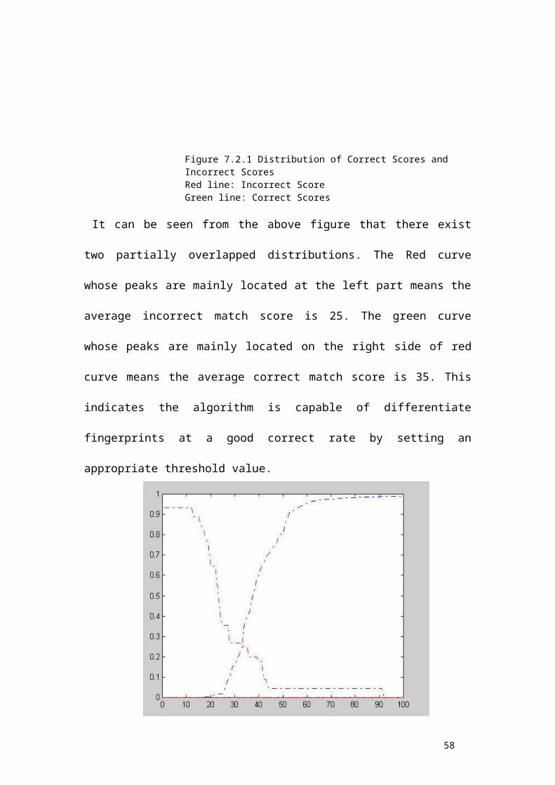
Figure 7.2.1 Distribution of Correct Scores and Incorrect Scores Red line: Incorrect Score Green line: Correct Scores
It can be seen from the above figure that there exist
two partially overlapped distributions. The Red curve
whose peaks are mainly located at the left part means the
average incorrect match score is 25. The green curve
whose peaks are mainly located on the right side of red
curve means the average correct match score is 35. This
indicates the algorithm is capable of differentiate
fingerprints at a good correct rate by setting an
appropriate threshold value.
58

Figure 7.2.2 FAR and FRR curveBlue dot line: FRR curveRed dot line: FAR curve
The above diagram shows the FRR and FAR curves. At the
equal error rate 25%, the separating score 33 will
falsely reject 25% genuine minutia pairs and falsely
accept 25% imposturous minutia pairs and has 75%
verification rate.
The high incorrect acceptance and false rejection are
due to some fingerprint images with bad quality and the
vulnerable minutia match algorithm.
59

CHAPTER 8 CONCLUSTION
My project has combined many methods to build a minutia
extractor and a minutia matcher. The combination of
multiple methods comes from a wide investigation into
research paper. Also some novel changes like segmentation
using Morphological operations, minutia marking with
special considering the triple branch counting, minutia
unification by decomposing a branch into three
terminations, and matching in the unified x-y coordinate
system after a two-step transformation are used in my
project, which are not reported in other literatures I
referred to.
Also a program coding with MATLAB going through all the
stages of the fingerprint recognition is built. It is
helpful to understand the procedures of fingerprint
recognition. And demonstrate the key issues of
fingerprint recognition.
60

61

REFERENCES
[1] Lin Hong. "Automatic Personal Identification Using
Fingerprints", Ph.D. Thesis, 1998.
[2] D.Maio and D. Maltoni. Direct gray-scale minutiae
detection in fingerprints. IEEE Trans. Pattern Anal. And
Machine Intell., 19(1):27-40, 1997.
[3] Jain, A.K., Hong, L., and Bolle, R.(1997), “On-Line
Fingerprint Verification,” IEEE Trans. On Pattern Anal
and Machine Intell, 19(4), pp. 302-314.
[4] N. Ratha, S. Chen and A.K. Jain, "Adaptive Flow
Orientation Based Feature Extraction in Fingerprint
Images", Pattern Recognition, Vol. 28, pp. 1657-1672,
November 1995.
[5] Alessandro Farina, Zsolt M.Kovacs-Vajna, Alberto
leone, Fingerprint minutiae extraction from skeletonized
binary images, Pattern Recognition, Vol.32, No.4, pp877-
889, 1999.
[6] Lee, C.J., and Wang, S.D.: Fingerprint feature
extration using Gabor filters, Electron. Lett., 1999, 35,
(4), pp.288-290.
62

[7] M. Tico, P.Kuosmanen and J.Saarinen. Wavelet domain
features for fingerprint recognition, Electroni. Lett.,
2001, 37, (1), pp.21-22.
[8] L. Hong, Y. Wan and A.K. Jain, "Fingerprint Image
Enhancement: Algorithms and Performance Evaluation",
IEEE Transactions on PAMI ,Vol. 20, No. 8, pp.777-789,
August 1998.
[9] Image Systems Engineering Program, Stanford
University. Student project By Thomas Yeo, Wee Peng Tay,
Ying Yu Tai.
http://ise0.stanford.edu/class/ee368a_proj01/dropbox/proj
ect22/finger/
[10] FVC2000. http://bias.csr.unibo.it/fvc2000/
[11] FVC2002. http://bias.csr.unibo.it/fvc2002/
[12] L.C. Jain, U.Halici, I. Hayashi, S.B. Lee and
S.Tsutsui. Intelligent biometric techniques in
fingerprint and face recognition. 1999, the CRC Press.
[13] M. J. Donahue and S. I. Rokhlin, "On the Use of
Level Curves in Image Analysis," Image Understanding,
VOL. 57, pp 652 - 655, 1992.
63

64

User Manual
1. Type command start_gui_single_mode in MATLAB 6.0
Figure M.1 the User Interface of the Fingerprint RecognitionSystem. The series of buttons on the left side will be invokedsequentially in the consequent demonstration. The two blank areasare used to show the fingerprint image before and after atransaction respectively.
2. Click Load Button
65

Figure M.2 Load a gray level fingerprint image from a drivespecified by Users. Multiple formats are supported and the imagesize is not limited. But the fingerprint ridges should have largegray intensity comparing with the background and valleys.
3. Click his-Equalization Button
Figure M.3 After Histogram Equalization. The image on the leftside is the original fingerprint. The enhanced image after theHistogram Equalization is shown on the right side.
4. Click fft Button
66

Figure M.4 Captured window after click ‘FFT’ button. The pop-updialog accepts the parameter k (please refer the formula 2). Theexperimental optimal k value is 0.45. Users can fill any otherconstant in the dialog to get a better performance. The enhancedimage will be shown in the left screen box, which however is notshown here.
5. Click Binarization Button
6.Click Direction Button
Figure M.5.6 Screen capture after binarization (left) and blockdirection estimation (right).
7. Click ROI Area Button
67

Figure M.7 ROI extraction(right). The intermediate steps for allthe morphological operations such close and open are not shown.The right screen box shows the final region of interest of thefingerprint image. The subsequent operations will only operate onthe region of interest.
8. Click Thinning Button
9. Click Remove H breaks Button
10. Click Remove spikes Button
Figure M.10 the Fingerprint image after thining, H breaks removal,isolated peaks removal and spike removal.(right).
68

11. Click Extract Button
12. Click Real Minutia Button
Figure M.12 Minutia Marking (right) and False Minutia Removal(Left). Bifurcations are located with yellow crosses andterminations are denotes with red stars. And the genuine minutia(left) are labeled with orientations with green arrows.
13. Click Save Button
69

Figure M.13 Save minutia to a text file. The saved text filestores the information on all genuine minutia. The exact format ofthe files are explained in the source code.
14. Click Match Button
Figure M.14 Load two minutia files and do matching. Users can opentwo minutia data files from the dialog invoked by clicking the‘Match’ button. The match algorithm will return a prompt of thematch score. But be noted that matching in the GUI mode is notencouraged since the match algorithm relies on heavy computation.Unpredicted states will happen after a long irresponsive runningtime. Batch testing is prepared for testing match. Please referthe source files for batch testing.
70