UWB Short-Range Bifocusing Tomographic Imaging
7
2414 IEEE TRANSACTIONS ON INSTRUMENTATION AND MEASUREMENT, VOL. 57, NO. 11, NOVEMBER 2008 UWB Short-Range Bifocusing Tomographic Imaging Lluís Jofre, Senior Member, IEEE, Anna Papió Toda, Josep Miquel Jornet Montana, Patricia Ceballos Carrascosa, Jordi Romeu, Sebastián Blanch, Member, IEEE, and Angel Cardama, Member, IEEE Abstract—In this paper, the capability of ultra-wideband (UWB) sensor arrays for tomographic imaging of electrically large objects in 2-D and 3-D environments is presented. One of the main concerns when imaging extended real objects is the capability of the system to correctly reconstruct the object cross-section electric properties. An imaging method using a UWB multifrequency bi- focusing (UWB-MFBF) operator with good tomographic imaging capabilities is presented, and numerical simulations are conducted to obtain the basic geometry and sampling parameters for a good-quality image reconstruction for geometrical and electrical parameters. Canonical-shape experimental reconstructions are performed to validate the established criteria. Index Terms—Antenna arrays, frequency domain, microwave imaging, near field, permittivity, tomography, ultra wideband (UWB). I. I NTRODUCTION T HE CAPABILITY of microwave signals to penetrate and sense light opaque materials with reasonable spatial reso- lution makes them attractive for different industrial, medical, and security applications [1]–[5]. Wideband signals, such as those produced with ultra-wideband (UWB) systems [6], [7] and, in particular, the recent 3.1- to 10.6-GHz band, offer new possibilities to increase spatial resolution and material electrical parameter measurement accuracy. Existing short-range imaging systems basically rely on two main techniques—the ones that are aimed at the internal inspec- tion of the objects, normally based on tomographic approaches [8]–[13], and those that are based on the radar techniques [14]–[17], which are oriented at the characterization of spe- cific scatters inside the interrogation zone. Although hybrid approaches exist, in general, radar-based techniques tend to be formulated in the time domain to use computationally efficient back-projection algorithms and to give accurate object shape and location results. Tomography-based techniques, on the other hand, tend to be formulated in the frequency domain to be based on nonlinear iterative inversion algorithms and to give Manuscript received July 31, 2007; revised December 9, 2007. First pub- lished June 27, 2008; current version published October 10, 2008. This work was supported in part by the Spanish Centro de Investigación Científica y Tecnológica Project TEC2004-04866-C04-02 and Project TEC2007-66698- C04-01, in part by the European Commission under Contract EC-FP6-IST- 508009 and under Contract EC-FP6-IST-026957, and in part by the Department of Universities, Generalitat de Catalunya, under SGR-00301. Portions of this paper have been reused, by permission, from the Proceedings of the Third International Conference on Electromagnetic Near-Field Characterization and Imaging (ICONIC’07). L. Jofre, A. Papió Toda, J. Romeu, S. Blanch, and A. Cardama are with the Polytechnic University of Catalonia, 08034 Barcelona, Spain. J. M. Jornet Montana and P. Ceballos Carrascosa are with the Massachusetts Institute of Technology, Cambridge, MA 02139-4307 USA. Color versions of one or more of the figures in this paper are available online at http://ieeexplore.ieee.org. Digital Object Identifier 10.1109/TIM.2008.926382 accurate information on the dielectric-property profiles of the objects for modest size-contrast products. When the interest is the tomographic reconstruction of high-contrast electrically ex- tended objects, the problem becomes highly nonlinear, and ex- isting techniques suffer from a lack of accuracy (ill-conditioned matrices) or from low computational efficiency (time-expensive inversion or iterative methods); consequently, new approaches need to be found. Most of the imaging methods (both monofre- quency and multifrequency) are frequency sensitive [18] in the sense that illuminating fields and their corresponding traces tend to be highly frequency dependent and, therefore, resonance modulated. On the other hand, a continuous frequency spectrum or, equivalently, a temporal impulse will reduce the resonance character of the reconstruction and, in some sense, the degree of nonlinearity. The method presented in this paper, which theoretically completes and extends the previous work presented in [19], consists of a UWB multifrequency bifocusing (UWB-MFBF) imaging technique that synthetically focuses a UWB incident- transmitted field and the corresponding scattered-received field on every “pixel” of the reconstructed scenario. Using the wide frequency-band character of the incident-wave frequency, resonant-free reconstructions may be obtained. The establish- ment of criteria in terms of the number of sensors and their geometrical disposition will offer an interesting number of possibilities and improvements in the field of electromagnetic short-range object visualization. In Section II, the analytical formulation is presented. In Section III, the spatial and frequency sampling criteria are established, and in Section IV, the quality of the reconstruction algorithm for low- and high-contrast objects is discussed. Para- metric simulations have been conducted to verify the results. A first experimental validation in Section V has been finally performed using two collinear arrays of UWB antennas, which act as transmitters and receivers. II. ANALYTICAL FORMULATION The general idea for UWB short-range imaging consists of distributing a certain number of microwave sensors (trans- mitters and/or receivers) on a certain region surrounding, as much as possible, the object under investigation. The goal is to obtain the 2-D or 3-D spatial and electrical information of the extended object, i.e., ε m ( r ), relative to the original background value of the interrogation area, i.e., ε b ( r ). The object can be a continuous distribution or a discrete set of independent objects S k with electrical permittivity ε S k ( r ). Following the electromagnetic compensation principle [20], the illumination of an object induces an equivalent electric current distribution that is proportional to the electrical contrast 0018-9456/$25.00 © 2008 IEEE Authorized licensed use limited to: Georgia Institute of Technology. Downloaded on August 12, 2009 at 23:00 from IEEE Xplore. Restrictions apply.
-
Upload
independent -
Category
Documents
-
view
7 -
download
0
Transcript of UWB Short-Range Bifocusing Tomographic Imaging
2414 IEEE TRANSACTIONS ON INSTRUMENTATION AND MEASUREMENT, VOL. 57, NO. 11, NOVEMBER 2008
UWB Short-Range Bifocusing Tomographic ImagingLluís Jofre, Senior Member, IEEE, Anna Papió Toda, Josep Miquel Jornet Montana, Patricia Ceballos Carrascosa,
Jordi Romeu, Sebastián Blanch, Member, IEEE, and Angel Cardama, Member, IEEE
Abstract—In this paper, the capability of ultra-wideband(UWB) sensor arrays for tomographic imaging of electrically largeobjects in 2-D and 3-D environments is presented. One of the mainconcerns when imaging extended real objects is the capability ofthe system to correctly reconstruct the object cross-section electricproperties. An imaging method using a UWB multifrequency bi-focusing (UWB-MFBF) operator with good tomographic imagingcapabilities is presented, and numerical simulations are conductedto obtain the basic geometry and sampling parameters for agood-quality image reconstruction for geometrical and electricalparameters. Canonical-shape experimental reconstructions areperformed to validate the established criteria.
Index Terms—Antenna arrays, frequency domain, microwaveimaging, near field, permittivity, tomography, ultra wideband(UWB).
I. INTRODUCTION
THE CAPABILITY of microwave signals to penetrate andsense light opaque materials with reasonable spatial reso-
lution makes them attractive for different industrial, medical,and security applications [1]–[5]. Wideband signals, such asthose produced with ultra-wideband (UWB) systems [6], [7]and, in particular, the recent 3.1- to 10.6-GHz band, offer newpossibilities to increase spatial resolution and material electricalparameter measurement accuracy.
Existing short-range imaging systems basically rely on twomain techniques—the ones that are aimed at the internal inspec-tion of the objects, normally based on tomographic approaches[8]–[13], and those that are based on the radar techniques[14]–[17], which are oriented at the characterization of spe-cific scatters inside the interrogation zone. Although hybridapproaches exist, in general, radar-based techniques tend to beformulated in the time domain to use computationally efficientback-projection algorithms and to give accurate object shapeand location results. Tomography-based techniques, on theother hand, tend to be formulated in the frequency domain tobe based on nonlinear iterative inversion algorithms and to give
Manuscript received July 31, 2007; revised December 9, 2007. First pub-lished June 27, 2008; current version published October 10, 2008. This workwas supported in part by the Spanish Centro de Investigación Científica yTecnológica Project TEC2004-04866-C04-02 and Project TEC2007-66698-C04-01, in part by the European Commission under Contract EC-FP6-IST-508009 and under Contract EC-FP6-IST-026957, and in part by the Departmentof Universities, Generalitat de Catalunya, under SGR-00301. Portions of thispaper have been reused, by permission, from the Proceedings of the ThirdInternational Conference on Electromagnetic Near-Field Characterization andImaging (ICONIC’07).
L. Jofre, A. Papió Toda, J. Romeu, S. Blanch, and A. Cardama are with thePolytechnic University of Catalonia, 08034 Barcelona, Spain.
J. M. Jornet Montana and P. Ceballos Carrascosa are with the MassachusettsInstitute of Technology, Cambridge, MA 02139-4307 USA.
Color versions of one or more of the figures in this paper are available onlineat http://ieeexplore.ieee.org.
Digital Object Identifier 10.1109/TIM.2008.926382
accurate information on the dielectric-property profiles of theobjects for modest size-contrast products. When the interest isthe tomographic reconstruction of high-contrast electrically ex-tended objects, the problem becomes highly nonlinear, and ex-isting techniques suffer from a lack of accuracy (ill-conditionedmatrices) or from low computational efficiency (time-expensiveinversion or iterative methods); consequently, new approachesneed to be found. Most of the imaging methods (both monofre-quency and multifrequency) are frequency sensitive [18] in thesense that illuminating fields and their corresponding tracestend to be highly frequency dependent and, therefore, resonancemodulated. On the other hand, a continuous frequency spectrumor, equivalently, a temporal impulse will reduce the resonancecharacter of the reconstruction and, in some sense, the degreeof nonlinearity.
The method presented in this paper, which theoreticallycompletes and extends the previous work presented in [19],consists of a UWB multifrequency bifocusing (UWB-MFBF)imaging technique that synthetically focuses a UWB incident-transmitted field and the corresponding scattered-received fieldon every “pixel” of the reconstructed scenario. Using thewide frequency-band character of the incident-wave frequency,resonant-free reconstructions may be obtained. The establish-ment of criteria in terms of the number of sensors and theirgeometrical disposition will offer an interesting number ofpossibilities and improvements in the field of electromagneticshort-range object visualization.
In Section II, the analytical formulation is presented. InSection III, the spatial and frequency sampling criteria areestablished, and in Section IV, the quality of the reconstructionalgorithm for low- and high-contrast objects is discussed. Para-metric simulations have been conducted to verify the results.
A first experimental validation in Section V has been finallyperformed using two collinear arrays of UWB antennas, whichact as transmitters and receivers.
II. ANALYTICAL FORMULATION
The general idea for UWB short-range imaging consistsof distributing a certain number of microwave sensors (trans-mitters and/or receivers) on a certain region surrounding, asmuch as possible, the object under investigation. The goal is toobtain the 2-D or 3-D spatial and electrical information of theextended object, i.e., εm(�r ), relative to the original backgroundvalue of the interrogation area, i.e., εb(�r ). The object can be acontinuous distribution or a discrete set of independent objectsSk with electrical permittivity εSk
(�r ).Following the electromagnetic compensation principle [20],
the illumination of an object induces an equivalent electriccurrent distribution that is proportional to the electrical contrast
0018-9456/$25.00 © 2008 IEEE
Authorized licensed use limited to: Georgia Institute of Technology. Downloaded on August 12, 2009 at 23:00 from IEEE Xplore. Restrictions apply.
JOFRE et al.: UWB SHORT-RANGE BIFOCUSING TOMOGRAPHIC IMAGING 2415
Fig. 1. Interrogation geometry.
c(�r )=(εm(�r )−εb(�r ))/εb(�r ) that, in the illumination process,may be seen as the source of the scattered field and, in theinverse imaging process, as an approximate “trace” of theoriginal object.
As shown in Fig. 1, a set of NT transmitters Ti and a set ofNR receivers Rj are used to scan the interrogation area wherethe reconstruction algorithm is applied. First, a measurementmatrix (information matrix) is obtained as follows. For everytransmitting element, the receiving array is scanned over eachreceiving element, obtaining an NR measurement vector. Then,the procedure is repeated for the NT transmitting elements,obtaining an NT × NR matrix.
The reconstruction algorithm forms every image point ofthe local electrical properties of the object by means of syn-thesizing two focused groups of antennas (transmitters andreceivers). The antenna elements (transmitting and receivingsignals) are numerically weighted by a focusing operator tobe focused on a unique object point. This is achieved bya mathematical treatment of the measurement matrix. Thisnumerical focusing operator [21] consists of taking the inverseweights of the electrical field that is induced by an imaginaryobject point that scans all the possible grid points of the spaceunder reconstruction. Applying this focusing operator to themeasurement matrix for all the points of the image space grid,we are able to obtain a replica of the extended object. Sincethere exist nonlinear phenomena, such as multiple or high-contrast scattering and frequency dependence, the continuousfrequency superposition that is proposed in this paper will tendto smooth out and reduce their effects.
To be more specific, in the 2-D case, for a particular wave-number k corresponding to the frequency f , the scattered fieldthat is measured at a receiver positioned in rR(xr, yr) havingan imaginary pointlike scatter placed at rS(xs, ys) is given by
Es(xr, yr, f) = Ei(xs, ys, f) · Iobj · H(2)0 (k|rr − rs|) (1)
where H20 is the Hankel function of the first order and the
second kind, Iobj(�r) ∝ fc(�r) Ei(�r) [9] is the equivalent currentinduced on the object, and Ei is the focused incident field onthe pointlike scatter position. This incident field can be ex-pressed as
Ei(xi, yi, f) =Nt∑
n=1
Itn(xf , yf , f) · H(2)0 (k|rtn − ri|) (2)
Itn(xf , yf , f) =1
H(2)0 (k|rtn − rf |)
(3)
where Itn is the focusing operator for the transmitters.
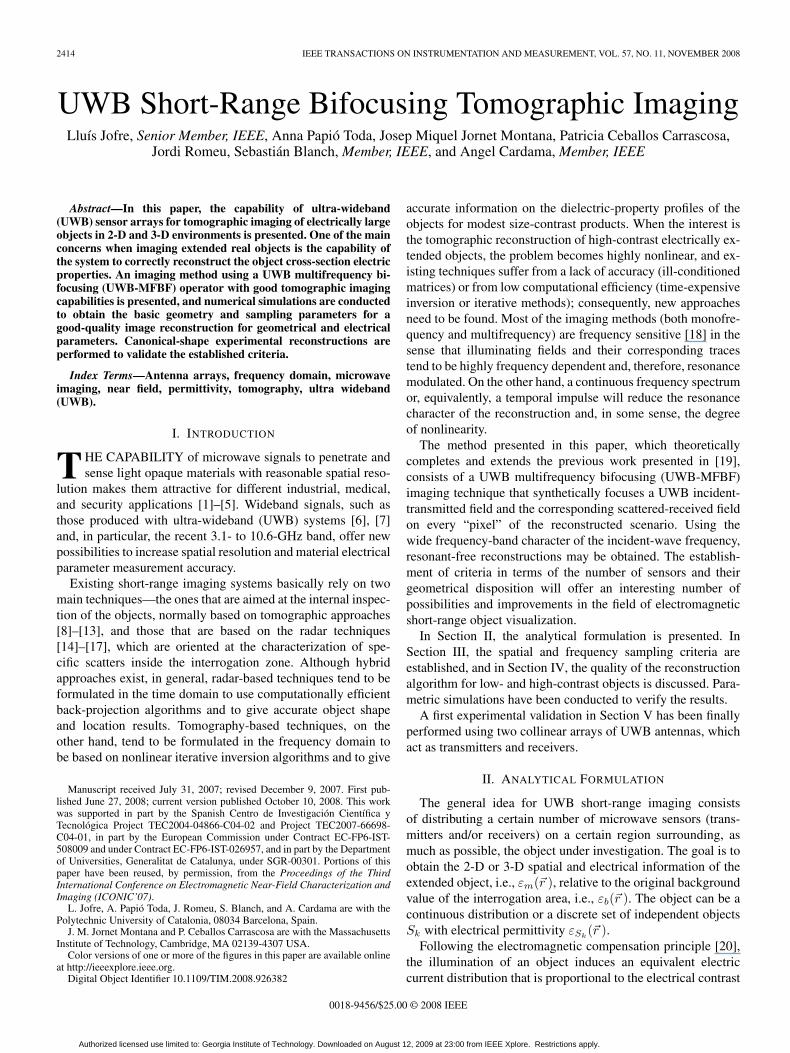
Fig. 2. (a) Space and (b) spectral domain geometry.
Then, the reconstructed field Ef in each of the focusingpoints of the grid is found as follows:
Ef (xf , yf , f) =Nrt∑n=1
Irn(xf , yf , f) · Es(xrn, yrn, f) (4)
Irn(xf , yf , f) =1
H(2)0 (k|rrn − rf |)
(5)
where Irn is the focusing operator for the receivers.Last, the entire process can be grouped using a matrix
formulation as follows:
Ef (xf , yf )=[It1 It2 It3 · · · ItNt]
·
⎡⎢⎢⎢⎢⎢⎢⎢⎣
Est1r1 Est1r2 · · · · · · Est1rNr
Est2r1
. . ....
Est2r1
. . ....
.... . .
...EstNt r1 · · · · · · · · · EstNt rNr
⎤⎥⎥⎥⎥⎥⎥⎥⎦·
⎡⎢⎢⎢⎢⎢⎢⎢⎣
Ir1
Ir2
Ir3
...
IrNr
⎤⎥⎥⎥⎥⎥⎥⎥⎦
. (6)
For the UWB case, when a certain set of frequencies arecombined, the total field can be obtained as a coherentaddition, i.e.,
Ef (xf , yf ) =f2∑
f=f1
Ef (xf , yf , f). (7)
The extension to the 3-D geometry can be done using the 3-Dspherical operator e−jkr/r instead of the 2-D Hankel operator.
III. SPACE AND FREQUENCY SAMPLING CRITERIA
Our aim is to obtain accurate spatial information about theelectrically extended object in terms of its geometrical shapeand electrical parameter values using a network of antennas thatare located regularly or randomly throughout the interrogationarea. The knowledge of the number of elements that must formthe sensor network and its disposition on the reconstructingscenario is crucial to obtain the desired results.
Based on the Fourier diffraction theorem [22], the imagingproblem can be stated as follows. The information obtainedfrom the scattered field Es produced by a particular frequencyf0 and orientation φ0 [Fig. 2(a)] may be translated into a
Authorized licensed use limited to: Georgia Institute of Technology. Downloaded on August 12, 2009 at 23:00 from IEEE Xplore. Restrictions apply.
2416 IEEE TRANSACTIONS ON INSTRUMENTATION AND MEASUREMENT, VOL. 57, NO. 11, NOVEMBER 2008
Fig. 3. Imaging sensor network geometry.
circle of radius k0 = 2πf0√
μbεb (semicircle TG for transmit-ting geometry and semicircle RG for reflection geometry) ofthe 2-D Fourier transform (FT) spectral domain (u, v) of theobject C(u, v) = FT{c(x, y)} [Fig. 2(b)]. The successive an-gular and frequency scans will fill the spectral domain “knowl-edge” on a specific manner, depending on the imaging systemdesign.
Under the low-contrast electrical property condition, i.e.,c(�r) � 1, which is usually known as the Born condition, fre-quency and geometrical scans are partially equivalent, and op-timized combinations can be found to fulfil the spectral domainC. Under the non-Born condition, however, those conditionsare not applicable, and new criteria need to be obtained.
To design the UWB imaging system, the spatial and fre-quency requirements need to be considered, according to thefollowing points.
1) Spatial-Angular Sampling: From the electromagneticmodal expansion of the fields scattered by an electric objectwhen illuminated by an incident field, it is known that toobtain an image with a resolution of λfmax/2 (with λfmax beingthe highest operating frequency inside the UWB interval), inall directions, good encircling interrogation geometry with anumber Nφ of views is required. The minimum number ofviews that are necessary to properly reconstruct the object isequal to the number of coefficients of the cylindrical-mode(or the spherical mode for 3-D geometry) expansion [20] of thescattered field, i.e.,
Nφ ≥ 2kfmaxa = 2 · π · a/(λfmax/2) (8)
with a being the object-encircling radius, and kfmax =2π/λfmax .
Thus, implying a maximum angular step, as shown in Fig. 3
Δφ = 2 · π/Nφ = λfmax/(2 · a). (9)
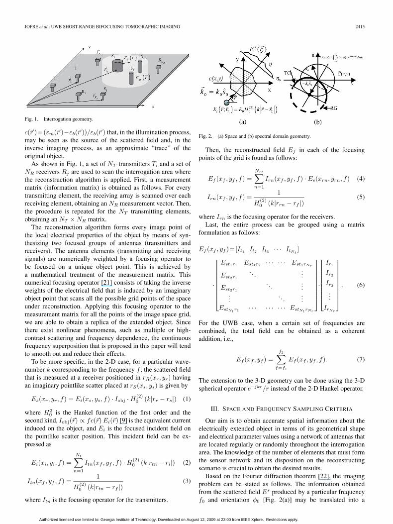
Fig. 4 shows the reconstruction results for a dielectriccylinder with a diameter of 25 cm using encircling circulargeometry with 128 transceivers [sequentially acting as emittersand receivers; Fig. 4(a)] and 16 transceivers [Fig. 4(b)]. Whenangular sampling criteria are satisfied [Nφ > 2ka; Fig. 4(a)],the reconstructed image is uniform over the cylinder, and thecontours are determined perfectly.
2) Frequency Sampling: To ensure an image that is free ofdistortion and false aliases into the radial (Fig. 3) direction,
Fig. 4. Reconstructed image of a 25-cm diameter cylinder with(a) 128 emitters and receivers and (b) 16 emitters and receivers.
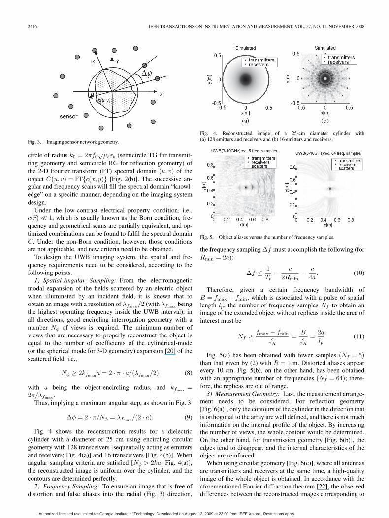
Fig. 5. Object aliases versus the number of frequency samples.
the frequency sampling Δf must accomplish the following (forRmin = 2a):
Δf ≤ 1Tt
=c
2Rmin=
c
4a. (10)
Therefore, given a certain frequency bandwidth ofB = fmax − fmin, which is associated with a pulse of spatiallength lp, the number of frequency samples Nf to obtain animage of the extended object without replicas inside the area ofinterest must be
Nf ≥ fmax − fminc
2R
=Bc
2R
=2a
lp. (11)
Fig. 5(a) has been obtained with fewer samples (Nf = 5)than that given by (2) with R = 1 m. Distorted aliases appearevery 10 cm. Fig. 5(b), on the other hand, has been obtainedwith an appropriate number of frequencies (Nf = 64); there-fore, the replicas are out of range.
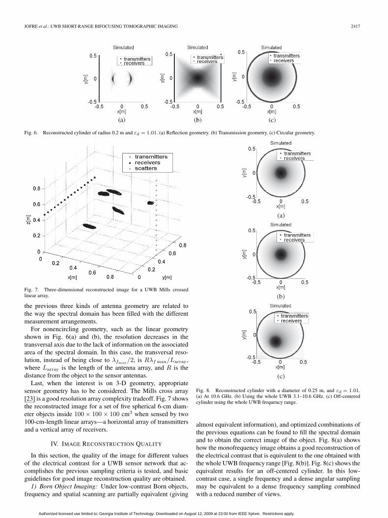
3) Measurement Geometry: Last, the measurement arrange-ment needs to be considered. For reflection geometry[Fig. 6(a)], only the contours of the cylinder in the direction thatis orthogonal to the array are well defined, and there is not muchinformation on the internal profile of the object. By increasingthe number of views, the whole contour would be determined.On the other hand, for transmission geometry [Fig. 6(b)], theedges tend to disappear, and the internal characteristics of theobject are reinforced.
When using circular geometry [Fig. 6(c)], where all antennasare transmitters and receivers at the same time, a high-qualityimage of the whole object is obtained. In accordance with theaforementioned Fourier diffraction theorem [22], the observeddifferences between the reconstructed images corresponding to
Authorized licensed use limited to: Georgia Institute of Technology. Downloaded on August 12, 2009 at 23:00 from IEEE Xplore. Restrictions apply.
JOFRE et al.: UWB SHORT-RANGE BIFOCUSING TOMOGRAPHIC IMAGING 2417
Fig. 6. Reconstructed cylinder of radius 0.2 m and εd = 1.01. (a) Reflection geometry. (b) Transmission geometry. (c) Circular geometry.
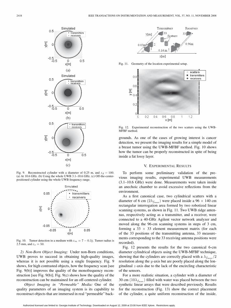
Fig. 7. Three-dimensional reconstructed image for a UWB Mills crossedlinear array.
the previous three kinds of antenna geometry are related tothe way the spectral domain has been filled with the differentmeasurement arrangements.
For nonencircling geometry, such as the linear geometryshown in Fig. 6(a) and (b), the resolution decreases in thetransversal axis due to the lack of information on the associatedarea of the spectral domain. In this case, the transversal reso-lution, instead of being close to λfmax/2, is Rλf max/Larray,where Larray is the length of the antenna array, and R is thedistance from the object to the sensor antennas.
Last, when the interest is on 3-D geometry, appropriatesensor geometry has to be considered. The Mills cross array[23] is a good resolution array complexity tradeoff. Fig. 7 showsthe reconstructed image for a set of five spherical 6-cm diam-eter objects inside 100 × 100 × 100 cm3 when sensed by two100-cm-length linear arrays—a horizontal array of transmittersand a vertical array of receivers.
IV. IMAGE RECONSTRUCTION QUALITY
In this section, the quality of the image for different valuesof the electrical contrast for a UWB sensor network that ac-complishes the previous sampling criteria is tested, and basicguidelines for good image reconstruction quality are obtained.
1) Born Object Imaging: Under low-contrast Born objects,frequency and spatial scanning are partially equivalent (giving
Fig. 8. Reconstructed cylinder with a diameter of 0.25 m, and εd = 1.01.(a) At 10.6 GHz. (b) Using the whole UWB 3.1–10.6 GHz. (c) Off-centeredcylinder using the whole UWB frequency range.
almost equivalent information), and optimized combinations ofthe previous equations can be found to fill the spectral domainand to obtain the correct image of the object. Fig. 8(a) showshow the monofrequency image obtains a good reconstruction ofthe electrical contrast that is equivalent to the one obtained withthe whole UWB frequency range [Fig. 8(b)]. Fig. 8(c) shows theequivalent results for an off-centered cylinder. In this low-contrast case, a single frequency and a dense angular samplingmay be equivalent to a dense frequency sampling combinedwith a reduced number of views.
Authorized licensed use limited to: Georgia Institute of Technology. Downloaded on August 12, 2009 at 23:00 from IEEE Xplore. Restrictions apply.
2418 IEEE TRANSACTIONS ON INSTRUMENTATION AND MEASUREMENT, VOL. 57, NO. 11, NOVEMBER 2008
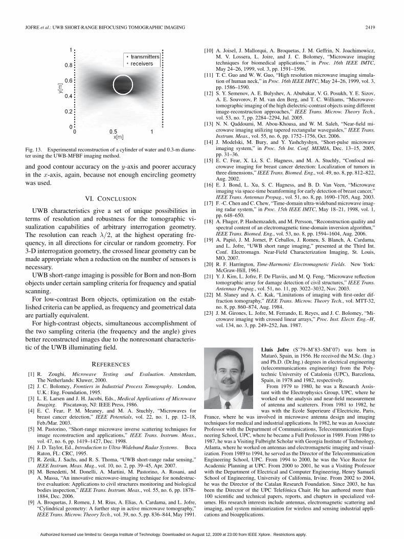
Fig. 9. Reconstructed cylinder with a diameter of 0.25 m, and εd = 100.(a) At 10.6 GHz. (b) Using the whole UWB 3.1–10.6 GHz. (c) Off-the-center-positioned cylinder using the whole UWB frequency range.
Fig. 10. Tumor detection in a medium with εm = 7 − 0.3j. Tumor radius is2.5 mm, and εs = 50.
2) Non-Born Object Imaging: Under non-Born conditions,UWB proves to succeed in obtaining high-quality images,whereas it is not possible using a single frequency. Fig. 9shows, for high contrasted objects, how the frequency scan [seeFig. 9(b)] improves the quality of the monofrequency recon-struction [see Fig. 9(b)]. Fig. 9(c) shows how the quality of thereconstruction can be maintained for an off-centered cylinder.
Object Imaging in “Permeable” Media: One of thequality parameters of an imaging system is its capability toreconstruct objects that are immersed in real “permeable” back-
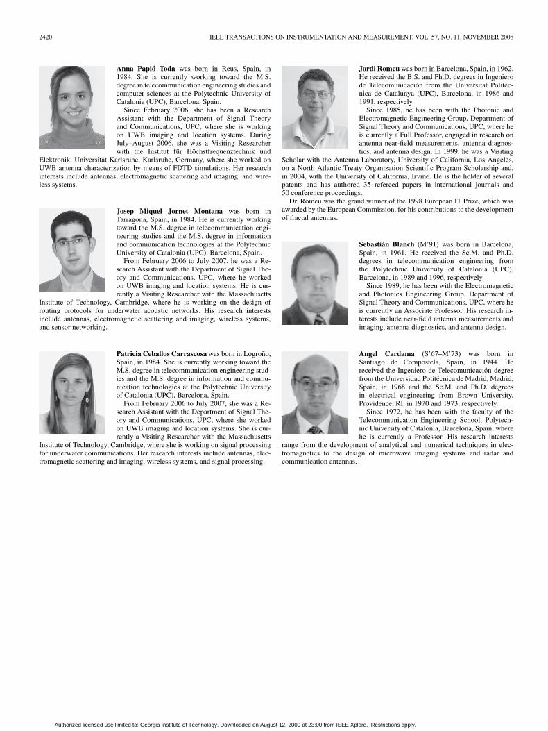
Fig. 11. Geometry of the location experimental setup.
Fig. 12. Experimental reconstruction of the two scatters using the UWB-MFBF method.
grounds. As one of the cases of growing interest is cancerdetection, we present the imaging results for a simple model ofa breast tumor using the UWB-MFBF method. Fig. 10 showshow the tumor can be properly reconstructed in spite of beinginside a fat lossy layer.
V. EXPERIMENTAL RESULTS
To perform some preliminary validation of the pre-vious imaging results, experimental UWB measurements(3.1–10.6 GHz) were done. Measurements were taken insidean anechoic chamber to avoid excessive reflections from theenvironment.
As a first canonical case, two cylindrical scatters with adiameter of 6 cm (2λfmax) were placed inside a 96 × 140 cmrectangular interrogation area formed by two robotized linearscanning systems, as shown in Fig. 11. Two UWB ridge anten-nas, respectively acting as a transmitter, and a receiver, wereconnected to a 40-GHz Agilent vector network analyzer andmoved along the 96-cm scanning systems in steps of 3 cm,forming a 33 × 33 element measurement matrix (for eachof the 33 positions of the transmitting antenna, 33 measure-ments corresponding to the 33 receiving antenna positions wererecorded).
Fig. 12 presents the results for the two canonical 6-cmdiameter cylindrical objects using the UWB-MFBF technique,showing that the cylinders are correctly placed with a λfmax/2resolution along the y-axis but are poorly placed along the lon-gitudinal z-axis due to the lack of the encircling characteristicof the sensors.
For a more realistic situation, a cylinder with a diameter of30 cm (10λfmax) filled with water was placed between the twosynthetic linear arrays that were described previously. Resultsfor the reconstruction (Fig. 13) show the correct placementof the cylinder, a quite uniform reconstruction of the inside,
Authorized licensed use limited to: Georgia Institute of Technology. Downloaded on August 12, 2009 at 23:00 from IEEE Xplore. Restrictions apply.
JOFRE et al.: UWB SHORT-RANGE BIFOCUSING TOMOGRAPHIC IMAGING 2419
Fig. 13. Experimental reconstruction of a cylinder of water and 0.3-m diame-ter using the UWB-MFBF imaging method.
and good contour accuracy on the y-axis and poorer accuracyin the x-axis, again, because not enough encircling geometrywas used.
VI. CONCLUSION
UWB characteristics give a set of unique possibilities interms of resolution and robustness for the tomographic vi-sualization capabilities of arbitrary interrogation geometry.The resolution can reach λ/2, at the highest operating fre-quency, in all directions for circular or random geometry. For3-D interrogation geometry, the crossed linear geometry can bemade appropriate when a reduction on the number of sensors isnecessary.
UWB short-range imaging is possible for Born and non-Bornobjects under certain sampling criteria for frequency and spatialscanning.
For low-contrast Born objects, optimization on the estab-lished criteria can be applied, as frequency and geometrical dataare partially equivalent.
For high-contrast objects, simultaneous accomplishment ofthe two sampling criteria (the frequency and the angle) givesbetter reconstructed images due to the nonresonant characteris-tic of the UWB illuminating field.
REFERENCES
[1] R. Zoughi, Microwave Testing and Evaluation. Amsterdam,The Netherlands: Kluwer, 2000.
[2] J. C. Bolomey, Frontiers in Industrial Process Tomography. London,U.K.: Eng. Foundation, 1995.
[3] L. E. Larsen and J. H. Jacobi, Eds., Medical Applications of MicrowaveImaging. Piscataway, NJ: IEEE Press, 1986.
[4] E. C. Fear, P. M. Meaney, and M. A. Stuchly, “Microwaves forbreast cancer detection,” IEEE Potentials, vol. 22, no. 1, pp. 12–18,Feb./Mar. 2003.
[5] M. Pastorino, “Short-range microwave inverse scattering techniques forimage reconstruction and applications,” IEEE Trans. Instrum. Meas.,vol. 47, no. 6, pp. 1419–1427, Dec. 1998.
[6] J. D. Taylor, Ed., Introduction to Ultra-Wideband Radar Systems. BocaRaton, FL: CRC, 1995.
[7] R. Zetik, J. Sachs, and R. S. Thoma, “UWB short-range radar sensing,”IEEE Instrum. Meas. Mag., vol. 10, no. 2, pp. 39–45, Apr. 2007.
[8] M. Benedetti, M. Donelli, A. Martini, M. Pastorino, A. Rosani, andA. Massa, “An innovative microwave-imaging technique for nondestruc-tive evaluation: Applications to civil structures monitoring and biologicalbodies inspection,” IEEE Trans. Instrum. Meas., vol. 55, no. 6, pp. 1878–1884, Dec. 2006.
[9] A. Broquetas, J. Romeu, J. M. Rius, A. Elias, A. Cardama, and L. Jofre,“Cylindrical geometry: A further step in active microwave tomography,”IEEE Trans. Microw. Theory Tech., vol. 39, no. 5, pp. 836–844, May 1991.
[10] A. Joisel, J. Mallorqui, A. Broquetas, J. M. Geffrin, N. Joachimowicz,M. V. Lossera, L. Joire, and J. C. Bolomey, “Microwave imagingtechniques for biomedical applications,” in Proc. 16th IEEE IMTC,May 24–26, 1999, vol. 3, pp. 1591–1596.
[11] T. C. Guo and W. W. Guo, “High resolution microwave imaging simula-tion of human neck,” in Proc. 16th IEEE IMTC, May 24–26, 1999, vol. 3,pp. 1586–1590.
[12] S. Y. Semenov, A. E. Bulyshev, A. Abubakar, V. G. Posukh, Y. E. Sizov,A. E. Souvorov, P. M. van den Berg, and T. C. Williams, “Microwave-tomographic imaging of the high dielectric-contrast objects using differentimage-reconstruction approaches,” IEEE Trans. Microw. Theory Tech.,vol. 53, no. 7, pp. 2284–2294, Jul. 2005.
[13] N. N. Qaddoumi, M. Abou-Khousa, and W. M. Saleh, “Near-field mi-crowave imaging utilizing tapered rectangular waveguides,” IEEE Trans.Instrum. Meas., vol. 55, no. 6, pp. 1752–1756, Oct. 2006.
[14] J. Modelski, M. Bury, and Y. Yashchyshyn, “Short-pulse microwaveimaging system,” in Proc. 5th Int. Conf. MEMIA, Dec. 13–15, 2005,pp. 31–36.
[15] E. C. Fear, X. Li, S. C. Hagness, and M. A. Stuchly, “Confocal mi-crowave imaging for breast cancer detection: Localization of tumors inthree dimensions,” IEEE Trans. Biomed. Eng., vol. 49, no. 8, pp. 812–822,Aug. 2002.
[16] E. J. Bond, L. Xu, S. C. Hagness, and B. D. Van Veen, “Microwaveimaging via space-time beamforming for early detection of breast cancer,”IEEE Trans. Antennas Propag., vol. 51, no. 8, pp. 1690–1705, Aug. 2003.
[17] F. -C. Chen and C. Chew, “Time-domain ultra-wideband microwave imag-ing radar system,” in Proc. 15th IEEE IMTC, May 18–21, 1998, vol. 1,pp. 648–650.
[18] A. Fhager, P. Hashemzadeh, and M. Persson, “Reconstruction quality andspectral content of an electromagnetic time-domain inversion algorithm,”IEEE Trans. Biomed. Eng., vol. 53, no. 8, pp. 1594–1604, Aug. 2006.
[19] A. Papió, J. M. Jornet, P. Ceballos, J. Romeu, S. Blanch, A. Cardama,and L. Jofre, “UWB short range imaging,” presented at the Third Int.Conf. Electromagn. Near-Field Characterization Imaging, St. Louis,MO, 2007.
[20] R. F. Harrington, Time-Harmonic Electromagnetic Fields. New York:McGraw-Hill, 1961.
[21] Y. J. Kim, L. Jofre, F. De Flaviis, and M. Q. Feng, “Microwave reflectiontomographic array for damage detection of civil structures,” IEEE Trans.Antennas Propag., vol. 51, no. 11, pp. 3022–3032, Nov. 2003.
[22] M. Slaney and A. C. Kak, “Limitations of imaging with first-order dif-fraction tomography,” IEEE Trans. Microw. Theory Tech., vol. MTT-32,no. 8, pp. 860–874, Aug. 1984.
[23] J. M. Girones, L. Jofre, M. Ferrando, E. Reyes, and J. C. Bolomey, “Mi-crowave imaging with crossed linear arrays,” Proc. Inst. Electr. Eng.–H,vol. 134, no. 3, pp. 249–252, Jun. 1987.
Lluís Jofre (S’79–M’83–SM’07) was born inMataró, Spain, in 1956. He received the M.Sc. (Ing.)and Ph.D. (Dr.Ing.) degrees in electrical engineering(telecommunications engineering) from the Poly-technic University of Catalonia (UPC), Barcelona,Spain, in 1978 and 1982, respectively.
From 1979 to 1980, he was a Research Assis-tant with the Electrophysics Group, UPC, where heworked on the analysis and near-field measurementof antenna and scatterers. From 1981 to 1982, hewas with the Ecole Superieure d’Electricite, Paris,
France, where he was involved in microwave antenna design and imagingtechniques for medical and industrial applications. In 1982, he was an AssociateProfessor with the Department of Communications, Telecommunication Engi-neering School, UPC, where he became a Full Professor in 1989. From 1986 to1987, he was a Visiting Fulbright Scholar with Georgia Institute of Technology,Atlanta, where he worked on antennas and electromagnetic imaging and visual-ization. From 1989 to 1994, he served as the Director of the TelecommunicationEngineering School, UPC. From 1994 to 2000, he was the Vice Rector forAcademic Planning at UPC. From 2000 to 2001, he was a Visiting Professorwith the Department of Electrical and Computer Engineering, Henry SamueliSchool of Engineering, University of California, Irvine. From 2002 to 2004,he was the Director of the Catalan Research Foundation. Since 2003, he hasbeen the Director of the UPC Telefónica Chair. He has authored more than100 scientific and technical papers, reports, and chapters in specialized vol-umes. His research interests include antennas, electromagnetic scattering andimaging, and system miniaturization for wireless and sensing industrial appli-cations and bioapplications.
Authorized licensed use limited to: Georgia Institute of Technology. Downloaded on August 12, 2009 at 23:00 from IEEE Xplore. Restrictions apply.
2420 IEEE TRANSACTIONS ON INSTRUMENTATION AND MEASUREMENT, VOL. 57, NO. 11, NOVEMBER 2008
Anna Papió Toda was born in Reus, Spain, in1984. She is currently working toward the M.S.degree in telecommunication engineering studies andcomputer sciences at the Polytechnic University ofCatalonia (UPC), Barcelona, Spain.
Since February 2006, she has been a ResearchAssistant with the Department of Signal Theoryand Communications, UPC, where she is workingon UWB imaging and location systems. DuringJuly–August 2006, she was a Visiting Researcherwith the Institut für Höchstfrequenztechnik und
Elektronik, Universität Karlsruhe, Karlsruhe, Germany, where she worked onUWB antenna characterization by means of FDTD simulations. Her researchinterests include antennas, electromagnetic scattering and imaging, and wire-less systems.
Josep Miquel Jornet Montana was born inTarragona, Spain, in 1984. He is currently workingtoward the M.S. degree in telecommunication engi-neering studies and the M.S. degree in informationand communication technologies at the PolytechnicUniversity of Catalonia (UPC), Barcelona, Spain.
From February 2006 to July 2007, he was a Re-search Assistant with the Department of Signal The-ory and Communications, UPC, where he workedon UWB imaging and location systems. He is cur-rently a Visiting Researcher with the Massachusetts
Institute of Technology, Cambridge, where he is working on the design ofrouting protocols for underwater acoustic networks. His research interestsinclude antennas, electromagnetic scattering and imaging, wireless systems,and sensor networking.
Patricia Ceballos Carrascosa was born in Logroño,Spain, in 1984. She is currently working toward theM.S. degree in telecommunication engineering stud-ies and the M.S. degree in information and commu-nication technologies at the Polytechnic Universityof Catalonia (UPC), Barcelona, Spain.
From February 2006 to July 2007, she was a Re-search Assistant with the Department of Signal The-ory and Communications, UPC, where she workedon UWB imaging and location systems. She is cur-rently a Visiting Researcher with the Massachusetts
Institute of Technology, Cambridge, where she is working on signal processingfor underwater communications. Her research interests include antennas, elec-tromagnetic scattering and imaging, wireless systems, and signal processing.
Jordi Romeu was born in Barcelona, Spain, in 1962.He received the B.S. and Ph.D. degrees in Ingenierode Telecomunicación from the Universitat Politèc-nica de Catalunya (UPC), Barcelona, in 1986 and1991, respectively.
Since 1985, he has been with the Photonic andElectromagnetic Engineering Group, Department ofSignal Theory and Communications, UPC, where heis currently a Full Professor, engaged in research onantenna near-field measurements, antenna diagnos-tics, and antenna design. In 1999, he was a Visiting
Scholar with the Antenna Laboratory, University of California, Los Angeles,on a North Atlantic Treaty Organization Scientific Program Scholarship and,in 2004, with the University of California, Irvine. He is the holder of severalpatents and has authored 35 refereed papers in international journals and50 conference proceedings.
Dr. Romeu was the grand winner of the 1998 European IT Prize, which wasawarded by the European Commission, for his contributions to the developmentof fractal antennas.
Sebastián Blanch (M’91) was born in Barcelona,Spain, in 1961. He received the Sc.M. and Ph.D.degrees in telecommunication engineering fromthe Polytechnic University of Catalonia (UPC),Barcelona, in 1989 and 1996, respectively.
Since 1989, he has been with the Electromagneticand Photonics Engineering Group, Department ofSignal Theory and Communications, UPC, where heis currently an Associate Professor. His research in-terests include near-field antenna measurements andimaging, antenna diagnostics, and antenna design.
Angel Cardama (S’67–M’73) was born inSantiago de Compostela, Spain, in 1944. Hereceived the Ingeniero de Telecomunicación degreefrom the Universidad Politécnica de Madrid, Madrid,Spain, in 1968 and the Sc.M. and Ph.D. degreesin electrical engineering from Brown University,Providence, RI, in 1970 and 1973, respectively.
Since 1972, he has been with the faculty of theTelecommunication Engineering School, Polytech-nic University of Catalonia, Barcelona, Spain, wherehe is currently a Professor. His research interests
range from the development of analytical and numerical techniques in elec-tromagnetics to the design of microwave imaging systems and radar andcommunication antennas.
Authorized licensed use limited to: Georgia Institute of Technology. Downloaded on August 12, 2009 at 23:00 from IEEE Xplore. Restrictions apply.