UWB body area network channel modeling: An analytical approach
7
Please cite this article in press as: Tiberi G, et al. UWB body area network channel modeling: An analytical approach. Int J Electron Commun (AEÜ) (2012), doi:10.1016/j.aeue.2012.03.014 ARTICLE IN PRESS G Model AEUE-50896; No. of Pages 7 Int. J. Electron. Commun. (AEÜ) xxx (2012) xxx–xxx Contents lists available at SciVerse ScienceDirect International Journal of Electronics and Communications (AEÜ) jou rn al h omepage: www.elsevier.de/aeue UWB body area network channel modeling: An analytical approach Gianluigi Tiberi a,c,∗ , Navid Ghavami b,∗∗ , David J. Edwards b , A. Monorchio c a Fondazione Imago7, Viale del Tirreno, I-56128 Pisa, Italy b Department of Engineering Science, University of Oxford, Parks Road, Oxford, UK c Department of Information Engineering, University of Pisa, Via G. Caruso 16, I-56122 Pisa, Italy a r t i c l e i n f o Article history: Received 13 October 2011 Received in revised form 18 March 2012 Accepted 19 March 2012 Keywords: UWB Body Area Network Channel modeling Multi-layered stratified cylinder a b s t r a c t The aim of this work is to develop an analytically-based approach for ultra wide band (UWB) body area network (BAN) channel modeling. In detail, the body will be modeled as multi-layered stratified cylinders of infinite length, and the Maxwell’s equation will be solved for plane wave and line source excitations. Human-type tissues will be assumed in the multi-layered stratified cylindrical model. Validation of the procedure through measurement results has been provided. © 2012 Elsevier GmbH. All rights reserved. 1. Introduction Ultra wide band (UWB) wireless biomedical sensors is a promis- ing new application area made possible by recent advances in ultra low power technology. Each sensor measures parameters of inter- est and sends the data in short bursts to a central device. Examples include sensors to observe brain activity for recording or warning against seizure events, to examine heart activity for diagnosis and automatic emergency calls, to measure glucose levels in diabetic patients, and to monitor oxygen, blood pressure, or disease mark- ers. The large diversity and potential of these applications makes it an exciting new research direction in wireless communications. In developing these sensors, detailed knowledge of the Body area network (BAN) communication channel is essential. Measure- ments [1] and finite difference time domain (FDTD) simulations [2] have been successfully applied for specific communication scenarios. However, measurements do not directly consider the physical propagation mechanism, forcing researchers to rely on ad-hoc modeling approaches. On the other hand, realistic FDTD simulations that numerically evaluate the solution to Maxwell’s equations of small antennas worn close to the sophisticated curved This document is a collaborative effort. This research was partially supported by a Marie Curie Intra European Fellowship within the 7th European Community Framework Programme and partially supported by UK Engineering and Physical Sciences Research Council. ∗ Corresponding author. ∗∗ Corresponding author. E-mail addresses: [email protected] (G. Tiberi), [email protected] (N. Ghavami), [email protected] (D.J. Edwards), [email protected] (A. Monorchio). inhomogeneous human bodies are very time-consuming. Another approach resorts to the uniform theory of diffraction (UTD) [3]; while this approach offers considerable physical insight, it typi- cally relies on a high-frequency asymptotic approximation. Here, in contrast to conventional approaches based on FDTD methods, the propagation phenomena of UWB signal in human tissue will be investigated analytically. In detail, the body will be modeled as a cylinder of infinite length, and Maxwell’s equation will be solved for plane wave and line source excitation. First, a simple perfectly electrically conducting (PEC) cylinder will be considered; next, the complexity will be increased considering homogeneous dielectric cylinder and multi-layered stratified cylinders. Finally, human-type tissue will be assumed in the multilayered stratified cylinder model. In order to validate the analytical method, the comparison between the analytical frequency response and that of measurement involv- ing a multilayered medium is presented. The originality of the work lies in always maintaining an analytical approach to the research. 2. PEC cylinder Let us consider a perfectly electric conducting (PEC) cylinder in free space with radius a illuminated by a plane wave having a z-polarized E-field and traveling along the x-axis (Fig. 1). In free space, characterized by ε 0 , 0 , we define: k 0 = (2f ) 2 ε 0 0 (1a) Z 0 = 0 ε 0 (1b) 1434-8411/$ – see front matter © 2012 Elsevier GmbH. All rights reserved. doi:10.1016/j.aeue.2012.03.014
Transcript of UWB body area network channel modeling: An analytical approach
G
A
U
Ga
b
c
a
ARRA
KUBCM
1
ileiaapea
am[spase
bFS
n(
1d
ARTICLE IN PRESS Model
EUE-50896; No. of Pages 7
Int. J. Electron. Commun. (AEÜ) xxx (2012) xxx– xxx
Contents lists available at SciVerse ScienceDirect
International Journal of Electronics andCommunications (AEÜ)
jou rn al h omepage: www.elsev ier .de /aeue
WB body area network channel modeling: An analytical approach�
ianluigi Tiberi a,c,∗, Navid Ghavamib,∗∗, David J. Edwardsb, A. Monorchioc
Fondazione Imago7, Viale del Tirreno, I-56128 Pisa, ItalyDepartment of Engineering Science, University of Oxford, Parks Road, Oxford, UKDepartment of Information Engineering, University of Pisa, Via G. Caruso 16, I-56122 Pisa, Italy
r t i c l e i n f o
rticle history:eceived 13 October 2011eceived in revised form 18 March 2012
a b s t r a c t
The aim of this work is to develop an analytically-based approach for ultra wide band (UWB) body areanetwork (BAN) channel modeling. In detail, the body will be modeled as multi-layered stratified cylindersof infinite length, and the Maxwell’s equation will be solved for plane wave and line source excitations.
ccepted 19 March 2012
eywords:WBody Area Networkhannel modeling
Human-type tissues will be assumed in the multi-layered stratified cylindrical model. Validation of theprocedure through measurement results has been provided.
© 2012 Elsevier GmbH. All rights reserved.
ulti-layered stratified cylinder
. Introduction
Ultra wide band (UWB) wireless biomedical sensors is a promis-ng new application area made possible by recent advances in ultraow power technology. Each sensor measures parameters of inter-st and sends the data in short bursts to a central device. Examplesnclude sensors to observe brain activity for recording or warninggainst seizure events, to examine heart activity for diagnosis andutomatic emergency calls, to measure glucose levels in diabeticatients, and to monitor oxygen, blood pressure, or disease mark-rs. The large diversity and potential of these applications makes itn exciting new research direction in wireless communications.
In developing these sensors, detailed knowledge of the Bodyrea network (BAN) communication channel is essential. Measure-ents [1] and finite difference time domain (FDTD) simulations
2] have been successfully applied for specific communicationcenarios. However, measurements do not directly consider thehysical propagation mechanism, forcing researchers to rely on
Please cite this article in press as: Tiberi G, et al. UWB body area network(AEÜ) (2012), doi:10.1016/j.aeue.2012.03.014
d-hoc modeling approaches. On the other hand, realistic FDTDimulations that numerically evaluate the solution to Maxwell’squations of small antennas worn close to the sophisticated curved
� This document is a collaborative effort. This research was partially supportedy a Marie Curie Intra European Fellowship within the 7th European Communityramework Programme and partially supported by UK Engineering and Physicalciences Research Council.∗ Corresponding author.
∗∗ Corresponding author.E-mail addresses: [email protected] (G. Tiberi),
[email protected] (N. Ghavami), [email protected]. Edwards), [email protected] (A. Monorchio).
434-8411/$ – see front matter © 2012 Elsevier GmbH. All rights reserved.oi:10.1016/j.aeue.2012.03.014
inhomogeneous human bodies are very time-consuming. Anotherapproach resorts to the uniform theory of diffraction (UTD) [3];while this approach offers considerable physical insight, it typi-cally relies on a high-frequency asymptotic approximation. Here,in contrast to conventional approaches based on FDTD methods,the propagation phenomena of UWB signal in human tissue will beinvestigated analytically. In detail, the body will be modeled as acylinder of infinite length, and Maxwell’s equation will be solvedfor plane wave and line source excitation. First, a simple perfectlyelectrically conducting (PEC) cylinder will be considered; next, thecomplexity will be increased considering homogeneous dielectriccylinder and multi-layered stratified cylinders. Finally, human-typetissue will be assumed in the multilayered stratified cylinder model.In order to validate the analytical method, the comparison betweenthe analytical frequency response and that of measurement involv-ing a multilayered medium is presented. The originality of the worklies in always maintaining an analytical approach to the research.
2. PEC cylinder
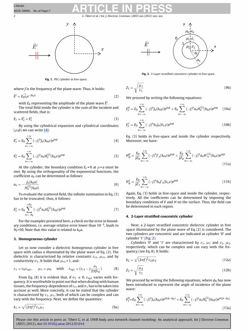
Let us consider a perfectly electric conducting (PEC) cylinderin free space with radius a illuminated by a plane wave having az-polarized E-field and traveling along the x-axis (Fig. 1). In freespace, characterized by ε0,�0, we define:
k =√
(2�f )2ε � (1a)
channel modeling: An analytical approach. Int J Electron Commun
0 0 0
Z0 =√
�0
ε0(1b)
ARTICLE IN PRESSG Model
AEUE-50896; No. of Pages 7
2 G. Tiberi et al. / Int. J. Electron. Commun. (AEÜ) xxx (2012) xxx– xxx
w
E
s
E
(
E
E
mc
a
h
E
aN
3
sdc
ε
qtaiv
k
Fig. 1. PEC cylinder in free space.
here f is the frequency of the plane wave. Thus, it holds:
� i = E0̂ize−jk0x (2)
with E0 representing the amplitude of the plane wave �Ei.The total field inside the cylinder is the sum of the incident and
cattered fields, that is:
z = Eiz + Es
z (3)
By using the cylindrical expansion and cylindrical coordinates�,�) we can write [4]:
iz = E0
+∞∑n=−∞
(−j)nJn(k0�)ejn� (4)
sz = E0
+∞∑n=−∞
(−j)nanH(2)n (k0�)ejn� (5)
At the cylinder, the boundary condition Ez = 0 at � = a must beet. By using the orthogonality of the exponential functions, the
oefficient an can be determined as follows:
n = − Jn(k0a)
H(2)n (k0a)
(6)
To evaluate the scattered field, the infinite summation in Eq. (5)as to be truncated; thus, it follows:
sz ≈ E0
+NF∑n=−NF
(−j)nanH(2)n (k0�)ejn� (7)
For the examples presented here, a check on the error in bound-ry conditions, i.e. average relative error lower than 10−3, leads toF=50. Note that this value is related to k0a.
. Homogeneous cylinder
Let us now consider a dielectric homogenous cylinder in freepace with radius a illuminated by the plane wave of Eq. (2). Theielectric is characterized by relative constants εr1, �r1, and byonductivity �1. It holds that �r1 = 1, and:
1 = ε0εeq1, �1 = �0 with εeq1 = (εr1 − j�1
2�fε0) (8)
From Eq. (8) it is evident that, if �1 /= 0, εeq1 varies with fre-uency. It is worthwhile to point out that when dealing with humanissues, the frequency-dependence of εr1 and �1 has to be taken intoccount as well. More concisely, it can be stated that the cylinder
Please cite this article in press as: Tiberi G, et al. UWB body area network(AEÜ) (2012), doi:10.1016/j.aeue.2012.03.014
s characterized by ε1, �1, both of which can be complex and canary with the frequency. Next, we define the quantities:
1 =√
(2�f )2ε1�1 (9a)
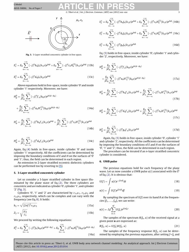
Fig. 2. 2-Layer stratified concentric cylinder in free space.
Z1 =√
�1
ε1(9b)
We proceed by writing the following equations:
E0z = E0
+∞∑n=−∞
(−j)nJn(k0�)ejn� + E0
+∞∑n=−∞
(−j)nanH(2)n (k0�)ejn� (10a)
E1z = E0
+∞∑n=−∞
(−j)nbnJn(k1�)ejn� (10b)
Eq. (3) holds in free-space and inside the cylinder respectively.Moreover, we have:
H0� = E0
jZ0
+∞∑n=−∞
(−j)nJ′n(k0�)ejn� + E0
jZ0
+∞∑n=−∞
(−j)nanH′(2)n (k0�)ejn�
(11a)
H1� = E0
jZ1
+∞∑n=−∞
(−j)nbnJ′n(k1�)ejn� (11b)
Again, Eq. (3) holds in free-space and inside the cylinder, respec-tively. All the coefficients can be determined by imposing theboundary conditions of E and H on the surface. Thus, the field canbe determined in each region.
4. 2-Layer stratified concentric cylinder
Next, a 2-layer stratified concentric dielectric cylinder in freespace illuminated by the plane wave of Eq. (2) is considered. Thetwo cylinders are concentric and are indicated as cylinder ‘0’ andcylinder ‘1’ (Fig. 2).
Cylinders ‘0’ and ‘1’ are characterized by ε1, �1 and ε2, �2,respectively, which can be complex and can vary with the fre-quency (see Eq. 8). It holds:
k2 =√
(2�f )2ε2�2 (12a)
Z2 =√
�2
ε2(12b)
We proceed by writing the following equations, where �0 has nowbeen introduced to represent the angle of incidence of the planewave:
channel modeling: An analytical approach. Int J Electron Commun
E0z =E0
+∞∑n=−∞
(−j)nJn(k0�)ejn(�−�0) + E0
+∞∑n=−∞
(−j)nanH(2)n (k0�)ejn(�−�0)
(13a)
ARTICLE ING Model
AEUE-50896; No. of Pages 7
G. Tiberi et al. / Int. J. Electron. Comm
E
E
c
H
H
H
Acia
c
5
mc‘
εf
k
Z
W
E
Fig. 3. 3-Layer stratified concentric cylinder in free space.
1z = E0
+∞∑n=−∞
(−j)nbnJn(k1�)ejn� + E0
+∞∑n=−∞
(−j)ncnH(2)n (k1�)ejn� (13b)
2z = E0
+∞∑n=−∞
(−j)ndnJn(k2�)ejn� (13c)
Above equations hold in free-space, inside cylinder ‘0’ and insideylinder ‘1’ respectively. Moreover, we have:
0� = E0
jZ0
+∞∑n=−∞
(−j)nJ′n(k0�)ejn(�−�0)
+ E0
jZ0
+∞∑n=−∞
(−j)nanH′(2)n (k0�)ejn(�−�0) (14a)
1� = E0
jZ1
+∞∑n=−∞
(−j)nbnJ′n(k1�)ejn� + E0
jZ1
+∞∑n=−∞
(−j)ncnH′(2)n (k1�)ejn�
(14b)
2� = E0
jZ2
+∞∑n=−∞
(−j)ndnJ′n(k2�)ejn� (14c)
gain, Eq. (4) holds in free-space, inside cylinder ‘0’ and insideylinder ‘1’ respectively. All the coefficients can be determined bymposing the boundary conditions of E and H on the surfaces of ‘0’nd ‘1’; thus, the field can be determined in each region.
An extension to 2-layer stratified eccentric dielectric cylindersan be performed too by resorting to [5].
. 3-Layer stratified concentric cylinder
Let us consider a 3-layer stratified cylinder in free space illu-inated by the plane wave of Eq. (2). The three cylinders are
oncentric and are indicated as cylinder ‘0’, cylinder ‘1’, and cylinder2’ (Fig. 3).
Cylinders ‘0’, ‘1’ and ‘2’ are characterized by ε1,�1, ε2,�2 and3,�3, respectively, which can be complex and can vary with therequency (see Eq. 8). It holds:
3 =√
(2�f )2ε3�3 (15a)
3 =√
�3
ε3(15b)
e proceed by writing the following equations:
Please cite this article in press as: Tiberi G, et al. UWB body area network(AEÜ) (2012), doi:10.1016/j.aeue.2012.03.014
0z = E0
+∞∑n=−∞
(−j)nJn(k0�)ejn(�−�0) + E0
+∞∑n=−∞
(−j)nanH(2)n (k0�)ejn(�−�0)
(16a)
PRESSun. (AEÜ) xxx (2012) xxx– xxx 3
E1z = E0
+∞∑n=−∞
(−j)nbnJn(k1�)ejn� + E0
+∞∑n=−∞
(−j)ncnH(2)n (k1�)ejn� (16b)
E2z = E0
+∞∑n=−∞
(−j)ndnJn(k2�)ejn� + E0
+∞∑n=−∞
(−j)nenH(2)n (k2�)ejn� (16c)
E3z = E0
+∞∑n=−∞
(−j)ngnJn(k3�)ejn� (16d)
Eq. (5) holds in free-space, inside cylinder ‘0’, cylinder ‘1’ and cylin-der ‘2’, respectively. Moreover, we have:
H0� = E0
jZ0
+∞∑n=−∞
(−j)nJ′n(k0�)ejn(�−�0)
+ E0
jZ0
+∞∑n=−∞
(−j)nanH′(2)n (k0�)ejn(�−�0) (17a)
H1� = E0
jZ1
+∞∑n=−∞
(−j)nbnJ′n(k1�)ejn� + E0
jZ1
+∞∑n=−∞
(−j)ncnH′(2)n (k1�)ejn�
(17b)
H2� = E0
jZ2
+∞∑n=−∞
(−j)ndnJ′n(k2�)ejn� + E0
jZ2
+∞∑n=−∞
(−j)nenH′(2)n (k2�)ejn�
(17c)
H3� = E0
jZ3
+∞∑n=−∞
(−j)ngnJ′n(k3�)ejn� (17d)
Again, Eq. (5) holds in free-space, inside cylinder ‘0’, cylinder ‘1’and cylinder ‘2’, respectively. All the coefficients can be determinedby imposing the boundary conditions of E and H on the surfaces of‘0’, ‘1’ and ‘2’; thus, the field can be determined in each region.
The procedure can be iterated if an n-layer stratified concentriccylinder is considered.
6. UWB pulse
The previous equations hold for each frequency of the planewave. Let us now consider a UWB pulse u(t) associated with the �Ei
of Eq. (2). It is obvious that:
U(f ) =∫
u(t)e−j2�ftdt (18)
u(t) =∫
U(f )ej2�ftdf (19)
By sampling the spectrum of U(f) over its band B at the frequen-cies [f1, . . . , fnf], we can write:
u(t) = �f
nf∑k=1
U(fk)ej2�fkt (20)
The samples of the spectrum R(fk, u) of the received signal at agiven point u are expressed as:
channel modeling: An analytical approach. Int J Electron Commun
R(fk, u) = U(fk)H(fk, u) (21)
The samples of the frequency response H(fk, u) can be deter-mined by employing the previous equations, after setting f = fk and
IN PRESSG
A
4 Commun. (AEÜ) xxx (2012) xxx– xxx
eTss
h
r
a
7
hB
1
23
4
5
cmmtcfaqcb(Tsε
mlfmD
ε
tdclf
8e
a‘ota
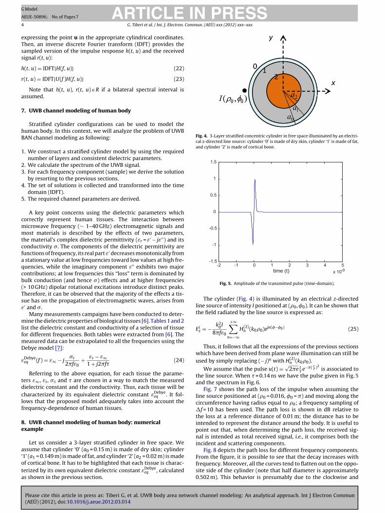
Fig. 4. 3-Layer stratified concentric cylinder in free space illuminated by an electri-cal z-directed line source: cylinder ‘0’ is made of dry skin, cylinder ‘1’ is made of fat,and cylinder ‘2’ is made of cortical bone.
-2 -1 0 1 2 3 4 5-1.5
-1
-0.5
0
0.5
1
1.5
ARTICLE Model
EUE-50896; No. of Pages 7
G. Tiberi et al. / Int. J. Electron.
xpressing the point u in the appropriate cylindrical coordinates.hen, an inverse discrete Fourier transform (IDFT) provides theampled version of the impulse response h(t, u) and the receivedignal r(t, u):
(t, u) = IDFT{H(f, u)} (22)
(t, u) = IDFT{U(f )H(f, u)} (23)
Note that h(t, u), r(t, u) ∈ R if a bilateral spectral interval isssumed.
. UWB channel modeling of human body
Stratified cylinder configurations can be used to model theuman body. In this context, we will analyze the problem of UWBAN channel modeling as following:
. We construct a stratified cylinder model by using the requirednumber of layers and consistent dielectric parameters.
. We calculate the spectrum of the UWB signal.
. For each frequency component (sample) we derive the solutionby resorting to the previous sections.
. The set of solutions is collected and transformed into the timedomain (IDFT).
. The required channel parameters are derived.
A key point concerns using the dielectric parameters whichorrectly represent human tissues. The interaction betweenicrowave frequency (∼ 1–40 GHz) electromagnetic signals andost materials is described by the effects of two parameters,
he material’s complex dielectric permittivity (εr = ε′ − jε′′) and itsonductivity �. The components of the dielectric permittivity areunctions of frequency, its real part ε′ decreases monotonically from
stationary value at low frequencies toward low values at high fre-uencies, while the imaginary component ε′′ exhibits two majorontributions; at low frequencies this “loss” term is dominated byulk conduction (and hence �) effects and at higher frequencies> 10 GHz) dipolar rotational excitations introduce distinct peaks.herefore, it can be observed that the majority of the effects a tis-ue has on the propagation of electromagnetic waves, arises from′ and �.
Many measurements campaigns have been conducted to deter-ine the dielectric properties of biological tissues [6]. Tables 1 and 2
ist the dielectric constant and conductivity of a selection of tissueor different frequencies. Both tables were extracted from [6]. The
easured data can be extrapolated to all the frequencies using theebye model [7]:
Debyeeq (f ) = ε∞ − j
�s
2�fε0+ εs − ε∞
1 + j2�f(24)
Referring to the above equation, for each tissue the parame-ers ε∞, εs, �s and are chosen in a way to match the measuredielectric constant and the conductivity. Thus, each tissue will beharacterized by its equivalent dielectric constant εDebye
eq . It fol-ows that the proposed model adequately takes into account therequency-dependence of human tissues.
. UWB channel modeling of human body: numericalxample
Let us consider a 3-layer stratified cylinder in free space. Wessume that cylinder ‘0’ (a0 = 0.15 m) is made of dry skin; cylinder
Please cite this article in press as: Tiberi G, et al. UWB body area network(AEÜ) (2012), doi:10.1016/j.aeue.2012.03.014
1’ (a1 = 0.149 m) is made of fat, and cylinder ‘2’ (a2 = 0.02 m) is madef cortical bone. It has to be highlighted that each tissue is charac-erized by its own equivalent dielectric constant εDebye
eq , calculateds shown in the previous section.
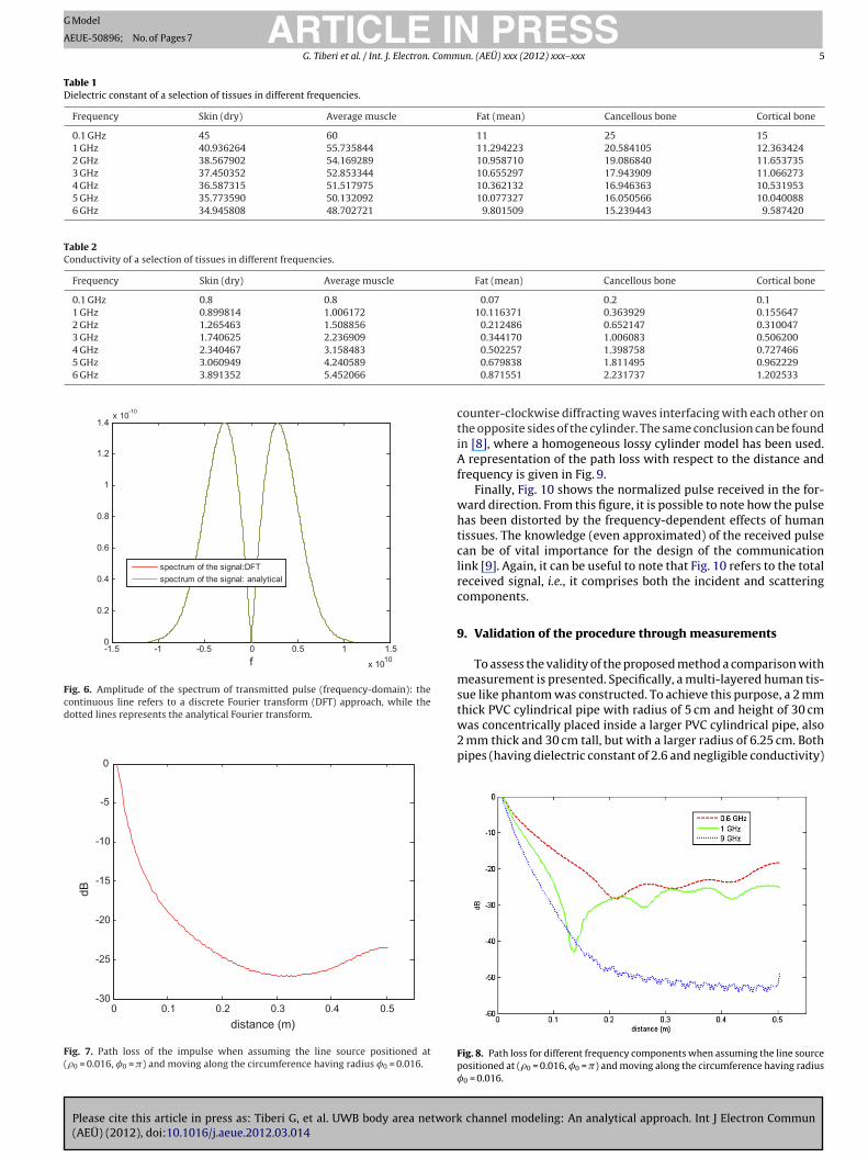
x 10-9time (t)
Fig. 5. Amplitude of the transmitted pulse (time-domain).
The cylinder (Fig. 4) is illuminated by an electrical z-directedline source of intensity I positioned at (�0, �0). It can be shown thatthe field radiated by the line source is expressed as:
Eiz = − k2
0I
8�fε0
+∞∑n=−∞
H(2)n (k0�0)ejn(�−�0) (25)
Thus, it follows that all the expressions of the previous sectionswhich have been derived from plane wave illumination can still beused by simply replacing (− j)n with H(2)
n (k0�0).
We assume that the pulse u(t) = √2�e t
e−�( t )2
is associated tothe line source. When = 0.14 ns we have the pulse given in Fig. 5and the spectrum in Fig. 6.
Fig. 7 shows the path loss of the impulse when assuming theline source positioned at (�0 = 0.016, �0 = �) and moving along thecircumference having radius equal to �0; a frequency sampling of�f = 10 has been used. The path loss is shown in dB relative tothe loss at a reference distance of 0.01 m; the distance has to beintended to represent the distance around the body. It is useful topoint out that, when determining the path loss, the received sig-nal is intended as total received signal, i.e., it comprises both theincident and scattering components.
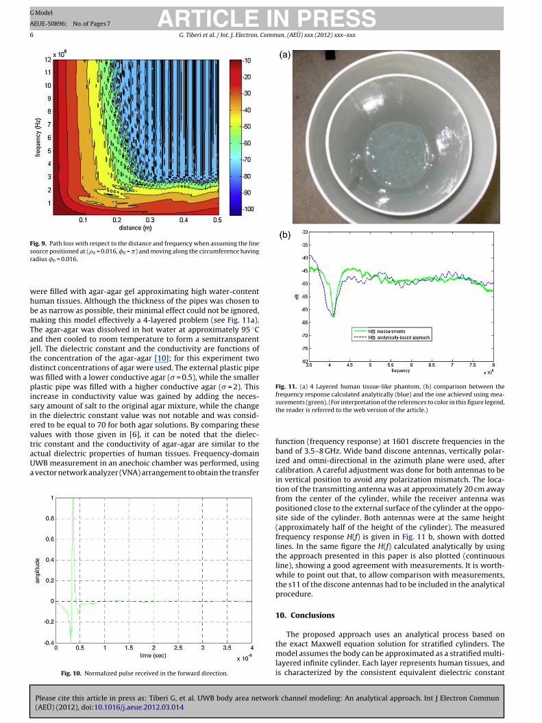
Fig. 8 depicts the path loss for different frequency components.
channel modeling: An analytical approach. Int J Electron Commun
From the figure, it is possible to see that the decay increases withfrequency. Moreover, all the curves tend to flatten out on the oppo-site side of the cylinder (note that half diameter is approximately0.502 m). This behavior is presumably due to the clockwise and
Please cite this article in press as: Tiberi G, et al. UWB body area network(AEÜ) (2012), doi:10.1016/j.aeue.2012.03.014
ARTICLE IN PRESSG Model
AEUE-50896; No. of Pages 7
G. Tiberi et al. / Int. J. Electron. Commun. (AEÜ) xxx (2012) xxx– xxx 5
Table 1Dielectric constant of a selection of tissues in different frequencies.
Frequency Skin (dry) Average muscle Fat (mean) Cancellous bone Cortical bone
0.1 GHz 45 60 11 25 151 GHz 40.936264 55.735844 11.294223 20.584105 12.3634242 GHz 38.567902 54.169289 10.958710 19.086840 11.6537353 GHz 37.450352 52.853344 10.655297 17.943909 11.0662734 GHz 36.587315 51.517975 10.362132 16.946363 10.5319535 GHz 35.773590 50.132092 10.077327 16.050566 10.0400886 GHz 34.945808 48.702721 9.801509 15.239443 9.587420
Table 2Conductivity of a selection of tissues in different frequencies.
Frequency Skin (dry) Average muscle Fat (mean) Cancellous bone Cortical bone
0.1 GHz 0.8 0.8 0.07 0.2 0.11 GHz 0.899814 1.006172 10.116371 0.363929 0.1556472 GHz 1.265463 1.508856 0.212486 0.652147 0.3100473 GHz 1.740625 2.236909 0.344170 1.006083 0.5062004 GHz 2.340467 3.158483
5 GHz 3.060949 4.240589
6 GHz 3.891352 5.452066
-1.5 -1 -0 .5 0 0.5 1 1.5
x 1010
0
0.2
0.4
0.6
0.8
1
1.2
1.4x 10⁻¹⁰
f
spectrum of the signal:DFTspectrum of the signal: analytical
Fig. 6. Amplitude of the spectrum of transmitted pulse (frequency-domain): thecontinuous line refers to a discrete Fourier transform (DFT) approach, while thedotted lines represents the analytical Fourier transform.
0 0.1 0.2 0.3 0.4 0.5-30
-25
-20
-15
-10
-5
0
distance (m)
dB
Fig. 7. Path loss of the impulse when assuming the line source positioned at(�0 = 0.016, �0 = �) and moving along the circumference having radius �0 = 0.016.
0.502257 1.398758 0.7274660.679838 1.811495 0.9622290.871551 2.231737 1.202533
counter-clockwise diffracting waves interfacing with each other onthe opposite sides of the cylinder. The same conclusion can be foundin [8], where a homogeneous lossy cylinder model has been used.A representation of the path loss with respect to the distance andfrequency is given in Fig. 9.
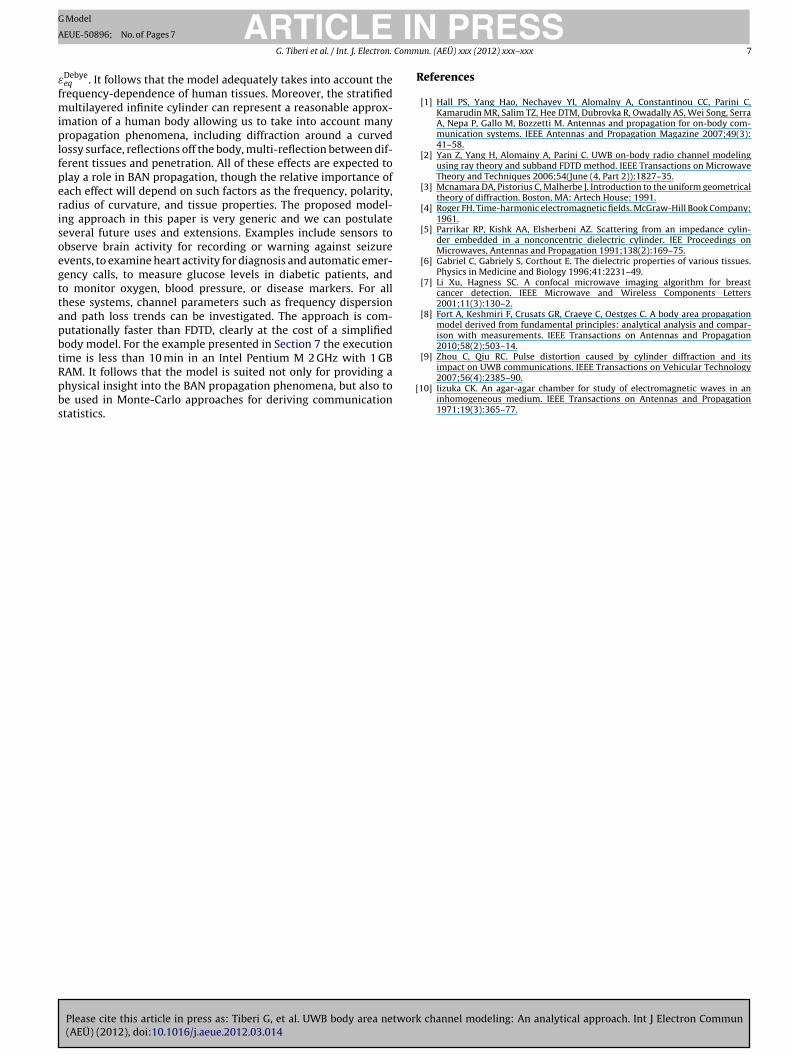
Finally, Fig. 10 shows the normalized pulse received in the for-ward direction. From this figure, it is possible to note how the pulsehas been distorted by the frequency-dependent effects of humantissues. The knowledge (even approximated) of the received pulsecan be of vital importance for the design of the communicationlink [9]. Again, it can be useful to note that Fig. 10 refers to the totalreceived signal, i.e., it comprises both the incident and scatteringcomponents.
9. Validation of the procedure through measurements
To assess the validity of the proposed method a comparison withmeasurement is presented. Specifically, a multi-layered human tis-sue like phantom was constructed. To achieve this purpose, a 2 mmthick PVC cylindrical pipe with radius of 5 cm and height of 30 cm
channel modeling: An analytical approach. Int J Electron Commun
was concentrically placed inside a larger PVC cylindrical pipe, also2 mm thick and 30 cm tall, but with a larger radius of 6.25 cm. Bothpipes (having dielectric constant of 2.6 and negligible conductivity)
Fig. 8. Path loss for different frequency components when assuming the line sourcepositioned at (�0 = 0.016, �0 = �) and moving along the circumference having radius�0 = 0.016.
ARTICLE IN PRESSG Model
AEUE-50896; No. of Pages 7
6 G. Tiberi et al. / Int. J. Electron. Commun. (AEÜ) xxx (2012) xxx– xxx
Fig. 9. Path loss with respect to the distance and frequency when assuming the linesr
whbmTajtdwpisievtaUa
Fig. 11. (a) 4 Layered human tissue-like phantom, (b) comparison between thefrequency response calculated analytically (blue) and the one achieved using mea-
ource positioned at (�0 = 0.016, �0 = �) and moving along the circumference havingadius �0 = 0.016.
ere filled with agar-agar gel approximating high water-contentuman tissues. Although the thickness of the pipes was chosen toe as narrow as possible, their minimal effect could not be ignored,aking this model effectively a 4-layered problem (see Fig. 11a).
he agar-agar was dissolved in hot water at approximately 95 ◦Cnd then cooled to room temperature to form a semitransparentell. The dielectric constant and the conductivity are functions ofhe concentration of the agar-agar [10]; for this experiment twoistinct concentrations of agar were used. The external plastic pipeas filled with a lower conductive agar (� = 0.5), while the smallerlastic pipe was filled with a higher conductive agar (� = 2). This
ncrease in conductivity value was gained by adding the neces-ary amount of salt to the original agar mixture, while the changen the dielectric constant value was not notable and was consid-red to be equal to 70 for both agar solutions. By comparing thesealues with those given in [6], it can be noted that the dielec-ric constant and the conductivity of agar-agar are similar to the
Please cite this article in press as: Tiberi G, et al. UWB body area network(AEÜ) (2012), doi:10.1016/j.aeue.2012.03.014
ctual dielectric properties of human tissues. Frequency-domainWB measurement in an anechoic chamber was performed, using
vector network analyzer (VNA) arrangement to obtain the transfer
Fig. 10. Normalized pulse received in the forward direction.
surements (green). (For interpretation of the references to color in this figure legend,the reader is referred to the web version of the article.)
function (frequency response) at 1601 discrete frequencies in theband of 3.5–8 GHz. Wide band discone antennas, vertically polar-ized and omni-directional in the azimuth plane were used, aftercalibration. A careful adjustment was done for both antennas to bein vertical position to avoid any polarization mismatch. The loca-tion of the transmitting antenna was at approximately 20 cm awayfrom the center of the cylinder, while the receiver antenna waspositioned close to the external surface of the cylinder at the oppo-site side of the cylinder. Both antennas were at the same height(approximately half of the height of the cylinder). The measuredfrequency response H(f) is given in Fig. 11 b, shown with dottedlines. In the same figure the H(f) calculated analytically by usingthe approach presented in this paper is also plotted (continuousline), showing a good agreement with measurements. It is worth-while to point out that, to allow comparison with measurements,the s11 of the discone antennas had to be included in the analyticalprocedure.
10. Conclusions
The proposed approach uses an analytical process based on
channel modeling: An analytical approach. Int J Electron Commun
the exact Maxwell equation solution for stratified cylinders. Themodel assumes the body can be approximated as a stratified multi-layered infinite cylinder. Each layer represents human tissues, andis characterized by the consistent equivalent dielectric constant
ING
A
Comm
εfmiplfperisoegttapbtRpbs
ARTICLE Model
EUE-50896; No. of Pages 7
G. Tiberi et al. / Int. J. Electron.
Debyeeq . It follows that the model adequately takes into account therequency-dependence of human tissues. Moreover, the stratified
ultilayered infinite cylinder can represent a reasonable approx-mation of a human body allowing us to take into account manyropagation phenomena, including diffraction around a curved
ossy surface, reflections off the body, multi-reflection between dif-erent tissues and penetration. All of these effects are expected tolay a role in BAN propagation, though the relative importance ofach effect will depend on such factors as the frequency, polarity,adius of curvature, and tissue properties. The proposed model-ng approach in this paper is very generic and we can postulateeveral future uses and extensions. Examples include sensors tobserve brain activity for recording or warning against seizurevents, to examine heart activity for diagnosis and automatic emer-ency calls, to measure glucose levels in diabetic patients, ando monitor oxygen, blood pressure, or disease markers. For allhese systems, channel parameters such as frequency dispersionnd path loss trends can be investigated. The approach is com-utationally faster than FDTD, clearly at the cost of a simplifiedody model. For the example presented in Section 7 the executionime is less than 10 min in an Intel Pentium M 2 GHz with 1 GB
Please cite this article in press as: Tiberi G, et al. UWB body area network(AEÜ) (2012), doi:10.1016/j.aeue.2012.03.014
AM. It follows that the model is suited not only for providing ahysical insight into the BAN propagation phenomena, but also toe used in Monte-Carlo approaches for deriving communicationtatistics.
[
PRESSun. (AEÜ) xxx (2012) xxx– xxx 7
References
[1] Hall PS, Yang Hao, Nechayev YI, Alomalny A, Constantinou CC, Parini C,Kamarudin MR, Salim TZ, Hee DTM, Dubrovka R, Owadally AS, Wei Song, SerraA, Nepa P, Gallo M, Bozzetti M. Antennas and propagation for on-body com-munication systems. IEEE Antennas and Propagation Magazine 2007;49(3):41–58.
[2] Yan Z, Yang H, Alomainy A, Parini C. UWB on-body radio channel modelingusing ray theory and subband FDTD method. IEEE Transactions on MicrowaveTheory and Techniques 2006;54(June (4, Part 2)):1827–35.
[3] Mcnamara DA, Pistorius C, Malherbe J. Introduction to the uniform geometricaltheory of diffraction. Boston, MA: Artech House; 1991.
[4] Roger FH. Time-harmonic electromagnetic fields. McGraw-Hill Book Company;1961.
[5] Parrikar RP, Kishk AA, Elsherbeni AZ. Scattering from an impedance cylin-der embedded in a nonconcentric dielectric cylinder. IEE Proceedings onMicrowaves, Antennas and Propagation 1991;138(2):169–75.
[6] Gabriel C, Gabriely S, Corthout E. The dielectric properties of various tissues.Physics in Medicine and Biology 1996;41:2231–49.
[7] Li Xu, Hagness SC. A confocal microwave imaging algorithm for breastcancer detection. IEEE Microwave and Wireless Components Letters2001;11(3):130–2.
[8] Fort A, Keshmiri F, Crusats GR, Craeye C, Oestges C. A body area propagationmodel derived from fundamental principles: analytical analysis and compar-ison with measurements. IEEE Transactions on Antennas and Propagation2010;58(2):503–14.
[9] Zhou C, Qiu RC. Pulse distortion caused by cylinder diffraction and its
channel modeling: An analytical approach. Int J Electron Commun
impact on UWB communications. IEEE Transactions on Vehicular Technology2007;56(4):2385–90.
10] Iizuka CK. An agar-agar chamber for study of electromagnetic waves in aninhomogeneous medium. IEEE Transactions on Antennas and Propagation1971;19(3):365–77.