NCT7290 - 16 Channel ADC, 12 Channel DAC, Internal Temp ...
34
© Semiconductor Components Industries, LLC, 2014 June, 2014 - Rev. 0 1 Publication Order Number: NCT7290/D NCT7290 16 Channel ADC, 12 Channel DAC, Internal Temp Sensor with I 2 C & SPI Interface The NCT7290 is a serially programmable voltage and temperature monitor. It can monitor its on chip temperature via its local sensor, a remotely connected diode and 16 analog inputs. Two 12 bit DACs allow for voltage control on 12 pins. Eight GPIO pins allow digital control and monitoring. An ALERT output is also available to signal out-of-limit conditions. Communication with the NCT7290 is accomplished via an I 2 C interface which is compatible with industry standard protocols or a 4 wire SPI interface. Both interfaces are available on this device. Through these interfaces the NCT7290s internal registers may be accessed. These registers allow the user to read the current temperature and input voltages, change the configuration settings, adjust each channels limits and set set the output DAC voltages on each of the 12 channels available. The NCT7290 is available in a 56-lead QFN (8 × 8 × 0.5 mm) package and operates over a supply range of 5.0 V ±10% (digital supply range of 3 V to 3.6 V) and temperature range of –55 to +125°C. This makes the NCT7290 ideal for a wide variety of applications ranging from cellular base stations to servers and industrial controls. Features • On-chip Temperature Sensor (±2°C Accuracy) • Remote Temperature Sensor • 5.0 V ±10% Supply Range • 16 Analog Voltage Inputs • 12 DAC Output Channels • 8 Digital GPIO Pins • SPI and I 2 C Interface • Package Type: 56 Lead QFN • These Devices are Pb-Free and are RoHS Compliant http://onsemi.com MARKING DIAGRAM QFN-56 CASE 485BK Device Package Shipping † ORDERING INFORMATION NCT7290MNTXG QFN-56 2000 Tape & Reel with MPQ †For information on tape and reel specifications, including part orientation and tape sizes, please refer to our Tape and Reel Packaging Specifications Brochure, BRD8011/D. 56 1 XXXXXXXXX XXXXXXXXX AWLYYWWG 1 XXXXX = Specific Device Code A = Assembly Location WL = Wafer Lot YY = Year WW = Work Week G = Pb-Free Package
-
Upload
khangminh22 -
Category
Documents
-
view
0 -
download
0
Transcript of NCT7290 - 16 Channel ADC, 12 Channel DAC, Internal Temp ...

© Semiconductor Components Industries, LLC, 2014
June, 2014 − Rev. 01 Publication Order Number:
NCT7290/D
NCT7290
16 Channel ADC, 12 Channel DAC, Internal Temp Sensor with I2C & SPI Interface
The NCT7290 is a serially programmable voltage and temperaturemonitor. It can monitor its on chip temperature via its local sensor,a remotely connected diode and 16 analog inputs. Two 12 bit DACsallow for voltage control on 12 pins. Eight GPIO pins allow digitalcontrol and monitoring. An ALERT output is also available to signalout-of-limit conditions.
Communication with the NCT7290 is accomplished via an I2Cinterface which is compatible with industry standard protocols or a 4wire SPI interface. Both interfaces are available on this device.Through these interfaces the NCT7290s internal registers may beaccessed. These registers allow the user to read the currenttemperature and input voltages, change the configuration settings,adjust each channels limits and set set the output DAC voltages oneach of the 12 channels available.
The NCT7290 is available in a 56-lead QFN (8 × 8 × 0.5 mm)package and operates over a supply range of 5.0 V ±10% (digitalsupply range of 3 V to 3.6 V) and temperature range of –55 to +125°C.This makes the NCT7290 ideal for a wide variety of applicationsranging from cellular base stations to servers and industrial controls.
Features
• On-chip Temperature Sensor (±2°C Accuracy)
• Remote Temperature Sensor
• 5.0 V ±10% Supply Range
• 16 Analog Voltage Inputs
• 12 DAC Output Channels
• 8 Digital GPIO Pins
• SPI and I2C Interface
• Package Type: 56 Lead QFN
• These Devices are Pb-Free and are RoHS Compliant
http://onsemi.com
MARKING DIAGRAM
QFN−56CASE 485BK
Device Package Shipping†
ORDERING INFORMATION
NCT7290MNTXG QFN−56 2000 Tape & Reelwith MPQ
†For information on tape and reel specifications,including part orientation and tape sizes, pleaserefer to our Tape and Reel Packaging SpecificationsBrochure, BRD8011/D.
561
XXXXXXXXXXXXXXXXXXAWLYYWWG
1
XXXXX = Specific Device CodeA = Assembly LocationWL = Wafer LotYY = YearWW = Work WeekG = Pb-Free Package

NCT7290
http://onsemi.com2
Figure 1. Functional Block Diagram of NCT7290
Figure 2. Typical Application Circuit
NCT7290
GPIO
Voltage Outputs − 12 V
Voltage Outputs − 5 V
System Voltages
I2C Interface
Interface Selection
SPI Interface
RemoteTemperature
Sensor
3.0
to 5
.5V
4.5
to 5
.5V
12V
5V
AG
ND
DA
C G
ND
1−
2
DG
ND
1−2
SCL
SDA
ADD
BUS_SEL
SCLK
SDO
SDI
CS
D+
D1
GPIO1−8
VOUT5, 6, 11, 12
VOUT1−4, 7−10
VIN1−16
VD
D
AV
DD
12 V
DA
C
12 V
DA
C
5 V
DA
C
5 V
DA
C
D− VOUT 1
D+
VIN1
VIN16
VIN15
VIN14
VIN13
VIN12
VIN11
VIN10
VIN9
VIN8
VIN7
VIN6
VIN5
VIN4
VIN3
VIN2
VOUT 2
VOUT 3
VOUT 4
VOUT 5
VOUT 6
VOUT 7
VOUT 8
VOUT 9
VOUT 10
VOUT 11
VOUT 12
12 VDAC
5 VDAC
DACGND
DACGND
ADD0 ADD1 SDA SCL BUS_SEL SCLK SDI SDO CS 5 VDAC Ban
k2D
AC
Shu
tdow
n
DGND
GP
IO1
ALE
RTAGND
GP
IO2
GP
IO3
GP
IO4
GP
IO5
GP
IO6
GP
IO7
GP
IO8 VDDAVDD 12 VDAC
Ban
k1D
AC
Shu
tdow
n
ON-CHIPTEMPERATURE
SENSOR
ANALOGMUX
10 bitA-to-D
CONVERTER
DATAREGISTERS
LIMITAND
CONFIGREGISTERS
LIM
ITC
OM
PA
RA
TO
R
STATUS REGISTER
GPIO CONTROL REGISTER
I2C INTERFACE* SPI INTERFACE*
12 b
it D
AC
Ban
k112
bit
DA
C B
ank2
5 VOUT
12 VOUT
5 VOUT
12 VOUT
2425 26 27 3224 2528 2926 27
7
30
31
36
35
33
38
10
6
1
8
5
3
37
9
34
23 42239 13 14 15 16 17 18 12402119 20
43
44
46
49
51
54
47
52
45
48
53
50
42
55
2
56
1
41
NCT7290

NCT7290
http://onsemi.com3
Figure 3. Pin Connections
D+
D−
AVDD
AGND
VOUT12
12 VDAC
VOUT11
VOUT10
DAC GND
VOUT9
5 VDAC
VOUT8
VOUT7
BANK2DACShutdown
VIN
1
VIN
3
VIN
5
VIN
7
VIN
9
VIN
11
VIN
13
VIN
2
VIN
4
VIN
6
VIN
8
VIN
10
VIN
12
VIN
14
VIN15
VIN16
VOUT6
12 VDAC
VOUT5
VOUT4
DAC GND
VOUT3
5 VDAC
VOUT2
VOUT1
GPIO1
GPIO2
BANK1DACShutdown
Note: GND Flag Located Underneath NCT7290
GP
IO3
GP
IO4
GP
IO5
GP
IO6
GP
IO7
GP
IO8
ALE
RT
VD
D
DG
ND
SC
L/S
CLK
SD
A/S
DI
AD
D0/
SD
O
AD
D1/
CS
BU
S_S
EL
NCT7290Top View
(Not to Scale)
1
2
3
4
5
6
7
8
9
10
11
12
13
14
15 16 17 18 19 20 21 22 23 24 25 26 27 28
29
30
31
32
33
34
35
36
37
38
39
40
41
42
4344454647484950515253545556
PIN FUNCTION DESCRIPTION
Pin No. Pin Name Description
1 VIN15 Analog Input. 0 V to 2.5 V.
2 VIN16 Analog Input. 0 V to 2.5 V.
3 VOUT6 Analog Output. 0 V to 12 V.
4 12VDAC Analog Supply. Analog supply pins for the DAC output amplifiers on VOUT5−6.
5 VOUT5 Analog Output. 0 V to 12 V.
6 VOUT4 Analog Output. 0 V to 5 V.
7 DACGND Ground pin for the DAC output amplifiers.
8 VOUT3 Analog Output. 0 V to 5 V.
9 5VDAC Analog Supply. Analog supply pin for the DAC output amplifiers on VOUT1−4.
10 VOUT2 Analog Output. 0 V to 5 V.
11 VOUT1 Analog Output. 0 V to 5 V.
12 BANK1DACShutdown
Shutdown pin for Bank1 DAC outputs (VOUT1, VOUT2, VOUT3, VOUT4, VOUT5 and VOUT6). Active low input (i.e. tie low to shutdown the bank). Active low input. Pin cannot be left floating.
13 GPIO1 Programmable general purpose digital input or output. Default = input.
14 GPIO2 Programmable general purpose digital input or output. Default = input.
15 GPIO3 Programmable general purpose digital input or output. Default = input.
16 GPIO4 Programmable general purpose digital input or output. Default = input.

NCT7290
http://onsemi.com4
PIN FUNCTION DESCRIPTION (continued)
Pin No. DescriptionPin Name
17 GPIO5 Programmable general purpose digital input or output. Default = input.
18 GPIO6 Programmable general purpose digital input or output. Default = input.
19 GPIO7 Programmable general purpose digital input or output. Default = input.
20 GPIO8 Programmable general purpose digital input or output. Default = input.
21 ALERT Open-Drain Logic Output Used as Interrupt or SMBus Alert. Active low output.
22 VDD Power Supply. Can be powered from a supply in the range 3.3 V or 5.0 V ±10%
23 DGND Digital Ground. This is the ground pin for all the digital circuitry.
24 SCL/SCLK Serial Clock Input for I2C and SPI interfaces
25 SDA/SDI Serial Data Input/Output in I2C mode. Serial Data Input in SPI mode.
26 ADD0/SDO Address selection pin for I2C mode. Can be tied high, low or left floating to give multiple addressoptions. Serial Data Out in SPI mode.
27 ADD1/CS Address selection pin for I2C mode. Can be tied high, low or left floating to give multiple addressoptions. Chip Select. Slave transmit enable in SPI mode – active low.
28 BUS_SEL Selects I2C or SPI interface. BUS_SEL = DGND selects I2C; BUS_SEL = VDD selects SPI.
29 BANK2DACShutdown
Shutdown pin for Bank1 DAC outputs (VOUT7, VOUT8, VOUT9, VOUT10, VOUT11 and VOUT12). Active low input (i.e. tie low to shutdown the bank). Active low input. Pin cannot be left floating.
30 VOUT7 Analog Output. 0 V to 5 V.
31 VOUT8 Analog Output. 0 V to 5 V.
32 5VDAC Analog Supply. Analog supply pin for the DAC output amplifiers on VOUT7−10.
33 VOUT9 Analog Output. 0 V to 5 V.
34 DACGND Ground pin for the DAC output amplifiers.
35 VOUT10 Analog Output. 0 V to 5 V.
36 VOUT11 Analog Output. 0 V to 12 V.
37 12VDAC Analog Supply. Analog supply pins for the DAC output amplifiers on VOUT11−12.
38 VOUT12 Analog Output. 0 V to 12 V.
39 AGND Analog ground. This is the ground pin for all the analog circuitry.
40 AVDD Analog Power Supply. Can be powered from a supply in the range 5.0 V ±10%.
41 D− Negative Connection to Remote Temperature Sensor.
42 D+ Positive Connection to Remote Temperature Sensor.
43 VIN1 Analog Input. 0 V to 2.5 V.
44 VIN2 Analog Input. 0 V to 2.5 V.
45 VIN3 Analog Input. 0 V to 2.5 V.
46 VIN4 Analog Input. 0 V to 2.5 V.
47 VIN5 Analog Input. 0 V to 2.5 V.
48 VIN6 Analog Input. 0 V to 2.5 V.
49 VIN7 Analog Input. 0 V to 2.5 V.
50 VIN8 Analog Input. 0 V to 2.5 V.
51 VIN9 Analog Input. 0 V to 2.5 V.
52 VIN10 Analog Input. 0 V to 2.5 V.
53 VIN11 Analog Input. 0 V to 2.5 V.
54 VIN12 Analog Input. 0 V to 2.5 V.
55 VIN13 Analog Input. 0 V to 2.5 V.
56 VIN14 Analog Input. 0 V to 2.5 V.
GND QFN GND flag located underneath package.

NCT7290
http://onsemi.com5
MAXIMUM RATINGS
Rating Symbol Value Unit
Supply Voltage AVDD 5.7 V
Supply Voltage DVDD 5.7 V
Input Voltage on SCL, SDA, A2, A1 and A0 −0.3 V to DVDD + 0.3 V V
Voltage on All Other Pins Except 12 VDAC Outputs −0.3 V to AVDD + 0.3 V V
Input Current on All Other Pins 5 mA
Input Current on SDA, A2, A1 and A0 IIN −1 mA to +50 mA mA
Maximum Junction Temperature TJ(max) 150.7 °C
Operating Temperature Range TOP −55 to 125 °C
Storage Temperature Range TSTG −65 to 160 °C
ESD Capability, Human Body Model (Note 2) ESDHBM 2000 V
ESD Capability, Machine Model (Note 2) ESDMM 200 V
Stresses exceeding those listed in the Maximum Ratings table may damage the device. If any of these limits are exceeded, device functionalityshould not be assumed, damage may occur and reliability may be affected.1. Refer to ELECTRICAL CHARACTERISTICS and APPLICATION INFORMATION for Safe Operating Area.2. This device series incorporates ESD protection and is tested by the following methods:
ESD Human Body Model tested per AEC-Q100-002 (EIA/JESD22-A114)ESD Machine Model tested per AEC-Q100-003 (EIA/JESD22-A115)
THERMAL CHARACTERISTICS
Rating Symbol Value Unit
Thermal Characteristics, QFN-56 (Note 3)Thermal Resistance, Junction-to-Air (Note 4)Thermal Reference, Junction-to-Board (Note 4)
R�JAR�JB
254
°C/W
3. Refer to ELECTRICAL CHARACTERISTICS and APPLICATION INFORMATION for Safe Operating Area.4. As measured using a copper heat spreading area of 650 mm2 (or 1 in2), of 1 oz copper thickness.
RECOMMENDED OPERATING RANGES
Rating Symbol Min Typ Max Unit
Operating Supply Voltage VDD 3.0 − 3.6 V
AVDD 4.5 − 5.5 V
5 VDAC Supply 5VDAC − 5 5.5 V
12 VDAC supply 12VDAC − 12 13.2 V
Operating Ambient Temperature Range TA −55 − 125 °C
Functional operation above the stresses listed in the Recommended Operating Ranges is not implied. Extended exposure to stresses beyondthe Recommended Operating Ranges limits may affect device reliability.5. Refer to ELECTRICAL CHARACTERISTICS and APPLICATION INFORMATION for Safe Operating Area.
ELECTRICAL CHARACTERISTICS TA = TMIN to TMAX, AVDD = 5.0 V ±10%. All specifications for −55°C to +125°C, unless otherwise noted.
Parameter Test Conditions Min Typ Max Unit
TEMPERATURE SENSOR
Local Sensor AccuracyAVDD = 5.0 V ±10%
TA = −40°C to +105°C, AVDD = 5 V − − ±3 °C
TA = −55°C to +125°C, AVDD = 5 V − − ±3.5 °C
Local Temperature Resolution − 0.25 − °C
Remote Sensor AccuracyAVDD = 5.0 V ±10%
TA = −40°C to +105°C, AVDD = 5 V − − ±2 °C
TA = −55°C to +125°C, AVDD = 5 V − − ±2.25 °C
Remote Temperature resolution − 0.25 − °C

NCT7290
http://onsemi.com6
ELECTRICAL CHARACTERISTICS (continued)TA = TMIN to TMAX, AVDD = 5.0 V ±10%. All specifications for −55°C to +125°C, unless otherwise noted.
Parameter UnitMaxTypMinTest Conditions
TEMPERATURE SENSOR
Remote Sensor Current High Level 1 − 240 − �A
Low Level 1 − 30 − �A
High Level 2 − 300 − �A
Low Level 2 − 37.5 − �A
Temperature Conversion Time Averaging On − 38 − ms
Averaging Off − 25 − ms
D− Voltage − 0.7 − V
ADC
ADC Resolution − 10 − Bits
Input Voltage Range 0 − 2.5 V
Input Impedance Converting − 1 − M�
Input Capacitance − 15 − pF
Input Leakage Current − ±1 − �A
Integral Linearity − − ±1 LSB
Differential Linearity − − ±1 LSB
Offset Error − ±1 ±4 LSB
Gain Error − − ±5 LSB
Conversion Time 2 × 2.5 �s ADCs in Parallel − 5 − �s
DAC
Output Voltage Range VOUT1−4, VOUT7−10 0 − 5.25* V
VOUT5−6, VOUT11−12 0 − 12.5* V
Output Current Fullscale Output − ±10 − mA
Resolution − 12 − bits
Integral Linearity 200 mV to VDD – 200 mV − ±1 ±2 LSB
Differential Linearity − − ±1 LSB
Offset Error Output: 0−5 V (200 mV to DAC Supply – 200 mV) − ±1 ±10 mV
Output: 0−12 V (200 mV to DAC Supply – 200mV) − ±3 ±25 mV
Gain Error Output: 0−5 V (200 mV to DAC Supply – 200 mV) − ±5 ±15 LSB
Output: 0−12 V (200 mV to DAC Supply – 200 mV) − ±5 ±25 LSB
Gain Error Drift − ±10 − ppmFS/°C
Settling Time Output = 1/4 to 3/4 of Fullscale, 2 k� // 200 pF Load − 3.5 10 �s
Overshoot Output = 1/4 to 3/4 of Fullscale, 2 k� // 200 pF Load − 200 − mV
Crosstalk Midscale Code − 1 − LSB
Slew Rate Measure between 3/8 and 5/8 − 1500 − mV/�s
POWER REQUIREMENTS
Supply Voltage (AVDD) 4.5 5.0 5.5 V
Supply Current (IAVDD) − 7.5 10 mA
Digital Supply Voltage (VDD) 3.0 3.3 3.6 V
Supply Current (IVDD) − 2 5 mA

NCT7290
http://onsemi.com7
ELECTRICAL CHARACTERISTICS (continued)TA = TMIN to TMAX, AVDD = 5.0 V ±10%. All specifications for −55°C to +125°C, unless otherwise noted.
Parameter UnitMaxTypMinTest Conditions
OPEN DRAIN DIGITAL OUTPUT (SDA & ALERT)
Current Sink IOL − − 8.0 mA
Output Low Voltage, VOL IOUT = −4.0 mA − − 0.6 V
High Level Output Current, IOH VOUT = VDD − 0.1 20 �A
GPIOs
Input High Voltage VIH 1.6 − VDD V
Input Low Voltage, VIL 0 − 0.8 V
Output Low Voltage, VOL − − 0.4 V
Input Capacitance − 5 − pF
I2C INTERFACE INPUT (SCL)
Input High Voltage VIH VDD = 3.3 V, IIH = 5 �A 2 − VDD + 0.3 V
Input Low Voltage, VIL VDD = 3.3 V, IIL = −5 �A 0 − 0.8 V
Input Capacitance − 5 − pF
SPI INTERFACE INPUT (SDI, SCLK, CS, BUS_SEL)
Input High Voltage VIH VDD = 3.3 V, IIH = 5 �A 2 − VDD + 0.3 V
Input Low Voltage, VIL VDD = 3.3 V, IIL = −5 �A 0 − 0.8 V
Input Capacitance − 5 − pF
SPI INTERFACE OUTPUT (SDO)
Output High Voltage, VOH VDD = 3.3 V, IOL = 3 �A 2.4 − VDD V
Output Low Voltage, VOL VDD = 3.3 V, IOL = −3 �A 0 − 0.4 V
GENERAL INTERFACE INFORMATION
Bit Rate SPI − − 5 MHz
I2C FS Mode − − 400 kHz
Table 1. I2C TIMING
Parameter (Note 6) Symbol Min Typ Max Unit
Clock Frequency fSCLK 10 − 400 kHz
Clock Period tSCLK 2.5 − − �s
SCL High Time tHIGH 0.6 − − �s
SCL Low Time tLOW 1.3 − − �s
Start Setup Time tSU;STA 0.6 − − �s
Start Hold Time (Note 7) tHD;STA 0.6 − − �s
Data Setup Time (Note 8) tSU;DAT 100 − − ns
Data Hold Time (Note 9) tHD;DAT 0.3 − 0.9 �s
SCL, SDA Rise Time tr − − 300 ns
SCL, SDA Fall Time tf − − 300 ns
Stop Setup Time tSU;STO 0.6 − − �s
Bus Free Time tBUF 1.3 − − �s
Glitch Immunity tSW − 50 − ns
6. Guaranteed by design, but not production tested7. Time from 10% of SDA to 90% of SCL8. Time for 10%or 90% of SDA to 10% of SCL9. A device must internally provide a hold time of at least 300 ns for the SDA signal to bridge the undefined region of the falling edge of SCL.

NCT7290
http://onsemi.com8
Figure 4. I2C Timing Diagram
STOPSTART
tSU; DAT
tHIGH
tF
tHD; DAT
tR
tLOW
tSU; STO
STOP START
SCLK
SDATA
tBUF
tHD; STA
tHD; STA
tSU; STA
Table 2. SPI TIMING
Parameter (Note 10) Symbol Min Max Unit
SPI Clock Freq fSCLK − 5 MHz
SPI Clock Period tSCLK 200 − ns
CS Falling Edge to SCLK Falling Edge tDELAY 15 − ns
SCLK Rising Edge to CS Rising Edge tQUIET 15 − ns
CS Rising Edge to SDO Disabled tDIS − 110 ns
CS Deassertion between SPI Communications tCS,DIS 250 − ns
SCLK Low Pulse Width tS 0.4 × tSCLK − ns
SCLK High Pulse Width tM 0.4 × tSCLK − ns
SCLK Falling Edge to SDO Transition tSDO − 100 ns
SDI Valid before SCLK Rising Edge tSETUP 15 − ns
SDI Valid after SCLK Rising Edge tHOLD 15 − ns
10.Guaranteed by design, but not production tested
Figure 5. SPI Timing Diagram
8 9 25SCLK
SDO
SDI
CS
1
8 9 251
8 9 251

NCT7290
http://onsemi.com9
TYPICAL CHARACTERISTICS(TA = +25°C, VDD = +3.3 V, AVDD = 5 V, unless otherwise stated)
Figure 6. DNL vs Code at 25�C for 5 V DAC OUTPUT
Figure 7. DNL vs Code at 25�C for 12 V DAC OUTPUT
−0.8
−0.6
−0.4
−0.2
0
0.2
0.4
0 1024 2048 3072 4096
DN
L (
LS
Bs)
CODE
DNL (5V DAC)
−0.5
−0.4
−0.3
−0.2
−0.1
0
0.1
0.2
0.3
0.4
0 1024 2048 3072 4096
DN
L (
LS
Bs)
CODE
DNL (12V DAC)

NCT7290
http://onsemi.com10
Figure 8. INL vs Code at 25�C for 5 V DAC OUTPUT
Figure 9. INL vs Code at 25�C for 12 V DAC OUTPUT
−0.5
−0.4
−0.3
−0.2
−0.1
0
0.1
0.2
0.3
0.4
0.5
0.6
0 1024 2048 3072 4096
INL
(L
SB
s)
CODE
INL (5V DAC)
−0.4
−0.2
0
0.2
0.4
0.6
0.8
1
1.2
0 1024 2048 3072 4096
INL
(L
SB
s)
CODE
INL (12V DAC)

NCT7290
http://onsemi.com11
Figure 10. ADC DNL vs Code at 25�C
Figure 11. ADC INL vs Code at 25�C
−1
−0.8
−0.6
−0.4
−0.2
0
0.2
0.4
0.6
0.8
1
28 228 428 628 828 1028
DN
L (
LS
Bs)
CODE
Differential Non Linearity
−1
−0.8
−0.6
−0.4
−0.2
0
0.2
0.4
0.6
0.8
1
0 200 400 600 800 1000
INL
(L
SB
s)
CODE
Integral Non Linearity

NCT7290
http://onsemi.com12
Figure 12. Supply Current vs Supply Voltage
Figure 13. Supply Current vs Temperature
1
2
3
4
5
6
7
8
9
10
4.5 4.7 4.9 5.1 5.3 5.5
Su
pp
ly C
urr
ent
AI D
D (
mA
)
AVDD (V)
Supply Voltage AVDD vs Current AIDD
0
1
2
3
4
5
6
7
8
9
10
−40 10 60 110
Su
pp
ly C
urr
ent
AI D
D (
mA
)
Temperature (�C)
Supply Current AIDD vs Temperature

NCT7290
http://onsemi.com13
Figure 14. Local Temperature Error vs Temperature
Figure 15. Remote Temperature Error vs Temperature
−1.2
−1
−0.8
−0.6
−0.4
−0.2
0
0.2
0.4
0.6
0.8
−60 −40 −20 0 20 40 60 80 100 120
Err
or
(�C
)
Temperature (�C)
Local Sensor Temperature Accuracy
−0.8
−0.6
−0.4
−0.2
0
0.2
0.4
0.6
−80 −60 −40 −20 0 20 40 60 80 100 120 140
Err
or
(�C
)
Temperature (�C)
Remote Sensor Temperature Accuracy

NCT7290
http://onsemi.com14
OVERVIEW
NCT7290 encompasses full analog monitoring, local andremote temperature sensing along with general purposeI/Os. The operational details of these functions are discussedbelow.
Power On ResetNCT7290 has a power-on-reset circuitry that resets the
device if the voltage level of power supplies goes below the
values specified in the datasheet. To avoid reset on the goAVDD, DVDD and DAC supplies must be within theirspecified range.
ANALOG TO DIGITAL CONVERTERS
The NCT7290 has three ADCs. These are all successiveapproximation ADCs used for the digitization of analoginputs and temperature information.
SAR ADCThe ADCs are power successive approximation with
a built in analog channel multiplexers and 10 bit resolution.The 10 bit resolution assures high noise immunity and fastdigitization that makes this device suitable for medium tohigh speed applications. The device internal circuitryoperates at speed higher than the conversion time of thedevice because of the binary algorithm used. The algorithmis based on approximating the input signal by comparingwith successive analog signal generated from the builtinDAC.
The value of each output bit is evaluated on the basis ofoutput of the comparator. The converter requires Nconversion periods to give N bit digital output of the inputanalog signal. The SAR register stores the digital equivalentbits of the input analog signal and can be read by the masterdevice using an I2C interface. The main building block of thedevice are:• Digital to Analog Converter
• Comparator
• Digital Logic
Digital to Analog ConverterA charge scaling DAC is used due to its compatibility with
the switch capacitor circuits. The DAC operation consists oftwo phases called acquisition phase and the conversionphase. The acquisition phase is analogous to sample andhold circuit while the conversion phase is the process ofconversion of the internal digital word in to an analogoutput.
Acquisition phase: The top plates of all the capacitors onthe array are connected to the ground and the bottom platesare connected to the applied voltage Vin. Thus there isa charge proportional to input voltage on the capacitor array.After acquisition the top and bottom plates are disconnectedfrom their respective connections.
Figure 16. The Acquisition Phase of the Typical ADC
512C 8C 4C 2C C
Vin
Conversion Phase: The conversion phase is administeredby a two phase non overlapping clock with phases φ1 and φ2respectively. During φ1 the bottom plates of all thecapacitors are grounded i.e. the top plates of all thecapacitors are now Vin times higher than the ground. As theconversion process starts the digital control sets all the bitszero except the MSB in the SAR register. During the φ2 thecapacitors associated with MSB is connected to VREF whileothers are connected to ground. In this way the DACgenerates analog voltage of magnitude VREF/2. The analogoutput of DAC is compared with the input analog signal. Thedigital control logic sets the MSB to 1 if comparator outputis high and 0 otherwise. Thus the first step of SAR algorithmdecides whether the input signal is greater or less thanVREF/2. The approximation process is then run again withthe MSB in its proven value and the next lower bit is set to1. This gives a general direction path and the remainingapproximations will converge the output in this direction.
Figure 17. The Conversion Phase of the Typical ADC
512C 8C 4C 2C C
VREF
Vin
φ2 φ1 φ2 φ1 φ2 φ1φ2 φ1

NCT7290
http://onsemi.com15
ComparatorA switch capacitor comparator is used to alleviate the
effects of input offset voltage. The issue of charge injectionis controlled by using fully differential topology.
Digital LogicThe function of the digital logic is to generate the binary
word to be compared with the input analog signal in eachapproximation cycle. The result of each approximationcycle is stored in the SAR register. In short the digital logicdetermines the value of each output bit in a sequentialmanner base don the output of the comparator.
ANALOG CHANNELS
The analog inputs (VIN1−VIN16) are multiplexed into twoon-chip successive approximation, analog-digitalconverters. Analog inputs VIN1−VIN8 are multiplexed ona 10 bit ADC1 whereas VIN9−VIN16 are multiplexed on
a second 10 bit ADC2. The maximum input range of analoginputs is 0−2.5 V. The device generates an internal referenceof 2.5 V which is used for the digitization of the analog inputchannel values.
VOLTAGE & TEMPERATURE MONITORING
The NCT7290 implements a simple round robin forgathering and converting voltage and temperature data. Allinputs are divided into groups and then multiplexed into 3separate ADCs. An internally generated reference of 2.5 Vis used.
Figure 18. Input Monitoring
10 bit ADC
Multiplexer
Dat
a R
egis
ter
Local TempRemote Temp
VIN1
10 bit ADC
10 bit ADC
Mul
tiple
xer
Mul
tiple
xer
VIN2VIN3VIN4VIN5VIN6
VIN8VIN7
VIN9VIN10VIN11VIN12VIN13VIN14
VIN16VIN15
VIN1−8 are implemented as one round robin sequence andmultiplexed into ADC1. VIN9−16 are implemented asanother separate round robin sequence and multiplexed intoADC2. Both local and remote temperature measurementsare then multiplexed into the third ADC. The resultingoutputs of each ADC is then stored in the appropriateregister.
Remote Sensing DiodesA simple method of measuring temperature is to exploit
the negative temperature coefficient of a diode, measuringthe base emitter voltage (VBE) of a transistor operated atconstant current. However, this technique requirescalibration to null the effect of the absolute value of VBE,which varies from device to device.
The NCT7290 is designed to work with either substratetransistors built into processors or discrete transistors.
Substrate transistors are generally PNP types with thecollector connected to the substrate. Discrete types can beeither PNP or NPN transistors connected as a diode(base-shorted to the collector). If an NPN transistor is used,the collector and base are connected to D+ and the emitteris connected to D−. If a PNP transistor is used, the collectorand base are connected to D− and the emitter is connected toD+.
Figure 19. Discrete NPN Transistoras Remote Sensor
NCT7290
D+
D−
2N3904NPN
Figure 20. Discrete PNP Transistoras Remote Sensor
NCT7290
D+
D−2N3906
PNP
If a discrete transistor is used with the NCT7290, the bestaccuracy is obtained by choosing devices according to thefollowing criteria:• Base-emitter voltage is greater than 0.25 V at 6 �A with
the highest operating temperature• Base-emitter voltage is less than 0.95 V at 100 �A with
the lowest operating temperature

NCT7290
http://onsemi.com16
• Base resistance is less than 100 �
• There is a small variation in hFE (for example, 50 to150) that indicates tight control of VBE characteristics
Transistors such as 2N3904, 2N3906, or equivalents inSOT−23 packages are suitable devices to use. If alternativetransistor is used the device operates as specified as long asthe above condition are met.
Series Resistance CancellationParasitic resistance to the D+ and D− inputs to the
NCT7290, seen in series with the remote diode, is caused bya variety of factors, including PCB track resistance and tracklength. This series resistance appears as a temperature offsetin the remote sensor temperature measurement. This errortypically causes a 0.5°C offset per ohm of parasiticresistance in series with the remote diode.
The NCT7290 automatically cancels out the effect of thisseries resistance on the temperature reading, providinga more accurate result, without the need for usercharacterization of this resistance. The NCT7290 is
designed to automatically cancel typically up to 130 � ofresistance per leg. By using an advanced temperaturemeasurement method, this is transparent to the user. Thisfeature allows resistances to be added to the sensor path toproduce a filter, allowing the part to be used in noisyenvironments.
The technique used in the NCT7290 measures the changein VBE when the device operates at four different currents.Previous devices used only two operating currents, but it isthe use of a third and fourth current that allows automaticcancellation of resistances in series with the externaltemperature sensor.
To measure �VBE, the operating current through thesensor is switched among four related currents. N1 × I ,N2 × I and N3 × I are different multiples of the current, I.The currents through the temperature diode are switchedbetween I and N1 × I, giving �VBE1; then between I andN2 × I, giving �VBE2 and then between I and N3 × I, giving�VBE3. The temperature is then calculated using the three�VBE measurements. This method also cancels the effect ofany series resistance on the temperature measurement.
The resulting �VBE waveforms are passed througha 65 kHz low-pass filter to remove noise and then toa chopper-stabilized amplifier. This amplifies and rectifiesthe waveform to produce a dc voltage proportional to �VBE.The ADC digitizes this voltage producing a temperaturemeasurement.
Reading TemperatureThe results of the local and remote temperature
measurements are stored in the temperature value registersin two’s complement format.
The result in these registers is compared with limitsprogrammed into the high and low limit registers. The highand low limits are also stored in 2’s complement format.
The data registers for storing local and remotetemperature data are present at address 0x0E and 0x0Frespectively. Only 10 bits are used which gives thetemperature measurement a resolution of 0.25°C.
Table 3. TWO’S COMPLEMENT TEMPERATUREDATA FORMAT
Temperature Digital Output (10-bit)
−55°C 1100 1001 00
−40°C 1101 1000 00
−10°C 1111 0110 00
−1°C 1111 1111 00
−0.25°C 1111 1111 11
0°C 0000 0000 00
10.25°C 0000 1010 01
25°C 0001 1001 00
125°C 0111 1101 00
Table 4. 10-BIT ADC OUTPUT CODE VS VIN
Input Voltage ADC Output
2.5 VIN Decimal Binary (10-bits)
< 0.002441 0 00000000 00
0.002441 to 0.004883 1 00000000 01
0.004883 to 0.007324 2 00000000 10
0.007324 to 0.009776 3 00000000 11
0.009776 to 0.012207 4 00000001 00
0.012207 to 0.014648 5 00000001 01
− − −
0.625000 to 0.627441 256 01000000 00
− − −
1.25000 to 1.252441 512 10000000 00
− − −
1.875000 to 1.877441 768 11000000 00
− − −
2.485352 to 2.487793 1018 11111110 10
2.487793 to 2.490234 1019 11111110 11
2.490234 to 2.492676 1020 11111111 00
2.492676 to 2.495117 1021 11111111 01
2.495117 to 2.497559 1022 11111111 10
2.497559 to 2.5 1023 11111111 11
The temperature measurement channels take longer topresent the data to the ADC than voltage channels. Thisis due to the time it takes to measure the temperature beforepresenting the corresponding voltage to the ADC. Data isupdated on every temperature round robin cycle. Ifaveraging is enabled then 16 round robin cycles are required

NCT7290
http://onsemi.com17
before data is updated. Until valid data is available theprevious temperature stays in the temperature value register.
AveragingTo reduce the effects of noise, digital filtering is
performed by averaging the results of 16 measurementcycles for low conversion rates. The conversion rates forwhich averaging can be on are 1/16, 1/8, 1/4, 1/2, 1 and 2conversions/second. At rates of 4, 8, 16 and 32conversions/second, no digital averaging occurs.
Signal conditioning and measurement of the internaltemperature sensor are performed in the same manner.Switching from Averaging OFF to ON or vice versa requiresa procedure. The user needs to stop monitoring, change theaveraging status and re-start monitoring to avoid glitches.Alternatively, the user can discard the first reading afterchanging the averaging state.
DAC OPERATION
There are 12 DACs output that can be programmed with12 bits resolution using an internal reference. This isa decoder type based Resistor String type converter whereN bits are used to create 2N value output.
Resistor String DACA resistor string in connected to a switch network.
The switch network is connected like a tree. Depending onthe switch selection there will be only one low impedancepath between the resistor string and the input of theamplifier. Figure 21 shows the block diagram of resistorstring DAC architecture.
The resistor string consists of resistors, each with value R.The code loaded in the DAC output registers determines atwhich node on the string the voltage is tapped off to be fedinto the output amplifier. Thus, the selection of switches iscontrolled by the bit selection in the DAC output registersfrom 0x2A to 0x35. Table 4 shows the DAC output valuesthat can be achieved depending on the codes in the DACoutput registers. Please the the Register Map section formore details
Power Rails for DAC OutputsSeparate power rails of 5 V and 12 V are required to be
connected to the device at pin 9 and 37 respectively. Seetypical application circuit Figure 2 for more details.The DAC powers-up with a default output of 0 V.
Configuration of 12 V DAC OutputsThe device has 12 DAC outputs, 8 of them have 5 V
output range while 4 have 12 V output range. The eight 5 VDAC outputs are available as VOUT1−4 and VOUT7−10. Onthe other hand four 5 V/12 V DAC outputs are available asVOUT5−6 and VOUT11−12 respectively.
The 12 V DAC outputs can be configured to operate as5 V outputs by setting the bit 7 of configuration Register 1
(0x03). By default all DAC outputs are configured to operateas 5 V outputs. See Configuration Register 1 in the RegisterMap section for more information.
Figure 21. DAC Register String Architecture
DAC VOUTRegister
VOUT
S2048
S2047
S2046
S2045
S0
R
R
R
R
R
R

NCT7290
http://onsemi.com18
Table 5. 12 BIT REGISTER CODE VS DAC OUTPUT
Register Value (12 Bits) Output Voltage
Decimal Binary (12 Bits) 5.0 VOUT 12 VOUT
0 00000000 0000 < 0.00122 < 0.00293
1 00000000 0001 0.00122 to 0.00244 0.00293 to 0.00586
2 00000000 0010 0.00244 to 0.00366 0.00586 to 0.00879
3 00000000 0011 0.00366 to 0.00488 0.00879 to 0.01172
4 00000000 0100 0.00488 to 0.00611 0.01172 to 0.01465
5 00000000 0101 0.00611 to 0.00733 0.01465 to 0.01758
− − − −
256 00010000 0000 0.3126 to 0.3138 0.75018 to 0.75311
− − − −
512 00100000 0000 0.62515 to 0.6264 1.5004 to 1.50329
− − − −
768 00110000 0000 0.9377 to 0.9389 2.25055 to 2.25348
− − − −
1024 01000000 0000 1.2503 to 1.2515 3.0007 to 3.00367
− − − −
2048 10000000 0000 2.5006 to 2.5018 6.0015 to 6.00439
− − − −
4090 111111111010 4.9939 to 4.9951 11.9853 to 11.9883
4091 111111111011 4.9951 to 4.9963 11.9883 to 11.9912
4092 111111111100 4.9963 to 4.9976 11.9912 to 11.9941
4093 111111111101 4.9976 to 4.9988 11.9941 to 11.9971
4094 111111111110 4.9988 to 5 11.9971 to 12
4095 111111111111 5 12
Clearing of DACsNCT7290 contains two external control lines,
BANK1DACSHUTDOWN and BANK2DACSHUTDOWNpins to shutdown the DAC outputs. When either pin goeslow, the corresponding DAC outputs are cleared. Shutdownpins disconnect the DAC output pins and cleared them toground. However, the outputs registers’ values remain intactuntil they are changed by writing to the corresponding VOUTregisters. When the DAC outputs are shutdown the deviceinternally connects the DACs output pins to GND via a 3 k�internal resistor
DAC outputs can also be cleared by writing appropriatelyin the register DAC_CHANNEL_SHUTDOWN register ataddress 0xC. All the DACs are enabled by default however;individual DACs can be turned OFF by writing 0 to theircorresponding bits. The clearing of any DAC output will justpull-down the output pin to ground while the correspondingVOUTx_DATA register retains its value. See Register Mapsection for more details.
ALERT
The ALERT output goes low whenever an out-of-limitmeasurement is detected or if the remote temperature sensoris open-circuit. It is an open drain pin and requires a 10 k�pull-up to VDD.
Status registers 1−5 (0x10−0x14) contains flagsindicating the result of the limit comparisons.
If the local and/or remote temperature measurement isabove the corresponding high temperature limit or below the
corresponding low temperature limit in the limit registers(0x56−0x59), one or more of these flags will be set in Statusregister 5.
If the high limit of analog input signal is over thecorresponding high limit in the limit registers (0x36−0x45)the corresponding flag in the status register 1−2 will be set.
NCT7290
http://onsemi.com19
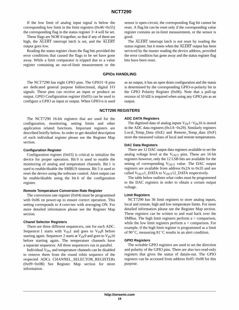
If the low limit of analog input signal is below thecorresponding low limit in the limit registers (0x46−0x55)the corresponding flag in the status register 3−4 will be set.
These flags are NOR’d together, so that if any of them arehigh, the ALERT interrupt latch is set, and the ALERToutput goes low.
Reading the status register clears the flag bits provided theerror conditions that caused the flags to be set have goneaway. While a limit comparator is tripped due to a valueregister containing an out-of-limit measurement or the
sensor is open-circuit, the corresponding flag bit cannot bereset. A flag bit can be reset only if the corresponding valueregister contains an in-limit measurement, or the sensor isgood.
The ALERT interrupt latch is not reset by reading thestatus register, but it resets when the ALERT output has beenserviced by the master reading the device address, providedthe error condition has gone away and the status register flagbits have been reset.
GPIOs HANDLING
The NCT7290 has eight GPIO pins. The GPIO1−8 pinsare dedicated general purpose bidirectional, digital I/Osignals. These pins can receive an input or produce anoutput. GPIO Configuration register (0x05) can be used toconfigure a GPIO as input or output. When GPIO-n is used
as an output, it has an open drain configuration and the statusis determined by the corresponding GPIO-n-polarity bit inthe GPIO Polarity Register (0x06). Note that a pull-upresistor of 10 k� is required when using any GPIO pin as anoutput.
NCT7290 REGISTERS
The NCT7290 16-bit registers that are used for theconfiguration, monitoring, setting limits and otherapplication related functions. Important registers aredescribed briefly below. In order to get detailed descriptionof each individual register please see the Register Mapsection.
Configuration RegisterConfiguration register (0x03) is critical to initialize the
device for proper operation. Bit 0 is used to enable themonitoring of analog and temperature channels. Bit 1 isused to enable/disable the SMBUS timeout. Bit 5 is used toreset the device using the software control. Alert output canbe enable/disable using the bit 6 of the configurationregister.
Remote Temperature Conversion Rate RegisterThe conversion rate register (0x04) must be programmed
with 0x06 on power-up to ensure correct operation. Thissetting corresponds to 4 conv/sec with averaging ON. Formore detailed information please see the Register Mapsection.
Chanel Selector RegistersThere are three different sequencers, one for each ADC.
Sequencer 1 starts with VIN1 and goes to VIN8 beforestarting again. Sequencer 2 starts at VIN9 and goes to VIN16before starting again. The temperature channels havea separate sequencer. All three sequencers run in parallel.
Individual VINs and temperature channels can be disabledto remove them from the round robin sequence of therespected ADCs CHANNEL_SELECTOR_REGISTERs(0x09−0x0B) See Register Map section for moreinformation.
ADC DATA RegistersThe digitized data of analog inputs VIN1−VIN16 is stored
in the ADC data registers (0x1A−0x29). Similarly registersLocal_Temp_Data (0xE) and Remote_Temp_data (0xF)store the measured values of local and remote temperatures.
DAC Data RegistersThere are 12 DAC output data registers available to set the
analog voltage level at the VOUT pins. These are 16 bitregisters however, only the 12 LSB bits are available for thesetting of corresponding VOUT value. The DAC outputregisters are available from address 0x2A to 0x35 and arecalled VOUT1_DATA to VOUT12_DATA respectively.
The table below outlines what codes must be programmedto the DAC registers in order to obtain a certain outputvoltage.
Limit RegistersNCT7290 has 36 limit registers to store analog inputs,
local and remote, high and low temperature limits. For moredetailed information please see the Register Map section.These registers can be written to and read back over theSMBus. The high limit registers perform a > comparison,while the low limit registers perform a < comparison. Forexample, if the high limit register is programmed as a limitof 90�C, measuring 81�C results in an alert condition.
GPIO RegistersThe writable GPIO registers are used to set the direction
and polarity of the GPIO pins. There are also two read-onlyregisters that gives the status of datain-out. The GPIOregisters can be accessed from address 0x05−0x08 for thispurpose.

NCT7290
http://onsemi.com20
COMMUNICATION
There are two communication interfaces on theNCT7290. On power-up you must select which interfaceyou intend on using. This is done via the BUS_SEL pin.Grounding this pin selects the I2C interface while setting itto VDD will select the SPI interface. The table below showthe pins related to each interface.
Table 6. COMMUNICATION PIN CONFIGURATION
BUS_SEL State GND VDD
Pin No. I2C SPI
24 SCL SCLK
25 SDA SDI
26 ADD0 SDO
27 ADD1 CS
Serial Bus Interface – I2CControl of the NCT7290 is carried out via the I2C bus.
The NCT7290 is connected to this bus as a slave device,under the control of a master device. The NCT7290 hasa 7-bit serial bus address. The upper 3 bits of the deviceaddress are fixed at ‘110’.The lower four bits are set by thestate of pins 26 and 27 as shown in Table 7. The address pinsare sampled continuously after power-up, so any changesmade while power is on changes the I2C address.
Table 7. ADDRESS SELECTION
ADD1 ADD0 Device Address
0 0 110 0001 (0x61)
0 1 110 0010 (0x62)
1 0 110 0100 (0x64)
1 1 110 0101 (0x65)
The serial bus protocol operates as follows:1. The master initiates data transfer by establishing
a START condition, defined as a high-to-lowtransition on the serial data line SDA while theserial clock line, SCL, remains high. This indicatesthat an address/data stream will follow. All slaveperipherals connected to the serial bus respond tothe START condition, and shift in the next eightbits, consisting of a 7-bit address (MSB first) plusan R/W bit, which determines the direction of thedata transfer, i.e., whether data will be written toor read from the slave device. The peripheralwhose address corresponds to the transmittedaddress responds by pulling the data line lowduring the low period before the ninth clock pulse,known as the Acknowledge Bit. All other deviceson the bus now remain idle while the selecteddevice waits for data to be read from or written toit. If the R/W bit is a 0, the master will write to the
slave device. If the R/W bit is a 1, the master willread from the slave device.
2. Data is sent over the serial bus in sequences ofnine clock pulses, eight bits of data followed by anAcknowledge Bit from the slave device.Transitions on the data line must occur during thelow period of the clock signal and remain stableduring the high period, as a low-to-high transitionwhen the clock is high may be interpreted asa STOP signal. The number of data bytes that canbe transmitted over the serial bus in a singleREAD or WRITE operation is limited only bywhat the master and slave devices can handle.
3. When all data bytes have been read or written,stop conditions are established. In WRITE mode,the master will pull the data line high during the10th clock pulse to assert a STOP condition.In READ mode, the master device will overridethe acknowledge bit by pulling the data line highduring the low period before the ninth clock pulse.This is known as No Acknowledge. The masterwill then take the data line low during the lowperiod before the tenth clock pulse, then highduring the tenth clock pulse to assert a STOPcondition.
Any number of bytes of data may be transferred over theserial bus in one operation, but it is not possible to mix readand write in one operation because the type of operation isdetermined at the beginning and cannot subsequently bechanged without starting a new operation. In the case of theNCT7290, write operations contain two bytes, and readoperations contain two bytes and perform the followingfunctions. To write data to one of the device data registers orread data from it, the Address Pointer Register must be setso that the correct data register is addressed, and then datacan be written into that register or read from it. The first byteof a write operation always contains an address that is storedin the Address Pointer Register. If data is to be written to thedevice, the write operation contains a second data byte thatis written to the register selected by the address pointerregister. The device address is sent over the bus followed byR/W set to 0. This is followed by two data bytes. The firstdata byte is the address of the internal data register to bewritten to, which is stored in the Address Pointer Register.The second data byte is the data to be written to the internaldata register.
When reading data from a register there are twopossibilities:
1. If the NCT7290’s Address Pointer Register valueis unknown or not the desired value, it is firstnecessary to set it to the correct value before datacan be read from the desired data register. This isdone by performing a write to the NCT7290 as

NCT7290
http://onsemi.com21
before, but only the data byte containing theregister address is sent, as data is not to be writtento the register. A read operation is then performedconsisting of the serial bus address, R/W bit set to1, followed by the data word read from the dataregister. This is shown in Figure 23.
2. If the Address Pointer Register is known to bealready at the desired address, data can be read
from the corresponding data register without firstwriting to the Address Pointer Register.
To read from a register it is necessary to first write theregister address to the address pointer. The Byte Writeprotocol is used for this.
Figure 22. Writing to the Address Pointer
1
SCL
SDA 1 0 0 D7 D6 D5 D4 D3 D2 D1 D0
ACK. BYNCT7290
STOP BYMASTER
START BYMASTER
FRAME 1SERIAL BUS ADDRESS BYTE
FRAME 2ADDRESS POINTER REGISTER BYTE
1 19
ACK. BYNCT7290
9
W
Figure 23. Reading a Word from a Previously Selected Register
D7 D6 D5 D4 D3 D2 D1 D0
NACK. BYMASTER
STOP BYMASTER
1 9
FRAME 3LSB DATA FROM VALUE REGISTERBYTE
1
SCL
SDA 1 0 0 D7 D6 D5 D4 D3 D2 D1 D0
ACK. BYMASTER
START BYMASTER
FRAME 1SERIAL BUS ADDRESS BYTE
FRAME 2MSB DATA FROM VALUE REGISTER
1 19
ACK. BYNCT7290
9
R
Figure 24. Writing a Word to a Specified Address
D7 D6 D5 D4 D3 D2 D1 D0
ACK. BYNCT7290
STOP BYMASTER
1 9
FRAME 4DATA BYTE
1
SCL
SDA 1 0 0 D7 D6 D5 D4 D3 D2 D1 D0
ACK. BYNCT7290
START BYMASTER
FRAME 1SERIAL BUS ADDRESS BYTE
FRAME 2ADDRESS POINTER REGISTER BYTE
1 19
ACK. BYNCT7290
9
W
D7 D6 D5 D4 D3 D2 D1 D0
1 9
ACK. BYNCT7290
FRAME 3DATA BYTE

NCT7290
http://onsemi.com22
Serial Peripheral Interface – SPIThe SPI interface of the NCT7290 consists of 4 wires: CS,
SCLK, SDI and SDO. The CS (chip select) pin is used toselect the device when more than one device is connected tothe serial clock and data lines. It is controlled by the SPImaster and must go low at the start of a transmission and highat the end of a transmission. The part operates in a slavemode and requires an externally applied (from the SPImaster) serial clock to the SCLK input to access data fromthe data registers. The master must configure the clocksignal polarity with respect to the data. The NCT7290operates using an active low (inverted) clock (shown inFigure 26). Data is simultaneously transmitted and receivedon the SDO and SDI pins. This is known as full-duplexcommunication.
Figure 25. SPI Interface between Master andNCT7290 (Slave)
NCT7290(Slave)
Master
SCLK
SDI
SDO
CS
SCLK
SDO
SDI
CS
Data is sampled on the rising edge of SCLK. Data isclocked into the NCT7290 (on the SDI pin) on the fallingedge of the clock and data is clocked out of the NCT7290 (onthe SDO pin) on the rising edge of the clock When the SDOpin of the slave is not being used it goes into a highimpedance state (Hi-Z).
SPI data transmission begins when the CS line is asserted(active low). This selects the slave to be communicated with.The 8 register address bits are then sent with the MSB first.Once this is complete the control signal for the Write/Readoperation is sent. This is by default set to read (low signal)and can be set to write by setting this bit high. The next 16bits is then clocked in. The NCT7290 sees all this data on itsSDI pin only. The SDO pin is used for read operations(i.e. sending data beck to the master). The data startsappearing on the NCT7290 SDO pin on the clock edge afterthe control signal has been sent.
Figure 26. Bit Timing Diagram for SPI Communication
SCLK
SDO
SDI
CS
1 8 9 25
1 8 9 25
1 8 9 25
NCT7290
http://onsemi.com23
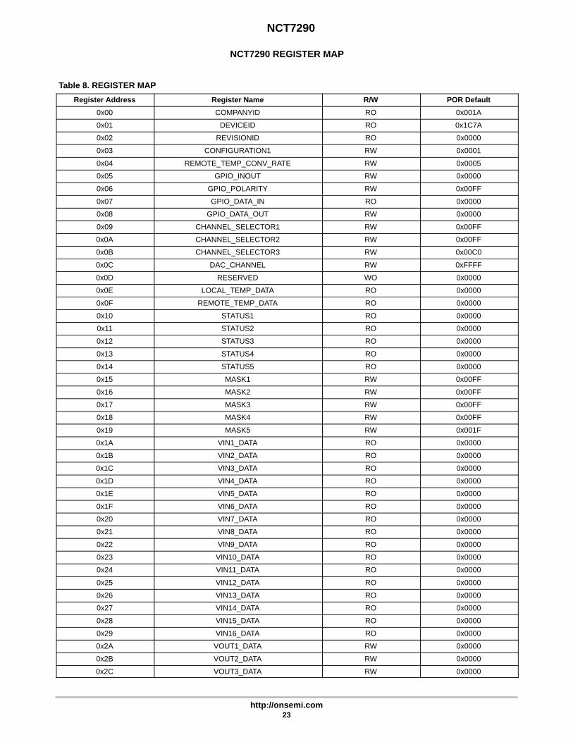
NCT7290 REGISTER MAP
Table 8. REGISTER MAP
Register Address Register Name R/W POR Default
0x00 COMPANYID RO 0x001A
0x01 DEVICEID RO 0x1C7A
0x02 REVISIONID RO 0x0000
0x03 CONFIGURATION1 RW 0x0001
0x04 REMOTE_TEMP_CONV_RATE RW 0x0005
0x05 GPIO_INOUT RW 0x0000
0x06 GPIO_POLARITY RW 0x00FF
0x07 GPIO_DATA_IN RO 0x0000
0x08 GPIO_DATA_OUT RW 0x0000
0x09 CHANNEL_SELECTOR1 RW 0x00FF
0x0A CHANNEL_SELECTOR2 RW 0x00FF
0x0B CHANNEL_SELECTOR3 RW 0x00C0
0x0C DAC_CHANNEL RW 0xFFFF
0x0D RESERVED WO 0x0000
0x0E LOCAL_TEMP_DATA RO 0x0000
0x0F REMOTE_TEMP_DATA RO 0x0000
0x10 STATUS1 RO 0x0000
0x11 STATUS2 RO 0x0000
0x12 STATUS3 RO 0x0000
0x13 STATUS4 RO 0x0000
0x14 STATUS5 RO 0x0000
0x15 MASK1 RW 0x00FF
0x16 MASK2 RW 0x00FF
0x17 MASK3 RW 0x00FF
0x18 MASK4 RW 0x00FF
0x19 MASK5 RW 0x001F
0x1A VIN1_DATA RO 0x0000
0x1B VIN2_DATA RO 0x0000
0x1C VIN3_DATA RO 0x0000
0x1D VIN4_DATA RO 0x0000
0x1E VIN5_DATA RO 0x0000
0x1F VIN6_DATA RO 0x0000
0x20 VIN7_DATA RO 0x0000
0x21 VIN8_DATA RO 0x0000
0x22 VIN9_DATA RO 0x0000
0x23 VIN10_DATA RO 0x0000
0x24 VIN11_DATA RO 0x0000
0x25 VIN12_DATA RO 0x0000
0x26 VIN13_DATA RO 0x0000
0x27 VIN14_DATA RO 0x0000
0x28 VIN15_DATA RO 0x0000
0x29 VIN16_DATA RO 0x0000
0x2A VOUT1_DATA RW 0x0000
0x2B VOUT2_DATA RW 0x0000
0x2C VOUT3_DATA RW 0x0000

NCT7290
http://onsemi.com24
Table 8. REGISTER MAP (continued)
Register Address POR DefaultR/WRegister Name
0x2D VOUT4_DATA RW 0x0000
0x2E VOUT5_DATA RW 0x0000
0x2F VOUT6_DATA RW 0x0000
0x30 VOUT7_DATA RW 0x0000
0x31 VOUT8_DATA RW 0x0000
0x32 VOUT9_DATA RW 0x0000
0x33 VOUT10_DATA RW 0x0000
0x34 VOUT11_DATA RW 0x0000
0x35 VOUT12_DATA RW 0x0000
0x36 VIN1_HIGH_LIM RW 0x03FF
0x37 VIN2_HIGH_LIM RW 0x03FF
0x38 VIN3_HIGH_LIM RW 0x03FF
0x39 VIN4_HIGH_LIM RW 0x03FF
0x3A VIN5_HIGH_LIM RW 0x03FF
0x3B VIN6_HIGH_LIM RW 0x03FF
0x3C VIN7_HIGH_LIM RW 0x03FF
0x3D VIN8_HIGH_LIM RW 0x03FF
0x3E VIN9_HIGH_LIM RW 0x03FF
0x3F VIN10_HIGH_LIM RW 0x03FF
0x40 VIN11_HIGH_LIM RW 0x03FF
0x41 VIN12_HIGH_LIM RW 0x03FF
0x42 VIN13_HIGH_LIM RW 0x03FF
0x43 VIN14_HIGH_LIM RW 0x03FF
0x44 VIN15_HIGH_LIM RW 0x03FF
0x45 VIN16_HIGH_LIM RW 0x03FF
0x46 VIN1_LOW_LIM RW 0x0000
0x47 VIN2_LOW_LIM RW 0x0000
0x48 VIN3_LOW_LIM RW 0x0000
0x49 VIN4_LOW_LIM RW 0x0000
0x4A VIN5_LOW_LIM RW 0x0000
0x4B VIN6_LOW_LIM RW 0x0000
0x4C VIN7_LOW_LIM RW 0x0000
0x4D VIN8_LOW_LIM RW 0x0000
0x4E VIN9_LOW_LIM RW 0x0000
0x4F VIN10_LOW_LIM RW 0x0000
0x50 VIN11_LOW_LIM RW 0x0000
0x51 VIN12_LOW_LIM RW 0x0000
0x52 VIN13_LOW_LIM RW 0x0000
0x53 VIN14_LOW_LIM RW 0x0000
0x54 VIN15_LOW_LIM RW 0x0000
0x55 VIN16_LOW_LIM RW 0x0000
0x56 LOCAL_TEMP_HIGH_LIM RW 0x0154
0x57 LOCAL_TEMP_LOW_LIM RW 0x0000
0x58 REMOTE_TEMP_HIGH_LIM RW 0x01B8
0x59 REMOTE_TEMP_LOW_LIM RW 0x0000
0x5A LOCAL_TEMP_OFFSET RW 0x0000
0x5B REMOTE_TEMP_OFFSET RW 0x0000

NCT7290
http://onsemi.com25
REGISTER DETAILS
Table 9. 0x03 CONFIGURATION REGISTER 1
Bit Field Name Description Access Default
15:8 Reserved ROReturns 0s
0x00
7 DAC_12_op_sel 12 V DAC Setting to Output 5 V if set to 00: 5 V Output1: 12 V Output
RW 0
6 Mask_alert Turns Off ALERT Output0: ALERT is Unmasked1: ALERT is Masked
RW 0
5 Sw_reset Resets All Configuration Registers and Limits to Default Values0: Reset Disabled1: Resets All Configuration Registers and Limits to Default
Values
RW 0
4:2 Reserved RO 0
1 Timeout_disable Disables I2C Timeout0: Enable_timeout1: Disable_timeout
RW 0
0 Start Enables Monitoring0: Disable Monitoring1: Enable Monitoring
RW 1
Table 10. 0x04 REMOTE TEMP CONVERSION RATE
Bit Field Name Description Access Default
15:5 Reserved RO Returns 0s 0x000
4 Averaging_off Average Configuration0: Turns Averaging On for the Remote Channel1: Turns Averaging Off for the Remote Channel
RW 0
3:0 Remote_temp_conv_rate 10 Different Timing Options0x0: 1/16 (Conv/Sec). Averaging On 0x1: 1/8 (Conv/Sec). Averaging On 0x2: 1/4 (Conv/Sec). Averaging On 0x3: 1/2 (Conv/Sec). Averaging On 0x4: 1 (Conv/Sec). Averaging On 0x5: 2 (Conv/Sec). Averaging On 0x6: 4 (Conv/Sec). Averaging Off 0x7: 8 (Conv/Sec). Averaging Off 0x8: 16 (Conv/Sec). Averaging Off 0x9: 20 (Conv/Sec). Averaging Off 0xA: 20 (Conv/Sec). Averaging Off 0xB: 20 (Conv/Sec). Averaging Off 0xC: 20 (Conv/Sec). Averaging Off 0xD: 20 (Conv/Sec). Averaging Off 0xE: 20 (Conv/Sec). Averaging Off 0xF: 20 (Conv/Sec). Averaging Off
RW 0x5

NCT7290
http://onsemi.com26
Table 11. 0x05 GPIO CONFIG
Bit Field Name Description Access Default
15:8 Reserved RO Returns 0s 0x000
7 gpio8_inout 0: Configures the Pin as an Input1: Configures the Pin as an Output
RW 0
6 gpio7_inout
5 gpio6_inout
4 gpio5_inout
3 gpio4_inout
2 gpio3_inout
1 gpio2_inout
0 gpio1_inout
Table 12. 0x06 GPIO POLARITY
Bit Field Name Description Access Default
15:8 Reserved RO Returns 0s 0x00
7 gpio8_polarity Controls Polarity of GPIO Pin0: Active Low1: Active High
RW 1
6 gpio7_polarity
5 gpio6_polarity
4 gpio5_polarity
3 gpio4_polarity
2 gpio3_polarity
1 gpio2_polarity
0 gpio1_polarity
Table 13. 0x07 GPIO DATA IN
Bit Field Name Description Access Default
15:8 Reserved RO Returns 0s 0x00
7 gpio8_data Incoming Data for GPIO PinRead 0: Logic Low Data Read 1: Logic High Data
RO 0
6 gpio7_data
5 gpio6_data
4 gpio5_data
3 gpio4_data
2 gpio3_data
1 gpio2_data
0 gpio1_data

NCT7290
http://onsemi.com27
Table 14. 0x08 GPIO DATA OUT
Bit Field Name Description Access Default
15:8 Reserved RO Returns 0s 0x00
7 gpio8_data Outgoing Data for GPIO Pin0: Logic Low Data1: Logic High Data
RW 0
6 gpio7_data
5 gpio6_data
4 gpio5_data
3 gpio4_data
2 gpio3_data
1 gpio2_data
0 gpio1_data
Table 15. 0x09 CHANNEL SELECTOR 1
Bit Field Name Description Access Default
15:8 Reserved RO Returns 0s 0x00
7 Vin8_en Enables Vin in the Round Robin ADC ConversionSequence
0: Disables Vin Channel from Round Robin Sequence1: Enables Vin Channel in the Round Robin Sequence
RW 1
6 Vin7_en
5 Vin6_en
4 Vin5_en
3 Vin4_en
2 Vin3_en
1 Vin2_en
0 Vin1_en
Table 16. 0x0A CHANNEL SELECTOR 2
Bit Field Name Description Access Default
15:8 Reserved RO Returns 0s 0x00
7 Vin16_en Enables Vin in the Round Robin ADC ConversionSequence
0: Disables Vin Channel from Round Robin Sequence1: Enables Vin Channel in the Round Robin Sequence
RW 1
6 Vin15_en
5 Vin14_en
4 Vin13_en
3 Vin12_en
2 Vin11_en
1 Vin10_en
0 Vin9_en

NCT7290
http://onsemi.com28
Table 17. 0x0B CHANNEL SELECTOR 3
Bit Field Name Description Access Default
15:8 Reserved RO Returns 0s 0x00
7 Local_temp_en Enables Local Temp in the Round Robin ADC ConversionSequence
0: Disables Local Temp Channel from Round RobinSequence
1: Enables Local Temp Channel in the Round RobinSequence
RW 1
6 Remote_temp_en Enables Remote Temp in the Round Robin ADCConversion Sequence
0: Disables Remote Temp Channel from Round RobinSequence
1: Enables Remote Temp Channel in the Round RobinSequence
RW 1
5:0 Reserved 0x00
Table 18. 0x0C DACOUTPUT SHUTDOWN
Bit Field Name Description Access Default
15 Reserved Reserved RW 1
14 Reserved Reserved RW 1
13 VOUT12 Shutdown VOUT12 by Writing 0 to this Bit RW 1
12 VOUT11 Shutdown VOUT11 by Writing 0 to this Bit RW 1
11 VOUT10 Shutdown VOUT10 by Writing 0 to this Bit RW 1
10 VOUT9 Shutdown VOUT9 by Writing 0 to this Bit RW 1
9 VOUT8 Shutdown VOUT8 by Writing 0 to this Bit RW 1
8 VOUT7 Shutdown VOUT7 by Writing 0 to this Bit RW 1
7 Reserved Reserved RW 1
6 Reserved Reserved RW 1
5 VOUT6 Shutdown VOUT6 by Writing 0 to this Bit RW 1
4 VOUT5 Shutdown VOUT5 by Writing 0 to this Bit RW 1
3 VOUT4 Shutdown VOUT4 by Writing 0 to this Bit RW 1
2 VOUT3 Shutdown VOUT3 by Writing 0 to this Bit RW 1
1 VOUT2 Shutdown VOUT2 by Writing 0 to this Bit RW 1
0 VOUT1 Shutdown VOUT1 by Writing 0 to this Bit RW 1
Table 19. 0x0D RESERVED
Bit Field Name Description Access Default
15:0 Reserved RO 0x000
Table 20. 0x0E LOCAL TEMPERATURE DATA
Bit Field Name Description Access Default
15:10 Reserved RO Returns 0s 0x00
9:0 Local_Temp_Data Stores the Local Temperature Data RO 0x000

NCT7290
http://onsemi.com29
Table 21. 0x0F REMOTE TEMPERATURE DATA
Bit Field Name Description Access Default
15:10 Reserved RO Returns 0s 0x00
9:0 Remote_Temp_Data Remote Temperature Data RO 0x000
Table 22. 0x10 STATUS 1 (Note 11)
Bit Field Name Description Access Default
15:8 Reserved RO Returns 0s 0x00
7 Vin8_High Vin_High Tripped RO 0
6 Vin7_High
5 Vin6_High
4 Vin5_High
3 Vin4_High
2 Vin3_High
1 Vin2_High
0 Vin1_High
11. Status registers (0x10−0x013) take 1 read to deassert ALERT and update register, so registers are not seen as cleared until second read.
Table 23. 0x11 STATUS 2 (Note 12)
Bit Field Name Description Access Default
15:8 Reserved RO Returns 0s 0x00
7 Vin16_High Vin_High Tripped RO 0
6 Vin15_High
5 Vin14_High
4 Vin13_High
3 Vin12_High
2 Vin11_High
1 Vin10_High
0 Vin9_High
12.Status registers (0x10−0x013) take 1 read to deassert ALERT and update register, so registers are not seen as cleared until second read.
Table 24. 0x12 STATUS 3 (Note 13)
Bit Field Name Description Access Default
15:8 Reserved RO Returns 0s 0x00
7 Vin8_Low Vin_Low Tripped RO 0
6 Vin7_Low
5 Vin6_Low
4 Vin5_Low
3 Vin4_Low
2 Vin3_Low
1 Vin2_Low
0 Vin1_Low
13.Status registers (0x10−0x013) take 1 read to deassert ALERT and update register, so registers are not seen as cleared until second read.

NCT7290
http://onsemi.com30
Table 25. 0x13 STATUS 4
Bit Field Name Description Access Default
15:8 Reserved RO Returns 0s 0x00
7 Vin16_Low Vin_Low tripped RO 0
6 Vin15_Low
5 Vin14_Low
4 Vin13_Low
3 Vin12_Low
2 Vin11_Low
1 Vin10_Low
0 Vin9_Low
Table 26. 0x14 STATUS 5
Bit Field Name Description Access Default
15:5 Reserved RO Returns 0s 0x000
4 Diode_open_short This Bit is Set if the Remote Diode Pins are Open Circuitor Short Circuit
RO 0
3 Local_High Local_High Temperature Tripped
2 Remote_High Remote_High Temperature Tripped
1 Local_Low Local_Low Temperature Tripped
0 Remote_Low Remote_Low Temperature Tripped
Table 27. 0x15 MASK 1
Bit Field Name Description Access Default
15:8 Reserved RO Returns 0s 0x00
7 Vin8_high_mask Masks Vin_high Alert0: Alert Not Masked for this Status Bit1: Alert Masked for this Status Bit
RW 1
6 Vin7_high_mask
5 Vin6_high_mask
4 Vin5_high_mask
3 Vin4_high_mask
2 Vin3_high_mask
1 Vin2_high_mask
0 Vin1_high_mask
Table 28. 0x16 MASK 2
Bit Field Name Description Access Default
15:8 Reserved RO Returns 0s 0x00
7 Vin16_high_mask Masks Vin_high Alert0: Alert Not Masked for this Status Bit1: Alert Masked for this Status Bit
RW 1
6 Vin15_high_mask
5 Vin14_high_mask
4 Vin13_high_mask
3 Vin12_high_mask
2 Vin11_high_mask
1 Vin10_high_mask
0 Vin9_high_mask

NCT7290
http://onsemi.com31
Table 29. 0x17 MASK 3
Bit Field Name Description Access Default
15:8 Reserved RO Returns 0s 0x00
7 Vin8_low_mask Masks Vin_low Alert0: Alert Not Masked for this Status Bit1: Alert Masked for this Status Bit
RW 1
6 Vin7_low_mask
5 Vin6_low_mask
4 Vin5_low_mask
3 Vin4_low_mask
2 Vin3_low_mask
1 Vin2_low_mask
0 Vin1_low_mask
Table 30. 0x18 MASK 4
Bit Field Name Description Access Default
15:8 Reserved RO Returns 0s 0x00
7 Vin16_low_mask Masks Vin_low Alert0: Alert Not Masked for this Status Bit1: Alert Masked for this Status Bit
RW 1
6 Vin15_low_mask
5 Vin14_low_mask
4 Vin13_low_mask
3 Vin12_low_mask
2 Vin11_low_mask
1 Vin10_low_mask
0 Vin9_low_mask
Table 31. 0x19 MASK 5
Bit Field Name Description Access Default
15:5 Reserved RO Returns 0s 0x000
4 Diode_open_short_mask Masks Diode_open_short Bit. Masked by Default RW 1
3 Local_High_mask Masks Local_Low Temperature Alert RW 1
2 Remote_High_mask Masks Remote_High Temperature Alert RW 1
1 Local_Low_mask Masks Local_Low Temperature Alert RW 1
0 Remote_Low_mask Masks Remote_Low Temperature Alert RW 1
Table 32. 0x1A−0x29 VIN1−VIN16 DATA REGISTERS
Bit Field Name Description Access Default
15:10 Reserved RO Returns 0s 0x00
9:0 Vin_data Vin Data is Stored in this Register (10 bits) RO 0x000
Table 33. 0x2A−0x35 VOUT1−VOUT12 DATA REGISTERS
Bit Field Name Description Access Default
15:12 Reserved RO Returns 0s 0x0
11:0 Vout_data Data Register for the DAC Output RW 0x000

NCT7290
http://onsemi.com32
Table 34. 0x36−0x45 VIN1−VIN16 HIGH LIMIT REGISTERS
Bit Field Name Description Access Default
15:10 Reserved RO Returns 0s 0x00
9:0 Vin_high_lim High Limit Register for Analog Input RW 0x3FF
Table 35. 0x46−0x55 VIN1−VIN16 LOW LIMIT REGISTERS
Bit Field Name Description Access Default
15:10 Reserved RO Returns 0s 0x00
9:0 Vin_low_lim Low Limit Register for Analog Input RW 0x000
Table 36. 0x56 LOCAL TEMPERATURE HIGH LIMIT
Bit Field Name Description Access Default
15:10 Reserved RO Returns 0s 0x00
9:0 Local_temp_high_lim High Limit for the Local Temperature RW 0x154
Table 37. 0x57 LOCAL TEMPERATURE LOW LIMIT
Bit Field Name Description Access Default
15:10 Reserved RO Returns 0s 0x00
9:0 Local_temp_low_lim Low Limit for the Local Temperature RW 0x000
Table 38. 0x58 REMOTE TEMPERATURE HIGH LIMIT
Bit Field Name Description Access Default
15:10 Reserved RO Returns 0s 0x00
9:0 Remote_temp_high_lim High Limit for the Remote Temperature RW 0x1B8
Table 39. 0x59 REMOTE TEMPERATURE LOW LIMIT
Bit Field Name Description Access Default
15:10 Reserved RO Returns 0s 0x00
9:0 Remote_temp_low_lim Low Limit for the Remote Temperature RW 0x000
Table 40. 0x5A LOCAL TEMPERATURE OFFSET
Bit Field Name Description Access Default
15:8 Reserved RO Returns 0s 0x00
7:0 Local_offset Two’s complement offset register. Any value entered intothis register is added to the local temperature result.
RW 0x000
Table 41. 0x5B REMOTE TEMPERATURE OFFSET
Bit Field Name Description Access Default
15:8 Reserved RO Returns 0s 0x00
7:0 Offset_data Two’s complement offset register. Any value entered intothis register is added to the remote temperature result.
RW 0x000

NCT7290
http://onsemi.com33
PACKAGE DIMENSIONS
QFN56 8x8, 0.5PCASE 485BK
ISSUE O
SEATING
0.15 C
(A3)
A
A1
b
1
5656X
L56X
BOTTOM VIEW
TOP VIEW
SIDE VIEW
D A B
E
0.15 C
ÉÉÉÉÉÉÉÉÉÉÉÉÉÉÉÉ
PIN ONELOCATION
0.10 C
0.08 C
C
e
A0.10 BC
0.05 C
NOTES:1. DIMENSIONING AND TOLERANCING PER
ASME Y14.5M, 1994.2. CONTROLLING DIMENSIONS: MILLIMETERS.3. DIMENSION b APPLIES TO PLATED
TERMINAL AND IS MEASURED BETWEEN0.15 AND 0.25mm FROM TERMINAL
4. COPLANARITY APPLIES TO THE EXPOSEDPAD AS WELL AS THE TERMINALS.
DIM MIN MAXMILLIMETERS
A 0.80 1.00A1 0.00 0.05A3 0.20 REFb 0.20 0.30D 8.00 BSCD2 6.30 6.50E 8.00 BSC
6.50E2 6.30e 0.50 BSC
L 0.30 0.50K 0.20 −−−
PLANE
MOUNTING FOOTPRINT
L1 0.05 0.15
NOTE 4
e/2
E2
D2
NOTE 3
DETAIL B
L1
DETAIL A
L
ALTERNATECONSTRUCTIONS
L
ÉÉÉÉÉÉ
DETAIL B
MOLD CMPDEXPOSED Cu
ALTERNATECONSTRUCTION
DETAIL A
A0.10 BC
K
DIMENSIONS: MILLIMETERS
8.30
6.54
6.54
0.50
0.63
0.32
56X
56X
PITCH
8.30
PKGOUTLINE
1
A0.10 BC
RECOMMENDED
ON Semiconductor and are registered trademarks of Semiconductor Components Industries, LLC (SCILLC). SCILLC owns the rights to a number of patents, trademarks,copyrights, trade secrets, and other intellectual property. A listing of SCILLC’s product/patent coverage may be accessed at www.onsemi.com/site/pdf/Patent−Marking.pdf. SCILLCreserves the right to make changes without further notice to any products herein. SCILLC makes no warranty, representation or guarantee regarding the suitability of its products for anyparticular purpose, nor does SCILLC assume any liability arising out of the application or use of any product or circuit, and specifically disclaims any and all liability, including withoutlimitation special, consequential or incidental damages. “Typical” parameters which may be provided in SCILLC data sheets and/or specifications can and do vary in different applicationsand actual performance may vary over time. All operating parameters, including “Typicals” must be validated for each customer application by customer’s technical experts. SCILLCdoes not convey any license under its patent rights nor the rights of others. SCILLC products are not designed, intended, or authorized for use as components in systems intended forsurgical implant into the body, or other applications intended to support or sustain life, or for any other application in which the failure of the SCILLC product could create a situation wherepersonal injury or death may occur. Should Buyer purchase or use SCILLC products for any such unintended or unauthorized application, Buyer shall indemnify and hold SCILLC andits officers, employees, subsidiaries, affiliates, and distributors harmless against all claims, costs, damages, and expenses, and reasonable attorney fees arising out of, directly or indirectly,any claim of personal injury or death associated with such unintended or unauthorized use, even if such claim alleges that SCILLC was negligent regarding the design or manufactureof the part. SCILLC is an Equal Opportunity/Affirmative Action Employer. This literature is subject to all applicable copyright laws and is not for resale in any manner.
PUBLICATION ORDERING INFORMATIONN. American Technical Support: 800−282−9855 Toll FreeUSA/Canada
Europe, Middle East and Africa Technical Support:Phone: 421 33 790 2910
Japan Customer Focus CenterPhone: 81−3−5817−1050
NCT7290/D
LITERATURE FULFILLMENT:Literature Distribution Center for ON SemiconductorP.O. Box 5163, Denver, Colorado 80217 USAPhone: 303−675−2175 or 800−344−3860 Toll Free USA/CanadaFax: 303−675−2176 or 800−344−3867 Toll Free USA/CanadaEmail: [email protected]
ON Semiconductor Website: www.onsemi.com
Order Literature: http://www.onsemi.com/orderlit
For additional information, please contact your localSales Representative

Mouser Electronics
Authorized Distributor
Click to View Pricing, Inventory, Delivery & Lifecycle Information: ON Semiconductor:
NCT7290MNTXG