Integration of UWB and Wireless Pressure Mapping in Surgical Navigation
15
2550 IEEE TRANSACTIONS ON MICROWAVE THEORY AND TECHNIQUES, VOL. 57, NO. 10, OCTOBER 2009 Integration of UWB and Wireless Pressure Mapping in Surgical Navigation Mohamed R. Mahfouz, Senior Member, IEEE, Michael J. Kuhn, Student Member, IEEE, Gary To, Student Member, IEEE, and Aly E. Fathy, Fellow, IEEE Abstract—Wireless technologies are becoming more prevalent in hospital environments. An ultra-wideband (UWB) indoor tracking system is outlined, which has dynamic 3-D real-time root-mean-square error in the range of 5.24–6.37 mm using line-of-sight signals in different experiments. This high 3-D ac- curacy opens up many new applications to UWB indoor wireless positioning, which includes its use for tracking smart surgical tools and its ability to register relevant objects in the scene such as a spacer block for real-time pressure mapping of the femoral condyles. Experimental results quantifying the operating room (OR) environment for UWB transmission fit to the IEEE 802.15.4a channel model are included. A simulation of our UWB positioning system with interference from an IEEE 802.11a source shows the need for a front-end bandpass filter at our UWB receiver. Both microcantilever and microelectromechanical systems-based wireless pressure sensors are presented including quantitative per- formance metrics (e.g., hysteresis, sensitivity). The data for these sensors is transmitted over the 315- and 433.92-MHz telemetry bands. These bands are examined for their performance in the OR. Index Terms—Indoor positioning, microelectromechanical systems (MEMS), surgical navigation, telemetry, ultra-wideband (UWB). I. INTRODUCTION W IRELESS technology has grown in the medical industry both in its prevalence and importance. Varshney de- scribes current and future uses of various wireless technologies for medical applications including intelligent mobile emergency response systems, ad hoc networks combined with wireless local area networks (WLANs) for patient monitoring both inside and outside the hospital, the use of smart phones, and other portable devices equipped with 802.11 WLAN technology for telemedicine applications (i.e., everyday hospital use such as downloading daily schedules, patient information, etc.), and indoor tracking of assets, personnel, and patients through dif- ferential global positioning systems (GPSs) or RF identification (RFID) technology [1]. Pattichis et al. gives a comprehensive overview of the wireless technologies used in telemedicine, as well as an overview of systems deployed by various research Manuscript received February 20, 2009; revised June 25, 2009. First pub- lished September 15, 2009; current version published October 14, 2009. M. R. Mahfouz, M. J. Kuhn, and G. To are with the Mechanical, Aerospace, and Biomedical Engineering Department, University of Tennessee, Knoxville, TN, 37996 USA (e-mail: [email protected]; [email protected]; [email protected]). A. E. Fathy is with the Electrical Engineering and Computer Science Depart- ment, University of Tennessee, Knoxville, TN 37996 USA (e-mail: fathy@eecs. utk.edu). Color versions of one or more of the figures in this paper are available online at http://ieeexplore.ieee.org. Digital Object Identifier 10.1109/TMTT.2009.2029721 groups to test the effect of telemedicine in various clinical settings for transmission of electrocardiograph, blood pressure, temperature, medical images, and other relevant signals for appli- cations such as remote monitoring, teleradiology, and emergency care [2]. The use of implantable in vivo sensors, which utilize a telemetry system to transmit data from the body, have become more common with advances in science and technology. Evans et al. and To et al. have done extensive simulation, design, and ex- perimental testing of microelectromechanical systems (MEMS) capacitive pressure sensors and microcantilever sensing tech- nology for recording a pressure map of the knee stresses on the spacer block used in a total knee arthroplasty (TKA) incorpo- rating RF telemetry in the 315- and 433-MHz bands [3], [4]. Pritchard et al. extended this sensor technology for in vivo use by embedding the sensors in a parylene coating for placement inside the polyethylene insert of a TKA and optimizing sensor performance for in vivo loading, which allows pressure map- ping of the knee stresses on the femoral condyles [5]. Computer-aided surgery (CAS) has played an increasingly important role in the positive outcome of orthopedic surgeries since gaining widespread prevalence and acceptance in the 1990s [6]. The main type of CAS system used in orthopedic surgeries is a passive system, and integral to these systems are a tracking capability to give real-time feedback to the computer and surgeon on the 3-D position and orientation of surgical tools and patient anatomy [7]. Optical and electromagnetic tracking systems are the de facto standard in orthopedic CAS. Both of these systems provide 6 degrees-of-freedom (DOF) real-time feedback with sub-millimeter translational accu- racy and sub-degree rotational accuracy (e.g. Polaris Spectra, Northern Digital Inc., Waterloo, ON, Canada [8] and 3-D Guid- ance medSAFE, Ascension Technology Corporation, Milton, VT [9]). Both optical and electromagnetic tracking systems have certain limitations when used for 3-D indoor tracking. Optical systems require a line-of-sight (LOS) signal between the probe and optical receiver, as shown in Fig. 1, while electromagnetic systems have a limited view volume and are susceptible to metallic interference (although new technologies, such as those employed in the 3-D Guidance medSAFE system, provide much better performance in terms of 3-D accuracy in the presence of metallic interference compared to previous generation systems). Both of these systems have been tested under various static and dynamic conditions typically observed during orthopedic CAS with results deemed satisfactory for CAS, assuming none of these limitations are violated [10]. Wireless tracking systems have never been seriously con- sidered in orthopedic CAS because the accuracy required in 0018-9480/$26.00 © 2009 IEEE
Transcript of Integration of UWB and Wireless Pressure Mapping in Surgical Navigation
2550 IEEE TRANSACTIONS ON MICROWAVE THEORY AND TECHNIQUES, VOL. 57, NO. 10, OCTOBER 2009
Integration of UWB and Wireless PressureMapping in Surgical Navigation
Mohamed R. Mahfouz, Senior Member, IEEE, Michael J. Kuhn, Student Member, IEEE,Gary To, Student Member, IEEE, and Aly E. Fathy, Fellow, IEEE
Abstract—Wireless technologies are becoming more prevalentin hospital environments. An ultra-wideband (UWB) indoortracking system is outlined, which has dynamic 3-D real-timeroot-mean-square error in the range of 5.24–6.37 mm usingline-of-sight signals in different experiments. This high 3-D ac-curacy opens up many new applications to UWB indoor wirelesspositioning, which includes its use for tracking smart surgicaltools and its ability to register relevant objects in the scene suchas a spacer block for real-time pressure mapping of the femoralcondyles. Experimental results quantifying the operating room(OR) environment for UWB transmission fit to the IEEE 802.15.4achannel model are included. A simulation of our UWB positioningsystem with interference from an IEEE 802.11a source showsthe need for a front-end bandpass filter at our UWB receiver.Both microcantilever and microelectromechanical systems-basedwireless pressure sensors are presented including quantitative per-formance metrics (e.g., hysteresis, sensitivity). The data for thesesensors is transmitted over the 315- and 433.92-MHz telemetrybands. These bands are examined for their performance in the OR.
Index Terms—Indoor positioning, microelectromechanicalsystems (MEMS), surgical navigation, telemetry, ultra-wideband(UWB).
I. INTRODUCTION
W IRELESS technology has grown in the medical industryboth in its prevalence and importance. Varshney de-
scribes current and future uses of various wireless technologiesfor medical applications including intelligent mobile emergencyresponse systems, ad hoc networks combined with wirelesslocal area networks (WLANs) for patient monitoring both insideand outside the hospital, the use of smart phones, and otherportable devices equipped with 802.11 WLAN technology fortelemedicine applications (i.e., everyday hospital use such asdownloading daily schedules, patient information, etc.), andindoor tracking of assets, personnel, and patients through dif-ferential global positioning systems (GPSs) or RF identification(RFID) technology [1]. Pattichis et al. gives a comprehensiveoverview of the wireless technologies used in telemedicine, aswell as an overview of systems deployed by various research
Manuscript received February 20, 2009; revised June 25, 2009. First pub-lished September 15, 2009; current version published October 14, 2009.
M. R. Mahfouz, M. J. Kuhn, and G. To are with the Mechanical, Aerospace,and Biomedical Engineering Department, University of Tennessee, Knoxville,TN, 37996 USA (e-mail: [email protected]; [email protected];[email protected]).
A. E. Fathy is with the Electrical Engineering and Computer Science Depart-ment, University of Tennessee, Knoxville, TN 37996 USA (e-mail: [email protected]).
Color versions of one or more of the figures in this paper are available onlineat http://ieeexplore.ieee.org.
Digital Object Identifier 10.1109/TMTT.2009.2029721
groups to test the effect of telemedicine in various clinicalsettings for transmission of electrocardiograph, blood pressure,temperature,medical images,andother relevant signals forappli-cations such as remote monitoring, teleradiology, and emergencycare [2]. The use of implantable in vivo sensors, which utilize atelemetry system to transmit data from the body, have becomemore common with advances in science and technology. Evans etal. and To et al. have done extensive simulation, design, and ex-perimental testing of microelectromechanical systems (MEMS)capacitive pressure sensors and microcantilever sensing tech-nology for recording a pressure map of the knee stresses on thespacer block used in a total knee arthroplasty (TKA) incorpo-rating RF telemetry in the 315- and 433-MHz bands [3], [4].Pritchard et al. extended this sensor technology for in vivo useby embedding the sensors in a parylene coating for placementinside the polyethylene insert of a TKA and optimizing sensorperformance for in vivo loading, which allows pressure map-ping of the knee stresses on the femoral condyles [5].
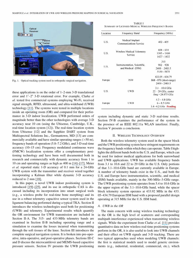
Computer-aided surgery (CAS) has played an increasinglyimportant role in the positive outcome of orthopedic surgeriessince gaining widespread prevalence and acceptance in the1990s [6]. The main type of CAS system used in orthopedicsurgeries is a passive system, and integral to these systems area tracking capability to give real-time feedback to the computerand surgeon on the 3-D position and orientation of surgicaltools and patient anatomy [7]. Optical and electromagnetictracking systems are the de facto standard in orthopedic CAS.Both of these systems provide 6 degrees-of-freedom (DOF)real-time feedback with sub-millimeter translational accu-racy and sub-degree rotational accuracy (e.g. Polaris Spectra,Northern Digital Inc., Waterloo, ON, Canada [8] and 3-D Guid-ance medSAFE, Ascension Technology Corporation, Milton,VT [9]). Both optical and electromagnetic tracking systemshave certain limitations when used for 3-D indoor tracking.Optical systems require a line-of-sight (LOS) signal betweenthe probe and optical receiver, as shown in Fig. 1, whileelectromagnetic systems have a limited view volume and aresusceptible to metallic interference (although new technologies,such as those employed in the 3-D Guidance medSAFE system,provide much better performance in terms of 3-D accuracyin the presence of metallic interference compared to previousgeneration systems). Both of these systems have been testedunder various static and dynamic conditions typically observedduring orthopedic CAS with results deemed satisfactory forCAS, assuming none of these limitations are violated [10].
Wireless tracking systems have never been seriously con-sidered in orthopedic CAS because the accuracy required in
0018-9480/$26.00 © 2009 IEEE
MAHFOUZ et al.: INTEGRATION OF UWB AND WIRELESS PRESSURE MAPPING IN SURGICAL NAVIGATION 2551
Fig. 1. Optical tracking system used in orthopedic surgical navigation.
these applications is on the order of 1–2-mm 3-D translationalerror and 1 –2 3-D rotational error. For example, Clarke etal. tested five commercial systems employing Wi-Fi, receivedsignal strength, RFID, ultrasound, and ultra-wideband (UWB)technology [11]. The systems were tested in multiple locationsinside an operating room (OR) and compared for their perfor-mance in 3-D indoor localization. UWB performed orders ofmagnitude better than the other technologies with average 3-Daccuracy near 10 cm (using the Ubisense, Cambridge, U.K.,real-time location system [12]). The real-time location systemfrom Ubisense [12] and the Sapphire DART system fromMultispectral Solutions Inc., Germantown, MD [13] are com-mercially available and have similar operating ranges ( 50 m),frequency bands of operation (5.8–7.2 GHz), and 3-D real-timeaccuracy (10–15 cm). Frequency modulated continuous wave(FMCW) localization systems offer a complementary posi-tioning technology and have been well documented both inresearch and commercially with dynamic accuracy from 1 to10 cm and operating ranges as high as 400 m [14]–[17]. Meieret al. reported static 1-D accuracy of 0.1 mm for a 24-GHzUWB system with the transmitter and receiver wired togetherincorporating a Kalman filter while dynamic 3-D accuracyreduced to 2 mm [18].
In this paper, a novel UWB indoor positioning system isintroduced [19]–[25], and its use in orthopedic CAS is dis-cussed including its incorporation into smart surgical tools(e.g., a wireless probe for real-time bone morphing) and itsuse in a robust telemetry capacitive sensor system used in theligament balancing performed during a typical TKA. Section IIintroduces the wireless technologies used both for positioning(UWB) and telemetry. Experimental results which quantifythe OR environment for UWB transmission are included inSection II-A. The 315- and 433-MHz telemetry bands areexamined in Section II-B including operating range and asimulation to examine the losses incurred when transmittingthrough the soft tissues of the knee. Section III introduces thecomplete surgical navigation system. It is broken into pre-oper-ative, intra-operative, and post-operative phases. Sections III-Cand D discuss the microcantilever and MEMS-based capacitivepressure sensors. Section IV presents the UWB positioning
TABLE ISUMMARY OF LICENSED MEDICAL WIRELESS FREQUENCY BANDS
system including dynamic and static 3-D real-time results.Section IV-B examines the performance of the system inthe presence of an IEEE 802.11a WLAN interferer. Finally,Section V presents a conclusion.
II. WIRELESS TECHNOLOGY OVERVIEW
Both the wireless telemetry system used in the spacer blockand the UWB positioning system have stringent requirements onthe frequency bands within which they can operate. Table I high-lights the different bands both in the U.S. and Europe, which canbe used for indoor medical applications for both narrowbandand UWB applications. UWB has available frequency bandsfrom 3.1 to 10.6 and 22 to 29 GHz in the U.S. Only portionsof that 3.1–10.6-GHz band are currently available in Europe.A number of telemetry bands exist in the U.S., and both theU.S. and Europe have instrumentation, scientific, and medical(ISM) bands available, mainly in the 300-MHz–3-GHz range.The UWB positioning system operates from 5.4 to 10.6 GHz inthe upper region of the 3.1–10.6-GHz band, while the spacerblock telemetry system operates at 433.92 MHz in the 433.05–434.79 European ISM band with a proposed parallel designoperating at 315 MHz for the U.S. ISM band.
A. UWB in the OR
The main concern with using wireless tracking technologyin the OR is the high level of scatterers and correspondingmultipath interference experienced when transmitting wirelesssignals. While the experiment from Clarke et al. [11] providesquantitative data on how wireless real-time positioning systemsperform in the OR, it is also useful to look into UWB channelsand their effect on UWB signals and 3-D tracking. There aretwo typical approaches used when modeling UWB channels:the first is statistical models used to model generic environ-ments (e.g., industrial, residential, commercial, etc.), which
2552 IEEE TRANSACTIONS ON MICROWAVE THEORY AND TECHNIQUES, VOL. 57, NO. 10, OCTOBER 2009
incorporate LOS or non-line-of-sight (NLOS) measurementstaken in the time and frequency domains, which are then usedin setting the parameters of these statistical models. The secondmethod uses ray tracing techniques to model specific geomet-rical layouts (e.g., buildings, cities) and can provide a moreaccurate depiction of which obstacles and structures will havethe greatest effect on wireless propagation [26]. The drawbackwith ray tracing is the static nature of the results (i.e., results areonly valid for a certain scenario of objects placed in the scene).Even if the base stations in the OR are static, other objects suchas people, patients, operating table, medical equipment, etc.will not be.
Therefore, in developing our UWB positioning system, wehave focused on the use of the IEEE 802.15.4a channel model,which uses a large number of parameters and random variablesin modeling a wide variety of environments (e.g., indoor indus-trial LOS/NLOS, indoor commercial LOS/NLOS, indoor res-idential LOS/NLOS, outdoor, body-area networks) [27], [28].The impulse response of the UWB channel in the time domainis shown in (1), while the pathloss model used in the corre-sponding UWB channel is shown in (2). These models havebeen used both in simulating the behavior of our UWB posi-tioning system [22], [23] and in designing and implementing
(1)
(2)
our receiver-side pulse detection algorithm for highly accurate1-D distance measurements between the transmitter and re-ceiver, integral to the high performance of our system [19],[26].
Although the IEEE 802.15.4a UWB channel model has beenfit to many environments, the OR is one place where measure-ment data is lacking and modeling information is still noncon-clusive. The most comprehensive analysis was done by Hentilaet al. who used time- and frequency-domain measurement tech-niques in analyzing UWB channels in different hospital environ-ments including the OR, X-ray examination room, and intensivecare unit [29]. The data best fit to a Nakagami-m distributionusing a modified Saleh-Valenzuela model, similar to (1).
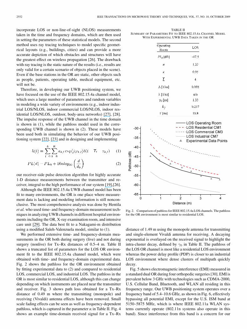
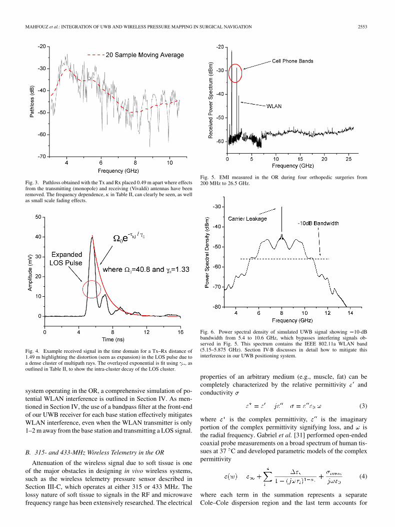
We performed extensive time- and frequency-domain mea-surements in the OR both during surgery (live) and not duringsurgery (nonlive) for Tx–Rx distances of 0.5–4 m. Table IIshows a truncated list of parameters for the LOS OR environ-ment fit to the IEEE 802.15.4a channel model, which wereobtained with time- and frequency-domain experimental data.Fig. 2 shows the pathloss for the OR environment obtainedby fitting experimental data to (2) and compared to residentialLOS, commercial LOS, and industrial LOS. The pathloss in theOR is most similar to residential LOS, although this can changedepending on which instruments are placed near the transmitterand receiver. Fig. 3 shows path loss obtained for a Tx–Rxdistance of 0.49 m where the transmitting (monopole) andreceiving (Vivaldi) antenna effects have been removed. Smallscale fading effects can be seen as well as frequency-dependentpathloss, which is captured in the parameter in Table II. Fig. 4shows an example time-domain received signal for a Tx–Rx
TABLE IISUMMARY OF PARAMETERS FIT TO IEEE 802.15.4A CHANNEL MODEL
WITH EXPERIMENTAL UWB DATA TAKEN IN THE OR
Fig. 2. Comparison of pathloss for IEEE 802.15.4a LOS channels. The pathlossfor the OR environment is most similar to residential LOS.
distance of 1.49 m using the monopole antenna for transmittingand single-element Vivaldi antenna for receiving. A decayingexponential is overlayed on the received signal to highlight theintra-cluster decay, defined by in Table II. The pathloss ofthe LOS OR channel is most like a residential LOS environmentwhereas the power delay profile (PDP) is closer to an industrialLOS environment where dense clusters of multipath quicklydecay.
Fig. 5 shows electromagnetic interference (EMI) measured ina standard dual OR during four orthopedic surgeries [30]. EMI isprevalent below 3 GHz with technologies such as CDMA-2000,U.S. Cellular Band, Bluetooth, and WLAN all residing in thisfrequency range. Our UWB positioning system operates over afrequency band of 5.4–10.6 GHz, as shown in Fig. 6, effectivelybypassing all potential EMI, except for the U.S. ISM band at5150–5875 MHz, which is where IEEE 802.11a WLAN sys-tems currently operate (802.11n systems also operate in thisband). Since interference from this band is a concern for our
MAHFOUZ et al.: INTEGRATION OF UWB AND WIRELESS PRESSURE MAPPING IN SURGICAL NAVIGATION 2553
Fig. 3. Pathloss obtained with the Tx and Rx placed 0.49 m apart where effectsfrom the transmitting (monopole) and receiving (Vivaldi) antennas have beenremoved. The frequency dependence, � in Table II, can clearly be seen, as wellas small scale fading effects.
Fig. 4. Example received signal in the time domain for a Tx–Rx distance of1.49 m highlighting the distortion (seen as expansion) in the LOS pulse due toa dense cluster of multipath rays. The overlayed exponential is fit using � , asoutlined in Table II, to show the intra-cluster decay of the LOS cluster.
system operating in the OR, a comprehensive simulation of po-tential WLAN interference is outlined in Section IV. As men-tioned in Section IV, the use of a bandpass filter at the front-endof our UWB receiver for each base station effectively mitigatesWLAN interference, even when the WLAN transmitter is only1–2 m away from the base station and transmitting a LOS signal.
B. 315- and 433-MHz Wireless Telemetry in the OR
Attenuation of the wireless signal due to soft tissue is oneof the major obstacles in designing in vivo wireless systems,such as the wireless telemetry pressure sensor described inSection III-C, which operates at either 315 or 433 MHz. Thelossy nature of soft tissue to signals in the RF and microwavefrequency range has been extensively researched. The electrical
Fig. 5. EMI measured in the OR during four orthopedic surgeries from200 MHz to 26.5 GHz.
Fig. 6. Power spectral density of simulated UWB signal showing �10-dBbandwidth from 5.4 to 10.6 GHz, which bypasses interfering signals ob-served in Fig. 5. This spectrum contains the IEEE 802.11a WLAN band(5.15–5.875 GHz). Section IV-B discusses in detail how to mitigate thisinterference in our UWB positioning system.
properties of an arbitrary medium (e.g., muscle, fat) can becompletely characterized by the relative permittivity andconductivity
(3)
where is the complex permittivity, is the imaginaryportion of the complex permittivity signifying loss, and isthe radial frequency. Gabriel et al. [31] performed open-endedcoaxial probe measurements on a broad spectrum of human tis-sues at 37 C and developed parametric models of the complexpermittivity
(4)
where each term in the summation represents a separateCole–Cole dispersion region and the last term accounts for
2554 IEEE TRANSACTIONS ON MICROWAVE THEORY AND TECHNIQUES, VOL. 57, NO. 10, OCTOBER 2009
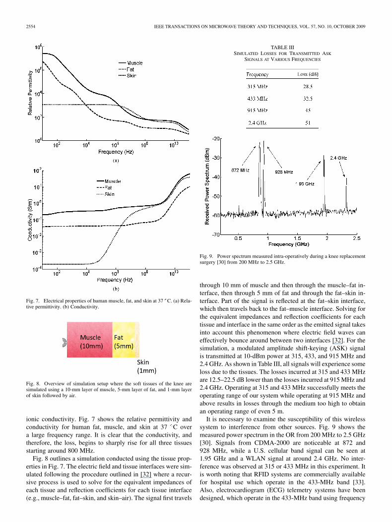
Fig. 7. Electrical properties of human muscle, fat, and skin at 37 C. (a) Rela-tive permittivity. (b) Conductivity.
Fig. 8. Overview of simulation setup where the soft tissues of the knee aresimulated using a 10-mm layer of muscle, 5-mm layer of fat, and 1-mm layerof skin followed by air.
ionic conductivity. Fig. 7 shows the relative permittivity andconductivity for human fat, muscle, and skin at 37 C overa large frequency range. It is clear that the conductivity, andtherefore, the loss, begins to sharply rise for all three tissuesstarting around 800 MHz.
Fig. 8 outlines a simulation conducted using the tissue prop-erties in Fig. 7. The electric field and tissue interfaces were sim-ulated following the procedure outlined in [32] where a recur-sive process is used to solve for the equivalent impedances ofeach tissue and reflection coefficients for each tissue interface(e.g., muscle–fat, fat–skin, and skin–air). The signal first travels
TABLE IIISIMULATED LOSSES FOR TRANSMITTED ASK
SIGNALS AT VARIOUS FREQUENCIES
Fig. 9. Power spectrum measured intra-operatively during a knee replacementsurgery [30] from 200 MHz to 2.5 GHz.
through 10 mm of muscle and then through the muscle–fat in-terface, then through 5 mm of fat and through the fat–skin in-terface. Part of the signal is reflected at the fat–skin interface,which then travels back to the fat–muscle interface. Solving forthe equivalent impedances and reflection coefficients for eachtissue and interface in the same order as the emitted signal takesinto account this phenomenon where electric field waves caneffectively bounce around between two interfaces [32]. For thesimulation, a modulated amplitude shift-keying (ASK) signalis transmitted at 10-dBm power at 315, 433, and 915 MHz and2.4 GHz. As shown in Table III, all signals will experience someloss due to the tissues. The losses incurred at 315 and 433 MHzare 12.5–22.5 dB lower than the losses incurred at 915 MHz and2.4 GHz. Operating at 315 and 433 MHz successfully meets theoperating range of our system while operating at 915 MHz andabove results in losses through the medium too high to obtainan operating range of even 5 m.
It is necessary to examine the susceptibility of this wirelesssystem to interference from other sources. Fig. 9 shows themeasured power spectrum in the OR from 200 MHz to 2.5 GHz[30]. Signals from CDMA-2000 are noticeable at 872 and928 MHz, while a U.S. cellular band signal can be seen at1.95 GHz and a WLAN signal at around 2.4 GHz. No inter-ference was observed at 315 or 433 MHz in this experiment. Itis worth noting that RFID systems are commercially availablefor hospital use which operate in the 433-MHz band [33].Also, electrocardiogram (ECG) telemetry systems have beendesigned, which operate in the 433-MHz band using frequency
MAHFOUZ et al.: INTEGRATION OF UWB AND WIRELESS PRESSURE MAPPING IN SURGICAL NAVIGATION 2555
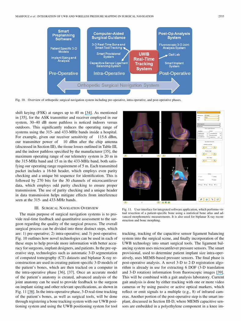
Fig. 10. Overview of orthopedic surgical navigation system including pre-operative, intra-operative, and post-operative phases.
shift keying (FSK) at ranges up to 40 m [34]. As mentionedin [35], for the ASK transmitter and receiver employed in oursystem, 30–40 dB more pathloss is noticed indoors versusoutdoors. This significantly reduces the operating range ofsystems using the 315- and 433-MHz bands inside a hospital.For example, given our receiver sensitivity of 115.6 dBm,our transmitter power of 10 dBm after the chip antenna(discussed in Section III), the tissue losses outlined in Table III,and the indoor pathloss specified by the manufacturer [35], themaximum operating range of our telemetry system is 20 m inthe 315-MHz band and 15 m in the 433-MHz band, both satis-fying our operating range requirement of 5 m. Each transmittedpacket includes a 16-bit header, which employs even paritychecking and a unique bit sequence for identification. This isfollowed by 270 bits for the 30 channels of microcantileverdata, which employs odd parity checking to ensure propertransmission. The use of parity checking and a unique headerin data transmission helps mitigate effects from interferenceseen at the 315- and 433-MHz bands.
III. SURGICAL NAVIGATION OVERVIEW
The main purpose of surgical navigation systems is to pro-vide real-time feedback and quantitative assessment to the sur-geon regarding the quality of the surgical process. The overallsurgical process can be divided into three distinct steps, whichare: 1) pre-operative; 2) intra-operative; and 3) post-operative.Fig. 10 outlines how novel technologies can be used in each ofthese steps to help provide more information with better accu-racy for surgeons, implant designers, and patients. In the pre-op-erative step, technologies such as automatic 3-D segmentationof computed tomography (CT) datasets and biplanar X-ray re-construction are used in creating patient-specific 3-D models ofthe patient’s bones, which are then tracked on a computer inthe intra-operative phase [36], [37]. Once an accurate modelof the patient’s anatomy is created, advanced analysis of thejoint anatomy can be used to provide feedback to the surgeonon implant sizing and other relevant specifications, as shown inFig. 11 [38]. In the intra-operative phase, 3-D real-time trackingof the patient’s bones, as well as surgical tools, will be donethrough registering a bone tracking system with our UWB posi-tioning system and using the UWB positioning system for tool
Fig. 11. User interface for integrated software application, which performs vir-tual resection of a patient-specific bone using a statistical bone atlas and ad-vanced morphometric measurements. It is also used for biplanar X-ray recon-struction and bone morphing.
tracking, tracking of the capacitive sensor ligament balancingsystem into the surgical scene, and finally incorporation of theUWB technology into smart surgical tools. The ligament bal-ancing system uses microcantilever pressure sensors. The smartprovisional, used to determine patient implant size intra-oper-atively, uses MEMS-based pressure sensors. The final phase ispost-operative analysis. A novel 3-D to 2-D registration algo-rithm is already in use for extracting 6 DOF (3-D translationand 3-D rotation) information from fluoroscopic images [39].This will be combined with a gait analysis laboratory. Currentgait analysis is done by either tracking with one or more videocameras or by using passive or active optical markers, whichreflect or emit signals to a multiple (e.g., 8) of infrared cam-eras. Another portion of the post-operative step is the smart im-plant, discussed in Section III-D, where MEMS capacitive sen-sors are embedded in a polyethylene component in a knee im-
2556 IEEE TRANSACTIONS ON MICROWAVE THEORY AND TECHNIQUES, VOL. 57, NO. 10, OCTOBER 2009
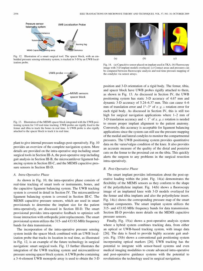
Fig. 12. Illustration of a smart surgical tool. The spacer block, with an em-bedded pressure sensing-telemetry system, is tracked in 3-D by an UWB local-ization probe.
Fig. 13. Illustration of the MEMS spacer block integrated with the UWB posi-tioning system for 3-D real-time tracking. UWB probes are rigidly fixed to thefemur and tibia to track the bones in real time. A UWB probe is also rigidlyattached to the spacer block to track it in real time.
plant to give internal pressure readings post-operatively. Fig. 10provides an overview of the complete navigation system. Moredetails are provided on the intra-operative step including smartsurgical tools in Section III-A, the post-operative step includinggait analysis in Section III-B, the microcantilever ligament bal-ancing system in Section III-C, and the MEMS capacitive pres-sure sensors in Section III-D.
A. Intra-Operative Phase
As shown in Fig. 10, the intra-operative phase consists ofreal-time tracking of smart tools or instruments, bones, andthe capacitive ligament balancing system. The UWB trackingsystem is covered in detail in Section IV. The microcantileverligament balancing system is covered in Section III-C. TheMEMS capacitive pressure sensors, which are used in smartprovisionals to determine the implant size for the patientintra-operatively, are discussed in Section III-D. The smartprovisional provides intra-operative feedback to optimize softtissue interaction with orthopedic joint replacements. The smartprovisional system utilizes the 315- and 433.92-MHz frequencybands for data transmission.
The incorporation of the intra-operative pressure sensingsystem inside the spacer block combined with an UWB local-ization probe that tracks its location in real time, as illustratedin Fig. 12, is an example of the future technology in surgicalnavigation: smart surgical tools. Fig. 13 further illustrates theintegration of the UWB tracking system and microcantileverpressure sensing spacer block system. A UWB probe containinga 3–6-element UWB monopole array is used to obtain the 3-D
Fig. 14. (a) Capacitive sensor placed on implant used in TKA. (b) Fluoroscopyimage with 3-D implant models overlayed. (c) Contact areas and pressures canbe compared between fluoroscopic analysis and real-time pressure mapping ofthe condyles via sensor arrays.
position and 3-D orientation of a rigid body. The femur, tibia,and spacer block have UWB probes rigidly attached to them,as shown in Fig. 13. As discussed in Section IV, the UWBpositioning system has static 3-D accuracy of 4.67 mm anddynamic 3-D accuracy of 5.24–6.37 mm. This can cause 4–6mm of translation error and 1 –3 of rotation error foreach rigid body. As discussed in Section IV, this is still toohigh for surgical navigation applications where 1–2 mm of3-D translation accuracy and 1 of rotation is neededto ensure proper implant alignment to the patient anatomy.Conversely, this accuracy is acceptable for ligament balancingapplications since the system can still use the pressure mappingof the medial and lateral condyles to monitor the compartmentalpressures. The UWB positioning system provides quantitativedata on the varus/valgus condition of the knee. It also providesan accurate measure of the quality of the distal and posteriorcuts on the femur to the proximal cut on the tibia. This quicklyalerts the surgeon to any problems in the surgical resectionintra-operatively.
B. Post-Operative Phase
The smart implant provides information about the post-op-erative loading within the joint. Fig. 14(a) demonstrates theflexibility of the MEMS sensors as they conform to the shapeof the polyethylene implant. Fig. 14(b) shows a fluoroscopyimage of an implanted knee with 3-D models overlayed forthe femur and tibia implants and also the polyethylene insert.Fig. 14(c) shows the corresponding pressure map of the smartimplant components. The smart implant system utilizes the315- and 433.92-MHz frequency bands for data transmission.Section III-D provides more details on the MEMS capacitivepressure sensors.
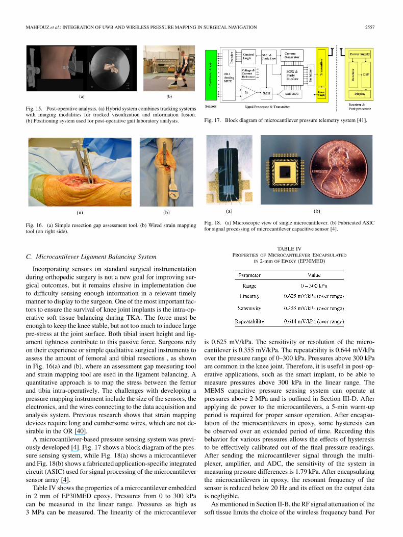
Finally, Fig. 15(a) shows a post-operative analysis systemwhere a hybrid system combines tracking data, from eitheran optical or UWB-based tracking system, with image data[26]. The data is fused to provide highly accurate gait anal-ysis. Fig. 15(b) shows a conventional gait positioning systemincorporating optical markers [26]. UWB tracking has thepotential to integrate with sensor-based systems and evenmedical imaging modalities to create advanced intra-operativeand post-operative guidance systems with the potential torevolutionize the technology used in surgical navigation.
MAHFOUZ et al.: INTEGRATION OF UWB AND WIRELESS PRESSURE MAPPING IN SURGICAL NAVIGATION 2557
Fig. 15. Post-operative analysis. (a) Hybrid system combines tracking systemswith imaging modalities for tracked visualization and information fusion.(b) Positioning system used for post-operative gait laboratory analysis.
Fig. 16. (a) Simple resection gap assessment tool. (b) Wired strain mappingtool (on right side).
C. Microcantilever Ligament Balancing System
Incorporating sensors on standard surgical instrumentationduring orthopedic surgery is not a new goal for improving sur-gical outcomes, but it remains elusive in implementation dueto difficulty sensing enough information in a relevant timelymanner to display to the surgeon. One of the most important fac-tors to ensure the survival of knee joint implants is the intra-op-erative soft tissue balancing during TKA. The force must beenough to keep the knee stable, but not too much to induce largepre-stress at the joint surface. Both tibial insert height and lig-ament tightness contribute to this passive force. Surgeons relyon their experience or simple qualitative surgical instruments toassess the amount of femoral and tibial resections , as shownin Fig. 16(a) and (b), where an assessment gap measuring tooland strain mapping tool are used in the ligament balancing. Aquantitative approach is to map the stress between the femurand tibia intra-operatively. The challenges with developing apressure mapping instrument include the size of the sensors, theelectronics, and the wires connecting to the data acquisition andanalysis system. Previous research shows that strain mappingdevices require long and cumbersome wires, which are not de-sirable in the OR [40].
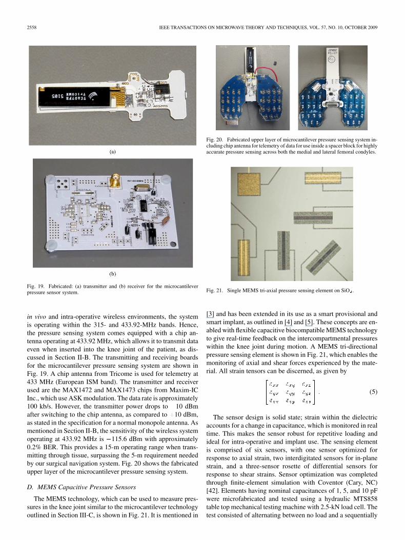
A microcantilever-based pressure sensing system was previ-ously developed [4]. Fig. 17 shows a block diagram of the pres-sure sensing system, while Fig. 18(a) shows a microcantileverand Fig. 18(b) shows a fabricated application-specific integratedcircuit (ASIC) used for signal processing of the microcantileversensor array [4].
Table IV shows the properties of a microcantilever embeddedin 2 mm of EP30MED epoxy. Pressures from 0 to 300 kPacan be measured in the linear range. Pressures as high as3 MPa can be measured. The linearity of the microcantilever
Fig. 17. Block diagram of microcantilever pressure telemetry system [41].
Fig. 18. (a) Microscopic view of single microcantilever. (b) Fabricated ASICfor signal processing of microcantilever capacitive sensor [4].
TABLE IVPROPERTIES OF MICROCANTILEVER ENCAPSULATED
IN 2-mm OF EPOXY (EP30MED)
is 0.625 mV/kPa. The sensitivity or resolution of the micro-cantilever is 0.355 mV/kPa. The repeatability is 0.644 mV/kPaover the pressure range of 0–300 kPa. Pressures above 300 kPaare common in the knee joint. Therefore, it is useful in post-op-erative applications, such as the smart implant, to be able tomeasure pressures above 300 kPa in the linear range. TheMEMS capacitive pressure sensing system can operate atpressures above 2 MPa and is outlined in Section III-D. Afterapplying dc power to the microcantilevers, a 5-min warm-upperiod is required for proper sensor operation. After encapsu-lation of the microcantilevers in epoxy, some hysteresis canbe observed over an extended period of time. Recording thisbehavior for various pressures allows the effects of hysteresisto be effectively calibrated out of the final pressure readings.After sending the microcantilever signal through the multi-plexer, amplifier, and ADC, the sensitivity of the system inmeasuring pressure differences is 1.79 kPa. After encapsulatingthe microcantilevers in epoxy, the resonant frequency of thesensor is reduced below 20 Hz and its effect on the output datais negligible.
As mentioned in Section II-B, the RF signal attenuation of thesoft tissue limits the choice of the wireless frequency band. For
2558 IEEE TRANSACTIONS ON MICROWAVE THEORY AND TECHNIQUES, VOL. 57, NO. 10, OCTOBER 2009
Fig. 19. Fabricated: (a) transmitter and (b) receiver for the microcantileverpressure sensor system.
in vivo and intra-operative wireless environments, the systemis operating within the 315- and 433.92-MHz bands. Hence,the pressure sensing system comes equipped with a chip an-tenna operating at 433.92 MHz, which allows it to transmit dataeven when inserted into the knee joint of the patient, as dis-cussed in Section II-B. The transmitting and receiving boardsfor the microcantilever pressure sensing system are shown inFig. 19. A chip antenna from Tricome is used for telemetry at433 MHz (European ISM band). The transmitter and receiverused are the MAX1472 and MAX1473 chips from Maxim-ICInc., which use ASK modulation. The data rate is approximately100 kb/s. However, the transmitter power drops to 10 dBmafter switching to the chip antenna, as compared to 10 dBm,as stated in the specification for a normal monopole antenna. Asmentioned in Section II-B, the sensitivity of the wireless systemoperating at 433.92 MHz is 115.6 dBm with approximately0.2% BER. This provides a 15-m operating range when trans-mitting through tissue, surpassing the 5-m requirement neededby our surgical navigation system. Fig. 20 shows the fabricatedupper layer of the microcantilever pressure sensing system.
D. MEMS Capacitive Pressure Sensors
The MEMS technology, which can be used to measure pres-sures in the knee joint similar to the microcantilever technologyoutlined in Section III-C, is shown in Fig. 21. It is mentioned in
Fig. 20. Fabricated upper layer of microcantilever pressure sensing system in-cluding chip antenna for telemetry of data for use inside a spacer block for highlyaccurate pressure sensing across both the medial and lateral femoral condyles.
Fig. 21. Single MEMS tri-axial pressure sensing element on SiO .
[3] and has been extended in its use as a smart provisional andsmart implant, as outlined in [4] and [5]. These concepts are en-abled with flexible capacitive biocompatible MEMS technologyto give real-time feedback on the intercompartmental pressureswithin the knee joint during motion. A MEMS tri-directionalpressure sensing element is shown in Fig. 21, which enables themonitoring of axial and shear forces experienced by the mate-rial. All strain tensors can be discerned, as given by
(5)
The sensor design is solid state; strain within the dielectricaccounts for a change in capacitance, which is monitored in realtime. This makes the sensor robust for repetitive loading andideal for intra-operative and implant use. The sensing elementis comprised of six sensors, with one sensor optimized forresponse to axial strain, two interdigitated sensors for in-planestrain, and a three-sensor rosette of differential sensors forresponse to shear strains. Sensor optimization was completedthrough finite-element simulation with Coventor (Cary, NC)[42]. Elements having nominal capacitances of 1, 5, and 10 pFwere microfabricated and tested using a hydraulic MTS858table top mechanical testing machine with 2.5-kN load cell. Thetest consisted of alternating between no load and a sequentially
MAHFOUZ et al.: INTEGRATION OF UWB AND WIRELESS PRESSURE MAPPING IN SURGICAL NAVIGATION 2559
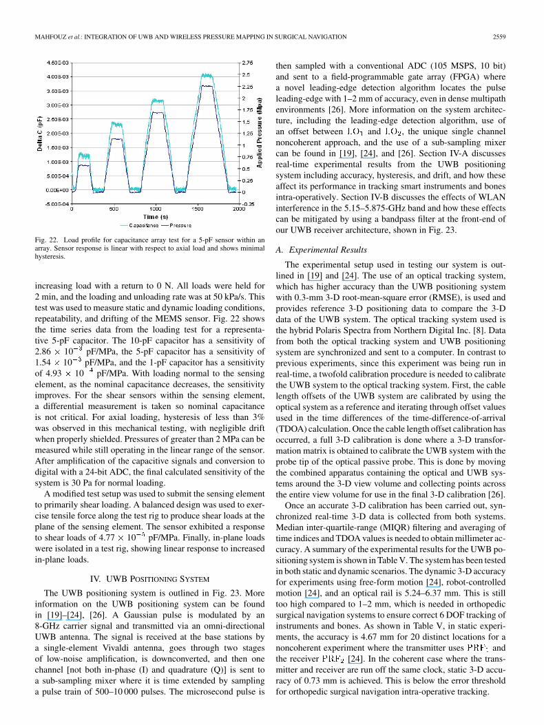
Fig. 22. Load profile for capacitance array test for a 5-pF sensor within anarray. Sensor response is linear with respect to axial load and shows minimalhysteresis.
increasing load with a return to 0 N. All loads were held for2 min, and the loading and unloading rate was at 50 kPa/s. Thistest was used to measure static and dynamic loading conditions,repeatability, and drifting of the MEMS sensor. Fig. 22 showsthe time series data from the loading test for a representa-tive 5-pF capacitor. The 10-pF capacitor has a sensitivity of2.86 10 pF/MPa, the 5-pF capacitor has a sensitivity of1.54 10 pF/MPa, and the 1-pF capacitor has a sensitivityof 4.93 10 pF/MPa. With loading normal to the sensingelement, as the nominal capacitance decreases, the sensitivityimproves. For the shear sensors within the sensing element,a differential measurement is taken so nominal capacitanceis not critical. For axial loading, hysteresis of less than 3%was observed in this mechanical testing, with negligible driftwhen properly shielded. Pressures of greater than 2 MPa can bemeasured while still operating in the linear range of the sensor.After amplification of the capacitive signals and conversion todigital with a 24-bit ADC, the final calculated sensitivity of thesystem is 30 Pa for normal loading.
A modified test setup was used to submit the sensing elementto primarily shear loading. A balanced design was used to exer-cise tensile force along the test rig to produce shear loads at theplane of the sensing element. The sensor exhibited a responseto shear loads of 4.77 10 pF/MPa. Finally, in-plane loadswere isolated in a test rig, showing linear response to increasedin-plane loads.
IV. UWB POSITIONING SYSTEM
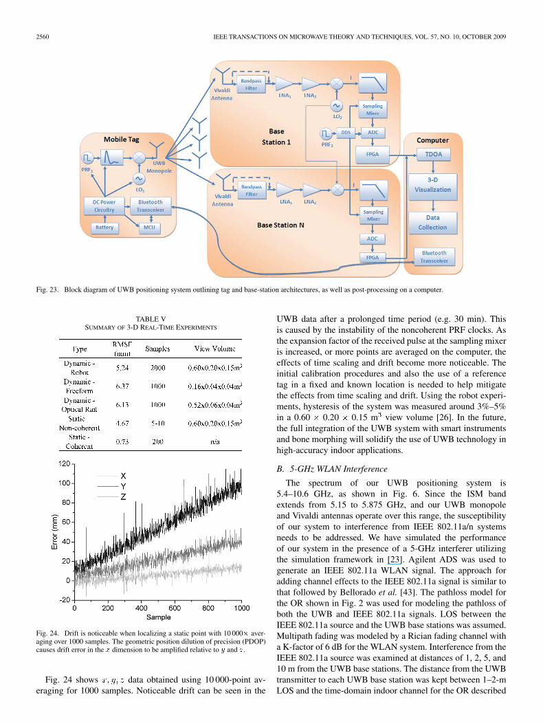
The UWB positioning system is outlined in Fig. 23. Moreinformation on the UWB positioning system can be foundin [19]–[24], [26]. A Gaussian pulse is modulated by an8-GHz carrier signal and transmitted via an omni-directionalUWB antenna. The signal is received at the base stations bya single-element Vivaldi antenna, goes through two stagesof low-noise amplification, is downconverted, and then onechannel [not both in-phase (I) and quadrature (Q)] is sent toa sub-sampling mixer where it is time extended by samplinga pulse train of 500–10 000 pulses. The microsecond pulse is
then sampled with a conventional ADC (105 MSPS, 10 bit)and sent to a field-programmable gate array (FPGA) wherea novel leading-edge detection algorithm locates the pulseleading-edge with 1–2 mm of accuracy, even in dense multipathenvironments [26]. More information on the system architec-ture, including the leading-edge detection algorithm, use ofan offset between and , the unique single channelnoncoherent approach, and the use of a sub-sampling mixercan be found in [19], [24], and [26]. Section IV-A discussesreal-time experimental results from the UWB positioningsystem including accuracy, hysteresis, and drift, and how theseaffect its performance in tracking smart instruments and bonesintra-operatively. Section IV-B discusses the effects of WLANinterference in the 5.15–5.875-GHz band and how these effectscan be mitigated by using a bandpass filter at the front-end ofour UWB receiver architecture, shown in Fig. 23.
A. Experimental Results
The experimental setup used in testing our system is out-lined in [19] and [24]. The use of an optical tracking system,which has higher accuracy than the UWB positioning systemwith 0.3-mm 3-D root-mean-square error (RMSE), is used andprovides reference 3-D positioning data to compare the 3-Ddata of the UWB system. The optical tracking system used isthe hybrid Polaris Spectra from Northern Digital Inc. [8]. Datafrom both the optical tracking system and UWB positioningsystem are synchronized and sent to a computer. In contrast toprevious experiments, since this experiment was being run inreal-time, a twofold calibration procedure is needed to calibratethe UWB system to the optical tracking system. First, the cablelength offsets of the UWB system are calibrated by using theoptical system as a reference and iterating through offset valuesused in the time differences of the time-difference-of-arrival(TDOA) calculation. Once the cable length offset calibration hasoccurred, a full 3-D calibration is done where a 3-D transfor-mation matrix is obtained to calibrate the UWB system with theprobe tip of the optical passive probe. This is done by movingthe combined apparatus containing the optical and UWB sys-tems around the 3-D view volume and collecting points acrossthe entire view volume for use in the final 3-D calibration [26].
Once an accurate 3-D calibration has been carried out, syn-chronized real-time 3-D data is collected from both systems.Median inter-quartile-range (MIQR) filtering and averaging oftime indices and TDOA values is needed to obtain millimeter ac-curacy. A summary of the experimental results for the UWB po-sitioning system is shown in Table V. The system has been testedin both static and dynamic scenarios. The dynamic 3-D accuracyfor experiments using free-form motion [24], robot-controlledmotion [24], and an optical rail is 5.24–6.37 mm. This is stilltoo high compared to 1–2 mm, which is needed in orthopedicsurgical navigation systems to ensure correct 6 DOF tracking ofinstruments and bones. As shown in Table V, in static experi-ments, the accuracy is 4.67 mm for 20 distinct locations for anoncoherent experiment where the transmitter uses andthe receiver [24]. In the coherent case where the trans-mitter and receiver are run off the same clock, static 3-D accu-racy of 0.73 mm is achieved. This is below the error thresholdfor orthopedic surgical navigation intra-operative tracking.
2560 IEEE TRANSACTIONS ON MICROWAVE THEORY AND TECHNIQUES, VOL. 57, NO. 10, OCTOBER 2009
Fig. 23. Block diagram of UWB positioning system outlining tag and base-station architectures, as well as post-processing on a computer.
TABLE VSUMMARY OF 3-D REAL-TIME EXPERIMENTS
Fig. 24. Drift is noticeable when localizing a static point with 10 000� aver-aging over 1000 samples. The geometric position dilution of precision (PDOP)causes drift error in the � dimension to be amplified relative to � and �.
Fig. 24 shows data obtained using 10 000-point av-eraging for 1000 samples. Noticeable drift can be seen in the
UWB data after a prolonged time period (e.g. 30 min). Thisis caused by the instability of the noncoherent PRF clocks. Asthe expansion factor of the received pulse at the sampling mixeris increased, or more points are averaged on the computer, theeffects of time scaling and drift become more noticeable. Theinitial calibration procedures and also the use of a referencetag in a fixed and known location is needed to help mitigatethe effects from time scaling and drift. Using the robot experi-ments, hysteresis of the system was measured around 3%–5%in a 0.60 0.20 0.15 m view volume [26]. In the future,the full integration of the UWB system with smart instrumentsand bone morphing will solidify the use of UWB technology inhigh-accuracy indoor applications.
B. 5-GHz WLAN Interference
The spectrum of our UWB positioning system is5.4–10.6 GHz, as shown in Fig. 6. Since the ISM bandextends from 5.15 to 5.875 GHz, and our UWB monopoleand Vivaldi antennas operate over this range, the susceptibilityof our system to interference from IEEE 802.11a/n systemsneeds to be addressed. We have simulated the performanceof our system in the presence of a 5-GHz interferer utilizingthe simulation framework in [23]. Agilent ADS was used togenerate an IEEE 802.11a WLAN signal. The approach foradding channel effects to the IEEE 802.11a signal is similar tothat followed by Bellorado et al. [43]. The pathloss model forthe OR shown in Fig. 2 was used for modeling the pathloss ofboth the UWB and IEEE 802.11a signals. LOS between theIEEE 802.11a source and the UWB base stations was assumed.Multipath fading was modeled by a Rician fading channel witha K-factor of 6 dB for the WLAN system. Interference from theIEEE 802.11a source was examined at distances of 1, 2, 5, and10 m from the UWB base stations. The distance from the UWBtransmitter to each UWB base station was kept between 1–2-mLOS and the time-domain indoor channel for the OR described
MAHFOUZ et al.: INTEGRATION OF UWB AND WIRELESS PRESSURE MAPPING IN SURGICAL NAVIGATION 2561
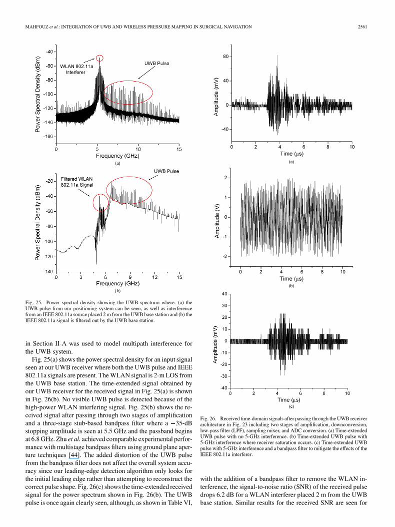
Fig. 25. Power spectral density showing the UWB spectrum where: (a) theUWB pulse from our positioning system can be seen, as well as interferencefrom an IEEE 802.11a source placed 2 m from the UWB base station and (b) theIEEE 802.11a signal is filtered out by the UWB base station.
in Section II-A was used to model multipath interference forthe UWB system.
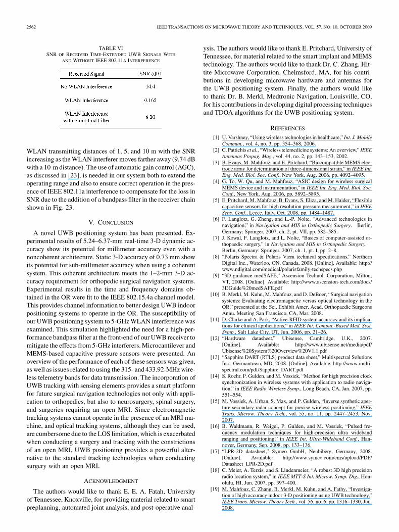
Fig. 25(a) shows the power spectral density for an input signalseen at our UWB receiver where both the UWB pulse and IEEE802.11a signals are present. The WLAN signal is 2-m LOS fromthe UWB base station. The time-extended signal obtained byour UWB receiver for the received signal in Fig. 25(a) is shownin Fig. 26(b). No visible UWB pulse is detected because of thehigh-power WLAN interfering signal. Fig. 25(b) shows the re-ceived signal after passing through two stages of amplificationand a three-stage stub-based bandpass filter where a 35-dBstopping amplitude is seen at 5.5 GHz and the passband beginsat 6.8 GHz. Zhu et al. achieved comparable experimental perfor-mance with multistage bandpass filters using ground plane aper-ture techniques [44]. The added distortion of the UWB pulsefrom the bandpass filter does not affect the overall system accu-racy since our leading-edge detection algorithm only looks forthe initial leading edge rather than attempting to reconstruct thecorrect pulse shape. Fig. 26(c) shows the time-extended receivedsignal for the power spectrum shown in Fig. 26(b). The UWBpulse is once again clearly seen, although, as shown in Table VI,
Fig. 26. Received time-domain signals after passing through the UWB receiverarchitecture in Fig. 23 including two stages of amplification, downconversion,low-pass filter (LPF), sampling mixer, and ADC conversion. (a) Time-extendedUWB pulse with no 5-GHz interference. (b) Time-extended UWB pulse with5-GHz interference where receiver saturation occurs. (c) Time-extended UWBpulse with 5-GHz interference and a bandpass filter to mitigate the effects of theIEEE 802.11a interferer.
with the addition of a bandpass filter to remove the WLAN in-terference, the signal-to-noise ratio (SNR) of the received pulsedrops 6.2 dB for a WLAN interferer placed 2 m from the UWBbase station. Similar results for the received SNR are seen for
2562 IEEE TRANSACTIONS ON MICROWAVE THEORY AND TECHNIQUES, VOL. 57, NO. 10, OCTOBER 2009
TABLE VISNR OF RECEIVED TIME-EXTENDED UWB SIGNALS WITH
AND WITHOUT IEEE 802.11A INTERFERENCE
WLAN transmitting distances of 1, 5, and 10 m with the SNRincreasing as the WLAN interferer moves farther away (9.74 dBwith a 10-m distance). The use of automatic gain control (AGC),as discussed in [23], is needed in our system both to extend theoperating range and also to ensure correct operation in the pres-ence of IEEE 802.11a interference to compensate for the loss inSNR due to the addition of a bandpass filter in the receiver chainshown in Fig. 23.
V. CONCLUSION
A novel UWB positioning system has been presented. Ex-perimental results of 5.24–6.37-mm real-time 3-D dynamic ac-curacy show its potential for millimeter accuracy even with anoncoherent architecture. Static 3-D accuracy of 0.73 mm showits potential for sub-millimeter accuracy when using a coherentsystem. This coherent architecture meets the 1–2-mm 3-D ac-curacy requirement for orthopedic surgical navigation systems.Experimental results in the time and frequency domains ob-tained in the OR were fit to the IEEE 802.15.4a channel model.This provides channel information to better design UWB indoorpositioning systems to operate in the OR. The susceptibility ofour UWB positioning system to 5-GHz WLAN interference wasexamined. This simulation highlighted the need for a high-per-formance bandpass filter at the front-end of our UWB receiver tomitigate the effects from 5-GHz interferers. Microcantilever andMEMS-based capacitive pressure sensors were presented. Anoverview of the performance of each of these sensors was given,as well as issues related to using the 315- and 433.92-MHz wire-less telemetry bands for data transmission. The incorporation ofUWB tracking with sensing elements provides a smart platformfor future surgical navigation technologies not only with appli-cation to orthopedics, but also to neurosurgery, spinal surgery,and surgeries requiring an open MRI. Since electromagnetictracking systems cannot operate in the presence of an MRI ma-chine, and optical tracking systems, although they can be used,are cumbersome due to the LOS limitation, which is exacerbatedwhen conducting a surgery and tracking with the constrictionsof an open MRI, UWB positioning provides a powerful alter-native to the standard tracking technologies when conductingsurgery with an open MRI.
ACKNOWLEDGMENT
The authors would like to thank E. E. A. Fatah, Universityof Tennessee, Knoxville, for providing material related to smartpreplanning, automated joint analysis, and post-operative anal-
ysis. The authors would like to thank E. Pritchard, University ofTennessee, for material related to the smart implant and MEMStechnology. The authors would like to thank Dr. C. Zhang, Hit-tite Microwave Corporation, Chelmsford, MA, for his contri-butions in developing microwave hardware and antennas forthe UWB positioning system. Finally, the authors would liketo thank Dr. B. Merkl, Medtronic Navigation, Louisville, CO,for his contributions in developing digital processing techniquesand TDOA algorithms for the UWB positioning system.
REFERENCES
[1] U. Varshney, “Using wireless technologies in healthcare,” Int. J. MobileCommun., vol. 4, no. 3, pp. 354–368, 2006.
[2] C. Pattichis et al., “Wireless telemedicine systems: An overview,” IEEEAntennas Propag. Mag., vol. 44, no. 2, pp. 143–153, 2002.
[3] B. Evans, M. Mahfouz, and E. Pritchard, “Biocompatible MEMS elec-trode array for determination of three-dimensional strain,” in IEEE Int.Eng. Med. Biol. Soc. Conf., New York, Aug. 2006, pp. 4092–4095.
[4] G. To, W. Qu, and M. Mahfouz, “ASIC design for wireless surgicalMEMS device and instrumentation,” in IEEE Int. Eng. Med. Biol. Soc.Conf., New York, Aug. 2006, pp. 5892–5895.
[5] E. Pritchard, M. Mahfouz, B. Evans, S. Eliza, and M. Haider, “Flexiblecapacitive sensors for high resolution pressure measurement,” in IEEESens. Conf., Lecce, Italy, Oct. 2008, pp. 1484–1487.
[6] F. Langlotz, G. Zheng, and L.-P. Nolte, “Advanced technologies innavigation,” in Navigation and MIS in Orthopedic Surgery. Berlin,Germany: Springer, 2007, ch. 2, pt. VII, pp. 582–585.
[7] J. Kowal, F. Langlotz, and L. Nolte, “Basics of computer-assisted or-thopaedic surgery,” in Navigation and MIS in Orthopedic Surgery.Berlin, Germany: Springer, 2007, ch. 1, pt. I, pp. 2–8.
[8] “Polaris Spectra & Polaris Vicra technical specifications,” NorthernDigital Inc., Waterloo, ON, Canada, 2008. [Online]. Available: http://www.ndigital.com/medical/polarisfamily-techspecs.php
[9] “3D guidance medSAFE,” Ascension Technol. Corporation, Milton,VT, 2008. [Online]. Available: http://www.ascension-tech.com/docs/3DGuide%20medSAFE.pdf
[10] B. Merkl, M. Kuhn, M. Mahfouz, and D. DeBoer, “Surgical navigationsystems: Evaluating electromagnetic versus optical technology in theOR,” presented at the Sci. Exhibit Amer. Acad. Orthopaedic SurgeonsAnnu. Meeting San Francisco, CA, Mar. 2008.
[11] D. Clarke and A. Park, “Active-RFID system accuracy and its implica-tions for clinical applications,” in IEEE Int. Comput.-Based Med. Syst.Symp., Salt Lake City, UT, Jun. 2006, pp. 21–26.
[12] “Hardware datasheet,” Ubisense, Cambridge, U.K., 2007.[Online]. Available: http://www.ubisense.net/media/pdf/Ubisense%20System%20Overview%20V1.1.pdf
[13] “Sapphire DART (RTLS) product data sheet,” Multispectral SolutionsInc., Germantown, MD, 2008. [Online]. Available: http://www.multi-spectral.com/pdf/Sapphire_DART.pdf
[14] S. Roehr, P. Gulden, and M. Vossiek, “Method for high precision clocksynchronization in wireless systems with application to radio naviga-tion,” in IEEE Radio Wireless Symp., Long Beach, CA, Jan. 2007, pp.551–554.
[15] M. Vossiek, A. Urban, S. Max, and P. Gulden, “Inverse synthetic aper-ture secondary radar concept for precise wireless positioning,” IEEETrans. Microw. Theory Tech., vol. 55, no. 11, pp. 2447–2453, Nov.2007.
[16] B. Waldmann, R. Weigel, P. Gulden, and M. Vossiek, “Pulsed fre-quency modulation techniques for high-precision ultra widebandranging and positioning,” in IEEE Int. Ultra-Wideband Conf., Han-nover, Germany, Sep. 2008, pp. 133–136.
[17] “LPR-2D datasheet,” Symeo GmbH, Neubiberg, Germany, 2008.[Online]. Available: http://www.symeo.com/cms/upload/PDF/Datasheet_LPR-2D.pdf
[18] C. Meier, A. Terzis, and S. Lindenmeier, “A robust 3D high precisionradio location system,” in IEEE MTT-S Int. Microw. Symp. Dig., Hon-olulu, HI, Jun. 2007, pp. 397–400.
[19] M. Mahfouz, C. Zhang, B. Merkl, M. Kuhn, and A. Fathy, “Investiga-tion of high accuracy indoor 3-D positioning using UWB technology,”IEEE Trans. Microw. Theory Tech., vol. 56, no. 6, pp. 1316–1330, Jun.2008.
MAHFOUZ et al.: INTEGRATION OF UWB AND WIRELESS PRESSURE MAPPING IN SURGICAL NAVIGATION 2563
[20] C. Zhang, M. Kuhn, B. Merkl, M. Mahfouz, and A. Fathy, “Devel-opment of an UWB indoor 3-D positioning radar with millimeter ac-curacy,” in IEEE MTT-S Int. Microw. Symp., San Francisco, CA, Jun.2006, pp. 106–109.
[21] C. Zhang, A. Fathy, and M. Mahfouz, “Performance enhancement ofa sub-sampling circuit for ultra-wideband signal processing,” IEEEMicrow. Wireless Compon. Lett., vol. 17, no. 12, pp. 873–875,2007.
[22] M. Kuhn, C. Zhang, B. Mserkl, D. Yang, Y. Wang, M. Mahfouz, andA. Fathy, “High accuracy UWB localization in dense indoor environ-ments,” in IEEE Int. Ultra-Wideband Conf., Hannover, Germany, Sep.2008, vol. 2, pp. 129–132.
[23] M. Kuhn, C. Zhang, S. Lin, M. Mahfouz, and A. Fathy, “A system leveldesign approach to UWB localization,” in IEEE MTT-S Int. Microw.Symp. Dig., Boston, MA, Jun. 2009, pp. 1409–1412.
[24] C. Zhang, M. Kuhn, M. Mahfouz, and A. Fathy, “Real-time nonco-herent UWB positioning radar with millimeter range accuracy in a 3Dindoor environment,” in IEEE MTT-S Int. Microw. Symp. Dig., Boston,MA, Jun. 2009, pp. 1413–1416.
[25] M. Mahfouz, “Operating room of the future: Orthopedic perspective,”presented at the Cairo Int. Biomed. Eng. Conf. Invited Talk, Cairo,Egypt, Dec. 2008.
[26] B. Merkl, “The future of the operating room: Surgical preplanningand navigation using high accuracy ultra-wideband positioning and ad-vanced bone measurement,” Ph.D. dissertation, Mech. Aero. Biomed.Eng. Dept., Univ. Tennessee, Knoxville, TN, 2008.
[27] A. Molisch, D. Cassioli, C. Chong, S. Emami, A. Fort, B. Kannan, J.Karedal, J. Kunisch, H. G. Schantz, K. Siwiak, and M. Z. Win, “A com-prehensive standardized model for ultrawideband propagation chan-nels,” IEEE Trans. Antennas Propag., vol. 54, no. 11, pp. 3151–3166,Nov. 2006.
[28] A. Molisch et al., “IEEE 802.15.4a channel model—Final report,”IEEE, Piscataway, NJ, Tech. Rep., Doc. IEEE 802.1504-0062-02-004a,2005.
[29] L. Hentila, A. Taparungssanagorn, H. Viittala, and M. Hämäläinen,“Measurement and modelling of an UWB channel at hospital,” inIEEE Int. Ultra-Wideband Conf., Zurich, Switzerland, Sep. 2005, pp.113–117.
[30] M. Kuhn, M. Mahfouz, C. Zhang, B. Merkl, and A. Fathy, “Electro-magnetic interference and its effects on ultra-wideband technology inthe operating room,” in Int. Biomed. Eng. Conf., Cairo, Egypt, Dec.2006, pp. 1–4.
[31] S. Gabriel, R. W. Lau, and C. Gabriel, “The dielectric properties ofbiological tissues: III Parametric models for the dielectric spectrum oftissue,” Phys. Med. Biol., vol. 41, pp. 2271–2293, 1996.
[32] A. V. Vorst, A. Rosen, and Y. Kotsuka, RF/Microwave Interaction WithBiological Tissues. Hoboken, NJ: Wiley, 2006.
[33] J. Collins, “RFID remedy for medical errors,” RFID J. May 28, 2004.[Online]. Available: http://www.rfidjournal.com/article/view/961/1/1
[34] N. F. Güler and U. Fidan, “Wireless transmission of ECG signal,” J.Med. Syst., vol. 30, no. 3, pp. 231–235, 2006.
[35] “Path loss in remote keyless entry systems,” Maxim-IC Inc., Sunny-vale, CA, Appl. Note 3945, Dec. 15, 2006. [Online]. Available: http://www.maxim-ic.com/appnotes.cfm/an_pk/3945
[36] B. Merkl and M. Mahfouz, “Unsupervised three-dimensional segmen-tation of medical images using an anatomical bone atlas,” in 12th Int.Biomed. Eng. Conf., Singapore, Dec. 2005, pp. 1–5.
[37] M. Mahfouz, E. Abdel Fatah, H. E. Dakhakhni, R. Tadross, andR. Komistek, “Three-dimensional bone creation and landmarkingusing two still X-rays,” presented at the Annu. Amer. Acad.Orthopaedic Surgeons Meeting, San Francisco, CA, Mar. 2008,Podium 196.
[38] M. Mahfouz, B. Merkl, E. Abdel Fatah, R. Booth, and J. Argenson,“Automatic methods for characterizing of sexual dimorphism of adultfemora: Distal femur,” Comput. Methods Biomech. Biomed. Eng., vol.10, no. 6, pp. 447–456, 2007.
[39] M. Mahfouz, W. Hoff, R. Komistek, and D. Dennis, “A robust methodfor registration of three-dimensional knee implant models to two-di-mensional fluoroscopy images,” IEEE Trans. Med. Imag., vol. 22, no.12, pp. 1561–1574, Dec. 2003.
[40] R. Wasielewski, D. Galat, and R. Komistek, “An intraoperativepressure-measuring device used in total knee arthroplasties and itskinematics correlations,” Clin. Orthopaedic Rel. Res., vol. 427, pp.171–178, 2004.
[41] W. Qu, S. Islam, G. To, and M. Mahfouz, “Micro-cantilever array pres-sure measurement system for biomedical instrumentation,” in IEEESens. Conf., Atlanta, GA, Oct. 2007, pp. 1009–1012.
[42] B. Evans and M. Mahfouz, “Design optimization of a three-dimen-sional strain sensor using multiphysics finite element analysis,” in Int.Biomed. Eng. Conf., Cairo, Egypt, Dec. 2006, pp. 1–4.
[43] J. Bellorado, S. S. Ghassemzadeh, L. J. Greenstein, T. Sveinsson1,and V. Tarokh1, “Coexistence of ultra-wideband systems with IEEE-802.11a wireless LANs,” in IEEE Global Telecom. Conf., San Fran-cisco, CA, Dec. 2003, pp. 410–414.
[44] L. Zhu, H. Bu, and K. Wu, “Broadband and compact multi-pole mi-crostrip bandpass filters using ground plane aperture technique,” Proc.Inst. Elect. Eng.—Microw., Antennas, Propag., vol. 149, no. 1, pp.71–77, 2002.
Mohamed R. Mahfouz (S’98–M’01–SM’06)received the B.S.B.M.E. and M.S.B.M.E. degreesfrom Cairo University, Cairo, Egypt, in 1987 and1992, respectively, the M.S.E.E. degree from theUniversity of Denver, Denver, CO, in 1997, and thePh.D. degree from the Colorado School of Mines,Golden, in 2002.
From 1998 to 2002, he was Technical Director ofthe Rocky Mountain Musculoskeletal Research Lab-oratory, Denver, CO. In 2002, he became both Tech-nical Director of the Center for Musculoskeletal Re-
search and an Associate Professor with the University of Tennessee, Knoxville.His current research interests include medical applications of UWB, biomedicalinstrumentation, medical imaging, surgical navigation, MEMS bio-sensors, and3-D bone and tissue reconstruction. He has authored numerous journal and con-ference papers and book chapters. He has received numerous National Institutesof Health (NIH) and National Science Foundation (NSF) grants.
Michael J. Kuhn (S’06) was born in Wheat Ridge,CO, in 1982. He received the B.S. degree in electricalengineering and B.S. degree in computer sciencefrom the Colorado School of Mines, Golden, in2004, the M.S. degree in engineering science fromthe University of Tennessee, Knoxville, in 2008,and is currently working toward the Ph.D. degreein biomedical engineering at the University ofTennessee.
Since 2005, he has been a Researcher with theCenter for Musculoskeletal Research, University of
Tennessee, Knoxville. He has authored/coauthored and presented at numerousinternational conferences in the fields of biomedical engineering and alsomicrowave and antenna engineering. His current research interests includemedical applications of UWB, numerical techniques in microwave engineering,and orthopedic surgical navigation.
Mr. Kuhn was the recipient of the 2005 Ph.D. Fellowship presented by theCollege of Engineering, University of Tennessee.
Gary To (S’05) was born in Hong Kong, in 1982. Hereceived the B.S. degree in biomedical engineering(with a minor in material science and engineering)from the University of Tennessee, Knoxville, in2004, the M.S. degree in biomedical engineeringfrom the University of Tennessee, Knoxville, in2007, and is currently working toward the Ph.D.degree in biomedical engineering at the Universityof Tennessee.
In Summer 2003, he was an Undergraduate Re-search Assistant with the Center for Musculoskeletal
Research, Knoxville, TN. He has authored/coauthored and presented at nu-merous international conferences in the fields of MEMS and ASIC design forbiomedical applications. His current research interests include bioinstrumenta-tion and smart implant design.
Mr. To has been a member of Tau Beta Pi since 2003.
2564 IEEE TRANSACTIONS ON MICROWAVE THEORY AND TECHNIQUES, VOL. 57, NO. 10, OCTOBER 2009
Aly E. Fathy (S’82–M’84–SM’92–F’04) receivedthe B.S.E.E. degree, B.S. degree in pure and appliedmathematics, and M.S.E.E. degree from Ain ShamsUniversity, Cairo, Egypt, in 1975, 1979, and 1980,respectively, and the Ph.D. degree from the Poly-technic Institute of New York, Brooklyn, in 1984.
In February 1985, he joined the RCA ResearchLaboratory (currently the Sarnoff Corporation),Princeton, NJ, as a Member of the Technical Staff. In2001, he became a Senior Member of the TechnicalStaff with the Sarnoff Corporation. With the Sarnoff
Corporation, he was engaged in the research and development of various en-abling technologies such as high-� superconductors, low-temperature co-firedceramic (LTCC), and reconfigurable holographic antennas. He was also an Ad-junct Professor with the Cooper Union School of Engineering, New York, NY. In
August 2003, he joined the University of Tennessee, Knoxville, as an AssociateProfessor. He has authored or coauthored numerous transaction and conferencepapers. He holds 11 U.S. patents. His current research interests include wirelessreconfigurable antennas, see-through walls, UWB systems, and high-efficiencyhigh-linearity combining of digital signals for base-station amplifiers. He hasdeveloped various microwave components/subsystems such as holographicreconfigurable antennas, radial combiners, direct broadcast antennas (DBSs),speed sensors, and LTCC packages for mixed-signal applications.
Dr. Fathy is a member of Sigma Xi and Eta Kappa Nu. He was the recipientof five Sarnoff Outstanding Achievement Awards (1988, 1994, 1995, 1997, and1999). He is an active member of the IEEE Microwave Theory and TechniquesSociety (IEEE MTT-S) International Microwave Symposium (IMS) TechnicalProgram Committee, the IEEE Antenna and Propagation Symposium, and theIEEE Radio and Wireless Steering Committee. He is currently the TechnicalProgram chair of the 2008 IEEE Radio and Wireless Conference.