ATP RADIO NAVIGATION ١
146
ATP RADIO NAVIGATION 1 1- When considering the use of NDB, night effect has its greatest effect during: A) autumn and winter. B) when using inland beacons. C) when using a horizontally polarised signal. D) at dawn and dusk. At night the NDB Indications are not reliable at distances greater than 70 NM due the night effect. The ionized layers of the atmosphere are: D-Layer (which is present only by day), E - layer and F-layer. During the day the LF and MF signals are partially absorbed by the D-layer, but at night (When the D-Layer is dispersed) the LF and MF signals are free to reach the -E and -F layers which are strong enough to produce the refraction and reflection of the radio waves. Thus, sky-waves may result during the night. These returning waves cut the loop members at a different angle to the ground wave. The plane of polarization of the returning sky wave may have a horizontal component that can induce signals in the horizontal loop members. These effects can cause the null to be shifted or suppressed giving bearing errors. The indications in the aircraft are often the fading of the signal, wandering of the needle about an arc and loss of signal. For the NDB signal transmissions (Which are in the LF and MF bands) the night effect errors are most significant at dusk and dawn when the D-Layer is in the process of disappearing and appearing, respectively. Note: The D,-Layer does not directly affect the accuracy of NDB bearings, but at night its absence permits the signals to reach the -E and -F layers h1fffrd affect the accuracy of NDB bearings. 2- A cumulonimbus cloud in the vicinity of an aeroplane can cause certain navigation systems to give false indications. This is particularly true of the: A) ADF B) VOR C) Weather radar D) DME For explanation refer to question 82 3-The frequency band chosen for NDB is: A) upper MF and lower LF B) VLF C) upper LF and lower MF D) LF (Refer to figure 062-E73 and 062-E44) The Non-Directional Beacon (NDB) is a ground-based radio transmitter that transmits radio energy in all directions (omni-directional transmission ).Power output can be as little as 15 watts and up to several Kw. All transmissions are vertically polarized and are intended to propagate as ground waves. Frequency allocation is 190 kHz (upper to LF band)-1750 kHz (MF band)but most NDBs in Europe are below 500kHz (lower end of the MF band spectrum).
-
Upload
khangminh22 -
Category
Documents
-
view
0 -
download
0
Transcript of ATP RADIO NAVIGATION ١

ATP RADIO NAVIGATION
1
1- When considering the use of NDB, night effect has its greatest effect during:
A) autumn and winter.
B) when using inland beacons.
C) when using a horizontally polarised signal.
D) at dawn and dusk.
At night the NDB Indications are not reliable at distances greater than 70 NM due the
night effect. The ionized layers of the atmosphere are: D-Layer (which is present only by
day), E - layer and F-layer. During the day the LF and MF signals are partially absorbed
by the D-layer, but at night (When the D-Layer is dispersed) the LF and MF signals are
free to reach the -E and -F layers which are strong enough to produce the refraction and
reflection of the radio waves. Thus, sky-waves may result during the night. These
returning waves cut the loop members at a different angle to the ground wave. The plane
of polarization of the returning sky wave may have a horizontal component that can
induce signals in the horizontal loop members. These effects can cause the null to be
shifted or suppressed giving bearing errors. The indications in the aircraft are often the
fading of the signal, wandering of the needle about an arc and loss of signal. For the NDB
signal transmissions (Which are in the LF and MF bands) the night effect errors are most
significant at dusk and dawn when the D-Layer is in the process of disappearing and
appearing, respectively.
Note: The D,-Layer does not directly affect the accuracy of NDB bearings, but at night its
absence permits the signals to reach the -E and -F layers h1fffrd affect the accuracy of
NDB bearings.
2- A cumulonimbus cloud in the vicinity of an aeroplane can cause certain
navigation systems to give false indications. This is particularly true of the:
A) ADF
B) VOR
C) Weather radar
D) DME
For explanation refer to question 82
3-The frequency band chosen for NDB is:
A) upper MF and lower LF
B) VLF
C) upper LF and lower MF
D) LF
(Refer to figure 062-E73 and 062-E44)
The Non-Directional Beacon (NDB) is a ground-based radio transmitter that transmits
radio energy in all directions (omni-directional transmission ).Power output can be as
little as 15 watts and up to several Kw. All transmissions are vertically polarized and are
intended to propagate as ground waves. Frequency allocation is 190 kHz (upper to LF
band)-1750 kHz (MF band)but most NDBs in Europe are below 500kHz (lower end of
the MF band spectrum).

ATP RADIO NAVIGATION
2
Note: Since the signal is vertically polarized it means that the electrical component travels
in the vertical plane and the magnetic component travels in horizontal plane.
4- NDBs transmit mainly in the:
A) VHF band.
B) UHF band.
C) HF band.
D) MF band.
For explanation refer to question 3
5- The heading read on a standard RMI is:
A) the magnetic heading.
B) the relative heading.
C) the compass heading.
D) the true heading.
(Refer to figures 062-E75 and 062-E76)
The indicator instrument of an ADF system can be one of three kinds:
Fixed-card ADF, also known as the Relative Bearing Indicator (RBI) - has a fixed
instrument dial and always indicates zero at the top of the instrument, and the needle
indicates the Relative Bearing (RB) from the aircraft to the station. This type of display
shows the bearing of the tuned NDB station relative to the fore and aft axis of the aircraft.
The relative bearing indicated is measured clockwise from the nose of the aircraft and is
expressed in degrees. In order to obtain the Magnetic Bearing (MB) the pilot has to
perform a mental calculation: MB = RB + MH.
Movable-card ADF - allows the pilot to rotate the aircraft's present heading to the top of
the instrument dial so that the head of the needle indicates Magnetic Bearing (MB) from
the aircraft to the station, and the tail of the needle indicates MB from the station. For
correct indication the pilot has to reset the instrument after any change of an aircraft
heading so that the actual heading is always at the top position of the instrument.
Radio Magnetic Indicator (RMI) - differs from the movable-card ADF in that it
automatically rotates the azimuth card (remotely controlled by a gyrocompass) to
represent aircraft heading (compass heading). The RMI has two needles, which can be
used to indicate navigation information from either the ADF or the VOR receivers. When
a needle is being driven by the ADF, the head of the needle indicates the Magnetic
Bearing (MB) TO the station tuned on the ADF receiver. The tail of the needle is the
bearing FROM the station. When a needle of the RMI is driven by a VOR receiver, the
needle indicates where the aircraft is radially with respect to the VOR station. The needle
points to the bearing TO the station, as read on the azimuth card. The tail of the needle
points to the radial of the VOR the aircraft is currently on or crossing.
6- Of the bearing indicators available for use on ADF, the most sophisticated one is:
A) the Relative Bearing Indicator.
B) the Radio Magnetic Indicator.
C) the Deviation Indicator.

ATP RADIO NAVIGATION
3
D) the Manually Rotatable Card.
For explanation refer to question5.
7- The basic information given by the ADF is:
A) the relative bearing from the aircraft to the NDB.
B) the magnetic bearing from the aircraft to the NDB.
C) the true great circle track from the NDB to the aircraft.
D) the magnetic direction of the loop aerial with reference to the sense aerial.
(Refer to figures 062-E75 and 062-E76)
The nondirectional beacon (NDB) is a ground-based radio transmitter that transmits radio
energy in all directions. The ADF, when used with an NDB, is the on-board aircraft
equipment that determines the bearing from the aircraft to the transmitting station.
8- Flying in the vicinity of CB clouds and using ADF:
A) the ANT position of the function switch should be used when listening for NDB
identification.
B) strong static emitted from the CB may cause the ADF needle to deflect towards
the CB.
C) the static emitted from the CB will fade soon after you have passed it.
D) all answers are correct.
(Refer to figures 062-E77, 062-E78, 062-E79 and 062-E80)
Static interference is one of the factors that can cause errors in ADF indications. It can be
caused by thunderstorms or precipitation. Thunderstorm activity in the vicinity of the
aircraft can be by far the most significant source of ADF indication errors. The thunder-
storms generate lightnings = strong atmospheric discharge of static electricity. These can
significantly affect the LF and MF frequency spectrum and thus cause bearing errors.
Thunderstorm static interference can be often identified by cracking noises on the ADF
audio and as a result the ADF needle can be fully deflected towards the CB cloud. As the
aircraft leaves the thunderstorm activity area the static errors fade out. Using the "ANT"
switch helps the pilot to obtain NDB station aural identification when the level of static
noise is high - when ANT is selected, only the sense antenna feeds the receiver.
9- Which of the following may cause inaccuracies in ADF bearings?
A) Static interference, height effect, lack of failure warning.
B) Station interference, mountain effect, selective availability.
C) Coastal refraction, slant range, night effect.
D) Lack of failure warning, station interference, static interference.
For explanation refer to question 82
10- What action must be taken to receive a bearing from An ADF:
A) BFO on.

ATP RADIO NAVIGATION
4
B) select the loop position.
C) both the loop and sense aerials must receive the signal.
D) select the ANT position.
11- Given:
Actual QDM: 2100
Actual HDG: 0600
Required QDM: 2600
What should be the first turn to intercept the required QDM?
A) Left HDG 170°.
B) Right HDG 215°.
C) Right HDG 170·.
D) Right HDG 260°.
(Refer to figure 062-E06)
When solving this type of questions it always helps to draw a sketch. You will notice that
the aircraft is heading almost in an opposite direction than the desired QDM. The most
effective way to intercept the desired QDM of 260° is to make a right turn and proceed on
a heading of 170° - it means at a 90° intercept angle. As you get close to your desired
QDM, reduce the intercept angle to make the interception smooth.
Note: Unfortunately we were not able to find any credible material that would clearly
define the interception techniques on which the JAA based these types of questions. What
we think should work for solution of these questions is an initial intercept angle of 90˚ for
bearing changes of 30˚ or more,45˚ initial intercept angle for bearing changes less than
30˚.
12- An aircraft is HOMING to a radio beacon whilst maintaining a relative bearing
of zero. If the magnetic heading decreases, the aircraft is experiencing:
A) left drift.
B) right drift.
C) a wind from the west.
D) zero drift.
(Refer to figures 062-E45, 062-E77, 062-E78, 062-E79 and 062-E80)
The heading is the direction of the fore and aft axis of the aircraft. The track is the line
(direction) on which the aircraft flies. The drift is the angle between the Heading and the
Track. It is expressed as - at how many degrees Left or Right is the Track situated from
the Heading. Homing = flying the aircraft on any heading required to keep the needle of
an ADF indicator pointing directly to the 0˚ RB position (maintaining a 0˚ Relative
Bearing to the station until reaching the station).
If a heading of the aircraft decreases it means that the aircraft has turned to the left => it
is compensating for a wind coming from the left side and pushing the aircraft to the right
=> aircraft is experiencing a right drift. For example, assume an aircraft is homing to a
station on a heading of 000˚ and maintaining a 0˚ Relative Bearing (RB) to the station
when it Suddenly experiences a left crosswind. It will drift to the right and the ADF

ATP RADIO NAVIGATION
5
indicator will start to indicate a RB of 355˚ ... 350˚ ... etc. To compensate for this RB
change the pilot will turn left to bring the RB indication back to 000˚.
If the heading indication was increasing it would mean that a right cross-wind (left drift)
is being experienced.
13- What gives the greatest error in ADF:
A) coastal effect.
B) night effect.
C) static interference from thunderstorms.
D) quadrant error.
For explanation refer to question 82
14- Using an NDB it is possible to experience which of the following errors or
limitations?
A) Coastal refraction, timing error and night effect.
B) Night effect, station interference and latitude error.
C) Night effect, station interference and lack of a failure warning system.
D) Coastal refraction, timing error and lack of a failure warning system.
For explanation refer to question 82
15- An RMI indicates aircraft heading and bearing. To convert the RMI bearings of
NDBs and VORs to true bearings the correct combination for the application of
magnetic variation is:
A) NDB: aircraft position; VOR: aircraft position.
B) NDB: beacon position; VOR: beacon position.
C) NDB: beacon position; VOR: aircraft position.
D) NDB: aircraft position; VOR: beacon position.
When converting magnetic bearings to true bearings, it is important to realize the
following:
*For NDB/ADF bearings the bearings are taken at the aircraft, therefore the magnetic
variation applicable at the aircraft's position is to be used.
*For VOR radials the bearings are taken at the VOR station, therefore the magnetic
variation applicable at the VOR station position is to be used.
16- On which of the following displays are you able to get a direct reed-out (no
calculation is necessary from the pilot) of the magnetic bearing from the aircraft to
the NDB?
A) Fixed card ADF and RMI.
B) Moving card ADF and RMI.
C) Moving and fixed card ADF.

ATP RADIO NAVIGATION
6
D) Fixed card ADF only.
For explanation refer to question 5.
17- NDBs operate in the:
A) VLF and LF bands.
B) LF and MF bands.
C) VLF, LF and MF bands.
D) VLF and MF bands.
For explanation refer to question 3.
18- Which of the following is true a bout the ADF?
A) It's accuracy is the same by day and by night.
B) It does not have a signal failure warning.
C) It should not be used at night because of sky waves.
D) Sky waves do not affect the bearing accuracy provided they come from the
correct NDB.
(Refer to figures 062-E77, 062-E78, 062-E79 and 062-E80)
Lack of Failure Warning System - unlike most gyroscopes or some VOR indicators, the
ADF indicator is not equipped with any kind of a warning flag that would indicate a
failure or a loss of signal. Great care must be exercised when using ADF equipment as the
only or primary navigation aid such as for example for an instrument approach procedure.
ADF signals must always be positively identified (aural identification using the station
Morse identifier) before use and continuously monitored by listening to the identifier
presence. Frequent cross-checks, if available, with other navigation aids are
recommended.
19- Homing on an NDB:
A) will call for an assessment of the drift.
B) is most effective in strong winds.
C) will in most situations result in frequent heading changes when approaching the
NDB.
D) will result in passing the NDB along the planned track.
(Refer to figures 062-E77, 062-£78, 062-E79 and 062-E80)
Homing represents the simplest method of NDB navigation. It involves flying the aircraft
on any heading required to keep the needle of an ADF indicator pointing directly to the 0˚
RB position (maintaining a 0˚ Relative Bearing to the station until reaching the station).
To carry-out a homing procedure, just turn the aeroplane in the direction of the ADF
needle until the needle points to the top of the indicator (0˚ RB). This points the
aeroplane's nose directly towards the station. Once aimed at the station, any crosswind
component will displace the aeroplane to either side of the straight track to the station and
the ADF needle will swing away from the top of the indicator. The pilot will then have to
make a correction of the heading towards the needle in order to continue heading to the

ATP RADIO NAVIGATION
7
station. This process will have to be repeated again and again since the crosswind will
continue to push the aeroplane away from the straight track. The resulting path to the sta-
tion will thus be a curved one. It is in a fact a compensation for the cross-wind, but the
evaluation of the cross-wind is not as crucial as with tracking a specific bearing. With
homing the pilot just needs to realize the cross-wind and adjust the heading by whatever
value is required to bring the Relative Bearing back to zero.
The crosswind component requires the aeroplane to turn further and further into the wind
in order to continue to point towards the station. The aeroplane must turn until a point is
eventually reached where it is headed directly into the wind. At that point, the aeroplane
will no longer drift off the direct track but is now heading straight to the station. The
actual curved path that results will be different for each combination of crosswind and
TAS; strong crosswind component and low TAS will result in a large deviation. A weak
crosswind component and a high TAS will result in a small deviation. Since the actual
track over the ground will vary with every wind and airspeed combination, there is no
way to ensure that any given aeroplane will stay within the boundaries of an airway or
approach path when homing.
Homing is a very simple but extremely inefficient procedure. Because of its uncertain
demands on airspace, it is not commonly used. As with any navigation aid, the more you
are closing, the more the indications are sensible, because the distance between bearings
is getting smaller and smaller.
20- Which of the following is correct regarding the range of an NDB?
A) The range is limited to the line of sight.
B) Aircraft height is not limiting for the reception of signals from the NDB .
C) The range of an NDB will most likely increase at day time compared to night
time.
D) The transmitter power of the NDB station has no affect on the range.
(Refer to figure 062-E73)
The Non-Directional Beacon (NDB) is a ground-based radio transmitter that transmits
radio energy in all directions (omni-directional transmission). Power output can be as
little as 15 watts and up to several Kw. All transmissions are vertically polarized and are
intended to propagate as ground waves. Frequency allocation is 190 kHz (upper LF band)
- 1750 kHz (MF band) but most NDBs in Europe are below 500 KHz (lower end of the
MF band spectrum). The following factors will affect the range at which accurate
bearings may be obtained from an NDB:
Frequency: The lower the frequency, the lower the attenuation of the surface waves i.e.
the greater the range for the same power output.
Power Output: The range obtainable is proportional to the square root of the power
transmitted, e.g. to double the range, the power must be increased four times.
Protection Range: Protection Range may also be referred to as Published Range,
Promulgated Range. The type of NDB will determine the power output and this will meet
the range requirements for that facility. Within the promulgated range, the NDB is
protected from harmful interference from other NDBs on the same or very close

ATP RADIO NAVIGATION
8
frequencies. This is achieved by geographic separation and by adjustment of the power
output to give a Signal to Noise Ratio of at least 3:1. Within most of Europe, use of the
NDB within the published range under optimum propagation conditions by day will limit
bearing errors to ±5°. Because NDBs operate in the LF/MF bend, which is subject to sky
wave interference at night (Night Effect), the signal/noise ratio will be reduced (by night)
and protection will not be provided out to the published range. In situations where the
noise levels are high, such as at night or in thunderstorms, greater bearing errors are likely
to occur - even within the published range. In such conditions you should not attempt to
use the facility until well within the range and the bearing indications are seen to be
stable.
Type of Surface: Signals at MF, and to a lesser extent at LF, are attenuated by the
surface over which they are transmitted. Attenuation over land may be as much as three
times more than over the sea thus greater ranges may be expected over the sea.
Precipitation Static: Flying through precipitation or atmospheric dust causes the
airframe to build up a static electrical charge. The associated discharges can be violent
and may produce enough noise to obscure NDB transmissions. This problem can be
minimised by fitting static wick dischargers on trailing edges and by installing suppressed
aerials that are mounted under the airframe skin.
Types of Emission: With NON A1A NDBs, the transmissions are unmodulated. The
lower bandwidth will make more effective use of power and will give a greater range than
for a NON A2A beacon with the same power.
21- An RMI shows the bearing of on NDB as 020˚. The heading of the aeroplane is
020° (M). In order to intercept an outbound course of 330° (from the NDB) at an
angle of 40°, the aeroplanes heading should be altered to :
A) 010˚
B) 330˚
C) 300˚
D) 040˚
(Refer to figure 062-E07)
Use the referenced illustration to visualize the situation and the angles involved in the
calculation. Note that when the RMI indicates a bearing of 020˚ it is a Magnetic Bearing
and not a Relative Bearing.
Y= 180° - 30° - 20°
Y= 130°
Z = 180° - 40° - Y
Z= 180° - 40° - 130°
Z= 10°
X= 20°-Z
X= 20°- 10°
X= 10° (= new heading) .

ATP RADIO NAVIGATION
9
22- When using an RMI as an indicator for the VOR receiver:
A) You will read the drift as the angle between the OBS bug and the tip of the VOR
needle.
B) You will read the number of the received radial under the tail of the VOR needle.
C) the TO/FROM indication on the RMI will indicate which way to turn the aircraft
in order to fly towards the VOR station being received.
D) you will read the number of the received radial under the tip of the VOR needle.
(Refer to figures 062-E84 and 062-E85)
The RMI is an alternative means of displaying VOR information . It is an instrument
whose compass card is automatically rotated so that it always indicates the actual
aircraft heading at the top of the instrument –this is achieved by using a remote
indicating gyrocompass system. The RMI has two needles, which can be used to
indicate navigation information from either the ADF or the VOR receivers. when a
needle is being driven by the ADF ,the head of the needle indicates the Magnetic
Bearing TO the station tuned on the ADF receiver. When a needle of the RMI is
driven by a VOR receiver, the needle indicates where the aircraft is radially with
respect to the VOR station=>the arrow head of the pointer indicates the QDM for the
VOR (bearing TO the VOR station)while the other end shows the QDR, or VOR
radial on which the aircraft is positioned a that instant.
23- The RMI indicates aircraft magnetic heading. To convert the RMI bearings of
NDBs and VORs to true bearings the correct positions to read magnetic variation
are:
A) VOR: aircraft position, NDB: beacon position.
B) VOR: beacon position, NDB: beacon position.
C) VOR: beacon position, NDB: aircraft position.
D) VOR: aircraft position, NDB: aircraft position.
When converting magnetic bearing to true bearings, it is important to realize the
following:
• For NDB/ADF bearings are taken at the aircraft ,therefore the magnetic variation
applicable at the aircraft’s position is to be used.
• For radials the bearings are taken at the VOR station , therefore the magnetic variation
applicable at the VOR station position is to be used.
24- Transmissions from VOR facilities may be adversely affected by:
A) static interference.
B) uneven propagation over irregular ground surfaces.
C) night effect.
D) quadrantal error.
(Refer to figure 062-E81,062-E82 and 062-E83)
The accuracy of VOR system is dependent ,in the first instance ,on the maintenance of the
necessary phase relationship. By using the VHF band , the VOR system largely avoids
the errors resultant from static and night effect that cause so many problems when using
the LF/MF system. Generally a tolerance of ±2°is the accepted limit for VOR system

ATP RADIO NAVIGATION
10
transmission and this tolerance is valid at all times(is constant night and day). Beyond the
transmitter ,the following factors can further effect accuracy:
•Bending of the transmission by terrain features. where it is known to occur, a notification
is made to the data on the facility in the relevant publications.
•Reflections from the ground can cause wrong phase difference calculations. A
counterpoise resolves most bending problems by suppressing ground reflections. This
factor, along whit item above is known as STING ERROR.
•Reflections from obstacles, such a building /installations, can only be overcome by re-
positioning the VOR ground installation.
•An oscillatory deviation of transmissions ,known as “scalloping” , can be experienced
near the ground.
•Synchronous transmission is keep to minimum (±1°)by confining use to within the DOC.
•The airborne equipment normally has an error up to ±3°.this is made up of phase
measurement, display and interpretation errors.
• Summarizing these errors gives an expected accuracy at the aircraft WITHIN THE
DOC as follows:
- VOR Radial Signal Error = ±3°
- VOR Aircraft Equipment = ±3°
- VOR Pilotage Error = ±2.5°
Using the RMI (root mean square)of these ,this gives an overall (95% probability) error
of within ±5°(ICAO Annex 10 Attachment C)when the VOR information is displayed on
an OBS/CDI ,the accuracy is taken as ±5°.However ,on an RMI there will be any
additional possible error due to the aircraft compass system and an allowance of ±2°is
made. Thus on an RMI , the accuracy is taken as ±7°. Where an airway is defined by a
series of VOR facilities sitting will be based on considerations of these anticipated levels
of accuracy.
25- Which frequency band is used by VOR transmissions?
A) SHF
B) UHF
C) VHF
D) HF
(Refer to figure 062-E81,062-E82 AND 062-E83)
The VOR (VHF Omni-directional Range)is a transmitter , operating in the VHF band,
which generates bearing from the ground facility -360 radials at 1°spacing which are
aligned in reference to the Magnetic North at the VOR station. By using the VHF band,
the VOR system largely avoids the errors resultant from static and night effect that cause
so many problems when using the LF/MF system. The frequency allocation for VOR is
108°- 117,975 MHZ. Transmission are horizontally polarized and use line of sight
propagation.
•Airway/En-Route Navigation: These VORs are high power, up to 200 W ,giving range
in the order of 200NM. Of the frequency allocation ,these stations are in the112-118
MHZ bracket. Channel spacing of 50 kHz gives 120 available channels.
•Terminal VOR(TVOR): These VORs are power limited to about 50 W giving ranges in
the order of 25NM.They lie in the frequency range of 108 – 112 MHZ . This is shared
ATP RADIO NAVIGATION
11
with the ILS Localizer frequencies. To prevent any possibility of mutual interference, the
TVORs are confined to even decimals while the ILS Localizers transmit on odd
decimals(e.g. 109,25 could be a TVOR ,but not a localizer and 109,35 could be localizer ,
but not a TVOR).Allowing for the ILS localizers ,there are only 40 channel for TVORs
but ,since they are of limited range ,this is no handicap. TVOR is an airfield location aid
which ,along with DME ,can also be used as a procedural approach aid.
26- In which frequency band do VOR transmitters operate?
A) VHF
B) UHF
C) SHF
D) EHF
For explanation refer to question 25.
27- The frequency band of VOR is:
A) VHF
B) UHF
C) HF
D) LF and MF
For explanation refer to question 25.
28-What are the indications to show that you are receiving a Doppler VOR:
A) the identification will always end with a D.
B) there is no difference from the conventional VOR indications.
C) The Doppler VOR identification begins with a D .
D) The ident is spoken e.g. "Aberdeen Doppler VOR "
(Refer to figure 062-E81,062-E82 and 062-E83)
Doppler VOR (DVOR) is the second generation VOR, providing improved signal quality
and accuracy over a Conventional VOR (CVOR). The REF signal of the VOR is
amplitude modulated ,while the VAR (bearing)signal is frequency modulated. This means
that the modulations are opposite as compared to those of a conventional VOR. The FM
signal is less subject to interference than the amplitude modulated signal and therefore the
received signals provide a more accurate bearing determination.
The Doppler effect is created by letting the VAR signal be “electronically rotated”,
through 52 aerial element placed in a circle , at a speed of 30 revolutions per second.
Whit a diameter of the circle of 13,4 meters, the radial velocity of the VAR signal will be
1264m/s. This will create a Doppler shift, causing the frequency to increase as the signal
is rotated towards the observer and reduce as it rotates away with 30 full cycles of
frequency variation per second. This results in an effective FM of 30 Hz.
From the pilot’s point of view there is no apparent difference in the use of a CVOR and a
DVOR. The VOR receiver dose not behave differently when receiving a signal from a
CVOR and from a VOR and the pilot interprets both types in the same way. The real
impact is on the accuracy , which is considerably improved by the reduction in site errors.
29-when the term "redial" is used in reference to VOR it means:

ATP RADIO NAVIGATION
12
A) the magnetic bearing of the VOR station.
B) the magnetic bearing from the VOR station.
C) the magnetic bearing of the aircraft to the station.
D) the true bearing from the VOR station.
Radial = line of equal phase difference – a line of magnetic bearing from the station
(QDR)=> the information determined at the aircraft is a bearing FROM the VOR.
Therefore , to fly TO the VOR you must track the reciprocal of the VOR radial. If you
need to convert a magnetic bearing to a true bearing , you must apply the variation at the
VOR station. You should note that , in areas of magnetic uncertainty (such as northern
Canada) the system might be referred to TRUE NORTH instead of the normal
MAGNETIC NORTH.
30- On an HIS (horizontal situation indicator) used in combination with a VOR
receiver:
A) a pictorial presentation of aircraft deviation relative to VOR radials is provided.
B) the lubber line will indicate the reciprocal value of the received radial.
C) the lubber line will indicate the selected radial.
D) there will be no Omni Bearing Selector kNDB, as this function is automatic on
this type of indicator.
(Refer to figure 062-E84 and 062-E85)
Horizontal Situation Indicator (HIS) is a more modern derivative of the OBS/CDI. As the
name suggests , the HSI provides the pilot with the pictorial presentation of the
aeroplane’s navigational situation in relation to a selected course as defined by a VOR
radial (or ILS localizer beam). It also displays glide slope information, a heading
reference and , on most units , a DME range indication.
31- The information carried by a signal emitted from a VOR is:
A) the direction from the aircraft to the VOR and the identification of the VOR.
B) the accurate timing signal and the station identifier.
C) the Magnetic North reference signal and the identification signal for the correct
direction to the aircraft.
D) In the Magnetic direction the signal left the VOR antenna,and the identification
of the station.
(Refer to figure 062-E81, 062-E82 and 062-E83)
The VOR station transmits at least two types of information:
• The magnetic direction in which the signal left the VOR transmitter antenna. This is in
the form of a phase difference between the reference and variable phase signals. The
aircraft receiver is able to decode this type of information and determine the bearing from
the VOR station on which the aircraft is presently located.
•A morse-code identification of the transmitting VOR station. VOR station transmit a 2 or
3 letter aural Morse code ,identifying the VOR station, on the reference signal at least
every 30 seconds.
Note: In addition to the above , some VORs may also transmit voice transmissions, such
as pre-recorded weather report such as ATIS , etc… .

ATP RADIO NAVIGATION
13
32-When the warning flag on a VOR indicator appears,it may indicate:
A) that no signal is received.
B) that the received signal is too weak to be processed in the receiver.
C) that the quality of the received signal is so poor that a stave establishment of
phase difference between the reference and the variable signal is not possible.
D) all answers are correct.
(Refer to figure 062-E84 and 062-E85)
A prominent warning flag (typically red) will appear on the CDI whenever:
• The airborne receiver fails , or power supply is lost.
• The aircraft receiver no acceptable VOR signal, due to range , height , or because the
aircraft is directly overhead or abeam the station.
• The VOR ground station fails and no signal at all is received.
33- The TO/FROM indicator of a VOR:
A) tells whether you are now flying towards or from the VOR.
B) tells whether a track equal to the selected bearing will bring you to or away from
the VOR.
C) tells whether the deviation indicator shows that you should maneuver the aircraft
towards or from the CDI needle.
D) Tells whether you should turn the aircraft towards or away from the CDI
indication.
(Refer to figure 062-E32)
The TO/FROM indication of the CDI indicator depends purely on the position of the
aircraft with reference to the course selected in the OBS. The actual aircraft heading is
irrelevant. The TO/FROM indication tells the pilot whether flying the course selected on
the OBS would bring the aircraft TO the VOR (TO indication) or away from the VOR
(FROM indication).For example , if we select a course of 270° in the OBS ,the
TO/FROM indications of the CDI will be the following:
• FROM for radial 270° ± 80° ( if the aircraft is located between radials 190° and
clockwise to 350°)
• TO for radials 270° ± 100° (if the aircraft is located between radials 010° and clockwise
to 170°)
• AMBIGUOUS for all other radials (between 170° and 190°/ between 350° and 010°)
34- An aircraft is flying on a heading of 270˚ (M). The VOR OBS is also set
to 270˚ with the full left deflection and FROM flag displayed. In which
sector is the aircraft from the VOR ground station:
A)SE
B) SW
C)NW
D) NE
(Refer to figures 062·E20, 062-E84 and 062-E85)
The CDI will show the TO or FROM flag depending on the relationship between the
actual bearing and the bearing selected on the OBS:
1) if the aircraft's QDM = selected bearing ± 800 => it will show the TO flag

ATP RADIO NAVIGATION
14
2) if the aircraft's QDR = selected bearing ± 80° => it will show the FROM flag
- QDM = magnetic bearing of the facility from the aircraft
- QDR = magnetic bearing of the aircraft from the facility (i.e. radial)
In this case we can deduce the following concerning the actual location of the aircraft:
With an OBS selection of 270˚ and a "FROM" indication we can say that the
aircraft is located somewhere between the radials 190° and 350° (due to the
FROM indication).
With a heading of 270° and the OBS setting 270' and FROM indication we can say
that the aircraft is flying away from the station and the CDI needle is indicating
correctly => a needle deviation to the left means that the selected radial (270°) is
located somewhere on to left from the aircraft => aircraft is in the North-Western
sector.
- With a full scale deviation of the needle we can say that the aircraft is located at least
10° away from the selected radial of 270° => full scale deflection means 5 dots and
each dot = 20. However, if the aircraft is located more than 10° away from its
selected radial, the indication will remain at full scale => we can not deduce a
specific radial => the only thing we can say is that the aircraft is somewhere between
the radials 280° and 350° => NW sector.
35- Aircraft is flying on a heading of 270° with 270° set on the OBS and
"FROM" indicated. The CDI needle shows 4 dots to the right. Which
segment are you in?
A)NE
B) SW
C) SE
D) NW
(Refer to figures 062-EB4, 062-E21 and 062-EB5)
The CDI will show the TO or FROM flag depending on the relationship between the
actual bearing and the bearing selected on the OBS:
1) if the aircraft's QDM = selected bearing ± 80 => it will show the TO flag
if the aircraft's QDR = selected bearing ± 80 => it will show the FROM flag
QDM = magnetic bearing of the facility from the aircraft
QDR = magnetic bearing of the aircraft from the facility (i. e. radial)
In this case we can deduce the following concerning the actual location of the
aircraft: .
With an OBS selection of 270° and a "FROM" indication we can say that the aircraft is
located somewhere between the radials 190° and 350° (due to the FROM indication).
With a heading of 270° and the OBS setting 270° and FROM indication we can say that
the aircraft is flying away from the station and the CDI needle is indicating correctly =>
a needle deviation to the right means that the selected radial (270°) is located some-
where on to right from the aircraft => aircraft is in the South-Western sector.
With a 4-dot deviation of the needle we can say that the aircraft is located 8O away (south)
from the selected radial of 2700 => on a standard CDI each dot represents a 2° radial deviation => in this case 4 dots ×
2° equals 8O => aircraft is on the 262
0 radial => SWsector.

ATP RADIO NAVIGATION
15
36- In order to establish what radial you are on, you could:
A)read the OBS when the CDI is centered and the TO/FROM is showing TO.
B) rotate the OBS until the CDI gets centered and the TO/FROM indicator is
showing FROM. Then read the radial on the OBS.
C) turn the OBS to make the TO/FROM change from TO to FROM. The OBS is
now indicating the radial you are on.
D) turn the aircraft until the CDI is centered. The aircraft magnetic heading is now
the reciprocal of the radial you are on.
(Refer to figures 062-E84 and 062-E85)
To obtain a VOR bearing using the OBS/CDI:
(a) Check that the aircraft is within the DOC
(b) Select the frequency on the NAV receiver and identify the station.
(c) Turn the OBS control until TO and zero deflection are indicated.
Read off QDM in OBS window. By turning the OBS control until FROM and zero
deflection are indicated, we can read off QDR in OBS window.
(d) To obtain a true bearing from the station, apply variation at the station to (c)
above.
37- A Course Deviation Indicator (CDI) shows full deflection to the left
when within range of a serviceable VOR. What angular deviation are
you from the selected radial?
A) 10° or more.
B)Less than 10°.
C)1,5° or more.
D) 2,5° or more.
(Refer to figures 062-E84 and 062-E85)
The scale of the conventional OBS/CDI (Omni Bearing Selector and Course
Deviation Indicator) is graduated in DOTS, normally five either side of the centre
line. Each dot represents 2°, giving a "ful1 scale" deflection of 10˚ or more. The
aircraft is at the centre of the display and the circle is the first of the 5 dots, each
of which represents 2°
.Anything in excess of 10° is shown as a "full scale"
deflection.
38- An aircraft is on the 120° radial from a VOR station. Course 340° is
selected on the HSI (Horizontal Situation Indicator). If the magnetic
heading is 070°, the deviation bar relative to the aeroplane model, will be:
A) behind.
B) in front.
C) right.
D) left.
(Refer to figures 062-E84, 062-E39 and 062-E85)
The indication of the TO / FROM flag depends on the relationship between the
actual bearing and the selected course:
1) if the aircraft's QDM=selected bearing ± 80° => it will show the TO flag
2) if the aircraft's QDR = selected bearing ± 80° => it will show the FROM

ATP RADIO NAVIGATION
16
flag
QD M= magnetic bearing of the facility from the aircraft
QDR = magnetic bearing of the aircraft from the facility (i.e. radial)
With an HSI the compass card is typically automatically rotated by a gyro-
compass to maintain the current aircraft heading under the lubber line at the top
of the instrument. The CDI indicator is rotated along with the compass card. The
desired course is selected by adjusting the needle pointer to the desired value . In
this case the course of 340° is selected = a 50° displacement from the current
radial 120°. If the aircraft was flying towards the VOR, for example in the
direction of 3000 (reciprocal of the current radial 120°), the CDI needle would be
displaced full scale to the left, indicating that the selected radial is located to the
left of the aircraft. However, as the aircraft turned to a heading of 070° (130° turn)
the compass card along with the CDI indicator have also turned by 130°, placing
the displaced needle to the bottom of the instrument-=behind the
aircraft symbol.
39- An aircraft is inbound to VOR X on the 073° radial and experiences a
drift of 12°L. A position report is required when crossing the 1330 radial
from VOR Y. If the aircraft is on track, the RMI indications at the report-
ing point will be:
A) heading: 085°; X Pointer: 073°; Y Pointer: 133°.
B) heading: 085°; X Pointer: 253°; Y Pointer: 133°.
C) heading: 265°; X Pointer: 073°; Y Pointer: 313°.
D) heading: 265°; X Pointer: 253°; Y Pointer: 313°.
(Refer to figures 062-E84, 062-E34, 062-E45 and 062-E85)
With the aircraft maintaining a course towards the VOR station "X" on a radial
073° inbound, the track the aircraft is actually maintaining is 253°. The RMI
pointer representing VOR "X" will indicate 253° (if the aircraft maintains radial
073° inbound to the VOR). The question states the aircraft is experiencing a 12°
drift to the left. It means that the aircraft heading is altered by the same amount
(12°) to the right in order to compensate for the wind coming from the right side
=> a left drift means that the aircraft is being pushed to the left of its heading by the
wind. The heading will therefore be 253˚ + 12
˚ = 265°. Upon arriving to the reporting
point the aircraft will be located on the 133˚ radial from VOR "Y". It means that the
RMI needle representing VOR "Y" will point to the VOR "Y" => it will indicate a
value of 313°. To gain a better understanding of the RMI, refer to the paragraph
below.
The RMI is an alternative means of displaying VOR information. It is an
instrument whose compass card is automatically rotated so that it always
indicates the actual aircraft heading at the top of the instrument - this is achieved
by using a remote indicating gyrocompass system. The RMI has two needles,
which can be used to indicate navigation information from either the ADF or the
VOR receivers. When a needle is being driven by the ADF, the head of the
needle indicates the Magnetic Bearing TO the station tuned on the ADF receiver.
When a needle of the RM/ is driven by a VOR receiver, the needle indicates

ATP RADIO NAVIGATION
17
where the aircraft is radially with respect to the VOR station => the arrow head of
the pointer indicates the QDM for the VOR (bearing TO the VOR station) while
the other end shows the QDR, or VOR radial on which the aircraft is positioned at
that instant.
40- You are on compass heading of 090˚ on the 255 radial from a VOR. You
set the course 190˚ on your OBS. The deviation bar will show:
A) full scale deflection right with a' FROM indication.
B) full scale deflection left with a FROM indication.
C) full scale deflection left with a TO indication.
D) full scale deflection right with a TO indication.
(Refer to figures 062-E84, 062-E17 and 062-E85)
The scale of the conventional OBS/CDI (Omni Bearing Selector and Course
Deviation Indicator) is graduated in DOTS, normally five either side of the centre
line. Each dot represents 2˚, giving a "full scale" deflection of 10
0 or more. The
aircraft is at the centre of the display and the circle is the first of the 5 dots, each of
which represents 2˚. Anything in excess of 10
˚ is shown as a "full scale" deflection.
When the aircraft is flying towards a VOR station on a specific radial (Mag. bearing
from the station) and the reciprocal of this radial is set as the OBS selected course,
the indication will be "TO" and the indication of the deviation bar (needle) will be
correct (if the deviation bar is displaced to the left then the aircraft should turn to the
left).
In the case of this question - with an OBS setting of 190° the needle would be
centered when on a radial of 190° or 010
°. If the aircraft is located on the radial
190° the TO/FROM indicator will display "FROM" indication, which is the case
in this question. If we assumed, hypothetically, that the aircraft is flying outbound
away from the VOR, the needle displacement would indicate in the correct sense
= a needle displaced to the left would indicate that we need to turn to the left to
get back on the desired radial 190˚. Since the aircraft is stated to be located on a
radial 255° it means that our selected radial (190
°) is located to the left of the
current position => the needle would be displaced to the left. On a standard CDI
each dot represents a 2° deviation from the selected radial, with a maximum
deviation indication of 5 dots either side = a total of 10˚ .In our case the radial
deviation is 65°, therefore the CDI will/ indicate a full-scale deviation, with the
needle being displaced to the left side of the instrument. Now remember that the CDI
indication is independent on the aircraft heading - in this case the CDI needle will be
displaced to the left side of the instrument regardless of the heading. With the actual
heading of 090° the aircraft is flying rather closer to the direction of towards the
VOR than away from it- therefore the needle indication will not be in the correct
sense => a needle displacement to the left will mean a right turn is required to
intercept the selected radial .
41- An aircraft is on a VOR radial of 235˚, heading 003
˚ (M), and with the
OBS set to 060. The correct indications are:
ATP RADIO NAVIGATION
18
A)TO; 1∕2 scale deflection to the left.
B)FROM; 1∕2 scale deflection to the left.
C)TO; 1∕2 scale deflection to the right.
D)FROM; 1∕2 scale deflection to the right.
(Refer to figures 062-E28, 062-E84 and 062-E85)
The CDI will show the TO or FROM flag depending on the relationship between
the actual bearing and the bearing selected on the OBS:
1) if the aircraft's QDM = selected bearing ± 80° => it will show the TO flag
2) if the aircraft's QDR = selected bearing ± 80° => it will show the FROM flag
• QDM = magnetic bearing of the facility from the aircraft
·QDR = magnetic bearing of the aircraft from the facility (i.e. radial)
In this case the aircraft is located on the 235° radial. With the course of 060
° in the
OBS the needle of the CDI would be centered with a "TO" indication if the aircraft
was located on the 240° radial (reciprocal of 060
°). The 240° radial is displaced 5˚ to
the left from the current aircraft position (radial 2350) => therefore the CDI needle
will be displaced to the left (regardless of the actual aircraft heading). Since the scale
of the standard CDI is graduated as 5 dots either side of the center position and each
dot represents 2˚of radial displacement, the needle will be displaced by 2,5 dots
(equivalent of 5˚) = ½ scale.
42-An aeroplane is on radial 070° of a VOR, HDG is 270˚ .If the OBS is set
to 260˚, the CDI will show:
A) fly left TO.
B) fly right TO.
C) fly left FROM.
D) fly right FROM.
(Refer to figures 062-E24, 062-E84 and 062-E85)
The CDI will show the TO or FROM flag depending on the relationship between
the actual bearing and the bearing selected on the OBS:
1) if the aircraft's QDM = selected bearing ± 80° => it will show the TO flag
2) if the aircraft's QDR = selected bearing ± 80°=> it will Show the FROM
flag
QDM = magnetic bearing of the facility from the aircraft
QDR = magnetic bearing of the aircraft from the facility (i.e. radial)
In this case the aircraft is located on the 0700 radial. With the course of 260
° in the
OBS the needle of the CDI would be centered with a "TO" indication if the aircraft
was located on the 0800 radial (reciprocal of 260°). The selected 080
0 radial is
displaced 10° to the left from the current aircraft position (radial 070°) => therefore
the CDI needle will be displaced to the left (regardless of the actual aircraft
heading). Since the scale of the standard CDI is graduated as 5 dots either side of
the center position and each dot represents 2° of radial displacement, the needle
will be displaced by 5 dots (equivalent of 10°) = full/ scale.
43- What information does military TACAN provide for civil aviation
users:
A) magnetic bearing.
B) DME.

ATP RADIO NAVIGATION
19
C) nothing.
D) DME and magnetic bearing.
A Tactical Air Navigation system, commonly referred to by the acronym "TACAN", is
a navigation system used by military aircraft. It provides the aircraft with bearing and
distance (slant-range) to a ground TACAN station. It is a more accurate version of the
VOR/DME system. At VORTAC facilities where a VOR is combined with a TACAN,
the DME portion (range) of the TACAN system is available for use by civil aircraft.
44- What use if any dose TACAN provide to civilian users:
A) bearing information only.
B) bearing and range information.
C) range information only.
D) it is of no use to civilian pilots.
For explanation refer to question 43.
45- In order to plot a bearing from a VOR station, a pilot needs to know
the magnetic variation:
A) at the VOR
B) at the aircraft location.
C) at the half-way point between the aircraft and the station.
D) at both the VOR and aircraft.
For explanation refer to question23.
46- Given:
Aircraft heading 160° (M).
Aircraft is on radial 240° from a VOR.
Selected course on HSI is 250°.
The HSI indications are deviation bar:
A) ahead of the aeroplane symbol with the FROM flag showing.
B) ahead of the aeroplane symbol with the TO flag showing.
C) behind the aeroplane symbol with the FROM flag showing.
D) behind the aeroplane symbol with the TO flag showing.
(Refer to figures 062-E40, 062-E84 and 062-E85)
The indication of the TO / FROM flag depends on the relationship between the actual
bearing and the selected course:
1) if the aircraft's QDM = selected bearing ± 80° => it will show the TO flag
2) if the aircraft's QDR = selected bearing ± 80° => it will show, the FROM flag
QDM = magnetic bearing of the facility from the aircraft
QDR = magnetic bearing of the aircraft from the facility (i.e. redial)
With an HSI the compass card is typically automatically rotated by a gyro-compass to
maintain the current aircraft heading under the lubber line at the top of the instrument.
The CDI indicator is rotated along with the compass card. The desired course is
selected: by adjusting the needle pointer to the desired value. In this case the course of
250° is selected = a 10° displacement from the current radial 240°. If the aircraft was
flying away from the VOR, for example in the direction of 240°, the CDI needle would
be displaced by two: dots (full scale on most HSIs) to the right, indicating that the

ATP RADIO NAVIGATION
20
selected radial is located to the right of the aircraft. However, as the aircraft turned to a
heading of 160˚ (80° turn) the compass card along with the CDI indicator have also
turned by 80°, placing the displaced needle to the bottom of the instrument = behind
the aircraft symbol .
47- A VOT is:
A) a test VOR.
B) a terminal VOR.
C) a trial VOR.
D) a tracking VOR.
(Refer to figures 062-E81, 062-E82 and 062-E83)
VORT (or VOT) is a test VOR facility provided at many airfields. When (at the
airfield) the pilot selects the published frequency on the VHF/NAV, the bearing
output will be fed to the display. The RMI should indicate 000°, On an OBS/CDI if
a bearing of 000° is selected, the needle should be central with a "TO"
indication. If errors exceed ± 4˚ the aeroplane's equipment is in error
and must be repaired.
48- An aircraft is required to approach a VOR via the 104˚ radial. Which of
the following settings should be made on the VOR/ILS deviation indicator?
A) 284˚ with the FROM flag showing.
B) 284˚ with the TO flag showing.
C) 104˚ with the TO flag showing.
D) 104˚ with the FROM flag showing.
(Refer to figure 062-E32)
The TO/FROM indication of the CDI indicator depends purely on the position of
the aircraft with reference to the course selected in the OBS. The actual aircraft
heading is irrelevant. The TO/FROM indication tells the pilot whether flying the
course selected on the OBS would bring the aircraft TO the VOR (TO indication)
or away from the VOR (FROM indication). For example, if we select a course of
270° in the OBS, the TO/FROM indications of the CDI will be the following:
FROM for radials 270° ± 80° (if the aircraft is located between radials 190˚ and
clockwise to 350°)
TO for radials 270˚± 100˚ (If the aircraft is located between radials 010˚ and
clockwise to 170˚)
•AMBIGUOUS for all other radials (between 170˚ and 190˚ / between 350° and
010˚)
If the pilot needs to fly towards a VOR station on a specific radial (Mag. bearing
from the station) he/she should set the reciprocal course in the OBS. In the
example of this question - if the pilot needs to arrive to the VOR on the 104° radial
(from the East/South-East) he/she should set the value of 284˚ (104˚ + 180˚) in the
OBS the indicator will display a “TO” indication and the indication of the
deviation bar will be correct (if the deviation bar is displaced to the left then the
aircraft should turn to the left). On the other hand, if the pilot set the value of 104°
in the OBS, the indication would be "FROM" and as in this case when flying

ATP RADIO NAVIGATION
21
inbound TO the VOR the deviation bar indication would be incorrect - actually
opposite (if the deviation bar was displaced to the left, then the aircraft should turn
to the right).
With an OBS setting of 284˚ and tracking inbound to the station the needle
indications are correct. After arriving to the VOR and not changing the setting of
the OBS the indication will change to "FROM" - and if continuing on the 284˚
radial outbound from the VOR with a FROM indication, the CDI needle indication
will continue to be correct (needle to the left = turn to the left).
49-Given:
OBS for a VOR is selected to 090˚
From/To indicator indicates TO.
CDI needle is deflected halfway to the right.
On what radial is the aircraft?
A) 085°
B) 275°
C) 265˚
D) 095˚
(Refer to figures 062-E30, 062-E84 and 062-E85)
The scale of the conventional OBS/CDI (Omni Bearing Selector and Course
Deviation Indicator) is graduated in DOTS, normally five either side of the centre
line. Each dot represents 2°, giving a "full scale" deflection of 10˚ or more. The
aircraft is at the centre of the display and the circle is the first of the 5 dots, each of
which represents 2˚. Anything in excess of 10˚ is shown as a "full scale"
deflection.
When the aircraft is flying towards a VOR station on a specific radial (Mag.
bearing from the station) and the reciprocal of this radial is set as the OBS selected
course, the indication will be ''TO'' and the indication of the deviation bar (needle)
will be correct (if the deviation bar is displaced to the left then the aircraft should
turn to the left).
In our case the needle is displaced to the right by1/2 of the scale It means by 2,5
dots. Knowing that each dot represents 2˚ of radial deviation we can deduce that
our desired radial (reciprocal of OBS selection =270˚) is
5˚to the right (assuming flying towards the VOR) => that means that the aircraft
is currently on the 275° radial and by making a correction turn to the right
(assuming flying towards the station) will intercept the radial 270° and the CDI
needle will center itself.
50- An aircraft , on heading of 180˚ (M) is on a radial of 270˚ (M) from a
VOR. The bearing you should select on the OMNI bearing selector to
centralize the VOR/ILS left/right deviation needle and to proceed to the
VOR is:
A) 360°
B)270°
C)090°

ATP RADIO NAVIGATION
22
D)180°
(Refer to figure 062-E32)
The TO/FROM indication of the CDI indicator depends purely on the position of
the aircraft with reference to the course selected in the OBS. The actual aircraft
heading is irrelevant. The TO/FROM indication tells the pilot whether flying the
course selected on the OBS would bring the aircraft TO the VOR (TO indication)
or away from the VOR (FROM indication). For example, if we select a course of
270˚ in the OBS, the TOIFROM indications of the CDI will be the following:
FROM for radials 270° ± 80° (if the aircraft is located between radials 190° and
clockwise to 350°)
TO for radials 270° ± 100˚ (if the aircraft is located between radials 010° and
clockwise to 170˚)
-AMBIGUOUS for all other radials (between 170˚ and 190˚ I between 350˚ and
010°)
If the pilot needs to fly towards a VOR station on a specific radial (Mag. bearing
from the station) he/she should set the reciprocal course in the OBS. In the example
of this question - if the pilot needs to arrive to the VOR on the 270˚ radial (from the
West) he/she should set the value of 090˚ (270˚ - 180°) in the OBS - the indicator
will display a ''TO'' indication and the indication of the deviation bar will be correct
(if the deviation bar is displaced to the left then the aircraft should turn to the left).
On the other hand, if the pilot
set the value of 270˚ in the OBS, the indication would be "FROM" and as in this
case when flying inbound TO the VOR the deviation bar indication would be
incorrect - actually opposite (if the deviation bar was displaced to the left, then
the aircraft should turn to the right).
With an OBS setting of 090˚ and tracking inbound to the station the needle
indications are correct. After arriving to the VOR and not changing the setting of
the OBS the indication will change to "FROM" - and if continuing on the 090°
radial outbound from the VOR with a FROM indication, the CDI needle
indication will continue to be correct needle to the left = turn to the left.
51-Aircraft is proceeding to a VOR station. The EHSI is showing 5°
"fly right" with a TO indication. The aircraft heading is 2800 (M) and
the required track is 270˚ (M). The radial is:
A) 275°
B)265°
C)085°
D)095°
(Refer to figure 062-E23)
In our case the needle of the indicator is displaced to the right (fly right command),
indicating an angular displacement of 5°. The indication is "TO". The question states
that the desired track to the station is 270˚M = that would mean that we wish to track
a 090° radial to the station. Since the indicator is showing that the aircraft is located
5˚ to the left of the desired radial (= fly right to intercept the desired radial) it means
that the aircraft is actually located on the 095˚ radial (090° + 5°).

ATP RADIO NAVIGATION
23
52- An aircraft bears 036° (T) from a VOR station. Its heading is 330˚ (T)
and the variation at the VOR station and aircraft is 8°E. What OBS
setting would make the CDI needle central with TO showing?
A) 028°
B) 208°
C) 232°
D) 052°
(Refer to figures 062-E84 and 062-E85)
If we know that the aircraft is presently located on a bearing of 036˚ TRUE from
the VOR station, we can easily obtain the magnetic bearing of the aircraft from
the station (radial) by applying the value of the magnetic variation: 036˚T - 8˚E ==
028°M. The aircraft is located on a radial 028°. Therefore to center the needle of the
CDI the OBS setting would have to be either 028° or the reciprocal 208".
If the pilot needs to fly towards a VOR station on a specific radial (Mag. bearing
from the station) he/she should set the reciprocal course in the OBS. In the
example of this question - if the pilot needs to arrive to the VOR on the 028˚
radial (from the North/North-East) he/she should set the value of 208° (028° +
180°) in the OBS the indicator will display a "TO" indication and the indication of
the deviation bar will be correct (if the deviation bar is displaced to the left then
the aircraft should turn to the left). On the other hand, if the pilot set the value of
028˚ in the OBS, the indication would be "From and as in this case when flying
inbound TO the VOR the deviation bar indication would be incorrect - actually
opposite (if the deviation bar was displaced to the left, then the aircraft should
turn to the right).
53- OBS course is set to 123° with a TO indication. The CDI is indicating 4
dots right on a standard 5-dot indicator. On what radial is the position of
your aircraft?
A) 295˚
B) 131˚
C) 311˚
D) 115˚
(Refer to figures 062-E84, 062-E15 and 062-E85)
The scale of the conventional OBS/CDI (Omni Bearing Selector and Course
Deviation Indicator) is graduated in DOTS, normally five either side of the centre
line. Each dot represents 2°, giving a "full scale" deflection of 10° or more. The
aircraft is at the centre of the display and the circle is the first of the 5 dots, each
of which represents 2°. Anything in excess of 10° is shown as a "full scale"
deflection.
When the aircraft is flying towards a VOR station on a specific radial (Mag.
bearing from the station) and the reciprocal of this radial is set as the OBS
selected course, the indication will be "TO" and the indication of the deviation
bar (needle) will be correct (if the deviation bar is displaced to the left then the
aircraft should turn to the left).

ATP RADIO NAVIGATION
24
In our case the needle is displaced to the right by 4 dots. Knowing that each dot
represents 2° of radial deviation we can deduce that our desired radial (reciprocal
of OBS selection => 303°) is 8° to the right (assuming flying towards the VOR)
=> that means that the aircraft is currently on the 311˚ radial (303° + 8°) and by
making a correction turn to the right (assuming flying towards the station) will
intercept the radial 303° and the CDI needle will center itself.
54- The indications :Of a VOR in an aircraft tracking towards a VOR are
075˚(M) with "TO" indication and the CDI needle centered. A co-located
NDB shows 012˚ relative. What are the drift and heading in ˚(M)?
A) 12˚right; 087°.
B) 12˚ left; 063°.
C) 12° right; 063°,
D) 12° left; 087°.
(Refer to figures 062-E84, 062-E37, 062-E45 and 062-E85)
With the aircraft maintaining the CDI indication given by the question constant (=
OBS course 075°, "TO", needle centered) it means that it is tracking a radial 255°
(075° + 180°) to the VOR station => track of the aircraft = 075°M. A relative
bearing (RB) is a bearing measured with respect to the nose (heading) of the aircraft
=> it is the angular difference, measured clockwise, between the heading of the
aircraft and the NDB station. In the case of this question the RB is indicated as 12°.
Since the NDB station and the VOR stations are co-located we can say that the
direct bearing to the NDB station would be the same as the direct bearing to the
VOR station = 075°. Therefore, with a relative bearing of 12° the heading of the
aircraft has to be 12° less than 075° => heading is 063°. A heading of 063° that
results in an actual track of 075° means that the aircraft is experiencing a left cross-
wind that is pushing the aircraft further to the right of its heading => the aircraft Is
drifting 12° to the right while maintaining a 12° Wind Correction Angle (WCA) to
the left
55- An aircraft is on heading of 100° (M) from a VOR. To make the OR/ILS
deviation indicator needle centralise with the TO flag showing, the following
bearing should be selected on the OBS:
A) 100˚
B) 110˚
C) 290˚
D) 280˚
(Refer to figure 062-E31)
The TO/FROM indication of the CDI indicator depends purely on the position of
the aircraft with reference to the course selected in the OBS. The actual aircraft
heading is irrelevant. For example, if we select a course of 270˚ in the OBS, the
TO/FROM indications of the CDI will be the following:
FROM for radials 270˚ ± 80˚ (if the aircraft is located between radials 190˚and
clockwise to 3500)
TO for radials 2700 ± 100
0 (if the aircraft is located between radials 010
0 and
clockwise to 170˚)

ATP RADIO NAVIGATION
25
•AMBIGUOUS for all other radials (between 170˚ and 190˚/ between 350˚and
0100)
If the aircraft is tracking away from the VOR on a heading of 1000 - and the pilot
wishes to center the needle, he/she can select an OBS course of either 100° or the
reciprocal (280˚). If the pilot selects an OBS course of 100˚ the indication will be
FROM. If the pilot selects an OBS course of 280˚the indication will be TO.
56- Which of the following is a valid frequency (MHz)for a VOR :
A) 107,75
B) 109,90
C) 118,35
D) 112,20
for explanation refer to question 25.
57- What is the approved frequency band assigned to VOR?
A) 108 - 117,975 MHz which is LF.
B) 108 - 117,975 MHz which is MF.
C) 108 - 117,975 MHz which is HF.
D) 108 -117,975 MHz which is VHF.
For explanation refer to question 25 .
58- The frequency range of VOR receiver is:
A) 108 - 117,95 MHz.
B) 108 - 111,95 MHz.
C) 118 - 135,95 MHz.
D) 108 - 135,95 MHz.
For explanation refer to question 25.
59-An aircraft is tracking inbound to a VOR beacon on the 105 radial.
The setting the pilot should put on the OBS and the CDI indications are:
A) 285˚ TO
B) 105˚ TO
C) 285˚ FROM .
D) 105˚ FROM.
The TO/FROM indication of the CDI indicator depends purely on the position of
the aircraft with reference to the course selected in the OBS. The actual aircraft
heading is irrelevant. For example, if we select a course of 270˚ in the OBS, the
TO/FROM indications of the CDI will be the following:
FROM for radials 270˚ ± 80° (if the aircraft is located between radials 190° and
clockwise to 350˚)
TO for radials 270˚ ± 100˚ (if the aircraft is located between radials 010˚and
clockwise to 170°)
•AMBIGUOUS for all other radials (between 170° and 190°/ between 350˚ and
010˚)
If an aircraft is located on the radial 105˚it means that the magnetic bearing of the

ATP RADIO NAVIGATION
26
aircraft from the station is 105˚=> it is located East, South East from the station. If
the pilot wishes to track inbound to the station, he/she should select an OBS course
that will center the needle = either the current radial (105˚) or its reciprocal (285°)
. If OBS value of 105° is selected with the aircraft in this position, the CDI
indication will be FROM. With OBS setting of 285˚ the CDI indication will be
TO. Because the aircraft is inbound it is advisable to select the bearing on the OBS
in order to have a TO flag on the CDI. This way the indication of the deviation bar
will be correct => for example, if the deviation bar is displaced to the left then the
aircraft should turn to the left. On the other hand, if the CDI would show a FROM
flag while the aircraft is inbound to the VOR, then the deviation bar indication
would be incorrect (actually opposite) => for example, if the deviation bar is
displaced to the left then the aircraft turn to the right.
60- An aircraft is flying a heading of 090° along the Equator,
tracking direct to a VOR. If the variation at the aircraft is 100E and
15°E at the VOR, on which radial is the aircraft situated?
A) 0900
B) 105˚
C) 255˚
D) 285˚
An important fact to remember is that the VOR radial information is determined at
the VOR station - therefore, if you need to convert between true and magnetic
when dealing with VOR bearings, you have to apply the value of magnetic
variation valid at the place of the VOR station.
If the aircraft on a heading of 090˚ is flying direct towards a VOR station it means
the aircraft is situated due west of the VOR in geographical terms = the aircraft is
on a 270˚ true bearing from the VOR. We know that the radials are referenced to
the Magnetic North. Therefore, to convert a bearing of 270˚ T to a magnetic value,
we have to apply the variation of the VOR position: 270° -15˚E= 25˚ The aircraft is
on the 255° radial (magnetic bearing from the station).
61- A CDI indicates 275˚ TO with the needle showing 2,5 dots fly right.
The aircraft is 20 NM from the beacon on a heading of 330˚ (M). The
radial that the aircraft is on and the correct way to turn after intercepting
the required track to fly to the facility is:
A) 092˚ I right.
B) 100˚ I left.
C) 272˚ I right.
D) 280˚ I left.
(Refer to figure 062-E29)
The scale of the conventional OBS/CDI (Omni Bearing Selector and Course
Deviation Indicator) is graduated in DOTS, normally five either side of the centre
line. Each dot represents 2˚, giving a "full scale" deflection of 10˚or more. The
aircraft is at the centre of the display and the circle is the first of the 5 dots, each of
which represents 2˚. Anything in excess of 10
˚ is shown as a "full scale" deflection.

ATP RADIO NAVIGATION
27
62- Aircraft is maintaining magnetic heading of 268˚.The needle of a
Course Deviation Indicator is showing 3 dots right on a 5-dot scale, with
268° set and FROM showing. What radial is the aircraft on?
A) 082
B) 094
C) 262
D) 274
(Refer to figure 062-E19)
The scale of the conventional OBS/CDI (Omni Bearing Selector and Course Deviation
Indicator) is graduated in DOTS, normally five either side of the centre line. Each dot
represents 2°, giving a "full scale" deflection of 10˚ or more. The aircraft is at the
centre of the display and the circle is the first of the 5 dots, each of which represents
2˚. Anything in excess of 10° is shown as a "full scale" deflection.
When the aircraft is flying towards a VOR station on a specific radial (Mag. bearing
from the station) and the reciprocal of this radial is set as the OBS selected course, the
indication will be "TO" and the indication of the deviation bar (needle) will be correct
(if the deviation bar is displaced to the left then the aircraft should turn to the left).
In our case the needle is displaced to the right by 3 dots. Knowing that each dot
represents 2˚ of radial deviation we can deduce that our desired radial is 6˚ (3 dots x
2˚) to the right. Since the aircraft is maintaining a heading of 268˚ (flying away
from the station) and since we are in the FROM sector, the needle indications are in
the correct sense. With OBS selection of 268° (our desired radial) and FROM
indication, flying westbound, we can say that the position of the aircraft is 6° (3 dots)
to the left of this radial => radial 262˚ (268° - 6°) .
63- An aircraft on a heading of 280° (M) is on a radial 090° (M) from a VOR. The
course you should select on the OMNI bearing selector (OBS) to centralize
the VOR/ILS deviation needle with a TO indication is:
A) 100˚
B)090˚
C)270˚
D)280˚
(Refer to figure 062-E25)
The TO/FROM indication of the CDI indicator depends purely on the position of the
aircraft with reference to the course selected in the OBS. The actual aircraft heading is
irrelevant. For example, if we select a course of 270˚ in the OBS the TO/FROM
indications of the CDI will be the following:
FROM for radials 2700 ± 80˚ (if the aircraft is located between radials 190˚ and
clockwise to 350˚)
• TO for radials 270˚ ± 100° (if the aircraft is located between radials 010˚ and
clockwise to 170˚)
·AMBIGUOUS for all other radials (between 170˚ and 190˚ / between 350˚and 010°)
If the aircraft is following a track of 090° outbound from a VOR (regardless of the
heading) and the pilot wishes to center the CDI needle, he/she can select an OBS

ATP RADIO NAVIGATION
28
course of either 270° or the reciprocal (090˚). If the pilot selects an OBS course of
090˚ the indication will be FROM. If the pilot selects an OBS course of 270˚ the
indication will be TO .
64- An aircraft on a heading of 270˚ (M) has 093 set on the OBS and TO
indicated on the VOR L/R deviation indicator. The needle shows two dots
fly left. The aircraft is on the:
A) 277° radial.
B) 089˚ radial.
C) 097˚ radial.
D) 2690 radial.
(Refer to figures 062-E84, 062-E36 and 062-E85)
The scale of the conventional OBS/CDI (Omni Bearing Selector and Course
Deviation Indicator) is graduated in DOTS, normally five either side of the centre
line. Each dot represents 2°, giving a "full scale" deflection of 10° or more. The
aircraft is at the centre of the display and the circle is the first of the 5 dots, each of
which represents 2˚. Anything in excess of 10° is shown as a "full scale"
deflection.
When the aircraft is flying towards a VOR station on a specific radial (Mag.
bearing from the station) and the reciprocal of this radial is set as the OBS selected
course, the indication will be "TO" and the indication of the deviation bar (needle)
will be correct (if the deviation bar is displaced to the left then the aircraft should
turn to the left).
In our case the needle is displaced to the left side of the indicator by 2 dots.
Knowing that each dot represents 2° of radial deviation we can deduce that our
desired radial (reciprocal of OBS selection => 273°) is 4˚ to the left (assuming
flying towards the VOR that means that the aircraft is currently on the 269°
radial. An Important thing to realize with this question is that the aircraft is
flying away from the VOR (heading 270˚). but the CDI is indicating "TO" =>
it means that the CDI needle indication will be incorrect => a deflection to the
left would mean that we have to make a turn to the right, away from the needle
to intercept the selected radial.
65- An aircraft is required to approach a VOR station via the 244°
radial. In order to obtain correct sense indications the deviation
indicator should be set to:
A) 064˚ with the FROM flag showing.
B) 064˚ with the TO flag showing.
C) 244˚ with the FROM flag showing.
D) 244˚ with the TO flag showing.
(Refer to figure 062-E32)
The TO/FROM indication of the CDI indicator depends purely on the position of
the aircraft with reference to the course selected in the OBS. The actual aircraft
heading is irrelevant. The TO/FROM indication tells the pilot whether flying the
course selected on the OBS would bring the aircraft TO the VOR (TO indication)

ATP RADIO NAVIGATION
29
or away from the VOR (FROM indication). For example, if we select a course of
270˚ in the OBS, the TO/FROM indications of the CDI will be the following:
FROM for radials 270˚ ± 80˚(if the aircraft is located between radials 190˚ and
clockwise to 350˚)
TO for radials 2700 ± 100˚ (if the aircraft is located between radials 010˚ and
clockwise to 170˚)
•AMBIGUOUS for all other radials (between 170˚ and 190˚ / between 350˚ and
010˚)
If the pilot needs to fly towards a VOR station on a specific radial (Mag. bearing
from the station) he/she should set the reciprocal course in the OBS. In the
example of this question - if the pilot needs to arrive to the VOR on the 244˚
radial (from the West/South West) he/she should set the value of 064˚ (244˚ -
180˚) in the OBS the indicator will display a "TO" indication and the indication of
the deviation bar will be correct. (if the deviation bar is displaced to the left then
the aircraft should turn to the left). On the other hand, if the pilot set the value of
244˚ in the OBS, the indication would be "FROM" and as in this case when flying
inbound TO the VOR the deviation bar indication would be incorrect - actually
opposite (if the deviation bar was displaced to the left, then the aircraft should turn
to the right).
With an OBS setting of 064˚ and tracking inbound to the station the needle
indications are correct. After arriving to the VOR and not changing the setting of
the OBS the indication will change to "FROM" - and if continuing on the 064˚
radial outbound from the VOR with a FROM indication, the CDI needle
Indication will continue to be. Correct (needle to the left = turn to the left).
66- The OBS is set on 048°, TO appears in the window. The needle is close
to full right deflection. The VOR radial is approximately:
A) 218˚
B)058˚
C)038˚
D)238˚
(Refer to figures 062-E84, 062-E14 and 062-E85)
The scale of the conventional OBS/CDI (Omni Bearing Selector and Course
Deviation Indicator) is graduated in DOTS, normally five either side of the centre
line. Each dot represents 2˚, giving a "full scale" deflection of 10
˚ or more. The
aircraft is at the centre of the display and the circle is the first of the 5 dots, each
of which represents 20. Anything in excess of l0˚ is shown as a "full scale"
deflection.
When the aircraft is flying towards a VOR station on a specific radial (Mag.
bearing from the station) and the reciprocal of this radial is set as the OBS
selected course, the indication will be "TO" and the indication of the deviation bar
(needle) will be correct (if the deviation bar is displaced to the left then the
aircraft should turn to the left).
In our case the CDI needle is displaced to the right by almost full scale - it means
by 5 dots. Knowing that each dot represents 2˚ of radial deviation we can deduce

ATP RADIO NAVIGATION
30
that our selected radial (reciprocal of OBS selection => 228˚) is 10˚ to the right
(assuming flying towards the VOR => that means that the aircraft is currently on
the 238˚ radial (228˚ + 10˚) and by making a correction turn to the right (assuming
flying towards the station) will intercept the radial 228˚ and the CDI needle will
center itself.
67- A VOR indication of 240° FROM is given .Variation at the aircraft is 9˚W and at
the VOR is 7°W. The heading in nil wind to reach the station is:
A) 231˚ (T)
B) 051˚(T)
C) 053˚ (T)
D) 233˚ (T)
(Refer to figures 062-E32 and 062-E55)
An important fact to remember is that the VOR radial information is determined
at the VOR station - therefore, if you need to convert between true and magnetic
when dealing with VOR bearings, you have to apply the value of magnetic
variation valid at the place of the VOR station.
The TO/FROM indication of the CDI indicator depends purely on the position of
the aircraft with reference to the course selected in the OBS. The actual aircraft
heading is irrelevant. The TO/FROM indication tells the pilot whether flying the
course selected on the OBS would bring the aircraft TO the VOR (TO Indication)
or away from the. VOR (FROM indication). For example, if we select a course of
2700 in the OBS, the TO/FROM indications of the CDI will be the following:
FROM for radials 270˚ ± 80˚ (if the aircraft is located between radials 190˚and
clockwise to 350˚)
TO for radials 270˚ ± 100˚ (if the aircraft is located between radials 010˚ and
clockwise to 170˚)
•AMBIGUOUS for all other radials (between 170˚ and 190˚/ between 350˚and
010˚)
The case of this question, an indication of 240˚ FROM means that the aircraft is
located on the 240˚ radial (an indication of 240˚ TO would mean the aircraft is
located on the 060˚ radial). It the aircraft is on the 240˚ radial the magnetic course
that would bring it directly to the VOR station would be 060°. However, the an-
swer possibilities only include the course values in terms of TRUE. We need to
convert 060˚M into ˚T using the magnetic variation at the station: 060˚ - 7˚W =
053˚ TRUE.
68- In which situation speed indications on an airborne Distance Measuring
Equipment (DME) most closely represent the groundspeed of an aircraft
flying at FL400?
A) When passing abeam the station and within 5 NM of it.
B) When tracking directly towards the station at a range of 100 NM or more.
C) When overhead the station, with no change of heading at transit.
D) When tracking directly away from the station at a range
of 10 NM.

ATP RADIO NAVIGATION
31
(Refer to figures 062-E92, 062-E93 and 062-E94)
Some aircraft DME installations can compute the rate of change of range to a
ground transponder. This data can be converted to a groundspeed (GS) in knots or
to time-to-overhead the DME station in minutes. However, you must remember
that both values will decrease in accuracy as the aircraft approaches the position
overhead the DME station because the DME computes the slant range (NM) and
not the true range. The difference between the slant and true ranges is not so
pronounced when the aircraft is far away from the station, but the difference
increases as the aircraft gets closer to overhead the station, especially at higher
altitudes. As a rule, when the slant range exceeds at least 3 times the aircraft
altitude, the difference between slant and true range may be considered negligible
in practical terms. Also remember, that the GS calculation can yield relatively
useful results only when the aircraft is flying directly to or away from the DME
station - such as when tracking an airway defined by a VOR/DME station. When
flying tangentially to the DME station, the GS readout will be erroneous.
Note: For example for an aircraft flying at 40 000 ft the difference between slant
and true range will be significant when at a distance of approx. 20 NM within
the DME station (40000 ft = 6,58 NM x 3 = 19,7NM).
69- Which of the following provides distance information:
A)DME
B)VOR
c) ADF
D)VDF
(Refer to figures 062-E92, 062-E93 and 062-E94)
The DME (Distance Measuring Equipment) systems display accurate slant range using
vertically polarized UHF pursed signals according to the secondary radar principles.
Like any other secondary radar system, DME employs an "interrogation and response
v technique. The interrogator is fitted in the aircraft, while the responder is a ground
installation. The airborne interrogator, using an omnidirectional antenna, radiates
coded RF pulse pairs. On receipt of the interrogation the responder (ground station),
after a fixed delay of 50 microseconds, transmits a suitably formatted reply (the only
exception to this delay is where a DME is associated with ILS.). When this response is
received at the aircraft, allowance is made for the delay and the time taken for the
round trip is determined. Using 'c' constant (speed of fight = 300 000 000 m/s) this
time is converted into a distance or range and is displayed as a slant range in nautical
miles.
DME operates within an allocated frequency spread 960 - 1215 MHz (in the UHF
band). The airborne interrogation is made on one of 126 channels at 1 MHz spacing
between 1025 - 1150 MHz. For each of the interrogation channels, two reply
frequencies are allocated, one is 63 MHz higher than the transmission and the other 63
MHz lower. The higher replies are designated "X" and the lower replies are designated
"Y". X channels have a 12 microsecond spacing between the pulse pairs for both inter-

ATP RADIO NAVIGATION
32
rogation and response transmissions whilst Y channels interrogate at 36 microsecond
spacing and respond at 30 microsecond spacing. There are therefore, 256 discrete
channels, without a possibility of causing mutual interference.
Normally, maximum DME ranges are in the order of 200 - 300 NM subject to aircraft
height. If the limit of range is exceeded, the Memory Mode is invoked and if the
aircraft's range (from the facility) continues to increase, after a further 10 seconds the
Search Mode starts again. At UHF the propagation method is by direct or space waves.
The maximum range will, of course, be governed by the height of both the ground
beacon and the aircraft. Signals at these frequencies are not greatly affected by the
diffraction experienced at lower frequencies. Obstacles will cause shadow zones to be
formed. Line of Sight may be interrupted when low flying or because of antenna
shielding during manoeuvres. When this occurs the Tracking Mode is discontinued and
the system enters the Memory Mode.
The formula for the maximum theoretical fine of sight range is: • Range (NM) =
1,25 x ( H1 + H2)
H1 = Altitude of aircraft (in ft)
H2 = Elevation of the DME station (in ft)
70- Distance Measuring Equipment (DME) operates in the:
A) UHF band and is a primary radar system.
B) VHF band and uses the principle of phase comparison.
c) UHF band and is a secondary radar system.
D) SHF band and uses frequency modulation techniques.
For explanation refer to question 69.
71- Which one of the statements below is correct regarding the DME?
A) Two lines of position obtained from two different DME's give an
unambiguous fix.
B) The DME operating frequencies are in the UHF frequency band.
C) The indicated distance is the ground distance measured from the aircraft's
projected position .on the ground to the DME ground installation.
D) The DME ground station is always co-located with a VOR station.
For explanation refer to question 69.
72- Regarding the DME system, which one of the following statements is
true?
A) DME operates in the VHF frequency band.
B) The DME measures the phase difference between the reference and variable
phase signals to calculate the distance.
C) The transponder reply carrier frequency differs by 63 MHz from that of the
interrogation signal.
D) When passing overhead the DME station the DME will indicate O.
For explanation refer to question 69 .

ATP RADIO NAVIGATION
33
73- In which of the following frequency bands does DME operate?
A) UHF
B) SHF
C)VHF
D)EHF
For explanation refer to question 69.
74- The most accurate measurement of speed by DME for an aircraft at
30.000 ft will be when the aircraft is:
A) tracking towards the beacon at 10 NM.
B) overhead the beacon.
C) tracking away from the beacon at 100 NM.
D) passing abeam the beacon at 50 NM.
For explanation refer to question 68.
75- Of what use, if any, is a military TACAN station to civil aviation?
A) It can provide a DME distance and magnetic bearing.
B) It is of no use to civil aviation.
C) It can provide DME distance.
D) It can provide a magnetic bearing.
A Tactical Air Navigation system, commonly referred to by the acronym
"TACAN", is a navigation system used by military aircraft it is the military
equivalent of the civilian VOR/DME station (a more accurate version of
VOR/DME). In addition to providing slant range, it also provides UHF
bearing facilities. The ranging mode of TACAN is Wholly compatible with
DME and is therefore of use to civilian aeroplanes. Where it is possible to
utilize a TAGAN with a VOR, the ranging element of TACAN will be
frequency paired with the VOR. A co-located VOR and TAGAN is known as
a VORTAG. Where there is no co-location, it is still possible to range on
TACAN as these facilities have a paired VHF frequency in the listings.
76- The indicated range from a DME station is:
A) slant range.
B) ground range.
C) 0 when passing overhead the station.
D) ground range only if the beacon is co-located with VOR.
(Refer to figures 062-E92, 062-E93 and 062-E94)
DME computes the slant range (NM) from a ground facility. When overhead the
beacon, the read-out will indicate aircraft altitude in NM. The difference between
slant and true (plan) ranges is at a maximum when the aircraft is overhead (note
that, because of the radiation pattern from the ground facility aerial, there is no
guarantee that lock-on will be maintained during the overhead). The difference
remains meaningful when the aircraft is high and close in to the beacon. As a rule,

ATP RADIO NAVIGATION
34
when the slant range exceeds at least 3 times the aircraft altitude, the difference
may be considered negligible in practical terms. The relation- ship between true
range and slant range may be determined from the formula: True range = -
.J(S/ant range2 "Aeroplane height
”)
Note: Ranges and heights must be in same units e.g. nautical miles.
77- The operating principle of a DME is the measurement of the:
A) time between the transmission and reception of radio pulses.
B) frequency change between the emitted wave and reflected wave.
C) frequency of the reflected wave.
D) phase difference between emitted wave and reflected wave.
For explanation refer to question 69.
78- A VOR and DME re co-locate . You want to identify the DME by
listening to the Morse ident. Having heard the same Morse indent 4 times
in 30 seconds the:
A) VOR and DME Morse idents were the same and broadcast with the same
pitch.
B) DME Morse ident was not transmitted, the distance information is sufficient
proof of correct operation.
C) DME Morse ident is the one with the lower pitch that was broadcast several
times.
D) DME Morse ident is the one with the higher pitch that
was broadcast only once.
The DME ground station transmits a 3-letter Morse code identification every 30
seconds. During the identification transmission the random pulses are replaced by
pulses with regular spacing and keyed with the station identification letters. The
range information is therefore not available during this identification period.
Since the aircraft DME equipment has a 10-second memory mode the range
information is continued to be displayed even during the ident period. DME aural
identification is distinguished from the VOR aural identification by a different
tone - the DME tone is usually higher than the VOR tone.
When a VOR and DME (or TACAN) stations are co-located and share the same
frequency and identification, the VOR station will transmit its Morse ident 3
times and the DME station once in a 30 second period, resulting in 4 Morse ident
transmissions at 7,5 second spacing (3 x
VOR at a lower tone followed by 1x
DME at a higher tone
79- Groundspeed measurement using DME equipment is most accurate
when flying:
A) from the station at long range.
B) directly over the station.
C) towards the station at short range.
D) past the station at short range.
For explanation refer to question 68.

ATP RADIO NAVIGATION
35
80- A DME is located at MSL. An aircraft passing vertically above the
station at flight level FL360 will obtain a DME range of approximately:
A) 11 NM
B) 7 NM
C) 6 NM
D) 8 NM
(Refer to figures 062-E92, 062-E93 and 062-E94)
DME computes the slant range (NM) from a ground facility. When overhead the
beacon, the read-out will indicate aircraft altitude in NM. The difference between
slant and true (plan) ranges is at a maximum when the aircraft is overhead (note
that, because of the radiation pattern from the ground facility aerial, there is no
guarantee that lock-on will be maintained during the overhead). The difference
remains meaningful when the aircraft is high and close in to the beacon. As a
rule, when the slant range exceeds at least 3 times the aircraft altitude, the
difference may be considered negligible in practical terms. The relationship
between true range and slant range may be determined from the formula:
True range:::: ..J(S/ant range2 - Aeroplane helghf2)
Note: Ranges and heights must be in same units e.g nautical miles
In the case of this question:
• 1 NM = 6080 ft
•36 000 ft = 5,92 NM
When passing directly overhead the DME station at FL360 the DME reading
will be 5,92 NM=> approximately 6 NM.
81- An aircraft passes overhead a DME station at 12.000 feet above the
station. At that time, the DME reading will be:
A) approximately 2 NM.
B) 0 NM.
C) FLAG/OFF, the aircraft is within the cone of silence.
D) fluctuating and not significant.
(Refer to figures 062-E92, 062-E93 and 062-E94)
DME computes the slant range (NM) from a ground facility. When overhead the
beacon, the read-out will indicate aircraft altitude in NM. The difference between slant
and true (plan) ranges is at a maximum when the aircraft is overhead (note that,
because of the radiation pattern from the ground facility aerial.
82-In accordance with Doc 8168, a pilot flying an NDB approach must achieve a
tracking accuracy within ………………… of the published approach track.
A) ±10°
B) ±5°
C) ±2,5°
D) ±2°
(Refer to figures 062-E77, 062-E78, 062-E79 and 062-E80)
ATP RADIO NAVIGATION
36
Designated Operational Coverage (DOC) of an NDB station is normally based on a
daytime protection ratio between wan and unwanted signals (signal to noise ratio of 3:1).
Bearing accuracy, within the promulgated area, is generally within ±5° or bet At greater
ranges bearing errors will increase. The factors affect accuracy are:
Static interference - caused by thunderstorms or precipitate The thunderstorms generate
lightnings = strong atmospheric discharge of static electricity. These can significantly
affect the and MF frequency spectrum and thus cause bearing errors. Thunderstorm static
interference can be often identified by cracking noises on the ADF audio and as a result
the ADF needle can be deflected towards the CB cloud. Precipitation static is caused by
the impact of water droplets, ice crystals or snow with the aircraft structure => reduction
of the signal to noise ratio => possible bearing errors.
Night effect - At night the ionospheric D layer is insignificant and sky waves at upper
LF/MF are returned to earth by the E and F layers. These returning waves cut the loop
members at a different angle to the ground wave. The plane of polarization of the
returning sky wave may have a horizontal component that can induce signals in the
horizontal loop members. These effects can cause the null to be shifted or suppressed
giving bearing errors. The indications in the aircraft are often the fading of the signal,
wandering of the needle about an arc and loss of signal.
Synchronous Transmissions / Station Interference - When the loop aerial receives
more than one transmission, within the tuned bandwidth, the null detected will be that
which is the resultant of the two synchronous signals.
Quadrantal Error - The theoretical Polar Diagram of the loop aerial can be distorted by
the airframe. Incoming radio waves are re-radiated from metallic parts of the airframe
causing an apparent deflection of the signal towards the aircraft electrical axis (normally
fore and aft). Signals arriving from ahead of the nose or from behind are not
contaminated nor are signals arriving from 90° port/star-board. Maximum errors are
experienced on signals arriving from a quadrantal direction, i.e., 045° R (Relative),
135°R, 225°R and 315°R. The aircraft shape and the position of the loop aerial will
govern the size of the quadrantal error. By carrying out a loop swing (not unlike a
compass swing), this error can be reduced, as well as installation of modern equipment
which is typically more compensated for this type of error.
Coastal Refraction - The speed of propagation of radio waves is slower over land than
sea because of the lower absorption of energy (attenuation) by water. When a signal
crosses a coastline at an angle other than 90°, the velocity of that part of the wave front
over water increases and the signal bends towards the coast. This refraction rate is
negligible for a signal crossing the coastline at 90°, but increases as the angle between the
signal and the coastline reduces below 90°. The resulting error for an aircraft flying over
the sea places its position closer to the coast than in reality. To decrease the error the
pilots can:
Use stations closer to the coast.
Use stations that produce signals crossing the coastline as close to 90° as
possible.
Use higher cruising altitude as the refraction error decreases with altitude.

ATP RADIO NAVIGATION
37
Terrain / Mountain Effect - In mountainous terrain, random reflections and refraction
can cause distortion of the signal bearing. Terrain errors are more troublesome when
flying near the ground and in mountainous regions.
Bank angle - because the loop antenna is designed to use vertically polarized signals.
Bank angle of an aircraft can induce current in the horizontal sections of the loop antenna
and thus create a bearing error (referred to as dip error). This error is present only during
banking.
Lack of Failure Warning System - unlike some gyroscopes or some VOR indicators, the
ADF indicator is not equipped with any kind of a warning flag that would indicate a
failure or a loss of signal. Great care must be exercised when using ADF equipment as the
only or primary navigation aid such as for example for an instrument approach procedure.
ADF signals must always be positively identified (aural identification using the station
Morse identifier) before use and continuously monitored by listening to the identifier
presence. Frequent cross-checks, if available, with other navigation aids are
recommended.
Note: Out of the above mentioned factors the most significant errors are those generated
by strong thunderstorms as they can completely deflect the ADF indicator needle to point
it in the direction of the strongest thunderstorm cell.
83-The accuracy of ADF within the DOC by day is:
A) ±1 °
B) ±2°
C) ±5°
D) ±10°
For explanation refer to question #82.
84-ADF bearings by an aeroplane by day within the published protection range
should be accurate to within a maximum error of:
A) ±10°
B) ±2,5°
C) ±21
D) ±5°
For explanation refer to question #82.
85-The 95% accuracy for ADF bearings of an NDB by day is:
A) ± 2°
B) ±5°
C) ± 10°
D) ± 3°
For explanation refer to question #82.
86-When identifying an NDB (NON A1A) it is necessary to:
A) turn the BFO on.
B) turn the BFO off.
C) turn the ANT on.

ATP RADIO NAVIGATION
38
D) turn the ANT off.
(Refer to figures 062-E75 and 062-E76)
Beat Frequency Oscillator (BFO): The purpose of the BFO is to permit an unmodulated
transmission to be heard. For NON A1A beacons, the BFO must be ON for identification
whether operating in the manual or automatic mode. The performance of direction finding
is degraded when the station idents. For NON A2A beacons, the BFO is required only
when manual bearings are being obtained.
NON A1A = BFO ON for tuning, identification and monitoring
NON A2A = BFO ON for tuning, OFF otherwise
87-There are two NDBs, one 15 NM inland, and the other 20 NM further inland
from the coast. Assuming that the error caused by coastal refraction is the same for
both propagations, the extent of the error in a position line plotted by an aircraft
that is over water will be:
A) smaller from the beacon that is 20 NM further inland.
B) the same from both beacons when the aircraft is on a relative bearing of 180° and
360°.
C) smaller from the beacon that is 15 NM inland.
D) the same from both beacons when the aircraft is on a relative bearing of 090° and
270°.
(Refer to figures 062-E77, 062-E78, 062-E79 and 062-E80)
Coastal Refraction: The speed of propagation of radio waves is slower over land than sea
because of the lower absorption of energy (attenuation) by water. When a signal crosses a
coastline at an angle other than 90°, the velocity of that part of the wave front over water
increases and the signal bends towards the coast. This refraction rate is negligible for a
signal crossing the coastline at 90 °, but increases as the angle of incidence increases. The
resulting error for an aircraft flying over the sea places its position closer to the coast than
in reality. To decrease the error the pilots can:
Use stations closer to the coast as opposed to stations further inland.
Use stations that produce signals crossing the coastline as close to 90° as
possible.
Use higher cruising altitude as the refraction error decreases with altitude.
88-An ADF is correctly tuned to an NDB, the needle is "hunting" and the signal is
fading and growing louder alternately, the reason for this is:
A) the required sky wave is being interfered with by the ground wave from another
NDB.
B) the required ground wave is being contaminated by sky waves.
C) scalloping.
D) the aircraft is flying outside the designated operational coverage.
For explanation refer to question #1.
ATP RADIO NAVIGATION
39
89-Two NDBs, one 15 NM from the coast and the other 20 NM further inland.
Assuming Coastal Refraction is the same for each, from which NDB will an aircraft
flying over the sea receive the greatest error?
A) The NDB at 15 NM.
B) The NDB at 20 NM further inland.
C) Same when the relative bearing is 090°/270°.
D) Same when the relative bearing is 180°/360°.
For explanation refer to question #87.
90-What actually happens in the ADF receiver when the BFO position is selected?
A) The BFO circuit is activated, and the receiver accepts only A1A modulated
signals.
B) The BFO circuit oscillates at an increased frequency in order to allow
identification of A2A NDBs.
C) The BFO circuit is de-activated.
D) The BFO circuit imposes a tone onto the carrier wave to make the NDB's ident
audible.
For explanation refer to question #86.
91-An aircraft over the sea is receiving a signal from an NDB 50 NM from the coast
and another from an NDB 20 NM from the coast. Which of the following statements
is most correct?
A) The bearing information from relative bearings of 90° and 270° would be most
correct.
B) The bearing information from relative bearings of 360° and 180° would be most
correct.
C) The bearing information from the beacon 20 NM inland would be most correct.
D) The bearing information from the beacon 50 NM inland would be most correct.
For explanation refer to question #87.
92-Using an ADF indicator of the manually rotatable card type:
A) relative bearing is normally indicated under the pointer needle.
B) the aircraft heading may be marked on the indicator with a manually controlled
"bug".
C) may be combined with a VOR indicator.
D) the card should be rotated so that the aircraft heading is at the top of the indicator.
For explanation refer to question #5.
93-The BFO selector on an ADF receiver is used to:
A) find the loop NULL position.
B) stop loop rotation.
C) hear the IDENT and must always be switched ON.
D) hear the IDENT of some NDB stations radiating a continuous wave signal.
For explanation refer to question #86.

ATP RADIO NAVIGATION
40
94-Factors liable to affect most NDB/ADF system performance and reliability
include:
A) height error - station interference - mountain effect.
B) static interference - station interference - latitude error.
C) static interference - night effect - absence of failure warning system.
D) coastal refraction - lane slip - mountain effect.
For explanation refer to question #82.
95-Which of the following disturbances is most likely to cause the greatest
inaccuracy in ADF bearings?
A) Coastal refraction.
B) Sky waves.
C) Night effect.
D) Thunderstorms nearby.
For explanation refer to question #82.
96-Do all ADF systems have a sense aerial?
A) Always.
B) Only when a rotating loop system is being used.
C) Never.
D) Only when a fixed loop system is being used.
97-If an NDB has a published range of 30 NM, its accuracy is:
A) guaranteed to that range.
B) only guaranteed at night to that range.
C) only guaranteed by day to that range.
D) is not protected in any way.
For explanation refer to question #82.
98-When using ADF, the sky-wave (night) effect:
A) is most dominant at the darkest time of the day.
B) occurs when the signal from the desired NDB is interfered with by a long distant
sky, wave signal from another NDB operating at the same or a close frequency.
C) occurs when two skywave signals from two different NDBs interfere with each
other.
D) is most dominant around dusk and dawn.
For explanation refer to question #1.
99-Which of the following are all errors associated with ADF:
A) selective availability, coastal refraction, night effect.
B) night effect, quadrantal error, lane slip.
C) mountain effect, station interference, static interference.
D) selective availability, coastal refraction, quadrantal error.

ATP RADIO NAVIGATION
41
For explanation refer to question #82.
100-Night Effect which causes loss of signal and fading, resulting in bearing errors
from NDB transmissions, is due to:
A) skywave distortion of the null position and is maximum at dawn and dusk.
B) interference from other transmissions and is maximum at dusk when east of the
NDB.
C) static activity increasing at night particularly in the lower frequency band.
D) the effect of the Aurora Borealis.
For explanation refer to question #1.
101-Errors caused by the effect of coastal refraction on bearings at lower altitudes
are maximum when the NDB is:
A) near the coast and the bearing crosses the coast at right angles.
B) inland and the bearing crosses the coast at an acute angle.
C) inland and the bearing crosses the coast at right angles.
D) near the coast and the bearing crosses the coast at an acute angle.
For explanation refer to question #87.
102-A failed RMI rose is locked on 090° and the ADF pointer indicates 225°. The
relative bearing to the station is:
A) 135°.
B) impossible to read, due to failure RMI.
C) 315°.
D) 225°.
(Refer to figure 062-E41)
We can view the RMI (Radio Magnetic Indicator) as a basic movable-card ADF
indicator, but with an automatic synchronization of the rose (azimuth card) and the actual
aircraft heading. The azimuth card is automatically maintained in-line with the current
aircraft heading by the use of a gyrocompass. When the needle of the RMI is driven by an
NDB signal (through ADF receiver) the head of the needle indicates the Magnetic
Bearing (MB) to the station and the tail of the needle indicates the MB from the station.
The needle indication and the automatic synchronization of the azimuth card are two
separate functions of the RMI. In case the automatic synchronization of the azimuth card
fails and the RMI is "stuck" on any given heading indication, the needle still functions -
in this case much in the same way as on a fixed card ADF indicator (RBI - relative
bearing indicator) with the only difference that the card is not aligned with North, but
remains on the constant heading where the failure occurred. Since the RMI instrument
does not typically have means of manually adjusting the azimuth card, the pilot has to
perform mental calculations. In the case of this question, the RMI is stuck on a heading of
090° with needle showing a value of 225° => imagine what would happen if the pilot
adjusted the azimuth card to indicate North - he/she would move the heading by minus
90° - the same would happen to the needle indication - it would now indicate 135° instead

ATP RADIO NAVIGATION
42
of 225°. With North aligned at the top of the RMI and needle indication of 135° (225° -
090°) it means that our actual relative bearing is 135° - just like on RBI (Relative Bearing
Indicator/ fixed card ADF indicator).
103-Which of the following is the most significant error in ADF:
A) quadrantal error.
B) coastal refraction.
C) precipitation static.
D) static from CB.
For explanation refer to question #82.
104-An NDB transmits signal pattern in the horizontal plane which is:
A) a beam rotating at 30 Hz.
B) bi-lobal circular.
C) a cardioid balanced at 30 Hz.
D) omnidirectional.
For explanation refer to question #3.
105-When is coastal error at its worst for an aircraft at low level?
A) Beacon inland at an acute angle to the coast.
B) Beacon inland at 90° to the coast.
C) Beacon close to the coast at an acute angle to the coast.
D) Beacon close to the coast at 90° to the coast.
For explanation refer to question #87.
106- An aircraft heading 315° (M) shows an NDB bearing 1800 on the RMI. Any
quadrantal error affecting the accuracy of this bearing is likely to be:
A) zero, as quadrantal errors are not found on the RMI.
B) at a maximum.
C) at a minimum.
D) zero, as quadrantal errors affect only the VOR.
(Refer to figures 062-E77, 062-E78, 062-E79 and 062-E80)
Quadrantal Error - The theoretical Polar Diagram of the loop aerial can be distorted by
the airframe. Incoming radio waves are re-radiated from metallic parts of the airframe
causing an apparent deflection of the signal towards the aircraft electrical axis (normally
fore and aft). Signals arriving from ahead of the nose or from behind are not
contaminated nor are signals arriving from 90° port/starboard. Maximum errors are
experienced on signals arriving, from a quadrantal direction, i.e., 045° R (Relative),
135°R, 225 and 315°R. The aircraft shape and the position of the loop aerial v govern the
size of the quadrantal error. By carrying out a loop swing (not unlike a compass swing),

ATP RADIO NAVIGATION
43
this error can be reduced, as w as installation of modern equipment which is typically
more compensated for this type of error.
In the case of this question: the RMI indicates a magnetic bearing - in this case 180°.
With a magnetic heading of 315° it means that our relative bearing is 135° (315° - 180°).
As we have learned above, the quadrantal error is maximum at quadrantal relative
bearings = 045°, 135°, 225° and 315° => quadrantal error will in this ca; be at its
maximum.
107-The BFO selector switch on the ADF control panel must be in the "ON"
position to enable the pilot to:
A) stop the loop rotation.
B) adjust the loop to the aural null position.
C) hear the IDENT of NDBs using NON A1A transmissions.
D) hear the IDENT of NDBs using NON A2A transmissions.
For explanation refer to question #86.
108-Given:
Actual QDM: 330°
Actual HDG: 060°
Required QDM: 350°
What should be the first turn to intercept the required QDM?
A) 260°
B) 315°
C) 305°
D) 350°
(Refer to figure 062-E05)
When solving this type of questions it always helps to draw a sketch. Now examine the
answer possibilities - we can immediately eliminate the heading of 350 ° as it will not
lead to the intercept. The heading of 315° would result in an intercept angle of 35°; the
heading of 305° will result in a 45° intercept and the heading of 260° in a 90° intercept.
Since the bearing difference is 20° the JAA believes that the 45° intercept will be the best
choice => heading of 305°
Note: Unfortunately we were not able to find any credible material that would clearly
define the interception techniques on which the JAA based these types of questions. What
we think should work for solution of these questions is an initial intercept angle of 90° for
bearing changes of 30° or more; 45° initial intercept angle for bearing changes less than
30°.
109-An NDB is on a relative bearing of 316° from an aircraft. Given:
Compass heading: 270°
At aircraft deviation: 2°W
At aircraft variation: 30°E
At station variation: 28°E
Calculate the true bearing of the NDB from the aircraft:

ATP RADIO NAVIGATION
44
A) 252°
B) 254°
C) 072°
D) 074°
(Refer to figures 062-E55, 062-E53 and 062-E54)
A relative bearing is a bearing measured with respect to the nose of the aircraft, or to the
aircraft heading. Relative Bearing (RB) can be converted into Magnetic Bearing (MB)
using the formula: MB = RB + MH.
The compass deviation is the angle between the Compass North and the Magnetic North.
It is expressed as - at how many degrees East (+) or West (-) is the Compass North
situated from the Magnetic North. Magnetic variation is the difference between True
North and Magnetic North (the true and magnetic meridians) at a given place. When the
magnetic North Pole lies to the East of the True Meridian, variation is Easterly (+). When
the magnetic North Pole lies to the West of the True Meridian, variation is Westerly (-).
A useful way of remembering how to apply variation and deviation is to use the
mnemonic: "C D M V T" = Can Dead Men Vote Twice? (Compass Deviation Magnetic
Variation True). When applying the values of Deviation and Variation we usually start
off with the True heading => we work from the right to the left using the above
"CDMVT" mnemonic. When applying the Deviation and Variation values we have to
apply it in the correct sense - either with a "plus" or a "minus" sign. Remember the
mnemonic "West is Best, East is Least" = in other words West = plus sign, East = minus
sign. This mnemonic works when starting with True heading and working your way
towards the left though the Magnetic heading to the Compass heading. When working the
other way around = starting with the Compass heading and wishing to obtain the Mag-
netic heading or the True heading, you have to reverse this logic => West = minus sign
and East = plus sign.
When converting magnetic bearings to true bearings, it is important to realize the
following:
-For NDB/ADF bearings the bearings are taken at the aircraft, therefore the magnetic
variation applicable at the aircraft's position is to be used.
-For VOR radials the bearings are taken at the VOR station, therefore the magnetic
variation applicable at the VOR station position is to be used.
Now that we have the terminology and procedure identified, we can start with the actual
solution of this question:
MH = 270° (CH) - 2°W (Deviation)
MH = 268'
Now we will use the Magnetic Bearing (MB) formula:
B =RB+MH
B=316°+268°
MB = 584'
Obviously a value of 584° is a nonsense, therefore we deduct 360° to obtain a value of
224°. Magnetic bearing of the station from the aircraft = 224°. The last step now is to
convert this bearing from magnetic to true. As mentioned above, we have to use the value
of magnetic variation at the aircraft, not at the station. In our case the variation at the
aircraft is 30°E => true bearing will equals to 224° (MB) + 30° (E var) => 254°.

ATP RADIO NAVIGATION
45
110-A VOR and an ADF are co-located. You cross the VOR radial of 240° on a
magnetic heading of 360°. At the same time you should read an ADF bearing of:
A) 060°
B) 240°
C) 300°
D) 120°
(Refer to figure 062-E38)
QDM = Magnetic bearing TO a station
QDR = Magnetic bearing FROM a station
A radial is basically a QDR - a bearing from the station. If the aircraft is passing a radial
240° from a VOR, then it means the magnetic bearing from the station is 240°. Using
simple logic we can deduce that the bearing TO the station will be the reciprocal of this
value = 240° - 180° = O60°. The aircraft is on a magnetic bearing of 060° to the station.
With a magnetic heading of 360° (000°) it is a relative bearing of O60° at the same time
(MB = MH + RB).
111-You are on a magnetic heading of 055° and your ADF indicates a relative
bearing of 325°. The QDM is:
A) 235°
B) 200°
C) 055°
D) 020°
(Refer to figures 062-E53 and 062-E54)
Q-codes used in Navigation:
QDM = Magnetic bearing TO a station
QDR = Magnetic bearing FROM a station
QUJ = True bearing TO a station
QTE = True bearing FROM a station
A relative bearing is a bearing measured with respect to the nose of the aircraft, or to the
aircraft heading. Relative Bearing (RB) can be converted into Magnetic Bearing (MB)
using the formula:
MB = RB + MH.
MB = 055° + 325°
MB = 380°
Obviously a value of 380° is a nonsense, therefore we deduct 360° to obtain a value of
020° = ODM = MB to the station.
112-Which of the following is the ICAO allocated frequency band for ADF
receivers?
A) 255 - 455 kHz.
B) 190 - 1750 kHz.
C) 300 - 3.000 kHz.
D) 200 - 2.000 kHz.
For explanation refer to question #3.

ATP RADIO NAVIGATION
46
113-What is the approved frequency band assigned to aeronautical NDBs?
A) 190 - 1750 Hz.
B) 190 - 1750 kHz.
C) 190 - 1750 MHz.
D) 190 - 1750 GHz.
For explanation refer to question #3.
114-The ICAO allocated frequency band for use by NDB ground stations is:
A) 255 - 455 kHz.
B) 190 - 1750 kHz.
C) 255 - 1750 kHz.
D) 200 - 455 kHz.
For explanation refer to question #3.
115-The allocated coverage of NDB is:
A) 250 - 450 kHz.
B) 190 - 1750 kHz.
C) 108 - 117,95 MHz.
D) 200 - 500 kHz.
For explanation refer to question #3.
116-To maintain the 314° QDR inbound ti5 a NDB with 7° right drift, the heading in
° M and relative bearing will be:
A) 321° / 173°
B) 127° / 007°
C) 141° / 353°
D) 307° / 183°
(Refer to figure 062-E02)
QDM = Magnetic bearing TO a station
QDR = Magnetic bearing FROM a station
A QDR 314° means a bearing of 314° from the station - you can think of it sort of as a
"radial" 314°. To track QDR 314° inbound actually means to track a QDM of 134°
(reciprocal of 314°). Now that we know the desired track - 134° we have to apply the
drift. A right drift means that the wind is coming from the left and it is pushing us to the
right off track. To compensate for this wind, we have to crab into the wind - adjust the
heading to the left by 7° => 134° - 7° = 127° (magnetic heading). In this case the nose of
the aircraft will be pointing 7° to the left of the station => relative bearing will therefore
be 7°.
117-On the QDR of 075° (in the vicinity of the station) with a magnetic heading of
295°, the relative bearing on the ADF indicator is:
A) 140°
B) 040°
C) 220°

ATP RADIO NAVIGATION
47
D) 320°
(Refer to figure 062-E12)
Q-codes used in Navigation:
ODM = Magnetic bearing TO a station
QDR = Magnetic bearing FROM a station
QUJ = True bearing TO a station
QTE = True bearing FROM a station
A relative bearing is a bearing measured with respect to the nose of the aircraft, or to the
aircraft heading. Relative Bearing (RB) can be converted into Magnetic Bearing (MB)
using the formula: MB = RB + MH. Before we proceed with the calculation we have to
realize that the QDR value given by the question is a bearing of the aircraft FROM the
station, but the formula uses a bearing from the aircraft TO the station => we have to find
a reciprocal of 075° => 255°.
MB=RB+MH
255° = ? + 295°
? = -040°
RB = 360° - 040° = 320°
118-Aircraft is flying over the sea. The maximum errors when using ADF will occur
in which of the following situations:
(i) position of the NDB?
(ii) angle of cut at the coast?
A) (i) On the coast; (ii) 90°
B) (i) Well inland; (ii) 90°
C) (i) On the coast; (ii) 15°
D) (i) Well inland; (ii) 20°
For explanation refer to question #87.
119-When using ADF ………… (i), the accuracy is …………. (ii) than ……… (iii),
because the surface wave is ………….. (iv).
A) (i) by day; (ii) greater; (iii) by night; (iv) not present
B) (i) by night; (ii) greater; (iii) by day; (iv) not present
C) (i) by night; (ii) less; (iii) by day; (iv) contaminated by skywaves
D) (i) by day; (ii) less; (iii) by night; (iv) contaminated by skywaves
For explanation refer to question #1.
120-When converting VOR and ADF bearings to true, the variation at the (i) should
be used for VOR and at the (ii) for ADF.
A) (i) aircraft; (ii) aircraft
B) (i) aircraft; (ii) station
C) (i) station; (ii) aircraft
D) (i) station; (ii) station
For explanation refer to question #15.

ATP RADIO NAVIGATION
48
121-If the remote compass providing heading information to the RMI suddenly
suffers a 20° deviation:
A) the magnetic track to the VOR station may be read on the compass card under the
tip of the VOR needle.
B) the value of the received radial may still be read
on the compass card under the tail of the VOR needle.
C) the relative bearing to the VOR, as observed on the RMI, will be incorrect by
20°.
D) all answers are correct.
(Refer to figures 062-E84 and 062-E85)
The RMI (Radio Magnetic Indicator) is an alternative means of displaying VOR
information to the standard CDI or HSI. It is an instrument whose compass card is
automatically rotated so that it always indicates the actual aircraft heading at the top of
the instrument - this is achieved by using a remote indicating gyrocompass system. The
RMI has two needles, which can be used to indicate navigation information from either
the ADF or the VOR receivers:
When a needle is being driven by the ADF, the head of the needle indicates the Magnetic
Bearing TO the station tuned on the ADF receiver. When the needle is driven by ADF it
will always point to the NDB station - there is no direct link between the position of the
compass card of the RMI and the needle. Regardless of the fact whether the compass card
is rotated or not, the needle will always indicate a relative bearing with reference to the
top of the instrument. When the RMI is fully operational and the compass card is rotated,
the needle indicates a magnetic bearing to the NDB station.
When a needle of the RMI is driven by a VOR receiver, the needle indicates where the
aircraft is radially with respect to the VOR station => the arrow head of the pointer
indicates the QDM for the VOR (bearing TO the VOR station) while the other end shows
the QDR, or VOR radial on which the aircraft is positioned at that instant. The way the
VOR needle of the RMI is positioned is however different from the ADF mode. In the
VOR mode the on-board receivers are able to determine the exact magnetic bearing to the
VOR station => therefore the needle is positioned in such a way that it points to the
desired value on the compass card => the RMI receives the bearing information from the
VOR receiver and moves the needle so that it points to the correct figure on the compass
card. If the compass card fail to rotate correctly with heading changes, the RMI will still
make sure the VOR pointer is aligned with the correct value on the failed compass card.
If the automatic rotaWtion of the compass card is functioning properly, the VOR needle
will point to the VOR station and display the correct bearing value. When the compass
card automatic rotation fails, the VOR needle will not point directly to the VOR station,
but will continue to display the correct bearing information. In this case it is not possible
to determine the relative bearing from the RMI only as the heading is unknown.
122-When a maximum range and altitude is published for a VOR:
A) the signal from the VOR will be too weak to provide information when you are
outside this airspace.

ATP RADIO NAVIGATION
49
B) the terrain will cause bends and/or scalloping on the VOR signal and make it
inaccurate outside standards in the airspace outside the published airspace.
C) the reception from this VOR is guaranteed free from harmful interference from other
VORs when you are within this airspace.
D) you are guaranteed to receive no interference to the VOR signal from other radio
transmissions as long as you are within the air space published.
(Refer to figures 062-E81, 062-E82 and 062-E83)
To protect VOR bearing information from interfering signals (especially from other
stations operating on the same frequency) or other factors that might degrade
performance, each VOR has a Published Range and Altitude (known in some states as a
Declared Operational Coverage -"DOC”). Such interference would imply low signal to
noise ratio (i.e. more noise than signal). In an ideal situation, this would form a cylinder
of airspace within which the transmissions from the VOR would be unaffected by
harmful interference. On some installations, the DOC is not symmetrical and may appear
like this:
XYZ VOR - 200 NM / 50 000 feet or,
60 NM /50 000 ft in sector 280° - 340°T
This infers that in the sector bounded by the bearings 280° to 340° T there are factors that
degrade VOR performance such as obstructions/terrain (causing bends) or other signals.
Within the DOC, the transmitted bearings are accurate to ± 2° (made up from the
combination of the tolerances for both transmitter and monitor).
123-If VOR bearing information is used beyond the published protection range,
errors could be caused by:
A) sky wave interference from distant transmitters on the same frequency.
B) interference from other transmitters.
C) noise from precipitation static exceeding the signal strength of the transmitter.
D) sky wave interference from the same transmitter.
For explanation refer to question #122.
124-The quoted accuracy of VOR is valid:
A) at all times.
B) by day only.
C) by night only.
D) at all times except dawn and dusk.
For explanation refer to question #24.
125-An aircraft is flying on the true track 090° towards a VOR station located near
the equator where the magnetic variation is 15°E. The variation at the aircraft
position is 8°E. The aircraft is on VOR radial:
A) 255°
B) 278°
C) 262°

ATP RADIO NAVIGATION
50
D) 285°
An important fact to remember is that the VOR radial information is determined at the
VOR station - therefore, if you need to convert between true and magnetic when dealing
with VOR bearings, you have to apply the value of magnetic variation valid at the place
of the VOR station.
In this case, if the aircraft is flying towards the VOR on a course of 090° T it means that
it is on a 270° T bearing from the station. If this bearing was a magnetic value, it would
be the VOR radial, but this value is True => to obtain the radial info, we have to convert
it from True to Magnetic. The variation at the VOR station is 15°E. Magnetic Bearing of
the aircraft from the station = True Bearing from station (270°) - 15°E variation = 255°.
Radial = 255°.
126-If you correctly tuned in a VOR situated to your east, your RMI should read
……………… and your OBS would read ……… .
A) 000; 000 with needle central an TO indicated
B) 090; 090 with needle central and FROM indicated
C) 000; 000 with needle central and FROM indicated
D) 090; 090 with needle central and TO indicated
(Refer to figures 062-E84 and 062-E85)
If the pilot correctly tuned a VOR station that is located to the magnetic east of the
aircraft (magnetic bearing of the station from the aircraft = 090°) then the pointer of the
RMI VOR needle should indicate the value of 090° and the tail of this needle the value of
270°, because the aircraft is situated on the 270° radial of the VOR. Concerning the
standard CDI => at the time of tuning and setting the value of 090° into the OBS the CDI
needle will be centered, indicating the aircraft on the selected radial. With an OBS
selection of 090° the indication will be "TO" and with the OBS selection of 270° the
indication will be "FROM". If the pilot wishes to proceed to the VOR, the correct OBS
setting would be 090° with a "TO" indication as this will result in the correct "sense" of
the needle display (e.g. a needle displacement to the left will indicate a need for a left
turn).
127-An aeroplane flies over position A which is due North of a VOR station sited at
position B. The magnetic variation at A is 18°W, and at B is 10°W. What radial
from B is the aircraft on?
A) 350°
B) 018°
C) 010°
D) 342°
An important fact to remember is that the VOR radial information is determined at the
VOR station - therefore, if you need to convert between true and magnetic when dealing
with VOR bearings, you have to apply the value of magnetic variation valid at the place
of the VOR station.
If the position of the aircraft is such that it is geographically due North of a VOR, it is on
a 000° True bearing from the VOR station.

ATP RADIO NAVIGATION
51
128-If a VOR station and a DME station, having different locations, are selected to
provide a fix:
A) two different IDs will have to be checked.
B) two positions, being ambiguous, will be presented.
C) two navigation radio sets, with separate frequency control, are required in the
aircraft.
D) all answers above are correct.
(Refer to figures 062-E92, 062-E93 and 062-E94)
DME stations provide a suitable means for determining aircraft DR position - position
fixing. The pilot can use:
2 different DME stations => find a distance from each of the stations and find two
positions where the range circles from the respective DMEs intersect. This will obviously
result in two position possibilities, creating an ambiguity which one of these two
positions is the correct one.
1 DME station + 1 VOR station that are not co-located => the pilot can obtain a radial
from a VOR station + a distance from a DME station and find two positions where the
range circle from the DME intersects the VOR radial. This will again result in two
position possibilities, creating an ambiguity which one of these two positions is the
correct one.
1 DME station + 1 VOR station that are co-located => the pilot can obtain a radial from a
VOR station + a distance from a co-located DME station. The result will be a position fix
giving only one possibility = without any ambiguity of two positions.
If a VOR station and DME station, having different locations and frequencies are selected
to provide a fix, then obviously the pilot will have to tune-in both stations separately. To
do this, the aircraft will have to be equipped with a set of 2 navigation radios allowing a
tuning of separate station in each of the radios. As mentioned above, the resulting
position fix will have an ambiguity of two position possibilities.
129-Which one is the most correct statement regarding the range of the DME
system?
A) Operates on the principle of phase comparison.
B) Operates on VHF.
C) Range within "line of sight", and maximum approx. 200 NM.
D) Has unlimited range due to ground wave propagation.
For explanation refer to question #69.
130-Which of the following would give the best indication of speed:
A) a VOR on the flight plan route.
B) a VOR off the flight plan route.
C) a DME on the flight plan route.
D) a DME off the flight plan route.

ATP RADIO NAVIGATION
52
For explanation refer to question #68.
131-Which of the following will give the most accurate calculation of aircraft ground
speed?
A) A VOR station sited on the flight route.
B) A VDF station sited across the flight route.
C) A DME station sited on the flight route.
D) An ADF sited on the flight route.
For explanation refer to question #68.
132-The DME (Distance Measuring Equipment) operates within the following
frequencies:
A) 329 to 335 MHz.
B) 960 to 1215 kHz.
C) 960 to 1215 MHz.
D) 108 to 118 MHz.
For explanation refer to question #69.
133-What is the approved frequency band assigned to DME?
A) 960 - 1215 MHz which is VHF.
B) 960 - 1215 MHz which is UHF.
C) 960 - 1215 MHz which is SHF.
D) 960 - 1215 MHz which is EHF.
For explanation refer to question #69.
134-When an aircraft at FL360 is directly above a DME, at mean sea level, the range
displayed will be:
A) 6 NM
B) 9 NM
C) 0 NM
D) 12 NM
(Refer to figures 062-E92, 062-E93 and 062-E94)
DME computes the slant range (NM) from a ground facility. When overhead the beacon,
the read-out will indicate aircraft altitude in NM. The difference between slant and true
(plan) ranges is at a maximum when the aircraft is overhead (note that, because of the
radiation pattern from the ground facility aerial, there is no guarantee that lock-on will be
maintained during the overhead). The difference remains meaningful when the aircraft is
high and close in to the beacon. As a rule, when the slant range exceeds at least 3 times
the aircraft altitude, the difference may be considered negligible in practical terms. The
relationship between true range and slant range may be determined from the formula:
True range = √(Slant range2 - Aeroplane height
2)

ATP RADIO NAVIGATION
53
Note: Ranges and heights must be in same units e.g. nautical miles. In the case of this
question:
1 NM = 6080 ft
36 000 ft = 5,92 NM
When the aircraft is directly above the DME station at 36 000 ft the DME reading will be
approximately 6 NM.
135-A typical DME frequency is:
A) 1000 MHz
B) 1300 MHz
C) 1000 kHz
D) 113,55 MHz
For explanation refer to question #69.
136-What are the DME frequencies?
A) 960 -1090 MHz.
B) 1030 -1090 MHz.
C) 690 -1215 MHz.
D) 960 -1215 MHz.
For explanation refer to question #69.
137-DME channels utilize frequencies of approximately:
A) 600 MHz
B) 1000 MHz
C) 300 MHz
D) 110 MHz
For explanation refer to question #69.
138-A typical frequency employed in Distance Measuring Equipment (DME) is:
A) 100 MHz
B) 100 GHz
C) 1000 MHz
D) 10 MHz
For explanation refer to question #69.
139-Which of the following is true in respect of using ILS back-beam approach
procedure?
A) When using a CDI you must set the OBS to the back-beam beam localizer course.
B) When using a CDI in the overshoot sector you must disobey the needles.
C) When using an HSI you must set the course arrow to the localizer front-beam
course.
D) When using an HSI the glide path must be set before approach.
When intending to fly an ILS approach the pilot must setup the equipment in the
following way:
Tune the ILS frequency (VHF) in the appropriate NAV radio.

ATP RADIO NAVIGATION
54
Verify the frequency and ILS signal using the Morse code ident.
-Rotate the CDI so that the ILS inbound approach course (localiser course) is at the top
of the instrument (selected OBS course).
-if using HSI, rotate the HSI needle so that it points to the ILS inbound approach course
(localiser course).
When flying a back-beam approach it is important to realize that the course setting of a
traditional CDI remains at the ILS inbound approach course (reciprocal of the actual track
flown) and therefore the localiser needle indications are reversed => when a localiser
needle is displaced to the left it means "fly right".
When a localiser needle is displaced to the right it means "fly left". When using an HSI
this reversed logic is removed as long as the HSI needle is pointing to the ILS inbound
approach course of the front beam (opposite to the actual track flown) the HIS removes
this reverse logic and the localiser needle indications are normal: needle displaced to the
left means "fly left", while a needle displaced to the right means "fly right".
Note: Not every ILS can be used for a back-beam approach. Back-beam approach may
only be used when specific approved procedure exist for that specific approach.
140-The frequency band of the ILS glide path is:
A) UHF
B) VHF
C) SHF
D) VLF
(Refer to figures 062-E87, 062-E60, 062-E88 and 062-E89)
The purpose of the Instrument Landing System (ILS) is to provide guidance in the
horizontal and vertical planes to an aircraft on final approach. The ILS system consists of
the following components:
Localiser, Glideslope and Marker Beacons.
Localiser transmissions are horizontally polarised and transmit in the VHF band. The
frequency allocation is between 108,1 - 111,95 MHz at odd tenths = for example 108,1
MHz, 108,15 MHz, 108,3 MHz, etc... (the even decimals such as 108,2 MHz are
allocated to Terminal VOR facilities). To maximize the use of the allocated frequency
band, many ILS installations work to the second decimal place at 0,05 MHz intervals - for
example 108,15 MHz, 108,35 MHz, etc... The classification of emission of ILS is A8W.
Glidepath transmissions are horizontally polarised and transmit in the UHF band. The
frequency allocation is 329,15 - 335 MHz (40 channels). Localiser and glidepath
transmissions are frequency paired so that any localiser VHF frequency has a specific
UHF glidepath frequency - for example 110,3 MHz for the localiser ALWAYS means
that the glidepath for the same installation will be 335 MHz. The pilot does not need to
memorise pairings - he only has to select the desired localiser VHF frequency and the
equipment does the rest of the UHF glideslope tuning. Accordingly, the glidepath has no
identification.
Marker Beacons operate at 75 MHz (VHF band), are amplitude modulated, and are
horizontally polarised. Frequently the marker beacons are now days being replaced by
DME equipment providing ft distance information in a more precise and effective way
instead of the markers.

ATP RADIO NAVIGATION
55
141-In which frequency band does an ILS glide slope transmit?
A) VHF
B) UHF
C) SHF
D) EHF
For explanation refer to question #140.
142-Which of the following correctly describes the Instrument Landing System
(ILS) localiser radiation pattern?
A) Two overlapping lobes on the same UHF carrier frequency.
B) Two overlapping lobes on the same VHF carrier frequency.
C) A pencil beam comprising a series of smaller beams each carrying a different
modulation.
D) Two overlapping lobes on different radio carrier frequencies but with the same
modulation.
(Refer to figures 062-E87, 062-E88 and 062-E89)
Localiser operation: the localiser antenna radiates two overlapping lobes of radio energy
on the same carrier frequency (VHF), but carrying different modulations, 150 Hz (right
lobe) and 90 Hz (left lobe). The aircraft equipment compares the respective depths of
modulation of the two lobes and determines a Difference in Depth of Modulation (DDM).
The comparison is used to produce a voltage, which energises the localiser pointer on the
aircraft instrumentation. If the aircraft is on the correct localiser path, the modulation
received from the 150 Hz and from the 90 Hz lobe is equal. If the aircraft receives more
of the 90 Hz modulation it means it is left of the localiser centerline and a command "fly
right" is issued. In the same way, when the aircraft receives more of the 150 Hz
modulation it means it is right of the localiser centerline and a command "fly left "is
issued.
Localiser back course: you should note that, in some installations, the modulated lobes
extend into the overshoot sector of the runway (back course) and could provide guidance
during a missed approach procedure or even for an approach from the opposite direction.
Such an approach is termed a back-beam (or a back-course) approach. A back beam
approach can only be conducted if there is a published procedure for the particular facility
in use! Back-beam approaches are very rarely authorized throughout Europe.
Glidepath operation: as with the localiser, two overlapping lobes of radio energy at the
same frequency, but carrying different modulations, are transmitted. This time, however,
the transmissions are at UHF and the overlap is in the vertical plane. Because of
interference between direct and reflected waves (waves reflected by the ground), the polar
diagram is more complex than that of the localiser. In a very simplified terms , the signal
modulated at 150 Hz produces multiple lobes. On the correct glidepath, the 150 Hz
modulation is the "bottom" one and the 90 Hz modulation lobe is the "upper" one. The
correct glideslope is represented by the intersection of the first 150 Hz bottom lobe with
the 90 Hz upper lobe. Therefore, if the aircraft is receiving mode of the 90 Hz modulation

ATP RADIO NAVIGATION
56
it means it is above the correct glidepath and a command "fly down" is issued. If the
aircraft is receiving more of the 150 Hz modulation is means it is located below the
correct glide path and a command "fly up" is issued. On the correct glidepath the aircraft
receives equal value of 150 Hz and 90 Hz modulation signals.
False Glidepath: when intercepting glideslope from above (= not a very good practice)
there is a danger of "capturing" a false glidepath. The multiple-lobe nature of the glide
path signals produce false glide paths at angles above the nominal glide path. As the first
such false intersections of the 150 Hz and 90 Hz lobes takes place at an angle of around
6° above the horizontal, this should not be a problem if intercepting glideslope from
below.
143-ILS marker beacons do not interfere with each other because:
A) they operate on different modulations.
B) they operate at different frequencies.
C) they transmit in narrow vertical beams.
D) they transmit low power signals, which cannot be detected by the aeroplane's
receiver.
144- ILS is subject to false glide paths resulting from:
A) back-scattering of antennas.
B) spurious signals reflected by nearby obstacles.
C) multiple lobes of radiation patterns in the vertical plane.
D) ground returns ahead of the antennas.
For explanation refer to question #142.
145- An aircraft is flying downwind outside the coverage of the ILS. The CDI
indications will be:
A) unreliable in azimuth and elevation.
B) reliable in azimuth, unreliable in elevation.
C) no indications will be shown.
D) reliable in azimuth and elevation.
146-Consider the following statements on ILS back-beam approach:
A) using a standard ILS indicator, a back beam approach must be flown with
heading adjustments made away from the localizer needle.
B) only when a published procedure is at hand, a back beam approach may be flown.
C) using an HSI the course selector should be set to the inbound track of the
localizer front beam, it order to get normal sensing.
D) all statements are correct.
For explanation refer to question #139.
147-ILS glide path transmits lobes which are:
A) on the same frequency and are separated by phase comparison.

ATP RADIO NAVIGATION
57
B) on different frequencies which are then phase compared.
C) on different frequencies and have different modulations.
D) on the same frequency and have different modulations.
For explanation refer to question #142.
148-ILS back beams may be received:
A) when flying outside the area of coverage.
B) never.
C) when approaching the ILS from behind the glide path aerial.
D) when approaching the ILS from behind the localiser aerial.
For explanation refer to question #142.
149-Which of the following elements of an ILS transmit in the VHF band?
A) Localiser only.
B) Marker beacons only.
C) Glide-path and marker beacons.
D) Localiser and marker beacons.
For explanation refer to question #140.
150-ILS markers are identified in the aeroplane by color light and audio signal. The
identification of the outer marker is:
A) high-pitched dashes; amber light.
B) low-pitched dots and dashes; amber light.
C) high pitched dots and dashes; blue light.
D) low-pitched dashes; blue light.
151-(Refer to figure 062-02)
According to the diagram of an ILS display, the aircraft is (display 3):
A) high on the approach and to the left of the center line.
B) low on the approach and to the left of the center line.
C) high on the approach and to the right of the center line.
D) low on the approach and to the right of the center line.
152-There are four types of marker beacons, all transmitting on the same carrier
frequency:
A) airway marker (fan marker), outer marker, middle marker, intersection marker.
B) intersection marker, outer marker, middle marker, inner marker.
C) airway marker (fan marker), outer marker, middle marker, inner marker.
D) boundary marker, outer marker, middle marker, inner marker.
153-Which range facility associated with the ILS may be identified by a two-letter
identification group?
A) Locator.

ATP RADIO NAVIGATION
58
B) Inner marker.
C) Outer marker.
D) Glide path.
154-Consider the following statements on ILS:
A) an ILS-approach may be flown only if all of the following components are
operational: localizer, glide path and marker beacons/DME.
B) if the localizer is out of service, an ILS approach with increased decision height
(DH) may be carried out.
C) ILS is the primary precision approach facility for civil aviation.
D) when the pilot is reaching the decision height (DH) he may only continue the
approach if both localizer and glide path indications are within one dot from the
centre positions.
(Refer to figures 062-E87, 062-E88 and 062-E89)
The purpose of the Instrument Landing System (ILS) is to provide guidance in the
horizontal and vertical planes to an aircraft on final approach. ILS system is considered to
be the primary precision approach system = it provides a continuous guidance both in the
vertical and in the horizontal planes. Other precision approaches may include GPS or
MLS approaches, however these are not so widely used as the ILS ones, although the
number of published GPS approaches has been dramatically increasing during the last
years with the advances in the GPS technology. ILS system consists of the following
components:
-Localizer: provides horizontal (left / right) guidance along the extended centerline of the
runway. The transmitter is a frangible construction and is located at a distance of about
335 meters from the upwind threshold. It provides the azimuth guidance along the
extended centreline of the ILS precision instrument runway. This is used to derive
indications of any left / right deviation from the centerline.
-Glide Slope (or GlidePath): provides vertical (up / down) guidance toward the runway
touchdown point, usually at a 3° slope. The transmitter is located to the side of the
runway in such a position that it will not constitute a hazard (typically 150 m from the
centerline). It is about 450 meters from the landing threshold. Its transmissions define the
approach path in the vertical plane. This signal component is used to derive indications of
any deviation from the prescribed vertical approach path.
-Marker beacons: provide range information along the approach path. There are
normally 2 or sometimes 3 such transmitters at each ILS installation. Nowdays the
function of marker beacons is gradually replaced by installing a DME together with the
ILS installation - the DME then provides precise distance information, zero referenced to
the threshold of the runway.
155-The minima for a CAT I ILS are:
A) height: 100 ft; RVR: 550 m.
B) height: 100 ft; RVR: 700 m.
C) height: 200 ft; RVR: 550 m.
D) height: 200 ft; RVR: 700 m.

ATP RADIO NAVIGATION
59
156-The errors of an ILS localizer beam are due to:
A) emission side-lobes.
B) ground reflections.
C) spurious signals from objects near the runway.
D) Interference from other systems operating on the same frequency.
157-Which of the following is correct regarding false beams on a glide path?
A) False beams will only be found more than 10° to the left or to the right of the
localiser centreline.
B) False beams will only be found above the correct glide path.
C) False beams are only present when flying a back beam ILS approach.
D) False beams will only be found below the correct glide path.
For explanation refer to question #142.
158-A HSI compass rose is stuck on 200°. When the aircraft is lined up on the
centerline of the ILS localiser for runway 25, the localiser needle will be:
A) left of the center.
B) centered.
C) right of the center.
D) centered with the fail flag showing.
If the heading of the HSI is frozen, this doesn't influence the indication of the ILS
localizer needle. It still shows whether the aircraft is located to the left, to the right or on
the localiser center line =>
if the aircraft is lined up on the localiser, the localizer needle will be centered.
159-The sensitive area of an ILS is the area aircraft may not enter when:
A) ILS operations are in progress.
B) category 1 ILS operations are in progress.
C) category II/III ILS operations are in progress.
D) the ILS is undergoing calibration.
Reflective objects, such as holding aircraft at the marshalling point, can bend the glide
path signal and cause erroneous indications for the arriving aircraft performing the ILS
approach. It is a normal practice for the ATC to hold taxiing aircraft well clear of the
glide path and localiser antennas when visibility is poor. When category II/III operations
are in progress (LVO - Low Visibility Operations in progress) all taxiing aircraft must
remain clear of the ILS sensitive area - aircraft must hold at the CAT II and III holding
points that are designed with protection of the ILS signals in mind and are further away
from the runway in use than the regular CAT I holding point. The taxiway centerline
lighting inside the ILS sensitive area is represented by alternating green and yellow lights
(as opposed to green only taxiway centerline outside of the ILS sensitive area).

ATP RADIO NAVIGATION
60
160- An ILS localiser can give reverse sense indications on the approach side and
outside the protected cover• age:
A) beyond 25 NM.
B) beyond 35° azimuth either side of the approach.
C) beyond 10° azimuth either side of the approach.
D) at anytime.
161-The middle marker is identified by:
A) audible alternate dots and dashes with tone 1300 Hz and an amber light.
B) audible alternate dots and dashes with tone 400 Hz and an amber light.
C) audible alternate dots and dashes with tone 400 Hz and a white light.
D) audible alternate dots and dashes with tone 1300 Hz and a white light.
162-Which of the following statements is true, in respect of an ILS?
A) If the glide path is not operating, the ILS will be switched off.
B) An ILS cannot be used if either of the outer or middle markers is switched off.
C) The glide path frequency is paired with the marker frequency.
D) The glide path transmits on UHF.
For explanation refer to question #140.
163-The visual and aural indications of the ILS outer marker are:
A) a blue light and 2 dashes per second of a 1.300 Hz modulated tone.
B) an amber light and alternate dots and dashes of a 1.300 Hz modulated tone.
C) a white light and 6 dots per second of a 30 Hz modulated tone.
D) a blue light and 2 dashes per second of 400 Hz modulated tone.
164- What is the color sequence of lights when passing over an Outer, Middle and
Inner Marker beacon when flying an ILS approach?
A) White - Amber - Blue.
B) Amber - White - Green.
C) Blue - Amber - White.
D) Blue - Green - White.
165-The middle marker of an ILS has an aural and visual identification of:
A) alternating dots and dashes (3 per second) with an amber light.
B) alternating dots and dashes (3 per second) with a blue light.
C) continuous dashes (3 per second) with an amber light.
D) continuous dashes (3 per second) with an blue light.
166-Which of the following statements is true?
A) A localiser back beam should only be used for approaches if there is a published
procedure.
B) All localisers have back beams. They provide guidance in the event of a missed

ATP RADIO NAVIGATION
61
approach.
C) Localiser back beams are never checked for accuracy.
D) A localizer back beam will always provide reversed steering signals.
For explanation refer to question #142.
167-The ILS glide path transmitter is located:
A) no more than 600 meters from the localizer transmitter.
B) about 150 meters upwind from the threshold and about 300 meters from the
center line of the runway.
C) about 400 meters upwind from the threshold and about 150 meters from the
center line of the runway.
D) as close to the runway threshold as possible without causing an obstruction to
aircraft.
For explanation refer to question #154.
168-What are the modulation frequencies of the two overlapping lobes that are used
on an ILS approach?
A) 75 kHz; 135 kHz.
B) 90 Hz; 150 Hz.
C) 328 MHz; 335 MHz.
D) 63MHz; 123 MHz.
For explanation refer to question #142.
169-What frequency is assigned to all ILS marker beacons?
A) One chosen from between 108 - 112 MHz at odd tenths.
B) 75 MHz.
C) 90 Hz.
D) 150 Hz.
170-On what carrier frequency does the inner marker transmit?
A) Same frequency as the localizer.
B) 75 MHz.
C) Same frequency as the glide path.
D) 3.000 Hz.
171-Full scale deflection of the localiser needle indicates that the aircraft is
approximately:
A) 10° offset from the localiser centerline.
B) 5° offset from the localiser centerline.
C) 1,25° offset from the localiser centerline.
D) 2,5° offset from the localiser centerline.

ATP RADIO NAVIGATION
62
172-Outer marker transmits on 75 MHz and has an aural frequency of:
A) 1300 Hz
B) 400 Hz
C) 2000 Hz
D) 3000 Hz
173-Assuming a five dot display on either side of the ILS localiser cockpit display,
what is the angular displacement of the aircraft from the localiser centreline when
the CDI is deflected 2 dots to the right?
A) 1° to the right.
B) 2° to the left.
C) 2° to the right.
D) 1° to the left.
174-The outer marker of an Instrument Landing system (ILS) facility transmits on a
frequency of:
A) 300 MHz and is modulated by morse at two dashes per second.
B) 200 MHz and is modulated by alternate dot/dash in morse.
C) 75 MHz and is modulated by alternate dot/dash in morse.
D) 75 MHz and is modulated by morse at two dashes per second.
175-The ILS localiser transmits VHF frequencies between:
A) 108 and 117,95 MHz.
B) 112 and 117,95 MHz.
C) 108 and 111,95 MHz.
D) 118 and 136,95 MHz.
For explanation refer to question #140.
176-Which of the following frequencies are used by ILS?
A) 109,35 MHz.
B) 111,10 MHz.
C) 108,45 MHz.
D) 109,35 MHz or 111,10 MHz.
For explanation refer to question #140.
177-At a distance of 20 NM from the localizer transmitter, the horizontal extent of
the localizer coverage is:
A) ±10 NM wide.
B) 10 NM wide.
C) ±10° from the runway extended center line.
D) ±2,5°.
178-Assuming a five dot display on either side of the CDI on the ILS localiser
cockpit display, what does each dot represent approximately?

ATP RADIO NAVIGATION
63
A) 2,5°
B) 1,5°
C) 0,5°
D) 2,0°
179-Full deflection on a glide slope indicator indicates that the aircraft is:
A) 2,5° above or below the correct glide path.
B) 0,7° above or below the correct glide path.
C) 0,5° above or below the correct glide path.
D) 1,25° above or below the correct glide path.
180-According to ICAO Annex 10, in which frequency band(s)
does a locator normally transmit?
A) HFIVHF
B) MF/HF
C) HF
D) LF/MF
(Refer to figure 062-E60)
According to ICAO Annex 10, a "locator" (a NDB with low power utilised
for approach procedures) transmits on 190 to 1750 kHz = LF/MF band.
Low Frequency (LF) band:
30 - 300 kHz = 10 km - 1 km (kilometric)
Medium Frequency (MF) band:
300 kHz - 3 MHz = 1 km - 100 m (hectometric)
181-Frequency is defined as the:
A) number of complete cycles recurring in one unit of time.
B) distance between a crest and a crest.
C) number of complete cycles recurring in ten units of time.
D) distance from the axis to the peak value.
182-Selcal is an equipment that:
A) is coupled with TCAS II and is to do with TA warning systems.
B) automatically transmits data signals.
C) automatically receives incoming signals.
D) functions as a frequency modulator.
In international aviation, SelCal or SELCAL is a selective-calling system
used by the International Civil Aviation Organization to alert flight crews
of transmissions directed to them as they fly transoceanic routes. It uses
pairs of tones mostly corresponding to the Z-chart of Motorola's obsolete
Quik Call I system. SelCal is used over HF SSB radios on ICAO trans-
oceanic routes.

ATP RADIO NAVIGATION
64
183-Which one of the following disturbances is most likely to cause the
greatest inaccuracy in AOF bearings?
A) Coastal effect.
B)Local thunderstorm activity.
C)Quadrantal error.
D) Precipitation interference.
For explanation refer to question #82.
184-NDBs operate in the:
A) VLF and LF bands.
B) LF and MF bands.
C) VLF, LF and MF bands.
D) VLF and MF bands.
For explanation refer to question #3 .
185-If an NDB signal is received at a range of 1.000 NM:
A) the signal is a surface wave and is quite usable.
B) it will be a ground wave and will be inaccurate.
C)it is a space wave and will be inaccurate.
D)it is a sky wave and is inaccurate .
NDB signals are propagated by surface waves and these do not have a
range of 1000 NM. If the aircraft receives an NDB station from a distance
of 1000 NM then the reception is through the sky waves reflected by the
ionospheric layers => these signals cannot be used for navigation as they
create erroneous ind7'cation
186-When considering the propagation of ADF transmissions night
effect is most pronounced:
A) at dusk and dawn.
B) during the long winter nights.
C) at or near the coast.
D) when flying at low altitude.
For explanation refer to question #1.
187-Snow will affect ADF by:
A) decreasing the range.
B) decreasing the accuracy.
C) decreasing the range and accuracy.
D) having no effect.

ATP RADIO NAVIGATION
65
(Refer to figures 062-E77, 062-E78, 062-E79 and 062-E80)
Snow has decreases the reception range of an NDB station and degrades
the accuracy of the ADF indications, just like any other type of
precipitation. Precipitation static is caused by the impact of water
droplets, ice crystals or snow with the aircraft structure => reduction of
the signal to noise ratio => possible bearing errors.
188-The purpose of the BFO switch on tile ADF receiver is to:
A) make the signal audible.
B) cut out the static noise.
C) improve the strength of the received signal.
D) attenuate the received signal.
For explanation refer to question #86.
189-Given:
Compass heading: 270ᵒ
Deviation: 2ᵒW
Variation: 30ᵒE
Relative bearing:316ᵒ
What is the QDR?
A) 2240
B) 2260
C) 0460
D) 044·
(Refer to figures 062-E55, 062-E53 and 062-E54)
Q-codes used in Navigation:
QDM = Magnetic bearing TO a station
QDR = Magnetic bearing FROM a station
QUJ = True bearing TO a station
QTE = True bearing FROM a station
A relative bearing is a bearing measured with respect to the nose of the
aircraft, or to the aircraft heading. Relative Bearing (RB) can be
converted into Magnetic Bearing (MB) using the formula:

ATP RADIO NAVIGATION
66
MB=RB+MH .
The compass deviation is the angle between the Compass North and the
Magnetic North. It is expressed as - at how many degrees East (+) or West
(-) is the Compass North situated from the Magnetic North. Magnetic
variation is the difference between True North and Magnetic North (the
true and magnetic meridians) at a given place. When the magnetic North
Pole lies to the East of the True Meridian, variation is Easterly (+). When
the magnetic North Pole lies to the West of the True Meridian, variation
is Westerly (-)
A useful way of remembering how to apply variation and deviation is to
use the mnemonic: "C D M V T" = Can Dead Men Vote Twice?
(Compass Deviation Magnetic Variation True).
190-With reference to a VOR, the cone of confusion is:
A) the area outside the DOC.
B) the area directly overhead a VOR.
C) the change over from TO to FROM when the OBS is set 90° to the
radial.
D) the change over from TO to FROM when the OBS is set 180· to the
radial.
(Refer to figure 062-E52)
Cone of Confusion (Cone of Silence): To overcome the effects of ground
reflections in the vicinity of the transmitter, a counterpoise is fitted below
the antenna. This reduces vertical coverage creating a “cone of confusion”
immediately above the transmitter. Within this cone guidance information
is unreliable . Under the requirements laid down in ICAO Annex 10, a
VOR installation is required to provide satisfactory operation from the
horizontal up to an elevation of 40 above the horizontal. Most exceed this
0minimum comfortably but, for license examination purposes, assume 40.
This means that the radius of the cone of confusion is approximately the
same as the aircraft height (in NM) above the transmitter.
To calculate the width of the cone of slience area at a specific altitude, we
can use he steps below – we will take an altitude of 30 000 ft as an
example:
1 NM = 6080ft
30000 ft = 4,9 NM
Distance D=4,9 NM * tan 50
Distance D = 5,8 NM

ATP RADIO NAVIGATION
67
The diameter of the cone of silence at 30 000 ft = 2*Distance D = 2*5,8
NM = 11,6 NM.
191-An aircraft is on radial 120 with a magnetic heading of 300°,
the track selector (OBS) reads 330. The indications on the Course
Deviation Indicator (CDI) are to fly:
A) left with FROM showing.
B) right with TO showing.
C) right with FROM showing.
D) left with TO showing.
(Refer to figure 062-E27)
The course selected in the OBS is 330°. The TO/FROM indication of the
CDI will be the following:
FROM for radials 330° ± 80° (if the aircraft is located between radials
250° and clockwise to 050°)
TO for radials 330° ± 100° (if the aircraft is located between radials
070° and clockwise to 230°)
'AMBIGUOUS for all other radials (between 050° and 070° / between
230° and 250°)
In the case of this question, the aircraft is located on the radial 120°,
therefore the indication will be "TO". It is located to the right of the
selected inbound course, therefore the needle will be deflected to the left,
indicating that the selected inbound course is situated to the left. With an
angular difference of 30° between the current and selected radials the
indicator will display a full-scale deflection.
192-If an aircraft flies along a VOR radial it will follow a:
A) rhumb line track.
B) great circle track.
C) line of constant bearing.
D) constant magnetic track.
A Great Circle is a circle on the surface of the earth whose centre and
radius are those of the earth itself. The shortest distance between two
points on the surface of the Earth is a segment of the Great Circle joining
the two points. When tracking a VOR radial the aircraft is tracking a radio
signal => as with any electromagnetic wave emitted by a radio-navigation
station the radio waves will follow the shortest path along t e Earth =>
they follow a part of a Great Circle along the Earth.
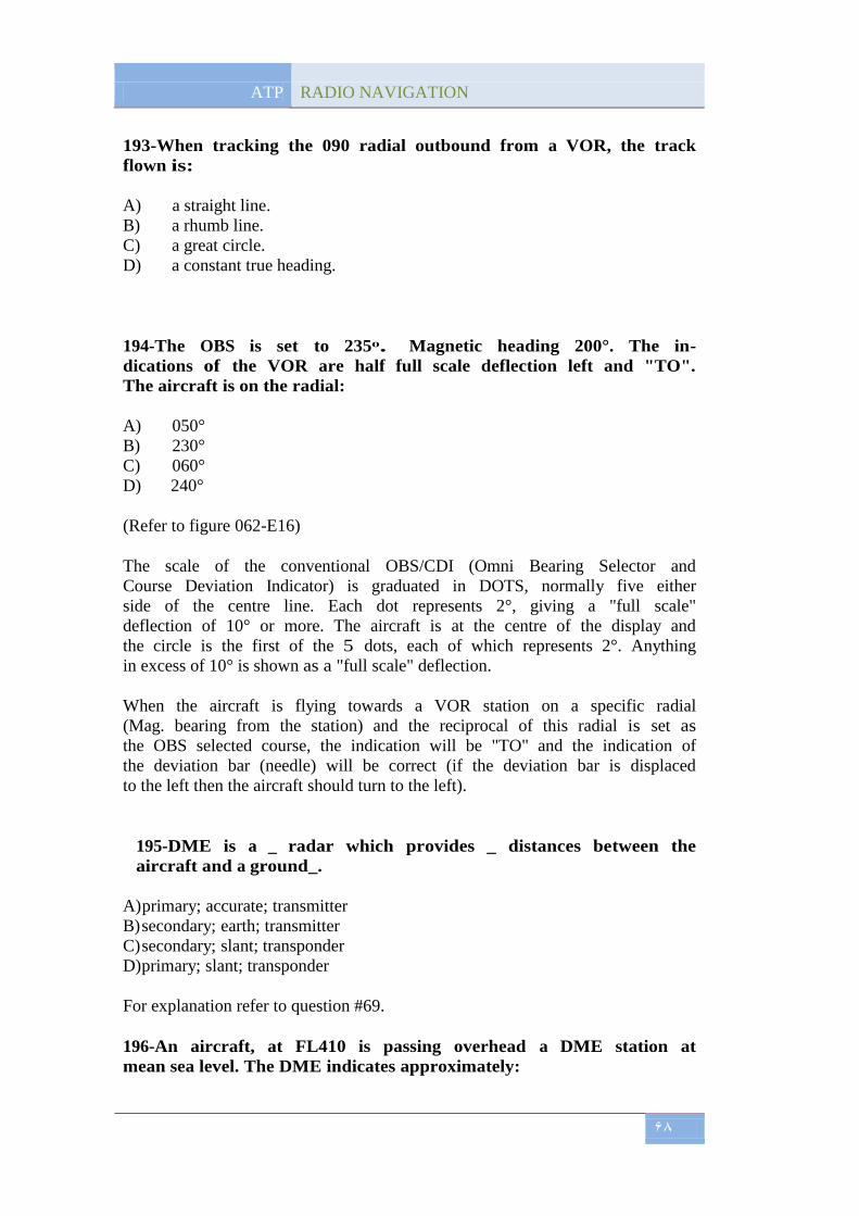
ATP RADIO NAVIGATION
68
193-When tracking the 090 radial outbound from a VOR, the track
flown is:
A) a straight line.
B) a rhumb line.
C) a great circle.
D) a constant true heading.
194-The OBS is set to 235ᵒ. Magnetic heading 200°. The in-
dications of the VOR are half full scale deflection left and "TO".
The aircraft is on the radial:
A) 050°
B) 230°
C) 060°
D) 240°
(Refer to figure 062-E16)
The scale of the conventional OBS/CDI (Omni Bearing Selector and
Course Deviation Indicator) is graduated in DOTS, normally five either
side of the centre line. Each dot represents 2°, giving a "full scale"
deflection of 10° or more. The aircraft is at the centre of the display and
the circle is the first of the 5 dots, each of which represents 2°. Anything
in excess of 10° is shown as a "full scale" deflection.
When the aircraft is flying towards a VOR station on a specific radial
(Mag. bearing from the station) and the reciprocal of this radial is set as
the OBS selected course, the indication will be "TO" and the indication of
the deviation bar (needle) will be correct (if the deviation bar is displaced
to the left then the aircraft should turn to the left).
195-DME is a _ radar which provides _ distances between the
aircraft and a ground_.
A) primary; accurate; transmitter
B) secondary; earth; transmitter
C) secondary; slant; transponder
D) primary; slant; transponder
For explanation refer to question #69.
196-An aircraft, at FL410 is passing overhead a DME station at
mean sea level. The DME indicates approximately:

ATP RADIO NAVIGATION
69
A) 6,8 km
B) 6,8 NM
C) 6,1 NM
D) 6,1 km
(Refer to figures 062-E92, 062-E93 and 062-E94)
DME computes the slant range (NM) from a ground facility. When
overhead the beacon, the read-out will indicate aircraft altitude in NM.
The difference between slant and true (plan) ranges is at a maximum
when the aircraft is overhead (note that, because of the radiation pattern
from the ground facility aerial, there is no guarantee that lock-on will be
maintained during the overhead). The difference remains meaningful
when the aircraft is high and close in to the beacon. As a rule, when the
slant range exceeds at least 3 times the aircraft altitude, the difference
may be considered negligible in practical terms. The relationship between
true range and slant range may be determined from the formula:
True range = √(Slant range2 - Aeroplane height
2)
Note: Ranges and heights must be in same units e.g. nautical miles.
In the case of this question:
·1 NM = 6080 ft
·41000 ft = 6,74 NM
When passing directly overhead the DME station at FL410 the DME
reading will be 6,74 NM.
197-DME uses a _ (i) radar principle in the _ (ii) band.
A) (i) primary; (ii) UHF
B) (i) primary; (ii) SHF
C) (i) secondary; (ii) UHF
D) (i) secondary; (ii) SHF
For explanation refer to question #69
198-An aircraft tracking to intercept the instrument Landing
System (ILS) localiser inbound on the approach side, outside the
published ILS coverage angle:
A) will receive signals without identification coding .
B) will not normally receive signals.
C) may receive false course indications .
D) can expect signals to give correct indications.

ATP RADIO NAVIGATION
70
199-The middle marker of an Instrument Landing System (ILS)
facility is identified audibly and visually by a series of:
A) alternate dots and dashes and an amber light flashing.
B) two dashes per second and a blue light flashing.
C) dots and a white light flashing.
D) dashes and an amber light flashing.
(Refer to figure 062-E90)
Marker beacons were installed as a means of providing the pilot on ILS
approach with distance information. Although, in recent years, it has been
the policy to introduce DMEs as the ranging component of the ILS -
particularly for CAT II and CAT III operations, marker beacons are still
widely used. There are normally 2, occasionally 3, marker beacons with
each (non-DME) ILS installation. All markers operate at a carrier
frequency of 75 MHz, are amplitude modulated, and are horizontally
polarized. All transmit a vertically disposed, narrow conical-shape beam
of elliptical cross-section arranged so that the minor axis is in line with
the localiser approach bearing - this is the reason why the marker beacon
transmissions do not interfere with each other (narrow vertical beam).
During the approach the duration of reception of each beacon is therefore
very short and, since low transmitter power limits the vertical penetration
to about 3000 ft; the markers are mutually non-interfering.
INNER Marker: The frequency of the modulating signal is 3000 Hz, the
white indicator lamp will flash, a high pitched 3000 Hz tone keyed to
form dots (“……”) at a rate of 6 per second will be heard. Touchdown
range 250 ft - 1500 ft (75 m - 450 my.
MIDDLE marker: The frequency of the modulating signal is 1300 Hz, the
amber indicator light flashes, a medium pitched 1300 Hz tone keyed to
form alternating dots and dashes ("-.-.-.-") will be heard. The rate is 2
dashes per second. Touchdown range approx. 1050 m (± 150 my.
OUTER marker: The frequency of the modulating signal is 400 Hz, the
blue indicator lamp will flash and a low-pitched 400 Hz tone, keyed to
form dashes (“----“) at a rate of 2 per second will be heard. Touchdown range
3,5 - 6 NM (6,5 - 11 km).
Another type of a marker beacon is the Airway marker. These are of
considerably higher power than the ILS markers and radiate a beam of
bone shaped cross section. They are used to mark pinpoints that cannot be
defined by the use of an NDB or a VOR because of the cone of confusion
associated with each of these facilities. The airway marker is becoming
very rear , as is the inner marker of ILS. Airway marker will typically
carry the same modulation as the ILS Inner marker.

ATP RADIO NAVIGATION
71
200-On a localizer the modulations are at 150 Hz and 90 Hz. Which
of the following statements is correct?
A) The 90 Hz modulation predominates to the right of the center line.
B) The 150 Hz modulation predominates to the right of the center line.
C) If the 150 Hz modulations predominates, the needle on the CDI
moves to the right of center.
D) When both modulations are received, the aeroplane will be on the
center line.
For explanation refer to question #142.


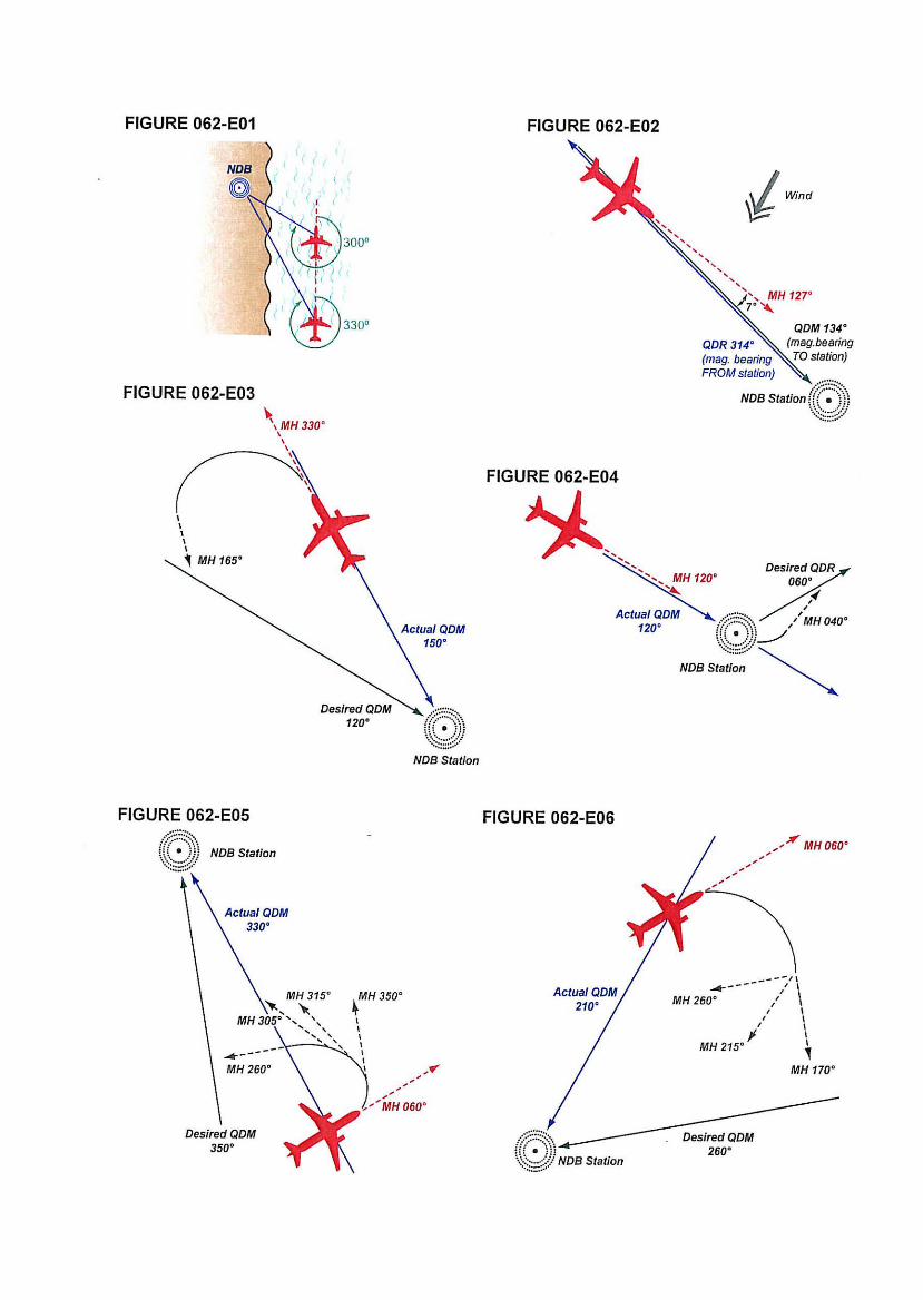


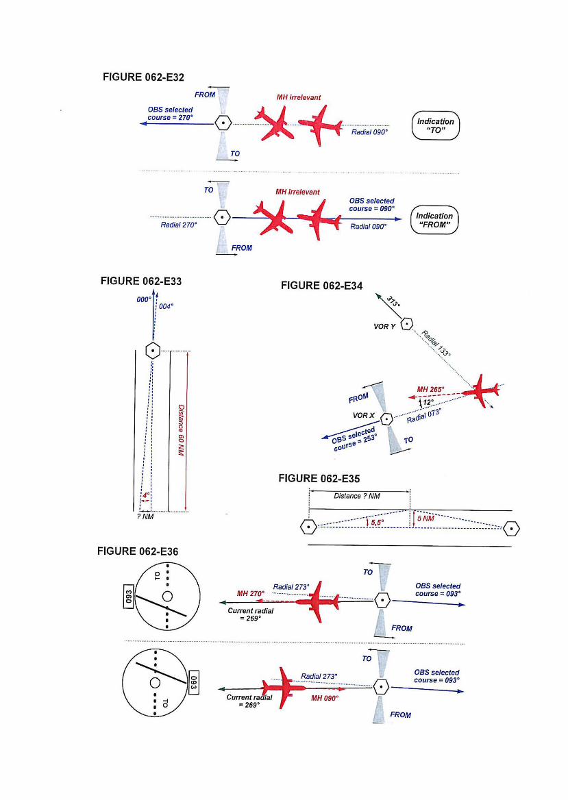


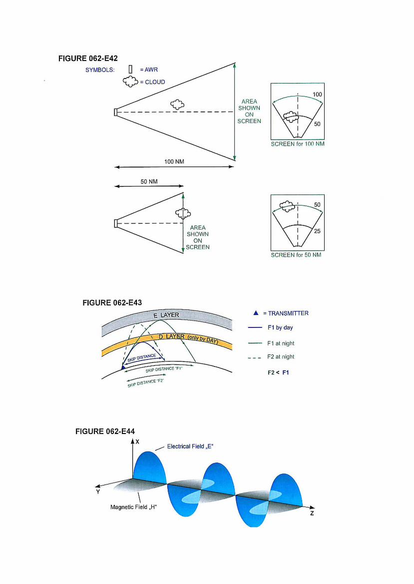


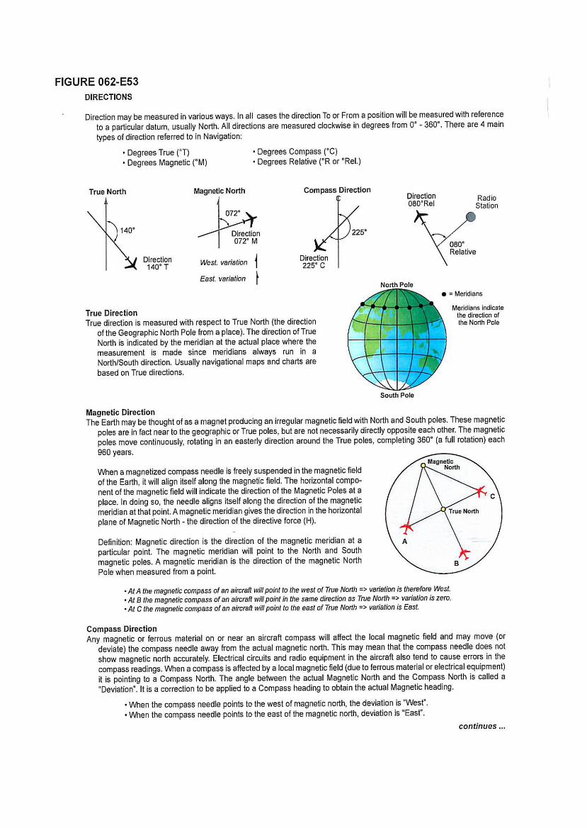


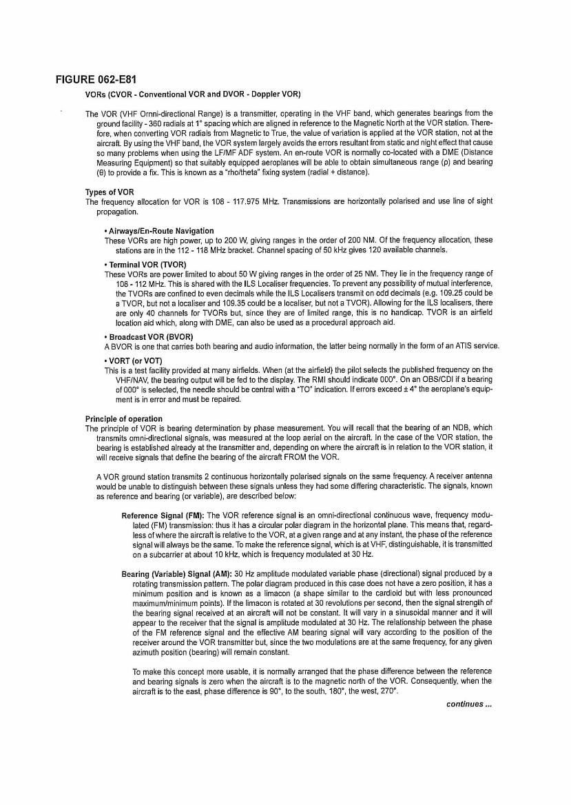


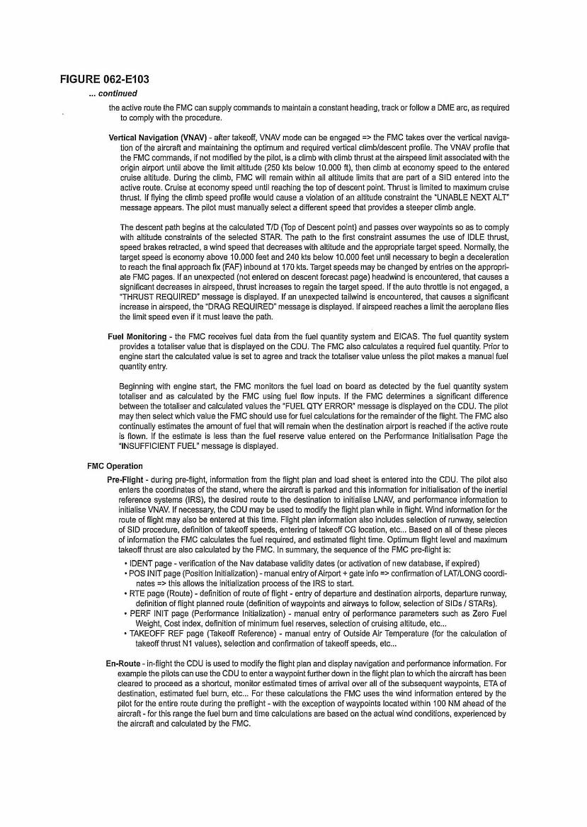


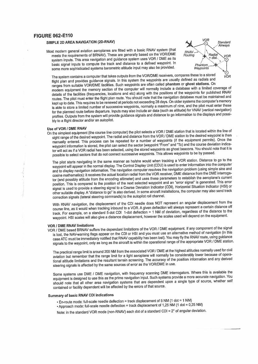

ATP [RADIO NAVIGATION]
1. D
2. A
3. C
4. D
5. C
6. B
7. A
8. D
9. D
10. C
11. C
12. B
13. C
14. C
15. D
16. B
17. B
18. B
19. C
20. B
21. A
22. B
23. C
24. B
25. C
26. A
27. A
28. B
29. B
30. A
31. D
32. D
33. B
34. C
35. B
36. B
37. A
38. A
39. D
40. B
41. A
42. A
43. B
44. C
45. A
46. C
47. A
48. B
49. B
50. C
51. D
52. B
53. C
54. C
55. D
56. D
57. D
58. A
59. A
60. C
61. B
62. C
63. C
64. D
65. B
66. D
67. C
68. B
69. A
70. C
71. B
72. C
73. A
74. C
75. C
76. A
77. A
78. D
79. A
80. C
81. A
82. B
83. C
84. D
85. B
86. A
87. C
88. B
89. B
90. D
91. C
92. D
93. D
94. C
95. D
96. A
97. C
98. D
99. C
100. A
101. B
102. A
103. D
104. D
105. A
106. B
107. C
108. C
109. B
110. A
111. D
112. B
113. B
114. B
115. B
116. B
117. D

ATP [RADIO NAVIGATION]
118. D
119. C
120. C
121. D
122. C
123. B
124. A
125. A
126. D
127. C
128. D
129. C
130. C
131. C
132. C
133. B
134. A
135. A
136. D
137. B
138. C
139. C
140. A
141. B
142. B
143. C
144. C
145. A
146. D
147. D
148. D
149. D
150. D
151. D
152. C
153. A
154. C
155. C
156. B
157. B
158. B
159. C
160. D
161. A
162. D
163. D
164. C
165. A
166. A
167. C
168. B
169. B
170. B
171. D
172. B
173. D
174. D
175. C
176. D
177. C
178. C
179. B
180. D
181. A
182. C
183. B
184. B
185. D
186. A
187. C
188. A
189. D
190. B
191. D
192. B
193. C
194. A
195. C
196. B
197. C
198. C
199. A
200. B