Catalytic Converters for Vehicle Exhaust - MDPI
17
Review Catalytic Converters for Vehicle Exhaust: Fundamental Aspects and Technology Overview for Newcomers to the Field Emmy Kritsanaviparkporn 1 , Francisco M. Baena-Moreno 1,2, * and T. R. Reina 1, * Citation: Kritsanaviparkporn, E.; Baena-Moreno, F.M.; Reina, T.R. Catalytic Converters for Vehicle Exhaust: Fundamental Aspects and Technology Overview for Newcomers to the Field. Chemistry 2021, 3, 630–646. https://doi.org/10.3390/ chemistry3020044 Academic Editor: Gianguido Ramis Received: 5 April 2021 Accepted: 12 May 2021 Published: 20 May 2021 Publisher’s Note: MDPI stays neutral with regard to jurisdictional claims in published maps and institutional affil- iations. Copyright: © 2021 by the authors. Licensee MDPI, Basel, Switzerland. This article is an open access article distributed under the terms and conditions of the Creative Commons Attribution (CC BY) license (https:// creativecommons.org/licenses/by/ 4.0/). 1 Department of Chemical and Process Engineering, University of Surrey, Guildford GU2 7XH, UK; [email protected] 2 Chemical and Environmental Engineering Department, Technical School of Engineering, University of Seville, C/Camino de los Descubrimientos s/n, 41092 Sevilla, Spain * Correspondence: [email protected] (F.M.B.-M.); [email protected] (T.R.R.) Abstract: This works aims to provide an understanding on basic chemical kinetics pertaining to three-way catalytic (TWC) converters from an educational perspective, aimed at those novel readers in this field. Rate of reactions and its factors are explained, showcasing that the chosen catalyst is the main factor affecting the overall rate of reaction. Furthermore, this overview revisit insights of the catalytic converter structure and the environmental issues that come along with it. Lastly, the chemical and physical properties of the reactants and products-pollutant and less-toxic gases—are discussed, in order to gather a better understanding of the reactants and products that enters a catalytic converter. Keywords: catalytic convertes; emissions; overview; catalysis 1. Introduction The use of fossil fuels in the transport sector has increased the greenhouse gas (GHG) emissions during the last decades [1,2]. Fossil transport fuels such as gasoline or diesel release exhaust gases composed by carbon dioxide (CO 2 ), methane (CH 4 ), nitrous oxide (N 2 O), carbon monoxide (CO) and hydrofluorocarbons (HFCs) [3]. Indeed, the GHG from the transport sector amounts 28% of the total US emissions [1]. This percentage is lower (19.4%) for European Union, but still important [4]. The reduction of these emissions are a big challenge for breaking the so called climate change cycle [5]. Some strategies have been proposed to solve the problem of emissions in the transport sector. Increasing the share of renewable energy and moving towards hydrogen as an energy vector are the preferred actions [6]. In fact, powering our vehicles through fuel cells or hydrogen internal combustion engines is already technically feasible [7], but overcoming the overall cost attached to these two technologies is still a challenge in the path towards a low-carbon transport sector [7]. In this line, other options must be explored. As presented in a recent review [8], advances in engine technologies are placing additional demands on emission control catalysts. In this sense, the use of catalytic converters to reduce exhaust gases from vehicles and converting them into unharmful compounds is widely extended [9]. Among catalytic converters, three-way catalytic (TWC) converters have been the state of the art technology since 1970 [10]. TWC converters are a tool used for reducing the emission of pollutant gases that are present in the exhaust gas released from an internal combustion engine of an automo- bile [11]. TWC is chosen over a two-way catalytic converter in automobiles because it can reduce the emissions of the N 2 O gases, as well as the emission of CO gas and unburned hydrocarbons. Two-way catalytic converters will only be able to reduce the emissions of CO gas and unburned hydrocarbons, due to the catalysts used and the reactions that occur [11]. By using the concept of heterogeneous catalysis and rate of reaction, a hon- eycomb ceramic structure (usually coated with Al 2 O 3 ), which acts as catalyst support, Chemistry 2021, 3, 630–646. https://doi.org/10.3390/chemistry3020044 https://www.mdpi.com/journal/chemistry
-
Upload
khangminh22 -
Category
Documents
-
view
3 -
download
0
Transcript of Catalytic Converters for Vehicle Exhaust - MDPI

Review
Catalytic Converters for Vehicle Exhaust: Fundamental Aspectsand Technology Overview for Newcomers to the Field
Emmy Kritsanaviparkporn 1, Francisco M. Baena-Moreno 1,2,* and T. R. Reina 1,*
�����������������
Citation: Kritsanaviparkporn, E.;
Baena-Moreno, F.M.; Reina, T.R.
Catalytic Converters for Vehicle
Exhaust: Fundamental Aspects and
Technology Overview for Newcomers
to the Field. Chemistry 2021, 3,
630–646. https://doi.org/10.3390/
chemistry3020044
Academic Editor: Gianguido Ramis
Received: 5 April 2021
Accepted: 12 May 2021
Published: 20 May 2021
Publisher’s Note: MDPI stays neutral
with regard to jurisdictional claims in
published maps and institutional affil-
iations.
Copyright: © 2021 by the authors.
Licensee MDPI, Basel, Switzerland.
This article is an open access article
distributed under the terms and
conditions of the Creative Commons
Attribution (CC BY) license (https://
creativecommons.org/licenses/by/
4.0/).
1 Department of Chemical and Process Engineering, University of Surrey, Guildford GU2 7XH, UK;[email protected]
2 Chemical and Environmental Engineering Department, Technical School of Engineering, University of Seville,C/Camino de los Descubrimientos s/n, 41092 Sevilla, Spain
* Correspondence: [email protected] (F.M.B.-M.); [email protected] (T.R.R.)
Abstract: This works aims to provide an understanding on basic chemical kinetics pertaining tothree-way catalytic (TWC) converters from an educational perspective, aimed at those novel readersin this field. Rate of reactions and its factors are explained, showcasing that the chosen catalyst isthe main factor affecting the overall rate of reaction. Furthermore, this overview revisit insights ofthe catalytic converter structure and the environmental issues that come along with it. Lastly, thechemical and physical properties of the reactants and products-pollutant and less-toxic gases—arediscussed, in order to gather a better understanding of the reactants and products that enters acatalytic converter.
Keywords: catalytic convertes; emissions; overview; catalysis
1. Introduction
The use of fossil fuels in the transport sector has increased the greenhouse gas (GHG)emissions during the last decades [1,2]. Fossil transport fuels such as gasoline or dieselrelease exhaust gases composed by carbon dioxide (CO2), methane (CH4), nitrous oxide(N2O), carbon monoxide (CO) and hydrofluorocarbons (HFCs) [3]. Indeed, the GHG fromthe transport sector amounts 28% of the total US emissions [1]. This percentage is lower(19.4%) for European Union, but still important [4]. The reduction of these emissions area big challenge for breaking the so called climate change cycle [5]. Some strategies havebeen proposed to solve the problem of emissions in the transport sector. Increasing theshare of renewable energy and moving towards hydrogen as an energy vector are thepreferred actions [6]. In fact, powering our vehicles through fuel cells or hydrogen internalcombustion engines is already technically feasible [7], but overcoming the overall costattached to these two technologies is still a challenge in the path towards a low-carbontransport sector [7]. In this line, other options must be explored. As presented in a recentreview [8], advances in engine technologies are placing additional demands on emissioncontrol catalysts. In this sense, the use of catalytic converters to reduce exhaust gases fromvehicles and converting them into unharmful compounds is widely extended [9]. Amongcatalytic converters, three-way catalytic (TWC) converters have been the state of the arttechnology since 1970 [10].
TWC converters are a tool used for reducing the emission of pollutant gases that arepresent in the exhaust gas released from an internal combustion engine of an automo-bile [11]. TWC is chosen over a two-way catalytic converter in automobiles because it canreduce the emissions of the N2O gases, as well as the emission of CO gas and unburnedhydrocarbons. Two-way catalytic converters will only be able to reduce the emissionsof CO gas and unburned hydrocarbons, due to the catalysts used and the reactions thatoccur [11]. By using the concept of heterogeneous catalysis and rate of reaction, a hon-eycomb ceramic structure (usually coated with Al2O3), which acts as catalyst support,
Chemistry 2021, 3, 630–646. https://doi.org/10.3390/chemistry3020044 https://www.mdpi.com/journal/chemistry
Chemistry 2021, 3 631
is used. The main reason is that it allows the best possible contact between the flowingexhaust gas and the catalyst surface [12]. The honeycomb ceramic structure is a catalystsupport that provides a large surface area, in order for redox reactions to take place ata higher rate and efficiency. A large surface area, along as temperature and pressure, isone of the main factors that provides a higher rate of reaction [13]. The structure is thencoated with a solution containing different noble metal nitrates such as palladium nitrate,rhodium nitrate and platinum nitrate [14]. The honeycomb structure facilitates the flow ofgas through the converter and controls any pressure drops.
Even though TWC converters are widely used commercially, and fundamental aspectsand technology have been described [15–20], a review from an educational perspectiveis still missing. Hence this work is a useful initial resource for newcomers to the field tofamiliarize them in a direct and clear manner with the main concepts and characteristicsof TWC technology. Therefore, the goal of this paper is to offer an overview of the mainfundamental working principles of TWC from an educational perspective. To this end, thiswork is organised as follows. First, the working principles of TWC converters are explained.Afterwards, the most common structures used for the devices are reviewed, along with thetypical working conditions for a TWC. The rates of reaction are subsequently provided,focusing finally on pollutant gases reduction.
2. Working Principles of Three-Way Catalytic Converters
Internal combustion engines use the exhaust stroke to expel the spent gases, via theexhaust system, where the harmful emissions are then passed through a muffler-typelooking device which is the catalytic converter [12,21]. Components of the spent gasesconsist of unburned hydrocarbons, NO, and CO [21]. As mentioned above, the mainpurpose of the catalytic converter is to reduce the original harmful emissions to the mostacceptable levels, by the means of catalyst controlled chemical reactions. Therefore, thereare needs to be the most careful attention to the engine design, before venting out the gasinto the air [12].
The majority of automobile catalytic converters have a design of a monolithic structure,which is coated with an alumina washcoat. The monolithic structure is referred to as thecore of the catalytic converter, where the core is typically a ceramic monolith with ahoneycomb configuration. The purpose of the honeycomb structure is to allow for theheterogeneous catalysis to occur on the surface of the honeycomb structure. Metallicmonolith is made out of FeCrAl where it has high heat resistance. The washcoat can alsoconsist of aluminum oxide, silicon dioxide, titanium dioxide or a mixture of silica andalumina [22].
Catalytic converters use metallic catalysts to promote the desired reactions at lowertemperatures [14]. Common metal catalysts used could be a base metal (such as chromium)and noble metals, such as platinum, palladium, and rhodium [14]. These catalysts can beused for redox reactions; the reduction of N2O and the oxidation of unburned hydrocarbonsand CO. If platinum, palladium, and rhodium metals are used, these can be a part ofthe Platinum Group of Metals Solution (PGM Solution), which is also used to coat thehoneycomb structure. This would allow for heterogeneous catalysis to take place on thesurface of the core, allowing for the production of less toxic gases (CO2, nitrogen and watervapour) to be produced [23].
Another component of the catalytic converter is its metal casing that surrounds thecore of the catalytic converter. This metal casing directs the exhaust gas flow throughthe catalyst bed. The metal casing is usually made out of stainless steel, but since low-temperature catalysts are used, stainless steel may not be necessary for the construction ofthe catalytic converter [24]. A diagram of a TWC converter is shown in Figure 1.

Chemistry 2021, 3 632
Chemistry 2021, 3, FOR PEER REVIEW 3
honeycomb the flow of gas through the converter and controls pressure drop. Since the composition of the exhaust gas also contains oxygen gas and the pollutant gases (CO, N2O and unburned hydrocarbons), oxygen atoms are made available to react with the other adsorbed pollutant gases. In the case of CO, the oxygen atom reacts with CO yielding CO2, and so, as the final step in heterogeneous catalysis, CO2 desorbs from the metal surface and is released as a product out of the catalytic converter. This concept is identical for both the N2O and the unburned hydrocarbons.
Figure 1. Automobile catalytic converter. Adapted from [25,26].
Briefly, in a TWC converter, the simultaneous redox reactions consist of a three-way system which controls emissions by oxidation of the unburned hydrocarbons and CO and by the reduction of the NOX [27], (unlike two-way catalytic converters, where only 2 oxidation reactions occurs, so the N2O are not reduced), so the three-way catalytic converter would have the following functions: (1) Oxidation of unburned hydrocarbons, where oxygen gas is present in the exhaust
gas, has its bonds broken and the oxygen atom reacts with the unburned hydrocarbons to produce CO2 and water vapour as the final products. An example would be the oxidation of benzene (Equation (1)): 2𝐶 𝐻 15𝑂 → 12𝐶𝑂 2𝐻 𝑂 (1)
In this particular reaction, palladium or platinum would be used. Even though palladium and platinum both have similar chemical properties [28], palladium would be preferred over platinum because of the decline in effectiveness of the converter, which means that platinum deactivates faster than palladium, therefore the converter efficiency would decrease very fast [29]. (2) Oxidation of CO to form CO2 by using either catalysts platinum or palladium nitrate.
Oxygen gas that is present in exhaust gases is adsorbed to the surface of the honeycomb ceramic, and so the oxygen bond is weakened and so the oxygen atom reacts with CO to give CO2 (Equation (2)): 𝐶𝑂 𝑂 → 𝐶𝑂 (2)
Either platinum of palladium can be used as a catalyst for this reaction, as they both have very similar physical and chemical properties.
Figure 1. Automobile catalytic converter. Adapted from [25,26].
The initial step in heterogeneous catalysis is the adsorption of the reactants, whereadsorption refers to the binding of molecules to a surface [12]. Adsorption would occurbecause of the high reactivity of the atoms/ions on the surface of the solid, facilitating thehoneycomb the flow of gas through the converter and controls pressure drop. Since thecomposition of the exhaust gas also contains oxygen gas and the pollutant gases (CO, N2Oand unburned hydrocarbons), oxygen atoms are made available to react with the otheradsorbed pollutant gases. In the case of CO, the oxygen atom reacts with CO yielding CO2,and so, as the final step in heterogeneous catalysis, CO2 desorbs from the metal surfaceand is released as a product out of the catalytic converter. This concept is identical for boththe N2O and the unburned hydrocarbons.
Briefly, in a TWC converter, the simultaneous redox reactions consist of a three-waysystem which controls emissions by oxidation of the unburned hydrocarbons and COand by the reduction of the NOX [27], (unlike two-way catalytic converters, where only2 oxidation reactions occurs, so the N2O are not reduced), so the three-way catalyticconverter would have the following functions:
(1) Oxidation of unburned hydrocarbons, where oxygen gas is present in the exhaust gas,has its bonds broken and the oxygen atom reacts with the unburned hydrocarbonsto produce CO2 and water vapour as the final products. An example would be theoxidation of benzene (Equation (1)):
2C6H6(g) + 15O2(g) → 12CO2(g) + 2H2O(l) (1)
In this particular reaction, palladium or platinum would be used. Even thoughpalladium and platinum both have similar chemical properties [28], palladium would bepreferred over platinum because of the decline in effectiveness of the converter, whichmeans that platinum deactivates faster than palladium, therefore the converter efficiencywould decrease very fast [29].
(2) Oxidation of CO to form CO2 by using either catalysts platinum or palladium nitrate.Oxygen gas that is present in exhaust gases is adsorbed to the surface of the honey-comb ceramic, and so the oxygen bond is weakened and so the oxygen atom reactswith CO to give CO2 (Equation (2)):
CO(g) + O2(g) → CO2(g) (2)

Chemistry 2021, 3 633
Either platinum of palladium can be used as a catalyst for this reaction, as they bothhave very similar physical and chemical properties.
(3) Reduction of N2O to give stable nitrogen and oxygen gas (Equation (3)). Since this isa reduction reaction, rhodium is used instead. Since it is a rare type of noble metal,rhodium is usually alloyed with platinum or palladium.
2NOX(g) → XO2(g) + N2(g) (3)
Rhodium metal is used for this reduction reaction because it is an oxidising agent(a substance that loses electrons), compared to the other reducing agents, palladium andplatinum. For these redox reactions the amount of oxygen gas present in the exhaustgas is a critical parameter. If there was a higher concentration of oxygen gas present inthe exhaust gas than required, the system is defined as lean, so oxidation of unburnedhydrocarbons and CO would more likely occur, as there is less fuel in the automobile.However, if there is a lower concentration of oxygen gas present in the exhaust gas, thesystem is defined as rich, so reduction of N2O are more likely to occur as there is a higherconcentration of fuel than needed. Therefore, the efficiency of catalytic converters are notalways 100% efficient [11].
In order to achieve the best efficiency of a catalytic converter, the fuel/air ratio, whichdefines how much fuel or excess air is inside the catalytic converter, can be measuredusing a feedback control loop system, where the metering of the fuel needs to be preciselymeasured, and the concentration of the oxygen leaving the catalytic converter is measuredusing a specific sensor [27].
3. Structure of Three-Way Catalytic Converters
To construct a catalytic converter, the following components must be considered:
(1) Catalyst Core (substrate).
Typically, for a catalytic converter, the core is an open-channel ceramic monolith oreither a metallic honeycomb substrate that provides an area for the catalyst [30]. Themost commonly used structure, the honeycomb ceramic, is designed to maximize thesurface area (Figure 2) [31]. A larger surface area would result in a higher reaction rate [32].Cordierite (2MgO-2Al2O3-5SiO2) is the most commonly used type of monolith because ithas a high surface area, large open frontal area, low heat capacity, and good mechanicalstrength [30,33]. Figure 2 displays how the catalyst is placed on the monolith channel.
Chemistry 2021, 3, FOR PEER REVIEW 4
(3) Reduction of N2O to give stable nitrogen and oxygen gas (Equation (3)). Since this is a reduction reaction, rhodium is used instead. Since it is a rare type of noble metal, rhodium is usually alloyed with platinum or palladium. 2𝑁𝑂 → 𝑋𝑂 𝑁 (3)
Rhodium metal is used for this reduction reaction because it is an oxidising agent (a substance that loses electrons), compared to the other reducing agents, palladium and platinum. For these redox reactions the amount of oxygen gas present in the exhaust gas is a critical parameter. If there was a higher concentration of oxygen gas present in the exhaust gas than required, the system is defined as lean, so oxidation of unburned hydrocarbons and CO would more likely occur, as there is less fuel in the automobile. However, if there is a lower concentration of oxygen gas present in the exhaust gas, the system is defined as rich, so reduction of N2O are more likely to occur as there is a higher concentration of fuel than needed. Therefore, the efficiency of catalytic converters are not always 100% efficient [11].
In order to achieve the best efficiency of a catalytic converter, the fuel/air ratio, which defines how much fuel or excess air is inside the catalytic converter, can be measured using a feedback control loop system, where the metering of the fuel needs to be precisely measured, and the concentration of the oxygen leaving the catalytic converter is measured using a specific sensor [27].
3. Structure of Three-Way Catalytic Converters To construct a catalytic converter, the following components must be considered:
(1) Catalyst Core (substrate). Typically, for a catalytic converter, the core is an open-channel ceramic monolith or
either a metallic honeycomb substrate that provides an area for the catalyst [30]. The most commonly used structure, the honeycomb ceramic, is designed to maximize the surface area (Figure 2) [31]. A larger surface area would result in a higher reaction rate [32]. Cordierite (2MgO-2Al2O3-5SiO2) is the most commonly used type of monolith because it has a high surface area, large open frontal area, low heat capacity, and good mechanical strength [30,33]. Figure 2 displays how the catalyst is placed on the monolith channel.
Figure 2. Reactants passing through a single monolith channel and exiting as products. Monolith wall = solid grey colour, secondary support = black and catalyst layer = green. Adapted from [34,35].
Figure 2. Reactants passing through a single monolith channel and exiting as products. Monolith wall = solid grey colour,secondary support = black and catalyst layer = green. Adapted from [34,35].

Chemistry 2021, 3 634
(2) Washcoat
A coat of supported catalysts is applied to the surface of the honeycomb ceramicstructure. A thin coating of a wet-based slurry is directly applied on the highly porousmaterial, which contains alumina as well as different metal oxides or zeolites [36]. Thehoneycomb ceramic structure is usually coated with γ-Al2O3, due to its high resistancetowards higher temperatures [14], which contains the catalyst materials of about 0.1–0.15%,20% cerium oxide, and stabilisers such as barium oxide. Rare earth and alkaline ions canimprove stabilisation [14]. Cerium oxide is mixed with the catalyst materials as it is usedto improve the thermal stability of alumina, and can store and release O2 in, respectively,lean and rich conditions [37]. This thin coating of the wet based slurry is then dried up andcalcined, which is the heating of solids to a high temperature to remove volatile substances.
There has been research done to directly apply the metal catalysts onto the surfaceof the honeycomb ceramic without the involvement of drying and calcination. Accordingto [38], this method involves the use of electrolysis (the electroplating technique), wherea washcoat of γ-Al2O3 on nickel oxide (NiO) catalyst is electroplated onto the FeCrAlsubstrate; the honeycomb ceramic is submerged into a solution and alumina ions aredirectly transferred to the honeycomb surface. A schematic diagram showing the set-upof the experiment is shown in Figure 3. As a result, [38] concluded that the CO emissionswere below 7 ppm when a catalytic converter of this experiment was used.
Chemistry 2021, 3, FOR PEER REVIEW 5
material, which contains alumina as well as different metal oxides or zeolites [36]. The honeycomb ceramic structure is usually coated with γ-Al2O3, due to its high resistance towards higher temperatures [14], which contains the catalyst materials of about 0.1–0.15%, 20% cerium oxide, and stabilisers such as barium oxide. Rare earth and alkaline ions can improve stabilisation [14]. Cerium oxide is mixed with the catalyst materials as it is used to improve the thermal stability of alumina, and can store and release O2 in, respectively, lean and rich conditions [37]. This thin coating of the wet based slurry is then dried up and calcined, which is the heating of solids to a high temperature to remove volatile substances.
There has been research done to directly apply the metal catalysts onto the surface of the honeycomb ceramic without the involvement of drying and calcination. According to [38], this method involves the use of electrolysis (the electroplating technique), where a washcoat of γ-Al2O3 on nickel oxide (NiO) catalyst is electroplated onto the FeCrAl substrate; the honeycomb ceramic is submerged into a solution and alumina ions are directly transferred to the honeycomb surface. A schematic diagram showing the set-up of the experiment is shown in Figure 3. As a result, [38] concluded that the CO emissions were below 7 ppm when a catalytic converter of this experiment was used.
Figure 3. Schematic diagram of the electroplating process. Adapted from [38].
Washcoat materials are selected in order to form a rough, irregular surface, which will increase the surface area compared to the smooth surface of the substrate. This coat will protect the sintering of catalytic metal particles even at high temperatures that can go up to 1000 Degrees Celsius [39]. (3) Catalyst Solution
Noble metals are the most commonly used heterogeneous catalysts, as they can be made more thermally resistant to reduced low-temperature activity. Another excellent characteristic is that they provide equivalent catalytic activation with smaller volumes than do base metals. Therefore, a small number of noble metals in the form of a solution, such as palladium, platinum and rhodium nitrates, is used to coat on the surface of a honeycomb ceramic [14]. This type of heterogeneous catalyst solution, called a PGM Solution, is a solution of platinum group metals that are highly resistant to chemical attacks and have very high-temperature resistance and corrosion resistance [40], therefore deemed to be the most appropriate catalyst solution in a catalytic converter [41]. The PGM Solution contains platinum, palladium and rhodium, where its chemical and physical properties are shown in Table 1, and is coated onto the honeycomb ceramic structure, supported by a coat of supported catalysts of thermal resistant metals [41].
The quantity of platinum, palladium and rhodium used in auto catalysts depends on the vehicle type, manufacturer, country, year and additional factors [40]. In TWC Converters, the ratio of Pt/Rh is 5 to 1, and the ratio of Pd/Rh is 7 to 1 [40].
Figure 3. Schematic diagram of the electroplating process. Adapted from [38].
Washcoat materials are selected in order to form a rough, irregular surface, which willincrease the surface area compared to the smooth surface of the substrate. This coat willprotect the sintering of catalytic metal particles even at high temperatures that can go up to1000 Degrees Celsius [39].
(3) Catalyst Solution
Noble metals are the most commonly used heterogeneous catalysts, as they can bemade more thermally resistant to reduced low-temperature activity. Another excellentcharacteristic is that they provide equivalent catalytic activation with smaller volumes thando base metals. Therefore, a small number of noble metals in the form of a solution, such aspalladium, platinum and rhodium nitrates, is used to coat on the surface of a honeycombceramic [14]. This type of heterogeneous catalyst solution, called a PGM Solution, is asolution of platinum group metals that are highly resistant to chemical attacks and havevery high-temperature resistance and corrosion resistance [40], therefore deemed to be themost appropriate catalyst solution in a catalytic converter [41]. The PGM Solution containsplatinum, palladium and rhodium, where its chemical and physical properties are shownin Table 1, and is coated onto the honeycomb ceramic structure, supported by a coat ofsupported catalysts of thermal resistant metals [41].

Chemistry 2021, 3 635
Table 1. Chemical and physical properties of PGM metals. Adapted from [42].
Chemical Name (Symbol) Platinum (Pt) Palladium (Pd) Rhodium (Rh)
Density (g/cm3) 21.45 12.02 12.41Melting Point (◦C) 1769 1554 1960
Vickers Hardness No. 40 40 101Thermal Conductivity (W/M/◦C) 73 75 150
Tensile Strength (kg/mm2) 14 17 71
Physical Properties Soft, ductile and resistant to oxidation and hightemperature corrosion Excellent performance
The quantity of platinum, palladium and rhodium used in auto catalysts dependson the vehicle type, manufacturer, country, year and additional factors [40]. In TWCConverters, the ratio of Pt/Rh is 5 to 1, and the ratio of Pd/Rh is 7 to 1 [40].
As demand for TWC converters are increasing, the demand for PGM is also increas-ing [40]. About 15–20% of the world demand for platinum comes with recycling fromused catalytic converters, however, the amount of platinum required is not enough to meetthe growing world demand, hence the shrinking in platinum reserves and the increase inplatinum price. Therefore, the high value of PGM has stimulated the recovery of PGMfrom used catalytic converters [40], and it is widely practiced. One of the common methodsof PGM recovery is shown in Figure 4. Recovering PGM is very important as it providessupplementary source to the mining of these metals, therefore protecting the environmentby limiting the number of waste disposal, saving natural resources exploitation, limitingelectricity consumption and diminishing pollutant emission [40].
Chemistry 2021, 3, FOR PEER REVIEW 6
Table 1. Chemical and physical properties of PGM metals. Adapted from [42].
Chemical Name (Symbol) Platinum (Pt) Palladium (Pd) Rhodium (Rh) Density (g/cm3) 21.45 12.02 12.41
Melting Point (°C) 1769 1554 1960 Vickers Hardness No. 40 40 101 Thermal Conductivity
(W/M/°C) 73 75 150
Tensile Strength (kg/mm2) 14 17 71
Physical Properties Soft, ductile and resistant to oxidation and high
temperature corrosion Excellent performance
As demand for TWC converters are increasing, the demand for PGM is also increasing [40]. About 15–20% of the world demand for platinum comes with recycling from used catalytic converters, however, the amount of platinum required is not enough to meet the growing world demand, hence the shrinking in platinum reserves and the increase in platinum price. Therefore, the high value of PGM has stimulated the recovery of PGM from used catalytic converters [40], and it is widely practiced. One of the common methods of PGM recovery is shown in Figure 4. Recovering PGM is very important as it provides supplementary source to the mining of these metals, therefore protecting the environment by limiting the number of waste disposal, saving natural resources exploitation, limiting electricity consumption and diminishing pollutant emission [40].
Figure 4. Main steps to recover PGM from used catalytic converters. Adapted from [40].
(4) Metal Casing Due to mechanical vibrations inside the car and thermal stresses, the metal casing is
essential [43]. Furthermore, a metal casing is used to direct the exhaust gas flow, since gas flow is a scalar quantity (only has a magnitude but no direction). High thermal stress can alter the shape of the substrate easily, so a metal casing is required to hold the ceramic together. At high thermal stress, this can result in permanent plastic deformations [43]. The metal casing can be produced through the canning process. A thinned wall metal casing is desired [44], as this can allow better heat transfer to the surroundings, to prevent the catalytic converter from reaching temperatures of up to 1000 °C. However, the question of durability and efficiency is considered, as high temperatures can result in deformation of the catalytic converter [45,46].
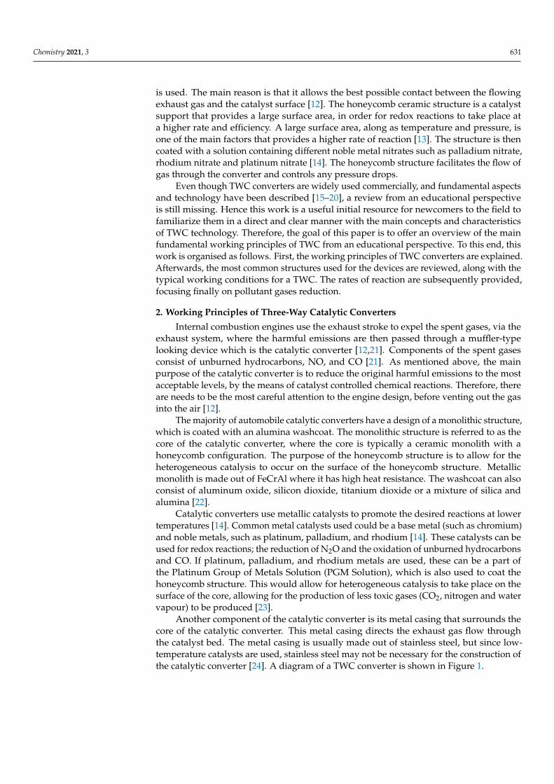
In another design, the option of using a support mat is considered, where it is placed in between the honeycomb ceramic and the steel casing acting as thermal insulation. A schematic diagram is shown in Figure 5. A support mat purpose is to act as a mechanical support of the monolith, provide thermal insulation and minimize the potential for shell deformation [45]. Shells may be a variety of grades of stainless steel and are an integral part of the exhaust system. Therefore, the designer should take the thermal expansion differences and yield strengths of various materials into consideration [45]. Substrate and the steel shell of the catalytic converter have different thermal coefficients of thermal expansion, so there is a gap present between both sections. The gap expands and contracts as the converter cycles in temperature during its use [45]. Gap expansion can be minimized by adjusting the material of the stainless-steel shell, where it is suggested to use ferritic steel shells (SS409), where is has about 50% lower thermal expansion compared to austenitic (SS310) [45,47].
Figure 4. Main steps to recover PGM from used catalytic converters. Adapted from [40].
(4) Metal Casing
Due to mechanical vibrations inside the car and thermal stresses, the metal casingis essential [43]. Furthermore, a metal casing is used to direct the exhaust gas flow, sincegas flow is a scalar quantity (only has a magnitude but no direction). High thermal stresscan alter the shape of the substrate easily, so a metal casing is required to hold the ceramictogether. At high thermal stress, this can result in permanent plastic deformations [43]. Themetal casing can be produced through the canning process. A thinned wall metal casingis desired [44], as this can allow better heat transfer to the surroundings, to prevent thecatalytic converter from reaching temperatures of up to 1000 ◦C. However, the question ofdurability and efficiency is considered, as high temperatures can result in deformation ofthe catalytic converter [45,46].
In another design, the option of using a support mat is considered, where it is placedin between the honeycomb ceramic and the steel casing acting as thermal insulation. Aschematic diagram is shown in Figure 5. A support mat purpose is to act as a mechanicalsupport of the monolith, provide thermal insulation and minimize the potential for shelldeformation [45]. Shells may be a variety of grades of stainless steel and are an integralpart of the exhaust system. Therefore, the designer should take the thermal expansiondifferences and yield strengths of various materials into consideration [45]. Substrateand the steel shell of the catalytic converter have different thermal coefficients of thermalexpansion, so there is a gap present between both sections. The gap expands and contractsas the converter cycles in temperature during its use [45]. Gap expansion can be minimizedby adjusting the material of the stainless-steel shell, where it is suggested to use ferritic steelshells (SS409), where is has about 50% lower thermal expansion compared to austenitic(SS310) [45,47].
Chemistry 2021, 3 636Chemistry 2021, 3, FOR PEER REVIEW 7
Figure 5. Diagram of converter with the mat. Adapted from [45].
4. Conditions in Catalytic Converters 4.1. Temperature
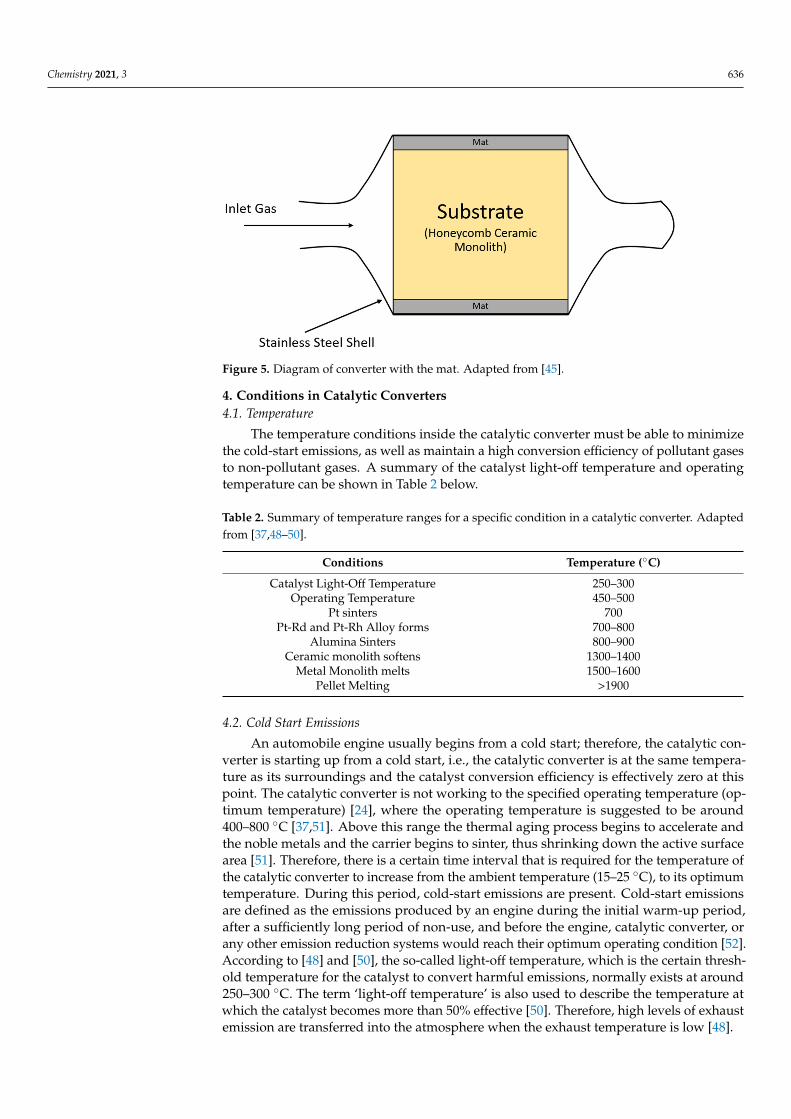
The temperature conditions inside the catalytic converter must be able to minimize the cold-start emissions, as well as maintain a high conversion efficiency of pollutant gases to non-pollutant gases. A summary of the catalyst light-off temperature and operating temperature can be shown in Table 2 below.
Table 2. Summary of temperature ranges for a specific condition in a catalytic converter. Adapted from [37,48–50].
Conditions Temperature (°C) Catalyst Light-Off Temperature 250–300
Operating Temperature 450–500 Pt sinters 700
Pt-Rd and Pt-Rh Alloy forms 700–800 Alumina Sinters 800–900
Ceramic monolith softens 1300–1400 Metal Monolith melts 1500–1600
Pellet Melting >1900
4.2. Cold Start Emissions An automobile engine usually begins from a cold start; therefore, the catalytic
converter is starting up from a cold start, i.e., the catalytic converter is at the same temperature as its surroundings and the catalyst conversion efficiency is effectively zero at this point. The catalytic converter is not working to the specified operating temperature (optimum temperature) [24], where the operating temperature is suggested to be around 400–800 °C [37,51]. Above this range the thermal aging process begins to accelerate and the noble metals and the carrier begins to sinter, thus shrinking down the active surface area [51]. Therefore, there is a certain time interval that is required for the temperature of the catalytic converter to increase from the ambient temperature (15–25 °C), to its optimum temperature. During this period, cold-start emissions are present. Cold-start emissions are defined as the emissions produced by an engine during the initial warm-up period, after a sufficiently long period of non-use, and before the engine, catalytic converter, or any other emission reduction systems would reach their optimum operating condition [52]. According to [48] and [50], the so-called light-off temperature, which is the certain threshold temperature for the catalyst to convert harmful emissions, normally exists at around 250–300 °C. The term ‘light-off temperature’ is also used to describe the temperature at which the catalyst becomes more than 50% effective [50]. Therefore, high
Figure 5. Diagram of converter with the mat. Adapted from [45].
4. Conditions in Catalytic Converters4.1. Temperature
The temperature conditions inside the catalytic converter must be able to minimizethe cold-start emissions, as well as maintain a high conversion efficiency of pollutant gasesto non-pollutant gases. A summary of the catalyst light-off temperature and operatingtemperature can be shown in Table 2 below.
Table 2. Summary of temperature ranges for a specific condition in a catalytic converter. Adaptedfrom [37,48–50].
Conditions Temperature (◦C)
Catalyst Light-Off Temperature 250–300Operating Temperature 450–500
Pt sinters 700Pt-Rd and Pt-Rh Alloy forms 700–800
Alumina Sinters 800–900Ceramic monolith softens 1300–1400
Metal Monolith melts 1500–1600Pellet Melting >1900
4.2. Cold Start Emissions
An automobile engine usually begins from a cold start; therefore, the catalytic con-verter is starting up from a cold start, i.e., the catalytic converter is at the same tempera-ture as its surroundings and the catalyst conversion efficiency is effectively zero at thispoint. The catalytic converter is not working to the specified operating temperature (op-timum temperature) [24], where the operating temperature is suggested to be around400–800 ◦C [37,51]. Above this range the thermal aging process begins to accelerate andthe noble metals and the carrier begins to sinter, thus shrinking down the active surfacearea [51]. Therefore, there is a certain time interval that is required for the temperature ofthe catalytic converter to increase from the ambient temperature (15–25 ◦C), to its optimumtemperature. During this period, cold-start emissions are present. Cold-start emissionsare defined as the emissions produced by an engine during the initial warm-up period,after a sufficiently long period of non-use, and before the engine, catalytic converter, orany other emission reduction systems would reach their optimum operating condition [52].According to [48] and [50], the so-called light-off temperature, which is the certain thresh-old temperature for the catalyst to convert harmful emissions, normally exists at around250–300 ◦C. The term ‘light-off temperature’ is also used to describe the temperature atwhich the catalyst becomes more than 50% effective [50]. Therefore, high levels of exhaustemission are transferred into the atmosphere when the exhaust temperature is low [48].

Chemistry 2021, 3 637
Cold start emissions are considered a problem in the automobile industry becausepollutant gases are emitted to the surroundings when the catalytic converter is startingup [48,49,53]. In a study recently conducted [48], it was found that the maximum concen-trations of CO and unburned hydrocarbons that we emitted out of the exhaust engineranged from 950 ppm to 8400 ppm and from 220 ppm to 28,000 ppm, respectively. Highemissions of these pollutant gas were caused by poor cylinder combustion and catalystefficiency. These two aspects were improved in [48]. Various techniques such as using theretard ignition timing method, adjusting the air/fuel ratio inside the catalytic converterand the use of thermal insultation materials were used, as one of the few key thermalmanagement techniques to control the emission of exhaust gases. Table 3 summarises just afew key thermal management methods to minimize the light-off period and the cumulativeemission of exhaust gases.
Table 3. Overview of catalyst light-off time reductions and the cumulative emission reductions with different thermalmanagement methods. Adapted from [48].
Thermal Management Methods Light-off Time Reduction Cumulative Emission Reduction
Start of combustion delay 80% n.a.Higher idle speed 90% n.a.
Variable Valve Timing n.a. 30%Air/fuel ratio adjustment n.a. n.a.
After-treatment layout 26% n.a.Burner 40% n.a.
Reformer 50% n.a.Thermal energy storage device 70% n.a.
EHC 50% n.a.Coolant and Lubricating Oil Heating n.a. 20%
The main methods to shorten the warm-up period would be heating with electricalpower, heating with an external combustion chamber, and installing an auxiliary small-capacity catalytic converter [54]. However, they all employ active means which wouldrequire an external energy source along with a control unit.
4.3. Catalyst Conversion Efficiency
As the temperature of the catalyst increases, the catalyst conversion efficiency wouldincrease for CO and unburned hydrocarbons [50]. To obtain the catalyst conversionefficiency mathematically, which is the ratio of the rate of mass removal in the catalyst of aparticular constituent of interest to the mass flow rate of that constituent into the catalyst,Equation (4) for unburned is used [50]. There is a positive correlation between the catalystconversion efficiency and the temperature (Figure 6).
ηcat =
.mHC,in −
.mHC,out
.mHC,in
(4)
Figure 6 shows a positive trend as the temperature increases, the catalyst conversionefficiency increases. At high enough temperatures of around 350 to 450 ◦C as shown on thegraph, the steady-state conversion efficiencies of CO and HC are typically 98–99 percentand 95 percent or above, respectively [50].
High temperatures were once the limiting factor for converter designs, as highertemperatures can lead to sintering, resulting in a decrease in fraction of metal availablefor catalytic reactions to occur as well as increased aging of coating when the gas inlettemperatures into the converter is above 850 ◦C [49]. As a result, new washcoat formula-tions were developed, where gas inlet temperatures of 1050 ◦C can be attained without theimpairment of the coating; high temperature coating of 1050 ◦C for 24 h can still maintain avery high conversion efficiency for hydrocarbons at 98% [49].

Chemistry 2021, 3 638Chemistry 2021, 3, FOR PEER REVIEW 9
Figure 6. Conversion efficiency for CO and HC as a function of temperature for a typical oxidizing catalytic converter. Adapted from [50].
Figure 6 shows a positive trend as the temperature increases, the catalyst conversion efficiency increases. At high enough temperatures of around 350 to 450 °C as shown on the graph, the steady-state conversion efficiencies of CO and HC are typically 98–99 percent and 95 percent or above, respectively [50].
High temperatures were once the limiting factor for converter designs, as higher temperatures can lead to sintering, resulting in a decrease in fraction of metal available for catalytic reactions to occur as well as increased aging of coating when the gas inlet temperatures into the converter is above 850 °C [49]. As a result, new washcoat formulations were developed, where gas inlet temperatures of 1050 °C can be attained without the impairment of the coating; high temperature coating of 1050 °C for 24 h can still maintain a very high conversion efficiency for hydrocarbons at 98% [49].
Furthermore, from [48], in order to maintain the temperature of the catalyst to work at its optimum, suggestions of improving the insulating material was discussed. A study from this paper showed that the effect of partially ceramic coated pistons on the cold-start emissions of engine would increase the temperature by around 100 °C, as well as reduce the peak values of Hydrocarbon emission by up to 15%. Furthermore, the efficiency of a precious metal-containing catalyst declines very steeply for a temperature below 350 °C, and cites the importance of using phase-change-material, so some of the thermal energy of exhaust gases are stored within the phase-changing material where the catalyst would be embedded [54].
In summary, if the catalysts is at its optimum at a lower operating temperature of around 300 °C, then a washcoat applied must be improved to withstand higher temperatures during the cold start period i.e., the wash coat needs to be able to withstand temperatures of around 950 to 1050 °C [24]. Furthermore, since it is expected that catalysts work at a lower temperature, expensive stainless steel is not required during the construction of the catalytic converter [24].
4.4. Pressure The pressure drop is considered an important design parameter as it represents
energy loss [38], and an increase in pressure drop can be an indication that catalyst plugging may occur [31]. When designing the monolithic substrates, there must be a trade-off between the pressure drop and the total geometric surface. This is because due to increasing pressure drop is a major issue as there is significant engine loss in terms of power and fuel economy [55]. According to [55], an engine will lose about 300W of power per 1000 Pa of pressure loss. However, increasing the total geometric surface area i.e., the higher the cpsi, the higher the conversion is [31]. Studies and experiments have been
Figure 6. Conversion efficiency for CO and HC as a function of temperature for a typical oxidizingcatalytic converter. Adapted from [50].
Furthermore, from [48], in order to maintain the temperature of the catalyst to workat its optimum, suggestions of improving the insulating material was discussed. A studyfrom this paper showed that the effect of partially ceramic coated pistons on the cold-startemissions of engine would increase the temperature by around 100 ◦C, as well as reducethe peak values of Hydrocarbon emission by up to 15%. Furthermore, the efficiency of aprecious metal-containing catalyst declines very steeply for a temperature below 350 ◦C,and cites the importance of using phase-change-material, so some of the thermal energy ofexhaust gases are stored within the phase-changing material where the catalyst would beembedded [54].
In summary, if the catalysts is at its optimum at a lower operating temperature ofaround 300 ◦C, then a washcoat applied must be improved to withstand higher tem-peratures during the cold start period i.e., the wash coat needs to be able to withstandtemperatures of around 950 to 1050 ◦C [24]. Furthermore, since it is expected that cat-alysts work at a lower temperature, expensive stainless steel is not required during theconstruction of the catalytic converter [24].
4.4. Pressure
The pressure drop is considered an important design parameter as it represents energyloss [38], and an increase in pressure drop can be an indication that catalyst plugging mayoccur [31]. When designing the monolithic substrates, there must be a trade-off betweenthe pressure drop and the total geometric surface. This is because due to increasingpressure drop is a major issue as there is significant engine loss in terms of power and fueleconomy [55]. According to [55], an engine will lose about 300W of power per 1000 Pa ofpressure loss. However, increasing the total geometric surface area i.e., the higher the cpsi,the higher the conversion is [31]. Studies and experiments have been conducted to minimizethe pressure drop, usually to adjust the substrate geometry and the flow distribution.
Experiments to adjust the geometry of the honeycomb ceramic were done to optimizethe flow distribution inside the catalytic converter so the pressure drop remains low. Beforecatalytic converter technologies were improved, substrate geometry inside the catalyticconverter used to be in a pellet form using spherical particular of aluminum oxide, beforebeing replaced with a honeycomb monolith structure, as having a honeycomb monolithstructure would ensure a lower pressure drop of over 70% by having a high open frontalarea (where it is defined as a function of wall thickness, cell spacing and cell density),which results in little resistance to flow [56].
The geometry structure of the monolith would affect the pressure drop, where theirhypothesis states that the channel geometry would affect the pressure drop from themonolith honeycomb [57]. An experiment was conducted and assumed that the flow of gas

Chemistry 2021, 3 639
would follow the Poiseuille flow and constant apparent permeability. Data of the channelvelocity and the pressure drop was plotted for different void fractions of 0.60, 0.66, 0.73,0.84. The channel velocity of the gas was in m/s and was increased from 1 m/s to 6 m/s.For all void fractions, as the channel velocity increases, the pressure drop entering andleaving the monolith increases.
As stated in the opening paragraph of the section, another factor that can be directlyadjusted would be the flow distribution. The flow distribution would have a significanteffect on the pressure drop of the catalytic converter [58]. Adjusting the flow distributionwould improve power consumption and can also provide higher conversion efficiency.Adjusting the geometry of the honeycomb ceramic by using square and hexagonal cellswas carried out in [55]. The authors pursued improving the pressure drop and thereforethe conversion efficiency. Dimensions of 600 cells per square inch (cpsi) and a thickness of0.114 mm and 400 cpsi and a thickness of 0.089 mm for square and hexagonal shaped cellswere compared, respectively. Air at uniform velocities of 5, 10, 15, 20 and 25 m/s wereused, with an air inlet temperature of 293K and an outlet pressure at atmospheric pressure.Assuming a constant hydraulic diameter was present, it was found that the hexagonalcell geometry would reduce the pressure drop more than the square cell geometry. Itis suggested in [55] that the hexagonal-shaped cell gives better mechanical performance(lower pressure drop), which proves that it would be better for flow distribution, so lessenergy consumption is needed for the catalytic converter. Experimental and Simulationpressure drops were recorded, and the root-square (RS) and root mean square (RMS) wascalculated for each inlet air velocity. Tables 4–6 show that for both a square and hexagonalshaped cell, with increasing air velocity, there is an increasing pressure drop. From Table 4,a hexagonal shaped cell would generate less pressure drop. However, there has beenindication that the monolith (honeycomb ceramic) would act as a flow resistance zone,creating a high-pressure area in the centre of the catalytic converter which would force flowredistribution to the sides. A simulation of airflow inside the catalytic converter suggeststhat there is a significant pressure drop inside the catalytic converter, and that backpressurecan occur at large pressure drops [58]. The larger the backpressure, the higher the resistanceto flow of pollutant gas there is.
It is known that backpressure can be a good indication of a clogged catalytic converter.If there is higher back pressure, there is a larger resistance to gas flow and the mass flowrate, which could indicate that the catalytic converter is clogged. This can result in pressurebuild-up inside, and the catalytic converter can explode. It is indicated that a back-pressureof 3 psi is the maximum backpressure that could exist inside a catalytic converter.
Another suggestion was to use a metallic honeycomb instead of the usual ceramicmonolith honeycomb, where it is manufactured using Fecralloy, a ferritic stainless steel withaluminium, which comes in a broader range of shapes and cpsi than the ceramic, dependingon the structure. Using metallic monoliths would provide thinner walls with open frontalareas approaching 90%, resulting in larger channel diameters [56], therefore resulting inlower pressure drop [31]. However, factors such as cost, weight, and maximum temp.would outweigh the change of material from a ceramic type to a metallic honeycomb [56].
4.5. Surface Areas
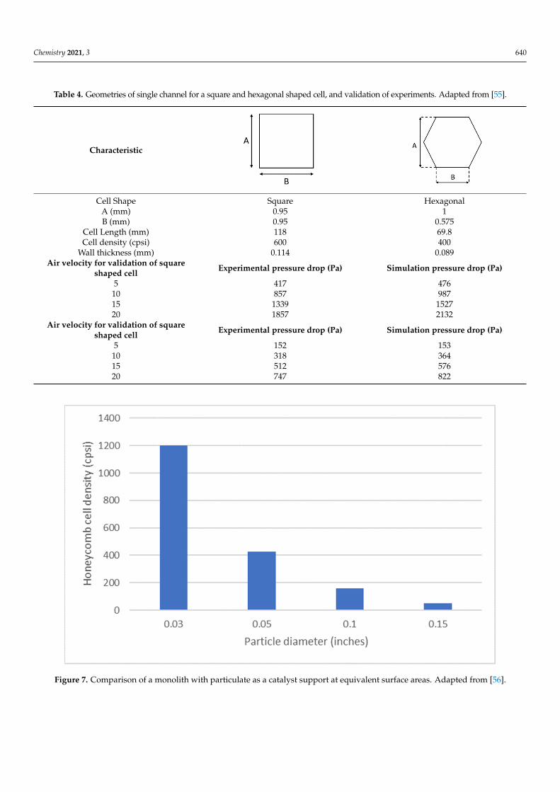
An experiment by Amirnordin, et al. [55] indicates that at a higher surface area, therewould be a significant improvement in chemical properties on the monolith structure(Figure 7). Another reference [30] suggests that a higher surface area and open frontal areaare needed, as it would allow more active components (in this case, the catalysts) to bepresent on the surface of the monolith [59].
Chemistry 2021, 3 640
Table 4. Geometries of single channel for a square and hexagonal shaped cell, and validation of experiments. Adapted from [55].
Characteristic
Chemistry 2021, 3, FOR PEER REVIEW 11
Table 4. Geometries of single channel for a square and hexagonal shaped cell, and validation of experiments. Adapted from [55].
Characteristic
Cell Shape Square Hexagonal A (mm) 0.95 1 B (mm) 0.95 0.575
Cell Length (mm) 118 69.8 Cell density (cpsi) 600 400
Wall thickness (mm) 0.114 0.089 Air velocity for validation of square
shaped cell Experimental pressure drop (Pa) Simulation pressure drop (Pa)
5 417 476 10 857 987 15 1339 1527 20 1857 2132
Air velocity for validation of square shaped cell Experimental pressure drop (Pa) Simulation pressure drop (Pa)
5 152 153 10 318 364 15 512 576 20 747 822
Another suggestion was to use a metallic honeycomb instead of the usual ceramic monolith honeycomb, where it is manufactured using Fecralloy, a ferritic stainless steel with aluminium, which comes in a broader range of shapes and cpsi than the ceramic, depending on the structure. Using metallic monoliths would provide thinner walls with open frontal areas approaching 90%, resulting in larger channel diameters [56], therefore resulting in lower pressure drop [31]. However, factors such as cost, weight, and maximum temp. would outweigh the change of material from a ceramic type to a metallic honeycomb [56].
4.5. Surface Areas An experiment by Amirnordin, et al. [55] indicates that at a higher surface area, there
would be a significant improvement in chemical properties on the monolith structure (Figure 7). Another reference [30] suggests that a higher surface area and open frontal area are needed, as it would allow more active components (in this case, the catalysts) to be present on the surface of the monolith [59].
Cell Shape Square HexagonalA (mm) 0.95 1B (mm) 0.95 0.575
Cell Length (mm) 118 69.8Cell density (cpsi) 600 400
Wall thickness (mm) 0.114 0.089Air velocity for validation of square
shaped cell Experimental pressure drop (Pa) Simulation pressure drop (Pa)
5 417 47610 857 98715 1339 152720 1857 2132
Air velocity for validation of squareshaped cell Experimental pressure drop (Pa) Simulation pressure drop (Pa)
5 152 15310 318 36415 512 57620 747 822
Chemistry 2021, 3, FOR PEER REVIEW 12
Figure 7. Comparison of a monolith with particulate as a catalyst support at equivalent surface areas. Adapted from [56].
4.6. Air/Fuel Equivalence Ratio The air/fuel ratio is also another important condition to consider inside a catalytic
converter. It is defined as the ratio between the air mass flow rate and the fuel mass flow rate [59], where the mathematical relationship is shown as Equation (5): 𝐴𝑖𝑟 − 𝐹𝑢𝑒𝑙 𝑟𝑎𝑡𝑖𝑜 𝐴𝐹 = 𝑚𝑚 (5)
The reciprocal, the Fuel/Air Ratio, can be defined as shown in Eqn. (6): 𝐹𝑢𝑒𝑙 − 𝐴𝑖𝑟 𝑟𝑎𝑡𝑖𝑜 𝐹𝐴 = 𝑚𝑚 (6)
Typical values of the A/F ratio in spark-ignited engines using gasoline fuel is between 12 and 18 (for the F/A ratio, values ranged between 0.056 and 0.083).
The stoichiometric air to fuel ratio, also defined as λ = 1, where λ is defined as the air/fuel equivalence ratio, is when all three pollutants can be converted [14]. A mathematical relationship can be used to define the air/fuel equivalence ratio [60]. 𝜆 = 𝐴𝐹𝑅𝐴𝐹𝑅 (7)
where 𝐴𝐹𝑅 is the actual air/fuel ratio, and 𝐴𝐹𝑅 is the stoichiometric air/fuel ratio. Rich air-fuel mixtures have 𝜆 1, and lean air/fuel mixtures have 𝜆 1 [60].
For oxidation reactions of CO and unburned hydrocarbons, they require an environment of excess air i.e., more oxygen is required so they must operate in lean air/fuel mixture settings, where 𝜆 1 [51]. This is done in a single-bed oxidation catalyst converter, and the NOx remain practically unaffected.
NOX reduction is conducted in a dual-bed catalytic converter, where the exhaust gases flow through a reduction catalyst, where the nitrogen oxides are converted into N2, CO2 and water vapour, then the unburned hydrocarbons and carbon monoxide are converted in a second bed [51]. Its schematic diagram is shown on Figure 8. Air is provided between the two beds [51]. A rich air-fuel mixture is required for the reduction of NOx, where λ < 1. However, as the mixture enriches further, small reduction in conversion efficiency occurs, but for leaner mixtures the conversion efficiency is large. For a mixture that is 1.5 percent lean from the stoichiometric, the conversion efficiency goes
Figure 7. Comparison of a monolith with particulate as a catalyst support at equivalent surface areas. Adapted from [56].

Chemistry 2021, 3 641
4.6. Air/Fuel Equivalence Ratio
The air/fuel ratio is also another important condition to consider inside a catalyticconverter. It is defined as the ratio between the air mass flow rate and the fuel mass flowrate [59], where the mathematical relationship is shown as Equation (5):
Air− Fuel ratio(
AF
)=
.ma.
m f(5)
The reciprocal, the Fuel/Air Ratio, can be defined as shown in Eqn. (6):
Fuel − Air ratio(
FA
)=
.m f.
ma(6)
Typical values of the A/F ratio in spark-ignited engines using gasoline fuel is between12 and 18 (for the F/A ratio, values ranged between 0.056 and 0.083).
The stoichiometric air to fuel ratio, also defined as λ = 1, where λ is defined asthe air/fuel equivalence ratio, is when all three pollutants can be converted [14]. Amathematical relationship can be used to define the air/fuel equivalence ratio [60].
λ =AFR
AFRstoichio(7)
where AFR is the actual air/fuel ratio, and AFRStoichio is the stoichiometric air/fuel ratio.Rich air-fuel mixtures have λ < 1, and lean air/fuel mixtures have λ > 1 [60].
For oxidation reactions of CO and unburned hydrocarbons, they require an envi-ronment of excess air i.e., more oxygen is required so they must operate in lean air/fuelmixture settings, where λ > 1 [51]. This is done in a single-bed oxidation catalyst converter,and the NOx remain practically unaffected.
NOX reduction is conducted in a dual-bed catalytic converter, where the exhaust gasesflow through a reduction catalyst, where the nitrogen oxides are converted into N2, CO2and water vapour, then the unburned hydrocarbons and carbon monoxide are convertedin a second bed [51]. Its schematic diagram is shown on Figure 8. Air is provided betweenthe two beds [51]. A rich air-fuel mixture is required for the reduction of NOx, where λ < 1.However, as the mixture enriches further, small reduction in conversion efficiency occurs,but for leaner mixtures the conversion efficiency is large. For a mixture that is 1.5 percentlean from the stoichiometric, the conversion efficiency goes down by 20 percent. Therefore,the use of catalytic converters for NOx reduction require tight control of any lean-burncombustion [14].
For a three-way catalytic converter, it allows for the air-fuel ratio to operate closeto stoichiometric. When combined with a lambda closed-loop control, it provides themost effective pollutant reduction possible [51]. Figure 9 shows the optimum conversionefficiency of all three exhaust gases at different air-fuel ratio equivalents.
Furthermore, the fuel/air equivalence ratio, φ, can also be defined as the inverse ofthe actual fuel/air ratio and the stoichiometric fuel/air ratio in Equation (8):
φ =
(FA
)actual(
FA
)stoichio
(8)
Therefore, a graph showing the relationship between the catalyst conversion efficiencyand the fuel/air equivalence ratio can be shown in Figure 9 for all three types of exhaustgases. It shows that at the fuel/air equivalence ratios of 0.995 and 1.008, where it is0.5 percent lean and 0.8 percent rich, respectively, the conversion efficiencies of all threegases are much greater than 80 percent [14]. Hence, the main criterion for the use of the

Chemistry 2021, 3 642
three-way catalytic converter, shown in Figure 9 must have tight air-fuel ratio controlthroughout this operating range [14].
Chemistry 2021, 3, FOR PEER REVIEW 13
down by 20 percent. Therefore, the use of catalytic converters for NOx reduction require tight control of any lean-burn combustion [14].
For a three-way catalytic converter, it allows for the air-fuel ratio to operate close to stoichiometric. When combined with a lambda closed-loop control, it provides the most effective pollutant reduction possible [51]. Figure 9 shows the optimum conversion efficiency of all three exhaust gases at different air-fuel ratio equivalents.
Furthermore, the fuel/air equivalence ratio, 𝜙, can also be defined as the inverse of the actual fuel/air ratio and the stoichiometric fuel/air ratio in Equation (8):
𝜙 = 𝐹𝐴𝐹𝐴 (8)
Therefore, a graph showing the relationship between the catalyst conversion efficiency and the fuel/air equivalence ratio can be shown in Figure 9 for all three types of exhaust gases. It shows that at the fuel/air equivalence ratios of 0.995 and 1.008, where it is 0.5 percent lean and 0.8 percent rich , respectively, the conversion efficiencies of all three gases are much greater than 80 percent [14]. Hence, the main criterion for the use of the three-way catalytic converter, shown in Figure 9 must have tight air-fuel ratio control throughout this operating range [14].
Figure 8. Installation of different types of catalytic converter systems. Adapted from [51]. Figure 8. Installation of different types of catalytic converter systems. Adapted from [51].
Chemistry 2021, 3, FOR PEER REVIEW 14
Figure 9. Window for operation of the three-way catalytic converter. Adapted from [14].
5. Rate of Reaction The rate of reaction is defined as the change in the concentration of reactants and
products in a certain amount of time, or in simpler terms, the speed of a chemical reaction [12]. The reactants, which in the case of a catalytic converter, would be the exhaust gas that is directly emitted from the combustion engine are conducted inside the catalytic converter, where these reactions produce the products, which produces the non-toxic gases.
To determine how each reaction happens and the conditions that are required to optimize the reaction, the factors that affect the rate of reaction need to be known. The key factors that would affect the rate of reaction would be the temperature of the reaction, pressure, the concentration of reactants, surface area, and catalysts [12].
If the temperature of the reaction is increased, the kinetic energy of the molecules (moving energy) would increase. An increase in kinetic energy means that the molecules would gain more energy to move around, as kinetic energy is the energy of an object has because of its motion. This would allow for molecules to move around more frequently and collide with each other at faster speeds, so the reaction rate would increase. So, a high temperature is more favorable for a chemical reaction if the reaction needs to be sped up.
When the exhaust gas temperature is between 450 K and 500 K, NO conversion efficiency of less than 10% and concentration of N2O generated is less than 0.01% [61]. It is because as there is a lower temperature in under these temperature conditions, the activity of the catalyst inside the porous medium is too low, so the reaction progresses slowly, making the reaction progress slowly. However, at a temperature at 600K, the NOx conversion efficiency reaches 68%—highlighting the fact that as the temperature increases, the activity of the catalyst i.e., the kinetic energy of the catalyst increases. A high temperature is favourable.
For a general gaseous reaction, if the pressure increases, this would force the gas particles closer together and so there are more gas molecules in a given volume; allowing for more frequent collisions to occur. Since the rate of reaction is dependent on the number of collisions, the rate of reaction would increase. Therefore, the products of a reaction are produced in a much shorter amount of time. The chances of collision occurring are greater. The effect of pressure on the catalytic activity is investigated by changing the pressure and observing the methane and CO2 conversion. Rising the pressure from 1 to 2 to 4 Bar leads to an increase in methane, CO and HCHO conversions, and there is higher residence time. This makes sense as the residence time is the time required to process one (reactor) volume
Figure 9. Window for operation of the three-way catalytic converter. Adapted from [14].
5. Rate of Reaction
The rate of reaction is defined as the change in the concentration of reactants and prod-ucts in a certain amount of time, or in simpler terms, the speed of a chemical reaction [12].The reactants, which in the case of a catalytic converter, would be the exhaust gas that isdirectly emitted from the combustion engine are conducted inside the catalytic converter,where these reactions produce the products, which produces the non-toxic gases.
To determine how each reaction happens and the conditions that are required tooptimize the reaction, the factors that affect the rate of reaction need to be known. The

Chemistry 2021, 3 643
key factors that would affect the rate of reaction would be the temperature of the reaction,pressure, the concentration of reactants, surface area, and catalysts [12].
If the temperature of the reaction is increased, the kinetic energy of the molecules(moving energy) would increase. An increase in kinetic energy means that the moleculeswould gain more energy to move around, as kinetic energy is the energy of an object hasbecause of its motion. This would allow for molecules to move around more frequentlyand collide with each other at faster speeds, so the reaction rate would increase. So, a hightemperature is more favorable for a chemical reaction if the reaction needs to be sped up.
When the exhaust gas temperature is between 450 K and 500 K, NO conversionefficiency of less than 10% and concentration of N2O generated is less than 0.01% [61].It is because as there is a lower temperature in under these temperature conditions, theactivity of the catalyst inside the porous medium is too low, so the reaction progressesslowly, making the reaction progress slowly. However, at a temperature at 600K, theNOx conversion efficiency reaches 68%—highlighting the fact that as the temperatureincreases, the activity of the catalyst i.e., the kinetic energy of the catalyst increases. A hightemperature is favourable.
For a general gaseous reaction, if the pressure increases, this would force the gasparticles closer together and so there are more gas molecules in a given volume; allowingfor more frequent collisions to occur. Since the rate of reaction is dependent on the numberof collisions, the rate of reaction would increase. Therefore, the products of a reaction areproduced in a much shorter amount of time. The chances of collision occurring are greater.The effect of pressure on the catalytic activity is investigated by changing the pressureand observing the methane and CO2 conversion. Rising the pressure from 1 to 2 to 4 Barleads to an increase in methane, CO and HCHO conversions, and there is higher residencetime. This makes sense as the residence time is the time required to process one (reactor)volume of feed under specific feed conditions. Therefore, if the pressure increases, the gasconcentration in a given volume increases, giving a higher residence time [62].
Table 5. Key pollutant gas components, their properties and effect on human health. Adapted from [63].
Pollutant Name and Symbol Properties Effect on Human Health
Carbon monoxide, CO Highly poisonous, odourless, colourlessand tasteless gas. Flammable.
Great effect on the oxygen delivery to thebody’s organs and tissues, which may cause
death. CO poisoning can occur.
Nitrogen oxides, NOX
Mixture of gases composed of Nitrogenand Oxygen. Nitrogen Oxide, NO iscarcinogenic and toxic than Nitrogen
Dioxide, NO2.
Linked to a wide range of respiratory problemse.g., cough and sore throat.
Unburned hydrocarbons, HCProduced from incomplete combustion oforganic fuels. These compounds contain
Carbon and Hydrogen bonds only.
HC, NOX and Sunlight can generate thephotochemical smog. Some hydrocarbon
compounds caused irritation to the eye anddamages lungs e.g., Benzene, C6H6. At high
concentrations, it can cause asthma and death.
Table 6. The emissions (mg/km) of CO, NOX and HC in a gasoline exhaust from vehicles withoutcatalysts and a TWC. Adapted from [63].
Gasoline Exhaust No Catalyst Three-Way Catalytic Converter
CO 1800 300NOX 3.46 0.82HC 1560 220
Concerning the surface area, as it increases, ‘more molecules are exposed’ to thesurroundings, so collisions between molecules inside the catalytic converter would occurmore frequently, so more products are produced at a higher rate, meaning that the rate ofreaction would increase [62].

Chemistry 2021, 3 644
6. Pollutant Gases Reduction and Environmental Issues
The effects of vehicle exhaust from burning gasoline and diesel fuels would releasetoxic exhaust components, where some of the main components are CO, NOX and un-burned HC. These pollutants have serious and irreversible impacts on both the humanhealth and environment. The implications that the pollutants have on the human health ishighlighted in Table 5 [63].
All of these gases can be minimized by the use of catalytic converters. Using gasolinefuel as an example, the emissions of CO, NOX and HC is minimized when there is the useof a catalytic converter, as shown in Table 6. Compared to non-catalyst converter gasolinevehicles, the Table shown below shows that the use of a TWC converter can reduce CO,NOX and HC by a factor of six, four and five times respectively. A catalytic converter is justone of the more effective exhaust after treatment devices which might be able to suppler abetter efficiency of fuel burning and less GHG emissions [63].
7. Conclusions and Outlook
Herein an overview of TWC converters from an educational perspective has beenpresented. The function of TWC converters is essential as they reduce harmful emissionsotherwise emitted to the atmosphere. TWC converters are preferred over two-ways asthey are able to remove a wider variety of pollutants. The main parts of a TWC are:(1) the honeycomb, for which cordierite is the most used compound; (2) the washcoat,typically formed by Al2O3 or metal oxides; (3) and the catalyst support, where PMGsolutions are common. The working temperature on TWC covers a wide range, althoughtypical operating temperatures are between 450–500 ◦C. At these temperatures, CO andHC conversions range between 90–99.9%. For TWC, the air-fuel ratio can be close tostoichiometric values which is an advantage from an operational point of view. The futurechallenges of TWC will be closely related to emission control policies. Even though duringthe past decades significant progress have been carried out for emission control, furtherrestrictions are envisaged for the coming decades to improve the overall quality of ouratmosphere. Thus, in this sense TWC will play a key role. These challenges will lead tonew developments of TWC and extensive research (i.e., catalyst with better behavior atcold start emissions). All in all, this work is a useful guide to gather a better understandingof TWC converters, essential devices for environmental control.
Author Contributions: Conceptualization, E.K. and T.R.R.; methodology, E.K. and F.M.B.-M.; valida-tion, F.M.B.-M. and T.R.R.; formal analysis, E.K., F.M.B.-M. and T.R.R.; investigation, E.K., F.M.B.-M.and T.R.R.; resources, T.R.R.; data curation, E.K.; writing—original draft preparation, E.K. and F.M.B.-M.; writing—review and editing, E.K., F.M.B.-M. and T.R.R.; visualization, T.R.R.; supervision, T.R.R.;project administration, T.R.R.; funding acquisition, T.R.R. All authors have read and agreed to thepublished version of the manuscript.
Funding: Financial support was provided by the Department of Chemical and Process Engineeringat the University of Surrey.
Institutional Review Board Statement: Not applicable.
Informed Consent Statement: Not applicable.
Conflicts of Interest: The authors declare no conflict of interest.
References1. EPA. Carbon Pollution from Transportation 2020. Available online: https://www.epa.gov/transportation-air-pollution-and-
climate-change/carbon-pollution-transportation (accessed on 16 May 2021).2. Hannappel, R. The impact of global warming on the automotive industry. AIP Conf. Proc. 2017, 1, 060001. [CrossRef]3. Kroeze, C. Nitrous oxide and global warming. Sci. Total Environ. 1994, 143, 193–209. [CrossRef]4. European Environment Agency. Greenhouse Gas Emissions from Transport in Europe. European Environment Agency 2019.
Available online: https://www.eea.europa.eu/data-and-maps/indicators/transport-emissions-of-greenhouse-gases/transport-emissions-of-greenhouse-gases-12 (accessed on 16 May 2021).
5. Baruch, J.J. Combating global warming while enhancing the future. Technol. Soc. 2008, 30, 111–121. [CrossRef]

Chemistry 2021, 3 645
6. Hydrogen Council. Hydrogen Scaling Up: A Sustainable Pathway for The Global Energy Transition. Available online: www.hydrogencouncil.com (accessed on 16 May 2021).
7. Desantes, J.; Molina, S.; Novella, R.; Lopez-Juarez, M. Comparative global warming impact and NOX emissions of conventionaland hydrogen automotive propulsion systems. Energy Convers. Manag. 2020, 221, 113137. [CrossRef]
8. Datye, A.K.; Votsmeier, M. Opportunities and challenges in the development of advanced materials for emission control catalysts.Nat. Mater. 2020, 1–11. [CrossRef]
9. Lazkar, A.; Mao-Chang, L. Probing the Operational Temperatures of Vehicular Catalytic Converters Using Clumped Isotopes inExhaust CO2. In Proceedings of the EGU General Assembly Conference Abstracts, Vienna, Austria, 4–13 April 2018.
10. Zeng, F.; Finke, J.; Olsen, D.; White, A.; Hohn, K.L. Modeling of three-way catalytic converter performance with exhaust mixturesfrom dithering natural gas-fueled engines. Chem. Eng. J. 2018, 352, 389–404. [CrossRef]
11. Avneet Kahlon, T.T. Catalytic Converters. In Chemistry LibreTexts. Available online: https://chem.libretexts.org/Bookshelves/Physical_and_Theoretical_Chemistry_Textbook_Maps/Supplemental_Modules_(Physical_and_Theoretical_Chemistry)/Kinetics/07%3A_Case_Studies-_Kinetics/7.01%3A_Catalytic_Converters (accessed on 16 May 2021).
12. Brown, T.E.; LeMay, H.E.; Bursten, B.E.; Murphy, C.; Woodward, P.; Stoltzfus, M.E. Catalytic Converters. In Chemistry: The CentralScience; Pearson: London, UK, 2018.
13. Clark, J. The Collision Theory of Reaction Rates 2003. Available online: https://www.chemguide.co.uk/physical/basicrates/introduction.html (accessed on 16 May 2021).
14. Milton, B.E. Handbook of Air Pollution from Internal Combustion Engines. In Control Technologies in Spark-Ignition Engines;Elsevier: Amsterdam, The Netherlands, 1998. [CrossRef]
15. Kummer, J. Catalysts for automobile emission control. Prog. Energy Combust. Sci. 1980, 6, 177–199. [CrossRef]16. Shelef, M.; McCabe, R. Twenty-five years after introduction of automotive catalysts: What next? Catal. Today 2000, 62, 35–50.
[CrossRef]17. Belton, D.N.; Taylor, K.C. Automobile exhaust emission control by catalysts. Curr. Opin. Solid State Mater. Sci. 1999, 4, 97–102.
[CrossRef]18. Burch, R. Knowledge and Know-How in Emission Control for Mobile Applications. Catal. Rev. Sci. Eng. 2004, 46, 271–334.
[CrossRef]19. Farrauto, R.J.; Deeba, M.; Alerasool, S. Gasoline automobile catalysis and its historical journey to cleaner air. Nat. Catal. 2019, 2,
603–613. [CrossRef]20. Deutschmann, O.; Grunwaldt, J.-D. Abgasnachbehandlung in mobilen Systemen: Stand der Technik, Herausforderungen und
Perspektiven. Chem. Ing. Tech. 2013, 85, 595–617. [CrossRef]21. Venkateswarlu, K.; Kumar, R.A.; Krishna, R.; Sreenivasan, M. Modeling and fabrication of catalytic converter for emission
reduction. Mater. Today: Proc. 2019, 33, 1093–1099. [CrossRef]22. Braun, J.; Hauber, T.; Többen, H.; Zacke, P.; Chatterjee, D.; Deutschmann, O.; Warnatz, J. Influence Of Physical And Chemical
Parameters On The Conversion Rate Of A Catalytic Converter: A Numerical Simulation Study. In Proceedings of the SAE 2000World Congress, Cobo Center, Detroit, MI, USA, 6–9 March 2000. [CrossRef]
23. Haldar, S.K. Exploration Guide. In Platinum-Nickel-Chromium Deposits; Elsevier: Amsterdam, The Netherlands, 2017. [CrossRef]24. Vanderveer, R.T.; Chandler, J.M. The Development of a Catalytic Converter for the Oxidation of Exhaust Hydrocarbons. SAE Tech.
Pap. Ser. 1959. [CrossRef]25. Kalam, M.A.; Masjuki, H.H.; Redzuan, M.; Mahlia, T.M.I.; Fuad, M.A.; Mohibah, M.; Halim, K.H.; Ishak, A.; Khair, M.; Shahrir, A.;
et al. Development and test of a new catalytic converter for natural gas fuelled engine. Sadhana Acad. Proc. Eng. Sci. 2009, 34,467–481. [CrossRef]
26. Majewski, W.A. DieselNet Technology Guide 2000. In Emission Control Catalysts; 2002; Available online: https://dieselnet.com/tech/catalysts.php (accessed on 16 May 2021).
27. Samuels, G.; Rose, A.; David, G.; Hooker, J.N. Energy Conservation in Transportation. Adv. Energy Syst. Technol. 1982, 187–297.[CrossRef]
28. Golunski, S.E. Final Analysis. Platin. Met. Rev. 2007, 51, 162. [CrossRef]29. USA News Group. Use of Palladium in Catalytic Converters Driving Demand for the Precious Metal 2019. Available on-
line: https://www.prnewswire.com/news-releases/use-of-palladium-in-catalytic-converters-driving-demand-for-the-precious-metal-300937620.html (accessed on 16 May 2021).
30. Thakur, P. Advanced Mine Ventilation. Diesel Exhaust Control 2019, 157–187. [CrossRef]31. Durilla, M.; Hizny, W.J.; Mack, S. Carbon monoxide oxidizers. In Heat Recover Steam Generator Technology; Elsevier: Amsterdam,
The Netherlands, 2017. [CrossRef]32. Green Chemistry: An Inclusive Approach. Focus Catal. 2018, 2018, 7. [CrossRef]33. Dell, R.M.; Moseley, P.T.; Rand, D.A. Development of Road Vehicles with Internal-Combustion Engines. In Towards Sustainable
Road Transport; Elsevier: Amsterdam, The Netherlands, 2014. [CrossRef]34. Govender, S.; Friedrich, H.B. Monoliths: A Review of the Basics, Preparation Methods and Their Relevance to Oxidation. Catal
2017, 7, 62. [CrossRef]35. Mahyon, N.I.; Li, T.; Martinez-Botas, R.; Wu, Z.; Li, K. A new hollow fibre catalytic converter design for sustainable automotive
emissions control. Catal. Commun. 2019, 120, 86–90. [CrossRef]

Chemistry 2021, 3 646
36. Siemund, S.; Leclerc, J.; Schweich, D.; Prigent, M.; Castagna, F. Three-way monolithic converter: Simulations versus experiments.Chem. Eng. Sci. 1996, 51, 3709–3720. [CrossRef]
37. Kašpar, J.; Fornasiero, P.; Graziani, M. Use of CeO2-based oxides in the three-way catalysis. Catal. Today 1999, 50, 285–298.[CrossRef]
38. Leman, A.; Afiqah, J.; Rahman, F.; Feriyanto, D.; Zakaria, S.; Rahmad, R. Catalytic Converter Developed by Washcoat ofγ-Alumina on Nickel Oxide (Nio) Catalyst in FeCrAl Substrate for Exhaust Emission Control: A Review. In Proceedings of theMATEC Web Conference 2016; (online). Available online: https://www.matec-conferences.org/articles/matecconf/abs/2016/23/contents/contents.html (accessed on 16 May 2021). [CrossRef]
39. Converters, C. Catalytic Converters 2020. Available online: https://www.catalyticconverters.com/construction/ (accessed on 16May 2021).
40. Fornalczyk, A.; Saternus, M. Removal of platinum group metals from the used auto catalytic converter. Metalurgija 2009, 48,133–136.
41. Hoffman, J.E. Britannica Encyclopedia: Platinum Group 2018. Available online: https://www.britannica.com/science/platinum-group (accessed on 16 May 2021).
42. Johnson, M. Properties of Platinum Group Metals 2020. Available online: http://www.platinum.matthey.com/about-pgm/applications/properties-of-pgm (accessed on 16 May 2021).
43. Martinez, N.; Amado, M.; Guerrero, M.P. Modeling the vibrations in a catalytic converter for diesel engines. In Proceedings of theSIMULIA Cust Conference, Providence, RI, USA, 19 May 2011.
44. Chen, Y.; Bowman, J.; Harris, J. Catalyst Converter Canning Simulation Studies. SAE Tech. Pap. Ser. 2003. [CrossRef]45. Fernandes, S.; Martins, S.C.; Olson, J.; Peters, B. The Role of New Catalytic Converter Mounting Materials in Providing Durability
and Efficiency. SAE Tech. Pap. Ser. 2002. [CrossRef]46. Spreen, K.B.; Heimrich, M.J.; Hornback, L.R.; Montalbano, A.J. Container Deformation Procedure for Ceramic Monolith Catalytic
Converters. SAE Tech. Pap. Ser. 2000. [CrossRef]47. Taylor, W. CFD Prediction and Experimental Validation of High-Temperature Thermal Behavior in Catalytic Converters. SAE
Tech. Pap. Ser. 1999. [CrossRef]48. Gao, J.; Tian, G.; Sorniotti, A.; Karci, A.E.; Di Palo, R. Review of thermal management of catalytic converters to decrease engine
emissions during cold start and warm up. Appl. Therm. Eng. 2019, 147, 177–1879. [CrossRef]49. Lee, S.; Bae, C.; Lee, Y.; Han, T. Effects of Engine Operating Conditions on Catalytic Converter Temperature in an SI Engine. SAE
Tech. Pap. Ser. 2002. [CrossRef]50. Choice Reviews Online. In Internal Combustion Engine Fundamentals; McGraw-Hill Education: New York, NY, USA, 1988; Volume
26, pp. 26–943. [CrossRef]51. Handbook of Air Pollution from Internal Combustion Engines; Elsevier: Amsterdam, The Netherlands, 1998. [CrossRef]52. Whelan, I.; Timoney, D.; Smith, W.; Samuel, S. The Effect of a Three-Way Catalytic Converter on Particulate Matter from a
Gasoline Direct-Injection Engine During Cold-Start. SAE Int. J. Engines 2013, 6, 1035–1045. [CrossRef]53. CITA. CITA Study No 4—Influence of Catalyst Temperature on Effectiveness of In-Service Testing; AEA Technology: Harwell, UK, 1994.54. Korin, E.; Reshef, R.; Tshernichovesky, D.; Sher, E. Improving Cold-Start Functioning of Catalytic Converters by Using Phase-
Change Materials. SAE Tech. Pap. Ser. 1998. [CrossRef]55. Amirnordin, S.H.; Seri, S.M.; Salim, W.S.-I.W.; Rahman, H.A.; Hasnan, K. Pressure Drop Analysis of Square and Hexagonal
Cellsand its Effects on the Performance of Catalytic Converters. Int. J. Environ. Sci. Dev. 2011, 239–247. [CrossRef]56. Heck, R.M.; Gulati, S.; Farrauto, R.J. The application of monoliths for gas phase catalytic reactions. Chem. Eng. J. 2001, 82, 149–156.
[CrossRef]57. Cornejo, I.; Nikrityuk, P.; Hayes, R.E. Effect of substrate geometry and flow condition on the turbulence generation after a
monolith. Can. J. Chem. Eng. 2020, 98, 947–956. [CrossRef]58. Ibrahim, H.A.; Abdou, S.; Ahmed, W.H. Understanding Flow through Catalytic Converters. In Proceedings of the 5th International
Conference of Fluid Flow, Heat and Mass Transfer (FFHMT’18), Orléans, ON, Canada, 7–9 June 2017. [CrossRef]59. Heywood, J.B. Pollutant formation and control in spark ignition engines. Symp. (Int.) Combust. 1975, 15, 1191–1211. [CrossRef]60. Al-Arkawazi, S.A.F. Analyzing and predicting the relation between air–fuel ratio (AFR), lambda (λ) and the exhaust emissions
percentages and values of gasoline-fueled vehicles using versatile and portable emissions measurement system tool. SN Appl. Sci.2019, 1, 1370. [CrossRef]
61. Zuo, Q.; Xie, Y.; Jiaqiang, E.; Zhu, X.; Zhang, B.; Tang, Y.; Zhu, G.; Wang, Z.; Zhang, J. Effect of different exhaust parameterson NO conversion efficiency enhancement of a dual-carrier catalytic converter in the gasoline engine. Energy 2020, 191, 116521.[CrossRef]
62. Levenspiel, O. Chemical Reaction Engineering. Ind. Eng. Chem. Res. 1999, 38, 4140–4143. [CrossRef]63. Jie, L. Environmental Effects of Vehicle Exhausts, Global and Local Effects—A Comparison between Gasoline and Diesel. Digit.
Vetensk. Ark. 2011, 27. Available online: https://www.diva-portal.org/smash/get/diva2:427347/FULLTEXT01.pdf (accessed on16 May 2021).