Development of Latest High Efficiency Side Exhaust Steam ...
10
Mitsubishi Heavy Industries Technical Review Vol. 58 No. 3 (September 2021) 1 *1 Deputy Head, Turbomachinery Headquarters, Mitsubishi Power, Ltd. *2 Director, Steam Turbine Engineering Department, Mitsubishi Power, Ltd. *3 Deputy Director, Steam Turbine Engineering Department, Mitsubishi Power, Ltd. *4 Manager, Steam Turbine Engineering Department, Mitsubishi Power, Ltd. *5 Manager, Large Frame Steam Turbine Engineering Department, Mitsubishi Power, Ltd. *6 Chief Staff Manager, Steam Turbine Engineering Department, Mitsubishi Power, Ltd. Development of Latest High Efficiency Side Exhaust Steam Turbine TAKASHI NAKANO *1 NAOTO TOCHITANI *2 NARIYUKI MATSUNO *3 MASAOMI MAKINO *4 GOINGWON LEE *5 SOICHIRO TABATA *6 Mitsubishi Power, Ltd. (Mitsubishi Power) has been making tireless efforts to improve the efficiency of thermal power generation facility. In order to meet the need for higher efficiency and the demand for smaller size, we have developed a latest steam turbine for the single shaft GTCC that uses a structure with separate high-pressure and intermediate-pressure casings, a side exhaust system and a SSS clutch. For this steam turbine, we adopted high-performance blade design (reaction blades, low-pressure end blades and exhaust diffuser), verification of clearance prediction and control technology, new seal and high-performance bearings, while verifying the performance and reliability at T-point 2 (our power plant demonstration facility). We have also carried out verification of the practical application of 700°C class high-temperature steam turbines, which are the next-generation technology. This report presents the new technologies adopted in the high-performance steam turbine, features of the new structure, and verification results in the real machine. | 1. Introduction The global decarbonization trend has been accelerating and the shift to renewable energy is progressing. On the other hand, it is expected that a certain amount of thermal power generation facility will remain in the future according to the power demand and supply, making the efficiency enhancement of thermal power generation indispensable for controlling greenhouse gas emissions. Mitsubishi Power has been working tirelessly to improve the efficiency of steam turbines 1) . We have expanded the use of the latest technology with high efficiency and high reliability to actual equipment by adopting the latest analysis technology for the design method, while also conducting actual- equipment verification of a rotor for 700°C class high-temperature steam turbines 2) , which is one of the future technologies. | 2. Overview of latest high-performance side exhaust steam turbine High-performance reaction blades, Low Pressure end (LP-End) blades, side exhaust LP turbines, clearance prediction technology, sealing technology and high specific load bearings, which are technologies applied to the latest steam turbine, can also be used for steam turbines for combined cycle power generation, small and medium capacity turbines, large capacity turbines for coal-fired power generation, nuclear power turbines, geothermal turbines, internal replacement work in after- sales service, etc. Figure 1 shows the high-efficiency steam turbine to which these technologies are applied and Table 1 lists the specifications. This turbine is the latest steam turbine with a rated output of 170 MW at a steam temperature of 600°C and is connected to a GT and a generator via a SSS clutch to configure a 566 MW GTCC (Gas turbine combined cycle) plant. For the high-pressure and
-
Upload
khangminh22 -
Category
Documents
-
view
0 -
download
0
Transcript of Development of Latest High Efficiency Side Exhaust Steam ...

Mitsubishi Heavy Industries Technical Review Vol. 58 No. 3 (September 2021) 1
*1 Deputy Head, Turbomachinery Headquarters, Mitsubishi Power, Ltd. *2 Director, Steam Turbine Engineering Department, Mitsubishi Power, Ltd. *3 Deputy Director, Steam Turbine Engineering Department, Mitsubishi Power, Ltd. *4 Manager, Steam Turbine Engineering Department, Mitsubishi Power, Ltd. *5 Manager, Large Frame Steam Turbine Engineering Department, Mitsubishi Power, Ltd. *6 Chief Staff Manager, Steam Turbine Engineering Department, Mitsubishi Power, Ltd.
Development of Latest High Efficiency Side Exhaust Steam Turbine
TAKASHI NAKANO*1 NAOTO TOCHITANI*2
NARIYUKI MATSUNO*3 MASAOMI MAKINO*4
GOINGWON LEE*5 SOICHIRO TABATA*6
Mitsubishi Power, Ltd. (Mitsubishi Power) has been making tireless efforts to improve the
efficiency of thermal power generation facility. In order to meet the need for higher efficiency and the demand for smaller size, we have developed a latest steam turbine for the single shaft GTCC that uses a structure with separate high-pressure and intermediate-pressure casings, a side exhaust system and a SSS clutch. For this steam turbine, we adopted high-performance blade design (reaction blades, low-pressure end blades and exhaust diffuser), verification of clearance prediction and control technology, new seal and high-performance bearings, while verifying the performance and reliability at T-point 2 (our power plant demonstration facility). We have also carried out verification of the practical application of 700°C class high-temperature steam turbines, which are the next-generation technology.
This report presents the new technologies adopted in the high-performance steam turbine, features of the new structure, and verification results in the real machine.
|1. Introduction The global decarbonization trend has been accelerating and the shift to renewable energy is
progressing. On the other hand, it is expected that a certain amount of thermal power generation facility will remain in the future according to the power demand and supply, making the efficiencyenhancement of thermal power generation indispensable for controlling greenhouse gas emissions.Mitsubishi Power has been working tirelessly to improve the efficiency of steam turbines1). We have expanded the use of the latest technology with high efficiency and high reliability to actual equipmentby adopting the latest analysis technology for the design method, while also conducting actual-equipment verification of a rotor for 700°C class high-temperature steam turbines2), which is one of the future technologies.
|2. Overview of latest high-performance side exhaust steam turbine High-performance reaction blades, Low Pressure end (LP-End) blades, side exhaust LP
turbines, clearance prediction technology, sealing technology and high specific load bearings, whichare technologies applied to the latest steam turbine, can also be used for steam turbines for combinedcycle power generation, small and medium capacity turbines, large capacity turbines for coal-fired power generation, nuclear power turbines, geothermal turbines, internal replacement work in after-sales service, etc. Figure 1 shows the high-efficiency steam turbine to which these technologies are applied and Table 1 lists the specifications. This turbine is the latest steam turbine with a rated outputof 170 MW at a steam temperature of 600°C and is connected to a GT and a generator via a SSSclutch to configure a 566 MW GTCC (Gas turbine combined cycle) plant. For the high-pressure and

Mitsubishi Heavy Industries Technical Review Vol. 58 No. 3 (September 2021) 2
intermediate-pressure turbines, we developed blades for high velocity ratios with small diametersand multiple stages and for the low-pressure turbine, we optimized the flow pattern of the last stagerotating blade and flow field inside exhaust chamber using integrated analysis. Despite double flowexhaust, the lower-height building was attained by adopting side exhaust instead of conventionaldownward exhaust. We also conducted clearance prediction using unsteady FEM(Finite Element Method) and verification of clearance control using a heater. A low-pressure loss and compact combination valve and high-performance high-surface pressure bearings were applied. A single shaft GTCC system was adopted using a SSS clutch. The turning device adopted a double turning system that can independently turn ST and GT alone, which resulted in an improvement in terms of operationduring regular inspection. We applied a Ni-based weld rotor, which had been developed as a rotor for 700°C class high-temperature steam turbines, to actual equipment for verification.
Figure 1 Overview of latest side exhaust steam turbine
Table 1 Specifications of T-point 2 steam turbine
Specifications of T-point 2 steam turbine Type TC2F-33.7 Output Approx. 170MW Rotational speed 3600rpm Shaft configuration HP+IP+LP Exhaust direction Side exhaust Main steam conditions 14.98MPa×600°C Reheat steam conditions 3.46MPa×600°C Condenser vacuum 6.8 kPa abs.
|3. Features of new technologies 3.1 Next-generation high-performance reaction blade
The performance of high-pressure and intermediate-pressure blades of the latest high-performance steam turbine was improved by reducing the diameter and multi- stages (reducing the rotor diameter and increasing the number of blade rows) compared with our conventional reaction blade path and reducing secondary flow loss at the blade end wall and leakage flow loss from theblade seal. We have improved the blade efficiency and the prediction accuracy of internal flow frombefore through development using multi-stage three-dimensional flow analysis and verification using an air turbine.
We have developed a high-performance reaction blade for high velocity ratio suitable forsmall-diameter multi-stage blade rows using the latest multi-stage three-dimensional flow analysis including cavities as shown in Figure 2. The blade profile loss was reduced due to the reduction ofthe profile surface area by reviewing the pitch-chord ratio and relaxing the bow shape compared with

Mitsubishi Heavy Industries Technical Review Vol. 58 No. 3 (September 2021) 3
the conventional complete three-dimensional reaction blade. Furthermore, by controlling the reaction distribution, the balance between blade loss and leakage flow loss was optimized to improve theperformance. The high velocity ratio reaction blades developed as described above were applied tothe high-pressure turbine, intermediate-pressure turbine and low-pressure turbine upstream stage after verification using an air turbine and it was confirmed using special measurement at the powerplant demonstration facility that the expected performance was attained.
Figure 2 Multi-stage three-dimensional analysis including cavities
3.2 Adoption of next-generation high-performance LP-End blades and side exhaustThe output carried by LP-End blades is large, and the number of turbine casings and the size
of the plant building depend on the size of the last stage rotating blades. Therefore, the performanceof LP-End blades plays an important role in the overall efficiency of the steam turbine. Since theperformance of LP-End blades is greatly affected by the exhaust hood performance, maximizing the exhaust hood performance has a profound effect on the overall performance of the steam turbine.
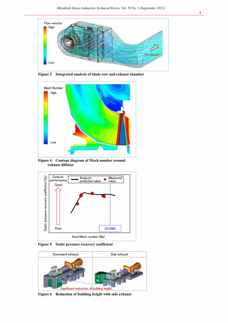
We used the latest numerical analysis technology to carry out the optimum design of theexhaust diffuser with the one through integral analysis method of the flow pattern of the last stagerotating blade and flow field inside exhaust chamber in addition to the stage load optimization, loaddistribution in the blade height direction and optimization of blade profile with respect to high-Mach-number flow, which have been implemented from before. Figure 3 gives an example of the one through integral analysis of the flow pattern of the last stage rotating blade and flow field inside(three-dimensional streamline diagram). Figure 4 depicts the meridional Mach number contours around the exhaust diffuser. As shown in Figure. 4, the flow inside the diffuser exhibits a normalflow pattern. Figure 5 compares the analysis-predicted value of the static pressure recovery coefficient and the measured value of that obtained at the power plant demonstration facility. Theanalysis-predicted value and the measured value are in good agreement, confirming that the expectedexhaust performance was attained3), 4).
As a result, the performance of the LP-End blades developed using the latest numerical analysis technology was verified by our power plant demonstration facility. In addition, the drainloss (wetness loss) particular to LP-End blades was also reduced by optimizing the shape and position of the moisture removal slit using the state of the art flow analysis technology. In terms of structure,despite the double exhaust flow directions, the height of the foundation and the height of the turbinebuilding could be significantly reduced by adopting side exhaust, compared with conventionaldownward exhaust (Figure. 6), which contributes to the reduction of construction costs.
Mitsubishi Heavy Industries Technical Review Vol. 58 No. 3 (September 2021) 4
Figure 3 Integrated analysis of blade row and exhaust chamber
Figure 4 Contour diagram of Mach number around
exhaust diffuser
Figure 5 Static pressure recovery coefficient
Figure 6 Reduction of building height with side exhaust

Mitsubishi Heavy Industries Technical Review Vol. 58 No. 3 (September 2021) 5
3.3 Clearance control technology Aiming to further reduce clearance to improve the performance and flexibility, we verified the
clearance control (outer casing vertical movement control) technology by heating with a heater andcooling with air from the outside of the turbine casing. Clearance were measured directly with a gap sensor (Figure 7) installed inside the turbine.
Figure 8 shows the trend of lifting the outer casing (expansion of the upper clearance) due toheating with a heater before start-up. By lifting the outer casing before start-up, it is possible to secure a margin for the upper clearance after the rotational speed increases. Similarly, Figure 9 shows the trend of lowering of the outer casing (expansion of the lower clearance) due to cooling with air duringrated operation. On the contrary, it is possible to lift the outer casing by heating with a heater.
Figure 7 GAP sensor mounting position
Figure 8 Clearance control with heater operation before start-up

Mitsubishi Heavy Industries Technical Review Vol. 58 No. 3 (September 2021) 6
Figure 9 Clearance control with cooling air during operation
As described above, we have established a sensor technology that enables the control ofclearance (vertical movement) from the outside and the measurement of clearance inside, regardlessof whether stopped or operating. In the future, we will use this technology to further improve theperformance and flexibility. 3.4 Sealing technology
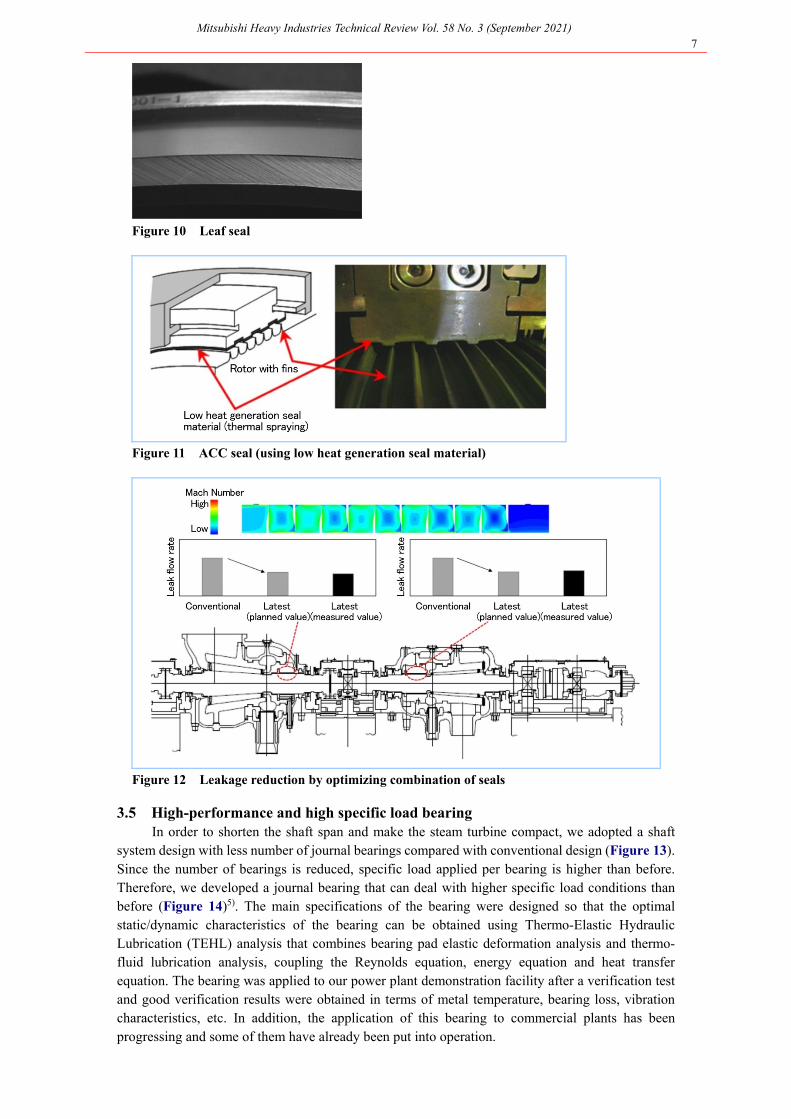
We have developed leaf seals and ACC abradable seals for the purpose of reducing leaks fromdummy rings, gland cases and blade tips and achieved high efficiency by arranging these in anappropriate combination.
The leaf seal is an array of plate-shaped leaves shown in Figure 10 in the circumferential direction and the tip of the leaf slightly rises to maintain a non-contact state when the rotor rotates. ACC (Active Clearance Control) abradable seal is a combination of ACC seal and an abradable seal.ACC seal maintains a large clearance between the rotor and labyrinth seal during start-up /shut-down operation and in a shut-down term of the steam turbine, and keeps the clearance small during constantload operation by using the seal differential pressure to move the seal segment to a predeterminedposition. An abradable seal uses a low heat generation seal material with excellent free-cutting characteristics thermally sprayed on the inner surface of the seal ring as shown in Figure 11. Due to this configuration, the ACC abradable seal can reduce the clearance during rated operation whilesuppressing heat generation caused by fin contact and it prevents shaft vibration as a result. We alsoapplied externally controlled ACC and achieved the leak reduction shown in Figure 12 by utilizing flow analysis technology to optimize the combination of these seals.
Mitsubishi Heavy Industries Technical Review Vol. 58 No. 3 (September 2021) 7
Figure 10 Leaf seal
Figure 11 ACC seal (using low heat generation seal material)
Figure 12 Leakage reduction by optimizing combination of seals
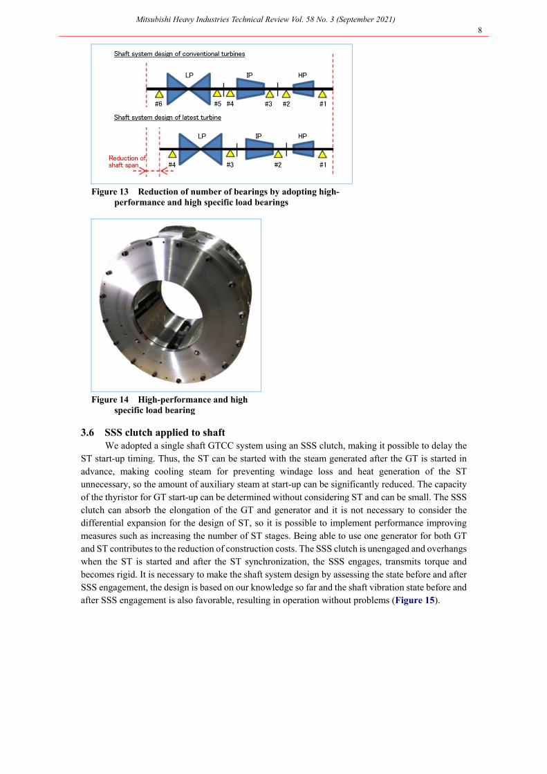
3.5 High-performance and high specific load bearing In order to shorten the shaft span and make the steam turbine compact, we adopted a shaft
system design with less number of journal bearings compared with conventional design (Figure 13). Since the number of bearings is reduced, specific load applied per bearing is higher than before. Therefore, we developed a journal bearing that can deal with higher specific load conditions thanbefore (Figure 14)5). The main specifications of the bearing were designed so that the optimalstatic/dynamic characteristics of the bearing can be obtained using Thermo-Elastic Hydraulic Lubrication (TEHL) analysis that combines bearing pad elastic deformation analysis and thermo-fluid lubrication analysis, coupling the Reynolds equation, energy equation and heat transferequation. The bearing was applied to our power plant demonstration facility after a verification testand good verification results were obtained in terms of metal temperature, bearing loss, vibrationcharacteristics, etc. In addition, the application of this bearing to commercial plants has been progressing and some of them have already been put into operation.
Mitsubishi Heavy Industries Technical Review Vol. 58 No. 3 (September 2021) 8
Figure 13 Reduction of number of bearings by adopting high-
performance and high specific load bearings
Figure 14 High-performance and high specific load bearing
3.6 SSS clutch applied to shaft
We adopted a single shaft GTCC system using an SSS clutch, making it possible to delay theST start-up timing. Thus, the ST can be started with the steam generated after the GT is started in advance, making cooling steam for preventing windage loss and heat generation of the STunnecessary, so the amount of auxiliary steam at start-up can be significantly reduced. The capacity of the thyristor for GT start-up can be determined without considering ST and can be small. The SSS clutch can absorb the elongation of the GT and generator and it is not necessary to consider thedifferential expansion for the design of ST, so it is possible to implement performance improvingmeasures such as increasing the number of ST stages. Being able to use one generator for both GTand ST contributes to the reduction of construction costs. The SSS clutch is unengaged and overhangswhen the ST is started and after the ST synchronization, the SSS engages, transmits torque and becomes rigid. It is necessary to make the shaft system design by assessing the state before and afterSSS engagement, the design is based on our knowledge so far and the shaft vibration state before andafter SSS engagement is also favorable, resulting in operation without problems (Figure 15).

Mitsubishi Heavy Industries Technical Review Vol. 58 No. 3 (September 2021) 9
Figure 15 Shaft vibration with SSS clutch used
3.7 High-efficiency combined SV/CV valve The developed combined SV/CV valve has a valve casing shared by the stop valve (SV) and
control valve (CV), so the number of valve chambers is reduced from 2 to 1, which reduces thenumber of components such as bonnet covers and bolts by about half. Therefore, compared with theconventional separated type SV and CV (i.e., each valve has a separate structure), the body is smaller, which is advantageous in terms of manufacturing cost. By applying the valve casing material, fullyclosing backseat function and stem leak connection system, which were proven with 600°C classunits, the reliability was improved. At the same time, by increasing the size and improving the steamflow path, the pressure loss was reduced (Figure 16). As a result of measuring the pressure loss of the combined SV/CV valve applied to a high-pressure main steam valve and a high-temperature reheat steam valve, the measured value was within the range of the planned value and it wasconfirmed that the pressure loss was reduced compared with the initially planned value6).
Figure 16 High-efficiency combined SV/CV valve
3.8 Double turning technology The turning time of a conventional single shaft GTCC (CGS arrangement) plant (after
shutdown) depends on the turning time on the ST, which requires time for metal temperaturereduction. To shorten the plant shut-down period at the time of inspection, GT turning is required tostop in advance. This time, we have developed a double turning device that can turn GT and STseparately with one turning device. This could also reduce the installation space compared with the case of installing two turning devices. Consideration was given to safety as well, such as addingmultiple interlocks, to prevent turning from being activated due to incorrect operation duringinspection work.

Mitsubishi Heavy Industries Technical Review Vol. 58 No. 3 (September 2021) 10
3.9 Verification targeting 700°C class high-temperature steam turbine technology For the intermediate-pressure turbine, we adopted a dissimilar metal welded rotor of Ni-based
alloy (LTES700R) and advanced 12Cr steel (MTR10A) developed in the A-USC Component Technology Development Project. The dissimilar metal welded rotor of Ni-based alloy and 12Cr steel was rotation-tested in a high-temperature air environment of 700°C for 1051 hours in a national project at the time and completed a long-term rotation test of the dissimilar metal welded joint equivalent to 160,000 hours. This technology won the Best Paper Award at Powergen Europe in20177). This rotation test was conducted under a rated rotational speed of 3600 rpm and in an air environment and the effect of load change including start-up and shut-down was not evaluated. Further reliability verification in a steam environment is ongoing with the temperature of thedissimilar metal welded joint area the same as the design temperature of the 700°C class high-temperature steam turbine (Figure 17). The ST temperature increasing technology is expected to beapplicable to high-temperature gas reactors, CO2 turbines and heat storage turbines.
Figure 17 Intermediate-pressure rotor (including dissimilar metal weld rotor
of Ni-based alloy and 12Cr steel)
|4. Conclusion We developed the performance enhancing technologies for the latest steam turbine and
confirmed that the expected results can be achieved using actual facility. These technologies areapplicable to all types of steam turbines, from small and medium capacity turbines to large-capacity turbines—as well as after-sales service replacement work—and have been already applied to some projects. We will continue to develop new technologies and high-performance steam turbines that apply the technologies with the aim of further improving the efficiency of power generation facility,thereby contributing to the reduction of greenhouse gas emissions.
References (1) Eiichiro Watanabe et.al, Development of New High Efficiency Steam Turbine, Mitsubishi Heavy Industries
Technical Review Vol.40 No.4 (2003) p.212~215 (2) Eiji Saito et. al, Latest Technologies and Future Prospects for a New Steam Turbine, Mitsubishi Heavy
Industries Technical Review Vol.52 No.2 (2015) p.36~43 (3) Tabata, S., et al., 2019, “Experimental and Numerical Investigations of Steam Turbine Exhaust Hood Flow
Field with Two Types of Diffusers,” ASME Turbo Expo GT2019-90640 (4) Tabata, S., et al., 2020, “Experimental and Numerical Investigations of the Effects of Real Shape Modeling
and Non-equilibrium Condensation Modeling on the Flow Pattern in Steam Turbine,” ASME Turbo Expo GT2020-14253
(5) T.Nakano. et al., Development of high specific load and low mechanical loss journal bearing with two pads of tilting supported type, Proceedings of ASME Turbo Expo 2018, GT2018-75593
(6) Fumiyuki Suzuki. et al., Verification of Combined Main Steam Valve Pressure Distribution and VibrationCharacteristics with Downscale Model Test on Air Condition, Proceedings of ASME Turbo Expo, GT2019-90406
(7) E.Siato, et al., ''700℃ class A-USC Steam Turbine Development”, Powergen Europe (2017)