Catalytic Membrane Reactors
22
catalysts Review Catalytic Membrane Reactors: The Industrial Applications Perspective Catia Algieri 1, *, Gerardo Coppola 2 , Debolina Mukherjee 2 , Mahaad Issa Shammas 3 , Vincenza Calabro 2 , Stefano Curcio 2 and Sudip Chakraborty 2, * Citation: Algieri, C.; Coppola, G.; Mukherjee, D.; Shammas, M.I.; Calabro, V.; Curcio, S.; Chakraborty, S. Catalytic Membrane Reactors: The Industrial Applications Perspective. Catalysts 2021, 11, 691. https://doi.org/10.3390/ catal11060691 Academic Editor: Jose Antonio Calles Martín Received: 23 April 2021 Accepted: 27 May 2021 Published: 29 May 2021 Publisher’s Note: MDPI stays neutral with regard to jurisdictional claims in published maps and institutional affil- iations. Copyright: © 2021 by the authors. Licensee MDPI, Basel, Switzerland. This article is an open access article distributed under the terms and conditions of the Creative Commons Attribution (CC BY) license (https:// creativecommons.org/licenses/by/ 4.0/). 1 Institute on Membrane Technology, National Research Council of Italy (ITM–CNR), Cubo 17C, Via Pietro Bucci, 87036 Rende, Italy 2 Department of DIMES, University of Calabria, Via Pietro Bucci, Cubo 42A, 87036 Rende, Italy; [email protected] (G.C.); [email protected] (D.M.); [email protected] (V.C.); [email protected] (S.C.) 3 Department of Civil & Environmental Engineering at Dhofar University, Salalah 211, Sultanate of Oman; [email protected] * Correspondence: author: [email protected] (C.A.); [email protected] (S.C.) Abstract: Catalytic membrane reactors have been widely used in different production industries around the world. Applying a catalytic membrane reactor (CMR) reduces waste generation from a cleaner process perspective and reduces energy consumption in line with the process intensification strategy. A CMR combines a chemical or biochemical reaction with a membrane separation process in a single unit by improving the performance of the process in terms of conversion and selectivity. The core of the CMR is the membrane which can be polymeric or inorganic depending on the operating conditions of the catalytic process. Besides, the membrane can be inert or catalytically active. The number of studies devoted to applying CMR with higher membrane area per unit volume in multi- phase reactions remains very limited for both catalytic polymeric and inorganic membranes. The various bio-based catalytic membrane system is also used in a different commercial application. The opportunities and advantages offered by applying catalytic membrane reactors to multi-phase systems need to be further explored. In this review, the preparation and the application of inorganic membrane reactors in the different catalytic processes as water gas shift (WGS), Fisher Tropsch synthesis (FTS), selective CO oxidation (CO SeLox), and so on, have been discussed. Keywords: catalysis; membrane reactor; process intensification; inorganic catalyst; enzyme; environmental applications 1. Inorganic Membrane Reactor 1.1. Introduction to Catalytic Inorganic Membrane Reactors Since the conventional methodologies of chemical processes have been successfully applied to synthesize enormous numbers of sophisticated products, researchers worldwide have been searching for alternative methods, which are more efficient concerning energy consumption, space reduction, and environmental safety [1]. One of the most promising strategies to achieve these challenging goals is utilizing catalysts. Catalysts play an essential role in numerous environmental transformations with high reaction regioselectivity and stereospecificity. These peculiar characteristics allow scientists to apply them in modern chemistry and organic synthesis processes. Anyway, the rapid growth of the chemical industries for producing different chemicals requires improving manufacturing and pro- cessing by reducing the equipment size, energy consumption, and waste production to achieve sustainable and cheaper technologies (process intensification strategy) [1]. Membrane reactors, a process intensification technology, combine the membrane sepa- ration process with chemical or biochemical reactions in a single unit [2]. This combination determines higher conversion and improved selectivity and a compact and cost-effective Catalysts 2021, 11, 691. https://doi.org/10.3390/catal11060691 https://www.mdpi.com/journal/catalysts
-
Upload
khangminh22 -
Category
Documents
-
view
0 -
download
0
Transcript of Catalytic Membrane Reactors
catalysts
Review
Catalytic Membrane Reactors: The IndustrialApplications Perspective
Catia Algieri 1,*, Gerardo Coppola 2, Debolina Mukherjee 2, Mahaad Issa Shammas 3, Vincenza Calabro 2 ,Stefano Curcio 2 and Sudip Chakraborty 2,*
�����������������
Citation: Algieri, C.; Coppola, G.;
Mukherjee, D.; Shammas, M.I.;
Calabro, V.; Curcio, S.; Chakraborty, S.
Catalytic Membrane Reactors:
The Industrial Applications
Perspective. Catalysts 2021, 11, 691.
https://doi.org/10.3390/
catal11060691
Academic Editor: Jose Antonio
Calles Martín
Received: 23 April 2021
Accepted: 27 May 2021
Published: 29 May 2021
Publisher’s Note: MDPI stays neutral
with regard to jurisdictional claims in
published maps and institutional affil-
iations.
Copyright: © 2021 by the authors.
Licensee MDPI, Basel, Switzerland.
This article is an open access article
distributed under the terms and
conditions of the Creative Commons
Attribution (CC BY) license (https://
creativecommons.org/licenses/by/
4.0/).
1 Institute on Membrane Technology, National Research Council of Italy (ITM–CNR), Cubo 17C,Via Pietro Bucci, 87036 Rende, Italy
2 Department of DIMES, University of Calabria, Via Pietro Bucci, Cubo 42A, 87036 Rende, Italy;[email protected] (G.C.); [email protected] (D.M.);[email protected] (V.C.); [email protected] (S.C.)
3 Department of Civil & Environmental Engineering at Dhofar University, Salalah 211, Sultanate of Oman;[email protected]
* Correspondence: author: [email protected] (C.A.); [email protected] (S.C.)
Abstract: Catalytic membrane reactors have been widely used in different production industriesaround the world. Applying a catalytic membrane reactor (CMR) reduces waste generation from acleaner process perspective and reduces energy consumption in line with the process intensificationstrategy. A CMR combines a chemical or biochemical reaction with a membrane separation process ina single unit by improving the performance of the process in terms of conversion and selectivity. Thecore of the CMR is the membrane which can be polymeric or inorganic depending on the operatingconditions of the catalytic process. Besides, the membrane can be inert or catalytically active. Thenumber of studies devoted to applying CMR with higher membrane area per unit volume in multi-phase reactions remains very limited for both catalytic polymeric and inorganic membranes. Thevarious bio-based catalytic membrane system is also used in a different commercial application.The opportunities and advantages offered by applying catalytic membrane reactors to multi-phasesystems need to be further explored. In this review, the preparation and the application of inorganicmembrane reactors in the different catalytic processes as water gas shift (WGS), Fisher Tropschsynthesis (FTS), selective CO oxidation (CO SeLox), and so on, have been discussed.
Keywords: catalysis; membrane reactor; process intensification; inorganic catalyst; enzyme;environmental applications
1. Inorganic Membrane Reactor1.1. Introduction to Catalytic Inorganic Membrane Reactors
Since the conventional methodologies of chemical processes have been successfullyapplied to synthesize enormous numbers of sophisticated products, researchers worldwidehave been searching for alternative methods, which are more efficient concerning energyconsumption, space reduction, and environmental safety [1]. One of the most promisingstrategies to achieve these challenging goals is utilizing catalysts. Catalysts play an essentialrole in numerous environmental transformations with high reaction regioselectivity andstereospecificity. These peculiar characteristics allow scientists to apply them in modernchemistry and organic synthesis processes. Anyway, the rapid growth of the chemicalindustries for producing different chemicals requires improving manufacturing and pro-cessing by reducing the equipment size, energy consumption, and waste production toachieve sustainable and cheaper technologies (process intensification strategy) [1].
Membrane reactors, a process intensification technology, combine the membrane sepa-ration process with chemical or biochemical reactions in a single unit [2]. This combinationdetermines higher conversion and improved selectivity and a compact and cost-effective
Catalysts 2021, 11, 691. https://doi.org/10.3390/catal11060691 https://www.mdpi.com/journal/catalysts
Catalysts 2021, 11, 691 2 of 22
reactor design [3]. Considering these aspects, membrane reactors (MRs) represent a poten-tial technology in different fields: pharmaceutical, biotechnology, petrochemical sectors,energy, and environmental applications, including phase change behaviour [4].
MRs are categorized as polymeric (or organic) and inorganic depending on the chemi-cal process operating conditions. Polymeric membranes can operate at temperatures thatdo not exceed 300 ◦C [5,6]. Inorganic membranes can be used when polymeric ones failconsidering that they can operate at higher temperatures (300–800 ◦C and in some caseover 1000 ◦C) and in the aggressive chemical environment due to their high chemical resis-tance [7]. In addition, in polymeric membranes, there is a trade-off between permeabilityand selectivity. Generally, glassy polymers have high selectivity and low permeability,while rubbery polymers show high permeability and low selectivity [8]. Consideringthis disadvantage, inorganic membranes have elicited much attention due to their highpermeability and selectivity. The limits in the inorganic membrane field are the highproduction cost and the brittleness [9]. Different materials have been used to fabricateinorganic membranes as carbon, silica, alumina, titania, zirconia, zeolite, palladium, sil-ver, and alloy [10,11]. Inorganic membranes can also be classified as dense or porous.Porous membranes are categorized according to the IUPAC classification into macrop-orous (pore diameter (pd) > 50 nm), mesoporous (2 nm < pd < 50 nm) and microporous(0.5 nm < pd < 2 nm) [11]. These membranes are self-standing or supported, the supportbeing used to give them mechanical strength [12].
According to the role of the membrane in the reactor, three different configurationshave been identified: extractor, distributor and contactor and their; these aspects will bedeeply explained in Section 2. In addition, the inorganic membranes used in MR can beinert or catalytically active. In the first case, the catalytic particles are separated from themembrane or are dispersed in its pores, and these configurations are called inert membranereactor (IMR). In the last case, the membrane acts as both separator and catalysts, and thisconfiguration is called catalytic membrane reactor (CMR).
In this review, the different methods used for the preparation of inorganic mem-branes have been presented. The application of inorganic membrane reactors in differentinteresting reactions has also been discussed.
1.2. Preparation of Inorganic Membrane Reactors
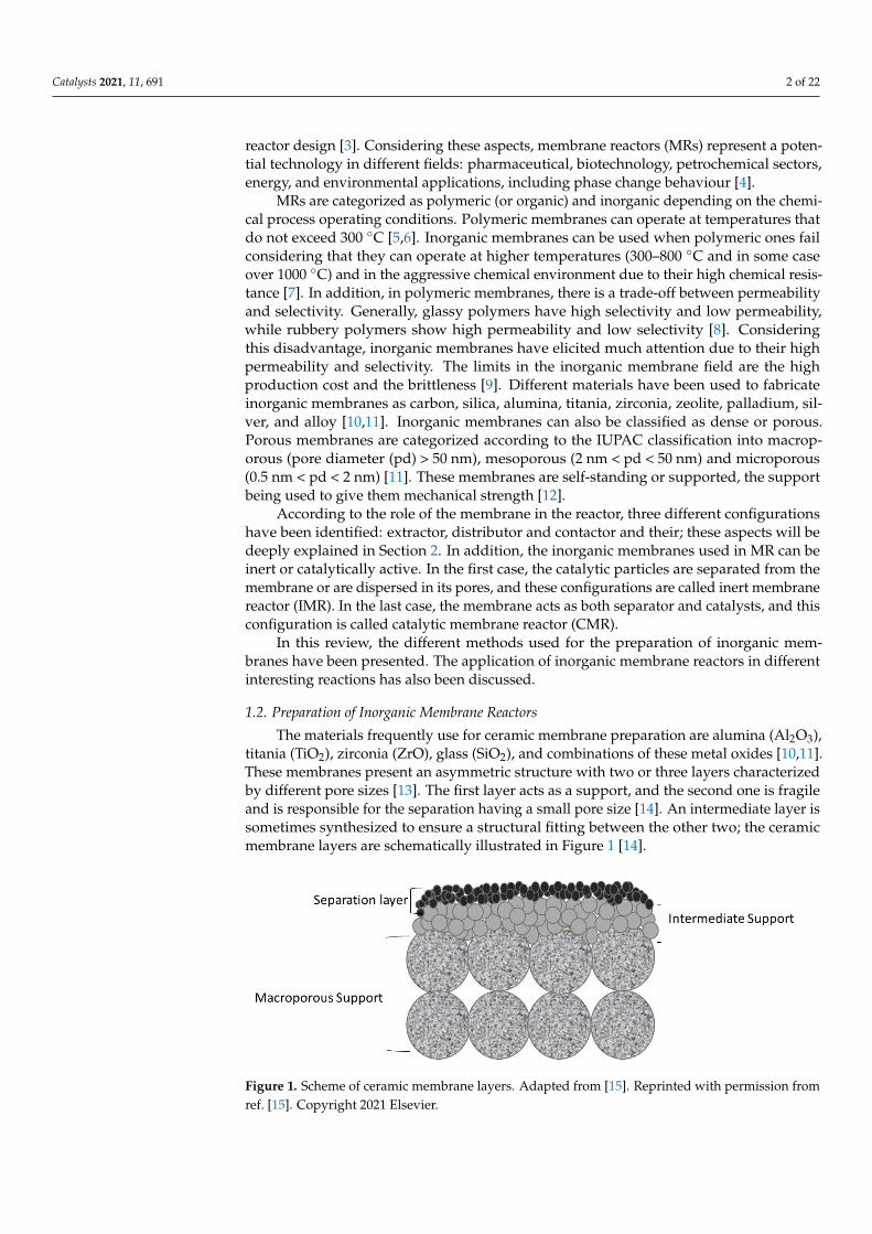
The materials frequently use for ceramic membrane preparation are alumina (Al2O3),titania (TiO2), zirconia (ZrO), glass (SiO2), and combinations of these metal oxides [10,11].These membranes present an asymmetric structure with two or three layers characterizedby different pore sizes [13]. The first layer acts as a support, and the second one is fragileand is responsible for the separation having a small pore size [14]. An intermediate layer issometimes synthesized to ensure a structural fitting between the other two; the ceramicmembrane layers are schematically illustrated in Figure 1 [14].
Catalysts 2021, 11, x FOR PEER REVIEW 2 of 22
Membrane reactors, a process intensification technology, combine the membrane separation process with chemical or biochemical reactions in a single unit [2]. This combi-nation determines higher conversion and improved selectivity and a compact and cost-effective reactor design [3]. Considering these aspects, membrane reactors (MRs) repre-sent a potential technology in different fields: pharmaceutical, biotechnology, petrochem-ical sectors, energy, and environmental applications, including phase change behaviour [4].
MRs are categorized as polymeric (or organic) and inorganic depending on the chem-ical process operating conditions. Polymeric membranes can operate at temperatures that do not exceed 300 °C [5,6]. Inorganic membranes can be used when polymeric ones fail considering that they can operate at higher temperatures (300–800 °C and in some case over 1000 °C) and in the aggressive chemical environment due to their high chemical re-sistance [7]. In addition, in polymeric membranes, there is a trade-off between permeabil-ity and selectivity. Generally, glassy polymers have high selectivity and low permeability, while rubbery polymers show high permeability and low selectivity [8]. Considering this disadvantage, inorganic membranes have elicited much attention due to their high per-meability and selectivity. The limits in the inorganic membrane field are the high produc-tion cost and the brittleness [9]. Different materials have been used to fabricate inorganic membranes as carbon, silica, alumina, titania, zirconia, zeolite, palladium, silver, and alloy [10,11]. Inorganic membranes can also be classified as dense or porous. Porous mem-branes are categorized according to the IUPAC classification into macroporous ( pore di-ameter (pd) > 50 nm), mesoporous (2 nm< pd <50 nm) and microporous (0.5 nm< pd <2 nm) [11]. These membranes are self-standing or supported, the support being used to give them mechanical strength [12].
According to the role of the membrane in the reactor, three different configurations have been identified: extractor, distributor and contactor and their; these aspects will be deeply explained in Section 2. In addition, the inorganic membranes used in MR can be inert or catalytically active. In the first case, the catalytic particles are separated from the membrane or are dispersed in its pores, and these configurations are called inert mem-brane reactor (IMR). In the last case, the membrane acts as both separator and catalysts, and this configuration is called catalytic membrane reactor (CMR).
In this review, the different methods used for the preparation of inorganic mem-branes have been presented. The application of inorganic membrane reactors in different interesting reactions has also been discussed.
1.2. Preparation of Inorganic Membrane Reactors The materials frequently use for ceramic membrane preparation are alumina (Al2O3),
titania (TiO2), zirconia (ZrO), glass (SiO2), and combinations of these metal oxides [10,11]. These membranes present an asymmetric structure with two or three layers characterized by different pore sizes [13]. The first layer acts as a support, and the second one is fragile and is responsible for the separation having a small pore size [14]. An intermediate layer is sometimes synthesized to ensure a structural fitting between the other two; the ceramic membrane layers are schematically illustrated in Figure 1 [14].
Figure 1. Scheme of ceramic membrane layers. Adapted from [15]. Reprinted with permission fromref. [15]. Copyright 2021 Elsevier.
Catalysts 2021, 11, 691 3 of 22
The methods used for their synthesis are slip casting, extrusion, pressing, freeze-casting, and sol-gel [15–18]. Among them, the most used is the slip-casting that includesthe following three steps: In the beginning, a paste or suspension is prepared by usinga ceramic powder. The paste is deposited on a porous support. Finally, the ceramicmembrane was subjected to a drying and heat treatment [19,20]. Tape casting and pressingtechnique permit fabricating flat sheet membranes. A ceramic paste is added to a reservoirand cast utilizing a blade adjusted at a fixed height in the tape casting. After, the membraneis dried and sintered at high temperatures [21]. In the pressing, the paste poured intoa metal mould, and a force equivalent to 100 to 1000 bar was applied for producingan asymmetric membrane with a flat configuration. Finally, the sintering procedure isperformed [22].
Tubular (mono and multichannel) and hollow-fibre membranes are prepared usingthe extrusion method. In this process, a semi-dried past passed through an orifice with afixed cross-section and shape [22]. The freeze-casting process is used for the preparation ofhighly porous membranes. Initially, a solid suspension is frozen. Later, the sublimationof the frozen solvent (by operating at low pressures) allows the formation of the porousstructure [23]. In the sol-gel method, the natural compound (metal alkoxide) is dissolved ina solvent, and then the hydrolysis permits the formation of a monomer [24]. The monomerpolymerizes, and the formed polymer is deposited on a support surface. After drying andthermal treatment, the membrane is obtained. The high production cost hinders a broadapplication of the ceramic membranes; in fact, different researchers focus their activity onfabricating ceramic membranes by using waste with the urban or industrial origin [25].
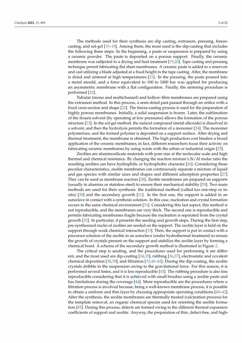
Zeolites are aluminosilicate materials with pore size at the molecular scale and highthermal and chemical resistance. By changing the reaction mixture’s Si/Al molar ratio theresulting zeolites can have hydrophilic or hydrophobic character [26]. Considering thesepeculiar characteristics, zeolite membranes can continuously separate a mixture of liquidand gas species with similar sizes and shapes and different adsorption properties [27].They can be used as membrane reactors [28]. Zeolite membranes are prepared on supports(usually in alumina or stainless steel) to ensure their mechanical stability [29]. Two mainmethods are used for their synthesis: the traditional method (called too one-step or in-situ) [30] and the secondary growth [31]. In the first one, the support is added in anautoclave in contact with a synthesis solution. In this case, nucleation and crystal formationoccurs in the same chemical environment [31]. Considering this last aspect, this method isnot reproducible, and the membranes are very thick. The second one is reproducible andpermits fabricating membranes fragile because the nucleation is separated from the crystalgrowth [32]. In particular, it presents the seeding and growth steps. During the first step,pre-synthesized nuclei of zeolites are seeded on the support. The zeolite layer is held on thesupport through weak chemical interaction [33]. Then, the support is put in contact with aprecursor solution of the zeolite in an autoclave (under hydrothermal treatment) to ensurethe growth of crystals present on the support and stabilize the zeolite layer by forming achemical bond. A schema of the secondary growth method is illustrated in Figure 2.
The critical step is seeding, and the procedures used for performing it are differ-ent, and the most used are dip-coating [34,35], rubbing [36,37], electrostatic and covalentchemical deposition [38,39], and filtration [33,40–42]. During the dip-coating, the zeolitecrystals dribble in the suspension owing to the gravitational force. For this reason, it isperformed several times, and it is less reproducible [43]. The rubbing procedure is also lessreproducible considering that it is achieved with small brushes using a zeolite paste andhas limitations during the coverage [44]. More reproducible are the procedures where afiltration process is involved because, being a well-known membrane process, it is possibleto obtain a uniform and thin layer by choosing appropriate operating conditions [40–42].After the synthesis, the zeolite membranes are thermally treated (calcination process) forthe template removal, an organic chemical species used for orienting the zeolite forma-tion [45]. During this process, defects are formed owing to the different thermal expansioncoefficients of support and zeolite. Anyway, the preparation of thin, defect-free, and high-
Catalysts 2021, 11, 691 4 of 22
reproducible, and low –cost membranes represent still challenges. Indeed, today, at anindustrial level, a few zeolite-membrane topologies are used in the dehydration of variousorganic solvents [46].
Catalysts 2021, 11, x FOR PEER REVIEW 4 of 22
Figure 2. Scheme of the secondary growth method.
The critical step is seeding, and the procedures used for performing it are different, and the most used are dip-coating [34,35], rubbing [36,37], electrostatic and covalent chemical deposition [38,39], and filtration [33,40–42]. During the dip-coating, the zeolite crystals dribble in the suspension owing to the gravitational force. For this reason, it is performed several times, and it is less reproducible [43]. The rubbing procedure is also less reproducible considering that it is achieved with small brushes using a zeolite paste and has limitations during the coverage [44]. More reproducible are the procedures where a filtration process is involved because, being a well-known membrane process, it is pos-sible to obtain a uniform and thin layer by choosing appropriate operating conditions [40–42]. After the synthesis, the zeolite membranes are thermally treated (calcination process) for the template removal, an organic chemical species used for orienting the zeolite for-mation [45]. During this process, defects are formed owing to the different thermal expan-sion coefficients of support and zeolite. Anyway, the preparation of thin, defect-free, and high-reproducible, and low –cost membranes represent still challenges. Indeed, today, at an industrial level, a few zeolite-membrane topologies are used in the dehydration of var-ious organic solvents [46].
The metal materials mainly used for the membrane preparation are palladium and alloys due to the high solubility and permeability of hydrogen [47]. These membranes have a dense structure and are applied in the gas separation process and as membrane reactors when H2 is a reactant or a product of the process [48–50].
Different methods are available for synthesizing Pd-based membranes, and the most used are electroless plating (ELP) [51], chemical vapour deposition (CVD) [52], physical vapour deposition (PVD) [53] and the electroplating deposition (EPD) [54]. In this review, the ELP method has been discussed as being mainly exploited for membrane fabrication [55]. This method includes four steps: the cleaning/smoothing of the support surface [56]. In the second and third ones, the activation of the support and the deposition of the pal-ladium is carried out, respectively. The membrane is dried and annealed for performing the Pd activation [57]. The precursor of the metal species, dissolved in an aqueous solu-tion, is stabilized by using ligand (as ammonium hydroxide and ethylene-diamine-tetra acetic acid (EDTA)) that can form a metal complex [58]. Then, the palladium ions are re-duced by an appropriate chemical reaction [59].
Figure 2. Scheme of the secondary growth method.
The metal materials mainly used for the membrane preparation are palladium andalloys due to the high solubility and permeability of hydrogen [47]. These membraneshave a dense structure and are applied in the gas separation process and as membranereactors when H2 is a reactant or a product of the process [48–50].
Different methods are available for synthesizing Pd-based membranes, and the mostused are electroless plating (ELP) [51], chemical vapour deposition (CVD) [52], physi-cal vapour deposition (PVD) [53] and the electroplating deposition (EPD) [54]. In thisreview, the ELP method has been discussed as being mainly exploited for membranefabrication [55]. This method includes four steps: the cleaning/smoothing of the supportsurface [56]. In the second and third ones, the activation of the support and the depositionof the palladium is carried out, respectively. The membrane is dried and annealed forperforming the Pd activation [57]. The precursor of the metal species, dissolved in anaqueous solution, is stabilized by using ligand (as ammonium hydroxide and ethylene-diamine-tetra acetic acid (EDTA)) that can form a metal complex [58]. Then, the palladiumions are reduced by an appropriate chemical reaction [59].
1.3. Inorganic Membrane Reactor Applications
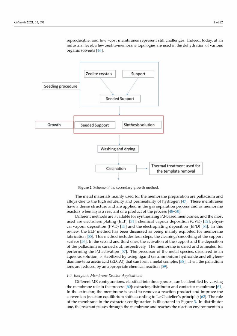
Different MR configurations, classified into three groups, can be identified by varyingthe membrane role in the process [60]: extractor, distributor and contactor membrane [61].In the extractor, the membrane is used to remove a reaction product and improve theconversion (reaction equilibrium shift according to Le Chatelier’s principle) [62]. The roleof the membrane in the extractor configuration is illustrated in Figure 3. In distributorone, the reactant passes through the membrane and reaches the reaction environment in a
Catalysts 2021, 11, 691 5 of 22
controlled way by limiting side reactions (see Figure 3) [63]. In these two configurations, themembrane is catalytically inert, and it is coupled with a conventional catalytic process. Inthe contactor, the membrane is catalytically active, and it is used for improving the contactbetween reactants and catalytic sites [64]. This last configuration is shown in Figure 3.
Figure 3. Membrane role in a membrane reactor.
The applications of inorganic membrane reactors in various chemical reactions havebeen reported and discussed. Today, steam methane reforming (SMR) is the primaryprocess for hydrogen production [65]. A gaseous mixture, called syngas, is producedcontaining hydrogen, carbon monoxide, and a low amount of carbon dioxide [64]. Forincreasing the hydrogen produced by SMR, the water-gas shift (WGS) produces H2 and CO2from carbon monoxide and steam. The WGS is limited by the thermodynamic equilibriumat elevated temperatures [65]. A possible way to improve the CO2 conversion is to removea reaction product to overcome the chemical equilibrium limitation [66]. Kim et al. usedMFI zeolite membranes as membrane reactors for performing a WGS reaction at hightemperatures [67], and the catalyst used was Fe/Ce nanoparticles. The membranes showeda reasonable hydrogen selectivity (H2/CO2 = 31 and H2/CO = 25) at 500 ◦C. In thiswork, the CO conversion enhanced (98.5%), overcoming the equilibrium limit by usingthe silicalite membranes and operating at high temperature (>500 ◦C) and pressure (6 bar).In addition, Simulation studies indicated that the zeolite MRs could achieve a very highCO conversion (≥99%) with these operating conditions: T > 500 ◦C, P = 30 atm andRH2O/CO∼3.5 [67].
Arvanitis et al. have also obtained exciting results by using MFI zeolite membranereactors [68]. A complete conversion of the carbon monoxide (>99.9%) was achieved andwith a hydrogen recovery of 99.9%, operating at 500 ◦C and 20 bar. The catalyst remained
Catalysts 2021, 11, 691 6 of 22
stable for about 50 h of WGS reaction at 20 bar. However, carbon deposition on the surfaceappeared, causing a CO conversion decline from 99.9% to ~96% within two days. Inaddition, a low purity of hydrogen was due to the moderate H2 selectivity of the zeolitemembrane. Table 1 reports other results on H2 production by WGS by using the zeolitemembrane reactors.
Table 1. Performance of zeolite membrane reactors in the WGS process.
Zeolite Topology Temperature (◦C) CO Conversion% H2 Recovery (%) References
MFI * 350 73.6 >98.2 [69]MFI 300 95.4 - [70]MFI 550 81.7 18 [71]MFI - >99 >60 [72]
* MFI = Mobil-Type Five.
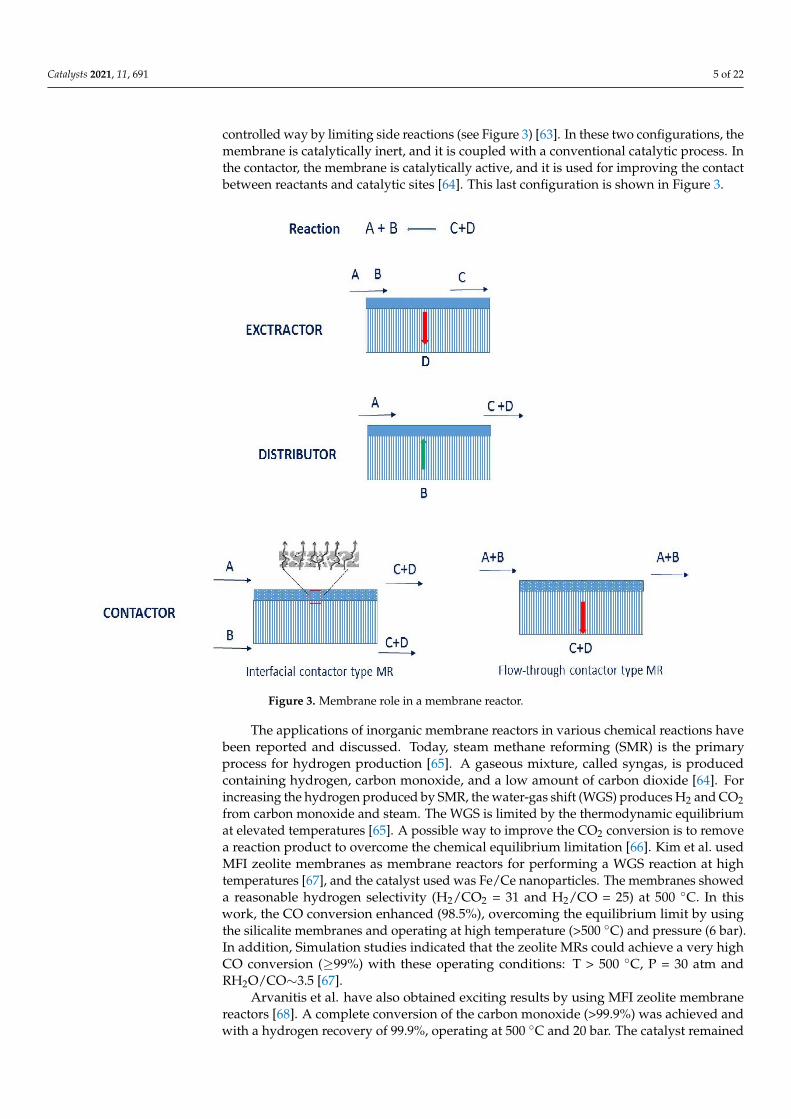
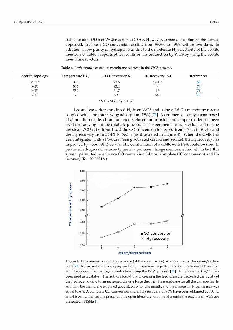
Lee and coworkers produced H2 from WGS and using a Pd-Cu membrane reactorcoupled with a pressure swing adsorption (PSA) [73]. A commercial catalyst (composedof aluminium oxide, chromium oxide, chromium trioxide and copper oxide) has beenused for carrying out the catalytic process. The experimental results evidenced raisingthe steam/CO ratio from 1 to 5 the CO conversion increased from 85.4% to 94.8% andthe H2 recovery from 53.4% to 56.1% (as illustrated in Figure 4). When the CMR hasbeen integrated with a PSA unit (using activated carbon and zeolite), the H2 recovery hasimproved by about 31.2–35.7%. The combination of a CMR with PSA could be used toproduce hydrogen rich-stream to use in a proton-exchange membrane fuel cell; in fact, thissystem permitted to enhance CO conversion (almost complete CO conversion) and H2recovery (R = 99.9991%).
Catalysts 2021, 11, x FOR PEER REVIEW 7 of 22
Figure 4. CO conversion and H2 recovery (at the steady-state) as a function of the steam/carbon ratio [73].Tsotsis and coworkers prepared an ultra-permeable palladium membrane via ELP method, and it was used for hydrogen production using the WGS process [74]. A commercial Cu/Zn has been used as a catalyst. The authors found that increasing the feed pressure decreased the purity of the hydrogen owing to an increased driving force through the membrane for all the gas species. In addition, the membrane exhibited good stability for one month, and the change in H2 permeance was equal to 6%. A complete CO conversion and an H2 recovery of 90% have been obtained at 300 °C and 4.6 bar. Other results present in the open literature with metal membrane reactors in WGS are presented in Table 2.
Table 2. Metal membrane reactors are applied in WGS process.
Membrane Temperature (°C)
CO Conversion %
H2 Recovery (%)
References
Pd 410 85 - [75] Pd-Ag 200 96.6 92 [76] Pd-Ag 300 99.1 98 [76]
Pd 400 92 <80 [77] Pd-Ag 400 99.5 <89 [77] Pd-Ag 330 85 80 [78] Pd-Cu 900 65 85-90 [79]
Fisher Tropsch synthesis (FTS) converts the syngas, obtained from natural gas or bi-omass, into liquid hydrocarbons (see Equation (1)) and on an industrial scale, iron and cobalt-based catalysts are used [80].
(2n + 1)H2 + nCO → CnH2n+2 + nH2O (1)
The membrane combined with the FTS can improve the performance of the catalytic process, exerting a function of extractor or distributor. In the first case, the membrane is used to remove water, a reaction product, to reduce the catalyst deactivation, increase conversion and displacing the water gas-shift equilibrium, and enhance the hydrocarbon production [81]. When it is used as a distributor, the membrane must be selective towards the H2 or CO. In this case, it is possible to maintain the reactants’ ratio and avoid side
Figure 4. CO conversion and H2 recovery (at the steady-state) as a function of the steam/carbonratio [73].Tsotsis and coworkers prepared an ultra-permeable palladium membrane via ELP method,and it was used for hydrogen production using the WGS process [74]. A commercial Cu/Zn hasbeen used as a catalyst. The authors found that increasing the feed pressure decreased the purity ofthe hydrogen owing to an increased driving force through the membrane for all the gas species. Inaddition, the membrane exhibited good stability for one month, and the change in H2 permeance wasequal to 6%. A complete CO conversion and an H2 recovery of 90% have been obtained at 300 ◦Cand 4.6 bar. Other results present in the open literature with metal membrane reactors in WGS arepresented in Table 2.
Catalysts 2021, 11, 691 7 of 22
Table 2. Metal membrane reactors are applied in WGS process.
Membrane Temperature (◦C) CO Conversion% H2 Recovery (%) References
Pd 410 85 - [75]Pd-Ag 200 96.6 92 [76]Pd-Ag 300 99.1 98 [76]
Pd 400 92 <80 [77]Pd-Ag 400 99.5 <89 [77]Pd-Ag 330 85 80 [78]Pd-Cu 900 65 85–90 [79]
Fisher Tropsch synthesis (FTS) converts the syngas, obtained from natural gas orbiomass, into liquid hydrocarbons (see Equation (1)) and on an industrial scale, iron andcobalt-based catalysts are used [80].
(2n + 1)H2 + nCO→ CnH2n+2 + nH2O (1)
The membrane combined with the FTS can improve the performance of the catalyticprocess, exerting a function of extractor or distributor. In the first case, the membraneis used to remove water, a reaction product, to reduce the catalyst deactivation, increaseconversion and displacing the water gas-shift equilibrium, and enhance the hydrocarbonproduction [81]. When it is used as a distributor, the membrane must be selective towardsthe H2 or CO. In this case, it is possible to maintain the reactants’ ratio and avoid sidereactions [82]. Different research groups studied the possibility of using hydrophilic zeolitemembranes for water removal from hydrogen and carbon monoxide using the operatingconditions typical of the FT process. In 2005, Zhou et al. [83] studied the separation ofH2O/CO, H2O/H2, and H2O/CH4 versus the temperature using NaA membranes. Theselectivities of H2O/CO, H2O/H2, and H2O/CH4 were 30, 72, and 323 at 100 ◦C. The waterquickly passes through the membrane for the high affinity with the zeolite NaA stronglyhydrophilic. Kapteijn and coworkers prepared sodalite membrane on alumina supportthat exhibited very high H2O/H2 selectivity up to 200 ◦C and so it is very promising forthe water removal in FTS [84].
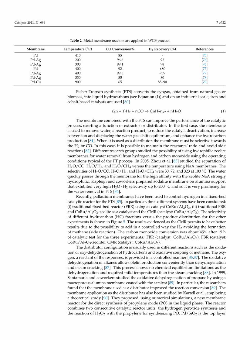
Recently, palladium membranes have been used to control hydrogen in a fixed-bedcatalytic reactor for the FTS [85]. In particular, three different systems have been considered:(i) traditional fixed-bed reactor (FBR) using as catalyst CoRu/Al2O3, (ii) traditional FBRand CoRu/Al2O3-zeolite as a catalyst and the CMR (catalyst: CoRu/Al2O3). The selectivityof different hydrocarbon (HC) fractions versus the product distribution for the otherexperiments is shown in Figure 5. The results evidenced as the CMR permits to have betterresults due to the possibility to add in a controlled way the H2 avoiding the formationof methane (side reaction). The carbon monoxide conversion was about 45% after 15 hof catalytic test for the three experiments. FBR (catalyst: CoRu/Al2O3), FBR (catalyst:CoRu/Al2O3-zeolite); CMR (catalyst: CoRu/Al2O3).
The distributor configuration is usually used in different reactions such as the oxida-tion or oxy-dehydrogenation of hydrocarbons and oxidative coupling of methane. The oxy-gen, a reactant of the responses, is provided in a controlled manner [86,87]. The oxidativedehydrogenation of alkanes allows olefin production conveniently than dehydrogenationand steam cracking [87]. This process shows no chemical equilibrium limitations as thedehydrogenation and required mild temperatures than the steam cracking [88]. In 1999,Santamaria and coworkers studied the oxidative dehydrogenation of propane by using amacroporous alumina membrane coated with the catalyst [89]. In particular, the researchersfound that the membrane used as a distributor improved the reaction conversion [89]. Themembrane application as the distributor has also been studied by Kartell et al., employinga theoretical study [90]. They proposed, using numerical simulations, a new membranereactor for the direct synthesis of propylene oxide (PO) in the liquid phase. The reactorcombines two consecutive catalytic reactor units: the hydrogen peroxide synthesis andthe reaction of H2O2 with the propylene for synthesizing PO. Pd/SiO2 is the top layer
Catalysts 2021, 11, 691 8 of 22
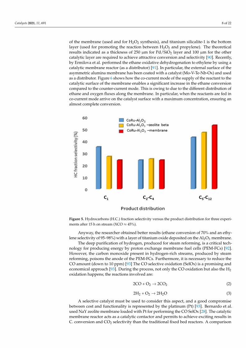
of the membrane (used and for H2O2 synthesis), and titanium silicalite-1 is the bottomlayer (used for promoting the reaction between H2O2 and propylene). The theoreticalresults indicated as a thickness of 250 µm for Pd/SiO2 layer and 100 µm for the othercatalytic layer are required to achieve attractive conversion and selectivity [90]. Recently,by Ermilova et al. performed the ethane oxidative dehydrogenation to ethylene by using acatalytic membrane reactor (as a distributor) [91]. In particular, the external surface of theasymmetric alumina membrane has been coated with a catalyst (Mo-V-Te-Nb-Ox) and usedas a distributor. Figure 6 shows how the co-current mode of the supply of the reactant to thecatalytic surface of the membrane enables a significant increase in the ethane conversioncompared to the counter-current mode. This is owing to due to the different distribution ofethane and oxygen fluxes along the membrane. In particular, when the reactants are fed inco-current mode arrive on the catalyst surface with a maximum concentration, ensuring analmost complete conversion.
Catalysts 2021, 11, x FOR PEER REVIEW 8 of 22
reactions [82]. Different research groups studied the possibility of using hydrophilic zeo-lite membranes for water removal from hydrogen and carbon monoxide using the oper-ating conditions typical of the FT process. In 2005, Zhou et al. [83] studied the separation of H2O/CO, H2O/H2, and H2O/CH4 versus the temperature using NaA membranes. The selectivities of H2O/CO, H2O/H2, and H2O/CH4 were 30, 72, and 323 at 100 °C. The water quickly passes through the membrane for the high affinity with the zeolite NaA strongly hydrophilic. Kapteijn and coworkers prepared sodalite membrane on alumina support that exhibited very high H2O/H2 selectivity up to 200 °C and so it is very promising for the water removal in FTS [84].
Recently, palladium membranes have been used to control hydrogen in a fixed-bed catalytic reactor for the FTS [85]. In particular, three different systems have been consid-ered: traditional fixed-bed reactor (FBR) using as catalyst CoRu/Al2O3, (ii) traditional FBR and CoRu/Al2O3-zeolite as a catalyst and the CMR (catalyst: CoRu/Al2O3). The selectivity of different hydrocarbon (HC) fractions versus the product distribution for the other ex-periments is shown in Figure 5. The results evidenced as the CMR permits to have better results due to the possibility to add in a controlled way the H2 avoiding the formation of methane (side reaction). The carbon monoxide conversion was about 45% after 15 h of catalytic test for the three experiments. FBR (catalyst: CoRu/Al2O3), FBR (catalyst: CoRu/Al2O3-zeolite); CMR (catalyst: CoRu/Al2O3).
.
Figure 5. Hydrocarbons (H.C.) fraction selectivity versus the product distribution for three experi-ments after 15 h on stream (XCO ≈45%).
The distributor configuration is usually used in different reactions such as the oxidation or oxy-dehydrogenation of hydrocarbons and oxidative coupling of methane. The oxygen, a reactant of the responses, is provided in a controlled manner [86,87]. The oxidative dehydrogenation of al-kanes allows olefin production conveniently than dehydrogenation and steam cracking [87]. This process shows no chemical equilibrium limitations as the dehydrogenation and required mild temperatures than the steam cracking [88]. In 1999, Santamaria and coworkers studied the oxida-tive dehydrogenation of propane by using a macroporous alumina membrane coated with the catalyst [89]. In particular, the researchers found that the membrane used as a distributor im-proved the reaction conversion [89]. The membrane application as the distributor has also been studied by Kartell et al., employing a theoretical study [90]. They proposed, using numerical simu-lations, a new membrane reactor for the direct synthesis of propylene oxide (PO) in the liquid phase. The reactor combines two consecutive catalytic reactor units: the hydrogen peroxide syn-thesis and the reaction of H2O2 with the propylene for synthesizing PO. Pd/SiO2 is the top layer of the membrane (used and for H2O2 synthesis), and titanium silicalite-1 is the bottom layer (used for
Figure 5. Hydrocarbons (H.C.) fraction selectivity versus the product distribution for three experi-ments after 15 h on stream (XCO ≈ 45%).
Anyway, the researcher obtained better results (ethane conversion of 70% and an ethy-lene selectivity of 95–98%) with a layer of titanium oxide deposited on the Al2O3 membrane.
The deep purification of hydrogen, produced for steam reforming, is a critical tech-nology for producing energy by proton exchange membrane fuel cells (PEM-FCs) [92].However, the carbon monoxide present in hydrogen-rich streams, produced by steamreforming, poisons the anode of the PEM-FCs. Furthermore, it is necessary to reduce theCO amount (down to 10 ppm) [93] The CO selective oxidation (SelOx) is a promising andeconomical approach [93]. During the process, not only the CO oxidation but also the H2oxidation happens; the reactions involved are:
2CO + O2 → 2CO2 (2)
2H2 + O2 → 2H2O (3)
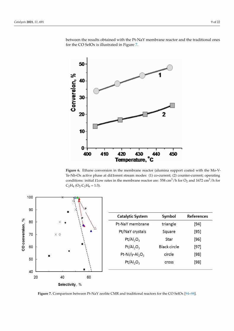
A selective catalyst must be used to consider this aspect, and a good compromisebetween cost and functionality is represented by the platinum (Pt) [93]. Bernardo et al.used NaY zeolite membrane loaded with Pt for performing the CO SelOx [28]. The catalyticmembrane reactor acts as a catalytic contactor and permits to achieve exciting results inC. conversion and CO2 selectivity than the traditional fixed bed reactors. A comparison
Catalysts 2021, 11, 691 9 of 22
between the results obtained with the Pt-NaY membrane reactor and the traditional onesfor the CO SelOx is illustrated in Figure 7.
Catalysts 2021, 11, x FOR PEER REVIEW 9 of 22
promoting the reaction between H2O2 and propylene). The theoretical results indicated as a thick-ness of 250 µm for Pd/SiO2 layer and 100 µm for the other catalytic layer are required to achieve attractive conversion and selectivity [90]. Recently, by Ermilova et al. performed the ethane oxida-tive dehydrogenation to ethylene by using a catalytic membrane reactor (as a distributor) [91]. In particular, the external surface of the asymmetric alumina membrane has been coated with a cata-lyst (Mo-V-Te-Nb-Ox) and used as a distributor. Figure 6 shows how the co-current mode of the supply of the reactant to the catalytic surface of the membrane enables a significant increase in the ethane conversion compared to the counter-current mode. This is owing to due to the different distribution of ethane and oxygen fluxes along the membrane. In particular, when the reactants are fed in co-current mode arrive on the catalyst surface with a maximum concentration, ensuring an almost complete conversion.
Figure 6. Ethane conversion in the membrane reactor (alumina support coated with the Mo-V-Te-Nb-Ox active phase at different stream modes: (1) co-current; (2) counter-current; operating condi-tions: initial flow rates in the membrane reactor are: 558 cm3/h for O 2and 1672 cm3/h forC2H4
(O2:C2H6 = 1:3.
Anyway, the researcher obtained better results (ethane conversion of 70% and an ethylene selectivity of 95–98% ) with a layer of titanium oxide deposited on the Al2O3 membrane.
The deep purification of hydrogen, produced for steam reforming, is a critical tech-nology for producing energy by proton exchange membrane fuel cells (PEM-FCs) [92]. However, the carbon monoxide present in hydrogen-rich streams, produced by steam re-forming, poisons the anode of the PEM-FCs. Furthermore, it is necessary to reduce the CO amount (down to 10 ppm) [93] The CO selective oxidation (SelOx) is a promising and economical approach [93]. During the process, not only the CO oxidation but also the H2 oxidation happens; the reactions involved are:
2CO+O2→2CO2 (2)
2H2+O2→2H2O (3)
A selective catalyst must be used to consider this aspect, and a good compromise between cost and functionality is represented by the platinum (Pt) [93]. Bernardo et al. used NaY zeolite membrane loaded with Pt for performing the CO SelOx [28]. The cata-lytic membrane reactor acts as a catalytic contactor and permits to achieve exciting results in C. conversion and CO2 selectivity than the traditional fixed bed reactors. A comparison
Figure 6. Ethane conversion in the membrane reactor (alumina support coated with the Mo-V-Te-Nb-Ox active phase at different stream modes: (1) co-current; (2) counter-current; operatingconditions: initial flow rates in the membrane reactor are: 558 cm3/h for O2 and 1672 cm3/h forC2H4 (O2:C2H6 = 1:3).
Catalysts 2021, 11, x FOR PEER REVIEW 10 of 22
between the results obtained with the Pt-NaY membrane reactor and the traditional ones for the CO SelOx is illustrated in Figure 7.
Figure 7. Comparison between Pt-NaY zeolite CMR and traditional reactors for the CO SelOx [94–98].
The better results obtained with the zeolite membrane reactor are due to the excellent dispersion of the catalytic particles in the zeolite layer. Good contact between reactants and catalytic sites is ensured [94,99]. Besides, considering that the zeolite layer is fragile a reduced by-pass and low-pressure drop are attained [94,99]. In an actual SelOx process, the gas stream, after the WGS, contains CO2 (20–25%) and Medrano et al. [99] demon-strated as the CO2 causes a decrease of the conversion and the selectivity due to the pres-ence of the reverse water gas shift that limited the CO oxidation at elevated temperature.
Their use at an industrial scale is missing among the different works focused on ap-plying membrane reactors in various industrial processes. The main drawbacks are the lack of scientific evidence about the long-term stability of the membrane reactors applied in actual operating conditions of the processes and the very high cost for the fabrication.
2. Organic Membrane Reactors 2.1. Introduction of Organic Membrane Reactors
Industrial-scale membrane units are often based on polymers, either natural (cellu-lose, rubbers and wool) or synthetic (Teflon, polyamide, polystyrene). Essentially, any kind of polymer can suit membrane casting, but, taking into account the wide range of physical and chemical features that they can exhibit, just a restricted part can be utilized. Choosing a polymer for a specific membrane is centred on precise features that regard the structural organization of the polymers themselves.
Porous or dense polymeric membranes are usually employed in processes with low reaction temperatures or in the presence of biocatalysts. Sorption–diffusion principles can couple catalytic reactions so that membranes such as the dense polymeric ones can act well to separate gases and liquids from mixtures in processes where separation and reac-tion act in the same step. Polymeric membranes need to be highly selective and exhibit high permeability to convey a satisfactory separation. Also, polymeric membranes may be well employed in catalytic reactions (liquid phase) [100].
2.2. Enzymatic Membrane Reactors: Preparation and Applications
Figure 7. Comparison between Pt-NaY zeolite CMR and traditional reactors for the CO SelOx [94–98].
Catalysts 2021, 11, 691 10 of 22
The better results obtained with the zeolite membrane reactor are due to the excellentdispersion of the catalytic particles in the zeolite layer. Good contact between reactantsand catalytic sites is ensured [94,99]. Besides, considering that the zeolite layer is fragile areduced by-pass and low-pressure drop are attained [94,99]. In an actual SelOx process, thegas stream, after the WGS, contains CO2 (20–25%) and Medrano et al. [99] demonstrated asthe CO2 causes a decrease of the conversion and the selectivity due to the presence of thereverse water gas shift that limited the CO oxidation at elevated temperature.
Their use at an industrial scale is missing among the different works focused onapplying membrane reactors in various industrial processes. The main drawbacks are thelack of scientific evidence about the long-term stability of the membrane reactors appliedin actual operating conditions of the processes and the very high cost for the fabrication.
2. Organic Membrane Reactors2.1. Introduction of Organic Membrane Reactors
Industrial-scale membrane units are often based on polymers, either natural (cellulose,rubbers and wool) or synthetic (Teflon, polyamide, polystyrene). Essentially, any kind ofpolymer can suit membrane casting, but, taking into account the wide range of physicaland chemical features that they can exhibit, just a restricted part can be utilized. Choosinga polymer for a specific membrane is centred on precise features that regard the structuralorganization of the polymers themselves.
Porous or dense polymeric membranes are usually employed in processes with lowreaction temperatures or in the presence of biocatalysts. Sorption–diffusion principles cancouple catalytic reactions so that membranes such as the dense polymeric ones can act wellto separate gases and liquids from mixtures in processes where separation and reactionact in the same step. Polymeric membranes need to be highly selective and exhibit highpermeability to convey a satisfactory separation. Also, polymeric membranes may be wellemployed in catalytic reactions (liquid phase) [100].
2.2. Enzymatic Membrane Reactors: Preparation and Applications
A catalytic membrane reactor (E-MBR) offers advantages concerning conventionalreactors because of the membrane’s ability to operate simultaneously as catalyst sup-port and selective barrier, combining a reaction with a particular mass transfer throughthe membrane.
Simultaneous removal of products from the reaction site allows effective conversion,even inhibiting or thermodynamically unfavourable reactions [101]. Researchers havedeveloped enzyme-catalyzed response at room temperature to reduce energy consumptionand minimize thermal degradation of the products. One of the essential characteristicsof the catalyst is activation by organic/aqueous biphasic interface (interface activation).The membrane allows them to independently control the catalyst and substrate concentra-tions, residence time and permeate flow; this, in turn, increases CMR productivity over abatch reactor.
Membrane reactors can be categorized into two types: inert and catalytic reactors. Themembrane is next to the reaction bulk in the inert type, which contains the catalyst, eithersuspended or packed. In contrast, in the catalytic reactors, the membrane is fixed on thecatalysts or has its catalytic activity. Often the inert types encounter inadequate compoundtransport due to the locking effect of particles, even by the enzymes/NPs, on the pores.At the same time, catalytic membrane reactors don’t suffer from these issues because oftheir fixed embedding of the catalysts on the membrane itself. Metal nanoparticles seemto be often chosen as catalysts, especially in environmental remediation scopes. They canhave very high catalytic performances; as an example Au and Pt nanoparticles are widelyused. In this context, Huang et al., as a solution for reducing 4-nitrophenol, developed acatalytic membrane reactor embedding a film by alloy nanoparticle-loaded β-lactoglobulinfibrils. They observed Cu nanoclusters’ formation, which stimulated the Ag0 synthesis as areducing agent for the 4-nitrophenol [101].
Catalysts 2021, 11, 691 11 of 22
Biofilms have widely been applied to civil water treatment before activated sludgeprocesses were available. In addition, biofilm reactors are used primarily in industrialfields for their reliability and ease of use. Biofilm growth begins by molecules (e.g., lipids,proteins) adsorption on a surface. These molecules can modify the physicochemical featuresof the surface, being a nutrient source for microbes, alter the release of metal ions, and causethe adsorption of inhibitory matters. As a general rule, biofilm reactors are consisted of:inlet and outlet sections, a biofilm carrier, an aeration unit in case of aerobic processes or amixing device in case of anoxic processes. Lai et al. demonstrated how perchlorate, mainlyknown as a groundwater contaminant, can undergo microbial reduction to form chloride.The process was driven by C2H6 or C3H8 with oxygen as a limiting compound. Theresearch applied two membrane biofilm reactors in parallel resulting in novel applicationsfor groundwater remediation [102].
Anaerobic membrane bioreactor (AnMBR) is a valid technology for domestic, civil,and wastewater treatment. This because of the high separation between hydraulic andsolid retention times (HRT and SRT), thus consenting to the growth of anaerobic bacteria; inaddition, they appear to have a low footprint and high treatment capacity while producinghigh-quality effluents. AnMBR, in contrast with aerobic MRs have low energy consumption(no aeration needed), exhibit lower solid yield and lower carbon dioxide emissions. Themain downside of AnMBRs being the fast decay of permeate flux caused by membranefouling. Berkessa et al. studied two formulations of AnMBRs applied on wastewatertreatment with long hydraulic retention times (47 days) and a 22 g·L−1 sludge concentration.The long HRT leadss to biofilm reduction by Chloroflexi (heterotrophic bacteria), resultingin large fluxes. Either the membrane resistances and the fouling rates values resulted aslow so that the study resulted in AnMBRs with excellent membrane fouling control [103].
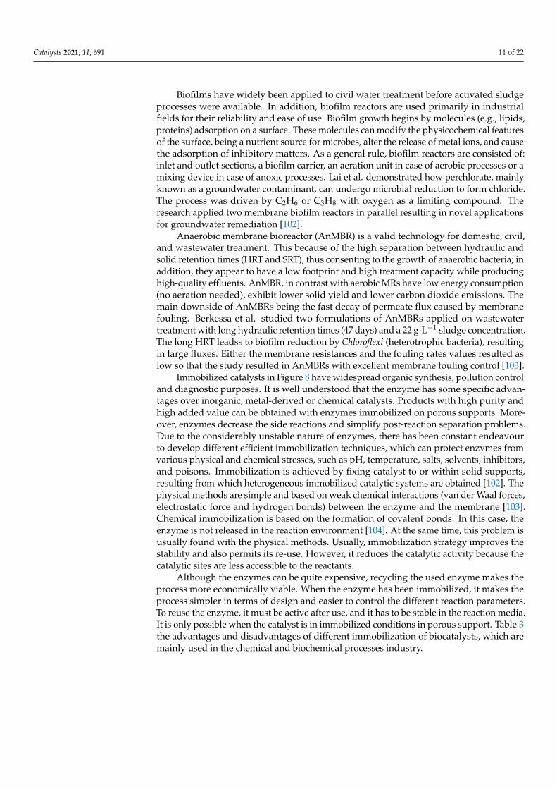
Immobilized catalysts in Figure 8 have widespread organic synthesis, pollution controland diagnostic purposes. It is well understood that the enzyme has some specific advan-tages over inorganic, metal-derived or chemical catalysts. Products with high purity andhigh added value can be obtained with enzymes immobilized on porous supports. More-over, enzymes decrease the side reactions and simplify post-reaction separation problems.Due to the considerably unstable nature of enzymes, there has been constant endeavourto develop different efficient immobilization techniques, which can protect enzymes fromvarious physical and chemical stresses, such as pH, temperature, salts, solvents, inhibitors,and poisons. Immobilization is achieved by fixing catalyst to or within solid supports,resulting from which heterogeneous immobilized catalytic systems are obtained [102]. Thephysical methods are simple and based on weak chemical interactions (van der Waal forces,electrostatic force and hydrogen bonds) between the enzyme and the membrane [103].Chemical immobilization is based on the formation of covalent bonds. In this case, theenzyme is not released in the reaction environment [104]. At the same time, this problem isusually found with the physical methods. Usually, immobilization strategy improves thestability and also permits its re-use. However, it reduces the catalytic activity because thecatalytic sites are less accessible to the reactants.
Although the enzymes can be quite expensive, recycling the used enzyme makes theprocess more economically viable. When the enzyme has been immobilized, it makes theprocess simpler in terms of design and easier to control the different reaction parameters.To reuse the enzyme, it must be active after use, and it has to be stable in the reaction media.It is only possible when the catalyst is in immobilized conditions in porous support. Table 3the advantages and disadvantages of different immobilization of biocatalysts, which aremainly used in the chemical and biochemical processes industry.
Catalysts 2021, 11, 691 12 of 22
Catalysts 2021, 11, x FOR PEER REVIEW 12 of 22
Moreover, enzymes decrease the side reactions and simplify post-reaction separation problems. Due to the considerably unstable nature of enzymes, there has been constant endeavour to develop different efficient immobilization techniques, which can protect en-zymes from various physical and chemical stresses, such as pH, temperature, salts, sol-vents, inhibitors, and poisons. Immobilization is achieved by fixing catalyst to or within solid supports, resulting from which heterogeneous immobilized catalytic systems are ob-tained [102]. The physical methods are simple and based on weak chemical interactions (van der Waal forces, electrostatic force and hydrogen bonds) between the enzyme and the membrane [103]. Chemical immobilization is based on the formation of covalent bonds. In this case, the enzyme is not released in the reaction environment [104]. At the same time, this problem is usually found with the physical methods. Usually, immobili-zation strategy improves the stability and also permits its re-use. However, it reduces the catalytic activity because the catalytic sites are less accessible to the reactants.
Figure 8. Different biocatalyst immobilization mechanism.
Although the enzymes can be quite expensive, recycling the used enzyme makes the process more economically viable. When the enzyme has been immobilized, it makes the process simpler in terms of design and easier to control the different reaction parameters. To reuse the enzyme, it must be active after use, and it has to be stable in the reaction media. It is only possible when the catalyst is in immobilized conditions in porous sup-port. Table 3 the advantages and disadvantages of different immobilization of biocata-lysts, which are mainly used in the chemical and biochemical processes industry.
Membrane bioreactors (MBR) are part of an established -developed technology found throughout the years’ many industrial applications worldwide. To mention one of the leading applications, many municipal and industrial wastewater is treated through MBR systems. Still, substantial research and progress are needed in this field as technical difficulties are still encountered, such as membrane fouling and not so low energy needs, thus slowing down the spread of MBR plants.
Table 3. Advantages and disadvantages of biocatalysts immobilized on porous supports.
Binding Method Binding Nature Advantages Disadvantages Adsorption Weak bonds Simple and easy to use Desorption
Limited loss of enzyme activ-ity
Non-specific adsorption
Figure 8. Different biocatalyst immobilization mechanism.
Table 3. Advantages and disadvantages of biocatalysts immobilized on porous supports.
Binding Method Binding Nature Advantages Disadvantages
Adsorption Weak bonds Simple and easy to use Desorption
Limited loss of enzyme activity Non-specific adsorption
Covalent BindingChemical binding between functionalgroups of the enzyme and those on
the supportNo diffusion barrier Matrix not regenerable
- - Stable & Short response time Coupling with toxic product
Entrapment Incorporation of the enzyme withina gel or a polymer
No chemical reaction between themonomer and the enzyme that
could affect the activity of enzyme
Enzyme leakage andDiffusion barrier
- -Several types of enzymes can be
immobilized within thesame polymer
High concentrations ofmonomer and enzyme for
electropolymerization
Cross-linking Bond between enzyme/cross-linker(e.g., glutaraldehyde)/inert molecule Simple High enzyme activity and
activity loss
AffinityAffinity bonds between a functionalgroup on a support and affinity tag
on a protein sequence
Controlled andoriented immobilization
Need of the presence ofspecific groups on enzyme
Membrane bioreactors (MBR) are part of an established -developed technology foundthroughout the years’ many industrial applications worldwide. To mention one of theleading applications, many municipal and industrial wastewater is treated through MBRsystems. Still, substantial research and progress are needed in this field as technicaldifficulties are still encountered, such as membrane fouling and not so low energy needs,thus slowing down the spread of MBR plants.
Nonetheless, as membrane costs of production have been reduced in recent years,MBR technology has gained increasing attention, mainly for constructing medium-size
Catalysts 2021, 11, 691 13 of 22
wastewater plants, corresponding to a water feed of an equivalent of up to 100,000 people.Moreover, in the same years, a focus on process optimization led to a substantial reductionof capital and operating expenses of new MBR plants.
Summing up all the features, it can be stated that the excellent quality of purified watermainly drives MBR technology in water treatment applications interest, the increasingwater scarcity issues, the growing strictness of quality and discharge legislations worldwide,the lower costs of investment, the fact that MBR technology is becoming more accepted asa valid option over time, and the possibility to be applied as an upgrade to existing watertreatment plants [101,105,106].
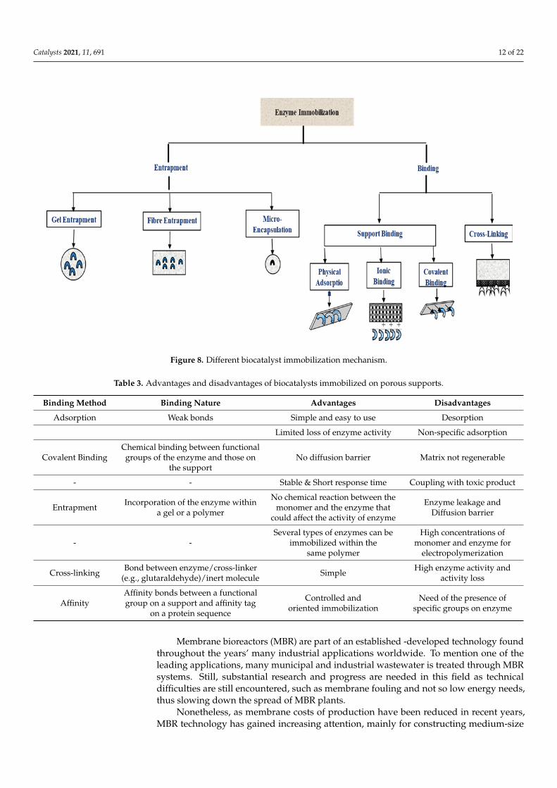
MBR devices can be organized in two main configurations, in which the positioningof the two main elements, the membrane and the reactor, varies. The first one can be seenas a side-stream method with a membrane situated outside the reactor, as in Figure 9a.The second one has the membrane collocated in the bulk of the reactor, so it acts whilesubmerged in the feed stream (Figure 9b).
Catalysts 2021, 11, x FOR PEER REVIEW 13 of 22
Covalent Binding
Chemical binding between functional groups of the en-zyme and those on the sup-
port
No diffusion barrier Matrix not regenerable
- - Stable & Short response time Coupling with toxic product
Entrapment Incorporation of the enzyme within a gel or a polymer
No chemical reaction be-tween the monomer and the enzyme that could affect the
activity of enzyme
Enzyme leakage and Diffu-sion barrier
- - Several types of enzymes can
be immobilized within the same polymer
High concentrations of mon-omer and enzyme for electro-
polymerization
Cross-linking Bond between enzyme/cross-
linker (e.g., glutaralde-hyde)/inert molecule
Simple High enzyme activity and ac-tivity loss
Affinity
Affinity bonds between a functional group on a sup-port and affinity tag on a
protein sequence
Controlled and oriented im-mobilization
Need of the presence of spe-cific groups on enzyme
Nonetheless, as membrane costs of production have been reduced in recent years, MBR technology has gained increasing attention, mainly for constructing medium-size wastewater plants, corresponding to a water feed of an equivalent of up to 100,000 people. Moreover, in the same years, a focus on process optimization led to a substantial reduction of capital and operating expenses of new MBR plants.
Summing up all the features, it can be stated that the excellent quality of purified water mainly drives MBR technology in water treatment applications interest, the increas-ing water scarcity issues, the growing strictness of quality and discharge legislations worldwide, the lower costs of investment, the fact that MBR technology is becoming more accepted as a valid option over time, and the possibility to be applied as an upgrade to existing water treatment plants [101,105,106].
MBR devices can be organized in two main configurations, in which the positioning of the two main elements, the membrane and the reactor, varies. The first one can be seen as a side-stream method with a membrane situated outside the reactor, as in Figure 9a. The second one has the membrane collocated in the bulk of the reactor, so it acts while submerged in the feed stream (Figure 9b).
Figure 9. MBR configurations: (a) Side-stream and (b) submerged.
In Table 4, the two configurations are compared in terms of applications and opera-tional features [107].
Figure 9. MBR configurations: (a) Side-stream and (b) submerged.
In Table 4, the two configurations are compared in terms of applications and opera-tional features [107].
Table 4. Comparison between the two MBR configurations. Adapted from [107].
Submerged MBR Sidestream MBR
Application Municipal-scale systems Industrial systemsSolids in activated sludge Feed with high temperature
Shear by Aeration Pump
Operation Mode Dead-end filtration Cross-flow filtration
Pressure Low High
Energy Consumption Significantly low High
Fouling Low High
The membrane in an MBR system works by three main principles: size exclusion,adsorption, electrostatic repulsion [107]. In size-exclusion, any compound larger than themembrane’s pores’ dimension is rejected or adsorptions of chemical species are governedby hydrophobicity and electrostatic repulsion [108]. The optimal circumstance occurs whenthe two constituents have either opposite charge or just a reduced charge; besides, a lowpH usually enhances adsorption. When the membrane and the chemical species have anidentical account, the molecules are rejected [108]. This determines the biomass growthin the reactor bulk, with the development of a phase with suspended solids and a (cake)layer directly attached to the surface of the membrane [109]. As an addition to that, the
Catalysts 2021, 11, 691 14 of 22
cake layer growth offers additional adsorption points, this because they are composed ofmicrobial products and polymers that can virtually act as an adsorbent for the chemicalspecies, which must be rejected [110,111].
MBR technology can improve water recycling thanks to its high pathogen eliminationperformance. The typically accepted limit of total suspended solids of 10 mg/L is notreachable by standard activated sludge technology but can be easily reached by MBRdevices in deeper detail. Furthermore, MBR technology applies physical disinfection to thetreated water, so the succeeding disinfection unit reaches a higher degree of effectiveness,thus reaching compliance with the imposed microbiological values. We can affirm thatwater recycling is significant to locate water scarcity and environmental remediationconcurrently. In addition, MBRs can efficiently eliminate an extensive range of organicpollutants, even some types that are immune to activated sludge [110].
Pharmaceutically-active compounds (PhACs) characterize an essential fraction oforganic pollutants traced in urban water environments. PhACs reach wastewater treat-ment plants (WWTPs) after human utilization either as metabolized or unmetabolizedcomponents. Even in PhACs remediation, MBR technology can deliver an efficient biologi-cal action on pollutants and a physical filtration without the limits that activated sludge(CAS) can bring. In fact, in MBR processes, biomass growth is not limited to flocculationmicroorganisms, however, bacteria can mature as dispersed. More than one study reportedthe successful usage of MBR technology for PhACs in urban wastewaters [112,113].
Urban and industrial wastewater streams may even contain an assortment of entericviruses, which take advantage of the faecal-oral routes of transmission to spread andcause numerous severe diseases like hepatitis and gastroenteritis [114]. In municipalsewage, the primary source of infection by enteric viruses starts with detachment frominfected people. The norovirus’s detaching (or shedding) rate surpasses 1010 particles pergram of faeces [115]. Furthermore, waterborne viruses result in more resistance to eitherenvironmental variables and treatments when compared to other pathogens (e.g., bacteria),this thanks to some of their peculiar features, either physical and biological.
It is easy to state that MBR applications can expand in many other wastewater streams,an example of greywater. Greywater is domestic sourcing wastewater (e.g., from kitchens,laundries and hand basins). These streams contain a wide range of pollutants like preser-vatives, emulsifiers, surfactants, softeners and solvents, and some heavy metals (Cd, Hg,Ni, Pb) lower concentrations than in urban wastewaters.
In the most recent years, the problem of energy recovery has mostly narrowed tomethane generation by anaerobic digestion (A.D.). The steps involved in the process arehydrolysis, acidogenesis, then acetogenesis, followed by methanogenesis. The latter is themain critical phase because it results in the slowest of all four A.D. steps. So A.D. methaneproduction improvement has been studied with lots of efforts to achieve higher energyefficiencies [116].
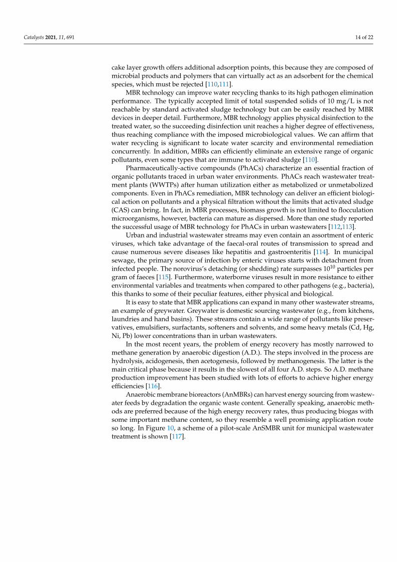
Anaerobic membrane bioreactors (AnMBRs) can harvest energy sourcing from wastew-ater feeds by degradation the organic waste content. Generally speaking, anaerobic meth-ods are preferred because of the high energy recovery rates, thus producing biogas withsome important methane content, so they resemble a well promising application routeso long. In Figure 10, a scheme of a pilot-scale AnSMBR unit for municipal wastewatertreatment is shown [117].
Catalysts 2021, 11, 691 15 of 22
Catalysts 2021, 11, x FOR PEER REVIEW 15 of 22
In the most recent years, the problem of energy recovery has mostly narrowed to methane generation by anaerobic digestion (A.D.). The steps involved in the process are hydrolysis, acidogenesis, then acetogenesis, followed by methanogenesis. The latter is the main critical phase because it results in the slowest of all four A.D. steps. So A.D. methane production improvement has been studied with lots of efforts to achieve higher energy efficiencies [116].
Anaerobic membrane bioreactors (AnMBRs) can harvest energy sourcing from wastewater feeds by degradation the organic waste content. Generally speaking, anaero-bic methods are preferred because of the high energy recovery rates, thus producing bio-gas with some important methane content, so they resemble a well promising application route so long. In Figure 10, a scheme of a pilot-scale AnSMBR unit for municipal wastewater treatment is shown [117].
Figure 10. Pilot scale AnSMBR unit for municipal wastewater treatment, as presented by D. Mar-tinez-Sosa et al. [117].
With improved process variables optimization, AnMBR technology for methane pro-duction is now a fully developed technology. It has been found that under thermophilic circumstances (ranging from 50 to 0°C), the growth rates of methanogenic bacteria are better compared to mesophilic conditions. Besides, coadjutants as nanoparticles (N.P.s) (Co, Ni, Fe oxides etc.) and modification methods as high-pressure treatments, alkaline pre-treatments, ammonia soaking can substantially increase the production yields [118].
As a valid application worth mentioning, biohydrogen production by anaerobic pro-cesses is in some ways preferred over methane for more than several reasons, such as the more comprehensive flammability limits, higher energy density, and the lower environ-mental impact during combustion which make hydrogen a preferable energy source. AnMBRs for biohydrogen production have a lesser environmental effect because of the absence of dissolved methane. Simultaneously, addressing both shows (hydrogen and methane) can increase efficiency in an AnMBR process.
Anyway, the more significant issue in biohydrogen production resides in the storage and transportation structure design. Storages with little densities, product losses (because of the hydrogen boiling-off), and methane chemical embrittlement (due to the penetration of hydrogen) are the main concerns in this field.
Nevertheless, energy production by AnMBRs still has engineering, financial, and ecological fields issues. It has been already said that methanogenesis is the slowest of the A.D. stages, resulting in really overall slow processes. Some treatments (either pre-or post) can be combined to quicken the initial steps of hydrolysis and acidogenesis, but in an case those might not increase the overall methane yield. Methane content is one of the critical features in biogases. For AnMBR processes, the product’s composition is directly linked to bacterial activity and substrate, starting with the feeds and process variables [119]. In
Figure 10. Pilot scale AnSMBR unit for municipal wastewater treatment, as presented by D. Martinez-Sosa et al. [117].
With improved process variables optimization, AnMBR technology for methaneproduction is now a fully developed technology. It has been found that under thermophiliccircumstances (ranging from 50 to 0 ◦C), the growth rates of methanogenic bacteria arebetter compared to mesophilic conditions. Besides, coadjutants as nanoparticles (N.P.s)(Co, Ni, Fe oxides etc.) and modification methods as high-pressure treatments, alkalinepre-treatments, ammonia soaking can substantially increase the production yields [118].
As a valid application worth mentioning, biohydrogen production by anaerobicprocesses is in some ways preferred over methane for more than several reasons, suchas the more comprehensive flammability limits, higher energy density, and the lowerenvironmental impact during combustion which make hydrogen a preferable energysource. AnMBRs for biohydrogen production have a lesser environmental effect because ofthe absence of dissolved methane. Simultaneously, addressing both shows (hydrogen andmethane) can increase efficiency in an AnMBR process.
Anyway, the more significant issue in biohydrogen production resides in the storageand transportation structure design. Storages with little densities, product losses (becauseof the hydrogen boiling-off), and methane chemical embrittlement (due to the penetrationof hydrogen) are the main concerns in this field.
Nevertheless, energy production by AnMBRs still has engineering, financial, andecological fields issues. It has been already said that methanogenesis is the slowest of theA.D. stages, resulting in really overall slow processes. Some treatments (either pre-or post)can be combined to quicken the initial steps of hydrolysis and acidogenesis, but in an casethose might not increase the overall methane yield. Methane content is one of the criticalfeatures in biogases. For AnMBR processes, the product’s composition is directly linked tobacterial activity and substrate, starting with the feeds and process variables [119]. In anaddition to that, the main challenge in the implementation of AnMBR applications on anindustrial scale is the need for invariability of the feed composition to avoid consequentalteration of the methane fraction in the biogas during the time.
The efficiency of AnMBR systems is furthermore affected by the effect of inhibitionon the methanogenesis step. This is due to some of the chemical compounds producedduring the intermediary stages of the A.D. In some instances, AnMBR goes through fasthydrolysis, leading to better rates of volatile fatty acids (VFAs) generation. The VFAs can
Catalysts 2021, 11, 691 16 of 22
gather in the reactor because they are transformed by methanogens in a extended manner,causing a severe reduction of pH and causing a level of instability in the process.
2.3. Cell Bioreactors
Microbial membrane bioreactors incorporate either a bioreactor in which biomass issuspended and a microfiltration (or even ultrafiltration) unit. Microbial cells are continu-ously recycled in the reactor through the retentate. Consequently, the biomass concentrationis enhanced in the reactor, resulting in efficiency and lower hydraulic residence times.
As membrane fouling is a significant disadvantage in MBR processes, alternativeMBR technologies can lead to better results. For instance, the incorporation of a post-treatment with micro-fuel cells (MFCs) in wastewater processing leads, at the same time,to high-quality effluents and modest bioelectricity harvesting, thus empowering the sus-tainability of wastewater treatments. The whole system is referred to as a microbial fuelcell–membrane bioreactor (MFC-MBR) system.
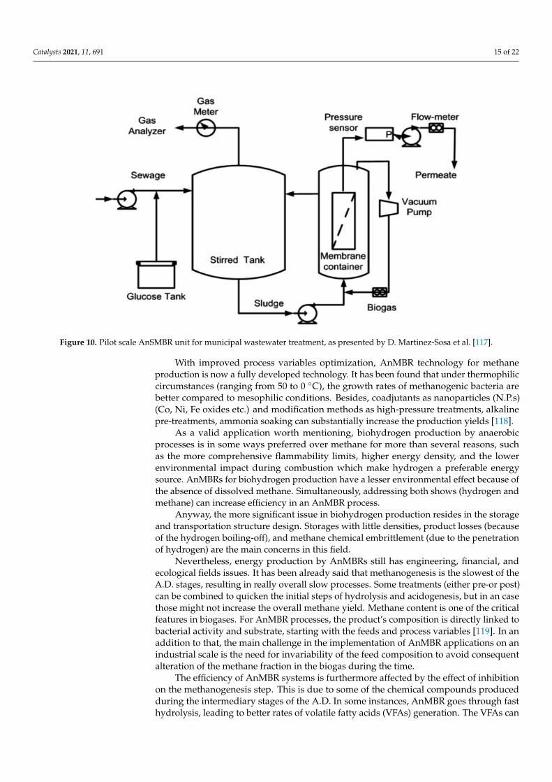
Two main types of MFCs can be distinguished: dual chamber and single chambertype. The dual-chamber MFC is subdivided in anode and cathode chambers through amembrane, either an ion or proton exchange membrane or even reverse osmosis or UF type.In the anode chamber, microorganisms electrochemically degrade organic and inorganiccompounds, thus generating electrons and protons. Bacteria enable electron transfer to theanode by a peripheral circuit, while the protons cross the membrane towards the cathode,reacting with electrons in the cathode chamber. This process generates a current whilethe contaminants are oxidized [1]. In the following Figure 11 the single chamber and thedual-chamber MFC-MBR layouts are presented.
Catalysts 2021, 11, x FOR PEER REVIEW 16 of 22
an addition to that, the main challenge in the implementation of AnMBR applications on an industrial scale is the need for invariability of the feed composition to avoid consequent alteration of the methane fraction in the biogas during the time.
The efficiency of AnMBR systems is furthermore affected by the effect of inhibition on the methanogenesis step. This is due to some of the chemical compounds produced during the intermediary stages of the A.D. In some instances, AnMBR goes through fast hydrolysis, leading to better rates of volatile fatty acids (VFAs) generation. The VFAs can gather in the reactor because they are transformed by methanogens in a extended manner, causing a severe reduction of pH and causing a level of instability in the process.
2.3. Cell Bioreactors Microbial membrane bioreactors incorporate either a bioreactor in which biomass is
suspended and a microfiltration (or even ultrafiltration) unit. Microbial cells are continu-ously recycled in the reactor through the retentate. Consequently, the biomass concentra-tion is enhanced in the reactor, resulting in efficiency and lower hydraulic residence times.
As membrane fouling is a significant disadvantage in MBR processes, alternative MBR technologies can lead to better results. For instance, the incorporation of a post-treat-ment with micro-fuel cells (MFCs) in wastewater processing leads, at the same time, to high-quality effluents and modest bioelectricity harvesting, thus empowering the sustain-ability of wastewater treatments. The whole system is referred to as a microbial fuel cell–membrane bioreactor (MFC-MBR) system.
Two main types of MFCs can be distinguished: dual chamber and single chamber type. The dual-chamber MFC is subdivided in anode and cathode chambers through a membrane, either an ion or proton exchange membrane or even reverse osmosis or UF type. In the anode chamber, microorganisms electrochemically degrade organic and inor-ganic compounds, thus generating electrons and protons. Bacteria enable electron transfer to the anode by a peripheral circuit, while the protons cross the membrane towards the cathode, reacting with electrons in the cathode chamber. This process generates a current while the contaminants are oxidized [1]. In the following Figure 11 the single chamber and the dual-chamber MFC-MBR layouts are presented.
Figure 11. MFC-MBR layouts: (a) single chamber, (b) dual chamber.
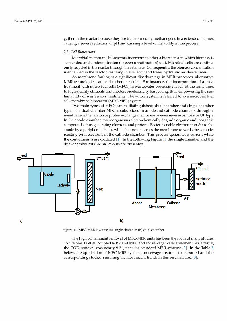
The high contaminant removal of MFC-MBR units has been the focus of many stud-ies. To cite one, Li et al. coupled MBR and MFC and for sewage water treatment. As a result, the COD removal was nearly 94%, near the standard MBR systems [2]. In the Table 5 _below, the application of MFC-MBR systems on sewage treatment is reported and the corresponding studies, summing the most recent trends in this research area [3].
Figure 11. MFC-MBR layouts: (a) single chamber, (b) dual chamber.
The high contaminant removal of MFC-MBR units has been the focus of many studies.To cite one, Li et al. coupled MBR and MFC and for sewage water treatment. As a result,the COD removal was nearly 94%, near the standard MBR systems [2]. In the Table 5below, the application of MFC-MBR systems on sewage treatment is reported and thecorresponding studies, summing the most recent trends in this research area [3].
Catalysts 2021, 11, 691 17 of 22
Table 5. MFC-MBR coupling systems for wastewater treatment.
Membrane Type Brand-Model COD Removal Rate NH3-N Removal Rate References
HOLLOW-FIBER MEMBRANE Self-preparation 95.6% 92.4% [117]HOLLOW-FIBER MEMBRANE Self-preparation 89.6 ± 3.7% - [118]HOLLOW-FIBER MEMBRANE Motian, China >90% 90 ± 3% [119]HOLLOW-FIBER MEMBRANE Self-preparation 95 ± 5% 70% [120]
- - >90% - [121]- - 97% 97% [122]
HOLLOW-FIBER MEMBRANE Self-preparation >95% - [123]- - 92.5% 70.6% [124]
HOLLOW-FIBER MEMBRANE Self-preparation 95 ± 2.5% 85 ± 2.5% [125]PVDF RuiBang, China 90% 80% [126]
TUBULAR MEMBRANE Motian, China 86.21% - [127]HOLLOW-FIBER MEMBRANE Self-preparation 77 ± 7% - [128]
PVDF Koion, South Korea 89 ± 3% - [129]PVDF Self-preparation 90% 80% [130]PVDF Self-preparation 73.87% - [131]
3. Conclusions and Future Perspective
Catalytic membrane reactors (CMRs) represent a process intensification-based technol-ogy that combines chemical or biochemical reactions with a membrane separation processin a single unit. CMR promotes an increase in process efficiency and a decrease in capitalcost and energy consumption. The membranes used can be polymeric and inorganic,depending on the operating conditions of the process. The membranes can also be inert orcatalytically active. Different catalytic processes are performed in very harsh conditionsand elevated temperatures, and so the use of the inorganic membranes is favored. Thefirst part is devoted to preparing and applying inorganic membrane in catalytic membranereactors in this review. Besides, the membrane roles in CMR have also been discussed.They can function as an extractor, distributor, and contractor. As an extractor, removing areaction product is achieved with better conversion due to the possibility of overcomingchemical equilibrium limitations when the membrane function as a distributor as a reactantis added to the reaction environment in a controlled way by limiting the side reactions. Themembrane as a contactor ensures better interaction between reactants and catalytic particlesby determining a conversion increase. Afterwards, MR application in various catalyticprocesses has also been reported and discussed. However, among the different worksfocused on the CMR application on various industrial processes, their use at an industrialscale is missing. The main disadvantages that block their application on a large scale arethe lack of scientific evidence about the CMRs’ long-term stability (when used under actualoperating conditions) and the high capital costs for their fabrication. Biocatalyst-basedprocesses are currently running in different parts of the world, but the application ofinorganic catalysts still needs lots more research before being applied industrially.
Author Contributions: Conceptualization by S.C. (Sudip Chakraborty) and C.A.; data investigationby G.C., data curation, C.A. and D.M.; writing—original draft preparation, S.C. (Sudip Chakraborty),C.A., G.C., D.M.; writing—review S.C. (Sudip Chakraborty) Sudip Chakraborty and C.A., M.I.S.,editing, S.C. (Stefano Curcio), V.C.; supervision, S.C. (Sudip Chakraborty). All authors have read andagreed to the published version of the manuscript.
Funding: This research received no external funding.
Data Availability Statement: Not applicable.
Conflicts of Interest: The authors declare no conflict of interests.
References1. Stankiewicz, A.I.; Moulijn, J.A. Process Intensification: Transforming Chemical Engineering. Chem. Eng. Prog. 2000, 96, 22–34.2. Helmi, A.; Gallucci, F. Latest Developments in Membrane (Bio)Reactors. Processes 2020, 8, 1239. [CrossRef]
Catalysts 2021, 11, 691 18 of 22
3. Westermann, T.; Melin, T. Flow-through Catalytic Membrane Reactors—Principles and Applications. Chem. Eng. Process. Process.Intensif. 2009, 48, 17–28. [CrossRef]
4. Algieri, C.; Chakraborty, S.; Pal, U. Efficacy of Phase Inversion Technique for Polymeric Membrane Fabrication. J. Phase Chang.Mater. 2021, 1. [CrossRef]
5. Abdallah, H. A Review on Catalytic Membranes Production and Applications. Bull. Chem. React. Eng. Catal. 2017, 12,136–156. [CrossRef]
6. Soria, R. Overview on Industrial Membranes. Catal. Today 1995, 25, 285–290. [CrossRef]7. Fard, A.K.; McKay, G.; Buekenhoudt, A.; Al Sulaiti, H.; Motmans, F.; Khraisheh, M.; Atieh, M. Inorganic Membranes: Preparation
and Application for Water Treatment and Desalination. Materials 2018, 11, 74. [CrossRef]8. Robeson, L.M. The Upper Bound Revisited. J. Memb. Sci. 2008, 320, 390–400. [CrossRef]9. Ismail, A.F.; David, L.I.B. A Review on the Latest Development of Carbon Membranes for Gas Separation. J. Membr. Sci. 2001,
193, 1–18. [CrossRef]10. Zaman, J.; Chakma, A. Inorganic Membrane Reactors. J. Membr. Sci. 1994, 92, 1–28. [CrossRef]11. van Veen, H.M.; Bracht, M.; Hamoen, E.; Alderliesten, P.T. Chapter 14 Feasibility of the Application of Porous Inorganic Gas
Separation Membranes in Some Large-Scale Chemical Processes. Membr. Sci. Technol. 1996, 4, 641–680. [CrossRef]12. Kallus, S.; Hahn, A.; Golemme, G.; Algieri, C.; Timmins, P.; Ramsay, J.D.F. Sol-Gel Routes to Zeolite Membranes and Thin Films.
J. Sol Gel Sci. Technol. 2003, 26, 721–725. [CrossRef]13. Alem, A.; Sarpoolaky, H.; Keshmiri, M. Sol-Gel Preparation of Titania Multilayer Membrane for Photocatalytic Applications.
Ceram. Int. 2009, 35, 1837–1843. [CrossRef]14. Dong, Y.; Chen, S.; Zhang, X.; Yang, J.; Liu, X.; Meng, G. Fabrication and Characterization of Low Cost Tubular Mineral-Based
Ceramic Membranes for Micro-Filtration from Natural Zeolite. J. Membr. Sci. 2006, 281, 592–599. [CrossRef]15. Kim, J.; Van der Bruggen, B. The use of nanoparticles in polymeric and ceramic membrane structures: Review of manufacturing
procedures and performance improvement for water treatment. Envrion. Pollut. 2010, 158, 2335–2349. [CrossRef] [PubMed]16. Li, K. Ceramic Membranes for Separation and Reaction; Wiley & Sons Ltd.: Chichester, UK, 2007.17. Dong, X.; Jin, W.; Xu, N.; Li, K. Dense Ceramic Catalytic Membranes and Membrane Reactors for Energy and Environmental
Applications. Chem. Commun. 2011, 47, 10886–10902. [CrossRef] [PubMed]18. Liu, J.; Dong, Y.; Dong, X.; Hampshire, S.; Zhu, L.; Zhu, Z.; Li, L. Feasible Recycling of Industrial Waste Coal Fly Ash for
Preparation of Anorthite-Cordierite Based Porous Ceramic Membrane Supports with Addition of Dolomite. J. Eur. Ceram. Soc.2016, 36, 1059–1071. [CrossRef]
19. Schafföner, S.; Freitag, L.; Hubalkova, J.; Aneziris, C.G. Functional Composites Based on Refractories Produced by Pressure SlipCasting. J. Eur. Ceram. Soc. 2016, 36, 2109–2117. [CrossRef]
20. Amin, S.K.; Abdallah, H.A.M.; Roushdy, M.H.; El-Sherbiny, S.A. An Overview of Production and Development of CeramicMembranes. Int. J. Appl. Eng. Res. 2016, 11, 7708–7721.
21. Das, N.; Maiti, H.S. Ceramic Membrane by Tape Casting and Sol–Gel Coating for Microfiltration and Ultrafiltration Application.J. Phys. Chem. Solids 2009, 70, 1395–1400. [CrossRef]
22. Fan, P.; Zhen, K.; Zan, Z.; Chao, Z.; Jian, Z.; Yun, J.Z. Preparation and Development of Porous Ceramic Membrane SupportsFabricated by Extrusion Technique. Chem. Eng. Trans. 2016, 55, 277–282.
23. Santos, L.N.R.M.; Silva, J.R.S.; Cartaxo, J.M.; Rodrigues, A.M.; Neves, G.A.; Menezes, R.R. Freeze-Casting Applied to CeramicMaterials: A Short Review of the Influence of Processing Parameters. Ceramica 2021, 67, 1–13. [CrossRef]
24. Agoudjil, N.; Kermadi, S.; Larbot, A. Synthesis of Inorganic Membrane by Sol–Gel Process. Desalination 2008, 223,417–424. [CrossRef]
25. Nandi, B.; Das, B.; Uppaluri, R.; Purkait, M.K. Microfiltration of Mosambi Juice Using Low Cost Ceramic Membrane. J. Food Eng.2009, 95, 597–605. [CrossRef]
26. Armbruster, T.; Gunter, M.E. Crystal Structures of Natural Zeolites. Rev. Mineral. Geochem. 2001, 45, 1–67. [CrossRef]27. Peng, P.; Gao, X.-H.; Yan, Z.-F.; Mintova, S. Diffusion and catalyst efficiency in hierarchical zeolite catalysts. Natl. Sci. Rev. 2020, 7,
1726–1742. [CrossRef]28. Bernardo, P.; Algieri, C.; Barbieri, G.; Drioli, E. Catalytic zeolite membrane reactors for the selective CO oxidation. Desalination
2006, 200, 702–704. [CrossRef]29. Jiang, J.; Wang, X.; Zhang, Y.; Liu, D.; Gu, X. Fabrication of pure-phase CHA zeolite membranes with ball-milled seeds at low K+
concentration. Microporous Mesoporous Mater. 2015, 215, 98–108. [CrossRef]30. Boudreau, L.C.; Kuck, J.A.; Tsapatsis, M. Deposition of Oriented Zeolite a Films: In Situ and Secondary Growth. J. Membr. Sci.
1999, 152, 41–59. [CrossRef]31. Lovallo, M.C.; Gouzinis, A.; Tsapatsis, M. Synthesis and characterization of oriented MFI membranes prepared by secondary
growth. AIChE J. 1998, 44, 1903–1913. [CrossRef]32. Nair, S.; Lai, Z.; Nikolakis, V.; Xomeritakis, G.; Bonilla, G.; Tsapatsis, M. Separation of close-boiling hydrocarbon mixtures by MFI
and FAU membranes made by secondary growth. Microporous Mesoporous Mater. 2001, 48, 219–228. [CrossRef]33. Algieri, C.; Bernardo, P.; Barbieri, G.; Drioli, E. A novel seeding procedure for preparing tubular NaY zeolite membranes.
Microporous Mesoporous Mater. 2009, 119, 129–136. [CrossRef]34. Lovallo, M.C.; Tsapatsis, M. Preferentially oriented submicron silicalite membranes. AIChE J. 1996, 42, 3020–3029. [CrossRef]

Catalysts 2021, 11, 691 19 of 22
35. Sato, K.; Nakane, T. A High Reproducible Fabrication Method for Industrial Production of High Flux NaA Zeolite Membrane.J. Membr. Sci. 2007, 301, 151–161. [CrossRef]
36. Kusakabe, K.; Kuroda, T.; Morooka, S. Separation of carbon dioxide from nitrogen using ion-exchanged faujasite-type zeolitemembranes formed on porous support tubes. J. Membr. Sci. 1998, 148, 13–23. [CrossRef]
37. Hasegawa, Y.; Sotowa, K.-I.; Kusakabe, K.; Morooka, S. The influence of feed composition on CO oxidation using zeolitemembranes loaded with metal catalysts. Microporous Mesoporous Mater. 2002, 53, 37–43. [CrossRef]
38. Chun, Y.S.; Ha, K.; Lee, Y.-J.; Lee, J.S.; Kim, H.S.; Park, Y.S.; Yoon, K.B. Diisocyanates as novel molecular binders for monolayerassembly of zeolite crystals on glass. Chem. Commun. 2002, 1846–1847. [CrossRef] [PubMed]
39. Huang, A.; Liang, F.; Steinbach, F.; Caro, J. Preparation and separation properties of LTA membranes by using 3-aminopropyltriethoxysilane as covalent linker. J. Membr. Sci. 2010, 350, 5–9. [CrossRef]
40. Pera-Titus, M.; Llorens, J.; Cunill, F.; Mallada, R.; Santamaría, J. Preparation of zeolite NaA membranes on the inner side oftubular supports by means of a controlled seeding technique. Catal. Today 2005, 104, 281–287. [CrossRef]
41. Garofalo, A.; Donato, L.; Drioli, E.; Criscuoli, A.; Carnevale, M.; Alharbi, O.; Aljlil, S.; Algieri, C. Supported MFI zeolitemembranes by cross flow filtration for water treatment. Sep. Purif. Technol. 2014, 137, 28–35. [CrossRef]
42. Garofalo, A.; Carnevale, M.; Donato, L.; Drioli, E.; Alharbi, O.; Aljlil, S.; Criscuoli, A.; Algieri, C. Scale-up of MFI zeolitemembranes for desalination by vacuum membrane distillation. Desalination 2016, 397, 205–212. [CrossRef]
43. Wang, Z.; Ge, Q.; Gao, J.; Shao, J.; Liu, C.; Yan, Y. High-performance zeolite membranes on inexpensive large-pore supports:Highly reproducible synthesis using a seed paste. ChemSusChem 2011, 4, 1570–1573. [CrossRef] [PubMed]
44. Feng, C.; Khulbe, K.C.; Matsuura, T.; Farnood, R.; Ismail, A.F. Recent Progress in Zeolite/Zeotype Membranes. J. Membr. Sci. Res.2015, 1, 49–72. [CrossRef]
45. Choi, J.; Jeong, H.-K.; Snyder, M.A.; Stoeger, J.A.; Masel, R.I.; Tsapatsis, M. Grain Boundary Defect Elimination in a ZeoliteMembrane by Rapid Thermal Processing. Science 2009, 325, 590–593. [CrossRef]
46. Morigami, Y.; Kondo, M.; Abe, J.; Kita, H.; Okamoto, K. The first large-scale pervaporation plant using tubular-type module withzeolite NaA membrane. Sep. Purif. Technol. 2001, 25, 251–260. [CrossRef]
47. Catalano, J.; Baschetti, M.G.; Sarti, G.C. Hydrogen permeation in palladium-based membranes in the presence of carbon monoxide.J. Membr. Sci. 2010, 362, 221–233. [CrossRef]
48. Gade, S.K.; Thoen, P.M.; Way, J.D. Unsupported palladium alloy foil membranes fabricated by electroless plating. J. Membr. Sci.2008, 316, 112–118. [CrossRef]
49. Palo, E.; Salladini, A.; Morico, B.; Palma, V.; Ricca, A.; Iaquaniello, G. Application of Pd-Based Membrane Reactors: An IndustrialPerspective. Membranes 2018, 8, 101. [CrossRef]
50. Fernandez, E.; Helmi, A.; Medrano, J.; Coenen, K.; Arratibel, A.; Melendez, J.; de Nooijer, N.; Spallina, V.; Viviente, J.;Zuñiga, J.; et al. Palladium based membranes and membrane reactors for hydrogen production and purification: An overview ofresearch activities at Tecnalia and TU/e. Int. J. Hydrogen Energy 2017, 42, 13763–13776. [CrossRef]
51. Wei, L.; Yu, J.; Hu, X.; Wang, R.; Huang, Y. Effects of Sn residue on the high temperature stability of the H2-permeable palladiummembranes prepared by electroless plating on Al2O3 substrate after SnCl2–PdCl2 process: A case study. Chin. J. Chem. Eng. 2016,24, 1154–1160. [CrossRef]
52. Iliuta, M.C.; Grandjean, B.P.A.; Larachi, F. Methane Nonoxidative Aromatization over Ru−Mo/HZSM-5 at Temperatures up to973 K in a Palladium−Silver/Stainless Steel Membrane Reactor. Ind. Eng. Chem. Res. 2003, 42, 323–330. [CrossRef]
53. Gallucci, F.; Fernandez, E.; Corengia, P.; van Annaland, M.S. Recent advances on membranes and membrane reactors for hydrogenproduction. Chem. Eng. Sci. 2013, 92, 40–66. [CrossRef]
54. Guo, Y.; Wu, H.; Fan, X.; Zhou, L.; Chen, Q. Palladium composite membrane fabricated on rough porous alumina tube withoutintermediate layer for hydrogen separation. Int. J. Hydrogen Energy 2017, 42, 9958–9965. [CrossRef]
55. Cheng, Y.S. Effects of electroless plating chemistry on the synthesis of palladium membranes. J. Membr. Sci. 2001, 182,195–203. [CrossRef]
56. Alkali, A. Electroless Plating of Palladium Membranes on Porous Substrates for Hydrogen Separation and the Effects of ProcessFactors on Plating Rate and Efficiency: A Review. J. Power Energy Eng. 2020, 8, 1–19. [CrossRef]
57. Alique, D.; Martinez-Diaz, D.; Sanz, R.; Calles, J.A. Review of Supported Pd-Based Membranes Preparation by Electroless Platingfor Ultra-Pure Hydrogen Production. Membranes 2018, 8, 5. [CrossRef]
58. Li, A.; Grace, J.R.; Lim, C.J. Preparation of thin Pd-based composite membrane on planar metallic substrate: Part II. Preparationof membranes by electroless plating and characterization. J. Membr. Sci. 2007, 306, 159–165. [CrossRef]
59. Miachon, S.; Dalmon, J.-A. Catalysis in Membrane Reactors: What about the Catalyst? Top. Catal. 2004, 29, 59–65. [CrossRef]60. Julbe, A.; Farrusseng, D.; Guizard, C. Porous ceramic membranes for catalytic reactors—Overview and new ideas. J. Membr. Sci.
2001, 181, 3–20. [CrossRef]61. Leonzio, G. Methanol Synthesis: Optimal Solution for a Better Efficiency of the Process. Processes 2018, 6, 20. [CrossRef]62. Kingsbury, B.F.; Wu, Z.; Li, K. A morphological study of ceramic hollow fibre membranes: A perspective on multifunctional
catalytic membrane reactors. Catal. Today 2010, 156, 306–315. [CrossRef]63. Caro, J.; Caspary, K.J.; Hamel, C.; Hoting, B.; Kölsch, P.; Langanke, B.; Nassauer, K.; Schiestel, T.; Schmidt, A.; Schomäcker, R.; et al.
Catalytic Membrane Reactors for Partial Oxidation Using Perovskite Hollow Fiber Membranes and for Partial HydrogenationUsing a Catalytic Membrane Contactor. Ind. Eng. Chem. Res. 2007, 46, 2286–2294. [CrossRef]

Catalysts 2021, 11, 691 20 of 22
64. Chen, L.; Qi, Z.; Zhang, S.; Su, J.; Somorjai, G.A. Catalytic Hydrogen Production from Methane: A Review on Recent Progressand Prospect. Catalysts 2020, 10, 858. [CrossRef]
65. Catalano, J.; Guazzone, F.; Mardilovich, I.P.; Kazantzis, N.K.; Ma, Y.H. Hydrogen Production in a Large Scale Water–Gas ShiftPd-Based Catalytic Membrane Reactor. Ind. Eng. Chem. Res. 2013, 52, 1042–1055. [CrossRef]
66. Augustine, A.S.; Ma, Y.H.; Kazantzis, N.K. High pressure palladium membrane reactor for the high temperature water–gas shiftreaction. Int. J. Hydrogen Energy 2011, 36, 5350–5360. [CrossRef]
67. Kim, S.-J.; Yang, S.; Reddy, G.K.; Smirniotis, P.; Dong, J. Zeolite Membrane Reactor for High-Temperature Water-Gas ShiftReaction: Effects of Membrane Properties and Operating Conditions. Energy Fuels 2013, 27, 4471–4480. [CrossRef]
68. Arvanitis, A.; Sun, X.; Yang, S.; Damma, D.; Smirniotis, P.; Dong, J. Approaching complete CO conversion and total H2 recoveryfor water gas shift reaction in a high-temperature and high-pressure zeolite membrane reactor. J. Membr. Sci. 2018, 549,575–580. [CrossRef]
69. Zhang, Y.; Sun, Q.; Gu, X. Pure H2production through hollow fiber hydrogen-selective MFI zeolite membranes using steam assweep gas. AIChE J. 2015, 61, 3459–3469. [CrossRef]
70. Zhang, Y.; Wu, Z.; Hong, Z.; Gu, X.; Xu, N. Hydrogen-selective zeolite membrane reactor for low temperature water gas shiftreaction. Chem. Eng. J. 2012, 197, 314–321. [CrossRef]
71. Tang, Z.; Kim, S.-J.; Reddy, G.K.; Dong, J.; Smirniotis, P. Modified zeolite membrane reactor for high temperature water gas shiftreaction. J. Membr. Sci. 2010, 354, 114–122. [CrossRef]
72. Kim, S.-J.; Xu, Z.; Reddy, G.K.; Smirniotis, P.; Dong, J. Effect of Pressure on High-Temperature Water Gas Shift Reaction inMicroporous Zeolite Membrane Reactor. Ind. Eng. Chem. Res. 2012, 51, 1364–1375. [CrossRef]
73. Bang, G.; Moon, D.-K.; Kang, J.-H.; Han, Y.-J.; Kim, K.-M.; Lee, C.-H. High-purity hydrogen production via a water-gas-shiftreaction in a palladium-copper catalytic membrane reactor integrated with pressure swing adsorption. Chem. Eng. J. 2021,411, 128473. [CrossRef]
74. Abdollahi, M.; Yu, J.; Liu, P.K.; Ciora, R.; Sahimi, M.; Tsotsis, T.T. Ultra-pure hydrogen production from reformate mixtures usinga palladium membrane reactor system. J. Membr. Sci. 2012, 390–391, 32–42. [CrossRef]
75. Pinacci, P.; Broglia, M.; Valli, C.; Capannelli, G.; Comite, A. Evaluation of the water gas shift reaction in a palladium membranereactor. Catal. Today 2010, 156, 165–172. [CrossRef]
76. Mendes, D.; Chibante, V.; Zheng, J.-M.; Tosti, S.; Borgognoni, F.; Mendes, A.; Madeira, L.M. Enhancing the production of hydrogenvia water–gas shift reaction using Pd-based membrane reactors. Int. J. Hydrogen Energy 2010, 35, 12596–12608. [CrossRef]
77. Dolan, M.; Donelson, R.; Dave, N. Performance and economics of a Pd-based planar WGS membrane reactor for coal gasification.Int. J. Hydrogen Energy 2010, 35, 10994–11003. [CrossRef]
78. Brunetti, A.; Drioli, E.; Barbieri, G. Medium/high temperature water gas shift reaction in a Pd–Ag membrane reactor: Anexperimental investigation. RSC Adv. 2012, 2, 226–233. [CrossRef]
79. Iyoha, O.; Enick, R.; Killmeyer, R.; Howard, B.; Morreale, B.; Ciocco, M. Wall-catalyzed water-gas shift reaction in multi-tubularPd and 80 wt%Pd–20 wt% Cu membrane reactors at 1173 K. J. Membr. Sci. 2007, 298, 14–23. [CrossRef]
80. Senatore, A.; Giorgianni, G.; Dalena, F.; Giglio, E. Lignocellulosic biomass conversion into bioenergy: Feedstock overview.J. Phase Chang. Mater. 2021, 1. [CrossRef]
81. Rohde, M.P.; Unruh, D.; Schaub, G. Membrane application in Fischer–Tropsch synthesis reactors—Overview of concepts. Catal.Today 2005, 106, 143–148. [CrossRef]
82. Liuzzi, D.; Fernandez, E.; Perez, S.; Ipiñazar, E.; Arteche, A.; Fierro, J.L.G.; Viviente, J.L.; Tanaka, D.A.P.; Rojas, S. Advances in mem-branes and membrane reactors for the Fischer-Tropsch synthesis process for biofuel production. Rev. Chem. Eng. 2019. [CrossRef]
83. Zhu, W.; Gora, L.; Berg, A.V.D.; Kapteijn, F.; Jansen, J.; Moulijn, J. Water vapour separation from permanent gases by a zeolite-4Amembrane. J. Membr. Sci. 2005, 253, 57–66. [CrossRef]
84. Rohde, M.; Schaub, G.; Khajavi, S.; Jansen, J.; Kapteijn, F. Fischer–Tropsch synthesis with in situ H2O removal—Directions ofmembrane development. Microporous Mesoporous Mater. 2008, 115, 123–136. [CrossRef]
85. Escorihuela, S.; Toldra-Reig, F.; Escolástico, S.; Murciano, R.; Martínez, A.; Serra, J.M. Copper surface-alloying of H2-permeablePd-based membrane for integration in Fischer–Tropsch synthesis reactors. J. Membr. Sci. 2021, 619, 118516. [CrossRef]
86. Kustov, L.M.; Kucherov, A.V.; Finashina, E.D. Oxidative dehydrogenation of C2–C4 alkanes into alkenes: Conventional catalyticsystems and microwave catalysis. Russ. J. Phys. Chem. A 2013, 87, 345–351. [CrossRef]
87. Mleczko, L.; Baerns, M. Catalytic oxidative coupling of methane—Reaction engineering aspects and process schemes. Fuel Process.Technol. 1995, 42, 217–248. [CrossRef]
88. Rostom, S.; De Lasa, H. Propane Oxidative Dehydrogenation on Vanadium-Based Catalysts under Oxygen-Free Atmospheres.Catalysts 2020, 10, 418. [CrossRef]
89. Alfonso, M.; Julbe, A.; Farrusseng, D.; Menéndez, M.; Santamaría, J. Oxidative dehydrogenation of propane on V/Al2O3 catalyticmembranes. Effect of the type of membrane and reactant feed configuration. Chem. Eng. Sci. 1999, 54, 1265–1272. [CrossRef]
90. Kertalli, E.; D’Angelo, M.N.; Schouten, J.; Nijhuis, T. Design and optimization of a catalytic membrane reactor for the directsynthesis of propylene oxide. Chem. Eng. Sci. 2015, 138, 465–472. [CrossRef]
91. Ermilova, M.; Kucherov, A.; Orekhova, N.; Finashina, E.; Kustov, L.; Yaroslavtsev, A. Ethane oxidative dehydrogenationto ethylene in a membrane reactor with asymmetric ceramic membranes. Chem. Eng. Process. Process. Intensif. 2018, 126,150–155. [CrossRef]
Catalysts 2021, 11, 691 21 of 22
92. Ercolino, G.; Ashraf, M.A.; Specchia, V.; Specchia, S. Performance evaluation and comparison of fuel processors integrated withPEM fuel cell based on steam or autothermal reforming and on CO preferential oxidation or selective methanation. Appl. Energy2015, 143, 138–153. [CrossRef]
93. Manasilp, A.; Gulari, E. Selective CO Oxidation over Pt/Alumina Catalysts for Fuel Cell Applications. Appl. Catal. B Environ.2002, 37, 17–25. [CrossRef]
94. Bernardo, P.; Algieri, C.; Barbieri, G.; Drioli, E. Hydrogen purification from carbon monoxide by means of selective oxidationusing zeolite catalytic membranes. Sep. Purif. Technol. 2008, 62, 629–635. [CrossRef]
95. Igarashi, H.; Uchida, H.; Suzuki, M.; Sasaki, Y.; Watanabe, M. Removal of carbon monoxide from hydrogen-rich fuels by selectiveoxidation over platinum catalyst supported on zeolite. Appl. Catal. A Gen. 1997, 159, 159–169. [CrossRef]
96. Avgouropoulos, G.; Ioannides, T.; Papadopoulou, C.; Batista, J.; Hocevar, S.; Matralis, H. A comparative study of Pt/γ-Al2O3,Au/α-Fe2O3 and CuO–CeO2 catalysts for the selective oxidation of carbon monoxide in excess hydrogen. Catal. Today 2002, 75,157–167. [CrossRef]
97. Ko, E.-Y.; Park, E.D.; Seo, K.W.; Lee, H.C.; Lee, D.; Kim, S. Selective CO oxidation in the presence of hydrogen over supported Ptcatalysts promoted with transition metals. Korean J. Chem. Eng. 2006, 23, 182–187. [CrossRef]
98. Monyanon, S.; Pongstabodee, S.; Luengnaruemitchai, A. Preferential oxidation of carbon monoxide over Pt, Au monometalliccatalyst, and Pt–Au bimetallic catalyst supported on ceria in hydrogen-rich reformate. J. Chin. Inst. Chem. Eng. 2007, 38,435–441. [CrossRef]
99. Medrano, J.; Garofalo, A.; Donato, L.; Basile, F.; De Santo, M.; Gallucci, F.; Cofone, F.; Ciuchi, F.; Algieri, C. CO selective oxidationusing catalytic zeolite membranes. Chem. Eng. J. 2018, 351, 40–47. [CrossRef]
100. Chakraborty, S.; Pal, U. Towards growth and sustainable researches in phase change materials. J. Phase Chang. Mater.2021, 1. [CrossRef]
101. Huang, R.; Zhu, H.; Su, R.; Qi, W.; He, Z. Catalytic Membrane Reactor Immobilized with Alloy Nanoparticle-Loaded ProteinFibrils for Continuous Reduction of 4-Nitrophenol. Environ. Sci. Technol. 2016, 50, 11263–11273. [CrossRef]
102. Lai, C.-Y.; Wu, M.; Lu, X.; Wang, Y.; Yuan, Z.; Guo, J. Microbial Perchlorate Reduction Driven by Ethane and Propane. Environ.Sci. Technol. 2021, 55, 2006–2015. [CrossRef] [PubMed]
103. Berkessa, Y.W.; Yan, B.; Li, T.; Tan, M.; She, Z.; Jegatheesan, V.; Jiang, H.; Zhang, Y. Novel anaerobic membrane bioreactor (AnMBR)design for wastewater treatment at long HRT and high solid concentration. Bioresour. Technol. 2018, 250, 281–289. [CrossRef]
104. Hamedi, H.; Ehteshami, M.; Mirbagheri, S.A.; Rasouli, S.A.; Zendehboudi, S. Current Status and Future Prospects of MembraneBioreactors (MBRs) and Fouling Phenomena: A Systematic Review. Can. J. Chem. Eng. 2019, 97, 32–58. [CrossRef]
105. Zhu, Y.; Chen, R.; Li, Y.-Y.; Sano, D. Virus removal by membrane bioreactors: A review of mechanism investigation and modelingefforts. Water Res. 2021, 188, 116522. [CrossRef]
106. Gentile, G.J.; Cruz, M.C.; Rajal, V.B.; de Cortalezzi, M.M.F. Electrostatic interactions in virus removal by ultrafiltration membranes.J. Environ. Chem. Eng. 2018, 6, 1314–1321. [CrossRef]
107. ElHadidy, A.M.; Peldszus, S.; Van Dyke, M.I. An evaluation of virus removal mechanisms by ultrafiltration membranes usingMS2 and ϕX174 bacteriophage. Sep. Purif. Technol. 2013, 120, 215–223. [CrossRef]
108. Yin, Z.; Tarabara, V.V.; Xagoraraki, I. Effect of pressure relaxation and membrane backwash on adenovirus removal in a membranebioreactor. Water Res. 2016, 88, 750–757. [CrossRef]
109. Sherwin, C.; Bhat, S.; Hebbar, S.P. Effect of plating time on surface morphology and coating thickness of nickel plating on coppersurface. J. Phase Chang. Mater. 2021, 1. [CrossRef]
110. Shakir, E.; Zahraw, Z.; Al-Obaidy, A.H.M. Environmental and health risks associated with reuse of wastewater for irrigation.Egypt. J. Pet. 2017, 26, 95–102. [CrossRef]
111. Teunis, P.F.M.; Sukhrie, F.H.A.; Vennema, H.; Bogerman, J.; Beersma, M.F.C.; Koopmans, M.P.G. Shedding of norovirus insymptomatic and asymptomatic infections. Epidemiol. Infect. 2015, 143, 1710–1717. [CrossRef] [PubMed]
112. Adekunle, K.F.; Okolie, J.A. A Review of Biochemical Process of Anaerobic Digestion. Adv. Biosci. Biotechnol. 2015, 06,205–212. [CrossRef]
113. Martinez-Sosa, D.; Helmreich, B.; Netter, T.; Paris, S.; Bischof, F.; Horn, H. Anaerobic submerged membrane bioreactor (AnSMBR)for municipal wastewater treatment under mesophilic and psychrophilic temperature conditions. Bioresour. Technol. 2011, 102,10377–10385. [CrossRef] [PubMed]
114. Abdelsalam, E.; Samer, M.; Attia, Y.; Abdel-Hadi, M.; Hassan, H.; Badr, Y. Comparison of nanoparticles effects on biogas andmethane production from anaerobic digestion of cattle dung slurry. Renew. Energy 2016, 87, 592–598. [CrossRef]
115. Mao, C.; Feng, Y.; Wang, X.; Ren, G. Review on research achievements of biogas from anaerobic digestion. Renew. Sustain. EnergyRev. 2015, 45, 540–555. [CrossRef]
116. Liu, W.; Jia, H.; Wang, J.; Zhang, H.; Xin, C.; Zhang, Y. Microbial fuel cell and membrane bioreactor coupling system: Recenttrends. Environ. Sci. Pollut. Res. 2018, 25, 23631–23644. [CrossRef]
117. Wang, Y.-K.; Sheng, G.-P.; Li, W.-W.; Huang, Y.-X.; Yu, Y.-Y.; Zeng, R.J.; Yu, H.-Q. Development of a Novel BioelectrochemicalMembrane Reactor for Wastewater Treatment. Environ. Sci. Technol. 2011, 45, 9256–9261. [CrossRef] [PubMed]
118. Wang, Y.-P.; Liu, X.-W.; Li, W.-W.; Li, F.; Wang, Y.-K.; Sheng, G.-P.; Zeng, R.J.; Yu, H.-Q. A microbial fuel cell–membrane bioreactorintegrated system for cost-effective wastewater treatment. Appl. Energy 2012, 98, 230–235. [CrossRef]
Catalysts 2021, 11, 691 22 of 22
119. Su, X.; Tian, Y.; Sun, Z.; Lu, Y.; Li, Z. Performance of a combined system of microbial fuel cell and membrane bioreactor:Wastewater treatment, sludge reduction, energy recovery and membrane fouling. Biosens. Bioelectron. 2013, 49, 92–98. [CrossRef]
120. Liu, J.; Shen, X.; Zhao, Y.; Chen, L. Acryloylmorpholine-Grafted PVDF Membrane with Improved Protein Fouling Resistance. Ind.Eng. Chem. Res. 2013, 52, 18392–18400. [CrossRef]
121. Kim, K.-Y.; Chae, K.-J.; Choi, M.-J.; Yang, E.-T.; Hwang, M.H.; Kim, I.S. High-quality effluent and electricity production fromnon-CEM based flow-through type microbial fuel cell. Chem. Eng. J. 2013, 218, 19–23. [CrossRef]
122. Malaeb, L.; Katuri, K.P.; Logan, B.E.; Maab, H.; Nunes, S.P.; Saikaly, P.E. A Hybrid Microbial Fuel Cell Membrane Biore-actor with a Conductive Ultrafiltration Membrane Biocathode for Wastewater Treatment. Environ. Sci. Technol. 2013, 47,11821–11828. [CrossRef]
123. Li, J.; Ge, Z.; He, Z. Advancing membrane bioelectrochemical reactor (MBER) with hollow-fiber membranes installed in thecathode compartment. J. Chem. Technol. Biotechnol. 2014, 89, 1330–1336. [CrossRef]
124. Xu, L.; Zhang, G.-Q.; Yuan, G.-E.; Liu, H.-Y.; Liu, J.-D.; Yang, F.-L. Anti-fouling performance and mechanism of an-thraquinone/polypyrrole composite modified membrane cathode in a novel MFC–aerobic MBR coupled system. RSC Adv. 2015,5, 22533–22543. [CrossRef]
125. Tian, Y.; Li, H.; Li, L.; Su, X.; Lu, Y.; Zuo, W.; Zhang, J. In-situ integration of microbial fuel cell with hollow-fiber membrane biore-actor for wastewater treatment and membrane fouling mitigation. Biosens. Bioelectron. 2015, 64, 189–195. [CrossRef] [PubMed]
126. Li, Y.; Liu, L.; Yang, F.; Ren, N. Performance of carbon fiber cathode membrane with C–Mn–Fe–O catalyst in MBR–MFC forwastewater treatment. J. Membr. Sci. 2015, 484, 27–34. [CrossRef]
127. Wang, J.; Bi, F.; Ngo, H.-H.; Guo, W.; Jia, H.; Zhang, H.; Zhang, X. Evaluation of energy-distribution of a hybrid microbial fuelcell–membrane bioreactor (MFC–MBR) for cost-effective wastewater treatment. Bioresour. Technol. 2016, 200, 420–425. [CrossRef]
128. Ishizaki, S.; Terada, K.; Miyake, H.; Okabe, S. Impact of Anodic Respiration on Biopolymer Production and Consequent MembraneFouling. Environ. Sci. Technol. 2016, 50, 9515–9523. [CrossRef] [PubMed]
129. Kim, K.-Y.; Yang, W.; Ye, Y.; LaBarge, N.; Logan, B.E. Performance of anaerobic fluidized membrane bioreactors using effluents ofmicrobial fuel cells treating domestic wastewater. Bioresour. Technol. 2016, 208, 58–63. [CrossRef] [PubMed]
130. Li, L.; Tian, Y.; Zhang, J.; Zuo, W.; Li, H.; Li, A.; Huang, D.; Liu, J.; Liu, Y.; Sun, Z.; et al. Insight into the roles of worm reactoron wastewater treatment and sludge reduction in anaerobic-anoxic-oxic membrane bioreactor (A2O-MBR): Performance andmechanism. Chem. Eng. J. 2017, 330, 718–726. [CrossRef]
131. Liu, J.; Tian, C.; Jia, X.; Xiong, J.; Dong, S.; Wang, L.; Bo, L. The brewery wastewater treatment and membrane fouling mitigationstrategies in anaerobic baffled anaerobic/aerobic membrane bioreactor. Biochem. Eng. J. 2017, 127, 53–59. [CrossRef]