Membrane Bio Reactors (MBR) in Waste Water Treatment: A Review of the Recent Patents
16
Recent Patents on Biotechnology 2010, 4, 65-80 65 1872-2083/10 $100.00+.00 © 2010 Bentham Science Publishers Ltd. Membrane Bio Reactors (MBR) in Waste Water Treatment: A Review of the Recent Patents A. Hussain 1 , Aiman Eid Al-Rawajfeh 1,2, * and Hassan Alsaraierh 3 1 Doosan Desalination R&D Centre, Doosan Heavy Industries and Construction, Dubai, United Arab Emirates, 2 Tafila Technical University, Department of Chemical Engineering, P. O. Box 179, 66110 Tafila, Jordan, 3 Tafila Technical University, Department of Chemistry, P. O. Box 179, 66110 Tafila, Jordan Received: August 4, 2009; Accepted: September 28, 2009; Revised: October 30, 2009 Abstract: Effluent standards have become more and more stringent due to an increase in awareness about environmental impacts on both continuous and intermittent polluting discharge. For that, a high efficient waste water treatment plants are needed to be designed. Membrane bioreactor (MBR) can be good solution to cope with such issues. MBR systems respects the conventional activated sludge process which use microorganisms for degradation of organic pollutants and requires aeration as well as reduced foot print and sludge production through maintaining a high biomass concentration in the bio reactor. The present work elucidates the recent patents and critically reviews the advancement in MBR process, which can be helpful to designer. It was found that the behavior of aeration device, mixed liquor suspended solids (MLSS) concentration, flux enhancer and handling of sludge plays an important role in the performance of MBR process. Keywords: Membrane, MBR, flux enhancer, activated sludge, municipal and industrial waste. 1. INTRODUCTION Waste water reclamation is gaining popularity world wide as a mean of conserving natural resources used for drinking water supply. The use of MBR technology, which combines conventional activated sludge treatment with low pressure membrane filtration, has been proven to be a feasible and efficient method of producing reclaimed water. The membrane component of the MBR process eliminates the need for a clarifier and is performed using low pressure membranes such as microfiltration (MF), ultrafiltration (UF) or nanofiltration (NF). MBR technology offers several advantages over the conventional waste water treatment including reduced foot print, and consistent, as well as, superior effluent water quality with ease of operation. For many areas, it is necessary to further treat reclaimed waste water to reduce its inherent salinity, which makes it useable for irrigation and industrial use. The superior effluent quality of the MBR process makes it suitable for further treatment by reverse osmosis (RO) and nanofiltration (NF) as a final polishing step in reducing the salinity of reclaimed water [1]. The original process of MBR was introduced by Dorr-Oliver Inc. and combines the use of an activated sludge bioreactor with cross flow membrane filtration loop [2]. The major break through for the MBR technology came in 1989 with the idea of Prof. Yamamoto to submerge membranes in the bio reactor [3]. Before that, MBRs were designed in which there are separation device located external to the reactor and relied on high transmembrane pressure (TMP) to maintain filtration. The other key steps in the recent MBR develop- ment were the acceptance of modest fluxes and the use of two phase bubbly flow to control fouling [4]. *Address correspondence to this author at Tafila Technical University (TTU), Department of Chemical Engineering, P. O. Box 179, 66110 Tafila, Jordan; Tel: 00962 3 22 50 034; Fax: 00962 3 22 50 431; E-mail: [email protected] The treatment of sewage or waste water is mostly done first in primary clarification tanks, where the settled solids are removed. The partially treated waste water is then fed to a secondary treatment plant for "biological treatment", where microorganism degrade and stabilize the organic waste water to bio mass, water and gas. The microorganism that grow on the substrate in the waste water are separated from the water by further settling of the reacted waste water in the biological tanks, in which carbon substrates are measured as biochemical oxygen demand (BOD) or chemical oxygen demand (COD), leaving a relatively clean effluent as the treated effluent. The latter will then be discharged into open water or sent for further tertiary treatment or for reuse. This biological treatment by far is the most common treatment process for municipal and industrial waste waters. Most biological treatment plants now use the conventional activated sludge process (CAS). CAS has proved useful for the treatment of many organic wastes which were at one time thought to be toxic to biological systems or species. This process is a treatment technique in which waste water and reused biological sludge full of living microorganisms is mixed and aerated. The mixture formed of waste water and biological sludge is designated as mixed liquor. After the mixed liquor has been formed in the aeration tank of an activated sludge process, excess mixed liquor is discharged into settling tanks and the treated supernatant is run off to undergo further treatment before discharge. Some of the settled material, the sludge, is returned back to the head of the aeration system to re-seed the new sewage or waste water entering the tank. “Excess sludge” which eventually accumulates beyond the returned sludge is removed from the treatment process to keep the ratio of biomass feed to sewage or wastewater, food to microorganism (F/M) in balance. However, activated sludge process has a large foot print due to the need for large aeration tanks and clarifier tanks. The CAS wastewater treatment process also generates large
Transcript of Membrane Bio Reactors (MBR) in Waste Water Treatment: A Review of the Recent Patents
Recent Patents on Biotechnology 2010, 4, 65-80 65
1872-2083/10 $100.00+.00 © 2010 Bentham Science Publishers Ltd.
Membrane Bio Reactors (MBR) in Waste Water Treatment: A Review of the Recent Patents
A. Hussain1, Aiman Eid Al-Rawajfeh
1,2,* and Hassan Alsaraierh
3
1Doosan Desalination R&D Centre, Doosan Heavy Industries and Construction, Dubai, United Arab Emirates,
2Tafila
Technical University, Department of Chemical Engineering, P. O. Box 179, 66110 Tafila, Jordan, 3Tafila Technical
University, Department of Chemistry, P. O. Box 179, 66110 Tafila, Jordan
Received: August 4, 2009; Accepted: September 28, 2009; Revised: October 30, 2009
Abstract: Effluent standards have become more and more stringent due to an increase in awareness about environmental
impacts on both continuous and intermittent polluting discharge. For that, a high efficient waste water treatment plants are
needed to be designed. Membrane bioreactor (MBR) can be good solution to cope with such issues. MBR systems
respects the conventional activated sludge process which use microorganisms for degradation of organic pollutants and
requires aeration as well as reduced foot print and sludge production through maintaining a high biomass concentration in
the bio reactor. The present work elucidates the recent patents and critically reviews the advancement in MBR process,
which can be helpful to designer. It was found that the behavior of aeration device, mixed liquor suspended solids (MLSS)
concentration, flux enhancer and handling of sludge plays an important role in the performance of MBR process.
Keywords: Membrane, MBR, flux enhancer, activated sludge, municipal and industrial waste.
1. INTRODUCTION
Waste water reclamation is gaining popularity world wide as a mean of conserving natural resources used for drinking water supply. The use of MBR technology, which combines conventional activated sludge treatment with low pressure membrane filtration, has been proven to be a feasible and efficient method of producing reclaimed water. The membrane component of the MBR process eliminates the need for a clarifier and is performed using low pressure membranes such as microfiltration (MF), ultrafiltration (UF) or nanofiltration (NF). MBR technology offers several advantages over the conventional waste water treatment including reduced foot print, and consistent, as well as, superior effluent water quality with ease of operation. For many areas, it is necessary to further treat reclaimed waste water to reduce its inherent salinity, which makes it useable for irrigation and industrial use. The superior effluent quality of the MBR process makes it suitable for further treatment by reverse osmosis (RO) and nanofiltration (NF) as a final polishing step in reducing the salinity of reclaimed water [1]. The original process of MBR was introduced by Dorr-Oliver Inc. and combines the use of an activated sludge bioreactor with cross flow membrane filtration loop [2]. The major break through for the MBR technology came in 1989 with the idea of Prof. Yamamoto to submerge membranes in the bio reactor [3]. Before that, MBRs were designed in which there are separation device located external to the reactor and relied on high transmembrane pressure (TMP) to maintain filtration. The other key steps in the recent MBR develop-ment were the acceptance of modest fluxes and the use of two phase bubbly flow to control fouling [4].
*Address correspondence to this author at Tafila Technical University
(TTU), Department of Chemical Engineering, P. O. Box 179, 66110 Tafila,
Jordan; Tel: 00962 3 22 50 034; Fax: 00962 3 22 50 431; E-mail: [email protected]
The treatment of sewage or waste water is mostly done first in primary clarification tanks, where the settled solids are removed. The partially treated waste water is then fed to a secondary treatment plant for "biological treatment", where microorganism degrade and stabilize the organic waste water to bio mass, water and gas. The microorganism that grow on the substrate in the waste water are separated from the water by further settling of the reacted waste water in the biological tanks, in which carbon substrates are measured as biochemical oxygen demand (BOD) or chemical oxygen demand (COD), leaving a relatively clean effluent as the treated effluent. The latter will then be discharged into open water or sent for further tertiary treatment or for reuse. This biological treatment by far is the most common treatment process for municipal and industrial waste waters. Most biological treatment plants now use the conventional activated sludge process (CAS). CAS has proved useful for the treatment of many organic wastes which were at one time thought to be toxic to biological systems or species. This process is a treatment technique in which waste water and reused biological sludge full of living microorganisms is mixed and aerated. The mixture formed of waste water and biological sludge is designated as mixed liquor. After the mixed liquor has been formed in the aeration tank of an activated sludge process, excess mixed liquor is discharged into settling tanks and the treated supernatant is run off to undergo further treatment before discharge. Some of the settled material, the sludge, is returned back to the head of the aeration system to re-seed the new sewage or waste water entering the tank. “Excess sludge” which eventually accumulates beyond the returned sludge is removed from the treatment process to keep the ratio of biomass feed to sewage or wastewater, food to microorganism (F/M) in balance. However, activated sludge process has a large foot print due to the need for large aeration tanks and clarifier tanks. The CAS wastewater treatment process also generates large

66 Recent Patents on Biotechnology 2010, Vol. 4, No. 1 Al-Rawajfeh et al.
quantities of excess sludge due to shorter retention time, normally in the range of 5-15 days. The treatment and disposal of this “excess sludge” usually represent 50-60% of the total cost for CAS waste water treatment process. These drawbacks can be largely circumvented if the biomass is completely or almost completely retained. This has lead researchers to study more-efficient and cost-effective waste water treatment techniques in recent years. MBR has been a suitable and efficient candidate for such challenging waste water.
A membrane bio reactor or submerged membrane biological reactor system has been paid increasing attention in recent years for its advantages over the CAS wastewater treatment. By replacing the CAS settling tank with a mem-brane filtration device in an MBR, the biomass concentration can be increased, leading to high organic growth, compact model structure system and low sludge production. An MBR uses micro porous or ultra porous membrane modules to separate the sludge from the activated sludge process (CAS). The clean water permeates from the one side of the membrane to the other side whereas suspended solids (SS), bacteria and viruses are retained in the bioreactor membrane tank of the MBR. The high level of mixed liquor suspended solids (MLSS) effectively achieves nitrification and denitri-fication without the need for extended aeration. Another advantage of the use of filtration membrane is the indif-ference in hydraulic fluctuations. Theoretically, a MBR runs at a very low F/M ratio and is supposed to achieve low sludge production.
The objective of the present work is to explore the recent patents available in membrane bio reactors (MBR). This can help the designers to give an overall vision to explore an up to date research to decrease the foulant adhered to the surface of the membrane and operate the MBR efficiently, which has not been fully explored in the literature. The operation of MBR process is complex and involves relatively large number of operating parameters such as sludge retention time (SRT), hydraulic retention time (HRT), feed mass characteristics, membrane configuration, MLSS, extra cellular microbial products, soluble microbial product, aeration and cross flow velocities.
2. IMPROVED INFILTRATION/INFLOW CONTROL FOR MBR
This patent which is filed by Siemens Water Techno-logies Corporation, a pioneering provider of membrane bio reactor systems [5], deals with the fluctuation of flow of influent streams. This system can automatically compensate for such large flows of influent. The invention can be directed to waste water treatment system utilizing MBR designed to treat waste water flows as low as 25,000 gallons per day, or peak flows as high as about 100 millions gallons per day or greater. The waste water treatment system inclu-des a fluidizable media housed in the treatment zone. The fluidizable media may comprise biomass carrier designed to immobilize anoxic organisms. The biomass carriers may be formed from any material suitable to support organisms and to remain fluidized under operating conditions. Figure 1 illustrates the patented MBR system which comprises of treatment tanks connected in series with the same or
different environments maintained in each tank, with a membrane filter connected to it. Possible environments in the treatment tanks include anaerobic, anoxic, aerated anoxic or aerobic and depend on the effluent water quality requirements for each specific application. The clarifier is fluidly connected to treatment tank 1 and 2 by fluid inflow line and fluid outflow line. A flow control device is provided between tank 1 and clarifier to control the flow of liquid between them. A fluid feed back line is provided from the feed side of the membrane filter to tank 1 and 2. Waste water influent enters through tank 1, then effluent is withdrawn from the permeate side of the membrane filter. During average inflow conditions, the inflow to tank 1 is the average design flow rate Q and all flow is directed through the treatment tank to the membrane filter. A portion of mixed liquor, typically a flow equal to around 2 to 8 times the average design flow, is returned to treatment tank 1 and there is no feed back of mixed liquor to tank 2. During wet weather or high inflow conditions, a portion of mixed liquor flow in to tank 1 is diverted to the clarifier under the control of flow control device through inflow line with the remained flowing from tank 1 to tank 2. The mixed liquor feed back from the membrane filter to tank 1 is also reduced by diverting a portion of the flow to tank 2. The flow from tank 1 into the clarifier is selected to allow reliable gravity settling for the solid materials in the clarifier. The flow control device may include pumps, valves, weirs, gates or similar control devices that respond to the inflow level in the system, to control the split of flow from tank 1, which is located between the clarifier and downstream tank 2.
In a further improvement, flow control device positioned, to control the flow of feedback liquid from the membrane filter to tank 1 and tank 2 was added. The flow control device controls the liquid flow split between the upstream tank and downstream tank 2 by measuring influent flow rate and the feed flow being treated by the membrane filter to calculate the proportion of the total flow being treated by the clarifier. The desired percentage of returned mixed liquor to be sent via the upstream tank 1 to the clarifier is calculated by programmed logic controller or similar device using a mass balance equation, to determine flow split required to maintain the required MLSS concentration in the liquid flow being transferred to the clarifier. The mass balance equation is a function of at least four variables namely the average total suspended solid (TSS) concentration in the mixed liquor, desired MLSS concentration in the upstream treat-ment tanks, influent flow to the treatment process and the percentage of that flow being treated by the clarifiers.
3. WATER RECLAMATION WITHOUT BIO SLUDGE PRODUCTION
This patent is filed by Nanyong Technological University of Singapore [6]. The innovation refers to a process and apparatus for cleaning waste water with no production of bio sludge. The fact that the production of excess sludge in a MBR or submerged MBR (sMBR) cannot be avoided com-pletely is due to the lack of understanding of the behavior of microorganism in the system. More dead or inactive microorganisms have been discovered in MBR compared to CAS. It was noted that the total microorganisms and rate of specific nitrification, denitrification and organic removal
Membrane Bio Reactors (MBR) in Waste Water Treatment Recent Patents on Biotechnology 2010, Vol. 4, No. 1 67
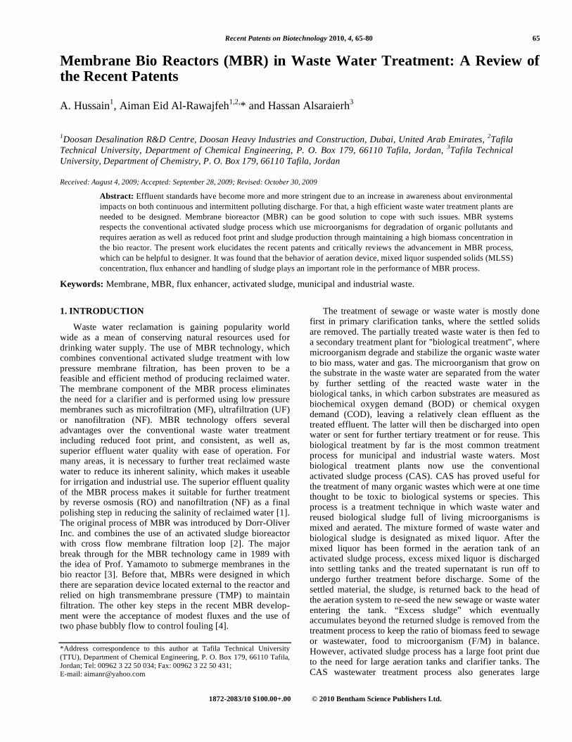
have been lower than those in the CAS process. The com-plete sludge retention time (SRT) is supposed to generate more dead or inactive microorganisms in MBR. If so, this controversial issue of complete sludge retention in a MBR is the change in composition of the mixed liquor which may reduce the biological capability. This means that the microbial viability becomes more questionable in MBR with complete sludge retention where dead or inactivate micro-organisms in MBR, accumulation of organic suspended solid (SS), especially the soluble microbial product (SMP) or extra cellular polymeric substance (EPS) is another major issue in doubt. In order to provide a system with no production of excess biosludge, the researchers have developed the novel apparatus. The schematic diagram of the conceptual work is shown in Fig. (2). The waste water is fed through an inlet into the MBR system comprising a submerged membrane. The high quality permeate which is filtered through the membrane is released back into the natural water cycle via an outlet. The excess sludge produced in the MBR is fed via connection to the pretreatment reactor in which sludge is conditioned before it is fed via the connection in to mem-brane module device as shown in Fig. (2). The membrane module device (MBD) comprises an outlet for releasing CO2 that is produced in it when the pretreated excess sludge is decomposed. The low quality permeate is filtered through the membrane of the MBD, and then fed back into the MBR system. The pretreatment reactor comprises a disperser which can be selected from the group consisting of an agita-tor and an ultrasonic transducer for conditioning the sludge. i.e. breaking and dispersing the sludge. The MBD comprises
also a submerged membrane through which water is filtered and then fed back into the MBR.
Some portion of biosludge is transferred from the MBD to element balancing reactor. This transfer is done if the ratio of mixed liquor volatile suspended solids/mixed liquor suspended solids is below 0.5 or upon deterioration of TOC removal or in the case of high metal concentration in the mixed liquor. An acidic solution is added to element balan-cing reactor to dissolve the inorganic compounds. Any type of acidic solution can be added. Centrifugation is conducted to separate the bio sludge and inorganic sludge from each other. A base solution is added in which inorganic sludge will get precipitated. As a result, the element balancing reactor removes inorganic compounds from the system. The waste water used in the present invention has excessive amounts of nutrients (primarily phosphorous, nitrogen and carbon). One of the key nutrients, nitrogen is often intro-duced excessively to the environment through untreated waste water. High level of nitrogen can result in eutro-phication of receiving waters which are characterized by excessive “blooms” of algae (e.g. Phytoplankton) promoted by these nutrients that changed water quality. These algal blooms lead to oxygen depletion and disappearance of native fish species. Beaches and shorelines are fouled by masses of rotting, stinking algae. To prevent these conditions, many jurisdictions have started to regulate the amount of total nitrogen that may be discharged from waste water treatment plants. To remove ammonia and total nitrogen from waste water, bacteria in a bioreactor are used to alternately nitrify
Fig. (1). Inflow control of membrane bio reactor (MBR).
68 Recent Patents on Biotechnology 2010, Vol. 4, No. 1 Al-Rawajfeh et al.
and denitrify the water. During “Nitrification”, a two step process converts ammonia into nitrites and nitrates. Firstly, nitrifying bacteria (Nitrosomonas) will oxidize ammonia and convert it to nitrite. Secondly, another genus of nitrifying bacteria in tandem (Nitrobacter) will then oxidize the nitrite and converts it into nitrate. Since oxidation occurs in both steps of the nitrification process, an aerobic environment is required. During “denitrification”, nitrate is converted to ammonia and nitrogen gas by denitrifying bacteria which remove oxygen from the nitrate. However, anoxic conditions will be needed to encourage the growth of such bacteria. Nitrogen gas, an inert gas will be produced as end product after the nitrification and denitrification stage are completed. This will reduce total nitrogen level in the waste water.
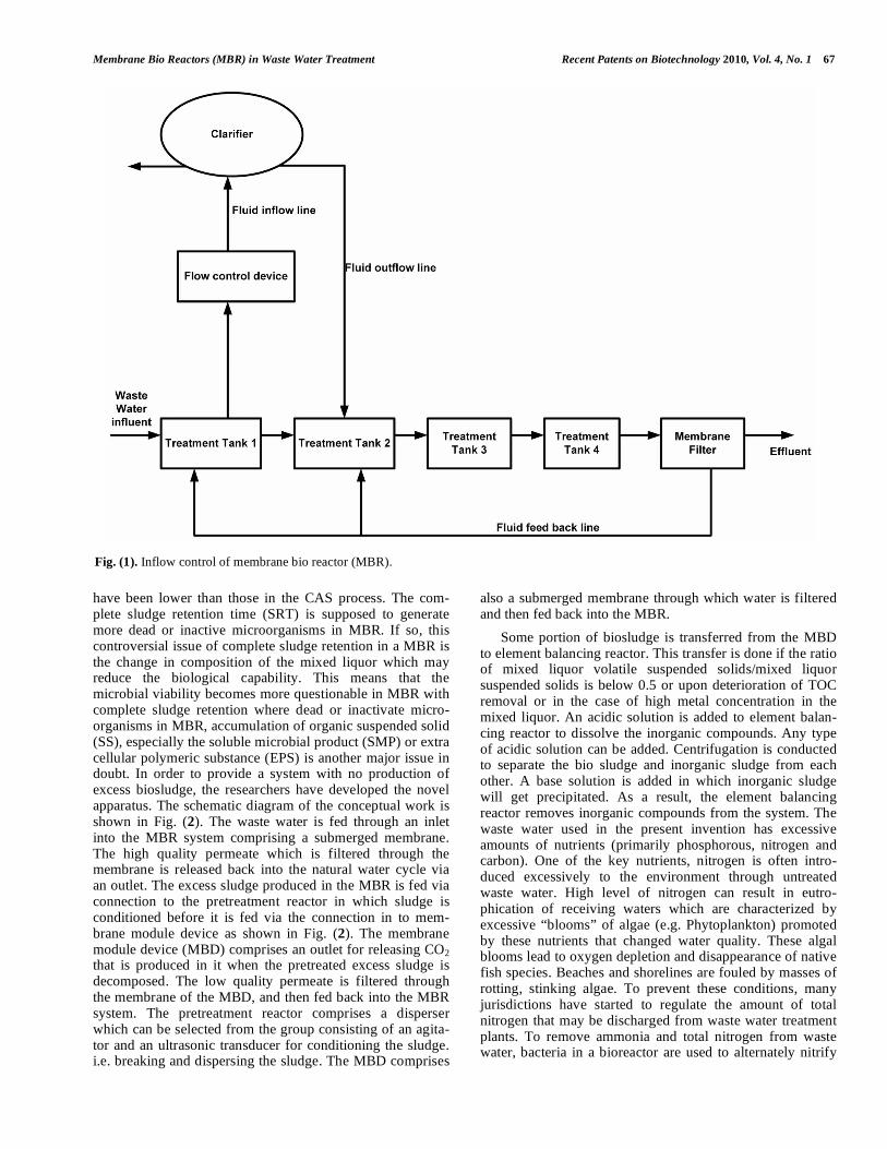
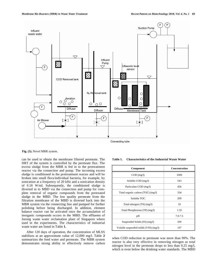
Figure 3 illustrates novel possible step of a MBR com-prising several tanks instead of one tank. The bioreactor is separated into three different compartments by baffles. The first compartment is named the chemical oxygen demand (COD) removal tank. The second compartment is named the nitrogen removal tank and the third compartment the membrane filtration tank. These tanks have working volumes of 6, 4, and 10L respectively. Aeration is provided in the COD tank and membrane tank. The oxygen level in the COD tank is equal or more than 2 mg/l. The oxygen level in the membrane tank is equal to or more than 1.5 mg/l. The aeration in the COD tank and membrane tank also provides
mixing, while the aeration intensity is higher in membrane tank to generate higher cross flow velocity and provide additional scouring membrane surfaces to reduce fouling. Intermittent low intensity aeration is provided for the N-tank to stimulate anoxic conditions, i.e. keep oxygen level below 0.5 or 0.2 mg/l. Since aeration in the N-tank is intermittent, an overhead mixer is used to provide the continuous mixing in the N-tank. All aerations can be supplied by compressed air or oxygen from an air blower to the diffuser located at the bottom of each compartment.
The membrane modules are placed in the centre of the membrane tank to ensure maximum contact with the coarse air bubbles to alleviate the fouling phenomenon commonly encountered at the membrane of a MBR. The membrane modules are kept at a fixed level above the membrane module by a level sensor controlling the feed pump to add feed water from the second compartment as necessary. The ceramic membranes indicated in Fig. (3) can be of MF type and can have the effective pore size of 0.9 μm. The surface area of each membrane was 0.024 m
2. However, other pore
sizes and surface areas for the membrane are possibly depending on the specific application and the nature of the waste water fed into the plant. The hydraulic retention time of each compartment makes up the total hydraulic retention time (HRT). Dissolved oxygen and pH are measured using online DO and pH probes. A suction pump or vacuum pump
Fig. (2). Innovative MBR to recover excess bio sludge [6].
Membrane Bio Reactors (MBR) in Waste Water Treatment Recent Patents on Biotechnology 2010, Vol. 4, No. 1 69
can be used to obtain the membrane filtered permeate. The HRT of the system is controlled by the permeate flux. The excess sludge from the MBR is fed in to the pretreatment reactor via the connection and pump. The incoming excess sludge is conditioned in the pretreatment reactor and will be broken into small flocs/individual bacteria, for example, by sonication at a frequency of 20 kHz and a sonication density of 0.18 W/ml. Subsequently, the conditioned sludge is diverted in to MBD via the connection and pump for com-plete removal of organic compounds from the pretreated sludge in the MBD. The low quality permeate from the filtration membrane of the MBD is diverted back into the MBR system via the connecting line and pumped for further polishing before being discharged. In addition, element balance reactor can be activated once the accumulation of inorganic compounds occurs in the MBD. The effluents of Jurong waste water reclamation plant of Singapore where used in the experiments. The characteristics of industrial waste water are listed in Table 1.
After 120 days of operation, the concentration of MLSS stabilizes at an approximate value of 12,000 mg/l. Table 2 summarizes the feed water and permeate. The MBR system demonstrates strong ability to effectively remove carbon
Table 1. Characteristics of the Industrial Waste Water
Component Concentration
COD (mg/l) 1000
Soluble COD (mg/l) 543
Particulate COD (mg/l) 456
Total organic carbon (TOC) (mg/l) 334
Soluble TOC 209
Total nitrogen (TN) (mg/l) 10
Total Phosphorous (TP) (mg/l) 1.35
pH 7.0-7.5
Suspended Solids (SS) (mg/l) 200
Volatile suspended solids (VSS) (mg/l) 197
when COD reduction in permeate was more than 99%. The reactor is also very effective in removing nitrogen as total nitrogen level in the permeate drops to less than 0.25 mg/l, which is even below the drinking water standards. The MBD
Fig. (3). Novel MBR system.
70 Recent Patents on Biotechnology 2010, Vol. 4, No. 1 Al-Rawajfeh et al.
demonstrates strong ability to effectively remove organic compounds in the bio sludge 99% of the incoming organic compounds in the bio sludge have been degraded and no accumulation of inorganic compounds found.
Table 2. Characteristics of the Industrial Waste Water
Component Feed Water Permeate
COD (mg/l) 1000 <10
TOC (mg/l) 334 <3
Turbidity (NTU) 330 <0.15
Total Nitrogen (mg-N/l) 20 <0.25
4. HYDRAULICALLY INTEGRATED SOLIDS/ LIQUID SEPARATION SYSTEM
Figure 4 illustrates the novel MBR system having a submerged membrane configuration. Waste water containing contaminants enters the MBR from source waste water, as it flows through screen, grit and large particles are removed [7]. The waste water flows to bioreactor as shown in Fig. (5). The weirs present divide the bioreactor into anoxic zone, aeration zone, membrane zone and treated water zone. Initially the waste water flows inside the anoxic zone which is equipped with mixer for denitrification. Effluent from the anoxic zone flows over the aeration zone. Aeration zone includes recirculation of activated sludge produced during waste treatment processes, accordingly activated sludge introduced into the aeration zone would generally be referred to as return activated sludge. The concentration of activated sludge solids in conventional membrane bio reactors can range from 5,000 mg/l up to 15,000 mg/l, depending on the type of membrane utilized. Hydraulic mixing and aeration occurs by using jet aeration system which includes a pump for continuously circulating/mixing the waste water in the aeration zone. The jet aeration system also includes a source of oxygen from the blower for providing required oxygen and keeping solids in suspension. Aeration can cost up to about 70% or more of the total energy cost of a waste water treatment systems. The bioreactor may be designed to permit waste water flow over the weir from the aeration zone to the membrane zone. The membrane zone includes one or more membrane module which can be any type of separation membrane. The membrane modules are at least partially submerged inside the membrane zone. The membrane zone also includes a membrane aerator such as fine and coarse bubble diffuser, for scouring the membrane to inhibit fouling of the membranes. The aeration zone and membrane zone may be provided with an integrated aeration system designed to maximize oxygen transfer and bubble formation in each of the zones where required by the given separation operation. A suction pump is connected to the permeate outlet side of the membranes to maintain negative pressure on the per-meate side of the membrane in order to achieve the required transmembrane pressure and flux across the membrane. A backwash pump is provided to reverse the flow of permeate to the membrane to remove solids build up on the surface of the membranes and restore uniform flux across the membrane. Cleaning can be performed at regular intervals or
at a given reduction of flux or transmembrane pressure. A recycle pump recycles the concentrated biomass from the membrane zone back to the anoxic zone. The treated effluent flows out of the bioreactor from the treated water zone through the discharge line. The effluent can be directly recycled for reuse.
Figure 5 illustrates the external membrane configuration. Waste water containing contaminants enters a MBR system from a source of waste water from which pumps move the wastewater through a screen, optionally provided to remove grit and larger particulates. It pumps the waste water into an equalization tank in order to balance the flows across the system ensuring accommodations in the system of peak flows. The waste water is pumped inside bioreactor 1. The bioreactor can be anoxic, aerobic and anaerobic depending on the processing requirements for the stream of waste water. A chemical coagulant such as alum may be added to the bioreactor to precipitate soluble phosphate to reduce phosphorous discharge. The bioreactor is provided with aeration and mixing system. The waste water will flow from the first to the second bioreactor. The other reactor will be aerobic which includes activated sludge, with the source of activated sludge being circulation of activated sludge produced during the waste treatment process. The waste water leaving the bioreactor is pumped to the membrane system. The permeate exits the membrane system where it is collected in a tank. The retentate flow of the concentrated bio mass is either recycled back to the bioreactor or it is discharged in a balance tank.
5. METHOD FOR IMPROVING FLUX
In the aerobic MBR process [8], membrane fouling has always been a significant issue limiting the hydraulic performance of the process. Due to membrane fouling, MBR through put or flux often decreases and more membranes are required to compensate for the throughput loss. Many research results have shown that one of the main causes of membrane fouling is bio polymers, which include poly-saccharides and proteins secreted by the biomass present in the mixed liquor. In addition, a number of inorganic scales formed in MBR have been reported, where the salt concentration in the influent were relatively high. As a result of scale formation on the membrane surface, the membrane performance is significantly reduced. To prevent membrane fouling caused by bio polymers, methods were developed using cationic polymer that does not react with negatively charged membrane in contact with mixed liquor. In this method, various polymers are added directly to the aerobic MBR usually to the aeration tank and this polymer reacts with the bio polymers. The resulting particles of bio polymer and polymers are considerably lower membrane fouling tendencies. The same microbiologically produced polysac-charides and protein biopolymers are also known to form foaming in the MBR mixed liquor. This is because the compound contains many surface active functional groups that help stabilize foam at the air-water interface.
In addition, MBR’s often contains filamentous micro-organisms that have been correlated to foam formation. Both the bio polymers and filamentous microorganisms react with cationic polymers to reduce fouling propensity at the surface

Membrane Bio Reactors (MBR) in Waste Water Treatment Recent Patents on Biotechnology 2010, Vol. 4, No. 1 71
Fig. (4). Novel hydraulic integrated submerged MBR.
Fig. (5). External membrane Bio Reactor.
72 Recent Patents on Biotechnology 2010, Vol. 4, No. 1 Al-Rawajfeh et al.
of the membrane. Anoxic and anaerobic tank were increa-singly being installed in MBR’s to increase nitrogen and phosphorous removal efficiencies. In these conditions, the aerobic biomass will be periodically exposed to oxygen scarce condition, while the anaerobic biomass will be exposed to aerobic conditions. Since the mixed liquor is recycled between oxygen rich and oxygen poor conditions, therefore biomass will produce more biopolymer due to oxygen stress. Apart from the biopolymer problem, recently inorganic fouling has also been reported in a number of MBR’s. This inorganic fouling often consists mainly of cal-cium carbonate and calcium phosphate, which may precipi-tate in the aerated biological waste water treatment or directly onto the membrane. The inorganic fouling including iron oxides. Aeration in the treatment tank can lead to inorganic fouling by various routes. Aeration drives the dis-solved CO2 out of the waste water and this pushes the equilibrium reaction towards producing more carbonate.
The carbonate formed by the reaction, precipitates with calcium ions present in waste water forming calcium carbo-nate. Moreover, the reaction will cause increase in pH, which will favour calcium phosphate and iron oxide precipitation. The precipitation of carbonates and phosphates will partly take place in the bulk waste water and this will form small particles, of which most will be retained by the membranes. This precipitation will also take place on all the surfaces, among which is the membrane charge. The cationic poly-mers that are added to the MBR are 25,000 Da or more and have about 10% mole charge or more. The cationic polymer added to a MBR is selected from the group consisting of a polymer of epichlorohydrin-dimethylamine cross linked with either ammonia or ethlyleldiamine; a linear polymer of epi-chlorohydrin and dimethylamine and it carries lot of additions of compounds [8].
Figure 6 shows the membrane submerged in the aeration tank. The latter can be divided by multiple numbers of
reactors. Membrane can be submerged in one of the reactors or installed outside the reactor. The MLSS of the mixed liquor can be maintained between 3,000 mg/l and 30,000 mg/l. When the influent has more than: 5 ppm calcium, 5 ppm magnesium, 10 ppm of silicon, 0.1 ppm iron, potential of scale formation or inorganic fouling increases and deposit on the membrane surface. Cationic polymers having a MW of 10,000-20,000,000 Da and charge 1-100% can be added directly to any of the tanks or the streams flowing to one of the reactors at a concentration of 10-2000 ppm as active polymer.
The anoxic tank is added to the aeration tank and mixed liquor in the aeration tank is recycled to the anoxic tank, where no air is supplied to maintain dissolved oxygen level at <0.5 mg/l. The nitrogen compounds contained in waste water are oxidized to nitrate in the aeration tank and recycled to anoxic tank. In the anoxic tank, some denitrifying bacteria utilize the combined oxygen contained in the nitrate ions and produce nitrogen gas. Though a broad range of cationic polymers may be helpful to prevent membrane fouling, high MW and high mole charge polymers will be particular effective. One or multiple number of different polymers can be added to the anoxic and aeration tanks and any flow stream flowing to any of the reactors.
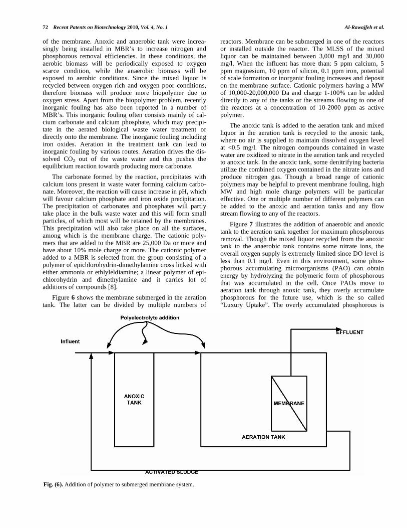
Figure 7 illustrates the addition of anaerobic and anoxic tank to the aeration tank together for maximum phosphorous removal. Though the mixed liquor recycled from the anoxic tank to the anaerobic tank contains some nitrate ions, the overall oxygen supply is extremely limited since DO level is less than 0.1 mg/l. Even in this environment, some phos-phorous accumulating microorganisms (PAO) can obtain energy by hydrolyzing the polymeric form of phosphorous that was accumulated in the cell. Once PAOs move to aeration tank through anoxic tank, they overly accumulate phosphorous for the future use, which is the so called “Luxury Uptake”. The overly accumulated phosphorous is
Fig. (6). Addition of polymer to submerged membrane system.

Membrane Bio Reactors (MBR) in Waste Water Treatment Recent Patents on Biotechnology 2010, Vol. 4, No. 1 73
eventually removed when excess biosolids are removed from the system. Cationic polymers can be used to increase the membrane flux in this particular system.
Anaerobic MBR is shown in Fig. (8) which can operate at ambient temperature and 70˚C. This MBR has cover on the top of the reactor and no air is supplied. An optional mechanical agitation can be performed using the mixer. In the case of submerged membrane, gases in the head space can be recycled to the bottom of the tank to scour the membranes. If membranes are externally equipped, sludge recirculation pumps should be used. This anaerobic digester can be used solely or in combination with aerobic reactor. The mixed liquor suspended solids level is maintained at 3,000-30,000 mg/l and the influent COD is 200-100,000 mg/l.
6. FILTRATION APPARATUS COMPRISING A MBR AND A TREATMENT VESSEL FOR DIGESTING
ORGANIC MATERIAL
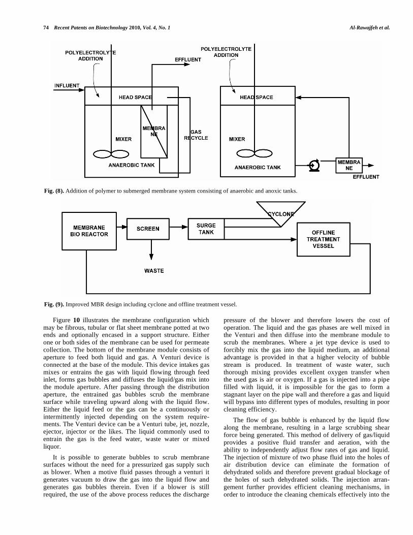
This patent is invented by Siemens Corporation [9]. Biological processes to treat contaminated water take many forms. Generally these involve exposure of the waste stream to one or more forms of microorganisms that stabilize or digest the contaminants. The microorganisms are chosen to complement the waste stream both in terms of sewage contents and chemical environment, since any species of microorganisms favors a particular environment with limited tolerance for variation. The activated sludge process utilizes aerobic bacteria that remove the soluble biological oxygen demand (BOD) from waste water. This generally, as shown in Fig. (9), involves conducting waste water into an aeration basin containing a suspension of digestive microorganism thereby forming a mixed liquor that is aerated to furnish oxygen for respiration of biomass; the biomass sorbs, assi-milates and metabolizes the BOD of the waste water. After a
suitable period of aeration, the mixed liquor is introduced into a clarifier, in which the biomass settles, allowing the treated waste water to overflow into an outlet effluent stream. The novel apparatus dramatically reduces the pro-duction of waste sludge by about 80% or more. Sludge is pumped from the MBR aerobic tank through a 250 μm screen. The screened solids are removed and the screened process fluid enters a storage tank where a portion of the process fluid is flowed to a hydrocyclone separator to remove inert material. The inert material is removed and the process fluid is returned to the surge tank. From the surge tank, process fluid is either returned back to the membrane bio reactor or it is directed to an offline treatment vessel which typically has a HRT of about 1 day or less to about 1 month or more preferably about 10 days HRT. The offline treatment vessel is employed to solubilize the organic mate-rial by operating in a very low oxygen environment. Digested process fluid is transferred back to the MBR.
For the aeration purpose, gas is introduced usually by a pressurized blower, into a liquid system where the membrane module is submerged to form gas bubbles. The produced bubbles then travel upward to scrub the membrane surface and remove the fouling substances formed on the membrane surface. The produced shear force largely relies on the initial gas bubble velocity, bubble size and the net forces applied on the bubbles. The fluid transfer in this approach is limited to the effectiveness of the gas lifting mechanisms. However, this method has several disadvan-tages: it consumes large amounts of energy; it can form mist or froth flow reducing effective membrane filtration area, and can be destructive to membranes. In an environment of high concentration of solids, the gas distribution system can gradually become blocked by dehydrated solids or by the ceasing accidental gas flow.
Fig. (7). Addition of polymer to submerged membrane system consisting of anerobic and anoxic tanks.
74 Recent Patents on Biotechnology 2010, Vol. 4, No. 1 Al-Rawajfeh et al.
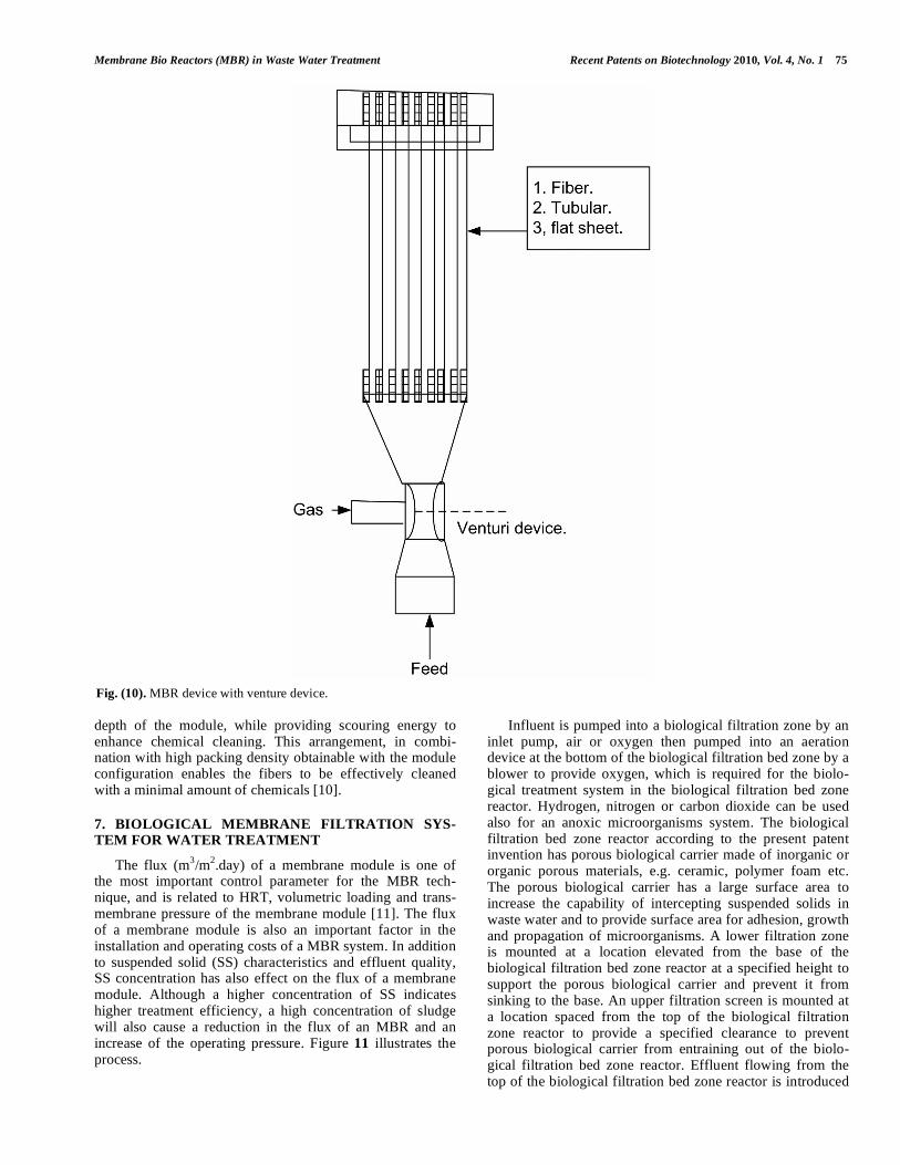
Figure 10 illustrates the membrane configuration which may be fibrous, tubular or flat sheet membrane potted at two ends and optionally encased in a support structure. Either one or both sides of the membrane can be used for permeate collection. The bottom of the membrane module consists of aperture to feed both liquid and gas. A Venturi device is connected at the base of the module. This device intakes gas mixes or entrains the gas with liquid flowing through feed inlet, forms gas bubbles and diffuses the liquid/gas mix into the module aperture. After passing through the distribution aperture, the entrained gas bubbles scrub the membrane surface while traveling upward along with the liquid flow. Either the liquid feed or the gas can be a continuously or intermittently injected depending on the system require-ments. The Venturi device can be a Venturi tube, jet, nozzle, ejector, injector or the likes. The liquid commonly used to entrain the gas is the feed water, waste water or mixed liquor.
It is possible to generate bubbles to scrub membrane surfaces without the need for a pressurized gas supply such as blower. When a motive fluid passes through a venturi it generates vacuum to draw the gas into the liquid flow and generates gas bubbles therein. Even if a blower is still required, the use of the above process reduces the discharge
pressure of the blower and therefore lowers the cost of operation. The liquid and the gas phases are well mixed in the Venturi and then diffuse into the membrane module to scrub the membranes. Where a jet type device is used to forcibly mix the gas into the liquid medium, an additional advantage is provided in that a higher velocity of bubble stream is produced. In treatment of waste water, such thorough mixing provides excellent oxygen transfer when the used gas is air or oxygen. If a gas is injected into a pipe filled with liquid, it is impossible for the gas to form a stagnant layer on the pipe wall and therefore a gas and liquid will bypass into different types of modules, resulting in poor cleaning efficiency.
The flow of gas bubble is enhanced by the liquid flow along the membrane, resulting in a large scrubbing shear force being generated. This method of delivery of gas/liquid provides a positive fluid transfer and aeration, with the ability to independently adjust flow rates of gas and liquid. The injection of mixture of two phase fluid into the holes of air distribution device can eliminate the formation of dehydrated solids and therefore prevent gradual blockage of the holes of such dehydrated solids. The injection arran-gement further provides efficient cleaning mechanisms, in order to introduce the cleaning chemicals effectively into the
Fig. (8). Addition of polymer to submerged membrane system consisting of anaerobic and anoxic tanks.
Fig. (9). Improved MBR design including cyclone and offline treatment vessel.
Membrane Bio Reactors (MBR) in Waste Water Treatment Recent Patents on Biotechnology 2010, Vol. 4, No. 1 75
depth of the module, while providing scouring energy to enhance chemical cleaning. This arrangement, in combi-nation with high packing density obtainable with the module configuration enables the fibers to be effectively cleaned with a minimal amount of chemicals [10].
7. BIOLOGICAL MEMBRANE FILTRATION SYS-TEM FOR WATER TREATMENT
The flux (m3/m
2.day) of a membrane module is one of
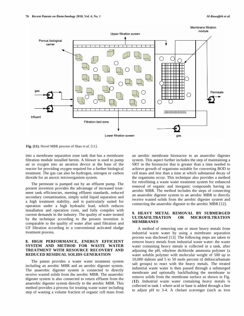
the most important control parameter for the MBR tech-nique, and is related to HRT, volumetric loading and trans-membrane pressure of the membrane module [11]. The flux of a membrane module is also an important factor in the installation and operating costs of a MBR system. In addition to suspended solid (SS) characteristics and effluent quality, SS concentration has also effect on the flux of a membrane module. Although a higher concentration of SS indicates higher treatment efficiency, a high concentration of sludge will also cause a reduction in the flux of an MBR and an increase of the operating pressure. Figure 11 illustrates the process.
Influent is pumped into a biological filtration zone by an inlet pump, air or oxygen then pumped into an aeration device at the bottom of the biological filtration bed zone by a blower to provide oxygen, which is required for the biolo-gical treatment system in the biological filtration bed zone reactor. Hydrogen, nitrogen or carbon dioxide can be used also for an anoxic microorganisms system. The biological filtration bed zone reactor according to the present patent invention has porous biological carrier made of inorganic or organic porous materials, e.g. ceramic, polymer foam etc. The porous biological carrier has a large surface area to increase the capability of intercepting suspended solids in waste water and to provide surface area for adhesion, growth and propagation of microorganisms. A lower filtration zone is mounted at a location elevated from the base of the biological filtration bed zone reactor at a specified height to support the porous biological carrier and prevent it from sinking to the base. An upper filtration screen is mounted at a location spaced from the top of the biological filtration zone reactor to provide a specified clearance to prevent porous biological carrier from entraining out of the biolo-gical filtration bed zone reactor. Effluent flowing from the top of the biological filtration bed zone reactor is introduced
Fig. (10). MBR device with venture device.
76 Recent Patents on Biotechnology 2010, Vol. 4, No. 1 Al-Rawajfeh et al.
into a membrane separation zone tank that has a membrane filtration module installed herein. A blower is used to pump air or oxygen into an aeration device at the base of the reactor for providing oxygen required for a further biological treatment. The gas can also be hydrogen, nitrogen or carbon dioxide for an anoxic microorganism system.
The permeate is pumped out by an effluent pump. The present invention provides the advantage of increased treat-ment tank efficiencies, meeting effluent standards, reduced secondary contamination, simply solid liquid separation and a high treatment stability, and is particularly suited for operation under a high hydraulic load, which reduces installation and operation costs, and fully compiles with current demands in the industry. The quality of water treated by the technique according to the present invention is comparable to the quality of water after sand filtration and UF filtration according to a conventional activated sludge treatment process.
8. HIGH PERFORMANCE, ENERGY EFFICIENT SYSTEM AND METHOD FOR WASTE WATER
TREATMENT WITH RESOURCE RECOVERY AND
REDUCED RESIDUAL SOLIDS GENERATION
The patent provides a waste water treatment system including an aerobic MBR and an aerobic digester system. The anaerobic digester system is connected to directly receive wasted solids from the aerobic MBR. The anaerobic digester system is also connected to return effluent from the anaerobic digester system directly to the aerobic MBR. This method provides a process for treating waste water including step of wasting a volume fraction of organic cell mass from
an aerobic membrane bioreactor to an anaerobic digester system. This aspect further includes the step of maintaining a SRT in the bioreactor that is greater than a time needed to achieve growth of organisms suitable for converting BOD to cell mass and less than a time at which substantial decay of the organisms occur. This technique also provides a method for retrofitting a waste water treatment system for enhanced removal of organic and inorganic compounds having an aerobic MBR. The method includes the steps of connecting an anaerobic digester system to an aerobic MBR to directly receive wasted solids from the aerobic digester system and connecting the anaerobic digester to the aerobic MBR [12].
9. HEAVY METAL REMOVAL BY SUBMERGED ULTRAFILTRATION OR MICROFILTRATION MEMBRANES
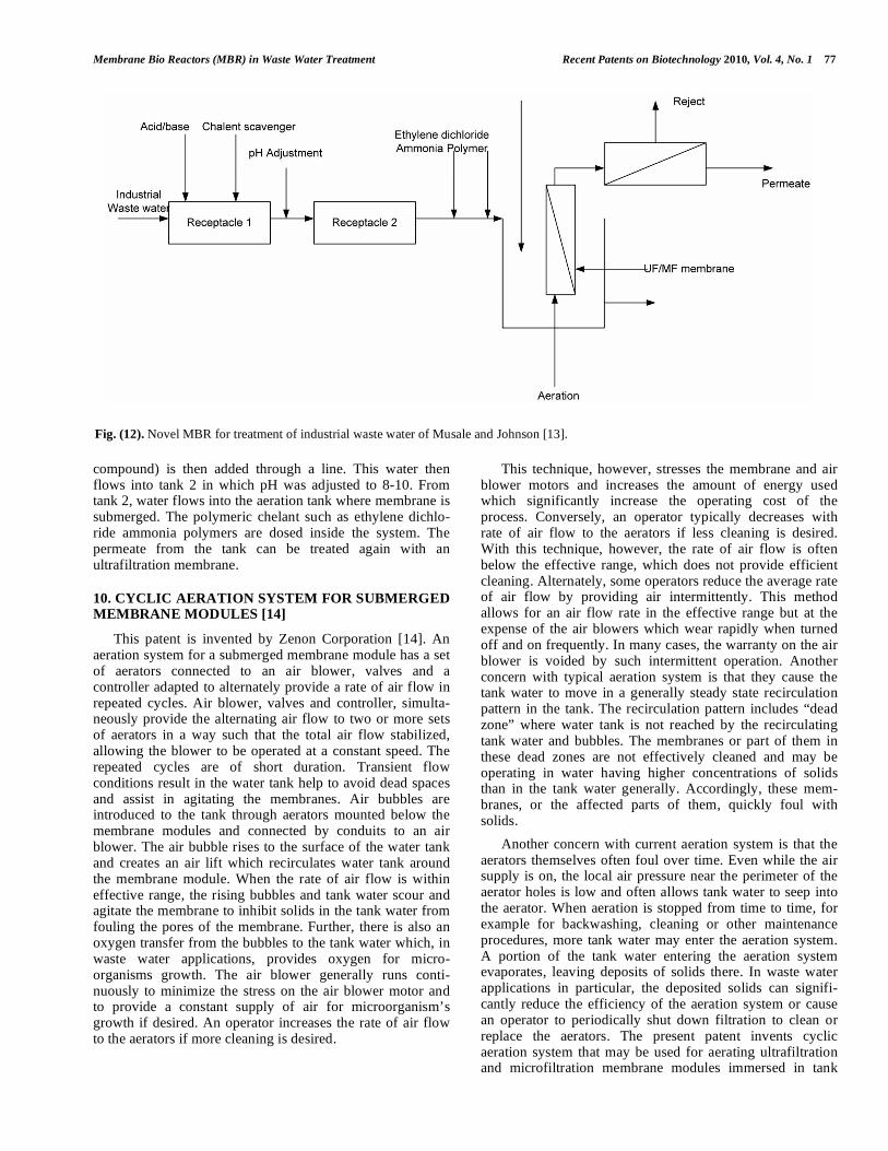
A method of removing one or more heavy metals from industrial waste water by using a membrane separation process was disclosed [13]. The following steps are taken to remove heavy metals from industrial waste water: the waste water containing heavy metals is collected in a tank, after adjusting the pH, ethylene dichloride ammonia polymer (a water soluble polymer with molecular weight of 500 up to 10,000 daltons and 5 to 50 mole percent of dithiocarbamate salt groups) to react with the heavy metals. The treated industrial waste water is then passed through a submerged membrane and optionally backflushing the membrane to remove solids from the membrane surface as shown in Fig. (12). Industrial waste water containing heavy metals is collected in tank 1 where acid or base is added through a line to adjust pH to 3-4. A chelant scavenger (such as iron
Fig. (11). Novel MBR process of Shao et al. [11].
Membrane Bio Reactors (MBR) in Waste Water Treatment Recent Patents on Biotechnology 2010, Vol. 4, No. 1 77
compound) is then added through a line. This water then flows into tank 2 in which pH was adjusted to 8-10. From tank 2, water flows into the aeration tank where membrane is submerged. The polymeric chelant such as ethylene dichlo-ride ammonia polymers are dosed inside the system. The permeate from the tank can be treated again with an ultrafiltration membrane.
10. CYCLIC AERATION SYSTEM FOR SUBMERGED MEMBRANE MODULES [14]
This patent is invented by Zenon Corporation [14]. An aeration system for a submerged membrane module has a set of aerators connected to an air blower, valves and a controller adapted to alternately provide a rate of air flow in repeated cycles. Air blower, valves and controller, simulta-neously provide the alternating air flow to two or more sets of aerators in a way such that the total air flow stabilized, allowing the blower to be operated at a constant speed. The repeated cycles are of short duration. Transient flow conditions result in the water tank help to avoid dead spaces and assist in agitating the membranes. Air bubbles are introduced to the tank through aerators mounted below the membrane modules and connected by conduits to an air blower. The air bubble rises to the surface of the water tank and creates an air lift which recirculates water tank around the membrane module. When the rate of air flow is within effective range, the rising bubbles and tank water scour and agitate the membrane to inhibit solids in the tank water from fouling the pores of the membrane. Further, there is also an oxygen transfer from the bubbles to the tank water which, in waste water applications, provides oxygen for micro-organisms growth. The air blower generally runs conti-nuously to minimize the stress on the air blower motor and to provide a constant supply of air for microorganism’s growth if desired. An operator increases the rate of air flow to the aerators if more cleaning is desired.
This technique, however, stresses the membrane and air blower motors and increases the amount of energy used which significantly increase the operating cost of the process. Conversely, an operator typically decreases with rate of air flow to the aerators if less cleaning is desired. With this technique, however, the rate of air flow is often below the effective range, which does not provide efficient cleaning. Alternately, some operators reduce the average rate of air flow by providing air intermittently. This method allows for an air flow rate in the effective range but at the expense of the air blowers which wear rapidly when turned off and on frequently. In many cases, the warranty on the air blower is voided by such intermittent operation. Another concern with typical aeration system is that they cause the tank water to move in a generally steady state recirculation pattern in the tank. The recirculation pattern includes “dead zone” where water tank is not reached by the recirculating tank water and bubbles. The membranes or part of them in these dead zones are not effectively cleaned and may be operating in water having higher concentrations of solids than in the tank water generally. Accordingly, these mem-branes, or the affected parts of them, quickly foul with solids.
Another concern with current aeration system is that the aerators themselves often foul over time. Even while the air supply is on, the local air pressure near the perimeter of the aerator holes is low and often allows tank water to seep into the aerator. When aeration is stopped from time to time, for example for backwashing, cleaning or other maintenance procedures, more tank water may enter the aeration system. A portion of the tank water entering the aeration system evaporates, leaving deposits of solids there. In waste water applications in particular, the deposited solids can signifi-cantly reduce the efficiency of the aeration system or cause an operator to periodically shut down filtration to clean or replace the aerators. The present patent invents cyclic aeration system that may be used for aerating ultrafiltration and microfiltration membrane modules immersed in tank
Fig. (12). Novel MBR for treatment of industrial waste water of Musale and Johnson [13].

78 Recent Patents on Biotechnology 2010, Vol. 4, No. 1 Al-Rawajfeh et al.
water in the tank. The cyclic aeration system uses a valve set and a valve set controller to connect an air supply to a plu-rality of distinct branches of an air delivery network which are in turn connected to aerators located below the mem-brane modules. While the air supply is operated to supply a steady initial flow of air, the valve set and valve set controller split and distribute the initial air flow between the distinct branches of the air distribution system. Such air flow to each distinct branch alternates between lower flow rates in repeated cycles.
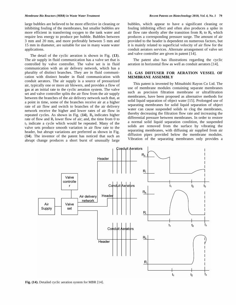
The cyclic aeration system is used to provide intermittent aeration to membrane modules arranged in plurality in filtration zones, each associated with a distinct branch of the air delivery network. The cyclic aeration system is confi-gured and operated to provide aeration for predetermined amount of time to each filtration zone in turn. The cyclic aeration system is used to provide intense aeration to a group of membrane modules. The cyclic aeration system is configured and operated to provide air to a branch of air delivery network alternating between a higher flow rate and lower flow rate in cycles of 120 seconds. The configuration is illustrated in Fig. (13).
Feed water may contain microorganisms, suspended solids or other matter which will be collectively called solids. One or more membrane modules are mounted in the tank and have one or more headers in fluid communication with a permeate side of one or more membrane. The membrane module is available in various sizes especially hollow fibers and flat sheets. The membrane tank is kept filled with tank water above the level of the membrane in the
membrane module during permeation. Filtered water called permeate flows through the wall of the membrane in the membrane module under the influence of transmembrane pressure and collects at the header, to be transported to a permeate outlet through a permeate line. The transmembrane pressure may vary for different membrane and different applications, but is typically between 1 KPa and 150 kPa. Permeate may also be periodically flowed in a reversed direction through the membrane modules to assist in clean-ing the membrane modules. During permeation, the mem-brane rejects solids which remain in the tank water. These solids may be removed by a number of methods including digestion by microorganism.
The aeration system has one or more aerators connected by an air delivery system and a distribution manifolds to an air source, which is typically one or more air blowers and produces bubbles in the tank water. The aerator may be of various types including distinct aerators, such as cap aerators or simply holes drilled in conduit attached to or part of the distribution manifold. The bubbles agitate the membrane which inhibits their fouling or cleans them. In addition, the bubbles also decrease the local density of tank water in or near the membrane modules which creates an air lift effect causing tank water to flow upwards past the membrane module. The air lift effect causes a recirculation pattern in which the tank water flows upward through the membrane modules and then downward along the sides or other part of the tank. The bubble typically burst at the surface and does not generally follow the tank water through the downward flowing parts of the recirculation pattern. The bubbles have an average diameter between 0.1 and 50 mm. Individual
Fig. (13). Cyclic Aeration system for MBR [14].
Membrane Bio Reactors (MBR) in Waste Water Treatment Recent Patents on Biotechnology 2010, Vol. 4, No. 1 79
large bubbles are believed to be more effective in cleaning or inhibiting fouling of the membranes, but smaller bubbles are more efficient in transferring oxygen to the tank water and require less energy to produce per bubble. Bubbles between 3 mm and 20 mm, and more preferably between 5 mm and 15 mm in diameter, are suitable for use in many waste water applications.
The detail of the cyclic aeration is shown in Fig. (13). The air supply in fluid communication has a valve set that is controlled by valve controller. The valve set is in fluid communication with an air delivery network, which has a plurality of distinct branches. They are in fluid communi-cation with distinct header in fluid communication with conduit aerators. The air supply is a source of pressurized air, typically one or more air blowers, and provides a flow of gas at an initial rate to the cyclic aeration system. The valve set and valve controller splits the air flow from the air supply between the branches of the air delivery network such that, at a point in time, some of the branches receive air at a higher rate of air flow and switch to branches of the air delivery network receive the higher and lower rates of air flow in repeated cycles. As shown in Fig. (14), Rh indicates higher rate of flow and Rl lower flow of air; and, the time from 0 to t3 indicate a cycle which would be repeated. Many of the valve sets produce smooth variation in air flow rate to the header, but abrupt variations are preferred as shown in Fig. (14). The inventor of the patent has noticed that such an abrupt change produces a short burst of unusually large
bubbles, which appear to have a significant cleaning or fouling inhibiting effect and often also produces a spike in air flow rate shortly after the transition from Rl to Rh which produces a corresponding pressure surge. The amount of air provided to the header is dependent on numerous factors, but it is mainly related to superficial velocity of air flow for the conduit aerators services. Alternate arrangement of valve set and valve controller are given in patent [14].
The patent also has illustrations regarding the cyclic aeration in horizontal flow as well as conduit aerators [14].
11. GAS DIFFUSER FOR AERATION VESSEL OF MEMBRANE ASSEMBLY
This patent is invented by Mitsubishi Rayon Co Ltd. The use of membrane modules containing separate membranes such as precision filtration membrane or ultrafiltration membranes, have been proposed as alternative methods for solid liquid separation of object water [15]. Prolonged use of separating membranes for solid liquid separation of object water can cause suspended solids to clog the membranes, thereby decreasing the filtration flow rate and increasing the differential pressure between membranes. In order to restore a normal solid liquid separation condition, the suspended solids are removed from the surface by vibrating the separating membranes, with diffusing air supplied from air diffusion pipes provided below the membrane modules. Vibration of the separating membranes only provides a
Fig. (14). Detailed cyclic aeration system for MBR [14].
80 Recent Patents on Biotechnology 2010, Vol. 4, No. 1 Al-Rawajfeh et al.
temporary solution, however; since suspended solids tend to clog even diffusion vibrated membranes, especially after long period of use. A gas diffuser is constructed and arran-ged to disperse gas into a aeration vessel of a water treatment assembly from a blower. The gas diffuser includes main pipes with branch pipes extending between the main pipes and containing gas discharge ports, wherein the branch pipes have a smaller cross sectional area than that of the main pipe. The gas discharge ports are further sized, constructed and arranged to reduce the possibility or likelihood of sludge blocking the ports or entering the branch pipes. This object is achieved either by placement of the ports on the bottom side of the branch pipes or alternatively, by construction of the ports to include conduit members (with an arrangement of openings or coverings to prevent or reduce the likelihood of sludge blocking the ports or entering branch pipes).
CURRENT & FUTURE DEVELOPMENTS
The recent patents on membrane bioreactor (MBR) were critically reviewed. There are significant important aspects that need to be considered in successful design of MBR especially the aeration, flux enhancer and behavior of mixed liquor suspended solids (MLSS). This review elucidates the activities of various organizations that contributed toward the improvement of the MBR design. This will help the designers to overcome the various physical problems asso-ciated with the design and usage of MBR.
ACKNOWLEDGEMENT
Dr. Basem K. Moh'd has critically read an early version of this manuscript.
CONFLICT OF INTEREST
The authors have no conflict of interest to declare.
REFERENCE
[1] Adham S, DeCarolis JF, Pearce W. Desalination and water purification research and development program final report no. 103,
Bureau of Reclamation, 2004. [2] Smith CV, DiGregoria D, Talcott RM. Proc. 24th
Annual Purdue
Industrial Waste Conference, 1969. [3] Yamamoto K, Hiasa M, Mahmood T, Matsuo T. Direct solid liquid
separation using hollow fiber membranes in activated sludge aeration tank. Water Sci Technol 1989; 21: 43-54.
[4] Clech PL, Chen V, Fane TAG. Fouling in membrane bioreactors used in wastewater treatment. J Membr Sci 2006; 284:17-53.
[5] Barnes, D. J.: WO2008123972A1 (2008). [6] Sun, D.D., Hay, C.T., Khor, S.L., Leckie, O.J.: WO2008066497A1
(2008). [7] Probst, T. H.: US7396453B1 (2008).
[8] Yoon, S. H., Collins, J.H., Koppes, J.A., Huisman I.H.: US0272198 (2006).
[9] Jordan, E.J.: US7387723B2 (2008). [10] Jordan, E.J., Liu, W.: US0264855A1 (2008).
[11] Shao, H., Chang, W.K., Horng, R.Y., Perng, M.J., Chang, M.C., Tzou, W.Y., Chen Y.C.: US7288197 (2007).
[12] Sutton, P.M.: US0223783A1 (2008). [13] Musale, D.A., Johnson, B.S.: US006099 (2008).
[14] Cote P.L., Janson A., Rabie H.R., Singh M.: US7347942B2 (2008). [15] Miyashita, S., Kato, O., Watari, K., Takashima, T., Itakura, M.,
Okazaki, H., Kinoshita, I., Inoue, N.: US6328886B1 (2006).


![Patente [Patents]](https://static.fdokumen.com/doc/165x107/631d0295665120b3330c2251/patente-patents.jpg)