Singlemode 1.1 mum InGaAs quantum well microstructured photonic crystal VCSEL
Upload
khangminh22Category
view
0download
0
UCLUniversity College London
Department of Chemical Engineering
Zeolite Microstructured Reactors
Yu Shan Susanna Wan
July 2003
A Thesis Submitted for the Degree of Doctor of Philosophy
of the University College London

ProQuest Number: 10010374
All rights reserved
INFORMATION TO ALL USERS The quality of this reproduction is dependent upon the quality of the copy submitted.
In the unlikely event that the author did not send a complete manuscript and there are missing pages, these will be noted. Also, if material had to be removed,
a note will indicate the deletion.
uest.
ProQuest 10010374
Published by ProQuest LLC(2016). Copyright of the Dissertation is held by the Author.
All rights reserved.This work is protected against unauthorized copying under Title 17, United States Code.
Microform Edition © ProQuest LLC.
ProQuest LLC 789 East Eisenhower Parkway
P.O. Box 1346 Ann Arbor, Ml 48106-1346

To my family
Zeolite Microstructured Reactors
Abstract
Microreactors can provide better energy and material utilization leading to
efficient chemical production. Due to the large surface area to volume ratio, the heat
and mass transfer efficiency can be maximized. Reactions can also be performed
under safe and automated conditions ensuring minimal environmental impact.
Zeolites can be precisely tailored up to the sub-nanometer scale. They are of
great interest in catalysis and separation, which serve as the best candidate material
for incorporation in microchemical systems. Titanium silicalite-1 zeolite (TS-1) is
known to be an efficient catalyst for selective oxidation of alcohols, epoxidation of
alkenes and hydroxylation of aromatics.
The techniques to incorporate zeolite in microchemical devices were
pioneered. Zeolites (Silicalite-1, ZSM-5 and TS-1) can be employed as catalysts,
membrane or structural materials. Traditional semiconductor fabrication technology
was employed in micromachining the device architecture. Three novel strategies for
manufacturing zeolite microchemical devices have been successfully demonstrated:
localized zeolite growth, etching of zeolite-silicon composite film and free-standing
zeolite membrane in microseparator.
The first prototype of zeolite-based single channel microreactor was
successfully experimented for 1-pentene epoxidation over TS-1 catalyst. A simple
computation model was developed to study the influence of reactor geometry, catalyst
properties and reaction conditions to improve the microreactor performance. TS-1
coatings with different titanium-contents and crystal grain sizes were studied. Short
term deactivation of TS-1 was observed due to the formation of organic compounds
and presence of water by product. Long-term deactivation by titanium leaching was
irreversible.
In order to selectively remove water, which is one of the byproducts, a multi
channel membrane microreactor was designed and fabricated. The reaction studied
was TS-1 catalysed selective oxidation of aniline while the membrane material was
hydrophilic ZSM-5. Deactivation of the catalyst was reduced with improved product
selectivity.
In this thesis, different strategies for incorporating zeolite in microreactors
were studied. The microreactors were successfully tested and their various
applications have been demonstrated. These results have provided an insight to
improve the design of zeolite microstructured reactors.

Acknowledgements
First of all I would like to thank the Croucher Foundation for my scholarship.
This work would not have been possible without the financial support from the
Trustees.
I would like to express my sincere gratitude to my supervisor, Dr. Asterios
Gavriilidis for his continuous guidance and encouragement throughout my PhD study.
His helpful comments and advice inspired me a lot. I would like to thank my
subsidiary supervisory, Dr. George Manos for his help and support.
I would also like to appreciate Dr. King Lun Yeung and Dr. Joseph Chau from
the Hong Kong University of Science and Technology for the collaboration of this
research. This work would not have happened so smoothly without their guidance and
contribution. I am truly grateful for them.
Special thanks should go to Prof. Paul Barnes and Prof. Graham Hutchings for
serving as my examiners.
I would like to express my warmest thoughts to all my friends in UCL and
HKUST for their encouragement and friendship. I would also like to thank my
research colleagues and technicians for their technical support. They make my
research life enjoyable and memorable. I treasure every moment with them. I wish
them all the best in the future.
Finally, I would like to thank my parents and granny for their unconditional
love. I would also like to express my love to Cecilia and Simon back home. We have
great fun together. I wish Cecilia happiness all her life and I believe Simon will be a
great photographer one day. May God bless them.
5
Table of contents
Abstract 3
Acknowledgements 5
Table of contents 6
List of figures 13
List of tables 23
Nomenclature 24
Chapter 1
Introduction 27
1.1 Microreaction technology 28
1.2 Application of zeolites 29
1.3 Objectives 31
1.4 Thesis outline 32
Chapter 2
Literature Survey 35
2.1 General Background on Zeolites 36
2.1.1 Zeolite Structure 36
2.1.2 Crystal Growth 41
2.2 Zeolite Catalysis 44
2.2.1 Molecular sieves as acid and base 45
2.2.2 Titanium containing molecular sieves 46
2.3 Titanium silcalite-1 catalysts 48
2.3.1 TS-1 synthesis 48
2.3.2 Catalytic properties 50
2.3.3 Oxidation reactions 51
2.3.4 Reactions considered in this work 54
2.4 Zeolite Membranes 56
2.4.1 In-situ synthesis 57
2.4.2 Ex-situ synthesis 59
2.5 Introduction to microreactors 61
2.5.1 Definition of microreactors 62
2.5.2 Advantages of microreactors 62
2.5.3 Micromachining techniques 65
2.6 Application of microreactors 73
2.6.1 Access to new reaction regime 73
2.6.2 Study of reaction kinetics 74
2.6.3 High throughput screening 75
2.6.4 Process integration 77
2.6.5 Process development 78
2.6.6 Extraterrestrial Processing 79
2.7 Incorporation of zeolites within microsystems 81
2.7.1 Microfabrication of zeolite films 81
2.7.2 Proposed zeolite incorporation techniques 83
Chapter 3
Instrumentation and methodology 85
3.1 Introduction 86
3.2 Selection of substrate 86
3.3 MicroChannel fabrication 87
3.4 Incorporation of zeolite within microreactor 89
3.4.1 Localized zeolite growth 89
3.4.2 Preparation of TS-1 synthesis solution 91
3.4.3 Hydrothermal treatment of synthesis mixture 94
3.5 Bonding of microreactor 95
3.6 Description of microreactor setup 98
3.7 Analysis of reaction samples 99
3.7.1 Gas chromatography 99
3.7.2 lodometric titration 103
3.8 Characterisation of zeolite-based microchemcial devices 105
Chapter 4
Incorporation of zeolites in the design architecture of microchemical 113
systems
4.1 Introduction 114
4.2 Experimental 116
4.2.1 Preparation of zeolite-silicon composite substrate 117
4.2.2 Characterisation 120
4.2.3 Materials 121
4.3 Results and discussion 121
4.3.1 Synthesis of zeolite-silicon composite 121
4.3.2 Fabrication of zeolite micropattems and their stability 133
4.3.3 Incorporation of zeolites in microchemical devices 136
4.4 Concluding remarks
Chapter 5
Design and fabrication of zeolite-based microreactors and membrane 141
microseparators
5.1 Introduction 142
5.2 Experimental 145
5.2.1 MicroChannel design and fabrication 145
5.2.2 Zeolite synthesis 147
5.2.3 Fabrication of zeolite-based microreactors 149
5.2.4 Fabrication of zeolite membrane microseparators 154
5.2.5 Characterization 156
5.2.6 Materials 156
5.3 Results and discussion 157
5.3.1 Zeolite-based microreactors 157
5.3.2 Zeolite membrane microseparator 165
5.4 Concluding remarks 168
Chapter 6
1-pentene epoxidation in titanium silicalite-1 microchannel reactor: 169
experiments and modelling
6.1 Introduction 170
6.2 Experimental 173
6.2.1 Zeolite catalyst incorporation in microchannel reactor 173
6.2.2 1-pentene epoxidation reaction 176
6.2.3 Materials 178
6.3 Microreactor model 179
6.4 Results and discussion 184
6.4.1 Batch reactor 184
10

6.4.2 Zeolite microreactor 185
6.4.3 Modelling results 189
6.4.4 Effect of catalyst coating 192
6.4.5 Catalyst deactivation 204
6.5 Concluding remarks 207
Chapter 7
Zeolite membrane microreactor for selective oxidation of aniline 209
Introduction 210
Experimental 214
7.2.1 Catalyst Preparation 214
7.2.2 Selection and preparation of substrate 215
7.2.3 Membrane preparation 217
7.2.4 Catalyst deposition 220
7.2.5 Membrane microreactor unit 220
7.2.6 Assembly of membrane microreactor 222
7.2.7 Selective oxidation of aniline 224
7.2.8 Characterization 225
7.2.9 Materials 226
Results and discussion 227
7.3.1 Membrane characterization 227
11
7.3.2 Selective oxidation of aniline to azoxybenzene 229
7.3.3 Membrane microreactor results 231
7.3.4 Reactor performance at different temperatures 236
7.4 Concluding remarks 239
Chapter 8
Conclusions and future work 240
8.1 Conclusions 241
8.2 Future work 245
8.2.1 Improvement in TS-1 catalytic properties 245
8.2.2 In-situ production of chemicals 245
8.2.3 Scale-out of microreactor 246
8.2.4 Application of zeolite microchemcial devices 246
Bibliography 247
Appendices 272
A1 Calculation of reaction constants for 1-pentene epoxidation 272
A2 Calculation of titanium content in TS-1 catalyst 281
A3 Correlation of titanium content with reaction constant 284
A4 Calculation of Weisz-Prater parameter 291
A5 Calculation of pressure drop in microreactor 294
12
List of figures
Figure 2.1 Primary building blocks of zeolites 37
Figure 2.2 Secondary building units 38
Figure 2.3 Schematic diagram of MFI zeolite (a) crystal plane 40
illustration, (b) framework viewed along [100] and (c)
framework viewed along [010]
Figure 2.4 Schematic diagram of MFI zeolite (a) 10-ring viewed 41
along [100] and (b) 10-ring viewed along [010]
Figure 2.5 Schematic diagram of the proposed mechanism of structure 43
direction and crystal growth involving inorganic-organic
composite species in the TPA-mediated synthesis of MFI
zeolite
Figure 2.6 Isomorphous substitution of ZSM-5 primary building block 45
Figure 2.7 Catalytic cracking catalysed by ZSM-5 zeolite 46
Figure 2.8 TS-1 catalysed oxidation with H2O2 47
Figure 2.9 Synthesis procedure for TS-1 49
Figure 2.10 Two possible active peroxotitanates species; (1) 50
hydroxylated or (11) dehydrated
Figure 2.11 A Si-ZSM-5 thin-film growth model on a support 58
Figure 2.12 SEM images of MFI crystal grains in solution under 60
conditions of secondary growth at 140°C and 175°C
Figure 2.13 Scale of microelectromechanical systems in comparison 61
13
with conventional systems
Figure 2.14 Microfabrication of silicon structure 66
Figure 2.15 Basic dry etching methods 67
Figure 2.16 The basic process steps of the LIGA technology 68
Figure 2.17 Schematic view of a laser micromachining setup 69
Figure 2.18 Schematic of the microlamination procedure used to 70
produce a dual microchannel array
Figure 2.19 Schematic view of the setup of microelectrodischarge 71
machining
Figure 2.20 Schematic representation of DPN 72
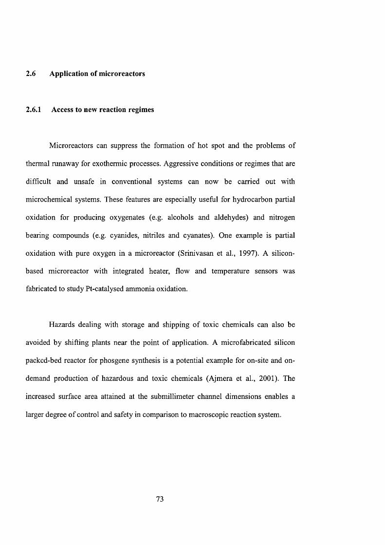
Figure 2.21 The silicon cross-flow reactor chip 75
Figure 2.22 Gas-phase microreactor. Photograph of device. Front view 78
and side schematics.
Figure 2.23 Principles of thin-layer preparation in silicon/silicon nitride 82
composites
Figure 2.24 Schematic representation of stainless steel microchannel 83
structure
Figure 3.1 A magnified picture of the T-shaped pattern on a chromium 87
glass mask used in lithography process with the dimensions
in pm
Figure 3.2 Schematic diagram for microchannel fabrication 89
Figure 3.3 Process diagram for zeolite incorporation within 90
microchannel
14
Figure 3.4 Preparation of TS-1 synthesis solution 93
Figure 3.5 Schematic diagram for zeolite synthesis 94
Figure 3.6 Procedure for microreactor bonding 97
Figure 3.7 Schematic diagram of microreactor setup 98
Figure 3.8 Pictures of microreactor setup 99
Figure 3.9 GC conditions used for sample analysis in 1-pentene 100
epoxidation
Figure 3.10 Sample gas chromatograph for different components 1 GO
Figure 3.11 Calibration factor of pentene using MTBE as internal 101
standard
Figure 3.12 Calibration factor of epoxypentane using MTBE as internal 102
standard
Figure 3.13 XRD patterns of uncalcined ZSM-5 106
Figure 3.14 Plot of number of emitted electron against binding energy 107
Figure 3.15 Photoemission and Auger decay 108
Figure 3.16 The interaction of the primary electron beam with a sample 109
in electron microscopy produces a wealth of detectable
signals
Figure 4.1 Fabrication of zeolite-based microstructured patterns 117
Figure 4.2 Scanning electron and atomic force micrographs of (a) plain 122
silicon and (b) seeded silicon substrates
Figure 4.3 Scanning electron micrographs of Sil-1 grown on plain 126
silicon for: (a) 6 h, (b) 12 h, (c) 24 h and (d) 48 h of
15
hydrothermal synthesis (80 TEOS - 10 TPAOH - 10000
H2O, 448 K)
Figure 4.4 XRD patterns of samples shown in (a) figure 4.3d, (b) 127
figure 4.6a, (c) figure 4.6b, (d) figure 4.5c, (e) figure 4.7a
and (f) figure 4.7b.
Figure 4.5 Scanning electron micrographs of Sil-1 grown on silicon 129
with 95x10^^ seeds/m^ for: (a) 12 h, (b) 24 h, (c) 48 h and
(d) 72 h of hydrothermal synthesis (40 TEOS - 10 TPAOH -
20000 H2O, 398 K)
Figure 4.6 MFI zeolites grown on silicon with seed populations of (a) 132
1.5x10'^ seeds/m^ (40 TEOS - 10 TPAOH - 2 OOOOH2O,
398K) and (b) 25xl0'^ seeds/m^ (40 TEOS - 10 TPAOH -
2 OOOOH2O, 398K)
Figure 4.7 Schematic drawing of the zeolite pore structure viewed 132
along <101>, <200> and <020> axes
Figure 4.8 Examples of zeolite micropattem (a) microchannels and (b) 135
fluid distribution hub
Figure 4.9 Example of a micro fabricated zeolite grid 136
Figure 4.10 (a) T-shaped microchannel etched onto 1 (lOl)-oriented Sil- 138
1-silicon composite, (b) magnified of the zeolite
microchannel, (c) cross-sectional view of the zeolite
microchannel and (d) an example of serpentine-shape
zeolite-based microreactor
16
Figure 4.11 (a) An I-shaped pattern fabricated onto Sil-1-silicon 139
composite and (b) magnified view of the membrane layer
between the two microchannel
Figure 5.1 A magnified picture of the T-shaped pattern on a chromium 146
glass mask used in lithography process with the dimensions
in pm.
Figure 5.2 Cross-sectional views of the T-reactor channel after wet 147
etching for (a) 4 h, (b) 6 h, (c) 8 h and (d) 10 h in 30 wt.%
KOH solution at 353 K
Figure 5.3 (a) Transmission electron micrograph and (b) X-ray 148
diffraction pattern of colloidal Sil-1 zeolite
Figure 5.4 Process diagram for zeolite incorporation using (a) Method 151
1, (b) Method 2, (c) Method 3 and (d) Method 4
Figure 5.5 Process diagram for the fabrication of zeolite membrane 155
microseparator
Figure 5.6 Scanning electron micrographs of NaZSM-5 zeolite 158
powders deposited onto the T-reactor microchannel using
Method 1
Figure 5.7 (a) Scanning electron micrograph of the zeolite-based 160
miniature T-reactor prepared by Method 2 (b) Top-view of
a well oriented (101) zeolite film grown on the surface of
the silicon wafer (c) Top-view of the well-oriented (101)
zeolite film grown within the reactor microchannel (d) A
17
cross-sectional view of the well-oriented (101) zeolite film
within the reactor microchannel (The figure inset is at 2x
higher magnifications.)
Figure 5.8 (a) Scanning electron micrograph of the zeolite-based 161
miniature T-reactor prepared by Method 3 (b) Image of the
wafer surface outside of the T-reactor channel (c)
Microstructure of the zeolite layer grown within the
confines of the microchannel
Figure 5.9 SEM images of the zeolite-based microreactor and zeolite 163
catalyst layer prepared by Method 3 (a) and (b) Al-ZSM-5
with Si/Al ratio of 27 (c) and (d) TS-1 with Si/Ti ratio of 17
Figure 5.10 (a) Scanning electron micrograph of the zeolite-based 165
miniature T-reactor prepared by Method 4 (b) Top-view of
the reactor microchannel etched through the zeolite film
layer (c) Microstructure of the deposited zeolite film layer
that made up the wall of the reactor channel (d)
Microstructure of the etched silicon wafer, which formed
the base of the microchannel
Figure 5.11 (a) A SEM picture of the T-microchannel coated with a 167
layer of Sil-1 membrane (the light rectangular area is the
free-standing zeolite membrane) (b) A higher magnification
image showing that the zeolite membrane was confined
within the microchannel (c) A higher magnification image
18
of the zeolite membrane grown within T-reactor channel (d)
A picture of the recess fabricated at the back of wafer with
the exposed zeolite membrane
Figure 6.1 Moles of hydrogen peroxide reactant and 1,2-epoxypentane 185
product in the batch reactor as a function of reaction time
Figure 6.2 SEM picture of TS-1 zeolite layer and its cross-section 186
(insert is 2x magnification of the figure)
Figure 6.3 1,2-epoxypentane yield as a function of residence time for 190
different channel widths; (O) - 500 pm, (A) - 1000 pm
Figure 6.4 1,2-epoxypentane yield as a function of residence time for 191
different [HiOzjo concentrations (w = 500 pm, S = 5 pm, e =
2-2.5 pm, p = 2.5 at. %, 6 = 4.5 and T = 298 K).
Experimental [HiOzjo =200molm'^ (symbols - experimental
data, lines - model data)
Figure 6.5 1,2-epoxypentane yield as a function of residence time for 192
different 0 values (w = 500 pm, 6= 5 pm, s= 2-2.5 pm, p =
2.5 at. %, [HiOzlo = 0.2 M and T = 298 K). Experimental
^= 4 .5 (symbols - experimental data, lines - model data)
Figure 6.6 (a) SEM picture of zeolite film grown onto silicon support, 194
on unseeded silicon wafer, (b) SEM picture of zeolite film
grown on seeded silicon wafer. Regrowth condition:
40TEOS - lOTPAOH - 1.6TE0T - IOOOOH2O, 175°C,
19
24hours
Figure 6.7 Corresponding X-ray diffraction diagram 195
Figure 6.8 SEM picture of zeolite crystal with different sizes with 197
synthesis solution
Figure 6.9 1,2-epoxypentane yield as a function of crystal grain size at 198
a fixed residence time of 100s (w = 500 pm, ^ = 5 pm,
1-2 at. %, [H202]o = 0.2 M, 4.5 and T = 298 K)
(symbols - experimental data, lines - model data)
Figure 6.10 XPS spectrum showing (a) no insertion of Titanium into 201
zeolite framework (b) partial insertion of Titanium into
zeolite framework (c) full insertion of Titanium into zeolite
framework
Figure 6.11 1,2-epoxypentane yield as a function of titanium-content at 203
a fixed residence time of 100s (w = 500 pm, 5 = 5 pm, s =
2-2.5 pm, [H202]o = 0.2 M, ^ = 4.5 and T = 298 K)
(symbols - experimental data, lines - model data)
Figure 6.12 1,2-epoxypentane yield as a function of running time at a 206
fixed residence time of 100s (w = 500 pm, 5 = 5 pm, e =
2pm, [H202]o = 0.2 M, ^ = 4.5 and T = 298 K) (dotted
line - experimental data, solid line - model data)
Figure 7.1 Formulas of the different compounds obtained from aniline 213
oxidation
20
Figure 7.2 (a) SEM picture of TS-1 nanocrystals, regrowth condition: 215
20TBOS-0.75TEOT-9TPAOH-404H2O, 398K, 50h (b)
SEM picture of TS-1 nanocrystals with lower magnification
Figure 7.3 (a) A picture showing the front and back view of the 217
multichannel stainless steel plate (b) SEM picture of the
microchannel cross section (c) Top view of the stainless
steel plate showing multiple channels with a width of
300pm
Figure 7.4 Pictures of membrane microreactor unit (a) top view of the 222
reactor main body (b) back view of the reactor body
showing inlet and outlet (c) assembled reactor unit and (d)
assembled membrane microreactor with heating unit
Figure 7.5 Assembly of membrane microreactor 223
Figure 7.6 (a) Top view of the ZSM-5 membrane grown onto the 228
porous stainless steel support (b) Cross section of the ZSM-
5 membrane across the stainless steel plate and (c)
Corresponding XRD diagram of the ZSM-5 membrane
Figure 7.7 Oxidation pathways of aniline 229
Figure 7.8 Reaction equation of aniline oxidation to azoxybenzene 230
Figure 7.9 Yield of azoxybenzene against running time at 2ml/hr: TS-1 232
catalyst = O.lg, T = 70°C, H2O2/aniline=0.2
Figure 7.10 (a) Yield of azoxybenzene and (b) product selectivity 235
against running time at Iml/h: TS-1 catalyst = O.lg, T =
21
70°C, H2O2/aniline=0.2
Figure 7.11 (a) Yield of azoxybenzene and (b) product selectivity 238
against running time at different temperatures: TS-1 catalyst
= O.lg, T = 30, 50, 70 and 90°C, H2O2/aniline=0.2,
flowrate=1.0ml/h with water removal
22

List of tables
Table 2.1 Constituent units of zeolite structure types 39
Table 2.2 Oxidation reactions catalysed by TS-1 53
Table 2.3 Epoxidation of C5-C8 olefins 55
Table 3.1 Composition of TS-1 synthesis solutions 92
Table 6.1 Synthesis conditions for TS-1 catalysts 175
Table 6.2 Microreactor model equations used in Femlab model 182
Table 6.3 Experimental and model values of microreactor parameters 183
Table 6.4 List of fabricated microreactors 188
Table 7.1 Experimental conditions for selective oxidation of aniline in
multichannel membrane microreactor
225
23
Nomenclature
C
C/is
d
d^bulk
D eff(in tra)
D e ff (inter)
kl
k2
k ’i
k ’2
m
Pe
total external surface area of catalyst
dimensionless concentration of hydrogen peroxide
used in Femlab model
concentration of hydrogen peroxide
concentration of species A at the external surface of
the catalyst
depth of channel
diffusion coefficient of bulk fluid
intra effective diffusitivity inside crystal
inter effective diffusivity of catalyst
kinetic constant of first order reaction per unit surface
area
kinetic constant of second order reaction per unit
surface area
kinetic constant of first order reaction per unit volume
kinetic constant of second order reaction per unit
volume
channel length
slope of reaction kinetic graph
reaction order
Peclet number
m
molm -3
molm -3
pm
m^s’’
m^s'^
m^s'^
ms
m' mof s'
m mof s'
mm
„ - i
24
e
R
S a
T
t
u
U m
Uy
V
w
w
X
y
y
volumetric flowrate
rate of hydrogen peroxide conversion per unit catalyst
surface area
rate of hydrogen peroxide conversion
dimensionless reaction rate used in Femlab model
radius of channel
surface area per unit mass of catalyst
reaction temperature
time
dimensionless velocity used in Femlah model
mean velocity
fluid velocity along the y axis
volume of reactor
catalyst weight
channel width
transverse dimension
dimensionless co-ordinate in x direction
dimension along channel length
dimensionless co-ordinate in y direction
concentration of hydrogen peroxide
concentration of 1-pentene
m^s'^
molm' s'
molm'^s'’
m
m^g'^
K
ms
-1ms
m '
g
pm
m
m
molm'^
molm'^
25
Greek Letters
A difference
AP pressure drop Pa
P titanium-content at.%
r residence time s
£ crystal grain size pm
p catalyst density gm'^
8 catalyst layer thickness pm
6 stoichiometric ratio of 1-pentene to hydrogen peroxide
^ conversion of hydrogen peroxide
(j) Thiele modulus
p viscosity Nsm'^
0 Weisz-Prater parameter
P overall yield of epoxypentane %
Subscripts
n reaction order
0 initial condition
X transverse dimension
y dimension along channel length
26

Chapter 1
Introduction
27
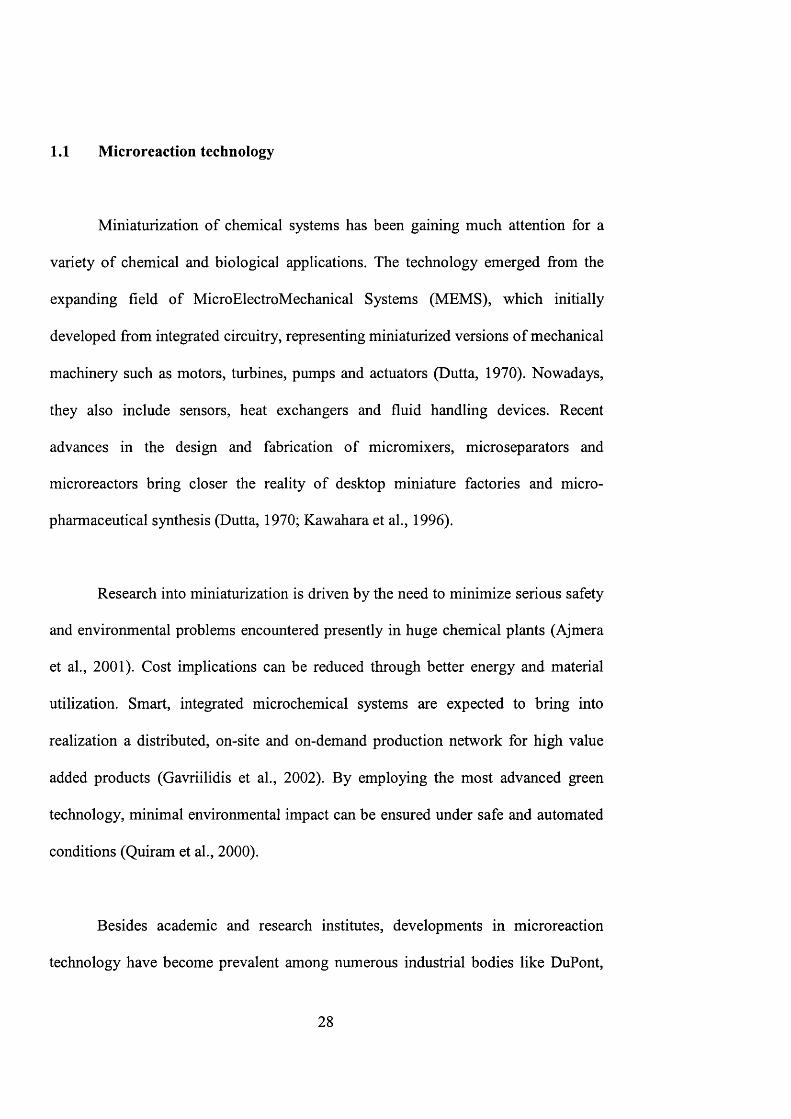
1.1 Microreaction technology
Miniaturization of chemical systems has been gaining much attention for a
variety of chemical and biological applications. The technology emerged from the
expanding field of MicroElectroMechanical Systems (MEMS), which initially
developed from integrated circuitry, representing miniaturized versions of mechanical
machinery such as motors, turbines, pumps and actuators (Dutta, 1970). Nowadays,
they also include sensors, heat exchangers and fluid handling devices. Recent
advances in the design and fabrication of micromixers, microseparators and
microreactors bring closer the reality of desktop miniature factories and micro-
pharmaceutical synthesis (Dutta, 1970; Kawahara et al., 1996).
Research into miniaturization is driven by the need to minimize serious safety
and environmental problems encountered presently in huge chemical plants (Ajmera
et al., 2001). Cost implications can be reduced through better energy and material
utilization. Smart, integrated microchemical systems are expected to bring into
realization a distributed, on-site and on-demand production network for high value
added products (Gavriilidis et al., 2002). By employing the most advanced green
technology, minimal environmental impact can be ensured under safe and automated
conditions (Quiram et al., 2000).
Besides academic and research institutes, developments in microreaction
technology have become prevalent among numerous industrial bodies like DuPont,
28
BASF, Shell, Merck, Bayer, Axiva, etc. Microreactors offer great advantages such as
safety, flexibility and pollution abatement (Lowe and Ehrfeld, 1999). The large
surface area to volume ratio has proved it can provide excellent heat and mass
transfer efficiency providing well-defined and uniform processes to increase product
conversion and selectivity (Hardt et al., 2000). They provide significant improvement
for rapid catalyst testing in high throughput experimentations (Haswell et al., 2001
and Greenway et al., 2000). The ability to accommodate completely new operating
regimes serves as a great tool to locate optimal reaction conditions that are not
accessible by conventional means (Worz et al., 2001). Higher process yields can be
attained (Worz et al., 1998) by applying new process implementation. Explosion
proof oxidation can also be now safely operated using microreactors (Jensen, 2001).
1.2 Application of zeolites
Zeolites, known as molecular sieves, are microporous tectosilicates with
different pore sizes. They can be precisely tailored up to the sub-nanometer scale with
desired arrangement and properties, which are of great interest in the field of
catalysis, ion-exchange, separation and extraction (Davis and Lobo, 1992; Davis,
1998; Caro et al., 2000). Nowadays, they are widely employed in the synthesis of fine
chemicals and pharmaceuticals (Holderich and van Bekkum, 1991; Derouane at al.,
2000), pollution abatement (Nishizaka and Misono, 1993; Sato et al., 1991),
membranes (Coronas and Santamaria, 1999a) and membrane reactors (Casanave et
al., 1995; Coronas and Santamaria, 1999b).
29
In the last decade, zeolite-support composites have been reported showing
enormous potential in industry (Suzuki, 1987). Zeolite membranes possess the
advantages of shape selectivity, sorption and catalysis properties, which serve as an
excellent choice for application in chemical synthesis, catalyst regeneration, product
separation, solvent recovery, liquid/liquid extraction and waste minimisation (van
Bekkum et al., 1994; Jansen et al., 1994; Tsapatsis, 1999; Chau et al., 2000). The
chemical environment within the zeolite pore channel can be manipulated to
influence the molecular transport of diffusing species during separation. In addition,
its unique framework chemistry and high internal surface area offer an excellent
catalytic environment for many chemical reactions.
Recently, a miniature MFI type zeolite film (sicalite-1, ZSM-5) was
successfully fabricated using traditional semiconductor technology (den Exter et al.,
1997; Rebrov et al., 2001). This opens up the door to incorporate zeolites into
microelectromechanical systems (MEMS). Zeolites, with their great thermal and
chemical stability, offer a great choice for integration in microsystems. Their
structures can be tuned and engineered precisely for design and application in nano
devices (Yan and Bein, 1995). Novel thoughts of integrated membrane reactors can
provide chemical reaction and product separation simultaneously (Schmidt et al.,
1998; Martin et al., 1999).
30
1.3 Objectives
The main objective of this work is to investigate the fabrication strategies and
design operating parameters of zeolite catalytic microreactors, membrane
microreactors and membrane microseparators by subsequent testing through
simulation and experiments. Traditional semiconductor fabrication methodology
along with zeolite thin film technology were developed to incorporate MFI type
zeolites into microreactor design as structural materials, catalysts or membranes. The
microstructure and chemistry of these zeolites were tailor-made to satisfy the
application requirements.
A first prototype of a zeolite microreactor was successfully tested. Detailed
simulation was conducted as a design and data interpretation tool to examine the
microreactor performance. A multi-channel membrane microreactor was also
developed utilizing the molecular sieving effect of a zeolite. This novel technology,
to fabricate zeolite microreactors, opens up a new horizon to incorporate zeolites in
microstructured reactors for various chemical applications.
31
1.4 Thesis Outline
The novel concept of microreaction technology is introduced in Chapter 1.
The development of miniaturized chemical systems and their advantages are
discussed. The potential applications of zeolites as catalyst and membrane material in
microreactors are suggested. The main objective of this work is also presented.
Chapter 2 contains a broad literature survey on zeolites and microsystem
technology. The characteristics of zeolites and their applications as catalysts and
membranes are illustrated. The advantages of microreactors and their further
applications are discussed in detail.
Chapter 3 outlines the instrumentation and methodology employed in this
work. Preparation of colloidal zeolite and zeolite membranes are introduced.
MicroChannel fabrication and characterisation methods are presented. Details for
microreactor testing are illustrated.
Novel fabrication techniques to incorporate MFI zeolites in microchemical
systems are discussed in Chapter 4. Complex microchannel geometry and networks,
as well as zeolite arrays successfully fabricated, are illustrated. Blueprints for zeolite-
based microchemical systems are presented and the structural details of the
microdevices are analysed.
32
In Chapter 5, design and fabrication of zeolite-based microreactors and
membrane microseparators are presented. Strategies for the manufacture of zeolite
catalytic microreactors are discussed: zeolite powder coating, uniform zeolite film
growth, localized zeolite growth, and etching of zeolite-silicon composite films. The
preparation of free-standing membranes for zeolite membrane microseparators is also
presented.
Chapter 6 presents the testing of a TS-1 microreactor for 1-pentene
epoxidation, which has been selectively incorporated within the microreactor channel
using a new synthesis procedure. A simple computation model is developed to
simulate the reaction in the single-channel microreactor. The result obtained from
computer simulation acts as a guideline to improve the reactor performance. The
technique to engineer the catalyst micro structure and chemistry is demonstrated.
Catalyst deactivation study was carried out on the TS-1 microreactor. Titanium
leaching from the zeolite framework was also observed in the experiment.
A multi-channel membrane microreactor is then developed for selective
removal of water. Chapter 7 presents the preliminary experimental result of the TS-1
catalysed selective oxidation of aniline. The product yield and selectivity are
compared with performance of normal microreactors.
Finally, the conclusions and suggestions for future work are outlined in
chapter 8. The practical implications of the thesis research are discussed. Applications
33

of zeolite-based microchemical devices in various research areas and industrial
processes are suggested.
34

Chapter 2
Literature Survey
35

2.1 General Background on Zeolites
Molecular sieve zeolites are crystalline alumino-silicalites in which the
aluminum and silicon atoms are present in the form of AIO4 or Si0 4 tetrahedra
(Thompson, 1998). A Swedish mineralogist, Cronstedt, discovered the first zeolite in
1756, who found that the mineral lost water rapidly upon heating and thus seemed to
boil (Cronstedt, 1756). The name “zeolite” comes from the Greek words zeo (to boil)
and lithos (stone). In this project, we will focus on the study of MFI type zeolites.
2.1.1 Zeolite Structure
The fundamental building block of all zeolites is a tetrahedron of four oxygen
anions surrounding a small silicon or aluminum ion. They are arranged so that each of
the four oxygen anions is shared in turn with another silica or alumina tetrahedron.
Figure 2.1 presents the primary building blocks of a zeolite. The cations required to
maintain electrical neutrality are usually sodium in the zeolites as initially prepared,
but they can be readily replaced by ion exchange which is the most direct and useful
method for the modification of zeolite properties (Bhatia, 1990).
36
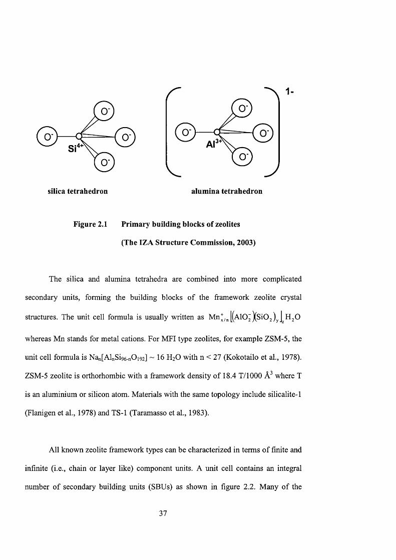
i4+"
silica tetrahedron alumina tetrahedron
Figure 2.1 Primary building blocks of zeolites
(The IZA Structure Commission, 2003)
The silica and alumina tetrahedra are combined into more complicated
secondary units, forming the building blocks of the framework zeolite crystal
structures. The unit cell formula is usually written as Mn^/^ [(AlO^ %Si02)y
whereas Mn stands for metal cations. For MFI type zeolites, for example ZSM-5, the
unit cell formula is Nan[AlnSi96-nOi92] - 1 6 H2O with n < 27 (Kokotailo et al., 1978).
ZSM-5 zeolite is orthorhombic with a framework density of 18.4 T/1000 where T
is an aluminium or silicon atom. Materials with the same topology include silicalite-1
(Flanigen et al., 1978) and TS-1 (Taramasso et al., 1983).
All known zeolite framework types can be characterized in terms of finite and
infinite (i.e., chain or layer like) component units. A unit cell contains an integral
number of secondary building units (SBUs) as shown in figure 2.2. Many of the
37
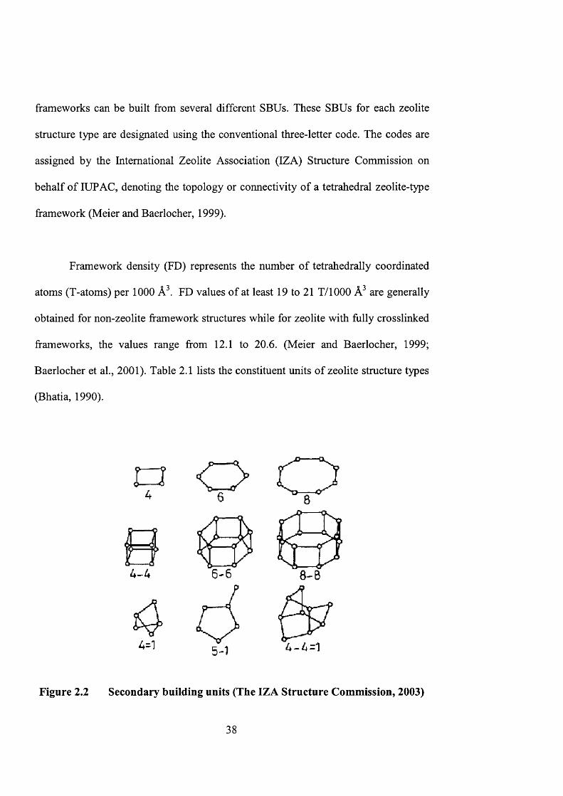
frameworks can be built from several different SBUs. These SBUs for each zeolite
structure type are designated using the conventional three-letter code. The codes are
assigned by the International Zeolite Association (IZA) Structure Commission on
behalf of lUPAC, denoting the topology or connectivity of a tetrahedral zeolite-type
framework (Meier and Baerlocher, 1999).
Framework density (FD) represents the number of tetrahedrally coordinated
atoms (T-atoms) per 1000 Â . FD values of at least 19 to 21 T/1000 are generally
obtained for non-zeolite framework structures while for zeolite with fully crosslinked
frameworks, the values range from 12.1 to 20.6. (Meier and Baerlocher, 1999;
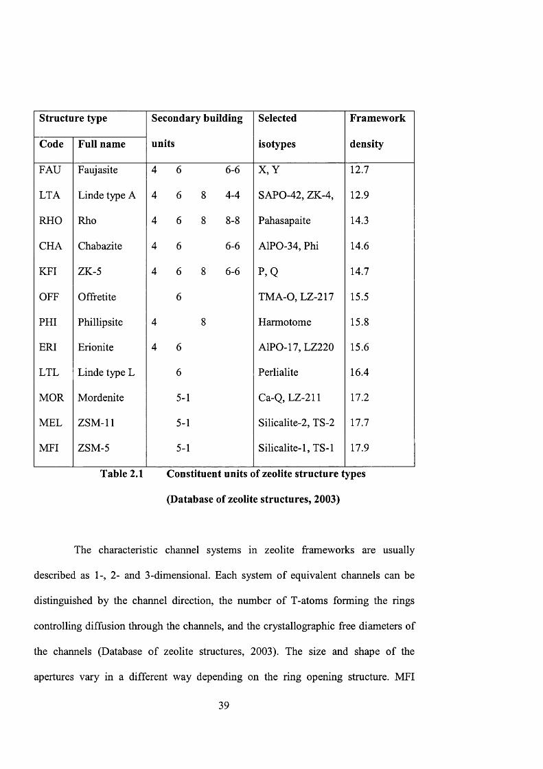
Baerlocher et al., 2001). Table 2.1 lists the constituent units of zeolite structure types
(Bhatia, 1990).
a O
4-1
Figure 2.2 Secondary building units (The IZA Structure Commission, 2003)
38
Structure type Secondary building
units
Selected
isotypes
Framework
densityCode Full name
FAU Faujasite 4 6 6-6 X ,Y 12.7
LTA Linde type A 4 6 8 4-4 SAPO-42, ZK-4, 12.9
RHO Rho 4 6 8 8 - 8 Pahasapaite 14.3
CHA Chabazite 4 6 6-6 AlPO-34, Phi 14.6
KFI ZK-5 4 6 8 6-6 P ,Q 14.7
OFF Offfetite 6 TMA-O, LZ-217 15.5
PHI Phillipsite 4 8 Harmotome 15.8
ERI Erionite 4 6 AlPO-17, LZ220 15.6
LTL Linde type L 6 Perlialite 16.4
MGR Mordenite 5-1 Ca-Q, LZ-211 17.2
MEL ZSM-11 5-1 Silicalite-2, TS-2 17.7
MFI ZSM-5 5-1 Silicalite-1, TS-1 17.9
Table 2.1 Constituent units of zeolite structure types
(Database of zeolite structures, 2003)
The characteristic channel systems in zeolite frameworks are usually
described as 1-, 2- and 3-dimensional. Each system of equivalent channels can be
distinguished by the channel direction, the number of T-atoms forming the rings
controlling diffusion through the channels, and the crystallographic free diameters of
the channels (Database of zeolite structures, 2003). The size and shape of the
apertures vary in a different way depending on the ring opening structure. MFI
39
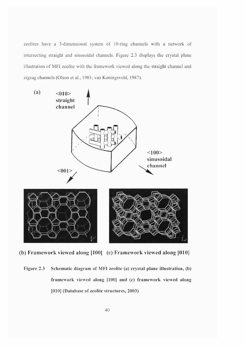
zeolites have a 3-dimensional system of 10-ring channels with a network of
intersecting straight and sinusoidal channels. Figure 2.3 displays the crystal plane
illustration o f MFI zeolite with the framework viewed along the straight channel and
zigzag channels (Olson et al., 1981; van Koningsveld, 1987).
(a) < 010>straightchannel
< 001>
< 100> sinusoidal
\ channel
Wa
1
m
mm
m km
(b) Framework viewed along [100] (c) Framework viewed along [010]
Figure 2.3 Schematic diagram of MFI zeolite (a) crystal plane illustration, (b)
framework viewed along [1 0 0 ] and (c) framework viewed along
[010] (Database of zeolite structures, 2003)
40
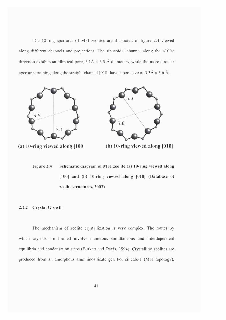
The 10-ring apertures o f MFI zeolites are illustrated in figure 2.4 viewed
along different channels and projections. The sinusoidal channel along the <100>
direction exhibits an elliptical pore, 5.1Â x 5.5 Â diameters, while the more circular
apertures running along the straight channel [010] have a pore size o f 5.3Â x 5.6 A.
5.5
5.3
5.6
(a) 10-ring viewed along [100] (b) 10-ring viewed along [010]
Figure 2.4 Schematic diagram of MFI zeolite (a) 10-ring viewed along
[100] and (b) 10-ring viewed along [010] (Database of
zeolite structures, 2003)
2.1.2 Crystal Growth
The mechanism of zeolite crystallization is very complex. The routes by
which crystals are formed involve numerous simultaneous and interdependent
equilibria and condensation steps (Burkett and Davis, 1994). Crystalline zeolites are
produced from an amorphous alumninosilicate gel. For silicate-1 (MFI topology).
41

tetraethyl orthosilicate (TEOS) and tetrapropylammonium hydroxide (TPAOH) are
used as the silica source and the template respectively.
The tetrapropylammonium (TPA) cation acts in an organic structure-directing
role in zeolite synthesis. The TP A molecules are located at the channel intersections
with propyl chains extending into both linear and sinusoidal channels (Chao et al,
1986). The molecules are held tightly at these sites and cannot diffuse in or out of the
structure, and can only be removed by calcination. This suggests that the TP A
molecules must be incorporated into the silicate structure during crystal growth.
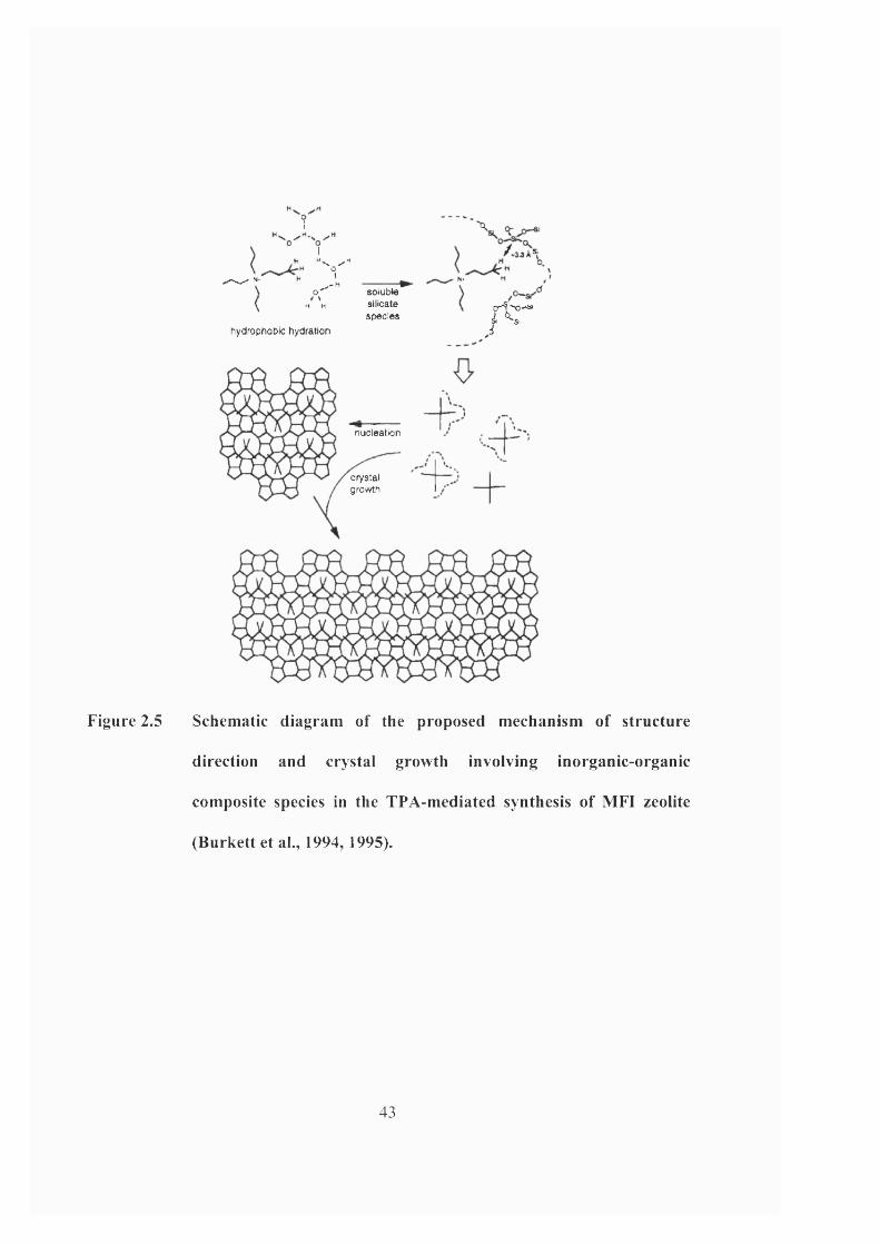
The mechanism of structure direction and self-assembly for the TPA-mediated
synthesis of Si-ZSM-5 is illustrated in figure 2.5. Burkett and co-workers (1994,
1995) have reported the existence of specific, intermolecular interactions within pre
organized, inorganic-organic composite structures during the synthesis of Si-ZSM-5.
Structure direction is determined by the van der Waals interactions between the alkyl
chains of the organic species and the hydrophobic silicate species, which give rise to
the geometric correspondence between the structure-directing agent and the zeolite
pore architecture. These structure-directing interactions have broad implications for
the design and synthesis of new molecular sieve materials.
42
H
S""— % ' ,-H 1\ O ' so lub le\ H M Silicate
sp e c ie s
hydrophobic hydration
‘X
f i : '
nucléation
crystalgrowth
Figure 2.5 Schematic diagram of the proposed mechanism of structure
direction and crystal growth involving inorganic-organic
composite species in the TPA-mediated synthesis of MFI zeolite
(Burkett et al., 1994, 1995).
43
2.2 Zeolite Catalysis
Zeolites are important catalysts in a wide range of chemical and petrochemical
processes over the last two decades. Recently, they have been applied in the synthesis
of intermediates and fine chemicals (Holderich and van Bekkum, 1991; Maxwell and
Stork, 1991; van Bekkum et al., 1994; Armor, 1999). The aluminum containing MFI
zeolite, Al-ZSM-5 is used to catalyse hydrogenation, disproportionation,
isomérisation and alkylation reactions (Jacobs and Martens, 1991). TS-1 zeolite is
known to be an efficient catalyst for selective oxidation of alcohols (Maspero and
Romano, 1994), epoxidation of alkenes (Clerici et al., 1991) and hydroxylation of
aromatics (van der Pol et al., 1992), etc.
Zeolites can be precisely tailored up to sub-nanometer scale for successful
applications. They can act as a very robust material to synthesize and withstand
severe reaction conditions (Feast and Lercher, 1996). In comparison with macro- and
mesoporous oxides, zeolites offer the advantages of high concentration of active sites
resulting in very active catalysts and their chemical properties can be better modified.
Their tuneable pore size and tortuosity can also determine the space available for
transition states and diffusivities of reactants and products.
The rate and selectivity of catalysed reactions over molecular sieves catalysts
are determined by their chemical induced selectivity (surface interface chemistry) and
shape selectivity (steric limitations). Molecular sieve catalysts can be tuned over a
44
wide range of acidity and basicity. Many cations can be introduced by ion exchange
and isomorphous substitution (Jacobs and Martens, 1991). They can also provide sites
or be the site carriers allowing valence changes in redox processes. Metal crystallites
and metal complexes can be entrapped within the zeolite framework offering a unique
steric and chemical environment (Lunsford, 1987; Holderich et al., 1991,).
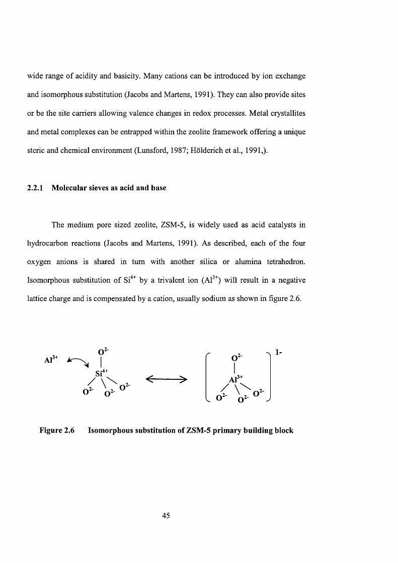
2.2.1 Molecular sieves as acid and base
The medium pore sized zeolite, ZSM-5, is widely used as acid catalysts in
hydrocarbon reactions (Jacobs and Martens, 1991). As described, each of the four
oxygen anions is shared in turn with another silica or alumina tetrahedron.
Isomorphous substitution of Si" by a trivalent ion (Al^^) will result in a negative
lattice charge and is compensated by a cation, usually sodium as shown in figure 2.6.
Al3+o 2 -
.4+
O 2-
i3+Al2-
1-
Figure 2.6 Isomorphous substitution of ZSM-5 primary building block
45
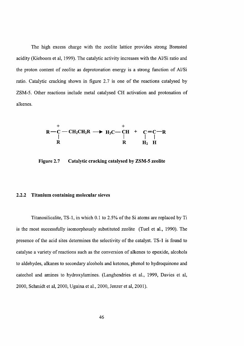
The high excess charge with the zeolite lattice provides strong Bronsted
acidity (Kieboom et al, 1999). The catalytic activity increases with the Al/Si ratio and
the proton content of zeolite as deprotonation energy is a strong function of Al/Si
ratio. Catalytic cracking shown in figure 2.7 is one of the reactions catalysed by
ZSM-5. Other reactions include metal catalysed CH activation and protonation of
alkenes.
+ 4-R — C — CH2CH2R — ► H3C— CH + C = C — R
I I I IR R Hz H
Figure 2.7 Catalytic cracking catalysed by ZSM-5 zeolite
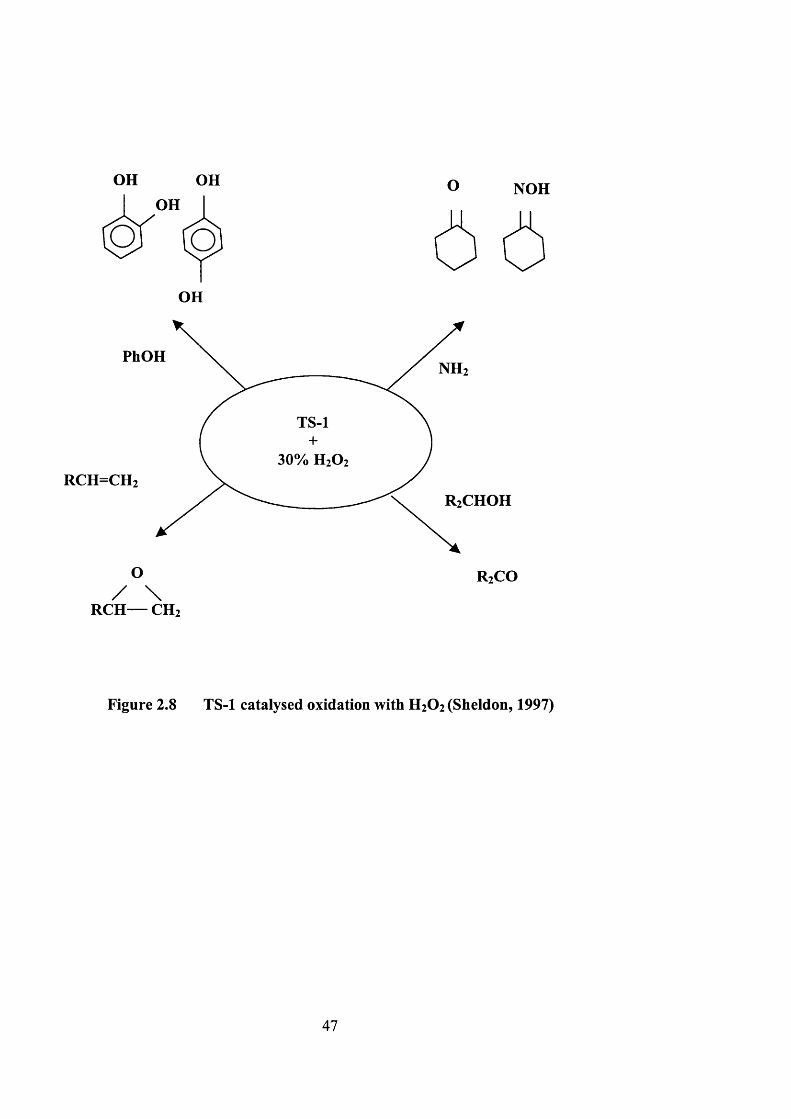
2.2.2 Titanium containing molecular sieves
Titanosilicalite, TS-1, in which 0.1 to 2.5% of the Si atoms are replaced by Ti
is the most successfully isomorphously substituted zeolite (Tuel et al., 1990). The
presence of the acid sites determines the selectivity of the catalyst. TS-1 is found to
catalyse a variety of reactions such as the conversion of alkenes to epoxide, alcohols
to aldehydes, alkanes to secondary alcohols and ketones, phenol to hydroquinone and
catechol and amines to hydroxylamines. (Langhendries et al., 1999, Davies et al,
2000, Schmidt et al, 2000, Uguina et al., 2000, Jenzer et al, 2001).
46
OH OHOH
OH
O NOH
/ \ RCH— CH2
PhOH
TS-1
O
Figure 2.8 TS-1 catalysed oxidation with H2O2 (Sheldon, 1997)
47
2.3 Titanium silicalite-1 catalysts
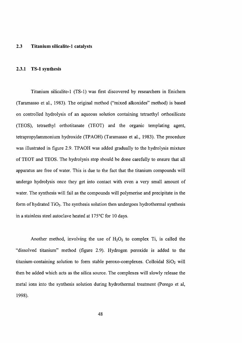
2.3.1 TS-1 synthesis
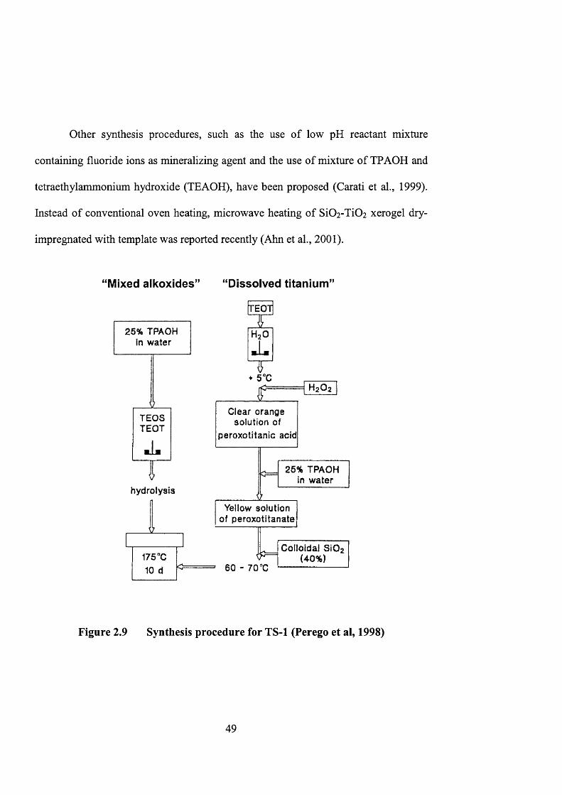
Titanium silicalite-1 (TS-1) was first discovered by researchers in Enichem
(Taramasso et al., 1983). The original method (“mixed alkoxides” method) is based
on controlled hydrolysis of an aqueous solution containing tetraethyl orthosilicate
(TEOS), tetraethyl orthotitanate (TEOT) and the organic templating agent,
tetrapropylammonium hydroxide (TPAOH) (Taramasso et al., 1983). The procedure
was illustrated in figure 2.9. TPAOH was added gradually to the hydrolysis mixture
of TEOT and TEOS. The hydrolysis step should be done carefully to ensure that all
apparatus are free of water. This is due to the fact that the titanium compounds will
undergo hydrolysis once they get into contact with even a very small amount of
water. The synthesis will fail as the compounds will polymerise and precipitate in the
form of hydrated TiO]. The synthesis solution then undergoes hydrothermal synthesis
in a stainless steel autoclave heated at 175°C for 10 days.
Another method, involving the use of H2O2 to complex Ti, is called the
“dissolved titanium” method (figure 2.9). Hydrogen peroxide is added to the
titanium-containing solution to form stable peroxo-complexes. Colloidal Si02 will
then be added which acts as the silica source. The complexes will slowly release the
metal ions into the synthesis solution during hydrothermal treatment (Perego et al,
1998).
48
Other synthesis procedures, such as the use of low pH reactant mixture
containing fluoride ions as mineralizing agent and the use of mixture of TPAOH and
tetraethylammonium hydroxide (TEAOH), have been proposed (Carati et al., 1999).
Instead of conventional oven heating, microwave heating of Si02-Ti02 xerogel dry-
impregnated with template was reported recently (Ahn et al., 2001).
“Mixed alkoxides” “Dissolved titanium”
♦ 5°C
hydrolysis
Yellow solution of pero)«3titanate
175 "C 10 d 60 - 70 “C
TEOT
HgO
26% TPAOH in w ater
Colloidal SiOa (40%)
TEOSTEOT
25% TPAOH in water
Clear orange solution of
peroxotftanic acid
Figure 2.9 Synthesis procedure for TS-1 (Perego et ai, 1998)
49
2.3.2 Catalytic properties
TS-1 is hydrophobic and high product selectivity is obtained in oxidation with
hydrogen peroxide. The catalytic properties of titanium silicalite-1 are unique. TS-1 is
characterized by its excellent selectivity, sterospecificity, and electrophilic behaviour
(Cleric and Ingallina, 1993). Only a slight loss of hydrogen peroxide is observed from
decomposition to H2O and O2 in a variety of liquid-phase oxidation reaction of H2O2
with alcohols, ketones and alkanes (Grzybowska-Swierkosz and Haber, 1994).
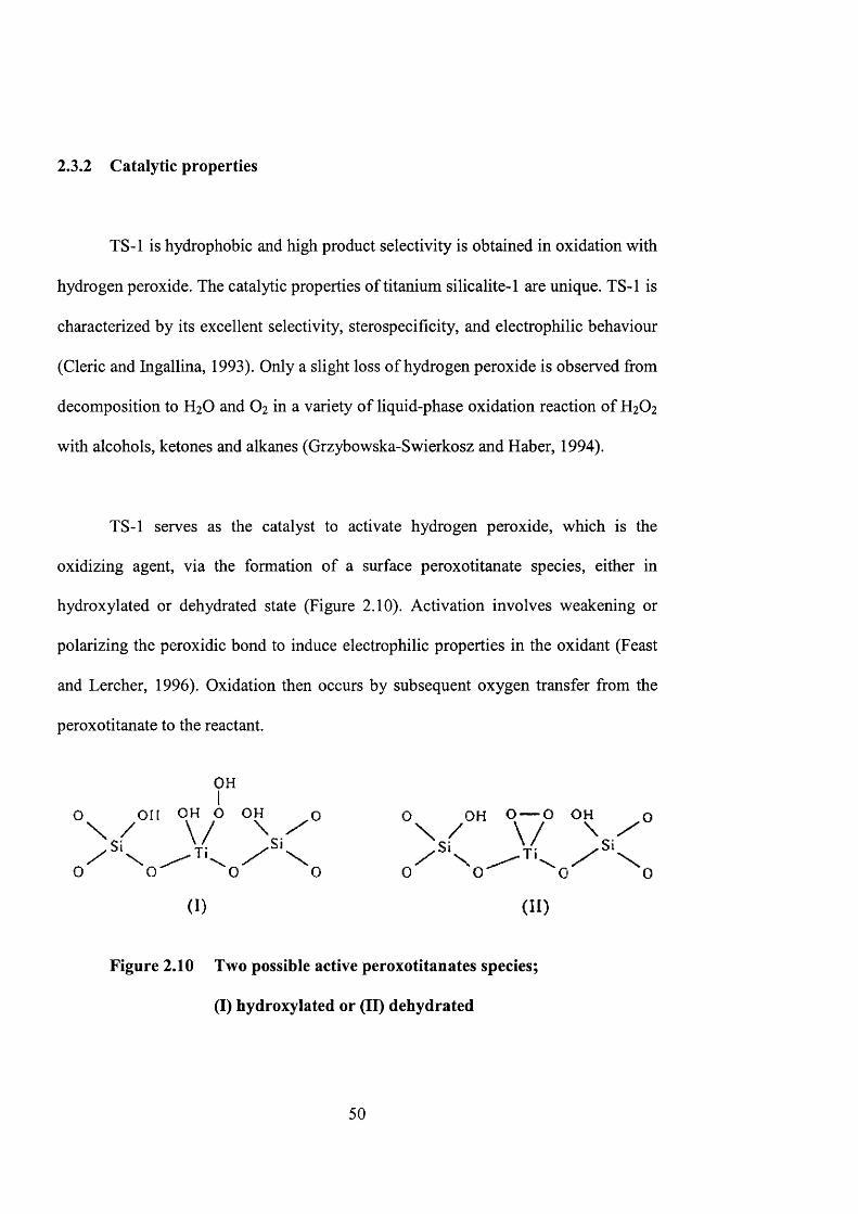
TS-1 serves as the catalyst to activate hydrogen peroxide, which is the
oxidizing agent, via the formation of a surface peroxotitanate species, either in
hydroxylated or dehydrated state (Figure 2.10). Activation involves weakening or
polarizing the peroxidic bond to induce electrophilic properties in the oxidant (Feast
and Lercher, 1996). Oxidation then occurs by subsequent oxygen transfer from the
peroxotitanate to the reactant.
OHI
O OH OH p OH o
(I)
O OH o — P OH O
(II)
Figure 2.10 Two possible active peroxotitanates species;
(I) hydroxylated or (II) dehydrated
50
2 . 3 . 3 O x i d a t i o n r e a c t i o n s
Examples of oxidation reactions catalysed by TS-1 are ammonia oxidation,
cyclohexanone ammoximation (Mantegazza et al., 1999), selective oxidation of
aniline (Gontier and Tuel, 1994), oxidation of glycerol (McMom et al., 1999) and
oxidation of primary and secondary alcohols (Maspero and Romano, 1994). Due to its
remarkable high efficiency and molecular selectivity, TS-1 is widely employed in
many chemical processes. TS-1 was used to catalyse cyclohexanone ammoximation
in the industrial production of Nylon 6.
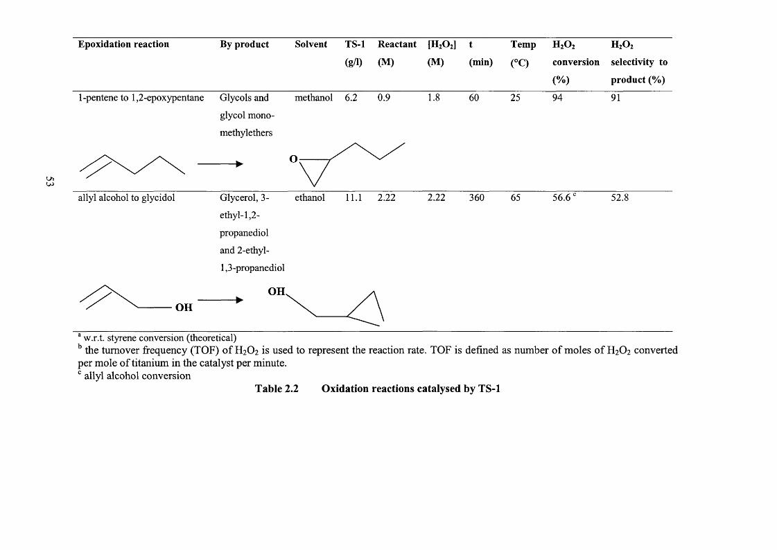
TS-1 is also an efficient catalyst for epoxidation reactions like lower olefins to
epoxides (Clerici and Ingallina, 1993), allyl chloride to epichlorohydrin (Gao et al.,
1996), allyl alcohol to glycidol (Hutchings et al., 1995), styrene to
phenylacetaldehyde (Kumar et al., 1995) and propylene to propylene oxide (Chen et
al, 1998). It is characterized by its excellent selectivity, stereo specificity, and
electrophilic behaviour (Cleric and Ingallina, 1993). The following table lists the
details of each example of epoxidation reactions catalysed by TS-1 (Table 2.2).
51

E p o x i d a t i o n r e a c t i o n B y p r o d u c t S o l v e n t T S - 1 R e a c t a n t [ H 2 O 2 ] t T e m p
( g / 1 ) ( M ) ( M ) ( m i n ) ( ° C )
H2O2 H2O2
conversion selectivity to
(%) product (%)
allyl chloride to
epichlorohydrin (ECH)
glycol methanol 10.00 1.214 0.517 60 45 98.7 97.8
toepoxidation of styrene and
further isomérisation to
phenylacetaldehyde
Benzaldehyde acetone
and
styrene epoxide
40.0 2 0.5 360 80 78' 77.5'
propylene to propylene oxide propylene diol methanol 10.0 1.5wt% 4.9mm 97.7
and mono-
methylethers
E p o x i d a t i o n r e a c t i o n B y p r o d u c t S o l v e n t T S - 1 R e a c t a n t [ H 2 O 2 ] t T e m p
( g / 1 ) ( M ) ( M ) ( m i n ) ( ° C )
H2O2 H2O2
conversion selectivity to
(%) product (%)
1-pentene to 1,2-epoxypentane Glycols and
glycol mono-
methylethers
methanol 6.2 0.9 1.8 60 25 94 91
O
ethanolallyl alcohol to glycidol Glycerol, 3- 2.22 56.611.1 2.22 360 52.
ethyl-1,2-
propanediol
and 2-ethyl-
1,3-propanediol
OHOH
w.r.t. styrene conversion (theoretical) the turnover frequency (TOP) of H2O2 is used to represent the reaction rate. TOP is defined as number of moles of H2O2 converted
per mole of titanium in the catalyst per minute. allyl alcohol conversion
Table 2.2 Oxidation reactions catalysed by TS-1
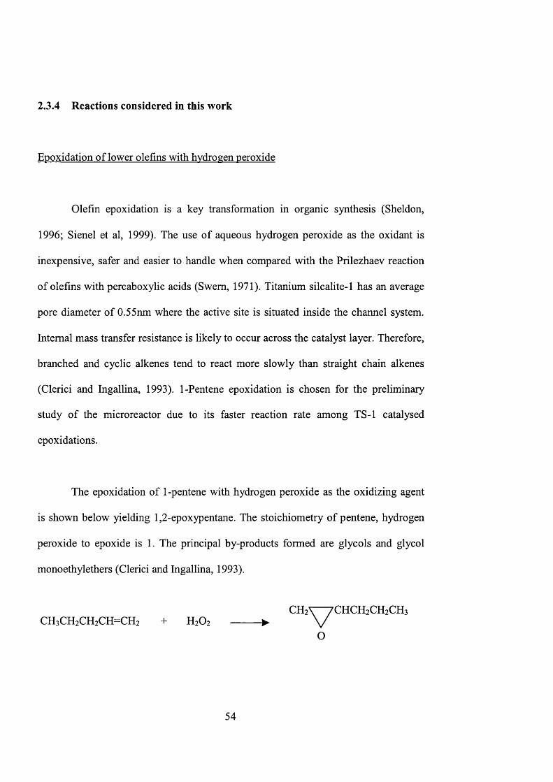
2.3.4 Reactions considered in this work
Epoxidation of lower olefins with hydrogen peroxide
Olefin epoxidation is a key transformation in organic synthesis (Sheldon,
1996; Sienel et al, 1999). The use of aqueous hydrogen peroxide as the oxidant is
inexpensive, safer and easier to handle when compared with the Prilezhaev reaction
of olefins with percaboxylic acids (Swem, 1971). Titanium silcalite-1 has an average
pore diameter of 0.55nm where the active site is situated inside the channel system.
Internal mass transfer resistance is likely to occur across the catalyst layer. Therefore,
branched and cyclic alkenes tend to react more slowly than straight chain alkenes
(Clerici and Ingallina, 1993). 1-Pentene epoxidation is chosen for the preliminary
study of the microreactor due to its faster reaction rate among TS-1 catalysed
epoxidations.
The epoxidation of 1-pentene with hydrogen peroxide as the oxidizing agent
is shown below yielding 1,2-epoxypentane. The stoichiometry of pentene, hydrogen
peroxide to epoxide is 1. The principal by-products formed are glycols and glycol
monoethylethers (Clerici and Ingallina, 1993).
CH2VTCHCH2CH2CH3 CH3CH2CH2CH=CH2 + H2O2 ------- ► V
O
54

The chosen reaction for TS-1 catalysis is the epoxidation of 1-pentene to form
1,2-epoxypentane using 33% by weight hydrogen peroxide as oxidant (Clerici and
Ingallina, 1993). The reaction can be performed at near room temperature with
selectivity up to 98% on hydrogen peroxide. Some of the literature values for the
reaction for C5-C8 olefins are listed in table 2.3.
n Olefin [HzOzjn T t H2O2 Selectivity tl /2
(M) (°C) (min) (conv. %) (% on H2O2)
1 1-Pentene 0.18 25 60 94 91 5
2 1-Hexene 0.18 25 70 8 8 90 8
3 1 -Hexene^ 0.18 25 70 6 8 90 14
4 1-Octene 0.17 45 45 81 91 5
Olefins, 0.90M; TS-1, 6.2 g/1; solvent, methanol; ti/2 is the time required for 50% H2O2 conversion. [1-Hexene] 0.18M.
Table 2.3 Epoxidation of C5-C8 olefins (Clerici and Ingallina, 1993)
55
2.4 Zeolite Membranes
Zeolites and molecular sieves are excellent materials for inorganic membranes
(Jansen et al., 1994). The pore structure of the zeolite restricts the size and shape of
the molecules that can enter and leave the channels. This gives rise to molecular
sieving effects observed in many separation and reaction processes (Jansen et al.,
1994). Unlike most microporous metal oxides (e.g., SiOz, AI2O3 and TiOz), which
have tortuous pore channels, zeolites have a well-defined pore system and a
crystalline structure. The chemical environment within the zeolite pore channel can
be manipulated to influence the molecular transport of diffusing species during
separation. When compared with conventional membranes, zeolite membranes
possess a higher open area with low aspect ratio providing volumetric efficiency
(Jansen et al., 1994).
Zeolite membranes serve as an excellent choice for application in chemical
synthesis, product separation, solvent recovery, liquid/liquid extraction and waste
minimisation, (van Bekkum et al., 1994; Jansen et al., 1994; Tsapatsis et al., 1999;
Chau et al., 2000). They can be used for separation of close boiling compounds and
isomers (Funke et al., 1996a, 1996b) or pervaporation of organic solutions at high
temperature (Nomura et al., 1998). Permeation studies have been carried out on MFI-
type membranes showing remarkable selectivity for different gas pairs (Lovallo et al.,
1998). They are also suitable for gas sensor applications (Koegler et al., 1994).
56
In recent progress of zeolite membrane development, synthesis approaches
have been reported for the preparation of zeolite film with different structure types,
silicalite-1 (Cheng et al, 1997), ZSM-5 (Sano et ah, 1992), TS-1 (Jung and Shul,
1997), Y-type zeolites (Kusakabe et ah, 1997), zeolite LTA (Hedlund et al, 1997),
zeolite A (Boudreau et ah, 1999) and CaA (Yan and Bein, 1995). Zeolites have been
successfully grown as free-standing membranes or onto support materials such as
glass, ceramics, porous stainless steel, silicon and alumina tube (van Bekkum et ah,
1994, den Exter et ah, 1997, Xomeritakis et ah, 1999, Chau et ah, 2000).
Supported zeolites have been considered for many industrial applications such
as membranes, adsorbents, catalyst components and in electronic devices (van
Bekkum et al, 1994). Because of their greater mechanical strength and thermal
stability provided by the support material, handling and implementation is easier.
Zeolite based membranes require a continuous layer of zeolite crystals with properly
aligned zeolite channels. They should be supported on a porous carrier material. They
are best prepared on an existing support by hydrothermal treatment. Two synthesis
methods are described in the following.
2.4.1 In-situ synthesis
The support material is immersed in zeolite precursor gel. The seed-free
substrate is in direct contact with the synthesis mixtures and hydrothermal treatment
takes place at autogenous pressure. Koegler et al. (1997) has proposed a model for
57
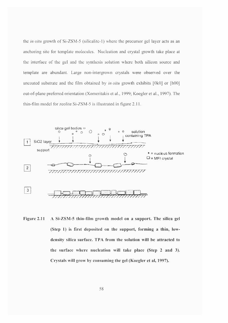
the in-situ growth o f Si-ZSM-5 (silicalite-1) where the precursor gel layer acts as an
anchoring site for template molecules. Nucléation and crystal growth take place at
the interface o f the gel and the synthesis solution where both silicon source and
template are abundant. Large non-intergrown crystals were observed over the
uncoated substrate and the film obtained by in-situ growth exhibits [OkO] or [hOO]
out-of-plane preferred orientation (Xomeritakis et ah, 1999; Koegler et al., 1997). The
thin-film model for zeolite Si-ZSM-5 is illustrated in figure 2.11.
silica gel bodies o o ° o O
pT| SIQ2 layer i \o o solution
containing TPA
support7 7 7 7 7 7 7 7 7 7 % 77777777
• = nucleus formation O = MFI crystal
a
Figure 2.11 A Si-ZSM-5 thin-film growth model on a support. The silica gel
(Step 1) is first deposited on the support, forming a thin, low-
density silica surface. TPA from the solution will be attracted to
the surface where nucléation will take place (Step 2 and 3).
Crystals will grow by consuming the gel (Koegler et al, 1997).
58
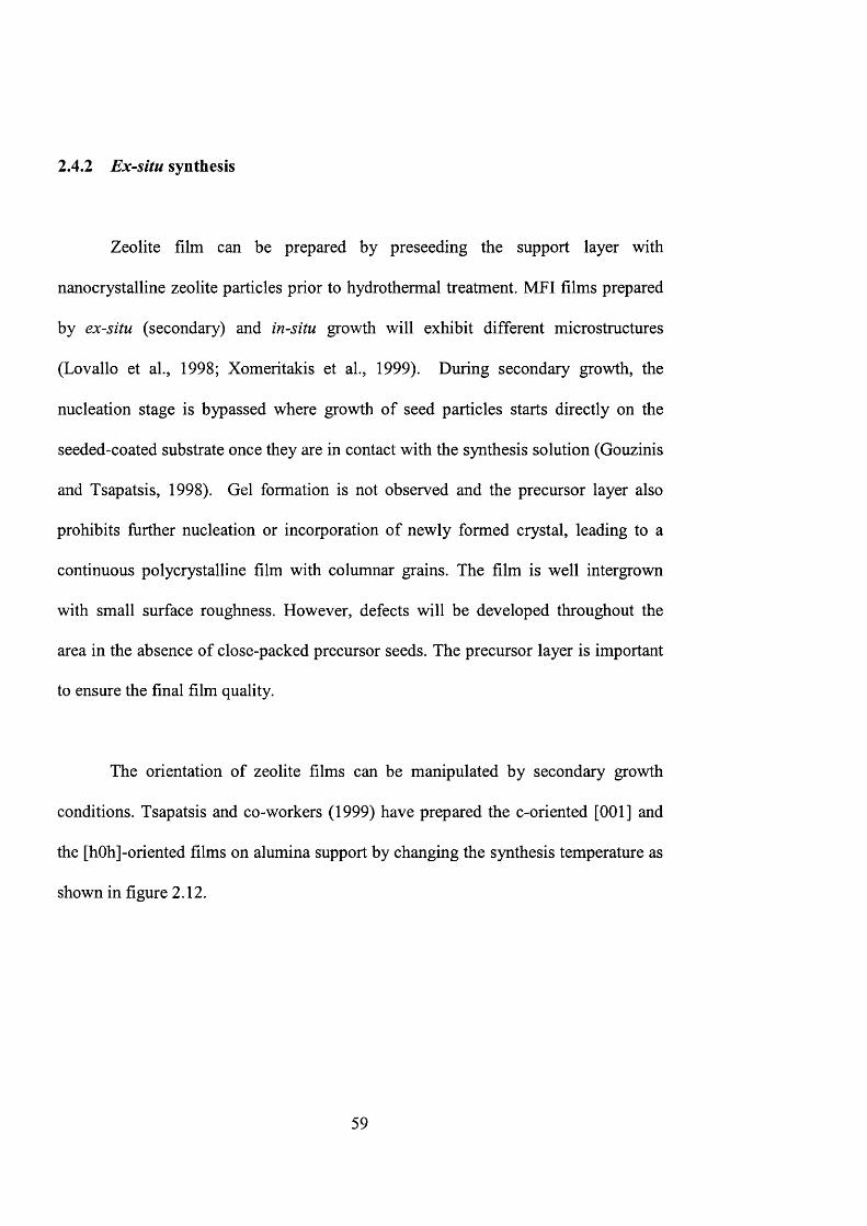
2.4.2 Ex-situ synthesis
Zeolite film can be prepared by preseeding the support layer with
nanocrystalline zeolite particles prior to hydrothermal treatment. MFI films prepared
by ex-situ (secondary) and in-situ growth will exhibit different microstructures
(Lovallo et al., 1998; Xomeritakis et al., 1999). During secondary growth, the
nucléation stage is bypassed where growth of seed particles starts directly on the
seeded-coated substrate once they are in contact with the synthesis solution (Gouzinis
and Tsapatsis, 1998). Gel formation is not observed and the precursor layer also
prohibits further nucléation or incorporation of newly formed crystal, leading to a
continuous polycrystalline film with columnar grains. The film is well intergrown
with small surface roughness. However, defects will be developed throughout the
area in the absence of close-packed precursor seeds. The precursor layer is important
to ensure the final film quality.
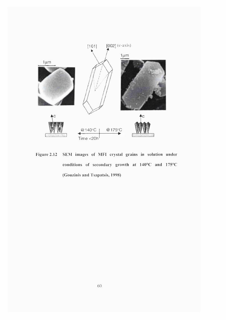
The orientation of zeolite films can be manipulated by secondary growth
conditions. Tsapatsis and co-workers (1999) have prepared the c-oriented [001] and
the [hOh]-oriented films on alumina support by changing the synthesis temperature as
shown in figure 2.12.
59
lum
m
[101] [002] (e-axis)
/' 1|.im
@140^'C
Tim e <20h
175^0 ►
Figure 2.12 SEM images of MFI crystal grains in solution under
conditions of secondary growth at 140°C and 175°C
(Gouzinis and Tsapatsis, 1998)
60

2.5 Introduction to microreactors
The small dimensions o f microreactors open up innovative pathways for many
reactions. Many research institutes and companies are developing microchemical
systems, as they are potentially beneficial to the environment. It is believed that
micro fabrication chemical systems with integrated sensors and actuators will
revolutionize chemical research and development (Jensen, 2001). Figure 2.13
illustrates the scale o f Microelectromechanical (MEMS) when compared with
different components in conventional systems. The drawback is that submillimeter
channels may sometimes be blocked by particulates.
< 1 1 1 1 1 — I I I I1nm 1pm 1mm 1km
Transistors/ICs < -----
Sensors/Actuators < -----
Pum ps^alves
React^ s /H ^ t Exchangers
Chemical Pjants
Microelectromechanical Systems (MEMS)
ConventionalSystems
Figure 2.13 Scale of microelectromechanical systems in
comparison with conventional systems
61
2.5.1 Definition of microreactors
Microreactors are defined as miniaturized reaction systems fabricated by
using, at least partially, methods of microtechnology and precision engineering
(Ehrfeld et al, 2000). They are usually micromachined on silicon, stainless steel,
glass, etc. with characteristic dimensions in the micrometer to millimeter range. They
contain submillimeter internal structures like fluid channels integrated with heaters,
temperature and flow sensors.
2.5.2 Advantages of microreactors
Fast screening of materials
Microreactors have the properties of short response times and small volumes
for reducing the inertia of the whole system (Zech et al., 2000). Miniaturization
enables a flexible, robust on-line screening system for use in catalysed reactions
under harsh processing conditions (Zech et al., 2000). Actual catalytic performance
can be detected based on fast screening processes offered in microreactors (Védrine,
2000).
Well-defined flow characteristics
Laminar fluid flow within the microsystem results in a more uniform velocity
distribution inside the microchannels. This provides benefits for reaction kinetics and
mechanism studies. Flow visualization using computer fluid dynamics can be
62
employed to further understand the behaviour of microfluidic reactions. Detailed
simulation can be served as the best tool for design and data interpretation. Optimum
design and operating parameters can be located (Hsing et al., 2000).
Easier scale-up through replication
Microreactors have the ability to integrate different microdevices for better
control and easier scale-up. Multiple repetition of basic units can be operated in
parallel to cope with the annual production of high value added chemicals (Gavriilidis
et al., 2002).
High surface area to volume ratio
The large surface area to volume ratio in a microreactor gives excellent heat
and mass transfer properties (Drost et al., 1997; Losey et al., 2000), which provides
effective heat management for isothermal processing even in fast and explosive
reactions (Richter et al., 2000). They are also an excellent choice for use in
multiphase reactions as the mass transfer path is minimal. Explosion proof oxidation,
which cannot be carried out utilizing conventional reactors, can now be safely
operated using microreactors (Jensen, 2001).
Improved safetv
Microreactors enable safer handling of explosive and hazardous chemicals.
The basic idea of having small units would help to prevent any major safety hazards
from occurring within the system. Smaller chemical plants can be located near the
63
intended point of application to eliminate storage and shipping constraints (Ajmera et
al., 2001).
Efficient chemical production
It is recognized that microreactors can provide better energy and material
utilization leading to more efficient chemical production and less pollution (Quiram
et al, 2000). Microreactors can achieve small sizes, affordability and low levels of
emission by relying on high rates of heat and mass transfer through specially
fabricated microchannels (Drost et al, 2000). As a result, operational and capital cost
for the process can be greatly reduced.
Production flexibilitv
Repetition of basic units of microreactors provides the ability to increase
product output by scaling out (numbering up) instead of scale up of the whole
systems. This results in higher flexibility in adapting production rate. A broader range
of operating conditions can be supported in comparison to the conventional system
(Ehrfeld et al., 2000)
64
2 . 5 . 3 M i c r o m a c h i n i n g t e c h n i q u e s
Most of the fabrication methods for MEMS are adapted from technology used
in the integrated circuit industry where materials are restricted to silicon and its
related compounds. Other micromachining methods have been developed for other
materials like glass, stainless steel, ceramic, etc. The following shortlists some of the
developed fabrication procedures used for microchemical devices:
Photolithographv and wet etching
Silicon possesses excellent mechanical strength, chemical resistance and
thermal stability, which is an ideal material for semiconductor manufacturing. The
perfect single crystal structure is great for chemical functionalisation and material
deposition. Nowadays, silicon and its compounds are widely employed to produce
complimentary metal-oxide semiconductor (CMOS) in integrated circuit (IC)
technology.
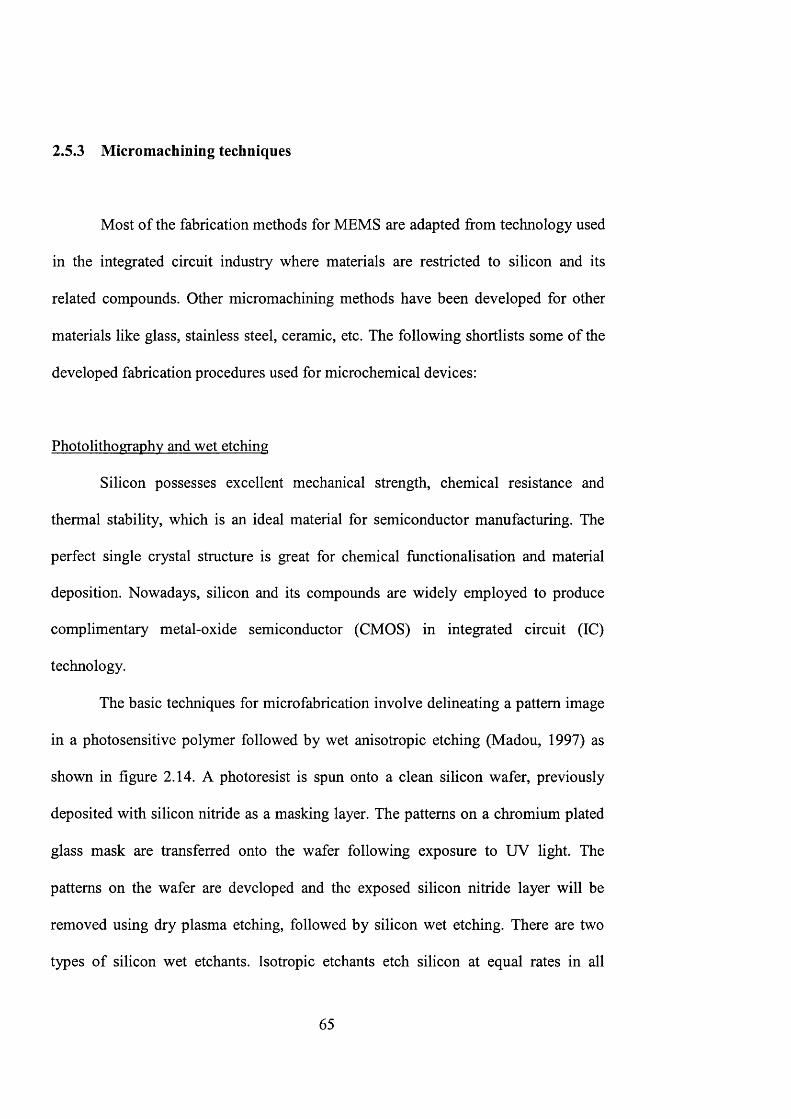
The basic techniques for microfabrication involve delineating a pattern image
in a photosensitive polymer followed by wet anisotropic etching (Madou, 1997) as
shown in figure 2.14. A photoresist is spun onto a clean silicon wafer, previously
deposited with silicon nitride as a masking layer. The patterns on a chromium plated
glass mask are transferred onto the wafer following exposure to UV light. The
patterns on the wafer are developed and the exposed silicon nitride layer will be
removed using dry plasma etching, followed by silicon wet etching. There are two
types of silicon wet etchants. Isotropic etchants etch silicon at equal rates in all
65
directions. They are easily used but are difficult to control for high precision. Wet
etchants, like potassium hydroxide (KOH), ethylene diamine pyrocateehnol (EDP)
and hydrazine, etch silicon [100] crystallographic plane faster than [111] plane. This
process is very reproducible allowing precise etching (Wise and Najafi, 1991).
Silicon D
Si3N4
UV
B E
M ask
Etch SisN 4
Etch Si
Rem ove Si3 N 4
Silicon M askc. SUN4 C5 ZES Photoresist
Figure 2.14 M icrofabrication of silicon structure
Drv etching
Dry etching involves various methods in which a solid state surface is etched
in the gas phase, through chemical or physical interaction between the ions in gas and
the atoms o f the substrate. The most often applied technique can divided into three
groups (Fatikow and Rembold, 1997):
• physieal sputter etching or ion beam etching
• chemical plasma etching
66
• combined physical/chemical etching
Sputter etching and ion beam etching are both physical processes, which employ
the concept o f elctrostatically accelerating chemical inert ions. These methods are
anisotropic, allowing a precise structure o f smooth walls, but they are unselective and
slow.
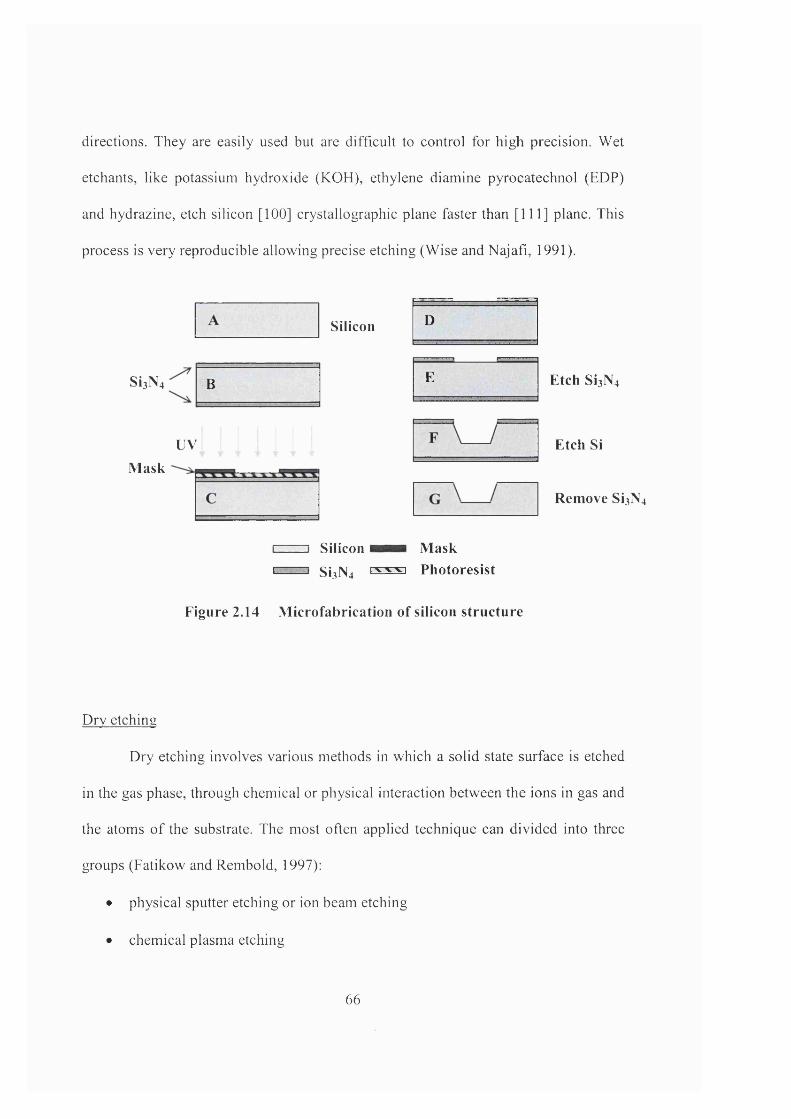
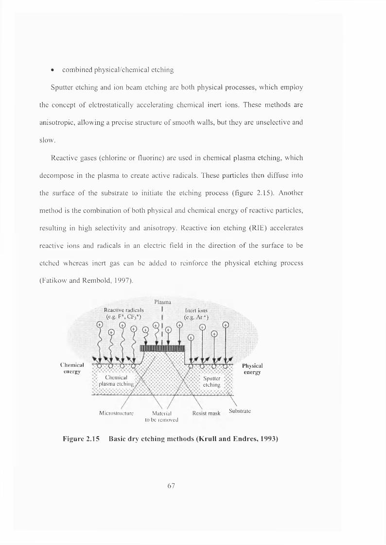
Reactive gases (chlorine or fluorine) are used in chemical plasma etching, which
decompose in the plasma to create active radicals. These particles then diffuse into
the surface o f the substrate to initiate the etching process (figure 2.15). Another
method is the combination of both physical and chemical energy o f reactive particles,
resulting in high selectivity and anisotropy. Reactive ion etching (RIE) accelerates
reactive ions and radicals in an electric field in the direction of the surface to be
etched whereas inert gas can be added to reinforce the physical etching process
(Fatikow and Rembold, 1997).
Chemicalenergy
Reactive radicals . (e.B.F\CF3*)
Plasm a
Inert ions ( e g Ar+) ->
Physicalenergy
C hem ical plasm a etching
Sputteretch ing
SubstrateM icrostructure Material to be rem oved
Figure 2.15 Basic dry etching methods (Krull and Endres, 1993)
67
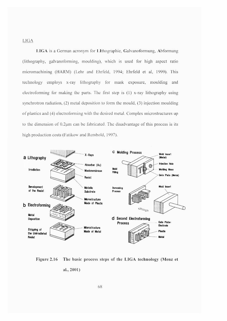
LIGA
LIGA is a German acronym for Lithographic, Galvanoformung, Abformung
(lithography, galvanoforming, moulding), which is used for high aspect ratio
micromachining (HARM) (Lehr and Ehrfeld, 1994; Ehrfeld ct al, 1999). This
technology employs x-ray lithography for mask exposure, moulding and
electro forming for making the parts. The first step is (1) x-ray lithography using
synchrotron radiation, (2) metal deposition to form the mould, (3) injection moulding
of plastics and (4) electroforming with the desired metal. Complex microstructures up
to the dimension o f 0.2pm can be fabricated. The disadvantage of this process is its
high production costs (Fatikow and Rembold, 1997).
a Lithography
Irradatlon
Development of the Resist
b Electroforming
MetalDeposition
Stripping of the Unlrradlated Resist
X-Rays
Absorber (Au)
Maskmemitrane
Resist
MetallicSubstrate
Mterostructure Made of fu s tic
C Molding Process
MIcfostructure Made of Metal
DemoMinoProcess
d Second Electroforming Process
MoM Insert (Metal)
Injection Hole
MoMnfl Mass
Gate Plate (Metal)
Mold Insert
Gate PlateBectrode
Figure 2.16 The basic process steps o f the LIG A technology (M enz et
al., 2001)
68
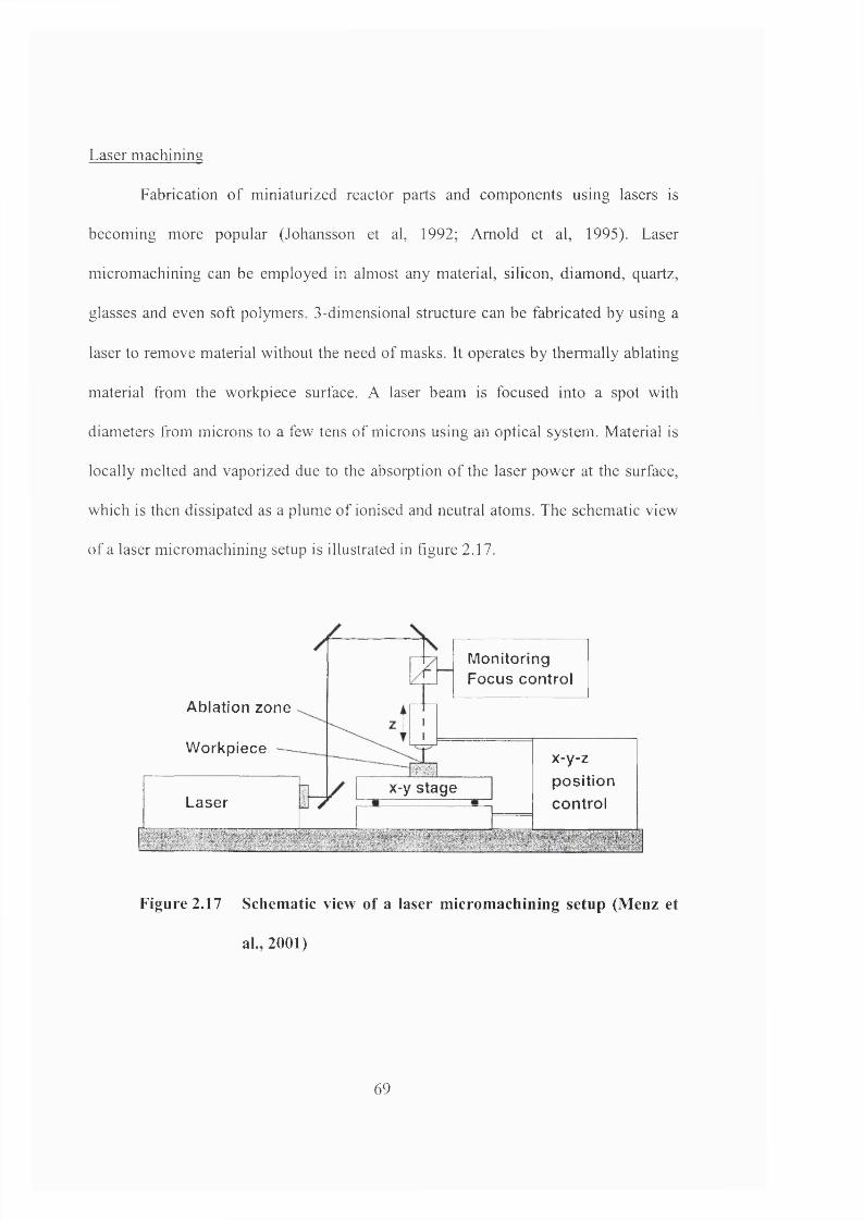
Laser machining
Fabrication o f miniaturized reactor parts and components using lasers is
becoming more popular (Johansson et al, 1992; Arnold et al, 1995). Laser
micromachining can be employed in almost any material, silicon, diamond, quartz,
glasses and even soft polymers. 3-dimensional structure can be fabricated by using a
laser to remove material without the need of masks. It operates by thermally ablating
material from the workpiece surface. A laser beam is focused into a spot with
diameters from microns to a few tens o f microns using an optical system. Material is
locally melted and vaporized due to the absorption o f the laser power at the surface,
which is then dissipated as a plume o f ionised and neutral atoms. The schematic view
of a laser micromachining setup is illustrated in figure 2.17.
Ablation zone
Workpiece x-y-zpositioncontrolLaser
x-y stage
Monitoring Focus control
Figure 2.17 Schem atic view of a laser m icrom achining setup (M enz et
al., 2001)
69
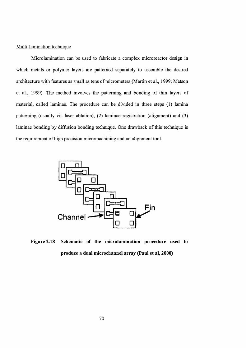
Multi-lamination technique
Microlamination can be used to fabricate a complex microreactor design in
which metals or polymer layers are patterned separately to assemble the desired
architecture with features as small as tens of micrometers (Martin et ah, 1999; Matson
et ah, 1999). The method involves the patterning and bonding of thin layers of
material, called laminae. The procedure can be divided in three steps (1) lamina
patterning (usually via laser ablation), (2) laminae registration (alignment) and (3)
laminae bonding by diffusion bonding technique. One drawback of this technique is
the requirement of high precision micromachining and an alignment tool.
D =
Channel
Figure 2.18 Schematic of the microlaminatioii procedure used to
produce a dual microchannel array (Paul et al, 2000)
70
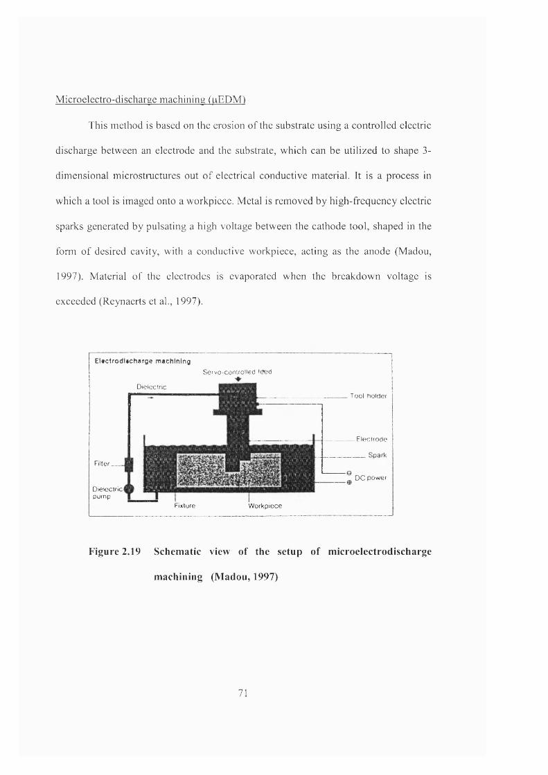
Microelectro-discharge machining (|aEDM)
This method is based on the erosion of the substrate using a controlled electric
discharge between an electrode and the substrate, which can be utilized to shape 3-
dimensional microstructures out o f electrical conductive material. It is a process in
which a tool is imaged onto a workpiece. Metal is removed by high-frequency electric
sparks generated by pulsating a high voltage between the cathode tool, shaped in the
form o f desired cavity, with a conductive workpiece, acting as the anode (Madou,
1997). Material o f the electrodes is evaporated when the breakdown voltage is
exceeded (Reynaerts et al., 1997).
E U c l r o d l t c h a r g e m a c h in in g
D ielectric
Servo-controlled I (Ted
Fixture W orkpiece
Tool holder
E lectrod e
F i l t e r _ _ _
D ieteclricpum p
D C pow er
Figure 2.19 Schem atic view of the setup o f m icroelectrodischarge
m achining (M adou, 1997)
71
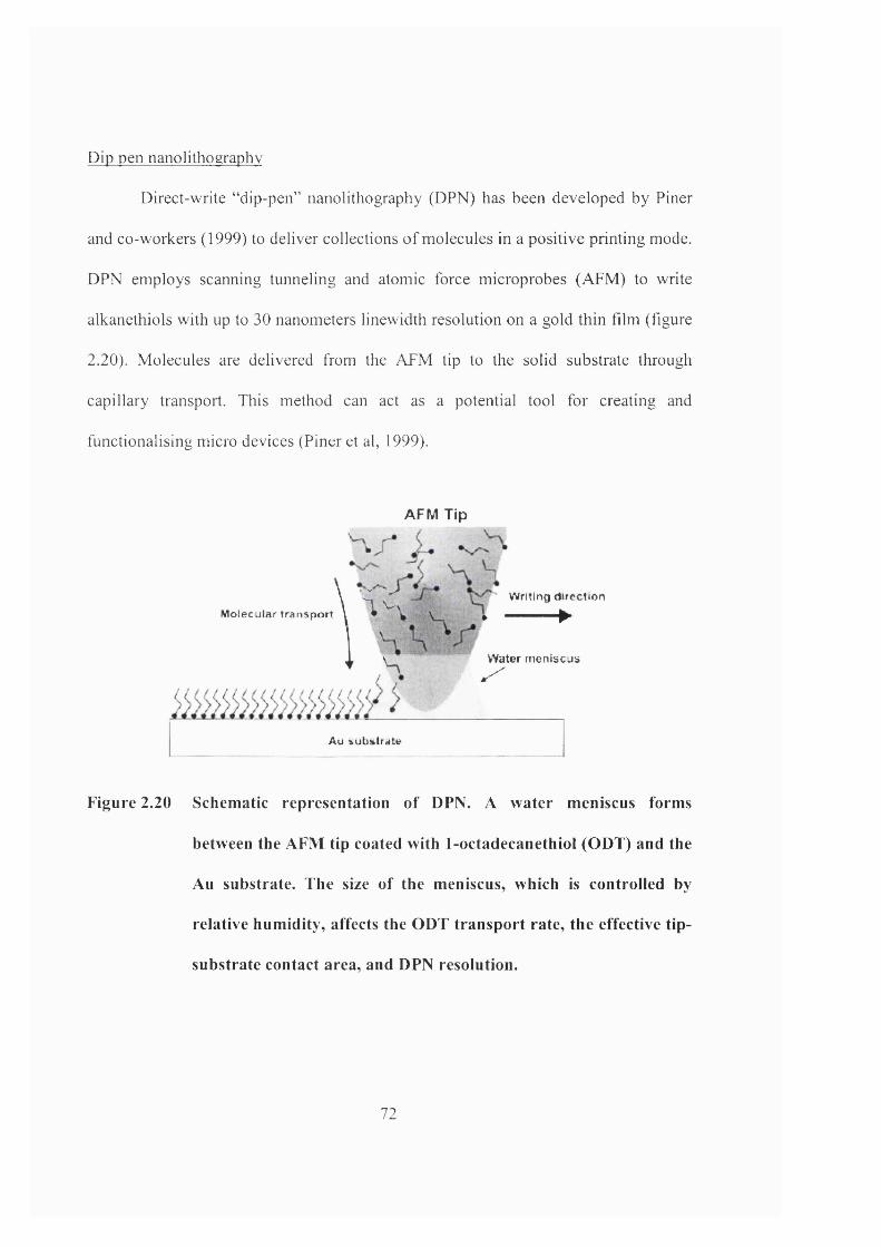
Dip pen nanolithography
Direct-write “dip-pen” nanolithography (DPN) has been developed by Finer
and co-workers (1999) to deliver collections o f molecules in a positive printing mode.
DPN employs scanning tunneling and atomic force microprobes (AFM) to write
alkanethiols with up to 30 nanometers linewidth resolution on a gold thin film (figure
2.20). Molecules are delivered from the AFM tip to the solid substrate through
capillary transport. This method can act as a potential tool for creating and
functionalising micro devices (Finer et al, 1999).
AFM Tip
\ ^ ^ Writing direction
M olecular t ra n s p o r t \ • V— * ^I1 \ Water m eniscus* ^
Au subs tra te
Figure 2.20 Schem atic representation o f DPN. A water m eniscus forms
between the AFM tip coated with 1-octadecanethiol (ODT) and the
An substrate. The size o f the m eniscus, which is controlled by
relative hum idity, affects the ODT transport rate, the effective tip-
substrate contact area, and DPN resolution.
72
2.6 Application of microreactors
2.6.1 Access to new reaction regimes
Microreactors can suppress the formation of hot spot and the problems of
thermal runaway for exothermic processes. Aggressive conditions or regimes that are
difficult and unsafe in conventional systems can now be carried out with
microchemical systems. These features are especially useful for hydrocarbon partial
oxidation for producing oxygenates (e.g. alcohols and aldehydes) and nitrogen
bearing compounds (e.g. cyanides, nitriles and cyanates). One example is partial
oxidation with pure oxygen in a microreactor (Srinivasan et al., 1997). A silicon-
based microreactor with integrated heater, flow and temperature sensors was
fabricated to study Pt-catalysed ammonia oxidation.
Hazards dealing with storage and shipping of toxic chemicals can also be
avoided by shifting plants near the point of application. A micro fabricated silicon
packed-bed reactor for phosgene synthesis is a potential example for on-site and on-
demand production of hazardous and toxic chemicals (Ajmera et al., 2001). The
increased surface area attained at the submillimeter channel dimensions enables a
larger degree of control and safety in comparison to macroscopic reaction system.
73

2.6.2 Study of reaction kinetics
Microreactors have the following properties: (a) efficient thermal control; (b)
short response time; (c) defined flow characteristics; (d) large surface area to volume
ratio and (e) small volumes for reducing the inertia of the whole system (Zech et al,
2000). These features are advantageous for extraction of chemical kinetics from
microreactor experiments (Ajmera et al., 2001). Undesirable side effects due to poor
heat exchange can be avoided, such as a long time required to heat up the inlet
reaction mixture and to quench the outlet product stream (Rebrov et al., 2002).
Inaccessible residence time can be achieved due to uniform velocity distribution in
microreactor. This opens up new possibilities for investigating fast kinetics of
chemical reactions.
The low temperature kinetics of ammonia oxidation on supported
polycrystalline platinum catalyst was examined in an aluminium-based microreactor
(Rebrov et al., 2002). A silicon cross-flow microreactor with a short pass multiple
flow-channel geometry was developed for the testing of catalyst particles for gas
phase chemical reactions (Ajmera et al., 2002). The cross flow design minimized
pressure drop through the catalyst bed in contrast to typical microfabricated packed-
bed configurations, which are susceptible to large pressure drops (figure 2.21).
Kinetic studies with carbon monoxide oxidation were performed on the cross-flow
microreactor showing absence of transport limitations.
74
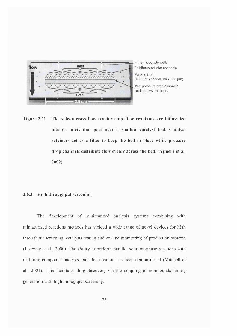
outlet
uim
4 thermocouple wells 64 bifurcated inlet channels
Packed-bed;(400 pm X 25550 pm x 500 pm)
256 pressure drop channels and caialysl retainers
Figure 2.21 The silicon cross-flow reactor chip. The reactants are bifurcated
into 64 inlets that pass over a shallow catalyst bed. Catalyst
retainers act as a filter to keep the bed in place while pressure
drop channels distribute flow evenly across the bed. (Ajm era et al,
2002)
2.6.3 High throughput screening
The development of miniaturized analysis systems combining with
miniaturized reactions methods has yielded a wide range o f novel devices for high
throughput screening, catalysts testing and on-line monitoring o f production systems
(Jakeway et al., 2000). The ability to perform parallel solution-phase reactions with
real-time compound analysis and identification has been demonstarted (Mitchell et
al., 2001). This facilitates drug discovery via the coupling o f compounds library
generation with high throughput screening.
75
Greenway et al. (2000) has constructed a flow injection microreactor for high
throughput continuous flow organic synthesis. The synthesis of 4-cyanobiphenyl was
carried out in micro-channels (300pm wide and 115pm deep) etched onto glass while
the yield of the product was analysed by GC-MS. The supported catalyst (1.8%
palladium on silica) was immobilised onto the reactor manifold. Another example of
heterogeneously catalysed reaction was developed by Zech et al. (2000). The catalyst
screening of the oxidation of methane was studied using a reactor module consisting
of 35 stainless steel microstructures. Each of these mierostructures was used for the
insertion of different catalyst wafers made of materials such as metals, silicon,
ceramic and glass. The product was analysed using a quadrupole mass spectrometer
(QMS) within 60s. The results show good reproducibility and errors below 10%.
Researchers at Institut fur Angewandte Chemie Berlin have developed a
parallelized catalyst screening unit using conventional mini-scale reactors
(Rodemerck et al., 2000). The reaction was oxidation coupling of methane with
Mn/Na2W0 4 /Si0 2 mixtures of varying composition as a catalyst. The first system
consisted of 15 quartz glass reactor tubes, 3.5mm inner diameter connected to an
analytical system QMS, providing more aceurate results. The second system will be a
ceramic monolithic reactor. Up to 250 catalyst compositions can be prepared and
tested in parallel.
76
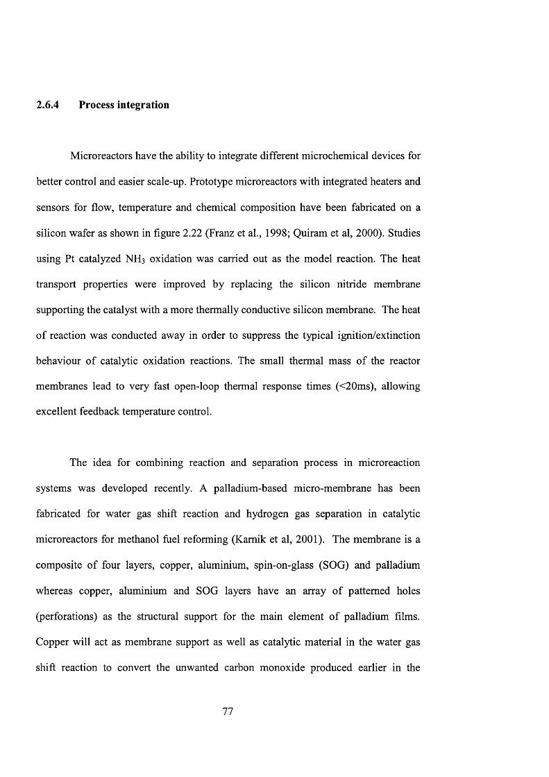
2.6.4 Process integration
Microreactors have the ability to integrate different microchemical devices for
better control and easier scale-up. Prototype microreactors with integrated heaters and
sensors for flow, temperature and chemical composition have been fabricated on a
silicon wafer as shown in figure 2.22 (Franz et al., 1998; Quiram et al, 2000). Studies
using Ft catalyzed NH3 oxidation was carried out as the model reaction. The heat
transport properties were improved by replacing the silicon nitride membrane
supporting the catalyst with a more thermally conductive silicon membrane. The heat
of reaction was conducted away in order to suppress the typical ignition/extinction
behaviour of catalytic oxidation reactions. The small thermal mass of the reactor
membranes lead to very fast open-loop thermal response times (<2 0 ms), allowing
excellent feedback temperature control.
The idea for combining reaction and separation process in microreaction
systems was developed recently. A palladium-based micro-membrane has been
fabricated for water gas shift reaction and hydrogen gas separation in catalytic
microreactors for methanol fuel reforming (Kamik et al, 2001). The membrane is a
composite of four layers, copper, aluminium, spin-on-glass (SOG) and palladium
whereas copper, aluminium and SOG layers have an array of patterned holes
(perforations) as the structural support for the main element of palladium films.
Copper will act as membrane support as well as catalytic material in the water gas
shift reaction to convert the unwanted carbon monoxide produced earlier in the
77
microreaction system into hydrogen, which will then be separated by the membrane.
The micromembrane can withstand a pressure gradient of 10 psi. The fabrication
process can allow for heaters and temperature sensors integrated into the device.
S ilic o n n itride Pi I | ^mcn^nmc
.Silicon I \
Pt h ea ler
 i i i m i m u n d e a l i n g p l a t e
3 55 m m
Î:550mn Gav flaw h c«1aivi.t
A lum inum «uilm g plate
18 m ill
Figure 2.22 G as-phase m icroreactor. Photograph o f device. Front view
and side schem atics (Srinivasan et al., 1997; Q uiram et al., 2000)
2.6.5 Process developm ent
Microreactors have the ability to accommodate completely new reaction
regimes and provide infonnation that is not aceessible otherwise (Richter et ah,
2000). Reactor performance can be tested quickly. The processing conditions and
characteristics can then be successfully used to develop a conventional reactor based
on a standardized choice of components. This can all be accomplished by using a
minimum amount of chemicals (Ehrfeld et ah, 2000, Krummradt et ah, 2000; Worz et
ah, 2001). Applying microreactors for process development, optimal conditions can
be located much quicker compared to conventional means (Worz et ah, 2001).
78
The process development for the synthesis of vitamin precursors has been
studied (Richter et ah, 2000; Ehrfeld et ah, 2000; Worz et ah, 2001). A microreactor
was developed as the reaction is highly exothermic whereas the reactant, intermediate
and product will very quickly form a by-product, which reduces the selectivity and
yield. The channels are 900pm deep and 60pm wide and surrounded by cooling
channels (Richter et ah, 2000). The reaction was carried out isothermally with rapid
mixing. No hotspot and adiabatic temperature rise were observed. Another example is
the oxidative dehydrogenation of alcohol to aldehyde. This is also a highly
exothermic reaction. The microreactor is made of silver, the catalytically active
material (Worz et ah, 2001).
2.6.6 Extraterrestrial Processing
Micro/nano-technology represents the synthesis and integration of materials,
processes and devices ranging from submillimeter to submicrometer size, which is
currently an area proceeding at a very fast pace (de Aragon, 1998). The utilization of
micro/nano-technologies in the space sector is very promising. Lightweight, compact
chemical systems can be applied to reduce total resources required yet providing
higher system performance per unit cost and mass (de Aragon, 1998).
Research has been conducted at the Pacific Northwest National Laboratory
(PNNL) for NASA In Situ Resource Utilization (ISRU) program planned for future
missions to Mars including chemical processes (Wegeng and Drost, 1998). In situ
79
propellant production (ISPP) is to convert the carbon dioxide from the Martian
environment to propellants, oxygen and other useful chemicals to reduce the required
launch mass from Earth. The program involves collecting and pressurizing
atmospheric carbon dioxide, conversion reactions, chemical separations, heat
exchangers and cryogenic storage (TeGrotenhuis et al., 2000). Due to negligible
convective heat transfer within the low-pressure environment of space, high energy
efficiency is achieved through the extensive recuperation and energy cascading from
hot to cold unit operations to minimize thermal and electrical wastage.
Developments in micro chemical and thermal systems (MCTS) have resulted
in an improved efficiency, reduction in volume and weight. This technological
advancement has fuelled tremendous leaps of faith in the progress of continued space
exploration (TeGrotenhuis et al., 2000).
80
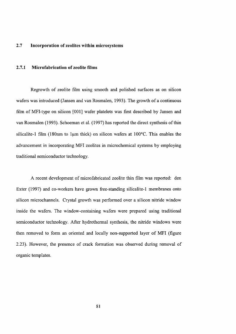
2.7 Incorporation of zeolites within microsystems
2.7.1 Microfabrication of zeolite films
Regrowth of zeolite film using smooth and polished surfaces as on silicon
wafers was introduced (Jansen and van Rosmalen, 1993). The growth of a continuous
film of MFI-type on silicon [001] wafer platelets was first described by Jansen and
van Rosmalen (1993). Schoeman et al. (1997) has reported the direct synthesis of thin
silicalite-1 film (180nm to 1pm thick) on silicon wafers at 100°C. This enables the
advancement in incorporating MFI zeolites in microchemical systems by employing
traditional semiconductor technology.
A recent development of microfabricated zeolite thin film was reported: den
Exter (1997) and co-workers have grown free-standing silicalite-1 membranes onto
silicon microchannels. Crystal growth was performed over a silicon nitride window
inside the wafers. The window-containing wafers were prepared using traditional
semiconductor technology. After hydrothermal synthesis, the nitride windows were
then removed to form an oriented and locally non-supported layer of MFI (figure
2.23). However, the presence of crack formation was observed during removal of
organic templates.
81
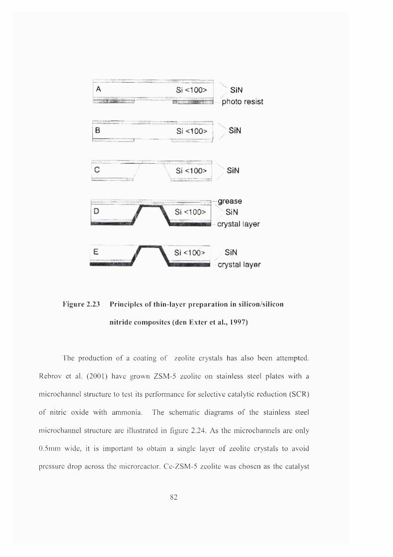
A
B
Si<100> SiNphoto resist
S i<100> j SIN
—:L_:' Si<100> SiN
Si <100>::_z:=zq-grease
SiN crystal layer
Si<100> SiNcrystal layer
Figure 2.23 Principles of thin-layer preparation in silicon/silicon
nitride com posites (den Exter et a!., 1997)
The production of a coating of zeolite crystals has also been attempted.
Rebrov et al. (2001) have grown ZSM-5 zeolite on stainless steel plates with a
microchannel structure to test its perfonnance for selective catalytic reduction (SCR)
of nitric oxide with ammonia. The schematic diagrams of the stainless steel
microchannel structure are illustrated in figure 2.24. As the microchannels are only
0.5mm wide, it is important to obtain a single layer of zeolite crystals to avoid
pressure drop across the microreactor. Ce-ZSM-5 zeolite was chosen as the catalyst
82
due to the improved hydrothemial stability when compared with other ion-exchanged
zeolites. Experimental results have revealed the absence of mass transfers limitations
and a faster SCR reaction rate was observed in comparison with the result obtained
with pelletized Ce-ZSM-5 catalysts.
Figure 2.24 Schem atic representation of stainless steel m icrochannel structure.
(a) isom etric view of one plate, (b) front view of two plates sealed
together, (c) single m icrochannel with zeolitic coating and (d)
scanning electron m icrographs o f zeolitic coating. (Rebrov et al.,
2001)
2.7.2 Proposed zeolite incorporation techniques
The growth of zeolite crystals onto silicon wafers enables new possibilities to
incorporate zeolites in the design architecture of microchemical devices. Zeolites
83

have the advantages of withstanding high temperature treatment without cracks and
delamination. They can provide better adhesion to the silicon substrate and can be
microfabricated using standard clean room procedures. Photolithography methods
and various etching techniques can be applied to pattern zeolite microstructures.
An elegant way to incorporate zeolite in microreactors is selective deposition
of zeolite crystals onto the microchannels. Traditional semiconductor technology can
be employed in fabricating silicon microstructures, hi this work, zeolite layers are
grown selectively onto silicon microstructures by hydrothermal synthesis. It is shown
that zeolites can be utilized as catalysts, membrane and structural materials in the
design architecture of different micro chemical devices.
84
Chapter 3
Instrumentation and Methodology
8 5
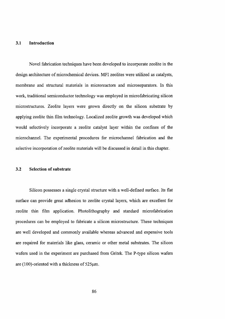
3.1 Introduction
Novel fabrication techniques have been developed to incorporate zeolite in the
design architecture of microchemical devices. MFI zeolites were utilized as catalysts,
membrane and structural materials in microreactors and microseparators. In this
work, traditional semiconductor technology was employed in microfabricating silicon
mierostructures. Zeolite layers were grown directly on the silicon substrate by
applying zeolite thin film technology. Localized zeolite growth was developed which
would selectively incorporate a zeolite catalyst layer within the confines of the
microchannel. The experimental procedures for microcharmel fabrication and the
selective incorporation of zeolite materials will be discussed in detail in this chapter.
3.2 Selection of substrate
Silicon possesses a single crystal structure with a well-defined surface. Its flat
surface can provide great adhesion to zeolite crystal layers, which are excellent for
zeolite thin film application. Photolithography and standard microfabrication
procedures can be employed to fabricate a silicon microstructure. These techniques
are well developed and commonly available whereas advanced and expensive tools
are required for materials like glass, ceramic or other metal substrates. The silicon
wafers used in the experiment are purchased from Gritek. The P-type silicon wafers
are (lOO)-oriented with a thickness of 525pm.
8 6
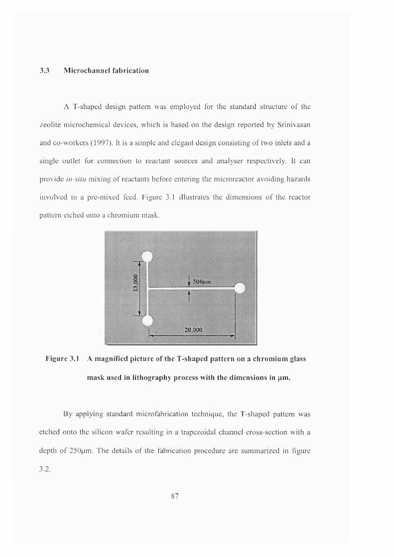
3.3 MicroChannel fabrication
A T-shaped design pattern was employed for the standard structure of the
zeolite microchemical devices, which is based on the design reported by Srinivasan
and co-workers (1997). It is a simple and elegant design consisting of two inlets and a
single outlet for connection to reactant sources and analyser respectively. It can
provide in-situ mixing of reactants before entering the microreactor avoiding hazards
involved in a pre-mixed feed. Figure 3.1 illustrates the dimensions of the reactor
pattern etched onto a chromium mask.
r '•
i.__
500um
20,000 ;
Figure 3.1 A m agnified picture of the T-shaped pattern on a chrom ium glass
m ask used in lithography process with the dim ensions in pm.
By applying standard microfabrication technique, the T-shaped pattern was
etched onto the silicon wafer resulting in a trapezoidal channel cross-section with a
depth of 250pm. The details of the fabrication procedure are summarized in figure
3.2.
87
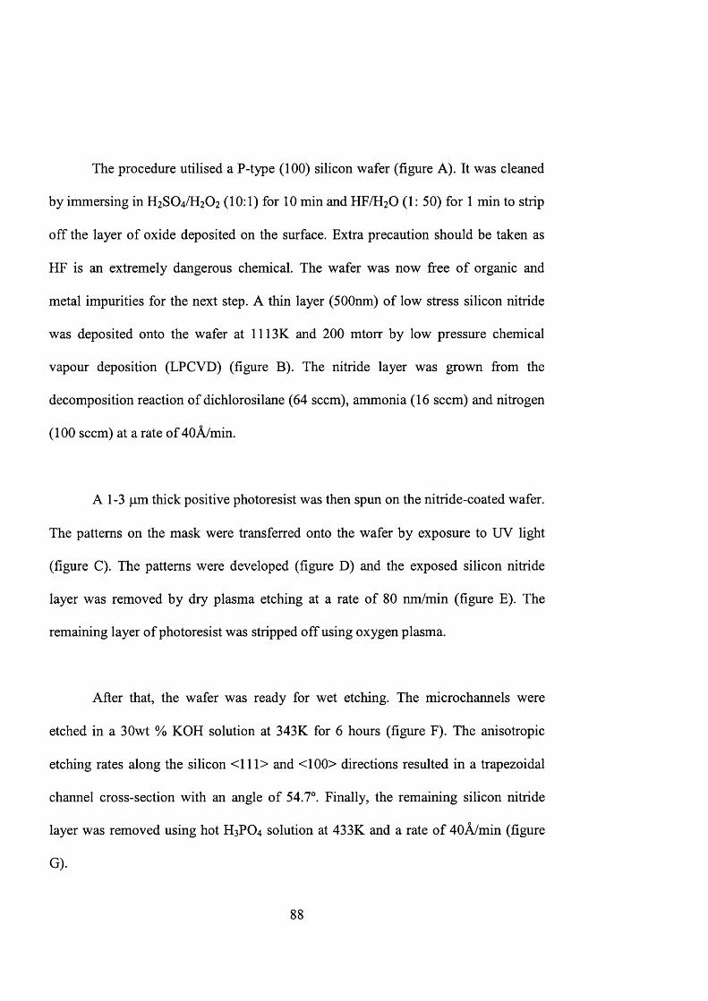
The procedure utilised a P-type (100) silicon wafer (figure A). It was cleaned
by immersing in H2SO4/H2O2 (10:1) for 10 min and HF/H2O (1: 50) for 1 min to strip
off the layer of oxide deposited on the surface. Extra precaution should be taken as
HF is an extremely dangerous chemical. The wafer was now free of organic and
metal impurities for the next step. A thin layer (500nm) of low stress silicon nitride
was deposited onto the wafer at 1113K and 200 mtorr by low pressure chemical
vapour deposition (LPCVD) (figure B). The nitride layer was grown from the
decomposition reaction of dichlorosilane (64 seem), ammonia (16 seem) and nitrogen
(100 seem) at a rate of 40Â/min.
A 1-3 pm thick positive photoresist was then spun on the nitride-coated wafer.
The patterns on the mask were transferred onto the wafer by exposure to UV light
(figure C). The patterns were developed (figure D) and the exposed silicon nitride
layer was removed by dry plasma etching at a rate of 80 nm/min (figure E). The
remaining layer of photoresist was stripped off using oxygen plasma.
After that, the wafer was ready for wet etching. The microchannels were
etched in a 30wt % KOH solution at 343K for 6 hours (figure F). The anisotropic
etching rates along the silicon <111> and <100> directions resulted in a trapezoidal
channel cross-section with an angle of 54.7°. Finally, the remaining silicon nitride
layer was removed using hot H 3 P O 4 solution at 433K and a rate of 40Â/min (figure
G).
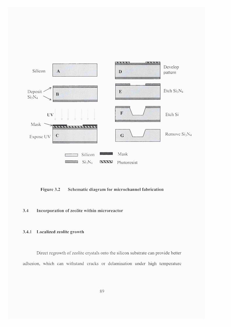
Silicon
Deposit ^ Si]N4
D
B E
Developpattern
Etch Si]N4
UV
Mask
Expose UV C
Etch Si
Remove Si]N4
Silicon Mask
I—......I Si]N4 Photoresist
Figure 3.2 Schem atic diagram for m icrochannel fabrication
3.4 Incorporation of zeolite within m icroreactor
3.4.1 Localized zeolite growth
Direct regrowth of zeolite crystals onto the silicon substrate can provide better
adhesion, which can withstand cracks or delamination under high temperature
89
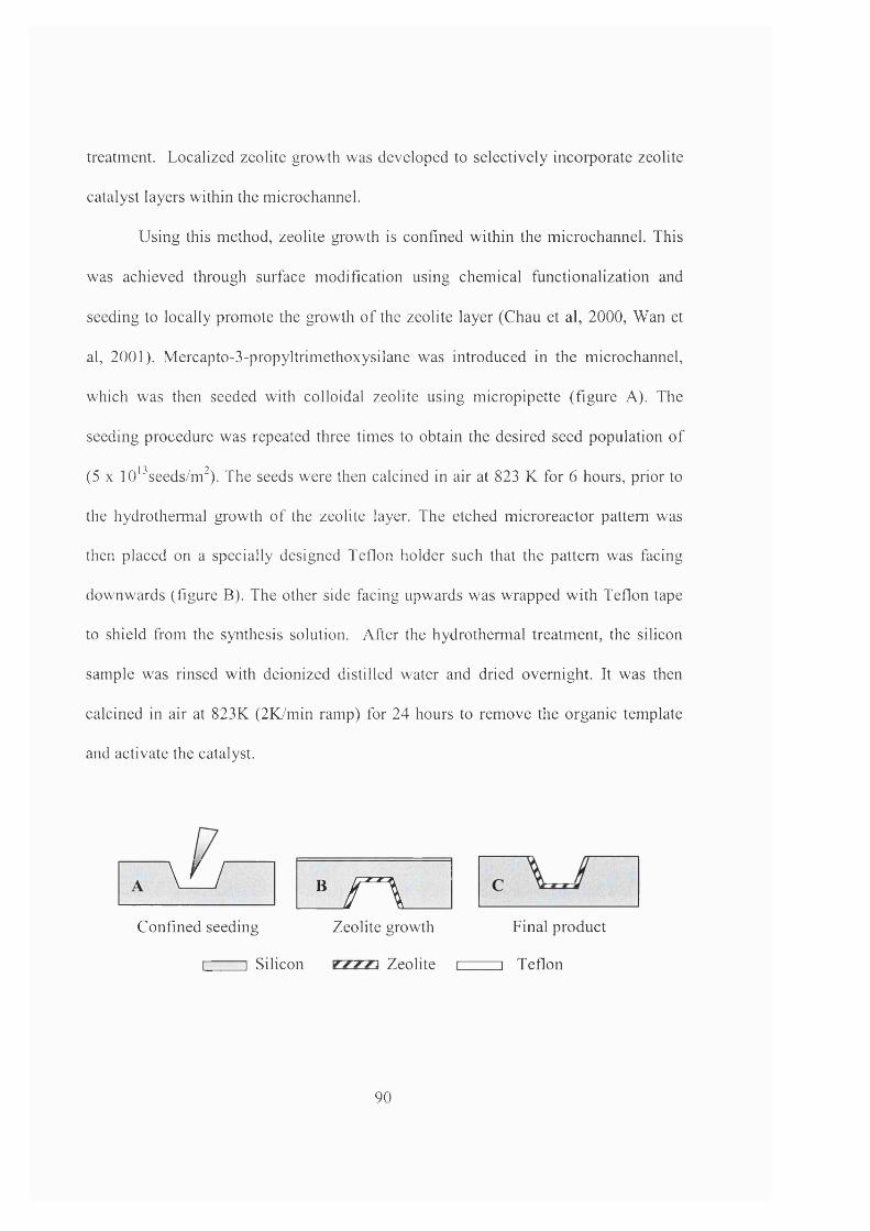
treatment. Localized zeolite growth was developed to selectively incorporate zeolite
catalyst layers within the microchannel.
Using this method, zeolite growth is confined within the microchannel. This
was achieved through surface modification using chemical functionalization and
seeding to locally promote the growth o f the zeolite layer (Chau et al, 2000, Wan et
al, 2001). Mercapto-3-propyltrimethoxysilane was introduced in the microchannel,
which was then seeded with colloidal zeolite using micropipette (figure A). The
seeding procedure was repeated three times to obtain the desired seed population of
(5 X lO'^seeds/m^). The seeds were then calcined in air at 823 K for 6 hours, prior to
the hydrothermal growth o f the zeolite layer. The etched microreactor pattern was
then placed on a specially designed Teflon holder such that the pattern was facing
downwards (figure B). The other side facing upwards was wrapped with Teflon tape
to shield from the synthesis solution. After the hydrothermal treatment, the silicon
sample was rinsed with deionized distilled water and dried overnight. It was then
calcined in air at 823K (2K/min ramp) for 24 hours to remove the organic template
and activate the catalyst.
\u B r\Confined seeding Zeolite growth Final product
I I Silicon Zeolite i i Teflon
90
Figure 3.3 Process diagram for zeolite incorporation within microchannel
3.4.2 Preparation of TS-1 synthesis solution
The “Mixed alkoxides” method is adopted to prepare the TS-1 synthesis
solution, which is based on the original procedure developed by researchers in
Enichem (Taramasso et al., 1983). The schematic diagram in figure 3.4 describes the
steps for preparing the synthesis solution. The procedure starts with the hydrolysis of
tetraethyl orthotitanate (TEOT) and tetraethyl orthosilicate (TEOS) mixtures. Extra
care should be taken to make sure that all apparatus were completely dry as the
presence of water would hydrolyse the titanium compounds to form hydrated TiO]. In
step 1, TEOS was first added into a Teflon vessel, which was pre-rinsed with ethanol.
Together with the sealed bottle of TEOT, they were placed in the nitrogen hood and
purged for an hour to prevent carbon dioxide and water absorption (Step 2). TEOT
was then added into the TEOS solution (Step 3). The TEOT/TEOS mixture should
change to light yellow to obtain depolymerisation of the titanate oligomers that may
be present in TEOT. The yellow colour came from partially hydrolysed TEOT,
however, full hydrolysation will result in precipitation of amorphous TiO]. The above
steps should be repeated if a colourless or white mixture was obtained indicating
formation of TiOi and the synthesis has failed (van der Pol and van Hoff, 1993).
91
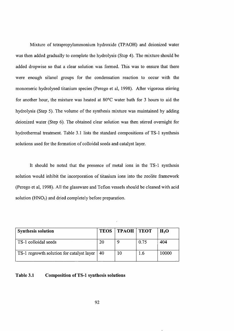
Mixture of tetrapropylammonium hydroxide (TPAOH) and deionized water
was then added gradually to complete the hydrolysis (Step 4). The mixture should be
added dropwise so that a clear solution was formed. This was to ensure that there
were enough silanol groups for the condensation reaction to occur with the
monomeric hydrolysed titanium species (Perego et al, 1998). After vigorous stirring
for another hour, the mixture was heated at 80°C water bath for 3 hours to aid the
hydrolysis (Step 5). The volume of the synthesis mixture was maintained by adding
deionized water (Step 6 ). The obtained clear solution was then stirred overnight for
hydrothermal treatment. Table 3.1 lists the standard compositions of TS-1 synthesis
solutions used for the formation of colloidal seeds and catalyst layer.
It should be noted that the presence of metal ions in the TS-1 synthesis
solution would inhibit the incorporation of titanium ions into the zeolite framework
(Perego et al, 1998). All the glassware and Teflon vessels should be cleaned with acid
solution ( H N O 3 ) and dried completely before preparation.
Synthesis solution TEOS TPAOH TEOT H2O
TS-1 colloidal seeds 2 0 9 0.75 404
TS-1 regrowth solution for catalyst layer 40 1 0 1 . 6 1 0 0 0 0
Table 3.1 Composition of TS-1 synthesis solutions
92
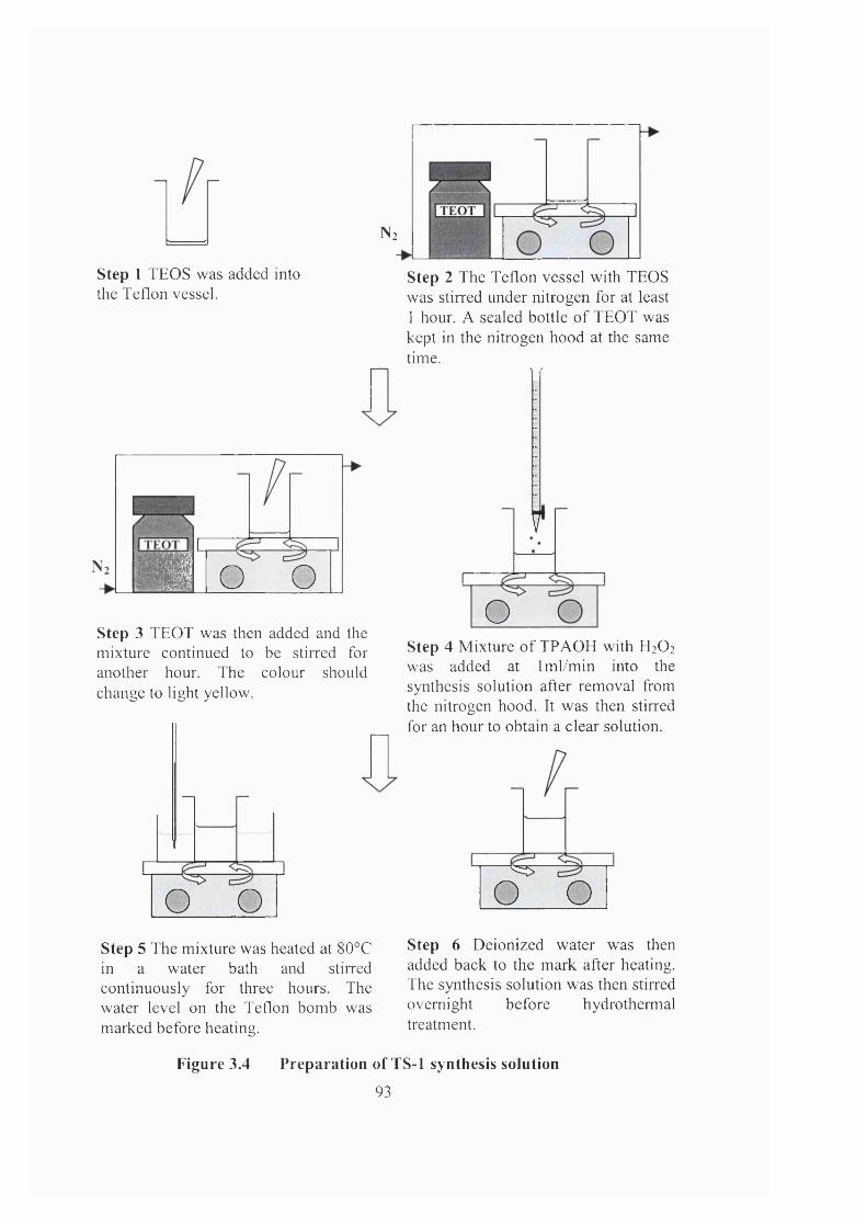
N2
■=1--------V L ■■■ 1
Step 1 TEOS was added into the Teflon vessel.
N-1
1 0 0 0Step 3 TEOT was then added and the mixture continued to be stirred for another hour. The colour should change to light yellow.
O OStep 5 The mixture was heated at 80°C in a water bath and stirred continuously for three hours. The water level on the Teflon bomb was marked before heating.
Step 2 The Teflon vessel with TEOS was stirred under nitrogen for at least 1 hour. A sealed bottle o f TEOT was kept in the nitrogen hood at the same time.
f
OStep 4 Mixture o f TPAOH with H2O2
was added at Iml/min into the synthesis solution after removal from the nitrogen hood. It was then stirred for an hour to obtain a clear solution.
O OStep 6 Deionized water was then added back to the mark after heating. The synthesis solution was then stirred overnight before hydrothermal treatment.
Figure 3.4 Preparation of TS-1 synthesis solution
93
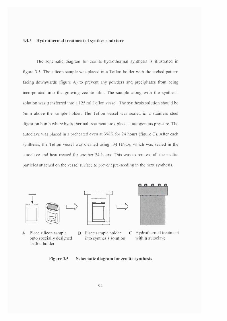
3 . 4 . 3 H y d r o t h e r m a l t r e a t m e n t o f s y n t h e s i s m i x t u r e
The schematic diagram for zeolite hydrothermal synthesis is illustrated in
figure 3.5. The silicon sample was placed in a Teflon holder with the etched pattern
facing downwards (figure A) to prevent any powders and precipitates from being
incorporated into the growing zeolite film. The sample along with the synthesis
solution was transferred into a 125 ml Teflon vessel. The synthesis solution should be
5mm above the sample holder. The Teflon vessel was sealed in a stainless steel
digestion bomb where hydrothermal treatment took place at autogenous pressure. The
autoclave was placed in a preheated oven at 398K for 24 hours (figure C). After each
synthesis, the Teflon vessel was cleaned using IM HNO3, which was sealed in the
autoclave and heat treated for another 24 hours. This was to remove all the zeolite
particles attached on the vessel surface to prevent pre-seeding in the next synthesis.
A Place silicon sample B Place sample holder C Hydrothermal treatment onto specially designed into synthesis solution within autoclaveTeflon holder
F i g u r e 3 . 5 S c h e m a t i c d i a g r a m f o r z e o l i t e s y n t h e s i s
94
3 . 5 B o n d i n g o f m i c r o r e a c t o r
The microreactor was bonded to a clean glass with pre-drilled holes after
hydrothermal synthesis. The glass was spread with a thin layer of SU- 8 (Sotec
Microsystems) and adhered to the etched microreactor. The holes on the glass plate
were connected to reactant feedthrough and outlet for sample collection.
The adhesive material employed for reactor bonding is SU-8 . It is a positive
photoresist that hardens on exposure to UV light. The material can withstand
hydrocarbons (i.e., methanol, MTBE and 1-pentene) and temperatures up to 373 K.
SU- 8 used in the experiment is SMI040, which is suitable for a thinner layer of
deposition (1-10pm). Figure 3.6 illustrates the procedure for bonding of the
microreactor.
The procedure first starts with a pre-drilled glass (step 1). The glass and
microreactor should be cleaned thoroughly with acetone to remove any dirt and oil on
the surface. Tapered holes were drilled onto the glass by precision drilling using
diamond drill bits (RS) to provide a good fit to the silicone tubing.
A thin layer of SU- 8 was brushed on both the surface of glass plate and the
silicon sample avoiding the channel (step 2 & 3). A better adhesion could be obtained
when bonding the two layers together. Both the glass plates and silicon sample were
heated on a hotplate at 95°C for lOmins to evaporate off the liquid and prepare for
95
adhesion. The hotplate was then lowered to a temperature of 80°C to bond the two
pieces together before the SU- 8 dried up (step 4). Deadweight can be applied on the
microreactor during the cooling process. It was then exposed to UV light for 6-7
minutes for the resist to set. A color change from pale yellow to yellowish brown was
observed (step 5).
After exposure to UV light, the bonded reactor was heated at a temperature of
95°C to complete the polymerisation (step 6 ). A leak-free seal between glass and
silicon was thus obtained. Silicone tubing (00.5mm) was then squeezed into the
holes to act as an interface for reactant feedthrough and sample collection (step 7).
96
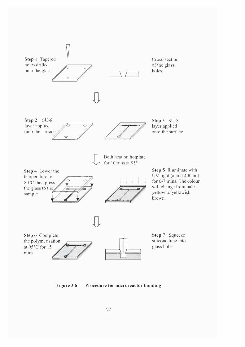
Step 1 Tapered holes drilled onto the glass
Cross-section of the glass holes
Step 2 SU-8 layer applied onto the surface
Step 3 SU-8 layer applied onto the surface
Step 4 Lower the temperature to 80°C then press the glass to the sample
Both heat on hotplate for lOmins at 95°
Step 5 Illuminate with UV light (about 400nm) for 6-7 mins. The colour will change from pale yellow to yellowish brown.
Step 6 Complete the polymerisation at95°C for 15mms. □
Step 7 Squeeze silicone tube into glass holes
F i g u r e 3 . 6 P r o c e d u r e f o r m i c r o r e a c t o r b o n d i n g
97
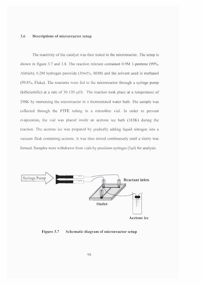
3 . 6 D e s c r i p t i o n s o f m i c r o r e a c t o r s e t u p
The reactivity o f the catalyst was then tested in the microreactor. The setup is
shown in figure 3.7 and 3.8. The reaction mixture contained 0.9M 1-pentene (99%,
Aldrich), 0.2M hydrogen peroxide (30wt%, BDH) and the solvent used is methanol
(99.8%, Fluka). The reactants were fed to the microreactor through a syringe pump
(kdScientific) at a rate o f 30-120 pl/h. The reaction took place at a temperature of
298K by immersing the microreactor in a thermostated water bath. The sample was
collected through the PTFE tubing in a microlitre vial. In order to prevent
evaporation, the vial was placed inside an acetone ice bath (183K) during the
reaction. The acetone ice was prepared by gradually adding liquid nitrogen into a
vacuum flask containing acetone. It was then stirred continuously until a slurry was
formed. Samples were withdrawn from vials by precision syringes (1 pi) for analysis.
Syringe Pump R eactant inlets
Outlet
Acetone ice
F i g u r e 3 . 7 S c h e m a t i c d i a g r a m o f m i c r o r e a c t o r s e t u p
9 8
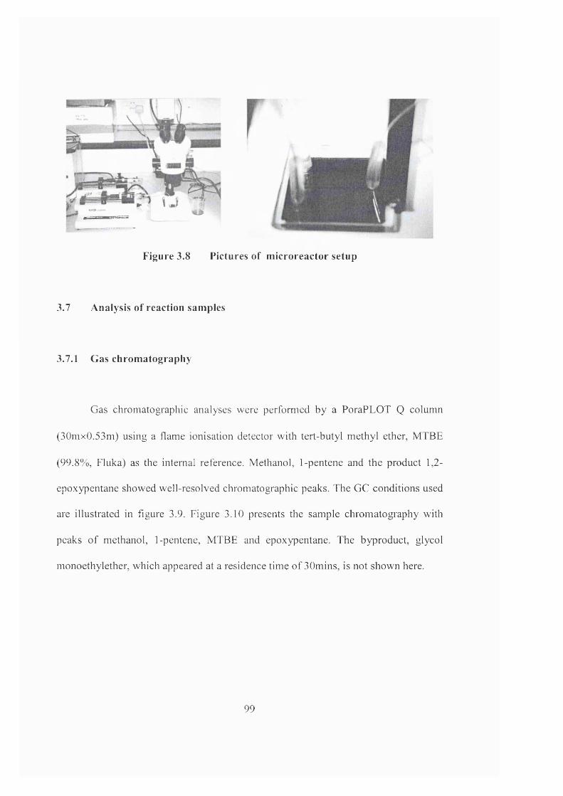
Figure 3.8 Pictures of m icroreactor setup
3.7 Analysis of reaction samples
3.7.1 Gas chrom atography
Gas chromatographic analyses were performed by a PoraPLOT Q column
(30mx0.53m) using a flame ionisation detector with tert-butyl methyl ether, MTBE
(99.8%, Fluka) as the internal reference. Methanol, 1-pentene and the product 1,2-
epoxypentane showed well-resolved chromatographic peaks. The GC conditions used
are illustrated in figure 3.9. Figure 3.10 presents the sample chromatography with
peaks o f methanol, 1-pentene, MTBE and epoxypentane. The byproduct, glycol
monoethylether, which appeared at a residence time o f 30mins, is not shown here.
99
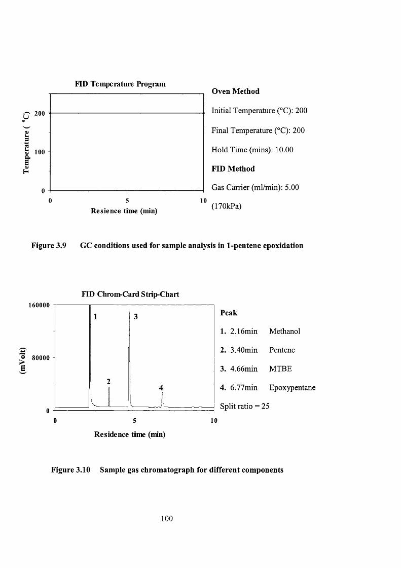
FID Temperature Program
10
R esience time (min)
Oven Method
Initial Temperature (°C): 200
Final Temperature (°C): 200
Hold Time (mins): 10.00
FID Method
Gas Carrier (ml/min): 5.00
(ITOkPa)
Figure 3.9 GC conditions used for sample analysis in 1-pentene epoxidation
FID Chrom-Card Strip-Chart160000
Peak
2.16min
3.40mino 80000 -
4.66min
6.77min
Split ratio = 25
0 5 10
Residence time (min)
F i g u r e 3 . 1 0 S a m p l e g a s c h r o m a t o g r a p h f o r d i f f e r e n t c o m p o n e n t s
100
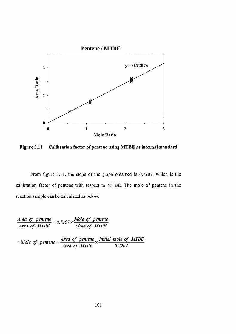
Pentene / MTBE
&Iy = 0 .7 2 0 7 X2
1
01 2 30
Mole Ratio
Figure 3.11 Calibration factor of pentene using MTBE as internal standard
From figure 3.11, the slope of the graph obtained is 0.7207, which is the
calibration factor of pentene with respect to MTBE. The mole of pentene in the
reaction sample can be calculated as below:
Area o f pentene _ Mole o f pentene— U . / z u / X
Area o f MTBE Mole o f MTBE
, , - Area o f pentene Initial mole o f MTBEMole o f pentene = ---------------------- x -------------------------------
Area o f MTBE
101
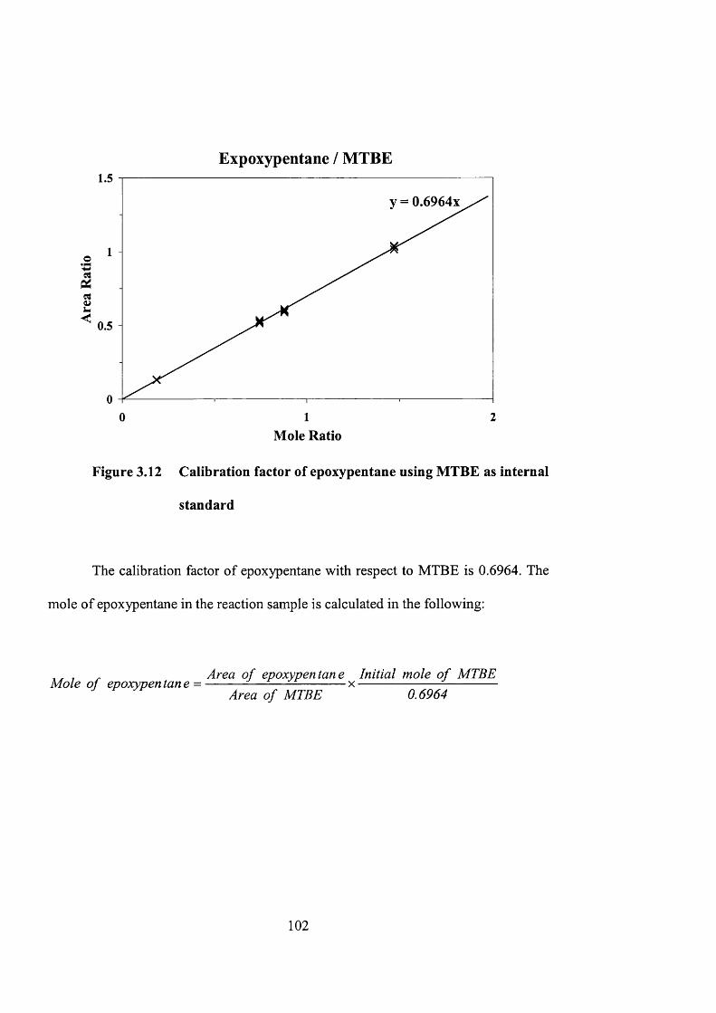
Expoxypentane / MTBE1.5
o
0.5
1 20Mole Ratio
Figure 3.12 Calibration factor of epoxypentane using MTBE as internal
standard
The calibration factor of epoxypentane with respect to MTBE is 0.6964. The
mole of epoxypentane in the reaction sample is calculated in the following:
, . Area o f epoxypen tan e Initial mole o f MTBEMole o f epoxypen tan e = ------------------------------ x -------------------------------
Area o f MTBE 0.6964
102
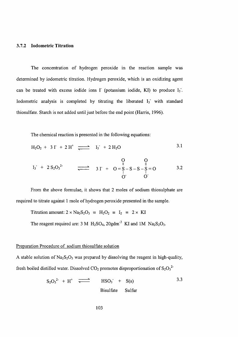
3.7.2 lodometric Titration
The concentration of hydrogen peroxide in the reaction sample was
determined by iodometric titration. Hydrogen peroxide, which is an oxidizing agent
can be treated with excess iodide ions T (potassium iodide, KI) to produce I3'.
lodometric analysis is completed by titrating the liberated I3' with standard
thiosulfate. Starch is not added until just before the end point (Harris, 1996).
The chemical reaction is presented in the following equations:
H 2 O 2 + 3 T + 2 H ^ ; ------ " I 3 ' + 2 H 2 O
0 O
I3' + 2 8 2 0 3 ' ; = ± 3 T + 0 = S - S - S - S = 0 3.21 I
o o
From the above formulae, it shows that 2 moles of sodium thiosulphate are
required to titrate against 1 mole of hydrogen peroxide presented in the sample.
Titration amount: 2 x Na2S2 0 3 = H2O2 = I2 = 2 x KI
The reagent required are: 3 M H 2 S O 4 , 20gdm'^ KI and IM N a 2 S 2 0 3 .
Preparation Procedure of sodium thiosulfate solution
A stable solution of Na2S2 0 3 was prepared by dissolving the reagent in high-quality,
fresh boiled distilled water. Dissolved CO2 promotes disproportionation of 8 2 0 3 '
8 2 0 3 - + HSOj- + S(s) 3,3
Bisulfate 8 ulfur
103
and metal ions catalyse atmospheric oxidation of thiosulfate. Thiosulfate solutions
were stored in the dark with 0.1 g of NaiCOg per litre to maintain optimum pH. Three
drops of chloroform should be added to a thiosulfate solution to prevent bacterial
growth. Although an acidic solution of thiosulfate is unstable, the reagent can be used
to titrate in acid because reaction 3.2 is faster than reaction 3.3 (Harris, 1996).
Preparation Procedure of starch solution
The starch solution was prepared by mbbing 20g of soluble starch with 50ml of water
to form a paste. They were then brought to boil in Idm^ water. The solution should be
changed after a few days due to bacterial growth.
Titration procedure
1. The sample containing hydrogen peroxide was collected in a conical flask. Excess
potassium iodide was added together with 3M sulphuric acid (about a quarter of
the amount of potassium iodide).
2. The mixture was stirred vigorously by shaking the conical flask until oxygen
bubbles were formed. The solution would turn from clear to brown colour
indicating the formation of iodine.
3. The mixture with iodine formed was titrated against IM standard sodium
thiosulphate solution.
4. A few drops of starch solution were added as indicator at the end of titration.
5. The end point was recorded when the solution suddenly turned from dark blue to
clear. Due to oxidation by air, the mixture will turn to dark blue again after the
104
end point, the volume should be recorded at the instance when the titration
mixture changed colour.
3.8 Characterisation of zeolite-based microchemcial devices
X-rav diffraction
The crystal structure, crystallinity and crystallographic orientation of the
zeolite film were determined using a Philips PW 1030 X-ray diffractometer equipped
with CuKa X-ray source and graphite monochromator. The X-ray line intensity was
obtained for 5 < 20 < 45 at a scan rate of 0.02 /min and time constant of 0.02.
X-ray diffraction (XRD) involves the irradiation of a sample with X-rays and
collection of the resultant X-rays diffraction pattern. The X-rays are usually CuKa
lines with wavelengths in the A range, which are sufficiently energetic to penetrate
solids and are well suited to probe their internal structure. It is used to estimate
particle sizes and to identify bulk phases. The position of diffraction peaks carries
information on the spacing of the reflecting planes. Diffraction lines from perfect
crystals are very narrow. Crystalline patterns will show sharp peaks while amorphous
phases and small particles will show broad bands and weak or zero diffraction
(Niemantsverdriet, 1993). The following shows the XRD pattern of ZSM-5 extracted
from literature (Koningsveld et al., 1987).
105
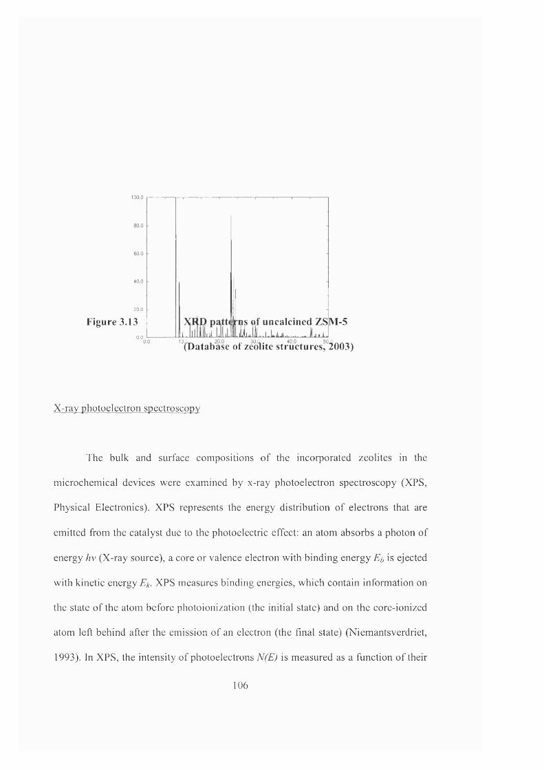
100.0
20.0
Figure 3.130.0
IS of uncalcined ZSM-5
“ifOatab^ase of z^o'lite structures,^°i003)
X-rav photoelectron spectroscopy
The bulk and surface compositions o f the incorporated zeolites in the
microchemical devices were examined by x-ray photoelectron spectroscopy (XPS,
Physical Electronics). XPS represents the energy distribution of electrons that are
emitted from the catalyst due to the photoelectric effect: an atom absorbs a photon of
energy hv (X-ray source), a core or valence electron with binding energy Et, is ejected
with kinetic energy Ek. XPS measures binding energies, which contain information on
the state o f the atom before photoionization (the initial state) and on the core-ionized
atom left behind after the emission o f an electron (the final state) (Niemantsverdriet,
1993). In XPS, the intensity o f photoelectrons N(E) is measured as a function o f their
106
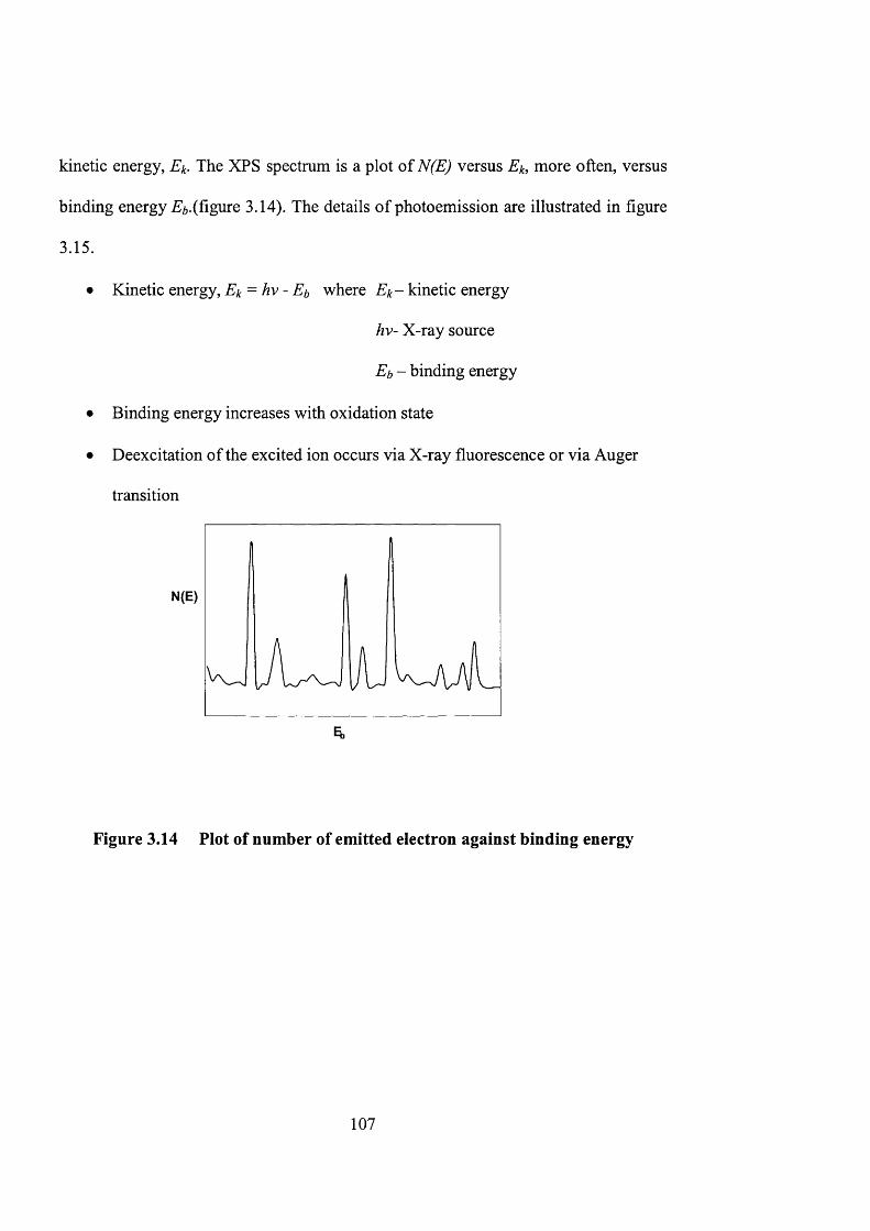
kinetic energy, Ek. The XPS spectrum is a plot of N(E) versus Ek, more often, versus
binding energy ^^.(figure 3.14). The details of photoemission are illustrated in figure
3.15.
• Kinetic energy, = /zv - where kinetic energy
hv- X-ray source
Eb - binding energy
• Binding energy increases with oxidation state
• Deexeitation of the excited ion occurs via X-ray fluorescence or via Auger
transition
N(E)
Figure 3.14 Plot of number of emitted electron against binding energy
107
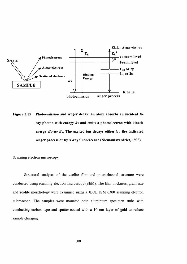
PhotoelectronsX-rays
Auger electrons
Scattered electrons
SAMPLEhv
E,
K L 1L 23 A u g e r e l e c t r o n
E /
BindingEnergy
vacuum level Fermi level
L23 or 2 p Li or 2 s
K or Isphotoemission Auger process
Figure 3.15 Photoemission and Auger decay: an atom absorbs an incident X-
ray photon with energy hv and emits a photoelectron with kinetic
energy Ek=hv-Eb. The excited ion decays either by the indicated
Auger process or by X-ray fluorescence (Niemantsverdriet, 1993).
Scanning electron microscopy
Structural analyses of the zeolite film and microchannel structure were
conducted using scanning electron microscopy (SEM). The film thickness, grain size
and zeolite morphology were examined using a JEOL JSM 6300 scanning electron
microscope. The samples were mounted onto aluminium specimen stubs with
conducting carbon tape and sputter-coated with a 1 0 nm layer of gold to reduce
sample charging.
108
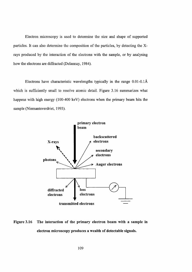
Electron microscopy is used to determine the size and shape of supported
particles. It can also determine the composition of the particles, by detecting the X-
rays produced by the interaction of the electrons with the sample, or by analysing
how the electrons are diffracted (Delannay, 1984).
Electrons have characteristic wavelengths typically in the range 0.01-0.1Â
which is sufficiently small to resolve atomic detail. Figure 3.16 summarizes what
happens with high energy (100-400 keV) electrons when the primary beam hits the
sample (Niemantsverdriet, 1993).
primary electron beam
backscatteredelectronsX-rays
secondaryelectrons
photonsAuger electrons
losselectrons
diffractedelectrons
transmitted electrons
Figure 3.16 The interaction of the primary electron beam with a sample in
electron microscopy produces a wealth of detectable signals.
109
SEM is carried out by rastering a narrow electron beam over the surface and
detecting the yield of the secondary or back-scattered electrons as a function of the
position of the primary beam (contrast due to the topology and composition of a
surface). The secondary electrons have low energies of 10-50eV and originate from
the surface region of the sample. Back-scattered electrons come from deeper and
carry information on the composition of the sample, because heavy elements are more
efficient electron scatterers and appear brighter in the image. SEM instruments
produce image with a resolution of 5nm (Niemantsverdriet, 1993).
Transmission electron spectroscopv
Transmission electron microscopy (TEM, JEOL JEM 2010) is used to
characterize particle size and morphology of the colloidal zeolite seeds. It uses
transmitted and diffracted electrons to project all information in a two-dimensional
image. A TEM instrument is very similar to an optical microscope with
electromagnetic lenses replacing its optical counter part. The dark field image is
obtained from the diffracted electron beams, which are slightly off angle from the
transmitted beam. Typical operating conditions of a conventional TEM instrument
are lOOkeV electrons. TEM is different from SEM as SEM sees contrast due to the
topology of a surface, and TEM projects all information in a two-dimensional image.
However, TEM can reach down to subnanometer resolution (Niemantsverdriet,
1993).
110
Energy dispersive analysis of X-rays
Another method to examine the bulk and surface compositions of incorporated
zeolites is energy dispersive x-ray spectroscopy (EDXS, Oxford Instruments),
Characteristic X-rays are emitted from the atoms in the sample when they are ionized
by the electron beam. Emitted X-rays are characteristic for an element for
determining the chemical composition of a selected part of the sample (0.5-1pm for
bulk samples). The X-ray spectrum detected consists of a series of peaks representing
the type and relative amounts of each elements in the sample (Wachs, 1992). Unlike
XPS, EDX cannot provide information about the chemical state of the elements.
Thermo gravimetric and differential thermal analyses
Thermogravimetric and differential thermal analyses (TGA/DTA, Setaram 92-
18) were used to determine the amount of water and hydrocarbons adsorbed on the
titanium silicalite-1 catalyst. The TS-1 powder sample was placed in a platinium
crucible and heated from 298K to 1073K at a rate of 5K/min in air. The reference
material for DTA analysis was alpha alumina powder. The sample weight was
measured by TGA while DTA recorded the change in temperature for constant
heating.
I l l
TGA analysis measures the gain or loss in weight of the sample as a function
of the composition of the atmosphere and the temperature. A gravimetric
thermoanalyzer consists of ( 1 ) an automatic magnetic re-equilibrating balance (2 ) a
temperature-programmed furnace and (3) a gas flow circuit to control the gaseous
environment. This setup is equipped to allow for other analytical methods such as
DTA. The exothermal or endothermal effects accompanied by changes in the
physiochemical states of the sample under changing temperature can be measured by
DTA (Auroux, 1994).
112
Chapter 4
Incorporation of Zeolites in the Design Architecture of
Microchemical Systems
113
4.1 Introduction
Molecular sieve zeolites are microporous tectosilicates with different pore
sizes. They can precisely tailored up to the scale of sub-nanometer to create desired
arrangement and properties, which are of great interest in the field of catalysis, ion-
exchange, separation and extraction (Davis and Lobo, 1992; Davis, 1998, Caro et al.,
2000). Zeolites, with their thermal and chemical stability, offer a great choice for
integration into microsystems. Their molecular structures can be tuned and
engineered precisely for design and application in nano devices (Yan and Bein,
1995).
Recently, zeolites have found applications as catalyst and membranes in
microchemical devices. Free-standing silicalite-1 membranes have been grown onto
silicon microchannels (den Exter et al., 1997). ZSM-5 zeolites were deposited onto
machined stainless steel microchannels for selective catalytic reduction of NO with
ammonia (Rebrov et al., 2001). These belong to an emerging new technology: the
microchemical systems that also include other microdevices such as micromixers,
micro heat-exchangers, micro-actuators and microsensors (Ehrfeld et al., 2000).
Ultimately, these discrete components can be assembled to create micro-analytical
laboratories, portable manufacturing plants and miniature fuel cells to satisfy the
needs of an increasingly mobile society.
114
Microreactors have great potential as analytical tools for catalytic, chemical
and biochemical research. They also represent another method for production of
specialty chemicals and biochemicals. Their unique properties, which include high
heat and mass transfer rates (Drost et al., 1997, Losey et al., 2000, Ehrfeld et al.,
2000) and short residence time (Jensen, 2001, Gavriilidis, et al., 2002) make them an
invaluable tool for studying demanding reaction systems. Microreactors can provide
important information on reaction mechanisms and intrinsic kinetic rates that are
essential for reactor design and scale-up. They can also be used for rapid screening of
synthesis pathways to determine the most efficient and environmentally responsible
synthesis route. Pioneering work in microreactor has been carried out among others
by groups at Institut fiir Mikrotechnik Mainz (IMM), Forschungszentrum Karlsruhe
GmbH (FK), Massachusetts Institute of Technology (MIT), Pacific Northwest
National Laboratory (PNNL), Technische Universitat Chemnitz (TUG), etc.
Miniaturization can also benefit membrane separation processes. It enables
large membrane areas to be accommodated within a small volume allowing for the
design of a compact separation unit. Instead of one continuous membrane surface, a
membrane microseparator will consist of an assembly of smaller membranes that
provides the same effective separation area. It is expected that by keeping the
individual membrane area small, the risk of membrane failure due to accumulated
stresses associated can be significantly diminished. This is particularly important for
inorganic membranes, where embrittlement, crack-formation and delamination are
115
some of the leading causes of failure, den Exter et al. (1997) have prepared free-
standing zeolite micromembranes on silicon substrates.
In this chapter, traditional semiconductor fabrication methodology along with
zeolite thin film technology is employed to create microstructured patterns that can be
employed in microchemical systems, such as microreactors, microseparators or
microelectrochemical cells.
4.2 Experimental
Figure 4.1 gives the general outline of the procedure for the fabrication of
zeolite-based micro structured patterns using standard semiconductor microfabrication
technology. First, a zeolite-silicon composite was prepared by growing an oriented
polycrystalline zeolite film onto a silicon wafer. The design pattern was then
transferred and etched onto the zeolite-silicon composite using conventional
photolithography.
116
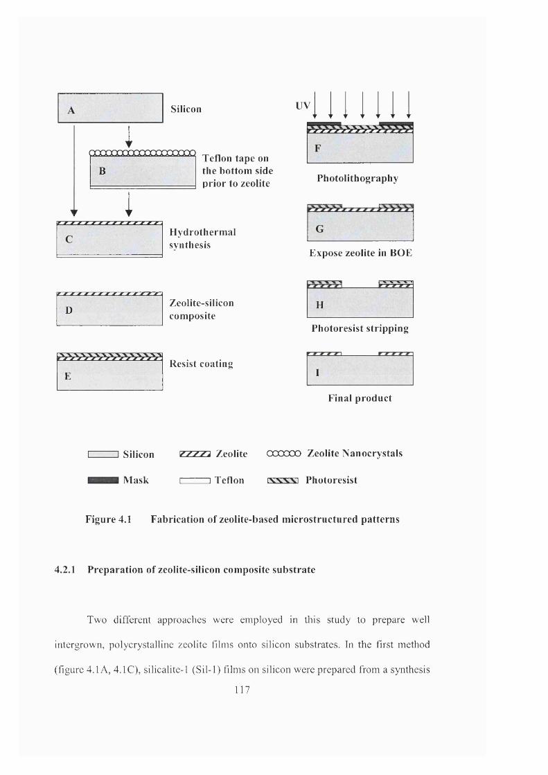
Silicon UV
iœOQœOQQQOOOOOOOÜÜ
BTeflon tape on the bottom side prior to zeolite
1Hydrothermalsynthesis
Photolithography
Expose zeolite in BOE
DZeolite-siliconcomposite
H
Photoresist stripping
FResist coating
I
Final product
I I Silicon ZZZZa Zeolite OOOOOO Zeolite Nanocrystals
Mask I I Teflon rsrvsrsn Photoresist
Figure 4.1 Fabrication of zeolite-based microstructured patterns
4.2.1 Preparation of zeolite-silicon composite substrate
Two different approaches were employed in this study to prepare well
intergrown, polycrystalline zeolite films onto silicon substrates. In the first method
(figure 4.1 A, 4.1C), silicalite-1 (Sil-1) films on silicon were prepared from a synthesis
117
mixture containing 6.5 ml of organosilicon precursor, tetraethyl orthosilicate (TEOS)
mixed with 65 ml of 0.05 M aqueous solution of the organic template,
tetrapropylammonium hydroxide (TPAOH) to give mole ratios of 80 TEOS: 10
TPAOH: 10,000 H2O. The silicon was held in a horizontal position with the polished
surface facing downwards. This decreased the number of growth defects caused by
incorporation of zeolite powder from the solution. The backside of the silicon was
covered with a layer of Teflon ribbon to prevent zeolite growth. Placed within an
autoclave vessel, the completely immersed silicon was hydrothermally treated at 448
K in a preheated oven (Memmert) between 6 to 48 h.
In the second approach (figure 4.IB, 1C), the silicon substrate was pre-seeded
with zeolite nanocrystals before hydrothermal synthesis. Schoeman et al. (1997) have
shown that submicron MFI zeolite films can be successfully grown onto seeded
silicon. The colloidal Sil-1 seeds were prepared from a synthesis mixture containing
15 g of fumed silica, 0.85 g of sodium hydroxide, and 60 ml of 1 M tetrapropyl
ammonium hydroxide (TPAOH) solution. The mixture was stirred for 24 h at room
temperature to produce a clear and homogeneous solution. This solution was then
transferred to a 125 ml Teflon autoclave (Parr Scientific Inc.) and heated in an oven
(Memmert GmbH Co.) to a temperature of 398 K. After 8 h of hydrothermal
treatment, the colloidal zeolites were recovered and purified using a series of
centrifugation and rinsing steps. The Sil-1 seeds were stored as 2 wt.% colloidal
suspension in ethanol.
118
The seeding procedure involved immersion of the silicon in 0.05 M 3-
mercaptopropyl trimethoxysilane/ethanol solution in order to functionalize the
substrate. The excess surfactants were rinsed off using ethanol. This was followed by
immersion in colloidal suspension of Sil-1 seeds. The seeded substrate was then dried
in the oven at 333 K for 15 min. This procedure gave uniform seed coverage on the
silicon. The seed population on the substrates can be adjusted by repeating the
seeding process several times. This way, seed populations up to 95 x 10 crystals per
m^ (i.e., complete surface coverage) were obtained. The seeded silicon was then
placed horizontally in a synthesis mixture containing 40 TEOS: 10 TPAOH: 20,000
H2O, and sealed in an autoclave for hydrothermal regrowth at 398 K. Zeolite films
grown for 6 , 12, 24 and 48 h were examined to determine layer thickness, surface
morphology and film orientation. After the synthesis, the zeolite-silicon composites
were rinsed in deionized distilled water, dried overnight in an oven at 333 K and
stored in a dry container (figure 4.ID).
Starting with a zeolite-silicon composite substrate, a layer of positive
photoresist was next spin-coated onto the substrate (figure 4. IE). The resist was soft
baked at 383 K for 1 min. Using contact printing, the micropattem etched on the
photomask was transferred onto the polymer resist layer after exposure to UV light
(figure 4.IF). The resist irradiated with UV light was washed away to expose the
zeolite layer underneath (figure 4.1G). The sample was then hard baked at 393 K for
30 min to harden the photoresist and improve its adhesion. A buffered oxide etching
solution (BOE) containing 1 HP: 6 NH4F was used to isotropically etch the
119
micropattem onto the zeolite layer. The etched substrate was rinsed with deionized
distilled water and dried using clean nitrogen gas. The photoresist was stripped from
the surface using acetone or oxidised using oxygen plasma (figure 4.1H). After a final
rinsing in deionized distilled water, the patterned substrate was dried overnight at 333
K and calcined in air at 823 K for 6 h (figure 4.11) to remove the organic templates
trapped within the zeolite cages. This final step frees the zeolite pore environment for
catalysis and separation.
4.2.2 Characterisation
Structural analyses were conducted using X-ray diffraction (XRD) and
scanning electron microscopy (SEM). The crystal stmcture, crystallinity and
crystallographic orientation of the zeolite film were determined using a Philips PW
1030 X-ray diffractometer equipped with CuKa X-ray source and graphite
monochromator. The film thickness, grain size and zeolite morphology were
examined using a JEOL JSM 6300 scanning electron microscope. The samples at
various stages of fabrication were inspected visually using an optical microscope
(Olympus, BH-2). The surface roughness of the silicon substrate was examined by
atomic force microscopy (Nanoscope Ilia, Digital Instmments). These combined
characterisation techniques provide detailed information on the microstmcture of the
zeolite-silicon composite material used in the preparation of microchemical devices.
120

4.2.3. Materials
The silicon substrate was a four-inch diameter p-type Si (100) wafer. The
silicon was cleaned using a series of sonification and rinsing in ethanol (99.8%) and
deionized distilled water. The wafer was then dried overnight in the oven at 333 K
and stored in a dry container for later use. Smaller substrates were obtained by
sectioning the wafer into 2.5 cm x 3.0 cm rectangular pieces. Chemicals used in
zeolite synthesis were tetraethyl orthosilicate (98%, Aldrich), tetrapropylammonium
hydroxide (1 M, Aldrich), fumed silica (0.01pm, 99.8%, Aldrich) and sodium
hydroxide (98%, BDH). The 3-mercaptopropyl trimethoxysilane (99%) employed in
grafting the zeolite seeds onto the silicon substrate was purchased from Aldrich. For
microfabrication, the following chemicals were used: HPR-207 positive photoresist
(Fuji-Hunt Electronics Technology Co), FHD-5 positive developer (Olin), Superwet
BOE Etchant 6-1 (General Chemical) and acetone (Lab Scan).
4.3. Results and discussion
4.3.1. Synthesis of zeolite-silicon composite
The clean silicon substrate (figure 4.2a) was seeded using the procedure
described in the experimental section in order to obtain a complete and uniform seed
coverage (i.e., 95 x 10 seeds/m^) as shown in figure 4.2b. The 120 nm colloidal Sil-
1 seeds were roughly ellipsoidal in shape with no apparent crystal facets. XRD
121
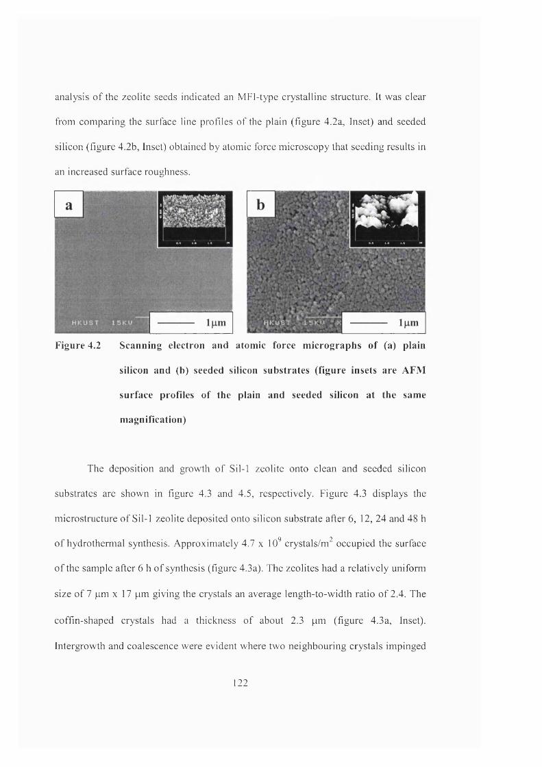
analysis of the zeolite seeds indicated an MFI-type crystalline structure. It was clear
from comparing the surface line profiles of the plain (figure 4.2a, Inset) and seeded
silicon (figure 4.2b, Inset) obtained by atomic force microscopy that seeding results in
an increased surface roughness.
Figure 4.2 Scanning electron and atomic force m icrographs o f (a) plain
silicon and (b) seeded silicon substrates (figure insets are AFM
surface profiles o f the plain and seeded silicon at the same
m agnification)
The deposition and growth of Sil-1 zeolite onto clean and seeded silicon
substrates are shown in figure 4.3 and 4.5, respectively. Figure 4.3 displays the
microstructure of Sil-1 zeolite deposited onto silicon substrate after 6, 12, 24 and 48 h
of hydrothermal synthesis. Approximately 4.7 x 10 crystals/m^ occupied the surface
of the sample after 6 h of synthesis (figure 4.3a). The zeolites had a relatively uniform
size of 7 pm x 17 pm giving the crystals an average length-to-width ratio of 2.4. The
coffin-shaped crystals had a thickness of about 2.3 pm (figure 4.3a, Inset).
Intergrowth and coalescence were evident where two neighbouring crystals impinged
122
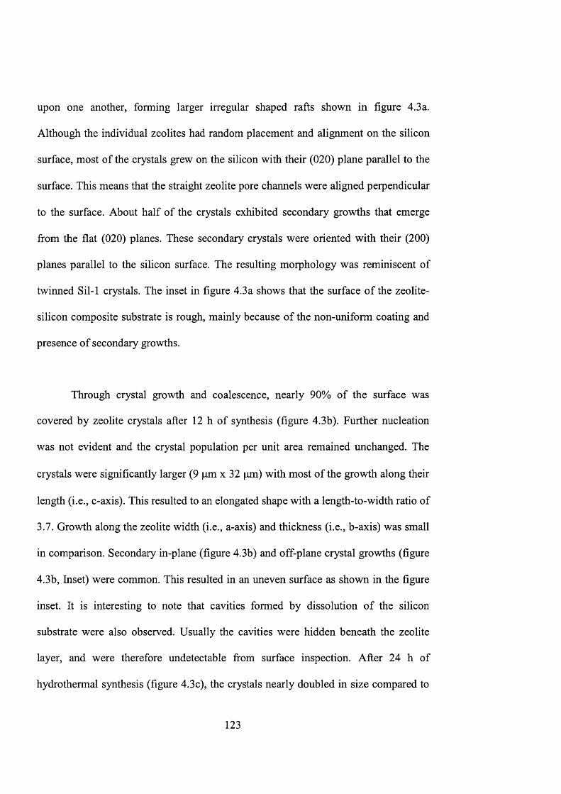
upon one another, forming larger irregular shaped rafts shown in figure 4.3a.
Although the individual zeolites had random placement and alignment on the silicon
surface, most of the crystals grew on the silicon with their (020) plane parallel to the
surface. This means that the straight zeolite pore channels were aligned perpendicular
to the surface. About half of the crystals exhibited secondary growths that emerge
from the flat (020) planes. These secondary crystals were oriented with their (200)
planes parallel to the silicon surface. The resulting morphology was reminiscent of
twinned Sil-1 crystals. The inset in figure 4.3a shows that the surface of the zeolite-
silicon composite substrate is rough, mainly because of the non-uniform coating and
presence of secondary growths.
Through crystal growth and coalescence, nearly 90% of the surface was
covered by zeolite crystals after 12 h of synthesis (figure 4.3b). Further nucléation
was not evident and the crystal population per unit area remained unchanged. The
crystals were significantly larger (9 pm x 32 pm) with most of the growth along their
length (i.e., c-axis). This resulted to an elongated shape with a length-to-width ratio of
3.7. Growth along the zeolite width (i.e., a-axis) and thickness (i.e., b-axis) was small
in comparison. Secondary in-plane (figure 4.3b) and off-plane crystal growths (figure
4.3b, Inset) were common. This resulted in an uneven surface as shown in the figure
inset. It is interesting to note that cavities formed by dissolution of the silicon
substrate were also observed. Usually the cavities were hidden beneath the zeolite
layer, and were therefore undetectable from surface inspection. After 24 h of
hydrothermal synthesis (figure 4.3c), the crystals nearly doubled in size compared to
123
those shown in figure 4.3b. These zeolites were roughly 6 |am thick, 16 |im wide and
64 |Lim long. Nearly all crystals exhibited secondary growth, which was responsible
for its rough surface (figure 4.3e, Inset). An additional 24 hours of synthesis allowed
the secondary crystals with (200) orientation to grow sufficiently large to coalesce
and form an intergrown layer (figure 4.3d). Defects in the form of misaligned crystals
interrupted the otherwise smooth surface (figure 4.3d). Unfortunately, defects in the
form of large cavities within the silicon were also present (figure 4.3d, Inset). The X-
ray diffraction pattern of this zeolite-silicon composite is shown in figure 4.4a.
Without pre-seeding, zeolite nuclei were formed on silicon by heterogeneous
nucléation or were incorporated after it had nucleated in the solution (i.e.,
homogeneous nucléation). It had also been suggested that microcrystals deposited
from the solution may act as seeds for zeolite growth (Bein, 1996). The number of
nuclei formed was usually less than 1 per micron square, especially in the absence of
ageing. This means that the concentration of nutrients immediately surrounding the
seeds is uniform. Off-plane crystal growth was observed (figure 4.3b, Inset), but were
not as common as the in-plane zeolite growth (figure 4.3a). The latter zeolites were
oriented with their (020) plane parallel to the surface. It had been argued that the
(020) oriented zeolite crystals have a more stable configuration because of their larger
contact area with the support (Jansen and van Rosmalen, 1993).
The Sil-1 displayed anisotropic growth that was typical of MFI-type zeolites
(Jansen, 1991; Iwasaki et al., 1997). The growth rate along the c-axis of the zeolite
124
crystal (i.e., <002>) was the highest at 2.6 pm/h, followed by a-axis (i.e., <200>) at
0.6 )im/h and b-axis (i.e., <020>) at 0.2 |am/h. Figures 4.3a-4.3c show that the
zeolites grew rapidly along the c- and a-axis, completely covering the silicon surface
in less than 24 h of synthesis. However, the increase in the layer thickness
corresponding to the zeolites’ b-axis was small. A competing crystal orientation was
evident even at the start of film growth (figure 4.3a). The (200)-oriented crystals grew
directly from the existing (020) crystals, and predominated once the (020) crystals
formed a complete film. This gave the resulting zeolite film (figure 4.3d) two distinct
layers of different crystallographic orientations.
125
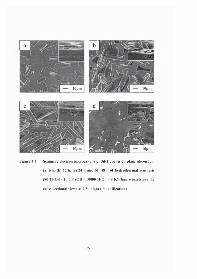
'I
Figure 4.3 Scanning electron micrographs of Sil-1 grown on plain silicon for:
(a) 6 h, (b) 12 h, (c) 24 h and (d) 48 h of hydrothermal synthesis
(80 TEOS - 10 TPAOH - 10000 H2O, 448 K) (figure insets are the
cross-sectional views at 2.5x higher magnification)
126
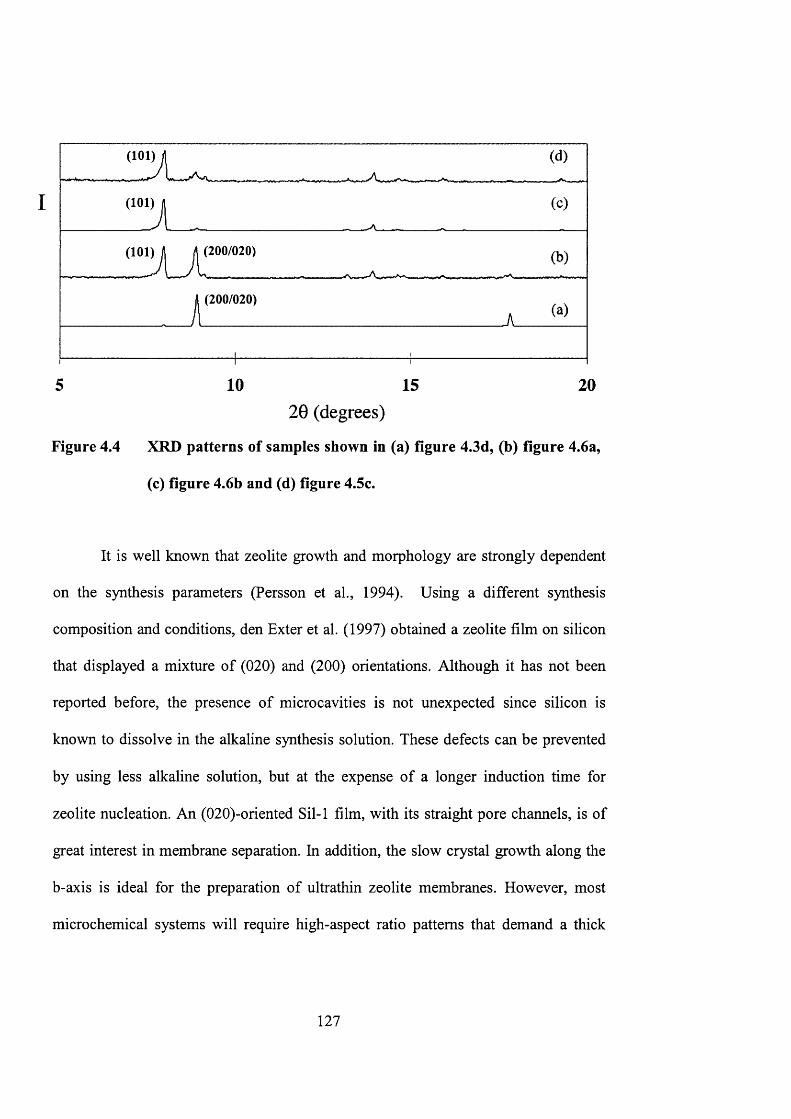
I
(200/020)
(200/020)
5 10 15 2020 (degrees)
Figure 4.4 XRD patterns of samples shown in (a) figure 4.3d, (b) figure 4.6a,
(c) figure 4.6b and (d) figure 4.5c.
It is well known that zeolite growth and morphology are strongly dependent
on the synthesis parameters (Persson et a l, 1994). Using a different synthesis
composition and conditions, den Exter et al. (1997) obtained a zeolite film on silicon
that displayed a mixture of (020) and (200) orientations. Although it has not been
reported before, the presence of microcavities is not unexpected since silicon is
known to dissolve in the alkaline synthesis solution. These defects can be prevented
by using less alkaline solution, but at the expense of a longer induction time for
zeolite nucléation. An (020)-oriented Sil-1 film, with its straight pore channels, is of
great interest in membrane separation. In addition, the slow crystal growth along the
b-axis is ideal for the preparation of ultrathin zeolite membranes. However, most
microchemical systems will require high-aspect ratio patterns that demand a thick
127
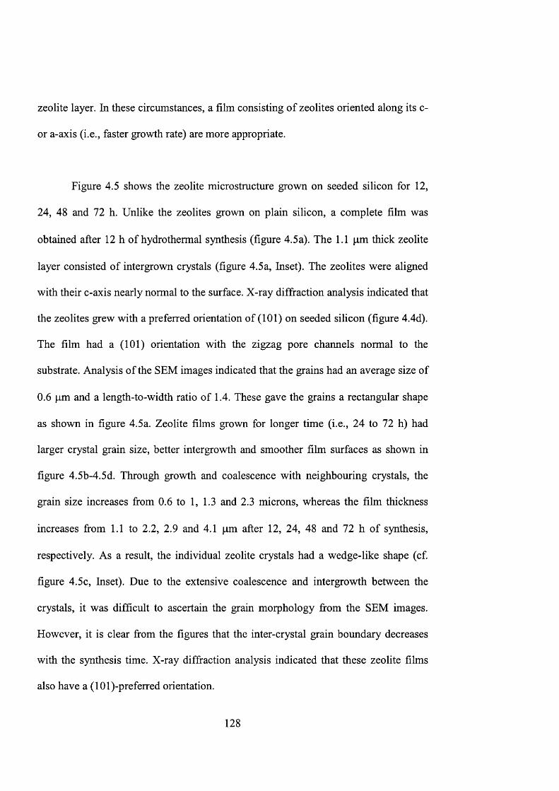
zeolite layer. In these circumstances, a film consisting of zeolites oriented along its c-
or a-axis (i.e., faster growth rate) are more appropriate.
Figure 4.5 shows the zeolite mierostructure grown on seeded silicon for 12,
24, 48 and 72 h. Unlike the zeolites grown on plain silicon, a complete film was
obtained after 12 h of hydrothermal synthesis (figure 4.5a). The 1.1 pm thick zeolite
layer consisted of intergrown crystals (figure 4.5a, Inset). The zeolites were aligned
with their c-axis nearly normal to the surface. X-ray diffraction analysis indicated that
the zeolites grew with a preferred orientation of (101) on seeded silicon (figure 4.4d).
The film had a (101) orientation with the zigzag pore channels normal to the
substrate. Analysis of the SEM images indicated that the grains had an average size of
0.6 pm and a length-to-width ratio of 1.4. These gave the grains a rectangular shape
as shown in figure 4.5a. Zeolite films grown for longer time (i.e., 24 to 72 h) had
larger crystal grain size, better intergrowth and smoother film surfaces as shown in
figure 4.5b-4.5d. Through growth and coalescence with neighbouring crystals, the
grain size increases from 0.6 to 1, 1.3 and 2.3 microns, whereas the film thickness
increases from 1.1 to 2.2, 2.9 and 4.1 pm after 12, 24, 48 and 72 h of synthesis,
respectively. As a result, the individual zeolite crystals had a wedge-like shape (cf.
figure 4.5c, Inset). Due to the extensive coalescence and intergrowth between the
crystals, it was difficult to ascertain the grain morphology from the SEM images.
However, it is clear from the figures that the inter-crystal grain boundary decreases
with the synthesis time. X-ray diffraction analysis indicated that these zeolite films
also have a (lOl)-preferred orientation.
128
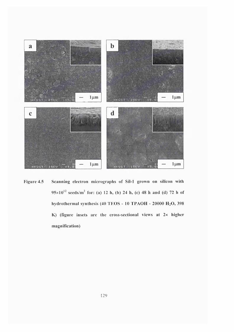
wm-rîJHt='UST:i- '4 S ’KM
,\r>" r " > • ^ - 1)
S t » ^ * i S K V V X 5 , 01
U
Figure 4.5 Scanning electron micrographs of Sil-1 grown on silicon with
95x10*^ seeds/m^ for: (a) 12 h, (b) 24 h, (c) 48 h and (d) 72 h of
hydrothermal synthesis (40 TEOS - 10 TPAOH - 20000 H2O, 398
K) (figure insets are the cross-sectional views at 2x higher
magnification)
129
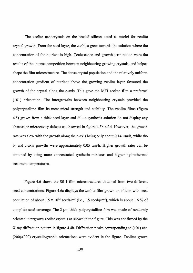
The zeolite nanocrystals on the seeded silicon acted as nuclei for zeolite
crystal growth. From the seed layer, the zeolites grew towards the solution where the
concentration of the nutrient is high. Coalescence and growth termination were the
results of the intense competition between neighbouring growing crystals, and helped
shape the film microstructure. The dense crystal population and the relatively uniform
concentration gradient of nutrient above the growing zeolite layer favoured the
growth of the crystal along the c-axis. This gave the MFI zeolite film a preferred
(101) orientation. The intergrowths between neighbouring crystals provided the
polycrystalline film its mechanical strength and stability. The zeolite films (figure
4.5) grown from a thick seed layer and dilute synthesis solution do not display any
abscess or microcavity defects as observed in figure 4.3b-4.3d. However, the growth
rate was slow with the growth along the c-axis being only about 0.14 pm/h, while the
b- and c-axis growths were approximately 0.05 pm/h. Higher growth rates can be
obtained by using more concentrated synthesis mixtures and higher hydrothermal
treatment temperatures.
Figure 4.6 shows the Sil-1 film microstructures obtained from two different
seed concentrations. Figure 4.6a displays the zeolite film grown on silicon with seed
population of about 1.5 x 10 seeds/m^ (i.e., 1.5 seed/pm^), which is about 1.6 % of
complete seed coverage. The 2 pm thick polycrystalline film was made of randomly
oriented intergrown zeolite crystals as shown in the figure. This was confirmed by the
X-ray diffraction pattern in figure 4.4b. Diffraction peaks corresponding to (101) and
(200)/(020) crystallographic orientations were evident in the figure. Zeolites grown
130
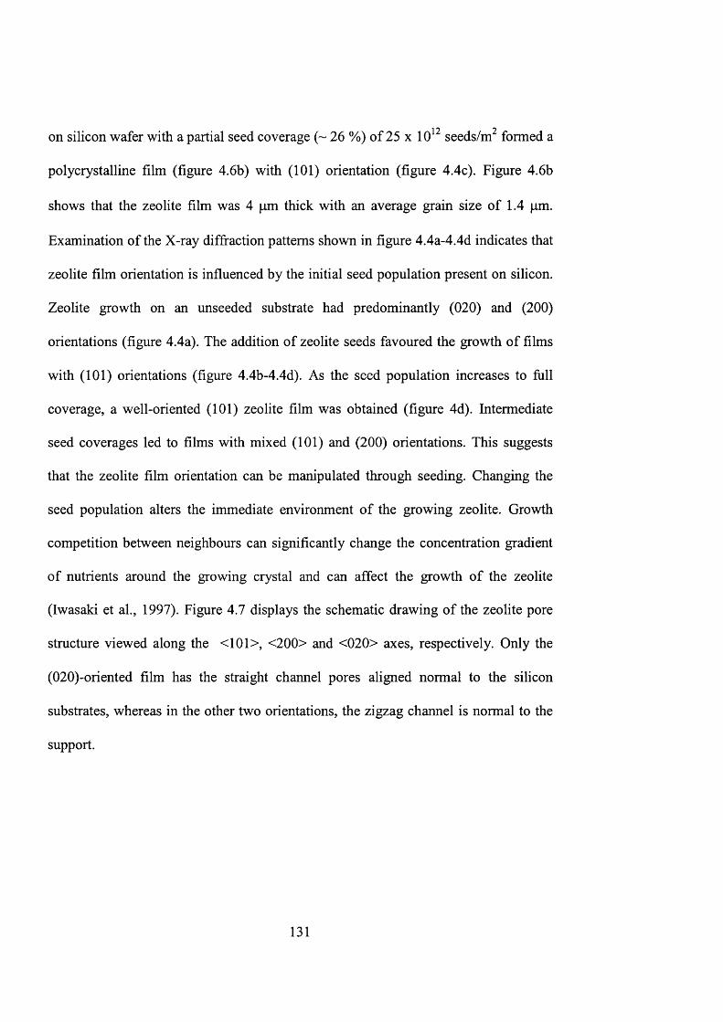
on silicon wafer with a partial seed coverage (~ 26 %) of 25 x 10 seeds/m formed a
polycrystalline film (figure 4.6b) with (101) orientation (figure 4.4c). Figure 4.6b
shows that the zeolite film was 4 pm thick with an average grain size of 1.4 pm.
Examination of the X-ray diffraction patterns shown in figure 4.4a-4.4d indicates that
zeolite film orientation is influenced by the initial seed population present on silicon.
Zeolite growth on an unseeded substrate had predominantly (020) and (200)
orientations (figure 4.4a). The addition of zeolite seeds favoured the growth of films
with (101) orientations (figure 4.4b-4.4d). As the seed population increases to full
coverage, a well-oriented (101) zeolite film was obtained (figure 4d). Intermediate
seed coverages led to films with mixed (101) and (200) orientations. This suggests
that the zeolite film orientation can be manipulated through seeding. Changing the
seed population alters the immediate environment of the growing zeolite. Growth
competition between neighbours can significantly change the concentration gradient
of nutrients around the growing crystal and can affect the growth of the zeolite
(Iwasaki et al., 1997). Figure 4.7 displays the schematic drawing of the zeolite pore
structure viewed along the <101>, <200> and <020> axes, respectively. Only the
(020)-oriented film has the straight channel pores aligned normal to the silicon
substrates, whereas in the other two orientations, the zigzag channel is normal to the
support.
131
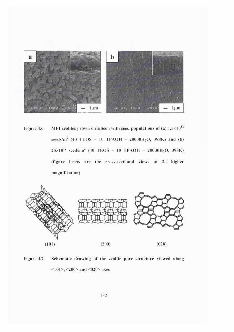
Figure 4.6 MFI zeolites grown on silicon with seed populations of (a) 1.5x10*
seedsW (40 TEOS - 10 TPAOH - 2 OOOOH2O, 398K) and (b)
25xl0‘ seeds/m^ (40 TEOS - 10 TPAOH - 20000H.O, 398K)
(figure insets are the cross-sectional views at 2x higher
magnification)
(101) (200) (020)
Figure 4.7 Schematic drawing of the zeolite pore structure viewed along
<101>, <200> and <020> axes
132
4.3.2. Fabrication of zeolite micropatterns and their stability
The previous section showed that zeolite films of controlled orientations and
thickness could be grown on a silicon wafer to serve as substrate for the fabrication of
microchemical devices. The ability to engineer and tailor the zeolite micro structure
and chemistry is very important for the effective incorporation of zeolites as catalyst,
membrane and structural materials in microchemical systems. The zeolite-silicon
composite substrates were thermally stable, as they were able to withstand
temperatures up to 873 K in both oxidising and reducing atmospheres for extended
periods of time without crack formation or film delamination. The zeolite film was
also stable in low to moderate concentrations of acids and bases, except in the
presence of fluoride containing acids and salts. However, corrosion of the silicon was
evident in alkaline solution. The composite substrate was also stable in alcohol,
acetone and aromatic solutions (e.g., xylene). However, this does not necessarily
mean that the fabricated zeolite micropatterns are stable under similar conditions.
Zeolite microchannels
Figure 4.8 displays three test patterns etched onto the zeolite-silicon
composite substrate using the procedure discussed in the experimental section. These
images were taken after the micro fabricated patterns had been subjected to 2 weeks of
thermal cycling between 303 K and 873 K in a furnace. Figure 4.8a displays a series
of microchannels etched onto a 10 pm thick silicalite-1 (101) film grown on seeded
133
silicon. The cross-section of the channels was rectangular with width of 5 microns.
The shape of the serpentine channels was based on a cosine function with a
periodicity defined by the peak-to-peak distance (L) of 15 pm. The shape of the
channels was varied by changing the amplitude (A) of the cosine function. Starting
from the left of the figure, the value of A for the first channel was 5 pm, the next two
were 6 pm and the following 2 were 6.5 pm. The last two patterns consisted of
staggered lines of 6 pm holes. It is clear from the results that complex microchannel
geometries can be faithfully reproduced from the mask onto the zeolite-silicon
composite substrate using the new fabrication technique. The pattern shown in figure
4.8b simulates a complex channel network that can exist in a micro fluidic device. The
figure shows a central distribution hub from which a network of microchannels
radiates. Abrupt changes in channel width and direction were also incorporated to
further test the precision of the new fabrication technique. The narrowest channel had
a width of 3 pm and height of 10 pm, giving the channel an aspect ratio of about 3.
There was no serious degradation in the microfabricated patterns (cf. figure 4.8a and
4.8b) even after prolonged exposure to harsh thermal conditions. Although
microchannels narrower than 30 pm are rarely used in microchemical and
microfluidic devices, the ability to fabricate high-resolution features is useful for
incorporating microfabricated zeolite catalysts within microreactor channels.
134

lOum
5#
Figure 4.8 Exam ples o f zeolite m icropatterii (a) microchanriels and (b) fluid
distribution hub
Zeolite micropattems
The mierostructure of the catalyst coating could be engineered during the
synthesis to introduce surface roughness and create intercrystalline porosity to
promote fluid mixing and enhance mass transfer. Access to the zeolite can also be
manipulated by changing the zeolite orientation (cf. figure 4.7). The zeolite deposited
within the microchannels can be further micropattemed to create regular array of
microfabricated catalysts with exact size, geometry and spacing. Figure 4.9 shows an
example of a microfabricated zeolite grid. Each zeolitic line forming the 8 x 16 pm
rectangular grids was 5 pm wide and 10 pm high. The zeolite grid was stable during
thermal treatment, and the occasional breaks in the zeolite lines were created during
the etching process. Unlike a fixed bed catalytic reactor, a microfabricated catalyst
laid out in a regular pattern can be easier to simulate. Thus, an optimum catalyst array
can be pre-designed to the specifications demanded by the application. Complex
135
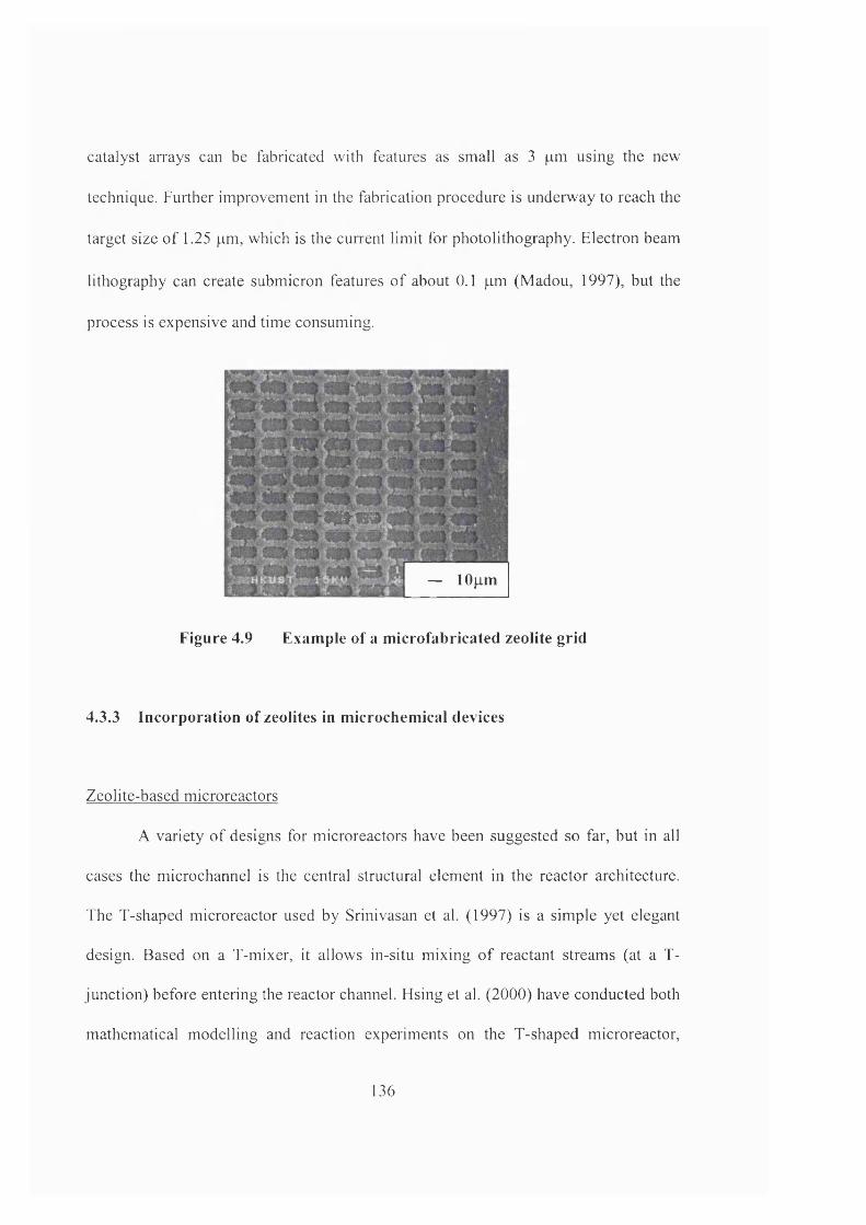
catalyst arrays can be fabricated with features as small as 3 |am using the new
technique. Further improvement in the fabrication procedure is underway to reach the
target size of 1.25 pm, which is the current limit for photolithography. Electron beam
lithography can create submicron features of about 0.1 pm (Madou, 1997), but the
process is expensive and time consuming.
w m
— lOpm
Figure 4.9 Exam ple o f a m icrofabricated zeolite grid
4.3.3 Incorporation of zeolites in m icrochem ical devices
Zeolite-based microreactors
A variety of designs for microreactors have been suggested so far, but in all
cases the microchannel is the central structural element in the reactor architecture.
The T-shaped microreactor used by Srinivasan et al. (1997) is a simple yet elegant
design. Based on a T-mixer, it allows in-situ mixing of reactant streams (at a T-
junction) before entering the reactor channel. Hsing et al. (2000) have conducted both
mathematical modelling and reaction experiments on the T-shaped microreactor.
136
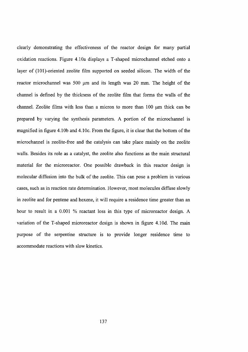
clearly demonstrating the effectiveness of the reactor design for many partial
oxidation reactions. Figure 4.10a displays a T-shaped microchannel etched onto a
layer of (lOl)-oriented zeolite film supported on seeded silicon. The width of the
reactor microchannel was 500 pm and its length was 20 mm. The height of the
channel is defined by the thickness of the zeolite film that forms the walls of the
channel. Zeolite films with less than a micron to more than 100 pm thick can be
prepared by varying the synthesis parameters. A portion of the microchannel is
magnified in figure 4.10b and 4.10c. From the figure, it is clear that the bottom of the
microchannel is zeolite-jfree and the catalysis can take place mainly on the zeolite
walls. Besides its role as a catalyst, the zeolite also functions as the main structural
material for the microreactor. One possible drawback in this reactor design is
molecular diffusion into the bulk of the zeolite. This can pose a problem in various
cases, such as in reaction rate determination. However, most molecules diffuse slowly
in zeolite and for pentene and hexene, it will require a residence time greater than an
hour to result in a 0.001 % reactant loss in this type of microreactor design. A
variation of the T-shaped microreactor design is shown in figure 4.10d. The main
purpose of the serpentine structure is to provide longer residence time to
accommodate reactions with slow kinetics.
137
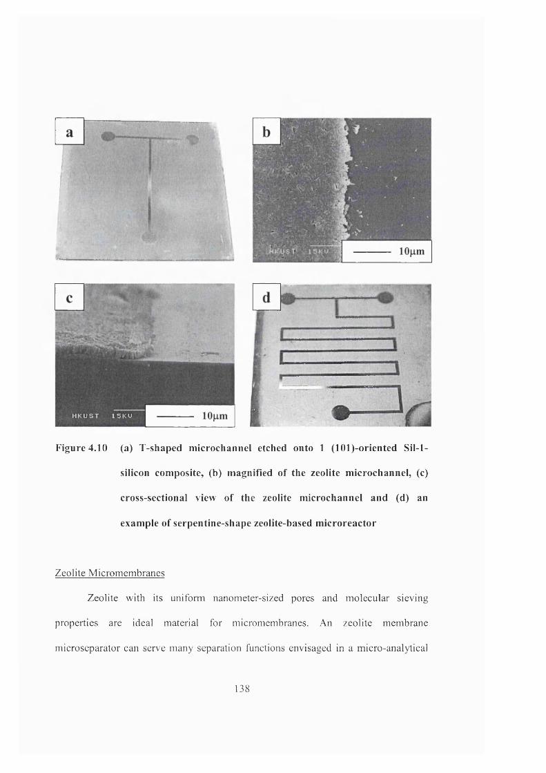
T
kZ' . ' # - '
HKUST 15KV
Figure 4.10 (a) T-shaped m icrochannel etched onto 1 (lO l)-oriented SiI-1-
silicon com posite, (b) magnified of the zeolite m icrochannel, (c)
cross-sectional view of the zeolite m icrochannel and (d) an
exam ple o f serpentine-shape zeolite-based m icroreactor
Zeolite Micromembranes
Zeolite with its uniform nanometer-sized pores and molecular sieving
properties are ideal material for micromembranes. An zeolite membrane
microseparator can serve many separation functions envisaged in a micro-analytical
138
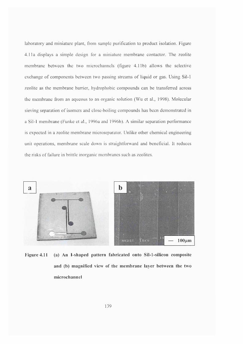
laboratory and miniature plant, from sample purification to product isolation. Figure
4.11a displays a simple design for a miniature membrane contactor. The zeolite
membrane between the two microchannels (figure 4.11b) allows the selective
exchange of components between two passing streams of liquid or gas. Using Sil-1
zeolite as the membrane barrier, hydrophobic compounds can be transferred across
the membrane from an aqueous to an organic solution (Wu et al., 1998). Molecular
sieving separation of isomers and close-boiling compounds has been demonstrated in
a Sil-1 membrane (Funke et ah, 1996a and 1996b). A similar separation performance
is expected in a zeolite membrane microseparator. Unlike other chemical engineering
unit operations, membrane scale down is straightforward and beneficial. It reduces
the risks of failure in brittle inorganic membranes such as zeolites.
a
— lOOum
Figure 4.11 (a) An I-shaped pattern fabricated onto S il-l-silicon composite
and (b) m agnified view of the m em brane layer between the two
m icrochannel
139
4 . 4 C o n c l u d i n g r e m a r k s
A new fabrication procedure for incorporating zeolite catalysts, membranes
and structural materials within the architecture of microchemical devices was
developed based on microelectronic fabrication and zeolite thin film technologies.
The ability to engineer and tailor the zeolite structure is essential for the incorporated
zeolites to effectively perform its various tasks. Zeolite films with preferred
orientation and engineered mierostructure were successfully grown on a silicon
substrate. Direct manipulation of the film mierostructure (i.e., thickness, orientation
etc.) was achieved by controlling the seed population, synthesis composition and
hydrothermal treatment conditions. High-resolution micropattems of complex
microchannel networks and geometry, as well as particle arrays as small as 3 pm,
were successfully fabricated from zeolite. These zeolite patterns survived prolonged
thermal treatment under harsh conditions (i.e., temperature oscillations between 303
to 873 K) demonstrating their excellent thermal stability. Design blueprints for the
incorporation of zeolites in microreactors and membrane microseparators were
illustrated. Working models were built using the new fabrication technique, and the
structural details of the microsystem architecture were examined. Studies are now
underway to test the performance of the zeolite-based microchemical devices for
chemical reactions and separations.
140

Chapter 5
Design and fabrication of zeolite-based microreactors
and membrane microseparators
141
5 . 1 I n t r o d u c t i o n
Microtechnology researchers envisage that desktop miniature factories and
micro-pharmacies can be developed through the advances in the fabrication of
micromixers, reactors and separators (Kawahara et al., 1997). Microreactors have the
advantages of better energy and material utilization, and result in more efficient chemical
production and less pollution. The large surface area-to-volume ratio that can be attained
in a microreactor enhances heat and mass transfer rates (Drost et al., 1997). Higher
chemical conversions were also obtained from such devices (Hardt et al., 2000). In
addition, the integration of microsensors and actuators enables rapid and precise control
of the reactor operation (Srinivasan et al., 1997). Other advantages include simpler
process optimization (Jensen, 2001), rapid design implementation (Ehrfeld et al., 2000),
easier scale-up through replication and better safety (Lerou and Ng, 1996; Jensen, 1999).
At the same time, separation processes can benefit from the large surface area-to-volume
ratio obtained in a microseparator. Chemical engineering separation processes, such as
extraction and membrane separation have been successfully miniaturized (TeGrotenhuis
et al., 1999; Turner et al., 2000a, 2000b).
In microreactors, an important task is to incorporate an active catalyst within the
microchannels. Metal catalysts (e.g., Pd, Ft, Ag) can be coated as a thin layer using
sputter coating, thermal deposition or chemical vapour deposition (Thomas and Thomas,
1997; Kursawe and Honicke, 2000). An alternative method is to form a porous oxide
layer by anodization, and impregnate it with a solution of the metal precursor (Wie^meier
142
and Honicke., 1996a and 1996b). However, deposition of zeolites requires a different
strategy. Zeolite films can be grown directly on microstructured supports by in-situ
synthesis. Free-standing silicalite-1 membranes have been grown onto silicon
microchannels (den Exter et al., 1997). ZSM-5 zeolite has also been grown on machined
stainless steel microchannels for selective catalytic reduction of NO with ammonia
(Rebrov et al., 2001).
Zeolites are important catalysts in many chemical and petrochemical processes,
such as production of fuels, pollution abatement and more recently, clean fine chemicals
production (Holderich and van Bekkum, 1991; Maxwell and Stork, 1991; van Bekkum et
al., 1994; Armor, 1999). The aluminum containing MFI zeolite, Al-ZSM-5 is an
important catalyst for many hydrogenation, disproportionation, isomerization and
alkylation reactions (Maxwell and Stork, 1991; Jacobs and Martens, 1991). It finds uses
in petroleum refining, petrochemical production and more recently, it is being considered
as an alternative catalyst for synthesis of fine chemicals (Feast and Lercher, 1996; van
Bekkum, 1998). Metal-exchanged ZSM-5 zeolites such as Cu-ZSM-5 are potential
environmental catalysts since they exhibit high activity for NOx reduction (Amiridis et
al., 1996). TS-1 zeolite is known to be an efficient catalyst for selective oxidation of
alcohols (Maspero and Romano, 1994), epoxidation of alkenes (Clerici et ah, 1991) and
hydroxylation of aromatics (van der Pol et ah, 1992)
Zeolites with their molecular sieving properties (Jansen et ah, 1994; Coronas and
Santamaria, 1999a) and tunable pore structure (Yan and Bein, 1995) are strong
143
candidates for membrane separation in miniature devices. Separation efficiency can be
increased by the large surface area-to-volume ratio that can be achieved in such
microsystems. High permselectivity has been observed in separation of azeotropic
mixtures (Sano et al., 1994), permanent gases (Kusakabe et al., 1998), close-boiling
hydrocarbon compounds (Funke et al., 1996a) and isomers (Funke et al., 1996b;
Xomeritakis et al., 1999) using zeolite membranes. The zeolite pores can host different
ions, atoms, molecules and clusters that can be used to modify its structural, chemical,
catalytic, separation, electronic and optical properties. Zeolite membranes can also be
utilized in membrane reactors. Their excellent permselectivity and molecular sieving
properties can benefit many reaction systems that are constrained by unfavorable
thermodynamics. Membrane reactors can exhibit better yield and higher selectivity than
fixed bed reactors (Armor, 1989; Hsieh, 1991; Zaman and Chakma, 1994; Saracoo and
Specchia, 1994). The ability of a membrane reactor to control the addition and mixing of
reactants and the selective removal of products result in better material utilization, less
waste and pollution, and safer operation. Other application includes miniature
electrochemical cells and sensors. In this case, zeolite films can act as membrane barriers
for creating microcompartments for storage of chemicals, catalysts and enzymes.
This chapter is to investigate the different designs and fabrication strategies for
zeolite catalytic microreactors and membrane microseparators. MFI-type zeolites
including silicalite-1 (Sil-1), aluminum ZSM-5 and titanium silicalite-1 (TS-1) were
incorporated into the microreactor design as a structural material, catalyst or membrane.
The mierostructure of these zeolites was manipulated in terms of thickness, orientation
144
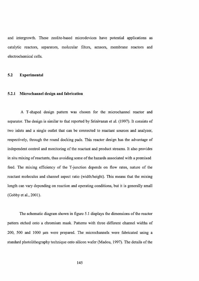
and intergrowth. These zeolite-based microdevices have potential applications as
catalytic reactors, separators, molecular filters, sensors, membrane reactors and
electrochemical cells.
5.2 Experimental
5.2.1 MicroChannel design and fabrication
A T-shaped design pattern was chosen for the microchannel reactor and
separator. The design is similar to that reported by Srinivasan et al. (1997). It consists of
two inlets and a single outlet that can be connected to reactant sources and analyzer,
respectively, through the round docking pads. This reactor design has the advantage of
independent control and monitoring of the reactant and product streams. It also provides
in situ mixing of reactants, thus avoiding some of the hazards associated with a premixed
feed. The mixing efficiency of the T-junction depends on flow rates, nature of the
reactant molecules and channel aspect ratio (width/height). This means that the mixing
length can vary depending on reaction and operating conditions, but it is generally small
(Gobby et al., 2001).
The schematic diagram shown in figure 5.1 displays the dimensions of the reactor
pattern etched onto a chromium mask. Patterns with three different channel widths of
200, 500 and 1000 pm were prepared. The microchannels were fabricated using a
standard photolithography technique onto silicon wafer (Madou, 1997). The details of the
145
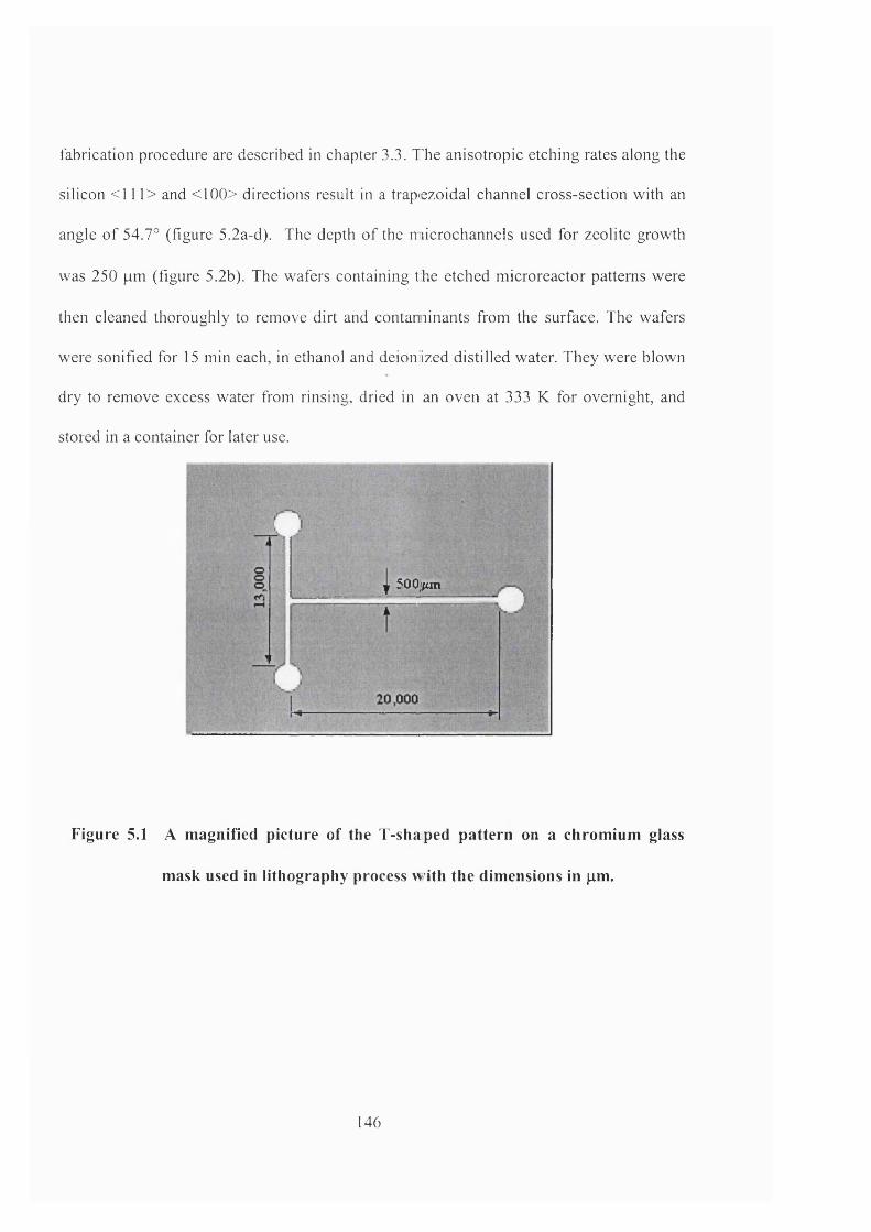
fabrication procedure are deseribed in chapter 3.3. The anisotropic etching rates along the
silicon <111> and <100> directions result in a trap'ezoidal channel cross-seetion with an
angle of 54.7° (figure 5.2a-d). The depth of the microchannels used for zeolite growth
was 250 pm (figure 5.2b). The wafers containing the etched microreactor patterns were
then cleaned thoroughly to remove dirt and contaminants from the surface. The wafers
were sonified for 15 min each, in ethanol and deioniized distilled water. They were blown
dry to remove excess water from rinsing, dried in an oven at 333 K for overnight, and
stored in a container for later use.
. j 500jfcm
Figure 5.1 A magnified picture of the T-shaped pattern on a chromium glass
mask used in lithography process with the dimensions in pm.
146
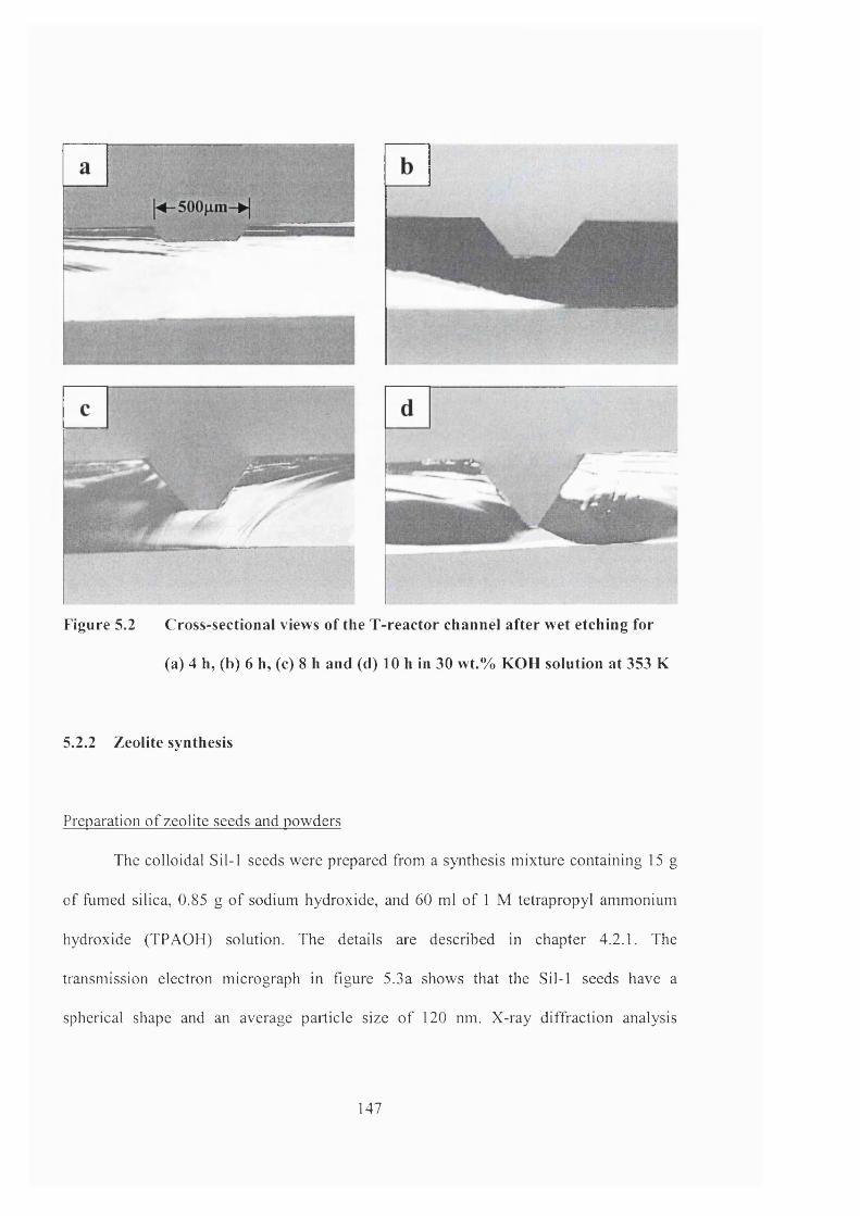
Figure 5.2 Cross-sectional views o f the T-reactor channel after wet etching for
(a) 4 h, (b) 6 h, (c) 8 h and (d) 10 h in 30 wt.% KOH solution at 353 K
5.2.2 Zeolite synthesis
Preparation of zeolite seeds and powders
The colloidal Sil-1 seeds were prepared from a synthesis mixture containing 15 g
of fumed silica, 0.85 g of sodium hydroxide, and 60 ml of 1 M tetrapropyl ammonium
hydroxide (TPAOH) solution. The details are described in chapter 4.2.1. The
transmission electron micrograph in figure 5.3a shows that the Sil-1 seeds have a
spherical shape and an average particle size of 120 nm. X-ray diffraction analysis
147
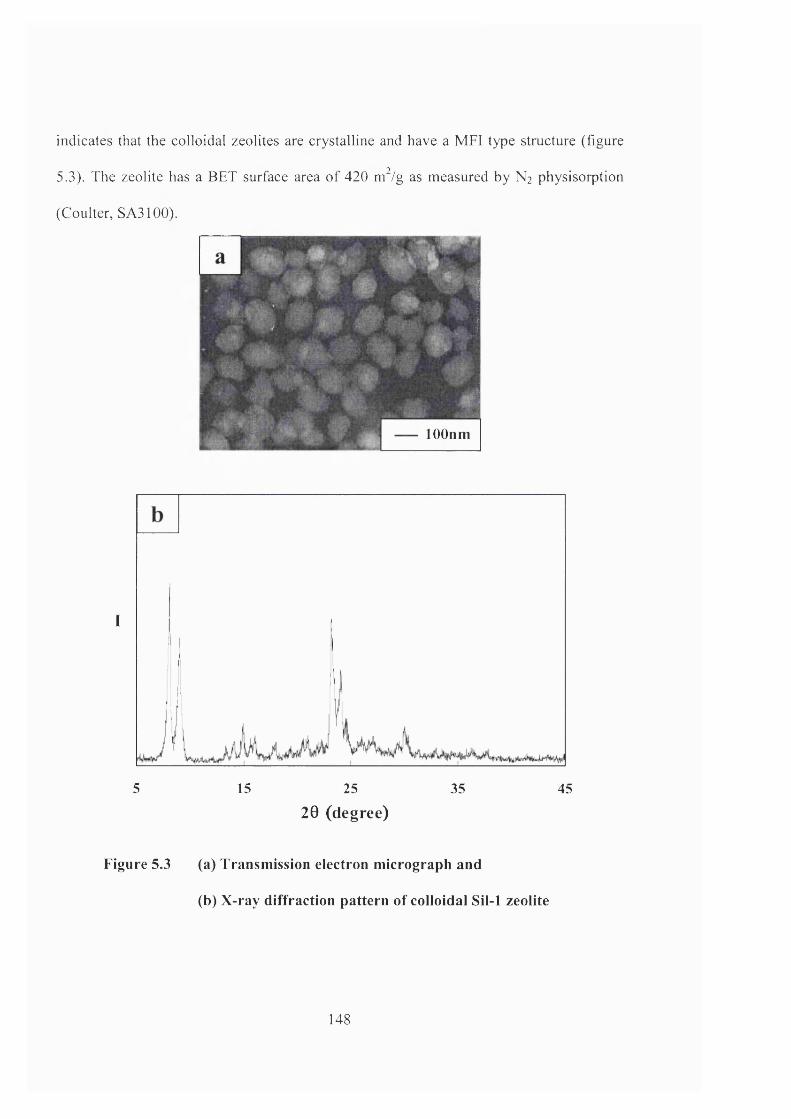
indicates that the colloidal zeolites are crystalline and have a MFI type structure (figure
5.3). The zeolite has a BET surface area of 420 m^/g as measured by N] physisorption
(Coulter, SA3100).
lOOnm
I
5 15 25 35 45
20 (degree)
Figure 5.3 (a) Transm ission electron m icrograph and
(b) X-ray diffraction pattern o f colloidal Sil-1 zeolite
148
A similar preparation procedure was used for making colloidal Al-ZSM-5 and
TS-1 zeolite seeds. The synthesis solution for colloidal Al-ZSM-5 contained lOSiO]:
0.2A100H: 2.4TPAOH: INaOH: IIOH2O. The 120 nm Al-ZSM-5 zeolites (XPS Si/Al =
18, BET surface area = 400 m^/g) were obtained after 8 h of hydrothermal treatment at
398 K. The 120 nm TS-1 was prepared from a solution with the composition of 20TEOS:
0.75TEOT: 9TPA0H: 4 0 4 H2O. Chemical analyses using EDXS, XPS and micro-Raman
indicated that the colloidal TS-1 has a spatially uniform Si/Ti content of 20, with most of
the Ti ions incorporated within the zeolite framework. The BET surface area of the TS-1
seeds (425 m^/g) is comparable to that of Sil-1 and Al-ZSM-5. The Sil-1, Al-ZSM-5, TS-
1 seeds were stored as 2 wt.% colloidal suspension in ethanol.
NaZSM-5 powder was used for zeolite incorporation within the reactor
microchannel. It was prepared by pre-seeding a synthesis solution containing 40SiO2
:0.8A100H: 0.4NaOH: lOTPAOH: 20,000H2O with 20 mg of colloidal zeolite seeds.
After hydrothermal treatment at 398 K and 48 h, NaZSM-5 powders with a uniform
crystal size of 0.5 pm and a Si/Al ratio of 16 (i.e., XPS analysis) were obtained.
5.2.3 Fabrication of zeolite-based microreactors
Four methods were examined for preparing zeolite-based microreactors. The first
three methods were based on incorporating zeolites onto prefabricated microchannels
149
(figure 5.4a-c), while in Method 4, the microchannel was fabricated onto a zeolite-silicon
composite wafer (figure 5.4d).
Method 1 Zeolite powder coating
The zeolite powder coating method simply deposits the zeolite powder onto the
microreactor channel (figure 5.4a). The zeolite was suspended in liquid and introduced
into the microreactor channel using a micropipette. A light sonification ensures that the
channel is evenly filled with zeolite slurry. The microreactor was subsequently dried at
333 K and calcined in air at 823 K. The amount of zeolite added was determined from the
weight gain measured after the calcination. The desired zeolite loading was obtained by
repeated coating with the zeolite slurry.
Method 2 Uniform zeolite film growth
Uniform zeolite film growth has been obtained by den Exter et al. (1997) and
Schoeman et al. (1997) on plain and seeded silicon wafers, respectively. Figure 5.4b
illustrates the procedure used for zeolite growth onto prestructured silicon wafer. The
zeolite was grown onto the silicon wafer by immersing it in zeolite synthesis solution,
either immediately after the fabrication of the microreactor pattern or following pre-
150
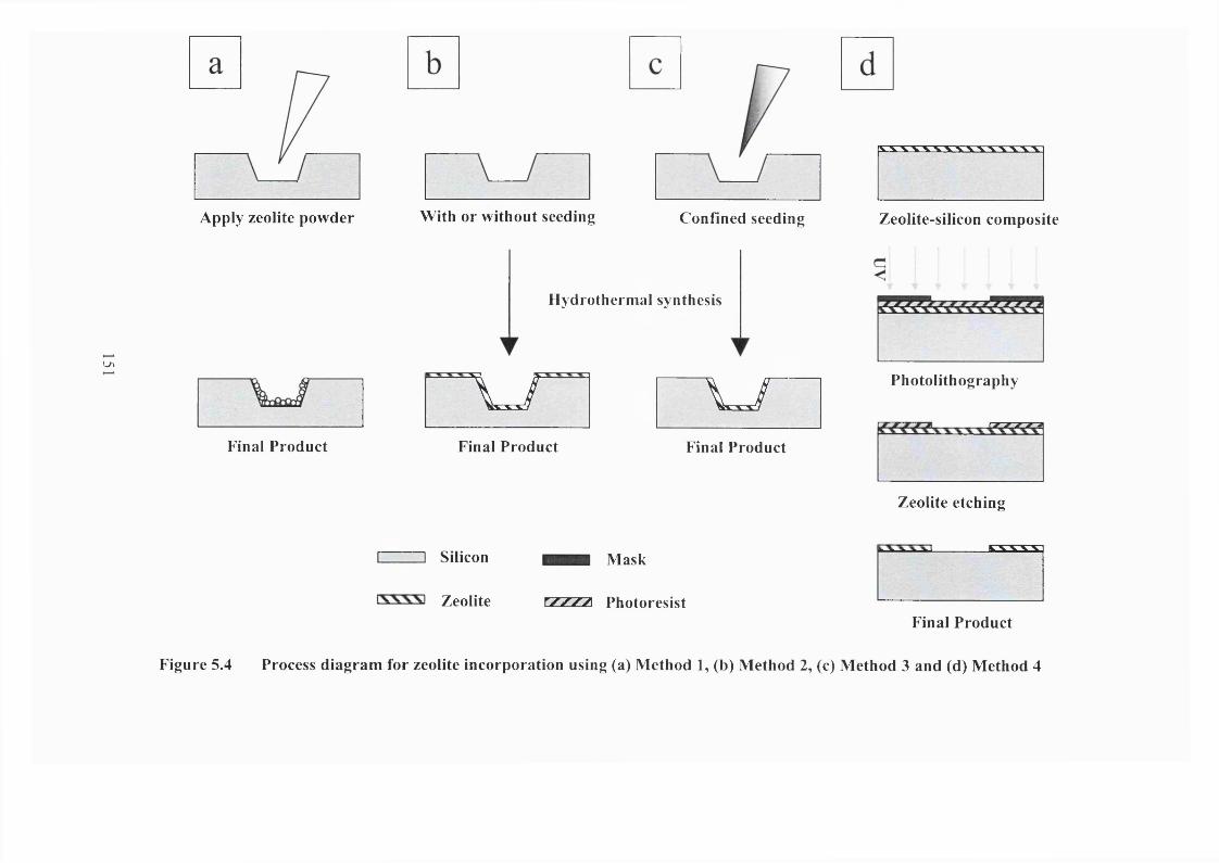
LA
Apply zeolite powder
Final Product
With or without seeding Confined seeding
Hydrothermal synthesis
\ J \ j -
Final Product Final Product
Zeolite-silicon composite
Photolithography
Zeolite etching
I I Silicon Mask
Zeolite xjL/:zy\ PhotoresistFinal Product
Figure 5.4 Process diagram for zeolite incorporation using (a) Method 1, (b) Method 2, (c) Method 3 and (d) Method 4
seeding with colloidal zeolites. The latter entailed functionalization of the silicon wafer
with mercapto-3-propyltrimethoxysilane (50 mM in ethanol), followed by immersion in
colloidal suspension of zeolite seeds and finally drying at 333 K. The seeding procedure
was repeated three times to obtain the desired seed population of (5x10^^ seeds/m^). The
seeds were then calcined in air at 823 K for 6 h, prior to the hydrothermal growth of the
zeolite layer.
Sil-1 film was grown from solution with the composition of 40TEOS: lOTPAOH:
20,OOOH20 prepared by adding 1.65 ml of tetraethyl orthosilicate (TEOS) drop-by-drop
to 70.4 ml of 0.027 M TPAOH solution. The mixture was stirred at room temperature for
24 h to produce a clear and homogeneous solution. Aluminum, titanium and other metal
ions can be added to impart the zeolite with the desired catalytic activity. The wafer
containing the etched microreactor pattern was then placed in a Teflon holder such that
the pattern was facing downwards. This was to prevent powders and precipitates from
being incorporated into the growing zeolite film. The wafer can also be placed vertically
in the Teflon holder. The sample and solution were transferred into a 125 ml Teflon
vessel and sealed within a stainless steel sleeve. The autoclave was placed in a preheated
oven (T = 398 K) and allowed to react for 24 h. At this temperature, the solution
generates an autogenous pressure of about 230 kPa. It was ensured that the liquid level
was always more than 5 mm above the sample surface. After the hydrothermal treatment,
the reaction was quenched to room temperature, and the silicon sample was rinsed with
deionized distilled water and dried overnight at an oven temperature of 333 K.
152
Method 3 Localized zeolite growth
Localized zeolite growth was achieved through selective seeding. In order to
confine zeolite growth only within the microchannel, the microchannel was first
functionalized with mercapto-3-propyltrimethoxysilane and then seeded with colloidal
zeolite using a micropipette (figure 5.4c). In some experiments, the microchannel was
seeded more than once to obtain the desired seed population. The wafer was calcined in
air at 823 K for 6 h. Sil-1 was then grown in the microchannel following the same
hydrothermal synthesis procedure described in Method 2. Al-ZSM-5 and TS-1 zeolites
were also deposited within the microchannel. For the former, colloidal Al-ZSM-5 was
used for seeding the microchannel and the Al- ZSM-5 layer was grown from a
hydrothermal synthesis solution containing 40TEOS: 4A100H: lOTPAOH: 4NaOH:
20,OOOH20 at a temperature of 398 K and for 24 h. TS-1 zeolite was grown within the
confines of the microchannel by preseeding with colloidal TS-1 followed by
hydrothermal treatment in a solution with a composition of 40TEOS: 1.6TE0T:
lOTPAOH: 10,000H2O at 448 K and 24 h.
Method 4 Etching of zeolite-silicon composite
Etching of zeolite-silicon composite wafer is an alternative method for fabricating
zeolite-based microreactors. A uniform layer of zeolite film was first grown onto a 4-in.
diameter silicon wafer using hydrothermal synthesis method. 1-20 pm thick MFl-type
zeolite films with (101) and (200) orientations had been prepared. The details of their
synthesis were discussed in chapter 4. In this study, a 5 pm thick, highly oriented (101)
Sil-1 on silicon composite wafer was used as the substrate material for the T-
153
microreactor. A 3 fim layer of HPR-207 photoresist was coated onto the 4-in. composite
wafer, and the T-reactor pattern was transferred onto the wafer using standard
photolithography (figure 5.4d). The reactor channel was then etched by BOB solution
(1HF:6NH4F, Olin) and the remaining photoresist was stripped using acetone (Lab-scan).
5.2.4 Fabrication of zeolite membrane microseparators
The membrane microseparator consists of a T-shaped channel on the front and a
rectangular recess at the back. The fabrication procedure used is illustrated in figure 5.5.
Using standard microfabrication technology, the T-microchannel and the rectangular
recess were etched onto the silicon wafer (figure 5.5, steps A-E). The etching rate and
time were used to control the depths of the microchannel and the recess. Etching was
allowed to continue until less than 50 pm of silicon separates the microchannel and the
recess. The Sil-1 membrane was then deposited onto the microcharmel (figure 5.5, steps F
and G) following seeding with colloidal Sil-1 and hydrothermal treatment in a synthesis
solution containing 40TEOS: lOTPAOH: 20,000H2O. The remaining 50 pm thick silicon
was then etched using TMAOH solution to expose the zeolite membrane.
154
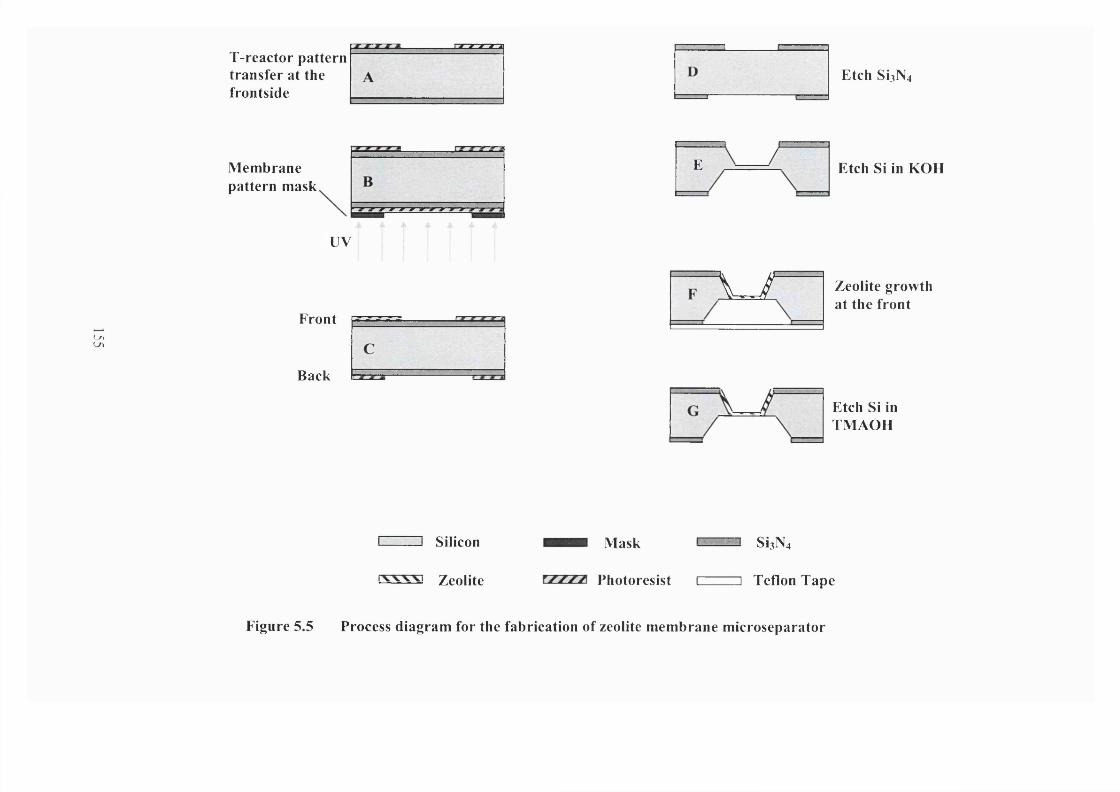
( /ILA
ï-reacto r pattern transfer at the frontside
Membrane pattern mask
UV
Front
Back
E
\ - /
E t c h S I 3 N 4
Etch Si in KOH
Zeolite growth at the front
Etch Si in TMAOH
Silicon
Zeolite
Mask
Photoresist
SiaN4
] Teflon Tape
Figure 5.5 Process diagram for the fabrication of zeolite membrane microseparator
5.2.5 Characterization
The fabricated units were analyzed by optical microscopy (Olympus BH-2) and
scanning electron microscopy (SEM, JEOL JSM 6300) before and after the incorporation
of the zeolites. The optical microscope was used mainly for quality control at each stage
of the fabrication. The SEM was employed to determine the exact shape and dimensions
of the microcbannels, and to measure the thickness of the zeolite layer deposited onto the
channel. The zeolite crystal size, shape and intergrowth were also determined from
analysis of the SEM micrographs. The structure, crystallinity and orientation of the
deposited zeolites were analyzed by an X-ray diffractometer (XRD, Philips PW 1030).
Bulk and surface compositions of the incorporated zeolites were examined by energy
dispersive X-ray spectroscopy (EDXS, Philips PW 1830) and X-ray photoelectron
spectroscopy (XPS, Physical Electronics PHI 5600).
5.2.6 Materials
Potassium hydroxide (85%, BDH Lab.), tétraméthylammonium hydroxide (25%
Moses Lake Ind.) and phosphoric acid (85%, Olin) were used to wet-etch the miniature
reactor and membrane patterns onto the silicon wafer and to strip the protective silicon
nitride layer. Ethanol (99.9%, Fisher) was used in degreasing and cleaning the wafer at
various stages of the device fabrication and zeolite incorporation. Mercapto-3-
propyltrimethoxysilane (99%, Aldrich) was employed in grafting the zeolite seeds onto
the microchannels. For the zeolite synthesis, the chemicals used were fumed silica (0.01
156
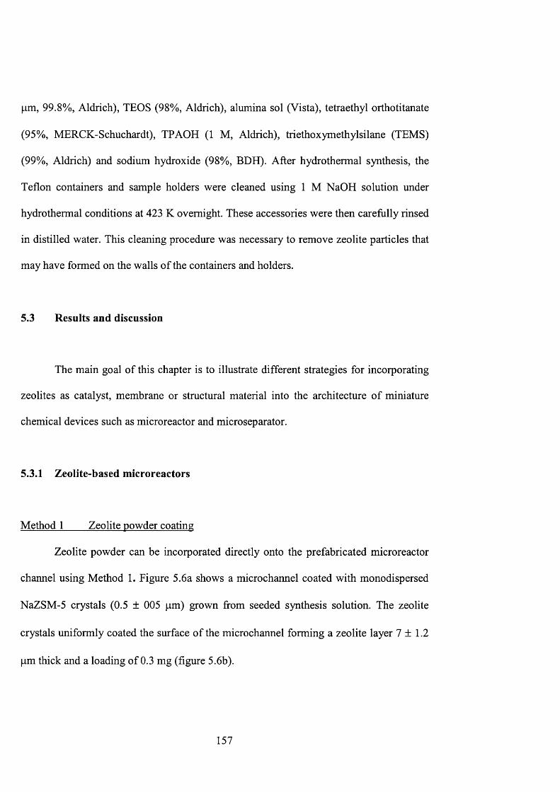
p,m, 99.8%, Aldrich), TEOS (98%, Aldrich), alumina sol (Vista), tetraethyl orthotitanate
(95%, MERCK-Schuchardt), TPAOH (1 M, Aldrich), triethoxymethylsilane (TEMS)
(99%, Aldrich) and sodium hydroxide (98%, BDH). After hydrothermal synthesis, the
Teflon containers and sample holders were cleaned using 1 M NaOH solution under
hydrothermal conditions at 423 K overnight. These accessories were then carefully rinsed
in distilled water. This cleaning procedure was necessary to remove zeolite particles that
may have formed on the walls of the containers and holders.
5.3 Results and discussion
The main goal of this chapter is to illustrate different strategies for incorporating
zeolites as catalyst, membrane or structural material into the architecture of miniature
chemical devices such as microreactor and microseparator.
5.3.1 Zeolite-based microreactors
Method 1 Zeolite powder coating
Zeolite powder can be incorporated directly onto the prefabricated microreactor
channel using Method 1. Figure 5.6a shows a microchannel coated with monodispersed
NaZSM-5 crystals (0.5 ± 005 pm) grown from seeded synthesis solution. The zeolite
crystals uniformly coated the surface of the microchannel forming a zeolite layer 7 ± 1.2
pm thick and a loading of 0.3 mg (figure 5.6b).
157
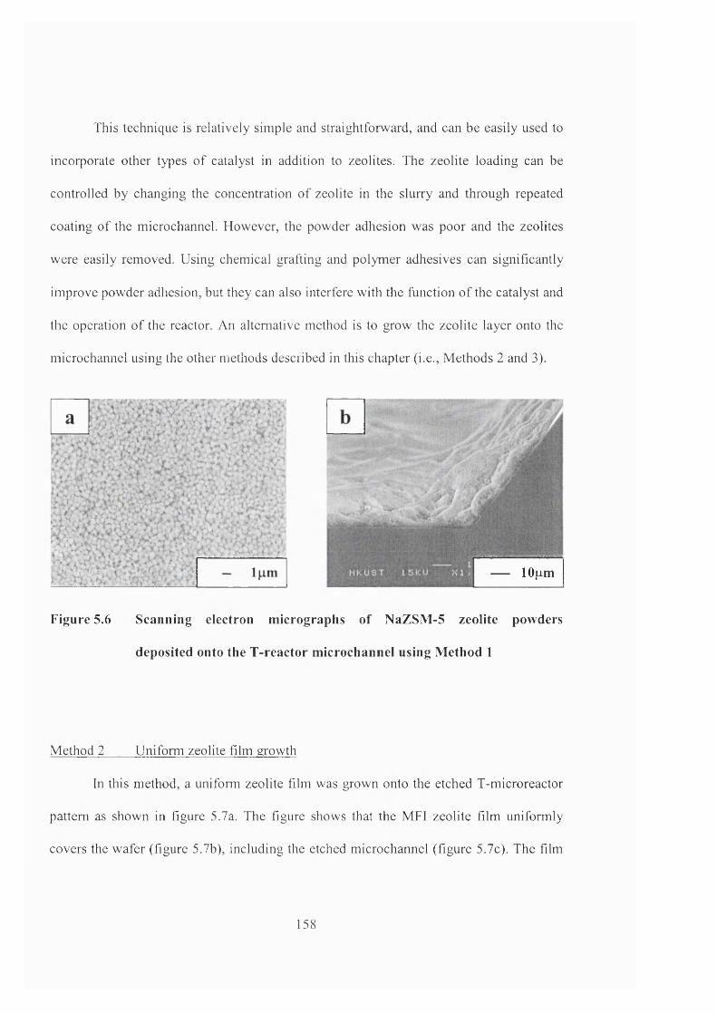
This technique is relatively simple and straightforward, and can be easily used to
incorporate other types o f catalyst in addition to zeolites. The zeolite loading can be
controlled by changing the concentration o f zeolite in the slurry and through repeated
coating o f the microchannel. However, the powder adhesion was poor and the zeolites
were easily removed. Using chemical grafting and polymer adhesives can significantly
improve powder adhesion, but they can also interfere with the function o f the catalyst and
the operation o f the reactor. An alternative method is to grow the zeolite layer onto the
microchannel using the other methods described in this chapter (i.e.. Methods 2 and 3).
.
lOum
Figure 5.6 Scanning electron micrographs of NaZSM-5 zeolite powders
deposited onto the T-reactor microchannel using Method 1
Method 2 Uniform zeolite film growth
In this method, a uniform zeolite film was grown onto the etched T-microreactor
pattern as shown in figure 5.7a. The figure shows that the MFI zeolite film uniformly
covers the wafer (figure 5.7b), including the etched microchannel (figure 5.7c). The film
158
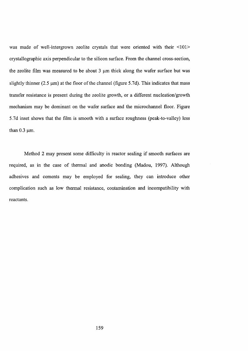
was made of well-intergrown zeolite crystals that were oriented with their <101>
crystallographic axis perpendicular to the silicon surface. From the channel cross-section,
the zeolite film was measured to be about 3 pm thick along the wafer surface but was
slightly thinner (2.5 pm) at the floor of the channel (figure 5.7d). This indicates that mass
transfer resistance is present during the zeolite growth, or a different nucleation/growth
mechanism may be dominant on the wafer surface and the microchannel floor. Figure
5.7d inset shows that the film is smooth with a surface roughness (peak-to-valley) less
than 0.3 pm.
Method 2 may present some difficulty in reactor sealing if smooth surfaces are
required, as in the case of thermal and anodic bonding (Madou, 1997). Although
adhesives and cements may be employed for sealing, they can introduce other
complication such as low thermal resistance, contamination and incompatibility with
reactants.
159
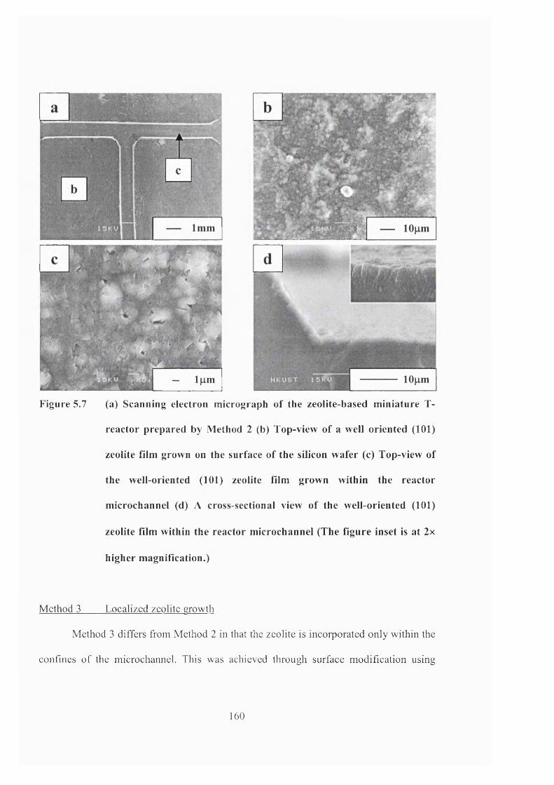
a
Figure 5.7 (a) Scanning electron micrograph of the zeolite-based miniature T-
reactor prepared by Method 2 (b) Top-view of a well oriented (101)
zeolite film grown on the surface of the silicon wafer (c) Top-view of
the well-oriented (101) zeolite film grown within the reactor
microchannel (d) A cross-sectional view of the well-oriented (101)
zeolite film within the reactor microchannel (The figure inset is at 2x
higher magnification.)
Method 3 Localized zeolite growth
Method 3 differs from Method 2 in that the zeolite is incorporated only within the
confines o f the microchannel. This was achieved through surface modification using
160
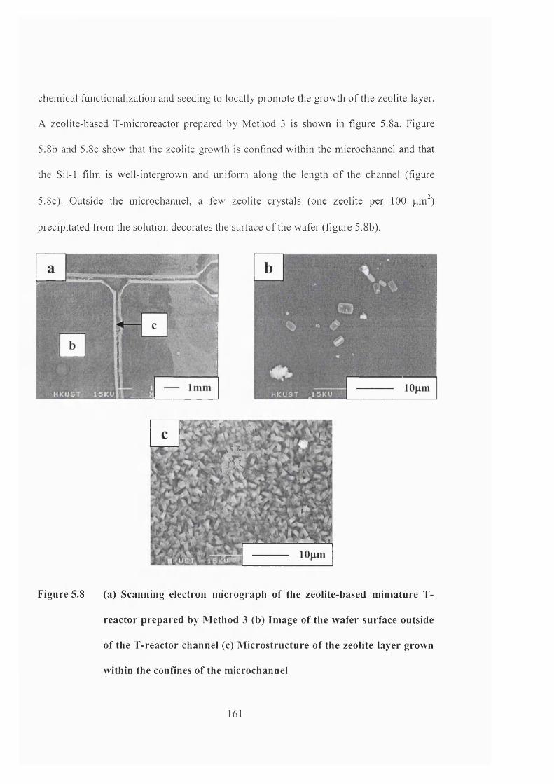
chemical functionalization and seeding to locally promote the growth o f the zeolite layer.
A zeolite-based T-micro reactor prepared by Method 3 is shown in figure 5.8a. Figure
5.8b and 5.8c show that the zeolite growth is confined within the microchannel and that
the Sil-1 film is well-intergrown and uni to mi along the length o f the channel (figure
5.8c). Outside the microchannel, a few zeolite crystals (one zeolite per 100 pm^)
precipitated from the solution decorates the surface o f the wafer (figure 5.8b).
1
Figure 5.8 (a) Scanning electron m icrograph o f the zeolite-based m iniature T-
reactor prepared by M ethod 3 (b) Im age o f the w afer surface outside
of the T-reactor channel (c) M icrostructure o f the zeolite layer grown
within the confines o f the m icrochannel
161
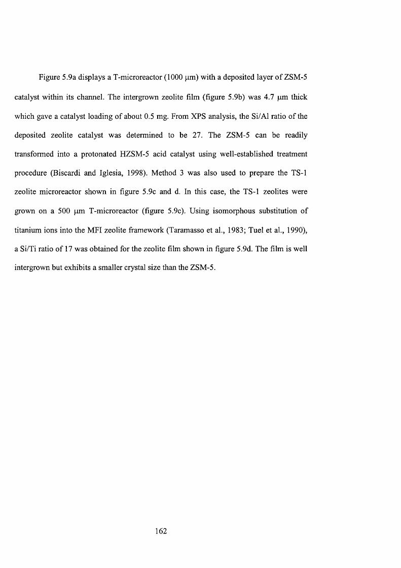
Figure 5.9a displays a T-microreactor (1000 pm) with a deposited layer of ZSM-5
catalyst within its channel. The intergrown zeolite film (figure 5.9b) was 4.7 pm thick
which gave a catalyst loading of about 0.5 mg. From XPS analysis, the Si/Al ratio of the
deposited zeolite catalyst was determined to be 27. The ZSM-5 can be readily
transformed into a protonated HZSM-5 acid catalyst using well-established treatment
procedure (Biscardi and Iglesia, 1998). Method 3 was also used to prepare the TS-1
zeolite microreactor shown in figure 5.9c and d. In this case, the TS-1 zeolites were
grown on a 500 pm T-microreactor (figure 5.9c). Using isomorphous substitution of
titanium ions into the MFI zeolite framework (Taramasso et al., 1983; Tuel et al., 1990),
a Si/Ti ratio of 17 was obtained for the zeolite film shown in figure 5.9d. The film is well
intergrown but exhibits a smaller crystal size than the ZSM-5.
162
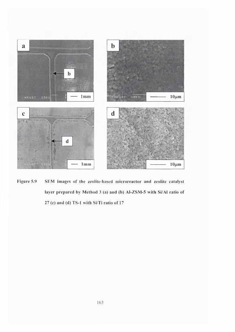
iîÈùtà-è
m#:l1mm
Ik
Imm
BTW
h.
Figure 5.9 SEM images of the zeolite-based microreactor and zeolite catalyst
layer prepared by Method 3 (a) and (b) Al-ZSM-5 with Si/Al ratio of
27 (c) and (d) TS-1 with Si/Ti ratio of 17
163

Method 4 Etching of zeolite-silicon composite wafer
In Method 4, the T-reactor pattern was etched onto a highly oriented (101) zeolite
film grown onto 4-in. silicon wafer (figure 5.10a). This zeolite-silicon composite wafer
was obtained by seeding the wafer five times with colloidal zeolites followed by 48 h
hydrothermal synthesis at 398 K in a solution containing 40TEOS: lOTPAOH:
20,OOOH20. a clean pattern was obtained (figure 5.10a and 5.10b) where the 5 pim thick
interlocking Sil-1 crystals form the wall that defines the reactor channel (figure 5.10c).
The good precision that can be attained using this method is apparent in figure 5.10b. The
channel was etched all the way through the zeolite layer to expose the silicon underneath
which forms the floor of the channel (figure 5.10d). There are several advantages in using
this fabrication methodology. Microfabricated catalysts can also be realized using this
method. Here, the shape, morphology, quantity and individual locations of the zeolite
catalysts can be precisely engineered to optimize the microreactor performance.
Miniature electrochemical cells and sensors, in which membrane barriers are an integral
part of the design, can also be made using this procedure. The details are illustrated in
chapter 4.
164
m
mm
M B E#m
lOOum
%
Figure 5.10 (a) Scanning electron micrograph of the zeolite-based miniature T-
reactor prepared by Method 4 (b) Top-view of the reactor
microchannel etched through the zeolite film layer (c) Microstructure
of the deposited zeolite film layer that made up the wall of the reactor
channel (d) Microstructure of the etched silicon wafer, which formed
the base of the microchannel
5.3.2 Zeolite membrane microseparator
For commercial application, a large membrane area is usually needed to provide
the required separation or production throughput. However, the scale-up o f zeolite
165
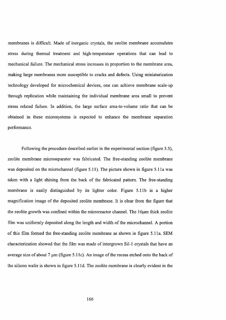
membranes is difficult. Made of inorganic crystals, the zeolite membrane accumulates
stress during thermal treatment and high-temperature operations that can lead to
mechanical failure. The mechanical stress increases in proportion to the membrane area,
making large membranes more susceptible to cracks and defects. Using miniaturization
technology developed for microchemical devices, one can achieve membrane scale-up
through replication while maintaining the individual membrane area small to prevent
stress related failure. In addition, the large surface area-to-volume ratio that can be
obtained in these microsystems is expected to enhance the membrane separation
performance.
Following the procedure described earlier in the experimental section (figure 5.5),
zeolite membrane micro separator was fabricated. The free-standing zeolite membrane
was deposited on the microchannel (figure 5.11). The picture shown in figure 5.11a was
taken with a light shining from the back of the fabricated pattern. The free-standing
membrane is easily distinguished by its lighter color. Figure 5.11b is a higher
magnification image of the deposited zeolite membrane. It is clear from the figure that
the zeolite growth was confined within the microreactor channel. The 16pm thick zeolite
film was uniformly deposited along the length and width of the microchannel. A portion
of this film formed the free-standing zeolite membrane as shown in figure 5.11a. SEM
characterization showed that the film was made of intergrown Sil-1 crystals that have an
average size of about 7 pm (figure 5.11c). An image of the recess etched onto the back of
the silicon wafer is shown in figure 5.1 Id. The zeolite membrane is clearly evident in the
166
figure. It has dimensions o f 0.7 x 4.8 mm as defined by the width o f the microchannel
and the length o f the recess.
; ) R
'Y l 'î' .1 1
1 Uu^lll
Figure 5.11 (a) A SEM picture of the T-microchannel coated with a layer of Sil-1
membrane (the light rectangular area is the free-standing zeolite
membrane) (b) A higher magnification image showing that the zeolite
membrane was confined within the microchannel (c) A higher
magnification image of the zeolite membrane grown within the T-
reactor channel (d) A picture of the recess fabricated at the back of
wafer with the exposed zeolite membrane
167
5 . 4 C o n c l u d i n g r e m a r k s
The ability to engineer the zeolite film micro structure and tailor its chemical and
catalytic properties is important for the successful incorporation of zeolites as catalyst,
membrane or structural materials in microchemical devices that include microreactors
and microseparators. Different fabrication strategies were adopted to incorporate zeolites
as powder catalysts (Method 1) or film within the reactor microchannel (Method 3).
Alternatively, a uniform zeolite film was deposited onto a prefabricated silicon wafer
(Method 2) or plain silicon to form a zeolite-silicon composite onto which the reactor
pattern was etched using traditional semiconductor fabrication techniques (Method 4).
Using these methods, Sil-1, ZSM-5 and TS-1 zeolites were successfully integrated into
microreactors either as catalyst or part of the reactor’s architecture. A zeolite membrane
microseparator was made using this new fabrication technology. The zeolite membrane
layer was deposited within a T-microchannel. This design promises many potential
applications as membrane devices, membrane microreactors, electrochemical cells and
sensors. Studies are now underway to test the performance of zeolite catalytic
microreactors and membrane microseparators for chemical reactions and separations.
168
Chapter 6
1-Pentene Epoxidation in Titanium Silicalite-1
MicroChannel Reactor:
Experiments and Modelling
169

6 . 1 I n t r o d u c t i o n
There is a growing interest in the use of zeolite and molecular sieve materials
as active components of miniature chemical devices such as chemical sensors,
microreactors, microseparators and lab-on-a-Chip devices. Zeolite catalysts have been
used in microreactors for catalytic reduction of NO with ammonia (Rebrov et al.,
2001), alkene epoxidation (Wan et al., 2002) and Knoevenagel condensation of
benzaldehyde and ethyl cyanoacetate (Lai et al., 2003). Zeolite micromembranes
exhibit excellent permselectivity for gases and hydrocarbon vapors (Chau et al.,
2003a). Zeolite micromembranes display excellent proton flux while selectively
rejecting methanol, making it an attractive material for the construction of a micro
fuel cell device (Chau et al., 2002a). Robertson (2001) employed zeolite adsorbents in
a miniature column for gas separation. Further studies of zeolite as structural material
in microsystem architecture have been reported (Wan et al., 2001, Chau et al., 2002b,
Chau et al., 2003b, Chau and Yeung 2002).
Zeolites can be deposited and grown on silicon and glass substrates by
hydrothermal synthesis method. Jansen and Rosmalen (1993) were among the first to
describe the growth of continuous zeolite film on silicon wafer. Schoeman et al.
(1997) reported an improved method to synthesize ultra-thin silicalite-1 films on a
silicon wafer, den Exter and coworkers (1997) prepared a freestanding silicalite-1
(Sil-1) membrane from the deposited Sil-1 film by selective etching of the silicon
170
substrate. It was demonstrated that Sil-1 films of different orientations and surface
morphologies can be grown on silicon by controlled seeding (Hedlund et ah, 1999;
Lai et al. 2002). This method afforded a convenient way for manipulating the
deposited zeolite film micro structure. Several strategies for incorporating zeolites in
chemical microsystems have been described in chapter 5.
Microreactors are becoming a crucial component in lab-on-a-chip
microdevices (Greenway et ah, 2000, Jakeway et ah, 2000; Jensen, 2001, Mitchell et
ah, 2001). Well-defined flow characteristics, rapid transport properties, high
precision, spatial and temporal control over temperature, mixing and residence time
provide ideal conditions for studying reaction mechanisms and kinetics (Gavriilidis et
ah, 2002). Microreactors can be operated under conditions that cannot be easily
attained in a conventional reactor system, providing much-needed kinetic information
in these operating regions (Worz et ah, 2001). Computational modelling and
simulation are important tools for the design of microreactor systems (Quiram et ah,
2000). Microfluidic calculations provide invaluable information on fluid flow,
component mixing and mechanical friction and stress that are important in designing
the architectural blueprint of the microreactor (Commenge et ah, 2002). Detailed
simulation and modelling studies conducted by various researchers have provided
important insights to the reaction behaviour in the microsystem environment (Hsing
et ah, 2000; Rebrov et ah, 2002).
171
Titanium silicalite-1 (TS-1) prepared by isomorphous substitution of titanium
ions into the MFI zeolite framework, is an excellent selective oxidation catalyst
(Notari, 1996; Clerici et a l, 1991, 1993). TS-1 can catalyse many reactions including
the conversion of alkenes to epoxides (Clerici and Ingallina, 1993; Langhendries et
a l, 1999; Schmidt et a l, 2000), alcohols to aldehydes (Maspero and Romano, 1994),
alkanes to secondary alcohols and ketones (Ingallina et a l, 1995), phenol to
hydroquinone and catechol (Atoguchi and Yao, 2001) and amines to hydroxylamines
(Gontier and Tuel, 1994) using hydrogen peroxide under mild reaction conditions.
Such catalyzed processes are environmentally friendly, as the oxidant, aqueous
hydrogen peroxide will turn into water whereas the reactions show very high product
yields and selectivity.
Exothermic oxidation reactions can benefit from the use of microreactors due
to their excellent heat transfer properties. Deubel et al. (2000) has reported that olefin
epoxidation is a highly exothermic process (e.g. bond dissociation energy of C2H2 is -
5.2kcal/mol). By confining the explosive and hazardous chemicals within small units,
the risk of dealing with strong oxidizing agent like hydrogen peroxide can be
minimized.
In this chapter, a detailed study of titanium silicalite-1 microreactor for 1-
pentene epoxidation was performed. A novel procedure for the fabrication of a TS-1
microreactor was described where the TS-1 catalysts were confined within the
microchannel only. The influence of zeolite structure and chemistry for TS-1 catalysts
172
was studied by varying the synthesis conditions. A simple reactor model for
predicting the behaviour of 1-pentene epoxidation in a titanium silicalite-1 (TS-1)-
coated, single-channel microreactor was also presented. The kinetic data for the
model were obtained from a separate batch experiment, while the transport data were
taken from literature. The influence of reactor geometry, catalyst properties and
reaction conditions were evaluated and the results compared with experimental data.
It was found that crystal size and titanium incorporation into the zeolite framework
exerted a great effect on the catalyst performance. The information provided by the
model suggests several ways of improving microreactor performance. Catalyst
reactivity was investigated over time to examine catalyst deactivation observed in TS-
1.
6.2 Experimental
6.2.1 Zeolite catalyst incorporation in microchannel reactor
The reaction occurs along a 20 mm long catalyst-coated channel.
Microreactors with a channel width of 500 pm were prepared by anisotropic etching
using KOH solution (30wt%). Precise and localized addition of zeolite materials was
obtained using the techniques of chapter 3.4.1. Zeolite growth was confined within
the wall of the main channel by selective seeding with TS-1 zeolite nanocrystals. This
was accomplished by grafting mercapto-3-propyltrimethoxysilane onto the freshly
etched microchannel to provide better adhesion for zeolite seeds. A colloidal
173
suspension of zeolite nanocrystals was then added, depositing a layer of seeds onto
the functionalized surface of the microchannel. The seeded sample was dried in oven
at 333 K overnight before calcining in air at 923 K for 6 h.
The colloidal TS-1 seeds were prepared from a clear synthesis solution
containing 20 tetraethyl orthosilicate (TEOS): 0.75 tetraethyl orthotitanate (TEOT): 9
tetrapropylammonium hydroxide (TPAOH): 404 H2O (mole ratio) at 398 K for 50 h.
The zeolite seeds were recovered by a series of washing and separation steps to obtain
a stable, 2 wt.% colloidal suspension in ethanol. X-ray diffraction confirms that the
seeds were MFI-type, TS-1 zeolite. An average particle size of lOOnm was
determined by scanning electron microscopy (SEM, JEOL JSM 6300). Chemical
analyses by X-ray photoelectron spectroscopy (XPS, Physical Electronics PHI 5600),
energy dispersive X-ray spectroscopy (EDXS, Oxford Instruments) and micro-Raman
(Renishaw 3000) indicated that the colloidal TS-1 has a spatially uniform Si/Ti
content of 20, with most of the titanium atoms incorporated within the zeolite
framework. A BET surface area of 425 m^/g was measured by N2 physisorption
(Coulter, SA3100).
The calcination step removed the organic template molecule (i.e., TPA^) from
the deposited TS-1 seeds. It also sintered the seeds into a stable layer and improved
their adhesion on the channel wall. A layer of TS-1 catalyst was grown onto the
seeded channel from a hydrothermal synthesis solution containing silicon and
titanium precursors, as well as the TPA^ organic template. The synthesis composition
174
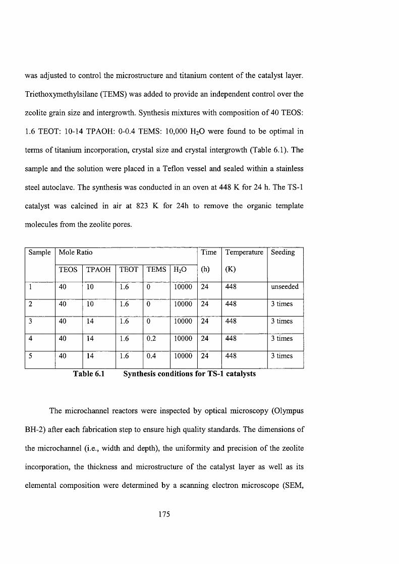
was adjusted to control the micro structure and titanium content of the catalyst layer.
Triethoxymethylsilane (TEMS) was added to provide an independent control over the
zeolite grain size and intergrowth. Synthesis mixtures with composition of 40 TEOS:
1.6 TEOT: 10-14 TPAOH; 0-0.4 TEMS: 10,000 H2O were found to be optimal in
terms of titanium incorporation, crystal size and crystal intergrowth (Table 6.1). The
sample and the solution were placed in a Teflon vessel and sealed within a stainless
steel autoclave. The synthesis was conducted in an oven at 448 K for 24 h. The TS-1
catalyst was calcined in air at 823 K for 24h to remove the organic template
molecules from the zeolite pores.
Sample Mole Ratio Time
(h)
Temperature
(K)
Seeding
TEOS TPAOH TEOT TEMS H2O
1 40 10 1.6 0 10000 24 448 unseeded
2 40 10 1.6 0 10000 24 448 3 times
3 40 14 1.6 0 10000 24 448 3 times
4 40 14 1.6 0.2 10000 24 448 3 times
5 40 14 1.6 0.4 10000 24 448 3 times
Table 6.1 Synthesis conditions for TS- catalysts
The microchannel reactors were inspected by optical microscopy (Olympus
BH-2) after each fabrication step to ensure high quality standards. The dimensions of
the microchannel (i.e., width and depth), the uniformity and precision of the zeolite
incorporation, the thickness and microstructure of the catalyst layer as well as its
elemental composition were determined by a scanning electron microscope (SEM,
175
JEOL JSM 6300) equipped with an energy dispersive X-ray spectrometer (EDXS,
Philips FW 1830). The structure, crystallinity and orientation of the deposited zeolites
were analyzed by an X-ray diffractometer (XRD, Philips PW 1030). The titanium
content was examined by X-ray photoelectron spectroscopy (XPS, Physical
Electronics PHI 5600) before and after the reaction.
6.2.2 1-pentene epoxidation reaction
Batch reactor
The kinetics of 1-pentene epoxidation reaction were determined using a batch
reactor. The catalyst was TS-1 zeolite grown onto a seeded silicon wafer prepared
following the synthesis procedure described previously. The Spm-thick TS-1 film
contained 2.5 at.% titanium and consisted of intergrown 2pm zeolite crystals. The
wafer was crushed into 5 pm powder and added to the reaction mixture containing 3 g
of 1-pentene and 1 ml of hydrogen peroxide dissolved in 50ml of methanol. This
gives an initial 1-pentene and hydrogen peroxide concentration of 1.49M (i.e., 1490
molm'^) and 0.33M (i.e., 330molm'^), respectively. Ig of methyl tert-butyl ether
(MTBE) was added as internal standard. The reaction was conducted under well-
mixed and isothermal conditions using a mechanical stirrer and a constant
temperature water bath (298 K). Samples were taken using a syringe at fixed time
intervals for analysis. 1 ml of sample was used for iodometric titration to determine
hydrogen peroxide concentration and the rest was analyzed by gas chromatography
176
(HP 6890) to obtain the concentration of the hydrocarbons in the sample. The gas
chromatograph was equipped with a 30 m PoraPLOT Q colunrn (Chrompack) and a
flame ionization detector. Three GC measurements were made for each sample and
the concentration of the reactants and products were determined using a calibration
curve prepared from standard solutions (chapter 3.7.1).
TS-1 coated microreactor
A clean Pyrex glass cover was bonded onto the zeolite microreactor to
complete the reactor assembly. A positive resist (SU-8 ) was coated onto the glass
cover to serve as an adhesion layer. A leak-free seal was obtained after UV-exposure.
Tests showed that the seal was able to withstand hydrocarbon solvents (i.e., methanol,
MTBE and 1-pentene) and reaction temperatures of up to 373 K. Pre-drilled holes on
the glass cover served as inlets and outlets for reactants and products. The
microreactor experiments were conducted using a reaction mixture containing 0.9 M
1-pentene and 0.2 M hydrogen peroxide in methanol/water (volume ratio 50/1). The
reaction temperature was kept at 298 K by a temperature-controlled water bath. A
syringe pump (kdScientific) delivered the reactants to the microreactor at a constant
rate (i.e., 30-120 pl/h) and the product mixture was collected from the outlet using a
sample vial cooled in acetone ice. The vials were replaced at fixed intervals. 1
microliter of the reaction solution was injected in a gas chromatograph (HP 6890)
equipped with a Poraplot Q column (30 m, Chrompack) and a flame ionisation
detector. Three GC measurements were made for each sample and the concentration
of the reactants and products were determined using a calibration curve prepared from
177
standard solutions containing known quantities of reactant ( 1 -pentene), product (1 ,2 -
epoxypentane) and internal standard (tert-butyl methyl ether, MTBE).
Catalyst deactivation was investigated by measuring the reaction conversion
as a function of time. A 500 pm-wide, microchannel reactor coated with 5pm thick,
TS-1 zeolite film (Si/Ti = 30-co, 2-4pm crystal grain) was selected for the study. The
reaction was conducted at a temperature of 298 K and residence time (t) of 100s.
Samples were collected and analyzed at fixed time interval during the entire 5 hours
experiment. Post-reaction analysis of the catalyst was conducted using XPS,
thermogravimetric and differential thermal analyses (TGA/DTA, Setaram 92-18) to
determine possible causes of deactivation. Catalyst reactivation was conducted at
823K in air. Weakly adsorbed molecules were desorbed at low temperature, while
strongly adsorbed organics were removed by oxidation at high temperature. Analyses
with XPS were performed after catalyst reactivation.
6.2.3 Materials
Chemicals used for zeolite synthesis include TEOS (98%, Aldrich), TEOT
(95%, MERCK-Schuchardt), TPAOH (1 M, Aldrich), TEMS (99%, Aldrich).
Mercapto-3-propyltrimethoxysilane (99%) employed for seeding was purchased from
Aldrich Chemicals. After hydrothermal synthesis, the Teflon containers and sample
holders were cleaned using 1 M HNO3 (69%, BDH) solution under hydrothermal
conditions at 423 K overnight. They were then carefully rinsed in distilled water.
178
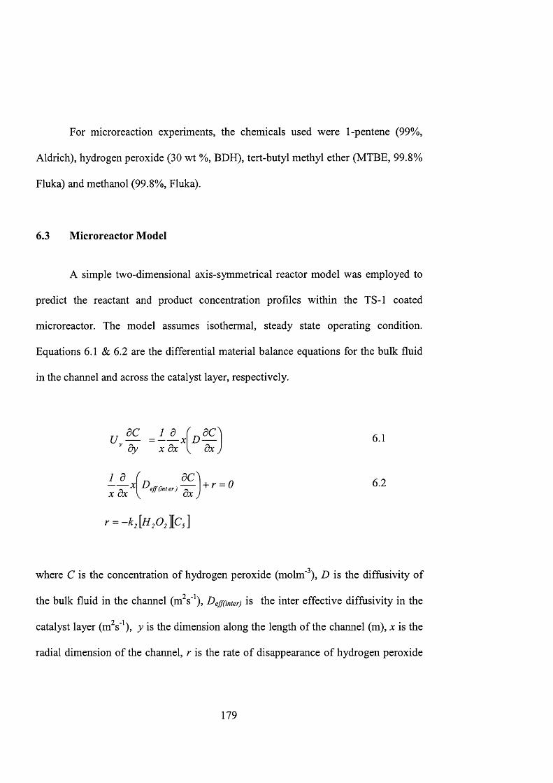
For microreaction experiments, the chemicals used were 1-pentene (99%,
Aldrich), hydrogen peroxide (30 wt %, BDH), tert-butyl methyl ether (MTBE, 99.8%
Fluka) and methanol (99.8%, Fluka).
6.3 Microreactor Model
A simple two-dimensional axis-symmetrical reactor model was employed to
predict the reactant and product concentration profiles within the TS-1 coated
microreactor. The model assumes isothermal, steady state operating condition.
Equations 6.1 & 6.2 are the differential material balance equations for the bulk fluid
in the channel and across the catalyst layer, respectively.
1 d XX d x V d x j
- t - r = 0 6 . 2
where C is the concentration of hydrogen peroxide (molm'^), D is the diffusivity of
the bulk fluid in the channel (m^s'^), Deff(mter) is the inter effective diffusivity in the
catalyst layer (m^s'^), y is the dimension along the length of the channel (m), x is the
radial dimension of the channel, r is the rate of disappearance of hydrogen peroxide
179
per unit area of catalytic surface (mols'^m'^) and Uy is the fluid velocity along the y
axis (ms'^).
The transport mechanisms are considered to be convection along the flow
direction and diffusion along the traverse directions. The inter-particle diffusion,
Deff(inter) was Calculated to be 8x10*^ m^s' based on the bulk diffusitivity taking into
account crystal porosity, constriction factor and tortuosity (Wakao and Kaguei, 1982;
Fogler, 1992). The fluid enters the microreactor from a channel of similar width. It
has uniform concentration and fully developed flow where the velocity profile is
invariant along the flow. The parabolic flow is described by the Hagen-Poiseuille
equation:
where Uy = 2U^ (/ - ) 6.3
where Uy is the velocity along the y axis (ms‘ ), Um is the mean velocity (ms’ ), x is
the radial coordinate (m). In the model, the trapezoidal channel was approximated by
a cylindrical channel having the same surface to volume ratio. The external perimeter
of the catalyst layer is 785 pm and for the trapezoidal cross-section is 759 pm. It was
also assumed that the fluid is incompressible, that its properties remain unchanged
during the reaction and the pressure drop along the channel is negligible (Ajmera et
al., 2001).
180
The partial differential equations (Eqns. 6.1 & 6.2) were integrated along the
y-axis to calculate the hydrogen peroxide concentration profile in the microreactor.
The concentrations profiles of 1-pentene and 1,2-epoxypentane were calculated from
the mass balance. The governing equations were solved using Femlab™. The
dimensionless model equations used in the Femlab model are listed in table 6.2. For
the computation, the microchannel was partitioned into approximately 8000 finite
element cells using an adaptive mesh. The mesh is smaller and denser at the
proximity of the catalyst layer where the reaction takes place in order to ensure a
more accurate calculation of the concentration profile along the microchannel. The
model is a useful and convenient tool for studying the effects of reactor geometry,
catalyst properties and reaction conditions on the microreactor performance.
Comparisons with experimental data provide an assessment of its predictive capacity.
The experimental and model values of microreactor parameters are shown in table
6.3.
181
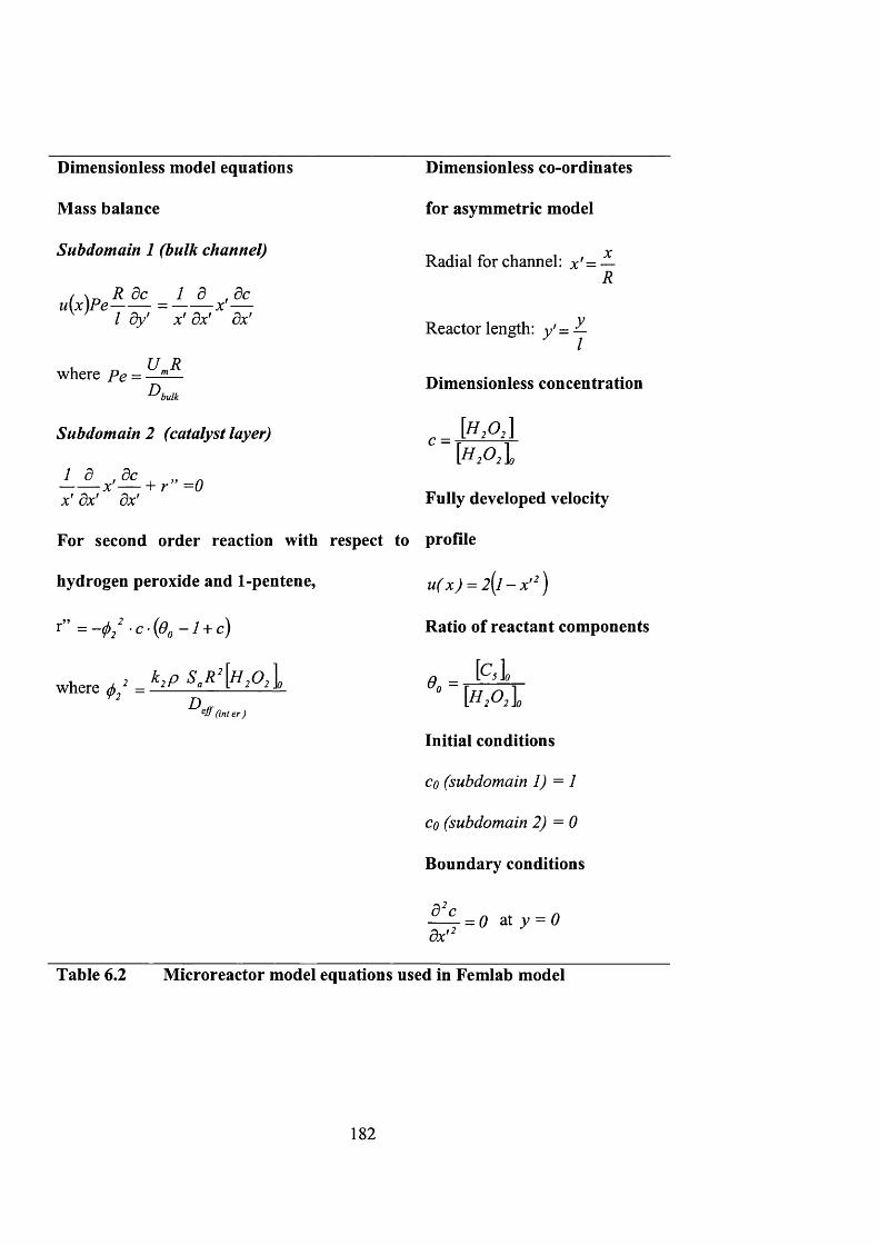
Dimensionless model equations
Mass balance
Subdomain 1 (bulk channel)
( \ R do I d ,0cu[x)Pe = ------- x '—/ dy' x' dx' dx'
Dimensionless co-ordinates
for asymmetric model
Radial for channel: x' = XR
Reactor length: y ' =I
where Pe = U RD Dimensionless concentration
bulk
Subdomain 2 (catalyst layer)
x' dx' dx'
For second order reaction with respect to
hydrogen peroxide and 1 -pentene,
r” = - ^ / c (^ 0 - i + c)
c = [h2oA
where = k,p
Fully developed velocity
profile
u(x) = 2 (1 - x '^ )
Ratio of reactant components
[C , lOn =D
(int er )[H2O2I
Initial conditions
Co (subdomain 1) = 1
cq (subdomain 2) = 0
Boundary conditions
dx t 2= 0 at y = 0
Table 6.2 Microreactor model equations used in Femlab model
182
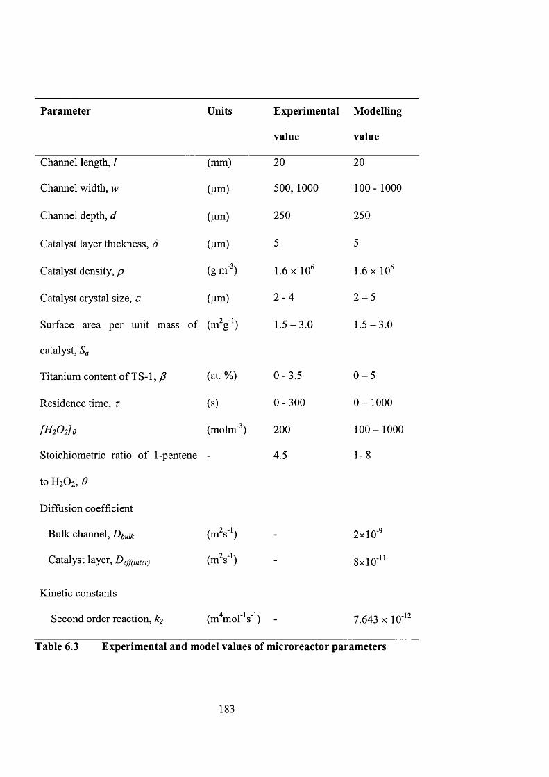
Parameter Units Experimental
value
Modelling
value
Channel length, I (mm) 20 20
Channel width, w (um) 500,1000 100- 1000
Channel depth, d (um) 250 250
Catalyst layer thickness, Ô (pm) 5 5
Catalyst density, p (g m" ) 1.6 X 10^ 1.6 X 10^
Catalyst crystal size, e (nm) 2 - 4 2 - 5
Surface area per unit mass of (m 'g ') 1 .5 -3 .0 1 .5 -3 .0
catalyst. Sa
Titanium content of TS-1, (at. %) 0 -3 .5 0 - 5
Residence time, r (s) 0 -300 0 -1 0 0 0
[H2O2] 0 (molm'^) 200 100-1000
Stoichiometric ratio of 1-pentene - 4.5 1-8
to H2O2 , 6
Diffusion coefficient
Bulk channel, Dbuik (m 's ') - 2x10'^
Catalyst layer, Deff(mter) (m 's ') - 8x10'^’
Kinetic constants
Second order reaction, k2 (m^^mol'^"^) - 7.643 X 10' ^
Table 6.3 Experimental and model values of microreactor parameters
183
6.4 Results and discussion
6.4.1 Batch reactor
Reaction kinetics and its corresponding rate constant were calculated from the
reaction data obtained from the batch reactor experiment using TS-1 zeolite grown on
silicon wafer as a catalyst. The upper range of Weisz-Prater parameter for the batch
reaction is 82 (appendix A4) indicating that the intra-particle diffusion resistance is
large and most of the reaction occurs at the external surface of the zeolite crystal.
Therefore the reaction rate is expressed per external surface area of the zeolite
crystals. Figure 6.1 plots the amounts of hydrogen peroxide consumed and 1,2-
epoxypentane produced in the batch reactor as a function of reaction time. A 90%
selectivity of 1,2-epoxypentane on hydrogen peroxide conversion was obtained. The
experimental data were fitted to first- and second-order reaction models (i.e., r = -
A:;[H202] and r = -^2[H202][Cs]) giving rate constants, kj of 9.443xlO'^ms'^ and kz of
7.643xlO'^^m'^mor^s'\ From the figure it shows that the second-order reaction model
fits the data better. Shea and Kim (1992) and Arasasingham et al. (1993) have also
indicated that the oxidation of alkene to epoxide is a second order reaction. The
details of the calculation can be found in appendix A l.
184

0.0181st order model
- 2nd order model
0.012
0.006
0 5000 10000 15000 20000 25000Tim e (s)
Figure 6.1 Moles of hydrogen peroxide reactant and 1,2-epoxypentane
product in the batch reactor as a function of reaction time
([H2 0 2 ]o = 0.33 M, [Cs]o = 1.49 M, catalyst loading = 2g/L, <^=5
pm, s = 2 pm, p = 2.5 at.%, T = 298 K, x - hydrogen peroxide, □ -
1 ,2 -epoxypentane)
6.4.2 Zeolite microreactor
A cross-section of the microchannel (figure 6.2) shows that the deposition of
TS-1 zeolite (2 at.% Ti) was restricted to the microchannel. Zeolite growth is absent
185
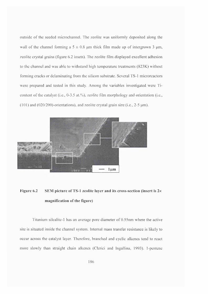
outside of the seeded microchannel. The zeolite was uniformly deposited along the
wall of the channel forming a 5 ± 0.8 pm thick film made up of intergrown 3 pm,
zeolite crystal grains (figure 6.2 insets). The zeolite film displayed excellent adhesion
to the channel and was able to withstand high temperature treatments (823K) without
forming cracks or delaminating from the silicon substrate. Several TS-1 microreactors
were prepared and tested in this study. Among the variables investigated were Ti-
content of the catalyst (i.e., 0-3.5 at.%), zeolite film morphology and orientation (i.e.,
(101) and (020/200)-orientations), and zeolite crystal grain size (i.e., 2-5 pm).
Figure 6.2 SEM picture of TS-1 zeolite layer and its cross-section (insert is 2x
m agnification of the figure)
Titanium silcalite-1 has an average pore diameter of 0.55nm where the active
site is situated inside the channel system. Internal mass transfer resistance is likely to
occur across the catalyst layer. Therefore, branched and cyclic alkenes tend to react
more slowly than straight chain alkenes (Clerici and Ingallina, 1993). 1-pentene
186
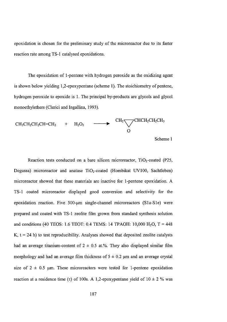
epoxidation is chosen for the preliminary study of the microreactor due to its faster
reaction rate among TS-1 catalysed epoxidations.
The epoxidation of 1-pentene with hydrogen peroxide as the oxidizing agent
is shown below yielding 1,2-epoxypentane (scheme 1). The stoichiometry of pentene,
hydrogen peroxide to epoxide is 1. The principal by-products are glycols and glycol
monoethylethers (Clerici and Ingallina, 1993).
CHz^^CHCHzCHzCHs CHsCHzCHzCH CHz + H2O2 ------- ► \ /
O
Scheme 1
Reaction tests conducted on a bare silicon microreactor, Ti02-coated (P25,
Degussa) microreactor and anatase Ti02-coated (Hombikat UVlOO, Sachtleben)
microreactor showed that these materials are inactive for 1-pentene epoxidation. A
TS-1 coated microreactor displayed good conversion and selectivity for the
epoxidation reaction. Five 500-pm single-channel microreactors (Sla-Sle) were
prepared and coated with TS-1 zeolite film grown from standard synthesis solution
and conditions (40 TEOS: 1.6 TEOT: 0.4 TEMS: 14 TPAOH: 10,000 H2O, T = 448
K, t = 24 h) to test reproducibility. Analyses showed that deposited zeolite catalysts
had an average titanium-content of 2 ± 0.5 at.%. They also displayed similar film
morphology and had an average film thickness of 5 ± 0.2 pm and an average crystal
size of 2 ± 0.5 pm. These microreactors were tested for 1-pentene epoxidation
reaction at a residence time (x) of 100s. A 1,2-epoxypentane yield of 10 ± 2 % was
187
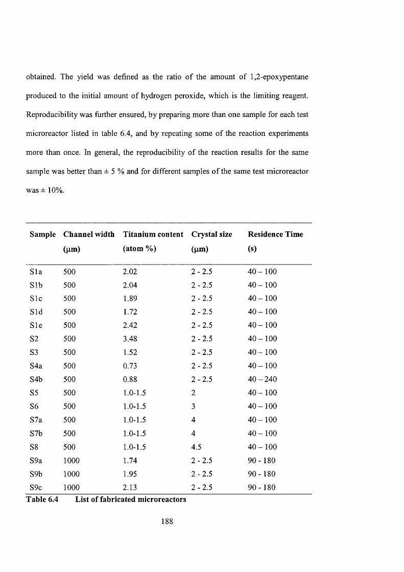
obtained. The yield was defined as the ratio of the amount of 1,2-epoxypentane
produced to the initial amount of hydrogen peroxide, which is the limiting reagent.
Reproducibility was further ensured, by preparing more than one sample for each test
microreactor listed in table 6.4, and by repeating some of the reaction experiments
more than once. In general, the reproducibility of the reaction results for the same
sample was better than ± 5 % and for different samples of the same test microreactor
was ± 10%.
Sample Channel width
(pm)
Titanium content
(atom %)
Crystal size
(pm)
Residence Time
(s)
Sla 500 2.02 2 -2 .5 4 0 -1 0 0
Sib 500 2.04 2-2 .5 4 0 -1 0 0
Sic 500 1.89 2-2 .5 4 0 -1 0 0
Sid 500 1.72 2-2 .5 4 0 -1 0 0
Sle 500 2.42 2-2 .5 4 0 -1 0 0
S2 500 3.48 2-2 .5 4 0 -1 0 0
S3 500 1.52 2 -2 .5 4 0 -1 0 0
S4a 500 0.73 2-2 .5 4 0 -1 0 0
S4b 500 0.88 2-2 .5 40 - 240
S5 500 1.0-1.5 2 4 0 -1 0 0
S6 500 1.0-1.5 3 4 0 -1 0 0
S7a 500 1.0-1.5 4 4 0 -1 0 0
S7b 500 1.0-1.5 4 4 0 -1 0 0
S8 500 1.0-1.5 4.5 4 0 -1 0 0
S9a 1000 1.74 2 -2 .5 90-180
S9b 1000 1.95 2 -2 .5 90-180
S9c 1000 2.13 2 -2 .5 90-180Table 6.4 List of fabricated microreactors
188

6.4.3 Modelling results
Influence of reactor geometry
The microchannel geometry is defined by the width (w) and depth (d) of its
cross-section and by the length (/) of the channel. In this study, the depth of the
microchannel was fixed at 250 pm and the channel length at 20 mm. Figure 6.3
shows the 1,2-epoxypentane yield as a function of residence time for different
channel widths. The experimental data for two channel widths 500 pm (Sla-Sle) and
1000 pm (S9a-S9c) are included in the plots for comparison. It can be seen that there
is a good agreement between the model prediction and experimental data, considering
the various simplifications made during the model derivation. However, the
experimental yield obtained at higher residence time was lower than predicted. It may
be due to catalyst deactivation by titanium leaching, which will be discussed later.
The narrower channels give higher conversion because the catalyst loading per unit
reactor volume is higher, even though the actual amount of catalyst is less due to
fixed thickness of zeolite catalyst layer (i.e., 5 pm). However, a narrower channel will
experience more severe pressure drop (AP), which increases in inverse proportion to
the cube of the channel width (appendix A5). Calculations show that pressure drop
will be a major problem for channel widths narrower than 100 pm, posing a severe
limitation on the microreactor operation. This experimental study has shown that
because of the relatively high volatility of 1-pentene, bubbles of hydrocarbon vapor
were formed during the reaction. Problems from bubble formation can become severe
189
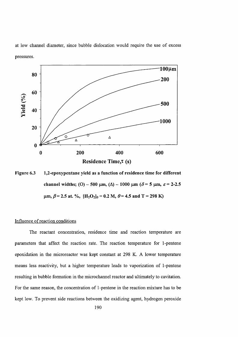
at low channel diameter, since bubble dislocation would require the use of excess
pressures.
8 0
6 0
5 0 0
4 0
100020
00 6 0 02 0 0 4 0 0
Residence Time,! (s)
Figure 6.3 1,2-epoxypentane yield as a function of residence time for different
channel widths; (O) - 500 pm, (A) - 1000 pm ( ^ = 5 pm, f = 2-2.5
pm, 2.5 at. %, [HiOzjo = 0.2 M, 4.5 and T = 298 K)
Influence of reaction conditions
The reactant concentration, residence time and reaction temperature are
parameters that affect the reaction rate. The reaction temperature for 1-pentene
epoxidation in the microreactor was kept constant at 298 K. A lower temperature
means less reactivity, but a higher temperature leads to vaporization of 1-pentene
resulting in bubble formation in the microchannel reactor and ultimately to cavitation.
For the same reason, the concentration of 1-pentene in the reaction mixture has to be
kept low. To prevent side reactions between the oxidizing agent, hydrogen peroxide
190
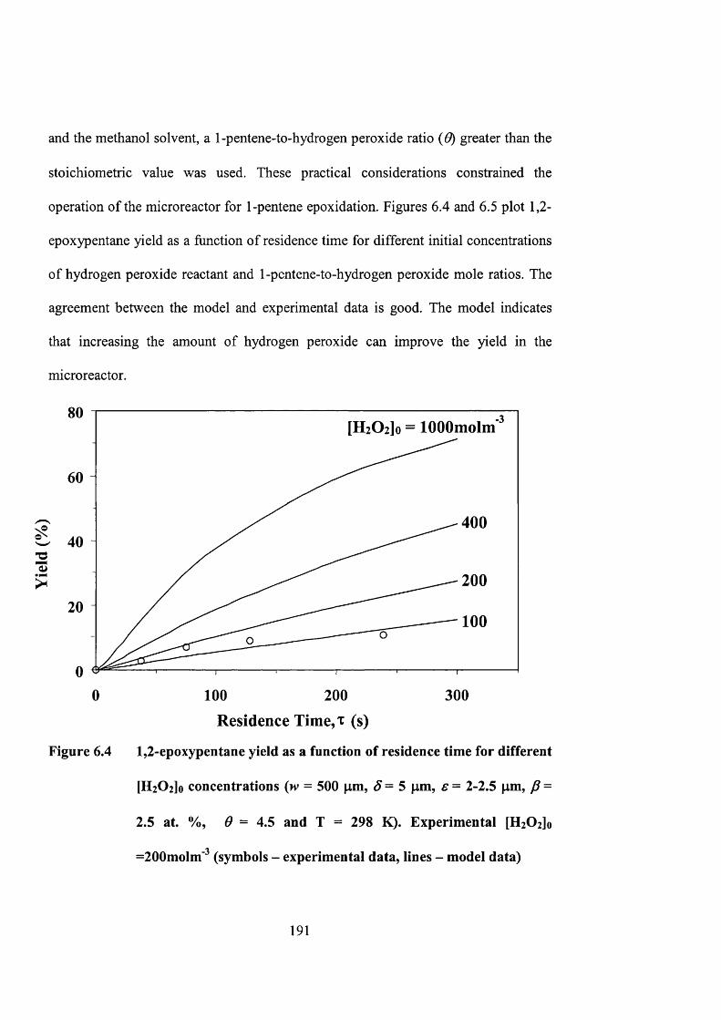
and the methanol solvent, a 1-pentene-to-hydrogen peroxide ratio {0) greater than the
stoichiometric value was used. These practical considerations constrained the
operation of the microreactor for 1-pentene epoxidation. Figures 6.4 and 6.5 plot 1,2-
epoxypentane yield as a function of residence time for different initial concentrations
of hydrogen peroxide reactant and 1-pentene-to-hydrogen peroxide mole ratios. The
agreement between the model and experimental data is good. The model indicates
that increasing the amount of hydrogen peroxide can improve the yield in the
microreactor.
[HiOilo = lOOOmolm
6 0 -
4004 0 -
200
100
0 100 200 3 0 0
Residence Time,T (s)
Figure 6.4 1,2-epoxypentane yield as a function of residence time for different
[HzOzjo concentrations {w = 500 pm, S = 5 pm, € = 2-2.5 pm, p =
2.5 at. %, 9 = 4.5 and T = 298 K). Experimental [HzOijo
=2 0 0 molm' (symbols - experimental data, lines - model data)
191
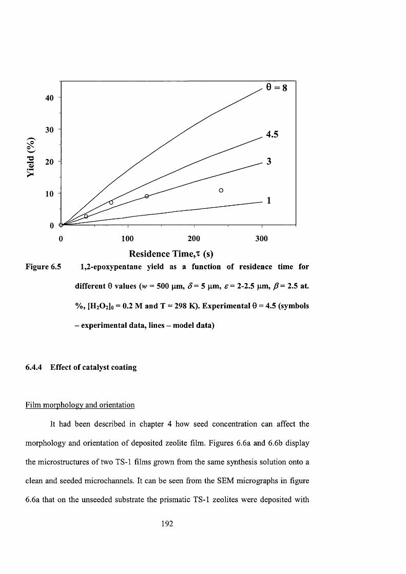
0 = 840
30 4.5
20
10
0
Figure 6.5
100 200 300
Residence Time,T (s)1 ,2 -epoxypentane yield as a function of residence time for
different 0 values (w = 500 pm, S = 5 pm, e = 2-2.5 pm, P = 2.5 at.
%, [HiOilo = 0.2 M and T = 298 K). Experimental 0 = 4.5 (symbols
- experimental data, lines - model data)
6.4.4 Effect of catalyst coating
Film morphology and orientation
It had been described in chapter 4 bow seed concentration can affect the
morphology and orientation of deposited zeolite film. Figures 6.6a and 6.6b display
the micro structures of two TS-1 films grown from the same synthesis solution onto a
clean and seeded microchannels. It can be seen from the SEM micrographs in figure
6.6a that on the unseeded substrate the prismatic TS-1 zeolites were deposited with
192

their (020) crystal plane parallel to the channel wall. Secondary growth crystals were
oriented with their (200) planes parallel to the silicon surface. This means that the
straight MFI zeolite pore channels were aligned normal to the substrate, while the
zigzag channels ran parallel to the channel surface. Indeed, X-ray diffraction analysis
confirmed that the film possessed a (020/200) preferred orientation. The
microchannel was covered with approximately 3.8 x 10 ® zeolite crystals/m^ that had
an average size of 6 pm x 8 pm. Neighboring crystals merged to form an intergrown
layer that was occasionally interrupted by defects caused by mismatched growth.
Secondary growth is evident from the presence of multi-layered deposit (figure 6.6a)
that consisted of smaller zeolite crystals.
TS-1 zeolites grown on seeded microchannel display a different morphology
and crystal habit as shown in figure 6.6b. An inverted pyramidal shape evolved as the
zeolite grew from the individual seeds. The seed resided at the apex of the pyramidal
zeolite grain that terminated on a (lOl)-crystallographic plane. The XRD pattern
displayed predominantly the (101) diffraction line. In this orientation, molecules must
diffuse through the zeolite by hopping between the intersecting straight and zigzag
zeolite pore channels. The film consisted of 5.5 x 10 zeolite crystals/m^ that has an
average grain size of 2 pm x 4 pm.
The microreactor coated with a TS-1 (020) film displayed low activity for 1-
pentene epoxidation. The overall reaction rate at 100s residence time is 9.0x10'
"^molm' s' despite having more accessible pore channels (i.e., straight pores). The
193
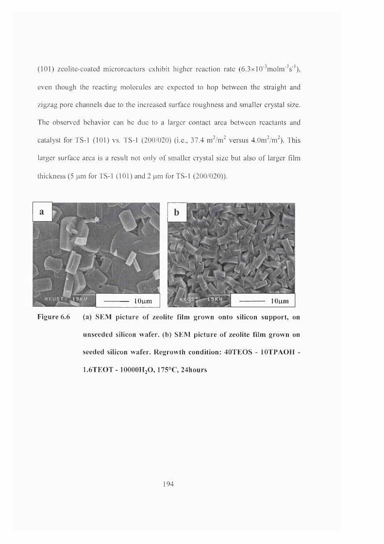
(101) zeolite-coated microreactors exhibit higher reaction rate (6.3x10'^molm'^s''),
even though the reacting molecules are expected to hop between the straight and
zigzag pore channels due to the increased surface roughness and smaller crystal size.
The observed behavior can be due to a larger contact area between reactants and
catalyst for TS-1 (101) vs. TS-1 (200/020) (i.e., 37.4 mVm^ versus 4.0mVm^). This
larger surface area is a result not only o f smaller crystal size but also o f larger film
thickness (5 pm for TS-1 (101) and 2 pm for TS-1 (200/020)).
a lOumlOum
Figure 6.6 (a) SEM picture o f zeolite film grown onto silicon support, on
unseeded silicon wafer, (b) SEM picture o f zeolite film grown on
seeded silicon wafer. Regrowth condition: 40TEO S - lOTPAOH -
1.6TEOT - IOOOOH2 O, 175°C, 24hours
194
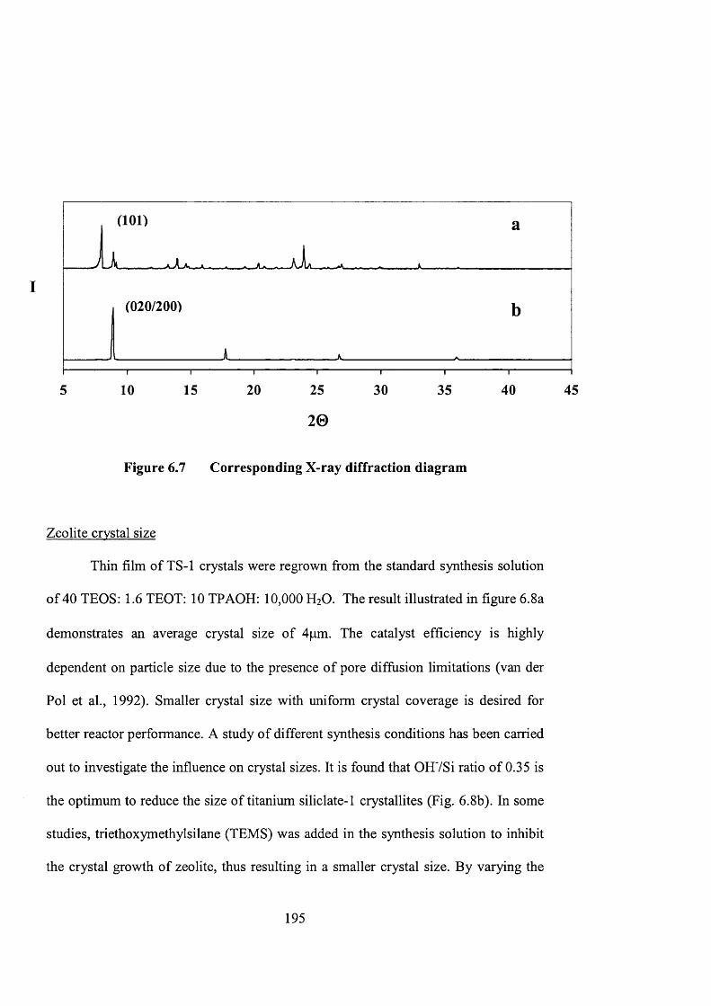
(101)
(020/200)
5 10 15 20 25 30 35 40 45
20
Figure 6.7 Corresponding X-ray diffraction diagram
Zeolite crystal size
Thin film of TS-1 crystals were regrown from the standard synthesis solution
of 40 TEOS: 1.6 TEOT: 10 TPAOH: 10,000 H2O. The result illustrated in figure 6.8a
demonstrates an average crystal size of 4|am. The catalyst efficiency is highly
dependent on particle size due to the presence of pore diffusion limitations (van der
Pol et al., 1992). Smaller crystal size with uniform crystal coverage is desired for
better reactor performance. A study of different synthesis conditions has been carried
out to investigate the influence on crystal sizes. It is found that OHVSi ratio of 0.35 is
the optimum to reduce the size of titanium siliclate-1 crystallites (Fig. 6.8b). In some
studies, triethoxymethylsilane (TEMS) was added in the synthesis solution to inhibit
the crystal growth of zeolite, thus resulting in a smaller crystal size. By varying the
195
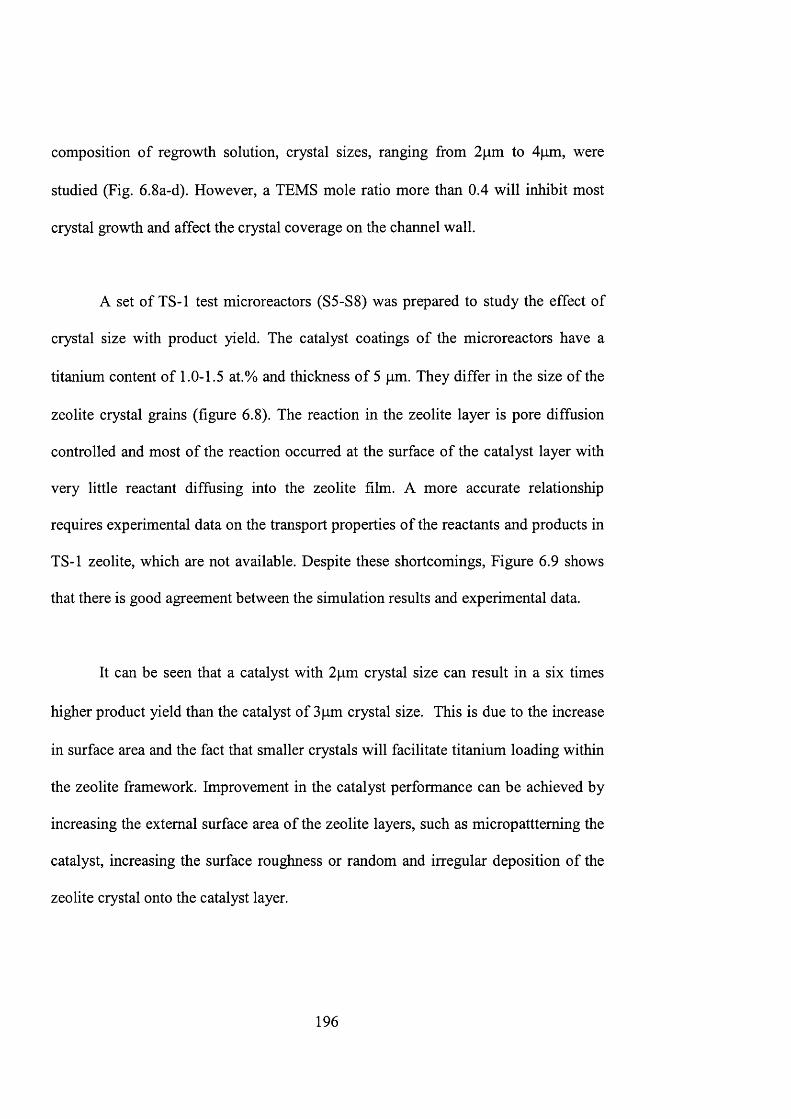
composition of regrowth solution, crystal sizes, ranging from 2pm to 4pm, were
studied (Fig. 6.8a-d). However, a TEMS mole ratio more than 0.4 will inhibit most
crystal growth and affect the crystal coverage on the channel wall.
A set of TS-1 test microreactors (S5-S8) was prepared to study the effect of
crystal size with product yield. The catalyst coatings of the microreactors have a
titanium content of 1.0-1.5 at.% and thickness of 5 pm. They differ in the size of the
zeolite crystal grains (figure 6.8). The reaction in the zeolite layer is pore diffusion
controlled and most of the reaction occurred at the surface of the catalyst layer with
very little reactant diffusing into the zeolite film. A more accurate relationship
requires experimental data on the transport properties of the reactants and products in
TS-1 zeolite, which are not available. Despite these shortcomings. Figure 6.9 shows
that there is good agreement between the simulation results and experimental data.
It can be seen that a catalyst with 2pm crystal size can result in a six times
higher product yield than the catalyst of 3pm crystal size. This is due to the increase
in surface area and the fact that smaller crystals will facilitate titanium loading within
the zeolite framework. Improvement in the catalyst performance can be achieved by
increasing the external surface area of the zeolite layers, such as micropattteming the
catalyst, increasing the surface roughness or random and irregular deposition of the
zeolite crystal onto the catalyst layer.
196
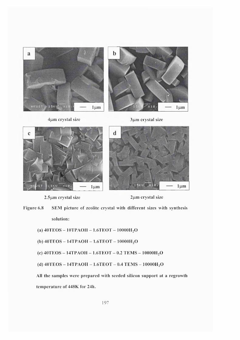
i
4pm crystal size 3pm crystal size
2.5pm crystal size 2pm crystal size
Figure 6.8 SEM picture of zeolite crystal with different sizes with synthesis
solution:
(a) 40TEOS - lOTPAOH - 1.6TEOT - lOOOOHjO
(b) 40TEOS - 14TPAOH - 1.6TEOT - lOOOOHjO
(c) 40TEOS - 14TPAOH - 1.6TEOT - 0.2 TEMS - IOOOOH2O
(d) 40TEOS - 14TPAOH - 1.6TEOT - 0.4 TEMS - lOOOOH^O
All the samples were prepared with seeded silicon support at a regrowth
temperature of 448K for 24h.
197
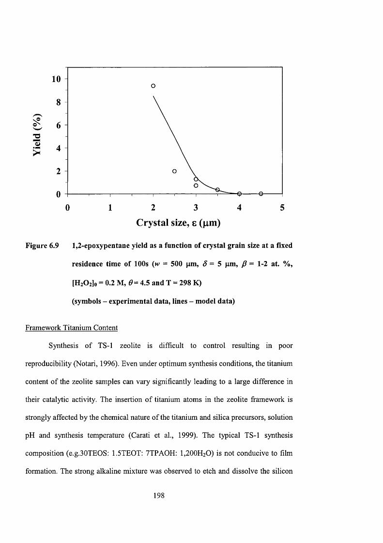
■OCJ?
10
8
6
4
2
02 3 41 50
Crystal size, 8 (jim )
Figure 6.9 1,2-epoxypentane yield as a function of crystal grain size at a fixed
residence time of 100s (iv = 500 pm, â = 5 pm, = 1-2 at. %,
[HiOzlo = 0.2 M, (9= 4.5 and T = 298 K)
(symbols - experimental data, lines - model data)
Framework Titanium Content
Synthesis of TS-1 zeolite is difficult to control resulting in poor
reproducibility (Notari, 1996). Even under optimum synthesis conditions, the titanium
content of the zeolite samples can vary significantly leading to a large difference in
their catalytic activity. The insertion of titanium atoms in the zeolite framework is
strongly affected by the chemical nature of the titanium and silica precursors, solution
pH and synthesis temperature (Carati et al., 1999). The typical TS-1 synthesis
composition (e.g.30TEOS: 1.5TE0T: 7TPA0H: 1,200H20) is not conducive to film
formation. The strong alkaline mixture was observed to etch and dissolve the silicon
198
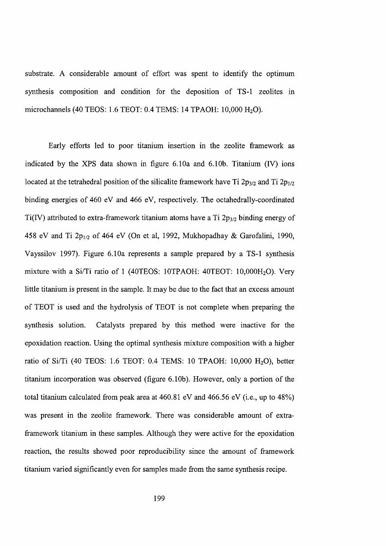
substrate. A considerable amount of effort was spent to identify the optimum
synthesis composition and condition for the deposition of TS-1 zeolites in
microchannels (40 TEOS: 1.6 TEOT: 0.4 TEMS: 14 TPAOH: 10,000 H2O).
Early efforts led to poor titanium insertion in the zeolite framework as
indicated by the XPS data shown in figure 6.10a and 6.10b. Titanium (IV) ions
located at the tetrahedral position of the silicalite framework have Ti 2ps/2 and Ti 2pi/2
binding energies of 460 eV and 466 eV, respectively. The octahedrally-coordinated
Ti(IV) attributed to extra-framework titanium atoms have a Ti 2p3/2 binding energy of
458 eV and Ti 2pi/2 of 464 eV (On et al, 1992, Mukhopadhay & Garofalini, 1990,
Vayssilov 1997). Figure 6.10a represents a sample prepared by a TS-1 synthesis
mixture with a Si/Ti ratio of 1 (40TEOS: lOTPAOH: 40TEOT: 10,000H2O). Very
little titanium is present in the sample. It may be due to the fact that an excess amount
of TEOT is used and the hydrolysis of TEOT is not complete when preparing the
synthesis solution. Catalysts prepared by this method were inactive for the
epoxidation reaction. Using the optimal synthesis mixture composition with a higher
ratio of Si/Ti (40 TEOS: 1.6 TEOT: 0.4 TEMS: 10 TPAOH: 10,000 H2O), better
titanium incorporation was observed (figure 6.10b). However, only a portion of the
total titanium calculated from peak area at 460.81 eV and 466.56 eV (i.e., up to 48%)
was present in the zeolite framework. There was considerable amount of extra
framework titanium in these samples. Although they were active for the epoxidation
reaction, the results showed poor reproducibility since the amount of framework
titanium varied significantly even for samples made from the same synthesis recipe.
199
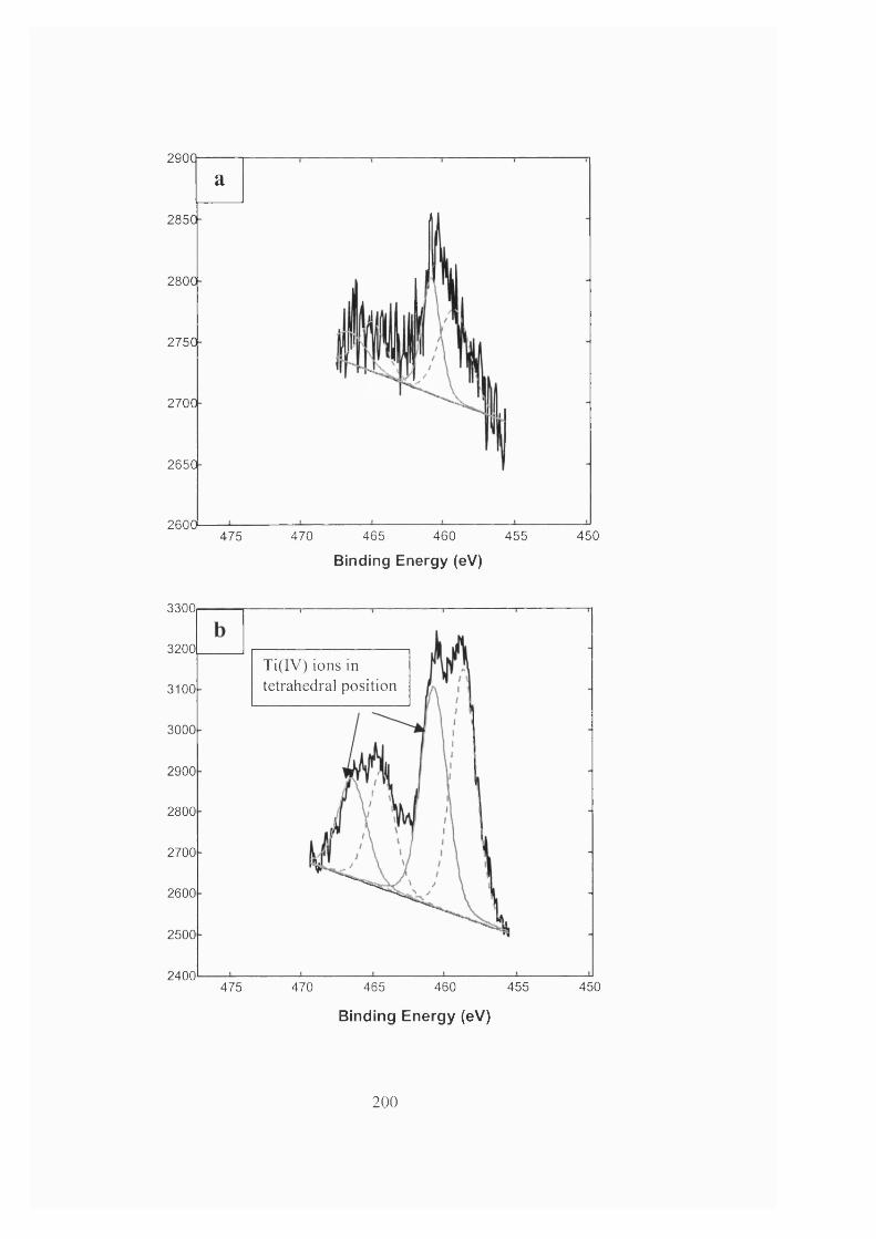
2900
285C
280C
275C
270C
265C
2 6 0 0
a
475 470 465 460 455
Binding Energy (eV)4 5 0
3300
3200Ti(IV) ions in tetrahedral position3100
3000
2900
2800
2700
2600
2500
2400450475 470 465 460 455
Binding Energy (eV)
200
340Q
3300
3200
3100
Ti(IV) ions in octahedral position (TiO])
3000
2900
2800
2700
2600
2500
2400465 460 450475 470 455
Binding Energy (eV)
Figure 6.10 XPS spectrum showing
(a) no insertion of Titanium into zeolite fram ew ork
(b) partial insertion of Titanium into zeolite fram ework
(c) full insertion of Titanium into zeolite fram ework
solid line corresponds to tetrahedrally-coordinated Ti(IV)
broken line corresponds to octahedrally-coordinated Ti(IV)
The problem was traced to the alkalis present in the TEOS reagent. The
present o f alkali was reported to inhibit titanium substitution in TS-1 zeolite (Perego
et al, 1998). Complete insertion o f titanium into the zeolite framework was obtained
after replacing the TEOS reagent with one containing less alkali impurities (figure
6.10c). Extra care was also taken to make sure that all apparatus were completely dry
201
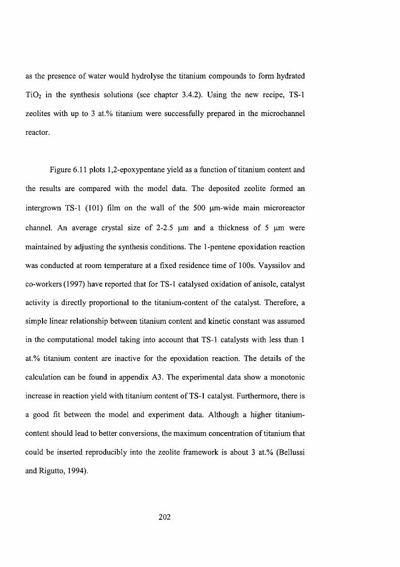
as the presence of water would hydrolyse the titanium compounds to form hydrated
TiOz in the synthesis solutions (see chapter 3.4.2). Using the new recipe, TS-1
zeolites with up to 3 at.% titanium were successfully prepared in the microchannel
reactor.
Figure 6.11 plots 1,2-epoxypentane yield as a function of titanium content and
the results are compared with the model data. The deposited zeolite formed an
intergrown TS-1 (101) film on the wall of the 500 pm-wide main microreactor
channel. An average crystal size of 2-2.5 pm and a thickness of 5 pm were
maintained by adjusting the synthesis conditions. The 1-pentene epoxidation reaction
was conducted at room temperature at a fixed residence time of 100s. Vayssilov and
co-workers (1997) have reported that for TS-1 catalysed oxidation of anisole, catalyst
activity is directly proportional to the titanium-content of the catalyst. Therefore, a
simple linear relationship between titanium content and kinetic constant was assumed
in the computational model taking into account that TS-1 catalysts with less than 1
at.% titanium content are inactive for the epoxidation reaction. The details of the
calculation can be found in appendix A3. The experimental data show a monotonie
increase in reaction yield with titanium content of TS-1 catalyst. Furthermore, there is
a good fit between the model and experiment data. Although a higher titanium-
content should lead to better conversions, the maximum concentration of titanium that
could be inserted reproducibly into the zeolite framework is about 3 at.% (Bellussi
and Rigutto, 1994).
2 0 2
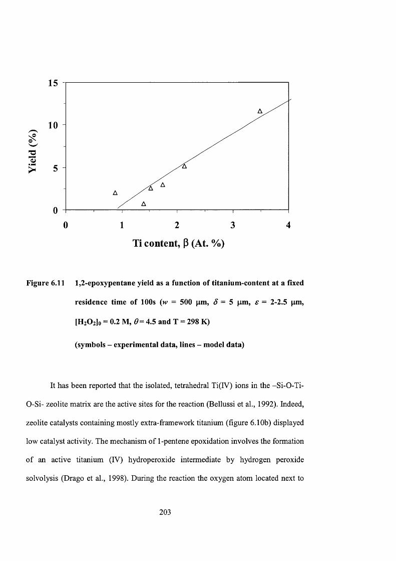
I
15
10
5
040 1 2 3
Ti content, P (At. %)
Figure 6.11 1,2-epoxypentane yield as a function of titanium-content at a fixed
residence time of 100s (m = 500 pm, = 5 pm, e = 2-2.5 pm,
[H2 0 2 ]o = 0.2 M, 4.5 and T = 298 K)
(symbols - experimental data, lines - model data)
It has been reported that the isolated, tetrahedral Ti(IV) ions in the -Si-O-Ti-
0-Si- zeolite matrix are the active sites for the reaction (Bellussi et al., 1992). Indeed,
zeolite catalysts containing mostly extra-framework titanium (figure 6.10b) displayed
low catalyst activity. The mechanism of 1-pentene epoxidation involves the formation
of an active titanium (IV) hydroperoxide intermediate by hydrogen peroxide
solvolysis (Drago et al., 1998). During the reaction the oxygen atom located next to
203
the metal centre initiates the reaction by attacking the carbon-carbon double bond of
the alkene molecule (Tantank, et ah, 1998).
6.4.5 Catalyst deactivation
A series of experiments were conducted to investigate the deactivation of TS-
1 catalyst in the microreactor. Each experiment (set of five) was around five hours
prior to characterization and reactivation (figure 6.12). Two types of deactivation
were observed. A short-term deactivation at the beginning of each 5 hour experiment
and an overall long-term deactivation. It was suspected that the short-term
deactivation was due to the presence of organic compounds blocking the active sites
and pores of TS-1.
To further understand the catalyst deactivation, TGA was carried out on TS-1
powder sample synthesised under the same synthesis condition as the zeolite film (40
TEOS: 1.6 TEOT: 10 TPAOH: 10,000 H2O). lOOmg of the catalyst was used for
epoxidation (0.9M 1-pentene and 0.2M H2O2 in methanol) and the catalyst was
heated in an oven at 333K before the TGA experiment. A mass loss of 35% at 373K
was observed while the total mass loss up to 1073K was 38%. The mass loss at 373K
is attributed to the endothermie desorption of water (enthalpy 638J/g) while the
additional 3% mass loss is attributed to desorption/decomposition of organic
compounds. It can be concluded that water, as one of the by-products, would poison
the catalyst.
204
In propylene epoxidation, TS-1 deactivated when propylene oxide oligomers
deposited inside the zeolite pores. The oligomers could be removed by calcination in
air at 773K (Chen et al., 1998) or refluxing with dilute hydrogen peroxide (Thiele and
Roland, 1997). Unguina et al. (2000) have studied the deactivation of TS-1 for
styrene oxidation with hydrogen peroxide and observed a decline in the catalyst
reactivity with time. The presence of diffusional limitations arising high degree of
occupancy of the TS-1 pores and strong adsorption of styrene, phenylacetaldehyde
and benzaldehyde on the Ti sites were proposed as the main reasons of deactivation.
Thiele and Roland (1997) further argue that water co-ordinates to the active site
increases acidity and hence the propensity for byproduct formation by acid catalysed
reactions. These deactivation mechanisms are consistent with this work. However, the
large amount of water observed in TGA experiments may indicate an additional
deactivation mechanism (e.g. pore size restriction).
205
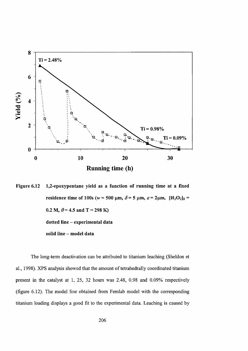
?
8Ti = 2.48%
6
4
2 Ti = 0.98%
Ti = 0.09%
00 10 20
Running time (h)
30
Figure 6.12 1,2-epoxypentane yield as a function of running time at a fixed
residence time of 100s {w = 500 pm, S= 5 pm, s = 2pm, [HzOijo =
0.2 M, 4.5 and T = 298 K)
dotted line - experimental data
solid line - model data
The long-term deactivation can be attributed to titanium leaching (Sheldon et
ah, 1998). XPS analysis showed that the amount of tetrahedrally coordinated titanium
present in the catalyst at 1, 25, 32 hours was 2.48, 0.98 and 0.09% respectively
(figure 6.12). The model line obtained from Femlab model with the corresponding
titanium loading displays a good fit to the experimental data. Leaching is caused by
206

solvolysis by polar molecules reacting with the metal-oxygen framework bonds,
resulting in the removal of the metal into solution. The titanium removed from TS-1
during reaction originates from defect sites in the framework where Ti is not perfectly
coordinated to the four 0-Si groups (Davies et al., 2001a, 2001b). Such defect sites
have been proposed by Lamberti et al. (1998) who observed that TS-1 can be highly
defective. There is a possibility that TS-1 prepared using a short crystallization period
may have an increased concentration of these defect sites (Davies et al., 2001a).
Furthermore, it has observed that (Davies, 2001b) titanium leaching is more prevalent
under continuous flow conditions. It is possible that the equilibrium established
between the solution Ti species and Ti on the catalyst surface is perturbed under such
conditions. A similar leaching mechanism may be taking place in this work.
6.5 Concluding remarks
The novel procedure of selective seeding and regrowth techniques enables the
selective incorporation of TS-1 catalysts within the microreactor channel. The
technique’s ability to engineer the zeolite film microstructure and chemistry is
invaluable for optimizing the catalytic and transport properties of the incorporated
catalyst layer. The deposited TS-1 films were active for catalyzing 1-pentene
epoxidation reaction to produce 1,2-epoxypentane. A computational model based on
established chemical engineering principles gave accurate prediction of the
microreactor behavior and performance. The best operating conditions are to use
stoichiometric amount of reactants and high concentration of hydrogen peroxide.
207
Practical limitations to the microreactor design and operations were imposed
primarily by the thermodynamics and fluid properties of the reaction mixture. The
high volatility of 1-pentene results to bubble formation in the microchannel.
A 500 pm width microreactor was employed in the study of catalyst
performance and its relation to different synthesis conditions. The crystal orientation
of (101) prepared with a seeded support displayed a better reactivity than crystals
grown on the unseeded silicon wafer with (020/200) orientation. As the reactivity of
the catalyst is dependent on the external surface area of the TS-1 crystal, a decrease in
crystal size results in higher reaction rates. It is found that a OHVSi ratio of 0.35 in
the synthesis solution is optimum for small crystals. The addition of TEMS, which
acts as crystal growth inhibitor, further improves the catalyst performance by
reducing crystal size. Catalysts with different titanium loadings were studied. It is
found that the reactivity increases linearly with the TS-1 titanium content. Short-term
deactivation was observed and attributed to the formation of organic compounds and
presence of water. Catalyst activity could be recovered by calcination. Long-term
deactivation by titanium leaching was irreversible.
2 0 8
Chapter 7
Zeolite membrane microreactor for selective oxidation of aniline
209
7 . 1 I n t r o d u c t i o n
Zeolites are microporous crystalline alumino-silcalites in which the
microstructure and chemistry can he precisely tailored (Davies and Loho, 1992).
They are widely employed in the fields of catalysis, ion-exchange, separation and
extraction. Their selective adsorption and molecular sieving properties make them an
ideal candidate as membrane material to integrate reaction and separation processes
(Caro et al., 2000; Chau et al., 2000). Zeolites possess fascinating gas permeation and
separation properties with oriented pores and uniform pore size, which are most
suitable for separation and membrane reactor applications (Lin et al., 2001; Bernal et
al., 2 0 0 2 ).
The application of membrane in chemical reactors involves the selective
removal of one or more of the reaction products through the membrane from the
reactors, thus combining reaction and separation in one single unit. Such a system is
advantageous for equilibrium-limited reactions, which can increase the product yield
and reaction conversion above the equilibrium point (Lai et al., 2003). A membrane
reactor can also help to prevent catalyst poisoning and reduce catalyst deactivation by
removing the unavoidable by-products in the reaction system (Salomon et al., 2000).
There are a number of examples on the use of zeolite membranes to integrate
reaction and separation processes. Zeolites, with their great thermal and mechanical
stability, are able to withstand harsh operation conditions. Besides hydrogen
210
separation, which can be achieved in Pd-based membrane systems, they can be
employed in a much broader range of selective separations (Yan and Bein, 1995;
Bein, 1996). Illgen and co-workers (2001) have reported the use of hydrogen
selective zeolite membranes for hydrogen removal in iso-butane dehydrogenation.
MFI type membranes were prepared in-situ on tubular a-AhOs supports with Cr2 0 3
as the catalyst. The membrane supported packed bed displayed a 1/3 improvement in
the conversion of iso-butane. Unlike Pd membranes, which will degrade in the
presence of hydrocarbons, low cost zeolite membranes offer great selectivity
permeance and long time stability for hydrogen removal.
Zeolite membranes can also be employed in the separation of water from
hydrocarbons. Espinoza and co-workers (1998) have displayed the use of hydrophilic
zeolite for water removal in Fischer-Tropsch synthesis. This resulted in an increase in
the reaction rate and catalyst deactivation was reduced. A further example was the
synthesis of methyl-/er^-butyl ether (MTBE) from /er^-butanol and methanol in
zeolite membrane reactors. The hydrophilic membranes used were mordenite and
NaA zeolite. MTBE yields were 10% above the equilibrium value obtained without
product removal (Salomon et al., 2000). Recently, the coupling of reaction and
separation processes was reported (Bernal et al., 2002). A catalytically active zeolite
membrane was employed for selective water permeation during ethanol estérification
with acetic acid. The use of H-ZSM-5 membrane was able to show efficient
integration of reaction and separation. The conversion obtained was greater than in
211
conventional fixed bed reactors, or in reactors where the zeolite membrane was kept
separated from the catalyst.
The oxidation of aniline is an important reaction for the synthesis of its O-
containing derivatives (figure 7.1). Hydroxylamines can be employed as reducing
agents, stabilizers and polymerisation inhibitors (Tonti et al., 1988) whereas azoxy
compounds are of great interest due to their physiological activity and their
ubiquitous utilization in liquid crystals (Sakaue et al., 1993). Titanium silicalite-1
zeolites (TS-1) are known for their remarkable properties in the oxidation of organic
compounds with hydrogen peroxide under mild reaction conditions (Clerici, 1993;
Sheldon et al., 1997). The application of TS-1 in the selective oxidation of aniline to
azoxybenzene was first reported by Sonawane et al. (1994) but very few details about
the reaction and nature of products were given. Detailed studies were later carried out
to investigate the influence of different reaction parameters on aniline oxidation over
TS-1 (Gontier and Tuel, 1994; Selvam and Ramaswamy, 1995), showing that TS-1
can be an excellent catalyst for selective oxidation of aniline to azoxybenzene.
In this chapter, a multi-channel membrane microreactor was developed.
Zeolites were employed as catalyst and membrane materials and incorporated in the
design of the multi-channel membrane microreactor. Selective oxidation of aniline to
azoxybenzene over TS-1 was studied whereas hydrophilic ZSM-5 was prepared as a
membrane for selective removal of water, which is one of the by-products.
Experimental results are presented in this chapter at different reaction parameters.
212

The product yield and selectivity were then compared with and without water
removal. This novel fabrication technology opens up a new horizon to incorporate
zeolite in microstructured reactors for various chemical applications.
Aniline Phenylhydroxylamine (PH) Nitrosobenzene (NSB) Nitrobenzene (NB)
<S)-nh2 <o )''= vr \----f >---- O
OHAminophenol (AP) Azobenzene (AZO) Azoxybenzene (AZY)
Figure 7.1 Formulas of the different compounds obtained from aniline
oxidation (Gontier and Tuel, 1994)
213
7.2 Experimental
7.2.1 Catalyst Preparation
TS-1 nanocrystals were used as the catalysts in the selective oxidation of
aniline, which are prepared similarly as the colloidal TS-1 seeds. The synthesis
solution was prepared from a mixture containing the silica source, tetraethyl
orthosilicate (TEOS), the titanium source, tetraethyl orthotitanate (TEOT) and the
organic templating agent, tetrapropylammonium hydroxide (TPAOH) to give a
composition 20 TEOS: 0.75 TEOT: 9 TPAOH: 404 H2O. A clear and homogeneous
solution was obtained after stirring for 24 hours at room temperature. The synthesis
mixture was then transferred to a 125 ml Teflon autoclave (Parr Scientific Inc.) and
heated in an oven (Memmert GmbH Co.) to a temperature of 398 K for 50 hours.
After hydrothermal synthesis, the colloidal zeolites were recovered and
purified using centrifugation and ultrasonic treatment. They were stored as colloidal
suspensions in deionized, distilled water. The SEM pictures of colloidal suspensions
of TS-1 nanocrystals are shown in figure 7.2. It is shown that the TS-1 crystals have
an average particle size of 120nm. They are crystalline and have an MFI-type
structure. Chemical analyses using XPS indicated that 1.12% of titanium atom was
incorporated into the zeolite framework of the catalysts. The crystals possessed a
BET surface area of 425 m^/g as measured by N2 physisorption (Coulter, SA3100).
Finally, the TS-1 nanocrystals were activated for catalytic reaction. The crystals were
214
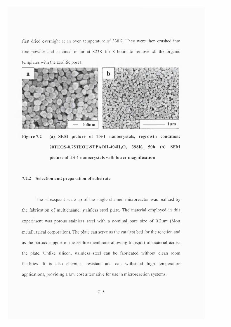
first dried overnight at an oven temperature of 338K. They were then crushed into
fine powder and calcined in air at 823K for 8 hours to remove all the organic
templates with the zeolitic pores.
— lOOnm
Figure 7.2 (a) SEM picture o f TS-1 nanocrystals, regrowth condition:
20TEOS-0.75TEO T-9TPAOH -404H 2O, 398K, 50h (b) SEM
picture of TS-1 nanocrystals with lower m agnification
7.2.2 Selection and preparation of substrate
The subsequent scale up of the single channel microreactor was realized by
the fabrication of multichannel stainless steel plate. The material employed in this
experiment was porous stainless steel with a nominal pore size of 0.2pm (Mott
metallurgical corporation). The plate can serve as the catalyst bed for the reaction and
as the porous support of the zeolite membrane allowing transport of material across
the plate. Unlike silicon, stainless steel can be fabricated without clean room
facilities. It is also chemical resistant and can withstand high temperature
applications, providing a low cost alternative for use in microreaetion systems.
215
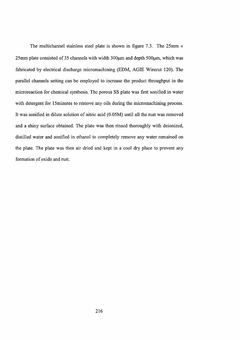
The multichannel stainless steel plate is shown in figure 7.3. The 25mm x
25mm plate consisted of 35 channels with width 300pm and depth 500pm, which was
fabricated by electrical discharge micromachining (EDM, AGIE Wirecut 120). The
parallel channels setting can be employed to increase the product throughput in the
microreaction for chemical synthesis. The porous SS plate was first sonified in water
with detergent for 15minutes to remove any oils during the micromachining process.
It was sonified in dilute solution of nitric acid (0.05M) until all the rust was removed
and a shiny surface obtained. The plate was then rinsed thoroughly with deionized,
distilled water and sonified in ethanol to completely remove any water remained on
the plate. The plate was then air dried and kept in a cool dry place to prevent any
formation of oxide and rust.
216
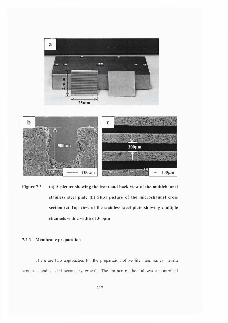
r f '
25mm
500|xm
lOOum — 1 0 0 |j,m
Figure 7.3 (a) A picture showing the front and back view of the multichannel
stainless steel plate (b) SEM picture of the microchannel cross
section (c) Top view of the stainless steel plate showing multiple
channels with a width of 300pm
7.2.3 Membrane preparation
There are two approaches for the preparation o f zeolite membranes: in-situ
synthesis and seeded secondary growth. The former method allows a controlled
217
condition so zeolite can nucleate and grow directly from the surfaee of the porous
support. However, this will require a longer synthesis time to obtain the continuous
film. A thick coating with multiple crystal layers and randomly orientation will result.
A more promising technique will be the synthesis of continuous zeolite film onto
seed-coated layers. Chau et al. (2000) has demonstrated the preparation of silicalite-1
film onto porous stainless steel. By chemically modification and seeding of the
support surface, this method gives highly reproducible film structure.
In this study, the seeded secondary growth method to prepare the ZSM-5
membrane is employed. The flat surface at the back of the stainless steel plate was
first coated with colloidal silicalite-1 seeds prior to hydrothermal synthesis. The
zeolite seeds were synthesized from a mixture eontaining 15 g of fumed silica, 0.85 g
of sodium hydroxide (NaOH), and 60mL of 1 M TPAOH solution. The mixture was
stirred overnight until a elear and homogeneous solution was obtained. The synthesis
mixture then underwent hydrothermal treatment at a temperature of 398 K for 8
hours. The colloidal zeolites were recovered and purified using a series of
centrifugation and rinsing steps. The silicalite-1 seeds have a spherical shape and an
average partiele size of 100 nm. The zeolite has a BET surfaee area of 420 m^/g as
measured by N2 physisorption.
The stainless steel support was first brushed with mercapto-3-
propyltrimethoxysilane surfactant. A thin layer of colloidal silicalite-1 zeolite seeds in
Iwt % of absolute ethanol was then applied onto the surface. The steps were repeated
218
four times to obtain a complete and uniform coverage of the zeolite seeds onto the
support surface. After drying at room temperature overnight, the seeded plate was
heat treated at 523 K for 24 hours to produce a better adhesion to the surface.
The ZSM-5 membranes were prepared with a synthesis mixture with a mole
ratio of 80TEOS: lONaOH: 1 TPAOH: 8 Al: 20000 H2O. A1 was obtained by heating
aluminium sulphate (Al3(S0 4 )2) with ammonium hydroxide (NH4OH) and mixed for
2 hours. The mixture was then washed and filtered with distilled, deionized water to
obtain the remaining white powder, which was the aluminium source. The powder
was then added to the mixture of NaOH, TPAOH with water. A homogenous
solution was acquired by 24 hours of mixing for hydrothermal synthesis.
The stainless steel plate was then placed onto a specially designed Teflon
holder so that the seeded surface facing downwards. This was to prevent any
precipitate or powders from being incorporated into the zeolite film. The
hydrothermal treatment was carried out at a temperature of 453 K for 48 hours. The
same treatment was repeated thrice to obtain the desired thickness and coverage of
the ZSM-5 membrane. The membrane was then activated at 673 K for 48 hours to
make sure the TPA^ organic template was removed from the voids in the zeolite
channels.
219
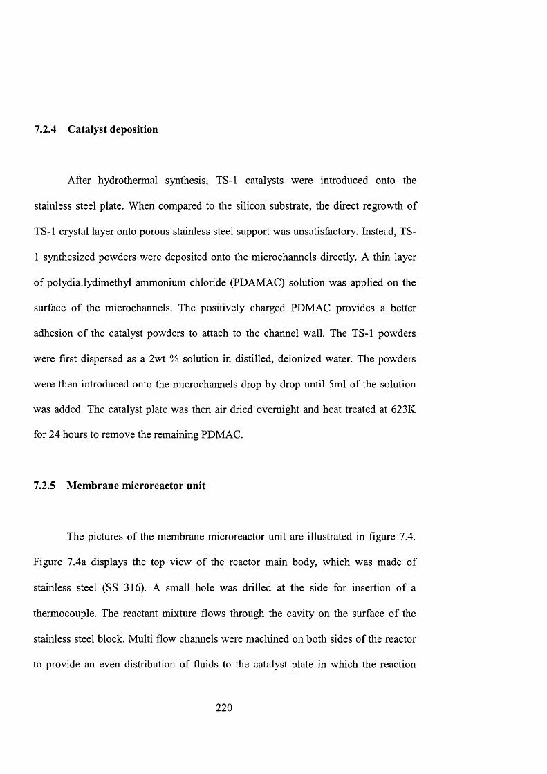
7.2.4 Catalyst deposition
After hydrothermal synthesis, TS-1 catalysts were introduced onto the
stainless steel plate. When compared to the silicon substrate, the direct regrowth of
TS-1 crystal layer onto porous stainless steel support was unsatisfactory. Instead, TS-
1 synthesized powders were deposited onto the microchannels directly. A thin layer
of polydiallydimethyl ammonium chloride (PDAMAC) solution was applied on the
surface of the microchannels. The positively charged PDMAC provides a better
adhesion of the catalyst powders to attach to the channel wall. The TS-1 powders
were first dispersed as a 2wt % solution in distilled, deionized water. The powders
were then introduced onto the microchannels drop by drop until 5ml of the solution
was added. The catalyst plate was then air dried overnight and heat treated at 623K
for 24 hours to remove the remaining PDMAC.
7.2.5 Membrane microreactor unit
The pictures of the membrane microreactor unit are illustrated in figure 7.4.
Figure 7.4a displays the top view of the reactor main body, which was made of
stainless steel (SS 316). A small hole was drilled at the side for insertion of a
thermocouple. The reactant mixture flows through the cavity on the surface of the
stainless steel block. Multi flow channels were machined on both sides of the reactor
to provide an even distribution of fluids to the catalyst plate in which the reaction
2 2 0
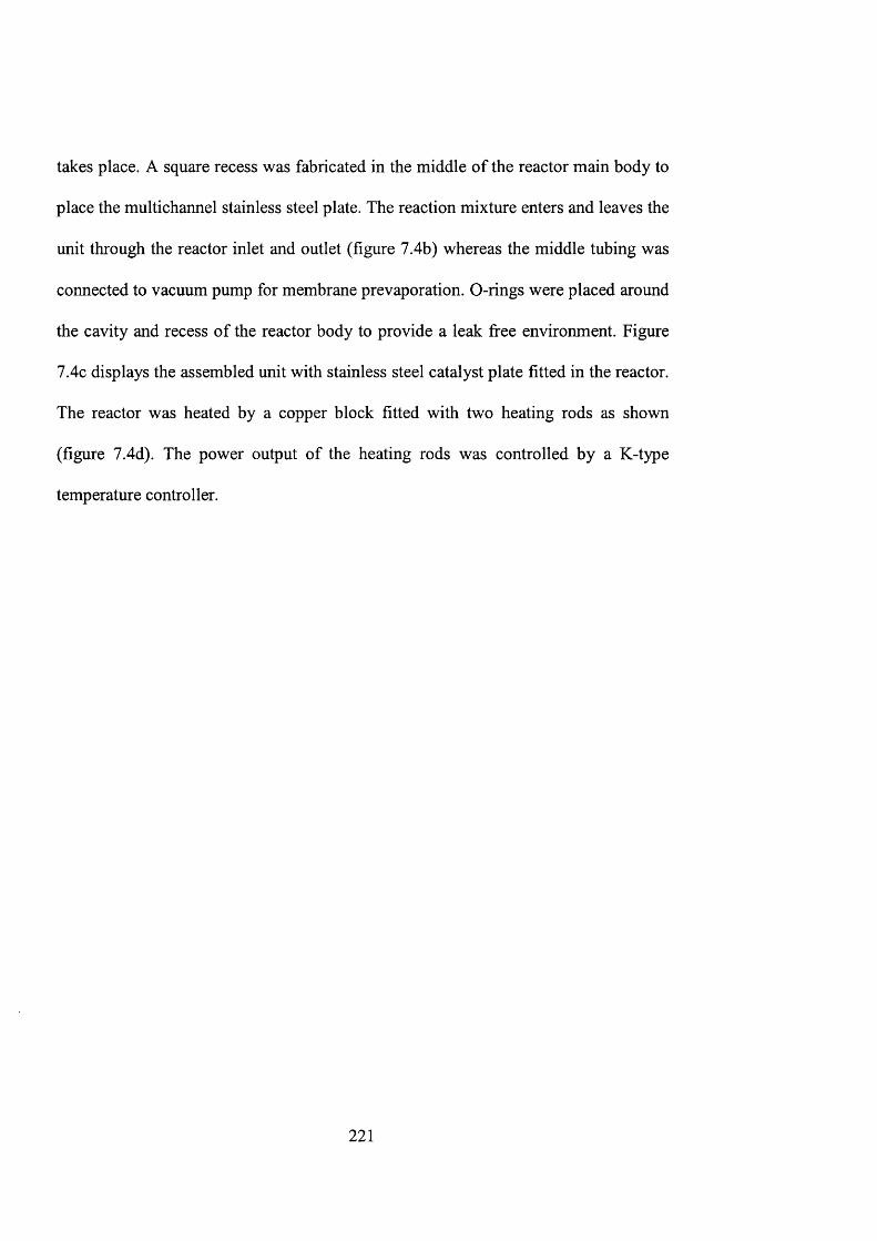
takes place. A square recess was fabricated in the middle of the reactor main body to
place the multichannel stainless steel plate. The reaction mixture enters and leaves the
unit through the reactor inlet and outlet (figure 7.4b) whereas the middle tubing was
connected to vacuum pump for membrane prevaporation. 0 -rings were placed around
the cavity and recess of the reactor body to provide a leak free environment. Figure
7.4c displays the assembled unit with stainless steel catalyst plate fitted in the reactor.
The reactor was heated by a copper block fitted with two heating rods as shown
(figure 7.4d). The power output of the heating rods was controlled by a K-type
temperature controller.
221
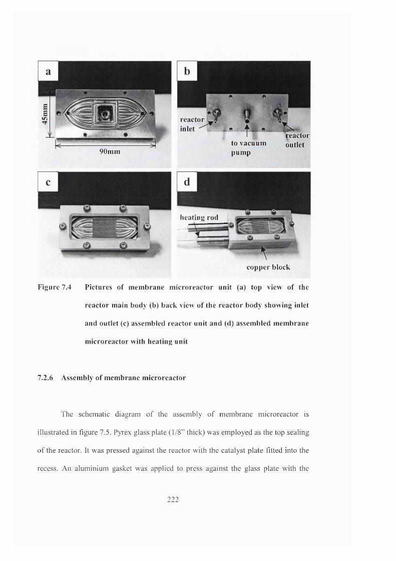
reactor inlet ft æ*-iism
90mmto vacuum pump
Reactoroutlet
heating rod
copper block
Figure 7.4 Pictures of membrane microreactor unit (a) top view of the
reactor main body (b) back view of the reactor body showing inlet
and outlet (c) assembled reactor unit and (d) assembled membrane
microreactor with heating unit
7.2.6 Assembly of membrane microreactor
The schematic diagram o f the assembly o f membrane microreactor is
illustrated in figure 7.5. Pyrex glass plate (1/8” thick) was employed as the top sealing
of the reactor. It was pressed against the reactor with the catalyst plate fitted into the
recess. An aluminium gasket was applied to press against the glass plate with the
222
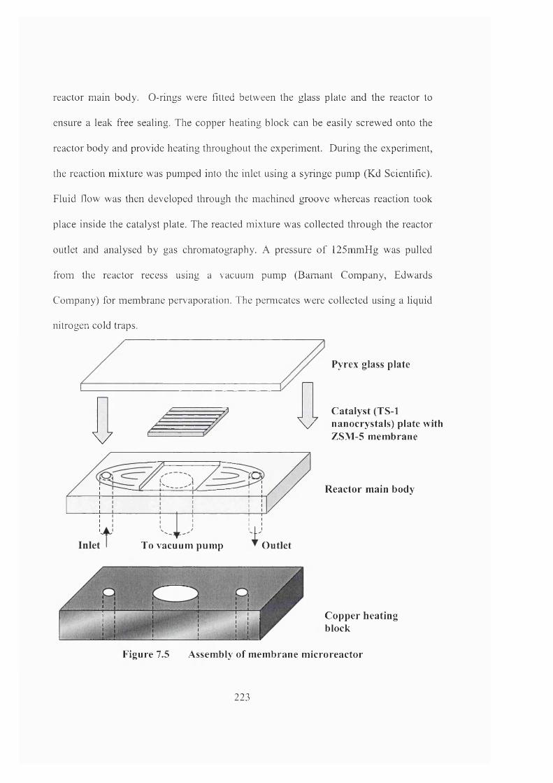
reactor main body. 0 -rings were fitted between the glass plate and the reactor to
ensure a leak free sealing. The copper heating block can be easily screwed onto the
reactor body and provide heating throughout the experiment. During the experiment,
the reaction mixture was pumped into the inlet using a syringe pump (Kd Scientific).
Fluid flow was then developed through the machined groove whereas reaction took
place inside the catalyst plate. The reacted mixture was collected through the reactor
outlet and analysed by gas chromatography. A pressure of 125mmHg was pulled
from the reactor recess using a vacuum pump (Bamant Company, Edwards
Company) for membrane pervaporation. The permeates were collected using a liquid
nitrogen cold traps.
Pyrex glass plate
I I Catalyst (TS-1 \ / nanocrystals) plate with
ZSM -5 m em braneV
" Outlet
R eactor main body
To vacuum pump
Copper heating block
Figure 7.5 A ssem bly o f m em brane m icroreactor
223
7 . 2 . 7 S e l e c t i v e o x i d a t i o n o f a n i l i n e
The membrane microreactor system was used to study titanium silicalite-1
catalyzed oxidation reaction using hydrogen peroxide as the oxidizing agent. This set
can allow a reaction temperature up to 150°C while the silicon T-channel
microreactor was for low temperature application in epoxidation reactions.
Hydrophilic ZSM-5, with a maximum free pore diameter of 5.4Â is capable of
selective water permeation from a mixture with hydrocarbons. ZSM-5 membrane can
be employed for removal of water, which is the side product of the TS-I/H2O2
oxidation reaction. As described in chapter 6.4.5, it is suspected that the presence of
water will deactivate the catalyst. Another reason for catalyst deactivation is the
adsorption of organic compounds on TS-1 active sites.
In order to observe the improvement obtained in the membrane microreactor
system, selective oxidation is chosen with a higher reaction temperature. In this study,
oxidation of aniline over TS-1 is examined with azobenzene and azoxybenzene as the
major products. The by-product water can be continuously removed from the
membrane by connecting to a vacuum while TS-1 deposited in the micromachined
channels acted as catalyst bed for the reaction. In a typical run of the membrane
microreaction, 4.8ml of aniline and 1.2ml of 30wt % hydrogen peroxide were added
to 14ml of chloroform, which acted as the solvent of the reaction. The reaction
mixture was then introduced into the unit where the reaction took place. The details
of the different reaction parameters are listed in table 7.1.
224
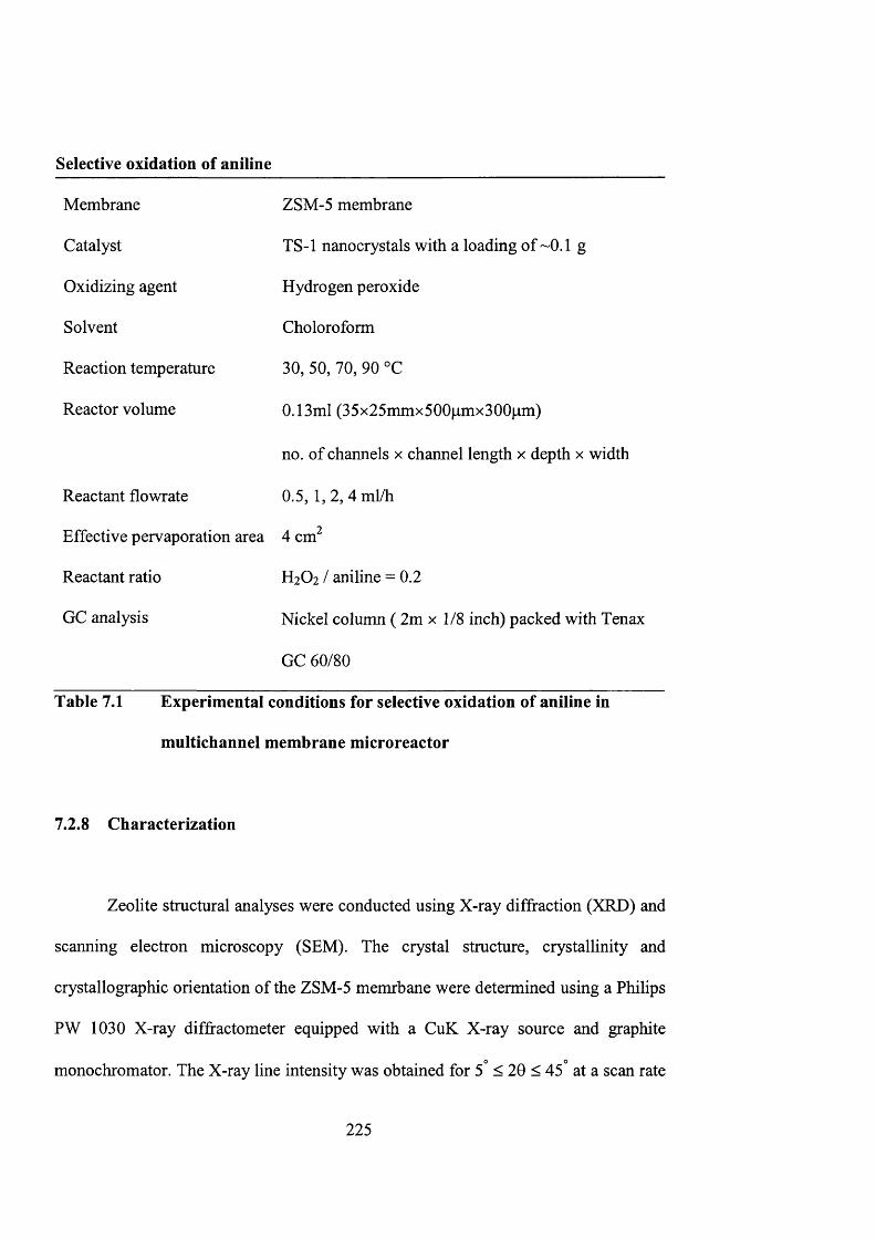
S e l e c t i v e o x i d a t i o n o f a n i l i n e
Membrane ZSM-5 membrane
Catalyst TS-1 nanocrystals with a loading of ~0.1 g
Oxidizing agent Hydrogen peroxide
Solvent Choloroform
Reaction temperature 30, 50, 70, 90 °C
Reactor volume 0.13ml (35x25mmx500pmx300p,m)
no. of chaimels x channel length x depth x width
Reactant flowrate 0.5, 1,2,4 ml/h
Effective pervaporation area 4 cm^
Reactant ratio H2O2 / aniline = 0.2
GC analysis Nickel column ( 2m x 1/8 inch) packed with Tenax
GC 60/80
Table 7.1 Experimental conditions for selective oxidation of aniline in
multichannel membrane microreactor
7.2.8 Characterization
Zeolite structural analyses were conducted using X-ray diffraction (XRD) and
scanning electron microscopy (SEM). The crystal structure, crystallinity and
crystallographic orientation of the ZSM-5 memrbane were determined using a Philips
PW 1030 X-ray diffractometer equipped with a CuK X-ray source and graphite
monochromator. The X-ray line intensity was obtained for 5° < 20 < 45° at a scan rate
225
of 0.02 /min and time constant of 0.02. SEM was employed to determine the
dimensions of the microchannels, and to measure the thickness of the ZSM-5
membrane coated on the back of the stainless steel plate. The samples were mounted
onto aluminium specimen stubs with conducting carbon tape and sputter-coated with
a 10 nm layer of gold to reduce sample charging. The zeolite surface morphology and
grain size were also determined from analysis of the SEM micrographs. Bulk and
surface compositions of zeolites were examined by X-ray photoelectron spectroscopy
(XPS, Physical Electronics PHI 5600).
7.2.9 Materials
For TS-1 synthesis, the chemicals used were TEOS (98%, Aldrich), tetraethyl
orthotitanate (95%, MERCK-Schuchardt) and TPAOH (1 M, Aldrich). The silicalite-
1 seeds were prepared with fumed silica (0.01pm, 99.8%, Aldrich), TEOS and
sodium hydroxide (98%, BDH). Aluminium sulphate (98+%, Aldrich) and
ammonium hydroxide (28-30%, Fisher Scientific), TPAOH and TEOS were
employed for the synthesis of ZSM-5 membrane. The chemicals used for catalyst
deposition was polydiallydimethyl ammonium chloride ( 2 0 wt% in water with
average Mw 200,000-350,000, Aldrich).
For reaction experiments, the chemicals used were aniline (99.5%, Aldrich),
hydrogen peroxide (30 wt.%, BDH) and chloroform (99.8%, Aldrich).
226
7.3 Results and discussion
7.3.1 Membrane characterization
It has been reported that the zeolite films obtained by in-situ synthesis will
exhibit [OkO] or [hOO]-out-of-plane orientation while a [hOh]-out-of-plane preferred
orientation will obtained by secondary growth (Gouzinis and Tsapatsis, 1998;
Xomeritakis et al, 1999; Koegler et al. 1997). In this study, the seeded secondary
growth method for the preparation of ZSM-5 membranes onto porous stainless steel
plate is employed.
The deposition and growth of ZSM-5 zeolite onto a stainless steel support are
shown in figure 7.6. Figure 7.6a displays the surface morphology of the ZSM-5
membrane. The zeolites indicated an MFI crystalline structure with a crystal coverage
of approximately 6.5x10^^ crystals/m^. The crystals were well intergrown with a size
of 10pmxl5pm forming a continuous zeolite film. The film has a thickness of 25pm
with a surface roughness about 5pm (figure 7.6b). XPS indicated a Si/Al ratio of 18.5
for the ZSM-5 zeolites. The zeolite film exhibits great adhesion to the stainless steel
support. They are able to withstand harsh and extreme operating conditions showing
stable prevaporation performance throughout the experiment.
The XRD analysis in figure 7.6c displays the different orientation of the
crystal layer obtained for the membrane. The ZSM-5 crystals on the seeded support
2 2 7
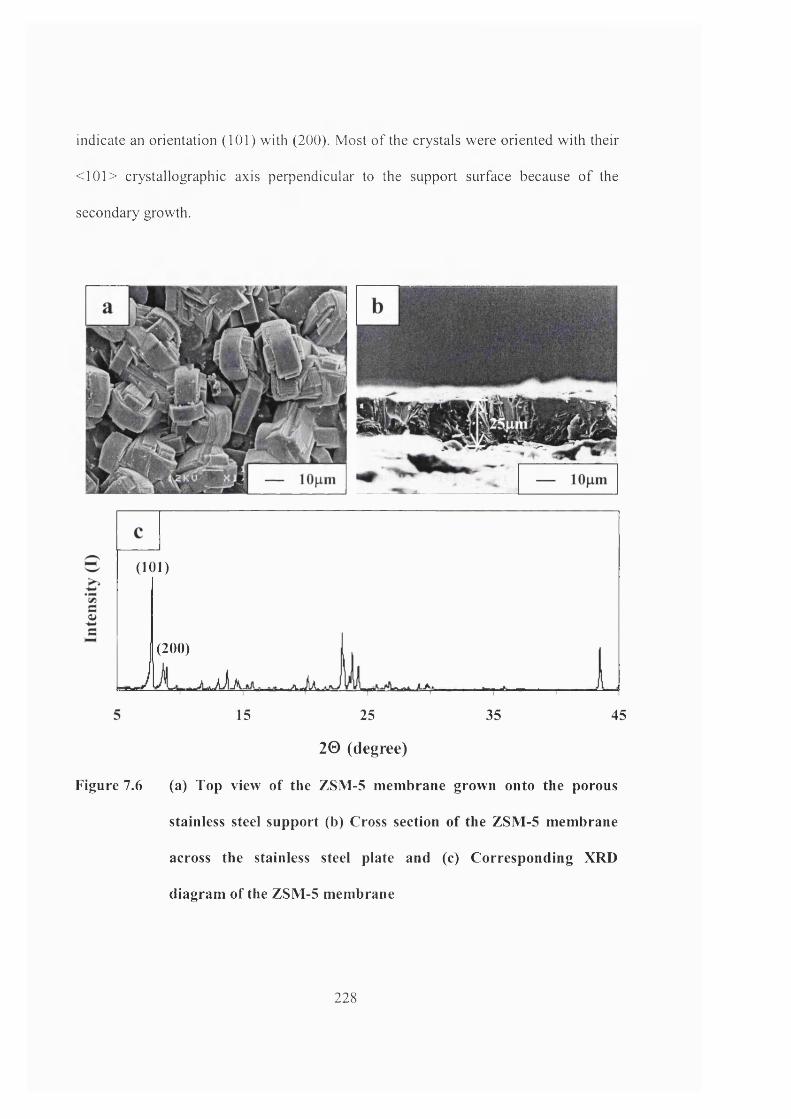
indicate an orientation (101) with (200). Most of the crystals were oriented with their
<101> crystallographic axis perpendicular to the support surface because o f the
secondary growth.
(101)
(200)
. fSËi f m iA^AAi
15 3525
2 0 (degree)
Figure 7.6 (a) Top view of the ZSM-5 membrane grown onto the porous
stainless steel support (b) Cross section of the ZSM-5 membrane
across the stainless steel plate and (c) Corresponding XRD
diagram of the ZSM-5 membrane
45
228
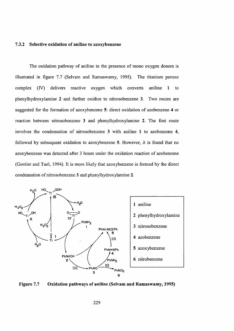
7 . 3 . 2 S e l e c t i v e o x i d a t i o n o f a n i l i n e t o a z o x y b e n z e n e
The oxidation pathway of aniline in the presence of mono oxygen donors is
illustrated in figure 7.7 (Selvam and Ramaswamy, 1995). The titanium peroxo
complex (IV) delivers reactive oxygen which converts aniline 1 to
phenylhydroxylamine 2 and further oxidize to nitrosobenzene 3. Two routes are
suggested for the formation of azoxybenzene 5: direct oxidation of azobenzene 4 or
reaction between nitrosobenzene 3 and phenylhydroxylamine 2. The first route
involves the condensation of nitrosobenzene 3 with aniline 1 to azobenzene 4,
followed by subsequent oxidation to azoxybenzene 5. However, it is found that no
azoxybenzene was detected after 3 hours under the oxidation reaction of azobenzene
(Gontier and Tuel, 1994). It is more likely that azoxybenzene is formed by the direct
condensation of nitrosobenzene 3 and phenylhydroxylamine 2.
.OCH
,0H
wPhNH.
P h N = N (0 )P h
to]
PhNHOHPhNH2
CO] P hN O
1 aniline
2 phenylhydroxylamine
3 nitrosobenzene
4 azobenzene
5 azoxybenzene
6 nitrobenzene
Figure 7.7 Oxidation pathways of aniline (Selvam and Ramaswamy, 1995)
229
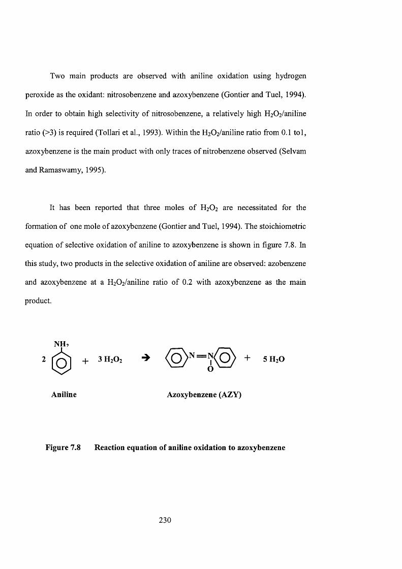
Two main products are observed with aniline oxidation using hydrogen
peroxide as the oxidant: nitrosobenzene and azoxybenzene (Gontier and Tuel, 1994).
In order to obtain high selectivity of nitrosobenzene, a relatively high H2 0 2 /aniline
ratio (>3) is required (Tollari et ah, 1993). Within the H2 0 2 /aniline ratio from 0.1 toi,
azoxybenzene is the main product with only traces of nitrobenzene observed (Selvam
and Ramaswamy, 1995).
It has been reported that three moles of H2O2 are necessitated for the
formation of one mole of azoxybenzene (Gontier and Tuel, 1994). The stoichiometric
equation of selective oxidation of aniline to azoxybenzene is shown in figure 7.8. In
this study, two products in the selective oxidation of aniline are observed: azobenzene
and azoxybenzene at a H2 0 2 /aniline ratio of 0 . 2 with azoxybenzene as the main
product.
NH,
O ] + +O ' — '
SH2O
Aniline Azoxybenzene (AZY)
Figure 7.8 Reaction equation of aniline oxidation to azoxybenzene
230
7.3.3 Membrane microreactor results
The reaction was conducted in the membrane microreactor unit with and
without water removal. Four flowrates were studied in the experiment: 0.5, 1, 2 and
4ml/h at a temperature of 343 K. However, it is found that at a flowrate of 4ml/h, the
product yields obtained for azobenzene and azoxybenzene were not adequate to
observe the difference of product removal. There was no significant improvement in
product selectivity towards azoxybenzene. This can be explained by the fact that the
residence time attained at such a flowrate was not enough for the reaction mixture to
stay in the reactor chamber for effective water removal.
Figure 7.9 illustrates the product yield of azoxybenzene at 2ml7h with a
residence time of 234s. The residence time was calculated from the volume of the
microchannels within the stainless steel plate (0.13ml) and total liquid flowrate
(2ml/h). The average product yield shows an increment of 10% with water removal
when compared with the result obtained without membrane prevaporation.
231
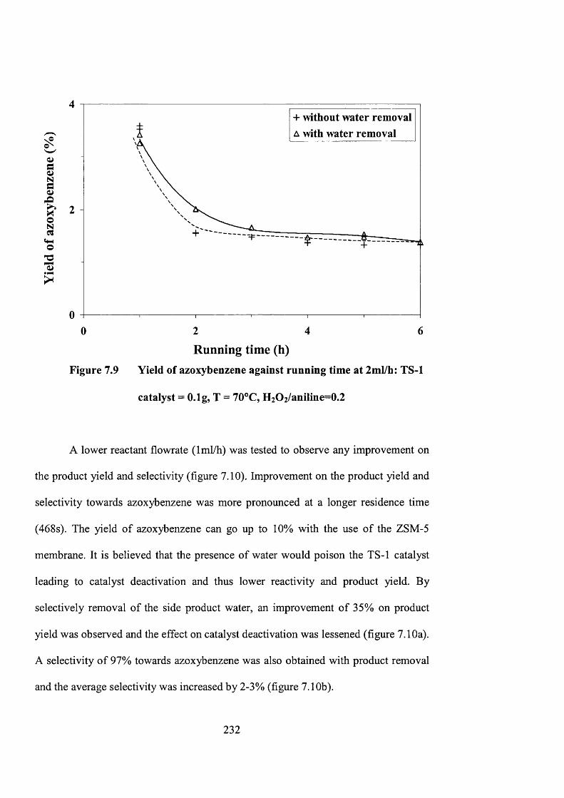
0ggf1O
?
4
+ without water rem oval
A with water rem oval
2
02 4 60
Running time (h)Figure 7.9 Yield of azoxybenzene against running time at 2ml/h: TS-1
catalyst = O.lg, T = 70°C, H2O2/aniline=0.2
A lower reactant flowrate (Iml/h) was tested to observe any improvement on
the product yield and selectivity (figure 7.10). Improvement on the product yield and
selectivity towards azoxybenzene was more pronounced at a longer residence time
(468s). The yield of azoxybenzene can go up to 10% with the use of the ZSM-5
membrane. It is believed that the presence of water would poison the TS-1 catalyst
leading to catalyst deactivation and thus lower reactivity and product yield. By
selectively removal of the side product water, an improvement of 35% on product
yield was observed and the effect on catalyst deactivation was lessened (figure 7.10a).
A selectivity of 97% towards azoxybenzene was also obtained with product removal
and the average selectivity was increased by 2-3% (figure 7.10b).
232
An increased yield of azoxybenzene was observed with water removal. This
can be explained by the fact that the presence of water will reduce the TS-1 activity.
Thiele and Roland (1997) have observed the reversible deprotonation of the
coordinated water which will convert most titanium sites to an ate complex with
coordinated hydrogen peroxide. The ate complex does not form any active sites for
reaction when in contact with hydrogen peroxide which increases the tendency for
byproduct formation. It is also suspected that the presence of water may induce side
reactions thus lowering the product selectivity towards azoxybenzene.
The catalyst deactivation is also caused by the adsorption of organic
compounds on Ti sites. Aniline and its reaction intermediates are bigger molecules,
which are likely to deposit inside the zeolite pores and will block the TS-1 pores
causing diffusional hindrance (Unguina et al., 2000).
It is also interesting to note that the product yield curve seems to tend towards
a constant value (figure 7.9 and 7.10a). After a reaction time of 5 hours, a similar
product yield was obtained regardless of the use of a membrane for water removal. It
may be due to the fact that water removal was less effective after prolonged periods
of prevaporation. Uguina and co-workers (2000) have observed that longer reaction
times will favour preferential chemisorption of aldehydes (product) versus styrene
(reactant) in TS-1 catalysed styrene oxidation. This may be the case for selective
oxidation of aniline. The proportion of aniline occluded in the spent catalyst will
2 3 3
decrease, while the amounts of hydroxylamines and azoxy compounds will be
enhanced with reaction time.
It can be concluded that there were two mechanisms involved in catalyst
deactivation: the presence of water byproduct and adsorption of organic compounds.
At high reaction rates (initial running time), water adsorption is predominant causing
catalyst deactivation over time while longer reaction times will favour preferential
adsorption of product. That is why the catalyst deactivation was reduced with a longer
running time.
Although a greater improvement on the product yield and selectivity was
observed when the residence time was lengthened, this would only apply at a
residence time larger than 500s. At a flowrate lower than Iml/h (i.e. 0.5ml/h), catalyst
initial deactivation was much more significant with reaction rates lower than
expected. Difficulties were encountered to evenly distribute the fluid along the
multiple microchannels. This will also result in bubble formation causing cavitation.
234
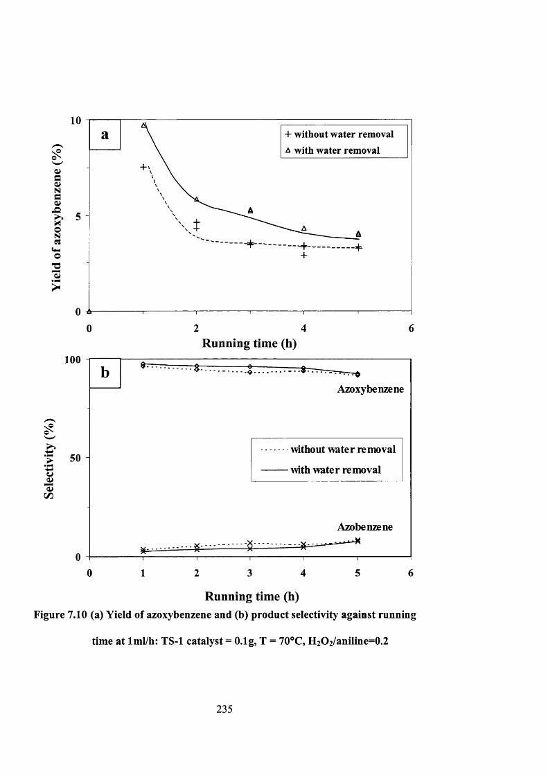
0^gI!>I
4-1O
?
10+ without water removalA with water removal
5
— -----
062 40
100
IIc/3
50
Running time (h)
Azoxybenzene
without water removal
with water removal
Azobenzene
Running time (h)Figure 7.10 (a) Yield of azoxybenzene and (b) product selectivity against running
time at Iml/h: TS-1 catalyst = O.lg, T = 70°C, H2O2/aniline=0.2
235
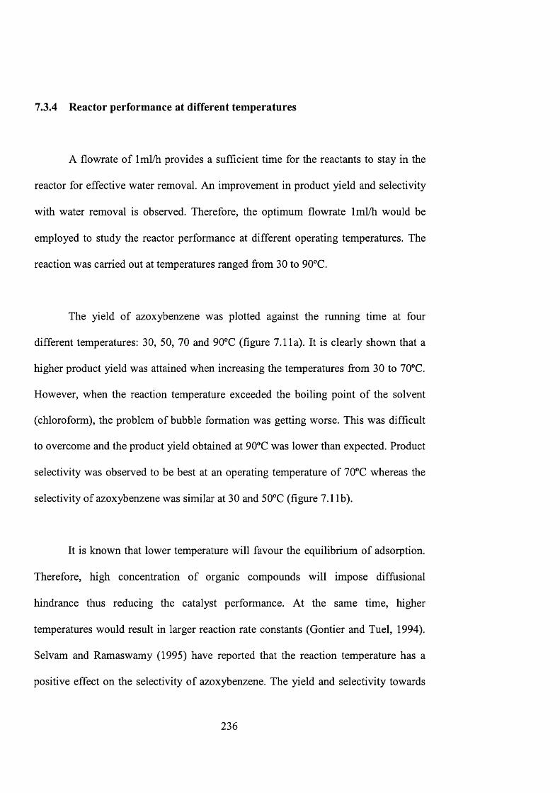
7 . 3 . 4 R e a c t o r p e r f o r m a n c e a t d i f f e r e n t t e m p e r a t u r e s
A flowrate of Iml/h provides a sufficient time for the reactants to stay in the
reactor for effective water removal. An improvement in product yield and selectivity
with water removal is observed. Therefore, the optimum flowrate Iml/h would be
employed to study the reactor performance at different operating temperatures. The
reaction was carried out at temperatures ranged from 30 to 90°C.
The yield of azoxybenzene was plotted against the running time at four
different temperatures: 30, 50, 70 and 90°C (figure 7.11a). It is clearly shown that a
higher product yield was attained when increasing the temperatures from 30 to 70”C.
However, when the reaction temperature exceeded the boiling point of the solvent
(chloroform), the problem of bubble formation was getting worse. This was difficult
to overcome and the product yield obtained at 90°C was lower than expected. Product
selectivity was observed to be best at an operating temperature of 70°C whereas the
selectivity of azoxybenzene was similar at 30 and 50®C (figure 7.1 lb).
It is known that lower temperature will favour the equilibrium of adsorption.
Therefore, high concentration of organic compounds will impose diffusional
hindrance thus reducing the catalyst performance. At the same time, higher
temperatures would result in larger reaction rate constants (Gontier and Tuel, 1994).
Selvam and Ramaswamy (1995) have reported that the reaction temperature has a
positive effect on the selectivity of azoxybenzene. The yield and selectivity towards
2 3 6
azoxybenzene was shown to increase with reaction temperature from 30 to 70°C.
However, this effect was not observed at a reaction temperature of 90°C. Besides
bubble formation, it is hypothesized that high reaction temperatures (90°C) will
increase the formation of oligomeric compounds in the reaction medium (Thiele and
Roland, 1997). The deposition of oligomeric compounds inside the zeolite pores will
block the catalyst active sites. This may also induce side reactions thus reducing
product selectivity to azoxybenzene.
237
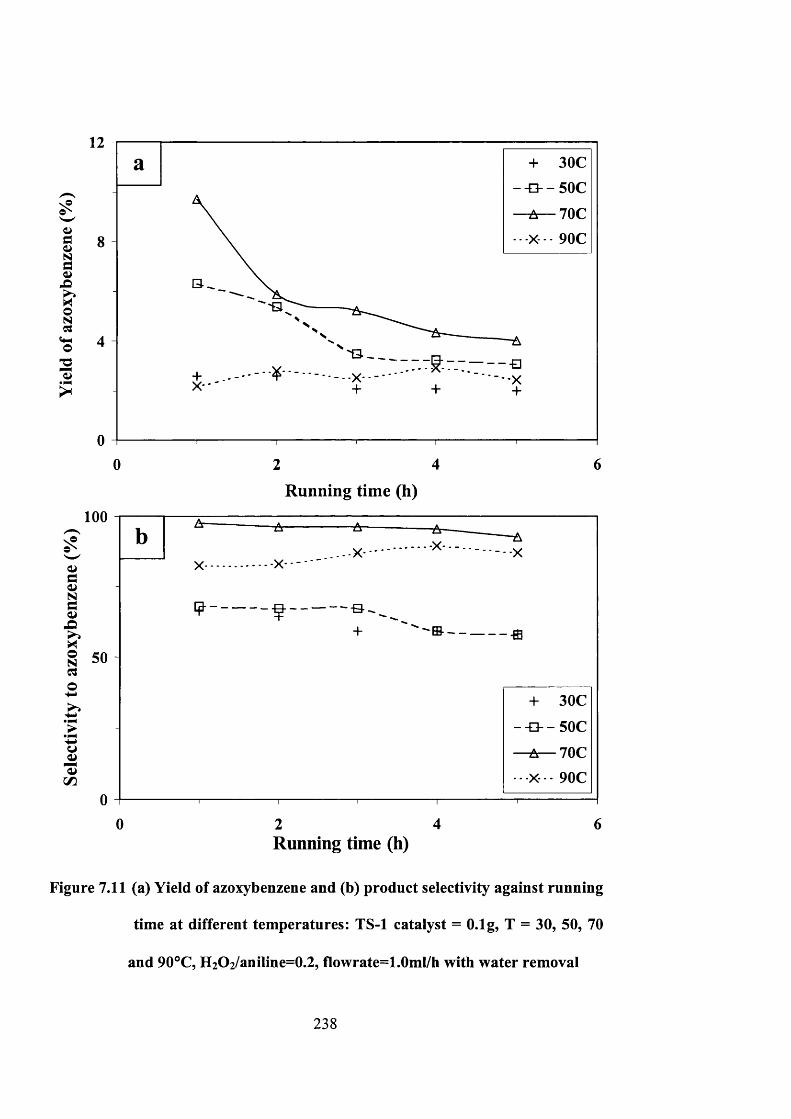
(UsgIio
?
12+ 30C
--E3--50C
70CX 90C8
4- € ]
XX '
04 620
Running tim e (h)
100
- XX -
g
itg soao'W
- fffi- ---------^
+ 30C
—D— 50C
4 60 2Running time (h)
Figure 7.11 (a) Yield of azoxybenzene and (b) product selectivity against running
time at different temperatures: TS-1 catalyst = O.lg, T = 30, 50, 70
and 90°C, H2O2/aniline=0.2, Uowrate=l .Oml/h with water removal
2 3 8
7 . 4 C o n c l u d i n g r e m a r k s
The application of a multichannel membrane microreactor in the study of
selective oxidation of aniline was successfully demonstrated. The high surface area to
volume ratio that can be attained in the microreactor (3000m^/m^) facilitates the
selective removal of water by-product, which reduces the effect of catalyst
deactivation during the reaction. The improvement in the product yield and selectivity
towards azoxybenzene was also obseiwed. The setup can also withstand a reaction
temperature up to 150°C.
The design of the reactor system facilitates the combination of separation and
reaction in one unit. This concept can be further developed for the in-situ production
of fine chemicals, enabling isolation of reaction intermediates and pure products. The
design also works well for a hazardous reaction system, for the case of aniline, which
is highly toxic. The idea of enclosing and integrating the reaction processes enables
safer handling of toxic and explosive chemicals.
However, the fabrication procedures of the ZSM-5 membrane and subsequent
catalyst deposition are quite lengthy. A possible alternative is the use of a
catalytically active membrane (i.e. H-ZSM-5, TS-1 membrane) to shorten the
preparation time and improve the catalyst loading. Improvement in the reactor design
should be considered to provide a better liquid distribution across the multichannel
plate.
2 3 9

CHAPTER 8
Conclusions and Future Work
240
8 . 1 C o n c l u s i o n s
Microtechnology has visualized the development of microchemical devices
for various chemical and biological applications. Microreactors can help to redeem
the main concerns of safety and environmental issues in major chemical plants
(Jensen, 2001). They can provide better energy and material utilization, leading to
cost reduction and pollution abatement (Gavriilidis et al., 2002). New reaction
regimes can be explored by the use of microreactors resulting in improved product
yield and selectivity (Ehrfeld et al., 2000).
Catalyst incorporation is a critical task in microreactor fabrication. Metal
catalysts can be deposited in microchannels using sputter coating, thermal deposition
or chemical vapour deposition (Thomas and Thomas, 1997; Kursawe and Hdnicke,
2000). However, these methods are only limited to metal thin film catalysts. Catalyst
powders are usually packed or coated on the microchannel. Packing requires a
catalyst filter structure and the pressure drop can be severe across the packed bed of
catalyst powders in the microchannel (Ajmera et al., 2001). Also, catalyst powders
coated onto the channel wall can delaminate during reaction resulting in lost activity
and in some cases the detached powder can clog the microchannel.
Incoporating zeolite employs a different strategy, this provides room to
improve current disadvantages of catalysts incorporation in microreactors. Zeolites
can be grown directly onto microstructured supports providing a strong adhesion to
241
the microchannel. The silica (Si02) structure of zeolites can also enable the
fabrication of zeolite micropattems by employing traditional clean room techniques.
A precise and localized addition of zeolite materials in a microchannel can be
obtained leading to a successful integration of zeolite catalyst and membrane within
the design architecture of microchemical devices. Therefore, zeolites can serve as
substrates for fabrication in microchemical devices. Their microstructure and
chemistry can be tailored for catalysis and separation processes (Bhatia, 1990). They
possess great thermal and mechanical stability, which can withstand severe reaction
conditions (Feast and Lercher, 1996).
The main objective of this project was to develop the technology and
applications of zeolite-based microreactors in catalytic reactions and separation
processes. The well-defined flow characteristics in the microchannel enable a better
theoretical prediction of the reactor performance through the development of
computer simulation models. It is expected to observe an increase in product yield
and selectivity with improved mass transfer properties.
However, due to catalyst deactivation and titanium leaching from the zeolite
framework, the experimental results reveal that the improvement in product yield in
the microreactor is not as expected. The other reason is the presence of internal
diffusion resistance within TS-1 catalysts. These findings provide an insight to further
understand the microreactor performance and suggesting ways to improve the catalyst
and reactor design.
242
The important findings from this objective are the following:
1. The thesis introduces a novel fabrication procedure to incorporate zeolite in
the design of microchemical devices. The technique was based on
microelectronic fabrication and zeolite thin film technologies. The ability to
control zeolite film thickness and orientation has been demonstrated. High-
resolution micropattems of complex microchannel geometry and network, as
well as complex catalyst arrays (size of 3 pm) were successfully etched onto
zeolite silicon composites. Blueprints for zeolite-based microchemical devices
are presented and their structural details were analysed.
2. MFI zeolite has been employed as catalyst, membrane and stmctural materials
in microreactors and microseparators. Zeolite powder coatings, uniform
zeolite film growth, localized zeolite growth, and etching of zeolite-silicon
composite films were successfully implemented for the fabrication of zeolite
catalytic microreactors. Silicalite-1 was prepared as a free-standing membrane
in zeolite microseparators.
3. The first prototype of zeolite catalytic microreactor has been successfully
fabricated and tested for 1-pentene epoxidation. A simple computational
model has been introduced for design and data interpretation to study the
243
microreactor performance. The modelling result was shown to compare well
with the experimental data.
4. The technique to engineer the catalyst microstructure and chemistry has been
demonstrated. The data obtained through computer simulation can act as a
tool to better understand the catalyst properties and suggest ways of
improving the microreactor performance. The catalyst performance can be
improved through the addition of crystal growth inhibitors and optimum OH
/Si ratio in synthesis solution whereas a linear relationship of catalytic activity
with titanium loading was obtained. Catalyst short-term deactivation was
attributed to the formation of organic compounds and presence of water.
Titanium leaching was also observed from the zeolite framework.
5. Further improvement and design modification in the zeolite microreactor was
carried out. A multichannel membrane microreactor has been designed and
fabricated for the selective water removal in the study of selective oxidation of
aniline. The high surface area to volume ratio in the microreactor facilitated
the removal of water by-product, thus reducing the effect of catalyst
deactivation. An improvement in product yield and selectivity was observed.
244
8 . 2 F u t u r e W o r k
The following suggested topics would require further investigation:
8.2.1 Improvement in TS-1 catalytic properties
The mechanism by which titanium is leached from the zeolite framework is
unknown. Further studies are to understand the reaction mechanism and improve the
titanium loading within the catalyst. Catalyst layers can be micropattemed to increase
the surface area exposing the active sites for reaction. A detailed computational
model can be established to enhance the microreactor performance.
8.2.2 In-situ production of chemicals
The incorporation of zeolite membranes in catalytic reactions can be further
studied for in-situ production of chemicals, enabling selective removal of reaction
intermediates and side products. Chemical reaction and product purification can be
combined within the membrane microreactor. It can also be applied to explore new
reaction regimes, which cannot be obtained by conventional means.
245
8.2.3 Scale-out of microreactor
Microreactors can be further applied in the chemical industry for fine
chemical production. The annual production throughput can be obtained by repeating
the basic units of microreactors to create an on-site, on-demand production network
for high value added chemicals. The main task is to improve the microreactor design
to achieve uniform flow distribution. Quality control should be carried out during the
fabrication of the microreactors to ensure a reliable operation of scale-out systems.
8.2.4 Application of zeolite microchemcial devices
Zeolite-based microchemical devices can find applications in various
biological and chemical processes. Zeolite membranes can be employed in the design
of microseparators and microcontactors, serving many separation functions in a
micro-analytical laboratory. A zeolite micromembrane can also be incorporated in
electrochemical and sensor devices. It can act as the proton exchange membrane in a
micro fuel cell. For sensor applications, the zeolite membrane can enhance the sensor
performance by acting as a selective barrier. Further studies are encouraged to
explore the different design and application of zeolite-based microchemical devices.
246
Bibliography
1. Ahn, W.S., Kang, K.K. and Kim, K.Y., 2001, Synthesis of TS-1 by microwave
heating of template-impregnated Si02-Ti02 xerogels, Catal Lett, 72: 229-232.
2. Ajmera, S. K, Losey, M.W, Jensen, K. F. and Schmidt, M. A., 2001,
Microfabricated packed-bed reactor for phosgene synthesis, AIChE, 47: 1639-
1647.
3. Ajmera, S. K., Delattre, C., Schmidt, M. A. and Jensen, K.F., 2002,
Microfabricated cross-flow chemical reactor for catalyst testing. Sensor Actuat
B-Chem, 82: 297-306.
4. Amiridis, M. D., Zhang, T. J. and Farrauto, R. J., 1996, Selective catalytic
reduction of nitric oxide by hydrocarbons, Appl Catal B, 10:203-227.
5. Arasasingham, R. D., He, G. X. and Bruice, T. C., 1993, Mechanism of
manganese porphyrin-catalysed oxidation of alkenes. Role of Mn(IV)-oxo
species, y yfm Chem Soc, 115: 7985-7991.
6. Armor, J. N., 1989, Catalysis with permselective inorganic membranes, Appl
Catal, 49: 1-25.
7. Armor, J. N., 1999, Advances in chemistry - Part 1 - Catalysis: Recent value
future opportunities, Chem Eng, 106: 70-74.
8. Arnold, J., Dasbach, U., Ehrfeld, W., Hesch, K. and Lowe, H., 1995,
Combination of excimer laser micromachining and replication processes suited
for large scale production, Appl Surf Soi, 86: 251-258.
247

9. Atoguchi, T. and Yao, S., 2001, Phenol oxidation over titanosilicalite-1:
experimental and DFT study of solvent, JM ol Catal A-Chem, 176: 173-178.
10. Auroux, A., 1994, in Imeik, B. and Vedrine, J. C. (Eds), Catalyst
Characterization Physical Techniques for Solid Materails, Plenum Press, New
York.
11. Baerlocher, Ch., Meier, W. M. and Olson, D. H., 2001, Atlas o f zeolite
framework types, 5 Edition, Elsevier.
12. Bein, T., 1996, Synthesis and applications of molecular sieve layers and
membranes, Chem Mater, 8: 1636-1653.
13. Bellussi, G., Carati, A., Clerici, M. G., Maddinelli, G. and Millini, R., 1992,
Reactions of titanium silicalite with protic molecules and hydrogen-peroxide, J
Catal, 133: 220-230.
14. Bellussi, G. and Rigutto, M. S., 1994, Metal ions associated to the molecular
sieve framework: possible catalytic oxidation sites. Stud in Surf Sci and Catal,
85: 177-213.
15. Bernal, M. P., Coronas, J., Menéndez, M. and Santamaria, J., 2002, Coupling of
reaction and separation at the microscopic level: estérification processes in a H-
ZSM-5 membrane reactor, Chem Eng Sci, 57: 1557-1562.
16. Bhatia, S., 1990, Zeolite Catalysis: Principles and Applications, CRC Press,
Inc.
17. Biscardi, J.A. and E. Iglesia, 1998, Isotopic tracer studies of propane reactions
on H-ZSM5 zeolite, JPhys Chem B, 102: 9284-9289.
248
18. Boudreau, L.C., Kuck, J. A. and Tsapatsis, M., 1999, Deposition of oriented
zeolite A films: in situ and secondary growth, J Membrane Sci, 152: 41-59.
19. Burkett, S.L. and Davis, M. E., 1994, Mechanism of structure direction in the
synthesis of Si-ZSM-5: An investigation by intermolecular ^H-^^Si CP MAS
NMR, JPhy Chem, 98: 4647-4653.
20. Burkett, S. L. and Davis, M. E., 1995, Mechanism of structure direction in the
synthesis of pure-silica zeolites. 1. Synthesis of TPA/Si-ZSM-5, Chem Mater,
7: 920-928.
21. Carati, A., Flego, C., Berti, D., Millini, R., Perego, C., Stocchi, B. and Perego,
C., 1999, Influence of synthesis media on the TS-1 characteristic. Stud in Surf
Sci and Catal, 125: 45-52.
22. Caro, J., Noack, M., Kolsch P. and Schafer, R, 2000, Zeolite membranes - state
of their development and perspective, Microporous Mesoporous Mat, 38: 3-24.
23. Casanave, D., Giroir-Fendler, A., Sanchez, J., Loutaty, R. and Dalmon, J.-A.,
1995, Control of transport properties with a microporous membrane reactor to
enhance yields in dehydrogenation reactions, Catal Today, 25: 309-314.
24. Chao, K. J., Lin, J. C., Wang, Y. and Lee, G. H., Single-crystal structure
refinement of TP A ZSM-5 zeolite, Zeolites, 1986, 6: 35-38.
25. Chau, J. L. H., Tellez, C., Yeung, K. L. and Ho, K., 2000, The role of surface
chemistry in zeolite membrane formation, JMembr Sci, 164: 257-275.
26. Chau, J. L. H., Leung, A. Y. L. and Yeung, K. L., 2002a, Design, fabrication
and performance of zeolite micromembranes, ISCRE-17, Hong Kong, August
25-28.
249
27. Chau, J. L. H., Wan, Y. S. S., Gavriilidis, A. and Yeung, K. L., 2002b,
Incorporating zeolites in microchemical systems, Chem Eng J, 88: 187-200.
28. Chau, J. L. H. and Yeung, K. L., 2002, Zeolite microtunnels and microchannels,
Chem Comm, 9: 960-961.
29. Chau, J. L. H., Leung, A. Y. L., Shing, M. B., Yeung, K. L. and Chan, C. M.,
2003a, Hydrogen and proton transport properties of nanoporous zeolite
micromembranes, in Tang, Z. and Sheng, P. (Eds), Nano Science and
Technology: Novel Structure and Phenomena, Taylor and Francis, London.
30. Chau, J. L. H., Leung, A. Y. L. and Yeung, K. L., 2003b, Zeolite
micromembranes, Lah-on-a-Chip, 3: 53.
31. Chen, L.Y., Chuah, G.K., Jaenicke S., 1998, Propylene epoxidation with
hydrogen peroxide catalyzed by molecular sieves containing framework
titanium ,/M o/ CatalA, 132: 281-292.
32. Cheng, M., Lin, L., Yang, W., Yang, Y., Xu, Y. and Li, X., 1997, Growth of
oriented zeolite crystal membranes. Stud in Surf Sci and Catal, 105: 2233.
33. Choudhary, V.R., Nayak, V. S. and Mamman, A. S., 1992, Diffusion of
straight- and branched-chain liquid compounds in H-ZSM-5 zeolite, Ind Eng
Chem Res, 31: 624-628.
34. Claus, P., Honicke, D. and Zech T., 2001, Miniaturization of Screening Devices
for the Combinatorial Development in Heterogeneous Catalysts, Catal Today,
67: 319-339.
35. Clerici, M.G., 1991, Oxidation of saturated hydrocarbons with hydrogen
peroxide, catalysed by titanium silicalite, Appl Catal, 68:249-261.
250
36. Clerici, M. G., Bellussi, G. and Romano, U., 1991, Synthesis of propylene oxide
from propylene and hydrogen peroxide catalysed by titanium silicalite, J Catal,
129: 159-167.
37. Clerici, M.G., 1993, Catalytic oxidations with hydrogen peroxide: new selective
catalysts. Stud in Surf Sci and Catal, 78: 21-33.
38. Clerici, M. G. and Ingallina, P., 1993, Epoxidation of lower olefins with
hydrogen peroxide and titanium silicalite, / 140: 71-81.
39. Commenge, J. M., Falk, L., Corriou, J. P. and Matlosz, M., 2002, Optimal
design for flow uniformity in microchannel reactors, AIChE J, 48(2): 345-358.
40. Coronas, J. and Santamaria, J., 1999a, Separations using zeolite membranes,
Sep Purification Meth, 28: 127-177.
41. Coronas, J. and Santamaria, J., 1999b, Catalytic reactors based on porous
ceramic membranes, Catal Today, 51: 377-389.
42. Cronstedt, A.F., 1756, Ron och beskrifhing om en obekant bârg art, som kallas
zeolites. Kongl., Vetenskaps Acad. Handl, Stockholm 17: 120-123.
43. Davies, L., McMom, P., Bethell, D., Page, P. C. B., King, F., Hancock, F. E.
and Hutchings, G.J., 2000, By-product formation causes leaching of Ti from
redox molecular sieve TS-1, Chem Comm, 1807-1808.
44. Davies, L., McMom, P., Bethell, D., Page, P. C. B., King, F., Hancock, F. E.
and Hutchings, G.J., 2001a, Effect of preparation method on leaching of Ti from
the redox molecular sieve TS-1, Phys Chem Chem Phys, 3: 632-639.
45. Davies, L., McMom, P., Bethell, D., Page, P. C. B., King, F., Hancock, F. E. and
Hutchings, G.J., 2001b, Epoxidation of Crotyl Alcohol Using Ti-Containing
251

Heterogeneous Catalysts: Comments on the Loss of Ti by Leaching, J Catal,
198: 319-327.
46. Davis, M.E. and Lobo, R.F., 1992, Zeolite and molecular sieve synthesis, Chem
Mater, 4: 756-768.
47. Davis, M.E., 1998, Zeolite-based catalysts for chemicals synthesis,
Microporous Mesoporous Mat, 21: 173-182.
48. de Aragon, 1998, Space applications of micro/nano-technologies, J Micromech
Microeng, 8: 54-56.
49. Delannay, F., 1984, Charaterization of Heterogeneous Catalysts, Dekker, New
York.
50. den Exter, M.J., van Bekkum, H., Rijn, C.J.M., Kapteijn, F., Moulijn, J. A.,
Schellevis, H. and Beenakker, C. I. N., 1997, Stability of oriented silicalite-1
films in view of zeolite membrane preparation. Zeolites, 19: 13-20.
51. Deubel, D. V., Sundermeyer, J. and Frenking, G., 2000, Theoretical studies of
molybdenum peroxo complexes [MoO«(02)3-«(OPH3)] as catalysts for olefin
epoxidation, Inorg Chem, 39: 2314-2320.
52. Derouane, E.G., Crehan, G., Dillon, C.J., Bethell, D., He, H. and Derouane-Abd
Hamid, S.B., 2000, Zeolite catalysts as solid solvents. 2 Competitive adsorption
of the reactants and products in Friedel Crafts acétylation of anisole and toluene,
J Catal, 194: 410-423.
53. Drago, R.S., Dias, S.C., McGilvray, J.M. and Mateus, A.L.M.L., 1998, Acidity
and Hydrophobicity of TS-1, yP/zy5 C/zem 5, 102: 1508-1514.
252
54. Drost, M. K., Call, C. J., Cuta, J. M. and Wegeng, R. S., 1997, MicroChannel
evaporator/combustor thermal process. Microscale Therm Eng, 1: 321-332.
55. Drost, M. K., Wegeng, R. S., Martin, P. M., Brooks, K. P., Martin, J. L. and
Call, C., 2000, Microheater, Proc 4th Inter Conf on Microreaction Technol,
Atlanta, 308-313.
56. Dutta, K, 1970, Integrated micromotor concept, Proc Int Conf on
Microelectronics Circuits and System Theory, 36.
57. Ehrfeld, W., Hessel, V. Lowe, H., Schulz, Ch. and Weber, L., 1999, Materials
o f lAGA. XQcYmoXogy, Microsystem Technol, 5: 105-112.
58. Ehrfeld, W., Hessel, V. and Lowe, H., 2000, Microreactors: New technology for
modern chemistry, Wiley-VCH, Weinheim.
59. Espinoza, R., Santamaria, J., Menéndez, M., Coronas, J., Trusta, S., 1998, Rep
South Africa Patt Appl Ner 985093.
60. Fatikow, S. and Rembold, U., 1997, Microsystem Technology and
Microrobotics, Springer, Berlin.
61. Feast, S. and Lercher, J. A., 1996, Synthesis of intermediates and fine chemicals
using molecular sieve catalysts. Stud in Surf Sci and Catal, 102: 363-412.
62. Flanigen, E.M., J.M. Bennett, R.W. Grose, J.P. Cohen, R.L. Patton, R.M.
Kirchner and J.V. smith, 1978, Silicalite, a new hydrophobic crystalline silica
molecular sieve, Nature, 271: 512-516.
63. Fogler, H. S., 1992, Elements o f chemical reaction engineering, Prentice-Hall,
Upper Saddle River, USA.
253
64. Franz, A. J,, Quiram, D., Srinivasan, R., Hsing, I. M., Firebaugh, S. L., Jensen,
K. F. and Schmidt, M. A., 1998, New operating regimes and applications
feasible with microreactors, Proc 2nd Int Conf on Microreaction Technol^ New
Orleans, 33-38.
65. Froment, G. F. and Bischoff, K. B., 1990, Chemical reactor analysis and
design, John Wiley & Sons, Inc., New York.
66. Funke, H. H., Argo, A. M., Baertsch, C. D., Falconer, J. L. and Noble, R. D.,
1996a, Separation of close-boiling hydrocarbons with silicalite zeolite
membranes, J CAgm Soc-Farad Trans, 92: 2499-2502.
67. Funke, H. H., Kovalchick, M. G., Falconer, J. L. and Noble, R. D., 1996b,
Separation of hydrocarbon isomer vapors with silicalite zeolite membranes, Ind
Eng Chem Res, 35: 1575-1582.
68. Gao, H., G. Lu, J. Suo and S. Li, 1996, Epoxidation of allyl chloride with
hydrogen pewroxide catalysed by titanium silicalite-1, Appl. Catal. A, 138, 27-
38.
69. Gavriilidis, A., Angeli, P., Gao, E., Yeong, K. K. and Wan, Y. S. S., 2002,
Technology and applications of microengineered reactors, Trans IChemE, 80: 3-
30.
70. Gobby, D., Angeli, P. and Gavriilidis, A., 2001, Mixing characteristics of T-
type micro fluidic mixers, J Micromech Microeng, 11: 126-132.
71. Gontier, S. and Tuel, A., 1994, Oxidation of aniline over TS-1, the titanium
substituted silicalite-1, Appl Catal A, 118: 173-186.
254

72. Gouzinis, A. and Tsapatsis, M., 1998, On the preferred orientation and
microstructural manipulation of molecular sieve films prepared by secondary
growth, Chem Mater, 10: 2497-2504.
73. Greenway, G.M., Haswell, S. J., Morgan, D. O., Skelton, V. and Styring, P.,
2000, The use of a novel microreactor for high throughput continuous flow
organic synthesis. Sensor Actual B-Chom, 63: 153-158.
74. Grzybowska-Swierkosz, B. and Haber, J., 1994, Catalysis, Annu Rep Prog
Chem C, 91:395.
75. Hardt, S., Ehrfeld, W., Hessel, V. and Vanden, K.M., 2000, Strategies for size
reduction of microreactors by heat transfer enhancement effects, Proc 4th Inter
Conf on Microreaction Technol, Atlanta, 432-440.
76. Harris, D. C., 1996, Exploring Chemical Analysis, W.H. Freeman and
Company, New York, 286-287.
77. Haswell, S.J., Middleton, R.J., O’Sullivan, B., Skelton, V., Watts, P. and
Styring, P., 2001, The application of micro reactors to synthetic chemistry,
Chem Commun, 391-398.
78. Hedlund, J., Schoeman, B. and Sterte, J., 1997, Ultrathin oriented zeolite LTA
films, Chem Commun, 13: 1193-1194.
79. Hedlund, J., Mintova, S. and Sterte, J., 1999, Controlling the preferred
orientation in silicalite-1 films synthesized by seeding, Microporous
Mesoporous Mater, 2%: 185-194.
80. Hdlderich, W. F. and van Bekkum, H., 1991, Zeolites in organic synthesis. Stud
in Surf Sci and Catal, 58: 631-726.
255
81. Hisng, L M., Srinivasan, R., Harold, M. P., Jensen, K.F. and Schmidt, M. A.,
2000, Simulation of micromachined chemical reactors for heterogeneous partial
oxidation reactions, Chem Eng Sci, 55: 3-13.
82. Hsieh, H. P., 1991, Inorganic membrane reactors, Catal Rev, 33: 1-70.
83. Hutchings, G. J., Lee, D. F. and Minihan, A. R., 1995, Epoxidation of allyl
alcohol to glycidol using titanium silicalite TS-1: effect of the method of
preparation, Catal Lett, 33: 369-385.
84. Illgen, U., Schafer, R., Noack, M., Kolsch, P., Kiihnle, A. and Caro, J., 2001,
Membrane supported catalytic dehydrogenation of iso-butane using MFI zeolite
membrane reactor, Catal Comm, 2: 339-345.
85. Ingallina, P., Clerici, M. G., Rossi, L. and Bellussi, G., 1995, Catalysis with TS-
1 : new perspectives for the industrial use of hydrogen peroxide. Stud Surf Sci
Catal, 92: 31-39
86. Jacobs, P. A. and Martens, J. A., 1991, Introduction to acid catalysis with
zeolites in hydrocarbon reactions. Stud in Surf Sci and Catal, 58: 445-496.
87. Jakeway, S. C., de Mello, A. J. and Russell, E. L., 2000, Miniaturized total
analysis systems for biological analysis, Fresen J Anal Chem, 366: 525-539.
88. Jansen, J. C. and van Rosmalen, G. M., 1993, Oriented growth of silica
molecular sieve crystals as supported films, J Crystals Growth, 128: 1150-1156.
89. Jansen, J. C., Kashchiev, D. and Erdem-Senatalar. A., 1994, Preparation of
coatings of molecular sieve crystals for catalysis and separation. Stud in Surf Sci
and Catal, 85: 215-250.
2 5 6

90. Jensen, K. F., 1999, Microchemical systems: status, challenges, and
opportunities, AIChE .,45: 2051-2054.
91. Jensen, K.F., 2000, Microfluidics module lecture notes.
92. Jensen, K. F., 2001, Microreaction engineering - is small better?, Chem Eng Sci,
56: 293-303.
93. Jenzer, G., Mallat, T., Maciejewski, M., Eigenmann, F. and Baiker, A., 2001,
Continuous epoxidation of propylene with oxygen and hydrogen on a Pd-Pt/TS-
1 catalyst, Appl Catal A, 208: 25-133.
94. Johansson, S., Schweitz, J. A . , Westberg, H. and Boman, M., 1992,
Microfabrication of three-dimensional boron structures by laser chemical
processing, J Appl Phys, 72: 5956-5963.
95. Jung, K. T. and Shul, Y. G., 1997, Preparation of transparent TS-1 zeolite film
by using nanosized TS-1 particles, Chem o f Mater, 9: 420.
96. Kamik, S. V., Hatalis, M. K. and Kothare, M. V., 2001, Palladium based micro
membrane for water gas shift reaction and hydrogen gas separation, 5th Int.
Conf Microreaction Tech., Strasbourg, France, May, 27-30.
97. Kawahara, N., Suto, T., Hirano, T. Ishikawa, Y., Kitahara, T., Ooyama N. and
Ataka, T., 1997, Micro factories: new applications of micromachine technology
to the manufacture of small products. Microsystems Technol., 3: 37-41.
98. Kieboom A .P. G, Moulijn, J. A., Sheldon, R. A., and van Leeuwen, P. W. N.
M., 1999, Catalytic processes in industry. Stud in Surf Sci and Catal, 123: 29-
80.
257
99. Klein, S. and Maier, W.F., 1996, Microporous mixed oxides - catalysts with
tunable surface polarity, Angew Chem Int Ed Engl, 35: 2230-2233.
100. Koegler, J. H., Zandbergen, H. W., Harteveld, J. L. N., Nieuwenbuizen, M. S.,
Jansen, J. C. and van Bekkum, H., 1994, Oriented coatings of silicalite-1 for gas
sensor applications. Stud in Surf Sci and Catal, 84: 307-314.
101. Koegler, J. H., van Bekkum, H. and Jansen, J. C., 1997, Growth model of
oriented crystals of zeolite Si-ZSM-5, Zeolites, 19: 262-269.
102. Kokotailo, G. T., S. L. Lawton, D. H. Olson and W. M. Meier, 1978, Structure
of synthetic ZSM-5, Nature, 27: 437-438.
103. Krull, F. and Endres, H.-E., 1993, Spiimasen: Grundbauelemente der
chemiscben Mikrosensorik, Technische Rundschau, 18: S28-34, 20: S46-52.
104. Krummradt, H., Koop, U. and Stoldt, J., 2000, Experience with the use of
microreactors in organic synthesis, Proc 3rd Inter Conf on Microreaction
Technol, Frankfurt, Germany, 181-185.
105. Kumar, S.B., Mirajkar, S. P., Pais, G.C.G., Kumar, P. and Kumar, R., 1995,
Epoxidation of styrene over titanium silicalite molecular sieve TS-1 using dilute
H2O2 as oxidizing âgent, J Catal, 156, 163-166.
106. Kursawe, A. and Honicke, D., 2000, Epoxidation of ethene with pure oxygen as
a model reaction for evaluating the performance of microchannel reactors, Proc
o f the 4th Inter Conf on Microreaction Technol, Atlanta, Georgia, 153-166.
107. Kusakabe, K., Kuroda, T., Murata, A. and Morooka, S., 1997, Formation of a
Y-type zeolite membrane on a porous a-alumina tube for gas separation, Ind
Eng Chem Res, 36: 649-655.
2 5 8
108. Kusakabe, K., Kuroda, T. and Morooka, S., 1998, Separation of carbon dioxide
from nitrogen using ion-exchanged faujasite-type zeolite membranes formed on
porous support tubes, JMembr Sci, 148: 13-23.
109. Lai, S. M., Au, L. T. Y. and Yeung, K. L., 2002, Influence of synthesis
conditions and growth environment on MFI zeolite film orientation,
Microporous Mesoporous Mater, 54: 63-77.
110. Lai, S. M., Martin-Aranda, R., Yeung, K. L., 2003, Knoevenagel condensation
reaction in a membrane microreactor, Chem Comm, 2: 218-219.
111. Lamberti, C., Bordiga, S., Arduino, D., Zecchina, A., Geobaldo, F., Spano, G.,
Genoni, F., Petrini, G., Carati, A., Villain, F. and Vlaic, G., 1998,
Evidence of the presence of two different framework Ti(IV) species in Ti-
silicalite-1 in vacuo conditions: an EXAFS and a photoluminescence study,
JPhys ChemB, 102: 6382-6390.
112. Langhendries, G., De Vos, D. E., Baron, G. V. and Jacobs, P.A., 1999,
Quantitative sorption experiments on Ti-zeolites and relation with a-Olefin
oxidation by H2O2, J Catal, 187: 453-463.
113. Lehr, H. and Ehrfeld, W., 1994, Advanced micro structure products by
synchrotron radiation lithography, J de Physique IV, 4: 229-236.
114. Lerou, J. J. and Ng, K. M., 1996, Chemical reaction engineering: a multiscale
approach to multiobjective task, Chem Eng Sci, 51: 1595-1614.
115. Lin, Y. S., 2001, Microporous and dense inorganic membranes: current status
and prospective, Sep Purif Technol, 25: 39-55.
259

116. Losey, M. W., Isogai, S., Schmidt, M. A. and Jensen, K. F., 2000,
Microfabricated devices for multiphase catalytic processes, Proc o f the 4th Inter
Conf on Microreaction Technol, Atlanta, U.S.A., 416-422.
117. Lovallo, M. C., Gouzinis, A. and Tsapatsis, M., 1998, Synthesis and
characterization of oriented MFI membranes prepared by seeondary growth,
AIChE J,AA\ 1903-1913.
118. Lowe, H. and Ehrfeld, W., 1999, State-of-the-art in microreaction technology:
concepts, manufacturing and applications, Electrochimica Acta, 44: 3679-3689.
119. Lunsford, J.H., 1987, Synthesis, characterisation and reaction of transition metal
complexes in zeolites. Review in Inorganic Chemistry, vol 9, no.l.
120. Madou, M., 1997, Fundamentals o f Microfabrication, CRC Press, New York.
121. Mantegazza, M.A., Petrini, G., Spano, G., Bagatin, R. and Rivetti F., 1999,
Selective oxidations with hydrogen peroxide and titanium silicalite catalyst, J
Mol CatalA, 146: 223-228.
122. Martin, P. M., Matson, D. W. and Bennett, W. D., 1999, Microfabrication
methods for microchannel reactors and separations systems, Chem Eng
Commun, 173: 245-254.
123. Maspero, F. and Romano, U., 1994, Oxidation of alcohols with H2O2 catalyzed
by titanium silicalite-1, J Catal, 146: 476-482.
124. Matson, D. W., Martin, P. M., Stewart, D. C., Tonkovich, A. L. Y., White, M.,
Zilka, J. L. and Roberts, G. L., 1999, Fabrication of microchannel chemical
reactors using a metal lamination process, Proc 3rd Inter Conf on
Microreaction Technol, Frankfurt, Germany, 62-71.
260

125. Maxwell, L E. and Stork, W. H. J., 1991, Hydrocarbon processing with zeolites.
Stud in Surf Sci and Catal, 58: 571-630.
126. McMom, P., Roberts, G. and Hutchings, G. J., 1999, Oxidation of glycerol with
hydrogen peroxide using silicalite and aluminophosphate catalysts, Catal Lett,
63: 193-197.
127. Meier, W.M. and C. Baerlocher, 1999, Zeolite type frameworks: connectivities,
configuration and conformations, in: H. G. Karge and J. Weitkamp (Eds.),
Molecular Sieves: Science and Technology, Vol. 2, Springer-Verlag, Berlin,
141-161.
128. Menz, W., Mohr, J. and Paul, O., 2001, Microsystem Technology, Wiley-VCH,
Weinheim.
129. Mitchell, M. C., Spikmans, V., Manz, A. and de Mello, A. J., 2001, Microchip-
based synthesis and total analysis systems (pSYNTAS): chemical
microprocessing for generation and analysis of compound libraries, J Chem Soc
Perk T 1,5: 5\A-5\%.
130. Mukhopadhyay, S. M. and Garofalini, S. H., 1990, Surface Studies of Ti02-Si02
Glasses By X-Ray Photo electron Spectroscopy, J Non Cryst Sol, 126: 202.
131. Niemantsverdriet, J.W., 1993, Catalyst characterisation with spectroscopic
techniques. Stud in Surf Sci and Catal, 79: 363-400.
132. Nishizaka, Y. and Misono, M., 1993, Catalytic reduction of nitrogen monoxide
by methane over palladium-loaded zeolites in the presence of oxygen, Chem
Lett 1295-1298.
261
133. Nomura, M., Yamaguchi, T. and Nakao, S., 1998, Ethanol/water transport
through silicalite membranes, J Membrane Sci, 144: 161-171.
134. Notari, B., 1996, Microporous crystalline titanium silicates, Adv Catal, 41: 253-
334.
135. Olson, D. H., Kokotailo, G. T., Lawton, S. L. and Meier, W. M., 1981, Crystal
Structure and Structure-Related Properties of ZSM-5, J Phys Chem, 85: 2238-
2243.
136. On, D. T., Bonnevoit, L., Bittar, A., Sayari A. and Kaliaguine, S., 1992, titanium
sites in titanium silicalites: an XPS, XANES and EXAFS study, J Mol Catal,
74: 233-249.
137. Paul, B, K., Dewey, T. Aim an, D. and Wilson, R. D., 2000, Intermetallic
microlamination for high-temperature reactors, 4th Int Conf Microreaction
Tech, Atlanta, GA, 236-243.
138. Perego, G., Millini, R. and Bellussi, G., 1998, Synthesis and characterization of
molecular sieves containing transition metals in the framework, in: Karge, H. G.
and Weitkamp, J. (Eds.), Molecular Sieves: Science and Technology, Vol. 1,
Springer-Verlag, Berlin, 187-227.
139. Piner, R. D., Zhu, J., Xu, F., Hong, S. H. and Mirkin, C. A., 1999, Dip-Pen
Nano lithography. Science, 283: 661-663.
140. Post, M. F. M., 1991, Diffusion in zeolite molecular sieves. Stud in Surf Sci and
Catal, 58: 391-443.
2 6 2

141. Quiram, D. J., Hsing, I. M., Franz, A. J., Jensen, K. F. and Schmidt, M. A.,
2000, Design issues for membrane-based, gas phase microchemical systems,
Chem Eng Sci, 55: 3065-3075.
142. Rebrov, E. V., Seijger, G. B. F., Calis, H. P. A., de Croon, M. H. J. M., van den
Bleek, C. M. and Schouten, J. C., 2001, The preparation of highly ordered
single layer ZSM-5 coating on prefabricated stainless steel microchannels, Appl
Catal A, 206: 125-143.
143. Rebrov E.V., de Croon M. H. J. M., Schouten, J. C., 2002, Development of the
kinetic model of platinum catalyzed ammonia oxidation in a microreactor,
Chem EngJ, 90:61-76.
144. Reynaerts, D., Heeren, P.H. and van Brussel, H., 1997, Micro structuring of
silicon by electro-discharge machining (EDM) .1. Theory, Sensor Actuat A-
Phys, 60:212-218.
145. Richter, Th., Ehrfeld, W., Hessel, V., Lowe, H., Storz, M. and Wolf, A., 2000,
A flexible multi-component microreaction system for liquid phase reactions,
Proc 3rd Inter Conf on Microreaction Technol, Frankfurt, Germany, 636-644.
146. Robertson, J. K., 2001, A vertical micromachined resistive heater for a micro
gas separation column. Sensor Actuat A-Phys, 91: 333-339.
147. Rodemerck, U., Ignaszewski, P., Lucas, M., Claus, P. and Baems, M., 2000,
Parallel synthesis and fast screening of heterogeneous catalysts. Topic Catalysis,
13: 249-252.
2 6 3
148. Sakuae, S., Tsubakino, T., Nishiyama, Y. and Ishii, Y., 1993, Oxidation of
aromatic-amines with hydrogen peroxide catalysed by cetylpyridinium
heteropolyoxometalates, / Org Chem, 58: 3633-3638.
149. Salomon, M. A., Coronas, J., Menéndez, M. and Santamaria, J., 2000, Synthesis
of MTBE in zeolite membrane reactors, Appl Catal A, 200: 210-210.
150. Sano, T., Mizukami, F., Takaya, H., Mouri, T. and Wananbi, M., 1992, Growth
Process of ZSM-5 Film, Bull Chem Soc Jpn, 65: 146-154.
151. Sano, T., Yanagishita, H., Kiyozumi, Y., Mizukami, F. and Haraya, K., 1994,
Separation of ethanol/water mixture by silicalite membrane on pervaporation, J
Membr Sci, 95: 221-228.
152. Saracco, G. and Specchia, V., 1994, Catalytic inorganic-membrane reactors:
present experience and future opportunities, Catal Rev, 36: 305-384.
153. Sato, S., Yu-u, Y., Yahiro, H., Mizuno, N. and Iwamoto, M., 1991, Cu-ZSM-5
zeolite as highly active catalyst for removal of nitrogen monoxide from
emission of diesel engines, Appl Catal, 70: L1-L5.
154. Schmidt, K., Ehricht, R., Ellinger, T. and McCaskill, J. S., 1998, A microflow
reactor with components for mixing, separation and detection for biochemical
experiments, Proc. o f the 2nd Int Conf on Microreaction Technol, New Orlean,
U.S.A., 125-126.
155. Schmidt, I., Krogh, A., Wienberg, K., Carlsson, A., Brorson, M. and Jacobsen,
C. J. H., 2000, Catalytic epoxidation of alkenes with hydrogen peroxide over
first Mesoporous titanium-coating zeolite, Chem Commun, 2157-2158.
264

156. Schoeman, B. J., Erdem-S enatalar, A., Hedlund J. and Sterte, J., 1997, The
growth of sub-micron films of TPA-silicalite-1 on single crystal silicon wafers
from low-temperature clear solutions, Zeolites, 19: 21-28.
157. Selvam, T. and Ramaswamy, A. V., 1995, Selective catalytic oxidation of aniline
to azoxybenzene over titanium silicalite molecular sieves, Catal Lett, 31: 103-
113.
158. Shea, K. J. and Kim, J. S., 1992, Influence of strain of chemical reactivity,
relative reactivity of torsionally distorted double bonds in MCPBA
epoxidations, J Am Chem Soc, 114: 3044-3051.
159. Sheldon, R. A., 1996, Applied Homogeneous Catalysis with Organometallic
Compounds, eds. B. Comils and W. A. Herrmann, VCH, Weinheim, vol. 1,411.
160. Sheldon, R. A, 1997, Catalysis: The key to waste minimization, J Chem Technol
Biotecnol, 68: 381-388.
161. Sheldon, R. A., Wallau, M., Arends, I. W. C. E. and Schuchardt, U., 1998,
Heterogeneous catalysts for liquid-phase oxidations: Philosophers’ stones or
Trojan horses?, Acc Chem Res, 31: 485-493.
162. Sienel, G., Rieth, R. and Rowbottom, K. T., 1999, Ullmann’s Encyclopedia o f
Organic Chemicals, vol. 4, Wiley-VCH, Weinheim.
163. Sonawane, H. R., Pol, A. V., Moghe, P. P., Biswas, S. S. and Sudalai, A., 1994,
Selective catalytic-oxidation of arylamines to azoxybenzenes with H2O2 over
zeolites, Chem Comm, 10: 1215-1216.
164. Srinivasan, R., Hsing, I. M., Berger, P. E., Jensen, K. F., Firebaugh, S. L.,
Schmidt, M. A., Harold, M. P., Lerou, J. J. and Ryley, J. F., 1997,
265
Micromachined reactors for catalytic partial oxidation reactions, AIChE J, 43:
3059-3069.
165. Suzuki, H., 1987, Composite membrane having a surface layer of an ultrathin
film of cage-shaped zeolite and process for production thereof, US Patent
4699892.
166. Swem, D., 1971, Organic Peroxides, vol. 2, Wiley Interscience, New York.
167.Tantanak, D., Vincent, M.A. and Hillier, I.H., 1998, Elucidation of the
mechanism of alkene epoxidation by hydrogen peroxide catalysed by
titanosilicates: a computational study, Chem Commun, 1031-1032.
168. Taramasso, M., G. Perego and B. Notari, 1983, Preparation of porous crystalline
synthetic material comprised of silicon and titanium oxide, U.S. Patent,
4,410,501.
169. TeGrotenhuis, W. E., Cameron, R. J., Butcher, M. G., Martin, P. M. and
Wegeng R. S., 1999, MicroChannel devices for efficient contacting of liquids in
solvent extraction, Sep Sci Technol, 34: 951-974.
170. TeGrotenhuis, W. E., Wegeng, R. S., Vanderwiel, D. P., Whyatt, G. A.,
Viswanathan, V. V., Schielke, K. P., Sanders, G. B. and Peters, T. A., 2000,
Microreactor system design for NASA in situ propellant production plant on
Mars, Proc 4th Inter Conf on Microreaction Technol, Atlanta, 343-348.
171. Thiele, G. F. and Roland, E., 1997, Propylene epoxidation with hydrogen
peroxide and titanium silicalite catalyst: Activity, deactivation and regeneration
of the catalyst,/M o/ CatalA, 117: 351-356.
2 6 6
172. Thomas, J. M. and Thomas, W. J., 1997, Principles and practice o f
heterogeneous catalysis, VCH Publishers, New York.
173. Thompson, R.W., 1998, Recent Advances in the Understanding of Zeolite
Synthesis, in: H. G. Karge and J. Weitkamp (Eds.), Molecular Sieves: Science
and Technology, Vol. 1, Springer-Verlag, Berlin, 1-33.
174. Tollari, S., Cuscela, M. and Porta, F., 1993, Catalytic-oxidation of primary
aromatic-amines to the corresponding nitroso-compounds by H2O2 and
[M0(0)(02)2(H20)(HMPA)] (HMPA=hexamethylphosphoric triamide), Chem
Comm, 19: 1510-1511.
175. Tonti, S., Roffia, P., Cesana, A., Mantegazza, M. and Padovan, M., 1988, Eur
Pat3\A \A l.
176. Tsapatsis, M., Xomeritakis, G., Hillhouse, H., Nair, S., Nikolakis, V., Bonilla G.
and Lai, Z., 1999, Zeolite membranes, Cattech, 3: 148-163.
177. Tuel, A., Diab, J., Gelin, P., Dufaux, M., Dutel, J. F. and Taarit, Y. B., 1990,
BPR evidence for the isomorphous substitution of titanium in silicalite structure,
J Mol Catal, 63: 95-102.
178. Turner, C., Shaw, J., Miller, B. and Bains, V., 2000a, Vapour stripping using a
micro-contactor, Proc o f the 4th Inter Conf on Microreaction Technol, Atlanta,
Georgia, 106-113.
179. Turner, C., Shaw, J., Miller, B. and Bains, V., 2000b, Solvent extraction using
micro-mesh reactors, Proc o f the 4th Inter Conf on Microreaction Technol,
Atlanta, Georgia, 334-340.
267
180. Uguina, M. A., Serrano, D. P., Sanz, R., Fierro, J. L. G., Lopez-Granados, M.
and Mariscal, R., 2000, Preliminary study on the TS-1 deactivation during
styrene oxidation with H2O2 , Catal Today, 61: 263-270.
181. van Bekkum, H., Geus, E. R. and Kouwenhoven, H. W., 1994, Supported
zeolite systems and applications. Stud in Surf Sci and Catal, 85: 509-542.
182. van Bekkum, H., 1998, Zeolite catalysts for the production of organic
chemicals, Proc o f1998 Catalysis and Zeolite Workshop, Hsinchu, Taiwan.
183. van Koningsveld, H., van Bekkum, H. and Jansen, J.C., 1987, On the location
and disorder of the tetrapropylammonium (TPA) ion in zeolite ZSM-5 with
improved framework accuracy, Acta Crystallogr, B43:127-132.
184. van der Pol, A. J. H. P., Verduyn, A. J. and van Hooff, J. H. C., 1992, Why are
some titanium silicalite-1 samples active and others not, Appl Catal A, 92:113-
130.
185. van der Pol, A. J. H. P. and van Hooff, J. H. C., 1993, Parameters affecting the
synthesis of titanium silicalite-1, Appl CatalA, 92: 93-111.
186. van Koningsveld, H., van Bekkum, H. and Jansen, J. C., 1987, On the location
and disorder of the tetrapropylammonium (TPA) ion in zeolite ZSM-5 with
improved framework accuracy, Acta Cryst, B43: 127-132.
187. Vayssilov, G. N., 1997, Structural and physiochemical features of titanium
silicalites, Catal Rev - Sci Eng, 39: 209-251.
188. Vayssilov, G. N., Popova, Z. and Tuel, A., 1997, Catalytic oxidation of anisole
over titanium silicalite-1, Chem Eng Technol, 20: 33-337.
2 6 8
189. Védrine, J. C., 2000, Combinatorial catalysis and high throughput catalyst
testing: conclusions of the workshop on “high throughput catalytic testing: its
challenges”. Combinatorial catalysis and high throughput catalyst design and
testing, Kluwer, Netherlands, 467-473.
190. Wachs, I. E., 1992, Characterization o f Catalytic Material, Butterworth-
Heinemann, Boston.
191. Wakao, N. and Kaguei, S., 1982, Heat and mass transfer in packed beds,
Gordon and Breach Science Publishers, New York, USA.
192. Wan, Y. S. S., Chau, J. L. H., Gavriilidis, A. and Yeung, K. L., 2001, Design
and fabrication of zeolite-based microreactors and membrane microseparators,
Microporous Mesoporous Mat, 42: 157-175.
193. Wan, Y. S. S., Gavriilidis, A., Chau, J. L. H. and Yeung, K. L., 2002, TS-1
zeolite microengineered reactors for 1-pentene epoxidation, Chem Commun, 8:
878-879.
194. Wegeng, R.S. and Drost, M.K., 1998, Opportunities for distributed processing
using micro chemical systems, Proc 2nd Int Conf on Microreaction Technol,
New Orleans, 3-9.
195. Wiepmeier, G. and Honicke, D., 1996a, Heterogeneously catalyzed gas-phase
hydrogenation of cis,trans,trans-l,5,9-cyclododecatriene on palladium catalysts
having regular pore systems, Ind Eng Chem Res, 35: 4412-4416.
196. WiePmeier, G. and Honicke, D., 1996b, Microfabricated components for
heterogeneously catalysed reactions, J Micromech Microeng, 6: 285-289.
2 6 9
197. Wise, K. D. and Najafi, K., 1991, Microfabrication techniques for integrated
sensors and microsystems. Science, 254: 1335-1342.
198. Worz, O., Jackel, K. P., Richter, Th., and Wolf, A., 1998, Microreactors, a new
efficient tool for optimum reactor design, Proc 2nd Inter Conf on Microreaction
Technol, New Orleans, 183-185.
199. Worz, O., Jackel, K. P., Richter, Th. and Wolf, A., 2001, Microreactors, a new
efficient tool for optimum reactor design, Chem Eng Sci, 56: 1029-1033.
200. Wu, S. Q, Bouchard, C. and Kaliaguine, S., 1998, Zeolite containing catalytic
membranes as interphase contactors. Res Chem Intermediat, 24: 273-289.
201. Xomeritakis, G., Gouzinis, A., Nair, S., Okubo, T., He, M. Y., Ovemey, R. M.
and Tsapatsis, M., 1999, Growth, microstructure, and permeation properties of
supported zeolite (MFI) films and membranes prepared by secondary growth,
Chem Eng Sci, 54: 3521-3531.
202. Yan, Y. and Bein, T., 1995, Zeolite thin films with tunable molecular sieve
function, J Amer Chem Soc, 117: 9990-9994.
203. Zaman, J. and Chakma, A., 1994, Inorganic membrane reactors, J Membr Sci,
92: 1-28.
204. Zech, T. and Honicke, D., 2000, Simultaneous screening of catalysts in
microchannels: methodology and experimental setup, Proc 3rd Inter Conf on
Microreaction Technol, Springer, Berlin, 260-266.
205. The IZA Structure Commission, http://www.iza-sc.ethz.ch/IZA-
SC/Atlas/data/models/MFI mod.html, viewed on 5/5/203.
270

206. Database of zeolite structures, http://www.zeolites.ethz.ch/zeolites, viewed on
5/5/203.
271

Appendix A l
Calculation of Reaction Constants for 1-Pentene Epoxidation
272
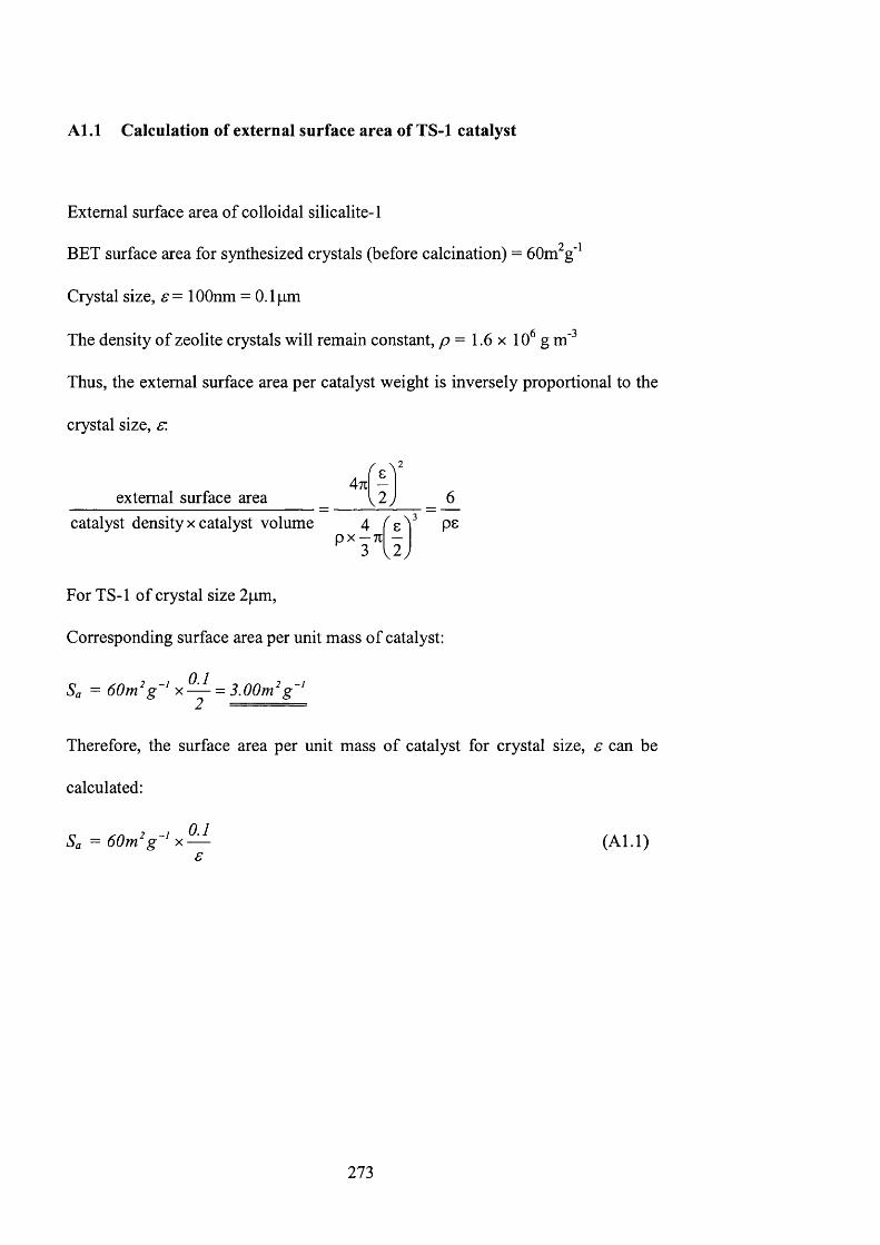
A l . l C alculation o f external surface area o f TS-1 catalyst
External surface area of colloidal silicalite-1
BET surface area for synthesized crystals (before calcination) = 60m^g’^
Crystal size, s= lOOnm = 0.1 jam
The density of zeolite crystals will remain constant, p = 1.6 x 10 g m'^
Thus, the external surface area per catalyst weight is inversely proportional to the
crystal size, s’.
471 -external surface area I 2
catalyst density x catalyst volume 4 ^ 8 ^ pG
For TS-1 of crystal size 2pm,
Corresponding surface area per unit mass of catalyst:
Sa =60m^g ' = 3.00m^g ‘
Therefore, the surface area per unit mass of catalyst for crystal size, s can be
calculated:
2 _y 0 .1Sa — 60ïn g X— (A l.l)s
273
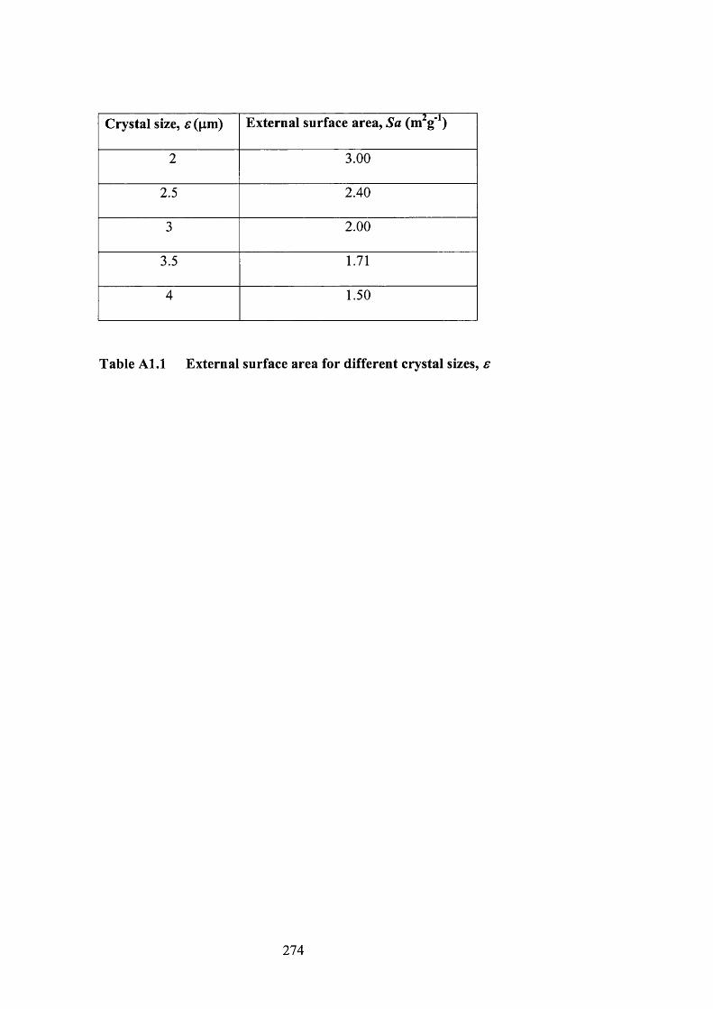
C rystal size, e (|im ) External surface area. Sa (m^g'^)
2 3.00
2.5 2.40
3 2.00
3.5 1.71
4 1.50
Table A l . l External surface area for different crystal sizes, e
274
A1.2 C alculation o f first order reaction constant for 1-pentene epoxidation
First order reaction with respect to hydrogen peroxide
r ’ = -k ’i[H202]
Catalysts weight, W=0. l g (crystal size, s = 2pm)
External surface area per unit mass of catalyst. Sa = 3.00 m^g'^
Total external surface area, A = 3 . 0 0 m ^ x O . l g = 0.30m^
Assume first order reaction w. r. t. [H2O2],
r ’ = -k ’,[H202] (A1.2)
d[H ,0 ,]dt
\h ,o A •*'[h , o ,]
A graph of In (obtained experimentally), was plotted against time, t.
275
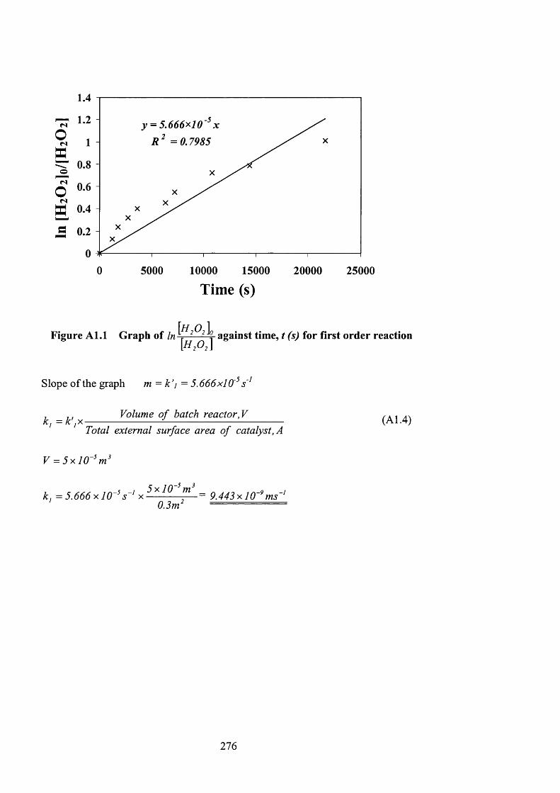
1 . 4
TT 1 - 2
I ■“ 0.8
o
o 0.3 5 0.4
0.2
0 5000 10000 15000 20000 25000
Time (s)
Figure A l . l G raph o f In against tim e, t (s) for first order reaction
Slope of the graph m = k ’i = 5.666x10'^
, , , Volume o f batch reactor, Vkj = k' jX--------------------- ----------------------------------Total external surface area o f catalyst, A
V = 5 x l 0 - ' m^
k, = 5 .6 6 6 x 1 0 -'s~' x - - -^ - ^ =0.3m‘
= 9.443xl0~^ms~‘
(A1.4)
276
A l .3 C alculation o f second order reaction constant for 1-pentene
epoxidation
Second order reaction with respect to hydrogen peroxide and 1-pentene
r ‘= [Cg]
Catalysts weight, JV=0.1g
Assume second order reaction w. r. t. [H2O2] dnà [C5],
r ' = (/LI 5)
dt ' ' " [ H f iX
[ H f i . I = - k \ [ H f i , I {I - x l H f i , I [e„ - x )
x =
dt
[H2O2 I
[Ü2O,\ ^ = k \ [ H f i , I ( / - x l H f i , I {9, - x )
Express the above in terms of [H2O2] & [C5]
0 0 - 1 0o { i - x )
[Col [HqOoI - I h ^Oo]
[HfiX [HfiX [Hfi.l
111
[ h 2 0 A In [H 2O 2 I[Csl [ H fiA K o J ,
[H2O2I [H2O2I
= k \ t
[C si[H ,oA
In[H2Û2i-[Csi UqI/Z.O.I = k \ t
0 y
In[C2 1 H 2 0 2 1
= k '2 i H f i A „ - [ c X ) t (A1.6)
( [h . o A c X
[H2O2] and [C5] were experimental values obtained from lodometric titration and
GC analysis respectively.
2 7 8
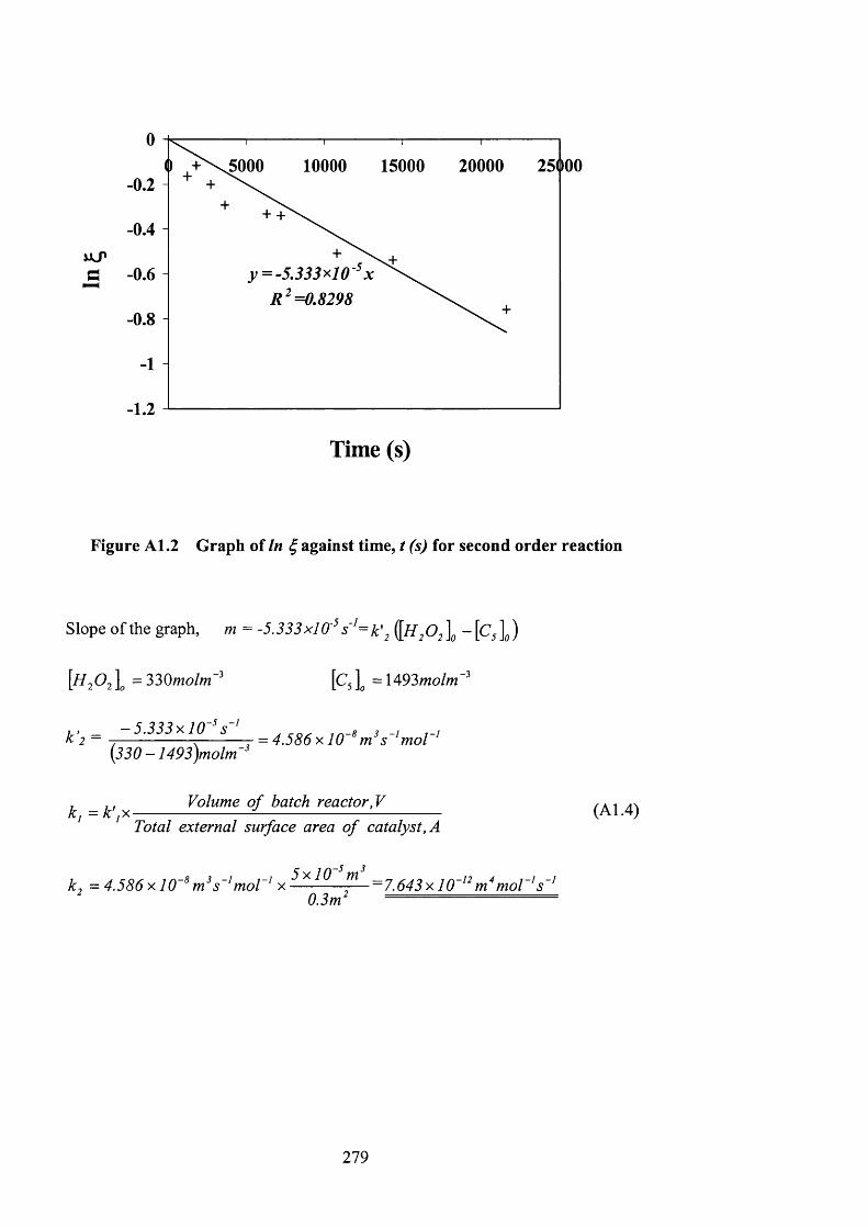
20000 250005000 10000 15000- 0.2
+ +-0.4
- 0.8
- 1.2
Time (s)
Figure A l.2 Graph of In against time, t (s) for second order reaction
Slope of the graph, m = -5.333 x l 0' s = k \ ^ 2 ]o ~ [Q \ )
[HiOj \ = 330mo/m'’ [C, \ = 1493mo/»j-^
k ’2 = 5.333x10 ^
k j = k ' j X
(330- 1493)molm'
Volume o f batch reactor,VTotal external surface area o f catalyst, A
5 V lf)~kj = 4.586 X 1 0 ~ ^ s ~ ‘moT^ x ---------;— — 7.643 x 10~^^moV^s~^
' 0.3m' •
(A1.4)
279
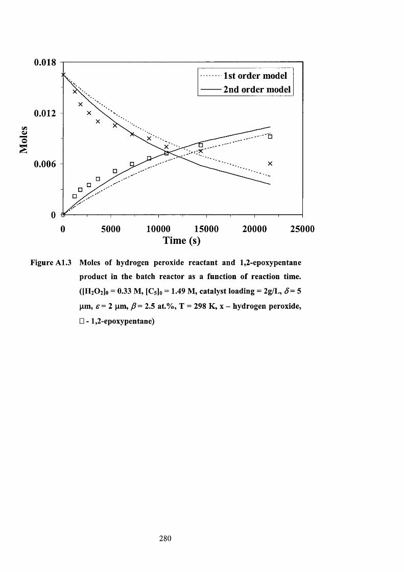
0.0181st order model
■ 2nd order model
0.012
0.006
0 5000 10000 15000Tim e (s)
20000 25000
Figure A l.3 Moles of hydrogen peroxide reactant and 1,2-epoxypentane
product in the batch reactor as a function of reaction time.
([HiOilo = 0.33 M, [Cs]o = 1.49 M, catalyst loading = 2g/L, S= 5
pm, e = 2 pm, p = 2.5 at.%, T = 298 K, x - hydrogen peroxide,
□ - 1,2-epoxypentane)
2 8 0
Appendix A2
Calculation of Titanium Content in TS-1 Catalyst
281
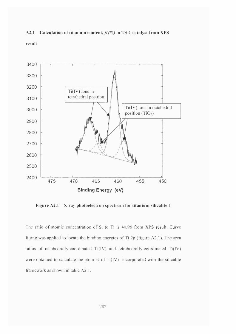
A2.1 Calculation o f titanium content, p (%) in TS-1 catalyst from XPS
result
3400
3300
3200Ti(IV) ions in tetrahedral position3100
Ti(IV) ions in octahedral position (TiO])
3000
2900
2800
2700
2600
2500
2400475 470 465 460 455 450
Binding Energy (eV)
Figure A2.1 X-ray photoelectron spectrum for titanium silicalite-1
The ratio o f atomic concentration o f Si to Ti is 40.96 from XPS result. Curve
fitting was applied to locate the binding energies o f Ti 2p (figure A2.1). The area
ratios o f octahedrally-coordinated Ti(IV) and tetrahedrally-coordinated Ti(IV)
were obtained to calculate the atom % of Ti(IV) incorporated with the silicalite
framework as shown in table A2.1.
282
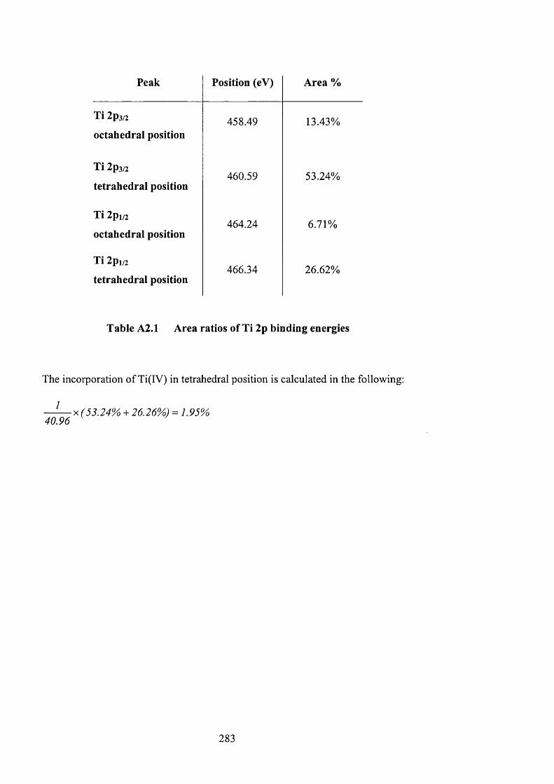
Peak Position (eV) Area %
Ti 2p3/2
octahedral position458.49 13.43%
Ti 2p3/2
tetrahedral position460.59 53.24%
Ti 2pi/2
octahedral position464.24 6.71%
Ti 2pi/2
tetrahedral position466.34 26.62%
Table A2.1 Area ratios of Ti 2p binding energies
The incorporation of Ti(IV) in tetrahedral position is calculated in the following:
1
40.96
2 8 3

Appendix A3
Correlation of Titanium Content with Reaction Constant
284
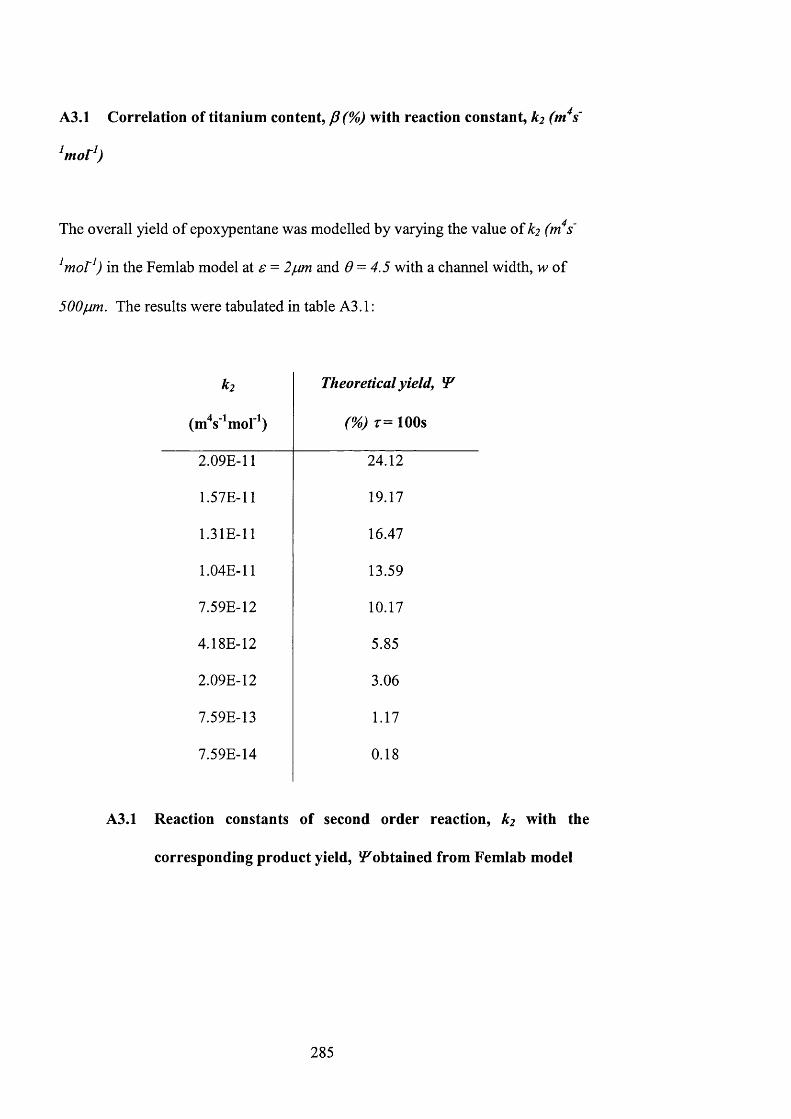
A3.1 Correlation of titanium content, (%) with reaction constant, k2 (m^s'
The overall yield of epoxypentane was modelled by varying the value of k2 (m^s'
^mor^) in the Femlab model at £• = and 6 = 4.5 with a channel width, w of
500p.m. The results were tabulated in table A3.1 :
k 2
(m s ^mol^)
Theoretical yield, ÎP
( % ) T = lOOs
2.09E-11 24.12
1.57E-11 19.17
1.31E-11 16.47
1.04E-11 13.59
7.59E-12 10.17
4.18E-12 5.85
2.09E-12 3.06
7.59E-13 1.17
7.59E-14 0.18
A3.1 Reaction constants of second order reaction, k2 with the
corresponding product yield, iP^obtained from Femlab model
2 8 5
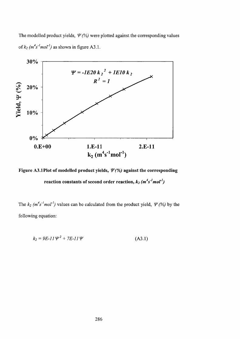
The modelled product yields, W (Vo) were plotted against the corresponding values
of k2 (m^s'^mor^) as shown in figure A3.1.
30%
^ = - l E 2 0 k 2 + l E 1 0 k
10%
O.E+00 2.E-11
Figure A3.1 Plot of modelled product yields, ^(%) against the corresponding
reaction constants of second order reaction, k2 (m^s'^mor^)
The k2 (rn s'^mol'^) values can be calculated from the product yield, ÎP (%) by the
following equation:
k2 = 9E-11 + 7E-11 W (A3.1)
2 8 6
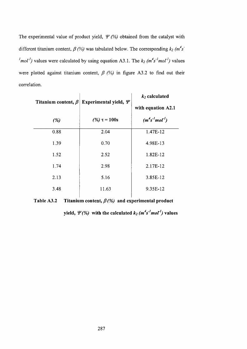
The experimental value of product yield, (%) obtained from the catalyst with
different titanium content, p (%) was tabulated below. The corresponding k2 (m*s'
^mot^) values were calculated by using equation A3.1. The ^2 (m*s'^mor^) values
were plotted against titanium content, p (%) in figure A3.2 to find out their
correlation.
Titanium content, P
W
Experimental yield, ÎP
(%) T = lOOs
k2 calculated
with equation A2.1
(m^s'^mor^)
0 . 8 8 2.04 1.47E-12
1.39 0.70 4.98E-13
1.52 2.52 1.82E-12
1.74 2.98 2.17E-12
2.13 5.16 3.85E-12
3.48 11.63 9.35E-12
Table A3.2 Titanium content, P (%) and experimental product
yield, ^(%) with the calculated kz (m*s'^mot^) values
287

l.E-11
k 2 = 3 E - 1 0 p - 3 E - 1 2
= 0 . 9 0 8 7oB
S5.E-12
O.E+002% 4%0%
Ti content, P (At. %)
Figure A3.2 Plot of k2 (tn^s'^mot^) values against titanium content, P (%)
Vayssilov and co-workers (1997) have reported that for TS-1 catalysed oxidation
of anisole, catalyst activity is directly proportional to the titanium-content of the
catalyst. Therefore, a simple linear relationship between titanium content and
kinetic constant was assumed taking into account that TS-1 catalysts with less
than 1 at.% titanium content are inactive for the epoxidation reaction.
Equation A3.2 gives the correlation between k2 values (m^s'^mor^) with titanium
content, P (%):
k2=3E-10P-3E-12 (A3.2)
Therefore, the corresponding k2 values (rns'^mor^) can be calculated from
titanium content, P (%)\xs,mg equation A3.2.
2 8 8
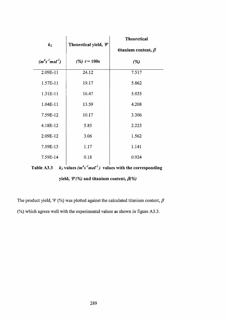
k 2
( tn * s~ ^ m o r^ )
Theoretical yield,
( % ) T = lOOs
Theoretical
titanium content, p
w
2.09E-11 24.12 7.517
1.57E-11 19.17 5.862
1.31E-11 16.47 5.035
1.04E-11 13.59 4.208
7.59E-12 10.17 3.306
4.18E-12 5.85 2.223
2.09E-12 3.06 1.562
7.59E-13 1.17 1.141
7.59E-14 0.18 0.924
Table A3.3 k2 \ 2L\vLts (m^s'^mot^) values with the corresponding
yield, ^(% ) and titanium content, P(%)
The product yield, (%) was plotted against the calculated titanium content, p
(%) which agrees well with the experimental values as shown in figure A3.3.
2 8 9
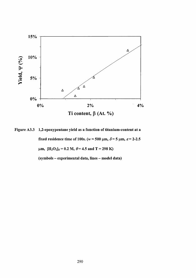
15%
10%
5%
0%0% 2% 4%
Ti content, P (At. %)
Figure A3.3 1,2-epoxypentane yield as a function of titanium-content at a
fixed residence time of 100s. (w = 500 pm, ^ = 5 pm, e= 2-2.5
pm, [HiOilo = 0.2 M, 4.5 and T = 298 K)
(symbols - experimental data, lines - model data)
290

Appendix A4
Calculation of Weisz-Prater Parameter
291
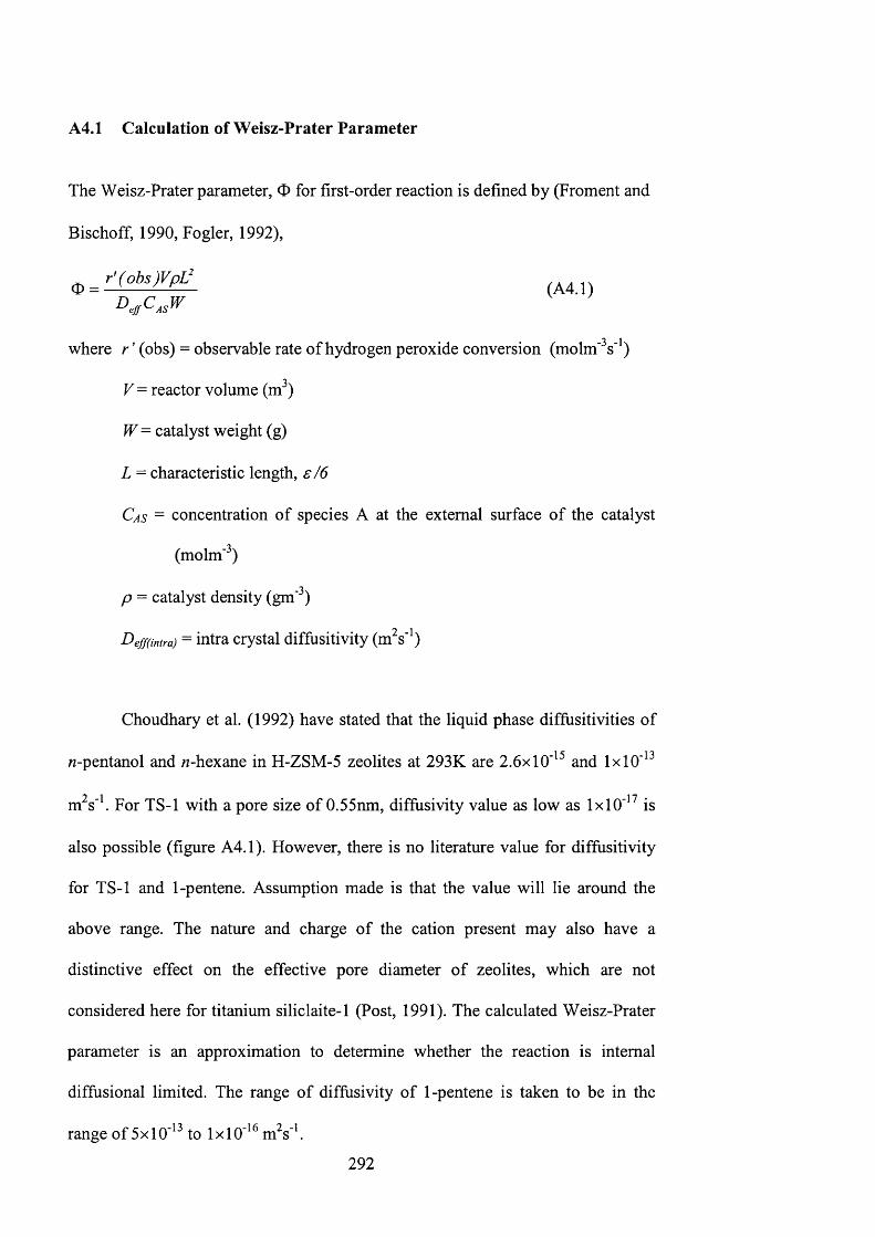
A4.1 Calculation of Weisz-Prater Parameter
The Weisz-Prater parameter, 0 for first-order reaction is defined by (Froment and
Bischoff, 1990, Fogler, 1992),
where r ’ (obs) = observable rate of hydrogen peroxide conversion (molm'^s*')
V= reactor volume (m^)
W= catalyst weight (g)
L = characteristic length, s / 6
Cas - concentration of species A at the external surface of the catalyst
(molm'^)
p = catalyst density (gm'^)
Deff(intra) = intra crystal diffusitivity (m^s'^)
Choudhary et al. (1992) have stated that the liquid phase diffusitivities of
M-pentanol and «-hexane in H-ZSM-5 zeolites at 293K are 2.6x10'^^ and 1 x 1 0 *
m^s'\ For TS-1 with a pore size of 0.55nm, diffusivity value as low as 1x10'^^ is
also possible (figure A4.1). However, there is no literature value for diffusitivity
for TS-1 and 1-pentene. Assumption made is that the value will lie around the
above range. The nature and charge of the cation present may also have a
distinctive effect on the effective pore diameter of zeolites, which are not
considered here for titanium siliclaite-1 (Post, 1991). The calculated Weisz-Prater
parameter is an approximation to determine whether the reaction is internal
diffusional limited. The range of diffusivity of 1-pentene is taken to be in the
range of 5x10'^^ to 1 x 1 0 ' m^s'\
292
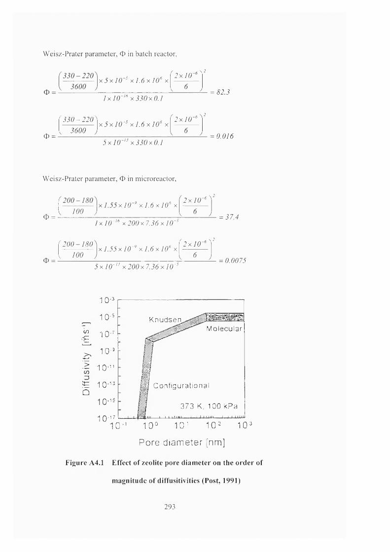
Weisz-Prater parameter, O in batch reactor,
X j x 7 0 - " X 7 . 6 x 7 0 ° x2 x 7 0
7x70-^"x jJOxO.7= <^22
0 =
^ j j O - 2 2 0 ^2600
X6x70'" X7.6x70° x2x70 - 6
5 x l 0 - ' ^ 3 3 0 x 0 . 1= 0.016
Weisz-Prater parameter, 0 in microreactor.
0 =
X I0~" x ] . 6 x 10‘ X100 j
2 x / 0 ~‘ ^
l x I O ' “ x 2 0 0 x 7 . 3 6 x l 0 - 5= 27.^
p o o -720 I 700
X 7.22x 70'" X 7.6x70° x 2 x 7 0\ 2
2x70-'" X 200x7.26x70 - 5= 0.0075
CO
Ê>>
1 0 -"
1 0 -
1 0 -'
1 0 -
1 0 -
^ 1 0-13Û
1 0 - ':
1 0 1 7
KnudsenM o l e c u l a r
Ig Configurational
373 K, 100 kPa<11 I I t L .im i I JLUiJ 1 t u . H U
1 0 - ’ 1 0 ° 1 0 ' 1 0 = 1 0 °
Pore diameter [nm]
Figure A4.1 Effect of zeolite pore diameter on the order of
magnitude of diffusitivities (Post, 1991)
293
Appendix A5
Calculation of Pressure Drop in Microreactor
294
A5.1 Pressure drop calculation in microreactor
Pressure drop, AP = where (A5.1)dw'
_ , . • r, . / 3 -K volume o f microreactorQ - volumetnc flowrate (m s ) = --------------------------------residence time
V = volume of microreactor = 1.548 x 10~^m^
T = residence time (s) where r = 50-1000s
I = length of mixing channel (m) where 1 = 0 .0 2 m
ju = viscosity (Nsm'^) where viscosity of methanol = 5.4 xlO'"* Nsin^
d = depth of channel (m) where d = 250fam = 2.5 xlO'"* m
w = width of channel (m) where w = 50-1000jum = 5xl0~^ - l x l O~^ m
Sample calculation of pressure drop at a residence time of 100s and a channel width, w of 500pm (Jensen, 2000):
At r= 100s, w= 500jam = 5 x 70
= (A5.1)dw'
_ 12Vlfj xdw^
12x1 .55x10 '’ x0 .02x5 .4x l0~ '
1 0 0 x2 .5 x1 0 '“ x [ 5 x l 0 - ‘‘)
= 0.06428Nm'“
295
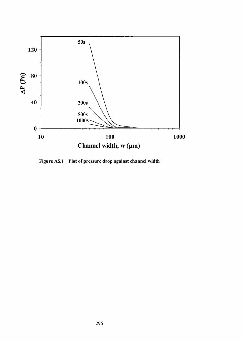
50s120
a100s
<
200s
500s1000s
10 100
Channel width, w (|im)1000
Figure A5.1 Plot of pressure drop against channel width
2 9 6
Copyright © 2022 FDOKUMEN