
First Order Linear Homogeneous Fuzzy Ordinary Differential ...
Upload
independentCategory
view
0download
0
Pergamon Chemical Enoineerir ~ Science, Vol. 50, No. 7, pp. 1149 1171, 1995 Copyright © 1995 Elsevier Science Ltd
Printed in Great Britain. All rights reserved 0009 2509/95 $9.50 + 0.00
0009-2509(94)00463-3
RUNAWAY LIMITS FOR HOMOGENEOUS AND CATALYTIC REACTORS
V E M U R I BALAKOTAIAH, t D U S A N K O D R A t and D U Y E N N G U Y E N Department of Chemical Engineering, University of Houston, Houston, TX 77204-4792, U.S.A.
(Received 5 May 1994; accepted in revised form 30 September 1994)
Abstraet--A unified approach that relates and combines the concepts of parametric sensitivity, ignition, extinction, hysteresis and isola formation is presented and used to derive a single universal runaway criterion valid for all homogeneous reactor models. It is also shown that the heat and mass dispersion have very little impact on this runaway locus. Next, the approach is extended to heterogeneous reactor models where interphase gradients strongly influence the runaway boundary. It is shown that the model of a well-mixed two-phase reactor may be used to derive runaway boundaries for a cooled multitubular catalytic reactor influenced by interparticle and intraparticle transport limitations. The validity of the approach is verified by numerical simulations of temperature profiles under safe and runaway conditions for some selected cases. The analysis of the heterogeneous model shows that the heat transfer resistance between the solid and the fluid introduces a qualitative change in the shape of the stability boundary. There exists a limiting value of the dimensionless heat of reaction parameter B, above which the reactor is in a runaway region regardless of the rate of external cooling. This limiting value of B corresponds to the ignition of catalyst particles. It is also shown that within the safe region of operation, there exists an optimal catalyst particle diameter that maximizes the reactor productivity. The main concepts involved and computation of the runaway boundaries for multiple reactions are illustrated by discussing three specific examples of consecutive, simultaneous and consecutive-simultaneous reactions. The important result is that the runaway locus for any multiple reaction network differs significantly from that of the single reaction only when the product 2b@ > 0.1. Here, 2, ~b and b, represent, respectively, the ratio of rate constants at feed conditions, heats of reaction and feed concentrations of the primary reaction to that of the main competing reaction. This work also presents slightly conservative analytical results for the determina- tion of the runaway limits of homogeneous and catalytic reactors for most cases of practical interest.
I. INTRODUCTION
Parametric sensitivity or runaway of a chemical reac- tor describes a situation in which a small change in an operating variable such as feed temperature or con- centration, coolant temperature or flow rate induces a large change in the temperature profile of the reac- tor. A small increase in the reaction temperature can lead to a large increase in the reaction rate due to the Arrhenius temperature dependence of the rate con- stant. The increased reaction rate results in more heat generation which further increases the reaction tem- perature. This feedback mechanism results in reactor runaway when the rate of heat generation far exceeds the rate of heat removal. Runaway can damage the reactor vessel and cause attendant personnel safety hazards. It can cause catalyst deactivation which in- creases the process operating cost. In addition, it can enhance undesirable side reactions which result in loss of selectivity. For these reasons, it is important to be able to predict a priori the runaway region in order to design and operate the reactor outside this region and avoid the undesirable behavior due to a small design error or small perturbation of an operating variable.
~Author to whom correspondence should be addressed. ~Present address: KTI SpA, Monte Carmelo 5, 00166,
Rome, Italy.
There have been many studies in the literature on the derivation of runaway criteria (Wilson, 1946; Barkelew, 1959, 1984; Thomas, 1961; Adler and Enig, 1964; van Welsenaere and Froment, 1970; Raja- dhyaksha et al., 1975; Morbidelli and Varma, 1986, 1987; Hagan et al., 1987, 1988a, b; Balakotaiah, 1989; Balakotaiah and Luss, 1991). Most existing criteria for predicting the runaway conditions in a homo- geneous or catalytic reactor are based on a single reaction and derived separately for each type of reac- tor using different defining conditions. In addition, previously derived criteria based on heterogeneous models are either too conservative or involve exten- sive computations. At present, there is very little guid- ance available for understanding runaway behavior in systems with multiple reactions.
In this work, we present a simple procedure for calculating runaway boundaries for homogeneous as well as heterogeneous reactor models. First, we review the runaway criteria for various homogeneous reactor models and show that they can all be combined into a single universal criterion which can be determined by using the simpler well-mixed reactor model. We then extend this result to heterogeneous reactor models. We show that the interphase gradients strongly influence the runaway boundary but, once again, a single universal criterion may be used to predict runaway in all heterogeneous reactor models.
1149 CES 50:7-F

1150
We illustrate the validity of this approach using nu- merical simulations for some selected cases. Finally, we present a systematic procedure for computing the runaway limits for the case of multiple reactions.
Since most of the computations involved in deter- mining the runaway boundaries are fairly simple and can be done on a personal computer, the focus here will be on the key ideas and procedures for determin- ing the runaway locus.
2. A UNIVERSAL RUNAWAY CRITERION FOR
HOMOGENEOUS REACTOR MODELS
In this section, we present a unified approach that relates and combines the concepts of parametric sensi- tivity, ignition, extinction hysteresis and isola forma- tion and use it to derive a single universal runaway criterion that is valid for all homogeneous reactor models. Some results of this section have been re- viewed in an article by Balakotaiah and Kodra (1992), which is not easily accessible. We extend these results and present them here in a more general form.
2.1. Runaway criterion for a batch reactor Consider an ideal well-stirred batch reactor in
which a single, irreversible exothermic reaction A ~ B occurs. Assume that the rate is given by the expression
r=k(T)C"aH(CA) , n>~O (1)
where H(CA) is the Heaviside's unit step function. Assume further that the reactor is cooled such that the rate of heat removal at any instant is given by
Q = UA( T - T~) (2)
where U is the overall heat transfer coefficient, A is the heat transfer area, T is the temperature in the reactor and T~ is the coolant temperature. Neglecting vari- ations in density and other physical properties, the dimensionless equations describing the evolution of the conversion (x) and temperature (0) are given by
d--x = ( l d t - x ) " exp ( l ~ 0 / y ) H ( 1 - x ) (3)
Le-d- ~ = B(1 - x ) exp H(1 - x)
- - ~ ( 0 - - O c ) (4)
x = 0 , 0 = 0 a t t = 0 (5) where
C~o - C~ E T - T o t=t ' / tR, x - - - , 0
CAo RTo To
E T~-- To E ( - - A H ) CAoVRo 0~ = - - - - , B =
RTo To RTo (MCvb To
_ _ _ (MCv)m E Le (MCp)R= 1 + - ? = - (MCv)f (MCv)f' RTo
UA
(MCv) I k(To) C~o I
t R -
(MCv)R = (MCv)y + (MCp)~
1 tR (MCv)f k(To)C%~, to= ~ , t~o= UA
VEMURI BALAKOTAIAH et al.
Here, tR is the characteristic reaction time, tg is the characteristic heat generation time and too is the char- acteristic cooling time. The parameter B is the adiabatic temperature rise, 7 is the dimensionless ac- tivation energy, 0c is the coolant temperature, n is the reaction order and • is the dimensionless heat re- moval parameter (~ = tR/tco). Typical range of values of parameters for highly exothermic reactions are: B is 10 to 100, Tis 10 to 30 ,0c i s - 1 to 1. The Lewis number, Le, is the ratio of the heat capacity of the reactor and its contents to that of the reactor contents. When the heat capacity of the reactor walls is negli- gible then Le ~ 1.
The time coordinate may be eliminated from eqs (3) and (4) by dividing eq. (4) by eq. (3). This gives
(6)
Le dO cl(O - Oc) - 1
B dx
0 = 0
B(1 - x)" exp [0/(1 + 0/~)] H(1 - x)
(7a)
at x = 0. (7b)
Integration of eq. (7) gives the reaction path in the temperature-conversion plane. Figure 1 shows sche- matic reaction paths for some typical cases. Examina- tion of eqs (3) and (4) shows that x ~ 1, 0 --* 0c for
B (a)
0 ¢ ,x= l
o, ~ = ~ X
e c,
B (b)
0 x 1
0 v x
B (c)
a = 0
e a=oo x = l
0, f " I 0 x 1
Fig. 1. Schematic diagrams of some typical reaction paths for a hatch reactor with Le = 1: (a) Oc < 0, (b) Or = 0 and (c)
0~>0.

Runaway limits for homogeneous and catalytic reactors
t --. oo. Thus, all reaction paths start at 0 = 0, x = 0, end at 0 = 0c, x = 1 and are confined to a region formed by the strongly cooled reaction path (~t = oo), the adiabatic reaction path (a = 0) and the equilib- rium line (x = 1). In the strongly cooled case, the temperature quickly reaches and remains constant at 0 = 0c, while the conversion increases monotonically from zero to unity. For the adiabatic case, the temper- ature increases monotonically from zero to B/Le. In many practical situations, the adiabatic temperature rise is unacceptably high and the purpose of cooling is to limit the temperature increase to a fraction of the adiabatic value for all conversion levels (0 < x < 1). The manner in which the temperature changes deter- mines the boundary between safe (or insensitive) and runaway behavior. Adler and Enig (1964) define a batch reactor to be insensitive if the reaction traject- ory defined by eq. (7) is such that d20/dx 2 is negative at all points, i.e. in the insensitive region, the temper- ature may increase with conversion but with a nega- tive second derivative. The transition from insensitive to runaway behavior occurs when two inflexion points begin to appear in the reaction trajectory. This boundary is defined by eq. (7) and
d20 daO dx 2 dx 3 = O. (8)
Elimination of 0 and x from eqs (7) and (8) gives the stability boundary (runaway locus) in the parameter space. On one side of this boundary (insensitive re- gion) d20/dx 2 is negative everywhere on the reaction path while on the other side (runaway region), both dO/dx and dZ0/dx 2 are positive on a segment of the reaction path.
For the special case of 0~ = 0 (equal coolant and initial temperatures) and ~ = ~ (large activation en- ergy) the eigenvalue problem defined by eqs (7) and (8) takes the form (Adler and Enig, 1964)
= [ 1 dO B l - - (9) dx Le B(1 -- x)" H(1 - x)
0 = 0 a t x = 0 (10a)
0 = l + x / ~ a t x = x < (10b)
where xc is the root of the equation
(1 -- x<)" Le(n B + V/-~) (1 -- x c ) " - i --~(1~ + v/-n)
× e x p ( - - 1 - - , f - n ) = 0. ( i l )
The runaway boundary is the set of (~t, B) values at which eqs (9)--(11) are satisfied. It may be determined by integrating eqs. (9) and (10) and adjusting the values of a and B so that eq. (11) is satisfied.
Figure 2 shows a plot of the runaway locus in the (MB, B/Le) plane for zeroth- and first-order reactions (n = 0, 1). This runaway locus can be described by two asymptotes. For the adiabatic case (~t = 0), it ap- proaches the asymptote
B - Bo = Le(1 + x / ~ ) 2 (12)
1151
100 °WB 10 -I I n = o
10-2/ . . . . . . . . . . . . l0 -1 l00 101 102 103
B/Le
Fig. 2. Runaway locus for the zeroth- and first-order reac- tions for a batch reactor with ), = ~ and 0c = 0.
while for the strongly cooled case (B ,> 1, a ,> 1 or, equivalently, tg ,~ tR and too ,~ tR) it approaches the asymptote
ct to . . . . e. (13) B too
Typical diagrams of conversion and temperature vs time are shown in Fig. 3 for the parameters, n = 1, 7 = oo, 0c = 0, B = 13, Le = 1 and three ct values. On the runaway locus where a = 20.1, the maximum tem- perature observed in the batch reactor is only a small fraction of the adiabatic temperature rise. However, in the runaway region (~t = 17.1), the maximum temper- ature is much higher while in the safe region (a = 22.0), the maximum temperature is much less than the adiabatic temperature rise.
For the special case of a zeroth-order reaction, it may be shown that the entire runaway boundary is given in a parametric form (Balakotaiah, 1989)
2 m m! B 1 + 7 Le 1 (m + 1) "+1
(14) ~t - = 2 , 0 ~ < 2 < e . B
For finite ~, and 0c # 0, the point (Oi,xl) at which eq. (8) is satisfied is obtained by the simultaneous solution of the algebraic equations
l (1 - n)(1 + 0 h ) 2 1 (1 + 0h)2_l n(O - OD
(0 - 0c) 2 (0 - 0c) ] x 2 ( l + 0 / y ) 2 y ( ] - + 0 - ~ ) j = 0 (15a)
,(o-o<, r - 0 31 1 expL J;( -x)
(o-oD 1 n~ x 1 (i~-o~,j+-ff-(o-oD=o. ( lSb)
The corresponding runaway locus may be obtained

1152
1.2
1
.~ 0.8
0.6
o 0.4
0.2
0 10
ct = 17.1 (a)
o~ = 2 0 . 1 ~ ~
8 e t = 1 7 . 1 ,
~= 6 O
E ~ 4 cz = 20"1N ¢0
2 ~
O ~ . . . . . . I
10 .2 10 -1
V E M U R I BALAKOTAIAH et al.
applicable to other homogeneous as well as hetero- geneous reactor models.
(b)
, , ~ . . . . . . . . i 10 ° 101
t or Da
Fig. 3. Diagrams of conversion and temperature vs holding time (or Da) for the batch reactor (plug flow reactor) on the runaway locus (ct = 20.1), in the runaway region (~t = 17.1) and in the safe region (ct = 22) for 7 = oo, 0~ = 0, B = 13 and
Le = 1.
by determining the locus of parameter values at which eqs (7) and (15) are satisfied. For the special case of a first-order reaction, the adiabatic asymptote is now given by
4Le B. = - - (16)
(1 - 4 / 7 )
while the strongly cooled asymptote changes to
, e = exp - (17a) B (1 + 0i/7) 0c)
where 0i is the smaller root of the quadratic equation
02/7 z - (1 - 2/7)0 + (1 + 0~) = 0. (17b)
We note that the strongly cooled asymptote is inde- pendent of reaction order and is given by eq. (17) for all types of kinetics. As stated earlier, this asymptote corresponds to the case of negligible reactant con- sumption (x --* 0) or, equivalently, tg < t , and too '~ tR but the ratio t,o/tg ( = ct/B) being finite. This asym- ptote may be obtained by equating the heat genera- tion and heat removal rates at zero conversion
0 Qg= B e x p [ ( l +-O/7) ] (18a)
Q, = 7(0 - 0~) (18b)
o(O)Z~Qa - Q, = 0 (18c)
and determining the limit (ignition) point of the result- ing equation. This is a key observation which is also
2.2. Runaway criterion for a CSTR The conversion and temperature in an ideal CSTR
in which a single exothermic nth-order reaction A ---, B occurs are described by the equations
dt Da + (1 - x)" exp H(1 - x)
Le dt Da + B(1 - x)"exp
× H(1 - x) - :~(0 - 0c)
where
(19a)
(19b)
Oa = Vak(T°)C"a-°l tc V• - - , t o=- - (20)
q tn q
and all other parameters are as defined previously. This model contains four characteristic times: the reaction time (ta), heat generation time (to) , cooling time (60) and the residence time (also referred to as the convection time or space time, 6). The steady-state temperature and conversion are given by the alge- braic equations
Bx + c~ Da 0 c O= 1 + ~Da (21)
F(x, Oa, p) - x -- Da(l -- x)"
[ B x + ~ D a O c ] H ( I - x ) = 0 . ×exp 1 + ~ D a + ( B x + ~ D a 0 c ) / 7
(22)
It follows from eqs (21) and (22) that x --+ 0, 0 ~ 0 for Da ~ 0 while x --+ 1, 0 ~ 0c for Da -+ oo. Thus, as in the case of the batch reactor, the reaction path starts at (0, 0) and ends at (1, 0c). The reaction path for any fixed values of p = (B,~,0~,7) may be obtained by eliminating the Damk6hler number (Da) from eqs (21) and (22). This gives the equation
1 0 1 - ~ ( 0 - 0c)
B x B(1 -- x)"exp[O/(1 + O/7)]H(1 -- x)
(23)
which is very similar to eq. (7) with O/x replacing dO/dx. (Note that the Lewis number, Le, does not appear in eq. (23). The main difference between batch and flow reactors or, equivalently, between transient and steady-state operation is the additional heat ca- pacity of reactor walls. For the case of a batch reactor, the adiabatic temperature rise is BILe instead of B.) As in the case of a batch reactor, all reaction trajec- tories are confined to a region formed by the strongly cooled and adiabatic reaction paths and the equilib- rium line (x = 1). However, unlike the batch reactor, the reaction paths for a CSTR may contain limit points (where dO/dx = oo) and isolated branches. Figure 4 shows some diagrams of typical reaction

20
15
10
0 0.0
/ B = 20.0 /
/ o~=0.
30.0
0.2 0.4 0.6 0.8 1.0 X
Fig. 4. Typical reaction paths for the homogeneous CSTR with the parameters B = 20, y = oo and 0c = 0.
paths. A complete classification of the different types of reaction paths (or, equivalently, bifurcation dia- grams of conversion vs Da) was given by Zeldovich and Zysin (1941), Balakotaiah and Luss (1981) and many others.
We define the steady-state behavior of a CSTR to be insensitive to small perturbations if the reaction path connecting the points x = 0, 0 = 0 and x = 1, 0 = 0c does not contain any limit points. Thus, the boundary between insensitive and runaway region is defined by the occurrence of two limit points in the reaction path connecting the points x = 0, 0 = 0 and x = 1, 0 = 0c. This definition is different from that of a batch reactor. However, it may be shown that the critical • value at which limit points disappear is only slightly higher than that at which inflection points disappear (especially for large B). We now use the above definition to determine the runaway boundary of the CSTR and compare it with that of the batch reactor. For simplicity, we first consider the case 3' = @ and 0c = 0. The results of Balakotaiah and Luss (1981, 1982) may be used to show that the runaway boundary consists of two segments. The first segment is given by
~- = [ 1 - (1+ ? ) 2 - ] (l + ~/~)- l-"n"/2 exp(l +
(24a)
for
Runaway limits for homogeneous and catalytic reactors 1153
Elimination of x, 0 and Da from eqs (24c) gives eqs (24a) and (24b). The second segment is for B values in the range (1 + x/~)3/x/-n < B < ~ and is given in a parametric form by
(nx + 1 - x) 2
B nx2(1 - x) (25a)
(1 - - X) n+2 f n x + 1 - x'~ B - ( n x + i ~ x ) 2 e x p k [ - - x ) '
1 0 < x < - - (25b)
l + w / - ~"
On this segment, two limit (ignition) points merge at an isola (bifurcation) point which appears on the reaction path. The isola point is defined by the equa- tions
~3F OF F = Ox OOa O. (25c)
Elimination of Oa from eq. (25c) gives eqs (25a) and (25b). For the special case of a zeroth-order reaction, the entire runaway locus is defined by eq. (24c), which gives the following analytical expression for the boundary:
B
Figure 5 shows a plot of the runaway boundary for the case of zeroth- and first-order reactions. As in the case of a batch reactor (with Le = 1), the boundaries start at the adiabatic asymptote B = (1 + x/~) 2 and become asymptotic to the strongly cooled asymptote e/B = e. The runaway boundary for a first-order reac- tion (n = 1) with a finite activation energy (3' = 20) is also shown in Fig. 5. In this figure, one can see the conservatism inherent in the runaway boundary when the approximation of infinite activation energy (3' = oo) is used. The runaway boundaries for 3' = 20 and 3' = oo do not differ very much, particularly in
(1 + ~ ) 3 (1 + , ~ ) 2 < B < - - (24b)
On this segment, two limit points (one ignition and one extinction point) merge at a cusp point which appears on the reaction path. The cusp point is de- fined by the equations
OF 02F F = Ox Ox 2 = 0. (24c)
[01 . . . . . . , , , , , ,Hj , . . . . ,Hj
Safe ~
,oo
c~/B
n = l
10 -2 , . . . . . . . I , , IJ,,,,I . . , , , ,
10 -1 10 o 101 102 B
Fig. 5. Runaway boundary for the homogeneous CSTR with Oc = O, n = O, l and ~, = oo, 20.
1154
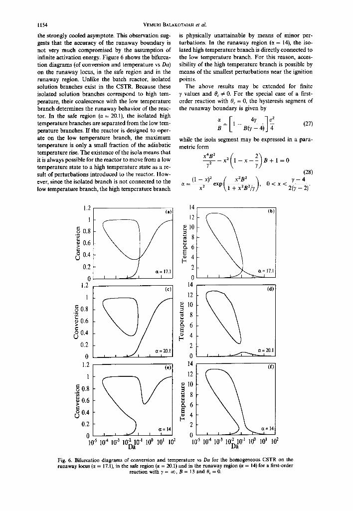
the strongly cooled asymptote. This observation sug- gests that the accuracy of the runaway boundary is not very much compromised by the assumption of infinite activation energy. Figure 6 shows the bifurca- tion diagrams (of conversion and temperature vs Da) on the runaway locus, in the safe region and in the runaway region. Unlike the batch reactor, isolated solution branches exist in the CSTR. Because these isolated solution branches correspond to high tem- perature, their coalescence with the low temperature branch determines the runaway behavior of the reac- tor. In the safe region (~ = 20.1), the isolated high temperature branches are separated from the low tem- perature branches. If the reactor is designed to oper- ate on the low temperature branch, the maximum temperature is only a small fraction of the adiabatic temperature rise. The existence of the isola means that it is always possible for the reactor to move from a low temperature state to a high temperature state as a re- sult of perturbations introduced to the reactor. How- ever, since the isolated branch is not connected to the low temperature branch, the high temperature branch
VEMURI BALAKOTAIAH et al.
is physically unattainable by means of minor per- turbations. In the runaway region (c¢ = 14), the iso- lated high temperature branch is directly connected to the low temperature branch. For this reason, acces- sibility of the high temperature branch is possible by means of the smallest perturbations near the ignition points.
The above results may be extended for finite Y values and 0c ~ 0. For the special case of a first- order reaction with 0c = 0, the hysteresis segment of the runaway boundary is given by
B B ( ? - 4 )
while the isola segment may be expressed in a para- metric form
72 x 2 l - x - B + I = 0
(28) (1 -- x) 2 f x2B 2 ~ ? -- 4
- e x p " 1 \ 0 < < 2~----)" 2(? i
1.2 (a)" 14 (b)
I 12
0.8 l0
8 ~ 0 . 6 ~ , 6
~ 0 . 4 ~ 4
0.2 2
0 0 1.2
1
00.8
0.6
o 0.4
0.2
0 1.2
1
.2 0.8
0.6 >
o 0.4 C)
0.2
(c )
(e )
0 10"510 -410 "310"210 -t 10 ° 101 102
D a
14
12
10
2
0 14
12
~ I0
~ 8
~ 6
o 4
2
(d)
, , 2°1
(f)
- 14 0 10-5 10 -4 10-3 10-2_.10 -l 10 0 101 10 2
Da
Fig. 6. Bifurcation diagrams of conversion and temperature vs Da for the homogeneous CSTR on the runaway locus (¢t = 17.1), in the safe region (~, = 20.1) and in the runaway region (ct = 14) for a first-order
reaction with ? = oo, B = 13 a n d 0c = 0.

Runaway limits for homogeneous and catalytic reactors
The two segments of the runaway locus meet tangen- tially at the pitch-fork point defined by
B 87(? - 2) 72 = (r 4)-----T' ~ = ~ e~
(29) 7 - 4 O a = ( 1 - ~ ) e -z
x 2(y - 2)'
satisfying the conditions
OF 02F OF F = ~x ~x 2 ODa O. (30)
As in the case of a batch reactor, the strongly cooled asymptote is independent of reaction order and is given by eq. (17). Equation (27) shows that the adiabatic asymptote is also the same as that of the batch reactor and is given by eq. (16) with Le = 1.
2.3. Runaway criterion for a homogeneous tubular re- actor
The conversion and temperature in a homogeneous tubular reactor in which an nth-order reaction occurs are given by
~3x 1 ~2X 1 ¢~X +(1 - x)"
Ot q)~ (3~2 Da O~
x exp ( 1 - ~ 0 ~ y ) H ( 1 - - x ) (31)
O0 1 020 1 ¢30 L e - ~ = q ) ~ O ~ 2 Dad~ + B ( 1 - - x ) ~
x exp ( 1 ~ 0 ~ ) H ( 1 - - x ) - - c t ( O - O c ) (32)
with boundary conditions
1 Ox x 1 O0 0 - 0 and = 0 a t e = 0
~p~ O~ Da q, g O~ Da
gx O0 . . . . 0 a t ~ = l
where
(33)
= __ L2k(To) C~o I th ~02 L 2 k ( T o ) C ] o ~ t , q~2 = _ - -
D tR' ( 2 f / p f C p f ) tR
L L 2 L 2 p f C p f t¢=~- -~ , t . = - - i f , t h );f
te Pei = ~i (i = m, h) (34)
Lk(To)C~o' t~ Da = = - -
(u) t~
and other parameters are as defined previously. The above model of the tubular reactor contains six char- acteristic times: the time for reaction (ts), heat genera- tion (tg), cooling (too), convection or residence time (to), mass dispersion time (tin) and heat dispersion time (th). Depending on the relative magnitude of these characteristic times, various limiting models may be
1155
obtained. As the number of limiting models is too numerous to detail here, we consider only some im- portant cases. When the characteristic times for reac- tion and cooling are much smaller compared to that of convection, heat dispersion and mass dispersion (t~,tco~.tc, tm, th), the dispersion and convection terms may be dropped from the above model to obtain the batch reactor equations. When the charac- teristic times for heat and mass dispersion are much smaller compared to that of reaction, cooling and convection (tm, th ~. tR, teo,tc), the conversion and temperature become independent of position and the model equations may be integrated over the length (~ = 0 to ~ = 1) to give the CSTR equations. Sim- ilarly, when t . and th are much larger than tR, t¢o and tc the dispersion terms may be dropped from eqs (31) and (32) and the boundary conditions to yield the plug flow model. (Note: this criterion for obtaining the plug flow model is quite different from what has been claimed in the literature!) Finally, when tm ~> tR and tco, tc >> th, we obtain the bubble column reactor (BCR) model or the fluidized bed reactor (FBR) model defined by the equations
& + Daa g-~ = (1 - x)" exp H(1 - x)
(35)
o Le dt Da t- Bexp
x f ~ ( 1 - x ) n n ( 1 - x ) d ~ - c t ( 0 - 0 c ) (36)
with boundary condition x = 0 at ~ = 0. It should be pointed out that the above formulation of the tubular reactor model using ~0~ and ~2 shows the limiting models as well as the reactor behavior in a more revealing way than the traditional formulation using the Peclet numbers. This is because of the fact that the above formulation isolates the residence time in a single parameter (Da) as was done with the CSTR and the batch reactor (with holding time playing the role of residence time).
Analysis of the steady-state version of eqs (31) and (32) shows that x ~ 0 , 0 ~ 0 for D a ~ O and x ~ 1, 0---, 0c for Da--, 0o. Thus, as in the case of other homogeneous reactor models, the reaction path in the (x, 0) plane starts at x = 0, 0 = 0 and ends at x = 1, 0 = 0c. Once again, we define a tubular reactor to be insensitive to small perturbations if the reaction path connecting these two points has no ignition points. This definition needs to be modified for the special case of the plug flow model (tp~ = ~o 2 = oo) with the replacement of "ignition point" by "inflection point". In this limiting case, the runaway boundary coincides with that of the batch reactor model (the only differ- ences being the interchange of t and ~ and replace- ment of B on the horizontal axis by BILe). For any finite ~02, the tubular reactor model exhibits a hyster- esis or an isola point and the runaway boundary consisting of two segments may be calculated in the
1156
same manner as that of the CSTR model (although the computational effort is much larger). We now claim that the runaway boundary of the tubular reac- tor model with finite q~ and q~ is not significantly different from that of the CSTR model, i.e. heat and mass dispersion have negligible impact on the run- away boundary. Based on the discussion of the limit- ing cases, we first note that the strongly cooled asym- ptote of the runaway boundary is independent of q~ and q~ . We also expect the largest difference between different models to occur in the adiabatic limit and for the limiting case q~ = 0 and ~0~ = ~ , which corresponds to the bubble column reactor (BCR) model. We now determine the runaway bound- ary of this model and show that it is not significantly different from that of the CSTR model.
The steady-state version ofeqs (35) and (36) may be integrated to give the following algebraic equations for the temperature and exit conversion:
Bx(1) + ~DaOc 0 = (37)
1 +o~Da
( ll I:''-"' 1 - x(1) = \1 + 0/~/3
( o ) O, Da exp 1 ~ > - -
V E M U R I B A L A K O T A I A H e t al.
0 = ~ {[1 + (n- - 1)t] "/("-1) - [1 + (n - 1)t]},
0 < t < l . (42)
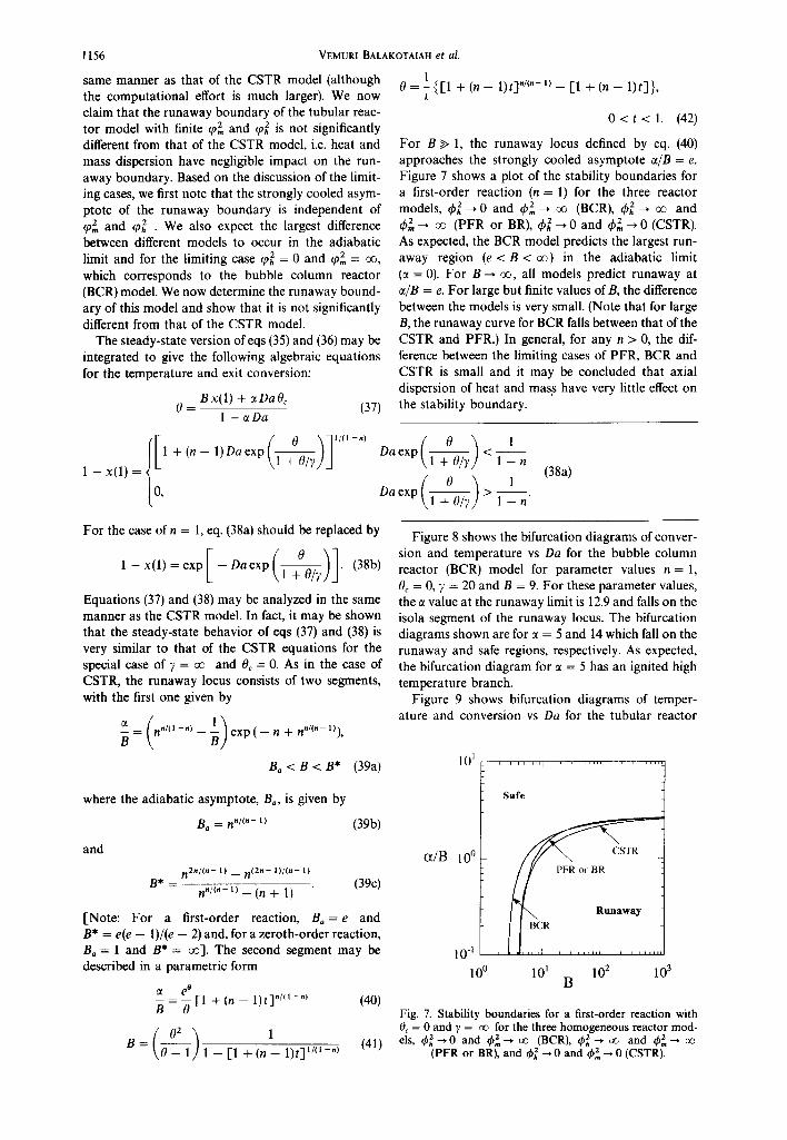
For B >> 1, the runaway locus defined by eq. (40) approaches the strongly cooled asymptote ~/B = e. Figure 7 shows a plot of the stability boundaries for a first-order reaction (n = 1) for the three reactor models, q~]--* 0 and 4,2--, oo (BCR), 4'~,--' oo and ¢2 __, oo (PFR or BR), 4~, --' 0 and q~2= __, 0 (CSTR). As expected, the BCR model predicts the largest run- away region (e < B < oo) in the adiabatic limit (a = 0). For B--* oo, all models predict runaway at ~/B = e. For large but finite values of B, the difference between the models is very small. (Note that for large B, the runaway curve for BCR falls between that of the CSTR and PFR.) In general, for any n > 0, the dif- ference between the limiting cases of PFR, BCR and CSTR is small and it may be concluded that axial dispersion of heat and mass have very little effect on the stability boundary.
1
1 - n (38a)
1
1 - n"
For the case of n = 1, eq. (38a) should be replaced by
0 1-- x ( 1 ) = e x p [ - D a e x P ( l ~ ) 1. (38b)
Equations (37) and (38) may be analyzed in the same manner as the CSTR model. In fact, it may be shown that the steady-state behavior of eqs (37) and (38) is very similar to that of the CSTR equations for the special case of ~ = ~ and Oc = O. As in the case of CSTR, the runaway locus consists of two segments, with the first one given by
-- = n "/"-") - e x p ( - n + n "/~" 1)), B
B a < B < B * (39a)
Figure 8 shows the bifurcation diagrams of conver- sion and temperature vs Da for the bubble column reactor (BCR) model for parameter values n = 1, 0c = 0, 7 = 20 and B = 9. For these parameter values, the ~ value at the runaway limit is 12.9 and falls on the isola segment of the runaway locus. The bifurcation diagrams shown are for ~ = 5 and 14 which fall on the runaway and safe regions, respectively. As expected, the bifurcation diagram for ~ = 5 has an ignited high temperature branch.
Figure 9 shows bifurcation diagrams of temper- ature and conversion vs Da for the tubular reactor
1 0 1 . . . . . . . . I . . . . . . . . t . . . . . .
where the adiabatic asymptote, Ba, is given by
Ba = nn/(n - 1)
and
(39b)
n 2 n / ( n - 1) __ n ( 2 n - l ) / ( n - 1)
B* -- (39c) n./~.- l) _ (n + 1)
[Note: For a first-order reaction, Ba = e and B* = e(e - 1)/(e - 2) and, for a zeroth-order reaction, Ba = 1 and B* = ~ ] . The second segment may be described in a parametric form
e 0 -- [1 + (n -- 1)t] "/" -"} (40)
B 0
( 0 ~ ) 1 B = ~ 1 - [1 + (n -- 1)t] 1/~1-") (41)
(z/B 10 °
l 0 -I 10 0
Safe
PFR or BR
[ ]""x Runaway
l J , ,7 ........ , ...... 101 102 103
B
Fig. 7. Stability boundaries for a first-order reaction with 0c = 0 and y = oo for the three homogeneous reactor mod- els, ~b 2 --* 0 and ~b 2 --* oo (BCR), ~bh 2 --, oo and $~--* oo
(PFR or BR), and q~h 2 --* 0 and ~2 ~ 0 (CSTR).

1.2
1
._ 0.8
0 .6 >
o 0.4
0.2
0 lO
8
K 4
E- 2
0 10 -3
( a )
Runaway limits for homogeneous and catalytic reactors
, , i ,H.
'(b) .... ~ = 14 o ~ = 5
10 -2 10 -1 100 101 Da
Fig. 8. Bifurcation diagrams of conversion and temperature vs Da for the bubble column reactor model with n = 1, B = 9, ~, = 20 and 0~ = 0 in the safe (~ = 14) and in the
runaway (~ = 5) regions.
1.2
1
.~ 0.8
0 .6 >
o O.g
0 .2
0 10
(a)
"/ , / , I
4
2
0 10 -2
( b ) 8
10-1 Da 10° 101
8
2 6
e.~
©
Fig. 9. Bifurcation diagrams of conversion and temperature vs Da for the homogeneous tubular reactor model with n = 1, B = 9, 7 = 20 and 0c = 0 in the safe (~ = 14) and in the
runaway (c~ = 5) regions.
model with parameter values q~ = ao, ~o~ = 1, n = 1, y = 20, 0c = 0, B = 9 and two different values of ~ (5 and 14) cor responding to the runaway and safe re- gions, respectively. For the parameters , n = 1, ~ = 20,
1157
0c = 0 and B = 9, the ~ value at the runaway limit as predicted by the CSTR model is 7.4 and falls on the hysteresis segment of the runaway curve. For the tubular reactor with q~ = 1, the ~ value at the run- away bounda ry is 10.0. This value is in agreement with the predict ions shown in Fig. 7. When compar ing Figs 8 and 9, we see tha t changing ~o~ from 0 to 1 has very little impact on the max imum temperatures at- tained in the safe as well as the runaway region. We show in Fig. 10 the profiles along the tube for Da = 0.11. In the runaway region, three tempera ture profiles corresponding to three different steady states are shown. The profile for the extinguished state is similar to the profile in the safe region. The ignited state has a hot spot whose tempera ture is very close to the adiabat ic tempera ture rise.
The above compar ison of the runaway criteria for the three homogeneous reactor models shows that the differences between the criteria are much smaller than the uncer ta inty involved in the de terminat ion of the kinetic and heat transfer parameters. Thus, a single universal criterion based on the CSTR model (or BCR model) may be used to determine the t ransi t ion be- tween insensitive (safe) and runaway behavior for all homogeneous reactor models.
We record here ano the r impor tan t observat ion as space l imitat ions prevent us from discussing the de- tails. The stability cri terion for a CSTR was based on the analysis of the steady-state behavior. However, eq. (19) can show instabili ty in the form of oscillations to t ime-dependent per turbat ions. A natural quest ion
0.8
E 0 .6
0.4 fi
[ - 0 .2
0 10
8
2 6 ~D
~ 4
~ 2
(a) Safe Region
I [ L I
(b) R u n a w a y Region
0.2 0.4 0.6 0.8
Fig. 10. Axial temperature profiles of the tubular reactor model in the safe (ct = 14) and runaway (ct = 5) regions for the parameters tph z = 1, ~z = oo, y = 20, 0c = 0, n = 1, B = 9
and Da = 0.11.

1158
that arises is whether the CSTR model shows oscilla- tory instability in the safe region shown in Fig. 7. This question has never been answered properly in the literature for the model given by eq. (19). We have performed an exhaustive analysis of the CSTR model for ), = oo and 0~ = 0 (which leads to analytical re- sults) and found that whenever the reaction path connecting x = 0, 0 = 0 to x = l, 0 = 0~ = 0 contains no ignition points it also contains no Hopf bifurcation where points for the practical range of Le values (Le >~ 1). This result which can be proved rigorously for the two limiting cases of adiabatic and strongly cooled limits (ct = 0 and B = oo) implies that whenever the stability criterion presented here is satisfied the reactor is in- sensitive to sufficiently small stationary as well as time-dependent perturbations. This result is certainly valid for the batch reactor and we conjecture that it is also valid for the tubular reactor model defined by eqs (31) and (32) with finite tp] and ~o 2 values.
We conclude that runaway in homogeneous reac- tors is mainly determined by the balance between heat generation and heat removal and is nearly indepen- dent of the reactor type. This may be explained by the fact that in the safe region of Fig. 7, the temperature increase is very small and the reactors are operated at near isothermal conditions. Thus, any differences in the reactor models are due to the flow patterns, which are reflected in the conversion profiles, where
VEMURI BALAKOTAIAH et al.
3. RUNAWAY LIMITS FOR CATALYTIC REACTORS
In this section, we consider the impact of interphase gradients on the runaway locus. As shown in the previous section, the model of a tubular reactor with axial heat and mass dispersion includes as special cases all other reactor models. Thus, we consider the model of a cooled tubular catalytic reactor with inter- phase gradients. When the temperature variation within the catalyst particles is ignored (a valid as- sumption in practice), the model in dimensionless form may be written as
~xf 1 02Xf 1 0 X f - -Xf -- + X~ (43) #t ¢ 2 0~2 Da O~ Da n.
~X s X s -- X f (1 - g) - ~- (1 - x , )"
Ot Dan.,
x exp rh (44)
OOf ~ 020f 1 c~O: O~ -- Of - q ~ ( 0 : - 03
& q)~ ~2 Da O~ Danh (45)
_ e) t30s (1 - e ) A t~20~ 0~--0 s 6(1 0"-7 = ~p2 0~2 Dan~ + B(1 - xs)"
x exp rh (46)
with boundary conditions
~30~ 0 a t ~ 0,1 (47a)
00__£ = O, 3x: O~ ~ - = 0 a t ~ = l (47b)
1 0 x : x : 0 a t ~ = O (47c) q,2,. ~ Da
e c~O: O: 0 a t ~ = O (47d) ~o~ a~ Da
k (To)C~o ' (Vn) Dap,, kc
Danh = h \ S n]
Da m h p~Cg - - a - (48)
Lep = Daph pfCpfkc' pfCnf
zs M,,Cn" A = ~ - , L e = l +
z: VR[epyCnf + (1 -- e)psCns ]
.L# = e Le + (Le - 1)a(1 - e).
Here, x : , x,, 0: and 0, represent the conversions and temperatures in the fluid and solid phases, respec- tively. The catalyst effectiveness factor ~ is approxim- ated by the expression
3tpv coth (3tpn) - 1 (49) rli = 3tp2
and
i Le n in - 1 ~ = ~ 2 o 1 - ~ : - - K Io~ - o:)
x e x p ( ~ ) (50)
k(rolC o' (51) 2 De \ S p ]
For spherical catalyst particles, Vp/Sp = dp/6, where dp is the particle diameter. The other parameters ap- pearing in eqs (43)-(46) have been defined previously for homogeneous models. [To make the equations look less cumbersome, we have not included the Heaviside function which multiplies the reaction terms in eqs (44) and (46).]
We note that the model defined by eqs (43)-(46) reduces to the more commonly used pseudo- homogeneous model in the limit of vanishingly small particle heat and mass Damk6hler numbers and Thiele modulus (Daph ~ O, Dap,, ~ 0, rpno --* 0). In this limit, the concentration and temperature in the two phases are nearly identical at all points along the reactor and eqs (43)-(46) may be combined to give the pseudohomogeneous model defined by the following equations:
a0 1 t~20 1 O0 L e * - - = + B(1 -- x) ~
Ot tp 2. O~ 2 Da O~
x exp - e(O - Oc) (52)
Runaway limits for homogeneous and catalytic reactors 1159
Ox _ 1 t32x 1 aX + (l _ x ) . exp ( ~ 0 "] ranged as
Ot ~p2 042 Da O~ \ 1 + 0 / 7 ,] x~ = xf(1 + Dapm/Da) (59) (53)
where Bxf + ct Da Oc
Le* = e Le + tr(1 -- e)Le, tP 2, = pfC~fL2k ( To)C~o 1 Of - 1 + ~ Da (60)
lea s + (1 -- e) As] Bx s + ct Da Oc Dat, h It may be shown that the entry boundary condition 0s - 1 + ~t Da + - ~ a B x s (61) given by eq. (47a) is no longer valid in the limit
where x s is given by the algebraic equation
{ (Bxf+atDaOc)/(l+otDa)+Bxf(Daph/Da) ~ ( LepDa¢, )" F(xf) - xy - Oa exp 1 + (1/7)[(Bxy + ct Oa 0c)/(1 + ~ Da) + Bxf (Dac,/Da)] ~ th 1 - xy - O------~ xy (62)
with the effectiveness factor, r/i, defined by eq. (49) with
dP 2 = dP~o (1 LepOaph ,-1 - -xy-- - - -~-- -a x f ) exp {1 (Bxy+ctDaOc)/(l+ctDa)+Bxy(Daph/Da) "~ + ( ~ x f f -+ ~t ~aO-~/(1 + ~ D a ~ ~ / D a ) ] J (63)
Examination of the above equations as well as eqs Daph ~ 0 and the proper boundary conditions to be (55)-(58) shows that x I ~ 0, 01 --* 0 for Da ~ 0 while used on eqs (52) and (53) are xy ~ 1, x~ --, 1, 0~ ~ 0c, 0y ~ Oc for Oa ~ ~ . However,
1 O0 0 unlike the homogeneous models, 0s and x~ are non- ~o2. O~ Da = 0 at ~ = 0 (54a) zero for Da ~ 0 and are determined by the particle
equations corresponding to inlet fluid conditions:
1 Ox x = 0 a t e = 0 (54b) x~ . [ 0s \ tp2 O~ Oa Oa, m - ( l - - x ~ ) e x p [ ~ ) q i (64)
~0 Ox ~3~=0, ~ - ~ = 0 a t ~ = l . (54c) D a , h O ~ - - B ( 1 - - x ~ ) " e x p ( ~ ) t / , (65)
The above pseudohomogeneous model may be re- where t h is given by eq. (49) with duced further to the homogeneous model in the limit
Le* = Le). It also reduces to the homogeneous model ~0p = tpp o 1 - ~ s ] exp . (66) in the more obvious limit of e --, 1.
Various limiting cases of the model defined by eqs Combining eqs (64) and (65), we get a single equation (43)-(46) may be formulated as illustrated for the for the particle temperature:
homogeneous tubular reactor model. We shall con- ( L e p ) " / O ~ \ sider here only the special case of the well-mixed 0~= BDaph 1 - ~ - 0 ~ e x p e l ) r / , . (67) two-phase system obtained in the limit tp~ ~ 0 , ¢p2 ~ 0 (with A finite). In this case, the model simpli- If this equation has only an ignited steady-state solu- ties to tion, then the catalyst particles will ignite at the inlet
dx I x s x~ - x s (55) of the reactor. Thus, we define the operat ion of a bet- e d----{ = Da "} Dapm erogeneous reactor to be insensitive to small per-
turbations if the reaction path connecting x I = 0, ( 1 - e ) d x s x s - x f ( 0 ~ ) 0 i = 0 t o x f = l , 0 i = 0 c h a s n o i g n i t i o n p o i n t a n d , i n
dt Dap~ + (1 - x~)" exp r/i addition, along this reaction path the particle equa- (56) tion has a low temperature (unignited) steady-state
solution. We use this definition to determine the run- _ _ away boundary of the well-mixed two-phase reactor £~' d0Sdt DaOS + OSDa~- 0s ct(0 s - 0~) (57) model.
a(1 - e) d0~ 0s - 0 s As in the homogeneous case, the runaway bound- - - - + B(1 - xA" ary of eq. (62) consists of two segments and it is not
dt Daph possible to obtain analytical expressions for the run- ( ~ ) away locus without further simplification of the
x exp r/i. (58) model. The runaway locus may be easily obtained numerically in the (ct/B, B) plane for various values of
We first determine the runaway boundary of this parameters Daph, dppo, n,7, Oc and Lep. model and argue later that the same boundary is Figure 11 shows the effect of solid to fluid heat approximately valid for other finite values of ~0] and transfer resistance on the runaway locus in the q~2 as in the case of the homogeneous models. The (ct/B, B) plane. As in the homogeneous case, the run- steady-state version of eqs (55)-(58) may be rear- away region corresponds to the values of(o/B,B) that

1160 VEMURI BALAKOTAIAH et al.
102~"1 .... ' e" . . . . 'l ''J [ . . . . . . .
I ? / / l 1 Daph= 0.005 10 I f Daph=0-~02 ~ Dab= ~
I-I/ Runaway t
10-23 10 100 1000 B
Fig. 11. Effect of the interparticle heat transfer resistance on the runaway locus of the catalytic reactor model. Parameter values used to construct this diagram are ~po = 0.l, n = l,
~, = oo, 0e = 0 and Lep = 1.0.
lie below and to the right of the curves, while for parameter values above and to the left of the curves, the operation of the reactor is insensitive to suffi- ciently small perturbations.
Increasing the value of Daph corresponds to increas- ing solid-fluid heat transfer resistance which results in higher temperature differences between the temper- ature of the catalyst particles and the bulk fluid. Figure 11 shows that, as expected, this effect increases the runaway region. The homogeneous model (with Daph = 0) predicts safe operation in the runaway re- gion and is therefore unsuitable for prediction of run- away conditions in systems with transport limitations.
The calculations in Fig. 11 show that for Daph > O, the runaway locus exhibits two vertical asymptotes. For low values of B (and ~), the adiabatic asymptote is obtained. This asymptote may be calculated by set- ting ~ = 0 in eqs (62) and (63) and determining the hysteresis point of the resulting equation. It depends on Daph, (a~,o, n, Lep and ),. In general, it is not possible to obtain an analytical expression for this asymptote. For the special case of ~bpo = 0, n = 1, and y = oo, this vertical asymptote may be shown to be
4 Bo = 1 + e 2 Dapm(1/Lep- 1)" (68)
For B < B,, the reactor is stable regardless of the rate of the external cooling (i.e. for all ~t). For Len = 1, Ba = 4 and the adiabatic asymptote is independent of the particle heat Damk6hler number. The particle Lewis number, Lep, is the ratio of particle mass and particle heat Damkfhler numbers. A low value for Lep implies that heat transfer from particle to fluid is poor. In this case, the region of stable operation is smaller, as predicted by eq. (68). Conversely, high values of Lep increase the region of stable operation.
The position of the second vertical asymptote cor- responds to the ignition of catalyst particles. This asymptote is determined by the rate of interparticle
heat (and mass) transport and therefore strongly de- pends on the value of Daph. For values of B above this asymptote, runaway is caused by the slow rate of heat removal from the catalyst particles to the bulk fluid which leads to an increase in particle temperature and eventual ignition of the catalytic particles. Under such conditions, no rate of external cooling can prevent the runaway of the reactor as the particles near the inlet of the reactor ignite. This asymptote depends on the six parameters Daph, q~po, n, Lep, Oc and ),. We will return to this asymptote shortly.
Figure 12 shows the effect of the intraparticle diffu- sion on the runaway locus. Intraparticle diffusion hinders the heat generation by the chemical reaction and it is therefore not surprising that it shrinks the region of unsafe operation. This effect is important for all values of the dimensionless heat of reaction and moves both asymptotes toward higher B values. Fig- ure 13 shows the effect of intraparticle diffusion on the solid and fluid phase temperature and fluid phase conversion on the runaway locus. As expected, the solid phase temperature is higher than the fluid phase due to heat transfer resistance between the catalyst and the fluid. On the adiabatic asymptote, the solid and fluid runaway temperatures are highest and de- crease with increased cooling.
By generalizing eq. (18) to heterogeneous reactor models, Balakotaiah and Luss (1991) derived an ana- lytical expression for the strongly cooled particle igni- tion asymptote shown in Figs 11 and 12. In their derivation of the explicit runaway criterion, they ne- glected reactant consumption (assuming zeroth-order reaction) and replaced the Arrhenius temperature de- pendence of the reaction rate by the positive exponen- tial approximation (which corresponds to the case of ? = oo). These assumptions led to the analytical cri- terion (Balakotaiah and Luss, 1991)
~t e (69a) --=
B [f(~bp0) -- eBDaph]
10:
101
(x/B 10°
10 -1
10 -2
1
Safe (ppo = 0.5~ 1.0
0.3
o . 1 ~
o ff, ff 10 100 B
Fig. 12. Effect of the intraparticle diffusional resistance on the runaway locus of the catalytic reactor model. Parameter values used to construct this diagram are Daph = 0.005,
n= 1,),= ~ , 0 c = 0 a n d L e n = l . 0 .

Runaway limits for homogeneous and catalytic reactors 1161
Table 1. Comparison of the runaway limits predicted by the analytical criterion and the more accurate
model for n = 1, Le = 1, I#J,~ = 0.1 and 6, = 0
(b)
0.6 (Ppo= 0 Cc)
,
o- ’ * ****’ 3 10 100
B
Fig. 13. Effect of intraparticle diffusional resistance on the solid phase temperature, fluid phase temperature and con- version at the runaway limits for the parameters
Da,,=0.005,n=l,y= co,tY,=OandLe,=l.O.
where
f(&O) = {
exp( - k); 4,0 < 0.5 ev ( - W) 2&oexp( - W2); 4,0 > 0.5 exp ( - W9.
WW
For the special case of Da,,, = 0 and (pPo = 0, eq. (69a) reduces to the strongly cooled asymptote of the ho- mogeneous case, eq. (13). For finite (pro and DQ, this is a conservative criterion, since it replaces the actual heat generation rate by a higher value. As illustrated in Table 1, the conservatism associated with the ana- lytical criterion is negligible for y values exceeding 20 and for B values near the particle ignition asymptote. However, for lower B and y values the conservatism of the analytical criterion could be significant. Table 1 shows that, for y = B = 10, the runaway limit pre- dicted by the analytical criterion is about 5 times that of the more accurate value obtained using eqs (62) and (63). As illustrated in Fig. 13, the main reason for the
Case a: Da,, = 0.005, y = 20 8.0 0.71
10.0 1.00 15.0 1.47 20.0 1.82 50.0 4.75
Asymptote B = 78.5
Case b: Da, = 0.002, y = 10 8.0 0.20
10.0 0.55 15.0 1.04 20.0 1.31 50.0 2.14
100.0 3.50 150.0 6.73
Asymptote B = 209.6
3.05 3.15 3.41 3.73 8.48
B = 73.6
2.84 2.87 2.96 3.05 3.73 5.96
14.73
B = 183.9
conservatism of the analytical criterion is that the reactant consumption is not negligible on the run- away boundary for B values in the range of S-50.
Figure 14 shows the effect of the coolant temper- ature, 0,, on the runaway locus. As expected, decreas- ing the coolant temperature increases the region of stable operation. The most interesting behavior is observed for negative values of 19, (i.e. for cases when coolant temperature is lower than the feed temper- ature). For these values of @,, the particle ignition asymptote becomes independent of the coolant tem- perature and corresponds to the ignition of catalyst particles at the reactor inlet. Therefore, one has to determine the particle ignition asymptote from eq.
(67), by noting that at the inlet both the fluid temper- ature and conversion equal zero. For 4ro + 0, y + co,
cc/B
IO2
10'
loo
I
10-l
1
Fig. 14. Effect of the coolant temperature on the runaway locus of the catalytic reactor model. Parameter values used to construct this diagram are: Da,, = 0.005, & = 0.1, n = 1.
y = cc and Le, = 1.0.

1162
and n = 1, the asymptote may be expressed in a para- metric form
LepO 2 (0~ - 1 ) e x p ( - 0~) 1 < 0~ < 2 B = ~ ~ i , Oaph = Lep '
(70)
where 0~ is the particle temperature at ignition. For large B and small Daph, the particle ignition temper- ature approaches unity and the product B Daph ap- proaches the value 0.368 predicted by the analytical criterion, eq. (69).
The calculations shown in Fig. 14 imply that the analytical runaway criterion, eq. (69), developed by Balakotaiah and Luss (1991) is valid only for 0¢ ~> 0. For negative values of 0¢, the asymptote predicted by their criterion is too high, which means that the cri- terion predicts safe operation in a runaway region. This discrepancy may be explained by the fact that the derivation of the analytical criterion assumes equilib- rium between heat generation by the reaction and heat removed by cooling. For 0~ ~> 0, this equilibrium is reached after a boundary layer at the inlet. How- ever, for 0~ < 0, the particles ignite at the inlet and cooling of the reactor has no effect on the ignition locus.
We now argue that the runaway boundaries shown in Figs 11, 12 and 14 based on the well-mixed two- phase model (tp~, ~ 0, ~o~ ~ 0) are also valid for other reactor models. More specifically, we argue that eqs (62) and (63) may be used to calculate the runaway limits of the cooled tubular catalytic reactor model with finite tp 2 and q~2. We have already shown this in the pseudohomogeneous case (Daph ~ O, Dap,, ~ O, ~Opo ~ 0). Next, we observe that the particle ignition asymptote in Figs 11, 12 and 14 occurs for x I --* 0, Da--* 0 and is independent of the specific reactor model. The difference between different reactor models can be seen more easily in the adiabatic limit (ct --* 0). For the two-phase plug flow model ((ph 2 ~ O0, ~0~--, ~ ) with no intraparticle gradients (~%o--' 0) and 7 --* ~ , this asymptote may be shown to be
n-"/2(1 + x/n) 1 "B" 1 Dat, h =
Leg
x exp [Lep(1 + x/~) z -- 1 - ~ /n - B]. (71)
For the case of a first-order reaction, eq. (71) may be rearranged as
= 4 L e p - - 2 + In (~- -~Da~) . (72) B&B.
When comparing eqs (68) and (72) for typical values of Lep and Daph, the difference is small and eq. (68) gives a more conservative estimate of the adiabatic asym- ptote. For example, for L% = 1, eq. (68) gives B, = 4 while eq. (72) gives B, = 4, 6.6 and 8.9 for Daph = e- 2, 10 -2 and 10 -3, respectively. The difference between the models becomes even smaller if we replace the ignition point criterion of the two-phase plug flow model by the inflexion point criterion.
VEMURI BALAKOTA1AH et al.
We conclude that as in the case of homogeneous reactor models, a single universal runaway criterion may be used for all heterogeneous reactor models in which interphase and intraphase gradients exist. This boundary may be calculated using the well-mixed two-phase reactor model defined by eqs (62) and (63).
To verify the validity of our approach for hetero- geneous models, we have computed bifurcation dia- grams (of exit solid phase temperature and fluid phase conversion vs Da) and the steady-state temperature and conversion profiles of the tubular catalytic reac- tor model given by eqs (43)-(46). For the parameter values n = 1, 0~=0 , B = 9 , y = 2 0 , Daph=0.005, q~po = 0, and Lep = 1.0, the weU-mixed two-phase model predicts the runaway limit at ct = 8.5 which falls in the hysteresis segment of the runaway locus. Using this value as a guide, we have calculated the ct value at runaway for the tubular catalytic reactor model with (1 - e ) A = 0.9, ~0~ = oo, q~ = 1.0 and with negligible fluid conduction. This value was found to be 11.13. Figure 15 shows the bifurcation diagrams of the tubular catalytic reactor model for these para- meter values in the safe (ct = 12) and runaway (~t = 5) regions. Figure 16 shows the temperature and conver- sion profiles for both the solid and fluid phases in the runaway region for Da = 0.1. These bifurcation dia- grams are similar to the bifurcation diagrams of the homogeneous tubular reactor shown in Fig. 9. Minor differences between the solid and fluid phases are observed in the temperature and conversion profiles of the extinguished branch. The similarity and minor differences are primarily due to a low value of Daph
1.2
= 1 .o ~ 0 . 8
0.6
0.4
0.2
0 8
o f/3
(a)
4
2
0 0.02
o ° /
) s 'f'
0.1 Da 1 4
Fig. 15. Bifurcation diagram of fluid conversion and solid temperature vs Da for the heterogeneous tubular reactor with parameters ~o~ = oo, ~0~ = 1.0, n --- l, (1 - e) A = 0.9, 0c = 0, B = 9, ~, = 20, Daph = 0.005, ~%o = 0 and Lep = 1.0.

Runaway limits for homogeneous and catalytic reactors
0.3 1.2
0.2 0.8 ," .~
U ~ 0.4
(c) Ignited Branch ~ ' ' , , , ,
1.6
j - " " _ _ S o l i d
l I I I
0.2 0.4 0.6 0.8
1.2 O
~'0 .8 0
0.4
4
¢ 2
l Fluid
' __ Solid
(d) Ignited Branch I I I I
0 0.2 0.4 0.6 0.8
Fig. 16. Solid and fluid temperature and conversion profiles for the heterogeneous tubular reactor with parameters tp~,-2 _ oo, tp 2 = 1.0, n = 1, (1 - e) A = 0.9, O, = 0, B = 9, y = 20, ~t = 12, D%h = 0.005, cpp o = 0,
L% = 1.0 and Da = 0.1.
1163
and to a Lewis number of unity used in the calcu- lations. As shown by the profiles in Fig. 16(c), the distinction between the solid and fluid temperatures is more important on the ignited branch of the bifurca- tion diagram. For larger D%h values and for Le < 1, the bifurcation diagram in the safe region will be once again similar with minor differences between the solid and fluid phases. However, the bifurcation diagrams and temperature and conversion profiles will be profoundly different in the runaway region for higher D%h values and Le < 1.
3.1. Optimal operating conditions We have analyzed the conservatism associated with
the analytical runaway criterion developed by Balakotaiah and Luss (1991) and showed that it is valid only for 0c >1 0. While the criterion may be very conservative sometimes, it is useful as it predicts ana- lytically the effect of various design and operating parameters on the runaway locus. In this section, we use this criterion to show that within the stable oper- ating region of a catalytic reactor, there exists an optimal catalyst particle size that maximizes the reac- tor productivity. We verify this prediction with the results of the more accurate well-mixed two-phase model.
For the case of a first-order reaction and the com- mon case of equal coolant and feed temperatures, eq. (69) may be written as
E (-AH,)k(To)CAo(d, dr) RTo To 4-U +-~
= 0.368f(~bpo) (73a)
where
1, Opo < 0.5 f(~po) = 2~vo ' ~bpo > 0.5
(73b)
and
q~po=~N/ ~ . (73c)
Equation (73a) can be rearranged as
RT 2 0.368 f(~bpo) C A O ~ - -
E (-AHr)k(To) (dd4U + dp/6h)"
(74)
For inlet concentrations (CAo) lower than the one predicted by the above equation, the operation of the reactor will be insensitive to small perturbations in operating conditions. Higher inlet concentrations can lead to reactor runaway. Equation (74) requires relat- ing the overall heat-transfer coefficient, U, and the heat-transfer coefficient between particles and the fluid, h, to the operating and design parameters. Li and Finlayson (1977) recommended the following cor- relation for the overall heat-transfer coefficient:
Udt 2: A Reap exp ( - 6dp/d,) (751)
where, for spherical pellets, A = 2.03 and a = 0.8. Dwivedi and Upadhay (1977) gave the following cor- relation for the heat-transfer coefficient between par- ticles and the fluid:
C :C._.._~_~ '-2:3 h =0"455G ":( ": :~ Re~ °4°7 (76) e \ 2 : /
1164
Substituting eqs (75) and (76) in eq. (74), one gets
RT~ 0.368 f(~bpo) Co - (77)
E (-- aHr) k(To) H
where the function H is defined as
H : 8 .~y \ ~ y j e x p t 6 ~ )
/ C 11 \ 2 / 3 / d G \ ° ' 4 ° 7 ~dp [ ,J s~ [ P } (78) + 2. 7 3 G C p~ \ ~-f-y J \ ~ f J "
Analyzing the function H, one can see that as dp--, O, the value of H --* oc, while for dp ~ 1, H in-
1.407 creases as dp . Thus, H has a minimum and hence Co exhibits a maximum as a function of particle size. In other words, there exists an optimum catalyst size that maximizes the inlet concentration within the safe
region of operation. This interesting behavior is due to the fact that for
very small catalyst particles, the overall heat-transfer coefficient, U, is low and therefore the cooling of the reactor tube is poor. On the other hand, for large particles, the solid to fluid heat-transfer coefficient, h is low and the heat withdrawal from the catalyst particles is slow. Both effects increase the fluid and solid temperature in the reactor and therefore increase
its tendency to runaway. We will use the commercially important reaction of
partial oxidation of o-xylene to phthalic anhydride to illustrate the effect of the particle size on the max- imum inlet concentration allowed for safe operation. The rate expression for this reaction is given by (Froment and Bischoff, 1990)
r = k~exp - PAPo (79)
where PA and PB are partial pressures of oxygen and o-xylene, respectively. Since oxygen is used in large excess, the reaction rate can be treated as being pseudo-first-order in the partial pressure of o-xylene and the rate expression can be written as
(5) r = k ; e x p - PB. (80)
Combining eqs (77) and (80), one gets
Rrg 0.368 f(q~o) (81)
PB ' °= E (-AH,)k'(To) H
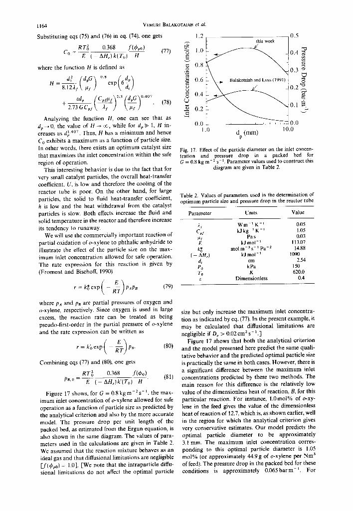
Figure 17 shows, for G = 0 . 8 k g m - Z s t, the max- imum inlet concentration of o-xylene allowed for safe operation as a function of particle size as predicted by the analytical criterion and also by the more accurate model. The pressure drop per unit length of the packed bed, as estimated from the Ergun equation, is also shown in the same diagram. The values of para- meters used in the calculations are given in Table 2. We assumed that the reaction mixture behaves as an ideal gas and that diffusional limitations are negligible [_f(q~po) = 1.0]. [We note that the intraparticle diffu- sional limitations do not affect the optimal particle
VEMURI BALAKOTAIAH et al.
1.2
-6 1.o
= 0.8 © "2
0.6
© 0.4
0.2
0.0 1.0
0.5 this work
o.3 ;
0.2 , ~
0.1
. . . . . . . 0.0 10.0
d (mm) p
Fig. 17. Effect of the particle diameter on the inlet concen- tration and pressure drop in a packed bed for G = 0.8 kg m- 2 s- 1. Parameter values used to construct this
diagram are given in Table 2.
Table 2. Values of parameters used in the determination of optimum particle size and pressure drop in the reactor tube
Parameter Units Value
2y Wm -t K - t 0.05 Cps kJ kg 1 K- 1 1.05 #I Pa s 0.03 E kJ mol - 1 113.07 k~ molm -3 s- 1 pa-2 14.88
( - AH,) kJ mol- 1 1090 dt cm 2.54 P0 kPa 150 To K 620.0
Dimensionless 0.4
size but only increase the maximum inlet concentra- tion as indicated by eq. (77). In the present example, it may be calculated that diffusional limitations are negligible if De > 0.02 cm 2 s- 1.]
Figure 17 shows that both the analytical criterion and the model presented here predict the same quali- tative behavior and the predicted optimal particle size is practically the same in both cases. However, there is a significant difference between the maximum inlet concentrations predicted by these two methods. The main reason for this difference is the relatively low value of the dimensionless heat of reaction, B, for this particular reaction. For instance, 1.0mol% of o-xy- lene in the feed gives the value of the dimensionless heat of reaction of 12.7, which is, as shown earlier, well in the region for which the analytical criterion gives very conservative estimates. Our model predicts the optimal particle diameter to be approximately 3.1 mm. The maximum inlet concentration corres- ponding to this optimal particle diameter is 1.05 mol% (or approximately 44.9 g of o-xylene per Nm 3 of feed). The pressure drop in the packed bed for these conditions is approximately 0 .065barm - t . For
Runaway limits for homogeneous and catalytic reactors
smaller particle diameters, the maximum inlet concen- tration decreases rapidly. At the same time, the pres- sure drop in the fixed bed increases. For particle sizes above 3.1 mm in diameter, both the maximum inlet concentration and pressure drop decrease. For d v = 6.0 mm (approximately one-quarter of the tube diameter), the maximum inlet concentration falls to 0.92 mol%, and for d v = 8.0 mm (one-third of the tube diameter) it falls to 0.79 mol%. Compared to the opti- mum particle diameter, this corresponds to a 12 and 25% decrease in production, respectively.
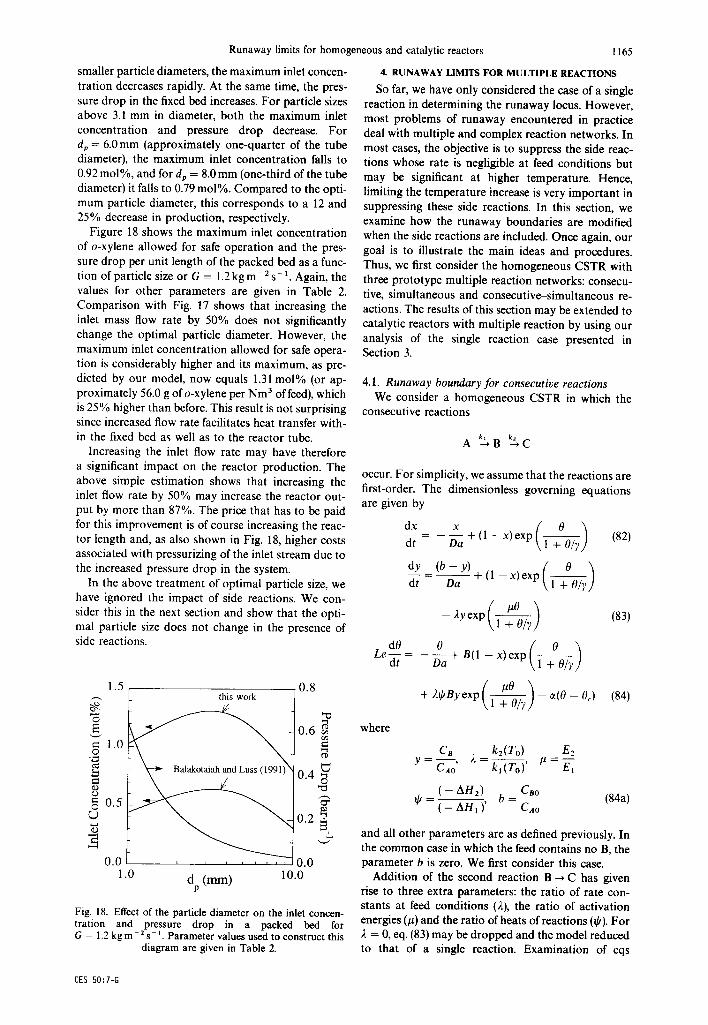
Figure 18 shows the maximum inlet concentration of o-xylene allowed for safe operation and the pres- sure drop per unit length of the packed bed as a func- tion of particle size or G = 1.2 kg m- 2 s- 1. Again, the values for other parameters are given in Table 2. Comparison with Fig. 17 shows that increasing the inlet mass flow rate by 50% does not significantly change the optimal particle diameter. However, the maximum inlet concentration allowed for safe opera- tion is considerably higher and its maximum, as pre- dicted by our model, now equals 1.31 mol% (or ap- proximately 56.0 g of o-xylene per Nm 3 of feed), which is 25% higher than before. This result is not surprising since increased flow rate facilitates heat transfer with- in the fixed bed as well as to the reactor tube.
Increasing the inlet flow rate may have therefore a significant impact on the reactor production. The above simple estimation shows that increasing the inlet flow rate by 50% may increase the reactor out- put by more than 87%. The price that has to be paid for this improvement is of course increasing the reac- tor length and, as also shown in Fig. 18, higher costs associated with pressurizing of the inlet stream due to the increased pressure drop in the system.
In the above treatment of optimal particle size, we have ignored the impact of side reactions. We con- sider this in the next section and show that the opti- mal particle size does not change in the presence of side reactions.
1.5 0 .8
= 1.0 o
¢..,) e.,.) o = 0.5
(.)
0.0
this work
i i i i I i i i
0.6 f ~
0.4 o
0.2 ~
0.0 1.0 d (mm) 10.0
p
Fig. 18. Effect of the particle diameter on the inlet concen- tration and pressure drop in a packed bed for G = 1.2 kg m 2 s- 1. Parameter values used to construct this
diagram are given in Table 2.
1165
4. RUNAWAY LIMITS FOR MULTIPLE REACTIONS
SO far, we have only considered the case of a single reaction in determining the runaway locus. However, most problems of runaway encountered in practice deal with multiple and complex reaction networks. In most cases, the objective is to suppress the side reac- tions whose rate is negligible at feed conditions but may be significant at higher temperature. Hence, limiting the temperature increase is very important in suppressing these side reactions. In this section, we examine how the runaway boundaries are modified when the side reactions are included. Once again, our goal is to illustrate the main ideas and procedures. Thus, we first consider the homogeneous CSTR with three prototype multiple reaction networks: consecu- tive, simultaneous and consecutive-simultaneous re- actions. The results of this section may be extended to catalytic reactors with multiple reaction by using our analysis of the single reaction case presented in Section 3.
4.1. Runaway boundary for consecutive reactions We consider a homogeneous CSTR in which the
consecutive reactions
A ~.B %c
occur. For simplicity, we assume that the reactions are first-order. The dimensionless governing equations are given by
dt Da + (1 - x) exp (82)
dYdt _(b Da-Y~)F ( 1 - x, exp ( 1 ~ 0 ~ ? )
- 2yexp ( ~ ) (83)
LedO 0 ( 0 ) ~ - = - ~a + B(1 - x)exp
+ 21pByexP( l~O~y ) -- o~(O -- Oc, (84)
where
y = Cn k2(To) E2 CAo' 2 = kt(To)' # = E-~
( -- AH2) Cao ~b - ( - AHi )' b = CAo (84a)
and all other parameters are as defined previously. In the common case in which the feed contains no B, the parameter b is zero. We first consider this case.
Addition of the second reaction B ~ C has given rise to three extra parameters: the ratio of rate con- stants at feed conditions (2), the ratio of activation energies (#) and the ratio of heats of reactions (qJ). For 2 = 0, eq. (83) may be dropped and the model reduced to that of a single reaction. Examination of eqs
CES 50:7-G

1166
(82)-(84) shows that x ~ 0, y ~ 0 and 0 ~ 0 for Da ~ 0
while x ~ 1, y ~ 0 and 0 ~ 0c for Da ~ oo. Thus, the reaction path in the (x, y, 0) space starts at (0, 0, 0) and ends at (1,0,0c). When 0 c = 0 and ct = oo (strongly cooled case), we have an isothermal system and the yield and selectivities obtained will be those corres- ponding to feed conditions. For any finite ct, it is not possible to maintain isothermal conditions (especially when ~ > 0, or equivalently when both reactions are exothermic). However, when ct is large, the temper- ature rise may be limited and it is possible to maintain close to isothermal conditions. As in the case of a single reaction, the appearance of an ignition point on the reaction path may lead to excessive temper- ature rise and insufficient cooling. Thus, we define the safe region of operation as the set of parameters (y, B, ct, 0o 2, #, ~,) for which the reaction path connect- ing (0, 0, 0) to (1, 0, 0~) contains no ignition points. We now determine the runaway boundary using this def- inition.
Before we present the numerical results, we con- sider some limiting cases in order to obtain some insight on the runaway behavior. When 0~ = 0 and
~ oo, the steady-state equations simplify to
Da e ° x - 1 + Da e ~ ° (85)
Da e ° (86)
Y (1 + Dae°) (1 + 2 D a e u°)
B Da e ° 21pB Da 2 e " +~oo
0(1 + ~Da) = (1 + D a e °) + (1 + Dae°)(1 + 2DaeU°)"
(87)
Since for 2 = 0, eq. (87) reduces to that of a single reaction, we expect that the runaway locus is close to that of the single reaction case for small 2 values. We can determine the adiabatic and strongly cooled asymptote analytically for small 2 using the standard perturbation method. The adiabatic asymptote may be shown to be
B = 4 - 4 2 ~ b ( 1 + 2#)e 2u-2 + 0(22 ) (88)
0 = 2 + 4~4b#2e 2"-2 + 0(22) (89)
D a e ° = 1 + 42~k/~(1 + #)e 2"-2 + 0(22) (90)
while the strongly cooled asymptote which occurs for x ~ 0, y ~ 0 is independent of 2 (for small ~.) and is the same as that for a single reaction.
Figure 19 shows the runaway boundaries (with Cao = 0 or equivalently b = 0) for the parameters p = 2 , y = 2 0 , ~k= 1.0 and 0 c = 0 with varying 2 values. The runaway boundary for 2 = 0 corres- ponds to the case of a single first-order reaction. As 2 increases, the side reaction becomes more important and the runaway region also increases. The effect of side reactions on the runaway boundary is observed to be most pronounced in the adiabatic asymptote. However, in the strongly cooled asymptote, this effect is not important for small 2 values (i.e. 2 < 0.1). Figure 20 shows the Damk6hler values and corresponding
VEMURI BALAKOTAIAH et al.
101
lO o
cdB
10 -1
101200
. . . . . . . . I
Safe
~=10 2
I )~=1
~.=10 -~ x
A ~ B ~ C
<. ~.=0
l l l l
10 l 10 2
B
Fig. I9. Runaway locus for the consecutive reactions in a homogeneous CSTR. Parameter values used to construct
this diagram are b = 0, # --- 2, 7 = 20, ~k = 1 and 0c = 0.
10 °
Da 10 -~
10 -~
4
3
0 2
1
0 10 °
' ' 2 . . . . . . I . . . . . . . . - (a)
k=10"
~.=1 ~ , = 0 ~
I I I I I I I l l I I I . . . .
(b)
~.=10 2
l i i i i i i i 1 [ . . . . i i , ~
101 10 2 B
Fig. 20. Temperature and residence time (Da) values at the runaway limit for consecutive reactions in a homogeneous CSTR. Parameter values used to construct this figure are
b = 0, # --- 2, ), = 20, t # = l and0 c=0.
temperatures on the runaway boundary. We note that, for each 2 value, the temperature is highest in the adiabatic asymptote as expected and decreases to- ward 0 = 1 as the strongly cooled asymptote is ap- proached. Figure 21 shows the bifurcation diagrams of 0, x and y vs the Damkfh le r number at the run- away boundary for the parameters 2 = 10 2, B = 20.14, ot = 29.23, # = 2.0, ~, = 20.0, ~b = 1.0 and 0c = 0. These bifurcation diagrams show the merging of the high temperature isolated branch with the low

Runaway limits for homogeneous and catalytic reactors
When b ~ 0, eq. (87) is modified to (a)
101
I 0 ° 0
10 -1
10 .2
Y
10 .3
101
10 °
10 -I
x 10 -2
10 .3
10 -4
10 4
101
10 2
I I I I I I
(b)
(c )
10 -t
10 .3
10 .5
10 -7
10 4 10 -4 10 .3 10 .2 10 -l D a
I
101 102
Isola Point
100
Fig. 21. Bifurcation diagrams of 0, x and y vs Da at the runaway boundary for consecutive reactions with para- meters 2 = 10 -2, B = 20.14, c~ = 29.23, ,u = 2.0, Y = 20.0,
= 1.0 and 0c = 0.
1167
B Da e ° 2qJb B Da e "° 0(1 + ~Da) = +
(1 + Dae °) 1 + 2 D a e "°
2qJ B Oa 2 e ° + ~)o
+ (1 + Dae°)(1 + 2DaeU°)" (91)
For strongly cooled conditions, eq. (91) simplifies to
e ° + ).~bb e "° B - 0 (92)
The strongly cooled asymptote is given by the ignition point of eq. (92). For/~ = 1, this is given by
Oi= 1 (93)
~t - = e(1 + b2~b). B
For/~ :~ 1 and 2 small, a perturbation solution gives the strongly cooled asymptote
Oi = 1 + 2t~b(l - / t ) e ~-1 + 0(22) (94)
= e(l + b2Oe " -1) + O(2Z).
It is clear from eq. (94) that for 0 > 0 and p > 1, the ignition temperature is lowered and the runaway re- gion is enlarged. For example, for a typical case of /~ = 2 and tp = 1, the ot/B value at runaway increases by about 30% for 2 = 0.1.
When /~ 4:1 and 2 is finite, the strongly cooled asymptote may be expressed in a parametric form
(1 -- 0 ) e II-u)° b2~b - (95)
( / t O - 1)
B - ( # 0 - 1 ~ ' 0 e ,1 . (96)
Figure 22 shows a plot of the values of ~/B on the strongly cooled asymptote as a function of the prod- uct 2bO for two values of /~. For 2bO < 0.1, the strongly cooled asymptote of the runaway boundary
temperature branch. Any further decrease in heat re- moval will lead to the break-up of the isola point into two ignition points. Under such a condition, the reac- tor can easily go from a low to a high temperature steady state with slight perturbations introduced into the reactor. F rom these bifurcation diagrams, it may also be observed that the selectivity or yield of the intermediate B is very low on the isolated branch. Thus far, the result for the consecutive reaction is shown for the case where no B is present in the feed. For this reason, we do not expect that the side reac- tion will have significant impact on the runaway boundary as verified by the numerical simulations.
When B is present in the feed, the runaway region may be considerably enlarged, especially when the second reaction is exothermic and has higher activa- tion energy. In this case, even the strongly cooled asymptote may change considerably as shown below.
l 0 2 . . . . . . . .
I.t=2 (analytical < n ) ,
Safe g=2 c(/B 101
Runaway
1 0°01 3 . . . . . . . . . . . . . . . . . . . . . . . . . . . . . . . . . . 10-2 10 q 10 ° 10 I
~, b lit
Fig. 22. Effect of side reactions on the strongly cooled asym- ptote of the runaway locus.

1168
is unaffected by side reactions. In the same figure, we also show the analytical expression given by eq. (94). From this comparison, we see that eq. (94) is a slightly conservative approximation of the strongly cooled asymptote in the practical range of /~ values (0 < p < 2).
4.2. R u n a w a y boundary f o r s imul taneous react ions
The conversion and temperature in a homogeneous CSTR in which the simultaneous reactions
kl
k2
occur are described by the equations
dt Da ~- (l - x) exp
#0 - 2 ( 1 - x ) exp ( 1 ~ ) (97)
Le dt - Da + B(1 -- x) exp
+ 20B(1 -- x) exp 1 ~ - e(0 -- 0c)
(98)
where all the dimensionless parameters are as defined previously. We consider here only the most relevant practical case in which both the reactions are exother- mic. Equations (97) and (98) may be analyzed in the same manner as in the consecutive reactions case. Once again, we consider the limiting case ? ~ oo and 0c = 0 to obtain some insight into the runaway behav- ior. In this case, the steady-state conversion and tem- perature are given by
Da e ° + 2 Da e ~° x - (99)
1 + D a e ° + 2 D a e u°
B Da e ° + 2~OB Da e ~° 0(1 + c t D a ) - 1 + D a e ° + 2 D a e ~°" (100)
For 2 --, 0, these equations reduce to the single reac- tion case. For small 2, the adiabatic asymptote may be calculated to be
B = 4 -- 42(2#0 - y - ~/)e 2u-2 + 0 ( 2 2 ) (101)
0 = 2 + 2(1 - p)[2# + 4~0(1 - p ) ] e 2u-2 + 0(22 )
(102)
D a e ° = 1 + 211 - 2# 2 + 4/t~O(# - 1)]e 2u-2 + 0(22).
(103)
Under strongly cooled conditions, eq. (100) simplifies t o
ot = e ° + 2tp e u° (104) B 0
This equation is identical to eq. (92) obtained for the consecutive reactions with b = 1. Thus, the results obtained above as well as Fig. 22 are applicable here with b = 1.
VEMURI BALAKOTAIAH et al.
l01 . . . . . . . . ~ . . . . . . . .
Sa fe
10 o t ~ Runaway ~ / B ~ B
10_ 1 ~,=1
10-2 . . . . . . . . . . 10 ° 101 10 2
B
Fig. 23. Effect of the competing reaction on the runaway locus for the simultaneous reaction network. Parameter values used to construct this figure are # = 2, ? = 20, ~O = 1
and 0c = 0.
Figure 23 shows the numerically computed run- away boundaries in the case of simultaneous reactions for varying 2 values with fixed y, y, q; and 0c values. We observe that as 2 increases the runaway region also increases. Unlike the case of consecutive reac- tions, the runaway boundary for the simultaneous reactions is significantly affected at both the adiabatic and strongly cooled limits. This is due to the fact that both the primary reaction and the side reaction simul- taneously compete for the same reactant even at short residence times (low conversions and temperatures). This is not the case for the consecutive reaction scheme (with b = 0) where the product B has to be formed first before the side reaction becomes impor- tant. As a result, the side reaction in the simultaneous reaction scheme is no longer insignificant but now plays an important role in determining the runaway boundary. Once again, eq. (94) (with b = 1) gives a slightly conservative analytical approximation of the runaway locus for a practical range of # values.
4.3. R u n a w a y boundary f o r consecut ive-s imul taneous
react ions
As a final example, we consider the consecut- ive-simultaneous reactions network
kl k2
A " B - - , ' C
which describes the oxidation of o-xylene to phthalic anhydride (with D = C) as well as many other partial oxidations. The species and energy balances for a CSTR in which the feed contains no B may be written as
dt Da + (1 - x) exp
, ( ~o + 22(1 - xJ exp t ~ ) (105)

dy
dt
d0 Le m =
dt
where
Runaway limits for homogeneous and catalytic reactors
Y + ( 1 - - x ) e x P ( l ~ 0 ~ 7 ) Da
, f - ,,yexpt, ) (106)
- - D~ + B(I - x)exp
(.lo5 + , l~qyexp \1 + O~ L /
, / . 2 0 + 2 2(1 - exp - - 0 < )
(107)
ki+l(To) Ei+l 2i k t ( T o ) ' lai= E1
( - AHi+ 1) ~b i - i = 1,2
( - AHI) '
and all other parameters are as defined previously. Figure 24 shows the numerically computed runaway boundaries for this consecutive-simultaneous reac- tion scheme for a typical set of parameters corres- ponding to the oxidation of o-xylene to phthalic anhydride (Froment, 1967). When compared to the runaway boundary for the single reaction, we observe a significant difference in the adiabatic asymptote and only a marginal difference in the strongly cooled asymptote. The difference in the runaway boundary is attributed to the fact that the product 22b2~b2 ~ 0.36 and is not small. For this value of 22bz~'z, eq. (94) predicts the a/B value at the runaway limit to be 38% higher than the single reaction case. This is confirmed by the numerical calculations shown in Fig. 24. The consecutive reaction is not as significant as the simul-
10 °
oWB
l 0 1 . . . . . . . . ~ . . . . . . . . .
S a f e
16 A--~ B--~ C
c "~c
i i i i . . . . . . .
101 102 B
l i f t
10~00
/
D.t
9.
1169
taneous direct oxidation reaction since there is no intermediate present in the feed (bl = 0).
In summary, it may be concluded that the runaway locus for multiple reactions differs significantly from that of the single reaction case only when one or more of the parameters 2i is of order 0.1 or larger. For any complex reaction network, the strongly cooled asymptote of the runaway boundary may be approx- imated by eqs (95) and (96) with 2, ~b and p corres- ponding to the most significant simultaneous (or par- allel) side reaction. Finally, the result of Fig. 22 shows that the strongly cooled asymptote of the runaway locus is unaffected by side reactions when the product b2~k < 0.1.
Fig. 24. Comparison of stability boundary for a single reac- tion (21 = 22 = 0) with that of the consecutive-simultaneous reaction network with parameters /z 2 = 1.06, 22 =0.1, ~b 2=3.55, /z 1 = 1.16, ~-t =0.06, $1 =2.55, 7=24 and
0c = 0.
5. DISCUSSION AND CONCLUSIONS
In this work, we have presented a rather compre- hensive treatment of the problem of runaway in ho- mogeneous as well as catalytic reactors. While this problem is not new and has been treated for over 50 years, the main contributions of this work are the unified treatment of various reactor models, identi- fication of the main asymptotes of the runaway boundaries and presentation of simple analytical and slightly conservative expressions for various limiting cases. It is hoped that the results and insight presented here can be used to calculate the runaway limits of any practical system in a routine manner.
For the case of homogeneous reactor models, the runaway boundary is determined by the existence of an ignition (or inflection) point in the reaction path. Using this definition, we have shown that the run- away boundary is independent of the reactor model in the practically important strongly cooled limit. The differences between the reactor models are also small even in the adiabatic limit. Considering the fact that the reaction, transport and heat transfer parameters cannot be determined so accurately in practice, we have suggested that a single universal runaway cri- terion may be used to define runaway limits in all homogeneous reactor models. This boundary is most easily calculated for the simplest CSTR model.
Based on our analysis of the homogeneous reactor models, we have presented a simple model for calcu- lating the stability boundaries for a cooled catalytic reactor influenced by interparticle and intraparticle transport limitations. The model is used to examine the effect of the particle Damk6hler number (Daph), the Thiele modulus (tPpo) and the coolant temperature (0c) on the stability boundaries and the conservatism of the explicit runaway criterion developed by Balakotaiah and Luss (1991). The computations show that higher interparticle heat transfer resistance, in- creased coolant temperature and higher activation energy increase the tendency of a catalytic reactor to runaway. In contrast, the intraparticle diffusional res- istance has the opposite effect on the runaway bound- ary. The analysis shows that the heat transfer resist- ance between the solid and the fluid introduces a qualitative change in the shape of the stability

1170 VEMURI BALAKOTAIAH et al.
boundary. There exists a limiting value of the heat reaction parameter B, above which the reactor is in A a runaway region regardless of the rate of external b cooling. This limiting value of B corresponds to the B ignition of catalytic particles. For negative values of 0c, ignition of particles occurs at the reactor inlet and C thus the particle ignition asymptote for these cases is CSTR independent of 0c. Cp
It is also shown that there exists an optimal catalyst dt particle diameter that maximizes the inlet concentra- dp tion within the safe region of operation of the reactor. De The commercially interesting case of oxidation of o-xylene to phthalic anhydride is used to show that Da this optimal particle diameter falls in the region of Daph practical interest. Using this optimal catalyst diameter e decreases the tendency of the reactor to runaway. E Consequently, the higher inlet concentration that can G be accommodated can significantly increase the reac- h tor production.
We have illustrated the main concepts and the H computation of the runaway boundaries for multiple ( - AHr) reactions by using three specific examples of consecut- k~ ive, simultaneous and consecutive-simultaneous reac- tion networks. The simulations presented in Section k* 4 lead to the following significant conclusions. The k' runaway locus for multiple reactions differs signifi- cantly from that of the single reaction case only when kc one or more of the parameters 2i is of order 0.1 or larger. For any complex reaction network, the L strongly cooled asymptote of the runaway boundary Le may be approximated by eqs (95) and (96) with 2, (MCp)R ~, and/~ corresponding to the most significant simul- (MCp)y taneous (or parallel) side reaction. Finally, the (MCp)m strongly cooled asymptote of the runaway locus is n unaffected by side reactions when the product p Abe, < 0.1. q
The homogeneous model presented in Section Q 4 may be extended for calculating runaway limits of R catalytic reactors with multiple reactions. This exten- sion is straightforward and is similar to that shown in Rep Section 3 for the single reaction case. S
A major limitation of the present work is the ab- t sence of control action in any of the reactor models, t~ The addition of a controller to a reactor adds addi- tional parameters (such as proportional gain, set too point, etc.) which can be adjusted to modify the stabil- tg ity limits. The analysis of reactor models with a con- th troller can be carried out in the same manner as tm shown in this work. However, the results and their tR interpretation will be quite different. The results pre- T sented in this work are valid in the worst-case U scenario where the control action completely fails.
Acknowledgements--This work was partially supported by grants from the American Chemical Society Petroleum Research Fund, the Robert A. Welch Foundation and a BASF fellowship to Duyen Nguyen. We are thankful to Professors M. Michelsen of the Institut for Kemiteknik and J. Villadsen of the Institut for Bioteknologi for their helpful comments on an earlier version of the manuscript.
V x
Y
NOTATION
heat transfer area, m 2 ratio of feed concentrations dimensionless adiabatic temperature rise defined by eq. (6) concentration, mol m- ~ continuous flow stirred tank reactor specific heat, J kg- 1 K - 1 tube diameter, m particle diameter, m effective diffusivity of reactant in the catalyst, m 2 s - 1
Damk6hler number particle heat Damk6hler number 2.718 activation energy, J mol-1 mass flux, kg m- 2 s- 1 fluid-particle heat-transfer coefficient, W m - 2 K - 1 Heaviside function heat of reaction, J mol 1 rate constant of reaction i, (mol m-3)1-n S-1
rate constant, mol m- 3 s- 1 Pa- 2 pseudo-first-order rate constant, mol m - 3 s - 1 pa-~ fluid-particle mass-transfer coefficient, m s - I
length of reactor Lewis number heat capacity of reactor and its contents heat capacity of fluid in the reactor heat capacity of reactor walls reaction order partial pressure, Pa volumetric flow rate, m 3 s- 1 rate of heat removal from reactor, J s- universal gas constant ( = 8.314 J mol- K - l )
particle Reynolds number surface area, m 2
dimensionless time characteristic time for convection (resi- dence time) characteristic time for cooling characteristic time for heat generation characteristic time for heat dispersion characteristic time for mass dispersion characteristic time for reaction temperature, K overall heat-transfer coefficient, W m -2 K - 1
volume, m 3 reactant conversion dimensionless concentration of inter- mediate species
Greek letters ~t dimensionless external heat-transfer co-
efficient

Runaway limits for homogeneous and catalytic reactors 1171
7
0 0c Os 2
~-f #
#f
P (9"
~o
dimensionless activation energy porosity internal effectiveness factor dimensionless temperature dimensionless coolant temperature dimensionless solid temperature ratio of activation energies at inlet condi- tions fluid thermal conductivity, W m - 1 K - ratio of activation energies at inlet condi- tions fluid viscosity, Pa s dimensionless axial position density, kg m - 3 ratio of heat of capacities of fluid to solid normalized Thiele modulus normalized Thiele modulus at inlet con- ditions ratio of heats of reaction at inlet condi- tions
Subscripts a adiabatic c coolant temperature f fluid h heat m mass, reactor material p particle R reactor s solid 0 inlet
REFERENCES
Adler, J. and Enig, J. W., 1964, The critical conditions in thermal explosion theory with reactant consumption. Combustion Flame 8, 97.
Balakotaiah, V., 1989, Simple runaway criteria for cooled reactors. A.LCh.E.J. 35, 1039.
Balakotaiah, V. and Kodra, D., 1992, Stability criteria for chemical reactors, in Dynamics and Control of Chemical Reactors, Distillation Columns and Batch Processes
Dycord + 92 preprints) (edited by J.G. Balchen). Mary- land, U.S.A.
Balakotaiah, V. and Luss, D., 1981 Analysis of the multipli- city patterns of a CSTR. Chem Engng Commun. 13, 111.
Balakotaiah, V. and Luss, D., 1991 Explicit runaway cri- terion for catalytic reactors with transport limitations. A.I.Ch.E.J. 37, 1780.
Barkelew, C. H., 1959, Stability of chemical reactors. A.I.Ch.E. Symp. Ser. 25, 37.
Barkelew, C. H., 1984, Stability of adiabatic reactors. ACS Syrup. Set. 237, 337.
Dwivedi, P. N. and Upadhay, S. N., 1977, Particle-fluid mass transfer in fixed and fluidized beds. Ind. Engng Chem. Process Des. Dev. 16, 157
Froment, G., 1967, Fixed bed catalytic reactors~current design status. Ind. Engng Chem. 59 (2), 18.
Froment, G. F. and Bischoff, K. B., 1990, Chemical Reactor Analysis and Design. Wiley, New York.
Hagan, P. S., Herskowitz, M. and Pirkle, C., 1987, Equilib- rium temperature profiles in highly sensitive tubular reac- tors. SIAM J. Appl. Math. 47, 1287.
Hagan, P. S., Herskowitz, M. and Pirkle, C., 1988a, A simple approach to highly sensitive tubular reactors. SIAM J. Appl. Math. 48, 1083.
Hagan, P. S., Herskowitz, M. and Pirkle, C., 1988b, Run- away in highly sensitive tubular reactors. SIAM J. Appl. Math. 48, 1437.
Li, C. H. and Finlayson, B. A., 1977, Heat-transfer in packed beds: a reevaluation. Chem. Engng Sci. 32, 1055.
Morbidelli, M. and Varma, A., 1986, Parametric sensitivity in fixed-bed reactors: the role of interparticle transfer resistances. A.I.Ch.E.J. 32, 297.
Morbidelli, M. and Varma, A., 1987, Parametric sensitivity in fixed-bed reactors: inter- and intraparticle resistances. A.I.Ch.E.J. 33, 1949.
Rajadhyaksha, R. A., Vusudeva, K. and Doraiswamy, L. K., 1975, Parametric sensitivity in fixed-bed reactors. Chem. Engng Sci. 30, 1399.
Thomas, P. H., 1961 Effect of reactant consumption on the induction period and critical conditions for a thermal explosion. Proc. R. Soc. A 262, 192.
van Welsenaere, R. J. and Froment, G. F. 1970, Parametric sensitivity and runaway in fixed-bed catalytic reactors. Chem. Engng Sci. 25, 1503.
Wilson, K. B., 1946, Calculation and analysis of longitudinal temperature gradients in tubular reactors, Trans. Instn Chem. Engrs 24, 77.
Zeldovich, Ya. B. and Zysin, Y. A., 1941, On the theory of the heat release rate from chemical reactions in streams. J. Tech. Phys. 1, 501.
Copyright © 2022 FDOKUMEN