exclusion zones for small modular reactors - University of ...
Upload
khangminh22Category
view
0download
0
© ABBSlide 1 AOctober 3, 2016October 3, 2016
Shunt ReactorsOptimizing Transmission Voltage System
Zahra Norouzian, Electrical Engineer, ABB Transformers and Reactors, Sep 6 / 2016
© ABBSlide 2 AOctober 3, 2016October 3, 2016
ABB oil immersed ReactorsAgenda
Introduction ABB Transformers, Ludvika
Why shunt reactors?
General Design
Variable Shunt Reactors (VSR)
Design
Applications and benefits
References VaasaLudvika
Stockholm

© ABBSlide 3 AOctober 3, 2016October 3, 2016
ABB Transformers LudvikaLarge power transformers & Shunt Reactors
World wide responsibility for Shunt reactors andHVDC transformers within ABB
Competence center for transformers world wide
Development team for TrafoStar (ABB Technology)
Complete product range for bushings, tap changersand insulation kits
More than 1000 reactors to all continents.
Tailor made reactors for each specific networkconfiguration.
Testing facilities up to the largest units in voltage andpower.

© ABBSlide 4 AOctober 3, 2016October 3, 2016
ABB TransformersReactor Portfolio
ABB – Ludvika
Reactive power
Single phase up to 133Mvar (Full bank 400Mvar)
Three phase up to >300Mvar
Voltage
up to >765kV
Testing facilities up to the largest unitsin voltage and Mvar
ABB – Vaasa
<72,5 kV up to 63 Mvar
72,5 - 145kV up to 25 Mvar

© ABBSlide 5 AOctober 3, 2016October 3, 2016
Reactor Power CompensationWhy Shunt Reactors?
© ABBSlide 6 AOctober 3, 2016October 3, 2016
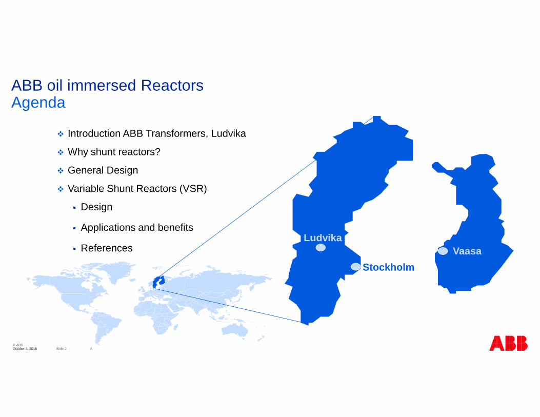
Reactive Power CompensationWhat is reactive power? Shunt Reactor
1. Stability on long line transmissions2. Voltage control during light load conditions
Reactor restores voltage to specifiedvalue
Voltage increase fromcapacitive generation
X
X
1
U
XQ
QX

© ABBSlide 7 AOctober 3, 2016October 3, 2016
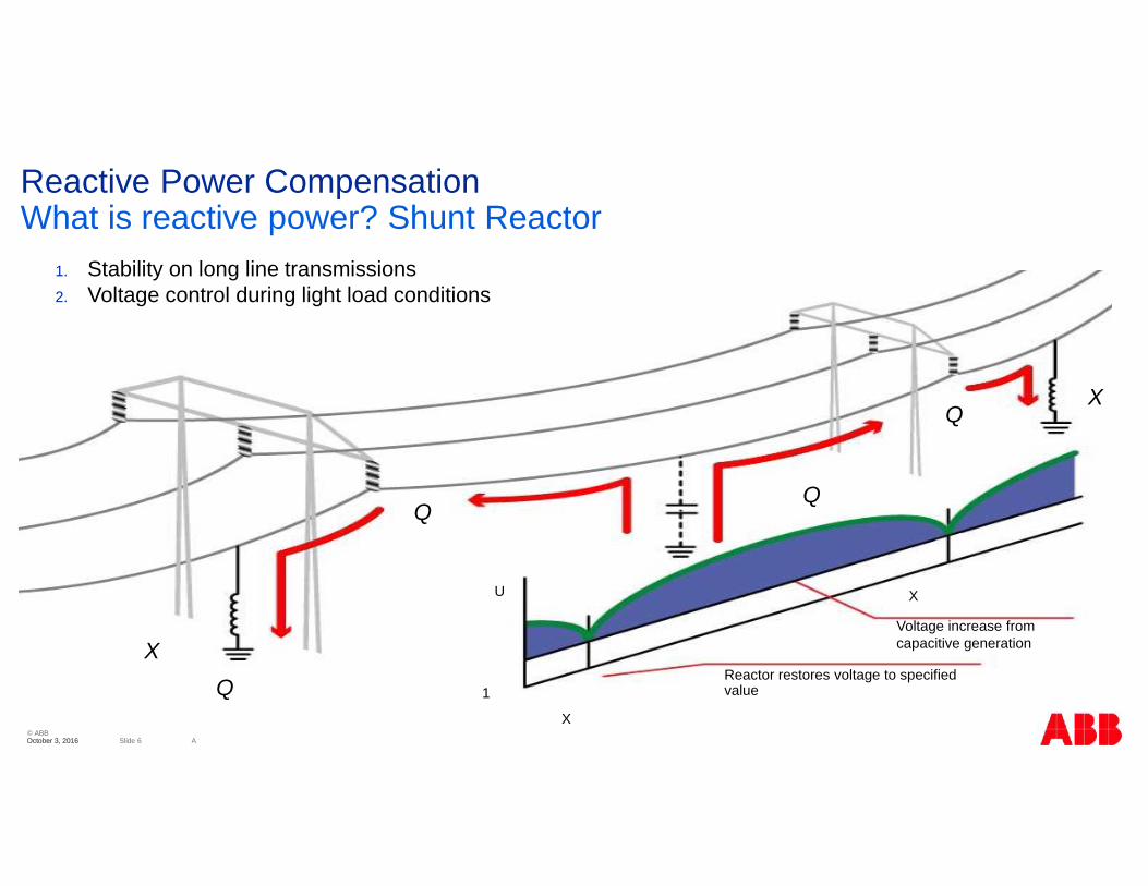
Reactive Power CompensationVoltage profiles and Shunt reactors
U1 U2
1,0 pu
P2, Q2
U2U1
(R) + X
Q U1 U2
1,0 pu
U1 U2
1,0 pu
Reactive power balance
Decreased load
Fixed power compensation
© ABBSlide 8 AOctober 3, 2016October 3, 2016
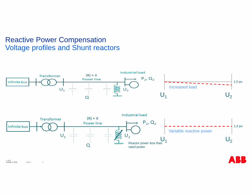
Reactive Power CompensationVoltage profiles and Shunt reactors
U1 U2
1,0 pu
U1 U2
1,0 pu
Reactor power less thanrated power.
Variable reactive power
Increased load

© ABBSlide 9 AOctober 3, 2016October 3, 2016
Shunt Reactor (SR): The most common device for controlling voltage stability. TheSR absorbs reactive power
Variable Shunt Reactor (VSR): The VSR also absorbs reactive power but allows fordynamic compensation, e.g. when load conditions or generation of reactive powerare varying
Synchronous Generators: Can be used not only for generating active power, butalso to both generate and absorb reactive power
Static Var Compensator (SVC): Provides very fast regulation of consumed orgenerated reactive power. Great possibilities but at high cost
Transformers with regulation: Can to some extent be used as their consumption ofreactive power depends on the tap position
Reactive Power CompensationDevices for reactive power compensation

© ABBSlide 10 AOctober 3, 2016October 3, 2016
ReactorDesign Concept

© ABBSlide 11 AOctober 3, 2016October 3, 2016
Rigid gapped core limb for low sound level
1. Core segments of grain oriented steel core sheetbonded by epoxy
2. Very stiff steatite spacers
3. Spacers are machined to exactly the same height
Precision crafted process ensures:
Small axial movements
Low vibrations & sound
Reactor design: Gapped core conceptLow sound

© ABBSlide 12 AOctober 3, 2016October 3, 2016
Extreme magnetic forces between the segments, up to 40 tons Long time mechanical stability is the main engineering challenge Requirements Pressure on the gapped limbs Precision in manufacturing of the segments and assembly. Tolerances on flatness and total height < 0,1 mm.
General DesignMechanical forces

© ABBSlide 13 AOctober 3, 2016October 3, 2016
General DesignFlux Control
Cross flux plate
The introduction of the cross flux plate makes it possible toprevent mechanical resonance in the core frame.
Control of leakage flux
Reduces magnetic losses
Reduce temperature in yokes

© ABBSlide 14 AOctober 3, 2016October 3, 2016
Earthed shieldno stress concentrationtowards core or winding
Winding centre entry andground potential towards yokesreduces overall size and losses
HV line terminal
General DesignWinding arrangement
© ABBSlide 15 AOctober 3, 2016October 3, 2016
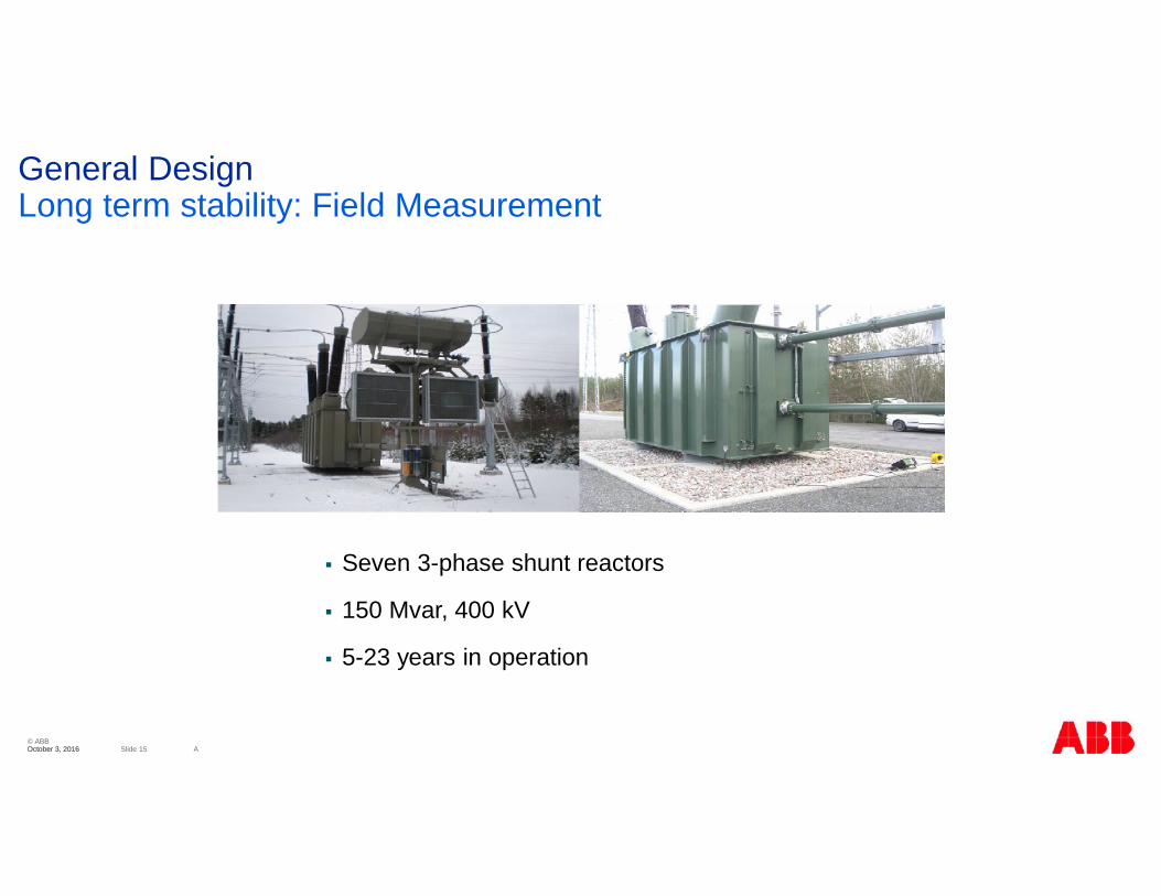
Seven 3-phase shunt reactors
150 Mvar, 400 kV
5-23 years in operation
General DesignLong term stability: Field Measurement
© ABBSlide 16 AOctober 3, 2016October 3, 2016
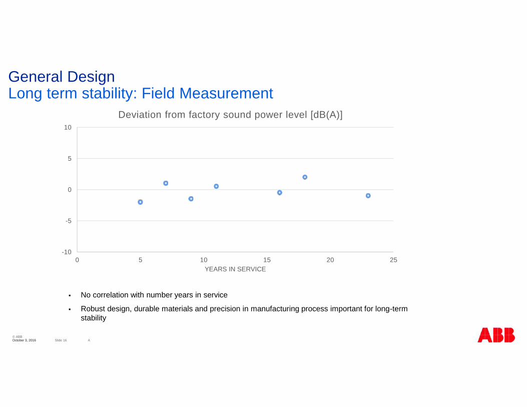
General DesignLong term stability: Field Measurement
-10
-5
0
5
10
0 5 10 15 20 25YEARS IN SERVICE
Deviation from factory sound power level [dB(A)]
No correlation with number years in service
Robust design, durable materials and precision in manufacturing process important for long-termstability
© ABBSlide 17 AOctober 3, 2016October 3, 2016
0
50
100
150
200
250
1996/05 1999/02 2001/11 2004/08 2007/04 2010/01 2012/10 2015/07
Max
sin
gle
peak
val
ue [µ
m]
Date of testing
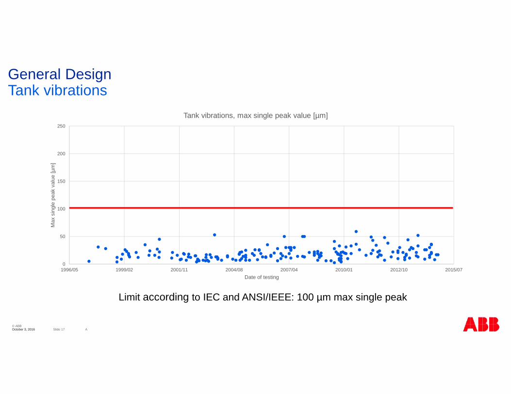
Tank vibrations, max single peak value [µm]
General DesignTank vibrations
Limit according to IEC and ANSI/IEEE: 100 µm max single peak
© ABBSlide 18 AOctober 3, 2016October 3, 2016
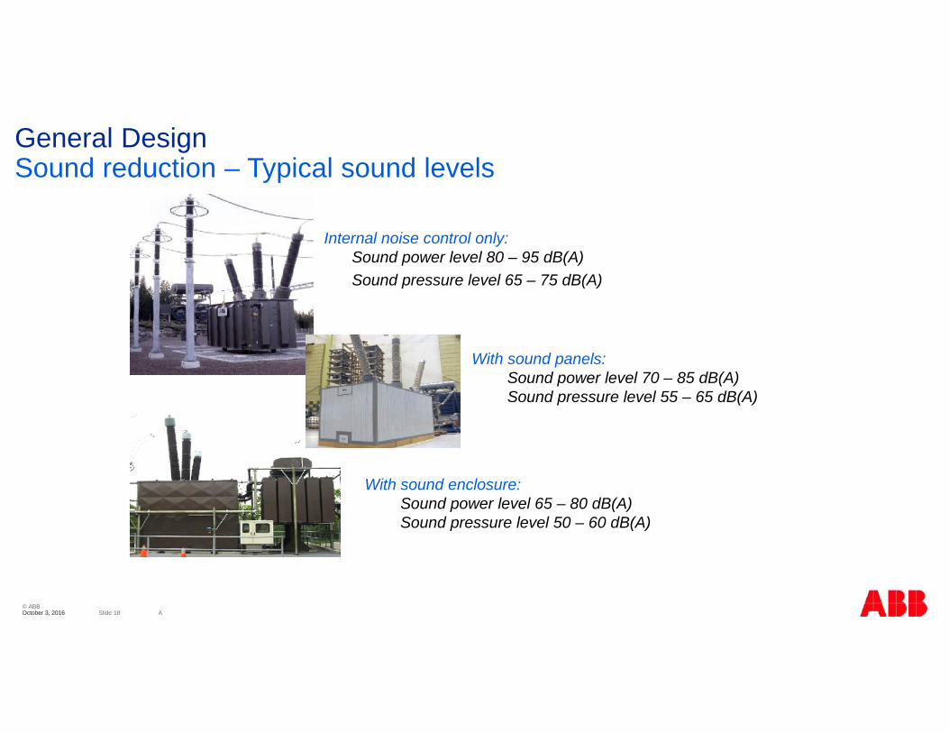
Internal noise control only:Sound power level 80 – 95 dB(A)Sound pressure level 65 – 75 dB(A)
With sound panels:Sound power level 70 – 85 dB(A)Sound pressure level 55 – 65 dB(A)
With sound enclosure:Sound power level 65 – 80 dB(A)Sound pressure level 50 – 60 dB(A)
General DesignSound reduction – Typical sound levels
© ABBSlide 19 AOctober 3, 2016October 3, 2016
Variable Shunt ReactorDesign

© ABBSlide 20 AOctober 3, 2016October 3, 2016
Neutral
Phaseterminal
NeutralPhase
terminal
OLTC An unconventional Reactor built onconventional technology
Variable Shunt ReactorDesign: Winding Concept

© ABBSlide 21 AOctober 3, 2016October 3, 2016
Fixed Shunt Reactor Variable Shunt Reactor
Limits for OLTC diverter switch: Maximum rated step voltage
Maximum through current
Switching capacity
Variable Shunt ReactorTap Changer Appearance

© ABBSlide 22 AOctober 3, 2016October 3, 2016
Variable Shunt ReactorDesign: Feasible Mvar Output Ranges
Blue: Traditional
Red: Latest
Example:50-100 Mvar345 kV

© ABBSlide 23 AOctober 3, 2016October 3, 2016
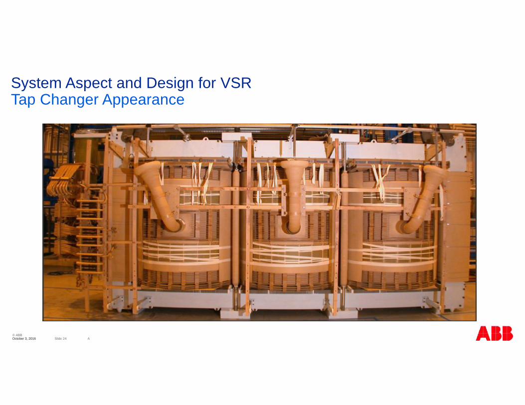
System Aspect and Design for VSRTap Changer Appearance
© ABBSlide 24 AOctober 3, 2016October 3, 2016
System Aspect and Design for VSRTap Changer Appearance

© ABBSlide 25 AOctober 3, 2016October 3, 2016
Variable Shunt ReactorApplications and References

© ABBSlide 26 AOctober 3, 2016October 3, 2016
Variable Shunt Reactor ApplicationsSuitable for different Applications
The is an optimum reactor rating at a certain load
Load varies with time Seasonal variations Daily variations
Shunt reactors are by traditionfixed in rating
Switching fixed reactors in andout leads to Voltage steps Wear on breakers Non-optimal compensation
We cannot today foresee the gridconditions of the future
© ABBSlide 27 AOctober 3, 2016October 3, 2016
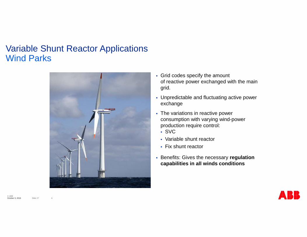
Variable Shunt Reactor ApplicationsWind Parks
Grid codes specify the amountof reactive power exchanged with the maingrid.
Unpredictable and fluctuating active powerexchange
The variations in reactive powerconsumption with varying wind-powerproduction require control: SVC Variable shunt reactor Fix shunt reactor
Benefits: Gives the necessary regulationcapabilities in all winds conditions
© ABBSlide 28 AOctober 3, 2016October 3, 2016
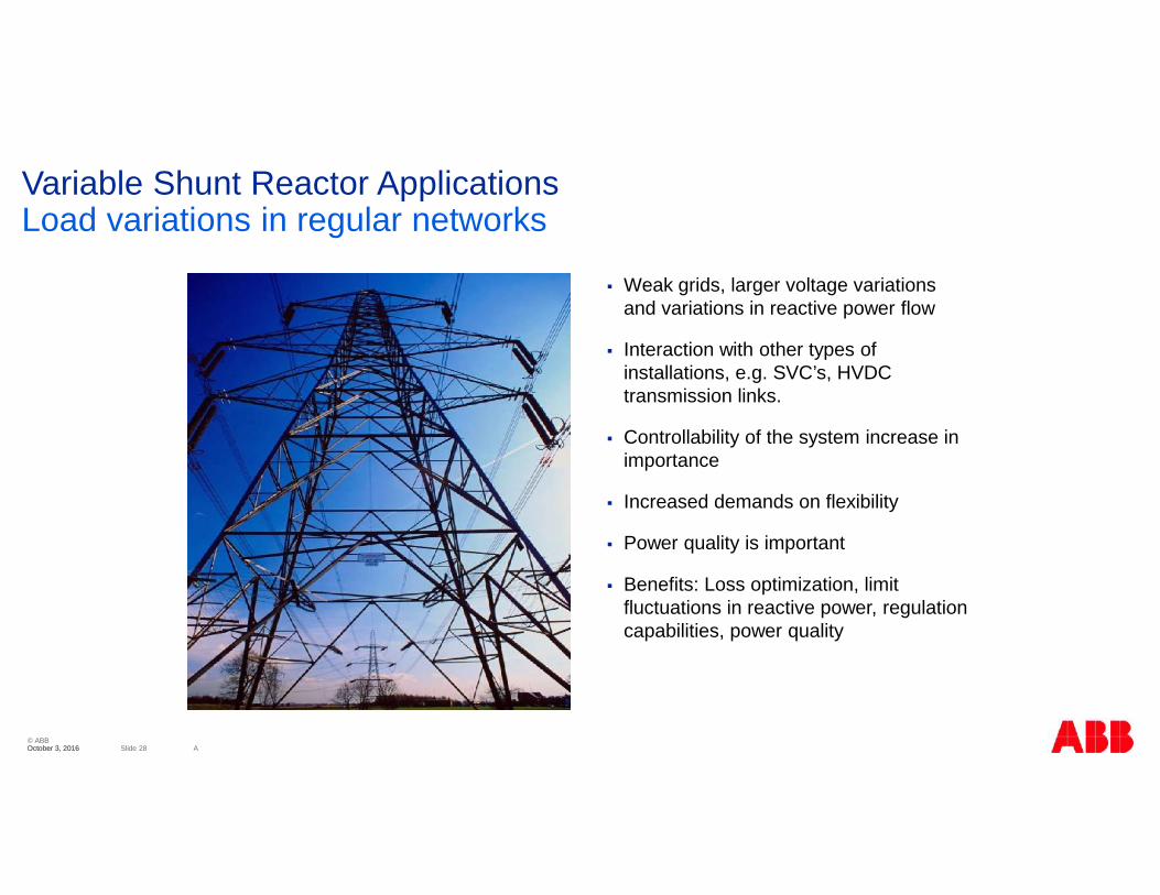
Variable Shunt Reactor ApplicationsLoad variations in regular networks
Weak grids, larger voltage variationsand variations in reactive power flow
Interaction with other types ofinstallations, e.g. SVC’s, HVDCtransmission links.
Controllability of the system increase inimportance
Increased demands on flexibility
Power quality is important
Benefits: Loss optimization, limitfluctuations in reactive power, regulationcapabilities, power quality
© ABBSlide 29 AOctober 3, 2016October 3, 2016
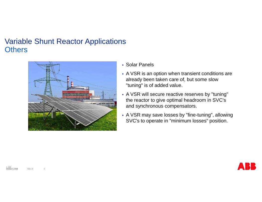
Variable Shunt Reactor ApplicationsOthers
Solar Panels
A VSR is an option when transient conditions arealready been taken care of, but some slow"tuning" is of added value.
A VSR will secure reactive reserves by "tuning"the reactor to give optimal headroom in SVC'sand synchronous compensators.
A VSR may save losses by "fine-tuning", allowingSVC's to operate in "minimum losses“ position.

© ABBSlide 30 AOctober 3, 2016October 3, 2016
Variable Shunt Reactor ApplicationsDenmark: Full use of VSR benefits
1: 50-110 Mvar, TC in min Mvar positionwhen cable is energized.2: 70-140 Mvar, to minimize voltagejump min Mvar position when switchedin.3: 70-140 Mvar, to minimize voltagejump min Mvar position when switchedin.4: 120 Mvar, compensation of sea cablefrom wind mill park.5: 60 -120 Mvar, 2 units to compensatefor variable wind power generation andloss optimization.
1
2
3
45
© ABBSlide 31 AOctober 3, 2016October 3, 2016
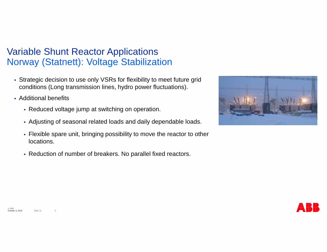
Variable Shunt Reactor ApplicationsNorway (Statnett): Voltage Stabilization
Strategic decision to use only VSRs for flexibility to meet future gridconditions (Long transmission lines, hydro power fluctuations).
Additional benefits
Reduced voltage jump at switching on operation.
Adjusting of seasonal related loads and daily dependable loads.
Flexible spare unit, bringing possibility to move the reactor to otherlocations.
Reduction of number of breakers. No parallel fixed reactors.
© ABBSlide 32 AOctober 3, 2016October 3, 2016
© ABB Group
October 3, 2016 | Slide 32
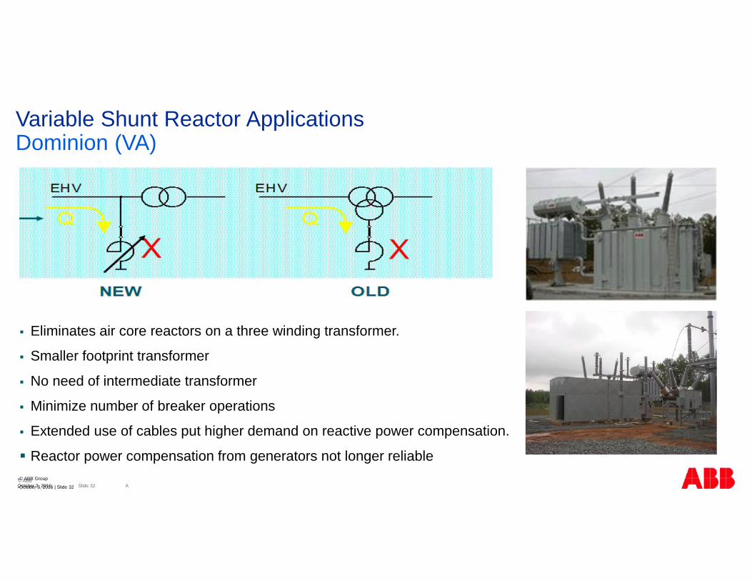
Variable Shunt Reactor ApplicationsDominion (VA)
Eliminates air core reactors on a three winding transformer.
Smaller footprint transformer
No need of intermediate transformer
Minimize number of breaker operations
Extended use of cables put higher demand on reactive power compensation.
Reactor power compensation from generators not longer reliable

© ABBSlide 33 AOctober 3, 2016October 3, 2016
Variable Shunt ReactorWorld Wide References
Customer Voltage (kV) Rating 3-phase - Mvar Year of delivery Customer Voltage (kV) Rating 3-phase - Mvar Year of delivery
Ghana, Africa 161 9-18 4 units 19891 units 2001 Vestas - Mexico 35 37 2 unit 2013
GEW, Köln, Germany 110 10-30 1 unit 1996 Center Point Energy, Texas, USA 143 25-50 1 unit 2014
Channel Islands, UK 132 7-16 2 units 1999 Jersey electricity - France 90 40 1 unit 2014
Sonabel, Burkina Faso, Africa 225 13-30 1 unit 2004 Cobra - Spain 161 9 4 unit 2014
Statnett, Norway 420 120-2001 unit 20082 units 20102 units 2010
City of Garland - Texas, USA 345 50-100 2 units 2015
E-Co Vannkraft, Norway 420 120-200 1 unit 2010 Kazakstan - Aktogai 10 3,8 2 units 2015
Dominion Virginia, USA 242 50-100
3 units 20094 units 20101 unit 20141 Unit 2016
BKK - Norway 420 90-200 2 units 2016
Svenska Kraftnät, Sweden 400 110-180 1 unit 2010 Eversource 345 70-160 2 units 2017Energinet dk, Denmark 235 60-120 2 units 2011 Energinet dk, Denmark 235 60-120 1 units 2017
Repsol - Libya 11 15,33 1 unit 2006Enercal – New Zeland 35 7,57 1 unit 2011
Statnett, Norway 420 90-200 8 units 2012 - 20131 unit 2014
Sharyland Utilities - Texas, USA 345 50-100 1 unit 2013
Energinet dk, Denmark 40050-110
70-140
3 units 20131 unit 20152 units 20131 unit 2015

© ABBSlide 34 AOctober 3, 2016October 3, 2016
Variable Shunt ReactorsSummary
SR used for voltage stability by consuming reactive power
SR are specialized products with substantial engineering challenges
SR: magnetic forces during normal operation
TFO: mechanical forces during short circuit
Manufacturing accuracy is requested to make reliable shunt reactors.
VSR is a new, advanced product type that provides:
Unique possibilities for variable network control
Variable ratings 50-100%
Several economical benefits
VSR customer references

Copyright © 2022 FDOKUMEN