for water cooled reactors - UNT Digital Library
303
TID 7006 march57 / for water cooled reactors
-
Upload
khangminh22 -
Category
Documents
-
view
0 -
download
0
Transcript of for water cooled reactors - UNT Digital Library

TID 7006 march57 /
for water cooled reactors

DISCLAIMER
This report was prepared as an account of work sponsored by an agency of the United States Government. Neither the United States Government nor any agency Thereof, nor any of their employees, makes any warranty, express or implied, or assumes any legal liability or responsibility for the accuracy, completeness, or usefulness of any information, apparatus, product, or process disclosed, or represents that its use would not infringe privately owned rights. Reference herein to any specific commercial product, process, or service by trade name, trademark, manufacturer, or otherwise does not necessarily constitute or imply its endorsement, recommendation, or favoring by the United States Government or any agency thereof. The views and opinions of authors expressed herein do not necessarily state or reflect those of the United States Government or any agency thereof.

DISCLAIMER Portions of this document may be illegible in electronic image products. Images are produced from the best available original document.

c

FOREWORD This handbook, sixth in a series on basic reactor technology sponsored by
the Naval Reactors Branch of the United States Atomic Energy Commission, is devoted to problems resulting from the use of water as a heat transfer medium in a reactor plant. There are many reasons why water has proved advan- tageous in powerplants, both conventional and nuclear. Water is readily available, cheap, and nontoxic, so that makeup, recovery, and waste disposal problems are minimized. These characteristics of water are very important because leakage in operating power plants can be many hundreds of gallons per day. Water has a low induced radioactivity, which dies away quickly when the reactor is shut down. It is liquid at room temperature. It can be stored in the open air. Technology has been built up over many years for handling i t in most of the common commercially available metals. I n other words, water is a “natural” material to use, offering a minimum of problems. This is in addition to its excellent characteristics as a heat transfer or working fluid.
It was generally believed, when work began on the pressurized water re- actor plant for the Nautilus prototype, that the technology of handling water a t moderate temperature in stainless-steel equipment was well developed. Compared with other possible reactor coolants, i t certainly was. But i t turned out that even a technology so well developed as water required a great deal of additional work specific to the peculiar conditions of a nuclear powerplant; this book, containing information developed through the expenditure of millions of dollars and thousands of man-years of effort, is evidence of the extent of that work.
I n spite of this work, our basic understanding of water technology is weak. We do not fully understand, for example, the processes by which metals be- come dissolved or suspended in- the reactor cooling water, how the radio- activity is then transported to the external system and how it is deposited on surfaces. We cannot be sure that changes in temperatures, flow rate, or chemical condition of the water will not lead to fouling of heat transfer surfaces, increased radioactivity in external systems, sticking and galling of water- lubricated mechanisms, or other deleterious conditions. We know that such problems can arise and we do not know all the causes and conditions which can create them nor can we assure their prevention. In future plants, dif- ferences in operating conditions now thought to be unimportant could mean the difference between a practical powerplant and an expensive toy.
Even with the large backlog of experience with water systems, there is still a great deal that must be learned. I hope that some readers of this hand- book will, starting from the data herein, work toward a firmer understanding of these problems.
H. G . RICKOVER, Chief, Naval Reactors Branch,
Division of Reactor Development, U . S. Atomic Energy Commission
111

I
I
EDITOR’S PREFACE
It is unfortunate that many people believe that most work in the atomic energy field is secret and that only a small fraction of the technology developed is available to them. This is not the case. The Atomic Energy Commission and its contractors are releasing more and more reports on nearly all phases of reactor technology. The series of books sponsored by the Naval Reactors Branch of the Atomic Energy Commission is one such means of making avail- able the technology developed in the naval and Shippingport reactor (PWR) programs. A list of these books is printed on the following page.
This Handbook on corrosion and wear deals with the use of water in a nuclear reactor system. The reasons water is desirable as a coolant for nu- clear reactors are discussed in the foreword by Rear Admiral H. G. Rickover.
The Handbook is organized in three parts. Part A gives background infor- mation and general principles for the benefit of engineers and scientists who are encountering for the first time the problems associated with the-use of high purity, high temperature water as a reactor coolant. This information is in- tended to help such persons evaluate new problems encountered in this field.
Part B of the Handbook contains tabulated data and detailed information for use as reference material for actual design work. Numerous references to additional data are also included.
Part C of the Handbook contains material on special types of corrosion and application problems involving wear.
Thanks go to all of the authors and contributors for their generous assist- ance. The editor appreciates the forbearance with which the contributors accepted editorial changes. These changes were generally made, not to correct faults, but to make each chapter fit into the whole. Special thanks go to J. W. Flaherty and S. Petach, of the Bettis Plant of the Atomic Energy Commission, for their untiring efforts and enthusiasm in gathering information and editing.
Acknowledgment is made to Rear Adm. H. G. Rickover, whose foresight and encouragement (prodding) caused this book to be written; to W. H. Wilson, R. R. Roof, and other members of Admiral Rickover’s staff in the Naval Reactors Branch for their valuable suggestions and comments.
D. J. DEPAUL, Editor.
V

V I PREFACE
This handbook is one of a series sponsored by the Naval Reactors Branch of the Atomic Energy Commission to publish in useful form the technology being developed in the naval and Shippingport reactor (PWR) programs. This series includes:
Liquid Metals Handbook. First edition: Edited by R. N. Lyon, June 1950. Second edition: Edited by R. N. Lyon, June 1952. .Third edition: (Sodium-NaK Supplement) First printing June 1955 ;
Metallurgy of Zirconium. Edited by B. Lustman and F. Kerze, Jr., July
The Metal Beryllium. Edited by D. W. White and J. E. Burke, July 1955.
Bibliography of Reactor Computer Codes, Report AECU-3078. Edited by R. S. Brodsky, December 1955.
Reactor Shielding Design Manual. Edited by T. Rockwell, 111, March
Corrosion and Wear Handbook for Water-cooled Reactors. Edited by D. J.
Naval Reactors Physics Handbook. A. Radkowsky, Chairman of Editorial
Reactor Core Design Manual. Edited by N. J. Palladino, in preparation.
Reactor Plant Piping Handbook. Edited by M. Shaw, in preparation.
Reactor Heat Transfer Handbook. Edited by J. Zerbe, in preparation.
second printing (Revised), November 1955.
1955.
1956.
DePaul, March 1957.
Board, in preparation.
Radiological Aspects OJ Naval Nuclear Propulsion Plants.
Metallurgy of Hafnium.
Edited by J. A.
Edited by E. T. Hayes and D. E. Thomas, in
Brimson, in preparation.
preparation.
VI11 CONTENTS
Page 135 136 137 138 139 140 141 141 142 142 142 143
147 147 150 159 171 171 187
187 188 188
191 211 214 219 225 225 225 226 227 229 229 230 23 1 236 237 239 239 34 1 245 25 1 263 263 263 266 266 266 267 2 i o 270 270
CONTENTS Page
iii V
3 3 3 .4 5 6 7 9
11 . 11 12 13 16 19 19 21 21 22 24 27 28 31 31 31 33 34 36
39 39 41 51 55 60 64 75 75 75 80 95 95 96 -
101 121 135 135
CONTENTS IX
Part A
Background Information

Chapter 1
INTRODUCTION
Editor-D. J. DEPAUL
Contributors-J. W. FLAHERTY, 'W. 2. FRIEND, E. P. P
Page 3
' 3 4 5 6 6
- 6 7 7 7 7 8 9 9 9
PURPOSE OF HANDBOOK Early in 1948, the United States Navy and
the Atomic Energy Commission undertook a program for the construction of a submarine that was to be powered with nuclear energy. The use of a nuclear reactor as a source of energy represented a new and untried method for the propulsion of ships a t sea. During the initial feasibility studies, several coolants were considered for removing heat directly from the reactor. These included water, liquid metals, and gases. ,
The investigators chose water as the primary t coolant in one of the naval reactors because
(1) it possesses desirable nuclear and heat- transfer properties, (2) its technology was more advanced and required the least amount of extrapolation, and (3) it, is a readili available and inexpensive coolant. However, the choice of high-purity water gave rise to many questions concerning the corrosion and wear properties of structural materials in pure water a t elevated
RTRIDGE, J. M. SEAMON
temperatures; there was essentially no indus- trial experience along these lines.
Because of the rigorous time schedule adopted for the construction of the atomic reactor and because of the multitude of problems requiring immediate investigation, the Naval Reactors Branch of the Reactor Development Division, Atomic Energy Commission, expedited the project by letting many prime contracts and subcontracts. Consequently, during the past 8 years the various participating organizations have amassed a large amount of information on the corrosion 'and wear resistance of materials under the expected service conditions.
It is the main purpose of this handbook to accumulate and correlate the pertinent corro- sion and wear information developed on this project into one source and in a form that is readily useful to the general engineering pro- fession, particularly ta those organizations that will participate in future nuclear reactor pro- grams. It is also intended that the handbook will indicate the many areas that have not been thoroughly investigated and may thereby serve as a source of stimulation for further research by industry and by universities.
SCOPE The basic data presented ,in the handbook
were obtained from all the government and private organizations who made a significant, contribution to the naval reactor project, either as prime or secondary contractors. The scope of the information included is primarily con- fined to corrosion and wear problems related to the primary, or radioactive, cooling system
n

4 CORROSION AND WEAR HANDBOOK FOR WATER-COOLED REACTORS
in the nuclear reactor portion of the power plant. (See fig. 1-1.)
Corrosion and wear studies were not nor- mally conducted for the selection of materials for the secondary, or nonradioactive, system. However, investigations were made to deter- mine the compatibility of stainless steel with the boiler water in the secondary system. The main heat exchanger, constructed of stainless steel, comes in contact with the primary coolant water on one side and with boiler water on the opposite side. No previous information was available on stainless steel in contact with boiler water. With this single exception, the secondary system parallels other industrial and military plants for which considerable experi- ence is available.
In order to expedite publication and to pre- sent corrosion and wear data in a readily avail- able form, it was considered necessary to limit the quantity of information included and to present only pertinent and generalized results. Nevertheless, a sufficient number of references are included so that additional detailed infor- mation on a particular subject can be obtained if desired.
It is anticipated that this handbook will be of greatest value to those engineers and tech- nicians who are not corrosion and wear special- ists. These engineers are in daily contact with general material problems, for which the hand- book may provide solutions. While the hand- book is in no way intended to transform these men into corrosion and wear specialists, it is hoped that the book will present all data necessary for the designer or engineer to face with confidence, problems involving corrosion and wear in a water-cooled nuclear reactor system.
Basically, the handbook will deal with three general categories of information.
Part A, consisting of four chapters, is in- tended to provide the reader with a general background so that the “numbers” and various special subjects discussed in subsequent chap- ters can be fully appreciated and understood in terms of the particular engineering application. These chapters include general discussions on
the nuclear reactor plant and its relation to conventional powerplants, considerations in choosing materials, fundamental aspects of corrosion and wear, and water technology.
These sup- ply basic information on methods of testing and on the inherent corrosion and wear resistance of various materials and combination of mate- rials under several different environmenlal conditions.
The remaining six chapters constitute part C, which deals primarily with special corrosion and wear problems resulting from the particular engineering application of materials. These include- discussions and detailed data on such items as crevice corrosion, stress corrosion, intergranular corrosion, system corrosion de- posits, wear, and manufacturing problems.
MAIN CONSIDERATIONS IN CHOOSING MATERIALS
Part B consists of four chapters.
In order that the reader may understand and appreciate more fully the basic problems in- volved in choosing materials for nuclear reactor applications, i t is desirable that some atltention be given to the gverall characteristics and re- quirements of the nuclear plant. A schematic layout of the water-cooled nuclear reactor and the steam power plant is shown in figure 1- 1.
FIGURE 1-1. Schematzc layout 0.f nuclear reactor and powerplant.
The plant consists of essentially two systems: (1) the primary cooling system, which re- moves heat from the nuclear reactor core and

INTRODUCTION 5
transfers it to the secondary boiler system through the steam generator, and' (2) the secondary cooling system, which may be con- sidered standard and representative of steam systems used with conventional fuels such as coal, oil, and gas. Therefore, the main differ- ence between a conventional and a nuclear plant is the method employed for heating the steam generator. In the nuclear plant, hot water rather than hot gases is circulated through the primary side of the main heat exchanger.
In conventional power and utility plants the purity of the boiler water is controlled by a continuous schedule of blowdown and makeup. Basically, this involves the removal of soluble and insoluble products by draining some water, more or less periodically, and replacing it with fresh water. It is considered easier in a nu- clear plant to circulate the same water con- tinuously in the primary radioactive system and to maintain purity by means of a mechanical filter and ion exchanger.
Corrosion products and other impurities in the water of the ,primary system become radio- active as the water circulales through the reactor core. Some of the radioactivity is long- lived and remains in the system even after the reactor is shut down. The disposal of the water containing radioactive waste products presents an obvious biological health hazard. Since the safety of operating personnel and integrity of the plant are the primary con- siderations in the design and operation of a nuclear reactor facility, it is necessary to keep the concentration of corrosion products, both soluble and insoluble, below specified safe levels. Only by closely controlling the amount of corrosion products in the primary system can this portion of the nuclear plant be made available for maintenance and. repair within a reasonable period of time. This, control can be effected by using highly corrosion-resistan t. materials or larger purification systems with materials of lower corrosion resistance. Thus i t is imperative that the corrosion and wear char- acteristics of all likely materials be kn-own. Through this knowledge, design personnel can
specify the requirements of the purificatiori sys tem.
As previously mentioned, when the project was initiated, there was essentially no ex- perience on materials exposed to high-purity water a t elevated temperatures. Owing to this lack of information, a conservative policy was adopted concerning the requircments for a material to be used in nuclear energy applica- trions. Only those materials having the.highest known corrosion and wear resistance were chosen for study. Materials were chosen on the basis that components or their parts would not require repair or replacement during the estimated life of the plant.
STAINLESS STEEL
Stainless steel has been chosen as the major material of construction for water-cooled nu- clear reactors such as the PWR.
This material was chosen because it pos- sesses many desirable characteristics from a nuclear application point of view and it re- quired the least amount of development in order to make a final material selection. Apart from its physical and fabricating characteristics, i t was chosen because it was the most corrosion- resistant material readily available in the forms required.
At the time this decision was made, the degree of corrosion resistance required for such a plant was not definitely known. Nevertheless, it was realized that a more corrosion-resistant mate- ial would minimize the various types of prob- lems expected in a water-cooled nuclear reactor. Because of the high corrosion resistance of stainless steel (less than 0.0001 in. per year), no corrosion allowance was employed in de- signing primary equipment. Consideration of a less corrosion resistant material would have to be based Ion' a compromise between the sav- ings in cost, procurement time, etc., and the size of the purification system needed. Weight and space (Iconsiderations are especially im- portant in naval applications.
This handbook deals primarily with problems arising from the use of stainless steel and other

6 CORROSION AND WEAR HANDBOOK FOR WATER-COOLED REACTORS
highly corrosion resistant alloys. From the preceding discussion it is apparent that many special metals and alloys not commonly used in industry are presently considered for nuclear applications. Most of these materials, al- though they possess many desirable properties, are special metals ,and alloys that are not normally employed in the construction of power and utility plants. Many of them are materials that have only recently been put on the market and, consequently, require some development work before they can be used. Also, these materials are, for the most part, expensive and hard to procure and often contain strategic elements.
Although the types of materials chosen have proven satisfactory in the submarine nuclear reactor and its prototype, interest has been steadily growing in the use of more common materials for nuclear power plants. In this connection, a large program has already been undertaken to study the feasibility of using materials that are more standard but less cor- rosion resistant, e. g., carbon steels.
CARBON STEEL
“ Early in 1954, work was started to determine the feasibility of employing carbon and low- alloy steels as the major materials of construc- tion for water-cooled nuclear reactors. The carbon steels investigated were of ‘ a type similar in composition and properties to ASTM A212, and the low alloy types included steels with chromium up to 5 percent. The incen- tives leading to this program, disadvantages, and the information obtained to date are dis- cussed briefly in the following sections.
Incentives
The current interest in carbon and low-alloy steel stems from the ultimate desire to be able to construct nuclear power plants with the types of materials that are presently used in conventional industrial and military power and utility plants. It is realized, of course, that the reliability of the plant cannot be reduced
by such material changes. The specific in- centives ‘for carbon and low-alloy steel, as compared with stainless steel, are given below:
1. Procurement time and cost for raw mate- terials and components would be reduced materially. Standard materials and tech- niques for fabrication, weldingland inspection could be employed.
2. There is considerably more industrial and military service experience in power and utility plants. Problems with carbon steel are well known.
3. Fewer materials would be employed which are listed by the Government as con- taining critical elements. 4. Carbon and low-alloy steels are not
susceptible to chloride stress corrosion. This form of corrosion imposes some stringent requirements on certain stainless steel com- ponents (see ch. 10, “Stress Corrosion”).
5 . There would be fewer undesirable ele- ments from the point of view of induced radioactivity (see ch. 4, “Water Technol- ogy,” and ch. 12, “Corrosion Products in Recirculating Systems”).
Disadvantages
with the use of carbon or low-alloy steel: There are two main disadvantages expected
1. The general corrosion rate of carbon and low-alloy steels is considerably great,er than stainless steel. This increased corrosion rate will very likely require special attention in order to reduce the possible adverse effects of system corrosion deposits on heat-transfer surfaces and on ,the radiation aspects of the plant (see ch. 12, “Corrosiun Products in Recirculating Systems”).
2. Carbon and low-alloy steels are sus- ceptible to pitting type corrosion under rer- tain expected reactor conditions. Special care would have to be taken in order to prevent objectionable pitting (and rusting) of certain carbon and low-alloy steel com- ponents during fabrication, storage, service, and shutdown. The main concern for local- ized corrosion is in thin pressure-containing members.
INTRODUCTION 7
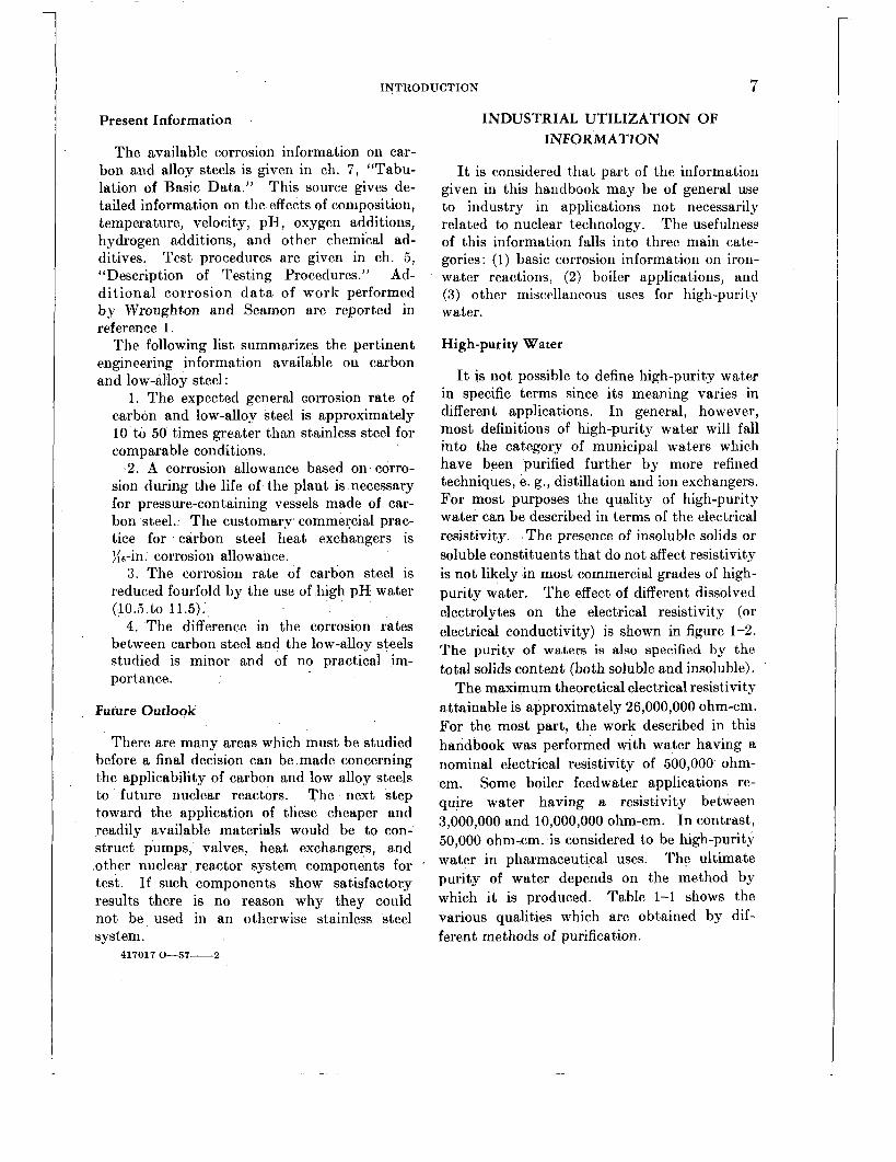
Present Information
The available corrosion information on car- bon and alloy steels is given in ch. 7, “Tabu- lation of Basic Data.” This source gives de- tailed information on the effects of composition, temperature, velocity, pH, oxygen additions, hydrogen additions, and other chemical ad- ditives. Test procedures are given in ch. 5, “Description of Testing Procedures.” Ad- dit ional corrosion d a t a of work performed by Wroughton and Seamon are report.ed in reference 1 .
The following list summarizes the pertinent engineering information available on carbon and low-alloy steel :
1. The expected general corrosion rate of carbon and low-alloy steel is approximately 10 to 50 times greater than stainless steel for comparable conditions.
2. A corrosion allowance based on corro- sion during the life of the plant is necessary for pressure-containing vessels made of car- bon steel. The customarv commercial prac- tice for carbon steel heat exchangers is )i6-in. corrosion allowance.
3. The corrosion rate of carbon steel is reduced fourfold by the use of high pH water (10.5 to 11.5).
4 . The difference in the corrosion rates between carbon steel and the low-alloy steels studied is minor and of no practical im- portance.
Future Outlook
There are many areas which must be studied before a final decision can be made concerning the applicability of carbon and low alloy steels to future nuclear reactors. The next step toward the application of these cheaper and readily available materials would be to con- struct pumps, valves, heat exchangers, and other nuclear. reactor system components for test. If such components show satisfactory results there is no reason why they could not be used in an otherwise stainless steel system.
417017 G 5 7 - 2
INDUSTRIAL UTILIZATION OF INFORMATION
It is considered that part of the information given in this handbook may be of general use to industry in applications not necessarily related to nuclear technology. The usefulness of this information falls into three main cate- gories : (1) basic corrosion information on iron- water reactions, (2) boiler applications, and (3) other miscellaneous uses for high-purity water.
High-purity Water
It is not possible to define high-purity water in specific terms since its meaning varies in different applications. In general, however, most definitions of high-purity water will fall into the category of municipal waters which have been purified further by more refined techniques, e. g., distillation and ion exchangers. For most purposes the quality of high-purity water can be described in terms of the electrical resistivity. The presence of insoluble solids or soluble constituents that do not affect resistivity is not likely in most commercial grades of high- purity water. The effect of different dissolved electrolytes on the electrical resistivity (or electrical conductivity) is shown in figure 1-2. The purity of waters is also specified by the total solids content (both soluble and insoluble).
The maximum theoretical electrical resistivity attainable is approximately 26,000,000 ohm-cm. For the most part, the work described in this handbook was performed with water having a nominal electrical resistivity of 500,000 ohm- cm. Some boiler feedwater applications re- quire water having a resistivity between 3,000,000 and 10,000,000 ohm-cm. In contrast, 50,000 ohm-cm. is considered to be high-purity water in pharmaceutical uses. The ultimate purity of water depends on the method by which i t is produced. Table 1-1 shows the various qualities which are obtained by dif- ferent methods of purification.

8 CORROSION AND WEAR HANDBOOK FOR WATER-COOLED REACTORS
FIGURE 1-2. Effect of dissolved electrolyte on electrical conductivity of water at 65' F .
TABLE 1-1
QUALITY OF WATER OBTAINED FROM VARIOUS SOURCES 2
Quality, electri- cal resratance in terms OJ
Water after 28 distillations in quartz*. . - - 23, 000, 000 Water treated by strongly acid-strongly
basic mixed bed resin (Delaware River water) ..____________________________ 18,000, 000
Water after 3 distillations in quartz - - - 2, 000, 000 Water after 3 distillations in glass ..______ 1, 000, 000 Water in equilibrium with the carbon
dioxide in the atmosphere ..___________ 700, 000 Water after a single distillation in glass.- - 500, 000 Approximate quality of U. S. P. distilled
watert.: .__________________.___ 100, 000-500, 000 Theoretical maximum quality (calculated) - 26, 000, 000
'Kohlrausch, 1894. t The U. 9. Pharmacopoeia specifles that U. 5. P. distilled water must
T y p e OJ water ohm-rm
not contain more than 5 ppm total dissolved solids.
Basic Information
The Joint Research Committee on Boiler *
Feedwater Studies has indicated a need for the typecof information given in the handbook. This committee was organized in 1925 for the purpose of coordinating studies in relation to boiler feedwater problems. It is made up of representatives from various societies and or- ganizations whose prime interest is in boiler- water treatment and water-corrosion problems. The following statement was made by the committee in 1954, in connection with a pro- posed research project.
We do not know the equilibrium condition toward which the prime step in the corrosion of steel moves at various temperatures in the boiler range. Nor do we know what controls the rate at which the further step of forming magnetic oxide of iron proceeds. Factual knowledge is needed to uncover further possible ways of combatting the corrosion process. Par t I of this project accordingly comprises the determination of:
A. The solubility product of Fe0.H20 at 70' t o 600' F. t o establish the equilibrium p H and ferrous ion concentration.
B. The mechanism and the rate of decomposition of FeO.H,O in pure water and in water at various p H values up t o 12 over a temperature range of 70' t o 600' F.
Parallel with the search for basic scientific data in par t I, an engineering study is scheduled in part 11. This will measure the rate of corrosion of low-carbon steel tubing:
A. I n pure water as a function of the following three independent variables : (1) heat transfer rates between 100,000 and 200,000 Btu/hr/ sq. ft., (2) mass velocities within and exceeding the nominal range of furnace wall circuits of high-pressure steam generators, and (3) tem- peratures between 300' and 700' F.
B. In water containing added sodium hydroxide t o give varying p H values up to 13, over the same range variables indicated above.
C. In water containing typical salts, such as sodium phosphate, sodium sulfate, and sodium chloride. The program for this part of the investigation would best be planned on the basis of the results from A and B, correlated with the results from the studies in part I on FeO.Hz0.
Most of the questions raised are discussed in one form or another in the handbook. ,
INTRODUCTION 9
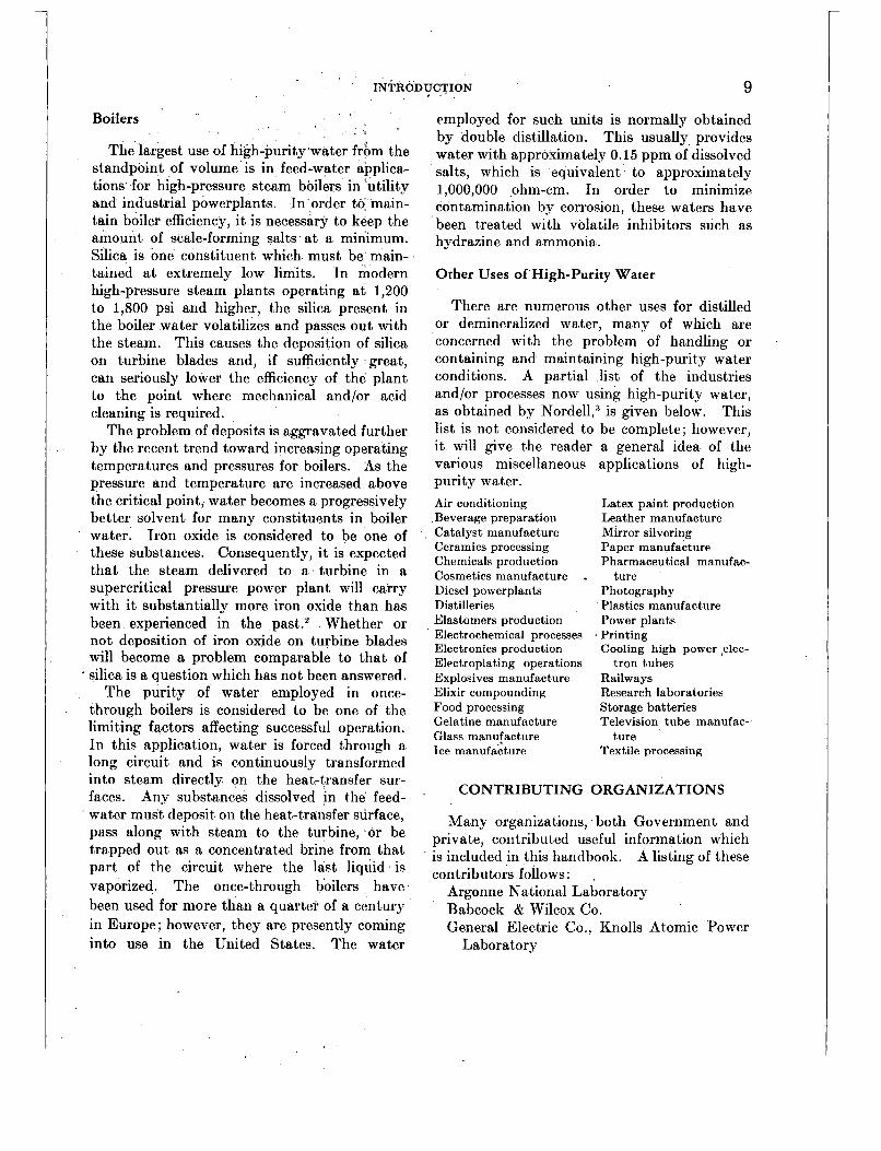
Boilers
The largest use of high-purity water frbm the standpoint of volume' is in feed-water applica- tions for high-pressure steam boilers in 'utility and industrial powerplants. In order to main- tain boiler efficiency, it is necessary to keep the amount of scale-forming salts a t a minimum. Silica is one constituent which must be main- tained a t extremely low limits. In modern high-pressure steam plants operating a t 1,200 to 1,800 psi and higher, the silica present in the boiler water volatilizes and passes out with the steam. This causes the deposition of silica on turbine blades and, if sufficiently great, can seriously lower the efficiency of the plant to the point where mechanical and/or acid cleaning is required.
The problem of deposits is aggravated further by the recent trend toward increasing operating temperatures and pressures for boilers. As the pressure and temperature are increased above the critical point, water becomes a progressively better solvent for many constituents in boiler water. Iron oxide is considered to be one of these substances. Consequently, i t is expected that the steam delivered to a turbine in a supercritical pressure power plant will carry with it substantially more iron oxide than has been experienced in the past.2 Whether or not deposition of iron oxide on turbine blades will become a problem comparable to that of
* silica is a question which has not been answered. The purity of water employed in once-
through boilers is considered to be one of the limiting factors affecting successful operation. In this application, water is forced through a long circuit and is continuously transformed into steam directly on the heat-transfer sur- faces. Any substances dissolved in the feed- water must deposit on the heat-transfer surface, pass along with steam to the turbine, or be trapped out as a concentrated brine from that part of the circuit where the last liquid is vaporized. The once-through boilers have been used for more than a quarter of a century in Europe; however, they are presently coming into use in the United States. The water
employed for such units is normally obtained by double distillation. This usually provides water with approximately 0.15 ppm of dissolved salts, which is equivalent to approximately 1,000,000 ohm-cm. In order to minimize contamination by corrosion, these waters have been treated with volatile inhibitors such as hydrazine and ammonia.
Other Uses of High-Purity Water
There are numerous other uses for distilled or demineralized water, many of which are concerned with the problem of handling or containing and maintaining high-purity water conditions. A partial list of the industries and/or processes now using high-purity water, as obtained by Nordell13 is given below. This list is not considered to be complete; however, i t will give the reader a general idea of the various miscellaneous applications of high- purity water. Air conditioning ,Beverage preparation Catalyst manufacture Ceramics processing Chemicals production Cosmetics manufacture . Diesel powerplants Distilleries Elastomers production Electrochemical processes Electronics production Electroplating operations Explosives manufacture Elixir compounding Food processing Gelatine manufacture Glass manufacture Ice manufacture
Latex paint production Leather manufacture Mirror silvering Paper manufacture Pharmaceutical manufac-
Photography Plastics manufacture Power plants
Cooling high power telec-
Railways Research laboratories Storage batteries Television tube manufac-
Textile processing
ture
. Printing
tron tubes
t.ure
CONTRIBUTING ORGANIZATIONS
Many organizations, both Government and private, contribut,ed useful information which is included in this handbook. A listing of these contributors foilows: .
Argonne National Laboratory Babcock & Wilcox Co. General Electric Co., Knolls Atomic Power
Laboratory
10 CORROSION AND WEAR HANDBOOK FOR WATER-COOLED REACTORS
United States Naval Engineering Experiment
United States Naval Research Laboratory Westinghouse Electric Corp., Atomic Power
Atomic Energy Commission, Naval Reactors
Station
Division
Branch REFERENCES
1 . 1). M. WROUGHTON, J. M. SEAMON, D. E. TACKETT,
P. BROWN, and R. ESPER, Review of Carbon Steel Corrosion Data in High-temperature, High-purity Water in Dynamic Systems, Report WAPD-
2. E. P. PARTRIDGE, Water Problems in Power Genera- tion at Supercritical Pressures, Mech. Eng. 77(10) :883 (October 1955).
3. ESKEL NORDELL, “Water Treatment for Industrial and Other Uses,” Rienhold Publishing Corp., New York, 1951.
’
LSR(C)-134, Oct. 14, 1955.

Chapter 2
FUNDAMENTAL ASPECTS OF IRON CORROSION
Editor-DAvID L. DOUGLAS
Page 11 12 13 15 15 16 16 16 17 17 17 18 18 I9 19
INTRODUCTION There are many definitions in the literature
of the term “corrosion.” The most appropriate definition is the one which states that corrosion is any process that involves the transfer of atoms from the metallic to the ionic state. All dissolution and scale-formation reactions come under this definition; however, such a brief definition is sometimes inadequate in light of the complexity of most corrosion processes. A complete understanding of any corrosion process requires a detailed specifica- tion of all the possible anodic and cathodic reactions and of how each is affected by many variables, such as temperature, activities of the reacting species, metallurgical condition of the metal, presence of alloying constituents in the metal, and mechanical properties of any oxide films or scales formed. Only a limited number of corrosion systems have been investigated completely. However, there is some pertinent information on iron-water reactions. The discussions in this chapter are based on information in published literature
in addition to basic data obtained in connection with work on the water-cooled nuclear reactor.
The material in this chapter will be restricted mainly to the corrosion of iron and ferrous alloys in high-temperature water. Some of the general considerations will apply to all metal systems.
One of the advantages of water as a reactor coolant is that the radioactive species formed by the interaction of. neutrons and hydrogen and oxygen are short lived. Therefore, from a theoretical point of view, water would not present a radioactivity problem were i t not for the presence of radioactive corrosion and wear products in the coolant stream. Because of the induced radioactivity (i. e., formation of radioactive species from elements in the reactor coolant) water of high purity is essential. For this reason, many of the inorganic additives commonly employed in boiler systems cannot be used. Organic inhibitors are not considered satisfactory because of their inability to with- stand the irradiation and temperatures as- sociated with the reactor. Thus the corrosion problem in a nuclear reactor resolves itself into the reaction of the metal in question with pure water a t elevated temperatures.
A great deal of effort has been expended over the past 8 years in determining the behavior of likely materials of construction in high-temper- ature water. In the case of iron and ferrous alloys, this has consisted mainly of empirical determinations of corrosion rates. Corrosion was measured by gross weight change and more recently by weight changes of descaled coupons (see ch. 5 , “Description of Testing Procedures”). During the early investigations only a limited amount of work was devoted to studying the
11

12 CORROSION AND WEAR ,HANDBOOK FOR WATER-COOLED REACTORS
fundamental aspects of iron corrosion in high- temperature-high-purity water. However, dur- ing the past 2 years many basic investigations have been undertaken in connection with nuclear reactor development work.
THERMODYNAMIC CONSIDERATIONS
It is difficult to overemphasize the importance of a knowledge of pertinent thermodynamic quantities to an understanding of an aqueous corrosion system. The ultimate in this regard is indicated in* the excellent monograph by M. J. N. Pourbaix.’ Here are presented in con- venient graphical form all the pertinent thermo- dynamic data for the iron-water system at room temperature. On one graph, a simplified form of which is shown in figure 2-1, oxidation-
. *
PASSIVATION
FIGURE 2-1. Thermodynamic data for the iron-water sys- tem at room temperature. ( M . J . N . Pourbaix, “Thermo- dynamics of Dilute Aqueous Solutions,” translated by J . N . Agar, Edward Arnold (Publishers), Ltd., London, 1949.)
reduciion potential is the ordinate and pH is the abscissa. The various equilibria appear as straight lines. These lines and their intersec-
tions define regions of explicit corrosion be- havior, i. e.;regions of corrosion, immunity, and passivation.
Thus a great deal of important information is packed into a small space. It would be a decided advantage to be able to construct such a.dia&am for all metal systems at high temper- atures. Unfortunately, however, the necessary thermodynamic data are not available.
The free energies of formation of the various metal oxides reported in the literature make it possible to estimate the equilibrium constants of the overall metal-water reaction,
X M + Y H ~ O P ? M X O ~ + Y H ~
The free energies of formation of some metal oxides over the temperature range of interest are shown graphically in figure 2-2.
. .
FIGURE 2-2. Free energies of formation of some metal oxides.
FUNDAMENTAL ASPECTS OF IRON CORROSION 13
Metal
Cu _ _ _ _ _ _ _ _ _ Ni _ _ _ _ _ _ _ _ _ Fe _ _ _ _ _ _ _ _ _
They are expressed in kilocalories per gram- atom of oxygen: A particularly convenient sys- tem for comparing their stability with that of the water molecule. Such information can be used to estimate the extent to which a given reaction will take place. Thus, such noble metals as gold and platinum have positive free energies of formation of their'oxides (not shown in fig. 2-2), and one would expect these metals to be completely resistant to attack by water. Metals with large negative free energies of oxide formation, e. g., chromium, titanium, alumi- num, and zirconium, will react to form metal oxides and hydrogen. Large negative free energies do not necessarily indicate poor corro- sion resistance. In many cases' the oxide films formed are extremely protective, and the metals are quite satisfactory for use in high-temper- a ture water sys tems.
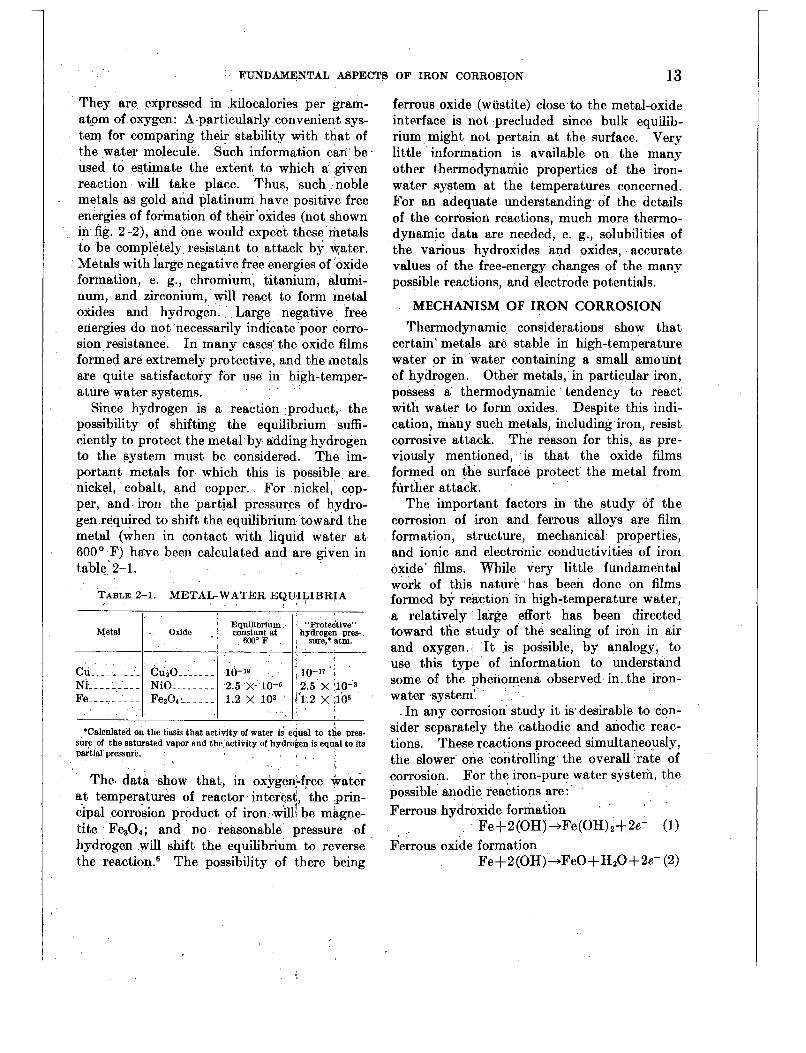
Since hydrogen is a reaction product, the possibility of shifting the equilibrium suffi- ciently to protect the metal by adding hydrogen to the system must be considered. The im- portant metals for which this is possible are- nickel, cobalt, and copper. For nickel, cop- per, and iron the partial pressures of hydro- gen required to shift the equilibrium toward the metal (when in contact with liquid water a t 600' F) hgve been calculated and are given in table 2-1.
TABLE 2-1. METAL-WATER EQUILIBRIA
Equilibrium "Protective" Oxide , constant at hydrogen pres-.
W 0 F , sure,*atm. - ' , I
CuaO ___.___ 10-19 ~ , io-" i NiO ..______ 2.5 X 10⁻⁵ 2.5 X ;l0-3 Fe304: _ _ _ _ _ 1.2 X 10³ ' d'1.2 X :lo5
I . I
ferrous oxide (wustite) close to the metal-oxide interface is not precluded since bulk equilib- rium might not pertain a t the surface. Very little information is available on the many other t*hermodynamic properties of the iron- water system at the temperatures concerned. For an adequate understanding of the details of the corrosion reactions, much more thermo- dynamic data are needed, e. g., solubilities of the various hydroxides and oxides, accurate values of the free-energy changes of the many possible reactions, and electrode potentials.
MECHANISM OF IRON CORROSION Thermodynamic considerations show that
certain' metals are stable in high-temperature water or in water containing a small amount of hydrogen. Other metals, in particular iron, possess a thermodynamic tendency to react with water to form oxides. Despite this indi- cation, many such metals, including iron, resist corrosive attack. The reason for this, as pre- viously mentioned, is that the oxide films formed on the surface protect the metal from flirther attack.
The important factors in the study of the corrosion of iron and ferrous alloys are film formation, structure, mechanical properties, and ionic and electronic conductivities of iron oxide' films. While very little fundamental work of this nature has been done on films formed by reaction in high-temperature water, a relatively large effort has been directed toward the study of the scaling of iron in air and oxygen. It is possible, by analogy, to use this type of information to understand some of the phenomena observed in. the iron- water system:' '
In any corrosion study it is desirable to con- sider separately the 'cathodic and anodic reac- tions. These reactions proceed simultaneously, the slower one controlling the overall rate of corrosion. For the iron-pure water system, the possible anodic reactions are: Ferrous hydroxide formation
Ferrous oxide formation Fe+ 2 (OH) +Fe(OH) 2+ 2e' (1)
Fe+2(OH)+FeO+HzO+2e- (2)

14 CORROSION AND WEAR HANDBOOK FOR WATER -COOLED REACTORS
Ferrous ion formation Fe-+Fe+++2e- (3)'
The eventual formation of magnetite probably takes place through a reaction of the type first suggested by Schikorr : '
Magnetite formation 3Fe(OH)z-+Fe304+ 2H20+Hz ( 4 4
or Magnetite formation 3FeO+Hz0+
Fe304SH2 (4b) In neutral or slightly basic solutions, which
are of primary interest for reactor coolants, the passage of ferrous ions into solution can be neglected. The distinction between reac- tion (1) followed by (4a) and reaction (2) fol- lowed-by (4b) is not significant since the ferrous oxide is likely to be hydrated when first. formed. In any event the distinction cannot be made without further information as to the stabili- ties of the two species. The ensuing discus- sion will assume that ferrous hydroxide is the intermediate formed. In pure water the only possible cathodic reaction is the discharge of hydrogen ions; thus
Hydrogen gas formation 2H++2e--+'Hz (5)-
Once the anodic and cathodic reactions have been postulated, they must be fitted into a more detailed picture of the way in which the overall corrosion proceeds. This picture, to be valid, must be in accord with experimental observations. The following qualitative obser- vations of the corrosion of pure iron in high- temperature water need to be accounted for:
1. In the early stages a tight oxide film is formed. After passing through the interfer- ence color region to a black film, the outer layer becomes dull black and can be partially rubbed off.
2.' Kirkendall experiments a t 460' and 680' F, using both radioactive tracers and inert materials as phase boundary markers, have shown that iron ions diffuse through the oxide film.34
3. Hydrogen is released into the solution and is also absorbed into the metal.* This
behavior is fairly general with aqueous corro- sion of metals. The nature of the system, i. e., solubility of hydrogen in the metal and hydride formation, determines the fraction of the total hydrogen which remains in the metal.
4. The time dependence of the oxide-film growth in the early stages is that of a diffu- sion-controlled process. Experiments con- ducted by Bloom and Krufeld show that the rate decreases with time. This would be expected if diffusion through the film is rate determining. Preliminary tests indicate that in the early stages film growth on pure iron exposed to water a t 550' F follows the well- known parabolic law (W2=Kt+K1), where W is some measure of film thickness and K and K' are constants.lo
A further clue as to the nature of the overall corrosion process may be obtained, reasoning by analogy, froin the more thoroughly investi- gated scaling studies of iron in air and oxygen. Conflicting views are expressed in the literature as to the oxidation of iron at low tempera- tures. Vernon and coworkers l1 studied the oxidation of abraded mild steel and concluded that above 392' F the oxide growth on iron in air or oxygen is due predominantly to the diffu- sion of iron ions outward through a rayer of cubic oxide which is approximately magnetite. The kinetics of this reaction are described by the parabolic law. Davies, Evans, and Agar l 2
obtained somewhat different results in their study of the oxidation of pure iron. These workers found that the parabolic law is ob- served on hydrogen-reduced surfaces only above 570' F. Both a-Fe203 and Fe30., are formed, the latter appearing between the metal and the ferric oxide layer. Below about 570' F, a logarithmic law is followed. Also to be con- sidered are the findings of Davies, Simnad, and Birchenall l 3 which indicate that diffusion in magnetite is predominantly cationic. Wickert and Pilz l4 recently investigated the reaction between water vapor and iron. Activation energies calculated from their results are of

FUNDAMENTAL ASPECTS OF IRON CORROSION 15
the proper magnitude for a diffusion-controlled process. Unless oxidation by water includes some unknown features, one would expect from the above that the reaction proceeds by diffu- sion of iron ions outward through a magnetite film and that the kinetics in at least one stage are parabolic.
Film Formation: Early Stages
Based on the observations and information given, the following mechanism is assumed for the early stages of the corrosion of iron in high- temperature water. (Results of corrosion stud- ies indicate that it applies only during the initial period while the oxide film is still intact and protective. At 600° F this period lasts per- haps 150 to 200 hr for an electrolytically pol- ished surface, and the film attains a thickness of about 0.5 p . ) Ferrous ions formed a t the metal- oxide interface diffuse through the oxide (Fe,O,) by migration into vacant lattice sites. On reaching the oxide-water interface, the ferrous ions combine with hydroxyl ions (or absorbed water molecules) to form ferrous hydroxide. The latter compound decomposes into magne- tite, water, and hydrogen. It may well. be that a t sufficiently low temperatures this reaction (Schikorr’s reaction) will be rate controlling. Recent experiments l6 indicate that i t will not be rate controlling above about 400’ F. Between 400° and 700’ F the rate is controlled by the diffusion of ferrous ions, and the kinetics are described by the parabolic law.
To maintain electrical neutrality, electrons must migrate with the ferrous ions. These elec- trons will neutralize protons at the oxide-water interface, resulting in the formation of hydrogen atoms which will combine to form molecules. This is the cathodic reaction indicated in reac- tion (5). The fact that hydrogen enters the metal lattice, in some cases in large amounts, means that either hydrogen atoms or protons must migrate from the water interface through the oxide to the metal interface. No valid basis exists for deciding which of the hydrogen species permeates the film. If the film is permeable to protons, some of these will be discharged a t
the metal-oxide interface to form hydrogen atoms which then enter the metal. A pictorial presentation of this oxide film growth mechan- ism is given in figure 2-3. This figure does not
IRON.
H (DISSOLVED)
Fe
REACT rmk-on
OXIDE
Fe*t 2e- 0
Us AT R EINERFACE 0)
WATER
fHt QH- ]H@
Ht 5 %O ‘ OH-
;TIONS AT E-WEER INTERFACE
Fe + Fo*t 20- Fa*+ 2 OK- Fe(OH12 H(ads)+ Ht + e- AND ~M(o~s) -H~(GAS) 3 F e ( O H ) p h O 4 t 2+0 + +
3 Fe? 6OH-+ Fe304t W p t H++ e-+H H t H + H e
H@is) ZH(ad8) OR
FIGURE 2-3. Oxide film growth mechanasm.
show Lhe countercurrent diffusion of lattice vacancies, which are formed a t the oxide-water interface. In the case of anion diffusers the entry of hydrogen into the metal is easily ac- counted for by the migration of hydroxyl ions along with the oxide ions.
Film Formation: Latter Stages
The discussion so far has dealt only with the initial oxide-film formation during which t.ime the kinetics are described by the usual parabolic law. There is considerable evidence that the corrosion rate eventually becomes constant a t a low value, and a linear rate law is followed.8 This would seem to indicate that the corrosion rate comes under some form of “mechanical

16 CORROSION AND WEAR HANDBOOK FOR WATER :COOLED REACTORS
control,” i. e., the oxide is no longer completely protective. Two possibilities exist: (1) the scale breaks down at a fairly constant rate, and the overall corrosion is controlled by an inter- face reaction; and (2) only the outer portions of the scale break down, and a more or less con- stant thickness of protective scale remains. The first possibility seems unlikely since one would expect an increase in corrosion rate if the scale breaks down completely and exposes fresh metal surface. The second possibility fits with the first of the qualitative observations listed a t the beginning of this section. Birchen- all has recently suggested a mechanism by which this may take place, namely, the conden- sation of lattice vacancies which migrate in a direction opposite the ferrous ions.
Since diffusion processes undoubtedly play an important part in the corrosion mechanism, the measurement of diffusion rates of iron ions in magnetite should be carried out. The tech- niques employed by Birchenall in determining diffusion coefficients in wustite, magnetite, and hematite a t higher temperatures could be ex- tended to the region and conditions of interest.
Occluded Hydrogen
One of the most interesting questions, and perhaps one of the most important, regarding iron corrosion is the role which hydrogen plays in the process. In the case of the metals alumi- num and zirconium, 2o the takeup of hydrogen by the metal substrate is believed to have a decisive effect on the course of the metal-water reaction. No such drastic situation has been observed with iron or any ferrous alloy; how- ever, there is abundant, evidence that the presence of hydrogen in iron can alter its elec- trochemical behavior. Patrick and Thompson 21
report on the effect of occluded hydrogen on the standard electrode potential of the iron-ferrous ion couple. Uhlig 22 has observed that hydro- gen (from cathodic charging) diffusing through chromium steels makes the electrode potential more active by as much as 100 mv. The recent experiments of Bloom and Krufeld gc indicate that vacuum-annealed steels show higher cor-
rosion rates in the early stages and take longer to reach a constant rate than do hydrogen- annealed steels.
A comprehensive investigation of the prob- lem is needed. One experiment should include simultaneous measurements of the hydrc gen released into the water and the hydrogen effused through the corroding metal. A study of the effect of occluded hydrogen on corrosion rate will require the development of an accurate method of determining corrosion other than measuring the hydrogen evolved. This should not be an insuperable obstacle.
Although measured electrode potentials are difficult to interpret in an absolute sense in corrosion systems, relative measurements can give valuable information about the effect of significant variables on corrosion behavior. Before much work in this direction can be done, a satisfactory insulating seal and the container must be developed. Teflon is normally satis- factory up to 600’ F. Above that temperature no plastic or ceramic has been found to be completely free of attack.
EFFECT OF WATER COMPOSITION I
Corrosion may also be affected by dissolved matter in the water, both ionic and molecular. The possibilities are limitless, of course, and only a few of the more important will be con- sidered here. For the most part, the conclusions made are corroborated by the experimental re- sults which are described in Chapter 7, Tabu- lation of Basic Data, and Chapter 8, Relative Importance of Different Variables.
Effects of pH
At sufficiently low pH the initial formation of hydroxide or oxide films will be prevented and the anodic reaction will be the simple dis- solution of iron as per. reaction (3). The result will be excessive corrosion, and this situation is not applicable to this study. Carbon steels and stainless steels have been extensively cor- rosion tested in water adjusted to pH 9 to 11 with sodium hydroxide, lithium hydroxide, or

FUNDAMENTAL ASPECTS OF IRON CORROSION 17
ammonia. There is some evidence during a t least the initial few hundred hours, that cor- rosion is less 23; however, the long-term experi- ments of Bloom and Krufeld show. that the final “steady-state” corrosion rates are un- affected by increasing the pH.
From the standpoint of the postulated mech- anism, it is instructive to consider the ways in which increasing the pH can affect the corrosion reaction. If a significant number of anion lattice positions are occupied by hydroxyl ions, an increase of pH would increase this number. However, increasing the number of OH ions in lattice positions will increase the number of cation vacancies, which should increase the corrosion rate. Thus this hypothesis appears without foundation. Another possibility, which needs further investigation, is that increased pH affects the rate a t which Schikorr’s reaction proceeds. Results of the study of this reaction make this seem unlikely.’“ A third possibility is that the hydroxyl ions are effective in polar- izing the cathodic discharge of hydrogen ions. This view has been put forth by Mayne, Menter, and Pryor 24 to explain inhibited corrosion of iron in deaerated 0.lN NaOH a t room tem- p e r a t ~ r e . ~ ~ Certainly the effect of pH on cor- rosion rate of pure iron merits further study. Unequivocal results would aid in formulating a valid reaction mechanism.
Effects of Dissolved Salts
Salts of certain complex anions containing oxygen, phosphates, chromates, silicates, bor- ates, etc., are more or less effective as anodic inhibitors in oxygen containing’ solutions a t room temperature. The work of Mayne and Menter 25 indicates that this is due, mainly to a more effective formation and repair of passive films of a-Fez03 or Fe,O, on the metal surface. It appears unlikely that’ they will have much effect on the corrosion of iron in oxygen-free water a t elevated temperatures.
Effects of Dissolved Oxygen
It is not possible to predict the effect of oxygen on the corrosion of iron with the limited
theoretical information available. There are many indications in industrial applications which show that oxygen has a marked effect on corrosion. The information on localized cor- rosion in high-purity water also shows that oxygen is important. However, it should be mentioned that data on general corrosion (see ch. 8, Relative Importance of Different Vari- ables) do not show an effect of oxygen within the limits studied and in the absence of irradia- tion. These different observations strengthen the need for additional fundamental data on the effect of oxygen.
The manner in which oxygen acts to increase the corrosion rate can be explained in a t least two different ways. One school holds that oxygen serves principally to depolarize the cathodic reaction, as in
$0, + H20 +e--+OH-+ OH OH+e--+OH-
Another possibility is that oxygen reacts with the metal in much the same way as in gaseous oxidation. Since the oxidation rates of iron in oxygen a t temperatures of about 600’ F are somewhat’lower than the observed aqueous cor- rosion rates, the latter mechanism seems unlikely. l2 *’ Effects of Dissolved Hydrogen
It has been shown that nominal partial pres- sures of hydrogen will not effect the iron-water equilibrium appreciably and thus would not be expected to noticeably reduce corrosion rates of iron or carbon steel. In the case of high nickel alloys, the equilibrium can be readily shifted, and small amounts of hydrogen will result in greatly reduced rates of corrosion (see ch. 8, Relative Importance of Different Variables).
If the dissolved hydrogen affects appreciably the amount of hydrogen in iron or steel being corroded, it may influence the electrochemical behavior of the metal. Such effects on corrosion rate cannot be specified a t this time because of the great lack of fundamental knowledge of such systems.

18 CORROSION AND WEAR HANDBOOK FOR WATER-COOLED REACTORS
Effects of Velocity
One factor which has been omitted in all the foregoing discussions is water velocity. Static water has been assumed throughout. Fast flowing water, such as will be present in a reactor coolant system, may alter the situation mate- rially. If the scale is not tightly adherent to the base metal, one would expect increased cor- rosion rates in dynamic systems. The effects of velocity on the corrosion rates of specimens are discussed in chapter 8, Relative Importance of Different Variables. The reported increase in the corrosion rate of certain materials with increased velocity can be attributed to an erosion of the oxide film. This provides the iron ions with a shorter diffusion path to the oxide-water interface, where they can react with hydroxyl ions. On the other hand, the 18-8 type stainless steels, which show almost negligible velocity effects, are protected by the CrZO3 or FeO.CrzO, film. This film is not only thinner but also is more adherent than the magnetite film formed on most ferrous alloys.
Effects of Alloying Elements If the mechanism of the corrosion of pure
iron in high-temperature water were &Ficiently well understood, it would be possible to predict the behavior of most of the alloys of interest. More important than this, an alloy development program could be undertaken on other than an empirical basis. Although the general scheme is probably correct, the details of the reaction mechanism postulated in the previous pages are lacking. Thus, admittedly, little can be done toward the aspired goal of selecting the best alloy. It is recognized that the best alloy will not have necessarily the ultimum in corrosion resistance; it will be the least expensive one which will do the job satisfactorily. Neverthe- less, i t will be instructive to bring out the principals involved in “designing” the optimum ferrous alloy.
For any given oxide-scale-formation reaction in which, as is generally accepted, the diffusion takes place by the migration of cations (or anions) from one lattice vacancy to another, the diffusion rate can be altered in two ways:
(1) changing the number of lattice defects and (2) varying the chemical composition and thus the structure of the scale.
In magnetite, as in most other oxides, a certain number of vacancies are in thermody- namic equilibrium in the lattice. Inclusion of certain impurities, either cationic or anionic, will alter the number and efficiency of these defects in such a way as to markedly decrease the diffusion rate. Specifying the effect of any given impurity requires more knowledge of the semiconducting nature of magnetite than is presently available. For a complete discussion of lattice vacancy diffusion, electronic and ionic conductivities, and their importance in oxida- tion theory, the reader is referred to the excellent monograph by Kubaschweski and Hopkins lo in which the subject is developed in detail and reference to the original work by Wagner and others will be found.
Increasing the oxidation resistance of a metal by adding sufficient amounts of an alloying constituent to change the chemical structure of the oxide layer is best exemplified by the effect of adding chromium to iron in air or oxygen. Low-chromium steels are a little more resistant to oxidation than iron or carbon steels. Below 1,800’ F additions of more than 12 percent chromium and above 1,800° F more than 17 percent, enhance the resistance to oxidation of iron by a factor of nearly 100. This protective effect is due to the formation of a compact layer Crz03 or Fe0 .Cr203 which acts as a diffusion barrier to the iron ions. After this film reaches a critical thickness, further oxidation proceeds very slowly. The oxidation resistance of the 18-8 type stainless steels is probably due to a similar effect. Of the ferrous alloys that have been extensively tested in high-tempera- ture water, the 18-8 type stainless steels show a markedly lower corrosion rate than do the steels containing 12 percent or less chromium.23 However, there arb indications that alloys con- taining as little as l>i percent chromium show some improvement over carbon steels in the high-temperature water e n v i r ~ n m e n t . ~ ~ In all likelihood, the same factors are active in the water reactions as in the air oxidation. Until

FUNDAMENTAL ASPECTS OF IRON CORROSION 19
more fundamental information on the mecha- nism of iron corrosion becomes available, little more can be said about ferrous alloy behavior in high-temperature water.
FUTURE STUDY REQUIRED It must be emphasized that the mechanism
of the corrosion of iron in water as described above is, to a considerable degree, speculative. A number of fundamental studies are needed before a definitive picture can be drawn. It is hoped that this chapter will serve to stimulate such investigations. Among the more import- ant investigations needed are the following :
A study of the structure of the scale formed a t various stages in the corrosion process is required. This could best be done by stripping the fdms, using one of the techniques described
. in the literature," 30 and examining the struc- ture with an electron microscope. In particular the film breakdown mechanism responsible for the constant corrosion rate after long exposure might be elucidated.
For years it has been recognized by workers in the corrosion field that Schikorr's reaction, the decomposition of ferrous hydroxide to magnetite, water, and hydrogen, may play an important part in boiler cor r~s ion .~ ' 32 While, contrary to Schikorr's original observation, ferrous hydroxide slurried in water appears to be stable up to about the boiling point of water 33 little is known of its chemistry at elevated temperatures. A comprehensive in- vestigation of the stability and reactions of this compound a t elevated temperatures (up to 700' F) is being undertaken.lB It seems certain that a t sufficiently low temperatures the fdm of ferrous hydroxide formed on iFon on exposure to pure water is completely protective.. The formation of oxide films takes place only when the hydroxide is oxidized by the water to form magnetite. I Certainly there is a need for careful corrosion rate measurements with pure iron and with ferrous alloys. Bloom and Krufeld have made a good start in this direction using an ingenious scheme for measuring the rate a t which hydro- gen effuses through capsules of carbon steel and stainless steel. The capsules are filled with
water, sealed, and then heated in an evacuated glass system. The pressure increase in the system due to the effused hydrogen is recorded and is used as a direct indication of the corro- sion rate. After steady-state conditions are reached, this method gives reliable results.
I n the early stages of corrosion, however, there is some question as to whether the corro- sion is the only process which controls the rate of hydrogen effusion. Nevertheless, corrosion measurements using a different method show good agreement with Bloom and Krufeld's results. In addition, rate determinations that establish the influence of the many variables are needed.
It will be particularly interesting to establish with certainty the rate law that governs the early stages of film growth (up to about 0.5 p ) . As mentioned earlier, preliminary results ob- tained here indicate that a parabolic law holds, but the possibility of a cubic or other relation must not be ignored. The results of the studies of the air oxidation of iron by Vernon and Davies, Evans, and Agar l2 suggest that some- where in the temperature range 400' to 700' F. the rate law may change from parabolic to logarithmic, the latter holding a t the higher temperatures .
Hauffe 27 has explained the low temperature oxidation mechanisms (logarithmic and cubic laws are observed for various metals) on the basis of a positive space charge formed in the oxide layer to compensate for a negative sur- face charge due to chemisorbed oxygen. If this picture is correct, any such effect will be quite different in a pure water system. How- ever, if a film breakdown and repair mech- anism, as suggested by Davies, Evans, and Agar, is responsible, then a similar change in rate law somewhere in this temperature rangc may pertain in water oxidation of iron.
SUMMARY A review of the limited information on the
thermodynamics of the iron-water system a t temperatures in the range 500° to 700' F shows that magnetite is the stable oxide. The equi- librium lies far enough on the oxide side SO that unreasonably high hydrogen pressures are re-
,
20 CORROSION AND WEAR HANDBOOK FOR WATER-COOLED REACTORS
quired to reverse it sufficiently to prevent attack on iron or carbon steel. The rate of the reaction between iron-and water a t these tem- peratures is controlled by the diffusion of iron ions through the magnetite film. In the early stages (up to a thickness of 0.5 p ) , the parabolic law is most likely followed; on reaching some critical thickness, the outer layers of the film become nonprotective, and a diffusion boundary of approximately constant thickness remains. This results in a constant rate of corrosion. Ferrous alloys, other than carbon steel which behaves very much like a pure iron, have been investigated only in an empirical manner.
’
REFERENCES 1. M. J. N. POURBAIX, “Thermodynamics of Dilute
Aqueous Solutions,” trans. by J. N. Agar, Edward Arnold (Publishers), Ltd., London, 1949.
2. K. K. KELLEY, Contributions to the Data on Theo- retical Metallurgy X: High-temperature Heat Content, Heat Capacity, and Entropy Data for Inorganic Compounds, Bureau of Mines Bulletin 476, Superintendent of Documents, U. S. Govern- ment Printing Office, Washington 25, D. C., 1949.
3. A. GLASSNER, A Survey of the Free Energies of Formation of the Fluorides, Chlorides, and Oxides of the Elements t o 2500” K, Report ANL-5107, August 1953.
4. 0. KUBACHEWSKI and E. EVANS, “Metallurgicnl Thermochemistry,” Academic Press, Inc., New York, 1951.
5. F. D. ROSSINI et al., Selected Values of Chemical Thermodynamic Properties, Natl. Bur. Standards (U. S.), Circular 500, Superintendent of Docu- ments, U. S. Government Printing Office. Wash- ington25, D. C., Feb. 1, 1952.
6 . G. CHAUDRON, Z. Elektrochem., 29:279 (1953); Ann. ehemie, 16: 221 (1921).
7. G. SCHIKORR, Z. Elektrochem., 35: 65 ‘(1929); 2. anorg. u. allgem. Chem., d l 2: 33 (1933).
8. F. J. NORTON, J . A p p l . Phys., 11: 262 (1940). 9a. M. C. BLOOM and M. KRUFELD, Nuclear Power
Progress Report, Report NRL-4350, Naval Re- search Laboratory, Washington, D. C., August 1954, pp. 48-61.
9b. NRL Quarterly on Nuclear Science and Tech- nology, Naval Research Laboratory, Washing- ton, D. C., October 1954, pp. 46-53.
9c. NRL Quarterly on Nuclear Science and Tech- nology, Naval Research Laboratory, January 1955, pp. 37-41; April 1955, pp. 4-6.
10. 0. KUBASCHEWSXI and B. E. HOPKINS, “Oxida- tion of Metals and Alloys,” p. 41 Butterworths Scientific Publications, London, 1953.
11. W. H. J. VERNON et al., Proc. Roy. SOC. (London),
12. D. F. DAVIES, U. R. EVANS, and J. N. AGAR, Proc.
13. M. H. DAVIES, M. T. SIMNAD, and C. E. BIRCHEN-
14. K. WICKERT and U. H. PILZ, Werkstofle u. Kor-
15. M. WERNER, Werkstofe u. Korrosion, 3: 340 (1952). 16. F. J. SHIPKO and D. L. DOUGGAS, J . Phys. Chem.,
17. C. E. BIRCBENAI~L, Kinetics of Formation of Porous or Partially Detached Scales, Metallurgy Report No. 1, OSR-TN-54-286, Princeton University, July 1954.
18. L. HUMMEL, R. F. MOHL, and C. E. BIRCHENALL, J . Metals, 5: 827 (1953).
19. J. E. DRALEY and W. E. RUTHER, Aqueous Cor- rosion of 25 Aluminum a t Elevated Tempera- tures, Report ANL-5001, Feb. 1, 1953.
20. C. R. SIMCOE and D. E. THOMAS, The Mechanisms of the Oxidation and Corrosion of Zirconium, Report WAPD-53, Apr. 11, 1953.
21. W. A. PATRICK and W. E. THOMAS, J . A m . Chem. SOC., 75: 1184 (1953).
22. H. H. UHLIG, N. F. CARR, and P. H. SCHNEIDER,
23. R. FOWLER, Jr., DAVID L. DOUGLAS, and F. C. ZYZES, Corrosion of Reactor Structural Material in High-temperature Water 11, Report KAPL- 1248, Dec. 1, 1954.
24. J. E. 0. MAYNE, J. W. MENTER, and M. J. PRYOR, J . Chem. SOC., 1950: 3229-3236.
25. J. E. 0. MAYNE, and J. W. MENTER, J . Chem. Soc.,
26. E. J . HART, Radiation Chemistry, Ann. Rev.
27. K. HAUFFE, Wekstofe u. Korrosion, 6: 117 (1955). 28. 0. KUBASCHEWSKI and B. E. HOPICINS, “Oxidation
of Metals and Alloys,” p. 192, Butterworths Scientific Publications, London, 1953.
29. Babcock & Wilcox Co., Progress Reports of Work for ‘ Bureau of Ships, Westinghouse Electric Corp., and General Electric Co. Report 5084, November and December 1954, and preceding reports.
, “Metallic Corrosion Passivity and ’ p. 71, Edward Arnold & Co.,
London, 1946. 31. U. R. EVANS, “Metallic Corrosion Passivity and
Protection,” p. 209, Edward Arnold (Publishers), Ltd., London, 1946.
216A: 375 (1953).
Roy. SOC. (London), 225A: 443 (1954).
ALL, J . Metals, 5: 1257 (1953).
rosion, 1: 56 (1950).
Vol. 60: 1519 (1956).
* Trans. Electrochem. SOC., 79: 111 (1941).
195.4: 103-107.
Phys. Chem., Vol. 50, p. 139 (1954). Pub.
32. U. R. EVANS, Engineering, May 8, 1954. 33. U. R. EVANS and J . N. WANKLYN, Nature, 162: 27
34. D. L. DOUGLAS and F. C. ZYZES, Corrosion of Iron In High-temperature Water, Report KAPL- 1376, Nov. 1, 1955.
(1948).
Chapter 3
FUNDAMENTAL ASPECTS OF FRICTION A N D WEAR
Editors-J. W. FLAHERTY, S. PETACH
Contributors-N. B. DEWEES, D. E. WHITE Page
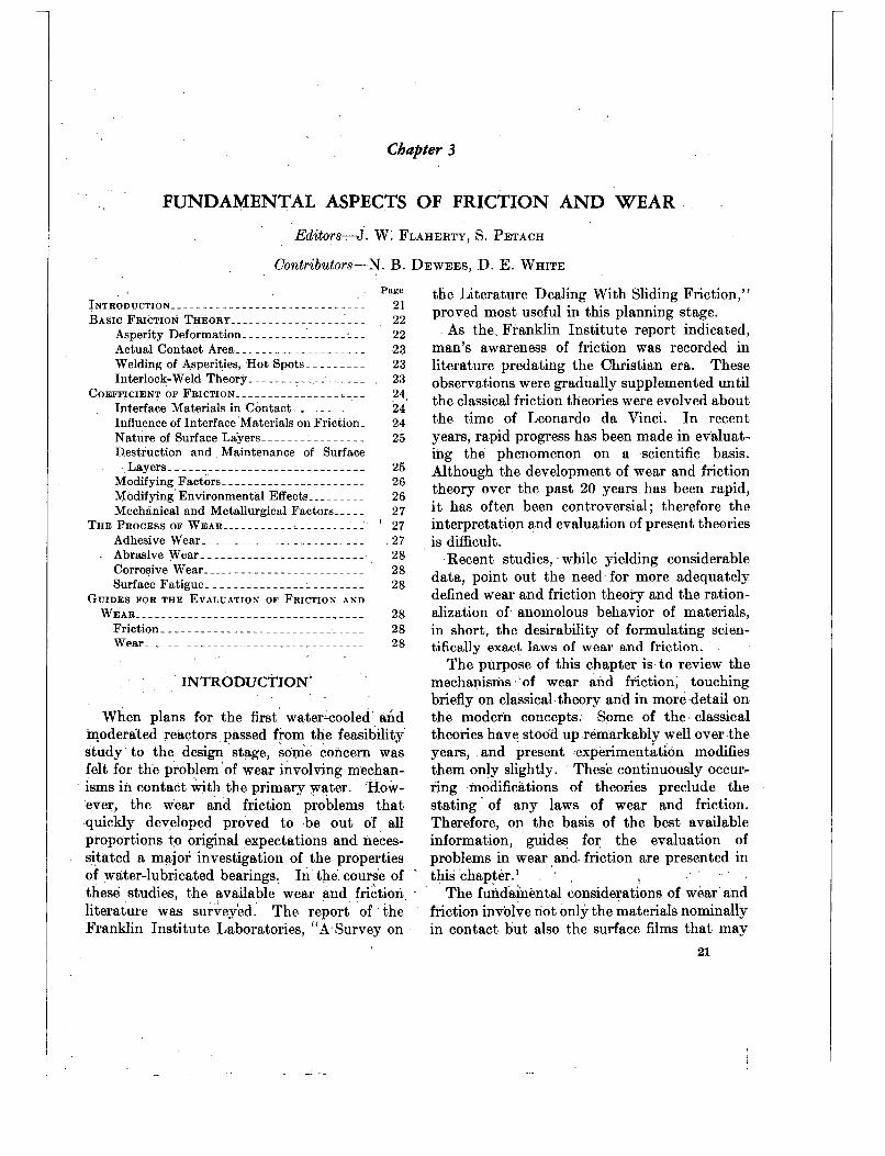
I N T R O D U C T I O N _ _ - _ - - - - - - - - - - - - - - - - - - - - - - - - - - 21 BASIC FRICTION THEORY . . . . . . . . . . . . . . . . . . . . . 22
Asperity Deformation- - - - - - - - - - - - - -. - - - - 22 Actual Contact Area . . . . . . . . . . . . . . . . . . . . 23 Welding of Asperities, Hot Spots- - _ _ _ _ _ _ _ 23 Interlock-Weld Theory- - - - - - - - - - - - - - - - - - 23
COEFFICIENT OF FRICTION . . . . . . . . . . . . . . . . . . . . 24 Interface Materials in Contact- _ _ _ _ _ _ _ _ _ _ 24 Influence of Interface Materials on Friction- 24 Nature of Surface Layers _____________.__ 25 Destruction and Maintenance of Surface
L a y e r s - - - - - - - - - - - - - - - - - - - - - - - - - - - - - - 25 Modifying Factors _ _ _ - - _ _ _ _ _ _ _ _ _ _ _ _ _ _ _ _ _ 26 Modifying Environmental Effects _ _ _ _ - - - - - 26 Mechanical and Metallurgical Factors__ - - - 27
THE PROCESS OF WEAR . . . . . . . . . . . . . . . . . . . . . . ‘ 27 Adhesive Wear _ _ _ _ _ _ _ _ _ _ _ _ _ _ _ _ _ _ _ _ _ _ _ _ _ 27 Abrasive Wear _ _ - - - - - - - - - - - - _ - _ - _ - _ _ _ _ _ 28 Corrosive Wear _ _ _ _ _ _ _ _ _ _ _ _ _ _ _ _ _ _ _ _ _ _ _ _ _ 28 Surface Fatigue _ _ _ _ _ _ _ _ _ _ _ _ _ _ _ _ _ _ _ _ _ _ _ _ 28
W E A R _ - _ - - _ _ _ _ _ _ _ _ _ _ _ _ _ _ _ _ _ _ _ _ _ _ _ _ _ , _ _ _ _ 28 Friction _ _ _ _ _ _ _ _ _ _ _ _ _ _ _ _ _ _ _ _ _ _ _ _ _ _ _ _ _ _ _ 28 Wear. - _ _ _ _ _ _ _ _ _ _ _ _ _ _ _ _ _ _ _ _ _ _ _ _ _ _ - _ 28
GUIDES FOR THE EVALUATION OF FRICTION AND
. .
INTRODUCTION’
When plans for the first water-cooled’ and moderated reactors passed from the feasibility study to the design stage, some concern was felt for the problem ‘of wear involving mechan- isms in contact &h the primary water. How- ever, the wear and friction problems that quickly developed proved to be out of all proportions to original expectations and neces- sitated a major investigation of the properties of water-lubricated bearings, In the course of ~
these studies, the available wear and. friction. . literature was survey’ed. The report of the Franklin Institute Laboratories, “A Survey on
the Literature Dealing With Sliding Friction,” proved most useful in this planning stage.
As the Franklin Institute report indicated, man’s awareness of friction was recorded in literature predating the Christian era. These observations were gradually supplemented until the classical friction theories were evolved about the time of Leonard0 da Vinci. In recent years, rapid progress has been made in evaluat- ing the phenomenon on a scientific basis. Although the development of wear and friction theory over the past 20 years has been rapid, i t has often been controversial; therefore the interpretation and evaluation of present theories is d s c u l t .
Recent studies, while yielding considerable data, point out the need for more adequately defined wear and friction theory and the ration- alization of anomolous behavior of materials, in short, the desirability of formulating scien- tifically exact laws of wear and friction.
The purpose of this chapter is to review the mechanisms * of wear and friction, touching briefly on classical theory and in more detail on the modern concepts. Some of the. classical theories have stood up remarkably well over the years, and present experimentation modifies them only slightly. These continuously occur- ring modifications of theories preclude the stating’ of any laws of wear and friction. Therefore, on the basis of the best available information, guides for the evaluation of problems in wear and friction are presented in this chapter.’
The fundamental considerations of wear and friction involve not only the materials nominally in contact but also the surface films that may
21
.

22 CORROSION AND WEAR HANDBOOK FOR WATER-COOLED REACTORS
separate them in service. Specifically this chapter deals with coefficient of friction deter- minations, asperity deformation, weld theory and interlock theory, the modifying effects of environment, mechanical properties, and phys- ical properties. Thus, within this chapter are presented the generally accepted concepts which, along with the modifying conditions, and jn the rationalization and perhaps prediction of most wear and friction phenomena encoun- tered in water-lubricated service.
In the interest of presenting the material in the most compact, easily digested manner, a considerable amount of the details are given in the form of references. References are directed toward leading technical journals, widely cir- culated books dealing with wear and friction, and reports of those organizations that have contributed to the study of wear and friction in a water environment. Some of the references are extracted from unpublished documents and letters that unfortunately may not be readily available.
BASIC FRICTION THEORY
The study of wear and friction involves sur- face phenomena as well as the fundamental properties of materials. This is particularly true when, as in the case of metal parts wearing in a water environment, the metals are not benefited by conventional lubrication. The smoothly finished surfaces associated with con- ventional bearing applications are in reality rough and irregular; they include many asperi- ties or high points. Thus, when two smooth metal surfaces are brought in contact, asperi- ties, and not the nominal areas, are brought to- gether. Metal-to-metal contact may be further reduced by the presence of a contaminant, or
oxide layer, but once contact has been made there is an altered or distorted layer within the metal itself.
If relative motion is then introduced, wear may occur in one or a combination of the fol- lowing ways: (1) by asperity contact and weld- ing under pressure, with the weaker of the two metals yielding; (2) by shearing of interface oxides protective to the base metals; (3) by the formation of a junction material that is stronger than either of the base metals; or (4), in the case of similar metals, by work hardening the contacting layers and increasing their shear strength and, as in (3), causing wear to take place in the bulk of the material.
The familiar smooth surface of a ball-bearing race or the even smoother surface of the balls generally ranges from 1 to 4 microinches (mil- lionfhs of an inch) root mean square (rms) in average roughness. These smooth surfaces are really very rough when compared to atomic dimensions. Four microinches are equal to 1,000 8, or approximately the distance covered by 1,000 contiguous atoms arranged in a row. When such a surface is magnified 10,000 times, it looks very much like a rolling field with plough furrows across it. A cross section of such a surface is shown in figure 3-1.
Asperity Deformation
It is apparent that, when two such smooth surfaces are brought together, initial contact will be at the peaks of the asperities. These asperi- ties will yield under continued pressure until more and more points are brought into contact and the full load can be supported. The asperi- ties retain their identities even with yielding, as shown in figure 3-2. In this illustrative example
FIGURE 3-1. Sketch of a smooth surface enlarged 10,000 X (from an electron microscope picture of steel ground to 3-6 rms microinches).

23 FUNDAMENTAL ASPECTS O F FRICTION AND WEAR
FIGTIRE 3-2 . Identity of deformed asperities.
a finely grooved copper surface was indented by a hard steel cylinder.2 The ridges yielded but. were not obliterated even though the ball made a substantial dent in the copper. The asperi- ties under contact must be stressed to the pres- sure required to deform the weaker of the two materials in order to support the applied load, regardless of what, the load may be.
Actual Contact Area
The load alone determines the number of asperities or the fraction of t,he gross area in contact. As shown in figure 3-3, the asperities
P
FIGURE 3-3. Sketch showzng the relatzon between nomtnal and actual contact areas.
deform to support the applied load. The plastic flow pressure, as estimated by Brinell hardness, is equal to approximately three times the yield strength for many of the usual engineering material^.^^ To illustrate this point, consider a high-strength metal with a yield strength of approximately 170,000 psi; the flow pressure would then be very nearly 500,000 psi. If a gross contact stress of 1,000 psi were applied against a harder material, the real area of
417017 0-57--3
contact could be determined from the relation:
Xgross or nominal area 1000 Area=- 500,000
Welding of Asperities, Hot Spots
Bowden and Stone demonstrated that hot spots accompany relative motion even when two highly finished surfaces are brought into contact and under the lightest loads. The highlj- polished surfaces of glass and quartz plates were placed in contact, and relative motion was initiated. The hot spots could be observed through the specimens as minute sparks. The resulting local temperature at the asperities may reach the melting point of the material at higher speeds and but cold welding may take place a t low speed, when subject to small loads, and in the absence of appreciable heat. *
A supplementary consideration in the deter- mination of total friction force is a ploughing force which may be illustrated by considering a large asperity pushing the mating material ahead of it in the manner of a bulldozer. This ploughing force has been measured with a steel sphere pushing soft indium. It was found to be about one-third of the total friction force.12 However, for the usual engineering bearing application of smooth and a t least moderately hard materials the ploughing force would be very much less than one-third and may be disregarded .
Interlock-weld Theory
Some facets of the wear picture do not seem to be ' adequately described by the above
'From the equat ion for temperature rise developed in reference i , i t m a y be s h o w n t h a t either load or velocity m:iy he decreased to give a negligible temperature rise; yet experience shows t h a t t he coefficient of friction may remain t h e same.
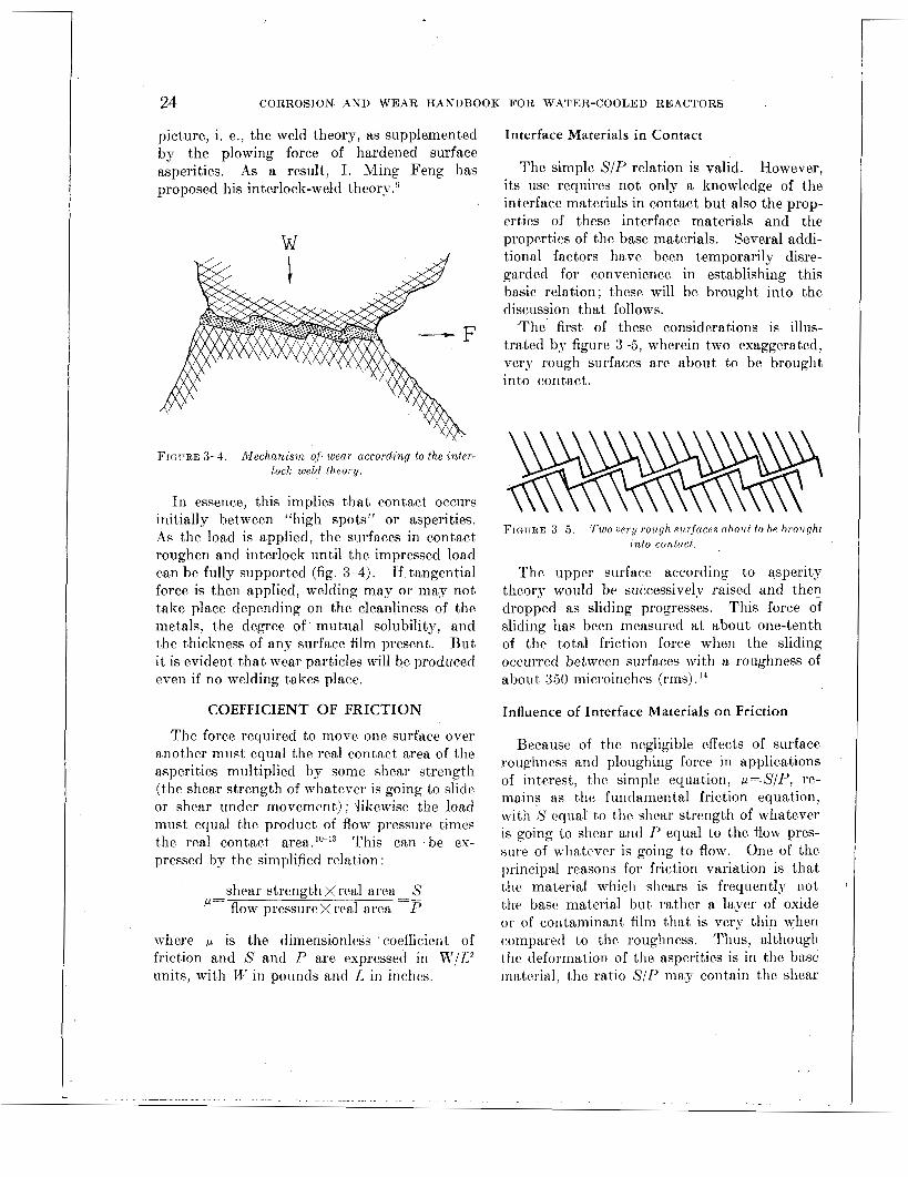
c
24 CORROSION AND WEAR HANDBOOK FOR WATER-COOLED REACTORS
pict,ure, i. e., the weld theory, as supplemented by the plowing force of hardened surface asperities, As a result, I. Ming Feng has proposed his interlock-weld theory.g
FIGURE 3-4. Mechanzsm of. wear according to the inter- lock w ~ l d theorti.
In essence, this implies that contact occurs initially between “high spots” or asperities. As the load is applied, the surfaces in contact roughen and interlock until the impressed load can be fully supported (fig. 3-4). If tangential force is then applied, welding may or may not take place depending on the cleanliness of the metals, the degree of mutual solubility, and the thickness of any surface film present. But i t is evident that wear particles will be produced even if no welding takes place.
COEFFICIENT OF FRICTION
The force required to move onc surface over another must equal the real contact area of the asperities multiplied by some shear strength (the shear strength of whatever is goiiig to slidc or shear under movement) : 3iltewise the load must equal the product of flow pressure times the real contact This can be ex- pressed by the simplified relation.
shear strengtlixrcd ~~ urea-S P I*= flow pressure x rcnl area
where is the dimensionless coefficient of friction and S and P are expressed in W / L z units, with I.I- i n pounds and L in iriches.
Interface Materials in Contact
The simple SIP relation is valid. However, its use requires not only a knowledge of the interface materials in contact but also the prop- erties of these interface materials and the properties of the base materials. Several addi- tional factors have been temporarily disre- garded for convenience in establishing this basic relation; these will be brought into the discussion that follows.
.The’ first of these considerations is illus- trated by figure 3-5, wherein two exaggcrated, very rough surfaces are about to be brought into contact.
F I G ~ ~ R E 8-5. T w o very rough sitrfaccs uholtf io he brouqhr into conturf . .
The upper surface according to asperity tlieorp worild be successively raised and then dropped as sliding progresses. This force of sliding iias been measured a t about one-tenth of the total friction force when thc sliding occurred between surfaces with a roughness of about 3.50 microinches (rms) . l 4
Influence of Interface Materials on Friction
Because of the negligible effects of surface roi~ghness nrid ploughing force in applications of interest, the simple equation, p=S/P, rc- mains as the fundamental friction equatiorl, with S equal to the shear strength of whatever is going to shear and I’ equal to the flow pres- siire of whatever is going to flow. One of the principal reasoils for friction variation is that ttic material which shears is frequently not tlic basr matcrial but rather a layer of oxide or of contaminant film that is very tliin when compared to the rcughness. Thus, although thc deformation of the asperities is in the base matcrial, the ratio S / P maj- contain the slicar

FUNDAMENTAL ASPECTS OF FRICTION AND WEAR 25
strength of a weaker material, e. g., oxide or contaminant film, and the flow pressure of a stronger material which yields a 'reduced value of p.
There is another important reason for fric- tion variation. The physical properties S and Y may not always vary in the same ratio in response to work hardening (either before rub- bing or by the rubbing process) to heat gene- rated at the asperities, or too heat applied ex- ternally. lo "
Nature of Surface Layers
. The cross section of a so-called "smooth" surface a t high magnification is shown i n deta.il in figure 3-6."-"
FIGTIRE :3M. Detailed cross sectzon o,f smooth stirface at h?gh maqnzficotion.
The sketch shows such a surface compressed horizontally but substantially to scale vertically. The height from the bottom to the top of the deeper grooves of a 4 microinch (rms) surface may be as great as 15 microinches. Starting at the outermost surface (fig. 3-6), there maj- be a thin layer of contaminant films anywhere from 1 to 25 A thick. This layer is composed of the contaminants from handling and process- ing as well as gases adsorbed on tlie surface. Beneath these films is an oxide layer which may he from 25 to 250 A thick. The final layer in figure 3-6 represents the base metal with tlie outerrnost portion probably cold worked to some degree from machining or from load application.
Destruction and Maintenance of Surface Layers
When two surfaces such as those just de- scribed are brought together, the destruction
or maintenance of surface layers becomes im- portant. For the case in which the contami- nant film is unbroken, the coefficient of friction is low, generally ranging from 0.1 to 0.2. How- ever, as soon as the contaminant films are penetrated, the oxide films arc exposed and can come in contact. Such oxide films, when un- broken, characteristically have a moderate coefficient of friction, about 0.4. Further wear exposes the base material resulting in the highest coefficient of friction, generally between 0.8 and 1 for fully work-hardened materials. lo "
In any actual case, there is very likely a mix- ture of the three layers in contact so that friction may varj- from the lowest value to the highest value, depending upon the durability of the films, the severity of the attack upon the surface layers, and their ability to repair them- selves During sucli wear the uct,ual particlc size, as determined dii specific tests, ranges between 1 and 2,500 A.25-28
CYCLES
FIGURE 3-7. The effects of contamznant j lms on the coeficaent o,f frzctrnra zn demzneralzred water ut rnom t e m p e r n h i e
,
Figure 3- i is a graphical representation of the effects of contaminant films on the co- efficient of frictioii, as determined in de- mineralized water a t room temperature by D e ~ e e s . * ~ . 24 In this investigation a clean Armco 17-4PH rider was run on a clean Stellite No. 3 disk under 40 lb initial load. After 400 cycles of opcration the load was reduced to 2.6 lbs, arid no significant variation could be observed. However, after 900 cycles the rider was removed
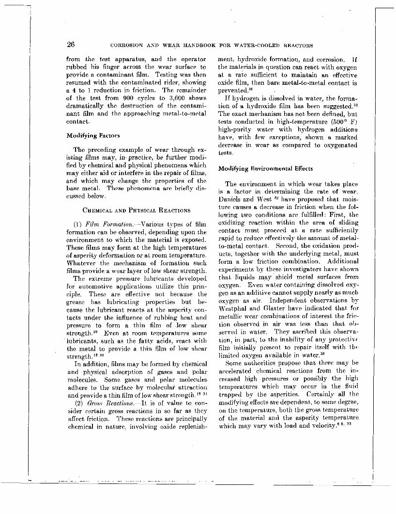
26 CORROSION AND WEAR HANDBOOK FOR WATER-COOLED REACTORS
from the test apparatus, and the operator rubbed his finger across the wear. surface to provide a contaminant film. Testing was then resumed with the contaminated rider, showing a 4 to 1 reduction in friction. The remainder of the test from 900 cycles to 3,600 shows dramatically .the destruction of the contami- nant film and the approaching metal-to-metal contact.
Modifying Factors
The preceding example of wear through ex- isting films may, in practice, be further modi- fied by chemical and physical phenomena which may either aid or interfere in the repair of films, and which may change the properties of the base metal. These phenomena are briefly dis- cussed below.
CHEMICAL AND PHYSICAL REACTIONS
(1) Film Formation.-Various types of film formation can be observed, depending upon the environment to which the material is exposed. These films may form at the high temperatures of asperity deformation or at room temperature. Whatever the mechanism of formation such films provide a wear layer of low shear strength.
The extreme pressure lubricants developed for automotive applications utilize this prin- ciple. These are effective not because the grease has lubricating properties but be- cause the lubricant reacts a t the asperity coxi- tacts under the influence of rubbing heat and pressure to form a thin film of low shear strength.29 Even at room temperatures some lubricants, such as the fatty acids, react with the metal to provide a thin film of low shear strength. 30
In addition, films may be formed by chemical and physical adsorption of gases and polar molecules. Some gases and polar molecules adhere to the surface by molecular attraction and provide a thin film of low shear strength.” 3’
(2) Gross Reactions.-It is of value to con- sider certain gross reactions in so far as they affect friction. These reactions are principally chemical in nature, involving oxide replenish-
ment, hydroxide formation, and corrosion. If the materials in question can react with oxygen a t a rate sufficient to maintain an effective oxide film, then bare metal-to-metal contact is p r e ~ e n t e d . ~ ~
If hydrogen is dissolved in water, the forma- tion of a hydroxide film has been suggested.32 The exact mechanism has not been defined, but tests conducted in high-temperature (500 O F) high-purity water with hydrogen additions have, with few exceptions, shown a marked decrease in wear as compared to oxygenated tests.
Modifying Environmental Effects
The environment in which wear takes place is a factor in determining the rate of wear. Daniels and West 32 have proposed that mois- ture causes a decrease in friction when the fol- lowing two conditions are fulfilled : First, the oxidizing reaction within the area of sliding contact must proceed a t a rate sufficiently rapid to reduce effectively the amount of metal- to-metal contact. Second, the oxidation prod- ucts, together with the underlying metal, must form a low friction combination. Additional experiments by these investigators have shown that liquids may shield metal surfaces from oxygen. Even water containing dissolved oxy- gen as an additive cannot supply nearly as much oxygen as air. Independent observations by Westphal and Glatter have indicated that, for metallic wear combinations of interest the frit:- tion observed in air was less than that ob- served in water. They ascribed this observa- tion, in part, to the inability of any protectivr film initially present to repair itself with th t - limited oxygen available in water.36
Some authorities propose that there may be accelerated chemical reactions from the in- creased high pressures or possibly the high temperatures which may occur in the fluid trapped by the asperities. Certainly all t’he modifying effects are dependent, to some degree, on the temperature, both the gross temperature of the material and the asperity temperature which may vary with load and velocity.e 33

FUNDA4MENT.A L ASPECTS O F FRICTIOX AND WEAR 29
t,lius change the mture of t,he a.ctua1 cont,actiiig surfaces) .26*
2 . Adhesive wear is proportional to load (be- low some critical load and a,s long BS t~he nat,ure. of t,he contacting surfaces is not changed by the load).zfi, 28, 33
3. Abrasive wear is characterized by the abilitjy of a particle to penetrat,e anot,her, re- lated to tfhe hardness of the metal, arid the ability of the particle t.o remove other pa.rt.icles and present a new wear surface.
4. Corrosive \war is complex a.nd has not, been adequately a,nalyzed. However, i t ap- pears to be proportional to load, distance tra.v- eled, a.nd to some funciion of frequenc.y and t,he corrosivitp of t,he e~ivironrnent~.~’. 38
5 . Surface fat.igue is a form of wear in wliicli t,he number of cycles unt,il breakdown of the surface is inversely proport,iona,l to t8he cube of the load.
6. The amount, of me,m cei*Lainly depends upon the materials in coiitac,t., but. t,he rules for relating wea.r n,nd mat’erial arc, st~ill not firmly estsblislred.”~ 3g-43
’
REFERENCES
1. N. B. UEWEES, Friction Fundan~entals Oiit.line, Report WAPD-CTA (R hI)-3 12, Westiiighoase Elect,ric Corp., I’it,tsburgh, Pa., No\;cn~her 1955.
2. F. P. Bowuss and 1). TABOR, ”The Frict.ioii and Lubrication of Solids,” Oxford Unii London, 1st ed., 1950, pp. 20-22.
3. “Met,als Handbook,” American Society for kIetala, Cleveland, 1948 ed., p. 94, Brinnel Hardness Test,.
4. E. HOLM, R. HOLM, and E. I. SHOBERT 11, Theory of I-Iardncss and Rleasurements Applicable t.o Contact Problems, J . A p p l . P h p . , 20: 3319-327 (April 1949).
5. F. P. BOWDEN and 14. A. STOSE, Visihlc Hot Spoh on Sliding Surfaces, Ezperientin, 2:
6. F. 1’. BOWDEN and P. H. T H O A I A ~ , The Surface Temperature of Sliding Solids, Proc. IZo!/. SOC. (London), A223: 29-40 (-April 1954).
7. F. P. BOWDEN- atid I<. E. W. RIDLER, Physical Propert-ies of Surfaces. 111. The Surface Tem- perature of Sliding Met,als, The Temperature of Lubricated Surfaces, Proc. Ro!J. SOC. ( L o n d o n ) , -4254: 640-656 (April 1936).
8. F. P. BOWI)ES and 11. T A R ~ R , ”The Friction and Lribricatiou of Solids,” Osford Tiniversit y Press,
186-188 (1946).
r,olldolr, 1st ed., 1050, pll..:u-57.
9. I . -MIsG Fssc, Metal Transfer and Wear, J . ; l p p l . Phys. , 23: 1011-1019 (September 1952).
10. H ~ s s ERXST and &I. E. MERCHAST, Surface Fric- tion of Clean Metals: A Basic Factor in the Metal Ciitt.iiig Process, Proceedings of the Spe- cial Summer Coiiference on Friction and Wear, Massachusetts Inst,itute of Technology, 1940, p.76 .
11. E. ~IERCHAST, The Mechariism of %atic Friction, J . i ippl. Phys. , 11: 230 (March 1940).
12. F. 1’. BOWIIES, A. J. W. MOORE, and I). TABOR, The Ploughing and Adhesion of Sliding hlet.als, J . 9 p p l . Phys . , f4: 80-91 (February 1943).
13. H. HOLM, Sieniens-\TTerken w’iss. T’eroffcnt,l., 17 : 42 (1938); 20: 68 (1941).
14. C. 11. STRAXG and C. R. LEWIS, On the Magnitude . of the Mechanical Component of Solid Friction,
~ J . 9 p p l . Phys. , 20: 1164-116i (December 1949). 15. 1’. W, BRIDGAIAS, ISffect,s of High Shearing Stress
Combined With High Hydrost.atic Pressure, Phys. Rev. , 48: 825-847 (Kovember 1935).
16. R . F. KISG and I). TABOR, The St,rength Properties and Frict,ional 13ehavior of Brittle Solids, Proc. Roy . SOC. (Londot i ) ; 9223: 225-238 (-4pril 1954).
1 7 . I. SIMOS, H. 0. Mch‘Imos, and It. J. B O ~ V U E X , Dry Metallic Friction as a Function of Teniper- at.ure Between 4.2” I< and 600” I<, J . ;Lppl . Phys. , 22: 177-184 (February 1951).
, Friction of Clean Metals and IiiNuence of .Adsorbed Films, Proc. Roy: SOC., :1208: 31 1-325 (September 1951).
19. J.. WELF, The h’Iet,allurgy of Surface Finish, Proceedings of t.he Special Summer Conference on Frict.ioii and Surface Finish, Massachusetts Institute of Technology, 1940.
20. C:. B. I<ARELITY, Borlndry Lubrication, Proceedings of the Special Surnnier Conference on Friction and Surface Finish, Massachusett,s Tiistitiite of Technologj-, 1940.
21. Remarks by W. E. Camphell in Proceedings of the Special Summer Conference on Friction and Surface Finish, Massachusetts Inst,it,iite of Technology, 1940.
22. “3Iechaiiical IVear,” editor, J. T. Burirell, J r . , .4mericaii Society for Metals, 1st ed., 1950, p. 136, discussion 1))- >I. E. Merchant,.
23. N. B. D E ~ Y E E R , JVear and Friction of Materials 011
the Pendrilum Slide Machine, Report, WAPII- CTA(ED)-18, West.inghousc Elect,ric Corp., Noveinher 1955.
24. N. B. I IE \vEss , Friction Coefficient Variation i l l
Rooin Temperat.ure Water, Report WAP 1)- AD(R3!)-18, April 19.55. ,
2.5, E. R.asrsoiv~cz, A Quantitative Study of the \+’ear Process, I’roc. P h y s . SOC. (London), R, LXT‘I: 929 (1953).
26. J. F. . ~ R C H A R I ) : Contact and Rubbing of Flat, Surfaces, .J. d p p l . P h y s , , 24: 981-088 (Angust 1953).
18. F. P. Bon; i ,~s and J . E. Y o

30 CORROSION AND WEAR HANDBOOK FOR WATER-COOLED REACT(): ;S
27. J. T. BURWELL and C. D. STRANG, Radioactive Tracers Reveal Friction and Wear of Metals, Metal Progr., 60: 69-74 (September 1951).
28 J . T. BURWELL and C. D. STRANG, On the Empirical Law of Adhesive Wear, J . A p p l . Phys., 25: 18-28 (January 1952).
29. 0. BEECK, J . W. GIVENS, A. E. SMITH, and E. C. WILLIAMS, On the Mechanism of Boundary Lubrication, Proceedings of the Special Summer Conference on Friction and Wear, Massachusetts Institute of Technology, 1950, p. 113.
30. “Mechanical Wear,” editor, J. T. Burwell, Jr., American Society for Metals, 1st ed., 1950, pp. 73-93, Chap. V, Chemical Aspects of Wear and Friction, R. G. Larsen and G. L. Perry.
31. F. P. BOWDEN and J. E. YOUNG, Friction of Dia- mond, Graphite, and Carbon and the Influence of Surface Films, PTOC. Roy. Soc. (London), A208: 444-455 (September 1951).
32. R. 0. DANIELS and A. C. WEST, The Influence of Moisture on the Friction and Surface Damage of Clean Metals, Lubrication Eng., l l ( 4 ) : 261-266
:3:3. R. L. JOHNSON, M. A. SWIKERT, a n d E . E. BISSON, Effects of Sliding Velocity and Temperature on Wear and Friction of Several Materials, Lubri- colion Eng., l l ( 3 ) : 164-170 (May-June 1955).
34. J. T. BURWELL, Jr., and E. RABINOWICZ, The Nature of the Coefficient of Friction, J. i l p p l . Phys. , 24: 136-139 (February 1953).
35. Private communication from Dr. E. Gulbransen of the Westinghouse Research Laboratories, as re- ported in reference 1 .
(July-August 1955).
. . . . . . - . . . . . .~ - __ . - . .
36. R. C. WESTPHAL and J. GLATTER, The Wear and Friction Properties of Materials Operated in High Temperature Water, Report WAPD-T-64, Westinghouse Electric Corporation, Dec. 4, 1953..
37. J. T. Burwell, Jr., Survey of Wear Mechanisms, presented at the American Society of Lubrication Engineers Annual Meeting, Chicago, April 13-1 5, 1955.
38. H. H. UHLIG, I.-MING FENG, W. D. TIERNEY, and A. MCCLELLAN, A Fundamental Investigation of Fretting Corrosion, National Bdvisory Conimittee for Aeronautics, Technical Note 3029, December 1953.
39. E. RABINOWICZ and D. TABOR, Metallic Transfer ’ Between Sliding Metals: An Autoradiographic
Study, PTOC. Roy. Soc. (London), A208: 455-475 (September 1951).
40. A. E. ROACH, C. L. GOODZEIT, and R. P. HUNNI- CUTT, Scoring Characteristics of Thirty-eight Different Elemental Metals on High Speed Sliding Contact with Steel, American Society of Mechanical Engineers, Paper No. 54-A-61, December 1954.
41. E. S. MACHLIN, Research Points the Way to New Methods of Preventing Galling and Seizing, Zron Age, 175: 91-93 (Feb. 10, 1955); 175: 104-106 (Feb. 17, 1955).
42. P. ‘F. CHENEA and A. E. ROACH, A Mass and Energy Balance for the Wear Process, presented at the American Society of Lubrication Engineers Annual Meeting, Chicago, April 13-15, 1955.
43. E. KOENIGSBERG and V. B. JOHNSON, Metallic Friction and Lubrication by Laminar Solids, Mech. Eng., 77: 141-147 (February 1955).

FUNDAMENTAL ASPECTS OF FRICTION AND WEAR 27
Mechanical and Metallurgical Factors
Mechanical and metallurgical factors influ- encing wear may be examined from t,he strand- point of those that are inherent to the material and those that are acquired during fabrication and service.
WORE HARDENING
As stated previously, the SIP relations for materials in various work hardened conditions are not yet known with certainty. These rela- tions are further complicated by the fact that the work hardened condition of the asperities is, in all likelihood, different from the base material after initial deformation has taken place.I0
VELOCITY
At very low velocities, in the 10P to in. per sec. range, there are indications of an increase in frictional force. This has been attributed to the dependence of shear strength on rate of shear.34 In addition, as the velocity decreases there is increased time for formation of welds. Thus the range of velocities in a mechanical system is of fundamental importance with rzgard to the frictional characteristics of the device, particularly when traveling in the low- velocity region.
SHEAR STRENGTH VERSUS PRESSURE
When contact pressure is increased, it may be observed that surfaces move across one another with increasing difficulty This is attributed to the fact that the shear strength of some ma- terials may increase under pressure. Rocksalt., although not a metal, illustrates the case in point. Specimens of this crystalline mineral have displayed a sevenfold increase in shear strength as pressure was increased to the point of failure. Analogous observations have been made for metals. Similar increases, although not so great, may be observed for many engineering materials of interest and, when observed, constitute a departure from the classical theory that friction forces are inde- pendent of load.'
Pressure may also promote the removal of oxide layers normally protective to the base mcLtal. When oxidation takes place, the crystal st,ructure of the oxide formed may differ from the vrystal structure of the base metal. Under thew circumstances internal stresses between oxide and base metal may contribute to the breciking of the oxide film under applied load.35 Th(5 films thus removed very ofter lose all semblance of protectiveness and may act as abrnsives, causing accelerated wear and ma- tei ial damage.
EXTERNAL LOAD
As external stress or load increases, there is an increase in the number of asperities in contact and, if subsequent movement takes place, more wear particles are produced. These wear particles may t,hen add, through abrasion, to more rapid wearing away of surface films than would otherwise be expected.28 In addition, abrasive foreign particles also increase the wearing away or destruction of surface films.
THE PROCESS OF WEAR
In order to clearly establish the term wear as used here, the following definition is presented : Wear is a complex surface phenomenon re- sulting in mechanical attrition of moving sur- faces in contact, as by welding and removal of particles through friction.
Wear resistance is not an inherent property of a metal which may be considered by itself; rather wear is the resultant of the material itself, of the mating material, the environment, and the operation conditions producing the wear. Wear resistance then is complicated by all these factors and cannot be determined apart from the specific conditions of service.
Burwell (and others) propose that the four basic types of wear are adhesive wear, abrasive wear, corrosive wear, and surface fatigue.
Adhesive Wear
Adhesive wear is best described by the weld t,heory as proposed by Bowden and Tabor and

28 CORROSION AND WEAR HANDBOOK FOR WATER-COOLED REACTORS
others. According to thisview, friction is due primarily to the cold welding of surfaces when they are brought together under load.
Subsequent motion results in the tearing of the metal, rupture taking place either in the newly formed weld, in the asperity, or in the underlying metal, which ever presents the weakest bond.
Such welding of asperities is normally pre- vented by using a lubricant film or by providing an intermediate layer of low shear strength.
Abrasive Wear
Abrasive wear (or cutting wear) results from the ploughing of asperities and the cutting action of either entrapped or free-rolling grit particles between the surfaces. In most con- ventional engineering applications the design engineer can greatly overcome abrasive wear by the proper choice of materials, lubricants, and surface finish: and by providing for a clean environment. Hardness and smooth finish are the primary means of minimizing abrasive wear.
Corrosive Wear
Corrosive wear is characterized by the inter- action of the wear surface with a corrosive environment. It should be remembered that the nature of the oxide must be considered for each material. These products can act as wear inhibitors in some applications and as primary causes of excessive wear in others. The in- tegrity of the oxide layer is also a factor to be considered, as in the case of tin oxide. When present as an unbroken film, the oxide is pro- tective and wear is low. However, once the oxide layer has been broken, the removed par- ticles become abrasive and promote accelerated wear. 36
Surface Fatigue
Surface fatigue is most oft,en encountered in ball and roller-type bearings, on gear teeth and cams, and other similar types of applications where the surface is subject to a great number
of stress reversals at high unit stress. Spalling, flaking, and eventual destruction of the wear surface are the results of surface fatigue.
GUIDES FOR THE EVALUATION OF FRICTION AND WEAR
The brief discussion of this chapter and the supplementary discussions afforded by the refer- enced articles are directed toward a general understanding of the problems of friction and wear. The guides that are presented here are made available to the reader as aids in the resolution of friction and wear problems. A summary of these guides is given below.
Friction
I . Frictional force is directly proportional to the actual area of This concept has been used and developed in the preceding discussion. I f the nominal area of contact is considered rather than the actual area, which includes only the asperities supporting the load, the classical “friction force is independent of the area of contact” would provide a working hypothesis.
2. Frictional force is independent of load, except as the load may cause the breaking through of surface f i l rn~.’~-’~ Here again if the nominal area of contact is considered rather than the supporting area developed by the load, the classical “frictional force is directly pro- portional to load” would appear to be valid.
3. The effect of velocity on frictional force is complex. At medium speeds (from about 1 in./sec to a few feet per second, friction appears independent of speed; a t lower speeds friction increases; and at higher speeds friction de- creases with speed.
4. Frictional force depends upon the nature of the materials in contact.
Wear
1. Adhesive wear (amount of wear pro- duced) is proportional to distance traveled (except as films may be worn through and

Chapter 4
WATER TECHNOLOGY
Editor-D. M . WROUGHTON Page
INTRODUCTION_..___.___________________ 31 CHEMICAL PROCESSES I N THE SYSTE~IL. ~ - - ~ -. . 31
Corrosion-. -. . . - -. - ~ ~. -. . . -. -. . - -. - -. . . 32 Water Dissociat,iori ._... . . _ ~ _. . . . ~. . .___. 32 Radiation Syiitheses- ~. - _ ~ . .__- .. . -. . _ ~ - 32 Purification by Ion Exchange-. . .___.__ ~~ 33 Nuclear Reactions- - - -.
~ ~ -. - ~ -. - - -. ~ -. - 33
34 I N T E R D E P E N D E N C E OF CHEMICAL h O C E S S E S _ _ _ - 33 PRACTICAL WATER CONDITIOXS.. . . ~ ._ _. . .~
I M P O R T A N C E OF WATER P U R I T Y - . - - - .... ~~ --.- , 36
INTRODUCTION
The chemistry of t,he corroding medium is of obvious significance to corrosion and wear processes and therefore to tbe selection of materials of construction. Several aspect's of the effects of wat8er composition upon corrosion are discussed in other sect,ions of this book. T t is import,ant, to point out. here t.ha.t, i t ma.!. be impract,ic,al to ma.intain an a.rbit.rary wat,e.r condition in a reactor syst,em and t,ha.t., to some degree, the system tends t,o control itself.
At first glance, reactor systems would seem to be exposed tjo about the same condit.ions as conventional boiler p1ant.s. Operating t.emper- atures are in t,he range of 400 t,o 600' F, with some parts at about 200'F. Experience in conventional power boilers covers this tempera,- t#ure range. Analogy between steam pla.nt4 a.nd reactor system practice csnnot. be based upon temperature and pressures a.lone. There a.re certain differences between t.he two syst,ems which are of greatest importance to wa.t,er tech nology .
First of all, there is the problem of handlirig radioactivity iii such a syst,em. Pra.ct.ic,ally all materials, including wat& itself, become raclio- a.ct,ive when exposed tmo the int.enst neut,ron flus i n tjhe reactor core. The accumulat,ion, tmns-
port, a.nd disposal of radioact'ivity is a matter of pa.ramount concern. This, in turn, results i n requiremenk for high-purit,y water and nearly absoluk leak t,iglitness. The use of high-purity wat,er removes react'or wat.er technology a t once from the realm of boiler wat'er technology. * Leak tight>ness result,s in compara,t'ively greater emphasis 011 syst,em wa,t'er changes than on control of feed wa.t,er.
Secondly, t,he effect of radiation introduces-a parameter upon wat,er ~hemist~ry which is for- eign t,o convent,ional systems. Radiat,ion pro- motes some chemical reactions of great im- port,a.nce. It. may make water chemist,ry simpler, as will be shown for the case of oxyge,n control, or it, may promote the formation of objectionable subst>ances such as acids which aggravate the corrosion problem. Even a simple boiler cont,rol problem such as maintain- ing an a.lkaline condition (pH 10 to 11) in the wat.er is severely rest.rict,ed by considerat'ions of induced radioactivity, radiation decomposition, or nuc1ea.r reactions. There are no corrosion inhibit,ors for st,a.inless, low alloy, or carbon steels which are sta.ble and effective a t temperature a.nd which a.re not. decomposed by radiation.
CHEMICAL PROCESSES I N THE SYSTEM
The chemical processes in a reactor system may be represented by relatively few chemical reactions. (1) corrosion, ( 2 ) water dissociation, (3) radiation synthesis, (4) purification by ion exchange, and (5) nuclear reactions. However, the interdependence of these processes results in a fairly complex situation. The chemical equations that follow should be considered
*There have been some instances \vhere convmt ional hoilers \ v ~ r e operated on high-purity water, hut this is not common practice.
31
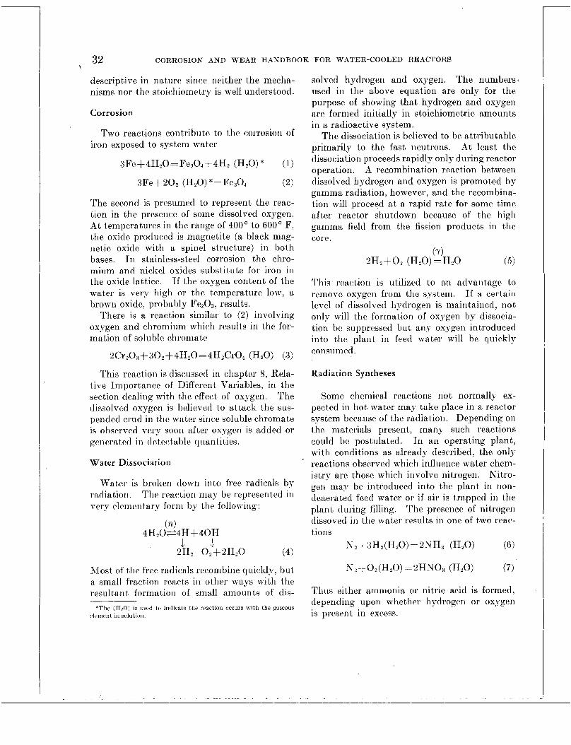
32 CORROSION AND WEAR HANDBOOK FOR WATER-COOLED REACTORS
descriptive in nature since neither the mecha- nisms nor the stoichiornetfry is well understood.
Corrosion
Two react,ions contribute to the corrosion of iron exposed to system water
3Fe+4HzO=Fe304+4Hz (HzO) * (1)
XFe+2OZ (HzO) *=Fe304 (2)
The second is presumed to represent the rcac- tion in the presence of some dissolvcd oxygen. At temperatures in the range of 400' to 600' F, the oxide produced is magnetite (a black mag- netic oxide with a spinel structure) in both bases. Tn stainless-steel corrosion the chro- mium and nickel oxides substitute for iron in the oxide lattice. If the oxygen content of the water is very high or the temperature low, a brown oxide, probably Fe203, results.
There is a reaction similar to (2) involving oxygen and chromium which results in the for- mation of soluble chromate
2Cr,03+ 302+4H,0= 4HzCrO4 (HZO) t X )
This reaction is discussed in chapter 8, Rela- tive Importance of Different Variables, in the section dealing with the effect of oxygen. The dissolved oxygen is believed to attack the sus- pended crud in the water since soluble chromate is observed very soon after oxygen is added or generated in detectable quantities.
Water Dissociation
Water is broken down into free radicals by The reaction may be represented in radiation.
very clementary form by the following:
(n) 4H20=4H+40H
L 1 2H, 0,+2H,O (4)
Most of tlie free radicals recombine quickly, but a small fraction reacts in otlicr ways with the resultant formatioil of small amounts of dis-
'The (I120) is usrd to indicatc the rract,ion occurs with thc! R:LSCOIIS elrrnent in solution.
solved hydrogen and oxygen. The numbers used in the above equation are only for the purpose of showing that hydrogen and oxygen are formed initially in stoichiometric amounts in a radioactive system.
The dissociation is believed to be attributable primarily to the fast neutrons. At least the dissociation proceeds rapidly only during reactor operation. A recombination reaction between dissolved hydrogen and oxygen is promoted by gamma radiation, however, a'nd the recombina- tion will proceed a t a rapid rate for some t,ime after reactor shutdown because of the high gamma field from the fission products in the corc.
(y) 2H,+02 (HzO)=H,O (5)
This reaction is utilized to an advantage to remove oxygen from the system. If a certain level of dissolved hydrogen is maintained, iiot
only will tlie formation of oxjrgen by dissocia- tion be suppressed but any oxygen introduced into the plant in fcetl water will hc quickly consumed.
Radiation Syntheses
Some chemical reactions not normally ex- pected in hot water may take place in a reactor system because of the radiation. Depending on the materials present, many such reactions could be postulated. I n an operating plant, with conditions as already described, the only reactions observed which influence water chem- istry are those which involve nitrogen. Nitro- gen may bc introduced into the plant in noti- deaerated feed water or if air is trapped in the plant during filling. The presence of nitrogen dissoved in the water results in onc of two reac- tions
N,+XH,(HZO) =2"3 (HZO) (6)
X,+O,(H,O) =2HN03 (H,O) (7)
Thus (ither ammonia or nitric acid is formed, depending upon whether hydrogen or oxygen is present in excess.
. ..

WATER TECHNOLOGY 33
Purification by Ion Exchange
An ion exchanger is usually included in water- cooled nuclear reactor systems primarily to remove radioactive materials in solution and thus reduce radiation levels in the reactor compartment. In addition to such removal, the ion exchanger plays an important part in wat,er chemistry.
Ion exchangers of the granular mixed-bed type are commonly used. If, initially, the cation resin is in the hydrogen form arid the anion is in the hydroxyl form, the ion exchanger tends to keep the water nearly neutral. The exchange process may be illustrated simply as follows for the removal of sodium chloride where (CR) and (AR) represent the two resins.
(CR)H++ Na+ = (CR) Na+ + H+ (8)
If the two resins are not used in the proper proportion or are not well mixed, the p H may
, shift from neutral because of the production of excess hydroxyl or hydrogen ions.
Special salt forms of ion-exchange resins may be used to control t,he pH above neutral. For example, the above equations written for a mixed-bed ion exchanger with the cation resin in the lithium form become:
(CR)Li+ + Na+ = (CR) Na+ + Li+ (10)
(AR)OH-+ el-= (AR) Cl-+OH- (1.1)
This will result in a p H corresponding to the resulting lithium hydroxide concentration. (In fact, pure water passed over such a mixed-bed resin will have a p H somewhat above 7.) In a similar way, an ammonia form resin might be used to maintain some level of ammonium hydroxide in the water, and since reaction (6) is reversible under radiation, an ammonia resin may put some liydrogcn into the plant.
Nuclear Reactions
Some nuclear reactions wliich occur in tht: wat8cr are important only to sliiclding or mntrttsr s
other than water chemistry; for example, the formation of the NI6 and N17 species. Other re- actions result in the formation of radioactive materials from impurities in the water. In the reaction
Fe5E(n,y)Fe59 (12)
the Fei9 becomes radioactive and emits both beta and gamma radiation. The products of similar reactions are the source of most of the radioactivities in the water with half lives more than a few seconds. Nuclides so formed, which produce hard gammas, interfere with personnel access to the system because of the resultant high gamma field in the compartment. The soft-gamma and pure beta emitters are ingestion hazards when the system is opened.
If lithium hydroxide is used for p H control, the latter situation arises because of a some- what analogous reaction. The lithium nu- cleus exposed to neutrons forms tritium:
T i 6 (n, a) H (13)
If the system is opened to the atmosphere or develops a lea.k, protection from the tritium must be provided.
INTERDEPENDENCE OF CHEMICAL PROCESSES
A study of the interaction of the above proc- esses yields an orderly picture of practical water conditions in an operating reactor. This picture is shown in a very simplified form in figure 4-1. Corrosion is shown to play a major part since without corrosion other problems would not exist or other reactions could be ignored.
It should be remembered that a reactor sys- tem is quite leakt>ight. Therefore the hydrogen generated by corrosion reaction (1) will build up in the system or will tend to maintain any initial hydrogen concentration. If oxygen is present initially because no hydrogen is added, i t will be consumed by corrosion reaction (2) until the hydrogen is prcscnt in sufficient ex- cess to suppress dissociation rcaction (4).

34 CORROSION AND WE 4R HANDBOOK FOR WATER-COOLED REACTORS
GENERATION
rmmmymiq
MATERIALS
I \“ERR-
I I I M F O r T : I V T O
pH MNTROL-
1 RAUOMIVITY
IN WATER
t FOULING
FIGURE 4-1. Interdependence of chemical processes.
Tf excess hydrogen is present in the water and some oxygen is added, as in aerated feed water, i t will be consumed very quickly by the radia- tion-catalyzed reaction ( 5 ) . If even small amounts (a few cubic centimeters per kilogram of H,O) of nitrogen are present, the pH tends to be controlled by the hydrogen concentration according to reactions (6) and (7). Thus dissolved hydrogen in the water plays the mul- tiple role of suppressing dissociation, indirectly reducing corrosion, and controlling pH.
The pH of the water can be controlled by another process if desired. If a mixed-bed H-OH ion-exchange resin is used for puri- fication, i t tends to keep the pH of the water near neutral. However, if the ratio of cation to anion resin is changed or if special salt forms of the cation resin are used, the pH of the water can be raised as already noted. By using a mixed-bed resin in about the usual proportions of anion and cation resin but having the cation resin in the salt form, e. g., a lithium form resin rather than a hydrogen form, the water will be raised to a pH of 10 or 11. A lithium form resin is still effective for water purification since practically all soluble impurities will be
removed by such resin. The exchange process, of course, releases lithium hydroxide to the water and also tends to raise the pH.
PRACTICAL WATER CONDITIONS
The most important controls specified for reactor water are the relation of impurities (e. g., chloride), dissolved oxygen, and pH. Since reactor water is of high purity, it is usually sufficient in practice to specify the conductivity, corrected for pH, to guarantee that the soluble solids are satisfactorily low.
In a reactor system the actual source of con- trol may be radically different from what it would be in a conventional boiler. The use of deaerated feed water does not insure oxygen- free water in the system nor does the use of aerated feed water mean that free oxygen will be found in the plant. The pH of the water may be internally controlled by the radiation- induced reactions or by the purification system.
Any discussion of reactor water chemistry a t this time cannot advance valid methods for the independent control of all factors. The in- dependent variables may be looked upon as : (1) the hydrogen gas content of the reactor system water, (2) the degree of deaeration of the feed water or the amount of air trapped in the system, and (3) the nature,and degree of internal purification. In a sense, the param- eters most important to corrosion are de- pendent variables.
The following requirements have evolved from present knowledge on water chemistry in water-cooled nuclear reactors :
1. Demineralized water should be used for filling and makeup. Deaeration is not objectionable but is not necessary if step (2) is followed.
2. Hydrogen gas should be added to the water to suppress dissociation and remove oxygen. The concentration required is 10 cc per kilogram of H20 or higher. Higher hydrogen concentrations are not objection- able and may reduce corrosion slightly. It is most convenient to keep the concentration below the solubility limit in cold water a t
Part B
Procedures and Data

WATER TECHNOLOGY 35
O
0 2-
atmospheric pressure. At times when there is not sufficient radiation in the core to pro- mote the recombination reaction (5) or when circulation through the core is impossible, hydrazine may be used to remove oxygen.
3. Adequate purification of the water within the primary system, by means of ion exchangers and/or mechanical filters, should be provided to keep the radioactivity low and reduce the probability of fouling. A mixed-bed ion-exchange resin will perform effectively for both filtration and deminerali- zation.
4. The pH of the water may be raised to 10 or 11 by adding a base or using a special ion-exchange resin. Whether or not pH control is used depends upon several con- siderations. The benefits afforded to corro- sion, wear, and crud must be weighed against the inconveniences of maintaining the re- quired pH control. If the above ground rules are followed, satis-
factory water conditions are reasonable t,o maintain. Table 4-1 gives four examples.
TABLE 4-1
PRACTICAL WATER CONDITIONS FOR REACTOR SYSTEM OPERATION
Example Parameter
_ _ _ _ _ _ _ _ _ ~ A I I I F
CONDUCTIVITY . P mhos/cm
4-:
P H
Hydrogen in water, cc/kg .... Feed water deaeration. -.... Ion-exchange resin form ...... Water conduct ivi ty , @mho ... Oxygen in water, cc/kg ...--.. plI (reactor operating). .. .. . .
10-30 NO 11-OH 2-10 50.05 8-9.5
IC-30 Ye; 11-OH 1 10.05 7-8
lW30 NO Li-OH 2 F i 5 10.05 l(t10.5
<5 ’
NO H-OII F 1 5 0.1-5 6 . 5 4 . 5
The first three parameters are those which are considered “controlled” and the last three are the “dependent” variables. The table is greatly simplified and presumes steady-state conditions. Some important items, such as flow rate in the purification system, which have an influence on the values of the dependent variables are not included. Qualitatively, how- ever, the table serves to highlight some im- portant considerations in water chemistry
Considerable corrosion testing has been done for example in “degassed” water and in water a t neutral pH with a few cubic centimeters of oxygen per kilogram. It is doubtful that either of these conditions is realizable in an operat- ing-reactor system.
Two typical operating logs from reactor loops are shown to illustrate the consequences of deviation from the principles set down above. The operating conditions are shown in fig- ure 4-2.
HYDROGEN c c / k g 140
100- 120- I r \ - - - - A
8 0 ---!- HYDROGEN ADDED
. O a t CRUD ppm 4 ,071 , , , , , , , , , , , , , , J
8 16 24 a 16 24 HOUR OF DAY
FIGURE 4-2. Water chemastry, typacal operatang log. tern- peratwe, 450” F , power, 8 to 30 percent ~f f d l power; filter and demanerolazer an servaee.
Deaerated feed water was being used, and the hydrogen concentration was maintained at an average of 100 cc per kilogram of H,O by adding gas at intervals in large increments. Conductivity was low. showing little solubles in the water, and pH was only a little above neutral. Oxygen was undetectable and crud levels* were very low ( 5 0 . 1 ppm). In con- trast, figure 4-3 shows the conditions resulting from an attempt to start up the loop without adding hydrogen after considerable air had been
‘See Glossar), app B , for definition

36 CORROSION AND WEAR HANDBOOK FOR WATER-COOLED REACTORS
20-
0 -
4@l 300 T 7
- 2001
5 f 4 4
NITRATE
HOUR OF DAY
FIGURE 4- 3. Plant startup wzth azr an loop, water chem- zstry , low power
trapped in the system on fitting. As the loop heated up, a t low reactor power, the pH dropped sharply as nitrate was formed. Conductivity passed through a minimum corresponding to neutral pH. (The pH a t start up was high because of previous operating conditions.) There was attack of the chromium or chromium oxide in the system as indicated by the soluble chromate curve. The crud level is not shown because it exceeded the capacity of the normal measuring techiiique and may have reached values as high as 25 ppm.
It was soon evident that these chemical con- ditions could not be tolerated, and hydrogen was added in increments to remove the oxygen. Soon after an excess of hydrogen was present, loop chemistry returned to nearly normal and
quite acceptable conditions. Because of the presence of substantial amounts of nitrogen in the air, considerable ammonia was generated, and the pH rose to about 9.
The above illustration shows the dependence of loop chemistry upon the free hydrogen gas content of the water. I t also emphasizes the necessity for complete evaluation of any change in water chemistry as outlined in figure 4-1.
IMPORTANCE OF WATER PURITY
The importance of material selection to corrosion rates and to water purity and, con- versely, the relation of water composition to corrosion are discussed in chapters 7 to 9 and 13. However, there is one additional area which emphasizes the need for high-purity water, the importance of minor constituents as affected by nuclear irradiation. Relatively small amounts of impurities and minor constituents may be more responsible for higher activity than the major elements.
Three cases serve to illustrate the point. The practicality of using nondeaerated water has been mentioned. However, the argon con- tained in the dissolved air may contribute as much radioactivity to the water as the sum of all corrosion products. Secondly, sodium hydroxide is unacceptable as a pH control reagent, even though only a few parts per million are required, because of the high sodium activity which results. Finally, in chapter 12 , Corrosion Products in Recirculating Systems, i t may be noted that a substantial part of the short-lived activity, manganese , comes from a minor element in the steel and some of the long-lived activity, cobalt, comes either as an impurity in steel or possibly from the wear on small surfaces such as bearings. Thus it is necessary in a nuclear reactor system to con- sider, quite seriously, secondary elements and secondary effects as well as what may seem to be the major problem.

Chapter 5
DESCRIPTION OF TESTING PROCEDURES
Editor-R. U. BLASER
Contributors-C. R. Breden, S. C. Datsko, J. J. Owens, A. H. Roebuck, D. L. Douglas, R. F. Koenig, P. Cohen, D. J. DePaul, J. W. Flaherty, J. Glat,ter, H. K. Lembersky, S. Petach, B. G. Schultz, R. C. Westphal, D. M. Wroughton, J
1NTRODUCTION
M. Seamon.
Page
39 40 40 40
41 41 44 46 51 51 52 54 5 4 55 55 56 56 56 57 58 58 GO 60 60 60 G3 G 3 64
64 64 64 6 .i
Zn this chapter are described the various procedures for investigating corrosion and wear
417017 0-57-4
in high-purity water applications. The test appa.ratus and procedures have become stand- ardized to the degree that duplicate systems may now be found in several installations en- gaged in t,he st,udy of materials c,onsidered for use in commerciaJ and naval water-cooled nuclear reactors.
The complesit,y and number of conditions that may arise in t,he planning and operating of nuclear power plants has made i t unfeasible to t,horoughly investigate all the variables in- volved. This is particularly true since the urgency of time has been felt throughout the ent,ire developmental period. One might well consider the great number of combinations t,hat. could evolve from such variables as mate- rials, corrosion environments, temperature, time in service, special service conditions, and design. It is evident that the programs of investigation have been, of necessity, directed toward those conditions that are most likely to occur in service.
The data in this handbook were obtained from many sources ; yet the techniques, proce- dures, and apparatus of each contributing organization were essentially the same. These systems are described in sufficient detail so that future investiga.tors will 'be able to com- plete all phases of planning. The references given at the end of the chapter are available for .a more complete explanation of any partic- ular a,pparatus or procedure.
39

40 CORROSION AND WEAR HANDBOOK FOR WATER-COOLED REACTORS
Variables
The requirements for an acceptable test are rigid. Within the confines of the system the following factors must be controlled with pre- cision : (1) water composition, ( 2 ) temperature and pressure, ( 3 ) water velocity, and (4) main- tenance of steady test conditions.
In addition to the test operation, important variables arise in the handling of specimens before and after testing. Some of these vari- ables are: (1) procedures for preparing speci- mens, (2) procedures for weighing and descaling, ( 3 ) observation techniques, and (4) shutdown and startup procedures. These variables can be controlled by adopting and enforcing rigid procedures. However, for specific tests per- formed to detect localized attack, it sometimes becomes necessary to alter the procedures to satisfy the requirements of the test.
One remaining variable is not readily con- trollable but can be compensated for, that is, the type of corrosion film formed on specimens is not the same for all materials. These films range from a tightly adhering thin film for the austenitic stainless steels to the loose, powdery film observed on such steels as ASTM A212. Obviously, reliable corrosion rate data cannot be obtained by gross weight change alone if these materials are to be compared. There- fore, the corrosion deposits are removed by one of several available processes, and net weight changes are compared.
Use of Statistics
One of the major problems in both design and experimental work is tlie proper recogni- tion of all the variables that may affect tlie satisfactory performance of equipment in serv- ice. The major portion of the work covered by this handbook has been in the nature of screening tests and simulated service investi- gations. These have confirmed the complexity of the factors entering into the corrosion and wear of materials in the various applications considered. Statistical procedures have proved valuable in the correlation and reporting of such data as the relation of corrosion ratcs to
time.1° Now that a large number of variables has been shown to be pertinent to corrosion and wear phenomena, as experienced in reactor environments, additional data are required. The statistical design of experimental programs will be particularly helpful to continued work. The quantitative role of the many variables can be more readily determined by the use of that branch of statistics known as “design of experiment” in the choice of test points, vari- ables selected, time intervals, and amount of data required. Standard works are available which discuss in detail the statistical tech- niques available in the planning of experiments and in the evaluation of the resulting data. Some of these works are listed in part B of the reference section, Stat,istical References.
Scope of Chapter
Thc procedures discussed here apply most directly to chapter 7, which deals with tabula- tions of basic data, and chapter 8, which com- ments 011 and evaluates the effects of important variables. Test apparatus and procedures are described here for corrosion and wear in the following general categories: (1) general cor- rosion in both static and flowing water; ( 2 ) local and specialized types of corrosion, such as pitting, galvanic corrosion, and crevice cor- rosion, and corrosion fatigue; and ( 3 ) wear as resulting from rolling, rotating, arid sliding motions.
The test systems used to study the corrosion properties of structural materials in water a t elevated temperatures can be classified into three types: no flow, low flow (semistatic), and high flow (dynamic). Dynamic test loops are closed circuits characterized by continuous natural or forced circulation of hot water past specimens. Pressurized autoclaves are used to test corrosion and wear specimens in static and semistatic water.
For general corrosion work flat strip speci- mens with high surface-to-weight ratio are used. For local corrosion and wear representative sections of equipment and simulated parts are used with corresponding test equipment. The

DESCRIPTION O F TESTING PROCEDURES 41
apparatus for wear studies involves the mot>ion of mechanical parts and test specimens actuated by external drives through sealed connections to pressurized autoclaves. The specimens placed inside such test apparatus are designed to simulate the application as closely as possible.
A number of specific engineering applications and tests run to simulate design problems are discussed in separate chapters. These esperi- mental methods and the apparatus involved are described in chapters 3 arid 10 to 12.
CORROSION TEST SYSTEMS
Static Systems
The prime advantage of the static tests con- ducted in autoclaves is that a large number of materials arid water conditions may be screened quickly. The more promising results can then be used to establish programs for the more complex dynamic systems. Several dozen small autoclaves can be placed in large electrically heated ovens and maintained at trhe desired temperature, or individual units can be con- trolled in insulated heating jackets. The dis- advantage to this type of test is that sampling and maintenance of controlled water conditions throughout the test is difficult; however, it is satisfactory for screening purposes.
I t has been shown that thc corrosioii of specimens in static and very low velocity s p terns differs from that of specimens exposed to water velocities of 30 ft/sec.
. DESCRIPTION
Autoclaves suitable for testing may either be obtained commercially or cohstructed to satisfy the requirements of the test. In most cases the autoclaves are made from AIS1 type 347 stainless steel, although other 18-8 stainless steels have been used. No standard specimen or arrangement is required for tests of this type, but coupon specimens are the most frc- quently uscd. Some representative arrange- ments are shown it1 figures 5-1 to 5-3; ail auto- clave used for static tests is shown in figure 5-4.
FIGURE 5-1. Block-type static specimens, specimen holder, and retaining jixture
For the application shown in figure 5-3, a circular cross-section tensile specimen (fig. 5-.2) is inserted in a special holder and spring loaded in tension.
PROCEDURES
Prior to use, the vessels are degreased with trichlorethylene, and thoroughly rinsed wi tli high-purity water.
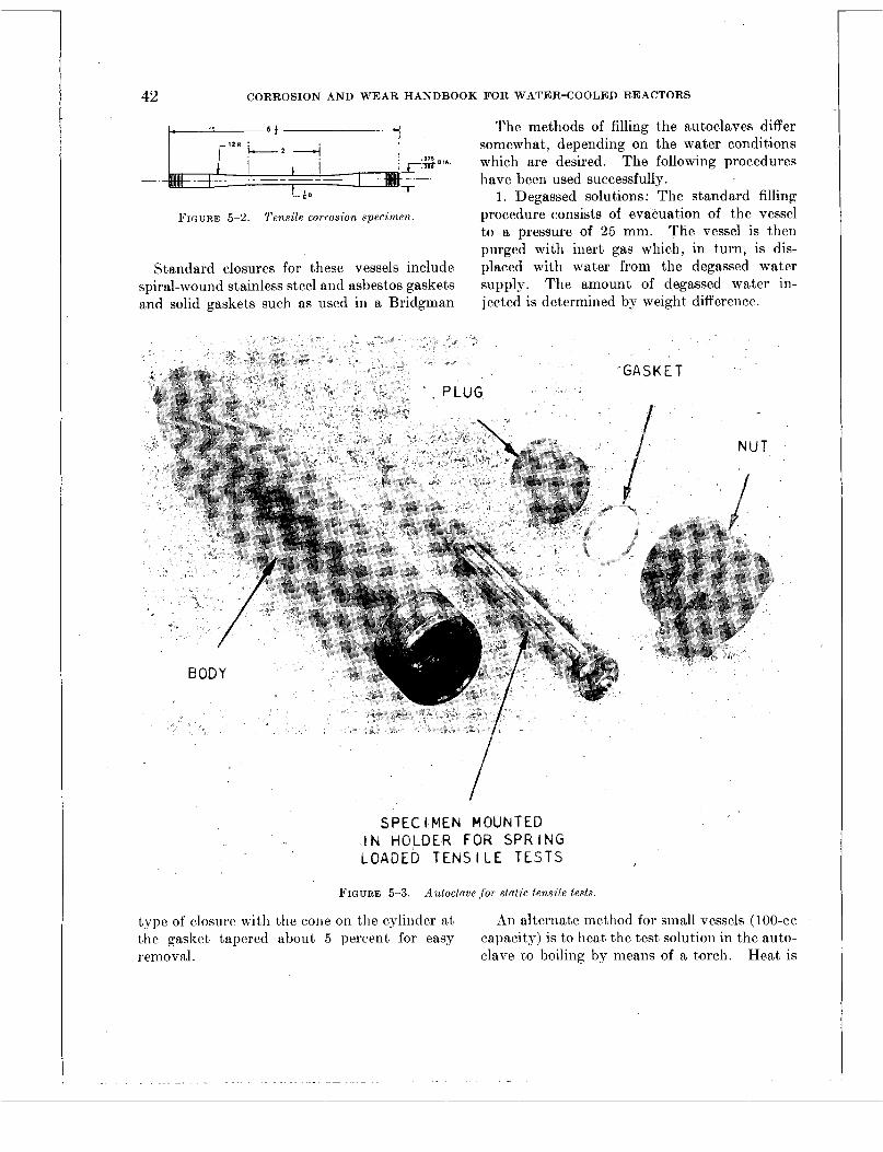
42 CORROSION AND WEAR HANDBOOK FOR WATER-COOLED REACTORS
The methods of filling the autoclaves differ somewhat, depending on the water conditions
0 t h which are desired. The following procedures have been used successfully.
1. Degassed solutions: The standard filling procedure consists of evacuation of the vessel to a pressure of 25 mm. The vessel is then purged with inert gas which, in turn, is dis- placed with water from the degassed water supply. The amount of degassed water in- jected is determined by weight difference.
FICI7RE 5-2 Tenszle corroszon speczmen
Standard closures for these vessels include spiral-wound stainless steel and asbestos gaskets and solid gaskets such as used in a Bridgman
SPEC I MEN M O U N T E ~ IN HOLDER FOR SPRING LOADED TENSILE TESTS
FIGURE 5-3. Autoclave f o r slatzc tenszle tests
type of closure with the cone on the cylinder at t h e gasket tapered about 5 percent for easy removal.
An alternate method for small vessels (loo-cc capacity) is to heat the test solution in the auto- clave 60 boiling by mcans of a torch. Heat is

DESCRIPTION O F TESTING PROCEDURES 43
maintained for several minut.es t'o degas t,he solution. A 50-cc sample of solut,ion is wit.11- drawn with a vacuum bulb for t,he pH and
is then sealed and placed in the furnace. 2. Deaerated solut,ion plus gas dissolved The pressure vessels heat,ed in t'he batch
under 1 atm of partial pressure: For this type. ovens are prot.ect,ed by rupture disk safety of experiment a modified sealing plug cont8a.ining devices. These t,hin diaphragms fail safcly, a gas inlet tube is used. c,ausing the vessel t80 lose it,s wakr content
admit,t,ed t,hrough t,he inlet pipe, at, t'he desired pressure, by means of a regulating valve.
conductivity measurement's. The a.ut,oclavc INSTRUMENTATION A K D SAFETY DEVICES
The vessel is filled t.0
I I -
GASKET
FIGURE 5-4. Autoclave for static tests.
the desired level with degassed water as above, and then the gaseous additive is bubbled through the water. An atmosphere of t,he gas is obtained above the water. The pressure is adjusted by venting to atmosphere. When sealed, the vessel is ready for test.
3. Deaerated solutions plus gas dissolved under partial pressure greater than 1 atm: For this type of experiment the sealing plug and inlet pipe described in procedure (2) is used. The vessel is filled to the desired level with degassed water. The additive gas is then
before a buildup of pressure can cause damage to the vessel. The vessels heated in individual jackets are also protected by rupture disks. In this application the escaping steam can be directed on the spoon-shaped arm of a pressure switch. The steam striking the switch cuts off the power source, and the heaters auto- matically cut out. Each individual vessel is also equipped with a pressure gage and a temperature controller-recorder so that the attending personnel can keep a log of test operations.

44 CORROSION AND WEAR HANDBOOK FOR WATER-COOLED REACTORS
Semistatic Systems
Autoclaves are not confined in application to static systems. They are the principal ele- ments of the semistatic (low flow) system. Here the velocity is limited to the minimum velocity that will ensure the maintenance of specified water composition.
The general-purpose semistatic test system
loop by blocking valves and can be operated as a static fluid system with a test medium completely foreign. to the remainder of the system. In this latter application the external drive may be used a t the discretion of the experimenter.
A schematic diagram of a typical general- purpose test loop, instrumented to deliver demineralized-oxygenated water is shown in
FIGURE 5-5. Semistatic test system.
is a closed loop that is outstanding because of its versatility. One such loop is shown in figure 5-5. Each autoclave installed in this system is provided with a mechanical drive to impart rotary motion to components within the vessel.
By disengaging or not operating the external drive mechanism, the test can be run with low flow (to maintain specified water chemistry) and no motion of the test piece. In addition, any vessel in the loop can be isolated from the
figure 5-6. The system may be modified to operate as a degassed system by directing the flow from the demineralized water storage tank, through a degassing tower, and then to the main loop pump.
A similar system to circulate hydrogenated water would require degassed water to be de- livered to a hydrogen absorber and then to the loop through the main loop pump. The gen- eral-purpose loop is designed to permit rapid

DESCRIPTION O F TESTING PROCEDURES 45
FIGURE 5-6 Schematzc dzagram of a general purpose test loop
changeover. However, care should be exer- cised, upon any change, to be certain that all lines are properly purged of any previously used gases or additives that might conflict in any way with the new conditions. This is particularly important where there is anj- danger of different gases reaching explosive-mixture proportions.
As shown in figure 5-6, city water is taken into the system and purified in a mixed-bed cation- anion exchange demineralizer. Oxygen is added to the water at the heater absorber, and the fluid is then pumped to the test chambers under pressure. Strip heaters raise the water tem- perature to the specified level prior to admission to the autoclave. Trim heaters fixed to the autoclave wall maintain a constant tempera- ture in the vessel. A back-pressure regulating valve maintains the system pressure a t all times. The discharged water from the test chambcr is then cooled, directed through filters, and then returned to the demineralizer for recirculation in the system. Once the system has been in usc, the only additional city water required is that necessary to compensate for leakage and sampling.
Draley has employed a different arrange- ment for the corrosion testing of aluminum in
TO D R A I N
I N E R T I I k
A U T O C L A V E
S P E C I M E N S
P R E H E A T EA 17' L P U M P
FIGURE 5-7. Schematzc diagram of $ow t ype autoclave test.
autoclaves. This arrangement, as shown sche- matically in figure 5-7,.provides for a continuous control of the corrosion environment.
The water conditions are,maintained by using a plunger,type pressurizing ',pump which feeds the- water through a preheater into the auto- clave.near the bottom. The fluid leaves the top of the autoclave, passes through a cooler, and then' through a relief valve. The small flow of liquid (10 to 15 cc/min) is thus dis- chafged while the valve maintains the desircd pressure in the system. The autoclave can be heated to any desired temperature below the saturation temperature for the pressure used. Gaseous additions are made upstream of the pump by pressurizing the gas space above water in a storage tank with the desired partial pres- sure of the additive gas.
46 CORROSION AND WEAR HANDBOOK FOR WATER-COOLED REACTORS
INSTRUMENTATION AND SAFETY DEVICES
Semistatic test circuits of the general- purpose type have the necessary instrumenta- tion to measure and control temperature, pressure, flow, and other variables of special interest. The instruments used are available commercially and are standard for high- temperature, high-pressure fluid systems. In addition to the automatic control instruments, pen recording devices are used to provide a log of temperature in the autoclaves and differential pressure across a calibrated orifice (flow re- corder).
Vessel heaters are arranged so that only a portion of the heat source is under automatic control to permit a smaller gradient in the ap- proach and control of the desired temperature. Temperatures have been held within 3 O F of the desired temperature by this method. Other instrumentation is commercially available to obtain control within 1 percent of full-scale deflection.
Circuit pressure is controlled by a pressure recorder-controller which actuates the heaters in the pressurizing boiler. At 2,000 psi the pressure is held within 50 psi of the desired setting.
Indicators of various kinds are used to de- termine the water level in the pressurizing boiler. Glass water gages have been used, but the difficulty from silica dissolving in the water generally prevents their use in corrosion test work. Therefore remote indicating differential pressure gages are commonly used to indicate water level ranges, on the order of 6 in. in pressurizing boilers.
Water flow is measured by the pressure drop across orifices or flow-type meters. The pres- sure drop across the meter is impressed on a differential pressure transmitter, and the output is recorded on a continuous chart.
Flow can be controlled either manually or automatically. Manual control is achieved by positioning the valve either in series with the test circuit or in the bypass line between inlet and outlet of the pump. Automatic control is obtained with either pneumatic or motor- operated valves.
SAFETY DEVICES
In addition to the equipment necessary to record data and control the operation of the test apparatus, good practice calls for the use of safety devices. The switches and interlocks used to shut down the system under various unsafe circumstances are listed below.
Safety devices include such items as pressure switches, temperature limit switches, safety valves, and/or rupture disks. Some of these devices are discussed below, with a brief ex- planation of their role in the system.
1. Pilot-operated switches for an under- pressue or an overpressure of about 150 psi: An underpressure shutoff is necessary to prevent steam generation which could affect corrosion data, increase pressure drop, and cause cavita- tion in the pumps.
2. Pilot-operated switches for an excessive drop in water flow: A drop in flow through the part of the circuit around which the heaters are wrapped or in which immersion heaters are located could cause local overheating.
3. Temperature limit switch to detect over- heating of such circuits.
4. Temperature limit switch for detection of overheating in the pressurizing boiler wall.
5. Pilot-operated switches for detection of reduced cooling oil flow through the main pump windings.
6. Safety valve and/or rupture disks in ex- haust lines as a final precaution against buildup of excessive steam pressure.
Dynamic Systems
The semistatic loops just described provide environmental control but were lacking in one variable required to give a more realistic duplication of reactor operating conditions. This additional variable is high velocity. It was the dynamic loop which became the workhorse in the latter stages of tlie corrosion programs.
D ESCRI PTIO N
Dynamic test systems operate above tlie saturation pressure for the test temperature in

DESCRIPTION OF TESTING PROCEDURES 47
order to avoid a phase change and t,he effects of boiling and water levels on specimens.
These systems include thermal difference \/"" (natural circulation) loops and pump circula-
tion loops.
B A I R BLOWER
PRESSURE INDICATOR 1 1 - - I
- I" xx nvr. PIPE I I I : I *
1 D I F F E R E N T I A L
I N D I C A T O R
S A M P L I N G AND I O N
E X C H A N G E R CONNECTIONS
I
PRESSURE
Y L
- - TO RUPTURE
D I S C
TEMPERATURE INDICATOR ' I U T
I T I M CONTROLLER M E R S l 6 N H E A T E R
FIGURE 5-8. Schematic diagram of natirral-circiilation circtrit.
Circulation in the thermal difference loop shown in figure 5-8 is obtained by tlie density differences in the downcomer and riser legs provided by a heater in the bottom location and a cooler at the top. In order to add and maintain gases in Lhe water, no boiling is permitted, and the density difference of the two legs at 750' and 700' F results in relatively low ,velocities. Placing the specimens in a venturi flow section provides higher velocities past the specimens and still recovers some of the pressure loss. This circuit has been oper- ated a t a pressure of 3,500 psi.
Pump circulated test units are designed and and built in accordance with the ASME codes. Design pressure is usually 2,000 psi or 2,500 psi for most of the test work performed a t tempera-
tures up to 600' F. Most of the test equipment now in use is built of AIS1 type 347 stainless steel. However, interest in carbon steel and other low-alloy materials has led to the con- struction of a number of carbon steel test
FIGURE 5-9. Schematic diagram of forced-circulation circuit,
circuit.s. Water velocities past specimens in some loops of this type can be as great as 60 ft/sec, although most data were obtained a t 30 ft/sec.
A typical forced-circulation test circuit is shown in figures 5-9 and 5-10. The unit shown is representative, but similar systems differ in size, capacity, number of specimens which can be tested simultaneously, and the types of auxiliaries used.
This circuit is one in which water is main- tained in forced circulation by a pump and is electrically heated to a desired test temperature. Pressure is maintained above saturation pres- sure for the test temperature by a separate small electric boiler. In most apparatus of this nature the circulating pumps are of the canned rotor design in which the bearings are sub- merge,d in the wat,er being circulated. This makes unnecessary any externa1,packing glands which could contaminate the water within the system. Pumps having a capacity of 30 gal/ min are satisfactory in most cases, although larger test circuits for studying corrosion related to heat transfer and other work have used pumps with capacities up to 150 gal/min.
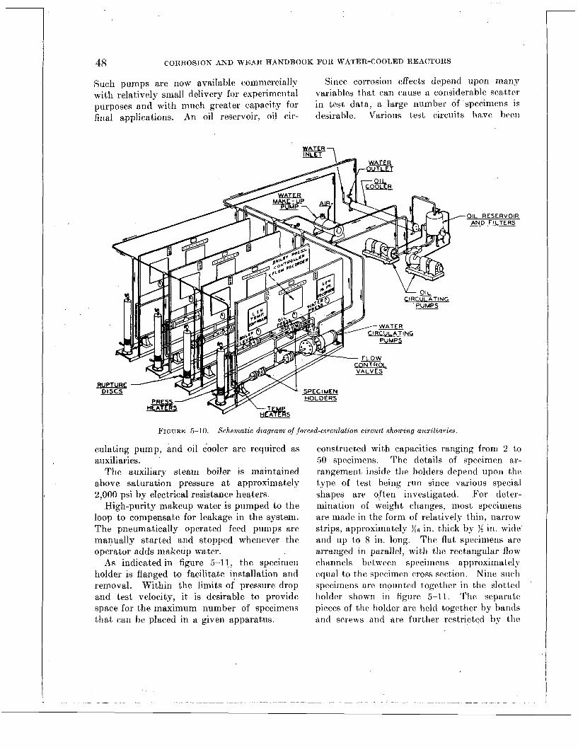
48 CORROSION AND WEAR HANDBOOK FOR WATER-COOLED REACTORS
Such pumps are now available commercially Since corrosion effects depend upon many with relatively small delivery for experimental variables t,hat can cause a considerable scatter purposes and with much greater capacity for in test data, a large number of specimens is final applications. An oil reservoir, oil cir- desirable. Various test circuits trave been
OIL RESERVOIR AND FILTERS
FIGURE 5-10. Schematic d iagram of forced-circulation circuit showing auxiliaries.
culating pump, and oil cooler are required as auxiliaries.
The auxiliary steam boiler is maintained above saturation pressure a t approximately 2,000 psi by electrical resistance heaters.
High-purity makeup water is pumped to the loop to compensate for leakage in the system. The pneumatically operated feed pumps are manually started and stopped whenever the operator adds makeup water.
As indicated in figure 5-1 1, the specimen holder is flanged to facilitate installation and removal. Within the limits of pressure drop and test velocity, it is desirable to provide space for t>he maximum number of specimens that can be placed in a given apparatjus.
constructed with capacities ranging from 2 to 50 specimens. The details of specimen ar- rangement inside the holders depend upon tIhc type of test being run since various special shapes are often investigated. For deter- mination of weight changes, most specimens are made in the form of rclatively thin, narrow strips, approximately in. thick by $4 in. wide and up to 8 in. long. The flat specimens are arranged i n parallel, with the rectangular flow channels bctween specimens approximatel>- equal to the specimen cross scction. Nine such spccimcns are motrn td togetlicr in the slotted holder shown i n figiirc 5-11. The separat,c pieces of the holder are held together by bands and scrpws arid are further restricted bp the

DESCRIPTION O F TESTING PROCEDURES 49
FIGURE 5-1 1. Dynamic corrosion specimen holder.

50 CORROSION AND WEAR HANDBOOK FOR WATER-COOLED REACTORS
outer flanged holder which forms part of the test circuit. I n some cases these specimens are made to resemble tensile specimens. These arr asscniblecl as shown in figure 5-12 with washers
FIGURE 5-12. Corrosion specimens and holder.
and screws; insulating spacers are sometimes used in special investigations.
Channel-shaped specimens can also be used, as shown in figiirc 5-13,
S P A C E R S 1 ~ 7 2. CHANNEL SPECIMEN / 1 \ \ _rRETENTION PLATE
R'IULTICHANNEL ARRANGEMENTS
The evaluation of the corrosion resistance of a particular material or the suitability of a wa.trr treatment may be expedited if a number of t h e operating variables can be studied in one
test. Such a system is shown in figure 5-14; here a relatively large number of flow channels is installed on a single loop. I n this multi- channel system such conditions as water velocity, thermal cycling, and, to some extent, temperature may be investigated in one test.
The principal advantage of this system is that all the specimens are subjected simul- taneously to water of the same chemistry, a condition that cannot be assured if separate tests are run for each of the variables.
The large number of specimens that may be included in any single test tends to yield uniform data and to effect a significant economy of testing.
The multichannel loop, shown in figures 5-14 and 5-15, consists of a hrader to which twelve separate channels are connected. These chan- nels have been used for various operating conditions, such as velocity, temperature. and thermal cycling.
Test water is circulated by a canned-rotor water pump. Provisions have also been made for the addition of ion exchangers, filters, and other test auxiliaries as required. Flow and temperature can be measured and controlled individually in eacki separate channel. Speci- mens can be removed from individual channels while the remainder of the equipment continues in operation.
The arrangernent of valves permits immedi- ate admission of water, a t test conditions, to specimen holders; i t also permits immediate shut off and removal of such specimens. Cor- rosion tests a t high temperature and pressure thus can be run for short time intervals of 1 hr. or less.
Another modification of the dynamic test loop is shown in figure 5-16. The advantage of this loop, as with the multichannel loop, is that specimens can be exposed to the same environment but a t two different velocities. The dual-velocity test loop, figure 5-16, is a forced-circulation system.
INSTRUMENTATION AND SbFETY DEVICES The controlling and recording instruments re-
quired for the dynamic test loops are essentially

DESCRIPTION O F TESTING PROCEDURES 51
the same as those described for t,he semistatic The system is checked for leaktightness by systems. The same elements are controlled in meaiis of the hydrostatic test. Here the sys- both systems-e. g., pressure, temperature, and tem is filled with water and pressurized a t
FIGURE 5-14. Schematic diagram of multichannel corrosion circuit.
rate of flow. The safety devices are also sim- ilar. Since no additional control or safety problems are involved in the dyna.mic loops, the reader is referred to the descript*ion of t.hdse devices given for semistatic systems.
TEST OPERATION
Startup: New Loops
I n starting up a new loop, the experimenter is faced with three problems t4hat must be re- solved satisfactorily before testing can proceed :
(2) Pre- conditioning: The initial high corrosion rates in a new stainless steel system can seriouslj- affect corrosion test results. (3) Cleanliness : Have all contaminants, such as weld particles, weld slag, lubricants, and abrasive particles, been removed from the system?
(1) Safety: Is the system leaktight?
room tempera.t,ure. The ASME Boiler Code for Unfired Pressure Vessels is used for deter- mining the hylrostatic test pressure.
Aft,er the syst,em has passed t,he hydrostatic leak test satisfactorily, i t is filled with deionized water a.nd operated a t temperature for approx- imately 1 week. During.t,his interval the ex- posed surfaces of the stainless-steel system are corroded, and the corrosion products, carried off in the flowing stream, are collected in filt,ers or in t.he resins of the deionizer. At t,he con- clusion of this preliminary hot run, the system has become c.ondit.ioned to the extent that a protective oxide film is formed.
The third fa.ct’or, Fleanliness, is achieved by first cleaning the system components prior to assembly ns indicated in Chaptler 14, “Manu- facturing Procedures Affecting Corrosion and Wear,” arid t.hen filtering any assembly protl- ucts from t,he system. During the 1-week

52 CORROSION AND WEAR HANDBOOK FOR WATER-COOLED REACTORS ’
FIGURE 5-15. Multichannel corrosion circuit.
run-in period, a t temperature, 100-mesh screens are inserted at various points in the loop to trap out foreign particles.
Startup: Existing Loops
When a loop that has been previously operated is started up, the following procedure is normally observed. Specimens are installed in the system. The system is evacuated, purged twice with inert gas, arid the final purge gas is displaced by deionized, degassed water which fills the system. The tightness of all joints is checked by hydrostatic cold leak test. If the system is leak-free, the heat can be ap- plied, and the test can proceed. Should leak-
age be detected, it becomes necessary to drain the system, repair the fault, and repeat the filling cycle.
As heat is applied, the system water expands and the excess is bled off. Tf a pressurizer tank is used, some of the excess water can be at- tributed to the steam head a t the top of the pressurizer.
The actual startup of semistatic and dynamic systems is governed by the safety devices pre- viously described. For the loop shown in figure 5-14, the following sequence has been estab- lished :
1. Water treatment chemicals or gases are added.

DESCRIPTION O F TESTING PROCEDURES 53
ORIF ICE
FIGURE 5-16. Schenialic arranyenient of dual-velocity test loop.
2 . The pressurizing unit is brought up to operating conditions, after which the over- and under-pressure cutouts are set.
3 . Cooling oil flow is establislied. 4. The main pumps are started, and the
desired waterflow is establislied through the various portions of the circuit.
5 . This waterflow then allows tlie main heaters to be -energized so that t4he water temperature may be raised to the operating level. Otliei. loops h n r c hccn started up in ac-
cordance with the following alteriiate procedure : After tlic test sections arc installed, tlie loop is
purged, vented, and filled with high-purity deaerated water. Circulation of the system water is then started. During the startup period, which lasts about 8 lir, the s.vstem water is circulated a t reduced temperature arid pres- sure (200' F and 500 psi). One of the following methods is usual1)- used for reduction of tlic oxygen concentrat.ion in the system water. (1) The surge tank may be operated as a de- gasifier, or ( 2 ) chemical oxygen scavengers may be added to tlie system water. 13-drazinc. has bccn used for this purpose. During tlic startup period h j dradic injections of the necessary clicmicnls into the. system n-ntcr provide tlie

54 CORROSION AND WEAR HANDBOOK FOR WATER-COOLED REACTORS
AIR COOLED I I CONTIMUOUS BLEED CON-
5s QAL DRUM
3 4 7 ss * OUOLlTE
5-10 OXVQEN AOSORBENT
R E S I N BE0 4-10 x 60'
I FIGURE 5-17. Diagram of water purijication system.
I
FEE0 PUMPS t l c .
1
AYBERLITE
M I X E D STRONQ ACID STRONQ BASE
E X C H a N Q E R E S I N BED .' I O x 60'
desired water condition for the test. When hydrogen is the only addition, the purification system demineralizer is operated to raise the resistivity of the water to the desired level. When the oxygen concentration has been re- duced below about 0.14 ppm, the loop water temperature and pressure are gradually raised to the operating level.
Feedwater Purification System
A flow sheet of a purified water feed and makeup system is shown in figure 5-17. Several analyses of municipal water entering the dis- tilling units gave:
pH-_- _ _ _ _ _ _ _ _ _ ~ _ _ _ _ _ _ _ _ ~ _ _ _ _ ~~ 9.5 to 10 C1, ppm .__.___________._ ~ _.___ ~ 13 to 62 Total solidfi, ppm-- _ _ -. - -~ - - - - - 80 to 520 Ca, ppm_- _ _ - - -~ ~- - _ _ ~ -. - - ~ - - _ _ 65 to 400 M g , p p r n . _ ~ _ _ . _ ~ - . _ ~ ~ - - - - - - - - - 2 5 t o 150 Resistivity, ohm-cm.-. ~- __. ~ - - - - 1,000
The water leaving the system contained less than 0.5 ppm total solids arid about 0.02 pprn total iron. ,
.Such commercially avaiIable distilling units are rated a t less than 1 ppm total solids when sea water is used as feed. The actual output, has not been analyzed chemica.lly, but the effluent from the Duolitme S-10 column in a representa- tive sea water sample had a p H of 6.4, a resis- tivity of 128,000 ohm-cm, arid a total solids content of about 0.71 ppm. About 20 percent of this solids cont,ent was lost on ignition a t 1,475' F.
The bottom effluent of the boiler-condenser deaerating unit contained about 0.2 cc of oxygen per liter. This was reduced to less than 0.01 cc of oxygen per liter of water by the deoxygenat- ing resin. The oxygen level increased if water was withdrawn a t a rate of more than 40 gal per day.
The resistivity of the water from the deioniz- ing resin was between 1,OOO,OO0 and 10,000,000 ohm-cm. The lower values were obtained if the water remained in the stainless feed lines; the resistivity increased as this water was replaced. Measurements of pH gave values between 6.1 and 7.2, but these values were not related to the resistivity readings. This water contained less than 0.01 cc of oxygen per liter after the first few days operation. During this initial period the oxygen content was about 0.02 cc per liter, owing to residual oxygen trapped in the bed.
Water Analysis
I n order to control the water and gas condi- tions in the dynamic test circuits used in corrosion studies, satisfactory methods must be used for determining the total volume of oxygen, hydrogen, and nitrogen in two-phase gas-water samples on a routine control schedule. This involves the quantitative transfer of the sample from its stainless-steel container to a volume measuring device and its subsequent transfer to a micro gas analyzer for the determination of
.
DESCRIPTION O F TESTING PROCEDURES 55
oxygen, hydrogen, and nitrogen. Techniques developed for these determinations are suffi- ciently simple and rugged for operation by technicians after a short period of training.
Water samples are taken from the corrosion loop in stainless steel containers through which some of the high-pressure hot water is bypassed during intervals of the test. The Toepler pumping principle (mercury displacement) is utilized to transfer the sample from its container to a measuring burette, where the relative volumes of water and undissolved gases are determined. A portion of the gas is then transferred to a modified Blacet-Leighton apparatus, which is integrated with the measur- ing burette. There the gas is analyzed for oxygen and hydrogen. Nitrogen is determined by difference.
The total volume of each of these gases is then determined on the basis of gas solubilities by using the gas analysis to calculate the quan- tity of each gas dissolved in the water.
In cases where there is insufficient free gas for analysis by the Blacet-Leighton technique, a sample of the water can be withdrawn from the measuring burette into a 50-ml McLean type dissolved oxygen flask, with the usual precau- tions against air contamination. With the use of ASTM referee method D-888 ,which has been modified for the use of 50-ml samples, the dissolved oxygen content of the water is then determined by using a dead-stop apparatus to detect the end point of the t i t r a t i ~ n . ~ Addi- tional details of gas analysis, where the water included carbon monoxide and carbon dioxide, have been r e p ~ r t e d . ~
TKBLE 5-1. WATER ANALYSIS
.4STM Determimiloit Procedure mclhod
Total i ron____ Colorimetric, orthophenan- D-1068
Phosphate- -i Colorimetric, reduced phos- - _ _ _ _ _ _ -
Ammonia- - - - - - - - - - -
Chorides _ _ _ _ _ _ _ _ _ _ _ _ _ _ _ _ _ _ _ _ _ _ _ _ _ _ _ _ _ D-512 Solids- -. - - - - - - _ _ - _ _ -
A water portion of the sample is withdrawn from the measuring burette for the determina-
. throline method.
pho-molybdate method. Colorimetric, sample treat-
' ed with Nessler's reagent.
By evaporation- - - - - - _ _ -
417017 0-57-5
tion of iron, phosphate, ammonia, chloride, and total solids. The methods used are shown in table 5-1.
A recent improvement in the iron determina- tion is to minimize contamination by using zirconium tubing for cooling and withdrawing water samples.
Additives to Test Water
When a gaseous or other additive is specified, a sample bomb containing a predetermined amount of the additive is connected to the circuit, and the gas or liquid in the bomb is flushed into the circuit with loop water. This procedure is used a t room temperature and at the elevated temperature to add gas content as desired.
For those tests whose conditions require the use of an ion exchanger, water is continuously bypassed a t about 0.04 gal/min through a column of mixed-bed ion-exchange resin, e. g., Amberlite MB1. Samples of the effluent water are checked for conductivity.
Continuous additions of chemicals for p H control can be made by using ion-exchange resins which release such cations as lithium and ammonia into solution while removing other impurities. Recharging methods have been developed for commercially available resins.
PROCEDURES FOR GENERAL CORROSION TESTING
Each of the several test devices described above includes provisions for a large number of specimens when data on general corrosion are to be obtained. The strip specimen shown in figures 5-11 and 5-12, are the most widely used for dynamic testing. These specimens are usually ){6 in. thick by )$ in. wide and as much as 8 in. long.
The history of each test specimen is followed carefully from the procurement of material through any metallurgical heat treatment, fabrication, testing, and measurement to final evaluation. Records of chemical composition and procedures of sample preparation and

56 CORROSION AND WEAR HANDBOOK FOR WATER-COOLED REACTORS
testing are invaluable in the interpretation of any unexpected general results or local corrosion effects.
Specimen Preparation
All phases of the preparation of corrosion specimens are carefully controlled, particularly shop practice and surface finish. Surface finish is discussed in chapter 14, “RIIanufactur- ing Procedures Affecting Corrosion and Wear.” A brief description of specimen handling pro- cedures follows.
Uniformity of surface finish is essential to precise corrosion testing. Specimens with poor surface finish and such irregularities as tool marks can usually be improved and made more uniform by polishing treatment on a belt sander (325 grit). Hand rubbing with abrasive cloths provides still smoother surfaces.
Prior to testing, each specimen is marked for future identification, degreased in methyl alco- hol or carbon tetrachloride, and washed with soap and water. Further surface treatment sometimes includes a Ij-sec dip in 5 percent hydrofluoric acid solution, followed by a hot distilled water rinse and an alcohol rinse. Specimens are dried, weighed, and kept in a desiccator until they are placed in the’corrosion circuit for testing .
All materials are not prepared for testing in the same manner. In addition, variations in preparatory treatments are often necessary for specimens with surface platings, .metallurgical case treatment, or other surface films. For example, nitrided specimens with thin cases cannot be rough sanded; marking, as by stamp- ing, may not be permissible for specimens with brittle surfaces.
Specimen Removal and Examination
Specimens removed from test are either brushed with a soft camel’s-hair brush or washed with soap and water to remove loose foreign particles; they are then dried either. in ovens a t about 220’ F or in desiccators at room temper- ature. The amount of corrosion product rc-
moved by brushing and drjing is highly significant for such materials which form thick, loose scale. Therefore, these materials are best evaluat&l after descaling.
The dried (or descaled) specimens are weighed and examined visually, and all pertinent information is recorded. Observations include visual appearance, weight changes, study of corrosion products, and metallographic exam- ination.
The binocular microscope has proved to be a valuable aid in making detailed observations of the corrosion oxide fiim. Metallographic examination is used for more thorough study of corrosion phenomena and general oxide compo- sition and adherence. X-ray diffraction is of value in the study of corrosion products and often affords a better insight into corrosion phenomena.
It is often necessary to obtain data pn the mechanical propert,ies of a material before and after exposure to the corrodent in order to determine the effects of exposure. The type of information required in such a case is governed by the ultimate application.
Weighing
Weighings should be made on an analytical balance. The sensitivity of the balance should be checked prior to each set of weighings to insure good working condition. The accuracy and precision of weighing cannot be over- emphasized.
For example, tolerances in weight could represent a considerable error in 18-8 stainless steels where overall corrosion is relatively low. This particular error can be reduced by cali- brating weights at each set of weighings and by conducting weighings under standardized con- ditions of temperature and humidity.
Handling of specimens should be kept to a minimum to insure the least amount of change to the sample; that is, the use of instruments, gloves, or fingers in handling should be governed by the quality of results desired, the amount of corrosion being measured, and the sensitivity required.

DESCRIPTION OF TESTING PROCEDURES 57
In evaluating corrosion data, visual and/or microscopic examination should accompany weight change data. Weight changes may be reported, as inches penetration per year or milligrams per square decimeter. Whether the rate or the absolute figure is given, i t represents a mean corrosion value and may not be indica- tive of local metal losses due to pitting or other forms of localized corrosion.
Descaling and Corrosion Products
For highly corrosion resistant materials reli- able evaluations can be made for a particular environment on the basis of weight changes alone. However, the relatively thick adherent corrosion scalc which is encountered in evalu- ating many materials, particularly carbon steels, makes i t desirable to descale such speci- mens. The adherent scale makos i t impossible to determine the amount of metal involved in the corrosion process by gross weight change. For example, two similar specimens, one from a hydrogenated and the other from a low oxy,reii test, may sometimes be reported as showing identical weight changes although the specimen from the oxygen loop may retain considerable oxide films. However, a comparison of these specimens after removal of their respective films might reveal a considerable difference in the net weight change. For this reason pro- cedures to remove such remaining oxide films are recommended, especially when observing materials that form heavy oxide scales. The appearance of corrosion specimens before and after descaling is shown in figures 5-18 and 5-19.
Descaling procedures require a control speci- men so that any weight change. due to the descaling proccdure will be evaluated when final corrosion results are calculated. Since usual descaling processes arc cathodic treat- ments of specimens in inhibited acid solutions with insoluble anodes, the time of specimen immersion in the acid solution should be kept to a minimum. After being descaled, the speci- men is immersed in a neutralizing bath and then dried. After bcing weighed, thc descaled specimens should be reexamined visually.
’
. . .., . . . . ” > ., .
II ?
. . , >._ . .. _ 1 . . .
FIGURE 5-18. Corrosion specimens after removal f r o m test.
FIGURE 5-19. Corroszon speczniens after descalzng
Some combinations of materials and test conditions exist for which descaling procedures are inadequate.6 In general, th? descaled data includecl in this handbook have been obtained from electrolytic descaling procedures. The specimens are made cathodes in a solution con- taining 5 percent sulfuric acid by weight (2): percent acid for carbon steels and up to 5 per- cent for chromium alloys). The solution also contains 1 g. of quinoline ethiodidc per liter. Platinum or pure lead is used as an anode in combination wit.h the specimen as a cathode. A voltage sufficient to cause a current density of 1 amp. per square inch of specimen is used. The time necessary for complete scale removal is recorded so that a blank correction can be made if necessary. When a blank is being run for correction purposes, a clean specimen is exposed to the descaling bath for the same amount of time as the descaled specimen. Thus, the amount of scale removed, corrected if necessary for blank losses, gives additional data to be used with gross weight changes.
Immersion in Clarke’s solution ’ is probably the most readilS used of the descaling pro- cedures. Clarke’s solution will descale carbon and low alloy steels with a small blank correc-

58 CORROSION AND WEAR HANDBOOK FOR WATER-COOLED REACTORS
tion, but will not descale many of the other materials tested.
The widest variety of materials are descaled by the sodium hydride bath.8 However, the high temperature (370' F) of this caustic bath makes it somewhat more difficult to use and less desirable than the others. In addition, the high-temperature liquid presents a hazard to operating personnel. The sodium hydride method is recommended only where other, safer methods are not applicable.
, The following procedure is followed in deter- mining corrosion rates of descaled and unde- scaled specimens.
Undescaled corrosion rate (milligrams per square decimeter per month)=R,
A-B 720 R , = D X E
Descaled corrosion rate (milligrams per square decimeter per month)=Rd
where A=original weight in milligrams B=weight after exposure, before descal-
C=weight after exposure and descaling,
D=specimen surface area in square
E=duration of exposure in hours
ing, in milligrams
in milligrams
decimeters
Often i t is important to calculate the rate a t which the corrosion products are entering the water. Since the corrosion products formed under primary system operating conditions are composed largely of magnetite (Fe304), a con- version factor of 1.4 can be used to relate the weight of iron entering the corrosion reaction to the weight of corrosion poducts (oxides) formed. The quantity of oxide entering the water is the total oxide formed minus the oxide scale adhering to the specimen.
Metal Lost to Water
Analyses have been made for soluble corro- sion products, but present analytical procedures are somewhat inadequate when these water samples include iron not only in suspension but also in solution. Cycling of temperature and pressure and even sampling procedures can in- crease iron content by dislodging oxides from loop surfaces. On the other hand, iron com- pounds deposited on surfaces of the sampling apparatus will reduce iron in the analysis. The size of the water sample that can be with- drawn from test circuits during operation is small and is a distinct disadvantage. By draining the entire water from a corrosion test apparatus and evaporating to dryness, i t may be possible to obtain somewhat more reliable result^.^ lo
Microscopic Examination
For microscopic examination, a plane is pre- pared perpendicular to the exposed surface of a corrosion test piece in order to measure the actual depth of penetration and to observe the nature of the attack. Descaling is omitted, and care must be taken not to dislodge scale and corrosion products from the surface.
Specimens with curved exposed surfaces, such as tubing, are mounted in plastic. Specimens with flat exposed surfaces, such as sheet or plate, usually are mounted with inserts of silver foil in a supporting metal clamp, the composite sample being polished. This method has the advantage that several flat test specimens may be prepared simultaneously in a single assembly. An additional advantage is the preservation of very sharp, level edges for examination a t high magnification. Such an edge cannot be ob- tained with a plastic mount.
Silver foil inserted between flat test speci- mens flows enough under clamping pressure to fill in small surface irregularities on the exposed test surface. Thus the space between test specimens is completely closed by silver foil, which prevents the seepage of washing and

DESCRIPTION O F TESTING PROCEDURES 59
etching reagents to the prepared surface after the specimen has been dried in the usual man-
tact between the foil and the specimen surface. The inside curved surface of small diameter
_.
+Silver foil
+Layer of oxide
+Zirconium sheet
! I
r .I +Silver foil
Deposit from test system, consisting primarily of spongy magnetic iron oxide
+Zirconium tubing, inner wall
+Gray layer is oxide. Also intergranular oxidation
+Type 304 stainless sheet
FIGURE 5-20. Photomicrographs of specimens. ( a ) S imp le ozidatzon 0.f zirconzum (1000 X). ( b ) Corrosion deposit, (c) Intergran~alar attact and surface oxidatzon of also oxide inlets in zzrconiurn tuhzng, cf zn. 0. D . (500 X).
304 staznless steel (250 X).
ner. Curved surfaces also have been wrapped with silver foil prior to mounting in plastic, but it is often difficult to obtain intimate con-
tubing has been satisfactorily prepared by two methods.
1. The tubing is split lengthwise, and foil
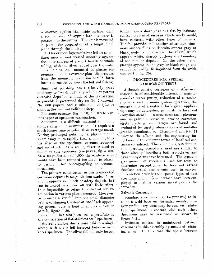
60 CORROSION AND WEAR HANDBOOK FOR WATER-COOLED REACTORS
is inserted against the inside surface; then a rod or wire of appropriate diameter is pressed into the tubing. The unit is mounted in plastic for preparation of a longitudinal plane through the tubing.
2. One or more layers of silver foil are some- times inserted and pressed smoothly against the inner surface of a short length of whole tubing, with the silver lapped over the ends. This unit is then mounted in plastic for preparation of a transverse plan ; the pressure from the mounting operation should force intimate contact between the foil and tubing. Since wet polishing has a relatively great
tendency to "wash out" any soluble or porous corrosion deposits, as much of the preparation as possible is performed dry on No. 2 through No. 000 papers, and a minimum of time is spent in the final wet polishing steps.
Photomicrographs (fig. 5-20) illustrate var- ious types of specimen examination.
Zirconium is a difficult material to mount for metallographic examination. J t 4requires a much longer time to polish than average metal. During prolonged polishing, a plastic mount wears away more rapidly than zirconium; thus the edge of the specimen becomes rounded and indistinct. As a result, silver is used to minimize this tendency (see part a, fig. 5-20). At a magnification of 1,000 the oxidized edge would have been rounded too much in .plastic to permit either photographing or' accurate measuring.
The primary constitutent in this transported corrosion deposit is magnetic iron oxide. Visu- ally, i t appears as a black powdery deposit that can be flaked or rubbed off with little effort. It is impossible to retain this deposit for ex- amination in various plastic mounts. However, by pressing silver foil into the small diameter tubing containing the deposit, the black-appear- ing porous layer is kept intact, as shown in part b, figure 5-20.
Silver foil has also been used successfully in the preparation of flat stainless steel specimens.
Several stainless sheets were held in a single clamp with silver foil inserted between each sheet specimen. The silver foil not only helped
.
to maintain a sharp edge but also by intimate contact prevented seepage which surely would have occurred with other types of mounts. The foil provides still another advantage: since most surface films or deposits appear gray or black under a microscope, the silver, which appears white, sharply outlines the boundary of the film or deposit. On the other hand, plastics appear in the gray or black range and cannot be readily distinguished from the oxide (see part c, fig. 20).
PROCEDURES FOR SPECIAL CORROSION TESTS
Although general corrosion of a structural material is of considerable interest in mainte- nance of water purity, reduction of corrosion products, and optimum system operation, the acceptability of a material for a given applica- tion may be determined primarily by localized
In most cases such phenom- ena as galvanic corrosion, crevice corrosion, stress cracking, and fatigue are found and evaluated by careful observation and metallo- graphic examinations. Chapters 6 and 9 to 11 describe the effects and the engineering im- portance of the different forms of localized cor- rosion considered. Tho equipment, tcst circuits, and operating procedures used are similar to those already 'described; both autoclaves and dynamic systcms have becn used. The type and arrangement of specimens used for tests to determine susceptibility to localized attack simulate actual components used in service. This section describes the special types of test specimens and equipmcnt which have becn em- ployed in making various investigations for corrosion. Galvanic Corrosion
Standard specimens may be prepared to in- clude a weld between dissimilar metals; how- ever preliminary tests may be run with plate- type specimens in contact with each other. Specimens may be assembled as shown in fgure 5-21.
Intimate contact is maintained between specimens in this assembly by means of retain- ing wires. In this case 'the space between
" corrosion attack.

DESCRIPTION O F TESTING PROCEDURES 61
specimens, or the degrec of contsct, can be fairly well controlled b y the use of insulat spacers.
’ *
FIGURE 5-21. Galvanic corrosion specimens.
Crevice Corrosion
Preliminary crevice corrosion tests are nor- mally conducted with plate-type specimens fastened together with or without spacers. A second type of specimen used to study crevice corrosion is the journal-sleeve test cquple. This <arrangement simulates service coiiditions more closely.
-- - . .i
FIGURE 5-22. Assembled journal-sleeve crebice corrosion specimen before test.
FIGURE ,523 . Journal-sleeve crevice corrosion specimen showing location and extent of crevice corrosion buildup.
Diametrical clearances can be maintained accurately. The couple provides a simple means for determining the effect of corrosion buildup in the annular crevice on the relative motion between the two parts. Such an ar- rangement is shown before testing in figure 5-22; figure 5-23 shows a journal-sleeve couple disassembled after test. A detailed description of crevice corrosion is given in chapter 9, “Crevice Corrosion.”
Stress Corrosion
The different types of stress specimens em- ployed and the various testing techniques used, are discussed in chapters 6 and 10.
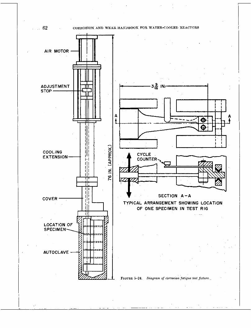
62 CORROSION AND WEAR HANDBOOK FOR WATER-COOLED REACTORS
AIR MOTOR
ADJUST MEN T
LOCATION OF
AUTOCLAVE
SECTION A - A TYPICAL ARRANGEMENT SHOWING LOCATION
OF ONE SPECIMEN IN TEST RIG
FIGURE 5-24. Diagram of corrosion fatigue test fixture.
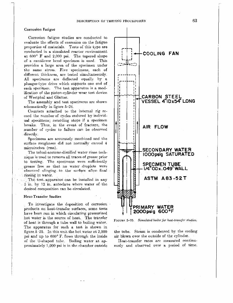
DESCRIPTION OF TESTING PROCEDURES 63
Corrosion Fatigue
Corrosion fatigue studies are conducted to evaluate the effects of corrosion on the fatigue properties of materials. Tests of this type are conducted in a simulated reactor environment a t 600' F and 2,000 psi. The tapered shape of a cantilever bend specimen is used. This provides a large arca of the specimen under the same stress. Five specimens, each of different thickness, are tested simultaneously. All specimens are deflected equally by a plunger-type drive which supports one end of each specimen. The test apparatus is a mod- ification of the piston-cylinder wear test device of Westphal and Glatter.
The assembly and test specimens are shown schematically in figure 5-24.
Counters attached to the internal rig re- cord the number of cycles endured by individ- ual specimens; recording stops if a specimen breaks. Thus, in the event of fracture, the number of cycles to failure can be observed directly.
Specimens are accurately machined and the surface roughness did not normally exceed 4 microinches (rms) .
The toluol-acetone-distilled water rinse tech- nique is used to remove all traces of grease prior to testing. The specimens were sufficiently grease free so that no water droplets were observed clinging to the surface after final rinsing in water.
The test apparatus can be installed in any 5 in. by 12 in. autoclave where water of the desired composition can be circulated.
Heat-Transfer Studies
To investigate the deposition of corrosion products on heat-transfer surfaces, some tests have been run in which circulating pressurized hot water is the source of heat. The transfer of heat is through a tube wall to boiling water. The apparatus for such a test is shown in figure 5-25. In this unit the hot water a t 2,000 psi and up to 600' F. flows through the inside of the U-shaped tube. Boiling water a t ap- proximately 1,000 psi is in the chamber outside
-COOLING F A N
CARBON STEEL VESSEL 4"IDx54' LONG
AIR FLOW
SECON DARY WATER I O 0 0 psig SATURATED
SPf,CIMEN TUBE - 114 OD x .049 WALL
ASTM A 8 3 - 5 2 T
FIGURE 5-25. Simulated boiler for heat-transfer studies.
the tube. Stea.m is condensed by the cooling air blown over the outside of the cylinder.
Heat-t,ransfer rates are measured continu- ously and observed over a period of time.
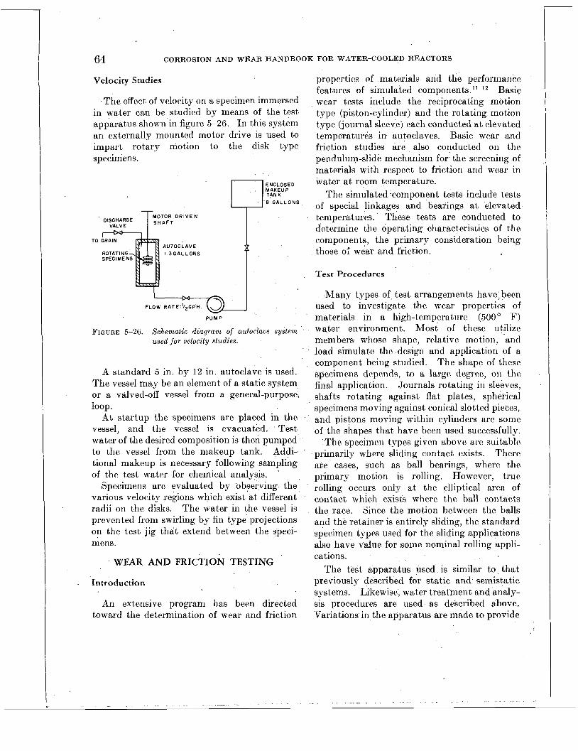
64 CORROSION AND WEAR HANDBOOK FOR WATER-COOLED REACTORS
Velocity Studies
The effect of velocity on a specimen immersed in water can be studied by means of the test apparatus shown in figure 5-26. In this system an externally mounted motor drive is used to impart rotary motion to tthe disk type specimens.
DISCHARGE I zzyT VALVE
TO AUTOCLAVE l 3 G A L L O N S
ENCLOSED
8 GALLONS
T I
FLOW R A T E : ' / ~ G P H
P U M P
FIGURE 5-26. Schematic d iagram of autoclave system used f o r velocity studies.
A standard 5 in. by 12 in. autoclave is used. The vessel may be an element of a static system or a valved-off vessel from a general-purpose,
At startup the specimens are placed in the vessel, and the vessel is evacuated. Test water of the desired composition is then pumped to the vessel from the makeup tank. Addi- tional makeup is necessary following sampling of the test water for chemical analysis.
Specimens are evaluated by observing the various velocity regions which exist a t different radii on the disks. The water in the vessel is prevented from swirling by fin type projections on the test jig that extend between the speci- mens.
loop.
WEAR AND FRICTION TESTING
Introduction
An extensive program has been directed toward the determination of wear and friction
properties of materials and the performance features of simulated components." l 2 Basic wear tests include the reciprocating motion type (piston-cylinder) and the rotating motion type (journal sleeve) each conducted a t elevated temperatures in autoclaves. Basic wear and friction studies are also conducted on the pendulum-slide mechanism for the screening of materials with respect to friction and wear in water a t room temperature.
The simulated component tests include tests of special linkages and bearings at elevated temperatures. These tests are conducted to determine the operating characteristics of the components, the primary consideration being those ol' wear and friction.
Test Procedures
Many types of test arrangements have-been used to investigate the wear properties of materials in a high-temperature (500' F) water environment. Most of these utilize members whose shape, relative motion, and load simulate the design and application of a component being studied. The shape of these specimens depends, to a large degree, on the final application. Journals rotating in sleeves, shafts rotating against flat plates, spherical specimens moving against conical slotted pieces, and pistons moving within cylinders are some of the shapes that have been used successfully.
The specimen types given above are suitable primarily where sliding contact exists. There are cases, such as ball bearings, where the primary motion is rolling. However, true rolling occurs only a t the elliptical area of contact which exists where the ball contacts the race. Since the motion between the balls and the retainer is entirely sliding, the standard specimen types used for the sliding applications also have value for some nominal rolling appli- cations.
The test apparatus used is similar to that previously described for static and semistatic systems. Likewise, water treatment and analy- sis procedures are used as described above. 'Variations in the apparatus are made to provide

DESCRIPTION O F TESTING PROCEDURES 65
for the specific type of simulated component and the motion required.
Basic Wear Tests
PISTON-CYLINDER TESTS
The type of motion observed in the piston- cylinder tests is linear, the reciprocating motion taking place by moving a piston within a. restraining cylinder.
Specimens
The specimens consist of a split piston which fits within a cylinder. Chevron springs located between the piston halves load the system by forcing the piston halves outward against the cylinder wall. Piston cylinder specimens are shown in figure 5-27, and their location in the assembled piston-cylinder test apparatus is shown in figure 5-28.
SECTION A-A
FIGURE 5-27. Piston-cylinder speciwten assembly.
The dimensions of the piston-cylikler speci- mens are standardized. The piston is 0.500 in. long and has a diameter of 0.7470 to 0.7472
RECIPROCATING AIR MOTOR
,ALIGNMENT COUPLING
WATER COOLING CONNECTIONS
LINEAR B A L L BUSHING
GRAPHITAR BUSHING
ALIGNMENT COUPLING
I!. i i, ,PISTON HOLDER SHAFT
2:
c- .u . - , i ‘-x. i FIGURE 5-28. Drawing of piston-cylinder wear test rig.
in. before splitting; the cylinder .is 1.250 in. long, with an outside diameter of 1.000 arid an inside diameter of 0.7500 to 0.7502 in.
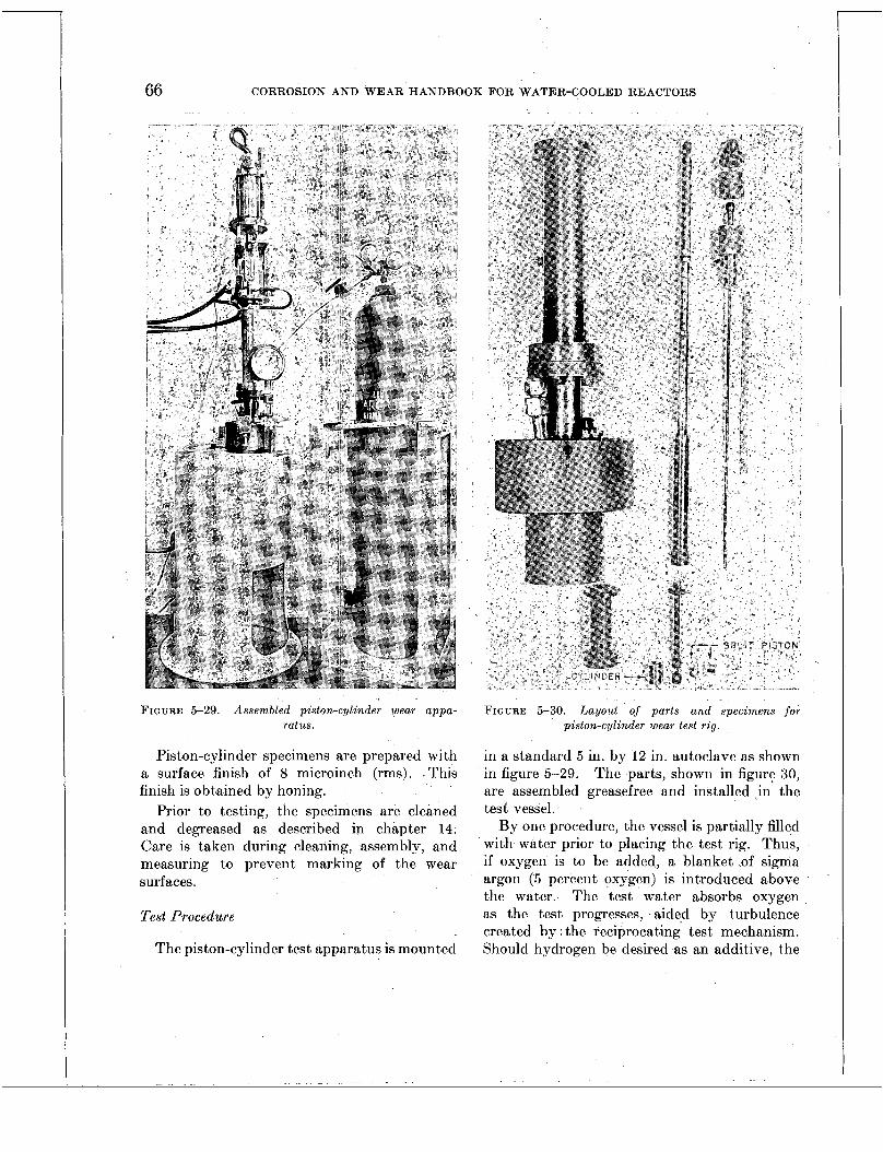
66 CORROSION AND WEAR HANDBOOK FOR WATER-COOLED REACTORS
FIGURE 5-29. Assembled piston-cylinder wear appa- ratus.
Piston-cylinder specimens are prepared with a surface finish of 8 microinch (rms). .This finish is obtained by honing.
Prior to testing, the specimens are cleaned and degreased as described in chapter 14. Care is taken during cleaning, assembly, and measuring to prevent marking of the wear surfaces.
Test Procedure
The piston-cylinder test apparatus is mounted
FIGURE 5-30. Layouf of parts and specimens for piston-cylinder wear test rig.
in a standard 5 in. by 12 in. autoclave as shown in figure 5-29. The parts, shown in figure 30, are assembled greasefree and installed in the test vessel.
By one procedure, the vessel is partially filled with water prior to placing the test rig. Thus, if oxygen is to be added, a blanket ,of sigma argon ( 5 percent oxygen) is introduced above the water. The test water absorbs oxygen as the test progresses, aided by turbulence created by the reciprocating test mechanism. Should hydrogen be desired as an additive, the
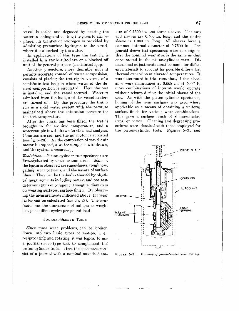
DESCRIPTION O F TESTING PROCEDURES 67
vessel is sealed and degassed by heating the water to boiling and venting the gases to at<mos- phere. A blanket of hydrogen is provided by admitting pressurized hydrogen to the vessel, where i t is absorbed by the water.
I n applications of this type the test rig is installed in a static autoclave or a blocked off unit of the general purpose (semistatic) loop.
Another procedure, more desirable since it permits accurate control of water composition, consists of placing the test rig in a vessel of a semistatic test loop in which water of the de- sired composition is circulated. Here the test is installed and the vessel secured. Water is admitted from the loop, and the vessel heaters are turned on. By this procedure the test is run in a solid water system with the pressure maintained above the saturation pressure for the test temperature.
After the vessel has been filled, the test is brought to the required temperature, and a water*sample is withdrawn for chemical analysis. Counters are set, and the air motor is actuated (see fig. 5-28). At the completion of test the air motor is stopped, a water sample is withdrawn, and the system is secured. Evaluation.-Piston-cylinder test specimens are first.evaluated by visual examination. Some of the features observed are smoothness, roughness, galling, wear patterns, and the nature of surface films. They can be further evaluated by physi- cal measurements including pretest and posttest determinations of component weights, diameters on wearing surfaces, surface finish. By observ- ing the measurements indicated above, the wear factor can be calculated (see ch. 13). The wear factor has the dimensions of milligrams weight lost per million cycles per pound load.
JOURNAL-SLEEVE TESTS
Since most wear problems can be broken down into two basic types of motion, i. e., reciprocating and rotating, it was logical to use a journal-sleeve-type test to comple.men t the piston-cylinder tests. Here the specimens con- sist of a journal with a nominal outside diam-
eter of 0.7500 in. and three sleeves. The two end sleeves are 0.500 in. long, and the center sleeve is 1.000 in. long. All sleeves have a common internal diameter of 0.7500 in. The journal-sleeve test specimens were so designed that the nominal wear area is the same as that encountered in the piston-cylinder tests. Di- mensional adjustments must be made for differ- ent materials to account for possible differential thermal expansion at elevated temperatures. It was determined in trial runs that, if this clear- ance were maintained a t 0.008 in. a t 500' F, most combinations of interest would operate without seizure during the initial phases of the test. As with the piston-cylinder specimens, honing of the wear surfaces was used where applicable as a means of obtaining a uniform surface finish for various wear combinations. This gave a surface finish of 8 microinches (rms) or better. Cleaning and degreasing pro- cedures were identical with those employed for the piston-cylinder tests. .Figures 5-3 1 and
I I
I I
FIGURE 5-31. Drawing of journal-sleeve wear test rig.

68 CORROSION AND WEAR HANDBOOK FOR WATER-COOLED REACTORS
FIGURE 5-32. Journal-sleeve wear test rig.
5-32 show the details of the journal-sleeve test specimens and apparatus. Test procedure-Test procedures are identical to those employed for the piston-cylinder tests, except that the journal-sleeve apparatus is driven by an electric motor mounted outside of the autoclave.
Evaluation-Evaluation of journal-sleeve spec- imens is based upon visual examination, weight change, and, to a lesser degree, dimensional changes. The methods employed are essen- tially the same as those used to evaluate piston- cylinder specimens.
PENDULUM-SLIDE APPARATUS l2
The pendulum-slide test apparatus is used to determine the friction and wear characteristics of materials in water a t room temperature. This device, developed by Dewees, is shown in figure 5-33. The data resulting from tests run on this machine correlate with data obtained by other investigators in high-temperature water. Thus the findings are usable in the solution of wear problems encountered in reactor environ- ments.
The apparatus is shown schematically in figure 5-34. A pendulum is attached through a

DESCRIPTION OF TESTING PROCEDURES 69
FIGURE 5-33. Closeup of pendulum slide machine.
ball bearing to one end of a horizontal connect- ing rod; the rider specimen is mounted in a receiver at the opposite end of the rod. When the pendulum swings, the connecting rod and, consequently, the rider are actuated horizon- tally. The mating element of the wcar couple is in the disk, which is mounted rigidly in room- temperature water. The rider, moving on the disk with a reciprocating mbtion, produces a wear track on the disk specimen.
\, START I N G \\ POSl T IO N \ ,
PENDULU
LOAD WEIGHT
RELEASE PENDULUM WEIGHT
FIGURE 5-34. Schematic daagram of pendulum slzde machzne.
The movement of the rider is perpendicular to the long axis of its face, and the total move- ment is 0.160 in. Test specimens are shown in figure 5-35.
0 RIDER
I I DISC FIGURE 5 3 5 . Specimens for pendulum slide wear and
frzctaon test.
Loads are suspended in the system through a hook-shaped load pan support, as shown in figure 5-33. Standard weights for these tests are 2.6, 10, and 40 lb.
Relative wear data can be obtained by driving the pendulum a prescribed number of cycles for each set of specimens tested. Kinetic friction data can be attained by relcasing potential energy to the system and counting the number of swings before the pendulum comes to a stands till. Specimens.-The specimens used in the pen- dulum-slide systcm consist of a disk and a rider. The arrangement of the specimen is shown in figure 5-34, and the dimensions are given in figure 5-35. The rider moves perpen- dicular to the long axis of its face, and the total movement is 0.160 in.
The test specimens are machined to have a surface roughness of 16 microinch (rms) as obtained commercially. Prior to testing the specimens, the cup, cover, and tools are cleaned and degreased, preferably by a toluol-acetone- distilled water rinse technique. In the final rinse, no droplets may be observed to cling to the specimens, tools, or cup. Test Procedure.-A standard procedure has been developed for most of the tests reported. The connecting rod is wiped with acetone. Bfter the specimens arc installed with clean tools, the

70 CORROSION AND WEAR HANDBOOK FOR WATER-COOLED REACTORS
cup is filled with deionized water, and the lid is installed, the rig is ready for test. Three fric- tion determinations are made in succession at each test point. Friction is usually measured a t every 100 cycles of operation. For the first 1,800 cycles the test load is 2.6 lbs (1,287 psi Hertz stress) ; for the second the load is 10 lbs (2,585 psi Hertz stress) ; and for the next 7,200 cycles the load is 40 lbs (5,060 psi Hertz stress). Following this series, a second series is under- taken which includes 1,600 cycles each at loads of 10 lbs and 2.6 lbs and a final 400 cycles a t 40 lbs. During this operation there are frequent disturbances, such as pushing the connecting rod a t the specimen end from one side of its guide to the other, a distance of about 0.010 in. There are occasional stops for visual inspection of the wear surfaces and also measurement of the rider length. (The primary wear measure- ment was the weight of specimens before and after test. The rider length change was fre- quently less than 0.0001 in.)
A test usually requires about 2 days from beginning to end. The apparatus can be set up in any clean relatively vibration free area. No special piping, heating, or auxiliaries are required. Evaluation.-Means must be provided’ to meas- ure the amount of wear so that comparisons and evaluations may be made. ’ The test data^ which have been obtained show that weight change is one of the most sensitive and repro- ducible measures of wear. With some mate- rials, particularly porous or soft metals, dimen- sional measurements are of greater significance than with such hard materials as the Stellites. In all of this work the dimensions should be measured as accurately as specimen configura- tion will allow. Weights should be accurate to 0.1 mg, and surface roughness should be ob- tained in microinches (rms) .
For the pendulum-slide apparatus, wear is evaluated on the basis of weight change, di- mensional change, visual appearance of the wear tracks, and changes in surface roughness. The weight change factor used here has the units microinches per pound load per square
inch of wear area per 1X106 in. travel. Di- mensional change studies include such factors as depth of wear track and change in length of the rider. Surface appearance and roughness changes indicate galling and seizing, etc., but in a larger sense these changes indicate the compatibility of the materials. This wear fac- tor (weight change) can be compared approxi- mately to the factor of Westphal and Glatter * l
by multiplying by 3.
W. F. (Dewees)X3=W.’F. (Westphal and Glat ter)
Kinetic friction in this sytem can be com- puted from the following equation:
P. E.= W,Xd+fm
where P. E.=potential energy of the system provided by releasing the’pen- dulum from a latched poiition
d = distance traveled ‘by the phndu- lum from the point of release to a standstill
fm=friction work of the machine, which is approximately .I, 3, and 10 percent for the 401, lo-, and 2.6-lb loads, respectively.
During the course of a test, three friction determinations are made at each of the load levels. These three observations are made 100 cycles apart.
W,=work of the friction force
SIMULATED COMPONENT TESTS
Simulated component tests determine the operating characteristics under simulated re- actor conditions of all types of mechanisms, linkages, and such parts as ball bearings. These tests are operated on,a “one shot” basis in many cases, but items such as ball bearings are tested in comprehensive programs. For the most part these tests are conducted in general purpose test loops. Specimens.-The specimens used in the testing of simulated components are nonstandard in that the number of tests run on any single item

DESCRIPTION O F TESTING PROCEDURES 71
FIGURE 5-36. Typical test station showing autoclave and instrumentation.
417017 0-57-6

1
72 CORROSION AND WEAR HANDBOOK FOR WATER-COOLED REACTORS
FIGURE 5-38. Layout and assembly of a f u l l housing type radially loaded ball-bearing test rig.
DESCRIPTION O F TESTING PROCEDURES 73
or apparatus are usually small and very often require special test rigs and special modifica- tions of test loops.
A common procedure to all tests in this group, however, is that they are degreased prior to testing and assembled grease free. (Degreasing procedures are given in ch. 14.)
The preferred method is that of cleaning with toluol, vapor degreasing with inhibited trichlor- ethylene, and drying in a forced circulation oven. This method is impractical for some large parts, including the autoclaves. These parts are degreased by wiping with acetone and rinsing with distilled water. Test Procedures.-The test procedures are non- standard. The exceptions, however, comprise the bulk of the component wear t8ests; ball bearings and lead screws. The test assemblies are placed in autoclaves that are filled with appropriate test water from the general purpose test loop. Most of these tests are driven by an externally mounted motor. A typical auto- clave station used to test ball bearings is shown in figure 5-36. A pressure gage, pressure switch, differential pressure transmitter, and differ- ential pressure controller can be identified in this photograph.
Several types of apparatus have been used to test <ball bearings. One spring-loaded, thrust- type jig is shown in figure 5-37. In this unit two bearings are tested simultaneously. A radially loaded test jig (also loaded by a coil spring) is shown in figure 5-38. This device is used to test four bearings simultaneously. Other jigs are available, and foremost among these is a deadweight loaded jig used to test a single bearing in thrust. Evaluation.-Component tests are evaluated in keeping with the specific problems that make the test necessary. Ball-bearing and lead- screw tests are evaluated on the basis of ap- pearance, weight change, and internal looseness developed during test.
.
REFERENCES
A . GENERAL REFERENCES
1. J. E. DRALEY, Argonne National Laboratory, School of Nuclear Science and Engineering Booklet, “High Temperature Corrosion Tests,” Chicago, Ill., June 1955.
2. F. E. BLACET and P. A. LEIGHTON, A Dry Method of Micro Analysis of Gases, Ind . Eng. Chem. i lnal. Ed., 3: 266 (July 15, 1931).
3. Ani. SOC. Testing Materials Proc., 43: 1258 (1943). 4. R. W. CURTIS, Instrumentation, Operation, Sam-
pling, and Analysis of High Pressure Water Cor- rosion Loops, Babcock & Wilcox Co., Research Center Report No. 5307, Alliance, Ohio, Oct. 17, 1951.
5. Knolls Atomic Power Laboratory, Quarterly Project Report, Chemistry and Chemical Engineering Section, May, June, July, 1954, Report KAPL- 1159, and Quarterly Project Report, Chemistry and Chemical Engineering Section, August and September, 1954, Report KAPG1216.
6. R. FOWLER, Jr., D. L. DOUGLAS, and F. C. ZYZES, Corrosion of Reactor Structural Materials in High- Temperature Water-Descaling Methods, Report
7. S. G. CLARKE, Trans. Electrochem. Soc., 69: 131 (1936). 8. H. N. GILBERT, U. S. Patent No. 2,377,873, issued
to E . I . du Pont de Nemours & Co. 9. Progress Report of Work for Bureau of Ships,
Westinghouse Electric Corp., and General Electric Co., Babcock &Wilcox Go., Research Center Re- port No. 5083, Alliance, Ohio, Nov. 8, 1954.
10. R. U. BLASER and J. J. OWENS, ASTM paper, Special Corrosion Study of Carbon and Low Alloy Steels, presented June 28, 1955.
11. R. C . WESTPHAL and J . GLATTER, The Wear and Friction Properties of Materials Operated in High- temperature Water, Report WAPD-T-64, Dec. 4, 1953.
12. N. B. DEWEES, Wear and Friction of Materials on the Pendulum Slide Machine, Report WAPD- CTA(ED)-18, November 1955.
KAPL-1198, Aug. 27, 1954.
B. STATISTICAL REFERENCES
ANDERSON, R. L., and BANCROFI, T. A,, “Statistical Theory in Research,” McGraw-Hill Book Co., New York, 1952.
BROWNLEE, K. A., “Industrial Experimentation,”
74 CORROSION AND WEAR HANDBOOK FOR WATER-COOLED REACTORS
Chemical Publishing Co., Inc., Brooklyn, N. Y., 1949.
COCHRAN, WILLIAM G., and Cox, GERTRUDE M., “Ex- perimental Designs,” John Wiley & Sons, Inc., New York, 1950.
DAVIES, OWEN L., editor, “The Design and Analysis of Industrial Experiments,” Hafner Publishing GO., Inc., New York, 1954.
DAVIES, OWEN L., editor, “Statistical Methods in Re- search and Production,” Hafner Publishing Co., Inc., New York, 1954.
DIXON, WILFRID J., and MASSEY, FRANK J., JR., “Introduction to Statistical Analysis,” McGraw-Hill Book Co., Inc., New York, 1951.
FISHER, R. A., “The Design of Experiments,” Oliver and Boyd, Ltd., 6th ed., 1951.
HALD, A., “Statistical Theory with Engineering Ap- plications,” John Wiley & Sons, Inc., New York, 1952.
KEMPTHORNE, OSCAR, “The Design and Analysis of Experiments,” John Wiley & Sons, Inc., New York, 1952.
MOOD, ALEXANDER MCFARLANE, “Introduction to the Theory of Statistics,” McGraw-Hill Book Go., Inc., New York, 1950.
YOUDEN, W. J., “Statistical Methods for Chemists,” John Wiley & Sons, Inc., New York, 1951.
London.

76 CORRqSION AND WEAR HANDBOOK FOR WATER-COOLED REACTORS
ics, and organic substances. For purposes of rapid screening and evaluation, a test known as the static autoclave test was developed. A detailed description of this test is given in chapter 5. Basically, the test consists of plac- ing specimens of the material in question in a stainless steel autoclave containing high- purity water, with oxygen added, and heating the vessel to 500’ F. Oxygen is added to the water because, for most of the materials under investigation, this represents the most aggres- sive corrosive condition that might exist in the reactor. For screening tests of t.his type, a 7-day period of exposure is sufficient to pro- vide an indication of the corrosion resistance of most materials. Depending on the mate- rial being studied, evaluations can be made by appearance, weight changes, analysis of tbe test waters, and microscopic examination. As indicated; the static autoclave corrosion test. is employed mostly for preliminary screening. Although water chemistry can be cont,rolled only to a limited extent, the autoclave test, retains certain advantages for screening, i. e., a standard rig or specimen is not required and tests are of short duration.
Photographs of the equipment normally eni- ployed for autoclave static corrosion tests are shown in figures 6-1 and 6-2. One type of cor- rosion specimen frequent.ly used is shown in figure 6-3.
These specimens are machined to a surface finish of 125 microinches (rms) and are cleaned and degreased prior to testing. Several speci- mens of this type can be tested simultaneously in a static autoclave. TO illustrate the kind of results normally observed, an “example” test was performed: Details o f the test condi- tions and the results obtained are given in tables 6-1 and 6-2 and in figures 6 4 t>o 6-8.
Since the weight changes given include the weight of the corrosion film on the specimen, t h e - are not truly representative of corrosion rate. However, because the film formed, is normallj- thin. arid adherent, the weight changes do per- mit, general evaluations and comparisons wi th other materials. Two important conclusions can be drawn from the results of this test.
FIGURE 6-1. Static autoclave an operation.
First, the material is considered to be suffi- cieti tly resistant to general corrosion to warrant’ further investigation. Secondly, the localized attack observed underneath the fastening wires

Chapter 6
APPROACH TO CORROSION PROBLEMS
Editors-D. J. DEPAUL, W. F. BRINDLEY Page
75 . 7 5 so 80 83 86 92 93
INTRODUCTION
The main purpose of this chapter is to de- scribe the general method of approaching cor- rosion problems. In addition, it illustrates some of the more important special techniques employed in studying corrosion problems and some typical results observed.
AIS1 type 410 stainless steel was chosen to illustrate the forms of corrosion under consid- eration because it is susceptible to many of the various types of corrosion involved. This chapter is not intended to be a general corro- sion study on the material employed since the- studies and evaluations are not complete.
Before recommending a material for a given engineering application, many phases of corro- sion must be investigated to determine its overall suitability with respect to corrosion. Good general corrosion resistance, defined as a uniform loss of metal resulting from corro- sive attack, is not the only crit rion for accept- ance. The various forms of loc I% lized corrosion which may occur under normal \ or abnormal operating conditions must be considered in the evaluation of any material. The forms of localized corrosion considered important in water-cooled nuclear reactor applications are crevice, galvanic, stress, inter- granular fatigue, fretting,' -and erosion corrosion. Those forms
_ _
which have been considered to be a problem are discussed in detail in separate chapters.
Depending on the application, one form of localized corrosion may be more important than another. For instance, in mechanical and welded joints crevice corrosion is not nearly as important a factor as in bearing ap- plications, where relatively small amounts of corrosion products could adversely affect the operational characteristics of components. Pit- ting type corrosion is particularly harmful in thin-walled pressure members since it may readily result in complete penetration. Inter- granular corrosion must also be considered in evaluating any material for a given applica- cation. Galvanic corrosion is always a possi- bility and must also be considered in those applications where dissimilar metals are in contact with one another in a corrosive environment.
The choice of any material, regardless of the application, should be based upon a thor- ough consideration of both general corrosion and the various types of localized corrosion . discussed in this chapter. The extent to which each type of corrosion must be investigated will depend on the particular problem.
GENERAL CORROSION
As indicated in chapter 1, when the project was initiated, there was little or no specific information on the corrosion resistance of ma- terials exposed to high-purity water a t temper- atures on the order of 500' F. Consequently, tests had to be made on all materials which showed some promise of being useful to the project. This required the testing of literally hundreds of materials, including metals, ceram-
75

77 APPROACH TO CORROSION PROBLEMS
FIGURE 6-2. Disassembled eyttipment used in static autoclave test.
FIGURE &3. Specimens used for general corrosion test. FIGURE 6-4. General corrosion specimens, us rigged, after test.

78 CORROSION AND WEAR HANDBOOK FOR WATER-COOLED REACTORS
R u n No 2463 (7 days)
Speci- Hea t treat- men No 1 m e n t I Weight gain 1 - Observations
FIGURE 6-5. General corrosion specimens showing localized corrosion under retaining ware.
R u n No 2612 (35 days) R u n No 2523 (21 days)*
Weight gam Observations
~~~
___ D-2321. ..
mg/dmt mg/dmz/mc --
Hardt ....... 9.0 38. 6
D-23Z ... D-2323.. . D-2324 ... D-2325 ... D-232k.. D- 2321... D-2328.. .
Bluish-black . color, fa in t crevice corro- sion around separating wire.
Same .............. Same.:. ........... Same .............. Same- ............. Same .............. Same .............. Same ..............
. 12.0
20.0 13.0 16.0 8 .0 8 . 0 5 .0 8 . 0
60.0 38. 6 55. 7 30.0 21.4 17. 2 1 30.0
Bluish-black color, crevice . corrosion around separat- ing wire.
Same .............. Same .............. Same. ............. Same .............. Same .............. Same. ............. Same ..............
mg/dml I- 11. 0
20.0 12.0 15.0 7.0 5 .0 4 .0 7.0
Hardt ....... HardT ....... Hardt ....... Annealed$. ~
Annealed$. ~
Annealed$- . Annealed$. .
17. 5
28.6 18. 5 22.8 11.4 11. 4 7. 1
11: 4
14.0 9 .0
13.0 7.0 5 .0 4 .0 7.0 I I I I I I I I
*Observations a n d weight measurements for run No 2489 (7 to 14 days' total exposure) were not made. t R , , 40-44, 1,80O0 F for 15 m m ; drawn a t fiooo F for 2 to 3 hr. 11,650' F followed b y furnace cool.
12.8
23.3 14.0 17.5 8. 2 5.0 4. 7 8. 2
Bluish-black color, crevice corrosion with pit t ing around separating wire.
Same. Same. Same. Same. Same. Same. Same.
I __-
_ _ _ ... _ - -. ....... -. . . . . . . . . . . . . .

APPROACH TO CORROSION PROBLEMS 79 TABLE 6-2. CHEMISTRY LOG FOR G.ENERAL, CREVICE, AND GALVANIC CORROSION TESTS
Pretest
8.70 6 . 4
1124
....-.-
0 2 , ppm _.........
p H . - . . - -. . . . . . . . . . . Specific resistance
(ohm-cm) x 1 1 I . . Water temperature,
F.-.............
A t tem- perature
~ _ _ _ _
'0.01 6 . 4
33
500
Speci- fied
Pre- A t tem- test perature
.__-
19.1 $7.63 6. 2 5. 7
824 103
........ 500
3-8 6-8
>500
500
t 3 . 6 I 0.84 6 .0 (t)
77 (t)
5 0 0 5 0 0 5 M )
R u n N o . 2 4 6 3 1 ' R u n N o . 2 4 8 9
0.05 5.6
84
Post- test
__
(t) (t)
(t)
500
Post- test -
1.92 5. 7
94
500
RunNo.2523 I R u n No. 2612
Pre- test
~
24.1 6 .6 ,
431
. . . . . . .
At tem- perature
16.0 6 . 3
248
500
Post- test
3. 84 5 .4
84
500
Pre- test
14.98 6 . 9
599
. . . . . .
*Resulted from temporary leak. tNot analyzed. tAIter adjustment.
(see figs. 6-5 and 6-7) suggests the possibility of either crevice or galvanic corrosion.
Materials which successfully pass the static autoclave tests may then be tested under more elaborate conditions, with closer control, and for relatively long periods of time. One of the main tests employed for this purpose is the dy- namic corrosion loop test. A description of this
test and the types of specimens employed is given in chapter 5 . Basically this test consists of a stainless steel pressure vessel tiirough which water is circulated by means of a pump or by thermal circulation. Precise control of the water chemistry is maintained by the me of a by-pass ion exchanger and a mechanical filter. The water is heated to 500' E' by means
FIGURE 6-6. Pitting observed 1 in . f r o m retaining wire on general corrosion specimen (20 X).

1 7
80 CORROSION AND WEAR HANDBOOK FOR WATER-COOLED REACTORS
FIGURE 6-7 Pzttznq whzch developed beneath retaznzng ware on general corroszon speczmen (20 X)
of immersion heaters. The water velocity was normally 30 ft/sec. Dynamic corrosion loop tests usually run for several thousand hours for the evaluation of a particular material or condition. They are employed primarily to provide reliable information on the general corrosion rate of materials under study. The results of a typical long-term dynamic corrosion test are shown in figure 6-9.
This curve is characteristic of most materials in that the corrosion rate usually decreases with time. It should be pointed out that this type of test provides reliable corrosion rates only if the corrosive attack is uniform. If localized attack occurs, the overall weight changes are not representative of thc corrosion rate. T n this particular example there was no evidence of localized attack.
Normally, dynamic loops are not employed in making specific studies on any of the localized
In such studies specific rigs are prepared for the particular tests, which are usually conducted in autoclaves in either a static or semistatic environment. In the semistatic tests the flow is set a t the minimum required to control thr water chemistry.
, forms of corrosive attack discussed herein.
LOCALIZED CORROSION
Crevice Corrosion
The importance of crevice corrosion as i t affects the operational charactcristics of com- ponents js discussed in chapters 5 arid 9. These chapters describe two types of crevice corrosion
. . ~ . . . - .. . . . . .

APPROACH TO CORROSION PROBLEMS 81
FIGURE 6-8. Photomacrograph of general corrosaon specimen showzng base metal and oxide jilm (500 X). , 1,
specimens commonly employed for studying this problem. The first of these specimens is a simple plate type used for preliminary screening tests. The second type is the journal-sleeve variety used for long-term tests. The journal- sleeve corrosion test is considered to be the
1 1 T F e C O * O I T I O " S T E Y P E R 1 T U R E - 1 0 O - F
FICIUIE 6-9. C'rtrve showirzg resrclts of n lqpical long- lerm dynamic corrosion / e s t .
more reliable of the two because i t simulates actual service conditions more closely. It also permits control of the clearances, which is considered extremely important in this t j pe of corrosion. '
An example of the plate type crevice corro- sion specimen is sho\vn in figure 6-10.
The conditions and results of typical tests on this type of specimen are shown in tables 6-2 and 6-3 and figures 6-11 to 6-13. This clear- ance betweeu the two plates was not controlled and proviclecl metal-to-metal con tact.
The results of similar tests conducted on the journal-sleeve-type specimens, shown in figures 6-14 and 6-15, are described and illustrated in table 4 and figures 6-16 and 6-17.
As in the case of general corrosion, the weight changes shown in tables 6-3a and 6-3b for the plat,e samples are not considered to be truly indicative of the corrosion rate and are included for general information only. Figures 6-1 2, 6-1 3 , and 6- I7 show the typical corrosion build-

82 CORROSION AND WEAR HANDBOOK FOR WATER-COOLED REACTORS
FIGURE 6-10. Plate type crevice corrosion specimen before test.
up observed on practically all parts in contact occurs more frequently on surfaces within which are exposed to high-purity water. Figure crevices than on surfaces exposed to the normal 6-6 shows pitting on the general corrosion sam- environment. ple. Although not clearly demonstrated in the Similar results are observed on journal-sleeve examples chosen, past experience has shown that specimens, except that specimens of this type pitting comparable to that shown in figure 6-6 may eventually bind as a result of the restraint
FIGURE 6-11. Plate type crevice corrosion specimen after lest.
. - -. .. . . .. ... ~ ... ~ I .

APPROACH TO CORROSION PROBLEMS 83 TABLE 6 3 a . RESULTS O F PLATE TYPE CREVICE CORROSION TESTS ON AIS1 TYPE 410 STAINLESS
STEEL SPECIMENS HARDENED
1 Run No. 2463 (7 days) 1 Run So. 2523 (21 days )* I Run No. 2612 (35 days)
Speci- m e n N o . 1
D-2329a..
H e a t treat- m e n t Weight gain
mg/dm2 mg/dm2/mc ~~
I I a r d t ....... 9 . 0 38.6
D-2330a.. D-2331b.. D-2332b.. D-2333c.. D - 2 3 3 4 ~
30.0 47. 2 47. 2 34.3 38.6
S a m e t ....... 7.0 S a m e t ....... 11.0 Samet ....... 11.0 % m e t ....... 8 .0 Saniet ....... 9 . 0
~~
Weight gain Observations ~
Weight gain Observations -
Same .............. Same .............. Same .............. Same .............. Same ..............
Discoloration on 1 17.0 1 24.3 1 Fa in t line of crev- 1 22.0 mating surface. ice corrosion on
13.0 31.0 29.0 17. 0 21.0
mating surface.
Same .............. Same .............. Same .............. Same .............. Same ..............
18.5 44.3 41. 5 24.3 30.0
17.0 36.0 33.0 20.0 25.0
Observations
ng/dm2/mi
Weight gain ~
18. 9
14.6 42. 0 38. 5 23.3 29.2
Fa in t line of crev- ice corrosion on mating surface.
Same .___ - - :-..: - -. Same ...... --! ..... Same .............. Same .............. Same: ......... :..- Same .............. s a m e ..............
0 bservations
mg/dm:
20.0
25. o 33.0 36.0 34.0 28.0 22.0 25.0
Crevice corrosion around outer edge of mat ing surface.
Same. Same. Same. Same. Same.
Crevice corrosion around outer edge of mating
Same .............. Same .............. Same .............. Same .............. Same .............. Same .............. Same ..............
.surface.
'Observations and weight mcasuremcnts for run No. 2489 (7 to 14 days' to ta l exposure) were not made. t R , , 4 W 4 ; 1,800° F for 15 min ; drawn a t 600' F for 2 to 3 hr. $Specimens wi th t h e same letter designation formed a single couple.
mgldm:
21.0
28.0 36.0 42.0 39.0 31.0 22.0 27.0
D-2336. -. D-2337 ... D-2338.-. D-2339 ... D-2340.. D-2341 ... D-2342.. .
-1 I-
Annealedt - - Annealedt. . Annealedt. . Annealedt. . Annealedt ._ Annealedt. . Annealedt ..
D-2335 ...I Annealedt..l
' : I I __
7. 0
10.0 6. 0 7 . 0 7 . 0 7. 0 5 .0 6 . 0
30.0
42. 9 25.8 30.0 30.0 30. 0 21.4 25. 8
Weight gain Observations -
lg/drnZ/mc
28.6
35 .7 47. 2 51.4 48. 5 40.0 31.4 35. 7
ig/dmZ/mc
24.5
32.7 ; 42.0
49.0 45. 5 36. 2 18.9 23. 2
0 bserva t ions
I I eavy crevice cor- rosion around edge of mat ing surface.
Same. Same. Same. Same. Same. Same. Same.
*Observations a n d weight measurements for run No. 2489 (7 to 14 days ' total exposure) were not made. t1,650° F followed b y furnace cool.
~
produced by the corrosion buildup within the annular crevice.
These general results would indicate that the localized attack observed on the initial general corrosion samples may have been caused by crevice corrosion effects. However, the possi- bility of the simultaneous occurrence of galvanic corrosion should not be overlooked since differ- ent materials were employed for the retaining wire and the specimen. The wire was AISI type 304, and the test specimens were AISI type 410 stainless steel.
Galvanic Corrosion
It is desirable to study galvanic corrosion in any system where dissimilar metals are in contact in a corrosive environment. However, i t was essential in the illustrative cases given because accelerated attack (pitting) occurred at the point of contact between two dissimilar materials. The corrosion buildup in the crevice would not normally be expected to result from galvanic corrosion because the materials in contact are similar. Consequentli tests were
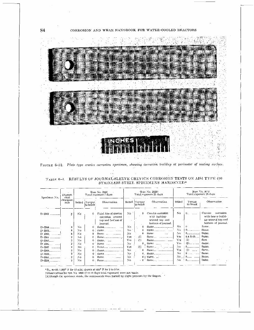
84 CORROSION AND WEAR HANDBOOK FOR WATER-COOLED REACTORS
Specimen S o .
-____
D-2343. ........
D-2348 ......... D-2352 ......... D-2353.. ....... D-2344 ......... D-2345 ......... D-2346. ........ 33.2347. ........ D-2349 ......... D-2350 ......... D-2351_______._ n-2354,. .......
FIGURE 6-12. Plate type crevzce corrosion specimen, showing corrosaon buzldzcp at perzmeter of matzng surface.
R u n S o . 2463 Diamet- Total esposurc 7 days
clearance, rical -____ ___-__ mils Seized T o r q u e Observation
to break _____ _ ~ _ _ _- -___---
8 KO 0 Fa in t line of crevice corrosion around top and bottom of journal.
8 s o 0 Same ............... 8 S o 0 Same ............... 8 s o 0 Same-- .............
0 Same-- ............. 2 s o 2 s o 0 Same ............... 2 s o 0 Same- .............. 2 No 0 Same ............... 2 s o 0 Same ............... 2 s o 0 Same ...............
, 2 s o 0 Same ....... :-- .....
2 s o 0 . Same ...............
TABLE 6-4. RESULTS OF JOURNAL-SLEEVE: CREVICE CORROSION TESTS OK AIS1 T Y P E -1'10 STAINLESS STEEL SPECIMENS HARDENED*
~ _ _ _ -
Observation
--_ Seized
R u n No. 2523t Tota l exposure 21 days
Torque to break
0.. ........
o... .......
O..- .......
0 ...... :... 0.4 ft-16. ~. (11.- ...... ($) ........ 0 .......... (1) ........ 0.. ......... 0.. ........
Seized Tornus 1 to hreal Observation
-
Crevice corrosion with heavy build- u p a round ' top and bot tom of journal.
Same. Same. Same. Same. Sam Same. Same. Same. Same. Same.
so ~ 0
s o ~ 0 s o ' 0
Crevice corrosion with bui ldup around top and bot tom ol journal.
Same ................ Same ................ Same: ............... Same ................ Same ................ Samc ................ S u n e ~ .... -I ......... Samc ................ Same.-.. ............ Same .... :--- ........
Samc ................
I .
N 0
s o No s o Yes Yes Y 1%
s o Y e s so s o , s o
* E c , 40-44; 1,800' F for 15 min ; drawn a t 600' F for 2 to 3 hr. tobservations'for r u n S o . 24RY (7 to 14 days total exposure) were not madc. tAlthough the specimen s tuck, t he components were par tcd by slight pressure by t he fingers.
R u n So. 2612 Tota l exposure 35 days
- ........ - ......... _._ . . . . - . . . . . . . .. - - . .

APPROACH TO CORROSION PROBLEMS 85
Area ratio 304 to 410
TABLE 6-5. RESULTS OF GALVAKIC CORROSIOX TESTS O K IIAltDE;NED* AISI TYPE 110 STAINLESS STEEL IVELDED TO AISI TYPE 304 STAINLESS STEEL
Run S o . 2523 (14 days) Run 3-0. 2612 (28 days)
Observation Weight gain Weight gain
0 bse r ra t ion
mg/dm? 1 mg/dm?/mo
Specimen S o .
D-5673.. .....................
1)-~6i4 1)-5675.. ..................... D-567B..
.......................
.....................
I 3/1 +2. 0 +8. 57 XO evidence of accelerated + I . 0 +l. 17 No evidence of accelerated
corrosion. corrosion. 311 +2.0 + % S i Same + L O +1.17 Same. 1/3 f2 .O f 8 . 5 Same ...................... 0 n Same. 1/3 +3.0 +12.8 Same + L O f l . 1 7 Same.
......................
......................
* R , , 4 M 4 ; 1,800' F for 15 min; dra\vn at 600' F for 2 to 3 hr.
madc 'on specimens similar to thosc shown in tact. * Figure 6-19 shows the manncr in which figure 6-18 to dctcrminc if galvanic corrosion the - \ \we assembled for tcsting. The test con- would occur under similar environmental con- ditions are shon-n i r i table 6-2, and the results ditions. Since the susceptibilitj- to galvanic arc givcn i n table 6-5 and figurcs 6-20 to 6-22. corrosion increases with the cstcnt of contact
were wclded in order to provide intimatc con- between metals, the two materials ill q,lcstioIl *.\Iore ~eliahle results n ould he ohtmied i f AIS1 t \ [)e ,308 clcctiodc Iiad
heen uscd. hone\rr the results i\ i t h AISI t i pr ,310 arr considcrcd to hc Indlcntl,c
FIGURE 6-13. Endarged view o,f corrosion biii ldiip on plate type crevice corrosion specimen (20 X)

86 CORROSION AND WEAR HANDBOOK FOR WATER-COOLED REACTORS
FIGURE 6-16. Journal-sleeve crevice corrosion specimen after lest.
Figure 6-22 shows the fusion zone between the two metals. No evidence of accelerated corro- sion was observed a t the point of contact between the two metals. Thus the attack observed in the general corrosion test can be' attributed to crevice corrosion.
Stress Corrosion
'FIGURE 6-15. Assembled journal-sleeve crevice corrosion Since there are many in any specimen before tesl. where high stresses may develop either in

87 APPROACH T O CORROSION PROBLEMS
FIGURE 6-17. Corrosion b u i l d u p o n disassembled journal-sleeve crevice corrosann specimen.'
normal or emergency operation, it is csceed- ingly important that stress corrosion be con- sidered as a routine matter. Obviously the specific tests required mill depend 011 the
8
AISI Type 304 Stanless Steel
AIS1 Type 310 Stanless Steel Weld Metal
AISI Type 410 Stainless Steel
\ /
AISI Type 410 Stain- less Steel
AISI Type 304 Stain- less Steel
FIGURE 6-18. Galvanic corrosion speczinens before test .
a,pplicat,ion. For instance, in choosing a ma- terial for a spring application, one moiild do considcrablj. more be,sting arid evaluatiiig than in clioosirig materials for an internal stxuctural pa.rt not normally suhject,etl to high stresses. Likewise, more consideration would be given to cyclic t,haii to st,at,ic st,ress applications.
'There arc many methods for c1et.ermining the stress corrosion resist'ance of a material. The types of specimens employed for st,ress cor-
FIGURE 6-19. Galvanzc corrosion specimens, as-r tgged , Defore test. 417017 0--57-7
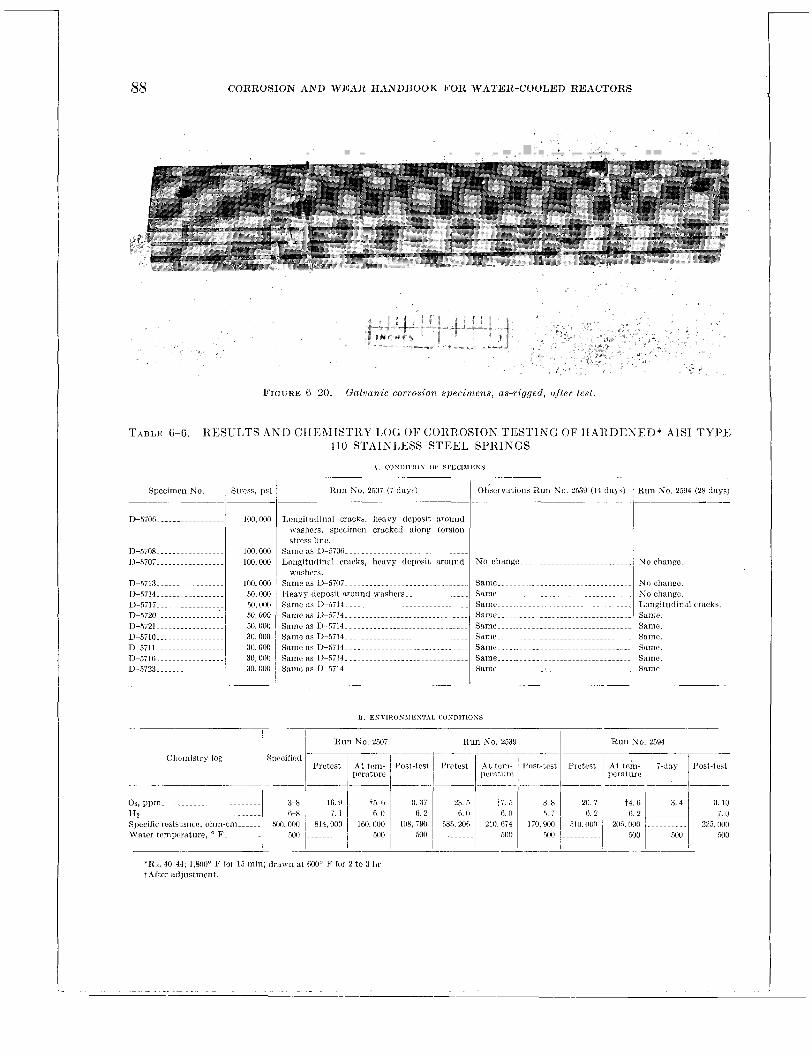
88 CORROSIOh’ AND WEAR HANDBOOK FOR WATER-COOLED REACTORS
FIGURE G-20. Galvanic corrosion specimens, as-rigged, after test .
TABLE 6-6 RESULTS 4x11 CHF;\IISTKI LOG O F CORROSIOK TESTIKG OF HARDENED* AIS1 TYPE 410 STAIK1,ESS STEEL SI’RIKGS
\ CO\DITIO\ OP 6P);LI\IEBY
Specimen No. 1 Stress, psi
Chemis t ry log
H u l l So. 250i (i days)
0 3; 6. 2
108, iyo 500
R u n S o . 2539
0. 10 7. IJ
225. 000 ,5110
*Rc, 40-44; 1,800’’ I.’ for 1%; min; d r a v n at 600° F lor 2 t o 3 hr tAftcr atljiistrnent.

APPROACH TO CORROSION PROBLEMS 89
rosion studies described in tdiis handbook were horseshoe bend, fulcrum loading, and compression springs. The horseshoe specimen is simple and readily provides high st,resses. Fulcrum-loaded specimens permit good control on the stress levcl. The conipressioii-spring type specimen also offers good cont,rol of the stress level and, i n addition, provides a more
AISI Type AISI Type 304 410 Stain- \ Stainless Steel
AISI Type 310 Stainless Steel Weld Metal
AIS1 Type 410 Stainless Steel / AISI Type
304 Stain- less Steel
FIGURE 6-21. Galvanic corroszon speczniens after t es t .
representative stress pattern for important applications such as pressuic-contnitiing miem- bers. The first two specimens are stressed in ten- sion whereas the compression spring is stressed in torsion (biasial stress). It slioultl be men- tioned that a given level of torsional stress is considerably more aggressive in producing stress corrosioii than the same stress levcl i n straight tension. This undouhtetlly results from the difference between the moduli of elasticity of a given metal under the same tensile and torsioiial stresses. 111 general, liomcrer, materials which are susceptible to stress corro- sioii in torsion are also susceptible to stress corrosion in tension. Tlie main difference is the magnitude of the stress and tJie time
Horseshoe-type specimens arc very useful i n preliminary scrwiiing tests \\-liere niaiij coiidi-
required to produce f a1 '1 ul'e.
tions must he esaminecl in a short period of time. The fulcmim-loading and compression- spring specimens are used where information on cliflercnt st,ress levels is desired. The choice between these t,wo specimens should depend on the types of stresses cspected in service.
Regardless of t,lie expected service stresses, i t is desira,ble in an; stress corrosion study to invest.ignt,e the effect of stress levels up to tlie yield point of the mat,erial in questtion. Opera- tional and emergency stress condit,ions are sometimes very difficult to calculat'e or esti- mat,e.
Because of the many uncoiitrollable and unknown variables involved in st,ress corrosion, t,lie number of specimens for a given condition should be large enough to permit adequate in- terpreta,tion of the result,s. I n some cases a hundred specimens have been employed for sti-dying one condit,ion. Variations in the results obtained will dict,gte the number of specimens required.
Figure 6-2 3 illu s t,ra tcs the spring- typ e sp eci- mens employed and t,he manner in which they mere stressed in an actual test. A group of 12 springs were tested in accordance with the con- ditions shown in table 6-6. Tlie results are described in table 6-6 and figures 6-24 to 6-27.
With regard t,o the above discussion, it is interesting to n0t.e t,hat:
(1) Two of t,he four specimens stressed to 100,000 psi cracked in 28 days. (2) None of the lower stressed specimens cracked during the test. period. ( 3 ) Cracks longitudinal to ttie wire would not be expected in stress corrosion with this type of specimen. These cracks rep- resent wire drawing defect,s. Cracks corre- sponding t'o t.orsionn1 lines of stress would be a.nticipat,ed wit,li springs macle from sound mire.
St.rictly speaking, the longitudinal cracks observed would invalitlat,e the entire test since the?: coulcl alter t,hc st,ress patterii in tlie spriiig a II d t.11 ereby i I i d u ce torsion a1 cracks.
In such a. case, the invc'stigator should repeat t,lic test, mit l i spriiigs rnatlc from sound wire. 'I7ic result,s of liorsc~sliot~ mid fulcrum-loadiiig- type specimens arc occasionally obscured by

90 CORROSION AND WEAR HANDBOOK FOR WATER-COOLED REACTORS
A Z S I type 4iO stainless steel A I S I type Si0 stainless
steel weld metal
FIGURE 6-22. Fusion line between dissimilar metals, galvanic corrosion specimen (20 X)
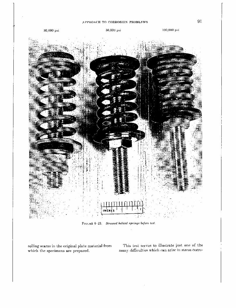
APPROACH TO CORROSION PROBLEMS
50,000 psi 100,000 psi 30,000 psi
91
FIGURE 6-23. Stressed helical springs before lest
rolling seams in the original plate matterial from which the specimens are prepared.
This test serves to illustrate just one of the many difficulties which can arise in stress corro-
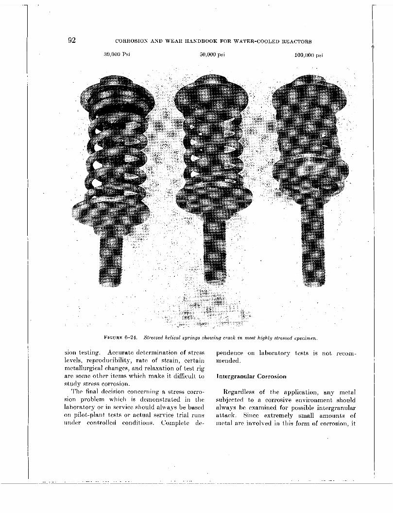
92 CORROSION AND WEAR HANDBOOK FOR WATER-COOLED REACTORS
30,000 Psi 50,000 psi 100,000 psi
FIGURE 6-24. Stressed helical springs showing crack i n most highly stressed specimen.
sion testing. Accurate determination of stress levels, reproducibility, rate of strain, certain metallurgical changes, arid relaxation of test rig are some other items which make i t difficult to study stress corrosion.
The final decision concerning a stress corro- sion problem which is demonstrated in the laboratory or in service should always be based on pilot-plant tests or actual service trial runs uncler controlled conditions. Complete de-
pendence on laboratory tests is not recom- mended.
Intergranular Corrosion
Regardless of the application, any metal subjected to a corrosive environment should always be examined for possible intergranulax attack. Since extremely small amounts of metal are involved in this form of corrosion, it

APPROACH TO CORROSION PROBLEMS 93
FIGURE 6 2 5 Cracked helzcal s p i t n g s , stressed io 100,000 p s i
cannot be readily detected by weight changes or visual inspection. Evalun tions should be based on metallographic esamiilations. An!
' I . .
. FIGURE: 6-26. Torsional and lony i lud ina l cracks observed
I n an itnstwssed o a c k e d s p i i n q .
FIGURE 6-2 i . Longit~rdinal cracks in a stressed spring.
t,j-pc of specimen employed for corrosion testing ma.\- be used for examination.
Fatigue, Fretting, and Erosion Corrosion
Generdly, fat,igue, fretting, and erosion corro- sion axe not considered t,o be a problem with t.he 18-8 type st,ainless st,eels or the other corrosion- resistant met,erials presen t.ly employxl in reac- tor construct,ioii. However, the investmigation of new ma,terials and/or different. operating condit,ioiis should include a consideratior1 of t.hese forms of corrosioii. The present inhrest in ca.rbon stmeel as a possible substitute for st,ainless st.eel makes i t even more mandatory t,o consider these forms of corrosion 011 n rout,irie basis.

Chapter 7
TABULATION OF BASIC DATA
Editors-D. J. DEPAUL, J. W. FLAHERTY
Contributors-H. F. BEEGHLY, R. U. BLASER, 14. C. BLooivr, C. R. BREDEN, P. E. BROWN, P. COHEN, S. C. DATSKO, T . S. DEFAIL, D . J. DEPAUL, D . L. DOUGLAS, R. T. ESPER, J. GLATTER, R . F. KOENIG, M. KRUFELD, H . K . LEMBERSKY, E. LIEBERMAN, W. MCALLISTER, J. J . OWENS, S. PETACH, A. H. ROEBUCK, B. G . SCHULTZ, J. 31. SEAMON, D . E. TACKETT, R . C. WESTPHAL, D. M. WROUGHTON
Page INTRODUCTION . . _ .~~~~~ . . . . . . . . . . . ~~ .~~~~~~~ 95 STATIC CORROSION TEST DATA ._............ ~ 96 DYNAMIC CORROSION TEST DATA ---.------... 101 WEAR TEST DATA .._.. ~~~~ .............. ~-~ 131
INTRODUCTION
The development and construction of a water-cooled nuclear power plant necessitated a thorough investigation of the corrosion and wear properties of numerous materials. Essen- tially all the work performed in this connection was related to those specific problems arising from the contact of these materials with the cooling water in the primary or radioactive sys- tem (see fig. 1-1, ch. 1). Corrosion and wear problems relating to the secondary or nonradio- active cooling system were not extensively in- vestigated since there was considerable informa- tion and experience on materials exposed to conventional boiler water environments.
The magnitude of the problem required the cooperative efforts of numerous laboratories under Government subcontracts in order to obtain the desired information in the allotted time. Many reports on the subject have been issued, varying in scope and treatment, but only a few papers have been published in tech- nical journals to date.
An endeavor has been made to summarize the pertinent data accumulated by the cooperating laboratories by means of a group of tables for ready reference. Tt is intended that the infor-
mat,ion in these t.ables will be useful in deter- mining t,he general corrosion and wear charac- t,erist.ics of mat,erials employed in the project. It. was not, considered practical to present all the da,t~a since this large volume of information, toget,her with the added complexity of inter- pretat.ion, would clet~ract from the usefulness of this handbook.
The data are'present'ed to provide the maxi- mum amount of information concerning the relative importa.nce of the environmental varia- bles normally considered important in making rnat.erial select,ions. Only average values are included in the t,a,bles to simplify comparisons and evaluations. Where the reader may not find t.he specific information needed for choosing a material, or combination of- materials, for a given application, i t is possible that related tabulated data will provide a reasonable basis for making a reliable extrapolation.
The rea.der will observe in examining the t.ables that all the materials were not investi- gated to the same extent,. This disparity re- sulted from the expeditious manner in which the project was carried out. For instance, a t the point where a material showed a lack of a requisite property, further investigation of that materia.1 would normally be terminated. Ex- perience showed t.hat i t !vas more advantageous t,o go t,o a new material or process rather than t,o modify an esist,ing material or process. How- ever, in cert.ain cases where a material possessed very desirable properties, it was mandat'ory
95
96 CORROSION AND WEAR HANDBOOK FOR WATER-COOLED REACTORS
that the details of its limitatioiis be investigated so that the material could be exploited to its fullest advantage. Such was the case with zirconium metal, which has extremely desirable nuclear properties, and AIS1 type 410 stainless steel, which possess good hardening and mag- netic characteristics; both matcrials presentcd man>- corrosion problems.
As is frequently the case with testing pro- cedures and equipment, several conditions may vary from test to test. In many cases, the interactions of variables may malie i t difficult to evaluate the importance of one particular variable. The reader will undoubtedly en- counter this problem when using the tables in this chapter. Since only condensed informa- tion is given in the tables and since there is no discussion of individual tests, it may be difficult at times to interpret the results to the satis- faction of the reader. To cope with this diffi- culty a separate chapter (ch. 8) has been pre- pared in which the relative importance of each variable is discussed in detail. It is intended that these discussions will aid substantially in the interpretation of the data, especially in those areas where several variables are involved.
The corrosion and wear information in this chapter is summarized in three tables:
Table 7-1 is a classification of all the materials studied. It is divided into three categories based on the material's corrosion resistance or stability under reactor water service conditions. These categories were based entirely on the results of preliminary short-term corrosion tests that were designed to cover a multitude of materials in the shortest possible time. In- dividual corrosion rates are not given since the values obtained would not provide a better understanding of the table. Furthermore, their incorporation could lead to misunderstanding if certain conditions, all of which are not neces- sarily covered herein, were not taken into ac- count. Corrosion rates on these tests are not considered important enough to warrant a detailed discussion of their interpretation. The main purpose of table 7-1 is to provide the reader with a list of all the materials studied and their approximate relation by corrosion resistance.
Specific choices should not be made solely on the basis of this table.
Table 7-2 presents the corrosion results ob- tained on materials that were actually con- sidered for use in the water-cooled reactor plant. These tests were conducted under more closelj- controlled conditions than the tests on which table 7-1 was based. Specific information is givcn on composition, corrosion rate, and the effect of pertinent environmental conditions.
Table 7-3 lists all the important combinations of bearing materials that were tested under simulated service conditions. The combina- tions are arranged in order of decreasing re- sistancc to wear and the table includes the effect of watcr chemistry, the typcs of motion studied, temperature, effects and materials used.
In addiLion to these three tables, supplemen- tary corrosion and wear data will be found throughout the handbook It was felt that the specialized nature of this information lends itself more readily to incorporation in the ap- propriate chapters rather than in a general tabulation in this chapter.
FOREWORD TO TABLE 7-I-STATIC CORROSION TEST DATA
Test Conditions
The classification of materials was b tests coiiducted iir high-pressure autoclaves containing high-purity water a t 500" F. No circulation of t,he water was provided for, ot,her than movement resulting from thermal circulation. In gcneral, the water con- tained 10 t,o 30 cc of oxygen (STP) per kilogram of water, and the initial electrical resistivity was 500,000 ohm-crn or greater. The test,s ranged in duration from 3 t,o 6 months. Details of t,he test procedures are given iii chapter 5.
ln,terpretation of Classificutiopt.
Class I : Materials showing the highest rcsistatice to corrosion. These may be used with the least ainonnt of consideration for t,lie. particular application. Weight, changes iii this group were generally on the order of 10 mg/dni2/nro (weight gain at,tribiitcd to :idherent, scale).
'Class I1 : Materials wit,h appreciably less corrosioii rcsist,aiice than those list,ed in class I. They require some consideration iii their application in order to insure satisfactory perforinancc. Weight, changes in

TABULATION
this group were generally on the order of f 5 0 mg/dmZ/mo. Many of the materials are subject. t.o minor pitting, especially in crevices.
Class 111: Materials in this group usually show weight. changes on the order of several hundred mg/drn2/mo and/or are susceptible to severe localized attack.
I
Special Notes
(1) Some test,ing was performed wit,li \vat,cr cont,aining In additions of hydrogen as R corrosion iiihibit,or.
O F BASIC DATA 97 general, the addition of hydrogen improved the cor- rosion resistance, h u t the relative position of each material was essentially unchanged. Additions of hydrogen ranged from 200 to 500 cc of hydrogen (STP) per kilogram of water.
(2) 3letallic specimens were machined or ground to a surface finish of 63 microinch (rms).
(3) Maberials, such as plastics and ceramics, were tested i n t.he “as-received” condition. They were evaluated on t.he basis of solution rate and/or chemical stability.
TABLE 7-1
CLASSIFICATION OF RIATERIAIS O N T H E RiiSIS OF STATIC CORROSION TESTS
Class I 301 302 303 304 304 modified* 304 ELC 305 308 300 310
3 I 6 31i 318 321 329 34 i 348
Armco 17-4PH Armco 17-iPH Carpenter 10 Carpenter 20 Ilurimet 20 USS 18-8 W Worthite
Class I1 Class 111 Slaznless steel (.-I ISZ N o . ) None
304 (Si, 2.5%) 316 (Cb, lye; Si, 1%) 31G (Si, 2.5%) 410 414 416 420 43 1 440 Bh.1 440 c 440 F 4-42 4x3 446 450 Bh.1
SpecLal stainless steels
Carpeiit,er 18-5 Crucible 331 1
Universal Cyclops 17-8
Cobalt-base alloils
Stellite No. 1 Stellite No. 3 Stellite No. 6 Stellite No. 12 Stellite No. I9 Stellite No. 21 Stellite No. 23 Stellite No. 26 Stellite No. 31 Haynes alloy No. 25
Bachrach alloy Eligiloy Refractalloy 70 Itefractalloy 80 Stellite Star J Metal
Oct,alloy
Crane special alloy (Co, 54%; Cr, 2070; W, 15%; Ag, 10%; Mn, I yo)
Haynes hIitltirnet 98 M2 Refractalloy 120 Resalloy Stellite No. 33 St,ellite KO. 42 Vascaloy Ramet 166 Vascaloy Ramet 171 Vascaloy Ramct 192
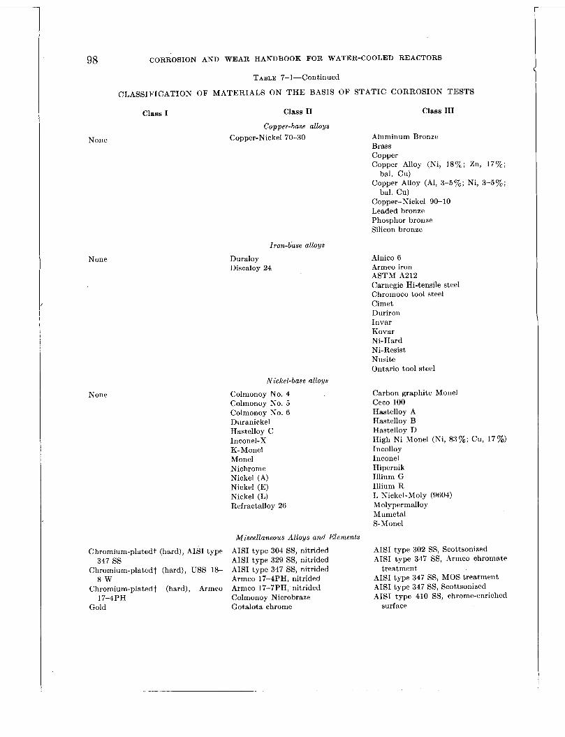
98 CORROSION AND WEAR HANDBOOK FOR WATER-COOLED REACTORS
TABLE 7-1-Continued
CLASSIFICATION O F MATERIALS ON T H E BASIS OF STATIC CORROSION TESTS
Class I
None
None
None
Class I1
Copper-base alloys Copper-Nickel 70-30
Duraloy Discaloy 24
Iron-base alloys
Nickel-base alloys
Colmonoy No. 4 Colmonoy No. 5 Colmonoy No. 6 Duranickel Hastelloy C Inconel-X K-Monel Monel Nichrome Nickel (A) Nickel (E) Nickel (L) Refractalloy 26
Miscellaneous Alloys and Elements
Chromium-plated? (hard), AISI type 347 ss
Chromium-plated1 (hard), USS 18- 8 W Armco 17-4PH, nitrided
Chromium-plated? (hard), Armco Armco 17-7PH, nitrided 17-4PH Colmonoy Nicrobraze
Gold Gotalota chrome
AISI type 304 SS, nitrided AISI type 329 SS, nitrided AISI type 347 SS, nitrided
Class 111
Aluminum Bronze Brass Copper Copper Alloy (Ni, 18%; Zn, 17%;
Copper Alloy (Al, 3-5’%; Ni, 3-570;
Copper-Nickel 90-10 Leaded bronze Phosphor bronze Silicon bronze
bal. Cu)
bal. Cu)
Alnico 6 Armco iron ASTM A212 Carnegie Hi-tensile steel Chromoco tool steel Cimet Duriron Invar Kovar Ni-Hard Ni-Resist Nusite Ontario tool steel
Carbon graphite Monel Ceco 100 Hastelloy A Hastelloy B Hastelloy D High Ni Monel (Ni, 83%; Cu, 17%) Incolloy Inconel Hipernik Illium G Illium R L Nickel-Moly (9604) Moly permalloy Mumetsl S-Monel
AISI type 302 SS, Scottsonized AISI type 347 SS, Armco chromate
AISI type 347 SS, MOS treatment AISI type 347 SS, Scottsonized AISI type 410 SS, chrome-enriched
treatment
surface
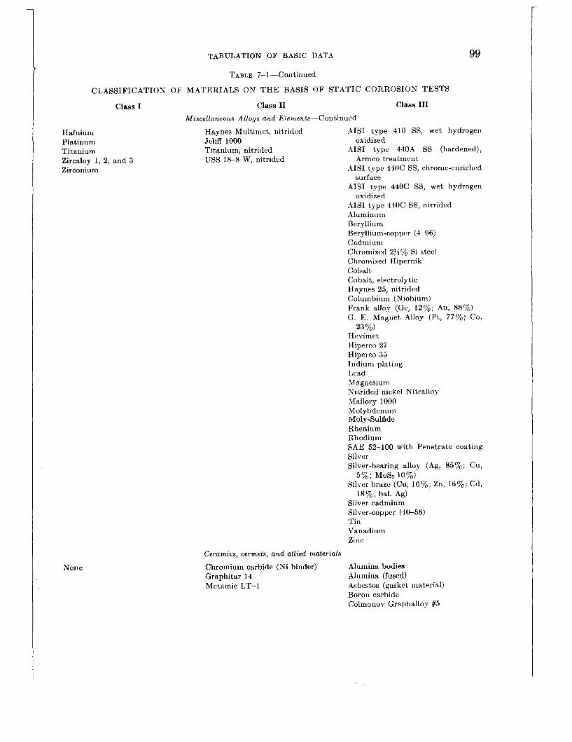
CLASS FI CAT1 0
Class I
Hafnium Platinum Titanium Zircaloy 1, 2, and 3 Zirconium
None
TABULATION OF BASIC DATA 99
TABLE 7-1-Continued
r OF MATERIALS ON THE BASIS OF STATIC CORROSION TESTS Class I11 Class I1
Miscellaneous Alloys and Elements-Con tinued Haynes Multimet, nitrided AISI type 410 SS, wet hydrogen Jeliff 1000 oxidized Titanium, nitrided AISI type 440A SS (hardened), USS 18-8 W, nitrided Armco treatment
AISI type 440C SS, chrome-enriched surface
AISI type 440C SS, wet hydrogen oxidized
AISI type 440C SS, nitrided Aluminum Beryllium Beryllium-copper (4-96) Cadmium Chromized 2)h% Si steel Chromized Hipernik Cobalt Cobalt, electrolytic Haynes 25, nitrided Columbium (Niobium) Frank alloy (Ge, 12%; Au, 88%) G. E. Magnet Alloy (Pt, 77%; CO,
Hevimet Hiperco 27 Hiperco 35 Indium plating Lead Magnesium Nitrided nickel Nitralloy Mallory 1000 Molybdenum Moly-Sulfide Rhenium Rhodium SAE 52-100 with Penetrate coating Silver Silver-bearing alloy (Ag, 85%; Cu,
5%; MoSz 10%) Silver braze (Cu, 16%; 211, 16%; Cd,
18%; bal. Ag) Silver cadmium Silver-copper (40-58) Tin Vanadium Zinc
23 %)
Ceramics, cermets, and allied materials Chromium carbide (Ni binder) Alumina bodies Graphitar 14 Alumina (fused) Metamic LT-1 Asbestos (gasket material)
Boron carbide Colmonov Graphalloy #5

100 CORROSION AND WEAR HANDBOOK FOR WATER-COOLED REACTORS
None
TABLE 7- 1-Coritinued
CLASSIFICATION OF MATERIALS ON T H E BASIS OF STATIC CORROSION TESTS
Class I Class I1 Class I11 Ceramics, cermets, and allied materials-Continued
Graphalloy Babbitt Graphalloy (copper) Graphalloy (gold) Graphite Karbate A Karbate C Mica (natural and glass bonded) Quartz Silica (fused) Solaramic (glass enarnel) Titania (fused) Titanium boride Tungsten carbide (Co binder) Titanium carbide (Ni binder) Titanium carbide (Pt binder) Tuiigsten carbide (Pt hinder) Zirconium boride
Plastics
Teflon Baked phenolic resin Teflon impregnated with asbeFtos Kel-F Teflon impregnated with copper Plexiglass
Polyethylene Ruloii Silastic
'Carbon, 0.06% max. tThickness: 0.0002 in.4.0005 in., or 0.002 in.

TABULATIOW OF BAISIC DATA 101
FOREWORD TO TABLE 7-2-DYNAMIC CORROSION TEST DATA
Test Conditions
The corrosion rates i n this table were based on tests conducted in closed stainless steel loops through which high-purity water was circulated over t,est samples included in the loop. Most tests were conducted at 500” F; however, some results are given a t 600’ F. Principal additives studied were oxygen, hydrogen, and lithium hydroxide. M’ater velocit.ies ranged froin one foot per minute (1/60 ft/sec) to 60 feet, per second. Details of t,he test procedures are given in chaptcr 5.
Interpretation o,f Corrosion Rates
Corrosion rates given in t.he table are nominal figures. * Weight gains or losses are indicated by t,he prefised plus or minus sign. It should be noted t.hat the corro- sion rates are based on overall corrosion for t,ot,al time in test.
Val id i ty Factors
The validity factor indicat.es the reliability of t,he corrosion rate given. This factor is based on a weight,ed consideration of the number of samples, duration of test, and consistency of results. Generally speaking, mate- rials which had the highest validity rating were tested for periods ranging from 1,500 to 5,000 hr (average about. 2,000 hr) and a t least 10 saniples were iested for each environment. Materials which had the lowest validity rating were generally ks ted for a period of about 500 hr and consisted of a few samples; or showed inconsistent results.
Val id i ty Factor “d”-Considered to be a represent.at,ive value for the particular condit,ion.
Val id i ty Factor “B”--Considered to be ti representat,ive value for the particular condition but. lacking iii
t,he.estent of data required for a validitmy fact.or of A. Val id i ty Factor “C”-Some doubt coiicerning the valid-
ity of the corrosion rate. Usually indicates in- consistent results or insufficient dat,a.
Abbreviations and Sy,n bols
( 1 ) Environment: I), degassed water, less than 0.5 cc of oxygen (STP)
per kilogram of water. NA, no analysis made for const.ituent.. When NA
appears in hydrogen column, the implication is ’
that hydrogen is probably present in the range 0 to 20 cc of hydrogen (STP) per kilogram of water. This amount of hydrogen generally results from corrosion reactions which evolve hydrogen.
*For simplification corrosion wtt‘s were originally grouped in ranges whicli were subsequently assigned nominal r a t w For e x a n i p k . il w- iiorted mtr of +5 rng/dni?/mo may h n r tunlly s h o w d i i slightly t l iffcrmt rate. ‘I‘lic nominnl riitv rri)rvscnts :I well-rounctcd arcragis.
(2) Condition of specimen: SA-Solution annealed S-Sensitized (carbidc €1-Hardened precipitation) 31-Malcomized W- Welded X-Nitrided E. P.-Electropolished 1’-Pickled N. B.-Nicrohrazed
S D-Sanded
Index of iWaterialn
STAISLESS STEELS AISI type 302
’ AISI type 303 AISI type 301 AISI type 304 ELC AISI type 316 AISI type 321 AIS1 type 347 AISI type 410 AISI t.ype 420 AISI type 140-C
USS 18-8 \v Armco 17-4PH .Arrnco 17-7PH Carpenter 20
Stellite No. 3 Stellite No. 6 Stellite No. 19 Stellite No. 21 Haynes Alloy No. 25
Copper-nickel (70-30)
AST M A 179 ASTM A212 (grade -4) ASThl A212 (grade R) ASTM .4302 Croloy 1)i Croloy 2% Low manganese carboit
SPECIAL STAINLESS STEELS
COB ALT-B ASE ALL0 Y S
COPPER-BASE ALLOYS
IROX-BASE ALLOYS
steel No. 1
IRON-BASE ALLOYS-COII-.
Low manganese carbon
Reference carbon steel Special carbon steel
Special carbon steel
Special carbon steel
Special carbon st,eel
Special carbon steel
Special carbon steel
steel No. 2
No. 3
No. 4
No. 5
No. 6
No. 8
No. 9
A-Nickel Incoilel Inconel-X Monel K-Monel
SICKEL-BASE ALLOYS
MISCELLASEOLS METALS A N D ALLOYS
Haf niurn Hard chromium plate Titanium Zircalloy-2 Zirconium crystal bar Special alloy (15% Pd,
30 & Cd, 55% Ag) Special alloy (20% I’d,
30 % Cd, 50 % .4g)
Special Notes
(1) The majority of weight changes recorded werr negative. Positive weight, changes were, in most cases, small (less t,han 5 mg/dmZ/rno) and are con- sidered t.o result. from thin tightly adherent oxidc films.
(2) Unless ot.herwise indicated metallic samples were machined or ground to a surface finish of 63 microinch (rms).
( 3 ) The sensitized specimerts reported in table 7-2 wercb heat.ed a t 1,200’ F for 2 hrs atid air coolcd.
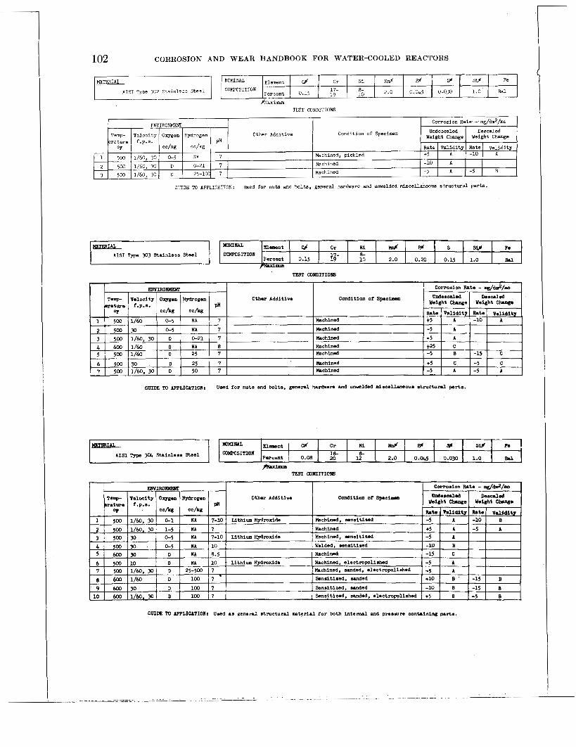
I
W W O S I T I O I le- percent 0.08 20
102 CORROSION AND WEAR HANDBOOK FOR WATER-COOLED REACTORS
e- 2.0 0.045 0.030 1.0 Brl 12
4 h x m TEST CONDITIONS
GUIDE M APPLICATION: Used for nuts and bolts, general hardware and m e l d e d miscellaneous structura l parts .
TEST WNDITIOIS
Other Additive condition O f specimen
G ~ D E TO AppLIcATIOnr Usad f o r nuts end bolts. g e n e n l hardrare and umalded nriscsllaneous s t m c t u n l parts.

MATERIAL ATSI Type 3oL Sta in less Steel
(continued)
I 1
TABULATION O F BASIC DATA 103
Undescaled Descaled Condition of Specimen Weight Change Weight Change
Temp- Velocity Oxygen Hydrogen C t h r Additive eratwe f.p.s. PI1
Rate Validity Rate Validity OF 4% c c h g
5M) 1/60 0-1 NA 7 Machined. oickled *5 I A -in I R
Element I I CONPOSITION
Fer cent
' 2
, 3 L 5
TEST CONDITIONS
Ctt.er Additive Condition of Specimen
GUIDE: 'I@ APPLICATION: Used as general s t ruc tura l material f o r both in te rna l and pressure containing p a r t s .
500 30 0-1 NA 7 Machined, p i c u e d t 5 4 -5 B ,500 30 0-1 N A 7 P i l C O m i Z e d -15 C 500 1/60 1-5 N A 7 Machined, pickled 500' 70, 30 1-5 I NA 6-7 Xaalcomized t 1 5 r:
t5 A -5 C
MTFRUL
lISI Typs 316 Stainless Steel C r Ni llnf
WWCSiTION 16- 10- 2 . G Fercent 0.10 18 ~1
G m E TO APPLICATION: used aa general s t r u c t u a l wterlal for both internal and pressure containing parts.
~ V . I R 0 ~ corrosion Rata - m&&/mo
vrdsscrrled DeSUled 1 Weight C-s 1 Weight Clang. I Rat0 I YllliditJ I Rat0 I V a l i d i t j I
Temp Velocity oxygen Hmogen Other Additise Condition Of specilwa e r a t m e f .p.8. PH
o? c c h g c c h g
4 Obtained fo r t e s t e at pH 7 mly.
WIDE 10 IPPtICITIORr Considerod satisfactory corrosion wise, ho-wr th io material was not n o m l y used
in the f i r - t r a t e r cooled nactor or i ts pmtotyps te.ceuM of pass ib ls a l d i n g
d i f f i d t i e a .
417017 0-57-8

104 CORROSION AND WEAR HANDBOOK FOR WATER-COOLED REACTORS
paxbmlm TEST CONDITIONS
Other Additive Condition of S p ~ e i a n
GUIDE TO AFTLICATION: Considered satisfactory cormsion-wise, horvcr, A151 T y p s 32155 waanot n o m l l y used In
the f i r s t water cooled reactor or i t s pmtotyps.
TEST WNPITICNS
GUIDE TO AF’PLICATIOR: General 8tmctuml material Cor both internal and pm5mm contAining parts.
Element 1 FEZ
COMPCSITION PISI ~ y p e 3!47 Stainless Steel
TEST CONDITIONS
Other Additive Condition of Specimen
GUIDE TC APPLICATION: General structural rater ia l f o r both internal and pressure containing parts .
. - ~ ~ .-. .. . .. . .. . . . . . .. .. .

105 T A B U L A T I O N O F B A S I C D A T A
kz rat-&
1 I 5 0 0 2 1 600
MTFRUL
A I S 1 Type h10 Stainless S tee l
Undeacnled D s s d e d Condition of Spselimo weight Change Weight Ctnngs
Velocity Ovgen RJdrogsn Other Additive f .p.8. PH
Rate M i d i t 7 Ute v a l i d l t y C C h c c b g
1/60, 30 1-5 NA 7-10 Sodium Hydmxide Hardenad - 5 A
30 D NA 8.5 Hardened -100 c 3 A 5
6
500 10, 20 D NA 10 Lithium Hydmxide Hardened -10 A
5 0 0 10. 20 D NA &- Lithium Hsdroxide Hardened -10 c 5w 10 D 100 7 Hardened -5 B
500 1/60. 30 D 2'20-500 7 Hardened -10 A
GUIDE 'M APPLICATIORt Haa good bcarlng Chare.cteristic8; n o t u=d f o r bearing appl icat ion because of i t a
suscep t ib i l i t y t o crsviicc corrosion.
bearing water.
Shows tendency toward p i t t i n g in oxygen
Subject tc stress cormsion in t he hardened and s t resaed condition.
MATERIAL
AISI Tyoe 420 St9inless Steel NcKINAL Element I C f I Cr N i CCHFOSITION
1.0 0.011 0.03 1.0 Percent 1 0.15 1 E- I
bearing water.
i n the hardened and s t ressed condition.
I t i s suspected tha t t h i s material i s subject to s t r e s s corrosion
Cr N i I& F% S f si# )io* FC
TEST MhDITIONS
percent 0.95- 1.2 18 16- 1.0 0.OL 0.03 1 1.0 0.75 Ea1
E N V I R O m
Temp- Velocity Oxygen Hwogen ra ture f.v.s. DH
Othe r Additive Condition of Specimen
GUIDE To APPLICATII3N: Kas goad bearing character is t ics ; not used for bearing application because o f its
suscept ibi l i ty to crevice corrosion. Shows tendency toward p i t t i ng i n oxygen
bearme water. It is suspected tha t this material is subject to st ress corrosion
in the haraened and s t ressed condition.
1
2
Rate Val idi ty I a t e 1 Validity -15 B 1 1 500 30 0-1 NA 7 Hamened
5 0 0 30 0-1 NA 10 Sodium Hydroxide Rardened -15 A I 1 OF cc/ke c c h g
3 L 5
6 7
500 1/60 1-5 NA 7 Hardened -10 A 500 30 1-5 N A 7 Hardened -50 C
D -15 A 5 0 0 30 NA 7 tiardened 500 1/60 D NA 7 Hardened -100 c 500 1/60, 30 D 500 7 Baldened -25 A
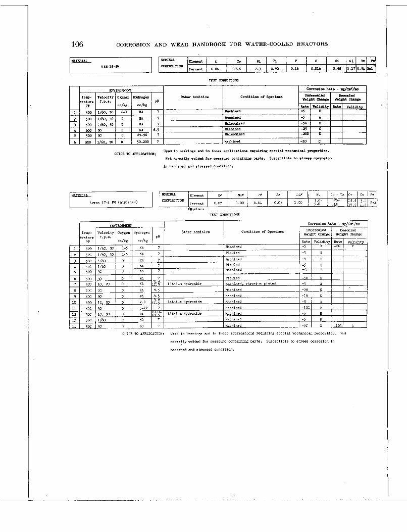
106 CORROSION AND WEAR HANDBOOK FOR WATER-COOLED REACTORS
KtTFRlAL USS 18-Sd
m m m n w n t j c j C r N i Ti P S
Percent 0.06 17.6 7.3 0.90 0.16 0.016 0 COMPOSITION
TEST CONDITIO=
I corrosion Rate - mg/dd/.o ] I Other Additive Condition of Speclmn
I Hachinad I Used i n hirings and i n those applications ruquiring s p e c i d rnscluniul pmprtiea. cmm TO -cmonI Not normrllp welded for pm#eura con t r idng parts. Sumcsptibls to stress cormelon
i n hardened md stressed condition.
TEST CONDITIONS
Other Additive Condition of Specimen
GUIDE To APPLICATION: Used i n bearings and in those applications requiring special mechanical properties.
normally welded for pressure containing parts.
hardened and stressed condition.
Not
Susceptible to stress corrosion in

TABULATION OF BASIC DATA ~~
Armco 114 PH (hardened)
107
NOMINAL nement COMPOSITION
Percent
I
S f ?#
Corrosion Rate - mg/dm2/mo ENYIROMEWT Other Additive Condition of Specimen Temp- Velocity Oxggen Hydrogen
s r a t u r e f.P.S.
Si* Ni Cr A 1 Fe
G’flIOE To APPLICATION: Used i n bewines and inethose applications requiring s p e c i d mechanicd properties.
normally welded for pressure containing parts.
hardened and stressed condition.
Not
Susceptible to stress corrosion i n
MrnIAL Cr N i si no I Cu’ I Fs I
Other Additive Condition of Specimen
Percent 0.07 ‘20 29 1 COWOSITION Carpenter 20
GUIDE m APPLICATION: Used in bearins and i n those applications requiring special mechanical properties.
Susceptible to stress corresion Not normally welded for pressure containing parts .
i n hardened and s t ressed condition.
2 3 B - l
EWIRONMEWI
erature f.P.B. PA OT C C h C C h
Machined 1 500 1/60, 30 0-5 NA 7 2 500 1/60, 30 D 0-50 7 Machined
Temp- Vslocity O w e n Iiydrogen Other A d d i t i v e Collditioa or spciwa
corro8ion itate - .P/dm2/.0
Weight Change Weight C W e
Fate W i d i t 7 Fate Validit7 -5 B
-5 A
ulldmsCa3.d rmauled
GUIDE TO APPLICATIOR: U r d i n r i v e t applications here non-rork hardening p r n p r t i e s a n des ired.
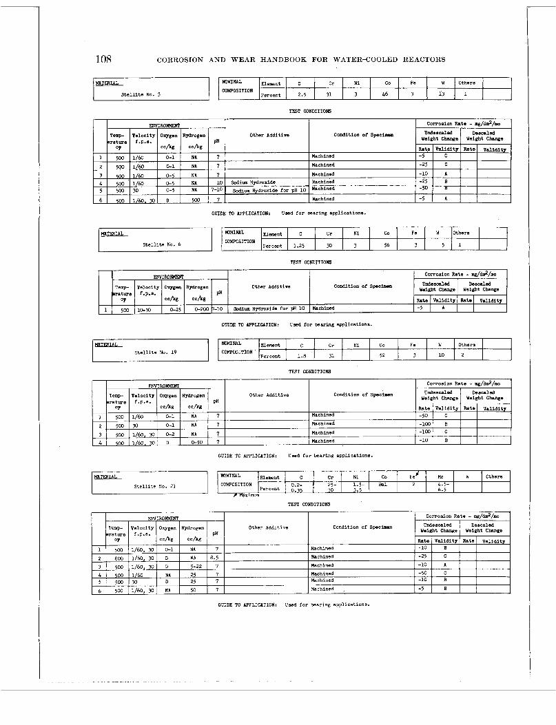
108 CORROSION AND WEAR HANDBOOK FOR WATER-COOLED REACTORS
I
Co F s VI Others C r N i N O ~ N A L Element I c I COW’OSITION
3 46 3 13 1 Percent 2.5 31
TEST CONDITIOKS
Other Additive Condition of Spaciaen
I
GUIDE TO AWLICATIOII: Uwd f a r bearing appl icat ions.
H A T W U L “IML Element c C r N i co Fe W Others
S t e l l i t e No. 6 Percent 1.25 YJ 3 56 3 5 1 CCWCSITION
TEST mNDITIOKS
E r 3 Corrosion Rate - .g/b.2/.0
Weight Change Weight Chnge
Rate I Val idi ty Rate I Validi ty
ENYIRONMERC Ordescaled Desded T e l l p Velocity Oqvgea Agdrogen Other Additive condition Of spaciaan
matwe f.P.8. PH OP C C h c c b g
1 5W 1&?0 0-25 0-200 7-10 sadium Hydroxide f o r pH 1 0 Wachined -5 I A
GUIDE M IPPLICATION: Usod f o r baring applications.
H A T W I h L C r N i CO FS W Othsra
TFST CONDITIONS
Other Additive Condition of Specimen
GUIDE TO APPLICATION: Umd f o r bearing applications.
Percent 1.8 31 52 S t e l l i t e No. 19 3 10 2
Other Additive Condition of Specimen
mrwm “IML Element I , c I C r N i co
GUIDE TO APPLICATION: Used f o r bearing appl icat ions.
Fed uo W Others COWCSITION S t e l l i t e No. 21 0.2- 25- 1.5- -1 2 L.5-
Percent 0.35 30 3.5 6.5
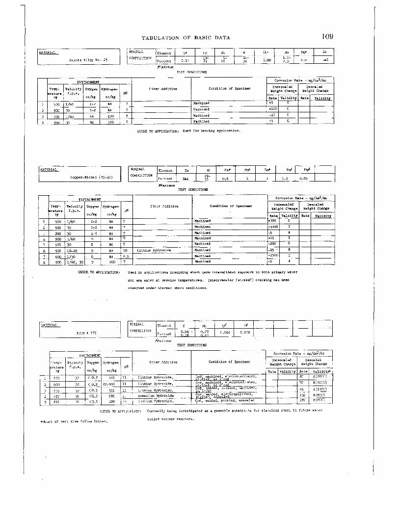
TABULATION O F BASIC DATA 109
Ctbr Additive Condition of Specimsn
C:ker Additive Condition 01 Specimen
GUIDE TO APPLICATION: Used in soplications involvlnK short tern intermittent exposum t o both primary water
end sea water at service t ewratum. .
observed under thermal shock conditions.
InterEmular (stmsa?) cracking has teen
Ctter Additive Condition of Specimen
GUIDE 1L7 APPLICATIOA: Currently being investigated as a possible substitiltu f a r s ta in less s t e e l in f u t u r e mater
cooled n x l e a r reactors. 4iHours o f t e s t time follow l e t t e r .

110
NONINAL COW'C~~TION
CORROSION AND WEAR HANDBOOK FOR WATER-COOLED REACTORS
Element 1 c I Mn s1 P s I Percent 0.27 0.62 0.26 o.fl12 o.P4
NCNl!'nL
ASTM A 212 GRADE A CCT'CSiTIGN
TFST CONDITIONS
Ctter Additive Condition of Specimen
GUIDE 'E APFLICATION: Currently being investigated as a possible subs t i tu te for s t a i n l e s s s t e e l i n fu ture water
Element I C I Hn si F S I Feicsnt 0.27 0.62 0.26 0.OU 0.04
* b u r s o f test time follow l e t t e r . - A i r exposed a t 95OOF. $ F i r s t 200 b u r s a t ZOOOF.
cooled nuclear reactors.
TEST CONDITICNS
Cundition of Specimen Cther Additive
~~
29 600 1 1 5 I < C . l O I 20 I 7 I No Ion-X; Amonia - l-2ppml rachined f in i sh 1 430 1 C(500) 1 5 1<0.10 I 20 I 7 I Yo Ion-X; Ammonia - 1-2ppml Et- Pretryated 13 hours - 'IW I I 500 I C(500) 30 I 600 1 T f o r 25 hours
GUIDE To APPLICATION: Currently being investigated as a possible subs t i tu te for sta in less s t e e l in fu ture water
+Hours of test time follaw l e t t e r . 'ahit- exposed a t 9503F.
@ F i r s t 200 b u r s a t 2CC"F.
cooled nuclear reactors.
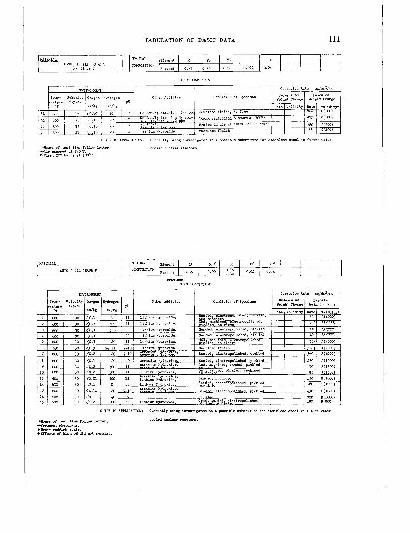
TABULATION O F BASIC DATA 111
ASTM A 212 GMUIIE A K ~ Z F ~ L Element 1 c I b!n si P S
Percsnt 0.27 0.62 0.26 0.012 0.04 CCWCSITION
GUIDE TD APPLICATIGti: Currently wing invest igated as' a possible subs t i t u t e for s t a in l e s s a t e e l i n fu tu re water
*Hours of test time follow letter. * A i r exposed at 95m. @ F i r s t 200 hours a t 2@F.
cooled nuclear reactnrs .
Cther Additive Condition of Specimen
GUIDE To APPLICATION: Currently being invest igated as a possible subs t i t u t e for stpinless steel i n fu tu re water
*ROWS o f t e a t t im follow l e t t e r . *Frequent s hutdonvr. +Heavy reddish scale. $Effects of high pH did not persist.
cooled nuclear reactors .
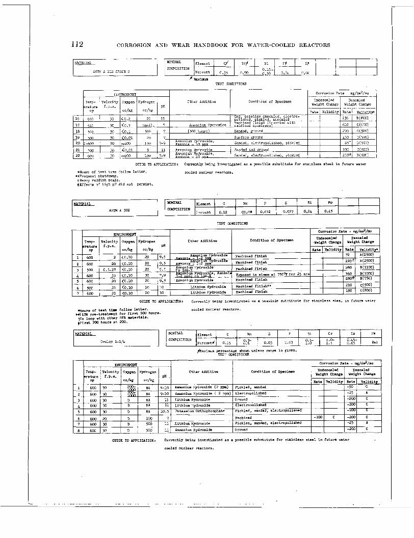
112 CORROSION AND WEAR HANDBOOK FOR WATER-COOLED REACTORS
Temp- erature
COEPCSiTION 0.15-
# w i n a r m TEST CONDITICNS
Undescaled Descaled Condition of Specimen weight Change Weight Change Velocity Oxygen Hydrogen Ctt.er Additive
f.p.s. PH ~
Hn P S
GUIDE TO APPLICATION: Currently being investigated as a possible subs t i t u t e fo r stainless steel i n future water
si uo
*HOUTE of t e s t time follow l e t t e r .
tHeavy reddish scale. (Effects of high pH did not pers is t .
+%Frequent shutdowns.
Fcrctnt 0.12 01.09 0.012 0.027 COYPCSITION
cooled nuclear reactors.
0.2L 0.L5
TEST CONDITICNS
Condition of Spscinen Cther Additive
CLTDE TO bpPLICA?~ii: Currently be in^ investipatcd as a oossible substicute f o r s t a in l e s s s t ee l In futum ,.atel
cooled nuclear reactors .
I 1
I ...
CmDE TO AppLICATIOli: Currently beinp investipated a8 a possible subs t i t u t e for s t a in l e s s steel i n future water
cooled nuclear mactor8.
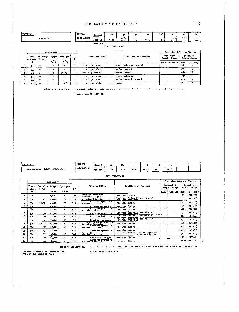
TABULATION O F BASIC DATA 113
w P s
Cthr Additive Condition of Specimen
I n 1 5rX 1 11 I Lithium Hvdmxide i i
si Ti
GUIDE TO APPLICATION: Currently being investipated a s a possible mbst i tute f o r s ta in less s t e e l in future hater
cooled nuclear reactors.
percent 0.22 0x8 0 . ~ ~ 8 0.017 COECSITION 0.19 0.16 I
GUIDE M APPLICATION: Currently *in@ investiFated 9s a w s s i b l e substitute for stainless s tee l i n future water
W O U ~ S tar& tisr follow lettar. WFlrnt Mo hours a t W F .
cooled nuclear reactors.

114 CORROSION AND WEAR HAND,BOOK FOR WATER-COOLED REACTORS
P Element 1 C Mn S S i T i
+Hours of test time follow l e t t e r . +rLithium W o x i d e aLso added.
rercent 0.19 0 . ~ 8 0 . ~ 1 0 0.C19 UIW YAliCANFSF. CAPECR STEn FC.
cooled nuclear reactors.
0.19 0.17
1
TEST COIUPITICNS
Ctber Additive Condition of Specimen
GUIDE TO APPLICATION: Currently be- investigated as a possible subs t i tu te for s t a i n l e s s s t e e l in fu ture mater
CHOUTS of test time follow l e t t e r . =Frequent s h u t d a m . +Heavy reddish scale.
cooled nuclear reac tms .
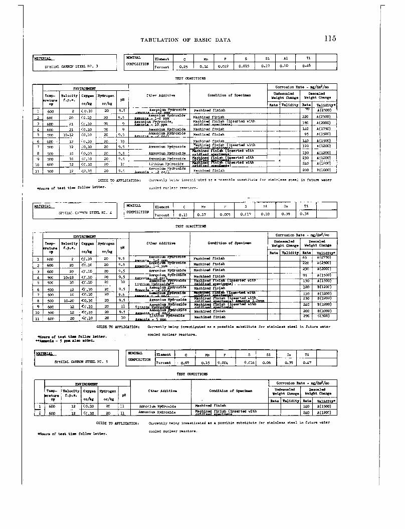
TABULATION OF BASIC DATA 115
SPECIAL CARBON STEFL NC. 3
Kn P s Si A 1 T i C?PXSITION
Fcrcont 0.25 0.U 0.012 0.015 0.17 0.10 0.L6
Cther Additive c0Dditioa or S p e c h a
MTSRIf.L
SF'.CIAI. CAPPON STEFL RC. 4
GUIDE TO APPLICATIOE: Currently hemp invest i ra ted as a m s s i b l e Subst i tute for s t a in l e s s s t e e l i n f u t u n water
*ours of test time f o l l m letter. cooled nuclear reactors.
Yn P S si cu Ti
Fercent 0.11 0.17 0.W 0.C17 0.10 0.39 0.38 KJPXS:TION
kmE€bL SPECIAL CARBOW STEEL KO. 5
TT5T COhiITICW
GUIDE To APF'LICITIONr OIlrrontly b i n p inoast ipated as a possible m b s t i t u t e lor stainless steel in fu tu re water
V m P Si Cu Ti COI(PCS1TIOH
Fcrc-t . 0.07 0.15 0 . a 0.C16 0.m 0.99 O.L?
woym of tat tjn fo l lw lettar. -Amnia - 5 pp. alm addad.
cooled nuclear reactor-.
Cther Additive Condition or spcinm
CLlDE TO APPLICATION: Currently bs inp invsst ieated as a possible subst i tute for s t a in l e s s a t ee l i n future water
cooled nuclear roactors. Wmrs or temt t l r f o l l w letter.
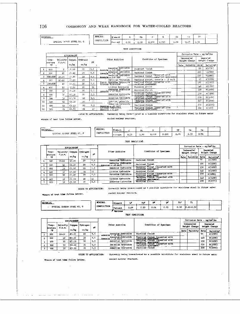
116 CORROSION AND WEAR HANDBOOK FOR WATER-COOLED REACTORS
NoM1r*L Element C 1 b!n P S S I cu zr
TFST COhiITIONS
Otter Additive Condition of Specimen
LOWCSITJCN Percent 0 . ~ 6 0.08 0.0ne 0.015 u.C9 U.L@
GUIDE TO APPLICATION: Currently being investigated as a possible subs t i t u t e for s t a in l e s s s t e e l i n future water
0.31 I
x ~ o m e of test time follow letter. cooled nuclear reactors .
TEST COhTITICNS
EKV1RC”I Corrosion Fate - .E/&/mo UndesealeE Descrled
wsight Change Weight ChPnga Tenp- Velocity Oxggen Hydrogen Cther Additive Condition of S p c i w n i
CmDE TO APPLICATION: ~ u r r e n t ~ y bsinp invest icated as i possible subst i tute fo r s t a in l s sa s t e e l in fiturn water
. H ~ ~ ~ or test t i m follow letter. cooled nuclear reactors.
Other Additive Condition of S p c i g n
GmDE M AF’F’LICATIONr Currently beina invsst ipnted 8s a possible subs t i t u t e for s t a in l e s s s t e e l i n future water
cooled nuclear reactors. auours of test time fallow letter.

TABULATION O F BASIC DATA 117
1'- 5 si cu F* Ni
/
W>TCSITION
TEST CONCITICKS
Cther Additin, Condition of Specinan
HXTWIAL
Inconel
GUIDE TO h'LICATIOI: Yiscellaneous m t e r i a l investivated.
water.
Susceptible t o p i t t i n g in cmviccs in oxygen bearing
Nom'ML Elemtnt 1 @ I Cr N W l e I COPCSifION 11- 6-
Feicant 0.15 I 17 72 i o 1.00 0.50
Other Additive Condition of S p c i a a n
GUIDE TO APPLICATION: Used as spring matnrlal i n aopl icat ions less than X@F. A b - t h i s tamperatun intargrpnular
a t tack may occur. EMct conditions which p d u e e at tack are not horn, although it is thouat
t o be duo t o a chromium carbide precipi ta te a t the wain boundaries. Susceptible to p i t t i n g
i n crsvicss in oaxgen bearing water.
Cthar Additl- Coadition of speeirn
GmDE TO APPLIUTION: Used a3 a apring mater ia l . Not subject to the l imi t a t ion of Inconel. Lscsptibl . r0
p i t t i n e on crev ices in o x y e n baring ratar.

118 CORROSION AND WEAR HANDBOOK FOR WATER-COOLED REACTORS
VATZRIAL
''onel
N i lln s Si cu FS
1.4 COWCSITION 0.15 0.01 0.1 30 Ferrnnt 0.1 67
TEST CC)rX!ITICNS
Cther Additive Condition of Speciwn
TO mLZ(TIOm: Used i n appl icat ions involving continuous expsum to pr imary water containins mall w n t s
of sea water due t o back lenkage in valves. P i t t i ng i n crev ices i n oxypn b a r i n g water.
Other Additive Condition of Specimen
GUIDE TO APFLICATIOL: Usad i n applications involvinp continuoue e w m m t o primsrg water containing d
amounts of sea water due t o back leakage i n valves.
bearing water.
P i t t i ng i n env ices i n oxygen
Other Additive Condition Of sp.ci..11
CmDE TO AppLIClTlOn: Used in appllcations nquirlng spscirl rmclear pmpsrt ies i n addition to superior cormaim
msistance.

TABULATION O F BASIC DATA 119
K M ~ CDIPCSITION
Element 1 Fercent
I I I I I
TBT WACITICKS
Condition of Specinan Dther Additive
* A c t u a l ,,bse-ad cormalon r a t e s given i n order t o demonstrate t he e f f ec t of oxygen concentrstion in a high pH envimnmrnt M d also to demonstrate t h e veloci ty e f f ec t observed a t 0.25 cc%/ a t pH 11.
GUIDE TO APPLICATIONr Considemd sat isfactory as a bearing material.
of i t s a sns i t i v i ty t o e n v i m m n t a l changes. Hadchra?dmd platinp: was ussd sxtansively in
the f i r s t rater cooled nuclear reactor Md i t s pmtotrpe.
Presently, i t is not n o m l l y uacd because
1
Corrosion Fate - ENyIROtWEW unde0CAl.d D.ecrled
Weight Change Weight Change Temp- Veloci ty Ovgen Hydrogen Other Additive conddition Of speciom mature f.p.n. pn
Rate I Y l l i d i t j Rate I V r l i d i t j .J? c c h g c c h
500 20 D l W 8.5 YAchimd -5 I B
~~
GUIDE TO AFTLICATIONr Used in appl icat ions requiring s p e c i d nuclear propert ies i n addi t ion t o superior c o m e i o n
n s i s t m c a .
417017 0-57-9

120 CORROSION AND WEAR HANDBOOK FOR WATER-COOLED REACTORS
wmNAz Element I Fcf 1 Cf A H I T i # / Nf I Zr 1
GUIDE To IWLICATION: Used i n applications mauirine, special nuclenr p r o p r t i c s i n addition to superior
percent 0.06 0.04 0.01 0.008 C D F C S I T I G N
cormaion msistance.
0.005 0.002 Ba
NGNINAL Eiemnt Pd Cd
TEST CCIaITXNS
Clther Additive Condition of Specimen
Ag
GUIDE To AWLICATION: Miscellaneous material investigated.
50 C0K"OS1TICP
Fer-cr::.t 20 30 1

TABULATION OF BASIC DATA 121
FOREWORD TO TABLE 7-3-WEAR TEST DATA
Test Condjtions
Wear factors were determined by means of two different wear test units. One unit, referred to as the piston-cylinder test rig, prqduces wear by means of linear reciprocating motion. The other unit, referred t o as the journal-sleeve test rig, produces wear by means of rotational movement. The majority of the tests were conducted in oxygenated water containing 10 t o 30 cc of oxygen (STP) per kilogram of water. The hydrogen content for wear tests in hydrogenated water:varied from 200 to 500 cc (STP) per kilogram of water. For both environments initial electrical resis- tivity of the water was 500,000 ohm-cm or greater. Tests were normally run for 500,000 cycles. Details of the test procedures are given in chapter 5 on testing procedures.
Interpretation of Wear Factors Wear factors for both tests were determined by meas-
uring the weight loss per pound load per million cycles.
Most of the material combinations considered suitable for service application possessed a wear factor less than 100 mg per pound load per million cycles.
Special Notes
(1) The martensitic stainless steels were tested in the hardened condition. For the precipitation-hardening alloys the symbol PH designates the hardened condi- tion, and SA indicates the solution annealed condition. Ceramics, cermets, and various miscellaneous mate- rials were tested in the as-received condition. The remaining metals and alloys were tested in the solution annealed condition. All references t o chro- mium plating are to plating applied by a n approved supplier. (See ch. 13.)
(2) The surface finish of untested samples ranged from 8 t o 16 microinch (rms).
(3) The bearing combinations are arranged so that the entry in the “materials” column is the moving ele- ment of the wear couple unless otherwise indicated. The combinations are listed in order of increasing wear. A complete cross index of all couples can be found in the general index.

122 CORROSION AND WEAR HANDBOOK FOR WATER-COOLED REACTORS
W E A R T E S T D A T A
k t W h l #
m l t q in thll oolrnn 18 llorlne ellmant of the w0.c coupl.
unless otherwise indicated. 4 Wear Factor - Milligrams per
*** Handy & Harman pound load per million cycles
9+ Ehployed i n service ( 1 ) No valid wear factor3 however, t h i s combination was
successful ly ut i l ized .
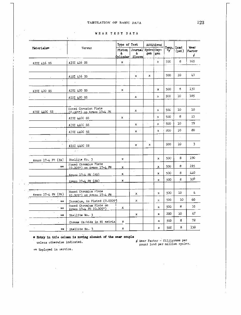
1
123 TABULATION OF BASIC DATA
W E A R T E S T D A T A
Material*
4 fit~g in this column i s m& element of the wear couple Wear Factor - hi i l l ipams per pound load per million cycles. unless otherwise indicated.
wt Employed i n service.

124 CORROSION AND WEAR HANDBOOK FOR WATER-COOLED REACTORS
W E A R T E S T D A T A
- t i
I ! f a l l Colmonoy No. 6 I I x I
500
10 220
9+ I S t e l l i t e No. 6 I I . I 10
8
8
8
-- 340 b30
460
- S t e l l i t e No. 21 (SA) X
S-Yonel X
A ~ C O 174 PH (PHI X x I 5 0 0 ~
Haynes 25 (Cold Vorked) X
AISI 304 SS X
k70 i x 500 8 I
x 500 8
, 200 8
475 - I I I I
99 S t e l l i t e No. 3 X X 2 . - X X
S t c l l i t e NO. 2 1 (m) X X
iw S t e l l i t e No. 3 X X
9+ Ste l l i t c No. 6 X X
W a l l Colmonoy No. 6 X X
'* 10 loo
~~
USS 18-8 '2 (SA) Ste l l l te No. 3 x * x 500 10 USS 18-8 H (W) Chrorcium, As Plated(0.0005": X
AISI U X , X
I x I I S t e l l i t e No. 3 X
Stellite No. 3 X x 500 8 130
e e in t h i o aoltllm l o mwlag did of the Ne- couple unless othcnrise indicated. d ki?ar Factor - Nilllgrams per
pound load per million cycles . rnloyed i n service.
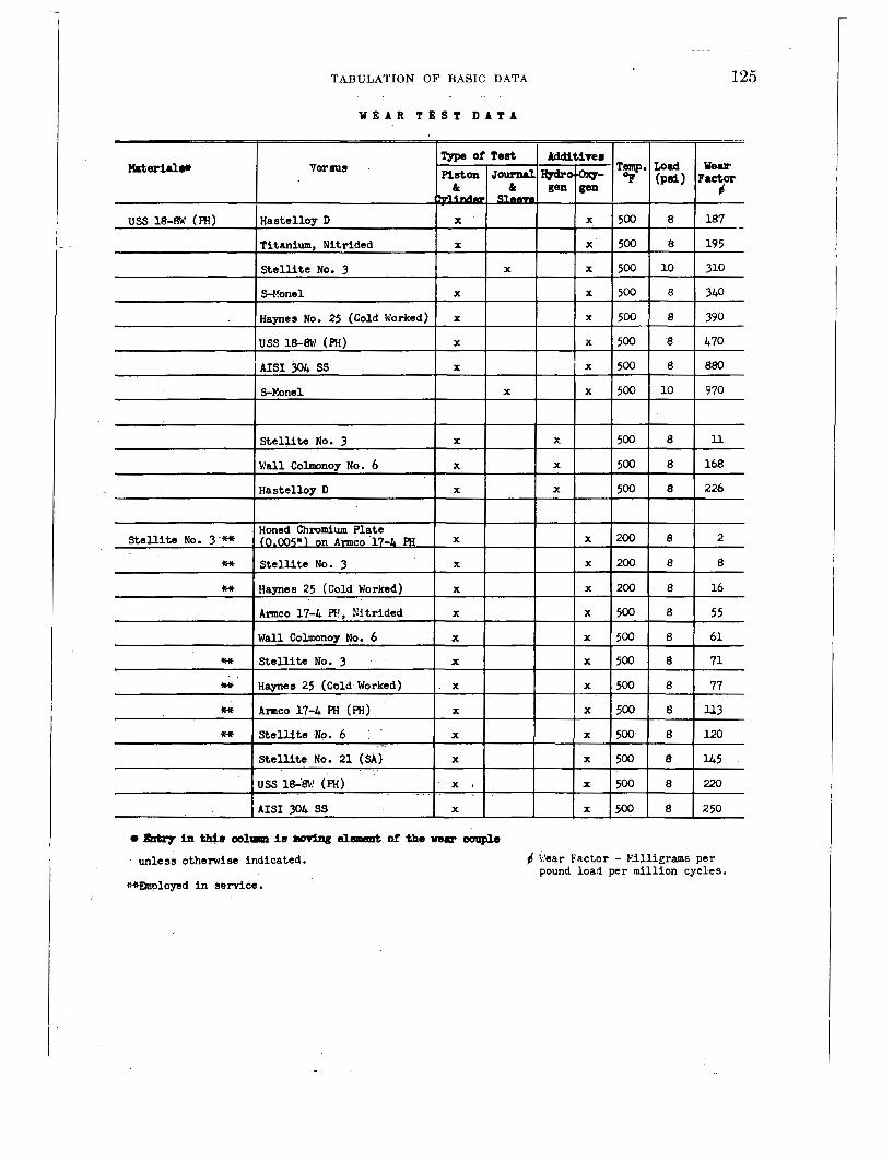
TABULATION O F BASIC DATA
W E A R T E S T D A T A
I I I
125
I
Honed Chromium Plate X Stellite No. 3 - M (0.1335 ") on Amco 17-1, PH
I
iw S t e l l i t e No. 3 X
iw Haynes 25 (Cold Worked) X
Amco 17-4 FT!, Kitrided X
wall Colmonoy No. 6 X
% S t e l l i t e No. 3 X
+9 Haynes 25 (Cold Worked) X
Q9 AITICO 17-4 PH (RI) X
int S t e l u t e No. 6 . X
StelUte No. 21 (SA) X
. -_
- uss 1E-@i (Ri) x i
AIS1 304 SS X
226
16 I
5 5 x 500 8 I I I I I * 113
500
220
250
h fhill001- i 8 a d d O f -0 W 8 . r CO@O
4 Year Factor - KUlierams per unless otherwise indicated. pound load per mill ion cycles .
MBmloyed i n service.

126 CORROSION AND WEAR HANDBOOK FOR WATER-COOLED REACTORS
W E A R T E S T , D A T A
X X
X X
X X S t e l l i t e No. 3 Boned Chromium Plate (0.005") on 17-L PH X X
Hastelloy D X X
+, S t e l l i t e No. 3
Q+ A ~ C O 17-4 Ffi (W)
+,
ball Colmonoy No. 6 I x I I x
USS 18-8W (?H) X X
S t e l l i t e No. 6 9Q S t e l l i t e KO. 6 X
t a l l Colmonoy No. 6 I x I -1 9Q Chromium As Plated (0.0005") x
, (HI loned Chromium Plate (0.005") on Armco 17-L RI X
S t e l u t e No. 21 (SA) X
J S S 18-BJ:' (PHI X
9Q IArmco 17-4 PH (Ffi) I I x 1
QQ joned Chromiiim Plate (0.00511) on Amco 17-1 PH x X
unless otherwise indicated.
QQ hployed i n service.
6 \!ear Facto+-Ydlliprams per pound load per mil l ion cyc les
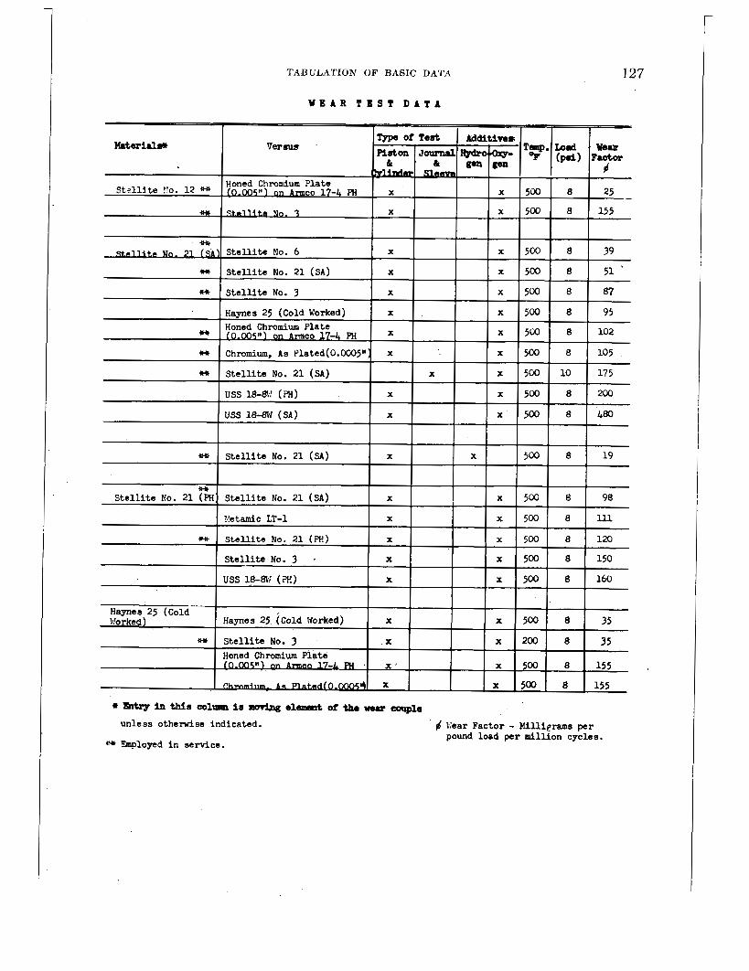
TABULATION OF BASIC DATA
W E A R T E S T D A T A
127
Honed Chromium Plate f- 17-1 F” X ’ x 500 8 155
x 500 8 155
unless o t h e d s e indicated.
* Employed i n service.
6 Vear Factor - Millierams per pound load per mi l l ion cycles .

128 CORROSION AND WEAR HANDBOOK FOR WATER-COOLED REACTORS
W E A R T E S T D A T A
s &try in this colrnnn i s mcivjng element of the mar couple 6 ';:ear Factor - Killigrams per unless otherwise indicated.
pound load per mil l ion cycles . +.* Employed i n servlce.
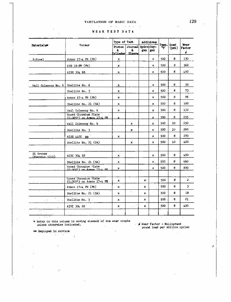
TABULATION OF BASIC DATA
S t e l l i t e NO. 21 (SA) X
, S t e l l i t e No. 3 X
AIS1 304 SS X
W E A R T E S T D A T A
X 500
X 500
X 500
-- (psi) Factor
T- 450
10 I 260
8 I 450 8 I 660 8 I 830
8 1 j-+ 21
it Entry i n t h i s column i s moving element of t h e wear Couple unless otneruise indicated. # Wear Factor - Milligrams
pound load per million cycles Q+ Employed i n service

130 CORROSION AND WEAR HANDBOOK FOR WATER-COOLED REACTORS
W E A R T E S T D A T A
* S t e l l i t e No. 3 X x 500 1 0 6
+W S t e l l i t e No. 3 X x 500 8 8
* A ~ C O 17-4 PH (i3I) X x 500 8 20
P.mco 17-4 PH, Nit r ided X x 500 8 22
Q9 AIIIICO 17-4 PH, (SA) X ! x 500 8 48 ~ ~ 1 ';'all Colrnonoy No. 6
~~
Chrome Carbide i n N i l c a t r h x x 500 8 64
AIS1 304 SS X x 500 8 65
+:* S t e l l i t e No. 6 X x 500 8 65
Yetamic LT-1 X x 500 8 73
xi+ Xaynes 25 (Cold b!orked) X x 500 8 105 Honed Chromium Plate (0.005") A ~ C O 17-4 FW X x 500 8 135
Has te l loy D * X x 500 8 U O
RT-SN-AM Brazing Alloy it+?+ X x 500 10 150 ~
S t e l l i t e No. 2 1 (SA) X 10 155
x 500 10 180 S-l:onel X
I x 500
9 Entry in tinis column is maping element of the near couple u n l e ~ s ob.h?rwise i nd ica t ed .
+:-E 3nuloyed i n se rv ice . I . ?: *. Hardy 8, l!erm;r
6 Year Fac tor - I4il l igrams pe r pound load pe r mi l l i on cyc les .
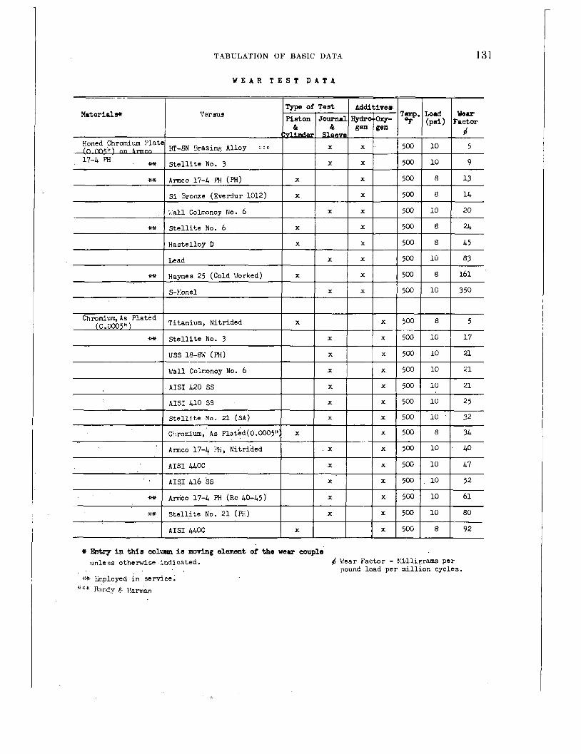
TABULATION OF BASIC DATA
Materiale
131
of Test Additives; Ver su? Temp. Load Wear
Piston Journrl ~ O ' . ~ - '% ( p s i ) Factor k & gen gen
W E A R T E S T D A T A
511'1 nn -0 X
Honed Chromium Plate E-6N Brazing Alloy ::%
17-4 PH 9+ S t e l l i t e No. 3 X
auSleeve----- d X 500 10 5
X 500 10 9
,
9+
A ~ C O 17-4 PH (PH) X X 500 8 13
S i Bronze (Everdur 1012) X X 5 0 0 8 14
';'all Colmonoy No. 6 X X 500 10 20
S t e l l i t e No. 6 X X 500 8 24
H
Lead X X 500 10 83
Haynes 25 (Cold Worked) X X 500 8 161
S-!:onel X X 500 i o 350
Chromium, A s Plated Titanium, Nitrided
S t e l l i t e No. 3 (0.0005" )
1 AISI 416 SS
X x 500 8 5
X x 500 10 17
uss 18-ffd (PH)
Wall Colnonoy No. 6
AISI 420 SS
9 Entry In this colrmm Is m o v l n g element of the wear couple unless otherwise indicated. 4 Wear Factor - Pll l ierams per
pound load per mill ion cycles. %* Employed i n service.
* ' * Hardy ? l'amar,
X x 500 10 21
X x 500 i o 21
X x 500 10 21
AISI 410 SS
S t e l l i t e No. 21 ( S A )
Chromium, As Plathd(0.0005":
Amco 17-4 ?H, Nitrided
~~
X x 500 10 25
X 500 10 32
x x 500 8 34
X x 500 10 40
iiit
~9
Am'co 17-4 i" (RC 40-45) X x 500 10 61
80
92
x 500 10
500 8
S t e l l i t e No. 21 (E) X
AISI U O C X

132 CORROSION AND WEAR HANDBOOK FOR WATER-COOLED REACTORS
W E A R T E S T D A T A
Tspe of Test Additives Ber sus Temp, Load We-
Piston J o u r n i r ~ O ' . ~ - (psi) Factor
ve & I% gen gen
Material#
B x 500 10 100
(0.0005" Chromium, As Plated
X S t e l l i t e No. 6
Chromium, As Plated(0.0005") , x x 500 10 170
S-None1 X x 500 10 420
X X 500 10 2 S-l'onel
AISI 4 l O SS X X 500 10 3
43 x , 500 6 Titanium,, Nitr ided T i t a n i u m , Nitr ided X
0 PIS1 347 ss, AISI 347 SS, Nitr ided X x 500 8 ed
X x 500 8 0 Chromium, Nitr ided Chromium, Nitr ided
Lead, (Sleeve) AISI 304 SS X x 200 10 270
AISI 304 SS X x 500 10 279Ot
* wtrg In this coluum is maring element of the wear couple un les s otherwise indicated. 4 W a r Factor - Yilligrams per
pound load per mil l ion cycles. ~ r l ~ Smployed i n service.
Lead Sleeve Badly Corroded No v a l i d Mar f a c t o r , however, t h i s combination has been successful ly employed i n bearinp app l i ca t ions a t temperatures l e s s than 200°F.
(1 f

TABULATION OF BASIC DATA
W E A R T E S T D A T A
Metamic LT-1 X X
I I I I 1
I I 1 I I
500
500
500
500
- -
133
8 1 7
8 I 127 I
ghtry in t h i s column l a mov3ng element of the mu conple unless otherwise indicated. Wear Factor - Millimams
Dound load Der mi l l i on cyc le s +w Employed in serv ice


Chapter 8
RELATIVE IMPORTANCE OF DIFFERENT VARIABLES
Editor-D. J. D EPAUL
Contributors-C. R. BREDEN, R. U. BLASER, D. M. WROUGHTON Page
INTRODUCTION_.___^^.^.._________________^^ 135 MATERIAL COMPOSITION- - -. .___ L-. . ._._. . ._. 135 TEMPERATURE__. - ~ ~ - ~. -. . - - -. - -. - - -. - ~ - ~ ~ ~ 136 TIME_______..______.____________________ 137 WATER VELOCITY __~_~.~~.___.._..-.....-.-- 138 O X Y G E N _ . _ _ . . _ _ . . _ _ . . _ _ _ _ _ _ _ _ _ _ _ _ _ _ _ _ _ 139 HYDROGEN__..^_.^_^.^_.._____________ 140 EFFECT OF OTHER GASES-. . - -. . - -. . - ~. ~ ~ ~ ~ 14 1 ELECTRICAL RESISTIVITY OF WATER --._-.-_-... 141 STRESS .................................... 142 HEAT TREATMENT ____. . ~. ~ ~ ~. . -. . . . . . . . . . 142 NUCLEAR IRRADIATION ____.__ ~ . ~ . . ._._. .. . . .. 142 SURFACE FINISH ._.~~~~~~~~___..__... . .~.. . . 143
INTRODUCTION
The data in chapter 7 present,s corrosion information for various mat,erials a,nd environ- mental conditions. However, many of the variables included were not studied over a wide range because work was usually done under specific service conditions. This lack of infor- mation may make i t difficult to weigh the im- portance of a variable. The purpose of . this chapter is to give the reader a better feel for the importance of the variables covered. Most of the discussions will be based on the results given in chapter 7 . * Information obtained from pilot-plant tests and reactor plant opera- tion, where available, will also be factored into the discussion.
For the most part, the conclusions and opinions given in this chapter will be of a general nature and will encompass 8.5 many groups of alloys as possible. Specific excep- tions to the generalizations made will be pointed out. Additional information on this subject is
, .
‘Evaluations are based on actual average corrosion .rates, therefarc there are some apparent discrepancies hettr-cen factors given in this chapter and the nominal rates in chaptcr i.
417017 0 - 5 7 - 1 0
given in an Argonne National Laboratory re- port’ which covers the effect of pertinent vari- ables on specific individual alloys rather than on groups of alloys as covered herein.
Most of the corrosion rates given in chapter 7 are based on undescaled weight change data rather than on descaled weight changes. Although the latter are considered to be more representative, the difference is important only with materials which form heavy scales, i. e., carbon steel. Therefore, for all practical pur- poses, the undescaled data are considered to provide a reliable basis for the discussions in this chapter.
Where it is considered applicable, the dis- cussions which follow for each variable will contain pertinent information concerning both corrosion and wear.
MATERIAL COMPOSITION
If one attempts to make a general statement concerning the effect of composition on the corrosion resistance of materials, it becomes apparent that the specific type of corrosion must be taken into account. For instance, the suitability of various materials from the point of view of general corrosion would not neces- sarily apply where such forms of localized attack as stress corrosion, crevice corrosion, galvanic corrosion, or pitting corrosion might be encountered. The term “general corrosion” as applied herein refers to the uniform loss of metal by the process of corrosion. In contrast, localized corrosion involves a nonuniform loss of metal, i. e., pitting.
In this respect, a broad classification of materials investigated with respect to composi-
13.5

136 CORROSION AND WEAR HANDBOOK FOR WATER-COOLED REACTORS
tion and general corrosion resistance is shown in table 8-1.
TABLE 8-1
RELATIVE GENERAL CORROSION RESIST- ANCE OF MATERIALS
High
Austenitic stsinless steels
Cobalt-base alloys
Gold
Hafnium
Plathum zirconium
Intermediate
Ferritic stainless steels
Martensitic stainless
Nickel-base alloys
Copper-base alloys
Stee l s
Teflon'
LOW
Carbon steels
Low alloy steels
Aluminum-base alloys Silver-base alloys Organic materials in
general'
Ceramic materials in general.
'Grouping with respect to thermal stability or solution rate.
The relative position of materials in the various groups is not substantially affected within the limits for the environments and material conditions discussed in chapter 7. For instsnce, if the materials listed in table 8-1' were rated in oxygen-bearing (most corrosive) and hydrogen-bearing (least corrosive) water, their relative positions would be essentially the same.
It is not possible to discuss the effect of com- position per se on wear since resistance to wear is more a function of the mutual contact of materials rather than of individual composi- tions. For example, hardened Armco 174PH stainless steel possesses excellent bearing char- acteristics (wear factor* of 10) in combination with hard chromium plate, whereas Po-or bear- ing qualities (wear factor of 460) are obtained with a combination of Armco 174PH versus Armco 174PH steel. Although numerous materials were investigated from the point of view of wear, only a few basic materials were ultimately chosen for actual service because of further limitations imposed by corrosion, me- chanical properties, and weldability. The basic materials employed are:
Stellites 1, 3, 6, 12, 19, 21, 25 Armco 17-4PH hard chromium plated
. -. . . . ~ . .. .. - . .. .. - - . - . . . . -. .
Armco 174PH Armco 174PH nitridedt Graphitar 14 t
TEMPERATURE i
Essentially all the dynamic corrosion test work was conducted at 500 or 600' F since the coolant water for nuclear reactor is normally operated between these two temperatures. Work done at lower temperatures was confined to special studies involving static autoclave tests where the determination of corrosion rate in itself was not the primary object. For in- stance, much of the work on crevice corrosion reported in chapter 9 was conducted at 200' F; however, in this case, evaluation was deter- mined by the extent of localized attack (pitting and buildup of corrosion products) and the increase in torque required to move the crevice corrosion test couple. Although most of the remarks made are concerned with the effect of temperature over a limited range, unpublished data are available at lower temperatures which provide some basis for estimating the overall effect of temperature.
Generally speaking, the dynamic corrosion rate of the materials studied at 500' F is in- creased between 5 and 20 times when tested at 600' F, the highly corrosion resistant materials, such as the 18-8 type stainless steels, being affected the least.
A survey on low-temperature water corrosion, conducted by A. H. Roebuck,2 reports infor- mation on the corrosion rate of five alloys of 18-8 type stainless steels. This work indicates that there is no significant difference in the rate of corrosion between 200' and 500' F. Tests were conducted at 190' F for 56 days in high- purity water (boiler feed water grade) with an oxygen content of 0.01 cc (STP) per kilogram of water (hereafter referred to as cc/kg) and having a pH of 8.1. The water velocity was 116 ft/sec. Corrosion rates ranged between 1.5 and 3 mg/dm2/mo. These rates are of the same order of magnitude as rates obtained a t
'See App. B, Glossary, for definition. tThese materials are not used at temperatures above 200' F because
they are lacking in oorrosion resfstance or thermal stability.

137 RELATIVE IMPORTANCE O F DIFFERENT VARIABLES
500' F at 30 ft/sec. It is not possible to cor- rect for the difference in velocity between 30 and 116 ft/sec. A lower rate of corrosion would
,.be expected at 30 ft/sec. However, based on ,,,'the discussion which follows on the effect of
velocity, this difference is expected to be very small and of no practical importance.
Although these few tests indicate little dif- ference between 200' and 500' F, this informa- tion should be confirmed by additional work since the details of the test procedures employed are not available. On the basis of general ob- servations made in corrosion testing, one would expect some measurable change in corrosion rate between these two temperatures.
The effect of temperature on the corrosion of zirconium has been extensively studied in static autoclave type tests using degassed water and steam at temperatures between 500' and 750' F. This work is described by Lustman and Kerze and is summarized in figure 8-1. The data show that the increase in corrosion of zirconium between 500 and 600' F is the same (factor of 5) as that observed for the 18-8 type stainless steels.
too I I I 1 1 1 1 1 ~ I I I I I I I I I
I I I I I 1 1 1 1 1 I I I 1 I I I I I I I I r l l l l 1 I' 5 to 50 loo tow
EXPOSURE TIME, DAVS
FIGURE 8-1. Effect of temperature on the corrosion , resistance of zirconium.
In the majority af observations the wear rate is increased by a factor of 5 to 20 between tests at 200' and 500' F. This is sufficiently great to eliminate some excellent bearing combina- tions at the higher temperature. Ceramic materials are also excluded because of high solution rates a t 500' F.
TIME
The influence of time as a variable affecting the corrosion rate of materials is well known. In most corrosion reactions involving corrosion- resistant materials, the rate decreases with time. There are numerous mechanisms which explain this observation, and the reader is referred to chapter 2 for details concerning this subject. Generally speaking, protection is afforded by the formation of a corrosion film which, with increasing time, becomes more resistant to at- tack than the metal in question.
The change in corrosion rate with time, for the type of materials studied, is shown in fig- ures 8-2 and 8-3. It is interesting to note that the corrosion rates of essentially all the mate- rials, including stainless and carbon steels, is reduced by a factor of approximately 10 dur- ing the test period between 250 and 4,700 hr. These results are of special significance in the case of carbon steel since a relatively low cor- rosion rate may be realized after a short term of operation in service.
-60
-55
-50
-45
p -* -3 SA -50
'a -2s I 8 -IO
w
-,5
-5
0
t5
+IO 0 mxa ,mu ,500 rax, 1500 3ooo 3 x a m 4500 5ma
TIME. )(OURS
FIGURE 8-2. Coirosion rate for typical structural materials.
Little can be said concerning the effect of time on corrosion rates determined by static tests since the techniques normally employed do not show measurable corrosion rates. The following figures illustrate this point. They were obtained on an 18-8 type stainless steel tested a t 500' F in high-purity water (500,000
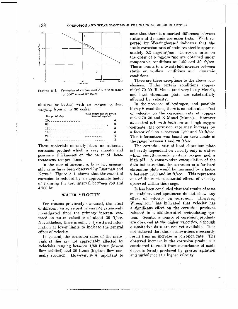
138 CORROSION AND WEAR HANDBOOK FOR WATER-COOLED REACTORS
FIGURE 8-3. Corrosion of carbon steel S A ,212 in water at BOOo F and 50 ftlsec.
ohm-cm or better) with an oxygen content varying from 5 to 30 cc/kg.
Total weight gain for period Test period, days indicated, mgldrnz
3 0 _ _ _ _ - - - - - - - - - - - - - - - - - - - - - ~ - - - - - - 4 6 0 _ _ _ _ - - - - - - - - - - - - - - - - - - - - - - - - - - - - 3 1 2 0 _ _ _ - - - - - - - - - - - - - - - - - - - - - - - - - - - - 3 1 8 0 _ _ _ _ - - - - - - - ~ - - . - - - - - - . - - - - - - - . - 3 2 4 0 _ _ _ - - - - - - - - - - - - - - - ~ - - - - - - - - - - - - 4 3 3 0 _ _ _ _ _ _ _ _ _ _ - - - . - - ~ - - - - - - - . - - - - - - 3
These materials normally show an adherent corrosion product which is very smooth and possesses thicknesses on the order of heat- treatment temper films.
In the case of zirconium, however, measur- able rates have been observed by Lustman and K e r ~ e . ~ Figure 8-1 shows that the extent of corrosion is reduced by an approximate factor of 2 during the test interval between 250 and 4,700 hr.
WATER VELOCITY
For reasons previously discussed, the effect of different water velocities was not extensively investigated since the primary interest cen- tered on water velocities of about 30 ft/sec. Nevertheless, there is sufficient scattered infor- mation a t lower limits to indicate the general effect of velocity.
In general, the corrosion rates of the mate- rials studies are not appreciably affected by velocities ranging between 1/60 ft/sec (lowest Aow studied) and 30 ft/sec (highest flow nor- mally studied). However, it is important to
note that there is a marked difference between static and dynamic corrosion tests. Work re- ported by Westinghouse indicates that the static corrosion rate of stainless steel is approx- imately 0.3 mg/dm2/mo. Corrosion rates on the order of 5 mg/dm2/mo are obtained under comparable conditions a t 1/60 and 30 ft/sec. This amounts to a twentyfold increase between static or no-flow conditions and dynamic conditions.
There are three exceptions to the above con- clusions. Under certain conditions copper- nickel 70-30; K-Monel (and very likely Monel), and hard chromium plate are substantially affected ,by velocity.
In the presence of hydrogen, and possibly high pH conditions, there is no noticeable effect of velocity on the corrosion rate of copper- nickel 70-30 and K-Monel (Monel). However a t neutral pH, with both low and high oxygen contents, the corrosion rate may increase by a factor of 2 to 4 between 1/60 and 30 ft/sec. This information was based on tests made in the range between 1 and 20 ft/sec.
The corrosion rate of hard chromium plate is heavily dependent on velocity only in waters which simultaneously contain oxygen and a high pH. A conservative extrapolation of the data indicates that the corrosion rate for hard chromium plate would be increased by a factor 8 between 1/60 and 30 ft/sec. This represents one of the most substantial effects of velocity observed within this range.
It has been concluded that the results of tests on stainless-steel specimens do not show any effect of velocity on corrosion. However, Wroughton has indicated that velocity has a significant effect on the corrosion products released in a stainless-steel recirculating sys- tem. Greater amounts of corrosion products are observed at the higher velocities, although quantitative data are not yet available. It is not believed that these observations necessarily result from an increase in corrosion rate. The observed increase in the corrosion products is considered to result from disturbance of oxide deposits (crud) produced by greater agitation and turbulence at a higher velocity.
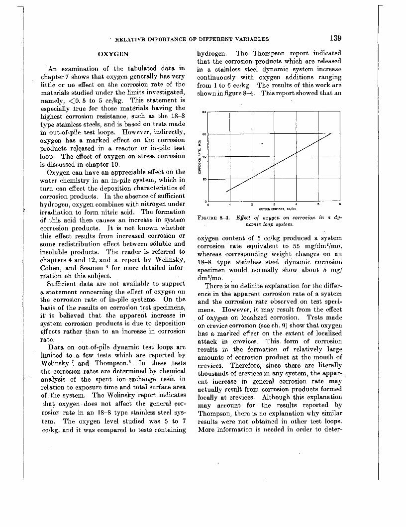
RELATIVE IMPORTANCE OF DIFFERENT VARIABLES 139
OXYGEN
An examination of the tabulated data in chapter 7 shows that oxygen generally has very little or no effect on the corrosion rate of the materials studied under the limits investigated, namely, < O . 5 to 5 cc/kg. This statement is especially true for those materials having the highest corrosion resistance, such as the 18-8 type stainless steels, and is based on tests made in out-of-pile test loops. However, indirectly, oxygen has a marked effect on the corrosion products released in a reactor or in-pile test loop. The effect of oxygen on stress corrosion is discussed in chapter 10.
Oxygen can have an appreciable effect on the water chemistry in an in-pile system, which in turn can effect the deposition characteristics of corrosion products. In the absence of sufficient hydrogen, oxygen combines with nitrogen under irradiation to form nitric acid. The formation of this acid then causes an increase in system corrosion products. It is not known whether this effect results from increased corrosion or some redistribution effect between soluble and insoluble products. The reader is referred to chapters 4 and 12, and a report by Welinsky, Cohen, and Seamon for more detailed infor- mation on this subject.
Sufficient data are not available to support a statement concerning the effect of oxygen on the corrosion rate of in-pile systems. On the basis of the results on corrosion test specimens, it is believed that the apparent increase in system corrosion products is due to deposition effects rather than to an increase in corrosion rate.
Data on out-of-pile dynamic test loops are limited to a few tests which are reported by Welinsky ' and Thompson.s In these tests the corrosion rates are determined by chemical analysis of the spent ion-exchange resin in relation to exposure time and total surface area of the system. The Welinsky report indicates that oxygen. does not affect the general cor- rosion rate in an 18-8 type stainless steel sys- tem. The oxygen level studied was 5 to 7 cc/kg, and it was compared to tests containing
hydrogen. The Thompson report indicated that the corrosion products which are released in a stainless steel dynamic system increase continuously with oxygen additions ranging from 1 to 6 cc/kg. The results of this work are shown in figure 8-4. This report showed that an
0 4 2 3 4 5 6
FIGURE 8-4. Effect of oxygen on corrosion in a dy- namic loop system.
OXYGEN CONTENT. CC/KG
oxygen content of 5 cc/kg produced a system corrosion rate equivalent to 55 mg/dm2/mo, whereas corresponding weight changes on an 18-8 type stainless steel dynamic corrosion specimen would normally show about 5 mg/ dm2/mo. ,
There is no definite explanation for the differ- ence in the apparent corrosion rate of a system and the corrosion rate' observed on test speci- mens. However, it may result from the effect of oxygen on localized corrosion. Tests made on crevice corrosion (see ch. 9) show that oxygen has a marked effect on the extent of localized attack in crevices. This form of corrosion results in the formation of relatively large amounts of corrosion product at the mouth of crevices. Therefore, since there are literally thousands of crevices in any system, the appar- ent increase in general corrosion rate may actually result from corrosion products formed locally a t crevices. Although this explanation may account for the results reported by Thompson, there is no explanation why similar results were not obtained in other test loops. More information is needed in order to deter-

140 CORROSION AND WEAR HANDBOOK FOR WATER-COOLED REACTORS
mine specifically what effect, if any, oxygen has on out-of-pile system corrosion.
Under certain specific conditions oxygen does have a marked effect on out-of-pile system corrosion products. Lembersky ' reports that the presence of high oxygen and high pH simultaneously, causes large quantities of chrom- ium to be released as chromates in an out-of-pile system (also observed in in-pile system).
The difference between laboratory and system corrosion results is also highlighted by exper- ience obtained in industy with boiler r,-ater corrosion problems, where oxygen must be con- trolled to limits below 0.05 cc/kg in order to minimize service failures and excessive replace- ment of parts. As suggested in the case of the system corrosion products, the majority of corro- sion products in boiler water systems are formed primarily in areas where differences in oxygen concentration occur (similar to crevice cor- rosion). The importance of this type of attack is illustrated by the fact that the corrosion allowances normally specified by the ASME Code are directed toward preventing premature failures due to localized attack, such as pitting, rather than to minimize the general loss of metal from container walls.
There are three exceptions to ithe generaliza- tion that oxygen has little or no effect on cor- rosion within the limits studied. They are (1) the harden&ble stainless steels, (2) copper- nickel 70-30, and (3) carbon steel.
Of special note is the effect of oxygen on the hardenable stainless steels such as USS 18-8W, Armco 17-4PH1 and the martensitic varieties. These materials indicate an inverse relation between oxygen content and corrosion rate. Within the range studied, higher corrosion rates are generally obtained at the lower oxygen level. The observed corrosion rates of these materials may differ by a factor 5 to 10 when exposed to water with oxygen contents at either extreme of the range studied (range extended from <0.5
The corrosion resistance of copper-nickel 70-30 is generally lowered by the presence of oxygen. Corrosion rates may increase by a
. to 5 cc/kg).
factor of 5 between the extreme oxygen con- centrations studied.
The test information to date on carbon steel has not progressed to a point where an adequate statement can be made concerning the effect of oxygen. The data reported on carbon steel, particularly A-212, include many variables which prevent an adequate interpretation of the effect of oxygen. However, it is interesting to note that the corrosion rate of specimens tested at the highest oxygen concentration studied, namely, 400 cc/kg, showed corrosion rates lower than the values obtained at low oxygen con- centrations, on the order of 0.5 cc/kg. The corrosion rate was reduced by a factor of 4 for comparable test periods. Since this comparison was based on one test run, it should not be completely accepted until substantiated by additional test data.
HYDROGEN
As in the case of oxygen, hydrogen additions within the limits studied have very little effect on the corrosion rate of the 18-8 type stainless steels tested in out-of-pile test loops. There is a slight inhibiting effect during the early states of corrosion; however, the magnitude of this effect is so small that it has no practical sig- nificance.
However, the introduction of hydrogen into a reactor or an in-pile test loop has a marked effect on the quantity of corrosion products re- leased to the system. The benefits afforded by hydrogen additions are reported by Welinsky, Cohen, and Seamon." This effect is believed to result indirectly from the formation of ammonia by the reaction of hydrogen and nitrogen under irradiation and the suppression of certain unde- sirable side reactions. The ammonia raises the pH of the system, which, in turn, reduces the quantity of corrosion products. The effect of high pH is discussed in the next section.'
The following comments are based on the data included in chapter 7.
The precipitation hardening and the harden- able martensitic stainless steels are affected by hydrogen additions. The corrosion rates of these materials in water containing low oxygen
RELATIVE IMPORTANCE OF DIFFERENT VARIABLES 141
are similar to the rates observed in water con- taining hydrogen. Both conditions show slightly higher corrosion rates than those olj- served for higher oxygen contents.
Hydrogen has a considerable inhibiting effect on the corrosion resistance of copper- and nickel- base alloys. For instance, the corrosion rate of copper-nickel 70-30 may be reduced by a fac- tor of 50 to 200 by the addition of hydrogen. Hydrogen also has an inhibiting effect on nickel- base alloys, although the effect here is not as great as that observed for 'copper-base alloys.
Because of the limited information available on carbon steel, it is not possible to determine the effect of hydrogen on corrosion; however, i t appears that hydrogen may have only a slight beneficial effect.
.
EFFECT OF OTHER GASES
The presence of small amounts of such gases as nitrogen, argon, helium, and ammonia do not appear to have a noticeable effect on the corrosion resistance of specimens tested in out-of-pile systems. Work conducted by Bab- cock & Wilcox showed that 200 ppm of am- monia does not affect the corrosion resistance of the materials shown in figure 8-2, in addition to beryllium-copper (4-96) and bronze. Addi- tional unpublished work performed by Cohen lo
indicates that 20 ppm of ammonia and small quantities of other gases mentioned did not adversely affect the wear characteristics of the basic materials employed for wear resistance. (Similar results were obtained with boric acid additions of approximately 1 percent.)
PH High p H (10 to 11) has a beneficial effect
in reducing the quantity of corrosion products released in an in-pile stainless steel system. Rockwell and Cohen l 1 report that the yield of transportable corrosion products is much lower a t high p H than with neutral water. It is believed that the insoluble corrosion products are more filterable a t high pH. The exact reasons for the beneficial effect of high p H are not known. However, work on p H is still in progress since i t holds much
promise for usein future reactors. Wroughton6 has indicated that high pH has a beneficial effect because it makes the crud deposits more tenacious, thereby reducing the quantity of products released to a system. Similar benefits have been obtained by high p H on out-of-pile test loops made of stainless steel and of carbon steel. As in the case of hydrogen and oxygen, the specific effect of high p H per se on the cor- rosion rate of stainless-steel systems is not too well understood. The conclusions which follow are based on data in chapter 7.
In many respects the inhibiting characteris- tics afforded by high p H are similar to the effects observed for hydrogen. The main difference is that in the case of the precipitation hardening and the hardenable martensitic stainless steels, high pH does not produce the decrease in corrosion resistance observed with additions of hydrogen. As in the case of hydro- gen, high p H has a pronounced inhibiting effect on the corrosion of copper-base and nickel-base alloys. These effects are of the same order of magnitude as those described for the effect of hydrogen.
In connection with carbon steel there is a considerable difference observed in the corrosion rate between hydrogen-bearing (and neutral) water compared to high pH water. Rates in the former medium are generally 5 to 10 times greater than rates observed in the latter.
As in the case of hydrogen, high pH also has an inhibiting effect on crevice corrosion. Both hydrogen and high p H are equally effective in this respect (see chap. 9).
Only a limited amount of unpublished data l 2
are available on the effect of high p H on wear. The results indicate a general effect similar to the effect of hydrogen. A 40-fold benefit was observed for AIS1 type 410 vs. 410 stainless steel as compared with oxygenated tests.
ELECTRICAL RESISTIVITY OF WATER
For reasons discussed in chapter 1, it was established that the electrical resistivity of the primary coolant would be limited to a minimum of 500,000 ohm-cm. Consequently, no work

142 CORROSION AND WEAR HANDBOOK FOR WATER-COOLED REACTORS
was done to determine the effect of resistivity on corrosion since this limit could readily be maintained in test and in service.
In a few cases the resistivity of test waters has fallen well below this limit without showing any adverse effects.
These observations would suggest that lower resistivity waters may be acceptable in future water-cooled nuclear reactors. However, con- siderable work will be necessary in order to definitely establish the validity of these indica- tions.
STRESS
Generally speaking, stress is not considered a problem with most of thb materials investi- gated. Unpublished data by DePaul l 3 indi- cates that some of the materials employed in the construction of water-cooled nuclear reac- tors are susceptible to stress corrosion cracking under certain specific conditions. These ma- terials are the martensitic and precipitation hardening stainless steels and cold-worked austenitic 18-8 type stainless steels.
Steels such as Armco 1 7 4 P H and 17-7PH, USS 18-8W, and AIS1 410 and 431 can fail by stress corrosion if in the fully hardened condi- tion and stressed to levels on the order of 60,000 psi in torsion. Steels under similar conditions, but stressed in tension, are considerably less susceptible to cracking.
Austenitic 18-8 type stainless steels, which are cold-worked above 30 percent are also susceptible to cracking at torsional stress levels on the order of 20,000 psi. This problem is also minimized by tensile stress under comparable conditions. Special attention should be given to these materials (not necessarily cold-worked) when in the stressed condition and exposed to water environments containing chlorides. The reader is referred to chapter 10 for specific information on this subject.
There are many areas of stress corrosion which should be more thoroughly investigated. The statements made above are considered to be conservative in light of the limited informa- tion available. It is likely that many of the
materials mentioned could be successfully em- ployed under high stress provided they are under confined conditions.
HEAT TREATMENT
It is generally considered that heat treatment has very little effect on the corrosion resistance of the materials studied. However, the amount of information on this subject is limited, and a more thorough investigation in the various environments under consideration may reveal substantial effects of heat treatment. pediency most of the test work done on heat- treatable materials was performed on the materials in the heat-treated condition.
On the basis of static corrosion tests, the precipitation hardening stainless steels are not materially affected by heat treatment to the extent t,hat they would fall in different cate- gories. Practically speaking, if these materials are affected under dynamic water conditions, the degree must be small since the corrosion rates which are normally observed in the hardened condition (which is expected to show the least corrosion resistance) are relatively low.
The information on K-Monel indicates that the age-hardening treatment will reduce the corrosion resistance slightly in the case of neutral waters and appreciable (by an approxi- mate factor of 10) in the case of high pH water. The importance of oxygen and hydrogen in affecting the degree of this effect should not be overlooked.
Heat treatments that involve the precipita- tion of chromium carbides in 18-8 type stainless steels are not considered harmful from the point of view of susceptibility to intergranular corrosion ; however, they do decrease resistance to chloride stress corrosion cracking. The effects of heat treatment on these forms of corrosion are discussed in detail in chapters 9 and 10.
For ex- .
NUCLEAR RADIATION
Early work l4 performed a t the Argonne National Laboratory and current investiga-

RELATIVE IMPORTANCE O F DIFFERENT VARIABLES 143
tions by Glick,15 Galonian, Callahan, and Koenig, l6 and more recently by Wroughton,’’ and Brown, and Alger,18 indicate that nuclear irradiation has no material effect on corrosion resistance. These studies were and are being conducted primarily on stainless steel, carbon steel, and zirconium under irradiation and water conditions (500’ F.) expected in service. A slight increase in corrosion rate has been ob- served in the case of carbon steel.ls
From a general materials point of view, the only effect which has been noted is a slight change in the metallurgical and mechanical properties comparable to that which might be expected from a small amount of cold working. However, a recent paper by Wilson and Berg- gren l9 suggests that more attention should be given the changes in mechanical properties resulting from nuclear irradiation.
SURFACE FINISH
Surface finishes ranging between 16 and 250 microinches (rms) did not produce any ob- servable effects on the corrosion resistance of the 18-8 type stainless steels.
REFERENCES
1. S. C. DATSKO and CALVIN R. BREDBN, Report ANI-5354, Nov. 6, 1954.
2. A. H. ROEBUCK, “Low Temperature Corrosion,” Special ANL report dated July 1951.
3. B. LUSTMAN and F. KERZE, “The Metallurgy of Zirconium,” McGraw-Hill Book Co., Inc., 1955, p. 611.
4. Westinghouse Electric Corp., Static Corrosion Test Reports by Large, Pa., Laboratory, Nos. 1-16.
5. D. M. WROUGHTON, Westinghouse Electric Corp., private communication.
6. I. H. WELINSKY, P. COHEN, and J. M. SEAMON, Chemistry of a Pressurized-water Nuclear Power Plant, presented at American Power Conference, March 1956.
7. I. H. WELINSKY, Report WAPD-(2-200, Jan. 10, 1955.
8. V. W. THOMPSON, Westinghouse Electric Corp., Research Memorandum WAPD-RM-49, May 1951.
9. H. LEMBERSKY, Westinghouse Electric Corp., pri- vate communication.
10. I . COHEN, Westinghouse Electric Corp., private communication.
11. T. ROCKWELL I11 and P. COHEN, Pressurized Water Reactor (PWR) Water Chemistry, pre- sented at the Geneva conference on Nuclear Power, June 1955, Report UN-536.
12. S. PETACH, Westinghouse Electric Corp., private communication.
13. D. J. DEPAUL, Westinghouse Electric Corp., private communication.
14. Argonne National Laboratory, Reports ANL-4327, Aug. 10, 1949; ANIr4465, Aug. 24, 1950; and ANL-4522, Jan. 15, 1951.
15. H. GLICK, Westinghouse Electric Corp., private communication.
16. G. F. GALONIAN, E. D. CALLAHAN, and R. F. KOENIG, The Effect of Irradiation on the Corrosion of Metallic Materials in Water at 580’ F., Report KAPL-M-GEG4, Sept. 9, 1955.
17. D. M. WROUGHTON and P. BROWN, Westinghouse Electric Corp., private communication.
18. J. V. ALGER, Westinghouse Electric Corp., Letter, Report WAPD-CTA (MPE)-339, Nov. 29, 1956.
19. J. G. WILSON and R. G. BERGGREN, Effect of Neutron Irradiation in Steel, presented at ASTM Annual Meeting, June 1955.
20. Westinghouse Electric Corp. letter, Report WAPD- AD(P)-743, Mar. 1, 1955.
.
’

Part c Special Studies

1

Chapter 9
CREVICE CORROSION
Editor-D. J. DEPAUL
Contributors-E. M. RENO, R. STEIN Yivge
147 148 148 149 150 152 155 157 157 157
158 159
159 159 161 162 165 167 168 169 171 171
BACKGROUND INFORMATION
When work was first started to study .the various corrosion problems that might be ex- pected in water-cooled nuclear reactor applica- tions, the amount of certain constituents in the water, namely, oxygen, was not definitely- known. However, it was estimated that the quantity of oxygen would be on the order of 1 to 10 cc per kilogram of water (STP), (sub- sequently referred to as cc/kg). Consequently, many of the corrosion studies were made with water containing oxygen within this range. Most of the work on crevice corrosion reported
in this chapter was performed during early investigations under such “high” oxygen con- ditions (1 to 10 cc/kg).
Operational experience of the PWR and naval reactor programs show that the oxygen content of the primary water is almost immeas- urable with the addition of hydrogen. The information described in this chapter shows that crevice corrosion is not normally a prob- lem requiring special attention in systems with low oxygen contents on the order of 0.1 cc/kg. Therefore, to some extent, the material in this chapter is not directly applicable to these re- actors. The main reason for including this chapter is to present all information developed on crevice corrosion which may be -pertinent in a water-cooled nuclear reactor. Such infor- mation would be useful in analyzing and solv- ing problems which may arise from accidental high oxygen water conditions in the present reactors and from consideration of future re- actor water environments which may contain more oxygen.
From an engineering point of view, crevice corrosion is considered important because it can cause high torque or complete seizure in bearings and mechanical linkages in a relatively short period of time. For this reason, crevice corrosion can be a limiting factor in the choice of materials and design of components with internal moving parts. The problem is espe- cially important if small clearances must be employed between bearing surfaces.
I n the field of corrosion the term “crevice corrosion” has acquired a very general meaning which normally includes all observations of
147

148 CORROSION AND WEAR HANDBOOK FOR WATER-COOLED REACTORS
accelerated attack observed at the junction between two metals exposed to a corrosive environment. For purposes of discussion, this form of corrosion may be divided into three main categories, all of which will be discussed in this chapter. Two of these forms of attack, the metal-ion concentration cell and the oxygen concentration cell, are very specific and can be defined in terms of known mechanisms of reac- tion. The third, a special case of stagnant area corrosion, is of a more general nature and does
, not lend itself readily to a specific definition.
Metal-ion Concentration Cell
That form of crevice corrosion which is defined as a metal-ion concentration cell results from corroding currents which arise in those regions where there is a difference in the metal-ion concentration. The extent of ac- celerated corrosion which occurs a t these points depends primarily upon the magnitude of the corroding current, which, in turn, is related directly to the difference in the metal-ion concentration a t the points in question. A schematic sketch illustrating the mechanism of this type of corrosion is shown in figure 9-1.
A J O U R N A L L---c
*__.__ O l R E C T l O N OF C U R R E N T
S L E E V E
FIGURE 9-1. Metal-ion cell.
The direction of the corroding current deter- mines the location of the accelerated corrosion products. Corrosion occurs a t those points where the current leaves the metal. In this case the current travels from the metal outside of the crevice to the metal inside the crevice.
Therefore the corrosion products will form at the mouth of a crevice or a t the perimeter of the contact area.
It is also apparent that this type of corrosion could be considerably minimized by continu- ously replacing the water in the crevice with fresh water from the outside, thus minimizing or eliminating a differential condition with respect to ion concentration. Likewise, one would expect this form of corrosion to be minimized or even eliminated by increasing the crevice gap so that sufficient flow and displace- ment of water could occur at the mouth of the crevice to prevent the formation of differential concentration areas.
Oxygen Concentration Cell
. That form of crevice corrosion which is defined as an oxygen concentration cell results from corroding currents which arise a t those points where a differential oxygen concentration occurs. As in the case of the metal-ion con- centration cell, the magnitude of the corroding current is directly related to the difference in the concentration of oxygen a t the point in ques- tion. A schematic sketch illustrating the mechanism of this type of corrosion is shown in figure 9-2.
O2 Oz o2 0,
O2 0 2 h
0 2
D l R E C T l O N OF C U R R E N T '
-*--*
S L E E V E
FIQURE 9-2. Oxygen concentration cell.
This sketch shows that the corroding current travels from the low oxygen-bearing medium to the metal. Therefore, in contrast to the metal-

CREVICB CORROSION 149
ion concentration cell, one would expect accelerated attack to occur a t the entire inter- face surfaces of both materials in contact rather than at the mouth of the crevice. This form of corrosion may be controlled'in the same manner as mentioned above for the metal-ion concen- tration cell.
Stagnant Area Corrosion
Strictly speaking, stagnant area corrosion is not normally considered a form of crevice cor- rosion. However, since it has been found to play an important part in the analysis of crevice corrosion problems, it is considered desirable to discuss this form of corrosion in order to in- dicate its importance in relation to the other forms of crevice attack and to actual design problems. Stagnant area corrosion, as specifi- cally related to crevices, may be defined as general accelerated attack which may occur within a crevice (or any stagnant area). It results directly from the increased corrosivity of the environment, which, in turn, is a direct result of the accumulation of both soluble and insoluble corrosion products formed within the crevice. In contrast, the accelerated attack which occurs in both the ion and the oxygen concentration cells results from diflerential effects.
Since essentially no circulation of water normally occurs within crevices, it would be expected that the concentration of corrosion products would increase almost indefinitely and, thereby, produce more corrosion than would normally be expected for the same material exposed to the environment outside the crevice.' For instance, if a crevice is exposed to high-purity water having a total solids con- tent of 1 ppm, it is very possible that the water within the crevice may eventually have a total solids content 100 or 1,000 times greater than that of the surrounding environment. The corrosion resistance of the particular metal involved may be entirely inadequate in the rela- tively impure water as compared to the pure water. Although this form of corrosion does not depend on differential effects, the methods
of controlling this problem are essentially the same as for ion and oxygen concentration cells. The mechanism of corrosion involved in stag- nant areas of all kinds is the same as that described for stagnant area corrosion in crevices. A schematic sketch of stagnant corrosion is shown in figure 9-3. Examples of stagnant area
M E C H A N I C A L L I N K A G E
C O N D U C T I V I T Y
M A L L C L E A R A N C E ' P E R M I T T I N G S L O W D I F F U S I O N
C O N D I T I O N S I N S T 4 G N 4 N T AREA P R O M O T E
I H I G H E R G E N E R A L C O R R O S I O N R A T E
2 G R E A T E R P O S S I B I L I T Y O F G A L V A N I C A T T A C K
3 G R E A T E R P O S S I B I L I T Y O F C R E V I C E CORROSION
4 4 C C U Y U L A T I O N O F C R U O ' ON SURFACES C O R R O S I O N P R O D U C T S
FIQURE 9-3. Stagnant area conditions.
corrosion occurring in a ball-nut and screw are shown in figures 9 4 and 9-5. This unit was ex- posed in the assembled condition to oxygenated high-purity water at 200' F for 3 months. Under the conditions of this test the exposed surfaces maintained their original bright me- tallic luster; whereas the surfaces of metal in the stagnant area were black, indicating the formation of a thicker corrosion flm. The engineering significance of such a thicker film formed in a stagnant area can only be evalu- ated by operational or simulated engineering type tests. This example merely serves to illustrate that corrosion can proceed at a faster rate in a stagnant area than in an area where there is movement of water. This type of attack, in applications involving moving parts with small clearances, may cause excessive wear, high torque, and even complete seizure.
The problem of crevice and stagnant area corrosion is especially aggravated by nuclear applications because of the complexity, small clearances, and limited operating forces nor-

150 CORROSION AND WEAR HANDBOOK FOR WATER-COOLED REACTORS
. . .
FIGURE 9-4. Example of stagnant area corrosion in a component.
mally available in certain mechanical parts which must operate in water. Examples of such a mechanism are shown in figures 9-6 to 9-8.
METHODS OF CONTROLLING CREVICE CORROSION
The basic problem of crevice corrosion can best be illustrated by using a specific example. Consider a typical journal-sleeve bearing ap- plication. In this case two cobalt-base alloys, Stellite No. 6 and Stellite No. 3, operating with a diametrical clearance of approximately 0.002 in., might seize after two or three weeks of exposure to 500' F high-purity water containing relatively small amounts of oxygen. The torque normally required to overcome this seizure could be in the order of several hundred inch-pounds. Since torques of this order are not normally available in mechanically operated components, it becomes a matter of prime im- portance to take all possible steps in order to minimize crevice corrosion.
Examination of parts exhibiting excessive torque or complete seizure shows that the
FIGURE 9-5. Closeup of stagnant area corrosion in a component.
difficulties observed result from the presence of small amounts of corrosion products at the perimeters of the contact areas. This would suggest that the corrosion products formed result from a metal-ion concentration cell. The extent and the nature of the corrosion buildup normally observed in such cases is shown in figure 9-9. This figure shows essen-
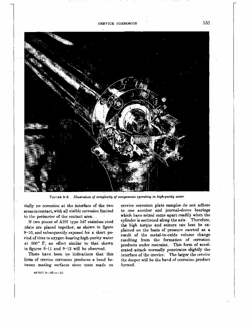
CREVICE CORROSION 151
FIGURE !&6. Illustration of wmplez i ty of wmponenls operating in high-purity water.
tially no corrosion at the interface of the two areasin contact, with all visible corrosion limited to the perimeter of the contact area.
If two pieces of AIS1 type 347 stainless steel plate are placed together, as shown in figure 9-10, and subsequently exposed for a short pe- riod of time to oxygen-bearing high-purity water at 500' F, an effect similar to that shown in figures 9-11 and 9-12 will be observed.
There have been no indications that this form of crevice corrosion produces a bond be- tween mating surfaces since tests made on
417017 0-57-11
crevice corrosion plate samples do not adhere to one another and journal-sleeve bearings which have seized come apart readily when the cylinder is sectioned along the axis. Therefore, the high torque and seizure can best be ex- plained on the basis of pressure exerted as a result of the metal-to-oxide volume change resulting from the formation of corrosion products under restraint. This form of accel- erated attack normally penetrates slightly the interface of the crevice. The larger the crevice the deeper will be the band of corrosion product formed.
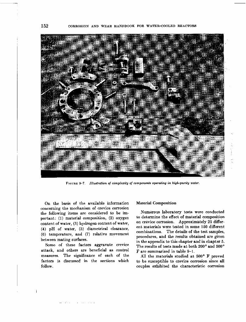
152 CORROSION AND WEAR HANDBOOK FOR WATER-COOLED REACTORS
FIGURE 9-7. Illustration of complexity of components operating in high-purity water.
On the basis of the available information concerning the mechanism of crevice corrosion the following items are considered to be im- portant: (1) material composition, (2) oxygen content of water, (3) hydrogen content of water, (4) pH of water, (5) diametrical clearance, (6) temperature, and (7) relative movement between mating surfaces.
Some of these factors aggravate crevice attack, and others are beneficial as control measures. The significance of each of the factors is discussed in the sections which follow.
Material Composition
Numerous laboratory tests were conducted to determine the effect of material composition on crevice corrosion. Approximately 25 differ- ent materials were tested in some 150 different combinations. The details of the test samples, procedures, and the results obtained are given in the appendix to this chapter and in chapter 5. The results of tests made a t both 200' and 500' F are summarized in table 9-1.
All the materials studied at 500' E' proved to be susceptible to crevice corrosion since all couples exhibited the characteristic corrosion

CREVICE CORROSION 153
TABLE 9-1. SUSCEPTIBILITY OF VARIOUS 'MATERIALS TO CREVICE CORROSION
FIQURE 9-8. Illustration of complexity of wmponente operating i n high-purity water.
buildup and/or pitting. The extent of buildup observed at1 the perimeter of the contact area normally decreased with increasing corrosion resistance of the material. Certain materials, namely, the straight chromium stainless steels and high copper- and high nickel-bearing alloys, were also subject to pitting of the area
Materials
Group designation I Investigated
Chromium-nickel AISI type 302,304, stainless steels. 316, 321, 347. .
Cobalt-base alloys.- Stellites Nos. 1,3, 6, 12, 19, 21, 24.
Ele@xoplat ing...--- Hard chromium plate.
Copper-base alloys- Brass, bronze, cop per-nickel (70-30).
Nlckel-base alloys. - Inconel, Inconel-X, Monel.
Straight chromium AISI type 410,420, stainless steels. 430,431,440.
Type of attack
Corrosion buildup-
Corrosion buildup-
Corrosion buildup-
Corrosion buildup
Corrosion buildup
Corrosion buildup
and pitting.
and pitting.
and pitting.
I
- NU- neri- Cal rting
, i , . .I, .: - . . . ..._ . . L -. . . ~
F I ~ U R E 9-9. Journal-sleeve crevice corrosion specimen showing location an3 extent of crevice corrosion buildup.
in contact in addition to the peripheral buildup. It is believed that this type of pitting does not

154 CORROSION AND WEAR HANDBOOK FOR WATER-COOLED REACTORS
FIGURE 9-10. Post test appearance of plate type crevice corrosion specimen.
result from any possible galvanic effects, since it also occurs with couples where both materials are the same and where one of the materials is a plastic.
The pitting observed is usually minor in nature and is normally not objectionable except in moving parts with close clearances. Such pitting has been observed with some of the alloys investigated a t temperatures as low as 200' F.
Therefore, in view of the high reliability that is required, the choice of materials for bearing applications is normally limited to those materials which dopot exhibit pitting and which show the least amount of corrosion, buildup. Since the major problem with crevice corrosion results from the accumulation of corrosion products within the mouth of the crevice and since all materials show this buildup to some degree, very little benefit can be afforded solely by changing materials, especially the highly corrosion resistant materials. , Other
methods must be employed to minimize or- eliminate this form of corrosion.
Additional tests were made on approximately 300 journal-sleeve type crevice test samples, similar to that shown in figure 9-9, in order to determine the effects of oxygen, hydrogen, pH, clearance, temperature, and relative movement. Four basic material combinations were em- ployed for this study:
1. Armco 17-4 PH versus Armco 17-4 PH chromium plated. ,
2. Armco 17-4 PH chromium plated versus Stellite No. 3 and/or No. 6.
3. Stellite No. 3 or No. 6 versus Stellite No. 3 and/or No. 6.
4. AIS1 type 410 stainless steel versus Stellite No. 3 and/or No. 6. The hardenable stainless steels were tested
in the hardened condition, . which ranged between 35 and 45 on the Rockwell C scale of hardness. Four diametrical clearances were employed for all combinations: 0.0005, 0.002,

CREVICE CORROSION 155
FIGURE 9-11. Disassembled plate type crevice corrosion specimen showing buildup (4.5 X).
0.005, and 0.008 in. The couples were tested under various water conditions, the details of which are given in subsequent sections. All tests were conducted in stainless steel auto- claves similar to those described in chapter 5 and 6.
Specimens were not electrically insulated from one another since galvanic corrosion was not expected to be a problem. Two stainless steel wires secured the sleeve on the journal to pre- vent rotation and movement along the axis. No attempt was made to center the journal within the cylinder since the corrosion products formed a t the perimeter of the contact area almost in- variably caused the journal to center itself. The discussions which follow are based on the above tests.
Oxygen Content of Water
Two series of tests were made to determine the effect of oxygen. One group was tested in high-purity water at 500' F with an oxygen content of 1 to 10 cc/kg. The remaining group was tested under the same conditions, except that the oxygen content was less than 0.005 cc/kg. The duration of the tests was six months, although, where seizure was observed, it normally occurred within one to three weeks of testing.
The effect of oxygen on crevice corrosion is shown in figure 9-13.
These general results indicate that the mech- anism of this form of corrosion is completely
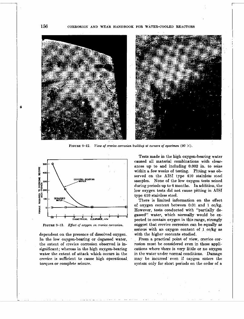
156 CORROSION AND WEAR HANDBOOK FOR WATER-COOLED REACTORS
FIGURE 9-12. V i e w of crevice corrosion buildup at cornera of specimen (20 X).
FIQURE 9-13. Effect of oxvgen on crevice corrosion.
dependent on the presence of dissolved oxygen. In the low oxygen-bearing or degassed water, the extent of crevice corrosion observed is in- significant; whereas in the high oxygen-bearing water the extent of attack which occurs in the crevice is sufficient to cause high operational torques or complete seizure.
Tests made in the high oxygen-bearing water caused all material combinations with clear- ances up to and including 0.002 in. to seize within a few weeks of testing. Pitting was ob- served on the AISI type 410 stainless steel samples. None of the low oxygen tests seized during periods up to 6 months. In addition, the low oxygen tests did not cause pitting in AISI type 410 stainless steel.
There is limited information on the effect of oxygen content between 0.01 and 1 cc/kg. However, tests conducted with “partially de- gassed” water, which normally would be ex- pected to contain oxygen in this range, strongly suggest that crevice corrosion can be equally as serious with an oxygen content of 1 cc/kg as with the higher contents studied.
From a practical point of view, crevice cor- rosion must be considered even in those appli- cations where‘there is very little or no oxygen in the water under normal conditions. Damage may be incurred even if oxygen enters the system only for short periods on the order of a

CREVICE CORROSION 157
few days or a week. This would be especially true for those applications involving close clear- ances and very little movement.
On the basis of a purely theoretical approach to this problem, one would expect the crevice corrosion buildup observed to result from a metal-ion concentration cell since accelerated attack is limited to the perimeter of the contact area. On the other hand it has been stated that crevice corrosion does not occur in the absence of oxygen. The tests made show that the mechanism of attack is not strictly in ac- cordance with what would be expected, because oxygen concentration cells normally produce attack on the interface area. The true basic mechanism of crevice corrosion which occurs in oxygen-bearing high-purity water is not known with certainty and requires further study.
Hydrogen Content of Water
Tests in hydrogenated water were conducted under conditions similar to those described above except that they contained about 500 cc/kg of hydrogen and from 0.5 to 1 cc/kg of oxygen. Only limited information is available on the effect of hydrogen on crevice corrosion. However, there is sufficient data to indicate that hydrogen plays an important role in the control of crevice corrosion by minimizing the adverse effects of oxygen. These preliminary tests show that crevice corrosion is virtually eliminated even in the worst combination of materials and clearances studies, e. g., AISI type 410 stainless steel with a 0.0005 in. clearance.
On the basis of the corrosion inhibition afforded by hydrogen on the general corrosion of materials, one would expect that a concen- tration of hydrogen on the order of 25 to 50 cc/kg would provide adequate protection against crevice corrosion. However, additional work will be required in order to verify this inference.
pH of Water
A limited number of tests were also directed toward determining the effect of high pH (10 to 11) on crevice corrosion. These tests were made under conditions similar to those em-
ployed for the oxygenated water tests, except that the pH of the water was raised to 11 by the addition of lithium hydroxide at the start of the test. Although the pH normally de- creased with test time, it seldom went below 10 during the test period.
The results of these tests indicate that high pH appears to have an inhibiting effect similar to that observed for hydrogen additions.
Relatively speaking, only exploratory work has been done in high pH media as compared to oxygenated, degassed, and hydrogenated solutions. Therefore, any statements made concerning high pH should be substantiated by additional tests before such information is actually employed in a given application.
.
Clearance Between Mating Surfaces
Clearance is one of the most important factors controlling the extent of damage result- ing from crevice corrosion applications where restraint can be developed by the formation of corrosion products within the mouth of a crevice, e. g., between a journal and sleeve. Clearance is also important in nonrestraint types of bearings since it can govern the degree of washing in the crevice, thereby making it possible to minimize attack. Any modifica- tions in design which would provide for circula- tion of water between the crevice and adjacent environment would tend to minimize or elimi- nate the problem.
As previously discussed, the diametrical clearances investigated were 0.0005, 0.002, 0.005, and 0.008 in. Samples were evaluated by exan$nation for freedom of movement or for seizure and by the torque required to pro- duce movement in those couples which did seize. In practically all cases where seizure occurred, it appeared after 1 to 3 weeks of testing. Tests on specimens which did not seize were continued for 6 months.
All the material combinations studied (with the exception of the AISI type 410 stainless steel couples) generally showed similar results with respect to the susceptibility to seizure and to the torques required to overcome seiz-
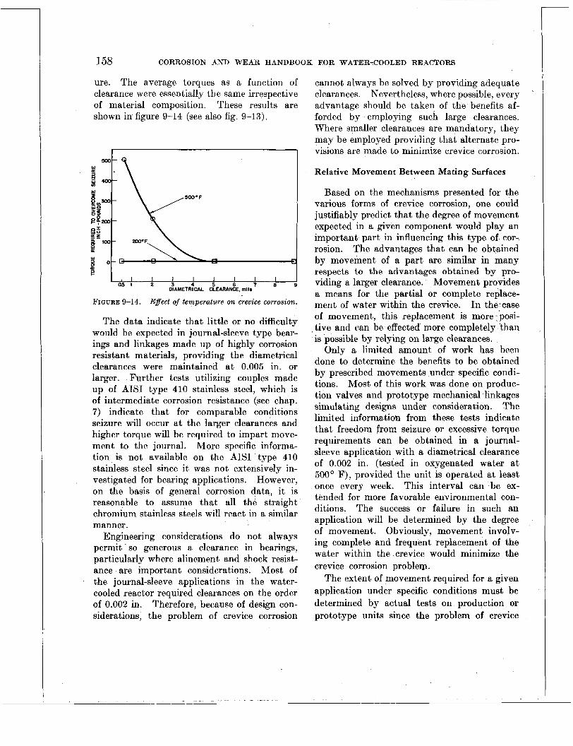
~~
158 CORROSION AND WEAR HANDBOOK FOR WATER-COOLED REACTORS
ure. The average torques as a function of clearance were essentially the same irrespective of material composition. These results are shown in. figure 9-14 (see also fig. 9-13).
I I I I I I I 1 Q ! 5 l 2 3 4 5 6 7 8 9
DIAMETRICAL CLEARANCE, mils
FIGURE 9-14. Effect of temperature on crevice corrosion.
The data indicate that little or no difficulty would be expected in journal-sleeve type bear- ings and linkages made up of highly corrosion resistant materials, providing the diametrical clearances were maintained a t 0.005 in. or larger. Further tests utilizing couples made up of AISI type 410 stainless steel, which is of intermediate corrosion resistance (see chap. 7) indicate that for comparable conditions seizure will occur a t the larger clearances and higher torque will be required to impart move- ment to the journal. More specific informa- tion is not available on the AISI type 410 stainless steel since it was not extensively in- vestigated for bearing applications. However, on the basis of general corrosion data, it is reasonable to assume that all the straight chromium stainless steels will react in a similar manner.
Engineering considerations do not always permit so generous a clearance in bearings, particularly where alinement and shock resist- ance are important considerations. Most of the journal-sleeve applications in the water- cooled reactor required clearances on the order of 0.002 in. Therefore, because of design con- siderations, the problem of crevice corrosion
cannot always be solved by providing adequate clearances. Nevertheless, where possible, every advantage should be taken of the benefits af- forded by employing such large clearances. Where smaller clearances are mandatory, they may be employed providing that alternate pro- visions are made to minimize crevice corrosion.
Relative Movement Between Mating Surfaces
Based on the mechanisms presented for the various forms of crevice corrosion, one could justifiably predict that the degree of movement expected in a given component would play an important part in influencing this type of cor- rosion. The advantages that can be obtained by movement of a part are similar in many respects to the advantages obtained by pro- viding a larger clearance. Movement provides a means for the partial or complete replace- ment of water within the crevice. In the case of movement, this replacement is more posi- tive and can be effected more completely than is possible by relying on large clearances.
Only a limited amount of work has been done to determine the benefits to be obtained by prescribed movements under specific condi- tions. Most of this work was done on produc- tion valves and prototype mechanical linkages simulating designs under consideration. The limited informatioh from these tests indicate that freedom from seizure or excessive torque requirements can be obtained in a journal- sleeve application with a diametrical clearance of 0.002 in. (tested in oxygenated water a t 500' F), provided the unit is operated a t least once every week. This interval can be ex- tended for more favorable environmental con- ditions. The success or failure in such an application will be determined by the degree of movement. Obviously, movement involv- ing complete and frequent replacement of the water within the crevice would minimize the crevice corrosion problem.
The extent of movement required for a given application under specific conditions must be determined by actual tests on production or prototype units since the problem of crevice
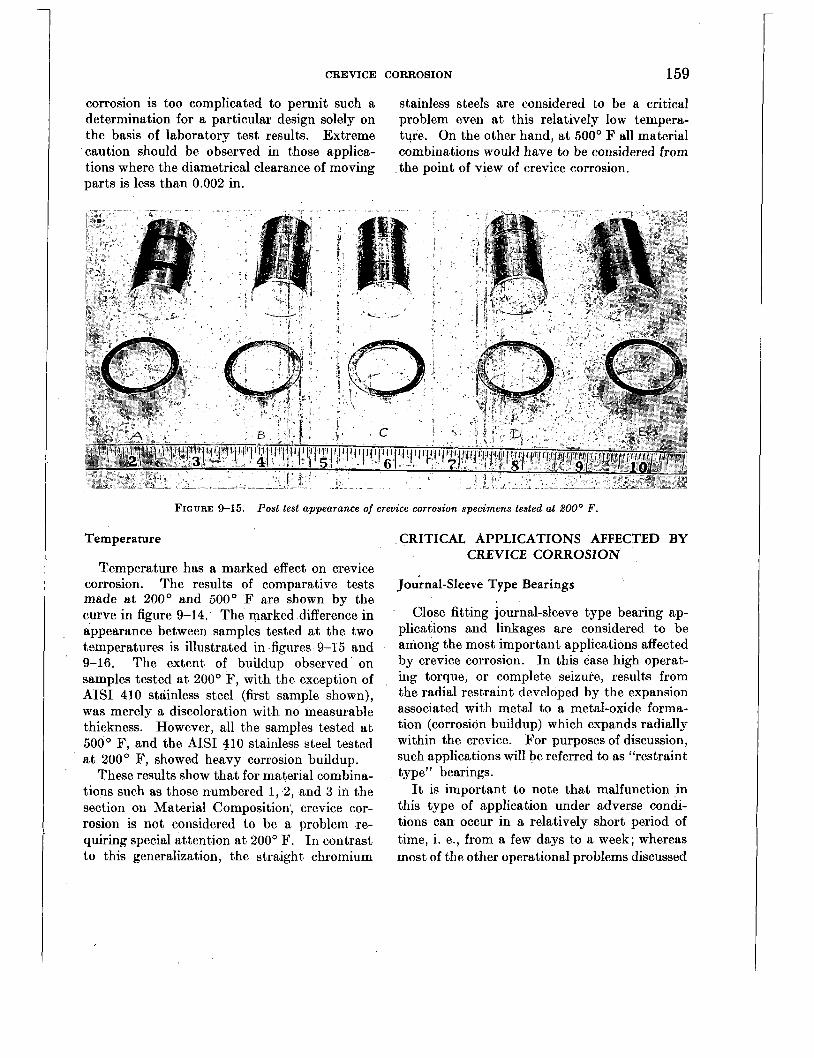
CREVICE CORROSION 159
corrosion is too complicated to permit such a determination for a particular design solely on the basis of laboratory test results. Extreme caution should be observed in those applica- tions where the diametrical clearance of moving parts is less than 0.002 in.
stainless steels are considered to be a critical problem even at this relatively low tempera- ture. On the other hand, at 500’ F all material combinations would have to be considered from
-the point of view of crevice corrosion.
FIGURE 9-15. Post test appearance of crevice corrosion specimens tested at BOOo F .
Temperature
Temperature has a marked effect on crevice corrosion. The results of comparative tests made at 200° and 500° F are shown by the curve in figure 9-14. The marked difference in appearance between samples tested a t the two tsmperatures is illustrated in figures 9-15 and 9-16. The extent of buildup observed on samples tested at 200’ F, with the exception of AISI 410 stainless steel (first sample shown), was merely a discoloration with no measurable thickness. However, all the samples tested at, 500’ F, and the AISI 410 stainless steel tested a t 200’ F, showed heavy corrosion buildup.
These results show that for material combina- tions such as those numbered 1, 2, and 3 in the section on Material Composition, crevice cor- rosion is not considered to be a problem re- quiring special attention a t 200’ F. In contrast to this generalization, the straight chromium
CRITICAL APPLICATIONS AFFECTED BY CREVICE CORROSION
Journal-Sleeve Type Bearings
Close fitting journal-sleeve type bearing ap- plications and linkages are considered to be among the most important applications affected by crevice corrosion. In this case high operat- ing torque, or complete seizure, results from the radial restraint developed by the expansion associated with metal to a metal-oxide forma- tion (corrosion buildup) which expands radially within the crevice. For purposes of discussion, such applications will be referred to as “restraint type” bearings.
It is important to note that malfunction in this type of application under adverse condi- tions can occur in a relatively short period of time, i. e., from a few days to a week; whereas most of the other operational problems discussed

160 CORROSION AND WEAR HANDBOOK FOR WATER-COOLED REACTORS
FIGURE 9-16. Post test appearance of crevice corrosion specimens tested at 600' F
FIGURE 9-17. Pitting on A I S I t y p e ai0 stainless-steel journal.
herein are affected only from a long-range point of view.
The order of magnitude of the torque required to overcome seizure in restraint bearings has
tion with the occurrence of pitting resulting from crevice corrosion, a typical test was con- ducted under conditions simulating those of service for a valve containing a journal-sleeve type stem and guide. In this test the stem,
made of AISI type 410 stainless steel, was operated against a Stellite No. 1 sleeve, with a diametrical clearance, of 0.008 in. The test was conducted at 5000 F in water with an .
was operated for hrs every week, and the total duration of the test was 6 weeks. The pitting observed on the AIS1 type 410 stem is shown in figures 9-17 and 9-18. The pits ob-
already been discuS3ed. However, in connec- oxygen content of 0.5 to 3 cc/kg. The valve

CREVICE CORROSION 161
served had an average diameter of 0.002 in. and an average depth of 0.005 in.
IGURE 9-19. Shoes employed in Kingsbury thrust bearings.
FIGURE 9-18. Magnified view of pitting on AZSZ type 410 stainless-steel journal.
Thiust Bearing
Because of the limited restraint that can be developed by crevice corrosion in thrust bear- ings, this is considered to be the one application which is least affected by this type of corrosion. Crevice corrosion buildup at the perimeter of the contact area is not normally detrimental because of the large amount of axial play usually present in this type of bearing. A small amount of pitting can also be tolerated in most designs since the corrosion products can readily be washed away during operation. Furthermore, loss of bearing' area due to slight pitting is of no real consequence. It is realized, however, that excessive pitting may interfere with suc- cessful operation of any type of bearing.
Ultimately, each case of crevice corrosion must be evaluated in terms of the specific de- sign and existing operational and materid problems. The Kingsbury type thrust bearing shown in figures 9-19 and 9-20 illustrates this
FIGURE 9-20. Runner employed in .Kingsbury thrust bearings.
case. Figure 9-19 shows the stationary shoes, and figure 9-20 shows the rotating runner.
The radial lines shown in the runner represent areas where crevice corrosion occurred dur- ing several shutdown periods. If the bear- ing had been idled only once and allowed to remain immobile for a period of sufficient dura-
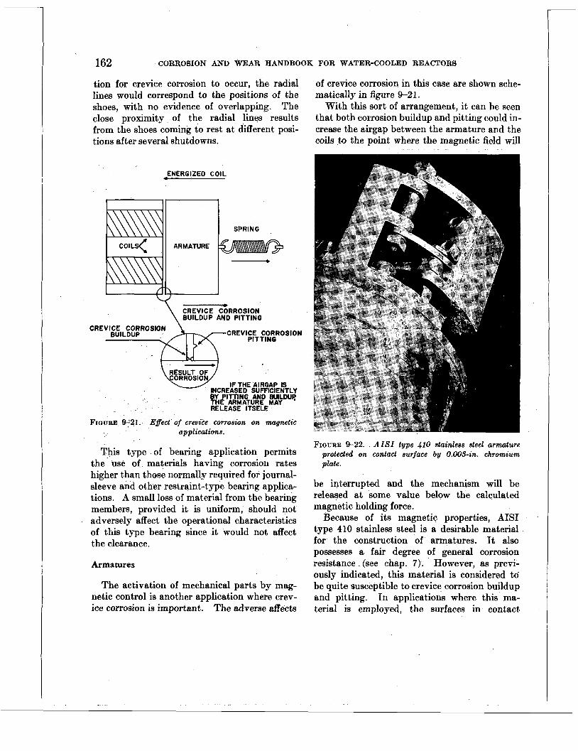
162 CORROSION AND WEAR HANDBOOK FOR WATER-COOLED REACTORS
tion for crevice corrosion to occur, the radial lines would correspond to the positions of the shoes, with no evidence of overlapping. The close proximity of the radial lines results from the shoes coming to rest at different posi- tions after several shutdowns.
of crevice corrosion in this case are shown sche- matically in figure 9-21.
With this sort of arrangement, it can be seen that both corrosion buildup and pitting could in- crease the airgap between the armature and the coils to the point where the magnetic field will
ENERGIZED COIL
SPRING
CREVICE C~RROSION \ BUILDUP AND PITTING
CREVICE CORROSION PITTING
CREVICE CORROSION BUILDUP
FIGURE 9-21. Effect of crevice corrosion on magnetic applications.
This type of bearing application permits the use of materials having corrosion rates higher than those normally required for journal- sleeve and other restraint-type bearing applica- tions. A small loss of material from the bearing members, provided it is uniform, should not adversely affect the operational characteristics of this type bearing since it would not affect the clearance.
Armatures
The activation of mechanical parts by mag- netic control is another application where crev- ice corrosion is important. The adverse affects
FIGURE 9-22. AZSZ t y p e 410 stainless steel armature protected on contact surface by 0.003-in. chromium plate.
be interrupted and the mechanism will be released at some value below the calculated magnetic holding force.
type 410 stainless steel is a desirable material for, the construction of armatures. It also possesses a fair degree of general corrosion resistance (see chap. 7). However, as previ- ously indicated, this material is considered to be quite susceptible to crevice corrosion buildup and pitting. In applications where this ma- terial is employed, the surfaces in contact
Because of its magnetic properties, AIS1 ~

CREVICE CORROSION 163
FIGURE 9-23. Pitting observed on AZSZ t ype 410 stainless-steel magnetic inserts.
between the coils and the armature can be protected by electroplating with a suitable material. A review of the various platings that can be considered shows hard chromium plate to be the most satisfactory material, even though it is normally considered to be porous. Figure 9-22 shows an armature made of AISI type 410 stainless steel protected by 0.003 in. of hard chromium plate on the surface in con- tact.
This unit was exposed to 200' F. oxygenated water for a period of approximately 3 months and showed no evidence of accelerated attack on the plated section but considerable corrosion on the unplated portions of the armature. The extent of pitting which can be expected to occur under comparable conditions on unplated AISI type 410 stainlss steel (and very likely all the straight chromium stainless steels) arma- tures is shown in figures 9-23 and 9-24.
k
The armature shown in figure 9-22 is made entirely of AISI type 410.stainless steel, whereas the one shown in figure 9-23 has two circular poles made of the same material in an armature body,made of AIS1 type 304 stainless steel. This difference is not important in illustrating the point in question. Pitting can be observed in several localized areas on both poles shown in figure 9-23. A photomicrograph of the pitted area (fig. 9-24) indicates the extent of pitting.
.In the interest of conserving space, some work has been done with gold-plated silicon steel. In this case, because of the extremely poor corrosion resistance of the silicon steel, the entire armature required plating. This ap- proach has not been utilized to any extent because of difEcul ties experienced in gold plating, e. g., blister formation during hydrogen relief heat treatment. A minimum thickness of 0.003 in. was originally used for corrosion
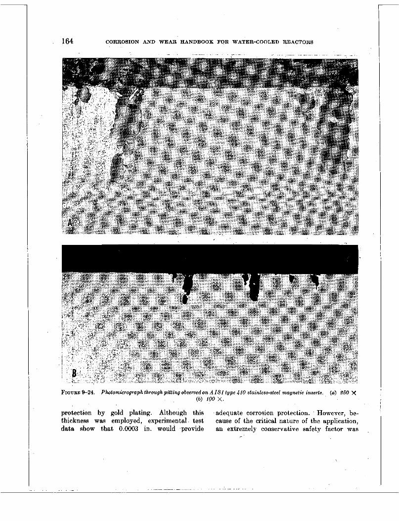
164 CORROSION AND WEAR HANDBOOK FOR WATER-COOLED REACTORS
FIGURE 9-24. Photomicrograph through pitting observed on AZSZ type 410 stainless-steel magnetic inserts. (b) 100 x.
protection by gold plating. Although this adequate corrosion protection. However, be- thickness was employed, experimental test cause of the critical nature of the application, data show that 0.0003 in. would provide an extremely conservative safety factor was ,
(a) 260 x
. . . . . . . . __ - .. - . . . . - - . . .. . . . . .. .
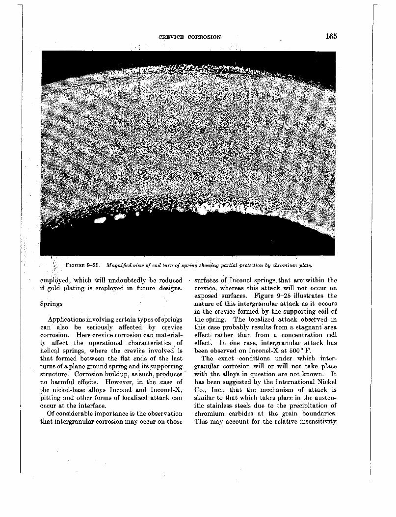
CREVICE CORROSION 165
;.,. FIGURE 9-25. Magnijied view of end turn of spring showing partial protection by chromium plate.
emiloyed, which will undoubtedly be reduced if gold plating is employed in future designs.
Springs
Applications involving certain types of springs can also be seriously affected by crevice corrosion. Here crevice corrosion can material- ly affect the operational characteristics of helical springs, where the crevice involved is that formed between the flat ends of the last turns of a plane ground spring and its supporting structure. Corrosion buildup, as such, produces no harmful effects. However, in 'the case of the nickel-base alloys Inconel and Inconel-X, pitting and other forms of localized attack can occur at the interface.
Of considerable importance is the observation that intergranular corrosion may occur on those
surfaces of Inconel springs that are within the crevice, whereas this attack will not occur on exposed surfaces. Figure 9-25 illustrates the nature of this intergranular attack as it occurs in the crevice formed by the supporting coil of the spring. The localized. attack observed in this case probably results from a stagnant area effect rather than from a concentration cell effect. In one case, intergranular attack has been observed on Inconel-X a t 500' F.
The exact conditions under which inter- granular corrosion will or will not take place with the alloys in question are not known. It has been suggested by the International Nickel Co., Inc., that the mechanism of attack is similar to that which takes place in the austen- itic stainless steels due to the precipitation of chromium carbides at the grain boundaries. This may account for the relative insensitivity

166 CORROSION AND WEAR HANDBOOK FOR WATER-COOLED REACTORS
, FIGURE 9-26. Magnified view of end turn of spring showing partial protection by chromium plate.
to ' attack of Inconel-X (columbium-bearing Inconel) as compared to Inconel. In view of the fact that Inconel-X does possess desirable spring properties and in view of the limited number of spring materials which are available, efforts were made to eliminate the possible oc- currence of intergranular corrosion in the crevice. Laboratory tests and service experi- ence have shown that adequate protection of this material can be afforded by electroplating the flat ends of the spring which form the crevice with approximately 0.0005 in. of hard chromium plate. Although such a plate is normally considered to be too porous for corro- sion protection, experience has shown that it will adequately protect the part in question against intergranular attack in the crevice.
Figures 9-26 to 9-28 illustrate the degree of pro- tection which can be afforded by chromium plating.
In relation to what has already been said concerning crevice corrosion in springs,- there is one other problem that warrants some discus- sion. This concerns the use of spring housings where stagnant area effects could conceivably promote more severe attack on the metal than might normally be expected in the nonstagnant environment. In such-cases i t has been found advantageous to provide several holes or open- ings in the housing, thereby promoting some circulation of water and, minimizing stagnant area effects. Figure 9-29 illustrates accelerated general corrosion in crevices, demonstrating the stagnant area effect on supporting spring coils.

CREVICE CORROSION 167
Rivets
The use of rivets must also be considered from the point of view of crevice corrosion. As in the case of springs, the problems associated with rivets are directly related to the particular materials involved. If the 18-8 type stainless steels did not work-harden, this group could be employed satisfactorily for rivets, and crevice corrosion would not be a problem. In most rivet applications for corrosion-resistant service, AISI type 410 stainless steel is employed be- cause of its nonwork-hardening properties. As indicated earlier, this material is susceptible to pitting in crevices. In addition, tests have also shown that accelerated attack of this metal may also result from the stagnant area effect. Figure 9-30 shows the extent of attack observed
417017 0-57-12
in an AISI type 410 stainless steel rivet after several months of exposure to water a t both 200' and 500' F.
Thissfigure shows a penetration rate along the axis of the rivet of approximately 0.070 in. per year a t both temperatures. It also shows no visible attack on the riveted structures which were made of an 18-8 type stainless steel. These results show that the use of this material, or one similar in composition, would not be considered satisfactory for rivet applications. The solution to this problem involved the choice of a more corrosion-resistant material, Carpen- ter No. 10 (a modified austenitic chrome-nickel steel) which possesses good m n work-hardening characteristics and is not susceptible to pit t iw or stagnant area corrosion in crevices.
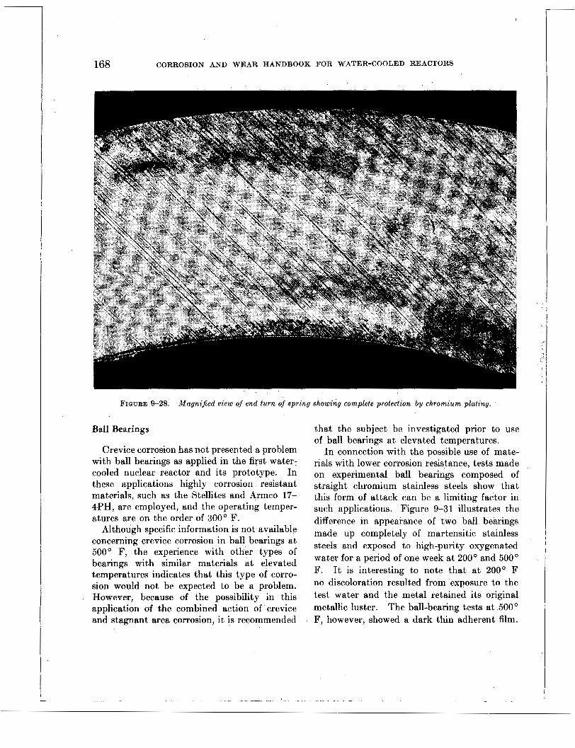
168 CORROSION AND WEAR HANDBOOK FOR WATER-COOLED REACTORS
FIGURE 4-28. Magnified view of end turn of spring showing complete protection by chromium plating.
Ball Bearings
Crevice corrosion has not presented a problem with ball bearings as applied in the first water: cooled nuclear reactor and its prototype. In these applications highly corrosion resistant materials, such as the Stellites and Armco 17- 4PH, are employed, and the operating temper- atures are on the order of 300' F.
Although specific information is not available concerning crevice corrosion in ball bearings at 500' F, the experience with other types of bearings with similar materials at elevated temperatures indicates that this type of corro- sion would not be expected to be a problem. However, because of the possibility in this application of the combined action of crevice and stagnant area corrosion, it is recommended
that the subject be investigated prior to use of ball bearings at elevated temperatures.
In connection with the possible use of mate- rials with lower corrosion resistance, tests made on experimental ball bearings composed of straight chromium stainless steels show that this form of attack can be a limiting factor in such applications. Figure 9-3 1 illustrates the difference in appearance of two ball bearings made up completely of martensitic stainless steels and exposed to high-purity oxygenated water for a period of one week at 200' and 500' F. I t is interesting to note that at 200' F no discoloration resulted from exposure to the test water and the metal retained its original metallic luster. The ball-bearing tests at 500' F, however, showed a dark thin adherent film.
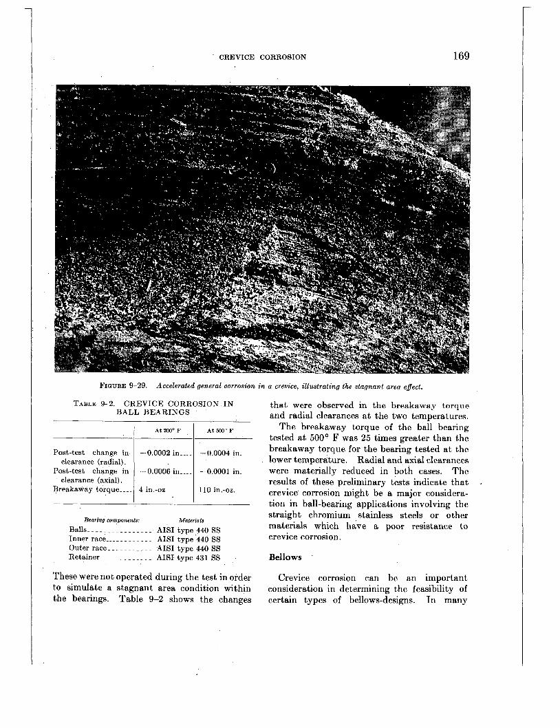
CREVICE CORROSION
Post-test change in clearance (radial).
Post-test change in clearance (axial).
Breakaway torque.. ..
169
At 2ooo F At 5ooo F
-0.0002 in -... -0.0004 in.
-0.0006 in-_.. -0.0001 in.
4 in.-oz.._ -. -. 110 in.-oz.
FIQURE 9-29. Accelerated general aorrosion in a crevice, illustrating the stagnant area effect.
Bearing components. Materia28 Balls _._______.______ AISI type 440 SS Inner race _.._.__.__-_ AISI type 440 SS Outer race - - _ _ _ _ _ _ _ - - AISI type 440 SS Retainer .________.___ AISI type 431 SS
These were not operated during the test in order to simulate a stagnant area condition within the bearings. Table 9-2 shows the changes
that were observed in the breakaway torque and radial clearances at the two temperat>ures.
The breakaway torque of the ball bearing tested a t 500' F was 25 times greater than the breakaway torque for the bearing tested at the lower temperature. Radial and axial clearances were materially reduced in both cases. The results of these preliminary tests indicate that crevice corrosion might be a major considera- tion in ball-bearing applications involving the straight chromium stainless steels or other materials which have a poor resistance to crevice corrosion.
Bellows
Crevice corrosion can be an important consideration in det.ermining the feasibility of certain types of bellows-designs. In many
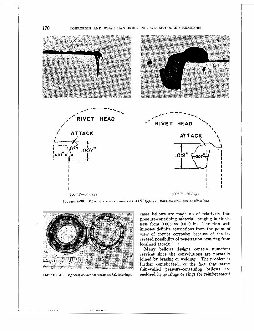
170 CORROSION AND WEAR HANDBOOK FOR WATER-COOLED REACTORS
0 / ' RIVET HEAD
I /
/. / ATTACK
/
I .. ,007
y--- I I i I ; ? 200 OF-60 days
\ ATTACK \
-@ Y' 1 I
I I
I I I I I
500' F-60 days
FIGURE 9-30. Eflect of crevice corrosion o n AZSZ type 410 stainless steel rivet applications.
cases bellows are made up of relatively thin pressure-containing material, ranging in thick- ness from 0.005 to 0.010 in. The thin wall imposes definite restrictions from the point of view of crevice corrosion because of the in- creased possibility of penetration resulting from localized attack.
Many bellows designs contain numerous crevices since the convolutions are normally joined by brazing or welding. The problem is further complicated by the fact that many thin-walled pressure-containing bellows are
FIGURE 9-31. Effect of crevice C O T T O S i O n on ball bearings. enclosed in housings or rings for reinforcement

CREVICE CORROSION 171
of the bellows. This condition is’ very con- ducive to the formation of the stagnant areas in which accelerated attack of either a general or a localized nature may occur.
Apart from a materials consideration, the operational characteristics of bellows may be adversely affected by crevice corrosion as a direct result of the buildup of corrosion products within the crevices formed between convolution joints. Here the buildup may interfere with movement of the bellows during compression.
The complexity of bellows and their variety of design make it difficult to discuss general methods of solving crevice corrosion problems. I n many cases, even where the specific condi- tions are known and well defined, it has been found that laboratory-type test data offer very little practical information concerning the suitability of a given type of bellows with a given material or set of conditions. Experience has shown that the most satisfactory approach to the evaluation of bellows is to test them under actual or simulated service conditions.
SUMMARY
The mechanism of crevice corrosion and controlling factors has been discussed. Crevice corrosion is not considered to be a problem in systems where the oxygen content of the water is on the order of 0.1 cc/kg or in high pH or hydrogen-bearing water. At higher con- centrations of oxygen (in the absence of high pH or hydrogen additions) , certain precaut-ions must be taken in order to ensure successful operation. This type of corrosion is not expected to be a problem in crevice joints, such as socket welds or flange joints. It can be extremely important in bearings and mechan- ical linkages, especially where clearances less than 0.002 in. are involved. This form of corrosion can be controlled by (1) maintaining low oxygen levels, (2) adding hydrogen to the
1 water, (3) raising the pH of the water, (4) providing adequate clearances in bearings and linkages, (5) periodic movement, and (6) choosing proper materials.
APPENDIX
Contact Corrosion on Various Material Combinations
Considerable attention has been given to the corrosion problems associated with metals in contact with one another under simulated re- actor conditions. The accelerated corrosion which may result normally occurs a t the areas in contact where there is very little or no movement between the water in the interface and the surrounding water. The confinement of water within the crevice leads to an increase in the conductivity of the water and/or depletes the oxygen in the water. Both these condi- tions aggravate galvanic, oxygen and ion con- centration cell corrosion.
Preliminary results have been obtained on about 140 different material combinations sim- ulating the various contacts to be found in the reactor. Tests were made a t 200’ F (in a dynamic .loop) and 500’ F (in static auto- claves). Both tests were made in oxygenated water. Specimens were lapped and polished with fine aluminum abrasive paper to give a finish of about 2 microinches (rms). All hard- enable materials were treated to maximum hardness. The area of contact, in most cases, was 2 cm2.
The4 results of microscopic examination on the tested surfaces in contact are shown in the attached tables. In general, the surfaces in contact all showed a narrow continuous ridge of corrosion product a t the perimeter of the contact area. The ridges were, for the most part, several mils wide and the heights varied from a few tenths of a mil (referred to as slight buildup”) to a few mils (referred to as “heavy buildup”). The pitting observed on contact surfaces was of a minor nature,’ most of which could easily be overlooked with the naked eye. The pits usually averaged about two per square centimeter of contact surface: ’ - In size, the pits measured a few mils in diameter and depth. Although the extent of pitting observed is not considered serious from an operational point of view, it is reason- able to predict pits will increase in size and num-
( I

.
68 __________.
9 3 _ _ _ _ _ . _ _ _ _ . _ _ 48, 55, 70, 74,
77, 78, 79, 80, 81, 82, 83, 88, 121
68, 73, 84, 85, 86, 87, 88, 89, 90, 91, 92, 101, 107, 108, 115, 127
44, 50, 64, 77, 85, 93, 94, 95, 96, 97, 99, 103, 111, 119
1 2 4 _ _ _ _ . _ _ _ . _ -
_ . _ _ _ _ _ _ _ _
\
172 CORROSION AND WEAR HANDBOOK FOR WATER-COOLED REACTORS
16, 23, 27, 31, 36, 40, 42
10, 13, 17, 18, 25, 27, 30, 37, 43F, 43D
12, 15, 17, 21, 28, 34, 40, 41, 43C, 43B
19, 26, 30: 31, 41, 43, 43E
3
ber with continued exposure. Unless otherwise indicated, contact and other surfaces showed good general corrosion resistance.
A summary of the results indicates: 1 . Essentially all the couples tested a t 200
or 500' F showed a narrow ridge of corrosion product a t the perimeter of the contact area.
2. In general, most of the couples exposed to 200' F water retained their original metallic appearance; couples a t 500' F were all dark- ened owing to the formation of a thicker oxide film. Exceptions to this generalization were the nickel and copper alloys, which showed the dark film a t 200' F.
3. Pitting was observed on Inconel and Monel samples. tested at 200' F; whereas, sim- ilar material couples a t 500' F did not show pitting. (There is no explanation for this ob- servation, except that the high temperature tests may have contained less oxygen.)
4. The pitting observed a t 200' F was lim- ited to the AIS1 type 400 stainless steels and to nickel, copper, and their high alloys.
5. There is insufficient data to correlate the occurrence of pitting with the type of mating material; however, i t appears that the type of mating material has no effect on the occurrence of pitting.
COUPLE INDEX
Material
Armco 17-7PH.. USS 18-8W_---.
Armco 17-4PH- ..
Z-rolled 347_. ~
Z-rolled 304- - ~ - ~
Couple No.
200OF 1 500°F
COUPLE INDEX-Continued
Material
____
Teflon impreg- nated with asbestos
SS 304 chrome plated
USS 18-8W chrome plated
SS 347 chrome plated
Armco 17-4 chrome plated
Armco 17-41"
USS 18-8W nitrided - - - - - - -
nitrided. - - - - -.
SS 410_-__
SS 440C chrome plated
Aluminum bronze
Copper- - - ~ ~. ~ -.
Phosphorus bronze
Silicon bronze - -. Wall Colmonoy
6 on SS 347 Inconel-X- - - -. . .
Haynes alloy 25.
Couple No.
2000 F
59, 60, 61, 62, 82, 90, 95, 125, 126
1 2 2 _ . _ _ _ _ - - . - - .
120, 129, 130, 131
98, 99, 100, 101,
111, 112, 113, 109
114, 115, 116, 128
102, 103, 104, 106, 108, 117, 127, 128, 132
1 3 1 _ _ _ _ _ _ _ _ _ _ _
49, 56, 58, 71,
47, 55, 56 ___.._
105, 106, 107-.- 70, 71, 72
48, 49, 69 _.__._
57, 58, 74, 75-. .
45, 47, 57, 62, 63, 64, 65, 69, 72, 76, 78, 86, 109, 110, 113, 129, 132
5000 F
32
5
43A
1, 2, 3, 32
4
6, 7, 8, 9
10, 12, 14, 16, 20, 22,35,43G
43B
7
11, 21, 22, 23, 25,
19, 24 29, 38
34 ,43c 4
8, 20, 24, 28, 29, 36, 37, 39, 43, 43E, 43F, 43C, 43A .

CREVICE CORROSION . 173 COUPLE INDEX-Continued
I I
COUPLE INDEX-Continued ~~
Couple No. -___- Material
200' F
Couple No. _ _ ~ _ __ 200' F _ _ _ - ~ _ _ _ _ - - - I 5000F
Material
5 Graphitar 14 _ _ _ _ 2, 14, 18, 38, 39,
43 D
61, 65, 83, 92, 9 94, 116, 117, 130
14day test 44day test
Same
Slight buildup
Heavy buildup, deposit on contact surface
Moderate buildup, sample cracked
Refractaloy 120- Stellite 3 _ _ _ _ _ _ _ .
1 2 6 _ _ _ _ _ _ _ _ . _ _ . 46, 51, 52, 53,
54, 59, 63, 67, 75, 80, 91, 97, 98, 102, 110, 112, 123
66, 79, 84, 96, 100, 104, 114, 122
118__.___- .___ .
Permo # 5 1 1 - _ _ _ _ Permo #11__---_
Permo #K-75 - - - Permo #I16 - - - Tantung G - - - -
1, 11, 13, 15, 33, 35,42
51 53
Stellite 6 _ _ _ _ 52 54 118, 119, 121 Vascoloy-Ramet
171 I I -
RESULTS ON PRELIMINARY CONTACT CORROSION TESTS
Couple Materials in contact
Moderate buildup SS 347 chrome plated
*1 Stellite 6
Stellite 3
*2 SS 347 chrome plated
2-rolled SS 347
SS 347 chrome plate,d *3
Heavy buildup, deposit on contact surface
Very slight buildup Moderate buildup, deposit on contact surface
Slight buildup Moderate buildup, deposit on contact surface
Moderate buildup I Heavy buildup
Refractaloy 26
Armco 17-4PH chrome plated *4 I Very slight buildup Heavy buildup
Moderate buildup
Slight buildup 1 Slight buildup Refractaloy 120
SS 304 chrome plated
Armco 17-4PH nitrided
Armco 17-4PH nitrided
SS 440C chrome plated
Armco 17-4PH nitrided
*5
6
*7
Same I Moderate buildup
Heavy buildup I Same
Moderate buildup
Same I-
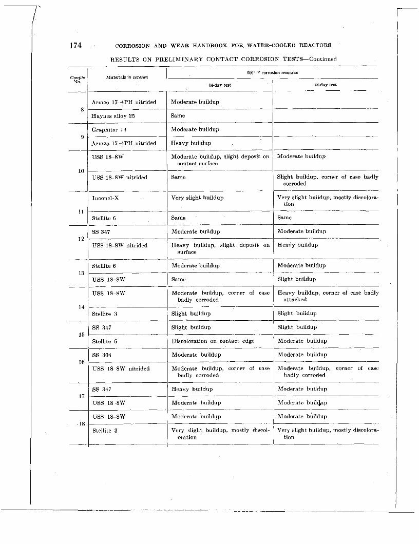
14-day test -
Moderate buildup
44-day test
Heavy buildup
Moderate buildup, slight deposit on contact surface
Moderate buildup
~
Same
Moderate buildup
Same
Moderate buildup
Heavy buildup, slight deposit on surface
Heavy buildup
Same
Moderate buildup, corner of case badly corroded
Slight buildup
Heavy buildup, corner of case badly attacked
Moderate buildup, corner of case badly corroded
Heavy buildup
Moderate buildup
Moderate buildup
Very slight buildup, mostly discol- oration
Moderate buildup, corner of case badly corroded
Moderate buildup
Moderate builc&p
Moderate bGildup
Very slight buildup, mostly discolora- tion
174 CORROSION AND WEAR HANDBOOK FOR WATER-COOLED REACTORS
RESULTS ON PRELIMINARY CONTACT CORROSION TESTS-Continued
Materials in contact 5ooo F corrosion remarks
Couple N O .
Armco 17-4PH nitrided ~~
Same Haynes alloy 25
Moderate buildup Graphitar 14
Armco 17-4PH nitrided
USS 18-8W
10
11
Same USS 1%8W nitrided Slight buildup, corner of case badly corroded
~-
Inconel-X Very slight buildup Very slight buildup, mostly discolora- tion
Stellite 6
ss 347
USS 18-8W nitrided 12
Moderate buildup I Moderate buildup Stellite 6
USS 18-8W 13
USS 18-8W
14 ~~ ~
Slight buildup 1 Slight buildup Stellite 3
Slight buildup 1 Slight buildup ss 347
Stellite 6 15 ~~ ~
Discoloration on contact edge 1 Moderate buildup
Moderate buildup I Moderate buildup SS 304
IiSS 18-8W nitrided 16
ss 347 17
USS 18-8W
USS 18-8W .18
Stellite 3
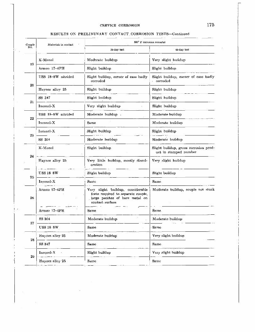
-
Couple NO.
Armco 17-4PH
USS 18-8W nitrided
19
20
Slight buildup Slight buildup
Slight buildup, corner of case badly Slight buildup, corner of case badly corroded corroded
21
Haynes alloy 25
ss 347
22
Slight buildup Slight buildup
Slight buildup Slight buildup
23 Inconel-X
SS 304
24
25
Slight buildup Slight buildup
Moderate buildup Moderate buildup
26
27
28
Haynes alloy 25
uss 18-8W
29
Very little buildup, mostly discol- Very slight buildup oration
Slight buildup Slight buildup
CREVICE CORROSION 175 RESULTS ON PRELIMINARY CONTACT CORROSION TESTS-Continued
Very slight buildup, considerable force required to separate couple, large patches of bare metal on contact surface
500' F corrosion remarks Materials in contact
&day test I 14day test
Mod'erate buildup, couple not stuck
K-Monel Moderate buildup I I Very slight buildup
Inconel-X I Very slight buildup . I Slight buildup
USS 18-8W nitrided I Moderate buildup I Moderate buildup
Inconel-X 1 Same I Moderate buildup
K-Monel Slight buildup Slight buildup, green corrosion prod- uct in stamped number
Inconel-X I Same I Same
Armco 17-4PH
Armco 17-4PH
SS 304 ' I ::rate buildup Moderate buildup
USS 1%8W
Haynes alloy 25 1 ::rate buildup 1 z s l i g h t buildup
ss 347 I Same I Same
Inconel-X I Slight buildup I Very slight buildup
Haynes alloy 25 I Same I Same

176
Materials in contact Couple NO.
500" F corrosion remarks -
44-day test 14-day test I
-
30
31
Moderate buildup, couple stuck, large patch of bare metal
*32
Slight buildup, couple very lightly stuck
33
~ ~-
Armco 17-4PH
Armco 17-4PH
34
Slight buildup, numerous small Same patches of bare metal
Slight buildup Moderate buildup
35
-- ~
SS 304
Teflon impregnated with asbestos
SS 347 chrome plated
Stellite 6 -
36
Same Same
Maintained original appearance, sur- face was oily
No buildup on surface
27-day test: moderate buildup
37
~
Stellite 6
Nickel -
38
Same
7-day test: severe pitting along outer ___ _~
37-day test: severe pitting along outer edge of contact surface edge of contact surface
39
-
8s 347
___ USS 18-8W nitrided
40
Very slight buildup, mostly discolor- Slight buildup ation
Moderate buildup Heavy buildup
CORROSION AND WEAR HANDBOOK FOR WATER-COOLED REACTORS
-~
Stellite 6
Haynes alloy 25 -1 ::rate buildup
Moderate buildup
Slight buildup _-
USS 18-8W
i Same I Slight buildup
Moderate buildup
Moderate buildup _ _ _ _ _ _ _ _ _ _ _ _ _ _ _ _ _ _ ~
Haynes alloy 25
Incone!-X
Same Very slight buildup
Very little buildup, mostly discolora- Very slight buildup tion
~~ ~
Stellite 3
Haynes alloy 25
Slight buildup Same
Slight buildup Slight buildup ~
Stellite 3
ss 347
SS 304
Same Same
Moderate buildup Moderate buildup
USS 18-8W
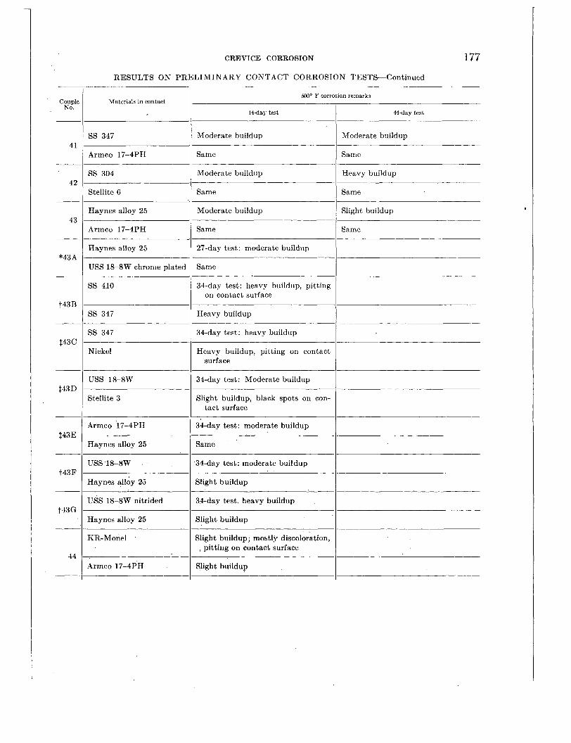
Moderate buildup
Same
Heavy buildup
Same
177 CREVICE CORROSION
RESULTS ON PRELIMINARY CONTACT CORROSION TESTS-Continued
5M)' F corrosion remarks
14day test 44-day test I Materials in contact
Moderate buildup ss 347 Moderate buildup
Armco 17-4PH Same I Same
SS 304
Stellite 6
Moderate buildup I Slight buildup Haynes alloy 25
Armco 17-4PH Same I Same
Haynes alloy 25 2i-day test: moderate buildup
USS 18-8W chrome plated Same
34-day test: heavy buildup, pitting on contact surface
SS 410
! Heavy buildup ss 347
ss 347 34-day test: heavy buildup
Nickel Heavy buildup, pitting on contact surface
USS 18-8W 34-day test: Moderate buildup I Stellite 3 Slight buildup, black spots on con-
tact surface
Armco 17-4PH 34-day test: moderate buildup I Same
34-day test: moderate buildup
Haynes alloy 25
USS 18-8W
Haynes alloy 26 Slight buildup I ~
USS 18-8W nitrided ~
34-day test. heavy buildup
Haynes alloy 25 Slight buildup ' I KR-Monel Slight buildup; mostly discoloration,
, pitting on contact surface
Armco 17-4PH Slight buildup I

178
14-day test
3Iight buildup .
CORROSION AND WEAR HANDBOOK FOR WATER-COOLED REACTORS
RESULTS ON PRELIMINARY CONTACT CORROSION TESTS-Continued
44-day test ___ Couple NO.
Slight buildup, pitting on contact surface
Slight buildup, mostly discoloration
500' F corrosion remarks
'
Materials in contact I
KR-Monel
Haynes alloy 25 45
Slight buildup, mostly discoloration I KR-Monel
46
-
47
-
48
Stellite 3
Aluminum bronze Slight buildup, possible pitting on contact surface
Slight buildup, mostly discoloratmion Haynes alloy 25 ~
Silicon bronze Moderate buildup -~ ~
uss 18-8W Slight buildup
Moderate buildup, pit,ting on con- tact surface
Silicon bronze
49 ~ ~~~
Heavy buildup SS 410
KR-Monel Slight buildup, heavy pitting on contact surface.
Slight buildup, mostly discoloration 50
Armco 17-4PH
Slight buildup, mostly discoloration 1 Stellite 3
Permo 511 51
Same
Slight buildup, mostly discoloration 1 Stellite 3
Permo K-75 52 ~~
Same
53 Slight buildup, mostly discoloration 1 ' Stellite 3
Permo 11 ~~
Slight buildup, pitting on contact surface '
Stellite 3 Slight buildup, mostly discoloration
Slight buildup, mostly discoloration, pitting on contact surface
54 Permo 116
Aluminum bronze I Moderate buildup, pitting on contact surface
55 uss 1%8W Slight buildup, mostly discoloration
_-____ I
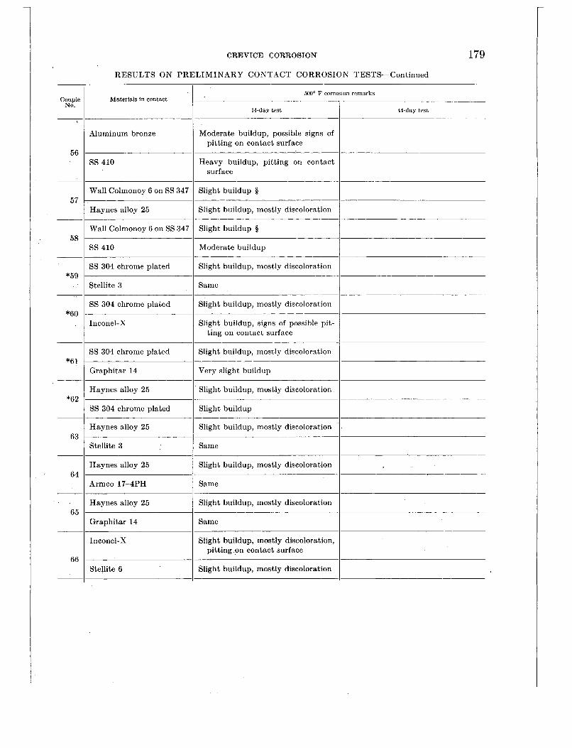
CREVICE CORROSION
RESULTS ON PRELIMINARY CONTACT CORROSION TESTS-Continued
Slight buildup, mostly discoloration
Same
179
.
500' F corrosion remarks Materials in contact
14-day test 44-day test I Aluminum bronze Moderate buildup, possible signs of
pitting on contact surface
SS 410 Heavy buildup, pitting on contact surface
Wall Colmonoy 6 on SS 347 Slight buildup 5
Haynes alloy 25 Slight buildup, mostly discoloration
Slight buildup 5 Wall Colmonoy 6 on SS 347
SS 410 Moderate buildup _ _ _ _ _ _ _ ~
SS 304 chrome plated Slight buildup, mostly discoloration
Stellite 3 Same
Slight buildup, mostly discoloration I
SS 304 chrome plated
Inconel-X Slight buildup, signs of possible pit- ting on contact surface
Slight buildup, mostly discoloration SS 304 chrome plated
Graphitar 14 Very slight buildup
Slight buildup, mostly discoloration Haynes alloy 25
SS 304 chrome plated Slight buildup
Haynes alloy 25
Stellite 3
Haynes alloy 25 Slight buildup, mostly discoloration I Armco 17-4PH Same
Haynes alloy 25 Slight buildup, mostly discoloration I Graphitar 14 Same
Slight buildup, mostly discoloration, pitting on contact surface
Inconel-X
Stellite 6 Slight buildup, mostly discoloration I

180 CORROSION AND WEAR HANDBOOK FOR WATER-COOLED REACTORS
RESULTS ON PRELIMINARY CONTACT CORROSION TESTS-Continued
Materials in contact 500' F corrosion remarks
14-day test I ' 44-day test Couplc
No.
Inconel-X Slight buildup, mostly discoloration, signs of pitting
Slight buildup, mostly discoloration 67
~
68
___
Stellite 3 ~~
ss 347 Moderate buildup
Slight buildup SS 304
Silicone bronze Moderate buildup, pitting on con- tact surface
69
__ Haynes alloy 25 Slight buildup, mostly discoloration 1 Phosphorus bronze Moderate buildup, pitting on contact
surface
Slight buildup, mostly discoloration 70
USS 1&8W
Phosphorus bronze Moderate buildup, pitting on contact surface
71
- SS 410 Moderate buildup I Phosphorus bronze Moderate buildup, pitting on contact
surface 72
Slight buildup, mostly discoloration 1 Haynes alloy 25
Nickel Moderate buildup, heavy pitting on contact surface
73 ss 347 Moderate buildup
Slight buildup, mostly discoloration 5 Wall Colmonoy 6 on SS 347
74 Same uss 18-8W
Wall Colmonoy 6 on SS 347
Slight buildup, mostly discoloration 5
75 ~~
Stellite 3 Slight buildup
Inconel-X Slight buildup, pitting on contact surface
Slight buildup, mostly discoloration 76
Haynes alloy 25

CREVICE CORROSION
RESULTS ON PRELIMINARY CONTACT CORROSION TESTS-Continued
181
5ooo F corrosion remarks Couple
No. Materials in contact
I 44-day test 14day test
USS 18-8W Moderate buildup 77 ~
hrmco 17-4PH Same I uss 1%8W Moderate buildup I
78 Haynes alloy 25 Slight buildup
Slight buildup, mostly discoloration USS 18-8W 79
80
Stellite 6
uss 18-8W
Same
Slight buildup
Stellite 3 Slight buildup, mostly discoloration I USS 18-8W Moderate buildup
Slight buildup, pitting on contact surface
81 Inconel-X
USS 1 8 4 W Moderate buildup I 82
SS 304 chrome plated Slight buildup I USS 18-8W Slight buildup, mostly discoloration
Slight buildup 83
Graphitar 14
ss 347 Moderate buildup
Same
Slight buildup, mostly discoloration
84
85
86
Stellite 6
ss 347
I Same . Armco 17-4PH
ss 347 Moderate buildup I Haylies alloy 25 Slight buildup, mostly discoloration I Mumetal Slight buildup
Same . 87
ss 347
ss 347
USS 18-8W
Slight buildup, mostly discoloration
Same - 88

182 CORROSION AND WEAR HANDBOOK FOR WATER-COOLED REACTORS
RESULTS ON PRELIMINARY CONTACT CORROSION TESTS-Continued
500' F corrosion remarks Couple
No. Materials in contact
44-day test I 14-day test ~
Slight buildup, mostly discoloration ss 347 89
Inconel-X Slight buildup, possible pitting on contact surface
- Slight buildup, mostly discoloration ss 347
*90 - SS 304 chrome plated Same
Moderate buildup ss 347 91
Stellite 3 Slight buildup, mostly discoloration 1 ~ ~~
Slight buildup, mostly discoloration
Slight buildup, deposit on contact surface
ss 347 92
93
Graphitar 14
Armco 17-4PH Slight buildup, mostly discoloration
Same Armco 17-7PH ~-
Armco 17-4PH Slight buildup,. mostly discoloration
Slight buildup 94
*95
96
Graphitar 14 ~
Armco 17-4PH Slight buildup
Same
Slight buildup
SS 304 chrome plated
Armco 17-4PH
Stellite 6 ~~
Slight buildup, mostly discoloration
Moderate buildup Armco 17-4PH
Stellite 3 97 ~~
Slight buildup, mostly discoloration
Heavy buildup, pitting on contact surface.
Slight buildup
SS 420
98
__ Stellite 3
SS 420 ~~~
Moderate buildup, pitting on con- tact surface
99 Armco 17-4 PH Slight buildup
I ____
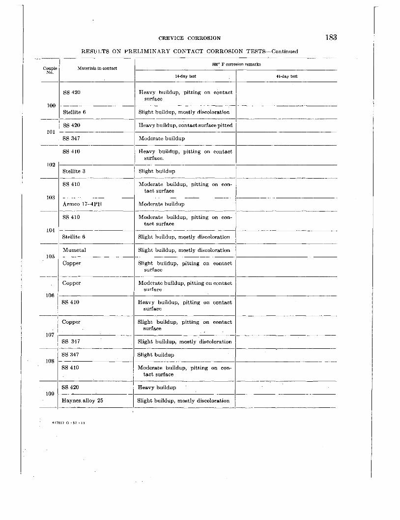
CREVICE CORROSION
RESULTS ON PRELIMINARY CONTACT CORROSION TESTS-Continued
183
500" F corrosion remarks Materials in contact coup1
No. 14day test 44day test
SS 420 Heavy buildup, pitting on contact surface
100
___
101
~.
102
__
103
Slight buildup, mostly discoloration Stellite 6
SS 420 ~~
Heavy buildup, contact surface pitted
ss 347 Moderate buildup ~
SS 410 ~~
Heavy buildup, pitting on contact surface.
Slight buildup
Moderate buildup, pitting on con- -
tact surface
Stellite 3
SS 410
Armco 17-4PH Moderate buildup
SS 410 Moderate buildup, pitting on con- tact surface
104 Stellite 6 Slight buildup, mostly discoloration
Mumetal Slight buildup, mostly discoloration 105
Copper Slight buildup, pitting on contact surface
Copper Moderate buildup, pitting on contact surface
106 35 410 Heavy buildup, pitting on contact
surface
Copper Slight buildup, pitting on contact surface
107 Slight buildup, mostly discoloration 3s 347
3s 347
3s 410
Slight buildup
Moderate buildup, pitting on con- tact surface
108
Heavy buildup 35 420
Haynes alloy 25 109
Slight buildup, mostly discoloration
417017 0 - 5 7 - 1 3
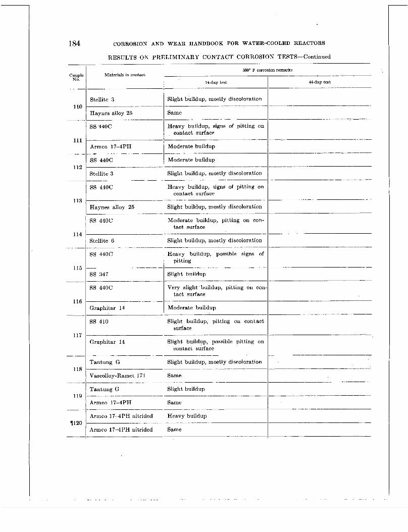
184
_ _ ~
Heavy buildup, signs of pitting on contact surface
__- Slight buildup, mostly discoloration
CORROSION AND WEAR HANDBOOK FOR WATER-COOLED REACTORS
RESULTS ON PRELIMINARY CONTACT CORROSION TESTS-Continued
~p-_~-_______--_-
Materials in contact 500' F corrosion remarks
14-day test 44-day test I Couple
No.
Slight buildup, mostly discoloration
Same _____ --____
Stellite 3 I10
Haynes alloy 25 _ _ ~ ~
Heavy buildup, signs of pitting on contact surface
SS 440C
111 Moderate buildup
Moderate buildup I --
Armco 17-4PH
SS 440C 112 ~
Stellite 3 Slight buildup, mostly discoloration I SS 440C
113 Haynes alloy 25
SS 440C _________-- ~~
Moderate buildup, pitting on con- tact surface
114 Slight buildup, mostly discoloration
Heavy buildup, possible signs of ~p___---
pitting
Stellite 6
SS 440C
115 - ss 347 Slight buildup
Very slight buildup, pitting on con- --
tact surface SS 440C
116 -
Graphitar 14 Moderate buildup
Slight buildup, pitting on contact - _ _ ~
surface
Slight buildup, possible pitting on contact surface
SS 410
117 Graphitar 14
__- Tantung G
~ ~~
Slight buildup, mostly discoloration I 118
Same Vascolloy-Ramet 171
Tantung G Slight buildup
Same -___ 119
7120
Armco 17-4PH
Arrnco 17-4PH nitrided Heavy buildup
Same I-- Armco 17-4PH nitrided ________
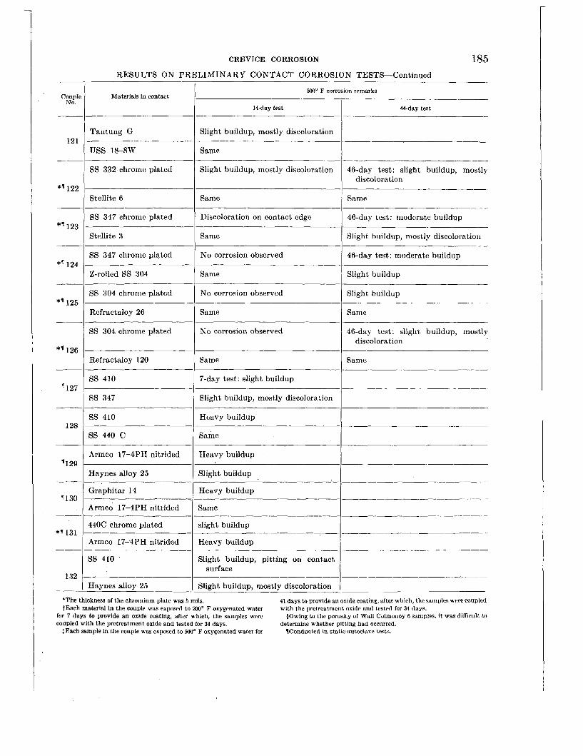
CREVICE CORROSION
RESULTS ON PRELIMINARY CONTACT CORROSION TESTS-Continued
Couple No.
500' F corrosion remarks Materials in contact
~~
14day test 44-day test
Slight buildup, mostly discoloration Tantung G
USS 18-8W 121
Same
SS 332 chrome plated Slight buildup, mostly discoloration ~
46-day test: slight buildup, mostly discoloration
*q 122 Stellite 6 Same Same
46-day test: moderate buildup SS 347 chrome plated
Stellite 3
Discoloration on contact edge
Same *'123
Slight buildup, mostly discoloration
SS 347 chrome plated No corrosion observed 46-day test: moderate buildup
Slight buildup *'I24 ~ ~~
2-rolled SS 304 Same
SS 304 chrome plated No corrosion observed Slight buildup
Same *' 125
Refractaloy 26 Same
SS 304 chrome plated No corrosion observed 46-day test: slight buildup, mostly discoloration
*'126 Refractaloy 120 Same Same
SS 410 7-day test: slight buildup '127
ss 347 Slight buildup, mostly disco1ora:ion
SS 410 Heavy buildup 128
SS 440 C Same
Heavy buildup Armco 17-4PH nitrided '129
_- '130
Haynes alloy 25
Graphitar 14
Slight buildup
Heavy buildup -____--__-____
Same Armco 17-4PH nitrided
440C chrome plated
Armco 1724PH nitrided
SS 410
-- - slight buildup *(I 131
Heavy buildup
Slight buildup, pitting on contact surface
132 Slight buildup, mostly discoloration Haynes alloy 25
'The thickness of the chromium plate was 5 mils. tEach material in the couple was exposed to 200' F oxygenated water
for 7 days to provide an oxide coating, after which, the samples were coupled with the pretreatment oxide and tested for 34 days.
$Each sample in the couple was exposed to 500' F oxygenated water for
41 days to provide an oxide coating, after which, the samples were coupled with the pretreatment oxide and tested for 34 days.
$Owing to the porosity of Wall Colmonoy 6 samples, it WBS difficult to determine whether pitting had occurred.
Wonducted in static autoclave tests.

Chapter 10
STRESS CORROSION
Editors-W. LEE WILLIAMS, JOHN F. ECKEL
Contributors-J. W . BARBOUR, W. F. BRINDLEY, E. G. BRUSH, E. J. CALLAHAN, J. G. CHRIST, F. E. CLARKE, D. J. DEPAUL, W. L. FLEISCHMANN, G. E. GALONIAN, E. R. HARRIS, J. R . HUNTER, R. F. KOENIG, C. J. LANCASTER, R. L. MEHAN, E. M. RENO, M. C. ROWLAND, R. S. SHANE, A. SQUIRE, W. C. STEWART, H. V. TYDINGS
Section I
I N T R O D U C T I O N _ _ _ - - - - - - - - - - - - - - - - - - - - - - - - - - - GENERAL PREVENTIVE MEASURES- _ _ -. - - - - - - - - DETAILS ON EFFECTS OF VARIABLES AND CON-
TROL M E A S U R E S _ - - _ - - - - - - - - - - - - - - - - - - - - - - Austenitic Stainless Steels in High-Purity
W a t e r _ - _ - - - - - - - - - - - - - - - - - - - - - - - - - - - - Austenitic Stainless Steels in Chloride-
Bearing Water- - - - _ _ _ _ _ - -. - - - _ _ - _ _ - - - Ferritic and Martensitic Stainless Steels- -. Precipitation-Hardening Stainless Steels- - - Nickel-Base Alloys_- - - - - - - - - - - - - - - - - - - - - Other Materials- - - - _ _ _ _ - - - _ _ _ _ _ _ - _ _ _ _ _ _
Page 187 188
188
188
188 190 191. 191 191
Section I1
LABORATORY T E S T S _ _ _ _ _ _ _ _ _ _ _ _ _ . _ - - - - - - ~ - - - Apparatus and Procedures- - - - - - - - - -. - - - -
Tests in Primary Water Systems- - - - _ _ _ _ _ Tests in Secondary Steam-Water Systems-
AUXILIARY BOILER EXPERIENCE- - ~ - - - - - - - - - - - STRESS CORROSION FAILURES I N MODEL HEAT
EXCHANGERS _____._______.___ ~ _ _ _ ~ _ ._____
INDUSTRIAL EXPERIENCE- - _ _ _ _ _ _ - _ _ ~ - - -
Paee
191 191 ,192 196 211
214 219
SECTION I-ENGINEERING CONSIDERATIONS
INTRODUCTION
Stress corrosion is that type of corrosive attack which occurs through the combined action of stress and a corrosive environment. The stress can be applied-or residual, but i t is always a tensile stress. The aggressiveness of the corrosive environment required to cause cracking may vary for different materials. The environment may be exceedingly mild, producing little or no corrosive attack in the absence of stress. However, the same environ- ment may cause localized attack (cracks) with the same material in the stressed condition. In very corrosive environments cracking maj- occur in the same material a t much lower stress levels.
Stress corrosion attack takes the form of cracks which grow slowly or rapidly, depend- ing on environmental conditions. The cracks
may be intergranular, transgranular, or a combination of both.
Many factors affect the occurrence and rate of stress corrosion. Among these are the stress level, the nature of the corrosive agent, the time and temperature of exposure, the struc- ture of the material, the amount of plastic strain, the behavior of protective films on the material, and perhaps others. These points are discussed in the published literature. For a more thorough study of the subject, the reader is referred to selected references listed a t the end of the chapter, particularly the following : (1) the general problem, references 1 to 6; (2) ferritic steels, references 5 , and 7 to 18; (3) nickel-base alloys, references 4, 6, and 19; (4) austenitic stainless steels, refer- ences 20 to 29; and ( 5 ) stress corrosion theories, references 30 to 35.
187

188 CORROSION AND WEAR HANDBOOK FOR WATER-COOLED REACTORS
Stress corrosion can be caused by two corro- sive media in nuclear powerplants. One is the high-purity water in the primary coolant system of water-cooled nuclear reactors. The other is the boiler water in the secondary steam generation system. In addition, the action of these waters can vary according to whether or not a material is exposed in the liquid phase or the vapor phase.
GENERAL PREVENTIVE MEASURES
Except for a few specialty items, such as materials of spring tamper, stress corrosion is not known to be a problem in primary water systems. The few problems that do exist ap- parently can be circumvented without much difficulty by the proper selection of materials and their heat treatments.
The main stress corrosion problem has come about through the use of austenitic stainless steels in the secondary steam generation sys- tem. The boiler water in the secondary sys- tem can contain chlorides, and most stress corrosion failures of austenitic stainless steels have been associated with chloride-bearing environments.
An obvious method of overcoming the stress corrosion problem would be to construct the secondary system of conventional boiler mate- rials, i. e., ferritic steels. However, if stainless steels are used for the primary system, a tran- sition from austenitic to ferritic steels between the primary and secondary systems would introduce complicated design and fabrication problems.
Much can be accomplished toward the reduc- tion or elimination of stress corrosion in aus- tenitic stainless steels by the use of annealed steels, stabilized steels, and stress relief treat- ments and by keeping design and operating stresses as low as possible. But these alone are not always enough. Positive control can be realized only by employing special means to inactivate the corrosiveness of the boiler water.
I t appears that stress corrosion of austenitic grades of stainless steel can be effectively
inhibited in the liquid phase of ordinary boiler waters by an alkalinerphosphate water treat- ment similar to that used in conventional naval boilers. However, this treatment is not effec- tive in the steam phase, and it is here that more extreme methods of control must be exercised.
The most critical areas in the steam phase are those in which the equipment is subjected to intermittent wetting and drying. This can come about above the water level by splashing, carryover, etc. Nevertheless highly critical areas can also exist below the water level. Zones which are especially vulnerable exist in crevices formed by tube joints and under corrosion deposits, wherein local hot spots can develop and the water can flash to steam. The intermittent wetting and drying leads to the concentration of boiler water constituents (and chlorides) , thereby creating a local aggressive medium in an otherwise mild environment.
Experiments have demonstrated that both chloride and oxygen must be present for stress corrosion of austenitic stainless steels to occur in boiler environments. Keeping the chloride content at a very low average level is helpful, but is not foolproof under conditions where local concentration can occur. Therefore, the most effective guard against stress corrosion in the secondary system is to keep the oxygen at the lowest possible level. The use of oxygen scavengers may be necessary.
DETAILS O N EFFECTS OF VARIABLES AND CONTROL MEASURES
Austenitic Stainless Steels in High-purity Water
The stress corrosion behavior of austenitic stainless steels in primary waters has not been explored as extensively as might be desired. However, the evidence shows that stress corrosion cracking is not a problem in the major structural components of primary systems. Such components would be fabricated from mill-annealed material, and stresses from fab- rication and service, even if beyond the yield strength, should not cause stress corrosion.
On the other hand, heavy cold working of these steels induces susceptibility to stress corro-

STRESS CORROSION 189
sion in primary waters, particularly oxygen- bearing waters. On this basis, austenitic stain- less steels are not recommended for use as springs or any other specialty item in which the material is to be strengthened by intentional cold working. In some applications, such as bolts a small amount (10 percent) of cold working can be tolerated.
Austenitic Stainless Steels in Chloride-bearing
The stress corrosion behavior of austenitic stainless steels in secondary steam-water en- vironments is a considerably more critical problem, mainly because of the quantities of chlorides which can be encountered in steam generation systems. This is especially true in naval .boilers, where the feed water is cooled with sea water, which usually causes contamina- tion by condenser leakage.
The austenitic stainless steels as a class ap- pear to be susceptible to stress corrosion crack- ing in high-temperature chloride water environ- ments. Some compositions are found to be more resistant than others. AISI types 304, 316, and 347 are'considered to be anLong the more susceptible alloys. However, insufficient, work has been done to enable listing the nu- merous alloys in a reliable order of relative resistance.
Stress corrosion is characterized by cracking of a predominantly transgranular nature, but intergranular failures have also been observed. Sensitivity to intergranular corrosion is not necessary for transgranular stress corrosion to occur. However, sensitized alloys can fail by stress corrosion cracks following an intergranu- lar path.
Transgranular stress corrosion cracks can vary in appearance from single, relatively straight cracks to highly branched, fingerlike crack networks. Stress corrosion cracks usually start a t corrosion pits, but i t cannot be con- cluded that all environments leading to corro- sion pits will also ultimately lead to stress corrosion cracks.
Stabilization of the austenite by a moderate increase of nickel content (such as in AISI
Water
types 305 and 316) does not prevent stress corrosion, although it probably does increase resistance to cracking.
Austenitic chromium-manganese steel is con- sidered to be as susceptible to cracking as the austenitic chromium-nickel grades.
The section thickness has no noticeable effect on susceptibility to cracking.
Applied stresses as low as 5,000 psi can cause stress corrosion of annealed steel under ideal conditions. Residual stresses from tube rolling, cold forming, welding, and even cleaning with emery cloth may be sufficient to cause failure in environments conducive to stress corrosion.
The temperature of the environment does not have to be high. Information from laboratory and pilot-plant tests and other industrial sources would indicate that stress corrosion can occur a t t,emperatures as low as the boiling point of water, and probably even lower. Although stress corrosion increases with temperature, quantitative data are not available.
Stress corrosion can occur rapidly under highly conducive conditions. Specimens have been ob- served to fail within 20 min a t 500' F (plus heating and cooling time).
Stress corrosion of austenitic stainless steels can occur in uninhibited water with a moder- ately low chloride content. Specimens im- mersed in oxygen-bearing water with 300 ppm chloride are readily cracked. Similar tests in chloride-free water did not result in cracks. The region below 300 ppm chloride has not been explored sufficiently to determine whether or not some threshold level exists (other than zero) below which stress corrosion will not occur with specimens exposed in the liquid phase.
The stress corrosion of austenitic stainless steels submerged in chloride-bearing waters of practical interest apparently can be prevented by alkaline-phosphate water treatment, pro- vided the steels are in the mill-annealed condi- tion a t the time of fabrication and provided sensitization does not occur from welding or operating temperatures. Tests of AISI type type 304 steel indicate that sensitization of unstabilized alloys can lead to failure by inter-
<
190 CORROSION AND WEAR HANDBOOK FOR WATER-COOLED REACTORS
granular stress corrosion cracking in low oxygen alkaline-phosphate treated water, except pos- sibly when the chloride content is kept very low.
Austenitic stainless steels exposed in the steam phase of chloride-bearing water and inter- mittently wetted (in tests, by inversion of the pressure vessel) are susceptible to stress cor- rosion cracking a t very low chloride contents. Cracks were produced readily under these cir- cumstances with water containing as little as 1 ppm chloride.
It is not known whether the extreme sensi- tivity to cracking in the steam phase is due to some reactive characteristic of the vapor not present in the water or to a concentration of the water constituents through the alternate wetting and drying process. However, the evidence favors the latter explanation. One test in the vapor without int,ermittent wetting did not result in cracks.
Alkaline-phosphate water treatment does not inhibit the stress corrosion of austenitic stainless steels in the steam phase of secondary system waters.
Oxygen is a strong accelerator of stress cor- rosion of austenitic stainless steels in hot-water environments. In fact, the evidence indicates that some oxygen is necessary for stress cor- rosion to occur. The necessary amount is small. It is believed that maintenance of oxy- gen a t some value below 1 ppm* (probably 0.5 ppm in critical areas) will provide reasonable as- surance against stress corrosion failures a t chlo- ride levels likely to be encountered in steam generation equipment.
The maintenance of low oxygen might not be an entirely satisfactory method of preventing intergranular stress corrosion in unstabilized sensitized steel, such as AISI type 304. How- ever, no problem of this sort is anticipated with stabilized steel, such as AISI type 347.
Inhibitors offer some promise for the control of stress corrosion in the vapor phase. I t is
'Although the standard practice in this handbook is to express oxygen as cubic centimeters per kilogram of water (STP) or cc/kg, because of its common usage in boiler water technology, parts per million or ppm was retained in this chapter.
probable that any successful inhibitor will have oxygen scavenging characteristics. Sulfite treat- ment has shown considerable promise.
There is some indication that stress corrosion of austenitic stainless steel may be controlled by suitable galvanic couples, however, this aspect has not been explored sufficiently to be of practical use a t this time.
The tests of the austenitic stainless steels, covered in section 11, were conducted for the most part under severe stress and environ- mental conditions. This was done purposely to detect susceptibility to stress corrosion within reasonable testing times. Thus, the high percentage of test specimen failures does not, in itself, indicate that service failures will occur in epidemic proportions. The principal value of the tests was to point to the need for extreme caution in the design and operation of equip- ment in which austenitic stainless steels are used in contact with high-temperature waters, and especially the steam phase of such waters. Much can be accomplished by proper design and by operation of equipment within safe limits. The use of annealed steels, stress relief treat- ments, stabilized grades, low operational stresses, low chloride levels, low oxygen levels, and proper corrosion inhibitors are all important steps toward the elimination of stress corrosion hazards.
Ferritic and Martensitic Stainless Steels
The ferritic stainless steels and the marten- sitic stainless steels at low hardness levels probably are immune to stress corrosion crack- ing in the high-temperature water environments associated with primary and secondary systems. This conclusion is based on limited tests which did not include studies of processing variables such as welding or cold rolling.
The martensitic stainless steels heat treated to high hardness levels (probably above Rock- well C-30) are susceptible to cracking, as demonstrated by the failure of coil springs in primary waters. Judging from published work of other investigators, the hardened steels

STRESS CORROSION 191
apparently fail because of sensitivity to hydro- gen embrittlement.
Precipitation-hardening Stainless Steels
Limited tests of precipitation-hardened stain- less steels indicate susceptibility to stress corrosion in high-temperature waters similar to, and perhaps greater than, the austenitic stainless steels. The precipitation-hardened steels are not suitable for springs in primary waters.
Nickel-base Alloys
Miscellaneous tests of the nickel-base alloys
listed in table 9 indicate immunity to stress corrosion cracking in primary and secondary water environments. The only failures ob- served were those of alloys I and K in 550’ F. sea dater (20,000 ppm chloride). Alloy J is indicated as a suitable spring material for exposure to primary waters.
Other Materials
Limit,ed tests of carbon steel, titanium, copper-nickel 90-10 and copper-nickel 70-30 did not reveal stress corrosion cracking in environments which would have led to cracking of austenitic stainless steels.
SECTION 11-SPECIAL INVESTIGATIONS AND SERVICE EXPERIENCE
LABORATORY TESTS
Numerous laboratory tests have been con- ducted to help define the conditions under which stress corrosion cracking will or will not occur in high-temperature waters. Most of the tests were conducted on the austenitic stainless steels, especially AIS1 types 304 and 347. However, limited data were gathered on other materials as well.
The data presented below are arranged, insofar as possible, to illustrate the effects of the several variables associated with conditions likely to exist in primary coolant systems and secondary steam-water systems of water-cooled nuclear reactors.
Apparatus and Procedures
The laboratory, stress corrosion tests are con- ducted at elevated temperatures in stainless steel pressure vessels. Two basic test systems are used. One is a hydraulic loop, which is a semi-closed system through which high-temper- ature water can be circulated past the corrosion specimens. Circulation is provided by a stain- less steel [‘canned rotor” pump.
The second system utilizes autoclaves to contain the specimens. Such a vessel can be
used either for static exposure or for dynamic exposure by utilizing some form of external drive to rotate the specimens in the water. The liquid level is usually maintained a t one- half to two-thirds full, and the specimens are exposed in either the steam phase or t,he water phase, or both alternately.
Waters of known composition, including gas content, are used as corrosive media. I t should be pointed out that the composition of these media can change during the course of some of the experiments, particularly in the case of the autoclave tests where the volume of the water is relatively small and is not replenished con- tinuously. Composition changes have been noted especially in regard to the oxygen content since the oxygen is sometimes scavenged by reaction with the specimens or with the pressure vessel itself.
The majority of the bests have been made with specimens basically similar to those shown in figure 10-1.
The U-bend specimens were used to determine susceptibility to stress corrosion under severe stress conditions. The simple beam specimens were used for tests a t lower stress levels, es- pecially when the stress level was of interest as a variable under study.

~~
192 CORROSION AND WEAR HANDBOOK FOR WATER-COOLED REACTORS
Other specimens and special environments were used in some cases. These are described, as necessary, along with the corresponding test results.
SIMPLE BEAM SPECIMEN STRESS AOJUSTEQ WITH STRAIN 6A6E
U - BEND SPECIMEN TIE ROD TO PREVENT
SPRINGBACK
FIGURE 10-1. Basic stress corrosion specimens used i n the majority of the laboratory tests.
Tests in Primary Water Systems
GENERAL
Primary coolant waters are characterized by their relatively high purity. The high-purity water used in the following experiments is defined as water having a total solids content of less than 1 ppm and a resistivity of a t least 500,000 ohm-cm. Such water is prepared by distillation and deionization. A gas of interest (usually oxygen) is added in most cases.
So far, annealed austenitic stainless steels have been used exclusively for the construction of the main elements of primary coolant sys- tems. Although these materials are not likely to stress-corrode in primary waters (except possibly under very special circumstances) specialty items, such as springs, present a more difficult problem. Much of the experimental work which follows has been directed toward the selection of suitable spring materials.
AUSTENITIC STAINLESS STEELS
Numerous tests in primary waters have been made with simple beam specimens made of
austenitic stainless steels. Four conditions of treatment have been considered : (1) annealed, (2) cold worked, (3) cold worked and annealed, and (4) sensitized 2 hr at 1,200' F. The results of these tests are summarized in table 10-1.
It is noteworthy that the two AISI type 304 specimens not cold worked prior to annealing and stressing did not crack when tested at 500' F. In contrast, over half of those cold worked, annealed and stressed did crack when tested at 600' F in oxygen-bearing water. The 600' F tests in hydrogen-bearing water (with less than 0.5 ppm oxygen) did not result in failure.
The effects of the many variables that might influence the stress corrosion behavior of austenitic stainless steels in primary waters have certainly not been explored as extensively as might be desired. However, it is believed that no particular difficulties will arise in actual equipment as long as fabrication is limited to hot rolled-annealed steels. On the other hand, there is sufficient evidence to indicate that austenitic steels should not be used for springs in primary waters because the spring temper material is obtained by intentional heavy cold working.
There remains the possibility that stress cor- rosion failure might occur in unexpected cases. At least one interesting case has been observed. Leaks developed in two sections of %-in. AISI type 347 stainless-steel tubing installed at orifice meters in a hydraulic test loop. The tubing apparently was obtained in the mill- annealed condition but was worked by severe cold bending during fabrication of the loop. Installation was in an area where the tubing could have been exposed to water vapor as well as to the water itself.
Failure developed after the loop had been operated 1,550 hr at 600' F and 4,200 hr a t 500' F. At various times the water in the system had been degassed or had contained either 1 to 5 or 20 to 30 ml of oxygen per kilo- gram of water (STP) (cc/kg). A typical cross section of the failed tubing is shown in figure 10-2. Similar tubes on other loops have not failed, and the reason for this particular casualty has not been determined.

STRESS CORROSION 193 TABLE 10-1
AUTOCLAVE STRESS CORROSION TESTS I N PRIMARY WATERS WITH SIMPLE BEAM SPECIMENS OF AIS1 AUSTENITIC STAINLESS STEELS
Temp., F
500 500 500 500 500 500 500 500 600
600 600
600 600 600 600 600 600 600 600 600 600 600 600 600 600 600 600 600 600 600 600 600 500 500 500 500 500 500 600
Water hnditions
Velocity,' ftlsec
0 0 0 0 0 0
11 11 0
0 0
0 0 0 0 0 0 0 0 0 0 0 0 0 0 0 0 0
' 0 0 0 0
11 11 11 11 11 11 25
\IS1 type
302 302 302 302 302 302 304 304 304
304 304
304 304 304 304 304 304 304 304 304 304 304 304 304 304
' 304 304 304 304 304 304 304 310 310 316 316 347 347 347
Condition Stress, psi
_____
10,000 30, 000 t>yp 10,000 30,000 t > Y P 30,400 30,400 30, 000
50,000 30,000
50, 000 60,000 80,000 70, 000 90,000 95,000
110,000 110,000 125,000 130,000 150,000 60,000 80,000 70,000 90,000 95,000
110,000 110,000 125, 000 130, 000 150, 000 29,800 29,800 28,300 28,300 31,500 31, 500
722, 400
Test time, days
90 90 90 90 90 90 30
120 74
74 74
74 74 74 30 74 30 30 30 30 30 30 38 38 38 38 38 38 38 38 38 38 30
120 30
120 30
120 34
Stress cor- rosion cracks
No No No No No No No No Yes
Yes Yes
No Yes Yes No Yes Yes No No Yes No No No No No No
($) ($1
($1 No
No No No No No No No No No
'Water velocity obtained by rotation of specimen in water or circula-
$Degassed means air purged by boiling autoclave before sealing. tion of water past specimen.
tslight defect parallel to direction of stress; apparently associat.ed with
ILoaded in direct tension. tYield point.
a rolling seam; doubtful if associated with stress corrosion.

194 CORROSION AND WEAR HANDBOOK FOR WATER-COOLED REACTORS
Returning again to autoclave tests of simple beam specimens, three proprietary austenitic stainless steels have been exposed in primary waters without stress corrosion damage. Each
primarily for spring applications. Results with simple beam specimens, both notched and un- notched, are listed in table 10-2. It is obvious that alloy F is unsuitable for the intended
FIGURE 10-2. Stress corrosion cracks i n a type 34Y steel tube from n hydraulic test loop ( X 7 ) .
of these was in the mill-annealed condition. The test conditions were as follows, and the compositions of the alloys were as listed in table 10-9.
Environment Ezposure 500' F water with 0.7 to 7 Alloy A, 28,300 psi, 30
Alloy B, 28,700 psi, 30
500' F water with 35 ppm Alloy A, 28,300 psi, 120
Alloy C, 35,000 psi, 90
PPm 0 2 days
days
0 2 days
days
PRECIPITATION HARDENING STAINLESS STEELS
The stress corrosion properties of the precipi- tation-hardening stainless steels were evaluated
*
application. In addition, tests of act a1 springs, described in a subsequent section, indicated the unsuitability of alloys G and H, despite the lack of stress corrosion in the simple beam specimens.
The compositions of the three alloys are indicated in table 10-9. A photograph of the alloy F specimens tested a t 600° F is shown in figure 10-3.
OTHER MATERIALS
Martensitic stainless steels, nickel-base alloys, and copper-nickel alloys were also tested. All the tests made use of simple beam specimens loaded in bending or of tension specimens loaded in direct stress. All the tests were negative, either because of inherent resistance
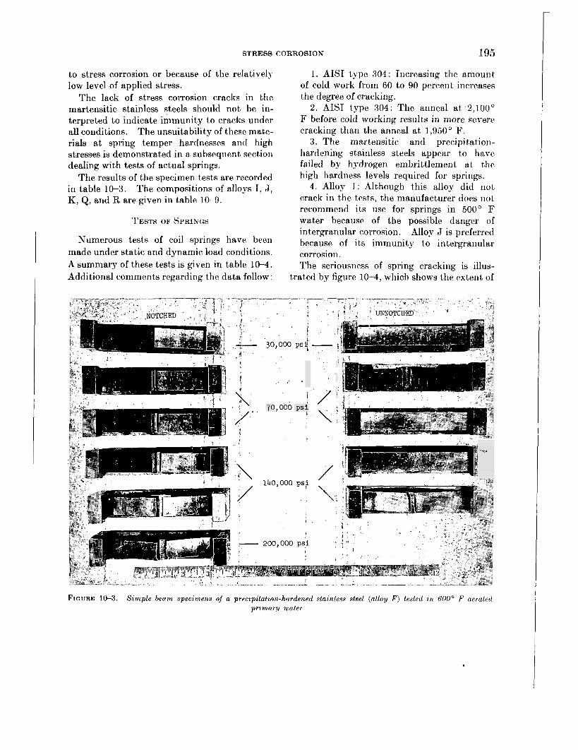
STRESS CORROSION 195
to stress corrosion or because of the relativel5- low level of applied stress.
The lack of stress corrosion cracks in the martensitic stainless steels should not be in- terpreted to indicate immunity to cracks under all conditions. The unsuitability of these mate- rials at spring temper hardnesses and high stresses is demonstrated in a subsequent section dealing with tests of actual springs.
The results of the specimen tests are recorded in table 10-3. The compositions of alloys 1, J, K, Q, and R are given in table 10-9.
TESTS OF SPRINGS
Numerous tests of coil springs have been made under static and dynamic load conditions.
1. AIS1 type 304: Increasing the amount of cold work from 60 to 90 percent increases the degree of cracking.
2. AIST type 304: The anneal a t 2,100' F before cold working results in more severe cracking than the anneal a t 1,950' F.
3 . The martensitic and precipitation- hardening stainless steels appear to have failed by hydrogen embrittlemerit at the high hardness levels required for springs.
4. Alloj- I : Although this alloy did not crack in the tests, the manufacturer does not recommend its use for springs in 500' F water because of the possible danger of intergranular corrosion. Alloy J is preferred because of its immunity to intergranular corrosion.
A summary of these tests is given in table 10-4. Additional comments regarding the data follow:
The seriousness of spring cracking is illus- trated by figure 10-4, which shows the extent of
/ ' 70,000 p s i
/ 140,000 psi
.- **I
F I C ~ J R E 10-3. Sample beam speczniens of a preczpztatzon-hardened staanless steel (al loy F ) tested an 600' F aerated pr imary uiater.
.

196 CORROSION AND WEAR HANDBOOK FOR WATER-COOLED REACTORS
Stress, psi
--_____
58, 600 58, 600 30,000 70, 000
140,000 30,000 70, 000
140, 000 200, 000 60, 800 60,800 58,300 58, 300
TABLE 10-2.
AUTOCLAVE STRESS CORROSION TESTS I N PRIMARY WATERS WITH SIMPLE BEAM SPECIMEN OF PRECIPITATION-HARDENING STAINLESS STEELS
Test time, days
30 120
15 15 15 15 15 15 15 30
120 30 60
Rockwell Water
hardness 1 O F
Alloy' I C 1 Typeofspecimen temp.,
1 1 1 2 2 1 2 2 1 1 1 1 1
F F F F F F F F F G G H H
No No No 1-Yes, 1-? 2-Yes yes 2-yes 2-yes Yes No No No No
500 500 600 600 600 600 600 600 600 500 .500 500 500
*Compositions given m table 10-9.
failure encountered in the AIS1 type 420 springs exposed to 600' F degassed water for 34 days.
FIGURE 10-4. Type 4SO steel springs after exposure to 600' F degassed primary water.
Tests in Secondary Steam-Water Systems
GENERAL
In contrast, to primary coolant water, an important characteristic of water in a secondary system is the presence of chlorides. It has been known for a number of years that austenitic stainless steels are susceptible to stress corrosion cracking in chloride-bearing environments. The preponderance of industrial failures has oc- curred in environments where chlorides were known or suspected to have been present. It is also known that oxygen plays an important role in the stress corrosion of austenitic steels in high-temperature water.
Number Stress
specs. cracks of 1 corrosion
-I---
There is no reason to believe that the actual mechanism of the stress corrosion process in the water phase is any different from that in the steam phase. However, alternate wetting and drying of parts in the steam phase can cause concentration of constituents p-esent in the water. Such behaviour is similar to the con- centration of constituents in crevices of heat- transfer equipment, such as at tube-header joints. Other important characteristics of a two-phase system include the unequal distribu- tion of any gases present and the possible in- effectiveness of corrosion inhibitors in control- ling corrosion in both the water and steam phases.
For these reasons the stress corrosion be- havior of a material in a given steam-water system depends on whether exposure is to the liquid or vapor. Accordingly, it is convenient to separate the water- and steam-phase tests in presenting the following data from corrosion tests carried out in laboratory autoclaves.
WATER-PHASE TESTS EFFECT OF CHLORIDE LEVEL IN UNTREATED
WATER
Very few tests were made in plain chloride- bearing waters for two reasons: (1) the sec-
. ~ - . . . . . - -

STRESS CORROSION 197 TABLE 10-3
AUTOCLAVE STRESS CORROSION TESTS IN PRIMARY WATERS WITH SPECIMENS OF MAR- TENSITIC STAINLESS STEELS, NICKEL-BASE ALLOYS, AND COPPER-NICKEL ALLOYS
[All results were negative (no cracks)]
Environment
600' F degassed water, velocity 29 ft/sec ....__________
600' F degassed water, velocity 25 ft/sec ....__________
500' F water, 0.5-4.6 ml/liter 0 2 , velocity 11 ft/sec._--.- 500' F water, 20-30 ml/liter 0 2 , velocity 11 ft/sec..-_-.
*Compositions and treatments,of lettered alloys are given in table 10-8. toil quenched from 1,850' F. tempered 1 hr at 650' F.
ondary system waters to be used in service were mostly to be alkaline-phosphate treated, and (2) water-phase problems did not prove to be as serious as steam-phase problems. Thus, there was no systematic study of chloride level in untreated waters.
The few available data on untreated waters are listed in table 10-5. In a very rough way, these data illustrate the expected increase in cracking susceptibility with increase in chloride level and temperature. The data also point to the importance of oxygen in the stress corrosion process.
EFFECT OF WATER COMPOSITION I N ALKALINE- PHOSPHATE TREATED WATERS
In contrast to the limited data on untreated waters, a great number of tests have been con- ducted with stainless steel specimens sub- merged in alkaline-phosphate treated waters. These tests have explored such variables as chloride level, oxygen content, temperature, time, pH, and material composition. Typical data, which illustrate the results obtained over a range of environmental conditions, are pre- sented in table 10-6 for stainless steels in the an- nealed condition prior to stressing.
Alloy* Stress, psi I TesAa;;rne,
20,000 20,000 20,000 20,000 20,000 51,000 51,000 23, 200 26,900 24, 600 40, 600 18,400 21. 600
30 30 30 30 30 34 34 34 34 34 30 60 60
The only positive cases of stress corrosion damage recorded in table 10-6 occurred to the first three specimens listed under the 530 ppm chloride tests. These specimens were exposed in the water phase during most of the test period. However, they were also exposed to the steam phase for brief intervals when the auto- clave was inverted to wet down specimens being treated simultaneously in the steam phase. An oxygen-saturated environment was used in the tests, and, since high oxygen is known to have an accelerating effect on stress corrosion, it is possible that the cracking was associated with the steam phase. In any case, similar vessel inversion tests did not lead to cracking in environments with lower, more realistic oxygen levels.
There have been 2 or 3 other isolated cases of cracking with specimens submerged in alka- line-phosphate-treated water. These cases have not been included in table 10-6 since there is a lack of complete information regarding the tests. Either the test environments have not been defined adequately or the cracks are very minor and not definitely established as having been caused by stress corrosion.
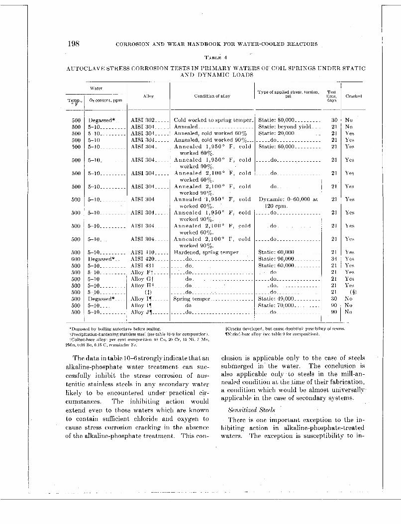
198 CORROSION AND W E A R HANDBOOK FOR WATER-COOLED REACTORS
TABLE 4
AUTOCLAVE STRESS CORROSION TESTS I N PRIMARY WATERS OF COIL SPRINGS UNDER STATIC AND DYNAMIC LOADS
.
Degassed*._ ~.
5-10 ......... 5-10 ......... 5-10 ......... 5-10. ~ ~ ~ ~ ~ ~ ~.
5-10_. .......
Te,mp., F
____
.500 500 500 500 500
500
500
500
500
500
500
500
500 600 500 500 500 500 500 500 500 500
AISI 302- ~ ~
AIS1 304-. . AISI 304-. . AISI 304-. . AISI 304- ~ ~
AISI 304
Water
02 content, ppm _-
Alloy
5-10 .........
5-10 .........
5-10K ~ ~ ~ ~ ~ ~~
5-10 .........
5-10.-. ......
AISI 304 ...
AISI 304 ...
AISI 304- ~~
AISI 304 ...
AISI 304.
5-10 ......... Degassed*_. ~ ~
5-10.- ~ ~ ~ ~ ~ ~~
5-10.- ....... 5-10- ........ 5-10L ....... 5-10._--- . - - - Degassed*._. . 5-10 ......... 5-10 .........
AISI 110 ... AISI 420- ~.
AISI 431L. Alloy Ft ... Alloy G t ... Alloy H t ...
( $1
Alloy IT.. .. Alloy JT ....
Alloy IT-- ~ ~
Condition of alloy
Cold worked to spring temper. Annealed-. ................. Annealed, cold worked 607,--. Annealed, cold worked 90 %... Annealed 1 ,950 ' F , cold
Annealed 1 ,950 ' F, cold
Annealed 2,100 ' F, cold
Annealed 2,100' F, cold
Annealed 1,950 ' F, cold
Annealed 1 ,950 ' F, cold
Annealed 2,100 ' F, cold
Annealed 2,100' F , cold
Hardened, spring t,emper ~ ~ ~ ~ ~
do^^^^^_^........._.... do_^^^^^_^^^^^^^^^^.^^^ ..'~.dO ..................... do ..................... .... d o . . . . . . . ~ _ _ . i ~ . ~ ~ ~ ~ ~ ~ ~ do_ do__ ~ ~ ~ ~ ~ ~ ~ ~ ~ ~. ~. ~ ~.
.... do_........._....^.^^^^
worked 607,.
worked 90%.
worked 60 yo.
worked 90%.
worked 60%.
worked 90%.
worked 60%.
worked 90%.
Spring temper-_. ............
Type of applied stress, torsion, Psi
Static: 80,000 ......... Static: beyond yield.. . Static: 20,000.. ~ ~ ~ ~ ~ - .... do ............... Static: 60,000- ........
.... do ...............
.do....
.do.
Dynamic: 0-60,000 a t
do_ do.^^_^.....^.^^^ 120 cpm.
... .do.. .
'Degassed by boiling autocldve before sealing tPrecipitation-hardening stainless steel (see table 10-Y foi composition) iColbat-base alloy per cent composition 40 Co, 20 Cr. 15 Ni, i Mo,
2Mn, 0 04 Re, 0 15 C, remainder F?
The data in table IO-6stronglyindicate that an alkaline-phosphate water treatment can suc- cessfully inhibit the stress corrosion of aus- tenitic stainless steels in any secondary water likely to be encountered under practical cir- cumstances. The inhibiting action would
Test time, days
30 21 21 21 21
21
21
21
21
21
21
21
21 34 21 21 21 21 21 3 0 90 90
~
Cracked
No No Yes Yes Yes
Yes
Yes
Pes
Yes
Yes
Yes
Yes
Yes Yes Yes Yes Yes Yes
KO No No
( I )
$Cracks devcloped, but cause doubtful; possibility of seams Wickcl-hasp alloy (see table Y for composition).
clusion is applicable only to the case of steels submerged in the wat'er. The conclusion is also applicable only to steels in the mill-an- nealed condition a t the time of their fabrication, a condition which would be almost universally applicable in t,he case of secondarj7 systems.
extend even to those waters which are known Sensitized Steels to contain sufficient chloride and oxygen to There is one important exception to the in- cause stress corrosion cracking in the absence hibiting action in alkaline-phosphate-treated of the alkaline-phosphate treatment. This con- waters. The exception is susceptibility to in-
- . . . . . . . . . . . . . . .. . . . . . .
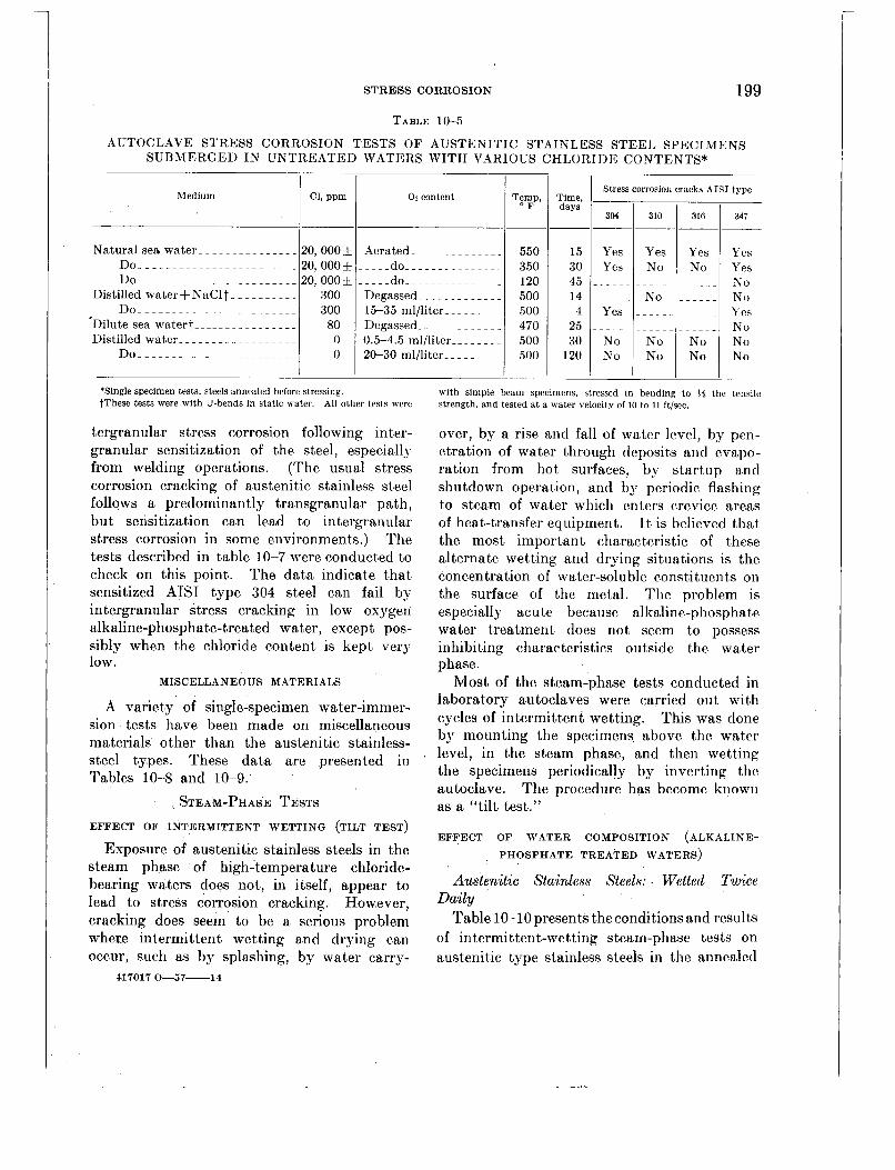
199
AUTOCLAVE STRESS CORROSIO
STRESS CORROSION
TABLE 10-5
‘Single specimen tests; steels annealed before stressing. tThese tests were with U-bends in static water. All other tests were
tergranular stress corrosion following inter- granular sensitization of the steel, especiall- from welding operations. (The usual stress corrosion cracking of austenitic stainless steel follows a predominantly transgranular path, but sensitization can lead to intergranular stress corrosion in some environments.) The tests described in table 10-7 were conducted to check on this point. The data indicate that sensitized AISI type 304 steel can fail b)- intergranular stress cracking in low oxygen alkaline-phosphate-treated water, except pos- sibly when the chloride content is kept very low.
MISCELLANEOUS MATERIALS
A variety of single-specimen water-immer- sion tests have been made on miscellaneous materials other than the austenitic stainless- steel types. These data arc presented in Tables 10-8 and 10-9.
STEAM-PHASE TESTS EFFECT OF INTERMITTENT WETTING (TILT TEST)
Exposure of austenitic stainless steels in the steam phase of high-temperature chloride- bearing waters does not, in itself, appear to lead to stress corrosion cracking. However, cracking does seem to be a serious problem where intermittent wetting and drying can occur, such as by splashing, by water carry-
417017 0-57-14
with simple beam specimens, stressed in bending to $5 the tensile strength, and tested a t a aater belocity of 10 to 11 ft/sec
over, by a rise and fall of water level, by pen- etration of water through deposits and evapo- ration from hot surfaces, by startup and shutdown operation, and by periodic flashing to steam of water which enters crevice areas of heat-transfer equipment. T t is believed that the most important characteristic of these alternate wetting and drying situations is the concentration of water-soluble constituents on the surface of the metal. The problem is especially acute because alkaline-phosphate water treatment does not seem to possess inhibiting characteristics outside the water phase.
Most of the steam-phase tests conducted in laboratory autoclaves were carried out with cycles of intermittent wetting. This was done by mounting the specimens above the water level, in the steam phase, and then wetting the specimens periodically by inverting the autoclave. The procedure has become known as a “tilt test.”
EFFECT OF WATER COMPOSITION (ALKALINE-
PHOSPHATE TREATED WATERS)
Austenitic Stainless Steels: Wetted Twice Daily
Table 10-10 prescnts theconditions and results of intermittent-wetting stearn-phase tests on austenit,ic type stainless steels in the annealed

200 CORROSION AND WEAR HANDBOOK FOR WATER-COOLED REACTORS
TABLE 10-6
AUTOCLAVE STRESS CORROSION TESTS OF AISI TYPE AUSTENITIC STAINLESS STEEL U-BEND SPECIMENS SUBMERGED I N VARIOUS ALKALINE-PHOSPHATE TREATED WATERS*
Nominal 0l.t ppm AISI type
i-
Days of test in water with PH of-$ -
11.3
55 51
Total lays in
test
14 14 15 7
30 7
15 62 82 15 15 15 15 15 90 90 14 15 15 15 15 30 30 30 15 65
105 15 15 78
140 116 116 103 139 15 15
I‘emp., F
500 500 467 500 467 500 467 500 500 500 500 500 500 500 500 500 470 467 467 500 467 500 470 500 467 500 500 467 500 500 500 500 500 500 500 500 500
‘Steels annealed before stressing. t”Degassed” means oxygen removed by boiling and venting auto-
clave. “Aerated” means no attempt WBS made to remove air before sealing autoclave. “Saturated” means oxygen was bubbled through autoclave before sealing. Actual or calculated oxygen contents are given where data are available.
$Water compositions were: pH-10.6, 50 ppm POq pH-11.0, 120 ppm POI: and pH-11.3, 200 ppm POI.
Number of specs.
2 2 2 3 2 3 4
40 ‘ 50
1 1 1 1 1 1 2 1 1 1 2 1 2 1 2 1
40 50
1 2
40 50 40 50 40 50 2 2
495
Stress eorro- sion cracks
No No No No No No No No No Yes** Yes** Yes** No No No No No No No No No No No No No No No No No No No No . No No No No No
Yes, 3 No, 492
#Exact chloride unknown. High chloride obtained by boiling off to full saturation a solution originally containing 530 ppm C1, 50 ppm POI, and 10.6 pH.
1Exact chloride unknown. High chloride obtained by boiling off to full saturation a solution originally containing 336 ppm C1, 200 ppm Pod, and 11.3 pH.
“Vessel was inverted momentarily twice each day, thus exposing the specimens to the vapor phase for short periods (see text).
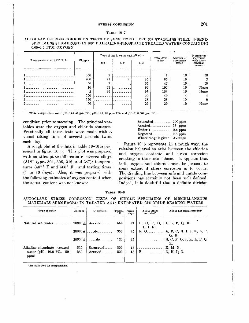
STRESS CORROSION
Number of specimens
tested
201
Number of specimens with inter- granular
cracks
TABLE 10-7
AUTOCLAVE STRESS CORROSION TESTS OF SENSITIZED TYPE 30 STAINLESS STEEL U-BEND SPECIMENS SUBMERGED IN 500' F ALKALINE-PHOSPHBTE TREATED WATERS CONTAINING 0.05-0.5 PPM OXYGEN
10 10 10 10 10 4
10 10
I I Days of test in water with pH of-* I
10 2
10 None None
4 6
None
Total days Time sensitized at 1,200° F, hr GI, ppm in test 1 1 10.6 1 11.0 . 1 11.3 1
Alloys stress corroded.
550 200 50 10 2
550 550 50
Alloys not stress corroded.
._.._ 7 35 65 35 42 69 102 67 103 40 40 28 28 29 29
Natural sea water _______.__
Alkaline-phosphate treated water (pH-10.6 Po4-50 PP14.
200003
20000 3
20000 * 530 530
condition prior to stressing. The principal var- iables were the oxygen and chloride contents. Practically all these tests were made with a vessel tilting time of several seconds twice
Saturated--- _ _ _ _ _ _ - 200 ppm Aerated _ _ _ _ _ _ _ _ _ _ _ 35 ppm Under 1.0 _ _ _ _ _ _ _ _ _ _ 0.6 ppm Degassed- _ _ _ _ _ _ _ _ _ 0.3 ppm Where range is given- Average ~-
each day. Figure 10-5 represents, in a rough way, the relation believed to exist between the chloride sented in figure 10-5. and oxygen contents and stress corrosion with no attempt to differentiate between alloys cracking in the phase. It appears that
tures (467' F and 500' F); and testing times . some extent if stress corrosion is to occur.
-
A rough plot of the data in table 10-10 is pre- This plot was prepared
types 304, 305, 3l6, and 347); tempera- both oxygen and chloride must be present to
(1 to 30 days). Also, it W a s Prepared with the following estimates of oxygen content when the actual content was not known:
The dividing line between safe and unsafe com- positions has certainly not been well defined. Indeed, it is doubtful that a definite division
TABLE 10-8
AUTOCLAVE STRESS CORROSION TESTS OF SINGLE SPECIMENS OF MISCELLANEOUS MATERIALS SUBMERGED IN TREATED AND UNTREATED CHLORIDE-BEARING WATERS
Type of water C1, ppm Temp., O F - 550
350
120
500 500
Time, days -
24
45
45
15 15
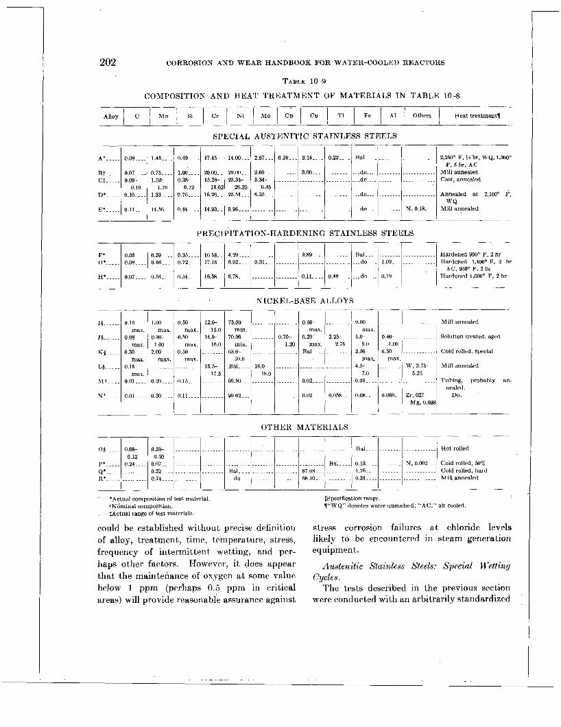
202
A*- .... 0.08 .... 1.45 .... 0.49 .... 17.45.. 14 .00... 2.87 ... 0 . 3 6 ~ . 3.14 .... 0.22 ....
B t ..... 0.07 .... 0.75 .... 1.00 .... 20.00.. 29.00.-. 2.00- . . ........ 3.00 Ct ..... 0.09- 1.52- 0.38- 15.28- 25.34- 5.34- ..........................
................
0.10 1.76 0.72 16.62 26.25 6.35 ... ............................. D* ..... 0.10 .... 1.33 .... 0.76..-. 16.26-. 25.51 6.35..-
E* ..... o.ll-.-. 14.56 ... 0.44 .... 14.93.. 0.9 6...- .....................................
CORROSION AND WEAR HANDBOOK FOR WATER-COOLED REACTORS
Bal ......................... 2,250°F,Yjhr, WQ,1,3(Xl0 F, 5 hr, AC
do-..- Millannealed .................... -..do ........................ Cast, annealed
........................ do Annealed a t 2,160'' F,
do N.0.18 Millannealed W Q
........... ....
F*. . - - . O B . . - 0.59 .... 0.35..-- 16.5%. 4.29 .................... 3.89--.. ......... Bal ........................ 0' ..... 0.08--.. 0.51..- 0.72.-- . 17.16-. 6.92 .... 0.31 1.02 ...............
H . . - - 0.07 .... 0.54..-. 0.54.-.. 16.58.. 6.78..-. ................ 0.11 .... 0.48-- ..... do .... 0.19 ...............
NICKEL-BASE ALLOYS
Hardened950°F,2hr Hardened 1,400'F. 2 hr
Hardened1,000"F,Zhr AC, 950' F, 2 hr
_-
._______ I I
...........
...........
.......
W, 3 . 7 b 5.25
...........
Zr, 027 Mg, 0.038
Mill annealed
Solution treated, aged
Cold rolled, special
Mill annealed
Tubing, probably an- nealed.
D O .
__
0.50
0.50
0.50
max.
max.
max. .......
0.15..-
0.11 ...
__
15 ......
,I5 ......
K $ .....
L $ - . - . .
vt. ~. .
x*---..
I I I 0.15 1.00
max. max. 0.08 0.30-
max. 1.00 0.30 2.00
max. max. 0.15 .........
max. o.oi..-- 0.20--..
0.01 .... 0.30
12.W
14.0- 15.0
16.0 ........
15.5- 17.5
........
0.50 max.
0.20 max.
RalL..
........
0.02.. ..
0.02 ...
75.w ...............
min. 70.00 ........ 0.70-
min. 1.20 63.0- ................
70.0 Bal .... 16.W .......
99.54.. ................ 18.0
__
........
2.25- 2.75
........
........
........
0 . 0 K .
~
............................................................ 05 ..... 0.08- 0.30- Bal
P' ..... 0.24-- . . 0.07 ....................................................... Bal .... 0.13.-.. Q*-, . - . . ......... 0.32.-.. ................. Bal .................... 87.08..- ......... 1.76..-- R'. ............. 0.74.- do 68.10. ........... 0.31
0.13 0.50
...................... .................... '
9.00
5.0- 9.u
2.50 rnax.
4. .5 7.0
0.05..
0.08.. -
mdX.
~~~ -
........................ Hotrolled
........ N,0.002-.. Coldrolled,50%,
.................... Coldrolled,hard ........................ Mill annealed
-_
__
.......
0.4W
0.50 1.00
max ........
.......
0.0%. .
__
OTHER MATERIALS
could be established without precise definition stress corrosion failures a t chloride levels of alloy, treatment, time, temperature, stress, likely to be encountered in steam generation frequency of intermittent wetting, and per- equipment. haps other factors. However, it does appear Austenitic Stainless Steels: Special Wettin!/ that the maintenance of oxygen a t some value cycles. below 1 ppm (perhaps 0.5 ppm in critical The tests described in the previous section areas) will provide reasonable assurance against were conducted with an arbitrarily standardized

STRESS CORROSION 203
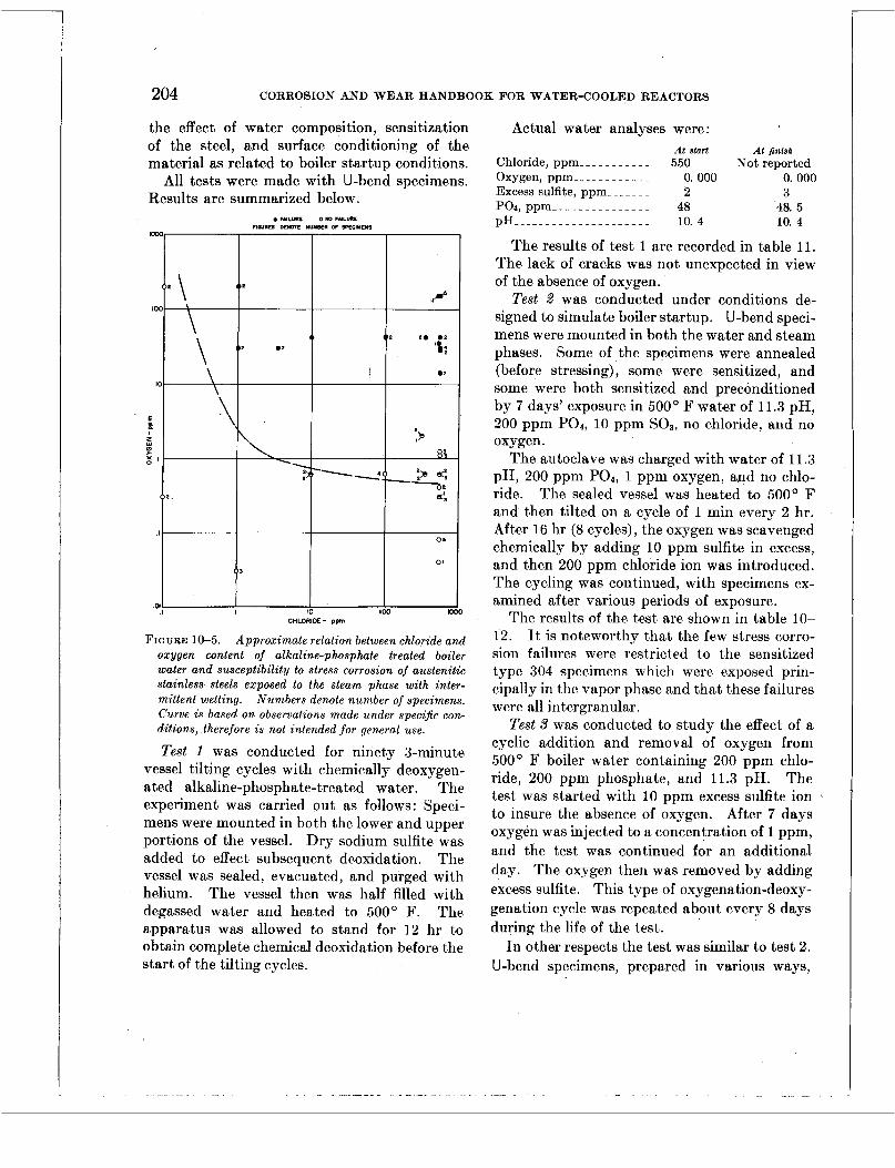
the effect of water composition, sensitization of the steel, and surface conditioning of the material as related to boiler startup conditions.
All tests were made with U-bend specimens. Results are summarized below
FIGURE 1&5. Approximate relation between chloride and oxygen content of alkaline-phosphate treated boiler water and susceptibility to stress corrosion of austenitic stainless steels exposed to the steam phase with inter- mittent wetting. Numbers denote number of specimens. Curve is based on observations made under specijc con- ditions, therefore is not intended for general use.
Test 1 was conducted for ninety 3-minute vessel tilting cycles with chemically deoxygen- ated alkaline-phosphate-treated water. The experiment was carried out as follows: Speci- mens were mounted in both the lower and upper portions of the vessel. Dry sodium sulfite was added to effect subsequent deoxidation. The vessel was sealed, evacuated, and purged with helium. The vessel then was half filled with degassed water and heated to 500' F. The apparatus was allowed to stand for 12 hr to obtain complete chemical deoxidation before the start of the tilting cycles.
204 CORROSION AND WEAR HANDBOOK FOR WATER-COOLED REACTORS
Actual water analyses were: At start At finish
Not reported Chloride, pprn _ _ _ - - - _ - _ _ _ 550 Oxygen, ppm _ _ _ _ _ - - - - _ _ _ 0. 000 0.000 Excess sulfite, ppm _ _ _ _ _ _ _ 2 3
p H _ _ _ _ _ _ _ _ _ _ _ _ _ _ _ _ _ _ - - - 10. 4 10. 4
The results of test 1 are recorded in table 11. The lack of cracks was not unexpected in view of the absence of oxygen.
Test 2 was conducted under conditions de- signed to simulate boiler startup. U-bend speci- mens were mounted in both the water and steam phases. Some of the specimens were annealed (before stressing), some were sensitized, and some were both sensitized and preconditioned by 7 days' exposure in 500' F water of 11.3 pH, 200 ppm PO4, 10 ppm SO3, no chloride, and no oxygen.
The autoclave was charged with water of 11.3 pH, 200 pprn POa, 1 ppm oxygen, and no chlo- ride. The sealed vessel was heated to 500' F and then tilted on a cycle of 1 min every 2 hr. After 16 hr (8 cycles), the oxygen was scavenged chemically by adding 10 ppm sulfite in excess, and then 200 pprn chloride ion was introduced. The cycling was continued, with specimens ex- amined after various periods of exposure.
The results of the test are shown in table 10- 12. It is noteworthy that the few stress corro- sion failures were restricted to the sensitized type 304 specimens which were exposed prin- cipally in the vapor phase and that these failures were all intergranular.
Test 3 was conducted to study the effect of a cyclic addition and removal of oxygen from 500' F boiler water containing 200 ppm chlo- ride, 200 pprn phosphate, and 11.3 pH. The test was started with 10 ppm excess sulfite ion to insure the absence of oxygen. After 7 days oxygen was injected to a concentration of 1 ppm, and the test was continued for an additional day. The oxygen then was removed by adding excess sulfite. This type of oxygenation-deoxy- genation cycle was repeated about every 8 days during the life of the test.
In other respects the test was similar to test 2. U-bend specimens, prepared in various ways,
Pod, ppm _ _ _ _ _ _ _ _ _ _ _ _ _ _ _ 48 48. 5
. -

STRESS CORROSION 205
AISI t m e t t
~-
Time per cycle Number of Number of Stress cor-
Treatment Specimen location at start1 cycles specs. rosion cracks
304 304 304 347 347 347
. . - . - - - . -
. - - - - - -
. - - - - - - - .
. - - - - - .
. - - - - - - - -
. - - - - - - - .
'C1,550 ppm; PO4,48 ppm; excess sos, 2 to 3 ppm; oxygen, 0 OOO ppm,
tType 304 had 0.063 percent carbon. $Type 347 had 0.061 percent carbon and 0.79 percent columbium
pH, 10.4; temperature, 500' F.
were mounted in the upper and lower portions of the autoclave. The pressure vessel was inverted for 1 rnin every 2 hr. The results of the test are indicated in table 10-13. The lone failure occurred in a sensitized specimen by a mixture of transgranular and int,ergranular cracking.
Test 4 was conducted with oxygen-free 500" F boiler water containing 200 ppm chloride, 200 pprn phosphate, and 11.3 pH. Freedom from oxygen was obtained by maintaining sulfite ion at 25 to 50 ppm. The specimens were U-bends of AISI type 304 steel which had been sensitized and preconditioned (see tests 2 and 3 for details). These were mounted in both the water and steam phases. The auto- clave was tilted for 1 rnin out of every 6 min.
The vessel was opened after 725 tilt cycles (total time, 72 hr). An analysis showed sul- fite ion to be present. No specimen cracks were detected. The test was continued to 1,674 cycles (total time, 167 hr). No sulfite could be detected a t that time, and all speci- mens showed intergranular attack. The ex- periment demonstrated the ease with which intergranular attack could be produced in stressed sensitized AISI type 304 steel exposed with intermittent wetting to low oxygen boiler water steam.
1 None 1 2 90 1 None 2 1 90 1 None 2 1 90
1 2 90 1 None 90 1 None 2 1
1 2 90 1 None
Test 5 was conducted to obtain information on the speed with which stress corrosion <racks could be produced in an intermittent tilting test. U-bend specimens were prepared from an- nealed AIST types 304 and 347 steels. These were exposed in both the water and steam phases of an autoclave half filled with water containing 550 ppm chloride, 50 pprn phosphate, 7 ppm
.oxygen, and 10.6 pH. The vessel was heated, tilted 5 times in 4-min cycles, and then cooled. The total test time was 20 min, plus heating and cooling time.
Three tilting schedules were tried, with results as shown in table 10-14. It isof interest that the specimens which started and finished in the steam phase cracked in all cases. This indicated that the exposure to the steam during the heating and cooling of the vessel contributed to the cracking of the specimens in addition to the exposure during the 20 min of vessel tilting. The test also demonstrated the brief time need- ed to crack the specimens under conditions highly conducive to stress corrosion damage.
MISCELLANEOUS MATERIALS WETTED TWICE DAILY
A number of miscellaneous materials were test,ed in the steam phase of alkaline-phosphate- treated waters, wit.h wetting twice daily by
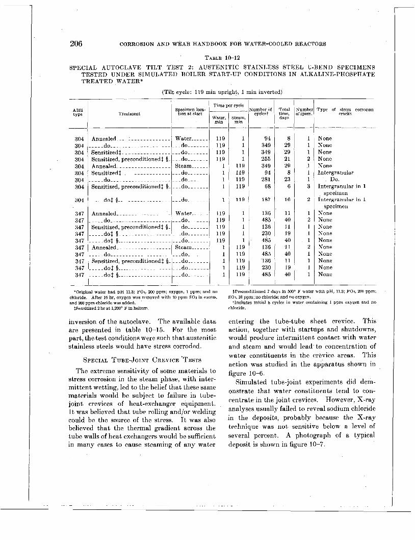
206 CORROSION AND WEAR HANDBOOK FOR WATER-COOLED REACTORS
TABLE 10-12
SPECIAL AUTOCLAVE TILT TEST 2: AUSTENITIC STAINLESS STEEL U-BEND SPECIMENS TESTED UNDER SIMULATED BOILER START-UP CONDITIONS IN ALKALINE-PHOSPHATE TREATED WATER*
(Tilt cycle: 119 min upright, 1 min inverted)
AIS1 type
304 304 304 304 304 304 304 304
304
347 347 347 347 347 347 347 347 347 347
__
Treatment
Time per cycle Specimen loca- ___
tion at start Water, I I min
119 119 119 119
1 1 1 1
119 119' 119 119 119
1 1 1 1 1
*Original water had pH 11.3; POI, 200 ppm; oxygen, 1 ppm; and no chloride. After 16 hr, oxygen was removed with 10 ppm SO3 in excess, and 200 ppm chloride was added.
$Sensitized 2 hr at 1,200° F in helium.
inversion of the autoclave. The available data are presented in table 10-15. For the most part, the test conditions were such that austenitic stainless steels would have stress corroded.
SPECIAL TUBE-JOINT CREVICE 'TESTS The extreme sensitivity of some materials to
stress corrosion in the steam phase, with inter- mittent wetting, led to the belief that these same materials would be subject to failure in tube- joint crevices of heat-exchanger equipment. It was believed that tube rolling and/or welding could be the source of the stress. It was also believed that the thermal gradient across the tube walls of heat exchangers would be sufficient in many cases to cause steaming of any water
Steam, mm
1 1 1 1
119 119 119 119
119
1 1 1 1 1
119 119 119 119 119
umber of cvclest
94 349 349 255 349
94 281
68
187
136 485 136 230 485 136 485 136 230 485
~
Total time, days
--
8 29 29 21 29 8
23 6
16
11 40 11 19 40 11 40 11 19 40
__
__
iumhet r specs.
1 1 1 2 1 1 1 3
2
1 2 1 1 1 2 1 1 1 1
__
Pype of stress corrosion crncks
None None None None None Intergranular
Intergranular in 1
Intergranular in 1
None None None None None None None None None None
' Do.
'specimen
specimen
$Preconditioned 7 days in 5oOo F water with pH, 11.3; POI, 200 ppm;
tlncludes initial 8 cycles in water containing 1 ppm oxygen and no SO3,lO ppm; no chloride; and no oxygen.
chloride.
entering the tube-tube sheet crevice. This action, together with startups and shutdowns, would produce intermittent contact with water and steam and would lead to concentration of water constituents in the crevice areas. This action was studied in the apparatus shown in figure 10-6.
Simulated tube-joint experiments did dem- onstrate that water constituents tend to con- centrate in the joint crevices. However, X-ray analyses usually failed to reveal sodium chloride in the deposits, probably because the X-ray technique was not sensitive below a level of several percent. A photograph of a typical deposit is shown in figure 10-7.

STRESS CORROSION 207 TABLE 10-13
SPECIAL AUTOCLAVE T I L T TEST 3: AUSTEN 1’rIC STAINLESS STEEL U-BEND SPECIMENS TESTED I N 500’ F BOILER WATER WITH CYCLIC ADDITION AND REMOVAL O F OXYGEN*
(Oxygen cycle: deoxygenated 7 days, oxygenated 1 day; tilt cycle: 119 rnin upright, 1 min inverted)
Treatment AIS1 type
Tilting cycles ______
Specimen location Time per cycle at start
304 347 347 347 347
347
Number of speci- mens
Type of stress corrosion cracks
*Basic water had C1,200ppm; P O I , 2M) ppm;and pH, 11.3. Oxygenated Deoxygenated by addition by injection of gas to produce 1 ppm oxygen.
of 10 ppm excess SO$.
TABLE 10-14
SPECIAL AUTOCLAVE T I L T TEST 5: AUSTEN- I T I C STAINLESS STEEL U-BEND SPECIMENS TESTED I N STEAM AND WATER PHASES OF
RIDE, 50 P P M PHOSPHATE, 7 PPM OXYGEN, AND 10.6 p H
500’ F WATER CONTAINING 550 P P M CHLO-
Tilting cycles -
Time per cycle
Water, Steam, min I min
Number ofcycles
__-___-
Total cycling time,t mm
02 contentt
Saturated _ _ _ _ _ _ _
Aerated _ _ _ _ _ _ _ _ _ Degassed _ _ _ _ _ _ _ I
3 1 3 2
‘ 2 2 2 3 1 3 1
Alloys stress corrodedt
Alloys not stress corroded1
D, E,§ F _ _ _ Type 410, type 430, I, J, K, L, M, N, 0
D, E _ _ _ _ _ _ _ K, L, 0 _ _ _ _ _ _ _ _ _ _ _ _ Type 410, I, J, K, 0 304
304 347 347 304 304 347 347 304 304 347 347
__
Stress lrrosion cracks
Water- - Steam_- Water-- Steam-- Water-- Steam-- Water- - Steam_- Water-- Steam-- Water- - Steam--
NO Yes No Yes Yes Yes Yes Yes No Yes No Yes
3 5 20 1 5 20 3 5 20 1 5 20 2 5 20 2 5 20 2 5 20 2 5 20 1 5 20 3 5 20 1 5 20
‘ 3 5 20
%earn, min
119 1 1
119 119
119
Tumbei I f cycler
272 665 665 665 393
665 __
\lumbe of oxy-
gen cycles
3 7 7 i 4
7 __
__
Total time, days
___
23 55 55 55 33
55 __
None None None None None, 1.; trans-
granular and intergranular, 1
None
tSensitized 2 hr at 1,200° F in helium, then preconditioned 7 days in 500’ F water with pH, 11.3; POI, 2W ppm; S03, 10 ppm; no chloride; and no oxygen.
~~
‘Compositions of coded alloys are as shown in table 10-9. (Tilt cycle: MomentarUy, twice daily, for 15 days)
t“Degassed” means oxygen removed by.boiling and venting autoclave. “Aerated” means no attempt was made to remove air before sealing autoclave. “Saturated” means oxygen was bubbled through autoclave before sealing.
%See table 10-9. 5pH--11.2
*Annealed before stressing. tTime of heating and cooling vessel not included.

208 CORROSION AND WEAR HANDBOOK FOR WATER-COOLED REACTORS
HEATING ELEMENT TO PRODUCE THERMAL. GRADIENT THROUGH TUBE WALL (TI - 1 2 ) Y
RING SIMULATING TUBE SHEET
BOILER WATER
AUTOCLAVE
FIGURE 10-6. Basic elements of special tube-joint crevice test apparatus.
MISCELLANEOUS EXPERIMENTS Except as otherwise indicated, the miscel-
laneous experiments described below were con- ducted under the following conditions:
Exposure: steam phase, wetted by vessel
Test time: 15 days, average. Water: 530 ppm C1, 50 ppm PO4, 10.6 pH,
and aerated (no attempt made to remove gases before sealing of autoclave).
inversion twice daily.
Temperature : 500 O F. Material: AIS1 types 304 and 347 austenitic
stainless steel, annealed before stressing.
EFFECTS OF STRESS LEVEL
Specimens of j{,-in.-thick strip were annealed by suspending them from wires, heating to 1,750' F, and air cooling. Then they were cleaned by a chemical method. This procedure was followed to produce strips with a minimum of residual internal stresses. The specimens so obtained were carefully inserted in a simple beam jig and stressed to 0, 5000, 15,000, 30,000, 40,000, and 50,000 psi. Exposure in the auto- clave produced stress corrosion cracks in all
FIGURE 10-7. Crevice deposit in a tube joint tested in an alkaline-phosphate treated chloride-bearing water.
specimens except the one without stress. The test demonstrated the probable lack of a prac- tical threshold stress below which failure will not occur in the steam phase.
EFFECTS OF TUBE ROLLING, TUBE WELDING, AND SURFACE PREPARATION
Experiments have shown that residual stresses produced by rolling and/or welding in the fabri- cation of tube-tube sheet joints are sufficient to cause failure. In fact, %-in.-diameter tubes with 40- to 50-mil wall thickness were expanded 1 to 3 mils and used successfully in lieu of U- bend specimens in numerous autoclave experi- ments.

STRESS CORROSION 209
Other metal
__-
There were indications in at least one experi- ment that the cleaning of annealed specimens with emery cloth produced sufficient residual surface stresses to result in stress corrosion with- out the presence of applied stress.
EFFECTS OF MATERIAL THICKNESS
Simultaneous tests of U-bend specimens rang- ing in thickness from 0.062 to 0.41 in. revealed no difference in stress corrosion sensitivity over a 15-day exposure period.
Type of couple CONCENTRATION OF WATER CONSTITUENTS IN INTERMITTENT WETTING TESTS
In the autoclave experiments described in this chapter, the vessels were one-half to two- thirds filled with water. Temperature surveys conducted in a few of the vessels revealed that with 500’ F water the steam was slightly super- heated. The maximum observed superheat was about 30’ F, and the minimum was as little as 1’ F.
A special autoclave experiment was designed to show if exposure of specimens in the steam phase, with intermittent wetting by vessel in- version, would lead to concentration of water constituents on the specimens. Specimens of a porous stainless steel filter medium were mounted in the steam phase of a typical auto- clave. The volume of the pores in the speci- mens was known. After 15 days’ exposure, with wetting twice daily, the chlorides were leached from the specimens and analyzed quan- titatively. It was found that the chloride content in the pores of the specimens was 4 to 8 times the chloride content in an equivalent volume of the test water. Thus i t is known that, when .a material in the steam phase is intermittently wetted, the water constituents concentrate on the specimen.
EFFECTS OF GALVANIC COUPLES
Testing in boiling 42 percent MgCl, solution has indicated some promise in the use of galvanic couples to control stress corrosion of austenitic stainless steel. The tests have been made with AIS1 type 347 steel U-bend speci- mens coupled in two ways: (1) attachment to a
coupon of a dissimilar metal and (2) plating of the legs of the U-bend but leaving the apex of the bend unplated. Results of such tests are shown in table 10-16. Cracks can be prevented in some cases, and in other cases cracking can be delayed.
TABLE 10-16
TESTS OF GALVANICALLY COUPLED TYPE 347 STEEL U-BEND SPECIMENS IN BOILING 42 PERCENT MgClz SOLUTION
-
Area ratio, coupled metal to type 347
-
.______ ~
1. 3 I. 3 2. 5 6. 0 1. 3 1. 3 3. 5 2. 0 2. 2
Exposure time, hr
2 17
111 24 24 60
810 92
1 ,000 27 24
Stress cor- rosion
cracks in type 347
Yes Yes Yes Yes Yes Yes No No NO No No
*Coupon attached to U-bend t h g s of U-bend electroplated; apex of bend not plated. $Coupon of copper inserted in solution without contact with U-bend.
Some copper dissolved in solution, and a part plated out on U-bend.
A few similar tests were made in autoclaves on plated U-bend specimens mounted in the steam phase of a synthetic boiler water. The interest here was to determine if protection would be obtained in an environment which would be expected to have low electrical con- ductivity. Only very limited data are avail- able, but i t would appear that chemical nickel plating, which produces a nickel-phosphorus alloy coating, might offer some chance of success. The results of the test are given in table 10-17.
EFFECTS OF INHIBITORS A N D OXYGEN SCAVENGERS
’ The ineffectiveness of alkaline-phosphate water treatment in preventing st,ress corrosion of austenitic stainless steels in the steam phase led to numerous autoclave “tilt” tests with

210 CORROSION AND WEAR HANDBOOK FOR WATER-COOLED REACTORS
TABLE 10-17
AUTOCLAVE STRESS CORROSION T I L T TESTS ( I N T E R M I T T E N T WETTING) O F PLATED AUSTEN- I T I C STAINLESS STEEL U-BEND SPECIMENS MOUNTED I N T H E STEAM PHASE OF 500' F WATER WITH 553 P P M CHLORIDE, 50 P P M PHOSPHATE, ANI) 10.6 p H
(Test time: 15 days; tilt cycle: momentarily, twice daily) I 1
U -bend, AIS1 1 type
Type of plating 1 Area ratio, Oxygen ir
Location of plating on U-bend plating to water, hare metal ppm
347 347 347 347 347 304 304
'Plated all over, then stripped in small area on apex of bend
other inhibitors. Tannin, chromate, and octa- decylamine (a film forming amine) were tried. None of these was found to be effective.
Tests have also been made with oxygen scavengers added to the autoclaves since i t has been postulated that stress corrosion will not occur in the absence of this gas. Both hydra- zine and sodium sulfite were tried. The results appear quite promising, especially in the case of the sodium sulfite additions. Stress corro- sion cracks occurred only in a minority of cases with sulfite, under conditions which otherwise would have caused consistent and severe cracking.
The results with sulfite additions were some- what inconsistent. These inconsistencies are probably related to a delay in complete scaveng- ing of oxygen in the steam when the sulfite is added to the water. Attempts to hasten the reaction with copper and cobalt catalysts have not been successful in eliminating inconsistent results in the autoclave tests.
GENERAL-OBSERVATIONS
Types o j Cracks Stress corrosion cracks in annealed austenitic
stainless steels are predominantly transgranular. The cracks may vary in appearance from single, relatively straight cracks to highly branched, fingerlike crack networks. Typical examples
Stress cor- rosion cracks
Yes Yes Yes Yes No No No
are illustrated in figures 10-8 and 10-9. T t is possible that the straight, single cracks are those which are produced under conditions causing rapid crack development, whereas the branched cracks are produced under milder circum- stances.
The transgranular crack network type is easy to recognize in austenitic stainless steels as
FIGURE 10-8. Example of a single relative/y straight transgranular stress corrosion crack in an austenitic stainless steel ( X 250).

STRESS CORROSION 21 1
FIGURE lG9. Example 0.f a highly branched network of transgranular stress corrosion cracks i n an austenitic stainless' steel ( X 500).
having been caused by stress corrosion. The straight single cracks are less easy to diagnose,, because they appear much like fatigue cracks. The diagnosis of the cause of such a crack requires knowledge of the type of stress and corrosive environment leading to failure. The acceleration of stress corrosion by cyclic fatigue stresses is also a distinct possibility. I n fact, corrosion fatigue can be considered as a special case of stress corrosion, the main difference being that stresses are cyclic in the former case and static in the latter.
Stress corrosion in sensitized stainless steels may follow an intergranular path. Intergran- ular attack would usually be found locally in heat affected zones near welds, although it could occur generally in stainless equipment operated at sensitizing temperatures. Differ- entiation between ordinary intergranular corro- sion and intergranular stress corrosion probably would require a supplementary corrosion study in the environment to determine whether stress WRS necessary for failure to develop. An ex- ample of intergranular stress corrosion is illus- trated in figure 10-11).
FIGURE 1 6 1 0 . Example of intergranular stress corro- sion cracks i n a sensttized tvpe so4 austenitic staznless steel (X 100).
Relation of Pitting and Crackiiq I t has been observed that stress corrosion
cracks in austenitic stainless steels nearly always start at macroscopic corrosion pits on the surface of the specimen. It is possible that pitting is a necessary initial step in the deveIop- ment of cracks. However, there is no evidence to indicate that all environments leading to corrosion pits will also ultimately lead to stress corrosion. In fact, i t has been observed that, although all cracks may start at pits, there are usually fewer cracks in specimens having more numerous pits.
AUXILIARY BOILER EXPERIENCE
The laboratory tests described in the pre- vious section indicated that austenitic stainless steels are especially vulnerable to stress corro- sion in the steam phase of secondary systems where intermittent wetting might occur. Of particular concern are tube-header joints of heat-transfer equipment since water entering

212 CORROSION AND WEAR HANDBOOK FOR WATER-COOLED REACTORS
the joint crevices might flash to steam and cause concentration of the solids dissolved in the water. The laboratory tests also indicate that control of the stress corrosion might be accomplished by (1) prevention of steaming in the crevices, (2) elimination of chlorides, or (3) elimination of oxygen.
Verification of these points under practical circumstances was provided by service and laboratory runs of some small stainless steel boilers. These units were fire-tube boilers intended for auxiliary services aboard non- magnetic minesweepers. The boilers were made of welded AIS1 type 304 steel. Normal opera- tion was a t 260’ F and 35 psi. The combustion gas temperature in the “hot end” header was between 1,700 and 1,800’ F. The maximum metal temperature of the header in the hot end was 440’ F as determined by measurement.
Critical crevice areas were located in three places. These were (I) the joints between the tubes and headers, (2) the joint between the combustion tube and one of the headers, which joint was welded with a backing ring on the water side, and (3) the joints between the headers and shell. A typical longitudinal section through a tube-header joint is shown in figure 10-11.
One of these boilers was steamed on a test stand with alkaline-phosphate-treated water and no special deaeration. The unit was steamed 1,008 hr with water containing 530 ppm chloride and then an additional 295 hr with water containing 1,775 ppm chloride. Tube- header joints were removed for examination after the initial 1,008 hr. In addition, samples of the tube-header joints, the combustion tube- header joint, and the header-shell joints were obtained after the full run of 1,303 hr. Stress corrosion cracks were found in all cases.
Typical examples of tube-header joint cracks are shown in figures 10-11 and 10-12. All in all, 48 tube-header joint sections were examined. Of these, 26 had tube-wall cracks, 14 had header cracks, and 5 had weld cracks. Some of the tube cracks penetrated the entire wall, although no malfunctioning from leaks had been observed during operation of the boiler.
FIGURE 10-11. Stress corrosion cracks in a tube-header joint front a type 304 steel auxi l iary boiler, longitudinal section ( X 6 ) .
Metallographic inspection revealed that the cracks were predominantly transgranular. All occurred within % in. of welds. All cracks originated from the water side in crevice areas. No cracks were observed a t joints which had no crevices.
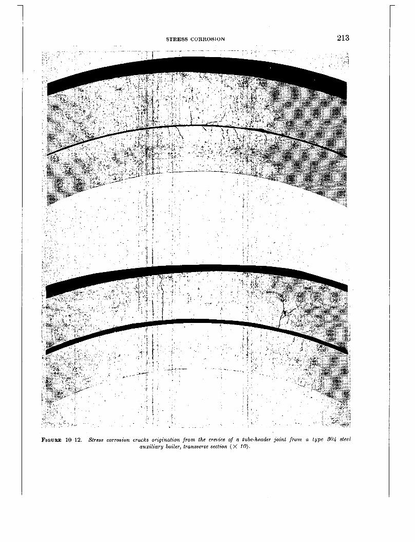
STRESS CORROSION 213
FIQURE 10-12. Stress corrosion cracks origination f r o m the crevice of a tube-header joint f r o m a type SO4 steel auz i l iary boiler, transverse section ( X 10).
214 CORROSION AND WEAR HANDBOOK FOR WATER-COOLED REACTORS
These observations led to the sampling of tube joints from four similar boilers which had been steamed aboard ship for about 1,000 hr.
Stress corrosion damage was observed in all these joints. Stress corrosion cracks were also found in the tube joints of an AISI type 304 steel hot-water heater which had been removed from shipboard service because of leaks after 2,000 hr of operation. This heater was a fire- tube unit operated a t a water discharge tem- perature of 190' F.
A second AISI type 304 steel auxiliary boiler was operated on a test stand to determine the effects of modified tube-joint designs. The boiler was steamed for a total of 1,574 hr with alkaline-phosphate-treated water of 2.5 to 3.5 epm alkalinity, with no special deaeration. The chloride level was 530 ppm during the first 1,048 hr, and 1,775 ppm during the final 526 hr. Table 10-18 describes the various tube joints and the operating times a t which in- spections were made.
Joint designs 1 through 5 all showed severe stress corrosion cracking. From this i t was concluded that deep J-welds and tube rolling were not satisfactory because crevices were not entirely eliminated from the tube-header joints. Joint design 6 was completely free of cracks, and this demonstrated the effectiveness of keeping water out of the crevices by welding from the water side of the joint. Joint 7 likewise pro- duced no stress corrosion cracks. This experi- mental joint was of interest because i t demon- strated that the presence of boiler water in the crevice was not harmful, provided the water was not allowed to boil.
A third boiler of standard design was operated on a test stand to determine the effect of elimi- nating chlorides from the water. The boiler was operated for 1,013 hr. The initial feed water was passed through an ion exchanger to reduce chlorides to about 0.1 ppm. A closed system was used, with the boiler water main- tained a t less than 10 micromhos during the entire operating period. Subsequent examina- tion of the tube joints revealed freedom from stress corrosion cracks.
TABLE 10-18
DESCRIPTION OF SPECIAL TUBE JOINTS TESTED I N T Y P E 304 STEEL AUXILIARY F I R E TUBE BOILER
Joint design NO.
Description of joint
Standard boiler design; header beveled 45' t o half thickness, welded from fire side- ______.
J-welded from fire side to near full depth of header .________
Same as 2, except type 316 t u b e s _ _ _ _ _ _ _ _ - - - - - - - - - - - - - -
Tube rolled to contact, J-welded from fire side to half depth of header, then rerolled lightly.
Tube rolled 3 mils on radius be- yond contact, then J-welded from fire side to half depth of h e a d e r _ _ _ _ _ _ _ _ _ . _ . _ _ - - - - - - .
Fillet welded on water side, and small J-weld on fire side.
Same as 1 , except tube was plugged to prevent gas circu- lation and ends were water cooled t o prevent steaming of boiler water in joint crevice..
Operating time vhen examined,
hr. ___--
1048
1048
1048
1048
1048
1048; 1574
1574
Finally, a fourth boiler of standard design was tested to determine the benefits to be ob- tained through oxygen control. This boiler was operated 3,000 hr with alkaline-phosphate treatment, 2.5 to 3.5 epm alkalinity, and 530 pprn chloride. In addition, the system was scavenged of oxygen by maintaining a minimum of 100 ppm sulfite, added as sodium sulfite. Examination of tube joints from this boiler revealed no evidence of stress corrosion.
STRESS CORROSION FAILURES I N MODEL HEAT EXCHANGERS
Tests of scale-model heat .exchangers were made primarily to obtain heat-transfer data and to establish design criteria. Although many of these units performed without failure, others failed by cracking during test. The cracking was identified as stress corrosion in only two
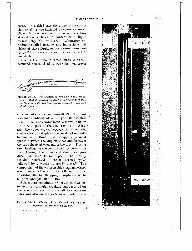
STRESS CORROSION 215
cases. In a third case there was a possibility that cracking was initiated by stress corrosion. Other failures occurred in which cracking started on surfaces in contact with liquid metals (Hg, Na, or NaK). Laboratory ex- periments failed to show any indications t,hat either of these liquid metals ,ca;uses stress cor- rosion 36 37 in several types of austenitic stain- less steels.
One of the units in which stress corrosion occurred. consisted of a two-tube evaporator
FIGURE 10-13. Construction of two-tube model evapo- rator. Radial cracking occurred t n the heavy tube sheet on the water side, and tube fuulure occurred in the third jluid region.
constructed as shown in figure 10-13. This unit was made entirely of AIS1 type 304 stainless steel. The tube arrangement is shown in figure 10-14 with part of the shell removed. Actu- ally,, the tubes shown between the inner tube sheets were of a duplex tube construction, with helium as a third fluid occupying grooved spaces between the duplex tubes and between the tube sheets a t each end of the unit. During test, heating was accomplished by circulating NaK through the tubes, and steam was pro- duced a t 467' F ' (500 p"). The testing schedule consisted of 2,500 thermal cycles followed by 2 weeks at steady state.38 The composition of the water in this steam generator was maintained within the following limits: chlorides, 462 to 602 ppm; phosphates, 50 to 60 ppm; and pH,'10.6 to 10.7.
Subsequent examination 39 revealed that ex- tensive transgranular cracking had occurred on the inside surface of the shell (water-steam
,side) a
FIGURE
,nd also
10-14. range
on
Phot ment
the water-steam side
lograph of tube and tube i n two-tube evaporator.
O f
shec
the
rt ar-
I
<..-
817017 0-57-15

1
216 CORROSION AND WEAR HANDBOOK FOR WATER-COOLED REACTORS
FIGURE 10-15. Radial cracks on water side of
tube sheet a t the hot end. I n neither case did the cracks penetrate to any great extent. I n the shell the penetration was about 0.010 in., whereas in the tube sheet, penetration was about one-fourth in. Cracks in the tube sheet were radial from the tube holes as shown in figure 10-15. Definite proof was obtained of chloride concentration in the annulus between the tubes
tube sheet in two-tube model evaporator ( X 4 ) .
and tube sheet. h deposit removed from this area was analyzed and showed the presence of 1 percent chlorides.40 This type of concentra- tion is believed to be caused by boiling within a crevice where athermal gradient exists.
I n addition to the cracks in the shell and tube sheet, others were found in the inner tubes of the helium manifold a t the hot end (fig. 10-16).
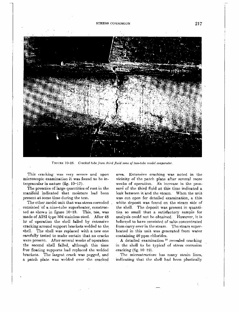
STRESS CORROSION 217
FIGURE 10-16. Cracked tube f r o m third .fluid zone of two-tube model evaporator.
This cracking was very severe and upon microscopic examination it was found to be in- tergranular in nature (fig. 10-17).
The presence of large quantities of rust in the manifold indicated that moisture had been present a t some time during the test.
The other model unit that was stress corroded consisted of a nine-tube superheater, construc- ted as show0 in figure 10-18. This, too, was made of AIS1 type 304 stainless steel. After 48 hr of operation the shell failed by extensive cracking around support brackets welded to the, shell. The shell was replaced with a new one carefully tested to make certain that no cracks were present. After several weeks of operation the second shell failed, although this time free floating supports had replaced the welded brackets. The largest crack was pegged, and a patch plate was welded over the cracked
area. Extensive cracking was noted in the vicinity of'the patch plate after several more weeks of operation. An increase in the pres- sure' of the third fluid a t this time indicated a leak between it and the steam. When the unit was cut open for detailed examination, a thin white deposit was found on the steam side of the shell. The deposit was present in quanti- ties so small that a satisfactory sample for analysis could not be obtained. However, i t is believed to have consisted of salts concentrated from carry over in the steam. The steam super- heated in this unit was generated from water containing 40 ppm chlorides.
A detailed examination 39 revealed cracking in the shell to be typical of stress corrosion cracking (fig. 10-19).
The microstructure has many strain lines, indicating that the shell had been plastically
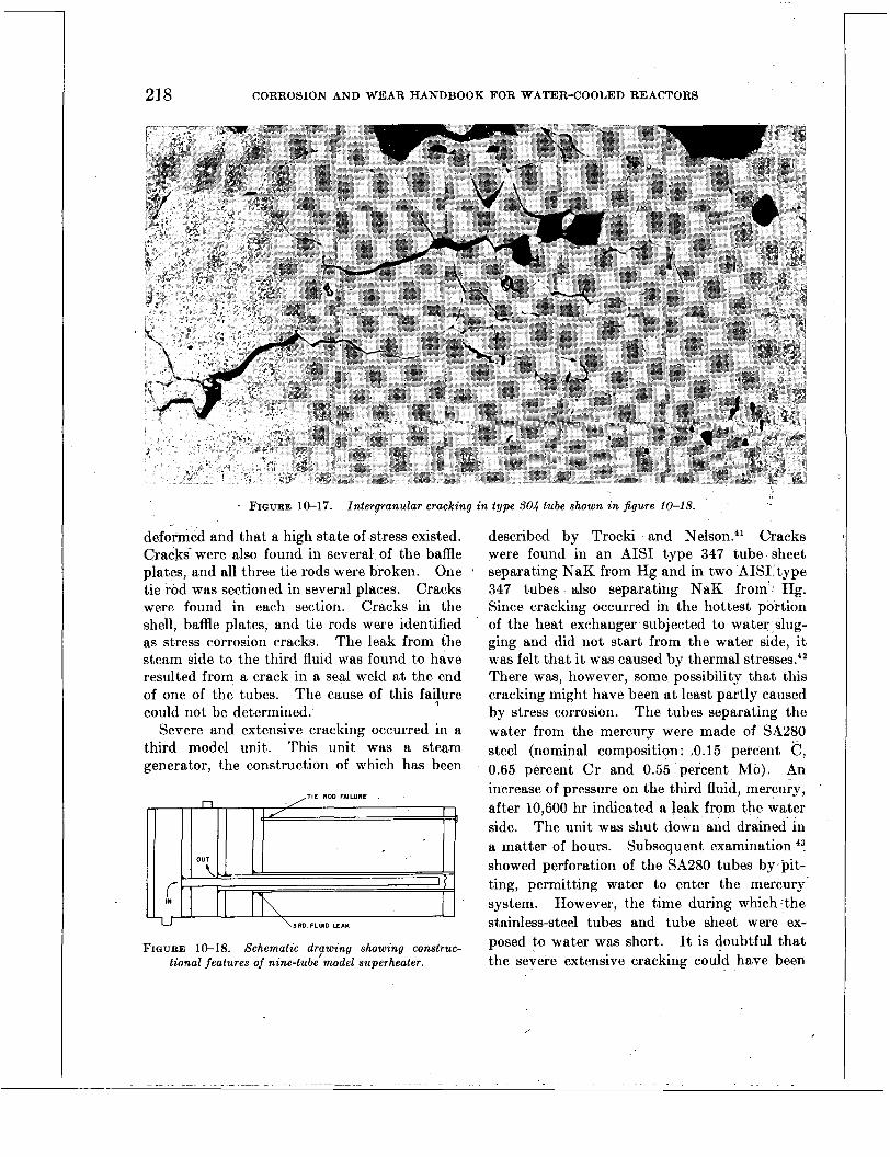
218 CORROSION AND WEAR HANDBOOK FOR WATER-COOLED REACTORS
FIGURE 10-17. Intergranular cracking in type SO4 tube shown in figure 10-1 8.
deformed and that a high state of stress existed. Cracks were also found in several of the baffle plates, and all three tie rods were broken. One tie rod was sectioned in several places. Cracks were found in each section. Cracks in the shell, baffle plates, and tie rods were identified as stress corrosion cracks. The leak from the steam side to the third fluid was found to have resulted from a crack in a seal weld at the end of one of the tubes. The cause of this failure could not be determined.
Severe and extensive cracking occurred in a third model unit. This unit was a steam generator, the construction of which has been
,TIE ROD FAILURE -
U \3RD. FLUID LEAK
FIGURE 10-18. Schematic drpwing showing construc- tional features of nine-tube model superheater.
described by Trocki and Nelson.41 Cracks were found in an AIS1 type 347 tube sheet separating NaK from Hg and in two AIS1 type 347 tubes also separating NaK from' Hg. Since cracking occurred in the hottest portion of the heat exchanger subjected to water slug- ging and did not start from the water side, it was felt that it was caused by thermal stresses.42 There was, however, some possibility that this cracking might have been at least partly caused by stress corrosion. The tubes separating the water from the mercury were made of SA280 steel (nominal composition: .0.15 percent C, 0.65 percent Cr and 0.55 percent Mo). An increase of pressure on the third fluid, mercury, &fter 10,600 hr indicated a leak from the water side. The unit was shut down and drained in a matter of hours. Subsequent examination 43. showed perforation of the SA280 tubes by pit- ting, permitting water to enter the mercury- system. However, the time during which the stainless-steel tubes and tube sheet were ex- posed to water was short. It is doubtful that the severe extensive cracking could have been
,

STRESS CORROSION 219
FIGURE 10-19. Typical cracks in shell of nine-tube superheater ( X 140) .
caused by str,ess corrosion in the short time of exposure to water.
INDUSTRIAL EXPERIENCE
Failures in industrial equipment from stress corrosion have occurred in several of the alloys that were tested and discussed in a previous section. Some of these failures are reviewed and commented upon in- this section.
Hardenable Stainless Steels
Most of the reported stress corrosion failures in this class of steels have occurred in media other than hot water and steam. Failures have
been numerous in the petroleum industry, par- ticularly where hydrogen sulfide has been en- countered." One known exception was the failure of AIS1 type 403 compressor-blades; l5 this was attributed to the presence of moisture. In this case, the cracking was intergranular in nature and did not appear until after a con- siderable amount of operation. Cracking was associated with a small amount of surface corrosion. Johnson suggested that cracking was caused by nascent hydrogen generated a t the surface. These failures occurred in the lower temperature stages and were, therefore, not directly comparable to conditions in water- cooled nuclear reactors. However, they were of considerable interest. because the importance

\
220 CORROSION AND WEAR HANDBOOK FOR WATER-COOLED REACTORS
of proper heat treatment was demonstrated. No additional failures were encountered after the adoption of a stress relieving heat treatment a t 950° F.
Nathorst 23 has described intergranular stress corrosion cracks in steam turbine blades made of martensitic stainless steel. However, no mention was made of heat treatment and the specific alloy.
Valve trim made of AISI type 410 stainless steel does not appear to be- susceptible to stress corrosion in the steam systems when the alloy is properly heat treated and excessively high operating stresses are not imposed.4s If proper heat treatment is not used on such parts con- structed of martensitic stainless steels, the combination of operating stresses superimposed on high residual stresses may render these materials susceptible to stress corrosion cracking when exposed to a corrosive medium.
In media other than moist air or steam, but much more corrosive, the importance of proper
' heat treatment has been demonstrated by laboratory experiments. The length of time required for failure in 1-1 HC1 plus 1.0 percent SeOz was materially increased by tempering AISI type 403 a t 1,050' F. Furthermore, failures were eliminated by this treatment when the applied stress did not exceed 75,000 psi.l5 Similar results have been obtained with several hardenable stainless steels using a corroding medium 46 consisting of 0.5 percent CH,COOH periodically saturated with H,S.
Of direct interest in connection with nuclear power plants is the experience in another service with a small waste heat boiler constructed' entirely of AISI type 430 stainless steel. This boiler has been operating satisfactorily a t about 350' F for approximately 2 years without f a i l ~ r e . ~ '
Nickel-base Alloys
As previously pointed out, nickel-base alloys are relatively free from stress corrosion cracking
Two cases are known in which failure of nickel-base alloys was attributed to stress corrosion cracking under
' except in certain specific media.
conditions similar to those encountered in nuclear power plants. Both these failures occurred in a material corresponding to alloy I of table 10-9, one in steam and the other in hot water.4s The component that failed in steam was a spring that had been tin service 4 years at a temperature of 750' F under a stress of 77,000 psi. Cracking was intergranular in nature.
The failure in hot water occurred in the tubes of a heat exchanger.48 The function of this heat exchanger was to maintain constant steam temperature in a steam line bypassing a portion of the steam through the unit. It was so operated that steam passed through vertical tubes surrounded by water. Stress corrosion occurred as intergranular cracks originating on the water side of the tubes within a sludge on the bottom tube sheet. An investigation of the failed tubes attributed the failure, a t least partially, to the presence of a continuous intergranular precipitate. D e P a ~ l , ~ ~ in dis- cussing intergranular attack in this alloy in high-temperature water, states that such attack can be minimized considerably if small amounts of columbium are present.
Austenitic Stainless Steels
It appears that stress corrosion failures 111
austenitic stainless steels were first recognized as such in the petroleum industry. described failures in heat exchanger and con- denser tubes and also in the linihgs of pressure vessels. Some failures originating on the product side have been attributed to chlorides in crude oils either as emulsified brines or as organic chlorides. Others originating on the water side in heat exchanger and condenser tubes have been attributed to soluble chlorides.
Failures in austenitic stainless steels have been reported in a wide variety of equipment ranging from coffee urns to heavy industrial equipment. In most cases, chlorides have been considered as the principal offenders. Other corrosive media have also been considered responsible for certain failures. Nathorst 23
describes a number of industrial failures in-
Dixon
...

STRESS CORROSION 221
volving many corrosive media, several of which contained chlorides. He also points out that in some cases trouble can be eliminated by reducing stresses either by design changes or by stress relief.
Of particular interest in connection with nuclear power plants are failures from stress corrosion in which either water or steam was the corrosive medium. Several of these have been discussed in the literature. The more pertinent ones are reviewed here. Davis 51 de- scribed the failure of a stainless steel (type 304) turbocompressor through stress corrosion of two rotors. Failure by transgranular crack- ing occurred after 3 months of service. The unit was used to compress steam which was subsequently condensed. The condensate con- tained less than 0.5 ppm total solids. How- ever, chlorides were present in the raw water to the extent of about 20 ppm and were also found in a nonmetallic deposit on the failed parts. Failure was attributed to concentra- tion of chlorides, which were presumed to have entered the conipressor in the medium of finely divided particles of water.
Another case described by Davis 52 occurred in the tubes of a heat exchanger. Normal temperature on the process side was 350' to 380' F, and in emergencies this could reach 500' F. The outside surfaces of the tubes were exposed to cooling water with a chloride content of 110 to 420 ppm. Examination showed that the tubes were cracked from the water side. The cracks had originated under a nonmetallic deposit on the underside of the tubes. This deposit may have permitted con- centration of chIorides on the metal surface and a t the same time caused a,rise in tempera- ture. The stresses were believed to be caused by the forming operation. This conclusion was reached when the cracks, which in the original specimen were just barely visible, opened one thirty-srcond in. when the pipe was sectioned.
Davis 52 also noted another failure in which conditions favorable to concentration existed. This occurred in 'a vapor-heated steam gener- ator after only 90 hr of service. It was believed that a small vapor space existed in the shell
directly under the upper tube sheet. A heavy deposit of a nonmetallic substance was found in this area, and transgranular cracks origi- nated on the water side. Water analysis showed only 13.5 ppm chlorides.
Additional failures have occurred in vertical tubular heat exchangers where the cooling water was low in chlorides, but the existence of a vapor space under the upper tube sheet was probable. Even though boiling on tube surfaces may not have occurred, it is probable that fluctuations in water level and turbulence afforded opportunity for the concentration of chlorides.
Collins 53 has described failures in vertical condensers where vapor spaces actually existed under the upper tube sheet. This resulted in concentration under nonmetallic deposits. He also pointed out two design changes and one operational change that corrected the condi- tion. Each of these was in the direction that reduced the tendency for concentration.
Three small waste heat boilers described by Collins 53 are of particular interest because they provided another means of concentration. These boilers were constructed of AIS1 type 316 stainless steel, all of the same basic design. Two of these boilers failed from stress corro- sion originating in a crevice between a backing strip and the weld joining the top tube sheet to the top flange. The other boiler failed from stress corrosion originating in crevices between the tubes and the lower tube sheet. The con- dition was materially improved in a rebuilt boiler by the elimination of crevices where concentration could occur.
Another interesting series of failures was described by N a t h ~ r s t . ~ ~ He reported ,the failure of 25 steam-jacketed boilers made by one manufacturer. ' The failure record of these vessels illus-' trated the variations in service life that can occur in presumably identical components. No mention was made of the chloride concentra- don in the steam. However, the fact that low-pressure steam was condensed on the inner boiler suggests the possibility of concentration.

222 CORROSION AND WEAR HANDBOOK FOR WATER-COOLED REACTORS
The distribution of service life is shown below. Approzimale
service Eije, Number o j boilera cracked years
Conclusions From Auxiliary Boiler Experience, Industrial Experience, and Model Heat Exchangers
A study of available stress corrosion data on service and simulated service equipment leads to a general confirmation of the conclusions reached from the laboratory tests. The main contributions of the laboratory tests were (1) a closer definition of the conditions causing stress corrosion in high-temperature’ waters and (2) a demonstration of the importance of oxygen in the stress corrosion process in chloride-bearing waters.
REFERENCES
1. H. S. RAWDON, The Intercrystalline ’Corrosion of Metals, Znd. Eng. Chem., 19: 613 (1927).
2. Symposium on Stress-corrosion Cracking of Metals held a t Philadelphia, Pa., Nov. 29-30 and Dec. 1, 1944, ASTM/AIME, 1945.
3. “Metals Handbook,” American Society for Metals, Cleveland, Ohio, 1948.
4. H. H. UHLIG, “Corrosion Handbook,” John Wiley & Sons, Inc., New York, 1948.
5. R. A. LINCOLN, Stress Corrosion in Stainless Steel, Yearbook Am. Iron Steel Inst., pp. 172-180, 1954.
6. H. R. COPSON, The Influence of Corrosion on the Cracking of Pressure Vessels, Welding J. N. Y . , 32: 755 (1953).
7. A. A. BERK and W. C. SCHROEDER, A Practical Way to Prevent Embrittlement Cracking, Trans. A m . Soc. Mech. Engrs., 66: 701 (1943).
8. W. C. SCHROEDER and A. A. BERK, Action of Solution of Sodium Silicate and Sodium Hy- droxide a t 250” C on Steel under Stress, AIME Technical Publication 691, 14 pp.; Combustion 7 (8) : 29-33 (1936).
9. J. A. JONES, Intercrystalline Cracking of Mild Steels in Salt Solutions, Trans. Faraday SOC., 17:
10. Standard D807-52, Book of Standards, No. 7,
,
102 (1921-22).
ASTM, 1952.
11. M. G. WINTERSTEIN, H. J. MCDONALD, and J. T. WABER, Determination of the Physical Chemical Factors in Stress Corrosion Cracking of Mild Steel, Welding J. N . Y . , 66: 7235 (1947).
12. W. C. SCHROEDER and A. A. BERK, Intercrystalline Cracking of Boiler Steel and Its Prevention, U. S. Bureau of Mines, Bull. 433, 1941, Supt. of Docu- ments, Govt. Printing Office, Washington 25, D. C.
13. W. C. SCHROEDER, A. A. BERK, and C. K. STOD- DARD, Embrittlement Detector Testing on Boilers, Power Plant Eng., 46: 76 (1941).
14. Symposium on Sulfide Corrosion Cracking, Cor- rosion, 8: 326 (1952).
15. W. L. BADGER, Stress Corrosion of 12% Cr Stain- less Steels, Trans. S. A. E., 66: 307 (1954).
16. H. H. UHLIG, Action of Corrosion and Stress on 13% Cr Stainless Steel, Metal Prog., 67: 486 (1950).
17. A. E. DURKIN, Corrosion Cracking of Martensitic Stainless Steel, Metal Prog., 64: 72 (1953).
18. A. E. DURKIN, How to Control Hydrogen Embrittle- ment in 12% Chrome Steels, Zron Age, 174: 154 (1954).
19. 0. B. J. FRASER, Stress-corrosion Cracking of Nickel and Some Nickel Alloys, Symposium on Stress-corrosion Cracking of Metals held at Philadelphia, Pa., Nov. 29-30 and Dec. 1, 1944, pp. 458-469, ASTM/AIME, 1945.
26. M. A. SCHIEL, Some Observations of Stress-corro- sion Cracking in Austenitic Stainless Alloys, Symposium on Stress-corrosion Cracking of Metals held a t Philadelphia, Pa., Nov. 29-30 and Dec. 1, 1944, pp. 395-410, ASTM/AIME, 1945.
21. R. FRANKS, W. 0. BINDER, and C. M. BROWN, The Susceptibility of Austenitic Stainless Steels to Stress-corrosion Cracking, Symposium on Stress- corrosion Cracking of Metals held a t Phila- delphia, Pa., Nov. 29-30 and Dec. 1, 1944, pp.
22. C. EDELEANU, Transgranular Stress Corrosion in Chromium-Nickel Stainless Steels, J. Zron Steel Znst. London, 173: 140 (1953).
23. H. NATHORST,‘ Stress Corrosion Cracking in Stain- less Steels, Welding Research Council Bull. Ser., No. 6, 1950.
24. H. C. FIEDLER, B. L. AVERBACH, and M. COHEN, The Effect of Deformation on the Martensitic Transformation in Austenitic Stainless Steel, Trans. Am. Soc. Metals, 47: 267 (1955).
25. J. T. WABER, Discussion on Stress Corrosion of Stainless Steels, Symposium on Stress-corrosion Cracking of Metals held at Philadelphia, Pa., Nov. 29-30 and Dec. 1, 1944, pp. 426-427, ASTM/AIME, 1945.
\
411-420, ASTM/AIME, 1945.
\

STRESS CORROSION 223 26. V. N. KRIVOBOK, Discussion on Stress Corrosion of
Stainless Steels, Symposium on Stress-corrosion Cracking of Metals held a t Philadelphia, Pa., Nov. 29-30 and Dec. 1, 1944, pp. 431-432, ASTM/AIME, 1945.
27. F. W. DAVIS, Discussion on Stress Corrosion of Stainless Steels, Symposium on Stress-corrosion Cracking of Metals held a t Philadelphia, Pa., Nov. 29-30 and Dec. 1, 1944, pp. 429-430, ASTM/AIME, 1945.
28. E. M. MAHLA and N. A. NIELSEN, A Study of Films Isolated from Passive Stainless Steels, J . Electrochem. soc. , 93: 1 (1948).
29. T. N. RHODIN, Oxide Films Composition Studies, Ann. N. Y. Acad. Sci., 58: 855-872 (1954).
30. J. J. HARWOOD, The Influence of Stress on Corro- sion, Part 2, Corrosion, 6: 290 (1950).
31. R. B. MEARS and R. H. BROWN, Causes of Corrosion Currents, Ind. Eng. Chem., 33: 1001 (1941).
32. H. L. LOGAN, Film-Rupture Mechanism of Stress Corrosion, J . Research Nat. Bur. Standards, 48: 99 (1952).
33. D. K. PRIEST, A Study of Stress Corrosion, motion picture film, the Pfaudler Co., Rochester, N. Y.
34. R. B. MEARS, R. H. BROWN, and E. H. Drx, Jr., A Generalized Theory of Stress Corrosion of Alloys, Symposium on Stress-corrosion Cracking of Metals held a t Philadelphia, Pa., Nov. 29-30 and Dec. 1, 1944, pp. 323-339, ASTM/AIME, 1945.
35. T. P. HOAR and J. G. HINES, The Corrosion Poten- tial of Stainless Steels During Stress Corrosion, J. Iron Steel Inst. London, 177: 248 (1954).
36. R. F. KOENIG and S. R. VANDENBERG, Liquid Sodium: A Noncorrosive Coolant, Metal Prog., 61: 71 (March 1952).
37. E. G. BRUSH, unpublished data. 38. R. C. ANDREWS and E. C. KING, Effects of Thermal
Cycling and Chloride Corrosion on Stainless Steel Generators, Mine Safety Appliance Co., Report NP-5279, July 30, 1954.
39. R. L. MEHAN, unpublished data. 40. G. E. GALONIAN, unpublished data. 41. T. TROCEI and D. B. NELSON, Liquid Metal Heat
Transfer System for Nuclear Power Plants, Mech. Eng., 75: 472 (1953).
42. E. J. CALLAHAN and W. L. FLEISCHMANN, Investi- , gation of the Causes of Cracking in the Natural
Circulation Evaporator, KAPL-Memo-WLF-5, Sept. 12, 1953.
43. E. G. BRUSH and E. J. CALLAHAN, Genie System Natural Circulation Evaporator Tubes, KAPL- Memo-DGB-15, Apr. 20, 1953.
44. R. B. JOHNSON,, What We Know About Stress- Corrosion Cracks in Compressor Blades, S. A. E . Journal, 61: 28 (December 1953).
45. J. J. KANTER, private communication. 46. F. K. BLOOM, private communication. 47. J. A. COLLINS, private communication. 48. F. L. LAQUE, private communication. 49. D. J. DEPAUL, Corrosion Engineering Problems in
High Purity Water, Corrosion, 13:91 (1957). 50. E. S. DIXON, Petroleum Refineries, “The Book of
Stainless Steels” (E. E. Thum), 2d ed., p. 590, American Society for Metals, 1935.
51. F. W. DAVIS, Stress Corrosion in a Stainless Steel Compressor, Trans. A m . SOC. Metals, 42: 1233 (1950).
52. F. W. DAVIS, private communication. 53. J. A. COLLINS, Efect of Design, Fabrication, and
Installation on the Performance of Stainless Steel Equipment, Corrosion, 11: 27 (1955).
.


INTERGRANULAR CORROSION
I Editor-D. J. DEPAUL
I -
Contributors-R. D. LEGGETT, D. E . THOMAS, R. U. BLASER, C. R. BREDEN, J. R. HUNTER, E. M. RENO, R. S . STEIN
Page INTRODUCTION _______._____ ~ _ . .__ 225 ENGINEERING IMPORTANCE__ -. - - - . - - . 225 MECHANISM A N D CONTROL. _._____ ~ _ _ _ _ _ _ _ _ _ 226 WORK DONE ON UNSTABILIZED STEELS ._____.__ 227
INTRODUCTION
Stainless steel AISI type 347 was generally chosen as the main material of construction for
- water-cooled reactors because it offered the maximum degree of corrosion resistance for the intended environment. This stainless steel is less susceptible to a specific type of localized corrosion, known as (‘intergranular corrosion,” than any of the other commonly employed stainless steels. It is classified as a “stabilized” stainless steel because an element (niobium) is added to the metal to prevent intergranular attack. Similar stainless steels that do not contain stablizing elements are classified as “unstabilized” grades. Until recently there was no information available concerning the susceptibility of unstabilized stainless steels to intergranular attack in high-purity water a t temperatures on the order of 600’ F. There- fore, the unstabilized grades of stainless steel, such as AISI type 304, were not initially employed.
As the project progressed toward the com- pletion of the prototype reactor, i t became ap- parent that the use of an unstabilized grade such as AISI type 304 would be highly advantageous. There were two advantages to using AISI type 304 in place of type 347. First the AISI type 347 stainless steel contained the element ni-
obium, which was a critical element during this period. Secondly, because of the overall ur- gency of the project, procurement time for purchasing materials was vitally important. Unstabilized stainless steels can be delivered in relatively short periods of time compared to the stabilized grades.
It was realized that before the stabilized grade could be replaced by the unstabilized grade many factors would have to be investi- gated in order to determine whether or not the unstabilized grade of stainless steel would be susceptible to intergranular attack under the expected service conditions.
The work described in this chapter showed that an unstabilized steel such as’AISI type 304 could be employed as a replacement for type 347 without danger of intergranular corrosion.
\
ENGINEERING IMPORTANCE
Intergranular corrosion may be defined as the selective attack occurring at the grain boundary of a metal or alloy exposed to a corrosive en- vironment. Specific details concerning the various proposed mechanisms and methods for controlling the problem are described in many text books and industrial publications. An ex- cellent discussion of intergranular corrosion in stainless steels is given in the ASTM Special Technical Publication No. 93 entitled “Sym- posium on Evaluation Tests for Stainless Steels.” This chapter will deal only with the highlights of the mechanism and the control of the problem. c
225

226 CORROSION AND WEAR HANDBOOK FOR WATER-COOLED REACTORS
’ When an unstabilized chromium-nickel stain- less steel such as AIS1 type 304 is exposed to temperatures ranging between 800’ and 1,500’ F, a preferential chemical reaction takes place between the carbon existing a t the grain boundary and the chromium in the adjacent grains which results in the formation of a dis- contkdous precipitate at the grain boundary. This precipitate is chromium carbide. Chro- mium carbides form predominately a t the grain boundary because most of the excess carbon (not soluble in austenite grains) is lo- cated at the grain boundary. When this type of precipitation occurs, the steel is said to be LLsensitized,” or in a condition which may be susceptible to intergranular attack. These carbides are dissolved only by solution anneal- ing followed by rapid cooling through the 800’ to 1,500’ F range.
From an engineering point of view this reac- tion is important since almost any piece of metal which is welded will be exposed to tem- peratures in this range for a time interval which varies with both the thickness of the metal being welded and the method of cooling. It is also important in that precipitation may occur during annealing or stress-relieving oper- ations.
From a struqtural point of view intergranular corrosion is important primarily because it pro- duces embrittlement, which thereby reduces the shock resistance and mechanical strength of the member. This type of corrosion is not readily detected by visual inspection because only an extremely small amount of metal (at the grain boundary) is subject to accelerated corrosion. Since i t is not readily observed it often leads to catastrophic failures. Therefore, every effort should be made to determine the susceptibility of a material to intergranular attack under the specific material and environmental conditions expect,ed in service.
MECHANISM AND CONTROL
The simplest explanation for the susceptibil- ity of the 18-8 chromium-nickel stainless steel to intergranular corrosion is that the corrosion
resistance of the chromium carbide precipitate formed during sensitization is considerably less than that of the alloy grains. Another mech- anism commonly accepted is that accelerated attack occurs a t the grain boundary because of the variation in the composition of chro- mium between the metal grains and the sur- face layer of the metal grains immediately adjacent to the grain boundary. Depletion of chromium occurs a t this point because of the chromium carbide precipitate which forms at the grain boundary. It is further postulated that galvanic corrosion occurs a t the point where the difference in composition exists.
There are many controlling factors that affect the degree of intergranular corrosion which occurs under a given set of conditions. The most important of these is heat treatment. Obviously, if a metal is not exposed to temper- atures within the sensitizing range, the chro- mium carbide precipitate will not form at the grain boundary. Another important factor is the carbon content of the steel. The quantity of chromium carbide precipitate varies dircctly with carbon content. Of lesser importance are grain size and ferrite and nitrogen content.
Grain size may affect intergranular corrosion in that it controls the concentration of the pre- cipitate formed a t the grain boundary. Tn small grain size alloys the precipitate will be finely dispersed, whereas with large grains the precipitate will be more concentrated. This is due primarily to the differences in grain boundary interfacial area.
Ferrite affects this form of corrosion in that austenite grain boundaries immediately adja- cent to ferrite grains are lower in carbon content. This difference exists because carbon is more soluble in the ferrite than in the austenite grains. Thus the carbon dissolved by the ferrite reduces the carbon available for pre- cipitation a t the grain boundary of the austenite grains and thereby effects a control on the extent of precipitation.
Nitrogen is important in that it affects the equilibrium between austenite and ferrite, i. e., high nitrogen reduces the ferrite content of the steel.
.

LZZ NOISOX803 8VTnNV8083dNI

228
Carbon contents studied, percent
0. 03
0. 10
CORROSION AND WEAR HANDBOOK FOR WATER-COOLED REACTORS
Heat treatment t
Each group of specimens for a given carbon content (9) contained
TABLE 11-1 SUMMARY DATA ON T H E SUSCEPTIBILITY O F AUSTENITIC STAINLESS STEELS T 0
INTERGRANULAR CORROSION*
0.20.. . --.. 0.25.. I .... 0.26 ..-....
Material conditions studied t
Condition (3). ._._._.._._....... 2 grains Condition (2) ._._.__............ 4 grains Condition (2) .__.._._........... 2 gralns
0. 15
0. 25
1 sample from each of the 3 heats which were heat treated as fol- lows:
1. Solution annealed a t
2. Sensitized at 1,200'
3. Sensitized a t 1,200'
1,900' F
F for 2 hr
F for 48 hr
Corrosion test conditions 6
All specimens were tested under the following conditions:
1. Oxygenated water a t 600' F, neutral
2. Oxygenated water a t 640' F, neutral
3. Partially oxygenated water at GOO' F,
4. Partially oxygenated
PH
PH
p H 10-11
water at 600' F, p H 3-2
'Based on unpublished work.* t15 different heats were employed in which there were 3 heats for each
carbon content studied. The percentage range in compositions was as follows: carbon, 0.03 to 0.25; chromium, 17.3 to 22.2; nickel, 7.6 to 10.9; manganese, 0.45 to 1.3; and silicon, 0.25 to 0.85.
$All specimens were air cooled following heat treatment, and the oxide film was removed with abrasive paper.
QWater employed for testing has a specific resistance of 500,ooO ohms-cm prior to additions and testing. The oxygen content of conditions (1) and (2) was 10 to 30 cc/kg of water at temperature and of (3) and (4) was 1 to 5 cc/kg. The range of pH given was maintained throughout the test.
Test condition (1) was considered to be the most aggressive normal environment which could exist, and (2) applied only in one piece of equipment which contained immersion heaters. Condition (3) represented possible short-term exposures. Condition (4) was included for information only and is not expected to occur in service.
Tests were made on the type of specimen shown in figure 6-3, chapter 6. The specimens were tested in stainless-steel autoclaves similar to those described in chapter 5. Details of the test conditions and the results obtained are shown in table 11-1.
' These results show that intergranular cor- rosion should not normally be expected to occur in unstabilized steels exposed to conditions (1) , (2), or (3). However, it also indicates that
Duration of tests
Conditions (l), (2) and (3) were tested for 4 months. Con- dition (4) was tested for 2 months.
Results
None of the specimens tested under condi- tion (l), (2), or (3) showed evidence of intergranular attack, Condition (4) showed intergranular attacks on sensitized steels at the higher carbon contents. 1
1 Intergranular attack was observed in the three specimens shown below.
Carbon, Heat treatment Depth of attack percent
intergranular corrosion should be considered very carefully where materials are exposed to low pH conditions. Since condition (4) was not expected to occur in the present reactor systems, it was considered satisfactory to employ AISI type 304 as a substitute for AISI type 347 without the requirement for heat treatment to dissolve precipitated chromium carbides.
i
REFERENCES
1.' R. D. LEGGETT and D. E. -THOMAS, Final Report on the Effect of Tantalum on the Corrosion Resist- ance of Columbium-stabilized Stainless Steel in 500' F. Aerated Water, Report WAPD-MM-150.
2. D. J. DEPAUL, R. S. STEIN, and E. M. RENO, West- inghouse Electric Corp., R. U. BLASER, Babcock & Wilcox Co., C. R. BREDEN, Argonne National Laboratory, unpablished work.
. . . -. .

Chapter 12
CORROSION PRODUCTS IN RECIRCULATING SYSTEMS
Editor-B. G . SCHULTZ
Contributors-P. COHEN. H. L. GLICB, I. H. WELIKSKY, D. M. WROUGHTON
Page INTRODUCTION _ _ _ _ _ _ _ _ _ _ _ _ _ _ _ _ _ _ _ _ _ _ _ _ _ _ _ _ _ ~ 229 PROPERTIES OF SYSTEM CORROSION PRODUCTS-. 230
Physical and Chemical Properties_- - -. - - -. 230 DEPOSITION OF SYSTEM CORROSION PRODUCTS- - 231
Observations of Deposition Tests- - - - - - - - - 23 1 Deposition _ _ _ _ - _ _ _ _ _ _ _ - - _ _ _ _ - -. - _ _ - _ _ _ - 233 Unirradiated Studies- - - - - .. - - - - - - - - - - -. - - 235
REMOVAL OF SYSTEM CORROSION PROUUCTS_- - - 236 Purification Systems- - -. - - _ _ _ _ - _ _ _ _ - _ _ _ _ 236 Removal by Chemical Techniques- -. - - - - - 237
DETAILED SUMMARY ______________. .___. .____ 23i
. .
INTRODUCTION
As indicated in chapter I, the major point of departure of the nuclear power plant from con\- ventional systems is the presence of a radio- active flux produced by the nuclear fuel employed.
The possible radiation hazards to operating personnel in such a system makes i t mandatory that the primary components of the reactor be hermetically sealed as much as is practically possible. Because of this requirement, the cor- rosion products formed cannot be removed by continuous blowdown as practiced in conven- tional boiler water installations. Consequently corrosion products must be kept to a minimum by other less conventional means. Corrosion products in a system present three major problems :
1. Fouling of heat transfer by corrosion products (crud *).
2. Accumulation of insolubles on moving parts in such quantity as to impair the operations of these parts.
“‘Crud” is a term developed in laboratory usage for insoluble corrosion products formed and circulated in the primary systems of pressurized water reactors and test loops.
3. Control of radioactivity a t levels low enough to permit accessibility for mainte- nance. Certain corrosion products present in the
primary system become highly radioactive when circulated through the reactor core. The in- fluence of corrosion products on fouling and activity level is considered to be more of a problem than the structural damage produced by corrosion. Corrosion rates that are negli- gible by industrial and military standards are considered to be extremely important in nuclear applications from the standpoint of radio- activity. For example, a corrosion rate of 10 mg/dm*/mo, which is representative for a stainless steel water-cooled nuclear reactor rep- resents only 0.001 in. of penetration in 16 years. Nevertheless, this represents about an ounce of corrosion product introduced into the system for every day of operation. The quantity of circulating corrosion products is maintained a t a tolerable level by three, methods, an ion exchanger, a mechanical filter, and the addition of hydrogen (in the presence of radioactive flux).
On the basis of reactor operating experience and observations made on in-pile and out-of-pile test loops, the following variables are considered important in affecting the deposition of cor- rosion products in radioactive systems: (1) presence of radioactive flux, (2) amount of cor- rosion product formed, (3) p H of the system, and (4) presence of oxygen in the system water.
Present methods of control include the fol- lowing: (1) maintenance of basic pH, (2) main- tenance of dissolved hydrogen in the system water, (3) purification, and (4) choice of cor-
229
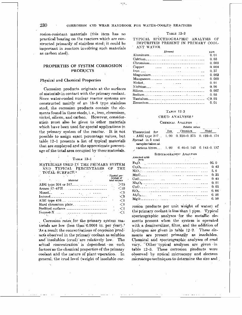
230 CORROSION 4 N D WEAR HANDBOOK FOR WATER-COOLED REACTORS
rosion-resistant materials (this item has no practical bearing on the reactors which are con- structed primarily of stainless steel ; it could be important in reactors involving such materials as carbon steel).
PROPERTIES OF SYSTEM CORROSION PRODUCTS
Physical and Chemical Properties
Corrosion products originate at. the surfaces of materials in contact with the primary coolant. Since water-cooled nuclear reactor systems are constructed mainly of an 18-8 type stainless steel, the corrosion products contain the ele- ments found in these steels, i. e., iron, chromium, nickel, silicon, and carbon. However, consider- ation must also be given to other materials which have been used for special applications in the primary system of the reactor. It is not possible to assign exact percentage values, but table 12-1 presents as list of typical materials that are ,employed and the approximate percent- age of the total area occupied by these materials.
TABLE 12-1 MATERIALS USED IN THE PRIMARY .SYSTEM
XND TYPICAL PERCENTAGES OF T H E TOTAL SURFACE'3 1 .
. , ,
I : , Material AISI type 304 or 347----.- - - - - - - - ~ - - - - - - - >75 Armco 17-4PH _ _ _ _ _ _ - - _ _ _ _ , <lo
<5 <5
M o n e l ~ _ _ _ _ _ _ _ _ _ _ _ _ _ _ - - - ~ - - - - - - - - - - - - - -
AISI type 410 _ _ _ _ _ _ _ _ ~ _ _ _ _ _ _ _ _ _ _ _ _ ' < 1 Hard chromium plate- - _ _ _ _ _ _ _ _ _ _ _ _ _ _ <1 Stellited surfaces _ _ _ _ _ - ~ ~ - -. - - - - ~ - - - - - - ~ ~ ; < I
< 1 Inconel-X _ _ _ _ _ _ _ _. ____. . -~__.
. Corrosion rates. for the primary system' ma- terials are low (less than'..o.O001 i i per year).l 'AS a result the concentrations of corrtision 'prodl ucis observed in the primary coolant as solubles and' insolubles (crud) ' are relatively low.' The actual concentration- is dependent - on 'such factors as the chemical properties of the primary coolant and the nature of plant-operation. In general, .the crud level (weight of insolublexcor-
:
, . '
, .- . .
TABLE 12-2
TABLE 12-3 CRUD ANALYSES
CHEMICAL ANALYSIS Relative values
Theoretical for &% Chromium Nickel
\ AISI type 347.- 1. 00 0. 230-0. 275 0. 122-0. 174 Spread in 5 crud
samples taken at various times.._ 1. 00 0. 40-0. 143 0. 143-0. 157
/
SPECTROGRAPHIC ANALYSIS
F e r O _ _ S , _ _ _ _ _ _ _ _ _ _ _ _ _ _ _ ~ _ _ _ _ _ _ _ _ _ _ _ _ _ _ _ _ _ _ _ 9 3 . 0 C r z 0 3 _ _ _ _ _ _ _ _ _ _ - _ _ _ _ - - - - - - - - - - . - - - - - - - - - - - - 0 . 4 2 NiO _ _ _ _ _ _ _ _ _ _ _ '---:> . . . . . . . . . . . . . . . . . . . . . . . 5. 6 M n O _ _ _ _ ~ _ _ _ _ _ _ - _ _ _ _ _ _ - - - - . - - ~ - - - - - - ~ ~ - - - - 0;23 COO ~ - - - - _ _ _ _ 0 . 4 3 N b z 0 5 - - - - - ~ - - - - - - - - - - _ - - - - - - - - - - - - - . - - - - - - - 0.01 C u O _ _ _ l _ _ _ _ _ _ _ . . - _ _ _ ~ _ _ _ _ _ _ _ _ _ _ _ _ _ ~ _ _ _ _ _ _ _ 0.03 S i O z - - - - - ~ - - - - - ~ ~ - - - - - - - - - - - - - - - - - - - - - - - - - - 0.06 A1203 .________.__ ~ _____________._ 0. 10 M g O _ _ l ~ _ _ _ . _ _ - - . . _ _ - - - - - - ~ ~ - - . . - - ~ ~ - - - - - - 0 . 1 0
rosibn products per unit weight of water) of the primary coolant is less'than 1 ppm. Typical spectrogrkphic analyses . for the metallic ele- ments present when the' system is operated with a demineralizer, filter, and the addition of hydrogen are given in table 12-2. These ele- ments are present primarily as insolubles. Chemical and spectrographic analyses of crud vary. ''Other typical ' analyses are given in table 12-3. These' corrosion pcoducts were observed by optical microscopy and electron microscope techniques to determine the size and
Assumed oxide jorm

CORROSION PRODUCTS IN
Radiation level, microcuries/ml
_____
RECIRCULATING SYSTEMS
Source
__--_
23 1
100 ._._.____.
(*) 5 X ____._
4 X - _ _ _ 4 X 10⁻²_ - . - - - 0.5 X - -. 1 X _ _ _ _ 2.5X 1 . 1 x - - - 0.6X _ _ _ _ _
structure of the products formed. A particle size distribution by optical microscopy tech- niques showed crud taken from the stainless steel system to have a mean diameter of 0.511. Electron microscope techniques showed an ulti- mate particle size distribution frequency, highly skewed in the less than 0.211 diameter range.
When formed during hot pressurized opera- tions, crud is normally a black, crystalline, mag- netic material having a spinel type st,ructure and good filtering properties. On the other hand, when crud is formed during cold or warm-up operations, reddish residues with vary- ing percentages of ferric oxide and less filterable properties are observed.2
0 1 6 in H20 . 0 1 7 in HzO. (?). Air in HzO. (?). Steel. Na in H20. Steel. Steel. Steel.
-
Radiochemical Properties Induced radioactivities are produced as a
result of recirculating the primary coolant and its constituents through the reactor core during critical operation. The bulk of the activity in the primary coolant is short lived, with a level largely dependent on the nuclear power level. When deaerated charging water is used in a typical reactor, the gross primary coolant (gamma) radioactivity, 15 min after sampling and during normal conditions, reaches a maxi- mum of 0.3 microcurie* per milliliter a t 100 percent power. Owing to the induced radio- activity of certain elements, a higher value could result if a higher crud level were present, but this would be a transitory condition. If nondeaerated charging water is used, the argon can add 0.5 microcurie to the maximum level, should the filling and charging water besaturated a t standard conditions. The long lived specific activities of crud (determined after 120 hr) have not exceeded 8 miciocuries/mg.'
The predominant radioact.ive species iden ti- fied in pressurized-water reactor primary cool- ant samples are shown in table 1 2 4 . The short-lived activities decay to levels that are insignificant within a few minutes after re- actor shutdown. Therefore, access to the shielded reactoi compartment is controlled by the longer lived activity from those impurities present, in the water or deposited on the walls
'One microcurie is equal to 3.iXlOi dis/sec.
417017 0-57-16
TABLE 12-4
TYPICAL RADIOCHEMISTRY OF COOLANT
Half-life
7 .3 sec- .. ~
4.1 set.._.
7.7 min. -
1.8 hr_ - - . . 1.9 hr_-. -. 2.6 hr_--. . 15 hr ..... 5.3 yr.---. 45 days. . . 111 days. .
'800 neut~rons/cm3kx
of piping and system components. One operat- ing loop has shown that the activity level in the primary water 15 min after reactor shut- down is generallj- in the range of 0.05 to 0.1 microcurie per milliliter of watcr, with radiation near the piping varying from 2 to 200 mr/hr, depending upon the location of measurement. One of the factors causing variations in the water activity is the variable concentration of insoluble corrosion products present in the system, a condition that is apparently caused by the alternate storing and releasing of these products in the system due to hydraulic and other effects.
DEPOSITION OF SYSTEM CORROSION PRODUCTS
Observations of Deposition Tests
One of the possible consequences of corrosion in a water-cooled reactor was pointed out by a PWR reactor fuel assembly irradiation experi- ment.4 The object of this experiment was to subject a large test fuel subassembly to irradia- tion under reactor conditions in order to observe the effects of irradiation. Reactor coolant conditions were simulated by means of a loop shown s6hemat.icall.v in figure 12-1.
Tn this test the zirconium was undamaged. However, corrosion products from the stainless-
-

232 CORROSION AND WEAR HANDBOOK FOR WATER-COOLED REACTORS
FIGURE 12-1. Schematic diagram of stainless-steel test loop with bypass puriJication system.
steel loop deposited on the heat-transfer surfaces of the in-pile subassembly in sufficient amounts to seriously affect heat transfer. Representa- tive photographs of the subassembly are shown in figures 12-2 %through 12-5. This prGferentia1 deposition (fouling) on in-pile fuel element specimens has continued to appear in several subsequent loop tests5
A characteristic noted in all of these tests has been the gradual increase in pressure drop with an accompanying decrease in flow across the test sections during operation. I t was found that these gradual changes could be alleviated by increasing the coolant pH to about 10 with lithium or potassium hydroxide.
During the more than 2 years of operation of other reactor loops and systems, several other fuel subassemblies have been withdrawn peri- odically and inspected. I t has been found that serious fouling of the fuel element surfaces can be prevented. Under favorable reactor plant conditions, uniform dull black coatings have been found on the outside and inside ends of the subassemblies, the flow channels have been clear; and the fuel elements hold small, almost negligible, amounts of deposited products.6
The only positive evidence of fouling in such systems was observed on throttling valves such as that shown in figures 12-6 and 12-7. When fouling of this type occurs, it is characterized by decreasing flow and can be alleviated by peri- odically closing and opening the fouled valve.
FIGURE 12-2. P W R reactor experimental fidel rod bundle before irradiation in an in-pile loop.

CORROSION PRODUCTS IN RECIRCULATING SYSTEMS 233
FIGURE 12-3. P W R reactor experimental fuel rod bundle after removal from in-pile loop.
Attempts have been made to correlate some automatic valve failures ’ and control rod drive mechanism malfunctions, with crud deposition.g In all cases observed, i t has been shown that while crud may have contributed to faulty oper- ation of these components, other factors prob- ably were the predominant cause for malfunc- tioning.,
During the performance of out-of-pile corro- sion tests, some general observations were made with regard to crud circulation and deposition. These are listed for comparison with in-pile test and reactor experiences discussed above.
1. Crud concentrations in the water of stainless steel loops are generally below 1 PPm.g
2. Crud deposits uniformly on all surface areas with a tendency for heavier deposition in low-velocity areas.
3. Preferential deposition is observed on throttling valves, as shown in figure 12-7.
Deposition
To obtain a more complete knowledge of the mechanism of crud deposition, studies were performed in which water containing stainless steel corrosion products was subjected to irra- diation and magnetic and chemical forces in an effort to produce deposition.
Simulated In-Pile Tests
Initial simulated in-pile experiments were performed in a hot pressurized loop. Water containing stainless steel corrosion products was circulated past a thin zirconium sheet which was irradiated by a deuteron beam from a cyclotron.1° It was observed in these experi- ments that fouling of the water side of the zirconium sheet occurs during exposure to a deuteron beam with neutral water in the loop. Experiments using the cyclotron as an irradia- tion source were discontinued in favor of a Van de Graaff electron accelerator a t this point in the investigations.
The irradiation tests with the Van de Graaff apparatus were performed with crud deliber-

r
234 CORROSION AND WEAR HANDBOOK FOR WATER-COOLED REACTORS
FIGURE 12-4. Views of individual rods from P W R Note crud deposits on road surface fuel rod bundle.
(4X).
ately added to the loop. These products were kept in suspension in the loop water by period- ically vibrating the system following additions of crud to the loop. The length of experiments was generally 36 to 48 hr, and the rate of energy dissipation in the water was approxi- mately 30 times that experienced in the pres- surized-water reactor. The following conclu- sions were drawn from these tests :
1. Deposition occurs on the flow channels in the irradiated areas and downstream for a distance corresponding to about 0.1 sec after irradiation.
2. Deposition is not appreciably affected by heat transfer in either direction between the metal and the water.


236 CORROSION AND WEAR HANDBOOK FOR WATER-COOLED REACTORS
PH fi pH 11 (LiOH)
FIGURE 12-7. Photograph of Van de Graaff target specimens showing effect of p H on deposition of crud on. irradiated Tested 45 hr with no zirconium surfaces i n a circulating water system.
ion exchanger. Loop 500' F , 1500 psi , $ow of 8.7 ftlsec.
Zirconium 9 mils thick; crud added to system. Van de Graaff: 2-new beam, 100 microamperes.
bility of effecting controlled deposition of crud on a given test section geometry. The deposi- tion mechanism utilized was cataphoresis, the migration of suspended or colloidal part,icles in a liquid due to the effect of a potential applied between immersed electrodes. It was found that deposition of magnetite can be effected on a positively charged zircaloy rod. A reversal in polarity results in no depo~ition. '~
REMOVAL OF SYSTEMS CORROSION PRODUCTS
- Purifidation Systems A typical purification system consists of a
bypass demineralizer and a mechanical filter. .
c
In general, these purification systems have per- formed satisfactorily in their ability to remove the transported corrosion products. Apart from flow rate considerations, the demineralizer is much more effective than the hydraulic service system filter. The demineralizer is over 99 per cent efficient in removing nongaseous solubles and from 89 to 99 percent efficient in removing crud. l4 The sintered stainless steel mechanical filter, having a 20p pore size, is effective in removing 60 to 80 percent of the crud and its associated long-lived activities but is only effective in removing from 15 to 40 percent of the total water activity which is attributed mainly to short-lived soluble ac- tivities.

CORROSION PRODUCTS IN RECIRCULATING SYSTEMS 237
The demineralizer is very efficient with regard to corrosion-product removal but suffers from thermal instability a t system temperatures. Therefore, heat exchangers are required for cooling the influent. Development of a high temperature resin would eliminate this prob-
The mechanical filters in pressurized-water reactor systems have shown very inconsistent and generally unsatisfactory operating charac- teristics. During low-temperature operation, they show rapid pressure drop increases which result in the need for frequent backflushing. The backflushing operation results in more complex operating procedures, excessive use of water, and a disposal problem with backflush water. Despite the difficulties associated with the mechanical filters, the overall efficiency of the purificat,ion system was satisfactory maialy because of the filtering characteristics of the demineralizer.
The disposal of the highly radioactive con- centrated products from spent ion-exchange resin and the backflush water from the filters presents difficult handling problems. These problems are for the most part associated with the exposure of personnel to radiation.
Removal by Chemical Techniques
iem.15
Considerable effort was expended toward investigating corrective measures for fouling by chemical techniques. The results were generally unsuccessful since the effective chemi- cal reagents were not compatible with the materials present in the ~ y s t e m . ~ l6 The most satisfactory reagents for dissolving crud for cleaning purposes include : (1) hydrochloric acid, (2) sulfuric acid, (3) a mixture of chromic and nitric acids, and (4) oxalic acid followed by nitric acid. These were studied in various concentrations and with various inhibitors, but in all cases the degree of their attack on system materials was considered prohibitive. In ad- dition to dissolving agents, dispersing and sus- pending agents were also investigated. These were ineffective in removing crud deposits, although the system corrosion rates remained low.
Cleaning by ultrasonic techniques was con- sidered ; however, preliminary observations do not appear promising.
DETAILED SUMMARY
Corrosion products appear as solubles and insolubles (crud) which are transported in the primary coolant, with the insolubles contribut- ing the major percentage by weight. The crud in stainless stmeel systems appears as a magnetic oxide consisting mainly of iron and some chromium and nickel. It tends to settle out on the walls of the system and is resuspended by changes in plant operating conditions, e. g., addition of oxygen or higher velocities.
The bulk of the radioactivity observed in the primary coolant is short lived, and its level is dependent largely on the reactor power level. The accessibility of the primary system for maintenance purposes is dependent on the in- duced activities present a t various time intervals after critical operation.
These observations have been made with regard to fouling : l 1
1. Although the corrosion rates of AIS1 type 304 and 347 stainless steel are low by ordinary standards, sufficient soluble and in- soluble corrosion products are present in the water to cause problems of fouling and high radioactivity level in the primary loops of water-cooled nuclear power plants.
2. In-pile experiments indicate that cor- rosion products deposit preferentially on fuel element surfaces of the in-pile subassemblies, whereas the out-of-pile subassembly surfaces remained relatively clean. In all these cases the pH of the water was about neutral.
3. iMeasures have been developed and dem- onstrated for preventing fouling in reactor loops- The use ?f dissolved hydrogen in the water in the pfesence of irradiation sup- presses free detectable oxygen; pH is main- tained at approximately 7.5 to 9.3. Crud suspension in water increases rapidly on occasion, usually during start-up.

238 CORROSION AND WEAR HANDBOOK FOR WATER-COOLED REACTORS
4. Zirconium surfaces irradiated by an electron beam become fouled with crud a t pH 6 to 6.5 but not a t p H 10 to 11.
5 . In unirradiated systems, heat-transfer surfaces become fouled (with an accompany- ing drop in heat-transfer rate) when low pH ( 5 to 6) and high oxygen ( 5 cc/kg) concentra- tions occur simultaneously. The addition of hydrogen during fouled condition (high oxy- gen and low pH) caused the elimination of oxygen, a rise in pH, and a release of crud from the heat-transfer surfaces. In order to meet accessibility requirements
and to maintain a minimum concentration of corrosion products in the primary system, a purification system is employed. The typical water-cooled nuclear reactor purification system consists of a sintered stainless steel mechanical filter and a demineralizer. The mechanical filter is effective in removing crud transported to it but much less effective in reducing the total nongaseous short lived activity. The demineralizer is very effective in its function as a demineralizer and a crud filter.
There are presently no completely satisfactory means for removing crud deposited in present reactor systems.
REFERENCES
1. I. H. WELINSKY, Westinghouse Electric Corp.,
2. B. G. SCHULTZ, Westinghouse Electric Corp., private communication.
private communication.
3. D. M. WROUGHTON, J. M. SEAMON, and H. F. BEEGHLY, Water Technology for Primary Sys- tems in Water-cooled Power Reactors (unpub- lished), Westinghouse Electric Corp., 1955.
4. P. COHEN, Fouling in the Chalk River Experiment, unpublished, Aug. 1, 1952.
5. P. COHEN, Crud Deposition in the PWR Core a t Low Velocities, unpublished, May 1955.
6. I. H. WELINSKY and D. M. WROUGHTON, Crud Memorandum No. 27, unpublished, Nov. 25, 1953.
7. W. H. MCKIM, Westinghouse Electric Corp.,
8. E. HUMEZ, J. MURRAY, and E. KREH, Westinghouse Electric Corp., private communication.
9. D. M. WROUOHTON and I. H. WELINSKY, Crud Memorandums, issued by Westinghouse Atomic Power Division, Pittsburgh, Pa.
10. H. L. GLICK, Effect of Accelerator Irradiation 011 the Deposition of Stainless-steel Corrosion Products from Hot Water, unpublished, March 1955.
11 . I . H. WELINSKY, Corrosion, Transport and Fouling in Water-cooled Reactors, unpublished, Jan. 10, 1955.
12. Babcock & Wilcox Co. Progress Reports, heat transfer through small-diameter zirconium tubes exposed to high-temperature water, Reports 5351, Apr. 30, 1952.
13. L. A. WALDMAN, Simulated Crud Deposition, UII-
published, July 15, 1953. 14. H. K. LEMBERSKY and V. H. HAYDEN, Westing-
house Electric Corp., private communication. 15. M. G. GOSSE, H. K. LEMBERJKY, and V. H. HAY-
DEN, Westinghouse Electric Corp., private com- munication.
16. C. L. WENDORFF, G. L. FLOYD, and 0. C. BYLER, Removal of Scale from a Heat-exchange System for Westinghouse Atomic Power Division, Final Report by Dowell, Inc.
. private communication.

Chapter 13
APPLICATION CONSIDERATIONS OF WEAR
Editors-J. XT. FLAHERTY, s. PETACH
Contributors--i\lT. B. DEWEES, J. GLAwER, R . c. WESTPH.41,
INTRODUCTION --------.--~-~.~--..-...-~~.--
Material Relationships- - -. -. -. . . -. - -. . - - Basis of Conclusions. - . - -. - - -. - - -. - - -. - ~
ISCU CUSS ION A N D INTERPRETATION OF WEAR DATA I N CHAPTER 7__.._.........._.._~-.-
The Wear F a c t o r . _ _ _ _ _ _ _ _ . . _ _ . . - - . - . - - - Factors Influencing Wear- _ _ - - -. - - -. . - - - -
Typical Problems Arising in Simulated Component Testing ____.______. .__. .__
Ball-bearing Tests- - - ____. ~ _ _ ~ .__. ._____
Claddings and Hard Facings- _._.___.____
PRACTICAL CONSIDERATIONS I N CHOOSIXG PIA-
design._.___._____.__.___.__._^_._____ Manufacturing and Processing- -. -. -. . - -. - Nonmetallic Materials Investigated. -. - - - - Martensitic Stainless Steels- - . . . . -. - -. - - - Environmental Considerations-. - -. - -. - - - - Introduction of Possible Lubricants- - - - - - - Special Considerations _ _ _ _ - -. - -. ~ - - - - - - - - Areas of Future Research._- .___ _ _ _ _ _ _ _ _ _
.
I)ISCUSSION OF SUPPLEMENTARY DATA. - -. - - - - -
! TERIALS _ _ _ _ ~ ~ ~ ~ ~ ~ ~ . ~ . ~ ~ . . ~ . ~ . ~ ~ ~ . ~ . ~ . ~ ~ ~ .
Page 239 239 2 40
24 1 24 1 242 245
245 246 250
251 251 252 256 256
1257 257 257 258
INTRODUCTION
The choice of water as the moderator and coolant for present commercial and naval nuclear reactors and the incorporation into the design of many complex mechanisms operating in contact with primary water presented new and practically uninvestigated problems to be solved in the field of wear. The major com- plicating factors were the absence of effective lubrication, high temperatures, and the possi- bilities of radiation damage.
Early experience with componend tests indi- cated that materials considered satisfactory by the designer on the basis of corrosion resistance (such as the austenitic stainless steels) suffered immediate seizure or a t best erratic short-term operation in service. This difficulty was ob-
served not only in antifriction bearings and linkages but also in such seemingly light service items as nuts and bolts.
It was also apparent that conventional bear- ing materials such as the babbitts would not satisfy the demands of service in the novel high-temperature high-purity water enviroii- ment. The choice of materials could be resolved only after careful evaluation of both corrosion resistance and wear resistance.
What was then required was a program to screen and evaluate all likely wear combina- tions in order to provide the designer with a body of information from which he could draw with some assurance of successful operation. Material Relationships
The bulk of information resulting from the basic wear test program involves material rela- tionships, i. e., the relative performance of materials in combination. Subsequent exper- ience with components in test and in service have either verified or slightly modified the original findings. The section entitled “Prac- tical Considerations in Choosing Materials” is a summation of the findings of the basic tests and subsequent. experience.
Earl)- in the program conventional soft, yielding bearing materials were found to be susceptible to severe corrosive attack in oxy- genated high-purity water at 500’ F. Conse- quently, they were unsatisfactory for reactor application. The highly corrosion resistant materials that remained for consideration 111
wear applications were generally hard, ranging from Rockwell C 30 to Rockwell C 60.
From this point the efforts in selecting and developing materials were directed toward two major goals: (1) the determination of optimum
2 39

240 CORROSION AND WEAR HANDBOOK FOR WATER-COOLED REACTORS
bearing combinations from among the hard corrosion-resistant materials and (2) the devel- opment of composites utilizing the softer, flowing materials embedded in a hard matrix, i. e., Teflon-impregnated stainless steel and silver bearing compacts.
The hard, corrosion-resistant materials were tested in simulated reactor environments. The standard tests for this phase of the program were of the piston-cylinder and sleeve-journal types. The equipment and methods of testing are described in chapter 5. The results of these tests were sufficiently reproducible and indicative that the ranking of materials com- binations shown in chapter 7 could be formulated.
Development of the composite materials for wear applications was carried out largely by the Armour Research Foundation. The pro- gram of investigation and the materials studied are described in the outline which follows:
1. Development of hard intermetallic or metalloid ' structures on the surfaces of corrosion-resistant metals.
Titanium nitride Carbon-nitride case development on
Chromium nitride Metal boride cases
titanium
2 . Development of hard intermetallic or metalloid structures through powder metal- lurgy or solid-state reactions.
Copper-nickel-graphi te Cobalt-chromium-carbon
3. Utilization of liquid or low melting, low shear strength materials as lubricants.
Tin-chromium composites Gold in a high melting corrosion-resistant
metal skeleton Utilization of silicones as lubricants
infiltrated into porous metal bodies Many of the experimental bearing materials
show promise and may be selected for future reactors. However to date, bearing materials in use are those available commercially.
The first or screening phase of investigation was considered ,essentially closed with the successful operation of the Arco prototype
reactor. This conclusively demonstrated the availability of a group of materials that could perform successfully in the wear application of an operating nuclear reactor.
The second phase of wear investigation called for a more detailed evaluation of successful wear combinations with the intent of improving performance. Problems of geometry and high unit bearing pressures could now be more thoroughly studied in detail and maximum operating loads determined. Uninvestigated problems, such as the effect of wear particles on wear rates, could be studied. Concurrent with these investigations the evaluation of new bearing materials could continue.
Included among the second-phase investiga- tions are wear and friction studies conducted by Dewees. These investigations are presently in progress. A partial tabulation of the results of these tests is given in table 13-6.
This chapter includes wear data that are not sufficiently extensive to warrant ta,bular pres- entation in chapter 7. Such information ' supplements the tables and broadens their utility by correlating with them the knowledge ' gained from simulated component tests and actual plant experience. Among these data are results of test programs on ball bearings showing effects on wear of such variables as load and speed.
Basis of Conclusions
Some of the information made available during the course of basic wear programs was immediately incorporated into mechanism de- sign, or it served as criteria for modifications. Concern was naturally felt a t what might be considered undue extrapolation, and with the successful operation of the prototype reactor a t the Naval Reactor Testing Facility a t Arco, Idaho, more emphasis was shifted to the testing of simulated components such as ball bearings, mechanical linkages, and lead screws.
As might be expected, some discrepancies arose from the comparison of the performance of materials in basic wear tests and in com- ponent tests. These were due to the introduc-

APPLICATION CONSIDERATIONS O F WEAR 241
tion of such new variables as geometry, severity and method of loading, continuity of operation, and varied chemical environments. However, these new data do not show any instances in which a material proposed ’ as acceptable, on the basis of either piston-cylinder or sleeve- journal wear tests, later proved unsatisfactory. ~
On the other hand, some material combina- tions that were not strongly recommended as a result of the basic wear’ tests proved usable with design modifications directed toward utilizing desirable qualities other than wear resistance. A material representative of such treatment-is Armco 17-4 PH stainless steel. Here, by the expedient of utilizing a relatively wide bearing surface, the combination 17-4PH vs. 17-4PH , (wear factor 460) was “success- fully” employed. The galled appearance of the wear track was in keeping with the high wear factor. The use of these materials in a closely confined bearing application would have resulted in erratic short-time operation a t best. Thus severity of application is an important factor in choosing material combinations.
The consequence of component failure map also be the determining factor in the choice of a material. Parts that are inaccessible or that may require complete shutdown in the event of failure must possess the highest integrity even a t the risk of becoming unduly costly. On the other hand, readily replaceable compo- nents may be so located that fair or borderline combinations can be tolerated.
It is intended that the data presented will assist in orienting the reader in the field of water-lubricated bearings. As a whole, they describe an area of materials choice which, to date, has proved to be compatible with the requirements for operation in a water-moder- ated nuclear reactor.
DISCUSSION AND INTERPRETATION OF WEAR DATA IN CHAPTER 7
The Wear Factor The necessity of estdblishing a uniform means
of evaluating the relative merit or performance of materials combinations became evident early
in the wear test program. Preliminary tests were run to determine what measurements would be significant in the evaluation of wear. In addition, methods for compiling and pre- senting the data were established so that the information would be of use to the design engineer. The following dimensional standards were adopted : Linear dimensions were meas- ured to the nearest 0.00001 in., and weights were recorded to the nearest 0.1 mg. Early test data showed that weight change was one of the most sensitive and most reproducible measures of wear. In fact there were only a few cases, involving porous materials which absorbed wat,er and soft materials which wiped or flowed under load, where dimensional meas- urements were of greater significance. By taking these measurements plus hardness and surface roughness data in microinches (rms) , it was found that the test results could be described satisfactorily. Early tests further proved, within the limit of the loads employed, that the amount of wear was directly propor- tional to the number of cycles of operation, disregarding the possibility of an initial wear-in period of relatively short duration.
An examination of these variables led to the introduction by Westphal and Glatter of the wear factor. This factor has the units of milligrams weight loss per pound load per million cycles. The duration of tests was approximately 500,000 cycles; a t 120 cycles/min i t required three days to perform a test. The information shown below includes data taken from a representative piston-cylinder test conducted a t 500’ F in oxygenated water.
Teat N o . 1796 Materials 17-4 PH vs. Haynes 21, SA Hardness Rockwell C scale:
43 17-4PH ...__ - _ _ _ _ _ _ _ _ _ _ _ _ - _ _ _ - - _ _ - Haynes 21, SA _...______________-____ 30
Number of cycles_- _ _ _ - -. - - _ _ _ _ _ _ -i-- - - 500,000
Dimension change, in. : L o a d , p s i _ . _ _ _ _ - - - - - - - - ~ - . - - - - - - - - - - - - - - - 8. 0
Piston (0. D.) .._____________________ -0. 0062 Cylinder (I. D.) . . . . . . . . . . . . . . . . . . . . . +O. 0028
Weight change: Piston _._.____. ~~ ____.________.____. -0. 2813 Cylinder .__. _ _ _ ~ _ _ ~ _ _ _ _ _ _.___. ~. ._ - -0. 1692
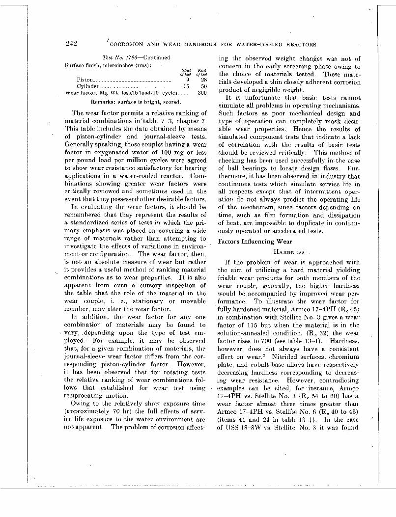
/ 242 CORROSION AND W E A R HANDBOOK FOR WATER-COOLED REACTORS
Test No. 1796-Continued Surface finish, microinches (rms) :
Start End of test of test
Piston__- _ _ _ _ _ _ _ _ _ _ _ _ _ _ _ _ _ _ _ _ _ _ _ 9 28 Cylinder _ _ _ _ _ _ _ _ _ _ _ _ _ _ _ _ _ _ _ _ _ _ _ _ _ 15 50
300 Wear factor, Mg Wt. loss/lb ‘load/lOB cycles- - - -
Remarks: surface is bright, scored.
The wear factor permits a relative ranking of material combinations in ‘table 7-3, chapter 7. This table includes the data obtained by means of piston-cylinder and journal-sleeve tests. Generally speaking, those couples having a wear factor in oxygenated water of 100 mg or less per pound load per million cycles were agreed to show wear resistance satisfactory for bearing applications in a water-cooled reactor. Com- binations showing greater wear factors were critically reviewed and sometimes med in the event that they possessed other desirable factors.
Tn evaluating the wear factors, i t should be remembered that they represent the results of a standardized series of tests i.1 which the pri- mary emphasis was placed on covering a wide range of materials rather than attempting to investigate the effects of variations in environ- ment or configuration. The wear factor, then, is not an absolute measure of wear but rather i t provides a useful method of ranking material combinations as to wear properties. T t is also apparent from even a cursory inspection of the table that the role of the material in the wear couple, i. e., stationary or movable member, may alter the wear factor.
In addition, the wear factor for any one combination of materials may be found to
\ vary, depending upon the type of test em- ployed: For example, i t may be observed that, for a given combination of materials, the journal-sleeve wear factor differs from the cor- responding piston-cylinder factor. However, it has been observed that for rotating tests the relative ranking of wear combinations fol- lows that established for wear test using reciprocating motion.
Owing to the relatively short exposure time (approximately 70 hr) the full effects of serv- ice life exposure to the water environment are not apparent. The problem of corrosion affect-
.
ing the observed weight changes was not of concern in the early screening phase owing to the choice of materials tested. These mate- rials developed a thin closely adherent corrosion product of negligible weight.
It is unfortunate that basic tests cannot simulate all problems in operating mechanisms. Such factors as poor mechanical design and type of operation can completely mask desir- able wear properties. Hence the results of simulated component tests that indicate a lack of correlation with the results of basic tests should be reviewed critically. This method of checking has been used successfully in“\the case of ball bearings to locate design flaws. Fur- thermore, i t has been observed in industry that continuous tests which simulate service life in all respects except that of intermittent oper- ation do not always predict the operating life of the mechanism, since factors depending on time, such as film formation and dissipation of heat, are impossible to duplicate in continu- ously operated or accelerated tests. Factors Influencing Wear
HARDNESS If the problem of wear is approached with
the aim of utilizing a hard material yielding friable wear products for both members of the wear couple, generally, the higher hardness would be ,accompanied by improved wear per- formance. To illustrate the wear factor for fully hardened material, Armco 17-4PH (R, 45) in combination with Stellite No. 3 gives a wear factor of 115 but when the material is in the solution-annealed condition, (R, 32) the wear factor rises to 700 (see table 13-1). Hardness, however, does not always have a consistent effect on wear.* Nitrided surfaces, chromium plate, and cobalt-base alloys have respectively decreasing hardness corresponding to decreas- ing wear resistance. However, contradicting examples can be cited, for instance, Armco 17-4PH vs. Stellite No. 3 (R, 54 to 60) has a wear factor alm’ost three times greater than Armco 17-4PH vs. Stellike No. 6 (R, 40 to 46) (items 41 and 24 in table 13-1). In the case of USS 18-8W vs. Stellite No. 3 i t was found

243 APPLICATION CONSIDERATIONS OF WEAR
TARLE 13-1 PARTIAL SUMMARY O F PISTON-CYLINDER
WEAR TESTS (All tests performed a t 500’ F in water; radial loading
a t 8 psi; first-named item is the piston) ’
M g . wt . loss per lb. load per million cycles
Materials combirralioiis’ 1. Nitrided AIS1 type 347 SS/
nitrided AIS1 type 347 SSL 2. Nitrided chrome plate/nitrided
chromium _ _ _ _ _ _ _ ~ _ _ _ _ _ _ _ _ _ 3. As-plated chrome/nitrided ti-
tanium _ _ _ _ _ _ -~ - ~ _ _ - - - ~. ~ -.
4. Metamic LT-l/nitrided Armco
5, Honed chrome plate/Stellit,e No. 3 _ _ _ _ _ - _ _ _ _ _ _ _ _ . _ _ _ _ _ _
6. AISI type 4 4 0 4 SS/AISI type 44&C ss ~ - ~ ~ ~ ~ . ~ ~ ~ ~ _ _ _ _ _ _
7. AISI type 410 SS/Stellite No. 3- 8. Honed chrome plate/Kenta-
nium K - 1 5 1 _ _ . _ _ _ _ _ _ _ _ . ~-~
9. Honed chrome plate/Armco 17- 4 P H _ _ _ _ _ _ _ _ _ ~ _ _ _ _ ~ _ ~ . _ _ _ _
10. Honed chrome plate/nitrided Armco 17-4PH
11. Stellite No. I/AISI type 4 4 0 4
12. Stellite. NO. l2/honed chrome
13. Stellite No. G/Stellite No. 6-_ 14. Nitrided Armco 17-4PH/ni-
trided titanium _ _ _ _ _ _ _ _ _ _ _ _ 15. US steel 18-8 W (SA)/Stellite
No. 3 _ _ _ _ _ - _ . . _ _ - _ - _ _ _ _ _ _ _ 16. Wall Colmorioy No. 6/Stellite
No. 6 _ _ _ _ _ _ _ _ _ _ _ _ _ _ _ _ ~ _ _ _ _ 17. As-plated chromium/as-plated
chromium- - - - - - - - - - - - - - - 18. Armco 17-4PH/honed chro-
mium plate ____.._______.__
19. Haynes No. 21 (SA)/Stellite No. 6 _ _ _ _ _ _ _ _ _ _ _ _ _ ~ _ _ _ _ _ _ _
20. Carboloy 608 (chrome carhide)/ honed chromium plate- _ _ _ _ -
21. Hayiies No. 21 (SA)/Haynes No. 21 (SA) ....___________
22. Stellite No. 3/horied chrome plate.. . - - - - - - - - - - - - - - - - - -
23.- Stellite No. 3/wall Colmoiioy No. 6 . _ _ _ _ _ _ _ _ _ _ _ _ _ _ _ _ _ _ _ ~
24. Armco 17-4PH/Stellite. No. 6- 25. Honed chrome plate/Stellite
26. Stellite No. 3/Stellitr No. 3 _.__
1 7 - 4 P H ~ _ _ _ _ _ _ _ _ _ _ _ _ _ _ _ _ ~
plate .._._ _ _ - - -. . - - ~. ~-~ _ _ . .
- NO:^ ______.___... ~ _ ~ _ ~ _ . ~
Ozygen- Hydro- ated genated
water water
35 11
65 24 71 1 34
A%fg. wl. loss per Ih. load per million cycles
Materials combinations* 27. Armco 17-4PH/Carboloy 608
(chrome carbide) _________..
28. Metamic LT-l/Metamic LT-1- 29. Stellite No. 3/Haynes No. 25
(Cb’) ___..__ ~ .-_.____._. ._
30. KR-hfonel/honed chrome plate- 31. Stellite No. I/Stellite No. 6 ..__
32. Haynes No. 21 (PH)/Haynes No. 21 (SA) .... ~ _ . ~ _ ~ ~ ~ . ~ _
33. Haynes No. 21 (SA) / h o 11 e d chrome plate. ~. ._ .. .__. ~ _ _
34. Honed chromium platc/Hayiies No. 25 ( C W - ...______ ~ _ _ _
35. Stellite No. 3/Armco 17-4PH.- 36. Haynes No. 21 (PH)/Haynes
No. 21 (pH)_-..- __..__.._
37. US steel 18-8 W/Stellite No. 3- 38. Honed chrome platelhoned
chrome plate.. . . ~ . ~ -~~ ~~~ ~
39. Honed chrome plat.e/Hastel- loy D _ _ _ _ ~ ~- .. ..______ ~-~~
40. AISI type ,304 SS/as-plated chromium - - -. ~ ~. ~- ~ - _ _ _ -.
41. Armco 17-4PH/Stellite No. 3_. 42. KR-hIonel/Stellite No. 3. ~ - _ _ 43. Stellite No. 3/Hastelloy D.. ~ ~
44. Armco 17-4PH/Armco 17-41” 45. Silicon broiize/Hayiies No. 21
( ~ A ) _ _ _ _ _ _ _ _ . . . _ ~ _ . . _ I _ _ ~ ~ 46. Stellite No. 3-Armco 17-4 (SA). 47. Silicon broiize-honed chrome
plate_.-..--- __._ ~ . _ ~ ....__
48. AISI type 304 SS/AISI type 301 S S _ _ _ . . ~ ~ . _ . . ~ ~ _ _ . _ . ~ _
Orygen Hydro- ded genated
water water
98 - -. . . -
102 28
120 ..~..._
130 11
140 15
150 .. . .
150 25 170 31 300 43 460 .. .___
660 18 700 . .. . . . . -
830 I 2
“‘SA” indlcates solution annealed, “PII,” prccipltdtion hardent‘d, and “CW,’,” cold norlied
that by heat treating the type W material to maximum hardness (R, 42 to 45) the com- bination displayed its highest wear fkctor, 130. However, when the hardness was reduced just a few points, the wear factor was reduced to 31.
AiiotJier material which t1oc.s not coiifornl to the popular conception that rnatcrials with Iiigtier Iiarclncss cspericiice less wear is t Iw cobalt-base alloy Stellite No. 21. This matc- rial when run in combination with itself resulted in the least wear when both elements were S O ~ U -
tion-annealed, morc wcar when one elemcn t was hardencd, and most wcar wlideri both rlemcnts were hardened.

244 CORROSION AND WEAR HANDBOOK FOR WATER-COOLED REACTORS
CORROSION
Ai1 appreciation 6f the effect of corrosion on wear may be obtained by comparing the wear factors listed in table 7-1 arid in chapter 7. The results in the column marked hydrogen were obtained from a number of tests that were similar to oxygenated tests in every respect, except that a partial pressure of hydrogen was substituted for oxygen.
In almost every case, a substantial reduction in wear factor was noted. The greatest change took place with those materials most susceptible to oxidation. Everdur No. 1012 (silicon bronze) vs. chrome plate, for example, produced the low wear factor of 2 in hydrogenated water and the extremely high factor of 830 in oxygenated water. An 88 percent reduction in wear was observed for the KR-Monel vs. chrome-plate combination. In contrast, the combinations of cobalt-base alloys, presumably because they are more oxidation resistant, did not show improve- ments of this magnitude. Here improvement, in terms of the wear factors, ranged from a few percent up to a maximum of 50 percent.
These materials which perform well in hydro- gen include many of the conventional bearing materials of industry. .The advantages that could be realized by employing these readily available materials is obvious since cost would be lower and manufacturing problems would be reduced. However, such bearings would be extremely sensitive to unfavorable environ- mental changes.
ENFIRONMENTAL CONSIDERATIONS
The environmental effects noted in the basic < tests were limited to two temperatures (200
and 500’ F) and two additives (oxygen and hydrogen). A small number of tests were con- ducted in lithium hydroxide, and these results are indicated in table 13-2.
A fine black powder (mostly magnetite) was commonly observed on autoclave and specimen surfaces after hydrogenated tests. This was in contrast to the heavier red dcposit (mostly hematite) found -after oxygenated tests; post- test examinations showed vessel surfaces to be
TABLE 13-2
SUMMARY OF JOURNAL-SLEEVE WEAR TESTS I N LiOH
(All tests performed in 500’ F water; radial ioading a t 10 psi; pH 10; first item is journal)
Mg. ut.
lb. load per mil-
l ion Material8 combinations’ cycles
1088 per
1. APCP on 17-4PH (0.0005 in.)jArmco
2. AISI type 410 SS/AISI type 410 SS ._____
3. Honed chromium plate on Armco 17-4PH/ Stellite No. 3 _ _ _ . . _ _ _ _ _ _ _ _ _ _ _ _ _ _ _ _ _ I _ _
4. Stellite No. 6iStellite No. 6 ....-_
5. APCP on 17-4PH (0.0005 in.)/Stellite No. 6- 6. APCP on 17-4PH (0.005 in.)/Haynes 21
SA)____.___________-------^--------- 7 . Stellite No. 1 (on 347 SS)/Stellite No. 3- - - - 8. Honed chromium plate on Armco 17-4PH/
Stellite No. 3 ...__ ~-~ _____.______.___
9. US .steel 18-8 W/Stellite No. 3 ______.___
10. 17-4PH/Stellite No. 3 .________-___-_____
11. Haynes 21 on AISI type 347 SSiHaynes 21 SA)_______.__^.___________________
12. ~Stellite No. 6 hard facing on AISI type 304 SSiHaynes 21 (SA) _________.___.__
13. Honed chromium plate on Armco 17-4PH/ Armco 17-4PH_--
1’4. APCP on Armco 17-4PH (0.005 in.)/Haynes 2 5 _ _ - - - - - - - - - - - ~ - - ~ - - - - . - - - - - - - - - - - . ~
17-4PH____________-_________________ 5 9
14 18 31
45 47
50 70 72
72
78
113
125 “‘apcd” Indicates as-plated chromium plate; “PH.” precipitation
hardened an4 “SA,” solution annealed.
extremely clean and pH measurements to be less acid in the hydrogenated water.
TEMPERATURE Tests were conducted a t the two temperatures
roughly corresponding to reactor operating temperatures. The bulk of the data is a t either 200 to 500” F. Although the 300” F diflerence of temperature is relatively small, marked differences in wear were observed.
These temperature effects were so pronounced that whole bodies of material, such as- the car- bon-graphites and ceramics, which proved ex- cellent in pump bearing investigations designed for operations in 200’ F water, \were ruled out a t 500” F. Exposure to water a t the 500” F temperature promotes the leaching out of the bonding agent leaving a rough skeletal surface.’
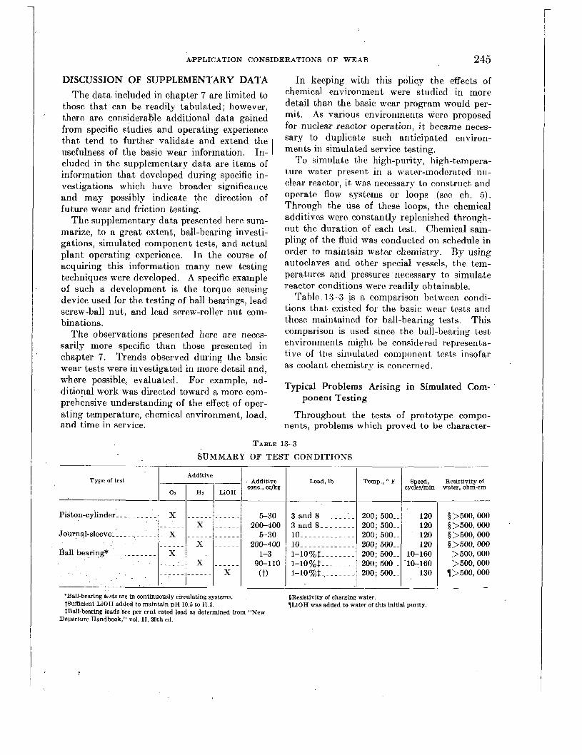
A.PPLICATION CONSIDERATIONS 0% WEAR 245
3 and 8 _____.__
3 and 8 ____..__
10 _...______ ~ _ _ 10 ____..__
1-1070 7 0 $ - - _ . . . _ _ 1-107070$ -.___._.
l - l O % $ .,---- ~ _ _
DISCUSSION OF SUPPLEMENTARY DATA The data included in chapter 7 are limited to
those that can be readily tabulated; however, there are considerable additional data gained from specific studies and operating experience that tend to further validate and extend the usefulness of the basic wear information. In- cluded in the supplementary data are items of information that developed during specific in- vestigations which have broader significance and may possibly indicate the direction of future wear and friction testing.
The supplementary data presented here sum- marize, to a great extent, ball-bearing investi- gations, simulated component tests, and actual plant operating experience. In the course of acquiring this information many new testing techniques were developed. A specific example of such a development is the torque sensing device used for the testing of ball bearings, lead screw-ball nut, and lead screw-roller nut com- binations.
The observations presented here are neces- sarily more specific than those presented in chapter 7 . Trends observed during the basic wear tests were investigated in more detail and, where possible, evaluated. For example, ad- ditional work was directed toward a more com- prehensive understanding of the effect of oper- ating temperature, chemical environment, load, and time in service.
’
200; 500_- 120 200; 500K 120
200; 500-_ 120 200; 500-_ 120
200; 500.- 10-160 200; 500_- -10-160 200; 500-_ 130
In keeping with this policy the effects of chemical environment were studied in more detail than the basic wear program would per- mit. As various environments were proposed for nuclear reactor operation, i t became neces- sary to duplicate such anticipated environ- ments in simulated service testing.
To simulate the high-purity, high-tempera- ture water present in a water-moderated nu- clear reactor, it was necessary to construct and operate flow systems or loops (see ch. 5) . Through the use of these loops, the chemical additives were constantly replenished through- out the duration of each test. Chemical sam- pling of the fluid was conducted on schedule in order to maintain water chemistry. By using autoclaves and other special vessels, the tem- peratures and pressures necessary to simulate reactor conditions were readily obtainable.
Table 13-3 i s a comparison between condi- tions that existed for the basic wear tests and those maintained for ball-bearing tests. This comparison is used since the ball-bearing test environments might be considered representa- tive of tile simulated component tests insofar as coolant chemistry is concerned.
Typical Problems Arising in Simulated Com-
Throughout the tests of prototype compo- nents, problems which proved to be character-
ponent Testing
.TABLE 13-3
SUMMARY OF TEST CONDITIONS
Additive Type of test . Additive
’ 1 02 I Hz I=/ wnc., cckg
Piston-cylinder- -. . .
Journal-sleeve- - - . . . .
Ball bearing* - - - - - -
.Ball-bearing tests are in continuously circulating systems. tsufficient LiOH added to maintain pH 10.5 to 11.5. tBall-bearing lobds are per cent rated load as determined from “New
,
Departure Handbook,” vol. IT, 20th ed.
cycleslmin Load, lb
l- Resistivity of
water, ohm-cm
0 >500,000 $>500,000 ’
0 >500,000 0>500,000 >500,000 >500,000
1>500,000

246 CORROSION AND WEAR HANDBOOK FOR WATER-COOLED REACTORS
istic of the mechanisnis tested were recurrent. For this reason, special studies were frequently necessary to eliminate the objectionable char- acteristics.
In the basic wear tests of the piston-cylinder or sleeve-journal types, it was possible to adopt standard procedures that were followed in all tests of that type; however, in the simulated component tests, each test or type of test required tailormade procedures. The major considerations in planning simulated service tests are not only that the environment be con- trollable and that it duplicate the reactor envi- ronment but also that the test specimen be observed in such a manner that its motions, loads, and materials duplicate those of actual service. In the course of these investigations, problems of testing techniques arose that re- quired solutions which could not be found in the literature.
The outstanding differences between the basic tests and simulated component tests were that basic tests operated in static or nonflow systems and that water chemistry for basic tests was known only a t the start and end of testing; whereas the simulated component tests had a programed sampling procedure as mentioned above.
Perhaps the outstanding difficulty with early ball-bearing investigations was the lack of knowledge of the frictional torques developed by bearings in operation. The ball-bearing tests were operated in a solid water system with temperatures up to 500' F, water pressure to 2,000 psig, and with gaseous additives. Exces- sive leakage could not be tolerated. With these requirenients in mind, a torque sensing element or ('torque tube" was developed. The torque problems encountered in lead screws closely paralleled those encountered in the investiga- tion of ball bearings. Therefore, the develop- ment of the torque sensing tube provided a most effective evaluating device for both tests.
Torque sensing units are extensions of the motor drive shaft. Torques developed in the bearing and transmitted through the shaft tend to restrain the rotation of the shaft. These
. I
restraining forces twist and displace a thin- walled annular section of the torque tube. The minute deflections thus produced vary the re- sistance of electrical strain gages, resulting in a low electromotive force that is amplified so that a continuous tape record can be obtained by means of a pen recording oscillograph. Figure 13-1 illustrates a torque sensing ele- ment developed for 200 to 400" F water nppli- cations at 1 ,OOO psig pressure.
One of the problems encountered in the development of- this device was the need for pressure seals. The system wiring was brought out of the pressurized vessel through the torque tube shaft. Another problem was that of cooling the strain gages so that they operated a t temperatures lower than 375' F while the tests were operating at 500 F.
Ball-Bearing Tests Ball bearings as a group were among the
most exhaustively investigated single items in the reactor system. Investigations were con- ducted with radial loads and thrust loads, a t high speed and low speed, with continuous rotation, intermittent service, and vibratory motion. 1 In normal lubricated service, ball-bearing failure can be attributed in large measure to fatigue failure. However, for the ball bearings tested during the development stages of the water-moderated nuclear reactor, fatigue was not critical since design life was shorter than the expected fatigue life in hot-water service. d s a resvlt, new criteria were established for the determination of nominal failures. These criteria involved increases in radial and axial looseness as well as weight loss. The looseness that could be tolerated in the system was dictated by the rigid alignment requirements of the control mechanism, and the weight loss, to a great extent, by the amount of wear and cor- rosion products that could be tolerated in the primary coolant.
Several ball-bearing test rigs described in chapter 5 are used in investigations designed to show specific effects of variables on ball-bearing wear and to proof-test these items. Among

APPLICATION CONSIDERATIONS O F WEAR 247
Additive
FIGURE 13-1. Torqice.sensing element used i n ball-bearing tests.
Additive conc.. cclke
these investigat.ions, as previously indicated; were such determinations as the effect. of chemi- cal environment, load, temperature, speed of rotation, time in operation, and proposed lubri- cants. Tn addition, work is currentrly being done to evaluate the effectiveness of hard facings and claddings. The results of these investigations are presented below.
CHEMICAL ADDITIVES Various chemical addit,ives were proposed in
the course of development. As indicated before; these additives were introduced to produce high p H environment,s, to decrease crud formation, to provide lubricity, and to lower the corrosion rate of the various alloys being invest,igat,ed.
During these investigations t,he variables s t d i e d were t.he effects o'f oxygen content', hydroge.n content,, and pH of t*he. water. Table 13-4 is, a summarizat.ion of some representativc control conditions for t,hF several media.
TABLE 13-4 C HE A I IC A L A D 1) IT I V ES T 0 B A L L- B E A RI N G TESTS
Water to which addition is made Oxygen residual.
cc/ks ptl I Resistivity,ohrn-em
6. 5-T. 5 I >500, 000 Not deter-
6. 5-7. 5 >500, 000 <O. 05 10. 5-11. 5 t>500,000 <O. 05 6. 5-7. 5 >500, 000 <O. 05
mined
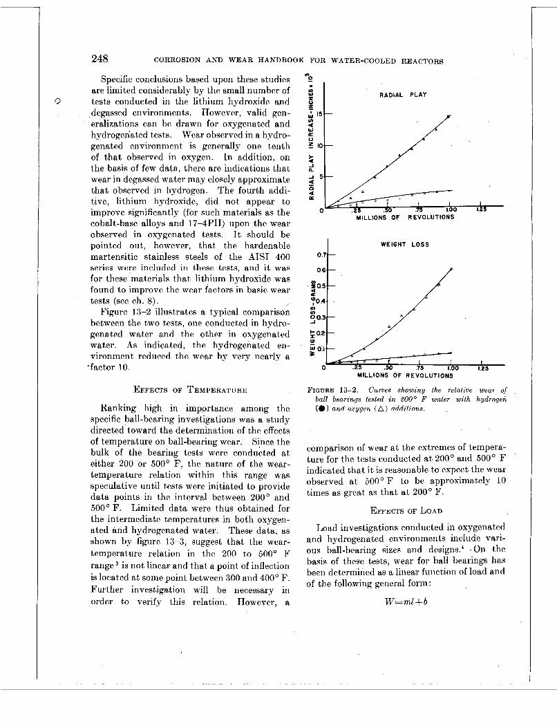
248 CORROSION AND WEAR HANDBOOK FOR WATER-COOLED REACTORS
Specific conclusions based upon these studies are limited considerably by the small number of tests conducted in the lithium hydroxide and degassed environments. However, valid gen- eralizations can be drawn for oxygenated and hydrogenated tests. Wear observed in a hydro- genated environment is generally one tenth of that observed in oxygen. In addition, on the basis of few data, there are indications that wear in degassed water may closely approximate that observed in hydrogen. The fourth addi- tive, lithium hydroxide, did not appear to improve significantly (for such materials as the cobalt-base alloys and 17-4l") upon the wear observed in oxygenated tests. It should be pointed out, however, that the hardenable martensitic stainless steels of the AIS1 400 series were included in these tests, and it was for these materials that lithium hydroxide was found to improve the wear factors in basic wear tests (see ch. 8) . /
Figure 13-2 illustrates a typical comparison between the two tests, one conducted in hydro- genated water and the other in oxygenated water. As indicated, the hydrogenated en- vironment reduced the wear by very nearly a
'factor 10.
(3
EFFECTS OF TEMPERATURE
Ranking high in impprtance among the specific ball-bearing investigations was a study directed toward the determination of the effects of temperature on ball-bearing wear. Since the bulk of the bearing tests were conducted a t either 200 or 500' F, the nature of the wear- temperature relation within this range was speculative until tests were initiated to provide data points in the interval between 200' and 5 O O O F . Limited data were thus obtained for the intermediate temperatures in both oxygen- ated and hydrogenated water. These data, as shown by figure 13-3, suggest that the wear- temperature relation in the 200 to 500' F range is not linear and that a point of inflection is located at some point between 300 and 400' F. Further investigation will be necessary in order to verify this relation. However, a
0 3 IO
i! "r 15- fn W 0: 0
a
3 10.-
MILLIONS OF REVOLUTIONS
6 a K
0 MILLIONS OF REVOLUTIONS
WEIGHT LOSS
P 0.6
MILLIONS O F REVOLUTIONS
FIGURE 13-2. Curves showing the relative wear of ball bearings tested in 200' F water with hydrogen (0 ) and oxygen (A) additions.
comparison of wear at the extremes of tempera- ture for the tests conducted at 200' and 500' F indicated that i t is reasonable to expect the wear observed a t 50O'F to be approximately 10 times as great as that a t 200' F.
EFFECTS OF LOAD
Load investigations conducted in oxygenated and hydrogenated environments include vari- ous ball-bearing sizes and design^.^ On the basis of these tests, wear for ball bearings has been determined as a linear function of load and of the following general form :
W=ml-kb

APPLICATION CONSIDERATIONS OF WEAR 249
0 I O V 200. 300. 400. 500' . Tsmper,?Iure Fohrenheit
FIGURE 13-3. Curve showing wear-temperatzcre relation.
where W=a particular measure of wear, i. e., weight loss, increase in radial looseness, or increase in axial looseness
m =slope l=load in pounds b-a constant
I t is necessary to determine the slope ex- perimentally for each bearing design and size and for each environment.. This .relation is shown by figure 13-4.
EFFECTS OF VELOCITY In the sleeve bearing tests of the basic wear
series, the angular velocity was set at 120 rpm since this velocity was considered to be low enough to preclude the formation of an effective hydrodynamic film. Thus contact between the materials under observation was assured, giving an indication of wear under the most adverse operating conditions. Tests conducted with ball bearings indicated that for a given number of total revolutions the wear decreased exponentially as angular velocity increased.
" 0.2 0.4 0 6 0.8 IO 12 1.4 . 1.6 1.8
Revolutions x IO 6
ANGULAR CONTACT BEARINGS-SIZE 203 THRUST LOADS
Teat
Pounds
load bearing Percent load
FIGURE 1,3-4. Curve showing wear-load relation.
0 2 0 40 60 BO 100 120 140
SPEED OF ROTATION - R P Y
0 FIGURE 13-5. Cwrve showing bear-velocity relation.
This is shown by figure 13-5 for angular veloci- ties ranging from 10 to 130 rpm. However, this

250 CORROSION AND WEAR HANDBOOK FOR WATER-COOLED REACTORS
result may be masked to some extent by cor- rosion since for an equal number of cycles the 10-rpm test was in the 200’ F water environ- ment 13 times as long as the (130 rpm) test with which it was compared. ’ .
RELATION BETWEEN TIME I N SERVICE A N D WEAR
. Throughout the investigat,ion of prototype
components, including latching mechanism, lead screw-roller nut, lead screw-ball nut, and ball-bearing tests, where periodic observations were necessary, the specimens were observed and measured after each of several periods of operation. In this manner a continuous record of wear vs. time in service was established. Upon examination of data, wear was found to be a linear function of time of operation. There are several instances where a break-in period is indicated, but such a period is usually of sufficiently short duration to permit the overall relation to be considered linear.
VIBRATION
Investigations of vibrations to simulate ship- board applications were carried out early in the development program. Previous industrial and military experience indicated that fretting might be troublesome in mechanisms subjected to standing vibrations from pumps and pro- pellors. However, examination of component9 after 2 years of operation failed to reveal fretting as a problem requiring special attention. Nevertheless, fretting should always be con- sidered in applications involving relative slip in critical areas.
INTRODUCTION OF POSSIBLE LUBRICANTS
From the beginning of the development of the first water-cooled and -moderated nuclear reactor, it was apparent that the lack of any but the boundary lubrication provided by the water environment would be a major obstacle. to design personnel. Various proposed lubri- cants were investigated, as were several plating materials designed to reduce wear and friction.
However, as previously explained, no lubricant was found to be compatible with the primary system. Nevertheless, there is presently under investigation a group of water-soluble lubricants which show definite promise in reducing wear and frictional torque. Several important fac- tors remain to be investigated: their effect on heat-transfer rates, their stability when exposed to radioactive flux, and their long-term stability a t elevated temperatures. The concentration of one water-soluble additive has been tenta- tively optimized in ball-bearing tests at about 0.2 percent added to deionized water with about 5 cc oxygen per kilogram and initial electrical resistivity in excess of 500,000 ohm-cm.
In an endeavor to determine the effectiveness of additives in this amount, a ball-bearing test was initiated where the bearings operated in oxygenated and deionized water until a pre- determined torque level was reached. At this time water-soluble lubricant sufficient to pro- vide the optimum concentration was injected into the pressure vessel. The result was a 50 percent reduction in torque compared to the value recorded prior to addition of the lubri- cant. Development of such a lubricant suitable for use in a reactor system might prove quite useful.
Another lubricant investigated is a colloidal dispersion of amorphous graphite in isopropyl alcohol. However, this material tends to “squeeze out” of ball bearings and become ineffective.’ The major applications of this lubricant are discussed in chapter 14.
Claddings and Hard.Facings
The cobalt-base alloys are considered the most promising materials studied in the ball- bearing wear test program. They are de- sirable not only from the standpoint of wear alone but also from the standpoint of corrosion resistance. However, there were some indi- cations that their application might possibly be restricted because of their. relatively low shock resistance. As a result Stellite No. 1 was deposited on a relatively soft backup ma- terial such as AIS1 type 304 stainless steel so
APPLICATION CONSIDERATIONS O F WEAR
that the composite might retain the excellent wear resistance of the cobalt-base alloJ-s plus the added shock resistance provided by the type 304 backup. The facing of Stcllite No. 1 on AIS1 type 304 provides a ,'metallurgical bond that, shows good stability against corrosive attack. One of the applications where Stellitc facing has been outstanding is in ball-bearing races. Of the materials considered for this applica- tion, Stellite No. 1 has shown the most promise us a facing matcriul, running against balls of Stellite No. 3 or 19.
, PRACTICAL CONSIDERATIONS I N CHOOSING MATERIALS
Standardized basic wear studies, component tests, and final acceptance proof tests have yielded a body of information which gives insight into the continuing problem of effecting maximum integrity and efficiency of operation. The wear problem is not simplj one of materials choice and cannot be considered apart from mutually interacting factors relating to the particular application in mind. Considera- tions such as accessibility for repair and con- sequences of failure illustrate the designers problem. Should the component be inaccessi- ble during plant operation or should the consequences of failure be severe then only materials rated excellent by wear test standards would be considered for the application. On the other hand readily accessible items that could fail without serious copequences may be manufactured from materials rated only fair on the basis of performance in wear tests. Thus i t becomes highly important that the wear properties of promising materials be investi- gated in the several water environments so that the designer will be more adequately equipped to meet the many wear problems arising in a pressurized-water reactor system.
Design For convenience the design factors of interest
for wear applications can be broken down some what arbitrarily into clearances, load, velocity, and geometry
25 1
CLEARANCE s
Clearances change upon heating; therefore it is necessary that thermal expansion be con- sidered when determining bearing clearances This dimension cannot be optimized, however., without also considering crevic-e corrosion. Tests and expericnce at 200' F have shown some material combinations to wquire clear- ances as great as 0.005 in. Wostphal and Glattcr * observed that clearances of 0.008 in. were sufficient to permit all material combina- tions observed in the journal-sleeve test jig a t 500' F to operate satisfactorily for 500,000 revolutions. Thesc clearances are cited as examples but are not to be considered as recommendations. Even the most sat isfactor) bearing materials can be adversely aff ccted by improper choice of clearance. Thercfore, i n designing parts for bearing applications i t is desirable to check carefully such factors as differential expansion, crevice corrosion (sec chap. 9), and frequency of operation.
~ J O A D
Ea.rly designs were limited, to some extent., by the geometrical requirements for wide bear- ing areas and correspondingly small con tact pressures. This necessitated an increase i n the size of moving parts and unduly large com- ponents. The situation assumes greakr im- portance when the space limitations aboard a naval vessel are considered. In addition, t.he wear amd corrosion occurring over t,his increased a,rea. release a .great<er quantity of wear partic.les into the primary coolant stlream.
The t,endency for even the best material combinations to seize made i t imperative, as menti0ne.d above, to keep loads to a minimum. T n ball-be,aring tests the loads imposed ranged between 1 a.nd 10 percent of the rated load under normal lubricated conditiom6 Results of load investigat,ions are discussed in the por- t.ion of this chapter dealing wit8h ball-hearing tests.
VELOCITY
Kclative velocit,y bctwecn moving parts can involve t.hr re.moval, pickup, and re.dist,ribut.ioll

2 52 CORROSION AND WEAR HANDBOOK FOR WATER-COOLED REACTORS
of wear particles. Thus the type of motion and the exact velocities are very often the govern- ing factors in the selection of wear couples for a particular application. Type of motion must be considered. An examination of the differ- ences between rotating journal-sleeve and re- ciprocating piston-cylinder tests illustrates the fact that performance is dependent on the type of motion, i. e., reciprocating or rotational. The degree of slip attributable to lack of con- formity between parts is also a factor here. Furthermore, should an application include inoperative periods followed by a sudden need for movement, crevice corrosion could prove to be a serious consideration.
GEOMETRY Considerations of geometry may frequently
mean the difference between successful opera- tion and immediate seizure of parts. Perhaps the most striking effect of geometry is illus- trated in the case of ball bearings where stress levels can be regulated by controlling such geometrical factors as ball and race conform- ities, angle of contact and width of wear track. The usefulness of many materials may well be reestablished in some cases on the basis of studies directed toward optimizing a bearing geometry for water-lubricated service. Ex- perience has shown that many objectionable wear problems can be overcome by redesign based upon geometrical considerations. Manufacturing and Processing
Although the design factors discussed here are fundamental to the successful operation of moving bearing parts in the high-temperature water environment, strict adherence to manu- facturing and processing specifications are necessary to establish the acceptability of finished parts. Here the importance of ade- quate quality control manifests itself. Readily observable features such as weights, measure- ments, and surface roughness can be examined with standard measuring devices, but such operations as cladding and plating are largely based on the integrity and competence of vendors who have been duly qualified by test to prrform the operations satisfactorily.
SURFACE ROUGHNESS Surface roughness of materials in contact
can affect the wear resistance and galling ten- dencies of the combination. I t may be ob- served generally that, if the thin lubricating water film available a t elevated temperatures is to be utilized, surface asperities must br kept small (2 to 5 microinches (rms) would be desirable, if practical). In the interest of reproducibility arid uniformity of the real con- tact area, a requirement of 8 microinches (rms) surface roughness, or better, was established for all wear specimens. However, i t was found that there are exceptions to this generalization. Upon testing certain materials, particular1)- the austenitic stainless steels, specimens pre- pared with this order of roughness galled and seized immediately under load. In sub- sequent testing sandblasting of the bearing surfaces enabled other specimens of the samc combination to operate, although with admit- tedly high wear. Thus, it is apparent that . superfine surface finishes are no overall guar- .. antee of good wear properties, particularly foc the austenitic stainless steels. I t is believed that the interrupted surface produced by sa11 blasting prevents the propagation of minute asperity welds into large-scale galling.
One such example may be seer; in table 13-1. As-plated chromium vs. as-plated chromium with a surface roughness of 30 to 40 micro- inches (rms) shows the low wear factor of 34, whereas the same materials combination with honed surfaces (1 microinch, rms) has a much higher wear factor of 135.
When it is necessary to use dissimilar mat- ing materials differing greatly in hardness, i t is important that the harder of thc two havt. a good finish. Otherwise wear is accelerated by a continuous cutting or “milling” actlion on the softer material or by excessive loading of the rough surface followed by abrasive wear.
CASE HARDEV I I N G
Case hardening provides a hard, wear-resist- ant bearing surface. Examination of table 1 :3-2 shows that nitrided surfaces liead the list. ’I‘hese materials have shown the greatest wear

. . '*
..
RV3M 69 SNOIAVXI3aISNO3 NOIAV3ITddV

254 CORROSION A N D W E A R HANDBOOK FOR WATER-COOLED REACTORS
resisting and antigalling characteristics of all the materials observed. Unfortunately, ni- trided chromium and nitrided titanium alone in this group have sufficient corrosion resist- ance in high-temperature water to be even considered for application. Thus the consider- ation of wear factor’alone is not sufficient for acceptance since the duration of the wear tests is only 72 hr ancl the effects of long-term corro- sion damage are not reflected. Among these effects are pitting of materials and the buildup of products which might occur arid collect under static conditions.
Nonuniform susceptibility to corrosive attack has been reported in long-term corrosion tests of nitrided specimens (see ch. 7 ) . However, it is significant that the more consistently cor- rosion resistant specimens were prepared under laboratory conditions. Extensive investigation of nitrided specimens has not revealed a reason- able explanation for this erratic behavior, but investigations are continuing in an attempt to obtain a more reproducible caw.
PLATING A survey of the data in chapter 7 shows
chromium plating second only to nitrided sur- faces in general wear performance. Hard, smooth, electro-deposited surfaces were pre- pared on several base materials as a method for reducing wear.
Tn the absence of a suitable nondestructive physical test for evaluating the quality of the chromium plate, an attempt was made to assure the quality by limiting the source of plating to approved suppliers. The suppliers who sought approval submitted standard chromium-plated piston samples (0.0005 in. plate thickness) which were tested in the piston-cylinder unit against cylinders made of AISI type 304 stain- less steel, 17-4PH, USS 18-8W or Monel. Specimens were tested under loads of 3 and 25 lb applied radially. The lighter loading was used as a measure of wear, ancl the heavier loading as a measure of adherence. Tt was observed that plating suppliers arc consistent i n the quality of their product, whether good or bad. Of the 24 suppliers who submitted test
samples for qualification, only 7 produced a satisfactory plate.
Figure 13-7 shows the appearance of speci- mens which gave satisfactory performance. Under heavy loading minor scuffing of the chro- mium was observed on the soft base material (AISI type 304) only. Figure 13-8 shows the post-test appearance of samples that were un- satisfactory. Here general scoring and scuffing has taken place indicating poor adherence of the plgte.
Of the platings suggested, only hard indus- trial chromium plate was investigated exten- sively and ultimately employed in operating mechanisms. Typical of the benefit which may be derived from the use of chromium plate is a comparison involving the high wear factor of 460 obtained for Armco 17-4PH stainless steel run against itself and the wear factor of 20 observed when one member was plated. This should not be interpreted to mean that plating can in any way substitute for good design and workmanship. For a typical application, such as threaded connections, plating will not pre- vent seizure if such conditions as wire edges, torn metal, burrs, or bad thread contours exist. These defects are often present in stainless steel machined parts.
Certain other precautions must be kept in mind in making use of chromium plate as a wearing surface to prevent scuffing. Sharp corners are to be avoided since these promote the formation of nodules during plating opera- tions. Such nodules present considerable diffi- culty in removal without, chipping. Corners may also result in the formation of points of highly concentrated stress, which promote flaking or spalling. By using corners with a 0.030 in. or larger radius, this difficulty was alleviated.
The chromium qualification program re- vealed an apparent relation between base ma- terial and the chromium plating. The base materials ranged in hardness from approxi- mately Rockwell B 85 (type 304 stainless steel) to Rockwell C 45 (17-4€”), and i t was noted that the harder thc base material the heavier the load that could be withstood by the chro-

APPLICATION CONSIDERATIONS OF WEAR 255
FIGIJRE 13-7 Post-test appearance o,f approved chroiiiiicni
plated spect inen.s sii bin? lfed f o r qua l?,ficn Iron fes t i ii 8 .
mium plate. T i l addition, it was found that a heavj- plate (0.005 in. or more) when honed to give a good surface finish (8 microinches (rms) or better) will not onlj- give longer service but will withstand heavier loads than a thin (0.0005 in.) unfinished plate.
'rests conducted under conditions that are unlikely in normal reactor operation ' have indicated that chromium plating is severely attacked in a flowing high-temperature water environment when high pH and dissolved oxygen ,are present simult,aneously (see chaps. 7 and 8).* Therefore if water control is relaxed in a flowiiig system and high PH an({ oxygen occur simultaneously, the use of chromium plating shouId be closely cxaniined. The limiting fac- tors in the use of chromium plate are the simul- taneous occurrctice of high temperaturc. fluid flow, Irigli pH, niitl t h e p*rset ic(~ of oxypcti i i r the sys ten1 .'
Should the intended application be of such a nature that onc or morr of these objections call be eliminated, thc iisc of ch~~omiuin plate be- comes more fcasiblc. A prcscrltl! approvctl
FICVRE 13-8. Posl-lest appearance o j iirasalisjaclor~l ch,roy nliiirn-plated specinien,s siibmitted j o r qitnli,ficcrtion 1eslin.y.
application involves the use of chromium plating for threaded joints. Here, wherc fluid velocity is negligible, plating can be used to aid in assem- bly and disassembly of parts that are required to operate infrequent.ly, and then under light loads.
Other electrically deposited platings mere inve&gat.ed to a limited extent. Piston- cylinder tests of gold plating and silver plating j-ielded inconclusive results. Gold plating smeared and deformed and silver plating brokc do~vti uticlcr ttst c.onclitiotis. However, u i r t l e ~ * conditions of pure impact or battering, goltl plating, epparently owing to its high dilctility, performed very wcll. Elcctro-deposited lead and indium performecl unsatisfactorily i n both hydrogenated and os?-genatecl cnvironmrnts, peeling off i n t.he former a n d ivcaring allrl corroding on the la t ter.x
Exploratory tests of electxodepositecl rhodium indicated a lack of adherence. Patches of the rhodium plate were removed from both piston halves whcn run under light load against n cylinder of ATST type 347 stainlcss strcl .
256 CORROSION AND WEAR HANDBOOK FOR WATER-COOLED REACTORS
Chromizing was investigated to a limited extent. This is a process in which chromium diffuses into a base material and forms a layer or “case” either of high chromium stainless steel or chromium carbide embedded in a high chromium alloy matrix depending on the com- position of the base alloy. Poor test results were attributed to a lack of case depth. A chrome carbon steel such as SAE 52100 pre- sumably could develop a deep case.8 Improved processing methods have renewed interest in chromizing, and an investigation is presently in progress to reevaluate the wear and corrosion resistance of materials prepared in this manner.
CLADDING AND HARD FACING
In general, the cobalt-base alloy materials rank third in wear tests, behind nitrided and chromium plated materials. However, since the two materials that rank ahead of them are restricted in use, the cobalt-base alloys emerge as the outstanding “usable” group of materials from the standpoint of wear. Extensive use is being made of this fact in the hard facing of wear surfaces for reactor applications. They have shown excellent performance in such applications as ball-bearing races, valve stems and seats, and sliders.
Although the process holds great promise, there are problems to be considered. Hard facing is often more expensive than the indus- trial hard chromium plating it replaces in some applications. Also there is the possibility of distorting the clad parts as by thermal expan- sion and contraction. In addition the use of claddings may require the redesign of parts to avoid complicated geometries.
Currently, the most extensively used overlay materials are Stellite No. 1, No. 6, and No. 12. With the No. 6 alloy, greater shock resistance is gained a t the expense of hardness. If hardness is the prime consideration, Stellite No. 12 is used in the intermediate range; for extreme wear, requiring very litt,le shock resistance and higher hardness than Stellite No. 12 offers, Stellite No. 1 is occasionally used.
Nonmetallic Materials Investigated A large number of nonmetallic materials
were tested, mostly as sleeve bearings against metallic journals. Among these were carbon- graphite compacts, ceramics, and plastic mate- rials. None performed with complete success in water at 500’ F. Physical properties of plastics changed under these conditions. The other two groups of materials generally ex- hibited rapid abrasive wear. This was attrib- uted to the leaching out of the bonding agents, leaving a rough skeletal structure on .the sur- face. An intermediate material, Metamic LT-1, which is a cermet consisting of chromium and alumina, exhibited excellent wear and cor- rosion resistance when run‘in combination with an abrasion-resistant mating material (a ni- trided porous chromium compact developed by Armour). Such a combination is shown as item 4 in table 13-1. Against mating materials with slightly less abrasion resistance, the wear factor was found to be high.8
Although breaking down a t the higher tem- peratures, the ceramic materials ranked high among the bearing materials investigated for 200’ F service. A list of such materials indi- cating wear properties is shown in table 13-5.’ The only sintered carbide found acceptable at 500’ F, again with respect to corrosion consider- ations, was Carboloy No. 608 which is chromium carbide bonded with nickel. However, with the stringent, requirements for reactor use, only Graphitar 14 (which might be considered repre- sentative of nonmetallic materials) is permitted for use to date. This material can be used only under compressive loading conditions, with an intimate metal backup at temperatures less than 200’ F.
Teflon coatings on Armco 17-4PH were evaluated since this material ranks high in antigalling characteristics. Good results ob- tained in earlier tests were not reproducible, indicating adherence to be variable.8
Martensitic Stainless Steels Excellent wear resistance was found with
straight chromium stainless steels as compared with nickel-chromium stainless alloys, but thc
. . . .. .. .

APPLICATION CONSIDERATIONS OF WEAR 257
former were unacceptable for use in oxygenated water because of crevice corrosion. The nickel- chromium stainless steels are well known for their susceptibility to seizure and galling. Of this class of steels only the age-hardening grades are usable for wear purposes to even a limited degree.
Environmental Considerations
The reactor designer is confronted with an environment established primarily for nuclear rather than wear considerations. Even such a mechanism as a ball nut-lead screw, reliable in normal service, develops severe operating prob- lems. Torques are unpredictable, and excessive wear promotes erratic performance.
The complicating factors encountered in environmental considerations are temperature, pressure, and coolant chemistry. Although these items were discussed in the presentation of ball-bearing test results, they may be briefly summarized as follows:
The wear-temperature relation in the 200 to 500’ F interval does not appear to be linear.. However, wear at 500’ F exceeds wear a t 200’ F by an approximate factor of 10 in both oxygenated and hydrogenated environments. Fluid pressure was not investigated as a var- iable, rather i t became contingent upon the operating temperature. For all tests the pres- sure was maintained above saturation pressure for the temperature so that the system remained liquid. The only chemical additives to the coolant that were studied in sufficient detail for evaluation were oxygen and hydrogen. It was shown tQat wear was generally lower in hydro- genated water by an appraximate factor of 5. Wear in other water environments, such as high pH (LiOH and NH,), degassed, and low pH (H,BO,), was not investigated sufficiently to permit conclusive evaluation.
Introduction of Possible Lubricants The various 1ubricant)s investigated in basic
tests and ball-bearing tests have been discussed. In review, there are no compatible lubricants presently available. Encouraging preliminarj-
results have been obtained for a water-soluble lubricant now being investigated (see the section ent,itled “Discussion of Supplementary Data”). Various other lubricants were proposed, and although none of the solid lubricants were employed in an operating nuclear reactor, several were considered during the screening phase. Among these were molybdenum di- sulfide, litharge, pure lead, plastilube, and mica. These proposals met with varying degrees of success.
Special Considerations Certain other factors are also of considerable
interest. Some of these have their counterpart in industrial experience but are modified by the stringent ground rules for nuclear power plants.
Corrosion, as related to wear, is considered widely as a superimposed effect. The problems most frequently encountered involve crevice cor- rosion, pitting, and general corrosion stress corrosion.
Crevice Corrosion.-Crevice corrosion is dis- cussed briefly in this chapter and is presented in detail in chapter 9. It is sufficient to say that crevice corrosion buildup can materially affect the operational characteristics of com- ponents. It has been found to be good practice to examine all close-fit bearing parts in order to eliminate or redesign all regions favorable to crevice attack.
Pitting Corrosion.-Pitting corrosion could result in very serious wear problems if an im- proper choice of materinls were made. Mate- rials such as the martensitic stainless steels which show a tendency to pit in most environ- ments of interest are not.recommended for wear purposes. Pitting can develop in the wear path and serve as incipient points of failure.
General Corrosion.-General corrosion should be considered for bearing materials since the designer must be ever mindful that the crud level (see Glossary) is of fundamental impor- tance to efficient operation. Although the corro- sion rates given, when translated into inches of penetration per year, seem to be insignificant, these corrosion rates do not take wear into

258 CORROSION AND WEAR HANDBOOK FOR WATER-COOLED REACTORS
account. Here there is a continuous wearing away of any protective film which might form and a constant replenishment of this film. The corrosion reaction on the bearing surface is confined to the steep initial portion of thr corro- sion curve (see fig. 8-2, ch. 8); so the amount of corrosion products liberated to the system would he out of proportioii to thc actual area involved.
5 Stress Corrosion.-Although it has not been considered as a serious problem among thr materials that have been chosen for wear appli- cations to date, the possibility of stress corro- sion must always be considered in the choice of bearing materials. Chapter 10 covers in detail the stress corrosion problcm i n rcactor applic-a- t,ions.
Areas of Future Research
Perhaps the most urgent need for further investigation lies in the field of basic develop- ment to provide adequate design criteria for improved mechanisms. Investigations of mate- rials under high unit stresses (as i n ball bearings) should be included in this arca. Effort might well be directed toward the investigation of m.ow long-range basic problems associated with environmental effects and design limitations of acceptable materials based on wear, galling, friction coefficient, temperature, and water chemistry.
There are indications I" that critical stresses ma>- exist for material combinations which, if exceeclctl, (-an lead to n marked iricrase i n t t ic l
amount of wear products. If such critical pres- sures can be tletcrminect for matrrials of interest, the dcsigner may then limit his loads and con- trol load surfacc geomctrics i n thc light of this informatioii.
The mechanisms contributing to wear arid friction in primwv water environments arc not reliably known. Physical surface phenomena associated with friction in a water media con- t aining varying concentrations of dissolved gases is a region of investigation that could be directed toward a basic understanding of wea? and friction for materials of interest, that coiild be incorporated a t the design level.
I n addition, investigation might well be di- rected toward the determination of the effect of wear particle accumulation on friction and wear factors in standardized tests. This would provide a means of more accurately predicting performancr for design variations from wear test specimens.
The possible investigations indicated above are for thc most part material considerations. However, tests have shown that there are materials and processes that perform satis- factorily when prepared under laboratory con- ditions but are not acceptable when prepared commercially. Therefore investigations cli- rected toward the removal of objectionable com- mercial practices and the development of a compatible product by commercially feasible methods could make available entire groups of materials for wear applications. The nitriding process remains, to a large extent, i n this class.
FOREWORD T O TABLES 13-5b ANI) 13-5c
The results shown in tables 13-5b and 13-5c were 2. As above, but at 1,800 rpm. reported by Wepfer and Cattabiani.9 . The sequence of 3. As above, but at 900 rpm. testing observed in the 2$/4-in. diameter journal bear- 4. A stop-start test mas run at 900 rpm and 25 psi. ing tests (table 13-~5b) and the l>(-in. bearing kst,s The cycle was 15 sec off and 45 SPC on. The test (table 13-5c) is given below:
Table 13-*5b: 2$/4-in.-dianieter journal:
continued for 1,000 cycles.
Table 13-5c: I$i-in.-diameter journal:
1 . Speed, 3,600 rpm constant. 2. The loading schedule used was 200 hr of test at,
each of the following loads: 20, 40, 60, and 80 psi based on projected bearing xrea.
The bearing testing sequence was as follows: 1 . With the unit assembled and at 200' F the
journal was rotated a t 3,600 rpni and a unidirectional load was applied at a rate of 25 psi per hour until 72 psi was reached. The test was continued for 24 hr at 72 psi.
The bearing testing sequence was as follows:

APPLICATION CONSIDERATIONS OF WEAR 2 59 TABLE 13-54
RESULTS () N M 0 R E FAVOR AB LE hl A T E RI A I, C ( ) \,I B I N AT1 0 K S : THRUST BE A R I N G TESTS*
Stellite No. 6 .... .. . . . . . ~. .
St,rIlite No. 6. . . . ..
St,ellite No. 12.- ~. . . . . . . . . . . . . .~
Aluminum oxide (cold pressed) ...
Aluminuni oxide (cold pressed) ...
Aluminum osidr: (cold pressed) .
Thrusl r r i n w r Stellik Star J.. . . . . .
Tungsten carbide (Carboloy
Copper graph:tlloy-- ~ ~ ~ ~ . . .
55B).
Silvcr graphiilloy
Tungstrii carbide (Carboloy
.4lr11ninr1m oside (cold pressed). 55B) .
Bonded t\lriininiirn osidr..
R e m a r k s I1:m 200 hr ; 500 start-stop cycles; hurnished;
no visible wear Ran 500 hr; 500 start-stop cycles; burnished;
no visible wear I t a n 150 h r at 1,800 rpin; 200 hr at 3,600
rpm ; 500 start-stop cycles; slight scratches on shoes
ltan 200 h r ; 500 st,art-stop cycles; ;;hoes slightly scratched
Itan 220 h r ; 500 start-stop cycles; sh0c.s burnished; no visible wear
I tan 1-10 h r at 3,600 rpin; 1,000 st,:irt-stop cycles; no visible wear
Itan 318 hr ; 500 start,-stop cycles; 1 1 0 visible $v r a r
*All tests at 21 psi load and 1,XfXI rpm unless otlimvise noted. Tested in high-purity osygrnntrd watcr at ZXP E' and 40 psi 1)rrssiirr
TABLE 1:3-5~ RESULTS 0 N k10 R E F A V 0 R .4 B L k: h.1 AT E R I A L CO M BIN A T IO I\: S : 2 $;-IN . I1 I A $1 E T E R J O U R N A 1,
BEARING TESTS*
Reartog Boron carbide. . - ~ ~ ~ ~ ~ ~. . ~.
Boron carbide-. . . . . . ~ ~ ~ ~ ~.
A l u m i n u m o x i d e . (cold
Boron carbide with titaniiini
Boron carbide. ~ ~ ~ ~ ~ ~. . . -. .
A l u m i n u m o x i d r ( h o t
Silver-lead ...._. . . . . ~. ~ ~ -. .
pressed) . .
boride addition
pressed)
Carbon graphik. . -. ~ ~ ~.
Boron carbide with titat;ium.
A l u m i n u m o x i d e (c,old
A l u m i n u m o x i d e ( h o t
boride addition
pressed)
prrssed)
Jotrrnnl Tungsten carbide (Firthit?
Tungsten carbide (Firt.hite
Tungsten carbide (Firt.hit.e
Tungst,en carbide (Firt,hite
Stcllite Star J . _ . . . . . . ~ ~ ~ ~
St,ellit,e Star J-. . . . ~ . ~ ~. . .
H- 13)
T-66)
T-66)
T-66) . .
Tungsten car hide (Firt.hite H-13)
Armco 1 7 - 4 P H , mal- comized
Tungsten carbide (Firt-hite
Tungsten carbide (Firthitr
Tringsten carbide (Firthitr
H-1:3) '
H- 13)
H-18)
Diamelra l clearance (co ld) , is. L o n d , psi
0. 0043
. 003
. 008
. 003
. OOX
. 003
. 003
. 0035
. 003 '
. 003
. 003
72
72
72
72
'72 72-125
72-125
72-325
72
72
72
Remark8 Tested 10 hr; no wear or corro-
sion ; journal polished Tested 44 hr: no failure
Tested 72 h r ; no failure
110.
DO. Tested 72 hr ; no failure; 600
start-stop cycles Tested 195 h r ; 1,410 start-stop
cycles; failed when loaded to 125 psi
Tested 196 hr ; 1,400 start-stop cycles; loaded to failure at 175 psi
Testfed 301 hr ; no wear; bearing and journal highly polished
Tested 78 h r ; no failure
Tested 101 hr ; no failiirr
*All tests in 200' F water. Results of the test wore reported by Wrpfer and Cattahiani. The hearing testing sequence was as follows: (1) With t he unit assrmblcd and at 200'' F, the journal was rotated at' 3,WO rpm. and a unidirrctional load w a s applied at R rate of 25 psi prr
hour until 72 psi \\-as reached. (2) Same s (1) hut at 1,800 rpm. -4 stop-start test \vas run at yo0 rpni and 25 psi. off and 45 scc on.
The test \vas continued for 24 hr at 72 Psi. (3) Same as ( J j hut at 900 rpm. I (41
T h e cyclr was 15 s w Thr test conlinurd for I,Wll cyclrs
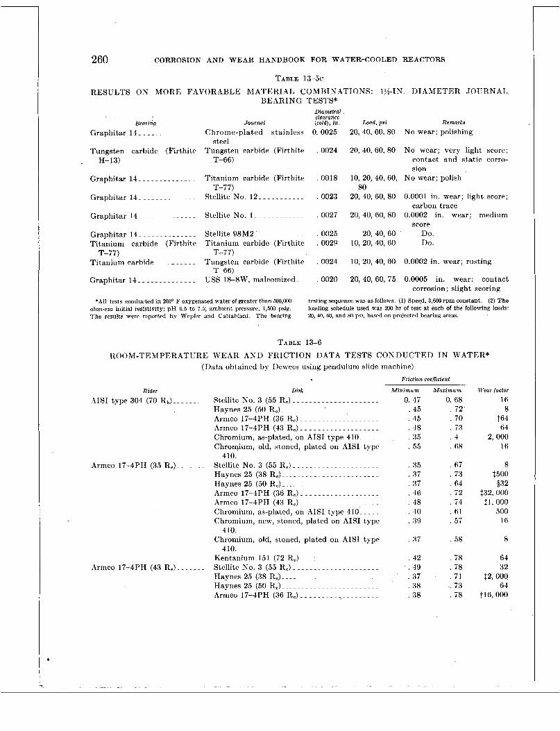
260 CORROSION AND WEAR HANDBOOK FOR WATER-COOLED REACTORS
TABLE 13-5c
BEARING TESTS* RESULTS ON MORE FAVORABLE MATERIAL COMBINATIONS: 134-1N. DIAMETER JOURNAL
Bearing Journal
Diametral clearance (cold), In. Load, psi
Graphitar 14.. ............ Chrome-plated stainless 0. 0025 steel
Tungsten carbide (Firthite Tungsten carbide (Firthitr . 0024 H- 13) T-66)
............. Graphitar 14- Titanium carbide (Firthite . 0018
Graphitar 14- ............. T-77)
Stellite No. 12. ........... 0023
Graphitar 14- .............
Graphitar 14- .............
Stellite No. 1 ............. 0027
Stellite 9 8 M 2 1 ~ ........... 0025 Titanium carbide (Firthite Titanium carbide (Firthite . 0029
Tit,anium carbide- ~ ~ - -. . -. Tungsten carbide (Firthite . 0024
Graphitar 14_ . ............ USS 18-8W, ma1comized.- . 0020
T-77) T-77)
T-66)
20, 40, 60, 80
20, 40, 60, 80
10, 20, 40, 60,
20, 40, 60, 80
20, 40, 60, 80
20,40,60 10, 20, 40, 60
10, 20, 40, 60
20, 40, 60, 75
80
Remarks No wear; polishing
No wear; very light score; contact and static corro- sion
No wear; polish
0.0001 in. wear; light score;
0.0002 in. wear; medium carbon trace
score DO. Do.
0.0002 in. wear; rusting
0.0005 in. wear; contact corrosion; slight scoring
'All tests conducted in ZOOo F oxygenated water of greater than 500,M)O ohm-em initial resistivity; pH 6.5 to 7.5; ambient pressure, 1,500 psig. The results wcre reported by Wepfer and Cattahiani. The bearing
testing sequence was as follows: (1) Speed, 3,600 rpm constant. (2) The loading schedule used was 200 hr of test at each of the following loads: 20, 40, 60, and 80 psi, based on projected bearing areas.
TABLE 13-6
ROOM-TEMPERATURE WEAR AND FRICTION DATA TESTS CONDUCTED I N WATER* (1)ata obtained by I)ewees using pendulum slide machine)
Friction coeficienl
Rider Disk AIS1 type 304 (70 Rb).-. ..... Stellite No. 3 (55 R,) .....................
Haynes 25 (50 R,) .......... -'- ............ Armco 17-4PH (36 R,) ~ - ~ ~ ~ ~ ~ ~ ~ ~ ~ ~ ~ ~ ~~ ~. .
Armco 17-4PH (43 R,) ................... Chromium, as-plated, on AISI type 410.. ... Chromium, old, st,oned, plated on AISI type
Armco 17-4PH (35 R,). ...... Stellite No. 3 (55 R,) ..................... Haynes 25 (38 Ro) . - - . .................... Haynes 25 (50 R,) ........................ Armco 17-4PH (36 R,) ................... Armco 17-4PH (43 R,). ..................
Chromium, as-plated, on AISI type 410'- ~ ~ ~ ~
Chromium, new, stoned, plated on AISI t,ype
Chromium, old, stoned, plated on AISI t,ype
Kentanium 151 (72 R,) ~ ~ ~ 1 ~ ~ ~ ~~~ ~ ~ ~ ~ ~ ~ ~ ~ ~
Stellite No. 3 (55 Rc) . . . - - - - - ............
Haynes 25 (38 R,) ........................ Haynes 25 (50 R,) ........................ Armco 17-4PH (36 R,). ...................
410.
410.
410.
hrmco 17-4PH (43 R,) .......
Minimum 0. 47
. 4 5
. 45
. 48
. 3 5
. 5 5
. 8 5
. 3 i
. 3 i
. 46
. 4 8
. 40
. 89
. 8 7
. 42
. 4 9
. 37
. 38
. 38
Maiimum 0. 68 . 72 . 70 . 73 . 4 . 68
. 67
. 73
. 64
. '72
. i 4
. 6 1
. 5 7
. 58
. 78
. 78
. 7 1 .. 73 . 78
Wear /actor 16 8
t64 64
2,000 16
8 $500
$32,000
500 16
8
64 32
$2,000 64
t l6 , 000
532
$1,000

APPLICATION CONSIDERATIONS O F WEAR 261
TABLE 13-6-Continued Friction coeffrcient
Ridei
7-_
Stellite No. 3 (46 R,) ........_
Haynes 25 (46 Rc). ..........
Chromium plate (honed) on
Inconel-X (28 Rc)-.. ~ ~ ~ ~. . . -.
17-4PH.
Disk Armco 17-4PH (43 R,) - - -. -. ~ ~ ~. ~. . . . . ~. ~
Chromium, as-plated, on AISI 410 ___...... ~
Chromium, old, stoned, plated on AISI 410L Kentanium 151 (72 R,). . . . .. ~. ~-~ .___ .__.
Stellite No. 3 (55 Rc)..-- ....._.._._._....
Chromium, as-plated, on AISI type 410- -. ~.
Chromium, new, stoned, plated on AISI type
Chromium, old, stoned, plated on AISI type
Kentanium 151 (72 R,) -. . . . - -. . -. . ~ ~ ~ ~ ~ ~ ~
Stellite No. 3 (55 R.) .__.__..___.___._._..
Haynes 25 (38 R,) _._._._...__..._..__....
Haynes 25 (50 R,)--.. .___. .__. . ._.___ ~ _ . ~.
Chromium, as-plated, on AISI type -110.. . . . Chromium, new, stoned, plated on AISI type
Chromium, old, stoned, plated on type 410.. Kentanium 151 (72 R,) -. . _. ._. _ ~ _ . . ._ ._. .
Chromium, as-plated, on AISI type 410. - - ~.
Chromium, old, stoned, on AISI type 410.. -
Stellite No. 3 (55 R,) -. __. ~ . ~ . ._._. . . . ._. .
Haynes 25 (38 R,) ___. ._. . . .. .__. ._~ . . . .. .
Haynes 25 (50 R,) ___. _.__. ._____. . -.. .
Armco 17-4PH (36 Re)- - - _..... ~~ .__...._
Chromium, as-plated, on AISI type 410.. . . . Chromium, new, stoned, plated on AISI type
Chromium, old, stoned, plated on AISI type
Kentanium 151 (72 Rc). - 1 .._...__..__.._.
410.
410.
410.
410.
410.
‘Loads, 2.6, 10, and 40 lh; IIertz stress, 1.200 to 5,000 psi; maximum
QPoor compatibility-roughness measurements. velocity, 0.5 in./sec.
REFERENCES 1. R. C. WESTPHAL and J . CLATTER, The Wear and
Friction Properties of Materials Operated in High-temperature Water, Report WAPD-T-64, Dec. 4, 1953.
2. R. C. WESTPHAL and J. CLATTER, The Wear and Friction Properties of Materials Operated in High-temperature Water, American Society of Mechanical Engineers, Paper No. 54-SA-13.
3. .J. W. FLAHERTY and N. R. WHEELOCK, Effect of Test-water Temperature on Ball-bearing. Wear, Report WAP I)-AI)(L)-665 (T DM-5B), July 1, 1955.
4. J. W. FLAHERTY e t al., Effect of Load Variations on Ball-bearing Wear, Evaluation Report E2- BB2, Westinghouse Electric Corp., Clairton Laboratory, Apr. 1 , 1953.
Minimum Maximum 0. 47 0. 66
. 3 9 . 7 1
. 5 9 . 71
. 46 . 64
. 3 4 . 67
. 2 7 . 46
. 37 . 5 5
35 . 48
. 3 7 . 62
. 4 1 . 5 5
. 4 5 . 5 7
. 3 1 . 5
.. 26 . 4 1
. 4 . 61
. 29 . 52
. 26 . 65
. 3 4 . 67
. 4 1 . 63
. 36 . 58
. 5 . 8
. 38 . 5 9
. 4 . 74
. 3 5 . 5 9
. 27 . 57
. 2 7 . 4 5
35 . 48
Wear factor
$64 16,000
32 64 32 64 32
16
32 16 8
516 125 32
16 8
64 64 16
$32,000 532
($1 ......_ ~~
16
32
16 t Rad compatibility-roughness measurements. $Rad compatibility-roughness measurements and photomicrographs.
5. J. C. EAZOR, J. W. FLAHERTY, and F. A. SORENSEN, Effect of Speed of Rotation on Ball-bearing Wear, Report TDM-4A, Westinghouse Electric Corp., Clairton Laboratory, Mar. 15, 19.54.
6. “New Departure Handbook,” Volume 1, 20th Edition, 1950.
7. PAUL COHEN, Effect of Oxygen on STR Materials a t High pH, Particularly Chrome Plating, Re- port WAPD-CP-287, Feb. 16, 1954.
8. J. CLATTER and R. C. WESTPHAL, Wear Test Re- port, Report WAPD-MA-1181, July 1953.
9. W. R I . WEPFER and E. J. CATTABIAKI, Water- lubricated Bearing Development, Report, WAPD-
10. G. T. BURWELL and C. 1). STRANG, On the Empirical Law of Adhesive Wear, J. A p p l . Ph-ys., 23: 18-28 (January 1952).
T-131.


Chapter 14
MANUFACTURING PROCEDURES AFFECTING CORROSION A N D WEAR
Editor-D. J. DEPAUL r'ontributor.s-E. 11. REYO, J. W. BARBOUR
Page
INTRODUCTIOS ..._~~..~---~.--1-------~
GENERAL CLEANLINESS. .. _ _ . ~ ._.__.. ~ _... ~ . .
MACHINING, GRISDIXG, A S D POLISHISG-. . ._. ~.
GRIT AND VAPOR BLASTISG _... ~ ._ ~ ~. ._ ~ -. . . ~ ~
LWBRICATIOX-. . ~. . ~~. . ~ ~ . . ~ ~. . ~ ~ _ . ~ ~. . __.
ACID CLEANING ._._ ~. .. . . . . . ~. . ~ ~. . ~ ~. . _ _ ~ . .
INITIAL CLEANING..- _. . ~ ._. ~ ~. . ~ ._. ~ ~ .. . .__.
I)ECREASING WATER EMPLOYED FOR CLEAXISG.. . ~ ~. . _ ~ _ . ._
DRYING. . ~ . . . ~ ....__.. ~~. ._~. .~. . .~ .... ~ . .
PREPARATION FOR STORAGE A K D S H I P M E S T ~. . . -
INTRODUCTION
263 263 266 266 266 267 2 70 270 270 27 1 27 1
There are many procedures performed during fabrication, assembly, and cleaning which can adversely affect a component or one of its parts (in the following discussion components and parts are also referred to as items) from the point of view of corrosion and wear. For reasons pointed out in chapter 1, i t is considered extremely necessary to minimize all diEculties which might arise in components which woulcl involve the removal or the replacement of items.
Tt is the purpose of this chapter to discuss those procedures which past experience has shown to be areas requiring special attention.
Forms of contamination such as metal chips and t,urnings, metal dust and abrasives from grinding, loose weld spatter, loose scale, and other foreign particles may lodge between bearing surfaces or between parts operated with extremely small clearances, thereby causing ex- cessive wear or complete seizure. Particles may also lodge in small orifices or other restric- tions which could block control lines or prevent valves from seating propwl>. Improper me- (*hanical and chemicd clcaninp ma> rcsult i l l
417017 0--.5--18
..
surface contarnination which causes rusting, rough surfaces, and accelerated corrosive attack, which ma>- OCCLW during cleaning or when the item is put into service. Also, lubricating oils and greases present as contaminants may de- compose under service conditions and, in the case of chloride- and sulfur-bearing cutting oils, ma?- cause either accelerated general corrosion or localized attack on critical surfaces. Apart from their effect on corrosion, small amounts of oil or grease not removed from areas to be welded ma?- alter the composition of weld metal, thereby possiblj- decreasing its strength, or induce porosity or cracking in the weld. These forms of contaminat,ion ma>- also have an appreciahle effect on wear. Localized corrosion on bearing surfaces can also increase the operat,ing torque or even cause complete seizure.
GENERAL CLEANLINESS
The general cleanliness of components rnain- tained during fabrication and installation is considered to be one of the important aspects affecting the integrity of the plant. Although it is not possible to define adequately the extent of cleanliness required for such a system, the desired degree of cleanliness may be obtained hj- defining the specific procedures to be em- ployed i n cleaning items This approach has been very helpful from the point of view of in- spection and quality control, since specific pro- cedures for cleaning can be defined precisely for contractual arrangements
For purposes of discussion, reference to sur- face containirlatiorl made herein is defined as any foreign matcrial which is present as a11
263
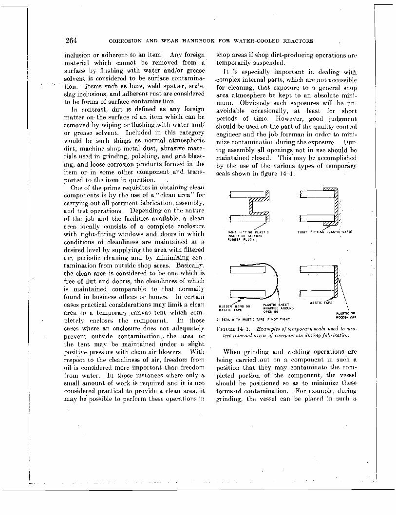
264 CORROSION AND WEAR HANDBOOK FOR WATER-COOLED REACTORS
inclusion or adherent to an item. Any foreign material which cannot be removed from a surface by flushing with water and/or grease solvent is considered to be surface contamina- tion. Items such as burs, weld spatter, scale, slag inclusions, and adherent rust are considered to be forms of surface contamination.
In contrast, dirt is defined as any foreign matter on- the surface of an item which can be removed by wiping or flushing with water and/ or grease solvent. Included in this category would be such things as normal atmospheric dirt, machine shop metal dust, abrasive mate- rials used in grinding, polishing, and grit blast- ing, and loose corrosion products formed in the item or in some other component and trans- ported to the item in question.
One of the prime requisites in obtaining clean components is by the use of a “clean area” for carrying out all pertinent fabrication, assembly, and test operations. Depending on the nature of the job and the facilities available, a clean area ideally consists of a complete enclosure with tight-fitting windows and doors in which conditions of cleanliness are maintained at a desired level by supplying the area with filtered air, periodic cleaning and by minimizing con- tamination from outside shop areas. Basically, the clean area is considered to be one which is free of dirt and debris, the cleanliness of which is maintained comparable to that normally found in business offices or homes. In certain cases practical considerations may limit a clean area to a temporary canvas tent which com- pletely encloses the component. In those cases where an enclosure does not adequately prevent outside contamination, the area or the tent map be maintained under a slight positive pressure with clean air blowers. With respect to the cleanliness of air, freedom from oil is considered more important than freedom from watcr. Tn those instances where only a small amount of work is required and i t is not considered practical to provide a clean area, it may be possible to perform these operations in
. c - . . .. . -
shop areas if shop dirt-producing operations are temporarily suspended.
Tt is especially important in dealing with complex internal parts, which are not accessible for cleaning, that exposure to a general shop area atmosphere be kept to an absolute mini- mum. Obviously such exposures will be un- avoidable occasionally, at least for short periods of time. However, good judgment should be used on the part of the quality control engineer and the job foreman in order to mini- mize contamination during the exposure. Dur- ing assembly all openings not in use should be maintained closed. This may be accomplished by the use of the various types of temporary seals shown in figure 14-1.
TIGHT FITTING -PLASTIC INSERT OR TAPERED RUBBER PLUG (I)
/ RUBBER BAND OR ~ ~ ~ $ ~ D s ~ ~ ~ ~ N D MASTIC TAPE OPENING
TIGHT F l T T l N Q P L I S T l C , tAPl11
a MASTIC TAPE
\ PLASTIC OR _. . WOODEN CAP ( I t SEAL W I T H MASTIC TAPE IF NOT TIGHT
FIGURE 14-1. Examples of temporary seals used to pro- tecl internal areas of components during fabrication
When grinding and welding operations are being carried out on a component in such a position that they may contaminate the com- pleted portion of the component, the vessel should be positioned so as to minimize these forms of contamination. For example, during grinding, the vessel can be placed in such a


266 CORROSION AND WEAR HANDBOOK FOR WATER-COOLED REACTORS
MACHINING, GRINDING, A N D POLISHING
Under ordinar>- circumstances the use of conventional tool steels for machining does not contaminate the surface of chromium-nickel stainless steel items. In certain cases, however, the use of conventional tool steels in not recom- mended. The straight chromium stainless steels, Armco 17-4 PH, and 17-7PH have occasionally shown contamination resulting from iron pickup. If the extent of contamina- tion observed is considered objectionable, then consideration should be given to the use of carbide cutting tools in order to minimize the problem.
Prepared surfaces should be machined to solid metal, free of all slag, scale, spatter, and surface inclusion. Unless otherwise required, as in the case of bearing surfaces, the surface finish on internal parts exposed to the primary coolant normally ranged between 63 and 125 microinches (rms) .
Experience has shown that the use of silica abrasive papers or grinding wheels generally re- sults in contamination of stainless steels in such a manner as to produce localized rust spots. Every effort should be made to prevent or mini- mize the contact of stainless steels with silica. For this reason, onl~7 aluminum oxide or silicon carbide abrasives are recommended for grinding or polishing. For the same reason, silicious bonding materials should not be employed in grinding wheels. Only resin- or rubber-bonded
* wheels are considered satisfactory. Carbide tools should be employed for filing and debur- ring operations in order to avoid iron contam- ination.
GRIT AND VAPOR BLASTING
For the same reasons mentioned above, it is not desirable to employ silica as a grit or vapor blasting material. At one time i t was considered that alumina or silicon carbide grit could be used on stainless steel without any adverse effects; however, experience has shown that even the so-called pure grades *of these materials can occasionally cause surface cori-
tamination. Consequently, where grit blasting is required, i t is followed by acid pickling in order to remove any contamination pickup from th-, process. In certain cases, i t may be possible to use alumina or silicon carbide (but not silica) grit without subsequent acid cleaning. This can be done by means of a grit qualification test which involves blasting sample pieces of stainless steel with the particular batch of grit in question and subsequently exposing the samples to an environment which will reveal contamination. This test is performed by im- mersing the blasted samples in a tank of hot water (150° F) saturated with oxygen. Con- tamination from blasting usually can be de- tected in 6 hr. If this grit qualification test does not reveal any contamination on the test samples, the grit may be employed for the purpose a t hand without subsequent acid clean- ing. It is desirable, however, not to recirculate the grit in such cases.
The size of the blasting material employed was approximatelr 100 mesh for air blasting and 230 mesh for vapor blasting. These par- ticle sizes do not materially affect the finish of items normally possessing a surface finish between 63 and 125 rms.
LUBRICATION
Careful consideration is given to the choice of a lubricant in those applications where i t cannot be completely removed from the item following its use, e. g., threaded joints and pipe-expand- ing operations. Lubricants retained in such crevices may decompose under service condi- tions and form highly corrosive products. In additsion lubricants may introduce into the system constituents which are undesirable from a nuclear point of view. The remarks made herein do not refer to lubricants used in machin- ing or other applivations where the lubricant can subsequently be completely removed. In this connection, it is not safe to assume that lubricants can be effectively removed from crevices and joints by washing with water or by degreasing.
MANUFACTURING PROCEDURES AFFECTING CORROSION AND WEAR 267
The lubricant,s normally employed for appli- cations where possible exposure to primary water exists are graphite-alcohol mixtures, high-purity water, and straight hydroca,rbon oils (consisting only of hydrogen, oxygen, and carbon) where only taaces of t.hc oil are expected to be retained.
Graphite-alcohol mixtures are limitfed t.o use in threaded joints where antigalling is required only during assembly, testing, and installation. Graphite will react with water slowly under service conditions to, form carbon dioxide; con- sequently i t should not be used in applications requiring antigalling properties after exposure to service conditions. In time t,he graphite will be depleted owing to oxidatmion. h4a,t,erials having inherent antigalling characteristics should be used in those applications where it is desirable to minimize galling of items i n tencletl for.remova1 after exposure to service conditions.
Water or straight hydrocarbon oils have beeii successfully used in tube and pipe expanding operations. Although every effort should be made to eliminate trhe ent,rapment of the oil, traces of oil are not considered det.rime.nt.al provided they do not interfere with the pro- duction of sound welds.
ACID CLEANING
Acid cleaning is generally considered un- desirable as a standard fabrication procedure because of the many difficulties which can arise owing to misapplication and improper handling during pickling operations. It is realized that in many cases acid cleaning affords a consider- able advantage; however, the possible con- sequences of mishaps very often outweigh its idvantages. In those instances where acid cleaning is considered necessary, the following procedures and precautions will be helpful i l l
minimizing the dangers . normall)- associatted with this process.
The acid cleaning procedures normally em- ployed for the various materials concerned arc shown in table 14-1.
Tt should be noted that the standard nitric- hydrofluoric acid pickle (treatment A) is not,
recornmended for use with the stabilized strain- less steels i n t he sensitized or welded condition. Ca.ses have been observed where intergranular corrosion has occurred on welded AIS1 type 347 items during normal pickling operatmioris with the above acids. Similarly, this type of attack may also be expect,ed on welded nonsta- bilized 18-8 type stainless steel such as AIS1 type 304. Tri order to insure against inter- gra.nu1a.r attack, the hydrochloric acid picklo (trea.t.ment B) sliould b.e employed. Although this solution will produce a mat te appearance, it does not cause intergranular corrosion.
Special consideration is given tmo the har- clenable st,ainless steels, such as ATST type 410 arid Armco 17-4PH, and 17-7PH in t,he har- dened condit,ion siricc st,ress corrosion cracking may occur after relatively short periods of exposure t'o pickling acids. Tn those cases where it is necessary to pickle, such matrerials i n the liardcned condition, it, is recommended t.1ia.t t,ests be. made to cleterminc if stress crack- ing ca.n occur under the specific conditions whic.11 are being considered for both the material a.nd the acid.
A few cases have been observed where both Inconel and Inc.onc1-X showed intergranular corrosion which resulted from pickling in hot, solutions of nit.ric-hydrofluoric and nitric acid. Therefore, ca.r.c,ful consideration is given t)o the exposure, of these materials to such corrosive
' e,nviro nmen ts. Organic. a.nd inorganic (metals excluded)
items a.re not normally. subjected to the liquids employed for pickling various met,a.ls since t'lie porosity of ma.ny of these materials makes acid removal difficult. Materials such as asbestos,
.graphite, bonded metal carbides, and alumina bodies can be adversely affected because of t,heir porosity. Like.wise extreme care is t,akeri in pickling porous metal filter plate materials.
Spcc.ia1 attention should be given to thr pickling of small-dia.meter tubing since t,hc restrictecl movement of acid within the tubc may akcelera.te corrosion or cause localized pitting. In such cases it is desirable to replacci the acid i n the t,ubc at. least, once cvery 5 mill during t,he opernt,ion. This may be doiic, by

268
AISI type 304 E L 0 AISI type 304 AISI type 308 AISI type 309 AISI type 316 AISI type 347 AISI type 321 Armco 17-4PH Armco 17-7PH
CORROSION AND WEAR HANDBOOK FOR WATER-COOLED REACTORS
Welded or exposed to tempera- tures in the carbide precipita- tion range. “A” treatment may be used if the parts are
1 given a solution anneal by heating to 1,900” F and water quenching prior to pickling.
TABLE 14-1 ACID CLEANING PROCEDURES EMPLOYED WITH VARIOUS MATERIALS
Materials
AISI type 410
. _- Inconel Inconel-X
Monel K-Monel KR-Monel Nickel
Copper Copper-nickel 70-30 Brass Bronze
Carbon and low alloy steel
Acid .reatment
A
B
C
D
E
F
G
Conditions
Nitric acid (1.42 sp. gr.)-- 150 parts by volume Hydrofluoric acid (60’%)-- 15 parts by volume Water _ _ _ _ _ _ _ _ _ _ _ _ _ _ _ _ - _ 835 parts by volume Temperature of solution-- 120’ to 130’ F Time of immersion _ _ _ _ _ _ _ 15 min
Hydrochloric acid (1.2 50 parts by volume
Water _ _ _ _ _ _ _ _ _ _ _ _ _ _ _ r _ _ 50 parts by volume Temperature of solution-.. 130’ to 150” F Time of immersion- - - - 15 min [NoTE.-In some cases a black deposit will result
from this bath. It can be removed by dipping the part in nitric acid (1.42 sp. gr.) ‘room temperature.]
sp. gr.).
Same as “A” above except that the time of immersion is 5 min
Same as “A” above except that the temperature is between 70’ and 100’ F
Sulfuric acid (1.83 sp. gr.)- 95 parts by volume Water _ _ _ _ _ _ _ _ _ _ _ _ _ _ _ _ _ _ 1,000 parts by vol-
Sodium nitrate (crude)--- 34 lb per gallon Common salt (NaC1) - - - - 1 lb per gallon Temperature of solution-- 180’ to ,190’ F Time of immersion- - - - - - 30 min
ume
Sulfuric acid (1.83 sp. gr.) - 70 parts by volume Sodium dichromate- - - - - - 2 percent by weight Water _ _ _ _ _ _ _ _ _ _ _ _ _ _ _ _ _ _ 1,000 parts by vol-
ume Temperature of solution-- 100’ t o 125’ F Time of immersion- - - - - - 30 min .
Hydrochloric acid.. - - - - - - 11 parts by volume Water _ _ _ _ _ _ _ _ _ _ _ _ _ _ _ _ _ _ 89,parts by volume Rodine #60_ - - - - - - - - - - - - 0.3 t o 0.5 (by weight) Temperature of solution-- 120’ to 150’ F Time of immersion - - - - - - 10 to 20 min

MANUFACTURING PROCEDURES AFFECTING CORROSION AND WEAR 269
raising the tubes out of the acid in such a manner that the acid is adequately drained. In addition, immersion should be done in a manner that will prevent the formation of air pockets.
Although it is considered undesirable to pickle items containing crevices, circumstances occasionally dictate the need for acid cleaning. When acid cleaning must be used on items with crevices, there are a number of precautions that are taken in order to minimize the type of damage which may result from pickling.
Pickling of units or parts with crevices requires special atten tion in order to minimize entrapment of acid or to ensure complete re- moval of acid from crevices. Entrapment of acid in crevices can be minimized considerably by wetting and filling the crevices with water prior to exposure to acid. Under these condi- tions acid can only reach the inside of the crevice by diffusion, which will be very slight because of the short exposure time. Following the pickling operation, crevice-bearing items are immersed in distilled water between 150' and 200' F for a period not less than 6 hr. At the end of this period the item is drained and litmus paper is placed immediately adjacent to the mouth of crevices in order to detect the presence of any residual acid. If the litmus paper showes a change in color indicating acid the immersion treatment is repeated.
In addition to crevices, the bearing surfaces of a unit may also require special 1 attention during pickling. Experience has shown that the pickling procedures recommended in table 14-1 do not adversely affect the surface finish proper- ties of the Stellites and industrial hard chro- mium plate. Bearing surfaces made of AIS1 type 410 stainless steel should be masked off during acid treatment since the finish on such parts can be substantially changed. In such cases adequate protection has been afforded to bearing surfaces by masking with liquid neo- prene paint. This preparation can be removed with toluol, xylol, or acetone following the completion of the pickling operation.
Because of the toxicity of acid fumes, pickling baths are covered with wooden or rubberized
steel exhaust hoods. In most cases the baths can best be heated by the use of stainless steel immersion heaters. Some means of agitation of the solution or the part being cleaned should be provided. Where large quantities of nitric- hydrofluoric acid solutions are used, the con- tainers may be made of carborundum brick supported by a steel tank with % in. of rubber or neoprene covering both the inside and the outside of the brick. Large quantities of the sulphuric acid solution can best be handled in lead-lined steel tanks or in acid-resisting brick lined tanks covered with asphalt or Bitumastic paint. Where small volumes of both acid solu- tions are used infrequently, stainless steel or glass equipment is used.
The information discussed so far has been in connection with the use of acid cleaning during fabrication of individual items or complete units. The use of acid cleaning for these operations has not created any serious problems since, as a matter of policy, acid cleaning has been avoided wherever possible. However, there is one area of considerable practical im- portance where the exposure of components to pickling solutions cannot be readily avoided.
This problem is in connection with the pos- sible adverse effects of uranium fuel-element ruptures in a water-cooled nuclear reactor. Such a failure could increase the radioactivity level in the reactor water to a level higher than that which was anticipated in initially determin- ing the thickness of shielding required during the design stage.
Since the greatest portion of insoluble solids in the primary system is deposited on the con- tainer walls, i t is difficult to remove this ma- terial by simply flushing the system. A pre- liminary analysis of the problem indicates that acid cleaning is the only feasible method of decontaminating the primary system in the event that it should be required as a result of fuel-element rupture. The problems associated with such an undertaking are extremely com- plex and beyond the scope of this handbook. The problem is considered to be twofold: (1) finding an acid which will decontaminate and not have any adverse effects on materials, and
'
270 CORROSION AND WEAR HANDBOOK FOR WATER-COOLED REACTORS
(2) the physical and mechanical problem in circulating the solution and subsequently re- moving i t completely from all areas. Initial studies have indicated that, for one reason or another, none -of the standard solutions shown in table 14-1 are completely satisfactory. Con- sequently, work is presently in progress to find a suitable acid or combination of acids which could be circulated through the reactor for purpose of decontamination and which would not have any adverse effects on the materials or the components in the system. Consideration is being given to the use of citric acid. How- ever, there is insufficient information on this subject to date to warrant a discussion a t this time.
-
INITIAL CLEANING
The cleaning operations normally employed can be divided into two main categories. The first phase consists of initial cleaning procedures on individual items following final machining or fabrication. These involve the removal of heavy grease and dirt, followed by scrubbing with a suitable soap and water and a hard bristle brush or by steam cleaning. The second
. phase of cleaning consists of a degreasing operation which is usually performed on in- dividual fabricated items prior to assembly in order to remove traces of oil not removed during initial cleaning and/or oil picked up from handling.
DEGREASING
The solvents normally employed for degreas- ing are acetone, inhibited trichlorcthylene, in- hibited perchlorethylene, and alcohol. Depend- ing on the size and complexity of the part being cleaned, degreasing is carried out by vapor degreasing, immersion in hot or cold solvent, or by swabbing with a clean cloth moistened with the solvent. The last traces of grease can best be removed by a combination of exposure to the solvent together with vigorous rubbing with a clean cloth. This is especially true with the use of cold solvent.
Since it is not always possible to remove liquids entrapped in crevices, the choice of a particular solvent is very important. All the solvents mentioned above decompose under service conditions. The ’ chloride-bearing sol- vents can b e ” extremely corrosive even a t slightly elevated temperatures. Consequently, these types of solvents are not used on parts containing crevices. In such cases acetone or alcohol can be employed since they are very volatile, leave little or no residue, and their decomposition products are considered to have no adverse effect on corrosion or wear. I t is desirable to rinse degreased items with water before the solvent has dried. The purpose of this rinse is to “mechanically” wash off the last traces of solvent which is laden with oil. Clean solvent is also used for this operation. This will minimize the slight amount of residue which is occasionally observed on degreased items.
WATER EMPLOYED FOR CLEANING
The purity of water employed in cleaning operations is considered to be important with regard to the ultimate cleanliness of the unit. Waters with a high solids content can leave harmful deposits on the surface of a metal after drying has occurred. In many cases, depend- ing on the specific chemistry of the water, deposits remaining after drying will not. re- dissolve when subsequently washed in water. This is attributed to the formation of insoluble carbonates resulting from the direct exposure of water residues to the air. Such deposits are considered harmful for two reasons. First, and uppermost in importance, they may intro- duce certain elements into the primary coolant which are detrimental from a nuclear point of view. Second, they could affect the corrosivity of the primary coolant if present ‘in large quantities.
It is realized that these remarks do not have a significant bearing in those applications where the total internal area of a component is small. However, it should be pointed out that some components, such as the main heat exchangers may occupy a large fraction of the total primary

MANUFACTURING PROCEDURES AFFECTING CORROSION AND WEAR 27 1
plant area. Therefore, improper handling of this one component could grossly affect initial plant operating conditions. In addition, the cu- mulative effect of numerous small components cannot be overlooked. .
Consequently, although tap water is em- ployed for many initial cleaning operations, the items are rinsed with high-purity wat,er before the tap water is allowed to dry.
The quality of high-purity water considered satisfactory for cleaning operations is defined as distiIled or demineralized water with a maxi- mum total solids content (soluble and insolu- ble) of 10 ppm, and a pH between 6 and 8.
DRYING
Drying is considered essential in those cases where a comp,onent or any part thereof will rust when exposed to water or high humidity during fabrication, storage, and shipment and in those applications where water must be removed in order to adequately perform leak tests. Units and parts which will not rust under these con- ditions are normally dried by draining and air drying, drying with hot air blowers or by wiping with clean cloths in those cases where all surfaces are accessible. Small amounts of moisture which may be retained by employing such procedures do not adversely affect the unit or the system in which it is installed. However, units and parts which are expected to rust under these conditions are thoroughly dried. 1 The following two procedures have been successfully employed where absolute dryness is required. .One-method involves oven drying and the other utlizes vacuum techniques.
Oven drying is normally carried out by placing the item in an oven maintained a t a temperature between 250' and 300' F. Inlet and outlet pipes or suitable hose attachments are provided on the unit so that i t can be flushed with an inert gas (-40° dewpoint), such as nitrogen. After the unit has reached the temperature of the oven, sufficient gas is introduced into the unit to completely replace the moisture-laden air. Following the completion of the flushing operation, the oven is turned off, and the unit is
, I
allowed to remain sealed for 8 hr, after which a dewpoint reading is taken on the gas in the unit to determine the extent of dryness. If the dewpoint of the gas in the unit is equal to or less than -40' F, the unit is considered dry. If the dewpoint is above -40' F, additional drying is employed until the desired degree of dryness is obtained.
Vacuum drying is normally carried out by evacuation of the unit, or a container in which the unit is placed, to a pressure of 0.1 mm. An acetone-dry ice cold trap is incorporated into the system in order to detect small quan- tities of moisture. In order to insure adequate removal there should be no water in the trap at a pressure of 0.1 mm.
Occasionally, freezing of the water may occur during evacuation, especially in units with complex internal parts. In such cases, freezing is eliminated by providing heat to the vessel during the evacuation. The absence of frozen water is determined by allowing the unit to remain a t the vacuum pressure for 30 min after the vacuum pumps have been disconnected from the unit. If the pressure does not rise during this period, there is good assurance that ice is not present. The cold trap may also be used to .detect freezing.
PREPARATION FOR STORAGE AND SHIPMENT
In order to maintain the degree of cleanliness desired in cleaned components, i t is necessary that they be adequately protected during storage and shipment. For this purpose many regulations, have been established to cover the various types of components involved and the service for which they are intended. In most cases, the preparation for storage is the same as for shipment. The preparations are sub- divided into three major categories: (1) com- ponents sealed in metal containers, (2) com- ponents sealed in moisture-vapor-proof enve- lopes, and (3) large components having a few openings which can readily be sealed off with expandable plugs.

272 CORROSION AND WEAR HANDBOOK FOR WATER-COOLED REACTORS
The air in packaged items made of materials which will not rust when exposed to water or the atmosphere, e. g., 18-8 type stainless steels, is not purged with an inert gas. However, packaged items made of materials which will rust, e. g., carbon steel, are purged and main- tained at 10 psig.
Large components having an internal surface that cannot be closed off completely by simply
USE P IPE FOR PRESSURIZING GASKET AND DISC
TO 1/32" LESS THAN BORE/
OR ROO FOR PLAIN BOLT D IAMETER 1/54"
-
LOCK
MECHANICALLY S E A L E D
I
FIGURE 14-3. Expandable plug employed for sealing components.
sealing a few openings are packaged in metal containers with rubber gasket seals. When required these containers are normally purged with nitrogen having a dewpoint of -40' F or lower. The purging operation can be carried out effectively by pressurizing the container to about 10 psig with the inert gas and venting to atmospheric pressure for a t least four complete cycles. The containers are not maintained above atmospheric pressure unless the materials in the components are susceptible to rusting under humid conditions.
Small components and spare parts having openings which cannot be completely closed off by sealing are normally packaged in polyethy- lene envelopes made of sheet material having a minimum thickness of 0.'004 in. The excess' air in these bags is evacuated either manually or mechanically prior to complete heat sealing. It is very important that special attention be given to the handling,of components sealed in this manner since the envelopes can be ruptured if not packed properly. Therefore, adequate cushioning should be provided during the final packing operation. *
Large components with internal surfaces that can readily be sealed from the outside by plug- ging several openings are sealed by means of expandable Tubber plugs. By this method the component itself forms a part of the moisture vapor-proof barrier, with the complete sealing being effected by the use of plugs on all exter- nal openings. The type plug employed is shown schematically in figure 14-3. Basically it consists of a solid rubber disk about one-fourth to one-half in. in thickness, which when com- pressed between two metal plates expands in diameter and seals the opening. When re- quired components sealed with expanded plugs are purged in the same manner described above for component packaging in metal containers. As previously indicated, only those components containing parts that would rust in the atmos- phere are purged and pressurized.
All items are packed in accordance with requirements consistent with the following Government specifications :
'More recently this procedure has been adopted for components which were originally packaged in metal containers.

Appendix A
CONTRIBUTING AUTHORS
J. W. BARBOUR
H. F. BEEGHLY
R. U. BLASER
M. C. BLOOM
C. R. BREDEN
W. F. BRINDLEY
P. E. BROWN
E. G. BRUSH
E. J. CALLAHAN
J. G. CHRIST
F. E. CLARKE
I. COHEN
P. COHEN
S. C. DATSKO
T. S. DEFAIL
D. J. DEPAUL
N.' B. DEWEES
D. L. DOUGLAS
R. T. ESPER
J. W. FLAHERTY
W. L. FLEISCHMANN
W. Z. FRIEND
G. E. GALONIAN
J. GLATTER
Westinghouse Electric Cow.
Westinghouse Electric Corp.*
Babcock & Wilcox Co.
Naval Research Laboratory
Argonne National Laboratory
Westinghouse Electric Corp.
Westinghouse Electric Corp.
General Electric Co.
General Electric Co.
Westinghouse Electric Corp.
U. S. Naval Engineering Experiment Station
Westinghouse Electric Corp.
Westinghouse Electric Corp.
Babcock & Wilcox Company
Westinghouse Electric Corp.
Westinghouse Electric Corp.
Westinghouse Electric Corp.
General Electric Go.
Westinghouse Electric Corp.
Westinghouse Electric Corp.
General Electric Co.
1nternationa;l Nickel Co., Inc.
General Electric Co.
Westinghouse Electric Corp. See footnotes on p. 274.
H. L. GLICK
E. R. HARRIS
J. R. HUNTER
R. F. KOENIG
M. KRUFELD
C. J. LANCASTER
R. D. LEGGETT
H. K. LEMBERSKY
E . LIEBERMAN
W. MCALLISTER
R. L. MEHAN
J. J. OWENS
E. P. PARTRIDGE
S. PETACH
E. M. RENO
A. H. ROEBUCK
M. C. ROWLAND
B. G. SCHULTZ
J. M. SEAMON
R. S. SHANE
A. SQUIRE
R. STEIN
W. C. STEWART
D. E. TACKETT
Westinghouse Electric Corp.
General Electric Go.
Westinghouse Electric Corp.
General Electric Co.
Naval Research Laboratory
U. S. Naval Engineering Experiment Station
Westinghouse Electric Corp.
Westinghouse Electric Corp.
Westinghouse Electric Corp.
Westinghouse Electric Corp.
General Electric Co.
Babcock & Wilcox Company
Hall Laboratories, Inc.
Westinghouse Electric Corp.
Westinghouse Electric Corp.
Continental Oil Company * * General Electric Co.
Westinghouse Electric Corp.
Westinghouse Electric Corp. t
Westinghouse Electric Corp.
Westinghouse Electric Corp.
Westinghouse Electric Corp. $
U. S. Naval Engineering Experiment Station
Westinghouse Electric Corp.5
273
274 CORROSION AND WEAR HANDBOOK FOR WATER-COOLED REACTORS
D. E. THOMAS
H. V. TYDINGS
I. H. WELINSKY
R. C. WESTPHAL
Westinghouse Electric Corp.
U. S. Naval Engineering Experiment Station
Westinghouse Electric Corp.
Westinghouse Electric Corp.
D. E. WHITE
D. M. WROUGHTON Westinghouse Electric Corp.
Westinghouse Electric Corp. *On loan from Jones & Laughlin Steel Corp. **Formerly with Argonne Nntional Laboratory. t On loan from National Aluminate Corp. :Presently with the New York State educational system. #On loan from Newport News Shipbuilding & Dry Dock Do
\

Appendix B
GLOSSARY OF TERMS
activity, long-lived Radioactive elements possessing a long half life (on the order of days or years).
activity, residual The radioactivity in primary sys- tems remaining after shutdown of a nuclear reactor.
activity, short-lived Radioactive elements possessing a short half life (on the order of seconds or minutes).
alkali-phosphate treatment Chemical treatment of boiler feed water for the purpose of reducing corro- sion and deposition. The treatment involves ap- proximately 50 ppm of phosphate (as POT) and sufficient alkali t o raise the p H to 10.5. These are nominal figures and vary slightly depending on the application.
ANL Argonne National Laboratory, Chicago, 111. anode The electrode of an electrolytic cell at which
oxidation occurs. In corrosion processes it is an area that is usually corroded.
American Society of Mechanical Engi- neers Boiler and Pressure Vessel Code.
High points or irregularities that exisc even on finely finished surfaces. These play a major role in friction and wear.
ASME Code
asperities
ASTM blowdown
American Society for Testing Materials. The process by which the total solids con-
tent of boiler water is maintained at a tolerable level. Quantities of boiler water with high solids are periodically replaced with makeup water contain- ing a low solids content.
BMI boiler water The water employed in boilers which
provides steam to operate the turbines. It is nor- mally treated (see alkali-phosphate treatment) t o inhibit corrosion and t o minimize deposits.
buildup, crevice corrosion Accelerated localized attack observed at the perimeter of a contact area resulting from crevice corrosion.
The electrode of an electrolytic cell at which reduction occurs. In corrosion processes i t is the area tha t is usually not corroded.
carbon steel Steels which do not contain alloying elements and whose properties are determined by the carbon content, e. g. , ASTM A212.
caustic embrittlement Stress corrosion cracking of carbon steel which is observed in boiler waters treated with alkali.
cc/kg Cubic centimeters of gas per kilogram of water (STP).
clean area Area employed for the final fabrication, assembly, and cleaning of primary components.
Battelle Memorial Institute, Columbus, Ohio.
cathode
The degree of cleanliness comparable t o tha t gener- ally observed in homes and offices.
contact corrosion coolant, primary In the pressurized-water nuclear
reactor the (radioactive) coolant fluid which comes directly in contact with the reactor core and extracts heat which is later transferred to the secondary system through the main steam generators.
coolant, secondary In the pressurized-water nuclear reactor, the (nonradioactive) coolant fluid which removes heat directIy from the main steam genera- tors and which forms steam to drive the turbines.
The central part of a nuclear reactor which con- tains the uranium or other fissionable elements and where fission heat is released. The primary source of heat in the nuclear reactor.
The transfer of atoms in a metal from the metallic to the ionic state. In aqueous solutions i t involves the formation of soluble and insoluble com- pounds of the metal being corroded.
corrosion fatigue Accelerated localized corrosive at- . tack which causes cracking to occur in areas where a
metal is subjected to cyclic stresses. crevice (contact) corrosion See buildup, crevice cor-
rosion. crud The insoluble corrosion products formed in the
primary coolant of water-cooled nuclear reactors. crud level The quantity of crud per unit volume of the
primary coolant. It is normally expressed as parts per million (ppm).
A device inserted directly into the pri- mary coolant system for the purpose of collecting sample quantities of crud.
curie The quantity of a radioactive species decaying at a rate of 3.7X10¹⁰ disintegrations per second. It is also defined as 3.7X1OLo gamma or beta disintegra- tions per second.
decontamination (for radioactivity) The process em- ployed t o reduce the activity resulting from radio- active deposits in components or a system t o a toler- able level. Mechanical and chemical cleaning methods are employed.
degassed water -Low oxygen-bearing water employed for corrosion tests to simulate low oxygen conditions in the reactor. The oxygen content for degassed water was normally 0.05 t o 0.1 cc/kg.
High-purity water obtained by the use of ion exchangers.
See buildup, crevice corrosion.
core
corrosion
Crud probe
demineralized water
275
276 CORROSION AND WEAR HANDBOOK FOR WATER-COOLED REACTORS
descaling (corrosion specimens) A procedure of re- moving corrosion products from the surface of a cor- rosion test specimen. It is employed to obtain weight-change measurements of the amount of metal converted to oxide during exposure to a cor- rosiv? enviromnent.
An apparatus which provides cir- culation of a test water past specimens under con- trolled water chemistry, velocity, and temperature.
erosion-corrosion The loss of metal resulting from the combined action of corrosion and erosion.
feed water Term employed in boiler water technology to signify the relatively pure water which is con- densed from the steam in the turbine and which is fed back t o the main system.
Accelerated attack of metal which occurs at the interface between two surfaces in contact and is directly attributable to the presence of vibra- tions which produce slip between adjacent surfaces.
fuel element Individual segments of a core containing the fissionable material.
galvanic corrosion Accelerated corrosive attack oc- curring at the point of contact between two dissimilar metals, resulting from the difference in electrical potentials produced by the two metals in contact.
The uniform loss of metal as.a result of corrosive attack.
The time required for the number of radio- active nuclei of a given kind, or for their activity, t o decay to half their initial value. The time is inde- pendent of the radioactivity present.
Arbitrarily defined as water having a minimum resistivity of 500,000 ohms-cm, with a total solids content of less than 2 ppm and a p H ranging between 6 and 8.
Accumulations of radioactive particles within the primary system, requiring pro- tective shielding for plant operating personnel.
Loss in ductility of a metal or alloy resulting from the adsorption of nascent hydrogen.
Test water used t o determine the effect of dissolved hydrogen on corrosion and wear in a simulated reactor environment. This water is prepared by adding known amounts of hydrogen to degassed water (see degassed water).
induced radioactivity That radioactivity which is induced in a material as a result of exposure t o radiation emanating from the core.
dynamic test loop
fretting corrosion
general corrosion
half life
high-purity water
hot spots (radioactive)
hydrogen embrittlement
hydrogenated water
in-pile tests See out-of-pile test. intercrystalline cracking See intergranular cracking. intergranular (intercrystalline) cracking Cracking
which occurs at the boundaries between the grains of a metal (see transgranular cracking).
intergranular corrosion A special form of localized corrosion in which accelerated corrosive sttack occurs only at the grain broundary of a metal.
ion exchanger A unit employed to purify water. The water is circulated through a column containing a resin or mixture of resins. These resins replace foreign ions (anions and cations) in the water with hydrogen and hydroxyl ions, which, in turn, combine to form water.
Knolls Atomic Power Laboratory, Schenectady, N. Y. This installation is operated by the General Electric Co. for ‘the Atomic Energy Commission.
Kirkendall experiment Experiments conducted t o determine the corrosion behavior of iron in high- temperature water, e. g., diffusion of iron ions through the oxide film.
localized corrosion Nonuniform loss of metal as a result of corrosive attack, e. g., pitting.
loop See dynamic test loop. low alloy steel
KAPL
Steels which possess special properties that are developed by the addition of alloying ele- ments, e. g., ASTM A213.
low oxygen water Test water employed t o simulate conditions where low oxygen-bearing water was expected in service. Normally ranged between 0.1 and 1.0 cc/kg.
mechanical filter Filter employed t o remove insoluble corrosion products from the primary coolant system. It consisted of numerous porous stainless-steel filter units having a pore size of 20p.
MDM Term employed t o represent the corrosion rate of a material, milligrams of metal corroded per square decimeter per month.
microcurie One-millionth of a curie (see curie). mil In linear measure, 1 mil equals one one-thousandth
NaK Designation employed t o signify a mixture of
NEES United States Naval Engineering Experiment Station, Annapolis, Md.
NRTF Naval Reactor Test Facility, Arco, Idaho. This installation is operated by Westinghouse Elec- tric Corp. for the Atomic Energy Commission.
Test water employed t o simulate conditions where high oxygen-bearing water was expected in service. Normally ranged between 1 and 30 cc/kg.
Term employed t o differentiate be- tween tests conducted under reactor radiation con- ditions (in-pile-tests) and those performed without radiation (out-of-pile tests).
pressurized-water reactor Another term employed for water-cooled nuclear reactor.
precipitation-hardening stainless steel Stainless steels which are hardened by a constituent precipitating from a n alloy during a specific heat treatment.
of a n inch (0.001 inch).
8 sodium and potassium
oxygenated water
out-of-pile test
primary coolant See coolant, primary. radioactivity The spontaneous emanation of electro-
magnetic waves and/or particles resulting from natural or induced nuclear instability or excitation.

GLOSSARY OF TERMS 277 reference water Water intended to simulate, for test
purposes, the coolant in the primary system of a water-cooled nuclear reactor (usually without the presence of radioactive flux).
restraint type bearings Bearing such as sleeve and journal wftere corrosion products in the annulus exert a radial force that restrains relative movement of the members. This force m y produce increased torque or result in seizure.
Root merm q u a r e , i. e., the square root of the arithmetic average of the squares of a group of numbers.
sensitization (chromium carbide) Exposure of an unstabiliaed austenitic stainless steel to tempera- tures which will cause& precipitation of chromium carbide at the grain boundaries. The material is
. thus rendered susceptible to intergranular attack in certain environments.
simulated component tests Tests conducted on a mechanism simulating a reactor component under conditions approximating these in service.
stainless steels Stainless steels are divided into three broad categories, the austenitic, ferritic, and marten- sitic types. The austenitic stainless steels generally refer t o the 18 chromium-8, nickel type, e. g., AISI type 304 or 347. The ferritic stainless steels gener- ally contain 12 percent or more of chromium and are not hardenable by heat treatment, e. g., AISI type 405 or 430. The martensitic stainless steels generally contain 12 percent or more of chromium and are hard- enable by heat treatment, e. g., AISI type 410 or 420.
stress corrosion Accelerated localized corrosive attack which causes cracking t o occur in highly stressed areas of a metal.
rms
structural materials (main) The main materials used in the fabrication of pressure-containing parts of the primary system.
surface contamination Arbitrarily defined as any for- eign material that is present as an inclusion or ad- herent t o a surface; e. g., any foreign material which cannot be removed from a surface by flushing with water and/or grease solvent is considered t o be surface contamination.
Barrier surrounding the core for the purpose of absorbing radiation (principally neutrons) which would otherwise overheat the pressure vessel walls.
transcrystalline cracking See transgranular cracking. transgranular (transcrystalline) cracking Cracking
tha t occurs through the grains of a metal (see inter- granular cracking).
transported corrosion products Insoluble corrosion products deposited at certain locations other than those where the products were initially formed.
treated boiler water Boiler feed water that has been treated with alkali and phosphate to inhibit corrosion and deposition (see alkali-phosphate treatment).
thermal shield
U. S. P. validity factors
United States Pharmacopoeia. Method for representing the overall
significance of corrosion rates given in the Handbook. This factor represents the weighted importance of consistency of results, number of samples, and dura- tion of test.
Westinghouse Atomic Power Division, Bettis Plant, Pittsburgh, Pa. This plant is operated by the Westinghouse Electric Corp. for the Atomic Energy Commission.
wear factor A numerical method of ranking materials by wear resistance. The factor varies directly with wear.
WAPD

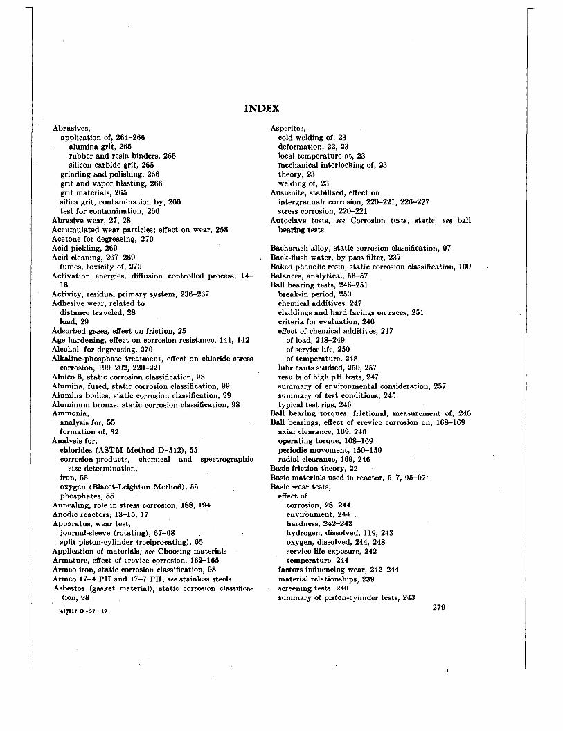
INDEX
Abrasives, application of, 264-266
alumina grit, 265 rubber and resin binders, 265 silicon carbide grit, 265
grinding and polishing, 266 grit and vapor blasting, 266 grit materials, 265 silica grit, contamination by, 266 test for contamination, 266
Abrasive wear, 27, 28 Accumulated wear particles; effect on wear, 258 Acetone for degreasing, 270 Acid pickling, 269 Acid cleaning, 267-269
Activation energies, diffusion controlled process, 14-
Activity, residual primary system, 236-237 Adhesive wear, related to
distance traveled, 28 load, 29
fumes, toxicity of, 270
16
Adsorbed gases, effect on friction, 25 Age hardening, effect on corrosion resistance, 141, 142 Alcohol, for degreasing, 270 Alkaline-phosphate treatment, effect on chloride stress
Alnico 6, static corrosion classification, 98 Alumina, fused, static corrosion classification, 99 Alumina bodies, static corrosion classification, 99 Aluminum bronze, static corrosion classification, 98 Ammonia,
corrosion, 199-202, 220-221
analysis for, 55 formation of, 32
chlorides (ASTM Method D-512), 55 corrosion products, chemical and spectrographic
iron, 55 oxygen (Blacet-Leighton Method), 55 phosphates, 55
Annealing, role in' stress corrosion, 188, 194 Anodic reactors, 13-15, 17 Apparatus, wear test,
Analysis for,
size determination,
journal-sleeve (rotating) , 67-68 split piston-cylinder (reciprocating) , 65
Application of materials, see Choosing materials Armature, effect of crevice corrosion, 162-165 Armco iron, static corrosion classification, 98 Armco 17-4 PH and 17-7 PH, see stainless steels Asbestos (gasket material), static corrosion classifica-
tion, 98 41?017 0 - 57 - 19
Asperites, cold welding of, 23 deformation, 22, 23 local temperature at, 23 mechanical interlocking of, 23 theory, 23 welding of, 23
Austenite, stabilized, effect on intergranualr corrosion, 220-221, 226-227 stress corrosion, 220-221
bearing tests Autoclave tests, see Corrosion tests, static, see ball
Bacharach alloy, static corrosion classification, 97 Back-flush water, by-pass filter, 237 Baked phenolic resin, static corrosion classification, 100 Balances, analytical, 56-57 Ball bearing tests, 246-251
break-in period, 250 chemical additives, 247 claddings and hard facings on races, 251 criteria for evaluation, 246 effect of chemical additives, 247
of load, 248-249 of service life, 250 of temperature, 248
lubricants studied, 250, 257 results of high pH tests, 247 summary of environmental consideration, 257 summary of test conditions, 245 typical test rigs, 246
Ball bearing torques, frictional, measurement of, 246 Ball bearings, effect of crevice corrosion on, 168-169
axial clearance, 169, 246 operating torque, 168-169 periodic movement, 150-159 radial clearance, 169, 246
Basic friction theory, 22 Basic materials used in reactor, 6-7, 95-97 Basic wear tests,
effect of corrosion, 28, 244 environment, 244 hardness, 242-243 hydrogen, dissolved, 119, 243 oxygen, dissolved, 244, 248 service life exposure, 242 temperature, 244
factors influencing wear, 242-244 material relationships, 239 screening tests, 240 summary of piston-cylinder tests, 243
279
I
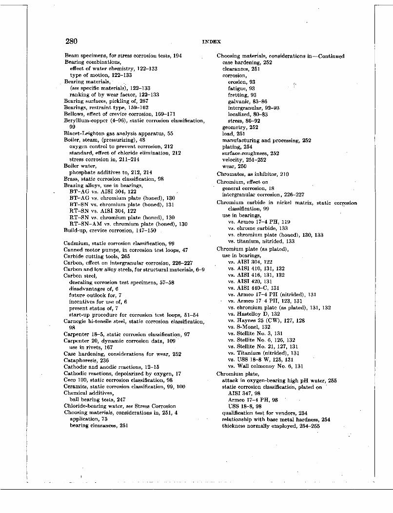
280 INDEX
Beam specimens, for stress corrosion tests, 194 Bearing combinations,
effect of water chemistry, 122-133 type of motion, 122-133
(see specific materials), 122-133 ranking of by wear factor, 12S133
Bearing materials,
Bearing surfaces, pickling of, 267 Bearings, restraint type, 159-162 Bellows, effect of crevice corrosion, 169-171 Beryllium-copper (4-96), static corrosion classification,
Blacet-Leighton gas analysis apparatus, 55 Boiler, steam, (pressurizing), 48
oxygen control to prevent corrosion, 212 standard, effect of chloride elimination, 212 stress corrosion in, 211-214
phosphate additives to, 212, 214
99
Boiler water,
Brass, static corrosion classification, 98 Brazing alloys, use in bearings,
BT-AG VS. AISI 304, 122 BT-AG vs. chromium plate (honed), 130 BT-SN vs. chromium plate (honed), 131
RT-SN vs. chromium plate (honed), 130 RT-SN-AM vs. chromium plate (honed), 130
RT-SN VS. AISI 304, 122
Build-up, crevice corrosion, 147-150
Cadmium, static corrosion classification, 99 Canned motor pumps, in corrosion test loops, 47 Carbide cutting tools, 265 Carbon, effect on intergranular corrosion, 226-227 Carbon and low alloy steels, for structural materials, 6-9 Carbon steel,
descaling corrosion test specimens, 57-58 disadvantages of, 6 future outlook for, 7 incentives for use of, 6 present status of, 7 start-up procedure for corrosion test loops, 51-54
Carnegie hi-tensile steel, static corrosion classification, 98
Carpenter 18-5, static corrosion classification, 97 Carpenter 20, dynamic corrosion data, 109
Case hardening, considerations for wear, 252 Cataphoresis, 236 Cathodic and anodic reactions, 12-15 Cathodic reactions, depolarized by oxygen, 17 Ceco 100, static corrosion classification, 98 Ceramics, static corrosion classification, 99, 100 Chemical additives,
Chloride-bearing water, see Stress Corrosion Choosing materials, considerations in, 251, 4
use in rivets, 167
ball bearing tests, 247
application, 75 bearing clearances, 251
Choosing materials, considerations in-Continued case hardening, 252 clearances, 251 corrosion,
erosion, 93 fatigue, 93 fretting, 93 galvanic, 83-86 intergranular, 92-93 localized, 80-83 stress, 86-92
geometry, 252 load, 251 manufacturing and processing, 252 plating, 254 surface>roughness, 252 velocity, 251-252 wear, 250
Chromates, as inhibitor, 210 Chromium, effect on
general corrosion, 18 intergranular corrosion, 226-227
Chromium carbide in nickel matrix, static corrosion classification, 99
vs. Armco 17-4 PH, 119 vs. chrome carbide, 133 vs. chromium plate (honed), 130, 133 vs. titanium, nitrided, 133
use in bearings,
Chromium plate (as plated), use in bearings,
vs. AISI 304, 122 vs. AISI 410, 131, 132 vs. AISI 416, 131, 132 vs. AISI 420, 131 vs. AISI 4 4 0 4 , 131 vs. Armco 17-4 PH (nitrided), 131 vs. Armco 17-4 PH, 123, 131 vs. chromium plate (as plated), 131, 132 vs. Hastelloy D, 132 vs. Haynes 25 (CW), 127, 128 vs. S-Monel, 132 vs. Stellite No. 3, 131 vs. Stellite No. 6, 126, 132 vs. Stellite No. 21, 127, 131 vs. Titanium (nitrided), 131
vs. Wall colmonoy No. 6, 131 VS. USS 18-8 W, 125, 131
Chromium plate, attack in oxygen-bearing high pH water, 255 static corrosion classification, plated on
AISI 347, 98 Armco 17-4 PH, 98 uss 18-8,98
qualification test for vendors, 254 relationship with base metal hardness, 254 thickness normally employed, 254-255

INDEX 281
Chromium plate (hard, honed), use in bearings,
vs. AISU 304, 130 vs. AIS1 440 C, 123 vs. Armco 17-4 PH, 123, 124, 130, 131 vs. Armco 17-4 P H (nitrided), 130, 131, 132 vs. brazing alloy B T AG, 130 vs. brazing alloy, BT-SN, 130, 131 vs. brazing alloy, RT-SN-AM, 130 vs. brazing alloy, RT-SN, 130 vs. chromium carbide in Ni matrix, 130 vs. chromium plate (honed), 130 vs. chromium plate (nitrided), 132 vs. Everdur 1012 (silicon bronze), 129, 130, 131 vs. Graphitar 14, 133 vs. Hastelloy D, 130, 131 vs. Haynes 25, 127, 128, 130, 131 vs. KR Monel, 128 vs. lead, 124, 125, 133 vs. Metamic Lt-1, 130 vs. Monel, 128 vs. S-Monel, 130, 131 vs. Stellite No. 3, 125, 126, 130, 131 vs. Stellite No. 6, 126, 130, 131 vs. Stellite No. 12, 127 vs. Stellite No. 21, 127, 130 vs. Wall Colmonoy No. 6, 129, 130, 131
Chromized 254 % silicon steel, static corrosion classi- fication, 99
Chromized Hipernik, static corrosion classification, 99 Chromizing, 256 Chromoco tool steel, static corrosion classification, 98 Cimet, static corrosion classification, 98 Circuits, dynamic corrosion, 46-50 Citric acid, for cleaning,_270 Claddings and hard facings, ball bearing raceways,
Clean area, cleanliness required, 263, 265 Cleaning,
250, 251
general, 263, 265, 267-271 acids, limitations and procedures, 267-270 autoclaves (static), 41-43 chemical, primary system, 237 parts with crevices, precautions, 269 test specimens, 56, 57 ultrasonic, 237 water employed for, 27&271
assembly operations, 265 grinding, 264 welding, 264
Cleanliness, in
Clearances in bearings, 251 Cobalt, static corrosion classification, 99 Cobalt (electrolytic), static corrosion classification, 99 Cobalt-base alloys,
dynamic corrosion data, 101, 105, 109 static corrosion classification, 97
Coefficient of diffusion, determination, 13-16
Coefficient of friction, destruction and maintenance of surface layers, 25-26 effect of adsorbed gases, 22, 26
chemical and physical reactions, 26 contaminant films, 25 corrosion, 26 mechanical and metallurgical factors, 27 film formation, 26 general, 24-27 gross reactions, 26 hydroxide formation, 26 influence of interface materials, 24-25 interface materials in contact, 24 modifying environmental effects, 26 nature of surface layers, 25 oxide replenishment, 26
Cold welding of asperities, 23 Cold working, effect on stress corrosion, 189, 208-209 Colmonoy 4, static corrosion classification, 98 Colmonoy 5, static corrosion classification, 98 Colmonoy 6, static corrosion classification, 98 Colmonoy Graphalloy 5, static corrosion classification,
99 Columbium (niobium), static corrosion classification, 99
importance in intergranular corrosion, 225 Component tests, simulated, problems, 245-246 Components, storage and shipment, 271-272 Composition of materials, effect on
crevice corrosion, 152-155 general corrosion, 135- 136 wear, 239-241, 252-257
Contact (bearing) area, 22-23 Contact corrosion, see Crevice Corrosion Contact of interface materials, 24 Contact pressure,
Containers for pickling solutions, 269 Contaminant films, effect on coefficient of friction, 26 Contamination,
fission products, 229-231 forms of, 268 resulting from iron pick-up, 266 surface, definition of, 263-264
Contributing organizations, 4-10 Coolant, choice of, 3 Cooling system, see Primary System
static corrosion classification, 98
in wear applications, 258
Copper,
Copper alloys, static corrosion classification, 98 Copper-base alloys,
.
dynamic corrosion data, 33, 109 effect of dissolved hydrogen on corrosion rezistance,
static corrosion classification, 98 susceptibility t o crevice corrosion, 153-155
gated, 97-100
140-141
Corrosion classification, static, of all materials investi-
Corrosion in crevices, see Crevice Corrosion

282 INDEX
Corrosion (see specific type), definition of, 11 effect in basic wear tests, 242 on friction surfaces, 26, 28 on systems, 95-96 films, 15;-16 - ' general, 75-80, 11-12 inhibitors, see Inhibitors iron, 13-16 main reactions (nuclear systems), 32
Corrosion fatigue, 211 Corrosion film study
binocular microscope, 56 X-ray diffraction, 56
Corrosion products, 229-238 Corrosion rate
determined by hydrogen effusion, 13-16 effect of occluded hydrogen, 16
dissolved hydrogen, 17 dissolved oxygen, 17 heat treatment, 142 localized attack, 80-83 pH, 16-17 time, 80-83 velocity, 18, 138
increase in dynamic systems, 18 interpretation of dynamic corrosion tests, 101 interpretation of static corrosion classification, 96-97 significance of, 76-80 stainless steel, 6-7, 136, 137-142, 102, 109
Corrosion specimens, preparation of, 56 Corrosion tests, dynamic
copper base alloys, 101, 106 corrosion rates, interpretation of, 101 description of, 41-64 description of specimens, 55-56 description of test circuits, 41-51 iron-base alloys, 101, 106, 110-116 loops, test, dynamic, 46-51
miscellaneous metals and alloys, 101 nickel-base alloys, 101, 117-118 principal additives to, 101 specimen arrangement, 48, 50 specimen holder, 48-50 surface finish of samples, 101
h test conditions, 101 validity factors, 101 weight changes in, 101
semi-static, 44-46
Corrosion tests, evaluation of, 56-60, 63-64 Corrosion tests, static,
classification on the basis of, 96-100 general, 41-60 significance of,
ceramics and allied materials, 99-100 cobalt-base alloys, 97 copper-base alloys, 98 iron-base alloys, 98
Corrosion tests, static-Continued significance of-Continued
miscellaneous alloys and elements, 98-99 nickel-base alloys, 98 plastics, 100 special stainless steels, 97 , stainless steels, 97
corrosion fatigue, 63 crevice, 61 galvanic, 60-61 heat transfer, 63 stress, 61
special,
Corrosive wear, 28, 29 Cracking (see Stress Corrosion, Fatigue Corrosion, Fret-
Crane special alloy, static sorrosion classification, 97 Crevice corrosion,
ting Corrosion, Intergranular Corrosion)
corrosion built-up in, 147-152 definition of, 147-150 effect of,
clearance, 157-158 hydrogen, 157 material composition, 152-155 oxygen, 155-157 pH, 157 periodic movement, 158 temperature, 159 wear, 257
/
engineering importance of, 187-191 metal-ion cell in, 14 occurrence in,
armatures, 162-165 ball bearings, 168-169 bellows, 169-171 journal-sleeve bearing, 159-160 rivets, 167 springs, 165-166
oxygen cell in, 148-149 pitting in, 147-150, 165
stagnant area effect in, 149 test specimens for,
journal-sleeve, 80-83 plate-type, 81
prevention by electroplating, 162-165
Crevices, entrapment of pickling fluids, 269 in stress corrosion, 188
Critical contact pressure, 258 Croloy, dynamic corrosion data,
l$i, 112 2f& 113
Crud, 229 Cupro-nickel (7040)
dynamic corrosion data, 106 effect of velocity on corrosion, 138

INDEX 283 Deburring procedures, 266 Degreasing,
autoclaves (static), 41 general, 270 parts with crevices, precautions, 270 solvents,
' acetone, 270 alcohol, 270 perchloroethylene, inhibited, 270
test specimens, 56 vapor, 270
Demineralized water, quality for cleaning, 271 Demineralizer,
trichloroethylene, inhibited, 270
see Ion Exchangers see Deionization thermal stability of resins, 237
Deposition, see Carbon Steel Crud and Stainless Steel Crud
Deuteron beam, used in crud experiments, 233 Dew point, reference for drying of components, 271 Diffusion coefficients, techniques for determining, 14-15 Diffusion controlled process,
Dirt, definition of, 264 Dirt-free work area-clean area, 264 Discaloy 24, static corrosion classification, 98 Dissociation of water-see Water Chemistry Dissolved hydrogen, effect on corrosion rate, 17 Dissolved oxygen,
Distilled water,
Drying,
experiments of Bloom and Krufeld, 19
effect on'corrosion rate, 17, 139, 140
quality for cleaning, 271
by oven and vacuum, 271 related t o dew point, 271
Duraloy, static corrosion classification, 98 Duranickel, static corrosion classification, 98 Duration of dynamic corrosion loop test, 80 Duration of static autoclave corrosion test, 76 Durimet 20, static corrosion classification, 97 Duriron, static corrosion classification, 98 Dynamic corrosion tests, see Corrosion Tests, Dynamic Dynamic test loops, see Corrosion Tests, Dynamic
Electrical resistivity of water, effect on,
corrosion resistance, 141-142 crevice corrosion, 141-142 galvanic corrosion, 141-142
Electrodeposition, see Plating Electroplating, see Plating Electroplating for,
Energies, activation, for diffusion controlled process,
Equilibria, metal-water
crevice corrosion protection, 162-165
13-16
copper, nickel, iron, 13
Equilibrium constants, metal-water reaction, 13 Evaluation of corrosion tests, 95-96, 101 Evaluation of wear,
by wear factor, 241-242 by weight change, 241-242
Expandable rubber plugs, for sealing, 271-272 Expanded tubes, effect on stress corrosion, 208, 209
Fatigue corrosion,
Fatigue, surface, in wear, 28, 29 Fatty acid lubricants, 26 Ferrite, effect on intergranular corrosion, 226-227 Ferritic stainless steels
general, 93
hytrogen embrittlement in, 190 susoeptibility to stress corrosion, 190
Ferrous hytroxide, formation of, 13-16 Filing of metals, procedures for, 266 Films,
formation on friction surfaces, 26 study of,
binoeular misroscope, 56 hydrodynamic, 239 X-ray diffraction, 56
Filter sintered stainlsss steel, 236 Finish, surface, of corrosion test specimens, 56 Firetube boilers, stress corrosion in, 212 Fissionable product contamination,'229, 231-233 Flow control, in dynamic corrosion test loops, 46 Flow pressure, plastic, 23 Flow section, Venturi, 4&46 Force, Friction, see Friction Force Formation of,
Fouling, magnetite, 13-16
by corrosion products, 231-237 influence on activity level, 23C231
99 Frank alloy (Ge 12, Au 88) static corrosion classification,
Friction, coefficient of, see Coefficient of Friction Friction force,
ploughing force as a contributor, 23 related t o actual contact area, 28 related t o applied load, 28 relsted to nature of materials, 28 related to velocity, 28
Friction Theory, basic, 22 Fuel element ruptures, consequences of, 268 Fumes, acid, toxicity of in pickling, 267 Future research, areas of wear and friction, 258
Galvanic corrosion, for protection in stress corrosion, 190, 209 importance of, 83 test methods for, 85-86 test samples for, 85-86
Gas analysis by Blacet-Leighton, method, 54-55 Gases, adsorbed, effect on friction, 24-25
284 INDEX
Gases, effect on systems, 139-141 General Electric Magnet Alloy (Pt 77, Co 23), static
Geometry, general considerations for wear applications,
Glass (silica), static corrosion classification, 100 Glatter, J. and Westphal, R. C., basic wear tests, 241 Gold, static corrosion classification, 98 Gold plating, 255 Gotalota Chrome, static corrosion classification, 98 Grain size, effect on intergranular corrosion, 226-227 Graphalloy, static corrosion classification,
corrosion classification, 99
252
babbit, 100 copper, 100 gold, 100 -
Graphitar, 14, static corrosion classification, 99 use in bearings,
vs. Armco 17-4 P H (nitrided), 132 vs. chromium plate (honed), 133
Graphite-alcohol lubricant. 266 Grease, removal of, 226 Grinding operations, cleanliness of, 263-265 Grinding wheels, see Abrasives, 265 Grit blasting, 265
followed by acid pickling, 265 grits employed, 265 grit qualification'test, 265
Gross area of contact,, 23
Hafnium, static corrosion classification, 99 dynamic corrosion data, 118
scope of, 3-4 Handbook, purpose of, 3,
Hard chromium plate, see Chromium Plate Hard facing and cladding, 252, 256 Hardened steels, hydrogen embrittlement in, 190 Hardening (work hardening), effect on friction, 27 Hardness, effects in basic wear tests, 242 Hastelloy, A, B, C and D, static corrosion classifica-
tion, 98
vs. chromium (as plated), 132 vs. chromium plate (honed), 130, 131
vs. Stellite No. 3, 125, 126
use in bearings,
VS. USS 18-8 W, 125
Haynes 21, use in bearings,
Haynes 25, vs. AISI type 304 stainless steel, 122
(cold worked) use in bearings, vs. AISI 304, 122, 128 vs. Armco 17-4 PH, 127, 128 vs. chromium (honed), 127, 128, 130,131 vs. Haynes 25, 127, 128 vs. Monel, 128 vs. SteIlite No. 3, 125, 127, 128 vs. Stellite No. 6, 128
Haynes 25-Continued (cold worked) use in bearings-Continued
vs. Stellite No. 21, 128
dynamic corrosion data, 109 static corrosion classification, 97
cation, 99
VS. USS 18-8 W, 125
Haynes Multimet, (nitrided), static corrosion classifi-'
Haynes 98 M2, static corrosion classification, 97 Heat affected zones, stress corrosion in, 211 Heat exchangers, stress corrosion failures, in 214-221 Heat transfer,
deposition of corrosion products, 231-232, 235-236 effect of hydrogen in crudded system, 235-236 variables causing decrease, 231-232, 235-236
effect on corrosion of materials, 142 hydrogen embrittlement, 191 intergranular corrosion, 225-228 role in stress corrosion, 188, 190
Heaters, electric, in test loops, 41, 42 Helical springs, stress corrosion of, 89 Hevimet, static corrosion classification, 99 High pH,
Heat treatment,
effect on ball bearing wear, 248 effect on corrosion, 16-17 results of basic wear tests, 25
High purity water, definition of, 7 present research on, 8-9 quality of, for cleaning, 269 stress corrosion in, 192 use in boilers, 9
Hiperco 27, static corrosion classification, 99 Hiperco 35, static corrosion classification, 99 Hot rolled steels, fabrication limits for stress corrosion
Hot spots,
Hydrazine, as oxygen scavenger, 210 Hydrogen
considerations, 194
frictidnal, 23
analysis for, by Blacet-Leighton method, 55 dissolved,
effect on bearing characteristics, 140-141 corrosion resistance, 12-13, 97, 244 corrosion resistance of copper base alloys and
crevice corrosion, 157 heat transfer in crudded system, 235 systems, 140
Hydrogen embrittlement,
nickel base alloys, 140
dependence on heat treatment, 190-191, 195 dependence on stress, 195 effect on precipitation hardening steels, 191 ferritic steels, 190-191 ' martensitic stainless steel, 190-191 media occurring in, 190-191
'

INDEX 285
Hydrogen oils for lubricants, 266 Hydrogenated water,
in wear tests, 121
Illium G, static corrosion classification, 98 Illium R, static corrosion classification, 98 Incolloy, static corrosion classification, 98 Inconel,
dynamic corrosion data, 117 intergranular attack in crevice corrosion, 165-166 static corrosion classification, 98
Inconel X, see Inconel Indium plating,
static corrosion classification, 99 wear applications, 255
ponents, 220-222 Industrial failures of austenitic stainless steel com-
Industrial failures due to stress corrosion, 219-222 Industrial uses of high purity water, 9 Inhibitors,
anodic, dissolved salts, 17 effects on stress corrosion, 209-210 vapor phase, role in stress corrosion, 199-205
corrosion products observed, 233-235 early investigations, 231-233 heat transfer, 232
In-pile tests,
Integrity of plant, cleanliness, 263-264 Intergranular attack (see specific materials)
Inconel, 165-166 Inconel X (alloy J), 195
Intergranular corrosion (see specific alloy) Intergranular failures due to stress corrosion, 189 Intermetallic or metalloid structures developed as
Invar, static corrosion classification, 98 Ion exchangers, in corrosion test loops, 46
lithium hydroxide regenerated, 237 thermal instability, 237
analysis for, 55
dynamic corrosion data, 109-116 static corrosion classification, 98
Iron corrosion, mechanism of, 13-16 Iron pick-up contamination, 266 Iron-water system, thermodynamic data for, 13, 4 Irradiation,
bearing materials, 240
Iron,
Iron-base alloys,
effect on corrosion, 231-232
Jeliff 1000, static corrosion classification, 99 Joints, threaded lubrication of, 265-266 Journal-sleeve bearings, crevice corrosion in, 159-160
Karbate A, static corrosion classification, 100 Karbate C, static corrosion classification, 100
Kel-F, static corrosion classification, 100 K-Monel,
dynamic corrosion data, 118 effect of water velocity on corrosion, 138
Kovar, static corrosion classification, 98 KR Monel,
use in bearings, vs. chromium plate (honed), 128 vs. Stellite No. 3, 128 vs. Stellite No. 6, 128 vs. Stellite No. 21. 128
Lead, static corrosion classification, 99 use in bearings,
vs. AIS1 304, 122, 132, 133 vs. chromium plate (honed), 130, 131, 132
Lead plating, 255 Leaded bronze, static corrosion classification, 98 Linear motion wear test apparatus, 65-67 Lithium hydroxide (high pH), see Corrosion Rate and
Load, Tests
considerations for wear applications, 248-249, 251 external, effect on friction, 27
Localized attack, see Crevice Corrosion, Erosion Cor- rosion, Fatigue Corrosion, Fretting Corrosion, Gal- vanic Corrosion, Intergranular Corrosion, Stress Corrosion
Loop, see Corrosion Tests, Dynamic Lubricants, extreme pressure, 26
fatty acid, 26 graphite-alcohol (Neolube), 266 hydrocarbon oils, straight, 226 in threaded joints, 226 low melting point, 240 low shear strength, 240 use for ball bearing application, 250, 257 water soluble, 250
Magnesium,
Mallory 1000, static corrosion classification, 99 Manufacturing and processing, general consideration
Martensitic stainless steel (see specific steel) Materials, consideration in choosing, 4 Materials Outlook, present and future, 7 Mechanical and metallurgical factors affecting friction,
static corrosion classification, 99
for wear, 251, 252
external load, 27 velocity, 27 work hardening, 2 7 ,
Mechanical history, effect on stress corrosion, 188 Metal oxides, free energies of formation, 13 Metal-water equilibria,
Metalloid structure developed as bearing material, 240 copper, nickel, iron, 13
286 INDEX
Metamic LT-1, static corrosion classification, 99 use in bearings,
vs. Armco 17-4 P H (nitrided), 133 trs. chromium plate (honed), 130 vs. Metamic LT-1, 133 vs. Stellite No. 3, 133 vs. Stellite No. 21 (PH), 127
Mica (natural and glass bonded), static corrosion
Micr-ope, electron, 230 Microscopic examination,
Mill annealed condition, as related to stress corrosion,
Miscellaneous anoys, static corrosion classification,
Molecules, polar, on friction surfaces, 26 Molybdenum, static corrosion classification, 99 Moly-sulfide, static corrosion classification, 99 Monel,
classification, 100
preparation of specimens for, 58-60
188
98-99
carbon graphite, static corrosion classification, 98 corrosion resistance of, effects of water velocity, 138 dynamic corrosion data, 118 high nickel, static corrosion classification, 98 K-Monel, static corrosion classification, 98 S-Monel,
static corrosion classification, 98 use in bearings,
vs. Armco 17-4 P H (nitrided), 132 vs. chromium plate (honed), 128 vs. Haynes 25, 128
Natural-circulation loop, 47 Neoprene paint, masking parts in pickling operation,
Nesslerization, in ammonia analysis, 55 Nichrome, static co;rosion classification, 98 Nickel,
267
A-nickel, dynamic corrosion data, 117 static corrosion classification, 98
effect on intergranular corrosion, 227 static corrosion classification, 98
static corrosion classification, 98
E-nickel,
L-nickel,
Nickel-base alloys, dissolved hydrogen on corrosion resistance, 141 in dynamic corrosion data, 101, 117-118 static corrosion classification, 98 stress corrosion,
conclusions on, 220 failures in, 220 immunity from, 220
’ occurrence in, 220 prevention in, 220
susceptibility to crevice corrosion, 152-155
Nickel-moly (L), static corrosion classification, 98 Nickel Nitralloy, nitrided, static corrosion classifica-
Ni-Resist, static corrosion classification, 98 Niobium, see Columbium Nitric acid,
Nitriding (see specific alloy), 254, 258 Nitrogen, effect on intergranular corrosion, 226 Nonmetallic materials investigated for wear, 256 Nuclear irradiation, effect on corrosion resistance,
Nuclear power plants, choice of materials for, 4-9 Nuclear reactions, 33 Nusite, static corrosion classification, 98
tion, 99
formation of, 33
142-143
Octadecylamine, as oxygen scavenger, 210 Oils, hydrocarbon (see Lubricants) Ontario tool steel, 98 Organic materials,
excluded from primary system, 12 see Feflon Orthophenanthroline in colorimetric analysis of, 55
Out-of-pile tests, 235-236 Oven drying (see Vacuum Drying) Oxidation of mild steel, following parobolic law, 14 Oxidation resistance, effect of alloying constituents
Oxide film, erosion of, 15-16 Oxide replenishment on friction surface, 26 Oxides, metal, free energies of formation, 13-16 Oxygen
18-19
analysis for, ASTM method, 55 Blacet-Leighton method, 55
dissolved, effects on,
ball bearing wear, 245 corrosion resistance of materials, 139-140 crevice corrosion, 155-157 systems, 139-140
role in stress corrosion, 190
in corrosion tests, 55 in wear tests, 121
Oxygenated water,
Oxygen-free, boiler water, 189-190 Oxygen level,
Oxygen scavengers, 210
Packing specifications, 270-271 Parobolic law, in oxidation of mild steel, 14, 20 Particle size, crud,
optical mioroscopy, 230 Pendulum slide test,
procedures, 68-70 specimens used, 68-70
required for stress corrosion protection, 190
Perchlorethylene, inhibited for degreasing, 270
INDEX 287 p H (see Corrosion)
effects on corrosion rate, 16-17 effect on crevice corrosion,l57 effects on systems, 141
Phosphates, analysis for, 55 Phosphor bronze, static corrosion classification, 98 Pickling, acid (see Cleaning, Acids),
acids employed, 267 agitation of, 267 containers for, 267 entrapment of fluids in crevices, 267 of bearing surfaces, 267 of small-diameter tubing, 267
protection of bearing surfaces, 267 toxicity of acid fumes, 267
Piston-cylinder wear tests apparatus, 65 description of specimen, 65-66 op’erating conditions for, 66 partial summary of basic wear tests, 243 representative data from, 241
Pitting (see Corrosion) adverse effects of, 75 as related to stress corrosion, 189, 21 1 in bearings, 257 in crevice corrosion, 147-150, 165
‘ precautions, 267
Plastics (see Teflon), static corrosion classification, 100 Plastic flow pressure, 23 Plastic strain, effect on stress corrosion, 187, 189, 208-
209 Plating,
chromium, 254-256 crevice corrosion protection, 162-165 for wear applications, 254-256 gold, 255 indium, 255 lead, 255 nickel, 209 qualification tests for vendors, 254 relationship with base metal hardness, 254 rhodium, 255 silver, 255 stress corrosion protection, 209
Platinum, static corrosion classification, 99 Plexiglass, static corrosion classification, 100 Ploughing force, contributing to friction force, 23, 28 Polar molecules on friction surfaces, 26 Polyethylene, static corrosion classification, 100 Polyethylene envelopes for storage and shipment, 272 Protection of bearing surfaces during pickling, 269 Protection films, role in stress corrosion, 187 Pump bearing materials, 25S261 Purification system, 236-237
efficiency of mechanical filter and demineralizer, 236- 237
Quartz, static corrosion classification, 100
Radiation, species predominant in corrosion products, 23CL231 tracers, Kirkendall experiments, 14
secondary system, 4 Radioactivity, induced in,
Ranking of bearing materials by wear factor, 241-242 Rate of corrosion (see Corrosion) Reactor conditions, simulated in test loops, 245-246 Reagents for dissolving crud,
chromic-nitric acid mixture, 237 hydrochloric acid, 237 oxalic acid followed by nitric acid, 237 sulfuric acid, 237
Reciprocating motion, in wear tests, 121 Refractalloy 26, static corrosion classification, 98 Refractalloy 80, static corrosion classification, 97 Refractalloy 120, static corrosion classification, 97 Relative areas, study of galvanic corrosion, 83-86 Relative general corrosion resistance of materials, 136 Removal of primary system corrosion products, 236-237 Research, future areas of, 258, 7, 8, 9 Residual activity in the primary system, 231 Resin bonded grinding wheels (see Abrasives), 266 Resistance to oxidation,
effect of alloying constituents, 18-19 resistivity of test water, 54
Restraint bearings, 161-162 Rexalloy, static corrosion classification, 97 Rhenium, static corrosion classification, 99 Rhodium, static corrosion classification, 99 Rivets,
Rotating motion wear test apparatus, 67-68 Roughness, surface, see also roughness, 24 Rubber bonded grinding wheels (see Abrasives), 266 Rubber plugs, for sealing components, 271-272 Rulon, static corrosion classification, 100 Rupture disk, safety device in pressurized systems,
effect of crevice corrosion, 167
43, 46
Safety devices, in corrosion test loops, 46 Safety valves, in corrosion test loops, 46 Salts, dissolved, as anodic inhibitors, 17 Schikorr’s equation, 19 Scale, corrosion, need for research in, 19 Scaling of,
iron in air, 19 iron in oxygen, 19
Scope, of subject handbook, 3-4 Screening tests, basic wear test type, 240-244 Seals, temporary, 264 Secondary system,
Semistatic test systems, 44-46 Sensitization,
effect on
stress corrosion tests in, 196-211
intergranular corrosion, 226-227 stress corrosion, 189, 198-199

INDEX
Service failures, stress corrosion, correlation with test
Shipments of components, see Storage and Shipment Significance of corrosion rate, 76-80, 101 Silastic, static corrosion classification, 100 Silica abrasive papers, see Abrasives, 266 Silica base grinding wheels, see Abrasives, 266 Silica, fused, 100 Silicon bronze (Everdur 1012),
failures, 211, 212
static corrosion classification, 98 use in bearings,
vs. AISI 304, 129 vs. Armco 17-4 PH, 129 vs. chromium plate, honed, 129, 130, 131 vs. Stellite No. 3, 129 vs. Stellite No. 21, 129
Silver, static corrosion classification, 99 Silver bearing alloy, static corrosion classification, 99 Silver braze, static corrosion classification, 99 Silver cadmium, static corrosion classification, 99 Silver-copper alloy, static corrosion classification, 99 Simulated component tests, 245-251
thrust bearings in, 161-162 typical problems arising in, 245-246
Sintered stainless steel filters, operating characteristics of, 236-237
S-Monel, use in bearings, vs. AISI 304, 119, 122, 129 vs. Armco 17-4 PH, 124, 129 vs. chromium (as plated), 132 vs. chromium plate (honed), 125, 130, 131 vs. USS 18-8 W, 125, 129
Sodium sulfite, prevention of stress corrosion, 210 Solaramic (glass enamel), static corrosion classifica-
Special alloy (Pd 15, Cd 30, Ag 55), corrosion data, 120 Special alloy (Pd 20, Cd 30, Ag 50), dynamic corrosion
Spectrographic analysis, of stainless steel crud, 230 Split piston-cylinder wear test apparatus, 65 Spring applications,
tion, 100
data, 120
hardenable stainless steels, 195 helical, for tests, 89 importance of crevice corrosion, 165-166 other materials investigated, 195
Stagnant area corrosion, 149 Stainless steel
austenitic, see Stainless steel types cleaning of, 267 ferritic,
see stainless steel types susceptibility to crevice corrosion, 152-155 susceptibility to stress corrosion, 190
hardenable, industrial failures of, 220 intergranular corrosion,
effect of carbon content, 226-227 effect of chromium and nickel, 227
Stainless steel-Continued intergranular corrosion-Continued
engineering importance of, 225-226 heat treatment after welding, 227 heat treatment, effect on, 226 heat treatment investigated, 227 mechanism of attack, 226-227 nitrogen, effect on, 226 role of corrosive environments, 227-228 role of ferrite in, 226 role of grain size in, 226 sensitization, role in, 226-228 stabilized steels, need for, 225 unstabilized steels, 227-228 unstabilized steels, disadvantages of, 225 weldments,'thickness effects in, 227
see also stainless steel types effects of stress corrosion on, 221 wear applications in, 256
static corrosion classification of, 97 types,
martensitic
AISI 301, static corrosion classification, 97 AISI 302, dynamic corrosion data, 102 AISI 302, static corrosion classification, 97 AISI 302, Scottsonized, static corrosion classifica-
AISI 303, dynamic corrosion data, 102 AISI 303, static corrosion classification, 97 AISI 304, dynamic corrosion data, 102, 103 AISI 304, static corrosion classification, 97 AISI 304 (2.5 percent Silicon), static corrosion
AISI 304 ELC, dynamic corrosion data, 103 AISI 304 ELC, static corrosion classification, 97 AISI 304 modified, static corrosion classification, 97 AISI 304 nitrided, static corrosion classification, 98 AISI 304, use in bearings
tion, 98
classification, 97
vs. AISI 304, 122 vs. brazing alloy (BT AG), 122 vs. brazing alloy (RT SN), 122 vs. chromium, as plated, 122 vs. chromium plate, honed, 130 vs. Haynes No. 21, 122 vs. Haynes 25 (CW), 122, 128 vs. lead, 119, 122, 126, 127, 132, 133 vs. silicon bronze (Everdur 1012), 129 vs. S-Monel, 122, 129 vs. Stellite No. 3, 125 vs. Stellite No. 6, 122 vs. USS 18-8 W, 122, 125
AISI 305, static corrosion classification, 97 AISI 308, static corrosion classification, 97 AISI 309, static corrosion classification, 97 AISI 310, static corrosion classification, 97 AISI 316, dynamic corrosion data, 103 AISI 316, static corrosion classification, 97

AISI 316, (2.5 per cent Silicon), static corrosion
AISI 317,Aatic corrosion classification, 97 AISI 318, static corrosion classification, 97 AISI 321, dynamic corrosion data, 104
AISI 329, nitrided, static corrosion classification, 98 AISI 329, static corrosion classification, 97 AISI 347, Armco chromate treatment, static
AISI 347, dynamic corrosion data, 104 AISI 347, MoS treatment, static corrosion classi-
fication, 98 AISI 347, nitrided,
static corrosion classification, 98 use in bearings,
vs. AISI 347, nitrided, 132
classification, 97
static corrosion classification, 97
corrosion classification, 98
AISI 347, Scottsonized, static corrosion classifica-
AISI 347, static corrosion classification, 97 AISI 348, static corrosion classification, 97 AISI 410, chromium enriched surface, static
AISI 410,
tion, 98
corrosion classification, 98
dynamic corrosion data, 105 static corrosion classification, 97 use in bearings,
vs. AISI 410, 122 vs. chromium, as plated, 121, 122 vs. Stellite No. 3, 122 vs. Stellite No. 6, 122
fication, 99 wet hydrogen oxidized, static corrosion classi-
AISI 414, static corrosion classification, 97 AISI 416,
static corrosion classification, 97 use in bearings,
vs. AISI 416, 123 vs. chromium plate, as plated, 121, 122
AISI 420, dynamic corrosion data, 105 static corrosion classification, 97 use in bearings,
vs. AISI 420, 123 vs. chromium (as plated), 131
static corrosion classification, 97
corrosion classification, 99
AISI, 431,
AISI 440 A, Armco chromate treatment, static
AISI 440 BM, static corrosion classification, 97 AISI 440 C,
chrome enriched surface, static corrosion classi-
dynamic corrosion data, 105 nitrided, static corrosion classification, 99 static corrosion classification, 97
fication, 99
INDEX
,
289 Stainless steel-Continued
types-Continued use in bearings,
vs. AISI 440C, 123 vs. chromium, as plated, 131 vs. chromium plate, honed, 123 vs. Wall Colmonoy No. 6, 129 vs. USS 18-8 W, 124
tion, 99 wet hydrogen oxidized, static corrosion classifica-
AISI 440 F, static corrosion classification, 97 AISI 442, static corrosion classification, 97 AISI 443, static corrosion classification, 97 AISI 446, static corrosion classification, 97 AISI 450 BM, static corrosion classification, 97 Armco 17-4 PH,
dynamic corrosion data, 108 static corrosion classification, 97 use in bearings,
VS. AISI 304, 122-124 vs. Armco 17-4 PH, 123-124 vs. chromium, as plated, 123-131 vs. chromium carbide (in nickel matrix), 119,
vs. chromium, nitrided, 124 vs. chromium plate, honed, 123, 124, 125, 130,
vs. Haynes 25, 124 vs. Silicon bronze (Everdur 1012), 129 vs. S-Monel, 124 vs. Stellite No. 3, 123, 124, 125, 126, 129 vs. Stellite No. 6, 124, 126 vs. Stellite No. 21, 124 vs. titanium, nitrided, 124 vs. Wall Colmonoy No. 6, 124, 129
123
131
Armco 17-4 PH, nitrided, dynamic corrosion data, 106, 107 static corrosion classification, 98 use in bearings,
vs. Armco 17-4 PH, nitrided, 132 vs. chromium, as plated, 131 vs. chromium plate, honed, 124, 125, 126, 131,
vs. Graphitar 14, 126, 132 vs. Metamic LT-1, 127, 133 vs. S-Monel, 132 vs. Stellite No. 3, 125 vs. titanium, nitrided, 132
dynamic corrosion data, 107 static corrosion classification, 98
132
Arrnco 17-7 PH,
Armco 17-7 PH, nitrided, static corrosion classi-
Carpenter 10, static corrosion classification, 97 Carpenter 20, dynamic corrosion data, 107
Octolloy (experimental alloy), static corrosion
fication, 98
static corrosion classification, 97
classification, 97

INDEX
Stainless steel-Continued types-Cont inued
USS 18-8 W, dynamic corrosion data, 106 nitrided, static corrosion classification, 99 static corrosion classification, 97 use in bearings,
vs. AISI 304, 122, 125 vs. AISI 440 C, 124 vs. chromium, as plated, 124, 131 vs. Hastelloy D, 125 vs. Haynes 25, 125 vs. S-Monel, 125, 129 vs. Stellite No. 3, 124, 125, 126 vs. Stellite No. 6, 126 vs. Stellite No. 21, 127 vs. titanium, nitrided, 125 vs. USS 18-8 W, 125 vs. Wall Colmonoy No. 6, 124, 125
Standard electrode potential, iron-ferrous ion couple, 16 Static autoclave tests, see Corrosion tests, static Steam flashing, in stress corrosion, 188 Steam generation system, chlorides, occurrence in,
188-190 Stellite No. 1, static corrosion classification, 97 Stellite No. 3,
dynamic corrosion data, 108 static corrosion classification, 97 use in bearings,
vs. chromium, as plated, 131 vs. chromium plate, honed, 120, 124, 125, 126,
vs. Hastelloy D, 120, 125, 126 vs. Haynes 25, 125, 127, 128 vs. KR Monel, 122, 128 vs. Metamic LT-1, 127, 133 vs. silicon bronze (Everdur 1012), 129 vs. stainless steel,
AISI 304, 125 AISI 410, 122 Armco 17-4 PH, 123, 124, 125, 126 Armco 17-4 PH, nitrided, 125 USS 18-8 W, 124, 125, 126
vs. Stellite No. 3, 120, 125, 126 vs. Stellite No. 6, 125, 126 vs. Stellite No. 12, 127 vs. Stellite No. 21, 120, 127 vs. Wall Colmonoy No. 6, 120, 125, 126, 132
130, 131
Stellite No. 6, dynamic corrosion data, 108 static corrosion classification, 97 use in bearings,
vs. chromium, as plated, 126, 132 vs. chromium plate, 126 vs. chromium plate, honed, 126 vs. Haynes 25, 128 vs. KR Monel, 128
Stellite No. 6-Continued
vs. stainless steel AISI 304, 122 AISI 410, 122 Armco 17-4 PH, 124, 126
use in bearings-Continued
USS 18-8 W, 126 vs. Stellite No. 3, 125, 126 vs. Stellite No. 6, 126 vs. Stellite No. 21, 126-127 vs. Wall Colmonoy No. 6, 126, 129
Stellite No. 12,
' use in bearings, static corrosion classification, 97
vs. chromium plate, honed, 127 vs. Stellite No. 3, 127
Stellite No. 19, dynamic corrosion data, 108 static corrosion classification, 97
dynamic corrosion data, 108 static corrosion classification, 97 use in bearings,
Stellite No. 21,
vs. chromium, as plated, 127, 131 vs. chromium plate, honed, 127, 130 vs. Haynes 25, 127 vs. KR Monel, 128 vs. Metamic LT-1, 127 vs. Silicon bronze (Everdur 1012), 127 vs. stainless steel
Armco 17-4 PH, 124 USS 18-8 W, 127
vs. Stellite No. 3, 127 vs. Stellite No. 6, 127 vs. Stellite No. 21, 127 vs. Wall Colmonoy No. 6, 129
Stellite No. 23, static corrosion classification, 97 Stellite No. 26, static corrosion classification, 97 Stellite No. 31, static corrosion classification, 97 Stellite No. 33, static corrosion classification, 97 Stellite No. 42, static corrosion classification, 97 Stellite Star J Metal, static corrosion classification, 97 Storage and shipment, 14, 27CL271 Stress corrosion,
alkaline-phosphate treatment, 197-202 alloy structure, effect on, 187-191 austenite stabilization, 220 austenitic stainless steels, as affected by, 188-190 alkaline-phosphate'treatment in, 199-205 beam specimen test results, 194 chloride bearing waters, in, 199, 205, 208 chloride concentration, effect of, 220, 221, 222 chloride content, role of, 221 conclusions on, 222 control by vapor phase inhibitors, 190, 196, 204 cracking, characteristic, 188-190 cracking, occurrence of in sensitized alloys, 189,190 crevices, as points of origin, 221
\
INDEX 29 1
Stress corrosion-Continued
elimination of, 190 failures in industry, 219-222 galvanic couples, protection afforded, 190, 209 low stresses occurrence with, 187, 194-195 materials of construction, 188-191 oxygen, role in, 188, 195-205 residual stresses in, 188, 208, 209 spring temper, 195 steam phase, sensitivity to, 190 stress relieving, 188, 195 structural components, in, 188-191, 211-217, 220-
sulfite treatment, 202-205 temperature effects in, 188-191 thickness, effects in, 188-191 time of occurrence, 188-191 wetting cycles, role of, 196-205
auxiliary boiler experiences, 21 1-219 conclusions from 211-219 in chloride free water, 214 in oxygen free water, 214 in tube joint design, 214-219 chloride-bearing waters, tests in, 196-205 cold working,
corrosion fatigue as a special case of, 211 cracking,
design, role of, 190
222
effects of, 188-189, 208-209
relation to, 205 reported in alkaline-phosphate treated water,
types of, 21&211
control in, 211-219 location of, 211-219
197- 199
crevices,
definition of, 187 design characteristics, relation to, 187-191, 211-219 ferritic stainless steel, 190
firetube boilers, 211-219 general observations on test results, 191-21 1 general problem of, 187-191 hardenable stainless steels, conclusions on, 191 hydrazine, as oxygen scavenger, 210 industrial experiences, conclusions from, 219-221 industrial failures in, 219-221
inhibitors,
immunity at low hardness levels, 190
hardenable stainless steels, 219-220
effectiveness of, 209-210 octadecylamine, 210
intergranular, 188-1 89 failures, 188-189
joint designs, effect of, 211-219 laboratory tests,
apparatus and procedures described, 191 conclusions from, 191-211 artensitic stainless steels, 194-195
metals, susceptibility to, 188-191 model heat exchangers,
nickel-base alloys, conclusions from, 214-219
conclusions on, 191, 220
concentration in, 191-211 role of, 191-211
oxygen,
phosphate additives to boiler water, 191-21 1 problems in,
secondary steam-water system, 187-191 protection by nickel plating, 209 protective films, role of, 187 secondary steam-water systems, tests in 191-21 1 sodium sulfite, utilization for deoxidation, 209, 210 special tube joint crevice tests, 206 spring cracking, problem of, 188 springs,
exposed t o primary water, 188, 195 under static and dynamic loads, 195
tensile compared to torsional, 87-89 stresses,
test methods in, 86-92 tests,
samples for 86-92 tilt tests,
oxygen content in, 199-207 wear, effect on, 258
Surface contamination, definition of, 263-264 Surface fatigue, 29
in wear, 28 Surface finish (see Surface Roughness)
of corrosion test specimens, 76, 101 Surface layers,
destruction and maintenance of, 25 nature of in friction determination, 25
Surface phenomena, physical, associated with friction,
Surface roughness, 257-258
effect on corrosion resistance of materials, 248 wear applications, special considerations for, 252 wear test specimens, 121
machining of, 266 roughness of, 266
effect on corrosion, 139-141
Surfaces,
Systems,
Tanin, 8s inhibitor, 210 Tantalum,
T a p water, for cleaning, 271 Teflon,
effect on intergranular corrosion,
impregnated with asbestos,
impregnated with copper, static corrosion classification, 100
static corrosion classification, 100
INDEX
Teflon-Continued static corrosion classification, 100 thermal stability, 256
Temperature, see Corrosion and Wear Tensile stress versus torsional stress, stress cobasion,
Test duration, 87-89
dynamic corrosion data, 79-80 static autoclave test, 76-79
Test loop see (Corrosion Tests, Dynamic) Test methods,
crevice corrosion, 80-83 galvanic corrosion, 83-86 general corrosion, 75-80 stress corrosion, 86-92
corrosion tests, observations and evaluation of, 56 corrosion tests, preparation of, 56 crevice corrosion,
Test specimens,
. journal-sleeve, 80-83 plate-type, 80-82
degreasing of, 56 dynamic corrosion, surface finish, 56 general corrosion tests, 75-80
dynamic, 46-51 semi-static, 44-46 static, 41-43
dqscription of journal-sleeve specimens, 67 description of piston-cylinder specimen, 65
Test systems,
Test, wear,
Testing techniques (see Test Methods) Thermal difference loops, 47 Thermal history, effect on stress corrosion, 187-188 Threaded joints, lubrication of, 266 Thrust bearings, effect of crevice corrosion, 161-162 Tilt tests (see Stress Corrosion) Time, effect on corrosion rate, 137-138 Tin, static corrosion classification, 99 Titania (fused), static corrosion classification, 100 Titanium,
dynamic corrosion data, 119 static corrosion classification, 99
Titanium boride, static corrosion classification, 100 Titanium carbide (nickel binder), static corrosion clas-
sification, 100 Titanium carbide (platinum binder), static corrosion
classificatior., 100 Titanium (nitrided),
static corrosion classification, 99 use in bearings,
vs. Armco 17-4 pH, 124 vs. Armco 17-4 P H (nitrided), 132 vs. chromium (as plated), 131 vs. chromium carbide in nickel matrix, 133 vs. titanium (nitrided), 132 vs. USS 18-8 W, 125
~
Tools, cutting, carbide, 266
Torque sensing element, 246 frictional, ball bearings measurement of, 246 tube, 246
Toxicity of acid fumes in pickling, 269 Transported corrosion products, 231-236, 237 Trichlorethylene, inhibited, for vapor degreasing (see
Tube joint, Degreasing), 268
crevice tests for stress corrosion, 206 designs, effect of stress corrosion on, 211-218
as a source of stress corrosion attack, 206 tube-to-tube sheet joints, stress corrosion in, 214-219
small diameter pickling of, 268-269
classification, 100
classification, 100
Tube rolling,
Tubing, ,
Tungsten carbide (cobalt binder), static corrosion
Tungsten carbide (platinum binder), static corrosion
Two-bed deionization system,
U-bend specimens, stress corrosion of, 191 Ultrasonic cleaning, 237 Universal cyclops 17-A, static corrosion classification,
Unstabilized steels (see Intergranular Corrosion) Uranium fuel element, consequences of rupture, 269
Vacuum drying, 271 Validity factors, in dynamic corrosion tests, 101 Valves, fouling of,
97
safety, in corrosion test loops, 46 throttling, fouling of, 232
Vanadium, static corrosion classification, 99 Van de Graaff irradiation experiments,
Vapor blasting, 266 Vapor degreasing, 270 Vascaloy Ramet, static corrosion classification, 97 Velocity (see Corrosion)
Wall Cblmonoy No. 6,
stainless steel, 233-235
static corrosion classification, 131 use in bearings,
vs. AIS1 440 C, 129 vs. Armco 17-4 PH, 129 vs. chromium (as plated), 131 vs. chromium plate (honed), 129, 130, 131 vs. Stellite No. 3, 125, 126
vs. Wall Colmonoy No. 6, 126 VS. USS 18-8 W, 124, 125
Water, analysis, 96-97, 121 chemistry conventio_nal boiler comparison, 3 1 affected by
corrosion, 32 nuclear reaction, 33 purification by ion exchange, 33

293 W ater-Continued
affected by-Continued radiation synthesis, 32 water dissociation, 32
choice of as coolant, 3 composition, during stress corrosion tests, 192-206 conditions,
demineralized, quality for cleaning, 270-271 dissociation, 32 distilled, quality for cleaning, 270-271 electrical resistivity of, effect on corrosion resistance,
employed for cleaning, 269 phase tests, for stress corrosion, 196 purification system, test loops, 54 purity,
practical, 34-36
141, 1.42
effect on corrosion, 16-19 importance of, 31, 35, 36
quality of, for cleaning, 269 tap, for initial cleaning, 270 technology--see water chemistry treatment, role in stress corrosion, 188, 189-190,
vapor exposure, effect on stress corrosion, 196-208 velocity, effect on corrosion resistance, 138
abrasive, 28, 29 ad sive, 27, 28
areas of future research, 258 effect on wear of,
accumulated particles, 258 composition, 239-240
196-208
,
. Wear,
-@related 2 to load, 29
crevice corrosion, 257 distance traveled, 29 general corrosion, 257-258 pitting corrosion, 257 stress corrosion, 258
by wear factor, 241-242, 121 by weight change, 241-242
factor, as a method of ranking materials, 241-242 factors influencing wear, 242-243 guides for evaluation of, 28-29 hydrogenated environment in, 120 oxygenated environment in, 121 reciprocating motion, how produced, 121, 65-67 rotational motion, how produced, 121, 67 specimens, metallurgical condition of, 121
test apparatus,
evaluation of,
surface roughness of, 121
journal-sleeve, tests (rotating), 67
piston-cylinder tests (reciprocating), 65
pendulum slide test, 40, 68-70
specimens for, 67
specimens for, 65-66
INDEX
Wear-Con tinued Simulated component test, 40
test conditions, 121 test data, background of, 121 tests,
ball bearing, 246-250 I autoclave test station, 246
break-in period, 250, chemical additions, 247-248 cladding and hard facing, 250-251 frictional torque measurements, 246 load effects, 248-249 lubricants studied, 250 service life, effect of, 250 temperature effect, 248 test rigs, 246
basic, effects on wear of,
corrosion, 244 environment, 244 hardness, 242-243 temperature, 244 test duration, exposure to corrodent, 242
factors influencing wear, 242-244 journal-sleeve, operating conditions for, 64 materia! relationships, 239-240, 121-133 partial summary of data, 243 piston-cylinder, operating conditions for, 64
results of high pH tests, 244 screening phase, 239-244
representative data from, 241-242
Weighing methods, 56-57 Weight change, used to evaluate wear, 241-242 Weight gains, in dynamic corrosion data, 101 Weight losses, in dynamic corrosion data, 101 Weight of specimens, procedure for determining, 56-57 Welded areas, stress corrosion in, 211 Welding of asperities, 23 Westphal R. C. and Gatter, J.
basic wear tests, 239-244 Wetting cycle test, for stress corrosion, 196-205 Wheels, grinding
resign or rubber bonded, 266 silica base, 265
static corrosion classification, 97
Zinc, static corrosion classification, 99 Zircalloy 1,
static corrosion classification, 99 Zircalloy 2,
dynamic corrosion data, 119 Zirconium, static corrosion classification, 99 Zirconium boride, static corrosion classification, 100 Zirconium crystal bar, dynamic date, 120
Worthite,
U. S. GOVERNMENT PRl"6 OFFICE: 1957 -417017
,