
YAP 7- - UNT Digital Library
320
I i REPORT OF . MATERIAL & EQUIPMENT SECTION'S ACTIVITIES AT NEW YORK SHIPBUILDING CORP. D U RIN G FA BRI CAT1 ON OF STARTING MAY 18,1951 YAP 7- x fs BY: JAMES RAY STEWART
-
Upload
khangminh22 -
Category
Documents
-
view
2 -
download
0
Transcript of YAP 7- - UNT Digital Library

I i
REPORT OF .
MATERIAL & EQUIPMENT
SECTION'S
ACTIVITIES AT
NEW YORK SHIPBUILDING CORP. D U RIN G FA BRI CAT1 ON
OF
STARTING MAY 18,1951 YAP 7- x fs
BY: JAMES RAY STEWART

DISCLAIMER
This report was prepared as an account of work sponsored by an agency of t he United States Government. Neither t h e United States Government nor any agency thereof, nor any of their employees, make any warranty, express or implied, or assumes any legal liability or responsibility for t he accuracy, completeness, or usefulness of any information, apparatus, product, or process disclosed, or represents that its use would not infringe privately owned rights. Reference herein to any specific commercial. product, process, or service by trade name, trademark, manufacturer, or otherwise does not necessarily constitute or imply its endorsement, recommendation, or favoring by the United States Government or any agency thereof. The views and opinions of authors expressed herein do not necessarily state or reflect those of the United States Government or
. . any agency thereof.

DISCLAIMER.
Portions of this document may be illegible in electronic image products. Images are produced from the best available original document.
I

NYX I N S P E C T I O N GAGES
I N S P E C T I O N S PERFORMED BY IXJ PONT
I N BUILDING 10
I Doc No. Classification Cancelled or
Changed I To: UNCLASSIFIED
I 1 Date November 29,1988
*-I
I !? ,.. - . I .
. I - * . ,’- .-
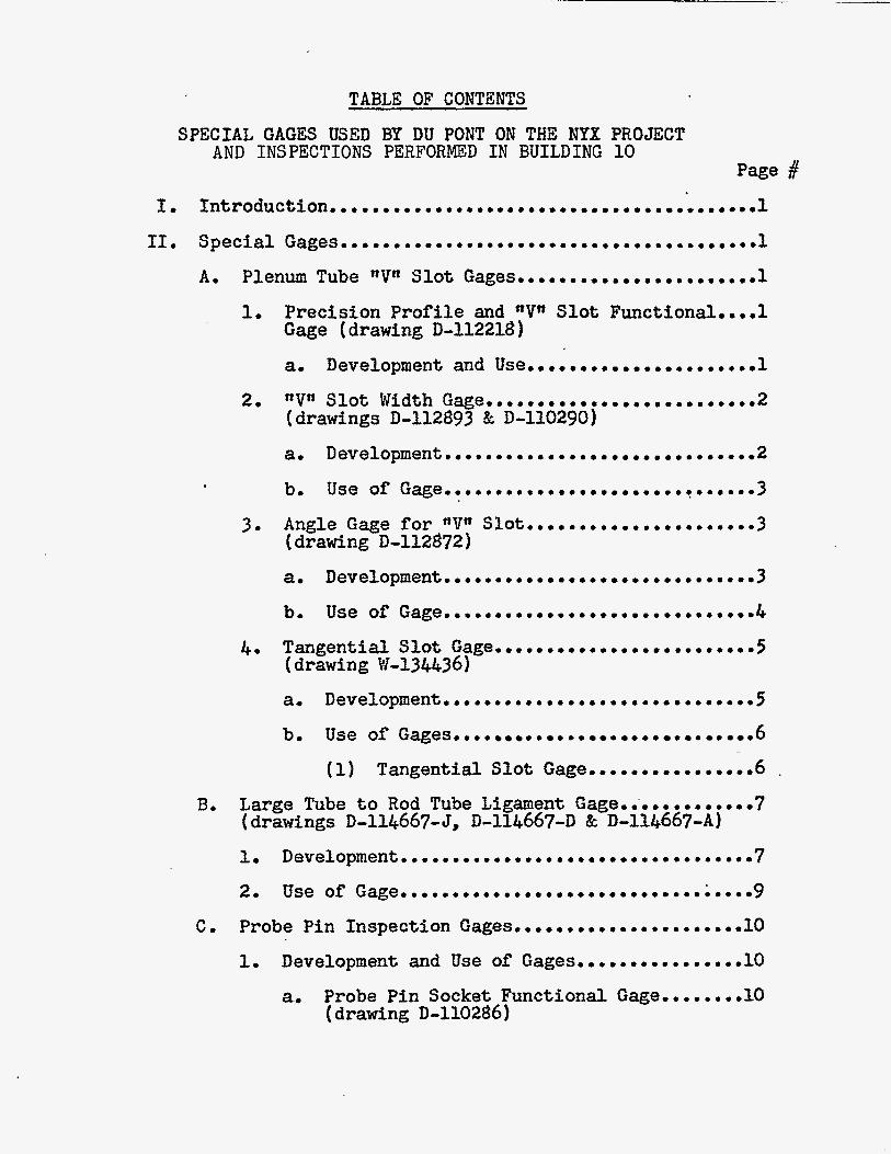
TABLE OF CONTENTS
SPECIAL GAGES USED BY DU FONT ON TBE NYX PROJECT AND INSPECTIONS PERFORMED I N BUILDING 10
11. S p e c i a l Gage~..............m~................m~....~.l
A. Plenum Tube nV" Slot Gitge~..............~.m.~....l
1. Precision Profile and "V" Slo t Funct€onal.~..l Gage (drawing D-212218 )
a. Development and Use......................l
2. Slot Width G~e........~.................2 (drawings D-112893 & D-110290)
3. Angle Gage for "V" Slot...................~~~3 ( drawing D-112872 1
a. De~elopment~........m~.~..m~~~~.~~~.~~~~~5
bm Use of Gages.. . . . . . . . . . . . . . 0 .6
(1) Tangential Slot Gage.. . . . . . . . . . . . . . .6 .
C. Probe Pin Inspection Gages........~.............lO
Development and Use of Gages................10 1.
a. Probe Pin Socket Functional Gage........lO (drawing D-110286)

I,
TABLE OF CONTENTS (Continued) Page d
Latch Stud Funct iona l Ga~eg. . ~ . . . ~ 0 0 . . 0 a ~ ~ a . o o ~ o o 1 3 (drawing D-110291)
2:onitor Pin Functional Gage.... . . . . o . . . . e o . o o o . o o ~
( ske tch k6) 1, Development and US^,...............^^^^..^^^.^^
Elec t ron ic Gage for Line Boring Operation..,..m,,Z5 (drawings D114.630 DL14414 I3114l&-B ks134.16'7
Pa t t e rn Gages and Ca l ib ra t ing Stanks Used on all
(drawing W30903 )
L a ?ked for Pattern G~ges...........ao..8,,,,.,,19
hl.31242 h!:l312l+3, Dl14632 Ec I)lI&629)
Sub-assemblies.......oa.~oao~e.a.eoDo..o...ao....l9
3. P a t t e r n Coordinate Calculations..o..o,...o..02~
2. Gperation a d U S ~ . ~ ~ . . . ~ ~ ~ . . . ~ ~ ~ ~ ~ ~ ~ ~ ~ ~ ~ ~ ~ ~ ~ ~ Z ~
Spec ia l Cages ijsed i n Building ;%I for Obtaining Leasureffients Before, During, and After Operational Tests Conducted on FlPX Process linit,. . .. 0 . a .26
1, Rota t iona l Movement of Plenum Chamber with iiespect to S i l 0 ~ ~ ~ . ~ . ~ . ~ ~ ~ ~ . ~ ~ ~ ~ ~ ~ ~ ~ ~ ~ ~ ~ . ~ . ~ ~ 2 7 ( ske tch $9)
2, V e r t i c a l i t y of Plenun Chamber Si'ith Respect t o Top Tube Sh~eto.00..0............~..eooooo29 (See drawings l i s t e d f o r V e r t i c a l i t y Gages, Section lrLn 1
3. Centrality of Plenum Chamber With Respect to Top Tube S h e e t , . . . . . . 0 0 . 0 . . . . o o . . o o . o . o ~ . ~ ~ . 0 3 0 (drawing DllG479-A & B )

TABLE OF CONTENTS (Continued)
5.
6.
7.
8.
9.
10
11.
12
Deflection of t h e Top Tube Sheet........,.B.031 (See sketch #lo) . .
Radial, Vertical , and Rotat ional Kovement of t h e Top Tube Shee t hrith Zespect t o the*Sile . ' .32 (drawing D112849-k &, sketch fll) . . . . . . . Deflection of t h e Top Tube Sheet with Respect t o t h e Concrete Floor...... ........ ;.34 (See sketch #12)
Radial, Rota t ion , and Other Xovements of t h e Bottom Tube Sheet with Respect t o the Silo...35 (See sketch 813)
Radia l Xovement of the Top P l a t e of t h e Tank Bottom with Res ect t o t h e Silo...,..........36 (See sketch #l$p
iiadial Novernent of the Top of t h e Tank S h e l l with Respect t o t h e Silo,.. . . . . . . . . . . . . . . . . . ,37 (See sketch # l 5 A & B )
Def lec t ion of t h e Expznsion Xing with Respect t o t h e Besring Ring..................39 (See sketch #16)
Rota t iona l Kovement o f t h e Plenum Chamber with Respect t o t h e Top Tube Sheet..........o&O (See ske tch $17)
Plenum Chamber Tube Xotion Eeasurements. .. . . ;41 (See sketch #18)
J. 3:ild IL'III P r e c i s i o n Level and Accessories. . . . . . . -43 (draviing Dl14941 I?G ske tch $19)
1.
2, Uses of t h e Ins t ru i ien t a t Mew Pork Ship. . . . . 4 5
L. V e r t i c a l i t y Ga e s , . . . . . . . . . .. . . . . . . . . . .. .. .. ..46
I n s t a l l a t i o n of P r e c i s i o n Crane i n Building #f0..48 (drawings DlU, 8 94, 0114633, tk D114498-A 9)
K.
1. General. . . . . . . . . .. . . . . . . . . . . . . . .. . . .. . . .48 2, Layout of -Center and Control Lines on Floor
and a t High Eleva t ion . ........~..,..,.;,.,,,,,49

TAB= OF CONTEHTS (Continued)
B. Temporary I n s t a l l a t i o n f o r Asserilbling and Test ing of C r ~ n ~ . . . . . o . ~ ~ . . . . s . . , , , . , 5 0
C. High Elevation;.o..o,.oo,oe.~~o~o.ooo~ooo51 . \
3 Installation of Crane Ra i l s [High Elevation) .52
4. 5 .
LnstalLation of Crane (Eiigh Elevation) a a a :.a .54 . . Alignment of Probe P i n s . . . . . . . . . . m . m . . m m ~ m ~ ~ 0 5 5
14. '+Cn Unit Bottom Tube Sheet i4onitor Pin Loca t ing S l o t Gages ..,bee. m...,.~..,.,om,.mmm.m.~..m~~o~~~55 (No drawin s l i s t e d o r sketches made - See Photo's 373 & 3747
a, Development and Procuremer;t.,...m.m.........,55
1. Funct iona l Gage f o r Checking S l o t Depth,,56
2. Grientat ion Gage....................,,,.,57
00
P a
Funct iona l Cages- . . a a . a . a a a a . . a a a a
[drawings DLl.2706 & D112621)
L i s t of Comercial Gages and Tools Used by inspectors at Hew York Ship.o..,..........ommom~m59
0 58
7

CHROiELOGICHL LIST OF ILLUSTBA.TTONS
1, Sketch #L - “Vw Slot P r o f i l e Gage (MIX Plen. Chanber)
2, Photo Serial #276
3. photo Serial g277
Photo Serial #299
5 , Table $1
6 , Sketch #2
7. Photo sesial #64 . 8, Photo Serial #65
9. Sketch 83 LO. Photo Serial +27%
11, ?hot0 SerioL #280
12. Sketch #4
15. ?hot0 Serial $234
16, Sketch 25 17. 2hoto Ser ia l #252
18,?hoto Serial $253
. 19. Sketch jTu6
20. Photo Serial g254
21. Photo Serial #223
22, Photo Serial $273
- IuTock-up Illustrating Curved Slot Yklls in a Slot
- Edock-up Illustrating Curved Slot ’F:mlls in a *!IT” Slot
- *tVn Slot Width Gage and Pdaster Setting Stand
- Chart for Determining Size of V * r Slots
- Layout of
- Angle Gage for Plenun Tub8 Usper Keg
- Functional Gage and &le Gage for
1, Plenm Tangentid. S l o t Orientation Gage
- Tangential. S l o t Gage and k;iast;er Setting
.I Tangential Slot Depth Gage
- Uethod Used in Detemhiag Bod Tube
Axis and Secondary Lines
Plenum Tube Upper Key
Tube
Locatjons
- Large Tube to Rod Tube Ligment Gage
Latch Stud Functional Cage and Thread Gase
- ?robe Pia Socket Location Gate
- Plenum Zhanber Probe ?in Location Ga,e
- Bottom Tube Sheet Monitor ?in Gages and
- Checking I.D. of Counter-bore in a
Heasuring FFacilities
Bottom Tube Sheet Tube with Standard Bore Gags and Checldng Proper Squeeze for UpflOt7?in and Sharp 3dges Cutting O-rings
- Bottom Tube Sheet Idonitor P5.n Functiona Gage
- Checking Orien$ation of Idonifor ?in Gr o ov’es
- Electronic Gage Indicating Panel
- Electronic Gage Setting Stand

23. >hot0 Cer ia1 i274
24. ?hot0 Serial #275
25. Sketch 7j-7
26. Sketch #8
27. Sketch $9
28. Sketch ;lo
29. 3hoto Serial if309
30. Sketch &I
31, Sketch $12
32, Sketch $13
33. Sketch $14
34. Sicetch
35. Sketch i4.6 36. Ekctch 4'17
37. Sketch :lS
38. Photo Ser ia l , + 3 l O 39. Photo Ser i a l $311
40. Sketch ~ i 1 9
41. Photo S e r i a l ,{25?
42. Figure L
4.3. Figwe 2
4.4. Figure 3
45. Sketch $20
46. Sketch $22.
- Xlectronic Gage Let t ing Ltand
- Eccentricity Gages
- Typical Zccentricity Gage
- Cross Section of S.C. 8G T.T.S. Tubes
- :et-up t o Check Eotatiooal iioveinen'c of
- Set-up t o Check Deflect ion of Top Tube
- Federcsl d i a l Indicabor and Gheck Stand
- Set-us1 to Zhecl; Vert ical , Radial and Rotational iiovenent
- Get-up to ZiecL x f l e c t i o f i of Xicttor Tube Sheet
- Set-up to Check Iiotational Govenent of T a k Botton Tabe sheet
- S e t - ~ p to ihheck i iadial iiovenent of l a n k Eot ton Tog ?lace
- (nAa C;; frBff) - Set-up t o Check i iadial irlovemnt of Tar& Shell
Plenum
Sheet
- Set-up t o Cheek Zxpansion Fin& Deflecticc i 1
- Set-Lzp to Check &dia l Aovemnt of ,Len.
- Set-sp to Take %'age i.k,su,ex;ents
- M l d MI11 Precision Level
- i ; i ld XI11 arecision Level
a Ki ld MIIF ? rec i s ion Level Optical Vie; :s
- F i t t i n g lfLn Uni-L Gain Tank Shell t o the Botton Xozzle Assembly for Field ;';eldin&
- Xanclrel to Gheck Verticality of 8t dock-
- Verticality Qege vi th Konenclature of
- Ver t i ca l i t y Gage Inserted in Tube That
- Layout of Control Lines on Floor
- Eigh Klevation oz: Zootroi Lines 2nd
Ep
Parts
is not Peri 'ectly V e r t i c a l
Eench ::ark

47. Sketch #22
4%.?hoto zerial h374
49. Photo Serial ,;373
- Layout of Teutporery Installation
- 0rienmti.cn Gage and Functional Gage for rri )rt 'iinit Eottont Tube Sheet
- Orientation Gage and Functional Gage f o r nGn Unit Eotton Tube Sheet
I
i-
\
!

SPECIAL GAGZS USED BY DU PONT ON THE NYX PROJECT NEW YORK SHIPBUILDING CORPORATION
I.
Page 1
In t roduct ion
The M & E Group a t New York Ship w a s r e spons ib l e f o r all measurements on process un i t s . To c a r r y out t h i s funct ion, it was necessary t o develop a g rea t many s p e c i a l purpose gages as well as procure many commercial gages.
This book w i l l descr ibe t h e development and use of t h e s p e c i a l gages. s p e c i a l gages were u t i l i z e d , commercial gages i n numerous in s t ances were incorporated t o ob ta in t h e u l t i m a t e r e s u l t . S ince t h e a c t u a l use of commercial gages f a l l s under t h e cate-- gory of s tandard machine shop methods and procedures, only those which were appl ied i n a s p e c i a l manner w i l l be described i n conjunct ion wi th t h e s p e c i a l purposs gages. commercial gages used on t h i s p r o j e c t , see Sec t ion I I -P of t h i s manual .
I n a g rea t many inspec t ion problems i n which
For a l ist of
11. S p e c i a l Gages
A. Plenum Tube nVtl S l o t Gages
1. Prec i s ion P r o f i l e and VTr S l o t Funct ional Gage
a. Development and Use
The need f o r a p r o f i l e t ype gage t o measure a f i n i s h machined VH s l o t mi l l ed wi th f l a t sur- f a c e s i n t h e t o p end of each 5&n O.D. plenum tubes was foreseen by t h e K & E Group a t New York Ship. Standard gages were not a v a i l a b l e at t h e pro jec t s i t e , o r manufactured commercially that could be incorporated t o obta in these measurements. ske tch of t h e proposed gage w a s made and submitted t o t h e Hew York Ship machine shop f o r f ab r i ca t ion . The gage was made t o f i t a s l o t of exact s i ze , and any deviat ion. was a a s u r e d by us ing f e e l e r gages &$he& besween $he.$age ap&g&&ti w a l l f o r oversize s l o t s , and between gage afi4-t;U5e t o p f o r undersize s l o t s . The s l o t s were mi l l ed (one p e r tube) w i t h a ItVersa-Milln feeding a r o t a t i n g v e r t i c a l c u t t e r ac ross t h e tube w a l l p a r a l l e l t o t h e u n i t !!Ja axis a i the Xi s ide . As ea& slot w a s machined and de-burred, t h e s i z e was checked w i t h t h i s gage (See Sketch #l).
A
The s l o t s i n nRm plenum chamber were measured e s s e n t i a l l y t h e same as o u t l i n e d f o r t h e NYX un i t , except a func t iona l t ype gage w a s employed. The M k E Group a t New York Ship suggested t o t h e Design Divis ion t h a t a gage of t h i s t ype , s imulat ing t h e a c t u a l mating p a r t which f i t s i n t o t h e tube s lo t , be designed such t h a t t h e use of f e e l e r gages. would be -a V i r t u a l l y e l iminated, thereby ' . resu l t ing

J . "
. I
, -; ..
. ' , * '
b
" I t
-: 1 *. t
L
.* L i i
. .

Page 2 i n a reduct inn of inspec t ion t i m e requi red per t u b e s l o t . This gage was designed by t h e Design Divis ion, who i n t u r n had t h e gage f a b r i c a t e d by Korthern Engineering and Hachine Company, Phila- de lphia , Pennsylvania. The f u n c t i o n a l gage Vtg s l o t i s i d e n t i f i e d as equipment p i e c e #790-113. For f a b r i c a t i o n d e t a i l s , see du Pont drawing D-112218. After inspec t ing t h e gage a t New Pork Ship, t h e Itkeyn width w a s found t o be .OIOtt unders ize ; however, t h e gage w a s accepted but had t o be used i n conjunction wi th fee le r gages as descr ibed i n t h e above paragraph.
1
On nRff and subsequent u n i t s , two a d d i t i o n a l V* s lo ts , each 1200 from t h e o r i g i n a l s l o t on X-- axis, were m i l l e d i n t h e t o p end of each plenun! tube. For loca t ion or" t h e s e s l o t s w i th respec t t o t h e X & Y axes, see Sketch # 3 . wise measured using the. f u n c t i o n a l t y p e gage des- c r ibed above. Fo r ' u se of t h i s gage, see Part I - C , Sgc t ion 3, Photo S e r i a l #63.
These were l i k e -
The use of t h i s gage iras discont inued a f t e r izsing it on t h e nRsl plenum chamber, and a similar gage of ad,vance design was s u b s t i t u t e d f o r use on subsequent un i t s . T h i s gage w i l l be discussed i n t h e s e c t i o n t o follow.
2. trVrt S l o t Width Gage
a. Development
With t h e advent of a plung m i l l i n g method on nPrr u n i t plenurrl chamber ( r e s u l t i n g i n curved s l o t walls), a new gage had t o be devised s imulat ing t h e func t ion of thefmating p a r t (Tapered key on semi-permanent s leeve) and s t i l l i n d i c a t e o f f - s i z e measurements.
P r i o r t o incorporat ing t h e plunge m i l l i n g method, s l o t s were o r i g i n a l l y machined by feeding t h e Versa 14illn v e r t i c a l ac ross t h e p lane of tube ends. A s p e c i a l mi l l i ng machine designed and b u i l t by Cincinnati-Bickford reduced t h e Vn s l o t machining t i m e considerably and replaced t h e "Versa-Kill" . ' T h i s machine incorporated t h e plunge m i l l i n g method i n which t h e c u t t e r i s f e d perpendicular t o t h e p lane of a tube end. T h i s method of machining r e s u l t e d i n curved s l o t w a l l s . During inspec t ion of f i n i s h e d "Vn s l o t s on I r P n u n i t , t h e use of t h e f u n c t i o n a l gage i n conjunction wi th feeler gages d i d no t produce accurate d a t a as t o whether o r not s l o t s were wi th in tolerance. It w a s discovered t h a t t h e f u n c t i o n a l gage f l ange seated properly, but t h e nkepff f i t t e d t i g h t a t po in t s aAIT and loose at nBtr. (See Photo S e r i a l Kumbers 276 and 277). i n s e r t e d a t po in t s ItB" ind ica ted t h e s l o t was out- s i d e t h e required to le rance ; however, a t po in t s "A* it ind ica t ed s l o t s were wi th in to l e rance .
Fee le r gages

The m u l t i p l i c i in t roduct ion of t h e t h e development of t h e I 4 & E Group devised t h e veyed v e r b a l l y the i n f o r t u r n designed t h e gage a Advance Tool and Enginee lvania. Also, a master b ra t ing t h e width gage the a c t u a l plenum tube semi-permanent s l e e above gage a t New Yo found s a t i s f a c t o r y . ider i t i f ied as equip d e t a i l s see du Pont " s e t t i n g gage'? is i d e n t number 790-135. For f du Pont drzwing D-110290.
b. Use of Gage
For measuring purposes, t h e wid ca l ibra ted by i n s e r t i n g t h e b a r r e l i " s e t t i n g gage" and then t h e d i a l ind a t lrO1l f o r nominal s lo t width, (See #299). Care must Se taken t o insure on the width gage is sea t ed f i rmly i " se t t i ng gage" s l o t , otherwise 5nacc bra t ion w i l l result. properly c a l i b r a t e d , i f o r use,
The 'gage is used by. i n s e r t i n a plenum tube p i t h t h e "Keyn rest t o be measured. Ther*keytt is then s l o t firmly by apply ing a s l i g h t sure on the "keyrl, and then t h e d read. The d i a l i n d i c a t o r reading si n, i .e,, (t-) i n (-7 i n d i c a t e s an o i zed t o d e t e r n i n e a
Before i n s e r t it is imperative t and s l o t s be de-bu f e rab ly wi th solven eign material w i l l reading.
chambers, and will be the gage t o be used i n a t u b operat ion, it i s necessary t ba r re l be reduced i n could be used i n a t O.D. of t h e ' b a r r e l plenum tube I,?. "
Angle Gage f o r V* S l o t
a. Development
This gage has be
3,

B o
L


"',.


- - - ~- . . . - -
cn
.-
.. :.
Q) n 3 r?,
w 3 4 c4
B
k x
k 0 k t 0 E
0 Q
C 0 0 0
0
8 k er k 5 a
c 0
0 & 0
s 0 0
8
S th ru Q r-t 4 I
R
a (D 3
0 c rr\ m M
Q #
0
t C M in
S
4 u! 2 0
3 2
k k
0 %i
.’. , L .


?

The need f o r a gage t o measure IrVn s l o t angular d e v i a t i o n w i t h respect t o t h e Vr axis l i n e s c r i b e d on t h e tube ends was fo re seen by 151 & E a t Mew York Ship, and Design Division was requested t o procure t h e required gage. The gage was f a b r i - ca ted a t Wilmington Shops, inspected and accepted at t h e sane loca t ion . It was then shipped t o New York Ship where it was put i n t o immediate use.
equipment p iece number 790-lZg. d e t a i l s , see du Pont drawing D-112872.
b, Use of Gage
c
Angular gage f o r "Vn s lots is i d e n t i f i e d as For f a b r i c a t i o n
This gage i s used f o r measuring t h e angular p o s i t i o n of each TPt s l o t with r e s p e c t t o a refer- ence l i n e s c r i b e d on the face of each tube end. These secondary o r reference l i n e s were e s t a b l i s h e d us ing t h e fol lowing out l ined procedure:
( 3 ) .
Unit X 8s Y axes are a s t ab l i shed ( f o r method of e s t a b l i s h i n g these l i n e s , see P a r t 1 1 - A , Section 13 1 , An 18' straight edge is a l igned coincident w i th the unit axis . For p o s i t i o n i n which s t r a i g h t edge i s placed on t o p of u n i t , see P a r t 114, Sect ion 13, Photo S e r i a l #53) . k p lane r gage is set t o 3.500" - t h e o r i t i c a l d i s t a n c e from center of t u b e s i n P axis t o ad jacen t row of tubes. s c r i -b ine a l l tube ends. See Sketch
This gage i s used f o r
After p l ane r gage i s se t , l i n e s are scr ibed on tube ends in row Y29.
S t r a i g h t edge is then pos i t ioned on row Y Z 9 and a l igned coincident with line j u s t sc r ibed , The above procedure i s repea ted f o r row Y3O, This procedure i s followed u n t i l all tubes i n Y1 d i r e c t i o n a re sc r ibed with c e n t e r l i n e s .
The s t r a i g h t edge is then turned w i t h toward X2 and t h e above procedure repeated.
After re ference l i n e s have been sc r ibed on t h e t o p end of a l l tubes , measurement of "Vn s l o t angu- l a r d e v i a t i o n can now be r e a d i l y performed. The barrel of the plug type sage i s lowered into t he tube u n t i l t h e 3 '*keysTr are proper ly s e a t e d i n t h e i r r e s p e c t i v e s l o t s . The pos i t i on ing b a r (both ends) is ad jus t ed t o coincide with t h e tube end cen te r l ine . The angular deviation i s then read d i r e c t l y from each "keyft, clockwise o r counter-clockwise , which- ever t h e case may be. The i n s i d e graduat fon on t h e *
rtkeyn r e p r e s e n t s lo devia t ion each way, and the out- s i d e graduat ions represent ho each way; io and 3 / 4 O

P a i s 5 <
is estimated. Should one s l o t be o f f more than Z 0 , t h e devia t ion of t h e o t h e r s cannot be read without removing t h e i n t e r f e r i n g "keyn. The same care must be l ikewise exe rc i sed i n regard to cleanliness of tube bore and s lo t s prior t o using gage f o r ineasurdng purposes.
(See Photo S e r i a l ff64 and 65).
Tolerance on "V" s l o t s is t A*.
I t . TangenGial Sloe Gage
a, Development
Along w i t h f i rming t h e design of t h e t a n g e n t i a l s l o t , a gage was developed by 3)esign t o handle t h e in spec t ion of these s lo t s . This gage was procured by t h e Design Division for t h e NYX Inspec t ion Group. It was f a b r i c a t e d by Chaumont Corporation, Glendora, New Jersey; shipped t o ?Jew York Ship, inspected and found satisfactory. master gage se t t ing tube i s i d e n t i f i e d as equipment piece number 165-24. du Pont drawing W-1344.36. on trP1f and r*Lrf plenum chambers, and w i l l be used on subsequent un i t s .
The t a n g e n t i a l slot gage and
For f a b r i c a t i o n d e t a i l s , see This gage has been used
Since t h e tangential s l o t m i l l i n g operat ion was i n progress, some means of measuring f in i shed slots had t o be devised u n t i l t h e above gzge was fabricated and received a t iGew York Ship. The M 8c E Inspec t ion Group modified t h e obso le t e "V" s lo t f u n c t i o n a l gage by adding a handle and ber gage t o serve as a measuring device u n t i l t h e one from Design could be procured. This gage was used f o r measuring approximately half the t a n g e n t i a l s l o t s i n the !'Pn u n i t . The gage (See Sketch # 3 ) was i n s e r t e d i n t o t h e TTVtr s l o t opposi te t h e t a n g e n t i a l slot, and t h e edge of the h o r i z o n t a l bar gage handle was checked for p a r z l l e l i s m with t he sc r ibed line (oppos i te "Vf s l o t ) on t o p of the f u n c t i o n a l gage, The deviation was est imated to t h e nearest 1/2O. Depth was checked with a 0-1" micrometer and machined block i n s e r t e d i n t o t h e t a n g e n t i a l slot. Upon r e c e i p t of t h e new gage and master s e t t i n g s tand developed by Design, a l l s l o t s were re-measured us ing t h e new gage.
The new t a n g e n t i a l s l o t gage (No. 165-24) incorporated two s a l i e n t f e a t u r e s : (1) Orienta t ion measurement of t a n g e n t i a l s l o t r e f e r e n c i n g from a nV" s l o t , and (2) measurement of r a d i a l d i s t ance from c e n t e r of t h e plenum tube. A t t h i s t ime, t h e . problem of tube wall s t r e n g t h r e l a t i v e t o s l o t depth presented i t s e l f and could not be reso lved u n t i l an a d d i t i o n a l special type gage (which measures t h e a c t u a l depth i n inches from tube O.D. a t t h e hori- zon ta l cen te r of t h e slot) cotxld be made. This depth type gage was developed by t h e New York Ship and i s used ir\, corjunct-ion with the t a n g e n t i a l slot gage. discussed i n &he following sec t ion .
& E Group a t
Uses of &he above gages zre

L
S e r i a l Number 6L
PROJECT 8980 - SAVANNAH RIVER PLANT
T h i s view shows the u s e of the Angle Gage for the plenum tube upper key.
The angle gage i s inser ted i n the tube with the "removable key" (#l) i n
position, Next, a scribed l i n e on the tongue o f the positioning bar (#4) i s brought i n to coincidence with the scribed l i n e through the center of
each tube end.
clamped t o hold the gage i n place.
positioning bar t o the tube ends.
scribed pa ra l l e l t o the Xl-X2 axes p r i o r t o the I1V" s lo t t ing operation.
Tho deviation, clockwise o r counterclockwise, can now be read d i rec t ly i n
degrees a t point #le
After the positioning bar i s set, the thimble (#6) is
A magnifying glass i s used t o set the
The scribed l i nes on the tube ends were
The "removable keys can be inserted a t points 2 and 3 and the above procedure
followed for measuring the other two lrV" s l o t deviations.


I, .,.;:;.'; , '
a,- . . .


rage o -t
b, Use of Gages
1, Tangential S l o t Gage
The fo l lowing i s t h e procedure f o r c a l i b r a t - ing and us ing the t a n g e n t i a l slot gage,
With t h e two gaging arms (#5 8c #6) depressed, t h e b a r r e l of t h e gage is inse r t ed i n t o t h e master gage s e t t i n g tube (#I). The sp r ing loaded "keytr (#4 & &-A) automatical ly seats t h e gage i n t h e s e t t i n g tube, Tension on t h e "key" is ad jus t ed a t #&Bo (See Photo S e r i a l
Dial i n d i c a t o r s ($2 Zc #3) a r e ad jus ted t o "0".
Gaging arms (#5 & #6) are depressed and gage (#7) i s removed,
Gage (#7) i s i n s e r t e d i n t o plenum tube which i s t o be checked. All gaging i s done refer- kncing from t h e *V s l o t on t h e X1 s i d e of t h e plenum tube by means of t h e sp r ing loaded ?!keyn ,
D i a l i n d i c a t o r s ($2 GC #3) are read and recorded,
I n t e r p r e t a t i o n of Resul t s :
Resu l t s a r e i n t e r p r e t e d keeping two consider- a t i o n s in mind, nzmely:
1. Angular o r i e n t a t i o n of slot
2. Radia l d i s t ance from center of tube.
Angular o r i e n t a t i o n o f s l o t i s determined by determining t h e a l g e b r a i c d i f fe rence of d i a l i n d i c a t o r readings #2 gt $3, obtained i s then converted i n t o degrees dev ia t ion from l o c a t i o n 00; which r ep resen t s a p e r f e c t l y or ien ted s lo t . The conversion t a b l e l i s t e d below is u t i l i z e d .
The d i f f e rence
Conversion Table f o r Determining Angular Ileviation of Tangent ia l S l o t
Algebraic Difference Angular Deviation From Oo
0 002 . 1200 , 004 Ir ,2300 ,006tT 3 50° ,OO&' 470' .010" 567" 012" ,680° . 0 1 ~ gooo , O W r .920* . 018" 1,0500 ,020" 1.1500
------------U~per Limit-------------- L

i t
The above conversion t a b l e ho lds t r u e f o r an a lgeb ra i c d i f f e rence up t o .020tr. 3-11 d i f f e r e n c e s g rea t e r t han .020" must be mathe- m a t i c a l l y analyzed as i n d i v i d u a l cases; how- ever, due t o method o f machining, a l l s l o t s have been w i t k i n the ,020" upper 1 i E i t .
Providing the angular o r i e n t a t i o n of the t a n g e n t i a l s l o t is s a t i s f a c t o r y , t h e r a d i a l d i s t a n c e f r o n the cen te r o f t h e plenum tube is deternined 5y not ing Fjhether o r no t 1/2 t h e a l g e b r a i c sum of ind lca to r readings are p o s i t - ive ' o r negative values. Pos i t i ve readings i n d i c a t e s l o t is deep and negat ive readings
. ' i nd i ca t e s l o t i s shallow ( w i t h r e spec t t o t h e r a d i a l d i s tance from t h e cen te r Gf t he tube) . The l a t t e r readings a r e a c t u a l dev ia t ions from the nominal r a d i a l d i s t ance from t h e center of t h e tube. In ,nathernatical symbols, the above i s s t a t e d as follows:
i<.D. (mean depth) = &indica tor regding $. $3 i n d l c a t o r reading
?
I
8
Large Tube t o
2 8
All deep s l o t s were considersd d c e p t a b l e ; however, s h d l o w s l o t s were mezsured%ith a s p s c f a l tyrje depth gzge r e fe renc ing from the 0.D. of the plenum tube. (See Photo S e r i a l #280) , For s z t i s f a c t o r y ope ra t ion of mating p a r t during un i t operat ion, Design requested a ninizum depth of 3/16" (From 0.3. t o bottom o f slot) t o be msintained.
-. i. . L L.
hod Tube Ligament Gage + : .* . &. 1. 3evelopment
The problem of measuring t h e center-*-center distance between a large tube and rod tube did no t p re san t i t s e l f u n t i l t h e f i n a l staces of f a b r i c a t i o n were completed on t h e u n i t plenum chamber and t o p tube sheet . This measurement was n o t deemed necessary on t h e LYX u n i t ; consequently, no gage had been developed t o handle t h i s p a r t i c u l a r phase of inspection. Upon rJesignls request t h a t t h i s measurement be incorporated i n t o the inspect ion procedure on r r ~ i f r and subsequent u n i t s , t h e X & S Group at New York Ship wzs confronted x i t h t h e problem of procuring a s p e c i a l t y p e gage f o r t,hs job, M 5t ii con- t a c t e d 3esign, ou t l ined t h e gage requirements, and re- quested procurement of t h e type gage required. compliance, Design Division designed the gage and had it f a b r i c a t e d by t h e Chaurnont Corporation, Glendora,
i s a breakdown list of each component p z r t :
(1) S e t t i n g s t and - (;ne purchased and i d e n t i f i e d as .
,
I
, i
I n 1 3
New Jersey. For i d e n t i f i c a t i o n purposes, t h e following 3 1
I

F4 k 0 u
k a, P
2 5
e a, P 5 Q
bo c *rl Q Q a, (0
k a, Q in cd E e c cd a, bo cd bo Q 0 rl in
ko -P 3 % k 5 in cd a, E
Q G a,
T i k 0
k 0 %I
T3 a, in 5 in *rl
a, hD cd hD in
.rl c i3
h
c, 0 rl in
E 0 k k
Q 0 rl ro rl cd
v i Q c a, hD c cd Q
ko . czl
H
0 Q
Q 0 a,
? a, k c Q .rl 3
ro -rl
a, ho cd a bD C *rl Q Q a, in
k a, Q (0 cd E
A Q a a, T3
k 0
a F: cd
. a, P 5 -P
a, A c,
a c (d
a, bo cd bo Q 0 rl in
. 3 cv I
in cd
Q G 0 pc 5
a, a, ro I
in rl *rl cd Q a, T3
C 0
-rl -P cd 0 .rl k P cd k k 0 I&


S e r i a l #280 New York Ship - Camden, New Jersey August 26, 1953
.
PROJECT 8980 SAVANNAH RIVEB PLANT
Modified depth gage constructed from standard gaging f a c i l i t i e s f o r
measuring tangential s l o t depth referencing from O.D. of plenum tube.
,-
.

.h
I

Page 8
.
Bracket with
equipment piece #790-126. For f a b r i c a t i o n d e t a i l s , see drawing D-114667-5, ser ia l number 224,
See item #3 on photo
a1 i n d i c a t o r a t tached - Two purchased and each i d e n t i f i e d as equipment
. piece .#790-126. For f a b r i c a t i o n details, see D-114667-D. See item # L a on photo s e r i a l number 224.
( 3 ) Centering p in - Two purchbsed and each i d e n t i f i e d as equipment piece #790-126. For f a b r i c a t i o n d e t a i l s , see d rawhg D-114667-A. See i t e m #2 on photo s e r i a l number 224
During t h e t i m e t h e above gage was being designed and f ab r i ca t ed , t he i n s p e c t i o n group was without a gage f o r obtaining t h e measurements requested by Design. A n s u b s t i t u t e gage" f o r i n spec t ion use u n t i l gage NO. 790- 126 was received wss immediately devised by E! & E . f a b r i - cated at New Pork Ship. This gage cons is ted pr imar i ly of two i n t e g r a l pa r t s : namely, a mandrel and a bracket t o which a d i a l i n d i c a t o r was af f ixed . (See Sketch jf4). Since rod tube location ,zsasurements were required on both sides of ths plenum chamber am3 t o p tube shee t , six individual nrandrels were machined t o f i t varying bore s i zes . (See !!note!' on Sketch #4) ,
The fol lowing i s a breakdown of t h e mandrels used: -I-..--- -- 7
l------ -7 -1__-__1-
TABLE -#l
f o r Top End of Rod Tubes on Plenuni Only
-1 Dimension ':ATr 1 1.500" D i a . Held Constant (See Sketch j9+)
-.------- ~
.--1_- ---
I Mandrels for Bottom End of Plenum Rod Tubes and Both Ends of Top Tub? Sheet Rod Tubes i
I -I- --
I f I Mandrel # 1 Dimension rrkTr
l.500r1 Dia. Eeld Constant 1 2 (See Sketch 3 1 , 3 1 5"
Since t h e counter-bore t o l e r a n c e a t t h e t o p end of a plenum rod tube was 1.505" t o l.510n and t h e rod tube bore on t h e hotton! end was 1.3075T1 t o 1.31751t, it can


- -' .? ., '* ', . : . . pi..., t
..,.: ., ,;. ,_\ .:
..# .I* 8.. ., " < ,'I
f * Page 9
- - *.'::$A i t,
of d i f f e r e n t s i z e mandrels. The same reasoning holds - . i
diameter vias 1.3125tT .005'I. '<' ;
be r e z d i l y deducted t h e need f o r a s u f f i c i e n t number
t r u e f o r a t o p tube shee t rod tube i n which t h e bore I i -.k
'. : .I, , t
c . ..= I . , ._ . : Using t h e above " s u b s t i t u t e gage", large tube t o "*,;:. 2 i . > 5,
i ' , chamber and t o p tube sheet were measured as o u t l i n e d h:A;T,; 'i i rod tube l igaments on both s i d e s of t h e "Rrr u n i t plenum
* ' - :* ,';z*l,t,', :..(*9p.$.:?;$ following. .procedure : .. ,- ,* , .... . . & ' - - y y .. r. i . I .
1. ~
I i: .. :;"lp', -. $,.: ' The bracket with d i a l i n d i c a t o r a f f ixed is first; . -.::' 2 t
c a l i b r a t e d with a p laner gage, The d i a l indicator , ' . i s set at Iron for t h e nominal rod tube li ament - .
dimension,
The proper mandrels are se l ec t ed for t h e i r r e s p ive tube end and z l l t h ree are t r i e d t o determine . t h e best F i t .
After a suitable mandrel has been s e l e c t e d , it i n s e r t e d i n t o t h e rod tube,
The bracket i s then i n s e r t e d i n a l a r g e t u the c a l i b r a t e d d i a l i n d i c a t o r r e g i s t e r i n g agai the mandrel.
Using a h o r i z o n t a l "roc-king i40tionn, and h o l d i the rad iused piece on the bracket bea r ing agai the large tube .wall, t h e highest " p o s i t 3 is determined by noting the. f l u c t u a t i n g
Reading is recorded and used fh cohju basic gage s e t t i n g and mandrel diamet f o r f i n a l computation of large tube t o r o ligament dimension. See Sketch #4 f o of computation,
(See Sketch #4, dimension "€3&
(Befers t o aimension "A").
. I . = '
i n d i c a t o r needle; . : . - , . ' . , I _
' . * .* *;,<,: 7.:': 2 I +..a 'i.r , . , ~ .
During t h e course of using found that Easuremen t s obtaihe also .the use of t h e gage-itself consuming, A f t e r the new gages Chaumont Corporation, the use of was discont inued, and t h e former l igaments on nPn 2nd subsequent un i t s .
Use of N e w Type Gage
tube to rod t ube on t o p and bottom'of both plenum. and t o p tube shee t , The p rocedure - fo r use of thi$ is as follows: .
(1)
2,
This gage is used f o r tak ing IE
The p l a t e gage o r center ing placed on t h e tops of large on the l a t te r and t h e t ape re t h e rod tube.., (See Photo Se
A "separate .arm" K i t h an i n t i n d i c a t o r , is s e t t o %he dimensi
. .
(2)

Page 10
center d i s t ance between tubes us ing t h e s e t t i n g stand, (The a c t u a l bore of t h e s p e c i f i c large tube must a lso be taken i n t o cons idera t ion) ,
( 3 ) The "separate arm" (1-a) i s placed ac ross t h e tube face with t h e v e r t i c e l p i n r e s t i n g a g s i n s t t h e in- side of t h e l a r g e tube.
(4 ) The minimum read ing on the d i a l i nd ica to r is then read and recorded. This reading i n d i c a t e s t h e deviat ion from t h e true cen te r t o center d i s t a c c e between t h e large t u b e and rod tcbe.
S p e c i d l e v e l i n g screws are supplied f o r measure- rner,t where plate gsge cannot be supported on f a c e s of t h r e e l a rge Cubes.
C. Probe P i n Inspect ion Gages
1. Development and Use of Gages
a. Probe P i n Socket Funct iona l Gage
During the machining of probe pin sockets , t h e need Tor a spec ia l type f u n c t i o n a l gage f o r checking the I.D. was foreseelt by t he i; & i; Group. T h s l s t t e r contacted Gesign 2nd rc,quested them t;o F ~ O C L ~ P ~ t h e required gage. I n colrpliance wi th t h e request, Eesign Division designed t h e gage and procured it f o r tk RYX Inspec t ion Group. % s e n t i a l l y t h i s gage was a go-no go plug gage f o r check- i n g i n s i d e diameters of probe pin sockets. The convent- ional method cjf gaging was employed. It was f a b r i c a t e d by Advance Tool and Engineering Company, York, Pennsyl- vania and shipped t o New York Ship where it was inspec ted and found s a t i s f a c t o r y , equipnent p i e c e number 79C-132. For Tabricat ion d e t a i l s , see du Font Draxing D-110266.
This gage i s i d e n t i f i e d as
After probe p in socke t s were welcled t o t h e top side o f t h e plenum chmber , an a d d i t i o n a l check u s i n g t h i s gage was =de t o determine whether weld shrinkage a f f e c t e d t h e 1.D. The above i n spec t ions Were perzormed on !Tifr ar?d nZ"r u n i t s only.
ilue t o a change i n design fronl an unthreaded t o a threaded bore on ?!LIr and subsequent u n i t s , t h e funct ion- a i plug type gzge was discont inued and a go-no-go standslrd threaded plug gage w2s used. (See Thoto S e r i a l $281) .
b. Probe Pin Socket and Rod Tube Para l leb Gage.
To hold t h e l o c a t i o n of probe ?ins t o drawing spec- iflcations, a gage o r gages t o deterruicz t h e l o c a t i o n of probe p ins with r e s p e c t t o a rod tube and l a r g e tube was required by t h e $5 & E Group. request f o r required gsges, Design Division designed the gage and procured it f o r t h e KYX Inspection Group. The gages were f a b r i c a t e d by Advance Tool and Zngineering
I n compliance with a

8
4


Serial $281 New York Ship - Camden, No J. August 17, 1953
PROJECT 8980 - SAVANNAH R I ~ R PLANT
81 Latch stud f t lnc t iona l gags
Gage is shown i n its proper p o s i t i o n f o r f u n c t i o n a l l y checking s tud locations ( a and b) with r e spec t to a rod tube, Piece #790-137. For f a b r i c a t i o n details, see du Pont drawing D-110291,
sequent units.
Gage is i d e n t i f i e d as du Pont. Equipment
82 Go-Not Go th read plug gages fo r checking probe p i n socket t h r e a d s on "L" and sub- Two thread gages were used:
a,
b,
7/16" - 20UNF - 2B; GO-Pitch dia . of .4050; NO-GO-Pitch Dia. of ,410h
7/16" - 20UNF - 38; GO-Pitch dia . of .4050; NO-GO-Pitch Dia, of .4091
Threads i n probe pin sockets were checked as follows:
a, Insert NO-GO end of 3B gage in all threads, i f loose f i t exists then,
b, Insert NO-GO end of 2B gage i n all 3B loose fits, fit w i t h 28 gage is considered a 1B f i t ,
C. Permanent record is made of tho number of socke t s t h a t are 3B, 2B, and 18 fits, and information forwarded to Design for approval.
Any that a r e a loose


i . . .
, , ..
. -
. . .c ,* ,

e m - . .


. .
. . . - i . ., - .
- . . ..
- . . . . . . . . . I
.- - . .
:
.I .
SIGNATURE: , ENGINEERING E. 1. D U PONT DE SKETCH NEMOURS SHEET 8: CO.
I PROJ. NO. BPBO
Y
-3
3'
n

2. Gage (#4) i s r o t a t e d clockwise o r counter- clockwise u n t i l t h e s c r i b e d l i n e s on both ends of t h e p o s i t i o n e r b a r (nBlr) coincide with =Ytr axis l i n e sc r ibed on end of l a r g e t u b e ( p o i n t s 1 & 2). Posi t ioner bar ( " B n ) i s clamped i n place by means of knurled thumb screw I r C t f .
3.. Threaded s t u d on end of swinging arm f*D1i is i n s e r t e d through p l a t e i n t o probe pin socket and scr'ewed i n t o l a t t e r .
Swinging arm ( I r D r l ) i s first ro t a t ed t o p o s i t i o n as shown i n photo s e r i a l 8234. The dev ia t ioa of dimension trA" (Sketch #5) i s read d i r e c t l y a t poin t #3, Due t o cons t ruc t ion of gage, deviat ions r'rorn drawing s p e c i f i c a t i o n i s read & 1/32Ir from nominal dimension 64/16" .
4.
5 , Swinging arm ( l rD") is t h e n ro t a t ed t o p o s i t i o n #5. The dev ia t ion of dimension nBlf (Sketch # 5 ) i s l ikewise read d i r e c t l y a t fioint #5 . Due t o cons t ruc t ion of gage, dev ia t ions from drawing spec i f i ca t ion i s
1/32" fron: nominal dimension ~?$3$tl. If t h e probe p i n socket i s not i n i ts proper l o c a t i o n , t h e l a t t e r i s bent; i n t h e requi red d i r e c t i o n u n t i l with- i n to le rance . Due t o t h e accuracy of l o c a t i n g and welding probe pin sockets t o t h e u n i t , t h e above method of "bending probe p i n socket u n t i l wi th in tolerance" was deemed acceptable , s i n c e readings were only s l i g h t l y p lus o r minus over t h e s p e c i f i e d t o l a r a c e i n a l l cases encount- ered,
D o Latch Stud Functional Gage
On ItR" t nPr* s "Ltl, "Kn and m2n u n i t plenum chambers, two l a t c h studs per rod tube were welded to t h e t o p s i d e of each u n i t , same on a l l t h e s e u n i t s , F o r l o c a t i o n of s tuds , see du Pont drawing W-133609.
chamber, t h e M & E Group a t RTew York Ship requested Design t o i n v e s t i g a t e t h e f u n c t i o n a l t o l e r a n c e s requi red on t h e l a t c h s tuds , and t o design and procure t h e necessary gage. I n compliance wi th I4 & 3 Group's reques t , Design Division designed t h e gage and had it f a b r i c a t e d by Advance Tool and Sngineer ing Company, York, Pennsylvania. The gage was shippel t o New York Ship where it was inspec ted by t h e M & I3 Group an found sa t i s f ac to ry . The l a t c h s tud f u n c t i o n a l gage i s i d e n t z as equipment piece number 790-137. see du Pont drawing D-110291, i
Latch stud l oca t ion wi th r e spec t t o a rod tube was t h e
Before t h e l a t c h s tuds were welded t o t h e ItR" u n i t plenur
For f a b r i c a t i o n d e t a i l s ,
i
1

Page 14
E s s e n t i a l l y t h i s i s a f l a t type gage w i t h a plug on one end t h a t r e g i s t e r s i n a rod tube , and w i t h two holes d r i l l e d ( .4?21r-.436" diameter) 2.500" and 3.000n respect i l re ly from t h e plug cen te r , which passes the l a t c h s tuds , providing t h e y are i n t h e i r proper loca t ion . (See photo s e r i a l #281)
E. Lon i to r Pin Functional Gage
1. Development and Use,
After t!H1f and I r P bottom tube shee t assemblies had been completely inspected a t Kew York Ship and accepted, they were shipped t o t h e Savannah River Plant f o r e r e c t - i o n ; however, a f t e r r e c e i v i n g t h e above u n i t s , prel iminary inspec t ion by Savannah River P ro jec t personnel on t h e bottom land of k r g e tubes revea led t h e fol lowing condit- i ons ;
a , t'RfF Bottorr Tube Sheet
1.
2.
Scratches i n t h e 3-3/8" diameter counterbore i n t h e lower ends of t h e tubes.
Depth of haU: round o r i e n t i n g grooves t o o shallow t o perinit en t ry or" some monitor pins. Depth here refers t o t h e dimension perpendicular t o t h e cen te r l ine of 8 tube.
Length of o r i e n t i n c grooves ( i n d i r e c t i o n p a r a l l e l t o tube cen te r l ine ) t o o g r e a t , t h u s v i o l a t i n g t h e O-ring s e a t i n g zone, o r t o o s h o r t , t h u s prevent ing complete e n t r y of monitor pins.
4,. Edges of h a l f round grooves and crow2 of chamfer s u f f i c i e n t l y sha rp t o endanger O-ring dur ing in se r t ion .
b. rrPr7 Bottoc Tube Sheet
1. .
Edges of ha l f round grooves and crown of chz;lu"er suff ic ient j ty sha rp t o endanger Goring dur ing in se r t ion .
The above d iscrepancies i n t h e u n i t s were cor rec ted i n t h e f i e l d . Eiowever, t o prevent occurrence of s i m i l a r condi t ions i n t h e "L!? bottom tube sheet (under f a b r i c a t - ion a t N.Y.S.) and l a t e r u n i t s , i t was Teqtlested by Design t h a t t h e Pi & E Group's i n s p e c t i o n procedure for a l l tube bores on t h e h t t e r u n i t be reviewed f o r adequacy, I n add i t ion t o checking conformation with a l l drawing sped- i f i c a t i o n s such as dimensions, f i n i s h and freedom from sharp edges, each bore was requested t o be independently examined as t o i t s s u i t a b i l i t y f o r O-ring. This exami- na t ion was t o include a c l o s e v i s u a l inspec t ion and running t h e hand over t h e s u r f a c e s involved.
I n response t o t h e above field complaints and i n compliance with Design t h a t a l l bottom lands i n "Ln u n i t be reviewed f o r adequacy, 1: & E Group immediately invest- i g a t e d and inspected t h e jig and d r i l l s used to machine
Page 15
monitor p in grooves. The j i g i t s e l f was found s a t i s - f a c t o r y ; however, 3/16': d r i l l s used were n o t of t h e proper size t o produce t h e r equ i r ed depth o f h a l f round o r i e n t i n g grooves. (Depth r e f e r s t o t h e dimension per- pendicular t o cen te r l ine o f a tube), o r i g i n a l l y used were replaced by a 3/GTr d r i l l ground t o 7/32" O.D, p i l o t f o r a length o f 1/2". Bushings i n t h e j i z were l ikewise replaced wi th proper s izes t o receive t h e new type d r i l l .
The 3/16" d r i l l s
After co r rec t ing t h e above s i t u a t i o n , a s u i t a b l e means of checking a o n i t o r pin groove dinens ions 2s reques-
grooves were developed by +,he ?< ei E Group and f ab r i ca t ed by Eew York Ship, These gages, p l u s t h e modifications t o s u i t cur ren t s p e c i f i c a t i o n s , were as fol lows:
t e d by Design was required. rn LWO gages f o r checking these
1) The first func t ioca l gage was f a b r i c a t e d f o r checking t h e proper squeeze f o r upflow p in and sharp edges c u t t i n g O-ring. The r o o t diarneter o f t h e gage was machined t o 3 .0ZOlr , and f i t t e d e i t h a n O-ring whose diameter was .222!', This gage :\'as used u n t i l it was discovered t k a t t h e g q e barrel v:as t o o long and would not s e a t properly i n same t ubes , and the 0- r i n g h i t t i t s tube chanfer. Item $1).
b. second f u n c t i o x l g t g e kiss fa3ricated w i t h a 3.005" r o o t d i a n e t e r and a ,222'; diameter O-ring f o r check- i n g slots t h a t were too s h o r t 21-16 f o r o r i e n t a t i o n and depth of slots, It was discovered dur ing i t s use t h a t t h e lrsqueezclr vias Rot t i g h t enough f o r checking shar ness of s l o t edges. ,7252, i t es l ,y3 P .
(See photcr s e r i a l 5~252, Also, photo s e r i a l $253, item $2.
2 )
(See photo s e r i a l
The purpose o f gzges $1 & 3 (photo s e r i a l $252, i t e m 1 & 3 ) were incorporated i n t o 51 s inEle gage by having gzge ~3 n e t a l sprape5., re-=zc%ned t o a 3 .O2Zt t r o o t d i m e t e r 2r,d f i t t e d wi th a .222" d i m e t e r O-ring. (See Sketch $5) This gzge now checks:
1) Grien$ation 2nd depth of 3 slots (&e photo s e r i a l ~2 54-1
3 ) S l o t s t o o shor t .
I ; ) Sharp edges,
It i s necessary t o use a depth mike t o deterrr:ine s l o t s too long. LecgtIi s l o t s are 1/23 ( + .OOO:T - . O I . ~ I ~ ) ; however, all slots were acceptab le by Zesign up to g/l61f long.
F. E lec t ron ic Gage f o r Line Boring CJpei-ation
a. khy Cage was Keeded


f s E #
B M
4 B u 3
4 C2
a f
.r Q
0 9 a H
sl d 0 Q 6
c cc ;3
0 c
0 i;, k e 2
E
ko n k s 8
43
n rc.(
6 M
t g


e
x s B
1
c


I
t
I
I .

SI
3 )D
4
-4 45
,
a &
. .. .' . Y
v , .$ '_ . I

Page 16 Since t h e l i n e boring operat ion requi red t h a t FJI & E
i n spec to r s t a k e measurements both concurrent and a f t e r t h i s operation, mechanica) gages had been developed t o t ake t h e s e p r e c i s i o n measurements; however, it was found t h a t t h e use of t h e s e mechanical gages on t h e NYX u n i t was inadequate. These inadequacies were t$me consuming due t o number of i n t r i c a t e measurernen$.@@.ich r equ i r ed t h e use of c e n t r a l i t y gages. To e l i rntete t h i s d i f f i c - u l t y , it was decided j o i n t l y by t h e Bi&$gn.and Material and Equipment S e c t i o n t o b u i l d and dgi$elod.an e l e c t r o - magnetic gage ( e l e c t r o n i c gage) prop&ea%y a member of t h e Prechanical Development Laboratory:. i..?:" .. :- ::!.. .). .*
b, Procurement and Applicat ion
C.
. - 1, #I Elec t ron ic Gage, S e t t i n g Stand S k i c a t i n g Panel,
.LC. ,,: .2- .-,. ' . -- -. 1 .* Panel Stand
<' . The first e l e c t r o n i c gage designed by t h e
Design Div is ion w a s f a b r i c a t e d by t h e Thau Manu- f a c t u r i n g Company, Baltimore, i'laryland,- and then shipped t o Automatic Temperature CoritroJ, Company, Phi ladelphia , Pa, , f o r assembly and widhg . t h i s t h e gage was shipped t o New York $hip, Camden, N. J., f o r o p e r a t i o n a l purposes and fur6;her develop- ment. It w a s i d e n t i f i e d as equipme$ p3,ece $790-42. For f a b r i c a t i o n d e t a i l s , see du Po@ drawings Wl31242, ~ 1 3 1 2 4 3 , Vi134167 and D114632,
The s e t t i n g s tand f o r t h e f i r s g l e f e c t r o n i c gage (See P a r t I - S e c t i o n C, paragraph &$ sketch #8) was f a b r i c a t e d by t he Thau Manufacturing .Xqmpany, Baltimore, Maryland, and shipped to7-New 'York Ship, It w a s i d e n t i f i e d as equipment piece.#7:9.0-58. For f a b r i c a t i o n d e t a i l s , s e e du Pont dr$wi@& Dll4630.
This gage and i ts component partszwere first u t i l i z e d f o r o p e r a t i o n a l and development purposes on t h e first and second seven tube mock-ups as d i s - cussed i n P a r t I - S e c t i o n s B & c. It w a s a l s o incorporated i n t o t h e l i n e boring procedure fo r t h e MYX and "Rn u n i t s ; however, due t o machanical d i f f i - c u l t i e s encountered i n t h e operation, of t h e gage i t se l f on both units, i t s use was discont inued and two new gages were b u i l t t o replace it.
After
.. .. . . . . :. .:is
:+;- E' -- ' *.
Purpose and Funct ions
The primary purpose of t h i s gage was t o determine if a plenum t u b e i s be ing bored concentric wi th t h e mid- point of t h e corresponding t o p tube sheet tube wi th in .015". gage t o i n d i c a t e t h i s condi t ion was a series of d i f f e r e n t i a : transSormer c o i l s , These c o i l s are connected cascade i n e l e c t r i c a l c i r c u i t s which are i n turn coupled t o an empli- f i e r i n t h e c o n t r o l panel . A t t h e con t ro l panel f o u r i n d i c a t i n g l e v e l s (bottom bore of plenum tube; top, mid-point and bottom of top tube shee t t ube ) a r e read d i r e c t l y t o t h e n e a r e s t thousandths of an inch. This
The medium of measurement incorporated i n t o t h e
(See photo serial #ZZ3)

a
l
a


Page 17
c '&
$1 r l !I
5
method of measurement was patented by t h e Autoniatic Temperatwe Control Company, Phi lade lphia , Pennsylvania.
L imi ta t ion of First Elec t ron ic Gage I I
;; d. ;j
These s t a g e s were loca ted a t t h r e e levels; nzrnely, . il
The first e l e c t r o n i c gage cons i s t ed of three stages. \I .? j
( 3 ) t o p (2) mid-point. and (3) ' bottom of t o p tube sheet bore.. Each stage consis ted of four plungers 900 x 1" in a clockwise spiral, and each plunger had its own d i f f e r e n t i a l transformer, The t o p plunger of any s tage i s i d e n t i f i e d a s North, second plunger as East, t h i r d
East, South and Kest plungers were i n the sa= relative plunger as South, .and fourth plunger as kiest. A l l North,
x :
*- I ~. pos i t ion .
'Another undesirable feature of t h i s gage m s t h e method i n which l eve l ing of the gage was done, t i m e t h e gage was r o t a t e d t o any one of t h e four quad- ran ts ( i n check s tand o r tube), it had t o be re-leveled, t h u s in t roducing a time consuming f z c t o r . This f ac to r was later overcome by re-designing and incorpora t ing i n t o t h e ??gzge head" a t h r u s t bearing so z s t o p e r m i t f r e e r o t a t i o n of t h e gage without re-leveling each t h e it was r o t a t e d t o one o r a l l f o u r quadrants,
Each
e. E l e c t r o n i c Gage S e t t i n g Stand
A s e t t i n g stand w a s designed and f a b r i c a t e d t o (See P a r t I - cillibrate the first e l e c t r o n i c gage.
Sec t ion C, sketch # e ) , f e w problems. R e p e t i t i v e readings could no t be dup l i ca t ed due t o t h e poor r i g i d i t y of the master s e t t i n g bars,
The s e t t i n g s t and presented a The main one was se t t i ng the plungers,
The s e t t i n g bars were replaced with a precis ion honed tube (4.375" bore d i a n e t e r , equ ipmnt piece ~790-56 drawing D114630) supported i n a r i g i d box type frame, t h u s f a c i l i t a t i n g the s e t t i n g of t h e e lectronic gage plwgers to sero panel d i a l readings.
The above p res i s ion honed tube was l a t e r rep laced- wi th 'Gwo master cy l inders made of high t e n s i l e bronze end chrome p la t ed on the I .D, and ground t o 4,3750" (1.D.). ( I n addi t ion , e i g h t more adjustment screws were added t o t h e check s tand so t h a t each cyl inder 's l o c a t i o n could be cont ro l led , 273 and 274)
*
(See photo serial numbers
f. $2 and $3 Elec t ronic Gages _ - . * _
The problems and d i f f i c u l t i e s encountered during ' ~
a c t u a l p r a c t i c e and use of t h e e l e c t r o n i c gage on BXX and lrEn uni t l i n e boring ope ra t ions were v i r t u a l l y eli-*, minated through t h e following design changes:
- - 1. > ._
,- 3-i. . 1. Addition of "plunger
of plenum tube,
.. ?-.-,~-.u. . stage" a t level of' bottom &ore:-?..-:
"

New York Shipbuilding Gorp*
September 1, 1953 Cmden, E. J o
PRDJSGT 8980 - SAVAR1lA.H HIVE12 PLAHT
Electronic Gage S@tt€ng Stand
This is a front view of tha revised electronic
setting starid,
piece #790-56.
DuPont drawiag D-116630,
St is identified as equipment
For fabricatifan deta i l s , see
(30e photo aerial
#273
The inspectors le f t hand $8 pointing to*the cylinder
used t o set the top-t;op stage (bottom of plenum bore)
and top stage (top of top tube sheet bore) of
electronic gage plufigers, The right hand i a pointing
t o the cylinder used t o sot the middle of bottom
stages of plungers - for mid-point and bottom bore of


Serial Piumber 273 New York Shipbuilding Gorp. Camden, Mew Jersey September 1, 1953
PROJZCT 8980- SAVANKAN R I V E R PLANT
Electronic Gage S e t t i n g Stand
This is a s i d e view of the revised electronic
setting stand. It i s identified as equipment
piece 8790-58. For fabrication detai ls , see
DuPont drawing D-114630. (See photo serial
' #276 1
The inspectors left hand is pointing t o one of
the s ix teen (16) adjustment screws for central ia ing
t he two master cyl inders w i t h tihe p i l o t r i n g which
locates %he gage i n the check stand.
hand is pointing to the p i l o t r ing .
The r ight


Page 18
This additional s tage of plungers was added t o l o c a t e the bottom land of a plenuz tube, an0 t o provide a d d i t i o n a l information of ii f in i shed bored tube. Other than t h i s , it had no d i r e c t bearing on pre-determining func t iona l . c h a r a c t e r i s t l c s of a tube or setting and aligning base plates. ~
2. Addition of Brass Strips for Plunger Tip Protection
Four brass s t r i p s were added t o the gage bzzrrel to protect plunger t i p s , and also to serve as a guiding implement during i n s e r t i o n and removal of gage. Part I - secCion 4 , photo serial #l&? illustration)
(See
3. Addition of Thrust Bearing f o r Universal Leveling i n One Operation
As pointed out i n s e c t i o n b, no nethod for l e v e l i n g the gage was incorporated which enabled free rotation t o any one of the four quadrants without re-leveling each time ing the nheadlr of the gage 2nd incorporat ing i n t o it a %hr*ust bezring machanism, drawing D - l l l & l 4 . ) , t h e gege only once f o r each tube c k c k e d ; thus el imhat- ing t h e time consuming job of re- level ing each time gage was rotated to another position during any one tube check,
This h h e r e n t feature was el iminated by re-design-
ffor details, see du Pont This feature required l e v e l i n g of
4. Safeey Cam Lock
A sa fe ty cam lock was incorporated i n t o t h e head of t h e gage t o prevent removal. of the gage from the check stand or 2 Cube being check without first retract- ing plungers which enabled the l i f t i n handle to be raised vertical for removal of gage. f for d e t a i l s of safely mechanim, see du Pont drakdng F134167)
Upper Gage Fixture for Leveling Gage After Reffiovzl of ErS Base Plate
5.
'itro ind ica t ing f i x t u r e s (D-lL!+J.&-B - equipment piece :790-89) were designed and f ab r i ca t ed t o permit leveling of the gage a f t e r removal of l i n e boring bases, (See photo serial ii223, items 1 and 2).
The two new gages were fabr ica ted by the Thau Kianu- facturizg Company, Baltimore, Xaryland, and then sh&pped t o Automatic Temperature Ccntro1 Company, Philadelphia, Pa,, f o r assembly and wir ing, After this t h e gages were shipped t o Iietr York Ship, Camden, 3. J,, fo r use i n t h e l i n e boring operation, are identified as equipment piece r,umbers 790-59 and 790-60
The $2 and #3 e l e c t r o n i c gzges
For f a b r i c a t i o n d e t a i l s , see du Pont drawings
The setting stan6 for the first electronic gage was
h/134157, hT13L242 Pi131243 Dll4.632,

Page 19
u t i l i z e d f o r c a l i b r a t i n g t h e second and t h i r d e l ec t ron ic gages. Panels with "Atcotran" d i a l i n d i c a t o r s mounted on it were purched from t h e Automatic Temperature Control Company, Phi ladelphia , Pa. These were i d e n t i f i e d as equipment p iece #790-78, drawing - BPF 120400, and equfp- ment p i ece $790-66, drawing - BPF 120403. ment panel s tands are i d e n t i f i e d as equipment p iece numbers 7.90-60. For f a b r i c a t i o n details , see du Pont drawing D-114629
The two ins t ru -
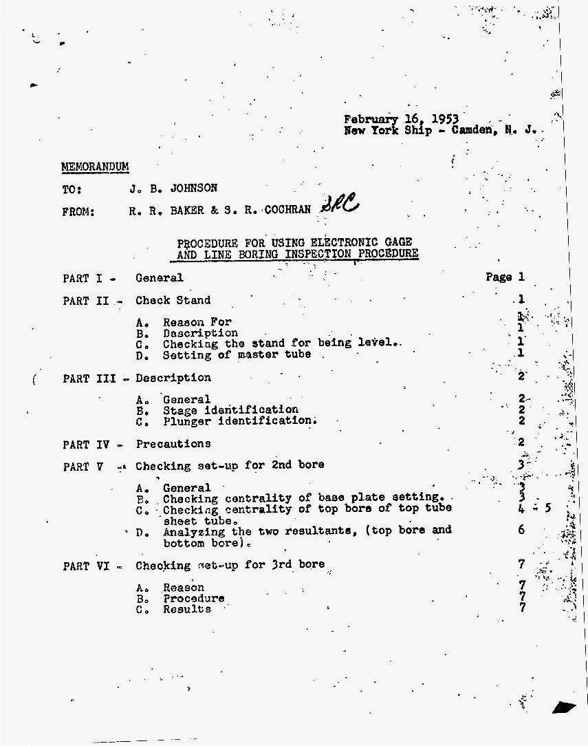
g, Procedure f o r Using E lec t ron ic Gage arid Line Boring Inspec t ion Procedure. (See fo l lowing memorandum)
G. P a t t e r n gages and C a l i b r a t i n g S tands Used on All Sub- Assemblies.
1. Need f o r Pa t t e rn Gages
P a t t e r n gages were necessary i n o r d e r t o determine t h e coordinate of each tube re la t ive t o t h e X and Y axis f o r plenum chamber, t o p t u b e shee t , and bottom tube sheet. I n o t h e r words t he d i s t a n c e from II: and Y axis t o t h e cen te r of each tube was required. permit ted t h e obtainment of t h e s e measurements t o t h e n e a r e s t .001" ,
P a t t e r n gages
2. Development of Gages
The o r i g i n a l gage used i n measuring p a t t e r n s con- s i s t ed of a wood beam with a d i a l i n d i c a t o r a t tached t o one end and a s teel hook a t tached t o the o t h e r end. Du Pont i n spec to r s assigned t o New York Ship were respon- s i b l e f o r t h e conception and production of t h i s gage.
h1W . This gage was, of course, necessary i n order t o measure t h e l o c a t i o n of each tube from t h e X and Y a x i s rows of tubes. s i o n by means of a p in gage c a l i b r a t e d t o .OOln. There were as many d i f f e ren t length p i n gages used as p a t t e r n requirements necess i ta ted . span a d i s t ance of one-half t h e dfameter of t h e uni t . It received use during p a t t e r n measurements on t h e experimental $1 diameter mock-up af ter all t u b e s were welded i n place.
For view of gage, see Part I, section A-1, photo serial
I n use, t h e gage was se t t o a bas ic dimen-
If necessary t h i s gage would
(See P a r t I)
Before t h e time a r r i v e d f o r ob ta in ing f i n a l pa t t e rn measurements on NYX u n i t , a v e r b a l reques t was made t o Design f o r a gage t o f a c i l i t a t e more r a p i d p a t t e r n mea- surements, Four gages were fu rn i shed as shown on du Pont drawing W-130903. p a t t e r n measurements on IQYX and a l l subsequent un i t s . Four ligament gages 4gn long were fabricated by Newton Tool Co., Wenonah, N. J., and shipped t o Rew York Ship f o r immediate use.
These gages were used t o obta in f i n a l
I n order t o set t h e gages t o a proper basic s e t t i n g a c a l i b r a t i n g s tand was fabricated. Th i s permitted a
c . L
I ;.&.. i -.
. . .. 6%
. - '\ J. . * ..
. i c -
t WiORANDUM - TO: J o B o JOHNSON FROM:
- . - . .. . .
PQOCEDURE FOR' USING ELECTRONIC GAGE AND LINE BORING INSPECTION PROCEDUW - -
PART I - General I-
PART I1 ,- Check Stand
A. Reason For
C, D. S e t t i n g of master tube ,
B o DaSCfiptiGn - Checking the stand for being level..
1
i PART 11.1 Deacription - I - _
- - 2' - A, GaAeral Be Stage identification C, Plunger identification. .
PART IV = Precautions
PART V Checking set-up for 2nd bore *
A. General . E, ,Checking centrality of base plate setting.. C, .-Checking ceritrality of top bore of top tube
sheet tube, De Analyzing the two resultants, (top bdrs and
bottom borej
'. .. - .A * .. .
PART VI = Checking neb-up for 3rd bore
A 0 .Reason Bo Procsdure
p:
G o R 0 8 U l t S ' ' C
. I - - 3
c

- .,. . . , . .
I.
- 0 .
." 9 .
' PART V I 1 - Inspection of fbal*b&,
A, General B. Inspections made with C. Inspections made with
. -
- ? +&"a .*. . . . -
-? L: . ? =*. ' * I s . '
. - - * PART- VI11 - .Sketches
.. 1 . -. - .
Sketch 1 Sketch 2 Sketch 3 Sketch 4 Sk&ch 1 I 5
" . .,, . '- .:. . . .3
..
i - ' _ . . _*C
r* C.
. .
- . . .
. . . . *. , . . I ' . - 1
F . .- - .. r 0 ...
\
. . .-
1

PART I .,
PART I1 -
i
Page 1
GENERAL
The Akee?mm Electronic Gage, for %ne action of the and f inal ,boring of the plerrw cham er tubes in,
ti relat set-u! on t o the center point of the tubes i n the top 8 e c t a l tube .sheet, is a d e l i c a t e instrument and should be use with . extreme care.
Basically its opekation and procedure is simple, but unlesa some thought and time is used it can be very confu&ig, The procedure for using th is gage should be followed with c,oncem. . CHECK STAND
A, b 8 S O n for: I
A check stand has been provi'ded for t h e electmko ,
It is uaed for checking the accuracy of the gage gags. as well as s e t t i n g it,
consists 0f.s rigid frome work that holds
and doweled t o the frame. The (304) ateel and the inside &a-
The inside diameter
tube" and a. "locating ring", The by 8 aetting ecrews. The
meter ha8 a honed finish of 5 R.M.S.
graduated i n thousandth8 of an inch on t o of the nlocating ring" on a diagonal
one at each corner, and these jacks control the level of the &and, AdJustment of the stand through these Jacks should b8 done with care and the stand should be checked for level at least once every 24 hour perioa, or before each work s h i f t , . .
The plungers 0-e gage are-sset t o 4.375OW. dfameter. When t h e ,ewe is placed in the. check stand and the instr'u- nient panel turned an, t h e d ia ld Al l read %erna at each . stage with the control switches ab "diameterw position - providing the tube I s ncenteredu and the plungers set COP- rectly,
Positions of t h e tube may be checked by turning the stage switches to N-E, (north & east), or Sew,. (south & west), position, When this is done and a plus or rninv8 reading shows on the dials, the tube is not centered cor- rectly,
ac.ros8 the co E umns of the atand. There are 4 jack screws In the base of t h e stand,
. I.
Do SettfnE of master tube..
. .
1.

a - . , .
1 .
.- 1
0
I
Page 2
the stage control switches i n this osition, adjust LeaviYi the setting screws which are found i n t g e 4 frame columns, (4 at top of t h e tube and 4 at the bogtom), u n t i l a zero reading-is obtained. The screws are 90 t o each other; thegefw8, the adjustment is controlled by 2 screws at 180 to each othero When one accew is' loosened, the opposite screw should be tightened, but onZy f i n g e r t ight In a l l caseso
Direct ion of adjustment may be determined by watch- ing the dials, . checked for "zero" when t he tube is considered centered, Plungers reading other than zero when the gage ie rotated 360' should be reset, but only. by a 'qualified person.
- Each plunger i n each stage should be
PART I ' IT <= DESCRIPTION 1 .
A, General . y e electroniegage consists o f a bronse bar with a leve l ing head consisting of thrust bearing f o r its ro- t a t i o n and a recision nallowap level on top of the head for leve P ing purposeso
Bo Stage ideneif icat ion There a r ' m g e s of plunger8 in the bar which m e .
extrachd and retracted by means of a control handle bn the head of the gage, The 4 stages are referred t o a8 Top-Top, Top, Center and 'Bottom,
positions are referred to 88 north east, south, and west. The north plungers are i n line w i t & the'cagle connection and the other positions are goo, MOO, 270 respect ive ly in a clockwise direction.
* c o P l u n er identif icatton %ere are 4 plungsrs in each stage and their
PART IV - .PR?XAUTIONS' ' rhe .xec t ronic gage w i l l be found in place in the check
The gage i s stand and should be kept there when not in use. .sat in place, rainoved from the check stand or boring aet-up bases by means of a crane with a block and fall. the latter to be h-&id operated,
'When using %he gage in general or checking it, the crane operator and t h e rigger should be cautioned and instructed as to the necessary care required i n raising and lowering the gage into operatin posit ion, The inspector should observe
its operation and accuracy might be impaired if a substantial bump or nunber of bumps occur,
The crane kjhcgld be used only as a means of locating the gage over the set-up base or check-stand, The block and fall is used t o lower or raise the gage into and from its operating position,
it is raised a d lowered t o prevent it from bumping t h e sides of the tube which it i s being lowered into or raised from.
I
each positionlag o f the gage, Bumpingthe gage must be avoided,
.
The gags must be guided by a rigger or t h e inspector'as
I

i
PART V - CHECKING SET-UP FOR 2ND BORE
a
,
A, General. . '7 checking the set-up for the -8acond. bore, the usual procedure should be followed using extreme, cacd in lowering the gage into position and removing it. .
muat - It must be continually remembered that t h e p g u e; ays be l e v e l before making any readings a t any tim
-wayrL 1 eve1 on top of t h e gaga should b e level t o the degree t h a t the bubble is within oneohalf l ine of ba- ing central, with the gage posit ioned In any direction. (See sketch #l) Checking centrality of base plate settin&.
nignnient tolerance on t h i a check has been establ i shed by desfgn as being 0005ne This m e a m t h a t the center of the basa w i l l be central,(within .005") , with a v e r t i c a l l i n e Dassing through the mid-length bore of the correspondo
tube sheet tube, Check this i n the following i n g t b p manner :
10
20
30 r, .i
,
50
Place gage in base plate, wi th in one-half line, New Park Ship level base until such a condition is reached, Use cen~er stage of: plungers and center set of d i a l s S e t selector on centrality, Road top d i a l for N-S reading and bottom ddal for E=W raading, a Precautions
Bubble should be level If it i s not, have
-.
0 When t a l i ng above readings make tha t the north plungers are
If t h e above r84tdiggS 88Bm northerly direction,
rotsrte t h e gage 90 and take a simhar set of readln e These should co with the ori if nol8 i n magnitude. %?hey do not, there i s an indicat ion that the gage requires readjusting by the method out l ined i n Part 31, section D e If the above check In gags a t a ~ d groves'sati& factory, it can be assumed that the top . tube sheet tube.has a defective bqre at the elevation of the plungers. The tube bore should be checked with electronic' gage in order t o determine bore siae: This will asceritain whether the bore is beyond tolerances, 4 dfrections,when tube bore i s uniform take new readings. (Return age t o normd position after rotation or a uatmentm)
l i s t e d in item 4 , are above 10, then have base adjusted accordingly by New York S h i unt i l f u l l dial readings are below 10, (Level a f t r
2,
.
Replace gage and choose
If either or both of the above f u l l d 4 a 1 readinm,
-

,
adjusting and before reading d i a l s , 1 # Z shows why the f u l l dial reading o f 10 is used in lieu of t h e ,OoSR alignment tolerance. Record f i n 2 1 results on appropriate fecord sheet,
s h i f t can be determined by referring to t h e following chart:
Sketch
6 , . Note: If base must be shifted, dtrection o f -
Centrality S h t f t Centrality Shift - ri - s Base E - W ' Base + North -+ E= . - South .c West
Exaqple: Ir' a reading such as this were obtained: N-S: +15; E-W: -20; the base would be shifted first t o the north and then to the west such that the final readings would be below 10,
1 . Checking c e n t r a l i t y of top bore of top tube sheet tube, Tnis check is one of two checks made in an effort to
determine i f . t h e functicrnal gage W i l l properly seat in t h e tube after final boring, determined kr:owledge of Chis fact , (seating .of functional gage), 1s an invaluable asset tg be credited to the use- fulness of the electronic gage, When t h e gage is handled carefully and conscientiously, and the results properly analyzed, m c h grief and money can be saved by knowing. the answer tx this one simple question.. W i l l t he functional gage properly seat after the tube is bored? The answer to %his question is obtained i n t h e following manner, with Lhs gage sti l l in place after t h e check of pare B:
1, Use top stags of plungers and l e f t hand set of d t a l s
2 , Set selector on centrality, 3 o Read r;op dial for N-S reading and bottom d i a l for s
&-W reading, a, Pmcautions .
Ce:
Needless t o say, pre-
.' -
T,,
2,
When taking above readings make certain that t h e noyth plungers are aligned in a norther ly direction, . If t h e above readimp seem radic'al, then rotate the gage 90 s e t of readings, These should compare . with t h e originals in magnitude, 'do not , there is an indication that the gage- reqliires readjusting by the method out l ined in P a r t 11, s e c t i o n D . If the above check in gage stand proves satis- factory,, I t can be assumed that the top t u b e shaet tube has a defective bore at $he e leva t icn of the plungers, bore should be checked .with electronic
and take a similar If they
The tube
._ . -
I

40
'
. 'gage i n order t'o determine bow 8188. This w i l l ascertain whether the bore is8 beyond tolerances, Replace gage and choose 4 directions.,when tube bore is uniform - take new readingab . (Return'-, gage to normal position after rotat$on or adjustment. )
Plot resultant of above components, N-S &'E-& on chart, (see sketch'#3), Make certain that you have payed proper tespect $0 the plu8 and minus signs of the, componentis, resultant w i l l give both magnitude and direction, If the resultant of above full d i a l reardine exceeds 50 make 8 note o fTh1 8 and continue w i t h ' t h e followfng check:
If you have, the
5:, (Did YOU ask, "Where does .
, I
t h e 50 come from?n The answer t o t h i a question w i l l be found on sketch #4.)
De' Checking centrality of bottom bore'of top tube sheet tube,
t o the question. W i l l the functional gage properly seat after the tube38 b r e d ? .
Use bottosa stage of plungers and right hand set of dials,
Read top set of 'dials for N-S reading and bottom set of dials' for E-W'readinge a, Precautions
This check is the final phase I n obtaining an answer
1,
2, Set selector on centrality, 3 0
0 When taking above reading8 make certain that the north plungers are aligned i n a northerly direction, If the above readifbgs seem radical, then rotate the gage 90 and take a similar set of readings, with the originals In magnitude, !%my' do not, there I s an indication that the gage requires readjusting by the method outlined in Part 11, section De If the above check In gage stand proves satfa- factory, it can be assumed that the top tube sheet tube ha8 a defective bore at the elevation of the plungers, bore should be checked with electronic gage i n order t o determine bore size. This will ascertain whether the bore i s beyond tolerances, Replace gage and choose 4. directlon8,wherr tube bore is+ uniform - take new readings, (Return gage t o normal position after rotation or adjustment, )
2,
These should 'com
The tube
4. Plot resultant of above fulx dial-components, N-S & E d . on chart.. (see sketch #$ ), {fi K
8

. ._
Page 6
..
. .
r
5 0 If the resultant of above full d i a l re-ad exceeds 0 make a note of this and pro&% 4
Eo AnalyBing the two resultants, (top bora and botkoa bore&. ~n order to analyze the two r e s ~ l t m t s top bore an boteom bore, one must be aware of the f i v e ca8ea that can exist. These c8se8 are illustrated on akatch #5, and typify hypothetical aectiona of the functional gage fully seated i n the top tube sheet tube. a. Explanation of f i v e cases.
lo
- Cas8 I T h i s I 8 what We term a double white area. It is our goal,
. indicate bhat the functibnol gage'Wil1 . properly aeat after boringe These re- 8ultant readings will be under 50.- * 'bothtop and bottom borsa. The gaga may be removed and tube bored.
Case 11-This is what we term a white-red area. It i s on1 a portion of our goal.
Indicate that the functional gage will c lear the top bore but not thwbottom boreo The resultant w i l l be under 50 for tha . top bore but over 50 for the bOtf;m bore.
To correct the above situation it. t o shfft the base and
disregard the f u 1 dial readin of 10 for. w i l l be neceus the middle bore, Proper sbift ng of base W i l l be i n a direction opposite to largest resultant plotted on chart..
A t completion of final shift ing of base, the top bore resultant and bottom bore resultant 8hould be equalized to OD amount un er 0 if possible , .
-in% it w i l l be-necessary t o check the mid-length bore centrality and determine if the reuultgllt 5s under 50. It w i l l rare1 irever, 6e over 50 if the Note: If it wa8 found t o be impossible
to obtain a double white area, (all resultant8 under 50); contact your s h i f t supen+virror and supply him .
. with your results, He and others w i l l make a decision as to whether the tube can be successfully bored...
Resultant readings in this area
Resu P tant readings in this are8
f 7
above method K as been followad.
Case 111-Here we have a red-white area. This i a the reverse of Case XI. It too, f a bnly a portion of our goal.-
R8SUlt&nt readings i n t h i s area indicate that the functional gagq.wi11 not clear t h e top bore, but w i l l clear

P w e 7 - . -: - 'i
the bottom bore.
the same a8 the procedure followad In Case 11,
Case fV-ThiS i 8 a dOUbX*-1$'8d., &ma. most problglaat$cal situation that. ax%dta.: ft i s the. exact o
Both t o readings nil! W above 50. Here.'also, :-= :< ' rectificatfon 6f the conditi.on.urh 8Qmb.z .: times be accomplished by folluuing thq procedure. of Caae 11. - That is, a contpr~-- ' ~
mise resulting in.equl1aation of the * *
two resulfanta, Again If both ~asultmts after dajuet-'
contact our ehift supervisor. Ha and
Rectification uf this 81tUt%On is *Zav*- .
~ .. It' $8' $ho * . .dt', :,. * . . - site o f &ar'Ipal. pgo O t t m bare M8UlWxlt''*-".
ing do not both fall in 8 white -a, * . -
- others K 11 make a decision 08 t o whether- the t u b CBD b8 BUCC888fUlly bored.
Case V- This I s a rare case indeed. It i8 .a d&bb red area, but notice that tube i e actually' beat, This can be determiaed with the . gage by noting that the resultants OaU. in the same or adjacent quadrants a d
four cases the reaultants f s l l ~ ~ ' a p p o s i t e Rectification of this situation c&
sometimes be accomplished folloddg the . procedurss o f cabe 11 and came fv. - 8 ,
Make cgtrtain that-the midobore -re.sultan$ does not exceed '50 &tor f inal ad3ustments. T h i s a pliee to -a l l C88e80
all five cas88 t h e gage may be mi110V8d from t h e base and the tube bored, t '
. - .
t are above the 50 l i m i t . In tho m a t . . - . 1 quadrants ,on the chart, . .
I
* After satisfactory readings have go en obtained I n
.Always be certain th'at you have recorded your rssulte. ' on the appropriate record sheet.
PART VI - CHECKXNC) SET -UP FOB 3RD BORE, (FINAL BORE,)
A. Reason -is check is made.la order t o determine whsthw the . base moved after maHng%he 2nd bore.' .
B, Procedure Folxow t h e 881118 prooedure aa that followed io P a r t fl - You w x 1
base slightly in SO$ of a l l ~ 8 8 8 8 ~ Remember, adjustment. . wi l l be all t, 80 you should be able t o uccuretely mbreese--. throughm th i? 8 checko.
-cord your results on the aG'opriate record she&
Checking 8 e t ~ for 2nd tiare. . . - c
ind th at it w i l l be necessaq $0 adjust t h e r ,
e,. Results 4. . .
a .

PART V I 1 - INSPECTION OF FINAL BORE
Page 8
t
'. . I A, General
are going t o divide the inspection of-fin& '. - :
ti - 1 , 52 ., .* bore into two categories, namely: 1, Inspections made with electronic-gage. . L -
2,' Inspections made with- other gages. Inspections made with electronic gage, 1, General
---&ult8 of the final bore are obtained i n a somewkiat different manner than heretofore.
d i f f e r e n t pilotxilameter.'
sing a bore gage se% for 4.373" diameter check the t:p land oE plenum for bore size. After d d bore size. has checked nOKn, (4e375n -- k.3?8' approx.) t h e boring fixture base plate must be removed and the bore swabbed clean until dry, Including the tube in t h e top special tube sheet,
Select the "8 ecial" base f o r t h e electronic . gage which has a f l o t diameter nearest, (on the
Position the base and lock into position by means of the locking f i n g e r s ,
Level t h e base by means of a @precision level" a's cloee as possible. The recision letreP-should - $9 positioned Sp l i n e with t R e -8, first in' direction and then the other, After this step l a -. completed, posit'ion t h e Blectronic gage and ad tiat the bas8 for l e v e l by meas of the *all-mP .level.
Extead the plun ers with the north plunger8
.- * 1 .
Bo
. are two "specialn bases made; each base
2, Procedure
minus side) ,. t o t E at of t h e *bore a i s e ,
*
- *
.. alignod i n a norther f p d irec t ion and continue a8
3 , RollOwso esults' . on bottom land of plenum chamber.tubo,
stage of pluqgers with .sqlector set on centralfty, Read t o left 'hand dial for N-Sereading a d
3 . Record the f u l l d i a l readin 8 showing t h e '
1, Use center stage of plungers with selector . . 5
bottom P eft hand d i a l for BOW reading.
pro er plus or minua signs f or each, bo Centra E ity of mid-length hore of top special tubep ."
proper plus or minus signs P or each:
.? set on centrality. . *.!'-
' 2, Read -top-center d i a l for N-S reading *and j , , - bottom center dial for E-W reading. Record t h e full dial readin s 8hodng the 3.
*
C, Inspections made with other g a ~ 8s. re si88 - using bore gage
A t one inch below top -face of plenum chamber . tube i n X 6; P directions, .
- . I . I ..

. - . Page 9 . .
b,
d, east south, and west-dlreoti&s
From one to three inches below chamfor'on bottom land of plenum chamber tuba in X - d t P. "e.'
dir8CthnS. 2. Verticalit h'
showing direcdon 88. wall -a8 *amoltnt bf vhi?$%od%~; L~ ' The end of the a m on which the -d$aX iadi&&or *.-
I s rnowted I s t o be 'used us a'.direct.ioW f'inder. Record plus and minus ai@a for-each reading. .
3. Surface f in ish of bore on plenum tube in remo8. micro- inches,
Do this using*your 'finger - nai l and cempariw with roughness specimen8, Segregate your reuults and record under one of the three ch88ifkcatian8. as follows: a. 0-63
. .L -
"
. - b e 63-125' w
C. 125-UPo t
k0 Functional Gaging t i . Use k0365" - 4J3OW dhm8ter functIonal.gag8, C. If no-go, explain how much ge'lackad of 8ektXng
without any force whatsoeve2 If sli t Qmount
record this also.
6. Record as go or no-go. 4 . of force by h a d . p8- **
5 . Use the remarks column generou8ly on record shest t o explain all discrspanciea..
~ . f *
I
. .

. .~ . . .
i
. .. a-
I I . 1
' .
. . r .
1 ,
. * . I
.-. . . .a
... 5 . .
, 4
i . .
. .
. .

- ., - . . _
I
w- 0 -
. .
,
.- E +IO
* .
. .
.-
c

.CENTRALITY . CHAkT

I
- 4,330"
SK* 4-

#
1
CASE 1
WHJTE
RED
CASE n .
-8' c
RED
CASE
RED
I
CrlSEXi -
SK*5

3 ,

- I .
7.. ,A.
., , ., * '
. .
;. ':', .< ''2
Page 21 - . I 7
: c are taken t o rows X28 and X29 from t he X center l ine,
diameter of tube X2$-Y45 is 4.386*, and t h e dis tance ' , .: . .;: ,A
of t h e outside edge of t h e I , D , from center l ine is, *.'.':;:::;*.
2,200r1, then t h e center l e f t of t h e center l ine , are then measured fr,om %hem ba
coordinates. It is ap be applied f o r t h e bas X39-YZl has a ligament tube X29-Y21 which has bore of tube X39-Y21 is The coordinate of tube 21. # 30.598" r(c 20195fr o r 38. is graphed as the ac tua l d i s t which i s t h e va r i a t ion from t
An a l t e r n a t i v e t o t gages at t h e o r e t i c a l d i s t t h e pa t te rn , add a l l devi deviat ion from t h e theo re t i c ing t h e p a t t e r n coordinate. and less cumbersome, and is ac tua l ly used t o calc t h e pa t te rn ,
see P a r t 11-A, Section 18, bottom s i d e ) ,
and Y45 and Y4$ from the Y center l ine, If t h e bore -..
be remembered 'that dl basic 't;
. - _ . .
For an i l l u s t r a t i v e ex
H, Eccent r ic i ty Gages
1. Development and Procurement .
Division r ea l i zed t h a t it data r e l a t i v e t o t h e eccent chamber tube bore and the t w a s , agreed t h a t the eccent mid-point of the top.tube- t h e upper and lower bore o
Due t o t h e basic design of %he top tube sheet, Design-Divfsion spe t r i c i t y measurements sh At t h i s point, it w a s pos would have t o be inser ted t h e mid-point.of the bore I n r e a l i t y , it was the final. :dec sleeve type gage would have t o ' b i nd ica to r mechanism suspended in th gage, The first gage (see Photogr Item f2) was fabricated- .and assemb and Manufacturing Company,. Wenonah cordance wi th Drawing No, D-114396 du Pont Equipment Piece No, 790-76
I n t h e e a r l y s tages of t h e NPX;.Projec
. %

._. . .-
Q

: iL
I ’ i .
i
i I, f
. . . .- . ,., . . . ,. . -
’ _. . . . -
. .
I

Page 22
When t h e first e c c e n t r i c i t y gage was received a t New Pork Ship, it was observed t h a t t h e gage had several l imi t a t ions . I n t h e first place , t h e d i a l i n d i c a t o r w a s mounted i n the 'bot tom end of t h e gage i n such a manner t h a t t h e plunger of t h e d i a l i n d i c a t o r could not be re- t r a c t e d between readings, After a series of readings had been taken, it was found t h a t t h e d i a l i n d i c a t o r plunger had been damaged. Evidently, t h e plunger caught on t h e plenum chamber o r t o p tube sheet tube when t h e e c c e n t r i c i t y gage was i n s e r t e d o r removed from t h e tube being measured.
To a l l e v i a t e t h i s condi t ion, M & E Inspect ion per- sonnel devised a method of retracting t h e dial i n d i c a t o r plunger when t h e gage w a s not i n use. t h e gage was accomplished by attaching; a cord t o t h e d i a l i n d i c a t o r plunger i n s i d e t h e gage body, This allowed t h e plunger t o be r e t r a c t e d while i n s e r t i n g or removing t h e gage from t h e tube bore,
Modification of
However, it was aga in observed t h a t t h i s modified gage (see Photograph, S e r i a l No. 275, Item #2, du Pont Equipment Piece No. 790-76) could be damaged-if t h e operator using t h e gage f o e o t t o r e t r a c t t h e d i a l in- d i c a t o r before removing t h e gage from t h e tube bore. T h i s problem was presented t o t h e Design Division f o r review and t h e i r recommendations.
I n due t i m e t h e Design Divis ion designed a new ec- c e n t r i c i t y gage !see Photograph. S e r i a l #275, Item #3, du Pont Equipment Piece #790-771 t o r ep lace t h e o ld gage. Since it w a s considered imprac t i ca l t o modify t h e o ld gage, t h e gage was considered obsolete. The new gage was f a b r i c a t e d and assembled by t h e Newton Tool and Manu- f a c t u r i n g Company, Wenonah, New Jersey,
i n t h e bas i c desi-that had been omitted i n t h e design of t h e o ld e c c e n t r i c i t y gage. t h e NYX plenum chamber and t o p tube shee t large tubes, carbon s t e e l base p l a t e s were posi t ioned over t h e tubes f o r a l ign ing and suppor t ing t h e boring bar. To t a k e a reading with t h e first e c c e n t r i c i t y gage, it was neces- s a ry t o have t h i s base p l a t e removed before i n s e r t i n g t h e gage i n t h e tube. By making t h e gage longer o r by adding t o t h e length of the t u b e body t o compensate f o r t h e th ickness of t h e base p l a t e , it was poss ib le t o t a k e readings when t h e base p l a t e was i n t h e p o s i t i o n used f o r l i n e boring t h e tube. Th i s made it poss ib l e t o t a k e e c c e n t r i c i t y readings before , during, and after t h e l i n e boring operation. t h e gage body t o act a5 a s t o p fo r t h e gage (see Sketch #7). T h i s c o l l a r could seat on t h e plenum chamber tube face and give p o s i t i v e c o n t r o l of t h e depth bo which t h e gage was i n s e r t e d i n t o t h e tubes. opera tor t h a t t h e d i a l i n d i c a t o r plunger was making contact ~ t h t h e mid-point of t h e i n t e r i o r of t h e t o p
The new gage had s e v e r a l good f e a t u r e s incorporated
During t h e l i n e boring of
A s p e c i a l c o l l a r was fab r i ca t ed f o r
It a l s o insured t h e

. . . - . i r
.. . .
#-+ n
'/ - _ . . ..

Page 22
tube shee t t u b e wall. With a p o s i t i v e method of con- t r o l l i n g t h e degree of i n s e r t i n g t h e gage i n t h e tube bore, it a l s o became apparent t h a t t h e two o t h e r c o l l a r s f a b r i c a t e d i n t o t h e body of t h e gage were s e a t i n g proper- ly i n t h e upper and lower bores of t h e plenum chamber.
i n d i c a t o r plunger when t h e e c c e n t r i c i t y gage was being withdrawn from t h e tube bore, t h e gage was re-designed so t h a t t h e d i a l i n d i c a t o r plunger was automat ica l ly re- t r a c t e d by a s p r i n g loaded f o r k and plunger arrangement. When a reading was taken, t h e opera tor had t o depress t h e plunger loca t ed a t t h e t o p of t h e gage. t h e d i a l i n d i c a t o r plunger t o come i n con tac t wi th t h e i n n e r w a l l of t h e t o p tube shee t t u b e mid-point. How- ever, it was found t h a t it was q u i t e d i f f i c u l t t o keep t h e gage i n proper adjustment, This w a s p a r t i a l l y due t o t h e f a c t t h a t t h e readings were being t a k e n i n thou- sandths of an inch. A t t h i s po in t , a s p e c i a l r i n g gage w a s designed and fabr ica ted . This r i n g gage was used as a known standard f o r s e t t i n g and checking t h e eccen- t r i c i t y gage be fo re readings were obtained. point , it was f e l t t h a t no more d i f f i c u l t i e s would be encountered i n t he axsage- of t h e e c c e n t r i c i t y gage.
Nevertheless, a f t e r t ak ing s e v e r a l hundred eccen- t r i c i t y readings, t h e observat ion w a s made t h a t t h e s e readings could not be dupl icated t o wi th in s e v e r a l thousandths of an inch. v a r i a t i o n of t h e tube bore w a s great enough t o cause t h i s v a r i a t i o n i n t h e readings. S ince t h i s gage w a s designed t o t a k e measurements t o t h e n e a r e s t thousandth of an inch, it w a s decided t h a t t h e gage w a s no t accu- rate and, t h e r e f o r e , f o r a l l p r a c t i c a l purposes, it was placed on a standby list. I n o t h e r words, ages number two and number t h r e e i n Photograph, S e r i a l # 275, were obsolete.
To overcome the safe ty hazard of damaging t h e d i a l
This allowed
A t t h i s
It w a s specula ted t h a t t h e
Seve ra l months elapsed between t h e t i m e t h a t t h e NYX plenum chamber and t o p tube shee t w e r e l i n e bored,. and t h e same u n i t s were placed i n opera t ion a t New Pork Shipbui lding’ Corporation. some emphasis was placed on t h e conjec ture t h a t t h e ec- c e n t r i c i t y gages should be re-designed, However, a f te r considerable inves t iga t ion , it was decided t h a t t h e present gages (see Photograph, S e r i a l #275, Items 2 and 3 ) could not be modified t o o b t a i n accu ra t e d a t a during t h e opera t ion of t h e above referenced Npx u n i t s ,
During t h i s i n t e r v a l of time,
To t a k e measurements p r i o r t o and du r ing t h e oper- a t i o n of t h e NYX u n i t a t var ious temperatures and pressures , it was necessary t o design new e c c e n t r i c i t y gages. Two gages were required. The first o r s h o r t gage was designed t o measure t h e e c c e n t r i c i t y between t h e plenum tube bore and t h e t o p of t h e t o p t u b e shee t tube., The second, or longer gage, was designed t o

. I
. r - ., . - -
L , ' , ' -'.-;-;.':page - .
measure t h e eccentr ic i ty between t h e p1en;Ud' and the bottom of the top tube sheet t gages were designed t o take measurements ,to Ithe-: thousandths .of an. inch,
c;
r - s ?.
These ,gages a re shown on Drawing z+l14&79 %nd -were
I6 d..-by >.+gg?sri5:-io )the Gbaupont.. ...mcK, d%aP;., ;Colpo~at~on,~,G~andor'a -..?::'::**+*-.; s '=,Hey i ' ",.,.the; gageg ~2 f-g e .. . I Photographi-'Seriax,:#2?5, Items:. .#l .ran~-#4-~..-:~erel; .$P~~~~
t o the eccen t r l c i ty~ gages used. during ' t he 5 i C e .boring '
of t h e NYX plenuni.chamber and top---tube sheet:-assembly. ' -. :.. .- However, both- gages employed a -back land I pZnion- gear to'. ; -.
'retract %he dial; . indicator plunger, --'.This .not, -op&y ,qe;-. sul ted. in-more accurate readings, :?$it also' redude'd .the.', --.
. , . -amouht. of, %hie. .required for. stand.ardi&ng' the. :gage.&'. .%- 4s'-, . . . - was $the :case.' with +the previous .eccentr ic i ty . I &ages'.:('see. Photograph:, Serial':#275, Items #Z and #3) a =special ri.ng-~.4 : 'gage had: to ; be -designed f o r ..st&rdardizing--ths new. ec- . ?'.:~.:~d-,
- . , C . _ _ ; I . . I . .- ._ - -..: .-.I? centri .pitp .gages, .-;. . -
. To use' . the new gages and obtain'readings '.accurat.e. .
t o a thousandth of an inch, fou r special: sleeves ,were, ...' . z .:-. .',
designed., . The sleeve was i n se r t ed - in. the. pleriiibj3ube :+: and held secure by .a- s e t screw. In turn, --the::bo&y..af.. I -- .:- .--- t h e eccent r ic i tx gage w a s inser ted i n t o the s$eeve,, k: . ' . Since the ins ide diameter of the sleeve'was "adkurat'e. .. ..
, t o %housandths. sf aq inch, the. var i a t ion . €n;,.the..r.e
. - , was'.co,nsi[aerably,~ less. than .had .bee& ~ & e v i 6 u @ ~ . ~ e ~ G r
Neverthelesss :,af'tex$ aneyzing~:a serieg: of,. .ei$iGri$ric ';'-gage -readings,l-Qbtained during the'-'trial'' op&%t3'on' of
the NylE :assembly; it -*was .-concluded - t h a t .the .readings were 'not accura te - to t h e nearest thousandths. of . an inch. :':. I n effect , ,ft was decided t h a t .for . a l l - -p rac t i&a l gurposes..,l
',
ecceqtriqity ' .g+ges, --a gage . (.see: Th Item,&, 1 du .Pont'..Equipment'.Piece- #? f o r measuring boring eccen t r i c i ty -:b chamber tube and the top tube sheet tube w a s fabricated by-the Thau Manufactur'i Baltimore; Maryland, Draning z>-ll&897- case. with-Ghe other eccentr5ci ty ga'ges t h a t khe--var%abion ,ih the-'size .lo< :the tube bore-. caused considerable ' diverke
. . . ~ . ,,, . . ~ , * . , . -, . , ;- , . .- . .-:- , - . . " *
. - . ..
* . . . - . . .~ .., 1
,. . .. . '
. . , I
. .- - .' 5ngs - obtaXned-::iiuring' the- ppera$.ion: Of'-'.tXe :NYjC,ass . I '. . . .,".!. - . . I . . ~. -.e edc-&d , d ~ @ g ~ ~ ~ ~ . e ' , ~ i ~ e ~ ~ : b & r i n g .*f: -~he.;'su~3'ect..'~~~~*~~~, . .
' . =%ycz-.
. , * .. ,' ,- . . ,..< t h e lat ter two eccent r ic i ty gages .wer.e obsolete;. - .\ . --
A t one. t j i m e . .during the early:. st '
-
- -


Page 25
method of ob ta in ing e c c e n t r i c i t y reading data. major i ty of t h e exper t s agreed t h a t d a t a obtained e l e c t r o n i c a l l y would be far more accura te than t h e d a t a obtained with a mechanical type of e c c e n t r i c i t y gage. I n addi t ion , t h e e l e c t r o n i c gage could obta in w i t h one s e t t i n g t h e exact r e l a t i o n s h i p i n f o u r d i r e c t i o n s (go0 apart) between t h e t o p and bottom lands of t h e plenum chamber tube, and t h e top, middle, and bottom of t h e t o p tube sheet tube. Not only was it observed t h a t t h e e l e c t r o n i c gage could obta in readings accurate t o w i t h i n a thousandth p a r t of an inch, but it was also r e a l i z e d t h a t t h e e l e c t r o n i c gage was a g r e a t t ime saver when it w a s compared t o t h e mechanical type of gage. Therefore, t h e advent and success fu l a p p l i c a t i o n of t h e e l e c t r o n i c gage d e f i n i t e l y placed t h e mechanical e c c e n t r i c i t y gages on t h e obsolescence s h e l f .
The
2. Operation and Use
The e c c e n t r i c i t y gages were first used during t h e l i n e boring of t h e tubes i n t h e plenum chamber and t o p tube sheet assemblies. To u s e t h e first gage ( see Photograph S e r i a l 8275, Item #2, du Pont Equipment Piece No. 790-76) t h e opera tor wouldlgrasp t h e handles of t h e gage and manually lower t h e gage i n t o t h e t u b e s allowing t h e gage by v i r t u e of i t s own weight and in- er t ia t o s e a t i t se l f . It w a s understood t h a t s ince t h e subjec t assemblies were mated and leve led p r i o r t o s t a r t i n g t h e l i n e boring operat ion, t h e bore of a tube was i n a v e r t i c a l plane common t o a l l o the r l a r g e t u b e s i n t h e un i t s . taken when t h e body of t h e gage had al igned i t s e l f with t h e bore of t h e plenum and t o p tube sheet tube.
It fo l lows t h a t t h e gage readings were
Generally speaking, t h e first reading was taken when the stem of t h e d i a l i n d i c a t o r plunger coincided with e i t h e r t h e "X!' or "Ytt ax is of t h e subjec t un i t s . Readings were taken f o r each quadrant o r a t 90' i n t e r v a l s covering a span of 360'. readings with two readings on t h e nXn a x i s and two read- i n g s on t h e "Y*' axis.
This allowed a t o t a l of f o u r
When t h e stem of t h e d i a l i n d i c a t o r was depressed, t h e hand of t h e i n d i c a t o r revolved i n a clockwise d i - rec t ion . The opera tor with t h e a i d of a f l a s h l i g h t could t a k e readings and record them f o r each of t h e quadrants. As previously ind ica t ed , t h i s f irst gage was not designed f o r mechanically r e t r a c t i n g the d i a l i n d i c a t o r plunger. Ear ly i n t h e game, it w a s placed on t h e i n a c t i v e gage l i s t i n g .
The next gage (see Photograph S e r i a l No. 275, Item #3, du Pont Equipment Piece No. 790-77) allowed t h e oper- a t o r t o r e l e a s e a sp r ing loaded f o r k and plunger arrange- ment before t a k i n g a reading. When re leased , t h e plunger

Page 26
came i n con tac t with t h e tube wal l and a reading could be taken. s e t t o a s tandard r i n g gage, s o a l l readings taken were i n e i t h e r a p l u s o r minus d i r ec t ion t o t h e s tandard s e t t i n g of ze ro i n most cases.
As before, t h e e c c e n t r i c i t y gage had t o be
Both of t h e above gages were set aside when t h e l i n e boring of t h e NYX u n i t was completed.
For ob ta in ing e c c e n t r i c i t y readings dur ing t h e oper- a t i o n of t h e NYX u n i t s (Building 101, t w o new gages were designed, f275, Item j f l , du Pont Zquipment Piece #790-111 and Item &, du Pont Equipment Piece #?go-112. i n s e r t e d i n t o t h e large tubes a f t e r t h e u n i t s had been mated, l e v e l e d and placed i n operation. As discussed before, f o u r s l e e v e s were used i n conjunction with t h e s e gages. These gages employed a rack and p in ion gear t o r e t r a c t t h e d i a l i nd ica to r . After t h e gage a l igned it- self w i t h t h e s l e e v e bore, t h e operator could release t h e d i a l i n d i c a t o r plunger, s o it came i n contac t with t h e wall of t h e t o p tube shee t tube. With t h e a i d of a f l a s h l i g h t , d i a l i n d i c a t o r readings were taken. As be- f o r e , t h e r ead ings were usua l ly taken a t 90' i n t e r v a l s and covered a range of 360°. The d i a l i n d i c a t o r had t o be previously set t o 2 known standard. The s tandard was used as a b a s i s f o r making a l l e c c e n t r i c i t y calcu- l a t i o n s .
The gages are shown i n t h e Photograph S e r i a l
These gages were
I n conclusion, a l l f i v e of t hese gages were de- c l a red obso le t e because accurate readings could not be obtained t o t h e n e a r e s t . 0 O l n . After changing t o t h e e l e c t r o n i c gage, readings were accura te ly obtained t o tahe nea res t .OOln. c o n t r o l l i n g t h e l i n e boring operation and t h e t e s t oper- a t i o n of a l l u n i t s .
The e l e c t r o n i c gage was ?sed f o r
I, Spec ia l Gages used i n Building 10 f o r Obtaining Measurements Before, During, and After Operational Tes t s conducted on t h e NYX Process Unit
General : ments on t h e NYX p rocess u n i t i n Building 10, and t h e s p e c i a l type gages and ins t ruments required t o perform t h i s job. All measurements were t aken a f t e r i n s t a l l a t i o n and alignment of t h e process u n i t f o r experimental t e s t i n g purposes.
This r epor t covers t h e procedure used i n secu r ing measure-
The procedures ou t l ined herewith were set up by t h e du Pont Operations Technical Group. They, i n tu rn , reques ted t h e M &= E Inspect ion Group loca ted a t New Pork Ship t o ob ta in t h e neces- s a r y opera t iona l data. The o r i g i n a l procedures as ou t l ined by t h e Technical Group were of a general nature . r e s p o n s i b i l i t y of t h e I4 & E Group t o develop t h e a c t u a l in - spec t ion techniques u t i l i z e d f o r completing t h e assignment,
It was t h e

Page 27
A l l d a t a and information recorded by the 14 8s E Inspec t ion Group was presented t o t h e Technical Group i n formal r e p o r t f o r a r
1. Rota t iona l Eovement of Plenum Chamber w i t h Respect t o S i l o
Khile o u t l i n i n g a procedure f o r t h e ope ra t ion and t e s t i n g of the NYX Unit, it was the opinion of the Oper- a t i o n a l Group t h a t t h e plenum chamber probably moved when subjected t o va r ious temperatures and pres su res , on t h i s suppos i t ion , t h i s group requested t h e '14 &, E Sec t ion of t h e cons t ruc t ion d iv i s ion t o secure exact da t a as t o t h e degree t o which t h e plenum chamber would move.
Based
A t a l a te r date, t h e &; E Sect ion r eques t ed the Operat ional Group t o spec i fy the d i r e c t i o n a l movement t h a t they were p r imar i ly concerned with, i nd ica t ed t h e i r d e s i r e t o a s c e r t a i n how niany increments on t h e o u t e r per iphery of t he plenum chamber moved i n r e spec t t o a f i x e d po in t during t h e i n t e r v a l of opera t ing the KYX Unit. It was considered adequate t o t a k e a l l r o t a t i o n a l measurements i n a clockwise o r counter-clock- wise d i r e c t i o n and confine these masurements t o a hori- z o n t a l plane . To f ac i l i t a t e the analyzing and c a l c u l a t i n g the exact amount of t h i s rotat ionalmovement , read ings were taken before, during, and a f t e r each of a series of ope ra t iona l t es t runs.
They I n turn
Severa l ins t ruments and methods were considered by t h e M & E Sec t ion f o r car ry ing out t h i s s p e c i f i c assign- ment. Based on p a s t experience, t h e 14 & E Inspec t ion Grou settled on the P!ild T-1 Theodolite, (See s e c t i o n "Kn, P as t h e proper instrument f o r t a k i n g a c c u r a t e mea- surements i n a minimum amount of time,
For a f i x e d po in t t o serve a s a bench mark f o r set- t i n g up and us ing t h e Theodolite, a spot was s e l e c t e d on t h e nor theas t corner of t h e concrete s i l o . To e s t a b l i s h and hold t h i s bench mark as a permanent f ixed point from which a l l r o t a t i o n a l measurements could be obta ined , t h e Ivi & E Sec t ion suggested t h a t a s t e e l instrument mount be f ab r i ca t ed . This instrument mount (See -Sketch #) would be mounted on a concre te pedes ta l loca ted on t h e s i l o . It was mutually agreed t h a t t h e concrete s i l o d i d not move t o any apprec iab le degree xhen t h e M Y X u n i t was operat ing. Therefore, it followed that t h e s teel pedes t e l should be i n s t a l l e d on top of the concrete s i l o . As an added f e a t u r e f o r ob ta in ing accurate measurements over a period of s e v e r a l weeks, the t o p plate of t h e instru- ment mount was machined t o a plane having a ground f i n i s h .
f e rence p o i n t s were es tab l i shed . was placed on t h e concrete block wall n o r t h e a s t of the instrument mount. This point e s t ab l i shed a check l i n e running from a po in t on t h e instrument mount t o the poin t on t h e concrete block w a l l . Another r e fe rence po in t was es t ab l i shed on the building s t e e l loca ted to t h e north- west of t he instrument mount. Th i s po in t es tabl ished a
P r i o r t o ope ra t ing t h e MYX un i t on a t e s t basis re- One r e fe rence Foint

.- -.-
ENGINEERING SKETCH SHEET ' E. 1. DU PONT DE NEMOURS & CO.
C.
SIGNATURE: No.
-.
-. TITLE DATE
SUBJECT : SETUPT~ C ~ E L Y R O T ~ T I ~ . V F L . i.? 0 tJ:Z,V 0 F pL I Z W " Ll.
-
t i
'2 - - , -_ . '. .
1 N
i

rage zt3
All measurements base l i n e running from e point on the instrument mount t o t h e point on the building s t e e l o were ts,ken from this base line.
Four reference tubes i n the plenum chamber were selected f o r studying the rotational movement of the RYX uni t , Its coordinate was designated as XF, Y48 in respect t o the .X and P axis of the plenum charher. -!&e other three reference tubes were located on the outer pe~iphery of the plenum chamber a p p r o x h a t e l g 120° aparL d ina te s were X6;-Y24; X2g;0Yg3;, X51;-Y27,
One tube was t he cen te r tube of the plenum chamber.
Their coor-
A spec ia l sleeve was inser ted i n each of the four For a l l p r z c t i c a l purposess the bore of chosen tubes.
any sleeve was considered perpendicuhz' t o the machined plane formed by the top surface of the plenum tube ends, k mandrel with a flat surface milled on one side and along its length was inserted i n each of t h e four sleeves. Since the sleeve bores were uniform i n size t o within a few thousandths of an inch, t h i s mandrel was machined t o give a snug f i t when fully i n se r t ed into any one of the four spec ia l sleeves. k center l ine was scr ibed on the f l a t surface of t h e mandrel, When the mandrel was seated i n a special sleeve, t h i s cen ter l i n e for all p r a c t i c a l purposes, was considered perpendiculac t o the machined plane out l ined by t h e top surface of t h e plenum tube ends. A small center punch mark was located on t h i s center lfne. When taking a reading the milled flat surface has t o face the tnstrument set up on the northeast corner of the sib*
A l l readings were taken i n the.followfng manner; A total of twelve readings were taken between t h e base lfne and check l ine. Six readings were taken d i r e c t l y and six readings were obtained ind i rec t ly , readings were taken t o n u l l i f y any error i n t he theodo- l i t e . Next, a t o t a l of twelve readings were taken between t h e base line and t h e four plenum chamber tubes referenced above, six were obtained indirectly, readings were taken t o cancel ou t m y error i n the theo- do l i t e . readings the operator merely reversed t h e te lescopic par t of t he instrument.
Ind i r ec t
S i x of these readings were taken d f r e c t l y and Likewise, the i nd i r ec t
It should be pointed out t h a t t o take ind i r ec t
Using these readings, calculat ions were made t o f ind t h e angles between t h e base l i n e and an imaginary l i n e running from the punchmzrk on t h e f l a t surface of t h e mandrel to a point i n the theodolf te . Since direct and i nd i r ec t readings were taken, it was necessary to average t h e angles obtained between the base l i n e and t h e line of s igh t of the theodol i te when t h e instrument was focused on the punch mark located on the f l a t surface of the mandrel, These angles (See Sketch 2A) were designated as A, B, C, and D, obtained before, during, and after operat ing the NYX u n i t on a test basis, The deviat ion between the angles mea- sured at various temperatures and pressures gave the
The angles were calculated from data

amount of r o t a t i o n o f t h e plenum chamber during i t s opera t ion ,
2,
For an i l l u s t r a t i o n of t h e results obta ined refer t o du Pont report number l32-X, Exhib i t B1, P a r t B1-2,
V e r t i c a l i t y of Plenum Chamber w i t h Respect t o Top Tube Sheet
Prior t o p lac ing t h e NYX process unit on en operat- i o n a l basis, it was r e z l i z e d t h a t d a t a would have t o be secured as t o the degree of movement of t h e plenum chamber i n r e spec t t o t h e t o p tube shee t .
When t h e u n i t s were i n s t a l l e d , p a r t i c u l a r emphasis was placed on see ing t h a t t h e t u b e f a c e s on t h e t o p s i d e of t h e t o p tube shee t and t h e bottom s i d e of the plenum chamber were proper ly mated. t h i s feat , v e r t i c a l i t y gages were employed. Several tubes were se l ec t ed as being r e p r e s e n t a t i v e of a l l tubes i n t h e unf t s . f o r these tubes , it was concluded t h z t a l l tubes i n the u n i t s were properly a l igned ,
Inspec t ion Group t h a t a v e r t i c a l i t y gage would give t h e desired data f o r f i n d i n g the degree o f movement of t h e plenum chamber r e l a t i v e t o t h e t o p tube sheet .
To a i d i n accomplishing
By f i n d i n g the b e s t average v e r t i c a l i t y
Based on the above, it w a s t h e opin ion of the I4 & E
Four tubes were s e l e c t e d f o r t h e s e measurements, Locat ion’of t hese tubes has been shown on Sketch 2k i n t h i s sect ion. They were ass igned t h e fo l lowing coordinate tube numbers; I6-Y24, X28-Yl&, X29-Yg3, and X51-YZ7. A s p e c i a l s tee l s leeve was i n s e r t e d i n each o f these tubes, t o ob ta in more accura te readings.
Since none of the v e r t i c a l i t y gages on hand would f i t i n the s t e e l s leeve , a s p e c i a l gage was designed by t h e Design Division and Wilmington Shops. It was fabri- ca ted by t h e Chaumont Corporation, Glendora, New Jersey. To comply with the f a c t t h a t v e r t i c a l i t y measuremnts represent the arrount o f i n c l i n a t i o n of a tube bore i n r e spec t t o a v e r t i c a l l i n e , t h e gage was b u i l t t o take measurements t o mOO1n p e r foot . A d i a l i n d i c a t o r c a l i - brated i n thousandths of an inch was a t t a c h e d t o the arm of t h e gage. A s p i r i t level 2nd a d j u s t i n g screw were a l s o made e s s e n t i a l components o f t h i s special v e r t i c a l i t y gage a
I n t a k i n g v e r t i c a l i t y r ead ings t h e gage was manually lowered i n t o one of t h e f o u r special s leeves . Next, t h e v e r t i c a l i t y gage was l eve led by a d j u s t i n g the hand ad jus t - ed set screw u n t i l t h e s p i r i t l e v e l i nd ica t ed t h a t t h e bubble had loca ted between t h e middle two graduations on t h e glass of t h e s p i r i t level. After l e v e l i n g the gage, readings were taken i n each of t h e f o u r quadrants covering 3600 . Each measurement: w a s t aken along e i t h e r t h e X o r Y axis.
- . . . . . . . .. . . . . - . . . . - - - ~ - ---- . . , ,

Page 30 All v e r t i c a l i t y data was presented by t h e 1.i 8c E
Inspec t ion Group t o t h e Techanical Operatfons Group. Based on t h i s data c a l c u l a t i o n s w e r e made t o a s c e r t a i n t h e exac t amount t h e plenum chamber moved fn respec t t o the t o p tube sheet, and af ter operating t h e NYX process unit on a t es t basis .
Cent ra l i t y of Plenum Chamber with Respect t o Top Tube- Sheet
Readings were taken before, during,
3.
During the period of agreeing on what measurements should be taken when the NYX u n i t was o p e r a t i n g on a t e s t b s s i s , it vias realized t h a t dzta would have to be secured t o determine the degree of movement of the plenum chamber i n r e l a t i o n t o t h e t o p tube sheet.
The u n i t s were i n s t a l l e d by using tk b e s t average , tube c e n t r a l i t y readings, t h a t such read ings not only aided i n a l i g n i n g the tubes i n t h e plenum chamber and t o p tube sheet, but also helped i n mating t h e tube f a c e s on the bottom s ide of t h e plenum chamber mi the tube faces on t h e top side of t h e t o p tube sheet. All c e n t r z l i t y readings were obtained by Eeasuring e r e p r e s e n t a t i v e nunber of tubes with gages s i m i l a r t o those discussed i n Sec t ion H.
A t the time it was observed
i3ased on experience gained i n p rev ious ly using t h e e c c e n t r i c i t y gages, it v:.!as decided by t h e 14 & E Inspect ion Group tha t two e c c e n t r i c i t y gages tmuld give t h e required data for determining t h e movement of t h e NYX plenum chamber i n r e s p e c t t o the t o p tube sheet dur ing the oper- a t i o n of t h e entire RYX assembly on a t e s t basis,
The i r coord ina tes w e r e as follows: X6-Y24, XZS-Y48, X29- Y93, and X51-Y27, ined t o a close tolerance, were i n s e r t e d i n t o t h e above referenced tubes. It was found t h a t more accurate data was obtained when the s t e e l sleeves were f i t t e d i n the sub jec t four tubes, This conclusion was based on a coinparison of readings obtained with t h e e c c e n t r i c i t y gages i n se r t ed i n t h e steel s leeves versus t h e eccen t r i - c i t y readings secured wlthout t h e s l e e v e s i n these tubes. Location of' the tubes i n the u n i t s has been shown on Sketch 2A.
Four t u b e s were selected f o r these measurements.
S p e c i a l s tee l sleeves, with bores mach-
I n l i e u of t h e fac t t h a t t he first e c c e n t r i c i t y gages would no t f i t i n the Sleeves, two new gages were designed by the Design Divis ion as shown on d e t a i l draw- i ng D-114.479. The gages were procured from the Chatmont Copporation, Glendora, Rew Jersey, on i n q u i r y nurnber C30- 816, order number AXC 6700&. ved a t the Mew York Shipbui lding Corporation they were assigned equipment piece numbers 790-111 and 790-112, r e spec t ive ly ,
A t the tirr;e they were recei-
The first gage, equipment p iece number 790-111, ,dwg. detai l D-11&&79k was designed t o measure t h e eccent- r i c i t y between the plenum tube bore and t h e t o p of the

t o p tube s h e e t tube bore, The second gage, equipment p iece number 790-112, dwg. d e t a i l D-114479B was designed t o measure t h e e c c e n t r i c i t y between t h e plenum tube bore and t h e bottom of t h e t o p tube shee t t ube bore.
E c c e n t r i c i t y o r c e n t r a l i t y readings were t aken before, dur ing , and a f t e r opera t ing t h e €XX assembly on a tes t basis. Four readings were taken f o r each tube covering 3600 with one reading i n each quadrant. A l l readings were taken along e i t h e r t h e X o r Y axis of t h e plenum ch araber .
Readings were taken by manually lowering t h e eccent- r i c i t y gage i n t o the tube being measured, To t a k e a read- ing. t h e stem of t h e d i a l i n d i c a t o r was depressed. This permit ted tb d i a l i n d i c a t o r plunger t o make con tac t with the i n n e r w a l l of t h e t o p tube shee t tube. The ope ra to r , with t h e a id o f a f l a s h l i g h t , could t a k e r ead ings and record them f o r each of t h e quadrants.
All c e n t r a l i t y data was presented i n r e p o r t form t o the Technical Operations Group by t h e N et E Inspec t ion Group, They, i n t u r n , examined the data ani c a l c u l a t e d t h e degree of xiovement of t h e plenum chamber i n r e l a t i o n t o t h e t o p tube sheet . %'here poss ib le a c o r r e l a t i o n was m d e between t h e r e s u l t s obtained wi th t h e c e n t r a l i t y data snd other d a t a such as t h a t secured w i t h v e r t i c a l i t y gages.
4. Def lec t ion of t h e Top Tube Sheet
kihile making a s tudy of t h e t y p e s of movement during the o p e r a t i o n o f t h e RYX u n i t on a t e s t basis, t h e 14 & E Inspec t ion and Technical Gperations Groups r e a l i z e d t h a t measurements should be taken of the amount o f v e r t i c a l zovement of the plenum chamber, t o p tube s h e e t and tank bottom, It was concluded by these groups t h a t a E a s u r e - ment of t h e d e f l e c t i o n of t i e t o p tube s h e e t would s u f f i c e , I n o t h e r words, the data obtained i n s tudy ing t h e de f l ec t - i on of t he top tube shee t represented t o a great degree t h e o v e r a l l p i c t u r e of the NYX assembly, Def l ec t ion da ta was c o l l e c t e d before , during, acd d t e r o p e r a t i n g t h e hlX assembly on a t e s t basis,
After cons ider ing s e v e r a l ins t ruments and ways of t a k i n g t h e d e f l e c t i o n measurenents, it was t h e concerted opinion of a l l p a r t i e s involved t h a t a Wild WIII prec i s ion l e v e l could be u t i l i z e d t o the best advantage, For 2 f i x e d po in t t o serve as a bench m r k f o r s e t t i n g up and us ing t h e Wild Level, a spot w a s s e l e c t e d on t h e north- east co rne r of t h e concrete s i l o . To e s t a b l i s h and hold t h i s bench mask as a permanent fixed p o i n t from which a l l d e f l e c t i o n measurements could be secured, t h e 14 & E Inspec t ion Group suggested t h a t a s tee l instrument mount be fabricated. This instrument mount was mounted on a concrete p e d e s t a l loca ted on the s i l o . The assumption was made t h a t t h e concrete s i l o d i d n o t move t o any appre- c i a b l e degree when the EiYX unit was opera t ing , It followed t h a t a s tee l p e d e s t a l had t o be i n s t a l l e d OR t o p of t h e

concre te silo t o support t h e Kild XI11 P r e c i s i o n l e v e l , As an added feature for obta in ing accura te measurements over a per iod of s e v e r a l weeks, the t o p plate of the instrument mount was machined t o a plane having a ground f i n i s h ,
The wild p rec i s ion nrtasuring staff was used in con- , junc t ion with t h e wild l eve l , A p o h 6 was established OR the s i l o at a known elevat ion, the e l e v a t i o n of t h i s point o r bench mark d i d no t change t o any apprec iab le degree.
NYX u n i t , They were assigned t h e following coordinate numbers: X6-Y24, X28-Y48, XZg-Yg3, and X[51-Y27, In t h e bottom l and of each of t h e four top tube sheet t u b e s a s t a i n l e s s s tee l plug wi th two "0" r i n g s was fnse r t ed .
.These plugs served as a stop o r base f o r the w i l d prec is - i on measuring staff.
It was pos tu l a t ed that
Four t u b e s were chosen t o represent all t u b e s i n the
Prior to t a k i n g any ' de f l ec t ion readings t h e h5ld l e v e l was s e t up over t h e s t e e l instrument mount. Sec t ion J). was set on the bench mark having an e s t a b l i s h e d e leva t ion . Readings were taken us ing both faces of t h e p r e c i s i o n s taff .
(See Next t h e wild prec is ion loeasuring s t a f f
This procedure n u l l i f i e d any e r r o r in t he s taff .
Next, the staff was removed f r o m the bench mark having a known e l e v a t i o n and i n s e r t e d i n one of the above refer- enced four t u b e s shown on Sketch #lo. measuring staff seated i t s e l f on the top face of the s t a i n l e s s s tee l plug locz ted i n the bottom of the tube. A t times considerable d i f f i c u l t y was experienced when t h e tube was f u l l of water, I n t h i s case t h e water had t o be pumped f rom the tube before i n s e r t i n g the wild p r e c i s i o n staff, For a l l readings it was considered adv i sab le t o use both f aces of the staff t o cance l any error i n t he S t a f f , Likewise, t h e t e l e s c o p i c pa r t of the wi ld l e v e l was reversed f o r each reading t o n u l l i f y any e r r o r i n the instrument, These readings automat ica l ly gave t h e elevation at the reference poin t located on the t o p of the s t a i n l e s s steel plug.
The bottom of t h e
By c a l c u l a t i n g the di f fe rence i n t h e readings a t any one re fe rence poin t before, during, and a f t e r oper- a t i n g t h e NYX assembly on a tes t basis t h e corresponding d e f l e c t i o n data was obtained,
A l l d e f l e c t i o n data was presented by the Pi et E Inspec t ion Group t o t h e Technical Operations Group. . I n t u r n , they examined t h i s data and app l i ed it t o t h e complete s tudy of the movement of the e n t i r e NYX assembly,
5. Radial, Vertical, and Ro ta t iona l Movement of the Top Tube Sheet w i t h Respect t o the S i l o
Khen the Technical Operations Group o u t l i n e d the va r ious s t e p s for covering the opera t ion of the M Y X u n i t

. . -. . ,. . . ’
e&?
, .-- ..+-
Y l c
12 - .
YL X Z Y - Y4-8 t--
I -

e
on a tes t b a s i s they l i s t e d t h e movement of the t o p tube shee t with r e spec t t o t h e s i l o i n t h ree d i r e c t i o n s . The t h r e e d i r e c t i o n s s p e c i f i e d were; r a d i a l , v e r t i c a l and ro t a t iona l . Radial measurements ind ica ted t h e degree of' movement along the r a d i u s of t h e t o p tube sheet. Verti- c a l measurements gave some ind ica t ion of t h e amount of contract ion o r expansion t h a t took place i n 8 v e r t i c a l d i r e c t i o n when t h e u n i t was subjected t o a series of different temperatures and pressures. urements primarily revea led how much the-uni t moved in a clockwise or counter-clockwi se di rec t ion .
It was further . spec i f i ed t h a t the i n s p e t i o n data should cover t h e s e movermnts a t three external p o i n t s approximately 120' a p a r t along t h e circumference o f t h e u n i t
All measurements were taken and recorded to the ,001". A Federa l Dial I n d i c a t o r Gage (see photo, se r ia l 8309) ca l ib ra t ed and graduated i n .001" was procured t o handle this assignnent. To s tandardize t h i s d i a l indic- a t o r gage a gage s t a n d was ordered from t h e KewtQn Tool Company, Kenonah, New Jersey , on inqui ry number C30-847, order number AXC 6776$, drawibg d e t a i l D112849-A. After rece iv ing t h e gage s t a n d o r set block a t Mew Pork Ship, it was assigned equipment p iece number 790-116. A spec- i a l clamp-type bracke t o r base was f a b r i c a t e d and a t t ached t o the s t e n of t h e d i a l i n d i c a t o r as i l l u s t r a t e d i n t h e above referenced photograph, as a s t o p , f o r s e t t i n g up t h e gage, as well as a s t o p f o r tak ing t h e requi red measurements, For example t h e d i a l i nd ica to r gage w a s set t o t ake measurements wi th a standard sett ing, of 2" from t h e t o p f a c e of t h e gage L. s tznd t o t h e bottom face of t h e s p e c i a l base a t t ached t o t h e stern of t h e d i a l i nd ica to r . This s e t t i n g was accom- p l i shed by having a distafice of approximstely 2" from t h e f a c e of t he gage s tand t o t h e bottom of t h e s p e c i a l stop. For t h i s standard s e t t i n g t h e d i a l i n d i c a t o r was hand ad jus ted by r o t a t i n g t h e f a c e t o a reading of zero.
Viith t h i s s e t t i n g i n mind s tee l bracke ts were fabr- i c a t e d f o r mounting on t h e silo and t h e MYX bearing r i n g (See Sketch #11), t o p tube sheet with t h r e e indexing lugs. Therefore, t h e bear ing r i n g became t h e movable p a r t fo r t a k i n g measure- ments while t h e s i l o remained as a f i x e d point f o r t h e s e measurements. Brackets wi th ho le s d r i l l e d i n each were f ab r i ca t ed and welded t o t h e bearing r ing . The d r i l l e d holes were large enough t o accept the stem of t h e d i a l ind ica tor . so t h a t t h e hole i n t h e bracket fzced i n t h e d i r e c t i o n of the movement being measured. above were:
a l l e l t o the face of the bracke t having a hole d r i l l e d i n it, bracket f a c e s had Go be approximately 2".
Rotational meas-
This special base served
The bear ing r i n g was locked t o t h e
Each b racke t was niounted on t h e bear ing r i n g
The d i r e c t i o n s , as noted
The face of t h e bracket mounted on the s & l o w a s par-
r a d i a l , v e r t i c a l and ro t a t iona l .
It followed t h a t t h e d i s tance between tne p a r a l l e l

P \
i
Ser i a l I\Twn'oer 309 New York Shipbuilding Corporation Camden, New Jersey October 22, 1953
PROJECT 8960 - SAVAIWUI RIVER PLAN"
"Federal Dial Indicator Gage graduated i n .001 inches and checlc stand - Eq. Pc. #790-116,
drawing d e t a i l D-112849-A 11
Instrunlent, check stand, and special base attached t o d i a l indicator used t o measure the
amount of movement of the WYX assenbly i n radial , ve r t i ca l and ro ta t iona l directions.
I
I
i
i.
i
I


:- . i ,. . -
. . ... . -*..
_I-

Deflection of, t h e Bottom Tube Sheet with respect t o the Concrete Silo Floor
In outlining t he steps for covering the operation of the MYX unit on 2 t e s t basis, the Technhal Operations Group included a s tep for determining t h e amount of deflection of the bottom tube sheet.
The W & E Inspection croup examined the NYX overall assembly and decided t h a t the s i l o floor was t he logical fixed point f o r the -deflection measurements, Deflection of the bottom t u b e . & e e t was t h e amount o f movement in t h e unit i n a vertfcaX'-di&ction,. :' I
ated at the extremlties of t h e ' X and P q i s and the center of the BYX assembly. .This made for a total of f ive Points as shown on Sketch #12,
Using a stud welding gun five special studs were
: .- .i'. , -i - ;.: . - ' ,
Deflection measurements 'were taken !from points b c -
. .
s t u d welded
middle of each We the silo. The p ation of the-ten of t h e studs *e
.- . ------ , , ' I-.- i :=;<.-* *'.%.-& -~ '
, -- ..-

A 8' '
, -- I - . - . ;
. ,
. ' . - 1 ~-
,;. I ' . .^ - . . . , .
. .. 1 -;
- , . ,

One hour before readings were taken t h i s s p e c i a l . gage was s t o r e d i n t h e silo. This time was considered s u f f i c i e n t for t h e s t u d s and s p e c i a l gage t o achieve t h e temperature of the surrounding a i r . Def lec t ion data was secured before , dur ing , and a f t e r p lac ing t h e NYX assembly on a test basis,
To take a reading t h e opera tor posi t ioned the spec- i a l gage between the upper and lower studs. Next, t h e micrometef head was hand adjus ted t o properly mate each" t i p of the special gage t o its corresponding s tud , By t a k i n g t h e difference between t h e readings obtained for any one pair of s t u d s a t var ious temperature and pres- sures, one a u t o m a t i c a l l y knew t h e exac t amount the bottom tube shee t moved i n a v e r t i c a l d i r e c t i o n at one point i n t h e bottom tube 'sheet.
data t o t h e Technical Operations Group. They, i n turn, assimilated t h i s data with other movement d a t a p e r t a i n i n g t o the h7YX assembly.
Radial, Rotat ion and Other Novements of t h e Bot6om Tube Sheet with r e s p e c t t o the Silo
'
The E9 & E Inspec t ion Group presented t h e d e f l e c t i o n
7.
I n add i t ion t o d e f l e c t i o n data covering the. bottom tube sheet dur ing its ope ra t ion on a tes t basisl the .' Technical Operations Group requested t h a t a radial and r o t a t i o n a l s tudy be conducted pertaining t o t h i s u n i t ,
After considering s e v e r a l accessible locations i n the bottom tube sheet f o r studying t h e var ious movements, the Bi & E Inspec t ion Group decided that the tank bottom stainless steel bearing pads (See Sketch #3.3) best represented the u n i t . As fixed reference p o i n t s t he steel bea r ing p l a t e s imbedded i n the concrete s i l o were chosen. Four l o c a t i o n s a t the e x t r e m i t i e s of the "XW and
f a c e s of the bottom t u b e sheet pads and the bear ing plates . were perpendicular to t h e r a d i u s o f t h e NPX u n i t and located on t h e i n s i d e edge of the above pads and bear ing Dlates. barks were sc r ibed across. t h e painted surfaces . A l l pain t ing and scribing opera t ions were performed prior t o ope ra t ing the MYX assembly on a tes t basis.
With t h e aid of a magnifying glass the match marks were v i s u a l l y in spec ted before, during, and af ter oper- a t i n g the HYX assembly on a t e s t basis. ions were considered adequate f o r observing any type of movement of the bottom tube sheet.- I n a d d i t i o n it was f e l t t h a t any movement greater than .002** could be observed in t h i s manner. ment would be noted fn one l o c a t i o n with no apparent
exis were selected f o r t h i s study.
Next, white paint was appl ied t o t h e v e r t i c a l sur-
Pa in t was a p p l i e d t o only those surfaces tha t
After t h e p a i n t had dr ied four v e r t i c a l match
The-&ur loca t -
I t was expected t h a t some move- 1
i ' \

- , -
. .
*..' . ' . ,
1. . _
8
, .
-. * -
SIGNATURE: ... ; * ? - , . - . . ~ - ~ . - :. f C - ~
"- . , . - ~ -. I
. I - * * . .. DATE $980 ENGINEERING SKETCH SHEET No*
E. 1. DU PONT DE NEMOURS & CO.
-. TITLE . . UPTOCHECK ROTR -. .-- l 3 0 T T O M
SUBJECT:

movement in the other three locations. Page 36 .., . I . , .~
. .-

. ,- .
. 13
/ I ' / .L.
..
V;t:
i ..
, .I . .. ..

r , .
A 1 1 readings were form Group t o the Technical Operat made the necessary c a l c u l a t i o n of radial movernent of the top with r e spec t $0 the s i lo . I n f o r t h e tank bottom u n i t was c pe r t a in ing t o t h e NYX assembly.
' - 9.. Radial &o+ekent of %he Top of the ' T $ e Sh t o the Silo
(a)
.
Readings t aken w i t h Dial I n d i c a t o r
As one of t h e s t e p movement of the EYX a s on a t e s t basis , the Tec l i s t e d the radial move i t i o n s approximately 1200 apart wer t h e o u t e r surface of the tank she1 s p o t s approximately one inch below ske tch j f l 5 - A ) joining t o p of the tank was l o beam support. These s p line t o insure t h e f a c t were being used for t a k i n g each se ements
I n a h o r i z o n t a l plane opposit mark a fabricated s teel bracket (S was welded to .an *?H" besm support of the -one leg of each bracket wa scribed distance from the scribe s h e l l . The s u b j e c t bracket leg fn it large enough t o acconmodat special dial i nd ice to r .
ered t h e fixed reference point the variable re ference poin t .-
- * Readings were taken before opera t ing the M X assembly on a taking a reading the spe standardized T h i s was done, indicator on a check stand (S allowing the spec ia l s t o p a t t rest on the two upr igh t posts The t i p of the d i a l i n d i c a t o on the sur face of the check point the dial i n d i c a t o r wa
To take a reading the c a t o r was inserted in t he b 154) a l lowing t h e t i p of t wi th a s p o t on the outer. s Then, by e x e r t i n g a s l igh t on the gage, the f i x t u r e B gage seated itself on t f te
With t h i s set-up t h e steel
. . ... I . . . .~ .. . ... , . ~ . . . . 1 -.--- . ,

- . . . , - . . - . . r . . -. . . . . .- ,- .
M t c ~ a H #&p
-';.? -

rage 35
bracket , thousandths of an inch, The time and l o c a t i o n was recorded f o r each reading,
A t t h i s point a r ead ing was t a k e n i n
After a series of readings had been taken they were analyzed by the Technical Operat ions Group. This a n a l y s i s ind ica ted t h a t t h e s tee l bracket o r f i xed reference point moved during t h e operat ion of
purposes, ft vias decided t h a t an a l t e rna te set-up would have t o be devise'd t o a c c u r a t e l y measure the movement of t h e tank she l l .
. the *NYX assembly, Therefore, for all practical
(b) Readings Taken with Pin Gage
For t h e new set-up (See ske tch #15-B) t h e concrete s i l o , ins tead o f a s tee l nHfr beam, was s e l e c t e d a s the f ixed re ference p o i n t , A s tee l plate with a 1/hn diameter by 1/2" long s tud welded t o OE f l a t surface was anchored t o t h e s i l o wall. As was t h e case f o r t h e o t h e r set-up sc r ibed marks were loca ted on t h e ou t s ide o f t h e t m k s h e l l approx- imate ly one inch below t h e weld j o i n i n g the expansion ring and t h e tank she l l . These s c r i b e d n a r k s and the s t u d s were opposite each o t h e r in a common hor- izontal plane A11 t h r e e l o c a t i o n s were approximat- ely 1200 apart.
Next, a pin gage with a micrometer head was assembled t o a length matching t h e average ho r i zon ta l distance between a s c r i b e mark on the tank and t h e head of a stud welded t o one of the t h r e e p l a t e s , Before any readings were taken the pin gage was calf- bra t ed to a d e f i n i t e l eng th when the microaeter head was set on zero.
Readings were taken before , dur ing , and a f t e r ope ra t ing t h e RTYX assembly on a t e s t basis. a reading t h e operator placed one end of t h e pin gage on t h e s c r i b e mark on t h e t ank surface and t h e other end of t h e pin gage on t h e t i p of t h e stud. Wext, t h e p in gage tias adjus ted t o give a snug f i t . A r e a d h g was taken t o the n e a r e s t thousandths of an inch a t t h i s point.- The time and l o c a t i o n was recorded for each reading,
A l l r a d i a l movement d a t a based on t h e l a t t e r set-up was formally presented t o the Technical Oper- a t i o n s Group, A ca re fu l a n a l y s i s i n d i c a t e d t h a t t h e l a s t set o f readings was accurate.
p r a c t i c a l purposes, remzined as a f i x e d re ference poin t and t h e difference o f var ious readings repre- s en ted t h e amount of r a d i a l movement of t h e tank s h e l l . These r e s u l t s were c o r r e l a t e d with o the r data covering t h e opera t ion of the MYX'assembly on 2 t e s t bas i s .
To t ake
.
I n o t h e r works, the concrete s i l o , f o r a l l
i
1
i

. ..
10, Deflect ion of t h e Expansion Ring wi th respec t t o t h e Bearing Ring
I n t he process of o u t l i n i n g t h e s t e p s f o r covering t h e operat ion of t h e BYX u n i t on a t e s t bas i s , t he Tech- n i c a l Operations Group included a s t e p f o r determining. t h e amount o f ' d e f l e c t i o n of t h e expansion r i n g with res- pect t o t h e bearing ring. For all p r a c t i c a l purposes,
.-J deflection of- the expansion rfng was t h e amount of move- ment in t he u n i t i n a v e r t i c a l d i r e c t i o n ,
The 14 6: E-Inspec t ion Group and Technical Operations Group examined t h e NYX assembly and decided t h a t t h ree l o c a t i o n s approximztely 120° a p a r t would be s u f f i c i e n t f o r ob ta in ing t h e r equ i r ed d e f l e c t i o n data. Each of t h e t h r e e loca t ions w a s ad j acen t t o a bearing pad, To f a c i l - i t a t e masur9ng t h e arsount of d e f l e c t i o n i n the expansion r i n g (See Sketch #16),it was deemed e s s e n t i a l t h a t s c r i b e marks be placed on i t s o u t e r surface. t h r e e chosen loca t ions f o u r marks were scr ibed on t h e outer sur face of the expansion r i n g . l oca t ed at a d is tance of 3", 5", 7", and respec t ive ly , from t h e weld jo in ing the bear ing r i n g and expansion r ing.
At'the same time s c r i b e marks were placed on t h e bottom side of t he .bea r ing r ing . placed on these sur faces t o n o t on ly a l low f o r g r e a t e r accuracy i n obta in ing t h e d e f l e c t i o n measurements, but also t o aid t h e i n s p e c t o r i n s e t t i n g up t h e necessary equipment for performing t h i s operation. The sc r ibed lines on the bearing r i n g s u r f a c e were loca ted a t a pre- determined distesnce from t h e weld jo in ing the expansion r i n g and bearing ring.
It was t k e logical conclusion of the M & E Group t h a t the f l a t machined sur face of the bear ing r i n g could serve t h e same purpose as a surface pla te f o r securing the d e f l e c t i o n data, ,00ltr was at tached t o the arm of 8 sur face gage. k check s t and siniulating the idea l r e l a t i o n s h i p between t h e bear- ing r i n g and expansion r i n g s u r f a c e s was devised and used t o s tandardize the su r face gage, Before tak ing any read- ings the surface gage was placed on t h e check s tand and t h e d i a l i n d i c a t o r was ad jus t ed t o a zero reading.
a t i n g t h e NYX assem'bly on a t e s t bas i s . thesbase of the sur face gage w 2 s pos i t ioned between t h e two sc r ibe marks on the bea r ing r i n g f l a t sur face w i t h t he arm of. t h e gage extended i n a h o r i z o n t a l d i r e c t i o n permit t ing t h e dial i n d i c a t o r t o make contact with t h e expamion r i n g surface. pressure was exerted on t h e s u r f a c e gage t o properly p o s i t i o n t h e t i p of t h e d i a l i n d i c a t o r stem on one of t h e expansion r i n g sc r ibe marks. Once the i n spec to r had ass- ured himself t h a t t h e base of t h e sur face gage and t h e d i a l i n d i c a t o r were proper ly pos i t ioned , a reading was t aken t o t h e neares t thousandths of an inch.
For each of t h e
These marks were
A l l s c r i b e marks were
Wext, a dial i n d i c a t o r graduated i n
Readings were taken before , during, and after oper- To t a k e a reading
Wext, a s l i g h t amount of manual

. - .. ' . .. .
il'
. . ~
. . . . .
I .
I
I
. .


h
. : , , "". , -
!
. - . . .. - .- .
* . -
. . ., . , . .- . , ,. . . . . . .., . . ,. I ._ .-, . . .. .- . . , . - ..-- ._

12
above referenced photograph. as a s t o p f o r se t t ing up t h e gage, as well as a s t o p f o r taking the r equ i r ed measurements. i n d i c a t o r , it was placed on a check s tand allowing t h e s p e c i a l s t o p a t t ached t o t h e stem t o rest on t h e two up- r i g h t pos ts of t h e check s tand, i n d i c a t o r stem sea ted i t s e l f on t h e surface of t h e check stand base, was manually adjusted t o a setting of zero.'
This specialbase served
To set-up t h e d i a l
The t i p of t h e d i a l
' A t this p o i n t t h e f a c e of the d i a l i n d i c a t o r
Readings were taken before, after, and during oper- a t ing t h e IGYX asseEbly on a t e s t bas i s , t h e stem of t h e d i a l i n d i c a t o r was i n se r t ed i n t h e brack- e t hole (See Sketch #17) al lowing the t i p of t h e stem t o make contact w i t h t h e narrow v e r t i c a l face of t h e Xi f t ing lug, Then', by exerting a s l i g h t amount of' hand pressure on the gage, t h e f i x t u r e a t tached t o t h e stem of t h e gage seated i tself on t h e face of t h e v e r t i c a l s tee l bracket , A t t h i s point a reading wa.s t aken i n thousandths of an inch. The time and l o c a t i o n was recorded for each reading,
To t a k e a reading
Rotat ional d a t a covering t h e movement of t h e plenum
I n t u r n , t h i s d a t a
chamber with r e s p e c t t o txo of t h e four t op tube shee t l i f t i n g lugs was presented t o t h e Technical Operations Group by t h e 14 et E Inspec t ion Group. was analyzed and c o r r e l a t e d with o the r d a t a p e r t a i n i n g t o t h e EYX assembly,
Plenum Chamber Tube Notion Keasurement s
A t t he t i m e t h e va r ious s t e p s were o u t l i n e d f o r studying the movement of the hYX plenum chamber dur ing i t s operat ion on a t e s t b a s i s , one s tep was included for measur9rlig t h e movement of t h e plenum chamber tubes ,
The K & E Inspec t ion Group and t h e Technical Operat- i o n s Group agreed t h a t four tubes would be r ep resen ta t ive of all of t h e plenum chaniber tubes. Sketch #l8E selected had t h e following coordinates: X6,- Y2b; X28 ,-YL+8; X29,-Yg3 ; and X51,-Y27, The X28 ,-Y48 tube was loca ted on t h e c e n t e r of the u n i t a t the i n t e r s e c t i o n of t h e X and Y axis. None of t h e o ther t h r e e t u b e s were on e i t h e r t h e X o r P axis, They were approximately 120° a p s r t and loca ted on t h e ot&er periphery of t h e u n i t where it was pos tu la ted t h e maximum amount of tube movement could be detected.
The four tubes (See
Four s p e c i a l s l e e v e s were designed f o r the s u b j e c t plenua tubes, A l l s l e e v e s had precis ion machined s u r f a c e s w i t h t h e bore of t h e s l e e v e s designed and machined t o accept a spec ia l mandrel. Only a few thousandths of an inch was allowed f o r t h e clearance between t h e plenum chamber tube w a l l and the o u t e r surface of the s leeve , Likewise, only a few thousandths of an inch was allowed as t h e clearance between t h e i n n e r s leeve wall and t h e outer sur face of t h e mandrel. I n other woras, it was necessary t o have a snug fit f o r these component parts t o secure accura t e measurements covering the novement of
!
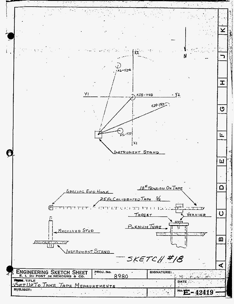
/
z
\
Q
m

Page 42
t he four plenum tubes. i n the top of t he special mandrel t o accept a precision ground plug type vernier scale. calibrated i n 1/64", w a s use'd i n conjunction with a stand- ard s t e e l tape.
A 8" hole was d r i l l e d and reamed
This vernier scale,
After considering several locations as possible fixed points f o r measuring t h e movement i n the plenum tubes, .it was %he concerted opinion of all parties involved t h a t a portion of the concrete s i l o could be u t i l i a e d t o the best advantage. A spot w a s selected on the northeast corner
'of the concrete silo. To establ ish and hold t h i s bench mark as a permanent fixed point from which a l l motion measurements could be secured, t h e E4 & E Inspection Group suggested t h a t a s t e e l mount be fabricated. This s t e e l mount was mounted on a concrete pedestal located on the s i lo . The assumption w a s made t h a t t he concrete s i l o d i d not move t o any appreciable degree when t h e NYX uni t was opera%ing. As an added fea ture a precision ground p la te was mounted i n a horizontal plane and welded t o the top of the s t e e l stand. A hole was d r i l l e d and reamed i n the center of t h i s plate. A special pin was machined t o press f i t i n the hole i n t h e plate. Next, t h e standard end loop of a 25 foo t S t a r r e t t , s ta in less s t e e l tape was removed. A spec ia l loop wi th a 3" hole was precision ma- chined and attached t o t h e end of t h e s t e e l tape i n place of t h e standard end loop. allowed f o r t h e special loop with a 4" eye t o f i t over the s t e e l pin a t the top of the Instrument mount.
A very small clearance was
Measurements were taken before, during, and after operating t h e NPX assembly on a t e s t basis. To take a reading t h e spec ia l eye attached t o t h e end of t h e cal i - brated s t e e l t ape was placed over the precision ground plug mounted on the instrument stand. stretched i n t h e direct ion of the vernier sca le plug previously i n s e r t e d i n t he mandrel located i n one of the f o u r plenum tubes being measured. to a lo# spring-type tension, it was passed over the vernier scale and read t o t h e nearest 1/64",
The tape was
With the tape subjected
A l l measurements were formally presented t o t he Technical Operations Group by the M & E Inspection Group. After noting t h a t there was a difference i n t h e readings, it was concluded there was movement i n the.plenum tubes when t h e NYX unit was subjected t o various temperatures and pressures over a period of several weeks. This data was correlated with ro ta t iona l (See Part 11, Section K, Wild T 1 double center theodolite) and other measurements to complete t h e study of t h e degree and d i rec t ion of movement of NYX plenum chamber tubes.
J. Wild MI11 Precision Level and Accessories
1. Procurement

The k i l d E111 prec i s ion l e v e l was procured p r imar i ly for t h e purpose of l e v e l i n g u n i t assemblies. Howver, i n a d d i t i o n t o t h i s , i t was also used f o r alignment and l e v e l i n g purposes as set f o r t h i n the following l i s t e d items: (1) leveling tube sheets i n c i r c u m f e r e n t i a l hand- ling j i g p r i o r t o i n s e r t i o n of large tubes ( 2 ) level ing holding rack a s sembl i e s ( 3 ) l e v e l i n g f o r e s t structures for t h e f ive telescope ac tua tor systems, and many other Jobs whfch r equ i r ed a u n i t o r a component par t t o be l e v e l during any on? p a r t i c u l a r f a b r i c z t i o n o r machining oper- a t ion .
The inst rument was bought by t h e du Pont Company from t h e Henry kiild Surveying Instruments Supply Co., Brooklyn, E. Y on AXC order #788&. with the vendor Kovernber 26, 1951, and t h e instrument was d e l i v e r e d t o 14 EC E Croup a t New York Ship s e v e r a l months later. U on r e c e i p t o f t h e ins t rument , du Pont equipment p i ece $790-54. was assigned t o it. On A p r i l 10, 1952, two ( 2 ) p r e c i s e l e v e l i n g rods and base p l a t e s were ordered on AXC o r d e r #6575& f o r use with the p r e c i s i o n level i n deternining r e l a t i v e e l eva t ions .
. The o r d e r was placed
I n a d d i t i o n t o t h e above, four s p e c i a l level t a r g e t s were designed by du Pont Design zt t h e request of t h e X & 3 Group a t New k’ork Ship . They were f a b r i c a t e d by t h e tiewton Tool Co., henonah, N. J., and shipped t o Kew York Ship f o r inmediate use. For f a b r i c a t i o n d e t a i l s , see du Pont drawing D114941: Each of t h e f o u r targets are i d e n t i f i e d 8s equipment piece #790-62, Two of t h e s e t a r g e t s were later sen t t o the Savannah River p l a n t s i t e f o r use during u n i t e r e c t i o n xork ,
it was discovered t h a t a d d i t i o n a l t a r g e t s wi th a r ev i sed housing s t r u c t u r e were needed t o f a c i l i t a t e the ease in handl ing dur ing set-up ope ra t ions f o r l e v e l i n g tube shee t asseinblies. A verba l r eques t was made by the I.I tc E Group t o Design t o produce the requi red t a rge t s . I n compliance wi th t h e reqtiest, Design Divis ion designed t h e gage and procured it f o r t h e E< gt E Group. designed targets were f a b r i c a t e d by Rewton Tool Company and shipped to Eew York Ship. l a t t e r l o c a t i o n , du Pont equipment piece #790-63 was assigned t o each of t h e f o u r t a r g e t s . targets were l ikewise serit t o t h e Savannah i i iver p l a n t s i t e f o r use during u n i t e r e c t i o n work.
After using t h e above t a r g e t s f o r leveling opera t ions ,
Four o f these newly
Upon t h e i r r e c e i p t a t t h e
Also, two of t h e s e
Note: The above k i l d 14111 Prec is ion Level and t a r g e t s are c a l i b r a t e d i n the metr ic systen! r a t h e r than %he more d e s i r a b l e English system. f o r t h i s s e l e c t i o n wzs due t o t h e f a c t that t h e level and p rec i se rods were procured a s ‘usead equipment. The manufacturer could not Sqpply a new instrument and a c c e s s o r i e s wi th in a r4asonable l eng th of time. Also, t a r g e t s designed b?. du Pont were l i kewise c a l i b r a t e d i n t h e metr ic system,
The reason
t

20 Procedure f o r Using Ki ld NIII Prec is ion Level
To observe t h e s p h e r i c a l l e v e l , loosen t h e locking screw (13) . This enables t h e instrument t o be swung ar- ound t o t h e most convenient p o s i t i o n (See Photo S e r i a l # 3 l O & 311). Then t u r n i n g t h e l a r g e i l l i m i n a t i n g mirror (2) wi11a;llm c l e a r observa t ion o f t h e buible i n i t s sur- face. The bubble i s centered p rec i se ly by a d j u s t i n g t h e foot screws (7) .
The i n s t r u m e n t - i s now ready f o r leve l ing . In high
Obta in the prel iminary approximate l e v e l i n g wi th p rec i s ion l e v e l i n g a very f i r m t r i p o d s tand must be ass- ured. t h e s p h e r i c a l l e v e l 2nd along the l i n e s of s i g h t by means of t he t u b u l a r l e v e l (17). I n o rde r t o render t h i s p r a c t i c a l , t h e p o s i t i o n of t h e t ubu la r l e v e l i n which i t s p r i n c i p l e tangent s t a n d s v e r t i c a l t o t h e ins t ruments v e r t i c a l , r o t a t i o n ax i s must be noted and i s quick ly found w i t h the a i d of drum s c a l e ( 5 ) . The drum should t h e n always be set a t t h e reading so obtained before t h e read- i n g is sighted. Po in t ing t h e te lescope along t h e l i n e of s i g h t and. u s i E s t h e open s i g h t s on t o p of t h e i n s t r u - nen t , an approximate s e t t i n may be determined. The azimuthal locking screw (13 7 is then l i g h t l y t i gh tened and the eye-piece (1) i s turned u n t i l t h e c r o s s l i n e s of t h e g r a t i c u l e appear sharp and black. Sharp focus ing i s obtained w i t h knob ( 3 ) and tested by moving the eye up and down before t h e eye-piece t o assure t h a t t h e r e i s no movement of t h e inage zga ins t the horozontal l i n e of t h e g r a t i c u l e . brou&t t o t h e c e n t e r of the measuring s t a f f o r t a r e t
found beside t h e l ock ing screw (13).
The v e r t i c a l c e n t e r l i n e of t h e g r a t i c u l e i s
by mans of t h e azimuthal fine-adjustment screw (12 7 Centering Level:
Obtain t h e most s a t i s f a c t o r y i l lumina t ion while oberving t h e t u b u l a r l e v e l (17) t h r u the eye-piece by t u r n i n g the r e f l e c t o r ( 2 ) . d i r e c t l y beneath the eye-piece, i s then turned u n t i l t h e t\.r, ha l f ima es of t h e l e v e l bubble form a s i n g l e continuolrs curve. 7 See Sketch $lg).
The t i l t i n g screw ( 4 ) , . p l a c e d
tieading t h e S t a f f o r Target:
The o p t i c a l micrometer i s u t i l i z e d f o r a l l s t a f f o r t a r g e t readings, The knob (11) i s turned u n t i l t h e wedge l i n e s o f t h e g r a t i c u l e s~jmmetrically enclose an i n t e r v a l - l i n e on t h e measuring s t a f f o r t a r g e t . (See Sketch #19). The i n t e r v a l - l i n e t h u s enclosed g ives the reading i n centimeters. The micrometer reading is observed t h r u t h e eye-piece (18) ; i t s sca l e runs f r o n r i g h t t o l e f t and the f i g u r e s thereon represer, t mi l l imeters w h i l e t h e smaller i n t e r v a l s r e p r e s e n t t e n t h s of mil l imeters . t h u s obtained on t h e n i c roEe te r added d i r e c t l y a s a dec- imal f r a c t i o n t o t h e s t a f f o r t a r g e t reading.
The reading
The reading is t h e n recorded and t h e same procedure i s followed i n t a k i n g a s e r i e s of readings by re - loca t ing

Ser i a l #3U
1. 2. 34 4. 5* 6, 7 ..I
8, 9 .
10 .
n
New York Shipbuilding Cow Camden 4, New Jersey October 17, 1953
PROJECT 8980 - SAVANNAH E V E R PLANT
WILD N l l l PRECISION LEVEL
Ident i f icat ion of Operating Parts
Telescope eye-piece Ref lector-knob Focussing-screw Tilting-screw Drum-scale Adjusting nut for Screw 4 Foot-screws Lug Protecting-glass mounting Locking-screw for protecting-glass
11 Mic romete r-knob 12. Fine adjustment screw for
azimuthal movement 13. Azimuthal locking-screw 14. Adjusting-screw 15. Triangular base-plate 16. Spherical-level 17, Eye-piece f o r tubular-level 18. Eye-piece f o r micrometer-
scale

9
b
S e r i a l #310 New York Shipbuilding Corp. Camden, 4, New Jersey October 17, 1953
PROJECT 8980 - SAVANNAH mVER PLANT
m L D Nlll PRECISION LEVEL
Ident i f icat ion of Operating Par t s
1. Telescope eye-piece 2 . Reflector-knob 3 . Focussing-screw 4. Tilting-screw 5. Drum-scale 6, 7 . Foot-screws
9. Protecting-glass mounting
Adjusting nut f o r Screw 4 8. Lug
10. Locldng-screw fo r protecting-glass
11. Micrometer-knob 12. &no adjustment screw for
azimuthal movement 13 . Azimuthal locking-screw 14 . Ad jus ting-screw 15. Triangular base-plate 16. Spherical-level 17. Eye-piece f o r tubular-level 18. Eye-piece f o r micrometer-
sca le


J
. .
T 1, .
TAR6-ET . -
OPTIC A L *
M1C.ROOMET-E f? d .
- . -..
r -
. . . J . I
No. - . 8980 1

t h e s t a f f a l o n g var ious poin ts of t t e u p i t t o be leve led , This having been accomplished a comparsion of readings i s made and t h e necessary s t e p s are taken t o improve t h e leve lness o f t h e u n i t a f t e r which the l e v e l i n g procedure i s again repea ted u n t i l t he des i red degree of leve lness i s a t t a ined .
K, Wild T 1 Double Center Theodolite
1. Procurement
I n a n t i c i p a t i o n of t h e i n s t a l l a t i o n of IiYX and o t h e r u n i t s i t vias r e a l i z e d t h a t X and Y c e n t e r l i n e s (which a r e e s t a b l i s h e d on t h e top s i d e of each plenum chamber a f t e r l i ne boring) would have t o be t r a n s f e r r e d t o t h e t op tube shee t , T h i s i s necessary because t h e t o p tube sheet (although it is keyed t o the plenum chamber t o reproduce t h e o r i e n t a t i o n of t h e two pieces as e s t a b l i s h e d a t t h e ti= of l i n e bor ing) must be i n s t a l l e d i n the tank and o r i en ted t o bu i ld ing a x i s by i t s e l f . I n o r d e r t h a t t he plenum chamber axes fzll or! t h e bui lding axes when it is Dated with the t o p tube shee t , t h e two s e t s o f ax is must f a l l in t h e same v e r t i c a l planes, I n view of t h e physi- c a l s ize of the p i eces involved and t h e degree of accuracy requi red , same method of o p t i c a l plumbing was considered best. But, t o do t h i s job, t h e nLi ld T l r l double center t heodo l i t e was s e l e c t e d and purchased from Henry k i l d Surveying Instrument Co, on P,O. dXC 65.149, ving t h e instrument a t Eew York Ship, equips?ent piece #790-90 w a s ass igned t o it. Pa r t 114, Sec t ion 7-b)
After r ece i -
(See photo s e r i a l #156 i n
2. Uses of t h e Instrument a t Kew York Ship
The procedure f o r t r ans fe r ing a x i s from the t o p of t h e plenum charnber t o t h e botton: of t h e plenum chamber and the t o p and bottom of the t o p tube shee t assembly . i s as
a.
b.
C.
d.
f 0 l lows :
S e t up t h e instrulnent on a t r i p o d i n t h e cen te r of t h e t o p o f t h e plenum c h m b e r a f t e r l i n e boring and w h i l e t h e plenum chamber and t o p tube shee t a r e s t i l l l e v e l and mated.
The i n s t r u m e n t is leve led , and by means of a c ross s l i d e Sore (descr ibed l a t e r ) the l i n e of s i g h t of t h e te lescope i s made t o coincide w i t h one a x i s of the plenum chamber which has been e s t ab l i shed and punch- marked on t h e t o p s of t h e tubes.
The t e l e s c o p e is then revolved on i t s v e r t i c a l a x i s and s i g h t e d on the f l o o r a t s u i t a b l e metal bench marks,
A center punch i s then moved ac ross the bench mark t o coincide w i t h the te lescopes l i n e of s i g h t and a punch nark made. Another such bench mark i s then e s t a b l i s h e d a s f a r a s poss ib le from t h e f irst (approx- imately 4.0' t o 50' i s d e s i r a b l e ) . Th i s procedure i s repeated on both ends of both axes.

I
L
i
i

c


cumbersome and slow, l e a d the way fo r approved d e t a i l s on designing a v e r t i c a l i t y gage.
a d e f i n i t e plan f o r design of t h e v e r t i c a l i t y gages was agreed to . The des ign of t h e v e r t i c a l i t y gages f o r t h e plenilm ckarnber, top s p e c i a l and tank bottom u n i t s was t h e same except f o r t h e d i f f e rence i n s i z e f o r the d i f f e r e n t s i z e tubes; therefore, a detail descr ip t ion and use of one v e r t i c a l i t y gage w i l l be given t o r ep resen t a l l t h e different v e r t i c a l i t y gages used t o measure t h e ou t of v e r t i c a l t h e t u b e s are ir, the u n i t s .
Through t h e cooperat ion betweennesign and in spec t ion ,
Figure 2 shows the d i f fe ' ren t sizes o f t h e v e r t i c a l i t y gages t h a t a r e used €o r t h e d i f f e r e n t un i t s . F i g 2 also shows a sketch with nomenclature of each par t of t h e gage. The shoes, both movsble and f ixed , are loca ted on t h e circumference of t h e gage 's mandrel 1200 a p a r t . vcith no coapression on t h e s p r i n g s of t h e movable shoes, Ghe diaiceter o f mandrel plus t h e shoes i s 1/8" l a r g e r t h a n t h e nominal diameter of t h e tube bores . The s p r i n z s of the movable shoes can be compressed 3/16"; t h i s i s t o take into account t h e ' b l u e print to le rances of t h e tube bores.
40 properly understand t h e use 03 tk v e r t i c a l i t y g g e , a tube t h a t is p e r f e c t l y v e r t i c a l ir, a11 d i r e c t i o n s , n o r t h , easl;, south, and west , will f i rs t be considered. %hen t h e gage i s i n s e r t e d i n t o t h e tube bore t h e sp r ings of the movable shoes w i l l be compressed. As explained before t h e diameter of mandrel plus the shoes i s larger than the bore of t h e tube ; t h e r e f o r e , f o r t h e gage t o f i t i n t o the tube bore, t h e sp r ings will heve t o conpress forc ing t h e rcovable shoes inward t o make a smller d ia- meter t o coiccide with d ime te r o f t h e tube bore. The compressed spr ings will f o r c e the f ixed 2nd movable shoes agains t t h e wal l of t h e tube bore givifig a t i s h t metal- to-metal fit of' all t h e &-oes aga ins t t h e tube wall, The tube is p e r f e c t l y v e r t i c a l ; t he re fo re , t he mandrel will be. p a r a l l e l t o t h e tube ; t h e f ixed bar w i l l be per- pendicular t o t h e mandrel ; t h e movable bar w i l l be para- l l e l t o t h e fixed bar; and because of per fec t v e r t i c a l i t y of the t ube , t he tube 2nd gage w i l l be i n a p e r f e c t plarie w i t h the e a r t h g i v i n g a zero reading on t h e l e v e l , KO a d j u s t w n t i s necessary on t h e Eovable bar ; t h e r e f o r e , the dial i n d i c a t o r r ead ing i s zero.
Tubes with pe r fec t v e r t i c a l i t y f o r all t h e d i f f e r e n t u n i t s s r e s e t up h e r e a t t h e vendors shop. These tubes a r e used as master gages t o prpperly set and a d j u s t t h e v e r t i c a l i t y gages. It i s not necessary t o have t h e vert- i c a l i t y gage set p e r f e c t l y . two poin ts 1800 a p a r t w i l l g ive the exact amount a tube i s out of, v e r t i c a l . The d i a l i n d i c a t o r i s set i n t h e v e r t i c a l i t y gage t o g ive a p l u s .125" and a minus .125" retrdings f rom zero setting.
.
An average reading of any
A tube such as the one &own i n Figure 3 w i l l now be taken i n t o account, The v e r t i c a l i t y gage i s i q s e r t e d

m

..*.,.
.

Page 48
i n t o t h e tube. shoes aga ins t tube wall. F i r s t t h e n o r t h reading w i l l be t a k e n . set t o face the north t o o b t a i n a no r th read'ing. before the mandrel w i l l be p a r a l l e l t o t h e w a l l of the t u b e ; t he f ixed bar w i l l be perpendicular t o the mandrel, and t h e movable bar w i l l be p a r a l l e l t o t h e f ixed bar. The tube not being p e r f e c t l y v e r t i c a l will be ind ica ted on t h e l eve l on t h e movable bar, used t o raise o r lower t h e movable ba r i n order t o a d j u s t t h e movable bar t o a pe r fec t plane wi th t h e e a r t h t o ob ta in a zero reading on t h e l e v e l , The up o r down move- ffient of t h e movable bar w i l l cause t h e stem of the d i a l i n d i c a t o r t o move inward o r t o extend ou t giving 8 d i r e c t reading on t h e i n d i c a t o r of plu9. o r minus's0 many thou- sandths. T h i s reading i s t h e ou t of v e r t i c a l reading t h e tube is i n one f o o t . i n d i c a t e s t h a t tube i s a l e a n i n g i n t h e d i r e c t i o n of t h e minus reading. t h e ba r s f ac ing east t o o b t a i n ou t -o f -ve r t i ca l i t y t h e tube i s i n t h e east d i r ec t ion . Same procedure is used as i n t h e north d i r e c t i o n . Th i s is done i n a l l f o u r d i r - e c t i o n s of North, Eas t , South and West. If the gage i s pre-set i n t h e master gage, the 1800 apart readings, o r Eas t and West readings w i l l be t h e same but i n opposite d i r e c t i o n s . For example, i f Xorth reading is .005", t h e south reading w i l l be 3. .00511 g i v i n g an average o f .005" t h e tube i s leaning towards t h e north.
The sp r ings w i l l compress forc ing t h e
The open end o f t h e movable and fixed bar i s As shown
The a d j u s t i n g screw is
The minus' read ing on t h e i n d i c a t o r
The gage i s r o t a t e d w i t h t h e open end of .
To show t h a t t h e gage does n o t need t o be pre-set an example w i l l be given of such il gage. i n s e r t e d in to t h e tube bore wi th t h e open end of the f i x e d and movable bar Zacing north. i s turned t o br ing the l e v e l i n t o a zero reading, dial i n d i c a t o r shows a reading of ,OIOn for t he north reading. of t h e ba r s f ac ing south. The adjustment knob is again turned t o br ing the l e v e l i n t o a zero reading, i n d i c a t o r shows a reading of .0OOfr for south reading. The average of both readings i s .005". This i n d i c a t e s t h a t t h s t o p of the tubes is l e a n i n g towards the North. From these readings the person us ing t h e v e r t i c a l i t y can mrke necessary adjustments on the d i a l indica+,or t o have t h e proper s e t t i n g on t h e gage. diagram of how the v e r t i c a l i t y of t h e tube i s computed.
The gage i s .
The adjustment knob The
The gage i s then r o t a t e d 180° wi th the open end
The d i a l
Fig. 3 shows a vec tor
X. I n s t a l l a t i o n of Precis ion Crane i n Building #lo 1. General .
It was the r e s p o n s i b i l i t y of t h e F i e l d Construction Group assigned t o 1;ew York Ship t o i n s t a l l t h e prec is ion cranp, i n Building #lo f o r tk. KYX u n i t while operat ing on a t e s t basis . Since t h e 14 & E Group assigned to t h e same l o c a t i o n had t h e necessary instruments and t r a i n e d personnel t o perform t h i s work, t h e F i e l d Construction Croup requested the former t o provide t h e necessary per- sonnel and equipnient. However, Construction engineers would s t i l l r e t a i n f u l l r e s p o n s i b i l i t y o f t h e crane in- s t a l l a t i o n and supervise M & E personnel performing t h e work

Page 49
I n t h e following s e c t i o n s a resume of t h e work procedure performed by 14 & E personnel ass igned t o New York Ship i s presented herewith, between August, 1952, and March, 1953. It required t h e services of two men from t h e M & E Croup, one full time and tk other part time.
Layout of Center and Control Lines on Floor and a t High Elevation
This work was performed
2.
A . Floor Elevation
E. The IrXn a i s on t h e top s i d e o f the IJYX plenum chamber was extended down t o t h e concrete f l o o r on t h e south s i d e of the silo, Secondary o r cont ro l l i n e s (which are p a r a l l e l t o t h e extended cen te r l ine on t h e east and west s i d e ) were l a i d out re ferenc ing from the '!Xn axis loca ted on t h e f l o o r using a K i l d . T 1 double c e n t e r t h e o d o l i t e and a s c r i b e for a t a r g e t . were made wi th a 100' stainless steel tape C a l i - brated by t h e U. S , Bureau of Standards.
A l l o t h e r measurements
2. The approximate l o c a t i o n f o r t h e s tee l p l a t e s on which the l i n e s are sc r ibed was l a i d out on t h e f loo r . A t t h e s e l o c a t i o n s s t e e l p l a t e s were welded t o s tee l rails embedded i n the concrete f loo r .
3. The instrument w a s se t on t o p of t h e plenum chamber and i t s l i n e of s i g h t ad jus t ed t o coincide with t h e nXTf axis c e n t e r l i n e on the t o p s i d e of t h e plenum, This l i n e was extended to p l a t e s numbered 1, 2, and 3 l oca t ed on the f l o o r using a s c r i b e as a t a r g e t . (See Sketch #20)
4. The instrument was %hen placed over the cen te r of t h e #1 p l a t e which was l oca t ed on t h e I%'? axis,
. Wext, the l i n e of s i g h t was ad jus t ed t o coincide with the "Xn axis c e n t e r l i n e sc r ibed on p l a t e s #2 and #4 as shov;n i n Sketch $20. Then t h e i n s t r - ument was turned 900 t o t h e east and a l i n e w a s sc r ibed on p l a t e 1E. The instrument was plunged and a l i n e was sc r ibed on p l a t e Ut, A chalk l i n e was s t r e t ched from t h e sc r ibed l i n e s on p l a t e s Id t o lX aad a lire s c r i b e d on p l a t e 91, thus , l o c a t i n g t h e first l i n e s on the f l o o r . The east s i d e con t ro l l i n e s on p l a t e el3 were t h e n estab- l i s h e d by .wasuring from the nXn axis on p l a t e #1 with a loop s t a i n l e s s s t ee l tape held i n l i n e with the 900 l i n e s s c r i b e d on p l a t e s #l and #lE. The west s i d e c o n t r o l l i n e on p l a t e #lX was es t ab l i shed i n t h e same mmner. The above procedure was also used t o e s t a b l i s h l i n e s on p l a t e s numbered 2, 2E, 2W, 3E and 3W.
5. The instrument .was t k n s e t between p l a t e s #1 and

_ .
+ e7Lcll
-$i t
+
5
.
,
.?
Irt ,
-.3 + %v
I f + 2E
m
+"3 w 4

Page 50
$2 and adjusted t o co inc ide wi th t h e 4Xn axis, The "X" axis was then extended t o p l a t e s #4 and #5 (See Sketch f20) l o c a t e d on t h e concrete slab. (See Sketch 821) The east and west con t ro l lines were scr ibed on p l a t e s 4E and .4h', 5E and gW f o l l - owing t h e procedure as o u t l i n e d above i n sec t ion #4
6, The instrument was then set between plates &E and #6E and ad jus ted t o the c o n t r o l I ines on p l a t e s #J+E iind #5E. After t h i s the instrument was plunged and con t ro l l i n e s on #6E and #7E were scr ibed, The cont ro l l i n e s on p l a t e s #6W and 7W were then scr ibed i n t h e same manner, The d id tance between the east and west c o n t r o l l i n e s on p l a t e s #6E and #6W, #?E ard #7K were checked with the 186? s t a in - less steel tape, The c e n t e r o r "Xn axis'was not necessary on the n0rt.h s i d e of the u n i t ,
B. Temporary I n s t a l l a t i o n f o r Assembling and Testing o f Crane
Since t h e prec is ion c rane was t o be assembled and t e s t e d a t New York Ship, a temporary i n s t a l l a t i o n approximately 8' above t h e f l o o r l e v e l was fab r i ca t ed t o f a c i l i t a t e t h e assembling of t h e crane 's component parts. This i n s t z l l a t i o n cons i s t ed of one l e f t hand and one r i g h t sec t ion of crane rail and t h e necessary support ing s tee l spaced a t t h e proper d i s t ance t o rece ive t h e crane bridge, [See Sketch f 2 2 )
I n the following procedure a resume of t h e work involved i n s e t t i n g and a l i g n i n g t h e l e f t and r i g h t hand s e c t i o n s of crane r a i l is presented herewith,
a.
b.
C.
The c e n t e r l i n e f o r tk l o c a t i o n o f the r a i l saddles was t r ans fe r r ed t o t h e suppor t ing s tee l from the east and west c o n t r o l l i n e s . (See Sketch #22) The rail szddles were set on 2' cen te r s , Then t h e cen te r l ine of t h e saddles w r e a l igned with t h e cen te r l fne on t k e suppor t ing s t ee l and clamped t i g h t w i t h hook b o l t s ,
The ra i l s were l eve led and a l igned with jack screws i n the saddles. The jack screws were held i n adjustment wi th check n u t s , the l e v e l i n g jack screws i n t h e east and west r a i l saddles were set i n a l e v e l plane, us ing the Wild NIII prec is ion l eve l .
The t o p end of
The crane ra i ls were then placed i n t h e saddles. F i r s t , t he west r a i l was roughly zl igned ( 4 1/32"] t o t h e cont ro l l i n e us ing a 12" scale, the e l eva t ion of t h e r a i l a t t h e no r th end saddle was checked with t h e S i ld €4111 prec i s ion l eve l and l ighted target. r a i l a t each saddle was set t o t h e same e leva t ion , Concurrent with s e t t i n g t h e r a i l a t t h e required e l eva t ion , t f E r a i l l e v e l (crosswise) was checked with a S tar re t t 12" p r e c i s i o n k v e 1 .
Then,
h'ext, t h e balance of t h e

~ :
. . I .
. . . . *: .I I . I . . -1 .1 . x; L . -c - 1 . . I .
-.* . _ . - . - . . , . I
. . -. . . . - .
. .
.- . -
._ I -
. . . . - . . - .. - . I . 6
! -
.
Sr Lo
tf S K E T C H 2 1
.- .. . r _ .

. ,
. . . . . . . .
" " ,
. . . . .
...
- . . .
7- J I I
1 I I i
i
I 1
I I i
1 4
* .~.L i
. . , I - .
- . k
"+ + #3 +&3d .
i t
t I' I
I
i I
i -
. , -
E L E V S T J O A J 4 L . , '
I
, . ,
f .
" .

Page 51 ..=-. . - *
Also, at the same time the rail alignment was checked from the side of the rail to the control l i n e using a 12a scale. This was necessary since final. elevation and leveling adjustments with t h e jack :screws moved the rail laterally.
C, High Elevation .- 8 . ' -
- .- ~ F ' - - .T I - In -'-.
The -control 'lihes-bn the ea& ana west5 .side were t ransferred from the east and west p la t e s on the .floor t o targets a t t h e high elevation. (See Sketch #21) angles welded and braced t o the rail supporting s t e e l at t h e north and south ends, These t a rge t s were located at the required elevation for align- ing the rafl saddles and the rail.
The instrument was set between p l a t e s #lW and #2W and adjusted t o coincide with the lines on p la t e s # l W and #3W. on t h e 2'! x Zb x l / 4 W angle target located on the south end of t h e rail supporting steel. At t h i s point t he high elevation.contro1 l i n e was scribed. The control line on the north end target was scribed by s e t t i n g t h e instrument between p la tes #5W and #&I about 10 feet from p l a t e #6W in the same manner described above. The east side high elevation control l i n e was l a id out following the same procedure outlined for the west side..
T h i s completes the layout of the control l i n e s at the high elevation.
These targets were 2u x 2s x 1/lp
Then, the instrument was focused
The layout of a l l l i n e s was re-checked f o r accur- acy by plunging and r e v e r s i n g t h e instrument t o eliminate all possible human and instrument errors. This completes the layout of t h e isenterline and control lines at floor. elevation.
The elevation, l eve l and alignment of the east rail was set t he same as the west rail using t he Wild precision leve l and lighted target as out- l i ned i n Paragraph #3. The distance between t he rails was checked with a 100' s t a i n l e s s s t e e l tape.
The crane bridge vas l i f t e d into positfon and placed on the rails. bridge was then checked with the Wild leve l and precision measuring staff.
The level of the crane
Wild T 1 theodolite was set on a rigid platform over t h e west side control line. The instrument's line of sight was adjusted t o coincide orith the control l ine . crane bridge moved until the dr ive wheel center- l i n e coincided with the instrument line of sfght, The crane wheels were blocked, thus holding the crane bridge i n position 90° t o the W P axis.
The crane bridge was received with t h e trolley
It was then turned 900 and the

Page 52
r a i l sadd le s welded i n pos i t ion . Next, it was necessary t o a d j u s t t h e level ing jack screws t o a leve l plane a t t h e proper e l e v a t i o n above t h e crane r a i l . This e l eva t ion was checked wi th t h e Wild p r e c i s i o n l e v e l and p r e c i s i o n measuring staff . The t r o l l e y r a i l s were then placed i n t h e saddles and bo l t ed toge ther with a s p l i c e p l a t e which had a lock f i t t i n g i n t o a hole i n t h e c e n t e r saddle t o ho ld t h e rails i n pos i t ion lengthwise.
9. A target with ad jus t ab le b racke t s was t a c k welded t o each end of t he crane br idge in l i n e with t h e d r i v e wheel cen te r l ine and a t t h e same e l e v a t i o n as t h e trolley ra i l . The a d j u s t a b l e b racke t s were a l i g n e d wi th t h e d r ive wheel c e n t e r l i n e us ing a s t r a i g h t edge and prec is ion box l e v e l .
A ]#l3 piano wire was used f o r t h e f i n a l a l ign - ment of t h e t r o l l e y ra i ls . The w i r e was s t r e t c h e d a c r o s s t h e crane br idge, supported i n trVfq s l o t s cu t i n t h e 2" x 2" x l/4" ang le s which were clamped t o t h e crane bridge, The piano wire was a l igned from t h e two ad jus tab le bracke ts wi th a p in gage (micrometer head on one end) t o a poin t 2" from t h e f i n a l pos i t ion of t h e r a i l so a 2" p i n gage could be used f o r the f i n a l alignment of t h e r a i l .
10. The Xild MI11 prec is ion l e v e l was se t i n t h e c e n t e r o f t h e south ra i l . Working from t h i s pos- i t i o n t h e west end of t h e no r th r a i l a t t h e first sadd le was set t o t h e pcoper e l e v a t i o n above t h e c rane r a i l us ing t h e h i l d N I I I p r e c i s i o n l e v e l and p r e c i s i o n messuring staff. The r a i l was clamp- ed on t h e l e v e l i n g jack screws wi th clamps fabr - i c a t e d f o r t h i s purpose. T h i s clamping was found necessary because Khen a d j u s t i n g tke second saddle. t h e jack screws a t t h e first saddle would move, A t least six saddles had t o be clamped a t a l l times dur ing l eve l ing . w a s done concurrent ly w i t h t h e l eve l ing . When t h e n o r t h r a i l had been completed t h e south r a i l was l e v e l e d t o the same e l e v a t i o n as t h e nor th r a i l , Using the & i l d p rec i s ion l e v e l se t i n t h e c e n t e r of north r a i l , and south ra i l s was s e t within a t o l e r a n c e of
? . 0 O Z t r wi th a pin gage of t h e proper l eng th which had a micrometer head on one end,
The f i n a l alignment of t h e r a i l
%he space between t h e north
3 . I n s t a l l a t i o n of Crane Ra i l s (High E leva t ion )
a. The high e l e v a t i o n bench mark f o r s e t t i n g t h e crane r a i l s was t aken from the instrument s tand bench mark which had previous ly beer, e s t ab l i shed . The Kild NIII p r e c i s i o n l e v e l was s e t on t o p of t h e plenum chamber and t h e e l e v a t i o n of t h e bench mark on the instrument s tand was t r a n s f e r r e d t o a target welded on t h e s t ee l column. Another t a r g e t was welded t o t h e r a i l sup- p o r t i n g s t ee l a t t h e same e l e v a t i o n as the r a i l and

d i r e c t l y over t he lower t a r g e t . The high e l e v a t i o n bench mark was e s t a b l i s h e d on t h e high target by measuring from t h e lower t a r g e t with a 100' s t a i n l e s s s tee l tape.
b. The sciddles were placed on 2' centers . The cen te r - l i n e of t h e s a d d l e s was a l igned from a #l3 piano wire s t r e t c h e d t h e f u l l l ength of t h e r a i l suppor t ing s teel 2" from t h e f i n a l p o s i t i o n of the ra i l . wire was a l i g n e d from t h e high con t ro l l ines s c r i b e d on t h e 2" x 2" x l/&" angle t a r g e t s . l e s were a l i g n e d and clamped t i g h t with C clamps, they were welded t o t h e supporting s t e e l .
The
After the sadd-
C. The t o p end of t h e l e v e l i n g jack screws were a l l s e t i n a l e v e l plane a t t h e proper e leva t ion . Next, t h e r a i l s were p laced i n the saddles. The r a i l s were held toge the r wi th , s p l i c e p l a t e s , which had one s p l i c e p l a t e with a square boss on t h e underneath s i d e t h a t f i ts i n t o a square hole i n the saddle t o hold t h e r a i l i n p o s i t i o n lengthwise.
The east s i d e crane r a i l was roughly. a l igned ( k 1/32"} from t h e piano wire before s t a r t i n g t b . l e v e 1 t h e r a i l s . The k i l d p r e c i s i o n l e v e l was set on a bracket clamped t o t h e suppor t ing s t e e l and focused on a l i g h t e d tar- ge t placed on t o p of t h e crane r a i l over t he saddle nea res t t o t h e bench mark. The crane r a i l a t t h i s po in t was set ( 2 .OO5") t o t h e proper e l e v a t i o n , and a t t h e same t i m e t he l e v e l of t h e rail crosswise was checked wi th a S t a r r e t t 12" prec is ion l eve l . The r a i l was then clamped t o t h e l e v e l i n g jack screws. The f i n a l alignment of t h e r a i l w a s done concurrent with t h e leve l ing .
d,
e;
f.
Wken t h e crane r a i l a t the first saddle had been s e t l e v e l a t t h e proper e l e v a t i o n ( ? .005"), t h e balance of t h e east r a i l i n t h e p rec i s ion area ( t h e a r e a over t he s i l o ) was se t and a l igned a t each saddle. It was found necessary t o c l aap t h e r a i l on t h e l e v e l i n g jack screws a t 10 saddles a t a l l times. This complet- ed t h e l e v e l i n g and alignment of t h e east r a i l i n t h e p rec i s ion area.
The west r a i l i n t h e p rec i s ion a rea was t h e n roughly. a l igned ( 3, l / 3 Z T f ) p a r a l l e l t o t h e e a s t r a i l . The g i l d p r e c i s i o n l e v e l and i t s supporting bracket was clamped t o t h e west r a i l support ing s t e e l and focused on t h e l i & t e d t a r g e t placed on t h e e a s t r a i l over t h e saddle n e a r e s t t h e bench mark. The l i g h t e d tar- get was then t r a n s f e r r e d t o the west r a i l and placed over a saddle approximately the same d i s t ance from t h e Viild p r e c i s i o n l e v e l . point was then l eve led and a l igned ( 2 .005") t o t h e same e l e v a t i o n as t h e east r a i l . The d i s t ance between the r a i l s was checked w i t h a 100' s t a i n l e s s s t ee l tape.
The west r a i l a t t h i s
g. The balance of t h e w e s t r a i l i n t h e prec is ion a r e a

.a r..;. . . . I j:$- was then leveled and aligned { % .OO!jn) f; procedure o u t l i n e d f o r t h e east rail. The ZJ
$5:
between ra i ls ~ a 5 checked a t 5' i n t e r v a l s .
h.
i,
j.
k.
The balance of the east and west r a i l s whid, in the p r e c i s i o n area was l eve led and align\ a to le rance o f ( 5 1/64")-which was cons ide l ate enough f o r t h e ope ra t ion of the crane.
'
After completing t h e l e v e l i n g and aligzihg 0 and west crane rails, t h e hild T1 Theodolite on t o p of plenum chazber and t h e i n s t m s z s i g h t ad jus ted t o co inc ide with t h e **p & nY11 axis was extended to t h e east and to west crane rails. A t t h e s e l o c a t i o n s s 7-e scribed. This l i n e was used 2s a poinz se t h e d r ive racks f o r t h e crane and for E = = f n g crane bridge p a r a l l e l to t h e ''Yn a x i s ,
The crane d r ive racks were i n 5' S e C t Z G L - 5 2nd w doweled i n pos i t i on with 3/gtr diameter 2awe l s , t oo th p i tch of the racks vias d i g n e d wftk one an us ing a gage f ab r i ca t ed f o r t h i s PU~POSZ:,
This completed the l e v e l i n g and ~ i g n m e n t of t h e and racks,
,
..
.'t kras t emporar i ly doweled and the The dfiveoved approx ina te ly 20' away from
crane bridSe y r e tu rned ; t h e alignment was checked, t h e "y" sxls,dge backed o f f and returned again, 2nd t h e crane alignment was checked and found t o I n both Case be s a t i s f a c t
Ls piere then checked f o r being parallel c. The t r o l l e ; af ter which i t was checked f o r l eve l -
t o the "y" ness.

d. The crane was returned t o t h e area where t h e l i f t i n g gear was i n s t a l l e d and t h e t r o l l e y l i f t e d i n t o place on t h e bridge. The crane was then re turned t o the
axis f o r t he alignment of t h e mast base plate .
e. A #l3 piano wire was s t r e t c h e d a c r o s s t h e mast base p l a t e i n alignment w i t h base p l a t e c e n t e r l i n e tqhich was paral le l t o t h e ?rXn axis. The Wild T.1 theodol i te was set on t o p of t he plenum and t h e instrument l i n e of s igh t ad jus ted t o co inc ide with the nXm axis. The in s t runen t was t h e n focused on t h e piano wire on t h e base p l a t e , Next, t h e base p l a t e was adjusted u n t i l t h e c e n t e r l i n e coincided with t h e "XN axis. The base p l a t e was bol ted and doweled i n p o s i t i o n and t h e alignment rechecked. The craEe was then moved t o a p o s i t i o n over t h e ' s t a g i n g which hzd been erected f o r t h e assembly of t h e masts. After assembling the masts, t h e crane was r e tu rned t o a p o s i t i o n approxi- m t e l y 10' from t h e s i l o so t h a t masts could be check- ed f o r v e r t i c a l alignment w i t h t h e \Gild T 1 theodolite. They iiere set t o a v e r t i c a l plane and re-checked with t h e theodo l i t e .
f, The movernellt of the suppor t ing s t ee l when t h e brakes were ap? l i ed on the crane was checked by clamping a 6" s t e e l s c a l e on the east r a i l and s e t t i n g t h e Bild T 1 t h e o d o l i t e on the f l o o r . The instrument was then focused on the sca l e and t h e amount of movement was de temined o p t i c a l l y . The amount of movement yas 3/32"
5. Al igmen t of Probe Pins
a. Since , the prec is ion s t r a i g h t edge, which w a s t o be used jil conjunction wi th t h e probe p i n s e t t i n g gages, d i d not a r r i v e a t Eeti York Ship i n time t o be used, t h e \ t i ld T 1 t heodo l i t e was used i n l i e u o f t he s t r a i - gh t edge t o a l ign t h e s e t t i n g gages.
b. The probe p in s e t t i n g gage was placed i n i t s mating tube and. t h e instruffient l i n e of s i g h t ad jus ted t o coincide w i t h e i t h e r t h e TrX" o r nYrr axis, and then t h e base o f t h e s e t t i n g gage was se t p a r a l l e l w i t h t h e !rXw axis using a 6" s c a l e a s a t a r g e t . The probe pin s e t t i n g gage xcas then locked i n place. The probe p in was set by reading the i n d i c a t o r s on t h e s e t t i n g gage
e. This completes the work on t h e p r e c i s i o n crane on Building $10.
N. r'Crr Unit Bottom Tube Sheet Ibonitor Fin Locating S l o t Gages.
a. Development znd Procurement
The Design Divis ion changed t h e th ree monitor p in s l o t s d r i l l e d i n the 1.3. of all BTS l a r g e t u b e s t o t h r e e Vee s l o t s pre-machined i n s t a i n l e s s s t e e l s t r i p s and spo t welded t o

t h e 0,D. of "C" B.T.S. large tubes. T h i s des ign change brought about t h e need f o r two a d d i t i o n a l gages. checkt the depth of a s l o t r e f e r e n c i n g from t h e bottom tube end and a n o t h e r gage t o check t h e o r i e n t a t i o n of t he t h r e e Vee s l o t s r e fe renc ing from the u n i t s "Y?' axis.
One t o
i? d e t z i l sketch of each gage w%s made by t h e du Pont I n s p e c t i o n 3epartment and submitted t o t h e ICew York Sh ip machine shop for fabrication, After the two gages were f a b r i c a t e d , t h e y were inspected and found t o meet a l l r eques t ed s p e c i f i c a t i o n s ,
b, lise of gzges
After one Vee slot s t r i p had been s p o t welded t o the G.D. of each "C" B.T.S. l a r g e tube, t h e t h r e e Vee s l o t s on each s t r i p were checked for depth using a f u n c t i o n a l gage of t h e type shown ori t h e l e f t had s i d e i n photo ser,iaf #374. t o a nominal s i z e as shown OR du Pont drawing F13l+132=Hll. S ince the Vee s l o t s t r i p s were pre-nachined t o depth and width, inspected and accepted before spo t welding t o t h e t ubes , it was only requi red t o check t h e depth of tk;e s l o t s r e fe renc ing from t h e bottom f a c e of a l l large tubes .
The key on t h e gage was machined
For measuring purposes, t h e f u n c t i o n a l gage WES used i n t h e fol lowing manner:
( a ) F i r s t , c a l i b r a t e t he gage. This i s done by s e t t i n g a depth micrometer t o read .234". Place the micrometer's spindle perpepdicular t o t h e bottom s i d e o f t h e key ' s housing and o r i e n t t h e f a c e of depth inicrometer such t h e t it depresses t h e botton end of the key, The dial i n d i c a t o r plilnger i s now r s g i s t e r e d t o t h e t op end of t h e key. i n d i c z t o r t o read The gage i s now c a l i b r a t e f and ready f o r use,
S e t t h e d i a l
(b) I n s e r t t he b a r r e l o f the gage i n t o a l a r g e tube and align the bottoffi of the key i n t h e s l o t and check t o see if i t i s seating properly. seated i n t h e s l o t f i r m l y by applying ~i slight downward hard prcssure on t h e key.
The key i s t h e n
( c ) kecord reading as P l u s (+) o r minus ( - ) s o many thousandths from t he zero s e t t i n g ,
( d ) Analyze resu l t s :
R e s u l t s are analyzed keeping tv;o things ir! nind; namely
(1) minus ( - ) reading means s l o t depth is deep.
( 2 ) p lus (t) reading means s l o t depth i s shallov:.

.- .
*I
i [u
0 0 0 c I
"̂ . c: ::.a
v
... A 3
c; ..A
t'
Y P. L
$! I C.

. .. I .

P
r'? . & 0
J
J
g "i
0 -E
,- .I I
d -.
I
Ff 'rl
k 3
r+
r: a

.) . ' . ..
r

rage x Design s p e c i f i e d a to le rance of -$ .OOO" - .O1Orr. Using pos i t i ve o r nega t ive readings read d i r e c t l y from t h e gage d i a l i n d i c a t o r , f i n a l r e s u l t s compared w i t h Design's t o l e rance i s d i r e c t and no signs (3 . . or -) a r e t o be changed. For example, a d i a l indh- ca tor reading of d- .002tt would mean t h e s l o t i s ,002" shallow, is deep by .008" r e fe renc ing from t h e zero se t t i ng . I n t h e first case, t h e s l o t is .002rr over the spec- i f i e d to le rance and i n t h e l a t te r t h e s l o t i s .008r' under to le rance which is wi th in t h e -.O1Ow spec i f i ed to le rance ,
A reading of -.008" would mean t h e s l o t
Before i n s e r t i n g the gage i n t o a tube , t h e following items should be checked:
(a) Check t o see if a l l s t r i p s are f l u s h with t h e bottom tube ends before i n s e r t i n g gage, This i s necessary s ince t h e face o f t h e f u n c t i o n a l gage w i l l r i d e t h e t o p edge o f the s t r i p ardLhence, an erron- eous reading w i l l r e s u l t .
( b ) Before i n s e r t i n g the f u n c t i o n a l gage i n t o a tube, it i s imperative t h a t t h e large tube end and I . D . be de-burred and thoroughly cleaned (preferab ly with F.O. 128), as the presence of any foreign mater ia l w i l l give an erroneous d i a l i n d i c a t o r reading.
2, Or i en ta t ion Gage
This gage is used f o r measuring the angular pos i t ion of each Vee s l o t with r e spec t t o a reference l i n e scr ibed on t h e f a c e of each tube end. These secondary o r re ference l i n e s were e s t ab l i shed using t h e fol lowing ou t l ined procedure:
U n i t X &.Y axes a r e e s t ab l i shed ( fo r method of e s t a b l i s h i n g these l i n e s , see P a r t 1 1 - A , Sect ion 13).
An 18' s t r a i g h t edge is a l igned co inc ident with t h e u n i t For pos i t i on i n which straight edge is placed
on t o p of u n i t , see Pa r t 11-A, Sect ion 13, Photo S e r i a l
k p lane r gage is se t t o 3.500" - t h e o r i t i c a l dis tance from center of tubes i n nYrr axis t o ad jacen t row of tubes. T h i s gage is used f o r s c r i b i n g a l l tube ends.
axis.
#53 -
After planer gage is se t , l i n e s e r e s c r i b e d on tube ends i n row Y29.
S t r a i g h t edge i s then pos i t ioned on row Y29 and al igned coincident wi th l i n e j u s t sc r ibed , The above procedure i s repeated f o r row Y3O, This procedure f%d&med u n t i l a l l tubes ,in Y1 d i r e c t i o n are scr ibed with cen te r l i n e s .
The straight edge is then turned with "face" toward X2 and th above procedure repeated.

Page 2o . .. . After reference l i n e s have been scribed on t h e top . * f a l l tubes, measurement of Vee Slot isnwlar d e v i a t i o n 5t; be readily performed. is lowered i n t o the tube until the 3 keys are properly d i n t h e i r r e spec t ive s lo t s . is adjusted t o coincide with t h e tube end centerlines Pgular deviation is then read d i r e c t l y f r o m each key, ise or counter-clockwrse, whichevor t h e case may be. &oto Serial #373) The inside padwtton on the gage rents 10 deviat ion each way. Should ore s l o t be off :$an 20, the deviat ion of t h e others cannot be read
The sane care must be likewtse exercised ir: '"eo cleanliness of tube bore and s lo t s pr ior t o usin€ gag measuring purposes.
The barrel oE the plug type
The WBItfoning bar (both
removing the i n t e r f e r i n g key- fr 10.
Tolerance on Vee
'* Fmc,l Gages
at ional requirements of the production u n i t s f o r resu l ted i n t h e use of f u n c t i o n a l gages, gages were used f o r determining t h e alignment
betwee{ plenum tube bore and corresPonding t o p tube shzst tube b d \ ~ thzt t h e operating element t r i l l pass through the tubs with no interference. desi@eathe Design g iv is ion and procured by t h s I< & E
'consisted of rods o r c y l i n d e r s which could be inserted 0 t h e appropriate tubes.
i n t h e plenum - top tube sheet assembly These
T h e m gages were

carbon s tee l , chrome plated. The gages were procured from t h e Chaumont Kanufacturing Co., Glendora, New Jersey, and the Kilmington Shops.
The rod tube func t iona l gages ( t o t a l of 3 ) were assign- From f a b r i c a t i o n d e t a i l s , ed equipment piece number 790-64.
see du Pont drawing D11'2706. of 6) were assigned equipment p iece number 790-30. f a b r i c a t i o n d e t a i l s , see du Pant. drawing D112621.
The l a r g e tube gages ( t o t a l For
A complete s t o r y and p i c t o r i a l i l l u s t r a t i o n s on t h e use of f u n c t i o n a l gages discussed i n Part V I I , Sect ion I.
P. L i s t of Commerical Gages and Tools used by Inspec tors a t New York Ship
Amount
1 1 1
34
11
1 1 1 1 2 2 1 1 1 2 2 1 2 1 1 1 1 1 1 1 1 1 1 2 1 2 1 3 1 1 1 1 1 1
Descript ion
Profi lometer Head & A r m P rec i s ion Cmera, 3 o t o r and Table (Tube Pa t t e rn ) 3/4*r 0.D. Boroscope, Regulator & Target Federal Dial Ind ica to r s (1" Travel
Standard Bore Gages
Small Boroscope, l /kfr O.D. x 3 Ft. 2" t o 6" S t a r r e t t O.D. 14icrometer. 5" t o 6" S t a r r e t t 0.D. Nicrometer 4" t o 5w S t a r r e t t 0.D. t5crometer 3" t o 4" S t a r r e t t O.D. Micrometer 2'' t o 3" S t a r r e t t O D D . Xicrometer 1" t o 2n S t a r r e t t O.D. Micrometer 0 t o 1" S t a r r e t t O.D. Xicrometer 1-1/2" t o 12:' I.D. (Lufkin) Micrometer S t a r r e t t 12" Bench Levels S t a r r e t t 1.D. Nicrometer 2" t o grf S t a r r e t t 100' S/S Tape S t a r c e t t 2 5 r S/S Tape l-l/4" t o 2-1/efr S t a r r e t t Telescope Gage 2-l/ilK t o 3-l/2" S t a r r e t t Telescope Gage 1/2" t o 3/4* S t a r r e t t Telescope Gage .L+OOtr t o .500ff S t a r r e t t Eole Gage .300t1 t o .4.0OT1 S t a r r e t t Hole Gage B & S Depth Kicroneter 0 S t a r r e t t Planer Gage S t a r r e t t 12" Surface Gage Etching Kachine 100' Lufkin;-S/S Tape S t a r r e t t Dial Ind ica to r Gage S e t s F e l l Prec is ion Level Blue Point See-ee-Zee EEirror 4" t o kOtr Lufkin I.D. K ic rone te r s Xagnifying Glasses B & S Hermo Calipers 6" S t a r r e t t I .D. Ca l ipers 0" t o 1" Spec. Offset Piicroneters 1" t o 2" Ligament Gage 2" t o 3" Ligament Gage 3" t o 4" Ligament Gage
( .25O Travel ( .0Ol1* Grad
( # 5 - 3-3/32." t o 6-1/8"; #2 - 1" to 1-17/32")
1"
t

Page 60
Amount
1 4.
Description
a 3 7 4 . 5 " GO & a4688 KO GO General E lec t r i c Halide Leak Detectors S e t Trammel Points Picker X-iiay I n t e n s i f i e r G .E. Fluorol ine ( X-Ray Viewer Zyglo Equipment Dy-chek Equipffient Ferroxyl Test K i t D ra f t ing Table & Suitable Drawing Equipment Suitable King Gages t o set Bore Gages

REPORT OF
MATERIAL 8t EQUIPMENT
S ECTI Q N 'S
ACTIVITIES AT
NEW YORK SHIPBUILDING CORP. DURING FABRICATION
OF
AXC 167112
STARTING MAY 18,1951 I PARTV BY: JAMES RAY STEWART
DEC. 15,1953

I.
I1 . 1
3
3 4 5 5 6
7 0
9
9 9 LO
10
m u. 11 u u. 3.l
3.3. J-1 12 12 3-3
. 0
. 0
4
0
0
0
0
e
e
0
8
0
. A. Tube Hest Impections ................
1. P.i.e-assmb* Inspect502 or" !Pukes. ........ 2. Rack P l a t e s and Probe Pklder. .......... 3. Assenb3.y of ?iifes in Tube Xes%. ......... &. Fi t t i ng of mbe IJest to Container ........ 5. PoUrim of Concrete and k a d mcl Subsequent -
Operations and kspec thns . . . . . . 6. Probe Fin Soeket Inspsctian . . . . . . ..... . . * . . 0
B, Container. . . . . . . . . . . . . . . . . 1. ~ n s p w d o n of i<elc?in.g zns ~5-t-w. . . 2. 0verdI.l. Dinensions (*'RIt). ....... 3. WraU Dimasions ( t P ) . .......
..... .
..... ..... 0 0 0 m o
0 . . C. 0 0 . . 0 0
1. Inspection of kbrel&ng and Fit-up. . . 2. Overall Dimensions. .......... 3. Fit t ing of Tanl: k t t o m to Contaber . . I. Hydrostatic TestZng ........... 5. sa-ndblastkg, . . . . . . . . . . . . .
..... ..... . 0 . 0 ..... ..... "Pn Tank htf;orn .............. , * . 0 . 0
1. Inspection of Fleldiing zn2 Fit-xp. ... h. Zydrostat5c Testing .......... 5. SCL?&bting* 0 0 0 . . 0 a 0 . . 2. Overall Dinensions.. I , . . . . 3. FLtting of Tar& Bottom to Container I .
0 . . 0 . -..e. ..... ..... . O O b *
0
0 .
0 .
.0
111 0 Salvaging of Large Tubes and Xor? Tubes zt Xew York LSfip for Use in "Ln, Wr and I%*! fioldinS Rnclr Assemblies. .
IV. Major FabricaEon Changes on Wr, r!En and 1%" Process Room Rolding Racks ....................
P. " t"U.ni t . ...........................
--. ..

COBTZ?TS (Continued)
v o
- ' e ,.. . . * . .*
. . I .
. . ,.

h
1. Photo Serial #250 - Holding Rack Tube Hest, wRn Unit
2, Photo Serial $314 - Assembling the "ICn Unit fiolding Rack Tube Sheets ami Tubea
3. Phobo Serial #331 - Eolding Rack Tube Nest tyEw Unit - Neck Reaming Tube 3ore
4. Pboto Serial #333 - "X" Unit Iiolding Rack Tube Nest Container
.5, Photo Serial $316 - Pouring Concrete in the nL1t Unit Holding Rack Upper Tank and Tube bundle Assembly
6. Photo Serial $320 - Pouring Zolten Lead hi yliCFy Vnit Holdiag . Rack Tube Rest
7. PhoQSerfal #353 - n K t f Unit Tube Nest Holding Zack
8. Sketch #l
9. Sketch f 2
30, Sketch #3 11. Sketch #4 12. Exhibit #1
- Typical Probe Pin Socket Pattern Used for Tenpla t e Layo ut
- Template for 4$rT Diameter Tubes
- Ifolding Rack Section - Top V i e w
- ?robe Pin Layout and Check
- Fabrication and K e l d h g Procedure, Contract 8212
13. Photo Zerial #2.!+9 - Holding Rack Bontainer, V'* Uzit
14, 3hoto Ser ia l if'255 - Iloldinf; Rack Tank, lrF1s Unlt
15. ?hot0 Ser ia l a313 - Upper and Lower Sections of Wf Unit Holding Rack Tank
18. Exhibit #2
19. Sketch #5
- Holding Rack Tube Marking and -asernbl ix Data
Ii&Location of Three Additional "VR Slots in Top Ends of W C " Unit's Xolding Xzck Tubes
20. Photo %rid. #369 . "C'* Unit Eolding Rack Assembly

21. Exh . - bit j/3 - Resume of Inspections gerrtomed on the rtLn Holding Rack rissenbly
. d
. . . ?;
. . -. . ,.
,; +. . . ~.
. . 82l2-318 ,
I . . - . F .i. ....... . ,, , . .-. .- . .
,.". . - . . . . ,<
. . . . :* .. ( I f 1 . . . . . -:-- :
. . " -. ~ r ..
. . - r .

.
Du
Revision Eo.
0
0 0 0 0 0 0
0 0 0
0 0 0 0

e
Page 1
After sumeying tho facilit2es and work schewes of severat fabficators, .it was initially decided by Ctu Pont that F.F. Sloc0;rib C o q ~ n y ~ tLlclingt;on, reutm, would be awrded the contract &for fabricating all five balding racks in accordance with the sped- fIe&ions furnished by du Pant. h Pont d d puschase, expedite, and inspect t h s matersal re@red to fabricate t he holding racks. Orders mre pkiced on t-ar501.1~ naterial suppliers for stzbless steel pla.t;es, hko etc., w5.t.b instructions t o ship the mterial to the F, F, slocoxb Company0
A t a h t e r &&e it cieveloped that the F. F, Slocori Conpany tou ld not fabricate the 2ive holding rack assemblies.
DLa ?ont E e s i g n and 1.5 and X InspectLon Group: contacted Sew York Ship and asked ?bw Pork Ship if tkey would Ua'OriCate the five process mom holding racks pro~Lding dlu Pont furnished the naterial. In %m, rjew xork Ship a g m d t o fabr?cate the first two holding racks. These were dssi,gna%ed as V2g and "P" u n i t s 4
pertaining to the fabrication of t b five assemblies. In the f i r s t place, du Pont had an inspection force loczted at Weu yosk S&p to cover the inspect5on during the fabrication of the min pmcess units, Gages and other instmnents t inst had been designed fur inspecting the m3in process m3.b could be readily adapted .t;o inspecting the holding rack assemblies. I n o the r words, narg of t h e steps roquimd for inspec- the holcEng rack assenbLies
on the m a i n process units.- On the other hand, New TaO rk Ship inspectian pointed would be similar to the steps required in pexto
out that they c o ~ l c i use part of the worEng force, incl.u&rg the- bg;ineelP;ag Department, nornally assigned t o the nain process m i t s TOP fabricatkg the holding racks.
S e w r a l , factors wra in du Pa% and Hew Ymk Ship's favor
Nevarfiheless, du Pont told E a r York ShLp that they had .OU&OI&- Du Pmt5mtmcted %ation to fabricab two holding rack asseinbEes,
F.P. Sloconb t o s'Mp the nraterial %hey had on hand assigned to holding r acb to Tfew Pork Ship, €! X.st of a l l of this material ma f-shed t o TJ'ew Pork SMp by du Pbnt. to Xeer York W p t o purchase the additional material r e q u i s d for aU fim holding racks. It; tras evident that %w Yo& uchp might
lh Pont granted peaission

rece5ve the contract f o r fabricating the last three h o l a g ~Cb, .: d ;:t> -. . .-. 4. " These were designated as lrLn, nKn and W n Units~
* . . 1.1 ~


1, Pm-assembly Inspect4on of Tubes
All tubes (a t o t a l of ,!tl tubes 5dent i f ied bjj dravings
8212-14, 8212-15 znd 8212-16), were inspected prior t o assembly. Inspection consisted of a complete dimensional
circmferant ia l bnft walds on those tubes wM.ch wre welded,
NYS 8212-1, 82124, 8212-10, 8212-32, 8212-12, 8212-13,
check, determinatlon of surface finish, and examn ation of
The dinensional check consisted of measuring tube outside 6 ameters Vith micror?ef;eYs. using a plug gage nachineci t o the required tolerance, depend- in2 on trhi.ch type tube was being checked. were measured using a scale of tha required length graiuated
1 nside diaaetcrs were checked
A l l other dhensions
1/6Lfl. Surface f h i s h (WS) u2s detemsned by-feel,
The tubes t h a t were b u t t velded together vere visually inspected for. undercutting, porosity, cracks and other defects,
L11 tubes were fom6 t o m e t dhens iona l a9d. slirface Visual examination of tubes butt fS,?ish specificatj-ons
welded. together rsvesled that uelcls yere coqLLetely penetrated anci of a somd quality.
The holes in the rzck plates (2/unit and ident i f ied as plates k & 15) were j i g drilled; therefore, only one tuba sheet for each w i t was given an overall w d deta5led dimensional inspection. kU bo- s!. nes were ine&cred using inside micmrneters. Hole locat5.ons with respect t o plate edges and t u ezch other u ~ r e measured using a 25, stainless steel tape graduated in 1/161fe A l l &censios wi?rs found to meet drawing tolerances,and the impacted plata for each mit I J ~ S positioned over its na tbg rack p l ~ t e and the alignment of the two p la tes i n each case was checked visually and found to be satisfactory,
The probe holder p la te was Ekewise given an overclll dimen- sional inspection followid by a secondary inspection during assembly of the probe holder t o tube nest. bot?? cases consisted of masuring the plate 'rTifih a scale grsduated in 1/64". wa.e i n accordance 115.i2-1 bluepent specif5cztioas
ins*wctLon i n
Results of these dimensional impwtions
Upon corrrpletion of the above dinensional inspect2ons, the rack plates and pro5e holder xem sardblastad, acid washed and femoxyl tested. Results of P c r r o ~ l testing and visual inspection igdicated plates were free of rust, fme iron and surfsce defects .

. 3. Assembly of Tubes in 2hbe Xest
Rack plates and tubes were assembled in a rnamer s i d l a r Hotrevsr, an ad&.ttional jig pla te t o that for process unlts.
at top end of tubes was used t o hslp setting o f tubes t o sEgn Vee s lo t s , and t o maintain required verticality during tackbg and welding. (See phob Serial #250), After installing shoulder tnbes and assembling rack plates and bolting the box type carbon steel j i g shown dn photo se r i a l $29, the top plate was then leveled using the 6 l d lU1. Precision Level ilnd t a rge t (Procedure for using this instrument is discussed in Part 111, Section J). %e top pla te was leveled within 8 range of .005" to ,0E1*, based m readinss taken at each corner axl a reading a t the center of the top plate. Holding the plates level trithin this range, they xere adj t s ted i n such a faskiLon as to proqride optiimm ve r t i ca l i t y of shoulder tubes. VorticaEty of shouldcr txbes were checked concurrent p r i t h leveling and sMr"ting ol" plat-3s mkil tci'r;e verticality ranged f rcn 0 to Four shoulder tubes rere involved i n this adjustmnt.
.OO8f* Fer foot,
Xter t h e above ccndLition was satisfied, the renaini35 tubes xere assezb1t.d i n t o the plates, 2nd the location of tcbes m s checked 'LO insurz thi; each type tube r-las pfztced i n its propar Loczt<on, BJ-1 tu3es wera i n the5r proper locatton. (See photo S e ~ a l #3~?4)
Next, t h e paralleEsm of %he Vee slots on the Wf, lfntr 9 and lrFn tubes were checked. establishing the fact that two tubs on the center-=ne were oriented such t h a t the Vee slots were in tolerance. edge xas the3 e~~ployed, pic! mferencinz fron the two original tubes, i t was found that all Vee slats were in the 1/32" parallelism a~2gmeat tolerzince. TZLs was acco-qlishcd after so3e adjusting. 61' scale graduated in 1/6tt1, A l l were found t o be t i i t hk tolerance.
%is inspection tras nade by first
12 straight,
Size of the slo.Ls wre also checked using a
Refore weldin? tubes t o plates, the &stance fms t h e top This in- ends of a U tubes t o top of rack plate w::s checked.
spection was done using a s t ra ight edqe and 6' s a l e graduated in 3./611%
'iirbes w e r e tac!~ welded and then_visuall.y j-rrspected for under- cutting and fomd satisfactory. After t h i s t h e tubes were fu l l ? welded t o the top and botton: rack plates, inspected for undercutting, pinholes, cracks a d other sechanical defects. Neldj.ng 'consi-dered satisfactory.
reference pkixe) % L a i n .01W, md verticali t ies of twenty- eight (28) representatLve tubes were takm.
'tclds were visually
The ftR*! t;r&t was re-leveled (us%ng the top p la t e as a
(Tor use of

Page G
v e r t j - c a ~ t y gage, see Park 111, Sactior, 1 1 ~ 1 1 ) . were f o F d to be within t h e range of .OOltr t o .025" per ft, This was considered satisfactory.
' Jert icali t ies
The llPn U n i t w a s re-leveled thin .008", and verti-calit5e.s of eight (8) representative tubes =re taken. were found t o be within the range of .oOo5" to- ,0195'' per f t , This was considered satisfactorg.
all tube boms were reamed 3 2 an area adjacent t o the tube weld. This was done t o produce 8 round bore of proper s i ze as welding tends to shrink me tube in the area.adjacent t o t o t h e tube mid.
VertkalitLes
After the mits were leveled within the ranges staked above,
(See photo Serjal 6331)
Upon completion or" the %e&%* reaming operatSon, t h e tub0 bores vere checked i n t h e following manner:
a, Tube i n positions 2, 3, h, 5, 8, 9 and 10 (see Xxg. To. IiYS 8212-1), were fmctTona1 gaged h5th 8 4a3751r diameter functional gage. the en t i r e length after ninor repairing.
A l l accepted the gage for
b. 'h i e s i n posi t ions 1, 6, 7, and 9 sere checked xLth a standarc: 6 a l tndicator bore gage. pairing it was found t h a t these tubes m e t drawing bore s ize tolerawes
After ninor m-
C . The top 3" in t he fcur rod tube bores w e r e checked with 2 profiloneter t o deternine i f the 63~m.s had been main- tained. Thej- %rere all sat isfactow.
d. ill. tube bores w e ~ e -&sually inspected for evidences of scratches, goups, etc , , and accepted.
&. Fi t t ing of &be Nes% t o Container
liith Ute tube nsst placed i n the container and the assembly resting on a level platen, level readings =re taken on the top edge of &%e container a t each comer using the Wild ?XU Precisiorr L ~ e l and target. tube nest is placed a s i d e dicated the conta-iner ( I r t l n j t=, be level \&thin .O2Ot1. Pert'lcality readings vere taken on s b (6) representat?= tubes. of these readings indicated verticaUties ranging f r o m 50Olt1 to .OZR per f t . ,003". Bert ical i ty resdings were taken on five (5) repressntative tubes. ?as?llts of these readings fo r "Pn m5-t indicated vcr%- caEtios ranging frm .OOO*l t o .010" per ft.
(For v i e w or" conktner before the see photo Serial #333) Results in-
Resfits
For I1Pn wit, the con tahe r was leveled within

iifter these checks the X 3" x flange plates, ( for supporting the tube nest) , were tack welded in to t h e con- tainer, were f i l l e t welded a t top anr! bottonc around t h en t i r e container. l;rcl.ds were exmined visuaUy for undercutting, cracks, ~5x1- holes, and other mechanical defects. satLsfactory ard the tube nest vas r e p l a x d I n the container. The 'cube nest iras f'ii11y welded t o the conixUer and then the folloting iaspections were made:
The tube nest vas then removed and the flange plates
The welding was considered
a. The fillet weld joiaing the top mck pl3te t o container and tha f i l l e t weld joining the flange plate to the botkow rack plate were visuaflly inspected f o r under- cutting, cracks, pin holes a d other obvious dafects. The welds ware considered satbfactory. -2
b. VertLcaEty reaciings or: %he prsvious s k (6) representa- t ive tubes era taken and favc,r&ly duplicated within .003r* t o .OOlfl per ft, x & t h the original madings abov8 (*R"). VeMcaXty re&i.ngs were not taken at this stage of fzbrication rn ''Pn; howaver, they omre taken a t a later date as ?iscussed i n the next section.
5. pouri,ng of Concrete and Lsad 2nd Sxbseqent Operations and Inspections
' \ e ki : &i
!IF$
4 $ 1
$ 1 1 5.!
Pr io r to przuring of concrete and lead, the InterLor of the . % - I.
tu3e nest and container was inspected €or clomliness. Upon satisfaction of Mlis inspection the concrete was poured, and' care was taken t o provi.de vibriation in order that honey combing ." would not result. Re. concrete vas allowed to sot approximately 48 hours before pouring lead. (See photo Serial Number 316). The conerete filled t h e area betwem the top an6 boStom rack p la t e s
prehaated with torches. photo serial number 320). This done to preveat lamination due to themal shock. Lead wzs then satisfactorily poured.
Jfter pouring of concrete and lead, the tube nest was
The container in the area in Wch lead w a s t o be poured was - - '
(For explanation of lead pouring, '888 -':* : z
funct5onal gaged and final bore sizes were obtained as follows:
a. Txbes i n positLons 2, 3, h, 5, 8, 9, and 10 ( ?To. HYS 82l2-1), xsre functional gaged 15th a &meter gage, entire length after minor repa i r ing ,
dicator bore gage and ring gage. These tubes
A l l tubes accepted the gage for
b. Tubes in pos2tions 1, 6, 7, and 9 with a stzudard

L. 0
d t F


0 I


d 2


& N 0 u
F\ m m -A.
I
Q k 3


Page 8
accepted; hoirever, tube bores isre above minim draL%ng size. Some tubes =re .Doln to .oo~" ovey bore srze tolerznce i n one 6 i rec t ion onQ7 (ESS latter stateneat pertains t o ItP1! unit only,) unit was satisfactorg.
1 1 ~ 1 '
C. Bore si.zes ere tztcn on all other tubes for a depth of
iiU. tiem fomd to lie (frox top end of tubes) using a standard in-
gca to r bore gage m-d ring gage, srithin drawing tolerance a?d accei>tsd,
The probe pin holier plats was then instslled, ' inspected, and found t o bo in proper locaVon, using z str~ght d y e matched to the u d t c e n t e r l h e a d a scale graduated i n 3./6&". Using t h e str&ght edge as a raftrerice line, the location 03 t i :c probe pix holder p l z t e edges trem thus de%em&ecl. perPorAmCi pr ior t o ins ta l la t ion a13 f ~ ~ l d satisfx"cry, This inspectior: has been pre~<ously ccvsred i n sect2on 2 3bo~e .
This inspoctim WL?S Ferforned
Cirr.e.;sTon;il inspoct-;on of t t l e plate itself m s
Escharge process mter tube anr! l i q u i d lad. control tubes were dimensionally checked, v5.suaXLy b s p e c t e 4 a x 1 s::a.;ljnsd f o r cloanE-ness and a 100r stalnless steel ta>o, ing was accepted. TIe tubes for "Rlr uni t were 22f-l/k11 lory: - ,!& beyond drawin,: size. long - 2 9 beyond drcl~ng size. This allowed the f h l d i n both cases t o cut these WDSS t o the required length d t e r She field veld is made.
This inspect ion was performed using n5crornetex-s Th2 tubes wl"r? elszrt mt! ireld-
Tie tubes for I*P" u*t r-re 219-1~@
6 . Probe E n Socket Inspection
As s t a t e d on iJYS W g . ?io. 8212-7, all prok pin sockets were t o be located T*s;,th respect to %e actual c m t e r E x of tho tub0 it serves a i d not wLth reszect t o a coord5nate. OR the drawing, welds f o r probe pin sockets were to be nacle &th the Qefson" s tud welder.
As callledfor
k holdins rack ccntrins a t o ta l cf tPirty-seve3 (37) large Of these twexty-zigfit (28) were 5.000rr LII d i a e t e r and tubes,
Fine ( 9 ) xere !:.500'' in d2aqator. ?n ad&tion to the l a z e tu3es, thore Hers e b o f o u r (t) rod tuScs .tz?lder! i n t o the unit . For a l l kckes, both la rge and m a l l , Ynere was o m probe pin socket located and wzlded a t a stLpulzted &Ls"taxe properly ofimted IiT;,th respect t o ~ t s corpanion tcbe (see photo s e r i a l #353)
To check the locat5011 of the probe pin sockats servinz lmge tubes required four (h) terplates, 3 c h tmplate was made t o ccn-to-m k i t h the probs pin socket pat tern shcm i n Sketch #I.

4 cr\
t -?)
I

I I*- ,,. -

/
5. r” 0 0 3 0 Y (D ct- (D
B P ::
z
a
M
M
Y 0 Y
bJ fo 0


I= *rf
- 1 4 P)
k !a Po
Q) k
a PI e
a $
B i a 3 :: a I -P M
6 k k a 9
M
rl 3 4, A -P k 0
61 ro a -9 rd rl 14 E a -P E 0 k k
k k
a
M Y
cd
_. c.
_.. I.

f i
I


, . L
B.
* , ..
.-
Con
1.
2.

i


1
?

(-
I.-)
BPo Moo
82x24
8212-2
8212-3
82112-1;-
8212-5
8212-6
%212-7
8 2 1 2 4
ea2-9 8212-3.0
821231%
$212012
sa22-x3, 8212 oar,

Fabrication and \':elding Procedure
Contrao t 8212
HoZding Rack R.?ucess Room - Dro Noa. 8222-1 Q General Arsangemant,
TIolding Raok t o be worked agproximate3y as foU.oWs:
1, Premaohine a13 tubes eo f i n i s h sfas and length h o l s d 5 . 2 . ~ -I+ slot and hales a t top of tube after;
( a ) Butt welding tubes together to f o m full length t!?.h3,

c
Dr, Noo 8222-2. - General. Arrangement (GontOd)
6, F i t and weldl olosing plate i n throat of Contafnero
7o Assemble and w e l d tantk bottom oomplete, leaving 3." exuess a31
8, Fit and weid Container Assembly to Tank Bottom, leaving "tho
around on top edge.
In excess on t o p edga.
go Teat for water Lfghizess
LO, Cut Container Assembly and Tank Bottom apart and preparte edges
In cutting apart it w i , Z l bo gea: for f i e l d welding from inside, using 750 inoluded w e , L/1Gn r o o t faoe ala& 0 root openinge mfssable t o use powder oultiag Eroin i n s i d e and thru center c f exce8s followed by chipping t o proper edge and bevel,
130 Set Probe Holder i n pbaaeO
(Sheet 2 of 2)

4/15/53
c
20
30
50
60
c-

r r .- .-_ . . .-

3ocedure
2,
20
. . . . . . . .

----

(Cant@ d.] DroNoo8212-6 - RaoIc Platx & Tube Assembly DroNo,8212-$ - Raok Plate -


t -*..a I .- . - ,
' .., ,.l Contracts fiOb/50&
Q r B B %5,,19 53
4, Straighten tube, if reqbired, by heating and qwnoh2ngo
(a) Determine erueness 0% tube in lathe and seleot side t o be hea te do
(b) Heat required sp0t using Reliars Toroh,
[ e ) D r i l l and tap hslss in top end of tubso
' P O

Page 10
The two mounthg p b t e s uem tack welded to the corrM-nor flanges anc! match dri l led, (See R$g. ?~!o. ?IPS 8212-5) Therefore, there w a s complete assurance of proper f i t t i n g of the p?=ir. These plates were inspcte.?. using a scale of the required length graduated i n 1/6bn and found satisfactory. However, it was i n p o r t a t that the proper r;ounting plats be fj-tted t o the proper flange i n the field, plates wen? marked IIA", Wr, fl'c" and Wt on t h e end and was to he so nssezbled.
I n viev of t k l s fact, flange
The flange plate around t3e top of the contabor for supporL5.n~ t he asse&ly wits also gven a d i s n L ~ ~ i o n a l iqspection es octlined i n Sect5on 3 zbom. wsasured us t rq a 25; sta5nless s t e e l tape graduated -in 1/16. and found withzn ckaxin,; tclergnce. fmn a jig on 1?25cl?, all. holes were x5thin l/6k" of drak-hg dirnension)
All rtnchor bol t holes wre
(These holes rere dyi l led
The two mount5w plates were tack welded to ti22 €lan.es and
Tnese plates j i g dril led, (See B i g . ?.lo, EYS 8212-5) therefore, t h $ r e was conplete assmxmce of Froper f5ttfng nf the pair. were i.r?spected using 2 s c a k of the required length graduated i-n 3./6l4" and found satisfactor.-. t h a t the proFer nounting plate he f i t t e d t o the proper f l a ~ c i n tkie field. *'!in, Vn, nC1! a26 Tr on tfie ends w d XZY +.o 'De so assexblcd,
Howevet-, it xas ;-r;Porfzqt
I n + L ~ Z of this fact, f p m g ~ plates t ~ m cndd.
A l l .e~elds mre :,kmall. inspected for d e t e m i m t i o n of mdercutting, cracks, pin holes and ot3.lsr nechaniczl defects, After minor repairs, a l l m l d s were satisfactory.
Et-cp of plztes vas i n accordance w i t h the above l i s ted Tho sane fabrication procedure as that followed in drawing.
tho con'tainsr ms adherd t o dufinz fzbrication of the tmk bottom.
I

2, Overall Emensions
A l l overall dinensions of t5e tznk bottom were checked and fourtc! t o neet drakeng requj.rt3mnt.s with the exceptLon of overall. length wPLch xas purpcszly made 5/16" long t o co.xpens&e for the container being 5/1@' t o o short* using a 100' sixinless steel tape graduated in 1/16".
These inspections Hers made
3. Fitting of T2:il: Eottom t o Contdner
k r i n z t h e FLitjnq: of tan!: bottori t o container, aligment of centerlines, wat inS of centering dev'lces, and relative location 07: plates arrd holes in sam were checked. Yne f i t t i n g and z l i g n a n t of conta5ner and tank bottom was satis- factory.
4 b fIydrostat5-c Testing
The en t i r e tank bottoz was s&rdblasted, ac&d irashed, and ferroryl tested. (See photo :,erial $255 and $313) Results of fe-1 testtnq sri? +.sual icspect5.on ind ica t ed all surfaces were free of mst , frze i r o n and surfzice defects. The m%i.re asse.nblj., tube nest coTtainer, anr! ixak bottox vas cleaned with a sohtLon of -?O-X?t p?-cr to sE.pmcnt, shove6 the assczbly to be free of &rt and o i l .
Visual i r q x x t i o n
2. Overall Emensions

0
a k 0 u
x k
c cd E
rl 0 3:
0 c,
d
t 0 -9 -9 0 9
,v c cd -9
k a, 4J 4-1 rd
0 -P aJ
. m
c 0 k T I
a,
k
8-l
m
0
h
4J & .ti a a,
i-i ri cd
I 4J to a, -9
Tb r i a l h X 0 k k a, k k 0
to c, ri rr 10 a, !z
- G 0 k .ti
a, a, k k m c, to 3 k
bd t a, k a,
2 3 10 0 0 cd k k 3 10
0
10 -9 u a,
rb a, 0 cd k k
%
: Tb G rd
x k 0 3-1 3 a,
a, a, (0
CI
m rl -rl cd 4J a, -d
c4 0
k P cd
4-1 k 0 k4
m 1
cu rl cu .,a


a 6 0 0
e
c 3
k Q) d 7-1 (d c, c 0 0
v) c 0 vi 4J
w c 4 n l-4 0 A Q) A Q '%I 0
cd P) P 1 #
?J .G V
F:
&' ro a, k a v) %I 0
4.J 0 al a v) c H
b
al p. cd -9
c c> 3 -1
F: 0 L)
5 c cd
35 n
k 0 k.
c bD
k 1: Q
ri I
(u
3 a -. .
L i
0 -0
k 8) c;l rL, k


a I
3 G
3
&I
. .J' B * e
p
rt
A


a. Emension from field weld to botton of cont&nsr: 15' - 7-13/16It, h g . size 15' - 740 f l/817. (SectLon &A) .
f
'These 63.screpancles e r e accepted by the DosSgn fi,-~5.slon on 6/12/53.
The above xeasurexents were taken i i t h a 251 stainless steel tape graduate*i f n 1/16".
3. Fi t t ing 'cl" T m k Eotkom t c Container
The tank bottox ms prGp;.rPj stfpported in a uzrtizal. position an6 f i l l e d with deionized trater. (See ?hot0 sefial #25L) t o hamer testing i n zccordance with the 1950 edltiori of t h e Unfired Pressure Yetsscls Code. pletcon of ~Lsual inspection.
S';atLc head was he16 for (1:) hours. li'elds were subjected
:yo le& xere Emxd upon com-

Serial !hmber 251 - Tew Y ork Shipbui ld ing Gorp. Gauden, hew Jersey September 4, 1953
PRCIJZCT 8980 - SAVANNAH RIVER PLANT
Hydrostatic testice; of Holding Rack Tank, “Fn Unit
Tank is ohown propsrly supported in a vert ical
position and f i l l e d with de-ionized water.
Stat ic huad was h e l d four hours. tilalds wera
subjected to harmer testing in accordance w i t h
the 1959 edi t ion of tho Unfired Pressure Vessel8 .
Code. Eo lwaks were found upon completion of
visual inspecl, Lon.
For fabrication deLai l s , setf Now York Shfp
drawing $8212-3.
0

. . , , ~ , _ _._.__ .. . _ ,.._ ~ _. . ~ . - - ,. . yy_ . . ". . , , ,. , . . ,.. " I . - , . _
L

ii 0 0
2 m
1 0 03 o\ Q
Q
2
6 m 0
Q
k 0 61 d 9
l;d 0 c P
i

Page 1.3
13s.
The ent t re tank b o t t o m rms sandblasted, acid washad and ferroxyl tested, Results*of ferroXj.1 testing and r i s u a l i n - spection indicated nU surfaces U B ~ free of rust, free iron, and surface defects. The tube nest and container bas cleaned with a solutton of mu8 prior to shipent. Visual inspectLon shoved the assenbly to be *at? of dirt znd oi l .
The 11Pt: kit holding rack was shipped by tmck t o L%vannah Ever Plant site on June 17, 1953.
Sal-ng of h q e Tubes and Rod 'hbes 2t New York Sh5p For Use i n ;'L*!, *'RlI and HoZ6-n~ 2ack Assemblies
Tubes rsquired f o r "LE, Vfl and trCtl hoU3-q rack assemblies had not been ordered eSther by CSU Pont or the orLgi.na3. veador. Since tubing was not i! stock siea, it mu16 have z=eqr&red a 16lI order k5th a four to six month dslivery,
Top h b e sheet k b e s fron &e 100 Area process uxits, which had been declared stray; by Uie du Font Inspection b+mrtment, were re- inspxted a d fcmd to be acceptable TOP the l a z e tubes and were ut5liacd. for f in i sh a d size f o r the holding racks wers mch more Wieral than on the process uaits, atld in addttbn, these tubes did not require O-ring seatlhg areas.
This m s posdblo due to =e fact that tolerances
?53. tubes ere stencilec? at my point on the circmference one inch below the top end of the tube, and stenciled x i th the tube l e t b r (see h g . ,$3.60300) and also v i th the correspondkg b u i l d h g number. in the cas3 of the lpa/2t1 & a x t a r tubes; tm designated !:eu York ship nmber was also s tenci lx? on the s a e plane
"he O,D, of .!~1/2~~ cE.amel;eP t=bes reclaim6 v&ed i n size. In order t o mske the Eost efficient use of these tubes, they wen? grouped acco*-ng to s k e for each ua5.t. tubes for W!, W1 and rrCrt Unsits, see W A b i t , #!2 presmted herowith,
For Xisting of large
Du Pont Design Cr;,visio2 agreed to accept the rejected tubes
!
I

After l a the work is finished a d before tubes are su'ornitted to clu Pont Inspectors for checking, each tube shal l be marked trith a ntm'be~ (or series of numbers), indicatbg:
.. I n q c c t o p s reference nunber
2nd - (Euilding nmber (L, K o r (3 as the case may b) (and Tube letter. (See Drai.ring #160300)0
3rd - E.Y. Ship Zesignation nun'cer. (Used on h&n *a. tubes only).
Fkrlcing shall be by 1/4" stencil and shall be locttted at any point on the circumfemnce, about 1/2" below any recluction 02 cross section a t top end of tcbe.
%pecially n-mlrerod tubes have been 2ssiF@ed t o $.Tien assem'blies a3d those tubes must be used i n the assembEes inficated.
l!j - IX 1s - Lc 3.6 - LC 17 - LC 18 - LC 19 - t c 20 - u: 2 1 - Ls 22 - LC 23 - LC 24 " LC 25 - u: 26 - LC
27 - T?. 28 - LP 2 9 - L B - 7 30-LE-3 3 1 - 1 3 4 32 - m - 10 33 - L3 - 3.3 34 - LB - 17 35 * LE3 - 1-9 36 - LE - 24 37 - - 27
- Fx 57 - KC 58 - h?= 59 - KC 60 - XC 61 - EC 62 - KC 63 - XC 6L * EC 65 - KC 66 - KG 67 - EC 68 - KC
69 - SZD 70 - KD 71 - I33 72 - 13 - 74 - I@
I
i f

For 8216 - W t l use the following tubes.
75 - CA 76 - CA 77 - CA 78 - CA 19 - CA 80 .. CA 81 - CA 82 - Ch a3 - CA
84 - CB - 2 8 5 - C B - 4 8 6 - C B - 5 87 - CB - 9 8 8 - C B - l . 4 89 - CB - 16 90 - CB - 22 91 - CD - 23 92 - CB - 26
93 - 94 - cc 95 - cc 96-a 9 7 - c C 98 - cc 99 .Ir cc
loo - cc 101 - cc 102 - CC 103 - cc lo& - cc 105 - cc
106 - CD 100 - CE 109 - CE 110 - El6 I l l - CP
107 - CD
.~ . . - .- ,
. . . . .
a

. , I -
+ \ that Mew pbrk Ship had avdhble t o fabricate the holding rack f o r sa, Wt and "c1'. Sone tubes could cot be held t o 1.D. tolerance of 5 .Oop' w i t h 125 micm-inch finish, so pemission WBS given to use + .032" and -&Osn t o be acceptable r-ri th the 4.38!9' tubma . t' , . . * ; *a-
i ' <f
5 .* 7
One hundred and five (105) welded tubes, which iEm not acceptable for use in the main 200 Area process un i t s and six (6) seamless tubes v ~ r e re-inspected a d accepted for fabricating into the "Ltrs and *IC" h o l d b g rack assenblhs. (See Seckion V-I of this manual f o r fur ther information concern5ng tube sal.mging operation.
IV* I-fajor Fabrication Changes on '%I i , and W1 Process Roon Holdlag b C k E i
1, A revision was received fro3 resign relocating the tm 1-21/64" drain holes t o the position shom on du Pont drawing ELWWF.
2. Other ninor chzngos a m covsrsd i n the rsdsed drawings 1M-b in *e f'pont of this Z i s t c d for !'L'*, "K" alld
manual.
Sam as *AIf above,
c "C" unit
Sane as f1AC above, except as follows:
i I I I
I. Three zdrE'Ciond. Vee slots were added t o %he top of i- 10 t o U inclusive shom on tube arrangezent ~J.603004 -%e e z j s t b g Vee s lo t nacfiined in tube ends on the Q s%& = - before the revision Las received at the du Pont Inspeckton Departnent reaiined 5a the tube ends. See Sketch #-s presented herexith covering tMs rSvisio3, Also, see . photo serial #369 shoving tho machinirg of these three '
additional Tee slots. &<
2. Container drr?.crj_ryi: Dll42.46 and tap& drawing 1 ) 1 ~ 3 ~ t A mmber of the Design Ev5sion roquestad tihat the. . . ,-,
vertical weld seas% adjacent t o t h e f ie ld joint'on both . . - " _. . I
cont&ner and tank be x-rayed f o r a &stance o rnches from the f2.eld j o h t . The resulting fi judged with the sap? stringemy as reqyired under
.. - . . :< . 1 .+- I.
1


e
a
k c Q
61 0
d n, Q, a 0) Q, P 3 .P
m W c 0
A 0 4J
E: 4
c 0
I
0 0 cr\ 0 \o ri
I 3

- -

Paragraph U68 of tho 1949 edition of the ASME Code. A l l radiographs were acceptable. ( This request came ab& as a result of. complaints received from the f i e l d that L 0 K units were x-rayed at the field joint and defects
'were found in the vertical j&nk adjacent to the f i e l d 3ointr)
V. Inspecttons Perfomed on the nLn Holding Rack Xssenibpy
rack assembly are covered in Exhibit & presented herewith. resum of a l l inspect5ons performed on the "L" holcllng
A resume of aU inspections perfomed on the aI;" holding rack assembly em coversed In =bit &!t presented herewith.
TnI. Inspections Perfomed on the rrCrr Holding Rack Assmbw.
rack assembly are covered in =bit Ss presented herm3th. A resume ofa31. inspections pwfomed on the ItGf1 hol-
I


I
,.- ,'lL 31:. ruc t i on BiY i si on

F EELD INS P3CTOil'S REPORT - FROM: FSatelc/Fszndsm

c
i

. I , . . * .. . ' . . I ,

I o
2,
3 d c

Q


FBLD INSPZCTORQS REPORT 3KGM : A , J, P5atek
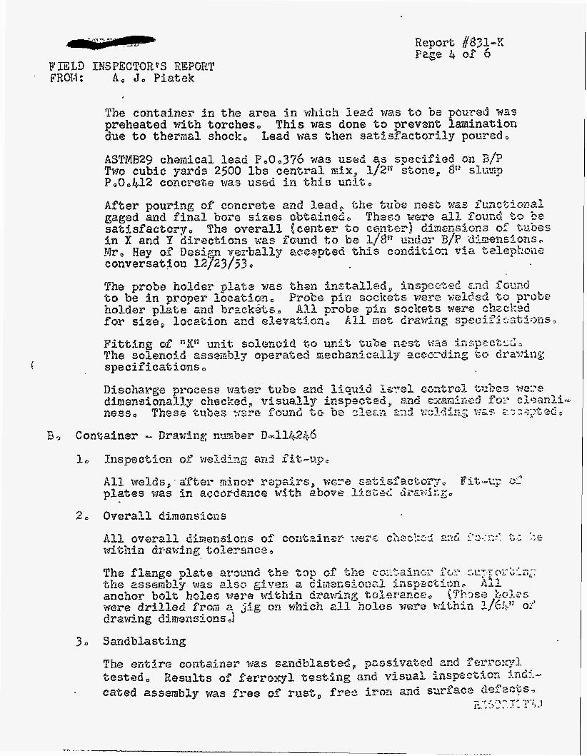

FIELD lidSPECTOR*S REPORT FROM : A , J, PiaLek
(’
b o
20
30
40
5 3
Inspection of w l d i n g and f i t -up


E o I o DU PONT DE NEMOURS & COO
Consk~uct ion Division
TO


The top 1pLatts was %hen reolePreEed within oO08n and the vef i i - caliky of ( 8 ) representative eubes was taken, VerblceLities were found to b8 within a range of 3000tF to oOIOn per ft,
A l l tube bores were reamed after welding was c ~ ~ ~ p l ~ t e d , was done to produce a mun6 bore of pope? size as welding tieilds to shrfnk the tube in the are= adjacmc t o the kube wa2d and all tube bores were small whea fixuse i n s e ~ e d into nost as explained i n a previous paragraph,
This
bo F i t t i n g of Tube Nos& to Container
AfZQP these checks, the 2 p x 3n x 1/25' z"1ang;e places [ f o r sup- porting tihe eube ne^%]^ were tack welded into the copltainer0 The tube netst w.3 then removed mi? the flange plages wer3 tack welded at top and fiXke8 welded at eke bat%sm around $he 0ntb1-e containero Welds were examined visual&y far cracks, pinholes, -and soundnm~s~ Welds weye considered satisfac&sry snd ths tube nest was replaced in the cancainer a d $he fslllowfng inspsct isns were made:
5 0 Pouring of ConersLe and Lead and Subsequen% Gperatfens and In- spections
Prior to pouring of conereZs and lead, %ha interior of' I;hs tubs nes$ and container was insFee%sd fo r cleanliness, Upon saCls- factory inspec t ion , %be concm're was poured as?d e w e was Lakan to provide vibraeisn in osdes &ha% honey ~"esu3.F;~ before pouring Isad,
cornbing wou3.d no% The eoncmtz was permitted to see appmximatelp 2% hours
The mea i n the coneainer in wkicpI lead was to be poured was pre- hezted wieh torches, thermal shock,
This was done tis prevent launina%ion due 'to Lead was then sai;%sfactorily poured,
ASTMB2g chemical lead 9,0, 376 we8 used-as s p s c i f i a d on B/Po cubic yards 2500 Ibs csnGral mlx, 1,/201 stons, 8Ir slump P,O, $22 concrete was used i n Chis u n i t ,
Two

('-
After pouring of concreee and lead, t h e tube ne& was functional gaged and final bore sizes obtained, These viere all found t o be sacisfaczoigr The probe holder plats was then ins%a%led, inspec.&& and found to be i n proper Zoezitisn, probe holder plate andl bracke&s, . checked for size, bscatkon and ebevaefsn, f%cations,
BmSe pin sockets w w e welded 6s 811 'probe pin soclccZ&s were
A l l met drawing speei-
Fi tg ing af W? unit solenoid to unit tubs nest was inspected, The solensfd assembly operated mechanically according $6 drawo fng spscffiea.l;isns
2, Overall Dimensions
The eneire container was smdBLasted, passivated and ferraxyl tesled, cated assembly was f ~ e s of ms&, free iron and surface defectso
Results of f e r ~ o x ~ l testing and visual inspect,ion i n d i -

c o Tank BstLam Drawing number Do913StL4
10
20
30
lo*
5 e
Inspection of Welding and FitoUpo
Fitoup of pla$es was in aceardmce wi,h the aforementioned draw- i ng , examinatdon as described in Section B-Par, 1,
A 1 1 welding was acceptxd afLes visual examination and x-ray
Overall Dimensions
The slope 04 t h e bottom plate was found be 1" shorG0 Overall diznens3ons met B/P speckfleations

. - ? . , ~ . ' - . > , I. _ . . . . _ _ ' , . rl.
., '5 ,-. . .e. . _. . ~
I . . . , , . * ' - , - , - .
I . - - - - . . ~. . , ~ - . - . , ..... ..., ..;.
. . . . .

REPORT *
OF
MATERIAL & EQUIPMENT
SECTION'S
ACTIVITIES AT
0 NEW YORK SHIPBUILDING.CORP. DURING FABRICATION
OF 1
STARTING MAY 18, I951 PARTVI .
BY: JAMES RAY STEWART
JAN. 11, 1954
i :i

\
I. General 0 . . . . . . . . . . . . . . . . . . . . e . 1
k. Design. . . ......... . . . . . . . . . . . .1 1. Boorhees, Salker, Folej; and Slmith . . . . . . . . .l 2. N a r Yo& Shipbuilding Corporat5on . , . . . . . . .l
Eo Procmment. . . . . . O . . . . . . . . .1
1. Ma~eri~SuppUers..........~~o....el
Inspection Trocedurs . . . . . . . . . . . , . . . . . 2 1. Special I-leeting. . . . . . . 8 . . . . . . , . . 2 C.
li, kssexnbly and shipment. . . . . . . . . . . . . . . . . 3
1. Assembly Inspection. . . . . . . . . . . . . . . . 3 2. Shipment. .'.. . . . . . . . . . . . . . . . . 3
G r f d Beam and G r i d Beam S u p o r t Assenflies . . . . . . . . . 3 XI.
A. Grid Beam kssenbly InspectAons . . e . . . , . . . 0 3
1. Wterial m e c t i o n s . . . , . . . . . . . . 0 . 0 3
a. S W e s s Stecl Q-pe 30b . a . 0 0 0 3 b. AlUrninuso Material Inspection . . . . . . .
2. side plates for hsseinbling Chid fjeams . . . 0 0 b a. Inspections After Sandblasting and Acid \Jading . b b. Grid Beam Sandblasting Problem . . . . . . . . 4
3. C-over Plate Inspection (?re-assembly) . . . . . . . 5 a, ~ y p e PI Cover Plates . . . . . . . . . . . . 5
(1) Length, M a t h and ThicKness Check . . . . . . 5 (2) Hole Diameters . . . . . . . . . . . . 5 (3) Cover plate Locating G ~ O I E S . . . . . . . 6

Page No.
b.
C.
de
Type P2 Cover Plates . . . . . . . . . 6 (1) Length, Ididth and Thickness Chec!c . . . 6 (3) Cover Plate Lcxat ing Grooves e . . 6
Fype €3, P4, ~ 5 , ~6 and P? Cover Plates . . . 6 Type P8 Through P20 Cover Plates . 7
(2) HoleD-j&ters. 0 0 0 0 0 0 6
.bo Inspections ferfomed M n g Grid Assenbly . 7 Be Grid &am Support Structure . . . . . b . . e 8
C4 Grid Bearu Inspections After Assembling Into Grid Ban
In. 77711 Physics La’coratOry Tank . . . . . . . . .. . . I2 1. Cleaning specifications . . a + . . . . . . . U 2. Drawing Specifications . . . . . . . . a 13
3. .I4
support Strwture b 0 0 b 0 b I b 0 0 0 b b 10
Fabrication InspectLons . . . . . . . . . . .

CHRONOLOQICAL LIST OF I L L U S m I a S
1. Photograph Serial #lo9 - Cover plate inspect&on
2. Photograph S e a # U O - hssembling &.d beams
3. Photograph S e r l d l #ill - Grid bean support structure
4. Exhibit I;n
5. FXhibit #2
6, Exhibit ff3
- Inspection report covering mate@l. inspec- tion performed on 1/41; b p s 304 stain= less steel?l.ates for the d i a p h q p assembly
- Inspection rei~ort coverhg rneasurenents mzde on contour of diaphragm plate with respect t o the &d beam support plate
- Inspection report covering inspection made to d e k r i i e out-of-mundnms of the hole cu t i n the diaphragu plate
7. Photograph S e S &U - Grid bean assembly
10. Exhibit jfs
l.3. -bit #S
- t?age for measuring cover plate Xocation
- Inspection report dovexing tlcasurments made on each grid bean cover plate..holes with respect to.each other,
- WpectAon report covering meamreaents made f m m the 1" atq>porting plate on the grid beam st ructure t o tihe top of the 3fS11 thick grid beail silpport plates
- Insp&i.on report covering ver t id . i t y check and cover plzte arrangemnt
- Inspection report covering measure;oeni;s taken f m the center grid beam to the outside grfd bean at f i . locations
- Inspection report covering final cleaning of diaphragm plate, cover plates and bttom plates, and other stainloss steel parts such ZLS Lol ts and nuts prior to shipping
b e a s - including altrminian

1.: . .
.? I. . .. . .: . , . / I . ' I
I

The foUowing list covers a l l du Pont drawings pertaining to fabrS- ca'bton released to the Bf 6: E Group at. Elm Pork ShipbuiMing Corporation, Cendea, HI 3.
M eC E Office at Hew York Ship on Novenber 6, 19% For reference purposes and, converxience, a l l drawings are listed by draw number, revision num- ber and title.
Thb lbt was prepared from exfsthg drasing files located in W
ML32453
R&S~OR fi
26
53
lo?
49 t 2
40
42
2l.
1
mpmgf!l Arrangemt
G r i d Beaq Support Arrange- ment
Bottom Plate Arrangemat, Sheet #2
Cover P l a t e Arrangenent, sheet a32
Laboratory Eildg. T a k E& Unit
Bo%bm ?late lktails

. . . I .... . I
Page 1 L .-
,. .
. .. , .


Page 3
D. Assembly and Shipment
1. Assembly Inspection
The grid beam assembly, cover plates, diapb%gm assenbsy, grid beam support assembly, tank and "Ztt beam frambg assembSy were visually inspected and checked for dimensions and align- ment by t he M & E InspeciLon Department prior to shipment. The various steps required for covering the inspection of all component parts of the 77Pi Physics Laboratory process unit have been discussed in detail in the sections that follow.
2. Shipment
After a l l component parts of the 777M process unit had been inspected and accepted, they were packed i n moden boxes and shipped to the Savannah River Plant site on Jamrary 15, 1953.
11. Grid Beam and G p l d beam Support Assemblies
A. Grid Bean &ssembly Inspections
1. Materlal Inspections
a+ Stainless Steel Type 304
The type 30& stainless sbel mater ia l for fabrication of the grid beams, support plates, and diaphragm assembly were given a loo$ inspection upon receipt at New York Ship. This inspection cowisbd of the following steps:
I. All plates were checked witin a magnet to aetcnnine if t h e material was of austenitic structure.
2, lill pla%es were inspected for surface condieon, imbedded iron, necbanical defects and dimensions.
3. Ferroxyl tests were perforned st randon on %?ne plates to determine if any free iron w a s imbedded in the surface. ~ n y indication of f.m iron was remotred by grinding.
h. A l l beat nmbers and d l markhgs were .recorded for each plate. In most cases when a section of a plate was cut f m the original., heat numbers were tmnsferked.
.
A l l of the materjal fnspected was accepted after minor repeirs and reheased for fabrication. -

.. *
,' .. . . .
be l i lmdiaum Haterfal Scgspection
UbloluxLmm bar stock, plates and angles received at New Pork Sbip were given the u~ual dm;laL inspection. After inqectlng this mterizil., it was found satbfactoiy anrl released for fabrkithn,
,
2, Side P l a t e s for AssemUhg Grid Barns
After fabrfcatiag eacn 'grid beam support; plate and before asse.&ly into a grid be%, it was sandl3asted and acid washod according to the established cleaning procediire. Since two suppo& plates arc required for each grid bemi, a d there uere i~ t o w of thirtpone (3) gPid beams i n %he assembly, the above operation bvdved the cleamng and insilection of sixt#-tko s i d e plates,
2be ZoUowing re~uae covers inspections made on these grid beam support plates (3/@* thick type 30b stainless steel) after sandblasting and acid washing:
A l l plates gem raac?tlas%ed before assemblr for purposes of:
a. Rerioving scale b. Pmeing surfaces of iron contamination, or
any other .surface contaxination
Foliov5ng saxiiilasting, the platek were v isual ly inspected. blastin, proi;lemn at end of %is section)
All p l a t e s were then acid washed using a standard acid kmsh solution developed for this job, and f o l l o a d by a clean hter wash (deionized or d i s t t l l e d water). Plates were then 17isUsll-J impcctcd; all were accepted.. (See P a r t 14, s e c t i m 3, paragraph c, ?or acid wash fomula)
A l l w e r e accepted (See %rid beai sand-
support p lates were ferror-1 b s k c i usint; the standad ferroxg.1 test solution; all were mce;>ted. Part 14, Section 3, parqpaph Wt* for fermql, test fornmrla), s.
(See
Four gr id bean support plates were lnistalferilr sand- blastea without hzvirg protective masking tape over the bevels on top and bottom edges of the plates, specifictitions for surface finish on tarese edges w a s 125 R.S micro-inches. This fi&h w a s ciestroyed by sandblasting; howcuer, subsequen% reworking restored the finish a ~ d plates Here acceptable by Bsign.
Blue p f i t

. %, .
3. Cover plate Inspection (pm-asseiibly)
Prior to asserns1;i of grid beans, all cover plates were dimensionall5. and visual&. inspected after faLricating at Hew Pork Ship. Du Pont drawings Fn3lkbY and K39824 snou the cki.uentiions OA the %went3 (20) different t 3 ~ e cover plates . for the grid heam assemlilies. AM. of these were machined fmn &Lm&rrum plate stock.
Since tam were twenty (20) different type cover plates fabricated f o r the a d beam assembly, t h e inspection of each type cover plate from the standpoiit of tob1.s and gages used w i l l be treated i n a general. discussion. It wLl1 be presented in Chis manner rather than outlining a detailed inspectioii procedure, since all gages axid tools used were of the commercial tme.
AS shown on du Pont -wing r.513489, each of tile twenty cover plates is identified by an appropriate cover plate identification numbr; namely, pl, ~ 2 , P3, PL, PS;, PG, P?, P8, P9, P10, P1L, PL2, P13, Pl4, Pl5, P16;- PI?, P18, P19 and P20. A breakdom of these different type cover plates and Lie inspections perfomed on eac.1 is presented i n t h e fr.lla.?lng paragraphs.
a. Type PI Cover Plates (See Deh5. l #I on du Pont Drawing W13l-489)
Length, Width an6 Thickness Cseck
These dintensions were measured using a surface gzge and surface plate, Since the length and widtt: dimensions as s 10m on the drawing are i n decimals, tt&s method of measuring n a necessary from tne standpoint of accuracy. t;?icknoss of each cover plate was measured at each of the four corners using a 0 - l n outside micrometer.
Hole Diameters
(See piloto serial &Os)
The
The 4.033” hole diameter was measured using a dial indicator bore gage and r ing gage, The locatLon of the hole with respect to tihe psripher: of the cover plate was checked with a surface gage a d surface plate. The method of measuring the location of the hole was similar .i;o that shown i n photo serial flW.
The four 9/16” d b n e t e r holes were spot checked using a 6. scale graduated in y64n. The location of these holes with respect to the sides of the plate was d.80 checked using this scale.
_ . . . . ’., . ~
. .
i
I I

Number 109 New York Shipbuilding Corporatfan Camden, New Jersey November 28, 1952
PROJECT 8980 - SAVANNAH RIVER PLANT
Process - 777M Physics Assembly Laboratory Building.
This view shows the Inspection of cover plates for the
g r i d beam assembly.
the cover plate using a aurface gage and surface plate.
dimenaions checked are (1) Bore ( 2 ) Clampfng b o l t holes ( 3 ) groove check.
See du Pont drawing number 1V-131489.
The inspector 18 measuring the width of
Other


Page 6
(3) Cover P l a t e LocatrLng Gmoves
(1) Length, Igidth dnd Thickness Check
These ifispections were performed as ouklined above in paragzqh 1-2..
These inspections were performed as ouUined abve
(1) TIE additional four s/16lf tape drilled 16-Nc-2 holes were checked using a standzrd thread 3ag& The raative location of these holes with mspect to each other, and the plate edge m s measured using a 6tl s d e graduated in 1/6Ll1.
in pagraph 1-b, ex~ept a~ foUm8:
AU fractional dhensions as s h m on the drating for . - these tj'pe cwer plates were measured using a 611 scale graduated


F' _ I - *
13soign =vision k , contacted for their comments, beams were acceptable to Design, providing the following conditions;
The a d

4 d


S e r i a l Number 111
PROJECT $980 - SAVANNAH RIVER PLANT
This view shows t h e assembling of t h e g r i d
beam support s t r u c t u r e f o r t h e 777M Physics
Lab Tank.
New York Shipbui ld ing Corporation
November 28, 1952' Camden, New Je r sey . .:
I "


i
. Uhen the grid barn support 6tructurr: was cox@etels: asserabled (exlclud- 5ng diaphragm asse;abl;r), zi-fiaal dirriensi~~nal anG Visual check as mads ty du ~ o n t lnspect.orG before dfsiuantJing for sandblasting and acid uasNng stainless steel parts. Fit-ap and dhezsional checks were satisfnc%ory, and then t h e tissemly xas dismantled for cl&g.
LLW. stainless sfx3d. $atcs, anaes, bolts and other miscellaneous staFnzcss sted parts Xiat ccmprise the skeleton g 5 d beam supgort 5.t;rUctUre were sandblastec! and a c i d vashed to rsriiovc traces of iron. JQl. pieces w e r e femoxyl tested, and a f t e r rdnor grinC;ing to T'EX~OVB iron inclusions and other mecbnicd. acfects, they xere accepted. were again os~enblec: i n t o tizc fyItI kern support stiucturc: for final fit-up nnd welding.
Tlrese pieces
t k x t t ie diaphragn assmbly (LEB ciu yont dsa~ri21g ;-2pL90) w a s fabri- cated and asnediled i n b %he fl.a;.,e, It vas fabricated fm 3" thick, type 3011 stainloss steel plates. Tine assembly was fabricsted in four sections. '
Aal material was inspecka p r i o r to fabrication. t'iiis insyechion, see L'- *V,Ltljit ' = iZ: 2ach of the four plates were san~iUaste4~~-, and ferroql tcsted before assembling into t h e T beam structure. - After, ';i.::: tn ia the four plates wore f i t welded i n to the fra.;e.
A% this stage of f;tbricbtion b o rzajor hspcctLons were perforned by .,. - tine du ?ont Inspection grou?. The f i r s t mjor inspection was t o d e t s m h e if the top surface of Lhe cfia$wagu ?late w a s within the reqarcd iili&&ance' -' from the top s-1~5ace of the grid beam s q p o r t p l a t e ; and the second, to I.";" cieter:.&nc- out-of-roundness of Xie hole cut in t he c i i a p h r a ~ plate. mese -. ..I inspectio& are coFereG in de ta i l in -w&bits 2 and 3 presented hermitk '.2;. '
' -,">'.:"v i - Pletallic arc weldins tias used t9 join the c i a p h g m assenbu to tho. z..'%t$i
plates and an&cs coverin;: t f i c 'T keaz stratwe. ;-",'.
V i W l y inspected €or undercutting, cracks, and other surface defects. ikcesssry repairs were mke, E-inspxted a d found satisfactory.
.-- For report covering
-, , -,,.<,. . " - . L .~, ....
' ,
: <',>..,
A l l welding urn %lien ' F:' . . I
kfore asem:,lh-. and aligning grid beai assmblics into the grid -' ;, :.J>. . beam support structure, sll stairiless steel nrr;terial in t i s structure. '
was visually inspected for cleanliness arid then fera-owl tasted. T U %st revealed tiat the diaphpags assem'cil.,. uas not satisfactory, ent i re asumbly w a then noved under a sandblasting hood, and the d i a p h r a s and mating parts uere again sandblasted aad acid washed, vlsual inspecting arid femxyl tcstiE, it was found satisfactou and released for assenibZing of grid beans in to the structure. a later date it was tiiscovered ky inspection that t w 5 stzLnless s t d anaes (See detail 7 on du Pont dmt-iink, Xl3lh90) 2nd four s W r i l
, ir , The .
HovJever, at

> . . 'F.'.' .

- . . _ . . ... . . - . - - - I . : . . - ,
I -. ., , ; -.. . . .r i


1
I t i I I i I I
i i I I I
d I i I
i 1
t
i
! I I
-, .. . . . . .. __ . . . . . . . .~, . . -_

; f ,?
L' .- !
'\
8 .
f? I J :
I
i I
i I i 1 I
i : 1
7 :
i . . ,
1
e
I -


S c o p ;
Besubts:
!

I
i

k ,

..
t
I I
_ . r , , - *
g. i‘“ .‘. . .. ..
, e.. ..r 3 I. L
I


- ., ~ ..: .. -..

Page ll
As s t s t ed i n fl aLove, e=!i hole i n a beam was t o be measured with respect t o tine ceriter hole i n the beams. This additional inspection was r;aived due t o t i e method used for aligning cover plates. As shorn i n Sketch #I, centerlines aA1r and rlEn were established by New York Ship, and from these lines, centerline A f t e r establishing centerline "Crl across the en t i re assembly, cover plates ?1 and P5 were s e t ;sing a fixed gage as s h o m i n Sketch #l. The gage I J ~ S inser ted in to the two cover p l a t e holes and centerline '*Da was made to coiiicide with centerline rlC1l. Cover p l a t e s ?1 and Ps were then firmlj bolted. Working out fm centerline nCff in any direction, ad,jzcent cover plates were se t t o previous cover p la tes just aligned ming the 7.000" center-to-cen- t e r plug gage. ments from the center hole i n a beam t o a l l other hole s i n tie bear, was not necessvy and, therefore, t h i s inspec- t i o n was xaivea.
was e s h U s h e d .
It can now be readily seen t i t measure-
The inspection required i n #2 ai;ove vas performed i n the f o l l m i n g manner:
As s ta ted i n 82 grid Leai height from t h e 1" plate supporting teams a t end t o Lie t o p of 3 / ~ " side plates of the beam nust be wi th in 1/16" from beam t o beam. an alternate t o taking phj-sic& measurements, a visual. inspection of the 3/6lt side plates i n conjunction with a dimensional chew of the cover plates was naae. It was physically impossible t o measure t he required dimen- sion without o i s m n t l i n g the enc cover plates on each beam. For the of t h i s inspection, see Exhibit
AS
f 5 .
The ins2ection required i n #3 is covered i n an inspec- t i o n report presented herewith as ;*bit #6.
The inspection required i n f 4 is covered i n an inspec- tionreport presented herewita as Ixli ibit f7.
The inspection required i n #s p l i o r t o shipping is covemd i n an iL?szecticjn report ?-resented herewith as Zxhibit $6. photo serial #l05.
For s t e z , cleaning of gric; beam, see
111. 777N Physics Laboratory Tank
1. Cleaning Specifications
I n conjunction with the desi22 of t h e 777i.i - P.D.P. physics l abora toq tank (equipment piece nmLer 7 7 ~ ) specifications were written pertaining t o the mount and t3Te of inspection required.
One phase of t h i s program was the degree of c le tnl iness required during t he fabrication of the -&t. Du Font cleaning

i
i

. . ' - , ._ ' . . - r ..
. . . . . . . I . . . . . . . . . . - . \ . . . . -.... . . . . . . . . ^ . ..._-. I ~ . - , * : < . .I . - .* .? ... .: b-. .. . .
I : . . . ,;..- - - . - " -_ . , . . , . . J
. . I _ . . . - . . ... .%--. - .- ,". .... _.... . . . I ' I ; ,*;.
. I
. : - s . '. . . .... . . . . . . .
. . .__ - . , .


. - . . . ..... I . ' 2
. . c:-. . r. - . , * :.. _. ( - I .. , ' . - . . , .- ._ . . ,. 1.; -I_. s . . . . . . . . 4 . . i t . - . .. .. - ....... . . . .
..
1: ,. a _.


I . . . . ' .* . . . . .
r . . . ' ..
- . . . .
...... 1 , ........... -." < . ,
-.-..d ......... , .- - .. - . - /
. , >I. , . .-,- :- . -- .I 9:' - .c . .< f . I . n ...........
? ' r c *'. -, . . . -
I C I
- ..". . - I - . . .. ... . ..- , . . . . . . _
I : - _ . . . : - ..
:. - . \.. - - * 'J " . - . . - . . . . I . . . _ . . , .
. . - . - . . .. . - -
._ . .
. .
- ' ,. . ; . r . . - . - * . .


. : , . .: . . ,- -.-> ?C' ; T , - - . - ..
' .-r : 'f .. - .......... (- . .- * * - , . . . . . . ?*- - .' ........ -a;. \: -. .I. -* .- . -=' :7c-: .. .A .%.\ * : r ... r, f: .. ,
- - * - . .
.. .. . . . . . . . . . . ' - ; . ........ _ . . . '= . . :. . . - . a . - ,., . . . . . . . . . , . * - . . . . .
. * . .... . . - . * .
. . . . . . . . . . * , . . .
-. a .. . . -

u - , -- ,p ,. . ..., 1 . . - * . I , -
,.


L

k'ire brubes, steel wool, etc., were reco;riienr.ic.r~ for clean- ing welds and other surfzces s-ibject to ferroxyl k:st. Grinding m s to Ee done with a1uninu.n oxide wheels. ail , crezLe, paint, dirt, e'cc., was subject to m o v a l by a detergent, solvent wash- ing, vapor dcgreasing, or other c l c m h g acthods zpnrovt.ti Ly the du Font inspector p r io r to w i d cl.leanin,;. It idas furher spec$.- fied t h a t welu filn, ticlci !lash, anu surface iron conb-tion should Le removed to secure Sri&t; netal. blasting cdt,h sand or dunciurl L"it w a mcostnc-nded for all suri'aces tha t i z d to pass the ferroxyl test.
In the case of mhdced iron acLd clczmint: :.ras hi ;lay recommended. Onc of the cmxerical solutions proposed w a ~ a p i a n g sulution of

Page 13
10-165 HE0 - 2% HF a t a'temperature of 120' - aO0F.
s k i n l e s s s t e e l t o be p i t ted o r inter-granularly attacked t o a degree that was considered hanuiul. t i o n the pickling acid had t o be thoroughly washed f r o m the surface
of t h e stainless steel with clean water.
Hmever, the du Pon 2 inspector was not allowed t o permit the surface of the
As i n the case of the ferroxyl s o h
A l l component pads , such as the stainless s t e e l tube center- ing mt, were to be cleaned p r i o r t o assembling i n the tank.
Before shipping the ta&, all surfaces were to be f r ee of con- t imination and finally inspected lq the du Pont inspector using the above prescri'cea methods. Where necessary, t o prevent contarn- ina t ion dwing shipment, the tank and its component parts w e r e t o be protected with a suitacl:. wra?ping matecial free of o i l , l i n t , etc. with full face mbter gaskets and iuic 'to Le suf f ic ien t ly sturdy to stand the abuse of shipnent anc iz~ndling. all closures would remain in place u n t i l t he W. was rigged into place f o r permanent ins ta l la t ion a t %he plant site. specif ied that the au Pont inspector make certain that a l l such closure Levices would not leave'any contaniniitioa zfter they were removec a t the plant site.
Closure devices for the tank nozzles, etc., were ~ o o d or netal
It ;-;as i nknaed that
1% xas further
2. D r a i ~ g Specifications
Special notes were added t o the drawings xhen the 7?7&1 P.D.P. physics l a b r a t o r y tank wa5 designed.
Since the tank shell, bottom, t o p flzrge and nozzles were of welded construction, a l l weld quality and woriananship had to be i n accordance with A.S.W.E. code f o r unfired vesseIs, paragraph ~-68, 19h9 ecEtion. In addition, all welding procedures znd opera- t o r s had t o be qualified i n accordance w i t h the ASHE koi ler code, Section M, 1949 edition. by i n e r t gas, shielded arc welding, e i the r non-consumable tungsten electrode or consmble stainless steel electrode.
It %as specified t h a t afl welding be
A l l butt welds had t o be radiogrzpxictilb exanined throughout their en t i r e l e n g t a and interpretcz in accordance wi th t he non- destructive tes t as specifieci in parasrqn 11-69, sect ion H - (2 t o 10) inclusive of the AS~E code for d i r e G vessels, 19&9 edition.
A l l material for the tank a m its conponent. pzr t s nad t o be txpe 304 with . O O b C ma. stainless steel in accorciitcce uiti: du ?on% engineering spec. S-%-3Ob-H (unless spec i f ica l ly noted other- wise). i n addition, the k n k shel l had t o be s u f f i c i e n t l j true- to-round, so ti:at the ckifference between the maxinun and ninimum diameters :'measured on hsicie or' tank) a t any cross section, did not exceed 0.02f;Ofl of inside diamter - 161 - 2 3/&". ing surface of t h e 3/hn t i l ick t o p flange had to- be finished
The top bear-


I I ----
.
!Y x
c3 3 Q


A f t e r thc centcrii-ies naG bee;^ located on the taAi :hell a d tad: 'wttcrs hezd the no?,:& opc-nii,a in bth were located and cut out, sections of s tandard scheCUle stainless steel. $ 5 ~ were welded to the subject two m a L ~ coqxments of thc- t a k e Tnis was folloved by setting thk tan.; die11 on the b0 t t . a bead, Yhe. sear- or juncture liekeen the txo riain sections xas checked f o r fit-up, preparation, ard clealiness priuil to tack xelciiing a d welding.
13 hri2 the Gu 2011% stams-rc nozzle necks or


..-11 - , . . . . I - . _ 1 .
- . ,. .
" . _._ - . i . . - ' -.* , - -.. e .
. . . . _- ...-,...+-- ~ . - . . . . .
.. -. , ,. ............... A . * . . I *
- A ..,.-_.-- * . 2 <--. :...
.. . d
. * . . . . . . -- . -, r . - .. _ _ - . . -. . . . 7 .- . . . . . - . . . . . . . . . . '!, . / . . ",- ... ...- .. ..... I- ._ e . .- . "
. .
.,. . . . . . ...
.............. . ...... ..... - - - * . I- . -*I . .-.;-+ .q - : _.^ -.- . , I - - .; -. .:a,. .....,. ._. . ,
-as z:,y+--,> I - . &*,,., =.?-", ..I.r_- ... .-.r. . . . . . . . . . . . - ..... -..---.. "....-* .........................................
- A , . , - . , . I. '= . , ' .. ' I;'- :" - . . _I. . . . . . . . . -,a . . _ . I . . . . . . . . . . . . . . . . - .
L . . ' ' . . . . . . . . . . . . - . . I
, 7 . I
*Ir ...... .L ' -
- . . I
. . . . . . .! , . . - . . - - .
. . . . . . . . I :. . ; . . . .. ; .. I:*- :.:< . . . . . - r . .. ,.. .
- , f . . -. .
. . . .

Pzge 16
Since Hew Yorlr S'nip had No. 25-12 welding rod i n stock they contacted du Font for t h e i r opinion regarding the use of 25 (chromium percentage) - 20 (nickel percentage) welding rod fo r welding the medium carbon stsel hot rolled 51' x 3kV x S/b" angles t o the typt 3011 stairiless stetil ta.* shell. Base& on the fac t that 25-20 welding rod had a p a t e r pemenbge of nickel in it thmr 25-12 rod called f o r on t h e drawing, du Pont apFroved the use of 25-20 f o r this particular application. The flange-type an:$es tmre bent t o confom t o t i e contour of t h e t a l k sheu and fabd- cat& i n three pieces t o rtul contimzoudy arouaa the tank. There were two flanges fabricated f o r ve l c iw to the t a l k ~hol1 a t elew- tions f r o m the h t t m of tht- ia$.es mounting t o 3*-6!! and l h t - 6 r t respctively, Before welGing the dnJe-type rlanges to t h e shell of the tank, the shell sur3cc areas i n and adjacent to tine above referenced elevations were visualLy inspected f o r c leanl iness with the a id of standard ferroxyl soluti,on. were insixcted for the pxiencc. of IKL~ scale, rust, oil, grease, paint or oL5er cjeleter iow m..terial,
%e carbon steel angles
After comidetinz the s e l d i n g of t k 5" x 33II x 5/o1! aL&c type flawes t o the wxter surface of the tak (see photogra?h, s e r i a l &W4), the ue1c.i s e a s ere vis-y inspected flashlight. i n g until deemed acceptable. At the sam tine the three wd.ded j o i n t s in eacn t i o n i n relation t o the centerlines of the tank as shown on tne plan view of t h e tank - arrange.:ent drawing S-13476.
a stanaard Som weld overlappin:; MZS founci and remvca by grind-
x 3%" x 5/G1' an@e 11mge uere checlicc for loca-
hefore welding the 3 / P x 3" carbon steel r i n g to the f ark s h e l l w i t i the top surface of the s teel ring 2:y from t h e top euge of the tank shell, a decision w a s reached by t i e Design =vi- sion pertaining t o the weep holes. (See Extiibit +U). it was decided that the top f i l le t weld joinin:: seal r i ~ g to tan! m u s t be ground cosm flush wi th Kne top surface oC the fins i n the vicinity of each weep hole i r i order to prrJvice good draimge f m a tne z e a l ring. T h i s was not necessary. ktween wee_:, holes.
As in the case of tihe top and bottom 5" x 3 p x 5/bt1 angles, t h i s r ing was ~~elceci to the -Lad-; siieU. using 25-20 wel&ng rod, before wcluin;, the a n g e to the shel l , the k i r k surfax i n and aGjiFCeilt t o the area designated t o be covered by thc riz.4 was v i sud ly il%pected f o r clemli~icss wiei the aiu of' fcrro:q1 s d u - tion. The carbon steel rin, was inspected f o r the presence ol" r n i l l scale, rust , o i l , grease, paint, o r o ther deleterious mte- rial. After the ring was weldec t o the tank shell the U&CI was visually inspected us in^ a staxidarc! flas.Ui$% ping was founa anci removeii L3; g r iming ar.til deerned acceptable.
:one weld overlq-
No majc; difficulties Mere mcouttercd i n fatritx&Lns the ialzr~cc. of t he %ani: assembly. Tiza four 241' x 2hrr x 1/P stainless steel Lafi'les locateu over t h e four outer t s n k tottoin head nozzles were checked for location, dimensions and trelciirg. Trior to rreld- ing t h e baffle plates, the inter ior n0z-d.e xelds WPE ground dovm and inspected,
- - r .I* . , . .

- i: -.
0 i
.


EXHIBIT

. . . . . . $ . .
7 . . . . . ' * . . . . . . ... .... ,-.. . . . . . . . _ . " L I . i - .
Q

Page 17
Next , the tank and a l l of its components, including the cen- A
tering mat and chairs were sandblasted (See Exhibit $12) and passi- vated, ferroxyl and white c lo th tests, kihere necessary tne surfaces were re-sandblasted and re-passivated, In any event the tank had t0 meet the requirements outlined i n du Pont cleaning specificatdon Hmber 3228. The t u b centering wit, mentioned above (See Exhibit i5rl.3) was checked for 6imnsions and cleanliness at the same time. Lach of the three sections of the tube centering Qat as v isu i t ly inspected for cleanliness and sprayed with ferroxyl solution to test for free iron. Layout and chairs and height dimensions were checked to cira~ng W-147317. Wemims fell within the a l l aw- able tolerance of :The tank pockets located at %he to?
and checked for dimensions,
A l l surfaces uere inspected for cleariLiness using the standard
of the tank were af so 1/14"* visually inspected using the ferroxyl test
kfter it w a s cietennined that the tank and its coinponents were acceptable for dimensions quality of veld and worknanship, along with c leadiness , it tias hydro tested. was filled with water contajnFng 20 gllonsof nCtlimt detergent to an i n s i d e height of 1st-3" and Uowed t0 stand for eight hours, Theoretically, the Wl.imff detergent reduced the amount of surface tension of the water, there* made it possX~le for the inspector to detect more leaks, for leaks, and no leaks were detected.
The tank (See kxhibit $14)
A l l weld sems uere V j s U l y inspected
Uter draining the water fran the tank, it t r a s re-pasbivated and flushed with de-ionized water to m o v e fhe detergent,
Before shipping, all tank outlets were measured (See Ex'nibit #ls) for proper orientation with tihe aid of a calibrated steel tape, ALL nozzles were inspected for location and orientation. nozzle flanges were checkea'fw du Pont standards including the diameter of the bolt circle, flange face finish, hole size and orientation and neck size. Tank height and a r t h measurements were checked using a calibrated steel tape, 6n and 20" scales.
me
Shipment of the tadk and its components took place after the nozzles were blanked off to meet shipping specifications, Other parts of the tank were protected to prevent contamination i n ship- nent, A review of the *us b a t " dimensions indicated that a l l dimensions were within the allozdile blue pxint tolerances. unit was hccepted Tor dimensions and cleanliness on January 10, 1953.
The
It was skipped to the Savannah River Plant site on J a n u q 15, 19$3.


I .
, ' . *,e f !. , , .. 4 ..... " J 6
. I
. . . . ._

EXHIBIT #13
INSPECTION REpOR!!2 COVERING F E B l O X l L TESTING AND INSPECTION OF TUEE CEXTERIHG HAT FOR P.D.P. TM?K

. . . . . - ......... ... ...c ..... '.I .-I .: i' 2 61-3. t-.:--- - d . : - -__ -,>.*. -,-a .-.; r::- -. ., -
L .
S I . 1 . . . . . . ..... . . . . . . . . , , <- .. ,- . -, -.,'A. 4.:: '. .~
I .
. I .
: . 5 r .. _.
il' .
- -
. -. c
. -- .... I. .. iu
. '.... .......... ., ..........
... ..: ,


c R

. . . . .. .., " * _ -

c *
I'
?
I