6463593.pdf - UNT Digital Library
682
GEND PLANNING REPORT A1 1 i ed-General Nuclear Servi ces Argonne National Laboratory EG&G Idaho, Inc. Electric Power Research Institute Sand i a Nat i on01 Laboratories Pub1 i shed October 1980 Prepared for the . U. S. Department o f Energy Three Mile Island Qperations Office Under DOE Contract No. DE-AC07-76IDO1570
-
Upload
khangminh22 -
Category
Documents
-
view
0 -
download
0
Transcript of 6463593.pdf - UNT Digital Library

GEND PLANNING REPORT
A1 1 i ed-General Nuclear Servi ces Argonne National Laboratory
EG&G Idaho, Inc. E l e c t r i c Power Research I n s t i t u t e
Sand i a Nat i on01 Laboratories
Pub1 i shed October 1980
Prepared f o r the . U. S. Department o f Energy
Three M i l e Is land Qperations Of f ice Under DOE Contract No. DE-AC07-76IDO1570

DISCLAIMER
This report was prepared as an account of work sponsored by an agency of the United States Government. Neither the United States Government nor any agency Thereof, nor any of their employees, makes any warranty, express or implied, or assumes any legal liability or responsibility for the accuracy, completeness, or usefulness of any information, apparatus, product, or process disclosed, or represents that its use would not infringe privately owned rights. Reference herein to any specific commercial product, process, or service by trade name, trademark, manufacturer, or otherwise does not necessarily constitute or imply its endorsement, recommendation, or favoring by the United States Government or any agency thereof. The views and opinions of authors expressed herein do not necessarily state or reflect those of the United States Government or any agency thereof.

DISCLAIMER
Portions of this document may be illegible in electronic image products. Images are produced from the best available original document.

GEND REPORT
ISSUE RECORD
To f a c i l i t a t e maintenance o f t h e Gend Report Document contents, , the Gend Report
w i l l be con t ro l l e d as a u n i t by use o f "ISSUE NUMBERS".
Each t r a n s m i t t a l of a Gend Report o r Revis ion w i l l be i d e n t i f i e d by an "ISSUE
! NUMBER".
Each re lease f o r i n c l u s i o n i n t h e Gend Report ( o r t o i n d i c a t e c a n c e l l a t i o n o f 1 an e x i s t i n g sec t i on ) w i l l be assigned t h e next " ISSUE NUMBER" n o t 'p rev ious ly
used.
As each new re lease i s received by the Gend Report holder , the "ISSUE NUMBER"
below t h a t corresponds t o t h e "ISSUE NUMBER" on t h e t r a n s m i t t a l memoranda
s h a l l be crossed o f f . Thus, when an "ISSUE NUMBER" i s crossed o f f and there
are numbers preceding t h i s number t h a t have not ' been crossed o f f , i t w i l l be
apparent t h a t a l l re leased sec t ions have e i t h e r n o t been received o r n o t
f i l e d i n the Gend Report.

CONTENTS
FOREWORD ............................................................. i
1.0 INSTRUMENTATION AND ELECTRICAL EQUIPMENT SURVIVABILITY .......... 1.0-1
2 . F ISSION PRODUCT TRANSPORT AND DEPOSITION AND ENVIRONMENTS. ................................................ CHARACTERIZATION 2.1-1
2.2 DECONTAMINATION AND PERSONNEL EXPOSURE CONTROL ( I s s u e d U n d e r S e p a r a t e C o v e r As A t t a c h m e n t 1) ...................................
..................... 2 . 3 EARLY CONTAINMENT PENETRATION AND MONITORING 2 . 3 - 1
3.0 RADIOACTI VE WASTE HANDLING ( I s s u e d U n d e r s e p a r a t e C o v e r As .................................................... A t t a c h m e n t 2 )
4.0 (Comb ined w i t h S e c t i o n 2 .0) ...................................... 5.0 ARCHIVE SAMPLE REPOSITORY ( T o B e P u b l i s h e d L a t e r ) ................
................ 6 . 1 PRIMARY SYSTEM PRESSURE BOUNDARY CHARACTERIZATION 6.1-1
6 . 2 NUCLEAR STEAM SUPPLY SYSTEM MECHANICAL COMPONENTS RECOMMENDED FOR EXAMINATION DURING RECOVERY OF THE TMI -2 PLANT .............. 6.2-1
............... 7 . 1 CRITICALITY CONTROL STUDY ( T o B e P u b l i s h e d ~ a t e r ) .
....... 7.2 KECOMMENDATIONS ON IN-PLACE TMI -2 CORE DAMAGE EXAMINATIONS 7 .2 -1
7.3 SCOPING STUDIES OF THE ALTERNATIVE OPTIONS FOR DEFUELING, PACKAGING, SHIPPING, AND DISPOSING OF THE TMI-2 SPENT FUEL CORE ....................................................... 7 . 3 - 1
7.4 TMI -2 FUEL AND CORE COMPONENTS EXAMINATION ....................... 7.4-1

FOREWORD
The Three Mile Island (TMI) Unit 2 accident on March 28, 1979 was and i s of great concern to the nuclear industry; e l e c t r i c power generating
compan i es and the i r cus tomers, regul a tory and other government agencies, the en t i r e nuclear community, and to the country as a whole. While the accident resul ted i n only limited external plant radia t ion exposure, the plant i t s e l f suffered extensive damage with high rad ia t ion contamination w i t h i n the reactor and auxi l iary system f a c i l i t i e s . ' TMI U n i t 2 current ly represents opportunit ies to provide information fo r the enhancement of 'the nuclear power industry sa fe ty and r e l i a b i l i t y of generic benef i t to nuclear power technology. Having a comnon in t e r e s t in assuring that t h i s information is obtained during the TMI Unit 2 cleanup, four organizations
have combined eff0r t . s to obtain t h i s goal. They are: General Public
Uti 1 i t i e s ( G P U ) , - Elec t r ic Power Research I n s t i t u t e (EPRI), - t'he Nuclear Regulatory Commission ( N R C ) , - and t he Department of Energy (DOE) . . - Hence the
: acronym GEND. P l ann i ng Groups have been formed to datermi ne the scope of research a c t i v i t i e s to be performed to recover t h i s .valuable information. The "GEND" Planning Report covers the areas of: instrumentat ion and e l e c t r i c a l equipment surv ivab i l i ty ; f i s s i on product t ranspor t ;
decon tami nat i onlrad i a t i on dose reduction technology; data bank organization and sample archive f a c i l i t y ; character izat ion of primary system pressure
' . boundary and mechanical components; core damage assessment; and fuel hand1 i n g , removal, examination and disposal. Through the e f f o r t s of .these
groups, a l i s t or "menu" of tasks which could be performed during the cleanup and recovery has been developed in each of the areas. Many of
these tasks wil l form the bas i s f o r the implementation phase of the program, the r e s u l t s of which will be used throughout the 'U.S. nuclear


Report Of The
Instrumentation and Electrical Equipment'
Survivability Planning Group
(Task 1.0)
September 1980 . . I
Planning Group Members
Richard A . Damerow, Chairman, Sandia Nat iona l Labora to r i e s
John T. Bauer, General A t o m i c Company
Lloyd L. Bonzon, Sandia Nat iona l L a b o r a t o r i e s '
Matthew Chiramal, U. S'. Nuclear Regulatory,. Commission
Ronald A. F e i t , U. S. Nuclear Regulatory Copunission
Jack W. Malcomb, Ba i l ey Con t ro l s Company
James Mock, EG&G Technica l I n t e g r a t i o n O f f i c e
Michael B. Murphy, Sandia Nat iona l Labora to r i e s
Lester C. Oakes, Oak Ridge National Laboratory
Gerald J. Sadauskas, Burns and R o e Company
Frank S i l a g , Ba i l ey Con t ro l s Company
George S l i t e r , E lec t r ic Power Research I n s t i t u t e
Kar l W. W e s t , Oak Ridge Nat iona l Laboratory

CONTENTS
.............................................. P l ann i ng Group Members 1.0.2
............................................. I . I n t r o d u c t i o n '. ....... 1.0.4
I 1 . Approach ........................................................ 1.0-8
I11 . Pre l im ina ry Recovery L i s t ...................................... 1.0.15
............................ I V . General F i ndi ngs and Recomnendati ons 1.0.52
Appendix 1 .. Sumnary o f Reactor B u i l d i n g Ins t rumenta t ion and E l e c t r i c a l Equipment ........................................... 1.0.57
......................... .. Appendix 2 Inst rument Analys is Procedure 1.0.62
.. ............................... Appendix 3 Selected P lan t Drawings 1.0.65
Appendix 4 .. Pip ing and Ins t rumenta t ion Diagram .................... 1.0.70
App.end i x 5 .. Master L i s t o f TIM-2 In-Containment Inst ruments and E l e c t r i c a l Equipment ........................................ 1.0.73

I. Introduction
The Instrumentation and Electrical Equipment Survivability
Planning Group (IEPG) was appointed to develop the planning
guidance needed for the orderly recovery of data pertaining to
the survivability of instrumentation and electrical equipment 1
contained within the TMI Unit 2 reactor building.
During an accident, the safety of a nuclear reactor depends
upon the proper functioning of certain items of instrumentation
and electrical equipment; other items wili be called on during
post-accident recovery operations. Hence, a knowledge of the
response of such equipment to accident conditions is crucial to
an assessment of the safety of a nuclear plant under accident
conditions. The TMI-2 accident subjected the in-containment
electrical equipment and instrumentation to the effects of an
accident environment which, while not one usually treated in
accident scenarios, is clearly possible. Thus, the .data obtained
.from an analysis of the accident response of the TMI-2 equipment . .
will be valuable in: 1) developing improved and more comprehensive
1 standards for equipment qualification; 2) understanding how equip-
a ment designed under existing standards performed; 3) identifying
- equipment failure modes; and 4) assessing the safety of existing
plants which use similar equipment. It should be noted that the
TMI accident provides two time frames for equipment study in
accomplishing these goals: a) the first few days of the accident

in which much of the. equipment was subjected to high heat, steam,
chemical, sprays, and explosion and high radiation levels: and b)
the long period since the accident where long term degradation
occurs.
One difficulty faced by the IEPG has been to devise a TMI-2
reentry program which strikes a reasonable balance between the
needs of the nuclear industry and various government agencies on
the one hand and the needs of the operating utility on the other.
The industry/government group is concerned with the need to
understand the effects on in-containment instrumentation and
electrical equipment of prolonged exposure to significant levels
of radiation and to various other hostile environments. The
operating utility is concerned with the need to restore the plant
to service with minimum delay.
A thorough analysis of all reactor building instrumentation
and electrical equipment could be very costly in itself and is
likely to be incompatible with the schedule's one would employ in
a..minimum time decontamination. and reentry strategy. There has '
been considerable concern expressed tha.t the decontamination
procedures will be' sufficiently damaging to the items within con-
tainment that much of the potential for assessing damage mechanisms
will be lost. On the other hand, one must not lose sight of the
fact that, without decontamination, "hands-on" examination and
recovery of any equipment might not be practical. Again, these

observations merely highlight the fact that the approach chosen
necessarily involves balance and compromise. ' . -
Having made the point that consideration was given to
striking a balance between the benefits of increased knowledge
and the increased ' costs (monetary, personnel exposure, . etc. ) to
be paid for these benefits, we will now turn to the purely tech-
nical goals of the IEPG.
Objectives - The objectives of this planning study were to: ,
1) Specify particular instrumentation and electrical - .equipment to be studied. The equipment might be.
simply'tested in place or it might be removed and thoroughly analyzed.
2) Define test objectives and methods for each component selected.
3 ) Develop a list of components and samples for archival storage.
Scope - The scope of this planning study includes all instru-
mentation and electrical equipment within the TMI-2 containment
building. Certain items within this broad ciass are required for ' .
core recove'ry operations (for example, in-core 'reactor instruments)
and may not be available for removal until the core is removed.
C However, the fact that their cables and connectors were exposed
0 to the in-containment environment suggests that it would be unwise
to eliminate them 'from our consideration..
This report lists some 228 pieces of equipment as candidates
for further study and possible recovery and analysis. This list
of candidates represents a broad sampling of .equipment types

generally with samples of a given type taken from several
different locations in the containment building. Many of the
items are presently under water. Some of the selections were
chosen because they.are representative of generic classes, while -
others were chosen because they.have unique qualities or were
known to behave in an unusual way during some stage of the accident.
It is expected that as more information becomes available the study
list will be further 'refined. . .
The planning group was divided on 'the questions of the depth
of analysis required, the types of equipment to he analyzed, and
the number of items required for analysis. The. cost vs. benefit
was the issue. The feeling of the group, however, was that as
more.thorough equipment status surveys, in situ tests and actual
analyses of some representative instruments are made,' answers to
these questions will become more apparent. ' It was agreed 'that
the longer the equipment remains in the containment building exposed '
to the degrading environments there the less useful the analysis
information will be.

11. Approach
The IEPG has done the following to accomplish the objectives
previously given: First, information was gathered .from the following
persons and/or organizations:
1 . Planning Group Members
2. Subcommittee Two (Qualification), Nuclear Power - .
Engineering Committee, Institute. of Electrical
and Electronics Engineers (IEEE).
3. Industry Experts
4. .National Laboratory Experts
Secondly, various reference documents were reviewed by the Planning
. Group, including the following:
1. TMI-2 Lessons'Learned Task Force Status Report
and Short-Term ~e'commendations, NUREG-0578, July 1979.
2. TMI-2 Lessons Learned Task Force Final Report,
NUREG-0585, October, 1979.
3 . Investigation into the March 28, 1979, Three Mile ' Island
Accident by 0,ffice. of Inspection and.Enforcement,
4 . Analysis of Three Mile Island - unit 2 Accident, NSAC-1, July 1979.
5. Supplement to Analysis of Three Mi,le Island-Unit 2 . .
Accident, NSAC-1 Supplement, October 1979.
6. A list of in-containment instrumentation and electrical
equipment dated June 19, 1979 (BLR-GPU-R-008) and
supp l i ed t o t h e p lanning group by GPU S e r v i c e Corpora t ion ,
October 2 , 1979.
7. A l i s t of Ba i l ey in s t rumen t s and a s s o c i a t e d drawings
supp l i ed by t h e Babcock & Wilcox Company, October 15 , 1979.
8. ~ e l e v a n t A r c h i t e c t and Engineer des ign drawings (i. e . ,
P&ID1s; g e n e r a l arrangement drawings , e t c . ) .
F i n a l l y , t h e s e l e c t i o n of i n s t rumen t s and e l e c t r i c a l equipment w a s 2 .
made wi th t h e thought t h a t t h e r e s u l t i n g d a t a can s e r v e s e v e r a l
purposes:
1. A comparison of t h e a c t u a l performance of LOCA q u a l i f i e d
equipment w i th i t s expec ted perform.ance should l e a d t o
t h e development of improved q u a l i f i c a t i o n s t anda rds .
These improvements can be expected t o i nvo lve (a) what
i s r e q u i r e d f o r proof o f q u a l i f i c a t i o n , ( b ) changes i n . .
t e s t type and l e v e l , and (c) t e s t i n g a g a i n s t a c c i d e n t
s c e n a r i o s which a r e d e r i v e d from t h e TMX-2 exper ience .
2 . Re la ted t o t h e q u e s t i o n o f improved q u a l i f i c a t i o n s t a n -
d a r d s i s t h e assessment o f t h e adequacy of e x i s t i n g
s t anda rds . Opera t ing data .frnm TMI-2, when compared
wi th t h e q u a l i f i c a t i o n s t a n d a r d s i n e f f e c t today , w i l l
a l l ow e v a l u a t i o n of t h e e x t e n t t o which p r e s e n t s t a n d a r d s
apply t o t h i s " r e a l world" a c c i d e n t . That i s , do t h e
p r e s e n t q u a l i f i c a t i o n s t a n d a r d s a s s u r e t h a t key i t ems o f
i n s t rumen ta t ion and equipment can wi ths t and t h i s s p e c i f i c
even t .

3. Analysis of equipment failure modes will provide im-
portant guidelines for design improvements. The failure
of equipment that, by current understanding, should not
have failed provides a fruitful area for study as does
the survival of items predicted to fail. In general,
failures that can be predicted on the basis of the
environmental exposures are unlikely to advance our
understanding although a few confirmation samples will
be required.
4. An important outcome of the analysis of TMI-2 data will
be an assessment of the vulnerability of the many existing
plants which have equipment identical to that in TMI-2.
Note that vulnerability has two important aspects: the
first involves accident managemen't, and the second involves
pos,t-dccident monitoring and recovery. As the lessons of
this accident are assimilated, it is becoming clear that
many othbr i t.ems beyond the rlormal (present standards)
complement of 1E equipment may be of crucial importance
in an accident situation. TMI-2 thus provides an op-
portunity for assessing the response of.typica1 equip-
ment to an actual accident.
5. . To the' above list of' c~enera!. ~ . ~ s e s for the data, one must
add a use which is specific to understanding the TMI-2
accident. This category includes calibration'of instru- .
ment readings recorded during the accident and the

determination of fission product transport and disposition.
Operator actions might also be more clearly evaluated.
Certainly, the items which yield information specific to the
accident (Item 5 above) should be recovered, as should Class 1E
items that failed and other items which failed but should not have.
Beyond this, it is difficult to argue that only recovery of items
from the TMI-2 containment will answer. the important general questions
of nuclear safety. In this regard, at least two thoughts should.be
kept in mind. First, we,cannot predict at this' time what accuracies
will be attained in the environmental maps which are being developed.
Second, the radiation qualification requirements (approximately
2 x lo4 rads total dose) for the TMI-2 instruments were not particu-
larly severe by modern standards.
. . his document provides a list of items whose study will po-
tentially serve one or more of the five purposes given above. The
list can be reasonably decomposed.into five different categories
(discussed below), and a priority assessment has been'provided for . .
each itern on the list.
IL.is not expected t h a t all of the . , items on this study list
will actually be recovered from within the TMI-2 containment or.
that other items will not eventually be selected for recovery.
Rather, this list can be adopted as a reasonab.le subset of all the
items within the containment building. As data becomes available
on these candidates for selectio,n, choices can be made as to the
need for recovery and' analysis. Whether or not laboratory 'simulation

i s needed t o prov ide a d d i t i o n a l in format ion i s a q u e s t i o n t h a t
should be add res sed on an item-by-item b a s i s .
?he s t u d y cand ida t e s .may be a s s o c i a t e d wi th one o r more o f
t h e f o l l o w i n g f i v e c a t e g o r i e s . The le t ters S,I ,D,E and A a r e
a b b r e v i a t i o n s of t h e g e n e r a l c a t e g o r i e s used i n t h e computer
l i s t i n g o f c a n d i d a t e s e l e c t i o n s .
S a f e t y Equipment (S) - . T h i s c a t e g o r y i n c l u d e s bo th i t e m s c u r r e n t l y des igned a s
s a f e t y equipment and t h o s e i t e m s expec ted t o r e c e i v e t h i s des ig - I
n a t i o n i n f u t u r e r e v i s i o n s o f t h e a p p r o p r i a t e r e g u l a t o r y gu ides .
! Inc iden t -Re la t ed Equipment ( I )
I n t h i s ca t ego ry w e have inc luded equipment which dese rves
p a r t i c u l a r a t t e n t i o n a s a r e s u l t of i t s s p e c i a l r e l a t i o n s h i p t o .
t h e a c c i d e n t . For example, equipment whose 0utpu. t d a t a was used 1
i n c a l c u l a t i o n s o f t h e a c c i d e n t development might w e l l r e q u i r e
r e c a l i b r a t i o n t o a s s e s s t h e l i k e l i h o o d t h a t t h e conc lus ions drawn
a r e c o r r e c t . Also, equipment used by t h e o p e r a t o r s as t h e a c c i d e n t
developed should be p a r t i c u l a r l y s c r u t i n i z e d t o s e e i f t h e d a t a
p rov iaed was c o r r e c t o r , a t l e a s t , w i t h i n t h e expec ted performance
enve lope g iven t h e a c c i d e n t c o n d i t i o n s .
Equipment Y ie ld ing ~ q u i p m e n t Design Data ( D )
A n a l y s i s of equipment i n t h i s c a t e g o r y can p o t e n t i a l l y c o n t r i -
b u t e t o improved equipment des ign . I n p a r t i c u l a r , a l l f a i l e d equip-
ment should be c a r e f u l l y cons idered . I n a d d i t i o n , one must be
\

alert to opportunities to assess operational margins and to explore '
actual performance versus expected performance.
Equipment Useful in the Determination of the Radiation Environ- . . - . d
ment I F ! )
variety of material properties undergo changes in response
to radiation exposure. Particular materials whose radiation response
make them possible "dosimeter" candidates include semiconductors,
glass, plastics, elastomers, and plastomers. The equipment in this
category has been chosen 'because it includes one or more of the
items listed above. Naturally, most of the items chosen under the
other cateqories will also include various samples of the "dosimeter1'
materials. In only a few cases do study candidates have only
"dosimeter" utility.
2 Equipment Designated for Archive Storage (A)
Certain items have been selected for archive storage before
any analysis has been attempted to preclude the loss of data which
future investigations might prove to be useful, In addition, some
items will be stored after analysis.
Having discussed the logic leading to the five cateyui-ies of
equipment, there only remains the need to define the priority
assignments and the' description of the entire. selection process
will be complete.
Priority one is assigned t.o equipment'of the following kinds:
1. 1E or potential ' lE equipment.
2. Reactor control equipment.

3 . Equipment needed to understand the accident.
4. Equipment thought to be especially sensitive to the environments and therefore useful for estab- 1 ishing margins.
5.. Equipment having properties especially useful in assess.ihg damage or representative of important generic features.
Priority two includes duplicates of priority one items as well
as items judged to have lower (relative to priority one) potential
for information.
Priority three items are those whiah have some chance ot '
adding to our store of knowledge but which are judged not to be of
the same urgency as priority one or two.
Along with a discussion of our overall selection and priority
assignment logic, it is worthwhile to state the principal impedi-
ment to proceeding to a firm selection list. This is the virtually
complete unavailability of information pertaining to the performance
of the equipment which is the object of nnr study. Thc principdJ -. a~aterial available to the IEPG has been other investigatory reports
and plant general arrangement drawings.
For example, all failed eqnjpment should be the ufiject Of
special attention. This would certainly include equipment which -
failed or had anomalou's readings during the first few days of the
accident and probably should include equipment failing later. To
the best of our knowledge,.no such list exists. Thus, in most
instances, we were forced to make speoific inslrwuent selections \
'and general recommendations without the necessary material to
justify in detail a particular selection.

111. Pre l imina ry Recovery L i s t
Table I c o n t a i n s a l i s t i n g o f c a n d i d a t e i t e m s t o be recovered .
A ' b r i e f s t a t emen t o f t h e r a t i o n a l ,and s e l e c t i o n b a s i s f o r ' t h e
v a r i o u s i t ems i s g iven i n Table 11. The pr imary i d e n t i f i c a t i o n .
f o r each i t e m i s t h e t a g number and t h e l i s ts throughout t h i s docu-
.>- ment a r e i n t a g number sequence. Z ' < ~ d d i t i o n a l in format ion i s provided
a s i n d i c a t e d by t h e v a r i o u s column headings . Table I11 provides an
exp lana t ion of t h e v a r i o u s codes used; i t , i s worthwhile , however,
t o supply a f e w a d d i t i o n a l comments about t h e computer l i s t i n g .
The in format ion ca t ego ry column (INFO) shows t h e v a r i o u s i n fo rma t ion
c a t e g o r i e s (see S e c t i o n 11) t o which t h e i t e m s belong. The s t a t u s
.(ST) column w i l l ' be used t o i n d i c a t e t h e p r e s e n t o p e r a t i n g condi-
t i o n and r eadou t c a p a b i l i t y o f each in s t rumen t . Th i s in format ion
i s e s s e n t i a l i n e s t a b l i s h i n g a pre-recovery t e s t program and, as
s t a t e d e a r l i e r , i s unknown t o u s a t t h i s t i m e . The work code column.
w i l l c o n t a i n in format ion r e g a r d i n g sample recovery p l a n s . For
example, t h e entryABXX means t h a t i n s i t u t e s t i n g is r e q u i r e d p r i o r . .
t o recovery and t h a t sample recovery cannot b e p e r f o r m e d u n t i l a f t e r
c o r e removal. The n o t a t i o n AB means t h a t i n s i t u t e s t i n g i s r e q u i r e d . .
and t h a t t h e r e a r e no r e s t r i c t i o n s on removal o f t h e sample. Note
t h a t i t e m s coded A must have p r i o r i t y i n t h e development of d e t a i l e d
t e s t i n g procedures . The work code can be completed a f t e r t h e s t a t u s
of i n s t rumen t s i s known. The s p e c i a l s e a l i n g program (SSP) column
i d e n t i f i e s t h o s e i t e m s which were s u b j e c t t o v a r i o u s a d d i t i o n a l
s e a l i n g procedures t o upgrade t h e i r r e s i s t a n c e t o wate r damage, e tc .

TABLE I
T M I U N I T 2 REACTOR B U I L D I N G INSTRUMENT L I S T I N G P 1 E E ? - C = ~ ~ ~ W K - Q ~ ~ ~ ~ U A C E . -1.. - . -. - . . . -
MFR. TAQ NO. CODE MODEL S E R V I C E / D E S C R I P T I O N
E L V FLOW WORK SSP* LOCAT ION F T D I A G I N F O S T CODE 1 E + PR
I
4 AH-EP-5037 ASCO 8 3 3 1 A 4 5 3-WAY SOLENOID PCRGE VALVE R 1 2 - 3 0 5 2 0 4 1 S 00 + 1
3-WAY SOLENOID P M Q E VALVE R 1 2 - 3 0 5 2 0 4 1 S 00 + 1 -- - - - - -
AH-EP-5040 ASCO 8 3 3 1 A 4 5 3-WAY SOLENOID PURGE VALVE R 1 3 - 3 0 9 2 0 4 1 S 00 + 1 8
2
AH-KS-9000 AH-E-11A A I R COOLER L I M I T SWITCH. R 1 9 - 331 2 0 4 1 S 00 + 1
AH-KS-5002A A-B 802T-PTPbJ3 AH-E-11C A I R COOLER L I M I T SWITCH R 2 0 - 331 2 0 4 1 S 00 + ' 2 ' 1 1
!2,
AH-KS-50028 AH-E-IIC AIR C O O L E ~ LIMIT SWITCH R 2 0 - 3 3 1 2 0 4 1 SA 00 + 1 - --- --
AH-KS-5037 AH-V2B VALVE L I M I T SWITCH R 1 2 - 305 2 0 4 1 , S 00 + 2 ' 14
'6
' AH-LS-3008 6EMS L S - 1 9 3 0 A I R COOLER PLENUM L E V E L SWITCH R1- 306 2041 D 00 2
AH-KS-5039 AH-V2A VALVE L I M I T SWITCH R 1 2 - 3 0 5 2 0 4 1 S 00 + 2
AH-KS-5040 AH-V3A VALVE L I M I T SWITCH R 1 3 - 309 2041 SA 00 + 1 17
'9
* AH-TE-5020 REC TEMP ELEMENT 0 -20GF RTD
AH-LS-5005 GEMS L S - 1 9 5 3 A I R COOLER PLENUM L E V E L SWITCH R 1 9 - 306 2 0 4 1 DA 00 2
AH-LS-5006 6EMS L S - 1 9 5 3 A I R COOLER PLENUM L E V E L SWITCH R2O- 306 20% D 00 2
AH-TE-5023 R B E L E V A T I O N 330 F T . 0-200F R T D CC-C50 330 2041 I D 00 1
0 , b-' cn
AH-TS-5024 PENN A2SCN-1 RB AMBIENT TEMP S M I T C H 29-215F
AH-TS-5084 PENN T - 2 2 EQUIPMENT HATCH T M P SWITCH 50-90F -- - AH-TS-3085 PENN A-25 ELEVATOR MACHINE R 3 0 M TEMP SWITCH 2 5 - 2 1 5 ~ R 1 6 A 3 4 7 2041 DA 00 2
'
a AH-TE-5021 R B TOP C E I L I N G 0-200F RTD R 7 3 5 3 2 0 4 1 I D A 00 . 1
AH-TE-5022 R B E L E V A T I O N 330 IFT. 0-200F RTD R 1 6 A 330 2 0 4 1 I D 00 . 1
H CF-1-PT4 FOX E l l G M - - D l CF-T-1B CORE FLDNG TNK PRESS 0-800 P S I G 3 2 4 2 0 3 4 .DEA 00 1
32
3
CF-2-LT1 - BMC BY8231 -X -A CF-T-1A CORE FLDNQ TNK L E V E L 0 - 1 4 F T 3 2 4 2034 DEA 00 it 1
CF-1 -PT l FOX E l l O M - % D l CF-T-1A CORE FLDNQ TNK PRESS 0-800 P S I G 3 2 4 2 0 3 4 D E 00 1
CF-1-PT3 FOX E11GM-SAD1 CF-T-10 CORE FLDNG TNK PRESS 0-800 P S I G 324 2 0 3 4 D E 00 1
BMC BY8231-N-A CF-T-18 CORE FLDNG TNK L E V E L 0 - 1 4 F T 3 2 4 2034 D E 00 * 1
09 V I C O 8 5 7 - 2 R A D I A T I O N DET /X -H ITTER ( 6 M ) 'FH BR ( N ) 3 4 7 2062 E A 00 2
HP-RT-0210 V I C O 8 5 7 - 2 R A D I A T I O N DET/X-MITTER (GM) F H BR ( S ) 3 4 7 2062 D E 00 2 -- 4) 44
HP-RT-0213 V I C O 8 5 7 - 2 R A D I A T I O N DET /X -M I1TER (GM) R 6 3 4 7 2062 DE 00 1
R A D I A T I O N DET /X -H ITTER ( I O N ) HP-RT-0214 V I C O 8 4 7 - 1 DOME 372 2062 I D E 00 1

TABLE I (Cont Id)
T M I U N I T 2 REACTOR B U I L D I N G INSTRUMENT LISTING' - f ~ p w w -05-0 -PAGE. .2. -- . . 1 1 7=
TAG N,. MFR E L V FLOU WORK SSP* CODE MODEL SERVICE/DESCRIPTION LOCATION FT DIAG INFO ST CODE IE + PR - --
-4 I C - ~ - T E ~ BMC PYROTRON RC-P-1A I N J WTR RECRC FLOW & PUMP J K T 0-200F RTD P I P I N G 327 2029 D 00 2
: 1
I C - F I - 7 5 6 7 BART 227 . . RC-P-IB SEAL FLOW D-P 0-100 I N H 2 0 3 7 N - 3 7 E 2029 DEA 00 2
1 5
6
-1. 1 .
I C - R T - 1 0 9 2 V I C O 8 4 3 - 2 0 -ICW LETDOWN C L R " ~ A 80KEV-2MEV ( S C I N T I L L A T O R ) 3 2 N - 1 8 E 282 2060 A 00 2
I?-10-DPT BMC B Y 8 2 3 0 X A CAD OUTLET HDR FLOW 0-200 1N. H 2 0 -- .--- -- R 6 391 2029 DE 00 1 ,
I C - F I - 7 5 6 6 BART 227 'RC-P-IA SEAL FLEW D-P '0-100 'IN 1-120 25N-43W 2029 DE 00 2
ICD- -17 BMC INC'ORE' DET ABLY 7LD-18-1TC M-10 3 5 0 N A I D 00 1
I I
' I C D - ' -30 BMC INCORE DET ABLY 7LD-10-1TC B -8 330 NA I D 00 1
4 . '
I C D - -05 BMC 'INCORE DET ' ABLY "~LD-IB-ITC E-9 350 N A I D 00 1
I C D - -16 BMC INCORE DET ABLY 7LD-18-1TC M-9 3 5 0 NA I D 00 1
I
ICD- -37 BMC INCORE DET ABLY 7LDL1B-1TC H- 1 3 5 0 NA I D 00 1
I C V - -43 BMC . INCORE DET ABLY 7LD-18-1TC R -7 350 NA I D 00 1
I C D - -49 BMC INCORE DET ABLY ~ L D - ~ B - I TC M-14 3 3 0 N A I D 00 1
ICU'- -52 BMC INCORE' DET ABLY AD-1~-ITC C - 1 3 330 NA I D 00 1 : . .
MU-10 -FT l BRK 8-3630 RC-P-1A S E A L WTR BLEED OFF 0-2GPM LOCAL 2 0 2 4 DA 00 3
MU-10-FT2 BRK 8-3630 RC-P-1A S E A L WTR BLEED O F F 0-26PM LOCAL' 2024 D 00 3
MU-10-FT4 BRK 8-3630 RC-P-1A SEAL WTR BLEED O F F 0-2GPM 2024 D 00 3 LOCAL
NI -AMP-1 BMC P T 6 6 2 3 1 4 0 N PREAMP RC-T-1 310 I S E A 00 + 1
N I -AMP-2 BMC P T 6 6 2 3 1 4 0 N PREAMP RC-T-1 310 I S E A 00 + 1
N I -ND- 1 W W L 2 3 6 8 2 A PROP COUNTER RC-T-1 310 I S E A 00 + 1
NI -ND-2 W W L 2 3 6 8 2 A PROP COUNTER RC-T-1 310 I S E A 00 + 1
N I -ND-3 W W L 2 3 6 3 5 A COMP I O N CHAMBER RC-T-1 322 l S E A 00 + 1
N I -ND-4 W W L 2 3 6 3 5 A COMP I O N CHAMBER RC-T-1 322 I S E A 00 + 1 - N I -ND-5 W W L 2 3 6 3 8 B UNCOMP I O N CHAMBER RC-T-1 322 I S E A 00 + 1
N I-ND-6 W W L 2 3 6 3 6 B UNCOMP I O N CHAMBER RC-T-1 322 I S E A 00 + 1
NI-ND-7 W W L 2 3 6 3 6 B UNC0MP:ION CHAMBER RC-T-1 322 I S E A 00 + 1
N I -ND-8 W W L 2 3 6 3 6 B UNCOMP I O N CHAflBER RC-T-1 322 ]SEA 00 + --- - - 1
NP.-PS- 1 4 3 4 SOR N 2 GAS TO RBI 10-275 P S I DIAPHRAGM PRESSURE SWITCH I R 4 3 2 3 4 9 2036 DA 00 3
NM-PS-4 174 SOR N2 GAS TO RBI 0 .2 -6 .0 P S I DIAPHRAGM PRESSURE SWITCH I R 432 3 4 9 2036 D 00 3

TABLE I (.Contfd)
T M I U N I T 2 REACTOR B U h L D I N G INSTRUMENT L I S T I N G r n -- -
I , I --- LEg6- ( rkJKOS-a8=%0-PACE
# TAG NO. MFR.
' CODE MODEL ' S E R V I C E / D E S C R I P T I O N E L V FLOW WORK SSP+
L O C A T I O N F T D I A G I N F O S T CODE 1 E + PR - - .. -
NM-PS-4175 SOR N 2 GAS TO R B i 1 0 - 2 7 5 P S I DIAPHRAGM PRESSURE S W I T Z H I R 4 3 2 3 4 9 2036 D 00 3
NS-FS-3977 MAG 3-F533-T-F FLOW SWITCH 0-100GPM 34N-23W 337 2030 DA 00 3 .. . . -
NS-FS-3978 MAC 3-FS~~-T-F FLOW SWITCH 0-1 OOGPM 19N-22E 336 2030 D 00 3 8
NS-FS-4023 BRK 3601 . -10DZ ROTAMETER 0-1 5 6 P N 21N-23E 3 3 4 2030 D 00 3
NS-FS-4024 BRK 3 6 0 1 - 1 0 D Z ROTAMETER 0-1SGPM 35N-24W 3 3 4 2030 DA 00 3. I I
12 -
!.!J
RC- - L S 4 BORG RC-P-2B S E A L LEAKAGE L V L S W I T C H ELECTRODE P I P I N G 3 4 0 2 6 0 1 D 00 1 3
NS-FS-4026 BRK 3601 -1ODZ ROTAMETER 0-15GPM 13N-24W 3 3 4 2030 D 00 3 ..
NS-FS-4027 HAG 3 -F503 -T -F .FLOW SWITCH 0-100GPM 2 3 N - 2 2 E 3 4 3 2030 D 00 3 14
5
. RC- - L S 1 BORG RC-P-1A S E A L LEAKAGE L V L SWITCH ELECTRODE P I P I N Q 3 4 0 2 6 0 1 DA 00 3
RC- - L S 2 BOR6 RC-P-2A S E A L LEAHAQE L V L SWITCH ELECTRODE P I P J N G 3 4 0 2 6 0 1 D 00 3
7 - -
a k RC-14A-DPT2 B f lC BY3X41X-A RC FLOW (HOT L E G ( A ) 1 0-8B8. 12IN H20 I R 4 2 7 286 2024 S E 00 *+ 1
l-'
0
26
1 RC-1%-TE1 REC 1 0 4 A F a - 2 RC HOT L E O ( A ) TEMP 0-BOOF R T D WELL 353 2 0 2 4 S A 00 it 1
2 RC-15A-TE2 REC 104AFP-2 RC-P-1A COLD L E O TEHP 0-8WF RTD WELL 310 2 0 2 4 S 00 u L. 1
E3 REC 1 0 4 A F P - 2 RC-P-2A COLD L E G TEMP 0-800F RTD WELL 3 1 0 2 0 2 4 S 00 9 1 -- ?EC 1 0 4 A F P - 2 PRESSURIZER WATER TEMP 0-7DOF DUAL RTD WELL 3222024 D 00 9 2
19 20
22 3
RC-Z-TE; REC 1 0 4 A F P - 2 P R E 6 5 U R I Z E R WATER TEMP 0 -73OF DUAL RTD WELL 322 2 0 2 4 D 00 ,' u 2
RC*-1-LT~ BMC BY3B40X-A PRESSURIZER L E V E L 0 - 4 0 0 I T J H20 I R 4 2 4 286 2 0 2 4 I D E A 00 * 1
RC-1-LT2 BMC BY3B40X-A PRESSURIZER L E V E L 0-400 It4 H 2 0 I R 4 2 4 286 2024 I D E A 00 9 1
RC-1-LT3 BMC BY3B40X-A PRESSURIZER L E V E L 0-400 I N H 2 0 1 R 4 2 6 286 2024 I D E A 00 u 1
RC-14A-DPT1 BMC BY3X41X-A RC FLOW (HOT L E G ( A ) ) 0 - 8 1 8 . 1 2 I N H 2 0 I R 4 2 3 286 2 0 2 4 SEA 00 it+ 1
5 35
RC-4A-TE2 REC 177HW-2 RC HOT L E G ( A ) TEMP 320-620F DUAL RTD P I P I N G 3 5 2 2 0 2 4 SA 00 *+ 1
RC-3A-PT1 REC 1 1 5 2 Q P 9 A RC HOT L E Q ( A ) PRESS-NARROW RANGE 1 7 0 0 - 2 5 0 0 P S I G I R 4 2 3 286 2024 I S E A 00 + 1
RC-3A-PT2 REC 1 1 3 2 G P 9 A RC HOT L E G ( A ) PRESS-NARROW RANGE 1 7 0 0 - 2 5 0 0 P S I G I R 4 2 7 286 2024 I S E 00 + 1
2 38
40
RC-4A-TE3 PEC 177HW-2 RC HOT L E O ( A ) TEMP 9 2 0 - 6 2 O F DUAL RTD P I P I N G 3 5 2 2 0 2 4 S 00 *+ 1
-- RC-3A-PT3 FOX E l I Q H - I N M 2 RC H O T L E Q ( A ) PA=-WIDE RANGE 0 - 2 5 0 0 P S I 0 I R 4 2 5 287 2024 SEA 00 + 1
RC-3A-PT4 FOX E l l Q H - I N M 2 RC H O T L E G ( A ) PRESS-WIDE RANOE 0-2300 P S I G . I R 4 2 7 287 2 0 2 4 S E 00 + 1
RC-3B-PT1 REC 1 1 3 2 G F 9 A RC H O T r L E G ( B ) PRESS NARROU RANGE 1 7 0 0 - 2 5 0 0 P S I G I R 4 2 9 287 2 0 2 4 S E 00 + 1 I
RC-4A-TE1 REC 177HW-.2 RC HOT L E G ( A ) . TEMP 520-620F DUAL' RTD P I P I N G 3 5 2 2 0 2 4 SA 00 *+ 1

TABLE I (Cont'd) . .
T M I U N I T 2 REACTOR B U I L D I N G INSTRUMENT L I S T I N G 1 - z
-?- 5
-L
P " - Kp&&U44.45-28--8@ .PA=' 4 .- . --
MFR . E L V FLOW WORK SSP* TAG Ni l . . CODE MODEL SERVbCE/DESCRIPT ION LOCATION F T D I A G I N F O S T CODE 1 E + PR
RC-4A-TE4 REC 177HW-2 ,RC HOT L E G ( A ) TEMP 5 2 0 - 6 2 0 F DUAL RTD P I P I N G 3 5 2 2 0 2 4 S 00 *+ 1
RC-4B-TE1 REC 177HW-2 RC HOT L E G ( B ) TEMP 5 2 0 - 6 2 0 F DUAL RTD - - -. -- - . - -- - - - -. - - . - -- P . I P I N G 3 5 2 2 0 2 4 SA 00 *+ 1 - -- .. . . .- - - -- . - - - . . . . . . - . .- .- -. .- -. .- -- .- RC-4B-TE2 REC 177HW-2 RC HOT L E 2 ' ( B ) TEMP 5 2 0 - 6 2 0 F DUAL RTD P I P I N G 3 5 2 2 0 2 4 SA 00 *+ 1
RC-4B-TE3 REC 177HW-2 RC HOT L E D ( B ) TEMP 5 2 0 - 6 2 0 F DUAL RTD P I P I N G 3 5 2 2 0 2 4 S 00 *+ 1
'O 11
14
RC-4B-TE4 REC 177HW-2 RC HOT LEQ ( B ) TEMP 320-620F DUAL RTD P I P I N G ' 3322024 S 00 *+ 1
RC-56-PSI BRK 9 0 4 8 - 4 RC-P-1A O I L L I F T D ISCHQ PRESS 240-3000 P S I G . A T DA 00 3
RC-56 -PS I4 BRK 9 0 4 8 - 4 RC-P-2B L I F T SYS MANIFOLD PRESS 240-3000 P S I 6 P 2 D 00 3
RC-36-PS20 BRK 9048-4 RC-P-1B O I L L I F T S Y S MANIFOLD PRESS 2 4 0 - 3 0 0 0 P S I 0 P 3 D $0 3
'6 17 - la
RC-57-FS1 M&M FS4-3 RC-P-IA THRUST RUNNER REV R O T . ' I N D : F 1 DA 00 3
RC-58-FS2 t l&M F S 4 - 3 RC-P-1A O I L FLOW THRU COOLER F6 D 00 3
RC-38-FS8 M t M F S 4 - 3 RC-P-1B O I L FLOW THRU COOLER F6 D 00 3 20
21 'f 23
RC-30-FS1 MLM F S l RC-P-1A BACKSTOP L U B E PUMP O I L FL F3 DA 00 3
RC-59-FS4 MLM F S 1 RC-P-21% BACKSTOP L U B E PUMP O I L FL F4 . D 00 3
RC-39-FS8 M&M F S 1 RC-P-1B BACKSTOP L U B E PUMP O I L FL F4 D 00 3
Is RC-3h-TE1 REC 177HW L . ; " RC-P-1A SUCT TEMP 90-650F DUAL R T D P I P I N G 310 2 0 2 4 DA 00 * 2
a 28 29
?!. 32
z 34 35
37 38 - 39
2 4 I - 4 2
2 44
RC-SA-TE2 REC 177HW ,RC-P-1A 9 U C T T E M P . 5 0 - 6 5 0 F DUAL RTD . P I P I N G 3102024 DA 00 2
RC-5A-TE3 REC 177HW RC-P-2A SUCT TEMP 50-650F D U A L R T D P I P I N G 310 2 0 2 4 D 00 * 2 L.
RC-SA-TE4 REC 177HW RC-P-2A SUCT TEMP 5 0 - 6 5 0 F DUAL RTD P I P I N G 3 1 0 2 0 2 4 D 00 . * 2 .
RC-5B-TE1 REC 177HW RC-P-1B SUCT TEMP 3 0 - 6 5 0 F D U A L RTD P I P I N G 3102024 D A 00 2
RC-38-TE2 REC 177HW RC-P-18 5UCT TEMP 30-650F D U A L R T D P I P I N Q 3102024 DA 00 * 2
RC-SO-TE3 REC 177HW RC-P-2B SUCT TEMP 5 0 - 6 5 0 F DUAL RTD P I P I N G 3102024 D 00 * 2
RC-SB-TE4 REC 177HW RC-P-2B SUCT TEMP 5 0 - 6 5 0 F DUAL RTD P I P I N G 3 1 0 2 0 2 4 D 00 --
* 2
RC-60 -LS1 SOR 12R2-KK2PB RC-P-1A UPPER RESERVOIR H I L E V E L R1&R2 D A 00 3
RC-60-LS2 SOR 12R2-KK2PB RC-P-1A UPPER RESERVOIR L O L E V E L L 1 & L 2 D 00 3
RC-60-LS8 SOR 12R2-KK2PB RC-P-1B UPPER RESERVOIR L O L E V E L LlLL2 D 00 3
RC-b2-LS1 WARR l C l D l RC-P-1A MOTOR A I R COOLING H 2 0 LEAKAGE DET. LOCAL DA 00 3
RC-b2-LS2 WARR l C l D 1 RC-P-2A MOTOR A I R COOLING H20 LEAKAGE DET. LOCAL D 00 3
RC-62 -LS4 . WARR l C l D 1 RC-P-1B MOTOR A I R C O O L I N G . H 2 0 LEAKAGE DET. LOCAL D 00 3

TABLE I (Cont t .d)
T M I U N I T 2 REACTOR B U I L D I N G INSTRUMENT L I S T I N G c--n .# . . ~ . & g & ~ U & J . * 5 = 2 ! & z . Q f J - p C \ C E . 5 - -- -. - - . .
MFR. E L V FLOW WORK SSP* TAG NO. CODE MODEL SERVICE/DESCR I P T I O N LOCATION F T D I A G I N F O S T CODE 1 E + PR
-. - - . -- . . RC-65-PCVl TEK VA-8 RC-P-1A O I L L I F T SY,S PRESS CONT VALVE DA 00 2
RC-65-PCV2 TEK VA-e RC-P-2A O I L L I F T S Y S PRESS CONT V A L V E ' D 00 2 -- - - - - -- - - - - .
RC-65-PCV3 TEK VA-E RC-P-2B O I L L I F T SYS PRESS CONT VALVE D 00 ' 2
RC-&-PI1 ASCH 0 - 5 0 0 0 RC-P-1~ O I L L I F T S Y S PRESSURE LOCAL E A 00 3
R C - 6 6 - P I 2 ASCH 0 - 5 0 0 0 RC-P-2A O I L L I F T SYS PREESURE LOCAL E 00 3
RC-&-PI3 ASCH 0 - 5 0 0 0 RC-P-2B O I L L I F T S Y S PREESURE LOCAL E 00 3 -- RC-67-VS1 R S 366 RC-P-1A V I B R A T I O N LOCAL D 00 3
RC-67-VS3 R S 366 . .RC-P -2B VIBRATION LOCAL D 00 3
RC-67-VS4 R S 366 RC-P-1B V I B R A T I O N LOCAL . DA 00 3
R C - U I - 7 9 0 7 I R D V I B R P T I O N I N D P N L 10 A 00 ' 3
R C - U I - 7 9 0 8 I R D V I B R A T I O N I N D A 00 3 P N L 10
RC-VE-7889 I R D E C C E N T R I C I T Y RC-P -1A RC-P-1A 328 D 00 3
RC-VE-7890 I R D E C C E N T R I C I T Y RC-F-1A RC-P-1A 328 D 00 3
RC-VE-7891 I R D PHASE REFERENCE RC-P-1A RC-P-1A 328 D 00 3
RC-VE-7899 I R D E C C E N T R I C I T Y RC-P-1B RC-P-1B 328 DA 00 3
RC-VE-7900 I R D E C C E N T R I C I T Y RC-P-18 RC-P-1B 328 DA 00 3
RC-VE-7901 I R D PHASE REFERENCE RC-P-1B RC-P-1B 328 DA 00 3
RC-VE-7904 IUD ECCEN'RICITY RC-P-2B RC-P-2B 328 D 00 3 --
RC-VE-7903 I R D E C C E N T R I C I T Y RC-P-28 RC-P-2B 328 D 00 3 .
RC-VE-7906 I R D PHASE REFERENCE RC-P-2B RC-P-28 328 D 00 3 RR-FT-1027 .=OX E l3DM-SAM2 COOLING C O I L "C" 0-100 I N 320 I R 428 287 2033 D E 00 2
RR-FT -1028 FOX E13DM-SAM2 COOLIKG C O I L "D" 0-,100 I N 4 2 0 MTG-Rl 2 8 5 2033 DE 00 2
RR-FT-1029 FOX E l3DM-SAM2 COOLINQ C O I L WEu 0-100 I N H 2 0 M T G - ~ 1 283 2033 DEA 00 2
SP-1A-LT1 BHC BY8241X-A STM BEN RC-H-1A F U L L RNGE LEVEL 0-600 I N H 2 0 I R 4 2 6 287 2 0 0 5 DE 00 2
SP-1A-LT2 BMC BYBB41X-A STM Q E N RC-H-1A OPTG RANGE L E V E L 0-291.51 I N H 2 0 I R 4 2 6 286 2005 D E 00 9 1 8
SP-1B-LT1 DMC B Y 8 2 4 l X - A STM GEN RC-H-1B F V L L RNG L E V E L 0-600 I N H 2 0 I R 4 2 8 286 2 0 0 5 DE 00 2 - - - -. - .- - SP-6A-PT1 FOX E l l ' G H - S A E 1 STM GE.U RC-H-1A OUT PRESS 0-1200 P S I G I R 4 2 6 287 2002 DE 00 1 .
SP-6A-PT2 FOX E11OM-SAEI STM 6 E N RC-H-1A OUT PRESS 0-1200 P S I Q I R 4 2 4 288 2002 D E 00 1 -- --
. .
7
y 7 ru 0
1 - z j L
5
- 8
'O I I
14
'b 17
'9 20
" z
'5 26
2 29
2 32
34 35
2 38
40
4.3 54

TABLE I .(.Cant ' d)
C T - T M I U N I T 2 REACTOR B U I L D I N G INSTRUMENT L I S T I N G
n " 1 . Y,, Y -- ---------I EpQ-)(w -O§-Ge-BQ P e - - & -. I I BR
TAG NO. MFR. CODE MODEL SERVICE/DESCRIPTION
ELV FLOW WORK SSP* LOCATION F T D I A G I N F O ST CODE 1E + PR
.. - . . .. - ----- WDL-LC-1205 JERG D R A I N TANK LEVEL GLASS GAUGE 0-96 I N H 2 0 27s-40W 282 2632 A 00 3
WDL-LT-1316 DREX 508-15-6 RB SUMP LEVEL 0-54 I N H2D . SUMP 282 2 0 4 5 DEA 00 2
5
7
8
k.d WDL-PS-1261 SOR 12N-AA4CSS PRESSURE SWITCH . 2-6 P S I G 289 2 0 2 7 DA 00 3
WDL-LS-1206 MAG 7 5 1 H I G H LEVEL SWITCH 2 7 ~ ~ 4 0 ~ 291 2 6 3 2 DA 00 3 ----- ----------.....-A .. WDL-LS-1208 WAG 7 5 1 LOW LEVEL SWITCH 2 7 s - 4 0 ~ 291 2632 D 00 3
n WDL-P81203-3 SOR 4N-AA2 DRN TANK PRESSURE SWITCH 1-8 P S I G I R 433 286 2632 D 00 3
I 1
1, 2 14
WDL-PSl203-1 SOR 9N-AA5 DRN TANK PRESSURE SWITCH 100-1000 P S I G I R 4 3 3 288 2632 DA 00 - 3
WDL-PS1203-2 SOR 6N-T3rC DRN TANK PRESSURE SWITCH 4-100 P S I G I R 4 3 3 286 2632 D 00 3
YM-VE-7025 RM VIBRATJON ELEMENT STM GEN B UPPER TUBE SHEET ON-OW 3 4 6 E 00 2
r
0
- 2 a
k;l YM-vE-7028 SOR V I B R A T I O N ELEMENT STM GEN A LOWER TUBE SHEET ON-OW 288 E 00 2
1 7
'9 20
22 23
25
Z8 29
2 32
5 35
3' 38
4 1
4-' 4 4
WDL-PT-1202 FOX E11QE-SAD2 D R A I N TANH BELLOWS 0 - 7 3 0 P S I G 325-36W 286 2632 DE 00 1
YM-APP-7022 V I B R A T I O N ELEMENT PREAMP DE 00 1
YM-AMP-7023 V I B R A T I O N ELEMENT PREAMP . DEA 00 1
YM-AMP-7024 V I B R A T I O N ELEMENT PREAMP I DE 00 2 . :., (F, . YM;-AMP-7025 VIBRATION.ELEMENT PREAMP ' DE 00 2
YM-ANP-7026 V I B R A T I O N ELEMENT PREAMP - DE 00 -- 1
YM-AMP-7027 V I B R A T I O N ELEMENT PREAMP DEA 00 1
YM-AMP-7028 V I B R A T I O N ELEMENT PREAMP DE 00 2
YM-AMP-7029 V I B R A T I O N ELEMENT PREAMP DE 00 2
YM-VE-7018 SOR V I B R A T I O N ELEMENT LOWER VESSEL I N CORE TUBES C H 1 ON-OU 288 -- -- D 00 3 -- YM-VE-7019 SOR V I B R A T I O N ELEMENT LOWER VESSEL I N CORE TUBES C H . 2 ON-OW 288 D 00 3
YM-VE-7020 SOR V I B R A T I O N ELEMENT UPPER VESSEL SHROUD ON-OW 3 2 5 D 00 3
YH-VE-7021 SOR V I B R A T I O N ELEMENT UPPER VESSEL SHROUD ON-OW 323 D 00 3
YM-VE-7022 RM V I B R A T I O N ELEMENT STM GEN A UPPER TUBE SHEET ON-OW 3 4 6 DE 00 1 - -- - - YM-VE-7023 RM V I B R A T I O N ELEMENT STM GEN B UPPER TUBE SHEET ON-OW 3 4 6 DEA 00 1
YM-VE-7024 RM V I B R A T I O N ELEMENT STM GEN A UPPER TUBE SHEET ON-OW 3 4 6 E 00 2
YM-VE-7026 SOR VIBRATION ELEWE* STM GEN A LOWER TUBE SHEET ON-OW 288 1 -- - - . - -- -- - .. - . - -. - -.- DE 00 - -- - -. -- -
Y M - E - 7 0 2 7 SOR VIBRATION ELEMENT STM GEN' B LOWER TUBE SHEET ON-OW 288 DEA, 00 1

TABLE I (-Cont'd)
M TAG NO. MFR. CODE MODEL S E R V I C E / D E S C R I P T I O N
E L V FLOW WORK SSP* L O C A T I O N F T D I A G I N F O ST CODE 1 E + PR - -- --
YM-VE-7029 SOR V I B R A T I O N ELEMENT S T H GEN B LOWER TUBE S H E E T ON-OW 288 E 00 2
PEAK REC. ACCELERATOPiETER 1 6 N - 0 2060 A 00 3 --- - - . - .- - - - -- PEAK REC. ACCELERATOhETER 18s-1W 206 1 A 00 3
8 - 9
1 0 - I I -
. . ; . * : , E N D ' E ~ D E N D ' ' " " ' . . .
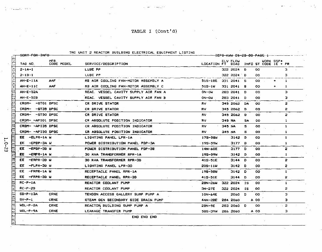
TABLE I (.Cont ' d )
T M I U N I T 2 REACTOR B U I L D I N G E L E C T R I C A L EQUIPMENT L I S T I N G I ,-, --=p-m- .o~-+JJ&.. -1- --- - . . - .. -
I 1 I 4-u
MFR. E L V FLOW WORK SSP* CODE MODEL S E R V I C E / D E S C R I P T I O N LOCATION F T D I A G I N F O S T CODE 1 E + PR
. .. . - . . - - 2-1A-1 L U B E P P 322 2 0 2 4 D 00 3
L U B E PP - - - - . . -. - - . . -. - . . . .- - --. . . -. . - .. . - - . - - .- - 322 2 0 2 4 ' D 00 3 - --- -. - .- .- - - . - .. . - .- . . -. .- - - .- -- . - - - -- - .- A A F RB A I R COOLING FAN-MOTOR ASSEMBLY A 5 1 s - 1 8 E 3 3 1 2 0 4 1 S 00 . + 1
AH-E-11C A A F RB A I R COOL lNG FAN-MOTOR ASSEHBLY C 51s-1W 331 2 0 4 1 S 00 + 1
'D I I
. A
AH-E-52k REAC. VESSEL CAVITY SUPPLY A I R F A N A ON-OW 283 2 0 4 1 D 00 3
AH-E-528 REAC. VESSEL C A V I T Y SUPPLY A I R F A N B ON-OW , 283 2 0 4 1 D 00 -- 3
CRDM- - S T 0 1 DPSC , CR D R I V E STATOR R V 343 2062 DA 00 2 . - '6 17
CRDM- - S T 3 3 DPSC CR D R I V E STATOR R V 3 4 3 2062 D 00 2
CRDM- - S T 3 0 DPSC CR D R I V E STATOR R V 343 2062 D 00 2 -.
'9
CRDM- - A P I O l DPSC CR ABSOLUTE P O S I T I O N IND ICATOR R V 3 4 3 N A SA 00 . .> 1
CRDM- - d P 1 3 3 DPSC CR ABSOLUTE P O S I T I O N IND ICATOR R V 343 !4A S 00 1
,
E E -FLPR-3D W L I G H T I N G PANEL LPR-3D 20s-1 l W 3 1 4 2 D 00 2
. 0 I
f~ W
EE -FAPR-1A W RECEPTACLE P A N E L RPR-1A 19s-28W 3142 D 00 1
22 3
CRDM- -APSSO DPSC CR ABSOLUTE P O S I T I O N IND ICATOR R V 3 4 3 N A S 00 1
EE -ELPR-1A W L I G H T I N G PANEL 'LPR-1A 17s-58W 3142 D 00 1 ZJ
20 2 26
?! 29
EE -EPDP-3A W POWER D I S T R I B U T I O N PANEL PDP-3A 1 9s -59W 3177 D 00 1
EE -EPDP-3B W . POWER D I S T R I B U T I O N P A N E L PDP-3B 14N-60E 3177 D 00 2
EE - E W R - 1 A W 30 K V A TRANSFORMER RPR-1A 196-59W 3142 D 00 1
EE -ERPR-3D W 30 HVA TRANSFORMER RPR-3D 4 1 s - 5 1 E 3144 D 00 2
2 3 5
E E -FRPR-3~ W RECEPTACLE P A N E L RPR-3D 4 1 s - 5 1 E 3 1 4 4 D 00 2
RC-P-1A REACTOR COOLANT PUMP 28N-26W 322 2 0 2 4 I S 00 1
2 38
RC-P-2B , REACTOR COOLANT PUHP 3N-27E 322 2 0 2 4 I S 00 2
SD-P-13A CRNE TENDON ACCESS GALLERY SUMP PUMP A 1 O N - 6 4 ~ 2060 D 00 3
37; 90 0 ,
4 3 - 44 - A <
SV-P-1 CRNE STEAM GEN SECONDARY S I D E D R A I N PUMP 44N-28E ' 2 8 4 2060 A 00 3
WDL-P-2A CRNE REACTOR B U I L D I N G SUMP PUMP A ~ E N - ~ E 283 2060 D 00 . 2 1
WDL-P-9A CRNE LEAKAGE TRANSFER PUMP 5 8 s - 3 9 ~ 286 2060 A 00 3 -- END END END

TABLE I (Cont'd)
MFR. E L V FLOW WORK SSP* CODE MODEL SERVICE/DESCRIPTI .ON LOCATION F T D I A G I N F O S T CODE 1E + 'PR - . -. . . - .. - . .- - - .- . - - - - . .- -
8
HNPR 36" E ' F L Y RB PURGE A I R ( A I R OPERATED) P I P I N G 3 3 7 - 2 0 4 1 , S 00 + 1
HNPR 36" B'FL.Y RB PURGE A I R ( A I R OPERATED) P I P I N G 3 4 3 2 0 4 1 SA 00 + 2 - - - - - - VLCR 1" SOLND RE PURGE A I R P I P I N G 322 2 0 4 1 SA 00 + 2
T M I U N I T 2 REFCTOR B U I L D I N G VALVE L I S T I N G m P. . - ------------- -+EpwW*O5-+m-.p*OE.--f..- .. . .- - . . .. , -
1 i d-
VLCR 1/2" SOLND RE V E N T I L A T I O N DAYPER (3-WAY) P I P I N G 3 2 2 2 0 4 1 S 00 . + 1 - VLAN 1 / 2 ' GATE PRESSURIZER STEAM SPACE SAMPLER (MOV) P I P I N G 3 2 4 2 0 3 1 S 00 + 1
kd MU-V2A V L A N 2" GATE LETDOWN COOLER PRI 'HARY (MOV) P I P I N G 2 8 9 2 0 2 4 S 00 + 1
I I
'3 14
17
C F - V I A VLAN 1 4 " GATE CORE FLOOD TANK TO REACTOR (MOV) P I P I N G 308 2 0 3 4 S 00 + - - - - - .. 1 ---.-
DH-V1 V L A N 12" GATE DECAY HEAT REMOVAL (MOV) P I P I N G 292 2026 D 00 1
DH-V2 ' VLAN 12" O A ~ E DECAY HEAT REMOVAL t MOV) P I P I N G 289 2026 S A 00 + 2
MU-VIE VLAN 2" GATE. LETDOWN COOLER PR:MARY (HOV) P I P I N G 289 2024 S A 00 + 2
r RC-V2 V L A N 2" GATE PRESSURIZER TO RC tMOV) P I P I N G 336 2024 I A 00 1
- -
2 20
-- ---- RC-R2 DRES PORV P I P I N G 359 2024 I D A 00 ' 1
RC-V1 V L A N 2" 6 L 0 1 E PRESSURIZER SPRAY L I N E (MOV) 2024 S 00 + 1 P I P I N G
END E N D E N D
0 I - 23
25
26
WDL-V1118 CRNE 4" RC D R A I N HEADER TC D R A I N TANK (MOV) ' P I P I N G 286 2632 D 00 - 3
WDL-V271 VLAN 4" GATE RE SUMP DISCHARGE. PIPING 318 2 0 4 5 S 00 + 1

TABLE I (.Cant Id)
' T M I U N I T '2 REACTOR B U I L D I N G P E N E T R A T I O N , L I S T I N G - . . --~WWU. 05--28-80-~&0~... 1 , . -. .- .- - -... .-
t2-I .- I .
TAG NO. MFR.
' CODE MODEL S E R V I C E / D E S C R I P T I O N E L V FLOW WORK SSP*
L O C A T I O N F T D I A G I N F O S T CODE 1 E + PR
R - 4 0 0 PRESSURIZER HEATERS POWER O U T L I N R 2 9 1 2 0 I D 00 1
R - 4 0 6 R P S & S F A E OUT L I N R 291 1 6 A D .00 1
2- 8
-- - - - -
PRESSURIZER HEATERS POWER I
R - 4 0 2 PRESSURIZER HEATERS POWER OUT L I N R 291 21 I D 00 1 - - - -- .- - -. . - . -. - -- -. - .- -. - - -- R - 4 0 5 BOP CONTRCH O U T L I N R 2 9 1 2 3 D , 00 1
R - 9 1 3 BOP CONTROL . . t OUT L l NR 293 2 7 A A 00 2 . 1
. .
14
17
INCORE M O N I T O R I N Q INSTM. O U T ~ 1 h k 3 3 1 1 2 D 00 1
CRD I N S T R OUT L I N R 291 7. D 00 2
R - 5 0 0 CONTROL OUT L I N R 299 2 B A D 00 2
R - 5 0 4 CONTROL ' OUT L I N R 323 25 D 00 2
R - 3 0 6 CONTROL OUT L I N R 323 a D 00 2
R - 5 0 9 R. B. COOLANT F A N S ETC, O U T L I N R 3 1 9 3 0 A D 00 1
R - 5 1 4 L. V. POWER BOP , O U T L I N R 2 9 9 3 1 A D 00 2
2: R - 6 1 2 SPARE OUT LINR 292 35 D 00 ' 2
r
I
I E N D E N D E N D '
- ~
2 25 9,
R-607 BOP INSTR OUT LINR 291 36 A 00 2 i . I
R - 6 0 8 RC-P-2B FEEDER OUT LINR 299 '35 D 00 1
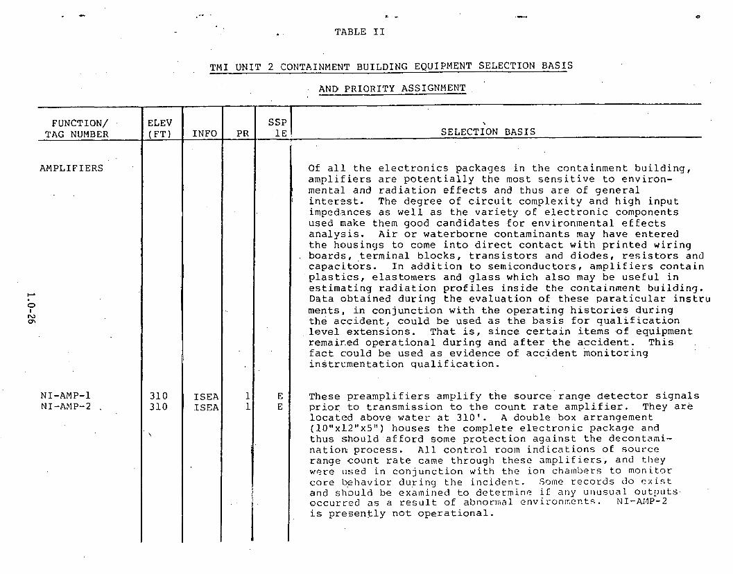
. . TABLE I1
TMI UNIT 2 CONTAINMENT BUILDING EQUIPMENT SELECTION BASIS
ANDi PRIORITY ASSIGNMENT
FUNCTION/ .
TAG NUMBER
AMPLIFIERS
\
SELECTION BASIS
Of a l l t h e e l e c t r o n i c s p a c k a g e s i n t h e c o n t a i n m e n t b u i l d i n g , a m p l i f i e r s a r e p o t e n t i a l l y t h e most s e n s i t i v e t o e n v i r o n - m e n t a l a n d r a d i a t i o n e f f e c t s and t h u s a r e o f g e n e r a l i n t e r - ? s t . The d e g r e e o f c i r c u i t c o m p l e x i t y a n d h i g h i n p u t impedances as w e l l as t h e v a r i e t y o f e l e c t r o n i c componen t s u s e d make them good c a n d i d a t e s . f o r e n v i r o n m e n t a l e f E e c t s a n a l y s i s . A i r o r w a t e r b o r n e c o n t a m i n a n t s may h a v e e n t e r e d t h e h o u s i n g s to come i n t o d i r e c t c o n t a c t w i t h p r i n t e d w i r i n g b o a r d s , . t e r m i n a l b l o c k s , t r a n s i s t o r s and d i o d e s , r e s i s t o r s and c a p a c i t o r s . I n a d d i t i o n to s e m i c o n d u c t o r s , a m p l i f i e r s c o n t a i n p l a s t i c s , e l a s t o m e r s and g l a s s w h i c h a l s o may b e u s e f u l i n e s t i m a t i n g r a d i a t i o n p r o f i l e s i n s i d e t h e c o n t a i n m e n t b u i l d i n g . Da ta o b t a i n e d d u r i n g t h e e v a l u a t i o n o f t h e s e p a r a t i c u l a r i n s t r u m e n t s , i n c o n j u n c t i o n w i t h t h e o p e r a t i n g h i s t o r i e s d u r i n g t h e a c c i d e n t , c o u l d be u s e d as t h e b a s i s f o r q u a l i f i c a t i o n l e v e l e x t e n s i o n s . T h a t i s , s i n c e c e r t a i n i t e m s . o f e q u i p m e n t r ema i r - ed o p e r a t i o n a l d u r i n g a n d a f t e r t h e a c c i d e n t . T h i s . ,
f a c t c o u l d b e u s e d as e v i d e n c e o f a c c i d e n t m o n i t o r i n g i n s t r c m e n t a t i o n q u a l i f i c a t i o n .
T h e s e p r e a m p l i f i e r s a m p l i f y t h e s o u r c e ' r a n g e detector s i g n a l s p r i o r , t o t r a n s m i s s i o n t o t h e c o u n t r a t e a m p l i f i e r . They a re l o c a t e d a b o v e w a t e r a t 3 1 0 ' . A d o u b l e box a r r a n g e m e n t (lO"x12"x5") h o u s e s t h e c o m p l e t e e l e c t r o n i c p a c k a g e and t h u s s h o u l d . a f f o r d some p r o t e c t i o n a g a i n s t t h e d e c o n t a m i - n a t i o n p r o c e s s . A l l c o n t r o l roo!n i n d i c a t i o n s oE s o u r c e . r ange c o u n t r a t e came t h r o u g h t h e s e a m p l i f i e r s , a n d t h e y w e r e u s e d i n c o n j u n c t i o n w i t h t h e i o n chamber s t o m o n i t o r c o r e L?zhavior d u r i n g t h e i n c i d e n t . Some r e c o r d s d o c x i s t a n d s h ~ u l d be exa ln ined t o d e t e r m i n e i f a n y u n u s u a l 0ut:)uLs. o c c u r r n d a s a r e s u l t o f abnorma l e n v i r o n m e ~ t s . NI-N4P-2 i s p r e s e n t l y n o t o p e r a t i o n a l .

TABLE I1 ( C o n t ' d )
?UNCTION/. TAG NUMBER
CONTROL ROD D R I V E MECH.
ELEV ( F T )
U N K UNI< U N K UNK
U N K UN K UNK UN K
\
TMI UNIT 2 CONTAINMENT BUILDING EQUIPMENT SELECTION BASIS
INFO
DE . DEA
DE DE
DE DEA
DE DE
AND PRIORITY ASSIGNMENT
SELECTION BASIS
T h e s e v i b r a t i o n m o n i t o r p r e a m p l i f i e r s a m p l i f y , f o r t r a n s m i s s i o n o u t o f t h e c o n t a i n m e n t b u i l d i n g , . t h e low l e v e l s i g n a l s g e n e r a t e d by t h e Rockwe l l c r y s t a l s e n s i n g e l e m e n t s . ' The a m p l i f i e r s are l o c a t e d r e m o t e l y f r o m t h e s e n s i n g e l e m e n t s which are mounted o n t h e u p p e r p o r t i o n s o f t h e s t e a m g e n e r a t o r s . I t i s ' l i k e l y t h a t t h e s e a m p l i f i e r s a r e w e l l a b o v e water, a l t h o u g h t h e i r p r e c i s e l o c a t i o n s a re unknown a t t h i s time. The s e n s o r t o p r e a m p l i f i e r i n t e r c o n n e c t c a b l e s s h o u l d b e removed a l so t o d e t e r m i n e t h e i r impedance c h a r a c t e r i s t i c s .
V i b r a t i o n s o f t h e lower p o r t i o n s o f . t h e steam g e n e r a t o r s are m o n i t o r e d by S t a t i c - 0 - R i n g c r y s t a l s e n s o r s a t t a c h e d t o t h e 1owe.r t u b e s h e e t s . The p r e a m p l i f i e r s a r e mounted r e m o t e l y f r o m t h e s e n s o r s . . S i n c e ' t h e c r y s t a l e l e m e n t s a r e n e a r t h e water l i n e , t h e s e a m p l i f i e r s may b e u n d e r water. I t is d e s i r a b l e t o o b t a i n as a u n i t t h e s e n s i n g e l e m e n t , c a b l e , a n d a m p l i f i e r . T h e s e a m p l i f i e r s c a n be compared w i t h t h o s e l o c a t e d h i g h e r u p i n t h e b u i l d i n g .

TABLE I1 (Cont Id)
. . TMI, UNIT 2 CONTAINMENT BUILDING EQUIPMENT SELECTION BASIS
. . .AND PRIORITY ASSIGNMENT
FUNCTION/ TAG NUMBER
CRDM- -APIOl CRDM- -API35 CRDM- -API50
ELECTRICAL POWER DIST.
+' EE-ELPR~A EE-EPDP-3A
0 I EE-EPDP-3B
EE-ERPR-1A EE-ERPR-'3D EE-'FLPR- 3D EE-FRPR-1A EE-FRPR-3D
ELEV (FT)
UNK UNK UNK UNK UNK UNK UNK UNK
INFO
These are control rod position indicators and are composed of a string of approximately 70 reed switches. They are not Class 1E at the present but may be designated 1E In future systems to assist in post accident monitoring. They will be examined for evidence of corrosion and contact isolation which may have resulted from the spray/steam environment.
SSP 1E
This list contains two of each of the following categories of electrical equipment: lighting panels, power distribution panels, 30 KVA transformers, and receptacle panels. These samples are meant to be representative of in-containment 110 V, 480 V, etc. power distribution equipment. It is believed to be important to analyze at least some iamples on a Priority 1 basis. This equip- ment will be at least visually examined'for degradation
SELECTION BASIS.
caused by the in-containment environment.

TABLE I1 ( C o n t ' d )
TMI YNIT 2 CONTAINMENT BUILDING EQUIPMENT SELECTION BASIS
AND PRIORITY ASSIGNMENT
FUNCTION/ TAG NUMBER
I NC ORE DETXTORS
I C D - -05 ICD- -16 ICD- -17 ICD- -30 ICD- -37 ICD- -45 ICD- -49 ICD- -52
ELEV ( F T )
350 3 50 350 350 350 350 350 350
\
-
SELECTION BASIS
a I T h e s e p a r t i c u l a r i n c o r e d e t e c t o r s r e p r e s e n t a good t e m p e r a t u r e s a m p l i n g o f t h e core. Numbers 30 , 37, 45 , 49 , a n d 52 a re l o c a t e d o n t h e o u t e r z o n e s o f t h e core w h e r e t h e maximum c a l c u l a t e d core t e m p e r a t u r e was o n t h e o r d e r o f 300°F. Number 2 r e g i s t e r e d t h e maximum core t e m p e r a t u r e o f 2580 F ( n e a r t h e m e l t i n g p o i n t o f s t a i n l e s s s t e e l ) . Numbers 1 6 a n d 1 7 a r e a d j a c e n t a n d n e a r t h e core c e n t e r b u t f o r some a s y e t u n e x p l a i n e d r e a s o n r e g i s t e r e d t e m p e r a - t u r e s o f 2327 a n d 348OF r e s p e c t i v e l y . I n c o r e d e t e c t o r s h a v e s e e n w i d e u s e as t e m p e r a t u r e s e n s o r s ' i n m o d e l i n g t h e core b e h a v i o r d u r i n g t h e i n c i d e n t , 'and r e c o v e r y o f t h e s e i f p o s s i b l e would b e u s e f u l . Due to t h e s p e c i a l h a n d l i n g p r o c e d u r e s which would b e n e c e s s a r y t o a n a l y z e e a c h i n d e t a i l , i t is p r o p o s e d t o a t t e m p t t h i s o n l y o n numbers 1 6 a n d 1 7 . The o t h e r u n i t s would b e v i s u a l l y examined f o r m e l t i n g a n d o t h e r d e g r a d a t i o n . U n f ~ r t u n ~ a t e l y , i f t h e core damage is a s g r e a t a s e x p e c t e d , t h e c e n t r a l l y l o c a t e d d e t e c t o r s w i l l be i m p o s s i b l e t o r e c o v e r .
INFO
D D D D 1
D D : D D
PR
1 1 1 P 1 1 1 1
SSP 1E

TABLE I1 ( C o n t ' d )
FUNCTION/ TAG NUMBER
LEVEL A N D DIFFERENTIAL PRESSURE TRANSMITTERS
TMI UNIT 2 CONTAINMENT BUILDING EQUIPMENT SELECTION BASIS
3 2 4 3 2 4 351 286 286 286 28 6 286 28 7 286 28 6
\
I
DEA DE. DE
IDEA I D E A I D E A
S E.R S E DE DE DE
AND PRIORITY ASSIGNMENT
PR
1 1 1 1 1 1 1 1 2 1 2
SELECTION BASIS SSP
1 E
S S
S S S
S E SE
S
T h e s e l e v e l and d i f f e r e n t i a l p r e s s u r e t r a n s m i t t e r s a re i a n u f a c t u r e d by B a i l e y C o n t r o l s . T r a n s m i t t e r s p r o v i d e a . good r e p r e s e n t a t i o n o f t h e v a r i o u s t e c h n o l o g i e s u s e d i n o t h e r i n s t r u m e n t s i n t h a t t h e y c o n t a i n g a s k e t s a n d sea l s , t e r m i n a l b l o c k s , p r i n t e d c i r c u i t b o a r d s , c o n f o r m a l c o a t i n g ~ n d r e a s o n a b l y complex e l e c t r o n i c s . A n a l y s i s o f e n v i r o n - m e n t a l e f f e c t s o n t h i s c l a s s o f i n s t r u m e n t s c a n p r o v i d e i n s i g h t i n t o e f f e c t s o n o t h e r i n s t r u m e n t t y p e s . I n a d d i t i o n , e l e c t r o n i c componen t s i n e a c h c o u l d b e u s e d t o d e t e r m i n e t h e t o t a l r a d i a t i o n d o s e s e e n a t s p e c i f i c l o c a t i o n s . The Bai.Ley t r a n s m i t t e r s a re s i m i l a r t o Rosemont a n d F o x b o r o t r a n s m i f t e r s .
T h e s e p a r t i c u l a r B a i l e y t r a n s m i t t e r s a re v e r y s imi l a r i n b ~ t h e l e c t r i c a l r a n d m e c h a n i c a l d e s i g n . The CF, I C , a n d S.P-1A-LT1 a n d SP-1B-LT1 t r a n s m i t t e r s h a v e s t a n d a r d .NEMA 4 h o u s i n g s wh ich are n o t q u a l i f i e d f o r steam or s p r a y e n v i r o n - m e n t s , a l t h o u g h t h e y a re s p e c i f i e d f o r u s e i n n u c l e a r power p l a n t s . The RC and SP-1A-LT2 t r a n s m i t t e r s h a v e LOCA q u a l i f i e d h o u s i n g s . T h i s q u a l i f i c a t i o n , a l t h o u g h good f o r a s t e a m e n v i r o n m e n t , d o e s n o t a p p l y . t o e x t e n d e d s u b m e r s i o n . A l l t h e s e t r a n s m i t t e r s u n d e r w e n t t h e s p e c i a l s e a l i n g p r o g r a m ( S S P ) e x c e p t SP-1A-LT1, SP-1B-LT1 a n d IC-10-DPT ( n o t e t h a t t h e s e u n i t s h a v e t h e NEMA 4 h o u s i n g a l s o ) . Compar i son o f . tl-.cse u n i t s c o u l d p r o v i d e i n s i g h t i n t o h o u s i n g and s e a l i n g d e s i g n s . T h e CF and I C u n i t s l o c a t e d a b o v e w a t e r c a n

TABLZ I1 (Cont'd)
TMI: UNIT 2 CONTAIN'MENT BUILDING EQUIPMENT SELECTION BASIS
AND PRIORITY ASSIGNMENT
SELECTION BASIS
be ccmpared against the SP units which are below water. The LOCA qualified RC's can be compared with the others. Comparisons can also be made between the Class 1E and non- 1E instruments. Air or waterborne contaminants should have been excluded from inside the 1E housings, preventing direct contact with the materials of interest. In addition, . the three RC level transmitters were used during the - 4
incident to measure pressurizer level. Operators did not. believe the pressurizer level readings in the early stages of the incident, although now the level readings are thought to be accurate indications of the collapsed water level in the pressurizer. The level readings do not indicate the true level of the two-phase froth present when f1ashing.i~ occurring in the pressurizer. These and other transmitters (Foxboro 'and Rosemont) began to degrade as the accident progressed, presumably due to high radiation levels. How the degradation progressed.and which trans- mitters were affected the most has not ,been determined at this time. . The IC-10-DPT is located near R6 where one of the best efforts can be made to determine radiation level history. R6 is near Penetration-626 at the 347' level, the initial "peep" show entry point. Radiation monitor IIP-RT-0213 is also located nearby. Survival of the units having the special NEMA 4 housing might suggest that similar units in other plants are adequately protected. RC-14A-DPT1 or RC-14A-DPT2, one of the three pressurizer level transmitters, and SP-1A-LT2 are recorded on the B&Td reactimeter .

TASLE I1 (Cont'd)
TMI UNIT 2 CONTAINM3NT BUILDING EQUIPMENT SELECTION BASIS
AN3 PRIORITY ASSIGNMENT
RC- 3A-PT1 RC- 3A-PT2 RC-3~-PT~
FUNCTION/ TAG NUMBER .
ELEV (FT) I N F O
PRESSURE AND FLOW TRANSMITTERS
CF-1-PT1 CF-1-PT3 CF-1-PT4 RC- 3A-PT3 RC-3A-PT4 RR-FT- 10 2 7 RR-FT-10 28 RR-FT-10 29 SP-6A-PT1 SP-6A-PT2 WL-PT-1202
PR SSP 1E
324 324 324 287 287
1 1 1 1 1 2 2 2 1 1 1
1' 1 1
SELECTION BASIS
DE DE DEA SEA SE
E E
E E E
287 285 285 287 288 286
286
The following Foxboro and Rosemont ~re'ssure and Flow transmitters are similar to the Bailey level and differential pressure transmitters discussed earlier and, therefore, the measurement objectives stated for the Eailey instruments apply also to these .instruments.
Foxboro pressure transmitters are used in most nuclear plants and therefore any information obtained from analysis of these applies to other plants. Two of the selections are Class 1E equipment. Both the Ell and El3 Foxboro instrument types are represented; however, the primary difference between the types is mechanical and not .
electrical. The CF transmitters are above containment flood level while the RC transmitters are below. CF units 3 and 4 are on the same core flood tank, and one will be place3 in archive storage while the other two are analyzed. The bzlow water units will be analyzed in the same manner
' as thase above water and the results compared. The WDL transmitter and either SP-6A-PT1 or SP-6A-PT2 are recorded on the B&W reactimeter. All these Foxboro instruments will be used to evaluate their radiation hardness, ability to withstand immersion and very humid condi~ions, and to compare to similar Bailey and Rosemont designs.
Rosemont manufactures these pressure transmitters, all of which are below water. They are all Class 1E and of the same model. The 1152 model is similar in function to the Foxboro and Bailey transmitters except that this model is of a new design which has recently been qualified to more s'rinqent environ~ental levels. As a consequence, this
DE DE
DEA DE: DE DE
.ISEA. 286 287
ISE SE

TABLE I1 (Cont Id)
. . . . . -TMI UNIT 2 CONTAINMENT.BUIL;DING EQUIPMENT SELECTION BASIS
AND PRIORITY ASSIGNMENT
FUNCTION/ TAG NUMBER
PRESSURE AND FLOW TRANSMITTERS
(Cont ' d)
LIMIT SWITCHES
ELEV (FTI
I
331- 3 3.1 331 3135 335 335
.instrument is widely called out.in new reactor designs. All are of specific interest for possible calibration because of their use during the incident to monitor steam/ water pressures. Numbers 3A-PT2 and 3B-PT1 will be analyzed first and 3A-PT1 will.be held in reserve. RC-3B-PT1 is recorded on the B&W reactimeter.
INFO
S
!? S A
S . S
S A
1 PR
The 1152 transmitters are intended to meet the following conditions: (1) qualified to IEEE 323/344 Standards, (2) amma radiation integrated dose qualification to 5~10% rads, (3) 39 seismic qualification, and steam- pressure-chemical spray testing. It is possible to compare the transmitter performance before, during, and after the accident to published specifications and qualification reports. In the comparison, it may be possible to deter- mine if there are any performance distinctions between the separate effects testing allowed by IEEE 323 and the combined effects imposed on the transmitter during the various accident phases.
Operating experience data obtained on these transmitters during the accident for such service conditions as submersion or high radiation levels may be used to aid in an extension of the qualification.
SSP 1E
Q
SELECTION BASIS -- -
E E E
These switches were .chosen as representations of Class 1E .limit switches. AH-5000, 5002A and ,5002B will be removed with fans AI-I-11.A and llC'. A!{-5037 and 5039 will be
E , removed with AH-V2A and V ~ B . Spares and archive samples E I have been selected
E l

,. .- - TABLE I1 (Cont'd)
TPI UNIT 2 COKTAINMENT BUILDING EQUIFMENT SELECTION.BASIS
AND PRIORITY ASS1GNM:ENT
MOTORS, FAN
AH-E-11A AH-E-11C AH-E-52A AH-E-52B
- FUNCTION/
TAG NUMBER
t-' MOTORS, REACTOR
7 COOLANT W P
RC-P-1A RC-P-1B
These four large reactor building and vessel cavity air cooling fans are representative samples of others in the containment building. The two located at 331 feet are Class 1E equipment. The effects of radiation, humidity and building spray can be evaluated on these motors. The corresponding limit switches .have been selected for analysis also. The two units at 283 feet can be compared, however probably little information can be obtained s i n e they are underwater.
EL E.V (FT)
3uring the accident, all four reactor coolant pumps were operated during abnormal coolant phase conditions. Approximately 6 minut.es into the accident RCS conditions were at saturation temperature and pressure. The four pumps operated with a steam/water mixture until at 73 and 100 minutes into the accident the two B loop and two A loop pumps, respectively, were turned off. During this operating time all experienced abnormal vibration . a d probably cavitation, RC-P-2~ was run for 18 minutes .later in the sequence and again vibrated badly. RC-P-1A has finally restarted, and forced circulation was .
a.chieved. RC-P-1A was used then to bring the plant $0 a stabilized decay heat removal condition. These two pumps should be.examined for both electrical and nwchanical degradation resulting from the aforementioned abnormal conditions as w ~ l l as the high radiation levels and building spray. The scope of this examination has
i l not been defined at this time.
INFO. I
PR ssp ! . 1 E SELECTION BASIS

TABLE I1 (Cont'd) ' ,
. .. . . . . . TMI UlNIT 2 CONTAINMENT BUILDING. EQUIPMENT SELECTION BASIS
' .AND PRIORITY ASSIGNMENT
FUNCTION/ TAG NUMBER
MOTORS, PUMP I
!-' "NEUTRON .DETECTORS
W ul
NI-ND-1 NI-ND-2 NI-NW3 NI-ND-4 NI-ND-5 NI-ND-6 NI-ND-7 NI-ND-8
ELEV (FT)
UNK 284 283 286
I I SELECTION BASIS - --.- -
These pump motors will be examined to determine their general condition. Three', and possibly all four, are under water,, thus making the discovery of any important information unlilcely. Unfortunately no pumps are known to be located above water. However, until at least one unit is examined it is difficult to predict the potential benefits of such an analysis.
The out of core neutron detectors provide core leakage neutron flux measurements over the full range of reactor operation. There are eight detectors divided into three ranges: Source Range (NI-ND-1,2), Intermediate Range (NI-ND-3,4) and Power Range (NI-ND-5,6,7,8) . The three ,
ranges overlap to give measurements from below startup to 125% Full Power or about ten decades of flux measure- ments. During and since the accident the core behavior has been studied using primarily the source range detectors and associated preamplifiers and, therefore, they may be of interest for calibration. The NI-ND-5 output was recorded on the B&W reactimeter and thus records do exist. In addition, all these instruments , '
are Class' 1E and should be studied for this reason. Care should be taken toe include the interconnect cables and connectors due to the possibility of leakage paths resulting from the steam/spray environment in these extremely low current.output devices.

TMI UNIT 2 CONTAINMENT BUILDING EOUIPMENT SELECTION BASIS
FUNCTION/ '
TAG NUMBER
PENETRATIONS
R-400 R-402 R-405 R-406 R-407 R-500 R-504 R-506 R-509 R-514 R-515 R- 59 6 R-601 R-607 R-608 R-612
.ELZV (FT)
291 291 291 2 91 291 299 323 3 23 319 299 295 351 291 291 ,293 292
INFO
ID ID D D D
. D D D D D A D D A D D
SSP ilE PR
1 1 1 1 1 2 2 2 1 2 2 1 2 2 1 2
SELECTION BASIS . . .- .-
Examination of penetrations is important to.determine how well they maintain their integrity, primarily with respect to isolation impedances, during and following an accident. Penetrations'generally fall into one of the following cateqories based on what type of signal-they carry: signal, control or power. Signhl penetrations carry very low power "monitor" lines. Control penetrations are used to control valves, motors, etc. and can have substantial power'handling requirements. Power penetrations normally have high voltage (4160V) requirements in addition to the requirement to carry large currents. Possibly all "signal" line penetrations should be at least visually examined since generally higher isolation impedances must be maintained; however, to limit the scope of this task visual examinations are proposed for signal penetrations R-406 and R-596. R-596 will be analyzed to the greatest possible extent. R-400, R-402 and R-407 are high power penetrations through which pressurizer heated power is supplied. Since several of the pressurizer heaters were lost during the incident, failure analysis is necessary. R-509 and R-608 are medium and high power penetrations respectively. R-405 is a control penetration. All these penetrations should be at least visually and resistively checked. All are above the water level.

TABLE I1 (Cont'd)
TMI UNIT 2 CONTAINMENT BUILDING EQUIPMENT SELECTION BASIS
AND PRIORITY ASSIGNMENT
FUNCTION/ ELEV TAG NlJMBER
RADIATION M3NITOF.S
SOLENOIDS
INFO
E A DE DE
I IDF
S - S SA
SELECTION BASIS
Containment building radiation .monitors are of value throughout an accident sequence. These four units are representative of this class of instruments, and their ability to function accurately in high radiation and humidity environments are of particular interest due to the .highly sensitive electronics used. Number 0213 is near the point of initial entry through P-626 at 347'. It is hoped that this unit can be used to dlagnose the radiation level in this. .aliea accurately. Number 0214 is the Dome Monitor and has been used extensively since the accident to determine containment radiation levels. Calibration of this unit is a necessity. At this point, it is unclear as to whether the usual lead shields are in place around 0214 or whether they were removed during maintenance and not replaced. Number 0209 wi1.l be held in reserve whkle analysis is made of the other units.
These valve control solenoids are representative:of Class' 1 E solenoids. HA-5037 and 5039 will. be removed with AH-V2A and V 2 B .

TABLE I1 (Cont'd)
FUNCTION/ TAG NUMBER
TEMPERATURE ELEMENTS
ELEV (FT)
TMI UNIT 2 COKTAINMENT BUILDING EQUIPMENT SELECTION BASIS
. . AND PRIORITY ASSIGNMENT
I I
INFO
These temperature elements are used to monitor containment ;: building ambient temperature. Although of only limited value from a generic standpoint, the prime importance is incident related. During the incident all recorded temperature monitors except Number 5020 spiked upward fcllowing the trip of the reactor building spray pumps initiated by the Hydrogen burn. Number 5020 dropped abruptly to 9 7 O ~ and later recovered somewhat. It appears
IC IDP Ic IC
that the hydrogen burn damaged this monitor. Number 5021 is located on the opposite side of the building and will be used for comparison. The reading from Number 5023 followed other monitor trends but fluctuated wildly on several occasions. This unit is located near column R5 at 330' elevation.. Since this is approximately overhead from the drain tank {but 30' and two floors higher), it is possible that steam may have caused these erratic readings. Both 5020 and 5023 should be given failure analyses; Number 5022 will be used for comparison.
PR
1 1 1 1'
I ' This is one of seven Bailey platinum RTD's. They are located in piping above water. The assembly includes a
.loll-ohm platinum resistance element packed in a sheath which is sealed with solder glass and epoxy. This is inserted in a well in the piping which'is topped with a connection head containing a ceramic terminal block. The assembly should be examined for signs of deterioration. -Measurement of insulation resistance to ground and an ice point check should expose any major faults. It should be retained for'possible future examination of the condition of materials.
SSP 1E SELECTION BASIS

TABLE I1 (Cont'd)
FUNCTION,; TAG NUMBER
TEMPERAFURE ELEMENTS
(Con= ' d)
RC-15A-TE1 RC-15A-TE2 RC-15A-TE3 RC-2-TE1 RC-2-TE2
. RC-$A-TE1 RC-4A-TE2 RC-4A-TE3 RC-4A-TE4 RC-4B-TE1 RC-4B-T32 RC-4B-TE3 RC-4B-TE4 RC-5A-TE1 RC- 5A-TE2 RC- SA-TE3 RC- 5A-TE4 RC-5B-'TE1 RC-5B-TE2 RC-5B-TE3 R C - S B - T E ~
ELEV (FT)
I
I INFO
SA S s D ' D
SA SA S S SA SA S S DA D A
, D D
D A D A
. C C
AND PRIORITY ASSIGNMENT
The Rosemont RTD1s are all model 104 AFP. Various studies are currently being conducted on this generic instrument to investigate platinum wire resistance changes, ceramic insulation and dry well sealing methods. Temperature elements performing the function of the RC-15~'s (reactor . .
wide range hot and cold leg temperatures) are being up- graded to Class 1E in NRC 1.97. Due to the ease of removal. several samples are being'taken. One unit will be held in archive storage. The 15A's are normally recorded. All units were sealed under the special sealing program and the effects of this can be analyzed.
PR
These are all Rosemont 177HW DUAL RTD's. The 4A's and dB's measure hot leg temperatures and the 5A's and 5B's measure cold leg temperatures. The hot leg RTS's are all Class .lE while the cold leg ones are not. At present, daily recordings of both hot and cold leg temperatures are being made using some of these instruments to aid in plant decay heat removal monitoring. As such, they have been ,
required to operate in the abnormal environment for months, and output records exist over this long period of time. The 4A and 4B TEl's, as well as the 5A and 5B TEl's, are recorded on the B&W reactimeter. One dual RTD from each leg is to be held in archive storage pending analysis of the others.. Many of the comments regarding interest in these instruments are the same as given for+the Rosemont Model 104 AFP. All these units underwent the special sealing program.
SSP 1E
- -
SELECTION BASIS

TABLE I1 (Cont Id)
TMI UNIT 2 CONTAINMENT B U I L D I N G EQUIPMENT SELECTION BASIS
AND PRIORITY ASSIGNMENT
SELECTION BASIS
These v a l v e s a r e meant t o g i v e a f i r s t c u t b road cove rage . T h i s t a s k group i s c o n c e r n e d w i t h v a l v e a c t u a t o r s o n l y ; however, t o o b t a i n i n f o r m a t i o n on t h e a c t u a t o r s , it i s p robab ly d e s i r a b l e t o remove t h e v a l v e a l s o . C o o r d i n a t i o n h a s been made w i t h Task Group 6.0 recommendations c o v e r i n g mechan ica l components.
his l i s t c o n t a i n s v a l v e s manufac tured by Velan , Va lco r and Henry P r a t t . Velan h a s s u p p l i e d t h e l a r g e m a j o r i t y o f t h e TMI-2 in-conta inment ' v a l v e s . These s e l e c t i o n s a r e a l l C l a s s 1 E e x c e p t f o r DH-V1. AH-V2A and V2B a r e 36" Henry P r a t t b u t t e r f l y v a l v e s . AH-V6 and AH-V74 a r e Va lco r s o l e n o i d a c t u a t e d v a l v e s w h i l e t h e o t h e r s a r e motor o p e r a t e d Velan g a t e v a l v e s which r ange from 1/2" t o 1 4 " i n c a p a c i t y . S e l e c t i o n s have been made o f v a l v e s i n d i f f e r e n t r e a c t o r b u i l d i n g a r e a s and e l e v a t i o n s . The p o s i t i o n o f t h e p r e s s u r i z e r s p r a y v a l v e , RC-V1, i s r e c o r d e d on t h e B&W r e a c t i m e t e r . Of i n t e r e s t a r e t h e e f f e c t s of NaOH s p r a y and h i g h m o i s t u r e c o n d i t i o n s a s w e l l a s r a d i a t i o n e f f e c t s on s o l e n o i d s and motors . The c o n t r o l c i r c u i t s for.DH-V1 have been checked r e s i s t i v e l y a t least weekly o v e r t h e p a s t month's i n o r d e r t o d e t e r m i n e t h e e f f e c t s o f a r i s i n g con ta inmen t b u i l d i n g w a t e r , l e v e l ( a l t h o u g h DH-V1 i s s i t u a t e d j u s t above w a t e r , t h e motor power. l i n e s may n o t b e ) . These d a t a would be u s e f u l i n an . ana1ys i . s o f t h e behav io r o f , the motor a c t u a t o r . DH-V2 i s t h e same mod.el, i s C l a s s lE. .and i s 3 ' lower i n t h e b u i l d i n g . Valves o f t h i s t y p e cou ld be c a l l e d on t o o p e r a t e i n v a r i o u s s t a g e s o f decay h e a t removal f o l l o w i n g an a c c i d e n t .

TABLE 11 iCon t ' d )
FUNCTION/ TAG NUMBER
VALVES (Cont ' d )
RC-R2 . '
TMI U N I T 2 CONTAINMENT B U I L D I N G EQUIPMENT SELECTION BASIS
AND PRIORITY ASSIGNMENT
INFO
IDA
IA
DE DEA
E E
l ~ h e TMI-2 i n c i d e n t was caused i n p a r t because t h i s PORV !manufactured by Dresser f a i l e d t o c l o s e upon a d r o p i n ! p r e s s u r i z e r p r e s s u r e . I t was p o s s i b l y l e a k i n g b e f o r e t h e . a c c i d e n t . I t i s t y p i c a l o f P O R V ' s used i n many r e a c t o r s , a n d f a i l u r e a n a l y s i s o f b o t h t h e s o l e n o i d a c t u a t o r and .mechan ica l assembly i s mandatory.
T h i s i s t h e motor o p e r a t e d b l o c k v a l v e ups t r eam from t h e :PORV. I t was c y c l e d many t i m e s under h i g h p r e s s u r e d u r i n g ' p l a n t r e c o v e r y o p e r a t i o n s ; and , a l t h o u g h it f u n c t i o n e d . p r o p e r l y , i t may have been deg raded . I t would b e d e s i r a b l e ' t o de t e rmine t h e e x t e n t o f d e g r a d a t i o n by f a i l u r e a n a l y s i s . * I t i s n o t C l a s s 1 E .
>
PR
These c r y s t a l e l emen t v i b r a t i o n and l o o s e p a r t s m o n i t o r s . a r e manufac tured by S t a t i c -0 -R ing . The c r y s t a l e l e m e n t s c o u l d p o s s i b l y b e u sed t o d e t e r m i n e l o c a l t o t a l r a d i a t i o n dose l e v e l s by examining c r y s t a l l a t t i c e p r o p e r t i e s changes . The u n i t s a r e l o c a t e d on t h e s team g e n e r a t o r lower t u b e s h e e t s . S i n c e t h e s e a r e i n c l o s e p r o x i m i t y t o t h e w a t e r ( t h e y may be j u s t unde r w a t e r ) t h e y . s h o u l d be good m o n i t o r s o f wa te r s h i n e - o f f . Due t o t h e e a s e o f removal a l l w i l l b e ' t a k e n . T h e i r a s s o c i a t e d p r e a m p l i f i e r s and i n t e r c o n n e c t c a b l e s w i l l be removed f o r a n a l y s i s a l s o .
SSP 1 E . SELECTION BASIS
i 1
?

T&ULE I1 (Cont'd)
TMI -UNIT 2 CONTAINMENT BUILDING EQUIPMENT SELECTION BASIS . .
AND PRIORITY ASSIGNMENT ~
SELECTION BASIS
I
These Rockwell vibration monitors are similar in design to the SOR models; however, these units are all well above water on the upper portions of the steam generators. Radiation level measurenents determined by analysis of these crystal sensors can be compared with those made on the lower tube sheets.
. .
I .
FUNCTIO~/. TAG NUMBER
VIBRATION ELEMENTS (Cont ' d)
YM-VE-7022 YM-VE-7023 YM-VE-70 24 YM-VE-7025
PR
1 1 2 2
SSP ' 1E
, ,
ELEV (FT) INFO
. .
346 346 346 346
DE DEA E E
\
I .

TABLS I1 (Cont'd)
. . TM-I UNIT 2 CONTAINMENT BUILDING EQUIPMENT SELECTION BASIS
AND PRIORITY ASSIGNMENT
FUNCTION/ TAG NUMBER
MISCELLANE.0US GENERIC EQUIPMENT
ELEV (FT)
-
-. ---
.SELECTION BASIS
Miscellaneous Generic ~quipment
The TMI-2 incident provides an opportunity to acquire accident-tested equipment for systematic evaluation, at minimal cost.
The TMI-2 equipment is generically similar to equipment in all equivalent-aged plants (between 30 to 50 plants operating in the US). The TMI-2 equipment evaluation will supply information which is directly applicable to these US plants.
It is imperative to select a broad sampling of equipment to achieve maximum coverage and to discover any "surprises" in equipment degradation. ,Also, the NRC is particularly interested in the analysis of samples of all Class 1~ equipment in order to verify the adequacy of existing environmental qualification methodology. Analysis of Class 1E and Non-Class 1E equipment required for post accident monitoring and control in operating nuclear plants is of interest. The TMI-2 data could be used in the near term to determine whether certain instrumentation and electrical. equipment would be capable of surviving an accident environment for the length of time its function is required. Based on these considerations, the following additional equipment selections have been made. Generally, three instruments of a given type have been chosen. , Two for analysis and one for archive storage pending,the analysis of the other two.
SSP 1E
. .
INFO
\
PR

TABLE I1 (Cont'd)
TMI UNIT 2 CONTAINFENT BUILDING EQUIPMENT SELECTION BASIS o-, Z
AKD PRIORITY ASSIGNMENT . ..
- - - ~ ~~pp-~- -
FUNCTION/ .
TAG NUMBER
CONTROL ROD DRIVE MECHANISMS
CRDM- -ST01 CRDM- -ST35 CRDM- -ST50
FLOW INDICATORS
IC-FI-7566 IC-FI-7567
FLOW SWITCHES NS-FS-3977 NS-FS-3978 . NS-FS-4023 NS-FS-4024 ' NS-FS-4026 NS-FS-4027 RC-57-FS1 RC-58-FS2 RC-58-FS8 RC-59-FS1 RC-59-FS4 RC-59-FS8
PR
2 2 2
2 2
3 3 3 3 3' 3 3 3 3 3 - 2 - -
SSP ! SELECTION BASIS 1~ 1
ELEV (FT)
\
345 345
INFO
Dl D
345
UNE UIIK
337 336 334 334 334 34 3 UNK UNK UNK UNK UNK UNK
D
DE DEA
DA D D
. DA D D DA D D D A D D

TABLE I1 [Cont'd)
.. . . TMI UNIT .2 CONTAINMENT BUILDING EQUIPMENT SELECTION BASIS
FUNCTION/ .
TAG NUMBER
FLOW '
TRANSMITTERS
MU-10-m1 MU-~o-FT~: MU-10-FT4.
? ! . '
LEVEL ~ CAU~GE * * >
WDL-LG- 12'0 5
LEVEL SWITCHES . '
0 '
AH-LS-500,s : C" AH-LS-500'6
AH-LS-500'8 RC- -LSl" RC- -LS~''' RC- -LS4' RC-60-LS1" . . RC-60-LS2 RC-60-LS8 ' ,
RC-62-LS1.-:'. ' '
R c - ~ ~ - L s ~ "
RC-62-LS4 WDL-LS-1206 WDL-LS-1208
LEVEL . .
TRANSMITTER
WDL-LT-131G
ELEV (FT) .
UNK UMK '
. UNK
2 8.2
'306 306 3 06 340 340 340 UNK
. UNK UFJF UNK UNK UNK 29i 291
2 3 2
INFO
DA ' D . .D
A .
DA . D
D DA
D . .
DA ' D D
..DA D D DA :
D
.
.DZA
PR
. ' 3 ; 3;
. . ,
. i
3" . .
2 2. 2. 3
D . 3 . " 3
3: 33 3 1
.3" 3 3, 3 3'
-
2
SSP 1E
3 , ; '
. . L :
. .
' AND PRIORITY ASSIGNMENT
SELECTION BASIS
. . . . . .
. .
, .

- . - IC
TABLE I1 (con-t 'dl
TMI UNIT 2 CONTAINMENT BUILDING EQUIPMENT SELECTION BASIS
FUNCTION/ TAG NUMBER
PRESSURE CONTROL VALVES
R C - 6 5 - ~ ~ ~ 1 RC-65-PCV2 RC-65-PCV3
*
PRESSURE INDICATORS
RC-66-PI1 .
RC-66-PI2 RC-66-PI3
PRESSURE SWITCHES
NM-P.S-1454 NM-PS-4174 NM-PS-4175 RC-56-PS1 RC-56-PSI4 RC-56-PS20
ELEV (FT)
UNK UNK '
' UNK
INFO
DA D D
PR
2 2 .
i' 3 3 3
.3 3 3 3 3 3
UNK UNK
. .
SSP 1E
2 .
EA E
SELECTION BASIS
UNK.
349 349 349 UNK UNK UNK
. E
DA D D DA D D

TABLE 11 (Cont'd)

-
TABLE I1 (Cont , 'd) .
TMI UNIT 2 COFITAINMENT BUILDING EQUIPMENT SELECTION BASIS . . . . .
,-. ANE PRIORITY ASSIGNMENT --
FUNCTION/ TAG NUMBER
VALVES .
~ ~ ~ - ~ 1 1 1 8 '
VIBRATION, ELEMENTS
YM-VE- 701 8 YM-VE-7019
ELEV (FT)
286
.
288 288
INFO
D
.
D D
YM-VE-7020 YM-VE-7021
VIBRATIQN MON I TORS
RC-67-VS1 RC-67-VS3 RC-67-VS4 RC-UI-7907 RC-UI-7908 RC-VE-7889. RC-VE-7890 RC-VE-7891 RC-VE-7899 RC-VE-7900 .
RC-VE-7901 .
RC-VE-7904 RC-VE-7905 .
RC-VE-7906 YM-VR- 3 9 6 1 YM-VR- 3 9 6 2
PR
3
3 3
SSP 1E
325 1 I, 325 , D .
SELECTION BASIS
UNK . UNK UNK UNK UNK 32 8 328 328 328 328 328 328 328 328 UN !< UNK
. .
3 3
3 3 3 .3 3 3 3 3 3 3 3 3 3 3 3 3
D D DA
A A D D D DA . DA DA D
. D D A A
!
. '

TABLE 111
TMI UNIT 2 REACTOR BUILDING INSTRUMENT LISTING CODES
Tag N n m b e r
F i r s t Two L e t t e r s i n ' ~ a g N o :
Symbol
SP WDL YM
Second Two L e t t e r s , .. , - . -- -
Symbol . .
cv DF?T EP FE ' .
FS FT HE KS LG LS ' 1 . 8 T N D P I .
PS PT RA
System
A i r Handl ing Equipment Core F l o o d i n g H e a l t h P h y s i c s I n t e r m e d i a t e Closed Cool ing Water Leak R a t e T e s t Main S t ream Make-up & P u r i f i c a t i o n Nuc lea r P l a n t N i t r o g e n Manifo ld Nuc lea r I n s t r u m e n t Nuclear S e r v i c e s - Closed Cool ing Water Reactor B u i l d i n g N o r m a l Coo l ing Reactor C o o l a n t Reactor Bldg. Emergency Cool ing -
River Water Secondary P l a n t Waste D i s p o s a l - L i q u i d M i s c . I n s t r u m e n t a t i o n
i n Tag N o : . .. - ., 9 .. ._*. . , L . " .,
F u n c t i o n
C o n t r o l Valve . . . D i f f e r e n t i a l P r e s s u r e T r a n s m i t t e r
E l e c t r i c P u s i L i o n e r Flow Element Flow Swi tch Flow T r a n s m i t t e r Humidity Element P o s i t i o n Swi tch L e v e l Gauge Leve l Swi tch Leve l ~ r a n s m i t t e r Nuc lea r =Detector P r e s s u r e ~ n d i c a t o r P r e s s u r e Swi tch P r e s s u r e T r a n s m i t t e r R a d i a t i o n A l a r m

TABLE (Cont'd)
Second Two Letters in Tag No: (Cont'd)
Symbol Function
Radiation Indicator Radiation Transmitter Speed Switch Speed Transmitter Temperature Element Temperature Indicator Temperature Switch Multivariable Indicator Vibration Element Vibration Switch
Manufacturer Code
Symbol . Manufacturer
A-B AM1 ASCO BDV BMC BING F R R B &W DREX ELPR FOX U K E S GEMS IRD .
JERG M&M MNCO MAG . PENN REC ,
m SOR TEC TEK VICO VLAN VLCR WARR W
Allen-Bradley ~minco Automatic Switch Co. Barksdale Bailey Bingham Pump Broolca Babcock & Wilcox Drexel Brooks Electro Products Foxboro Dresser Valves GEMS Sensor Div. De Lava1 .Turbine I RD, Jerguson Gage & Valve. McDonnell & Miller Minco Products Magnatrol Penn Controls Roseniont Engineering Co. Rockwell Static-0-Ring Thermo Electric Taktro (Applied Power Ind. ) Victoreen Instrument Div. Velan Valcor Warrick Westinghouse
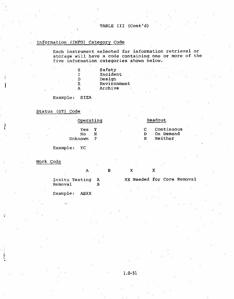
TABLE I11 (.C0ntVd) r.
Informat ion (INFO) Category Code
Each in s t rumen t s e l e c t e d f o r in format ion r e t r i e v a l o r s t o r a g e wil.1 have a code c o n t a i n i n g one o r more. o f t h e f i v e in format ion c a t e g o r i e s shown below.
S S a f e t y I n c i d e n t I
D ~e s ign E Environment A Archive
Example: SIEA
S t a t u s (ST) .Code
Opera t ing
Y e s Y No N
Unknown ?
Example: YC
Work Code
A B
I n s i t u Tes t ing A Removal B
Example: ABXX
Readout
C Continuous D On Demand N Ne i the r
XX Needed f o r Core Removal

I V . General Findings and Recommendatipns
Findings - The f a c t s , obse rva t ions , e t c . given below have had varying
degrees of impact on o u r work and a r e presented wi th t h e idea of
provid ing t h e r eader wi th some a d d i t i o n a l pe r spec t ive on t h e
t a s k . a t hand. No p a r t i c u l a r s i g n i f i c a n c e is a t t ached t o t h e
o rde r . i n which t h e i t e m s a r e presented. 1
1. A coordina ted l i s t of ins t rumenta t ion and e l e c t r i c a l
equipment w i t h i n t h e r e a c t o r bu i ld ing was no t r e a d i l y
a v a i l a b l e . W e have compiled what w e be l i eve t o be
t h e most comprehensive l i s t a v a i l a b l e . I t i s included
. i n Appendix 5.
2 . An up-to-date account of t h e o p e r a t i o n a l s t a t u s of
t h e ins t rumenta t ion and e l e c t r i c a l equipment wi th in
t h e r e a c t o r b u i l d i n g does n o t e x i s t .
3 + A s of AugusL 1 9 8 0 , t h e water l e v e l i n t h e reactor
b u i l d i n g had reached roughly t h e 290.7 f t . e l e v a t i o n ;
t h e r e f o r e , much of t h e equipment of i n t e r e s t i s under
water ( f o r r e f e r e n c e , th.e e l e v a t i o n of t h e lower l e v e l
of t h e r e a c t o r b u i l d i n g is 282.5 f e e t ) .
4 . A p a r t i c u l a r l y important a c t i v i t y i s t o o b t a i n a doau-
mented h i s t o r y of s e l e c t e d instruments . This inc ludes
manufacturing d e t a i l s and q u a l i f i c a t i o n procedures, a s
w e l l a s performance during t h e acc iden t .

5. The value of the information odtained as.a result
of analysis of the recovered samples is s$rongly
dependent on the .accuracy of the environmental history
(including radiation exposure) which results from
TWG Task .2 and 'upon the timely recovery of -the
equipment. b
< . . . - .
6. It i's that' a 'mdter.iais analysis of ';selected components (i. e :, cables, glass seals, semiconductors)
can provide another source of data for estimating
the radiation environment (this clearly interfaces
with the efforts . of . the Task 2 planning group) . 7. A definitive working arrangement between the various
study groups and GPU/Me% Ed must be developed. . ,
8. The decontamination plan adopbed could have a severe
impact on the usefulness of th.is equipment study. ' . !
Recommendations
The general recommendations resulting from this study are
given below. General guidance for sample analysis is contained
in Appendix 2.
1. As soon as possible, a remote test program (i.e.,
testing from the cable or control room) for instruments,
electrical equipment,. etc., should be established.

2. The operational status for all instruments and
electrical equipment within the reactor building
should be .determined. A diagnosis of out-of-spec
equipment should be attempted. This work should be
done prior to decontamination and without disturbing
the equipment.
3. The predicted behavior of class 1E electr'ical equip-
ment should be correlated with actual performance.
If significant discrepancies exist, further analysis
would be warranted. A similar correlation should be
'attempted fbr selected itenis of non-1E electrical'
equipment. . .
4 . An instrumentation and electrical equipment data book
should be compiled.to document, in readily available
form, all pertinent pre. and post accident information.
5 . Items 1 through 4 should be accomplished as soon as
possible. Items 1 through 3 are obviously time urgent;
the urgency of item 4 is simply that much of the data
needed for accurate planning would be contained in
such a compilation.
6. The IEPG, or a similar group, should be tasked to
continue in the role of technical monitor and inter-
face between the community of users'and the various
groups under contract to implement the instrument and
electrical equipment recovery plan. In addition, the

IEPG should be tasked to continue the development,
and refinement of this recovery plan as new infor-
mation becomes available.
7. Obviously, budgets need to be established and funding
managers appointed for the various tasks required to
execute this plan.
8. Written and approved procedures must be developed
for the removal and testing of all items. If possible,
the recovery procedure for each type of equipment
should be reviewed by the equipment manufacturer, or
an'equivalent' expert, prior to any .physical contact
(including decontamination) with the equipment.
9. Plans need to be developed for temporary and permanent
storage sites for recovered material.
10. Photographs .and/or TV videotape recordings of equipment
should be used (a) to assist in preparing for equipment
retrieval, and (b) to provide a .part of the historical
record for removed equipment (this effort may inter-
face with the work of Task Group 4.0) . 11. An attempt should be made to identify and store those
items of equipment not initially selected to be part of
the survivability study. Final disposal of any item
should be done only after approval by the TWG.
12. A representative of the IEPG should be present at TMI
at least during the early phase of the recovery operation.

13. A plan for the disposition of the electrkal equipment
which is removed'for study needs to be developed. The
plan would specify a procedure for designating a
company or agency to perform the physical analysis
and summarize the results.
14. Immediate coordination needs to begin with the plant
decontamination team to arrive at an acceptable plan.

Summary of Reactor Building Instrumentatkon and Electrical Equipment
The s h a r y data given in this Appendix is based on the
master.list given in Appendix 5. The purpose of this list is
to show the different kinds of equipment in the containment
.building and their elevations.

Appendix 1
. TMI UNIT 2 CONTAINMENT BUILDING EQUIPMENT SUMMARY
CONTAINMENT DESCRIPTION . - NO. REACTOR SYSTEM LEVEL ( F T )
D i f f . P r e s s u r e 1 I n t e r m e d i a t e C l o s e d 351 T r a n s m i t t e r C o o l i n g
8 R e a c t o r C o o l a n t 284, 286
F l o w S e n s o r .5 R e a c t o r B l g. Emergency 282 C o o l i n g , R i v e r W a t e r
5 Was te D i s p o s a l L i q u i d 284, - -
F l o w S w i t c h 1 6 N u c l e a r S e r v i c e s , R i v e r W a t e r
F l ow T r a n s m i t t e r s 4 Make-up - - 5 R e a c t o r B l g . Emergency 286
C o o l i n g , R i v e r W a t e r 1 W a s t e D i s p o s a l L i q u i d 2 8 4
Humi d i t y E l e m e n t 2 A i r H a n d l i n g
I n c o r e D e t e c t o r s 52 R e a c t o r C o r e 350
L e v e l Gage 1 W a s t e D i s p o s a l ~ i ~ u l d 282
L e v e l S w i t c h 5 A i r Hand1 i n g . 306 1 OTSG C l e a n i n g S y s t e m 346 3 W a s t c D i s p o s a l L i q u i d 283, 2 9 1
L e v e l T r a n s m i t t e r 4 C o r e F l o o d 32 4 3 R e a c t o r C o o l a n t 285
1 0 . S e c o n d a r y P l a n t 286 2 Was te D i s p o s a l L i q u i d 2 8 3
L i m i t S w i t c h 1 3 A i r Hand1 i n g

TMI UNIT 2 CONTAINMENT BUILD ING EQUIPMENT SUMMARY (CONT..)
CONTAINMENT DESCRIPTION - NO. R E A C T O R . .. S Y S T E M
M i s c e l l a n e o u s - - N o t L i s t e d E q u i p m e n t
M o v a b l e I n c o r e 2 R e a c t o r C o r e D e t e c t o r D r i v e s
N u c l e a r D e t e c t o r s 8 N u c l e a r ' I n s t r u m e n t a t i o n O u t - o f - c o r e
P e n e t r a t i o n s 1 0 N o t A p p l i c a b l e 3
LEVEL (FT)
p r e s s u r e S w i t c h 3 ~ u c l e a r . P I a n t . ~ i t r o g e n 3 4 9 2 R e a c t o r C o o l a n t - - 6 W a s t e D i s p o s a l L i q u i d 2 8 2 , 2 8 6 , 2 8 9
P r e s s u r e T.ransrni t t e r
4 C o r e F l o o d 3 2 4 1 6 R e a c t o r C o o l a n t 2 8 7
4 S e c o n d a r y P l a n t 2 8 4 , 2 8 8 5 W a s t e D i s p o s a l L i q u i d 2 8 5
. ..
Pumps/Fan M o t o r s 35 . " S e v e r a l S y s t e m s " . . " S e v e r a l L e v e l s '
R a d i a t i o n M o n i t o r s 1 2 ' . H e a l t h P h y s i c s - - 347., 372 2 I n t e r m e d i a t e C l o s e d 28;
. . C o o l i n g

BUILDIN,G EQUIPMENT SUMMARY (CONT. ) TMI UNIT 2 CONTAINMENT
. . CONTAINMENT REACTOR SYSTEM LEVEL ( F T ) DESCRIPTION NO. -
4 R e a c t o r C o o l a n t R e a c t o r C o o l a n t Pumps
F l o w S w i t c h
L e v e l S w i t c h
P r e s s u r e C o n t . V a l v e
P r e s s u r e I n d i c a t o r
P r e s s u r e S w i t c h
RTD
S h a f t Speed S e n s o r
T e m p e r a t u r e E l emen.t
V e l o c i t y S e n s o r
V i b r a t i o n S w i t c h *
A i r H a n d l i n g 30 5 S o l e n o i d 3
T e m p e r a t u r e S e n s o r s
L e a k R a t e Tes t . Dew P o i n t 1 0
A i r H a n d l i n g I n t e r m e d i a t e C l o s e d C o o l i n g
I n d i c a t o r 3 6
' A i r Hand1 i n g RTD : , ..
I n t e r m e d i a t e C l o s e d C o o l i n g L e a k R a t e T e s t
M a i n S t r e a m Make-up

TMI UNIT 2 CONTAINMENT BUILD ING EQUIPMENT SUMMARY (CONT. ' )
CONTAINMENT DESCRIPTION - NO. REACTOR. .SYSTEM . .. i .,_ LEVEL ( F T )
RTD ( C o n t . )
S w i t c h
T / C
N u c l e a r S e r v i c e s , R i v e r W a t e r R e a c t o r B u , i l d i n g L , N o r m a l - C o o l i n g
2 ,
R e a c t o r C o o l a n t S e c o n d a r y P l a n t W a s t e D i s p o s a 1 ' ~ i ~ u i d ' I ,
A i r Hand1 i n g
R e a c t o r C o o l a n t S e c o n d a r y P l a n t ;
W a s t e D i s p o s a l L i q u i d
Temp. ~ l ' e ~ l l e n t , . 8 . , R e a c t o r C o o l a n t - -
V a l v e s 72 . " A l l S y s t e . m s U . ,
7
V i b r a t i o n I n d i c a t o r 2, R e a c t o r C o o l a n t
" A l l L e v e l s "
V i b r a t i o n S e n s o r s 1 2 . M i s c e l l a n e o u s 28'8, 3 2 5 , 346

Appendix 2
Instrument Analysis Procedure
Introduction
.All samples which are removed from the containment building, except perhaps some 0.f those destined for archive storage, will eventually undergo an analysis to determine their functional'ity and degradation, if any, . Consequently, a specific handling and analysis procedure must be generated for each sample type. While these detailed procedures may be quite involved for some, for others the. procedure might be reasonably simple. In addition, background data packages must be assembled which may include (a) data traces during and after the event, (b) equipment histories, and (c) qualification data. It is recognized that only a portion of these data may exist for a given sample since not all are Cl.ass 1E and data traces either may not have been.recorded during the incident or such data may have been lost.
Typical Instrument Analysis Procedure
The tasks shown below outline what might be necessary in the analysis of an instrument such as pressure transmitter. Many pressure transmitters are safety related 1E instruments and possess electrical, electronic, mechanical and materials properties characteristic of .many of the in-containment instruments. Information obtained from such a device might be of incident related, generic and/or environ- ment analysis interest.
1. Records Retrieval (Data package)
A. Manufacturer's specifications
B. Manufacturer's test data
C. Plant data traces
1. Control.room, alarm computer and reactimeter sources
D. ' Rabcock and Wilcox "noise team" data
E. Detailed information on where the instrument was installed
F. Determine environmental history and levels
1. From environment study group

\
2. Test in Place
A. Electrical measurements
1. DC resistance, output current or voltage, capacitance, time domain reflectometry, power spectral density, calibration characteristics
B. Operate in Place ,
, 1. Is it possible?
2. .Will degradation occur?
3. Record data
C. Photograph before removal
D. Expert examination before disturbance >
3. Remove and Ship . .
A. Cable and piping disconnects and mounting procedures and removal
B., Handling procedures and packaging
C. Shipment
4. Decontaminate
A. Determine proper procedure for external and internal components
B. Is water dry-out necessary?
5. Bench Tests Before Disassembly
A. Record measurable parameters and compare to ' manufacturer specifications
6. Disassemble
Test, After Disassembly
A. Functipnality of electronic 'circuits
1. Failure analysis ok electronic components
R . Examination and analysis of gasket's and seals
C. Insulation resistance measurements of inter- connect wires, lugs and terminal blocks
D. Mechanical examination'of functionality and to detect corrosion and stress points
. Analyze external cables

8. Determine b i s p o s i t i o n of Components
A. For in-containment environment determinat . ion
B. Archive s t o r a g e ,
C. Disposa l
9. Simula te Environments on "New" Devices and "New" Subcomponents
A. Determine environment exposure t y p e and l e v e l s
B. Compare d e g r a d a t i o n d i f fe ren ,ces , a f t e r exposures
10. Report R e s u l t s
A. Should c o n t a i n infor inat ion r e l a t i n g to:"
1. O p e r a b i l i t y
2 . Causes o f deg rada t ion o r f a i l u r e i f a p p l i c a b l e
3 . ~ d e ~ u a c ~ o f q u a l i f i c a t i o n t e s t i n g ,
4 . C a l i b r a t i o n of i n c i d e n t recorded d a t a

Appendix 3
Selected Plant Drawings
This Appendix contains plan views o f the 282 .5 , 305, and 347.5 f t . levels and, a l so , a s ide view o f the reactor and containment structure. These are the main plant drawings used i n the sample se lec t ion process.


LEGEND


Piping and I n s t r n t a t i on Diagram ,
1
This Appendix provides a sqhematic of t h e TMI-2 p l an t which shows t h e loca t ions of many. of the samples selected. In some cases t he nota t ion w i l l apply only t o t he function s ince t he loca t ion of t h e t ransmi t te r i s of ten separa te from the sample point . Instruments a r e indicated by circles o r squares. Those i t e m s se lec ted as ana lys i s candidates a r e designated by p a r t i a l l y blackening t h e appropriate circle o r square. Valves which have been se lected a l s o have p a r t i a l l y blackened c i r c l e s o r squares appended. P a r t i a l l y blackened t r i a n g l e s have another meaning (see symbol shee t below).

NOTE$
FOR CLARITY, o w r ERTIWEICI COY PONENTS AND INSTRUYEITATIOW
RBlNE BYPASS ARE SHOWN
VALVE POSITKWIS W W N ARE FOR OPERATlON PLUS E l ACfum
3 -
li L+ - T TEMPERATURE
#I=<- '6: TC - COLD LEQ TEYMERAlURC .&: 2. TH - not UG m m T u r n
? - - E R E r-mow L - LEVEL.
10 Y~~EELUNEOUS E ECOCTRK: MOTOR OPERATED HOLD-UP TANK S - SOLENOID OPEMTEb
A - AIR OPERATED CS - INTEGRATED CONTROL SYSTEM ES ENalNEERED SAFEGWROS HI - SOURCE RAWE NUCLEAR
1HStRUMENTATK)N - WC-8 DRTaToft - eLe . o C m r r t l O ~ - -VlBA&TmN RADtA?lOU mi- MdnrPC)
- QQLSSUM W ~ T C * LS - Lorr~ sutrrn FS - FLOW SWtTcM - b/- n -TOUP SWITCH
FROM BORATEB WATER STORAGE TANK
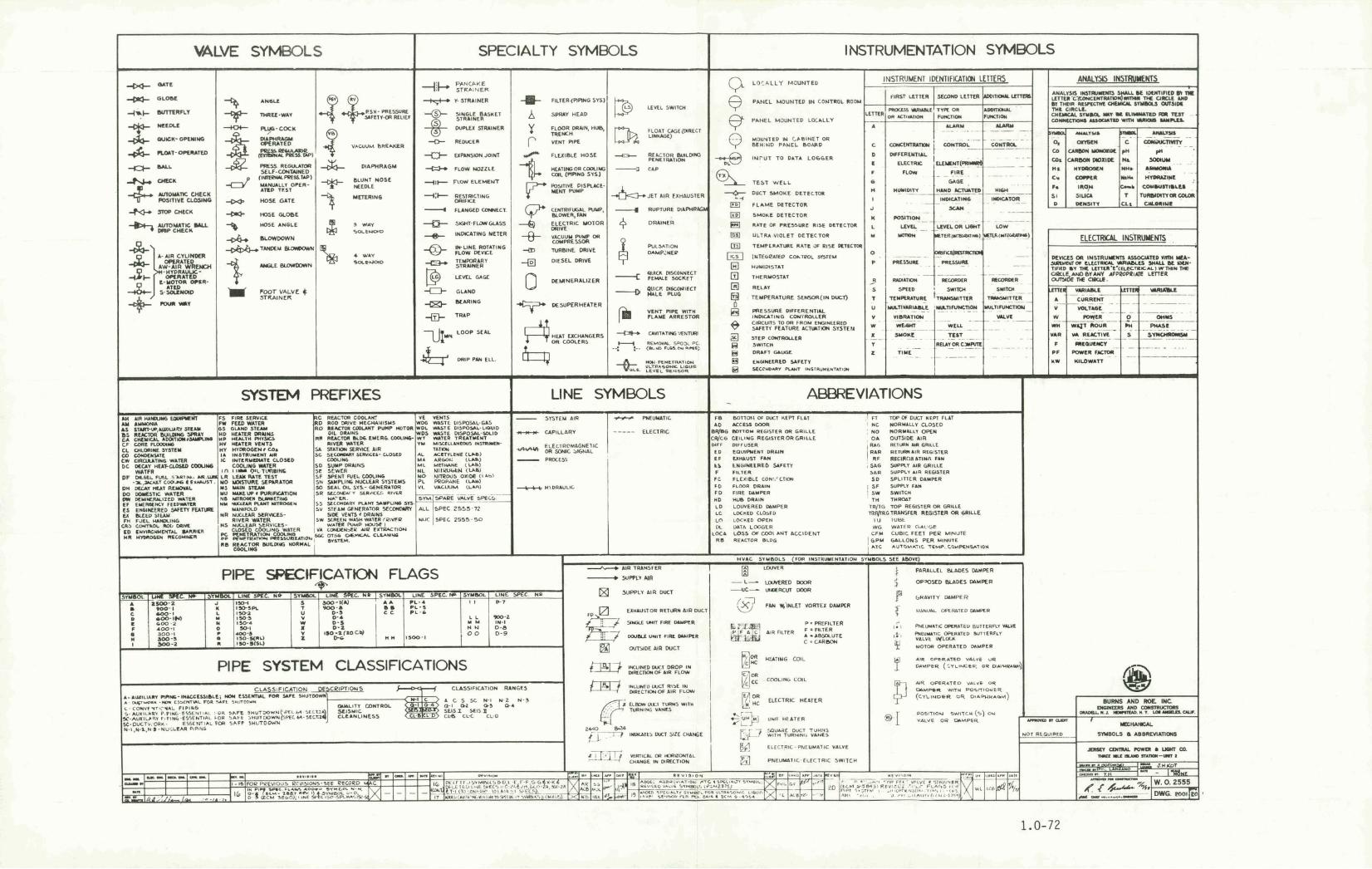
Appendix 5
Master List of TMI-2 In-Containment '~nstruments and Electrical Equipment
. , . . .. . .':: '
This Appendix contains the complete iist of Instruments ' .
and Electrical Equipment contained within the TM1.-2 containment .building. It is complete. in the sense that .a considerable effort 'has been expended to create a data base which incorporates the various other lists which exist. It is certainly complete in the sense that all .items which have. been. considered for inclusion in the sample recovery plan are given.here whether or not they were ultimately selected. It is unlikely to be complete if judged against the standard that no errors exi'st or that'no omissions have been made.
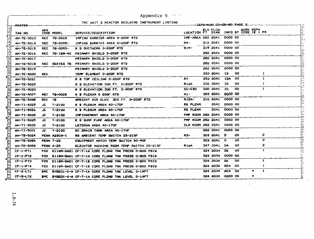
- 2
I
AH-TI -5030 JC T -2100 LETDOWN AREA 40-170F CLR ROOM 282 2041' 0000 00 p-
kc '[ . . AH-TI-SO31 JC 7-2100 RC DRAIN T M AREA 40-17W 282 2041" 0000~~00
MFR E L V FLOW WORK SSP* CO& MODEL SERVICE/DESCRIPTIDN LOCATION F T D I A 6 INFO ST CODE 1 E + PR TAQ NO.
26 -
32 - AH-TS-5024 PENN MXN-1 RB AMBIENT T W W I T C H 25-21% R5- 305 2041 D 00 2 rl .I -
EQUIPMENT HATCH TEMP SWITCH 50-90F 303 2041 D 00 2
-. J - .I -
A AH-TE-5013 REC 78-0065 I H P I N G BARRIER AREA 0-20OF RTD IMP-AREA 282 2041 0000 00
'1 - 2 11 -
14 - '%
17 -
20 -
$5 23 -
'g AH-TI -3028 X T-2100 I W I N Q E I E N T AREA 40-170F P W ROOPI 282 2041 0000 00 ti?
I JL
AH-TI-5029 JC 7-2100 R B SUMP PUMP AREA 40-170F P W ROOM 282 2041 0000 00 J1
,JC
35 - AH-18-3085 P E W A-23 ELEVATOR MACHINE ROOM TEMP SWITCH 2 3 - 2 1 5 F R I M 347 2041 DA 00 2 # 3;
: -1 I
L, CF-I-PT1 FOX E11W-SADl CF-T-1A CORE F L W TNK PRESS 0-800 P S I C 324 2034 DE 60 1 I:
,, .
FOX E I l W - S A D l CF-T-1A CORE FLDNO T W PRESS 07800 P S I 0 324 203$ 0000 00 I S .
FOX E l l W t S A D 1 CF-T-1B CORE FLDNO TNK PRESS 0-800 P S I 6 324 2034 DE 00 1 k.
AH-TE-5014 REC 78-0095- IMPING BARRIER AREA 0-2DOF RTD R4- 310 2 0 4 1 0000 00 I-:: - - -- - - - - .- - . - - - - - - . . -. - -- - . . - . . - ---+I: AH-TE-5015 REC 78-0095- R B WCTUQRL 0-200F RTD R19- 319 2041 0000 00 t-
AH-TE-5016 REC 78-183-40 PRIMARY SHIELD 0-200F RTD 282 204 1 0000 .OO P I .'
PRIHARV SHIELD 0-ZOOF RTD 282 2041 0000 00 I . AH-TE-5017 - 1 ..
282 2 0 4 1 0000 00 7;
4 3 2 4 2034 DEA 00 1 F CF-1-PT4 FOX E l l O K - S A D 1 CF-T-1B CORE FLDNQ TNK PRESS 0-800 P S I 0 I*,~ -. - CF-2-LT1 324 2034 DEA 00 * 1 BHC BYB231-X-A CF-T-LA CORE FLDNO TNK LEVEL 0-14FT k.
AH-TE-SO18 REC SERIES 78 PRIMARY SHIELD 0-2OOF RTD -- AH-TE-5019 PRIMARY SHIELD 0-200F RTD 282 2041 0000 00
TEHP E L E m N T 0-ZOOF RTD 3 5 3 2 0 4 1 I D 00 1 AH-TE-5020 REC
- i t ,
1 I. I r.
1 ' .
:,$I
AH-TE-SO21 R B TOP C E I L I N G 0-2OOF RTD R 7 3 5 3 2041 I D A 00 1 k-'! L: :,
AH-TE-5022 R B ELEVATION 330 FT. 0-2OOF RTD R16A 330 2041 I D 00 I -7,
1:: AH-TE-3023 R B ELEVATION 330 FT. 0-2OOF RTD CC-CSO 330 2 0 4 1 Ib 00 1
--F I:,.
303 2041 I .-.
AH-TE-M37 REC 79-0005 R B PLENUM 0 ROOT RTD HI- #?: R I B A - 310 2041 0000 00 AH-TE-5098 REC 78 AMBIENT A I R ELEV. 303 FT . O-2OOF RTD
L' . b
2 .l
- j i ,
AH-TI-5023 J C 1-21 00 R B PLENUM AREA 40 -170F RB PLENM 2041 0000 00 t: AH-TI-5026 JC T -2100 R B PLENUM AREA 40-170F RB PLENM 2041 0000 00 ! s t ! ,J

... . . . Appendix 5 (Cont'd)
TMI U N I T 2 REACTOR BUILDING INSTRUMENT L I S T I N G 9
" - -. W R . ELV FLOW WORK SSP* - , . .
LOCATION FT DIAG INFO ST CODE IE + PR : . CODE HODEL GERVICE/DESCRIPTION - . , - I 4 CF-2-LT3 BHC BY8231-X-A CF-T-18 CORE FLDNG TNK LEVEL 0-14Ff 3 2 4 2034 DE 00 + 1
3 2 4 2 0 3 4 0000 00 9 ' I
CF-2-LT4 BMC BY8231-X-A CF-T-10 CORE FLDNG TNK 0-14FT --. --- - --- 3 :
2196 0000 00 . ' I
DC-TX-2011 r(ERC LEAKAGE COOLER WDL-C-1A I N L E T TEMPERATURE 30s-26W -- -4
-. RE 28 1 0000 00 .i'Il 4 HP-RA-7586-1 RE EVACUATION HORN 7, -
9 'O 11
l d
2196 0000 00 I
LEAKAQE COOLER WDL-C-1A W T L E T TEMPERATURE 50s-26W M - T x - ~ o ~ ~ . W C - ; J j 4 DC-TX-2013 E R C LEAKAQB COOLER WDL-C-1B I N L E T TEMPERATURE 90s-26W 2196 0000 00 . : d : - -
LEAKAQE COOLER WDL-C-16 OUTLET TEHPERATURE 50s-26W 2196 0000 00 2 DC-TX-2014 MERC _c,
F H BR 0000 00 : 7 i t
HP-RA-0209 VICO RADIAT ION ALARM - .:,; .-
'6 11 7
'9 .20
21 22 23
11 26
28 - 29
- 2 '32
. ' . HP-RA-7566-2 . RE EVACUATION HORN RB 28 1 0000 00
0000 00 3
HP-RA-7586-3 RB EVACUATION HORN RB 28 1 : ~ 1 .. ! i
HP-RI-0209 VICO 836-2 ' RADIAT ION IND/W-BISTABLE8 F H BR (N) 0000 00 z, -3
F H ER (8) 0000 00 127;
HP-RI -0210 VICO 856-9 RADIAT ION IND/W-EISTABLES 7 7 . - 0000 00
..,. i PER HTCH HP-RI-A0211 VICO 858-3 RADIAT ION ALARH/HETER U N I T -. 2 --
0000 00 j i ! HP-RI-'AO~~~ VICO 858-3 RADIAT ION ALARHIHETER U N I T EOP HTCH - (
;;: 4 HP-RI -A0213 VICO A M - 3 R M X A T I O N ALARM/((ETER U N I T I W T PNL 0000 00 3 -
F H HU t N ) 3 4 7 2ObP E A 00 2 I -: HP-RT-0209 VICO 857-2 RADIAT ION DET/X-HITTER (OM) -. , I n
2 , .I I
HP-RT-0210' VICO 857-2 RADIAT ION DET/X-HITTER ( W I ) F H BR ( S ) 3 4 7 2062 DE 00 a i d ' - ... 309 0000 00
q HP-RT-0211 VICO 857-2 RADIAT ION DET/X-HITTER (OH) . -. 'A,;!
HP-RT-0212 ' VICO 837-2 309 0000 00 . A i i i RADIAT ION DET/X-HITTER (OM) '
+ . . '.a -.
5
35
HP-RT-0213 VICO 857-2 RADIAT ION DET/X-HITTER (OM) R 6 347 2062 DE 00 1
I~F,. .RT-0214 - V ICO 847-1 RADIAT ION DE;T/X-HITTER .'( I O N . ' D O E 372 2062 I D € 00 1 - :d a j ' 4 .-
. -"
O
, - - - a , . $4 , IC-7-TE2 BflC PYROTRON LET- CLR PW-C-1A WIT I C FLOW' TEMP 0-2SOF RTD P I P I N O 290 2029 0000 00 5 ?,.,!
k . 3 7 - qn
IC-1-TE3 BHC PYROTRON RC-P-1A I N J W T R RECRC FLOW & PUMP J K T 0-200F RTD P I P I N G 327 2029 0000 00 . .::I .. *, . .- 5 ji '
IC-1-TE4 BMC PYROTRON R C S - 1 A I N J WTR RECRC FLOW & PUMP J K T 0-200F RTD P I P I N Q 325 2029 0000 00 - 5J/
,
. -1 a
I C - l - T E l ' BMC P Y R O ~ R O N RC-P-1A I N J WTR RECRC FLOW & PUMP i l K T 0-200F RTD P IP fh lO ' 3 2 7 2029 D 00 2 2 71 --
'. -.-- . . I u'
IC" l -TE2 ' ' .- . BHC . PYRQTRON,' ,. R C S - 1 A INJ',WTR' RECRC FLOW & PUMP JnT 0-2OOF RTD . P I P I N O . 327 2029 0000 00 . . ..y
_ i ,
1 . ,.
IC-10-DPT BMC BY8230XA CRD OUTLET HDR FLOW 0-200 I N . H 2 0 R 6 351 2029 DE 00 - - . :!. ! - , :? +
IC-7-TE1 EMC PYROTRON LETDOWN CLR HU-C-16 OUT .IC FLOW TE~T;-~ P I P I N Q 290 2029 0000 00 . .. : ., --

- Appendix 5 (Cont'd) f
T H I U N I T 2 REACTOR B U I L D I N G INSTRUMENT L I S T I N G - - - - - - - - . - . . - -- . . -- - - - - - ...I.-. 4 . - -- -. - . -. ., - . , ..
I
5 IC -FE-7566 DAN O R I F I C E 0-100 GPH 39N-40W 2029 0000 00.
.
23
BMC PYROTRON CRD OUTLET HDR TEHP 0-2OOF RTD 348 2029 0000 00 IC-9-TE I+
- 2
5
I C - T I - 2 0 0 3 RC-P-1A INJ WTR RECRC F L N P W J K T CLQ WTR OLT TEMP LOCAL 327 2029 0000 00 1;) ! ..
IC-Tl-ZtUQ4 RC-.P-PB IFCJ WTR RLCRC P L W W JIIT CLG WTR OLT T E W Lui;n~ XiC3 ZOYV 0000 00 I i I,'.
26
28 --
MFR. E L V FLOW WORK SSP* . ,
SERVICE /DESCRIPT ION LOCATION F T D I A Q I N F O S T CODE 1E + PR ! ..-
TAQ NO. : CODE ISODEL I.-: -- . d : L
I 8
lo 11
;; L? 14
'b 17
' 9 - PO
;; 3
LY
2 --
I C - T I - 2 0 0 5 RC-P-2A JACKET CW WTLET TE)9 LOCAL 325 2029 0000 00 F: 38
I C - T I - 2 0 0 7 LETDOWN CLR MU-C-1B OUTLET I C FLOW TEMP LOCAL 290 2029 0000 00
IC -TX-2001 MERC INTERHEDIATE COOLINQ 49 -19W 2167 0000 W 3 1
;;
38 IC -TX-2013 r(ERC INTERMEDIATE C M L I N O - . IC -TX-2014 W A C INTERMEDIATE COOLINQ
---- - - . - . - - - - . . . . .- .. . - . - - - -- - . - - - - . IC -FE-7567 DAN O R I F I C E 0-100 QPH 4 1 N-26E 2029 0000 00 12
I U. !--. IC -FE-7568 DAN O R I F I C E 0-100 QPM 40N-2 1 E 2029 0000 00 i! I ! .., IC -FE-7569 DAN O R I F I C E 0-100 6PM 41N-21E 2029 0000 00 i d,
1 I
I C - F I - 7 3 6 6 BART 227 RC-P-1A SEAL FLOW D-P 0-100 I N H 2 0 23N-43W 2029 DE 00 2 IiG ,.__ I:,
IC-TI-= RC-P-18 INJ WTR RECRC F L W P W J K T C L 6 WTR O L T TEMP LOCAL 290 2029 0000 00
I35 ,, IC-TX-2004 H€RC INTERMEDIATE COOLING 28N-19E 2167 0000 00
4 I 2413 0000 00 IC -TX-2021 E R C INTERMEDIATE COOLING 32N-5W
IC -TX-2022 HERC INTERHEDIATE COULINQ 43N-5W 2413 0000 00 !.
-- . I C - F I - 7 5 6 7 BART 227 RC-P-1B SEAL FLOU D-P 0-100 I N k20 3 7 ~ - 3 7 ~ 2zc9 DEA 00 2
XG-FI -7568 BART 227 RC-P-2A WEAL FLW D-P 0-100 I N H 2 0 3%-43U 2029 0000 00
i J
IC -TX-2002 E R C INTERMEDIATE COOLING 31N-19W 21 67 0000 00
IC-TX-2003 R R C INTERMEDIATE COOLIN0 2N- 1 9 E 2167 0000 00
--. . IC -TX-2005 E R C JN-26W . 2161 0000 00 INTERMEDIATE COOLINO
I I
< :' I :. - 2"
4
4
1
J
2
I@-FI-7369 BART 227 RC-P-2B SEAL FLOW D-P 0-100 I N H2O 37N-37E 2029 0000 00 : i .. . 282 2040 0000 00 r:-. IC-RT-1091 V I C O 843-20 ICW LETDOWN CLR 1 8 BOKEV-mEV ( S C I N T I L L A T O R ) 11.. .; --
I C - R T = l W 3 VXCO 0 4 1 - 7 8 I G U LETDOWN OLR 1 A 00UEV-0t.eV ( B C I N T I L L A T O R ) 3 2 ~ - i a ~ as2 ~ 0 6 ~ R w .d
IC-TCg2Q24 R ~ G I N T F R W n T A T E COOLIN0 4 W - O W a410 0000 00
I C - T I - 2 0 0 2 RC-P-2A I N J WTR RECRC F L W W J K T CLQ WTR O L T TEMP LOCAL 327 2029. 0000 00 - .

Appendix- 5 . .(Cont 'd.)
TMI UNIT 2 REACTOR BUILDING INSTRUMENT r- - -0-. .5 .- ---.l- b.. . , -. -
2
,T - .. '4
5 a 1,
WORK .SSP* ! :
ICD- -01 B ~ C INCORE DET ABLY 7LD-16-1TC H-8 - - - - 350 NA 0000 00 - - - . .- . .. - . . --- . - ICD- -02 B ~ C INCORE DET ABLY 7LD-18-ITC H-9 350 NA 0000 00
8
9 '0 . .
!:!,I -25 B ~ C INCORE DET ABLY 7LD-16-lTC 6-1 1 350 . NA 0000 00 ::,:!
I!./ . -26 BMC INCORE DET ABLY.7LD-18-1TC E-1 1 330 NA 0000 00 I>H'
nFR. ELV FLOW LOCATIm FT DIAG INFO ST CODE 1E + PR
'
TAO NO. CODE MlDEL GERVICE/DESCRIPTION
2413 0000 00 IC-TX-2024 MERC INTERMEDIATE COOLING 46N-5W
330 NA 0000 00 ICD- -03 6% INCORE D€T ABLY 7LD-16-1TC 0-9 I _ I
ICD- INCORE'DET ABLY 7LD-16-1TC F-8 350 NA 0000 00 1 .:, -04 BRC I:!! I 1
16
'6 17
.s 20
22 23
26
27 a 29 - 30
32
;; 34 - 35
z 37 - 38
JO
> ' I
-27 BHC INCWE DET ABLY 7L.D-18-lTC D-10 390NA OOOOOO U U ;
' J - .I . :. i
2.; ---l
ECD- -03 BMC INCORE DET ABLY 7LD-16-1TC E-9 350 NA ID 00 1 t"' 350 NA 0000 00 ICD- -06 6% INCORE DET ABLY 7LD-16-ITC F-7
330 NA OOOO 00 ICD- -07 B% INCORE DET ABLY 7LD-1B-1TC E-7
330 NA 0000 00' ICD- -08 B ~ C INCORE DET ABLY ~LD-16-~TC 0-6
350 NA 0000 00 ICD- -09 BHC INCORE DET ABLY 7LD-16-1TC 6-3
ICD- -10 B ~ C INCORE DET ABLY 7LD-16-ITC H-3 350 NA 0000 00
350 NA 0000 00 ICD- -11 BMC INCORE DET ABLY 7LD-16-1TC K-3
ICD- -12 BHC INCORE DET ABLY 7LD-16-ITC L-6 350 NA 0000 00
350 NA 0000 00 ICD- -13 BHC INCORE DET ABLY 7LD-16-1TC fl-7
N-e 330 NA 0000 00 ICD- -i4 BIU INCORE DET ABLY 7LD-16-1TC
ICD- -15 BflC INCORE DET ABLY 7LD-16-1TC . N-V ,350NA 000000 4 ICD- n-9 350NA ID 00 1 -16 B ~ C INCORE DET ABLY 7LD-18-1TC
350 NA ID 00 1 ICD-, . -17 . B ~ C INCORE DET ABLY 7LD-16-1TC M-10 -- ICD- - . - -18 BW . . . . . . L-11. 330NA 000000 . INCORE DET ABLY 7LD-16-PTC ,
INCORE DET ABLY ~LD-16-ITC K-11 390 NA 0000 00 rce- . -19 BW
1=0- -20 H ~ C INCORE BET ~B1.y 7LD-18-1 TC K-12 350 NA 0000 00 . .
ICD- . -21 BMC INCORE BET ABLY 7LD-16-ITC H-13 350 NA . 0000 00 . . 4 -.
. I . . La BnC- ' '. C-13. 350NA, 000000 . - ' INCORE DET ABLY 7LD"lB-ITC '' .
ICD- -23 BHC I N C m E DET ABLY 71-9-1B-1TC F-13 390 NA 0000 00 . .
F-12 - 350 NA 0000 00 . ICD- -24 BRC INCORE DET ABLY 7LD-18-1TC
I . . ..-. 0 .< ! - 1 . 1 ;
7;: -. .' I, ' - 7 . . ,
3 ;.I!
?'.., . . :'u: .. , .' ,' -- 4 ?d'
2!1l .,(,I , I ! J ~ l
>31 3J)
37, 781 32 JU
-I ?I a31 . ...
-3 .,I 4.1 J .I,!
2 . t i
331 .;:I 5 J;
-'!I -

- .- . . . .- .- - . . . . Appendix 5 (Cont'd)
T M I U N I T 2 REACTOR B U I L D I N G INSTRUHENT L I S T I N G T P A . . - - -- - lT, - -
Q 5
7 . 2
E L V FLOW WORK SSP* . ?
3 5 0 NA 0000 00 ICD- -29 RMC INCORE DCT ADLY 7LD'1Bd1TC C-9 -- - ICD- -30 BMC INCORE DET ABLY 7LD-18-1TC B% 350 NA I D 00 ' 1
8
MFR. CODE MODEL SERVICE/DESCRIPTION T A o m. L O C A T I O N F T D I A Q I N F O S T CODE I € + P A
INCORE DET'ABLY 7LD-18-1TC C-10 350 NA 0000 00 ICD- -2s BMC
-31 BMC INCORE DET ABLY 7LD-18-1TC 8-7 350 NA W O O 00 I r ~ j ICD- . .
11
14
Z !I6
i;;
II. 20
35 ICD- -49 BMC INCORE DET ABLY 7LD-18-1TC M-14 3 5 0 NA I D 00 1
ICD- -30 BUC INCORE DET ABLY 7LD-18-1TC L-13 350 NA 0000 00 E
5 5 1 . ,
I C D - -32 BMC INCORE OET ABLY 7LD-1B- ITC C-6 330 NA 0000 00
32
ICD- -33 BHC INCORE DET ABLY 7LD-1B- ITC D -3 350 NA 0000 00 -- .- 4 I C D - -34 btlC INCORE DET ABLY ~ U ) - ~ B - ~ T C E -4 350 NA W O O 00
. . LOCAL 288 0000 '00
i T 5 1 LR-TE-4130 REC 78-170-18W CONT. L E A H RATE TEST 0-230F RTD j-G-1
LOC'AL 288 0000 00 ., :?
LR-TE-4131 REC 78-170-18U CONT. LEAK RATE TEST 0-2-TTD 15, .. .
-35 BMC INCORE DET ABLY 7LD-18-1TC F-3 330 NA 0000 00 , am-
ICD- -47 BUC INCORE DET ABLY 7U)-1B-1TC 0-10 330 NA 0500 00
ICD- -48 BUC INCORE DET ABLY 7LD-18-1TC 0-12 350 N A , 0000 00
'
. ..' . &-. ;
0-TE*& R E C 78-170-lm CON?. L E 4 \ . R A T E TEST 0 - 2 s RTD LOCAL a . ' 2; ,UU! 0000 00
'2. 14 :rj
1v
J O ~ ~ i ; -- 1.1, -
1 23
- - . ... 1?/ 4-1
a:; ;,I
ICD- -40 BMC INCORE DET ABLY 7LD-1B-1TC M-3 350 NA 0000 00
N-4 350 NA 0000 00 lCD- -41 BMC INCORE DET ABLY 7LD-18-1TC
38
-10
-36 BMC INCORE DET ABLY 7 L D - 1 8 - l T C 0-2 330 NA W O O 00 2 I! XCD-
ICD- -37 BMC INCORE DET ABLY 7LD-18-1TC H- 1 350 NA I D 00 1 14 I ~ J !
25 7fi
28 29
330 NA OOOO 00 IcD- -51 BUC INCORE, DET ABLY 7LD-18-1TC D-14 . . .';I
I--
>: - INeORE DET ABLY 7 L L - I Y - I I C C -13 3 5 0 N A I D 00 1
>J! ICD- -32 BMC 1 ~ ~ 1
350 NA OOOO 00 ICD- -38 BNC INCORE DET ABLY ~ ~ D - ~ B - I T C L-2
L-3 3mNa OOOO00 IcD- -39 BUC IWmE DKT ABLY 7 L D - I B - 1 T e
ICD- -42 BUC INCORE DET ABLY 7hB-18-1TC 0-8 380 NA 8860 00 ~2 : 1-3
-43 BUC INCORE DET ABLY 7 L D - I B - I T C 0 4 350 NA 0000 00 3.., I C D - - . : 1 1 0 :
ICD- -44 BMC INCORE DET ABLY 7LD-18-1TC P-6 350 NA 0000 00 131;
ICD- - 4 5 BMC INCORE DET ABLY 7LD- IB-1TC R-7 . 350 NA I D 00 1 125 $2,)'
I C D - -46 BMC INCORE DET ABLY 7LD-1B- ITC R -10 350 N A 0000 00 .I I : - I, .I
..?. :.,,,I 211
?dl

LA-TE-4137 REC 78-170-18 CONT. LEAK RATE TEST 0-25OF RTD LOCAL 311 0000 00 t$
. . . . f - - - . . - - - . . - . . . . . . . . . . . Appendix 5 (Cont'd)
T H I U N I T 2 REACTOR B U I L D I N G INSTRUMENT L I S T I N G n IfPG-HWW.-.-- - . --- - -- - - - r-
LR-TE-4138 REC 78-170-18W CONT. L E A K RATE TEST 0 - 2 5 0 F RTD LOCAL 333 0000 00 1" lib
LOCAL 3 5 3 0000 00 I I LR-TE-4139 REC 78-170-18W CONT. LEAK RATE TEST 0 - 2 5 0 F RTD 8 M
- 2
2- 5
.' 9
M R . E L V FLOW WORK SSP*
14
LOCAL 333 0000 00 LR-TE-4140 REC 78-170-18W CONT. LEAK RATE TEST 0-230F RTD
LOCAL 353 0000 00 fi LR-TE-4141 REC 78-170-18W CONT. L E A K . RATE TEST 0-250F RTD 1 7
TAQ NO. CODE PIODEL SERVICE/DESCRIPTION LOCATION F T D I A Q I N F O S T CODE 1 E + PR
0000 00 LR-TE-4133 REC 78-170-18W CONT. LEAK RATE TEST 0 - 2 5 0 F RTD LOCAL 288
LR-TE-4134 REC 78-170-18 CONT. LEAK RATE TEST 0 - 2 5 0 F RTD LOCAL 311 0000 00 - - - -
LR-TE-4135 REC 78-170-18 CONT. LEAK RATE TEST 0-290F RTD LOCAL 31 1 0000 00
. - -- I' 10
21 - 7" .. - . .
LOCAL 370 0000 00 LR-TE-4142 REC 79-170-18W CONT. LEAK RATE TEST 0-250F RTD - LOCAL 370 0000 00 . 5 LR-TE-4143 REC 79-170-18W CONT. LEAK RATE TEST 0-230F RTD
70
M LR-TE-4146 REC 78-170-18W CONT. LEAK RATE TEST 0-230F RTD LOCAL 371 0000 00 1::.
J - 4
- I H (I
I, -
? 2
2a .,> :IL - -
2 11 23
LR-TE-4136 REC 78-170-18 CONT. LEAK RATE TEST 0-2- RTD LOCAL 311 0000 00 I , t:
LOCAL 370 m o 00 LR-TE-4144 REC 79-170-1W CONT. L E A K RATE TEST 0-230F R T D
LOCAL 370 0000 00 LR-VE-4145 REC 79 -170 -16U CONT. LEAK RATE TEST 0-230F RTD
5 26
21 'z
29
o 32
Z *% 35
2 : 2" 2 5
-3'
-- , y *
38
LOCAL 371 0000 00 LA-TC-4147 R f C 78-170-1BW C O W LEAK RATE TEST 0-2- RTD
L m A L 371 0000 00 LR-TE-4148 REC 78-170-1BU CONT. LEAK RATE TEST 0-230F R T D
LOCAL 371 0000 00 LR-TE-4149 REC 78-170-18W CONT. LEAK RATE TEST 0-290F RTD
LR-TE-4130 REC 78-170-18W CONT LEAK RATE TEST 0-230F RTD LOCAL 371 0000 00
LR-TE-4131 REC 78-170-18W CONT. LEAK RATE TEST 0-230F RTD LOCAL 371 0000 00
LR-TE-4132 REC 78 -170 -18U CONT. L E A K RATE TEST 0-230F RTD LOCAL 426 0000 00 - LOCAL 426 0000 00 LH-TE-4193 REC 70 170-18W CONT. LEAH RATE TEST 0-230F RTD
2 '40
& ' E
a s
J 3
A? JS - I .
J I
24 .?'J 411
AL 4'
-11 4.1
02 -- 4 b
LR-TE-4164 FOX 2711-AC CONT. L . R . - T E S T D E W P O I N T O - 1 O O F - LOCAL 288 uOOO 00 .+ -- LR-TE-4165 ' FOX . 271.1-AQ 'CONT. L. R . TEST DEW' P O I N T .O-I'OOF. .. .- L-AL 2W 0000 00 .
, . .. .
-. 4 I
YC
49 5 I-,
I bii
LR-TE-4166 FOX 2 7 1 1 A 9 CONT. L. R. TEST D E W P O I N T 0-1OOF LOCAI 311 OOOo 00
LR-TE-4167 FOX - 2 7 1 1 ~ 8 CONT. L. R. TEST DEW P O I N T 0-1 00F LOCAL 311 0000 00
LR-TE-4168 FOX 2 7 1 1 A Q CONT. L. R. TEST DEW P O I N T 0-100F LOCAL 347 0000 00
3 I 2.'
- :,.I 5 1
- . . !!> $,11
LR-TE-41'69 FOX 2 7 1 1 A 9 LOCAL 333 0000 00 5 I
CONT. L. R. TEST DEW' P O I N T 0-1OOF :IH
. LA -TE-4170 FOX. 271 1AO LOCAL 333 000000 !*'#
CQNT. L. R. TEBT DEW P O I N T 0-100F

~- - sH N I - A W - I BHC PT662314ON P R E M RC-T-1 310 I S E A 00 + 1
TMI U N I T 2 REACTOR BUILDING INSTRUMENT L I S T I N G
,
.
-2
W WL23635A COnP I O N CHAMBER RC-T-1 322 I S E A 00 + 1 -- - U WL23638B UMCWP I O N CHANBER RC-T-I 322 I S E A 00 + 1
1 - T Q
5
L 8
'D 11
'I 14
2 17
19 2u
,, -- It. 23
5 26
c-'
r-m Tr- .a b.. --
2 ' MFR. ELV FLOW WORK SSP* TAQ NO. CODE MODEL SERVICE/DESCRIPTION LOCATION F T D I A Q I N F O ST CODE 1E + PR
.- LR-TE-4171 FOX 2711AG CONT. L. R. TEST DEW POINT 0-1OOF LOCAL 370 0000 00 '
LR-TE- I172 FnX 2711AC CUNI. L . R. TEST DEW POIMI 0-100F 0000 00 - -. -. . - - LOCAL 371
- ------- P
LR-TE-4173 FOX 2711AG CONT. L. R. TEST DEW POINT 0 -100F LOCAL 371 0000 00
MID- -DR BLW MOVABLE INCORE DETECTOR DRIVE P I P I N G 3 5 0 N A 000000 '
HID- -ND .BMC m L E INCORE DETECTOR P I P I N G 3 5 0 N A 000000
M s - T E - ~ o ~ REC 2555-1-38 STM QEN RC-H-1B OUTLET TEMP 0-6OOF RTD P I P I N G 330 2002 0000 00 - HS-TE-104 REC 2555-1-38 STM E N RC-H-10 OUTLET TEMP 0-&OOF RTD P I P I N Q 330 2002 0000 00
MS-TE-109 REC 2535-1-38 STH E N RC-H-IA OUTLET T W 0-60OF RTD P I P I N B 330 2002 0000 00
HS-TE-110 REC 2555-1-38 STM 4EN RC-H-1A OUTLET TEMP 0-60OF RTD P I P I N G 330 2002 0000 00
MU-10-FT1 BRK 8-3630 RC-P-1A SEAL WTR BLEED OFF 0-2GPH LOCAL 2024 DA 00 3 - - --
W l O - F T 2 BRK 8 - n A X l RC-P-&A BCAL UTR DLCCD O F ~ o-.!w~ LOCAL 2024 D 00 3
HU-10-6T3 BRK 0 3630 RC3-in WAI u~r ! BLEED OFF 0 - 2 W H L W A L 2d24 0000 00
MU-10-FT4 BRK 8-3630 RC- f - IA SEAL WTR BLEED OFF 0 - 2 W H LOCAL 2024 D 00 3
MU-TE-739 W C - 1 A LETDOWN OUTLET TEMP COOLER I N L I N E 285 2024 0000 00
W-TE-740 W - C . I D LETDOWN OUTLET I t W COOLER I N LGE- 285 20% 0000 00
MU-TE-741 2335-1-42 LETDOUN CODLER I N L E T 0-6- DUAL RTD I N L I N E 298 2024 0000 00
29
. 1:
W UL23634B UNCOMP I O N CHAMBER RC-T-I 322 I B E A 00 + 1 - - . . - - - . -- -- - -
NZ GAS TO R B i 10-275 P S I DIAPHRAGM PRESSURE SWITCH I R 432 349 2036 DA 00 3
NI-AMP-2 BMC PT6623140N PREAMP RC-T-1 310 + 1 I S E A 00
NI-ND-1 W w U 3 6 8 2 A PROP COUNTER RC-T-I 310 I S E A 00 + 1 32
$,
L .
. . ' W - Q A S TO R B i 0.2-6. 0 P S I DIAPHRAQH, PRESSURE SWITCH I R 432 349 2036 D 00 3 b
N1-M)-2 Y PROP COUNTER RC-T-1 310 S E A 00 + 1
NI-ND-3 W WL23635A C O W I O N CHAMBER RC-T-1 322 JSEA 00 + 1
38 . NI-ND-6 W UL23636B M O W I O N CHAMBER RC-T-1 322 XSEA 00 + 1
NI-ND-7 W UL23636B VNCOMP I O N CHAMBER RC-T-1 322 I S E A 00 + 1

Appendix 5 (Cont 'd) . .
T R I U N I T 2 REACTOR BUILDING INSTRUMENT L I S T I N G - :,--*5-2&88-pcIBE -9 .. -.-- -.. -. -. ..--. -. I I
I -; MFR. ELV FLOW WORK SSP* CODE MODEL SERVICE/DESCRIPTION LOCATION F T D I A G INFO ST CODE I E + PR
-- 2
fl NM-PS-4175 SOR N2 6AS TO RE; 10 -275 P S I DIAPHRAGM PRESSURE SWITCH I R 4 3 2 3 4 9 2036 D 00 3
7 2
NS-FS-4023 BRH 3601 -10DZ ROTAMETER 0-1 SGPM P IN-23E 334 2030 D 00 3
Ids-FS-4024 BRK 3601-IODZ ROTAMETER 0-156PM 3SN-24W 3 3 4 2030 DA 00 3
3 i
34N-23W 3 3 7 2030 DA 00 3 NS-F8-3977 MAG 3-F503-T-F FLOW SWITCH 0-100GPM , . -- --- . - I :. -. . . . - - .. . - . - - - - - - --- . . - - -- .- -- - - -+ . : ..
19N-22E 336 2030 D 00 3 NS-FS-3978 MAS 3-FS03-T-F FLOW SWITCH 0-100GPM cr 9 'O
1 3 N - 2 1 W 336 2030 0000 00 !: , ;
NS-FS-3979 MAO. 3 f S 0 3 - T - F FLOW SWITCH 0 - 1 0 W M !Td NS-FS-3980 MAC 3 f 5 0 3 - T - F FLOW SWITCH 0-1006PM 11s -22E 336 2030 0000 00 p!. ,...
- - k '6 17
I N - 2 2 E 343 2030 0000 00 2;t NS-Fa-4029 MA0 3 f 3 0 3 - T - F FLOW SWITCH 0-1006PM 1.. "! -.,* 2N-26W 343 2030 0000 00 NS-FS-4030 MAC 3 f 5 0 3 - T f FLOW SWITCH 0-1006PM : I , ?!:
38 -24E 3 3 4 2030 0000 00 A, . . : .US-FS-4025 BRK 3601-10D2D ROTMETER 0-15OPM -. ..la - .. . 3
I. , : NS-FS-4026 BRK 3601-IODZ ROTAMETER 0 -156Pt l 13N-24W 3 3 4 2030 D 00 2 I
. . .
2 '9 20
7c
25N-22E 3 4 3 2030 D 00 3 NS-FS-4027 ,MAS 3-FS03-T-F FLOW SWITCH 0-1006PM - ..... I<;; ZSN-26W 3 4 3 2030 0000 00
?'. NS-FS-4028 MA0 3 f S O 3 - T - F FLOW SWITCH 0 -1006Pt l ..,,>:
NS-FS-4031 MA0 3f503-1-F FLOW SWITCH 0-1008PM 30N-26E 3 4 3 2030 0000 00 1:;: NS-FS-4032 MA0 3-F303-1-F FLOW W I T C H 0-100GPM 31N-22U 343 2030- 0000 00 1:': 2 -"
2 20
NS-fS-4033 r(AO 3-503-1-f FLOW SWITCH 0 - 1 0 0 W M 7Npa&C 343 PO30 OOOQ 00 i ~ . . r1.. . .
NS-F8-4634 MAQ 3-F%3-T-F FLOW SWITCH 0-1006PM 7N-22W 3 4 3 2030 0000 00 3 ' b!
SS - 2 0 ~ 3 3 5 2030 0000 00 NS-TE-1415 REC 104WC26BX 0 -~POF 'DUAL RTD - -. I ; , , s
. .
NS-TE-1419 REC 104WC26BX 0-12OF DUAL'RTD. ' . . . . iBN-2UE 333 2030 0000 00 -.. . . k,:l -
NS-TE-1420 .. REC 1 0 4 ~ 2 6 8 ~ . 8-12OF DUAL. RTD ' . . . . . . 2ZN-19E 335 2030 0000 0 0 . . ' 13
2s - 1 9 E . 335 2030 0000 00 REC 1 0 4 ~ 2 6 ~ ~ 0-120F DUAL RTD . . -
'k e.
-1 L/ .I : !
IN-IBE 388 ioao oooo oo 1a.iI : N8-TE-1417 REC 104UC26BX 0-120F DU4L RTD. i .l
8N-18E 388 2030 0000 '00 431 NS-TE-1418 RE6 104WC26BX 0-120~ DUAL RTD . .- -'_u I
1 . ~ ! I j,:.
NS-TE-1423 REC 104WC26BX 0-12OF DUAL RTD SS-17W 337 2030 0000 00 !. ,:.,,. . , :.>>.:
2N-17W 3 3 7 2030 0000 00 .. . NS-TE-1424 . REC 104WCZ6BX 0-1ZOF DUAL RTD , I:.n. . 8 . ., . '
l l N - 1 9 W 334 2030 0000 00 s f 8 ; NS-TE-1-5 REC 10SWC2bBX 0-12W DUAL RTD t.i.8
.
. .
I 5 2 44
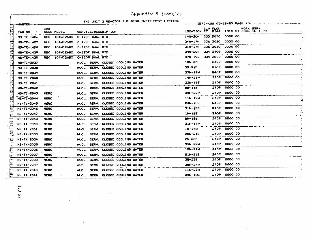
- -- - - . . . - - - - f Appendix 5 (Cont'd)
E L V FLOW WOA LOCATION FT D I A G I N F O ST COC
- 2
2,
PlFR . IK SSP* TAG NO. CODE MODEL SERVICE/DESCRIPTION . - - - . . . - - . - . . - - - - . - )E 1 E + PR
-- NS-TE-1426 REC 104WC26BX 0-120F DUAL RTD 14N-20W 3 3 5 2030 0000 00
N8-71-2043 HERC W L . SERV. C L W D tMl T N Q tdntFR 35bb33W 3 4 9 9 9900 00
NB-TI -2044 RERC NUCL. SERV. CLOSED COOLINQ WATER 1 lN-19W 2409 0000 00 . ,
5
L 8
2 11
;; 13 14
- .
17 - L! E
NSaTE;1427 ntc 104WC26tlX 0-120F DUAL RTD 24N-17W 336 2030 0000 00 . . - - - - - -- - -- . _ _____ -
N S - T E - I ~ ~ ~ REC lO4WC26BX 0-120F DUAL RTD 31N-17W 336 2030 0000 00 -- NS-TE-1429 REC 104UCZLBX 0-120F DUAL RTD 34N-20W 334 2409 0000 00
NS-TE-1430 REC 104WC26BX 0-12OP DUAL RTD 37N-19W 334 2030 0000 00 - -
W L . SERV. CLOSED COOLING WATER l8N-2OE 2 4 0 9 0000 00 NS-TI -2037 - -- N!5-~1-2038 MS. SERV. CLOSED COOLINO UATER 5sr2 1E s o 9 0000 00 --
- NUCL. SERV. CLOSED COOLING WATER 37N- 19W 2409 W O O 00 N6-T I -2039
NWL. SERV. CLOSED COOLING WATER 14N-2 lW 2409 0000 00 N6-T I -2040
NUCL. SERV. CLOSED COOLING WATER 22N- 19E 2409 0000 00 NS-TL - 2 0 4 1 .- -
CRCCL. OERV. CLWED COOLINO UATCR 05- 1 TI! 2409 0000 00 NS-11-1013
, , 2 1
2 26
e
?-
NS -T I -2045 HERC NUCL. SERV. CLOSED COOLINQ WATER 24N- i 8 E 2409 0000 00
2409 0000 00 NS-T I -2046 t E R C NWL. SERV. CLOSED C W L I N O UATER 31N-18E
WCL. SERV. CLOSED COOLINQ WATER IN-laE 2409 W O O 00 N6-11-2047 IlERC
NS-TI-- HERC NUCL. SERV. CLOSU) COOLING WATER 8N- 18E 2409 0000 00 29
"'2, NS-T I -2030 HERC NUCL. SERV. CLOSED COOLINO WATER 31N-17W 2409 0000 00
WL . SERV. CLOSED C M L I N O WATER I N - 1 7 W 2409 O W 0 00 NS-T I -2031 MERC 32
;; '54
k! N B - T X - ~ O ~ ~ ' ~ R C WL. SERV. CLOSED C W L I N Q WATER 2 1 N-23E 2409 0000 00
NS-TX-2033 IlERC NUCL. SERV. CLOSED COOLINQ WATER ?ON-2 1 E 2409 0000 00 +
2409 0000 00 NS-TX-2034 HERC NUCL. SERV. CLOSED COOLINO WATER 2s-22E 7
35
'17
-- 2 NS-TX-2038 HERC NUCL. SERV. -CLOSED COOLING WATER 28 -23E 2409 0000 00 4 1
NS-TX-2039 MERC NUCL. SERV. CLOSED COOLINO WATER 2BN-24W 2409 0000 00
NS-TX-2040 MERC MICL;. SERV. CLOSED COOLINQ WATER 1 1 N-23W 2409 0000 00
NS-TX-2041 &RC WCL. 8ERV. CL'OSED 'COOL.INO WATER . 25N-18E 2409 0000 00
2409 0000 00 NS-TX-2035 MERC NUCL. SERV. CLOSED COOLINO WATER 35N-22W
N B - T X - 2 0 s HERC NUCL. SERV. CLOSED COOLINO WATER l 2 ~ - 2 1.w 2409 0000 00

T M I . U N I T 2 REACTOR B U I L D I N G INSTRUMENT L I S T I N G .--. 1.1. ... ....... I!-- .. -
W R . E L V FLOW WORK SSP* CODE MODEL SERVICE/DESCRIPTION LOCATION F T D I A Q I N F O S T CODE 1 E + PR -.
-. - i s - T X - 2 0 4 2 RERC NUCL. SERV. CLOSED COOLIN8 WATER 30N- 1 8 E 2 4 0 9 0000 00
'T j 7
NS-TX-2043 H€RC NUCL. SERV. CLOSED COOLING WATER 2N-.1 8 E -. 2 4 0 9 0000 00 - . - - - . - . - . - - - - - -.
NS-TX-2044 rOERC NUCL. SERV. CLOSED COOLINQ WATER EN- 1 8 E 2 4 0 9 0000 00
'G l o
I I
IT. .- . NB-TX-2045 rtERC NUCL. SERV. CLOSED C W L I N Q WATER 23N-26W 2409 0000 00
NS-TX-2046 t E R C NUCL. SERV. CLOSED COOLINQ WATER 30W-23W 2409 0000 00 -. . . -.-
';;
la
M RE-TE-3271 TEC RB PENETRATION 60-2OOF RTD 29 1 0000 00
NS-TX-2047 nERC NUCL. SERV. CLOSED COOLING WATER IN-25W 2409 0000 00 - .-
NS-TX-2048 CLRC NUCL. SERV. CLOSED C W L I N O WATER 1 IN-22W 2409 0000 00 .. . . . .- - -
5 I7
RB-TE-3267 TEC RB PENETRATION M)-=OF RTD 305 0000 00 -. .
RB-TE-3269 TEC RE PENETRATION 60-200F RTD 291 , O W 0 00 . - . - . . . -.
'
.
' .
.
.
'9 20
21 2 23
26
2 29
2 32
x . 2 35
a 55 38
2 4 1
2 44
29 1 0000 00 . .
RB-TE-3273 TEC RB PENETRATION 60-2OOF RTD . .
29 1 OOM) 00 . . RB-TE-3273 TEC RB PENETRATION 60-ZOOF RTD . .
29 1 0000 00 RB-TE-3279 TEC RB PENETRATION 60-200F RTD .. . . . . . RB PENETRATION 60-200F RTD 298 0000 00 RB-TE-3281 TEC . .
0000 00 RE-TL-32BS TCC RB PENFTRATIRN 6Q-ZWF RTD 298 . . . . : - -
2- Rfr-TE-3187 TEC RB PENETRATION 60-2OOF RTD , 0000 OQ . . -. -, . .
298 0000 00 RE-TE-3289 TEC RB PENETRATION 60-200F RTD - . . - - . . 299 . 0000 00 RE-TE-3293 TEC RB PENETRATION 60-2OOF RTD . .
- .
. ' R B - ~ ~ - 3 2 9 7 TEC RB. PENETRATION 60-2OOF RTD . 299 .. 0000 00 -. . - : -..
RB PENETRATION 60-- RTD 299 0000- 00 1 _.
RB-TE-3305. TEC - - RB- ' IE-3307 n e ' RB PENETRATION AO-2OOF RTD 295 0000 00 -: .-.
' L: . - ... 29 3 0Luu 00. RE-:TE-3309. TEC . ,' RB PENETRATION 60-2OOF RTD ' - -I . 1 ? ~ - ~ i i - 3 3 1 3 TEC RB PENETRATION 60-200~ R?D . . 2 9 5 . 0000 00 - - .. . . RE-TE-3313 TEC RB PENETRATION 60-200F RTD 29a woo 00 . . . . . . . .
. . 295 0000 00
. . RE-TE-3317 TEC RB PENETRATION 60-200F RTD -- - . . .
298 0000 00 . . RE-TE-3319 TEC RB PENETRATION 60-200F RTD - .
-- - . 2 9 3 0000 00 RB-TE-3321 TEC. RB PENETRATION 60-200F RTD . . . . . . . . .
998 0000 00 RB-TE-3323 TEC RB PENETRATION 60-200F RTD --- - - ..

- - - . - -. . . . . Appendix 5 (Cont'd)
TMI U N I T 2 REACTOR BUILDING INSTRUMENT L I S T I N G p- rrPe,uuw.-. 12 7 - - ,
-. 2
-- 4 RE-TE-3363 TEC RB PENETRATION 60-ZOOF RTD 322 0000 00 . .
MFR .
L 8
2 I I
'2 L 4
'6 1 7
1 ZU
+ 23 ;;
RE-TE-3327 TEC RB PENETRATION 60 -200F RTD 29 1 0000 00 -- - . -- - -. --
0000 00 RB-TE-3329 TEC RB PENETRATION 60-200F RTD 29 5 -
RB PENETRATION 60-200F RTD 292 0000 00 RB-TE-3331 TEC -.
0000 00 RB PENWRATION 60-2OOF RTD 295 . .
RB-TE-3333 TEC .- . - -
RB PENETRATION 60-200F RTD 2 9 5 0000 00 . .
RB-TE-3337 TEC .- ..-- -- -- -
RB-TE-3339 TEC RB PENETRATION 60-200F RTD 29 5 0000 00 - - --
298 0000 00 RB-TE-3341 TEC RB PENETRATION 60-2OOF RTD - 29 1 0000 00 - . . RB-TE-3343 TEC . RB PENETRATION 60-2OOF RTD - .
. . -. - RB PENETRATION 60-200F RTD 298 0000 00 RB-TE-3347 TEC -
322 0000 00 . . RB-TE-3331 TEC RB PENETRATION 60-200F RTD - - -. . - 318 0000 00 RB-TE-3353 TEC RB'PENETRATION 60-200F RTD . . . . .
. . RE-TE-3337 TEC ' RB PENETRATION 60-200F RTD 318 0000 00 - .
RB PENETRATION 60-200F RTD 318 0000 00 RB-TE-3361. TEC . .
ELV FLOW WORK SSP* -
26
7 i,
. . .- 0000 00 RB PENETRATION 60-2WF RTD 318 RB-TE-3365 TEC . .
RE-TE-3367 TEC RB PENETRATION 60-200F RTD 3 4 1 0000 00 - - ;29
" - ~
& RE-TE-3377 TEC 3 5 7 ' 0000 00 RB PENETRATION 60-200F RTD -. . 1: --
353 oooo' 00 1 <
- RE-TE-3379 TEC RE PENETRATION 60-2O0F RTD -. . .
SERVICE/DESCRIPTI.W LOCATION F T D I A C I N F O ST CODE 1E + PR ' TAG -NO. CODE MODEL - RB-TE-3325 TEC RB PENETRATION 60-200F RTD 29 5 0000 00 . -
. . -- 29 1 0000 00 RB-TE-3369 TEC RB PENETRATION 60-2OOF RTD --
-.
RB-TE-3371 TEC RB PENETRATION 60-200F RTD 347 0060 00 -. - . - .- -= 32
;; 34
R B - T E - ~ ~ ~ I TEC RB PENETRATION 60-2&~ RTD 349 0000 00
P I P I N O 3402601 DA 00 3 . . -LSI B O R ~ ' RC-P-1A SEAL L E A K M E L V L SWITCH ELECTRODE - . - -
RB PENETRATION M)-2OOF RTD 3 4 7 000000 ::
RB-TE-3373 TEC - - -- 0000 00 RB-TE-3375 TEC RB PENETRATION 60-200F RTD 349
-. - - -.
. . RC- -LS2 BORG RC-P-2A SEAL LEAKAGE L V L SWITCH ELECTRODE P I P I N G 3 4 0 2 6 0 1 D 00 3 , . . -
-. k2. RC- . -LS3 ' 8 0 ~ 6 R C - P - l B SEAL LEAKME LVL W I T C H ~ E C T R O D E P I P I N Q 3 4 0 2601 .OOOO 00 . . . .
A S 4 BORQ .. . RC-P-2B SEAL L ~ Q E LVL SWITCH ELECTRODE . . . . P I P I N B 3402601 D . 00 3 . . . - .

/ . -- - . - .. . Appendix 5 (Cont'd)
MI U N I T 2 REACTOR B U I L D I N G INSTRUMENT L I S T I N G .. n --- v- --f.-j -- - - . .- - . 7. ; . .
M . .. MFR. E L V FLOW WORK SSP* i..,
LOCATION F T D I A G I N F O S T CODE 1 E + PR TAQ NO. CODE MODEL S€RVICE/DESCRIPTION I .; . a P I P I N G 340 2062 0000 00 RC- - ' T E ~ BING TC RC-P-1A LOWER SEAL CHAMBER TEHP - I :y RC- -TE2 B I N G TC RC-P-2A. LOWER SEAL CHAMBER TEMP
- . - -. . - - . .- P I P I N G 3 4 0 2062 0000 00 . - .--. --
' RC- , -TE3 B I N 6 TC . R C - P - 1 8 LOWER SEAL CHAMBER TEMP P I P I N G 3 4 0 2062 0000 00
RC- P I P I N Q 340 2062 0000 00 -TE4 B I N 8 TC t
RC-P-2B LOWER SEAL CHAMBER TEMP - I 'O I1
"
'
"
-
7--
RC- I -LT1 BMC BY3B40X-A PRESSURIZER L E V E L 0-400 I N H 2 0 I R 4 2 4 286 2024 I D E A 00 1
I R 4 2 4 286 2 0 2 4 I D E A 00 4 1 RC-1-LT2 BMC BY3B40X-A PRESSURIZER L E V E L 0 - 4 0 0 I N H 2 0
2 14
17
la '9 20
2, 22 23
3 26
28 - 29
- 31 32
'2
37 38
40 4 1
'2 44
4
2- 1:
I ' - I I
- - p~ - -
RC-1-LT3 BMC BY3840X-A P R E S S U l l Z E R L E V E L 0-400 I N Ha0 I R 4 2 6 286 2024 I D E A 00 1 p RC-10-TEI TEC 2 E 2 1 2 l A PRESSURIZER R E L I E F OUT TEHP 0-700F T / C PORV C L A W ON 359 2024 0000 00 1 il
2 r RC-10-TE2 TEC 2 E 2 1 2 l A PRESSURIZER R E L I E F OUT TEMP 0-700F T /C CODE SAFE CLAHP ON 334 2 0 2 4 0000 00
RC-10-TE3 TEC 2 E 2 1 2 l A PRESSURIZER R E L I E F OUT TEMP 0-700F T / C CODE SAFE CLAMP ON 354 2 0 2 4 0000 00 1;: P I P I N Q 3 5 4 2 0 2 4 0000 00 RC-11-TE TEC 2 E 2 1 2 1 A PRESSVRIZER SPRAY L I N E TEFtP 0-700F T I C
I R 4 2 3 286 2 0 2 4 SEA 00 1 RC-14A-DPT1 BHC BY3X41X-A RC FLW (HOT LE6 ( A ) ) 0 - 8 1 8 . 1 2 I N H Z 0
RC-IQA-DPT2 BMC BY3X41X-A RC FLOW (HOT L E O ( A ) ) 0 - 8 1 8 . 1 2 I N H 2 0 I R 4 2 7 286 2 0 2 4 S E 00 *+ 1
-
RC-14A-DPT3 BHC BY3X41X-A RC FLOW (HOT L E G ( A ) ) 0-818.12IN H20 I R 4 2 9 284 2 0 2 4 0000 00 + 1' KC-L4A-DPV4 DMC PY3X4 lX -A RC FbW (HOT LEQ ( A ) ) 0 - 8 1 8 . 1 2 I N Ha0 - I R 4 3 0 284 2024 0000 00 ik'+
F 3
RC-14B-DPT1 BUC BY3X4 lX -A RC FLOW (HOT L E O ( 8 ) ) 0 - 8 1 8 . 1 2 I N H 2 0 IR ' 173 284 2 0 2 4 0000 00 *+ 2 - . .P ! J
RC-14B-DPT2 BHC BY3X41X-A RC FLOW (HOT LEQ ( B ) ) 0 - 8 1 8 . 1 2 I N H 2 0 I R 4 2 7 2 8 4 2024 0000 00 a+ I
J
RC-14B-DPT3 'BtlC BY3X41X-A RC FLOW (HOT LEG ( B ) ) 0 - 8 1 8 . 1 2 I N H 2 0 I R 4 2 9 286 2024 0000 00 ++ R C - ~ ~ B - D P T ~ B M BY3X41X-A RC FLWJ (HOT LE6 ( B ) 0-BIB. 1 2 1 ~ H2O I R 4 3 0 286 2 0 2 4 0000 00 ++ -4
. - RC-1%-TE1 REC 104AFP-2 RC HOT LEO ( A ) TEMP 0-800F RTD WELL 335 2024 SA , 00 , . L 1; R C - ~ S A - T E ~ ' REC ' 104AFP-2 RC-P-1A COLD L E G TEHP 0 - B O W RTD WELL 310 2024 S 00 1
WELL 310 31324 8 00 1 RC-134-TE3 REC 104AFP-2 RC-P-2A C O L D . L E 6 TEMP 0-800F RTD .- -
2
J
?
' R ~ ' 1 5 8 - T E l . ' REC 104AFP-2 RC HOT L E O (B) TEMP 0-8dOF RTD . WELL 353 2024 0000 00 '. .:* . . . . 1; , -
RC-13B-TEZ REC 104AFP-2 RC-P-18 COLD L E Q TEHP 0-800F RTD . WELL 310 a014 0000 00 ' * ' 1 :. -3
RC-13B-TE3 REC 104AFP-2 RC-P-2B COLD LEG,TEMP 0 - B O W RTD WELL 310 2 0 2 4 0000 00 !.
RC-2-TE1 REC 104AFP-2 PRESSURIZER WATER. TEMP 0-700F DUAL RTD WELL 2 c 322 2024 D 00 --.-- RC-2-TE2 322 2024 D 00 2 . REC- 104AFP-2 ' PRESSURIZER WATER TEMP. 0-7- DUAL RTD WELL
1.
RC-20-TE1 . RC-P-1A I N J E C T I O N WTR: R E C I R - F L O T P I P I N Q 2601 0000 00 -.

TMI U N I T 2 REACTOR BUILDINQ INSTRUMENT L I S T I N G n -- r * -, .
. - 4 RC-22-PT6 FOX E l I Q H - W E 1 RC-P-24 I N J WTR FLO H I D SL I N PRE 0 - 2 5 0 0 P S I 0 I R 4 2 5 287 2024 0000 00 - 9 1
1 - 2
4 5
F 8
.o 1
j 2 . 4
.b : I
2 10
. - ,RC-22-PT7 FOX E l l Q H - S A E 1 RC-P-1B I N J WTR FLO H I D S L I N PRE 0 - 2 3 0 0 P S I 0 I R 4 2 9 286 2024 0000 00 . . .. .
"1 F)C-22-PTO FOX C l l 5 H - S A E l RC-P-ZB 1NJ WI'R F L U H I D a I N P R G - 2 5 0 0 PSIQ -- I R 4 3 0 288 2024 0000 00 - . .. ,.
. L1 MFR. WORK SSP* ELV FLOW . , CODE HODEL SERVICE/DESCRIPTION LOCATION F T D I A O INFO ST CODE 1 E + PR
1 TAQ NO. .- .
.I 8
, .~ . RC-20-TE2 RC-P-2A INJECTION WTR.RECIR FLO T P I P I N G 2 6 0 1 0000 00 .rv 1 nc;-20-TC3 HC-r-l~ INJECTION WTR. REC.IR FLO T 2601 0000 00 . .
-- - . P I P I N G - - . . - -- - - - .- . - . - -- - - - .. RC-20-TE4 RC-P-2B INJECTION WTR. RECIR FLO T P 1-61 NO 2601 0000 00 --. ; ..$I - 1
RC-21-TEl RC-P-1A I N J WTR F L O UP 8L CHBR OT P I P I N B 2601 0000 00 :!I -. : .t
RC-21-TE2 RC-P-2A'INJ WTR FLO UP S L CHBR OT P I P I N Q 2501 0000 00 $1 RC-P-1B I N J WTR FLO UP S L CHBR flT P I P I N O 2601 0000 00
. >. RC-21-TE3 .- 7 - RC-21-TE4 ' RC-P-20 I N J WTR FLO UP S L CHBR OT P I P I N G 2601 0000 00 -1
' I = !
I R 4 2 6 287 2024 0000 00 7z.i
RC-22-PT1 FOX E I IQH- INM2 RC-P-1A I N J UTR FLO UP S L CHBR I N 0-2500 P S I Q .. j _ . . n - , .I
RC-22-PT2 FOX E11CH-INM2 RC-P-2A I N J WTR FLO UP S L CHBR I N 0-2500 P S I O I R 4 2 6 ' 287 2 0 2 4 0000 00 --.I . . L: i
RC-22-PT3 FOX E l l Q H - I N M 2 RC-P-18 I N J WTR FLO UP S L CHBR I N 0 - 2 5 0 0 P S I G I R 4 2 8 2 8 7 2024 0000 00 -. . A ,
RC-22-PT4 FOX E 1 1 Q H - I M P HC-P-2B INJ WT# FLO UP sl CHBR I N 0 ~ 5 0 0 P S I 0 I R 4 2 8 287 2074 0000 00 ,:.I 'I., . ?'
RC-22-PTS PUX El lQW-PAE i RC-P-SA XNd WTR TLO H I D 8L 1N ?RE 0- lNU PSlQ I R 4 2 4 286 2024 0000 00 : .a I
' 16
."
- . RC-3A-PT1 REC 1192QP9A RC HOT LEG<A) PRESS-N4RROU R W E 1700-2300 P S I 0 I R S 2 5 286 2024 I S E A 00 + 1 > > .- .
I"/
RC-3A-PT2 REC 1132QP9A RC HOT LEQ(A) PRESS-NARROW RANGE 1700-2500 P S I 0 I R 4 2 7 286 2024 I S E 00 + 1 1 7 : -- j, :
:-J
fi 32
5 $5
5 18 - 19
'U 11 I2
2 '4
RC-3A-PT3 FOX E l I Q H - I N M 2 RC HOT LEG(A) PRESS-WIDE RANGE 0 - 2 5 0 0 P S I 0 I R 4 2 5 287 2024 SEA 00 + 1 - - A , , .
RC-3A-PT4 FOX E l l G H - I N H 2 RC HOT LEO(A) PRESS-WIDE RANOE 0-2500 P S I Q I R 4 2 7 287 2024 SE 00 + 1 ! J ~ ! s;! I R 4 2 9 287 2024 0000 00 I .. RC-3A-PTI FOX E 1 1 O H - I W RC HOT LEQ(A) PREBB-LOW RANOE 0-500 P S I Q +-.?: ,JJ I
RC-3B-PT1 REC 1132GP9A RC HOT LEO (0) PRESS NARROU RANGE 1700-2500 P S I 6 I R 4 2 9 287 2 0 2 4 SE 00 + 1 +; + Sj RC-30-PT2 REC 1132QP9A RC HOT LEG ( 0 ) PRESS NARROW RANGE 1 7 0 0 - 2 5 0 0 P S I G I R 4 3 0 286 2024 0000 00 ; G .
RC-3B-PT3 FOX E11OH-INH2 RC HOT LEO ( B ) PRESS WIDE RANQE 0-2500 P S I 4 I R 4 2 9 287 2024 0000'0 + : ?2 ', d . z
RC-4A-TEI REC 177HU-2 RC HOT LEO ( A ) TEMP 320-&!OF DUAL R T D P I P I N O 332 2OP4 SA 00 ++- 1 ~ l i , -
RC-4A-TE2 RE€ 1 7 7 ~ ~ - 2 RC HOT LEG. ( A ) ' TEHP 520-62OF DUAL RTD P I P I N Q 3522024 SA 00 *+ 1 > > -- - ;a: - .
R C - ~ A - T E ~ REC 177HW-2 RC HOT LEO ( A ) TEMP' 520-620~ DUAL RTD P I P I N Q 3522024 S 08 *+ 1 >,' -';! -. -- -
.RC-4A-TE4 REC 177HW-2 RC HOT LEO ( A ) TEMP 530-620F DUAL RTD P I P I N G 3322024 S 00 * + . I ' .->. I .
RC-48-TEI -REC 177HW-2 . RC HOT LEO (8 ) TUQ 520-620F . DUAL RTD . . P E P I N 0 332 2024 SA 00 *+ . I , . F3
.*a,

. . . . . - - . . - . . . Appendix 5 (Cont'd)
T M I U N I T 2 REACTOR B U I L D I N G INSTRUMENT L I S T I N G ,. .-.- -"'"'--05-* 5 .-- - -- - - n : ! - -
- MFR. E L V FLOW WORK SSP* : . T A 4 NO. CODE MODEL SERVICE/DESCRIPTION LOCATIDN F T D I A G I N F O S T CODE 1 E + PR
e I ; - RC-48-TE2 REC 177HW-2 RC HOT LEG ( B ) T E W 320-620F DUAL RTD P I P I N Q 3 5 2 2 0 2 4 S A 00 *+ 1 -
+ RC-48-TE3 REC 177HW-2 RC HOT LEG ( 8 ) TEMP 520 -62OF DUAL RTD P I P I N G 3 5 2 2 0 2 4 S 00 *+ 1 -- I; P I P I N G 3 5 2 2 0 2 4 S 00 + 1 RC-4B-TE4 REC 177HW-2 RC HOT LEG ( 8 ) T W 320-620F DUAL RTD I2 . , L! ,: -
:. RC-.SO-TEl M C O NA-SPECIAL RC-P-1A MOTOR STATOR TEMP 0 -200C R T D SLOT 13 340 0000 00 I I
. . L-. 8 _ _ I ..>. - RC.-SO-TE10 MNCO NA-SPECIAL RC-P-2A MOTOR STATOR TEMP 0 -200C RTD SLOT 85 3 4 0 0000 00 . -. - -,, RC-50-TE11 MNCO NA-SPECIAL RC-P-2A MOTOR STATOR TEMP 0-200C RTD SLOT 101 340 0000 00 1: I *
':I. SLOT 117 3 4 0 0000 00 RC-50-TEl2 MNCO NA-SPECIAL RC-P-2A MOTOR STATOR TEMP 0-20% RTD I -. I I - .,
SLOT 13 3 4 0 0000 00 1 1 .
RC-50-TE13 W O NA-SPECIAL RC-P-2B MOTOR STATOR TEMP 0-2OOC RTD 3. s :
SLOT 29 340 0000 00 g.
% RC-SO-TE14 MNCO NA-SPECIAL RC-P-2B MOTOR STATOR TEMP 0 -200C RTD ' 7 .
8 . 9 .
K - . > 1 SLOT 4 5 3 4 0 0000 00 I 2 11: RC-50-TE15 MNCO NA-SPECIAL RC-P-28 MOTOR STATOR TEMP 0-200C RTD I i .
' - > ' - RC-30-TE16 RNCO NA-SPECIAL RC-P-2B MOTOR STATOR TEMP 0 - 2 0 0 C RTD SLOT 83 3 4 0 0000 00 pq Zr'
SLOT 101 3 4 0 0000 00 p
1. RC-90-TE17 HNCO NA-SPECIAL RC-P-2B MOTOR STATOR TEHP 0-2OOC RTD
'22 RC-50 -TE l8 M C O NA-SPECIAL RC-P-2B MOTOR STATOR TEMP 0-2OOC RTD SLOT 117 3 4 0 0000 00 22. ,- J RC-50-TE19 MNCO NA-SPECIAL RC-P-18 MOTOR STATOR TEMP 0-2OOC RTD SLOT 13 3 4 0 0000 00 L -
'25: w -
RC-50-TE2 tlNCO NA-SPECIAL RC-P-1A RUTOR STATOR TEMP n-200C RTD SLOT 29 3 4 0 oooo 00
SLOT 29 340 0000 CZO '27 R C - S T - W O N A - S P E C 1 6 RC-P-18 MOTOR STATOR T E W 0-2OOC RTD $.I
'k 1.29
RC-30-TE21 M O NA-SPECIAL RC-P-18 MOTOR STATOR TEMP 0-2OOC RTD SLOT 4 3 3 4 0 0000 00 P RC-50-TE22 XNCO NA-SPECIAL RC-P-18 MOTOR STATOR TEMP 0-2OOC RTD SLOT 8 5 3 4 0 0000 00
RC-SO-TE23 N O NA-SPECIAL RC-P-18 NOTOR STATOR TEMP 0-20OC RTD SLOT 101 340 oooO 00 b 1
' 2
STATOR T E W 0-2OOC RTD SLOT 117 340 000000 k 4
STATOR TEMP 0-annc RTP SLOT 4 3 340 0000 00 K STATOR TEHP 0 -200C RTD SLOT 93 3 4 0 0000 00 r. - STAT& TEHP 0 -300C RTD SLOT 101 340 0000 00
STATOR TEMP 0 -200C RTD SLOT 117 340 0000 00 i=
-- * a RC-50-TE7 M C O NA-SPECIAL RC-P-1A NOTOR STATOR TEMP 0 -200C RTD SLOT 13 3 4 0 0000 00 -
0000 00 RC-50-TE8 RNCO NA-SPECIAL RC-P-PA MOTOR STATOR TEMP 0-2OOC RTD SLOT 29 3 4 0 -- RC-30-TE9 -0 NA-SPECIAL RC-P-2A HOTOR STATOR T E W 0-2OOC RTD SLOT 4 3 3 4 0 0300 00 - RC-31-TE1A -0 851 RC-9-1A MITOR A I R INLET TEMP 0-1OOC DUAL RTD LOCAL 340 000000 lC
I-'
7 e

.. . -.- -. Appendix 5 (Cont'd) - .... ~ . .. . . . . . . - . - .- .- . -- -. - - . . . / - I
THI UNIT 2 REACTOR BUILDINQ INSTRUMENT LISTING !
1 - 2
T 4
5
-- A-
RFR. ELV FLOW WORK SSP* CODE MODEL SERVICE/DESCRIPTION LOCATION F T D I A O I N F O S T CODE I € + PR TAG 'NO.
RC-P-IA ROTOR AIR INLET TEMP 0-IOOC DUAL RTD LOCAL 340 0000 on RC-51-TEIB RNCO S 5 1
. L. J - 2'
6 - RC-P-2A MIJIOR A I R I N L E T TEMP 0 -100C DUAL RTD LOCAL 3 4 0 0000 00 RC-51-TF24 RNCO 6 5 1 - - .- - - - - . - - - - - .-. -- -
0000 00 I RC-51-TE2B RNCO S 5 1 RC-P-2A ROTOR A I R I N L E T TEHP 0 -100C DUAL RTD LOCAL 3 4 0 8
RC-P-2B ROTOR A I R I N L E T TEMP 0 -100C DUAL RTD LOCAL 340 0000 00 RC-51-TE3A RNCO 851
5 1
-5% - !,', - 60
43 44
1 -- :- - 10 I I - ;: 1.1 15 - 2 1 R - 19 - g 22 2 3 24 i ? t Ti - 27 -.
;; - 30 -. J l
32
3 3 34
35
Jb-
2 ' I I
II ;la
0000 00 RC-54-TE2B UNCO. S S 1 R C - P - I A ROTOR UPPER THRUST BRD TEMP 0-2OOC RTD U 2 340
0000 00 R C - ~ ~ - T E ~ A & C O 651 RC-P-2~ ROTOR, UPPER ,THRUST BRO ~ E R P 0-200~ RTD U 1 340
f
f
4
4
t
(
f
LOCAL 340 0000 00 RC-51-TE3B RNCO S 3 1 RC-P-2 f f ROTOR A I R I N L E T TERP 0-1OOC DUAL RTD
R C 4 - 1 8 IIOTOR A I R I N L E T TERP 0 -100C DUAL RTD LOCAL 3 4 0 0000 00 RC-51-TE4A RNCO S 5 1
RC-31-TE4B NNCO 551 RC'~B H~TIW A'TR I N L E T TEMP 0 LOOC BUPlL RTD LOCAL 3 4 0 0000 00
RC-P-1A ROTOR LOWER R A D I A L BRO TEMP 0-ZOOC RTD L O 340 0000 00 RC-52-TElA MNCO 651
29
2 3 2
Z 35
Z 38
40 4 1
RC-52-TElB RNCO S 5 1 RC-P - IA ROTOR LOWER R A D I A L BRQ TERP 0 -200C RTD L C 340 0000 00 !I 7
RC-P-2A ROTOR LOWER,RADIAL BR6 TERP 0 -200C RTD L O 3 4 0 0000 00 RC-52-TE2A RNCO S 5 1 ,- ..
RC-53-TE2A RNCO 551 RC-P-2A ROTOR UPPER R A D I A L BR8 TEMP 0 -200C RTD UQ 3 4 0 0000 00 Js
JU
22 23
11. LU
2B
- - . . .- . ... R C - 5 3 - T U B N O 831 RC-P-2A ROTOR UPPER R A D I A L BRO TEMP 0-2OOC RTD W 340 0000 00
RC-53-TE3A N O 851 RC-P-2B ROTOR UPPER R A D I A L BRO T E W 0-2OOC RTD W 340 0000 00
RC-53-TE3B tlNCO S 5 1 RC-P-2B ROTOR UPPER R A D I A L BRO TEMP 0-200C R T D UO 340 0000 00
RC-53-TE4A HNCO S 5 1 RC-P-18 MOTOR UPPER R A D I A L BR6 TEMP 0 -200C RTD UQ 340 0000 00
RC-53-TE4B MiKO 851 RC-P-1B ROTOR UPPER R A D I A L BRO TEMP 0 -200C RTD UO 3 4 0 0000 00
RC-54-TEl'A m C O 851 RC-P-1~ MOTOR UPPER THRUST BRQ TEMP 0-200~ RTD U 1 340 0000 00
3 4 0 0000 00 ' RC-54-TElB MNCO. 631 RC-P-1A ROTOR UPPER THRUST BRO TERP 0 -200C RTD U 1
RC-54-TE2A RNCO S S 1 RC-P-1A ROTOR UPPER THRUST ERG TEMP 0 -200C RTD U 2 3 4 0 0000 00
CQ 340 0000 00 RC-32-TE2B n N C O S 5 1 RC-P -2h ROTOR LOWER R A D I k 8 U O TEHP 0-ZOOC RTD
Re--21 W I U U L W E R RADIAL BRO TEMP 0-2OOC RTD L O 3 4 0 0000 00 RC-52-TE3A n N C O E 5 1
RC-52-TE3B MNCO 831 RC-P-2B ROTOR LOWER R A D I A L BRO TEMP 0 -200C RTD L Q 3 4 0 0000 00
RC-P-18 ROTOR LOWER R A D I A L BR6 TERP 0 -200C RTD L C 340 0000 00 RC-52-TE4A RNCO S 5 1 --
RC-52-TE4B W O S 5 1 RC-P - IB MOTOR LOWER RADIAL 8 K 9 TEMP 0-2OOC RTD L O 3 4 0 0000 00
RC-53-TE1A W O 651 RC-P-1A MOTOR UPPER R A D I A L BRO TEMP 0 -200C RTD W 340 0000 00
RC-53-TElB RNCO 851 RC-P-1A ROTOR UPPER R A D I A L BRO TERP 0 -200C RTD 3 4 0 0005- 00
-" 2 43 44 * 4 6
4 7 4 0
49
' 0 9; ;; 2 5 3 - 54 - (2, < .:
I
I
:

- . . . - . . . Appendix .5 ..(Contgd)
T M I U N I T 2 REACTOR B U I L D I N G INSTRUMENT L I S T I N G -- + - . - . - - . - -. . - . - - - - - . . - . - - . . - . - - . , 1 TAG HO. ,
IlFR' .- -. -
ELV FLOW WORK SSP* !. . CODE MODEL SERVICE/DESCRIPTION LOCATION F T D IAG ' I N F O S T CODE 1 E + PR . i>
U l 3 4 0 0000 00 i >
RC-54-TE3B MNCO S 5 1 RC-P-2A MOTOR W P E R THRUST B R 6 TEMP 0-2OOC RTD !-;: - - 4
7
n RC-54-TEMS MNCO S 5 1 RC-P-2B MOTOR UPPER THRUST BRG TEMP 0 -200C RTD U 2 3 4 0 0000 00
a . I
RC-54-TE4A MNCO S 5 1 RC-P-2A MOTOR UPPER THRUST BRG TEMP 0-200C RTD U 2 3 4 0 0000 00 . &* . ,
-- - .-- . . RC-54-TE4B HNCO S 5 1 RC-P-2A MOTOR W P E R THRUST B R 6 TEMP 0-2OOC RTD U 2 3 4 0 0000 00 ,.. . , : ." -.
% 1 %
U 1 340 0000 00 ! ':
AC-54-TESA M C O S 3 1 RC-P-2B MOTOR UPPER THRUST BRO TEMP 0 -200C RTD - 2 . ..
0000 00 ! I i.
RC-54-TE5B HNCO S 5 1 RC-P-20 MOTOR W P E R THRUST BRQ TEMP 0-200C RTD U 1 3 4 0 : 2 . -- .
'3 14
6 17 - l a
'9 20 - 21
'2 23
24 fl. 26
8 29
-" 32
J 2 3s
z "
. . . U 2 3 4 0 0000 00
1 . ' RC-54-TE6B MNCO S 5 1 RC-P-2B W T m W P E R THRUST BRO TEMP 0-200C RTD --7
I l r . .- . U 1 3 4 0 0000 00
, . I. RC-54-TE7A HNCO S 3 1 RC-P-18 ROTOR W E R THRUST BRO TEMP 0-ZOOC RTD :.:.i. - -. . . .
U 1 3 4 0 0000 00 - . ,
RC-54-TE7B M C O S 3 1 RC-P-1B MOTOR W P E R THRUST B R 6 TEMP 0-2OOC RTD - .. . , . , - . . -- .- .
U 2 3 4 0 0000 00 .. >.
RC-54-TEBA MNCO S 5 1 RC-P-IB MOTOR W P E R THRUST BRQ TEMP 0 -200C RTD . . -. . .
U 2 3 4 0 0000 00 RC-54-TE8B M O S 3 1 RC-P-18 MOTOR UPPER THRUST BRO TEMP 0-2OOC RTD . . 8 2<
RC-35-TElA HNCO S 3 1 D l 340 0000 00 . - ' RC-P-1A ROTOR W1# THRUST BRO TERP 0-2OOC RTD t..>. ,,.
RC-35-TElB MNCO S31. D l 3 4 0 0000 00 . . RC-P-14 MOTOR WLH THRUST BRC TEHP 0-2OOC RTD .. . '>O! -- .
B 2 340 0000 00 , l i '
RC-53-TEZA MNCO 5 3 1 RC-P-IA MOTOR w THRUST BRO TEW 0-200~ RTD . .
RC-35-TUB N O S 3 1 KC-?-1A PtOTOtl DOW THRUST B R 6 TEMP 0-2OOC RTD B 2 340 0000 00 ! .
' .% z
$2.
RC-35-TWA HNCO S 3 1 RC-P-2A MOTOR WUN THRUST BRO TEW 0-2OOC RTD ~ 1 ' 340 0000 0 0 . . -. J ' . -+ RC-55-TE3B HNCO S 3 1 RC-P-2A MOTOR WLH THRUST BRO TEMP 0-2OOC RTD D 1 340 0000 00
1:
i ' E _
0000 00 )*,
RC-33-TEIA , MNCO 331 RC-P-2A MOTOR DaaJ THR.UST BRG TEMP 0 -200C RTD D 2 3 4 0 , . . . .,..:.
RC-55-TE4B MNCO $91 .. ' RQ-P-2A MOTOR DOW THRUST BRC T E W . 0 - 2 0 0 C RTD D2 340 0000 00 . . . . -. . .
LA2. : . .
RC-35-TE5A ' . MNCO 831 .- 8 --- RC-P-2B ROT* DUdN THRUST BRO TERP 0-2OOC RTD D 1 340 0000 00 ii Y
- R C - ~ ~ - T E ~ B MNCO ~ 3 1 D l . 340 : . 0000 00 . . Id,'
RC-P-2ki HOTOR WY)I( THRUST BRC T W .Q-2OOC RTD . .
c; --.
. RC-55-TEbA MNCO S 3 1 . ' . RC-P-2B MOTOR.DWi4 THRUST BRQ T E t l . 0 - 2 0 0 C RTD D2, . 3 4 0 ' . ' 0000 00 ' . 57. . .. -.
RC-SS-TE~B ' MNCO' s.31; " ' . RC-P-28 MOTOR -'THRUST BRQ TEW '0-2OOC RTD . D 2 3 4 0 0 0 0 0 . 0 0 . i ,. . .- p+,
i?".
RC-35-TE7A PWCO 831 RC-P-16 MOTOR D(MN THRUST BRO TEW 0-2OOC RTD D 1 . 340 0000 00 S!. I52
RC-59-TE7B W C O S 5 1 D 1 340 0000 00 7 RC-P-18 MOTOR DOWN THRUST BRQ T E W 0-20OC RTD -- - ':a
b. RC-53-TE8A MNCO 5 5 1 RC-P-18 MOTOR DQUN THRUST B R 6 TE* 0-2OOC RTD D 2 340 0000 00 .$, - *?.
. , -35-TEBB MNCO S 3 1 . RC-P-18 MOTOR WUN THRUST BRO TEMP 0-2OOC RTD D 2 3 4 0 0000 00 . . .. .
8 ,
DA 00 3 -5Q-PSl : BRU 904e-4 ' RC-P-1A O I L L I F T D lSCHO PRESS 240-3000 P S I O A T -? .LO

/ ' - . .. .- . Appendix 5 (Cont'd)
T M I U N I T 2 REACTOR B U I L D I N G INSTRUISENT L I S T I N G - .--.a.--- - - -7 - 2 E L V FLOW UORK SSP* i :I MFR.
CODE MODEL SERVICE/DESCRIPTION . .
TAQ NO. LOCATION F T D I A G I N F O S T CODE 1 E + PR 21 .I I
- 7 1 4 5
6 2
8
32
2 35
1:
RC-!%-PSI0 BRK 9 0 4 8 - 4 RC-P-2A O I L L I F T SYS MANIFOLD PRESS 240-3000 P S I G P 3 0000 CK)
RC-37-FB2 M&M FS4-3 RC-P-1A THRUST RUNNER REV ROT. IND . F3 000000
RC-37-FS3 M&H FS4-3 RC-P-IA THRUST RUNNER REV ROT. I N D . F 1 0000 00
38
- ..
R C - W W f lWl FS4-3 . RC+-2A ,011' FLOW TCQIU COOLER . . . . F? 000000 bo 5 5
-- -I,., I
RC-%-PSI3 BRK 9048-4 RC-P-28 L I F T SYS MANIFOLD PRESS 240-3000 P S I 8 P 1 0000 00 .I:
r ' j
-- % -%!I 45
31 an.
RC-37-FS5 MLM F S 4 - 3 RC-P-2B THRUST RUNNER REV ROT. I N D . F 1 0000 00
RC-37-F86 M&M F S 4 - 3 RC-P-2B THRUST RUNNER REV ROT. IND . F3 0000 -00
RC-P-18 THRUST RUNNER REV ROT. IND . F2 0000 00 p,i RC-57-F87 M&M FS4-3 5 2
0000 00 RC-57-FS8 MLU F S 4 - 3 - RC-P-18 THRUST RUNNER REV ROT. IND . F6 ( 5 3
ys? 41
??.
0000 00 RC-SL P 3 1 1 BRK 904U-* RC-P-2~ O I L L I F T PUMP DISCHO PRESS 2 4 0 - 3 0 0 0 P S I G AT !-" I - -. - --.-- 0000 00
I I *
RC-56-PSI2 BRH 9 0 4 8 - 4 RC-P-2% OIL LIFT P U ~ P DISCHG PRESS 2 4 0 - 3 0 0 0 PSIG DT iq
'O 11
J 14
'6 I 7
&! 20
-- 2 !' 48 49
To'
0000 00 F2 5 3
. RC-58-FS1 MLM F S 4 - 3 RC-P-1A O I L FLOW THRU COOLER -. 5,. -
Fb D 00 3 57 RR%-38-FS2 M&M FS4-3 RC-P-1A O I L FLOU THRU COOLER ' ,. 6
RC-%-PSI4 BRK ' 9048-4 RC-P-2B L I F T SYS MANIFOLD PRESS 240-3000 P S I S P 2 D 00 3
RC-36-PSIS BRK 9 0 4 8 - 4 . RC-P-2B O I L L I F T MANIFOLD PRESS 240-3000 P S I C P 3 0000 00
RC-%-PSI6 BRK 9 0 4 8 - 4 R C - P - ~ P O I L L I F T P U H P D I 9 C t 1 8 f R E S S 2 4 \ t J w U ~ S 1 G AT 0000 00-
RC-Sb-P817 BRK 9 0 4 8 - 4 RC-P-18 O I L L I F T PUMP DISCHO PRESS 240-3000 P S I 8 D T 0000 00 .
I il
Ti 1 13; -- 8 "
I 7
T"] I.,*!
3-z RC-56-PSI8 BRK 9048-4 RC-P-18 O I L L I F T SYS MANIFOLD PRESS 240-3000 P S I 6 P I 0000 OQ
RC-56-PSI9 BRK 9048-4 RC-P-18 O I L L I F T SYS MANIFOLD PRESS 240-3000 P S I O Pa 0000 00
RC-56-PS2 BRK 9 0 4 8 - 4 RC-P-1~ OIL LIFT PUMP DISCHO PRESS 240-3000 PSIG DT 0 0 ~ ~ 0 0 ? I ;:i '*I
"9 - RC-56-PS20 BRK 9048-4 RC-P-1R nTl. L I F T EVE M I T O L D PRL- 2+0-3inru.PSlU P3 D 00 3
22 RC-36-PS3 BRK 9 0 4 8 - 4 RC-P-IA O I L L I F T SYS MANIFOLD PRESS 240-3000 P S I 0 P I 0000 00 23
zl 26
28 29
!,
'01 RC-36-PS4 BRK 9048-4 RC-P-1A O I L L I F T SYS MANIFOLD PRESS 240-3000 P S I G P 2 0000 00 1.' - RC-56-PE6 BRK 9048-4 R C - P - 2 A O I L L I P T ? W D I t K ; H U P R E S 8 2 4 6 3 0 0 0 P S I C A T 0000 60 RC-56-PS7 BRK 9048-4 RC-P-2A O I L L I F T P W D I8CHO PRESS 240-3000 P S I 6 ' D T 0000 00
.I I :
2 2 . 3: 30
RC-56-PS8 BRK 9048-4 RC-P-2A O I L L I F T SYS MANIFOLD PRESS 240-3000 P S I C P 1 0000 00 37
2 RC-36-PS9 BRK 9 0 4 8 - 4 RC-P-PA O I L L I F T SYS MANIFOLD PRESS 240-3000 P S I 6 P 2 0000 00 a
RC-57-FS1 . M&M FS4-3 RC-P-1A THRUST RUNNER REV ROT. IND . F1 D A 00 3

Appendix 5 (Cont'd)
T M I U N I T 2 REACTOR B U I L D I N G INSTRUMENT L I S T I N G l---.. 14 - - -. - - - -
A . HFR. E L V FLOW WORK SSP*
CODE MODEL SERVICE/DESCRIPTION LOCATION F T D I A G I N F O S T CODE 1 E + PR :, - RC-38-FS4 M&M FS4 -3 RC-P-2A O I L FLOW THRU COOLER F6 0000 00
5
A , RC-58-FSS M&M ES4-3 RC-P-2B O I L FLOW THRU COOLER F2 0000 00 -- - - -- - 5 . M&M FS4 -3 RC-P-2B O I L FLOW THRU COOLER F6 0000 00
..&
. . RC-39-FS5 M&M F S 1 RC-P-2B BACKSTOP LUBE PUMP O I L FL F3 0000 00 JC RC-39+56 M&M FBI RC-P-2B BACKSTOP LUBE PUMP O I L FL F4 , 0000 00
'E
8.
9
. . 0000 00 . .
9 RC-60-LS3 80R 1 2 R 2 4 2 P B RC-P--.UPPER RESERVOIR H I L E V E L R 1 &R2
RC-60-LS4 SOR I~R~-KUPB RC-P-2A UPPER RESERVOIR L O L E V E L L 1 & L 2 0000 00
RC-38-F87 rwlM F S 4 - 3 RC-f-1B O I L FLOW THRU C O M E R F2 0000 00
RC-JB-F68 M M F S 4 - 3 R C - P * l B O I L FLOW THRU COOLER F6 D 00 3
14 - - 7
4k
9~
I O b ~
*&
RC-60-LSS SOR l a R 2 - K K 2 P B RC-P-2B UPPER RESERVOIR H I L E V E L ' R l & R 2 0600 00 -
RC-60-Ls6 SOR l Z R 2 - W 2 P B RC-P-2B UPPER RESERVOIR L O L E V E L L 1 L L ~ 0000 00
RC-59-F83 PNcM F S l RC-P-2A BACKSTOP LUBE PUMP O I L FL F2 0000 00
RC-39-FS4 M&fl F S 1 RC-P-2A BACKSTOP LUBE PUMP O I L FL F4 D 00 3
RC-60-L57 SOR 12RZ-KK2PB RC-P-18 UPPER RESERVOIR H I LEVEL. ' R l W 2 0000 00
20
21
24
26
29
32
RC-39-F57 H&M F51 RC-P-18 BACKSTOP LUBE PUMP O I L FL F3 0000 00
RC-39-F68 M t M F S l RC-P-18 BACKSTOP LUBE PUMP OIL FL F4 D 00 3
RC-SA-TE1 REC 177HW RC-P-IA SUCT TEMP 3 0 - 6 5 0 ~ DUAL RTD P I P I N G 310 2 0 2 4 DA 00 * 2
RC-M-TE2 REC 177W RC-P-1A SUCT TEMP 30-630F DUAL RTD P I P I N Q 3102024 DA 00 2
RC-M-TE3 REC 177W RC-P-2A SUCT TEMP 30-630F DUAL RTD P X P I N O 310 2024 D 00 4 2
RC-5A-TE4 REC 177W RC-P-2A SUCT TEMP 30-630F DUAL RTD P I P I N Q 310 2024 D 00 2
RC-38-TE1 REC 177HW RC-P-IB SUCT TEMP SO-630F DUAL RTD P I P I N Q 310 2 0 2 4 DA 00 2 - RC-3B-TE2 REC 177W AC-P-1B SUCT TEMP 50-630F DUAL RTD P I P I N Q 310 2024 DA 00 2
RC-3B-TE3 REC 177W RC-P-2B GUCT TEMP 30-630F DUAL RTD P I P I N O 310 2024 D 00 2
RC - I D - T E I REC 177HW RC-P-2B SUCT TEMP 50-630F DUAL RTD P I P I N Q 310 2024 D 00 2
RC-60-LS l SOU 12R2-KK2PB RC-P-1A UPPER RESERVOIR H I L E V E L - R l & R 2 DA 00 - 3 -- *,;-SORPER RESERVOIR L O LEV= LlW2 D 00 3

T M I U N I T 2 REACTOR BUI.LDINO INSTRUflENT L I S T I N G -. -.-- --.--,-____ TI
E L V FLOW WORK SSP* W R . CODE MODEL . SERVICE/DESCRIPTION L O C b T I O N FT D I A 6 I N F O ST CODE 1E + PR
I
h R C - 6 0 4 s SOR 12R2-KK2PB RC-P-18 UPPER RESERVOIR L O L E V E L L l C L 2 D 00 3 1 5
RC-61-LS1 SOR 12R2-KK2PB RC-P-1A LOWER RESERVOIR H I L E V E L LOCAL 0000 00 . . . - - - - - -- - - - . - - - . - . --
RC-61-LS2 SUR l 2R2 -KK2PB RC-P-IA LOWER RESERVOIR L O L E V E L LOCAL 0000 00 8
'O 11
i?. 14
'6 17
'P 1 U
- Z L
Z 23
15 26
28 29
2,
. -
32
;;
R C - 6 1 1 5 3 BOR 12R2-KK2PB RC-P-2A LOWER RESERVOIR H I L E V E L LOCAL 0000 00
R C - 6 l I M SOR 12R2-KK2PB RC-P-2d LOWER RESERVOIR L O L E V E L LOCAL 0000 00
RC-61-LSS SOR 12R2-KK2PB RC-P-28 LQUER RESERVOIR H I L E V E L LOCAL 0000 00
RC-6 I -CS6 SOR 12R2-KH2PB RC-P-2B LOUER RESERVOIR L O L E V E L LOCAL 0000 00
HC-61-LS7 SOR 12R2-KK2PB RC-P-18 LOUER RESERVOIR H I L E V E L LOCAL 0000 00
RC-61-LS8 SOR 12R2-KK2PB RC-P-18 LOUER RESERVOIR L O LEVEL LOCAL 0000 00
RC-62-LSI WARR l C l D l RC-P-1A ROTOR A I R COOLINQ H20 LEAKAGE DET. LOCAL DA 00 3
RC LL3P U M R lClDl HC-P-2A WTOR A I R COOLINO I420 WAOE DET. LOCAL D 00 3
R C - 6 2 4 9 3 WARR l C l D 1 RC-P-28 M T O R A I R C O M I N O WO LEAnAQE DET. LOCAL 000000
RC-62-LS4 WARR l C l D 1 RC-P-18 M T D R A I R COOLINQ W O LEAKAGE DET. LOCAL D 00 3
RC-63-SS1 ELPR 5 5 1 4 1 / 9 / 3 2 RC-P-1A SHAFT SPEED SENSOR 61 0000 00
RC-63-SS2 ELPR 53141/9/32 RC-P-1A SHAFT SPEED SENSOR S l 0000 00
RC-63- ELPR 35141/9/32 R C S - 2 A SHAFT SPEED SENSOR 81 0000 00 . RC-63-SS4 ELPR 5 5 1 4 1 / 9 / 3 2 RC-P-2A SHAFT SPEED SENSOR S 1 0000 00
RC-63-SSS ELPR 5 5 1 4 1 / 9 / 3 2 RC-P-2B SHAFT SPEED SENSOR S 1 - 0000 00
RC-63-SSB ELPR 33141/9/52 RC-P-2B W T W E E D SENSOR S 1 0GiO 00
J S
2
RC-64-SSl ELPR 5 5 1 4 1 / 9 / 3 2 RC-P-1A SHAFT SPEED SENSOR . S 2 0000 00 . -- .-
RC-64-SS2 ELPR 55141/9/32 RC-P-IA SHAFT SPEED SENSIX? S 2 0000 00
I I - 12 I ( 7
14 L 12 - 16 I / - 18 - 19 - 2 0 2 1- - ??
2 3 d
2 5 -- ?a
B I I - ?9 --
Ll_o J I
J2 J 3
3. J5 -- Ju
.?L 38
- 3 1 40
4 1 ., 7
RC-43--7 ELPR 33141/9/32 RC-P-18 BHAR SPEED SEN- 91 0000 00
RC-43-ST1 ELPR X -4943 RC-P-1A SHAFT SPEED SENSOR 91 0000 00
3 8
?2,
S 2 0000 00 RC-64-SS5 ELPR 53141/9/32 RC-P-28 SHAFT SPEED SENSOR LIB
-. - 4 3
41
r . . RC---ST2 ELPR X -4943 RC-P-2A SHAFT SPEED SENSOR S 1 0000 00
RC-63-ST3 ELPR X - 4 9 4 3 RC-P-28 SHAFT SPEED SENSOR S 1 0000 00
-"I 6 2
3 S 1 0000 00 RC-63-ST4 ELPR X -4943 . RC-P-18 W A F T SPEED SENSOU
RC-63-ST8 ELPR RC-P-18 SHAFT SPEED SEN- S 1 0000 00
> : I > .! .?.? !..I

Appendix 5 (Cont'd)
T f l I U N I T 2 REACTOR B U I L D I N G INSTRUMENT L I S T I N G --- a a=@-Ruu-05--28--88-f=M€-31 -- . - -- - - . . - E L V FLOW WORK SSP* i :
MFR. -. . . LOCAT ION F T D I A Q I N F O S T CODE 1 E + PR CODE MODEL SERVICE/DESCRIPTION
52 0000 00 , : ,
RC-64-SS6 ELPR 5 5 1 4 1 / 9 / 5 2 RC-P-28 SHAFT SPEED SENSOR d
52 0000 00 Ei
RC-P-18 SHAFT SPEED SENSOR -- .- ... A - - . .. . -. . .
: .. , RC-P-18 SHAFT SPEED SENSOR S 2 0000 00
. . --- -ti
S2 0000 00 ;!:
RC-64-ST1 ELPR X -4943 RC-P-1A SHAFT SPEED SENSUR - .. - . - RC-64-ST2 ELPR X -4943 RC-P-24 SHAFT SPEED SENSOR
RC-64-ST3 ELPR X -4943 RC-P-28 SHAFT SPEED SENSOR
RC-64-ST4 ELPR X -4943 RC-P-1B SHAFT SPEED SENSOR
R C - 6 5 4 C V 1 TEK VA-8 RC-P-1A O I L L I F T B Y 8 PRESS CONT VALVE
RCC-5-PCV2 TEK VA-8 RC-P-2A O I L L I F T SYS PRESS CUNT VALVE D 00 2
., LOCAL E A 00 3 RC-66 -911 ASCH 0-3000 RC-P-1A O I L L I F T SYS PRESSURE v. ;-li .
3 I ...: ! " RC-&-PI2 ASCH 0-9000 RC-P-2A O I L L I F T SYS PRESSURE LOCAL E 00 .. 2
2 J - -.
2 '9 20
RC-66 -P I3 ASCH 0-3000 RC-P-28 O I L L I F T SYS PRESSURE LOCAL E 00 3 I , / .- ,
1 _ 2 RC-&-PI4 ABCH 0-9000 RC-P-18 O I L L I F T S Y S PRE98URE LOCAL 0000 00 8 > .. ... ,
DC : >:
D 00 2 . . ' 2 i j RC-63-PCV3 TEK VA-8 RC-P-28 O I L L I F T SYS PRESS CONT VALVE !-. 2 4 1 . 1 ..: RC-65-PCV4 TEN VA-8 . 0000 00
- . RC-P-18 O I L L I F T SYS PRESS CONT VALVE -...
' . !c ' r : :
-- $ 28 90
n . RC*-TE TEC - 2 E 2 1 2 1 A PREBSURIZER S U R E LINE TEMP 0-7- T /C C L A W ON 309 2024 0000 00 14,; 7 . 7 , . .
3 . . RC-P-1A V I B R A T I O N LW& D 00 3
.JZ. RC-67-VS1. R 8 366 , -- . -
RC-67-VS2 R 8 '366 R C 4 - 2 A V I B R A T I O N LOCAL 0000 00 y. 'A. - -
2 32
I . _ I
RC-674463 R 8 366 RC-P-2B V I B R A T I O N LOCAL b 00 3 :3.,. --, - :A,:.
. RC-67-VS4 R S 366 R C T - 1 B V I B R A T I O N LOCAL DA 00 3 . . . !JA !.<2;
RC+-7890 I R D ECCENTRICITY RC-P-1A RC-P-:A 328 D 00 3 --- --
.
ECCENTRICITY RC-P-IA R C - f - I A 328 D 00 . 3 . .
% J5
!.!- 38
"U 4 1
-
. RC-PS-7JaO '80R. . I R 425 286 , 2 0 2 4 0000 00 'a51
RC H b T LEP ( A ) PRESS 3 0 0 - 3 0 0 0 P S I 6 - . . i . ..Lo. , . '4:'
RC-PS-7361. . SOR RC HOT LEO. ( A ) PRESS 3 0 0 - 3 0 0 0 P S I Q I R ,427 587 2024 WOO0 06 -. . --.-.. - d b '
. . . R C Y I - 7 9 0 7 I R D V I B R A T I O N . I N D . . . P N L : 10 . A 0 0 . 3 . ;k _ _ . - >] . .
R C - U I - 7 9 0 8 I R D V I B R A T I O N I N D PNL 10 A 0 0 3 5 : . . ! . .,: . ... . .-. . ..
RC-VE-7887 I R D HOTMI VELOCITY SENSOR RC-P-1 A RC-P-1A ,331 0000 00 .... . I . . . . . R C - M - 7 8 8 8 . I R D HOTOR VELOCITY SENSOR RC-P-IA RC-P-1A 331 0000 00. . . .
.- . . - - - - . - - -. . - - - .

Appendix 5 (Cont 'd)
T M I U N I T 2 REACTOR B U I L D I N 6 INSTRUMENT L I S T I N G I ?'--a- - - . '-1
RR-FT-1027 FOX El3DH-SAIO C O U I N O C O I L "C" 0-100 fN H20 I R 4m 287 2033 DE 00 2 I . -.
-02~ FOX E13Dtl-SNG? COOLING C O I L UD" 0-100 I N -0 HTC-R1 285 2033 DE 00 2 . :.
i
i
i
P - I N T I ' B l C 6 ~ & 2 4 1 ~ - 4 STH OEU RC-H-1A.FULL RNOE Y&L .o-600 I N H20 I R 4 2 6 2872003 DE 00 . 2 F *. = ti
- I . ~ Q 5 -
1. B
2 I I
,
'11. 14
2 17 - )
20 - 5: - 23
k 26
.i
' E 29
$2. 32
;; ' 2
3 5
i.?,
MFR. E L V FLOW UORK SSP* TAO NO. CODE MODEL SERVICE/DESCRIPTION LOCATION F T D I A Q I N F O S T CODE 1E + PR -1 c-:
PHASE REFERENCE RC-P-IA RC-P-IA 328 D 00 3 : s RC-VE-7891 I R D *...
' 0
RC-P-1B 331 0000 00 RC-VE-7892 I R D MOTOR VELOCITY SENSOR RC-P-2A 7 r, .... .-- 8 1
R C - M - 7 8 9 3 I R D M T O R VELOCITY SENSOR RC-P-2A RC-G~A 331 0000 00 !.-: ! I .,; ,-.
RC-VE-7894 I R D ECCENTRIC ITY RC-P-2A RC- f - 18 328 0000 00 J.! 1
RC-VE-7893 I R D ECCENTRIC ITY RC-P-2A RC-P-1B 328 0000 00
RC-VE-7896 I R D PHASE REFERENCE RC-P-2A RC-P-1B 328 0000 00
IlOTOR VELOCITY SENSOR RC-P-18 RC-P-18 331 0050 00 1 1 :
RC-VE-7897 I R D ri
MTOR VELOCITY SENSOR RC-P-18 RC-P -18 331 0000 00 I :a
RC-VE.-7- I R D . 3,.
RC-W-7899 I R D ECCENTRIC ITY RC-P-IB RC-P-18 328 DA 00 3 2il : 2:- I - -
DA 00 3 : > , I
R C - M - 7 9 0 0 IUD ECCENTRIC ITY RC-P-1B RC-P- IB 328
4
- ,E,
3 RC-VE-7901 I R D PHCIEK REFERENCE RC-P-1B RC-P-18 328 DA 00
0000 00 RC-VT-7W3 XRP ROTOR WELOCITY -OR RC+-Z?I RC-P-26 331
RR-FE-1023 O R I F I C E 0 - 1 5 0 0 GPH R 1 3 - R l 6 282 2033 0000 00 is. : Le
RR-FE-1026 O R I F I C E 0-1500 6 P H R1S-R16 282 2033 0000 00 14' - --- 1 . 1 4 1
RR-FE-1027 O R I F I C E 0-1300 OPH R 1 3 - A 1 6 262 2033 0000 00 0 F! -! -
MTC-A1 285 2033 DEA 00 2 RR-FT-1029 FOX E13DM-!SAW COOLIN0 C O I L "En 0-100 I N H20 --- 346 2606 0000 00 SOC-LS-7183 MQ 291-C LEVEL SWITCH
,.:: -. >,f
9 i
: :d. I
RR-FE-1- O R I F I C E 0-1300 W H R l S - R J 6 2B2 2033 0000 00
RC-VE-7903 I R D HOTOR VELOCITY SENSOR RC-P-2B RC-P-2B 331 0000 00 2 3
* b:: RC-VE-7904 I R D ECCENTRIC ITY RC-P-2B RC-P-2B 328 D 00 3 , . .
RC-VE-7903 I R D ~CCENTRICITY RC-P-28 RC-P-28 328. D 00 3 , : 1-1 -
RC-VE-7- I R D PHASE REFERENCE RC-P-28 RC-P-28 328 D 00 3 i2V, I > ' .
4:
.I .I
RR-FE-1029 O R I F I C E 0-1300 QPH R13 -R14 282 2033 0000 00 l ~ ! r' ; Id r -
RR-FT-1023 FOX E 1 3 D M - S V U COOLINQ C O I L "A" 0-100 I N H 2 0 I R 4 2 8 287 2033 0000 00 I; a --- RR-FT-1026 FOX E13DH-SAIU COOLING C O I L '8" 0-100 I N ti20 I R 428 287 2033 0000 00 y{
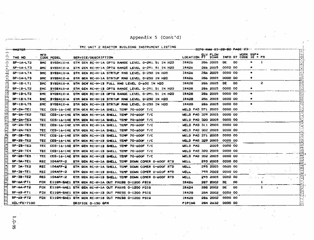
Appendix 5 (Cont'd)
TMI U N I T 2 REACTOR BUILDING INSTRURENT L I S T I N G -- - - " M 1 1 1 1 1 1 - . . 2 3 : I 1 - HFR. ELV FLOW WORK SSP* - - . TAG NO. ' CODE MODEL SERVICE/DESCRIPTION LOCATION F T D I A Q - INFO S T CODE 1E + PR
- ' i w - 1 4 - L T 2 , BMC BYBB4lX-A STM 6EN RC-H-1A OPT6 RANGE LEVEL 0 - 2 9 1 . 3 1 I N H2O I R 4 2 6 286 2 0 0 5 DE 00 9 1 c . - 6 Sf'-IA-LT3 BMC BYBB4lX-A STM 6EN RC-H-1A OPT6 RANGE LEVEL 0 - 2 9 1 . 5 1 I N H 2 0 I R 4 2 6 286 2 0 0 5 0000 00 o --- - - - - - - - . - - - -- -- - - -- -. . 9 SP-1A-LT4 BHC BYBB41X-A STM GEN RC-H-14 STRTUP RN6 LEVEL 0-250 I N H 2 0 I R 4 2 6 286 2003 0000 00 * 2 Sf'-1A-LTS B K BYBB4lX-A STM OEN RC-H-1A STRTUP RNQ LEVEL 0-250 I N H2O I R 4 2 6 286 2009 0000 00
: t i
b-4 9 SB-1B-LT1 BMC BY8241X-A STM GW RC-H-18 FULL RN6 LEVEL 0-600 I N HZ0 I R 4 2 8 286 2005 DE 00 2
12 I.?!
,d SP-18-LT2 BHC BYBB41X-A STH CEN RC-H-IB OPTC RANGE LEVEL 0-291. 5 1 I N H 2 0 I R 4 2 8 286 2 0 0 5 0000 00 9
: I 3 -4 SP-1B-LT3 BHC BYBB41X-A STM OW RC-H-16 OPT0 RANQE.LEVEL 0 - 2 9 1 . 5 1 I N H2O I R 4 2 B 286 2005 0000 00 . ..
B - l B 4 T I B K BYBB4lX-A STH E N RC-H-lB STRTUP RNQ LEVEL 0-250 I N H z 0 I R 4 2 8 286 2005 0000 00 191
SP-18-LTS BHC BY8B41X-A ST t l E N RC-H-16 'STRTW RNQ LEVEL 0 - 2 5 0 I N H 2 0 . 7
I R 4 2 6 286 2005 0000 00
11 9 .- :,n
-- SP-24-TE5 TEC CES-16-14E STM E N RC-H-1A S-LL TEMP 70-600F T I C WELD PAD 302 2005 0000 00
6?-19-TEl TFC CES-14-14E S T l l O M RC-H-1B SHELL T E t P 70-6OOF T I C 26
WELD PAD 371 2005 0000 00
WELD PAD 371 2 0 0 5 0000 00 ? 1
SP-24-TEl TEC CES-16-14E STM E N RC-H-1A SHELL TEMP 70-600F T/C :a
W-2A-TE2 TEC CES-16-14E STM OEN RC-H-LA WELL TEHP 70-600F T/C WELD PAD 329 2 0 0 5 0000 00 z5i
WKLD PAD 319 2005 0000 00 7 SP-28-TE2 TEC CES-16-14E STM OEN RC-H-16 SHELL T W 7'0-600F I / C 3~ - WELD PAD 2 0 0 3 0000 00 .< I 3 SP-2B-TE3 TEC CES-16-14E STH CEN RC-H-18 !WELL T E W 70-60OF T I C -
29 2
., ,: t , ! 8 1
'JO!
122 ', 2 -
WELD PAD 320 2005 0000 00 ;I-28-TE3 TEC CES-16-14E STM QEN RC-H-1A SHELL TEM? 70-6OCF T I C
WELD PAD 311 2005 , 0000 00 SB-2A-TE4 TEC CES-16-14E STM CEN RC-H-IA WELL TEMP 70-600F T I C
8P-3A-TEl REC 104AFP-2 STH QEN RC-H-I+ 8HELL T W DOWN C O E R 0-600F RTD WELL 295 2003 0080 00
BP 3A-TE1 REG 104AFP-2 STM QEN RC-H-1A SHELL TEMP. DOUN COMER 0-6OOF RTD WELL ,295 2005 0000 00' 2'
3 1 - 32
-., 6'-36-TEl REC 104AFP-2 STM CEN RC-H-18 SHELL TEMP'DOWN COMER 0-6OOF RTD WELL 795 2 0 0 3 0000 00
0- -. -- 299 2005 0000 00 SP-3B-TE2 REC 104AFP-2 STH QEN RG-H-16 TEMP DOUN C O E R O-6OOF RTD - . HELL . . . .
31
SP-2B-TE4 TEC CES-16-14E STM QEN RC-H-i~ SHELL TEMP 70-600F T I C WELD PAD 320 2005 0000 00 -- ,
8P-ZB-TE3 ' ' TEC CES-16-14E. STH QEN RC-H-18 gf l l TEMP 70-60OF T I C WELD PAD 302 2005 0000 0 0 . . - 4 2 . ..
- - SP-6A-fT1 FOX E l 1 W - = E l STM QEN RC-+LA OUT PRESS 0-1200 PBIO 1~426 3e7 2002 DE 1
I R 4 2 4 288 2002 DE 00 1 2 SP-64-PT7 FOX E l 1QM-B4E1 ST t l -QEN RC-H-IA OUT PRESS 0-1200 P S I 0
SP-6B-PT1 . FOX El lQM-SAE1 STH QEN RC-H-IB WIT PRESS 0-1200 P S I 6 I R 4 2 8 284 2002 0000 00 - 9'' 6P-68-PT2 FOX E l 1QM-8AE1 BTM QEN RC-H-18 OUT PRESS 0-1200 P S I 0 I R 4 2 8 286 2002 0000 00 b,s i
,. . k;i WDL-FE-7100 O R I F I C E 0-190 CPM P I P I N @ 284 2632 0000 00 I.:<:

. - -- .- - - . - - - .. - . - - . . . . ~ppendix . . . 5 . . . . . . - (Cont'd) . . . . . . f
7HI UNIT 2 REACTOR BUILDINQ INSTRUMENT LISTING
1 - 2
4 5
I 8
'O I I
2 14
'6 17
'3 ' U
US
37 - -
_ r . . . o - e . 1 4 - - .
ELV FLOW WORK SSP* nFR. TAQ NO. CODE WDEL SERVICEIDESCRIPTI~ LOCATION FT DIAC INFO ST CODE 1E + PR -.. --- -. WDL-FE-7107 RC-P-IA SEAL LEAK FLO TO RC DR TK WDL-U24A 2632 0000 0 0
,
WDL-FE-7 1 OR RC-P-18 SEAL LEA^ FLU TO RC DR' TK WDL-U24B 2632 0000 0 0 - -.--- -- -----....---.-----.----.-A-
RC-P-2A SEAL LEAK FLO TO RC DR TK WDL-U2SA 2 6 3 5 - O ~ O O 00 WDL-FE-7 109 .. - . ..
WDL-FE-7 1 10 RC-P-2B SEAL LEAK FLO TO RC DR TK WDL-U25B 2632 0000 0 0 . .
WDL-FT-7100 FOX E13DH-SAM2 RC LEAH COOLERS OUT FLO TO RC DRN 0-100 I N H20 MTC R9 284 2632 0000 00 - -- . . 3 WDL-LO-1205 JERQ DRAIN TANK LEVEL CLASS O W E 0-96 I N H20 27s-40W 282 2632 A 00 -
- .---- WDL-LS-1206 W 731 ' HIOH LEVEL WITCH 275-40W 291 2632 DA 0 0 3 --
LOU LEVEL SWITCH 27s-40W 291 2632 D 0 0 3 WDL-LB-1208 ))AO 751
WDL-LS-1315 A133FYXWD TOP HTD DISPLCR 0-56 I N kt20 SUHP 283 2045 0000 00 - -. . .. - . -- WDL-LT-1207 FOX E13DH-SM2 RC DRAIN TANK LEVEL 0-96 I N H20 275-43W 284 2632 0000 0 0 - -- WDL-LT-1316 DREX 508-15-6 RB SUnP LEVEL 0-84 I N H2O S U ~ P 282 2043 DEA 0 0 2
WDL-PB-It61 13N-AA4CaO PREBOURC DWITCH , Z - B PSlU 289 Z W I UA 00 3 - . . . 3 . .
290 2027 0000 0 0 WDL-TE-1209 REC 104WC23BX DRAIN HEADER P7 0-220F DUAL RTD i.
P~PINQ 2632 oooo oo WDL-TE-7 102 REC RC LEAK COOLER OUT HDR TEW 0-230F DUAL RTD - JLI
&
- Y D L - E - ~ % ~ ~ ' TEC 2 ~ 1 0 1 ~ RC LEU T w .DN STREW RC-P-a* QBYT DRN 0-7WF TIC PIPINO 2632 0000 00 -
W D L - T E - ~ ~ ~ ~ TEC 2E21214 RC LEAK TE,W DN STREAM 'RC-P-2B OSUT DRN 0-700F TIC PIPINQ 2632 0000 00
PIPINC 2632 0000 00 UDL-TE-7114 TEC 2E2121A RC LEAK TEMP DN STREAH WW-TE7113 0-700F TIC - '
E 23
E 26
2 29
?! 32
UbL-PS1203-1 SUR 9N-AA3 DRN TANK PRESSURE SWITCH 100-1000 PSIC IR 433 288 2632 DA 0 0 . . IR 433 286 2632 D 0 0 ' 3 WDL-PS1203-2 SOR LN-13-c DRN TANK PRESSURE SWITCH 4-100 PSI0 -
3 . WDL-PSl203-3 SOR 4N-AA2 DRN TANK PRESSURE SWITCH 1-8 PSI0 IR 433 286 2632 D 00 - - :- --
3 2 6 - 3 6 W 286 2632 DE 00 1 WDL-PT-1202 FOX E110tI-SAD2 DRAIN TANK BELLOWS 0-750 PSIO -. :L
WDL-PT-1211 FOX EllOH-SAA2 DRAIN PURGE DISCHG BELLOWS 0-50 PSI6 2B6 2027 0000 00 -- L
WDL-PT-3143 FOX EllOH-SAC2 DRAIN PURQE DISCHQ BELLOWS 0-160 PSI6 286 2027 0000 0 0 -. . . --- --- - WDL-PT-7105 FOX EllWl-SAC2 RC LEAK XFR PUMP WDLP9A DISCHQ PR 0-150 PSI0 UTQ RB 283 2632 0000 00 .is v- .--
283 2632 0000 00 . .
WDL-PT-7106 FOX E11W-SAC2 RC LEAK XFR P W UDLP9B DISCHO PR 0-150 PSIC -. .-
- - - - - - - - - -
WDL-TE-7116 TEC 2E2121A RC LEAU TEHP DN STREAM WDL-TE7115 0-700F TIC PIPINQ 2632 0000 00 --
4 1
DL-TE-1200 REC 104W468XX DRAIN TANK T-3 0-250F DU4L RTD 289 2632 0000 00 +t l i -
- . . 2632 '0000 0 0 WDL-TE-7115 TEC 2E2121A RC LEAK TEHP DN STREAH RC-P-18 QSKT DRN 0-700F TIC PIPINQ -

Appendix.' 5 (Cont ' d) .
THI UNIT 2 REACTOR BUILD~NC INSTRUMENT LISTING F" Iron-..* LI.
1 :I - 2
, '
MFR: . - E L V FLOW WORK SSP* T ~ Q NO. CODE MODEL SERVICE/DESCRIPTION LOCATION F T D I A G I N F O S T CODE 1 E + PR
'4 5 WDL-TX-2004 nERC R. .c. LEAKAGE RECOVERY WDL-C- I A INLET 508-26W 2060 ___$ 0000 90
7 I
9 'O I I
'3 14 - 15
5 17 - 18
'0 20
'
2 23
MBL-TX-2005' HERC R.C. LEAKAGE RECOVERY WDC-C-1A OUTLET 50s-26W -- 2060 0000 00 . .- . . . - -- .- . . - - - - - -- - :I I
,, c
WDL-TX-2006 MERC R.C. LEAKAGE RECOVERY WDL-C-1B I N L E T 30s-26W 2060 0000 00 . - . WDL-TX-2007 MERC R.C., LEAKAQE RECOVERY WDL-C-18 OUTLET 50s-26W 2060 0000 00
YM-AMP-7022 DE 00 1 V I B R A T M N ELEMENT 'PREAMP
YM-AMP-7023 V I B R A T I O N ELEMENT PREAMP ' DEA 00 ' 1 - - -- YM-AMP-7024 DE 00 2 V I B R A T I O N ELEMENT PREAMP
YH-AMP-7023 ' V I B R A T I O N ELEMENT PREAMP DE W 2
YM-AMP-7026 V I B R A T I O N ELEMENT PREAMP DE 00 1
DEA 00 1 YM-AMP-7027 V I B R A T I O N ELEMENT PREAMP
YH-AMP-7028 DE 00 2 . V I B R A T I O N ELEMENT PREAMP
DE 00 2 . YH-AMP-7029 - V I B R A T I O N ELEMENT PREAMP
YH-VE-7018 80R D 00 ' 3 VIBRATION-.ELEMENT LOWER VESSEL I N CORE TUBES CH. 1 ON-OW 288
YM-vE-7019 SOR V I B R A T I O N ELEMENT LOWER VESSEL I N CORE TUBES C H . 2 ON-OW 288 D - 00 3
E% L.
I :' I' i -2 l -- 4 121 7:; 1 7 1
-17 -..I ;.;.! - , . I - - 2 I ,
f .11 ?5 . .. ?,%, - . . ? ? I
I b i :'" JO ..-..
"I JL.! 3 3 .. .. .* &I 36
>L a 2. JO 4 1 - J?
4 2 JJ
5 26
28 29
2'. 32
YH-VE-7020 S3i -
V I B R A T I O N ELEMFNT UPPER VESSEL SHROUD ON-OW 325 D 00 3'
YM-VE-7021 SOR V I B R A T I O N ELEMENT UPPER VESSEL SHROUD . 6N-OW 329 D 00 3 - YH-VE-7022 RM V I B R A T I O N ELEMENT STM OEN A UPPER TUBE SHEET ON-OW 3 4 6 DE 00 1 .
YM-VE-7023 RM V I B R A T I O N ELEMENT STM GEN B UPPER TUBE SHEET ON-OW 3 4 6 DEA 00 1 - YH-VE-7024 , RH ' . , . .. ' ' V IBRAT ION ELEMENT STM 6 E N A UPPER TUBE SHEET ON-OW 346 E 00 2
.. . -
'YH-VE-7023 R H - , ' V I B R A T I O N ELEHENT STM CEN B UPPER TUBE SHEET ON-OW 3 4 6 E 00 2 L_
2 : . YH-VE-7026 . WR ' . . VIBRATION ELEMENT STM CEN A LOWER TUBE SHEET ON-OW 288 . .DE 00 1 35
Y H - V E - ~ O ~ ~ .SOR. .. ' . V I B R A T I O N ELEMENT STM GEN B LOWER TUDE SHEET ON-OW 2 8 8 DEA 00 4.7;
31 38
JT
..- YM-VE-7029 ' W R .. '. s. .V~BRATION-.ELEMENT STM QEN A LOWER TUBE SHEET ON-OW 288
VR-VE-7029 BOR V I B R A T I O N ELEMENT STM 0 E N B LOWER TUBE SHEET ON-OW 2- .. '4 ; 00 i
2 4 1
.)J -
E 00 !, I !
YH-VR-3961 HERC PEAK REC. ACCELERATOMETER 16N-0 2060 A 00 3 >,: -. 541 .-
A 00 >!#I
YN-VR-39U . MERC PEAK REC. ACCELERATOMETER 206 1 , ::,,! - . .-
18s-1w , . . . -;I
. L . . END END END. I...:;

--- . . . - . Appendix 5 (Cont'd)
T M I U N I T 2 REACTOR B U I L D I N G PENETRATION L I S T I N G -- T r w - - + - - - b . -- -
,T E L V FLOW WORK SSP* 2 . MFR.
TAG NO. CODE MODEL SERVICE/DESCRIPTION LOCATION FT DIAG INFO ST CODE IE + PR '1
5
1. 8
'O 11
'a I I
'6 17
'9 20
22 23
2 26
28 29
32
Z % 35
11. 38
40 41
2 44
'A. R-400 PRESSUR I ZER HEATERS POWER O U T L I N R 2 9 1 2 0 I D 00 1 L . . - - . ~ H ~ S S U R I ZER ' HEATERS POWER . 1 R-402 -- - . . - - - - - . . - - - OUT L I N R 291 21 I D 00 -- --.-.-. ---
R-403 I N CORE HONITORINO INSTH. OUT L I N R 3 5 9 10 0000 00 -. --
W T L I N R 2 9 1 2 3 D 00 1 t : R-403 BOP CONTROL -.
OUT L I N R 291 1 6 A D 00. 1 ; !
R -406 RPS & SFAS 7
PRESSURIZER HEATERS POWER f l l l T I T N R 2 9 t 2 1 I D 00 1 ,2 R-407 . - IC
. - - OUT LINR 299 2 8 A D w a I t :
R -500 CONTROL -. ii..
W T L I N R 299 2 4 A 0000 00 !I..
R -502 L. V. POWER - - 'L.; . - .
OUT L I N R 323 25 D 00 2 - 8
R-504 CONTROL -.- -. - OUT L I N R 319 2 9 A 0000 00
. . . R-505 PDP-3B ELEVATORS - - -
OUT LINR 323 a6 D w a . . R -306 CONTROL I;.
1 . R -507 - . b L I Q U I D W T T n R ! ? OUT L P i w 31v 34 oooo 00 t:.
W T L I N R 319 3OA D 00 1 1::
R-509 R. B. COOLANT F A N S ETC. !:J . OUT L I N R 323 3 2 A 0000 00
. A * R-310 PDP-3A POWER P N L
R -311 R. B. COOLANT FANS ETC. QUT L I N R 319 3 3 A 0000 00 ! ?. - .
OUT L I N R 299 3 1 A D 00 2 R - 3 1 4 L. V. POWER BOP - ' i'
R - 3 1 5 BOP CONTROL W I T L I N R 295 2 7 A A m 2 2
OUT L I N R 293 2 0000 00 R-316 CRD POWER ,.-
R - 5 1 8 CRD POWER OUT L I N R 2 9 5 3 OOOO '&I C'. '2
W I T OF CORE DETECTORS OUT L I N R 348 174 0000 00 . a R - 5 3 4 1 J
OUT L I N R 335 11 0000 00 R-595 I N CORE MONITORINQ INSTH. 9 .. 1 R-596 INCORE MONITORING INSTM. O U T L I N R 3 5 1 1 2 D 00
R-597 I N CORE MONITORINQ INSTH. OUT L I N R 359 13 . 0000 00
OUT L I N R 353 1 4 ' 0000 00 . R -598 ' I N CORE HONITORINO INSTM.
R-999 I N CORE MONITORING INSTM. OUT L I N R 331 .13 0000 00 - . .
R -601 . CRD INSTR . . OUT L I N R 291 7 D 00 . 2 - R-603 CRD INSTR . ',. O U T L I N R 2 9 1 9 A 000000
. . . . R-607 . . . . . . BOP I N B T R . ' .. . . . . . . . OUT. L I N R 2 9 1 . 3 6 " A 00 ' 2 . .. . . . . - . .
-

.- - .... . . . -- Appendix- 5-..:-(.Con t '.d ) . .. .- .. - . . . . . . , . . - (
T M I U N I T 2 REACTOR B U I L D I N G PENETRATION L I S T I N G ---a 1 - 2
P 5
2 8
P 10 - I I - 12
13 - 14 - 15
1 6 - 17 -
I-;- ,.-'. MFR-. WORK SSP* ELV F L O U . - CODE MODEL S E R V I C E / D E S C R I P T I O N L O C A T I O N FT D I M I N F O S T CODE 1 E + PR TAQ NO. F.
R - 6 0 8 RC-P-2B FEEDER O U T L I N R 2 W 3 5 D 00 1 F: R - 6 1 0 R P S & SFAS OUT LINR 292 1 9 ~ . 0000 00 r;
- - - -- - - . . - . . - - -. T t ' R - 6 1 1 . RC-P-26 FEEDER OUT L I N R 2W 35 0000 00 L:'
p!! , W T , L.IW 292 35 D ..w. . , 2 I .
. R-611. . . . . . . .ww?E ., - . . , . . . . : , . . - .. . t END END END I l i
! I 1 . -. k< ! i t >
'I? 1.2 I :' ,- - :, . :I -. > . . . .
,_' .I

-- . -- -- - - -. -- - .. . ..... -. . . . . . . . - . . . - . . . .. .- .Agpendix...5. . ( C m t ' d) . . . - . . , . . . ..
4 T M I U N I T 2 REACTOR BUILDING VALVE L I S T I N G - p . phrrC--. .. I-
&!
2 ELV FLOU WORK SSP* : . MFR. TAG NO. CODE MODEL SERVICE/DESCRIPTION LOCATION F T D I S I N F O S T CODE 1E + PR -- 1. AH-V103 VLCR 1" SOLND RB RADIATION DETECTION P I P I N G 320 2041 0000 00 + !! a -
- 6
-1.
AH-V 1 0 4 VLCR 1/211 SOLND RB RADIATION DETECTION P I P I N G 3 1 9 . 2 0 4 1 0000 00 -. - -. - i - - - --.-
AH-V106 VLCR 1" SOLND RB RADIAT ION DETECTION P I P I N G 3 1 7 2 0 4 1 000000
',
-.
q
.+
= '
. >
W P
9
2 I 1
;;. 1. 14
5 17
2 20
2 23 - 24 25 26 - 27
28 29
9i 32
Y 35
"3' 38
40 4 1
d-l. 44
AH-v 1 08 ' VLCR 1/2" SOLND RB RADIAT ION DETECTION P I P I N G 3 1 7 2041 0000 00 - AH-V2A HNPR 36" B 'FLY RE PURQE A I R ( A I R OPERATED) P I P I N G 3 3 7 2041 S 00 + 1 ~ 1 -
1 - : - AH-V26 HNPR 36" B 'FLY R B PURGE A I R ( A I R OPERATED) P I P I N G 3 4 3 2 0 4 1 SA 00 + 2 I.!
I I -. . -- . . - . - -- - - -- - - AH-V$ HNPR 36" B 'FLY RB PURQE A I R ( A I R OPERATED) P I P I N G 3432041 000000 p.
AH-V3B HNPR 36" B 'FLY RB PURQE A I R ( A I R OPERATED) P I P I N G 337 2 M l 0000 00 1.:. AH-V6 VLCR 1" SOLND RB PURGE A I R P I P I N G 3222041 S4 00 + 3 1:'
AH-V61 VLCR '1/211 SOLND RB PURGE A I R P I P I N G 3 2 4 2 0 4 1 0000 00 -- f
AH-V63 VLCR l /2" SQLND RE PURGE A I R P I P I N C 320 2 0 4 1 0600 00 I .
AH-V71 VLCR 1" W L N D RB VENTILATION DAHPER (3-WAY) P I P I N Q 321 2041 0C)W 00
AH-V74 VLCR 1/2" SOLND RB VENTILATION D M E R (3-WAY) P I P I N G 322 2041 S 00 + 1 1" AH-VBO HNPR 10" B 'FLY RB PRESSURIZATION tMOV) P I P I N G 3 3 4 2 0 4 1 000000 I )
-- ---.- -1; CA-Vl VLAN 1 / Z n OATE PRESSURIZER S T E M SPACE SAMPLER tPlOV) P I P I N G 324 2031 S 00 + 1
! / CA-V3 VLAN 1/20' QATE PREBSURIZER UATER SPACE SAHPLER (BOV) P I P I N G 3262031 000000
j ,
I',
CA-V4A VLAN 1/2" QLOBE STEAM GENERATOR SAtlPLER (MOV) P I P I N G 291 2 4 1 4 0000 00 ! -, C A - V ~ B VLAN 1/2" QLOBE STEAPl QENERATOR SAMPLER tMOV) P I P I N G 2 9 4 2 4 1 4 000000 1;
- . .--- - - CA-V6 VLAN 112" GATE UPSTREW LETDOWN COOLERS SAMPLER (MOV) P I P I N O 3232031 000000 i] 1.; CF-V115 VLAN 1" QLOBE CORE FLOOD TANK SAMPLER (MOV) P I P I N O 2892034 000000
CF-VIA VLAN 1 4 " GATE CORE FLOOD TANK TO REACTOR t H W ) PIPING 308 2034 S 00 + 1 -
CF-V1B VLAN 1 4 " QATE CORE FLOOD TANK TO REACTOR ( ~ o v ) P I P I N G 312 2 0 3 4 0000 00 + i. - -- - - - . . . . . . - ---. -
CF-V2A ' V L A N 1" GATE CORE FLOOD TANK CROSS CONNECTOfl (MOV) P I P I N G 325 2034 0000 00 . .
CF-V2B VLAN .1" GATE CORE FLOOD TANK CROSS C ~ C T O R t MOV) P I P I N Q , 325 2034 0000 00 !!
CF-V3A ' VLAN 1" GLOBE CORE FLOOD TANK VENT (ROV)' P I P I N O 344 2034 0000 00 I.
i . CF-V3B VLAN 1" VQLOBE CORE FLOOD TANK VENT t MOV) P I P I N Q 343 2034 0000 00
-- DC-V114 VLAN 8". DECAY HEAT CLOSED COOLINQ ( W ) . P I P I N G 2 ~ 2 0 3 5 . O o 0 o O O L .
P I P I M O 2q2. 2026 D 00 1 -DH-V1 . VLAN 12" OATE DECAY HEAT REMW.AA (W.) . ' I*

T M I U N I T 2 REACTOR B U I L D I N G VALVE L I S T I N G ---- - ? - 7
MFR. E L V FLOW WORK SSP* CODE MODEL SERVICE/DESCRIPTION LOCATION F T D I A 6 I N F O S T CODE 1 E + PR -
)O 00 DH-V171 VLAN 8" GATE . DH-V1 BYPASS (MOV) P I P I N G 2 9 2 2026 OOC
DH-V2 VLAN 12" BATE DECAY HEAT REMOVAL (MOV) P I P I N 6 289 2026 SA 00 + 2 - --.- - - -- - ---- 2 I C - V I A VLAN 4" QATE LETDOWN COOLER SECONDARY (HOV) P I P I N G 209 2029 0000 00
d IC-vie VLAN 4 " QATE LETDOWN COOLER SECONDARY (MOV, P I P I N G 289 2029 0000 00 ~ --
A IC-~2 VLAN 6" QATE INTERHEDIATE COOLINQ BLOCK (MOV). P I P I N G 31 5 2029 0000 00 11.1 cL'/ 1 1
14
'7 '6 , . . , 2 ~ ~
P I P I N G 289 2024 0000 ,00 $4
MU-VlA VLAN 2" GATE LETDOWN COOLER PRIMARY (MOV) --- --- MU-V1B . VLAN 2" QATE LETDOWN COOLER PRIMARY (MOV) P I P I N G 289 2024 S A 00 + 2
i;l;l
MU-V2B VLAN 2" QATE LETDOWN COOLER PRIMARY (MOV) P I P I N G 209 2 0 2 4 0000 00 I.:;\ - .- P I P I N G 311 2024 0000 00
T:? MU-V33A VLAN 1" QATE RC PUMP SEAL RETURN tHOV) :.:d
20
Zr 22 ,,
' . y 4 RC-V117 . . VLAN .1 /2" &OBE PRESSURIZER SAMPLINQ ( MOV). P I P I N G 3 5 4 2024 0000 00 . . - M
P I P I N G 3 1 5 2024 0000 00 . MU-V25 VLAN 4 * QLOBE RC PUMP SEAL OUTLET (MOV)
!;,!
MU-V33B VLAN 1" QATE RC PUMP SEAL RETURN t HOV) P I P I N G 310 2024 0000 00 h s ! - , . -.
. l , i
MU-V33C VLAN 1" QATE RC PUMP SEAL RETURN (MOV) P I P I N G 309 2024 0000 00 i: . 4 I.!?! -- ;d
29
% 29
'dl
---, '9.1'
MU-V33D VLAN 1" GATE RC PUMP SEAL RETURN tMOV) P I P I N G 309 2024 0000 00
NPliV104 V L M 1" NITROOEN TO RB P I P I N G 337 2036 0000 00 .
NS-V100 VLAN 8" OAT€ RC PUMP COOLANT LETDOWN (PtW) PIPINO a192030 000000
RC-R2. DRES PORV P I P I N G 3592024 I D A 00 1
RC-V1 - . VLAN 2" QLOBE PRESSURIZER SPRAY L I N E (MOV) . P I P I N G 2024 S 00 + . 1 -. 111
MU-V2A VLAN 2" QATE LETDOWN COOLER PRIMARY (MOV) P I P I N Q 289 2024 S 00 + 1 c+) 2 1 1
$ 5 IS
RC-V122 . VLAN 1/2" QLOBE PRESSURIZER SAMPL INQ- (MOV) ' P I P I N Q 318 2024 0000 00' ' 3 3 -. .la
RC-V123 . VLAN 1/2" QLOBE.PRESSUR1ZER SAHPLINQ (MOV) . . . . P I P I N G 301 2024 0000 00 '5 . . 46 *.,
17 .- 18
-. RC-V7 VALVE P I P I N G 3 5 8 2 0 2 4 000000
RC-V137 . V L A N . l m QLOBE PRESSURIZER TO RC D R A I N TANK (MOV) . P I P I N G 3 5 2 2 0 2 4 0000 00 . .
. R C - V M ~ . . VL~AN: 3;' QLOBE .P~ESSURIZER AUX. WRAY -.LINE cnov) . PIPINQ 3% 2 0 2 4 0000 00
2
-
VLAN 8" QATE RE AH COOLINQ C O I L S t MOV)
VLAN 8" OATE RB AH COOLINO- C O I L S (MOV)
. . . RC-V2 VLAN 2" QATE PRESSURIZER TO RC tPlOV) P I P I N G 3 3 6 2 0 2 4 I A 0 0 1 +.. RC-V3 P I P I N G 338 2024 0000 00
!, 3 VLAN 2" QATE SPRAY L I N E , PRIMARY LOOP (MOV)
P I P I N Q 297 2033 0000 00
P I P I N Q 297 2033 0000 00

B SV-V11B VLAN l/l" QLOBE STEAM QENERATOR RC-H-1B W L I N Q (MOV) P I P I N G 297 2 4 1 4 0000 00
' T M I U N I T 2 REACTOR B U I L D I N G VALVE L I S T I N G
!!q SV-V54 2 " HOT D R A I N COOLINQ P I P I N G 289 2 4 1 4 0000 00 - . -. . ,
1 - 2
5 Q 5
1 8
2 11
;; L!,
- - - . - - - - -
M R . E L V FLOW WORK SSP* . . . CODE MODEL . SERVICE /DESCRIPT ION LOCATION FT DIAG INFO ST CODE 1~ + PR TAQ NO.
.. --- P I P I N G 277 2033 0000 UU RR-V26C V L A N 8 " Q A T E RBAHCOOLINGCOILS(HOV) --.- - 7 ,
RR-V26D VLAN 8" GATE RB AH COOLING C O I L S (MOV) . P I P I N G 297 2033 0000 00 - .. . -- - - .- -- --, - . ... ...... --
P I P I N G 297 2033 0000 00 RR-V26E VLAN 8" OATE RB AH COOLING C O I L S ( M V )
RR-V79 8" OATE RR-V26C BYPASS (MOV) P I P I N Q 297 2033 0000 00 - - -- SV-VIOA RAN 1/2" GLOBE STEAM &NERATOR RC-H-1~ SAMPLING (MOV) P I P I N G 293 2 4 1 4 0000 ,00 --
: - - .. SV-VIOB VLAN 1/2" GLOBE STEAM GENERATOR RC-Y-18 SAMPLING (MOV) P I P I N C 297 2 4 1 4 0000 00 -- -- . . - - - - - - ---- -- . . SV-V11A R A N 1/2" QLOBE STEAM GENERATOR RC-H-1A SAHPLING (HOV) P I P I N G 293 2 4 1 4 0000 00 .- .
20 .- . ... 3 2l WDL-V1118 CRNE 4" RC D R A I N HEADER TO D R A I N TANK ( I lOV) P I P I N Q 286 2632 D 00 -- . . - . .
WDL-V126 VLAN 1" OLOBE RC D R A I N TANK VENT ( M W ) P I P I N Q 296 2632 0000 00 -. .
17
2,
. . -- . . . .
WDC-V2 VLAN 4 " QATE RB VENT HEADER BLOCK P I P I N G 333 2028 0000 00 - . . . - . . - - -- -
WDL-~1093 WAN zU RC BLEED HOLDUP TANK TO/FROM DRAIN TANK t n o v ) PIPING ~ ~ 1 5 z Z 2 0 0 0 0 00 - . . -
23
21 18
2 DO
I-'
- . VLAN 1" OLOBE RC D R A I N TANK VENT (MOV) P I P I N G 296 2632 0000 00 WDL-V127
--... -. WDL-V22' VLAN 4" OATE RC D R A I N HEADER 180. P I P I N Q 289 2027 0000 00 . .
: 2 . - WDL-V27 1 VL4N 4" QATE R E S U M DISCHARQE P I P I N G 3182043 S 00 + 1
: L . . WDL-V7 a V & A N 4 " O A T ; F P C . . D P A I b l . P U H P B Y P A S ~ P I R I N D 2 W 2 Q 2 7 0 0 Q 0 0 0 -. . - -- --
JO
31 - 32
. . . . END END END - .
. - . -- - - . .

Appendix 5 (Cont'd) . . .. . .
T M I U N I T 2 REACTOR B U I L D I N G ELECTRICAL EQUIPMENT L I S T I N G F -- L --9AQE.--f - ---- . .
a 9-L
9
CRDB- - S T 1 3 WSC CR D R I V E STATOR R V 3 4 3 2062 0000 00 .
CRDPI- , -ST16 WSC CR D R I V E STATOR R V 343 2062 . 0000 00 . .
2-161-2 LUBE PP 322 2 0 2 4 0000 00 - - - -- . - - - -- -- -. -. 2-1B-1 LUBE P P 322 2024 D 0 0 . 3
LUBE P P 322 2 0 2 4 0000 00 2-1B-2 -.
.
I-'
0 I
' E 1 1
'J 14 - 15
'16 17
19 - 20
AH-E-11A A AF R E - A I R ' C O O L I N 6 FAN-MOTOR ASSEMBLY A 5 1 s - 1 8 E 331 2041 S 00 + 1 . -
AAF RB A I R COOLING FAN-MOTOR ASSEMBLY B 5 1 s - 1 0 E 331 2041 0000 00 . .
AH-E-1 I B . - - . t
1 .! f
AH-E-11C AAF RB A I R C M L I N Q FAN-MOTOR ASSEMBLY C . 3 1 S - l W 3312041 S 00 + .- ! i .: -
318-9W 331 2041 0000 00 1.5
AH-E-1 I D . AAF RB A I R C M L I N Q F A W T O R ASSEBBLY D j' - . AH-E-11E AAF RB A I R COOLINO FAN-MOTOR ASSEMBLY E 51s-18W 331 2041 0000 00 - . . .-. - . .
ON-OW 283 2041 D 00 3 -.
AH-E-32A REAC. VESSEL C A V I T Y SUPPLY A I R F A N A - - -- AH-E-92B REAC. VESSEL C A V I T Y SUPPLY A I R F A N B ON-OW 283 2041 D 00 3 r..
. - . - . - . . . .
BUFO 22s-33E 2227 0000 00 A H - € 4 3 ELEVATOR BACH R B EXH F A N -. - - -. - _ ' 2 23
z iz
26
CRDB- -ST01 DPSC CR DRIVE STATOR RV 3 4 5 2062 DA 00 2 . - . .- 2 ., --
RV 3 4 3 2062 0000 00 . >
C R ~ M - - S T Q ~ DPSC CR D R I V E STATOR ~-
C R M - -ST03 DPSC CR . DRIVE STATOR R V 3 4 5 2062 0000 00 : - -- CRDtl- -ST04 DPBC CR D R I V E STATOR RV 343 2062 W O O 00
' 2 29
30 5 32
,1
-'& 35
'J' 38
59 i s
4 1
-. - - : J <
CRDM- -ST03 MSC CR D R I V E STATOR RV 3 4 5 2062 0000 00 i: - -. .-
CRDH- -ST06 DPSC CR D R I V E STATOR RV 343 2062 0000 00 2 . . - . ! . .
C R M - . -STO~ DPSC ' CR D R I V E STATOR , . RV 343 2062 0000 00 -. .- -. -.
CRDM- - I T O B Dfs , . RV 3 4 3 2062 0000 00 .:.
CR D R I V E STATOR -. . . ' A -
. . -CRDB- -ST- DPSC CR DRIVE. STATOR RV 343 2062 0000 00 : a 1 . - i.
CRDB- -ST10 ,DPSC CR D R I V E STATOR RV- 3 4 5 '2062 0000 '00 .- ---".. .I:
. CRDm-. -STI~. D~SC.. CR D R I V E STATOR .. . . . I ' R V 3 4 3 2062 0000 00 -: . , -.-.
CRDH- - S T 1 2 DeSC CR DRIVE' STATOR R V 343 2062 0000 '00 . . . .
CRDH- -ST13 DPSC R V 34s 2062 0000 00 . . CR D R I V E STATOR - '
. .. - CRDM- -ST14 D f S C CR D R I V E STATOR RV 3 4 3 2062 0000 00

. . ,. - - . --- - -. .- .. -- .. . . - . Appendix 5 (Cont'd) - - . .. - -, . - -. . - . . - . -- - - - , . . - . - -- - . . . . . . . . - . . - . . . . . -- . . -. - - . . . - - . - . - - - . . - . . ... -
T M I U N I T 2 REACTOR B U I L D I N G ELECTRICAL EQUIPMENT L I S T I N G :a - . ~ ~ " - Y W " Z - - ----- . .
I- MFR. E L V FLOW WORK SSP* $ TAG NO. CODE MODEL SERVICE/DESCRIPTIO?4 LOCATION F T D I A G I N F O S T CODE PE + PR ... .
CRDH- -ST17 DPSC CR D R I V E STATOR R V 3 4 5 2E62 0000 00 5 ' - CRDH- -ST18 DPSC CR D R I V E STATOR RV 3 4 5 2062 0000 00
.u: . - - . - -- - . . - - - -- ... - -. . - .. . .- 2 CRDH-* - S T I ~ DPSC CR DRIVE STATOR RV 3 4 5 2062 0000 00 , - . 3 CRDM- -ST20 DPSC CR D R I V E STATOR RV 343 2062 0000 00
.d i J CRDM- -ST21 DPSC CR D R I V E STATOR R V 3 4 5 2062 0000 00
'.,, - . i. ,: CRDH- -ST22 DPSC CR D R I V E STATOR R V 345 2062 0000 00 .---
CR D R I V E STATOR R V 345 2062 0000 00 'g CRDM- -ST23 DPSC L a :
CRDM- -ST24 DPSC CR D R I V E STATOR R V 345 2062 0000 00 31"' 3 CRDM- -ST25 DPSC CR D R I V E STATOR RV 343 2 0 6 2 . 0000 00
CRDH- -ST26 DPSC CR D R I V E STATOR RV 3 4 5 2062 0000 00 . . .-
CR D R I V E SThTOR RV - 345-5062 0000 00
LttUIF -ST= DP8C CR D R I V E STATOR UV 343 2062 0000 00
ORDII- - s i a DPSC - --
CR D R I V E STATOR RV 345 2062 0000 00
CRDH- -ST30 DPSC CR D R I V E STATOR R V 3 4 5 2062 0000 00
CR D R I V E STATOR R V 343 2062 , 0 5 0 0 . ,
"1 EHM- -ST= DPSC CR D R I V E STATOR R V 345 2062 0000 00 'L C R D h - S T 3 3 DPSC CR D R I V E STATOR R V 343 2062 0050 00
CRDM- -ST36 DPSC CR D R I V E STATWZ R V 345 2062 W O O 00
3 -
C - -ST37 DPSC CR D R I V E STATOR R V 345 2062 00& 00
CRDH- -ST34 DPSC CR D R I V E STATOR RV 343 2062 0000 00 --..
C R M - -ST33 D f S C CR DRIVE STAT~R RV 345 2062 D 00 2
3 5 ' ,, CRDH- -ST38 DPSC , CR D R I V E STATOR RV 343 2062 0000 00 ---- wA CRDll- -ST39 DPSC ' . ' CR D R I V E STATOR R V 343 2062 O&O 00
CRDH- -ST42 DPSC CR D R I V E STATOR . . : R V 345 2062 0000 00 - . -
CRDH- -ST43 DPSC CR D R I V E STATOR R V 343 2062 ' 0000 00
38
C R D t l - -ST44 DPSC * , CR D R I V E STATOR . R V 345 2062 0000 'OQ - . . . .. . . . . . ..
C R M - -ST40 DPSC CR D R I V E STATOR R V 345 2062 0000 W
CRDH- -ST41 DPSC CR D R I V E STATOR R V 345 2062 0008 00

. .
Appendix .. 5._. ..( C.0n.t ' d . .. . .. . -. - . . .. . . . . -
I T M I U N I T 2 REACTOR B U I L D I N G ELECTRICAL EQUIPMENT L I S T I N G -. h z w - -3- - - .. . . ,.-- . . MFR. E L V FLOU WORK SSP* - . - * CODE MODEL SERVICE/DESCRIPTION LOCATION F T D I A G I N F O ST CODE 1 E + PR J j
7 -- : .I
CRDH- -ST45 DPSC CR D R I V E STATOR RV 3 4 5 2062 0000 00 1 3 1 114
. , CRDM- -ST48 DPSC CR D R I V E STATOR RV 3 4 5 2062 0000 00 . . I , .- . : -,,
a 2
W CRDM- -ST49 DPSC
CRDH- -ST30 DPSC
I : ! CRDM- - s f 4 6 DPSC CR DRIVE STATOR R v 3 4 5 2062 0000 00
. .. -- --- . - -. .- - .- . - . - -. .- .- . .. -. ... .- - - -- . ?,+ i -,
CRDM- -ST47 DPSC CR D R I V E STATOR RV 3 4 5 2062 0000 00 . L . z4 _I;
CR D R I E STATOR
CR D R I V E STATOR
' I . Ti - : I : ? --. *. '
. . CRDH- -ST63 DPSC . CR D R I V E STATOR . . . RV . 3 4 5 aoba 0000 00 - , : :.';I 1321
10
15 '6 17
la '9 20
CRDH- -ST51 DPSC CR D R I V E STATOR RV 343 2062 0000 00 I I : - -*
2-5 CRDH- -ST32 DPSC CR D R I V E STATOR RV 343 2062 0000 00
CRDM- -ST33 DPSC CR D R I V E STATOR RV 343 2062 0000 00
CRDH- -ST34 'DPSC CR D R I V E STATOR RV 3 4 5 2062 0000 00 ij;! ."..
C R M - -ST95 DPBC CR D R I V E STATOR RV 343 2062 0000 00 )-.-.
CRDH- -ST36 DPSC CR D R I V E STATOR RV 345 2062 0000 00 12
: 2%
';;' 5 1c
. CRDH- -ST37 DPSC CR D R I V E STATOR . RV 3 4 3 2062 0000 00 ' 12.4
-- k 37 - 38
CRDM- - A P I O l DPSC CR ABSOLUTE P O S I T I O N INDICATOR R V 343 NA SA 00 1 . . , . . "!
23
2.a fi 26
CRDH- -ST64 DPSC CR D R I V E STATOR RV . 3 4 5 2062 W O O 00 ;341 % ~ a
. . CRDM- -ST66 DPSC CR D R I V E STqTOR , RV 349 20&2 . 0000 00 ' '
:27i -.
-- -- ,- . -....-.,id CRDH- -sf67 DPSC . CR DRIVE STATOR . . RV 3 4 5 2062 .oooo 00 . .. , - .
. . .
. .- i 2 3 , ! 5 , ; ;
2 ,a,
-
CRDH- -MI02 DPSC CR ABSOLUTE P O S I T I O N INDICATOR R V 3 4 3 NA 0000 00 . a . I C R W - -*I03 WSC CR ABSOLUTE P O S I T I O N INDICATOR R V 343 NA 0000 00 - . I > --
J .I, . .- CRDH- -ST58 DPSC CR D R I V E STATOR RV 3 4 5 2062 0000 00 . I
/ , la
--. ... ' J 2 .
CRDR- -8139 W 8 C CR D R I V E STATOR RV 343 2062 0000 00 ; I; ; j i . .... -
'CRDH- - 8 1 6 3 DPBC CR D R I V E STATOR RV 3 4 3 2062 0000 00
i: CRDH- - e l m DPSC CR D R I V E STATOR R V 343 2062 0000 00 i -4 ., CRDH- -ST69 DPSC
I
R V 345 2062 0000 00 CR D R I V E STATOR - - 21
CRDH- -ST60 DP8C CR D R I V E STATOR H V 343 2062 0000 IM ,A 28 CRDH- -ST61 DPSC CR D R I V E STATOR RV 343 2062 0000 00 29 i"j 2L , ..
CRDM- -ST62 DPSC CR 'DR IVE STATOR RV 3 4 3 2062 0000 00 >.,I -. <A,,,
? i -?'?I

I L D I N G ELECTRICAL EQUIPMENT L I S T I N G -- --. 4 - MFR. E L V FLOW WORK SSP* , ,-. . CODE HODEL SERVICE/DESCRIPTION LOCATION F T D I A G I N F O S T CODE 1 E + PR
: .. - p--
i ;
CRDM- + P I 0 4 DPSC CR ABSOLUTE P O S I T I O N INDICATOR R V 345 NA . 0000 00 I.- , .
CRDH- -MI07 DPSC CR ABSOLUTE P O S I T I O N INDICATOR RV 345 NA 0000 00
CRDM- -MI08 DPSC CR ABSOLUTE P O S I T I O N INDICATOR RV 345 NA 0000 00 L 2
5
I
H CRDM-' -APIOT DPSC c R ABSOLUTE P O S ~ T I ~ N INDICATOR R v 345 NA 0000 00
t CRnM- - M I 0 5 DPSC CR ABSULUIE P O S I T I O N INDICATOR R V - 345 NA 0000 00
-- -- - - - - - - - - - - -. - -- - - - - -. - - . - - -. - - I . -- CR ABSOLUTE P O S I T I O N INDICATOR RV 345 NA 0000 00 CRDM- - 4 P I O 6 DPSC . - -
-- - - CRDM- - 4 P I l O DPSC CR ABSOLUTE P O S I T I O N INDICATOR RV 345 NA 0000 00 ., ,
1:- CRDM- -4 f I l l DPSC CR ABSOLUTE P O S I T I O N INDICATOR R V 345 NA 0000 00 f
'b 17
19 dU
2 23
31 20
28 29
2 32
2 35
3' 38
2 4 1
0-1
-
CRDM- -4f112 DPSC CR ABSOLUTE P O S I T I O N INDICATOR RV 345 NA 0000 00 i:. . i2.
RV 343 NA 0000 00 CRDH- - A P I 1 3 DPSC CR ABSOLUTE P O S I T I O N INDICATOR -- -.- ~ -- ----.
CRDM- -4P114 DPSG CR ABSOLUTE P 0 3 I T I O N INDICATOR RV 345 NA 0000 00 8 :
CUM- - A P ~ ~ S ww OR ABSOLUTE POSIIIUN INDICATOR R V 343 NA 0000 00 I : . ! 2;
CRDH- - A P I 16 DPSC CR ABSOLUTE P O S I T I O N INDICATOR R V 345 NA 0000 00 I' r: . I
CRDM- - 4 P I 1 7 DPSC CR ABSOLUTE P O S I T I O N INDICATOR R V 345 NA 0000 00 o-- - - --
R V 345 N4 0000 00 CRDR- - 4 P I l B WsC CR APSQLUTE P O 3 I T I B N I N D I C A T W r .
CRDtl- -MI19 DPSC CR ABSOLUTE P O S I T I O N INDICATOR R V 345 NA 0000 00 1 - .JC
CRDM- -4P I20 DPSC CR ABSOLUTE P O S I T I O N INDICATOR R V 343 NA 0000 00 -. I I '
RV 345 NA 0000 00 CRDH- - A P I 2 1 DPSC CR ABSOLUTE P O S I T I O N INDICATOR ,. .. - 1 J
CRDM- -4fI22 DPSC CR ABSOLUTE P O S I T I O N INDICATOR R V 345 N4 0000 00 -?T ;I
R V 343 NA 0000 00 CRDH- + P I 2 3 DPSC CR ABSOLUTE P O S I T I O N INDICATOR i' :i
CRDH- - A P I 2 4 DPSC CR ABSOLUTE P O S I T I O N INDICATOR R V 345 N4 0000 00 12
I; CRDM- - 4 P 1 2 5 DPSC CR ABSOLUTE P O S I T I O N INDICATOR R V 343 NA 0000 00 ir' ---- CRDM- - 4 P I 2 6 DPSC CR ABSOLUTE P O S I T I O N INDICATOR R V 343 NA 0000 00
CRDM- - 4 P I 2 7 DPSC , C R ABSOLUTE P O S I T I O N INDICATOR ' . R V 345 NA 0000 00
CRDR- + P I 2 8 DPSC CR ABSOLUTE P O S I T I O N INDICATOR R V 345 N4 0000 00 -- -. CRDtl- - A P I 2 9 DPSC CR ABSOLUTE P O S I T I O N INDICATOR R V 343 M 0000 00 I
CRDM- .-MI30 DPSC CR ABSOLUTE P O S I T I O N INDICATOR R V 343 NA 0000 00 4 .
CRDM- - A P I J I DPSC ' CR ABSOLUTE P O S I T I O N INDICATOR' " . '? " 343 NA 0 0 0 0 . 0 0 , .- . . I.

T M I U N I T 2 REACTOR B U I L D I N G ELECTRICAL-EQUIPMENT L I S T I N G - -- -""" .pcIBE .*. . --.1 x
ELV FLOW WORK SSP* I : MFR . I - LOCATION F T D I A G I N F O S T CODE 1E + PR
I J
CODE MODEL SERVICE/DESCRIPTION - I
k/ C R D W -*I32 DPSC CR ABSOLUTE POSITION INDICATOR R V 3 4 5 NA 0000 00 =.
b R V 3 4 5 NA 0000 00
! ; CRDk- -MI33 DPSC CR ABSOLUTE P O S I T I O N INDICATOR ! 5-
i .; CRDR- - M I 3 4 DPSC CR ABSOLUTE P O S I T I O N INDICATOR RV 3 4 5 NA 0000 00 [!;,'
1
.A
!.? . ..
CRDH- - M I 4 1 D f S C CR ABSOLUTE P O S I T I O N INDICATOR RV 3 4 5 NA 0000 00
- 'O . .
CRDH- -MI37 DPSC CR ABSOLUTE P O S I T I O N INDICATOR R V 3 4 5 NA 0000 00
CRDR- -*I38 DPSC CR .ABSOLUTE P O S I T I O N INDICATOR RV 3 4 5 NA 0000 00 . - '6 I ,
.. -- CRDH- -MI42 DPSC CR ABSOLUTE P O S I T I O N INDICATOR R V 3 4 3 NA 0000 00
20 I - . ,: RV 343NA 000000
- . CRDH- -AP143 DPSC CR ABSOLUTE P O S I T I O N INDICATOR . 'k ,
-RV 3 4 5 NA S 00 1 I : !
CRDR- +I35 DPSC CR ABSOLUTE P O S I T I O N INDXCATOR I :
CRDR- -MI36 DPSC CR ABSOLUTE P O S I T I O N INDICATOR R V 3 4 5 NA 0000 00
CR ABSOLUTE P O S I T I O N I N D I C A
. , . . . . .n
CRDH- +I39 DPSC CR ABSOLUTE P O S I T I O N INDICATOR RV 345 NA 0000 00 20
RV 3 4 5 NA 0000 00 CRDfl- -MI40 DPSC CR ABSOLUTE P O S I T I O N INDICATOR 2 , .
2-2!

-- . - Appendix 5 (Cont'd)
T M I U N I T 2 REACTOR B U I L D I N G ELECTRICAL EQUIPMENT L I S T I N G L. ----
LL! - J - 4
2 MFR.
I
E L V FLOW WORK SSP* CODE.MODEL . SERVICE /DESCRIPT ION L O C A T I O N F T D I A C I N F O S T .CODE 1 E + PR TAQ M. .
,L, 1 5
-L 8
!2 11
3 14
'b 17
2 20
,, ZC 23
2 26
CRDN- - A ? 1 6 l DPSL CR ABSOLUTE P O S I T I O N IND ICATOR R V 3 4 5 NA 0000 00 -- -- -- -- --- -- - M CRDM- -AP162 DPSC CR ABSOLUTE P O S I T I O N INDICATOR R V 3 4 5 NA 0000 00 T' CRDM- -AP163 DPSC CR ABSOLUTE P O S I T I O N IND ICATOR R V 345 NA 0000 00 d !.&I
CRDM- -API6O DPSC CR ABSOLUTE P O S I T I O N INDICATOR R V 3 4 5 NA 0000 00 ) (.
CRDM- -MI64 DPSC CR ABSOLUTE P O S I T I O N IND ICATOR R V 3 4 3 NA QOOO 00
CR M G Q L U T C l"031TTflN IHP ICATOR R V 343 NA UUUU 0 0 CUDPI- -API~S npsc -- --- CRDM- -API66 DPSC CR ABSOLUTE P O S I T I O N INDICATOR R V 343 NA 0000 00
CR ABSOLUTE P O S I T I O N IND ICATOR R V 345 NA 0000 00 CRDM- -AP117 DPSC
CRDM- -MI68 DPSC CR ABSOLUTE P O S I T I O N INDICATOR R V 343 NA 0000 00
CR ABSOLUTE P O S I T I O N IND ICATOR R V 349 NA OOQQ 00 CRDM- - A P I 6 9 DPSC -- - -- EE -EL?~-IA u L I M I N B PANEL LPR-IA 1 7sZm 3142 n nn 1
L I O H T I N O PANEL U R - 1 8 %5-77€ 3141 0000 00 k t -ELPA-1R Y -- P
EE -ELPR-24 W L I G H T I N 0 PANEL LPR-2A 17s-59U 3143 0000 00
L I G H T I N G PANEL LPR-2B 12N-6OE 3 1 4 3 0000 00 E E -ELPR-28 W P
CC -EL?R-3A W L I C H T IN0 PANEL-LPR-3A 12s-63W 3144 0000 00
EE - U P R - 3 8 W L I W T I N O PANEL LPR-3B US+= 3144 0000 00
E E -ELPR-3C W 30 KVA TRANSFORMER LPR-3C 41s-51E 3 1 4 4 0000 00
E E -ELPR-3D W 30 KVA TRANSFORMER LPR-3D 2 0 s - 1 l W 3 1 4 2 0000 00
EE -ELPR-4D W 30 KVA TRANSFORMER LPR-4D 6 0 ) s - 1 1 W 3224 0000 00
E E -€PDP-3A W POUER D I S T R I B U T I O N PANEL PDP-3A . 19S-S9U 3177 D 00 1
E E -EPDP-38 W P W Y R D I S T R I B U T I O N PANEL POP-38 14M-LOE 3177 D 00 2
EE -ERPR-14 W 30 KVA TRANSFORHER RPR-1A l f f -59U 3142 D 00 1
E E -ERPR-3D W 30 KVA TRANSFORMER RPR-3D 4 1 s - 9 1 E 3 1 4 4 D 00 2
41s-51E 3 1 4 4 0000 00 E E -FLPR-3C U L I O H T I N O PANEL LPR-3C - 20s -11W 3142 D 00 2 ' 5 EE -FLPR-3D W L I Q H T I N O PANEL LPR-3D
4 1 E E -FLPR-4D WERC L I Q H T I N O PANEL LPR-4D L O N - 1 1 W 3224 0000 00
/Kl I > - I b
- I I I 8 - 1 1
?u - 21 -- ?* 2-1 '4
? a
,I.
." LLI
-9 10 - 3 1
JL
?1, 1JI
>>l 3" JI
3s
~ J-J
20
JI
.I'
.i 8 4 4
4 5
34 4 7 - 4 t
J'J 50 L I
3 - > J -
'
3142 D 00 1 E E -FRPR-1A W RECEPTACLE PANEL RPR- IA I f f-3BU 4
E E -FRPR-3D W RECEPTACLE PANEL RPR-3D 41s-51E 3144 D 00 2
2 29
3' 32
;; ' 2

. . . Appendix 5 (Cont Id). . . - -. - .- .
TMI. U N I T 2 REACTOR B U I L D I N G ELECTRICAL EQUIPMENT L I S T I N G 1 - 7 - - . . . - - - -. - - . -- . .- - . -- ----I:
. 4 TAO NO. MFR. CODE MODEL SERVICE/DESCRIPTION
E L V FLOW ' WORK SSP* LOCATION FT D I A 6 I N F O S T CODE 1 E + PR
SD-P-13A CRNE TENDOF('ACCESS GALLERY SUMP PUMP A ION-64E 2060 D 00 3
I - $2 RC-P-le REACTOR COOLANT PUHP 2m-I~E 322 2024 oo00 00 I .
. 7 - i a
- -.- --i+; RC-P-2A r REACTOR COOLANT PUMP 4N-26U 322 2024 0000 00 I__: 2! RC-P-;re REACT^ COOLANT PUHP WPTE -2024 IS 00 . a :,. ' : I :
SD-P-13B CRNE TENDON ACCESS GALLERY SUMP P W B ION-64€ 2060 0000 00
3 > WDL-P-9A CRNE LEAWIOE TRANSFER PUMP 38s-39U 286 2060 A 00 27 .7d
22 WDL-P-98 CRNE L E M E TRANSFER PUMP SBS-32U 286 2060 WXX) 00 ?y 23
L? I4
;;
. . k '9 20
ZA -PNL-332A BLW FUEL TRANSFER I N REACTOR B U I L D I N G 63N-9€ 2062 0000 00
WDL-P-2B CRNE REACTOR BUILDING SUMP P U ~ P B 2BN-SE 283 2060 0000 00 23 $4
WDL-P-7 CRNE REACTOR COOLANT D R A I N PUMP 44N-2lE 283 2060 0000 00 2 !I I-?
-- SV-P-1 CRNE S T E M QEN SECONDARY S I D E D R A I N PUMP 44N-28E 284 2060 A 00 3
SV-P-2 CRNE S E A M OEN WET LAY* PUMP 284 000000
L' 1 r -- I ? - 10
U D L 4 - 2 A CRNE REACTOR BUILDINO SUMP PUMP A 28N-SE 283 2060 D 00 2 17
- 1 3 - - - -


SAND80-0699 Unlimited Release
March 1980
Recommended Data Acquisi t ion Tasks a t TMI-2
Relating to
F iss ion Product Transport and Deposition and
Environments c h a r a c t e r i z a t i o n
Prepared by:
The TMI Examination Task 2 . 1 Planning Group
Fina l Report
P. Yarr ington (SNL) - Coord,inatoc D. Dahlgren (SNL) - . Person ' i n ' Charge
LWR Safety R&D Division - 4 4 4 3 Sandia National Laborator ies , Albuquerque, N.M. 87185
Prepared f o r :
Technical Working Group TMI Information and Examination Program
(Program sponsored j o i n t l y by DOE, EPRI, NRC, GPU)
. ' . . .
Funded i n p a r t ,by:.
~ u c i e a r Power Development ~ i v i s i o n u'. S. Department of Energy. '.

ABSTRACT
This' report presents a list of 'data acquisition tasks which are recommended for.iinplementation during recovery of the TMI-2 nuclear power plant. The focus of this effort was the environment in containment during and after the accident. The data which would be collected under the recommended tasks were determined to be of significant value for improving current understanding of fission product dispersal processes during nuclear plant accidents. In dev'eloping these recommendations, several specific technical areas were considered which would benefit from such data. These technical areas are described in the report and data reqairements in each area are identified and prioritized. A general discussion is presented of the sampling methods and analytical techniques which will be needed to implement the recommended tasks and obtain the'desired data.

Planninq Group Members/Participants
T h i s r e p o r t was assembled and ed i t ed by F. Yarrlngton ( S N L ) . A l l those l i s t e d below a s planning grcup members cont r ibuted t e x t and/or suggest ions fo r the present r epor t . D . Dahlgren (SNL) had lead r e s p o n s i b i l i t y for the planning group e f f o r t .
(Organizat ions l i s t e d a l p h a b e t i c a l l y , a s t e r i s k den0 t e s TWG-designa ted planning group member )
D
B a t t e l l e Columbus Laboratory
Richard S. Denning* James A. Gieseke*
B a t t e l l e Northwest Laborator ies
Leo G . Faust* .. .
Lyle D. Perrigo* . . . ,
DOE/NPD . .
Andrew C. M i l l u n z i
DOE/TMI Technical In teg ra t ion Off ice
Harold Bur ton . . Greg Eidam . .
EGbG - Idaho
John W. Mandler*
Allan D. Mil ler*
Exxon Nuclear
Carl Crouthammel*
GPU/Bech t e l
B i l l Hopkins*
W. I?. Pasedag* Ar l in Postma ( N R R Consul tant)

NRC/RES ------
'R'ichard R. Sherry*
oak' Ridqe National Laboratory
A. P. Malinauskas* I
Sandia Laborator ies
. Allan S. Benjamin* Dirk A. Dahlgren (Lead)* Peter 0. Strom Paul Yarr ington (Ccordinator ) *
Science Applicat ions Inc.
Robert L. Ritzman*

CONTENTS
Planning Group Membership L i s t ................................. 2.1-3
.................................................... I . I n t r o d u c t i o n 2.1.6
11: Recomnended Tasks .............................................. 2.1.10 . .
111 . Task In fo rma t i on ............................................... 2.1.16
................................... I V . Discussion o f Technical Areas 2.1-40 . .
..................................... 1V.A L i cens ing Assumptions 2.1-41
.............................. . I V B Assessment o f Safe ty Systems 2.1.46
1V.C Model Tes t ing and Development ............................ 2.1-54
1V.D Equipment Environments .................................... 2.1-58
1V.E Accident Diagnosis ........................................ 2.1-63
............................................ 1V.F Decontamination 2.1.76
............................................. I V . G Mass Bal ance 2.1.79
1V.H Hea l th Physics ......................................... 2.1-83
IV.1 Fuel Examination f o r F i s s i o n Product Release ......,....... 2.1-86
....................................... V . Discussion o f Procedures 2.1'90
V I . . Recomnendations f o r Future Technical Support .................... 2.1.99
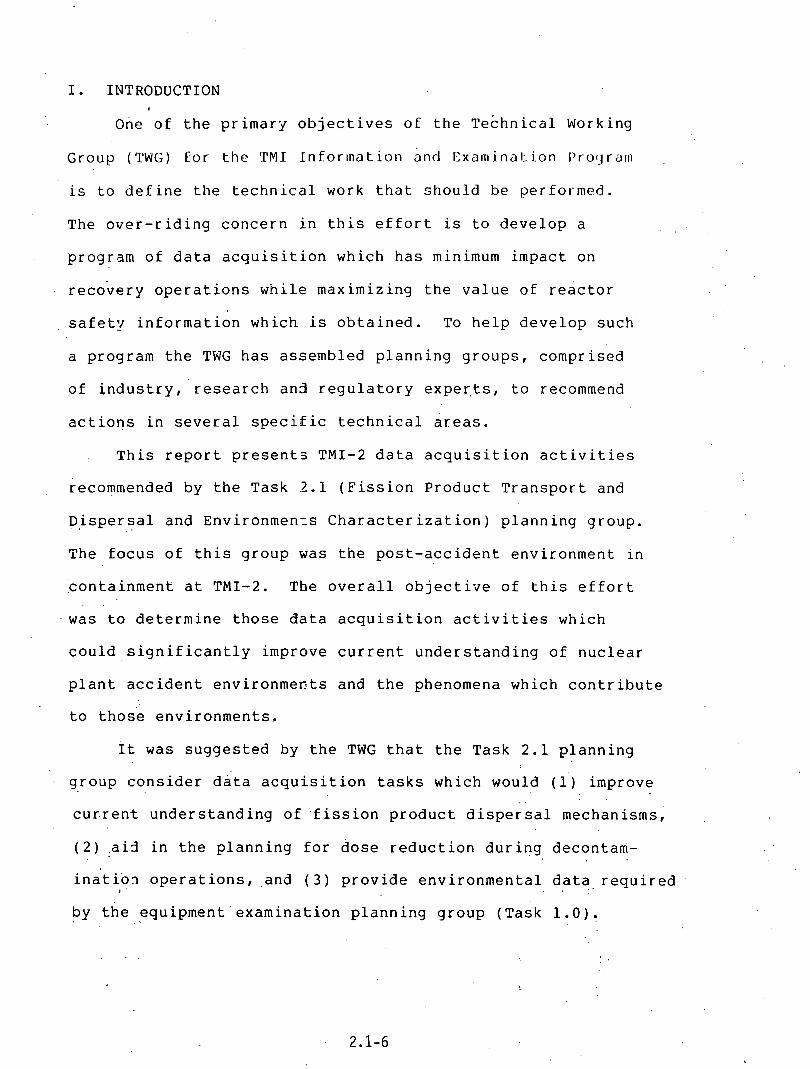
I . INTRODUCTION
o n e o f t h e p r i m a r y o b j e c t i v e s o f t h e ~ e c h n i c a l Working
G r o u p ( T W G ) f o r t h e TMI I n f o r l n a t i o n and lSxani ina t ion I'rocjram
is t o d e f i n e t h e t e c h n i c a l work t h a t s h o u l d b e p e r f o r m e d .
The o v e r - r i d i n g c o n c e r n i n t h i s e f f o r t is t o d e v e l o p a
p r o g r a m o f d a t a a c q u i s i t i o n w h i c h h a s minimum i m p a c t on
r e c o v e r y o p e r a t i o n s w h i l e m a x i m i z i n g t h e v a l u e o f r e a c t o r
s a f e t y i n f o r m a t i o n w h i c h is o b t a i n e d . To h e l p d e v e l o p s u c h
a p r o g r a m t h e TWG h a s a s s e m b l e d p l a n n i n g g r o u p s , c o m p r i s e d
o f i n d u s t r y , r e s e a r c h a n 3 r e g u l a t o r y e x p e r , t s , t o recommend
a c t i o n s i n s e v e r a l s p e c i f i c t e c h n i c a l a r e a s .
T h i s r e p o r t p r e s e n t s TMI-2 d a t a a c q u i s i t i o n a c t i v i t i e s
recommended b y t h e T a s k 2 . 1 ( F i s s i o n P r o d u c t T r a n s p o r t and
D i s p e r s a l . . a n d E n v i r o n m e n : ~ C h a r a c t e r i z a t i o n ) p l a n n i n g g r o u p .
The f o c u s o f t h i s g r o u p was t h e p o s t - a c c i d e n t e n v i r o n m e n t i n
: c o n t a i n m e n t a t TMI-2. The o v e r a l l o b j e c t i v e o f t h i s e f f o r t
was t o d e t e r m i n e t h o s e d a t a a c q u i s i t i o n a c t i v i t i e s which
c o u l d s i g n i f i c a n t l y i m p r o v e c u r r e n t u n d e r s t a n d i n g o f n u c l e a r
p l a n t a c c i d e n t e n v i r o n m e n t s and t h e phenomena w h i c h c o n t r i b u t e
t o t h o s e e n v i r o n m e n t s .
I t was s u g g e s t e d b y t h e TWG t h a t t h e T a s k 2 . 1 p l a n n i n g
g r o u p c o n s i d e r d a t a a c q u i s i t i o n t a s k s w h i c h would (1) i m p r o v e . .
c u r r e n t u n d e r s t a n d i n g o f ' f i s s i o n p r o d u c t d i s p e r s a l mechanisms, '
( 2 ) . a i d i n t h e p l a n n i n g f o r d o s e r e d u c t i o n d u r i n g d e c o n t a m -
i n a t i o n o p e r a t i o n s , a n d ( 3 ) p r o v i d e e n v i r o n m e n t a l d a t a . r e q u i r e d I . .
b y t h e e q u i p m e n t ' e x a m i n a t i o n p l a n n i n g g r o u p ( T a s k 1 . 0 ) .
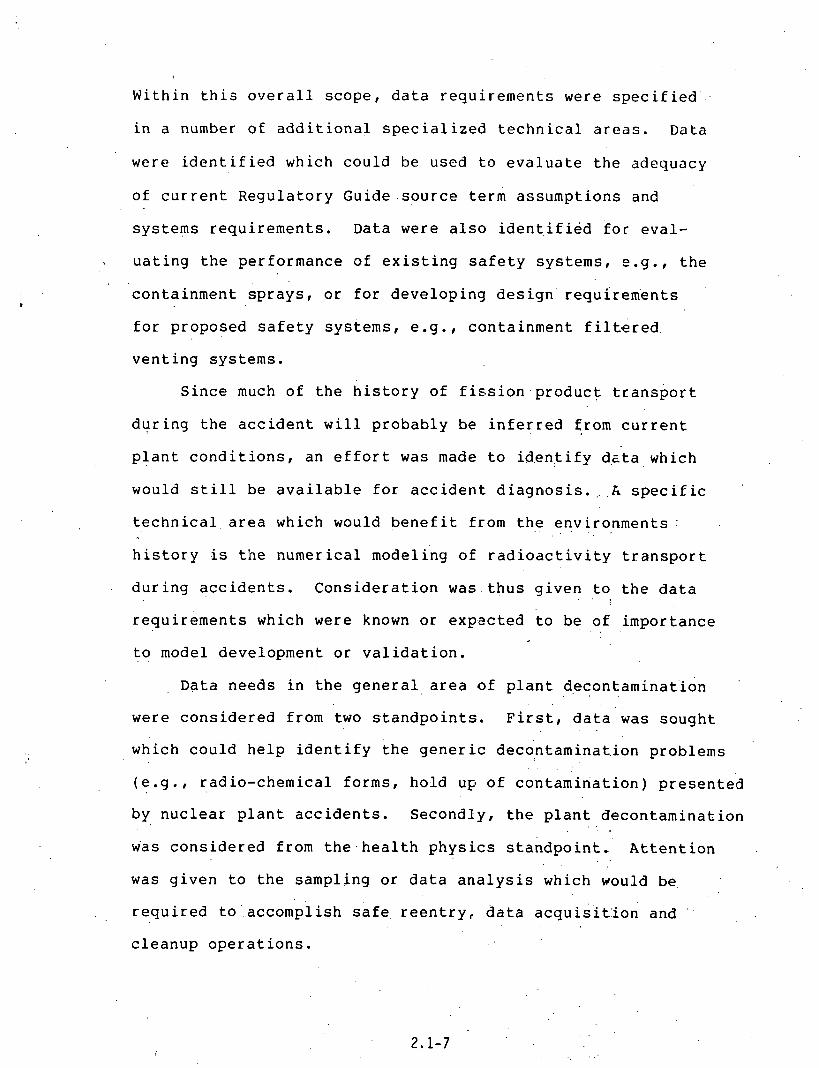
W i t h i n t h i s o v e r a l l scope, da ta requirements were spec i f i ed
i n a number of add i t iona l spec ia l ized technica l a r e a s . Data
were i d e n t i f i e d which could be used t o evalua te the adequacy
of cu r ren t Regulatory Guide source term assumptions and
systems requirements. Data were a l s o i d e n t i f i e d for eval-
, uating the performance of e x i s t i n g s a f e t y systems, e.g. , the
containment sprays , or for developing des ign ' requi rements
fo r proposed s a f e t y systems, e .g . , containment f i l t , e r e d
venting systems.
Since much of the h i s t o r y of f i s s i o n . p r o d u c t t r anspor t
during the accident w i l l probably be in fe r red from cur ren t
p lan t condi t ions , an e f f o r t was made t o id.en.tify de ta which
would s t i l l be a v a i l a b l e for accident d iagnos is . .. . A s p e c i f i c
t echn ica l a rea which would b e n e f i t from the environments ; . .
h i s t o r y is the numerical modeling of r a d i o a c t i v i t y t r anspor t
during acc idents . Consideration was t h u s given t o . t h e da ta . . ,
requirements which were known or expscted t o be of importance , .
t o . . model development or va l ida t ion .
~ a t a needs i n the general a rea of p lan t d,econtaminat'ion . .
. .
were considered from two s tandpoints . F i r s t , d a t a was sought . .
which could help i d e n t i f y the gener ic decontaminat-ion problems
( e . g . , radio-chemical forms, hold u~ of contamination) presented
by nuclear p lan t acc idents . Secondly, the p lan t decontamination , "
w.as considered from t h e . hea l th physics s tandpoint . Attent ion . . . .
was given t o the sampling or da ta a n a l y s i s which would be,
required- to 'accomplish safe . r een t ry , da ta acquisi t : ion and
cleanup opera t ions .

Z'inally, cons idera t ion was given t o t h e , d a t a require-
ments for performing a mass balance on s i g n i f i c a n t radiolog-
i c a l l y tox ic spec ies . Completing a mass balance ensures t h a t
a l l important s i n k s and a t t enua t ion mechanisms have been iden t i -
f i ed f o r those spec ies and t h u s t h a t t r a n s p o r t and depos i t ion
s t u d i e s a r e accura te and complete. An important p a r t of
completing mass ba lances .wi l1 be the determinat ion of f r a c t i o n a l
r e l ease and re ten t ion of spec ies i n the f u e l . T h u s a t t e n t i o n
was a l s o given t o the da ta which m u s t be obtained from the
f u e l t o t a c h i e v e the ob jec t ives of the present task,. . Recommend-
a t i o n s for f u e l analyses w i l l be t ransmi t ted t o . t h e f u e l examin-
a t i o n planning group (Task 7 . 4 )
The t a sks which a r e recommended by the group a re l i s t e d
i n Seczion 11. s p e c i f i c task information follows . . i n Section
111. The task information includes a summary of the ob jec t ives
and t echn ica l j u s t i f i c a t i o n fo r each task . These summaries,
i n t u r n , r e f e r t o l a t e r s e c t i o n s of the r epor t where more
t echn ica l d e t a i l can be found regarding the purpose and 8 . . .
usefulness of any given t a sk . The d a t a a c q u i s i t i o n procedures
and sampling s t r a t e g y t o be used fo r each task ar;e a l s o included
a s task information i n Sect ion 111.
Sect ion I V p resen t s d e t a i l e d d iscuss ions of the var ious
t echn ica l a reas which were considered i n making the Task I . s
recommendations. The mate r i a l addresses d a t a requirements,
suggestsd sampling and a n a l y s i s procedures, and a p r i o r i t y
assessment fo r the requested da ta i n each t echn ica l a rea . . . . .

A general d iscuss ion of sampling and ana1ysi.s methods
which w i l l be required i n executing the recommended da ta
a c q u i s i t i o n program is presented i n Sect ion V:. Deta i l s of
the procedures a r e not spec i f i ed s i n c s ' m o s t : w i l l - b e s p e c i f i c
for each task and many w i l l be q u i t e invol'ved.
The need for continued t echn ica l guidance during the . .
I implementation phase of t h i s program is discussed i n s ec t ion
..VI. B r i e f l y , the procedures necessary t o optimize the use
of a v a i l a b l e time and maximize the q u a l i t y of inEorrnation
obtained can be expected t o depend on what is ,le.3rned a s the ' : .
program proceeds. T h u s , t echnica l guidance w i l l be needed
t o i n t e r p r e t these ' new da ta i n terms of remaining work t o
be done. I t is recommended t h a t the present group be preserved, . .
i n some form, t o perform t h i s t echnica l guidance funct ion.

11. RECOMMENDED TASKS
The da ta a c q u i s i t i o n t a s k s recommended by the Task
2 . 1 planning group a re presented below. Table 11.1 give,s
a s i r .p le p r i o r i t y ranking of the recommended t a s k s , where
highest p r i o r i t y = 1. The t a sks which were assigned
h i g h e s t p r i o r i t y were considered t o be very important t o ,
providing da ta needs ia a t l e a s t one of the technica l a reas
s tudied by the group (See Sect ion I V ) . I n order t o provide
fur th ,s r guidance for implementing the t a s k s , t h i s highest
p r i o r i t y . group was subdivided t o ind ica te the r e l a t i v e
importance of the t a sks from an o v e r a l l program standpoint . :
The p r i p r i t y ranking used was a s follows: 1 - H = . h i g h e s t ,
1-M..= . < in termedia te , I-L = lowest. Those t a sks of rank. 1 - H
a r e expected t o provide maximum techn ica l b e n e f i t from the I .
acquired da ta . I t should be emphasized, however, t h a t tasks
of rank 1 - M or 1 - L provide very important information i n
some t echn ica l a r e a , and a r e t h u s highly recommended from
a t echn ica l s tandpoint . T h u s the present p r i o r i t y scheme
is intended '- to r e f l e c t both the t echn ica l importance of the . , . .
t a s k , a s well a s , the o v e r a l l b e n e f i t which is expected t o
be de r ivab le from the da ta .
A summary of task i.nformation is presented i n Table
1 1 . 2 . T h i s t a b l e provices e s t ima tes of time involved for .
implementing t a s k s , expected rad ia t ion l e v e l s (environments)
i n a reas where the work w i l l be performed, .and indica t ion
of whether major equipment development w i l l be needed t o
complete the task . The information provided the re g ives

o n l y rough e s t i m a t e s of t imes and environments , and is in tended
f o r o v e r a l l p lann ing o r f o r t a s k comparison purposes .

Table 11.1
List of Recommended Tasks
Item - 1.
Task Priority*
Containment radiation mapping 1-H
Sump ~amples and inspection 1-H
RCS sludge samples 1-H (fron vessel and primary system)
. .
Equipment environments survey 1-H
Deco~tamination operations 1-H
Fuel examination for fission 1-H prcd~ct release
Samples from ,let down purification 1-M system
Samples from charcoal filters 1-M
Containment surfaces deposition 1-M samples
Containment stainless steel 1-M surface swipes and samples
RCS samples (current) 1-M
Examination of let down coolers 1-M
Containment air samples 1-M
Primary system internals exa~iaat ion and sampling
Air ccol ing coil sample . 1-M
Sample from containment stairwel.1 concrete block 1-L
Operational histories 1-L
RCDT sludge samples 2
Gas decay tank swipe 2
Hydrogec recombiner inspection 2
Samples from bleed tank 3

Table 11.2
TASK SUMIVW Task No. - Task
Equip. Dev. Est. ~ime(~) Rad. h v . Required
1. Containment radiation mapping 1-H
2. Sump samples (Thru pen.) : 1-H and inspection (In cont.):
3. RCS sludge samples < 1-H (from vessel and primary system)
4. Equipment environment survey 1-H
5. Decontamination operations
6. Fuel examination for fission 1-H product release
I
M H Y
S/piece H N '
Recommendations transmitted to separate TMf P&E. Program Task group - no further act ion needed.

TASK SUMMARY Task No. Task - -.
Expected(C) Equip. Dev. (d E s t . ~ i m e ( ~ ) Rad. h v . _muired -- - - --
7. Samples from let-down ( f i l t e r ) : 1-M M purification system ( resin) : S
8. Samples from charcoal f i l t e r s 1-M M L N
9. Csntai~ln~e~~t surface^ deposition samples
10. Containment stainless steel 1-M surfaces swipes and samples
11. RCS samples (current) 1-M NA NA NA
12. Examination of let-down coolers
13. Containment air samples 1-M
14 . ' Primary system intervals 1-M L H N examination and sampling
15. A i r cooling coil sample

Table 11.2
. ,.
Task . No. Task
TASK SUMMARY - Expected(c) Equip. D ~ v . ( ~ )
E s t . ~ i m e ( ~ ) h d . Env. Required
1-L M H N 16. Sample from containment stairwell concrete block
1-L NA NA NA 17. Operational histories
18. RCUT sludge samples 2 M LJH -Y
2 S L 19. Gas decay tank swipe N
20. Hydrogen recombiner inspection 2 M M N
21. Samples from bleed tank 3 M H N
a. A l l tasks of priority = 1 provide very important data to a t least one technical area --- considerd by the planning group. Tasks of rank 1-H are of most importance from an overall program standpoint, rank 1-M and 1:L follow in i m p r tdlice, in that order.
b. Time estimates were made for actually performing the data/sample acquisition, L =Mng . -. -(.days), M = Medium (FIrs), S =.Short, (Mins).
c . ~adia t ion environments expected i n the working vicinity for each task were estimated, H = High ( 200 mR/hr), M: Medium (1 - ?fl0 n-@hr), L = Low ( 1 mR/hr).
. . . . . . :: 1.. ,. ., : . :d. Need tor major equip*il&i~, dcveJopmcnt to , campletn the task is indicated as follows :
Y = Yes (major d e v e l h n t i s expected) , N = No (equipme'nt is believed to exist and be available).

111. TASK INFORMATION
This section presents a summary of the objectives and
technical justification for each task listed in Section 11.
A data acquisition plan is also recommended for eachtask.
The data acquisition plan, in general, specifies the sampling
techniques, number and size of samples, location of samples,
disposition of samples, estimate of required time, and sampling
schedule relative to anticipated decontamination operations.

111. Task Information -. Task No. 1
1. Task: Containment Radiation Mapping -----
2 . Summary of Object ives: The ob jec t ives of t h i s task a r e t o acquire information about the d i s t r i b u t i o n of r ad ioac t ive ma te r i a l s i n the containment s t r u c t u r e and associa ted i n t e r n a l systems and measure r ad ia t ion f i e l d s a t var ious s i t e s i n the containment a rea .
. .
3. J u s t i f i c a t i o n : Radiation mapping shou ld be under- taken t o a s sess the a f f e c t s of component sysrem and equipment l ayou t , geometries and o r i e n t a t i o n on hold up of contamination and cleanup t o remove contamination'. The payoff is i n b e t t e r des igns for f u t u r e r ,=actor
: systems and layouts t h a t can be more r e a d i l y cleaned be they fo r s imi la r acc idents or more rout ine opera t ions necessary t o con t ro l occupational exposure. Data obtained i n t h i s task w i l l a l s o supply needs i n the a reas o f : Equipment Environments ( I V . D ) , Accident ~ i a g n o s i s ( I V . E ) , and Health Physics ( 1 V . H ) . I n a d d i t i o n , the da ta w i l l help de f ine the scope and sampling s t r a t e g y t o be used i n subsequent da ta
: a c q u i s i t i o n t a s k s ( e .g . , Tasks 9 and 1 0 ) .
4 . Data Acquisi t ion Plan and Schedule: ~ l l of t h e r a d i a t i o n mapping work m u s t be done w i t h spec ia l instruments before any decontamination is undertaken on any p a r t of the containment or primary systems of the r eac to r . Field r a d i a t i o n measur'emeri'ts .and adhesion samples acquired by the use o f we,tted c e l l u l o s e a c e t a t e a r e needed from mater ial ' s , ' equipment and su r faces a t a l l l e v e l s i n t h e containment. system. To meet the ob jec t ives of acquir ing comprehensive d a t a on rad ioac t ive d i s t r i b u t i o n , the i d e n t i f i c a t i o n of s p e c i f i c s i t e s for these measurements and 'adhesion. samples m u s t be done from d e t a i l e d drawing's .and photo- graphs of the system. Radiation l e v e l nieasure,~ before and a f t e r TMI-2 decontamination can be. used t'o measure DFs. T h i s task should be completed before (and provide guidance t o ) Tasks 9 and 1 0 . I n order t o reduce dose t o personnel, cons idera t ion should be given t o - t h e use of remote equipme.nt for some of the work under' t h ' i s t a sk .

. 111. Task Information - Task No. 2
1. Task: Sump Samples & Inspect ion
Summary_of Object ives: Determine the quan t i ty of radio- a c t i v e ma te r i a l i n t he containment sump, and i t s chemical and physical form. Determine the height of the f loccu len t ma te r i a l of the sump and, i f p o s s i b l e , the gradient of the f l o c c u l e n t ' s dens i ty . Determine the i so top ic and chemical (e lemental and compound) nature of the f loccu len t and the sediment on contac t of the 282' e l eva t ion basement f l o o r . Determine the s i z e , l o c a t i o n , and type of s o l i d d e b r i s present i n the sump water. Determine i f fhe re a r e any d e b r i s f l o a t i n g on the water.
3 . -- J u s t i f i c a t i o n : - See Data Requirements for the following s e c t ions :
1 V . A Licensing Assumptions 1 V . B Assessment of Safe ty Systems 1 V . C Model Testing & Development 1 V . D Equipment Environments 1 V . E Accident Diagnosis 1V.F Decontamination
' TV. G Mass Balance
4 . ~ a t a Acquisi t ion Plan & Schedule: T h i s task w i l l proceed i n th ree p h a s E . Phase one is t o obta in quick da ta from e x i s t i n g penet ra t ions before they a r e covered. The reasoning is t h a t the man-rem and c o s t t o obta in the da ta a f t e r penet ra t ion covering may be p r o h i b i t i v e . T h i s phase should use the e x i s t i n g water sampling procedure t o obta in samples of approximately 2 0 0 m l volume of the water and severa l mixed water/sediment samples. Also, penet ra t ions R-401 and R-605 t o obta in a v i s u a l (submersible TV camera recording t o t a p e ) record of the s i z e , l o c a t i o n , and type of s o l i d d e b r i s present on the 282' e l eva t ion basement f l o o r . Determine i f t h e r e a r e any f l o a t i n g d e b r i s , i ts s i z e , i t s loca t ion , and type.
Phase two c o n s i s t s of designing and implementing improved sampling schemes for the water and sediment. Core samples, t o t a l l i n g approximately 200 m l volume, should be withdrawn from th ree d i f f e r e n t planar and depth pos i t ions . Depth- wise, samples should be withdrawn from near the pool. sur ' face, from mid-depth, and from the bottom. Planar p o s i t i o n s should be determined t o achieve the best average composition, recognizing the l i m i t a t i o n s of ' sample w i t h - drawal equipment. . . .
The' sampling procedure should not mix the l i q u i d or suspended s o l i d s . P a r t i c u l a r l y f o r the bottom sample,

suspended s o l i d s ( f l o c ) and s e t t l e d p a r t i c l e s ( s ludge) should .be removed from a known planar a rea so t h a t the sump inventory can be ca lcu la ted from sample da ta . In add i t ion , 'it would be d e s i r a b l e t o obta in a v i s u a l record of the o p t i c a l dens i ty of the f loccu len t a s a funct ion of he ight . The sump sample appara tus . should t r y t o obta in a f loccu len t sample t h a t preserves a x i a l g rad ien t of dens i ty and it should take the sample d i r e c t l y from basement f l o o r . The analyses should look fo r any sediment due t o unprocessed .water from containment a i r coolers . .Analyze the sediment samples for i s o t o p i c , elemental chemical, and chemical compounds. Use s t a t e -o f - the -a r t 'me thods of a n a l y s i s , e .g . , Ge(~ i ) / rnu l t i channe l a n a l y s i s s p e c t r a l s t r i p p i n g of da ta w i t h a l a rge s c a l e spec t ra l s t r i p p i n g computer code; spark source mass spec t ra a n a l y s i s of s o l i d s , x-r'ay f luorescence, e t c .
Each of the water samples withdrawn should be divided i n t o a l i q u o t s , w i t h half of the samp1,e being re ta ined for a rch iva l purposes. Each a l i q u o t wou1.d f i r s t be v i s u a l l y inspected f o r c o l o r , t u r b i d i t y , f l o c , and sediment. Next,. the sample would be centr i fuged t o sepa ra te l fqu id arid p a r t i c l e s . Each phase would then be analyzed for i so top ic content . Liquid would be analyzed fo r pH, elemental compos'ition, mineral con ten t , and other chemical compounds: Solids.wou1d be analyzed fo r p a r t i c l e s i z e , elemental con ten t , ' and chemical compounds. The a n a l y t i c a l procedures used should "be se lec ted a f t e r study of a v a i l a b l e option by an a n a l y t i c a l chemist. I t is ' an t i c ipa ted t h a t a n a l y s i s method would include : emission spectroscopy, x-r.ay d i f f r a c t i o n , e l ec t ron m'icrosc'opy, and '
x-ray f luorescence. . .
. . : Sampling of the sump m u s t be done pri 'or t o cleanup
opera t ions which would appreciably a l t e r t h e ' q u a n t i t y or form of ma te r i a l present i n the sump.. . .
Phase th ree c o n s i s t s of a pos t sump decontamination and dr'aining a n a l y s i s of the d e b r i s . The focus is ' on ' those d e b r i s which could e f f e c t ' the performance'o'f safe ' ty systems re ly ing on sump water. Care should be taken t o ' d i . f f e r e n t i a t e adcident d e b r i s from decontamination debr i s . .
. -
111. Task Information - Task No. 3
1. Task: RCS Sludge Ssmples from Vessel and Primary System
' 2 . - S.ummary .- of Object ives: Acquire s p e c i f i c information about the i d e n t i t y and concent ra t ion of rupture d e b r i s , f i s s i o n products and ac t iva ted ' cor ros ion products i n the primary system of TMI-2. . .
3 . - J u s t i f i c a t i o n : - -.- The sludge from the primary system is needed t o proof t e s t and spec i fy decontamination processes f ~ r cu r ren t e f f o r t s t o cleanup TMI-2 and t o a c q u i r e . information on condi t ions t h a t may be encountered i n such systems following acc iden t s such a s occurred a t TMI-2. Data from t h i s task w i l l supply needs for Model Testing and Development ( I V . C ) , Accident Diagnosis ( I V . E ) , Decontamination ( 1 V . F ) and Mass Balance ( 1 V . G ) .
4 . - Data ..- Acquisi t ion Plan -- and Schedule: - A s soon a s reasonably p o s s i b l e , a f t e r en t ry in t o containment, samples should be drawn from the reac tor v e s s e l , t he p ressu r i ze r v e s s e l , the upper tube shee t and lower por t ion of steam genera tors , a lcw spot i n the piping leading t o the steam genera.tors, and/ gr 'a low spot i n the r e t u r n t o the reac tor vesse l . ' , ~ a c h sample should contain a reasonable amount of mater ia l up t o 10'09. Care should be exercised t o ensure t h a t sampling is.down a t the low spot i n each of these t e s t a reas and t h a t personnel exposure is minimized.

111. Task Information - Task No. 4 1. - Task: .. - - Equipment Environments Survey.
2. -- bummar~_of --- Objectives: Obtain samples and measurements in the vicinity of key equipment (specified in Task 1.0 planning group report) on or accessible from the 305 ft. floor < ,
3. ---. Justification: See data requirements for Equipment Environ- ments (Section 1V.D)
4.' --. Data Acquisition Plan and Schedule: For each piece of .-.- - equ'ipment included in the TMI-Examination Task 1.0 list of selected equipment (see Task 1.0 planning group report) obtain the following data and samples:
(i) Smears: One on equipment directly and one from supporting surf ace
(ii) Directional gamma dose rate:
A) Toward and away from equipment B) In plane of supporting wall
. . . . C) Toward sump
(iii) Total dose samples: Remove length ( 8 in.) of : .. insulated electrical cable near equ'ipment (within 2 ft. of equipment, --- do - not ..-- +stretch - during removal), remove glass.samples (e.g., light bulbs) .
(iv) Surface samples: If supporting surface is painted, remove a sample of the paint near the equipment (within 2 feet, but not at same location as smears)

111. Task Information - Task No. 5
1. "ask: Decontamination Operations
2. - - Summaryof -- Objectives: The purpose of this work is to cetermine the time, cost, and efficiency of various eecontamination steps and processes applied to the cleanup cf containment structure, primary system and associated components in TMI.
3. ---- Justification: - . Thzse data are needed .to judge the relative merit of various c~nstituent steps in decontamination and t3 determine the cost-benef it- incentives for various operations.
4. -.- Data Aquisition - Plan and Schedule: The first part of this -.- - - effort is to prepare a detailed operating procedure that will specify the various decontamination operations that are to be conducted within containment at TMI. oil ow in^ the preparation, acceptance and approval of such a plan, the next step is tc- keep judicious records on the amount of time and manpower needed for various cleanup operations wi.thin containment. Additionally the cleanup DF for each sub operation should be measured to assist in the assessment of decontamination efficiency. With suitable records on the amount of waste generated in the specific decontamination operations, a cost-benef it analysis can be .conducted from the- data that are rlquired. A more detailed recommendation for quantifying the effectiveness of decontamination activitie's (as outlined here) will be forwarded to the Tezhnical Working Group for consideration under TMI Exam- ination Task 2.2 (Decontamination/Radiation .Dose Reduction Technology).
** NOTE:, Current plans call for recommendations regarding ' . - this task {Decontamination Operations) 'to be
reported by Task 2.1 planning group member(s) at the review of the 11/27 - 29/79'decontamination workshop report (Workshop and review coordinated by Task 2.2 - Decontamination/Radiation Dose
. . Reduction Technology) . A .

111. Task Information - Task No. 6
1. Task: Fuel ~xamina t ion fo r F iss ion Product Rslease.
2 . Summary b 2 t i v e s : .- .- To determi.ne the amount and type of f ' i s s ion products released from various . regions of the TMI-2 core. To c h a r a c t e r i z e t h i s r e l e a s e a s a f . ~ n c t i o n of f u e l temperature, f u e l g ra in morphoiogy, f u e l fragmentation, e t c .
3 . J u s t i f i c a t i o n : The information t o be obtained under t h i s - - -.- . . . task is .necessary fo r a r e a s IV-A through.IV-.F and is
c r u c i a l fo r es tabl ' i sh ing the F i s s ' i o n product Mass Balance ( I V - G ) .
4 . Data Acquisi t ion ----- Plan and Schedule: The sampling s t r a t e g y ..- .- and measurements needed f o r t h i s task a r e d e t a i l e d i n Sect ion I V . 1 of t h i s r epor t . These recommendat'ions should be t ransmi t ted t o the TMI-Examination Task 7..4 (Fuel Experiments and ~ x a m i n a t i o n ) planning group for inclusion i n t h e i r core examination plan.
** NOTE: Task 2 . 1 recommendations for 'fuel examination ( a s described above and i n Sectio'n I V , I ) have. been t ransmit ted t o the Task 7.4 'planning g r o u p . ( l e t t e r , 12/18/79# P. ~ a r r i n 3 t . o n / ~ ~ ~ t o A . M i l l u n z i / D O E ) .

111. Task Information - Task No. 7
1. Task: - Samples from Letdown Cleanup System
2 . Summarycf - Object ives: --- Determine the radionucl ide i n v e n t o r ~ re ta ined on ion exchanqe r e s i n s and f i l t e r s i n the rGactor coolant and p u r i f i c a t i o n (letdown cleanup) system. T h i s includes alpha-, beta- , and gamma-emitting radio-nucl ides . DE termine the chemical spec ies of the ? a r t i c u l a t e and c o l l o i d a l ma te r i a l re ta ined on the r e s i n s and f i l t e r s .
3. ---- J u s t i f i c a t i o n : T h i s information is required for the following:
1. Determination of the amounts of f i s s i o n products and f u e l re leased during the acc ident ( s e e s e c t i o n 1 V . E - Accident D i a g n ~ s i s ) .
2 . Mass balance ( s e e Sect ion 1 V . G ) . 3. Determination of the amount and chemical spec ies of
rupture d e b r i s ( s e e Sect ion 1V.F - Decontamination).
4 . Data Acquisi t ion Plan and ----- Schedule: Obtain and review the operat ing h i s t o r y of the letdown cleanup system during and a f t e r the acc ident . I d e n t i f y which f i l t e r s and r e s i n s were i n use. I f r ad ia t ion l e v e l s permit, obta in sec t ion of makeup and p u r i f i c a t i o n demineral izer f i l t e r MU-F-SA or MU-F-SB (whichever was i n use during and a f t e r the acc iden t ) and makeup f i l t e r MU-F-2A or MU-F-2B (whichever was i n use during and a f t e r the a c c i d e n t ) . Divide each f i l t e r sec t ion i n t o 5 p ieces f o r : (1) i so top ic beta-gamma analyses , ( 2 ) alpha a n a l y s i s , ( 3 ) mass spec. a n a l y s i s , ( 4 ) chemical a n a l y s i s , and ( 5 ) a rchives . I f high r a d i a t i o n l e v e l s prevent c o l l e c t i o n of samples of the f i l t e r s , then back f lush each f i l t e r , c o l l e c t the back f lush s o l u t i o n ' i n a tank , r e c i r c u l a t e the tank s o l u t i o n , and c o l l e c t " 5 samples of the so lu t ion for 1-5 above.
I f a c c e s s i b l e , c o l l e c t 3 samples of r e s i n from makeup and p u r i f i c a t i o n demineral izer MU-K-1A or MU-K-1B (which- ever was i n use during and a f t e r the a c c i d e n t ) , one each from the top, middie, and bottom of the demineralizer bed. I f high r a d i a t i o n l e v e l s prevent c o l l e c t i o n of these samples, then c o l l e c t 5 samples while the r e s i n is being sluced from the d e r n i ~ e r a l i z e r . Divide each sample i n t o 5 p a r t s f o r : (1) i so top ic beta-gamma analyses , ( 2 ) alpha ar -a lys is , ( 3 ) mass spec. a n a l y s i s , ( 4 ) chemical a n a l y s i s , and ( 5 ) a rchives . Use Ge (Li) /mult ichannel a n a l y s i s for s ~ e c t r a l s t r i p p i n g of da ta .
I n c o l l e c t i o n of a l l samples (both f i l t e r and r e s i n ) , ca re m u s t be used t o obta in r ep resen ta t ive samples. I n .performing analyses , s p e c i a l a t t e n t i o n should be paid

. . t o determine. the q u a n t i t i e s of Ni-59, Ni-63, T.c-99, 1 -129 , Cs-134, Cs-137, Zr-95/Nb-95, Sr-89, Sr-90, Ru-103, Ru-106, Ce-141, Ce-144, .~ranium, plutonium, and crud-associated radionucl ides ( e . g . , Co-58, Co-60, Cr-51, ~ n - 5 4 ) , and the chemical ,composition of p a r t i c u l a t e and c o l l o i d a l ma te r i a l .

111. Task Information - Task No. 8
1. Task: .- - Sarr.ples f ron Charcoal F i l t e r s
2 . -- Obiect ives: - --- Deterxine inventory of iodine and other radionucl ides i n cnarcoal and HEPA f i l t e r s obtained from the a u x i l i a r y bui lding and f u e l handling b u i l d i n g , v e n t i l a t i o n exhaust cleanup systems. Determine 1-129 inventory i n charcoal f i l t e r s and ' inventory p lus chemical spec ies of rad ionucl ides on H3PA f i l t e r s .
3. J u s t i f i c a t i o n : -- .- This. information is required ' for the following:
1. Determination of the amounts of f i s s i o n products released during the acc ident ( s e e Sect ion 1 V . E - Accidsnt Diagnosis) .
2. Mass 3alance I see Sect ion 1 V . G ) .
3 . . Determination of the amounts of rad ionucl ides present i n the a i r t o a id i n es t imating p a r t i t i o n f a c t o r s ( s e e Section 1 V . C - Model Testing and Evalua t ion) .
. Determination of the amount of rad ionucl ides removed from the a i r t y the cleanup systems ( s e e Sect ion . ~ 1 V . B -
' Assessment of Safety Systems).
4 . Data Acquisi t ion Plan and ----- Schedule: Obtain one sec t ion of HEPA f i i t e r and t r a y of charcoal f i l t e r from a u x i l i a r y bui lding and one from f u e l handling bui lding v e n t i l a t i o n cleanup systems. Obtain operat ing h i s t o r i e s for these f i l t e r s . Divide each HEPA sec t ion i n t o 4 p a r t s f o r : (1) i so top ic beta-gamma analyses ( in lud ing 1-129 a n a l y s i s ) , ( 2 ) chemiczl a n a l y s i s , ( 3 ) mass spec. a n a l y s i s , and ( 4 ) a rchives . Obtain 3 samples from each charcoal t r a y , one each from f r o n t , middle, and back r e l a t i v e t o d i r e c t i o n of a i r flow. Divid? each sample i n t o 2 po r t ions for (1) 1-129 a n a l y s i s and ( 2 ) a rchives . I t has a l s o been suggested t h a t the radiochemical analyses include Tc-99, Ni-59 and Ni-63.

111. Task ~nformation - Task No. 9 1. Task: Containment surface deposition samples - -
Summary of Obiectives: Determine as much as possible the -- -- --- composition and distribution of radionuclides, deposited on containment surfaces. This includes determinstion of the isotopic, chemical, and physical character of deposits including attached or settled particulates. Also determine general surface radiation dose rate patterns around the containment and obtain visual observations of the appearance and condition'of various surfaces.
3. - Justification: ---- See data requirements for: Licensing Assumptions, Assessment of Safety Systems, Model Testing and Development, Equipment Environments, Accident Diagnosis, Decontamination, and Mass Balance (Sections IV-A, IV-B, IV-C, IV-D, IV-E, IV-F, and 1V-G)-
4. Data Acquisition Plan and Schedule: All samples and obser- -- -- - - vations should be obtained after Kr-85 is removed from the containment atmosphere but before any surface decontam- inatlon work is begun. Work requires personnel entry into containment. Divide containment into quadrants at Elev. 347' (sprayed) and Elev 305' (mostly unsprayed). Visually inspect for paint discoloration, metal corrosion, and/or equipment damage and obtain gamma radiation dose rate measurements at surfaces. Record observations and data. Obtain samples of both vertical and horizontal surfaces from all quadrants. Samples should include swipes and adhesion samples, portions of Epoxy paint paint, easily demountable pieces of hardware, pieces of glass, and perhaps drill or chisel chips (concrete). Estimated 50 to 100 samples, placed in protective containers and removed for laboratory analysis. Time requirement estimated at 2-4 man-hours. Laboratory analysis should include: quantitative gamma-ray spectrometry and radiochemical determination for Tc-99, Ni-59, Ni-63, Cs-137, Sr-90, Ru-106, Ce-144, and 1-129; particulate characterization by emission/mass spectrometry and size classification by SEM and TEM; surface deposit chemical characterization by reagent tests and perhaps X-ray diffraction; integrated dose determination using photo-luminescence techniques on glass samples. Save approximately 20% of the samples for archive storage.

111. Task In f -~rmat ion - Task No. 10
1. Task: Car-tainment s t a i n l e s s s t e e l su r face swipes and samples
. 2. - Summaryof - Objective: -.. Determine a s much a s poss ib le the i so top ic and chemical composition of depos i t s on s t a i n l e s s s t e e l - su r faces and the accompanying r a d i a t i o n dose r a t e .
3 . J u s t i f i c a t i o n : See da ta requirements f o r Licensing Assump- t i o n s , Assessment of Safe ty Systems, Model Testing and Developmenz, Accident Diagnosis, Decontamination, and Mass Balance (Sect ions IV-A, I V - B , I V - C , I V - E , IV-F, and I V - G ) .
4 . -- Data Acguisi t ion --- Plan and Schedule: A l l samples should be obtainec. a f t e r Kr-85 is removed from the containment atmosphere but before any su r face decontamination work is begun. Work requ i res personnel e n t r y i n t o containment and coordinat ion w i t h Task No. 9 e f f o r t s . Obtain gamma r a d i a t i o n dose r a t e measurements a t s t a i n l e s s su r faces and then c o l l e c t samples from v e r t i c a l and hor izonta l su r faces i n sprayed and unsprayed a reas i f poss ib le . Samples s h o ~ l d include swipes, adhesion samples, and eas ' i ly 'de rno~n tab le ~ i e c e s of hardware or equipment. ' Estimated 1 3 t o 20 samples, placed i n p ro tec t ive ' con ta ine r s and remove,d for l abora to ry ana lys i s . Time requirement est imated 3t 1 / 2 man-hour. Laboratory a n a l y s i s using gamma-ray spectrometry and ,radiochemical analyses fo r Tc-99, Ni-59 and Ni-53, Cs-137, Sr-90, RU-1'06, Ce-144, arid 1 -129 and p a r t i c u l a t e c h a r a c t e r i z a t i o n by emiss'i'on/mass s ~ e c t r o m e t r y and using SEM and TEM for p a r t i c l e s i z e evalua t ion . Surface layer chemical c h a r a c t e r i z a t i o n by reagent t e s t s and perhaps X-ray d i f f r a c t i o n . Save approximately 2 0 % of the samples for archive ' s torage . 4 s .

111. Task Informat ion - Task No. 11
1. Task: RCS samples ( c u r r e n t )
2 . Summary of Objectives. : Determine a s thoroughly a s p o s s i b l e t h e i s o t o p i c composit ion -and t h e zhemical c h a r a c t e r of c u r r e n t l y ob ta ined r e a c t o r c o o l a n t samples. .
3 . J u s t i f i c a t i o n : See d a t a requ i rements f o r : Licensing Assumptions, Assessment of S a f e t y Systems, Model Tes t i ng ' and Devebopment, Accident Diagnos i s , and Mass Balance ( S e c t i o n
. , : . .. IV-A, I V - B , IV-C , IV-E , and I V - G 11 .
4 . Data Acqu i s i t i on Plan and Schedule: RCS samples a r e being taken and analyzed on a reasonably r o u t i n e b a s i s . The ,
i n t e n t of t h i s t a s k is t o review t h e p r o c e d . ~ r e s being employed and t o recommend a d d i t i o n s o r m o d i f i c a t i o n s , i f a p p r o p r i a t e , f o r maximizing t h e informat ion gained from t h i s work. Sampling f a c t o r s t o cons ide r inz lude number, f requency, method of wi thdrawal , c o n t a i n e r used, and l o c a t i o n of t h e sampling p o i n t . Ana lys i s f a c t o r s t o cons ider a r e p o s s i b l y more complete r ad io i so tope a n a l y s i s , a n a l y s i s f o r d i s s o l v e d g a s e s , more complete chemical and phys i ca l p rope r ty d e t e r m i n a t i o n s , and in spec t ion and i d e n t i f i c a t i o n of any suspended s o l i d s . Th is t a s k work should begin immediately.

111. Task ~ n f o r m a t i o n - Task No. 1 2
1. Task: - Examination o f - Let-Down coo le r s
2 . - Summary of -- Object ives: - -- Examine coo le r s t o determine the quan t i ty and composition of r ad ioac t ive ma te r i a l s p la ted out or c o l l e c t e d i n the coo le r s .
3 . J u s t i f i c a t i o n : The coo le r s a r e a l i k e l y place for radio- act?ve mate r i a l re leased during and subsequent t o core uncovery to be deposi ted. I t is a l s o poss ib le t h a t p r e c i p i t a t i o n from the bor ic acid s o l u t i o n would have occurred i n the coo le r s . The p r i n c i p a l motivation for a n a l y s i s of the coo le r s is t o a id i n the d iagnos is of the accident (Sect ion 1 V . E ) . The performance of the e n t i r e
' letdown system is under review, however, a s it funct ions i n severe acc idents . Analysis of the letdown coo le r s could provide da ta t o a i d regula tory guidance (Sect ion 1 V . A ) i n t h e fu tu re .
4 . Data Acquisi t ion Plan -- and .- Schedule: The letdown coo le r s would be expected t o be a h i q h r a d i a t i o n sourc'e which would probably be removed i n - t a c t . Gamma scanning should be used t o i d e n t i f y deposi ted radio iso topes . Disassembly, physical inspect ion.and the determinat ion of chemical form would have t o be performed i n a hot c e l l . Archival samples of crud should be re ta ined i f poss ib le .

111. Task ~ n f o r m a t i o n - Task No, 13
1. - Task: - Containment Air Samples
2 . S u m m a r y b f c t i v e s : Determine the i s o t o p i c , elemental , -- chemical and chemical compound form of a l l a i rborne spec ies a t the d i f f e r e n t e l eva t ions of the containment.
3 . J u s t i f i c a t i o n : See Data Requirements for the fo l lowing ' - - - - - - Sect ions :
1 V . A Licensing Assumptions , . . . . . . 1 V . C Model Testing & Development 1 V . D Equipment Environments 1 V . E Accident ~ i a g n o s i s 1V.F Decontamination 1 V . G Mass Balance
4 . Data Acquisi t ion -- Plans & schedule: . - -
Using the following pene t ra t ions :
R-626 ( e l . 347 ' ) R-508 ( e l . 3 0 5 ' ) . : R-605 ( e l . 282') . . .
' . .;
obta in a d i r e c t containment a i r sample w i t h a new apparatus t h a t has a minimal run of piping' t o prevent p la teout l o s s e s while maintaining containment i n t e g r i t y .
Analyze samples for s p e c i f i c r a d i o i s o t o p i c a c t i v i t y , chemical elemental and chemical compounds. p a r t i c u l a r l y analyze for t r i t i u m , Xe, Kr, H 2 . 02 , N 2 , H e , Organic, Iodines, P a r t i c u l a t e ~ o d i n e , Elemental Iodine and tox ic gases..
Use s ta te -of - the-ar t methods of a n a l y s i s , e.g., mass spect- rometry and, i f i nd ica ted i gas chromatography. . .
Obtain samples before purge. ---

111. Task Information - Task No. 1 4 .
1. Task: Primary Sys tem. In te rna l s , Examination and Samples
2 . Summary of Object ives: Dstermine i s o t o p i c , chemical and physical p r o p e r t i e s ' o f plate-out on i n t e r n a l su r faces of primary system.
3 . J u s t i f i c a t i - o n : Measurements a r e needed t o supply information r e l a t e d t o mass balances, model t e s t i n g and development, acc ident d iagnos i s , and decontamination. Analysis of ac t iva ted products ( a c t i v a t e d poisons) i n con t ro l rods w i l l provide benchmark d a t a fo r improved understanding of problems associa ted w i t h waste (pr im. , low-level) d i sposa l . Further d e f i n i t i o n of needs f 0 r . t k . i ~ task a r e provided i n Sect ions I V . C , I V . E , I V . F , and 1V.C . .
4 . -- Data Acquisi t ion Plan and Schedule: Sect ions of con t ro l rods, guide tubes, steam generator tubes , spacer g r i d s , and upper g r i d p l a t e should be c o l l e c t e d for analyses . Samples of machined s t a i n l e s s su r faces should be obtained a s well a s samples of weld deposi ted s t a i n l e s s outs ide the reac tor vesse l ( e .g . , from steam generator manhole c o v e r s ) . Deposits and r e a c t i o n s w i t h su r faces should be analyzed by gamma-scan a s well a s for chemical composition and physical p roper t i e s . So l ids depos i t s should. be obtained preferably a s swipes or scrapings or washing. A l l samples could be co l l ec ted a f t e r purge and remote containment decontamination. Some samples may have t o wait for core removal. Hovever, it would b e ' d e s i r a b l e t o g e t some samples from the bottom of the pressure vesse l and from system low p o i n t s . b e f o r e d i s tu rb ing th'e core.
. .

111. Task Information - Task No. 15
1. Task: - Air Cooling, c o i l Sample
2 . Object ive: - - Make t o t a l dose measurements on a i r cooler . u n i t s . Determine i so top ic nature of .pl 'ateout on
represen, ta t ive sample. , .
3 . ---- J u s t i f i c a t i o n : See da ta requirements f o r : Licensing Assumptions, Assessment of Sa fe ty Systems, Accident Diagnosis and Mass Balance (Sect ions I V . A , I V . B , IV..E and: tI.V..!B) .
- . " 4 .: ,, ::, i ! ! : o .
4 . - -- Data .Acqgisit ion --. Plan and Schedule:. . .I . . \ . I ' I . l . , ~ L.,!.
Ind ividuapl. radi.at;ion surveys ( t o t a l , dose! . - rates) should be made of each u n i t . Use gamma spectroscopy t o examine a por.t,ipn showing represen ta t ive dose r a t e s . : I n si1t.u; :tec.hlniques a r e recommended .. Take a t l e a s t cne .smear' from: rep,res.enttat ive' a rea . .I 5 %sample: m u s t . be removed f o r . *spe.ct!ralr :ana.Lys:i!s , r.oughly 1.00 sq , cm. each of c o i l and, cool ing, $i jn tsurd~cre! a rea w i l l . be >required. Consult oper.ationa1 h$stor,y! ~(.T'a'sk.. 1
No. 15) . : to .ensure t h a t u n i t s e l e c t e d fo r ~arnpli.ng.~w.ast I . , I
operated dur ing acc ident . Estimated times a i e :as dollows : Dose r a t e r a d i a t i o n survey ( 5 r n i n . ) ; i n s i t u gamma spec. ,
. , i f . possible. , including smear ( 1 0 m i n . ) . ; removing .sampl,e,,, . if necessary (1.5 min . ) . Samples and. d a t a should be taken before containment temperature or humidity is s i g n i f i c a n t l y a l t e red . , , , . . .
I : ' .
. ,

111. Task Information - Task No. 16
1. Task: Sample from containment s t a i r w e l l concrete block
2 . - Summary of Objective: - -. Determine the i so top ic and chemical c h a r a c t e r i s t i c s cf su r face contamination on bare concrete not exposed t o sgrays. Evaluate the penet ra t ion p r o f i l e of the contamination i n t o the concrete .
3 . J u s t i f i c a t i o n : ------- See data requirements f o r : ~ i c e n s i n ~ , Assumptions, Model. Tsst ing and Development, Accident
Qiagnos is , D e c o n t a n i ~ a t i o n , and Mass Balance (Sect ions IV-A, IV-C, IV-E, IV-F, and I V - G ) .
4 . Data Acquisi t ion Plan and Schedule.: - Samples of bare zoncrete from the s t a i r w e l l a rea should be obtained before any sur face decontamination work is begun. Personnel en t ry i n t o the containment is necessary and the work should be coordinated w i t h Task No. 11 e f f o r t s . Obtain core samples ( i f p o s s i b l e ) of unpainted concrete a t th ree or four e l e v a t i o n s i n the s t a i r w e l l from v e r t i c a l and hor izon ta l su r faces . A l t e r n a t i v e l y , knock off p ieces of concrete wall or f loor corners fo r samples. Estimated 5 t o . 1 0 samples placed in p r o t e c t i v e con ta ine r s and 'removed fo r labora tory study. Time requirement estimated a t 1 / 2 t o 1 man-hour. Laboratory a n a l y s i s using Gamma'-ray spectrometry and radiochemical a n a l y s i s for Cs -137 , Sr-90, RU-106, Ce-144, and 1-129. Sectioning techniques (g r ind ing , s l i c i n g , c r ch ipping) should be used. t o i determine penet ra t ion depth and p r o f i l e of the suf face contamination. Autoradiography might be used 'to record uniformity of su r face contamination. Save one or two .samples f o r archive s torage .
' .

111. Task Information - Tesk No. 1 7
1. Task: Operational h i s t o r i e s --
2 . Object ives: Obtain operat ing h i s t o r i e s for components/ systems which were opera t ional during or following the accident and which have been se lec ted for examinat ion or eva lua t ion by the Task 2 . 1 Planning group.
3. ~ u s t i f i c a t i o n : The performance ,of systems i n containment can be expected t o depend on the opera t ional h i s t o r i e s of those systems during the acc ident . The performance o f . i n t e r e s t includes both system e f f e c t i v e n e s s i n performing intended funct ions , a s well a s e f f e c t i v e n e s s i n c o n t r o l l i n g ( o r enhancing ) f i s s i o n product d i s p e r s a l through unant ici- pated processes ( e . g . , depos i t ion , resuspension, e t c . )
4 . - Data Acquisi t ion Plan and Schedule: Operational h i s t o r i e s a r e required for the following systems:
1) Containment Air Coolers 2 ) BWST/NaOH Tanks ( l e v e l h i s t o r i e s ) 3 ) Letdown Cleanup System . .
4 ) Hydrogen Recombiner , . . . 5 ) Auxiliary Building Vent i la t ion C1,eanup systems
The h i s t o r i e s should extend from the p resen t ' t ime back t o times p r i o r t o the acc ident . H i s to r i e s should a l s o be obtained for any o ther equipment or system used t o add chemicals or water a f t e r the acc ident .

111. Task Information - Task No. 18
1. T a s k : KCDT Sludge Samples
2. .- Summaryof -- - - - - - Object ives: - -- To sample any sludge or p a r t i c u l a t e s t h a t may be i n the bottom of the Reactor Coolant Drain Tank.
3 . J u s t i f i c a t i o n : ---- The p r i n c i p a l flow pathway for the t r anspor t of r a d i o a c t i v i t y and core d e b r i s t o the containment during the accident was through the POV d ischar ing i n t o the RCDT. Sludge and d e b r i s c o l l e c t e d i n the tank could' provide information on the form of ma te r i a l re leased from the system a s input t o acc ident d iagnos is (Sect ion 1V.E).
4 . Data Acquisi t ion Plan and Schedule: The RCDT is c u r r e n t l y
under water. Sampling must t h e r e f o r e await cleanup and removal of the containment water. To be of value, the sample would have t o be taken p r i o r t o f lushing and iecontamination of the ta2k. Access t o the tank is a v a i l a b l e through a manhole but the sample would probably have t o be c o l l e c t e d remotely. The sample would be taken by scraping the su r face . The mate r i a l c o l l e c t e d would undergo physical ex'amination, r ad io i so top ic a n a l y s i s , and determination of chemical form. A few samples would be adequate including those for a rch iva l r e t e n t i o n .

111. Task Information - Task No. 19 1. Task: - Gas Decay Tank Swipe
2.. -- Summary-of ---- objectives: -- - Determine the isotopic composition . . and chemical form of swipes .from the waste gas decay tanks.
3 ' . . 3. - - - - - - Justification: The., waste gas decay tanks'receive and
accumulate gases released from the primary fl~id through the Makeup arid Purification System. Scme volatile materials such as iodine and,cesium could have been transported to the tanks and deposited on the tank surface. An approximate analysis of the quantity deposited and chemical form could assist in the analysis of the accident (Section 1V.E) and in the modeling of radionuclide transport and deposition (Section 1V.C).
4. Data Acquisition Planning and Schedule: If possible, the swipes should be taken immediately following venting, of the tank. Swipes would be d,esired from both the sides and bottom of the tanks. Analysis should be made of isotopic. mix and of chemical form.
5 .
111. Task Information - Task No. 20
1. Task: Hydrogen recombiner inspect ion .
2 . Summary of Object ives: Determine chemical and i so top ic p r o p e r t i e s of p la t eou t on i n t e r n a l su r faces of hydrogen recombiner system. . .
3 . ~ u s t i f i c a t i o n ' : See d a t a requirements ' f o r : ~va l ' ua t ion t of Safety Systems, Mass Balance (Sec t ions 1 V . B and 1 V . G )
4 . .Data Acquisi t ion Plan and Schedule: Smear and gross gamma-scan should be obtained from i n t e r n a l sur face of f o r e and a f t spool p ieces , fo re and a f t vent l i n e s , and innermost (toward zontainment) valve of hydrogen con t ro l vent l i n e . Two ons-foot s e c t i o n s of vent l . ine taken near the forward containment pene t ra t ion a r e requi red , one for a rchives and the o ther for mass spec. t e s t i n g , laser-Raman spec. xes t ing , and x-ray f luorescence t e s t i n g . Estimated time for smears' and . g r o s s scans is about 1 0 m i n . , time fo r obta in ing vent l i n e sec t ion should be l e s s than 20 m i n . A l l work could be done a f t e r purge and remote decon. . . .

111. Task Information -, Task No. 2 1
1. Task: --- Samples from Bleed Tank
2 . ------ Summary -- of ---- Object ives: - ------ Determine t h e quant i ry of ra.dio- a c t i v e mater ia l i n the bLeed tank and i ts chemical and physical form.
3 . J u s t i f i c a t i o n : Because an appreciable voluma of reac tor - - coolant is contained i n the bleed tank, i t s content m u s t be known t o account for a l l of the f i s s i o n products released from the core. T h i s task supp l i e s information t o the following study a reas : Licensing Assumptions (IV.A), Assessment of Safety Systems ( ' I V . B ) , Model Testing and Development ( I V . C ) , Accident Diagnosis ( IV.E), and Mass Balance ( 1 V . G ) . Data Acguisi t ion Plan and Schedule ---- Liquid i n the bleed tank should be thoroughly a g i t a t e d and then two samples of 1 0 0 m l withdrawn. One of the l i q u i d samples would be re ta ined fo r a rch iva l purposes, and the other one divided i n t o a l i q u o t s for ana lys i s .
After the l i q u i d is drained from the bleed tahk, sur face d e p o s i t s of r ep resen ta t ive a reas facing upw3rd, v e r t i c a l , and downward, should be removed for ana lys i s . Half of each sample should be re ta ined i n a rchives . Liquid samples would be v i s u a l l y observed f o r c o l o r , t u r b i d i t y , f l o c , and' sediment. Then the sample should b e cent r i£uged t o sepa ra te p a r t k l e s . I n add i t ion t o i s o t o p i c con ten t , each phase would be analyzed for elemental .content. ' - The l i q u i d would fu r the r be analyzed fo r pH and boron concent ra t ion .
. .
The sur face samples (swipes) would be' analyzed for i so top ic makeup, w i t h 1-129 being of p a r t i c u l a r i n t e r e s t .
T h i s ' t a s k needs t o be c a r r i e d o u t . i n the near fu tu re because re-entry procedures w i l l r e s u l t i n . f l u s h i n g of l i q u i d c u r r e n t l y held i n bleed tanks.

I V . DISCUSSION OF T E C H N I C A L AREAS
T h i s s ec t ion p resen t s more d e t a i l e d d iscuss ions of the
var ious t echn ica l a reas which were addressed by the planning
group: Take2 toge the r , the da ta requirements ident i f . ied i n
these a reas were f e l t t o provide a comprehensive da ta
a c y c i s i t i o n program on .TMI acc ident environments. I n
genera l , the review of each indiv idual a rea includes a
technica l j u s t i f i c a t i o n fo r i n t e r e s t i n t he TMI d a t a , a
d iscuss ion of the d a t 3 requirements i n t h a t a rea , and an
assessment of the p r i o r i t y fo r d a t a which'might be obtained.

1 V . A . LICENSING ASSUMPTIONS
I . -- Technical J u s t i f i c a t i o n
The f i s s i o n .product source term f o r t h e des ign b a s i s
a c c i d e n t s p e c i f i e d i n Regulatory Guides 1.3a and 1 . 4 a , and
a s s o c i a t e d assumptions concerning t r a n s p o r t and d e p o s i t i o n
i n containment were der ived f o r t h e purpose of spec i fy ing a
s u i t a b l y conse rva t ive method of e v a l u a t i n g r e a c t o r s i t e s .
There fore t h e primary purpose of t h e p o s t u i a t e d source t e rms .
is t o p rov ide a conse rva t ive envelop of t h e maximum o f f - s i t e
doses. r e s u l t i n g from a des ign b a s i s a c c i d e n t . '
Although t h e s e assumptions were no t in tended t o r e a l i s t -
i c a l l y d e s c r i b e f i s s i o n product b e h a v i o r . i n conta inment , t h e I
l a ck of d a t a concerning f i s s i o n product r e l e a s e and t r a n s p o r t
under degraded co re c o n d i t i o n s has r e s u l t e d i n t h e use of d .
t h e s e s i t i n g assumptions f o r such uses as : (1) s p e c i f i c a t i o n . .
of des ign parameters f o r f i s s i o n product removal and r e t e n t i o n , . .
( 2 ) assessment of t h e r a d i a t i o n environment i n pos t -acc iden t . .
conta inments , ( 3 ) provid ing t h e s h i e l d i n g c r i t e r i a f o r
s h i e l d i n g of coo l ing system components o u t s i d e of con ta innen t ,
( 4 ) s e t t i n g c r i t e r i a f o r i n s t rumen ta t i on t o fol low t h e cour'se
of a LOCA, and ( 5 ) p rov id ing c r i t e r i a fo r ,emergency planning.
TMI-2 prov ides t h e oppor tun i ty t o ' g a t h e r r e a l i s t i c d a t a
concerning c e r t a i n a s p e c t s of f i s s i o n product behavior ir. . . - .
conta inment . D e t a i l s of t h e f i s s i ~ n p r o d u c t . t r a n s p o r t . a n d
d i s p e r s a l p roces s probably cannot be deduced from t h e a v a i l a b l e
d a t a . Some in format ion can be o b t a i n e d , however-, on d i s p e r s a l
p a t t e r n s and d e p o s i t i o n mechanisms. T h i s informat ion ----
5 g u l a t o r y Guides r e f e r r e d t o h e r e i n a r e l i s t e d i n Table I V ; ~ .

TABLE I V . l --
Regulatory Guides Relevant t o TMI-Examination Task 2 . 1 Data Acquisi t ion Recommendations
Reg.
Reg.
Reg.
Reg.
Reg.
Reg.
Reg.
Reg.
Reg.
Reg.
Reg.
Reg.
Reg.
Guide 1 .3 , Rev., 2
Guide 1 . 4 , Rev. 2
Guide l . ? ,
Guide 1.59,
Guide 1.52,
Guide 1.54,
Guide 1.63,
Guide 1.73,
Guide 1.82,
Guide 1.89,
Gaide 1.97,
Guide 1.101,
Guide 1.145,
' Assumptions Used for Evaluating t h e P o t e n t i a l Radiological Conseq- uences of a Loss-of-Coolant .Accident f o r Boiling Water Reactors"
'?Assumptions Used for Evaluating the P o t e n t i a l Radiological Consequences of a Loss-of-Coolant Accident for Pressur ized Water Reactors"
"Control of Combustible Gas Concen- t r a t i o n s i n Containment ~ol low' ing a Loss-of-Coolant Accident"
"Yousekeeping Requirements fo r Water- Cooled Nuclear Power P lan t s"
"Design, Tes t ing , and Maintenance C r i t e r i a for Atmosphere. Cleanup System Air F i l t r a t i o n and Adsorption Units of Light-Water-cooled Nuclear Power P lan t s"
"Qua1 i t y Assurance Requirements for P ro tec t ive Coatings Applied t o Water- Cooled Nuclear Power p lan t s"
'ELectr i c Penet ra t ion Assemblies i n Containment S t r u c t u r e s ' for Light- Water-Cooled Nuclear Power ~ l a n t s "
"Qua l i f i ca t ion Tes ts of E l e c t r i c Valve Operators I n s t a l l e d Ins ide the Contain- mznt of Nuclear Power P lan t s"
"S~mps f o r Emergency Core Cooling and _ . i Containment- spray Systems1' "Qua l i f i ca t ion of Class 1 E Equipment ,
for Nuclear Power p lan t s" "Instrumentat ion f o r Light-Water-cooled Nuclear Power P lan t s t o - A s s e s s P lant Condi'tions During and Following an Accident" . .
"Emergency Planning for .Nuclear ' Power P lan t s"
"At.mospheric Dispersion Models for P o t e n t i a l Accident consequence '
Assessments a t Nuclear Power P l a n t s (For Comment ) "

can provide a valuable b a s i s for the re-examination of the
f i s s i o n product source terms and d i s p e r s a l assumptions
c o n t a i n e d . i n these Regulatory Guides. After c a r e f u l exam-
ina t ion of these d a t a , adjustments may be suggested t o
the assumptions i n non-si t ing-related Regulatory Guides.
Such adjustments, i f warranted, could be expected t o . .
provide, for example: improvements i n f i s s i o n product t rapping
system des igns , a more r e a l i s t i c s p e c i f i c a t i o n of the post-
accident environment, and/or more r e a l i s t i c c r i t e r i a fo r
emergency planning. F i n a l l y , the proposed da ta c o l l e c t i o n
program would provide a va luable , r e a l i s t i c da ta base t o
support on-going e f f o r t s wi th in NRC r e l a t e d t o the c l a s s -
i f i c a t i o n of acc idents , the r ev i s ion of s i t i n g c r i t e r i a , and
the improvement of emergency prepardness.
11. Spec i f i ca t ion - - of D a t a Needsand AcqujsiJion Procedures -- - I n order t o achieve these goals the d a t a , c o l l e c t i o n
. .
program m u s t provide q u a n t i t a t i v e information on the .
physical and chemical s t a t e of the f i s s i o n products , t h e i r
p a r t i t i o n betweent l i q u i d and gas, and t h e i r loca t ion i n the
containment. The co l l ec ted d a t a need' t o answer the following ; Y
ques t ions . . ,
. . . . - How much rad' ioactive ma te r i a l escaped f'rom the f u e l
, .
and over what, time period did the r e l ease occur?
- How much radi0activ.e ma te r i a l was a i rborne i n the
containment, and how long did it remain airborne?
- To what ex ten t did t h e spray system funct ion a s , .
designed? . .

- Did f a l l o u t &and p la teou t occur t o the ex ten t expected?
Based on these information needs, samples of su r faces ,
l i q u i d s , s o l i d s , and gases need t o be analyzed for' i s o t o p i c ,
chemical, and physics1 composition. (1-129 is the s i n g l e
most c r i t i c a l nucl ide t o be quan t i f i ed . ) . A l l of the sources
which conta in s i g n i f i c a n t q u a n t i t i e s of r ad ioac t ive mater ia l
need t o be assayed. While ' the examination process w i l l
i t s e l f he lp i d e n t i f y the loca t ion and types of samples t o
be obta ined , the following l i s t i d e n t i f i e d the samples
p resen t ly thought t o be important. . . . .
- Surface Contaminatio2
painted wal l s
s t a i n l e s s s t e e l washed and unwashed
containment' sprays concrete
a i r cooler c o i l s
hydrogen recombiner
bleed tank
gas decay tank
leakage ~ a t h s
let-down h e a t exzhanger
- Liquids
containment sump : i n c l . water pumped t o aux ' i l ia ry
bu i ld ing)
reac tor coolant
bleed tank
spray water supply tanks

. . - Sol ids
charcoal 'used i n a u x i l i a r y bidg. ' v e n t i l a t i o n
charcoal used i n f u e l hand.1 ing bldg . v e n t i l a t i o n
f l o a t i n g or submerged i n sump
r e s i n s used i n let-down system..
f u e l and/or f u e l d e b r i s . I .
. . - Gases . .
containment .atmosphere
gas decay tanks
3. P r i o r i t i e s
The p r i o r i t y of information needs is re l a t ed t o the
. . quan t i ty of rad ioac t ive mater ia l a t the l o c a t i o n , in question . . . .
and the importance of the loca t ion i n showing t r anspor t
behavior. While a l l of the i d e n t i f i e d samples a r e important,
the highest p r i o r i t y (1) should be given to :
- containment sump
- reac tor coolant
- containment su r faces
- containment gas . .
- f u e l and/or f u e l d e b r i s
Next i n . p r i o r i t y ( 2 ) would be samples from: , .
. . . . . - gas decay tank sur face . . . .
. ;
- spray water composition
- hydrogen recombiner sur face
Lowest i n p r i o r i t y ( 3 ) a re examinations of
.- gas from gas decay tanks
- water from bleed tank
- su r face of bleed tank

1V.B ASSESSP.ENT OF SAFETY SYSTEMS
Technical J u s t i f i c a t i o n
Data on r a d i o a c t i v i t y t r a n s p o r t and chemical s p e c i f i c a t i o n
of both f i s s i o n product and nonradioact ive chemical forms
i n the containment and a u x i l i a r y bui ld ings can provide a
ba,sis fo r assessmeat of e x i s t i n g s a f e t y systems or proposed
new s a f e t y systems. Eight a r e a s have been i d e n t i f i e d where
d a t a from the Three-Mile I s land p l a n t may provide useful
information for systems assessment. I n order .of l i k e l y
b e n e f i t , these a reas may be summarized a s follows:
( a ) P o t e n t i a l e f f e c t of sump water d e b r i s , sediment, and/
or sludge on cpera t ion of. ECCS and containment spray
r e c i r c u l a t i o n pumps.
( b ) Effec t of containment sprays .on sur face depos i t ion .
( c ) Effec t iveness 3f r eac to r coolant chemistry con t ro l .
( d ) Establishment of design c r i t e r i a for proposed contain- . .
ment venting systems. . , . .
( e ) Effec t iveness of a i r cleanup and v e n t i l a t i o n systems.
( £ 1 E f fec t on sump water chemistry 'caused by addi t ion of
r i v e r water.
( g ) I n t e r a c t i o n of f i s s i o n product forms w i t h contain-
ment a i r coolers .
( h ) Establishment o,f design provis ions for chemical makeup
system t o reducs personnel exposure i n a u x i l i a r y
bui ld ing .
S p e c i f i c j u s t i f i c a t i o n s for each of these a reas of ' i n t e r e s t
a r e provided i n the following paragraphs.

( a ) Sump Water Reci rcula t ion . The.presence of d e b r i s ,
sediment, and sludge i n the sump water could have a f fec ted the
opera t iona l e f f e c t i v e n e s s of the ECCS and containment spray
r e c i r c u l a t i o n pumps i n var ious ways. Sol id debkis such a s ' 3 .
wood pieces or l a rge pa in t ch ips might have blocked the flow
of water through the sump screens or., if the screens were torn . .
or improperly placed, might have been sucked i n t o the pumps.
Sand-like sediments might a l s o have ?resented a hazard t o the
pumps s ince they could have penetrated the screens. Sludge
or o ther viscous l i q u i d p r e c i p i t a n t s could have a f fec ted the
opera t iona l c h a r a c t e r i s t i c s of the pumps by increasing the
v i s c o s i t y and thermal conduct iv i ty cf the. w.orki,ng. f l u i d . . .
T h u s it is important t o a s s e s s the physical s t a t e , of the
sump.
( b ) Containment Spray E f f e ~ t ~ i v e n e s s . Fiss ion product - -. da ta from the TMI containment may be useful a s a'rneans of ' . . .
assess ing the e f f e c t i v e n e s s of .the containment sprays i n . ' ' - . .
promoting f i s s i o n product depos i t ion . The sprays a r e
designed t o enhance th.e r a t e of d e p o s i t i o n . f o r both iodine . .
and p a r t i c l e s . Since the sprays operated fo r 5 minutes
following the hydrogen burning, su r faces t h a t were exposed
t o the spray should exh'ibit d i f f e r e n t depos i t ion charac ter - . . . .
i s t i c s than those t h a t were not exposed t o the spray.
Analysis of the 'd i f ferences should shed l i g h t o n 'the e f f e c t -
iveness of the spray i n promoting f i s s i o n product deposi t ion . .
and the mechanisms governing t h a t depos i t ion . . .

( c ) ~ e a c t o r Coolant Chemistry Control. B he e f f e c t i v e -
ness of systems designed t o con t ro l the reac tor coolant chemistry
can be ascer ta ined by examining the i so top ic and chemical c o n s t i t -
ut ion of the primary sys,tem coolant and su r face p la teou t . The
concent ra t ion of boron i n the primary system should be measured
t o determine whether a s a t i s f a c t o r y de l ive ry and subsequent
maintenance of d e s i r a b l e boron l e v e l s were achieved. Concent-
r a t i o n s of sodium hydroxide should be measured and. f i s s i o n
product forms should be ascer ta ined t o determine whether ' fue l
leaching cont r ibuted a s i g n i f i c a n t source of i i s s i o n . . . . . products ,
and t h u s whether sodium hydroxide concent ra t ions should be more
c a r e f u l l y con t ro l l ed .
( d ) Vent System Design C r i t e r i a . Containment v e n t - f i l t e r
systems for c o n t r o l l i n g pressures w i t h i n containment . . and
hydrogen con t ro l systems involving venting from containment . .
a r e being proposed for the mi t iga t ion of consequences from
core me1 t acc idents involving severe core damage without
melting. The design of c e r t a i n a spec t s of these systems (e .g . ,
the f i l t e r i n g media i n vent-f i l t e r systems) w i l l depend upon
. the p,hysical and chemical forms of the f i s s i o n 'products ' being
vented. I t is unl ike ly t h a t ex tens ive information can be
obtained a t t h i s time on the f i s s i o n products which were
gaseous or a i rborn during the acc ident . Nevertheless,
analyses of the p la teou t on containment su r faces may provide,
a t l e a s t , q u a l i t a t i v e information on the forms and concentra-
t i o n s of c e r t a i n of these f i s s i o n products during the accident .
I t i s recognized t h a t processes ( e . g . , condensation, decay,

f looding) have l i k e l y taken place s ince 'the accident which
could i n t e r f e r e w i t h the interpretat ican of p la t eou t da ta for
t h i s purpose.
( e ) ------ Air Cleanupand v e n t i l a t i o n Sxstem Effec t iveness . __-_-------- ------------_ .:
T h e e f f e c t i v e n e s s of var ious a i r c leaning and v e n t i l a t i o n
exhaust systems i n reducing t h e - a i r b o r n e f r a c t i o n s of r a d i o - .
nhcl ides can be. assessed by examining the amounts and chemical
composition o f ' f i s s i o n products captured on the f i l t e r s . . The v e n t i l a t i o n exhaust systems in the a u x i l i a r y and f u e l
handling bui ld ings a re p e r t i n e n t .
. ( f ) Sump Water Chemistry. During opera t ion of the
containment a i r coo le r s i n the emergency mode ( i . e . , following
the hydrogen burn ing) , some 50,000 ga l lons of r i v e r water a r e
believed t o have been pumped by the reac tor bui lding emergency I
cooling .boas ter pumps in to the containment sump v ia the a i r
cooler r e l i e f valve. The mineral impur i t ies i n the r ive r .
water could have a f fec ted the chemistry of the sump water,
which might have been important i f emergency care co.oling
r e c i r c u l a t i o n had been required. The concentrat ion and
chemical s p e c i f i c a t i o n of mineral impur i t ies i n the sump
should be ascer ta ined . ( g ) Air Cooler Effec t iveness . The e f fec t iveness of the
containment a i r 'oolers- might be inEluenced by depos i t ion of
f i s s i o n products on the copper cooling coi l s . ' S ign i f i can t
amounts of deposi.tion would (1) provide a , h e a t source (through
f i s s i o n product decay) t h a t m i g h t c:ounteract the cooling funct ion ,
and would ( 2 ) a l t e r the sur face s t a t e of the c:oi ls . T h u s the

i so top ic and physical s t a t e of depos i t s on the cooling c o i l s
should be asce r t a ined .
( h ) Chemical Makeup System D e s h n C r i t e r i a . A primary - - .. . .. -
source of r a d i o a c t i v i t y exposure t o personnel working i n the
a u x i l i a r y bui lding was associa ted w i t h r a d i o a c t i v i t y i n s the
chemical letdown and makeup system. Methods of preventing
these exposures i n s imi la r s i t u a t i o n s might include:
(1) e a r l i e r i s o l a t i o n of the chemical letdown/makeup l i n e ,
( 2 ) upgrade of the system t o the s t a t u s of engineered s a f e t y
f e a t u r e s (ESFs) , or ( 3 ) incorporat ion of a p r o v i s i o n t o
'remove f i s s i o n products from the letdown l i n e . The second
and t h i r d measures might b e n e f i t from i d e n t i f i c a t i o n of the
f i s s i o n products and t h e i r chemical forms.
2 . Spec i f i ca t ion of Data Needs and Acquisi t ion Procedures - . The na ture of the sump d e b r i s ( i . e . , the' quan t i ty of the
d e b r i s and i t s physical c h a r a c t e r i s t i c s ) should be examined
by t e l e v i s i o n cameras inse r t ed through the a v a i l a b l e penet ra t -
ions ( R - 4 0 1 and R - 6 0 5 ) . These cameras should survey as wide
an a rea of the sump surface a s poss ib le .
The depth of sludge and/or sediment a t the bottom of the
sump should a l s o be es t ab l i shed by e i t h e r d i r e c t v i sua l
observat ion ( e . g . , cameras) or by i n s e r t i o n and withdrawal
of a sampling tube. Sludge or sediment depth should be
es t ab l i shed fo r a t l e a s t 3 d i f f e r e n t l o c a t i o n s i n the sump.
Water samples should be taken from the sump a t var ious
depths and f loor l o c a t i o n s , including samples taken from the
bottom of the sump where sludge and sediment could be co l l ec ted .

These samples should be analyzed ( o f f s i t e ) t o determine sediment
g ra in s i z e d i s t r i b u t i o n s and f l u i d p r o p e r t i e s such a s d e n s i t y ,
v i s c o s i t y , thermal conduct iv i ty , and s p e c i f i c hea t . Chemical
analyses should a l s o be performed t o d2termine the concent-
r a t i o n s and molecular forms of mineral impur i t ies i n the
sump water.
Smear samples and gamma-scans should be obtained i n
the open s ta i rwel ' l ' a rea in regions t h z t were exposed t o
spray ( e . g . , top of the s t a i r w e l l ) and regions t h a t were
not ( e . g . , lower por t ions of s t a i r w e l l ) . Furthermore,
smears and gamma scans should be obtained i n the area where . . . .
the 18-inch l i n e from the reac tor coohant .dra in tank exhausts
i n t o the s t a i r w e l l a rea . I n add i t ion , sur face samples should
be c o l l e c t e d ( e . g . , cu tou t s , bol theads, d r i l l ch ip samples,
pa in t p a t c h e s ) , t o be used for chemical ana lys i s of isotopes
and compounds and fo r archiving. These samples a l s o should be
c o l l e c t e d i n both sprayed and unsprayed regions i n the s t a i r -
well a rea . ,
Reactor coolant samples should be taken from the primary . .
system and subjected t o i so top ic and -chemical a n a l y s i s to
determine (1) the concentrat ion of boron, ( 2 ) the 'concent -
r a t i o n of sodium hydroxide, and ( 3 ) the i so top ic forms and
concent ra t ions of f i s s i o n products. Swipes and scrapings
should be taken from primary system .surfaces i n order t o . ,
determine the amounts of deposited bor ic acid .and' the amounts '
and forms of f i s s i o n product spec ies p la ted out on the sur faces .
Smears and gamma scans should be obtained from i n t e r n a l

su r faces of the hydrogen recombiner system, including the
associa ted vent l i n e s and valves. I n p a r t i c u l a r , smears and - scans should be taken along the f o r e and a f t vent l i n e s , fo re
and a f t spool p ieces , and innermost (toward containment) valve
of the hydrogen con t ro l vent l i n e . Cutouts from the vent
l i n e should be taken near the forward (upstream) containment
p e r e t r a t i o n fo r chemical a n a l y s i s of i so topes and compounds
and fo r a rchiv ing .
Sec t ions of the HEPA and charcoal f i l t e r s i n the
v e n t i l a t i o n exhaust system of the a u x i l i a r y and f u e l handling
bu i ld ings should be obtained for purposes of isotope/compound
a n a l y s i s and fo r archiving.
Smears and gamma scans should be obtained from the copper
cooling c o i l s of the containment a i r coo le r , and i f poss ib le ,
a 12-inch or longer cu tout should be ext rac ted from the cooling
c o i l s . The cutout can subsequently be divided i n t o severa l
p a r t s fo r purposes of isotopic/compound a n a l y s i s , and for
archiving . Liquid and swipe samples should be taken from the chemical
. ' .
letdown and makeup system for purposes of isotope/compound
a n a l y s i s and for archiving. Samples from the r e s i n s and
f i l t e r s , t h e letdown coo le r , and the letdown l i n e would be
use fu l .
3 . P r i o r i t i e s -- The da ta needs described above fo r s a f e t y system assess-
ment a r e l i s t e d below i n order of decreasing p r i o r i t y :
(1) Camera examination of sump d e b r i s ; camera examin-

a t i o n or sampling tube de t e rmina t i on o f . s e d i m e n t
and/or s ludge d e p t h s ( f i r s t p r i o r i t y ) .
( 2 ) Sump water samples f o r de t e rmina t i on of sediment
and/or s ludge p r o p e r t i e s ( f i r s t p r i o r i t y ) and
minera l i m p u r i t i e s (second pr io f i t y ) . ( 3 ) Smear samples , gamma scans and s u r f a c e samples
from open s t a i r w e l l a r e a i n sprayed and unsprayed
( f i r s t ' p r i o r i t y ) .
( 4 ) primary system r e a c t o r c o o l a n t samples and
s u r f a c e swipes and s c r a p i n g s ( f i r s t p r i , o r i t y ) .
( 5 ) Smear samples, gamma s c a n s , and cutout:^ from
hydrogen recombiner ven t l i n e s , v a l v e s , and
spool p i e c e s ( second p r i o r i t y ) . . .
( 6 ) HEPA and cha rcoa l f i l t e r s e c t i o n s f ro r . v e n t i l a t i o n
exhaus t sys tems (second p r i o r i t y ) . . .
( 7 ) Smear samples, gamma scans and c u t o u t of copper
coo l ing c o i l from conta inment a i r c o o l e r (second
p r i o r i t y ) . ( 8 ) Cutouts and swipes from chemical letdown/makeup
system and a s s o c i a t e d f i l t e r s ( t h i r d p r i o r i t y ) .
I V . C MODEL TESTING AND DEVELOPMENT
I . - Technical J u s t i f i c a t i o n
A v a r i e t y of c o r r e l a t i o n s and computer codes have .been
developed t o help evalua te the r ad io log ica l consequences of
nuclear reac tor acc idents by p red ic t ing the r e l e a s e , t r a n s p o r t ,
and depos i t ion of f i s s i o n products w i t h i n reac tor primary
systems and containments. Information de.rived from i so top ic
mass r e l e a s e and d i s t r i b u t i o n da ta de r ivab le from samples t h a t
can be now obtained from w i t h i n the TMI-2 primary system and
containment vesse l could help determine the adequ.acy of
such c o r r e l a t i o n s and codes. Limitat ions e x i s t , however,
on the usefulness of the TMI da ta fo r va l ida t ion purposes. The
thermal and hydraul ic condi t ions which have a c o n t r o l l i n g
e f f e c t on r e l e a s e , t r a n s p o r t and depos i t ion cannot be estimated . .
accura te ly for the t r a n s i e n t per iod. I n add i t ion , much of the
evidence regarding the e a r l y t r a n s p o r t and depos i t ion of radio-
a c t i v i t y has been l i t e r a l l y washed away by the subsequent
hydraul ic condi t ions . For these reasons, i t is believed t h a t
the p r i n c i p a l da ta of i n t e r e s t for q u a n t i t a t i v e model development
or va l ida t ion r e l a t e t o the ex ten t and timing of r a d i o a c t i v i t y
r e l e a s e from the f u e l r a the r than t o t r a n s p o r t and deposi t ion
behavior.
Because of the ex ten t of f u e l damage and r a d i o a c t i v i t y
r e l ease i n the acc ident , the da ta a r e probably not of p a r t i c u l a r
value for codes t h a t p r e d i c t gap inven to r i e s or r e l ease i n l e s s
severe acc idents ( e .g . D B A ' s ) . The types of r e l ease fo r which
d a t a may be in fe r red a r e core melt r e l e a s e s ( a s b e i n g examined

w i t h s imulants i n t he SASCMA t e s t s ) or extended heatup r e l e a s e s
a t e levated temperatures below melting ( a s s tudied i n the
most recent s e r i e s of t e s t s a t O R N L ) . I n add i t ion , r e l ease
. in fo rmat ion fo r leaching from damaged f u e l . c a n be obtained.
I t is unl ikqly t h a t da ta can be c s e d . d i r e c t l y i n the
ve r i f i ca t , ion of such computer codes a s TRAP, CORRAL or NAUA
s which model radionucl ide t r a n s p o r t and ' depos i t ion . Some
q u a l i t a t i v e information may e x i s t , however, r e l a t i n g t o
chemical r eac t ions , physical form and chemical form which
would be valuable fo r mod,eling purposes.
' 11. Spec i f i ca t ion of Data Needs . . . - . . . . .
I n genera l , da ta a r e needed t o provide i so top ic mass
d i s t r i b u t i o n and chemical and. physical p r o p e r t i e s cof radio-
nucl ides w i t h i n the primary system and containment.vesse1.
A primary goal m u s t be t o obta in da ta s u f f i c i e n t t o c lose .
a mass balance r e l a t i n g the amounts ca lcula ted ( e . g . , by . . : . .
O R I G E N ) t o have. been present i n t he f u e l w i t h the amounts
now present . i n . t h e f u e l and elsewhere. The d i s t r i b u t i o n of '. 8
I
these ma te r i a l s re leased from the f u e l is r e l a t e d t o t h e i r
t r a n s p o r t , depos i t ion and washout. Since physical form
'(gaseous or vapor, p a r t i c u l a t e ) determines predicted t r anspor t
and depos i t ion r a t e s , it should be analyzed i n the samples.
Chemical forms o f . deposited mate r i a l s a r e important i n . .
assess ing sorp t ion and possibly subsequent desorpkion r a t e s
fo r surface. depos i t s . To analyze r e l e a s e from t h e f u e l and
t o permit t e s t i n g of t r a n s p o r t and depos i t ion models,
s u f f i c i e n t da ta m u s t be co l l ec ted t o spec i fy t h e ' s p a t i a l

d i s t r i b u t i o n of rad ionucl ides w i t h i n the primary system and
containment which a r e present i n gaseous, l i q u i d and s o l i d forms.
Spec i f i c samples should come from sprayed and unsprayed
su r faces w i t h i n the containment. To provide a means for
determining chemical forms on su r faces , a t l e a s t a por t ion of
the samples m u s t be obtained by su r face removal. To provide a
more complete map of depos i t ion p a t t e r n s , an extensive s e t of
measurements of deposi ted concent ra t ions should be obtained from
surface a c t i v i t y .
Gas and water samples should be obtained from d i f f e r e n t
l o c a t i o n s i f the re is reason t o be l ieve t h a t s p a t i a l inhomo-
g e n e i t i e s e x i s t . T h i s is probably not the case for the gas;
howe-~er, water samples could e x h i b i t s i g n i f i c a n t s p a t i a l
v a r i a t i o n s i n concentrat ion. Water samples should be co l l ec ted
from several.containment'compartments and, i f they e x i s t ,
from s e c t i o n s of piping i so la ted a t e a r l i e r times. Attent ion
should be d i rec ted toward q u a n t i t a t i v e l y sampling s o l i d s . , depos i t s
or sludge on the f loor of water-containing regions. Surfaces
from w i t h i n the primary system should be co l l ec ted f o r , i s o t o p i c
mass, chemical form, and physical form determinat ions. Such
su r faces should include s e c t i o n s of guide tubes, con t ro l rods,
and steam generator tubes. ,
~ l t h o u g h examination of the f u e l i t s e l f is not the responsi-
b i l i t y of t h i s e f f o r t t o i d e n t i f y d a t a needs, the importance
of a thorough a n a l y s i s t o determine the inventory by radio-
i so topes remaining w i t h t he fue l .mus t be emphasized.

111.. Priorities - - Information needed for testing and improvement of models
is nearly identifical whether the goal is to determine releases
from the fuel or to assess deposition nechanisms. The major
additional requirements for evaluation of transport and
deposition models include chemical and physical forms for
deposited materials. Of highest prior.ity is the direct measure-
, ment of the radioisotopes remaining 'within the fuel as a function
of position in the core. High priority should also be: given to
the overall distribution of isotopic mass within the primary <I ,
system and containment. Of secondary importance would )be -
thorough analyses of spatially distributed samples for the
chemical and physical forms of deposited materials, although
analyses for a limited number of samples should have high
priority.

1 V . D . EQUIPMENT ENVIRONMENTS
I. Technical - J u s t i f i c a t i o n - Proper funct ioning of equipment and instrumentat ion w i t h i n
. . containment under severe environmental condi t ions can be very
important t o the mi t iga t ion of acc ident consequences. The TMI
acc ident o f f e r s the opportuni ty t o obta in da ta on ac tua l accident
environments and t o evalua te the performance of '.equipment
subjected t o those environments. The TMI Examination Task
1 . 0 planning group w i l l be s e l e c t i n g s p e c i f i c equipment' from
containment fo r examination. In order t o i n t e r p r e t the r e s u l t s
of t e s t s on. t h a t equipment it w i l l be necessary t o def ine
the environments t o which the equipment was 'subjected. The
present planning group (Task 2 . 1 ) is iden t i fy ing the da ta
required t o es t imate these environments.
11. s p e c i f i c a t i o n of Data -- Needs and Acquisi t ion Procedures
The important environmental condi t ions t o be described a r e
pressure , temperature, humidity, f looding ( inc luding c a u s t i c
sp rays ) and rad ia t ion f i e l d a s a funct ion of time. The
d e s c r i p t i o n of pressure , temperature, humidity and flooding
m u s t be obtained from p l a n t records or in fe r red from"ana1ysis. '
The ex ten t t o which i n v e s t i g a t i o n s of the e x i s t i n g condi t ions '
i n containment can be used t o i n f e r the pas t thermodynamic . .
condi t ions is , l imited.
Recor'dings of containment temperatures and pressures . . as a
funct ion of time i n the acc ident a r e a v a i l a b l e and can, i n
genera l , be used t o p r e d i c t equipment environments. The

r e l a t i v e humidity a s a funct ion of pos i t ion withi'a containmer-t
can a l s o be determined from a n a l y s i s of these temperature and
pressure da ta .
The a v a i l a b l e records, however, probably do no t provide
the l o c a l temperatures which were g.enerated during the hydrogen
burn. Evidence of the maximum temperatures might be obtained
by v i s u a l examination. Scorched or b l i s t e r e d su r faces would
provide t h i s evidence and samples.should be co l l ec ted of any
such damage observed i n the v i c i n i t y caf key equipment.
Of the condi t ions a f f e c t i n g equipment performance, the
most important from the viewpoint of d a t a needs is the
r a d i a t i o n environment. Both the gamma and beta f i e l d s C
m u s t be described for each piece of equipment. The sources
t h a t m u s t be examined a r e a i rborne , surface-deposited , shine from neighboring sources, and dissolved sources fo r
submerged equipment.
A t the time of reent ry , . t he only d a t a on rad ia t ion
en.vironments " h i c h can be obtained d i r e c t l y from containment
samples w i l l be cu r ren t l e v e l s and, poss ib ly , t o t a l dose.
Smear samples and d i r e c t i o n a l dose r a t e measurements or gamma
surveys should be taken on and/or near each piece of equipment
which is access ib le and has been se lec ted fo r study. The
smear samples w i l l help d e f i n e , t h e c u r r e n t r a d i a t i o n l e v e l s . ,
due t o l o c a l l y deposi ted contaminates. smears should be . .
t a k e n d i r e c t l y from "the equipment and i t s supp.or t i n < sur face
or s t r u c t u r e . The smears should be i s o t o p i c a l l y analyzed
for da ta on both beta and gamma sourc:es.

The d i r e c t i o n a l dose r a t e measurements or gamma surveys
w i l l help de f ine the r a d i a t i o n environments due . t o airborne
sources and neighboring sources, or hot spots . These measure-
ments should a t l e a s t be obtained i n the d i r e c t i o n of the sump
and immediate hor izonta l and v e r t i c a l surfaces. . . .
Surface samples should be obtained i n the v i c i n i t y of
each piece of se lec ted equipment. These samples should be
. subjected t o labora tory analyses t o determine i so top ic
concent ra t ions of a l l contaminates present i n s i g n i f i c a n t
amounts.
For determining equipment q u a l i f i c a t i o n l i m i t s , da ta
on t o t a l dose can be very important. I f r a d i a t i o n monitors
were opera t ive and recording accura te ly during the acc ident ,
then t o t a l dose ( a t the monitor l o c a t i o n ) can be determined
e a s i l y . The monitor d a t a , however, w i l l probably not be
su ' f f i c i en t t o determine dose t o var ious instruments i f s ign . i f i -
c a n t ' s p a t i a l dependence is found for the r a d i a t i o n l e v e l s .
The smear samples'recommended above w i l l help determine the
s p a t i a l uniformity of contamination.
Several i n d i r e c t methods have been suggested, fo r determi-
n i n g . t h e l o c a l t o t a l dose. These methods a r e based on radi -
a t i o n induced degradation of (1) e l e c t r i c a l cable e l a s t i c i t y ,
( 2 ) semiconductor proper t i e s and ( 3 ) o p t i c a l .p roper t ies . of
.glass, ' Samples, should be taken f o r these t e s t s i n the
v i c i n i t y of equipment se lec ted for study (and/or near smear
sampling l o c a t i o n s ) . Since . these methods a r e i n d i r e c t
dosimetry techniques, it is recommended t h a t the samples

taken for these t e s t s be placed i n a rchives . In case
more . d i r e c t t e s t s and/or 'analyses cannct provide the des i red
information, or i n order t o provide confirmatory d a t a , these
samples may be re t r i eved and t e s t e d .
111. P r i o r i t i e s
The sampling procedures recommended above should be
implemented i n the v i c i n i t y of equipment chosen fo r study by
'the. Task 1 . 0 , Equipment S u r v i v a b i l i t y , planning group. That
equipment w i l l be p r i o r i t i z e d according t o i ts importance from
a s u r v i v a b i l i t y s tandpoint . The p r io r i t y of . the environmental
da ta for a gsven piece of equipment should be the same a s the
p r i o r i t y of t h a t equipment for s u r v i v a b i l i t y s t u d i e s .
The d a t a or samples which a r e recommended t o be taken for
each piece of equipment a r e summarized below:
1) smears: from equipment d i r e c t l y and from support ing '
s t r u c t u r e
2 ) . Direc.tiona1 dose r a t e s :
: , A ) Toward and away from equipment
5 ) I n plane of supporting wcll
C ) Toward sump
3 ) Total dose: 6 i n . length of e l e c t r i c a l cabje c lose
t o 'equipment, samples of g l a s s ( e . g . , l i g h t bulbs)
4 ) . . Surface samples: from adjacent supporting s t r u c t u r e
The dome monitor (EP-R-214) i n , t h e reac tor bui lding is a
key instrument i n reconstruct ing the r ad io log ica l .sequences
of the acc ident . The accident began with .a mis- in terpre ta t ion
of t h i s instrument and i ts response cont inues t o be a source

of disagreement . There fore , very c a r e f u l and s p e c i a l
a t t e n t i o n m u s t be paid t o it dur ing t h e recovery e f f o r t .
A program c o n s i s t i n g o f , bu t no t n e c e s s a r i l y l i m i t e d t o ,
i n s i t u . t e s t i n g and p 3 r t i a l r e p a i r , and r e c a l i b r a t i o n
followed by more -- i n s i t u t e s t i n g should precede removal
of HP-R214'. A d u p l i c a t e monitor should be procured f o r
comparison purposes . Every e f f o r t should be made t o
reproduce t h e a c c i d e n t c o n d i t i o n s i n o b t a i n i n g an empi r i ca l
c a l i b r a t i o n f o r .comparison purposes wi th t h e o r e t i c a l
c a l c u l a t i o n s , e . g . gaseous o r a t l e a s t p l ana r gamma ray
sou rces ( n o t po in t s o u r c e s ) should be used. Only by very
c a r e f u l a t t e n t - i o n t o d e t a i l w i l l t h e q u e s t i o n s about t h i s
monitor I s response be answered. Because of t h e importance
of t h e dome monitor t o t h e p r e s e n t Task 2 . 1 , it is requested
t h a t p a r t i c u l a r a t t e n t i o n (h igh p r i o r i t y ) be g iven ' to t h i s
ins t rument by t h e Task 1 . 0 p lanning group, whose r e s p o n s i b i l i t y
it i s t o recommend recovery , examination and t e s t i n g of equip-
ment from containment.

IV .'E . A C C I D E N T DIAGNOSIS EFFORTS AND NEEDS . .
'GENERAL -- The suggest ions of fered here focus on the acqu i s i t ion of ,
information and da ta t h a t should be of p a r t i c u l a r value' for
accident d iagnos t i c purposes w i t h respect t o the jehavior of
the f i s s i o n products. Since the i n i t i a l events of the TMI-2
accident occurred over seven months ago, i t may appear somewhat
doubtful t h a t fu r the r sampling and da ta acqu i s i t ion a t t h i s
po in t and l a t e r w i l l y i e ld s u f f i c i e n t new information t o j u s t i f y
the e f f o r t . However, many aspec t s regarding t h e behavior of
t h e f i s s i o n pr.oducts throughout the accident and i t s af termath
remain unclear or unknown. There fo re , ' an attempg was made t o
i d e n t i f y work t h a t could be done which might provide some useful
ins igh t in these a reas so t h a t we l e a r n a s much a s poss ib le
from t h i s unfortunate event. Some thought was given t o da ta
gathering procedures which would tend t o minimize (1) interfe ' rence
w i t h the p lan t recovery opera t ions and ( 2 ) r ad ia t ion exposures
t o working personnel. The following sec t ions o u t l i n e sample- .
taking e f f o r t s ' i n severa l a reas , including at tempts t o i d e n t i f y
the need and t h e general f e a t u r e s of the sampling and analyses
, s t r a t e g i e s t h a t might be used i n each case.
GAS 'SAMPLES - CONTAINMENT ----.
Need
Numerous gas.samples of the containment atmosphere have been
taken s ince the e a r l y days of the acc iden t , but apparent ly a l l
of them have been ext rac ted through a long sample l i n e t h a t runs
.from the done region of the containment s t r u c t u r e . Analyses

have concentrated ' o n noble gas r a d i o a c t i v i t i 'es and t h e . bulk
gases ( H 2 r 0 2 . amd N2) although a few iodine spec ies samples
have been analyzed. A t p resent the only f i s s i o n gas a c t i v i t y
expedted t o be l e f t i n the containment atmosphere is Kr-85.
flowever, i t would be wise t o c h a r a c t e r i z e the containment gas
composition a s comple te ly 'as poss ib le before var ious decon
procedures a r e used and/or before poss ib le purging and contain-
1 I ment opening occurs.
Sampling St ra tegy --
1) Obtain dup l i ca te gas samples from a t l e a s t two widely
separated regions of the containment space ( i f p o s s i b l e ) u s i n g
s h o r t sample l i n e s ( i f p o s s i b l e ) before the cu r ren t "s teady
s t a t e " condi t ion of the atmosphere is perturbed by any major
ac t ion connected w i t h p l an t recovery opera t ions . The ob jec t ive
would-be t o check uniformity of atmosphere composition and *
minimize e f f e c t s ( i f any) of sample l i n e sur face area on
composition measurements.
2 ) Gas samples should be c o l l e c t e d i n high i n t e g r i t y
con ta ine r s . such a s g l a s s break-seal tubes which a r e clean and
outgassed before use. There is probably not much value i n
r e t a i n i n g any of these samples fo r a rchive purposes because
sample. i n t e g r i t y for a long period is hard t o assure .
3 ) Similar gas samples might be taken a f t e r major s t e p s
i n t he containment decon e f f o r t t o determine the e f f e c t s of
the.decon procedure on the gas composition. However, these
samples may not be of much value for accident d iagnos is unless
supersatura ' t ion of spray l i q u i d s w i t h non-condensable gases
vere indica ted .

Analysis S t ra t eqy --- - - 1) The samples should be analyzed by gamma-ray spectro-
metry fo r Kr-85 content and/or o ther r a d . i o a c t i v i t i e s . 2
2 ) The samples should be a n a 1 y z e d . b ~ mass. spectrometry
i n an e f f o r t t o i d e n t i f y the components o f , t h e g ~ s mixture;
i . e . , p r i n c i p a l and t r a c e gaseous and vapor spec ies . Gas
chromatography might a l s o be used t o heip iden t i fy ' important
molecular spec ies .
G A S SAMPLES - A U X I L I A R Y B U I L D I N G , . .. . ---
Need - ,
No s p e c i f i c need for samples which could be of value i n
accident d iagnos is were i d e n t i f i e d fo r t h i s p l an t loca t ion .
WATER SAMPLES - CONTAINMENT -- -- -- Need
The s e t of water samples obtained from the lower l eve l
of the containment (sump) i n l a t e A u c u s t provided very valuable
information about f i s s i o n product r e l e a s e s during the TMI-2
acc ident . However, o n l y one loca t ion . was sampled and only
l imi ted information was obtained about the charac ter and
composition of the sludge which l i e s on the bottom of the
water pool. Therefore it would be very useful t o have da ta
from one or more other loca t ions i n t he sump t o determine
the uniformity of the l i q u i d composition. Also, some type
of core sample ( o r a way o f , c o l - l e c t i n g the sludge from
a known cross-sec t ional a r e a ) would be q u i t e u ~ e f u l . I n
add i t ion , samples from other possibl .e 'water pools (maybe
loca l ized puddles i n the r e fue l ing c a n a l ) might, on a n a l y s i s ,

r e v e a l d i f f e r e n t r ad ionuc l ide composi t ions than t hose in t h e
l a r g e sump volume. Such d i f f e r e n c e s would probably provide
some d a t a , a l though i n d i r e c t l y , about t h e a i r b o r n e rad io-
a c t i v i t i e s t h a t occurred dur ing t h e a c c i d e n t . I t is l i k e l y ,
though, t h a t i n t e r p r e t a t i o n of t h e s e l a t t e r r e s u l t s i n .terms
of very e a r l y a c c i d e n t behavior might be q u i t e d i f f i c u l t i
because of t h e time f a c t o r .
Sam_p1inq S t r a t e s - -----
1) Much o f ' t h e sampling s t r a t e g y i s determined by l i m i t -
a t i o n s on adequate a c c e s s t o t h e containment sump. I f Pene-
t r a t i o n 605 could be used, then a s e t of l i q u i d samples should
be e x t r a c t e d . A co re type of sample should be taken v i a Pene-
t r a t i o n 401 i f a technique can be developed t o do so . So f a r ,
a good p l an has not emerged f o r doing t h i s . In e i t h e r ca se
sampling should be done be fo re decon a c t i o n is s t a r t e d .
2 ) water samples from misce l laneous puddles a t h igher
containment l e v e l s probably w i l l r e q u i r e containment e n t r y .
However, t h e s e samples would be of no va lue i f l i q u i d decon
or wash-down procedures a r e used be fo re containment e n t r y is
made. his is no t a high p r i o r i t y i tem, bu t i f samples a r e
La taken t h e sampling should be done i n d u p l i c a t e . Sample
volumes should be a t l e a s t 5 0 m l i f p o s s i b l e .
A n a A s i s s t r a t e = . - ..------
1 ) Liquid samples should be analyzed a s complete ly a s
p o s s i b l e f o r r ad ionuc l ide c o n t e n t us ing gamma-ray spec t ro -
metry and radiochemical s e p a r a t i o n s procedures t o o b t a i n
samples f o r be t a count ing. In a d d i t i o n t o cesium, s t ron t ium,

iodine , and t r i t i u m radionucl ides , e f f ~ r t s should be made t o
determine, i so top ic concentrations: f o r t e l lu r ium, ruthenium,
cer i u m , and zirconium-niobium species .
2 ) Chemical cha rac te r i za t ion of the composition of the
l i q u i d samples should be done u s i n g ' q u a l i t a t i v e ana lys i s
procedures, emission spectrometry, and other staradard measure-
,merits such a s pH. I f sludge samples can be recovered, the
chemical composition of the s o l i d should .be i d e n t i f i e d -through
q u a l i t a t i v e a n a l y s i s and emission spectrometry.
WATER SAMPLES - PRIMARY COOLANT ----
Need / ---- u
Man.y primary coolant system samples have been taken and
analyzed s ince the e a r l y pahses of the acc ident . The p r a c t i c e
'should be continued on a regular b a s i s i n order t o accumylate
f u r t h e r da ta which can be he lpfu l i n e s t a b l i s h i n g the r a t e s
fo r radionucli'de r e l ease by f u e l leaching.
Sampl inxStra tegy - -- Continue sampling on a weekly b a s i s u n t i l the primary
system is flushed or opened.
Analysis S t ra t egy -- - - .-
Iso topic a n a l y s i s by gamma-ray spectrometer and beta
assay f o r cesium, s t ront ium, ruthenium, and, cerium isotopes.
WATER SAMPLES - A U X I L I A R Y BUILD.ING ----- ---- Need --
Since sampling of contaminated water s to red i n various
tanks i n and around the Auxil iary Building has been a ' r o u t i n e
procedure connected w i t h plans t o process ' t h i s waste water, i t

does not seem necessary t o suggest add i t iona l samples. The only
recommendation t h a t might be made would be t o encourage as
complete a radionucl ide a n a l y s i s of the samples a s poss ib le .
T h i s would include the use of a c t i v a t i o n a n a l y s i s t o de te r -
mine 1-129 concent ra t ions and e f f o r t s t o measure ruthenium
and cerium radio iso topes .
SURFACE DEPOSITION SAMPLES - CONTAINMENT --- - - -- - --- ---- .. - . .-
Need
his is considered t o be the most important' s e r i e s of
samples t h a t can be co l l ec ted s ince only two such samples have
been withdrawn up t o now: Deposition samples have the p o t e n t i a l
for indica t ing how much a i rborne r a d i o a c t i v i t y e x i s t e d , for
t e l l i n g u s something about the timing of r e l e a s e s , for completing
radionucl ide a c t i v i t y balances i n t he system, and f o r ind ica t ing
c i r c u l a t i o n paths i n the containment space. The problem is
obtaining enough samples and from the proper loca t ions without
severe ly impacting the p lan t recovery t imetable and/or causrng
unwarranted r a d i a t i o n doses t o working personnel.
1) I t is doubtful t h a t meaningful samples could be
obtained without en ter ing the containment i t s e l f . I n order
for personnel t o en ter the r eac to r bui lding ( R B ) it would
seem imperative t o f i r s t remove the a i rborne Kr-85 from the RB.
his might be accomplished by purging or by c i r c u l a t i n g the
RB atmosphere through some KR-85 removal system and re turn ing
the cleaned gas back t o the RB. Whatever approach i s . used,
i t is recommended t h a t the moisture content of the RB atmosphere
be maintained a s c lose to the pre-treatment value a s poss ib le . . . .
i n order t o avoid upse t t ing c o n d i t i o n s ' a t . t h e a i r - su r face
i n t e r f a c e s which m i g h t t r i g g e r desorpt ion of some deposited
a c t i v i t y .
2 ) I f or when the containment is f r e e .oE Kr.-85, sur face
deposited r a d i o a c t i v i t y measurement work should begin. That is,'
these da ta m u s t be .obta ined , 'before any s u r f a c e decontamination
is done by i n j e c t i n g steam, water sprays , ,or chemical sprays.
The opening of containment for possibLe. personnel. en t ry w i l l
l i k e l y be followed immediately by, rad. ia t ion surveys of varying
ex ten t . Only a f t e r the r e s u l t s 'of these 'surveys a.re ava i l ab le
w i l l it be poss ib le t o determine whether personnel can e n t e r ,
or i f they can, how much working time w i l l be ava i l ab le . I£
personnel en t ry before decon ac t ion were t o be not allowed,
then perhaps some remote method of acquir ing sur face deposi t ion
da ta could be used. The only idea a t present would u t i l i z e
something l i k e a remote ( cab le or e l e c t r o n i c s i g n a l ) con t ro l l ed
t r ave l ing u n i t , equipped w i t h a shielded and coll imated de tec tc r ,
which could be posit ioned near wal ls or ov'er var ious f loor a reas
t o record gamma-ray spec t ra of r a d i o z c t i v i t y f i x ~ d on these
sur faces . Such a survey apparatus may not be f e a s i b l e , too
expensive, or too time consuming t o be of p rac t i ca l - ,va lue .
The concept and any apparatus t h a t . m i g h t r e s u l t would have
t o be c a r e f u l l y evaluated and checked out ( c a l i b r a t e d ,
p r a c t i c e missions, e t c . ) before being used. ~ l t e r n a t i v e l y ,
the best s t r a t e g y might simply be t o abandon any idea of
t ry ing t o obtain da ta under. such condi t ions .

3 ) I f i t should be determined t h a t ' personnel could
e n t e r . t h e RB for the purpose of obta in ing measurements or
samples then planning snould be done t o minimize the time
spent on such a c t i v i t i e s . The following suggest ions a r e .made
w i t h t h i s r e s t r i c t i o n i n mind.
a ) Develop and t e s t i n ,an ou t s ide labora tory a ! semi-portable, c a l i b r a t e d , col l imated survey
instrument which could be posi t ioned a t a f ixed d i s t ance from any sur face i n order t o obta in r a the r r ap id ly a depos i t ion p r o f i l e throughout access ib le regions of the contain- .merit. I d e a l l y , the instrument could record gamma-ray spec t ra for subsequent unfolding
. . . a n a l y s i s . Such da ta could be valuable i n reveal ing c i r c u l a t i o n p a t t e r n s i n the vesse l . Such surveys would a l s o reveal "hot spots" on hor izonta l su r faces which might ind ica te ' residue from evsporated l i q u i d puddles.* ,
Div ide ' the containment i n t o quadran t s ' o r 120 degree s e c t o r s and. obta in depos i t ion samples from a v e r t i c a l and hor izon ta l sur face i n each sec tor on each f l o o r . Cover 'two f l o o r s - t he operat ing f ioor (Elev. 3 4 7 ' ) s ince most of t h i s region was sprayed, and the ground f loor (Elev. 305') because l a r g e a reas of t h i s region were not sprayed ( s e e TMI-2 F S A R ) . The depcs i t ion samples could c o n s i s t o f . e a s i l y removable p ieces of hardware, equipment housings, and g r a t i n g s or hatch covers (pa in ted o r unpain ted) . Such . .
samples should b e placed i n s p e c i a l l y designed con ta ine r s w i t h covers or spacers t o p ro tec t the depos i t ion su r faces p r i o r t o , analysis . ' Sanples of concrete ( d r i l l ch ips or c h i s e l c h i p s ) should a l s o be obtained. The whole sample gathering operat ion should be well planned and .rehearsed t o minimize the exposure time for .workers . Volunteers might be .requested .
t o perform t h i s p a r t i c u l a r work.
------------------------- *However, poss ib le ex te rna l contamination of t h e de tec to r i n
such an apparatus could render i t e s s e n t i a l l y use less .

C ) A l t e r n a t i v e l y , ~ s u r f a c e samples from the s e c t o r s i d e n t i f i e d above might be obt3ined by using swipes or smears and adhesive ( c e l l u l o s e a c e t a t e ) pa . r t i c l e pickup samples. These would give only q u a l i t a t i v e or perhaps semi-quant, i tat ive da ta because reproducible samples a r e hard t o achieve, , and because only a f r a c t i o n of , the sur face a c t i v i t y ' is co l l ec ted . The advantage is speed and small sample s i z e . Perhaps a reproducible method could be devised for scraping the pa in t of f a f ixed area of f l a t sur faces .
Analysis S t ra t egy .- ---a-
1 ) The .ob jec t ive of a n a l y s i s of depos i t ion samples would
be measurement of the t o t a l amount deposi ted on a known a rea of
a su r face for each measurable radionucl ide. . Large samples
should be sectioned without r a i s i n g mater ia l temperatures or
d i s tu rb ing the depos i t ion sur face except along the c u t t i n g
l i n e s . Samples should be examined fo r p a r t i c u l a t e depos i t s
and the p a r t i c u l a t e morphology should be cha rac te r i zed , if
poss ib le . Sectioned specimens might be radioassayed d i r e c t l y
or subjected t o chemical reagents ( a c i d s or complexing agen t s )
t o remove and d i s so lve the . radionucl ide depos i t s . The so1utior.s
would then be radioassayed.
2 ) Radioassay should use gamma-ray spectrometry, beta
a n a l y s i s , and maybe a c t i v a t i o n a n a l y s i s fo r iodine for quant- . .
i t a t i v e de terminat ion .of individual radionucl ides such as Cs-134,
3 ) 'Archive specimens might be saved but czireful s torage
p r a c t i c e s would have t o be followed t o preserve the depos i t ion
su r faces . Also, some samples might be reserved for t e s t i n g
the e f fec t iveness of var ious decon procedures t h a t could be
ussed fo r the general containment cleanup process.

EQUIPMENT REMOVAL FROM CONTAINMENT ---- ---- -- -- Need ---
The removal and subsequent examination of c e r t a i n pieces
of equipment from the RB 'could provide valuable da ta for
. reconstruct ing r a d i o a c t i v i t y r e l ease and r e d i s t r i b u t i o n i n
the containment during the acc ident . Two pieces of equipment
can be i d e n t i f i e d ; the RB dome monitor (HP-R-214) and the
containment cooler u n i t s . The dome mon.itor u n i t should. be
r e t r i eved for inspect ion s ince it provided r a d i a t i o n l e v e l
da ta during the e a r l y days of the acc ident . .The i n t e g r i t y
of the lead sh ie ld around the de tec to r should be examined
i n order t o b e t t e r de f ine the gamma-ray response ( t h e . a t t e n -
uat ion f a c t o r ) for the u n i t . The cooler u n i t s may contain a
s i g n i f i c a n t . f r a c t i o n of the iodine t h a t was released from
the core deposited on t h e i r i n t e r n a l su r faces , p a r t i c u l a r l y
the copper a l l o y cooling c o i l s . If examination confirms t h i s
suspic ion , the da ta would be valuable i n c los ing the a c t i v i t y
(ma te r i a l ) balance for rad io iodine .
Samplinp S t r a t e q ~ - . - -- -----
.l) ' I t appears t h a t dome monitor recovery could be done
a f t e r containment decon procedures have been performed. T h u s ,
timing is not an important f ac to r for t h i s item. The same I
may be t r u e regarding removal of a RB cooler u n i t s ince the
su r faces of the cooling c o i l s a r e probably protected. from
decon sprays by the u n i t housing. However, i f steam cleaning . .
is performed, the c o i l s w i l l be exposed t o the steam, and
perhaps lose a port ion of the deposi ted a c t i v i t y . Therefore,

some 'reason e x i s t s for t ry ing t o remove a RB cooler u n i t
before decon e f f o r t s s t a r t .
2 ) The. ,advisabi l i ty of removing a cooler u n i t can be . .
assessed only a f t e r s u f f i c i e n t r a d i a t i o n surveys have been
done t o ind ica te the degree of hazard involved i n the
operat ion. I f poss ib le , t h i s survey e f f o r t should include
individual survey of each of the f i v e u n i t s so t h a t the r e s u l t s
of ,any d e t a i l e d examina.tion of one u n i . t can, be extraPolated
t o the o t h e r s t o provide crude es t ima tes of deposited radio-
a c t i v i . t y . f o r the e n t i r e cooler system. .The exact d i s p o s i t i o n
of a cooler u n i t depends on severa l f a c t o r s : the r ad ia t ion
l e v e l , the u n i t design, the demounting procedure; and 'whatever
m u s t be done t o g e t a u n i t out of the RB i t s e l f . These i ssues
have received no appreciable evalua t ion a t t h i s po in t . However,
if containment. ,entry by workers is poss ib le , a n d , i f r ad ia t ion -- - . .
surveys ind ica te the cooler u n i t s a r e .important r a d i o a c t i v i t y
depos i t ion s i t e s , and..if - removal and shipment of a t l e a s t
one u n i t for 1abo.rato'ry or hot c e l l exams. .is feas . ib le , i t . .
is 'recommended t h a t the p r o j e c t be . s t rongly considered.
Ana l l s i s S t ra t egy --- -.-----
1) The dome monitor inspect ion should include s t u d y t o
attempt to determine when and why it may have stopped giving
usable r ad ia t ion readings and should include eval.uation of
the d e t a i l s . o f the lead sh ie ld around the de tec to r .
2 ) The a n a l y s i s of a,RB cooler or i ts par . ts .should
attempt t o determine how much radio iodine and other spec ies
such a s cesium, s t ront ium, e t c . , is deposited on the i n t e r i o r

su r faces . . D i r e c t gamma ray radio-assay or a n a l y s i s of chemical
e tch s o l u t i o n s m i g h t be used. Iodine depos i t ion can probably
be determined only by using a c t i v a t i o n a n a l y s i s methods.
FUEL SAMPLES ------
Need --
Eventually, samples of core mater ia l m u s t be obtained and
subjected t o comprehensive radiochemical a n a l y s i s t o obta in
measurements of the radionucl ide inventory t h a t s t i l l remains
i n the fue.1. These da ta a r e e s s e n t i a l f o r obtaining a mater ia l
balance. for t h e f i s s i o n products.
Sampling S t r a t e ~ - ------ . .
Samples of f u e l should 'be obtained from various loca t ions
i n the reac tor core and from regions below the core ( i f any
f u e l is found t h e r e ) so t h a t a s u f f i c i e n t s e t of f i s s i o n
product inventory da ta can be developed t o help i d e n t i f y the
s p a t i a l p a t t e r n s or boundaries of the damaged f u e l . r e g i o n ( s ) . .
The exact sampling g r i d can only be determined a f t e r access t o
the core has been achieved and v i s u a l (TV or o t h e r ) surveys
have revealed the s p e c i f i c condi t ions t h a t e x i s t .
Ana_l_ysis s t r a t e g y -- ------- -
Fuel kamples from known locat , ions should probably be
dissolved ( w i t h c o l l e c t i o n of evolved gases), and then radio-
chemical analyses performed for f i s s i o n products having
d i f f e r e n t thermophysical and chemical p roper t i e s . Examples
a r e Cs-137, S r - 9 0 , Zr-95, Ru-106,nCe-144, and Pu-238, although
o t h e r s may be poss ib le . The gases co l l ec ted during specimen
diss .3lut ion should be analyzed for Kr-85 content by radio-

assay , or for s t a b l e noble gas (Xe and Kr) content by mass
spectrometry. The ob jec t ive of the analyses would be t o
e s t a b l i s h the amount of f i s s i o n product r e l ease t h a t . .
occurred from the damaged f u e l fo r t h e var ious types of
f i s s i o n products and t o map regions of the core having . ,
s imi la r radionucl ide r e l ease values.
The s i x ' areas . of sampling and da ta wor'k discussed above
. have been ranked roughly i n terms of p r i o r i t y of information . .
and a l s o i n terms of a judgment regarding t h e e a s e of obtaining . .
the needed d a t a . The r e s u l t s of the rankings a re given i n
the fo1,lowing t ab le .
S a x l i n g Area, - - Ease of Data Informat ion(a)
P r i o r i t y -- - Acquisi t ion ( b
Containment Gas 4 2
Containment Water 3
.Primary'Coolant Water 4
S'ur face Dep0si.t ion i n RB ' . 1
Equipment Removal -RB 2
Core Fuel Debris 1 . .
( a ) Highest p r i o r i t y = 1
( b ) Eas ies t = 1

1V.F. DECONTAMINATION
During t h e TMIL2 a c c i d e n t , t h e f u e l was sub j ec t ed t o very
high tempera tures and such o p e r a t i o n l e d t o t h e rup tu re
of the' f u e l c ladd ing w i t h r e s u l t a n t d i s cha rge and d i s t r i b u t i o n
of f u e l r up tu re d e b r i s and f i s s i o n p roduc t s i n t o t h e primary
system ~ n d ' o the r p a r t s of t h e containment system. The
c leanup of t he rup tu re d e b r i s and f i s s i o n produc ts t h a t a r e
i n t h e containment s t r u c t u r e and t h e primary system prov ides
a unique oppor tun i ty t o determine in format ion t h a t has a
g e n e r i c impact on t h e desigi of f u t u r e r e a c t o r s and component
systems. I t is e s s e n t i a l , t h e r e f o r e t h a t t h e decontaminat ion
of t h i s TMI containment and primary system be undertaken in
such a way t h a t a maximum amount of in format ion can be
acqu i r ed . T h i s means t h a t a l l a l l i e d .ope.rat ions a s wel l a s
the' c l ean ing a c t i v i t i e s ' be i d e n t i f i e d . , p lanned, conduct'ed
and eva lua ted ' t o achieve d e s i r e d o b j e c t i v e s . , E s p e c i a l l y
important is t h e a l l i e d e f f o r t of thoroughly mapping
r a d i a t i o n l e v e l s throughout t h e containment system p r i o r
t o decontalnination and fo l lowing a l l major c leanup a c t i v i t i e s .
2 . Technical J u s t i f i c a t i o n - -- - - - - - . - - - -- . - - - - - --
The purpose of t h e proposed work is t o p rov ide g e n e r i c
informat ion t h a t should lead t o b e t t e r . r e a c t o r containment
and primary systems des ign . Such des igns should make
decontaminat.ion e a s i e r be i t f o r a c c i d e n t s such a s occurred
a t TMI , o r more r o u t i n e c leanup a c t i v i t i e s t o reduce occupat-
i o n a l exposure. A c a r e f u l assessment of t h e e f f e c t i v e n e s s
of var ious decontamination techniques and analyses of the
f a c t o r s a f f e c t i n g each..of the c o n s t i t u e n t s t e p s w i l l provide . a usefu l and.much needed informaticn base on decontamination
opera t ions . Acquisit ion and a n a l y s i s of sludge and adhesion
samples spec i f i ed i n t h i s work w i l l a l s o be useful i n
i den t i fy ing and spec i fy ing cleanup p r ~ c e d u r e s f o r TMI-2.
The da ta acquired during the r a d i a t i o n mapping of the
containment and primary systems w i l l . a l so he12 es tab l i sh .
ex'pected o'ccupation exposure f o r o ther gener ic work i n
and around these systems. The TMI recovery operat ion should
benef i t from the d e t a i l e d r a d i a t i o n measurements t h a t a re
proposed fo r the mapping program. I t is extremely import-
an t for the gener ic use of these d a t a t h a t they be . .
acquired before containment system decontamination i s
s t a r t e d .
3 . . 9 e c i . f i c a t i o n of Data Needs and Acquisi t ion --- -- - .-----..--- There ' a re th ree types of t a sks t h a t should be undertaken.
t o acqui ie the needed da ta for work i n t h i s a rea . These
a re l i s t e d 'below and were given more d e t a i l e d treatment
i n Sect ions I1 and I11 of t h i s r epor t :
Task 1: Data should be acquired on RCS sludge samples - - -
from the reac tor vesse l and primary. system.
Task 2: Information should be acquired on rad ia t ion - -- mapping and d i s t r i b u t i o n i n ' t h e containment system.
Task 3: The decontamination opera t ion should be - -- c a r e f u l l y monitored t o provide a maximun amount of
information t h a t can be of use t o .other operatio'ns

of a s imi la r or a l l i e d na ture .
The da ta obtained i n 'the f i r s t and second of these t a sks
w i l l provide useful complementary or predecessor information
for work proposed elsewhere i n t h i s r epor t .
4 . P r i o r i t i e s ---------
The h ighes t p r i o r i t y should be given t o the r a d i a t i o n mapping
of the containment sys ten and the a c q u i s i t i o n of sludge
samples from the reac tor vesse l and a low spot i n the
,primary system. The monitoring of decontaminat'ion e f f o r t s ,
e f f e c t i v e n e s s and c o s t s is a l s o extremely important. The
demanding need for these decontamination da ta w i l l be . .
supported by a pos i t ion paper t h a t w i l l be forwarded t o
another task group to' ensilre t h a t proper a t t e n t i o n and -\
emphasis is placed on t h i s work.

I'V.G MASS BALANCE
1. ~ e c h n i c a l J u s t i f i c a t i o n . ----- --
I t is d e s i r a b l e ' t o determine, a s accura te ly a s poss ib le ,
the cu r ren t mass balances of s i g n i f i c ~ n t radiological . ly
tox ic spec ies for two primary reasons: (1) such exerc i ses
guarantee the completeness of .the s t u d i e s , and ( 2 ) mass balance
determinat ions .ensure t h a t a l l important s i n k s and a t t enua t ion
mechanisins have been. iden t i f i ed : Although it is perhaps i n t e l l e c -
t u a l l y s a t i s f y i n g t o perform d e t a i l e d mass balance determinat ions,
considerable reduct ion i n the e f f o r t required can be made .on
the b a s i s of technica l su f f i c i ency . T h u s , the spec ies se lec ted '
fo r mass balance cons idera t ions a r e to be se lec ted based upon . .
t' t he followi.ng ' c r i t e r i a : (1) s ign i f i cance from the s tandpoint
of s a f e t y t o the general publ ic ; ( 2 ) s ign i f i cance from the
. standpoint of personnel exposure during c leanupjdecontarninat ion
opera t ions ; ( 3 ) s ign i f i cance from the s tandpoint of personnel . -
exposure during normal p l a n t maintenance; and ( 4 ) ex tent t o
which the spec ies represents other spec ies of s-irnilar chemical
11. ------- Specification of Data Needs and Acquisi t ion Procedures
Using the c r i t e r i a presented, the chemical spec ies which
a r e t o be given p r i o r i t y i n mass balance determination exe rc i ses
a r e a s follows:
1. Helium - because of i ts d i r e c t r e l a t i ~ n t o the number
of f a i l e d f u e l elements.
2 . Krypton - because of i ts p o t e n t i a l ease of r e l ease . I
from the containment. Also, i t s chemistry is
c h a r . a c t e r i s t i c of xenon isotopes a s wel l .

Tritium .- t h i s nucl ide provides a bas.is for comparison
of a l l water s c l u b l e f i s s i o n product spec ies
Iodine - the dominant s h o r t term radio toxic spec ies i n
most pos tu la ted acc ident modes. Perhaps . t h e most '
complex spec ies chemically. Similar t o bromine.
Cesium - a "semi-vola t i le" spec ies which i s e a s i l y
released when defected f u e l has a t t a i n e d high temperatures.
I t is highly so luble i n the coolant and' is the dominant ,
radio toxic spec:es from the s tandpoint of cleanup/
decontamination and maintenance under many pos tu la ted
accident scenar ios .
Tellurium - a mcderately v o l a t i l e spec ies which, unl ike -
cesium, is not r e a d i l y so lub i l i zed and can the re fo re
become a dominant contaminant for spec i f i c equipment
or loca t ions .
Ruthenium - genera l ly re leased oniy under highly
oxidizing condi t ions and very d i f f i c u l t t o s o l u b i l i z e .
.Can be employed w i t h cerium and uranium determinat ions
t o a s sess ex ten t of f i s s i o n product r e d i s t r i b u t i o n .
Strontium - Domi~ant beta-emitt ing spec ies of low
v o l a t i l i t y b u t ' reasonably so luble ( i n oxide form) i n
water. Carbonate form is o rde r s of magnitude l e s s
so luble . Possibly a major sludge component.
Barium - low v o l a t i l i t y spec ies but highly so luble
( i n oxide form) i~ water and the re fo re a good indica tor
of r e l ease by leaching of f u e l . Carbonate is four
orders of magnitude l e s s so luble than the oxide.

. . . .
1 0 . Cobalt - major a c t i v a t i o n product.
11. S i l v e r - major component of con t ro l rods and has a
high propensity for iodide and iodate , which causes
p r e c i p i t a t i o n of the dissolved iodine spec ies .
1 2 . Uranium - . a typ ica l r e f r a c t o r y .group spec ies , it is
a l s o the primary. ca r r i e r , of most of the r a d i o a c t i v i t y
i n the core.
The system over which the balan'c'es. a r e t o be .performed
can be subdivided. i n many d i f f e r e n t wa-ys, w i t h varying degrees
of d e t a i l . The . f i n a l . s t r a t egy .is bes,t. d.eveloped l 'a ter , however,
,as the task.s o.ut.lined :in Secti,on .I1 , a r e 'r.ev,ie'wed and a re considered
w i t h i n the con'text of the decontamination program. For example,
i t is poss ib le , to. es t imate . f i s s i o n product d i s t r i b u t i o n s on the
su r faces of the primary c i r c u i t by examining the c i r c u i t compone;lt
by component, w i t h emphasis on the steam generator region. I n
a l l likelihood, however, . it w i l l not be poss ib le . t o do t h i s .
Rather, the e n t i r e primary c i r c u i t w i l l probably be subjected t o
decontamination a s a u n i t . I f such be the case , the sampling
s t r a t e g y w i l l . then involve determinat ions of the volumes .and
spec ies conce-ntrat.ions of . the decontamination so lu t ions , r a the r .
than a n a l y s i s . o f c i r c u i t sur faces .
111. P r i o r i t i e s ---------- , .
Sampling : s t r a t egy p r i o r i t i e s a re t o be given to those
f e a t u r e s which, because of the volumes/surface a reas involved
.{e.g., sump, fue l region, l i q u i d stor,age t a n k s ) ) or because
the component performs a unique funct ion which tends t o
concentrate released mater ia l ( e .g . , cooler u n i t s , p u r i f i -

cat ion/cleanup componer-ts, e t c . ) , can be reasonably expected t o
contr ibute signi.f ican.t ly t o the mass balance r e s u l t . Pr'ior i t i e s
w i t h respect t o spec ies vary because of t h e ' d i f f e r e n t nature of
t h e samples se lec ted for ana lys i s . Moreover, i t may be necessary
t o re-examine t h i s aspezt a s the program proceeds. I n genera l ,
however, highest p r i o r i t y should be given t o accura te mass
balances for iodine, uranium, krypton, and cesium, i n approxi-
mately the order l i s t e d .

1V.H. HEALTH PHYSICS
I . -- Technical -- ~ u s t i f i c a t i o n
T h e bulk pf the bas ic hea l th physics needs w i l l be . .
generated . . by the other i d e n t i f i e d tasks . Hcwever, i t m u s t
be s t r e s sed t h a t no operat ion or a c t i v i t y w i l l be conducted
unless it can be done s a f e l y and a t m i n i m u m personnel
exposures. The p o t e n t i a l su re ly e x i s t s for a maximum
allowable exppsure bank which cannot be exceeded but may
e f f e c t i v e l y l i m i t . t o t a l a c t i v i t i e s , including sampling.
W? do not want t o advocate such a bank but we m u s t be
cognizant t h a t it may be es t ab l i shed . The point ' is t h a t
we may be r e q u i r e d . t o do e s s e n t i a l 1 y . a cos t -benef i t . .
a n a l y s i s for many of the proposed a c t i v i t i e s .
W i t h t h a t i n mind, the following hea l th physics da ta needs
a r e presented.
11. = e c i f i c a t i o n ----- .- of Data -- Needs and Acquisi t ion procedures - -- .--- -- ---
1. Health Physics Data -- Needs. Quan t i ty , q u a l i t y and d i s -
t r i b u t i o n of a l l r a d i a t i o n sources need t o be determined.
AS a min imum, an i so top ic determination of the f i s s i o n
products and any T R U t s is necess.ary.
2 . 'Personnel ------- Dosimetry -Prosam. There i s a high p robab i l i ty - -
t h a t dosimetry needs w i l l change a s a funct ion of decon-
tamination processes and ,p rogress , a reas and loca t ions
w i t h i n the f a ' c i l i t y , and of the individual components.
1t' is envisioned t h a t i n th,e beginning .one. w i l l be
worried about high dose r a t e s typ ica l of the gamma
emit t ing components of the f i s s i o n products. B u t a s

these a re removed by decontamination e f f o r t s t o much
lower values, then one may only be concerned w i t h
r e s idua l beta contamination. I f t h i s tu rns out t o
be the case , then the same dosimetry program for
personnel p ro tec t ion may .change, including the needs
for whole-body counting and bioassay procedures.
3 . - Records. -- Records . m u s t be a f i r ' s t - c l a s s system .kept
cu r ren t and complete and m u s t be de fens ib le f o r a long
period of time. These records m u s t s tand long a f t e r
TMI recovery opera t ions a r e completed. They m u s t
not only include the exposure records for each
indiv idual but should a l s o include a running h i s t o r y
of job-related a c t i v i t i e s .
4 , ----- C r i t e r i a . - Establishment of c r i t e r i a r e l a t i n g t o the
l e v e l of decontamination required m u s t be generated.
This is e s p e c i a l l y important fo r a reas and components
outs ide , t h e primary system. C r i t e r i a re la ' t ing t o
r e s idua l sources of contamination based on a c t i v i t y
r a the r than exposure r a t e a r e probably l e s s s t r i n g e n t
than one normally employees. Methods and means of
determining the r e s i d u a l s m u s t a l s o be es t ab l i shed .
5. - Waste. -- The development of waste handling p lans ,
including t r a n s p o r t a t i o n , for occupational exposure
con t ro l m u s t be developed. Most c e r t a i n l y o n s i t e
s to rage , a t l e a s t temporari ly , w i l l probably be
required. That could r e s u l t i n another source of
personnel exposure which, i f not t r e a t e d adequately,
' could r e s u l t i n unnecessary r e s t r i c t i o n s .
6 . .- Area and Eff luent Radiation. Monitors. A review of the - l o c a t i o n , a c c e s s i b i l i t y , and usefulness of both area and
e f f l u e n t r a d i a t i o n monitors m u s t be accomplished.
Did they do what they were supposed t o do or did they
f a i l ? Are they located correc t ' ly and were the re enough
of th.em for adequate coverage? , ~ n s w e r s t o these ques t ions . .
would and should be u t i l i z e d f ~r f u t u r e instrument needs.
7 . - Fa i lu res . - -- .- O f t h e f a i l u r e s t h a t d i d o c c u r , were they the
predicted ones? I f no t , can t h i s be factored i n t o the . .
pred ic t ive models for f u t u r e -pro jec t ions ' of f a i l u r e s .
I n add i t ion , from what was de tec ted , could one p red ic t
what f a i l e d , e s p e c i a l l y i f the measurement was exposure
r a t e .
8 . - Contingency --- Plans. Last but not l e a s t , plans m u s t be --
in case of mishaps t h a t might occur during sampling,.
'decontamination, waste handling and recovery' opera t ion&.
p r i o r i t i e s -------
.The needs out l ined i n items. 11. 1, 2 , 3 , 6 , and 8 , above,
a r e considered t o be of highest p r i o r i t y . Items 11. 4 , 5, and
7 i d e n t i t y needs of a somewhat lower p r i o r i t y .

IV.1. TMI FUEL E X A M I N A T I O N FOR FISSION PRODUCT RELEASE
I . _ Technical _________ ~ u s t i f i c a t i o n ____ - The purpose of t h i s s ec t ion is t o recommend the t y p e s of
da ta and measurements needed t o c h a r a c t e r i z e the r e l ease of
f i s s i o n products from the TMI-2 core. Another ob jec t ive is t o
recommend a n a l y s i s and experimentation t h a t w i l l be useful i n
understanding and i n t e r p r e t i n g the r e l e a s e da ta obtained during
examination of the TMI-2 f u e l .
The da ta described i n t h i s s ec t ion a r e needed for the following
purposes :
A . To develap a d e t a i l e d time-dependent and location-dependent . .
map of ' radionucludes.
B. To evaluate the r e l ease and t r a n s p o r t of f i s s i o n products
from the core region t o the containment. *
C. To compare w i t h regulatory gu ide l ines , and t o guide the
development of new accident a n a l y s i s source terms.
D . To verify/develop f i s s i o n product source term models for
use i n r i s k assessment s t u d i e s .
E . To' gain ins igh t in to f i s s i o n product r e l ease phenomena
under f u l l s c a l e LWR accident condi t ions .
The t echn ica l working group has e s t ab l i shed a Fuel Experiments
and Examination Planning Group t o plan and oversee the
a c q u i s i t i o n of d a t a . necessary t o c h a r a c t e r i z e t h e , condi t ion
of the 'TMI-2 core , and t o evalua te the type. and amount of
core damage. The recommendations included i n t h i s sec t ion
should be t ransmit ted t o the Fuel Examination Group fo r
inclusi.on i n t h e i r core examination p l a n t .

11. - specification ----- of Data Needs a n d Acquisi t ion procedures - .- - The following sampling s t r a t e g y and .measurements a re
1. Reasonably. i n t a c t f u e l rods should be given f u l l length
gamma s.cans.
2 . Fiss ion product concentrat ion ( b y i s . o t o p e ) b y d i s s o l v i c g
f u e l samples and counting w i t h a gamma spectrometer.
3 . Using transmission and scanning e l e c t r o n microscopy
( S E M ) : cha rac te r i ze the f i s s i o n gas bubble concentrat ion
and d i s t r i b u t i o n , poros i ty f r a c t i o n , poros i ty i n t e r -
l inkage , cracking, g ra in separa t ion , e t c .
4 . using SEMI e l e c t r o n microprobe, and/or ion microprobe,
cha rac te r i ze the d i s t r i b u t i o n of s o l i d f i s s i o n product
spec ies (e .g . , cesium and i o d i n e ) .
5. Examine the f u e l c r o s s sec t ion for nonhomogeneous
d i s t r i b u t i o n of f i s s i o n products ( i . e . , w i t h i n the fue l
matr ix , w i t h i n gas bubbles, a t g r a i n bcundar i e s , or
associa ted w i t h m e t a l l i c or oxid ic i n c l u s i o n s ) .
6 . ' Determine, where .poss ib le , the chemical form of the
. f i s s i o n products ( i . e . , o x i d e , metal , e ' tc . ) . 7. For samples which have experienced cladding melting and
f u e l l i q u e f a c t i o n , i d e n t i f y and c h a r a c t e r i z e the
p a r t i t i o n i n g of f i s s i o n products between the oxid ic
and m e t a l l i c phases. . .
'8. Analyze metall i 'c core compone'nts for ' f i s s i o n product
"ge t t e r ing" (e, .g. , 1. exposed s i l v e r from the con t ro l
rods fo r iodine g e t t e r i n g and, 2 . the amount of te l lur ium

associated w i t h the cladding a s a funct ion of cladding
oxidat ion s t a t e . )
9 . For each sample analyzed, a s i b l i n g sample should be
t ransmit ted t o the TMI-2 sample archive.
Each of the f u e l samples subjected t o the above exam-
ina t ions should be charac ter ized f o r :
a ) . . f u e l oxidat ion s t a t e ,
b ) cladding oxida t ion s t a t e ,
. c ) fue l g ra in s iz .es , type, sepa ra t ion , e t c . ,
d ) i f fragmented, the s i z e and su r face area (BET)
of the fragments;
e ) condi t ion of f u e l sample ( i . e . , which of the
seven c l a s s e s descr ibed below does it ' f a l l i n t o ) ,
f ) es t imate of peak f u e l temperature a t t a i n e d .
~t can be expected t h a t the re e x i s t s an a x i a l and r a d i a l gradat ion
of f u e l rod damage.
Moving r a d i a l l y inward' from the f u e l per iphery t o the core center,- . .
l i n e , one may expect t o encounter the following reg ions 'o f fue l
rod damage:
A ) ballooned, but i n t a c t f u e l rods,
B ) ballooned and burs t f u e l r ~ d s ,
C ) btillooned, b u r s t , and oxidized f u e l rods,
D) f ~ e l rods w i t h l a r g e segments o f . o x i d i z e d cladding missing,
but w i t h f u e l s t i l l reasonably i n t a c t ,
E ) f u e l rods where l a r g e s e c t i o n s of cladding and f u e l a re
missing ( i . e . , fragmented f u e l p e l l e t s and oxidized cladding "

L
L.
.~
a, -
rlua,
a,. U
L
5
a .O
WL
iU
a
5
CW
Q
,U
I
N
H
'r'
0 z
aJ
JB
..-I
m.
w 2.
U
- u.
a h
m C
rl
au
a,
d
u
aa
a
2.;
.$
m
ma
l
m 5
wa
a
0 0
a, LCun

Four general c l a s s e s of samples w i l l . . be submitted for
a n a l y s i s during the course of t h i s e x e r c i s e ; these include
gas samples, l iqu id samples (poss ib ly containing suspended
m a t t e r ) , s o l i d s , and samples containing surface-deposited
mate r i a l . Analyt ical methods which can be employed t o determine
the composition of each of the four c l a s s e s of samples a re
i d e n t i f i e d below:
Gas Samples
8 5 ~ r counting 1 ,*
2 . Mass spec,trometry ( s p e c i e s f r a c t i o n a t i o n may be
necessary t o concent ra te some of the components)
3. Gas chromatography
Liquid Samples -
1. Gamma-ray.spectrometry (be fo re and a f t e r
F ( O H ) 3 , Pr(OH)3, or other scavenging p r e c i p i t a t i o n )
2 . . Rad iochemical a n a l y s i s for s t ront ium, , t r i t i u m , . and
iocline ,
. . 3. 'Gross alpha ' . .
4 . Spark Source Mass spectrometry (SSMS)
5. Isotoj?ic. Dilut ion Mass Spectrometry ( I D M S ) , . . . .
pr imar i l y f o r . uranium and plutonium i so top ic "assays
So l ids -- 1. Activation a n a l y s i s
2 . Autoradiography ,
3 . Scanning Electron Microscopy ( S E M ) , X-ray
f luorescence ( X R F ) , Transmission Electron Microscopy
.(TEM), and o p t i c a l microscopy . .

4 . Gamma-ray. spectrometry
5. Dissolu t ion , then se lec ted a n a l y s i s methods a s
descr ibed under ' "Liquid Samples"
6 . . Laser-Raman spectroscopy (Raman microprobe)
7 . Inf rared spectroscopy (To ta l r e f l ec tance )
.Surf aces -
1. Autoradiography
. 2 . SEM and XRF
3 . Gamma-ray spectrometry
4 . Alpha p a r t i c l e t rack a n a l y s i s
5. Leaching, then se lec ted a n a l y s i s methods a s
described under "Liquid Samplesn
6 . ~aser- am an spectroscopy
7: Inf rared spectroscopy
8. Secondary ion mass spectroscopy (SIMS)
9. Electron spectroscopy for. chemical a n a l y s i s ( E S C A )
A general d iscuss ion of sampling and a n a l y s i s procedures
i s presented below. De ta i l s of the procedures s r e not included
s ince these w i l l , in most cases , be s p e c i f i c t o ' e a c h sample.
co l l ec t ion ' - of ' l i q u i d Samples:
Pr ior t o sampling, the piping and instrument diagrams
( P 6 I D ' S ) of the tank or system should be' examined t o
de-termine where samples should be taken, the lengths of
sample l i n e s , and tank volumes. Next, inspect ions of the
systems should be made t o . v e r i f y the e f f i c a c y of the sample
po in t s and loca t ions se lec ted . Whenever'samples a r e taken,
the. sample l ine . m u s t be adequately purged t o assure t h a t a

r e p r e s e n t a t i v e sample is o b t a i n e d . T h i s i n v o l v e s p u r g i n g t h e
l i n e f o r - a t l e a s t t h r e e l i n e volumes b e f o r e t a k i n g a sample .
When'samplihg from a t a n k , t h e t a n k s h o u l d be r e c i r c u l a t e d
t h r o u g h two o r t h r e e t a n k volumes , i f p o s s i b l e .
I f v a l v e s e t t i n g s must be a l t e r e d p r i o r t o s ampl ing
( e . g . , i f p u r g i n g r e q u i r e s a h i g h f l o w r a t e t h a t must be
r educed d u r i n g sampl ing ' ) , t h e v a l v e m u s t be purged p r i o r t o
o b t a i n i n g t h e sample l n o r d e r t o remove t h e p a r t i c u l a t e m a t t e r , .
l o o s e n e d by a l t e r i n g . t h e v a l v e s e t t i n g . Any change i n a v a l v e
s e t t i n g c a n c a u s e a c r u d . b u r s t . T h i s c r u d b u r s t mus t be
e l i m i n a t e d b e f o r e a sample is t a k e n , o t h e r w i s e t h e sample '
may n o t ' be v a l i d .
A l l l i q u i d samples s h o u l d be c o l l e c t e d i n p l a s t i c
b o t t l e s . Those c q l l e c t e d f o r i s o t o p i c gamma a n a l y s i s s h o u l d
be made s l i g h t l y a c i d i c . t h rough t h e a d d i t i o n of s m a l l amounts
of c o n c e n t r a t e d H C 1 ( a b o u t 2 cc p e r 100 cc of l i q u i d ) . T h i s
is done t o r e d u c e r a d i o n u c l i d e p l a t e o u t on t h e s u r f a c e of
t h e b o t t l e . Samples o b t a i n e d f o r a l p h a - , b e t a - , o r mass s p e c .
a n a l y s i s s h o u l d be c h e m i c a l l y u n t r e a t e d ( i . e . , no Hcl a d d e d ) .
C o l l e c t i o n ' ,of Gaseous -- Sam_plees: -
P r i o r to. sampl ing t h e P & ID'S of t h e sys t em shou ld be
examined t o v e r i f y t h a t t h e sample p o i n t s c a n be e x p e c t e d t o
y i e l d va'l i d s amples . ' Whenever s amples a r e t a k e n , t h e sample
l i n e mus t be a d e q u a t e l y purged t o a s s u r e t h a t a r e p r e s e n t a t i v e
sample is o b t a i n e d . T h i s i n v o l v e d p u r g i n g t h e ' l i n e f o r a t
l e a s t t h r e e ' l i n e volumes.
When o b t a i n i n g g r a b s a m p l e s , s t a n d a r d p r o c e d u r e s

u t i l i z i n g e i t h e r a flow-through conta iner or an ev.3cuated
conta iner should be used. When sampling for 12'1, iodine
spec ies , or oxidized-oxidizable t r i t ium., . pr0cedure.s such a s . .
those out l ined i n NUREG0384 can be used.
Col lec t ion of Swipes and Smear Sam-: ---
Standard procedures should be followed in obtaining smear
and swipe samples. For example, the ' a rea sampled should be
1 0 0 cm2 and gauze or f i l t e r s should be used for snears .
Col lec t ion of Containment .- Surface Deposition Samples
I t seems e s s e n t i a l t h a t such samples m u s t be obtained by
personnel who enter the containment . for t h i s p u r p ~ s e . There-
fo re the sample gathering 0peratio.n should be well planned and
rehearsed t o minimize the exposure time for workers.. The
planning process should include persons 'who a r e very fami l ia r
w i t h containment layout and contents . I n i t i a l e n t r i e s in to
the containment should i d e n t i f y s p e c i f i c l o c a t i o n s and items
for sampling, p a r t i c u l a r t o o l s needed, and the requirements
fo r sample t r a n s p o r t conta iners . Actually , i t would be he lpfu l
t o do a s much of t h i s a s poss ib le on the b a s i s O F p r io r know-
ledge before en t ry is made; then the en t ry could confirm or
maybe modify the i n i t i a l plans.
The e s s e n t i a l item t o observe i n obtaining sur face
depos i t ion samples is t o preserve the i n t e g r i t y o f , the
sample . sur face . T h i s usual ly means de tach ing . the specimens - - --- w i t h care ( m i n i m u m mechanical and thermal s t r e s s ) and t rans-
por t ing them i n p ro tec t ive con ta ine r s which permit min imum
a g i t a t i o n and no sur face abrasion.. The con ta ine r s may have

t o b s s p e c i a l l y designed and f a b r i c a t e d , and the ma te r i a l s
and zons t ruc t ion should f a c i l i t a t e ex te rna l decontamination
o p e r i t i o n s a f t e r container removal from containment. sur face
swipes, of course, s p o i l . the v i r g i n na ture of the sur face . .
they a r e taken from, but the swipes themselves should be
placed i n p ro tec t ive con ta ine r s fo r t r a n s p o r t . I t is obvious
t h a t a sample i d e n t i f i c a t i o n scheme is needed so the pos i t ion
from where' the sample was taken can be tracked.
Surface depos i t ion samples should be taken from a reas
which were and were not exposed t o the containment spray
and from both v e r t i c a l and hor izon ta l su r faces i n each area .
Sampl? s i z e s should be a t l e a s t 1 sq. i n . i n a rea and could
range up .to a sq. f t . or more depending o n , e a s e of t r anspor t .
E f f o r t s should be made t o i d e n t i f y hardware items ( n u t s , small
cover p l a t e s , f lat-head b o l t s , e t c . ) or small p ieces of
equipment (metal insu la t ion panels , equipment housing panels ,
e t c . ) t h a t could be e a s i l y removed. Epoxy painted su r faces ,
a s well a s unpainted su r faces ( s t a i n l e s s s t e e l ) , should be
sampled. F ina l ly , some e f f o r t might be spent t ry ing to-
develop a technique for gent ly obta in ing concrete samples.
Perhaps a piece could be broken o f f the corner of a concrete
ledge Dr square column by c a r e f u l use of d r i l l s or c h i s e l s .
~ s ' o t o p i c Gamma Analysis: -- . - S'amples should be gamma counted using cur ren t
de tec to r technology. The . spec t ra should be analyzed using one
of the c u r r e n t l y accepted algori thms (e.g. ' , GAMANAL, GAUSS-VI,
SAMPO). Lower l i m i t s of de tec t ion should. be d,etermined fo r
each radionucl ide o f i n t e r e s t t h a t is not detected i n a sample.
Care m u s t be taken when counting samples t h a t contain p a r t i c u l a t e s
t h a t could s e t t l e . T h i s is e s p e c i a l l y important i f counting is
done u s i n g a v e r t i c a l geometry.
Standard gamma-ray counting QA procedures should be followed.
T h i s includes e f f i c i e n c y c a l i b r a t i o n s using NBS sthndards or
s tandards t r aceab le t o NBS, rout ine e f f i c i e n c y checks, and
d a i l y energy c a l i b r a t i o n s . The systems should be c a l i b r a t e d
for each type and s i z e of sample t o be counted (e .g . , b o t t l e s
of l i q u i d , gas bombs, smears, .swipes, pa in t ch ips , e t c . ) .
Labora to r - Analysis of Surface Deposition Samples ---- - - --
The ob jec t ive of the labora tory ana ly i i s - is t o i d e n t i f y
what is on the su r face , how much is on the su r face , how it
is d i s t r i b u t e d ; and penet ra t ion i n t o the base mater ia l ( i f
any) on a radionucl ide bas i s and on a chemical. or physical
b a s i s , i f poss ib le . The labora tory a n a l y s i s r equ i res a s much
planning a s the sample c o l l e c t i o n e f f o r t . I t would be advisable
t o design an inves t iga t ion sequence t h a t . would proceed i n s t ages .
The f i r s t s tage might c o n s i s t of v i s u a l observat ions of as-
received samples using o p t i c a l microscopy t o a s sess sur face
morphology and charac te r . P a r t i c u l a t e mater ia l charac ter - . .
i z a t i o n would be p a r t i c u l a r l y usefu l . Radioassay by gamma-
ray spectrometry migh t . a l so be done a t t h i s s tage to obta in
i n i t i a l radionucl ide content da ta .
Following the i n i t i a l examination, sample sec t ioning
s t r a t e .g ies might be developed t o subdivide the sample so
tha t . var ious other analyses could be performed. Scanning

electron microscopy (SEM) might be used to better resolve
surfaze morphology and perhaps determine size distribution
data for particulate material. Numerous destructive
analyses could be performed such as:
I) use of chemical etchants and reagents to dissolve the deposition layer followed by quantitative gamma-ray spectrometry to determine radionuclide composition and amou,nts.
2) use of emission spectrometry and/or mass spectro- metry on scrapings of the surface to identify chemical constituents of the layer of-particulates.
3 ) .perhaps use o£ x-ray diffraction analysis of scrapings of the surface in attempts to identify 'crystal structures in the deposition layer or the deposited particulates.
4j grinding' or sectioning techniques might be used with radioassay of the substrate after each "s1ic.e" to determine the penetration profile of radioactivity below the surface of the sample.
Swipe ~amples should be analyzed for radionuclide species and
content by gamma-ray spectrometry and beta-ray spectrometry
if possible.
Chemical Compound Identification for Surface Samples
he most promising analytic technique for identifying
fission product molecular for'ms on various surfaces (i.e.,
on concrete, steel, and swipe material surfaces) appears to
be laser-Raman spectroscopy (i.e., the Raman microprobe). The
Raman microprobe can be used microscopically to study particles
as small as 1 micron in diameter, or can be applied macro-
scopically with a sensitivity of parts-per-million. The
microprobe does not require a vacuum and does not perturb
the sample..

Of the seven or so Raman microprobe f a c i l i t i e s i n
ex i s t ence , none a r e s e t up t o handle r ad ioac t ive ma te r i a l s ;
however, the National Bureau of s t anda ids may be in te res ted
i n .accommodating , the i r labora tory t o the task (Ref. :
Pr iva te comm. Dr. E . S. E t z , NBS). The analyt ica: procedure . .
would involve: (1) determining the Raman spec t ra :or non-
r ad ioac t ive simulants of var ious se lec ted f i s s i o n product
compounds, a n d , ( 2 ) observing which, . i f any,. 'of t h ~ s e - s p e c t r a
can be i d e n t i f i e d i n the o v e r a l l s p e c t r a l readings obtained
from the radioac t ive samples.
Various other sur face a n a l y t i c techniques t h a t may be
useful i n conjunction w i t h laser-Raman spectrosccpy include:
(1) secondary ion mass' . . spectroscopy (SIMS), ( 2 ) in f rared ( IR)
spectroscopy, and ( 3 ) e lec t ron spectroscopy for chemical
a n a l y s i s ( E S C A ) . Scanning e lec t ron microscopy ('sEM) would
a l s o be usefu l a s a complementary c h a r a c t e r i z a t i o n procedure.
Other ~ n a l y s i ' s Techniques:
Standard anal.ysis and QA procedures should be followed
when performing other analyses such a s mass spec . , gas chrom-
atography, x-ray fluore,scence, radiography, radiochemistry,
metal lojraphy, SEM, microprobe.
General QA: -. ----
Q u a l i t y Assurance ( Q A ) is , a very important aspect of .the
sampling a n d , a n a l y s i s program. The ~ G & ~ ] I d a h o group coordinat ing
the sample c o l l e c t i o n and a n a l y s i s should be requested t o
provide t h e i r QA program t o the TMI ~ x a m i n a t i o n Group fo r review.
The TMI Examination Group should review t h i s QA program and wor'k
w i t h E G & G Idaho, if needed, to insure an adequate QA program.
Due to the importance of the samples and .the sampling and
analysis program, it may be advisable to form a group to perform'
independent confirmatory measurements at TMI. -This measurement
group could report to either the NRC or the TMI Examination
Group.

V I . RECOMMENDATIONS FOR F U T U R E ' T E C H Y I C A L SUPPORT
~t is recommended t h a t the p resen t , planning. group
continue to provide technica l guidance throughout implemen-
. t a t i o n of the requested tasks . I t may be d e s i r a b l e , from an
e f f i c i e n c y s tandpoint , to' organize subgroups w i t h respons-
i b l l i t y for s p e c i f i c s e t s of tasks . Overall guidance by the
present group, however, should probably s t i l l be maintained.
The need for t h i s continued 'guidance a.r i s e s pr imari ly
from u n c e r t a i n t i e s i n the containment environments, p l an t
layo.ut, and a c c e ~ s i b i 1 i . t ~ of s p e c i f i c sample loca t ions . . .
These u n c e r t a i n t i e s make i t impossikle, a t t h i s time, t o
adequately spec i fy d e t a i l s of the procedures to be used
for the var ious tasks . These task d e t a i l s should, ins t ead ,
be provided more near the time of implementation, and w i t h
the understanding of s i t u a t i o n s i n containment a t t h a t time.
The s p e c i f i c a n a l y t i c a l techniques to be used a re
expected to change a s da ta accumulates on the containment
environments. Certain analyses may become 'unnecessary,
b.ased o n r e s u l t s 'of e a r l i e r ' t a sks , or p a r t i c u l a r anal'yti.ca1
techniques may prove t o be more appropr ia te f6r c e r t a i n s e t s
of tasks . Such 'cons idera t ions m u s t be made a s the da ta
a c q u i s i t i o n program progresses.
F ina l ly , and most importantly, considering the
uniqueness of the TMI d a t a , an a c t i v e q u a l i t y assurance ( Q A )
program m u s t be implemented t o guarantee the accuracy and
v a l i d i t y of t h a t d a t a . . T h i s QA funct ion could wel l ' be
provided by members of the present planni.ng group.


DECONTAMINATION AND PERSONNEL EXPOSURE CONTROL
( i ssued under separate cover as attachment 1)


2.3 EARLY CONTAINMENT PENETRATION AND MONITORING
Prepared by
P, Y a r r i n g t o n
LWR Safety R&D D i v i s i o n 4443
Sandia ~ a t i o n a l Labo ra ta r i es
Albuquerque, New Mexico 87185

2.3 EARLY CONTAINMENT PENETRATION AND MONITORING
INTRODUCTION
At t h e meeting of t h e MI Technical Working Group on
Decemer 10-12, 1979, i t was decided t h a t a recommended p l a n would be
developed f o r t h e use o f remote equipment f o r e a r l y containment pene t ra t i on
and mon i to r i ng a t TMI. The main purpose o f t h i s equipment would be t o
a s s i s t i n performing var ious tasks under t h e TMI Examination and I I n f o r n a t i o n Program, thus m in im iz ing t h e r a d i a t i o n dosage workers r e c e i v e
i n c a r r y i n g o u t t h e 'Program. We have i d e n t i f i e d several da ta a c q u i s i t i o n
tasks t h a t cou ld be performed remotely. The 1 i s t i n g o f these tasks i n
Enclosure 2 inc ludes var ious TMI-Examination p lann ing groups'
recom~endat ions and i n p u t f rom discussions a t t h e December TWG meeting.
SURVEY SUMMARY
.
We contacted several o rgan iza t ions around the count ry t h a t have had
experience i n designing , developing, o r implementing equipment o f t h e s o r t
t h a t would be needed f o r t h i s program. (These organ iza t ions and . t h e i r key
personnel a r e l i s t e d i n Enclosure 1.) Through i n q u i r i e s t o these
organ iza t ions we sought t o determine
o The s o r t o f system/equipment t h a t would be needed
o The avai l a b i 1 i t y o f remote equipment f o r t h i s p r o j e c t
o Which groups would be i n t e r e s t e d i n p a r t i c i p a t i n g i n t h i s
p ro jec t , i f i t i s pursued
o Approximate cos ts and t ime scales f o r o b t a i n i n g t h e necessary
equipment.
Pr imary cons idera t ion was g iven t o equipment t h a t could be used t o gather
da ta du r ing ear1.y e n t r y i n t o containment.

To date, t h e survey 'on t h e a v a i l a b i l i t y and c o s t o f equipment t h a t
would be s u i t a b l e f o r MI work has y i e l d e d t h e f o l l o w i n g f i nd ings :
o There i s no a v a i l a b l e system t h a t i s t o t a l l y adequat. f o r t h e
range o f t a s k s d e s i r e d t o be performed.
o Most p i eces o f equipment needed t 'o develop an adequzte remote
capabi 1 i t y e x i s t a t va r i ous o r g a n i z a t i o n s around t h e c o u n t r y (see
Enclosure 3 ) . Some o f t h e d e s i r e d equipment, e.g., c o l l imated
r a d i a t i o n survey ins t ruments and t e l e m e t r y p'ackages may r e q u i r e
smal l development e f f o r t s .
o To develop adequate remote equipment f o r t h e range 3 f tasks t h a t
can be reasonab ly expected o f such equipment, t h e es t imated
f und ing and schedule commitments are: 1
fund ing :
t ime:
$500K t o $1000K
6 non ths t o 12 months
cA 1 i m i t e d remote capabi 1 i t y c o u l d p robab l y be pro;lided w i t h i n
3 months a t a c o s t o f about $300K.)
A n u i b e r o f organ i z a t i o n s have expressed i n t e r e s t i n pe r f o rm ing
t h i s system development work (see Enclosure 4 ) .
o The WORM (W i re l ess Observing Remote Man ipu la to r ) v e h i c l e ( w i t h
at tachments) a t Lawrence L ivermore Labo ra to r y cou ld be made
a v a i l a b l e w i t h i n 3 months a t a c o s t 3 f $1M. The WORM i s f a i r l y
1 i m i t e d i n i t s m a n i p u l a t i v e capabi 1 i t i e s , b u t r ep resen ts a v e r y
reasonable " e a r l y o p t i o n " i f t i m e sca les a r e suddenly shor tened
o r do n o t p e r m i t development o f a mc.re complete c a p a b i l i t y , as
above.

General Recommendations
All those contacted f o r t h i s remote equipment survey generally agreed tha t in order t o perform the desired tasks, a vehicle should be obtained
and equipped w i t h the following gear:
o Manipul ating arm(s) t o obtain swipes and surface/equipment samples, and d o in-situ testing.
o TV and s t i 11 cameras f o r inspection/navigation/permanent. records.
o Radiation monitoring equipment f o r making dose r a t e and
gamma-spectrum surveys.
The mobile capabili ty was f e l t t o be highly desirable due to:
1. Present uncertainties in the radionuclear and physical s ta tus i n
containment areas where tasks would be perf ormed
2. The re la t ive ly large area in containment throughout which tasks
are desired t o be performed.
Availability of Equipment
L i sted ' i n Enclosure 3 , by organization, i s equipment tha t could be used direct ly , or integrated in a system design e f fo r t , and which could be
made available immediately, i .e. , probably in a matter of weeks a t most. In most cases, the equipment i s committed t o programs and would, therefore,,
need t o have bac'kup systems identified before becoming available fo r the PI1 work. Also, a backup capabili ty would need t o be identified and provided ( the time scale f o r t h i s var4es) t o cover the possibi l i t y of not being able t o reuse (or decontaminate) the equipment a f t e r use a t TMI.

Whi l e t h e 1 i s t o f immediately ava i l ab le equipment i s somewhat 1 imited,
a1 1 o f t h e o rgan iza t i ons which were contacted i n d i c a t e d i n t e r e s t i ' n
p a r t i c i p a t i n g i n some way t o make appropr ia te equipment ava i l ab le f o r t h i s
program. 1n' Enclosure 4, I have l i s t e d t h e areas/ a c t i v i t i e s i n which each
o rgan iza t i on expressed i n t e r e s t . Actual p a r t i c i p a t i o n would, o f course,
depend on fund ing l e v e l s and upper management approval .
Use o f Remote Equipment f o r P l a n t Recovery
It should be noted t h a t , f o r p lanning a ~ d mon i to r i ng p l a n t recovery
operat ions, t h e u t i l i t y w i l l probably a l so have i n t e r e s t Jn much o f t h e
in formaton obta ined under TMI Examination .tasks (1 i s t e d i n Enclosure 2 ) .
Rad ia t ion surveys, f o r example, w i l l be needed du r ing decontamination t o
l o c a t e ' 'hot spots" ( p a r t i c u l a r l y du r ing . e a r l y e n t r i e s ) anld t o assess t h e
ef fect iveness o f decontami n a t i o n act ions. A1 so, d iscussions w i t h Bechtel
personnel have i n d i c a t e d t h a t remote equipment cou ld be q u i t e use fu l f o r
doing actual ,decontaminat ion work ( i n troubl,esome/i naccessible areas), as
we1 1 as f o r performing minor r e p a i r s (e.g., sea l packing t o prevent
recontaminat ion o f cleaned areas) . Most o f these recovery a c t i v i t i e s are
not , of course, i w o r t a n t from t h e standpoint o f acqu i r i ng da ta o r gener ic
i n fo rma t ion under t h e TMI Examination .program. The usefulness o f remote
equ'ipment f o r these p l a n t recovery ac t i v i t i ~ s should, however, p rov ide some
m o t i v a t i o n f o r t h e u t i l i t y t o a s s i s t i n o b t a i n i n g t h e equipment.
- FURTHER QUESTIONS TO BE ADDRESSED
I n t h e very near fu tu re , and probably be fo re recommending a d e f i n i t e
course o f a c t i o n f o r ! 'Early Containment Penet ra t ion and on it or in^ ,'I t he
f 01 lowing quest ions should be addressed:
o What a r e t h e c u r r e n t t ime c o n s t r a i n t s on development and
depl ojment o f t h i s equipment?

For exampl e:
1. When m igh t b u i l d i ng sprays be used?
2. When m igh t t h e sump be dra ined?
3. When might systems, e.g., crane, be ava i l ab le?
(GPU/Bechtel i n p u t p robab ly needed t o answer most o f these)
o What i s t h e b e s t es t imate o f containment s ta tus?
For example:
1. What spare pene t ra t i ons w i 11 .be avai l ab le?
2. W i l l systems such as crane, e leva tor , e l e c t r i c a l c i r c u i t s be
opera t ive?
3 . What a re t h e c u r r e n t r a d i a t i o n l e v e l s - genera l l y and h o t
spot s?
(GPU/Bechtel i nput probably needed t o answer these)
o What l e v e l o f fund ing i s an t i c i pa ted?
(Present est imated requirements:
Funds: $500K - $1000K, Time t o develop/del i ve r : 3 t o 1 2 months
o Would i t be d e s i r a b l e t o have t h e u t i l i t y share i n t h e c o s t o f
t h i s e f f o r t ?
o Would t h e u t i l i t y be w i l l i n g t o share cos ts?

o How w i l l t h e p r o j e c t be funded, b i d o r s o l e source?
o Should t h i s be an i n d u s t r y e f f o r t o r na t i ona l l a b e f f o r t ?

Enclosure .1
TMI Examination Remote Equipment Survey
Organizations - (and Personnel) Contacted
krgonne National Laboratory, Chicago, I L Dr. A. Teveb~ugh Harry Youngqcist
Fsrmi National Accelerator Laboratory, Chicago, I L John Simon John Grimson
Programmed and Remote Systems, Inc. , S t . Paul , MN Kar 1 Neume i e r Ray Karinen
ME Associa tes , San Ramon, CA Lynn Foote Carl Witham
Lcs Alamos S c i e n t i f i c Laboratory, Los Alamos, NM Lo'uis Rosen Don Grisham
Nuzlear Systems Associates , Brea, CA B ill Thompson
Lawrence Livermore Laboratory, Livermore, CA Fred Jessen I r a ' ~ o r r ison
SarLdia National Labcra tor ies , Albuquerque, NM Dirk Dahlgren J i m Gover
Grumman Aerospace, LDng I s l and , NY R u s s Hagerman

Enclosure .2
TMI ~xamination.Remote Equipment Survey
Tasks Which Could Be Performed Remotely
Radiation surveys of containment surfaces (dose rate and spectral data)
Collection of swipes/smears from containment surfaces (from walls., floors, components)
Collection of samples of containment surfaces (from walls, floors, componencs)
Collection of adhesion samples (for "liftable" surface contamination)
Re~noval of hardware samples (concrete chips, cables, glass samples, etc.)
In-situ testing of instruments (electrical tests, calibratio,n, etc.)
Removal of small equipment/instrument:s (thermocouples, transmitters, gauges, etc.)
Photography' (stills - records- of physical-condition, TV- surveillance)

Enclosure 3 , page 1
TMI ~ x a m i n a t i o n Remote Equipment Survey
Current ly Available Equipment (backup c a p a b i l i t i e s needed i n some c a s e s )
. Argonne National Laboratory
Equipment : Remote cont ro l led veh ic le w i t h manipulator arm.
Notes: Arm is l ightweight but l imi ted in d e x t e r i t y . Vehicle is bas ic PAR u n i t , 15 yea r s o ld .
. Fermi ~ a t i o n a l ~ c c e l e r a t o r Laboratory
Equipment : Manipulator arms
Notes: Arms a re r a the r heavy ( 300 l b s / p a i r ) , but
dexterous E l e c t r i c a l , servo-control led manipulation Minor refurb ish ing needed
. Los Alamos S c i e n t i f i c Laboratory
Equipment : Manipulator arms
Notes: Arms a i e l ightweight ( 1 0 0 l b s / p a i r ) , highly
dexterous E l e c t r i c a l servo-control led and/or hydraul ic
manipulation Many s p e c i a 1 . l ~ adapted t o o l s a v a i l a b l e Routinely used, r e l i a b l e equiment LASL personnel con t inua l ly upgrade t h i s equipment
. MB Associates
Equipment: Remotely c o n t r o l l e d , wheeled veh ic le .
Notes: Vehicle designed t o be highly in t rep id ( s t a i r
climbing c a p a b i l i t y , nego t i a t e s rough t e r r a i n ) Vehicle m u s t be r e t r i e v e d , from owner -- Minor refurbishment probably needed

Enclosure 3; page 2
. Programmed and Remote Systems
Equipment : Manipulator arms, video equipment and remote cont ro l
equipment
Notes: . . .
T h i s equipment is new, "on the shelf ." hardware. - ,
R e l i a b i l i t y seems t o be well e s t ab l i shed Manipulator arms l imi ted i n d e x t e r i t y
. Lawrence Livermore Laboratory
Equipment : WORM (Wireless Obsqrving Remote Manipulator ) T h i s
is a t racked, remote con t ro l l ed vehic le equipped with video system, manipulat in3 arm, r a d i a t i o n d e t e c t ion equipment
Notes: U n i t is r e l a t i v e l y new ( 3 years o l d ) LLL has s u b s t a n t i a l l y upgraded the equipment a s
o r i g i n a l l y received from Rocky F l a t s (manu- f a c t u r e r )
Manipulating arm has l imi ted dexter i r y Vehicle is f a i r l y in t r ep id (cl imbs moderate-grade
s t a i r s , e t c . ) . . Equipment is c u r r e n t l y dedicated t o NEST (Nuclear
Emergency Search Team) and kept . i n good rapa i r

Enclosure 4 , page 1
TMI ~xamination Remote Equipment Survey
Areas of - Participation Desired by Contacted Orqanizations
. Argonne National Laboratory
Participation Desired: Make resident vehicle available, Consult on operations and system design
. Fermi National Accelerator Laboratory
Participation Desired: Make resident manipulators available Consult on operations, system design, video
equipment
. Programmed and Remote Systems
Farticipation Desired: Supply manipulator arm(s), vehicle hardware Do complete or partial system design/ development jintegrat ion
Pa'rticipation Desired: Supply vehicle manipulator arms, video equipment Do complete or partial system design/development/ integration
. Los Alamos Scientific Laboratory
Participation Desired: Make resident manipulator ( s) available and supply
(limited time) technicians to.operate/train Do complete or partial system design/development/
integration
. Lawrenc? Livermore Laboratory
Pa.: t ic ipat ion Desired: Make resident WORM vehicle (with "attachments")
available and supply (limited time) technicians to operate/train
Consult on operations or system design

Enclosure 4, page 2
. . Sandia National Laboratories
Participation Desired: Do instrument/subsystem design and development Consult on system design
. Grumman Aerospace Corporation
Participation Desired: .Do complete system d e ~ i ~ n / d e v e l o ~ m e n t / i n t ~ ~ r a t i o n
. Nuclear Systems Associates
Participation Desired: Do complete or partial system design/development/
integration Consult on system design


R A D I O A C T I V E WASTE HANDLING
( issued under separate cover as attachment 2 )


PHYSICAL PLANT EXAMINATION
(combined w i t h s e c t i o n 2.0)

ARCH1 VE SAMPLE REPOSITORY
(archive f a c i l i t y requ i rements und2r
review by DOE)


6 ; 1 JOINT TMI-2 INFORMATION AND EXAMINATION PROGRAM - TASK 6.1
PR IMARY SYSTEM PRESSURE BOUNDARY CHARACTERIZATION RECOMMENDED ACTION PLAN
INTRODUCTION AND SUMMARY
P r i n c i p a l bases f o r the sub jec t program, b r i e f l y stated, a re t h a t (1) there s h o d d be s i g n i f i c a n t amounts o f gener i ca l l y usefu l - techn ica l in fo rmat ion uniquely a v a i l a b l e a t TMI-2 beyond t h a t which must necessar i ly be ex t rac ted i n the course o f p l a n t cleanup, and ( 2 ) there may be generic techn ica l informa- t i o n o f s i g n i f i c a n t value t o p l a n t cleanup and recovery which i s no t immedi- a t e l y ava i l ab le b u t the development o f which cou ld be accelerated so t h a t i t cou ld be used there. I n the area o f primary system pressure boundary charac- t e r i z a t i o n , there i s no doubt t h a t s i g n i f i c a n t in format ion i s uniquely a v a i l - able a t TMI-2. Because, primary system components are expensive t o replace, p a r t i c u l a r l y the reac to r vessel and head, the re i s g reat i n t e r e s t i n ob ta in ing i n fo rmat ion on how t o determine (and demonstrate) c a p a b i l i t y f o r continued usefu l serv ice a f t e r an unusual opera t i ng i n c i d e n t o r accident and, a1 though n o t exact ly a we1 1-cont ro l l e d experiment, examination and t e s t i n g o f M I - 2 components can provide r e a l data t h a t would be d i f f i c u l t and expensive t o get any o ther way. Because o f the p o t e n t i a l impact on o v e r a l l recovery s t ra tegy ' and plans, i t has been assumed t h a t GPU's base program f o r determining whether t h e TMI-2 reac to r vessel and head are s t i l l usable w i l l have t o be very com- prehensi ve and thus i nc lude a c q u i s i t i o n o f essent ia l l y a1 1 t he s i g n i f i c a n t i n fo rma t ion p o t e n t i a l l y avai lable. A poss ib le exception i s i n regard t o the vessel head where i t has been recognized t h a t the dec is ion might be made t o order a new one because o f the r e l a t i v e cos t and uncer ta in ty involved i n t ry ing t o demonstrate r e u s a b i l i t y . I n such a case, considerable i n fo rma t ion of generic value could be obtained from d e t a i l e d examination o f the discarded head. O the rw ise , ' i t has been assumed t h a t t he j o i n t program i n t h i s area would cons is t mainly o f accelerated e f f o r t on generic research and development programs which can provide needed i n p u t data and more advanced methods and techniques f o r use i n M I - 2 pressure boundary component q u a l i f i c a t i o n assessment and conf i rmat ion.
I t was planned i n i t i a l l y t o u t i l i z e e x i s t i n g channels and resources (EPRI's Pressure Vessel Study Group, cognizant code bodies, etc. ) t o develop a c t i o n recmmendat:ions f o r t h i s aspect o f the j o i n t in fo rmat ion and exami nati0.n program. I n add i t ion , because o f t h e i r substant ia l impact on the opportuni- t i e s and needs appropr iate t o Task 6.1,. GPU base recovery program pla'ns, i n t h i s area were the sub jec t o f e a r l y discussion w i t h designated GPU representa- t i v e s and re1 a.ted EPRI/NSAC p r o j e c t s a1 so were reviewed w i t h responsib le s t a f f members t o i d e n t i f y techn ica l areas o f p a r t i c u l a r i n t e r e s t . Po ten t ia l Task 6.1 work items which appear t o m e r i t d e t a i l e d cons idera t ion are i n the f o l l owing categories': Technical I npu t and I n t e g r a t i o n w i t h t h e Base Recovery Program; Ana ly t i ca l Support t o the Base Program; Advanced Methods Development and Demonstration; Data Acqu is i t i on and Analysis, and Cotrpi lat ion and D i ssemi- n a t i o n o f Results. Examples of work items expected t o be inc luded i n these var ious categor ies are c i t e d i n t h e Task Descr ip t ion sec t ion below.
Costs assignable t o t h i s task,. i.e. n o t covered by GPU's base program o r by independent E P R I o r NSAC pro jec ts , are roughly pro jec ted t o t o t a l $2.3 m i l l i o n . Considering necessary i n t e ~ a c t i o n s w i t h the recovery program

schedule and o ther cons t ra in ts as c u r r e n t l y perceived, i t i s expected t h a t complet ion o f the task w i l l take about 42 months. According to cu r ren t agree- ments among the j o i n t program par t i c ipan ts , t h i s task w i l l be funded by EPRI. With the except ion o f f i e l d data a c q u i s i t i o n a t the p l a n t s i t e , i t i s expected t h a t subtask implementation w i l l be managed d i r e c t l y by EPRIINSAC r a t h e r than going through DOE'S Technical I n t e g r a t i o n Off ice.
TASK DE.SCRIPTION - Technical I n p u t and In teg ra t i on : Spec i f i c e f f o r t w l l l be requ i red t o assure e f f e c t i v e exchange o f technical in fo rmat ion and support among var ious para1 l e l e f f o r t s r e l a t e d t o (a) assessment o f cond i t i ons t o which TMI-2 pr imary system pressure boundary components, p a r t i c u l a r l y t h e reac to r vessel and head, were exposed (NSAC, GPU, etc.) and (b ) procedures f o r demonstrating the q u a l i f i c a - ti on o f pressure boundary components f o r cont inued use a f t e r experiencing cond i t ions beyond those considered i n t h e i r design (EPRI, GPU, code bodies). This i s expected t o i nc lude d iscussion o f techn ica l t o p i c s o f general i n t e r e s t such as the r e l a t i v e m e r i t s o f a1 t e r n a t i v e a n a l y t i c a l o r t e s t methods, and a1 so more s p e c i f i c i tems such as proposed program o r p r o j e c t p lan review and comment. For implementation o f t h i s subtask, i t i s recommended t h a t an appro- p r i a t e l y s ized and q u a l i f i e d group o f representa t ives o f the var ious organiza- t i o n s and func t ions be es tab l ished. Those represented shoul d inc lude GPU (Lee Rochi no), se lected con t rac to rs (e. g. Steve Brown, B&W; B i 11 Cooper, Tel edyne) , . NSAC (Garry Thomas) and E P R I (Ted Marston, Sam Tagart) . A representa t ive o f DOE a lso might be inc luded but, because o f p o t e n t i a l c o n f l i c t o f i n t e r e s t , NRC representa t ion probably should not.
Ana ly t i ca l Support: The GPU base program approach t o cha rac te r i za t i on o f reac to r vessel and head cond i t i on c a l l s f i r s t f o r a thermal-hydraul i c ana lys is t o determine the temperatures and pressures a t ta ined i n these components. Analysis then w i l l be made of r e s u l t i n g stresses i n var ious areas, p a r t i c u l a r - l y those which thermal analyses show may have exceeded design temperature con- d i t i ons . Because o f the importance o f ca l cu la ted temperatures t o the o v e r a l l evaluat ion, i t has been agreed t h a t an independent ana lys is would be i n order. . A s p a r t o f t h e i r e f f o r t t o provide an accurate reconst ruc t ion o f t h e TMI-2 event, NSAC has a r e l a t e d p r o j e c t underway t h a t should meet t h i s requirement. It i s recommended t h a t the p a r a l l e l NSAC and GPU programs be in teg ra ted t o t h i s ex ten t and t h a t Task 6.1 o f t he j o i n t in fo rmat ion and examination program provide f o r o r d e r l y compari son o f r e s u l t s and r e s o l u t i o n o f d i f fe rences inc lud ing u t i l i z a t i o n u l t i m a t e l y o f temperature "bench marks" t h a t should be ava i l ab le from examination o f TMI-2 core components, upper plenum in te rna ls , vessel and head specimens, etc. It a lso i s recommended t h a t t he j o i n t program task provide a n a l y t i c a l support t o GPU's assessment o f imposed stresses, ma te r ia l propert ies, e tc . t o which there are p a r a l l e l EPRI p r o j e c t s (Nuclear Systems & Ma te r ia l s Department Research Program Plan-1980) o r o ther independent b u t t e c h n i c a l l y r e l a t e d e f f o r t s t h a t cou ld provide usefu l input . Such longer-term generic development a c t i v i t i e s i n t u r n would benef i t from the in format ion and i n s i g h t s gained from t h i s " rea l l i f e " example.
Advanced Methods Development and Demonstration: As noted e a r l i e r , one o f t he bases f o r the j o i n t in fo rmat ion and examination program i s t h a t there may be techn ica l advances i n development which would be o f value a t TMI-2 and which might be made a v a i l a b l e i n t ime f o r use there i f provided appropr iate i n i t i a - t i v e and support. This i s c e r t a i n l y so i n regard t o methods f o r determining

the cond i t i on o f primary system ,pressure boundary components, p a r t i c u l a r l y t h e r e a c t o r vessel and head. GPU's base program w i l l i nc lude 10G% i nspec t ion o f these major components, d e t a i l ed examination o f i n-vessel s u r v e i l lance speci- mens, an arch ive sample t e s t program and, f i n a l l y , a c q u i s i t i o n o f actual mater i a1 samples from c r i t i c a l component l o c a t i o n s f o r d e t a i l e d charac ter i za- t i o n and conf i rmat ion. There are advances being made i n methods and techni- ques which may be o f s i g n i f i c a n t value i n each o f these program elements. Not a l l such advances a re ready f o r f i e l d a p p l i c a t i o n under the cond i t ions e x i s t i n g o r expected a t M I - 2 , however. For example, there are a number of NDE methods and techniques being worked on under EPRI's Nuclear Systems and Mate r ia l s Subprogram 424, "NDE Development and Appl i ca t ion , " which might improve TMI-2 pr imary system pressure boundary inspect ion' capabi 1 i ty if they can be adapted t o the p a r t i c u l a r requirements and constraints o f concern. Another advance conceived f o r o the r purposes bu t p o t e n t i a l l y o f substant ia l value i n t h i s area i s the "micro-specimen" approach t o the d i r e c t charac ter i - z a t i o n o f component mater ia ls . Development o f t h i s approach f o r poss ib le use i n nuclear system r e q u a l i f i c a t i o n i s a longer term ob jec t i ve o f EPRI Sub- program 405, "Pressure Boundary Technology." In both these cases i t appears t h a t e f . f o r t could be increased and focused t o provide t i m e l y r e s u l t s f o r appl i c a t i o n t o essent ia l TMI-2 recovery program funct ions. Other s i m i l a r needs and oppor tun i t i es probably e x i s t f o r acce lera t ing development o f generical l y useful methods and/or f o r es tab l i sh ing the v a l i d i t y o f such advanced methods fo r determining whether pressure system conponents are qua1 i f i e d f o r cont inued use a f t e r exper ienci ng emergency o r f a u l t ed t ran- s ients, as def ined by code. Therefore i t i s recommended t h a t t he ' j o i n t program Task 6.1 i nclude p rov i sions f o r accel w a t i ng. devel opment and appl i- c a t i o n of advanced methods and techniques i n the two areas described above and i n o ther areas i d e n t i f i e d under the Technical I npu t and I n t e g r a t i o n Subtask where t ime ly r e s u l t s should be obta inable a t costs commensurate w i t h t h e i r value t o the industry.
Data A c q u i s i t i o n and Analysis: As noted e a r l i e r , GPU's base program on p r i - mary system pressure boundary cha rac te r i za t i on probably w i 11 have t o i n c l ude acqui s i t i o n o f essent ia l l y a1 1 the s i g n i f i c a n t data p o t e n t i a l l y a v a i l able. However, a prescr ibed p a r t o f t h e Technical I npu t and I n t d g r a t i o n Subtask o f 6.1 should be t o i d e n t i f y add i t i ona l data o f generic value t h a t may n o t be inc luded i n . t he base program as f i n a l l y deta i led. The dec is ion as t o whether t o provide f o r the a c q u i s i t i o n o f such data under t h i s subtask would s t i l l be sub jec t t o the broader program c o n s t r a i n t s of compat ib i l ty w i t h GPU's recovery program schedule and value s u f f i c i e n t t o j u s t i f y the cos t o f acqu is i t i on . S i m i l a r l y i n regard t o data analyses, j o i n t program bases and ob jec t i ves may i n d i c a t e j u s t i f i c a t i o n f o r more extensive o r generic considerat ion than requ i red by the base recovery program. The existence of such needs and oppor- t u n i t i e s w i l l have t o be determined as data a v a i l a b i l i t y and base program scope are more f u l l y defined.
Task 6.1 Act ion Plan Summary
Ear l y Items:
- Es tab l i sh PSPBC Task Imp1 ementation Group t o communicate and discuss para1 1 e l program plans and resu l t s .
- I n i t i a t e o rde r l y comparison o f independent analyses o f component thermal
h i s t o r i e s and proceed t o r e s o l u t i o n o f s i g n i f i c a n t d i f ferences, i f any.
- Fol low up w i t h support o f subsequent s t ress analys is , etc., as appropriate. (A lso provfde s p e c i f i c input , consu l ta t i on and support t o the deci s ion on head d i sposi t i on , i f requested).
- ~ e v e l op d e t a i l ed plans f o r accel e r a t i ng a v a i l ab i 1 i ty o f advanced NDE and micro-specimen methods and techniques; i n i t i a t e e f f o r t f n o ther areas agreed t o be o f p o t e n t i a l value and capable o f t i m e l y resu l t s .
- I d e n t i f y p o t e n t i a l requirements f o r data a c q u i s i t i o n o r o ther s i t e a c t i v i t i e s i n support o f t h i s task so t h a t they can be t ransmi t ted t o the TI0 f o r cons ide ra t i on o f p o t e n t i a l costs, schedul e c o n f l i c t s , operat ional f e a s i b i l i t y , cont rac tua l provis ions, etc.
Rough Cost Pro jec t ions :
- ~ e c h n i c a l I n p u t and I n t e g r a t i o n 50K
- Ana ly t ica l ' Support 1,050K
o Thennal ana lys is comparison and reconci 1 i a t i o n
o Coordinat ion w i t h GPU on t h e i r e l a s t i c ana lys is
o Deta i led e l a s t i c - p l as t i c , ana lys is o f key areas ,
o Advanced f r a c t u r e mechanics .ana lys is
o Devel opment o f appropr iate f 1 ow p roper t i es from arch iva l mater ia l s
- Advanced Methods lOOOK
o 'NDE: ' Ma te r ia l s Property Measurement Nozzle and Pressure Vessel NDT Techniques Inspect ion Methods Device Development NDE Center Support
o: D i r e c t Assessment o f Mater ia l Proper t ies
Micro-specimen a c q u i s i t i o n techniques Micro-speci'men qua1 i f i c a t i o n and c o d i f i c a t i o n Micro-rjpeciman conf i rmat ion f o r TMI-2 mater ia ls , EPRI a rch i va l samples ( i r r a d i a t e d , aged), etc.
o Other
- Data Acqui s i ti on and Analys i s
- Compilation and Dissemination o f Results


DRAFT L I S T
0 F
NUCLEAR STEAM SUPPLY SYSTEM MECHANICAL COMPONENTS
RECOMMENDED FOR EXAMINATION
, DURING RECOVERY O F THE T M I - 2 . PLANT
P r e p a r e d by
T M I -2 RECOVERY MECHANICAL COMPONENTS PLANN JNG GROUP
R.N. W h i t e s e l ( E P R I ) - C h a i r m a n
P r e p a r e d f o r
TECHNICAL WORKING GROUP.
TMI-P RECOVERY R ~ D PROGRAM ( JOINTLY-SPONSORED B Y DOE, NRC, GPU & EPRI)
A p r i l 1980'

PREFACE
This repor t has been prepared a t the request o f the Technical Working ,
.Group f o r TMI-2 Recovery R&D Planning. The purpose o f t h i s repor t i s
t o recommend a number o f mechanical components f o r study. This repor t
i s one of several which, when taken together, comprise the scope of
research a c t i v i t i e s present ly envisioned by the four sponsoring organi - zations - DOE, NRC, GPU and EPRI,
CONTENTS . .
PREFACE ........................................................ 6.2.2
.......................................................... . I CHARTER 6.2.4
........................................... I 1 . L I ST OF PARTICIPANTS 6.2.6
111 . LIST OF COMPONENTS .............................................. 6.2.7
I V . JUSTIFICATION FOR SELECTION . . . . . . . . . . . . . . . . . . . . . . . . . . . . . . . . . . . . '6. 2-14
V . RECOMMENDED TESTING ............................................. 6.2-19

TASK 6.2 Mechani cal Components
Examination programs f o r e 'ec t r i ca l equipment and instruments and
f o r the primary system pressure tloundary are described under Tasks 1.0 and
6.1. The goal o f the Planning Gmup f o r Mechanical Components i s t o determine
the research required re l a ted t o the safe ty and engineering aspects of the
performance o f the other components, most o f which are mechanical.
The mechanical components ins ide the containment bui 1 d i ng were subjected
t o temperatures, pressures, chemicals, rad ia t ion, and moisture condit ions not
normally encountered. For many o f these components these unusual condit ions
can be judged t o haye neg l i g i b l e e f f e c t on the component's performance o r
continued useabi 1 i t y . The Planning Group w i 11 determine which of these mechan-
i c a l components i s deserving o f study o r inspection, using the, fo l lowing c r i t e r i a :
1. I s i t l i k e l y t h a t the accident condit ions could have affected the
component's performance i n such a way as t o impact p lan t safe ty?
2. Would inspect ion o r t e s t i n g o f the component y i e l d informat ion on
the q u a l i t y o f component design, leading, perhaps, t o design improve-
ments?
A t en ta t i ve l i s t o f mechanical components which may be judged worthy
of examination i s l i s t e d below:
1. Reactor Coolant pumps
2. Re l i e f valves

I. CHARTER, cont.
3. I s o l a t i o n valves i n s i d e containment
4. Control Rod Dr ive Mechanisms L
5. Pressur izer Heaters
6. Containment A i r Coolers
7. Letdown system
8. Gas Compressor (3
9. A u x i l i a r y Bldg. F i l t e r s
The tasks o f t h i s : Planning Group w i l l cons is t o f t h e fo l lowing:
1. Make the l i s t more complete.
2. Develop s p e c i f i c reasons why in format ion from a given component
w i 11 be .-useful and/or i n t e r e s t i n g . i I'
3 . L i s t . the techniques f o r ob ta in ing t h e informat ion, c.g., i n - s i t u
tes t i ng , bench tes t i ng , o f f s i t e disassembly, e tc .
4.' P r i o r i t i z e t h e l i s t .

11. LIST OF PARTICIPANTS
The fo l lowing ind iv idua ls took p a r t i n developing the informat ion contained
i n t h i s report :
1
NAME - H. Alexander
T. ' ~ump
J. Crawford
M. Cross
S. Dam
R. Dietz
J. Drab
G . Echl barger
J. Ferrel T M. Hauck
R. Holzworth
R.. Lyons
F. Manning
C. Paolino
T. Patterson
J. R i chardson
9 . J. Schlereth.
T. Skogland
L. Stanek
W. Tacy, J r .
A. Te l f e r
R. Whi tese l
J. Zudans
AFFILIATION PHONE NO.
Ontario Hydro
AN L
Combustion Engineering I1 I1
Burns & Roe
Byron Jackson
Limi torque Inc.
Diamond Power Spec. Corp.
Vel an Engineering
B i ngham-Wi 11 amette Co.
EG&G/TIO
Ontario Hydro
US NRC
Westi nghouse
Bechtel Power
Dresser Ind.
Anchor-Darl i ng
G E
B&W
Dresser, Ind.
Ontari o Hydro
EPRI
US NRC

111. LIST OF COMPONENTS
The components recommended f o r study under t h i s program a re l i s t e d , i n
Table 1. These have been p r i o r i t i z e d us ing t h e numbers 1 through 6, w i t h a
"1" assigned t o the most important items. General ly, t he p r i o r i t i e s were
determined by the importance o f t he i t em t o t h e func t i on ing of a safety o r
safe ty - re la ted system, and by the use fu lnes j o f t he in fo rmat ion ' t o be gained
from study of t he component.
I t i s assumed t h a t much general decontamination o f t h e i n t e r i o r o f t he
containment . . b u i l d i n g w i 11 take p lace before extensive study o f 'these compo-
nents gets underway. For t h i s reason, some p r o t e c t i o n from the f l u i d s 3nd
processes t o be used may be necessary i n o rder t o preserve t h e data t o be
ob ta i ned from c e r t a i n cqmponents , especia l 1 y va l ve actuators.

TABLE 1
ITFM NO PRIORITY COMPONENT NAME TAG NUMBER SYSTEM FLOW DIAGRAM DECON PROTECTION REQTS
1 2024 None 1 Reactor Coolant Pumps RC-P-1A Reactor B Cool ant
- 2A B
- - - - - - - - - - - - - - - - - - - - - - - - - - - - - - - - - - - - - - - - - - - - - - - - - - - - - - - - - - - - - - - - - - - - - - - - - - - - - - - - - - - - - - - - - - - - - - - - - - - - - - - - - - - - - - - - - - .
2 1 Reactor Coolant Pump RC-P- 1A Reactor 2024 Motors B Cool an t - 2A
B
None
3 1 -Elect romat ic Re1 i e f RC-R2 Reactor 2024 P l a s t i c bag p r i o r t o Valve (mfd. by Dresser) Cool an t 1 arge seal e decon
P .................................................................................................................. rU I 03 4 1 Pressur i zer Block Valve, RC-V2 Reactor 2024 P r o t e c t from sprays
(mfd. by Vel an) Cool a n t i n c l ud i ng L im i torque opera to r
Pressur ize r Re1 i e f Valve P ip i ng and Supports
Reactor Cool a n t
None
6 1 Major Component Supports . None steam generator p ressu r i ze r r eac to r vessel core f l o o d tank

TABLE 1 cont.
I T E M '
NO PRIORITY COMPONENT NAME TAG NUMBER SYSTEM
Coupons f o r Metal 1 u rg i ca l Examination:
,a) I n s t r . Tubing a t bottom o f RV
b) Carbon s tee l from . ' various locat ions c) Compression F i t t i n g s d) Samples from CRD
par ts
FLOW DIAGRAM DECON PROTECTION. REQTS
None
8 1 Steam Generators RC-H- 1A Reactor 2024 None B Cool an t
9 2 Hydraul i c Snubbers Pro tec t dur ing decon
10. 2 Containment I s o l a t i o n . MU-V-2A Makeup/ 2024 Decon' p r o t e c t i o n f o r . B Letdown e-l e c t r i c a l pa r t s ,Valves
or MU-376(al t) N I Containment I s o l a t i o n AH-V-3A .Rx Bldg. I1 II
. Va.lvcs . B Purge System . .
AH-EP-50.40 + So1enoi.d Operators -5041
-----------_--_--__----*-----------------------------------------------------------------------------------------
11 2 Control Rod Drive's & Pos i t ion Ind ica tors
Decon p ro tec t i on . .

I H ~ L ~ 1 cont .
ITEM N 0 PRIORITY COMPONENT NAME TAG NUMBER SYSTEM FLOW DIAGRAM DECON PROTECTION REQTS
12 2 Pressur izer Safety RC-R- 1A Reactor 2024 P ro tec t f rom sprays B R e l i e f Valve Cool a n t
13 2 Concrete & P ip ing Coat i ngs
a) 3 coat app l i ca t i on i n l e r~ded f o r sub- mergence (basement wa l l s & f l o o r )
b ) 2 coat a p p l i c a t i o n on o ther concrete s u r f aces
c ) App l i ca t ions on O\ p ip ing , misc. s t e e l R) surfaces & core I F 0
f l o o d tank
None
14 2 Inner Door Seals on A i r Lock '#2
None
-_--_______-___-___---- - - - - - - - - - - - - - - - - - - - - - - - - - - - - - - - - - - - - - - - - - - - - - - - - - - - - - - - - - - - -~--- - - - - - - - - - - - - - - - - - - - - - - - , - - - -
15 3 Dra in Tank Re1 i e f WDL-R-1. Reactor 2632 None Val ve Cool a n t
16 3 Mechanical Snubbers MUH-281-S MUH-282-S RCH-4-S RCH-5-S RCH-21-S FWH-124-S FWH-125-S
None

TABLE 1 cont
ITEM N o PRIORITY. COMPONENT NAME TAG 'NUMBER SYSTEM FLOW DIAGRAM DECON PROTECTION REQTS
17 ' 3 Makeup System F i 1 te rs . . MU-F-5A . Makeup/ 2024 None B Letdown
-------------------------------------------------------------------------------------------.------------------------
18 3 . - Polar. Crane (preferred) None Fuel Hand1 i ng Bridge
(a1 ternate)
19 3 Reactor Vessel Closure None Head Seals & Holddown
QI B o l t s N
---------------------------------------------L-------------------------------------------------------------------- +
20 3 Makeup'. Pumps MU- P- Makeup/ Letdown
2024 None
Pressurizer Heater Reactor Cool an t
2024 None
Re f lec t i ve Insu la t i on on Selected Piping & Components
None
Rx. B l d g . A i r C o ? l i n g ,
Fans Rx. Bldg. Cooling (AH)
None

TABLE 1 cont
ITEM NO PRIORITY COMPONENT NAME TAG NUMBER SYSTEM, FLOW DIAGRAM DECON PROTECTION REQTS
24 5 Damper (p lus actuator) & D-5127-B Reactor B l dg . 2041 Pro tec t dur ing decon Valve- i n Rx. Bldg. Cooling (AH) Cooling System
2 5 5 Rx. Bldg. A i r Cooling AH-E-13A Rx. Bldg.. 204 1 Coi 1s $. Cooling (AH)
E
None
26 5 Rx. Bldg, Ductwork Rx. Bldg. 2041 Cooling (AH)
None
2 7 5 Rx. Bldg. Fan I n l e t Crav i Ly Dampers
Rx. Dldy. 2041 Cooling (AH)
None
5 Selected Valves of AH-V-6 P ro tec t du r ing decon 28 Various Sizes & MU-V-33A
DH-V-7 QI Servi ce Conditions R) CF-V-1A 1 w R)
AH-V-2A
29 6 Control Rod Dr ive AH-E-52A Service St ruc ture B Cooling Fans
2041 . - . P ro tec t du r ing decon
30 6 Letdown Coolers MU-C-1A Makeup1 None B Letdown
..................................................................................................................

TABLE 1 cont. . ITEM
NO. PRIORITY COMPONENT NAME
Pipe & Cab1 e 'Tray Supports
.TAG NUMBER' . ' SYSTEM FLOW DIAGRAM DECON PROTECTION REQTS
None
Concrete Surfaces i n Contact w/ r a d i o a c t i v e f l u i d
None
Block O r i f i c e i n Letdown System
Makeup/ Letdown
None
Selected E l e c t r i c a l D i s t r i b u t i o n , L i g h t i n g Panels & Transformers
P r o t e c t d u r i n g decon

I V . JUSTIFICATION FOR SELECTION
The j u s t i f i c a t i o n s f o r the se lec t ion o f the components l i s t e d i n Table 1
are summarized i n Table 2. The order and numbering o f the components i s
the same i n both tables.

TABLE 2
ITEM NO. COMPONENT NAME
Reactor Coolant Pumps
Reactor Coolant Pump Motors
Electromatic R e l i e f Valve
Block Valve
JUST1 FICATION
0 ' The pumps operated f o r long pe r i ~ d s o f time w i t h coolant condit ions which were c o ~ s i d e r a b l y d i f f e r e n t from those f o r which they were dssigned.
Information t o be gained from t h i s examination w i l l he lp determine the a b i l i t y o f reactor coolant pumps t o perform acceptably i n off-normal condit ions.
m ' See I tem 1 above.
Inc ident re lated: opened and f a i l e d t o close.
m Possibly leaking before accident.
Subjected t o condit ions outside i t s designed parameters.
Inc ident re lated.
m Was cycled t o maintain pressure cont ro l : Did t h i s cyc l i ng cause weEr, o r d i d the accident serv ice condi- t i ons a f fec t i t ?
Used f o r .serv ice outside design parameters.
m The seals i n the valve w i l l be useful i n studies o f mater i a1 s perfornance.
5 Pressurizer Inc ident re lated. Re1 i e f Val ve Pip ing and Could have a bearing .'on valve performance. Supports
Experienced severe t rans ien ts dur ing the inc ident . b
6 Major Component Subjected t o extreme t rans ien ts from the f l u i d system. Supports
7 Coupo~is f o r Look f o r evidence o f chemical attack. Metal 'I u rg i ca l Examinations ~ o o k f o r evidence o f hydrogen embri t t l e s e n t .
Look f o r corros ion product hideout. .
@ Look f o r e f f e c t s o f h igh r a d i a t i o n environment and temperature.

TABLE 2 cont.
ITEM NO. COMPONENT NAME JUSTIFICATION
8 Steam Generators r Subjected t o thermal shock a f t e r the generator bo i led dry.
r Evidence o f leaking i n the "A" steam generator: Was t h i s caused by the accident, and what was the nature o f . t h e leak?
9 Hydraul ic r Component motion caused by the i nc iden t may have Snubbers degraded snubber i n teg r i t y ; da ta are requi red t o assess a
snubber performance dur ing such an inc ident .
10 Containment r Are the valves. operable? I s o l a t i o n Valve
r What i s the post- inc ident cond i t ion of the valve, the motor operator and the valve seat?
Control Rod Drives r What i s the cgnd i t ion o f magnets and other e l e c t r i c a l and Pos i t ion pa r t s fo l lowing exposure t o r a d i a t i o n and high tempera- Ind ica tors t u r e and humidity?
Pressurizer Safety r Inc ident re lated. R e l i e f Valve
r May have l i f t e d dur ing the inc ident .
Concrete and r Subjected t o prolonged h igh r a d i a t i o n environment and Pip ing Coatings extended t ime under water.
r Looking f o r performance under these condit ions.
Inner Door Seals r Suspected o f leaking dur ing inc ident . f o r A i r Lock #2
a Was t h i s leak i nc iden t re la ted?
Drain Tank R e l i e f r Inc ident re lated. Valve
r Appears t o have l i f t e d ea r l y based on pressure sensor i n the d ra in tank.
f
Mechanical r In te res ted i n post- inc ident ope rab i l i t y . Snubber
r No known data e x i s t s on performance o f snubbers . f o l l ow ing exposure t o such inc idents.
17 Makeup System r Examine f o r load o f rad ioac t ive debris. F i 1 t e r s
r Are they plugged?
18 Polar Crane r Subjected t o high rad ia t ion , humidity , and r e l a t i v e l y h igh temperatures.
r Source o f elastomers and l ub r i can ts for mater ia ls tes t ing .

TABLE 2 cont.
A ,'EM NO.
19
COMPONENT NAME JUSTIFICATION
@ Post- incident cond i t ion fo l low ing thermal t rans ien t . Reactor Vessel Closure Head Seals and Hol ddown Bol t s
What i s the present cond i t ion o f the pump which passed the most f low o f rad ioac t ive coolant?
a Some have f a i l e d .
Makeup Pumps
Pressurizer Heater
a In te res ted i n post- incident condi t ion.
a In te res ted i n gene:ral pos t - inc i dent condi ti on. Ref1 e c t i ve Insu la t i on on Selected Pip ing and Components
I d e n t i f i c a t i o n o f any damage t h a t ind icates p ip ing moved.
In terested i n how. present performance compares w i t h data from envi romenta l qua1 i f i c a t i o n tes ts , vendor performance t e s t s and s tar tup t e s t program resu l ts .
Reactor Bu i l d ing A i r Cool i ng . Fan
Damper (Plus Actu- a t o r ) . & Valve i n Reactor Bui 1 d ing Cool i n g System
This damper opens t o provide c i r c u l a t i o n of a i r t o the top o f the containment bu i l d ing (solenoid val ve operated).
a Interested i n post- inc ident cond i t ion : and present o p e r a b i l i t y o f t h i s representat ive safety-re lated par t .
a Inc ident re lated. Reactor Bui 1 d ing A i r Cool i ng Coi 1 s
Safety related,.
Evidence o f leakage.
Reactor Bu i ld ing Duct Work
a V e r i f i c a t i o n o f the performance o f r e l i e f panels used f o r over pressure protect ion.
Safety-related i tem - prevents bypassing o f the fans. ~ e a c t o r Bu i ld ing Fan I n l e t Gravi ty Dampers 0 P o t e n t i a l l y i nc iden t re lated.
@ ~ n t e r e s t e d i n post- inc ident candi t i o n and operabi 1 i t y a f t e r exposure t o i nc iden t environment.
Selected Valves o f Various Sizes & Service Conditions
a In te res ted i n post- inc ident operat ing condit ion. Control Rod Drives Service .Structure Cool i n g Fans

TABLE 2 cont.
ITEM NO.
30
3 1
COMPONENT NAME
Letdown Coolers
Pipe & Cable Tray Supports
Concrete Surfaces i n Contact w i t h ,
Radioacti ve Flu ids
Block O r i f i c e i n the Letdown System
Selected E l e c t r i c a l Distribut; ion L igh t i ng Panels & Transformers
JUST1 FICATION
0 In terested i n post- inc ident condi t ion.
0 Post- incident condit ion.
Did anything move?
0 If coating systems f a i l , how much penetrat ion of r a d i o a c t i v i t y occurs?
In te res ted in. possib le blockage.
Post- incident condit ion.
0 Survivabi 1 i ty . i n accident environment.

V. RECOMMENDED TESTING
A l i s t o f recommended t e s t i n g i s shown f o r each component i n Table 3.
These are intended for use as guides i n developing d e t a i l e d examination
work plans and' procedures.

TABLE 3
ITEM NO. COMPONENT NAME
1 Reactor Cool ant Pumps
TEST RECOMMENDATIONS
A c t i v i t i e s
1. Remove and inspec t mechanical s h a f t seals ( v i sua l & pressure breakdown checks).
2. Inspec t pr imary cover-to-case gasket enclosure f o r leakage.
3. Attempt t o determine r a d i a t i o n exposure t o the thermal sh ie ld .
4. Inspect main c losure stubs by:
a. Visual
b. U l t rason ics (as requ i red)
c. Dye penetrant (as requ i red)
5. Perform v i sua l inspec t ion and dimensional checks on.:
a. Bearings *
b. Impe l le rs
c. Thermal b a r r i e r (and a b o l t secur ing the thermal b a r r i e r )
d. Shaft
6. Inspec t pump ins t rumenta t ion
7. Performance t e s t s ( i n c l u d i n g v i b r a t i o n )
Test Un i t s
Perform t e s t s 1, 2, 3 & 4 on a l l f o u r pumps. Perform t e s t s 5, 6 & 7 on one u n i t only.
Test Sequence
1. Tests t o be performed a f t e r RCS i s drained and the pumps decontaminated.
Data - 1. Gather 'data from prev ious opera t ion and record
i t f o r comparison w i t h r e s u l t s o f performance t e s t s .

TABLE 3 cont.
I i t M NO. COMPONENT NAME
2 Reactor Coolant Pump Motors
TEST RECOMMENDAT I O N S
A c t i v i t i e s
1. Perform v i s u a l inspec t ion and dimensional checks of bearings.
?. Examine 1 u b r i c a t i ng o i 1 f o r contaminat ion and breakdown o f l u b r i c a t i n g q u a l i t i e s .
3. Performance t e s t on the motors.
Test Un i ts
1. Examine, one motor per t e s t and determine useful- ness of f u r t h e r t e s t i n g o f o ther u n i t s .
Test Sequence
1. Perform t e s t s ,a f ter removal of pump spacer.
I n - s i t u Tests
E lect romat i c ~ e ' l i e f 1. Note a x i a l p o s i t i o n o f soyenoid .p lunger . Valve
2. Note p o s i t i o n o f p i l o t va lve opera t ing l eve r .
3. Perform s t a t i c e l e c t r i c a l checks of solenoid.
4. Determine o p e r a b i l i t y o f s o l e n o i d and val ve con t ro l , system.
A f t e r Removal
1. Note cor ros ion products i n o r near valve.
2. Note p o s i t i o n o f main valve d i sc upon removal o f o u t l e t pipe.
3 . Note p i pe movements ( c o l d spr ing a t i n l e t and o u t l e t ) .
Bench Tes t ing . .
1. check' op'erabi 1 i ty.
2. Disassembie f o r co r ros ian product search, dimen- s i ona l checks and wear'measurements .
3 . Look f o r . p l a s t i c defamation . i n the va lve bod;!.

TABLE 3 cont.
ITEM KO. -- COMPONENT NAME
4 Pressur izer Block Val ve
Pressur izer Re1 i ef Valve P ip i ng & Supports
6 Major Component Supports
Coupons f o r Metal 1 u r g i ca l Examination
8 Steam Generators
9 . . Hydrau l i c Snubbers
TEST RECOMMENDATIONS
I n - s i t u
1. Visual examination.
2. Perform s t a t i c e l e c t r i c a l checks o f ac tua to r .
Bench Tests
1. Examine f o r wear o f p a r t s and check operabi 1 i t y . 2, Check cond i t i on o f seals.
I n s i t u
1. Make v i sua l inspec t ion o f p i p i n g i n s t a l l a t i o n supports, attachments, welds, snubber connections & p ressur ize r nozzles from the th ree connections on t he p ressu r i ze r t o t h e d r a i n tank.
2. Fo l lowing v i sua l inspect ion, add i t i ona l modeling, t e s t i n g & me ta l l u rg i ca l & s t r ess ana lys is may be requ i red.
V i sual Inspect ion.
Perform standard metal 1 u r g i c a l t e s t s f o r hardness, d u c t i l i t y , b r i t t l e n e s s , e tc .
1. Perform eddy cu r ren t t e s t i n g on se lected groups o f tubes.
2. Remove some number o f tubes and d e s t r u c t i v e l y examine .
3. Per fo rm-v isua l examination o f secondary.side.
1. V i s u a l l y inspec t f o r leakage and i n t e g r i t y of seals .
2. Perform func t i ona l t e s t s f o r a c t i v a t i o n l e v e l , re lease ra te , drag, sp r i ng r a t e and dead band.
3. Make dimensional i nspec t i on t o conf i rm s t r u c t u r a l . i n t e g r i t y .
4. V i s u a l l y inspec t f o r impact ing o f r e s t r a i n t s on motor stand.
NOTE: It i s suggested t h a t cons idera t ion be g iv t t o d r a f t NRC Reg Guide SC708-4 i n the p lanning o! t h e t e s t procedures.

. .
TABLE 3 cont.
1 1 i M NO.
10
COMPONENT NAME
Containment I s o l a - t i o n Valve
Control Rod Drives & Posi t i o n I nd i ca to r s
TEST RECOMMENDATIONS
For t he makeup system valves, perform v i sua l & e l e c t r i c a l checks i n - s i t u , and bench t e s t s f o r both operabi 1 i ty and wear masurements . For the valves i n t he reac to r b u i l d i n g purge system perform the f o l l ow ing :
a) v i sua l and e l e c t r i c a l checks i n - s i t u
b ) determine t igh tness o f t he va lve seat
c ) destruct 've ana lys is o f elastomers (ASTM D2882, ~2670 , & D2625)
d) disassemble and inspec t so lenoid and operator f o r cond i t i on
Standard e l e c t r i c a l checks.
Des t ruc t i ve analys is o f CRDN Closure Seals.
12 Pressur izer Safety 1. Visual inspect ion. Re1 i e f Valve
2. Poss ib le bench examination f o r leakage and cha t te r .
13 Concrete & P ip ing Eva1 uate adhesion, d u r a b i l i t y and penet ra t ion of Coatings r a d i o a c t i v i t y .
14 Inner Door Seals 1. V i s u a l l y inspec t t o determine cause of leak, i.e., damage o r m i s i n s t a l l a t i o n .
2. Perform des t ruc t i ve ana lys is o f e l astomer seal .
15 Dra in Tank R e l i e f 1. Bench t e s t f o r o p e r a b i l i t y . Valve
2. Check va lve seat faces.
16 Mechanical 1. Visual l y inspect . Snubbers
2. Perform func t i ona l t e s t s on 3 t o 5 samples t o measure a c t i v a t i o n l e v e l , re lease ra te , drag, deadband and sp r i ng ra te .
NOTE: Again, ,NRC D r a f t Reg Guide SC708-4 may be h e l p f u l i n d e t a i l e d t e s t procedure planning. .

TABLE 3 cont.
TEST RECOMMENDATIONS
1. Sample f i l t e r material for analysis of debris.
ITEM NO. COMPONENT NAME
17 Makeup System Fi 1 ters
2. Attempt to characterize isotopic content.
Note conditions of lubricants and parts (mostly electrical ).
18 Polar Crane
1. Visually inspect "0" r i n g seal.
2 . Perform metal lurgical . t e s t s of one or more head bol ts .
No specific recommendations.
1. Visually inspect for evidence of operation dry.
2. Perform standard electrical checks for continuity , etc.
1 19 Reactor Vessel Closure Head Seals & Holddown Bolts
2 0 ' . Makeup Pumps
2 1 Pressurizer Heater
Reflective Insulation on Selected Piping & Components
Visual inspection.
1. Check operabi 1 i ty. Reactor Bui lding Air Cooling Fans
2. Disassemble for seal and bearing inspection.
1. Visual inspection.
2. In-si t u operability check.
Damper & Valve in Reactor Building Cooling System
Reactor B u i 1 di ng Ai r Cool i ng Coi 1 s
1. Perform visual inspection and check for leakage.
Reactor Bui 1 ding Duct Work
Visual inspection for damage.
. . 1. Visual inspection.
2. In-situ operability check.
1. Visual inspection of valve and 'operator.
Reactor Building Fan Inlet Gravity Dampers
Selected Valves
2. Disassembly and inspection for condition of seats , packing , elastomers, and electrical parts.
Control Rod Drive Service Structure Cool ing Fan
In-si t u operabi 1 i ty check.

TABLE 3' cont .
ITEM NO. TEST RECOMMENDATI'ONS
Letdown Coolers 1. v isua l inspection.
2. Leak tes t . ' - . :
, . Pi'pe and. Cab1 e Visual inspection.
I ' Tray Supports
Concrete Surfaces Follow resu l t s o f GPU t e s t borings for i n Contact w i t h requal i f i c a t i o n Radioactive F l u i ds
33 Block O r i f i c e . Attempt t o mkasure pressure drop.
34 Selected E lec t r i ca l 1. Visual inspection. D i s t r i bu t i on L igh t ing Panels & Transformers 2. Standard e l e c t r i c a l checks.


CRITICALITY CONTROL STUDY
( t o be supp l ied a t a
1 a t e r date)

RECOMMENDATIONS ON IN-PLACE
T M I - 2 CORE DAMAGE EXAMINATIONS
PREPARED BY
T M I - 2 EXAMINATION PLANNING GROUP 7 . 2
. . FOR THE a
J O I N T DOE/EPRI/NRC/GPU TECHNICAL WORKING GROUP
A P R I L 1980

PREFACE
This pjocument represents t h e compi l a t i o n o f suggestions, recommendations
and ideas presented by the var ious members o f t h e TMI-2 Examination Planning
Group 7.2. The p lann ing group h e l d two formal meetings t o f i r s t discuss the
assignment and l a t e r t o ,review t h e d r a f t repo r t .
The fo l l ow ing i s a l i s t of t h e organ iza t ions and personnel who p a r t i c i p a t e d
i n t he discussions and prepara t ion o f t h i s document.
Argonne Nat iona l Laboratory
Babcock & Wilcox Co.
B a t t e l l e Northwest Laboratory
Bechtel Power Corporat ion
Conbusti on Engineer ing
EGSG- Idaho - T I 0 O f f i c e
Nuclear Regulatory Commission
Oak Ridge Nat ional Labs
Rocxwell ( A I )
U.S. Dept. o f Energy
Westinghouse E l e c t r i c Co.
G. Chisholm
G. E . Kulynych M . H . Montgomery R.A. King
E.L. C o u r t r i gh t
W.C. Hopkins T.E. Mor r is
A. Stathopl os
D.D. Owen H.M. Burton
R.H. Leyse A.B. Carson R.N. Whitsel G.R. Thomas L.C. Oakes R. Oehlberg D. Cain
M.L. Pick les imer R. Meyer
R. Blumberg D.O. Hobson J.T. Mihalczo
L.M. Maki
A.C. M i t l u n t i
D.L. Burman L. E. Hochrei t e r

TABLE OF CONTENTS
1.0 INTRODUCTION
2.0 DESCRIPTION OF REACTOR AND CORE
2.1 Reactor Vessel
2.2 Reactor I n t e r n a l s
2.3 Fuel Assemblies
2.4 Cont ro l Rod Assembly
2.5 Burnable Poison Rod Assembly b 2.6 Neutron Source Ho lder
3.0 RECOMMENDED INSPECTION & EXAMINATI~N PROGRAM
3.1 Before Head Removal
3.2 Be fo re Plenum Removal
3.3 Before Fuel Removal
3.4 . Dur ing Fuel Re'moval
3.5 A f t e r Fuel Removal
4.0 SUMMARY DISCUSSION & TASK DESCRIPTION
4.1 Task Group 7.2 Recommended L i s t o f Key E a r l y P r o j e c t s
APPENDIX A - AXIAL GAMMA SCAN OF EACH FUEL ASSEMBLY PRIOR TO REMOVAL FROM THE REACTlIR VESSEL
APPENDIX B - STATE OF THE ART OF EXAMINATION TECHNIQUES FOR USE ON THE TMI-2 CORE

1 .0 INTRODUCTION
The TMI-2 incident i s the only significant commercial power accident that
has occurred since the beginning of e lec t r ica l generati on using nuclear power.
Since i t i s the only accident, e f fo r t should be made to accurately investigate
the reactor system and particularly the core t o obtain data on the core behavior
and the resul ts of degraded core cooling.
The m o s t important data include the core configuration, local fuel damage,
damage t o other core components including control rod thimbles, grids, control
rods and burnable poison' rods.
Information can be developed from the TMI-2 core to be used to assess the
margin between current licensing c r i t e r i a and degraded core cool ing situations . TMI-2 proved that the core remained coolable a t elevated temperatures f a r in
excess of the current 1 icensing 1 imi t even though s ignif icant core damage occurred.
There are three areas of e f fo r t tha t can benefit from an extensive
examination of the TMI-2 core damage:
An understanding of the specif ic condition of the fuel and other core components in the TMI-2 reactor.
Data tha t will be useful in bet ter benchmarking the analytical
studies in the area of degraded core cooling.
Data tha t will enable bet ter planning of research programs i n the area of damaged fuel behavior.
Some of the specif ic questions t o be studied related t o the TMI-2 accident include:
(1 ) How. much fission product ac t iv i ty was released?
(2) . Degree of eutect ic formation and/or fuel melting? (3) Degree of metal-water reaction?
(4 ) Genera1 core confi guration and location of core.debris?
(5 ) 'Location of the thermocouples junctions?

. .
. .
These quest ions and others r e l a t e d t o t h e ~ ~ 1 ' 2 core damage can be
answered by an examination o f the TMI-2 core d u r i n g the reac to r disassembly
and core removal program, i t i s appropr ia te t h a t t h i s assessment be performed
as p a r t o f t he R&D program t o ob ta in v i t a l i n d u s t r y data f rom t h e TMI-2 acc ident .
I n t h e 'area o f a n a l y t i c a l and e x p e r i i e n t a l s tud ies r e l a t e d t o damaged f u e l
performance, TMI-2 can be considered as an important p r o t o t y p i c a l exper imentat ion
and may y i e l d many important answers. Various study groups have recommended
t h a t t h e behavior o f severely damaged f u e l should be b e t t e r understood i n o rder
t o know more c l e a r l y what margins e x i s t e d a t TMI-2 and i n nuc lear power p lan ts
i n general.
The t h i r d area o f examination i s l ess d i r e c t l y r e l a t e d t o TMI-2 than core
damage assessment and the behav,ior o f severely damaged f u e l . The TMI-2 acc ident
probably a l s o has some f u e l damage o f the k i n d tha t , ' i s considered i n the present
desi gn-basis acc idents (e. g. , f u e l c ladd ing ba l looning. and rup ture) . Inasmuch .
as research programs a re c u r r e n t l y be ing funded i n these areas t o reduce e x i s t i n g
uncer ta in t ies , TMI-2 examinations would prov ide an expedient way o f making
s i g n i f i c a n t progress i n these areas. The s c i e n t i f i c value o f these t e s t s . should '
n o t be underestimated s ince i t i s very d i f f i c u l t i n even the most expensive'
t e s t - r e a c t o r experiemnts t o achieve t h e accident cond i t ions o f a commerci a1 reac to r
en~ i ronmen t t h a t were present i n TMI-2.
I n a d d i t i o n t o measurements on f u e l and core mater ia ls , i t i s des i rab le
t o undertake a program o f examination o f o t h e r components . i n s i d e the r e a c t o r vessel.
These i nc lude examination o f some o f t h e i n t e r n a l s s t ruc tu res , c o n t r o l ' rod guides,
vent valves, and o t h e r ' s i m i l a r components t o ob ta in in fo rmat ion r e l a t i v e t o
degree o f ox ida t ion , s i gni f i cant deformations a f f e c t i n g f l ow paths, performance
o f key components under severe cond i t ions , etc .
Many o f t he i n d i v i d u a l TMI-2 core measurments w i l l apply t o a.11 th ree
o f t h e above areas o f i n t e r e s t .
While i t i s n o t expected t h a t core o r f u e l designs w i l l change s i g n i f i c a n t l y
i n l i g h t o f TMI-2, t h e in fo rmat ion f rom t h e core examination w i l l improve under-
s tand ing o f r e a c t o r sa fe ty and thereby improve s a f e t y through improved. opera t ing
and emergency procedures. - . .

2.0 DESCRIPTION OF REACTOR AND .CORE
The purpose of th i s section i s t o present a summary description of the
TMI-2 reactor and core that may be important in the examination program. The
areas of in te res t include the reactor vessel and closure head, the internal
structure , and the vari ous core components . 2.1 REACTOR VESSEL
The reactor vessel consists of a cylindrical ' shell with a spherically
dished bottom head, and a ring flange t o which a removable reactor closure
head i s bolted. A cylinder attached t o the vessel 's shell supports t h e vessel
and extends downward to a. flanged base ring which i s bolted to the foundation
of the building. The reactor closure head i s spherically dished and welded to a ring flange which mates with and i s bolted to the vessel with large-diameter
studs. All internal surfaces of the vessel are clad with s tainless steel ' weld
deposit. The reactor vessel and internals general arrangement are' shown on
Figure 2-1, and a cross section i s shown i n Figure 2-2.
Two concentric metal l i c O-rings provide the pressure integri ty seal
between the closure head and the vessel 's flange. Pressure taps a t the annulus
between the two O-rings a re used to monitor seal 1eakage.and t o hydrotest
the seal a f t e r closure. The reactor vessel 's ring flange includes an internal
ledge t o support the core and the internal structural components.
The vessel had two out le t . nozzles through which the reactor coolant
i s transported t o the' steam generators, and four in l e t nozzles through whi:ch
reactor coolant re-enters the reactor vessel. Two smaller nozzles between the reactor coolant nozzles serve as in l e t s for decay heat cooling and emergency
cool ing water injection (core flooding and low-pressure inject ion) .
The bottom head of the. vessel i s penetrated by small in-core instru-
mentation nozzles. The closure head i s penetrated by sixty-nine flanged nozzles for the control rod drive mechanisms and eight small flan,ged nozzles originally
designed for vent valve thermocouples.

Figura 2-1 Reac.tlor Vessel & Internals- General &rangeman t
7.2-7

Figure 2-2 Reactor Vessel & Internals- Cross Secti on

Core guide lugs welded t o the reactor vessel inside wall limit the vertical drop of the reactor internals and prevents rotaaon about the vertical axis i n the unlikely event of major internals structural failure.
Surveillance specimen holder tubes are located between the reactor ukssel wall and the thermal shield.
Metal reflective insulation is used on the exterior of the vessel from the closure flange down t o the support cylinder, on the exterior of the bottom head dome, and an a1 1 insulated surfaces of the support skirt. Removable metal reflective insulation panels enclose the top head closure flange and studs. Metal reflective insulation is used on the closure head dome fitted around the control rod drive mechanism nozzles.
The incore instrument penetrations are field-weld-joi ned t o pipes t h a t contain two 90 degree bends and terminate i n bolted sealing flanges in a shielded area a t a higher elevation in the reactor building. These tubes contain incore detector assemblies for measuring the neutron flux and temperatures in the reactor core.
2.2 REACTOR INTERNALS
The reactor internals include two major sub-assemblies : the plenum assembly and the core support assembly. The core support assembly i s made up the core support structure, the core barrel, lower grid, flow distributor, incore instrument guide tubes, thermal shield and surveil 1 ance holder tubes. Figure '
2-1 shows the reactor vessel and reactor internals arrangement. Figure 2-2 is a cross section through the reactor vessel. The internals structure can be removed from the reactor vessel by lifting fram above.
2.2.1 Plenum Assembly
The plenum assembly is located above the reactor core and is removed as a single component before refueling. I t consists of a plenum cover, upper grid, CRA guide tube assemblies, and a flanged plenum cy'flnder wS t h openings

f o r reactor coolant ou t l e t flaw. The plenum cover i s a series o f para1 l e l
th ick plates , intersecting t o f o m square l a t t i c e s wi th a perTorated top p la te
and flange; f t i s attached t o the plenum cyl inder 's top flange. The perforated
top p la te i s 112-inch th ick and has sixty-nine 8.520-inch-diameter holes. The
plenum Cover 7s attached t o the top flange o f the plenum cylinder. Three
, 1 i f t i n g lugs are provided f o r hand1 ing the plenum assembly. These 1 ugs, 17-1/4
inches high, 3 inches thick, and 3 inches wide, are welded t o the l a t t i c e systems ,
of the cover. The CM guide tubes are welded t o the plenum cover top p late and
bolted t o the upper grid. CRA guide assemblies provide guidance and protect
CRA from the ef fects o f coolant crossflow, and provide s t ructura l attachment
o f the g r i d assembly t o the plenum cover.
The plenum cyl inder i s a 130-inch-OD, 1-1/2-inch th ick cyl inder
wi th flanges on both ends t o connect the cyl inder t o the plenum cover and upper
grid. Six 34-inch-diameter holes and four 22-inch-diameth holes i n the plenum
cylinder provide a flow path f o r the coolant water.
The upper g r i d i s a machined p la te wi th openings tha t locate the
lower end o f the ind iv idual CRA guide tube assembly re la t i ve t o the upper end
o f a corresponding fuel assembly. The g r i d i s bol ted t o the plenum cyl inder 's
lower flange. Locating keyways i n the plenum assembly cover flange engage the
reacotr vessel 's top flange locat ing keys t o a l ign the plenum assembly wi th the
reactor vessel, the reactor closure head and the core support assembly. The
bottom o f the plenum assembly i s guided by the inside surface o f the lower flange
o f the core support shield.
A1 i gnment between fue l assemblies i s provided by pads bolted t o the
lower surface o f the upper grid.
2.2.2 Core Support Assembly
The core support assembly consists o f the core support shield,
core barrel, lower g r i d assembly, flow. d is t r ibu tor , thermal shield, incore
inskrument guide tubes, surveil lance specimen holder tubes, and in ternals vent
val ves .

The core support sh ie ld i s a large, flanged cyl inder which
mates wi th the reactor vessel opening. The forged top flange (146 inches I D ) rests
on a circumferential ledge i n the reactor vessel top closure flange. The core
support sh ie ld lower flange (1 36 inches I D ) i s bol ted t a the core barrel . The
inside surface o f the lower flange guides and al igns the plenum assembly re la t i ve
t o the core support shield. The cyl inder wal l has two nozzle openings f o r coolant
flow. These openings are formed by two forged rings, which seal t o the reactor
vessel ou t l e t nozzles by the d i f f e r e n t i a l thermal expansion between the stainless
steel core support sh ie ld and the carbon steel reactor vessel. The nozzle seal
surfaces are f in ished and f i t t e d t o a predetermined cold gap providing clearance
during core support assembly i n s t a l l a t i o n and remaval. A t reactor operating
temperatures, the mating metal surfaces are i n contact t o make a seal without exceeding a1 lowable stresses i n e i ther the reactor vessel o r the internals. The
cyl inder wall a lso has e igh t holes i n which vent valve mounting r ings are welded.
The core barrel supports the fue l assemblies, lower gr id, f low
d is t r ibu tor , and incore intrurnent guide tubes. The barrel consists o f a flanged
cyl inder, a series o f in te rna l horizontal spacers bol ted t o the cyl inder, and
a series o f ver t i ca l plates bolted t o the inner surfaces o f the horizontal
spacers t o form an inner wall enclosing the fue l assemblies. The upper flange
o f the cyl inder i s bolted t o the mating lower flange o f the core support shield
assembly, and the lower flange i s bol ted t o the mating flange o f the lower g r i d
assembly. A l l bo l ts are lock-welded a f t e r f i n a l assembly.
The lower g r i d assembly provides alignment and support f o r the
fuel assemblies , supports the thermal sh ie ld and f low d is t r ibu tor , and a1 igns
the incore instrument guide tubes wi th fuel assembly instrument tubes. The lower
g r i d consists o f two l a t t i c e structures separated by short tubular columns and
surrounded by a forged flanged cyl inder. The top flange o f the forged cyl inder
i s bolted t o the lower flange o f the core barrel. A perforated f l a t plate,
midway between the two l a t t i c e structures aids i n d i s t r i bu t i ng coolant f low through
the core. A1 ignment between fuel assemblies i s provided by pads bolted t o the
top surface o f the upper l a t t i c e structure.

The flow d i s t r i bu to r i s a perforated, dished head wi th
an external flange which i s bol ted t o the bottom flange o f the lower grid.
The d i s t v i butor supports the i ncore instrument guide tubes and dis tri butes
the reactor coolant entering. the bottom o f the core.
The thermal sh ie ld i s a stainless s teel cyl inder 151 inches
i n OD, i n s t a l l e d i n the annulus between the core barrel cyl inder and the reactor
vessel.'^ inner wal l .
surveil lance specimen holder tubes are i ns ta l l ed on the core
support assembly's outer wal l t o contain the surveil lance specimen assemblies.
The tubes extend from the top flange t o the core support sh ie ld t o the lower end
o f the thermal shield.
2,3, FUEL ASSEPlBL I ES
The f u e l 1 f o r the reactor i s i n the form o f s inteted pe l le ts o f low- enriched urahium d i oxide clad i n Zircaloy-4 tubing. The ends o f the tubing are
sealed by Zircaloy-4 end caps attached t o the tubing by welding. The cladding,
fue l pe l le ts , end caps, and fue l support components form a " fuel rod". Two- hundred and eight fuel rods, sixteen control rod guide tubes, one i n s t r u m n t a t i on
tube assembly, seven spacer sleeves, e igh t spacer grids, and two end f i t t i n g s
form a s t ructura l cage. which contains the rods and tubes i n a 15 X 15 array. The center posi tiom i n the assembly i s resewed f o r instrumentation, and the
remaining 16 posit ions are provided f o r the guide tubes which guide the control
rods. Figure 2-3 shows the construction features o f a fue l assembly. Fuel assembly components, materials , and dimensf ons are 1 i s t e d below.
I tern Material Dimensions, In.
Fuel Rod
Fuel
Fuel C l adding
Fuel rod p i tc l l
Active fue l length
Ce rami c spacer
Spri n g
U02 sintered pe l l e t s
Zi rca l oy-4
Z r02
SS, Type 302
0.370 di,a.
0.430 OD X 0.377 I D X 153-1/8 long
0.568
1 44
0.368 dia.
4 in .

Figure 2-3 FUEL ASSEMBLY

I tem. qater i a1 Dimensions, In.
Fuel Assembly
Fuel Assy Pitch
Overall Length
Control Rod Guide Tube Z i rcaloy-4
Instrumentation Tube Zircaloy-4
End F i t t ings
Spacer Grid
Spacer Sleeve
SS, Grade CF3M
Inconel -718 Str ips 0.020 th i ck exter iors 0.016 th ick i n te r i o rs
2.4 CONTROL ROD ASSEMBLY
Each control rod assenbly has 16 control rods, a stainless steel spider, and a female coupling. f igure 2-4 shows the control rod assembly configurati,ons.
The control rod dr ive connects t o the CM a t the female coupling by bayonet
type connection. On the side o f . t h e s ~ i d e r opposite the control rod dr ive
connection, the 16 control rods are attached. When the CRA i s inserted i n t o
the fue l assembly's upper end f i-t t ings, the rods are guided by the guide tubes
o f the f ~ e l assembly. Full- length guidance f o r the CRA i s also provided i n the upper plenum assembly by the coatrol rod guide assembly.
Each control rod contains a section o f neutron absorber material - an a l l oy o f s i l ver-indium-cadni um clad i n cold-worked, type 304 stainless steel
tubing and type 304 stainless s tse l (upper and lower end pieces). The end
pieces are welded t o the tubir*g t o form a water-and pressure-t ight container
f o r the absorber material. Above the ebsorber material i s a spacer o f corrugated
. tubing which keeps the absorber m a t e r i ~ l i n place during shipping and handling.
Data on the CRA are as follows:

TOP ViEW
Figure 2-4 CONTROL ROD ASSEMBLY
.~ . 7.2-15,

.,,....... , . , I tem 1
Number o f CRAs I
Nulftber o f control rocs per assy
OD o f control rod, in.
Cladding thickness, in. Cladding material
End gllug materi a1
Spider & t e r i a1
Poison m t e r i a1
Female coup1 i n g matem'al
Corrugated tubing
Length o f poison section, in.
Sltrake o f control rod, in.
2.5 , ,B,URt$ABLE POISON ROD ASSEMBL:f
Data
61 Fu l l length plus 8 par t length
16
Type 304 SS, cold-worked
Type 304 SS , annealed
SS, Grade CF3M
80% Ag, 15% In, 5% Cd
Type 304 SS, annealed
Type. 321 SS
134 (Fu l l Length)
The burnable poison rod assembly (BRPA) (Figure 2-5) i s configured
s imi la r EQ the control rod assembly (Figure 2-4). The cladding material i s
Zircaloy-4 and the poison material i s a1 umina/boron carbide (A1203/B4C) i n
p e l l e t form.
the BPRA's are not connected t o a control rod dr ive mechanism but
instead bave a bal l - lock assembly on the sp ider assembly tha t engag& the fue l
assembly upper end f i t t i n g .
I n addit ion, a BPRA re ta iner i s provided on each BPRA t o engage
~ 4 t h the gpper g r i d assembly f o r pos f t i ve holddatim. ------.... -
2.6 NEUTRON SOURCE HOLDER
TWO neutron source holders are provided i n two o f the comer fue l
positions. These source holders are a tube containing the source located i n
a control rod guide tube of the two fuel assemblies. A modified o r i f h e rod assembly and reta iner are provided f o r t o re ta in the source! i n the guide tube.


3.0 F:ECOMMENDED INSPECT1 ON & EXAMINATION PROGRAM - The reactor damage assessment can be conveniently divided into f ive
major phases depending upon the s tatus of the reactor.
Before Head Removal a Before Plenum Removal a Before Fuel Removal e During Fuel Removal a After Fuel Removal
The fol lowing sections present background information and describe proposed inspection and examination program f o r each phase.
3-1 BEFORE HEAD R M V A L
One of the key dpportunities t o obtain information on the undisturbed condi t i on of the care is pr ior 'to the RV Head Removal . The reactor internals and core, a t this time, are essent ial ly i n the same condition as following the transient except for changes resulting from:
a) Operation of a Reaetor Coolant Pump during the period March 28, 1979 t h r u April 27, 1979.
b) Flow pattern change regulting from deterioration' of the fuel exposed t o heated borated water from March 28, 1979 t o the date o f the inspection.
There are several reasons why it is important t o observe reactor coolant internal conditions pr ior t o head removal.
a Time - Collecting data on core and vessel internal conditjons as soon as possible will make data available t o analysts who have been making accident analysis predictions, thereby enabling early preliminary benchmarking of analyses mdels and assumptions.

e Evaluat ion o f Fuel Inspect ion & Removal Methods - Both the
R&D inspec t i on programs and t h e Fuel Removal Programs w i l l
have been planned based upon p red i c t i ons o f core & i n t e r n a l s
cond i t ions . Actual measurements and observat ions w i 11 serve
t o add v a l i d i t y t o t he assumptions o r suggest mod i f i ca t i ons
are necessary ,. thereby enab l ing b e t t e r advance p lann ing o f
R&D and core removal a c t i v i t i e s .
a Acquire V i t a l Samples f o r O f f s i t e 'Examination - The pro,cess o f
o b t a i n i n g access f o r inspect ions lay r e s u l t i n o b t a i n i n g key
samples o f se lec ted ma te r ia l s which may be analqzed f o r in fo rmat ion
o f core donciit ions.
o Obtain Undisturbed Data - The process o f removing t h e reac to r
vessel head and upper i n t e r n a l s has t h e p o t e n t i a l ' f o r d i s t u r b i n g
t h e components i n s i d e the vessel .' Data obta ined from the
undisturbed core c o n d i t i o n w i 11 a l l ow b e t t e r cha rac te r i za t i on
o f t h e d e t a i l e d data obta ined du r ing the l i t e r core examinations.
Several complementary techniques, could be c a r r i e d ou t t o assess core
cond i t ions . They can be charac ter ized approximately as f o l lows :
A. D i r e c t Visual Observation
B. I n d i r e c t Measurements . .
C. Component Movement
D. Co l l ec t Samples
The f o l l o w i n g proposed programs out1 j ne se lec ted p ro jec ts which
encompass one o r more o f these techniques.
3.1.1 Core Access Thru CRDM Nozzle
This p r o j e c t would i n v o l v e removing one o r more o f the .
c o n t r o l - rod .d r ive mechanisms from t h e vessel head and, u t i l i z e the vessel opening
f o r v iewing i n t o ' the vessel ,. t h e upper i n t e r n a l s ( c o n t r o l rod guides) and the
top o f t he f u e l assembly. , .

This p r o j e c t would:
e Demonstrate uncoupl ing o f a CRDM extension rod
from a c o n t r o l rod.
e Demonstrate the a b i l i t y t o remove a CRDM from t h e
vessel head.
e Provide a sample o f ma te r i a l (CRDM coup l ing) t h a t was
l oca ted immediately above the f u e l d u r i n g the t r a n s i e n t
f o r 1 aboratory examination t o enable assessment o f
temperature h i s t o r y based upon metal 1 u r g i c a l examination
p lus o t h e r examinations.
e Other da ta on cond i t i ons o f upper plenum assembly
i n c l u d i n g the upper g r i d and t h e Contro l Rod Guide
columns. O f p a r t i c u l a r i n t e r e s t i s t h e degree o f
slumping, i f any, o f t he upper g r i d s t r u c t u r e .
Provide in. formation on t h e p o t e n t i a l separat ion o f t h e
f u e l upper 'end f i t t i n g from the upper g r i d s t r u c t u r e .
Provide an i n s i g h t i n t o t h e general c o n d i t i o n o f t he
upper p a r t s o f t h e f u e l assemblies.
The observat ion and measurements t h a t cou ld be made would
u t i l i z e some combination o f v i s u a l (op t i cs , TV, e tc . ) and o t h e r (UT, EC, e t c . )
techniques.
3.1.2 Core Access Thru TC Nozzles
Another access t o t h e RV i n t e r i o r i s through one o r more o f
the smal l (-1" d i a ) f langed penet ra t ions ou ts ide t h e c l u s t e r o f CRDM'S on
the vessel head, ' ~ n s e r t i n g a viewi.ng dev i ce through these holes would prov ide
i n fo rma t ion on the cond i t ions i n t h e upper head region, t he plenum cover, and
p o t e n t i a l l y p rov ide t h e a b i l i t y t o l ook i n t o t h e plenum assembly and the top
o f t h e upper g r i d s t r u c t u r e . . I t may a l s o be poss ib le t o extend the observat ions
t o r e a c t o r vessel annulus area and ob ta in i n fo rma t ion from t h e bottom o f t h e
reac to r vessel. This would r e q u i r e .development o f a long (40' ) v iewing device
t h a t could be i n s e r t e d i n t o a 1 i nch diameter opening.

3.1.3 Incore Detector Ca l i b r a t i o n Tube
The gen.era1 cond i t i on o f t h e i nco re detectors may be
determined p r i o r t o removal o f t he detectors us ing several t x h n i q u e s .
8 Make an assessment based upon v i s u a l observat ion
and dose measurements t o see i f the center c a l i -
b r a t i on tubes have f a i led. Water i n t he ca l i ' b r a t i o n
tube i s an i n d i c a t i o n o f tube f a i l u r e .
8 I n s e r t i o n o f a w i r e probe i n t o t h e c a l i b r a t i o n tubes
would be an i n d i c a t i o n o f t h e l e v e l i n t h e core where
gross. damage may have occurred.
8 May be able t o o b t a i n neutron f l u x p r o f i l e w i t h a
w i r e scan o f t h e core t h r u t h e c a l i b r a t i o n tubes.
3.1 . 4 Incore Ins t rumenta t ion
The i nco re ins t rumenta t ion guide tubes prov ide d i r e c t access
t o the core p r i o r t o head removal from t h e l o ~ e r p o r t i o n o f t he reac to r vessel.
These access holes can prov ide considerable i r s i g h t i n t o the r a d i a l and
a x i a l damage con f i gu ra t i on .
Incore ins t rumenta t ion ' s t r i n g s should be removed from s e l e c t i v e
assemblies t o p rov ide a representa t ive number and t y p e . o f damaged assemblies.
The a b i l i t y t o remove an incore de tec to r gives valuab1.e i n fo rma t ion as we l l as
p rov i d ing samples o f core ma te r ia l f o r 1 aboratory examination. With the
de tec tor removed from t h e i nco re guide tubes, o t h e r measurements cou ld be , I made. u t i l i z i n g t h e i nco re guide tube access to t h e f u e l assemblies.
The mechanical s t reng th o f t h e f u e l as~emk~ ly ins t rumenta t ion
tubes can be ineasured. This can be accomplished by a mechanical l oad ing head
i n s e r t e d a f t e r removal o f . t h e detector . Measurements cou ld be made at. var ious
he igh ts t o determine res idua l tube s t rength . The d iametra l l oad could be
e m p i r i c a l l y re1 ated t o t e n s i l e p roper t ies . This d i r e c t measurement cou ld be
coupled w i t h ox ide thickness measurements us ing eddy cu r ren t methods t o g ive
i n d i c a t i ons o f t he mechanical p roper t ies .

The 1 ower r e a c t o r vessel head can be checked us ing gamma-scan
techniques t o survey f o r gross f u e l debr is i n t h i s region. The sensing elements
could be c a l i b r a t e d t o p rov ide rough measurements o f cu r i es content o f mixed
i n s o l uble f i s s i o n products c h a r a c t e r i s t i c s o f fuel - res idua l .
A neutron f l u x p r o f i l e may be obta ined by i n s e r t i n g a Dy-Ae
w i r e through t h e guide tube i f t h e i nco re de tec tor i s removed. An eva lua t ion
must f i r s t be made t o v e r i f y t h a t s u f f i c i e n t neutron f l u x e x i s t f rom spontaneous
and ( y ,n) r e a c t i ons.
The use of a neutron source, and a f i s s i o n chamber
i n an adjacent l o c a t i o n o r use of t h e e x i s t i n g source l e v e l ins t rumenta t ion may
prov ide i n f o r m a t i on o f the s u b c r i t i ca l mu1 t i p l i c a t i on o f t he core.
3.1.5 Contro l Rod Movement
The e i g h t APSR's are l oca ted near t he per iphery o f t he core.
A program should be developed t o attempt t o move se lec ted APSR's t o determine
i f they can be moved. I f the APSR1s can be moved, t h i s would i n d i c a t e minimum '
d3mage ld is t r ibu t ion t o t h e guide tubes.
The movement o f t h e APSR1s w i t h neutron detec tors l oca ted i n
nearby i nso re guide tubes could prov ide i n fo rma t ion o r r e a c t i v i t y d i s t r i b u t i o n
i n t h a t reg ion o f t h e core.
3.2 BEFORE PLENUM REMOVAL . .
k f t e r removal o f t h e RV Head, t he plenum cover i s exposed. This a f fo rds
an opportuni ' ty f o r several measurements, samples and observat ions t h a t are
'inportant re1 a t i ve t o core con f i gu ra t i on .
3.2.1 Photograph and Sample Any Loose Ma te r ia l on the Plenum Cover
The area above t h e plenum cover i s a "low" f l o w area i.n a PWR.
It i s poss ib le t h a t even w i t h s i n g l e pump operat ion, s u f f i c i e n t
f l u i d v e l o c i t i e s were achieved i n t h e core and plenum areas t o t ranspor t some
l2ose f u e l o r c l a d segments t o t h e area above t h e plenum cover. This ma te r i a l
would then s e t t l e on the plenum cover.

RECOMMENDED INSPECTION
TABLE 3.1
SUMMARY - INSPECTION AND TECHNIQUES
BEFORE HEAD REMOVAL
1. Visual examination th ru Head Penetrations
e TC Nozzles CRDM Nozzles
2. Gamma Scan i n te rna l
vessel penetrat ion incore detector tubes
3. Gamma Scan external
.V 4. Neutron Fl ux P r o f i l e TU I
5.. Movement o f Core Components
CRDM APS R Incore c a l i b r a t i o n wires Incore detectors
6. Samples f o r examination
CRDcoupling - . Incore detector
TECHNIOUEIEOUIPMENT DEFINITION
Visual examination techniques
Video Fibers cope.
Potent ia l f o r EC o r UT examination
Gamma probe t h r u vessel penetrat ions o r incore detector tubes.
Gamma detectors f o r ex terna l gamma scan.
Neutron detector i nse r t ed t h r u incore tubes
' e Systematic program o f at tempt ing t o remotely move core components t o determine i f they can be moved
Tool ing and containers t o remove samples t o hot c e l l

~ h b t o g r a p h i n g and sanpl i n g t h e ma te r ia l ' on t h e plenum cover
w i l l preserve data on potent ia4 f u e l and c l a d segments t h a t may have come
loose ii the core. It would a l s o serve t o i n d i c a t e the types o f f u e l segments
t h a t may be l oca ted i n o the r p a r t s o f t he system. Samples o f ma te r i a l could be
shipped o f f - s i t e f o r d e t a i l e d examinz.tion.
3.2.2 Measure Contro l Rod Locat ion Re la t i ve t o Plenum Cover
Measurement o f t he l o c a t i o n o f t he top o f t he c o n t r o l rod
coup l ing w i l l p rov ide a s e t o f data r e l a t i v e t o t h e degree o f d i s l o c a t i o n o f t he
f u e l upper end f i t t i n g s . Separat ion o f t h e f u e l end f i t t i n g f rom the upper g r i d
would i n d i c a t e degree o f core slump - i f any.
3.2.3 Measure Key D im~ns ions o f Plenum
Several key reasurements o f t h e plenum cover can be used t a
ob ta in s ~ p p o r t i n g data on core cond i t i on :
e Measurement o f f l a t n e s s o f plenum cover may g i ve
some i n d i c 3 t i o n o f t h e loads imposed by t h e f u e l
on t h e plenun.
e l i s t o r t i o n o f c o n t m l rod guide tubes may i n d i c a t e
semperature i n t h e i~lenum.
Measurement o f oxide th ickness i n t h e guide tubes
o r plenum s t r ~ c t u r e may i n d i c a t e temperatures i n
t h e plenum area. Ins t rumenta t ion t o determine ox ide
th ickness r a y have t o be developed.
3.2.4 Program o f Sel x t e d Contro l Rod Measurement
A c a r e f u l l y cont ro lqed s e l e c t e d program o f attempts t o move
c o n t r o l rc1,ds would prov ide some ca ta on t h e cond i t ions o f c o n t r o l rods and
associated guide tubes. This pragram w3uld' supplement t he program o f APSR
novement suggested i n Sect ion 3.1.5. Tqese c o n t r o l rod movements would be
done by hand . w i t h d i r e c t measurenent o f f o rce requ i red t o move the rod.

.3.2.5 Visual Observations
A program o f v i sua l and photographic observat ions should be
conducted p r i o r t o and d u r i n g the plenum movement. These observat ions and
records w i l l p rov ide data on:
a) Inspect ion o f t o p o f pe r iphe ra l f u e l assem'bli'es by
i n s e r t i n g t h e v iewing device through t h e openings
i n t h e plenum.
b) I f any end f i t t i n g s are below the upper g r i d , obser-
vat ions o f t h e surrounding upper end f i t t i n g areas
can be made by i n s e r t i n g t h e viewing device through
t h e CRD guide tubes.
c ) It may be poss ib le t o d r i l l through t h e plenum cover
and ob ta in access t o t h e top' o f f u e l assemblies con-
t a i r i i n g LBP's.
d) It may be poss ib le t o ob ta in access t o t h e c o n t r o l
r o d guide tubes o f pe r iphe ra l f u e l assemblies. Eddy
cu r ren t measurement o r a h y d r a u l i c mandrel cou ld be
used t o determine w a l l th ickness o f . the c o n t r o l rod
guide tubes i n t h e pe r iphe ra l f u e l assemblies.
e) Visual mon i to r ing and record ing du r ing t h e plenum removal
w i l l p rov ide :
evidence o f f u e l assembly h.ang-up i n t he plenum
e a r l y data on t h e general cond i t ions on the . t op
o f t h e core.
3.2.6 Sample Debris f rom Ins ide Plenum
Pieces o f f u e l o r c l a d may have migrated i n t o the plenum
r e g i o n above t h e core o r i n t o the guide tubes.. Samples o f t h i s ma te r i a l . .
woul d suppl ement previous samples from above t h e plenum.
3.2.7 Visual Examination o f .Nozzle Gap
With t h e use o f v iewing devices .and/or th ickness . gage, the
inspect ion o f the gap between the core support assembly and the o u t l e t nozz!e.
on the r e a c t o r vessel may'be p r a c t i c a l . This would g i ve a good e a r l y i n d i c a t i o n
o f t he degree o f d i s t o r t i o n o f t h e i n t e r n a l s du r ing the t r a n s i e n t - hence, a
benchmark f o r i n t e r n a l s temperature.

TABLE 3.2
SUMMARY - INSPECTION AND TECHNIOUES
BEFORE PLENUM REMOVAL
RECOMMENDED INSPECTION
1. Visual Examination o f Plenum Cover
2 . Col lec t samples on plenum cover, i ns ide plenum assembly
3. Measurement o f l oca t ion o f components
f la tness o f plenum cover loca t ion o f f ue l upper end f i t t i n g s
4. Visual observation o f top o f core V
5. Movement o f con t ro l rods I N 01'
6. Z i r ca loy ox i d a t i on measurements
7. Visual examination o f nozzle gap
TECHNIQUE/EQUIPMENT DEFINITION
Visual . s examination techniques
Video, co lo r photography
Sample containers f o r shipment t o hot. c e l l
Tool ing t o r e t r i e v e samples
Tool ing f o r underwater measurements
Viewing device t h r u plenum (TV, f i b e r o p t i c s )
Systematic program t o determine load requ i red f o r movement o f con t ro l rods
Techni ques t o determi ne oxide th ickness
Eddy. cu r ren t strength. o f z i r c a l o y tube
Viewing device & th ickness gage
Fol lowing removal o f t h e TMI-2 r e a c t o r vessel head and the upper
plenum assembly, t he re a re a v a r i e t y o f inspe'ctions t h a t should be made t o
ascer ta in the i n - s i t u core cond i t i on .
A number o f assumptions were used t o form t h e framework w i t h i n which
t h e inspect ion recommendations a re made;
1. Assume r e a c t o r vessel head and upper plenum assembly has been
removed and t h e top o f t h e core i s accessible.
2. Movernent/removal o f core ins t rumeqta t ion presumed t o be minor; . .
.. no s i g n i f i c a n t pe r tu rba t i on o f core ma te r ia l has occurred.
3. Sequential inspect ions prov ide foundation f o r eva lua t i ng appl i-
c a b i l i t y o f subsequent .e f fo r ts .
4. Focus o f core examinations on thcse requ i red t o charac ter ize
core cond i t i on t h a t cou ld n o t be performed a f t e r f u e l movement.
5. L i m i t man-rem exposure.
6. I nspec t i on program has been l i m i t e d t o c o r e l f u e l examinations ;
inspec t i on o f o the r components such as core b a r r e l , vessel nozzles, e t c .
assumed covered e l sewhere.
7. Inspect ion program pred ica ted b a s i c a l l y upon a v a i l a b i l i t y o f
e x i s t i n g equipment techniques w i t h adaptat ions t o TMI environmental requ i rements.
Two key assumptions a r e t h a t operat ions p r i o r t o uncovery o f t he top
o f t he core have n o t s i g n i f i c a n t l y per tu rbed the core cond i t i on and. t h a t t he . . program would depend on essent i a1 l y avai lab1 e i n s p e c t i on techniques and
equipment.
The recommended inspect ions a re 1 im'ited. t o core components de f ined
by t h e , f ue l assembly and c o n t r o l components p r i o r t o f u e l movement. Examination
o f o the r core i n t e r n a l s (e.g. ,' core support assembly, f l o w nozzles) may a l so be
des i rab le t o per form p r i o r t o f u e l movement, b u t are n o t addressed here. The

type o f examinat ions proposed are considered t o be genera l l y w i t h i n e x i s t i n g
design o r o v e r a l l NDT c a p a b i l i t i e s a l though t h e a d a p t a b i l i t y o f any system
t o the TMI environment must be evaluated. The s p e c i f i c i nspec t i on sequence
. must be f l e x i b l e based on the observed core cond i t ion . . A l l observat ions
shbul d be thoroughly documented us ing as much e l e c t r o n i c record ing instrumen-
t a t i o n as poss ib le a long w i t h t h e more converi t ional manual l o g g i n g o f unusual
observat ions.
The e l e c t r o n i c record ing c a p a b i l i t y w i l l permi t subsequent computerized
data processing and r e t r i e v a l f o r more e f f i c i e n t ana lys is .
The o v e r a l l ob jec t i ves o f t h e proposed core i nspec t i on program p r i o r
t o f u e l s h u f f l i n g areas fo l l ows :
a Assess t h e r a d i a l and a x i a l ex ten t o f damage t o f u e l assemblies
and re1 a ted core components. Speci f i c cons ide ra t i on w i 11 be given
t o i d e n t i f y i n g and cha rac te r i z i ng those features t h a t may be severely
d i s tu rbed o r destroyed once f u e l movement begins.
a Provide a bases f o r eva lua t i ng a l t e r n a t e techniques f o r removing
core. components.
a . Provide techn ica l bases f o r s e l e c t i n g components (e.g., pe r i phe ra l
f u e l assemblies, CRAs, APSRAs) f o r e a r l y t r a n s f e r ou t o f t he core
t o permi t more exhaust ive examinations e l sewhere.
Any f l o a t i n g debr is i n t h e c a v i t y pool water r e s u l t i n g from plenum
removal should be cleaned up before beginning the "over t he core" inspect ions.
t o improve v i s i b i l i ty and reduce man-rem exposures. The examinations are
in tended t o be sequent ia l and prov ide i n fo rma t ion ab.out t h e core which cannot
be reconst ruc ted l a t e r . For. example, eva lua t i ng t h e degree o f f u e l assembly
independence p r i o r t o f u e l mov-ement w i l l be impor tan t i n s e l e c t i n g t h e techniques
f o r core removal and a l s o make i t poss ib le t o l o c a t e and i d e n t i f y a cond i t i on
between assemblies (e. g. , bowed rods o r g r ids , r e a c t i o n products) which may be
destroye'd d u r i n g removal. The i n i t i a l ' a c t i v i t i e s l i s t e d i n Table 3.3 w i l l be
employed on a core wide basis t o charac ter ize t h e e x t e n t and nature o f any damage
t h a t may be present. The p rec i se method i n which l a t e r inspect ions are a p p l i e d

would then be es tab l i shed a f t e r review of t h e i n i t i a l i nspec t i on r e s u l t s .
I n any case, however, , p r i o r i t y would be given t o c h a r a c t e r i z i n g regio'ns o f
t he core w i t h va ry ing degrees o f damage as w e l l as pe r iphe ra l assemblies
i n t he prepara t ion f o r moving se lec ted assemblies e a r l i e r i n the program.
Contro l Rods and Ax ia l Power Shaping Rods w i l l be examined t o determine
i f they a re i n t a c t and t h e ex ten t o f any dam3ge t h a t may be present. Several o f
the CRAs and APSRs inspected would then be ramoved from the core and t r a n s f e r r e d
t o the spent f u e l pool . Th is opera t ion w i l l permi t i nspec t i on i o f t he guide
tube I D . i n var ious core regions t o assess t h e i n t e g r i t y and a x i a l damage p r o f i l e .
Examination o f t h e i n s t r u m e n t a t i ~ n tube cou ld p o t e n t i a l l y be done
by removing the "mix ing cup" from t h e f u e l assembly upper end f i t t i n g t o g i ve
access t o t h e inst rument guide tube a t t h e top o f . t h e core. The a x i a l p o s i t i o n
and cond i t i on o f t h e top o f se lec ted inst ruments can be determined p r i o r t o
inst rument removal. A f te r these inst ruments are removed, t he I D o f t he guide
tube can then be examined t o evaluate cond i t i on and presence o f any r e a c t i o n
products. This would a l s o make i t poss ib le . to remotely i nspec t t he lower core
as we l l as t h e lower core support s t ruc tu re .
A f t e r a l l ' o f t h e proposed exams have been completed and the r e s u l t s
reviewed, then one o r more pe r iphe ra l o r moderately damaged assemblies can be L
removed from the core. This improved access would make i t poss ib le t o per form.
add i t i ona l inspect ions , i f necessary, t o t h e f u e l remaining i n t h e core as w e l l
as t h e lower core support s t ruc tu re .
3.3.1 Recommended Inspect ions
The recommended inspect ions a re l i s t e d i n Table 1 w i t h the
app l i cab le equipment/technique f o r o b t a i n i n g t h e i n fo rma t ion correspondingly
i d e n t i f i e d i n a side-by-side format. A1 though the t a b l e i s l a r g e se l f -exp lana to ry
Sect ion 3.3.2 prov ides an expanded d e s c r i p t i o n o f t h e i n s p e c t i on techniques/
equipment.

TABLE 3.3
SUMMARY-INSPECTIONS AND TECHNIQUES . . B C ~ O R C FUEL REMOVAL
Recomended Inspect i on Technique/Equipment D e f i n i t i o n
1. Docunient and map top o f core t o assess Visual inspect ion (forward t o r i ght angle viewing d i r ec t i on ) o extent of .observable damage funct ions o f r a d i a l
pos i ti on o h igh reso l u t i o n TV system w i t h computer enhancement o l o c a t i on and' inventory o f debris and hard copy reproduct ion capabi 1 i t y . o determination of observable component i n t e g r i t y periscope for high magnitifcation, high .resolution, ( i .e., corrosion and/or. ox idat ion f i l m
co l o r photography o f top o f vessel charac te r i s t i cs , RCC c l us te r upper end f i t t i n a . . i n t e g r i t y )
-
2. Re1 a t i v e e levat ion p r o f i l e o f core components o mechanical probe manual l y operated i n conjunct ion t o evaluate sever i t y o f f ue l assembly slumping. w i t h remote TV
o a1 ternate-acoust ical imaging o r h i gh frequency u l t r ason i c equipment f o r mapping
V
k 3. Sampling o f debr is and loose mater ia l from top o f I
- ,continuous v isua l moni tor ing. c a p a b i l i t y by remote TV W 0
core t o ascerta in composition o f loose products o r any reac t ion products , t h a t may be present
- provide ea r l y d i r e c t i nd i ca t i on o f type o f - vacuum.pumping and f i l t r a t i o n system f o r loose r e a c t i ons product
- debris analysis and est imat ion o f amount o f - .technique f o r ob ta in ing sample o f f i x e d o r agglomerated deposit mater ia l (bas ic mechani ca l removal)

TABLE 3.3 (contd)
Eva1 u a t i on o f convect ive cool an t f l ow charac te r i s ' t i cs - t ime 1 apsed i n f r a r e d photography t o determine coo lant f low paths through core and i d e n t i f y p o t e n t i a l blockage loca t ions over e n t i r e - a d d i t i o n o f dye o r t r a c e r element t o coo lant
core cross sec t i on along w i t h cha rac te r i za t i on . - f 1 ow ve l o c i t y measurement o f f l o w v e l o c i t y .
Incore res idua l temperature measurements' t o provide - standard thermocouple reco rd ing and ins t rumen ta t i on a x i a l and r a d i a l p r o f i l e s o f core and p o t e n t i a l l y ' assess l oca t ions o f l a r g e masses o f h igh source mate r ia l r e s u l t i n g from core damage.
Gross and speci f i c iso tope count ing measurements t o l o c a t e regions and i d e n t i f y source isotopes associated w i t h h i gh f i e l d s
o a x i a l and r a d i a l core p r o f i l e s us ing r e s u l t s o f previous exams t o l o c a t e regions o f h igh i n t e r e s t . ,
Evaluat ion o f Contro l Rod Assembly damage
- cracks, ox ida t i on /co r ros ion o f l i f t i n g hub and vanes.
- i n t e g r i t y ( i .e. , cracks, ba l loon ing, chemical i n t e r a c t i o n s ) on i n d i v i d u a l f i n g e r s
- CRA, removal - mix ing .cup removal o r penet ra t ion t o a l l o w
access t o c e n t r a l th imble tubes
- s e l f powered detec tors
- c o l l ima to r system w i t h spect romet r ic ana lys i s capabi 1 i ty
- u l t r a s o n i c s ( p l a t e wave generator)
- ECT '
- l i f t i n g device w i t h c a l i b r a t e d load c e l l

TABLE 3.3 (con-td)
8. Thimble tube probing t o charac ter ize cond i t i on and debr is sampling
- f r e e path measurements - ECT f o r evidence o f ox ida t ion /cor ros ion , o r
cracks - v i sua l inspect ion and photography
9. Ax ia l .pos i t ion o f ins t rumenta t ion w i t h i n the th imble
10. Expansion of CRA th imbles a t bottom o f pre- determined s t r a i n t o eva luate i n t e g r i t y , p r i o r t o movement o f . f u e l assembly
11. Assessment o f phys ica l independence o f f ue l assembl i e s p r i o r t o movement
Y 12. L i f t pe r iphe ra l and/or "undamaged" f u e l N I assemblies f o r more d e t a i l e d eva luat ions W e l sewhere N
- one assembly o r group o f assemblies are moved then 'add i t iona l inspect ions can be performed due t o increased access.
- mechanical probe w i t h simultaneous ECT capabi 1 i ty
- borescope/photographic system w i t h l i g h t enhancement capabi 1 i t y
- c u t t i n g device t o remove T I C m ix ing cup - depth probe
- h y d r a u l i c expansion head w i t h "U" cup sea ls
- mechanical spreading device - gaging technique t o q u a n t i f y assembly t o
assembly spacing
- spears - f u e l assembly basket
- c a l i b r a t e d l o a d c e l l dev ice

3.3.2 Technique and Equipment Descr ipt ions
The fo l low ing, i s a summary o f t h e var ious techniques t h a t
cou ld . be used t o per form the inspect ions summarized i n Table 1. The numbered '
i tems correspond t o t h e s i m i l a r i t e m numbers ir; Table 1.
1. Visual techniques would be employed t o document and map
the top o f t he core. The equipment used would depend upon the exact purpose
o f t h e inspect ion. The bas ic equipment would cons i s t o f a h igh reso lu t i on ,
underwater TV system and a periscope w i t h h igh magni f i c a t i on! and photographic
adaptabi l i t y . Both systems would have forward t o r i g h t - a n g l e v iewing c a p a b i l i t i e s .
Extensions o f t he bas ic c a p a b i l i t i e s would inc lude:
a. Computer enhancement and hard copy reproduct ion
f o r t h e TV system.
b. Stereoscopic v iewing f o r both periscope and TV.
sys terns.
2. Measurements taken from a f i x e d reference elevat.ion t o
an es tab l ished fea tu re a t t h e top o f t he core would c o n s t i t u t e t h e bas ic technique
f o r o b t a i n i n g t h e r e l a t i v e a x i a l core p r o f i l e . .
,The equipment would cons i s t o f a manual mechanical probe,
i n con junc t ion w i t h an underwater TV. sys tem. Development o f ' an acoust ica l
imaging system t o map t h e core p r o f i l e as an extension o f present c a p a b i l i t i e s .
3. The techniques t o ob ta in samples o f loose o r f i x e d ma te r ia l
\ from t h e top o f t he core i nvo l ve manual manipulat ion o f bas ic t oo l s . The t o o l s /
equipment f o r t h i s opera t ion inc lude:
a. Remote, Underwater TV .to p,rovi.de, continuous v i s u a l
moni tor ing. s
b. Vacuum pumping and f i 1 t r a t i on system f o r c.01 l e c t i on
of loose products.
c. Mechanical removal system f o r f i x e d o r agglomerated
mater i a1 .

4. The techniques f o r eva lua t ion o f convect ive coo lan t f l ow
are considered s t a t e o f t he a r t , bu t would r e q u i r e adaptat' ion f o r s p e c i f i c
,app l ica t ions . Some o f t he techniques deemed s u i t a b l e f o r t h i s purpose are:
a: I n f r a r e d Photography
b. F l ow Veloc i t y Measurements
c. Tracer Element o r Dye Add i t ion
d. ~empera tu re P r o f i 1 i n g w i t h Thermocouples
5. The technique f o r ob ta in ing i nco re res idua l temperature
measurements i n v o l v e manual probing w i t h f i x t u r e s u t i l i z i n g s t a t e o f t he a r t
thermocouples i n con junc t ion w i t h standard record ing i nstrumentat i on.
6 . Measuring gamma and/or neutron f l u x invo lves manually
p o s i t i o n i n g t h e detectors a t p o i n t s o f i n t e r e s t and through appropr ia te
read-out / record ing equipment t h e l e v e l s and/or spec t ra could be obtained. This
technique i s an extension o f t h e s t a t e o f t h e a r t and would r e q u i r e a developmental
e f f o r t .
7. Techniques f o r Evaluat ion o f c o n t r o l rod damage' invo lves
v i sua l i nspec t i on and NDT Methods, which a re c u r r e n t l y s t a t e o f t he a r t , w i t h
adaptat ion f o r t he s p e c i f i c app l i ca t i ons .
The equipment used would depend upon the s p e c i f i c NDT
technique and/or t he i tes/area being evaluated.
8: Two techniques cou ld be used f o r th imb le tube probing
The f i r s t i s a mechanical i n t e r f e r e n c e probe w i t h simultaneous Eddy Current
c a p a b i l i t y . The second i s a v i s u a l system, i n v o l v i n g t h e use o f a boroscope
w i t h photographic c a p a b i l i t y .
These techniques i n v o l v e s t a t e o f t h e a r t equipment w i t h
s u i t a b l e development f o r t he app l i ca t i on .
' 9. A technique f o r Evaluat ion o f : t he ' con t ro l rod guide tube
i n t e g r i t y p r i o r t o movement o f a f u e l assembly i nvo l ves t h e use o f expansion
techniques along the tube and/or eva lua t i on by Eddy Current t e s t i n g methods.

10. A technique f o r assessing t h e phys ica l independence
o f f u e l assemblies invo lves t h e i n s e r t i o n o f a " f e e l e r gauge" between asscimbl i e s . Basic mechanical devices such, as spreadina device and a gauge are requi red.
11. A technique f o r moving an "undamaged" f u e l assembly
invo lves t h e use o f spears, which prov ide a s t r u c t u r a l l i n k between t h e top and
bottom o f t h e f u e l assembly and/or t he use o f a '.basketM.
12. A technique f o r determin ing t h e a x i a l p o s i t i o n o f t h e
ins t rumenta t ion th imb le i nvo l ves a mechanical p r o b l e a f t e r any obs t ruc t ions a t
t he . t op o f t h e f u e l assembly a re removed by whatever. c u t t i n g device i s ' requ i red .
The c u t t i n g device : requ i res development f o r t h e s p e c i f i c appl i cat ion .
3.4 DURING FUEL REMOVAL
Fo l low ing t h e removal o f t h e TMI-2 upDer head and plenum assembly,
t h e top o f t h e core i s exposed. A se r i es - o f measurements and data tak. ing w i 11
be performed be fore ac tua l f u e l removal i s s ta r ted . These measurements and
techniques a r e discussed i n Sect ions 3.1 through 3.3 o f t h i s repo r t . This s e c t i o n
o f t h e r e p o r t discusses t h e da ta needs and t h e measurements methods which cou ld . .
be used w h i l e t h e damaged f u e l i s be ing removed from t h e core.
Several a n a l y t i c a l p r e d i c t i o n s have been performed t o assess thermal-
h y d r a u l i c e f f e c t s and t h e r e s u l t i n g core damage which may have occurred du r i ng 'the
TMI-2 acc ident . Post acc ident examinat ion o f t h e core and r e a c t o r hardware
shou ld p rov ide s u f f i c i e n t da ta t o address t h e assumptions and models use.d t o
cha rac te r i ze . t h e core d u r i n g t h e acc ident , and t o p rov ide data on t h e modes o f
f u e l f a i l u r e . . S p e c i f i c da ta needs i nc lude :
1. Overa l l Core Conf igura t ion ;
a The degree o f : c o r e blockage-assembly b y assembly.
a The - s i z e o f t h e blockage zones.
a The r a d i a l and a x i a l d i s t r i ' b u t i o n o f core blockage.
2. Local Fuel Damage
a Evidence o f f u e l melt..
a Evidence o f f u e l s lumping due t o me l t ing . '

0 Evidence o f c l a d " d r i p " o r " f l o w " o r d i d i t conipletely
ox id i ze f i r s t .
Evidence o f e u t e c t i c fo rmat i on ..
F.uel p a r t i c l e s i z e and d i s t r i b u t i o n . , .
a Fuel rod ba l l oon ing and b u r s t c h a r a c t e r i s t i c s .
3. Core Hardware Examinati on
a Evidence o f s t a i n l e s s s t e e l mel t ing. .
a Degree o f c o n t r o l r o d guide tube ox ida t i on o r o t h e r damage.
r Degree o f damage o r m e l t i n g o f t h e inconel f u e l assembly g r i ds .
4. Est imate o f Core Temperature H i s t o r y
r Pre l im inary est imates o f 1 ocal core temperature h i s t o r y
as a func t i on o f e l e v a t i o n .and r a d i a l p o s i t i o n .
0 D i s t r i b u t i o n and degree of c lad .ox ida t i on .
5 . Core Fuel ~ i s t r i b u t i o n
D i s t r i b u t i o n o f f u e l i n t h e core, t h e reac to r vessel and
throuqhout t h e remainder o f t h e systems.
0 Mass balance.
Many o f t he above data needs can on ly be met by a combination o f i n - s i t u
observat ions and d e t a i l e d h o t - c e l l examinations. The i n - s i t u measurements w i l l
g ive pre l im inary r e s u l t s , however, they w i l l l a t e r be conf irmed by more d e t a i l e d
o f f - s i t e measurements. I n t e g r a t i o n o f t h e i n - s i t u program and the o f f - s i t e
program w i 11 be requ i red t o op t im ize data gather ing.
3.4..1 Pre-Defuel ing Preparat ion
P r i o r t o core removal, a good deal o f data w i l l be ob ta ined 'on
the s t r u c t u r a l . s t a t e o f t h e core. This i n fo rma t ion w i l l be used du r ing de fue l i ng
p lann ing and i s a l s o p a r t o f t h e i d e n t i f i e d data requirements. Before core
3xamination begins, a f i l e should be.developed f o r each f u e l assembly. I n t h i s
f i l e should go key manufacturing, f u e l load ing and assembly i nspec t i on and
3perat ional ' data. The i n t e n t i s t o have, each o f t he f u e l assembly's h i s t o r y

documented. A d i t a i l e d sketch o f the f u e l assembly should be made w i t h each
g r i d , rod, guide th imb le 'g iven an i d e n t i f i c a t i o n number. The o r i e n t a t i o n o f
the assembly w i t h respect t o t h e core should a l s o be noted. As data i s obta ined
on each assembly i t can a l so be recorded and f i l e d w i t h the be fo re accident'
fuel assembly records.
Before removing f u e l , metal impact detectors should be attached
t o the i n t e r n a l s and/or t he r e a c t o r vessel lower plenum: Several sensors cou ld
b e attached 90' apar t and b t h e r sensors on t h e h o t legs. These sensors can be
used t o hear i f l a r g e q u a n t i t i e s o f rubb le f a l l onto the lower g r i d o r r e a c t o r
lower plenum. , The detec tors probably cannot p i c k up a. s i n g l e p e l l e t however.
. . 3.4.2 Photographs and Other Visual
The f i r s t approach should be t 3 immediately photograph the top
o f t he core us ing TV camera i n h igh q u a l i t y c o l o r . Conventional and periscope
TV cameras should be used. I n addi t ion ' , mechanical measurements o f t he length
from some f i x e d reference p o i n t l i k e the top f lange, t o each fuel ' assembly.nozzle
should be made t o see i f any s l umping o f t h e core top has occurred. What i s ' o f
i n t e r e s t i s whether t h e core damage can be assumd t o be symmetrical and s i m i l a r
t o t he before acc ident power d i s t r i b u t i o n . It i s assumed t h a t t h e c o n t r o l rods
can n o t be moved i n t h e center o f t h e core. I f they can be moved, then smal l
gamma detec tors should be i n s e r t e d i n t o the i n c c r e de tec to r l oca t i ons t o obtain,
a gamma map. The r e s u l t s f rom a gamma map should i n d i c a t e the degree o f symmetry
o f t he core damage.
The TV camera scan should a l so i n d i c a t e the s t a t e o f the top
f u e l nozzles, and should i n d i c a t e whether any s t a i n l e s s s t e e l m e l t i n g occurred.
TV scans and the mechanical measurements should a l so i n d i c a t e t h e s t r u c t u r a l
d i f fe rences between an edge. f u e l assembly and . the center f u e l 'assemblies. It
i s . be l ieved . . t h a t the edge fuel assemblies should be less damaged and may be
removable i n a convent ional fashion. I f t h e edge assemblies appear s t r u c t u r a l l y
sound, then e i ght o f t h e ou ts ide assembl i e s should be removed' i n . s y m e t r i ca l
1 ocat ions as d i c t a t e d by t h e ' be fo re acc ident powe'r d i s t r i but ' on. . .

3.4.3 Study o f Outer Assemblies
W i t h e i ght ou ts ide assembl i e s removed, d e t a i l e d a x i a l TV
camera scans can be made i n these l oca t i ons . This w i l l he lp getermine the a x i a l
ex ten t o f t h e f u e l damage as w e l l as t o determine the symmetry o f t he damage.
Mechanical measurements should a1 so be made from t h e vacated assembly p o s i t i o n
on rod spacing, g r i d loca t ions , and' re1 a t i v e rod spacing on those assemblies
which can be viewed. De ta i l ed photograph s tud ies can a l s o be made o f se lec ted
f u e l damage a f t e r rev iewing the TV camera data. The o b j e c t i v e o f t he d e t a i l
photographic study would be t o ob ta in l o c a l f u e l damage in fo rma t ion us ing h igh
r e s o l u t i o n photographs. Scales o r reference dimensions should a l s o appear on
the photographs f o r each reference.
3.4.4 Removal o f Upper End F i t t i n g s I
A f t e r removing t h e e i g h t ou ts ide assemblies, i t i s recommended
t h a t t h e upper end f i t t i n g s o f t h e i n t e r i o r f u e l assemblies be removed w i thou t
causing any f u e l movement. I t i s be l i eved t h a t these end f i t t i n g s could no t . be
~ u ~ c e s s f u 1 1 y used t o 1 i f t the i n n e r f u e l assemblies and removing them w i l l a l l ow
more d e t a i l e d v iewing o f t h e core damage. De ta i l ed TV camera scans should be
made o f t h e core top (w i thou t end f i t t i n g s ) . Once these scans are reviewed,
more l o c a l i z e d TV camera and photographic s tud ies can then be made o f l o c a l areas
t o ob ta in l o c a l f u e l damage, c l a d damdge, f u e l p a r t i c l e s i zes , and the presence
o f f u e l o r c l a d mel t ing . The degree o f core wide fuel damage s y m e t r y can be
examined. Mechanical measurements o f f u e l p a r t i c l e s izes , c l a d damage, and f l ow
blockage can be made by i 'nsert ion o f c a l i b r a t e d f e e l e r gauges from the top o f
the core. Also se lec ted samples o f c lad, f u e l , and core s t ruc tu res can be
obta ined f o r p re l im ina ry h o t c e l l ana lys is .
3.3.4 Removal. o f Contro l Assemhl i e s
A f t e r the mechanical and ph0tographi.c data has b.een ohtai.ned,
attempts. should he made t o remove. se lec ted c o n t r o l rods o r LBP rods t o open
the guide tube thimbles such t h a t smal l gamma detec tors 'can be inser ted . The gamma de tec to r techmnique should i n d i c a t e fuel dens i t y and, there fore , blockage
(on an assembly wide bas i s ) as a f u n c t i o n of a x i a l p o s i t i o n f o r each assembly
measured i n t he core. Some R&D w i l l be needed t o he lp develop the,computer

software t o t r a n s l a t e the gamma data i n t o f low b'ockage. Some.lbench t e s t s
w i l l a l so be needed t o c a l i b r a t e t h e measurement technique. I f symmetry i s
tes ted , and found t o . e x i s t f rom assembly t o assembly ,' n o t a1 1 assenibl i e s w i ; 1
r e q u i r e gamma scans. The gamma scans can a l s o he lp s e l e c t those assemblies
which w i l l be saved f o r h o t c e l l Post I r r a d i a t i o n Examination work.
3.4.6 CR Guide Tube Oxidat ion
P r i o r . t o movement o f f u e l , i t i s des i rab le t o determine the
degree o f c o n t r o l rod guide tube ox ida t i on f o r se lec ted f u e l assemblies. Most
' o f t he per iphera l assemblies do n o t conta in c o n t r o l rods o r burnable poison rods
and the re fo re t h e guide tube thimbles may be open. This c o n d i t i o n may be achieved
o.n o the r assemblies by removing the c o n t r o l rod o r burnable poison rod assembly.
Special inst rumentat ions t o measure the s t reng th (hence the
thickness o f z i r c a l o y ) can be i n s e r t e d i n t o the guide tubes t o g i v e a p re l im ina ry
measurement o f t he degree o f res idua l z i r c a l o y metal remaining a t var ious r a d i a l
and ax.ial l oca t i ons i n t he core.
. , R&D w i l l be requ i red t o develo,3 the ins t rumenta l and bencg
t e s t i n g f o r c a l i b r a t i o n o f oxide thickness.
3.4.7 I n d i v i d u a l . Assembly' Movemenf
A f t e r t h e gamma scans and ox ide measurements are complete and
.reviewed, a dec is ion can be made on how much o f t h e core can be removed with
a minimum o f data. Each f u e l assembly should be photographed, sketches made, and
pa - r t i cu l a r i r r e g u l a r i t i e s noted. The assemblies se lec ted f o r h o t c e l l PIE work
should be removed so t h a t t h e P I E assemblies can be handled,wi th l ess f e a r o f . .
damage and d i s t o r t i o n due t o hand1 ing .
A p i e shaped wedge such as t h a t shown i n F igure 3-1 would
remain a f t e r t he remainder of t h e f u e l has been l i f t e d ou t o f the core. Since
the re does n o t appear t o be any p r a c t i b l e way t o "cas t " t he f u e l i n epoxy c r o the r
compounds, t h i s f u e l should be removed a x i a l l y . such t h a t more accurate photographs
can be made of t h e f u e l damage a t each e l e v a t i o n t o ob ta in tk r e s u l t i n g a x i a l .
f l ow blockage. Samples o f fuel c lad, f u e l p a r t i c l e s , g r i ds , guide tubes, c.ontro1

TABLE 3.4
SUMMARY - INSPECTION AND TECHNIQUES . , DURING FUEL REMOVAL
RECOMMENDED INSPECTION
1. TV and Photographi c' mapping of fuel assembly during removal
2. TV and photographic axial mapping of in-place fuel via vacated assembly areas
3. Gamma scan axial mapping of in-place rue1 v i a vacated assembly
4. Control rod guide tube z i rcaloy s t rength measurement
5. Fuel rod measurement t o determine extent of rod bow, ballooning, e t c .
6 . Encapsulated Fuel Assembly(ies)
7. Collect samples of fuel , control rod, burnable poison rod, e t c . f o r off -s i t e examinati ons.
TECHNIQUEIEQUIPMENT DEFINITION
r Visual Inspection (forward t o r i g h t angle viewing di rec t ion)
a High resol u t i on TV system r Color Photography - periscope f o r ' magnification
Visual Inspection
a High resolut ion r Color photography
r Movable coll imated gamma de tec tor
8 Calibrated mechanical o r hydraul i c expander t o measure res idual Zr tube s t rneg th
r Calibrated rod gap measurement device
8 Method of .encapsu la t ion t o remove damaged fuel assemblies i n t a c t .
Sample co l l ec t i on t oo l s and containers

F I G U R E 3-1
TMI-2 PROPOSED F'UEL REMOVAL
\REMOVE THIS CORE AREA AXIALLY WITH MAXIFUM- DATA

rod materials; can be taken' fo r additional PIE work. Mechanical measurements
of fuel rod d is tor t ion , bowing, oxidation, and clearances should also be made
along with the photographic study t o help infer the localized flow blockage.
These measurements should continue downward into the undamaged fuel zone.
After a l l the fuel has been removed, TV scans 'can be made of
the lower internals , lower plenum, and the fuel par t ic le distribution which i s
present in the lower plenum. The dis t r ibut ion of the fuel rubble in the lower
plenum can be inferred with mechanical measurements of the height of the debris
as function or radial and angular position. I t i s assumed tha t similar measure-
ments of fuel rubble which could have collected on the top of the internals
has been made such tha t a complete fuel mass balance can be made. Samples should be obtained a t different points to obtain the par t ic le s izes and packing density.
The fuel inventory in the lower plenum can then be calculated and conveyed to
the final measurement when the lower plenum i s cleared out. The same type of
measurements may also be needed for fuel rubble in the lower guide support
structure.
3.5 AFTER FUEL REMOVAL
After the core i s removed, a number of key ac t iv i t i e s are required
t o complete the cleanup. During these ac t iv i t i e s , measurements and observations should be made to supplement the previously gathered data.
Some of these key ac t iv i t i e s include:
Inspection of lower internals
Search for loose fuel & hardware Inspection of Reactor Vessel
3.5.1 Inspection of Lower Internals
Physical measurements of the reactor internals should be made according t o a pre-planned program. This should-be a part of the overall e f fo r t
t o provide a post accident geometry of the reactor vessel and i t s internals. Drawings of the internals showing the key as-built and post accident geometry should be prepared. Changes in dimension should provide the following information :

a) Peak temperatures and d i f fe rent ia l , temperature
of core and reactor vessel,
b ) the reuseabi 1 i ty of core structural components, and
c ) . indication .of changes in flow passages during the acci dent .
The measurements can be'made by working a t the level of the
reactor' closure flange, using measurement te'chn?ques that are existing technology
These techniques include optical and laser surveying instruments, as we1 1 as
direct measurements using 'rods and tapes.
In addition t o physical measurements, visual and color TV
observations should be made t o record color changes, dis tor t ions, fa i led fasteners, etc. tha t will give added information on the temperatures reached during the
transient.
Following removal of the internals from the reactor vessel,
visual and TV records can be made of external 1:onditions of the core support s t ructure, the thermal shield clamps, and the lower flow dis tr ibutor assembly.
3.5.2 Search for Loose Fuel & Hardware
Using an underwater te.levision camera with several l ive monitors
pl us continuous video tape recording, the in-vessel area st-,all be photographed. All features tha t appear t o be worthy of attention are t o be photographed. These incl ude discolored, disfigured, mechanically damaged areas, as we1 1 as col lections o f debris or i terns of un'known origin. Video recordings will be identified 'as to
location in the core.
The television camera viewing operation can be followed by
adaptation of the camera with small bore extensions, right. angle viewing hezds, and special l ighting to view the areas under ' the core support plate to search for more loose fuel :pieces and parts.'
, .

It would seem l o g i c a l t h a t t he r e a c t o r cou ld n o t be re turned
t o se rv i ce w i thou t assurance t h a t a l l ' f u e l and 1oose.debris were cleaned up.
A t t h i s p o i n t i t would seem t h a t t h i s c r i t e r i o n would r e q u i r e f u l l view o f t he
lower head o f t h e r e a c t o r vessel and any surfaces t h a t cou ld be suspected o f
ho ld ing up ma te r ia l . I t may a l s o r e q u i r e rep lac ing the r e a c t o r upper head,
e s t a b l i s h i n g c i r c u l a t i o n through t h e v.esse1, f i l t e r i n g ou t debr is and then
examining t h e vessel once again. This process may determine t h a t the bes t t imes
. for ga in ing access f o r t h e var ious v iewing and gamma scanning operat ions.
Traverses should be made w i t h gamma detectors over as much
. o f t h e i n t e r i o r o f t h e r e a c t o r vessel as poss ib le . Traverses a re t o be done
i n the x-y d i r e c t i o n ( p l a n view) as we1 1 as i n t h e z d i r e c t i o n (up and down),
i f poss ib le . Gamma spectroscopy prov ides i n d i c a t i o n of gross amounts o f
r a d i o a c t i v e ma te r ia l as w e l l as s p e c i f i c i d e n t i f i c a t i o n o f t he isotopes t h a t are
present. These readings can:
a) l o c a t e f u e l remaining i n t h e vessel a f t e r t he cleanup
operat ions ,' b) prov ide i n fo rma t ion on t h e sur face c o n d i t i o n o f t he
r e a c t o r i n t e r n a l s such as t h e support shroud; core support
p l a n t , f l ow d i f f u s e r , etc. , t h i s i n fo rma t ion can poss ib l y
be u t i l i z e d as an i n d i c a t i o n o f t h e r e u s a b i l i t y and/or
t he d isposal technique t o be used on i n d i v i d u a l components,
c ) p rov ide i n fo rma t ion on t h e t r a n s p o r t o f r a d i o a c t i v e
species du r ing t h e accident; these readings would have t o
be i n t e r p r e t e d and analyzed along w i t h o the r opera t ing
data such as f low, cleanup operat ions, e tc . , t h a t would
a f f e c t t r a n s p o r t and depos i t i on o f ma te r i a l s .
The technique o f gamma spectroscopy i s qu i t'e soph is t i ca ted and
has many appl i c a t i ons i n c l u d i n g the examination o f both ope ra t i ng and shutdown
, r e a c t o r components. The program proposed above would probably r e q u i r e some
development work. The geometry o f aiming a c o l l i n a t o r / d e t e c t o r assembly a t a
v e r t i c a l w a l l would have t o be examined. Looking s t r a i g h t down would r e q u i r e
very l i t t l e , i f any, development. The l e v e l s o f r a d i a t i o n t o be encountered

would have t o be est imated. It may a l so r e q u i r e some advanced p lann ing and
prepara t ion and perhaps some experiments t o ca l i b r a t e and ad jus t the instruments.
Also, there may be some amount o f computer progrmming and sof tware development'
requ i red f o r t h e ana lys is o f t h e data. It would. requ i re , i n 3dd i t i on , a smal l
s t a f f o f knowledgeable techn ic ians t o use t h e ins t rumenta t ion and t o i n t e r p r e t
t he da ta !at thje t ime t h e opera t ion t o assure t h a t t he date i s useful ' .
3.5.3 Inspect ion o f Reactor Vessel
Fol low ing removal o f t he i n t e r n a l s ; t h e r e a c t o r vessel should
be examined f o r damage r e s u l t i n g from t h e t ransient , . Some key areas include.: .
0 damage t o o u t l e t nozzle se.31~ due t o excessive
r a d i a1 thermal expansion o f f t h e core su?port . .
s t r u c t u r e
damage t o t h e lower guide lugs due t o excessive . .
a x i a l thermal expansion of t h e core support
' s t r u c t u r e I
0 p o s i t i o n and v e r t i c a l i t y o f t h e i nco re de tec tor
nozzles
0 Evidence 'o f l o c a l "hot spots" due t o accumulation
o f f u e l fragments.
These observat ions and measurements w i 11 r e q u i r e devel cpment
o f an i n t e g r a t e d measurement program. The data w i l l be used t o charac ter ize the
temperature response o f t h e reac to r ' i n t e r n a l s du r ing t h e t r a n s i e n t .
3.5.4 Metal l u r g i c a l Specimens (Archive)
Metal 1 u r g i ca l specimens should be gathered. Those com~onents
t h a t may have some f u r t h e r u s e a b i l i t y w i l l n o t be c u t up, bu t any areas &here
there are obvious i n d i c a t i o n s o f damage should have metal specimens remwed.
The techniques f o r removal can i nc lude mechanical metal c u t t e r s , such as ho le
saws o r n i b b l e r s , o r thermal devices such as an underwater plasma to rch . These
specimens can be taken a t any t ime i n the process o f r e b u i l d i n g the p l a r t o r o f
d isposing o f t h e damaged components. Examination o f these specimens o f f - s i t e can
p rov i de e v i dence o f temperature h i s t o r y , and any metal 1 u r g i ca l changes t o the
phys ica l p rope r t i es o f t he ma te r ia l s due t o t h e accident.

RECOMMENDED INSPECTION
TABLE 3.5
SUMMARY - ' INSPECTION A N D TECtINIQUES
AFTER FUEL REMOVAL
1. Photography & Visual Examination o f I n t e r n a l s & Vessel
damage deformation c o l o r ( temperature)
2. Search f o r Loose Fuel & Debris ( loose f u e l i n i n t e r n a l b a f f l e p la tes , lower plenum, e tc . )
3. I n t e r n a l s & Vessel Measurements
N deformation, I
4. Samples f o r examinat ion and arch ive
TECHNIOUE/EOUIPMENT DEFINITION
Visual mon i to r i ng techniques
Video w i t h image enhancement Color photography
V isua l and Gamma Scan
co l l imated.movab le gamma scan i s o t o p i c d i s c r i m i n a t i o n methods
Remote measurement t o o l i ng
I m p r i n t c a s t i n g f o r l o c a l de format ion Op t i ca l & l a s e r techniques
Sample c u t t i n g equipment

The February 1980 meeting of Task Group.7.2'-reviewed :he d r a f t
inspection and examination program and recomrnsnded a l i s t of key ear ly
projects fo r consideration by t he TUG.
Summary Task Descriptions have been prepared t o describe i.n more
de ta i l the scope of the proposed Tasks and tk.e estimated key milestone
schedule data. . ,
I t i s recognized t h a t much de ta i l plann-ing and evaluatton i s necessary
t o eventually evolve t he comprehensive program. Task 17 l i s t s preparation
of "event t r e e s " f o r the program. This preparation of " e v e n t t r e e s " i s par t of the de ta i l planning necessary t o define th.e program and properly in tegra te the inspecti on and examination program in to the o v e r a l l , Reactor
Disassembly and Core, Removal Plan.
4.1 TASK GROUP 7.2 RECOMMENDEE LIST OF KEY EARLY PROJECTS
1. ( I ) . Penetrat ion o f Reactor Vessel from Top
2. ( I ) Ex-Vessel Radiat ion Examination
3. ( I )
4. (11)
5. (11)
6. (1 )
7. (11)
8. (11)
9 . (1 )
10. (11)
11. ( I )
12. (11)
13. ( I )
14. ( I )
15. ( I )
Examination Via Incore Ins t rumenta t ion Tubes
Plenum Penetrat ion & Mockup Design
Pre-Head Removal Access t o Annulus and Lower Plenum
Topography o f Top o f Core
Technique f o r Measuring Core Poros i ty
Technique t o Access Physical ~ n d e ~ e n d e n c e o f Damaged Fuel
Techniques f o r Debris Ret r ieda l and Charac ter iza t ion
Core ' ~amna Scan Through Fuel Ass,embly Contro l Rod Gui de T i bes
Cast ing (Encapsulat ion) o f one o r more Fuel Assemblies
Technique o f TV and Photo Sc~.nn ing
Technique f o r Removing Damaged Fuel
Techniques fo r . Measuring Strength o f Fuel Bundle S t r u c t u r a l Members
Data Needs ( i den t i f i c a t i on)
16. ( I ) Spec i f i ca t i ons o f Core Status
17. ( I I ) Summary o f Event Trees
18. ( I ) Special Tool i n g Development
NOTE: ( I ) = Pro.iect should a e t s . ta r ted immedi.atelv
(11) = P r o j e c t can be s t a r t e d l a t e r

Objective . .
Inspection of . Reactor Internals and Fuel pr ior t o RV Head Removal.
Discussion
,The degree of equipment and fuel damage in the TMI-2 reactor i s not precisely known. I t i s expected tha t s ignif icant fuel damage h:as occurred, that debris i s present in the core and the reactoc internals and that some .fusing together of core components has occurred. Reactor internals damage resulting from the t ransient may impede disassembly of the ' r eac to r and upon removal', may dis turb the core configurati,on.
I t i s important tha t as much information as practical be obtained on the conditions inside the reactor prior t o react.or disassembly. This informatjon will serve t o benchmark the various analyses already completed or underway. I t will also guide the development of proarams t o ~ b t a i n more data on the TMI-2 core and other experiments planned o r underway. The early look, into the reactor vessel will also provide data fo r detailed planning of the examination programs to ,be conducted during and a f t e r de,fueling.
Scope o f Pro,ject'
The scope of the project wi l l involve:
8 Identify methods of providing the desired inspection.. 8 Eva1 u a t i on of inspecti on a1 te rna t i ves.
o Selection of primary approach.
8 Engineering of equipment and procedures.
a Integration into the TMI-2 Reactor Disassembly Plan. 8 Assembly of equipment.
8 Demonstration of equ.ipment and procedures. 8 Conduct inspection a t TMI-2
8 Report resul ts of development Program and .lnspecti'on
Schedule - (Key Milestone) . . . . .
Demonstration of Equipment and Procedures ready fo r .fi,zld operations by March 1981 .

2. EX-VESSEL RADIATION EXAKIFIATION ( I ) Objec t ive
Examination o f t h e r a d i a t i o n st reaming f rom t h e r e a c t o r vessel t o assess t h e p o t e n t i a l f u e l d i s t r i b u t i o n i n t h e TMI-2 reac tor .
Discussion
The degree o f equipment and f u e l damage i n t h e TMI-2 r e a c t o r i s n o t p r e c i s e l y known. One method o f o b t a i n i n g i n fo rma t ion on t h e l o c a t i o n o f f u e l (and hence, ex ten t o f f u e l damage) i s t o per fo rm an accurate scan o f gamma r a d i a t i o n coming from the reac to r vessel. By measuring t h e gamma r a d i a t i o n l e v e l s a t se lec ted ax i a1 and c i r c u m f e r e n t i a l p o s i t i o n s around t h e r e a c t o r vessel, then comparing these measurements w i t h var ious p o s t u l a t e d f u e l geometries, i t may be poss ib le t o c o r r e l a t e t h e measurements w i t h ca lcu- l a t ions, thereby o b t a i n i n g an assessment o f r e a c t o r core damage.
O f p a r t i c u l a r i n t e r e s t , i t may be p o s s i b l e t o determine i f t h e pe r iphe ra l f u e l assemblies are s i g n i f i c a n t l y damaged ( i .e . , slumped.) as p red i c ted by '
some s tud ies o r i f they a re r e l a t i v e l y undamaged. This i n fo rma t ion would be use fu l i n gu id ing o the r NRC fuel behavior experiments and analyses code deve 1 opmen t . Scope
The scope .o f the p r o j e c t w i l l i n v o l v e :
8 I d e n t i f y methods t o p rov ide t h e des i red measurement.
8 Evaluat ion o f a1 t e r n a t i ves a n d ' s e l e c t i o n o f p r imary approach.
8 Engineering o f equipment and procedures.
8 Assembly o f equipment and demonstration.
8 Conduct i nspec t i on a t TMI-2.
8 Analyses o f r a d i a t i o n leakage f rom t h e r e a c t o r f o r var ious f u e l geometries.
8 Cor re la t i on o f measurements w i t h analyses.
8 Report r e s u l t s and conclusions o f p r o j e c t .
Schedule (Key M i 1 estone)
Equipment ready f o r s i t e work - March 1981.

3. EXAMINATION VIA I N C O R E - INSTRUMEFdTATION TUBES ( I.)
Objective.
0btai.n information on TMI-2 core s ta tus pr ior t o removal of reactor vessel closure head and internals.
D i scus s i on
The degree of fuel damage and the physical configuration of the TMI-2 :ore i s not precisely known. One method of obtaining information on the core s ta tus i s to u t i l i z e the incore instrumentation guide tubes t o perform physical measurements of the core. The types of physical measurements tha t could be performed include:
e The force required to rSemove an incore detector assembly.
e Examination of the physical condition o f the incore d2tector.
a Instal la t ion of' gamma detectors t o monitor fuel radiation levels. a Instal la t ion of neutron source and neutron detector t o assess the
degree of c r i t i c a l i t y .
Some combination of these measurements with appropriate evaluation wi 11 provide early assessment of the 'core damage.
Scope
The scope of the project wil l involve:
e Identify and recommend an integrated prr~gram 0.f rneas~rement.~.
Engineering of equipment and procedures. . .
a Assembly of equipment and demonstration. e Di rect incontainment measurement program.
e Correlate measurements and evaluate resul ts .
a Report resul ts and conclusions on project.
Schedule (Key Milestone)
Equipment and procedure demonstration - ready fo r s i t e work - March 1981
Objec t ive
To e s t a b l i s h a p re l im ina ry p lan f o r making pene t ra t i ng t h r u the plenum assembly and p re l im ina ry plenum mock-up design.
Discussion
Removal o f the r e a c t o r c losu re head permi ts access t o t h e top o f the plenum assembly. The plenum assembly e f f e c t i v e l y i n h i b i t s much d i r e c t observat ion of t he top o f t h e core; thereby making i t d i f f i c u l t t o ob ta in much data about t he c o n d i t i o n o f t h e core p r i o r t o removal o f t h e plenum.
The plenum assembly conta ins t h e upper g r i d p l a t e which engages the upper end f i t t i n g o f t he f u e l assemblies. It i s important t o known t h e s ta tus o f ' the upper end f i t t i n g s p r i o r t o and du r ing t h e l i f t o f t he plenum. One way t o ob ta in t h i s i n fo rma t ion i s t o c u t holes i n t he plenum cover and i n s e r t v iewing devices down t o and beyond t h e upper g r i d p l a t e ( i f poss ib le ) .
Performing such an opera t ion a t TMI w i 11 poss ib l y requ i re ' a mock-up o f t h e plenum f o r demonstrat ion .and t r a i n i n g . This p r o j e c t w.ould i d e n t i f y cases f o r a mock-up and prepare a p r e l i m i n a r y design.
Scope o f P ro jec t
The scope. o f t h e p r o j e c t . w i l l i nvo l ve :
r I d e n t i f y methods t o ob ta in core assessment da ta t h r u t h e plenum; i n c l u d i n g need t o cu t access holes i n t h e plenum.
r i d e n t i f y l o c a t i o n and s i z e o f access holes ( i f requ i red) .
r Pre l im inary Design o f Mock-up ( i f requ i red) t o check a b i l i t y t o make pene t ra t i on and inspect ions .
I n t e g r a t i o n i n t o TMI-2 Recovery Plan Schedule.
m . Report r e s u l t s .
Schedule (Key Mi lestone) .
complete study by December 1980.

5. PRE-HE.AD REMOVAL ACCESS TO ANNULUS AND LOWER PLENUM (1.1)'
0b.i ec t i ve
Perform .a study t o evaluate methods, r i s k s and bene f i t s o f i nspec t i ng the R V annul'us and lower plenum reg ion p r i o r t o head removal.
Discussion
Inspect ion o f the RV annulus and bottom plmurn may d i sc lose the presence ( o r absence) o f f u e l and o the r core debr is . T ' i is i n fo rma t ion i s b e n e f i c i a l i n understanding t h e p o t e n t i a l c o n d i t i o n o f . t h e core . '
p r i o r t o removal o f t h e head and upper i n t e r v a l s .
. . A method suggested t o benef i . t these inspect ions i s t o , c u t the .core f l o o d nozzle and i n s e r t v iewing devices (TV, f i b e r op t i cs , etc . ) i n t o t h e annulus region.and t o the lower plenum. This , i s a f a i r l y s i g n i f i c a n t opera t ion and would i nvo l ve some hazard and cons iderab le man-rem exposure. A study should there fore be conducted t o evaluate,
. . , t h i s approach and t o determine i f t h i s i nspec t i on i s j u s t i f i e d .
Scope o f P ro jec t
The scope o f t h i s p r o j e c t w i l l i nvo l ve :
a Evaluate p o t e n t i a l program o f annulus and lower plenum inspect ion .
a . I d e n t i f y conceptual 'designs.
a I d e n t i f y a l t e r n a t e means t o ob ta in data.
a Estimate cost (do1 l a r s , schedule, man-rem).
a Perform p re l im ina ry sa fe ty assessment.
a Evaluate bene f i t s versus cos t and r i s k , and make. recommendations.
Schedule (Key Mi lestone)
Study completion - December 1980

6. TOPOGRAPHY OF TOP OF CORE ( I )
Objec t ive
To a s s i s t i n e s t a b l i s h i n g t h e degree o f core damage by measurement o f t h e p r o f i l e o f t he t o p o f t h e core f o l l o w i n g Plenum Assembly removal.
Di scuss i on
Unres t r i c ted i nspec t i on access t o t h e t o p o f t h e core occurs f o l l o w i n g plenum assembly removal. Subsequent f u e l movement a c t i v i t i e s may r e s u l t i n l o s s o f i n fo rma t ion and evidence impor tan t t o core damage eva lua t i on . . It i s t h e r e f o r e important ' t o e s t a b l i s h t h e "as i s " c o n d i t i o n o f t h e core a f t e r
a plenumassembly removal and before f u e l movement a c t i v i t i e s . 'Measur ing and reco rd ing t h e p r o f i l e o f t h e t o p o f core i s one method o f cap tu r i ng "as i s " data.
The topography o f t h e top o f t h e core may p rov ide conf i rmat ion evidence regard ing areas o f minimum and maximum damage. It w i l l p rov ide q u a l i t a t i v e evidence o f core time-ten-iperature r e l a t i o n s h i p s d u r i n g t h e accident .
The topography examination w i 11 a1 so a s s i s t i n e s t a b l i s h i n g re1 i a b l e methods o f r e t r i e v i n g deb r i s and core p a r t s f o r f u r t h e r inspect ions, eva lua t ions and ana lys is . Scope o f P r o j e c t
The scope o f t h e p r o j e c t w i l l i n v o l v e :
I d e n t i f y ~ e t h o d s o f per fo rming t h e measurements and/or reco rd ing t l i e ' e v i dence.
Eva1 u a t i on o f methods descr ibed above. -. .
' I n t e g r a t i o n i n t o . TMI-2 Fuel Removal Plan.
P r i o r i t y s e l e c t i o n o f methods f o r measurement and/or record ing.
Equipment and system s p e c i f i c a t i o n and s e l e c t i o n .
Method demonstrat i on a ~ d equipment/system tes ts ;
Procedure development . I n t e g r a t i o n i n t o TMI-2 schedule.
Execute work on TMI-2.
Report r e s u l t s .
Schedule (Key Mi les tone)
Equipment and procedure ready f o r s i t e work - August 1981.

Objective
Develop a method f o r in - s i tu determination of core porosity p r io r t o o r during t he fuel removal program.
Discussion
Various scenarios of the TMI-2 accident have postulated varying degrees of core damage. Whatever the actual degree o f damage, the core retained a "coolable" geometry i n t he post-accident recovery period.' I t i s of i n t e r e s t to'. obtain a "Macro" sca le determination of core porosity as a function of radial position in the core.
Following remove1 of the fue l , i t may be possible t o reccnstruct empirically the geometry of the core. The macro-scale measurement would be useful i n ' corre la t ing hydraulic behavior t o the core'geometry.
Several methods have been suggested: 0 Fluid velocity measLirements ( f ixed or na tura l ' c i rcd la t ion) .
Penetration of dyes. . .
o Thermal measurements.
Scope of Project
The scope of the project will involve: Identify potential means t o determine core porosity d i s t r ibu t ion .
0 Eva1 uate practical i t y of the suggested methods. I f any methods appear p r ac t i c a l , ident i fy development needs, schedule & cost .
Prepare recommendations on whether t o pursue the program.
Schedule .(Key Mi lestone) . .
Comp.1 e t e study^ by December 1980.

8. TEC-INIQUE TO ACCESS PHYSICAL INDEPENDENCE OF DAMAGED FUEL (11)
Ob jec t ive
Develop a technique ( t o o l i n g ) t h a t can be r e a d i l y used t o assess i f t h e damaged f u e l assemblies o f t h e core are p h y s i c a l l y independent o r are metal 1 u r g i c a l l y and mechanical ly interconnected.
Discussion
The var ious core damage scenarios have est imated t h a t t h e TMI-2 f u e l assemblies experienced a wide range o f damage. The degree o f damage can range from s l i g h t overheat ing and o x i d a t i o n and p e r f o r a t i o n o f t he c l a d where t h e phys ica l geometry o f t he assembly i s r e l a t i v e l y unchanged .
t o complete d i ~ i n t e g r a t i o r i o f t h e upper p a r t s o f t h e f u e l assembly w i t h some degree o f me1 t i n g and e u t e c t i c format ion, forming a m e t a l l u r g i c a l bond between adjacent f u e l assembl i e s .
- Upon ob ta in ing access t o t h e top o f t h e core ( i . e . , removal o f upper plenum) i t . i s important t o l e a r n which of t he fue l assemblies are phys ica l l y independent and which may be e i t h e r mechanical ly and/or m e t a l l u r g i c a l l y . .
bonded together .
hi's. i n fo rma t ion i s use fu l i n understanding the degree and nature o f core damage as w e l l as being important t o t h e p lannfng o f subsequent f u e l removal and i nspec t i on program.
Scope o f P ro jec t
The scope o f t h i s p r o j e c t i nvo l ve :
a I d e n t i f y conceptual techniques f o r determin ing f u e l assembly independence.
a Eva1 uate techniques f o r p r a c t i cabi 1 i ty , cost , r i s k , probabi 1 i t y o f success, e t c . and recommend referenced technique..
r Deta i l ed design o f a p ro to type development.
r Delronstrat i on o f prototy'pe.
r Development o f procedure.
Schedule (Key M i 1 es tone).
Demons: r a t e pro to type t o o l i n g - December 1981

9. TECHNIQUES FOR DEBRIS RETRIEVAL AND CHARACTERIZATION ( I )
Ob jec t ive
Develop methods f o r core p a r t s deb r i s removal du r ing Reactor Disassembly and Fuel Removal. Prepare methods which document t he phys i ca l cond i t i ons o f t h i s debris. .
Debr is from damaged fue l and c o n t r o l components i s expected t o be d ispersed through- o u t t he Reactor Coolant System. Some o f t h i s d e w i s w i l l be c o l l e c t e d f o r f u r t h e r examination and ana lys i s . It i s impor tan t t o cha rac te r i ze t h e d e b r i s ( t o the EX- t e n t t h a t phys ica l cond i t i ons pe rm i t ) w i t h rega rd t o l o c a t i o n , s ize , shape, c o l c r and any o the r phys ica l c o n d i t i o n which may a s s i s t i n e s t a b l i s h i n g t h e progress of the acc ident and r e s u l t a n t core damage.
Due t o Reactor Coolant Pump opera t i on a f t e r core damage occurred, i t i s expected t h a t debr is w i l l be found throughout the RCS and in te rconnected a u x i l i a r y systems; p a r t i c u l a r l y i n dead l egs and low f l o w areas. Nethods a re needed t o . loca te , re,- t r i e v e ' and document t he cond i t i ons o f t h i s ou ts jde the r e a c t o r debr is .
Debr is i s a lso expected t o be i n t he Plenum Assembly, t h e Co-e Support Assembly and. i n the Core Area. As Reactor Disassembly proceeds, p a r t o f t h i s debri's w i l l . be exposed and e a s i l y r e t r i e v e d . I f i t i s n o t r e t r i e v e d , some debr i s w i l l l i k e l y be d i s tu rbed du r ing subsequent Reactor Disassembly a c t i v i t ' ies . Other deb r i s w i 11 be lodged i n the Reactor Components i n vary ing degrees o f a c c e s s a b i l i t y . Methods t o remove some p o r t i o n o f t h i s debr is a re needed and a means to.document deb r i s condi t i o n s i s needed.
Scope o f p r o j e c t
The scope o f t h i s work w i l l i nvo l ve : . - .. . -
0 I d e n t i f y p o t e n t i a l Pocations f o r debr is o f i n t e r e s t t o the R&D plan. e I d e n t i f y p o t e n t i a l physc ia l c o n f i g u r a t i o n o f deb r i s .
Es tab l i sh c h a r a c t e r i z a t i o n c r i t e r i a and methods. a ' - I d e n t i f y and eva lua te r e t r i e v a l methods f o r each p o t e n t i a l l o c a t i o n and
phys ica l con f i gu ra t i on . Es tab l i sh equipment and t o o l i n g needs f o r above methods.
e I n t e g r a t e in . to TMI-2 Reactor Disassembly an3 Fuel Removal Plan. 8 Equi pmerlt procurement and assembly. o Equipment and procedure demonstration. e Execute w3rk a t TMI-2. e Prepare f i n a l repo r t .
Schedule (Key M i les tone)
Prepara t ion ' f o r on s i t e work complete by August 1981'.

CORE GAMMA SCAN THROUGH FUEL ASSEMBLY CONTROL ROD GUIDE TUBES
Object ive
Development o f equipment and techniques t o per form core 'gamma scan through f u e l assembly c o n t r o l rod gu ide tubes.
D i scuss i o n
One techni.que f o r e s t a b l i s h i n g i n - s i t u f u e l geometry i s t o per form a comprehensive core gamma scan. Th is technique invo lves i n s e r t i n g a smal l gamma de tec to r i n t o c o n t r o l rod guide tubes and per forming an a x i a l gamma scan o f se lec ted f u e l assemblies thhroughout t he core.
To ob ta in access t o t h e c o n t r o l rod guide tubes may r e q u i r e removal o f core c o n t r o l components ( i n d i v i d u a l rods o r assembl i es ) . The pe r iphe ra l assemblies do n o t conta in c o n t r o l components 'and i f r e l a t i v e l y undamaged would prov ide easy access f o r t h e gamma scan.
Scope o f P r o j e c t
The scope o f t h i s p r o j e c t i nvo l ves :
0 Review core damage est imates and evaluate p o t e n t i a l i n fo rma t ion t o be obtained by core gamma scan. . .
9 I d e n t i f y development requ i red ( a n a l y t i c a l and hardware) f o r the gamma scan program.
0 Develop instrumentat i 'on.
Devel op procedures . Conduct gamma scan
Evaluate da ta and r e p o r t r e s u l t s .
Schedule (Key M i les tone)
Demonstrate technique o f p ro to type equipment - December 1981

11. CASTING (ENCAPSULATION) OF ONE OR MORE FUEL. ASSEMBLIES (I)
Objec t ive
The o b j e c t i v e o f t h i s p r o j e c t i s t o develop a technique t o encapsulate a s e c t i o n o f t he TM1'-2 core (one o r more f u e l assemblies).
Discussion
Several a n a l y t i c a l s tud ies have been performed t o assess the thermal -hydrau l ic e f f e c t s which ha've occurred du r ing the TMI-2 acc ident and the r e s u l t i n g core damage. Post-examination o f t he core and r e a c t o r hardware shculd prov ide su f - f i c i e n t data t o .assess t h e assumptions and models used t o . cha rac te r i ze t h e co.re du r ing the acc ident . Since s i g n i f i c a n t p o r t i o n s o f the core may be s e v e r e . 1 ~ damaged, and removal o f t he f u e l w i l l d i s t u r b t h e "as-found" c o n d i t i o n i t i s of i n t e r e s t t o preserve a t l e a s t a p o r t i o n o f t he core i n t he "as-found" c o n d i t i o n f o r u l t i m a t e d e t a i l e d examinat ion o f f . s i t e . One pos tu la ted method i s t o en- capsulate some p o r t i o n o f t he core (one o r two f u e l assemblies) thereby r e t a i n - i n g t h e "as-found" phys ica l cond' i t ionduring t h e removal process.
The. encapsulated' f u e l column co.uld then be shipped t o a . l a b o r a t o r y f o r d e t a i l e d examinations t o o b t a i n i n fo rma t ion on t h e core damage sequence.which cou ld l a t e r be -used f o r f ue l damage model i n g s tud ies .
0 I -dent i f y conceptual encapsulat ion techni'ques . e I d e n t i f y i n t e r f a c e l i m i t a t i o n s f o r f u e l encapsulat ion. '
Eva1 uate p r a c t i c a l i t y o f encapsulat ion vs p o t e n t i a l b e n e f i t o f i n f o n a t i o n . m s Recommend encapsulat ion f e a s i b i l i t y .
Schedule (Key M i les tone)
Recommendation u f encapsulat ion f e a s i b i 1 i'ty by October 1980.

12. TECHNIQUE OF TV AND PHOTO SCANNING (11)
Ob jec t i ve - .
Prepare a program of ' TV and photo scanning, us ing s t a t e - o f - t h e - a r t technique, t o record the c.ondit ion o f t h e TMI-2 core.
Perhaps t h e most s i g n i f i c a n t reco rd o f t he i n - s i t u cond i t i on of t he TMI-2 core can be made by a program of video and photo mapping us ing s ta te -o f - t he -a r t underwater techniques. This program w i l l p rov ide a necessary reference documentation o f t he o v e r a l l as-found cond i t ion .
To success fu l l y ca r r y out such a program requires. knowledge o f the dates technology i s a v a i l a b l e i n t h i s area. Techniques such as c o l o r , photo-enhancement ., i n f r a - r e d photography, 3-D v ideo o r photo should be eva l uated.
Engineering and development e f f o r t s t o apply these technologies t o the TMI-2 environment should be s p e c i f i e d and planned.
. .
Scope o f P r o j e c t
The scope o f t h e p r o j e c t i nvo l ves :
, I d e n t i f y techniques t h a t a re a v a i l able.
Eva1 uate a1 t e r n a t i ves and' recommend pr imary approach.
e I d e n t i fy deve lopmnt and/or engineer ing f o r s p e c i f i c appl i c a t i o n .
m , In tegrat i ,on i n t o TMI-2 core removal plan.
Procurement o f equipment and/or serv ices
m Demonstration o f equipment.
e, Conduct i nspec t i on a t TMI-2 and d e l i v e r records. /
Schedule (Key Mi lestone)
Demons t r a t i on o f equipment by December 1981

.13. TECHNIQUE 'FOR REMOVING DAMAGED FUEL ( I ) .
' ' Ob jec t ive
. Development o f techniques t o remove damaged f u e l f rom t h e TMI-2 r e a c t o r f o r f u r t h e r examination.
Discussion
I n o rder t o e s t a b l i s h t h e s p e c i f i c core damage t h a t occured d u r i n g the TMI-2 acc ident , damaged fue l must be r e t r i e v e d f o r f u r t h e r o f f - s i t e examinat ion and experiments. The fuel se lec ted f o r examinat ion should be rep resen ta t i ve
:. o f t h e va ry ing degrees o f damage. Other c r i t e r i a f o r s e l e c t i o n would i n c l ude benchmarking damage t o a n a l y t i c a l p r e d i c t i o n s o f core damage 'based . .
upon data recorded d u r i n g t h e accident.
I n o rder f o r subsequent ,examination o f damaged f u e l t o be meaningful i n e s t a b l i s h i n g s p e c i f i c core damage which occurred du r ing t h e accident, t he f u e l t o be examined must be removed w i t h o u t causing f u r t h e r damage.
The technique f o r damaged f u e l removal should i nc lude steps t o inspecs f u e l in-p lace, s e l e c t f i n a l means o f handl ing, movement t o an i nspec t i on s t a t i o n and' movement t o a s u i t a b l e conta iner .
Scop'e o f P r o j e c t
The scope o f . t h i s work w i l l i nc lude t h e f o l l o w i n g :
r Es tab l i sh p r e l im inary t a r g e t f u e l assembl i e s f o r remaval f o r subsequent examinat i on .'
r Prepare a p lan t o f i n a l i z e t a r g e t f u e l assemblies a f t e r access t o the fuel .
e Def ine the boundary-damage cond i t i ons f o r f u e l t o 'be removed f o r sub- sequent ' examinat i on.
r Prepare methods f o r removal o f t h e spectrum o f damaged f u e l expected p e r . t h e s e l e c t i o n process above and th.e 'boundary damage cond i t i ons above.
r I n t e g r a t e p r o j e c t i n t o TMI-2 Fuel Removal Plan.
r Evaluate and s e l e c t methods t o be p.ursued.
r Procure equipment and m a t e r i a l and f a b r i c a t e t o o l i n3 .
' a Demonstr.ate t o o l i n g and procedures.
r Prepare f i n a l repo r t . . .
Schedule (Key M i les tone)
Preparat ions f o r on-s i t e work complete by October 1981.
14. TECHNIQUES FO'R MEASURING STRENGTH O F FUEL BUNDLE STRUCTURAL MEMBERS ( I ) Objective
To measure strength of a representative number of fuel element s t ructural members in order to.:
1 ) Assist in evaluation core damage
2) Establ ish load bearing capabi 1 i ty of fuel t o support removal methods hhi le minimizing fur ther damage.
Discuss ion
The structural members of in te res t in t h i s project are the control rod guide tubes and attachment of these tubes t o the fuel end f i t t i n g s .
Although the degree of core damage i s not precisely known, i t i s believed tha t degrees of s t ructural .weakening e x i s t up t o f a i lu re , thus leaving' portions of some fuel assemblies i'n a rubbl ized condition. In order t o a s s i s t in evaluating both radial and axial damage, i t i s desirable t o measure the strength remaining in a representative number of fuel assemblies. St.rength comparison radially (fuel assembly t o fuel assembly) and axial ly ( s ingle- fue l assembl i e s ) and an overall comparison t o as-bui 1 t strength shoul d provide input to the overall evaluation of the fuel damage 'caused by the accident.
I t i s desired tha t some number of fuel assemblies be removed carefully so tha t additional examinations can be performed. The strength measurement would provide data in establishing the residual strength in fue l , assemblies and a s s i s t in fuel removal method selection t o minimize fur ther damage during removal . Scope of Project
The scope of th i s project will involve:
Identify methods of measurement of control rod guide tube strength. Identify methods of inspection fo r lo r measurement of strength of guide tube attachment t o upper end f i t t i n g .
Evaluation and selection of methods to pursue.
. Equipment . ,procurement and system assembly.
0 Demonstrati on o f equipment and procedures. 0 integration of project intb TMI-2 Fuel Removal Plan.
Execute work a t TMI-2. 0 prepare final report.
Schedule (Key ~i lestone)
preparation fort on-si t e work complete by October 1981 .

15. DATA NEEDS (IDENTIFICATION) ( I )
: Objective
Define the requirements for data from the TMI-2 Core Damage Assessment Porgram.
Discussion
The TMI-2 Core Damage Assessment Program may involve a ,substantial number of measurements and observations. Each step in the reactor defueling pro- gram will resul t in the' accumulation of observations and data on the con- dit ions in and around the reactor.
I t i s important tha t a pre-planned analysis of data' requirements be con-' ducted to guide, the development of the examivation and inspection programs. Such an analysis wi.11 a s s i s t in performing cost trade-off evaluation studies as we1 1 as .minimize the potential of overlooking 'significant. data during the process.
This project can be carried out i n parallel with the Technical Planning of specif ic projects including the definit ion of event trees (See Pro- ject 1 7 ) . The scope of the project involves:
o Identify type of data required
o Identify alternatives for obtaining dat.a
,o Define how data will be reported and stored.

16. SPECIFICATIONS OF CORE STATUS (I)
Objec t ive
Prepare a s p e c i f i c a t i o n which can serve as t h e re ference core s t a t u s d e s c r i p t i o n f o r the design and development o f equipment and procedures f o r Core Damage Assessment.
Discussion
Various a n a l y t i c a l s tud ies o f t h e TMI-2 acc iden t have been perfomled ' t o assess t h e thermal -hydrua l ic t r a n s i e n t and t h e r e s u l t i n g core damage.
Most o f these s tud ies agree t h a t p a r t s o f t h e core have been severe ly damaged t o t h e ex ten t t h a t convent ional f u e l hand l ing methods w i l l n o t be poss ib le for, t h e e n t i r e de fue l i ng and core i n s p e c t i o n opera t ions : .
I t i s necessary t h e r e f o r e t o prepare a s p e c i f i c a t i o n document t h a t describes i n some d e t a i l t he " reference" core d e s c r i p t i o n t h a t would be used as a guide i n t he var ious Planning and Developinent Frograms associated w i t h the Core Gamage Assessment Plan.
Th is t ask i s @ intended as an a n a l y t i c a l t ask t o perform an independent assess- ments, bu t i t ' w o u l d review the assessmsnts made t o da te .with t h e o.b ject ive of desc r ib ing the range o f core damage assessments. I n add i t i on , i t would e s t a b l i s h a " reference" desci-Sption f o r t h e d i f f s r e n t degrees o f damage t h a t w i l l have t o be inspected and rcrnoved from t h e core. These cou ld 'vary from e s s e n t i a l l y un- damaged.fue1 assemblies t o assemblies :hat have o n l y ' 2 - 3 f t o f undamaged s t r u c t u r e w i t h the remainder i n some s p e c i f i e d con f i gu ra t i on above the undamaged sec t ion . Th is s p e c i f i c a t i o n would then form a common bas is f o r t h e development o f equipment and procedures f o r core i nspec t i on and de fue l i ng .
a Col l e c t ava i 1 ab le core darnage assessments. a Prepare a d e s c r i p t i o n o f t he d i f f e r e n t types o f damaged f u e l and non-fuel
componeri t s i n the core. o Def ine the " reference" types o f damaged f u e l and non-fuel components i n
the core. 8 Prepare drawings, sketches, etc. , t o v i s u a l l y descr ibe the types o f damaged,
f u e l .and non- fuel components. r Compile the above i n fo rma t ion i n a document, " S p e c i f i c a t i o n o f Core
Status."
Schedule (Key M i 1 es tone)
The document should be a v a i l a b l e t o guide designers by, October 1, 1980.

17. SUMMARY OF EVENT TREES (11)
Ob jec t ive
Develop "event t rees " t o a,id i n t he p lanning and execut ioq o f the TMI-2 Core Damage Assessment Program.
Discussion
The TMI-2 Core Damage Assessment Program invo lves a number o f measurements and inspect ions du r ing the program f o r disassembly and de fue l i ng o f the TMI-2 reac to r . The s p e c i f i c cond i t i on , o f the reac to r i s n o t c u r r e n t l y known, t he re fo re the p lanning f o r the,program i s based upon assumed cond i t ions t h a t w i l l . e x i s t dur ing the de fue l ing .
Since i t i s l i k e l y t h a t ac tua l cond i t i ons and/or ac tua l disassembly and de fue l i ng steps w i l l be d i f f e r e n t from those c u r r e n t l y assumed, i t i s of b e n e i f t t o e s t a b l i s h a se r ies o f "ev.ent t rees " t o de f i ne the inspect- i o n and examination pr.ogram both under base-case cond i t ions and w i t h assumed a1 t e r n a t i ve cond i t ions .
Scope o f P r o j e c t
Scope o f p r o j e c t w i l l i nvo lve :
o Prepare "event t rees ' d e f i n i n g sequence o f i nspec t i on and examination program.
o I d e n t i f y a l t e r n a t i v e i nspec t i on and examination programs.
These "event t reeNprepara t i ons can be d9ne i n p a r a l l e l w i t h the techn ica l p lanning f o r the i nspec t i on examination program and the i d e n t i f i c a t i o n o f data needs (See P ro jec t 15).

18. SPEC l A L TOOLING DEVELOPMENT ( I )
Objective
Develop generic special tooling needed for potential applications on the core damage assessment of TMI-2. \ - Discussion
To carry outathe core damAge assessment tasks a t TMI-2 will require the development of speci a1 i zed tool i ng . Exampl es of ' the types of tool i ng t h a t may - requi re development i ncl ude:
0 ~ e s t s ' and tool i ng to enable CRDM uncoupl i ng.
Tooling t o cut CRDM's to allow head removal in the event that C R D uncoupl i ng cannot be accompl i s hed .
0 Tooling t o cut samples of materials from inside the reactor vessel.
e Other special tooling t o handle semi-remote operations in high radiation areas.
This tooling, developed as p a r t of the TMI-2 Core Damage Assessment Program i s the type of tool'ing required on a generic basis for special maintenance application in high radiation fields on other reactors; I n addition, this tool ing will have application in dismantling and decommissioning of power reactors.
Scope ~f Project
The scope of this project involves:
Identify speci a1 tool i ng requi fed for core damage assessment.
0 Identify requi red developments 0 Design, and devel opment of tool s i ncl udi ng fabrication and/or
procurement e Demonstration testing
Schedule (Key Mi 1 estone)
Depends .upon specific tooling required. Identification of special tools by December 1980.

APPENDIX A
AXIAL GAMMA SCAN OF EACH FUEL ASSEMBLY P R I O R TO REMOVAL FROM THE REACTOR VESSEL
OBJECTIVE
To measure the d i s t r i b u t i o n o f . f u e l w i t h i n the r e a c t o r vessel and q u a n t i f y t he
ex ten t , i n a th ree dimensional sense, o f f u e l d i s l o c a t i o n s r e s u l t a n t f rom the
acci dent.
. METHOD
By l o c a t i n g a m in ia tu re gamma s e n s i t i v e de tec tor i n one o f the f i n g e r s o f the
f u e l assembly removal t o o l , a x i a l gamma scan data can be acqui red as the t o o l
i s being i n s e r t e d f o r assembly removal. By combining t h e gamma de tec to r w i t h
the removal t o o l , t h e need f o r speci a1 gamma scan equipment i s e l iminated. By
per forming the data a c q u i s i t i o n i n para1 l e l w i t h core disassembly, v i r t u a l l y no.
c r i t i c a l path t ime would be requ i red and hence minimum impact on t h e o v e r a l l
schedule would r e s u l t . Recording 'of the data cou ld be done remotely and
automati c a l l y .
DISCUSSION
Because o f t h e h igh e l e c t r o n dens i ty o f uranium, t h e mean f r ? e path o f f i s s i o n
product gamma rays w i t h i n a spent f u e l assembly i s considered t o be shor t , approxi-
mating t h e r a d i a l dimensions o f t h e f u e l assembly. Hence, a gamma s e n s i t i v e
probe, runn ing a long t h e l eng th o f t h e assembly somewhere near t he assembly center ,
would rece i ve a s igna l p ropo r t i ona l t o t he f i s s i o n product dens i ty i n the area
o f t he de tec tor . Since t h e f i s s i o n product dens i t y i s expected t o be smoothly
vary ing and p ropo r t i ona l t o t he most recent 1 ocal power dens i ty , d i s c o n t i n u i t i e s
o r abnormal i t ies i n t he expected gamma s igna l , can be i n t e r p r e t e d as discon-
t i n u i t i e s o r abnormal i t ies i n t he l o o a l f u e l density., Axia' surveys i n each
f u e l assembly ( o r h a l f , quar te r , o r e i g h t h core segment) cou ld be used t o cons t ruc t
a th ree dimensional gamma p l o t from which equ iva len t f u e l content contour p1o:s
coul d be constructed. . .
'
he proposal t o l oca te a gamma s e n s i t i v e d e t e c t o r i n t h e fue l ' assembly removal
t o o l i s based on the proposal t h a t t h i s t o o l be capable o f l i f t i n g i n t a c t f u e l
assemblies from the bottom assembly nozzle. E t i s assumed t h a t , t o accomp1,ish
t h i s , severa l " f i nge rs " would have t o be i n s e r t e d i n t o the fUel assembly c o n t r o l
rod guide tube reaching t o the bottom nozzle which would be grasped f o r assembly
withdrawal . 7.2-67

Since' a l l 16 c o n t r o l rod guide tube loca t ions w i l l probably no t be used, i t
i s proposed t h a t one o r poss ib ly two a d d i t i o n a l " f i nge rs " be added t o the f u e l
assembly removal t o o l ( f o r t he f i r s t i n t e r i o r r i n g o f guide tubes) and be used
t o house a min ia ture gamma de tec to r a t t he bottom t i p . The gamma de tec to r
could be one o f several commercially a v a i l a b l e o f t h e s i z e and s e n t i t i v i t y
t o acquire t h e requ i red data. ( W - Eltqyra d i v i s i o n makes a m in ia tu re neutron
de tec to r .188" d ia. which i s s e n s i t i v e t o gamna rays. Increased s e n s i t i v i t y
o f t h i s de tec tor could be achieved by i nc reas ing t h e gas pressure, t h i n n i n g
the dimension o f t h e center e lec t rode and/or f i l l i n g w i t h a h igh Z gas such
as Xenonf. I f t ime and developmental money were ava i lab le , a gamma s e n s i t i v e
c r y s t a l (NaI o r equ iva lent ) mounted on t h e end of a f i b e r o p t i c s l i g h t p ipe
could poss ib l y be developed and used i n p lace o f t he gas f i l l e d i o n chamber.
Whatever de tec tor i s used, the necessary power .suppl i es , preamp l i f i e rs , ampl'i f i e r s , cables, connectors and recorders would be requ i red t o complete the measuring/ .
record ing process. ~ a t ' a analys is would r e q u i r e c o r r e l a t i o n o f t h e detec tor
p o s i t i o n ( a x i a l l o c a t i o n of t h e f u e l assembly removal t o o l ) , w i t h detec tor
ou tput s igna l .

STATE.-OF-THE-ART FOR EXAMINATION TECHNIQUES
+ FOR USE I N THE TMI-2 CORE
Compi l e d by
David 0. Hobson Metals and Ceramics D i v i s i o n Oak Ridge Na t i ona l Laboratory

PREFACE
The following compilation i s the result of the cooperation of many
people and several institutions who provided the compiler w i t h their
expertise, suggestions and help. A probably highly inadequate effort
i s made in the text to give these persons and. institutions due credit for
their he1 p. Names are placed aarentheti cal ly under various text headings
t o indicate input into the report. In several instances the compiler
has quoted verbatim from written submissions ; in other instances he has
taken the input and d is t i l led i t i n t o his own words. Where no names
are included, the compiler i s responsible.
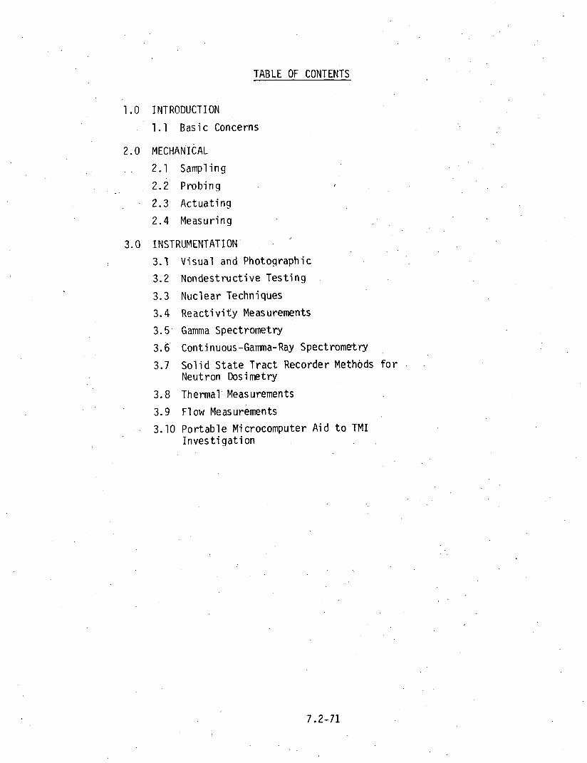
TABLE OF CONTENTS
1.0 INTRODUCTION
1.1 Basic Concerns
2. o MECHANICAL
. . . . 2.1 Sampling
. . 2 .2 ' Probing , 2.3 Actuating
2 .4 Measuring
3.0 INSTRUMENTATION .
I 3.1 Visual and Photographic 3.2 Nondestructive Testing
3.3 Nuclear Techniques
3.4 Reactivity Measurements
3.5 Gamma Spectrometry
3.6 Continuous-Gamma-Ray Spectrometry
3.7 Solid State Tract Recorder Methods f o r Neutron Dosimetry
3.8 Thermal' Measurements
3.9 Flow ~easurements
3.10 Portable Microcomputer Aid t o TMI Investigation
1.0 INTRODUCTION
Among the examinations and measurenients proposed f o r use before, dur ing,
and a f t e r removal o f t h e TMI-2 core are many t h a t represent h igh technology
techniques. I n a d d i t i o n t o t h e s o p h i s t i c a t i o n inherent i n t he techniques
themselves, t he re i s t he need t o implement them i n a hos t i l e , . unwie ld ly
environment. It should be emphasized a t t h e ou tse t t h a t t he needed
techniques do e x i s t t o . do t h e requ i red exami n a t i ons .
Mechanical examination methods, f o r remote s u r v e i l l a n c e o f reac to r components
have been avai lab1 e f o r years. S p e c i f i c e a r l y examples i nc lude t h e techniques
used w i t h t h e Homogeneous Reactor Experiment (HRE-2) core tank and w i t h the
B o i l i n g Nuclear Superheater Reactor (BONUS) i n t he e a r l y and l a t e 1960s. Both
o f these examples invo lved mechanical manipulat ion t o a1 low v i sua l , photographic,
and videographic examination o f i n - r e a c t o r components. I n add i t i on , t h e
mechani ca l operat ions o f c u t t i n g , handl ing, and p a r t removal had t o be accomplished.
S i m i 1 a r .operat ions have been c a r r i e d ou t a t CANDU, Enr ico Fermi , Windscale, and
SRE. S ta te o f t he a r t advancements i n t h e above areas l i e i n more soph is t i ca ted
methods f o r manipulat ing equipment and i n advances i n m i n i a t u r i z a t i o n , reso lu t i on ,
and d u r a b i l i t y o f t he components.
I n a d d i t i o n t o t h e mechanical l y - o r i e n t e d methods, t he re are instrument-based
measurement t i c h n o l o g i es t h a t should be employed i n the TMI-2 s i t u a t i o n . These
inc lude t h e areas of neutron and gamma r a y t r a n s p o r t i n both complex and deep
penet ra t ion geometries. I n f a c t , a s u b s t a n t i a l p o r t i o n o f t h i s compi la t ion i s
devoted t o these areas. These w i l l be among t h e fi r s t areas t o be explored on . .
TMI-2 and are among the most complex, t echno log i ca l l y , t o be u t i l i z e d i n t he
examination.
F i n a l l y , t he re e x i s t s much expe r t i se i n t h e area o f computer science
.*el a t i ve t o r a d i a t i o n t ranspor t methods, r e a c t o r physics app l i ca t i ons , and , ' .
o the r computer-based a n a l y t i c a l methods. This i s use fu l f o r i n t e r p r e t i n g data
from measurements taken both before t h e pressure vessel i s opened and dur ing
a l l phases o f measurements r e l a t e d t o t h e nuc lear con f i gu ra t i on o f the core.
Various computer codes are a v a i l a b l e t o handle t h e complex ana lys is problems
i n v o l v i n g r e a c t i v i t y and o the r r a d i a t i o n t ranspor t problems.

. he f o l l o w i n g pages o f t h i s r e p o r t w i l l descr ibe suggested examination
procedures, discuss t h e i r requirements, and descr ibe the apparent s ta tes
o f t h e a r t , t h a t e x i s t f o r them. Time l i m i t s prevented an exha-rstive search
f o r methods and techniques, so any d e s c r i p t i o n contained here in i s sub jec t
t o updating.
The proposed examination procedure i s broken down i n t o the f i v e chrono-
l o g i c a l stages o u t l i n e d below. subsequent d iscussion w i l l r e f e r t o t he various
stage numbers.
Stage 1. Before pressure vessel head removal.
Stage 2. Before removal o f plenum and upper i n t e r n a l s .
Stage 3. Before f u e l movement.
Stage 4. During f u e l removal.
Stage 5. A f t e r f u e l removal. . .
1.1 BASIC CONCERNS
The'techniques t o be discussed i n t h i s sec t i on are a l l i n tended ' fo r
use i n a h i gh-radi a t i on l e v e l , aqueous environment which w i 11 r e q u i r e remote
operat ion a t a l l t imes. This presents two major p r o b l e m t h a t must be addressed
for,,each technique:
1. How does one manipulate, l i f t , cu t , photograph,' measure, o r
do whatever e l s e .has t o be done a t a d is tance, under water, ' ind. o u t o f s i g h t ,
and s t i l l know e x a c t l y where t h e manipulat ing, l i f t i n g , c u t t i n g , e t c . , i s
actual l y being done?
2. What measures are necessary i n o rder t o be able t o do the ab0v.e.
tasks i n .a h igh r a d i a t i o n .and contaminat ion environment?
A t h i r d cons ide ra t i on t h a t permeates the e n t i r e task i s t h a t o f
r e a c t i v i t y i n t h e ,core. Any movement o f f u e l i n t h e core w i l'l have an e f f e c t
on r e a c t i v i t y and, i f t h e core i s d i s rup ted as a ' r e s u l t o f t he accident,
r e a c t i v i t y changes r e s u l t i n g from core removal may n o t be pred ic tab le . Because
6f t h i s , r e a c t i v i ty measurements w i 11 be necessary th rou ihou t t h e 'examination.

2.0 MECHANICAL (P. Holz, R. Blumberg - ORNL)
The mechanical a c t i v i t i e s o f sampling, probing, ac tua t ing , and measuring
requ i re a wide range o f man ipu la t ive operat ions. Many can be performed
around the top and s ides o f t h e r e a c t o r vessel p r i o r t o head removal and from
above t h e vessel a f t e r head removal. Others must be accomplished through
e x i s t i n g tubes, penetrat ions, and accessory components. Table 2-1 out1 ines
the proposed mechanical a c t i v i t i e s according t o type and stage number.
I n a d d i t i o n t o t h e above a c t i v i t i e s , almost a l l o f t h e o the r observat ion
techniques (photography, TV, eddy cur ren t , r e a c t i v i t y , etc. ) involve. mechanical
methods f o r g e t t i n g t h e observing inst rument i n t o p o s i t i o n .
Techniques p resen t l y e x i s t f o r implementing a1 1 o f t h e necessary mechanical
a c t i v i t i e s . However, t h e amount o f opera t iona l complexity w i l l u l t i m a t e l y depend
- upon t h e r a d i a t i o n l e v e l s present i n t he working area. For t h e purpose o f
t h i s repo r t , i t i s assumed t h a t working personnel have access t o the containment
b u i l d i n g and are ab le t o work, w i t h whatever r a d i a t i o n o r contaminat ion pro-
t e c t i o n i s requ i red , over the r e a c t o r vessel. (If such access i s unava i lab le ,
then the area o f robo t i cs must be explored) . A f u r t h e r assumption i s made t h a t
f a c i 1 i t i.es ' a re .avai 1 abl e f o r 1 i ft i ng heavy equipment (500t po l a r crane, auxi 1 i ary
hook, e t c . ) , f o r p o s i t i o n i n g and ho ld ing manipulat ion equipment, and f o r
'removing t h e r e a c t o r head, b o l t s under water.
2.1 SAMPLING
~ a n i p u l a t o r technology i s we1 1 advanced and inc ludes capabi 1 i t i e s f o r
de l i ca te , w e l l c o n t r o l l e d movements as we1 1 as h igh fo rce app l i ca t i ons . Master/
s lave manipulators, as we1 1 as motor d r i ven o r h y d r a u l i c a l l y operated remote
arms, a re ava i l ab le . The l ong opera t ing distances, poss ib l y 50 t o 60 ft., may
r e q u i r e space technology techniques i n v o l v i n g fo rce compensation t o a l l ow l a t e r a l
o r torque forces t o be appl ied.
Small underwater c u t t i n g torches, as w e l l as saws, shears, d r i l l s , tongs,
e tc . , are a1 1 adaptable f o r sampling a c t i v i t i e s . Proper ly instrumented, f o r s i g h t
and nuc lear de tec t i on c a p a b i l i t i e s , these should a l l ow sampling o f any p o r t i o n
o f t he core, core vessel, and i n t e r n a l s .

TABLE 2-1
ACT I V ITY DESCRIPTION STAGE NUMEER(s
'sampling . ' obtain samples of. material by cutting, 1$2,3,4, and 5 scrapin'g, picking up , breaking of f , etc.
-Probing ~echani cal probing 'of core 1 Depth probes through C R guides 2
Core height measurements 3-
Search for loose fuel and other parts 5
Actuating ~ovements of in-core instruments 1 . . .
Exercise CR and APSR components 1 - Control component movement exper' ments L .
Measure internal key dimensions 3,5 Measuring

2.2 PROBING
This a c t i v i t y i s 3 r i n c i p a l l y one o f seeing how f a r a w i re , rod,
de tec tor , o r l i g h t w i l l go i n t o a tube, o r i f i c e , o r c a v i t y i .n t h e ,reactor.
I t s p r i n c i p a l duty i s t o determine blockage loca t ions , b u t a n c i l l a r y du t ies
could i n v o l v e boroscopy, and the i n s e r t i o n o f a c t i v a t i o n sources i n t o t h e core.
Al though engineer ing drawings o f t h e pressure vessel and r e a c t o r core e x i s t
and skew t h e var ious places i n t o and through which a probe can be i nse r ted ,
i t i s probable t h a t core d i s r u p t i o n w i l l necess i ta te exp lo ra to ry probing t o
d i %cover e x i s t i n g pathways i n t o t h e core.
2.3 ACTUATING
This a c t i v i t y invo lves c a r e f u l movement o f e x i s t i n g components
w i t h i n t h e pressure vessel , such as c o n t r o l rods, a x i a l power shaping rods,
in -core ins t rumenta t ion , e tc . Such movements w i 11 supply d i f f e r e n t types of
in fo rmat ion , such as:
1. Mechanical feeeback
a. ease o f movement
b. ex ten t o f mvement
2. ' Nuclear feedbacc
a. neutron f l u x changes
b. r e a c t i v i t y d i s t r i b u t i o n
2.4 MEASURING
This a c t i v i t y has bath manipulat ive and v i s u a l requirements whereby
'mechanical measurements are ma& o f var ious key dimensions i n t he r e a c t o r vessel.
O f t he var ious mechanical a c t i v i t i e s discussed i n t h i s sec t i on , t h i s probably
has t h e qos t s t r i n g e n t requirements f o r p rec i se movement and placement. Among
t h e meawrements t o be made are:
1. Distance f rom top o f core t o a reference plane
2. ~ e a c t o r Vessel diameters
3. Warpage o f vessel i n t e r n a l s
Present manipulator technology i s adequate f o r any foreseeable requ i re -
ments o f t h e TMI-2 examination.

3.0 INSTRUMENTATION IVlEASUREMENTS (R. L. Shepard - ORNL; 'E. L. C o u r t r i g h t - PNL)
TMI-2 examinat ion techniques w i l l i n v o l v e the use o f var ious i tems o f i n -
s t rumenta t ion o f a w ide l y desparate nature. These techniques are summarized
i n Table 3-1.
Many o f t he techniques i n Table 3-1 w i l l require-computer backup, e i t h e r as
a - d a t a a c q u i s i t i o n se rv i ce o r as an a n a l y t i c a l t o o l f o r processing the data ob-
t a ined f rom the inst ruments.
I n t he f o l l o w i n g sec t ions a b r i e f d e s c r i p t i o n o f t he s t a t e o f t h e a r t w i l l
be g iven f o r each technique. I t must be recognized t h a t any re fe rence t o a
s p e c i f i c brand name o r s p e c i f i c Aethod i s f o r i l l u s t r a t i v e purposes on ly , ane
t h a t comparable a l t e r n a t i v e s may e x i s t .
3 .1 v i s u a l and Photographic (G.J. B o l f i n g , R.L. Moore, and R. Blumberg - ORNL)
In general , t h e s t a t e s o f t he a r t f o r v i s u a l and photographic examination
o f t he TMI-2 core a re w e l l advanced. M i n i a t u r i z a t i o n o f v ideo cameras has pro-
gressed, a long w i t h development o f r a d i a t i o n r e s i s t a n t components and a v a i l a b i l i t y
o f -adequate l i g h t i n g sources, t o a p o i n t where e x p l o r a t i o n w i t h i n t h e core i s
poss ib le . . .
A 1977 brochure by Westinghouse E l e c t r i c Corporat ion descr ibes a camera
as f o l l o w s :
The equipment t o .be demonstrated i s a m i n i a t r u e s e l f - l i g h t e d
W camera designed s p e c i f i c a l l y f o r nuc lear r e a c t o r inspec t ion . - This camera cons i s t s o f a camera head, a mu1 t i l e a d in te rconnec t ing
cable and a camera c o n t r o l u n i t . Special fea tu res are a smal l ,
l i g h t w e i g h t , r a d i a t i o n t o l e r a n t camera head o f 1 .25 ' in . diam and .
13 i n . leng th , more than 550 TV Pines resolut . ion, remote o p t i c a l
focus and an i n t e r n a l . i i g h t source power supply. A wide range
o f v iewing and l i g h t i n g attachments make t h e camera very v e r s a t i l e
and thus s u i t a b l e i n many remote ve iwing appl i c a t i o n s . AtLachments
i nc lude forward, f i x e d , and r 0 t a t i n . g r i g h t angel v iewing w i t h and
w i t h o u t i n t e r n a l l i g h t s usable i n a i r and underwater.

Tab1 e 3-1 Examination Techiiiques an3 ~nstrumentation Requirements
Technique Type of Instrumentation or Measurement
1. Visual and Photographic Video
a. standard b. stereoscopic
Camera (photographic)
a. wide angle b. miniaturized . stereoscopic fddy Current 2. Nondestructive Testing a . oxide thickness b. gap measurements c. swelling measurements
. . Ul trasoni c
. . distance measurements b. acoustical imaging
Reactivity
a. source neutron multiplication measurement b. boron displacement measurement c. Zs2Cf source drive neutron noise analysis y Measurements a. y scanning
i . gross configuration ii. specific isotope ... . .. counting
b. Compton Recoil Y-ray Spectroscopy Thermometry 4. Thermal a. thermocouples b- resistance thermometers Infrared Scanning
Ultrasonic Flow Measurements 5. 'Flow Pitot Tube
3. Hot Film Anemometry 4. . Tracer Techniques 5. Tine-lapse Infrared Photography 6. Turbine Fl owmeters 7. Day Techniques

This camera i s designed and tes ted f o r opera t ion up t o 600C (which might necessi-
t a t e development o f a method f o r coo l i ng ) and a t gamma dose r a t e s ' o f 2 x l o 6 R/hr
up t o a f luence o f l o 8 R, according t o - W l i t e r a t u r e . More recent i n fo rma t ion i n -
d ica tes t h a t camera s izes l e s s than 1 inch. diameter a re ava i l ab le .
Stereoscopic 'v iewing c a p a b i l i t i e s a re a v a i l a b l e i n video equipment manu-
fac tu red by several companies. One example u t i l i z e d p o l a r i z a t i o n coding fo r ' sepa -
r a t i o n o f l e f t and r i g h t video channels and the wearing o f simple viewing glasses.
Another uses a m u l t i p l e x i n g technique whereby the video from two cameras i s d i s -
played and vi.ewed through glasses w i t h e l e c t r o n i c a l l y c o n t r o l l e d shu t te rs f o r each
eye. The l a t t e r system i s s t a t e d t o be compatible w i t h both c o l o r and black,'white
cameras. Both systems have video record ing capabi 1 i t i e s .
3 . 2 Nondestruct ive Tes t ing (C.V. Dodd - ORNL; E.L. C o u r t r i g h t - PNL; R. L. Brown and E.M. Sheen - dEDL)
Both eddy cu r ren t and acoust ica l e x a m i ~ a t i o n .methods are we1 1 developed
and app l i cab le t o the TMI-2 task. Eddy c u r r e n t techniques have been used t o
measure ox ide f i l m thicknesses i n a range from 0-0.005 i n . (0.13 mm) w i t h an ac-
curacy o f +0.00005 i n . (+0.001 mm). The probe cons is ts o f a smal l , f l a t c o i l
s p r i n g loaded aga ins t t he pa r t . The ox ide s u r f a c e w i l l keep fhe c o i l from r e s t i n g
f l a t on the metal surface, and the d is tance betw2en the c o i l face and the m t a l
(which i.s the ox ide th ickness) is.measured. This type o f measurement has been.
performed i n h igh r a d i a t i o n and, thermal environments (up t o 1400 h i n an opera t ing
reac to r ) w i t h no degradat ion o f t he probe. The probe w i l l have t o be constructed
and ca l i b ra ted , us ing we1 1 es tab l ished design r u l e s ,: b u t t h e ins t rumenta t ion
i s on hand.
Eddy c u r r e n t techniques have been used t o measure small dimensional
v a r i a t i o n s t o w i t h i n k0.00001 inch (0.3 i n '7igh r a d i a t i o n environments and
i n narrow places E o o l an t channels as smal l as 3.032 i n . (0.8 MM) have been
measured. The probe cons is ts o f a f i x e d c o i l t h a t measures t h e d is tance
t o a spr ing- loaded f e e l e r o r d i r e c t l y t o the metal surface. Add i t i ona l c o i l s
have been used t o measure the d is tance t o d i f f e r e n t p o i n t s on .a tube surface and
a p r o f i l e o f the tube has been measured. Ins t rumenta t ion tca d r i v e a 24 c o i l a r -
ray i s on hand, b u t t he probes would have t o be cons t ruc ted t o f i t i n s i d e the

the tube bundle.
Mu1 t i pl e-f requency eddy-current techniques are avai lab1 e that could
with appropriate calibration adid adaptation, simultaneously measure oxide,
oxygen-stablized a . and prior B phase thicknesses on in tac t fuel rods and other
Zi rcaloy surfaces. A three-frequency instrument i s capable of measuring. s ix
independent parameters such as thickness , conductivity , etc .
Ultrasonic techniques are presently avai l:atj':le.:tb: perform. both distance . .
measur.enents and acoustical imaging .
A possible use of ultrasound in the core damage assessment fo r TMI
i s in measuring distances from 3 reference plane to points in a rubble p i l e or
specif ic object in the core. Small displacements can be readily measured.
Sound veJ oci ty in water i s approximately 0.06 i-h. per microsecond yiel di.ng range measurements w i t h i n a few mils ui thout d i f f icu l ty , using standard commercially
avai 1 abl e ul trasoni c t e s t instruments and transducers. his type of data could
greatly supplement optical +inages and may be used in confined areas where TV
imaging i s not possible due to c i f f icu l ty in illuminating the area or s ize of the
TV camera. Ultrasonic transducers 1 /2 inch in diam o r smal l e r are commonplace.'
Standard commercial ultrasound transducers are avai lab1 e for operation
to 4000F, we1 1 above the boiling point of low pressure water. Specific applica- tion a t T A I will require advanced planning and possible construction of special scanners and probes to enter available apertures and make specif ic range measure-
ments or ultrasonic images.
An advantage of ultrascund gauging measurements over mechanical measure- ment i s tt-e application of negligible force on the object, which. may be important
i n measuring distance to loose parts o r fuel pieces.
In addition, acoustical imaging techniques are available capable of pro- viding images of objects submergei i n opaque liquid media. Such a technique could provide information to supplement video or photographic resul ts .

3.3 Nuclear Techniques (D. E. Ba r t i ne - 'ORNLj
As s ta ted e a r l i e r , r e a c t i v i t y of the core i s an impor:ant cons idera t ion
dur ing any examination o r removal operat ion. Because the core i s probably d i s -
r'upted o r d isp laced t o some ex ten t by the accident, i . t s response t o t h a t examina- .
t i o n o r removal may n o t be p red i c tab le . It was suggested by the Technical S t a f f
Report prepared f o r the Pres ident 's Commission on the Accident a t Three M i l e
I s l a n d t h a t r e c r i t i c a l i t y i n the d i s rup ted core dc.es n o t have a h igh p o t e n t i a l
f o r occurrence. Th i s conclus ion should n o t be i n t e r p r e t e d t o mean t h a t r e e n t r y
and recovery operat ions a t t he r e a c t o r a r e f r e e from. the p o s s i b i l t y o f c r i t i -
c a l i t y . With t h i s i,n mind, i t can be seen t h a t the examination techniques d i s -
cussed below have a spec ia l importance; one t h a t extends beyond the a c q u i s i t i o n
o f data f o r c u r i o s i t y ' s sake.
Several techniques e x i s t f o r determin ing the r e a c t i v i t y o f t he core.
Three o f them w i l l be discussed: ( 1 ) Source neutron m u l t i p l i c a t i o n measure-
ments, (2 ) Boron displacement measurements, and (3) 252Cf-source-driven neutron
noise ana lys i s . These techniques, i n general, r e q u i r e computer backup t o analyze
the data t h a t w i l l be generated. Appropr iate computer programs e x i s t t o do t h e
requi red analyses.
I n addi. t ion t o t h e above, s i g n i f i c a n t neutronics analyses w i l l be re -
qu i red t o i n t e r p r e t the data obta ined from the var ious neutron and gamma measure-
ments. . Th is ana lys is should inc lude 1-D,* 2-D,* and poss ib l y 3-0 models.
*1-D and 2-D TMI models have been developed a t ORNL and used t o c a l c u l a t e both neutron and gamma . f luxes dur ing and a f t e r t h e accident . Thus, t he models . t o be' used are ava i l ab le .
. , 3.4 ' R e a c t i v i t y Measurements (J.T. ~ i h a l c z o and J.T. Thcmas - ORNL)
Neutron Source Mu1 t i p 1 i c a t i o n Measurements. By i n s e r t i n g p h y s i c a l l y
small 2 5 2 ~ f neutron sources i n t o the core and measuring t h e r e s u l t i n g count r a t e
i n neutron-sensi ti ve detec tors placed around the ' core, the source neutron mu1 ti-
p l i c a t i o n 'can be determined. The r e s u l t s o f t h s e measurements skoul d be compared
w i t h the r e s u l t s o f ca l cu la t i ons . Because o f t h e i r smal l s ize , the 2 5 2 ~ f sour,ces

could be moved in reentrant holes or along the outer surfaces of the core to pro-
vide the Spatial variation of the neutron multiplication. Existing detector
systems may or may not be adequate. Top-to-bottom asymmetry of the measurement
would give some indication of the extent of the damaged core region.
This type of measurement could be performed before head removal, before
plenum removal, and before and during fuel movement.
Source neutron multiplication measurements depend on the source-core-
detector configuration and do not determine the reactivity di.rectly. However,
if detection efficiency and neutron source changes are properly accounted for,
the sign of any .reactivity increment (introduced, for example, by control rod or fuel movements) can be determined but not the magnitude. These changes are
usually calculated, and so depend on some knowledge of the core configuration.
When this method is used to determine reactivity, reference measurements at a
known reactivity configuration are required.
Boron Displacement Measurements. Reactivity determination by boron dis-
pl acement measurements invol ves changing the boron content of the cool ant by a
known amount and then measuring the'corresponding change in the neutron count
rate. In the interpretation of these measurements it is assumed that the count
rate is proportional to the source neutron mu1 tiplication which, in turn, is
inversely proportional to the departure 07 the neutron mu1 i tpl ication factor, k , from unity. Given measurements of the count rate at two boron concentra- tions:
the mu1 tip1 ication factor kl can be determined if the value of ~k is known from previous measurements or from calculations of the change in the multiplication
factor with boron concentration. Since the count rates are proportional to
both the detection efficiency and neutron source strengths, changes in these quantities must be accounted for in interpreting the measured count rates.
Boron displacement measurements should be made before head removal. Re-
peating the measurement after head removal with a detector close to the core

would a l so be usefu l , s ince the ef fects o f changes i n de tec t i on e f f i c i e n c y w i t h
changes i n t he neutron a t tenua t i on through t h e borat,?d water would be reduced.
L i ke the prev ious method, boron displacement r e s u l t s may be s e n s i t i v e
t o the source-core-detector con f i gu ra t i on . The value o f ~ k associated w i t h
the change i n boron concent ra t ion must be known. I f t h i s value i s based on
previous measurements w i t h an undamaged core o r on c a l c u l a t i o n s f o r some assumed
core con f i gu ra t i on , then an unce r ta in t y i n t he value o f the r e a c t i v i t y i s i n t r o -
duced.
252Cf-Source Dr iven Neutron Noise Analys is . The 252~fTdv' i .ve.n neutron noise method o f subcr i t i ca l i t y mon i to r ing has some slnique advantages f o r appl i ca -
t i o n a t TMI-2, namely t h a t t he r e a c t i ' v i t y i s determined from measurements on l y
a t the s u b c r i t i c a l s t a t e o f i n t e r e s t and t h e i n t e r p r e t a t i o n o f the data does n o t
r e q u i r e knowledge o f e i t h e r the absolute o r r e l a t i v e vales o f the de tec t i on e f -
f i c i e n c y o r t he core!s i nhe ren t neutron source st rength. I n t h i s measurement
method a 2 5 2 C f neutron source i n an i o n i z a t i o n chamber (de tec to r 1) i s placed
i n t h e core o r near t he core boundary, along w i t h a p a i r of h i g h - s e n s i t i v i t y f i s -
s i on chambers (de tec tors 2 and 3) t h a t conta in up r o lOOg o f 235U each. These
detectors could be placed on top o f t he core when the upper plenum has been re -
moved. The crosspower spec t ra l dens i t i es between the two f i s s i o n chamgers (G23),
as we1 1 as the crosspower spec t ra l dens i t y between each de tec to r and the 2 5 2 C f
i o n i z a t i o n chamber (G12;and G, ,) a re obta ined from t h e de tec to r s igna ls . The
mu1 ti p l i c a t i o n f a c t o r , k, depends on the f o l lowing r a t i o of these spec t ra l den-
s i t i e s :
where the constant C depends on known o r measured p rope r t i es o f the reac to r and
the 2 5 2 C f i o n i z a t i o n chamber and * means complex :onjugation. Pre l im inary con-
s ide ra t i ons i n d i c a t e t h a t measurements might be t e c h n i c a l l y f e a s i b l e w i t h de-
t e c t o r s a t t he core boundary. For tunate ly , f i s s i o n chambers are i n s e n s i t i v e t o
y rays (chambers e x i s t which can detec t i n d i v i d u a l f i s s i o n i n gamma ray f i e l d s
of l o 7 R/hr, thus y/n d i s c r i m i n a t i o n r a t i o s o f l o 8 a r e poss ib le ) and h igh-
i n t e n s i t y 2 5 2 C f sources can a l so be f a b r i c a t e d i n s i d e i o n i z a t i o n chambers.

Pre l im inary ca l cu la t i ons i n d i c a t e t h a t de tec t i on e f f i c i e n c y w i t h high-sensi t i v i t y
f i s s i o n chambers would permi t measurements t o be made w i t h around 15% accuracy
i n 20 h.
252Cf-driven noise measurements should be made o n l y a f t e r the upper
plenum has been removed, p r i o r t o f u e l movement. The r e a c t i v i t y thus deter-
mined cou ld be used as a reference measurement f o r t he source neutron mu1 t i p 1 i-
c a t i o n method described e a r l i e r . If access t o t h e core through inst rument
guide tubes o r c o n t r o l rod guides i s poss ib le then the q u a n t i t i e s requ i red t o
ob ta in the r e a c t i v i t y can be measured and s p e c i f i c knowledge o f core conf igura-
t i o n i s n o t needed.
Th is method o f r e a c t i v i t y determinat ion requ i res f u r t h e r experimental
and t h e o r ~ t i ca l eval ua t i on p r i o r t o appl i ca t i o n t o a 1 arge reac to r ; f u r t h e r -
more, i t r 'equires cons t ruc t i on of a h igh i n t e n s i t y 252C f i o n i z a t i o n chamber.
Theoret ica l eva lua t ion must asce r ta in the i n f l uence o f s p a t i a l e f f e c t s o r the
subcr i t i c c l i t y deterrni nation, Measurements by t h i s method on an undamaged LWR
core woulc be h i g h l y des i rab le be fore at tempt ing measurements w i t h the TMI-2
damaged core. For m u l t i p l i c a t i o n f a c t o r s lower than 0.8 t h i s method may o n l y
be capable o f determin ing t h a t t he neutron m u l t i p l i c a t i o n f a c t o r i s l e s s than
0.8 and no t t he ac tua l value.
Cn add i t i on , these no ise ana lys is measurements ob ta in t h e prompt neutron
decay consxant by two methods: (1) from the breakfrequency o f the cross power
spec t ra l dens i t i es , GI,, GI,, and G 2 3 ( t h r e e determinat ions) and ( 2 ) from the
r a t i o o f t he r e a l t o t he imaginary p a r t o f the cross power spec t ra l dens i t i es
w i t h 2 5 2 C f . The prompt neutron decay constant can a l so be obta ined from pulsed
neutron measurements i n t h e t ime domain b u t these frequency domain noise ana lys is
measurements do no t r e q u i r e the use of an e labora te pulsed neutron source. I n
e f f e c t , t h e 252C f i s t h e equ iva len t o f a randomly pulsed neutron source and was
i n i t i a l l y used f o r pulsed neutron measurements be fore t h e advantages o f t he f r e -
qLency domain measurements were rea l i zed . Although t h i s method obta ins the same
in fo rmat ion ( t h e prompt neutron decay constant) as the pulsed neutron method,
i n a d d i t i o n t o the r a t i o o f spec t ra l dens i t i es which i s p ropo r t i ona l t o the

reactiv.ity, i t may not be as sensit ive to spatial ef'ects since the ra t io of
spectral densit ies i s independent of frequency.
Comparative Measurements. Performance of simultaneous measurements in
a similar, b u t undamaged core ( fo r example, TMI-1) and comparison with measurements on TM1'-2 would establish the accuracy of the methods. This, of course, depends
on the ava i lab i l i ty of TMI-1 for such measurements.
General Comment. A1 1 three methods descr'bed- rely to some extent on
knowledge of the core conditi-on. If the core i s accessible through guide tubes, ,
the parameters required for react ivi ty determtnatioq'by the 252,Cf source driven no'ise method that depend on the core configuration can be measured. Multiple
methods of react ivi ty determination are highly recommended. In these measure-
ments i t must be assured that the react ivi ty of the en'tire core i s determined..
3.5 Gamma Spectometry (K.H. Valentine and F.F. Dyer - O R N L )
Gamma spectrometry has been used routinely i n the postirradiation examination of irradiated fuel assemblies and fuel samples from both commercial
and experimental nuclear reactors. The exceptional energy resolution of the 1 i thium-drifted germanium detector (Ge-Li ) provides the capability fo r e f f ic ien t and accurate evaluative identification of radionuclides. In cases where the
source geometry i s known or can be inferred, quantitative analysis can also be performed, often with accuracies exceeding 1%.
The TMI-2 core will have cooled for approximately two years by the time
the damage assessment measurements commence. Thus, the more active, short-lived
fission products wi 11 have decayed, resulting in nore easi ly interpretable' gamma ray'energy spectra. After two years of cooling, the fission products that will s t i l l be present in detectable quantit ies include 13%s, 1 5 4 E ~ , 125Sb, l3'+CsY and 144Ce.
Before Head Removal. Gamma spectroscopy may be useful in determining
the position of fission products (which presumably will be strongly correlated with the position of fuel material ) within the reactor vessel. A major compl i -
cation i s that the core must be viewed through a minimum of approximately 12 inches

of s teel ( 8 in. in the reactor vessel and 2 in. in each the thermal shield and
core barrel) . Assuming that the measurement i s possible, i t could be performed
by posit iming a shielded, collimated Ge-Li detector in the 3 f t wide annular
region between the reactor vessel and the biological shield with the collimator
entrance as close t o the reactor vessel wall as possible. The collimator would
then by angularly scanned in a horizontal plane between tangents t o the inner
wall of the reactor vessel. By repeating the measurement a t differenc elevations
and different azimuthal locations on the reactor vessel wall, i t should be possible
to construct a f a i r ly accurate outline of the fuel mass.
As previously mentioned, radiation originating in the core must pass
through a .minimum of 1 2 in. of s teel t o reach an ex-vessel detector and a t the
l imits of the angular scan, the effect ive thickness will be about twice th is
value. The measurement should therefore be based on a high energy photon which has a larger probability for penetrating the s teel with no interaction. A
l ikely candidate would be the 2186 keV gamma-ray of 14'+Ce which i s easily detectable
i n a typicel f iss ion product energy specturm. A t 2186 keV, the transmission coef-
f i c i en t for 12 in. of s t e e l i s about 6 x l 0 - ~ and fo r 24 in. i t will be about 4 x lo-'.
I n addition, water between the core and reactor vessel will 'further reduce the un- scattered photon intensity by a factor of 10 to 100. Although the total attenua- tion i s large, the core i s a very intense source so useful data rates may s t i l l
be obtainab'le. The feasi bil i ty of th i s method could be 'demonstrated by some re1 atively simple hot cell measurements.
Before any core components have been removed, i t i s doubtful that useful information could be obtained from a spectrometer lowered into the vici-
nity of the core. A typical Ge-Li spectrometer will tend to saturate i n ambient radiation fselds exceeding 10 rnR/h. Therefore, until enough fuel assembl ies have been renoved to provide space for an adequate shield, i n s i t u gamma spec-
rometry of t.qe core i s not feasible. However, the sens i t iv i ty of gamma ioniza-
tion chambers can be adjusted f o r a wide range gamma dose rates so i t would be possible to -ewer such a chamber down any vertical core penetration to obtain an axial profi le of the total gamma dose rate.

During Fuel. Movement. If individual fuel assembl ies are removable,
then i t would be possible to obtain accurate, on-site axial f ission product
profi les , for single assemblies. Such a procedure was performed during the
gamma spectroscopic examination of Peach Bottom HTGR core components. This
work was performed by placing a shield-collimator assembly over the core; data
were acqui,red by a Ge-Li spectrometer as each fuel element was withdrawn from
the core into the shield-collimator assembly. One of the major goals of th is work was to determine the re la t ive release and redistribution of f.ission pro-
ducts, particularly the isotopes of Cs.
3.6 ~ontinuous- am ma-~a~ Spectrometry ( R . Gold - H E D L )
In addition to the gamma-ray spectrometry w i t h a Ge-Li detector des- cribed in the previous section, a method called Compton Recoil Gamma-Ray
Spectroscopy has been developed by H E D L and has been employed for the measure- ment of the continuous gamma-ray component of the nixed radiation f i e ld of the
pressure vessel and for determining the absolute gamma dose rate.
Measurement of th i s gamma-ray component i s important, not only as the major radiation constituent of a reactor f i e l d , b u t also to provide further studies of the interdependent relationship between neutron and the gamma-ray components of a power reactor environment. A high-resolution, lithium-drifted solicon soiid s t a t e detector (Si(Li) detector) was used i n th i s work. Rather
than the customary application of solid s t a t e detectors ( i . e . , the direct detection of discrete photo-peaks) th i s method uses the detector response for measurement of the Compton recoil electron d is t r i ju t ion induced by the contin- uous gamma-ray spectrum of in te res t . The Compton electron distribution and
the continuous gamma-ray spectrum are related by a integral equation, based on the well known Klein-Nishina formula for Compton scattering. In terms .of
the measured Compton recoil electron dis t r ibut ion, the continuous gamma-ray spectrum can be determined with appropirate unfolding techniques.
3.7 Sol id State Tract Recorder Methods for Neutron Dosimetry. ( R . Gold - H E D L )
This i s a nondestructive method that can be applied direct ly to assem- blies to provide comprehensive measurements of spontaneous neutron generation from

spent f u e l . Neutron dosimetry measurements w i t h spent ' f u e l assembl i e s can
serve two broad purposes; namely, t o charac ter ize t h e composit ion and the
r a d i a t i o n environment . This f i r s t purpose inc ludes the need t o understand
and q u a n t i f y spent f u e l f i s s i l e i s o t o p i c composit ions f o r reasons o f economics,
safeguards, o r r e a c t o r physics. The second purpose encompasses hea l th and
sa fe ty requirements created by the spent f u e l r a d i a t i o n environment . :Compiler's Comments:
Fol lowing review o f the o r i g i n a l d r a f t o f t h i s document, several poss ib le
technical -problem areas were po in ted o u t by Gold. and Kaiser o f HEDL. These areas
are enumerated and addressed below.)
1. I n t e r f e r e n c e from a 2.23 MeV gamma r a y a r i s i n g f rom neutron capture
on hydrogen. 0
The t o t a l neutron source s t reng th o f t he TMI-2 core 300 days a f t e r 9 the accident i s l ess than 10 neutrons s-'.* I f i t i s assumed t h a t
every neutron i s captured by hydrogen, then the r e s u l t i n g source o f 9 2.23 MeV gamma rays i n 10 photons s - l . However, t h e TMI-2 core con-
U i n s about 82 m e t r i c tons o f f u e l w i t h an average burnup o f 3100
MdD/T.* This should have r e s u l t e d i n a cumulat ive y i e l d o f about 9 kg
of 144~e, of which perhaps 10% 1 kg) w i l l be present by the t ime
the measurement i s made. One kg o f 1 4 4 ~ e prov ides source o f 2186 keV
photons w i t h a s t reng th o f approximately 1015 photons s - l . Thus, t he 6 1 4 4 ~ e t o neutron capture photon r a t i o should be t h e o rde r o f 10 .
Even i f ' the 2.23 MeV capture gamma were detectable, i t would n o t
i n t e r f e r e w i t h t h e measurement s ince i t s f u l l energy peak i s about
40 keV above the 3186 keV f u l l energy peak (and the re fo re separate ly
reso lvab le) and t h e continuous (Compton) p o r t i o n o f the response on l y
extends up t o about 2000 keV (except ing some lower-probabi 1 i ty mu1 t i p l e
i n t e r a c t i o n s ) .
*Personal communication w i t h D. Selby, ORNL Engineering Physics, dated February. 15, 1980.

Add i t i ona l sources o f gamma background may i nc lude a i rborne 85~r ,
contaminated water, and d isp laced f u e l ma te r i a l i n t he plenums o r p r i -
mary p ip ing . The most troublesone source o f background w i l l be ex-
vessel sources q f 1 4 4 ~ e s ince 2186 keV photons emi t ted by ex-vessel
ces i urn sources w i 11 be i n d i s t i n g u i s h a b l e from t h e usefu l . s i gna l con-
s i s t i n g o f unscattered, 2186 keV photons o r i g i n a t i n g i n the core.
The problem i s completely inde'pendent o f de tec to r type and one o f the
-major ob jec t i ves o f t he h o t c e l l scoping measurements would be t o i n -
sure t h a t adequate s h i e l d i n g c a n be pr&ided i n the a l lowab le space.
2. N o n - i n t e r p r e t a b i l i t y o f Ge-Li spectra due t o ex is tence o f a complex,
h i g h l y degrad.ed gamma continuum.
This measurement does no t r e q u i r e ana lys is o f the continuum. .The
choice o f the 2186 keV gamma ray emi t ted by 1 4 4 ~ e was made n o t on l y
t o ma.ximize penetrabi 1 i t y . o f t he core b a r r e l , thermal s h i e l d and
reac to r vessel ' bu t a l so t o p lace the usefu l response c f the de tec tor
beyond the continuum.
3. . P o s s i b i l i t y o f de tec tor s a t u r a t i o n from low'energy events.
Low energy photon' events c o n s t i t u t e a noise source f o r t h i s measure-
ment regardless o f t he type o f de tec tor t h a t i s employed. The h o t
c e l l scopi rig measurements w i 11 i n d i c a t e whether o r n o t 'adequate
sh ie lds , f i l t e r s , and c o l l i m a t o r s can be prov ided i n the a l lowab le . , space.
4. A p p l i c a b i l i t y o f t he Ge-Li de tec tor i s severely r e s t r i c t e d due t o the
need f o r c o l l imat ion, s h i e l d i n g and 1 i q u i d n i t r o g e n cool ing. .
The c o l l i m a t o r i s necessary t o l i m i t the s o l i d angle viewed by the
de tec tor t o a l i m i t e d p o r t i o n o f the core and thus i s an i n t e g r a l
p a r t o f t he system regardless o f de tec tor type. Also, f o r reasons
mentioned prev ious ly , .any de tec tor w i l l probably have t o be sh ie lded
aga ins t background. L i q u i d n i t r o g e n coo l i ng i s a proven technique
f o r ma in ta in ing cryogenic temperatures and a smal l dewar (conta in ing
a 5-7 day supply o f l i q u i d n i t rogen) should n o t r e s t r i c t a p p l i c a b i l i t y
f o r the proposed measurement.

The Compton r e c o i l probe has been suggested as a poss ib le a l t e r n a t i v e
t o the Ge-Li de tec tor . I t s advantage 1 i e s main ly w i t h i t s l a r g e r us!e-
f u l cross sec t i on f o r h igh energy photon i n t e r a c t i o n s r e s u l t i n g i n an
i n h e r e n t l y g rea ter capabi 1 i t y f o r low energy photon r e j e c t i o n . How-
ever, whereas the Ge-Li de tec tor concentrates the usefu l 's ignal from
2186 keV photons i n t o a 3 keV wide reg ion about the f u l l energy,
t he Compton r e c o i 1 probe w i 11 d i s t r i b u t e the usefu l i n fo rma t ion between
0 keV and the Compton edge (1957 keV). I n p rac t i ce , t h i s means t h a t
f u l l energy peaks are d i r e c t l y observable i n a Ge-Li spectrum b u t
must be mathematical ly unfo lded from a Compton r e c o i l spectrum. I n
t h e i n t e r e s t o f supply ing t h e bes t poss ib le p iece o f hardware t o TMI-2,
i t would probably be advisable t o sub jec t both types o f detectors t o
i d e n t i c a l scoping measurements, p r e f e r a b l y a t t he same s i t e . (End
o f answer t o HEDL comments). 1
Before Plenum Removal. A f t e r the head i s removed, a view o f t he core
from above the r e a c t o r vessel w i l l s t i l l be obs t ruc ted by t h e upper i n t e r n a l
s t ruc tu re . However, gamma spectrometry might s t i l l be usefu l t o scan the
i n s i d e sur face o f the head f o r condensation o f v o l a t i l e f i s s i o n products.
A f t e r Plenum Removal. I f the water cover ing t h e core i s s u f f i c i e n t l y
t ransparent , the .core should be observable w i t h remote TV cameras a t t h i s po in t .
I f t he water i s opaque, than a Ge-Li de tec to r w i t h a v e r t i c a l c o l l i m a t o r could be
used t o determine o r v e r i f y t h e ex ten t o f l a t e r a l f u e l displacement ( i f any).
The measurements described above might a l so be defer red u n t i l ho t
c e l l examination i f the' f u e l assemblies do n o t appear t o be susceptable t o
hand1 i ng damage.
A f t e r Fuel Removal. A f t e r t h e core i s removed, gamma spectrometry
c o ~ l d be used t o examine the i n s i d e o f the reac to r vessel f o r condensed o r
p l a t e d ou t f i s s i o n products.
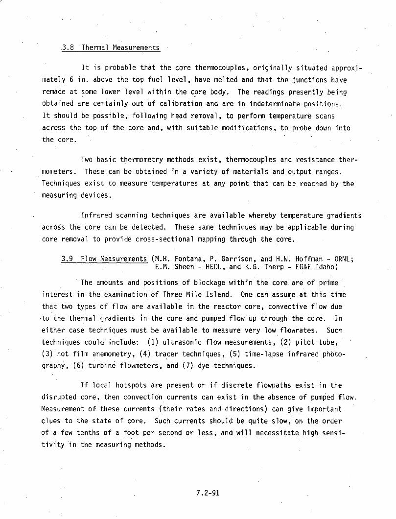
.3.8 Thermal Measurements
I t i s probable t h a t the core thermocouples, o r i g i n a l l y s i t u a t e d approxi -
mately 6 i n . above the t o p f u e l 1 eve1 , have me1 t e d and t h a t t he j unc t i ons have
remade a t some lower l e v e l w i t h i n the core body. The readings present ly being
obta ined a re c e r t a i n l y ou t of ca l i b r a t i o n and are i n indeterminate pos i t i ons .
I t should be possib le, f o l l o w i n g head removal, t o perform tempers.ture scans
across the top o f t he core and, w i t h s u i t a b l e mod i f i ca t i ons , t o probe down i n t o
t h e core.
Two bas.ic thermometry methods e x i s t , themocouples and res is tance t h e r -
mon~eters; These.can be obta ined i n a v a r i e t y o f ma te r i a l s and output ranges.
Techniques e x i s t t o measure'temperatures a t any p o i n t t h a t can b2 reached by t h e
measuring devices .
I n f r a r e d scanning techniques a re a v a i l a b l e whereby temperature gradients
across the core can be detected. These same techniques may be app l i cab le dur ing
core removal t o p rov ide cross-sect ional mapping th iough t h e core.
3.9 Flow Measurements (M.H. Fontana, P. Garrison, and H.W. Hoffman - ORNL; E.M. Sheen - HEDL, and K.G. Therp - EG&E Idaho)
' The amounts and p o s i t i o n s of blockage w i t h i n ' t h e core. are o f prime .,
i n t e r e s t i n the examination, o f Three M i l e Is land. One can assume a t t h i s t ime
t h a t ' t w o types o f f l o w are a v a i l a b l e i n the r e a c t o r core, convect ive f l ow due
, t o the thermal g rad ien ts i n the core and pumped fllow. up through the core. I n
e i t h e r case techniques must be a v a i l a b l e t o measure very low f lowrates. Such
techniques cou ld include.: (1) u l t r a s o n i c f l o w mezsurements, ( 2 ) p i t o t tube,
(3 ) h o t f i l m anemometry, ( 4 ) t r a c e r techniques, ( 5 ) t ime-lapse i n f r a r e d photo-
graphy, ( 6 ) t u r b i n e flowmeters, and (7 ) dye techniques.
I f l o c a l hotspots are present o r i f d i s c r e t e f lowpaths e x i s t i n t he
d i s rup ted core, then convectio'n cur ren ts can e x i s t i n t h e absence o f pumped f low.
Measurement o f these cur ren ts ( t h e i r ra tes and d i r e c t i o n s ) can g i ve important
c lues t o the s t a t e of core. Such cur ren ts should be q u i t e slow,' on the o rde r
o f a few ten ths o f a f o o t per second o r l ess , and w i l l necess i ta te h igh sensi -
t i v ' i t y i n the measuring methods.

Ul t rason ic f lowmeters a r e p resen t l y a v a i l a b l e conme.rcia1 l y from a
number o f vendors and have gocd s e n s i t i v i t y i n the 0.1 t o 0.2 f t / s e c range.
Some development work may be requ i red t o adapt them f o r i n s e r t i o n i n t o a bu l k
l i q u i d medium t h a t has no we l l de f ined f l o w boundaries.
Both p i t o t tube and h o t f i l m anemometry techniques a re a v a i l a b l e .
which cou ld prov ide measurements w i t h i n we1 1 de f ined p o s i t i o n s over the core.
The p i t o t tube.method i s perhaps somewhat l e s s s e n s i t i v e than the ho t f i l m
anemometer.
Tracer t e c h ~ i q u e s can prov ide f l o w d i ' s t r i b u t i o n i n fo rma t ion when used
i n con junc t ion w i t h small amounts of pumped f l o w up through the core. Arrays o f
detectors w i t h d i s c r e ~ e energy w-ndows would be used t o de tec t t he emergence o f
the t r a c e r a t the top o f t he core.
Time-lapse i n f r a r e d phctography can be used t o de l i nea te f l o w pat te rns
above the core. I f the water f lows a t d i f f e r e n t ra tes . through d i f f e r e n t paths
i n the core, then thermal g rad ien ts w i l l be in t roduced and should be detectable.
Commercial i n f r a r e d equipment e x i s t s t o handle the task.
I n c o n j u n c t i ~ n w i t h t h e var ious f l o w r a t e detectors, . it should be pos-
s i b l e t o i n s e r t s t r i n g e r s i n t o d i f f e r e n t r a d i a l and circumferen.t ia1 p o s i t i o n s
to measure pressure drops as a f u n c t i o n o f var ious fo rced convect ion f lowra tes .
Inst rumentat ion and data a c q u i s i t i o n techniques e x i s t t o perform the experiment.
3.10 Por tab le Microcomputer P i d t o TMI Inves t i ga t i ons (J.T. West - ORNL)
Small microcomputer technology and capabi 1 i t y i s changing a t a very
r a p i d r a t e . The micrommputer systems a v a i l a b l e now are smal l , por tab le , econom-
i c a l , sel f -conta ined, and of fer a s i g n i f i c a n t resource t o o l t o the f i e l d engineers,
a t reac to r s i t e s du r ing normal ope ra t i on and du r ing post-acc i dent eval ua t i o n .
There e x i s t s a need f o r computational c o ~ p a t i b i l i t y a t r e a c t o r s i t e s which take
advantage o f the techno log ica l t o o l s now ava i l ab le .
The hardware cos t o f such a system cou ld be l ess than $6,000. It
could be se l f -conta ined and por tab le . I t s opera t ion would n o t be dependent on

any ex te rna l dev ice such as phone l i n e s o r an o f f - s i t e computer. I t s space
requirements would be minimal and i t would be e a s i l y t ranspor tab le .
The most s t r a i g h t f o r w a r d approach t o u t i l i z e t h i s resource would be
t o consider making severa l smal l computer codes opera t iona l on a small micro-
computer. These codes cou ld be made i n t e r a c t i v e and t h e i n p u t c o u l d be l i m i t e d
t o simple engineer ing- type parameters. The codes which a re s u i t a b l e f o r immediate
a p p l i c a t i o n are as fo l lows:
1. . SDC - - Sh ie ld ing - Design - Code, g ives severa l d i f f e r e n t geometry
con f i gu ra t i ons o f source, sh ie ld , and p o i n t de tec to r as op t ions .
I t employs Rockwel l 's s h i e l d i n g equat ions. C a p a b i l i t i e s i n -
c l ude:
1) Dose a t a p o i n t , g iven t h e source
2) Sh ie ld th ickness; g iven source and dose a t a p o i n t requirements
3) Could be made t o i t e r a t e - g iven dose a t a p o i n t and s h i e l d
th ickness t o determine a source dens i ty .
2. NAC - - Neutron - A c t i v a t i o n - Code - f o r zero dimensional systems, t h i s
code w i t h a g iven f l u x , m a t e r i a l desc r i p t i on , i r r a d i a t i o n t ime,
decay t ime generates gamma source d ~ n s i ti es due t o neutron a c t i v a t i o n .
I t can per form c y c l i c a c t i v a t i o n w i t h d i f f e r i n g i r r a d i a t i o n and
decay per iods. Source ou tpu t cou ld be used i n SDC.
3. PHOEBE - Beta and gamma source from 2 3 5 U f i s s i o n products g iven
f u e l composit ion, burn-up, and decay t ime. Source cou ld be used
i n SDC.
4. To be developed - A s i m p l i f i e d m a t e r i a l s composit ion processor
capable o f generat ing i s o t o p i c atom d e n s i t i e s f o r severa l standard
compos i t i ons . 5. To be developed - A spectrum un fo ld ing code t o compute source
s t rengths and m a t e r i a l composit ion g iven i n p u t f rom a gamma
spectroscopy analyzer.
6. To be developed - A n o f f l i n e i n t e r a c t i v e i n p u t processor t o
generate i n p u t f o r a l a r g e r standard computer code t o r u n on a
l a r g e standard computer o f f - s i t e . Th is g ives t h e microcomputer smart
remote te rmina l c a p a b i l i t y as w e l l as o f f l i n e c a p a b i l i t i e s .
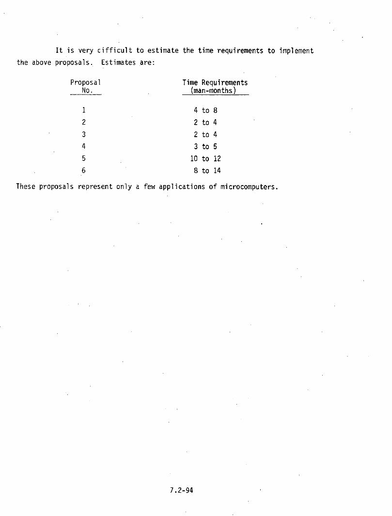
I t i s very ciff icul t t o estimate the time requirements to implement
the above proposals. Estimates are:
Proposal Time Requirements No. (man-mon ths )
These proposals represent only a few applications of microcomputers.


Distribution Category UC-85
. ,
SCOPING STUDIES bF THE ALTERNATIVE OPTIONS FOR DEFUELING, PACKAGING, SHIPPING, AND DISPOSING OF THE TMI-2 SPENT FUEL CORE
Robert T. Anderson Project Engineer
ALLIED-GENERAL.NUCLEAR SERVICES POST OFFICE BOX 8 4 7
BARNWELL, SOUTH CAROLINA 29812
PREPARED FOR THE DEPARTMENT OF ENERGY
WASTE AND FUEL CYCLE TECHNOLOGY OFFICE UNDER CONTRACT DE-AC09-78ET35900
FOREWORD
T h i s s t u d y was r e q u e s t e d by t h e D e p a r t m e n t of Energy a s p a r t o f its c o n t i n u i n g e f f o r t s to a s s u r e t h a t e x p e r i e n c e g a i n e d and l e s s o n s l e a r n e d f r o m t h e a c c i d e n t and r e c o v e r y o f t h e T h r e e Mile I s l a n d {TMI) n u c l e a r p l a n t are made g e n e r a l l y a v a i l a b l e t o t h e n u c l e a r c o m m u n i t y t h e r e b y p r o m o t i n g improved s a f e t y i n t h e f u t u r e . T h e s e e f f o r t s and s t u d i e s a r e i n a c c o r d a n c e with r e c ~ m m e n d a t i o n s made by t h e P r e s i - d e n t ' s Commission to i n v e s t i g a t e t h e a c c i d e n t a t TMI, t h e P r e s i d e n t ' s December 7 , 1 9 7 9 , a c t i o n on t h e s e recommenda- t i o n s , and r e c e n t C o n g r e s s i o n a l a u t h o r i z a t i o n f o r DOE to c o n d u c t a TMI i n f o r m a t i o n a n d e x a m i n a t i o n p r o g r a m . I t s h o u l d be n o t e d t h a t t h e a n a l y s e s , c o n c l u s i o n s , and recom- m e n d a t i o n s h e r e i n a r e s o l e l y t h o s e of t h e c o n t r a c t o r and a r e n e i t h e r e n d o r s e d nor o p p o s e d by t h e D e p a r t m e n t . F u r t h e r , t h e r e s p o n s i b i l i t y f o r d e c i s i o n s o n d e f u e l i n g , p a c k a g i n g , s h i p p i n g , and d i s p o s i n g o f t h e TMI-2 core rests w i t h t h e G e n e r a l P u b l i c U t i l i t i e s (GPU) C o r p o r a t i o n u n d e r t h e i r l i c e n s e and s u b j e c t to t h e r e g u l a t i o n s o f t h e N u c l e a r Reg- u l a t o r y Commission ( N F C ) . I t is h o p e d t h a t t h e s t u d y w i l l p r o v e u s e f u l to b o t h KRC and GPU a s one s o u r c e o f t e c h n i c a l i n p u t to t h e i r d e c i s i c n .

ACKNOWLEDGMEKT
T h i s r e p o r t w a s p r e p a r e d b y a t e a m o f AGKS t e c h n i c a l
\ p e r s o n n e l . The g e n e r a l a r e a s . o f r e s p o n s i b i l i t y a r e n o t e d below. . .
. . . . . . . . . . . . . . Kenne th J . Anderson Dry S t o r a g e . . . . . . R o b e r t T. Anderson Wet S t o r a g e , T r a n s p o r t a t i o n . . . . . . . . . . . . . . . . W . Lynn G o d f r e y . . E c o n o m i c s . . . . . . . . . . . . . J o h n H . Gray Chemical R e p r o c e s s i n g . . . . . . . . . . . . . . . . . Lawrence A. Kean D e s i g n . . . . . . . . . . . . . P a u l N . McCreery S h i p p i n g C a s k s . . . . . . . . George A. Townes F u e l H a n d l i n g & P a c k a g i n g W i l l i a m R. Wal tz . . . . . . . . . . F u e l characteristic,^

ABSTRACT
T h i s r e p o r t p r e s e n t s t h e r e s u l t s o f a s t u d y p e r f o r m e d by A l l i e d - G e n e r a l N u c l e a r S e r v i c e s u n d e r c o n t r a c t t o t h e D e p a r t m e n t o f E n e r g y t o e x a m i n e t h e m e a n s o f p a c k a g i n g , s h i p p i n g , and e v e n t u a l l y d i s p o s i n g o f t h e f a i l e d f u e l f r o m t h e TMI-2 r e a c t o r co re . A p o r t i o n o f t h i s f u e l w i l l b e s h i p p e d t o n u c l e a r f a c i l i t i e s to p e r , f o r m d e t a i l e d p h y s i c a l e x a m i n a t i o n s . T h e s e d i a g n o s t i c t es t s w i l l r e s e a r c h t h e b e h a v i o r o f p o w e r r e a c t o r f u e l u n d e r " 1 0 ~ ~ - 0 f - ~ o 0 1 a n t " a c c i d e n t c o n d i t i o n s . T h e r e s u l t i n g i n f o r m a t i o n will b e o f b e n e f i t t o n u c l e a r power p l a n t owners and d e s i g n e r s , t o t h e g o v e r n m e n t a l r e g u l a t o r y a g e n c i e s , a n d t o . n u c l e a r f u e l d e s i g n e r s .
Remova l o f t h i s f u e l f r o m t h e TMI-2 core i.s a l s o a s i g - n i f i c a n t s t e p i n t h e e v e n t u a l c l e a n u p o f t h i s f a c i l i t y . The r e p o r t p r e s e n t s a s c o p i n g s t u d y o f t h e t e c h n i c a l o p e r a t i o n s r e q u i r e d f o r d e f u e l i n g a n d c a n n i n g . T h e TMI f u e l w h e n c a n n e d c o u l d b e s t o r e d i n t h e s p e n t f u e l s t o r a g e p o o l . A f t e r a p e r i o d o f o n - s i t e s t o r a g e , i t i s e x p e c t e d t h a t t h e . b u l k o f t h e f u e l w i l l b e s h i p p e d o f f - s i t e f o r e i t h e r e x t e n d e d s t o r a g e or p o s s i b l y , c h e m i c a l r e p r o c e s s i n g . The f i n a l d i s p o s i t i o n o f t h i s f u e l , a s i s common t o t h e e x p e c t a t i o n s f o r a l l s p e n t h i g h - l e v e l n u c l e a r w a s t e , i s g e o l o g i c a l b u r i a l .
E v a l u a t i o n i s m a d e o f t h e t e c h n i c a l , e c o n o m i c , a n d i n s t i t u t i o n a l f a c t o r s a s s o c i a t e d w i t h a l t e r n a t e a p p r o a c h e s to d i s p o s i t i o n o f t h i s f u e l . Recommendations a re p r e s e n t e d c o n c e r n i n g f u t u r e g e n e r i c d e v e l o p m e n t t a s k s n e e d e d f o r t h e d e f u e l i n g , p a c k a g i n g , o n - s i t e s t o r a g e , and p o s s i b l e o f f - s i t e s h i p p i n g o f t h i s f u e l .
,The a l t e r n a t i v e a c t i o n s p r o p o s e d a r e t y p i c a l l y t h e same a s t h o s e p r o j e c t e d f o r t h e d i s p o s i t i o n o f s p e n t f u e l from a l l p r i v a t e n u c l e a r p o w e r p l a n t s . O b v i o u s l y , t h e . m e c h a n i c a l c o n d i t i o n o f t h e f u e l ' w i l l d i c t a t e t h e e x a c t t e c h n i q u e s t o b e e m p l o y e d f o r d e f u e l i n g a n d c a n n i n g o f t h e f u e l components . The v a r i o u s t e c h n i c a l o p e r a t i o n s r e q u i r e d f o r f u e l h a n d l i n g h a v e i n d i v i d u a l l y b e e n p e r f o r m e d a t o t h e r n u c l e a r i n s t a l l a t i o n s . Even t h o u g h t h e e x p e c t e d s c a l e o f t h e o p e r a t i o n s p r e s e n t e d a r e l a r g e , t h e y a r e n o t e x p e c t e d t o p r e s e n t . i n s u r m o u n t a b l e p r q b l e m s i n , . terms o f o p e r a t i o n a l d i f f i c u l t y .
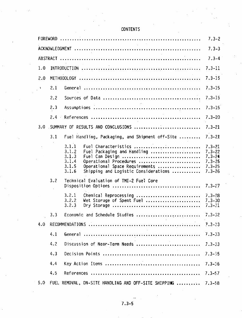
CONTENTS
.... FOREWORD ............. ............................................ 7.3-2
ACKNOWLEDGMENT ..................................................... 7.3-3
ABSTRACT ........................................................... 7.3-4
1.0 INTRODUCTION .................................................. 7.3-11
2.0 METHODOLOGY .............................................. 7.3.15
4 2.1 General ................................................. 7.3.15
2.2 Sources o f Data ........................................ 7.3.15
2.3 Assumptions .............................................. 7.3-15,
2.4 . References ........................................ 7.3.20
3.0 .SUMMARY OF RESULTS AND CONCLUSIONS ............................ 7.3-21
3.1 Fuel Hand1 ing. . Packaging. and Shipment o f f - S i t e ......... 7:3-21
3.1.1; Fuel . C h a r a c t e r i s t i c s ............................. 7.3-21 3.1.2 Fuel Packaging and Handl ing ............. : ....... 7.3-22 3.1.3 Fuel Can Design .................................. 7.3-24 3.1.4 0perat. i onal Procedures ........................... 7.3-25 3.1.5 Operat ional Space Requirements .................. 7.3-25 3.1.6 Shipping and L o g i s t i c Considerat ions ............ 7.3-26
3.2 Technical Eva lua t ion o f TMI-2 Fuel Core ..................................... D i s p o s i t i o n Options 7.3.27
........................... 3.2.1 Chemical Reprocessing 7.3.;18 3.2.2 Wet Storage o f Spent Fuel ....................... 7.3.30 3.2.3 Dry Storage ..................................... 7 . 3 4 1
7 ............................ 3.3 Economic and Schedule Studi'es ,.3-32
4.0 RECOMMENDATIONS ................................................ 7.3-33
4.1 General ................................................. 7.3.33
4.2 Discuss i on of Near-Term Needs ........................... 7.3.33
.......................................... 4.3 Decis ion Po in ts 7.3.35
4.4 Key Ac t i on Items ......................................... 7.3-26
.............................................. 4.5 References 7.3.57
5.0 FUEL REMOVAL. ON-SITE HANDLING AND OFF-SITE SHIPPING .......... 7.3.58

5.1 Introduction ............................................ 7.3.58 ............................................. 5.2 Fuel Status 7.3.59
5.2.1 General ......................................... 7.3.59 ....................... 5.2.2 I n i t i a l Fuel Lcading Data 7.3.60 ................................ 5.2.3 Fuel Burnup Data 7.3.60 ........................ 5.2.4 Nuclear and Thermal Data 7.3.70 ......................... 5.2.5 Damaged Fuel Cmdi t ions 7.3.73 5.2.6 C r i t i c a l i t y Condi t ions for Fuel Debris .....'..... 7.3.75
5.3 Fuel Handling and Packqing Evaluation .................. 7.3.77
5.3.1 General ........................................ 7.3.77 5.3.2 Fuel Handling I:3terface Evaluatl'on .............. 7.3.78 5.3.3 Prel i m i nary Package Design ...................... 7.3.85 5.3.4 Preliminary Scoping of Operational . Procedures ... 7.3.105 5.3.5 Conclusjons and Recommendations ................. 7.3.113
5.4 Shipping Cask Evaluation f o r Off-Site Fuel Movement ..... 7.3.115 . .
.......................................... 5.4.1'. General 7.3-115 5.4.2 Description of Licensed . LWR Shipping Cask
Systems ......................................... 7.3-116 ....... 5.4.3 NRC Licensing C r i t e r i a f o r Shipping Casks 7.3.122 5.4.4 Fuel Loading Location Options ................... 7.3.123 5.4.5 Concl usions and Secommendat ions ................. 7.3.132
5.5 Spent Fuel Shipping Logist ic and Safety Cons i derat i ons .......................................... 7.3.133 5.5.1 General ......................................... 7.3-133 5.5.2 Shipping Campaign ............................... 7.3-134 5.5.3 Shipping Economics .......................... '. .... 7.3.134 5.5.4 Ins t i tu t iona l Problems Involved with
Spent Fuel Shipping ............................. 7.3.139 5.5.5 Safety and Envircnmental Aspects of
Spent Fuel Shipping ............................. 7.3.143 6.0 TMI-2 FUEL DISPOSITION OPTIONS ................................ 7.3.149
6.1 Introduction ............................................ 7.3.149 6.2 Chemical Reprocessing of TMI-2 Fuel ..................... 7.3.150
......................................... 6.2.1 General 7.3.150 6.2.2 Technical Review of Selected Reprocessing ...................................... F a c i l i t i e s 7.3.152 6.2.3 Preliminary F a c i l i t y Assessment ................. 7.3-154 6.2.4 Core Parameters Affecting Reprocessing .......... 7.3.155 6.2.5 Safety Considerations ........................... 7.3.158 6.2.6 Product and Waste Hand1 ing A1 ternat ives ......... 7.3.158 6.2.7 Concl us i on ...................................... 7.3-158

6.3 Wet (Pool) Storage ...................................... 7.3.160 6.3.1 I n t r o d u c t i o n .................................... 7.3-160 6.3.2 Technical Considerat ions ........ ; ............... 7'.3-162 6.3.3 I n s t i t u t i o n a l Problems' .......................... 7.3-168 6.3.4 F a c i l i t y L icens ing .............................. 7.3-172 6.3.5 Implementation Considerat ions ................... 7.3-172 6.3.6 Advanced Wet Storage Techniques ................. 7.3-173
6.4 Dry Storage Concepts f o r TMI-2 Reactor Fuel .............. 7.3.174 6.4.1 General .......................................... 7.3.174 6.4.2 Thermal Considerat ions ........................... 7 .. 3-175 6.4.3 Vaul t Storage Concepts .......................... 7.3.176 6.4.4 Caisson ( S i l o ) Storage Concepts .................. 7.3.181 6.4.5 Engineered Berm ................................. 7.3-192 6.4.6 Cost Estimates .................................. 7.3.195 6.4.7 Conclusions ...................................... 7.3-196
7.0 ECONOMIC AND SCHEDULE EVALUATION .............................. 7.3.199 ................................................. 7.1 General 7.3.199
................................... 7.2 Economic Study Resul ts 7.3-199
7.2.1 Chemical Reprocessing ............................ 7.3-199 7.2.2 Pool Storage .................................... 7.3-202 7.2.3 Dry Storage ..................................... 7.3-202
7.3 Cost Assumptions ......................................... 7.3.204 7.3.1 TMI On-Si t e Cost (Cost Center 1.0) .............. 7.3.206 7.3.2 Shipping Costs .................................... 7.3.206
TABLES
2-1 Sources o f Study Data .......................................... 7.3.16 2-2 Study Assumptions ............................................. 7.3.17
.......................... 4-1 Recornendations f o r Key Ac t i on Items 7.3-37
5-1 B&W . TMI-2 Fuel Data ........................................... 7.3.61 ............................ 5-2 Core To ta l s . A t Shutdown (Average) 7.3.66
5-3 Region 1 . A t Shutdown ........................................ 7.3.67
........................................ 5-4 Region 2 . A t Shutdown 7.3.58
5-5 Region 3 ., A t Shutdown ........................................ 7.3.69

5-6 TMI-2 Core Region 2 Fuel . Gamnas per Second per M e t r i c Ton o f Uranium a t Various Decay Times ............................. 7.3.71
5-7 Cornpar i son o f Gamma Source Terms . TMI-2 Fuel Versus High Burnup Fuel (One Year Decay -ime) ............................. 7.3.72
5-8 Selected Packaging system Dinensi ons f o r Candidate Truck Cask ( i n Inches) ........................................ 7.3.87
5-9a Defuel ing Manpower Est imates .................................. 7.3.112
5-9b Sumnary of Shipping L o g i s t i c 3a ta .............................. 7.3.135
5-10 C h a r a c t e r i s t i c s o f LWR Spent Fuel Casks ....................... 7.3.136
5-11 .Spent . Fuel Shipping Assumptions ................................ 7.3.137
.......... 5-12 Sumnary o f Spent Fuel Shippi-ng I n s t i t u t i o n a l Fac tors 7.3.140
5-13 TMI-2 Spent Fuel Shipment AccPdent P r o b a b i l i t y Summary ........ 7.3.145
6-1 D i s p o s i t i o n A l t e r n a t i v e Comparison ............................ 7.3.151
6-2 S.umnary o f Pool Storage Study i e s u l t s .......................... 7.3-161
.................. 6-3 Spent Fuel Pool I n t e r f a c e C r i t e r i a (Summary) 7.3.169
7-1 TMI-2 Fuel D i s p o s i t i o n Cost Centers ........................... 7.3.200
7.2 . Reprocessing Scenarios ......................................... 7.3.201
........................................ 7-3 Psol Storage Scenarios 7.3.203
7-4 Dry Storage Scenarios .......................................... 7.3.205
F [GURES
................................ 1-1 TMI-2 Core D i s p o s i t i o n Options 7.3.12
2-1 Re j resen ta t i ve TMI-2 Cleanup Schedule ......................... 7.3.18
3-1 I l l u s t r a t i o n o f TMI Defue l ing and Canning and Storage Areas ................................................... 7.3-23
......................................... 4-1 Key Areas of Dec is ion 7.3-56
................................................. 5-1 Fuel Assembly 7.3.63
5-2 Cont ro l Rod Assembly ........................................... 7.3-64
.................................. 5-3 Burnable Poison Rod Assembly 7.3.65

. 5.4 . TMI.2.Core Decay Heat Level ................................... 7.3-.74
......................................... 5-5 B u i l d i n g F l o o r Layout 7.3-79
5-6 Tru.ck Cask C a v i t y Dimensions ( Inches) ......................... 7.3-83
5.7. Packaging Dimensional I n t e r f a c e s .............................. 7.3.88
5-8 Bottom Loading Shroud .......................................... 7.3.90
5-9 Shroud Bottom-Loading Sequence ................................ 7.3.92
5-10 Grappl i ng Cap D e t a i l ............................... ., .......... 7.3.93
5-11 Side-Loading . ~ u e l Handl ing Shroud ........................... 7.3.94
5-12 Loaded (Two P a r t ) Hand1 i n g Shroud Concept ..................... 7.3.95
5-13 TMI-2 Reactor Vessel & In te rna ls -Genera l Arrangement .......... 7.3.97
5-14 E l e v a t i o n View Debr is System .................................. 7.3.98
5-15 Debr is System S e t t l i n g Pot .................................... 7.3.99
5-16 Debr is System Sc reen IF i l t e r Pot ................................ 7.3-101
5-17 Fuel Can i s te r Loaded w i t h Debr is System Elements f o r T rans fe r ................................. ; ........ 7.3.1012
5-18 Pressure Con ta in i ng Sh ipp ing Can .............................. 7.3.103
. 5.19 Mechan ica l l y Seal i n g Cap f o r Shipp ing Vessel' C losure .......... 7.3.104
5-20 Not Used ...................................................... ...................................................... 5-21 Not Used
....................................... 5-22 Legal Weight Truck Casks 7.3-117
5-23 Cask Handl ing a t TMI ........................................... 7.3-127
5-24 Yoke Attachments ................................ . . . . . . . . . . . . . . 7.3-1.28
5-25 Shelf f o r Cask Loading Pool .......................... .. ....... 7.3-129
5-26 Cur ren t Est imates o f spent Fuel Sh ipp ing Costs . (Exc l u s i ve of Canning) ......................................... 7.3-138
. 5-27 NRC R e s t r i c t e d C i t i e s ......................................... 7.3-141
5-28 Highway Weight and Dimensional L im i t a t ions .................... 7.3.142
................................ 6-1 Movable LWR Fuel Storage Racks 7.3.163

6-2 Typica l PWR Spent Fuel Storage Rack . Poison-F ixed Design ( 7 x 8 ) ................................... 7.3.167
6-3 k a d i a t i o n Levels f o r PWR Fuel i n Pool ......................... 7.3.165
6-4 Square (Nine-Inch) Can Loaded w i t h Fuel Pins from Two Complete PW2 Fuel Assembly Dummies ................... 7.3.174
6-5 Vaul t w i t h Forced A i r Cool ing ................................. 7.3.177
6-6 Vaul t w i t h Natura l Convection Cool ing ......................... 7.3-179
6-7 Vaul t w i t h Heat Pipes ........................................ 7.3.180
6-8 .Vau l t w i t h Cool ing F ins ....................................... 7.3-182
6-9 J a u l t w i t h No Coo l ing Devices ................................. 7.3.183 . .
. 6-10 Caisson . Natura l Convection . Aboveground .................... 7.3.185
6-11 Caisson . Natura l Convection . Below ground ................... 7.3.186
6-12 Caisson Aboveground w i t h Heat Pipes ........................... 7.3.188
6-13 Caisson Below ground w i t h Heat Pipes .......................... 7.3.189
6-14 Caisson Abcveground w i t h No Cool ing ........................... 7.3.190
.......................... 6-15 C3isson Below ground w i t h No Cool i ng 7.3.191
6-16 Engineered Berm Concept Caisson Storage ....................... 7.3.194

1.0 INTRODUCTION
This report presents an evaluation of technical, institu- tional, and economic considerations related to the dispos i- tion of the fuel from the TMI-2 reactor core. This work was performed under contract to the Department of Energy (DOE) by personnel of Allied-General Nuclehr Services (AGNS). The study takes the form of a scoping evaluation of the various technical options open to the TMI-2 recovery team and the problems associated with the implementat ion of these same options. Due to the uncertainty of the physical condition of the fuel and its removal from the core, as well as the nationwide uncertainty related to spent fuel disposition, a number of different approaches are covered. is cuss ion of the different alternative approaches or options relates to the probable implications in the expected time frame for the reactor defueling and fuel canning (1983 to 1985).
The ideal sequence of operations fcr movement of the fuel from the core to its ultimate disposition is shown schematically in Figure 1-1. Techn.ically, there are three phases which must be addressed. These include the removal of the fuel from the core and canistering of the fuel in , a form suitable to maintain its integrity during further handling, storage, or shipping operations. The fuel may remain in storage on-site until a permanent disposition is identified. A possible second phase is the shipment of the fuel off-site. This could be to either an interim facility for diagnostic evaluation or for storage. Finally, the nuclear fuel waste material must be disposed of, probably by subterranean burial. The latter step is common to all spent fuel or nuclear waste. A possible technical option preparatory to burial is reprocessing to recover and recycle useful fuel material.
As illustrated in Figure 1-1, the fuel condition could range from intact to pieces of "debris," or even large "fused" segments of the core. The canning operation must accommodate this wide spectrum of possible conditions. It is expected that the TMI reactor spent fuel pool will be used .as a storage area and for other possible handling and testing operations preparatory to shipment off -si te. The cannistered fuel will be stored in a spent fuel pool until there is an identification of a means for disposition of the fuel. A small portion of the fuel will be sent to hot cell areas at national laboratories or commercial facilities to permit a diagnostic evaluation. An evaluation of the fuel condition will permit a greater xnderstanding of the TMI reactor accident sequences and consequences. The remainder

Packaging Shipping Disposal
TMI-2 CORE DISPOSITION OPTIONS
FIGURE 1-1

of the fuel will .eventually be shipped to another .location for either interim storage or for final disposition.
The first four sections of the report summarize the methodology, results, and recommended areas of further work to be performed. The remainder of ,the study was divided into three detailed areas of emphasis: (1) the technical aspects of packaging and shipping; (2) the technical aspects of various disposition alternatives; and (3) the economic and schedular examination of the various disposition alternatives. These are summarized in the folLowing report sect ions.
(1) Chapter 5.0 - Fuel Packaging and Shipping Considera- tions - Section 5.2 examines the status of the fuel, and Section 5.3 examines the packaging of the fuel preparatory to being placed into a shipping cask. This includes the various considerations associated with removal from the region of the reactor core itself,. handling between the reactor building and the auxiliary building, the canning of the fuel and related opera- tions preparatory to placement in a spent fuel cask, and the loading of the spent fuel cask. Section 5.4 examines the shipping cask operations at the TMI-2 facility and alternative unloading facility, and the various aspects of selecting a cask to handle the fuel or fuel debris which has been canned. Section 5.5 examines the logistics considerations related to shipping the fuel off-site including availability of equipment, routing, and current uncertainties in shipping.
(2) Chapter 6.0 - Disposition Options - The various options examined are wet and dry stor,sge of the fuel and chemi- cal reprocessing. Section 6.2 examines the technical 'feasibility of eventually reprocessing the fuel to recover useful uranium and possibly plutonium. Exami- nation was made of all current domestic reprocessing processes as related to performing this at both govern- ment laboratories and at domestic commercial facilities specifically designed for LWR power reactor fuel. Section 6.3 examines the technical factors associated with storage of canned fuel in a wet pool. Section 6.4 similarly evaluates the dry storage options available, including storage within a hot cell. These options were evaluated for technical feasibility and relative safety. Implementation c.3nsiderations including facility availability were also covered.
(3) Chapter 7.0 - Comparative Economics - This is a summary of the comparative economics of ultimateby disposing of this fuel based on the various alternatives studied.

These estimates allow for variations in the actual date of implementation.
The report results presented allow sufficient latitude to accommodate a wide variety of fuel conditions. In a similar vein, the TMI recovery group will have the option of deter.- mining such areas as shipping mode and disposition technique based on the facility options open or expected to be open within the time frame. The conclusions and recommendations are also covered in a like manner.
We recommend that an operational plan for defueling be formulated in the near future to permit more definitive plans to be made. his involves - examining the recommended areas for future studies and determining a projected plan of action. This will be needed to arrange for the fabrication, leasing, licensing, etc., of the various equipment to be utilized. In this line, the most evident need to permit detailed planning is that a preliminary examination of the actual fuel condition be made as soon as possible.

2.0 METHODOLOGY
2 .1 G e n e r a l
T h i s s e c t i o n o f t h e report d i s c u s s e s t h e m e a n s u t i l i z e d t o a c c u m u l a t e m e a n i n g f u l d a t a and to d e v e l o p s p e c i f i c i n f o r m a - t i o n . A l s o i n c l u d e d a re t h e t e c h n i c a l a s s u m p t i o n s u s e d which l e a d t o t h e v a r i o u s c o n c l u s i o n s a n d r e c o m m e n d a t i o n s . Where s p e c i f i c c o n c l u s i o n s a r e b a s e d o n t e n t a t i v e o r unp roven d a t a , and whe re t h e r e c o m m e n d a t i o n s are e x t r e m e l y s e n s i t i v e t o t h e s e f a c t o r s , s p e c i f i c n o t a t i o n is made w i t h i n t h e body o f t h e r e p o r t . I n t h e s e s i t u a t i o n s , a l t e r n a t i v e p a t h s o f a c t i o n s a r e p r e s e n t e d w i t h t h e r e s u l t i n g c o n - s e q u e n c e s .
2.2 S o u r c e s o f Data
The s p e c i f i c p r o g r e s s i o n o f d e v e l o p m e n t o f i n £ ormat i o n f o r t h i s r e p o r t and t h e s o u r c e s o f d a t a are n o t e d o n T a b l e 2-1. Maximum u s e was made o f i n f o r m a t i o n f u r n i s h e d by DOE and GPU r e l a t e d to reco' i i-struction o f t h e a c c i d e n t s c e n a r i o a n d t h e i n i t i a l d e s i g n o f TMI-2. F u e l d a t a were o b t a i n e d f r o m t h e B a b c o c k & W i l c o x Company (B&W) a n d f r o m t h e p l a n t F i n a l S a f e t y A n a l y s i s Report (FSAR) . I n c e r t a i n s p e c i f i c areas r e l a t e d t o f u e l m o v e m e n t b e t w e e n t h e r e a c t o r a n d t h e a u x i l i a r y b u i l d i n g , a s - b u i l t d r a w i n ~ s were s u p p l i e d b y GPU and t h e DOE-TMI T e c h n i c a l I n t e g r a t i o n O f f i c e .
U t i l i z a t i o n was made o f in -house AGNS da ta r e l a t e d t o s p e n t f u e l t r a n s p o r t a t i o n , s p e n t f u e l c a n n i n g f o r f a i l e d f u e l a n d s h i p m e n t , c h e m i c a l r e p r o c e s s i n g , s p e n t f u e l p o o l ( w e t ) s t o r a g e , and h o t c e l l ( d r y ) s t o r a g e . AGNS d a t a and ha rdware e x p e r i e n c e on t h e s e v a r i o u s areas were found t o b e d i r e c t l y applicable i n d e v e l o p i n g t e c h n i c a l d a t a and f a c t o r s r e l a t e d t o i m p l e m e n t a t i o n a t s imi lar t y p e f a c i l i t i e s .
2.3 Assumpt ions
A l i s t i n g o f t h e major r e p o r t and s t u d y a s s u m p t i o n s is pr -e - s e n t e d i n T a b l e 2-2. The r a t i o n a l e f o r t h e s e a s s u m p t i o n s is p r e s e n t e d i n g r e a t e r d e t a i l f o l l o w i n g t h e t a b L e :
Mid-1983 I n i t i a l F u e l Removal Date - T h i s ' C . a t e was p o s t u - l a t e d o n t h e a b s t r a c t e d p u b l i s h e d s c h e i i u l e s h o w n i n F i g u r e 2-1. The d a t e is n o t c r u c i a l t o t h e r e s u l t s o f t h i s s t u d y ; h o w e v e r , i t p e r m i t s e v a l u a t i o n s o f f u e l s o u r c e s t r e n g t h to be d e v e l o p e d a n d t o p o r t r a y t h e time f a c t o r s ' a s s o c i a t e d w i t h t h e i m p l e m e n t a t i o n o f s h i p p i n g a n d v a r i o u s d i s p o s i t i o n o p t i o n s .
F u e l C o n d i t i o n - The ~ o g o v i n r e p o r t ( R e f e r e n c e 2 . 1 ) a n d t h e NSAC s t u d y ( R e f e r e n c e 2 .2 ) p r e s e n t d i v e r g e n t v i ews on

TABLE 2-1
SOURCES OF STUDY DATA
.d
V I S 1 . T TO T M I - 2 S I T E , DUKE OCONEE POWER PLANT (B&W NSSS) TO OBSERVE REFUEL1 NG
f
CONTACTS WITH DOE T E C H N I C A L I N T E G R A T I O N OFFICE, B&W, BECHTEL, SANDIA-TTC j OAK R I D G E N A T I O N A L LABORATORY ( F U E L INFORMATION)
- T E C H N I C A L REVIEWS OF T M I FSAR, APPLICABLE S I T E DRAWINGS, B8W F U E L INFORMATION, BECHTEL STUDY ON T M I -RECOVERY
T E C H N I C A L EVALUATIONS OF P U B L I S H E D S T U D I E S AND DATA:
- F U E L STATUS AND CURRENT C H A R C T E R I S T I C S - S H I P P I N G CASK STATUS - S H I P P I N G L O G I S T I C S
T E C H N I C A L EVALUATIONS OF "STATE-OF-THE-ART" OF:
- CHEMICAL REPROCESSING - WET POOL STORAGE - DRY STORAGE
ECONOMIC MODELS BASED ON P U B L I S H E D S T U D I E S OF WET STORAGE COSTS, REPROCESSING COSTS, S H I P P I N G COSTS, AND GEOLOGICAL REPOSITORY COSTS

TABLE 2-2
-. STUDY ASSUMPTICNS
F U E L - HAS BEEN FREED FROM THE REACTOR CORE BASKET . * I
F U E L STATUS - FROM I N T A C T (POOR SHAPE) TO D E B R I S (RUBBLE) I
> ,
.-+ CANNING REQUIRED FOR HANDLING/SH I ~ . P ~ N G / S T O R A G E
F U E L MOVEMENT - THROUGH UPENDER (REACTOR B U I L D I N G ) TO A U X I L I A K Y B U I LD I N G (SPENT F U E L POOL)
NHC L I C E N S I N G OVERVIEW OF A L L O N - S I T E - OPERATIONS AND S H I P P I N G
d
APPROXIMATELY 3 TO 5% OF F U E L GOES T i l HOT C E L L FOR D I A G N O S T I C EVALUATION
DATES: START OF DEFUELING AND CANNING
I N I T I A L S H I P P I N G
" O F F - S I T E " S H I P P I N G DURATION
- E A R L I E S T GOVERNMENT-AFR A V A I L A B I L I T Y
- E A R L I E S T REPROCESSING ,
- GEOLOGICAL R E P O S I T O ~ Y
AVA I L A B LE
A T LEAST 6 MONTHS AFTER START OF D E F U E L I N G
1 TO 2 YEARS
ECONOMICS - 1980 DOLLARS - COSTS E S T I M A T E D THROUGH F I N A L D I S P O S A L OF F U E L

REPRESENTATIVE TMI-2 CLEANUP SCHEDULE ( FROM REFERENCE 2.5 )
FIGURE 2-1

the expected condition o f , the damaged fuel. These two studies present a spectrum of opinions on the fuel status. Plans must be made to accommodate a gamut of possible fuel conditions.
1980 Cost Data - The cost data presented in this report are based primarily on generic estimates of various operations and the equipment and facilities where these would be performed. Many of these operations have never been performed. As a result, the reported information is based on speculative dat,a without recourse to any actual experience. However, the purpose of the cost estimates is merely to portray the relative magnitude of cost for the various options. It is not meant to be utilized for detailed planning purposes. As a result, sclphis t icated analyses considering the effect of the time value of money, or in£ lationary factors were not employed.
NRC Licensing Overview - All of the operations currently being performed in the recovery of the TMI core are being separately and individually evaluated by a team of NRC personnel. Since the TMI facility is a commercial operating reactor and the fuel is in the possession of Metropolitan-Edison (Met-Ed) , it seems plausible to assume that all of the operations related to defueling, canning of the fuel, shipment off-site, and probably any disposition alternatives, will come under the NRC overview. However, fuel could be moved utilizing government leased casks or other shipping equipment; fuel could be stored at governmental facilities such as national laboratories preparatory to further examination or storage; and governmental ownership of the fuel or the recovered products is a possibility. These are special situations; however, DOE authority related to recovery of spent fuel from other commerical facilities may establish precedents in this area.
Facility Availability - Current projections are that the earliest available date for away-from-reactor storage facilities is projected to be. 1984 (Reference 2.3). Similarly, AGNS in-house evaluations of the earliest possible date for domestic reprocessing'of commercial LWR fuel is assumed to be the late 198'OCs, and more likely 1990. Recent policy statements.by President Carter (Reference 2.4)'indicate that selection 3f a suitable site for final disposition of nuclear ,waste, 'either com- mercial or defense, is not expected until 1985. Hence, it is expected that a repository for high-level nuclear spent fuel or other waste material would not be opera- tional until the 1995-2000 period.

REFERENCES
2.1 Rogovin, M e I e t a l , Three Mile I s l a n d - A Report t o t h e Commissioners and t o t h e P u b l i c , TMI 18 : 5 2 , Volume 1 ( A p r i l 1 9 7 9 ) .
2.2 Supplement t o A n a l y s i s of T h r e e Mile I s l a n d - U n i t 2 A c c i d e n t , NSAC-1 (Oc tobe r 1 9 7 9 ) .
2.3 Department o f Energy S t u d y on S p e n t N u c l e a r ~ u e l ' S t o r - s, DOE/SR-0004,.Volume 1 (March 1 9 8 0 ) .
2.4 " S t a t e m e n t on N u c l e a r Power P o l i c y , " P r e s i d e n t Car te r ( A p r i l 1 9 7 7 ) .
2 .5 N u c l e a r N e w s , page 56, (March 1 9 8 0 ) .

3 . 0 SUMMARY OF RESULTS AND CONCLUSIONS
3.1 Fue l Handl ing , Packaging, and Sh,ipment O f f - S i t e
The major u n c e r t a i n t y i n t h e d e f u e l i n g and c a n n i n g o f t h e TMI-2 core is, o f c o u r s e , t h e . p h y s i c a l s t a t u s o f t h e f u e l i t s e l f . I t w i l l be n e c e s s a r y to d e v e l o p s e v e r a l a l t e r n a t i v e t e , chn iques f o r t h e packaging and h a n d l i n g o f t h e f u e l . I n a l l c a s e s , , f u e l c a n n i n g is s e e n a s a n e c e s s a r y c o n d i t i o n b o t h f o r t h e s t o r a g e o f f u e l , a n d . t h e p o s s i b l e ' o f f - s i t e sh ipment of f u e l . I n t h e former c a s e s , p a c k a g i n g . i s n e e d e d f o r s t r u c t u r a l i n t e g r i t y , c o l l e c t i o n , and t o p r e v e n t f u e l p o o l c o n t a m i n a t i o n d u e t o loose, n o n s o l u b l e d e b r i s , a n d s o l u b l e f i s s i o n p r o d u c t s . To t h e l a r g e s t e x t e n t p o s s i b l e , p r o c . e d u r e s s h o u l d a s s u r e t h a t a s t a n d a r d c a n s i z e i s developed and f u e l h a n d l i n g o p e r a t i o n s m i n i m i z e d . C a n n i n g w i l l a l s o b e r e q u i r e d f o r s h i p m e n t t.0 a s s u r e c o n t a i n m e n t d u r i n g t r a n s p o r t .
The problems a s s o c i a t e d w i t h t h e assumed poor p h y s i c a l shape of t h e f u e l a r e to some d e g r e e c o u n t e r b a l a n c e d by t h e low burnup o f t h e f u e l a n d t h e a g i n g p e r i o d p r i o r t o r e m o v a l f r o m t h e r e a c t o r . ' T h e s e f a c t o r s r e s u l t i n l o w n u c l e a r s o u r c e s t r e n g t h and i n v e r y l o w v a l u e s o f the rmal decay h e a t l e v e l s . I n a d d i t i o n , most o f t h e f r e e , v o l a t i l e f i s s i o n g a s e s normal ly found i n t h e f u e l plenum a r e b e l i e v e d t o have b e e n r e l e a s e d d u r i n g t h e a c c i d e n . t . ~ e n c e , t h e h a n d l i n g equipment des igned and t h e p r o c e d u r e s d e v e l o p e d m u s t p r i - m a r i l y c o n s i d e r t h e p h y s i c a l form o f t h e f u e l . T o a lesser e x t e n t t h a n n o r m a l , a r e t h e o p e r a t i o n s bo .anded b y f u e l r a d i a t i o n l e v e l s .
3.1.1 ~ u e l C h a r a c t e r i s t i c s
(1) Three g e n e r a l f u e l c o n f i g u r a t i o n s were assumed. I n t h e f i r s t , t h e f u e l i s i n t a c t b u t b a d l y w e a k e n e d a n d p r o b a b l y bowed i n t h e upper r e g i o n s o f t h e a s s e m b l i e s . I n t h e s e c o n d , t h e f u e l i s a s s u m e d t o b e d e b r i s . D e b r i s may b e f u r t h e r d i v i d e d i n t o two t y p e s . T h e f i r s t c o n s i s t s o f r e l a t i v e l y l a r g e p i e c e s which c a n be h a n d l e d by m e c h a n i c a l h a n d l i n g d e v i c e s . The s e c o n d t y p e c o n s i s t s o f s m a l l e r p i e c e s which must be vacuumed and f i l t e r e d . A t h i r d f u e l c o n f i g u r a t i o n a s s u m e s = h a t p o r t i o n s o f a d j a c e n t f u e l a s s e m b l i e s may be "welded" to e a c h o t h e r i n an undef ined p h y s i c a l c o n f i g u r a t i o n . I n t h i s c a s e , t e c h n i q u e s w i l l be r e q u i r e d t o p h y s i c s l l y s e p a r a t e t h e s e l a r g e r p i e c e s ' i n t o s i z e s which c a n be canned.
( 2 ) I n t h e c e n t r a l c o r e r e g i o n , t h e n o n f u e l - b e a r i n g compo- n e n t s such a s c o n t r o l rod s p i d e r s , a x i a l power s h a p i n g

r o d s , e t c . , may b e b a d l y d i s t o r t e d a n d n o n s e p a r a b l e from t h e remainder o f t h e f u e l assembly.
( 3 ) The r a d i o l o g i c a l s o u r c e s t r e n g t h , a n d t h e d e c a y h e a t l e v e l , a s noted p r e v i o u s l y , w i l l b e e x t r e m e l y low d u e t o l o w b u r n u p a n d a g i n g o f t h e f u e l . T h e s e s o u r c e terms, a f te r t h r e e y e a r s o f a g i n g , w i l l b e c o m p a r a b l e t o t h o s e n o r m a l i y c o n s i d e r e d f o r 1 0 - t o 1 5 - y e a r o l d f u e l . J
( 4 ) The maximum and a v e r a g e e n r i c h m e n t s ' o f t h e f u e l a r e . . a p p r o x i m a t e l y 3.0% and 2.2%, r e s p e c t i v e l y . The p l u t o -
nium q u a n t i t y is approx imate ly 154 k i lograms . . .
( 5 ) The h i g h a v e r a g e enr ichment o f t h e f a i l e d f u e l u n d e r - . s c o r e s t h e e c o n o m i c v a l u e o f t h e r e m a i n i n g f u e l
. . m a t e r i a l .
( 6 ) C r i t i c a l i t y l i m i t a t i o n s appear t o l i m i t t h e c a n cross- s e c t i o n a l s i z e to approx imate ly 9.4 i n c h e s f o r a s q u a r e c a n , o r a 10.6-inch d i a m e t e r f o r a round c a n . The u s e o f a can w i t h n e u t r o n p o i s o n s i n t e g r a l w i t h t h e w a l l s t r u c t u r e shou ld be examined, i f a l a r g e r c a n s i z e is r e q u i r e d .
3.1.2 Fue l Packaging and Handling
(1) Fue l Movement Route - The f u e l can be removed f r o m t h e con ta inment b u i l d i n g and t r a n s p o r t e d t o t h e , a u x i l i a r y b u i l d i n g v i a t w o r o u t e s . The more p r a c t i c a l r o u t e is a movement d i r e c t l y between t h e two b u i l d i n g s u s i n g t h e f u e l t r a n s f e r c a r r i a g e / u p e n d e r a n d t h e f u e l c a n a l t o p l a c e t h e f u e l i n t h e a u x i l i a r y b u i l d i n g p o o l . ( S e e F i g u r e 3 .1 . ) T h i s o p t i o n p r e s e n t s c e r t a i n g e o m e t r i c a l ( t r a n s p o r t e r can c r o s s s e c t i o n ) r e s t r a i n t s , and l i m i t s t h e s i z e o f t h e p a c k a g e t o 1 1 . 4 8 i n c h e s s q u a r e c r o s s s e c t i o n o r 15.25 i n c h e s i n d i a m e t e r and 15 .1 f e e t long. Another r o u t e would be t h e l o a d i n g o f l a r g e r or f u s e d p i e c e s i n t o a t r a n s p o r t c a s k , a n d - m o v i n g t h i s c a s k th rough t h e conta inment h a t c h e x t e r n a l t o t h e r e a c t o r and back i n t o t h e s p e n t f u e l poo l f o r f u r t h e r packaging and h a n d l i n g . Due t o t h e need t o d e s i g n s p e c i a l i z e d t r a n s p o r t packages and t h e p o t e n t i a l . d i f f i c u l t i e s i n moving t h i s l a r g e r c a s k t h r o u g h t h e reactor b u i l d i n g , i t is n o t recommended u n l e s s d i s e n g a g e m e n t o f f u s e d f u e l p i e c e s p r o v e s to be o f overwhelming d i f f i c u l t y .
( 2 ) F u e l Removal A l t e r n a t i v e s and P r o c e d u r e s - Three a l t e r - n a t i v e d e f u e l i n g and c a n n i n g p r o c e d u r e s a r e b r i e f l y summarized below. T h e i r usage depends on t h e p h y s i c a l c o n d i t i o n o f t h e f u e l .

. .
. . ILLUSTRATION OF TMI DEFUELING AND CANNING AND STORAGE AREAS - -.-..
FIGURE 3-1

I n t a c t Fue l - T h i s f u e l is assumed t o be s e v e r e l y weakened and t o h a v e p e r f o r a t i o n s i n t h e u p p e r r e g i o n o f t h e a s s e m b l y . A t h i n - w a l l e d c a n i s recommended a s a s t r u c t u r a l shroud f o r t h e h a n d l i n g ,
o f t h i s f u e l . T h i s c a n would b e u s e d i m m e d i a t e l y upon r e m o v a l f r o m t h e r e a c t o r core. I t would b e u t i l i z e d t o p r o v i d e b o t h v e r t i c a l a n d l a t e r a l s u p p o r t of t h e f u e l a s s e m b l y a s it is b e i n g moved v i a t h e upender to t h e a u x i l i a r y b u i l d i n g . I t would a l s o f u n c t i o n t o p r e v e n t t h e s p r e a d o f m a j o r c o n t a m i n a t i o n to t h e r a d i o a c t i v e w a t e r , or m a t e r i a l from t h e f u e l .
a D e b r i s - I t is expec ted t h a t t h e f u e l d e b r i s w i l l be r e m o t e l y removed f r o m t h e r e a c t o r core, i n a two- s t e p p r o c e s s . The l a r g e r p i e c e s , s u c h a s damaged f u e l , e n d f i t t i n g s , a n d g r i d s p a c e r s , w i l l b e r e m o v e d u t i l i z i n g m e c h a n i c a l t o n g s o r s i m i l a r d e v i c e s . These p i e c e s would b e p l a c e d i n t o a c a n w h i c h f u n c t i o n s a s a " b u c k e t . " T h e r e m a i n i n g s m a l l e r p i e c e s such a s f u e l s h r o u d s , c l a d d i n g , and f u e l f i n e s / c o r r o s i o n p r o d u c t s , would b e "vacuumed" from t h e core . A vacuuming s y s t e m ' would u t i l i z e a combinat ion o f a c e n t r i f u g a l a c t i o n a n d f i l t e r i n g s c r e e n s t o f u r t h e r s e g r e g a t e t h e p i e c e s by s i z e . These s m a l l e r p i e c e s would b e c a n n e d i n a s i m i l a r manner t o t h e l a r g e r p i e c e s . T h e s e c a n s would be capped and a g a i n moved v i a t h e f u e l t r a n s p o r t e r t o t h e a u x i l i a r y pool . .
Larqe "Fused" P i e c e s - Some f u e l a s s e m b l i e s may be f u s e d t o q e t h e r p r e v e n t i n s t h e i r s e p a r a t i o n i n t o a normal g~ometry-utilizing-convent i o n a l t e c h n i q u e s . Hence, it w i l l be n e c e s s a r y t o e i t h e r p l a c e t h e s e l a r g e r segments i n a t r a n s p o r t e r can a s n o t e d a b o v e or t o mechan ica l ly s e p a r a t e t h e s e p i e c e s i n t o sec- t i o n s which a r e s u i t a b l y s i z e d t o f i t - t h e h a n d l i n g c a n s r e q u i r e d to move t h e f u e l v i a t h e upender.
3.1.3 Fue l Can Design
A major near- term a c t i o n r e q u i r e d is t h e d e s i g n o f t h e c a n u t i l i z e d f o r f u e l h a n d l i n g , s t o r a g e , and p o s s i b l y , s h i p m e n t o f t h e f u e l . I n t e r f a c e s between t h e r e a c t o r f u e l h a n d l i n g equipment , f u e l s t o r a g e r a c k s , s h i p p i n g c a s k s , s t o r a g e and un load ing f a c i l i t i e s , must a l l be c o n s i d e r e d . E v a l u a t i o n s must be made of geometry, c r i t i c a l i t y , con ta inment , envi ron- m e n t a l , and c o r r o s i o n e f f e c t s . Some of t h e d e s i g n f e a t u r e s o f t h e canning a r e :
Fue l Handl ing - Major c o n s i d e r a t i o n s a r e h a n d l i n g d u r i n g b o t h r e a c t o r def u e l i n g and s t o r a g e o p e r a t i o n s , and l a t e r

utilization with the shipping cask, and reopening of the package for examination purposes.
Debris and Large Fuel Pieces - The can must be sized to accommodate a variety of fuel component sizes. Simultan- eously, the can must be compatible with the storage rack and shipping casks. A problem is the criticality uncer- tainty as it relates to the cross-sectional dimension of the can. The can size could be increased by using neutron poisons built into the can.
. .
Storaqe Conditions - The fuel can must. be compatible with the poo1,water. Containment to prevent dispersion of radioactivity and subsequent decontamination problems must be assured.
- The can functions as the containment of the * w? material required for use with a shipping cask.,
This can must have connections for venting and draining water. It must also be compatible with existing shipping casks from a dimensional standpoint.
Optimally, a single can design would be devsloped that is adaptable to all projected uses. These canning opera- tions would be coordinated with defueling of the core to minimize handling operations. The can would be sized to accommodate the entire spectrum of.fue1 conditions expected. In the case of possible large fuel pieces, a separation technique would be utilized pricr to canning.
3.1.4 Operational Procedures
It was not within the scope of this report to define in detail the operational procedures required Bor defueling. The scoping procedures presented in the report indicate that there are means for handling the fuel or debris and for canning this fuel. It is expected that many of the proce- dures will be unique to the TMI defueling situation and will also be subject to extensive regulatory overview,and approval. Development time should be allocated for this reviewing approval cycle. A major consideration is the prevention of contamination spreading during handling and canning operations between the various pools. A. contamina- tion barrier is noted within this report which could serve in this capacity. It would make the decontamination of a shipping cask, which is loaded in the TMI cask loading pool, a simpler operation.
3.1.5 Operational Space Requirements
The extent of decontamination of the reactor building and the potential conflicts between various cleanup operations, which require the need for the pool storage space, mandate

that priorities be established for these defueling and .fuel canning operations.
3.1.6 Shipping and Logistic Considerations
(1) Shipping Cask Utilization - A review of the TMI facil- ity indicates that probably all of the available and licensed LWR shipping casks (a total of about 16 casks) could be utilized for operations at TMI if required. Specifically, both legal and overweight truck casks and rail casks could be handled at this facility. (The facility was designed to accommodate the GE-IF300 rail cask. )
(2) Selection of the Most Suitable Cask - The realities of t.he TMI situation stress operational flexibility and ease of licensing for this situation. For this reason, we have recommended the use of a legal weight truck cask for off-site shipment. The weight of these casks (approximately 25 tons) facilitates ease of handling. These casks are normally smooth-walled, and will result in easier decontamination. In addition, questions related to cask content, in particular "debris", can be more readily accommodated from a licensing framework. There are three separately licensed cask models noted within the report, and there are a total of. 10 casks which could be made available.
The rail casks offer a larger internal volume (typi- cally 36-inch cavity I.D. versus 13- to 17-inches for truck casks) but handling, licensing, and availability considerations, are all expected to be far more dif f i- cult to resolve (based on historical precedents in the licensing of rail casks.)
(3) Shipping Can Interface - It is expected that a separate shipping can will be required as an additional contain- ment barrier during any off-site move. The design of this can must be accommodated within the fixed dimen- sions of the available shipping casks. Ideally, the can used for fuel handling and storage would also function as the containment during shipping.
(4) Cask Handling - This report discusses several opera- tional improvements at the TMI facility related to the interface between the facility crane and the cask loading. A shelf is proposed to simplify operational steps and eliminate the crane contamination.
(5) Cask Requirements - It is estimated that there will be 200 to 250 shipments off-site. To accomplish this over approximately 2-years time, a minimum of two casks for

relatively short distances and upwards of four casks would be needed. If rail cask movement were selected, the same shipping campaign could be handled with one cask.
(6) Institutional Problems - In recent years a number of cities and other regions have precluded movement of radioactive materials through their boundaries. In addition, recent NRC and DOT regulations have sought to embargo routes through cities with populations greater than 100,000 people. rans sport at ion movements of spent fuel have been minimal to date; however, local and federal regulations have been enacted to safeguard against possible terrorist attack and accidents within urban areas. Guarded shipments, secret ( unpublished ) routings, vehicle immobilization techniques, and constant en-route communications are required by the newest governmental regulation (10 CFR Part 73 ) . The result has been to considerably increase the cost and difficulty associated with the shipment of spent fuel.
(7) NRC Licensing of Casks - The specific cask(s) selected for the TMI spent fuel shipments will probably require a licensing amendment for TMI failed fuel. This will require a period of time to portray the specific char- acterization of the fuel, debris, shipping container, and handling techniques.
3.2 Technical Evaluation of TMI-2 Fuel Core Disposition Options
It is known that a certain fraction of the fuel will be shipped off-site to permit examination and evaluation of
. ' this severely damaged fuel. However, it is expected that the bulk of the fuel must be stored prior to ultimate dis- posal or perhaps reprocessing. Technical evaluations were made of wet storage as either a short-term or long-term option, dry storage at either hot cell vaults or i.n cais- sons, or chemical reprocessing for recovery of uranium and possibly plutonium. These evaluations considered whether . the process could be performed, how the option would be implemented, and the institutional-economic problems asso- ciated with its implementation. Final disposition (not projected to be available until at least 1995), was assumee to be a canning of an immobilized form of either reprocessed high-level waste (HLW) or the spent fuel itself, at a federal repository.
The evaluations performed showed each option is technically feasible. Institutional and/or perhaps licensing restric- tions may be the major deterrent to implementation. Pool storage, probably at the TMI facility, was felt to be the

obvious n e a r - t e r m o p t i o n a v a i l a b l e f o r most o f t h e f u e l . The o n l y n o n - s t a n d a r d t e c h n i c a l c o n s i d e r a t i o n a s s o c i a t e d w i t h poo l s t o r a g e is r e l a t e d t o t h e need to can most or a l l t h e f u e l p r i o r t o s t o r a g e . C a n n i n g i s ' n e e d e d f o r f u e l s t r u c t u r a l i n t e g r i t y a n d t o p r e v e n t t h e s p r e a d o f contam- i n a t i o n . The major problem is t h e p o s s i b l e l a c k o f a v a i l - a b l e s p a c e . T h i s is a n a t i o n w i d e p r o b l e m i n t h e n u c l e a r i n d u s t r y .
Chemical r e p r o c e s s i n g cou ld be p e r f o r m e d b o t h d o m e s t i c a l l y a n d o v e r s e a s i f n e e d b e . No t e c h n i c a l p r o b l e m a p p e a r e d i n s o l u b l e . However, t h e i n t e r n a t i o n a l p e r s p e c t i v e o f i n s t i t u t i o n a l p r o b l e m s r e l a t e d t o s e p a r a t e d p l u t o n i u m is u n c l e a r . The a v a i l a b i l i t y of d o m e s t i c r e p r o c e s s i n g is n o t e x p e c t e d u n t i l t h e l a t e 1 9 8 0 ' s a t t h e e a r l i e s t .
Dry s t o r a g e of s p e n t f u e l cou ld be t h e most f l e x i b l e a l t e r - n a t i v e due t o t h e amount o f f u e l t o be handled . However, to d a t e , t h e r e h a s been no major d e m o n s t r a t i o n o f d r y s t o r a g e o f LWR f u e l . Canned TMI f u e l i n a d r y e n v i r o n m e n t s h o u l d p r e s e n t few t e c h n i c a l p r o b l e m s , d u e t o t h e e x t r e m e l y l o w h e a t l o a d and t h e p r o b a b l e r e l e a s e of most o f t h e f r e e f i s - s i o n g a s e s from t h e f u e l d u r i n g t h e a c c i d e n t .
The u l t i m a t e s t e p , g e o l o g i c a l d i s p o s a l o f HLW or s p e n t f u e l , is o f c o u r s e a m a j o r i m p e d i m e n t , t o t h e n u c l e a r i n d u s t r y r e l a t i n g to t h e r e s o l u t i o n of t h e n u c l e a r power i s s u e . Cur- r e n t pronouncements by t h e P r e s i d e n t i n d i c a t e t h a t r e s o l u - t i o n o f t h i s problem is n o t t o b e e x p e c t e d u n t i l t h e l a t e 1 9 9 0 ' s .
A .summary of t h e major c o n c l u s i o n s f o r each o f t h e a l t e r n a - t i v e d i s p o s i t i o n o p t i o n s s t u d i e d is p r e s e n t e d below.
3.2.1 Chemical Reprocess inq
(1) The r e p r o c e s s i n g o p t i o n is t e c h n i c a l l y p e r f o r m a b l e a t any f a c i l i t y des igned and c o n s t r u c t e d f o r t h e h a n d 1 i n g o f commercial LWR f u e l ,. and cou ld p r o b a b l y be performed a t ' c e r t a i n g o v e r n m e n t a l f a c i l i t i e s . I n t h e l a t t e r c a s e , c o n c e r n s a r i s e t o t h e a v a i l a b i l i t y o f a chop- l e a c h , headend p r o c e s s to d i s s o l v e t h e f u e l , and to t h e NRC l i c e n s i n g c o n s i d e r a t i o n s r e l a t e d to t h e emiss ion of g a s e s and l i q u i d was te from t h e p r o c e s s . Conversion o f t h e u r a n y l s t r e a m t o u r a n i u m h g x a f l u o r i d e ( U F 6 ) may p r e s e n t c r i t i c a l i t y p r o b l e m s , s i n c e p l a n ' t l i m i t s a r e normal ly h e l d to maximum uranium enr ichments of between 1 . 2 t o 1 .8% (depending on t h e f a c i l i t y ) . However, t h i s c o u l d b e accommodated by p r o c e s s m o d i f i c a t i o n s or a b l e n d i n g o f t h e f u e l t o a t t a i n lower e n r i c h m e n t l e v e l s ,

(2) Uranium Value - The economics of reprocessing are enhanced by the low fuel burnup which results in an average enrichment of 2.2%. This is much higher than baseline economic studies of reprocessing which postulate a fuel enrichment of less than 1% remaining in the fuel.
( 3 ) Plutonium Disposition - The technical options available include separation of the plutonium:stream, permitting the .plutonium to remain with the uranium product. (coprocessing) , and the mixing of the .plutonium stream with the high-level waste. Each one of these options is technically possible. However, the :economic and political considerations vary drastically. Economi- cally, the separation of plutonium is a better alterna- tive since it potentially has value as a feed for advanced fuel (breeder) cycles. From a ,safety stand- point, it is desirable to reuse or "reburn" the plutonium rather than disposing of it due to its long radioactive half-life. The above areas have been argued and disputed for several years and near-term resolution is not forthcoming.
(4) Facility Availability - A total of six chemical repro- cessing facilities were evaluated. Detailed evalua- tions of three were discussed within the report. The current governmental facilities were deemed to be far less suitable for this application. They were not specifically designed for this fuel and would require plant modification to accommodate the fuel. Licensing considerations related to enissions might preclude their use. In certain cases, the facilities are currently inoperative or their processing capacity was too low. However, it also is assumed that the current commercial reprocessing f acillt ies could never operate in a private mode. They would require governmental ownership to proceed. Hence, the largest impediment to implementation of chemical r2processing would be the transfer of these facilities to governmental ownership or the resolution of political.impediments to reprocessing.
(5) Foreign Reprocessing - This is a technical possibility and could be implemented in the 1980's. The cost of fuel shipment overseas would be a significant portion of the total cost of reprocessing. In view of United States ~xecutive'~ranch concerns relating to inter- national nuclear proliferation, this does not appear to be a practical alternative.

3.4.2 Wet Storage of Spent Fuel
(1) Feasibilit - Some fuel will be stored at a spent fuel d e r at TMI or elsewhere, for a limited dura- tion. Intact fuel and fuel with minor cladding failure has been stored under wet pool conditions for over 20 years with no major technical or licensing problems.
(2) Technical - The .only.nonstandard technical undertaking is the canning of the core and the design of storage racks to accommodate canned fuel. Canning and storage of nuclear fuel has been performed heretofore. The major concern is assuring that handling operations are optimized from a safety concern and that the can is compatible with future shipping and disposition alter- natives. The cans must be designed for both intact fuel and debris. The cans must operate in pool environments where the water is either heavily borated or demineralized. The cans must prevent the spread of badly fragmented fuel and minimize pool contamination. The new spent fuel racks must be designed to accommo- date the fuel can size. Criticality. evaluations must be performed for the debris since it has an unknown composition and configuration. ' Prior experience with reactor license amendments to accommodate fuel pool reracking has shown that an average'of 2 to 2-1/2 years is required for review and approval.
(3) Pool Space and Volume Conditions - Utilizing state-of- the-art fuel storage rack technology, the floor space required to store the entire core is relatively small (approximately 250 square feet). In addition, due to the low source strength of the fuel itself, the amount ~f water cover required over the fuel for shielding purposes can also be limited.
(4) Facility Availability - Four possible alternatives for. wet storage of spent fuel are presented within the report. The most obvious would be to retain an area within the TMI fuel pool it-self. This is probably the nost economical alternative. Also possible is the transshipment to another reactor pool, preferably at a site resulting in the shortest transport distance. There have been several transshipments between reactor ~ools within the United States. This alternative is subject to the availability of space at other reactors, and'this appears to be a tentative assumption at best,. Another possible alternative is the movement to an independent or away-from-reactor ( AFR) pool locat ion. This regionalized facility, operated under proposed governmental ownership, would store fuel from a number

of different reactors, with supposedly each having no available space. The storage period at the AFR would be limited, pending resolution of disposition of high- level waste and spent fuel within the United States. The difficulty with this option is that the earliest operational date for an AFR may be later than that. desired for off-site shipment. Current,projections are that an AFR could be operational in the 1983 to 1985 time period and operated by DOE. This .is a highly specula,tive assumption. A fourth alternative is the storage of fuel at a pool located at a governmental facility.
3.2.3 Dry Storage
(1) Technical Feasibility - An evaluation was made of sev- eral different dry storage options including vault storag'e and caisson storage (several assemblies within a heavily shielded container). Both above- and below- ground storage was considered. The primary generic limitation to dry storage of spent fuel is the need to filter the off-gas coolant and to assure cooling resulting from the decay heat load of the fuel. In the case of TMI fuel, it is expected that the free fission gases normally contained in the fuel rod plenum were released during the accident.. Also, the fuel decay heat level will be extremely low (in the vicinity of 20 kilowatts) for the entire core after five years of aging. As with wet storage, the. fuel must be canned. However, the can will function as the containment during storage.
(2) ~ec'hnical Precedents - The technical attractiveness of this option is clear. However, dry storage has never been practiced for quantities of LWR spent fuel. Neither has dry storage ever been 1icen.sed by the NRC for this fuel type. However, there is no major or insurmountable safety problem which could not,be overcome with proper design.
(3) Convenience - If the availability of a hot cell were demonstrated or caissons couid be fabricated within the requisite time period, this particular option could have merit for limited on-sire storage. Little opera- tional support is required and only .minimal facilities are -needed.
(4) Facility Availability - There are several governmenta'l hot cells located at national laboratories which could be utilized to store portions of this fuel. The stor- age volume required is not great. Questions involving safety and licensing would have to be evaluated for

each f a c i l i t y on a c a s e b a s i s . T h e s e q u e s t i o n s c o u l d be t i m e consuming i f a nea r - t e rm s o l u t i o n is d e s i r e d . C a i s s o n s t o r a g e is a d v a n t a g e o u s s i n c e it is s i t e - independent .
3 . 3 Economic and Schedu le S t u d i e s
Stuci ies were performed r e l a t e d to t h e cost f a c t o r s a s s o c i a - t e d wi th :
(1) Shipment o f f - s i t e .
I ( 2 ) D i s p o s i t i o n of s p e n t f u e l by:
0 Chemical ' r e p r o c e s s i n g ' Pool s t o r a g e
Dry s t o r a g e .
( 3 ) F i n a l d i s p o s i t i o n c f f a i l e d f u e l a s HLW.or canned s p e n t f u e l i n a g e o l o g i c a l r e p o s i t o r y .
I The d e t a i l s of n i n e s p e c i f i c s c e n a r i o s a r e p r e s e n t e d i n S e c t i o n 7.0. his s e c t i o n p r e s e n t s i n d i v i d u a l cos ts a s a f u n c t i o n of t h e t e c h n i c a l o p t i o n s s e l e c t e d f o r s t u d y , and t h e a p p r o p r i a t e d a t e o f i m p l e m e n t a t i o n f o r e a c h s t e p . I n g e n e r a l t h e f o l l o w i n g c o n c l u s i o n s were needed:
The economic va lue of t h e low burnup f u e l core ( a v e r a g e enr ichment of -2 .2%) is s u f f i c i e n t to j u s t i f y r e p r o c e s s i n g s t r i c t l y t o r e c o v e r t k e uranium. T h i s is t r u e i r r e s p e c - . t i v e of t h e s t a t u s of u t i l i z a t i o n of plutonium. However, t h i s assumption is p r e d i c a t e d on t h e a v a i l a b i l i t y of a n e s t a b l i s h e d and m a t u r e r e p r o c e s s i n g i n d u s t r y , ' which is now an i n d e t e r m i n a t e f a c t o r .
Pocl s t o r a g e of canned f u e l , a t t h e TMI F a c i l i t y is t h e 'most e c o n o m i c a l n e a r - t e r m c h o i c e u n t i l r e s o l u t i o n or d e f i n i t i o n o f t h e n u z l e a r h i g h - l e v e l w a s t e p i c t u r e b e c ~ m e s a v a i l a b l e .
1 Dry s t o r a g e of f u e l i n d e d i c a t e d v a u l t s or c a i s s o n s is t h e most c o s t l y d i s p o s i t i o n a l t e r n a t i v e i f t h e e n t i r e core is handled i n t h i s manner . Of t h e s e two o p t i o n s , c a i s s o n s t o r a g e is more e c o n o m i c a l . C a i s s o n s would be used t o handle p o r t i o n s of t h e core which r e q u i r e s p e c i a l h a n d l i n g .

4.0 RECOMMENDATIONS I
4.1 General
A series of' recommendations 'was developed based on the results of this report. These recommendations are to he used as general guidance for programmatic plans related to the ultimate usage b y concerned parties such as the TMI- Technical Integration Office under DOE sponsorship and the TMI-2 recovery team from GPU. These recommendations are intended to be a part of the .integrated research program being developed for the nuclear community through a coord r- nating agreement of the following parties : Department, of Energy (DOE), Electric Power Research ~nstikute (EPRIS, Nuclear Regulatory Commission (NRC)., and General Public Utilities (GPU). The study contained herein was performed to comprise the requirements for Sub-Task 7.3 of a joint agreement between the four cooperating parties (Reference 4.1).
Table 4-1' presents a listing of near-term, priority recom- mendations for this program. The following guidelines were utilized to develop the items categorized a s near-term requirements:
(1) Schedule ~imltinp,- A major impact on the overall TMI recovery schedule.
(2) TMI-2 Cleanup Need - An area which must k e technically resolved prior to defueling, gackagi.ng, or shipment off site.,
(3) Safety/Licensinq - A technical area which has an over- all impact on the operational safety involved in the recovery and is expected to be given close scrutiny by the NRC preparatory to the operation proceeding.
I
(4) Nuclear Community Interest - An area of interest to the nuclear community (both indus.try and government)' from the standpoint'of near term operational and safsty evaluations related to fuel performance during accidents and potential recovery operations.
4.2 Discussion of Near-Term Needs
The following discussion broadly summarLzes the items con- sidered to be of greatest importance for. near-term studies, design, or testing ?elated to the defueling and associated operations of the TMI-2 core. I

(1) Fuel Examination and Core Removal Procedures - These items are noted here because of the close relationship they bear-to the planning of the total defueling opera- tion. The near-term examination of the core ,should be of the highest priority. Only through at least a preliminary examination can any detailed planning be performed related to procedures. Preliminary plans will, of necessity, be diverse due to the lack of knowledge of the degree of fuel damage. Of equal importance is the preliminary definition of fuel removal techniques. Contained within this report are tentative techniques for removing debris. However, techniques for removing intact fuel and fused sections of fuel will have to be developed to the same extent. Item 14, Reference 4.2 (the Sub-Task 7.2 Report) denotes a tool which penetrates the central guide tube and permits a go/no-go evaluation of the structural strength of the fuel assembly. This type of tool would be valuable in the defueling operations.
As a portion of the above development studies, various tooling and observation techniques must be developed to permit remofe examination and handling of the fuel in the reactor core. This equipment should be tested in a simulated operational environment. This would be preparatory to usage in a nuclear pool environment. Operator training and checking of necessary tools should be performed utilizing mock-ups. Another pos- sibility is videotaped simulations of the operations as they are expected to be performed, which can be used as a reference'for future operations.
(2) Canning (Design, Analysis , , - , and Testing) , - In this report, a number of different types of canning require- ments are described. It is readily noted that the number of interfaces between the reactor, spent fuel pool handling conditions, shipping casks conditions, and ultimate or interim storage requirements must be consistent and compatible. The canning definition presented is preliminary. The prime requisite is determining can dimens ions which are compatible with handling, storage, and shipping restraints. The can design must also assure that containment and structural problems are resolved, that criticality is precluded and that the equipment can be utilized operationally at the TMI-2 facility.
A single can design and canning procedure is desired. It is possible, that due to the variation in observed fuel condition, that more than one can should be developed. A thorough interface study is necessary to assure that there are no loose ends concerning handling

restrictions.. Criticality limitations associated with debris collection may place restraints on the opera- t ional requirements.
(3). Shipping Cask Selection and Testing
Interface questions related to both on-site and receiving site handling options are strongly affected by the shipping cask(s) to be used. It will probably be necessary to have the cask owner process a license amendment to the certificate-of-compliance (COC) to accommodate the fuel "debris.' In addition, certain modifications may be required.to the TMI handling facility, the receiving facility(ies), and the cask itself. It is recommended that a detailed selection study be made of the spent fuel casks and initial negotiations be arranged with a cask owner to permit "formal" plans to be made.
(4) Continuing Receipt Site Studies and Contingency ---___--- ------ ----_-----------_-_----_- --- Planning
Of necessity, this report focused on the "generic" characteristics of possible sites for off-site receipt and temporary (long- or short-term) storage of the TMI-2 fuel. It is very important that "focused" studies for these receipt locations be developed in order to permit planning of technical interfaces, shipping campaigns, and possible modifications to either the shipping cask or the receipt site handling facilities and equipment.
In addition, the possibility of only "limited" fuel movement (in the near-term) from the TMI plant site must be con- sidered. Two alternatives which should be considered are:
(a) Pool Storage - The provision of spent fuel racks suit- able for canned fuel to accommodate the entire TMI-2 core within either the Unit 1 or Unit 2 spent fuel pool should be evaluated.
(b) Caisson Storaqe - A s a contingency, caissons similar to concrete vessels or possibly similar in design to rail - spent fuel casks could be employed to serve as caissons on the island.
4.3 Decision Points
Figure 4-1 categorizes the specific items or locations that would be involved in making key decisipns. Specifica1l.y covered are:

F a i l e d Fue l C a t e g o r i e s - S i x d i f f e r e n t f u e l s t a t e s are no ted which impact canning and f u e l h a n d l i n g c o n s i d e r a - t i o n s .
On-Site H a n d l i n q - Two d i f f e r e n t a l t e r n a t i v e s f o r t h e movement of t h e s p e n t f u e l and d e b r i s f rom t h e r e a c t o r conta inment to t h e a u x i l i a r y b u i l d i n g are p r e s e n t e d .
On-Si te S t o r a g e - F o u r p o s s i b l e ' o n - s i t e l o c a t i o n s a r e deno ted r e l a t e d to p o s s i b l e means of t e m p o r a r i l y s t o r i n g t h e f u e l on t h e i s l a n d .
Canninq O p t i o n s - S e v e n c a n c a t e g o r i e s f o r a l t e r n a t i v e approaches t o hand l ing , c o l l e c t i o n , s t o r a g e , and s h i p p i n g o f t h e f u e l a r e p r e s e n t e d .
O f f - S i t e S t o r a g e - E i g h t p o s s i b l e t y p e s of f a c i l i t i e s cou ld be cons ide red f o r near- term r e c e i p t of a l l or p a r t - - o f t h e TMI-2 core.
S p e n t Fue l Cask - Four t y p e s of s p e n t f u e l c a s k s cou ld be u t i l i z e d f o r shipment of t h e TMI-2 f u e 1 , o f f - s i t e .
4.4 Key Ac t ion Items
T h i s s e c t i o n of t h e r e p o r t p r e s e n t s f o u r t e e n a c t i o n items which i d e n t i f y and comprise s i m p l i f i e d work s c o p e s f o r t h e major near- term a r e a s of s t u d y r e l a t e d to core d e f u e l i n g and d i s p o s i t i o n . Items A and B a r e r e p e a t e d from R e f e r e n c e 4 . 2 s i n c e t h e y a r e of g r e a t importance to t h e accompl i shment of t h e remaining twelve i t e m s . Item C is a p r e p a r a t o r y s t u d y of o p e r a t i o n a l f a c t o r s and o t h e r g e n e r a l a r e a s r e l a t e d t o u n i q u e c o n c e r n s s u c h a s r a d i a t i o n f i e l d s s a f e g u a r d s a n d a c c o u n t a b i l i t y of t h e f u e l . A s noted p r e v i o u s l y , it w i l l be d e s i r a b l e to combine f u n c t i o n s o f t h e v a r i o u s c a n n i n g a l t e r n a t i v e s p r o p o s e d i n o r d e r t o m i n i m i z e h a n d l i n g a n d c o s t . Items 4-8 may be combined as a d d i t i o n a l d e v e l o p m e n t i n t h i s ' a r e a commences. S i m i l a r l y , Items 1-3 w h i c h r e l a t e t o d e f u e l i n g o p e r a t i o n s could be amalgamated i n t o a s i n g l e l a r g e r work a r e a .

TABLE 4-1
ITEM
A
RECOMMENDATIONS FOR K E Y ACTION ITEMS
P e n e t r a t i o n of Reactor Vessel and E x a m i n a t i o n of Core C o n d i t i o n
F u e l Bund le S t r e n g t h "Go/No-Gon T e s t
P r e p a r a t o r y S t u d i e s o f O p e r a t i o n a l ~ a c t o r s .
Fused F u e l S e p a r a t i o n T e c h n i q u e s . ' .
H a n d l i n g T e c h n i q u e s for "Large"' F u e l P i e c e s
F u e l " F i n e s " Vacuuming T e c h n i q u e s
I n t a c t F u e l H a n d l i n g S h r o u d Deve lopment
Debris Can Development
H a n d l i n g and S t o r a g e of Fused F u e l
Development o f F u e l " L e a k e r n Cans and' S t o r a g e Racks
O p e r a t i o n a l P r o c e d u r e s f o r Canned F u e l
S h i p p i n g Cask S e l e c t i o n and T e s t i n g
R e c e i v i n g Cr i te r ia for R e s e a r c h F u e l
C o n t i n u e d S t u d i e s of F u e l D i s p o s i t i o n s i tes
"Ca i s son" S t o r a g e S t u d i e s

.ITEM A - PENETRATION OF REACTOR VESSEL FROM TOP (REFER- ENCE 4 . 2 ) *
O b j e c t i v e
I n d p e c t i o n of Reac to r I n t e r n a l s and F u e l p r i o r t o reactor v e s s e l (RV) Head Removal.
D i s c u s s i o n
The d e g r e e of equipment and f u e l damage i n t h e TMI-2 reactor t is n o t p r e c i ~ e l y known. I t is e x p e c t e d t h a t s i g n i f i c a n t
j ' f u e l damage h a s o c c u r r e d , t h a t d e b r i s is p r e s e n t i n t h e core and t h e r e a c t o r i n t e r n a l s , and t h a t some f u s i n g t o g e t h e r o f core c o m p o n e n t s h a s o c c u r r e d . R e a c t o r i n t e r n a l s d a m a g e r e s u l t i n g f r o n t h e t r a n s i e n t may impede d i s a s s e m b l y o f t h e r e a c t o r a n d - , u p o n r e m o v a l , m a y d i s t u r b t h e c o r e c o n f i g u r a t i o n .
I t is i m p o r t a a t ' t h a t a s much i n f o r m a t i o n as p r a c t i c a l be o b t a i n e d on t h e c o n d i t i o n s i n s i d e t h e r e a c t o r p r i o r t o r e a c t o r d i sassembly . T h i s i n f o r m a t i o n w i l l s e r v e t o bench- mark t h e v a r i o u s a n a l y s e s a l r e a d y completed or underway. I t w i l l a l s o g u i d e t h e development of p r o g r a m s t o o b t a i n more d a t a on t h e TMI-2 core and o t h e r e x p e r i m e n t s p l a n n e d o r underway. The e a r l y l o o k i n t o t h e r e a c t o r v e s s e l w i l l a l s o p r o v i d e d a t a f o r d e t a i l e d p l a n n i n g of t h e e x a m , i n a t i o n programs t o be conducted d u r i n g and a f t e r d e f u e l i n g .
P r o j e c t Scope
The scope of t h e p r o j e c t w i l l i nvo lve :
I d e n t i f y methods of p r o v i d i n g t h e d e s i r e d i n s p e c t i o n E v a l u a t i o n af i n s p e c t i o n a 1 t e r n a t i v e s S e l e c t i o n o f p r imary approach Eng ineer ing o f equipment and p r o c e d u r e s I n t e g r a t i o n i n t o t h e TMI-2 Reac to r Disassembly P l a n Assembly of equipment demon st ratio:^ of equipment and p r o c e d u r e s Conduct i n s p e c t i o n a t TMI-2 Repor t r e s u l c s of Development Program and I n s p e c t i o n .
Schedule
Demonst ra t ion of Equipment a n d p r o c e d u r e s r e a d y fo r f i e l d o p e r a t i o n s by March 1981.
*Sub-Task 7.2 R e p o r t , "Recommendat ions on I n - P l a c e TMI-2 Core Damage Exa.ninations."

ITEM B - TECHNIQUES FOR MEASURING' STRENGTH OF FUEL BUNDLE' STRUCTURAL MEMBERS (REFERENCE 4 . 2 )
( ' t ~ o / ~ o - ~ o n T e s t o f I n t a c t Fue l )
O b j e c t i v e
To m e a s u r e s t r e n g t h o f a r e p r e s e n t a t i v e n u m b e r o f f u e l e l ement s t r u c t u r a l members i n 0rde.r to:
(1) A s s i s t i n e v a l u a t i o n o f core damage.
( 2 ) E s t a b l i s h l o a d b e a r i n g c a p a b i l i t y - 0 5 f u e l . to s u p p o r t ' removal methods w h i l e minimizing f u r t h e r damage.
D i s c u s s i o n ,
The s t r u c t u r a l members of i n t e r e s t i n t h i s p r o j e c t a r e . t h e c o n t r o l rod g u i d e t u b e s and a t t achment of t h e s e t u b e s to t h e f u e l end f i t t i n g s . . .
~ l t h o u g h t h e d e g r e e of core damage is n o t p r e c i s e l y known, i t is b e l i e v e d t h a t d e g r e e s of s t r u c t u r a l weakening e x i s t up t o f a i l u r e , t h u s l e a v i n g p o r t i o n s of some f u e l a s s e m b l i e s i n a " r u b b l i z e d " c o n d i t i o n . I n o r d e r to ass is t i n e v a l u a t i n g b o t h r a d i a l and a x i a l damage, it is d e s i r a b l e to measure t h e s t r e n g t h r e m a i n i n g i n a r e p r e s e n t a t i v e n u m b e r o f f u e l a s s e m b l i e s . S t r e n g t h comparison r a d i a l l y ( f u e l a s s e m b l y to f u e l assembly) and a x i a l l y ( s i n g l e f u e l a s s e m b l i e s ) and an o v e r a l l c o m p a r i s o n to a s - b u i l t s t r e n g t h s h o u l d p r o v i d e i n p u t .
Schedule
P r e p a r a t i o n f o r o n - s i t e work complete by October 1981.

ITEM C - PREPARATO3Y STUDZES OF OPERATIONAL FACTORS
Obiective
Evaluation of operational factors and constraints related to the core defueling and canning procedures.
Drscussion
T h e exact nature of the operational procedures for defueling ar-d cannery w i l l be determined to a large extent by var ious environmental and regulatory factors which are unique to the TMI-2 reactor f a c i l i t y and circumstances. Among these a r e nuclear-related factors and the radiation f i e l d surrounding the areas where the operations are to take place and special s tudies of means of determrning and accounting f o r the core material i t s e l f .
The radiation f i e l d w i l l determine the number of ope ra to r s required, operational s t e p s and precaut ions , the types of personal equipmene r e q u i r e d , and t h e 'work l o c a t i o n s . Materials . accountat i l i t y w i l l be required t o assure t h a t p r o v i s i o n s a r e made f o r p r o p e r s a f e g u a r d i n g o f t h e cannis te red f u e l . T h i s i s p a r t i c u l a r l y t r u e f o r f u e l collected and canned i n the debris form.
Project Scope
Perform survey of radiation f i e l d i n various port ion's of the reactor containment and auxil iary building. Use t h i s d a t a t o es t imate opera t iona l working tones and o t h e r radiation safety precaution.
Develop prel iminary o p e r a t i o n a l p r o c e d u r e s d e f i n i n g operating areas ard remote equipment requirements.
Evaluate material accountsbility requirements canned fo r ' .debris and fai led fuel .
Prepare safeguards plan for canned fuel.
Schedule
Radeological factors study required' by early 1981.
Safeguard plans required by mid 1981.

.ITEM 1 -- "FUSED" FUEL SEPARATION TECHNIQUES : ,, ' . . . .: . ;: : . i
. . .- .
O b j e c t i v e
T o o l i n g and e q u i p m e n t t o p e r m i t p a c k a g i n g o f l a r g e f u e l p i e c e s which w i l l have c o m p a t a b i l i t y w i t h s t o r a g e c a n s and o f f - s i t e shipment .
D i s c u s s i o n
There is a p o s s i b i l i t y t h a t ' p r t i o n s of t h e core a r e " fused" :
tog.ether . . These p i e c e s may. b e . too . 'Iarg:e to p l a c e i n a c a n and moved v i a t h e "normaln r o u t e to' t h e ' a u x i l i a r y b u i l d i n g . S i m u l t a n e o u s l y , t h i s f u e l w i l l be' uncapable of b e i n g p l a c e d i n "normal" f u e l s t o r a g e ' r a c k s a n d ' o f , b e i n g s h i p p e d o f f - s i t e . I t is i m p o r t a n t t h a t a t o o l ( s ) a n d e q u i p m e n t b e developed t h a t cou ld "Pry" t h e f u e l a p a r t . The f u e l would be s e p a r a t e d i n t o a ' s i z e s u i t a b l e f o r ; packagi'ng. , .. . .
. . P r o j e c t Scope
Examine p o t e n t i a l f u e l damage s c e n a r i o s and' i d e n t i f y a r a n g e of p o s s i b l e f u s i n g mechan~isms and c o n f i g u r a t i o n s
E v a l u a t e , p o s s i b l e a r e a s of o p e r a t i o n a l " d a n g e r " i n s e p a r a t i n g and means o f p r e c l u d i n g damage t o a d j a c e n t - i n t a c t f u e l . .
D e f i n e t h e amount of remote hand l ing r e q u i r e d and deve lop "viewing" t e c h n i q u e s
Develop s e v e r a l c o n c e p t u a l d e s i g n s and e v a l u a t e , i n terms o f f u n c t i o n , o p e r a t i o n a l f l e x i b i l i t y , s a f e t y , and r e l i - a b i l i t y
* S e l e c t d e s i g n and. f a b r i c a t e - a pro , to type .
T e s t p r o t o t y p e t o o l i n non-contaminated environment . .
~ e m o k s t r a t e e q u i p m e n t and t r a i n s e l e c t e d o p e r a t i o n ' a l p e r s o n n e l
Develop f i n a l o p e r a t i o n a l p rocedures .
Schedule ' . ,
Equipment and p r o c e d u r e s . s h o u l d ' b e r e a d y f o r f i e l d o p e r a - t i o n s by e a r l y 1982. . ! ' : . . .
' - ,

ITEM 2 -- HANDLING "LARGE" FUEL PIECES
O b i e c t i v e
T o o l i n g a n d e q u i p m e n t f o r c o l l e c t i n g a n d r e m o v i n g l a r g e (normal package s i z e ) f u e l p i e c e s from t h e reactor.
D i s c u s s i o n
I t is p o s s i b l e t h a t there w i l l be l a r g e ( b u t m a n a g e a b l e ) f u e l p i e c e s which must be removed f r o m t h e reactor v e s s e l . T h i s coul'd i n c l u d e f u e l end f i t t i n g s , s h r o u d s , s p a c e r g r i d s , c o n t r o l - r o d a s s e m b l y p i e c e s , e t c . T h e s e p i e c e s may h a v e o c c u r r e d a s a r e s u l t of t h e a c c i d e n t or . , f rom s e p a r a t i o n o f f u s e d . p i e c e s .
I t is e x p e c t e d t h a t ' t hese tools would i n c l u d e l o n g - h a n d l e d g r a p p l e s a n d t o n g s o f a s p e c i a l i z e d d e s i g n . The t o o l s , equipment , and p r o c e d u r e s developed t o h a n d l e t h e s e p i e c e s c o u l d have " g e n e r i c n a p p l i c a b i l i t y t o t h e n u c l e a r i n d u s t r y . T h e r e a r e i n s t a n c e s where it is n e c . e s s a r y t o remove a n d c o l l e c t s i m i l a r - s i z e d p i e c e s of h i g h l y r a d i o a c t i v e m a t e r i a l .
P r o j e c t Scope
C h a r a c t e r i z e t h e s i z e , w e i g h t , a n d c o n f i g u r a t i o n of p o s s i b l e f u e l p i e c e s
I d e n t i f y t h e p o s s i b l e l o c a t i o n ( s ) o f t h i s f u e l , w i t h i n t h e r e a c t o r v e s s e l
I d e n t i f y t h e d e g r e e o f remote o p e r a t i o n and t h e n e e d and t y p e of v i s u a l s u r v e i l l a n c e equipment r e q u i r e d
I d e n t i f y a r e a s of o p e r a t i o n a l inconven ience and p o t e n t i a l s a f e t y problems r e l a t e d w i t h equipment h a n d l i n g
Survey t h e a v a i l a b i l i t y o f e x i s t i n g e q u i p m e n t and t h e , p o s s i b l e purchase of commercia l ly a v a i l a b l e equipment
Develop s e v e r a l c o n c e p t u a l d e s i g n s o f t o o l i n g + f o r t h e s p e c i a l i z e d t a s k s and e v a l u a t e i n terms o f f u n c t i o n , o p e r a t i o n a l f l e x i b i l i t y , s a f e t y , . and r e l i a b i l i t y .
F a b r i c a t e p r o t o t y p e equipment a s n e c e s s a r y
T e s t p r o t o t y p e e q u i p m e n t i n a n o n - c o n t a m i n a t e d envi ronment
. D e m o n s t r a t e e q u i p m e n t and t r a i n s e l e c t e d o p e r a t i o n a l p e r s o n n e l

. Develop . f i n a l o p e r a t i o n a l . p r o c e d u r e s .
Schedu le
Equipment and p r o c e d u r e s s h o u l d b e r e a d y for f i e l d o p e r a - t i o n s by e a r l y 1982 .

ITEM 3 -- FUEL " F I N E S " VACUUMING TECHNIQUE
. . Objective
Equipment to remove and segregate fuel "fines" and other highly radioactive particles from the reactor vessel.
A portion of the fuel (and other highly radioactive debris) may be in the form of fine particulate matter that cannot be removed ' using conventional hand1 ing tools. A "vacuuming" technique which removes the "fines" and segregates th,e particulate by straining, settling, 'or filtering for ul.timate collection in a "debris" can is required.
This type of equipment is of generic interest to the nuclear community for decontamination of areas with extensive loose corrosion product deposition, possible cleaning of the exterior of stored fuel assemblies, and similar applica- t ions.
Project Scope
Identify the areas of the reactor vessel containing "fines" and the degree of remote operation of the equip- ment which is required
Survey the "available" equipment (if any) and commercial components,with similar applicability
Identify remote surveillance equipment needed
Develop equipment performance specifications and preliminary~conceptual designs
Evaluate equipment in terms of operational safety (including possibility of nuclear criticality), .function, operational flexibility, and reliability
Purchase or fabricate prototype "skid-mounted" vacuuming system
Test prototype equipm'ent in a non-contaminat'ed environment
Demonstrate equipment and.train selected operational personnel
Develop final operational procedures.'
Schedule
Equipment and procedures should be ready for field opera- tions by early 1982.
7.3-44

ITEM 4 -- "INTACT" FUEL HANDLING CAN DEVELOPMENT
O b j e c t i v e
T o p rov ide p h y s i c a l s u p p o r t and s t r u c t u r a l a u g m e n t a t i o n to i n t a c t f u e l a s s e m b l i e s o f q u e s t i p n a b l e i n t e g r i t y d u r i n g h a n d l i n g movements w i t h i n t h e reac tor ' , ' conta ' inment b u i l d i n g .
D i s c u s s i o n . .
There is a p o s s i b i l i t y t h a t a l a r g e p o r t i o n of t h e . f u e l w i l l be p h y s i c a l l y i n t a c t , and c a p a b l e of normal movement f rom t h e r e a c t o r and c o n t a i n m e n t t o t h e a u x i l i a r y . b u i l d i n g . However, t h e s t r u c t u r a l i n t e g r i t y wouid be s u s p e c t . . T h e r e i s a need to p l a c e a "shroud" around t h e f u e l to p e r m i t s a f e h a n d l i n g w i t h i n t h e r e a c t o r b u i l d i n g . T h i s s h r o u d would p r o v i d e t h e s t r u c t u r a l and h a n d l i n g e n v e l o p e f o r t h e f u e l . 1t 'would a l s o s e r v e t o p r e v e n t ' t h e s p r e a d ' of damaged f u e l and p a r t i c u l a t e m a t t e r a t t a c h e d to t h e f u e l s t r u c t u r e .
P r o j e c t Scope . .
Examine c a n n i s t e r h a n d l i n g f r o m t h e s t a n d p o . i n t o f minimizing o p e r a t , i o n s , s a f e t y , and a s s u r i n g o p e r a t i o n a l
' f l e x i b i l i t y and i n t e r f a c e wi th hand l ing tools
A s s u r e t h a t v i s u a l s u r v e i l l a n c e e q u i p m e n t h a s be,en developed and can f u n c t i o n i n t h i s , environment
F a b r i c a t e p r o t o t y p e equipment
T e s t equipment on "dummy f u e l " i n ,a s i m u l a t e d , n o n r a d i o - a c t i v e environment
. .
.Demons t ra te f i n a l d e s i g n and t r a i n s e l e c t e d o p e r a t i o n a l p e r s o n n e l . .
P r e p a r e o p e r a t i o n a l procedure 's .
Schedu le
Equipment 't i o n s by
and p r o c e d u r e s s h o u l d be r e a d y f o r f i e l d o p e r a - ' e a r l y 1982.

ITEM 5 -- "DEBRIS" CAN DEVELOPMENT -
Obiective
Collection and handling of fuel debris in a safe geometry to prevent external release of contamination:.
Discussion
It is expected that a portion of the fuel material will be removed from the TMI-2 rea'ctor ves'sel as debris. This. debris is of unknown size, and the source strength/ criticality parameters cannot be estimated in advance. It is important that a can be designed to colleTct this debris in a safe manner.
The can design parameters should consider safe geometry and preclude contamination spreading during the handling operations.
Project Scope
Preparation of design and performance specification
Evaluation of can interfaces with reactor handling equipment, leaker can ( if separate), fuel upender , shipping cask, etc.
Evaluation of maintaining "safe-geome'tryrl' nuclear source evaluation, .etc.
Preliminary design of can, considering facility opera- tional interfaces, material selection, etc.
Fabrication of prototype can
Develop criticality and source strength measurement devices b
Perform can loading and -handling tests using simulated I
fuel "debris" in a wet pool environment
. Preparation o£ design specifications for procurement of cans ,
.~rocurement and fabrication of the number of cans needed.
Schedule
Prototype can developed and tested by late 1981
Cans procured and at TMI-2 by second quarter 1982.
7.3-46

ITEM 6 -- HANDLING AND STORAGE OF FUSED FUEL
Objective
To provide procedures and equipment (possibly) f o r hand1 ing ,"on-s i te" s to rage of l a r g e "fusedn f u e l assemblies which cannot be separated (see ITEM 1).
Based on prior studies, it is possible that por t ions of the core w i l l be "fused" toge ther . These p ieces may no t be separable into . s izes which can be. 'posi t ioned. i n a '"Fa? e-- geometry" debri's can or readily moved to the a u x i l i a r y f u e l pools u s i n g the fuel upender/transporter.
I t is important tha t operational procedures and equipment be, available for col lect ion of t h i s fuel for on-si te movement, (both w i t h i n and out of the r e a c t o r containment) a n d , f o r eventual on-site storage.
Project Sco'pe
. Definition of performance c r i t e r i a and. nece.ssary 'opera- t i ons , including l a r g e "pieces" and poss ib le handling . routes
.. Selection (or development) of a transporter cask
Preliminary development of ope ra t iona l techniques and procedures for .on-s i te handling of fuel
Decision t o l e a s e s p e n t f u e l r a i l c a s k , e i t h e r t o fabr ica te or lease a special purpose transporter cask, or decide that procedure is unnecessary
Develop on-site storage location considering pool and dry ca isson op t ions -- p o s s i b l e movement o f f - s i t e t o a research f a c i l i t y
Develop operational procedures and t e s t s based on demon- s t ra ted need.
Schedule
Decision for fabrication of on-site transporter needed by mid-1981
Availabil i ty of demonstrated procedures and equipment by second quarter ,1982 ( i f 'needed).

ITEM 7 -- DEVELOPMENT FUEL STORAGE CANS AND STORAGE RACKS
Objective
To provide cans and pool storage locations for the handling and storage of fuel assemblies or (manageable) 'debris .
Discussion
I t is expected tha t most of the fuel and fuel ma te r i a l w i l l be canistered to permit long-term storage and containment of
i t h e f u e l . The f u e l c a n i s t e r w i l l have to. be s t o r e d "on-site" w i t h spent fuel racks for a period of time. The can m u s t be compatible w i t h f u e l s to rage racks ( b o t h a t TMI-2 and possibly a t an of f - s i te locat ion) , shipping casks, and TMI-2 handling equipment.
The design of a can f o r f a i l e d f u e l has broad g e n e r i c appl icab i l i ty to the world-wide nuclear community due to the current need of storing spent fuel f o r extended per iods of time.
Project . Scope I
'Develop performance s p e c i f i c a t i o n f o r s t o r a g e can , defining a l l re la ted ' interface considerations
Develop performance specif icat ion f o r f u e l s to rage rack c o n s i d e r i n g t h e can i n t e r f a c e and t h e T M I - 2 p o o l requirements
, Prepare p r e l i m i n a r y d e s i g n of a can and f a b r i c a t e prototype
Evaluate can d e s i g n i n ternis of t h e s h i p p i n g cask (on-si te and of £ - s i t e ) handling l imita t ions
Test can i n wet (nonradioactive) environment and perform loading t e s t s w i t h simulated (damaged) in tac t : fuel
I
Prepare operational procedures fo r ' canning
Prepare cannister procurement specif icat ions
Prepare procurement specif icat ions for the detai led design and fabricat ion of fuel storage racks
. . Determine number of storage rack s l o t s and cans required
Evaluate storage pool modifications to accommodate rack

Procure storage cans and racks based. on. ,required projec- . . . . . .
t ions
I n s t a l l storage racks i n pool storage area. J
Schedule
~ r ' o t o t ~ ~ e can designed and tested by mid-1981 - Spent fuel rack design completed by mid-1981
. . ' , Leaker cans and fuel storage racks procurement in i t i a t ed .. . .
i n t h i r d quarter 1981 . .
Leaker cans available and f u e l s t o r a g e racks in-place a t ' * . . ' TMI-2 by mid-198,2.

ITEM 8 -- OPERATIONAL PROC3DURES FOR CANNED FUEL
O b j e c t i v e
T o d e v e l o p p r o c e d u r e s f o r h a n d 1 i n g i n - r e a c t o r movement o f canned f u e l a s s e m b l i e s and d e b r i s .
D i s c u s s i o n
I t w i l l be n e c e s s a r y t o p l s n t h e t e c h n i q u e s n e c e s s a r y f o r . moving canned f u e l from t h e reactor conta inment b u i l d i n g ' t o t h e a u x i l i a r y b u i l d i n g f o r s t o r a g e . I n a d d i t i o n t o t e s t i n g o f t h e , f u e l h a n d l i n g equipment , it w i l l a lso be n e c e s s a r y to ' p l a n ( a ) where t h e canning w i l l t a k e p l a c e , ( b ) t h e need f o r i n t e r - p o o l c o n t a m i n a t i o n b a r r i e r s , , ( c ) p o s s i b l e s a f e t y and equipment r e l i a b i l i t y p r o b l e m s d u r i n g h a n d l i n g , ( d ) w h e r e t h e f u e l w i l l b e s t o r e d , a n d ( e ) w h e r e t h e f u e l w i l l b e loaded i n t o a s p e n t f u e l c a s k f o r o f f - s i t e s h i p p i n g .
P r o j e c t Scope.
E v a l u a t e canning, s t o r a g e , and s h i p p i n g s c h e d u l e s i n view o f o v e r a l l p l a n t r e c o v e r y o p e r a t i o n and needed decontami- n a t i o n a r e a s
Examine t h e e f f e c t s o f f u e l c a n n i n g on t h e h a n d l i n g , s t o r i n g , and s h i p p i n g o p e r a t i o n s
Develop p r e l i m i n a r y o p e r a t i o n a l p r o c e d u r e s and e v a l u a t e t e c h n i c a l , s a f e t y , and l i c e n s i n g i n t e r f a c e s
Perform " o n - s i t e " tes ts u s i n g dummy f u e l a n d p r o t o t y p e c a n ( s )
T r a i n o p e r a t o r s i n s e l e c t s d p r o c e d u r e s
P r e p a r e f i n a l p r o c e d u r e s .
Schedule
Equipment and p r o c e d u r e s r e q u i r e d i n - p l a c e by ,mid-1982.

ITEM 9 -- SHIPPING CASK SELECTION AND TESTING
Objective , . .
To provide means of shipping, fuel from the TMI-2 reactor.
Discussion
- Off-site shipment of TMI-2 fue l mus t be coordinated w i t h the operation and use of the specific shipping cask to , be used. I t i s ' important t h a t the operat ions r e l a t e d to o n - s i t e canning, loading of the spent f u e l , and off-loading a t a
1 r e c e i p t s i t e consider the s p e c i f i c des ign and hand1 i n g aspects o f . the cask.
Shipment of TMI-2 fuel w i l l probably require an NRC l i cense amendment to the cask COC to accommodate the "uncer ta in- debris" fuel form. I t .is a l s o recommended t h a t a spec ia l shipping can'be ut i l ized w i t h the cask. . ,
Project Scope
Evaluate truck cask character is t ics and select cask(s) to be used
Negotiate cask usage w i t h owner
Evaluate cavity dimensional and opera t iona l i n t e r f aces between the cask and the leaker can
Develop debris. "source'.' term fo r shipping cask l icense amendment ' to COC
Cask owner prepare cask/site interface plan and prel imi- nary operational procedure
Cask owner prepare and process l icense amendment to the - cask COC'
Fabricate prototype shipping can
Test i n t e r f a c e s and. opera t iona l procedures i n a non- contaminated pool w i t h the can..and the spent fuel cask
V e r i f y ( w i t h dummy f u e l ) cask, handling procedures a t ' TMI-2 pool . .
Train plant operators i n loading techniques,

Schedule
Finalize negotiations with'cask owner by early 1981
Submit cask COC license zmendment by third'quarter 1981
Procedure and equipment in field and demonstrated by third quarter 1982.

ITEM 10 -- RECEIVING CRITERIA FOR RESEARCH FUEL
O b j e c t i v e
To p r o v i d e i n t e r f a c e c r i t e r i a a t r e c e i v i n g s i t e f o r , c a s k h a n d l i n g and f u e l package handling.. -.
D i s c u s s i o n
Approximate ly 2 t o 5% o f t h e canned f u e l w i l l be s h i p p e d t o h o t c e l l s f o r d i a g n o s t i c e x a m i n a t i o n p u r p o s e s . T h e h o t c e l l s may r e q u i r e m o d i f i c a t i o n o r s p e c i a l h a n d l i n g p r o c e d u r e s t o unload t h e s h i p p i n g c a s k a n d t o " d e c a n " t h e f u e l i n t h e h o t ce l l .
An i n f o r m a t i o n a l package w i l l be r e q u i r e d a t t h e r e c e i v i n g f a c i l i t y c o n c e r n i n g t h e d e t a i l s cnf: t h e p a c k a g e a n d t h e s h i p p i n g c a s k . I n a d d i . t i o n , i t may p r o v e n e c e s s a r y t o m o d i f y t h e i n t e r n a l l e a k e r c a n s t o p e r m i t h a n d l i n g or
; ' . . l o a d i n g a t t h i s r e s e a r c h f a c i l i t y .
P r o ' j e c t Scope
. P r e p a r e i n t e r f a c e c r i t e r i a document on s h i p p i n g c a s k P r e p a r e i n t e r f a c e c r i t e r i a document on l e a k e r can Perform i n t e r f a c e s t u d i e s w i t h s e l e c t e d r e s e a r c h s i tes T e s t c a s k un load ing p r o c e d u r e s ( w i t h empty c a s k ) .
Schedule
C r i t e r i a package r e q u i r e d by e a r l y 1982
Cask and e q u i p m e n t r e q u i r e d i n ' f i e l d by t h i r d q u a r t e r 1982

ITEM 11 -- CONTINUED STUDIES OF FUEL DISPOSITION SITES
Objective
To determine the l o c a t i o n of an o f f - s i t e nuc lear s to rage . . f a c i l i t y for the TMI-2 fue l ;ore.
Discussion
I t #ill probably be necessary to ship the TMI-2' f ue l core to an o f f - s i t e location. f o r secure s to rage . The AGNS r e p o r t develops the basic technical and ins t i t u t iona l c r i t e r i a f o r comparing a l t e r n a t i v e l o c a t i o n s . I t is important t h a t a study of actual locations and p o s s i b i l i t i e s be made d i r ec t ly by . e i the r a governmental agency or GPU (o r both).
S i t e "specif ic" s tudies are r:eeded t o complete fur ther plans r e l a t e d t o on - s i t e ( T M I ) s t o r a g e n e e d s , s h i p p i n g c a s k def. ini t ion and r o u t i n g , and the length of time needed t o t o t a l l y defuel the reactor preparatory t o recommissioning.
Project Scope
Develop s p e c i f i c a t i o n on t o t a l q u a n t i t y of f u e l t o be shipped, expected date of shipment, f u e l congigura t ion , and means of shipping of f - s i te .
Prepare ( o r abs t rac t ) l i s t i n g of a l l p o t e n t i a l domestic pool, hot-cell , storage-vault, e tc . , locations a t nuclear f a c i l i t i e s .
* Develop s h i p p i n g c a s k ' a n d f u e l package i n t e r f a c e c r i t e r i a .
Compare s i t e c r , i t e r i a w i t h cask/package interface limita- t ions and " re f inen l ist of possible s i t e s .
V i s i t selected s i te ' s and rank a l te rna tes on basis of .both technical and nontechnical ( p o l i t i c a l , economic) imple- mentation poss ib i l i ty .
I n i t i a t e implementation plans for selected f a c i l i t y ( i e s ) . Develop operational, sequencas - i n t e r f a c e l i m i t s - s i t e modification requirements.
Schedule
The irr.plementation plan should be completed by mid-1981..

ITEM 12 -- g g ~ ~ ~ ~ ~ ~ ~ n STORAGE STUDIES
Objective
To provide an .alternative means,,,of storage for a portion of the TMI-2 fuel core.
Discussion
The uncertainties of the TMI-2 core defueling and off-site shipment are sufficiently great that a backup alternative is required for fuel storage (either on-site or off-s'ite). Caisson storage is a means whereby a.heavily s5ielded, (dry) container could be utilized for safe and secure storage.
These caissons (which could approx.imate rail - spent fuel casks) can be manufactured on demand. They are si.te independent which provides flexibility in location. In addition, these caissons could be utilized for the. "on-site." transport.of large fused pieces (see Item 6).
This study has generic interest to the nuclear industry in the event of an AFR not being available for storage at the required time.
Project ~ c o p b - .
Examine use of modified rail cask design, foreign "Stone henge" , equipment, and new design concepts
Preliminary contacts with owners/designers of current equipment
* Develop cost and implementation schedule
Develop oper&ional criteria based on canned TMI-2 fuel
- Develop implementation plan'.
Schedule
Implementation plan required by fourth quarter 1981.

Action Item Definition
I. Falled Furl Catogorlutlon.
Fuaed Pleces - (cannot be "canned") Debtfa Large Pleces
Fines
"weakened" - (cannot 1111) Intact Bowed - (Poor External Geometry) Furl Normal Handllng Perrnltted
. I On-Site Hrndllng (ContainmenUAuxlllary Blg.) 1 D Normal Route (Fuel Transfer Canal)
Contalnment Hatch-Transporter Speclal Handllng BddgelTools
Location Sebcted
On-Site Stomge
Reactor Contalnment Bldg. Areas 0 AUX. Bldg. - Po01 "A" ,.
AUX. Bldg. - Po01 "0" TMI - 1 Pools "Calssons" -1
Cannlng Requirements I Debrls "Fused" Pleces Handllng Shroud for lntact Fuel
a "Leaker"-Storage Can Shlpplng
Legal Welght Truck Overweight Truck Rall
; Debrls (Short) Cask - (Speclal Deslgn?) On-Site Transporter Cask (New Deslgn?)
KEY AREAS OF D E C I S I O N
0 *
FIGURE 4-1
Off-Sltr Stonge
0' Research "Hot" Cell Dry Storage Vault
Calssons
AFR Reactor Pool Govt. Facility . Foreign Reprocessor
4.5 References
4.1. Meeting Report of TMI Examination Technical Workinq Group on Recommendations for the DOE/NRC/EPRI/GPU Joint Coordinating Committee, (September 1979).
4.2 Recommendations on In-Place TMI-2 Core Damage- Examina- tions. (April 1980).

5.0 FUEL REMOVAL, ON-SITE HANDLING AND OFF-SITE SHIPPING
5.1 I n t r o d u c t i o n .
The purpose of t h i s s e c t i o n of t h e r e p o r t is to e x a m i n e t h e t e c h n i c a l d e t a i l s a s s o c i a t e d w i t h (1) t h e r e m o v a l of t h e f u e l from t h e r e a c t o r core b a s k e t , ( 2 ) t h e h a n d l i n g o f t h e f u e l w i t h i n t h e r e a c t o r c o n t a i n m e n t a n d s p e n t f u e l b u i l d - i n g s , ( 3 ) t h e n e c e s s a r y f u e l c a n n i n g t o p e r m i t l o n g - t e r m s t o r a g e and o f f - s i t e s h i p m e n t , and ( 4 ) t h e t e c h n i c a l and ' l o g i s t i c a s p e c t s o f moving f u e l o f f - s i t e v i a a s h i p p i n g c a s k . A s no ted p r e v i o u s l y , t h e t e c h n i q u e s a s s o c i a t e d w i t h t h e i n i t i a l movement of t h e f u e l f rom t h e r e a c t o r were n o t w i t h i n t h e scope of t h i s p a r t i c u l a r s tudy . C e r t a i n . g e n e r a l a s s u m p t i o n s a n d r e c o m m e n d a t i o n s a r e i n c l u d e d a n d a r e p r e s e n t e d i n t h e a p p l i c a b l e s e c t i o n (5 .3 ) .
P r e s e n t e d i n t h i s s e c t i o n is scop ing i n f o r m a t i o n p e r t a i n i n g . t o t h e t e c h n i c a l a l t e r n a t i v e s which c o n s i d e r s a v a r i e t y o f f u e l c o n d i t i o n s and i n s t i t u t i o n a l 1 i m i t . a t i o n s . The d a t a p r e s e n t e d is n o t meant to d e f i n e t h e e x a c t p r o c e d u r e s which a r e n e c e s s a r y . However , i t i s c l e a r t h a t n o r m a l f u e l h a n d l i n g t e c h n i q u e s t y p i c a l l y employed a t s i m i l a r r e a c t o r s w i l l p r o b a b l y be p rec luded due t o t h e ' damaged n a t u r e o f t h e f u e l . To t h i s end, c o n c e p t s f o r h a n d l i n g b o t h i n t a c t f u e l and d e b r i s a r e i n c l u d e d . A v a r i e t y o f p o s s i b l e s h i p p i n g a l t e r n a t i v e s a r e p r e s e n t e d on a p a r a m e t r i c b a s i s . Also i n c l u d e d is a d i s c u s s i o n of t h e f u e l i t s e l f . The comparison b e t w e e n t h e f u e l i n i t s n o r m a l c o n f i g u r a t i o n , a t t h e e x p e c t e d c o n d i t i o n or r a n g e s of c o n d i t i o n s , and t h e n u c l e a r compos i t ion , s o u r c e s t r e n g t h and the rmal decay h e a t l o a d s a t t h e e x p e c t e d t ime of shipment were a l s o developed.
I n summary, t h e f o l l o w i n g key p o i n t s a r e n o t e d i n t h i s s e c t i o n :
(1) The u n c e r t a i n n a t u r e o f t h e f u e l ' s c o n d i t i o n f o r c e s p l a n n i n g t o b e made f o r b o t h i n t a c t f u e l a n d f u e l debr , i s .
( 2 ) The f u e l n u c l e a r s o u r c e s t r e n g t h and t h e t h e r m a l d e c a y h e a t l e v e l s a r e expec ted to be v e r y low a t t h e time o f core d e f u e l i n g due t o f u e l a g i n g and t h e low b u r n u p e x p e r i e n c e d .
( 3 ) I t is h i g h l y p r o b a b l e t h a t t h e f u e l w i l l r e q u i r e can- n i n g f o r o n - s i t e s t o r a g e and h a n d l i n g . T h e c a n n i n g
. d e s i g n f u n c t i o n c a n b e c o m b i n e d t o p r o v i d e b o t h con ta inment and s t r u c t u r a l s t r e n g t h t o t h e f u e l .

( 4 ) F u e l s h i p m e n t o f f - s i t e w i l l r e q u i r e i n d i v i d u a l f u e l c o n t a i n m e n t w i t h i n t h e c a s k c a v i t y . T h i s c a n p r o b a b l y b e accompl i shed i n common w i t h t h e f u e l s t o r a g e can .
( 5 ) The 'use of l e g a l w e i g h t t r u c k (LWT) c a s k s a p p e a r s most .
a t t r a c t i v e f o r o f f - s i t e sh ipmen t . The p r e f e r r e d use of t h i s l i g h t e r w e i g h t - s m a l l . c a p a c i t y c a s k is d u e t o g r e a t e r ease i n h a n d l i n g , , t h e a v a i l a b i l i t y o f m0r.e c a s k s , a n d a p p l i c a t i o n a t t h e maximum n u m b e r o f r e c e i v i n g s i tes . L i c e n s i n g of the c a s k by t h e NRC f o r . t h i s a p p l i c a t i o n is a l s o e x p e c k e d to. be more r e a d i l y accompl i shed . . ,
( 6 ) A major a r e a of deve lopment is -the d e s i g n and s i z i n g of t h e f u e l c a n n i s t e r to a s s u r e c o m p a t i b i l i t y w i t h t h e on- s i t e f u e l t r a n s p o r t e r / u p e n d e r ,' s p e n t f u e l r a c k s , and s p e n t f u e l s h i p p i n g c a s k s .
5 .2 F u e l S t a t u s
5.2.1 G e n e r a l
The i n t e n t of t h i s s t u d y was to c a t e g o r i z e t h e f u e l f o r t h e p u r p o s e s of e v a l u a t i n g t h e v a r i o u s h a n d l i n g , p a c k a g i n g , and s h i p p i n g t e c h n i q u e s to be d i s c u s s e d i n l a t e r s e c t i o n s . I t is a l s o c o n v e n i e n t to group , f o r . s t u d y p u r p o s e s , t h e d e s i g n c h a r a c t e r i s t i c s and t h e b u r n u p c h a r a c t e r i s t i c s of t h e TMI f u e l a s it w a s i n i t i a l l y . l o a d e d i n t o t h e r eac to r core and u t i l i z e d . T h r e e s p e c i f i c f a c t o r s r e l a t e d to t h i s f u e l a r e d e v e l o p e d i n la ter p a r a g r a p h s and h a v e c o n s i d e r a b l e i m p a c t on t h i s s t u d y :
(1) , The gamma, n e u t r o n , and t h e r m a l decay h e a t l e v e l s a f t e r t h r e e y e a r s o f a g i n g , a n d , as a s s o c i a t e d w i t h t h e r e l a t i v e l y low burnup of t h i s f u e l , a r e f a r less t h a n h a s n o r m a l l y been p o s t u l a t e d f o r most f u e l s h i p p i n g and w e t s t o r a g e s c e n a r i o s . T h i s e x t e n d s t h e r a n g e o f p o s s i b l e c a s k s which can be u t i l i z e d f o r s h i p p i n g and m i n i m i z e s some o f t h e p o o l a n d ' s u p p o r t i n g e q u i p m e n t l i m i t a t i o n s n o r m a l l y r e q u i r e d f o r wet s t o r a g e . '
( 2 ) The g e n e r a l a s sumpt ion t h a t t h e r e is almost t o t a l f u e l f a i l u r e ( i n terms of c l a d d i n g i n t e g r i t y ) w i l l f o r c e t h e r e ' q u i r e m e n t f o r c a n n i n g . C a n n i n g w i l l l i m i t c o n t a m i n a t i o n of t h e s t o r a g e area. d u e t o l e a c h i n g and c r u d f a l l o f f .
( 3 ) The cann ing of d e b r i s p r e s e n t s a n u n c e r t a i n s i t u a t i o n r e l a t e d t o e x a c t m a t e r i a l c o m p o s i t i o n and e s t i m a t e d s o u r c e s t r e n g t h . The s i z i n g c f t h e c a n mus t p r e c l u d e a n y p o s s i b i l i t y of a f u e l l o a d i n g w h i c h c o u l d l e a d to a n a c c i d e n t a l c r i t i c a l i t y . I n t h i s s t u d y , c o n s e r v a t i v e

a s s u m p t i o n s h a v e b e e n m a d e r e l a t e d t o t h e i n t e r - r e l a t i o n s h i p bezween c r i t i c a l i t y a n d c a n s i z e , T h e s e a s s u m p t i o n s p l a c e r e s t r a i n t s o n t h e d i m e n s i o n s a n d c o n f i g u r a t i o n s f o r t h e c a n i t s e l f . W i t h p r o p e r c a n s i z i n g , it . c a n r e a d i l y be shown t h a t c r i t i c a l i t y is n o t a p rob l em w i t h d e b r i s . I f t h e s e l i m i t a t i o n s p r e s e n t u n w o r k a b l e r e s t r i c t i o n s o n t h e p a c k a g i n g , i t i s p o s s i b l e to u t i l i z e a n e u t r o n p o i s o n i n t h e s t r u c t u r e o f t h e can .
5 .2 .2 I n i t i a l F u e l Load ing Data
T a b l e 5 -1 p r e s e n t s d a t a o n t h e 1 7 7 a s s e m b l i e s w h i c h were i n i t i a l l y p l a c e d i n t o t h e TMI-2 f u e l core. T h e s e d a t a were o b t a i n e d d i r e c t l y f rom t h e B a b c o c k a n d W i l c o x Company and r e p r e s e n t t h e b a s e l i n e c o n d i t i o n f o r r e m o v a l . T h e core c o m p r i s e s a t o t a l o f 82.7 MTU a n d t h r e e separate e n r i c h m e n t r e g i o n s . T h i s t a b l e a lso d e f i n e s a n d p r e s e n t s t h e n o n f u e l c o m p o n e n t s t h a t were i n c l u d e d w i t h t h i s core . I t is b e l i e v e d t h a t most of t h e s e components which f i t w i t h i n t h e g u i d e t u b e s o f t h e s p e n t f u e l a s s e m b l y are n o t r e m o v a b l e f r o m t h e f u e l . Hence, it is n e c e s s a r y to e v a l u a t e t h e i n p u t of t h e s e components on t h e f u e l geome t ry and n u c l e a r c h a r a c - t e r i s t i c s when c o n s i d e r i n g s h i p p i n g , c a n n i n g , and p o s s i b l y a,t a l a t e r date , s t o r z g e or c h e m i c a l r e p r o c e s s i n g o p t i o n s . F i g u r e s 5-1 t h r o u g h 5-3 show t h e g e o m e t r i c a l cross s e c t i o n o f t h e f u e l i n c l u d i n g a c o n t r o l r o d a s s e m b l y , and a n a x i a l s h a p i n g rod a s sembly .
5 .2 .3 F u e l Burnup Data
I n order to d e t e r m i n e t h e a c t u a l n u c l e a r l e v e l s c o n t a i n e d w i t h i n t h e f u e l , it was n e c e s s a r y to p e r f o r m s e v e r a l .com- p u t e r a n a l y s e s d i r e c t l y r e l a t e d to t h e o p e r a t i n g h i s t o r y o f t h i s f u e l . T h e b u r n u p o f , t h i s f u e l i s a p p r o x i m a t e l y 3200 M W ~ / M T U , w h i c h is 1 0 % o f p r o j e c t e d e q u i l i b r i u m f u e l b u r n u p f o r normal f u e l management. To g e t e x a c t v a l u e s o f t h e f u e l i s o t o p i c c o n c e n t r a t i o n , d a t a was made a v a i l a b l e from t h e Babcock and Wi lcox Company based on t h e i r i n - h o u s e c a l c u l a t i o n s . AGNS made s i m i l a r c a l c u l a t i o n s u s i n g t h e NULIF compu te r p rog ram ( R e f e r e n c e 5 . 2 ) t o d e t e r m i n e t h e s e f u e l burnup c h a r a c t e r i s t i c s and to f u r t h e r c o r r o b o r a t e t h e Babcock and Wilcox d a t a . T a b l e s 5-2 t h r o u g h 5-5 c o n t a i n t h e v a l u e s f o r t h e t h r e e i n d i v i d u a l core r e g i o n s and t h e core a v e r a g e . Each t a b l e h a s f o u r parts: P a r t A l i s t s t h e mass of e a c h o f t h e u ran ium, p l u t o n i u m , and n e p t u n i u m i s o t o p e s ; P a r t B s h o w s t h e e l e n e n t a l q u a n t i ' t i e s o f u r a n i u m a n d p l u t o n i u m ; P a r t C d i s p l a y s t h e u r a n i u m e n r i c h m e n t ( i . e :, p e r c e n t U-235); and P a r t D s h o w s t h e p e r c e n t o f Pu-240 I n t o t a l p l u t o n i u m .
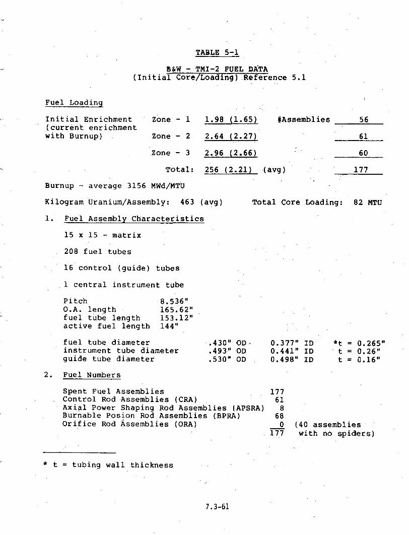
TABLE 5-1
BLW - TMI-2 FUEL DATA (Initial Core/Loading) .Reference 5.1
Fuel Loading . .
Initial Enrichment ' Zone - 1 1.98 (1.65) #Assemblies 56 (current enrichment with Burnup) Zone - 2 2.64 (2.,27)
. . 61
Total: 256 (2.21) -(avg) 177 . .
Burnup - average 3156 MWd/MTU .
Kilogram '~ranium/~ssembly: 463 (avg) Total Core Loading: 82 MTU
1. Fuel Assembly Characteristics
15 x 15 - matrix 208 fuel tubes
. 16' control (guide) tubes
, 1 central instrument tube
Pitch 8.536" O.A. length 165.62"
153.12" fuel tube length active fuel length 144"
fuel tube diameter .43OW O D * 0.377" ID *t = 0.265" instrument tube diameter .493" OD 0.441" ID t = 0.26" guide tube diameter .530" OD 0.498" ID t = 0.16"
2. Fuel Numbers
Spent Fuel Assemblies . . 177 Control Rod Assembl.ies (CRA) 61 Axial Power Shaping Rod Assemblies (APSRA) 8' Burnable Posion Rod.Assemblies (BPRA) 68 Orif ice Rod ~ssemblies (ORA) 0 (40 assemblies . ' -
177 with no spiders)
* t = tubing wall thickness

TABLE 5-1 (CONTINUED)
B&W - TMI-2' FUEL DATA ( I n i t i a l C o r e l o a d i n g ) R e f e r e n c e 5.1
3. F u e l Assembly Composi t ion
U p , - 92.5% t h e o r e t i c a l d e n s i t y
f u e l c l a d Z i r c a l l o y 4 g u i d e t u b e s Z i r c a l l o y 4 s p a c e r . g r i d s ' Inconel -718 e n d f i t t i n g s S t a i n 1 e . s ~ .steel, g r a d e . C F ~ M
4. C o n t r o l Rod Assembly . (CRA) , .
16/assembly g u i d e t u b e material l e n g t h - 134" Type 304 s t a i n l e s s s teel d i m e n s i o n s 0.440" OD
0.21" - t c l a d c o m p o s i t i o n - Ag-In-Cd, 80-15-5% r a t i o
5. ~ x i a i Shap inq Rod Assembl i e s
16 /a s sembly Type 304 s t a i n l e s s s tee l 0.440" OD ' 0.021" c l a d t h i c k n e s s l e n g t h 36" ( p o i s o n ) c o m p o s i t i o n - Ag-In-Cd 80-15-5% r a t i o
6 . Burnab le P o i s o n Rod Assembl i e s
16 /assembly Z i r c a l l o y 4 0.430" OD 0.35" c l a d t h i c k n e s s p o i s o n l e n g t h 126" p o i s o n - A 1 0 - B C

FUEL ASSEMBLY
FIGURE 5-1'

TOP VIEW
CONTROL ROD ASSEMBLY . ,
FIGURE 5-2

BURNABLE POIS.0N ROD ASSEMBLY
FIGURE 5-3

TABLE 5-2
CORE ISOTOPIC TOTALS - (AT SHUTDOWN - AVERAGE)
A. Isotope
Element
Mass (AGNS) (Kiloqrams)
C. Uranium Enrichment
AGNS (Kilograms
AGNS B&W
Mass (B&w).* JKilograms)
B&W . (Kilograms
D. Percent Pu-240 in Total Plutonium
AGNS B&W
* " ~ e f e r s to da.ta supplied b y ' ~ 6 ~ to AGNS in March 19.80.

TABLE 5-3
REGION 1 FUEL ISOTOPIC CONTRATION - (AT SHUTDOWN)
A. Isotope
B . Element
Mass (AGNS) (Kilqqrams)
Mass (B&W) (Kiloqrams)
. .
AGNS (Kilograms
B &W (Kiloqrams
U 25821 26172 Pu 50.7 54.2
C.. Uranium. Enrichment .+ i
AGNS 1.68% / i
B&W 1.65%
D. Percent Pu-240 in Total Plutonium -._.
AGNS 8.3% B.& W 8.2%
- .

TABLE 5-4
A. Isotope
B. Element
Mass (AGNS) Mass (B&W) (Kilograms) (Kiloqrams)
. AGNS (K iloqrams
C. Uranium ~nrichment
AGNS B&W
Percent Pu-240 in Total Plutonium
AGNS B&W
B&W (Kiloqrams

TABLE 5-5
REGION 3 FUEL ISOTOPIC CONCENTRATION - (AT SHUTDOWN)
Mass (AGN.S.) , ; (Kiloarams)
Mass ( B C W ) (Kilograms)
AGNS B &W Element (Kiloqrams (Kiloqrams
Uranium Enrichment
AGNS B&W
Percent Pu-240 in Total Plutonium
AGNS B&W
AGNS-B&W Agreement - There is r e a s o n a b l y 'good a g r e e m e n t between t h e AGNS and 'B&W eva lua t ions . ; I m p o r t a n t q u a n t i-1 t ies such a s t h e uranium enr ichment and p e r c e n t Pu-240 i n t h e p lu tonium a r e v i r t u a l l y i d e n t i c a l . I t is. n o t e d t h a t t h e B&W r e s u l t s show somewhat l a r g e r q u a n t i t i e s of p l u t o - nium. The t y p i c a l v a r i a t i o n i s less t h a n 1 0 % . A s a n i l l u s t r a t i o n , t h e B&W v a l u e f o r t o t a l core p l u t o n i u m is
,153.7 k i lograms v e r s u s t h e AGNS v a l u e of 142.2 k i l o g r a m s (see Tab le 5-2, P a r t B'). The B&W v a l u e s were u t i l i z e d a s t h e b a s e l i n e f o r t h i s core s tudy .
Uranium Enrichment - The v a l u e of t h e enr ichment of U-235 o f t h e e x i s t i n g "burned-up" f u e l is 1 . 6 5 % i n R e q i o n 1, 2.27% i n Region 2 , a n d 2.'66% i n R e g i o n 3. The ;ve rage enr ichment is 2.2%. The enr ichment i n Regions 2 and 3 is , .
h i g h e r t h a n t h a t a l l o w e d i n f a c i l i t i e s u t i l i z e d t o c o n v e r t t h e u r a n y l n i t r a t e f r o m r e p r o c e s s i n g p l a n t s t o u r a n i u m h e x a f l o r i d e (UF ) . T y p i c a l u p p e r l i m i t s o n enr ichment from a c r i t i c a l i t y s t a n d p o i n t are 1 . 8 % . .
Pu-240 Conten t - The p e r c e n t o f Pu-240 i n p l u t o n i u m is less t h a n t h a t of u s u a l " r e a c t o r - g r a d e " p l u t o n i u m d u e t o low ' f u e l burnup. The Pu-240 c o n t e n t r a n g e s f r o m 5 . 8 % i n Region 3 t o 8 .2% i n Region 1. I n a r e p r o c e s s i n g p l a n t , t y p i c a l l y , Pu-240 l i m i t s m u s t b e g r e a t e r t h a n 5 % t o p r e v e n t c r i t i c a l i t y problems. A 1 so, t h e Pu-240 c o n t e n t i n t h e 5 t o 8 % r a n g e is i n t h e v i c i n i t y o f t h a t c o n - s i d e r e d t o b e w e a p o n s - g r a d e . Note t h a t t h e p l u t o n i u m c o n t e n t is approx imate ly o n e - s i x t h o f t h a t e x p e c t e d f o r f u l l burnup f u e l .
5.2.4 Nuclear and Thermal Data
An i n i t i a l assumpt ion was t h a t t h e f u e l would n o t be removed from t h e core and canned, p r e p a r a t o r y to s h i p p i n g u n t i l mid- 1982. C u r r e n t e x p e c t a t i o n s a r e t h a t t h i s r e p r e s e n t s a t b e s t a n e a , r l y l i m i t . Due t o t h e r e l a t i v e l y low b u r n u p o f t h e TMI-2 f u e l , it was expec ted t h a t t h e n u c l e a r s o u r c e s t r e n g t h would be r e l a t i v e l y l o w a t t h i s time. To c o r r o b o r a t e t h i s , a n e v a l u a t i o n was made to d e t e r m i n e t h e v a l u e s a f t e r t h r e e y e a r s or more o f a g i n g . S h i p p i n g a t a n y l a t e r d a t e w i l l r e s u l t i n s t i l l lower v a l u e s of n u c l e a r s o u r c e s t r e n g t h and decay h e a t .
The computer code ORIGEN ( R e f e r e n c e 5 . 3 ) was u s e d f o r t h i s purpose . The v a l u e s p r e s e n t e d a r e t h o s e f o r Region 2 o f t h e core which r e c e i v e d t h e h i g h e s t b u r n u p a n d , a s s u c h , would p r e s e n t t h e l i m i t i n g c a s e . T a b l e 5-5 shows t h e gamma s o u r c e s t r e n g t h s a t s e l e c t e d d e c a y times f r o m o n e t o f i v e y e a r s a f t e r t h e shutdown of t h i s c o r e i n March 1 9 7 9 . The v a l u e s p r e s e n t e d r e p r e s e n t t h e number f o r e a c h o f t w e l v e s p e c i f i c e n e r g y g roups . T a b l e s 5-6 and 5-7 a r e a c o m p a r i s o n o f t h e

Mean E n e r g y ( MeV
N'OTES :
TABLE :5 7.6,
T M I - 2 CORE REGION 2 FUEL S0URCE:STRENGTH ( 2 ) GAMMAS PER SECOND. PER METRIC TON - OF . 'RANIUM
D e c a y T i m e O n e Two . " . . ,The,ee : :' . ' , F o u r F i v e Y e a r Y e a r s - Y e a r s . Y e a r s Y e a r s
. . . .
( 1 ) E a r l i e s t shipping da te . ( 2 ) F u e l a s s e m b l y loading = 0 . 4 6 7 MTU.

TABLE 5-7
( 1 ) Mean
E n e r g y ( MeV
COMPARISON OF GAMMA SOURCE TERMS - TMI-2 FUEL VERSUS HIGH BURNUP FUEL
( O n e Y e a r D e c a y T : i m e ) .
\( 2 ( 3 ) Gammas per Second per Metric T o n
TMI-2 High B u r n u p F u e l
( 4 ) R a t i o of
C o l u m n ( 3 ) to C o l u m n ( 2 )

gamma s o u r c e terms f o r t h e low b u r n u p TMI f u e l a f t e r o n e y e a r o f . decay time w i t h t h o s e o f h i g h ' b u r n u p f u e l ' ( 3 3 , 0 0 0 MWd/MTU v e r s u s a p p r o x i m a t e l y 3 2 0 0 MWd/MTU) . Th ' e se t a b l e s 4 t o 1 5 , be low 3.7 MeV ( a h i g h e n e r g y c u t o f f ) . F o r t h e h i g h e n e r g y g a m m a g r o u p s , t h e s o u r c e . t e r m s a ' r e l a r g e r by a f a c t o r of 2000. Hence , t h e t o t a l gamma s o u r c e s t r e n g t h f o r TMI- f u e l is c o n s i d e r a b l y lower t h a n f u e l o f normal bu rnup .
A s imilar e v a l u a t i o n was made o f t h e n e u t r o n s o u r c e term i n t h e TMI f u e l . T h i s s o u r c e s t r e n g t h is f r o m s p o n t a n e o u s f i s s i o n s and ( u r n ) r e a c t i o n s , a t a t y p i c a l n e u t r o n e n e r g y l e v e l o f 5 .0 MeV. D u r i n g t h e p e r i o d o f time o f i n t e r e s t , t h e s o u r c e s t r e n g t h for t h e TMI . f u e l is a p p r o x i m a t e l y 1 0 0 0 times l e s s t h a n t h a t f o r t y p i c a l h i g h b u r n u p f u e l . T h e n e u t r o n s o u r c e s t r e n g t h i s v i r t u a l l y n e g l i g i b l e f r o m a s h i e l d i n g s t a n d p o i n t . T h i s is o f i m p o r t a n c e i n r e c o g n i z i n g t h a t a separate n e u t r o n s h i e l d w o u l d n o t b e r e q u i r e d i n a s p e n t f u e l c a s k .
A l s o o f i m p o r t a n c e is t h e t h e r m a l p o w e r o f t h e f u e l o c c u r - r i n g from d e c a y h e a t e m a n a t i n g f rom gamma e m i s s i o n . A g a i n , t h e c o m p u t e r p r o g r a m O R I G E N was u s e d t o d e t e r m i n e t h i s t h e r m a l power f o r e a c h o f t h e ' t h r e e co re . r e g i o n s a s a f u n c t i o n o f ' d e ' c a y time. T h e r e s u i t s shown i n F i g u r e 5-4 . d e p i c t t h e c o r r e s p o n d i n g t h e r m a l powe'r o f f u e l w i t h h i g h bu rnup . The d e c a y h e a t l e v e l , a f t e r t h r e e y e a r s o f b u r n u p ,
. . i s a p p r o x i m a t e l y a n o r d e r o f m a g n i t u d e l e s s t h a n . t h a t e x p e c t e d f o r h i g h b u r n u p f u e l . T h e a v e r a g e v a l u e s . f o r t h e e n t i r e core and f o r a t y p i c a l a s s e m b l y are g i v e n below:
T o t a l core h e a t l o a d a f t e r t h r e e y e a r s - 30 k i l o w a t t s Maximum.fue1 a s s e m b l y h e a t l o a d - 190 watts,
T h e s e . h e a t l o a d v a l u e s a re a p p r o x i m a t e l y two o r d e r s o f . m a g n i t u d e l e s s t h a n t h e d e s i g n v a l u e s n o r m a l l y u s e d f o r s p e n t f u e l s h i p p i n g o r wet p o o l s t o r a g e f o r i n d i v i d u a l a s s e b m l i e s . I n t h e normal d e s i g n case, h i g h b u r n u p f u e l and a p p r o x i m a t e l y 120 d a y s o f f u e l a g i n g are assumed. I t is no't e x p e c t e d t h a t t h e r e w i l l be a n y . t h e r m a l l i m i t a t i o n s a s s o c i a t e d w i t h e i t h e r d r y s t o r a g e , d r y s h i p m e n t w i t h i n a s p e n t f u e l c a s k , or s t o r a g e i n a wet p o o l . I n t h e l a t t e r
,case, t h e n a t u r a l c i r c u l a t i o n p r e s e n t i n t h e p o o l s h o u l d , b e a d e q u a t e t o a s s u r e c o o l i n g ( i f s u f f i c i e n t water v o l u m e i s p r e s e n t . ) . 5.2.5 Damaged F u e 1 , C o n d i t i o n s
T h e r e h a v e b e e n two s e p a r a t e a n d . i n d e p e n d e n t a s s e s s m e n t s made . o f t h e TMI-2 f u e l core a f t e r ; t h e a c c i d e n t i t s e l f . T h e s e a s s e s s m e n t s were b a s e d on o p e r a t i n g r e c o r d s , i n s t r u - ment r e a d i n g s ( p r i m a r i l y p r e s s u r e d r o p s a n d t h e r m o c o u p l e

1 One Assembly = 0.46 MTU d
Full Core = 82 MTU 2 Decay Heat Level, KW
Mid-Year . 82 83 84 Hot Assembly 0.19 0.13 0.09 Total Core 30.00 20.00 15.00
3 Design Basis for Shipping Casks . .-- . f20'day aging -- 12 KWlAssembly
~ e c a ~ Time (Months)
TMI-2 CORE DECAY HEAT LEVEL'
FIGURE 5-4

e v a l u a t i o n s ) , and c o m p u t e r i z e d r e c o n s t r u c t i o n s o f t h e a c c i d e n t . ~ h e s e * two e v a l u a t i o n s r e p r e s e n t a n optimist ic and a p e s s i m i s t i c b o u n d a r y on t h e core c o n d i t i o n s . T h e more o p t i m i s t i c e v a l u a t i o n was p e r f o r m e d u n d e r t h e a u s p i c e s o f t h e EPRI-NSAC s t u d y team ( R e f e r e n c e 5 .5 ) ; t h i s e v a l u a t i o n f o c u s e d on most of t h e major s t r u c t u r a l damage o c c u r r i n g i n t h e c e n t r a l r e g i o n of t h e core and e x t e n d i n g a p p r o x i m a t e l y o n e - h a l f o f t h e a x i a l l e n g t h d o w n i n t o t h e f u e l ( t h i s c o r r e s p o n d s t o t h e amoun t o f t h e f u e l t h a t was u n c o v e r e d d u r i n g t h e a c c i d e n t ) . I n t h i s s t u d y , it was assumed t h a t t h e o u t e r p e r i p h e r a l f u e l a s s e m b l i e s were r e l a t i v e l y undamaged f rom a s t r u c t u r a l s t a n d p o i n t , w i t h t h e p o s s i b l e e x c e p t i o n of t h e f i s s i o n g a s p lenums. T h e s e were a s s u m e d t o h a v e b e e n b r e a c h e d due to t h e t h e r m a l c r e e p o f t h e c l a d d i n g . (Note: PWR f u e l r o d s a r e t y p i c a l l y p r e s s u r i z e d t o 6 0 0 t o 8 0 0 p s i w i t h he l i um d u r i n g m a n u f a c t u r e . F i s s i o n g a s e s would m i g r a t e f r o m t h e f u e l to t h e plenum gap d u r i n g t h e a c c i d e n t t h e r m a l t r a n s i e n t . D u r i n g t h e a c c i d e n t , t h e g a s p r e s s u r e i n t h e f u e l p lenums and a x i a l g a p s o f t h e f u e l may h a v e e x c e e d e d 2000 t o 3000 p s i . ) The more p e s s i m i s t i c s t u d y , r e f e r r e d t o a s t h e R o g o v i n r e p o r t a n a l y s i s ( r e f e r e n c e 5 . 4 ) p r e d i c t s major f u e l damage and p e r h a p s m e l t i n g of t h e f u e l c l a d d i n g i t s e l f . The Rogovin s t u d y assumed t h a t a s u f f i c i e n t amoun t o f t h e c o r e r e a c h e d a t e m p e r a t u r e w h e r e a s o l i d "a lmos t w e l d e d n s t r u c t u r e may h a v e f o r m e d b e t w e e n v a r i o u s f u e l components . I t was also e x p e c t e d t h a t a p o r t i o n of t h e f u e l had dropped to t h e lower r e g i o n s of t h e reactor v e s s e l .
Based on t h e s e c o n f l i c t i n g o p i n i o n s and l a c k i n g o b s e r v a - . . t i o n a l i n f o r m a t i o n , it is o b v i o u s t h a t p r o v i s i o n and p l a n -
n i n g must be made f o r h a n d l i n g b o t h i n t a c t f u e l and d e b r i s ( f u e l f i t t i n g s , c l a d d i n g , U02 powder, etc. ) . P r o v i s i o n must - a l s o be made f o r h a n d l i n g or s e p a r a t i n g f u s e d f o r m a t i o n s o f . f u e l w h i c h . a r e l a r g e r i n c r o s s s e c t i o n . t h a n t h e f u e l a s sembly . Even w i t h t h e " i n t a c t " a s s e m b l i e s , t h e r e w i l l b e c o n s i d e r a b l e damage and e m b r i t t l e m e n t o f t h e c l a d d i n g . T h e r e w i l l p r o b a b l y be some bowing ' o f t h e i n d i v i d u a l f u e l r o d s . The f a ' i l e d rod plenum (or some o t h e r p o r t i o n of t h e f u e l ) may . p r o j e c t o u t i n t o t h e f l o w p a s s a g e . F u e l h a n d l i n g a n d p a c k a g i n g t e c h n i q u e s m u s t b e w e l l t h o u g h t o u t t o m i n i m i z e any p o s s i b l e f u r t h e r damage o f t h e f u e l . C a n n i n g i s r e q u i r e d to p r e v e n t t h e s p r e a d of f u e l m a t e r i a l t o o t h e r p o r t i o n s o f ' t h e c o n t a i n m e n t v e s s e l a n d p o o l s d u r i n g h a n d l i n g .
5 .2 .6 C r i t i c a l i t y C o n d i t i o n s f o r F u e l D e b r i s
T h e r e 'is no commerc ia l r e a c t o r e x p e r i e n c e r e l a t e d to l o a d i n g p i e c e s ( d e b r i s ) o f LWR f u e l i n t o s p e n t . f u e l c a n s . U ' l t i - m a t e l y , t h i s d e b r i s must e i t h e r be s t o r e d w i t h i n r a c k s i n a s p e n t f u e l p o o l or be p l a c e d w i t h i n a c a n and s h i p p e d of f - s i t e i n a s p e n t f u e l ca sk . The o p e . r a t i o n a 1 s a f e t y q u e s t i o n s

relate to the nuclear source strength within the container and the precluding the possibility of criticality. As noted in Section 5.2.3, the source strengths will be very low. However, the capability of assessing them prior to actual loading is not possible due to the segregated nature of the fuel.
Criticality concerns are not straightforward. A separate evaluation was made of this question. The analysis evaluated a single, water-filled can approximately 9 inches square in cross section and 15 feet long located in an unborated fuel storage pool. Pool water bor.ation reduces the probability of criticality; however, accommodation for unborated water will probably be required, since off-site storage pools will probably'be unborated. Both the fuel. geometry and the fuel enrichment are unknown. From the standpoint of geometry, it can be conservatively assumed that the fuel will be in virtually any shape and size corresponding to the can dimension, and that any metal to water ratio may exist within the can. A detailed evaluation of khis question requires a series of parametric studies equating various fuel sizes, shapes, and various metal-to- .water ratios so that a worst case configuration could be ,
established. A study of the literature (Reference 5.6 ) con'tains information that is useful for this purpose. Spe'cifically, an infinitely tall cylinder 10.6 inches in diameter can be .shown to be slightly subcritical containing a heterogeneous oxide fuel at 3.0% enrichment. In this reference case, the' U02 could be in any shape and size, as well as the metal-to-water ratio. The infinite water reflector can be assumed which is the worse case. Using hand techniques, the 10.6,-inch diameter was determined to be equivalent from a criticality standpoint to a square cross section approximately 9.4 inches on a side. Evaluations of the can indicate that the can will be fabricated from stainless steel and will have a wall thickness typically between 0.08 and 0.10 inches thick. The effect of the stainless steel wall on reactivity is essentially negligible in this case.
The preceding evaluation was conservatively based on the 3.0% maximum initial enrichment in ~ e g i o n 3 of this core.. This upper (no burnup) limit was utilized due to the fact that. there are many regions which are blanketed by control rods during the short burnup history. As a result, there are axial regions of the core that would ha~e~experienced very little burnup. ~ e n c e , this upper limit is not an unrealistic assumpt'ion, particularly in view of potential licensing questions.
The criticality concerns related to the canning of debris are of sufficient importance that it'is recommended that

f u r t h e r a n a l y s e s b e p e r f o r m e d . T h e s e p r o b l e m s w o u l d b e min imized to some e x t e n t a t t h e TMI-2 s i t e w h e r e t h ' e p o o l s a r e b o r a t e d . However, a t u n l o a d i n g f a c i l i t i e s 'and i n t h e l i c e n s i n g o f s p e n t f u e l c a s k s , a more c o m p r e h e n s i v e e v a l u a t i o n would be r e q u i r e d .
The t o t a l u n c e r t a i n t y i n t h e p h y s i c a l . s t a t u s o f t h e TMI-2 core r e q u i r e s t h a t a number o f a l t e r n a t i v e p a t h s b e d e v e l - o p e d f o r t h e h a n d l i n g s c e n a r i o s . T h e s e p a t h s c o u l d b e s i m p l i f i e d t o a c e r t a i n e x t e n t i f i n i t i a l i n f o r m a t i o n a n d t e s t i n g t e c h n i q u e s were d e v e l o p e d e a r l y o n . H e n c e , i t is recommended t h a t a t t h e e a r l i e s t p r a c t i c a l time a means b e d e v e l o p e d ' f o r o b t a i n i n g a v i s u a l s c a n ' o f t h e core . I n a d d i t i o n , i t i s recommended t h a t a m e a s u r e m e n t t o o l b e d e v e l o p e d f o r d e t e r m i n i n g ( i n t h e c a s e o f v i s u a l l y i n t ' a c t f u e l ) s t r u c t u r a l i n t e g r i t y . A p o s s i b l e t o o l c o n c e p t f o r t h i s p u r p o s e is n o t e d a s Item 1 4 R e f e r e n c e 5 . 7 . T h i s t o o l t e s t s t h e c e n t r a l g u i d e t u b e o f t h e f u e l a s s e m b l y a n d
' d e t e r m i n e s t h e r e l a t i v e s t r e n g t h o f t h e g u i d e - t u b e . T h i s c a n be used to e s t i m a t e t h e a x i a l s t r e n g t h o f t h e a s s e m b l y .
5 .3 F u e l Hand l ing and Packag ing E v a l u a t i o n
5.3 .1 G e n e r a l
T h e p u r p o s e o f t h i s s p e c i f i c s t u d y i s t o e v a l u a t e , t h e t e c h n i c a l a s p e c t s o f f u e l h a n d l i n g w i t h i n t h e c o n t a i n m e n t and s p e n t f u e l ( a u x i l i a r y ) b u i l d i n g s , and t h e p r o v i s i o n s f o r p a c k a g i n g t h e f u e l i n a f o r m w h i c h i s s u i t a b l e f o r e i t h e r e x t e n d e d p o o l s t o r a g e or f o r sh ipmen t o f f - s i t e . T h i s s t u d y i s d i v i d e d i n t o t h r e e s p e c i f i c t e c h n i c a l a r e a s w h i c h a r e l i s t e d below:
Hand l inq I n t e r f a c e E v a l u a t i o n - T h i s i n v o l v e s t h e p h y s i - c a l movement o f t h e f u e l or d e b r i s from t h e reactor a r e a a n d c o n t a i ' n m e n t b u i l d i n g , t h r o u g h t h e f u e l t r a n s f e r t u n n e l , t o t h e p o o l a r e a s i n t h e a u x i l i a r y b u i l d i n g . I t i n c l u d e s d i s c u s s i o n o f t empora ry s t o r a g e i n s t o r a g e r a c k s a n d t h e i s o l a t i o n o f t h e c o n t a m i n a t e d f r o m t h e n o n c o n t a m i n a t e d d u r i n g h a n d l i n g o p e r a t i o n s . I t a l s o i n c l u d e s a p r e l i m i n a r y e v a l u a t i o n o f t h e l o a d i n g a n d u n l o a d i n g o f t h e f u e l package from t h e s p e n t f u e l c a s k a t a r e c e i v i n g f a c i l i t y .
C a n i s t e r Des ign - T h i s i s a n . e v a l u a t i o n o f t h e c a n n i n g r e q u i r e m e n t s f o r b o t h " i n t a c t " f u e l and d e b r i s . I t a l s o i n c l u d e s a d i s c u s s i o n o f c a n n i n g t e c h n i q u e s . A c o n - s i d e r a b l e number o f i n t e r f a c e s e x i s t b e t w e e n h a n d l i n g r e q u i r e m e n t s f o r o n - s i t e movement o f t h e i n t a c t f u e l a n d d e b r i s h a n d l i n g . The can must f u n c t i o n a s a c o n t a i n m e n t boundary f o r u se w i t h t h e s h i p p i n g c a s k a n d a l s o p e r m i t long- te rm, o n - s i t e s t o r a g e i n t h e TMI p o o l s ;

Scoping of Operational Procedures - Included is a preli- minary evaluation of the types of techniques and opera- tional factors which must be examined prior to the removal of the fuel from the core. Included in this are the transport of the fuel from the core. Included in this are the transport of fuel between buildings and the canning operations. These procedures are defined in sufficient detail to allow a preliminary evaluation of potential hazard areas to be developed.
5.5.2 Fuel Handling Interface Evaluation
5.3.2.1 Handling Operations at the Reactor
(1) Fuel Hoisting (Removal from the Reactor Fuel Basket)
~ f . the fuel bow or twist is excessive (typically 1/4 .inch), the fuel handling bridges probably cannot be utilized without modification. Also, if the structural integrity .of the assemblies is not adequate for vertical lift with the nornal.top-end grappling, a different grapply system must be provided on these units. The fuel assembly must be provided with additional structure of verified integrity. (This additional structure could reduce the bow and twist allow- ance discussed above.) The auxiliary crane units also provide'little flexibility for grappling and for working around mechanical lifting interferences that could develop from distortion of the fuel. Obviously, the standard lifting gear cannot be used to lift debris.
If the fuel handling bridges in the Fuel Transfer Pool (FTP) and the Fuel Storage Pools (FSP) cannot be utilized (see Fig~re 5-5 which is schematic of the three pools), auxiliary
, service hoist trolleys to replace the existing trolleys and designed to accommodate potentially damaged fuel handling are an acceptable alternate. These crane hoists should be of the hook and cable type versus telescoping tubes in order to provide great hoisting flexibility and to accommodate tooling to fit between the hook and the fuel assembly.
Another alternative for hoisting an intact assembly would be t.he ilse of the existing overhead cranes with modified aux- iliary hoist control. Special systems would be required to ensure adequate water cover over fuel at all times (inter- lock;~ and hoisting control flexibilitysuch as extended.slow speed operation, small vertical and horizontal positioning tolerances, and overload sensing capabilities. However, auxiliary service hoist trolleys installed on the fuel handling bridge would decouple existing crane functions and fuel hand1 ing. An auxiliary hoist trolley should. ,better

N E L TRANSFER TUBES
MAIN FUEL HANDLING BRIDGE Double Telescopln~ Boom 7
SPENT N E L GATE
FUEL POOL '8' (27' r 19.5' x 38' D)
CASK UNLOADING POOL (lo' x 10' x 40' 0)
, L &EL S ~ W G E WNDUN= mmE Dauble T.tascoplng Barm
NEW NU ELEVATOR
BUILDING FLOOR LAYOUT
FIGURE ' 5-5

a c c o m m o d a t e t h e a n t i c i p a t e d m a n u a l o p e r a t i o n s i n t h e d e f u e l i n g o p e r a t i o n .
Communicat ions w i t h GPU p e r s o n n e l ( R e f e r e n c e 5 . 9 ) i n d i c a t e t h a t o p e r a t i n g e x p e r i e n c e w i t h t h e s e e x i s t i n g f u e l h a n d l i n g u n i t s b y i t s e l f w o u l d s u g g e s t a l t e r n a t i v e f u e l h o i s t i n g e n d f i t t i n g d i s t o r t i o n , f u e l c o u l d b e p a c k a g e d a n d t h e p a z k a g e s h a n d l e d by i n t e r m e d i a t e h o i s t i n g t o o l s s u s p e n d e d f rom c r a n e hooks. F i n a l engagement s h o u l d allow f o r m a n u a l p o s i t i o n i n g correct i o n s . H o i s t i n g and t r a n s l a t i o n s h o u l d be p r e c e d e d by v i s u a l v e r i f i c a t i o n o f a p o s i t i v e e n g a g e m e n t o f t h e f u e l a s sembly b e i n g g r a p p l e d .
( 2 5 F u e l T r a n s f e r C a r r i a g e / U p e n d e r (Movement B e t w e e n t h e Conta inment and t h e A u x i l i a r y B u i l d i n g )
An e v a l u a t i o n o f t h e i n t e r f a c e s be tween packaged f u e l assem- b l i e s and t h e f u e l t r a n s f e r c a r r i a g e b a s k e t was pe r fo rmed by r e f e r e n c e t o B a b c o c k a n d W i l c o x d r ' a w i n g s o f t h e f u e l t r z n s f e r sys tem: ( R e f e r e n c e 5 . 9 ) .
The e v a l u a t i o n was used to d e v e l o p any l i m i t i n g or p o t e n t i a l d i m e n s i o n a l i n t e r f a c e s such as t h e maximum c a n i s t e r l e n g t h or l a r g e s t a l l o w a b l e cross s e c t i o n .
The maximum packaged f u e l l e n g t h t h a t c o u l d be accommoda ted by t h e c a r r i a g e b a s k e t was i n v e s t i g a t e d . ~ s s u m i n g t h e s t o p a s sembly ( I t e m 1170 , 44-54-011-02) c o u l d b e r e l o c a t e d , t h e l i m i t i n g i n t e r f e r e n c e w o u l d b e t h e f l a n g e o f t h e t r a n s f e r t u b e (Item 3 3 6 7 , 44-54-040-30) on t h e reactor s i d e . Use o f t h i s maximum l e n g t h m i g h t r e q u i r e r e m o v a l o f t h e p o o l e m e r g e n c y c a b l e s y s t e m ( I t e m 0 0 2 2 , 4 4 - 5 4 - 0 1 7 - 0 8 ) , b u t i n s u f f i c i e n t d e t a i l was a v a i l a b l e t o s a y w i t h c e r t a i n t y . The maximum, u n i n t e r f e r e d l e n g t h would be 1 5 f e e t 1/8 i n c h . - The maximum s q u a r e cross s e c t i o n t h a t c o u l d b e c o n t a i n e d w i t h i n t h e 1 5 . 2 5 - i n c h o c t a q o n a l i n s i d e d i a m e t e r o f t h e b a s k e t would be 1 1 . 4 8 inches- . However , s i n c e t h e "worst- c a s e " c r i t i c a l i t y ( s q u a r e ) cross s e c t i o n h a s been c a l c u l a t e d a t 9 .4 i n c h e s (see S e c t i o n 5 . 2 . 6 ) , t h i s 11 .48- inch d imens ion i s n o t l i m i t i n g a n d i s n o t e d f o r r e f e r e n c e p u r p o s e s . T h e r e f o r e , a s q u a r e f u e l a s s e m b l y s t r u c t u r a l p a c k a g i n g c a v i t y s h o u l d n o t exceed 9.4 i n c h e s . Assuming t h e 9 . 4 - i n c h d imens ion (13 .3 - inch d i a g o n a l ) is l i m i t i n g , i t a p p e a r s , so f a r a s t h e b a s k e t is c o n c e r n e d , t h a t c y l i n d r i c a l p a c k a g i n g o f t h e f u e l f o r c o n t a i n m e n t p u r p o s e s ( a l r e a d y w i t h i n a s t r u c t u r a l p a c k a g e ) c o u l d be pe r fo rmed i n t h e f u e l t r a n s f e r
p o o l and s t i l l u t i l i z e t h e c a r r i a g e f o r ' t r a n s f e r to t h e f u e l s t o r a g e p o o l . ( S e e ~ i g u r e 5 -5) .
The r e q u i r e d s t r u c t u r a l c a p a c i t y of t h e : u n i t was q u a ' l i t a - t i v e l y e v a l u a t e d . T h e a d d e d w e i g h t o f p r o v i d i n g t h e p a c k a g i n g f o r t h e f u e l a s s e m b l y , a s d i s c u s s e d a b o v e a n d i n d e t a i l l a te r , would n o t i n c r e a s e t h e f u e l - p l u s - c o n t r o l - r o d
p a c k a g i n g f o r t h e f u e l a s s e m b l y , a s d i s c u s s e d a b o v e a n d i n d e t a i l l a t e r , would n o t i n c r e a s e t h e . f u e l - p l u s - c o n t r o l - r o d w e i g h t o f 1 7 0 0 p o u n d s ( w h i c h t h e c a r r i a g e r o u t i n e l y accommodates ) by more t h a n 35%. F o r t h e p r e s e n t s t u d y , i t was assumed t h a t c o n s e r v a t i s m i n the s t r u c t u r a l d e s i g n o f t h e u n i t c o u l d accommodate t h i s , b u t t h i s . shou.ld be v e r i f i e d when t h e p a c k a g i n g s y s t e m d e s i g n is f i n a l i z e d .
( 3 ) ' F u e l S t o r a g e Rack ( S t o r a g e i n . t h e A u x i l i a r y B u i l d i n g . P o o l )
S p e c i a l l y d e s i g n e d packaged f u e l r a c k q w i l l be r e q u i r e d f o r t h e f a i l e d f u e l ( B u r n s and Roe Drawing W.O. 2555/2066 R.15). T y p i c a l l y , f o r seismic r e a s o n s , r a c k s are l i m i t e d t o 3 / 8 t o 1 / 2 i n c h maximum c r o s s - s e c t i o n a l c l e a r a n c e b e t w e e n t h e f c e l a n d t h e r a c k . I n t h i s case , t h e p a c k a g e d , d a m a g e d f u e l would n o t be e x p e c t e d to f i t e x i s t i n g s lo ts i n t h e B u r n s and Roe d e s i g n . However, new r a c k s c o u l d be d e s i g n e d t o accam- modate any p a c k a g i n g s y s t e m s e n v i s i o n e d u s i n g s t a t e - o f - t t e - a r t t e c h n o l o g y .
( 4 ) S t o r a q e P o o l I s o l a t i o n ( P r e v e n t i o n o f C o n t a m i n a t i o n Between P o o l s )
C o n t a m i n a t i o n c o n t r o l c o u l d b e a s i g n i f i c a n t c h a l l e n g e d u r i n g t h e d e f u e l i n g a n d c a n n i n g o p e r a t i o n s . F o u r a r e a s c o u l d b e p o t e n t i a l l y i s o l a t e d f r o m e a c h o t h e r ( s e e F i g u r e 5-5) .' They' a r e ' t h e f o l l o w i n g :
F u e l - T r a n s f e r P o o l (FTP) S p e n t F u e l S t o r a g e P o o l A (FSP A ) S p e n t F u e l S t o r a g e P o o l B (FSP E) . C a s k Loading P o o l (CLP).
ow ever, f rom p r e l i m i n a r y e v a l u a t i o n , i t a p p e a r s t h a t t h e FTP and FSP A would n o t be e a s i l y isolated d u r i n g d e f u e l i n g . The p o t e n t i a l t o i s o l a t e t h e FTP a n d FSP A from FSP .B a n d FSP B , f r o m t h e CLP a p p e a r e d more f e a s i b l e . T h e s e i s o l a t i o n s c o u l d b e a c c o m p l i s h e d b y . a m o d u l e c a n a l l o c k s y s t e m i n s t a l l e d i n t h e area where t h e i s o l a t i o n g a t e s now f i t (see F i g u r e 5-5) . The l o c k s w o u l d p e r m i t i s o l a t i o n a n d t r a n s - f e r s ; w h e r e a s , t h e e x i s t i n g g a t e s p e r m i t . o n l y o n e o f t h o s e f u n c t i o n s . The l o c k s would be r e l a t i v e low v o l u m e , t emgo- r a r y w a t e r barriers t h a t c o u l d be isolated v i a g a t e c l o s i n g s

and p i p e d f o r m u l t i p l e w a t e r i n v e n t o r y c h a n g e o u t s when so i s o l a t e d . The c h a n g e o u t s would a f f e c t d c c o n t a m i n a t i o n . Mechan ica l or c h e m i c a l d e c o n t a m i n a t i o n c a p a b i l i t i e s c o u l d a l s o be added to t h e l o c k sys t ems . O n e - t e n t h d e c o n t a m i n a - t i o n f a c t o r s a t e a c h o f t h e two e n v i s i o n e d l o c k s w o u l d p r o v i d e a h u n d r e d - f o l d d e c o n t a m i n a t i o n f a c t o r f o r t h e p a c k a g e d f u e l a n d , a s a r e s u l t , wou ld p r e v e n t e x c e s s i v e c o n t a m i n a t i o n of t h e s h i p p i n g c a s k e x t e r i o r d u r i n g l o a d i n g .
W i t h . t h i s t w o - l o c k s y s t e m , t h e r e is o n l y p r o v i s i o n f o r s t r u c t u r a l packaging . T h i s s h o u l d be d o n e to t h e f u e l i n t h e h i g h e r background area of t h e FTP and a l l c o n t a m i n a t i o n c o n t a i n m e n t packag ing s h o u l d be done i n FSP A.
O u r e v a l u a t i o n i n d i c a t e s t h a t t h e a b o v e i s o l a t i o n / d e c o n t a m i n a t i o n c o n c e p t would b e ' c o m p a t i b l e w i t h t h e e x i s t - i n g w a t e r c l e a n u p / c o o l i n g s y s t e m s o f t h e r e a c t o r f a c i l i t y . However, t empora ry submerged d e m i n e r a l i z e r s y s t e m s i n t h e s e p o o l s might be p r e f e r r e d t o t h e f a c i l i t y s y s t e m s b a s e d on r a d i a t i o n e x p o s u r e e x p e r i e n c e a s s o c i a t e d w i t h u s e o f t h e s e u n i t s a s r e p o r t e d by GPU. ( R e f e r e n c e 5 . 0 ) .
5.3.2.2 F u e l Packag ing and S p e n t F u e l Cask ~ n t e r f a c e s
Cask E v a l u a t i o n s
I n t e r f a c e e v a l u a t i o n s w i t h t h e t h r e e c a n d i d a t e t r u c k c a s k s a r e more e a s i l y v i s u a l i z e d by r e f e r e n c e t o F i g u r e 5 - 6 . O b v i o u s l y , t h e NLI 1 /2 c a s k is most r e s t r i c t i v e w i t h i t s s m a l l e r 13.375-inch d i a m e t e r . The f u e l c a v i t y l e n g t h c o u l d b e i n c r e a s e d t o 1 7 6 . 3 7 i n c h e s u s i n g e l l i p t i c a l h e a d s ( a n u n l i c e n s e d m o d i f i c a t i o n ) a s e n v i s i o n e d f o r p r e s s u r e i n t e g - r i t y of t h e c o n t a i n m e n t packag ing i f cann ing c o n s i d e r a t i o n s mandate e x t r a l e n g t h . S c a l e d and more d e t a i l e d d r a w i n g s o f t h e s e c a s k s a r e shown i n S e c t i o n 5 . 4 . The F o r t S t . V r a i n c a s k w i t h i ts l a r g e r c a v i t y o f f e r s t h e most f l e x i b i l i t y i n t h i s r e g a r d .
A s e x p l a i n e d i n S e c t i o n 5 . 4 , v a r i o u s c o n s i d e r a t i o n s w i t h r a i l , casks c l o u d c o n s i d e r a t i o n o f t h e i r u s e i n d e f u e l i n g . However, a l a r g e r a i l c a s k c o u l d ' c o n c e i v a b l y be u t i l i z e d a s a l lbucketl ' to move f u s e d p i e c e s o f d e b r i s d i r e c t l y . t h r o u g h t h e . c o n t a i n m e n t h a t c h and o u t s i d e to t h e a u x i l i a r y b u i l d i n g . I n a d d i t i o n , a s p e c i a l h a n d l i n g c a s k w i t h i n s i d e c a v i t y d i a m e t e r s i n e x c e s s o f 4 0 t o 4 5 i n c h e s c o u l d be d e v e l o p e d f o r t h e same f u n c t i o n . A c a s k s u c h a s t h i s wou ld w e i g h i n e x c e s s o f 100 t o n s . Ca re i n moving t h e s e c a s k s n e a r s a f e t y - r e l a t e d i t e m s m u s t b e e v a l u a t e d w h i l e i n t h e c o n t a i n m e n t b u i l d i n g .

NUCLEAR -ASSURANCE CORP.
(NAC- 1)
TRUCK CASK CAVITY DIMENSIONS (INCHES)
- 13.375- D I A .
FT. ST. VRAIN
(FSV )
i .I I j I
C U ' y i L n h F-4
Ln 5 .
0, h F-4
FIGURE 5-6.

5.3.2.3 Off-Site Receivinq Facility Considerations -
A generic interface evaluation of the packaged fuel with an off-site receiving facility was made. The receiving facility could be assumed to provide some of the following f ~r~ctions for the fuel:
(1) Analysis of Fuel Condition (2) Fuel Storage (3) Chemical Reprocessing (4) Ultimate Disposal as Waste.
The. facility must be able to receive and unload the shipping cask. As a result, the design of the fuel packaging system should be small enough to minimize hindrance with implemen- tation of the above four functions and to permit the cask receipt to be made. The following minimal package criteria were established. The packaging system should:
Frovide pressure retaining capability and contamination control
Provide internal sampling capability to the package
Fermit a coarse "dryout" of a wet container and alter- nately a water filling via a fill and drain system.
A pr- assure providing fuel would
retaining cylindrical can with .a welded end cap vent, fill, and drain capability for the enclosed meet the first three requirements. It would not
accommodate these possible requirements:
. T-3 provide an alternative for remote mechanical wet or dry unpackaging .
To provide alternative can cross sections to preclude mendatory repackaging for more efficient storage, or to accommodate handling preparatory to reprocessing, or for hct cell analysis and examinations.
Space and equipment limitation present at potential receiv- ing facilities could require mechanical uncapping and/or pa.ckaging that opens or disassembles mechanically to expose the fuel. For example, a research facility that must unpackage may not. have remote, metal-cutting equipment. Also, it is probably more likely that the facility lacks the room .or has insufficient size (typically a length equal to twice the can length is needed to permit axial unpackaging). Here, a specially designed can that parted on an axial centerline would be desirable. However, this design would compromise the degree of containment integrity provided by

t h e welded c a p on t h e c y l i n d r i c a l c a n . T h i s c a n c o u l d b e p l a c e d w i t h i n t h e - s t o r a g e can.
R e p r o c e s s i n g and s t o r a g e f a c i l i t i e s w h i c h c a n h a n d l e c a n s w i t h s q u a r e cross s e c t i o n s c o u l d a l s o e x . p e r i e n c e d i f f i c u l t y i f c y l i n d r i c a l c a n s were e m p l o y e d . ' Howeve.r , f o r s t o r a g e f a c i l i t i e s c o m p l e t e i n t e r f a c e e v a l u a t i o n s would b e r e q u i r e d on a s i t e s p e c i f i c b a s i s . I n t e r f a c e , i tems t o b e a d d r e s s e d f o r t h e s e p r o p o s e d f a c i l i t i e s wou ld i n c l u d e among o t h e r t h i n g s :
D imens iona l s u i t a b i l i t y S t r u c t u r a l and seismic i n t e g r i t y
* . C r i t i c a l i t y e v a l u a t i o n Thermal env i ronmen t C o r r o s i o n env i ronmen t .
S i n c e f a c i l i t i e s s e l e c t i o n is n o t f e a s i b l e a t t h i s s t a g e o f t h e s t u d y , t h e f i r s t t h r e e r e q u i r a m e n t s f o r t h e c a n w i l l b e assumed c o n t r o l l i n g . I n any case, t h e h a n d l i n g f l e x i b i l i t y d e s i r e d i n t h e packag ing s y s t e m m u s t b e d e c i d e d b e f o r e t h e d e s i g n o f t h e package is f i n a l i z e d .
5.3.3 P r e l i m i n a r y Canning Des iqn
5.3 .3 .1 I n t r o d u c t i o n
Any TMI-2 f u e l f o r w h i c h t h e r e i s d o u b t c o n c e r n i n g s t r u c - t u r a l a d e q u a c y f o r l i f t i n g s h o u l d b e p r o v i d e d s t r u c t u r a l i n t e g r i t y f o r , f u r t h e r h a n d l i n g . A u g m e n t a t i o n o f t h e a x i a l s t r u c t u r a l s t r e n g t h o f t h e f u e l s h o ~ l d be, p r o v i d e d a s s o o n a s f e a s i b l e d u r i n g t h e d e f u e l i n g o p e r a t i o n . One p o s s i b l e c o n c e p t i s t h e u s e o f a h a n d l i n g s h r o u d t o p r o v i d e s t r u c t u r a l i n t e g r i t y . T h i s s h r o u d wou ld b e a t h i n - w a l l e d c a n which f i t s a round a n d h o l d s o r " g i r d l e s " t h e a s s e m b a y somewhat l i k e a "second s k i n . " V a r i a t i o n s i n t h e d e s i g n o f t h e s h r o u d cou ld accommodate a spec t rum o f f u e l damage. For t h e p r e s e n t c o n s i d e r a t i o n s , con f inemen t o f c o n t a m i n a t i o n i s n o t p o s s i b l e e x c e p t to p r e c l u d e f u r t h e r s t r u c t u r a l f a i l u r e . However, i f i t is n e c e s s a r y to remove d e b r i s , a n u n d e r w a t e r vacuum sys t am c o u l d b e u s e d t o p r o v i d e a n a l t e r n a t i v e f o r removing t h e f u e l f rom t h e r e a c t o r a n d p a c k a g i n g t h e f u e l p i e c e s .
Con tamina t i o n con£ inement is an o b v i o u s f i n a l r e q u i r e m e n t o f t h e packag ing sys tem. To p r o v i d e t h i s f u n c t i o n , a s e c o n d p a c k a g i n g u n i t wou ld b e p r o v i d e d o v e r t h e , s h r o u d . I t i s r e f e r r e d t o i n t h i s r e p o r t a s t h e "can."
A common f e a t u r e o f a n y p a c k a g i n g s y s t e m d e s i g n i s t h e f o l l o w i n g m a t e r i a l and b a i l f e a t u r e s . The m a t e r i a l m u s t b e c o m p a t i b l e w i t h b o t h d r y a n d wet p o t e n t i a l s t o r a g e a n d

s h i p p i n g e n v i r o n m e n t s . N o t a b l y , t h e TMI p o o l s a r e b o r a t e d w h e r e a s many p o o l s u t i l i z e d e m i n e r a l i z e d water. A u s t e n i t i c s t a i n l e s s s t e e l ( e . g . , 304 or 3 1 6 s t a i n l e s s s t e e l ) h a s h i s t o r i c a l l y s e r v e d well i n s imi lar a p p l i c a t i o n s and w i l l be adsumed i n a l l f o l l o w i n g d e s i g n s .
Q u z s t i o n s . c o u l d arise r e g a r d i n g s t r e s s - c o r r o s i o n c r a c k i n g o f t h e s e a u s t e n i t i c s t a i n l e s s s t e e l s i n t h e p r e s e n c e o f c a u s t i c s a n d c h l o r i d e s . C a u s t i c . c o u l d a p p e a r f r o m t h e c o m b i n a t i o n o f water a n d r u b i d i u m , t h e d e c a y p r o d u c t of Kryp ton 85 . C h l o r i d e s c o u l d a p p e a r f r o m c o n t a m i n a t i o n o f t h e w a t e r s y s t e m s b y c h l o r i d e - c o n t a i n i n g s u b s t a n c e s i n a d v e r t e n t l y i n t r o d u c e d to t h e p o o l water. H o w e v e r , b o t h mechanisms a r e d e p e n d e n t on stress, t e m p e r a t u r e , and concen- ' t r a t i o n . I n a d d i t i o n , p a c k a g i n g s y s t e m s w o u l d h a v e t o b e exposed to t e m p e r a t u r e s i n e x c e s s o f a b o u t 1 2 0 ° F r e g a r d l e s s o f c o n c e n t r a t i o n ' f o r e i t h e r c o n t a m i n a t e to b e o f c o n c e r n i n t h l s c o n t e x t . T h i s is n o t a n t i c i p a t e d d u e to t h e l o w t h e r - mal h e a t l o a d o f t h e f u e l . I f h i g h e r t e m p e r a t u r e s m u s t b e c o n s i d e r e d , t h e n q u a n t i f y i n g t h e c o n c e n t r a t i o n s is n e c e s s a r y to d e t e r m i n e i f t h e c o m b i n a t i o n s o f t e m p e r a t u r e a n d c o n c e n - t r a t i o n w o u l d r e q u i r e s t r e s s - r e l i e v i n g o f w e l d s o r o t h e r accommodat ions . The l e v e l o f o x y g e n , c h l o r i d e s , o r o t h e r p o o l c o n t a m i n a n t s w o u l d i n f l u e n c e p i t t i n g c o n c e r n s t h a t c o u l d s u g g e s t c o n s i d e r a t i o n of t i t a n i u m or o t h e r c o r r o s i o n - r e s i s t a n t a i l o y s f o r t h e p a c k a g i n g s y s t e m . H o w e v e r , u n t i l c h l o r i d e l e v e l s a r e shown t o b e a p r o b l e m , t h e a u s t e n i t i c s t a i n l e s s s t ee l s would b e p r e f e r r e d i n l i g h t o f t h e lower c o s t .
The d e s i g n o f t h e h a n d l i n g b a i l f o r t h e c a n s h o u l d a l low s i r p l e engagement o f a tool t h a t l i n k s t h e c r a n e hook. T h i s tool would p e r m i t a v o i d a n c e of s u b m e r g e n c e ( i . e . , c o n t a m i - n a t i o n ) o f . c r a n e hook b l o c k and c a b l e s w h i l e m a i n t a i n i n g t h e r e q u i r e d w a t e r c o v e r ( t y p i c a l l y 8 f e e t ) o v e r t h e f u e l . I t a lso would p r o v i d e t h e o p p o r t u n i t y t o d e s i g n b o t h m a n u a l p o s i t i o n i n g and v i s u a l l y v e r i f i e d e n g a g e m e n t c a p a b i l i t i e s i n t o t h e t o o l i n g . F i n a l l y , b a i l d e s i g n s h o u l d m i n i m i z e t h e c a n a x i a l l e n g t h due t o t h e l i m i t e d s p e n t f u e l c a s k c a v i t y l e ' c g t h s ( s e e F i g u r e 5 - 6 ) t h a t p a c k a g i n g u n i t s m u s t e v e n t u a l l y f i t w i t h i n . Common to a l l p a c k a g i n g d e s i g n s a r e t h e d i m e n s i o n a l c o n s t r a i n t o f t h e v a r i o u s c a n d i d a t e c a s k s t h a t c o u l d be used t o s h i p t h e f u e l . V a r i o u s o p t i o n s a r e p r e s e n t e d i n T a b l e . 5-8. F i g u r e 5-7 c l a r i f i e s t h e d i m e n s i o n s l i s t e d i n t h e t a b l e .
The r e q u i r e d c l e a r a n c e b e t w e e n c o n c e n t r i c c a n s ( i f d o u b l e c o n ~ a i n m e n t is d e s i r e d ) a re e x p e c t e d t o be a p p r o x i m a t e l y 1 /8 i n c h t o 1. /4 i n c h t o t a l . T h i s r a n g e i s b a s e d o n t h e f a b r i c a t i o n t o l e r a n c e a n d o p e r a t i n g e x p e r i e n c e w i t h s p e n t f u e l r a c k s and c a s k s . L i s t e d w a l l t h i c k n e s s e s a r e b a s e d o n s t r u c t u r a l c a l c u l a t i o n s t h a t were u s e d t o s i z e m i n i m u m

TABLE. 5-8 ,
S E L E C T E D .PACKAGING SYSTEM D I M E N S I O N S FOR CANDIDATE TRUCK CASK ( I N I N C H E S )
C r i t i c a l Square
(1.e.. 9.4 Fuel-to- minus
Exoskeleton Exoskeleton
Bow', Dis tor t ion ,
Damaged e t c . Fuel Allowance
Diagonal (1.e.. @ / @ /T- 8 . ~ 3 6 ~ )
Tota l o f : k o s k e l e t o n
Wall Thickness
0
Cawto- Cask 1.0. Can Wall
Thickness
L Dimension Cask Case --
Clearance Cavity ( i . e., 2 @ @ / r n + 2 6 3 Comments
NLI I 0.078 (14 GA)
N L I I1
NLI 111 0.094 (13 GA)
Increased Wall Thickness
V
G, NAC I V I
NAC V . 114" CL. 'S end Increased Wall Thickness
FSV V I , 12.844 0.546 0.250 . 0.067 0.078 0.250 0.250 3.760 17.760 14" Sch. 10 Pipe Can
. . NOTES : - (1) See Figure 1-3. , .
(2 ) Green f u e l c r o s s sect ion. (3) thy requ i re spacer s leeve to acconnndate excess t o cask I . D .

PACKAGING DIMENSIONAL INTERFACES
FIGURE 5-7

v a l u e s . T h e s e were n e c e s s a r y ' to p r o v i d e r e a ' s o n a b l e f i t s w i t h i n t h e smaller c a v i t i e s . H o w e v e r , f a b r i c a t i o n a n d h a n d l i n g . d i f f i c u l t i e s u s i n g t h e s e minimum wa l l t h i c k n e s s e s c o u l d p r e c l u d e t h e i r u s e . Development and d e m o n s t r a t i o n o f c a n d i d a t e s y s tems would r e s o l v e . t h e s e c o n c e r n s .
. .
R e s u l t i n g f u e l d i s t o r t i o n a l l o w a n c e s (co lumn 2 ) were d e r i v e d b y s u b t r a c t i n g t h e sum o f t h e s e c l e a r a n c e s and t h i c k n e s s e s from i n t e r n a l c a v i t y d i m e n s i o n s o f t h e c a n d i d a t e c a s k s . '
More d i s p o s i t i o n d e f i n i t i o n s h o u l d . b e d e v e l o p e d b e £ o r e e i t h e r s e l e c t i n g f rom t h e s e a l t e r n a t i v e s o r c r e a t i n g a d d i - t i o n a l o n e s . Note t h a t c o l u m n 4 s h o w s t h a t . a l l o f t h e c a v i t y d i a m e t e r s are c r i t i c a l l y s a f e .
5.3.3.2 H a n d l i n a I n t a c t F u e l
An o p t i m i s t i c s c e n a r i o w h e r e i n (some o f t h e f u e l is i n t a c t and c a p a b l e of . h a n d l i n g ) mus t be a n t i c i p a t e d . T h i s f u e l is p r o b a b l y l o c a t e d a t t h e o u t e r p e r i p h e r y o f t h e core. A s a worst case s i t u a t i o n r e g a r d i n g p a c k a g i n g s y s t e m d e s i g n , t h e a c c i d e n t c o u l d have r e n d e r e d t h e . nonf u e l c o m p o n e n t s ( i . e . , c o n t r o l rod a s s e m b l i e s , a x i a l power s h a p i n g rod (see F i g u r e s 5-'2 a n d 5 - 3 ) as a f i x e d c o m p o n e n t o f ' . the f u e l a s s e m b l y . T h e r e f o r e , t h e " d e s i g , n W fue ' l ' f o r t h i s c a s e w o u l d b e as f o l l o w s :
NOTES
Normal Length : 165 5/8" Maximum Length : 171'' I n c l u d e s a l l o w a n c e s f o r
i r r a d i a t i o n g r o w t h , t h e r - m a l e x p a n s i o n a t 2 1 2 OF, a n d a d d e d l e n g t h o f non- f u e l b e a r i n g component.
Normal Cross S e c t i o n : 8.536" Maximum C r o s s S e c t i o n : Max imums t h a t c o u l d be 9.4-9.5" (estimate) accommodated by c a n d i d a t e
c a s k s a r e s h o w n i n T a b l e 5-7.
Weigh t : 1682 l b s . N o r m a l g r e e n f u e l p l u s c o n t r o l rod assembly. ,
The f u e l c a n i s t e r . d e s i g n c o n c e p t was i n £ l u e n c e d . by a n t i c i - p a t e d methods of l i f t i n g t h e damaged f u e l . T h e s e l i f t i n g t e c h n i q u e s i n c l u d e :
G r a p p l i n q o f f u e l v i a empty i n s t r u m e n t a t i o n t u b e ( s ) below t h e s u s p e c t e d s t r u c t u r a l damage l e v e l .
, G r a p p l i n g o f . f u e l a s s e m b l y v i a s i d e a c c e s s below t h e s u s p e c t e d s t r u c t u r a l damage l e v e l [ i . e . , a f t e r removal of n e i g h b o r i n g a s s e m b l y ( i e s ) ] .

BOTTOM L O A D I N G SHROUD. .. .
I I SECTIION - A A SECTION- 00
NOTE :. f SUPPORT PAD CLEARS FUEL
A GRAPPLE DURLNG ENGAGEMENT.
BOTTOM LOADING SHROUD CONCEPT
FIGURE '5-8

A h a n d l i n g s h r o u d c o n c e p t shown. i n F i g u r e 5 -8 w-ould accom- modate t h e f i r s t two methods . The s h r o u d w o u l d b e "bo t t ' om l o a d e d . " Once t h e f u e l was l i f t e d c o m p l e t e l y , t h e p a d s (see S e c t i o n s AA and BB o f F i g u r e 5-8) would d r o p down a n d c o u l d s u p p o r t t h e f u e l i f needed . The n e e d w o u l d a r i s e i f a x i a l f a i l u r e s o f t h e f u e l o c c u r r e d d u r i n g f u r t h e r h a n d l i n g . .
The i n t e n d e d h a n d l i n g s e q u e n c e is shown i n F i g u r e 5-9. T h e g r a p p l e head would b e p l a c e d w i t h i n t h e s h r o u d . The g r a p p l e c a p would be s e c u r e d and t h e g r a p p l e w o u l d move t h e s h r o u d i n t o its h o l d e r f o r l o a d i n g . T h i s would p e r m i t t h e g r a p p l e t o lower and to e n g a g e t h e f u e l . M e a n w h i l e t h e s h r o u d i s b e i n g s u p p o r t e d by t h e h o l d e r . S e q u e n c e 6 t o @ s h o w s s h r o u d l o a d i n g .
I t m i g h t be d e s , i r a b l e to l e t a p o r t i o n o f t h e g r a p p l e r ema in w i t h t h e f u e l . Th , i s w o u l d r e q u i r e a d i s c o n n e ' c t d e s i g n e d i n t o t h e g r a p p l e . B u t , a t t h i s s t a g e o f t h e s t u d y , a r e u s - a b l e g r a p p l e was assumed. The n e x t s t e p would r e q u i r e se t - down o f t h e s h r o u d . S e q u e n c e @ o f F i g u r e 5-9 s h o w s t h e s h r o u d a f t e r se tdown i n t h e f u e l t r a n s f e r c a r r i a g e b a s k e t . I n S e q u e n c e , t h e g r a p p l e c a p is shown b e i n g r e m o v e d , t h u s f r e e i n g g r a p p l e w h i c h w o u l d l i k e w i s e b e r e m o v e d . The g r a p p l e c a p d e t a i l c a n b e s e e n i n F i g u r e 5-10 s h o w i n g t h e r e l e a s e p i n a n d r e m o v a l h i n g e . T h e h a n d l i n g c a p ( F i g u r e 5-10) is t h e n i n s t a l l e d ( S e q u e n c e @ ) . Note t h e s c r e w e d r e t a i n i n g c l i p shown on t h e l e f t s i d e o f S e c t i o n AA, F i g u r e 5-8. T h i s p e r m i t s remote m e c h a n i c a l unpackag ing a t a r e c e i v i n g f a c i l i t y , i f r e q u i r e d , b y r e m o v a l o f a screw. A l s o , i n t h i s f i g u r e , n o t e t h a t t h e d e s i g n c f t h e b a i l would . .
m i n i m i z e t h e s h r o u d ' s a x i a l l e n g t h and p e r m i t v i s u a l v e r i f i - c a t i o n o f t h e h a n d l i n g tool engagement f rom above . F i n a l l y , .
i n F i g u r e 5-9, Sequence , t h e f u e l sh rouC is shown a f t e r b e i n g l o a d e d i n t o a c a n and r e a d y f o r s h i p m e n t .
A s i d e access s h r o u d which would accommodate t h e f u e l l i f t - i n g method f o r b a d l y d i s t o r t e d f u e l a s shown i n F i g u r e 5-11. T h e f u e l w o u l d b e s i d e l o a d e d i n t o t h e 90 ' h a l f - s e c t i ' o n shown. on t h e l e f t . A h o l d i n g f r ame would i n c l i n e t h i s sec- t i o n to e n s u r e t h a t t h e f u e l d i d n o t t o p p l e when r e l e a s e d f rom t h e g r a p p l e t h a t r e m o v e d i t f r o m t h e core. W i t h t h e g r a p p l e c l e a r , t h e m a t i n g h a l £ ( o n r i g h t ) w o u l d b e p o s i - t i o n e d . F i g u r e .S-12 s h o w s t h e f u e l l o a d e d i n t h e s h r o u d . Note t h a t end o v e r l a p s would p r e v e n t l e n g t h w i s e d i s p l a c e m e n t and r e s u l t i n g d i s e n g a g e m e n t o f t h e h a l v e s . Then t h e s p r i n g - l o a d e d l a t c h e s would .be r e m o t e l y s e t . T h i s w o u l d mechan- i c a l l y l o c k t h e h a l v e s t o g e t h e r .
The p r e c e d i n g p r o c e d u r e is c o n c e p t u a l i n n a t u r e . I f p o s s i - b l e , i t is d e s i r a b l e t o . combine a l l o f t h e c a n n i n g o p e r a - t i o n s a n d t o h a v e o n e b a s i c c a n n i n g p r o c e d u r e a n d c a n

SHROUD BOTTOM-LOADING SEQUENCE
FIGURE 5-9

I BAIL I I
BAIL r- LEAD-IN WP. 4 COQNERS
GRAPPLING CAP DETAIL
FIGURE 5-10

SIDE LOADING - F U E L HANDLING SHROUD (CONCEPT)
FIGURE 5-11

FUEL
LOADED (TWO P A R T ) HANDLING SHROUD CONCEPT
FIGURE 5-12

design. This canning operation would logically be combined with the core defueling to minimize handling.
5.3.3.3 Handling Debris
Some of the fuel may be disintegrated to the point of debris. This debris might consist of:
. UO, pellets
Cladding
U02 powder
Cladding' fines
Other fuel hardware fragmenzs in a size spectrum ranging from visually discernible to fine particulate.
Debris would probably be located in the upper, central core region, or on the reactor vessel bottom (see Figure 5-13). Frozen core sections are not directly addressed but some form of remote sectioning would be assumed to render, them dimensionally equivalent to either intact fuel or debris.
The first steps of the approach to package debris would possibly be to utilize remote underwater tools (hook and tongs). They would be used to manually segregate and free, large-scale fragments into cans for collect ion. Once the larger fragments were cleared, an underwater vacuum debris system would be placed o n the core periphery (see Figure 5-14). Alternatively, the vacuuming of fines could be performed prior to removing large fuel component pieces. The vacuum system would be operated remotely and should include a:
Vacuum
Remotely positioned vacuum intake hose
Settling pot and filtering pot(s) with replaceable element(s)
Discharge hose or pipe and other interconnecting hose or pipe.
The' settling pot would serve as a coarse filter. By utilizing turbulence in the settling region and centrifugal action provided by baffling, it would disentrain the coarser debris. Determination of the number of pots required would require better definition or estimation of the particle size distribution (this is a recommended development area). The

Control Rod Assembly
Plenum Assembly
(2) Outlet Nozzle.
Core Barrel
Lower Grid
Control Rod (Typical of 69) Drive
Flow Distribulor
.TMI -2 REACTOR VESSEL AND INTERNALS-GENERAL ARRANGEMENT
FIGURE 5-13

DEBRIS VACUUM STATION
TOP V lEW
ELEVATION VlEW
ELEVATION VIEW - DEBRIS SYSTEM (CONCEPT)
. FIGURE 5-14

DEBRIS SYSTEM SETTLING POT (CONCEPT)
FIGURE 5-15

f i n a l s t a g e o f t h i s s y s t e m s h o u l d r e q u i r e f i l t r a t i o n a s p r o v i d e d by t h e f i l t e r i n g p o t or p o t s f o r t h e f i n e p a r t i - c u l a t e . T h e s e u n i t s a r e i l l u s t r a t e d i n F i g u r e s 5-15 a n d 5-16. The v a c u u m i n g s y s t e m is i l l u s t r a t e d a s d i s c r e t e cofnponents b u t , a f t e r a d e s i g n d e f i n i t i o n , a n i n t e g r a t e d s k i d package u n i t would be i n t e n d e d . Maximum u s e s h o u l d be made of o p e r a t i o n a l l y proven equipment which is commerc i a l ly a v a i l a b l e . C r i t i c a l l y s a f e g e o m e t r i e s s h o u l d be i n c o r p o r a - t e d t h r o u g h o u t t h e d e s i g n . The b o r o n c o n c e n t r a t i o n i r . t h e p o o l w a t e r s h o u l d p r e c l u d e c r i t i c a l i t y . However, a n e u t r o n m u l t i p l i c a t i o n c o u n t e r m e a s u r i n g c h a n n e l is shown on t h e f i l t e r p o t . L i c e n s i n g c o n c e r n s c o u l d r e q u i r e v e r i f i c a t i o n t h a t K e f f of t h e d e b r i s is w i t h i n a c c e p t a b l e l i m i t s d u r i n g l o a d i n g . Note t h a t it wou ld be d e s i r a b l e t o u t i l i z e a commerc ia l vacuuming s y s t e m i f one were a v a i l a b l e .
A f t e r l o a d i n g of t h e r e p l a c e a b l e f i l t e r e l e m e n t s , t h e y would b e c a p p e d and t h e c a p p e d u n i t t r a n s f e r r e d f o r s h i p m e n t c a n n i n g . E lemen t s w i t h i n t h e f u e l c a n u n i t s a r e shown i n F i g u r e 5-17.
5 .3 .3 .4 C o n c e ~ t u a l D e s i a n o f t h e S h i ~ ~ i n a Can
I t ' i s f e l t t h a t a l l of t h e f u e l w i l l r e q u i r e c a n n i n g t o . p r e v e n t l e a k a g e and p o o l c o n t a m i n a t i o n d u r i n g . s . t o r a g e .
A ~ . s o , i f t h e sh roud c o n c e p t is employed f o r h a n d l i n g , ( n o t e t h a t it is n o t a p r e s s u r e v e s s e l n o r d o e s i t p r o v i d e a b s ' o l u t e con£ inemen t of f u e l c o n t a m i n a t i o n ) . P l a c i n g b o t h t h e . f u e l and t h e s h r o u d i n t o a n a d d i t i o n a l c a n , p r o v i d e s c o n t a m i n a t i o n c o n f i n e m e n t . T h i s is shown i n F i g u r e 5-18. A s q u a r e cross s e c t i o n t o f a c i l i t a t e v a r i o u s d i s p o s i t i o n o p t i o n s would be p o s s i b l e . However, d i s p o s i t i o n d e c i s i o n s ,
would be r e q u i r e d a s w e l l a s d e s i g n d e c i s i o n s r e l a t i n g to t h e p r e s s u r e - r e t a i n i n g r e q u i r e m e n t s of t h e can.
A d r . a i n for t h e can would p e r m i t a p r e s s u r i z e d d r a i n i n g of t h e can i n t e r i o r . T h i s i n t u r n wou ld ' d r a i n b o t h t h e exo- s k e l e t o n and f u e l . . A l l s h r o u d c o n c e p t d e s i g n s s h o u l d be e i t h e r i n h e r e n t l y f r e e d r a i n i n g or s h o u l d be p r o v i d e d w i t h s e p a r a t e d r a i n s . However, f u e l and can d i s p l a c e m e n t w e i g h t s o f a p p r o x i m a t e l y 2000 pounds would p r e c l u d e buoyant f l o a t i n g o f d r a i n e d and packaged f u e l . The d r a i n s y s t e m c o u l d con- s is t of a d r a i n l e g and a p r e s s u r e l e g . The d r a i n l e g would be a£ f i x e d t o t h e c a n cap and be t h e l e n g t h of t h e can. . I t would f i t j.ntc.> t h e c l e a r a n c e be tween t h e c a n c ross s e c t i o n and t h e s i d e w a l l d u r i n g c a p i n s t a l l a t i o n . B o t h l e g s wou ld be p r o v i d e d w i t h remote v a l v e s and remote q u i c k d i s c o n n e c t s . T h i s sys t em wou1.d p e r m i t bo th c o n n e c t i o n s t o be on t h e c a n upper l i d .
The. c a n c a p !nay r e q u i r e w e l d i n g t o . t h e p r e s s u r e v e s s e l d e ~ e ' n d i n g on she p r e s s u r e r e t a i n i n g r e q u i r e m e n t s . ( A l s o , a

FIGURE 5-16
7.3-101

BAIL-
'SHROUD
FUEL CANISTER LOADED WITH DEBRIS SYSTEM ELEMENTS FOR TRANSFER
FIGURE 5-17
7.3-102

I, PIPING GUUU)
PRESSURE CONTAINING SHIPPING CAN (CONCEPT)
FIGURE 5-18

MECHANICAL CAP (ALTERNATE),
DETAILS OMIT TED
MECHANICALLY SEALING CAP FOR SHIPPING VESSEL CLOSURE
FIGURE 5-19

valve pressure seal and piping guard could be necessary as shown [dotted] in the figure. ) As an alternative, a mechan- ically secured cap is shown in Figure 5-19. . his would facilitate unpackaging at a receiving facility if .shipping requirements would accept the low internal pressure capa- bility of this can. Lower pressure retaining requirements seem probable if it is confirmed most, or all, .of the free fission gas was released during the accident. Also, the. low decay level of the fuel results in pressure r.etaining requirements. ~ o t e ' that temperatures of the aged fuel will also be comparable'to the temperature of the can itself (probably less than 200°F).
5.3.4 Preliminary Scoping of Operational Procedures
.5.3.4.1 Packaging
It is expected that the normal reactor defueling operations will be impossible because of the fuel condition. Two obvious alternatives exist as to the location for canning the fuel. As discussed earlier, criticality limitations on can geometry fix a can diameter that should fit in the fuel transfer carriage/upender "as-built," Therefore, canning could be done either in the FTP or the FSP's. The following factors related to each of the areas are listed for cannin~ locations (see Figure 5-5):
FUEL CANNING LOCATIONAL FACTORS
Canning in the Canning in the Fuel Transfer Pool Fuel Storage Pool
With additional isolation Lower background radiation system(s), contamination and contamination'potential can be confined to a to canning :personnel. smaller area.
Canning Operations can be More operational space. combined and handling operations minimized.
Lower contamination of can exterior.
Reduced operational restrictions (due to proximity of surrounding critical equipment).
Lower operator fatigue since personnel protec- tive clotting requirements should .be reduced

Based .on t h e above l i s t , c a n n i n g ' i n t h e f u e l s t o r a g e . p o o l a p p e a r s a d v a n t a g e o u s f rom t h e s t a n d p o i n t of r educed o p e r a t o r e x p o s u r e . C a n n i n g i n t h e FTP p e r m i t s a more. e f f i c i e n t o p e r a t i o n and c a n r e d u c e c o n t a m i n a t i o n . O f , c o u r s e , as t h e f u e l c o n d i t i o n is d e f i n e d , t h e d e g r e e of conf i n e m e n t w i l l be b e t t e r known. I f t h e c o n c e p t u a l s h r o u d p r e v i o u s l y d e f i n e d is used , , d e f i n i t i o n o f t h e f u e l c o n d i t i o n w i l l f i x t h e d e g r e e o f c o n £ i n e m e n t t h a t c o u l d b e e x p e c t e d . I f i t is d e c i d e d to p e r f o r m t h e c a n n i n g o p e r a t i o n i n t h e f u e l t r a n s - f e r p o o l a n e f f e c t i v e i s o l a t i o n b a r r i e r s h o u l d be p r o v i d e d be tween t h e two p o o l s ( w h e r e none now e x i s t s ) to p r e v e n t t h e . '
s p r e a d of c o n t a m i n a t i o n .
One method of con£ i nemen t when u s i n g t h e t r a n s f e r t u b e as a l o c k c o u l d be u t i l i z e d b e t w e e n t h e FTP a n d FSP A. . Addi - t i o n a l equ ipment r e q u i r e d would be t h e i n s t a l l a t i o n o f -sup- p o r t p i p i n g and a 30- inch g a t e v a l v e on t h e reactor s i d e o f t h e ' t r a n s f e r t u b e . Ano the r n o d i f i c a t i o n w o u l d b e t h e pro- v i s i o n f o r a remote m e c h a n i c a l d i s c o n n e c t b e t w e e n t h e 'two fue .1 t r a n s f e r c a r r i a g e s u b a s s e m b l i e s i n p l a c e of t h e perman- e n t b o l t e d c o n n e c t i o n s t h a t now e x i s t . A l s o r e q u i r e d wou ld b e .an a d d i t i o n a l d r i v e o n . t h e r e a c t o r s i d e t h a t c o u l d . r e m o t e l y c o n n e c t to t h e b a s k e t h a l f of t h e c a r r i a g e a s sembly i n . t h e t r a n s f e r t u b e and move it i n t o t h e r e a c t o r s i d e u p e n d e r ( a n d r e v e r s e t h e p r o c e d u r e ) .
The s y s t e m would t-hen o p e r a t e as f o l l o w s :
'(1) S h u t b o t h v a l v e s .
( 2 ) F lood FSP, t r a n s f e r t u b e , and FTP.
( 3 ) Load damaged f u e l i n FTP c a r r i a g e .
( 4 ) Open FTP v a l v e .
( 5 ) Move f u e l i n t o t u b e and d i s c o n n e c t d r i v e .
( 6 ) S h u t FrP va lve , .
( 7 ) F l u s h t u b e .
( 8 ) Open FSP v a l v e .
( 9 ) Connect: d r i v e and move f u e l t o FSP.
( 1 0 ) Unload f u e l f rom c a r r i a g e i n t o FSP.
(11) R e t u r n c a r r i a g e b a s k e t to FTP p r o v i d i n g i s o l a t i o n v i a v a l v e s .
112) R e p e a t l i e f u e l i n g t r a n s f e r s t e p s as above as r e q u i r e d .

S i n c e t h i s app roach would r e q u i r e b l i n d remote c o n n e c t i o n s a n d s u b s t a n t i a l e q u i p m e n t m o d i f i c a t i o n , it w i l l ' n o t b e ',
p u r s u e d f u r t h e r u n t i l . b e t t e r c o n t a m i n a t i o n c o n t r o l c r i t e r i a a r e d e v e l o p e d . I t d o e s a p p e a r t h o u g h to h a . v e g e n e r i c a p p l i c a t i o n to f u t u r e reactor or r e t r o f i t d e s i g n s t o b e t t e r accommoda te t h e p o t e n t i a l f o r d a m a g e d f u e l d e f u e l i n g . T h e r e f o r e , t h e ETP w i l l be c o n s i d e r e d o n l y f o r f i t t i n g . t h e s h r o u d .
Using t h e FTP f o r f i t t i n g t h e e x o s k e l e t o n and t h e FSP A f o r c a n n i n g h a s b e e n p r e v i o u s l y d i s c u s s e d . L o c k s c o u l d b e f i t t e d . i n t o t h e g a t e c l e a r a n c e s between t h e FSP A 'and .B. and between FSP B and t h e CLP. T h i s s cheme w i l l s e r v e as t h e s e l e c t e d c a n d i d a t e . to d e v e l o p o n e a l t e r n a t i v e . d e f u e l i n g p r o c e d u r e .
. . 5 . 3 . 4 . 2 D e f u e l i n g P r o c e d u r e s
P r e l i m i n a r y to any p r o c e d u r e d e f i n i t i o n , t h e s e p a r a m e t e r s were q u a l i t a t i v e l y reviewed f o r t h e i r impact on t h e d e t a i l s o f t h e p r o c e d u r e s :
C r i t i c a l i t y c o n t r o l
C o n t a m i n a t i o n c o n t r o l .
, P r o t e c t i v e c l o t h i n g . r e q u i r e m e n t s
R a d i a t i o n env i ronmen t
Humidi ty and. t e m p e r a t u r e
Degree of mechan , iza t ion of d e f u e l i n g equiprr.ent
V i . s i b i l i t y
S p e c i a l n u c l e a r m a t e r i a l a c c o u n t a b i l i t y and s a f e g u a r d i n g . .
c o n t r o l
P r e s e r v a t i o n of a c c i d e n t d a t a un ique to coFe c o n d i t i o n .
I f i n v e s t i g a t i o n of t h e t h e core c o n d i t i o n shows it to be composed of b a d l y damaged ( b u t i n t a c t ) f u e l and d e b r i s , t h e f o l l o w i n g p r o c e d u r e cou ld be used. The f o l l o w i n g p r o c e d u r e i m p l i c i t l y r e c o g n i z e s r e q u i r e m e n t s r e s u l t i n g from t h e a b o v e p a r a m e t e r s .
F i r s t , t h e h a n d l i n g t o o l s , dummy f a i l e d f ~ e l , f u e l c a n s , d e b r i s vacuuming s y s t e m , and t h e s h i p p i n g c a s k ( s ) and a l l o t h e r p l a n n e d e q u i p m e n t s h o u l d be " c h e c k e d o u t " a t a n uncon tamina ted p o o l or f a c i l i t y (see S e c t i o n 4 .0 , "Recommen- d a t i o n s " ) . T h i s p r o c e d u r e h a s a p r e c e d e n t i n t h e t e s t i n g

o p e r a t i o n s o f t h e TMI . submerged , d e m i n e r a l i z e r s y s tem. Checkout should a d d r e s s a l l d e s i g n f u n c t i o n s and maintenance c a p a b i l i t i e s of t h e equipment. Checkout shou ld be completed w i t h both d i r e c t v iewing a s well a s w i t h u n d e r w a t e r tele- v i s i o n viewing. T h i s checkout s h o u l d be done by o p e r a t o r s who would perform t h e . d e f u e l i n g a s a p o r t i o n of t h e i r t r a i n - i n g . The o v e r a l l o b j e c t i v e of t h i s c h e c k o u t would be to f a m i l i a r i z e . o p e r a t o r s w i t h s t r e a m l i n e d p r o c e d u r e s on r e d u c - i n g t o t a l o p e r a t o r e x p o s u r e d u r i n g t h e a c t u a l d e f u e l i n g . The n e x t , or p a r a l l e l , s t e p would i n v o l v e o p e r a t o r t r a i n i n g . I t would f o r m a l l y a d d r e s s i n t h e c l a s s r o o m a n d , t h e n , i n p r a c t i c e and demons t ra t ion :
(1) A l l n i n e pa ramete r s above.
( 2 ) F a c i l i t y , f a c i l i t y p rocedures , and equipment and tool- i n g f a m i l i a r i z a t i o n .
( 3 ) . . Emergency p rocedures .
( 4 j . Step-by-step d e f u e l i n g from c o r e to s h i p p i n g cask. . .
The d e f u e l i n g and c a n n i n g p r o c e d u r e c o u l d be e x p e c t e d to' proceed i n a g e n e r i c manner wi th s t e p s s imilar to t h e f o l - low'ing procedure . Var ious o p e r a t i o n a l c o n c e r n s r e l a t e d to t h e e x a c t sequence of o p e r a t i o n must i n c l u d e d e c i s i o n s . on:
( a ) u s i n g s i n g l e o r double canning ( o r hand l ing s h r o u d )
(b) t h e s e q u e n c e o f c o l l e c t i o n ( i . e . when v a c u u m i n g , i n t a c t f u e l removal, e tc . ) is performed
( c ) l o c a t i o n of canning o p e r a t i o n s ( i . e . conta inment bu i ld - i n g a u x i l i a r y b u i l d i n g )
T h i s g e n e r i c p rocedure w i l l u n d o u b t e d l y v a r y i n many ways from t h e f i n a l method s e l e c t e d due t o f a c t o r s i n d e f u e l i n g which have n o t y e t been determined. However, t h e p r o c e d u r e i s p r e s e n t e d t o i l l u s t r a t e t.he t y p e s of s t e p s which must be t a k e n .
DRAFT HANDLING PROCEDURE . .
S t e p N o . D e s c r i p t i o n
(1) E s t a b l i s h and implement a l l a c c e s s and a d m i n i s - t r a t i v e c o n t r o l s u b s y s t e m s o f . t h e p a c k a g i n g p rocedure .
(2 1 Expose c o r e f o r d e f u e l i n g by remova l of p l e n u m assembly and i n c o r e d e t e c t o r s ( i f p o s s i b l e ) .

S t e p N o . D e s c r i p t i o n
( 3 ) P o s i t i o n a c a n n i s t e r i n FTP t o p a c k a g e r e l a t i v e l a r g e d e b r i s f r a g m e n t s .
( 4 ) Using manual t o o l i n g a n d u n d e r w a t e r t e l e v i s i o n , i n s p e c t , i n v e n t o r y , and package l a r g e d e b r i s f r a g - '
ment s . Capping o f . t h e c a n i s t e r a n d t r a n s p o r t t o FSP w i l l be r e p e a t e d as r e q u i r e d u n t i l a l l l a r g e d e b r i s f r a g m e n t s a r e removed.
(5 ) I n s p e c t t o c o n f i r m t h a t no ' l a r g e d e b r i s f r a g m e n t s r ema in .
( 6 ) I n s t a l l core d e b r i s sys tem.
( 7 ) I n s t a l l and c h e c k o u t n e u t r o n m u l t i p l i c a t i o n mea- s u r i n g sys t em i n core debr i s sys tem.
( 8 ) M a n u a l l y p o s i t i o n vacuum i n t a k e t o r emove core d e b r i s .
( 9 1 A s t h e vacuum sys t em is l o a d e d , r e p l a c e w i t h f r e s h e l e m e n t s and s t a c k l o a d e d e l e m e n t s i n t o t h e c a n i s - te r . Cap and t r a n s p o r t to FSP.
( 1 0 1 I n s p e c t to c o n f i r m t h a t no core d e b r i s r e m a i n s and r e m a i n i n g . . f u e l is a c c e s s i b l e t o h o i s t i n g .
(11 ) (Assuming conformance t o t h e c r i t i c a l i t y c o n t r o l p l a n ) , select one r a d i u s on which a s s e m b l i e s t o u c h s i d e - . t o - s i d e toward core c e n t e r ( i . e . , a t 0 ° , 90° , 1 8 0 ° , or 270 ' ) .
(12) P o s i t i o n t h e h a n d l i n g s h r o u d o v e r p e r i p h e r a l a s s e m b l y on r a d i u s s e l e c t e d i n S t e p N o . . l l .
( 1 3 ) I n v e n t o r y f u e l , g r a p p l e , and l o a d i n t o t h e s h r o u d .
(14) . I n s p e c t r emoved f u e l d u r i n g l o a d i n g . I n s p e c t a d j a c e n t f u e l i n co r e a f t e r l o a d i n g t o g u i d e s e l e c t i o n o f t h e h a n d l i n g s h r o u d a n d g r a p p l e m e t h o d ( i . e . , t o p e n d , i n s t r u m e n t a t i o n t u b e i n t e r n a l , o r s i d e ) f o r r e m o v i n g n e x t a s s e m b l y toward c e n t e r .
(15) Move f u e l t o f u e l t r a n s f e r c a r r i a g e / u p e n d e r . .
(16 1' Free g r a p p l y , s e c u r e c a n i s t e r , and t r a n s p o r t f u e l t o FSP. S t o r e f u e l . Complete i n v e n t o r y . P r e p a r e t o l o a d n e x t a s s e m b l y i n a c c o r d a n c e w i t h S t e p N o . ( 1 4 ) .

Step No. Description
(17) Proceed toward center, repeating Step Nos. (13) to (16).
NOTE: Major revision in the procedure should be anticipated a s core physical data is obtained during Step No. (17). The degree of "free-standing ability" of fuel assem- '.blies progressing toward the core center could impact the removal sequence ' ( i .e., a "radius-at-the-time" or "concentric rings") and would determine whether'"latera1 sup- port shims" (i.e.! mechanical structures to replace the sidewlse support to a remaining .damaged assembly formerly provided by the removed assembly) must be inserted. A1 so, distortion and interference may require freeing two, three, or even four sides of an assembly to' clear interferences before the assembly itself can be removed.
(18) 'Reactivate. core debris system as required during defueling.
(19) Complete defueling.
(20) Prepare core for repair work.
NOTE: With all fuel/canisters in FSP now, the FTP can be isolated. Storage or canning for st'orage or shipping ca'n proceed in the FSP.
(21) To can fuel-position can vertically on FSP bottom in "loading holder."
(22) Hoist shroud into can.
(23 Position and secure can cap. Store and complete inventory. I
(24) If required, drain can interior.
( 2 5 ) Move t o * f i r s t d e c o n t a m i n a t i o n l o c k a n d decontaminate.
'(26) Move. to FSP B and store or proceed to ,second decontamination lock in preparation for cask loading. Decontaminate in second lock.
(27) Move to CLP.

S t e p NO. -- Descr i p t l o n
( 2 8 ) Load c a n i n t o c a s k and p o s i t i o n c a n s p a c e r i n s e r t , i f r e q u i r e d .
( 2 9 ) S e c u r e c a s k . and d r a i n , i f r e q u i r e d . .
( 3 0 D r a i n c a s k l o a d i n g p o o l , d e c o n t a m i n a t e c a s k , a n d l o a d c a s k o n t r u c k t r a i l e r i n p r e p a r a t i o n . f o r s h i p m e n t .
O t h e r s have. shown t h a t w i t h p o i s o n e d h i g h e r d e n s i t y r a c k s . and s t o r a g e o f 250 c o n t . a i n e r s o f damaged f u e l i n t h e e x i s t - i n g p o o l s , t h a t 1 0 y e a r s o f n o r m a l r e a c t o r o . p e r a t i o n i s p o s s i b l e a t TMI-2 f o l l o w i n g r e c o v e r y .
5 .3 .4 .3 O p e r a t i o n s E v a l u a t i o n
Manpower ~ e q u i r e m e n t s
O t h e r manpower e s t i m a t e s were r e v i e w e d a t t h i s s t a g e o f s c o p i n g t h e d e f u e l i n g . F o u r s h i f t s c o u l d b e s t a f f e d y i e l d i n g a t o t a l o f 8 7 p e r s o n s . The s t a f f i n g p r o j e c t i o n s 1
a r e l i s t e d i n T a b l e . 5 -9a . O b v i o u s l y t h i s s t a f f i n g l e v e l c o u l d be v a r i e d t o r e i l e c t l o c a l r a d i a t i o n l j m , i t s ,and t o - maximize * . o p e r a t i o n a l e f f i c i e n c y .
A s h i e l d e d . a r e a s h o u l d be p r o v i d e d where p e r s o n n e l c o u l d g o ' i f one p h a s e o f t h e o p e r a t i o n o u t p a c e d t h e o t h e r a n d w h z r e t h e second team c o u l d s t a n d by. Hands-on work would r e q u i r e t w o t e a m s i f c o n d i t i o n s r e q u i r e t h e u s e o f r e s p i r a t . o r s , which. would l i m i t t h e , c o n t i n u o u s work span .
O p e r a t i o n s H a z a r d s A n a l y s i s
I n a n a l y z i n g t h e impact t h a t core damage d e t e r m i n a t i o n w i l l h a v e o n d e f i n i t i o n o f t h e p a c k a g i n g s y s t e m , a f r o z e n e u t e c t i c i s a s s u m e d a s t h e worst p o t e n t i a l c a s e , . p e ' n d i n g a c t u a l core i n s p e c t i o n . A p a c k a g i n g s y s t e m f o . r t h i s c a s e c o u l d r e s u l t i n s p e c i a l c a s k s used f o r c o n t a i n m e n t b u i l d i n g d e f u e l i n g . I n between t h i s ex t r eme and 100% r u b b l e woul3 be damaged f u e l a s s e m b l i e s and f u e l d e b r i s w i t h d e f u e l i n g Eol- lowing o r i g i n a l d e s i g n r o u t i n g s . Unde,r t h e m o s t f a v o m b l e o f c o n d i t i o n s , . t h e p a c k a g i n g s y s i e m c o u l d b e n o more k h a n l e a k e r c a n s used w i t h r o u t i n e d e f . ~ e l i n g . .
V a r i o u s p e r s o n n e l , equ ipmen t , and i n s t i t u t i o n a l h a z a r d s w i l l e f f e c t t h e s u c c e s s of t h e r e c o v e r y o p e r a t i o n . They w i l l a l l r e q u i r e c o m p l e t e d e f i n i t i o n o f l e v e l o r p o t e n t i a l f o r NRC l i c e n s i n g c o n c u r r e n c e p r i o r to a f i n a l d e s i g n of t h e d e f u e l - i n g scheme. Those t h a t a f f e c t t h e packag ing and w h i c h m u s t b e e v a l u a t e d a r e l i s t e d i n T a b l e 5-10.

TABLE 5-9a
DEFUELING MANPOWER ESTIMATES* . ,
One p r o q r a m manager . (1 t o t a l )
One v i d e o spec ia l i s t and a h e l p e r . To m a i n t a i n t h e v i d e o zqu ipmen t and p e r f o r m r e p a i r s as n e c e s s a r y . ( 2 t o t a l )
One c o o r d i n a t o r o r s h i f t s u p e r v i s o r per s h i f t . . ( 4 ----- ----- ------ t o t a l ) .
TWO teams o f t w o p e o p l e p e r s h i f t f o r e a c h series opera- t i o n ( i . e . , 2 x 2 p e r o p e r a t i o n ' per s h i f t ) of (1) p l a c i n g damaged f u e l i n e x o s k e l e t o n or d e b r i s v a c u u m i n g a n d movement o f f u e l e x o s k e l e t o n to t r a n s f e r t u b e , ( 2 ) s u p - p o r t of movement t h r o u g h t u b e , c a n n i n g a n d movement o f f u e l ' i n s p e n t f u e l a r e a , a n d ( 3 ) l o a d i n g c a s k a n d p r e - p a r i n g c a s k f o r s h i p m e n t . R a d i a t i o n c o n t r o l a n d t r a c k i n g t o m a i n t a i n a c c u r a t e r e c o r d s o f t h e l o c a t i o n o f assem- b l i e s and wastes w h i c h may b e g e n e r a t e d w o u l d b e t h e r e s p o n s i b i l i t y of t h e v a r i o u s teams. ( 4 8 t o t a l )
H e a l t h P h y s i c s p e r s o n n e l . 3 two-man teams f o r e a c h o p e r a t i o n a b o v e ( i . e . , s i x p e r s h i f t ) , s h o u l d a l s o b e f a m i l i a r w i t h t h e equ ipmen t and p r o c e d u r e s . ( 2 4 t o t a l )
F u e l e n g i n e e r i n q p e r s o n n e l . Two per s h i f t , would m o n i t o r t h e o p e r a t i o n s a n d f u e l c o n d i t i o n f r o m t h e c o n t r o ' l - - - -
c e n t e r . ( 8 t o t a l )
TOTAL CENSUS - 87*
* ~ c t u a l . crew s i z e may be 2-3 times l a r g e r to min imize o p e r a t o r r a d i a t i o n d o s e .

Once the d'amaged fuel conditions and the institutional - factors are defined, the other hazards can be .addressed by '
training, equipment design, redundancy, and administrative control.
.5.3.5 Conclusions and Recommendations
5 ..3.5.1 Fuel Handling
Detail development of these procedures and equipment will require better definition of the core (and its fuel) condi- tion. Therefore, the importance of .timely information retrieval on the actual core condition cannot be over-' emphasized. However, if confirmation is not possible,. alternates must be available. Therefore, alternate defuel- ing procedures and equipment will be discussed in the fol- lowing. As a minimum, due to fission gas releases recorded, leaker fuel must be assumed.
Normal def ueling procedures and fuel. hand1 ing equipment as originally conceived could be used for defueling, if core inspection and fuel damage assessment can con£ irm that:
(1) The fuel deformation external to the design envelope (bow) is less than 1/4 inch.
(2) The fuel twist is less than 3-4O. CI
(3) The structural integrity is adequate for a vertical lift.
(4) The structeral integrity is adequate for horizontal positioning of the fuel (with only bottom side fully supported) .'
(5) Top end fitting distortion does not preclude grapple e~gagement.
(6) Debris and/or distortions have not created mechanical interferences between top end fittings and lifting grapple, between assemblies in the core, or between assemblies and the core support structure. -
If, however, fuel damage creates a fuel envelope requirement in excess of 8.8-inches square or precludes top-end grappling, auxiliary service hoist trolleys replacing .the existing fuel handling bridge trolleys would provide a fuel hoisting and handling alternative. Modification of existing crane hoist controls for damaged £>el handling is another alternative but would preclude other recovery work during fuel handling.

C r i t i c a l i t y c o n s i d e r a t i o n s ( i . e . , 1 0 . 6 - i n c h d i a m e t e r or 9 . 4 - i n c h s q u a r e c r o s s - s e c t i o n ) f o r c e . a n y p o t e n t i a l p a c k a g i n g s y s t e m to e a s i l y f i t w i t h i n t h e e x i s t i n g f u e l t r a n s f e r c a r r i a g e b a s k e t . M i n o r m o d i f i c a t i o n s w o u l d p e r m i t a maximum p a c k a g i n g s y s t e m l e n g t h o f 1 5 f e e t 1 / 8 i n c h to f i t t h e c a r r i a g e . The cross s e c t i o n d i m e n s i o n s - c o u l d be i n c r e a s e d u s i n g a p o i s o n e d c a n n i n g sys tem.
N e w p o o l s t o r a g e r a c k s w i l l p r o b a b l y b e r e q u i r e d t h a t w i l l accommodate t h e new p a c k a g i n g sys tem.
C o n t a m i n a t i o n c o n t r o l b e t w e e n f ' u e l p o o l s c o u l d b e p r o - v i d e d by p o o l i s o l a t i o n l o c k s a n d s t i l l p e r m i t p o o l - t o - p o o l t r a n s f e r s i f c o n t a m i n a t i o n c o n t r o l r e q u i r e m e n t s j u s t i f y .
T h e N L I 1 / 2 l e g a l w e i g h t t r u c k c a s k . i s t h e l i m i t i n g l i c e n s e d s h i p p i n g c a s k w i t h a 13-3/8-inch ' i n n e r d i a m e t e r by 175 .22- inch l o n g c a v i t y . P o t e n t i a l p a c k a g i n g s y s t e m a l t e r n a t i v e s a p p e a r f e a s i b l e t h a t w o u l d f i t w i t h i n t h i s c a s k . Cask s i z e d e f i n i t i o n is a major f a c t o r i n se lect - i n g an a p p r o p r i a t e c a n s i z e .
G e n e r i c r e q u i r e m e n t s o f p o t e n t i a l r e c e i v i n g f a c i l ' i t i e s t h a t would " s t u d y , s tore, or p r o c e s s " ' t h e f u e l c o u l d b e accommodated by p o t e n t i a l packag ing sys t ems .
5 .3 .5 .2 P r e l i m i n a r y Package Des ign Z
O f p r i m a r y i m p o r t a n c e i n d e v e l o p m e n t o f t h e c a n d e s i g n and r e s u l t i n g o p e r a t i o n a l p r o c e d u r e s i s t o m i n i m i z e t o t o t a l number o f c a n n i n g o p e r a t i o n s a n d h e n c e t h e number of c a n s r e q u i r e d . However , . c e r t a i n c a n i s t e r c o n c e p t s , s u c h a s t h e s h r o u d may b e r e q u i r e d t o a u g m e n t t h e weakened s t a t e o f t h e f u e l .
F u e l f o r which s t r u c t u r a l i n t e g r i t y c a n n o t b e c o n £ iqmed c o u l d be p r o v i d e d w i t h a n e x t e r n a l m e t a l s h r o u d . T h i s would be f i t t e d a s soon a s p o s s i b l e a f t e r i n i t i a l d e f u e l - i n g f u e l movement . I f d e b r i s i s p r e s e n t , u n d e r w a t e r
, vacuum s y s t e m s p r o v i d e an a l t e r n a t i v e f o r p a c k a g i n g t h e f u e l . I f f r o z e n o r l a r g e f u s e d s e c t i o n s a r e p r e s e n t , remote s e c t i o n i n g c o u l d be done t o r e n d e r them d imens ion- a l l y . e q u i v a l e n t t o i n t a c t f u e l or d e b r i s . A l t e r n a t e l y , a t r a n s f e r c a s k e t or " b u c k e t " c o u l d be e m p l o y e d . The c a n m a t e r i a l would be a n a u s t e n i t i c s t a i n l e s s s t e e l u n l e s s f u t u r e c h e m i c a l c o n t a m i n a t i o n p o t e n t i a l was v e r i f i e d t h a t would p r e c l u d e i t s . u s e . S i m p l e , l o w - a x i a l h e i g h t a n d e a s i l y viewed h a n d l i n g b a i l s f o r g r a p p l i n g a p p e a r d e s i r - a b l e f o r p o t e n t i a l p a c k a g i n g s y s t e m a l t e r n a t i v e s . D imens iona l c o n s t r a i n t s a p p e a r to a l l o w s e v e r a l a l t e r n a - t i v e s y s t e m s . T h e u s e o f a h a n d l i n g s h r o u d c o u l d
accommodate either reasonably intact fuel, fuel that was excessively bowed, or fuel that required other than top- end grappling.
A vacuum system for debris could consist of both settling and filter pots, These pots would have. replaceable elements that could be remotely packaged after loading. The system. would be designed as a packaged unit. for submergence in the core shelf area. The pots and the elements would be integral with or capable of being fitted into the storage can.
The shipping can would provide contamination confinement as required by the'degree of fuel damage. It would per- mit draining and water filling. Configuration and pres- sure retaining alternatives are envisioned to accommodate various disposition options. The storage can may be designed to serve as an additional containment within the slippery cask.
5.3.5.3 Operational Procedures
If fuel damage warrants either a vacuum system for debris, cans, and contamination control locks between. the st.orage and cask loading pools as noted in this report, then defueling procedures would involve:
Training Cold Checkout Fragment Removal De br is Removal Fuel Assembly Remova.1 Transfer to Auxiliary Building Canning Contamination Control Shipping.
If contamination control is required, the fuel transfer tube could be modified to a contamination control lock by modi- fying the transfer carriage and adding a gate valve at the reactor end of the tube. Also, if fuel damage required, "lateral support shims" (i.e., box-like structures simu- lating fuel envelope) could be replaced for removed fuel assemblies to provide lateral support to remaining fuel.
5.4 Shipping Cask Evaluation for Off-Site Fuel ~ovement
5.4.1 General
Included in this section is an evaluation of the spent fuel casks which could be utilized for moving the core off-site. Included are the considerations related to the interfaces

b e t w e e n t h e c a s k s and t h e TMI-2 s i t e , o t h e r u n l o a d i n g ( r e c . e i v i n g ) a r e a s . A l s o d e v e l o p e d a r e p r e l i m i n a r y c a s k h a n e l i n g p r o c e d u r e s f o r h a n d l i n g c a n n e d f u e l . ' T h i s e v a 1 : ~ a t i o n t a k e s i n t o a c c o u n t t h a t t h e f u e l movement w i l l p r o b a b l y n o t o c c u r u n t i l 1 9 8 3 or l a t e r b a s e d on c u r r e n t p r o j e c t i o n s . A s n o t e d p r e v i o u s l y , t h e r e is a p o s s i b i l i t y t h a t f u e l w i l l be s t o r e d o n - s i t e f o r a n , e x t e n d e d p e r i o d . P r e l i m i n a r y i n d i c a t i o n s are t h a t it would p r o b a b l y t a k e o n e t o t h r e e y e a r s to s h i p a l l of t h e f u e l from t h e s i t e . T h i s s t u 2 y e x a m i n e s t h e a v a i l a b l e c a s k s t h a t a r e c u r r e n t l y l i c e n s e d or cou ld be l i c e n s e d w i t h i n t h e U n i t e d S t a t e s f o r t h i s f u e l movement, t h e l i c e n s i n g of t h e s e c a s k s i n l i g h t of c u r r z n t and p r o j e c t e d NRC r e q u i r e m e n t s , and t h e o p e r a t i o n a l p r o c e d u r e s n e c e s s a r y to h a n d l e t h e s p e n t f u e l c a s k s .
V i a b l e t r a n s p o r t a t i o n modes f o r most o f t h e TMI f u e l o r d i - n a r i l y would i n c l u d e l e g a l w e i g h t t r u c k (LWT), o v e r w e i g h t t r u c : c (OWT), and r a i l s y s t e m s . The LWT s y s t e m s a r e t h e NAC-1 (NFS-4), t h e N L I 1/2, and t h e GA FSV ( F o r t S t . V r a i n ) c a s k s . O v e r w e i g h t ' t r u c k s y s t e m s i n c l u d e t h e TN-8 a n d pos - s i b l y t h e HTGR Peachbot tom (Vandenberg) c a s k s . The p o s s i b l e l i c e n s e d LWR r a i l s y s t e m s a r e t h e N L I 1 0 / 2 4 a n d t h e G E IF-3C0 s y s t e m s w h i c h a r e c o v e r e d i n t h i s s e c t i o n . I t is a l s o p o s s i b l e t h a t s m a l l e r c a s k s ( n o t ' n o r m a l l y employed f o r LWR f u e l ) c o u l d be used f o r moving f u e l d e b r i s to a r e s e a r c h f a c i l i t y . The p o t e n t i a l a v a i l a b i l i t y of a l l t h e c a s k s m u s t be r e v i e w e d i n l i g h t of t h e a n t i c i p a t e d r e q u i r e m e n t s f o r t h e i r use d u r i n g t h e . 1983-85 time p e r i o d .
The r e p o r t c o n c l u s i o n s p r e s e n t a p r e f e r e n c e f o r LWT c a s k s . T h i s is due t o e a s i e r h a n d l i n g , l i c e n s i n g , s i m p l i f i e d opera- t i o n e l p r o c e d u r e s , and g r e a t e r p o t e n t i a l f o r o p e r a t i o n a t o t h e r u n l o a d i n g s i t e s . N e v e r t h e l e s s , a n e f f o r t h a s b e e n made to d e f i n e and d e s c r i b e t h e two r a i l c a s k s w h i c h are a p p l i c a b l e . The l a r g e r f u e l c a v i t i e s a v a i l a b l e w i t h t h e s e c a s k s p e r m i t them to be u t i l i z e d f o r b o t h o f f - s i t e u s e and p o t e ~ t i a l l y f o r o n - s i t e h a n d l i n g . However , it is b e l i e v e d t h a t l i c e n s i n g , p a r t i c u l a r l y f o r t h e p a c k a g e s h a n d l i n g d e b r i s , w i l l . be e x t r e m e l y d i f f i c u l t . The OWT c . a s k s are n o t c o n s i d e r e d to be a v i a b l e o p t i o n f o r u t i l i z a t i o n i n Penn- s y l v a n i a , b o t h due to t h e i r l a c k of a v a i l a b i l i t y and d u e to t h e need f o r o v e r w e i g h t p e r m i t s . Summary d a t a on a l l of t h e l i c e n s e d LWH c a s k s is p r e s e n t e d i n T a b l e 5-10.
5 .4 .2 D e s c r i p t i o n o f L i c e n s e d LWR S h i p p i n g Cask Sys tems
5 .4 .2 .1 L e g a l Weight T ruck (LWT) Sys tem
The LWT c a s k s c o n s i d e r e d f o r t h i s a p p l i c a t i o n a r e shown i n t h e i r r e l a t i v e p r o p o r t i o n s i n F i g u r e 5 - 2 2 ( r e f e r t o F i g u r e 5-6, S e c t i o n 5.3 f o r c a v i t y d i m e n s i o n s ) . A minimum of t h r e e d e d i c a t e d c a s k s would be r e q u i r e d to move a l l of
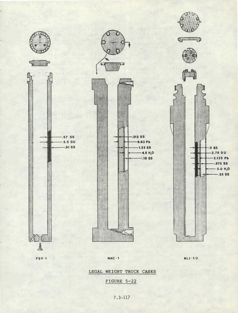
LEGAL WEIGHT TRUCK CASKS
FIGURE 5-22

the fuel envisioned from TMI within a reasonable time interval. We believe that the shipper will find that the use of this number of identical casks will reduce t h e administrative effort needed to pr-epare for and to execute these shipments. At the preaent time, only NAC (Nuclear Agsurance Corporat ian, Atlanta, Georgia) could provide a . suitably sized cask fleet . However, with sufficient lead time, it is very likely that GA (General Atomic), LaJolla, California, would augment their present fleets with the required number of casks, provided they were offered a suitable contract for cask servi"ce. blll of these casks can be operated with the cask cavity dry, due to the low beat load of the TMI-2 fuel.
. ( 1 I. NAC-1 (Nuclear Assurance Corpor&tion, Atlanta, Gear- qia) - LWT Cask
This is a legal weight LWR truck cask capable of shipping a si~gle PWR fuel assembly, or any container that will fit into its 13.5 inches diameter cavity. Three of these casks are now in service out of a total of silt constructed '(one is owned by Duke Power and may be available to other usera). These are the oldest design of all LWT casks now certified b y , N ~ c and reaent restrictions on their certification give cause to hesitate to include all of them in any long term planing. The only restriction that would affect their .use in transporting the TML-2 core would be the increased f req.&ency of testing, including additional dimensional mejsu&ments that might, lower their in-service efficiency . Lifting yokes for this cask can be either of two options: me is a "Jn hook; the other a manually attached eye hook. Both hooks require that the crane hook be moved horizontally to disengage or engage the lifting yoke. With the crane block and hook well down inside the 10,5 foot x 10.5 foot pool and cable played off the spools to a wide separation, horizontal movement nay be restricted. This should be kept
. in mind during cask evaluation. ~ e s i g n and fabrication of a new remote-operating yoke is not considered to be a major problem.
(2) NLI 1/2 (NL ~ndustries, Inc., Wilmington, Delaware) - LW.@.' Cask
This cask is also capable of shipping a single PWR assembly or any container that will fit into its 13.375 inches diameter cavity, provided accommodation is made for a 1/2-inch drain line running down the inside edge of the cavity. Five of these casks are currently available. In the spring of 1980, the certification was renewed by NRC for another five years. This cask is estimated to have the least licensing difficulty of any of the casks. It also has the smallest cavity cross section. The lifting yoke system
. .
f o r t h e s e c a s k s h a s g o o d remote o p e r a t i o n c a p a b i l i t i e s ; h o w e v e r , a yo'ke a d a p t o r f o r s i n g l e p a l m h o o k e n g a g e m e n t would e x p e d i t e h a n d l i n g . . The a d a p t o r i s a l m o s t m a n d a t o r y f r o m a n o p e r a t i o n a l c o n v e n i e n c e s - t a n d p o i n t ,, s i n c e t h e p r o c e d u r e s r e q u i r e t h a t t h e yoke be a t t a c h e d to a n d r emoved f rom t h e hook f r e q u e n t l y .
T h i s d r y c a s k h a s i t s d r a i n o u t l e t a t t h e t o p . I't i s d r a i n e d b y p r e s s u r i z i n g t h e f u e l c a v i t y a n d f o r c i n g t h e w a t e r up t h r o u g h t h e d r a i n l i n e ( b o t t o m t o t o p ) . When t h e l a s t o f t h e w a t e r is e x p e l l e d , it is f o l l o w e d b y a s u r g e o f compressed a i r ( 1 0 t o 1 5 p s i g ) . P r o v i s i o n m u s t be made i n t h e c a s k w o r k a rea t o h a n d l e t h i s p r e s s u r i z e d , wet g a s t h r o u g h an e f f l u e n t c o n t r o l sys tem.
The m e t a l l i c O-r ing s e a l on t h e c a s k i n n e r head is s u s c e p t i - b l e t o b e i n g damaged. W e would recommend, a s a p a r t o f t h e NRC l i c e n s i n g amendment r e v i e w f o r t h i s o p e r a t i o n , t h a t a head m o d i f i c a t i o n be p r o p o s e d a s a l i c e n s i n g amendment t o a l l o w r e p l a c e m e n t o f t h e m e t a l l i c "0" r i n g head seal w i t h an e l a s t o m e r "0" r i n g . T h i s change would p r o v e ta be p r a c t i c a l a s a time s a v e r f o r t h e u s e r . The p r o b l e m is t h a t i f t h e m e t a l l i c s e a l is damaged, i t is n o t d i s c e r n i b l e u n t i l t h e c a s k is o u t o f t h e p o o l . I f t h e h e a d s ea l w i l l n o t h o l d p r e s s u r e , t h e n t h e c a s k must g o back i n t o t h e p o o l , t h e head l i f t e d o f f , a n d b r o u g h t b a c k t o t h e s u r f a c e a n d t h e s ea l r e p l a c e d . A l l o f t h i s a m o u n t s t o a n e x t r a c a s k h a n d l i n g c y c l e . Replacement o f t h i s $150 s e a l b e f o r e e a c h u s e w i l l n o t p r e c l u d e damage d u r i n g s e a t i n g . An e l a s t o m e r s e a l c a n r e c o v e r f r o m b u m p s t h a t w i l l r u i n a m e t a l s e a l . T h e m e t a l l i c s e a l is n e c e s s a r y when t h i s c a s k i s b e i n g u s e d a t i t s r a t e d t h e r m a l c a p a c i t y , 10 .5 k i l o w a t t s . I t p r o b a b l y i s n o t n e c e s s a r y a t t h e low decay h e a t l o a d s of t h e TMI-2 f u e l . T h i s c a s k i s c o n s i d e r e d t o be a p r i n e c a n d i d a t e f o r t h e TMI job .
( 3 ) F o r t S t . V r a i n (FSV) C a s k ( G e n e r a l A t o m i c , La J o l l a , C a l i f o r n i a )
T h i s is a l e g a l w e i g h t , H T G R f u e l c a s k , . n o t a n LWR c a s k . H o w e v e r , G A i s i n t h e p r o c e s s o f r e v i e w i c g i t s d e s i g n a p p l i c a b i l i t y f o r h a u l i n g l o w burnup or aged LWR f u e l . I t s c a v i t y i s o v e r 1 0 i n c h e s l o n g e r a n d t w i c e t h e c r o s s - s e c t i o n a l a r e a (17 .76 i n c h e s d i a m e t e r ) ' o f t h e N A C - 1 a n d t h e N L I 1/2. T h i s c o u l d be u s e f u l f o r l a r g e r f u e l p i e c e s . The c u r r e n t d e s i g n r e v i s i o n s i n c l u d e i n n e r h e a d s e a t i n g a n d s e a l i n g and a r e v i s e d l i f t i n g s y s t e m . T h e r e is n o n e u t r o n s h i e l d o n t h e c a s k . However , nGne s h o u l d b e . n e e d e d f o r TMI-2 f u e l due t o i t s low neu t ron . s o u r c e s t r e n g t h . Three o f t h e s e c a s k s now e x i s t . Two a r e u s e d i n f r e q u e n t l y f o r HTGR ( ~ t ' . S t . V r a i n ) . f u e l movemen t s a n d a r e o w n e d b y P u b l i c S e r v i c e o f Co lo rado . The o t h e r is owned by G e n e r a l A t o m i c .

The l a r g e c a v i t y c a p a c i t y 'and volume o f t h i s c a s k makes it e s ~ e c i a l l y a t t r a c t i v e . T h e c e r t i f i c a t i o n u n c e r t a i n t y is c a u s e f o r c a u t i o n i n c o m m i t t i n g to i ts u s e ; h o w e v e r , it is l i k e l y t h a t t h i s u n c e r t a i n t y c o u l d be r e s o l v e d i n a t i m e l y manner . Once t h e l i c e n s i n g u n c e r t a i n t i e s are r e s o l v e d , t h i s c a s k w i l l be a v e r y v i a b l e c a n d i d a t e f o r t h i s job. ( P a r t i c - u l a r l y s i n c e it is t h e o n l y c a s k d e s i g n e d to d i r e c t l y l o a d and un load i n t o a h o t cel l . )
5 . 4 . 2 . 2 Ove rwe iqh t T r u c k C a s k s
(1) TN-8 ( T r a n s n u c l e a r , Whi t e P l a i n s , New York ) - OWT Cask
T h i s is an o v e r w e i g h t t r u c k c a s k ( a p p r o x i m a t e l y 3 5 - t o n c a s k w e i ~ h t ) w i t h a c a p a c i t y of t h r e e PWR a s s e m b l i e s . The t h r e e f u e l c h a n n e l s a r e a n i n t e g r a l p a r t o f t h e c a s k s t r u c t u r e , t h u s t h e ' e n v e 1 o p . e cross s e c t i o n is l i m i t e d to 8 . 5 i n c h e s s q u a r e . We b e l i e v e t h a t t h i s is too r e s t r i c t i v e to al low t h i s c a s k t o be a v i a b l e c a n d i d a t e f o r TMI-2 u s e w i t h t h e p r e s e n t f a i l e d f u e l d i m e n s i o n a l u n c e r t a i n t y . A s a p o i n t o f . i n f o r m a t i o n , TN is p r e p a r i n g a d e s i g n r e v i s i o n to t h e i r TN-9 c a s k model ( t h i s is s i m i l a r i n s i z e and a p p e a r a n c e t o t h e TN-8, b u t is d e d i c a t e d to BWR f u e l ) t o p r o v i d e t h e o p t i o n of a c a v i t y w i t h removable b a s k e t . * T h e c a v i t y d i a m e t e r w i l l , b e a h o u t 1 8 i n c h e s . TN p r o j e c t s t h a t c a s k s c o u l d b e a v a i l a b l e i n t h e U n i t e d S t a t e s by 1982 .
Any p o t e n t i a l u s e r of a n o v e r w e i g h t s y s t e m is c a u t i o n e d to c o n s i d e r t h e s y s t e m ' s v u l n e r a b i l i t y to l o c a l r e g u l a t o r y a g e n c i e s ' a r b i t r a r y d i s c u s s i o n s . T h i s is p a r t i c u l a r l y t r u e i n t t e S t a t e of P e n n s y l v a n i a which is e s p e c i a l l y r e s t r i c t i v e t o o v e r w e i g h t t r u c k s h i p m e n t s (see F i g u r e .5-28 ) . ( 2 ) P e a c h b o t t o m ( o r V a n d e n b e r g C a s k ) One U n i t Owned ----- b y Chem-Nuclear S y s t e m s , B a r n w e l l , S o u t h C a r o l i n a ; One O t h e r U n i t i n E x i s t e n c e ) - OWT
T h i s i s .a 3 5 - t o n OWT c a s k w i t h c a v i t y d i m e n s i o n s o f 116 i ? c h e s i n l e n g t h by 36 i n c h e s d i a m e t e r . Both c a v i t y and p a y l o a d must be s h i p p e d d r y . T h i s c a s k w o u l d b e a v i a b l e c a n d i d a t e o n l y i f it became n e c e s s a r y to s h i p s h o r t , l a r g e ( u p to 36 i n c h e s d i a m e t e r ) c a n i s t e r s which have to be loaded i n ' t h e s p e n t f u e l . p o o l . T h i s s i t u a t i o n is n o t v e r y l i k e l y b e c a u s e of c r i t i c a l i t y c o n s i d e r a t i o n s . T h e c e r t i f i c a t e on t h i s c a s k e x p i r e s December 31, 1980 . I ts o p e r a t i o n a l u s a g e f o r s p e n t f u e l is t e n t a t i v e beyond t h a t .
*~ersonal~Comrnunication w i t h K . Goldman, T r a n s n u c l e a r .

5.4.2.3 Rail Shipping Cask System
(1) IF-300 (General Electric, Morris, Illinois)
This is a 70-ton LWR rail cask designed to haul 7 ass ass em- blies or 18 BWR's. The cask cavity is 37.5 inches, in diameter. This cask system has been in service since 1975 and is operationally proven. The TMI site has a rail spur capability and was designed for shipping fuel of f-site using these GE casks.
The lifting yoke is a "J" hook so, like 'the NAC-1, block clearances for horizontal travel wou.ld. have to be verified 'before this cask could be considered for use.
Like all multi-element casks, we are concerned regarding the possible licensing delay if the IF-3.00 should be selected to haul TMI-2 fuel from the present core. We doubt. that rapid approval would be forthcoming. The IF-300 would be more time consuming to decontaminate after loading than any of the legal weight truck casks beca.use it does not have a smooth outer surface and no contamination barrier-type skirt has been developed for it.
(2) NLI 10/24 (NL ~ndustries, Wilmington, Delaware)
This is a 100-ton rail cask designed to haul 10. PWR assem- blies or 24 BWR assemblies. Its cavity diameter is 45 inches. Like the IF-300, .we doubt that the advisability of requesting the NRC to consider licensing it to haul TMI-2 fuel canisters. Two casks could be made available but are not now in operahion.
This cas,k i.s not .considered to be viable for the TMI-2 application because of its large size. A silhouette of the 10/2'4 is shown (Figure 5-23) in the TMI decontamination pit. Decontamination work obviously would have to be done else- where. andli ling this cask in the 10.5-foot x 10.5-foot pool would be a tedious operation. We believe also that a special mobile head-handling gantry would be required.
(3) General Rail Considerations
A preliminary evaluation was made of rail handling possibil- ities at the TMI site. It appeare6 that either the GE IF- 300 or NLI 10/24 could be used. A point of caution concerns the rail track/rail car interface leading into the site. ail cars with three-axle trucks (such as the NLI 10/24) may have potential problems in negotiating the curve at the start of the siding as the track leaves the main line .and enters a bridge approach that is shared with road traffic. Under these.conditions, rocks, etc., that lodge in the track

recess i n t e n d e d f o r t h e whee l f l a n g e s , c a n c a u s e d e r a i l m e n t . The c u r v e r a d i u s is w i t h i n t h a t a l l o w a b l e f o r t h e s e t r u c k s ; and i f t h e recesses were c l e a n e d p r i o r t o e a c h u s e , t h e r e s h o u l d b e 1 i t t l . e p r o b l e m , b u t a d m i n i s t r a t i v e c o n t r o l s i n t h i s r e g a r d u s u a l l y are weak. Two-axle r a i l t r u c k s ( s u c h as employed o n t h e IF -300 c a r ) w o u l d b e l e s s s u s c e p t i b l e t o t h i s t y p e o f d e r a i l m e n t . An incoming ( empty ) c a s k w o u l d b e h e a d e d t o w a r d . t h e r i v e r irf i t d e r a i l e d . . ' An o u t g o i n g ( l o a d e d ) c a s k c a r m i g h t 'come t o rest i n t e r f e r i n g w i t h t h e main l i n e t r a f f i c o f t h e . r a i l r o a d .
5.4.3 NRC L i c e n s i n g Cri ter ia f o r S h i p p i n g Casks
We have p r e v i o u s l y a s sumed t h a t a l l o f f - s i t e s h i p m e n t s o f TMI-2 f u e l would be made i n NRC c e r t i f i e d c a s k s . W e f u r t h e r a s s u m e t h a t a n y c a s k s now c e r t i f i e d f o r t h e s h i p m e n t o f s p e n t n u c l e a r f u e l w i l l r e q u i r e a c e r t i f i c a t e a m e n d m e n t p r i o r t o s h i p p i n g s e v e r e l y damaged f u e l . T h i s amendment would be r e q u e s t e d b y t h e c a s k o w n e r (who w o u l d b e u n d e r c o n t r a c t f o r t h i s movemen t ) e v e n t h o u g h t h e r e may b e n o s t r u c t u r a l m o d i f i c a t i o n s t o t h e c a s k sys tem. T h e r e a r e good r e a s o n s f o r t h e c a s k owner to do t h e p r o c e s s i n g o f t h e NRC l i c e n s i n g amendment . T h e b e s t i s t h a t i t i s t h e m 0 s . t e x p e d i t i o u s way and t h e o w n e r s a r e most f a m i l i a r w i t h t h e NRC SAR and l i c e n s i n g r e s t r i c t i o n s . T h e owner may a g r e e t o d o t h i s work a s a c o n d i t i o n f o r s e l l i n g h i s s e r v i c e s . The l i c e n s i n g amendment c a n n o t be i n i t i a t e d u n t i l t h e i n t e r n a l s h i p p i n g c o n t a i n e r is w e l l i n t o . t h e d e s i g n p h a s e . S i n c e t h e f i s s i l e m a t e r i a l c a n n o t b e a s s u m e d t o h a v e a n y s t r u c t u r a l i n t e g r i t . ~ , a f u e l p a r t ' i c l ' e s i z e f o r o p t i ' m u m r e a c t i v i t y p r o b a b l y w i l l need t o be c o n s i d e r e d . S i m i l a r l y , . i t s h o u l d b e a s s u m e d t h a t a t some t i m e d u r i n g l o a d i n g , d r a i ' n i n g , s h i p p i n g , f i l l i n g , and u n l o a d i n g , t h e s y s t e m w i l l e x p e r i e n c e optimum wa te r - to -me ta l r a t i o and maximum n e u t r o n r e f l e c t i o n . U n l e s s t h e above a s s u m p t i o n s c a n be shown t o be unwar ran ted , t h e f u e l c o n t a i n e r d e s i g n a l m o s t c e r t a i n l y w i l l b e b a s e d o n a n a l w a y s - s a f e ( c r i t i c a l i t y ) g e o m e t r y . F u r t h e r c o n s i d e r a - t i o n o f t h e s e i n d i v i d u a l l y s a f e g e o m e t r i e s must b e made f o r i n t e r a c t i o n s b e t w e e n t h e m d u r i n g c a n , i s t e r l o a d i n g a n d s t o r a g e . P a c k a g i n g i n e f f i c i e n c i e s w i l l b e e x p e c t e d w i t h m u l t i - e l e m e n t c a s k s . I t is e x p e c t e d t h a t n o t a s many TMI-2 c a n i s t e r s c o u l d b e i n c l u d e d i n t h e p a c k a g e a s t h e c a s k d e s i g n can a c c e p t a s PWR a s s e m b l i e s . I f t h i s i s t h e c a s e , t h e economics of t h e t r a n s p o r t s e r v i c e w i l l s w i n g i n f a v o r o f t h e LWT mode.
A f i n a l p r o b l e m i s c a s k a v a i l a b i l i t y . The s h i p p e r (TMI) m u s t b e c e r t a i n t h a t t h e c a s k ( s ) s e l e c t e d . f o r c a n i s t e r c a p a b i l i t y and NRC c e r t i f i c a t e amendment w i l l b e a v a i l a b l e i n t h e q u a n t i t y n e e d e d w h e n e v e r t h e core i s r e a d y t o b e moved. I f t h e o p e n i n g o f a n A F R c o i n c i d e s w i t h t h e TMI s h i p p i n g s c h e d u l e , a v a i l a b l e c a s k s may be i n s h o r t s u p p l y .

5.4.4 Fuel Loading Location Options ,
There are two possible locations for loading the spent f u e l . cask a t the TMI s i t e . These are the spent fuel cask loading pool and the fue l service pool. Operational cons ide ra t ions a t both locations are presented here.
5.4.4.1 Spent Fuel Cask Loadinq Pool
The TMI fue l pool is a specific-purpose ( d e d i c a t e d ) ,des ign and is the 'be t te r of the two possible available option's f o r cask loading. I t s use would be denied only i f , f o r some reason, the packaged. fue l cannot be moved f r.om the r e a c t o r s e r v i c e pool i n t o the s p e n t f u e l s t o r a g e p o o l v i a t h e t r a n s f e r t unne l s o r th 'at i t is being .used f o r o t h e r TMI recovery o p e r a t i o n s . Although no s t a n d a r d o p e r a t i n g
,procedures now e x i s t f o r loading spent f u e l a t TMI, these can r e a d i l y be deve loped from t h e g e n e r i c p r o c e d u r e s furn ished by the cask owner. . Be fo re d e v e l o p i n g t h e s e procedures based on the A E ' s cask handling design concept, i t w i l l do well t o .consider some changes tha t w i l l :
Eliminate handling the cask c losu re heads w i t h s p e c i a l too ls a
Permit greater l a t e r a l movement of the hook wi th in the confines of the pool boundary.
These w i l l , i n t u r n , decrease turnaround time.
In our in terpreta t ion of the p rese2 t concept , the pool is dry whenever the cask is lowered i .nto the pool o r removed from the pool. T h i s is done to avoid 'wetting the block and ropes and prevent ing the spread of contamination a s pool water d r ips from them. Since the pool m u s t be f u l l of water u n t i l t he head is s e t i n t o p l ace , t h e ' d e s i g n t e c h n i q u e requires tha t the head be a t tached t o a ' s p e c i a l t o o l . - - a grapple on the end of 'a segmented pole which, i n . t u r n , i s suspended from an auxi l iary hook. The most expedient method of handling a head i n t h i s manner i s t o leave the head and grapple i n the pool a l l the t ime, from a t i e -of f po in t a t l e a s t 2 f e e t ( f o r LWT) from the edge of the pool. The upper section may have to be removable t o allow t h e f u e l bridge
. . crane access d i r ec t ly over the cask. In p rac t i ce , the head would. be re.moved from the cask f o r inspec t ion before the cask goes in to the pool. The head is then replaced and .the cask lowered into the dry pool, and the pool is f i l l e d w i t h
. . water. Next, the head is grappled using the s p e c i a l t o o l , l i f t e d from the ' cask and set , a s i d e , s t i l l i n t h e ,pool . Af t e r loading the cask w i t h f u e l , t he head i s r e p l a c e d , released from the grapple and the grapple is returned to i t s pool-edge holder. '

Using t h e above s y s t e m i n t h e TMI pool w i t h a r a i l c a s k is i m p o s s i b l e ; t h e r e is n o t s u f f i c i e n t room i n t h e 1 0 . 5 - f o o t s q u a r e cross s e c t i o n . Removal o f t h e h e a d b e f o r e g o i n g i n t o t h e p o o l a n d r e p l a c i n g i t l a t e r i s p o s s i b l e , b u t n o t p r a c t i c a l . W i t h t r u c k - c a s k s i z e c l o s u r e h e a d s , t h e p r o c e d u r e w i l l work, b u t it wastes time b e c a u s e i t r e q u i r e s t h a t o p e r a t i o n a l p r o c e d u r e s b e p e r f o r m e d i n s e r i es t h a t c o u l d be done i n p a r a l l e l . Also, i f a s e a l r i n g p ro tec to r i s t o b e u s e d , i t , too, would r e q u i r e remote h a n d l i n g i n t h e p o o l r a t h e r t h a n s i m p l y p l a c i n g it o n t o p o f t h e c a s k b e f o r e t h e c a s k i s s u b m e r g e d . I n a d d i t i o n , p l a c e m e n t o f t h e c l o s u r e head s h o u l d n o t b e a t t e m p t e d u s i n g n o n r i g i d ( c a b l e ) s l i n g s . The t o r s i o n a l pendulum e f f e c t o n t h e s l i n g s i s too much t o c o n t r o l a d e q u a t e l y . T h e p r e f e r r e d m e t h o d o f h e a d p l a c e m e n t is t o s u s p e n d it by s l i n g s f r o m t h e l i f t i n g y o k e a n d seat t h e h e a d j u s t p r i o r t o l a t c h i n g o n t o t h e c a s k t o r e t u r n it t o t h e s u r f a c e . To a c c o m p l i s h t is w i t h o u t w e t t i n g t h e b l o c k ( w e t t i n g t h e h o o k s h o u l d b e o f l i t t l e c o n c e r n ) , t w o a d d i t i o n a l f i x t u r e s are needed . One is a yoke e x t e n s i o n a b o u t 20 f e e t l o n g (see S e c t i o n 5 .4 .4 , Appendix B ) , a n d t h e o t h e r is a s h e l f a b o u t h a l f t h e d e p t h o f t h e pool o n w h i c h t h e c a s k c a n r e s t ( s ee S e c t i o n 5 . 4 . 4 , A p p e n d i x C ) . T h i s c o n c e p t is i n u s e a t v a r i o u s s i t e s ( e . g . , t h e Duke O c o n e e p o o l s ) , a n d t h e o n l y t h i n g o u t o f t h e o r d i n a r y f o r t h i s a p p l i c a t i o n would b e t h e f o l d i n g c a p a b i l i t y o f t h e s h e l f . Wi th t h i s s y s t e m , t h e p o o l d o e s n o t n e e d t o b e d r a i n e d t o f a c i l i t a t e c a s k h a n d l i n g . The c a s k is p i c k e d up b y t h e yoke a n d p l a c e d o n t h e s h e l f a t a l e v e l 2 2 f e e t b e l o w t h e c u r b . T h e l i f t p i n o f t h e y o k e a d a p t o r w i l l b e j u s t a b o v e t h e water s u r f a c e . N e x t , t h e y o k e i s r e l e a s e d f r o m t h e h o o k . The e x t e n s i o n is a t t a c h e d t o t h e h o o k a n d t h e y o k e t o t h e s h e l f is f o l d e d a g a i n s t t h e walls o f t h e p o o l , t h e n l o w e r e d t o t h e f l o o r o f t h e p o o l . Now t h e c a s k is a t t h e -44 f o o t l e v e l w i t h r e s p e c t t o t h e c u r b , t h e y o k e l i f t i n g e t e , or b o t t o m o f t h e e x t e n s i o n , a t t h e -22.5 f o o t l e v e l . T h e h o o k i s a t t h e -1.5 f o o t l e v e l , j u s t be low pool water l e v e l w i t h t h e b l o c k s t i l l d r y . E x a c t d i m e n s i o n s f o r t h e a b o v e w i l l v a r y d e p e n d i n g on t h e c a s k m o d e l s e l e c t e d , b u t t h e s y s t e m s h o u l d b e w o r k a b l e w i t h a n y o f t h e m . When t h e f u e l i s l o a d e d , s i m p l y a t t a c h t h e h e a d t o t h e y o k e i n t h e n o r m a l manner , s e a t t h e head , l a t c h on to t h e c a s k , a n d r e t u r n i t t o t h e s h e l f . Remove t h e e x t e n s i o n a n d t h e n c o m p l e t e t h e r e m o v a l o f t h e c a s k f r o m t h e pool t o t h e d e c o n t a m i n a t i o n area. A s t e p - w i s e summary l o a d i n g p r o c e d u r e i s g i v e n i n Appendix A ( S e c t i o n 5 . 4 . 4 ) .
The u s e o f a s h e l f f o r l o a d i n g w i l l e l i m i n a t e t h e n e e d t o e m p t y a n d t h e n t o r e f i l l t h e l o a d i n g p o o l , w h i c h h a s ' a c a p a c i t y o f 3 5 , 0 0 0 g a l l o n s o f wa t e r . A l s o , u s e o f t h e e x t e n s i o n on t h e hook e l i m i n a t e s t h e n e e d f o r t h e b l o c k t o t r a v e l a b o u t 2 2 f e e t down i n t o t h e p o o l , w h e r e i t s

horizontal travel may have to be restricted to prevent cables from contacting the pool curbing.
The feasibility of using the decontamination pit as a cask . shelf was investigated and rejected. The floor elevation is too high (several feet), to permit use of hook extensions of' the necessary length. It would have entailed the installa- tion of a gate between the two pools. .The use of a 5-foot thick crash pad in the pool might resolve the extension length problem, so this may be a possibility to keep in mind for the future when ordinary spent fuel will be shipped from the site.
Even if smooth exterior surface truck casks ,are used (rail .casks typically have cooling fins on their outer surface), it is recommended that a jacket (contamination-barrier) be fitted to the cask body prior to eacn loading'. This jacket functions as a barrier to the spreading of contamination from the pool water and will reduce decontamination time and measurably improve turnaround time.
5.4.4.2 Fuel Service Pool
, It is possible that canistered fuel could not be moved via . the normal route through the transfer tunnel (a situation
where the "fused" fuel assemblies cannot be separated into suitable sizes). In this case a transfer cask will be 'needed. The "fused"' fuel must be loaded into the transfer cask inside the containment building. here . is adequate crane capacity (500-ton polar crane) to handle the cask. It appears that the cask movement could be routed throligh the containment building to the building hatch. his. movement needs further study .when the area becomes accessible for. operational needs and the recovery equipment is in place: Space is available in the containment building to decontaminate the cask, but . it is, said to be limited and wash water may recontaminate other areas. Access.by highway
' vehicle is available but would require. repeated openirig of containment into a yet-to-be-built air lock. Rail cars cannot be accommodated because there is no siding planned into this new air lock. A siding, if used, would be a very short branch off the rail line into the turbine building. A large cavity rail cask could be used to move the fuel or fuel segment to the auxiliary building.
A clearance .study indicates that, if. casks were to be loaded in this area, the present fuel handling crane (bridge) could not be used because the bottom of the masts would not clear the top of any LWR cask in the canal. The tap of the fuel, if still intact, would have to be brought to within .5 to 6 feet of the surface (elevation 346 feet) to clear a 16-foot cask sitting at the 308.5-foot elevation. However,

w i t h t h e low f u e l b u r n u p . c o n d i t i o n , t h a t much water m i g h t s u f f i c e . I t a p p e a r s t h a t t h e u s e of a n e x i s t i n g " s h e l f " a t t h e 322- foo t l e v e l c o u l d s e r v e as a c a s k r e s t i n g l o c a t i o n , so t h a t a yoke e x t e n s i o n c o u l d b e u s e d i n l i e u o f w e t t i n g t h e hook.
5 . 4 . 4 . 3 P ippend ix A - Summary L o a d i n g P r o c e d u r e s ---------- U s i n g Recommended M o d i f i c a t i o n s
(1) B r i n g t h e c a s k f r o m t h e t r a n s p o r t v e h i c l e t o t h e d e c o n t a m i n a t i o n p i t .
( 2 ) F i l l and f l u s h t h e c a s k w i t h d e m i n e r a l i z e d water.
( 3 ) Remove t h e h e a d a n d i n s p e c t t h e p r e s s u r e b o u n d a r y seals . S e t head a s i d e .
( 4 ) Move t h e c a s k to t h e s h e l f * i n t h e l o a d i n g p o o l . De t ach t h e hookf* f rom t h e yoke**.
( 5 ) . A t t a c h t h e e x t e n s i o n f * to t h e h o o k ; t h e n a t t a c h t h e yoke to t h e e x t e n s i o n .
( 6 ) L i f t t h e c a s k a f e w f e e t t o a l low c l e a r a n c e f o r t h e s h e l f s e c t i o n s as t h e y f o l d away.
( 7 ) Lower t h e c a s k to t h e bo t t om o f t h e pool. D i s e n g a g e t h e ca sk .
( 8 ) Remove t h e yoke f rom t t e p o o l and a t t ' a c h t h e , c a s k head t o t h e yoke s l i n g s w h i l e t h e f u e l c a n i s t e r is b e i n g l o a d e d i n t o t h e c a s k .
9 ) . R e t u r n t h e yoke to t h e p o o l a n d place t h e h e a d i n t o p o s i t i o n b e f o r e e n g a g i n g t h e yoke to t h e ca sk . Engage t h e c a s k .
( 1 0 ) Raise t h e c a s k above t h e c a s k s h e l f l e v e l .
( 11 ) . Move t h e s h e l v e s i n t o p l a c e .
( 1 2 ) L o w e r t h e c a s k o n t o t h e s h e l f .
( 1 3 ) R e l e a s e t h e e x t e n s i o n f rom t h e yoke.
( 1 4 ) Remove t h e e x t e n s i o n f rom t h e hook.
* s e e Appendix C , f o l l o w i n g . **See F i g u r e s 5-23, 5-24, and 5-25.

CASK HANDLING AT TEII
FIGURE 5-23

S i n g l e P a l m Hoak Attachment For SSstcs Hook
Figurzl 5-1
Hook Extension Figure 8-2
YOKE A1FTXliWNTS
FIGURE 5-24

Shelf Cross Section
SHELF FOR CASK LOADING POOL
FIGURE 5-25

( 1 5 ) Reengage t h e main hook to t h e y o k e and move t h e c a s k to t h e d e c o n t a m i n a t i o n area.
( 1 6 ) P e r f o r m t h e f u n c t i o n s f o r p r e p a r i n g t h e c a s k f o r s h i p m e n t .
( 1 7 ) Move t h e c a s k to t h e v e h i c l e .
5 .4 .4 .4 Appendix B - L i f t i n g A d a p t o r s ( S e e F i q u r e 5-22)
F i g u r e B-1 S i s t e r . Hook S i n q l e Pa lm E x t e n s i o n - T h e s is ter hook of t h e c a s k h a n d l i n g c r a n e is n o t p a r t i c u - . l a r l y s u i t e d . to m a t i n g w i t h c a s k l i f t i n g y o k e s i n u se t oday . Some of t h e a v a i l a b l e y o k e s , f o r s p e c i f i c c a s k s , c a n u s e t h e l i f t i n g . eye i n t h e sister hook . I f t h e s e y o k e s m u s t b e r emoved and a t t a c h e d v e r y o f t e n , a lo t of time w i l l be u s e d j u s t i n g e t t i n g t h e p i n i n and o u t . An a d a p t o r of t h e t y p e , i l l u s t r a t e d i n F i g u r e 5-24, w i l l a l l o w e x p e d i t i o u s u s e w i t . h most o f t h e e x i s t i n g yokes and w i t h t h e o t h e r a d a p t o r s . I f i t is d e c i d e d to used t h e f o l d i n g s h e l f c o n c e p t f o r c a s k h a n d l i n g , t h i s a d a p t o r s h o u l d b e u s e d .
F i g u r e B-2 Yoke E x t e n s i o n - The e x t e n s i o n is u s e d i n l i e u o f w e t t i n g t h e b l o c k when p l a c i n g t h e c a s k i n t o t h e c a s k l o a d i n g p o o l . The h o o k - t o - y o k e - t o - c a s k a r r a n g e m e n t is used to lower t h e c a s k to a l e v e l t h a t a b o u t c o v e r s . t h e y o k e . T h e n t h e e x t e n s i o n is used be tween t h e hook and y o k e to lower t h e c a s k t h e r e m a i n i n g d i s t a n c e t o t h e b o t t o m of t h e p o o l . The p r o c e d u r e is r e v e r s e d f o r c a s k removal .
F i q u r e B - 3 NL Yoke A d a p t o r - The NL y o k e s u s e a l i f t p i n t h r o u g h t h e s t r o n g b a c k s t o mate w i t h t h e p a l m o f a hook or t h e l i f t i n g e y e i f t h a t is what is a v a i l a b l e . T h e NL " A " y o k e a l s o f e a t u r e s o p t i o n a l d o u b l e p i n s , t h e s p a c i n g o f w h i c h is d e s i g n e d s p e c i f i c a l l y and e x c l u s i v e l y f o r t h e s i s t e r h o o k o f a W h i t i n g r e d u n d a n t l i f t i n g s y s t e m . The l i f t i n g p i n t h r o u g h . t h e s t r o n g b a c k is n o t a s a t i s f a c t o r y s y s t e m i f t h e y o k e m u s t b e d e t a c h e d and r e p l a c e d even o c c a s i o n a l l y . ' A 'simple a d a p t o r l e f t p e r m a n e n t l y i n p l a c e ( b u t r e m o v a b l e ) a l l o w s t h e yoke to be engaged by t h e s i n g l e . p a l m h o o k w i t h o u t w i t h d r a w i n g a n d i n s e r t i n g t h e l i f t i n g p i n .
5.4 .4 .5 Appendix C - Cask Sit-Down S h e l f ( S e e ~ i g u r e 5-25)
T h i s s t r u c t u r e is a framework of E-inch box s e c t i o n s w i t h a s p l i t p l a t f o r m on t o p h inged a t o p p o s i t e ' e d g e s . The p l a t - fo rm ' is made of 10 i n c h , 22 pound "I" beams w e l d e d e d g e to e d g e , a b o u t 1.3 beams on each s i d e . A l l f o u r e d g e s o f t h i s weldment are c l o s e d by weld ing 10 - inch c h a n n e l , as shown. A p i a n o - t y p e h i n g e is u s e d . T h e p l a t k o r m , or s h e l f , is a i r t i g h t and t h e b u o y a n c y e f f e c t is a b o u t 8 5 % , so l i t t l e e f f o r ' t is n e e d e d to r a i s e them. . T h i s w o u l d b e d o n e by h y d r a u l i c ( w a t e r ) c y l i n d e r s , c o n t r o l l e d f r o m t h e s u r f ace. The s t r u c t u r e f i t s a s s n u g l y i n t o t h e , p o o l c a v i t y as c o n s t r u c t i o n t o l e r a n c e s w i l l p e r m i t . Any t h r e e beams w i l i s u p p o r t t h e 25-ton c a s k , assuming i n d e p e n d e n t end s u p p o r t e d beams and c e n t e r l o a d i n g . The c a s k . b o t t o m d i a m e t e r w i l l a lways c o v e r a t least 7 beams.
When f o l d e d , t h e open ing i n t o t h e bot tom of t h e p o o l w i l l be j u s t unde r 9 f e e t s q u a r e i n s t e a d of 10 .5 f e e t s q u a r e . T h i s is a d e q u a t e f o r h a n d l i n g LWT c a s k s and t h e i r l i f t i n g yokes .
When i n u s e , t h e p o o l w i l l be f u l l and t h e s h e l v e s w i l l be i n t h e c l o s e d p o s i t i o n . The c a s k w i l l be l o w e r e d to t h e s h e l f l e v e l and t h e y o k e r e l e a s e d . An e x t e n s i o n w i l l be added between t h e hook and t h e yoke, and t h e yoke r e a t t a c h e d t o t h e ca sk . The c a s k w i l l be r a i s e d 4 or 5 f e e t to allow t h e s h e l v e s to f o l d b a c k a g a i n s t t h e p o o l w a l l s . G r a v i t y a c t u a t e d s a f e t y l a t c h e s w i l l h o l d t h e s h e l v e s a g a i n s t t h e p o o l w a l l s , even though t h e h i n g e p l acemen t of each s h e l f is s u c h t h a t t h e s h e l f c e n t e r o f g r a v i t y is n e a r e r t h e w a l l t h a n is t h e c e n t e r l i n e of t h e h inge . .The s h e l v e s r e m a i n i n t h i s p o s i t i o n u n t i l t h e c a s k is b r o u g h t o u t o f t h e p o o l . The c a s k is r a i s e d to abou t 4 t o 6 f e e t a b o v e t h e s h e l v e s , t h e n t h e s h e l v e s a r e made t o c lose. The c a s k is se t down and t h e e x t e n s i o n is r e l e a s e d f r o m t h e y o k e . The hook is r e a t t a c h e d to t h e yoke and t h e c a s k is removed. The s h e l v e s remain c l o s e d a w a i t i n g t h e n e x t l o a d i n g cycle. .
The d i ag ram ( F i g u r e 5-25) is c o n c e p t u a l . Load d i s t r i b u t i o n a t t h e bot tom of t h e poo l must be t a k e n i n t o a c c o u n t , p a r - t i c u l a r l y f o r d r o p - a c c i d e n t c o n d i t i o n s .
J u d g i n g from t h e d e p t h o f t h e poo l . , i t is l i k e l y t h a t t h e p l a n t a r c h i t e c t - e n g i n e e r i n t e n d e d e v e n t u a l l y to i n s t a l l a 4- t o 5 - f o o t t h i c k c r a s h . p a d on t h e f l o o r of t h e p o o l . Not o n l y would t h i s a f f e c t t h e d e s i g n of t h e base of t h e s u p p o r t s t r u c t u r e b u t a l s o would a f f e c t t h e l e n g t h of t h e p ropos . ed e x t e n s i o n f o r t h e hook ( F i g u r e 5-24) .

5.4.5 Conclusions and Recommendations
5.4.5.1 Cask Selection
Shipping cask certification for damaged fuel should be ditected initially toward casks of the single assembly truck cask (LWT) design, because:
The cask certification amendment at the NRC should be more readily accomplished.
Fuel being sh.ipped to examination facilities for research facility must move by truck casks due to facility limita- tions.
The remote handling of the heavy closure heads on rail casks is very difficult, even with special handling tools.
~nformation developed for the single-assembly cask will be useful in certifying multi-assembly casks if it becomes apparent that certification of the latter is warranted.
Regulatory controls and inconsistencies at the local level weigh heavily against the use of overweight truck casks.
5.4.5.2 Recommended Actions
The selection of a specific highway cask may be limited by the size of the canister within which the fuel is shipped. Cask selection and canister design should proceed with the responsible parti.es i n c l o s e communication.
When the cask selection is finalized, prepare detailed casks handling procedures for each. This will cause potential operating problems to surface, including the need for additional special tools.
* Perform "dry runs" at the TMI facility with the cask selected. It would be particularly desirable to do this before the cask handling area becomes excessively con- taminated. A dry run will help train the operators and will provide a final check on the adequacies of the operating procedures.
If the cask is to be loaded in the fuel service pool, and if the fuel handling bridge is to be used, the fuel masts
- will have to be shortened to clear the top of the cask. either "if" is considered very likely. )

5.5 Spent Fuel Shippinq Logistic and Safety Considerations . .
5.5.1 General
It has previously been assumed that all of the fuel from the TMI-2 reactor will eventually be canned and moved off-site in a shipping cask to either an interim hot cell location for laboratory-type examination, or to an interim pool storage location. The pool storage may be preparatory to reprocessing or wet storage.
In the current "millieu" associated with the shipment of nuclear spent fuel, there is almost as much uncertainty with attaining the requisite approvals for shipping as there is in finding a suitable storage location. It is recognized that the fuel itself will probably not be moved until 1983 or later. However, the problems which have been fomenting in the area of spent fuel transportation have existed and perhaps become worse in the last 3 to 5 years. As a result, a current evaluation of the shipping considerations concern- ing cask availability, routing, estimates of the shipping duration, and costs which are incurred can probably be accurately projected.
The specific areas examined are:
Can fuel'be shipped off-site?
Hpw .many canisters will be shipped and how much fuel can be shipped in a given spent fu,el cask?
What are the possible or likely shipping distances?
What is the expected duration of the shipping campaign? .
I .
What type of routing problems and restrictions can be expected?
.In. the preceding portion of this study (Section 5 . 4 ) , it was noted that both truck and rail shipments are theoretically possible. Also, it is believed that the TMI site could accommodate all of the NRC-lice'nsed casks. 'However, truck shipment (LWT) was shown to be the preferred alternative because of its greater' operational flexibility and due to
. our belief th.at it's NRC ~ertificat'e of Compliance could be more easily amended for this type of failed fuel shipment.
' The logistics s t u d i e s t o be presented'show that rai.1 shipments, while requiring less 02erational time and fewer shipments, will probably involve a more .lengthy shipping . .
campaign. Under ideal conditio2s, the comparative costs between rail and truck shipments. are expected' to be within

1 0 % o f e a c h o t h e r w h e n t h e s h i p p i n g d i s t a n c e e x c e e d s ,500 miles.
5 .5 .2 S h i p p i n g Campaign
From t w o t o f o u r t r u c k s h i p p i n g c a s k s s h o u l d be made a v a i l - a b l e f o r t h i s o p e r a t i o n . W h e r e a s t h e r e is n o s p e c i f i c c o n s t r a i n t concern , ing t h e l e n g t h o f t i m e t o r emove . a l l o f t h e f u e l from t h e TMI-2 s i t e , a r e a s o n a b l e p e r i o d is 1 8 t o 24 months . F o r s c o p i n g p u r p o s e s , f o u r t r a n s p o r t d i s t a n c e s - 3 0 0 m i l e s , 7 5 0 m i l e s , 1 5 0 0 m i l e s , 3 0 0 0 m i l e s - were examined. T a b l e 5-9b p r e s e n t s s h i p p i n g c y c l e times and t h e t o t a l s h i p p i n g c a m p a i g n d u r a t i o n u t i l i z i n g e i t h e r two; t h r e e , .and f o u r t r u c k c a s k s or o n e 7 - e l e m e n t r a i l c a s k . Even though t h e r e a r e 177 a s s e m b l i e s to be s h i p p e d , it was a s s u m e d t h a t f a i l e d f u e l c o n s i d e r a t i o n s w o u l d l e a d t o a p p r o x i m a t e l y 30% more packages ( 2 2 5 to 235 s h i p m e n t s ) . A s c a n be s e e n from t h i s t a b l e , a b a r e minimum of e i t h e r two t r u c k c a s k s or one r a i l c a s k would be r e q u i r e d to a c c o m p l i s h t h e s e s h i p m e n t s w i t h i n a r e a s o n a b l e t i m e p e r i o d f o r e v e n movement t o a n e a r b y reac tor . F o r s h i p p i n g d i s t a n c e s i n e x c e s s of 1500 m i l e s f r o m t h e TMI s i t e , a t l e a s t t h r e e to f o u r t r u c k c a s k s or a g a i n one r a i l c a s k would be d e s i r a b l e .
A f u r t h e r . q u e s t i o n to be examined is t h e r e q u i s i t e number 'of c a s k s a v a i l a b l e . T a b l e 5-10 is a l i s t i n g o f t h e c u r r e n t l y l i c e n s e d s p e n t f u e l ' c a s k s now a v a i l a b l e . T h e c u r r e n t commitment f o r u t i l i z a t i o n of t h e s e c a s k s is n o t known. I t w i l l p r o b a b l y depend upon t h e n a t i o n a l a v a i l a b i l i t y of a n AFR l o c a t i o n or t h e . w idesp read t r a n s s h i p m e n t o f s p e n t f u e l b e t w e e n r e a c t o r s w i t h s u i t a b l e s t o r a g e s p a c e . A s n o t e d p r e v i o u s l y , w e recommend. t h a t new c a s k s be i d e n t i f i e d and r e s e r v e d f o r t h i s p u r p o s e a t t h e e a r l i e s t p r a c t i c a l t i m e a f t e r a d a t e f o r p o s s i b l e s h i p m e n t is d e t e r m i n e d . O u r o p i n i o n is t h a t t h i s e q u i p m e n t c o u l d d e f i n i t e l y b e 'made a v a i l a b l e i f a f i r m commitment is made w i t h t h e c a s k owner.
5 . 5 . 3 S h i p p i n g Economics
T h e r e a r e a number o f u n c e r t a i n f a c t o r s i n v o l v e d w i t h e s t i m a t i n g s p e n t f u e l - s h i p p i n g costs . T a b l e 5 - 1 1 p r e s e n t s t h e a s s u m p t i o n s used to s c o p e t h e a p p r o x i m a t e cos t s to move a l l of t h e f u e l from t h e s i t e . The o n l y r ema in ing f a c t o r to be e v a l u a t e d p a r a m e t r i c a l l y is t h e a c t u a l d i s t a n c e f r o m t h e s i t e to t h e r e c e i p t l o c a t i o n . F i g u r e 5-26 is an e s t i m a t e of t h e a p p r o x i m a t e u n i t cost ($/kgU) of sh ipmen t , and t h e t o t a l c o s t f o r s h i p p i n g t h e f u e l core. T h i s d a t a was f a c t o r e d i n t o t h e v a r i o u s p o s s i b l e d i s p o s i t i o n e c o n o m i c s s c e n a r i o s d i s c u s s e d i n S e c t i o n s 6 . 0 and 7.0 . S h i p p i n g costs f r o m a n i n t e r i m s t o r a g e s i t e to a f i n a l o r u l t i m a t e l o c a t i o n was a l s o c o n s i d e r e d i n t h a t e v a l u a t i o n . The cos t of s h i p p i n g c a n r e p r e s e n t a s i g n i f i c a n t p o r t i o n of t h e near - te rm cost of

TABLE '5-9b
CYCLE TIMEJ DAYS ------ TRUCK RAIL
- CAMPAIGN DURATIOIJM08 *

TABLE 5-10
CHARACTERISTICS OF LWR SPENT FUEL CASKS
LWT - Legal Ueight Truck OUT - Overweight Truck
*NAC-I and che NFS-4 cask designs a r e e s s e n t i a l l y i den t i ca l . **This l i cense appl ica t ion has been withdrawn.
***NL Indus t r i e s i s not i n t h i s business (9130180) and i s considering l ea s ing equipment t o NAC (A t l an t a , Georgia).
NL Indus t r i e s , Inc. *** Nuclear Division
. .
General E l e c t r i c Co. San Jose. Ca l i fo rn i a
IF-300
OWrlRail
7/18
63.5
37 x 180
64 x 208
Uranim
Water
Water
Corrugated
Yes
4/01 ( m e owned by Carolina Power end Light)
Wilmlngton, NLI-112
LWT
112
22
13.375 x 178
40 x 193
&ead/Uranium
Water
Bellurn
Smooth
Yes
5/0
Transnuclear, Inc. Nuclear Assurance Corp. At lanta , Georgia
. NAC-I*
LWT
112
22.5
13.5 x 178
50 x 214
Lead
Borated Water
Water
Smooth
Yes
410. (Tvo ovned by W e Power C o . )
Cask Name:
Transport k d e
PVR/BUR Assemblies Per Cask
Loaded Weight Tons
Cavity Dimensions (Mameter x Length) Inches
Overall Dimensions (Diamerer x Length) Inches
Gamma Shield Mater ia l
Neutron Shield
Cavity Coolant
Cask Exter ior Surface
U. S. NRC License
Number of Units (OperationalIUnder Construction)
Del. NLI-10124
Ra i l
10124
90
45 x 179
103.5 x 224
Lead
Water
Eel ium
S t a i n l e s s S t e e l F ins
Yes
2/0
White P l a ins , . TN-819
OW
317 - 34.5
( 9 s q . x l 6 8 ) (5.5 oq. x 178)
68 x 192 (68 x 202)
Lead
Organic
Air
Copperas
Yes
( l / l ) * (Cue owned by Co-nvealth . Bdison Co.)
Nuclear Fuel Services West Valley, N. Y.
NSF-4
LWI
112
22.5
13.5 x 178
50 x 214
Lead
Borated Water
Uater
Smooth
Yes
210
N. Y. TN-12
R a i l
12/32
97
4 8 x 1 8 0
98 x 265
S t e e l
Orgapic
Air
Copperas
Fending**
o/o

TABLE 5-11.
S P E N T FUEL S H I P P I N G ASSUMPTIONS
1. CASK .LEASE COSTS .
TRUCK CASK R A I L CASK
2 . AVERAGE TURNAROUND T I M E S AND S P E E D S
TRUCK - S P E E D 30 MPH TMI TURNAROUND 24 H o u r s RECEIVING F A C I L I T Y TURNAROUND 24 H o u r s
R A I L - S P E E D 6 MPH TMI TURNAROUND 4 8 H o u r s RECEIVING F A C I L I T Y TURNAROUND 4 8 H o , u r s
3 . S H I P P I N G T A R I F F S *
TRUCK . $ 2 . 2 5 / ~ i l e . R A I L $ 1 6 . 0 0 / M i l e
4 . AVERAGE S H I P P I N G CASK C A P A C I T Y . ( T M I - 2 ,FUEL CANNED)
TRUCK R A I L '
0 . 4 MTU .2.5 MTU
5. S H I P P I N G DISTANCE IS '15% GREATER THAN NORMAL-ROUTE MILEAGE.
* W i t h special sa feguard provisions..

40 -
30 -.
' -2;o
- 1.0
I ' I 1000
I . , 2000 3000
Transport Distance, Miles (One-Way)
(1) T M I - 2 C o r e Inventory is 8 2 , 7 0 0 K g U .
CURRENT ESTIMATES OF S P E N T FUEL S H I P P I N G COSTS ( E X C L U S I V E O F CANNING)
FIGURE 5-26

d i s p o s i t i o n o f t h e TMI core. his is p a r t i c u l a r l y t r u e i f t h e f u e l were to be s h i p p e d to a d i s t a n t l o c a t i o n .
5 . 5 . 4 I n s t i . t u t i o n a 1 P r o b l e m s I n v o l v e d ------ w i t h S p e n t ------ F u e l S h i p p i n g
T h e r e are c u r r e n t l y many f a c t o r s e t work w i t h i n t h e U n i t e d S t a t e s to make s h i p p i n g o f s p e n t f u e l , e i t h e r b y t r u c k or r a i l , . a d i f f i c u l t and time consuming o p e r a t i o n . R e f e r e n c e s . 5 . 1 1 a n d 5 . 1 2 l i s t some o f t h e c u r r e n t p r o b l e m s f o r so- c a l l e d "normal" s p e n t f u e l s h i p m e n t s . T a b l e 5-12 h i g h l i g h t s t h e major areas to be c o n s i d e r e d .
Cask L i c e n s i n q - The NRC C e r t i f i c a t e o f C o m p l i a n c e f o r a n y o f t h e c a s k s n o t e d i n T a b l e .5 -10 w i l l h a v e t o b e amended to h a n d l e t h e TMI f u e l . 1t is e x p e c t e d ' t h a t o n l y canned f u e l w i l l be s h i p p e d .
R o u t i n q C o n s i d e r a t i o n s - R e f e r e n c e 5.13, t h e NRC r e g u l a - t i o n g u i d e on s a f e g u a r d s , and R e f e r e n c e 5.14 proposes DOT r o u t i n g p r o v i s i o n s * , d e l i n e a t e s a number of p r o v i s i o n s r e l a t e d to t h e movement of s p e n t f u e l . T h e s e p r o v i s i o n s i n c l u d e s p e c i a l i z e d r o u t i n g , t h e u s e o f s u r v e i l l a n c e v e h i c l e s , r o u t i n g p r e a p p r o v a l by s t a t e o f f i c i a l s , and embargoes o f major p o p u l a t i o n c e n t e r s .
The most p r o b l e m a t i c c o n c e r n f o r t h e TMI core d i s p o s i t i o n w i l l p r o b a b l y b e . r e l a t e d to r o u t i n g of s h i p m e n t s a r o u n d t h e p e r i p h e r y of major p o p u l a t i o n c e n t e r s . S e v e r a l case s t u d i e s were pe r fo rmed f o r t h i s s t u d y by M r . David J c y o f Oak R i d g e N a t i o n a l L a b o r a t o r y l o o k i n g a t p o s s i b l e . r e c e i p t l o c a t i o n s of t h e TMI f u e l . F i g u r e 5-27 i l l u s t r a t e s ( a non-TMI r o u t i n g p l a n ) t h e number of c i t i e s which mus t be b y p a s s e d to accom- m o d a t e t h e NRC ( a n d p o s s i b l y DOT-MTB.) r e g u l a t i o n s . T h e t y p i c a l r o u t i n g e x p e c t e d is l o n g e r t h a n the n o r m a l r o u t e d i s t a n c e by a b o u t 1 5 - 2 5 % . T h i s w i l l be r e f l e c t e d i n t h e r e l a t ' i v e i n c o n v e n i e n c e o f t h e o p e r a t i o n and p e r h a p s t h e o v e r a l l d u r a t i o n o f t h e s h i p p i n g campaign.
here' are a l s o s h i p p i n g r e s t r i c t i o n s r e l a t e d to t h e w e i g h t o f t h e package b e i n g s h i p p e d and t h e s i z e of t h e v e h i c l e . C u r r e n t l y , t h e l e g a l w e i g h t t r u c k minimum i n t h e ' U n i t e d S t a t e s is 73 ,280 pounds GVW ( g r o s s v e h i c l e w e i g h t ) . S i n c e 1977 , t h e r e h a s been a " p u s h " t o e x t e n d t h i s to 7 8 , 0 0 0 t o 80 ,000 GVW f o r f e d e r a l h i g h w a y s . F i g u r e 5-28 i l ' l u s t r a t e s t h e s t a t e s t h a t h a v e n o t i n c r e a s e d to 8 0 , 0 0 0 p o u n d s . a n d
*DOT-MTB D o c k e t HM-164, Highway outing o f R a d i o a c t i v e Materials.

TABLE 5-12 . ,
SUMMARY OF SPENT FUEL SHIPPING INSTITUTIONAL FACTORS - MOST SUBJECT TO LOCAL I N T E R V E N T I O N DUE TO V I S I B I L I T Y ON H IGHWAYS
ROOTINGS - MUST BYPASS URBAN AREAS > 100,000 PEOPLE
DOT/NRC - I N T E R F A C E W I T H RESPECT TO USE OF H I G H W A Y S - SECONDARY ROADS
DOT HEARINGS CURRENTLY UNDERWAY CONCERNING ROUT I N G - L O C A L EMBARGOS, . ETC ( DOT-MTB, H f l - 164
LARGE NUMBER OF S H I P M E N T S ( 225 - 1 2 - 2 4 MO- D U R A T I O N REQUIRED)
W I L L PROBABLY NEED 3-4 I D E N T I C A L CASKS -- ARE THEY A V A I L - .ABLE?
HANDLIWG AND L I C E N S I N G E A S I E R
S P E C I A L HIGHWAY FERMITS NEEDED
ONE CASK A V A I L A B E
DEDICATED F U E L C A V I T I E S ( M O D I F I C A T I O N B E I N G EXAMINED)
LESS V I S I B L E , LESS SHIPMENTS
OPERATIONAL HANDLING MORE D I F F I C U L T LEADING TO MORE S I T E 1 NTERFACE PROBLEMS
L l CENS ING D l FF I C U L T I E S ARE GREATER
KA I LROAD-NUCLEAR INDUSTRY CONFLICTS S T 1 L L POSSIBLE
GOVERNMENT CASKS
- NOT S P E C I F I C A L L Y D E S I G N E D FOR COMMERCIAL LWR F U E L OR F A C l L l T I E S
POTENTIALLY USABLE FOR SH I P P l N G DEBRIS I N SHORT CANISTERS

FIGURE 5-27

A - " I ' ' I .
8 . 8
I-J lC),000 LB SINGLE AXLE 32,000 LB TANDEM 73,280 LB GROSS (73,000 IN COIYN.) '
w 0 1 MENS101Y LIMITATIONS . UNtWH: 35 FEET WEMU LEWBTH HEl6MT: I3 FEET 6 INCHES (12'6- IN D.C.) WIDTH: 96 lNCME8
HIGHWAY WEIGHT AND DIMENSIONAL LIMITATIONS
FIGURE 5-28
shows that a literal "chain" stretches across the "mid- U. S." This limits any major overweight "East-to-West" traffic flow. Also limiting on the East Coast (for North-to-South movement) are the states of Connecticut, Maryland, and Pennsylvania. This consideration further emphasizes the difficulty in empl~ying ov.erweight truck shipments (typically 100 to 105,OCIO GVW).from TMI where special highway permits would be required. [Note: Spent HTGR fuel has been moved in the early 1970's from the Peach
Bottom reactor ('also in Pennsylvania) using a 105,000 GVW shipping cask system.] Most LWT spent fuel casks are designed to be very close to the 73,280 pound weight limit. Canned fuel and shipping containers may cause this limit to be exceeded. (This should be examined as a portion of a study of cask/shipping can interface study.)
Routing limitations are affected by local ordinances and prohibitions against radioactive material shipments. At present, there are over 100 such local ordinances. Oak Ridge National Laboratory maintains a listing of these localities. Since the "picture" is changing constantly, there is no need to present that data here. 'It should be noted that the proposed DOT regulations in HM-164 would assert federal "authority" over interstate shipments and, while not simplifying the logistic problems, should at least present a national coordination .of radioactive material routing . .5 .5 .5 Safety and Environmental Aspects of Spent Fuel ------------ ------ -------- Shipping
There has.been widespread movement of radioactive material throughout the United States for over thirty years. How- ever, the majority of the material shipped has been .low level (in particular, waste material) and small quantities (short-lived medical isotopes). High-level shipments such as spent fuel have been far less, and rarely have amounted to more than one million miles per year over the road, including both 'defense wastes and fuel and commercial power reactor spent fuel. To date, although there have been accidents with radioactive material shipmedts, there has been no release of high-level nuclear material. The princi- ple userlying shipping safety is containment of the radio- active material during a sequence of extreme "hypothetical" accidents which in summation are far more severe and improb- able than any naturally occurring accident. These scenarios are described in 10 CFR 71 and 49 CFR 171.
To look at actual safety or environmental impact of any given shipment, it is necessary to examine .the specifics of the situation. This can be accomplished in three stages:

Accident probability Accident scenario Shipping cask/radioactive material design and interface.
These areas are developed in the following paragraphs.
5.5.5.1 Accident Probabilitv
Reference 5.16 examined the probability (based on statistics cf billions of highway transport miles and thousands of accidents) of a loaded truck being in (1) any accident and (2) being involved in a serious accident. The latter cate- gory does not equate to the "hypotheticalt' accidents pre- viously discussed. In fact, they are typically far less ssvere. The exact definition is presented in Table 5-13. The probabilities are:
( 9 ) Any Highway Accident -- 2.5 x 10'~/mile (2) A Severe Accident -- 7.2 x l~'~/rnile.
Table 5-13 evaluates the probabilistic frequency of (1) any accident and (2) a severe accident for the TMI-2 shipping scenario. his table indicates that a ----- minor accident ( fender-bender) could occur. However, the probability of a highway accident of any major damage to the transport vehicle (other than to flame anti-nuclear hysteria) is very small. Statistics for rail transport are in the same order of magnitude, but since there are less shipments to move the same amount of material, a lower probability of an accident would result.
5.5.5.2 Accident Scenario
Reference 5.17, NuReg/CR-0811, is a scoping study which examines the generic technical aspects of.spent fuel cask transportation accidents. The study looks at the following factors:.
(1) HOW is the radioactive material released from the fuel cladding?
(2) How is the material released from the spent fuel cask?
(3) What accident scenario is required to breach the cladding or the cask containment?
(4) How much and what type of material would be released?
(5) What are the mechanisms for material dispersion (i.e., wind, fire, environment, etc.)?
(6) What is the biological effect?

TABLE 5-13
TMI-2 SPENT FUEL SHIPMENT ACCIDENT PROBABILITY SUMMARY
1. SEVERE ACCIDENT DEFINITION
Collision Vehicle Speed, MPH
Fire Fire Duration, Hour
2. SHIPPING MILEAGE ESTIMATE
Shipment to interim storage from TMI (750 miles x 225 shipments) = 168,750 miles'
Shipment to geological repository from interim storage (1500 miles x 225 shipments) = 337,500 miles
Total = 506,250 miles
3. PROBABILITY CALCULATION (BASED ON 225 SHIPMENTS)
(A) Any Accident (506,250 miles) x (2.5 x 10'~)' = 1.25.
( b ) Severe Accident (506,250 miles) x (7.2 x lo-' ) = .. 0036.

The r e s u l t s of t h i s s t u d y a r e a b s t r a c t e d below:
" C a l c u l a t i o n s were pe r fo rmed to e s t i m a t e c a s k and f u e l a s sembly f a i l u r e t h r e s h o l d s when f a c e d w i t h v a r i o u s c h a l l e n g e s , m a i n l y i m p a c t e n v i r o n m e n t s . The c a l c u l a t i o n i i n d i c a t e d - t h a t g r o s s c a s k f a i l u r e i s u n l i k e l y , and t h a t s u c h a c o n c l u s i o n . c a n b e d e m o n s t r a t e d . I t was a l s o s e e n t h a t t h e f a i l u r e t h r e s h o l d f o r f u e l r o d s s u b j e c t e d to i m p a c t i s p r o b a b l y much lower t h a n t h e c a s k i t s e l f .
C a l c u l a t i o n s were a l s o p e r f o r m e d t o d e v e l o p a r a n g e of r a d i o n u c l i d e s o u r c e term estimates f o r s e v e r a l " e x t r a s e v e r e " s c e n a r i o s w h i c h w o u l d r e f l e c t t h e i n h e r e n t u n c e r t a i n t i e s t h a t e x i s t i n d a t a or models c o n c e r n i n g f u e l and f i s s i o n p r o d u c t b e h a v i o r . P o s s i b l e e f f e c t s o n p u b l i c h e a l t h o f t h e v a r i a b i l i t y o f t h e s e s o u r c e t e rms were examined by p e r f o r m i n g r a d i a t i o n d o s e c a l c u l a t i o n s u s i n g s t a n d a r d e n v i r o n m e n t a l t r a n s p o r t and d o s e e v a l u a t i o n m o d e l s . T h e r e s u l t s were u s e d t o i n d i c a t e which p o r t i o n s of t h e r a d i o l o g i c a l s o u r c e terms h a v e t h e g r e a t e r i n f l u e n c e o n e s t i m a t e d p u b l i c h e a l t h impac t s . F i n d i n g s showed t h a t t h e p o t e n t i a l r e l e a s e of r e s p i r a b l e f u e l d u s t h a s t h e g r e a t e s t e f f e c t o n r a d i a t i o n d o s e e s t i m a t e s , p a r t i c u l a r l y w i t h respect to t h e l u n g and b o n e o r g a n s . I n a d d i t i o n , i f t h e c e s i u m a n d / o r r u t h e n i u m f i s s i o n p r o d u c t s s h o u l d e x i s t a s v o l a t i l e s p e c i e s , t h e s e m a t e r i a l s w o u l d a l s o become s i g n i f i c a n t d o s e c o n t r i b u t o r s . The o t h e r v o l a t i l e f i s s i o n p r o d u c t s ( k r y p t o n , i o d i n e , and t e l l u r i u m ) w e r e f o u n d t o b e m i n o r d o s e - -
c o n t r i b u t o r s u n d e r n e a r l y a l l re lease v a r i a t i o n cond i t Lens. "
T h i s s t u d y d e f i n e s t h e l o w p r o b a b i l i t y of a s e v e r e a c c i d e n t b r e a c h i n g t h e , c a s k c o n t a i n m e n t o c c u r r i n g and t h e r e l a t i v e l y mino r r a d i o l o g i c a l imp,ac t . The s t u d y a l s o shows t h a t t h e f o r m of t h e f u e l is r e l a t i v e l y u n i m p o r t a n t f rom a s t r u c t u r a l s t a n d p o i n t , e x c e p t where t h e r e l e a s e of " f i n e " p a r t i c l e s is p o s s i b l e . T h i s l a t t e r f a c t o r e m p h a s i z e s t h e n e e d o f s e p a - r a t e l y cann ing f u e l d e b r i s .
5.5.5.3 S p e c i f i c S h i p p i n q C a s k / R a d i o a c t i v e M a t e r i a l Form
Even though t h e s p e c i f i c c a s k and f u e l f o r m a r e n o t known, c e r t a i n " l i m i t i n g " a s s u m p t i o n s c a n be made f o r t h e TMI-2 s i t u a t i o n :
(1) X l e g a l w e i g h t t r u c k s p e n t f u e l c a s k is employed.

( 2 ) An a d d i t i o n a l c o n t a i n e r or s h i p p i n g 'can is employed.
( 3 ) .The , f .ue l c l a d d i n g is f a i l e d . Some of t h e f u e l d e b r i s is. i n a " f i n e " p a r t i c u l a t e form. However, a l l of t h e
, f r e e Kr-85 a n d o t h e r v o l a t i l e f i s s i o n p r o d u c t s have b e e n r e l e a s e d . A l s o , most o f t h , e c e s i u m h a s b e e n
'
l e a c h e d o u t by t h e wa te r i n t h e c o r e primary. loop.
( 4 ) The f u e l is shipped "dry. n
(5) The f u e l has aged f o r over t h r e e y e a r s and h a s a d e c a y h e a t load of about 0.2 k i l o w a t t p e r cask or less.
I n t h i s s c e n a r i o , c l e a r l y t h e g r e a t e s t a c c i d e n t a l d a n g e r ( b i o l o g i c a l ) is t h e r e l e a s e of t h e . f i n e s n p r € s e n t i n t h e d e b r i s . I t is g e n e r a l l y f e l t t h a t t h e p r i m a r y c a s k c a v i t y c o u l d p r e v e n t t h e r e l e a s e of t h i s m a t e r i a l . However , a - s e a l e d can would s e r v e a s an a d d i t i o n a l b a r r i e r t o r e l e a s e . The i n n e r c o n t a i n e r o r can is a l s o r e q u i r e d f o r f u e l s t o r a g e and hand l ing purposes . We f e e l t h a t t h e NRC would r e q u i r e cann ing of damaged f u e l sh ipped o f f -site.

REFERENCES
5 . 1 T h r e e Mile I s l a n d - U n i t 2 , F i n a l S a f e t y A n a l y s i s R e p o r t .
5 . 2 N u c l e a r S a f e t y G u i d e - T I D - 7 0 1 6 , p . 4 4 , R e v . 2 ( J u n e 1 9 7 8 ) .
5 . 3 ORIGEN - C o m p u t e r P r o g r a m , (AGNS Memorandum - TMI-2 F u e l C h a r a c t e r i s t i c s - Gamma a n d N e u t r o n S o u r c e Items, NT-80-63 (March 1 9 8 0 ) .
5.4 R o g o v i n , M . , e t a l l T h r e e Mile I s l a n d - A R e p o r t t o t h e C o m m i s s i o n e r s a n d t o t h e P u b l i c , TMI 1 8 : 5 2 , ....................... Volume 1 ( A p r i l 1 9 7 9 ) .
5 . 5 S u p p l e m e n t t o A n a l y s i s o f T h r e e Mile I s l a n d - U n i t 2 - A c c i d e n t , NSAC-1 ( O c t o b e r 1 9 7 9 ) .
5 . 6 AGNS I n t e r n a l M e m o r a n d u m : W a l t z , W . R . , t o A n d e r s o n , R. T . , -- TMI-2 F u e l C h a r a c t e r i s t i c s - D e c a y Heat a n d C r i t i c a l i t y C o n s i d e r a t i o n s , NT/80/86 ( M a r c h 1 9 8 0 ) .
5. ? Recommendat ions o f TMI E x a m i n a t i o n T e c h n i c a l W o r k i n g Group T a s k 7 .2 f o r t h e DOE/NRC/EPRI/GPu J o i n t C o o r d i - n a t i n q C o m m i t t e e ( A ~ r i l 1 9 8 0 ) .
5 . 8 T e l e p h o n e C o m m u n i c a t i o n - P. N . M c C r e e r y (AGNS) t o G . Kunder (GPU).
5 . 9 TMI-2 I n i t i a l P l a n n i n g S t u d y f o r C o n t a m i n a n t E n t r y a n d D e c o n t a m i n a t i o n , B e c h t e l Power C o r p . ( J u l y 1 9 7 9 ) .
5 . 1 0 TMI-2 P l a n n i n g S t u d y f o r P h a s e I1 - R e a c t o r I n t e r n a l s D i s a s s e m b l y , F u e l Removal a n d C l e a n u p , B e c h t e l C o r p . (May 1 9 8 0 ) .
5 . 1 1 A n d e r s o n , R. T . , N u c l e a r S p e n t F u e l T r a n s p o r t a t i o n S t u d i e s , AGNS 35900-1.4-59 ( ~ o v g m b e r 1 9 7 9 ) . ---
5 . 1 2 N u c l e a r S - h i p m e n t s ________________ - T h e G o i n g ______- i s R o u g h , _ N u c l e a r I n d u s ' t r y (November 1 9 7 9 ) .
5 . 1 3 P h y s i c a l P r o t e c t i o n o f S h i p m e n t s of I r r a d i a t e d Reactor F u e l , NuReg-0561 ( S e p t e m b e r 1 9 7 9 ) .
5 . 1 4 P r o p o s e d L e g i s l a t i o n - D e p a r t m e n t o f T r a n s p o r t a t i o n HM-164 o n S h i p m e n t o f R a d i o a c t i v e Materials.
5 .15 C l a r k e , R . , e t a l , S e v e r i t i e s o f T r a n s p o r t a t i o n Acci- ---- d e n t s , SLA-74-0001, S a n d i a L a b o r a t o r i e s ( J u l y 1976 ) .

6.0 TMI-2 FUEL DISPOSITION OPTIONS
6 . 1 I n t r o d u c t i o n
, T h e r e are a number of p o t e n t i a l a l t e r n a t i v e s f o r d i s p o s i t i o n o f t h e damaged TMI-2 core. A f t e r c a n n i n g is c o m p l e t e d , . t h e o v e r a l l q u e s t i o n s r e g a r d i n g d i s p o s i t i o n of TMI f u e l are n o t s i g n i f i c a n t l y g r e a t e r t h a n f o r any o t h e r c u r r e n t - g e n e r a t i o n LWR f u e l . Some o f t h e p o s s i b l e o p t i o n s a r e i n t , e r i m s o l u t i o n s , s i n c e f i n a l d i s p o s i t i o n of LWR s p e n t f u e l i n t h e U n i t e d S t a t e s is n o t e x p e c t e d to be r e s ' o l v e d u n t i l 1 9 9 0 o r l a t e r . Temporary s t o r a g e a t t h e TMI f u e l pool, p r e p a r a t o r y to e i t h e r t h e p r o p o s e d d i a g n o s t i c e v a l u a t i o n o f s e l e c t e d f u e l s e g m e n t s or to t o t a l o f f - s i t e s h i p m e n t , is e x p e c t e d . T h i s s t u d y e x a m i n e s t h e t e c h n i c a l a s p e c t s o f . a l t e r n a t i v e
, s h o r t - and l ong - t e rm d i s p o s i t i o n o p t i o n s . S p e c i f i c f o c u s is d i r e c t e d t o w a r d s t h e c u r r e n t s t a t e - o f - t h e - a r t , i n d u s t r y , and t e c h n i c a l p r o b l e m s , ,and p o s s i b l e v a r i a t i o n s . i n o p e r a t i o n s and t e c h n i q u e s a t v a r i o u s sites. A l s o i n c l u d e d a re g e n e r i c i n s t i t u t i o n a l p rob l ems r e l a t e d to t h e s e a1 t e r n a t i v e s . .The ' s t u d y is g e n e r i c and d o e s n o t e x a m i n e s p e c i f i c s i t e s o t h e r t h a n to p o r t r a y p o s s i b l e t e c h n i c a l p rob l ems .
T h r e e d i s p o s i t i o n a l t e r n a t i v e s were s t u d i e d a n d a re n o t e d below:
(1) Chemica l R e p r o c e s s i n g - U n t i l 1 9 7 7 , it was g e n e r a l l y a s s u m e d t h a t a l l s p e n t LWR f u e l w o u l d be c h e m i c a l l y r e p r o c e s s e d to r e c o v e r t h e u s e f u l u r a n i u m and p l u t o - n ium. T h i s is o b v i o u s l y n o t t h e c u r r e n t s i t u a t i o n . However, r e p r o c e s s i n g a t a l a t e r d a t e is c e r t a i n l y . a p o s s i . b i l i t y . T h i s s t u d y e x a m i n e d t h e c u r r e n t s t a t u s a n d t e c h n i c a l f a c t o r s a s s o c i a t e d s p e c i f i c a l l y w i t h r e p r o c e s s i n g of TMI-2 f u e l . D i s c u s s i o n is made of b o t h t h e v a r i a t i o n s i n c h e m i c a l p r o c e s s e s d e v e l o p e d f o r d o m e s t i c g o v e r n m e n t a l and commercial f a c i l i t i e s . The s t u d y a lso examined v a r i a t i o n s to p l u t o n i u m r e c o v e r y s u c h a s c o p r o c e s s i n g or p a r t i t i o n i n g o f t h e p l u t o n i u m w i t h t h e waste. W e p r o j e c t t h a t d o m e s t i c r e p r o c e s s i n g would n o t be a v a i l a b l e u n t i l 1 9 9 0 ; h e n c e , a n i n t e r i m p e r i o d of w e t s t o r a g e wou ld b e r e q u i r e d ' f o r t h e 5 t o 6 y e a r s p r i o r t o t h e i n i t i a t i o n o f r e p r o c e s s i n g . A n o t h e r p o s s i b l e o p t i o n . is f o r e i g n r e p r o c e s s i n g .
( 2 ) Wet S t o r a q e - Most s p e n t LWR f u e l is c u r r e n t l y . b e i n g s t o r e d i n ' p o o l s a t o p e r a t i o n a l reac tors and g o v e r n - m e n t a l f a c i l i t i e s . The TMI-2 f u e l w i l l be s t o r e d unde r p o o l c o n d i t i o n s a t t h e TMI f a c i l i t y a w a i t i n g p o s s i b l e o f f - s i t e s h i p m e n t . L o n g - t e r m w e t s t o r a g e o f f u e l e i t h e r a t a reac tor or a n AFR, p r e p a r a t o r y to f i n a l d i s p o s i t i o n i n t h e s p e n t f u e l f o r m , is a l s o l i k e l y .

Wet s t o r a g e o f s p e n t f u e l h a s b e e n common p r a c t i c e s i n c e t h e m i d - 1 9 5 0 ' ~ ~ a n d f e w t e c h n i c a l ' p r o b l e m s a r e f o r e s e e n . The damaged TMI f u e l w i l l , howeve r , r e q u i r e c a n n i n g and' s t o r a g e i n s p e c i a l s p e n t f u e l r a c k s .
( 3 ) Dry S t o r a g e - T h i s o p t i o n c o n s i s t s o f t a k i n g c a n n e d TMI-2 f u e l a n d l o c a t i n g i t w i t h i n e i t h e r a s t o r a g e v a u l t o r h o t c e l l , s p e c i a l l y d e s i g n e d s p e n t f u e l o r c o n c r e t e . c a i s s o n s . T h e r e is l i t t l e d o m e s t i c e x p e r i e n c e w i t h t h i s t y p e o f s t o r a g e . Due t o t h e low d e c a y h e a t . l oad o f t h e f u e l , t h e s m a l l q u a n t i t y o f f u e l w h i c h h a s t o be h a n d l e d , and t h e r e l a t i v e l y low source. term. The p o s s i b i l i t y o f i n t e r i m d r y s t o r a g e o f a t l e a s t p o r t i o n s o f t h e f u e l core is a r e a l c o n s i d e r a t i o n . I n a d d i t i o n , t h e r e s e a r c h e x a m i n a t i o n o f some o f t h e f u e l w i l l b e pe r fo rmed a t v a r i o u s h o t ce l l s unde r d r y c o n d i t i o n s .
Each o f t h e s e o p t i o n s is examined i n t h i s s e c t i o n , a n d e a c h a p p e a r t o have c e r t a i n merit. T a b l e 6-1 summar izes t h e most i m p o r t a n t f a c t o r s f o r e a c h . I n t h e n e a r term, a c t u a l d i s - p o s i t i o n o p t i o n s m u s t c o n s i d e r t h e w e t a n d d r y s t o r a g e a l t e r n a t i v e s .
The e v a l u a t i o n s p r e s e n t e d i n t h i s s e c t i o n f o c u s p r i m a r i l y on t h e t e c h n i c a l d e t a i l s o f s t o r a g e a n d r e p r o c e s s i n g . I n a l l o f f - s i t e c o n d i t i o n s , t h e i n t e r f a c e w i t h t h e s p e n t f u e l c a s k s b e i n g u t i l i z e d t o d e l i v e r f u e l a n d r e m o v e f u e l f r o m t h e s e f a c i l i t i e s must be c o n s i d e r e d . I n a d d i t i o n , t h e e f f e c t o f t h e c a n n i n g o p e r a t i o n s a t t h e TMI-2 f u e l p o o l m u s t a l s o b e i n c l u d e d . Due t o t h e u n c e r t a i n t y i n t h e s i t e ( s ) t o b e u t i l i z e d , t h e s e i n t e r f a c e s t u d i e s h a v e o f n e c e s s i t y b e e n g e n e r i c . However, it is b e l i e v e d , b a s e d o n p r i o r e x p e r i - e n c e , t h a t t h e m a j o r t e c h n i c a l f a c t o r s h a v e b e e n h i g h l i g h t e d .
6.2 Chemical R e p r o c e s s i n g o f TMI-2 F u e l
6 . 2 . 1 G e n e r a l
One of t h e a l t e r n a t i v e s a v a i l a b l e f o r t h e d i s p o s i t i o n o f t h e damaged core a t t h e TMI-2 reactor i n v o l v e s c h e m i c a l r e p r o - c e s s i n g . B y r e p r o c e s s i n g f u e l , t h e v a l u e a s s o c i a t e d w i t h uran lum and p l u t o n i u m , s e p a r a t i v e work, and c o n v e r s i o n s t e p s i s r e c o v e r e d a n d e c o n o m i c b e n e f i t s r e a l i z e d w h e n t h e s e m a t e r i a l s a r e r e u s e d t h r o u g h r e c y c l e . S i n c e t h e f u e l v a l u e f o r TMI-2 l e v e l w i t h l o w b u r n u p is g r e a t e r t h a n t h e e s t i - m a t e d c o s t s a s s o c i a t e d w i t h r e p r o c e s s i n g , a n e c o n o m i c i n c e n t i v e e x i s t s f o r t h e r e p r o c e s s i n g o p t i o n . T h e c o s t a s s o c i a t e d w i t h d o m e s t i c c o m m e r c i a l r e p r o c e s s i n g h a s b e e n e s t i m a t e d t o be a p p r o x i m a t e l y $ 2 6 5 / k i l o g r a m s u r a n i u m ( 1 9 8 0 d o l l a r s ) . T h i s e s t i m a t e i n c l u d e s co s t s f o r t h e s e p a r a t i o n and p u r i f i c a t i o n p r o c e s s e s and t h e u r a n y l n i t r a t e c o n v e r s i o n

TABLE 6-1
DISPOSITION ALTERNATIVE COMPARISON
1 W A L PROCESSING
dDVANTAGES ECONOMIC VALUE OF 2.2% ENRICHED U-235
IMPROVED WASTE FORM
DISADVANTAGES EFFECT OF PLUTONIUM SEPARATION ON U-So PROLIFERAPION POLICY
. NOT AVAI LABLE UNT I L 1x10
- ADVANTAGES PROVEN TECHNOLOGY
LOW STORAGE SPACE REQUIREMENTS
DISADVANTAGES PROJECTED U\CK OF STORAGE SPACE BY 1983
TEMPORARY SOLUTION
ADVANTAGES COULD MAKE USE OF AVAI L A N E HOT CELL SPACE
TMI FUEL HEAT LOAD I S LOW AND FREE F I S S I O N GASES RELEASED'
CAISSON STORAGE I S SITE-INDEPENDENT .
DISADVANTAGES '* NOT A ' LICENSED TECHNOLOGY
. TEMPORARY SOLUTION

t o urani .um h e x a f l u o r i d e ( U F 6 ) . I t was a l s o a s s u m e d t h a t t h e s e c o s t s a r e ' i n c u r r e d d u r i n g a p e r i o d when t h e f a c i l i t y is f u l l y o p e r a t i o n a l and h a s p r o c e s s e d l i g h t water r e a c t o r f u e l . Th is . app roach is c o m p a t i b l e w i t h p o s s i b l e g o v e r n m e n t o t j n e r s h i p o f a d o m e s t i c r e p r o c e s s i n g f a c i l i t y . T h e s c h e d u l e s w h i c h i n c l u d e f u e l a v a i l a b i l i t y a £ t e r 1 9 8 5 , f o l l o w i n g i n t e r i m s t o r a g e , wou ld b e on a s i m i l a r e c o n o m i c b a s i s .
Fo r e a c h metric t o n n e of heavy metal r e c o v e r e d , cost s a v i n g s are r e a l i z e d i n a r e a s o f u r a n i u m n o t m i n e d , p u r i f i e d , and c o n v e r t e d t o o x i d e s , i n e n r i c h m e n t s a b o v e n a t u r a l w h i c h r e s u l t s i n l e s s s e p a r a t i v e w o r k , a n d i n c o n v e r s i o n t o u ran ium hexaf l u o r i d e (UF6) . T h i s p a r t i c u l a r s t u d y a s s u m e s t h e r e c o v e r e d p l u t o n i u m w i l l be used i n b r e e d e r f u e l .
I n i t i a l estimates i n d i c a t e t h a t c u r r e n t d o m e s t i c reprocess- i n g costs w i l l be a p p r o x i n ~ a t e l y 20 t o 25 m i l l i o n d o l l a r s f o r t h e 8 3 MTU o f TMI-2 f u e l . The v a l u e o f t h i s f u e l when r e c y c l e d is a b o u t $55 t o $60 m i l l i o n .
T h e r e a re s i x r e p r o c e s s i n g f a c i l i t i e s w i t h i n t h e U n i t e d S t a t e s which were e x a m i n e d a n d i n c l u d e d ' as c a n d i d a t e s f o r p r o c e s s i n g t h e TMI-2 f u e l . T h r e e o f t h e c a n d i d a t e f a c i l i t i e s were s t u d i e d i n d e t a i l , t h e o t h e r t h r e e h a v i n g b e e n e l i m i n a t e d by c o n s i d e r a t i o n s o f s i z e , c o n d i t i o n o f p l a n t , e tc .
R e p r o c e s s i n g o f s p e n t f u e l h a s b e e n s u c c e s s f u l l y demon- s t r a t e d i n o v e r s e a s f a c i l i t i e s l o c a t e d a t W i n d s c a l e a n d L a Hague. They were n o t t e c h n i c a l l y e v a l u a t e d as p o t e n t i a l c a n d i d a t e s . T h i s is p a r t i a l l y due t o o u r l a c k o f d e t a i l e d knowledge o f t h e i r p r o c e s s , and t h e u n c e r t a i n t y r e l a t e d to r e s o l u t i o n of d i f f e r e n c e s between t h e U n i t e d S t a t e s p r o l i f - e r a t i o n p o s i t i o n and i n t e r n a t i o n a l a g r e e m e n t s . P r e l i m i n a r y d a t a i n d i c a t e t h a t t h e i r r e p r o c e s s i n g c h a r g e s would be h i g h and t h a t o v e r s e a s s h i p m e n t s and r e t u r n of r e c o v e r e d p r o d u c t a n d waste w o u l d b e b o t h e x t r e m e l y c o s t l y a n d p r e s e n t i n s t i t u t i o n a l p r o b l e m s . Howeve r , b e c a u s e b o t h f o r e i g n f a c i l i t i e s a r e e q u i p p e d w i t h chop - l each headend and u t i l i z e t h e P u r e x p r o c e s s , t h e y s h o u l d b e a b l e t o p r o c e s s t h e damaged c o r e , w i t h some headend mod i f i c a t i o n s p o s s i b l e .
6.2:2 T e c h n i c a l Review o f S e l e c t e d R e p r o c e s s i n g F a c i l i t i e s . . - - - -
Government-owned f a c i l i t i e s a r e a v a i l a b l e t o h a n d l e e i t h e r h i g h l y e n r i c h e d or d e p l e t e d t o s l i g h t l y e n r i c h e d u r a n i u m . I n the z i r f l e x p r o c e s s , t h e z i r c o n i u m c l a d d i n g a r o u n d t h e m e t a l f u e l is f i r s t removed i n an ammonium n i t r a t e - f l u o r i d e m i x t u r e f o l l o w e d by u r a n i u m m e t a l d i s s o l u t i o n i n n i t r i c a c i d . F u e l d e c l a d d i n g by t h i s method s i g n i f i c a n t l y r e d u c e s t h e p r o c e s s i n g r a t e . T h i s rate c o u l d be improved i f mode rn

c h o p - l e a c h equ ipmen t u sed f o r commercial f u e l were i n c o r p o - r a t e d i n t o t h e f a c i l i t y . S u b s e q u e n t p r o c e s s i n g o p e r a t i o n s , i n c l u d i n g t h e b a s i c PUREX e x t r a c t i o n , p a r t i t i o n i n g , a n d heavy metal p u r i f i c a t i o n s t e p s , were a l s o r e s t r i c t e d f o r c r i t i c a l i t y c o n t r o l . The l a r g e process t a n k s a n d p u l s e co lumns l i m i t e d uran ium e n r i c h m e n t t o 1 t o 1 . 2 % ( n o t e t h a t TMI f u e l e n r i c h m e n t is e x p e c t e d to r a n g e f rom 1 . 7 t o 3 . 0 % ) . To p r o c e s s f u e l w i t h h i g h e r f i s s i l e c o n t e n t , s i g n i f i c a n t m o d i f i c a t i o n s to process equ ipmen t wou ld b e r e q u i r e d . The p r o d u c t f o r m s h a v e b e e n u r a n y l a n d p l u t o n i u m n i t r a t e s o l u t i o n s which were c o n v e r t e d to t h e i r r e s p e c t i v e o x i d e s or p l u t o n i u m m e t a l .
S i n c e t h e f u e l from TMI-2 c o n t a i n s u r a n i u m e n r i c h e d up t o , 3 % , p r o c e s s i n g would be a c c o m p l i s h e d u s i n g t h e HM f l o w s h e e t s p e c i f i c a l l y m o d i f i e d to h a n d l e e n r i c h e d f u e l .
A c h e m i c a l . method i n v o l v i n g m e r c u r y - c a t a l y z e d a c i d d i s s o l u - t i o n o f t h e aluminum-uranium f u e l is t h e normal app roach f o r o b t a i n i n g t h e heavy metal p r o c e s s s o l u t i o n s . his' 'method would be s u i t a b l e f o r u r a n i u m f u e l c o n t a i n e d i n s t a i n l e s s s t e e l or Z i r c a l o y p r o v i d e d t h e c l a e d i n y was i~ smal l . p i e c e s to' m a x i m i z e , t h e s u r f a c e area o f t h e f u e l ' e x p o s e d t o t h . e d i s s o l v i n g s o l u t i o n . However, none of t h e gove rnmen t -owned p r o c e s s l i n e s are. e q u i p p e d w i t h a c h o p - l e a c h h e a d e n d w h i c h w i l l r e q u i r e t h e a l t e r n a t e method o f ' e l e c t r o l y t i c d i s s o l u - t i o n ' to be used f o r t h e d i s s o l u t i o n of i n t e g r a . 1 f u e l r o d s and a s s e m b l i e s . S i n c e most e x p e r i e n c e w i t h e l e c t r o l y t i c d i s s o l u t i o n h a s been w i t h s t a i n l e s s s t ee l c l a d d i n g , a d d i - t i o n a l deve lopment work would be r e q u i r e d b e f o r e d i s s o l u t i o n . o f Z i r c a l o y by t h i s a p p r o a c h c o u l d be c o n s i d e r e d p r a c t i c a l .
Once t h e heavy metals are i n s o l u t i o n , t h e c a p a b i l i t i e s f o r p e r f o r m i n g any t y p e of PUREX o p e r a t i o n u s i n g a n y number o f p o t e n t i a l f l o w s h e e t c o n d i t i o n s a t government f a c i l i t i e s are p o s s i b l e . The o n l y p r o c e s s r e l a t e d r e s t r i c t i o n is d u e t o t h e l a c k of g e o m e t r i c a l l y f a v o r e d equ ipment ,*ich l i m i t s t h e p r o c e s s c o n c e n t r a t i o n s o f U-235 t o b e l o w 6 g r a m s / l i t e r . D u r i n g d i s s o l u t i o n s p e c i a l l y d e s i g n e d i n s e r t s h a v e b e e n p l a c e d i n t h e d i s s o l v e r v e s s e l to h o l d t h e f u e l t u b e s i n a c r i t i c a l l y s a f e c o n f i g u r a t i o n .
, P u r i f i e d p r o d u c t s o l u t i o n s of u r a n y l and p l u t o n i u m n i t r a t e c a n be c o n v e r t e d to a v a r i e t y of p r o d u c t fo rms . B o t h rneta-1 and. o x i d e fo rms of p l u t o n i u m are r o u t i - n e l y made. Howeve r , o n l y s o l u t i o n s of d e p l e t e d to s l i g h t l y e n r i c h e d u r a n i u m c a n b e c o n v e r t e d to t h e o x i d e s . E n r i c h e d u r a n y f n i t r a t e s o l u - t i o n s a r e s h i p p e d o f f - s i t e b e f c r e c o n v e r s i o n to u r a n ' i u r n h e x a f l u o r i d e .
Comme.rc ia1 . r e p r o c e s s i n g E a c i l i t i e s a r e d i f f e r e n t f r o m e x i s t i n g government f a c i l i t i e s i n t h a t t h e y were d e s i g n e d

specifically to handle light water reactor fuel. � his has necessitated~compliance during process design with NRC regulations and criteria regarding design, construction, and release of liquid and gaseous effluents. Release limits are nbrmally not as restrictive for government facilities although they may be required if commercial light water reactor fuel is processed in those facilities.
The canned fuel from the TMI-2 core would be remotely transferred from the storage pool to the feed mechanism of a shear where fuel segments are chopped into 2- to 5-inch lengths for maximum exposure to the acid dissolvent. After dissolution, feed solutions are clarified and adjustments made 'in acidity and heavy .metal concentration to permit fuel processing using different flowsheet condit.ions. partition of uranium from plutonium is performed ele.ctrolytically which reduces .the concentration of contaminants in the product streams and. lowers the' volume. of solid waste. Additional purification cycles are used in both the uranium and plutonium cycles with the products being purified uranyl and plutonium nitrate solutions.
There are no commercial facilities to convert the liquid plutonium nitrate stream to a solid form ,(plutonium oxide) or waste conversion facilities. The plutonium facility may not be needed if this stream -is included with the waste .or is coprocessed with the uranium.
6.2.3 Preliminary Facility Assessment
Nontechnical factors have had a significant impact on the reprocess'ing of commercial LWR spent fuel and could affect the selection of a facility for the processing of the TMI-2 core. Because commercial reprocessing of fuel has.been deferred indefinitely , government ownership of a private facility appears to be. a prerequisite. Simila'rly, the reprocessing of privately owned fuel in a government facility, built and operated with public' funds, would be diffic-ult to resolve.
In terms af government facilities, the Hanford PUREX Plant is not currently operational and would require expensive equipment modifications to satisfy current operational and emission regulations.. It would probably have to be licensed by the NRC for commercial light water reactor fuel. Modif i- cation and use of a currently operating government ,produc- tion facility would necessitate a reduction in weapons production capacity until the expensive process modifica- tions could be implemented. This would probably be unacceptable.

6 .2 .4 Core P a r a m e t e r s A f f e c t i n g R e p r o c e s s i n g
I n o r d e r to p r o p e r l y e v a l u a t e t h e v i a b i l i t y o f t h e r e p r o - c e s s i n g o p t i o n , s p e c i f i c i n f o r m a t i o n is r e q u i r e d c o n c e r n i n g f u e l c h a r a c t e r i s t i c s , reactor o p e r a t i n g c o n d i t i o n s , and t h e c o n d i t i o n o f t h e core. T h i s i n t u r n d e f i n e s t h e f i n a l pro- p e r t i e s of t h e f u e l and e n a b l e s t h e c a n n i n g , s h i p p i n g , and s t o r a g e a l t e r n a t i v e s to be c o m p a t i b l e w i t h t h e r e p r o c e s s i n g r e q u i r e m e n t s . Where n e c e s s a r y f u e l c o n d i t i o n i n£ o r m a t i o n is n o t a v a i l a b l e , b e s t a s s u m p t i o n s h a v e b e e n made i n t h i s s t u d y .
6 .2 .4 .1 F u e l C h a r a c t e r i s t i c s
A p p r o x i m a t e l y 1 4 2 metr ic t o n s o f s o l i d m a t e r i a l w i l l b e removed f rom t h e damaged 'core f o r r e p r o c e s s i n g . I n c l u d e d a r e 8 3 t o n n e s o f h e a v y metal a c t i n i d e s and 59 t o n n e s o f c l a d d i n g a n d n o n f u e l b e a r i n g c o m p o n e n t s . T h e a v e r a g e e n r i c h m e n t o f . t h e u ran ium now i n t h e t h r e e core r e g i o n s is 2 . 2 % w i t h a maximum o f 2 . 7 % e x i s t i n g i n R e g i o n 3 . T h e maximum b u r n u p o c c u r r e d i n - R e g i o n 2 ( 3 5 1 8 MWd/MTU) w h i c h p roduced a p p r o x i m a t e l y 2 . 1 k i l o g r a m s of plutonium/MTU . The a v e r a g e core c o n c e n t r a t i o n o f p l u t o n i u m 'is 1 .85 k i l o g r a m s of p lu ton ium/MTU. B e c a u s e o f t h e low b u r n u p , most o f t h e p l u t o n i u m e x i s t s as Pu-239 (91 .3% a v e r a g e ) , w i t h r e m a i n i n g a v e r a g e i s o t o p i c c o n c e n t r a t i o n s of 7 .1% f o r Pu-240, 1 . 5 % f o r Pu-241, and 0 . 0 5 % fo r Pu-242. Both t h e l o w b u r n u p and l o n g c o o l i n g p e r i o d b e f o r e r e p r o c e s s i n g w i l . 1 , r e s u l t i n op t imum h a n d l i n g and p r o c e s s i n g c o n d i t i o n s f o r t h e s p e n t f u e l .
C l a d d i n g m a t e r i a l s and most o f t h e n o n f u e l - b e a r i n g com- p o n e n t s a s s o c i a t e d w i t h t h e f u e l h a v e l o w s o l u b i l i t y i n n i t r i c a c i d s o l u t i o n s . T h e i r c o n c e n t r a t i o n s i n t h e p r o d u c t s o l u t i o n s w i l l be i n s i g n i f i c a n t c o m p a r e d to c o n t r i b u t i o n s f rom p r o c e s s i n g c o n d i t i o n s and c h e m i c a l a d d i t i v e s . Mos t o f t h e s i lve r - ind ium-cadmium c o n t a i n e d i n t h e c o n t r o l r o d s w i l l d i s s o l v e d u r i n y t h e d i s . s o l u t i o n s t e p . Howeve r , t h e i r l o w . d i s t r i b u t i o n c o e f f i c i e n t s i n t r i b n t y l p h o s p h a t e w i l l r e s u l t i n removal w i t h t h e h i g h l e v e l l i q u i d waste stream.
The f o l l o w i n g l i s t of a s s u m p t i o n s a r e t h o s e which h a v e b e e n made. B e s i d e s a s s u m p t i o n s p e r t a i n i n g t o f u e l p r o p e r t i e s , t h o s e a s s o c i a t e d w i t h core, c a n n i n g , and s t o r a g e o p e r a t i o n s are i n c l u d e d when t h e y h a v e a n i m p a c t on t h e r e p r o c e s s i n g a l t e r n a t i v e .
1. The damaged core c o n t a i n s . ~ o t h i n t . e g r a 1 f u e l r o d s / a s s e m b l i e s and randomly mixed d e b r i s c o n t a i n i n g u r a n i u m f u e l .
2. Both t y p e s o f f u e l w i l l be canned i n c o n t a i n e r s s u i t a b l e f o r a chop - l each d i s s o l u t i o n headend .
3 . A n o n d e s t r u c t i v e a n a l y s i s method w i l l be u s e d t o d e t e r - mine t h e u r a n i u m c o n t e n t o f t h e c a n n e d f u e l p r i o r t o s h i p m e n t . T h i s i n f o r m a t i o n would be h e l p f u l b u t i s no t manda to ry f o r t h e r e p r o c e s s i n g o p t i o n .
4 . I n t e r i m s t o r a g e o f t h e canned f u e l w i l l t a k e place u n t i l a n a c c e p t a b l e f a c i l i t y i s i d e n t i f i e d a n d a s c h e d u l e
. a p p r o v e d .
5. P l u t o n i u m c o u l d make a p o s i t i v e c o n t r i b u t i o n to t h e f u e l w o r t h t h r o u g h e v e n t u a l u s e i n b r e e d e r reactors.
6 , E s t i m a t i o n o f r e p r o c e s s i n g costs f o r t h e TMI-2 core a t a c o m m e r c i a l f a c i l i t y i s b a s e d o n a s c h e d u l e w h i c h p r o j e c t s imminent h o t o p e r a t i o n o r is d u r i n g a p e r i o d when t h e f a c i l i t y is a l r e a d y o p e r a t i n g .
7. The p o s s i b i l i t y ' o f a commercial f a c i l i t y i n a p r o c e s s i n g mode which would p r o d u c e a p u r i f i e d p l u t o n i u m p r o d u c t s o l u t i o n h a s n o t been e l i m i n a t e d . .
6 . 2 .4 .3 F u e l R e p r o c e s s i n g A l t e r n a t i v e s
The PUREX p r o c e s s is c o n s i d e r e d " s t a n d a r d l l f o r s p e n t f u e l r e p r o c e s s i n g . The b a s i c s t e p s i n c l u d e a c t i n i d e e x t r a c t i o n i n t o a s o l v e n t , t r i b u t y l p h o s p h a t e (TBP) , w h i c h e l i m i n a t e s most o f t h e f i s s i o n p r o d u c t s w i t h t h e h i g h - l e v e l a q u e o u s r a f f i n a t e . N e x t , u r a n i u m a n d p l u t o n i u m a r e p a r t i t i o n e d u s i n g c h e m i c a l r e d u c t a n t s or an e l e c t r o l y t i c p r o c e s s o f t h e t y ~ e i n s t a l l e d a t t h e BNFP. The s e p a r a t e d s t r e a m s f o r t h e p a r t i t i o n s t e p unde rgo a d d i t i o n a l p u r i f i c a t i o n c y c l e s w i t h t h e f i n a l p u r i f i e d p r o d u c t s b e i n g s e p a r a t e , u r a n y l n i t r a t e a n d p l u t o n i u m n i t r a t e , l i q u i d s o l u t i o n s .
F o r p r o l i f e r a t i o n r e a s o n s , t h i s a p p r o a c h t o c h e m i c a l r e p r o c e s s i n g is n o t p r e s e n t l y c o n s i d e r e d t o b e a c c e p t a b l e . A l t e r n a t i v e s have b e e n s u g g e s t e d a n d s t u d i e s c o n d u c t e d a t t h e BNFP and wor ldwide which have d e m o n s t r a t e d a h i g h d e g r e e o f f l e x i b i l i t y f o r c h a n g i n g t h e b a s i c PUREX p r o c e s s f l o w s h e e t t o meet p r o p o s e d weapons p r o l i f e r a t i o n c r i t e r i a .
6 .2 .4 .3 .1 C o p r o c e s s i n g
T h i s a p p r o a c h t o c h e m i c a l r e p r o c e s s i n g i n v o l v e s p a r t i a l p a r t i t i o n i n g w h e r e t h e u r a n i u m t o p l u t o n i u m r a t i o i s c o n t r o l l e d i n t h e a q u e o u s s t r e a m f rom t h e p a r t i t i o n i n g s t e p . F o r t h e TMI f u e l , t h i s w o u l d i n v o l v e a l l o f t h e p l u t o n i u m r e m a i n i n g w i t h t h e u r a n i u m p r o d u c t , r e s u l t i n g i n o n l y o n e p r o d ~ c t stream. A t y p i c a l r a t i o f o r b r e e d e r a p p l i c a t i o n i s

20 to 25% plutonium. This coproduct may then undergo additional purification from fission products, depending on whether the low or high decontamination flowsheet is used. For the low decontamination flowsheet, a controlled amount of fission products is extracted with the actinides and remain with the coproduct stream without further decon- tamination. With both the low and high decontamination flowsheets, the organic stream containing the .bul,k of the uranium from the partitioning step undergoes additional fission product purification. Therefore, the product forms from the coprocessing alternative are a pure uranyl nitrate solution and a uranium-plutonium coproduct solution with or without a controlled level of fission product impurities.
6.2.4.3.2 Plutonium with High-Level Waste
The final alternative for the plutonium would be to discard it with the high-level waste. This could be accomplished using the high decontamination coprocessing flowsheet. After the plutonium is partitioned from the.uranium, the aqueous stream would be sent directly to waste.
The process high-level waste typically consists of a nitric acid solution containing the fission products and part icu- .late matter removed from the process streams. The major point of origination is the dissolver in the chop-leach portion of the process. The plutonium nitrate stream would be separately partitioned and then diverted and mixed with the dissolver liquid. The mixture of the two solutions would be stored in waste tanks pending national resolution of the dlsposal of nuclear high-level waste material.
6.2.4.4 Plutonium Questions
The major question which must be resolved before the damaged core at TMI-2 is reprocessed concerns the "fate" of the plutonium. Since the economics for reprocessing are improved if the plutonium could be used in breeder fuel, this is the preferred position and offers the greatest economic incentive. Even if plutonium is not recovered, the value associated with the uranium alone is considerable. This is particularly true for the TMI fuel where the enrich- ment value is high (2.2% average). A suitable product containing plutonium would be obtained from the coprocessing alternative or could result using a reprocessing f lowsheet where no partitioning between uranium and plutonium occurs. This would involve a series of extraction and stripping cycles to remove the fission products, resulting in a purified uranium-plutonium coproduct solution in the same concentration ratio as the feed solution. In this forin the uranium-plutonium mixture would have little value. A sig- nif icant conversion effort would be necessary to produce the

20 t o 2 5 % p l u t o n i u m m i x t u r e needed f o r b r e e d e r a p p l i c a t i o n . T h i s app roach is too e x p e n s i v e to j u s t i f y f u r t h e r c o n s i d e r a - t i o n . The economics f o r t h e r e p r o c e s s i n g o p t i o n wou ld a l s o improve i f t h e g o v e r n m e n t were to p u r c h a s e t h e r e c o v e r e d p l u t o n i u m . T h i s a c q u i s i t i o n c u r r e n t l y seems u n l i k e l y .
The f i n a l a l t e r n a t i v e f o r t h e p l u t o n i u m would b e t o ' d i s c a r d it w i t h t h e h i g h - l e v e l waste. T h i s c o u l d b e a c c o m p l i s h e d u s i n g t h e h i , gh d e c o n t a m i n a t i o n c o p r o c e s s i n g f l o w s h e e t . A f t e r t h e p l u t o n i u m is p a r t i t i o n e d f r o m t h e . u r a n i u m , t h e a q u e o u s stream would be s e n t d i r e c t l y to waste..
6.2.5 S a f e t y C o n s i d e r a t i o n s
K i t h e a c h o'f t h e c a n d i d a t e r e p r o c e s s i n g f a c i l i t i e s and w i t h e a c h o f t h e a l t e r n a t e r e p r o c e s s i n g f l o w s h e e t s , s a f e t y c o n s i d e r a t i o n s were e v a l u a t e d . The major c o n c e r n i n s i d e t h e r e p r o c e s s i n g f a c i l i t y is c r i t i c a l i t y c o n t r o l . E x t e r n a l t o t h e o p e r a t i o n s is c o n t r o l o f t h e g a s e o u s a n d l i q u i d emissions . 6 . 2 . 6 P r o d u c t and Waste H a n d l i n g A l t e r n a t i v e s
Each of t h e c a n d i d a t e f a c i l i t i e s h a s d i f f e r e n t c a p a b i l i t i e s f ~ r h a n d l i n g t h e p r o d u c t s a n d was tes g e n e r a t e d d u r i n g r e p r o c e s s i n g .
A t t h e p r e s e n t t ime, h o w e v e r , s u i t a b l e f a c i l i t i e s d o n o t e x i s t f o r t h e l o n g - t e r m s t o r a g e ' o f c o p r o d u c t s o l u t i o n s or mixed o x i d e which would e v e n t u a l l y b e c o n v e r t e d 'to b r e e d e r f u e l . Use o f a g o v e r n m e n t - o w n e d f a c i l i t y wou ld r e q u i r e
' r e s o l u t i o n o f t h e q u e s t i o n a s t o w h e t h e r was t e s . f r o m c o m m e r c i a l f u e l c a n b e s o l i d i f i e d a l o n g w i t h wastes f r o m weapons p r o d u c t i o n .
6 . 2 . 7 C o n c l u s i o n
C h 2 m i c a l r e p r o c e s s i n g o f t h e damaged core a t TMI-2 i s a p o s s i b l e d i s p o s a l a l t e r n a t i v e . F a v o r a b l e economics c o u l d be r e a l i z e d s o l e l y t h r o u g h r e c y c l e of u ran ium and do n o t depend upon t h e r e c y c l e of p l u t o n i u m . Even i f t h e p l u ' t o n i u m were t o be d i s c a r d e d i n t o t h e h i g h - l e v e l waste, t h e f u e l worth of t h e e n r i c h e d uran ium c o u l d j u s t i f y i t s ' r e c o v e r y . Howeve r , t h e e c o n o m i c s wou ld b e i m p r o v e d i f . t h e p l u t o n i u m w e r e e v e n t u a l l y used i n b r e e d e r reactors.
The t e c h n i c a l a s p e c t s a s s o c i a t e d w i t h r e p r o c e s s i n g o f t h e TMI f u e l have been s t u d i e d , a n d it h a s b e e n v e r i f i e d t h a t t h e f u e l c o u l d be r e p r o c e s s e d . Any o f t h e t h r e e f o l l o w i n g s c e n a r i o s are p o s s i b l e :

Normal R e p r o c e s s i n q - S e p a r a t i o n i n t o d i s t i n c t u r a n i u m , p l u t o n i u m , and h i g h - l e v e l w a s t e streams.
C o p r o c e s s i n g - The p l u t o n i u m stream r e m a i n i n g w i t h t h e u r a n i u m , and t h e h i g h - l e v e l w a s t e s t r eams a s n o r m a l r e p r o c e s s i n g .
P l u t o n i u m a s Waste - The uranium w a s t e s t r e a m is d i s t i n c t (as i n n o r m a l r e p r o c e s s i n g ) a n d t h e p l u t o n i u m r e m a i n s w i t h t h e h i g h - l e v e l waste stream ( h i g h - D ~ f l o w s h e e t ) .
The p r o c e s s i n g or chemica l s e p a r a t i o n p r o c e s s c a n accommo- d a t e t h e damaged p h y s i c a l f o r m o f t h e TMI f u e l ' a n d t h e i n c o r p o r a t i o n of nonf u e l mater ia l ( c o n t r o l r o d s , b u r n a b l e p o i s o n s , e t c . ) w i t h t h e f u e l s t r e a m . The c a n n i n g o f t h e f u e l of t h e TMI r e a c t o r must be s u c h as t o accommoda te t h e m e c h a n i c a l "headend" of t h e S e p a r a t i o n s F a c i l i t y t o p e r m i t t h e "chop-leach" to be per formed.
I n s t i t u t i o n a l p rob lems r e l a t e d to t h e f o l l o w i n g q u e s t i o n 3 p r e v a i l :
1. When w i l l d o m e s t i c r e p r o c e s s i n g be a v a i l a b l e ( i f e v e r ) ' ? T h i s is e s t i m a t e d to be 1990. a t t h e ear l ies t .
2. H o w w i l l t h e w a s t e form be h a n d l e d ? S o l i d i f i c a t i o n o f p r o c e s s wastes h a s b e e n shown on l a b o r a t o r y or p i l o t s c a l e p r o c e s s e s . T h e r e is c o n s i d e r a b l e q u e s t i o n a s to when t h e p r o c e s s w i l l be a v a i l a b l e f o r waste s o l i d i f i - c a t i o n and a s to what form t h e w a s t e w i l l be p e r m i t t e d t o be c o n v e r t e d to.
3 . P l u t o n i u m d i s p o s i t i o n ? The p l u t o n i u m c a n b e e i t h e r s e p a r a t e d f o r b r e e d e r or m i l i t a r y u s e s , r e m a i n w i t h t h e u r a n i u m , o r r e m a i n w i t h t h e was te . E a c h o f t h e s e o p t i o n s pose t e c h n i c a l , p o l i t i c a l , and s a f e t y q u e s t i o n s which w i l l n o t be r e s o l v e d i n t h e n e x t few y e a r s .
4 . F o r e i g n r e p r o c e s s i n g ? I t a p p e a r s f o r e i g n r e p r o c e s s i n g p l a n t s c o u l d h a n d l e t h e TMI f u e l . A g a i n , c e r t a i n t e c h n i c a l q u e s t i o n s i n v o l v i n g f u e l f o r m and f a c i l i t y e n r i c h m e n t l i m i t s a r e n o t known by AGNS. H o w e v e r , c o n s i d e r a t i o n of t h e U n i t e d S t a t e s " e x p o r t i n g " w a s t e m a t e r i a l and t h e s h i p p i n g o v e r s e a s w o u l d b e h i g h l y c o n t r o v e r s i a l .
5 . F a c i l i t y s e l e c t i o n ? O n l y a f a c i l i t y s p e c i f i c a l l y d e s i g n e d f o r commercial LWR f u e l cou ld s a t i s f y l i c e n s i n g r e q u i r e m e n t s f o r r e p r 0 c e s s i n . g and be a b l e t o c o n f o r m w i t h government r e g u l a t i o n r e o a r d i n g e m i s s i o n s t a n d a r d s . Two of t h e t h r e e f a c i l i t i e s a r e c a p a b l e of r e p r o c e s s i n g t h e e n r i c h e d f u e l u s i n g any of t h e c a n d i d a t e f l o w s h e e t s

once t h e heavy metals are i n s o l u t i o n . However, f o r t h e c o p r o c e s s i n g a l t e r n a t i v e p r o d u c i n g a m i x t u r e o f u r a n i u m a n d p l u t o n i u m , s u i t a b l e f a c i l i t i e s d o n o t e x i s t f o r e i t h e r i n t e r i m s t o r a g e o f c o p r o d u c t s o l u t i o n s o r c o n v e r s i o n to mixed o x i d e .
T h e i m p o r t a n t f a c i l i t y r e q u i r e m e n t f o r r e p r o c e s s i n g t h e 1"MI-2 core is b e l i e v e d to be t h e p o s s e s s i o n of a c h o p - l e a c h headend .
6.3 Wet ( P o o l ) S t o r a q e
6 , 3 . 1 I n t r o d u c t i o n .
The most p r a c t i c a l n e a r - t e r m means o f s t o r a g e o f t h e TMI f u e l would a p p e a r t o be w e t s t o r a g e a t t h e TMI f a c i l i t y . S t o r a g e of s p e n t f u e l i n a p o o l is a we l l -p roven t e c h n o l o g y . The m a j o r i t y of s p e n t f u e l i n t h e U n i t e d S t a t e s is now b e i n g s t o r e d i n t h e s e p o o l s . The o n l y c l ea r d i s t i n c t i o n b e t w e e n t h e TMI f u e l and t h e v a s t m a j o r i t y o f ' o t h e r LWR s p e n t f u e l a s s e m b l i e s is t h e b a d l y f a i l e d c o n d i t i o n of TMI f u e l . A s a r e s u l t , as n o t e d i n p r e c e d i n g s e c t i o n s o f t h i s r e p o r t , t h i s f u e l w i l l be c a n i s t e r e d . T h i s a p p e a r s to be a p r e r e q u i s i t e f c r t h i s f a i l e d f u e l to a s s u r e t h a t it is i s o l a t e d f r o m t h e p o o l water to p r e v e n t c o n t a m i n a t i o n .
The o p t i o n s open f o r t h e d i s p o s i t i o n o f TMI s p e n t f u e l i n a d d i t i o n to t h e TMI p o o l s are as f o l l o w s :
A t a n o t h e r reactor p o o l ( p r e f e r a b l y a t a n e a r b y f a c i l i t y ) A t a r e g i o n a l Away-From-Reactor (AFR) , s t o r a g e p o o l I n p o o l s p a c e s a t n a t i o n a l l a b o r a t o r i e s .
The a v a i l a b i l i t y of o f f - s i t e s p e n t f u e l p o o l s is d i f f i c u l t t o p r e d i c t a t t h i s p o i n t i n t i m e . T h i s is d u e t o t h e p r c ~ j e c t e d n o n a v a i l a b i l i t y of w e t p o o l s t o r a g e s p a c e w i t h i n t h e U n i t e d S t a t e s p r o j e c t e d i n t h e 1 9 8 3 t o 1 9 8 5 p e r i o d . U s i n g s t a t e - o f - t h e - a r t , h i g h - d e n s i t y " p o i s o n " r a c k d e s i g n , r e s u l t s i n r e l a t i v e l y sma l l s t o r a g e s p a c e r e q u i r e m e n t s . P r e l i m i n a r y estimates .of t h e s p a c e r e q u i r e d i n d i c a t e a n area o f a p p r o x i m a t e l y 250 s q u a r e f e e t , which d o e s n o t r e p r e s e n t a major p o r t i o n of e x i s t i n g f u e l p o o l areas.
T a b l e 6-2 summar izes t h e key r e s u l t s and recommendat ions f o r t h i s . s t udy . R e f e r e n c e 6.2 i n d i c a t e s t h a t o v e r 5 0 d o m e s t i c LWR . a p p l i c a t i o n s have b e e n r e c e i v e d by t h e NRC s i n c e 1 9 7 4 f o r r e r a c k i n g s p e n t f u e l p o o l s . C u r r e n t s t u d i e s by AGNS i n d i c a t e t h a t a number of companies are now i n v o l v e d i n t h e de s i . gn , l i c e n s i n g , and f a b r i c a t i o n o f h i g h - d e n s i t y r a c k s f o r r e a c t o r p o o l s . L i c e n s i n g d i f f i c u l t y is compounded w h e n t h e r e is o u t s i d e i n t e r v e n t i o n and a r e q u i r e m e n t f o r p u b l i c h e a r i n g s . The r e m a i n d e r of t h e t e c h n i c a l c o n s i d e r a t i o n s are n o r m a l l y " s t r a i g h t f o r w a r d . "

SUMMARY OF' P O 0 1 STORAGF STUDY RESUl T S -,
WET STORAGE PROBABLE FOR SOME F U E L ( E I T H E R .SHORT- OR LONG-TERM)
' F U E L WOULD B E CANNED ( S T A I N L E S S ' S T E E L ) AND STORED V E R T I C A L L Y I N S P E C I A L H I GH-DENSITY STORAGE RACKS
T E C H N I C A L PROBLEMS RELATED TO F U E L CANNING INCLUDE CAN S I Z E , C R I T I C A L I T Y . PRECAUTIONS,. . AND P O S S I B L E CAN CORROSION I N BORATED POOLS
C I L I T Y HEQUIREMFNTS 2. F A
STORAGE - APPROX- 250 SQUARE F E E T FLOOR SPACE - APPROX. 21 TO 22 F E E T HEIGHT ( M I N I M U M )
CASK UNLOADING - P I T APPROX. 8 ' x 8 ' x 34 ' DEEP - CRANE APPKOX. 25+ TONS (TRUCK CASK)
SPENT F U E L RACKS - F U E L SLOT D I M E N S I O N TO F I T 10- TO 1 1 - I N C H SQUARE CAN - I I I N I M U M SPAC- I N G . APPROXIPIATELY 12 INCHES (CENTEH'CENTER 1
3. PUSS I B L E STORAGF LOCAT I O N S
T M I SPENT F U E L POOLS NEARBY REACTOR (SPACE A V A I L A B L I T Y PROBLEMS) AFH (1983 E A R L I t S T DATE OF STARTUP) GOVERNMEhT FAC I L I T Y ( L I C E N S I N G / E O M M E F C I A L F U E L
F A C I L I T Y M O D I F I C A T I O N S REQUIRED)
4. 8ECOMMENDAT IONS
EXAMINE SEVERAL P O S S I B L E LOCATIONS ( I N T E R F A C E STUDY)
D E S I t i M LEAKER CAN/STOHAGE RACK COkF I tiURAT 1014

6.3.2 Technical Considerations
Th.e primary t echn ica l a r e a s t o be considered a r e l i s t e d below:
Space - How much pool f l o o r space is required t o s t o r e the spent fuel?
Fuel Can Dimensions - The physical geometry of the f u e l can and i t s compatibility w i t h available fuel racks.
Fuel Pool/Fuel Can Compat ibi l i ty - The e f f e c t of t h e canned fuel on the fuel pool water m u s t be evaluated.
Nuclear Criticality/Structural/Seismic/~hermal Considera- t ions - These areas are evaluated f o r any r e a c t o r spent fuel pool when a reracking modification is planned.
Pool Depth - A depth of water is required over the f u e l i t s e l f for shielding and handling purposes.
Spent Fuel Cask Handling Capability - There is a need t o have sui table equipment and spaces t o rece ive the spent f u e l casks which have shipped t h e f u e l from t h e TMI reactor f a c i l i t y .
Handlinq Accident Problems - Evalua t ion of hand l ing cranes and racks f o r acc iden t s , such a s cask drops or fuel element dropping.
Preliminary evaluations indicate that the technical f a c t o r s noted above would not. normally preclude fuel s torage a t any reactor or currently proposed AFR f a c i l i t y . However, pools a t government l a b o r a t o r i e s o r f a c i l i t i e s , which were not designed specif ical ly for commercial LWR fuel , would have to be evaluated on a "case" bases.
The amount of fuel to be handled or the number of cans to be stored has previously been assumed t o be approximately 225 t o 250. T o comply w i t h shipping cons ide ra t ions , we can assume that the overal l envelope per can w i l l probably be l e s s than 1 0 inches i n square c ross sec t ion ( a s noted i n Section 5 .2 , c r i t i c a l i t y considerations could l i m i t t h i s t o 9 .4 inches) by approximately 1 5 f e e t i n length. Spent f u e l racks are typically designed i n a "honeycomb" fa sh ion , w i t h s t a in l e s s s t e e l walls comprising the s t r u c t u r e of the rack and serving to segregate (or posit ion) adjacent assemblies. Figure 6-1 shows a typical design of a "fixed' rack using a neutron poison t o minimize spacing. The poison is not a s t ruc tura l material and is t y p i c a l l y "vented" t o the pool water to permit "outgassing" of the poison mater ia l . Racks may e i ther be " f ree standing on the pool f l o o r " or mounted

I . D I O * T P.#.v1.1... S . 7 1 .-I
. .
VlEM 'A' -
SIDE VIEW
NOTE: FIXEO RACKS WILL BE OF SIMILAR CO)J~~UUCTION BARNWELL NUCLEAR FUEL PLANT
WITHOUT LIFTING LUGS. MULTIPLES Q CELLS MOVEABLE LhlR FUEL STORAGE RAWS FOR Flu= RACKS APE % W O W ON O W I N G NO. . ,8C Im.mrlUI1 -Iw CNOlmLEnlW O e a I T Y c Y T 5190-4- 5019. ,DsC- FRs3 C.O. IOI a47 IGfS .."".CLL. .,e. *..lR
m r l C T R 8
3041403
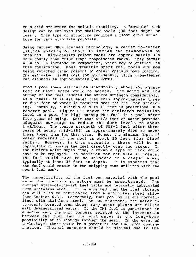
t o a g r i d s t r u c t u r e f o r seismic s t a b i l i t y . ' A "movable" r a c k d e s i g n can be employed f o r s h a l l o w p o o l s ( 3 0 - f o o t d e p t h or l e s s ) . T h i s t y p e of s t r u c t u r e r e q u i r e s a f l o o r g r i d s t r u c - t u r e f o r r a c k s t a b i l i t y p u r p o s e s .
Us ing c u r r e n t NRC-l icensed t e c h n o l o g y , a c e n t e r - t o - c e n t e r l a t t i c e s p a c i n g o f a b o u t 1 2 i n c h e s c a n r e a s o n a b l y be o b t a i n e d . H i g h - d e n s i t y p o i s o n r a c k s are a p p r o x i m a t e l y 3 0 % more c o s t l y t h a n " f l u x t r a p " nonpoisoned r a c k s . T h e y , p e r m i t a 30 t o 35% i n c r e a s e i n compac t ion , which may be . c r i t i c a l i n t h i s a p p l i c a t i o n . Most d o m e s t i c s p e n t f u e l p o o l s are now b e i n g r e r a c k e d u s i n g p o i s o n s to o b t a i n optimum pool. l o a d i n g . The e s t i m a t e d ( 1 9 8 0 ) cost f o r h i g h - d e n s i t y r a c k s ( n o n - l e a k e r c a n assumed) is a p p r o x i m a t e l y $5000/MTU.
From a p o o l s p a c e a l l o c a t i o n s t a n d p o i n t , a b o u t 250 s q u a r e f e e t o f f l o o r s p a c e wou ld be n e e d e d . The a g i n g a n d l o w bu rnup of t h e f u e l r e d u c e s t h e s o u r c e s t r e n g t h c o n s i d e r a b l y . AS a r e s u l t , it is e s t i m a t e d t h a t o n l y a p p r o x i m a t e l y t h r e e t o f i v e f e e t o f w a t e r is r e q u i r e d o v e r t h e f u e l f o r s h i e l d - i n g . Normal ly , a minimum of 9 t o 11 f e e t . is p r e s c r i b e d i n a r e a c t o r p o o l . F i g u r e 6 - 3 s h o w s t h e e s t i m a t e d r a d i a t i o n l e v e l i n a p o o l f o r h i g h b u r n u p PWR f u e l i n a p o o l a f t e r f i v e y e a r s o f a g i n g . Note t h a t 4-1/2 f e e t of w a t e r p r o v i d e s a d e q u a t e c o v e r a g e t o r e d u c e t h e d o s e l e v e l s t o a b o u t 1 mR/hour. The s o u r c e s t r e n g t h o f TMI-2 f u e l a f t e r t h r e e y e a r s o f a g i n g ( m i d - 1 9 8 2 ) is a p p r o x i m a t e l y f i v e t o s e v e n t i m e s lower t h a n f o r t h i s c a s e . Hence, t h e minimum d e p t h of w a t e r r e q u i r e d i n t h e p o o l is a b o u t 3 5 f e e t ( f o r f i x e d r a c k s ) . However , i n t h i s s i t u a t i o n , t h e r e w i l l b e n o c a p a b i l i t y of moving t h e f u e l d i r e c t l y o v e r t h e r a c k s . I n t h e minimum w a t e r d e p t h c a s e , a movab le t y p e of r a c k would h a v e to be employed. I n a d d i t i o n f o r o f f - s i t e s h i p m e n t s , t h e f u e l w o u l d h a v e t o b e u n l o a d e d i n a d e e p e r a r e a , t y p i c a l l y a t l e a s t 35 f e e t i n d e p t h . I t is e x p e c t e d t h a t t h e f u e l would remain i n the ' s h i p p i n g c a n s u t i l i z e d w i t h t h e s p e n t f u e l c a s k .
The c o m p a t i b i l i t y o f t h e f u e l c a n m a t e r i a l w i t h t h e p o o l w a t e r and t h e r a c k s t r u c t u r e m u s t b e a s c e r t a i n e d . T h e c u r r e n t s t a t e - o f - t h e - a r t f u e l r a c k s are t y p i c a l l y f a b r i c a t e d f rom s t a i n l e s s s tee l . I t is e x p e c t e d t h a t t h e f u e l s t o r a g e c a n w i l l a l s o be f a b r i c a t e d f r o m a s t a i n l e s s s t e e l a l l o y (see S e c t i o n 6 . 3 ) . C o n v e r s e l y , f u e l p o o l w a l l s a r e n o r m a l l y l i n e d w i t h s t a i n l e s s s tee l . A t PWR r e a c t o r s , t h e w a t e r is t y p i c a l l y b o r a t e d even though many o t h e r p l a n t s a r e f i l l e d w i t h d e m i n e r a l i z e d w a t e r . I f t h e TMI f u e l is p o s i t i o n e d i n a s e a l e d can , t h e o n l y c o n c e r n r e l a t e d to t h e i n t e r a c t i o n b e t w e e n t h e f u e l a n d t h e p o o l w a t e r is t h e l o n g - t e r m p o s s i b i l i t y of i n - l e a k a g e t h r o u g h t h e s e a l . I n t h e e v e n t of i n - l e a k a g e , t h e r e would be a p o t e n t i a l f o r f u e l p o o l contam- i n a t i o n . T h e r m a l c o n c e r n s s h o u l d be m i n i m a l d u e t o t h e

0 I 2 3 4 5 6 7 8 9 1 0 WATER [KPTH WER TOP OF FUEL (FEIET)
RADIATION LEVELS FOR PWR FUEL IN POOL
FIGURE 6-3
(FROM REFEREECE 6 . 4 )
7.3-1'65

e x t r e m e l y low d e c a y h e a t l e v e l s . T h e i n t e r a c t i o n o f t h e p o o l w a t e r and t h e materials used f o r t h e r a c k s t r u c t u r e and t h e f u e l c a n m u s t b e e x a m i n e d f o r p o s s i b l e c o r r o s i o n mechanisms. I t is b e l i e v e d t h a t T y p e 3 0 4 s t a i n l e s s s t e e l a l l o y s s h o u l d be a d e q u a t e ; h o w e v e r , more c o s t l y c o r r o s i o n r e s i s t a n t metals f o r t h e c a n c o u l d be u t i l i z e d to p r e c l u d e a n y p o s s i b l e p r o b l e m s i f l o n g - t e r m s t o r a g e is e n v i s i o n e d . C u r r e n t day reactor f u e l pools a n d ' e x p e c t e d AFR l o c a t i o n s are s e r v i c e d by d e m i n e r a l i z e r s t o m a i n t a i n p o o l a c t i v i t y l e v e l s b e l o w se t l i m i t s . E v a l u a t i o n o f p o t e n t i a l w e t s t o r a g e a r e a s w i l l h a v e to c o n s i d e r t h e a d e q u a c y o f t h e c a p a c i t y o f t h e i n s t a l l e d d e m i n e r a l i z e r s y s t e m i f o n e is a v a i l a b l e . T h e s t a b i l i t y o f t h e p o i s o n ma te r i a l m u s t be c o n s i d e r e d d u r i n g t h e f u e l r a c k d e s i g n p o r t i o n s . The p o i s o n p o s i t i o n i n most f u e l s t o r a g e r a c k s is v e n t e d to t h e p o o l w a t e r .
The t e c h n o l o g y a s s o c i a t e d w i t h h i g h - d e n s i t y s p e n t f u e l r a c k s h a s been r e f i n e d f o r a r e a c t o r a p p l i c a t i o n o v e r t h e l a s t f i v e y e a r s , as shown i n F i g u r e 6-2. The p o i s o n material f o r a s p e n t f u e l r a c k , n o r m a l l y composed o f a b o r o n c a r b i d e c o m p o s i t e i n a m a t r i x , may be mounted on e i t h e r t w o o r f o u r s i d e s w i t h i n t h e f u e l s l o t h o l e . The p o i s o n a x i a l l y e x t e n d s t o . m a t c h t h e a c t i v e f u e l l e n g t h of t h e assembly . The p o i s o n s e l e c t e d must w i t h s t a n d t h e r a d i a t i o n e x p o s u r e (gamma) f o r t h e p r o j e c t e d f u e l l i f e t i m e . The NRC r e q u i r e s t h a t a means o f v e r i f y i n g p o i s o n e f f i c e c y be p r o v i d e d . H e n c e , e i t h e r i n s p e c t i o n p o r t s o r removable p o i s o n s may be s u p p l i e d . The f o r m e r is t h e more common s i t u a t i o n . P r e l i m i n a r y e x a m i n a - t i o n s i n d i c a t e t h a t TMI-.2 f u e l s h o u l d be a lesser p r o b l e m t h a n i n r e a c t o r p o o l i n s t a l l a t i o n s w h i c h c a n n o t a s s u m e t h e p r i o r a g i n g o f t h e f u e l ( a s w i t h T M I ) . H e n c e , a n y o f s e v e r a l p o i s o n c o m p o s i t e s w o u l d be a c c e p t a b l e . The f u e l s l o t w i t h i n t h e r a c k m u s t be d e s i g n e d to a c c o m m o d a t e t h e c r o s s - s e c t i o n a l d i m e n s i o n of t h e f u e l can . Fo r "normal" PWR f u e l , t h i s s l o t wou ld b e f r o m 8 . 7 5 t o 9 . 0 i n c h e s s q u a r e . F o r canned f u e l , a s i n t h i s s i t u a t i o n , t h e s l o t d i m e n s i o n would have to be opened to a.=commodate t h e c a n d i m e n s i o n s . Norma l ly , f rom 0.125- t o 0 .18- inch c l e a r a n c e is r e q u i r e d on e a c h s i d e . However, d u e to t h e l a c k of p r e s e n t . knowledge of t h e f u e l s i z e , or t h e s i z e of t h e s h i p p i n g c a n , it may n o t b e p , o s s i b l e t o d e s i g n t h e r a c k s u n t i l t h e s e a r e a s o f i n f o r m a t i o n have been d e f i n e d . I n S e c t i o n 5 . 4 , it was no ted t h a t t h e f u e l may b e s h i ~ p e d i n a c y l i n d r i c a l c a n . O b v i o u s l y , r a c k s c o u l d be f a b r i c a t e d t o s t o r e t h i s t y p e of c o n t a i n e r ; however , t h e y would r e q u i r e a l a r g e r s t o r a g e area and a r e n o t recommended.
T h e r e a r e c e r t a i n t e c h n i c a l a reas w h i c h a r e h i s t o r i c a l l y . e v a l u a t e d f o r any r a c k i n g of a s p e n t f u e l p o o l . The s p e c i - f i c NRC g u i d e l i n e s are no t ed En R e f e r e n c e 6-3 . I n e s s e n c e , t h e y a d d r e s s n u c l e a r c r i t i c a l ~ t y , t h e r m a l or f u e l decay h e a t

TYPICAL PWR SPENT FUEL STORAGE RACK - POISON-FIXED DESIGN :7 x 8)
FIGURE 6-2

l o a d s , s e i s m i c - s t r u c t u r a l a s p e c t s of t h e r ack /can s t r u c t u r e , and t h e p o o l and h a n d l i n g a c c i d e n t s c e n a r i o s . T h e s e w i l l h ave t o be examined on a c a s e b a s i s c o n s i d e r i n g t h e s p e c i f i c d e s i g n c h a r a c t e r i s t i c s e x p e c t e d . The d e s i g n s i t u a t i o n f o r t h i s a g e d low b u r n u p f u e l s h o u l d n o t p r e s e n t a n y m a j o r t e c h n i c a l p roblems.
I f t h e f u e l is s h i p p e d t o a w e t p o o l s t o r a g e s i t e , t h e r e mus t be a means a t t h e s i t e of h a n d l i n g t h e f u e l c a s k s and u n l o a d i n g t h e f u e l . A s no t ed i n S e c t i o n 5 .4 , s i t e i n t e r f a c e p rob lems a r e min imized f o r t r u c k c a s k s w h i c h a r e l i g h t e r , smaller, and do n o t r e q u i r e s p e c i a l r a i l l i n e s d i r e c t l y i n t o t h e f a c i l i t y . The f a c i l i t y h a n d l i n g e q u i p m e n t ( c r a n e s , u n l o a d i n g a r e a s , y o k e s , e t c . ) m u s t h a v e t h e c a p a b i l i t y of h a n d l i n g t h e c a s k and a s s u r i n g t h a t c e r t a i n . h y p o t h e t i c a l h a n d l i n g a c c i d e n t s c a n n o t o c c u r . T h e s e a c c i d e n t s i n c l u d e c r a n e f a i l u r e , c a s k d r o p , etc. The mere e x i s t e n c e 'of a p o o l . '
of s u i t a b l e s i z e d o e s n o t a s s u r e t h a t t h e f u e l c o u l d e i t h e r be b rough t i n t o or o u t of t h e f a c i l i t y .
T a b l e 6-3 p r e s e n t s a l i s t o f i tems to be e v a l u a t e d f o r a n o f f - s i t e w e t p o o l i n s t a l l a t i o n p r e p a r a t o r y to a d e c i s i o n b e i n g made to r e c e i v e f u e l . A s f u r t h e r i n f o r m a t i o n becomes a v a i l a b l e an t h e a v a i l a b i l i t y of v a r i o u s sites, a p o r t i o n of t h e f e a s i b i l i t y s t u d y s h o u l d i n c l u d e e v a l u a t i n g t h e s e f a c t o r s . R e f e r e n c e 6-5 p r e s e n t s t h e r e s u l t s of a s u r v e y of t h e d e s i g n and i n t e r f a c e c h a r a c t e r i s t i c s of a number o f p o s s i b l e poo l s i t e s .
6 .3 .3 I n s t i t u t i o n a l Problems
Wet s t o r a g e o f s p e n t f u e l w i l l a l w a y s b e v i e w e d a s a n i n t e r i m s o l u t i o n . Arguments have been made t h a t movement to a poo l o f f s i t e i n v o l v e s t h e p o s s i b l e h a z a r d of o f f - s i t e s h i p p i n g . B a s e d on f a c t s , t h i s is more o f a n e m o t i o n a l a rgument w i t h l i t t l e t e c h n i c a l b a s i s .
I t is i n e v i t a b l e t h a t a c e r t a i n q u a n t i t y of f u e l w i l l be s t o r e d , i f o n l y f o r a p e r i o d o f a few m o n t h s , a t t h e TMI f a c i l i t y pending d i s p o s i t i o n . However , u t i l i z a t i o n of any o f f - s i t e f a c i l i t y is dependen t upon a v a i l a b i l i t y of a d e q u a t e s p a c e , l i c e n s i n g , and o p e r a t i n g c o n s t r a i n t s , a l o n g w i t h t h e s i t u a t i o n i n t h e time frame needed.
6 .3 .3 .1 TMI F u e l P o o l
T h e r e is a - n e e d to s t o r e t h e b u l k of t h e f u e l f o r a t i m e p e r i o d e x t e n d i n g p r o b a b l y i n t o t h e e a r l y 1 9 9 0 ' s when a program f o r u l t i m a t e d i s p o s i t i o n of f u e l . is h o p e f u l l y i n p l a c e . S t o r a g e of t h e r e m a i n i n g f u e l f o r a 5- t o 1 0 - y e a r p e r i o d ( 1 9 8 0 t o 1 9 9 0 / 1 9 9 2 ) may be f o u n d w i t h i n t h e TMI f a c i l i t y i t s e l f . C e r t a i n l y , t h e most e c o n o m i c a p p l i c a t i o n

TABLE 6-3
SPENT FUEL POOL INTERFACE CRITERIA (SUMMARY) -
I. SHIPPING CASK INTERFACE
Pool Water Depth 'Floor Structural Loading Crane Limits (Structural and' Lifting, Road,
Redundancy) Adequately Spaced Unloading Area , .
Means of Moving Cask' to Pool Roads (Truck'), Rail Spur (Rail)
' Possible Accident Scenarios-(Cask Dro?, Etc.)
11. POOL INTERFACE
Pool Lining ~emineralizer/Filtration Systems for Water Control Pool Cooling System Capacity Floor Space, Water Depth
' Ventilation Systems, Pool Leak Detection System
111. SPENT FUEL RACK INTERFACE
Pool/Rack' Structural and Seismic Adequacy Means of Mounting Rack Rack Loading Crane/Handling Tools
IV. NRC-LICENSING CRITERIA
Regulatory Guide 3.'44 10 CFR 50, 10 CFR 72 Fuel Quantities
0 Storage Period, NRC No. OTSB Position Guide.

of p o o l s t o r a g e would be .at any of t h e p o o l a r e a s c u r r e n t l y c o n s t r u c t e d and on t h e TMI s i t e i t s e l f . F i g u r e 5-5 i l l u s - t r a t e s t h e a v a i l a b l e a r e a s and t h e s i z e and d e p t h d a t a . However, t h e r e is a l s o a c o n f l i c t i n g need f o r p o o l s p a c e f o r s t o r a g e of equipment p r i o r to d e c o n t a m i n a t i o n . I n a d d i t i o n , t h e r e may be p u b l i c p r e s s u r e to move a l l of t h e f a i l e d f u e l of f - s i t e . S t o r a g e o n - s i t e would i n v o l v e r e r a c k i n g s e l e c t e d a r e a s o f t h e p o o l s a n d i s e x p e c t e d t o b e t h e s i m p l e s t a l t e r n a t i v e s i n c e o f f - s i t e s h i p m e n t is n o t r e q u i r e d i n t h e near - te rm.
6.3.3.2 R e a c t o r P o o l s
A n o t h e r p o s s i b i l i t y is t r a n s s h i p m e n t to a n o t h e r r e a c t o r p o o l . , In a l l l i k e l i h o o d , a n o t h e r reactor, p a r t i c u l a r l y o n e w i t h i n s e v e r a l hundred miles o f t h e TMI s i t e , would o f f e r v a r i o u s h a n d l i n g and l o g i s t i c a d v a n t a g e s . I t is e x p e c t e d t h a t t h e r e a c t o r s i t e s wou ld be t e c h n i c a l l y c a p a b l e o f h a n d l i n g t h e s h i p p i n g c a s k s and u n l o a d i n g t h e f u e l a s w e l l as be ing d e s i g n e d and l i c e n s e d to accommodate LWR t y p e f u e l . The p r i m a r y d i s a d v a n t a g e a t t h i s p o i n t i n t ime i s t h e e x p e c t e d n o n a v a i l a b i l i t y of s t o r a g e s p a c e . R e f e r e n c e . 6 .6 , a r e p o r t by a DOE o f f i c i a l to Congres s , i n d i c a t e s a p o t e n t i a l s h o r t f a l l i n r e a c t o r o n - s i t e s t o r a g e s p a c e i n t h e U n i t e d S t a t e s by 1 9 8 3 o f 3 8 0 MTU. E v e n i f a m u t u a l s h a r i n g a r r angemen t cou ld be made w i t h a n o t h e r u t i l i t y or r e a c t o r p l a n t w i t h a d e q u a t e s t o r a g e s p a c e , and s u i t a b l e t e c h n i c a l and l i c e n s i n g q u e s t i o n s r e s o l v e d , t h e r e c o u l d be c o n s i d e r - a t l e p r e s s u r e b r o u g h t t o p r e v e n t or b l o c k s u c h t y p e s o f s p e n t f u e l t r a n s s h i p m e n t . T h i s p r o b l e m h a s o c c u r r e d p r e - v i ~ u s l y w i t h Duke Power. T h e i r program i n c l u d e s movement of f u l l from t h e i r Oconee to t h e i r McGuire p l a n t s . T h i s is a r e l a t i v e l y s h o r t s h i p p i n g d i s t a n c e ( less t h a n 1 0 0 mi les ) . However, t h i s movement h a s been d e l a y e d f o r o v e r two y e a r s and is n o t r e s o l v e d a t p r e s e n t ( m i d - 1 9 8 0 ) . C u r r e n t l y , t h e C a r o l i n a Power a n d L i g h t Company t r a n s s h i p s f u e l b e t w e e n t h e i r Robinson and B r u n s w i c k p l a n t s . Commonwealth E d i s o n ' h a s p r o p o s e d s i m , i l a r f u e l movements f r o m t h e i r D r e s d e n p l a : ? t s . Arguments used to p r e v e n t sh ipmen t have i n c l u d e d t h e c o n c e r n w i t h p o s s i b l e s h i p p i n g d a n g e r s .
6 .3 .3 .3 AFR S t o r a g e
I n r e c e n t p o l i c y a d d r e s s e s by t h e D e p a r t m e n t o f E n e r g y (DOS) , R e f e r e n c e 6 . 6 , t h e g o v e r n m e n t h a s made known i t s i n t e n t to store s p e n t n u c l e a r f u e l a t a n a w a y - f r o m - r e a c t o r f a c i l i t y ( A F R ) . The r a t i o n a l e b e i n g t h a t t h e r e w i l l b e i n s c f f i c i e n t a t - r e a c t o r s t o r a g e s p a c e a v a i l a b l e beyond t h e 1983. t i m e f r a m e , and t h a t t h e r e s o l u t i o n o f a m e a n s o f u l t i m a t e s p e n t f u e l ~ d i s p o s i t i o n w i l l n o t be a d d r e s s e d u n t i l 1985 . T h i s l a c k of s t o r a g e s p a c e cou ld l e a d to p l a n t s h u t - down. The e x p e c t e d nea r - t e rm s i t e s i n v o l v e u t i l i z a t i o n of

o n e or s e v e r a l n o n o p e r a t i o n a l ' r e p r o c e s s i n g p l a n t p o o l s ( i . e . , Morris, NFS, West V a l l e y , AGNS-Barnwel l ) . T h e s e s t o r a g e f a c i l i t i e s w o u l d b e o b t a i n e d v i a g o v e r n m e n t a l a c q u i s i t i o n a n d a re p r o p o s e d i n . c u r r e n t c o n g r e s s i o n a l l e g i s l a t i o n (H.R. 3 0 0 0 ) . I t is also f e l t t h a t t h e s e o p t i o n s w i l l r e s u l t i n a lower cost to t h e e lectr ical power i n d u s t r y t h a n t h e u t i l i z a t i o n o f c o l o c a t e d s t o r a g e areas a t l a r g e m u l t i r e a c t o r p l a n t s i tes ( R e f e r e n c e 6 . 6 ) . However , c u r r e n t d e l a y e x p e r i e n c e d i n AFR s i t e s e l e c t i o n i n d i c a t e s t h a t u n l e s s a c t i o n is t a k e n f o r p u r c h a s e o f t h e s e f a c i l i t i e s , t h a t t h e f a c i l i t i e s w o u l d n o t b e o p e r a t i o n a l when n e e d e d ( 1 9 8 3 to 1 9 8 4 ) .
6.3.3.4 Government F a c i l i t y
A f i n a l a l t e r n a t i v e would be u t i l i z a t i o n of s u i t a b l e s p a c e s a t g o v e r n m e n t a l n u c l e a r i n s t a l l a t i o n s . S t u d i e s n o t e d i n . R e f e r e n c e 6.5 i n d i c a t e t h a t t h e r e are p l a c e s w h i c h p o t e n - t i a l l y have a v a i l a b l e s p a c e . E x p e r i e n c e h a s b e e n o b t a i n e d w i t h p o o l s t o r a g e of s p e n t r e s e a r c h f u e l or f o r e i g n f u e l a t a number o f t h e s e i n s t a l l a t i o n s . S i n c e f u e l w i l l be s h i p p e d t o many of t h e s e l o c a t i o n s f o r R & D e v a l u a t i o n , t h e r e is t h e p o s s i b i l i t y t h a t t h e t o t a l q u a n t i t y o f f u e l c o u l d a l s o be s u b d i v i d e d and s t o r e d a t more t h a n one of t h e s e f a c i l i t i e s . The t o t a l q u a n t i t y o f f u e l is n o t l a r g e , and i t c o u l d be d i v i d e d i n t o amounts which c o u l d be manageab ly accommoda ted a t s e v e r a l l o c a t i o n s . Of major i m p o r t a n c e is t h e e v a l u a t i o n o f t h e c a p a b i l i t y of t h e s e f a c i l i t i e s t o a c c o m m o d a t e c a s k u n l o a d i n g a n d t h e p h y s i c a l d i m e n s i o n s a n d s i z e o f t h e i n d i v i d u a l packages . P r i o r e v a l u a t i o n s have i n d i c a t e d t h a t a number of p o t e n t i a l f a c i l i t i e s do n o t have t h e c a p a b i l i t y o f h a n d l i n g c u r r e n t LWR s p e n t f u e l c a s k s and f u l l l e n g t h c u r r e n t f u e l . T h i s is n o t t h e case i f d e b r i s p a c k a g e s or smaller c a n s are d e v e l o p e d which c 3 n b e s h i p p e d i n s p e c i a l c a s k s . A s d i s c u s s e d i n s u c c e e d i n g p a r a g r a p h s , t h e n e e d f o r a government f a c i l i t y to o b t a i n a n NRC f a c i l i t y l i c e n s e f o r t h i s r e c e i p t and s t o r a g e is n o t c lear . The u t i l i z a t i o n o f t h i s f u e l f o r R & D may e l i m i n a t e t h i s r e q u i r e m e n t . A p r e c e d e n t is t h e movement of f u e l f rom t h e F l o r i d a Power and L igh t -Tu rkey P o i n t p l a n t to government i n s t a l l a t i o n s a t t h e B a t t e l l e L a b o r a t o r i e s i n O h i o , and t h e E-MAD f a c i l i t y n e a r L a s Vegas , Nevada.
I n summary , f o r a n y o f f - s i t e s t o r a g e o f TMI f u e l , t h e c a p a b i l i t y of t h e f a c i l i t y to h a n d l e t h e f u e l , t h e n e e d f o r s p e c i a l r a c k s to accommodate t h e canned f u e l , and t h e s p a c e r e q u i r e m e n t s must be e v a l u a t e d . A t p r e s e n t , it a p p e a r s t h a t no s p a c e is c u r r e n t l y a v a i l a b l e f o r s t o r a g e o f t h e e n t i r e , core o f f - s i t e . The p o s s i b l e i n z e r v e n t i o n by a n t i n u c l e a r a c t i v i s t g r o u p s t o p r e v e n t o f f - s i t e s h i p m e n t s may b e a t t e m p t e d no matter w h a t o p t i o n i s s e l e c t e d . H e n c e , w i t h t h e p o s s i b l e e x c e p t i o n of a small p o r t i o n of t h e f u e l moved

3 f f - s i te f o r r e s e a r c h i n t e r e s t s , GPU s h o u l d c o n s i d e r o n - s i t e p o o l s t o r a g e of canned f u e l f o r most of t h e core.
. 6 . 3 . 4 F a c i l i t y L i c e n s i n g
h major a r e a t o b e e v a l u a t e d i s t h e NRC l i c e n s i n g r e q u i r e m e n t s f o r any f a c i l i t y used f o r s t o r a g e .
A t TMI - A m o d i f i c a t i o n to t h e 1 0 CFR 50 l i c e n s e would be r e q u i r e d t o a c c o m m o d a t e t h e p r o c e d u r e s and e q u i p m e n t ( c a n i s t e r s , r a c k s , etc. ) u t i l i z e d .
T r a n s s h i p m e n t ' t o A n o t h e r Reactor - T h e f a c i l i t y w o u l d a l s o r e q u i r e a n amendment t o t h e 1 0 CFR 50 o p e r a t i n g l i c e n s e t o accommodate t h e TMI-2 f u e l . ( P r e c e d e n t h a s been e s t a b l i s h e d a t s u c h p l a c e s as t h e C a r o l i n a Power and Ligh t -Brunswick i n s t a l l a t i o n , )
- AFR - A l i c e n s e f o r t h e f a c i l i t y w o u l d b e r e q u i r e d i n a c c o r d a n c e w i t h 1 0 CFR 72 . The f a c i l i t y l i c e n s e wou ld s p e c i f i c a l l y d i s c u s s t h e s t o r a g e o f f a i l e d ( c a n n e d ) f u e l s .
.- Government F a c i l i t y - Unknown.
6.3.5 I m p l e m e n t a t i o n C o n s i d e r a t i o n s
I m p l e m e n t a t i o n of e ach of t h e s e s t o r a g e schemes c a n be e:;ti- mated . The c u r r e n t l e n g t h of t i m e f o r t h e NRC t o a p p r o v e a l i c e n s i n g amendment f o r r e r a c k i n g o f a reactor f a c i l i t y is a b o u t 2 t o 2-1/2 y e a r s . The time to d e s i g n , c o n s t r u c t , and f a b r i c a t e ( a n d p o s s i b l y t e s t ) t h e p o o l s t o r a g e r a c k s and c a n s is a l s o a b o u t 2 t o 2-1/2 y e a r s . Howeve r , t h e s e two t a s k s can be per formed i n p a r a l l e l i f n e c e s s a r y . H e n c e , a minimum of 2-1/2 y e a r s would be r e q u i r e d to implement use of t h e TMI ~ 0 0 1 . The same time wou ld be r e q u i r e d f o r u s e o f a n o t h e r LWR p o w e r r eac to r s i t e . L i c e n s i n g t i m e c o u l d be e x t e n d e d f o r t r a n s s h i p m e n t and f o r some n e c e s s a r y f a c i 1 i t y m o d i f i c a t i o n s . Hence, o u r es t imate is a 3- t o 3 - 1 / 2 - y e a r l e a d t i m e u n t i l i n i t i a l s t o r a g e is a v a i l a b l e (mid -1983 ) . AFR's are needed n a t i o n a l l y by 1983 . However, b a s e d on t h e c u r r e n t s t a t u s of t h e government e f f o r t to p u r c h a s e a t l e a s t o n e of t h e i n o p e r a t i v e r e p r o c e s s i n g p l a n t p o o l s , t h e d a t e of e a r l i e s t a v a i l a b i l i t y is p r o j e c t e d to be 1 9 8 4 o r b e y o n d . S i m i l a r l y , t h e u t i l i z a t i o n of g o v e r n m e n t f a c i l i t i e s ( b a s e d o n R e f e r e n c e 6 . 5 ) c o u l d t a k e f rom t w o to s i x y e a r s depend ing o n t h e f a c i l i t y , m o d i f i c a t i o n s r e q u i r e d , e t c . A s c a n b e s e e n , t h e l e a d t i m e b e t w e e n i n i t i a t i o n o f s p e c i f i c a c t i o n
' f o r s t o r a g e and t h e t i m e of i n i t i a l r e c e i p t c a n e x t e n d f r o m t w o to e i g h t y e a r s . W e s u g g e s t t h a t t e n t a t i v e s e l e c t i o n of s e v e r a l sites be i d e n t i f i e d as e a r l y as p o s s i b l e to c o m p l e t e more d e t a i l e d s t u d i e s of t h e p l a c e s c o n s i d e r e d .

6.3.6 Advanced Wet S to raqe Techniques
S p e n t f u e l d i s a s s e m b l y is a t e c h n i q u e t h a t now a p p e a r s p o s s i b l e f o r Hnorma ln i n t a c t f u e l , T h i s o p e r a t i o n is u t i l i z e d to compact the wet s t o r a g e of spen t f u e l . The f u e l assembly is dismant led i n t o i n d i v i d u a l rods and c a n i s t e r e d . The amount t h a t c a n be s t o r e d w i t h i n a g i v e n a r e a is increased by 1-1/2 t o 2 times. The bas i c o p e r a t i o n a l s t e p s are :
Removal of end f i t t i n g Rod p u l l i n g Canning of t h e f u e l rods Compaction and d i s p o s a l of the f u e l ske le ton .
This technique involves s e v e r a l h a n d l i n g s t e p s which would n o r m a l l y pose no p rob lems w i t h f u e l c l a d d i n g s t r u c t u r a l i n t e g r i t y . However, i n t he case of t h e b a d l y f a i l e d TMI-2 f u e l , it is prudent to minimize f u e l handling. It would not be recommended to p u r p o s e l y a t t e m p t to d i s a s s e m b l e TMI-2 f u e l f o r compacted s to rage ,
Conceivably, t h e o p e r a t i o n a l steps used f a r hand1 i n g t h e research and examination of s e l e c t e d TMI-2 f u e l a s s e m b l i e s w i l l be s imi lar to t h o s e used i n d i s a s s e m b l y . F u e l d i s - a s sembly to some d e g r e e is r e q u i r e d t o make i n d i v i d u a l r e sea rch eva lua t ions of t h e i n t e r i o r r o d s w i t h i n t he f u e l matr ix . Hence, techniques f o r d ismant l ing the f u e l for h o t ce l l examinations w i l l probably p a r a l l e l t h e s e d i s a s s e m b l y s t e p s . Eventual ly , the i nd iv idua l rods w i l l r e q u i r e p l a c e - ment i n t o a s e p a r a t e can f o r f u r t h e r d i s p o s i t i o n . Develop- m e n t a l s t u d i e s w i t h cann ing of i n d i v i d u a l r o d s and f u e l components have been performed a t AGNS i n t h e 1978-1980 time frame. Figure 6-4 i l l u s t r a t e s the s t o r a g e of f u e l rods from two complete assemblies wi th in a r ec t angu la r con ta iner .
6.4 Dry S torage Concepts f o r TMI-2 Reactor Fuel
6.4.1 General
There are a t l e a s t f o u r p o s s i b l e means f o r d r y s t o r a g e of t h e f u e l from the TMI-2 r e a c t o r : (1) s t o r a g e a t e x i s t i n g f a c i l i t i e s ( l a r g e h o t ce l l s ) w i t h i n t h e U n i t e d S t a t e s , ( 2 ) conceptual ized v a u l t s t o r a g e , ( 3 ) canceptual ized ca i sson s t o r a g e , and ( 4 ) Federa l r e p o s i t o r y s to rage ( R e f e r e n c e s 6 , 7 and 6.18). Repos i to ry s t o r a g e wculd e n t a i l p l a c i n g TMI-2 f u e l d i r e c t l y i n t o g e o l o g i c b u r i a l f o r permanent d i s p o s a l ( a l t hough a 10- t o 50-year r e t r i e v a l du ra t ion would probably be engineered i n t o the r e p o s i t o r y d e s i g n 1 . The r e p o s i t o r y could be loca ted i n underground formations of s a l t , b a s a l t . , g r a n i t e , sha l e , or some o t h e r s t a b l e g e o l o g i c media. T h i ~ r e p o s i t o r y is e n v i s a g e d t o be owned and r e g u l a t e d by t h e

f... ..... ..>. . , :;. ..$ ' ,,.... ' @ ' . 4 $:.. .:>
B 2.
;*<: , ,.
SQUARE ( N I N E - I N C H ) CAN LOADED WITH FUEL P I N S FROM TWO COMPLETE PWR FUEL ASSEMBLY DUMMIES
FIGURE 6-4

Fede ra l Government and would be s imi la r t o t h o s e p roposed f o r N e w Mexico (WIPP-salt m e d i a ) , Wash ing ton (BWIP-basal t media ) , and Nevada (NNWSI-tuff, g r a n i t e , and s h a l e media ) . It is e s t ima ted t h a t t h e f i r s t government r e p o s i t o r y w i l l n o t be on- l ine u n t i l a t l eas t 1990. I n F e b r u a r y of 1980 , P r e s i d e n t Carter e s t a b l i s h e d a cow.prehensive r a d i o a c t i v e waste management program t h a t set t h e g o a l s of a r e p o s i t o r y s i t e s e l e c t i o n by abou t 1 9 8 5 and a n o p e r a t i n g f a c i l i t y by about 1995. s i n c e a r e s o l u t i o n of t h e d i s p o s i t i o n of TMI f u e l needs to be made p r i o r to 1990, near-term s t o r a g e i n a Fede ra l r e p o s i t o r y is - n o t a v i a b l e s o l u t i o n . R e p o s i t o r y s t o r a g e w i l l no t be d i s cus sed any f u r t h e r i n t h i s r e p o r t .
One p o s s i b l e means cons idered f o r s t o r a g e of TMI-2 f u e l is u t i l i z a t i o n of ho t cells or v a u l t s a t nuc l ea r f a c i l i t i e s and l a b o r a t o r i e s opera ted by t h e Federa l Government. ~ e v i e w of e x i s t i n g f a c i l i t i e s is v a l u a b l e f rom a t i m i n g s t a n d p o i n t , i.e., they may be modified to accept t h e TMI-2 f u e l f a s t e r t han bu i l d ing new ded i ca t ed f a c i l i t i e s . However, t e c h n i c a l d e s c r i p t i o n s of t h e e x i s t i n g f a c i l i t i e s a r e c o v e r e d i n t h e d i s c u s s i o n on v a u l t s and c a i s s o n s , p a r t i c u l a r l y v a u l t s . T h i s r e p o r t d e a l s w i t h t h e s e v a r i o u s v a u l t and c a i s s o n concep t s f o r t h e d r y s t o r a g e of TMI-2 f u e l . Each concept is p r e s e n t e d s e p a r a t e l y ; a n d i n t h e case of t h e c a i s s o n c o n c e p t s , it is assumed t h a t e a c h c a i s s o n c o n t a i n s t h e e q u i v a l e n t of one f u e l assembly. Some of t h e c o n c e p t s f o r h e a t removal could be combined. For i n s t a n e e , c o o l i n g f i n s and fo rced convect ion coo l ing could be combined i n a v a u l t , or h e a t p i p e c o o l i n g a n d n a t u r a l c o n v e c t i . o n c o u l d b e combined i n ca i s son s t o r a g e . There are many such combina- t i o n s ; bu t t o s i m p l i f y t h e d i s c u s s i o n , o n l y t h e b a s i c con- c e p t s a r e d i s cus sed i n d i v i d u a l l y . C a i s s o n s c o u l d p r o b a b l y store more than one t o t h r e e f u e l a s s e m b l i e s b u t t h i s h a s n o t been addressed.
6.4.2 Thermal Cons ide ra t i ons
To a l a r g e degree , t he means of s t o r i n g the FMI-2 s p e n t f u e l w i l l be based on t he rma l c o n s i d e r a t i o n s . Due t o t h e v e r y low burnup of t he f u e l , the f u e l is r e l a t i v e l y " c o l d n com- pared t o most commerc ia l power r e a c t o r f u e l s . A s f a r as h e a t l o a d is c o n s i d e r e d , t h e TMI-2 f u e l h e a t l o a d a f t e r t h r e e y e a r s is a p p r o x i m a t e l y e q u a l t o t y p i c a l f u e l d i s - charged from an LWR and cooled f o r about 10 y e a r s . The h e a t l o a d from TMI-2 f u e l a f t e r t h r e e y e a r s of c o o l i n g is a b o u t 300 to 400 watts/MTU o r 190 (maximum) w a t t s / a s s e m b l y . I n t h e e n t i r e co re , t h e r e is a t o t a l of 82.7 MTU ( w i t h a h e a t l o a d of 30 k i l o w a t t s ) c o n t a i n e d i n a l l o f t h e 1 7 7 f u e l a s s e m b l i e s . A f t e r f i v e y e a r s of c o o l i n g (mid-1984 ) , t h e h e a t load d rops t o about 100 watts/assembly o r less t h a n 20 kW f o r t he e n t i r e core . To p l a c e t h i s i n p e r s p e c t i v e , t h e de s ign h e a t load f o r d ry t r u c k shipping casks (one assembly)

is about 1 0 kWt and f o r d r y r a i l c a s k s (NLI-16/24) is 7 0 kWt. Hence, t h e TMI-3 f u e l is r e l a t i v e l y c o l d , t h e r m a l l y , and would na t be expected to p r e s e n t h e a t l o a d p rob lems to any of the des igns , with t he p o s s i b l e e x c e p t i o n of t h e "no cool ingn vau l t . S ince t h i s s tudy is conceptua l , a d e t a i l e d thermal a n a l y s i s was not performed. However, p r i o r s t u d i e s of d r y - c a n i s t e r e d f u e l ( R e f e r e n c e 6 .9 ) i n d i c a t e t h a t t h e thermal g r a d i e n t across the f u e l bundle f o r t h i s "agedn f u e l is extremely small (<50°F). I n a d d i t i o n , the l i k e l i h o o d is t h a t a l l of t he f r e e f i s s i o n gases have been r e l e a s e d from t h e f u e l . Hence, s i n c e t h e c a n i s t e r w i l l p e r f o r m t h e containment func t ion and the thermal l o a d is v e r y low, t h e d r y s t o r a g e does not appear to p r e s e n t a c r i t ica l t e c h n i c a l problem. . 6.4.3 - V a u l t S torage Concepts
rhe v a u l t concepts considered f o r spen t f u e l s t o r a g e c o n s i s t of f o u r p o s s i b l e designs . A v a u l t is def ined as a dedicated d r y s to rage bui lding. These f o u r - v a u l t c o n c e p t s i n c l u d e : *(1) v a u l t w i t h f a r c e d a i r c o o l i n g , ( 2 ) v a u l t u s i n g h e a t p i p e s f o r cool ing, ( 3 ) v a u l t cooled by a n a t u r a l d r a f t , open t o the o u t s i d e environment, and ( 4 ) v a u l t w i t h no c o o l i n g , s e a l e d t o t h e o u t s i d e env i ronmen t . T h e r e a re numerous v a r i a t i o n s of these f o u r concepts , bu t f o r s i m p l i c i t y , o n l y t h e f o u r b a s i c c o n c e p t s a re d i s c u s s e d . A l l t h e v a u l t cdncepts have many f e a t u r e s i n common, i.e., they store many u n i t q u a n t i t i e s of p a ~ k a g e d r e a c t o r f u e l and p r o t e c t t h e s e packages from acc iden t s . They d i f f e r ma in ly i n t h e method used to remove r a d i o l y t i c decay heat .
-: 6.4.3.1 Forced A i r Cool ing 1 -. sb - . .".
. f +., " . The v a u l t c o n c e p t w i t h f o r c e d a i r c o o l i n g is shown i n F igure 6-5. This is t y p i c a l of the design of most e x i s t i n g v a u l t s and hot c e l l s . I t u t i l i z e s well-understood e x i s t i n g technology and many e x i s t i n g f a c i l i t i e s , p a r t i c u l a r l y l a r g e h o t cel ls , c o u l d be mod i f i ed t o s t o r e canned TMI-2 s p e n t f u e l i n t h i s manner. Nearly a l l n u c l e a r f a c i l i t i e s employ forced a i r v e n t i l a t i o n followed by High E f f i c i e n c y P a r t i c u - l a te ~ i r (HEPA) f i l t r a t i o n to remove r a d i o a c t i v e p a r t i c l e s from the a i r p r i o r to i ts e x h a u s t t o t h e env i ronmen t . I f any e x i s t i n g f a c i l i t i e s were t o be used for f u e l s t o r a g e , t h e y would p r o b a b l y employ f o r c e d a f r c o o l i n g . As an example, Idaho Nat iona l Engineering Laboratory ( Idaho F a l l s , Idaho) h a s designed, b u i l t , and is o p e r a t i n g two t y p e s of d ry spen t f u e l s t o r a g e f a c i l i t i e s (Reference 6.10). The two i n s t a l l a t i o n s , t h e Peach B o t t o m S t o r a g e V a u l t s and t h e I r r a d i a t e d Fue l s S t o r a g e F . a c i l i t y ( I B S F ) , a r e bo th f o r c e d convect ion cooled s to rage vau l t s .

HEP
Air Flow -
VAULT WITH FORCED AIR COOLING
'As 4 Blower
FIGURE 6-5

The obvious disadvantage of the f o r c e d a i r c o o l i n g is t h a t it is an " a c t i v e R system and r e q u i r e s the con t inuous e f f e c - t i v e ope ra t ion of the v e n t i l a t i o n and f i l t r a t i o n sys t ems . This disadvantage is r e f l e c t e d i n y e a r l y ape ra t ing costs and s a f e t y cons ide ra t ions . The f o r c e d a i r sys tem requires an Lacident ana lyses to determine what happens when compan,ents cbf the system f a i l , which o f t e n r e g a l q e g c o s t l y s e c o n d a r y backup ( " fa i l - s a fe" ) systems or mechanifi*.
6.4*3.2 Natura l C i r c u l a t i o n Cool ing
The v a u l t c o n c e p t shown i n F i g u r e 6-6 r e l i e s upon t h e n a t u r a l e'onvection (or p m s i v e c o o l i n g of a i r ) to cool t h e f u e l a s s e m b l i e s and is open t o t h e o u t s i d e . . a n v i r o n m e n t . Nukem GmbH of Germany -S8~elfer,@nce 6.X2'1) and ~ n t a r i o Hydro of Canada ~ p e f ere 'nce q. 12) . bath have p r o p s s e d a dry s t o r a g e concept fbe, \spent g q e l t h g t u t i l i z e s a concre te v a u l t cooled by n a t u r a l convedtian. Lase>* of c o o l i n g due to 'tkie £a i l u r e o f mechanical equipltaent is ImpossibXe. The 'mjor d i sadvan- t a g e is i n the a rea of s a f e t y . S i n c e t h e a i r c u r r e n t s do no t deu'klop eno~q t? f a r c e ta overcome the resistance of HEPA -2 ilters (due ta the p r e s s u r e &op across the f i l t e r s ) , it is u n l i k e l y t h a t abs<frlQte f i l t e r s ' caurld be used. Theref ore, to ensu re the s a f e t y of t h e p u b l i c , t h e r a d i o a c t i v i t y i n t h e @pent f u e l must be p ro t ec t ed b y - m u l t i p l e b a r r i e r s . A c a s e car, be made t h a t tlte cladding ' of some f u e l elements ( i n t h i s cam the majori ty. of the mI-2A<gf9re) qanhot be c l a s a i f f e d as a b e , s i n c e t W y may c o n t a i n c r a c k s , h o l e s , e t c . Therefore , t o ensure a minimum of double Containment of t h e s p e a t f u e l , Qe f u e l r o d s ( o s e~lt ire.~assemblies) would be canned, I n the case ~f THI-2, even a d o u b l e cann ing migh t Be -considered. ' N o t e t h a t for pr.opa~.ad. geeolog i c a l ( r e p o s i- ttory-) b u r i a l , m u l t i p l e c a n i s t e r s have been pgoposed . '6.4.3.3 Heat Pipe Cpobi,ng
The v a u l t concept r;iboydA in Figure 6-7 - se l ies on heat p i p e s to cool t h e f u e l a s s e m b l i e s . A h e a t p i p e is a " p a s s i v e n h e a t - t r a n s f e r device c o n s i s t i n g of a sea l ed metal t u b e w i t h an idne r Lining of w ick l ike c a p i l l a r y m a t e r i a l and a s m a l l amount of f l u i d i n a vacuum. Beat is absorbed a t ane end by vapor i za t ion of the f l u i d and is r e l e a s e d a t t h e o t h e r end hy coridensatian of the v8po-r. F l u i d c i r c u l a t i o n . is enha'hced
- b y . the c a p i l l a r y a c t i o n of the wick and g r a v i t y . The t u b e s are c o m p l e t d l y s e a l e d and would p r o v i d e no p a t h w a y f o r release of r a d i o a c t i v e material. from the v a u l t t~ t h e env i - ranment. The t u b e s mdy be f i n n e d to i n c r e a s e t h e i r h e a t t r a n s f e r a b i l i t y . The system is p a s s i v e and d o e s n o t r e q u i r e v e n t i l a t i o n on a r o u t i n e bas i s . A backup low capa- c i t y Claw flow r a t e ) v e n t i l a t i o n system may be d e s i r a b l e to t a k e a i r samples, a l l o w major repa i r s /modiE i c a t i o n s to the h e a t p i p e s , p r o v i d e c l e a n a i r f l o w c o n t r o l f o r n o n r o u t i n e

Stack 4
Air Flow In
VAULT WITH NATURAL CONVECTION CQOLING
FIGURE 6-6


manned e n t r y , and allow a degree of s a f e t y by p r o v i d i n g t h e r e q u i r e d d i f f e r e n t i a l a i r p r e s s u r e f o r n o r m a l o p e r a t i o n s . T h i s s y s t e m would p r o b a b l y n o t c o n t a i n i t s own b a c k u p s y s t e m s , s u c h as r e d u n d a n t s e c o n d a r y b l o w e r s a n d H E P A f i l t e r s , and c o u l d a l so be a r e c i r c u l a t i n g s y s t e m . T h i s v e n t i l a t i o n s y s t e m would p r o v i d e p e r h a p s 0 .5 t o 2 e n t i r e v a u l t a i r c h a n g e s p e r h o u r v e r s u s a b o u t t e n times t h a t amount when a v e n t i l a t i o n sys tem is used on a r o u t i n e basis for airflow and coo l ing .
6.4.3.4 F i n coolin-g
A v e r y similar concept to u t i l i z i n g h e a t p i p e s is shown i n F i g u r e 6-8 i n which metal f i n s are used to t r a n s f e r h e a t , by c o n d u c t i o n , o u t o f t h e v a u l t s t o r a g e a r e a . T h i s c o o l i n g s y s t e m is p a s s i v e i n s i d e t h e v a u l t . Forced (or p e r h a p s n a t u r a l ) convec t ion is used to sweep t h e h e a t from t h e f i n s o u t s i d e t h e v a u l t s t o r a g e a r e a . The a i r from t h i s sweep w o u l d b e n o n c o n t a m i n a t e d a n d H S P A f i l t r a t i o n may b e o p t i o n a l . I n t h i s d e s i g n , t h e e n t i r e c e i l i n g of t h e v a u l t c o u l d be metal which would assist t r a n s f e r r i n g t h e h e a t o u t of t h e v a u l t . T h i s v a u l t concept cou ld also he p r o v i d e d a n a i r r e c i r c u l a t i o n s y s t e m t h a t w o u l d cool a n d f i l t e r r e l a t i v e l y small volumes of a i r , i.e., about 0.5 t o 2 v a u l t a i r changes p e r hour. T h i s sys tem would p r o v i d e a n e g a t i v e a i r p r e s s u r e i n s i d e t h e v a u l t , pe rhaps -1.0 i ~ c h of wa te r .
6.4.3.5 No Coolinq Devices
The v a u l t d e s i g n i n F i g u r e 6-9 assumes a "c losedn v a u l t wi th no c o o l i n g d e v i c e s . The v a u l t would o n l y be open d u r i n g p lacement or removal of s p e n t f u e l . ' V e n t i l a t i o n would be s i m i l a r to t h a t d i s c u s s e d i n t h e h e a t p i p e or metal f i n s t o r a g e c o n c e p t s , i .e . , a r e c i r c u l a t i n g , l o w c a p a c i t y v e n t i l a t i o n s y s t e m employed m a i n l y to r e t a i n a n e g a t i v e p r e s s u r e and n o t u s e d f o r c o o l i n g . The a b i l i t y to use a v a u l t d e s i g n wi th no s p e c i f i c c o o l i n g d e v i c e s ( o t h e r t h a n t h e h e a t s i n k provided by t h e v a u l t ' s c o n c r e t e s t r u c t u r e ) is o n l y p o s s i b l e w i t h s p e n t f u e l t h a t h a s been c o o l e d many y e a r s a f ter reactor d i s c h a r g e . F u e l t h a t is removed from t h e r e a c t o r wi th ve ry l o w burnup , s u c h a s t h e TMI-2 f u e l , w i t h a very low h e a t load may be accommodated i n t h i s manner.
6.4.4 Ca i s son (S i lo ) S t o r a q e Concepts
The a t t r a c t i v e n e s s of t h e c a i s s o n concept is due t o t h e f a c t t h a t a v e s s e l can be f a b r i c a t e d on demand to h a n d l e one or p e r h a p s s e v e r a l f u e l a s sembl ies . These a s s e m b l i e s wou I d be canned p r i o r to being p laced w i t h i n t h e c a i s s o n f o r hand l ing p u r p o s e s and t o p r o v i d e m u l t i b a r r i e r c o n t a i n m e n t . T h e p r i m a r y a d v a n t a g e o f t h e c a i s s o n is t h a t i t is ' s i t e - independent . ' The c a i s s o n could c o n c e i v a b l y be l o c a t e d a t

Cooling Fins
BE Forced Air Flow
. -
VAULT WITH COOLING FINS
FIGURE 6-8

VAULT WITH PJQ COOLING DEVICES
FIGURE 6-9

t ne TMI-2 s i t e or a remote s i t e depending upon t h e needs of t h e pa r . t i cu l a r s i t u a t i o n .
The ca i sson concepts rev iewed i n c l u d e : (1) c a i s s o n s w i t h n a t u r a l c o n v e c t i o n c o o l i n g , ( 2 ) c a i s s o n s w i t h h e a t p i p e b o l i n g , and ( 3 ) c a i s s o n s with no c o o l i n g . I n a d d i t i o n , each of the concepts is reviewed on t h e basis of aboveground s t o r a g e and below ground s t o r a g e . The a a i s s o n , or s i l o , concepts of s t o r i n g spen t fuel, .are a l l s i m i l a r i n , t h a t o n l y small q u a n t i t i e s of packaged r e a c t o r f u e l -4 re s t o r e d i n each caisson. and t h a t there a r e many caissons, i n k p n t r a s t t o l a r g e v a u l t s con ta in ing m u l t i p l e elements.
6.4.4.1 Natura l C i r cu l a t i on ' Caisson
The c a i s s o n concepts w i t h n a t u r a l c o n v e c t i o n are shown i n F igure 6-10 onnd F igu re 6-11. The abavegruund s t o r a g e con- c e p t , Figure 6-10, uses a l a r g e conc re t e d t r u c t u r e f o r each c a i s s o n t o p r o v i d e s h i e l d i n g and p r o t e c t i o n from n a t u r a l phenomena.. Outs ide a i r is allowed to e n t e r a t t he bottom of t h e concre te ca i s son , a ~ d rAtura2 co~nvec'tWm ~ u r r e n t s move t h e air upward and o u t openings p rov ided a t t h e t o p of t h e s t r u c t u r e . A c o n c r e t e p l a g 5s pxovidsd ' a t : t h e t o p of t h e c a i s s o n f o r i n s e r t i o n and removal of spen t f u e l . S i n c e t h e hea ted a i r is vented to the o u t s i d e environment without HEPA f i l t r a t i o n , the spen t fue,J wust be tionfined w i t h i n a t l eas t twcr con ta inment b a r r i e r @ . Theaie b a r r i e r s would p r o b a b l y consist o f a met-a1 c o n t a i n e r wi th a metai averpack.
I f the ca i s sons are placed underground, t h e so i l would act a s a r a d i a t i o n s h i e l d and missile b a r r i e r ; t h e r e f o r e , t h e need f o r a m a s s i v e c o n c r e t e s t r u c t u r e is e l i m i n a t e d . F igure 6-11 i l l u s t r a t e s a poss ib l e des ign u t i l i z i n g n a t u r a l convect ion aool ing 'fat spent f h l ' $ to red underground. I n t h i s case , the spen t f u e l would be placed i n double contain- ment and p l a c e d i n t o c a i s s o n s w i t h i n a,n e n g i n e e r e d berm. V e n t s a r e p r o v i d e a on t h e rtop andb, bo t tom of t h e s t o r a g e c a i s s o n and pass through t h e so i l to t h e o u t s i d e env i ron - mcnt. N o f i l t r a t i o n is p r o v i d e d b e d a u s e of t h e s e c u r e containment of t h e spen t f u e l .
6.4.4.2 Heat P ipe Caisson
Caisson s t o r a g e us ing hea t p ipes f o r cool ing, both above and below ground, a r e shown i n F i g u r e s 6-12 and 6-13, r e s p e c - t i v e l y . The concept of abovegrou.nd s to rage , Figure 6-12, is very s i m i l a r t o the n a t u r a l convec t ion abovegraund s t o r a g e showr- i n F i g u r e 6-10. The r e l a t i v e s i z e of t h e c o n c r e t e s t r u c t u r e and normal ope ra t ions would be t h e same f o r bo th . A conceptual des ign combining n a t u r a l c o n v e c t i o n .and h e a t p i p e s f o r c o o l i n g s t o r e d s p e n t f u e l a s s e m b l i e s h a s b e e n

Heated Air Out
Air In
Access Plug
rleated Air Out
CAISSON - NATURAL CONVECTION - ABOVEGROUND
FIGURE 6-10
Air In
lund Level v , . . ,
.

Concrete Access Plua
FIGURE 6-11

proposed by Electrowatt Engineering S e r v i c e s , Ltd . ( R e f e r - ence 6.13). Each concre te s i l o i n t h e E l e c t r o w a t t concep- t u a l des ign would have the a b i l i t y t~ store s e v e n PWR f u e l assembl ies and could h a n d l e a masimum of 4 0 - k i l o w a t t h e a t load p e r silo. This. is w e l l i n e x c e s s of t h a t r e q u i r e d i n t h e aged TMI-2 f u e l (by approximately a f a c t o r & 30) . Heat p i p e s c o u l d a lso be i n t r o d u c e d t h r o u g h t h e ' s i d e s of t h e conc re t e s h i e l d . In e i t h e r case, it is n e c e s s a r y to p l a c e t h e h e a t p i p e s i n o r i e n t a t i o n s t h a t would m i n i m i z e t h e amount of r a d i a t i o n "shiningn th rough t h e h e a t p i p e access o p e n i n g s . The h e a t p i p e s would t r a n s f e r h e a t f r o m t h e s t o r e d s p e n t f u e l t o t h e o u t s i d e a i r w h e r e it would be d i spe r sed by n a t u r a l convect ion.
The use of h e a t p ipes i n underground s t o r a g e of s p e n t f u e l is shown i n F igure 6-13. This concept may or may not use an engineered berm. The c o n c e p t is shown n o t u s i n g a berm, which is p r o b a b l y less e x p e n s i v e . I t is as sumed t h a t s t o r a g e of s p e n t f u e l underground can be o p e r a t e d s a f e l y wi thout employing an engineered b e r m . A d e t a i l e d e n g i n e e r - ing s a f e t y a n a l y s i s would have t o be conduc ted to s u p p o r t t h i s assumgt ion . The h e a t p i p e s a te i n s e r t e d i n t o t h e conc re t e s h i e l d i n g plug and draw hea t from the spen t f u e l to be d i spe r sed by n a t u r a l convect ion.
6.4.4.3 No Cooling Caisson
The f i n a l ca i s son s tmragemconcept reviewed is above or below ground s to rage with n6 cooling.. These concepts are shown i n F igures 6-14 and 6-15, r e s p e c t i v e l y . These conceptg are t h e most s i m p l e and l eas t c o s t l y d e s i g n s . The a b o v e g r o u n d c a i s s o n concept, shown i n Figure 6-14, p r o v i d e s no c o o l i n g o t h e r t h a n t h e h e a t s i n k e f f e c t o f t h e l a r g e c o n c r e t e s t ruc t -u re . Nukem of Germany (Reference 6.11), Ontar la Hydro o f Canada ( R e f e r e n c e 6 . 1 2 ) , and t h e Nevada T e s t S i t e (References 6.14, 6* 15) have proposed d r y s t o r a g e c ~ n c e p t s f o r s t o r i n g spen t f u e l t h a t ' u t i l i z e s the aboveground ca i s son concept w i t h no a u x i l i ~ r y cooling. he ou t s ide w a l l of t h e c o n c r e t e w i L l bec6me h e a t e d s l i g h t l y once e q u i l i b r i u m is reached. ' A s l i g h t degree of cool ing w i l l t ake p l a c e on t h e o u t e r c o n c r e t e w a l l d u e t o n a t u r a l convect ion, This ca i sson concept could work e i t h e r o u t s i d e o r i n s i d e a bui lding.
The concept shown i n F i g u r e 6-15. underground s p e n t f u e l s tor .age without a u x i l i a r y c o o l i n g , is s i m i l a r t o t h e con- c e p t u a l ca i s son s to rage designed by A l l i e d - G e n e r a l N u c l e a r S e r v i c e s (AGNS) f o r t h e i r p roposed s t o r a g e of h u l l s and g e n e r a l process t r a s h (References 7, 8 , and 9 ) ; a g a i n , t h i s is waste m a t e r i a l wi th s m a l l h e a t l o a d s . The Nevada T e s t S i t e and t h e A t l a n t i c R i c h f i e l d Company ( R e f e r e n c e 6 , 16 j have both proposed d r y s t o r a g e c o n c e p t s f o r s t o r i n g s p e n t

CAISSON A@QVEGROUBD WITH HEAT PIPES
FIGURE 6-12

Heat Pipes
CAISSON BELOW GROUND WITH HEAT P I P E S
FIGURE 6-13

Cancrets -
Access Plug
CAISSOPJ ABOrnGROUND ,WITH NO COOGIPJG
FIGURE 6-14 '

Shieldina Flua
CAISSON BELOW GROUND WITH NO COOLING
FIGURE 6-15

f u e l t h a t employ ca i sson? , or s i loas, below g ~ o u n d w i t h no a u x i l i a r y cooling. It was demonstra ted t h a t t h e use of an engineered berm would a l l e v i a t e some of the d e s i g n pzoblems c o n c e r n i n g e a r t h q u a k e s , f l o o d s , and h e a t r e m o v a l . The d e t a i l s of such a berm are d iscus$ed i n S e c t i o n 6 .4 . I t would be possible a t some l o c a t i o n s t o f a b r i c a t e c a i s s o n s d i r e c t l y i n the ground w i t h o u t a berm. I f t h i s were pos- s i b l e , it cou ld g l i m i n a t e t h e e x p e n s e . o f d e s i g n i n g a n d b u i l d i n g a berm.
The spen t f u r l w i i l be p l a c e d i n t h e c a i s s o n s i n an a r r a y e q u a l l y spaced, Assuming t h a t t h e c a i s s o n s were b u i l t on 25-f mt c e n t e r s ( conserv.a t ive spaginlg ) and on ly one. assembly was placed i n each cai.ssol.~ ( t h e r e -are 177 caisson.8 i n t h e T%I-2 core), it would t a k e -)r 2.5 a c r e % of l a n d area f o r s t o r a g e , This is an e%&reme case and o b v i o u s l y f a r less land a rea would -be requi red i f a closer spacing were chosen. 4Since TMI-2 f u e l is r e l a t i v e l y "co ld , " t h e minimum s p a c i n g would probably be d i c t a t e d by handling equipment and ope ra - t i o n s r a t h e r t h a n s o i l h e a t l o a d i n g . Space f o r h a n d l i n g equipment, aiecess roads, etc . , would perhaps br ing the total t o five acres (see Sect i -an 6.4,5.2).
6,4.5 Engineered Berm
6.4.5.1 Engineered Berms -
The ca isson s t o r a g e c o n c e p t s d i s c u s s e d i n t h i s r e p o r t may r e q u i r e an e n g i n e e r e d berm. T h i s would be d e c i d e d by a s a f e t y a n a l y s i s . The cast e s t i m a t e assumed t h a t t h e below- ground concepts would r e q u i r e an engineered b e r m , w h i l e t h e aboveground c o n c e p t s wauld n o t . By u s i n g a n e n g i n e e r e d berm, t h e e n t i r e c a i s s o n assembly may be p l a c e d i n s o i l above g r a d e l e v e l . The berm is" e r e c t e d f r o m m a t e r i a l s having known permeabi l i ty alid i an exchange p r o p e r t i e s . The c a i s s o n s are t h u s i s o l a t e d from t h e n a t u r a l s o i l , wh ich c o u l d be a c i d i c . his a p p r o a c h a l s o al lows a t h r e e - d i m e n s i o n a l d ry -we l l m o n i t o r i n g s y s tern t o be i n s t a l l e d be fo re t h e berm f i a t e r i a l s a re ' se t i n p l a c e . Any l e a k a g e which can be p o s t u l a t e d is m o n i t o r a b l e w h i l e s t i l l w i t h i n t h e b e r m , thus giving s e v e r a l months n o t i c e b e f o r e e s c a p i n g t h e engineered system (Reference 6'.17). The use of a berm also he lps i n determining t h a t the containment s y s t e m s w i l l no t be b reached d u r i n g a d e s i g n b a s i s s e i s m i c e v e n t or a t o r n a d o , I t is much e a s i e r t o c a l c u l a t e t h e e f f e c t of des ign b a s i s a c c i d e n t s i f t h e p r o p e r t i e s o f t h e s o i l a r e known, a s i n the case of an engineered berm.
An example of an engineered berm is shown i n Figure 6-16. A c l a y pad is l a i d a t the e x i s t i n g grade l e v e l and is covered w i t h a layer of r e l a t i v q l y l a r g e aggregate . The pu rpose of

t h e c l a y and grave l l a y e r s is to break the c a p i l l a r y commu- n i c a t i o n between t h e o r i g i n a l s o i l and t h e berm. The aggrega te is then covered with another c l a y l a y e r t o provide a d d i t i o n a l c a p i l l a r y c o n t r a s t . The remainder of t he berm is cons t ruc t ed of a homogeneous f i l l having known i o n exchange p r o p e r t i e s and a pore s t r u c t u r e which is more open and f r e e d r a i n i n g than the c l a y pads. I n t he f i l l , l oca t ed above the c l a y pads, is l a i d a h o r i z o n t a l network of monitoring pipes . The berm m a t e r i a l is added and capped w i t h a n o t h e r r e l a - t i v e l y impermeable c l a y l aye r . The toe of the berm is open, i n the manner of an e a r t h f i l l dam, to p r o v i d e an e s c a p e r o u t e f o r w a t e r which may p a s s t h r o u g h any b reach i n t h e c l a y cap. A monitorable s u r f a c e dra inage system is provided f o r s u r f a c e run-off from t h e berm.
I n the case of underground ca i s son s t o r a g e con-zep ts , h o l e s a r e excavated i n the berm and corru .gated c a i s s o n s ( o r con- crete "s i losn) a r e set i n p lace . Large aggrega te is p l a c e d around the metallic ca i sson . The p u r p o s e of t h e a g g r e g a t e i n t h i s case is to: (1) break the c a p i l l a r y communicatidn between the ca i s son i t s e l f and t h e s o i l , and ( 2 ) i n s u l a t e t h e metal from any a c i d i c s o i l . The ca i sson may be equipped wi th a d i p l e g f o r m o n i t o r i n g p u r p o s e s which is, i n t u r n , equipped with a valve and a p re s su re gauge. An accumulation of water o r change i n a c t i v i t y l e v e l i n s i d e the c a i s s o n can be de t ec t ed v i a t h i s r o u t e . B e s i d e each c a i s s o n is a d r y w e l l which, coupled with the underlying p ipe network, y i e l d s a three-dimensional " f i x u on any leaked r a d i o a c t i v i t y . The cover blocks a r e des igned to s e a l t h e t o p of t h e c a i s s o n . S i n c e c a i s s o n b r e a t h i n g w i l l be n i n o r and s i n c e t o r n a d o c r i t e r i a ( 3 p s i ) is n o t s u f f i c i e n t t o b r e a k a p r o p e r l y designed cover-block seal, t h e r e is no reason t o provide f o r c o n t i n u a l a i r f l ow. I f , however, t h e need a r i s e s , a s m a l l HEPA f i l t e r could be mounted on t h e d i p t ube and t h e v a l v e l e f t open.
6.4.5.2 S i t i n q Fac to r s
Depending upon t h e degree of compaction and spac ing (one to t h r e e assemblies o r more pe r c o n t a i n e r ) , t h e ca i sson s to rage concepts might t ake from l / 2 t o 2-1/2 a c r e s of land, and t h e v a u l t concepts would r e q u i r e less than 1 / 2 a n a c r e f o r t h e a c t u a l s t o r a g e a r e a , The " s u p p o r t n f a c i l i t i e s , however, could r e q u i r e f i v e a c r e s o r more ( f o r an independent f a c i l - i t y ) . These support f a c i l i t i e s would i n c l u d e u t i l i t y d i s - t r i b u t i o n , s to rage a r eas , o p e r a t i n g a r e a s , w ~ r k e r ' s change rooms, r e s t rooms, o f f i c e s , r e c e i v i n g and s h i p p i n g f a c i l i - t ies, p a r k i n g a r e a , a c c e s s r o a d s , c l e a r e d s e c u r i t y a r e a s nea r per imeter fences , e t c . Theref o r e , t h e s p a c e r e q u i r e d f o r e i ther v a u l t o r ca i sson s to rage w i l l p robably r e q u i r e a minimum of 5 t o 1 0 a c r e s f o r a stand-alone f a c i l i t y . I f t h e s t o r a g e of TMI-2 f u e l were t o be a t an e x i s t i n g f a c i l i t y ,

DIP Leg for Pressure - Temperature - Moisture-- Monitoring
Existi
ENGINEERED BERM CONCEPT CAISSON STORAGE

such as a nat ional laboratory, most ' of the suppor t f a c i l i - t i e s ( roads , parking., e t c . ) would be ava i l ab le , and the land a rea required s p e c i f i c a l l y f o r the TMI-2 d r y f u e l s t o r a g e would be reduced.
The possible decision to s t o r e TMI-2 spent fue l o n - s i t e ( i n a caisson or possibly a spent fue l cask, a t or near the TMI reac to rs s i t e ) depends .upon t rade-offs of t e c h n i c a l f e a s i - b i l i t y , p o l i t i c a l f ac to r s , economics, and comparative r i sks . The f e a s i b i l i t y of the concepts may be measured by t h e a b i l i t y to s t o r e the fuel ' sa fe ly f o r an extended period of time, to meet al.1 government laws/regulations/codes , and t o
.be approved by appropr ia te a u t h o r i t i e s . A dry spent f u e l s t o r a g e ' f a ~ i l i t ~ would require the preparation and approval of a s a f e t y a n a l y s i s t h a t would con£ i r m t h e f a c i l i t y ' s a b i l i t y to operate sa fe ly even during design basis .accidents ' (e.g. , tornadoes or earthquakes). This has to be contrasted with the p o l i t i c a l r e a l i t i e s associated w i t h such t h i n g s as l o c a l p u b l i c a ccep t ance , p o l i t i c a l p r e s s u r e s , and GPU company policy.
The l a s t general area of concern, economics and schedu les , i s pos tu la ted below. I t is expected t h a t a new f a c i l i t y would take f ive to e i g h t yea r s t o br ing t o an o p e r a t i o n a l mode, unless s p e c i a l c o n s i d e r a t i o n was received from the Federal government. A storage f a c i l i t y b u i l t as an exten- s i o n of an e x i s t i n g nuc l ea r f a c i l i t y could , pe rhaps , be opera t ional i n three to f ive years. If p o l i t i c a l r e a l i t i e s d i d not preclude on-site aboveground (TMI) ca i s son s t o r a g e of spent fue l , the ac tual construction of the caissons could be performed t o co inc ide w i t h the cann ing of t h e f u e l . Hence, considerable schedule time could be saved.
6 . 4 . 6 Cost ~ s t i m a t e s
I n i t i a l c ap i t a l cos ts and annual operating cos ts were e s t i - mated fo r the dry storage concepts under consi.deration. A l l of t h e s t o r a g e ' c o n c e p t s were assumed t o accommodate d i spos i t ion of the e n t i r e core. The cos ts would be l e ~ i s i f more than one TMI-2 f u e l assembly were placed i n t o each container o r c a i s son . T h i s is p a r t i c u l a r l y t r u e £01- ' the daisson concepts. A l l of the concepts are based upon at:tual construct ion taking between 2 t o 4 years and being opei.ated f o r 20 years . I t was assumed tha t the below ground ca i s son concepts would require an engineered berm while the above- ground concepts would not.
I t is a l so important t o note t h a t the capac i t y of al l . the s torage concepts is enough to handle a s i n g l e TMI-2 c o r e , but n o t large enough to obtain cost savings from "economy of sca le . " For example, if one were to double the capac i t y of the vault concepts, the cos ts ( c a p i t a l and ope ra t i ng ) would

n o t d o u b l e . They would i n c r e a s e by a b o u t 30 t o 50%. I f t h e c a i s s o n s t o r a g e ca-r>acity were to be d o u b l e d , t h e costs would a l s o n o t d o u b l e , b ~ t i n t ~ i s case , t h e y wou ld i n c r e a s e by p e r h a p s 60 t o 80%. I t wo. l ld a p p e a r t h a t f o r a r e l a t i v e l y small c a p a c i t y s t o r a g e s y s t e m , t h e c a i s s o n c o n c e p t s h a v e a n economic a d v a n t a g e , b u t f c r l a r g e r c a p a c i t y s t o r a g e c e n t e r s ( s a y 500 t o 1000 assemblies), t h e v a u l t c o n c e p t s may be more economic .
6.4.7 C o n c l u s i o n s
The s t o r a g e of TMI-2 s p e n t f u e l i n a d r y e n v i r o n m e n t a p p e a r s t o be f e a s i b l e . For small q u a n t i t i e s o f s p e n t f u e l ( e . g . , t h e core o f . TMI-2), it is more economic to store t h e f u e l i n c a i s s o n s r a t h e r t h a n i n l a r g e v a u l t s . T h e most t i m e l y and least c o s t l y app roach a p p e a r s to be s t o r i n g t h e TMI-2 f u e l a t an e x i s t i n g n u c l e a r f a s i l i t y . F o r i n s t a n c e , p r e v i o u s s t u d i e s ( R e f e r e n c e 6 . 2 4 ) h a v e s u r v e y e d e x i s t i n g h o t c e l l f a c i l i t i e s i n t h e U n i t e d S t a t e s to d e t e r m i n e t h e i r a b i l i t y t o . r e c e i v e , h a n d l e , d i s a s s e m b l e , and r e c o n s t i t u t e f u l l - l e n g t h l i g h t water r e a c t o r s p e n t f u e l a s s e m b l i e s . S e v e r a l o f t h e h o t ce l l s examined would be a d a p t a b l e to t h e s t o r a g e o f TMI-2 f u e l .

REFERENCES
6.1. C u m u l a t i v e AFR S t o r a g e R e q u i r e m e n t s , P l a n n i n g B a s e T o t a l (US and F o r e i g n ) , S p e n t F u e l - S t o r a g e R e q u i r e - m e n t , DOE/NE 0002 ( J a n u a r y 1 9 8 0 ) .
6 .2 Carter , T. J , , S t a t u s o f S p e n t F u e l P o o l A p p l i c a t i o n r , , 1 9 7 9 Annua l ANS Mee t ing ( J u n e 1 9 7 9 ) .
6 . 3 U . S. N u c l e a r R e g u l a t o r y C o m m i s s i o n , S t a f f P o s i t i o n Gu ide o n S p e n t F u e l S t o r a g e and H a n d l i n g A p p l i c a t i o n s ( A p r i l 1 9 7 8 ) .
6 .4 F i n a l ~ e n e r i c E n v i r o n m e n t a l I m p a c t S t a t e m e n t o n Han- d l i n g and S t o r a q e o f S p e n t L i g h t Water P o w e r R e a c t o r F u e l . Document NUREG-0575, V o 1 . 1, U . S . N u c l e a r ~ e ~ u i a t o r ~ Commission ( ~ u ~ u s t 1 9 7 9 ) . -
6 . 5 S p e n t F u e l Program P r e l i m i n a r y T e c h n i c a l A s s e s s m e n t . o f E x i s t i n g F a ' c i l i t i e s f o r AFR S t o r a g e C a p a b i l i t y , Docu-
. m e n t D O E / S ~ 1 0 0 0 7 , R e v . '1, D e p a r t m e n t o f E n e r g y ( S e p t e m b e r 1 9 7 9 ) .
6 . 6 , Myer-s , S . ( D O E ) , P o l i c y s t a t e m e n t o n DOE R e m e d i a l a c t i o n f o r S p e n t F u e l N u c l e a r Programs to Committee o n I n t e r i o r a n d ' I n s u l a r A£ f a i r s , S u b c o m m i t t e e o n E n e r g y and t h e Envi ronment ( F e b r u a r y 25, 1 9 8 0 ) .
S t o r a q e o f S ~ e n t 6 .7 H e n r y , K . H . , a n d T u r n e r , D. A . , --- U n r e p r o c e s s e d F u e l ( S U R F ) , R o c k w e l l I n t e r n a t i o n a l , - R o c k w e l l H a n f o r d o p e r a t i o n , R i c h l a n d , W a s h i n g t o n , RHO-SA-40 (March 1 9 7 8 ) .
6 . 8 ' B l a c k b u r n , L. D . , e t a l , Maximum A l l o w a b l e T e m p e r a t u r e . . f o r S t o r a g e o f S p e n t N u c l e a r Reac to r F u e l , H a n f o r d --.
E n g i n e e r i n g Development L a b o r a t o r y , R i c h l a n d , 'Washing- t o n , HEDL-TME 78 -37 , UC-70, a n i n t e r i m r epor t (May
1 9 7 8 ) .
6 . 9 Ramspo t t , L. D . , e t a l , T e c h n i c a l C o n c e p t -- f o r a T e s t o f Geologic S t o r a g e o f S ~ e n t . R e a c t o r F u e l i n t h e -- ---- Climax ~ r a z t e , Nevada T e s t S i t e , L a w r e n c e L i v e r m o r e L a b o r a t o r y , UCRL-52796 ( ~ u n e r , 1979 ) .
6 .10 P a i n t e r , M. J . , and Meyer, H. S . , Des ign and O p e r a t i o n o f a Dry S p e n t F u e l S t o r a g e I n s t a l l a t i o n , F i n a l sum= ' m a r y f o r t h e 1 9 7 9 a n n u a l ANS m e e t i n g ( A t l a ' n t a , G e o r g i a ) , CONF790602-25, A l l i e d Chemical C o r p o r a t i o n , I d a h o N a t i o n a l E n g i n e e r i n g L a b o r a t o r y , I d a h o F a l l s , I d a h o ( 1 9 7 9 ) .

6.11' K l e i n , D . , % S t o r a g e ---- o f S e e n t ------------- F u e l f r o m L i q h t - --- Water-Reactors w i t h I n h e r e n t l y S a f e A i r C o o l i n g , Nuke~n GmbH (Augus t 1 9 7 9 ) .
6 . 12 B a r n e s , R. W . , and Drolet, T. S . , U t i l i t i e s E x p e r i e n c e - w i t h t h e S t o r a g e o f I r r a d i a t e d F u e l , O n t a r i o H y d r o , T o r o n t o , O n t a r i o , MSG 1x6 , p a p e r p r e s e n t e d a t workshop o n t h e M a n a g e m e n t o f S p e n t F u e l ' a n d R a d i o a c t i v e ' ,
Wastes, Wash ing ton , D. C . , ( S e p t e m b e r 16-19, 1 9 7 9 ) .
6.13 D o r o s z l a i , P. G . ; F e r r o n i , F. G.; a n d W a t k i n s , G . Y . , T r a n s p o r t a n d Dry S t o r a g e - o f S p e n t F u e l E l e m e n t s , ----------- %per p r e s e n t e d a t t h e European N u c l e a r C o n f e r e n c e 7 9 , Hamburg , E l e c t r o w a t t E n g i n e e r i n g S e r v i c e s , L t d . , Z u r i c h , S w i t z e r l a n d (May 1 9 7 9 ) .
6 .14 S t a f f , F u e l T e m p e r a t u r e T e s t I n t e r i m R e p o r t , N e v a d a T e s t S i t e , W e s t i n g h o u s e E l e c t r i c C o r p o r a t i o n ,. WI:JBW:79-367 ( O c t o b e r 1 9 7 9 ) .
. . 6 .15 S t a f f , Drywe l l S p e n t F u e l T e s t I n t e r i m The rma l R e p o r t , Nevada T e s t S i t e , W e s t i n g h o u s e E l e c t r i c C o r p o r a t i o n , WI:JBW:79-388 (November 1 9 7 9 ) . '
6 .16 R i c h a r d s , L. M . , a n d ~ z u l i n s ' k i , M . J . , S u b s u r f a c e S t o r a g e o f Commercial S p e n t N u c l e a r F u e l , N u c l e . a r ---- T e c h n o l o g y , Volume 4 3 (mid -Apr i l 1 9 7 9 ) .
6 .17 A n d e r s o n , K . J . , e t a l l F i n a l R e p o r t : E n g i n e e r i n g E v a l u a t i o n s o f Was t e s H a n d l i n g . a n d S t o r a g e F a c i l i t i e s , A l l i e d - G e n e r a l N u c l e a r S e r v i c e s , AGNS-35900-4.2-26 (November 1 9 7 9 ) .
6 . 18 Menon, M . N . , S p e n t F u e l H a n d l i n g a n d P a c k a g i n g P r o - --. g r a m -- A S u r v e y ---------------- o f H o t C e l l F a c i l i t i e s , H a n f o r d Engineering D e v e l o p m e n t L a b o r a t o r y , HEDL-TME 78-53, UC-70 ( J u l y 1 9 7 8 ) .
,

7 .0 ECONOMIC AND SCHEDULE EVALUATION
7 . 1 G e n e r a l
S c o p i n g e v a l u a t i o n s were pe r fo rmed r e l a t e d t o t h e e c o n o m i c c o m p a r i s o n s o f a number o f TMI-2 core d i s p o s i t i o n o p t i o n s . T h e s e e v a l u a t i o n s were based on a c o m b i n a t i o n o f p u b l i s h e d d a t a , d e t a i l e d cost es t imates , a n d b e s t j u d g m e n t . T h r e e s p e c i f i c i n t e r i m a l t e r n a t i v e s f o r d i s p o s i t i o n , a s n o t e d i n S e c t i o n 6 .0 , were examined on a p a r a m e t r i c b a s i s t o o b t a i n t h e r a n g e o f p o s s i b l e cos ts . S p e c i f i c a l l y , t h e i n t e r i m o p t i o n s -- c h e m i c a l r e p r o c e s s i n g , p o o l s t o r a g e , d r y s t o r a g e -- were a d d r e s s e d , u t i l i z i n g a number o f p o s s i b l e s c e n a r i o s r e l a t e d to of f - s i t e s h i p m e n t d a t e , s t o r a g e p e r i o d , a n d t h e i n i t i a l a v a i l a b i l i t y o f a was te r e p o s i t o r y f o r h i g h - l e v e l n u c l e a r ma te r i a l . T a b l e 7 - 1 p r e s e n t s t h e cos t c e n t e r s a d d r e s s e d f o r e a c h s p e c i f i c case. Costs a s s o c i a t e d w i t h o n - s i t e c a n n i n g and s t o r a g e were n o t a d d r e s s e d . I t mus t be n o t e d t h a t s u c h f a c t o r s as i n f l a t i o n , t i m e - v a l u e o f money, and a c c o u n t a b i l i t y f o r O&M l a b o r were d e v e l o p e d i n a s i m p l i f i e d manner due to t h e u n i q u e n a t u r e of t h i s p r o b l e m . T h e s e s t u d i e s s h o u l d be u t i l i z e d s o l e l y to s c o p e t h e magn i - t u d e o f t h e e x t r a costs i n v o l v e d w i t h t h e core d i s p o s i t i o n . C i r c u m s t a n c e s and t h e a c c o u n t i n g p r o c e d u r e s u s e d may c a u s e t h e s e v a l u e s t o c h a n g e c o n s i d e r a b l y , h o w e v e r t h e g e n e r a l c o n c l u s i o n s d e r i v e d f rom t h e s e r e s u l t s w i l l s t i l l be ' v a l i d .
7 .2 Economic S t u d y R e s u l t s
7 . 2 . 1 Chemica l R e p r o c e s s i n g
T h r e e cases were d e v e l o p e d , e a c h of which are s u m m a r i z e d i n T a b l e 7-2. The cases ' r e p r e s e n t t h e f o l l o w i n g s c e n a r i o s :
Case 1 -- M a t u r e (Domestic) R e p r a c e s s i n g -.- R e p r o c e s s i n g s t a r t s i n 1 9 9 0 w i t h r e c o v ' e r e d u r a n i u m a n d p l u t o n i u m .
Case 2 -- M a t u r e (Domest ic) R e p r o c e s s i n g -- R e p r o c e s s i n g s t a r t s i n 1990 w i t h no v a l u e f o r p lu ton ium. -
Case 3 -- F o r e i g n R e p r o c e s s i n g w i t h e q u i v a l e n t ( t o U n i t e d S t a t e s ) v a l u e s f o r r e c o v e r e d u r a n i u m a n d p l u t o n i u m .
Cases 1 t h r o u g h 3 a s s u m e o n - s i t e p o o l s t o r a g e p r i o r t o r e p r o c e s s i n g . C a s e 2 ( n o p l u t o n i u m r e c o v e r e d ) c o u l d d e s c r i b e e i t h e r a c o p r o c e s s i n g o p t i o n or d i r e c t d i s p o s a l o f t h e p l u t o n i u m w i t h t h e h i g h - l e v e l w a s t e . I n e i t h e r e v e n t , t h e r e l a t i v e v a l u e of r e c o v e r e d p l u t o n i u m d o e s n o t g r e a t l y a f f e c t t h e r e s u l t s of t h e s e s t u d i e s . I n o t h e r w o r d s , t h e
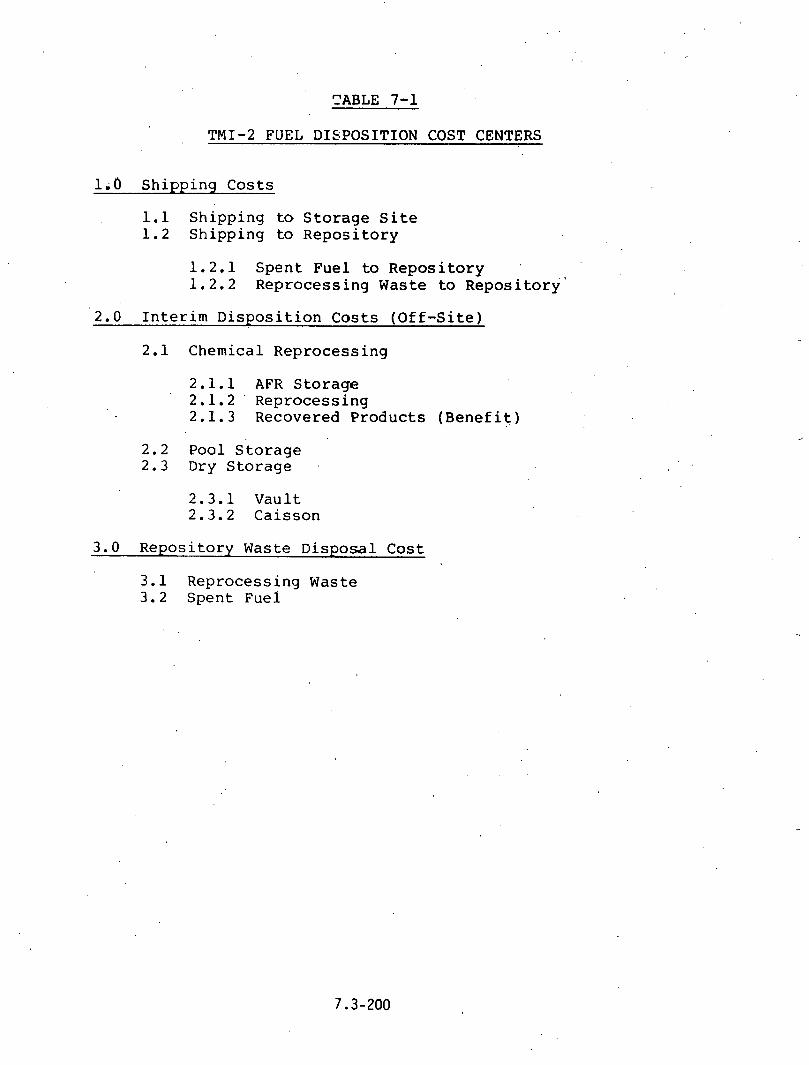
TABLE 7-1
TMI-2 FUEL DISPOSITION COST CENTERS
l;O Shipping Costs
1.1 Shipping to Storage Site 1.2 Shipping to Repository
1.2.1 Spent Fuel to Repository '
1.2.2 Reprocessing Waste to ~epositor~'
2.0 Interim Disposition Costs (Off-Site)
2.1 Chemical Reprocessing
2.1.1 AFR Storage 2.1.2 ' Reprocessing 2.1.3 Recovered Products (Benefit)
2.2 Pool Storage 2.3 Dry Storage
2.3.1 Vault 2.3.2 Caisson
3.0 Repository Waste Disposal Cost
3.1 Reprocessing Waste 3.2 Spent Fuel

TABLE 7-2.
REPROCESSING SCENARIOS
ASSUMPTIONS
1nitia1 fuel off-site shipment - 1983 Reprocessing start date - 1985 - Case 3
- 1990 - Cases 1 and 2 Geological repository open - 2000
. :
CASE NUMBER: 1 2 3 .
L IDEAL FORE1 GN DESCRIPTION REPROCESSING .NO PU VALUE REPROCESSING
2.1.2 Repro- 21,920,000 21,920,00 62,050,000: cessing
3.1 Repository Disposal 7,280,000 7,280,000 ---
3.1.3 Recovered (53,820,000) (49,950,000) (53,820,000) Product (Benefit)*
TOTAL COST (23,030,000) (19,160,000) 14,850,000

d i s p o s i t i o n of p l u t o n i u m d o e s n o t r e p r e s e n t a major economic v a r i a b l e f o r TMI-2 f u e l .
Thea r e p r o c e s s i n g c a s e s do i l l u s t r a t e t h a t t h e r e c o v e r y v a l u e o f t h e u r a n i u m f o r t h e TMI f u e l is l a r g e . I f t h e r e is a v i a b l e , r e p r o c e s s i n g o p t i o n a v a i l a b l e , t h e TMI f u e l (more so t h a n f u l l burnup f u e l ) would r e p r e s e n t a pr ime economic can- d i d a t e f o r such r e p r o c e s s i n g . R e p r o c e s s i n g o v e r s e a s . While seeming less a t t r a c t i v e t h ~ n t h e " i d e a l i z e d " d o m e s t i c c a s e s , a p p e a r s a t t r a c t i v e when t h e cost of s t o r a g e p r i o r to "throw- away" o f t h e f u e l i n a F e d e r a l R e p o s i t o r y is a d d e d . I n summation, r e p r o c e s s i n g to r e c o v e r uranium h a s th'e p o t e n t i a l f o r t h e g r e a t e s t e c o n o m i c i m p a c t on t h i s s t u d y i f i t is a l l o w a b l e w i t h t h i s f u e l .
7 . 2 . 2 ' P o o l S t o r a g e
T h r e e d i f f e r e n t p o o l s t o r a ~ g e s c e n a r i o s ( a l l r e l a t e d to a throwaway f u e l c y c l e ) were examined i n c l u d i n g o n - s i t e p o o l s t o r a g e and e a r l y or l a t e open ing of t h e f e d e r a l r e p o s i t o r y . T h e s e c a s e s a r e s u m m a r i z e 2 i n T a b l e 7 - 3 . The f o l l o w i n g s c e n a r i o s a r e p r e s e n t e d :
Case 4 -- O n l y TMI S t o r a g e - TMI-2 o n - s i t e s t o r a g e u n t i l r e p o s i t o r y opens i n 2000 ( t y p i c a l ) ,
Case 5 -- Both TMI and AFR S z o r a g e - TMI-2 o n - s i t e s t o r a g e ( 8 y e a r s a v e r a g e ) p l u s t e n y e a r s AFR s t o r a g e - R e p o s i t o r y opens i n y e a r 2000 ( t y p i c a l ) .
Case 6 -- Long-Term AFR S t o r a g e - Twenty y e a r s o f AFR s t o r - , a g e u n t i l r e p o s i t o r y opens i n y e a r 2005 ( " l a t e ) .
T h e c o s t s f o r t h e s e t h r e e c a s e s r a n g e f r o m $ 1 2 ' t o $31 m i l l i o n . o b v i o u s l y , t h e m a j o r f a c t o r s i n t h e s e c a s e s a r e t h e s h i p p i n g cos t . and t h e d u r a t i o n o f o f f - s i t ' e AFR s t o r a g e . .
O n - s i t e s t o r a g e o b v i o u s l y is che l e a s t c o s t l y a l t e r n a t i v e , p a r t i c u l a r l y s i n c e t h i s e v a l u a t i o n d o e s n o t f a c t o r i n a n y u n u s u a l costs f o r t h i s . T h i s c o n c l u s i o n is p r o b a b l y reason- a b l e so long a s there is an o p e r a t i n g crew a t t h e TMI s i t e . I f it is n e c e s s a r y to e i t h e r cecommission t h e p l a n t o r move t h e f u e l o f f - s i t e , c a s e s 5 a n d 6 t h e n b e c o m e m o r e r e a l i s t i c .
7 .2 .3 Dry S t o r a g e
T h r e e d i f f e r e n t d r y s t o r a g e s c e n a r i o s were examined i n c l u d - i n g v a u l t and c a i s s o n s t o r a g e and t h e e f f e c t of a d e d i c a t e d ( s m a l l c a p a c i t y ) v e r s u s a n o ~ d e d i c a t e d ( l a r g e c a p a c i t y )

TABLE .7-3
POOL STORAGE SCENARI'OS
CASE SUMMARY:
CASE 4 5 6. -, .
NO AFR ' TMI & AFR LONG-TERM AFR DESCRIPTION STORAGE STORAGE ' , STORAGE
2000 ,, 199D ' ' , 1985 Initial Shipment from TMI
Initial Shipment ---- 2000 . 2005 From AFR
Repository Opens 2000 20Cs,0 20 0 5-
1.1 Shipment ------ . 1,590,000 1,590,'000 . .
to AFR
1 . 2 Shipment to 5 ,030 ,000 , 4 ,260 ,000 . , 4,260,000 . . Repository
2 . 2 AFR Storage ------ 10 ,750 ,000 18 ,200 ,000
3 . 2 Repository 7,280,000 7 ,280,000 7 ,280,000 Disposal
TOTAL COST $12,310,000 $23,880;000 $31,330,000 , .
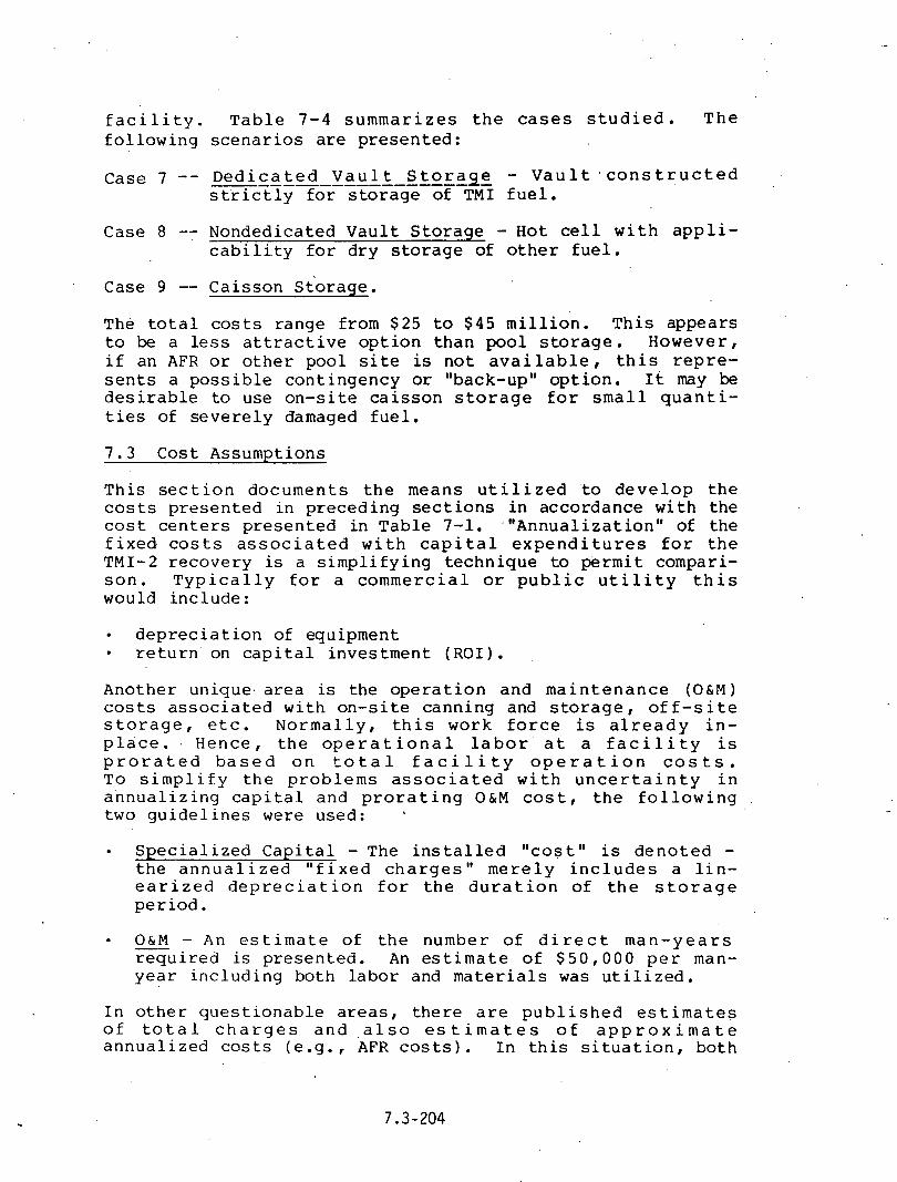
f a c i l i t y . T a b l e 7-4 s u m m a r i z e s t h e c a s e s s t u d i e d . T h e f o l l o w i n g s c e n a r i o s a r e p r e s e n t e d :
Case 7 -- D e d i c a t e d V a u l t S t o r a g e - V a u l t ' c o n s t r u c t e d ----------------- - s t r i c t l y f o r s t o r a g e of TMI f u e l .
Case 8 -- Nonded ica t ed V a u l t S t o r a g e - H o t ce l l w i t h a p p l i - c a b i 1 i . t ~ f o r d r y s t o r a g e of o t h e r f u e l .
Case 9 -- C a i s s o n s t o r a g e .
The t o t a l costs r a n g e from $25 to $45 m i l l i o n . T h i s a p p e a r s t o be a less a t t r a c t i v e o p t i o n t h a n p o o l s t o r a g e . Howeve r , i f an AFR or o t h e r p o o l s i t e is n o t a v a i l a b l e , t h i s r e p r e - s e n t s a p o s s i b l e c o n t i n g e n c y or "back-up" o p t i o n . 1t may be d e s i r a b l e to use o n - s i t e c a i s s o n s t o r a g e f o r s m a l l q u a n t i - t i e s of s e v e r e l y damaged f u e l .
7 . 3 C o s t Assumpt ions
T h i s s e c t i o n d o c u m e n t s t h e means u t i l i z e d t o d e v e l o p t h e costs p r e s e n t e d i n p r e c e d i n g s e c t i o n s i n a c c o r d a n c e w i t h t h e cost c e n t e r s p r e s e n t e d i n T a b l e 7-1. ~ " A n n u a l i z a t i o n " of t h e f i x e d . cos t s a s s o c i a t e d w i t h c a p i t a l e x p e n d i t u r e s f o r t h e TMI-2 r e c o v e r y is a s i m p l i f y i n g t e c h n i q u e to p e r m i t compari - s o n . T y p i c a l l y f o r a c o m m e r c i a l o r p u b l i c u t i l i t y t h i s would i n c l u d e :
d e p r e c i a t i o n of equ ipment r e t u r n on c a p i t a l i n v e s t m e n t ( R O I ) .
Ano the r un ique . a r e a is t h e o p e r a t i o n and m a i n t e n a n c e ( O & M ) costs a s s o c i a t e d w i t h o n - s i t e c a n n i n g and s t o r a g e , o f f - s i t e s t o r a g e , e t c . N o r m a l l y , t h i s work f o r c e is a l r e a d y i n - p l a c e . . H e n c e , t h e o p e r a t i o n a l l a b o r ' a t a f a c i l i t y is p r o r a t e d b a s e d o n t o t a l f a c i l i t y o p e r a t i o n c o s t s . T o s i m p l i f y t h e p r o b l e m s a s s o c i a t e d w i t h u n c e r t a i n t y i n a n n u a l i z i n g c a p i t a l and p r o r a t i n g O&M c o s t , t h e f o l l o w i n g two g u i d e l i n e s were used :
S p e c i a l i z e d C a p i t a l - The i n s t a l l e d " c o s t " is d e n o t e d - t h e a n n u a l i z e d " f i x e d c h a r g e s " m e r e l y i n c l u d e s a l i n - e a r i z e d d e p r e c i a t i o n f o r t h e d u r a t i o n o f t h e s t o r a g e p e r i o d .
O&M - An e s t i m a t e of t h e number o f d i r e c t m a n - y e a r s - r e q u i r e d is p r e s e n t e d . An e s t i m a t e o f $ 5 0 , 0 0 0 p e r man- y e a r i n c l u d i n g bo th l a b o r and m a t e r i a l s was u t i l i z e d .
I n o t h e r q u e s t i o n a b l e a r e a s , t h e r e a r e p u b l i s h e d e s t i m a t e s o f t o t a l c h a r g e s a n d , a l s o e s t i m a t e s o f a p p r o x . i m a t e a n n u a l i z e d c o s t s ( e . g . , AFR c o s t s ) . I n t h i s s i t u a t i o n , b o t h

TABLE 7-4
DRY STORAGE SCENARIOS
. .
ASSUMPTIONS . . , .
I n i t i a l TMI-2 F u e l O f f - S i t e Sh ipmen t - V a u l t 1980
1985 . . - C a i s s o n
S h i p p i n g D i s t a n c e - ,TMI t o S t o r a g e 2000 miles - S t o r a g e to R e p o s i t o r y 1000 'miles
I n i t i a l Date o f R e p o s i t o r y O p e r a t i o n 2000
8 Case 7 9
DEDICATED NON-DE.DICATED . .
DESCRIPTION VAULT VAULT CAISSON -
1.1 Shipment . 3 ,500 ,000 3 ,500,000 3 ,500 ,000 . t o S t o r a g e
1 . 2 Sh ipment to 1 ,980 ,000 1 ,980 ,000 1 ,980 ,000 R e p o s i t o r y
I
-"
2.3 ~ r y S t o r a g e 32 ,500 ,000 ' 12,500,000 20 ,900 ,000
3 .2 R e p o s i t o r y ' 7 ,280 ,000 7 , 2 8 0 , 0 0 0 ~ o 7 ,280 ,000 D i s p o s a l
TOTAL COST $45 ,260 ,000 $25 ,260 ,000 $33,660,000.

v a l u e s a r e p r e s e n t e d a n d t h e p u b l i s h e d c h a r g e u s e d a s a b a s i s .
7 . C.. 1 S h i p p i n g Costs
The cost a s s u m p t i o n s were d e l i n e a t e d i n S e c t i o n 5 . 5 o f t h i s report and a r e a s f o l l o w s :
D i s t a n c e (Miles) $ / E n t i r e Core
$1.59 M i l l i o n 1 .98 M i l l i o n 3.50 M i l l i o n 5.03 M i l l i o n
o v e r s e a s Sh ipment - 80 $/KgU
7 .3 .2 I n t e r i m D i s p o s i t i o n Costs
7 . 3 . 2 . 1 Chemica l R e p r o c e s s i n q
The costs e s t i m a t e d w i t h d o m e s t i c r e p r o c e s s i n g as a m a t u r e l n d u s t r y are p r e s e n t e d i n R e f e r e n c e 7 .1 . ,
Dames t i c R e p r o c e s s i n g $265/KgU or $21.92 M i l l i o n
F o r e i g n R e p r o c e s s i n g ( R 2 f e r e n c e 7 . 2 )
$750/Kgu or $'62.05 M i l l i o n
Xecovered Uranium ( b e n e f i t ) $604/Kgu o r $49 .95 M i l l i o n
Recove red P l u t o n i u m ( b e n e f i t ) $ 47/KgU or $3.87 M i l l i o n
7..3.2.2 P o o l S t o r a g e
The c o s t s a s s o c i a t e d w i t h wet s t o r a g e a t a n e x t e r n a l reactor (AFR or a n y o t h e r f a c i l i t y n o t d e d i c a t e d s o l e l y to TMI-2 f u e l ) are a s f o l l o w s :
AFR Poo l S t o r a g e ( ~ e f e r e n c e . 7 . 3 )
$130/KgU or $10 .75 M i l l i o n
Ind ,ependent e s t i m a t e s o f t e m p o r a r y costs are $15-20/KgU/year d u r i n g t h e i n i t i a l y e a r s o f r e c e i v i n g f u e l a n d $8-12/Kgu/ y e a r af t e r w a r d s ; h e n c e , t h e p r e c e d i n g c h a r g e was u t i l i z e d f o r up t o 1 0 y e a r s s t o r a g e . The g r a d u a t e d s c a l e a s s u m e d was:
up to 1 0 y e a r s s t o r a g e @ $ 1 3 0 / ~ g ~ or $10 .75 m i l l i o n 20 y e a r s s t o r a g e @ $220/KgU o r $18.20 m i l l i o n 30 y e a r s s t o r a g e @ $300/KgU or $24 .81 m i l l i o n .

7.3.2.3 Dry Storage
Vault Storage
Two, poss ib i l i t i e s are evident concerning the case of a vault f o r d r y s to rage . The f i r s t (n0te.d i n S e c t i o n 6 . 3 ) is dedicated, solely to TMI-2 fue l . The second p o s s i b i l i t y is the use of an e x i s t i n g hot c e l l or a por t ion of a l a r g e s t o r a g e v a u l t . I n . t h . e l a t t e r czse . where e i t h e r new construction was - not involved or a por t ion of the f a c i l i t y .was prorated fo r . u se of TMI-2 f u e l , it is expected t h a t lower capi ta l or operating costs would resu l t .
. ' The following c o s t s were es t imated based on the d a t a i n Section 6.3:
Dedicated Vault Storage $25 Million plus 15 man- years per year for O&M
Nondedicated Vault Storage $10 Million plus 5 man- years per year. for O&M.
caisson Storage
Estimates of the c a p i t a l and ope ra t iona l cos t s assoc ia ted w i t h dedicated caissons were made. There is a p o s s i b i l i t y of using nondedicated equipment f o r s torage caisson usage (e .g . , u t i l i za t ion of spent fuel casks or temporary usage of similar equipment). In t h i s case , the increased years of service l i f e would iower the annual c o s t s . The es t imates are presented below:
Dedicated Caisson Storage $13.4 Million plus 1 0 man- years per year* O&M
Nondedicated' Caisson Storage $8.0 Million plus 5- .man- years per year O&M.
I n order to obtain comparable cos t s f o r ,vaui t and caisson s t o r a g e , the c a p i t a l was deprecia ted during the s t o r a g e l i fe t ime and added t o the O&M costs.
7.3.2.4 Repository Costs
These c o s t s were o b t a i n e d from R e f e r e n c e 7 . 2 which summarizes previous work perf orrr.ed by consul tan ts to D O E related to repository use charges. The follc.wing costs were u t i l i zed :
*Storage year.

Spent fuel (throw away) disposal-$88/KgU or $7.28 Million
Reprocessing Waste (including -$77/KgU or $6.34 Million transportation).

REFERENCES
7 . 1 S p e n t LWR F u e l S t o r a g e Costs - R e r a c k i n g , , AR E a s i n s , a n d AFR B a s i n s , --- D o c u m e n t ~ 0 3 / S ~ - S ~ - 2 0 0 2 , R e v . 1 , Department of Energy ( J a n u a r y 1 9 8 0 ) .
7 . 2 AGNS I n t e r n a l D o c u m e n t , N u c l e a r F u e l C y c 1 . e ------ C L o s u r e ------ A l t e r n a t i v e s : A R e a s s e s s m e n t (May 1 9 7 9 ) .
7 . 3 AGNS I n t e r n a l Document, A P r o c e d u r e for C a l c u l a t i n g t h e S a l v a g e . . V a l u e of S p e n t N u c l e a r F u e l (August 1979 1 .

DISTRIBUTION FOR TOPICAL AND FINAL REPORTS
AGNSIDOE CONTRACT NO. DE-AC09-78ET35900 UC-85
Report No.: AGNS-35900-1.5-79 Date Issued: May 28, 1980
Standard AGNS ~ n t e r n a l D i s t r i b u t i o n :
K. J. Bambas ( 1 ) J. A. Buckham (1) R. J. Cho l i s t e r (1) P. F. Highberger (1) W. Knox (1) 5. C. Ravasz ( 1 ) G. T. S t r i b l i n g ( 1 ) W. B. Sumner (1) A. K. Williams ( 1) Library ( 1 ) Records Management (40)
Addi t iona l AGNS I n t e r n a l D i s t r i bu t ion :
K. J. h d e r s d n (1) R. T. Anderson ( 1 ) W. H. Carr ( 1 ) W. L. Godfrey ( 1 ) J. H. Gray ( 1 ) P. N. ~ c C r e e r y (1 ) .
G. A. Tomes ( 1 ) !.d. R. Waltz (1 )
Other D i s t r i b u t i o n :
Mr. Willis Bixby (12) Manager, DOE. S i t e Of f i ce P. 0. Box 88 Middletown, Pennsylvania 17057
5r . Herbert Feinroth (12) Nuclear Power Development Div is ion 3epartment of Energy Mail Stop.Bl07 Washington, D. C. 20545
DOE D i s t r i b u t i o n :
Mr. J. W. Geiger, P ro j ec t Engineer (2 ) Waste and ~ h e l Cycle Technology Off ice DOE Savannah River Operat ions Off ice P ~ s t Off ice Box A Aiken, South Carolina 29801
William Burch (3) Oak Ridge Nat ional Laboratory Post Off i c e Box X Oak Ridge, Tennessee 37830
Mr. S. W. OIRear, TIC (1 ) Savannah River Laboratory E. I. du Pont de Nemours and Company Aiken, South Carolina 29801
Mr. D. C. Drennon (1) Contract ing O f f i c e r DOE Savannah River Operat ions Off ice Pos t Of f i ce Box A Aiken, South Carol ina 29801
W. W. Bal lard (3) Chief Nuclear.Fue1 Cycle Program Branch DOE Germantown, Maryland 20767
M r . M. J. Lawrence (3) D i r ec to r Fuel Storage and Transfer DOE Germantown, Maryland. 20767
Mr. L. H. Meyer (3) Savannah River P l a n t E. I. du Pont de Nemours and Company Aiken, South Carol ina 29801
TIC D i s t r i b u t i o n :
*DOE Technical In£ ormation Center (1 26) Post Off ice Box 62 .Oak Ridge, Tennessee 37830
*Per a t tached l i s t .
Dr. 3 . . Spencer ( 2 ) Savannah River Laboratory E. I. du Pont de Nemours and Company Afken, South Carolina 29801 .

' . TIC STANDARD DISTRIBUTION ( T o t a l 119) UC-85 D i s t r i b u t i o n L i s t Away-From-Reactor program
DOE Opera t ions O f f i c e
1 Albuquerque .
1 Chicago 1 . Savannah k i v e r , Manager 1 Savannah River , C o n t r a c t i n g O f f i c e r 1 Idaho
. 1 Oak Ridge 2 Ric hland 1 San F r a n c i s c o 1 Nevada 9 Savannah River , AFRPO 1 Savannah River , C l a s s i f i c a t i o n O f f i c e r 1 ' . Columbus (Ohio) Area O f f i c e
DOE' Prime C o n t r a c t o r s
Mound Lab, DAO Rockwell I n t e r n a t i o n a l , RFP Argonne Nat iona l Lab, CH B a t t e l l e P a c i f i c Northwest Lab, RL Savannah River Lab, SR Hanford. Engineer ing Development Lab, RL. Los Alamos S c i e n t i f i c Lab, AL Oak Ridge Nat iona l Lab, OR Sandia Lab, AL Lawrence Livermore Lab, SAN Rockwell Harlford Opera t ions , RL Oak Ridge Gaseous' D i f f u s i o n P l a n t , OR EGGG Idaho Inc . ,, I D Brookhaven Nat iona l Lab, Upton, NY Exxon ~ u c l e a r Corpora t ion , I D Savannah River Ecology Lab., Aiken, SC B a t t e l l e Columbus O W I , Columbus, OH
Government, Other
3 DOE Div i s ion of Spent Fuel S t o r a g e and T r a n s f e r , D i r e c t o r , HQ 1 Libra ry of Congress 2 5 DOE TIC 2 5 Nat lona l Techn ica l In format ion S e r v i c e (C0Mb.I) 1 DOE O f f i c e of Safeguards and S e c u r i t y , HQ 2 DOE O f f i c e Waste Management D i v i s i o n , HQ 1 Nuclear Regulatory~Commission, Washington, D.C. 1 Nuclear Regulatory Commission, A t l a n t a , GA 1 DOE Nuclear Power D i v i s i o n , HQ 2 DOE Divis ion of Energy Research, HQ 1 DOE O f f i c e of Environmental and S a f e t y , 11Q

TIC STANDARD DISTRIBUTION (CONTINUED) UC-85 D i s t r i b u t i o n L i s t Away-From-Reactor Program
Incus t r y
Management Analysis Corporation, San Diego, CA Babcock & Wilcox Co., Lynchburg Research F a c i l i t y , ' ~ ~ n c h b u r ~ , VA General ' ~ l e c t r i c Uranium Management Corporation, San Jose , CA B a t t e l l e Columbus Lab., Columbus, OH Boeing Engineering and Cons t ruc t ion , ' ~ e a t t l e , WA Kaman Science Corp., Colorado Spr ings , CO Nuclear Assurance 'Corp., At lan ta , GA .
General Atomic, San Diego, CA Allied-General Nyclear Se rv i ce s , Barnwell, SC S. M. ~ t o l l e r Corp., New York, NY Nuclear Serv ices Corp. , Campbell, CA Westinghouse Corporat ion, Albuquerque, NM
I n s t i t u t e s '
1 , EPRI, Palo Alto, CA
U n i v e r s i t i e s
1 Univers i ty of South Carol ina, Columbia, SC

EXTERNAL DISTRIBUTION FOR TASK 1 DOE REPORTS
Frank A r s e n a u l t , D i r e c t o r D i v i s i o n of Sa feguards , Fuel Cycle , and
~ n v i r o n m e n t a l Research O f f i c e of Nuclear Regu la to ry Research U. S. Nuclear Regu la to ry Commission .
Washington, D. C. 20555
Dr. R. E. Brooksbank B u i l d i n g 3019 Oak Ridge N a t i o n a l L a b o r a t o r y P o s t O f f i c e Box X Oak Ridge, Tennessee 37830
Wil l iam H. Chambers Deputy A s s o c i a t e D i r e c t o r f o r
~ a f eguards & S e c u r i t y Mail S t o p 550 Pos t O f f i c e Box 1663 Los Alamos S c i e n t i f i c Labora to ry Los Alamos, New Mexico 87545
D r . L. D. Chapman, S u p e r v i s o r Systems Ana lys i s D i v i s i o n I Sandia L a b o r a t o r i e s Albuquerque, New Mexico 87115
R. J. J o n e s , Chief M a t e r i a l s P r o t e c t i o n S t a n d a r d s Branch D i v i s i o n of S i t i n g , Hea l th , and . Safeguards S tandards Off i c e of S tandards Development U. S. Nuclear Regu la to ry Commission Washington, D. C. 20555
D r . G. Robert Keepin A s s o c i a t e D i v i s i o n Leader Nuclear Sa feguards Program D i r e c t o r Mai l S t o p 550 Los Alamos S c i e n t i f i c Labora to ry Los Alamos, New Mexico 87545
R. G. Page; S p e c i a l ~ s s i s t a n t t o t h e Dire 'c tor f o r L i c e n s i n g
D i v i s i o n of Sa feguards Off i c k of Nuclear Mater ' ia l S a f e t y
and S a f e g u a r d s U. S. Nuclear Regu la to ry Commission Washington, D. C. 20555
D r . P.. J. P e r s i a n i Argonne. N a t i o n a l L a b o r a t o r y 9700 Sou th Cass Avenue Argonne, I l l i n o i s 60439
T. A- S e l l e r s , S u p e r v i s o r Advanced F a c i l i t i e s P r o t e c t i o n D i v i s i o n D i v i s i o n 17.61. Sandla L a b o r a t o r i e s Albuquerque, New Mexico 87115
S y l v e s t e r 'Suda Techn ica l Suppor t O r g a n i z a t i o n Bui ld ing 197 Brookhaven N a t i o n a l Labora to ry Upton, Long I s l a n d , New York 11973
Don C r a n d a l l B e c h t e l , Inc. P o s t O f f i c e Box 3965 San F r a n c i s c o , C a l i f o r n i a 94105
R. W. P e t e r s o n . .
B a t t e l l e P r o j e c t Management D i v i s i o n O f f i c e of Nuclear Waste I s o l a t i o n 505 King Avenue Columbus, Ohio 43201
F. A. O'Hara B a t t e l l e ~ o l u m b u s L a b o r a t o r i e s 505 King Avenue Columbus, Ohio. 43201
George Weisz, D i r e c t o r G. L. Stukenbroeker Off i c e of Safeguards and S e c u r i t y Nuclear T r a n s p o r t a t i o n U. S. Department of Energy NL I n d u s t r i e s , Inc. Washington, D. C. 20545 1130 C e n t r a l Avenue
Albany, Kew York 12205 H. T. Ker r , Sa feguards Task Leader Conso l ida ted Fuel Reprocess ing Programs Engineer ing Technology D i v i s i o n b
Oak Ridge Na t iona l Laboratory-Nuclear Div. P. 0. BOX Y Oak Ridge, Tennessee 37830

J. V. CUPO .
Westinghouse E l e c t r i c Corpora t ion Power Systems Nuclear Center P o s t O f f i c e Box 355 P i t t s b u r g h , Pennsylvania 15230
General E. C. Hardin U. ,S. Department of Energy Mail Number B-107 Washington, D. C. 20545
R. M. J e f f e r s o n , Manager Nuclear Fue l Cycle Technology Development I e p a r t m e n t 5430 Sandia ~ a b o r a t o r i e s Albuquerque, New Mexico 871 15
!';. K. Rhode, Vice P r e s i d e n t h'iagara Mohawk . '
300 E r i e Boulevard Syracuse , New York 132'02
k. B. Chitwood, A s s i s t a n t D i r e c t o r T r a n s p o r t a t i o n Branch U, S. Department of Energy Mail No. I)-107 Wzshington, D. C. 20545
C b r l e s E. MacDonald, Chief T r a n s p o r t a t i o n Branch O f t i c e of Nuclear M a t e r i a l Safecy
and Safeguards U. S. Nuclear Regulatory Commission Washington, D. C. 20555
'R. R. Raw1 M a c e r i a l s T r a n s p o r t a t i o n Bureau U. S. Department of T r a n s p o r t a t i o n Washington, D. C. 20591
Tom C a r t e r Deputy D i r e c t o r D i v i s i o n of Fuel. Cycle and
H a t e r i a l S a f e t y U. S. Nuclear Regulatory Commission Washingtoii, D. C. 20555

TMI-2 FUEL AND CORE COMPONENTS EXAMINATI'ONS.: . .
FINAL REPORT OF TMI-2 PLANNI'NG.GROUP 7.4
Compiled and Ed i ted
J. E. Hanson D. E. Owen .
D. W. Croucher . .
EG&G Idaho, I r c .
J u l y 1980

ABSTRACT
T h i s . r e p o r t summarizes the sequence o f events which occurred during.
the TMI-2 acc ident as these events -e la te t o f u e l and core component . .
behavior. I t a l so i d e n t i f i e s the h i g h l y unique, f u l l y t y p i c a l data which
can be provided by an examinat ion o f the TMI core. These data can be used
f o r advancing a n a l y t i c a l method ,development, l i c e n s i n g c r i t e r i a , safety,
accident conseqqence m i t i g a t i o n , ana the design, operat ion, and maintenance
o f l i g h t water reactors. I n add i t ion , the r e p o r t o u t l i n e s p o t e n t i a l fue l
and core component examinations, depending on the c o n d i t i o n o f the core,
and presents guide1 ines f o r transpor.:in,g the f u e l and the core components
and fo r se lec t i ng examination and d isposal f a c i l i t i e s . F i n a l l y , the r e p o r t
considers the Task 7.2 recommendations on i n - p l ace TMI-2 core damage
examinat ion, and mates recommendat ioris f o r TMI-2 f u e l experiments,
exami nat ion, and coord ina t ion w i t h other tasks.

EXECUTIVE SUMMARY
A t the i n i t i a l meet ing o f t he Technica l Working Group, he ld on
September 11-13, 1979, 17 spec if i c tasks i n seven general areas were
i d e n t i f i e d . The group agreed t h a t most o f t he l ? tasks r e q u i r e d a
Technica l P lanning Group t o develop a d e t a i l e d d e f i n i t i o n o f each task and
t o c l a r i f y i t s goa ls and methods o f implementat ion. Among t h s tasks
r e q u i r i n g d e t a i l e d d e f i n i t i o n was one des ignated as Task 7.4, Fuel
Experiments and Examination. The goa-l o f P lanning Group 7.4 was t o ' d e v e l o p
a program p lan f o r the d e t a i l e d t echn i ca l examinat ion o f the TMI-2 f u e l and
core 'components. To prepare t he plan, members o f P lanning Group 7.4 met
November 20, 1979 and February 7-8, 1980; and exchanged much .
correspondence. Th i s r e p o r t i s a comp i l a t i on of t he e f f o r t s o f P lann ing
Group- 7.4, and represen ts the f i n a l program p l a n f o r Task 7.4.
The r e p o r t begins w i t h a summary o f t he sequence o f events which
t r a n s p i r e d d u r i n g the TMI-2 acc ident . The est imated core c o n d i t i o n i s
d iscussed and serves as a b a s i s f o r examinat ion recommendat ions which
fo l low.
The nex t four r e p o r t sec t i ons p resen t r a t i o n a l e and j u 5 t i f i c a t i c . n f o r
per fo rming the TMI-2 f u e l and core component examinat ions. These sec t i ons
i n d i c a t e how examinat ion da ta cou ld be used t o make a broad Orange o f
improvements t o a number o f gener ic LWR technolog ies.
One of .the technolog ies t o be advanced by TMI-2 i s the 'development and
assessment o f computer models used t o descr ibe t he course and.consequences
of severe damage acc idents . The development of such models would .improve
r i s k assessment and acc iden t consequence ana lys is , and cou ld be used t o
eva lua te r e a c t o r des ign change recommendations.
The TMI-2 exper ience cou ld a l s o supp ly c r i t i c a l da ta i n the area of
f u t u r e l i c e n s i n g c r i t e r i a , s i nce i t appears t h a t ru lemak ing .hear ings may be
h e l d t o eva lua te new r e a c t o r s i t i n g c r i t e r i a and severe core damage
acc iden t ana l ys i s requirements.

Data f o r accident consequence m i t i g a t i o n i s a t h i r d area t o which the
TMI-2 examination would con t r i bu te . The TMI-2 examinations w i l l revea l if
inherent m i t i g a t i o n o f s?vere accidents i s poss ib le i n e x i s t i n g reac to r
des i p s ; if any features o f present designs exacerbate accident cond i t i ons;
and . w i 11 prov ide gu idance fo r the development o f inherent accident
m i t i q a t o r s .
The fourtl.1 technology t o .which the TMI-2 examination would c o n t r i b u t e
i s reac to r opera t ion and naintenance. These inc lude such i tems as improved
i nd i ca t i ons o f reac to r s tatus, improved equipment t e s t i n g procedures,
b e t t e r decontamination p r ~ e d u r e s , and development o f techniques f o r
a c c i l e n t recovery.
4nother sec t ion o f the r e p o r t i s devoted t o core examination
recommend,ations. This sec t i on presents recommendations f o r a broad range
of i n ~ a c t assembly and fue l debr is examinations, and f o r examinations o f
i n t e r n a l core components m d techniques f o r core hyd rau l i c measurements.
(lither. sect ions of the .report address support quest ions such as removal,
packaging, and sh ipp ing of core samples; examination f a c i l i t y c r i t e r i a ;
f ue l disposal; and coord ina t ion w i t h Task 7.2 on core damage assessment.
T.?e l a s t sec t i on o f tt-e r e p o r t presents the f i n a l recommendations o f
Planning Group 7.4. These recommendations w i l l now be considered by the
Technical Working Group and the J o i n t Coordinat ing Committee.
Implementat ion o f the tasks approved by these bodies w i l l be a t the
d i r e c t i m o f DOE.
App l icab le p o s t i r r a d i a t i o n examination techniques are d e t a i l e d i n
tabu1 ar form i n Appendix A.

ACKNOWLEDGMENTS
The f o l l o w i n g , i n d i v i d u a l s are g r a t e f u l l y recognized f o r t h e i r
c o n t r i b u t i o n s to Planning Group 7.4. The . e f f o r t s of E. L. Ccu r t r i gh t ,
J. S. Tulenko, and R. A. Copeland were p a r t i c u l a r l y s i g n i f i c a n t and
represent a major p o r t i o n o f t h i s repo r t .
NAME AFFILIATION
Andrew C. M i 1 lunz i - -P lann ing Group Chairman U. S. Department o f Energy
Harold M. Burton Denn i s E. Owen
Edward L. Cour tr i gh t
John E. Hanson P h i l i p E. MacDonald Doug1 as. W. Croucher
L a r r y E. Hochre i t e r Dennis L. Burman
George A. Last
Ernest L. Long David 0. Hobson
Len M. Mak i
-Frank1 i n D. Coffman Ralph 0. Meyer M. L. P ick les imer
Tom E. Mor r is
Howard Ocken ,.
A r t B. Carson Richard Oehl.berg, Robert N. Whitesel
Jon A. Reuscher . -
George A.. Sofer
EE&G Idaho, Inc., TMI-2 . .
Technical I n t e ~ r a t i o n O f f i ce
B a t t e l l e P a c i f i c Northwest Labor a to r i es
EG&G Idaho, Inc .
West inghouse E l e c t r i c Corporat i on
Nest inghouse F,anford Co.
Oak Ridge Nat ional Laboratory
Rockwell I n t e r n a t i o n a l
.U. S. Nuclear Regulatory Commission
Bechtel Power Corporat ion
El ec tr i c Power ~ e s e a r c h I n s t i t u t e , .
Sandia Nat ional Laboratory
Exxon Nuclear Company
Gary L. Soz'zi . General El e c t r i c .Company
Tony Stathoplos Combustion Engineering, Inc.

Ne i l E. Todreas
James S. ~ u l e n k o George E. Kulynych R. A. Cope1 and
Massachusetts I n s t i t u t e of Techno1 ogy
Babcock & Wilcox Company

EXECUTIVE SUMMARY ................................................... 7.4.3
..................................................... ACKNOWLEDGMENTS 7.4.5 . . .................................................... 1 . INTRODUCTION 7.4.11
2 . ESTIMATED TMI-2 CORE CONDITION .................:................:7.. 4-12
.......................................... 2.1 Sequence of Events 7.4-12
.............................. 2.2 . ~ o n d i t i on o f Core Components 7.4.17
2.1 Fuel Rods (U02 Fuel. Z i r c a l o y - 4 Cladding) 7.4.17 . ........ . 2.2 Con t ro l Rods and A x i a l Power Shaping Rods (80% Ag-15% In-5% Cd Absorber. 304SS Cladding) ... 7.4.17
. 2.3 Burnable Poison Rods (B4C-AL203 ........................ Absorber. Zry-4 C l adding) 7.4.17 ....................... . 2.4 Spacer G r i ds ( I ncone l 718) 7.4.18 .............................. 2.2.5 Guide Tubes (Z ry -4 ) 7.4.18 2.2.6 Cen t ra l Ins t rument Thimble .......................... ( Incone l 718 Oversheath) 7.4.18
............................... 2.3 core Examinat ion Ob jec t i ves 7.4-18.
3 . DATA FOR ANALYTICAL TOOL DEVELOPMENT AN3 ASSESSMENT ............ 7.4.29
...................................... . 3.1 Sub task b b j e c t i ves . . 7.4-20
3.2 Recommended Program ...................................... 7.4-20
............................. 4 .. DATA FOR FUTURE LICENSING CRITERIA '7.4-23
........................................ 4.1 Subtask Ob jec t i ves 7.4.23
4.2 Recommended Programs ...................................... 7.4-23
5 . DATA FOR SAFETY AND ACCIDENT CONSEQUENCE MITIGATION ............ 7.4.26
5.1 Subtask Ob jec t i ves ....................................... 7.4.26
5.2 Recomended Program ...................................... 7.4.26
6 . DATA FOR OPERATION AND MAINTENANCE ............................. 7.4.31
6 .1 Subtask O b j e c t i v e ......................................... 7.4-31. . .
6.2 Recommended Program ....................................... 7.4-31

. .
7 . REMOVAL. PACKAGING. AND TRAFSPORTATION OF TMI-2 FUEL ..................................... AND .CORE COMPONENT SAMPLES 7.4-33
........................................ 7.1 Subtask Ob jec t i ves 7.4.33
7.2 Recornended Program ...................................... 7.4.33
............................................ 7.2.1 Removal 7.4.33 7.2.2 Packaging ......................................... 7.4.'33 7.2.3 T ranspo r ta t i on .................................... 7.4.33
8 . CORE EXAMINATION ................................................ 7.4.36
........................................ 8.1 Subtask Ob jec t i ves 7.4.36
8.2 Recomnended Program ........................................ 7.4.36
......................... 8.2.1 Fuel Assembly Etami n a t i o n 7.4.37 8.2.2 Examinat ion o f Other Core Components .............. 7.4.41 8.2.3 Core H y d r a u l i c 'ests ............................. 7.4-45
9 . CRITERIA FOR TMI-2 EXAMINATION FACILITIES ...................... 7.4.50
....................................... 9.1 ' Subtask Ob jec t i ves 7.4.50
9.2 Recommended Program ...................................... 7.4.50
9.2.1 General C r i t e r i a .................................. 7.4.50 9.2.2 S p e c i f i c C r i t e r i a ................................ 7.4-53 9.2.3 P o t e n t i a l TMI-2 Examinat ion F a c i l i t i e s ........... 7.4-53
................................................... 10 . FUEL DISPOSAL 7.4.58
10.1 Subtask Ob jec t i ves ........................................ 7.4.58 \
10.2 Recornended Programs ..................................... 7.4.58
11 . REQUIREMENTS FOR DATA FROM TASK 7.2, CORE DAMAGE ASSESSMENT AND CORE REMOVAL .................................... 7.4-60.
11.1 Subtask O b j e c t i v e ........................................ 7.4.00
11.2 Recomnended Program ....................................... 7.4-60
. ................................................ 12 RECOMMENDATIONS 7.4.61
13 . REFERENCES ..................................................... 7.4.63
APPENDIX A.. ANALYTICAL METHODS FOR EX3MINI'NG TMI-2 FUEL AND CORE COMPONENTS ......................................... 7.4.64

FIGURES
1 . Calculated mixture level during uncovering of the TMI-2 core ................................................... 7.4.13
........................................... . .2 . Fuel assembly design 7.4.38
......................... 3 . Ax i a1 power shaping rod assembly ;. .... 7.4.40 ................................... 4 . Burnable po i'son rod assembly' . . 7.4.42
5 . In-core instrumentation string .................................... 7.4-43
.................................... 6 . Control rod drive mechanism 7.4.44
7a .. Side view of reactor vessel and internals showing ............................... location of surveillance capsule 7.4-46
7b: Cross section of reactor vessel and internals showing ........................... surveil 1 ance specimen holder l'ocations 7.4.47
TABLES
1 . Required and Obtainable Data for Developing and Assessing Models for Severe Core Damage ....................... 7.4.21
............. 2 . TMI Data Needs for Safety and Accident Mitigation 7.4.28
3.' Potential DomesticFaci.lities for TMI-2Fuel and Core Component Examination .................................... 7.4-57
.............................. A-1 . TMI-2 Examination Characteristics 7.4-71
.............................................. A.2 . Component Melting . . 7.4.72
A.3 . Estimating Temperatures ....................................... 7.4.75 A.4 . Oxide Thickness ............................................... 7.4.81 A.5 . Hydride Concentration ......................................... 7.4.83 'A.6 . Wall or Component Thickness .................................... 7.444 A.7 . Dimensional and Functional Integrity .......................... 7.4.85 A.8 . Mechanical Properties ......................................... 7.4.88 A.9 . Retained Fission Products ...................................... 7.4.90

A-10. U02 Ox ida t ion (S tc i ch iome t ry ) . . . . . . . . . . . :. . . . . . . . . . . . . . . . . . . . . 7.4-93
- 1 . Debris and Rubble Bed Ana lys is ................................ 7'.4-95 ,
1. INTRODUCTION
This report presents the recomnendations of the Technical Planning
Group for Fuel Experiments and Examination, Task 7.4. The pLrpose of this task has been to develop a plan for the detailed technical examination of the TMI-2 fuel and core components. The recommended program and its
foundations are discussed herein.
Section 2 sumnarizes the sequence of events during the TMI-2 accident
and indicates the estimated condition of the reactor core. Sections 3 through 6 present objectives and 'recommended programs to obtain data for development of analytic methods, future licensing criteria, safety and
accident consequence mi t.i gat i on,, and design, operation, and maintenance of future l i ght water reactors. Section 7 discusses major considerations in removal, packaging, and transportat ion of TMI-? fuel and core component
samples, and provides recommendat ions for areas of further planning and study. Section 8 discusses the core examinat ion that shoul!j be performed
'
to provide the data identified in Sections 3 through 6. Sections 9 and 10 discuss the crj teria For selection of TMI-2 examinat ion and archiving facilities and the guidelines for disposal of the fuel and core component samples, respectively. Requirements for data from Task 7.2, Core Damage
Assessment and Core Removal, are identified in Section 11. Recommendations
for near- and long-term tasks are presented in Section 12.
Appendix A reviews specific examination techniques that may be applicable to examination of the TMI-2 core.

. 2. ESTIMATED TMI-2 CORE CONDITION
The purpose of this section 's to br ief ly sumnarize the sequence of I .
events at TMI-2 as they re la te to the behavior of the core materials.
T h u s , the stage will be se t fo r the following discussions on why and how
the TMI-2 core should be examined. For core examination planning purposes 1 only, this summary is based primarily on the Rogovin Report , and thus
represents a worst-case core damag? scenario. I t i s recognized that other
evaluations completed to date predict less damage. However the pl anning
group recomnends that the worst case scenario be used to fu l ly identify
potent i a1 resource 'requirements.
2.1 Sequence of Events
The sequence of events describ3d below occurred af te r the reactor was shut d3wn. Core damage occurred due t o a loss of adequate decay heat
removal capab i 1 i ty. The core experienced no damage during the f i r s t 100
minutes into the accident. D u r i n g this time, the core was fu l ly covered by
water, even though the pi lot ope ra t~d re l ie f valve ( P O R V ) remained open,
causinq a decrease i n pressure and a loss of coolant inventory from the
primary cool ant system.
At.73 minutes into the accident, the primary coolant pumps in..the B
1 oop were stopped and a t 100 minutes, the A loop pumps were stopped. As a
resul t of continued loss of coolant through the PORV and the accompanying
.loss of primary coolant flow, the core began to uncover. The two-phase steam ard water mixture which remained homogeneous w h i i e the primary pumps
were operating now separated, and steam collected i n the high regions of the primary system. The calculated steam-water mixture level i n the core during this period is shown i n Figure 1.' Figure 1 was derived from
calculatzd heat 2nd mass balances and a variety of data taken from such instruments as the ex-core source range detectors and in-core self-powered
neutron detectors (SPND) (see Reference 2 ) . Below the mixture level, the coolant was near or at i t s saturation temperature and adequate heat
transfer from the fuel rods to the coolant prevented fuel rod damage. Above the mixture level, re la t ive ly inefficient heat transfer occurred, and fuel rod temperatures i ncreased dramati cal ly. . .
. 7.4-12

. ,
A Indicated commencement of. uncovering
' / . , Activation of Loop 6 - primary circulator
0 110 120 . 130 1 40 150 1 60 170 1 80 190
Time (minutes afrer trip)
Figure 1. Calcu'l a ted mixture level ,dur,ir,g uncovering of the T M I - 2 .csre.

Between 102 and 112 minutes, the core was no .longer .completely covered
by hater (see Reference 1, pp. 511,516). Based on core damage estimates
and heat transfer calculat ions of the boildown of the water, the coolant
mixture dropped to 1.2 - + 0.15 m (4 - + 112 f e e t ) above the bottom of the core
(see Reference 1, p. 511). A steady s t a t e coolant mixture level may have
been achieved a f t e r about 120 minutes (see Reference I, p. 511), a1 though
Figure 1 indicates a gradual decrease up to 174 minutes (see Reference 2 ) .
At 130 m i nu t e s , the primary system pressure began to r i s e , and' a t about
140 rrinutes, the PORV block valve was closed, stopping the loss of primary
cool ant (see Reference 1, p. 512). The primary sys tern pressure cont i nued
to insrease and the coolant mixture level i n the core began to r i s e .
During t h i s period of core uncovery, from about 102 to 174 minutes a f te r reactor shutdown, the fuel rod temperatures rose. Cl adding
temperatures reached 1150 to 1650 K (1600 to 2500' F ) within 30 to 40 mirutes a f t e r the core began to uncover, causing a l l of the fuel rods t c burst within 50 minutes of uncovering--that i s , by about 150 minutes into
the aczident. The r a t e of cladding oxidation and hydrogen generation and
re lease increased as the fuel rods continued to heat. The Rogovin report
s t a t e s that between 32 and 39% of the z i rcaloy i n the fueled region, and between 26 to 31% of the to ta l z i rcaloy i n the core was probably converted
to zirconium dioxide a t 174 minutes into the accident. During t h i s period, temperatures rose to 2500 K and higher, b u t d i d not exceed the me1 t ing
point of U02 (3100 K ) . Approximately 50% of the fuel rod cladding was embrittled by oxidation. The cladding may have formed a eu tec t ic l iquid with th? Zr02 and flowed into the fuel-cladding gap of the fuel rods when i t reached. temperatures of 2175 K (3455' F) . The eu tec t ic then reacted
w i t h the U02 fuel to form a 1 iquid phase of Zr-U-0. Estimates of the amount of "1 iquefied fue l" produced varies from a small amount i n the upper
portion of the highest power central fuel assembly to 10% of the fuel i n
the upper half of the core. Other core components were a1 so damaged:
... Inconel g r i d spacers had been melted to a t l e a s t 4 f e e t from the top; . . .and the control rod guide tubes and ins :rumen ta t ion tubes remained i n pl ace and in tac t , a1 though oxidized to a greater or l esse r extent . . . ( see Reference 1, p. 512)

Ins t rumenta t ion tubes and c o n t r o l rod guide tubes surv ived longer than the neighbor ing f u e l rods because they were no t s i g n i f i c a n t heat sources and because they served as "perco la tor tubes" dur ing depressur izat ion, i n which steam bubbles, formed i n the annul i , caused 1 i q u i d water t o perco la te above the average l e v e l i n the core t o reach h igher temper,ature regions before evaporat ing. The ne t e f f e c t was t o produce a much h igher mass f low o f steam, as we l l as v e l o c i t y o f steam f low, through the annul i between the guide tubes and the c o n t r o l rods (and i n the double annul i o f the ins t rumenta t ion tubes) than occurred i n the subchannels between neighbor ing f u e l rods. Thus, the guide tubes, c o n t r o l rods, and ins t rumenta t ion tubes stayed much cooler than otherwise expected dur ing depressur i zat ion and, consequently, 1 agged s i g n i f i c a n t l y i n temperature r i s e compared w i t h t h e i r surroun.dings. The i r heatup s t a r t e d l a t e r , and the heat absorbed by them was t ransferred by r a d i a t i o n from neighbor ing f u e l rods and by conduct i on-convect i on i n t e r a c t i o n w i t h the steam i n the f u e l subchannels (see Reference 1, p. 512).
A t 174 minutes, w i t h the coolant m ix tu re l e v e l a t about 1.5 m (5 f e e t )
above the bottom o f the core, one pr imary cool ant pump i n the B loop was
turned on f o r '19 minutes. This produced a sudden i n f l u x o f water t o the
core from the once-through steam generator B. Since the c ladd ing was
embri t t l e d due t o ox ida t ion , the en te r i ng water would have produced a
thermal shock to the cladding, causing fragmentat ion o f the Zr02 and
U02. This would have e i t h e r formed a debr is bed above the a x i a l midplan.?
o f , the core or increased t h e s i z e o f one a1 ready present. A1 though
subs tan t i a l quenching of the rods occurred, the debr is bed i t s e l f remained
hot and i n steam.
The next major change i n core cond i t i on occurred between 222 and
226 minutes i n t o the accident. The source range moni tors showed a sharp
increase i n a c t i v i t y , the pr imary system pressure increased even though the
b lock valve was open, and the co ld i e g temperatures o f bo th steam
generators increased. Temperature est imates from thermocouples and SPMDs
i n d i c a t e tha t temperatures of 800 K ( 1 0 0 0 ~ F ) were reached a t l oca t i ons
0.25 t o 0.75 m (10 t o 30 inches) above the bottom of the fue l rods. This
behavior i s discussed i n the Rogovin r e p o r t :
From the above evidence, we be l i eve t h a t the debr is bed and shat tered core produced i n the p r i o r per iod were f u r t h e r consol idated by add i t i ona l fo rmat ion o f l i q u e f i e d f u e l t o form a c r u s t i n the bed, which spread over much o f the core. This

crust effectively sealed the debris bed off from cooling by steam percolation, and a steam bubble was formed below the debris bed. This allowed additional oxidation of the fuel rod stubs by dryout, producing damage to a greater depth in the core. The debris bed and crust were penetrated by the increasing steam pressure below, and much of the bed and crust suddenly slumped to lower levels i n the core, part of i t droppi.ng or dripping into the water i n the lower part of the core. The sudden local pressure generation may have forced a radial displacement of part of the core materi a1 into the region between the core and the downcomer. Also, in some assemblies, 1 iquef ied fuel flowed down the small channels surrounding the instrumentation tube to reach levels as low as 10 inches from the bottom of the fuel i n the rods, or lower, producing the activation of levels 1 and 2 SPNDs observed and forming a hot ,casing around it below the average water level i n the core. This' then would have formed a steam je t through the annuli of the instrumentation tube to keep the upper part of the tubes cooled enough to survive until the overall system cooled below about 2600° F.. . (see Reference 1, p. 519).
As one resul t of the additional oxidation, core slumpin'g, 21d format.ion of liquefied fuel , more hydrogen was formed by r 2 . a~ t i on between zircal oy and steam. Additional sources of h:ydrogen would be oxidation of the s tainless steel upper end f i t t i n g s on each of the fuel assemblies and oxidation of some of the UO to a higher oxidation s tate . . . (see Reference 1, p. 519f.
The condition of the core was summarized as follows:
We believe the condition of the core a t t h i s time to.be roughly as f3llows: the debris bed plus crust has been lowered i n the core so that i t s lower boundary may be as low as 4-112 to 5 feet from the bottom of the fuel i n the fuel rods, and i t s upper boundary may be as low as 3 f ee t from the top of the fuel stack i n the original fuel rods; i t s density has been increased toward 90% of f u l l density; i t res t s on fuel r o d stubs that may be no more than 5 to 6 ' f e e t long; and many assembly sections contain drips of frozen liquefied fuel reaching as f a r down as 10 inches from the bottom of the fuel . This would indicate . that a t Peast 50% and perhaps somewhat more of the Zircaloy i n the core has reacted or been embri t tled (see Reference 1, p. 519).
Based on available instrumentation, no apparent change i n the condition of
the core occurred af ter the event between 222 and 226 minutes.

2.2. Condi t ion o f core Components
This subsect ion sumnarizes the c o n d i t i o n o f the core components based
on the preced ing .sequence' o f events. General damage t o the Yore i s
expected t o be i n t he shape o f an i nve r ted b e l l . Embri t t l e d , fragmented
c l adding e x i s t s near the top per iphery o f the core and extends downward and
toward the core c e n t e r l i n e ( a bel l -shaped volume). At t h e c.enter of the
core, the damage may extend down t o 4 o r 5 f e e t above the bottom of the
core.
2.2.1 Fuel Rods (UO, Fuel, Z i rca loy-4 C1 adding),
A l l o f the rods are expected t o have ballooned, ruptured, and re leased
f i s s i o n products. Some f 1 ow blockage may have occurred. Eods a t the
per iphery w i l l be i n t a c t . Rods toward the center were e m b r i t t l e d
due to ox ida t ion and fragmented dur ing the codrse o f the accident. A
U-Zr-0 e u t e c t i c f ormed and probably resu l ted i n several 1 arge areas of
fused core components. Stubs o f rods, perhaps 5 t o 6 f e e t long, remain..
The debr is bed r e s t s on these and a t l oca t i ons o f g r i d spacers.
2.2.2 Contro l Rods and .Ax ia l Power Shaping Rods (80% Ag-15% 1 ~ 5 % Cd -
Absorber, 304SS Cladding)
Since the me1 t i n g po in t s of the Ag-In-Cd a l l o y and the 304SS are about
1075 and 1675 K, r espec t i ve l y , these rods mel ted over muc'h o f the same
volume o f the core i n which the f u e l rods were ox id ized. The Ag-In-Cd
a l l o y probably remained i n p lace s ince i t i s an i nso lub le metal. Both
m a t e r i a l s con t r i bu ted t o format ion o f the debr is bed and f u s i n g o f po r t i ons
o f the rubble.
2.2.3 Buraabl e Poison Rods (B,C-AL& Absarber, Zry-4 Cladding).
The z i r c a l o y c ladd ing ox id i zed over the same reg ion as the c ladd ing on
the f u e l rods, so these rods are i n the same fragmented cond i t ion . The
rods are probably i n place, bu t the boron absorber i s known t o leach out i n
the .presence of water i n a radia t ion environment. Gadolinia burnable pois3n rods (U02-Gd203) i n two t e s t assembl ies are a lso oxidized and
f ragmented.
2.2.L Spacer Grids (Inconel 718)
Since the melting point . of Inconel 718 is about 1550 K , the, gr ids
would' have melted over most of region of the core in which the fuel ' rods
were 3xi dized.
2.2.5 ,Guide Tubes (Zry-4)
The z i rcaloy guide tubes oxidized over the same region as the fuel rod cladding, contributing to the material in the debris bed.
2.2.6 Central Instrument Thimble (Inconel 718 Oversheath)
S i nce some of the thermocouples and se l f -powered neutron detectors
were net affected, some of the instrument thimbles are expected t o be par t i a1 ly in tac t . The Inconel oversheath is probably badly damaged, b u t
the several layers of ma t e r i a l s present i n the thimbles may have
contribgted to the instrument's survival .
2.3 Core Examination Objectives
The foregoing is a sumnary of one postulated sequence of events and represents the expected worst-case condition of the TMI-2 core. I t is a possible scenario, b u t not the only one. Therefore, two of the key objectives i n examining the TMI-2 core are: ( a ) to obtain data which will
e lucidate the accident scenario, and . (b) to evaluate the adequacy of exis t ing accident analysis and 'damage predict ion tools.
~ t t a i n i n g these objectives may require t h a t maximum temperatures f o r some or a1 1 core components be estimated from evidence of component me1 t ing, eu tec t i c formation, oxidation, and changes i n microstructure, mechanical proper t ies , or dimensional in tegr i ty . Zircaloy cladding should

be exami ned f o r bowing, b a l l oon i n g deformat ion, and rup tu re . The
s t o i c h i o m e t r y of t he f u e l p e l l e t s and t h e deb r i s bed should be determined
t o assess U02 o x i d a t i o n . The r a d i a l and a x i a l ex ten t o f damage, and t he
mechanical , chemical, and thermal -hydraul i c c h a r a c t e r i s t i c s o f r u b b l e beds
should be determined t o eva lua te the ex ten t o f co re blockages and areas o f
reduced c o o l a b i l i t y . F i s s i o n p roduc ts r e t a i n e d i n t h e f u e l and depos i ted
on c o l d s u r f aces should be measured t o eva lua te f i s s i o n p roduc t re lease ,
t r a n s p o r t , and depos i t i on dur i ng t h e acc i dent.

3. DATA FOR ANALYTICAL TOOL DEVELOPMENT
AND ASSESSMENT
The TMI-2 accident g r a p h i c a l l y i l l u s t r a t e s the need f o r development
and cssessment o f a n a l y t i c models t o descr ibe the course and consequences
o f severe damage accidents i n l i g h t water reac tors . The TMI-2 core
represents a weal t h o f data from which the adequacy o f present ' a n a l y t i c
techn i ques can be confirmed , gu i dance f o r the need f o r f u r t h e r devel opmen t
o f a n a l y t i c methods can be derived, and the need f o r new model s i d e n t i f i e d .
A d d i t i o n a l l y , examination of TMI-2 w i l l p rov ide unique data.
Spec if i c a l l y , TMI-2 w i l l p rov ide data on actual commercial nuclear f u e l
rods m d assembl ies i n a severe ly damaged reac to r t h a t inc ludes other core
components. Areas o f i n t e r e s t i n which TMI-2 may prov ide unique data
inc lude the magnitude and ex ten t of coplanar f l o w . blockage due t o rod
bal looning, debr is bed formation and c o o l a b i l i t y , U02 d i s s o l u t i o n by
m o l t e n - z i r c a l o y , and r e l o c a t i o n and f r e e z i n g o f the l i q u i d so lu t i on .
3.1 Subtask Object ives
' ~ h k o b j e c t i v e of ' t h i s subtask i s t o i d e n t i f y the data ob ta inab le f rom
TMI-2 re levan t t o core and m a t e r i a l s behavior phenomena which may be
appl i cab le to the fo rmu la t i on o r conf i m a t i o n o f an ,a ly t i c models f o r
assessirg the course and consequences o f accidents i n l i g h t water
reac tors . Such ana ly t i c 'mode ls could be used f o r improved r i s k and
consequence analyses and f o r the design o f fea tures t o prevent severe
damage ascidents.
3.2 Recommended Programs
The data requ i red f o r the development and assessment of new o r
extended models and the data ob ta inab le from TMI-2 are 1 i s t e d i n Table 1.
The p lan f o r a c q u i s i t i o n o f the data i s presented i n Sect ion 8, Core
Examination.

. .
Another impor tant e f f o r t . i n t h i s subtask i s , a n e v a l u a t i o n o f those
p resen t under-development a n a l y t i c methods used i n l i g h t water r e a c t o r
acc iden t a n a l y s i s t o con f i rm t h a t key da ta needs have been. i d e n t i f i e d and
t h a t p lans have been made t o s a t i s f y them.
TABLE 1. Examples o f Required and .Obtainable Data f o r .Developing and Assess i ng Model s f o r Severe Core ama age
Data Needed Data Obta inab le
1. Coplanar f l o w blockage 1. Rad ia l and a x i a l ex ten t o f co re blockages and areas o f reduced coo l ab i 1 i t y
2. U02 d i s s o l u t i o n by mo l ten 2. Ex ten t o f U02 d i s s o l u t i o n hy z i r c a l oy mo l ten z i r c a l o y
3. L i q u i d z i r c a l o y r e l o c a t i o n and f r e e z i n g and s l a g format i o n
4. Debr is bed f o r m a t i o n and coo l abi1.i t y
5. High temperature o x i d a t i o n k i n e t i c s of s o l i d and l i q u i d z i r c a l oy, , and U02
6. Rod fragment,at ion upon quenching
7. Peak temperatures i n the core
8. F i s s i o n product re lease, t r anspo r t , and depos i t i on
3. Rad ia l and a x i a l ex ten t o f l i q u i d z i r c a l o y re1 oca t i on and f r eez ing , and s l a g fo rmat i o n
4. Rad ia l and a x i a l e x t e n t o f format i o n and phys i ca l , chemical, and h y d r a u l i c c h a r a c t e r i s t i c s of d e b i s
5. Ex ten t o f o x i d a t i o n o f z i r c a l o y and U02
6. Thermal shock f ragmenta t ion o f embr i t t l ed f u e l rods and o the r core components du r i ng r e f l o o d
7. Peak core component temperatures'
8. F i s s i o n p roduc t r e t e n t i o n i n f u e l and d e p o s i t i o n on core components and w i t h i n the p r ima ry system p i p i n g
9. Ex ten t and k i n e t i c s o f i nne r 9. Extent and th icknesses of i n n e r s u r f ace c l adding o x i d a t i o n sur face c l add ing o x i d a t i o n
LO. Cladding deformat ion and 10. Bow, ba l l oon ing , and r u p t u r e of r u p t u r e z i r c a l o y c l add ing
11; High temperature m e t a l l u r g i c a l 11. I n t e r a c t i o n s between core i n t e r a c t i o n between core ma te r i a1 s ma te r i a l s , (e.g., e u t e c t i c s )

TABLE 1. (con t i nued)
Data Needed ' Data Obtai nab1 e
12 . Molten fuel and cladding. 12. Evidence, if any, of rapid deform- in teract ion with coolant at ions and f a i l u r e s of components and associated energetics from pressure pulses, and the
formation and dispersal of l iquid fuel droplets
13.. Neutron absorber mater i a1 13. Extent of damage to absorber behavior during .severe core materials and interact ion with damage acc i dents other core components
14. Hydrogen evol u t i on 14. Hydrogen evolution can be assessed by measuring the extent of U02 and z i rcaloy oxidation
15. ~ e h a v i or of mol ten fuel 15. Molten fuel i s no t expected i n TMI-2, b u t any evidence of i t will be investigated

4. DATA FOR FUTURE LICENSING CRITERIA
As a r e s u l t of NUREG-0660,~ core degradat ion and me1 t i n g beyond the
design bas is may be considered i n f u t u r e s a f e t y reviews. This cou ld
invo lve .new c r i t e r i a, new .analysis requirements, and new .desi gn approaches
f o r a l l c lasses of. accidents. Rulemaking hearings f o r s i t i n g c r i t e r i a and
fo r severe core damage accident cons.equence mi t.i gat i on are p l anned f o r 1980
and 1981.. The techn ica l bases f o r the rulemaking m,ay have t o be developed
a f t e r the f a c t s ince the t ime f o r conduct ing the r e q u i s i t e E&D programs ,
extends beyond 1981. The TMI-2 core exarn inat i l~n program w i l l p rov ide a
source o f techn ica l data fo r developing the bas is f o r f u t u r e l i c e n s i n g
c r i t e r i a .
4.1 Subtask Object ives
The o v e r a l l o b j e c t i v e o f t h i s subtask i s ' t o i d e n t i f y those data f rom
the TMI-2 core examination program upon which fu tu re l i c e n s i n g c r i t e r i a
could be based.
4.2 Recommended Programs
The assessment and development o f p o t e n t i a l l i c e n s i n g c r i t e r i a r e q u i r e
in format i on i n the areas o f the c o o l a b i l i t y and cond i t i on o f severely
damaged reac to r cores. This in forrnat i on inc ludes:
1. The thermal-hydraul ic response of core rubb le up t o
extended per iods 'of dryout, both i n t h e ' reac to r vessel and
i n the reac to r c a v i t y
2. The thermal, chemical , mechanical, and s t r u c t u r a l
i n t e r a c t i o n of melted f u e l w i t h concrete, s tee l ,
r e f r a c t o r i e s , s o i l , e tc .
3. The model i ng of fue l behavior abfive 1480 K (2200' F )
i n c l u d i n g rubb le format ion, f l o w blockage, and the ex ten t
of f u e l l i q u e f a c t i o n and re loca t i on .

In addit ion, t h i s task of assessment and development need not focus only on expanding the l icensing requirements f o r Class 9 accidents. The
TMI-2 core damage may be f a r i n excess of what has been considered i n most
of the present 1 icensing and sa fe ty analyses f o r nuclear p lants ; ye t
despi te t h i s damage, the TMI-2 corg has remained coolable and the off -s i t e radiological re lease f o r t h i s accident has been a t very low levels . T h u s ,
i t is expected that the TMI-2 fuel experiments and examination wil l provide
deta i led data and information tha t can be the bas is f o r an assessment (and
possibly some re1 axat ion) of current 1 icensing c r i t e r i a and regulatory
requirements f o r postulated accider ts. Specific areas which might be
addressed include:
1. Greatly improved d e f i n i t i m of what cons t i tu tes a coolable
geometry
2 , Assessment of 10 CFR 50.46 c r i t e r i a f o r peak cladding
temperature and max imum 1 ecal metal reaction
3. Assessment of the 10 CFR 50.46 c r i t e r i o n f o r t o t a l hydrogen
generation
4. Modifications to ca lcula t ions of the radiological ' .
., consequences of an acci.dent.
' Because the TMI-2 core remained cool able, i t is important to measure
the hydraulics (flow d i s t r i bu t i on cha rac t e r i s t i c s ) of the core. These measurements i n conjunction w i t h the character iza t ion of the damage (e.g., rod ballooning, f ragrnentation, cladding me1 t ing and f'uel 1 iquefaction, and
slag and rubble formation) wil l permit an improved def in i t ion of what
cons t i tu tes a coolable geometry.
Determination via microstructure of ol adding peak temperatures and
measurement of the extent of cladding oxidation and fuel rod fragmentation i n the TMI-2 core wil l ailow assessment of the 10 CFR 50.46 c r i t e r i a f o r peak cl adding temperature and max imum 1 ocal metal reaction.
I n i t i a l ana l ys i s i nd i ca tes tha t the 10 CFR 50.46 hydrogen generat ion
c r i t e r i o n i s conserva t ive w i t h respec t to' vessel o r containment damage, bu t
may no t be w i t h respec t t o dam.age t o support sys'tems w i t h i n the
containment. The es t ima t i on o f hydrogen generat ion f rom f u e l and c ladd ing
o x i d a t i o n i n the TMI-2 core and the . assessment o f damage w i t h i n the . .
containment cou ld be used t o assess the hydrogGn c r i t e r i o n .
Measurement of the f i s s i o n products r e t a i n e d i n the f u s l , those
deposited on surfaces w i t h i n the core and w i t h i n t he pr imary system, and
those d isso lved i n the pr imary water w i l l permi t improved requirements w i t h
respect t o c a l c u l a t i o n s o f t he r a d i o l o g i c a l consequences o f an accident.

5. DATA FOR SAFETY AND ACCIDENT CONSEQUENCE MITIGATION
As a resu l t o f the P res iden t ' s Commission r e p o r t and .other re1 ated
s tud ies on the TMI-2 accident, f u t u r e reac to r s a f e t y reviews may r e q u i r e
d e t a i l e d evaluat ions o f p l a n t design fea tu res which m i t i g a t e the
consequences of beyond design bas i s accidents. Data from examination of ,
t he TMI-2 core which w i l l be u s e f u l f o r eva lua t i ng these design
considerat ions are i d e n t i f i e d ' i n t h i s sect ion. These data w i l l p rbv ide
in fo rmat ion to:
1. Evaluate inherent m i t i g a t o r s whichmay have acted du r ing
the accident i n minimizing core damage o r f i s s i o n product
re1 eases.
2. Gain i n s i g h t s i n t o p ~ t e n t i ~ a l add i t i ona l m i t i g a t o r s , e i t h e r
inherent o r s p e c i f i c a l l y eqgineered, which may have
prevented f u r t h e r core dam3ge o r releases. ..
3 . Evaluate core component design fea tu res which enhance o r
degrade core cool ab i 1 i t y dcr i ng an accident .
4. I d e n t i f y m a t e r i a l incompati ,bi l i t i e s under acc ident
cond i t ions .
The o v e r a l l o b j e c t i v e o f t h i s subtask i's t o i d e n t i f y those data f rom
TMI-2 which can be used t o improve r e c c t o r s a f e t y and reduce the
consequences o f an accident . This w i l l i nc lude i den . t i f y i ng what TMI-2 data
are needed, j u s t i f y i n g the data needs, s p e c i f y i n g how the data' w i l l be
u t i l i z e d , and spec i f y i ng when the da ta should be obtained.
5.2 Recommended Program
The c a r e f u l disassembly o f t he TMi-2 core w i l l reveal i t s f i n a l
cond i t ion . . Various examinat ions o f the core components w i l l p rov ide a
d e s c r i p t i o n of the cond i t ions and environment experienced as a r e s u l t of

the accident. This in format ion, coupled w i t h the B&W design in format ion,
. . h i l l p rov ide i n s i g h t i n t o p o t e n t i a l design-re lated mod i f i ca t ions which w i l l
enhance reac to r sa fe ty . The program w i l l i nves t i ga te reac to r systems,
subsys tems, and components, and t h e i r performance .dur ing th ree stages of
the accident 1 i s t e d below:
. . 1. Up t o i n i t i a t i o n o f severe core damage
2. During the per iod of severe core damage
3. During the pe r iod o f r a d i o a c t i v i t y re lease from t h e
.containment.
There are p resen t l y .no mechanist ica l ly-based ana ly t i c . models f o r
safety eva lua t ion of the complete course of a core me1 t accident. Bounding
analyses have t y p i c a l l y been employed, bu t these are general l y inadequate
f o r eva lua t ing var ious de ta i 1 ed core designs or design-re1 ated accident
consequence m i t i ga to rs . Therefore, the proposed program inc ludes some data
requirements f o r the reac to r vessel i n t e r n a l s, i n a d d i t i o n - t o the core
design i t s e l f , which w i l l be used t o more thoroughly i d e n t i f y those design
fea tu res which tend t o m i t i g a t e o r aggravate t h e s e v e r i t y o f core damage or
core me1 t.
S p e c i f i c core and i n t e r n a l components data needs are l i s t e d i n
Table 2. This t ab le a lso ind ica tes ' why the data are needed and how they
w i l l be used. These data w i l l gene ra l l y be obtained dur ing core removal
a f t e r the vessel head has been removed. However, some data can be obta ined
now and p e r i o d i c a l l y up t o the t ime of head removal; these are a lso
i nd i ca ted i n Table 2.
The physical , mechanical ,. and m e t a l l u r g i c a l p rope r t i es and
c h a r a c t e r i s t i c s o f the core and components l i s t e d are needed t o evaluate
the o v e r a l l i n t e g r i t y of the components and design features. Some of the
e x i s t i n g design fea tu res i n TMI-2 w i l l be evaluated t o determine t h e i r
e f fect on. the course and consequences o f the accident and whether they
acted t o m i t i g a t e or aggravate t h e event. These fea tu res s p e c i f i c a l l y
inc lude the fo l l ow ing :

TABLE 2. Data Needs f o r Safety and Accident M i t i g a t i o n
Data Source and Type. - .- Phenomena u r Feature Evaluated - When/Where
Physical , mechanical meta i 1 u r g i ca l Effects on coo lan t blockage proper t i es o f
I n s i t u and removal '
- Core I n t e g r i t y of components and I n s i t u and d u r i n g removal, h o t - C1 adding des i gns c e l l - Fuel p e l l e t s - Fuel end f i t t i n g s Accessi b i 1 i t y and removabi 1 i t y o f I n s i t u and d u r i n g removal - Spacer g r i d s components - Contro l rods - Guide t~rbes M a t e r i a l s i n t e r a c t i o n s Hot c e l l - Core support s t r u c t u r e s - We1 d mater i a1
u - Pressure vessel ( i n c l u d e P I
seals, gaskets, "OM r i ngs . IU (r,
studs) - Flapper va lve - Bypass fl'ow geometry
Chemical ana lys i s o f f i s s i o n . I n t e r a c t i o n p o t e n t i a l o f Z r , Hot c e l l products Inconel, SS, and o the r m a t e r i a l s
Re ten t i on i n f u e l / c l adding Hot c e l l
Retent ion i n containment Hot c e l l
Re ten t i on i n c o n t r o l ma te r i a1 s Hot c e l l (e.g., f o rma t ion o f Ag I )
Debr is c o l l e c t e d near g r i d spacers Po ten t i a1 f o r cool ant blockage I n s i t u and d u r i n g removal and end f i t t i n g s


1. Core support and upper plenum structure
3. Bypass flow configuration
3. Fuel assembly spacer grids
1. Core formers
5. Material incompatibilities and eutecticformations at high
temperatures.
From the examinations, i t will be possible to provide more detailed
evaluations of future reactor saf etj improvements and design features.

6 . DATA FOR OPERATION AND MAINTENANCE
Examination of t he TMI-2 core w i l i p rov ide i n fo rma t ion t h a t can be
used t o evaluate the opera t ion and maintenance o f l i g h t water reac to r power
p l ants and p o t e n t i a1 r e v i s i o n s t o ope ra t i on and mai ntenance procedures.
6.1 Subtask o b j e c t i v e
The o b j e c t i v e o f t h i s subtask i s t o gather data from tf?e .examinat ion
o f the TMI-2 core components which would be app l icab le t o the operat ion and
maintenance o f 1 i g h t water reac to r power p lan ts .
Recommended Program
The programs ' t o improve reac to r opera t ion and ,maintenance should begi n
w i t h a review o f opera t ion and maintenance procedures p r i o r t o and
f 011 owing the accident. Recornendations cou ld then be formulated which
would lead t o the c o l l e c t i o n of operat ion and maintenance re1 ated data
'dur ing the course o f the f u e l and core component 'examinations. Examples of
the types of improvements . t o r 'eactor operat i,on and maintenance dur ing both
normal. and acci dent s i t ua t i ons i nc l ude:
1. Improved s a f e t y ins t rumenta t ion i n c l ;ding a b i l i t y t o
su rv i ve accidents.
. . 2: Techniques f o r remo.va1 and replacement. o f damaged core .'
components.
3. Te'chn iques fo r assessment of core component s t r u c t u r a l
i n t e g r i t y .
4. Techniques f o r debr is removal w i t h minimum reac to r
contamination.
5. Improved techniques fo r core component decont ami na t i on.

6. . Improved training of maintenance personnel. "
7'. Mod i f i cat i ons to control rooms.
8. Improved techniques for minimizing radiation exposure
dur i ng fuel hand1 i ng operat i ons.
7. REMOVAL, PACKAGING, AND T~ANSPORTATION OF
TMI-2 FUEL AND CORE COMPONENT SAMPLES
The t reatment of TMI-2 f u e l and core component samples f rom the t ime
of t h e i r removal t o t h e i r a r r i v a l a t an examinat ion f a c i l i t y must be
ca re fu l 1 y c o n t r o l 1 ed t o prevent sampl e damage o r a1 t e r a t i on. The purpose
o f t h i s s e c t i o n i s t o address t he major aspects o f ' t h i s problem and. t o make
recommendat ions f o r areas of f u r t h e r ' p l ann ing and study. The subtasks o f
, s e l e c t i n g , handl ing, and sh ipp ing o f TMI-2 samples f o r s c i e n t i f i c
examinat ion w i l l have a broad range o f gene r i c appl i c a b i l i t y t o
LWR technology. Th i s s e c t i o n r e 1 i e s h e a v i l y on t h e A1 1 ied-General Nuclear 4 Serv ices s tudy o f the TMI-2 core d i spos i t i o i .
7.1 Subtask Ob jec t i ves
The o b j e c t i v e s o f t h i s subtask a re t o develop a r e p r e s e n t a t i v e TMI-2
core sampl ing p l a n and t o develop f u e l deb r i s hand1 ing, packaging, and
t r a n s p o r t a t i o n techniques which preserve TM1-2 s c i e n t i f i c da ta and have
gener ic a p p l i c a b i l i t y t o LWR acc iden t recovery technology.
7.2 Recommended Program
T h i s s e c t i o n i s d i v i d e d i n t o d iscuss ions o f sample removal, packaging,
and t r a n s p o r t a t i o n .
7.2.1 Removal
.For p l ann ing purposes i t should be assumed t h a t t h e TMI-2 core
con ta ins b o t h r e l a t i v e l y i n t a c t f u e l elements as w e l l as f u e l deb r i s i n a
v a r i e t y of con f i gu ra t i ons . Removal o f these samples must be preceded by
t he e s t a b l ishment o f a core sampl ing p lan . Th is p l a n w i l l a t tempt t o
ensure t h a t the specimens se lec ted f o r ana l ys i s are r e p r e s e n t a t i v e o f the
e n t i r e spectrum o f co re damage. Formu la t ion o f a d e t a i l e d p l a n must awai t
the r e s u l t s o f the e a r l y co re damage assessment a c t i v i t i e s ; however, the
general fea tu res o f t he sampl ing p l a n are c l e a r . The p l a n must cons ider
the f u l l range o f core damage f rom i n t e g r a l f u e l assembl i es (undamaged,
d i s t o r t e d , f a i l e d ) t o debr is ( la rge , small, fused, loose) . The'damage must
be sainpled as a f u n c t i o n o f r a d i a l p o s i t i o n and h 6 i g h t w i t h i n the core.
Any small loose debris, present i n the vessel plenum s t r u c t u r e or below the
lower core g r i d p la te , must be sampled t o determine the ex ten t o f debr is
migra t ion . I f i t can be shown t h a t the damage i s r a d i a l l y symmetrical,
then a smal ler sampling p lan from a c e r t a i n core segment may be
acceptable. I n add i t ion , a l l o f th3 in-core s t ruc tu res must be sampled and
analyzed. These i n c l ude the p l enum assemb.ly, core b a r r e l , c o n t r o l rod
guide tubes, core support sh ie ld , vessel thermal sh ie ld , f l o w d i s t r i b u t o r ,
and the instrument guide tubes. The ex ten t o f sampling o f these s t ruc tu res
w i 11 be h i g h l y dependent on ? t h e i r apparent damage.
T i e actual removal o f the bulk o f the core i s no t expected t o be
s i g n i f i c a n t l y d i f f e r e n t from the r e ~ o v a l o f the examination specimens.
Very general gu ide l ines f o r t h i s process are discussed i n Reference 4.
Because o f core d i s t o r t i o n , i t i s l i k e l y t h a t the main and a u x i l i a r y f u e l
hand1 i ng b r i dges w ill r e q u i r e mod i f i sa t ion. Speci a1 grapples and tongs
w i l l be requ i red because o f the reduced s t r u c t u r a l i n t e g r i t y o f the f u e l
assembl'ies. Underwater c u t t i n g c a p a b i l i t i e s w i l l be requ i red because of
the l i k l i h o o d o f fused debr is . Too'ing w i l l be developed f o r core debr is
and exaai n a t i on sample removal. Speci a1 removal procedures may be
necessary, i nc lud ing such th ings as the a d d i t i o n o f a load c e l l t o l i f t i n g
equipme:~t t o measure e x t r a c t i o n forces, or s p e c i f y i n g very small
acce lera t ion values to prevent r e l o c a t i o n of very loose debr is . An
underwater vacuuming system to c o l l e c t f i n e debr is w i l l a lso be requi red.
7.2.2 Packaging
A v a r i e t y o f buckets, conta iners . and sh ipp ing cans w i l l be requ i red
f o r examination samples. Conceptual designs have been developed f o r such
devices dhich are a lso requ i red fo r general core removal (see
Reference 4 ) . Once e a r l y core damage assessment has been performed, a
b e t t e r idea o f the s i z e range o f the examination specimens w i l l be
ava i lab le . Fab r i ca t i on o f t he sh ipp ing conta iners should then begin. The
design o f the conta iners should fo l l ow , as c l o s e l y as possib le, the designs
selected b y GPU f o r bulk core recoval .

The i n t e g r i ty o f the exami na t i on samples dur i ng hand1 i ng and s h i pp i ng
i s ve ry impor tant t o t h e success o f t he examinat ion. Therefore, i t i s
recommended t h a t a tech ique be developed t o encap,sul a t e h i g h l y embri t t 1 ed
f u e l examinat ion samples f o r sh ipp ing. The encapsu la t ion technique would
be used on . c r i t i c a l samples which, if damaged, c o u l d compromise the va lue
o f t h e i r subsequent s tudy and ana lys is . I d e a l l y , t h e encapsu la t ion
m a t e r i a1 would be appl i e d i n s i t u p r i o r t o removal o f the sample f rom the
core; t h e m a t e r i a l would n o t degrade i n t he r a d i a t i o n and thermal
environment, and would be removable so t h a t h y d r a u l i c f l o w t e s t s cou ld be
conducted on some d e b r i s samples. Some o r g a r i c s (such as res ins , waxes,
ge ls , and s i 1 icone f o r m u l a t i o n s ) o r low me1 t i n g meta l a1 l o j s may meet some
o r a l l of these .requirements. I t i s recomnended t h a t e a r l y encapsu la t ion
s tud ies be i n i t i a t e d , and t h a t candidate m a t e r i a l s be screened by
1 abo ra to r y exp'er iments, so t h a t an encapsul.ati on technology w i 11 be
a v a i l a b l e p r i o r t o the s t a r t o f co re removal.
7.2.3 T ranspo r ta t i on
Dur ing removal o f a damaged core, the us,e o f l a r g e spent f u e l c a s k c t o
reduce the number and cos t o f shipments should be emphasized. Many o f t he
deb r i s samples se lec ted f o r examinat ion w i l l , however, be f a i r l y smal l .
.Therefore, a s tudy must be i n i t i a t e d t o i d e n t i f y s u i t a b l e r a d i o a c t i v e
mater i a1 sh ipp ing casks f o r t r a n s p o r t a t i o n o f these smal l e r deb r i s samples.
A t r a n s p o r t a t i o n o p t i o n which should be eva lua ted i s t h a t i n which
none .of the examinat i o n samples would be shipped u n t i l a l l (or most) had
been removed f r om the core, p'ackaged, and s to red a t an i n t e r i m TMI l o c a t i o q
i n one o f the spent f u e l pools . Then, a l a r g e cask would be used t o
t r a n s p o r t a l l o f t he samples t o a c e n t r a l remote hand l ing f a c i l i t y i n a
s i n g l e ( o r ve ry few) sh ipment(s) . A t the c e n t r a l f a c i l i ty , the samples
cou ld be photographed, catalogued, decontami nated, and repackaged f o r
shipment t o a n a l y t i c a l . l a b o r a t o r i e s . The c e n t r a l f a c i l i ty cou ld house a
TMI a r ch i ve f ac il i t y where samples remained i n c o n t r o l l e d s to rage w h i l e
spec if i c examinat i o n p l ans were formulated. Th is procedure cou ld a1 so
reduce t he number o f shipments o r i g i n a t i n g f r om TMI, and thereby reduce t he
impact on , the o v e r a l l TMI-2 recove ry e f f o r t .

8. CORE EXAMINATION
The TMI-2 core p o s t i r r a d i a t i o n examinations w i l l be ext remely
important due t o the nature o f the accident and the in tense amount of
pub1 i c and s c i en t i f ' i c i n t e r e s t t h a t i t generated. Quest ions re1 a t ing t o
core behavior dur ing the course of the accident extend beyond prev ious fue l
behavior s tud ies or ana lys i s o f design bas is accidents. The in fo rmat ion
obta in2d from these examinat ions w i l l be v i t a l t o understanding what
a c t u a l l y happened, and determin ing the r i s k of o ther accidents which might
occur. Many o f the a n a l y t i c a l techniques tha t w i l l be r e q u i r e d t o evaluate
both f u e l and core components w i 11 i nvo l ve advanced methods t h a t depend
h e a v i l y upon the expe r t i se and knowledge o f the analyst . S ta te-o f - the-ar t
p o s t i r r a d i a t i o n examinat ion techniques w i l l be used t o supplement the
spec ia l a n a l y t i c a l methods and t o prov ide a complete and thorough
evaluat ion.
Subtask Ob jec t ives
The bas ic o b j e c t i v e o f the examinations i s t o p rov ide the data
i d e n t i f i e d i n Sections 3 through 6. These data w i l l be obtained by
per forming those examinations and analyses requ i red t o determine the core
thermal h i s t o r y and the chemical, ceramographic, m e t a l l u r g i c a l , and
physical changes t h a t occurred i n the f u e l and core components dur ing the
course o f the accident.
8.2 Recommended Program
This sec t i on i s d i v ided i n t o th ree subsections. Subsection 8.2.1
discusses the examination o f the fue l assemblies, i nc lud ing s t r u c t u r a l
components and con t ro l elements. Subsection 8.2.2 discusses the
examination of o ther core components such as inst rumentat ion, experimental
assembl i es, and reac to r vessel i n te rna l s. Hydraul i c t e s t s t o charac ter ize
coolant channeling and f l o w blockages are discussed i n Subsection 8.2.3.
I n add i t ion , Appendix A conta ins a sumnary o f the a n a l y t i c a l techniques
a v a i l a b l e f o r ob ta in ing s p e c i f i c types o f data. Appendix A can be used t o
determine what s p e c i f i c analyses could be used t o perform the. recomnended
examinat 'ons.

8.2.1 Fuel Assembly Examination
The design o f the TMI-2 f u e l assembly i s shown i n Figure 2. I t s
overa l l f u e l rod length i s 12.75 ft. I n add i t ion t o extensive fuel
assembly debris, i t i s l i k e l y tha t part - length and perhaps even some
f u l l - l e n g t h f u e l assemblies w i l l be present i n the TMI-2 cors. The fue l
rods o f the part- length ' assembly provide one o f the most important data
sources. The deformation and i n t e g r i t y o f the cladding i s important for
cool ab i 1 i ty assessment. The mechanical propert ies and damace structures
are needed t o evaluate f u e l rod performance during the incident. The .
ox idat ion (both inner and outer surface) should be measured t o assess the
temperature h i s t o r y as wel l as t o provide data on hydrogen generation. Tne
presence o f eu tec t i c react ions (w i th g r ids or other components) should be
ascertained. Cladding microstructures should be evaluated t o determine the
ax ia l temperature p ro f i l e s . The inspection of the par t - length f ue l
assembl i es should a1 so include f u e l assembly geometry measurements, e. g.,
bow, tw is t , water channel spacing, f low blockage determinations. These
examinations w i l l determine if there was an ax ia l or radia: pa t te rn t o the
damage.
Re1 a t i v e l y i n t ac t f u l l - l e n g t h f u e l assemblies are most 1 i k e l y located
near the core periphery. As w i t h the part- length assembly, the f u e l
assembly conf igurat ion (e.g., bow, tw is t , water channel s~ac ing ,
def ormati on) and resul tan t cool ab i 1 i ty should be determined. The upper en i f i t t i ng conf i gurat i on, and the hol d-down spr ing re1 axat i on propert i es are
needed before f ue l disassembly t o provide temperature data. Af ter
disassembly,. meta l lu rg ica l examinations o f the upper end f i tt i ngs and
hold-down springs are needed f o r oxide and secondary phase measurements.
The g r ids should be inspected t o determine m y ax ia l gradient i n the
microstructure, possib le eu tec t i c formation w i t h the f ue l rods, and extent
of oxidation. The f u e l ,rod character izat ions should include dimensional
and mechan i cal i n tegr i t y tes ts .
Cladding mechanical propert ies and meta l lu rg ica l anslysis should y i e l j
data on ax ia l temperature gradients, oxidation, and hydr3gen absorption.
Fuel analysis f o r reta ined f i s s i o n products, s t ruc tu re (U02 or U308),
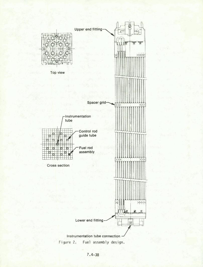
Top view
Instrumentation
Lower end fitting
+ 1 Instrumentation tube connection
F i gure 2. Fuel assembly des ign.

extent o f oxidation, swell ing, and me l t ing should be performed. Gamma scans
and f u e l rod neutron radiographs should ind icate f u e l re1 ocat ion w i t h i n the
rods.
Meta l lu rg ica l and mechanical tes ts o f the upper and lower fuel rod
springs should give data on the temperature condi t ions a t the ends of the
rods. Mechanical and metal 1 u rg ica l inspections o f the cont ro l rod guide
tubes are necessary since the guide tubes are the s t r uc tu ra l members of a
f u e l assembly and provide paths f o r cont ro l rod inser t ion. Metal 1 u rg ica l
examinations o f the lower end f i t t i n g s should y i e l d temperature data on the
pa r t o f the' core tha t d i d not become uncovered during the accident. Since
the upper and lower f i t t i n g s are o f the same na te r i a l , va r ia t ions i n
performance based on environmental d i f ferences should be evident.
The cont ro l elements, cons is t ing o f the con t ro l rods, the ax ia l power
shaping rods (APSR), and the burnable poison rods, must be thoroughly
examined. The short ax i a l power shaping rods are a silver-indium-cadmium
a l l o y c lad i n 304 s ta in less s tee l attached to a CF3M ( a cast s t a i n l ess
s tee l ) spider (as shown i n Figure 3). These rods were parked i n an
operating mode in the lower f ou r f ee t o f the core; therefore j meta l lu rg ica l
and mechanical analysis o f the ASPRs can provide ind icat ions of the
corrdi t ions i n the region above the core. TCle cont ro l rods (a lso
. s i 1 ver- i ndium-cadmium a l l o y c l ad i n 304 s ta in less) were inser ted i n t o the
core at the time o f reactor scram. Rod deformations i n the poison area,
, ( i .e., creep-col l apse) may provide t ime-temperature informat ion when
coup1 ed w i t h the metal1 u rg ica l data. Eddy current i n t e g r i t y checks may
provide speci f ic f a i l u r e locat ions f o r f u r t h e r analysis. The . silver-indium-cadmium poison i n the rods has a low me1 t i n g po in t
( 1075 K ) . Examination o f the poison zones should provide i ns i gh t i n t o
shutdown responses during accident condit ions. By examining me1 t i ng or
remel t i n g p ro f i l e s , informat ion about the time-temperature h i s t o r y may be
obtained. Meta l lu rg ica l determinations of poison-cl adding compat i b i 1 i ty,
secondary phase segregation, etc., should- a1 so be conducted, If there was a large cladding breach, erosion pat terns i n the poison may give
information about.flow pat terns i n the care dur ing the the accident.

Coupling

The burnable poison rods (Figure 4) are pel 1 e t ized a1 umina-boron
carbide (A1203-B4C) c l ad w i t h z i r c a l oy-4, the sane c l adding mater i a1
as the f u e l rods. The rod geometry (bal looning o r creepdown), i n t eg r i t y ,
and types o f defects , can be compared t o the f ue l rods. Excess i ve swell i ng
r e s u l t i n g from poison volume changes upon react ion w i t h the coolant may
have occurred. Metal 1 u rg ica l determinations ( fo r oxides and secondary
phases) can y i e l d informat ion about the thermal h is to ry . The burnable
poison rod assembly spiders are made o f CF3M and 17-4 PH (a s ta in less
steel ). They should be thoroughly examined and compared t o other examples
o f the same mater ia ls i n the core. Examination o f the A1203-B4C
pel1 e ts could y ie ld , data about system mechanical and t hema l shocks. Since
the p e l l e t s are normally very strong, i f the p e l l e t s are not in tac t ,
t rans ient sever i t y estimates can be made, and the stresses and the
correspond i ng temperatures can be approximated.
The burnable poison rod assembly re ta iners are other components which
should be examined. The re ta iners are manufactured from 304 s ta in less
s tee1 and Inconel X-750 mater i a1 . Metal 1 u rg i cal and hardness exarni nations
should provide temperature h i s t o r y i n f o m a t i m of the top of the f ue l
assembl ye
8.2.2 Examination o f Other Core Components
F i f t y - two f ue l assemblies i n TMI-2 are instrumented w i t h in-core
detectors cons is t ing o f a s t r i n g o f s e l f -powered neutron detectors and a
thermocouple, as shown i n Figure 5. I f in tac t , t h i s instrumentation can be
removed p r i o r t o core access; Damaged instruments can be re t r ieved during
core removal. Metal 1 u rg i cal invest i g a t i onc o f ihstrumepts may provide t i r e
temperature h is to r ies . Selected instruments should be reca l i brated t o help
understand some o f the anomalies; i n the on l ine measurements made during tt-.e
course o f the accident. Detai led planning f o r examination of the in-core
i nstruwenta,ti on i s being addressed by Pl arming Group 1.0, Lns trumentat i on
and E l & t r i c a l Equipment Survivabi l ity.
The condi t ion o f the cont ro l rod d r i ve mechanism lead screws shawn i n
Figure 6 w i l l r e f l e c t the temperatures reached i n the upper pa r t o f the

Figure 4. Burnable poison rod assembly.

f Self-powered neutron detector (7)
I / lnconel oversheath
Calibration tube
Background detector,
Reactor vessel I n-core thermocouples (above 52 fuel assemblies)
\ Thermocouple (1)
a. Fixed SPND assembly'cross section
k To cable spreading room
Figure
b. Instrument locations IN EL-A-I 6 285
5. In-Core instrumentation string,

/Reactor closure
/- Lead screw assembly
Figure 6. Control rod drive mechanism.

core. Analysis of oxide layers, meta l lu rg ica l structure, hardness, and me l t ing w i l l provide a good pre l iminary estimate o f the temperature
condit ions across the upper core.
The pressure vessel su'rveil lance capsule shown i n Figures 7a and 7b
can provide an estimate o f the environment i n the reactor vessel. There
are s i x such capsules i n TMI-2, The capsules contain vessel samples,
we1 ding sampl es, dosimetry, and a1 1 oy temperature moni t o r specimens. An
examination o f one o f these capsules could provide boundary ternperat ure
estimates. The i n i ti a1 specimen inspect ion should include mechanical
t es t i ng and meta l lu rg ica l determinations. Alro, the specimen holder s h o ~ l d
be inspected f o r ox idat ion and microst ruc tura l changes. Since the ~ r i m a r y
value o f the su rve i l 1 ance capsule specimens w i l l be t o a i d the pressure
vessel requal i f icat ion, i t i s important t ha t these examinat ion
recommendat i ons be integrated i n t o the requal i f i cat i on program.
TMI-2 contained several experimental assembl ies. These include
Gd203-U02 f u e l rods and some borated graph i t e burnable poi son rods.
Deta i led inspect ion o f the gad01 i n i a rods should provide data on the e f f e c t
of Gdp03 on UOp f u e l dur ing accident conditions. He1 t i ng, gas
re1 ease or gas retent ion, phase changes, and microstructure changes can be
measured as a func t ion o f axi a1 pos i t i on t o assess behavior over a range o f
conditions. Inves t iga t ion o f the borated graphi te behavior should provide
an estimate o f the upper l i m i t o f the core temperatures. The borated
graphi te i s very s tab le a t h igh temperatures; thus, the major changes would
be caused by water corrosion. Possi b l e graphi te -c l addir.g reac t ions may be
present and may help provide temperature h i s t o r y data.
8.2.3 Core Hydraul ic Tests
The loss o f ab i l i t y t o cool the TMI-2 core during and af ter the
accident due t o f l ow res t r i c t ions , f 1 ow blockages, and degradation o f heat
t ransfer was a major concern. The fac t that the core remained cool able
despite apparent major damage means tha t nydraul ic tes:s on por t ions of the
core w i 11 g rea t l y improve understanding of reactor accident heat removal,
F u l l - and p a r t i al-1 ength bundles, representat ive o f moderately and severely

Control rod drive
Figure 7a. Side view of reactor vessel and. internals showing location of surveillance capsule.

r F u e l assembly
Inlet
' \ \core barrel Y
Surveillance specimen holder tube (typiCal of 6 positions)
0 TMI-2 locations
Surveillance specimen holder tube azimuthal location
, ,-
Figure 7b. Cross section of reactor vesrgl wd internal~ showirg surve i 11 ance specimen holder locations.

damaged fuel, should be se1ecl;ed far QSm testing and subsequent sectioning. T k bundles shuJ d rethkn the xxtiutr~l" rods and in-oora instrumentation so their iriflwsrce *dll"be pr&ent in the tests as i t was i n M e ! acci dmlt. The number of $mdI~es,,and their 1 ocati on ia 'the core
A \ - >
sMuld be selected t o provide rufficieint <. :,- * i b b d t i & . I I tq p m 4 t 'naappiag the core def m a t i on and r.qims of 9 ~ . e , itnd m&rdei;rate flow restrist9nn. Dat 3
c ~ l l e c t e d i n t h e s e f l o w t a s t s w i l l ~ b i s ~ t c r f ~ ~ l a l . ~ ~ d ~ ~ ~ p r e s s u r e -
loss md wlgcitg'p~ofilCs as a function .of2 #lrlg rates.. The y@ocit$ profiles are extremely inportant .@w aa$$ais fJow re#i5fr6ution &thin the test =rays. The H k i d nay& k r r i h b ~ e liq&!ds, $is&& ar +
4 '
Mo-phase mixtwes, - - I
6 -
" r I
Identical flaw t e p t s ~ u s t be perfmmgd on lndma&d referen& bumlles assmbled.frrm ~unlrrad.ia4;:duna~k;lo, ~ & e M*en*&ce flw best< Mu& be perfaraed in the same test aquipndnt $bat will be ust$*lat& io':the TMI-2
. ,
bundlq tests in order to ,check. oat the tat faci lify'-ha el i.inate as many
extraaeous effects as possible. ,-
, C , *
Mter the TNS bundles have b n f 1 ow tested, they should be cast in a sui table potting materj a1 and sectioocd t rammel y for dctebmining deformation and .coolant uh@ml flw arb@ seduction as a function sf! axial
i r
p g i b k . , Qefarmrrtim and 10s; of + l a ares can be detemlned from eniarged photographs ef the sections. The aeztiwas should be m d e a$ ~~uff iclent ly c l ~ s e ifitervals to -it conat;rzlctlim oif accurate defomation prof i 1 er of the individual mds md of the bundle as a who1 e. These data will a'd the analys4r of the flw data and the vwificbtion of d e f h a t i m arodels,
The heat generation and r m ~ r a l .eharacttristics of massive se$t3ono a'% soxlidif id f we1 and f ue? ~wixble can a1 so be sthdied by ~~hb-+tests. Tkse data will pottide estimates o f maximmu ternperntures &acht$ in certain regions af the TMI-2 c w , may g iw ,eyidmce m whether or not the maxtnnun temperatures acurred before or aft& ?"the .fuel bugdl es fragmented, and ~i 31 provide iImp.9rtant data for a6delinq coaldab1.e @ m e t ~ i & s QT severely daM?lgwl
3. i<.
cores. To obtain the ne-ry d&a9 masst& sectirm~ !of debris rep~eiemtative of kmun Majj ow @ th. W e should f& pl'&ced into ?bge
4 . t

f low housings. Flow tes ts should be conducted us ing s u i t a b l e 1 iqu ids,
gases, or two-phase mixtures. Hot t e s t f l u i d s , i n combination w i t h
s u i t a b l y loca ted thermocouples, w i l l p rov ide data on e f f e c t i v e thermal
parameters, temperature d i s t r i b u t i o n s , etc .
A f t e r the f l o w tes t , the conglomerates must be character fzed f o r
p rope r t i es such as volume f r a c t i o n o f the cons t i tuents , po ros i t y , densi ty ,
heat capaci.ty, ' thermal conduc t i v i t y , e tc . These data w i l l be needed f o r
analys is o f the f l o w tes ts , w i l l p rov ide i n p u t f o r es t ima t ing heat
generation, cool ing, and temperature l e v e l s 3ur ing the accident, 3nd w i l l
become important f o r cons t ruc t i ng p r e d i c t i v e models f o r eve rely damaged
cores.

9. CRITERIA FOR TMI-2 EXAMINATION FACILITIES
Th is sec t i on ,presents recommendat i ons f o r general c r i t e r i a f o r
f a c i l i t i e s and organ iza t i3ns respons ib le f o r examination, ana lys is , and
temperary storage o f f u e l ma te r i a1 s and samples taken as p a r t o f t he TMI-2
In fo rma t i on and Examinat i o n Program. The development o f these general
c r i t e r i a w i l l enable e a r l ? i d e n t i f i c a t i o n o f p o t e n t i a l l y acceptable
f a c i l i t i e s and organ iza t ions and a l l ow f o r accurate cos t es t ima t i ng and
p lann ing f o r a l l of t he t x k s necessary t o ensure removal o f m a t e r i a l s from
TMI-2, sh ipp ing t o examination l oca t i ons , r e l o c a t i o n t o a rch i va l storage
f a c i l i t i e s , and u l t i m a t e d isposa l . More s p e c i f i c requirements w i l l have t o
be prepared f o r each examination, analys is , and storage task.
The f o l l o w i n g ' subsect ions discuss general and s p e c i f i c examinat ion
f a c i l i t y c r i t e r i a . P o t e n t i a l Un i ted States examinat ion f a c i l i t i e s are
1 isted'.
9.1 Subtask Ob jec t i ves '
There i s broad i n t e r e s t i n p a r t i c i p a t i n g i n TMI-2 core examinations by
domestic remote hand1 i ng f a z i l i t i e s . The ob jec t i ves o f t h i s subtask are t o
develop examinat ion f a c i l i t y c r i t e r i a , i d e n t i f y unique examinat ion
c a p a b i l i t i e s , and encourage broad p a r t i c i p a t i o n i n the p o s t i r r a d i a t i o n
examinat ion o f TMI-2.
9.2 Recommended Program
9.2.1 General C r i t e r i a . --
9.2.1.1 App l icab le Experienze. The f a c i l i t y processing contaminated,
components and samples should have experience i n re1 ated tasks. ~ e s i r a b l e
exper i ence i n c l udes :
1. Hot c e l l operat ions, m a t e r i a l a rch iv ing , and r e t r i e v a l
sys tems w i t h t h o r o ~ f g h ma te r i a1 records

2. irradiated and c o n t a m i n a t e d m a t e r i a l s r ece i v i ng , handl ing,
decontaminat ion, and s to rage
3. P o s t i r r a d i a t i o n examinat ion ( P I E ) da ta i n t e r p r e t a t i o n and
anal y s i s
4. Equipment, component, and m a t e r i a l s r equa l i f i c a t i o n o r .
c e r t i f i c a t i o n
5. Use o f accura te equipment f o r r a d i o a c t i v e m a t e r i a l s ana l ys i s
6. Nondes t ruc t i ve and d e s t r u c t i v e examinat ion o f r a d i o a c t i v e
mat e r i a1
7. F a m i l i a r i t y and exper ience w i t h dccumentat ion and QA
requi rements f o r government r a d i o a c t i v e m a t e r i 21 1 icenses
8. Coord ina t ion of work w i t h o t h e r r e l a t e d f a c i l i t i e s .
9.2.1.2 Q u a l i t y Assurance. The examinat ion, processing., o r s to rage
p a r t i c i pant w i 1 1 be r e q u i r e d t o have an o r g m i za t i onal and f a c i 1 i t y QA p l an
i nc l ud ing , bu t no t l i m i t e d to, t h e f o l l o w i n g :
1. Inspec t i on and document a t i on o f ~ a t e r i a1 as rece i ved
2. T r a c e a b i l i t y records f o r work performed
3. Hand1 i ng and s to rage procedures and ' c r i t e r i a t o prevent
degradat ion o f m a t e r i a l s p r i o r t o ana l ys i s
4 : Cal i b r a t i o n and/or s t a t i s t i c a l records f o r processes o r \
equipment used i n ana l ys i s
5. Organ iza t iona l QA independence.

9.2.1.3 Safe ty and Secur i ty . The per forming organizat . ion s h a l l have a
s a f e t y program t h a t ensures operat. ions are conducted i n a manner t h a t
p ro tec t s t h e h e a l t h and s a f e t y o f ~mployees and the general p u b l i c and t h a t
minimizes danger f rom a l l hazards t o 1 i f e and proper ty . The s a f e t y program
s h a l l comply w i t h appl i c a b l e f ede ra l , s ta te , and l o c a l heal th, sa fe ty , and
f i r e 3 r o t e c t i o n regu la t i ons and requirements. I n p a r t i c u l a r , t he sa fe t y
program s h a l l conform t o appl i cab1 e DOE (DOE Order 5483.1) and OSHA (29 CFR
1910 and 29 CFR 1926) s a f e t y regu l t t i o n s .
The f ac il i t y i n which work i s performed s h a l l have appropr i a te
approved s a f e t y assessments under dh ich a u t h o r i z a t i o n ' to perform the work
i s def ined.
The per forming o rgan i za t i on s h a l l have a s e c u r i t y program which i n
combinat ion w i t h a d m i n i s t r a t i v e c o n j r o l s and f a c i l i t y fea tures , ensures
tha t m a t e r i a l s are secure from t h e f t , loss , o r sabotage. I f handl ing o f
spec ia l nuc lear m a t e r i a l s i s involved, t he program s h a l l conform t o t he
prov is 'ons o f the DOE Order 5632 Series, as app l i cab le .
9 . 2 . L icens ing Requirements. Any o rgan i za t i on t h a t receives,
possesses, uses, o r t rans fers rad i o x t i ve mater i a1 s h a l l be 1 i cens zd i n
accordance w i t h the a p p l i c a b l e r e g u l 3 t i o n s i n T i t l e 10, Par ts 20, 30
through 35, 40, 50, o r 70 o f the Code of Federal Regulat ions ( P r i v a t e
Fac i 1 i t i es) or be operated under t he Atomic Energy Act o f 1954, as amended,
the Ene-gy Reorganizat ion Act o f 1974, and the Department o f Energy
Organ iza t ion Act o f 1977 (Government F a c i l i t i e s ) .
9.2.1.5- Documentation and Con f i gu ra t i on Cont ro l . The per forming
organ' izat i on s h a l l have a documentation and c o n f i g u r a t i o n c o n t r o l system
which er:sures the 1 a tes t approved procedures and processes are used i n
handl i n g or examinat ion o f m a t e r i a l s o r samples. De ta i l s , procedures,. and
spec i a1 processes f o r accompl i sh i ng e.~ami na t i ons s h a l l be prepared,
approved as requi red, and u t i l i z e d i n per forming work tasks. The
con f i gu ra t i on c o n t r o l system s h a l l ensure p o s i t i v e i d e n t i f i c a t i o n o f
m a t e r i a l s and t h e i r l oca t i on , and p e r t i n e n t data, such as spec ia l h a d l i n g
requirements and f i s s i l e m a t e r i a l content.

9.2.1.6 Performance Management System. The ?erforrning o r g a n i z a t i o n s h a l i
use t h e TMI-2 s tandard r e p o r t i n g system p r e s e n t l y be ing developed by t h e
Technica l I n t e g r a t i o n O f f i ce . The r e p o r t i n g system must i nc l ude schedule
and cos t ana l ys i s r epo r t s . The per fo rming or :ganizat i on should have a
proven reco rd o f m a i n t a i n i n g es tab l ished schedule and cos t agreements. A1 1
schedule and cos t es t imates s h a l l be r e q u i r e c i n s u f f i c i e n t d e t a i l t o a l l o w
proper eva l ua t i on.
9.2.1.7 I n s t i t u t i o n a l . The per fo rming o r g a n i z a t i o n and f a c i l i t y l o c a t i o n
s h a l l s a t i s f y a number o f i n s t i t u t i o n a l gu ide l i nes . The f o l l o w i n g - i s a . . .
p a r t i a1 1 i s t o f i'tems t o be considered:
1. Compliance w i t h EEO, m i n o r i t y business, and o the r f e d e r a l
and s t a t e requi rements
2. D i s c l o s u r e o f any c u r r e n t o r pending l i t i g a t i o n s
3. Commun i t y acceptabi 1 i t y
4. Pub1 i c a f f a i r s and image
5. Possession o f r e q u i r e d s ta te , r e g i o n a l , l o c a l , and f e d e r a l
permi ts . .
9.2.2 S p e c i f i c C r i t e r i a
9.2.2.1 F a c i l i t y Requirements. F a c i l i t i e s are r e q u i r e d f o r process ing
TMI-2. f u e l components and sampl es t h a t w i 11 enable t h e nuc lear comrnun i t y
and general pub1 i c t o ga in the maximum in fo rma t i on p o s s i b l e f rom the events
t h a t occurred. The p rocess ing o f components w i l l r e q u i r e f a c i l i t i e s t o
per form the f 01 1 owing serv ices :
1. Rece iv ing o f h i gh l e v e l r a d i o a c t i v e m a t e r i a l packaged i n
s tandard l i censed sh ipp ing casks and con ta ine rs

2. Removal o f ma te r i a l from casks fo r general inspect ion
i nc lud ing dimensional, photography, radiography, weight,
v i sua l , e tc .
3 . Disassembly and assembly o f f u e l and core components, and
samples i n c o n t r o l 1 ed envi ronments
L. Decontamina.tion o f sh ipping conta iners
E. Ensuring i n t e r i m storage i n a c o n t r o l l e d environment f o r
f u e l and core components ma te r i a l p r i o r t o d i s p o s i t i o n
6. Packaging and sh ipp ing o f f u e l and core components m a t e r i a l
f o r f u r t h e r ana lys is or d isposal .
Spec i f i c equipment which may be requ i red inc ludes:
1. Vent i 1 at i on equipment adequate t o meet f ede ra l r a d i o l o g i c a l
standards f o r the fo l l ow ing :
a: Stack gasmon i to rs ( p a r t i c u l a t e and gas)
b. A i r moni t o r i n g i n f a c i l i t y containment ( p a r t i c u l a t e
and .gas)
2. Fuel hand 1 i ng equipment ( s t rong backs, pa l 1 ets,
manipulators, etc . ) compatible w i t h requirements (e.g.,
accelerat ion, decelerat ion, v e l o c i t y , hand1 i ng fo rces ) f o r
disassembling and handl ing h i g h l y damaged, b r i t t l e f u e l
assembl ies, and capabl e o f disassembl i ng f u e l bundl es w i t h
b r i t t l e , bal looned, p rev ious l y molten, o r f r a c t u r e d fue l .
rods
3. B i o l o g i c a l s h i e l d i n g adequate t o m e e t f ede ra l gu ide l ines
f o r exposure t o r a d i oact i ve components and samples

4. Chemical and mechanical decontamination equipment t o meet
federal contaminat ion con t ro l gu ide l ines f o r handl ing and
sh ipp ing c l a s s i f i c a t i o n s
5. Equipment t o p rov ide remote handling, disassembly,
rece iv ing , inspect ion, and analys is (e.g., manipulators,
tu rn tab les , f i x t u r e s , etc.) o f r a d i o a c t i v e hardware w i t h i n
a1 1 owabl e personnel exposure guide1 ines w i thout damage o r
degradat i 6n t o the f u e l component or sample under
i n v e s t i g a t i o n
..a
6. R e c e i v i n g f a c i l i t i e s , i nc lud ing cranes andmanipulators f o r
unloading components and samples f rom sh ipp ing conta iners
and casks
7. ~ x a m i n a t i o n / a n a l ~ s i s equipment necassary t o perform s ta te-
o f - t h e - a r t nondestruct ive and d e s b u c t i i e examination of
f ue l and other r a d i o a c t i v e m a t e r i z l
8. Personnel w i t h c a p a b i l i t i e s f o r i n t e r p r e t i n g ar,d analyz ing
(e.g., recognized techn ica l expe r t i se i n PIE, meta l lurgy,
chemistry, m a t e r i a l s science, etc . )
9. F a c i l i t i e s f o r obta in ing, i n t e r p r e t i n g , and. s t x - i n g
photographs, radiographs, m ic ro f i lm , etc., o f f u e l ,
components, and sampl es as requ i red
10. A r e a d i l y accessib le f a c i l i t y l o c a t i o n t h a t can be e a s i l y
entered by l i censed commercial c a r r i e r s .
9.2.2.2 Examination, Analys is and Test ing. The f a c i l i t i e s and
organ iza t ions respons ib le f o r performing s p e c i f i c examinations, analyses,
and t e s t i n g o f f u e l m a t e r i a l s and samples f r o m TMI-2 should have the
c a p a b i l i t i e s f o r performing s ta te -o f - t he -a r t nondestruct ive and des t ruc t i ve
examinations. I n order t o minimize hea l th hazards, the p o t e n t i a l f o r l o s s
or damage, .and reduce program cost, i t i s des i rab le that' the f a c i l i t i e s

i d e n t i f i e d f o r the examinations have s u f f i c i e n t in-house ana lys is
capabi 1 i t y t o min imize the need f o r sample r e l o c a t i o n f o r examinations.
F u r t i e r , i t i s d e s i r a b l e t h a t the f a c i l i t y have the capabi l i t y f o r
temporary a rch ive s torage o f t h e f u e l m a t e r i a l s and samp1.e~.
9.2.2.3 Disposal o r ~ e t e n t i o n . Fo l low ing examinat ion and processing, a l l
m a t e r i a l w i l l be i d e n t i f i e d f o r d isposal o r r e t e n t i o n . I tems w i l l be
packaged i n accordance w i t h DOT standards f o r shipment, i f requ i red .
Packaging w i l l ensure contaminat ion- f ree hand l ing du r i ng d isposal o r f o r
the r e t e n t i o n t ime i d e n t i f i e d . A11 storage w i l l be i n a p ro tec ted
envi rmment t o ensure contami n a t i o n - f r e e r e t r i evabi 1 i t y and a l l d isposal
w i l l be made i n an o f f i c i a l l y designated d isposal area i n conformance w i t h
requirements a t t h a t f a c i l i ty . Sh ie ld ing requirements f o r r a d i a t i o n l e v e l s
a t package sur f aces w i 11 conform t o es tab1 i shed regu l a t i ons.
9.2.2.4 Decontamination. Shipping casks w i l l undergo i n i t i a l
decont.amination a t the TMI-2 s i t e t o the l e v e l requ i red f o r t r anspo r ta t i o n
t o t h e examinat ion f a c i l i t y . Cask decontaminat ion a t t he examinat ion . .
f a c i l i t y may r e q u i r e a deionized water f l u s h , a detergent f l ush , o r steam
c leaning. Sample ma te r i a1 decontaminat ion may r e q u i r e a l l o f the above
p l us chemical t reatment. The examinat ion f ac i 1 i ty i s responsi b l e f o r
hand1 i ng and d isposal o f the decontaminat ion so lu t i ons .
9.2.2.5 Segregation. Sel ected TMI-2 samples may r e q u i r e segregated
storage t o prevent phys ica l damage o r cross-contaminat ion w i t h o ther
samples. Damaged f u e l w i l l r e q u i r e secondary, water and gas t i g h t
encapsulat ion tubes. Some small so l i d samples (c ladding, etc . ) may r e q u i r e
d r y storage.
9.2.3 P o t e n t i a l TMI-2 Examination F a c i l i t i e s
Tatmle 3 conta ins a 1 i s t i n g o f p o t e n t i a l domestic f a c i l i t i e s f o r
examinat ion o f TMI-2 f u e l and core components. The 1 i s t was formulated by
con tac t i ng the members o f P lanning Group 7.4 and, i n some cases, t h e
l a b o r a t o r i e s d i r e c t l y . The l i s t i s be l i eved t o be complete; however,
addi t ion; t o the l i s t are welcome. Determinat ion o f whether these

f a c i l i t i e s meet a l l o f . the general and s p e c i f i c c r i t e r i a o u t l i n e d above has
not y e t been made, bu t the'- nature o f t h e i r o n ~ o i n g work ind ica tes t h a t they
are qual if i e d to' p a r t i c i p a t e i n the TMI-2 f u e l and core component
examinations. I t i s recomnended t h a t t he Technical I n t e g r a t i o n Of f i ce
cont inue t o develop s p e c i f i c examination c r i t e r i a and match these w i t h
es tab l ished admin i s t ra t i ve and technical c a p a b i l i t i e s of these
l abo ra to r i es . This w i l l permi t compet i t ive b idd ing except i n those cases
where a l abo ra to ry has unique capabi l i t es . .
TABLE 3. P o t e n t i a l Domestic F a c i l i t i e s f o r TMI-2 Fuel and Core Component Exam i nat i ona
I n d u s t r i a1 Labora tor ies Government Laborator ies
Babcock and W i l cox Company Argonne at i onal Laboratory-Eas t
Argonne Nat ional . Laboratory-West B a t t e l l e Columbus Labora tor ies
Combustion Engineering, Inc.. B a t t e l l e P a c i f i c Northwest Laborator ies
Exxon Nucl ear Company Brookhaven Nat iona l Laboratory
General Atomic Company Hanford Engineering Development Laboratory
General El e c t r i c Nuclear Center , Idaho Nat iona l Engineering Laboratory
Rockwell ~ n t e r n a t iona l Los Alamos S c i e n t i f i c Laboratory
Oak Ridge Nat ional Laboratory
Sandi a f lat i onal Labora tor ies
a. I n add i t i on t o the f a c i l i t i e s l i s t e d , several u n i v e r s i t i e s w i t h remote-hand1 i n g f a c i l i ' t i e s may be qual i f i e d t o p a r t i c i p a t e i n t he TMI-2 examinat ions.

10. FUEL DISPOSAL
Advance cons idera t ion must be g iven t o the d i s p o s i t i o n o f t he TMI-2
fue l and core component s3mpl es once t h e i r examinations have been completej.
I n t e r i m and u l t imate d i s p o s i t i o n o f t he TMI-2 core has been considered (see
Ref eronce 4). This study, which cons i dered chemical reprocess i ng, pool
storage, and d ry storage, concl uded t h a t def i n i t i v e recomnendati ons are
prese.-~t l y imposs i b l e b e c a ~ s e o f po l i t i c a l , ins t i t u t i onal , and economic
uncer ta i n t i es. However, a 1 i k e l y d ispos i t i on sequence would almost
c e r t a i n l y begin w i t h a per iod o f temporary pool storage a t TMI o r
elsewhere. Dry s torage i n spec ia l caissons o r i n e x i s t i n g vau l t s (such as
those loca ted a t government hot c e l l f a c i l i t i e s ) was found t o have some
econoa i c benef i t s because of t he extremely 1 ow TMI-2 core decay heat.
Chemical reprocessing w i t h d isposal o f h igh - leve l waste was recognized as
the best technical s o l u t i o r , bu t one which would probably not be a v a i l a b l e
u n t i l the mid- t o late-199Cs.
10.1 Subtask Ob jec t ives
The ob jec t i ves o f t h i s subtask are t o recommend general gu ide l ines f o r
the disposal o f f u e l examined under the TMI-2 In fo rmat ion and Examination
Program, and t o ensure tha t d isposal opt ions are in -p lace and adequately
funded when the TMI-2 f u e l examination begins.
10.2 Recommended Programs
S i r ze the f u e l se lec ted f o r examinat ion w i l l be o n l y a small. f r a c t i o n
of the core, Planning Group 7.4 does not recommend pursuing disposal
op t ions -ndependent o f those being developed by the u t i l i t y . We suggest
t ha t the f a c i l i t i e s selected t o perform the techn ica l examinations be
respons ic le f o r s t o r i n g the fue l f o r ' a s h o r t i n t e r i m p e r i o d o f < 1 year,
wh il e the examination resu l t z are reviewed and analyzed. Thereaf ter the '
f u e l samples should be p rope r l y contained and shipped t o the f a c i l i t y
ho ld ing t i e l a r g e s t p a r t o f t i e core, and from tha t p o i n t on be handled by ,
the u t i l i:y or i t s agent as p a r t o f the general TMI-2 core debr is .

Spec if i ca l l y we recommend:
1. Mon i to r i ng o f TMI-2 core d i s p o s i t i o n plans, and prepare a
program to i n t e g r a t e the d isposal o' f u e l examination
samples i n t o these' p l ans.
2. Storage o f the f u e l f o r an i n t e r i m p e r i o d fo l l owed by
shipment t o the designated TMI-2 care. d i s p o s i t i o n s i t e .
3 . Ensuring t h a t f u e l and core component specimens prepared
f o r examinat i on can b e disposed i f 'when the ieramograph or
metal l og raph ic examinations are compl eted.
4. Prov id ing f o r a rch i va l storage o f specimens f o r f u t u r e
examination and experiments as i d e n t i f i e d by .advances i n
techno1 ogy.

11. REQUIREMENTS FOR DATA FROM TASK 7.2, CORE DAMAGE
ASSESSMENT AND CORE REMOVAL
The p r i n c i p a l o b j e c t i v e o f Planning Group 7.2 i s t o determine the
exam! n a t i ons needed t o es tab l i s h the undisturbed c o n d i t i o n o f the core
p r i o r t o i t s removal. I t i s imperat ive tha t the r e s u l t s o f the
examinations be used a t the e a r l i e s t poss ib le t ime t o f u r t h e r r e f i n e the
p lanning presented i n t h i s r e p o r t since, as s ta ted e a r l i e r , the Task 7.4
p lann ing i s based s o l e l y on a n a l y t i c es'timates o f the ex ten t o f core damage.
11.1 Subtask Ob jec t ive
The o b j e c t i v e o f . t h i s subtask i s t o coordinate, t o t he maximum ex tent
poss i b l e, the core damage assessment and f u e l exami na t i on p l anni ng.
11.2 Recomnended Program
, I t i s p a r t i c u l a r l y i m p o r t a n t ' t o Tas'k 7.4 p lann ing t h a t in fo rmat ion on
the f o l l o w i n g i tems be obta ined a t the e a r l ' i e s t poss ib le time:
'1. Radial and a x i a l extent o f f u e l assembly damage
2. Presence and ex ten t o f a rubb le bed
3. Symmetry o f damage
4. Apparent s t ruc tura7 i n t e g r i t y o f core components
5. Extent o f damage to c o n t r o l rods
. I n fo rma t ion o f t h i s type i s needzd t o f i n a l i z e plans f o r . t h e s e l e c t i o n
o f samples f o r a rch i v ing and f o r d e t a i l e d examinations. I t i s recomnended
t h a t a very c lose 1 i a i s o n between the groups respons ib le fo r implementation
o f t he Task 7.2 and 7.4 plans be maineained so t h a t f i n a l Task 7.4 p lanning
re f1 ects the best assessment o f actual core damage.

The recomnendations o f P lanning Group 7.4 are l i s t e d below.
1. The f u e l and core component examinat ion p lan w i l l be h i g h l y
dependent on the resu l t s f rom t h e Task 7.2 (core damage
assessment) ac t i v i t i es . . ~ c c o r d i ng l y,, a techn ica l
eval u a t i on group should .be mainta ined . t o r e v i s e the p lan
presented he re in as the Task 7.2 a c t i v i t y progresses.
I t i s ev ident t h a t the data obta ined f rom' imp,lementation of
the Task 7.2 and 7.4 p lans may d i f f e r i n value and may be
app l i ed i n a d i f f e r e n t f ash ion f o r each o f t h e areas
descr ibed i n Sect ions 3, 4, 5, and 6 o f t h i s repor t . ~ h u s ,
i t i s recomnended t h a t a small number o f exper ts f rom each
o f these areas be r e t a i n e d t o evaluate and ca ta log the data
f o r a p p l i c a t i o n i n t h e i r areas o f i n t e r e s t and s x p e r t i s e
and t o p rov ide an overview o f examinat ion procedures.
3. Fu r the r develop s p e c i f i c c r i t e r i a f o r the d e t a i l e d
examinat ion o f se lec ted TMI-2 f ue; and core components.
These should i nc lude the f o l l o w i n g :
a. I n t a c t f u e l assemblies
b. Debr is o f v a r i o u s . a n t i c i p a t e d f o r m s
c. Pressure vessel s u r v e i l 1 ance capsules
d. Exper imental assembl i es
e. Debr is f l o w tes ts .
4. Assess candi date exam'i na t i on 1 abo ra to r i es against t h e
c r i t e r i a presented i n s e c t i o n 9 and i d e n t i f y i n d e t a i l the
techn ica l capab i 1 i t i e s o f each f ac i 1 i ty.

. 5. I n t e g r a t e d isposal p1ar.s. o f examined f u e l ,and core
component samples w i t h the p lans f o r u l t imate disposal of
the TMI-2 core.
6 . Assess present regu la to-y guides t o i d e n t i f y incons is tenc ies
'and instances where the TMI-2 accident revea ls e i t h e r
excess ive ly conservat ive o r nonconservati ve c r i t e r i a . Use
the r e s u l t s o f t h i s study t o f u r t h e r de f i ne the examination
and analyses programs.
7. Eval uate r e a c t o r accident ana lys is methods t o more p r e c i s e l y
de f i ne the s ta te -o f - t he -a r t and asce r ta in t h a t key data
needs have been i dent if i zd and tha t p l ans have been mad.e t o
s a t i s f y them. . .
8. Review accident consequence m i t i gat i on des i gn s tud ies (such
as those o f Z ion and I n d i a n Point , t he F l o a t i n g Nuclear
Power P lan t and the cu r ren t EG&G Idaho study) t o asce r ta in
t h a t key data needs have been i d e n t i f i e d and t h a t plans
have been made t o s a t i s f y them.
5 . Es tab l i sh a T M I - 2 f u e l and core component a rch ive f a c i l i t y
so t h a t samples o f s c i e n t - f i c i n t e r e s t may be -preserved f o r
f u t u r e exami nat ions.
10. Develop schedules and cos t est imates f o r implementat i o n o f
the examination program.
1 . Eval uate environment'al e f f e c t s on f u e l .

13. REFERENCES
1. M. Rogovin (D i rec to r , NRC Special I n q u i r y Group), Thre? M i l e Is land--A
.Report t o the Commissioners and t o the Pu'bl ic , U. S. Nuclear Regulatory
Cornmission~Special I n q u i r y Group, NUREGICR-1250, Vol. 11, Pa r t 2,
January 1980.
2. E l e c t r i c Power Research I n s t i t u t e , Ana lys is o f t h e T h r e e M i l e I s l a n d
U n i t No. 2 Accident, NSAC-80-1, March 1930.
3. NRC Act i on P l an Developed as a ~ e s u l t o f the T~I-2 Acciden,t,
NUREG-0660, Vols. I, 11, May 1980.
4. R. T. Anderson, Scoping Studies o f the A1 te rna te Options f o r Defuel ing,
AGNS-35900-1.5-79, May 1980.

,
APPENDIX A
ANALYTICAL METHODS FOR EXAMINING T M I - 2
FUEL AND CORE COMPONENTS

APPENDIX A . .
ANALYTICAL METHODS FOR EXAMINING TMI-2
FUEL AND CORE COMPONENTS
Comp i 1 ed by
Edward L. Court r ighk Jr .
~ a t e r i a1 s Department
P a c i f i c Northwest Labc-rator ies
Con t r i bu t i ng Organizat ions:
Argonne Nat iona l Laboratory J. P. Bacca - Argonne-West H. M. Chung S. M. Gehl
Babcox & W i 1 cox G. M. Bain D. L. Baty b?. A. Rigdon
Bat t e l l e Columbus Labora tor ies J. S. P e r r i n
B a t t e l l e P a c i f i c Northwest L. R.' Bunnell J. L. Daniel P. E. Hart R. Wang
EG&G Idaho, Inc. D. E. Owen
General E l ec tr i c C.ompany R. B. 'Adamson E. L. Esch S. Y .- Ogawa
Hanford Engineering Development Laboratory
G. J. A l k i r e
Nuclear Regulatory Commission F. D. Coffman, M'. L. Pick les imer
Oak R i dge Nat i 0n.31 Laboratory D. 0. Hobson E. L. Long
APPENDIX A
ANALYTICAL METHODS FOR EXAMINING TMI-2
FUEL AND CORE COMPONENTS
The p r i n c i p a l character i s t i c c needed i n the TMI-2 f u e l and component
examinat ions have been seTected from c r i t e r i a recommended by Planning Group
7.4 nembers. These data c h a r a c t e r i s t i c s are d i v ided i n t o ten major
categor ies l i s t e d i n Table A-1 w i t 9 the major components t o be examined,
and p r i n c i p a l regions o r l o c a t i o n s f rom which samples.wi l1 most l i k e l y be
taken.
The a n a l y t i c a l techniques tha t w i l l be needed t o prov ide bas ic
in fo rmat ion f o r each o f the ten categor ies are presented i n Tables A-2
through A-11. The ob jec t ives i n p repar ing t h i s in fo rmat ion were to:
1. I d e n t i f y techniques f o r ob ta in ing m i c r o s t r u c t u r a l and
macros t r u c t u r a l inf 'ormat i on
2. I d e n t i f y the chemical, microchemical, o r o ther a n a l y t i c a l
techniques tha t would be needed t o analyze the range o f
p o t e n t i a l m a t e r i a l s or c o m ~ o s i t e s
3. Ident i f y core component metro1 ogy requirements
4. I d e n t i f y NDT techniques thz.t can be used t o support
des t ruc t i ve ana lys is
5. I d e n t i f y the ana lys is techniques tha t w i l l r e q u i r e exper t
im te rp re ta t i on p r i o r t o the f i n a l r e p o r t i n g o r t ransmi - t t i ng
o f data
6. Obtain thermal-hydraul i c in format i on f o r f u e l bundles o r
bundl e segments
7. Discover where arch ive samples w i l l be needed.

In each of these tab1 es, appl icable measurement techniques t r e indicated,
, along with the spec i f i c parameter or information to be obtained. Practical degrees of accuracy and precision f o r each technique are also ,included, is
they are avail able, a1 though equally precise w thods o f . sample se lect ion . . and removal' are considered to be equally important to a successful
evaluation. However, 1 i m i teb or poor understanding of sample location o r
h is tory could have a greater impact on data analysis than experimental uncer ta int ies .
For i l l us t ra t i ve and comparat i ve purposes, . . . comments on each of the
analytical techniques are a l so included i n the tables. In addit ion, ways ; to use and apply the data are suggested. The 1 i s t i ng order of each
measurement technique i s purely arbitrary--no attempt i s made t o rank the
techniques w i t h respect to accuracy, appl i cabi 1 i t y , or usef ul'ness. In many
instances, the techniques complement one another, so the use ,of more than one method may be necessary to .verify examinat ion r e su l t s .
I t will be apparent tha t the scope of the presented material i s great enough t o cover a l l possible examination subjects,, from an in tac t fuel rod
to a p i l e of rubble. The most appropriate. se lec t ion of .aq examination technique, or an experimental method, cannot be made, however, without consideration of the spec i f i c sample to be analyzed. As an example,
elemental and isotopic d i s t r ibu t ion can have qu i te d i f fe ren t meanings,
depending on whether one i s analyzing a sample of an in tac t rod or a p 'ece of debris from the rubble bed. Many of the techniques will a lso be highly
dependent upon the knowledge and exper t i se of the individual performing the analys is . For these techniques, the s k i l l of the interp-eter will be as important to proper evaluation of the information as the analytical technique. i t s e l f . In addit ion, many .of the newer techniques may require some development or cal ibrat ion before they can be applied t o . the myriad of
special analysis problems that are 1 ikely to be encountered.
The basic objectives of the examinations wil l be to determine the core thermal his tory a1 ong w i t h the chemi cal and physical changes that soccwred
to the fuel and core components during the course of the accident. The.
bulk of the important information wiil be obtained from microstructur?l examinations or chemical analysis .

The micros t r u c t u r a l evaluat ions would inc lude the extent o f c ladding
ox ida t i on and oxygen uptake, t he type and ex ten t o f f u e l - z i r c a l o y
i n te rac t i ons , the occurrence o f f u e l ox ida t i on and/or reduct ion, evidence
of g r a i n growth, 1 i qua t i on o r me1 t i n g o f s t a i n l e s s s tee l components, and
cha rac te r i za t i on of the debr is be j . I n most cases, these studies w i l l
d i r e c t l y or i n d i r e c t l y answer temperature r e l a t e d quest ions (e.g.,
m i c r o s t r u c t u r a l evidence o f 'g ra in boundary 1 i qua t i on i n s t a i n l e s s s tee l or '
the formation of a U02-Zr e u t e c t i c are c lea r signs tha t the s o l i d u s and
eu t e c t i c temperatures, respec t i ve l y , were exceeded). Simi 1 a r l y , a s tudy o f
Zr02 and oxygen-stabi l ized alpha l 'ayer thicknesses can be used t o i n f e r
the envelope o f t ime- temperature a n d i t i ons t h a t coul d have produced the
observed micros t ruc tures . The amo~nt and d i s t r i b u t i o n of c ladd ing hydrides
and the morphology o f the alpha p h , ~ s e w i l l p rov ide in fo rmat ion about t h e .
mecha,nism of hydrogen uptake and the cool i n g h i s t o r y of the cladding.
The most useful t o o l s f o r m i c r o s t r u c t u r a l i n v e s t i g a t i o n s w i l l probably
be o p t i c a l or scanning e l e c t r o n microscopy. For phase i d e n t i f i c a t i o n and
o the rc rys t a l l og raphys tud i e s e . , UOq l a t t i c e parameter measurements
to determi ne O/M), X-ray d i f f r a c t i o n and e l e c t r o n microprobe ana lys is .
should prove useful . Elec t ron channel i ng pa t te rns obtained from SEM
ana lys is may a lso have some l i m i t e d a p p l i c a b i l i t y i n eva lua t i ng the complex
ma te r ia l s t ruc tu res tha t may be discovered i n the course of t h i s
examination.
An at1 as o f mic ros t ruc tures w i l l p robably have t o be prepared t o
a s s i s t i n proper i n t e r p r e t a t i o n o f the r e s u l t a n t mic ros t ruc tures . The PBF
t e s t s o f LWR f u e l behavior, as we l l as the TREAT and .SLSF tes ts , should
prov ide micrographs f o r a v a r i e t y of we l l -charac ter ized cond i t ions .
Chemical cha rac te r i za t i on of f u e l mater ia ls , c ladd ing segments, and
debr is rubb le ( p a r t i c u l a r l y f o r r e t a i n e d f i s s i o n products) w i l l a lso be an
i n t e g r a l and important part, o f the evaluat ion. By measuring the amount and
type o f f i s s i o n products remaining i n the f u e l , a temperature-time h i s t o r y
can be estimated. Such measurements w i l l necessa r i l y be complicated by the
1 ow concentrat ion o f f i s s i o n products; however, c a r e f u l r a d i ochemical

techn i ques i nvol v i ng wet chemical element separat ion should prov ide
adequate s e n s i t i v i t y f o r most isotopes. For s t a b l e isotopes, atomic
absorpt ion spectrometry o r neutron a c t i v a t i o n ana lys is may prove useful..
Gradients i n f i s s i o n product concent ra t ion w i l l probably be most
advantageously s tud ied w i t h an i on microprobe ~ h i c h has b e t t e r s e n s i t i v i t y
than the e l e c t r o n microprobe by several orders o f magnitude and i s a1 so
capable o f i s o t o p i c analys is . The u t i l i t y o f the e lec t ron microprobe i n
f i s s i o n product character izat ' ions w i l l probab1.y be 1 imi ted' t o t he study of
more massi ve f i s s i o n . . concentrat ions (e.g.1, cesi um uranate phases:.
If t h i n f i l m s o f f issi 'on product are present (e.'g., on g r a i n boundaries),
surf ace. analys i s t o o l s, such .as scanning Auger microscopy analys i s. may have I -.
t o be employed. The use o f p r e c i s i o n gamna ~ ~ e c t r o s c ~ ~ ~ w i l l most 1 i k e l v
be l i m i t e d t o the i n t e r r o g a t i o n o f i n t a c t f u e l elements f o r the longer
1 ived isotopes, but could he lp i n t he cons t ruc t i on o f a qua1 i t a t i v e core,
w i de temperature map. based on the temperature-dependent r e d i s t r i b u t i o n cf .
the f i s s i o n products.
F i s s i o n gas measurements o f the plenum gas from unbreached rods, i f
any are l e f t , w i l l c o n t r i b u t e t o constru 'c t ing the q u a l i t a t i v e corewide
temperature map. However, d i r e c t measuremenzs o f the f i s s i o n gas r e t a i l e d
i n recovered f u e l , whether from breached o r unbre.ached rods, w i 11 ass i sk i n
es tab l i sh ing the amount o f f i s s i o n gas re leased dur ing th.2 accident. Some
o f the techniques to be employed w i l l i nvo l ve t o t a l d i s s o ~ l u t i o n or m e l t i n g
o f sampl es f 01 1 owed by gas chromatography o r mass spectrometry.
The hydrogen concentrat ion o f the c ladd ing w i l l a1 sc prov ide a ,
va l uabl e p iece o f chemical in format ion. The ax i a1 p r o f i 1 e of hydr.ogen'
concent ra t ion i n the v i c i n i t y o f a c ladd ing r u p t u r e w i l l he lp t o determine
temperature h i s t o r y dur ing the accident. Vacuum f u s i o n and other
techniques can be used t o determine hydrogen c o n ~ e n t ~ a t i ~ n s . .,
Two important considerat ions associated w i t h sample s e l e c t i o n are the
problem o f sampling the core, and the f a c t ' tha t a l l o f the core m a t e r i a l
w i l l have been washed i n hot twater f o r a t l e a s t two years p r i o r t o t he
examination. The cont inued presence o f water i n contact ' w i t h the core

m a t e r i a l s means tha t the exposed sur faces may be cons iderab ly changed from
t h e i r c o n d i t i o n du r i ng and j u s t a f t e r t he accident. Corros ion products,
o ther depos i t s , a'nd subsur f ace 1 each i ng w i 1 1 have obscured and perhaps
destroyed p a r t s o f the evidence upon which t o base the acc ident h i s t o r y .
Much e f f o r t w i l l be requ i red t o separate changes t h a t occurred du r i ng the
acc ident f rom those t h a t have occurred since. As a r e s u l t , speci a1
examinat ion and specimen p repa ra t i on techniques may have t o be consi dered.
A l l m a t e r i a l s removed du r i ng t h e examinations must be documented i n terms
o f t h e i r l o c a t i o n and o r i e n t a t i o n w i t h i n the core.

TABLE A-1 . T M I - 2 EXAMI NATION DATA C H A R A C T E R I S T I C S
. Component and Locat ion
Cladding AL e leva t i on o f mel t ingc Adjacent t o rubb le ,
I n t a c t c ladd inge
Cont ro l rods Braz ings Rodletse
Fuel bundles Radia l reg ion ( l e a s t damage) Radia l r eg ion ( in termedia te damage) Radia l r eg ion (h i gh damage)
Component Est imat ing
~e1t in~"emperatures b Table A-2 Table A-3
Dimensional Debr is and Wal l o r and Retained
Oxide Rubble
Hydride Component Funct iona l Mechanical F i s s i o n "'2 Oxidation Bed Thickness Concen t ra t i on , Thickness I n t e g r i t y Proper t ies Products (S to i ch iome t r y ) . Ana lys i s Ta::eA-4 Tab leA-5 Tab leA-6 TableA-7 Tab leA-8 Tab leA-9 Tab leA-10 Tab leA-11
Fue l bundle components Guide tubes X X X Spacer g r i d s X X End f i t t i n g s X
Fue l p e l l e t s f A t e l e v a t i o n o f me l t i ng X A d j a v n t t o rubb le X I n t a c t p e l l e t s X
Core instrument tubes X X
Upper vessel i n t e r n a l s g X
Rubble Below core X
. Packed w i t h i n f u e l X X Packed above f u e l X X
a. Evidence o f eu tec t i cs , mel t ing , et.c.
b. Maximum temperature experienced by component. .
c. Bu rs t deformation and r u p t u r e c h a r a c t e r i s t i c s i f n o t destroyed.
d. Bo thave rageandmax imumox ida t i on . ' '
e. Hardness and t e n s i l e s t rength .
f. Burnup.
g. Deposited f i s s i o n products.
1 1 . P i - i n c i p a l l y chemical anal.ysis f o r major cons t i t uen ts .
*... . -

TABLE A-2. COMPONENT MELTING
Measurement P rac t i ca l Technique Parameter Accuracy
1. Visual Temperature * 5 ' ~ inspect ion and metal lography
2. Radiography Temperat~~re * l O c Ax ia l '11 2" l oca t i on
Prec is ion
Not l a . Th is technique i s usefu l t o determine Appl icable l oca t i ons where temperatures exceed
the me l t i ng p o i n t o f "low" me l t i ng p o i n t a l l o y s o r a l l o y couples which are e i t h e r e x t e r n a l l y v i s i h l e o r which Cdn be made v i s i b l e by s s c t i o n i n j .
l b . Some labora tory t e s t i n g may be requ i red t o accura te ly f i x t he mel t ing p o i n t o f s p e c i f i c a l l o y couples found i n t he TMI core i f publ ished data o f s u f f i c i e n t accuracy are not ava i lab le .
l c . Sect ion ing w i l l be requ i red t o v . isua l ly inspect some componcnts.
Id. Ax ia l and r a d i a l l oca t i on accurracy w i l l depend on spacing and c o n t i n u i t y o f t h e p a r t i c u l a r a l l o y o r a l l o y couple being studied. For instance, a x i a l l oca t i on o f temperature based on Z i r ca loy c ladd ing l incone l g r i d eutec- t i c me l t i ng w i l l be +1/2 o f g r id - to - g r i d spacing. I n t h z c a s e o f m e l t i n g o f t h e Ag-In-Cd con t ro l a l loy . t h e a x i a l l oca t i on a t which me l t i ng was reached can be f i x e d w i t h i n +1/2" o r be t te r .
l e . Design data and core l oca t i on maps w i l l be requ i red t o f i x a x i a l and r a d i a l locat ions.
2a. Th is technique i s use fu l t o determine melting(s1umping) of components i n l oca t i ons where sect ion ing i s t oo t ime consuming o r d i f f i c u l t . The technique can a l so be used t o ob ta in la rge quan- t i t i e s o f da ta i n a shor t time.
App l i ca t i on o f Data
l a . Three dimensional maps of melted and'non- melted a l l o y couples can be const ruc ted i f me l t i ng has occurred. These maps w i l l p rov ide approximate l oca t i ons o f t he reg ions where the m e l t i n g p o i n t o f the p d r t i c u l a r couple o r a l l o y being s tud ied was exceeded. I n t h i s case, t he uncer- t a i n t y w i l l no t be i n t he determinat ion o f t he me l t i ng p o i n t b u t i n t h e exact l oca t i on a t which the m e l t i n g p o i n t was exceeded. Locat ion of t he f i n a l a x i a l
. l e v e l o f me l t i ng i n t h e Ag-In-Cd c o n t r o l rods can probably be reduced t o an unce r ta in t y o f +1 in . o r b e t t e r w i t h appropr iate t ransverse Sect ion ing o r ' '
rddiography techniques.
2a. See comen ts i n l a above.
2b. See comments l b and l e above.

TABLE A-2. (continued)
Measurement Prac t ica l Technique Para~reter Accuracy Prec is ion
2. Radiography (continued)
3. Opt ica l Temperature Not *loot Estimated
Mel t ing N6t Not temperature Estimated Estimated
Reaction temperature
Cornments on Techniques
?c. Sinre t h i s technlque w i l l be uspd cn continuous f u l l length components such as con t ro l rods and fue l rods, ax ia l l oca t i on con t ro l should be exce l l en t . Radial l oca t i on accuracy w i l l depend on con t ro l rod spacing and fue l r o d p i tch , as we l l as on the a v a i l a b i l i t y o f rods from var ious regions w i t h i n t he core.
2d. Q u a l i t y assurance radiographs may provide usefu l p r e i r r a d i a t i o n data.
3a. Op t i ca l techniques have sucessfu l ly been used t o measure the me l t i ng po in t o f i r r a d i a t e d UO f u e l s (Reference: J. L. Bates, "Me?ting Po in t o f I r r a - d ia ted Uranium Dioxide," J. Nucl. Mater., 36. 234-236 (1970- t h i s approachTpe1 l e t fragments are melted i n a V-filament furnace; onset o f melt- i n g i s observed o p t i c a l l y and can be recorded on f i l m .
4a. The react ions evaluated w i t h t h i s approacl~ would not he l i m i t e d t o the me l t i ng po in t , bu t would inc lude de~u~i i - p o s i t i o n react ions and s o l i d s ta te react ions as we l l . A shielded micro- probe and shielded x-ray techniques, coupled w i t h ceramographic evaluat ions cou ld be used t o a id i n t he eva luat ion o f reac t ions i n t e s t samples and t o compare microstructures and component d is t . r ibu t ions w i t h those o f f u e l s t h a t a c t u a l l y melted i n the t.taetor.
4b. The accuracy o f f u e l temperature e s t i - . mates on an absolute scale wi l1,depcnd on how we l l accident parameters are known and how we l l they can be repro- duced from ex-reactor experlmel~ts. I n general, t h i s method i s no t very accurate f o r i nd i ca t i ng ma te r i a l temper- a ture except poss ib ly i n small tempera- t u r e bands. Core d r i l l i n g o r physical separat ion can be d i f f ' i c u l t and some machining may be requ i red t o obta in samples.
App l i ca t i on o f Data
3a. Th is technique could be used ' t o e s t a b l i s h t he m e l t i n g p o i n t o f undamaged f u e l and damaged f u e l w i t h i n the core.
4a. Co r re la t i ons obtained between sample l oca t i ons and the nature and type o f r ~ a c t i o n s which have occurred i nc lud ing e u t e c t i c react ions , w i l l he lp tn recon- s t r u c t t h e movement o f mater ia l , s l u m p
'
ing, and core geometry du r i ng the course o f the accident.

TABLE A-2. ( con t inued)
Measurement P rac t i ca l . Technique Parameter Accuracy Prec is ion Comnents on Technique% App l i ca t i on o f Data
4. DTAITGA (continued)
4c. The optimum samples f o r use i n t h i s eva luat ion would be i r r a d i a t e d samples t h a t had not melted but had the same i r r a d i a t i o n h i s t o r y as those po r t i ons o f f u e l t h a t exh ib i ted mel t ing . There would be some value, however, i n e ra l - ua t i ng t he behavior o f non i r r a d i a t e d ma te r i a l s conta in ing appropr iate l e v e l s o f dopents t o es tab l i sh experience and a data base p t i o r t o conduct ing extensive pos t - i r r ad ia t i on examina- t ions . This data base should be estab- l i shed p r i o r t o TMI-2 samples being ava i l ab le f n r hot ee l1 exdmlnat.ion.
4d. The DTA-TGA approach would a lso be app l i cab le t o examining UOZ-Zr02-Zr reac t i ons under nonequi l ibr ium condi- t i ons . Reactions o f t h i s nature may be as important. if nnt more irnpur.Lant, i n terms o f forming 14quid phase than melt ing, per se, under e q u i l i b r i u m condi t ions.
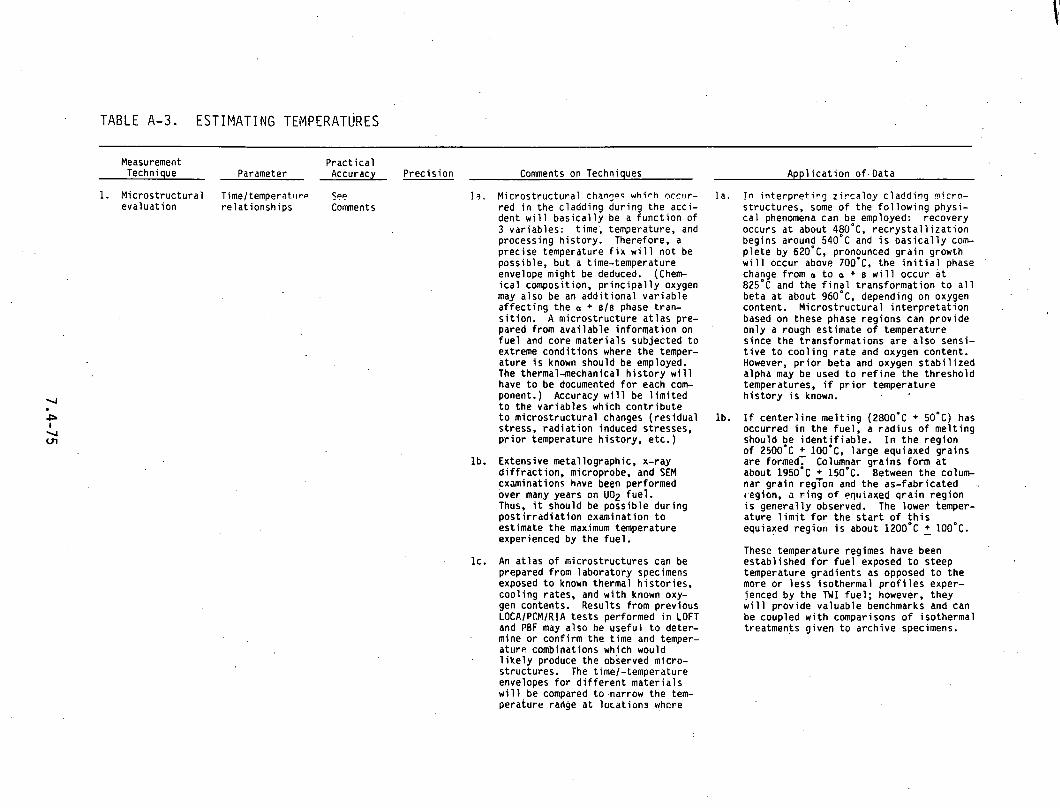
T A B L E A-3. E S T I M A T I N G TEMPERATURES
Measurement P rac t i ca l Technique Parameter Accuracy Prec is ion Comments on Techniques App l i ca t i on o f . Data
1. Micros t ruc tura l T i m e / t e m p e r a t ~ ~ r ~ Sac evaluat ion re la t ionsh ips Connnents
1 9 , Micros t ruc tura l chanyq which ncrvr - red i n the c ladding dur ing the acci- dent w i l l bas i ca l l y be a f unc t i on o f 3 var iab les : time; temperature, and processing h is tory . Therefore, a prec ise temperature f i x w i l l no t be possible, bu t a time-temperature envelope might be deduced. (Chem- i c a l composition, p r i n c i p a l l y oxygen may a lso be an add i t i ona l va r i ab le a f f e c t i n g the a + 61% phase tran- s i t i o n . A micros t ruc ture a t l a s pre- pared from ava i lab le in format ion on f u e l and core mater ia ls subjected t o extreme cond i t ions where the temper- ature i s known should be employed. The thermal-mechanical h i s t o r y w i l l have t o be documented f o r each com- ponent.) Accuracy w i l l be l i m i t e d t o the var iab les which con t r i bu te t o micros t ruc tura l changes ( res idua l stress, r a d i a t i o n induced stresses, p r i o r temperature h is tory , etc.)
lb . Extensive metallographic, x-ray d i f f r a c t i o n , microprobe, and SEM examinations have been performed over many years on U02 fue l . Thus, i t should be poss ib le dur ing p o s t i r r i l d i a t i o n examination t o estimate the max6mum temperature experienced by the fue l .
l c . An a t l a s o f microstructures can be prepared from labora tory specimens exposed t o known thermal h i s to r i es , coo l ing rates, and w i t h known oxy- gen contents. Results from previous LOCAIPCMIRIA t e s t s performed i n LOFT and PBF may a lso he usefu l t o deter- mine o r conf i rm the time and temper- a ture combinations which would l i k e l y produce the observed mlcro- structures. The time/-temperature envelopes f o r d i f f e r e n t ma te r i a l s w i l l be compared t o .narrow the tem- perature range a t l o ra t i ons whcre
I n . !n i n t e r p r e t i n g z i r c a l o y c ladd ivg micro- structures, some o f the f o l l o w i n g physi- c a l phenomena can be employed: recovery occurs a t about 480'C, r e c r y s t a l 1 i z a t i o n begins around 5 4 0 ' ~ and i s b a s i c a l l y com- p l e t e by 620'C, pronounced g r a i n growth w i l l occur above ~ O O ' C , t h e i n i t i a l phase change from a t o a + 6 w i l l occur a t 8 2 5 ' ~ and the f i n a l t rans format ion t o a l l beta a t about 960'C, depending on oxygen content. M ic ros t ruc tu ra l i n t e r p r e t a t i o n based on these phase reg ions can prov ide on l y a rough est imate o f temperature s ince the transformat ions are a lso sensi- t i v e t o coo l i ng r a t e and oxygen content. However, p r i o r be ta and oxygen s t a b i l i z e d alpha may be used t o r e f i n e t h e th resho ld temperatures, i f p r i o r temperature h i s t o r y i s known.
l b . If c e n t e r l i n e me l t i ng ( 2 8 0 0 ' ~ + 50°C) has occurred i n t he f ue l , a rad ius o f me l t i ng should be i d e n t i f i a b l e . I n t h e reg ion of 2 5 0 0 ' ~ + 100 '~ . l a rge equiaxed gra ins are formed, Columnar g ra ins form a t about 1 9 5 0 ' ~ + 150°C. Between t h e colum- nar g ra in reg ion and the as-fabr icated .. region, a r i n g o f ~ q l r i a x e d g r a i n reg ion i s genera l ly observed. The lower temper- a ture l i m i t f o r the s t a r t o f t h i s equiaxed regior i i s about 1 2 0 0 ~ ~ + 100 '~ .
These temperature regimes have been es tab l ished f o r f u e l exposed t o steep temperature grad ients as opposed t o t he more o r less isothermal p r o f i l e s exper- ienced by the TWI fue l ; however, they w i l l p rov ide valuable benchmarks and can be coupled w i t h comparisons o f isothermal treatments g iven t o arch ive specimens.
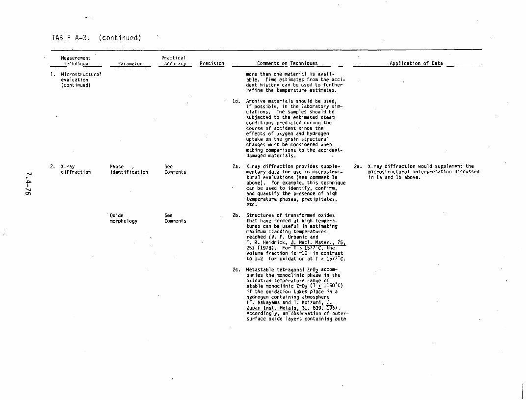
TABLE A-3. ( con t i nued )
Measurement P rac t i ca l T ~ r h n i q u e - -- P A ~ ~ltl~brler A c i u ~ acy Prec is ion Comments on Techniques App l i ca t i on o f Data
1. Micros t ruc tura l evaluat ion (continued)
2. X-ray Phase , See v d i f f r a c t i o n i d e n t i f i c a t i o n Comments
P I V 01
Oxide See morphology Comnents
more than one ma te r i a l i s ava i l - able. Time estimates f rom the acci- dent h i s t o r y can be used t o f u r t h e r r e f i n e the temperature estimates.
Id . Archive ma te r i a l s should be used, i f possible, i n the labora tory sin+ u la t i ons . The samples should be subjected t o the estimated steam cond i t ions pred ic ted dur ing the course o f accident s ince the e f f e c t s o f oxygen and hydrogen uptake on the g ra in s t r u c t u r a l changes must be considered when making comparisons t o t he accident- damaged ma te r i a l s.
2a. X-ray d i f f r a c t i o n provides supple- 2a. X-ray d i f f r a c t i o n would supplement t he mentary data f o r use i n microstruc- m l t r o s t r u c t u r a l i n t e r p r e t a t i o n discussed t u r a l eva luat ions (see comnent l a i n l a and l b above. above). For example, t h i s technique can be used t o i den t i f y , confirm. and quant i fy t he presence o f h i gh temperature phases, p rec ip i t a tes , etc.
, 2b. S t ruc tures o f transformed oxides t h a t have formed a t h igh tempera- t u res can be use fu l i n es t imat ing maxlmum c ladd ino temoeratures reached (V. F. Grbanic and T. R. Heidr ick, J. Nucl. Mater.. 75, 251 (1978). For T > 1577-C. t h e volume f r i c t i o n i s -10 i n - c o n t r a s t t o 1-2 f o r ox ida t i on a t T < 1577'~.
2c. Metastable te t ragona l Zr02 accom panies t he monocl in ic pl~ase i n t he ox ida t i on temperature'range o f s tab le monocl in ic Zr02 (T 1150 '~ ) i f t h c ox idat iu l t LdkeS p l a t e i n a hydrogen con ta in ing atmosphere (T. Nakayama and T. Koizumi, J. Japan I n s t . Metals, 31, 839, m67 . Accordingly, an observat ion o f ou ter - surface oxide layers conta in ing both

TABLE A-3. (continued)
Measurement Practical Technique Parameter Accuracy Precision Comments on Techniques
2. X-ray monoclinic and tetragonal modifica- diflrLaction tions would indicate oxidation of (continued) TMI-2 fuel cladding in a steam-
hydrogen mixture. Under such a sit- uation, the relative intensity of x-ray diffraction peaks correspon- ding to moneclinic and tetragonal ZrOE should be measured and com- pared with out-of-reactor simulation tests.
3. Hardness Annealing
4. Microhardness Localized
5. Oxide thickness
See Comments
*5 KHN
Temperature 1 um
3a. Accuracy and precision depend on equipment and hardness scale used for the test.
3b. Hardness tests on thermal simula- tions performed in the laboratory on archive or duplicate materials could be used to describe a time- temperature envelope consistent with measured data.
3c. This technique can be used to pro- cess a large number of samples relatively quickly.
Not 4a. Microhardness m e d m ements can be Estimated used to define the oxygen enriched
0-zircaloy boundary.
0..3 urn 5a. Oxide thicknesses can be used to implicitly establish a range of temperatures to which the material was,subjected. If the oxidation was slow, the established temper- atures would be more accurate than If the reaction had proceeded rap- idly. The method is basically a time-temperature correlation and will depend upon how accurately the time at any specific temperature region is known.
5b. Metallography on zircaloy tubes will provide measurements of oxide layer thicknesses, oxygen-stabilized,
Application of Data
3a. Hardness data from core components can be compared with hardness data from labora- tory simulations to assist in determining the time-temperature envelopes. Core radial and axial hardness scans.wil1 also serve to locate temperature transition points more accurately. For instance, there will be an abrupt change in hard- ness at the axial location on the zirca- loy fuel cladding where recrystallization temperature was exceeded. (See comnent la above.)
Aa. The thickness of the oxygen enriched zir- caloy layer provide9 a 3rd var'iablc which can be used along with diffusion and time data from the accident history to help define a temperature profile.
5a. Computer codes such as ZORO, COBILD, and . SIMTRAN can utilize the oxide and oxygen
stabilized alpha thickness measurements - to compare predicted reaction times and
temperatures which would have provided those thicknesses. Verification of cur- . ,
rent "state-of-the-art" analytical models to predict oxidation under a accident conditions will be one of the major uses of the TMI fuel examinations. Most models currently employ parabolic rate constants and may not be entirely valid for the transient thermal exposure history experienced by the TMI fuel rods.
5b. The appearance of such features as a

TABLE A-3. (continued)
Measurement Prac t ica l Technique Parameter _ - Accuracy Prec is ion Coments on Techniques - Appl icat. ion o f Data
5. Oxide t t ~ ickness (continued)
6. Elemental d i f f u s i o n p r o f i l e s
7. Prec is ion g m a scanning
Temperature imposed chemical gradients
Sample p o s i t i o n
Temperature induced i so top i c concentrat ion p r o f i l e s
alpha-layer thicknesses and the remaining metal o r c ladd ing wa l l thickness. I n the case of f u e l cladding, the th ickness o f r eac t i on layers on the ins ide surface can a lso be measured and may prov ide 5c. cn r re la ry in format ion fo l l ow ing rod rupture .
5c. For z i r c a l o y tubes i n regions where there i s s i g n i f i c a n t ox ida t i on and spa l l ing , the d i f f e rence between the remaining amount o f unox id i red z i r c a l o y the o r i g i n a l w a l l t h i c k - ness w i l l provide a illore use tu l measurement o f oxide thickness f o r temperature co r re la t i on .
5d. Oxidat ion layer thicknesses nn qtssn less sLee l and Inconel components w i l l be a f unc t i on o f time, tempera- t u r e and the l o c a l oxygen po ten t i a l .
1112 wt% Not 6a. Q u a n t i t a t i v e elemental analysis, Estimated element d i s t r i bu t i ons , and concen-
t r a t i o n p r o f i l e s could be deter- mined by an e lec t ron microprobe and x-ray wave length d ispers ive tech- niques, and used t o conf i rm the bas is o f temperature est imates made by o ther techniques.
*l um Not 6b. The accuracy o f t h i s technique w i l l Estimated most l i k e l y decrease w i t h increas-
i n g r a d i a t i o n levels. On h i g h l y rad ioac t i ve samples, the data w i l l . be q u a l i t a t i v e .
Not Not 7a. Th is i s a nondestruct ive technique Estimated Estimated t h a t can be used t o determine the
a x i a l and r a d i a l concentrat ion pro- f i l e s of r ad ioac t i ve isotopes i n the f u e l and cladding.
second phase i n t he ox ide o r hydr ide p r e c i p i t a t e s i n t he z i r c a l o y wa l l w i l l a lso provide add i t i ona l in format ion on temperature 1 imi ts .
Ox idat ion layer th ickness o f s ta in less and Inconel components can be u t i l i z e d along w i t h r e a c t i o n k i n e t i c s , thermody- namic data and t ime est imates from the accident h i s t o r y t o e s t a b l i s h temperature.
6a. Chemical composi t ion data w i l l be used t o conf i rm the i d e n t i t y o f micros t ruc tures observed by meta l lograph ic techniques. (See comnent l a above).
6b. Chemical composi t ion versus l o c a t i o n ( d i f f u s i o n p r o f i l e s ) along w i t h known o r determined d i f f u s i o n constants and times from the accident h i s t o r y can be used t o descr ibe a temperature envelope.
7a. Knowledge o f i s o t o p i c d i s t r i b u t i o n s and t h e i r m o b i l i t i e s i n t h e f u e l and c ladd ing can be used t o assess temperatures and temperature grad ients experienced i n the f u e l rods du r i ng t h e accident.
7b. Spec i f i c i otop s such as 1 3 7 ~ s , 137mBa 13$Cs, f06Ru-106Rh. and
144~e-144~r could be determined by

TABLE A-3. (continued)
Measurement Practical Technique Parameter Accuracy Precision Comnents on Techniques Application of Data
7. Precision gamna scanning (continued)
. 8. Electron microprobe
Temperature See induced Comnents elemental distributions
gamna ray spectrometry. Elemental penetration and distribution can be used to predict or estimate upper temperature 1 imits.
8a. Electron microprobe techniques for 8a. Electron microprobe analysis would sup- estimating temperature are dependent plement the microstructural evaluations on measuring the distribution of some discussed in Paragraph 1 above. Areas element which migrates under a tern where incipient melting has occurred perature gradient, then relating the could be more definitely analyzed and observed distribution to similar sam- thereby aid in reconstructing the events ples of known temperature history. leading to fuel damage and core slumping. The elemental distributions charac- terizing the high uniform tempera- tures experienced by the MI fuel during core uncovery may be altered - by subsequent lower temperature migration, thereby complicating the analysis. Changes in fuel morphology may result in increased uniformity of composition although resolidifi- cation may well cause nonhomogene- ities Y o recur through the process of coring and multiple phase precipitation.
8b. 'ine locdion o f a solid (fnrmerly liquid) interface can be determined more readily by metallographic tech- niques with the microprobe being used to verify that the observed change is not due to the presence of some other material. This technique is limited to determination of the
, location of one temperature along a tempprature gradient-the melting point of the material. the absence of a temperature .gradient, it indicates only that the material was above or below the melting point.
8c. Relatively volatile elements such as cesium, tellurium. and rubidium migrategrate to.cooler regions under a temperature gradient. High core tcmperaturcs and flatter temperature gradients such as occurred at TMI may cause some elemental migration

TABLE A-3. (continued)
Practical Measurement Technique Parameter Accuracy Precision Comments on Techniques Application of Dat*
8. Electron back toward the fuel center. The experimental technique is to gather microprobe
(continued) a series of photomicrographs of cesium distribution (for example) and correlate the depth of penetra- tion of cesium alor~y fuel grain hn~lndariec, oto., w i t l r ti~~ycl~alures from similar fuel at known tempera- ture. Since cesium profiles can only be measured by electron micro- probe in fuels with burnups greater than -2%. this technique may not be generally applicahl~ to the MI fuel examinations excepL In local regions of high cesium concentration. Huw- ever, an ion microprobe may be used to determine qualitative concentra- tion profiles at much lower cesium levels.
V
& 9. Puseir~aaratrbn Temperature heating of
03 0 cladding
Not *5 9a. This technique is based on the mea- Estimated . surement of the rate of release of
Kr-85 durina controlled heatina of irradiated Fuel cladding samplis. (Swanson. et al., J. Nucl. Mater., 3:302-310 (1960). The recision of this technique is +3% where minimal clad attack has occurred; the pre- cision degenerates to +8% where severe attack is evident (Buzzel li, et al., GA-A14459 (April 1978).
9a. The Kr-85 annealing technique has been used as means of determining in-reactor fuel cladding'temperatures. This method is based on the measurement of the rate of release of Kr-85 during controlled heating of irradiated fuel cladding sam- ples. An increased rate of release of - Kr-85, which had impregnated the inner surface of the cladding from fission recoil, will occur when the maximum oper- ating temperature is exceeded during annealing.

TABLE A-4. OXIDE TH1CKNES.S
Measurement Prac t ica l Technique Parameter Accuracy
1. Metal lography Oxide *3 ( l o ) thickness1 alpha s t a b i l i z e d 1 ayer
2. NDT-Eddy cur rent
Oxide thickness
Alpha s t a b i l i z e d 1 ayers (poss ib ly )
Prec is ion Corments on Techniques
Not 13. Samples o f mater ia l t o be exzzisc: Estimated would be mounted i n standard metal-
lographic mounts su i t ab le f o r oxide thickness measurements a t magnif i - ca t ions up t o 500X. For thicknes- ses less than 10 microns, scanning e lec t ron microscopy could be used a t magnif icat ions up t o 3,000X. Micro- s t ruc tu ra l features, such as mor- phology, g ra in s ize and shape, and f rac ture appearances would be analyzed.
Not 2a. Oxide layer thicknesses measured by Estimated eddy cur rent techniques have been
perfected f o r z i rconium oxide f i l m s on i r r a d i a t e d f u e l rods. A spec ia l l y designed probe i s used as t he sensor. Measurements can be made underwater as we l l as in -ce l l . I n addi t ion, measure- ments can be made a t d i sc re te po in t s o r as continuous traces along a rod length. Accuracy i s best on th i cke r oxide layers (>2 m i l s ) which should be the case f o r most o f t he exposed cladding mater ia l .
2b. Comparisons have been made between thickness measurements obtained . using the eddy cur rent technique and the same measurements obtained by metal lography. Resul ts compare very favorably. At f i l m thicknesses less than 5 urn, the eddy cu r ren t re- s u l t s tend t o be less accurate; hnwever. they should be s a t i s f a c t o r y over f i l m thicknesses t h a t range from f i v e t o several hundred microns.
2c. P rac t i ca l accuracy w i l l be l i m i t e d by (a ) a b i l i t y t n accura te ly measure oxide thicknesses on standards and (b) the extent of oxide removal caused by s l i d i n g contact between t.he probe and any nonadherent oxide 1 ayer.
App l i ca t i on o f Data
1 - LC,. The oxide th i c i ness daLa w i l l be usefu l
i n postaccident heat t r ans fe r . ca l cu la - t ions . M ic ros t ruc tu ra l f ea tu res such as morphology, g r a i n s ize and shape, and f r a c t u r e appearances w i l l p rov ide ev i - dence o f f u e l r o d damage t h a t occurred dur ing Lhe accident.
2a. The data can be compared w i t h ca lcu la- . t i o n s from computer codes such as ZORO, COBILD, o r SIMTRAN which p r e d i c t bo th oxide and oxygen s t a b i l i z e d alpha th i ck - nesses from given reac t i on t ime and temperature h i s to r i es .
2b. Oxidat ion l aye r thicknesses on stainl 'ess and Inconel components can be u t i l i z e d along w i t h reac t i on k i n e t i c s , thermo- dynamic data, and t ime est imates from,: the accident h i s t o r y t o es t imate temperature.

TABLE A-4. (continued)
Measurement P rac t i ca l Tcchniquc Pardl~leter Accuracy Prec is ion ' Comments on Techniques App l i ca t i on o f Data
2. NDT-Eddy cu r ren t
3. Color standards
Oxide thickness
2d. Oxide thicknesses measurements can be made q u i c k l y on a l a r g e r number o f rods o r o ther components.
Not Not 3a. Because t h e co lo r o f z i rconium oxide Appl icable Appl icable f i l m va r i es w i t h thickness, a qual- (mater ia l i t a t i v e i n d i c a t i o n o f f i l m thickness and can be obtained from observing f i l m operator co lor . A se r i es o f co lo r standards dependent) have been def ined which co r re la tes
w i t h z i rconium oxide f i l m thickness. The standards are app l icab le over a th ickness range o f a few t o several hundred microns. However, because o f i t s q u a l i t a t i v e nature, t he method i s not appropr iate f o r p rec i - s i on measurements. I n addi t ion, t he oxide thicknesses on the z i r c a l o y f u e l c ladd inq g t TMI w i l l likely bo beyond t h e c o l o r sens i t i ve range.
3b. Th is technique may be more use fu l f o r es t imat ing ox ide thicknesses on Inconel and s ta in less s t e e l compon- ents i n areas where the temperatures were no t extremely h igh and the ox i - da t i on e f f e c t s were not severe.
3c. Th is technique i s fas t , nondestruc- t i ve , and can be used t o process a l a rge number o f samples o r t o view a cross-sect ion o f components t o ob- t a i n a 34 imens iona l perspect ive o f ox ida t i on outs ide heav i l y damaged regions.
3a. The p r i n c i p a l use o f c o l o r standards would l i k e l y be t o prov ide a quick 3- dimensional perspect ive o f ox ida t i on and temperature d i s t r i b u t i o n i n t he p e r i - pheral core reg ion and, would there fore , a i d i n t he se lec t i on of samples f o r more . d e t a i l e d examinations by one of t he o ther techniques l i s t e d above.

2. Hot vacuum . Hydrogen 10 P P ~ extraction concentration
T A B L E A-5. H Y D R I D E CONCENTRATION
Measurement Practical Technique Parameter Accuracy Precision Connnents on Techniques Application of Data
1. Metal lography Hydride Not Not la. Metallography will provide hydride la. Orientation and volume fraction data orientation Applicable Applicable orientation and volume fraction will be correlated with mechanical pro- distribution information. Precipitation char- perty test results. Volume fraction can and acteristics will be different for also be correlated with accident time concentration 6 transformed Zircaloy rather than and temperature estimates.
for the a-materials.
lb. Metallographic techniques can be used to evaluate hydride concen- trations visual ly to +Z(Prelative.
Not 2a. Measures total hydrogen pickup from 2a. Measurements on hydrogen concentration Estimated oxidation and fabrication. in the fuel cladding will provide impor-
tant information on the fraction of hydrogen released from metal water reaction that has been absorbed in the zircaloy metal. If uptake is signifi- cant, the hydrogen could contribute to the fracture or shattering of the fuel rods.
ih I 2b. Axial mapping of hydrogen may help to
00 estimate thermal gradients. W
3. Inert gas , Hydrogen *5%(1)a€ 'Nut . 3a . Hydrogen content can be determin- 3a. See comnents la. 2a, and 2b above. fusion concentration . 50 ppm level Estimated . ed. by inert gas fusion. Ii l this
technique, metallic and ceramic materials ,are heated to 2000'~ in .high purity argon.

TABLE A-6. WALL OR COMPONENT THICKNESS
Prac t i ca l Measurement Techniqu?. ' Paramet~r Accuracy P rec i s i u r~ Corm~ents on Techniques App l i ca t i on o f Data -
1. Metallography Wall o r lum Not la . Th is i s a very e f f e c t i v e and.accurate l a . Postaccident w a l l th ickness data can be used component . Estimated technique f o r measuring the thickness f o r heat t r a n s f e r c a l c u l a t i o n s and mechani- thickness o f r ad ioac t i ve mater ia ls . Thickness c a l behavior pred ic t ions .
i s determined by d i r e c t measurement from a photographic p r i n t of a specimen
' and a s i ze standard i n a metal lographic mount, The greatest uncer ta in ty i s t t i a t o f a e f i n i n g t h e measurement end po in t s on the photographic p r i n t .
' . Not 2a. This technique i s f o r generating a x i a l 2a. See I tem l a above. Estimated wa l l th ickness p r o f i l e s f o r l a rge num-
bers o f heav i l y ox id ized tubu lar compo- nents. It i s no t use fu l Tor components w i t h complex geometries.
2. Eddy cur rent Wall o r component thickness
3. U l t rason ics Wall o r component th ickness
4. Metrology Wall o r component th ickness
2b. D i f f i c u l t i e s may be experienced i n d e f i n i n g absolute dimensions o r gradual changes i n dimensions. Ca l i b ra t i on standards must be used t o produce s ig- na l responses i d e n t i f i a b l e w i t h thicknesses.
Not Not 3a. Useful f o r l i g h t l y ox id ized corn 3a. Same as I t em l a above. Estimated Estimated ponents w i t h complex geometries.
Not 4a. Th is i s a very e f f e c t i v e and accurate 4a. Same as I t em l a above. *25 Estimated technique f o r making measurements pro- .
v ided the component t o be measured i s ava i l ab le f o r d i rec t , a l be i t . remote handling. Micrometers, d i a l gauges. ca l ipers , etc. are capable o f measure- ment accuracies t o cent imeters i n some instances. .
4b. Useful f o r measuring gross cross- sec t iona l changes o f l i g h t l y ox id i zed s t r u c t u r a l components, e.g., Inconel gr ids, s ta in less s t e e l end f i t t i n g s , ho ld down springs, BPRA re ta iners . etc.

TABLE,.A-7. ' D I M E N S T I O N A L AND F U N C T I O N A L I N T E G R I T Y
Measurement Practical Technique parameter Accuracy
1. Sulo probe Water *25 channel spacing
2. LVDT Assembly 250 um bow
3. Stretch wire Bow and *50 mils technique twist
4. Larcr Fuel rod a2.5 - profilometry diameter
5. X-radiography Flaw Not detection Estimated
Precision
*25 urn
.Not Estimated
Not Fstimated
Not Estimated
Comments on Techniques
la. This measurement will provide rod-to-rod spacing on the intact portions of fuel assemblies and wi'll also provide informa- tion in situ fuel rod bow.
2a. This technique is 111ore useful for measur- ing fuel assembly envelope dimensions to' determine overall bow.
3a. Both bow and twist measurements of the entire fuel assembly are possible using a stretch wire technique. By using the top and bottom nozzle plates as reference points. it is possible to measure bow in the assembly to within '50 mils although only a qualitative measuve of the amount of twist in the assembly is possible. The position and dPstortion of the indi- vidual components within an assembly can be determined with a Sulo type probe. Channel closure, bow, and general distor- tion of ttie fuel rods and control rod cluster tubes could be measured to accu- racies of 100 mils with this approach.
3b. Individual core components can also be mea- sured for distortion ortLe they have b e ~ n removed from the assemblies. The stretch. wire technique can be employed to measure the bowing of components such as fuel rods., control rods, and neutron monitors to accuracies of +20 mils.
4a. This technique will provide the overall fuel rod envelope and its noncontacting nature is particularly suited for measur- ing fragile samples. It. would only be applicable to individual rods or peri- pheral rods In the fuel assembly.
Sa. X-radiography is not likely to be of much use in examirllng Lt~e irradiated f11e1 rod assemblies or their components. The heavy fogging of the radiographic film by the activated components will result in little or no detail.
Application of Data
la. These data can be used to predict thermal-hydraulic behavior in the post- accident condition if intact assemblies still exist.
2a. Same as la above.
3a. Same as la above.
4a. These data can be used to measure aver- age and local diametral strains as.a function of rod axial position.(e.g., the amo~rnt of ballooning and its loca- tion). They can also be used to pi-e- dict thermal hydraulic performance.

TABLE .4-7. . (continued)
Measurement Practical Technique Parameter Accuracy Precision Comncnts on Techniques
6. Neutron Flaws, 0.5 mils 0.5 mils 6a. Neutron radiography is frequently used to radiography defects provide valuable postirradiation data. A
f issile high flux (-2 to 5 x lo6 nlcm2 sec) content 1 neutron (both thermal and epithermal)
source is required. The neutron bed111 must be well collimated (with L/O ratios of at least 50 to 1) and the sample handling mech-' anisms designed to minimize scattering in order to provide adequate resolution. The capabilities of computer assisted axial t o m ography using neutron radiography is rapidly developing and should provide information on fuel element distortion.
6b. Fuel redistributi~n in a largo number o r IIJIJS Or a block of solidified debris may be difficult to determine if the interior rod images are observed in the radiograph. It may be possible, however, to measure total and axial ficri!o content w ill1 drl accuracy of -1 .
6c. Neutron radiography would be an excellent technique for characterizing defects and structural aspects of the fuel assemblies and their individual components. By util- izing the proper techniques, fuel rod condi- tions - such as centerline fuel melting, internal void formation, fuel pellet crack- ing and fragmentation, and relocation of any fuel fragments - could be easily resolved. Dimensional changes should be repeatable and accurate to 0.5 mils.
6d. Radiography will be extremely useful for detecting internal flaws in large section components, (e.g., end fittings and spider-couplings).
. .
7. Eddy current Flaw Not Not 7a. Multi-frequency eddy current will be use- detection Estimated Estimated ful for locating flaws in tubular components
(e.g., fuel and control rod components).
8. Dye Surf ace Not Not 8a. This technique would be useful for detecting penetrant flaws Estimated Estimated surface flaws in regularly shaped components
such as hold down springs, end fittings, and upper vessel internals.
Application of Data
6a. This technique will locate cracks or other surface flaws that would contri- bute to a degradation in the structural integrity of various core components. It will provide evidence of damage and an indication of whether or not some components which have not failed are at or near the damage thresholds.
76. See 6a above.
8a. See 6a above.

TABLE A-7. (cont inued)
Measurement Practical . Technique Parameter Accuracy Precision Comnents on Techniques Application of Data
8. Dye penetrant (continued)
8b. Dye penetrant would be the most effective technique for the inspection of a large number of samples.

TABLE A-8. MECHANICAL PROPERTIES
Measurement P rac t i ca l Technique
.- Acmrary Parameter -- Prcc i z i i ~ ~ ~
1. Uniax ia l Tensi le *2 k s i +2 k s i and strength, (s t rength) (stre.ngth) b i a x i a l y i e l d tension strength, *O. 1%. *0.1%
d u c t i l i t y ( d u c t i l i t y ) ( d u c t i l i t y )
2. Tube burs t Transverse Not Not s t rength and Estimated Estimated c i r cumfe ren t i a l d u c t i l i t y
3. Ring D u c t i l i t y compression
Not Not Estimated Estimated
Co~mnents on Techniques - l a . Tests under var ious load ing cond i t ions l a .
should be conducted t o evaluate mechani- c a l p roper t ies o f i n t a c t c ladding, con- t r o l r od components, spacer g r i d mater ia l , and end f i t t i n g s .
l b . Samples should be selected from core ax ia l and r a d i a l locat ions which repre- sent the f u l l range o f expected proper ty changes (e.g., f u l l y r e c r y s t a l l i z e d mic- ros t ruc ture , evidence o f the low d u c t i l - i t y a + B phase region, o r a f u l l y transformed p r i o r 6 micros t ruc ture .
l c . Un iax ia l tension tes t s a t room tempera- t u r e and elevated temperatures can be performed on a l l the s t ruc tu res l i s t e d above. For mater ia ls which were o r i g i - n a l l y an i so t rop i c r i ngs t e n s i l e and b u r s t t e s t s w i l l p rov ide usefu l supplemental informat ion.
Id . A l l samples should be tes ted i n t he as- received cond i t i on i f possible. No attempt should be made t o remove oxide layers o r other deposi ts from the samples.
2a. The tube bu rs t t e s t i s a good means 2a. o f eva luat ing t h e performance o f f u e l r o d c ladd ing tes ted i n a b i -ax ia l a x i a l s t ress s ta te . This t e s t w i l l provide an i n d i c a t i o n o f circum- f e r e n t i a l s t rength and d u c t i l i t y .
3a. I n the r i n g compression tes t , the 3a. c i r cumfe ren t i a l d i r e c t i o n o f t he c ladd ing i s the major s t r a i n axis. Th is technique may prove t o be the most adaptable f o r t e s t i n g a wide range o f segments taken from var ious locat ions w i t h i n t he core t o prov ide an i n d i c a t i o n o f the amount o f duc- t i l i t y l e f t i n t he c ladding and the degree of embritt lement.
- App l i ca t i on o f Data
These t e s t s w i l l determine post- accident mechanical p roper t ies . . The data w i l l p rov ide documentation of component nlechanical p rope r t i es degraded by h igh temperatures, and w i l l i nc lude the e f f e c t s o f d ls - solved oxygen and hydrogen which are not normal ly present i n PIE specimens.
The tube bu rs t t e s t s would prov ide in format ion on the circumferential d u c t i l i t y o f ox id i zed samples. The data, however, would n o t c o r r e l a t e w i t h t he ba l loon- rupture character- i s t i c s o f the f ue l c ladd ing dur ing , t he e a r l y stages o f t h e t r ans ien t .
Compression tes t s , a long w i t h bend tes ts , w i l l p rov ide supplementary in format ion t o f u l l y evaluate c lad- d ing d u c t i l i t y and mechanical behavior.

TABLE A-8. (con t inued)
Measurement Technique Parameter
4. Bending D u c t i l i t y and embritt lement
5. Load1 Changes i n de f l ec t i on component t e s t s e l a s t i c i t y
6. Expanding Strength and mandrel d u c t i l i t y
7. Impact Embritt lement
P rac t i ca l Accuracy
Not Estimated
Not Estimated
Not Estimated
Not Estimated
Prec is ion
Not Estimated
Not Estimated
Not Estimated.
Not Estimated
Comments on Techniques
4a. Experience w i t h bend t e s t i n g o f i r r a d i - ated z i r c a l o y f u e l c ladding a t tempera- tu res t o 1 3 0 0 ' ~ ( 7 0 0 ' ~ ) ind ica tes t h a t t h i s t e s t does not provide a sens i t i ve measure o f embri t t lement as a r e s u l t o f i r r a d i a t i o n . The bend t e s t should be a more e f f e c t i v e t o o l as an i nd i ca t i on o f c ladding embri t t lement and d u c t i l i t y f o r heav i l y ox id ized specimens.
5a. Changes i n spr ing constant and permanent se t should be measured f o r the hold down springs and f u e l r od i n t e r n a l springs t o evaluate changes i n func t iona l i n t e g r i t y .
5b. Changes i n l i f t - o f f f o r ce and spr ing r a t e can be measured on Inconel spacer gr ids .
6a. Expanding mandrel t e s t s have been used successfu l ly t o dup l i ca te p e l l e t clad- i n te rac t i on r e s u l t i n g from f u e l expan- sion. However, the s t ress s ta te i n the cladding may not be representa t ive o f a LOCA unless the c ladding has been co l - lapsed onto t he fue l ; which i s not thought t o be the case f o r TMI-2.
7a. Recent research e f f o r t s have been d i rec ted towards determining the impact proper t ies 07 i r r a d i a t e d z i r c a l o y (H. M. Chung and T. F. Kassner. ANL-79-48, NUREGICR-1344, January 1980). Due t o t he .h igh l y s t ra in - ra te sens i t i ve nature g f z i rca loy , impact t es t s seem t o provide the most adaptable neans o f dc f i n i ng appropr iate embri t t lement c r i t e r i a . Impact t e s t s w i l l not on l y be most usefu l i n assessing the degree o f embri t t lement i n heav i l y ox id ized specimens, but can help t o v e r i f y t t ie a p p l i c a b i l i t y o f newly developed embri t t lement c r i t e r i a .
App l ica t ion o f Data
4.3. Same as 3a above.
5a. Load/def lec t ion t e s t s w i l l p rov ide data t o evaluate t he func t i ona l in- t e g r i t y o f the var ious 'pring and spacer components w i t h i n the core. Th is in format ion should prove usefu l i n assessing changes i n core geome- t r y dur ing the course o f t he accident.
7a. In format ion obtained from impact t e s t i n g w l l l p rov ide data t o eva111- a te embri t t lement f a i l u r e c r i t e r i a
. undcr core-wide acc ident cond i t ions and can be used t o compare w i t h ex- reac to r tes ts .

T A B L E A-9. R E T A I N E D F I S S I O N PRODUCTS
Measurement P rac t i ca l Technique Parameter Accur jcy P~.YL; is ion
1. Microprobe Q u a n t i t a t i v e *lo70 low Not analysis and grad ient concentrat ion Estimated
analysis high
concentrat ion
2. I on I so top i c Accuracy and Accuracy and microprobe ana lys is p rec i s i on are p rec i s i on are
t y p i c a l o f a t y p i c a l o f a semi- semi- quan t i t a t i ve quan t i t a t i ve technique technique
Comments on Techniques
la . By use o f a shielded e lec t ron microprobe (EMP), quan t i t a t i ve and grad ient ana lys is could be performed on ma te r i a l s t o 100 R/hr a t 1 f o o t fo r 'e lements Atomic No. 11 (Na) through Atomic No. 94(Pu)..
l h F icc ion ~ W J ~ L I L L ~ III cne 1 range ( t o t a l elemental) could be analyzed t o fl*. Three elements could be step-scafined simul- taneously w i t h a wave length d ispers ive x-ray detec tor system f o r r a d i a l o r
cross-sect ional grad.ients. '
l c . The e l e i l r o n mlcroprobe i s usefu l f o r deter- mining re ta ined f i s s i o n products i n both the d i sp lay mode o r as a q u a n t i t a t i v e determina- t i o n o f concentrat ion w i t h p o s i t i o n along the f u e l radius. I n the d i sp lay mode, photo- micrographs o f t he elemental d i 5 t r i b u t i o n i n a ylven area are prepared. A separate photo- micrograph i s requ i red f o r each element i n each area. Concentrations must be a few percent o r higher t o produce a meaningful s ignal .
2a. I so top i c ana lys is o f r e ta ined f i s s i o n pro- ducts can be accomplished us ing an i o n micro- probe mass analyzer or i o n microscope. I f shielded versions o f these instruments are no t ava i l ab le i n cur rent f a c i l i t i e s , work must be done using t h i n sample techniques and seg- ments o f f u e l p i n cross-sections. Displays o f isotope d i s t r i b u t i o n , as w e l l as quant i - t a t i v e isotope r a t i o s as a f u n c t i o n o f p o s i t i o n can be obtained.
2b. The i o n microprobe i s usefu l f o r determining. r e l a t i v e concentrat ions p r o f i l e s but not . absolute magnitudes. The s e n s i t i v i t y o f t h e . i o n microprobe i s i n the p a r t s per m i l l i o n range o r b e t t e r f o r most elements.
App l i ca t i on o f Datd
l a . These data can be used t o deter- mine the e f f e c t s o f t r ans ien t behavior on f i s s i o n product d is - t r i b u t i o n o r r e d i s t r i b u t i o n w i t h i n the f u e l .
2a. Same as l a above.
2b. The most l i k e l y app l i ca t i on i s f o r de termin ing 1-129, a low- a c t i v i t y iso tope which w i l l be present i n low concentrat ions. A q u a n t i t a t i v e core-wide, 1-129 concent ra t ion w i l l con t r i bu te t o t he determinat ion o f a rad io log- i c a l source time. Local var ia - t i o n s i n concent ra t ion can c o n t r i b u t e q u a l i t a t i v e l y t o determining t h e temperature range.

TABLE A-9. (continued)
Measurement Prac t ica l Technique Parameter Accuracy Prec is ion Comments on Techniques App l ica t ion of Data
3. Chemistry Chemical and * lo% Not 3a. I so top i c ana lys is by p rec i s i on gamna ray 3a. Same as l a above. i so top i c Estimated spectroscopy would y i e l d a l l products w i t h analysis h a l f l i v e s over 100 da s. Ex ected roducts
would include 137Cs-l37mBa, Y ~ ~ C S , f06Ru- . 106~11, and 1 4 4 ~ e - 1 4 4 ~ r a t accuracies o f +1W&
3b. I n add i t ion t o those const i tuents analyzed . by EMP or gamma detection, 90Sr-90~ might be analyzed by separation and beta counting. Other const i tuents might be analyzed by mass spectroscopy.
.b 4. F iss ion gas F iss ion gas *3% I rn measurements
3c. The f i s s i o n gases Xe and Kr are r o u t i n e l y measured i n i r r a d i a t e d fue l by i n e r t gas fusion. Accuracies fo r Xe are i n the 5% range; those f o r Kr are poorer due t o i t s lower concentration. Sample s ize i s l i m i t e d t o about 1 gram.
4a. Same as l a above. Not 4a. I f f i s s i o n gas samples can be obtained, Estimated measurements could y i e l d t o t a l gas volume o r
quan t i t y t o +5% Mass spectroscopy ana lys is would a l low complete ana lys is f o r v i r t u a l l y a l l expected const i tuents such as Hz, He, NZ, 02, CO, H20. Kr, Xe, and 12 if present present. Accuraciei wnuld be +3% r e l a t i v e f o r each species present in . amEunts o t a t l eas t . 2 volume percent. The void volume o f gas i n the plenum of i n t a c t rods could a lso be determined t o 55%.
5. Mass Contamination Var iable Not 5a. A spark source mass spectrometer could be 5a. This ana lys is might prov ide some spectrometry and impur i ty Estimated used f o r t race impur i ty ana lys is o f f u e l .seg- in format ion on the mass trans-
ana lys is ments. The accuracy w i l l depend on concen- p o r t o f var ious elements du r i ng t r q t i o n : a t 100 .ppm, i t w i l l be 0.1-0.5% the course o f t he accident. r e l a t i v e ; a t I0 ppm, 10-50% re la t i vo ; and a t 1 ppm i t would be 50%relat' lve.
6. Prec is ion I so top i c 2 t o 5% Not 6a. Prec is ion gama spectrometry techniques g m a d i s t r i b u t i o n Estimated invo lve t he use o f mult ichannel analyzers spectroscopy coupled t o h igh reso lu t i on Ge-Li detectors.
na l ys i s usua l l y requ i res hot c e l l sample d is - so lu t i on p r i o r t o r a d i o chemical analysis. For',a few isotopes, chemical separation i s needed. Under favorable condi t ions, accura- c i e s i n the 2-5%range can be obtainfd.

TABLE 'A-9. (continued)
. . Measurement Prac t ica l '
Technique para yet^^ Acc~~racy r r e c i b iun Coments on Techniques App l i ca t i on o f Data
6. Precis ion g amid spectroscopy (continued)
6b. Data from low burnup f u e l which operated under normal operat ing cond i t ions can be obtained and used f o r comparison.
7. Atomic Radiological Not Not 7a. The accuracy o f t h i s technique w i l l depend 7a. Could be used t o he lp make quan- absorption source term . Estimated Estimated upon the concentrat lon and the chemical t i t a t i v e determinat ions o f f i s - spectrometry separation technique. s ion products f o r r a d i o l o g i c a l
source term, temperature, and chemical i n t e r a c t i o n studies.'

Measurement Prac t i ca l Technique Parameter Accuracy Prec is ion Comments on Techniques A p p l i c a t i o n o f
Data
1. Polarography *lo% Not Not . l a . Oxygen-to-metal r a t i o s by polarography l a . Analys is o f se lected f u e l samples f o r O/U Estimated Estimated would be the most accurate means of w i l l i n d i c a t e the degree o f o x i d a t i o n o f
determining sto ich iometry since compari- exposed f u e l du r ing the course o f t h e sons can be made w i t h known standards. , accident. Comparisions w i t h adjacent seg- Oxygen-to-metal r a t i o s f o r U O ~ . ~ C ~ ~ be ments o f c ladd ing w i l l i n d i c a t e t h e r e l a - determined t o l O % r e l a t i v e . t i v e degree o f oxygen p a r t i t i o n i n g between
the f u e l and i n t e r i o r z i r c a l o y surfaces.
2. Coulometry OIU *5 (U) Not 2a. Another method f o r determinat ion of U02 Estimated ox ida t ion i s uranium analys is (a lso Pu
i f requi red) by coulometr ic techniques f o r known U02 f u e l weights. Accuracy o f elemental uranium could be q u a n t i f i e d t o ~ W P
Thermogravimetric O/U Not 0.0005 3a. Fuel p e l l e t s would f i r s t be exposed t o a . Estimated He-H2-H20 atmosphere a t e levated
temperatures. The i n i t i a l ox ida t ion r a t e data, acquired i n a real - t ime mode would be used t o p r e d i c t the ox ida t ion end p o i n t and t o c a l c u l a t e the addi- t i o n a l oxygercto-metal r a t i o . P rec is ion i s 0.0005.
4. SEM
2a. Same as l a above.
3a. Thermogravimetric techniques should be use fu l t o analyze l i q u i f i e d f u e l r u b b l e when d i s s o l u t i o n o f UO2 i n oxygen satur- ated a Zr has taken place. The s t o i c h i o - metry i n t h e (U. Zr)02-x w i l l p rov ide a measure o f t h e maximum temperature reached above t h a t o f the l i q u i d s .
q . 0 1 Not 3b. A thermogravimetric technique developed Ezt.imated by McNei l ly and C h i k a l l a ("Determination
o t Uxyger~lMttal Ratios fnr Ilranium, Plutonium, and (U. Pu) Mixed Oxides." 3. Nucl. Mater.. 39, 77-83. 1971) has b e e n a p p l ~ e d t o h t r n o n i r r a d i a t e d and i r r a - d ia ted fue ls . The technique can be appl ied t o i n t a c t p e l l e t s , core samples taken from i n t a c t f u e l , p e l l e t frag- ments, o r rubble. The accuracy o f t h e technique depends upon the success o f i n t e r p o l a t i n g and ex t rapo la t ing . W-02 for p u r ~ UOZ t o UOp = f i s s i o n product and U02 - cladding - f i s s i o n product mixtures. Estimated uncer ta in- t i e s I n O/U values are ~ . n O l t o 0.01.
LatL ice Not Not 4a. Q u a l i t a t i v e and general e l e c t r o n chan- 4a. Crys ta l log raph ic measurement.^ w i l l supple- d i s t o r t i o n Estimated Estimated n e l i n g pa t te rns can be performed by SEM ment the O/U measurements by p r o v i d i n g
examination o f small samples. These in fo rmat ion on t h e mechanics o f t h e oxida- pa t te rns can be used t o determine t i o n process. I t w i ! ! a lso be u s e f u l i n changes o r d i s t o r t i o n t o the U02 analyz ing l i q u e f i e d f u e l samples where c r y s t a l l a t t i c e . Elect ron microprobe te rnary phase i n t e r a c t i o n s have taken analys is might a lso be considered as a place. supplemental ana lys is f o r determining U02 v a r i a t i o n s o r gradients.

T A B L E A-10. U 0 2 O X I D A T I O N ( S T O I C H I O M E T R Y )
. Measurement Practical Technique Parameter Accuracy Precision Comnents on Techniques Application of Data
5. Electrolyte o/u 4.1 Not 5a. An electrolyte probe technique developed . probe Est imated by Bones and Carney, ("A Galvanic Cell
Technique for the Rapid Measurement of O/U Ratios In-Oxide Fuel Pellets," AERE-R-6301, 1969) has been applied to non-irradiated and irradiated fuels. This technique is most readily applied to samples with flat surfaces due to the need for electrical contact between probe and sample. The accuracy of this technique is similar to that described in 3b above.
6. Electrochemical Not Not 6a. Electrochemical dissolulion of oxidized 68. This analysis technique may prove useful :!!dation Estimated Estimated fuel can be used to evaluate the charac- in separating out the effects of low tern
teristics of pellet surfaces. The perature oxidation occurring over the long . results are compared to laboratory time period since the accident, as the samples which have been oxidized under exposed UO reacts with oxygen dissolved controlled conditions and the oxidation in the cooiant. films characterized by x-ray diffrac- tion. SEM, or Auger analysis. The dis- solution products can also be used to provide information on the chemical dis- tribution of radionuclides in the sample.
7. X-ray M.01 O/U t0.005 OIU diffraction unit unit
7a. This method relies on standardized tech- 7a. This information should be useful in niques. The specimen can be either a estimating core thermal history, determin- polished metallographic mount or a ation of gas atmosphere in contact w i t h powdered compact. Other phases in the fuel, mechanisms of fission-product U-0 systems (e.g.. U metal, U308) can release, etc. can be also identified by x-ray diffraction.

. T A B L E A-11. ' D E B R I S AND RUBBLE BED A N A L Y S I S . . . . .
Measurement Practical Technique Parameter Accuracy Precision Comments on Techniques
1. Image analysis Particle Not Not la. Quantitative metallographylmicroscopy (QTM, SEMI, size, shape, Applicable Applicable should play an important role in eval-
distribution uating debris and characterizing the rubble bed. Utilizing available stereological methods, estimates of volumes, size distributions, and shape relationships can be obtained from photomicrographs of fuel porosity,
. multi-phase materials, particles and fragments of the rubble, etc. The quality of the data obtained by these . techniques will-depend on careful sampling methods and the subsequent sample preparation.
lb. Particles of debris mounted for quan- titative metallography may also pro- vide information on the composition and thermal history of the particles. Diimect viewing of particles by . stereomicroscopy will help determine
. ' shapes which could provide additional information about their history.
lc. Quantitative metai lography wi 11 prob- ably be most useful for classifying small debris and individual particles.
2. Sieve Particle Not Not 2a. hieve andlysis will. be the m c t prac- analysis size Applicable Applicable' tical method for obtainina article
size distribution in the ;i;e range '
above 37 microns.
2b. Sieve analysis will also be the fast- est way to classify the debris into a weighted size distribution and to aid in selecting individual samples for more detailed analysis by quantitative metal 1uyr.apliic techniques ,
3. Fine particle Particle Not Not 3a. For particles smaller than 37 microns. size analysis ,s'ize, . Estimated Estimated Coulter counter analysis will provide
distribution a size distribution. A multi-channel, automatic optical particle size analy- ser counts thc voltage pulses created by passing particles through a light
, beam which is directed onto a photo . diode.. Such instruments are used to
size and count HTGR microspheres.
Application of Data
la. Particle size and distribution data can be used to predict theoretical packing density for input ,to thermal-hydraul ic calculations.
2a. Same as la above.
3a. Particle size analysis can be used to characterize the degree of desintering and fuel fracture which occurred during the course-of the accident.

TABLE A-11 . (cont inued)
Practical Measurement Technique Parameter Accuracy Precision
3. Fine particle size analysis (continued
4. Gamma and emission spectrnscopy
Composition Not Not Estimated Estimated
5. Chemical Composition Not ' Not analysis Estimated Estimated
6. . Visual General size. Not Not examinations shape, and Applicable Applicable
distribution
I ~ o m n c ~ t s on Techniques Application of Data
3 b . . Fischer 'subsieve analysis can be used . to provide the average particle size for the fraction below 37 microns.
3c. Separation of particles for more detailed analysis may be desirable and could best be done by alluviation or usiny a microparticle separator such as a Bahco Unit.
4a. These techniques can be used to deter- 4a. Data on debris composition indicatir~g the mine the composition and source of isotopes present can be used to predict individual pleces of debris. heat generation rates in the rubble pile
for input into thermo-hydraulic 4b. The 'particles could be analyzed by calculations.
gamna spectroscopy and possibly by alpha spectroscopy to determine ttie . isotopes present in the debris.
ic mater' 1s such as 2e~;::~~k::"rae~~ ,,, might be determined by alpha pulse height spectroscopy. Accuracy would depend on the nature of the sample. Filter samples may be limited to qual- itative identification only. More definitive samples with purification may allow quantitative analysis.
5a. Chemical analyses of the debris could help determine the origin of the par- ticles. This information could be used to complement and confirm metallograpnic and activity analysis.
6a. One appropriate visual method for debris size and shape analysis would be to use a television optic system supported by an image analysis com- puter system and a digital video- signal recording or video tape system.
6b. A Questar telescope coupled with,an Omni-scope ( 1 X image) can also be used for detailed analysis of selected areas at considerable distances.

TABLE A-11. (continued) . ..
P r a c t i c a l Measurement Accuracy P r e c i s i o n Corments on Techniques Techr~ique Parameter A p p l i c a t i o n o f Data
7. Impregnat ion Packing Not Not 7a. Imprcgnat ion o f t h e r u b b l e bed w i t h 7a. Analyses o f t h e r u b b l e bed p a c k i n g den- and neu t ron d e n s i t y A p p l i c a b l e A p p l i c a b l e epoxy o r some o t h e r s u i t a b l e f i l l e r s i t y and i n t e r c o n n e c t e d f l o w p a t h s which rad iography medium f o l l o w e d b y t h e s e c t i o n i n g would p e r m i t water f l o w th rough t h e bed
would p e r m i t q u a n t i t a t i v e metal - w i l l pr 'ovide i n f o r m a t i o n on t h e thermo- ' lography t h a t would determine d e n s i t y . h y d r a u l i c performance and c o o l a b i l i t y
and an e s t l i n a t i o n o f t h e amount of o f a b a d l y p e r t u r b e d c o r e geometry. i n te rconnec ted p o r o s i t y t h a t would '
p e r m i t water f l o w th rough t h e bed. Radiography c o u l d a l s o be used t o e s t i m a t e t h e r e s i s t a n c e o f t h e bed t o water f l ow.