BHClftSSra - UNT Digital Library
132
V - "1 - • i BHClftSSra BV-17769 i u_ . TKRMHAL REPORT CXY THE RADIOLAEmmm xaboratort / I. IABORATORY AND LABCRATCBT EQUIPMENT DESIGN v J L 1 *' f TV £ : • a ! < V v \ 'f • m o U. J. K. Figenahau Analytical Section Technical Service# Diviiion July 21, 1950 y \ '■ \ v ---- ,.,vr \ L ___ _______ 1- L, . tw« OpartM l WH<«• W CW~f»- Photoitot Charge S p i foe •'■W*. M *My fMM M*U« M U tw ir «f Ha C mbb I m I m m U* any —naMy a> lay-wW lM . ayM«f (a*JM , m « 'H i **aaccuracy , c— ylaHaan. t w Un •» Ha t». ~ ( mmi I m ca»4lnaJlarkJi ayai,•> Hm Ha ** W My W«- ■•*•*". ■wwl.i, >**HP •> yNM«*claraH In *U apart a«yM i M ila* a>!«M alyMMH 'I#*. TW Cawnni’iR « mm A cchu PornittfMi Available from Technical Information Sorviet "•llafcllty »'* -*«a<* to Ha MM «l,«rliai HanapM mw l'liy • IfM *■ u» H ,anyiiWw, ««■*«. —HaH . » yrac«* P. O. Box 1001, Oak Ridge, Tenrwuee 1__ *idawH la *U opart. ,4wa.u — C, * r ., „ ..., . — t ____ 1 ------- 4 * ? I General E lectric Company Hanford Worka* C. AEC RESEARCH AND DEVELOPMENT REPORT - * ' ,1-2 • ••*•■••• ■TJiL. M •# • hS4 v DOI :
-
Upload
khangminh22 -
Category
Documents
-
view
5 -
download
0
Transcript of BHClftSSra - UNT Digital Library

V - " 1- • i
BHClftSSraBV-17769
i u _ .
TKRMHAL REPORT
CXY THE
RADIOLAEm m m xaboratort /
I . IABORATORY AND LABCRATCBT EQUIPMENT DESIGNv J L 1 *'
f TV
£ :
• a !
<V v\ 'f
• mo U.
J . K. Figenahau Analytical Section
Technical Service# Diviiion
Ju ly 21, 1950
y\ '■
\ v---- ,.,vr
\L___ _______ 1- L, .tw« Opart Ml WH< «• W CW~f»- Photoitot Charge S p i foe
•'■W*. M* My fMM M*U« M Utwir «f Ha CmbbImIm mU* any —naMy a> lay-wWlM. ayM «f (a*JM, m«'Hi* *a accuracy, c—ylaHaan. t wUn •» Ha t». ~ (mmiIm ca»4lnaJ la rkJi ayai,•> Hm Ha ** W My W«- ■•*•*". ■wwl.i, >**HP •> yNM «*claraH In *U apart a«yMi Mila* a>!«MalyMMH 'I#*. TW Cawnni’iR «mm
Acchu PornittfMi
Available fromTechnical Information Sorviet"• llafcllty »'* -*«a<* to Ha M M «l,«r liai HanapM mwl'liy • IfM *■ u» H, any iiWw, ««■*«. —HaH. » yrac«* P. O. Box 1001, Oak Ridge, Tenrwuee
1__ *idawH la *U opart. ,4wa.u — C, * r ., „ ..., . —
t ____ 1
-------4 *
? IGeneral E lec tric Company
Hanford Worka*
C .AEC R ESEA R C H AND DEVELOPM ENT R E PO R T
- * ' ,1-2
• • • * • ■ • • •■TJiL.
M •# •hS4 v DOI:

&
SECRET -3' EH-17769 ;etabu or ooranrrs
HISTORICAL INTRODUCTION
PART Is lABCgUTQBT IBSIQH CRITERIA
Introduction
A. Types of Laboratory Operation end Xquipment
1. Open Hood - Open Cave
2. Package Technique
B. Types of Manipulators
1. Universal Manipulators
2« Tongs and Grippers
3. Ball Socket Manipulators
4. Choke Wire and Flexible Shaft Manipulators
% Lead Screw or Lathe Bed Manipulators
6. Remote Control Transport end the Vertical Motion
Mechanism
7. Rotary Table or "Lazy Susan" Manipulators
C. Types of Viewers
1. Periscopes, Binoculars, and Telescopes
2. Mirror Systems
3. Vindovs
(a) Lead Glass
(b) Radiation Resistant Glass
(c) Liquid Pilled
4. Stereo-Television Viewing
D. Sample Storage Facilities
E. Decontamination Facilities
SECRETciSS:* fOfjSj.: \ \ . ::
.#***<**'

B -in ®ECRU
7« Spec trocheal cal F ac ilitie s
PART XI: THE LABORATORY AS tgSIPlgD
Introduction
A* Sample Receiving and Storage Area
B. The Cubicle
C. The Speotrographic Arcing Cave
D. The Transfer Cave
X. The Determination Cave Area
F. The Gloved Hood Area
G. The Decontamination Cave Area
H. General Service Requirements
1. Ventilation Requirements
2. E lectrical Services
3. Piped Services
4. Health Instrumentation
PART I l ls APPABATOB AHD MTSCMAHEOCB BQtJIBflnfP
A. Five Ton Bridge Crane
B. Cubicle Maintenance Unit
C. The Remote Control Transport System
D. The V ertical Motion Mechanism
X. Periscopes and Viewers
F. Manipulators
0. Sampling
H. Stations and Installation
SECRET;IlSlllli
* » ■ * * •»» • • • •
X*,1 ;.. V’>V
i * * * * . ;SECRET
CV
W.I7769
’Sill® E'-sMi, Asi ▼£>-r.;.iv-" ••".•• ;V’-'':'
*n
i *
>l%
m
m ■ v<;
I I; v " ; '. ■ : .: '■’ - ■. E ; / ;-’ •:>■ ■■; ;
n m vrt SSBSSBSM
kcmmanam
aaaaj j a p iBIDLIOGRAPHT
M B I ofp.g | j | REH i
■V-. i'l"
I;
.c'
•I •«• « • • »• •• • ••• • ••• (•
lit r.i8WV?o&it i•I ••• • •»• • • « • • • • • « ••• ••
$ SECRET
’mmwmii

TABLE z rot InventoryTABU n Hon-cataloged Bjuipaent LiftTABIE in Blueprint Status
TABU IV Droving 8choduldTABU V Eqtiipaent Design Status
V'
SECRET’ .
*
*•«,«** * i* * * . * —* * * ' -■>?rinr'wtttij-

SECRETFIGURE 1 SK-2-l87t»9 Pictorial View of Bala Analytical Laboratory
FIGURE 2 SK-2-I87X6 Sketch • R,C,T. System
HOURS 3 SK-2-18761 Pictorial Section of MJ-3 Cubicle
FICHJKK k 8K-2-187X3 Schematic of MJ-3 Cubicle Piping
FIGURE 5 SK-2-18736 Sections Through Transfer Cave-Study for MJ-3
FIOUFE 6 8K-2-18738 Isometric of Determination Cave-Study for HJ-3
FIGURE 7 8K-2-18739 Section Through Determination Cave-Study for MJ-3
Micro Polarographic ApparatusFIGURE 8 8K-2-18750
figure 9 8K-2-10741 Sample Disposal 8tat ion
FIOURB 10 SK-2-187H2 Mlcro-Coulometric Apparatus
FIGURE 11 8K-2-lQ7>tO Primary Sampling, Secondary Sampling,
Plutonium and Iodine Determination Cave
FIOURB 12 8K-2-18743 Dilution and Sampling Station
FIOURB 13 8K-2-l8ylA Plutonium Extraction and Iodine Extraction Station
FIGURE i k 8K.2-I87U5 Iodine Extraction and Plutonium Disk Preparation
FIGURE 15 8K-2-l87te Gloved Hood-Stations 17, 16, and 20, Barium
FIGURE 16 811-2-187*7 Fluorophotooetrio UEH, Total Activity, and
Fission Products
FIOURB 17 SK-2-l87*8 Proposed Flatbed Equipment Holder
FIOURB 16 Station Layout
FIGURE 19 BK-2-X8720 Vertical Motion Mechanism
Assembly end Bill of Materials

SECRETTTOgMAL JSB9BL°* Bi MKBfflSS
laboratory and Laboratory Bqulpoent Design
HISTORICAL OfTBODUCriOH
Following tho fe a s ib ili ty studios conducted by tho Design and Construction,
hanufaoturlng, and Tochnicol Divisions, the ABC directive HW-U?6, Modif. 3, ( l)
ioouod Docoobor 15, 19**9# authorised the design, in s ta lla tio n , and opera tie*
of faollltiaB ot Hanford for the production of radlolanthenue (Bala) L ^ e t ^, , „ , t - j .—- iI i - i n ^ i ' i T r -i
the ASC project number C-3 3* Jf& T£t5£uty the Hnaford process, like the *
OKSL prooeaiw upon which I t voa very cloeoly booed, m i to iso la te end purify.1,. nr— » ■ » - - - - - ril .i . , i„, , L I " ir "" “ ‘ 1 ..............................* " — i n ,
ra d to b a rl^ fo r shipment to another alto who re the senerated rad iolanthonum
/v a s to be periodically removed, The baelo of the Hanford capacity vei ten (] "
batches per year, each to contain 50,000 ouries of redtolaathanun at maxima ^
g ro v th ^ ^ n o ra a l batch vm expected to require eboutTn^ve dayaTln prooees.
decided th a t the prooeae should be oarrlod cut In the Idle "Head end"
of tho T canyon and I t voa roollteod tha t a nearby laboratory was essential
to provldo analytical control. 81noe no fa c ility existed to houae the rvev
analytical program, I t bocaao nocossary to plan a now laboratory* econoey end
timing dictated that I t be on annex to the present Bldg. 222-T, certain foo il-
itiofl of vhlch could be shared.
In addition to th o lr activitloa rela tive to the process equlp&oat, the Design
and Construction Divio ions attuned tho responsibility fo r designing the
Bldg. 222-T addition eholl and i ts oorvicos on tho basis of the Analytical
Section^ detailed requlreaenta, while the Analytical Soctiun undertook to
design concurrently the heavily-ohlelded working areas and tho necossary re
mote control and d istan t handling apparatus and equipment. Concurrently,
}•; 1 s j •*.' •'.* i u 1IV‘L v hMJ 1*13 : i.1
SECRET

W-17769SISCSKT
itfhj 1 (1-4 f ,,J f t',0f v . fmalso , the Analytical Section proceeded to devise nov cr to adapt existing Oak
*Ridge and Hanford analy tical procedures fo r rosaoto control operation.
The Badlolanthaoum Analytical Laboratory vas to have on overall area of
approximately 3DOO sq. f t . divided about equally between the two main sections,
tho Analytical Line Laboratory and the Spectrochoaical Laboratory. Ib is re
port w ill be concerned mainly with the former as the 8pectroohemloal Laboratory
vas standard vith respect to the usual subdivisions, Instrument Boca and Latho
Room (both air-conditioned end htaidity-controlled), Office, Dark Boon, and
Chemical Laboratory) very l i t t l e specially designed equipment was required
in th is area (Refs. 7 and b8)«*
The principal features of the projected Radiolanthama Laboratory were to be
found in tho Analytical Line Laboratory section end, specifically , these were
to bo the Cubicle end i t s attached Analytical Line. Tho Cubicle vas to bo a
f l a t , completely enclosed, steel ce ll v ith sides and top 12” and 8n thick,
respectively, 'while tho Line vas to be a double string of lees heavily
shielded steel caves (3" v a il, lead glass windows) and wooden gloved-hoods
In ihich the work v ith samples of lover radiation level vas to be performed,
One-m ill i l i te r samples of process solutions, ranging up to 4 l curies in
ac tiv ity (Refs, 6, 11, 28, and 55), were to be received from the canyon In
ehieldod carriers weighing approximately 1,700 pounds for the most active
samples, The carrier was to be placed on the Cubicle top by means of a crane
and the sample container introduced into the Cublolo Area by reacts control
and deposited on one of several types of mobile transports running an tracks
*Tho appended Bibliography liBta koy documents of importance to the history and status of the Analytical Section's contribution to tho Radiolanthanum Project,
SECRET
•• ... . .... ... *• •« . . . .• • . . . • • * * . . c f * • •• '» •h -S u J K i ; : :
• e• • e • • • •• ••

it — ji
ggqtg -10. HW-17769
within tho Cubicle and down a tunnel In the Analytical Una, These trans
port a, the track system, and the electronic controls hod been adapted from
oqulpaont devolopod by the Lionel Corporation, and close technical liaison
with that organisation bed been established (Ref, 33)* from the sample re-
colying station, the transport vas to move under renote control and peri
scope observation to a desired location. In a typical case, It might pro-
cood to the primary sampling station shore specialised oquipment on a
vertical notion mechanism vould remove measured portions for dilution or for
dlroct transfer to other containers, which in turn could be transported to
analytical stations either irlthln the Cubicle or vithJn a designated cavo
or gloved-hood,
Simple, observable, remotely controlled, positioning and vertical lifting
mechanisms vers to operate at the various stations vithln tho Cubicle to
bring measuring olectrodes or reagent-delivering devices to the sample, Tho
course of a reaction voo to be followed by electrical measurement or by peri
scope inspection. Of the comparatively fev operations actually to be per
formed vithln tho Cubicle Area, that la the Spectrographic Arcing Cave,
attached to the Cublole, vas unlquo. In the Cublole, a solution sample vos
to bo transferred to an arcing electrode and evaporated) tho electrode system
van than to be Introduced Into the Arcing Cave) upon excitation of the spec
trum, the emitted light vas to bo directed away from the gamma emission end
passod through a lens system to the spectrograph located in the adjacent
Instrument Boom of the Spectrochoaloal Laboratory. Less active samples or
dilutions were to be carried down the Analytical Line and Into the lese-
hoavlly shielded working locations vhoro the operations voro to be performed
either by distant-handling techniques using manipulators in ball and socket
SECRET
■****&«

SBOTT -11- HWf-17769
J o in ts o r by m oaual o p e ra tio n s th rough glovod p o r ts .
P re - s e t sequence o o le o to rs and co n secu tiv e s a f e ty d ev ices to g e th e r v l t h ade
quate sh lo ld ln g woro designed to p r o te c t th e la b o ra to ry p e rso n n e l, v h ilo an
a l te r n a te system o f rem ote-handling d ev ices o p e ra tin g th ro u g h p o r ts In th e
C ubicle ro o f v as t o p rovide a aeons f o r moving samples m anually from s ta t io n
to s ta t io n , exchanging any p iece o f f a i l e d equipm ent, o r decontam inating
a c tiv e sp o ts v i t h i n th e C ubicle.
The ph ilosophy upon vh lch t h i s com plete o p e ra tio n had been based vas th u s
one of movement o f th e sample to a predeterm ined s t a t i o n , vhero equipment
designod s p e c i f i c a l ly f o r th o p a r t i c u l a r o p e ra tio n was t o be lo c a te d .
At a l l p o in ts I t v as n e ce ssa ry t o d e s ig n a maximum o f f l e x i b i l i t y in to each
device o r p ro ced u re , and a d d i t io n a l ly t o choose t h a t v h lch vas l e a s t de
manding on th e tim e o f the few a v a i la b le h ig h ly - s k i l le d re se a rc h chem ists
and d e s ig n e rs . The R esearch and A d ap ta tio n Croups v e re , a t th o tim e o f can
c e l l a t io n , e s tim a te d to employ th e e f f o r t o f fo u r chem ists on th e se a c t i v i t i e s ,
v h ilo th e B a la D esign C h it c o n s is te d o f seventeen d e s ig n e rs and draftsm en
working an a s ix -d a y veek (R ef. 27) • The tim ing re q u ire d th a t a n a ly t ic a l
methods re se a rc h and equipment d e s ig n proceod c o n c u rre n tly and d id n o t a l lo y
th o form er t o bo completed f i r s t and th e equipment designed th e r e a f te r . F u r
therm ore, th o C ubicle and c e r ta in r e l a t e d designs v e re n e c e s s a r i ly f r o ton
b e fo re a com pletely c le a r r e a l i z a t io n vae e s ta b lis h e d re g a rd in g th e o p e ra tio n s
to be perform ed In i t (Ref. 29)* A t th e t in e o f c a n c e l la t io n o f th e p r o je c t ,'
th e methods development vas la r g e ly com pleted, a t l e a s t to th e e x te n t p o s s ib le
• in th e absence o f h e a v ily -sh ie ld e d f a c i l i t i e s in v h lch t o s tu d y th e methods
under o p e ra tin g c o n d itio n s , and th e design a c t i v i t i e s v e re proceeding an a
.-Jjt \
%■
SECRET
i roil xiIM • ••• • « M
«• • ••• • ! It ••
jpipinr • ---— IrW

SECBEP - 12- W-17769
favorable schedule.
Determinations of radiobariun, uranium, lead, plutonium, several iodine iso
topee, hydrogen and hydroxyl ions, chromium, iron, nickel, and long-lived
fission products vers required on various of the th irty -five samples per run
vhich <vere to bo submitted from Rain process solutions; the methods research,
development and adaptation is described in "Terminal Report on the Radiolan-
thonum Laboratory, I I . Analytical Methods," Research and Adaptation (Ref. 69).
Due to the extreme urgency of the program and the rapid progress expected of
the Analytical Section Design Unit (Refs, 21, 27# 33# 35# and 58) , i t was
apparent that some means of review of the design effort should be established
within the Analytical Section. Therefore, the MJ-3 Analytical Laboratory De
sign Review Coanlttoo was fanned and i t s responsib ilities and operations de
fined (Ref, 36), The conmittee was to review c ritica lly the following points:
1# Plena for Operation of the Laboratory
How each determination was to be carried out; the adequacy of the
principles behind and the lim itations of each analytical method.
2. Plans for Equipment Maintenance
How each end every piece of equipment In the Analytical Line and
in tho Spoctrochemical Laboratory was to be maintolnod in service
able condition.
3. Plans fo r Decontamination
How the In terio r surfaces of Cubicle and Determination Caves and
oqulpmont in these units was to be decontaminated when the necessity
arose.
SECRET

13- HM-17769SEGREr
4, Plano for Health Safety
How adequate protection for personnel vas to be obtained and main
tained.
Periodic findings and recoanendatlons of the committee are reported In the
Meeting Minutes of the MJ-3 Analytical Laboratory Dealga Review Committee (Refs. 36 , 39, **3, 46, 52, and 53).
Semi-monthly progress reports were issued jointly by the leader of the Design
Unit and the technical liaison (Refs, 34, 37, 42, 47, 57, 62, and 66).
The Design and Construction Divisions were to be responsible for the procure
ment and installation of the equipment designed by the Analytical Section and
the following procedures were established for approval of designs and for
procurement. After completion of blueprints by the Analytical 8ection, pre
liminary copies were to be Issued for connent to the MJ-3 Analytical Labora
tory Design Review Committee, to the Contact Engineers Croup and to the De
sign end Construction Divisions, After comments were made and noted, these
blueprints were returned to the Analytical Section Design tbit and any
necessary corrections, revisions or compromises were to be worked out and
Incorporated in the drawings. Copies of the revised prints were lien to be
submitted to the Rala Working Committee for final approval. When approved
by this c omit tee, the blueprints were to be transmitted to the Design and
Construction Divisions, This procedure vaa to be followed on all large
equipment for the laboratory. Installation of the laboratory apparatus de
signed for each determination method was to remain the responsibility of the
Analytical Section (Ref, 23)#
8SGKBT884 i W i hi *•!!
♦ tc« ft ft

SECRET -14- HW-17769
The purpose o f t h i s p re se n t document I s tw ofo ld :
1 . To acq u a in t th e re a d e r w ith th e p lan n in g o f th e rad io ch em ica l
la b o ra to ry designed f o r th e a n a ly t i c a l c o n tro l o f th e B ad io -
lanthanum P ro c e s s .
2 . To d e fin e th e te rm in a l s ta tu s o f th e desig n o f t h i s la b o ra to ry
and I t* equipm ent.
Thus th e r e p o r t r e a d i ly subdiv ides i t s e l f in to fo u r p a r t s :
P a r t I la b o r a to r y Do s ig n C r i t e r i a
P a r t I I The L ab o ra to ry as D esigned
P a rt I I I A pparatu s and M iscellaneous Equipment
P a r t IV C onclusion
PART I : LABQRATCRT DESIGN CRITERIA
I n th is p a r t o f th e r e p o r t th e re w i l l b e g iven a d e s c r ip t io n o f th e p o s s ib le
approaches| and o f th e choices made! f o r s o lu t io n o f each o f th e problems con
f ro n te d In th e d e s ig n o f th e la b o ra to ry . F a c to rs g iven m ajo r c o n s id e ra tio n i n
making th e v a r io u s ch o ice s wore:
1 . Typo o f P e rso n n e l. S ince i t v a s p lanned to u s e , t o a la rg o e x te n t ,
n o n -to c h n ic a l p e rso n n e l o f th e L ab o ra to ry A s s is ta n t Job C la s s lf lc a -#
t io n a t o s t a f f th e la b o ra to ry , th e equipment should b e as simple
as p o s s ib le .
2 . F u n c tio n o f th e L aborato ry . T h is la b o ra to ry vae to b e used fo r
c o n tro l pu rp o ses o n ly , and a l l a n a ly se s would be ru n on r e p e t i t iv e
f ix e d p ro c e d u re s •
3* C o n tin u ity o f O peration . D ep en d a b ility and m a in ten an ce -free o p e ra tio n
would be e s s e n t i a l ; tim e de lay s would bo in to le r a b le because o f th e
p roduction sch ed u le .
SECRET• • * * i «* • 1 * »
!- f o !3
• * •#• • • •» M• « ». • • * 1 * * • a » * • • • • • • «• . r . •5 • * ... M• » . • * • • • » «• . • •
~ — — —— — ■"■■"■— -■■‘H1* ' «

SECCT 15- W-17769
4. Radiation Hazards. Hazards of this type wore expected to be of a
much higher level than those encountered in any process heretofore
need at Hanford.
5. Docontaminability. All equipment and apparatus should be easily and
quickly docantaminablo.
6. Scheduling of Design Effort. The laboratory vas scheduled for full
scale operation by January 1, 1951* A late start had been made and
since many of the equipment items for the laboratory vould be In the
long range procurement category, the designs of these items vould
have to bo expedited if deadlines vere to be met. Some parts of
the building shell could not bo designed until equipment designs vere
complete (Refs. 21, 27# 33# 35# and 58).
The problems which demanded answers will be discussed in the following orders
A. Types of Laboratory Operation and Equipment
B. TypeB of Manipulators
C. Types of Viewers
D. Semple Storage Facilities
E. Decontamination Facilities
F. Spoctrochomical Facilities
A. Typos of Laboratory Operation end Equipment. There are two general
classifications into which radiochemical laboratory operation can be divided.
They orej
1. Tho Open Face Hood - Open Top Cave, or barricade and distant handling
type. This type of operation is the older and more commonly used
system. It involves simply the removal of the material to a safe dis-
8ECKET• •** * ••
\ M K \ WV-.j.•• »*• • ••» • • •• •• • •• • •«• • •• • •• • •••• •*

n
SECRET -16- H -17769
taaco from the operator and performance of the neoeeoary operations
with suitable tonga and distant handling equipnent; observation of
tho work Is by direct viewing. It 1? obvious that such arrangements
are suitable In control lab oratorios only for samples of lower
activity levels. In cases where higher beta and gonna activity are
encountered, a suitable thickness of a shielding material is Inter*
posed between the operator and the material. The operator In such a
case has been forced to operate either over or around tho shield; ob
servation of the work is by mirror system or periscope.
2. The second method lo a much newer development and still somewhat un
tried. However, early indications show the system to be greatly
superior to Its predecessor. In this system, which has been called
the "Package Technique", the radioactive material is completely en
closed, contained, and adequately shielded on all sides at all times
within specially designed cubicles or work cells. This protects the
operator from any possibility of inadvertent overexposure except
under emergency conditions. The system insures that the spread of
contamination la restricted to the Interior surfaces of the enclosed
area. Manipulators are designed to operate through the shielding
barrier either by distant handling (involving mechanical joints in
the shielding vail), or by remote control (involving electrical cir
cuits designed to actuate operating mechanisms within the shielding).
Viewing is obtained through windows, mirror systems, or periscopes.
Since Hanford policy has always been to provide the safest working conditions
possible, the "Package Technique" was chosen (Refs. 3 end 12) for the primary
reason that radioactive materials are completely isolated from the operator
SECRETi • «* . •s: {. j ; 3 : . . •» « ••• M. 3 3* S 3 : 3 : :• »*« .1
■ W M

SECRET -1 7 - EH-17769
a t a l l t io o s and th e p o s s i b i l i t i e s o f In ad v e rten t exposures aro kep t t o on
ab so lu te minimum. Furtherm ore, th e c o s t o f f a b r ic a t io n f o r th i s typo o f
la b o ra to ry o p e ra tio n does n o t m a te r ia l ly d i f f e r from t h a t o f th e Open Hood «
Open Cavo m ethod, s in ce expensive f in i s h e s a re n o t r e q u ir e d . F in a l ly , th e•fi
a ir -c o n d it io n in g requ irem en ts f o r t h i s ty p e o f o p e ra tio n a r e much l e s s th a n4
thoso f o r th e Open Hood - Open Cave method. F ig u re 1 , appended, shove an
o v e r -n i l v iew o f th e Radiolanthanum la b o ra to ry and I l l u s t r a t e s th e a p p l ic a
t io n o f th e package techn ique to t h e A n a ly tic a l t i n e la b o ra to ry s e c tio n .
•*
, ;
im
B, Typos o f H e n lp u la to rs . There a r e seven main ty p e s o f m anipu lato rs I n u se
a t th o p re s e n t tim e in rad io ch em ica l la b o ra to r ie s . They a re a s fo llo w s::
1 . The U n iv e rsa l M anipu lato rs: Thoso m an ipu la to rs a r e v e i l I l l u s t r a t e d
b y th o "John Payne Hands” , "Tho M aste r-S lav e" , and th e "Remote C o n tro l
J ib C ran e ." These m an ip u la to rs a l l have th re e th in g s In caiman:
th e y a r e expensive , h ig h ly complox, and g e n e r a l ly lo s s s u i ta b le f o r
use by n o n -to ch n ica l p e rso n n e l.1 ■
I n a l l c ase s th e y a re a tte m p ts to reproduce th e m otions and fu n c tio n s
o f th e human hand end arm and may be co n sid ered m ere ly as e x te n s io n s
o f th e hand and a m .
2 . Sim ple Tongs and G rip p ers : These again a re e x te n s io n s o f th e hand
% and a m v i t h th o l r prim e purpose th e s im u la tio n o f th e g ripp ing
a c tio n o f th o human hand; d is ta n c e alone p ro v id e s th e sh ie ld in g f o r
th e o p e ra to r . V htlo u s u a l ly f a i r l y cheap and s im p le , t h e i r most
common weakness I s th a t th e y become cumbersome and u n v io ld ly os more* ,
d is ta n c e i s re q u ire d .
v” 3* B o ll and Socket M an ip u la to rs: T h is I s th e new est hand ling system t om
d a te and can be d e sc rib ed a s a s im p lif ic a t io n o f th e th lv e r s a l M anipu-
m - 1
SECRET
: • M « . .. , « • » *• , • • • ••. ! ! •U M . . - o iV ::
• • *• * «:• : :. • «... ••
mmmamix
* Lator coupled v lth a refinement of tongs and grippers to operate
through shielding rather than over or around i t . The system em
ploys a large h a l l and socket jo in t mounted In the shielding v lth
a pair of tongs Introduced Into the shielded area through the h a ll.
While not as expensive as the Universal Manipulator/ th is equip
ment is sufficiently costly that I t cannot he considered expendable.
4-. Choke Wire and Flexible Shaft Manipulators: This type of manipulator
i s very useful where push-pull and ro tary motion is desired and
allows easy operation around radius corners. The disadvantages are
th a t backlash is sometimes encountered and tha t the working parts
must he rig idly mounted and fixed in position in re s t oases.
5. The Lead Screw or Iathe-Bed Manipulator: This system is more a con
veyor than a manipulator system; i t i s quite cumbersome, heavy end
expensive. I t i s very d ifficu lt to provide and maintain adequate
fume protection fo r the accurately machined parte. All parte must
he specially constructed since with the exception of gears sad motors
they are not available commercially. The system can he used to trans
port only one unit or sample a t a time over a limited distance and
on a soH-fixed course.
6. The Remote Control Transport 8ysten and Vertical Motion Mechanism:
The Remote Control Transport System, as the name implies, finds i ts
principal application in the transportation of radioactive materials,
i t is largely untried having been f i r s t used In the Cleveland Clinic
fo r the movement o f radon capsules between laboratories and storage
roans.
Within the shielded areas, general motion to and from specific
SECRET• a * • • • .• « a . • .* #a. . « . *
aa « . « •. .. ••(H7:•• • . . . » r .* .. • .
* * ■ • «• « • .. . . • . . . . . « » • • •

Bf-17769
locations in the horizontal plane Is provided b j a fixed r a i l or
"guide” system. At any location, alignment along the guide is ac
complished by a motorized wheeled transport; a l ignment across the
guide is unnecessary since the guide and a V ertical Motion Mechanism
are accurately pre-posltloned a t the tin s of original Insta lla tion .
The V ertical Motion Mechanism, which is ea s ily disassembled and re
movable through the shielding and which is f i t te d with removable
adapter blocks fo r specific needs, is used to provide vertica l notions
a t the desired fixed locations or "stations” along the guide.
The RCT System proper consists of equipment sim ilar in construction
and operation to model railway equipment. The mobile equipment
("transports") conoists of suitable "tractor" and " tra ile r" un its
plus a "flatbed" un it. The tractor, as i t s name Implies, i s simply
a power unit end is used primarily to push and pull other equipment.
I t is equipped with forward end reverse drives and uncouple mechanisms,
a l l operated from a control station located a t a distant point. The
t r a i l e r i s a nonpovered unit to be pushed o r pulled to a desired
location. The t r a i le r is equipped with a removable block shaped tov—
hold any single desirod container. There are no control devices on
the tr a i le r . The flatbed is a powered u n it, having forward and r e
verse controls, equipped with a removable bos or blook that can be
securely mounted on the bed yet is quickly and easily removed even
by manipulator when necessary. On or in th is blook, which can be
constructed to accommodate any small pieces of laboratory equipment,
apparatus may be moved a t w ill to any sta tion on the system covered
by the ra ils or "guide". An illu stra tio n of the RCT guide system
SECRET; / , t i t * * , « , ( • • • • « » . • • • • •
iihtU W M r ir Ui
.

.
6SECRET -20- HW-17769
and early sketches of the transports are shown an figure 2, appended.
Most operating parts for this type of system are available commer
cially through model train equipment dealers or from the manufacturer.
7. The Rotary Table or "Lazy Susan" Manipulators! This system Is a
simple rotating table which, to the present time, has found its
widest use as a positioning device rather than as a manipulator
system. It is mechanically simple and free of maintenance) however,
the system Is not economical from the standpoint of space utilization
since only a section of the peripheral area of the table Is utilized
as a working area at any one time. The system adapts Itself readily
to pre-positioning of samples or apparatus by the addition of the
Geneva Wheel feature.
The Radlolanthanum Analytical Laboratory was probably the first of its kind
to be planned strictly for the rapid routine control analysis of very high
radioactivity level process samples. After the basic( jecisian to employ the
package technique was reached, It was realized that the most important func
tion of the chosen manipulator system would be its adaptability to the trans
portation, always within the shielding, of samples and aliquots to the ana
lytical stations. The short time allowable for design made desirable the use
of equipment on which the fundamental design work was largely complete and
for which component parte were commercially available, finally, It was
realized that previously designed manipulators to be used through extremely
heavy shielding were more suitable for research than for routine control
operations and were not well suited for application to the necessarily ex
tremely small samples end delicate equipment required for fine micro and
a ami-micro analytical work.
SECRET

8ECKJT •21. HW-17769m
lor these several reasons, the BCT system and Vertical Motion Mechanism
vere eoleotod for use in the heavily-shielded Cubicle Areas while the Ball
and 8ocket Manipulators, together with the BCT and occasionally, the Ver
tical Motion Mechanism, sere chosen for the la88-heavily shielded areas in
the Decontamination Cave, In the Transfer Cave and at the stations in the
Determination Caves,
The design, control, and operation of the BCT System will be described in
detail in Port in of this report.C. Types of Viewers. There are six general classifications of viewers that
were considered for use in this laboratory. They are described briefly below:
1. Periscopes, Binoculars end Telescopes: These are costly, delicate
precision instruments that can provide magnification or reduction
of the image and also a general or specific field of view. In
struments of this type are usually designed for a limited use in a .
fixed location. Seme difficulty can be anticipated because of the
« deleterious effect of radiation on glass.
2. Mirror Systems: These systems are the simplest and the oldest but
are being used to a lesser extent as the better systems are developed.
They have in general an extremely long optical path and therefore
give decreased visibility and the optical path is difficult to
shield adequately. If first-surface mirrors are not used,
secondary or ghost images are obtained and definition is lost;
views are frequently reversed or inverted. Mirror surfaces must j:
be of high quality to be free of distortion and are hard to protect
from fumes. o
3. Windows: Windows may be classified according to their materials
«•. •••■i-«5i « I ••• • • •• •• • •
• J• •
SECRET

22 HW-17769
of construction, as follow t
(a) Lead Glass, Theoo window are fabricated of high density
(6.3 to 6.5 in somo cases) load glass platoo and may bo ob
tained In exceptional optical quality by special fabrication.
They aro almost equivalent to steel in radiation shlolding and
are thorefore compact though heavy. Unpublished early tests
of this glass indicate that a thickness to diomotar ratio of
0.6 to 1.0 vill provide a l8o# field of viev. Tho glass is
soft and fragile and must bo suitably protected and mounted.
Tho glass is also susceptible, to some extent, to discoloration
from radiation. This discoloration can be removed by proporly
baking tho glass (Ref. 72).
No more difficult problems ore presented by the use of this
glass than in the cases of the alternates and, for equivalent
shielding, no groater expense is involved.
(b) Radiation Resistant Glass. Theoo vlndovs are mado from a
special radiation resistant glass developed by Argonne National
Laboratory in conjunction vith tho Corning Olass Company and the
Pittsburgh Plate Glass Company (Ref. 66). The glass Is approxi
mately equivalent to concrete in density end radiation shield
ing ability. Laminated construction in a liquid filled tank Is
the standard use of this material viewing vlndovs. The glaea
doos not have the high index of refraction of the load glass
and consequently much larger vlndovs must be used vith increase
in expense.
(c) Liquid Filled, Tank-type vlndovs filled vith high density
SECRETe « . s .. .« • .1. • ... •*1* HWi \\% i :• i :• : s* • * • • • ^ • •• ••

SECRET -23- HW-17769
liquids, such as ZnBr2 solution, have found some application
fo r direct viewing. However, the liquids are usually corrosive,o
chemically unstable and susceptible to clouding when exposed to
high level radiation. The la tte r condition can be remedied by
periodic pressure f ilte rin g . I t Is believed that these viewers
nay not be highly resis tan t to mechanical shock,
h, Stereo-Television Viewings A recent development which shows great
promise Is stereo-television. This work is In an early experimental
sta te ; the equipment is cumbersome and costly and lighting is ex
tremely c r itic a l for good reproduction. Lights as well as tho camera
must be operated by remote control.
No single type of viewer would meet a l l the requirements for the various
ports of the Analytical Lino Laboratory, The choice of types of viewers,
hovovor, could be limited to two main types, periscopes and lead glass
viewers, Periscopes were to be used In tho heavlly-ohlelded areas of the
Cubiclo, Sample Storage Area, and the Spectrogrophlc Arcing Cave and fo r the
following reasons:
(a) Magnification or reduction would be noceesary for adequate
viewing in same coses, depending upon tho need at the par
ticu la r point of Insta lla tion .
(b) In most oases I t would be necessary to ro ta te the fie ld of view
so that the operator would bo given an adequate view of the
work area Involved.
(0) Periscopes aro easily lnstallod and removed from shielding
walls and the optical paths are easily shielded.
(d) Beplaceaent parts aro available and can bo kept on hand.
■ I i n i ' - - - - - - - - - - - - - - - - - - - -
V-'l ■
* ’ ■
IJH

SECRET HW-1776924-
(0) To avoid confusion, the field of view of on operator at a given
station ahould he restricted to this work area.
Load glasB windows vero to be used in the Determination Clives because of
thoir adequate shielding qualities, relatively lov coot, exceptional optical
qualities, and snail sizo. No serious problems would be involved in replacing
theso viewers if a replacement unit were kept on hand,
D. Banple deceiving and 8torape Facilities. Facilities wore required for
removing tho sample from the shipping containor and Introducing it into the
Cubicle. In view of the estimated size and general construction of the
shipping container, it was felt advisable to remove the sample cup from it
in an aroa adjacent both to tho Cubicle nnd to tho Sample Storage Facilities
rather than In close proximity to the delicate equipment within these areas.
Three reasons for provision of sample storage faoilitioe were apparent 1
process considerations demanded that certain samples bo held for varying
periods of time before analysis (Bef. 20); laboratory space limitations and
cost considerations limited In turn tho number of sample shipping containers
which could be hold and hence a shielded area was required to store the
eample after return of the shipping container} any temporary shutdown in tho
Analytical Line or necessity to clear the Cubicle would demand space for
Incoming samples or for aliquots.
B. Decontamination Facilities. Bequirod decontamination facilities would
be two-fold in that they would provide for (a) the final clean-up of all
equipment being removed from the Cubiolo or Analytical Line and (b) for the
removal of possible traces of activity fron the sample shipping container.
Tho latter operation would be carried out in a special decontamination hood
SECRET

s BCfrw -23- HW-17769
and oink vhile tho former vould be provided fo r In a series of shielded
work locations with Intermediate and fin a l monitoring devices. The Package
Technique suggests th a t decontamination fa c i l i t ie s be adjacent to the Cubicle
and Analytical Line and to the heavy duty crone required fo r the shipping
container.
F, Snectrochenlcal F a c ilitie s . When i t was decided that a Bpectrographic
analysis of the product of the Badiolanthanun Process should be made (Ref. 14)
I t was realised that certain specially-designed fa c ilitie s would be required.
Apart from the Instrument Room, Dark Room and other areas of standard de
sign within the Spectrochemical Laboratory (Bef. 13), fa c i l i t ie s fo r tho
preparation and arcing of the highly actlvo source vould be necessary
(Rofs. 5* 8, 9# 12f and 32). I t was decided that the electrode preparation
would be carried out a t a station within tho Cubicle vhile tho arc source
should be locatod in a 8pectrographlo Arcing Cava attached to the Cubicle;
from th is location, tho emitted ligh t vould pass to the speotrograph In
tho adjacent laboratory (Ref. 69).
S u m ary
Thio concludes Part I of the report- which hae presented a consideration of
tho basic c rite ria Involved in tho design of tb* Badlolanthonum Analytical
Laboratory and has Indicated the choices made among the alternates avail-*
able. Part II w ill develop tho design of the major places of laboratory
equipment.
BECHET
'i&8& ;v: r t♦ • . # . • «• a*. . *iQ W • .
i.« • .«.* . .1 • •• .«• D

BECHET HW-1776926-
PABT II; TUB IABQRATCRT AS DESIGNED
This part of the report vill explain the design of the salient pieces of
equlpuent, their location in the laboratory, the node of operation, the
relationship between various pieces of equipment, and suggested maintenance
features. Several illustrations of typical pieces of laboratory equipment
are included.
The heavy shielding required for ecoe sample8, less shielding for intermediate samples and little or no shielding for certain other samples caused
tho Analytical line design to be baaed on descending radiation levels,
8overal materials were considered as possible shielding materials, the principal of these being steel, lead, high-density concrete, and normal
concroto. A cost study of these and other materials was made and detailed
Information obtained (Ref, 10, 26, 36 and 5M. The decision was thereupon
made to use stool plate even though this material was slightly more ex
pensive than high-density concrete, it was more amenable both to future
alteration and to decontamination.
All Joints would bo of flame-cut tolerances where possible, although sene
machining would bo necessary where stop type Interfaces must be provided.
In all cases in tho laboratory, bolted construction, although slightly moire
expensive Initially, was favored over welded construction. It was felt
that additional flexibility and versatility was afforded by this type of
construct ion so that replacement of parts rather than entire units would be
possible If gross contamination were to occur. This type of construction
was typical of the Sample Receiving end Storage Area and the Cubicle Area
as well os of the Determination Cave, Transfer Cave and Decontamination Cave
Areas,PBHKBT

SECT! .27. Hv-17769
In order to proceed vith the Cubicle design, it was necessary to establish
firmly the adequacy of the shielding as stated in preliminary estimates
(Rof d.3 and 25), Further calculations wore therefore requested (Befs, 40,
30) and received (Ref. 6l),
The shielding thickness requirement for the laboratory can bo tabulated as
follow for stoel plates
SIDES TOP
Sample Rocoiving and Storage 12" 12*Cubiclo 12" 8*Cubiclo to Do contamination 12" 0"
Aroa (Air Lock)Spectrographlc Arcing Cave 8" 8"Decontamination Aroa 3" 3"
(Shielded Area)Transfer Cave 3” 3Determination Cave Aroa 3" 3"OXoved-Hood Area 0* 0*
* While no permanent shielding vao to be required in this area, load or lead-glass brick, could bo used for spot shielding. Distant handling techniques would ho used in this area since 10" distance would usually ho ample protection.
A good conception of the Bala Analytical Laboratory con he obtained from
Figuron 1, 2, 3 and 19, appendedj the reader night well familiarise himself vitli these prints before going further.
Tt would soon tliat the most logical manner in which to doscribo the various
equipment pieces and ports of the Analytical Line would be to follow the
ordor of a normal sample through the laboratory. Iho order of prosontationwill therefore bo as follows:
A. Sample Receiving and Storage AreaB. The CubicleC. Tho Spectrographlc Arcing CaveD. Tho Transfer Cave
SECRET* S'I N S ! j-jdsfc:| • 11S 5M l »•

r w
SECRET - 28-
E . Tho D eterm ination Cavo AreaF . The Gloved Hood A rea0 . Tho D econtam ination A rea H. G enera l S erv ice R equirem ents
A. Srurole R eceiving and 8 t o r age Aroa
HW-I7769
T his a ro a was to he a tta c h e d t o th o main (h ib ic le and ah lo ldod com ple te lyi
w ith 12" e to o l v a i l s and to p , w h ile th o su p p o rt was to bo c o n c re te . Tho
w a lls and to p vero to bo lam in a ted o f s t e o l p l a t e s and a l l J o in ts and
* In g en era l., whore b lu e p r in t mmtoers and t i t l e s a r e given o f th o r e p o r t , th e b lu o p r ln ts a rc n o t appended t o th o rep o rt* b lu e p r in ts non tioned o re a v a i la b le from th o “R eproduction S ec t I). f- C« D iv is io n s , Hanford Works*
t r a n s i t i o n p o in ts o f s to p c o n s tru c tio n a s i l l u s t r a t e d in F ig u re 3 . Tho
f lo o r a r e a I s t h a t p o r t o f F ig u re 2 la b e l le d ( l ) and (2 ) ; I t was t o c o n s is t
o f a lo n g low s tru c tu re on c lo o ln g 10 spurs o f th o RCT guido f o r 0ample
s to ra g e ( la b e l le d 2) and th o eample re c e iv in g sp u r ( la b e l le d 1 ) . A p o r t
above th o 8t:aplo Rocoiving sp u r was p lanned to bo an a c tu a l d u p lic a t io n o f
th o sam pling p o r t on th o canyon dock (R efs . 2 2 , 1 8 , 16) and so a rra n g ed th a t
by re v e r s in g th o canyon deck sam pling p ro ced u re , th o sample cou ld bo r e
moved from th e sh ipp ing c o n ta in e r and p laced In s id e th e A n a ly tic a l L ine
w ith o u t orpooure o f la b o ra to ry p e rso n n e l. D esign o f th o sam pling p o r t was
a w a itin g com pletion o f d o s ig n o f th e sh ip p in g c o n ta in e r by th e D# & C.
D iv is io n s vhon th a p ro je c t was te rm in a te d . P re lim in a ry sk e tch * , 8K-2-17338,
F lo v a t Io n Sample C a r r ie r , had boon p repared and a t r i a l u n i t c o n s tru c to d .
The w orking le v e l in s id e th e Sample R eceiv ing A rea was to be 36" abovo
l e v e l . The in e id e dim ensions o f th e aroa euro 9 ,^ w * 1*6* X 9W
guido l e v e l ) .

r• • • ■■ • •'
• •'A4- V ’V * . / '' ’’ t '* •1 ............. - - . ■ ■ 1 ■
SECRET -29- HW-17769
located In the side wall at the Sample Receiving Station was to be a#
periscope to be need during control of the unloading of the shipping con
tainer* By using an auxiliary prism mounted on the objective lens a view
of the entire eanple receiving tunnel could be obtained*
Air flow through this area was to be from the Sample Receiving Station Into
the Cubicle through a V x 8" opening at the Cubicle end of the area. Air
requirements in the area are kept at a minimum since the package technique
relies on air leakage through Joints# into a low pressure area* Ho air was
to be added other than by leakage through Joints and cracks* Ho facilities
other than those mentioned were required in this area*
The design of this area was considered consists and the original drawings
(see Table XIX# Blueprint Status and Table XV# Drawing Schedule# appended)
were ready for fInal approval when It became evident that it would
be necessary to redraw# in much greater detail# all blueprints relating to
the Cubicle# Sample Receiving and Storage Area and the Decontamination
Area (Bef. 65) *
B* Tip Cubicle
The Chibicle was to consist of 12” thick laminated steel plate side walls#
an 0" thick laminated steel plate sectional top and concrete supporting base. Joints were to be of the step type, overlapping construction. This
structure was to be the heart of the Analytical Line laboratory and by far
the largest single piece of equipment in It. It is Illustrated on the
appended Figures 1# 2 and 3.
The Inside measurements of the Cubicle were to be 4* 6 3/4" vide# 9* long and 30” high; the working level# as It was to be throughout the rest of the
BECHET

1
1
SUCRE! 30- HW-17769
Analytical Lino laboratory, vos to be above the laboratory floor level.
The un it vas to re s t on a concreto support th a t vos to fora on access tunnel
under the Cubicle proper; the tunnel vas designed to support 250,000 pounds.
Thie load lim it would allow doubling the in te rio r hoight i f fu ture uso of
the Cubicle should require greater height. It vas f e l t that the tunnel
vould bo noro desirable than a diversion box exterior to the building, as
alternatively suggested, fa r the following reasons (Ref. 50):
1. Original In sta lla tio n of laboratory apparatus would bo ouch castor
and sinplor since i t was planned to uso sorvico lines of a temporary
or qulck-dlr,connect nature passing through a tunnel to tlio enclosed
areas. Since much of the datailod Infornaticn required for tho
fin a l Insta lla tion vos not to be available for sooe t in e , I t vas
f e l t desirable to preserve tho f le x ib i l i ty offered by the tunnel
feature.

SEC -31 EW-17T69
The preliminary plana for eductor installation in the tunnel were
later modified (Bef. k9) to provide for its inotallatian in the
Cubicle. This vac done for three reasons:
a. Any maintenance work necessary on the eductor could be handled
by the Cubicle Maintenance unit to be descrlbod later in this
report.b. Tho eductor if irreparable could be handled safely in either
the decontamination or the disposal facilities.
c. The length of the waste line frca the staple disposal tip
(Figure 9) to the eductor would be kept to a minimum.
It vaa further decided that the eductors and eductor effluent lines
would be installed In duplicate and the latter would bo cost into the
concrete support base. These lines woro to bo connected to existing
222-T contaminated waste linos* Removal of the eductor frca tunnel
to Ctiblolo thus eliminated the (Objection, of exposed piping in the
tunnel; provision of on alternate line from the eductor would allow
installation of a diversion box later should that become necessary.
9* Since solution back-up through service and reagent addition lines is
always a possibility, it was felt that the tunnel offered on ideal
location for automatic monitoring equipment and warning devices which,
in the absence of a tunnel, would necessarily be located in the labora
tory proper where warning of the presence of highly active solution
would be obtained only after personnel exposure might have occurred.
6. Since the tunnel was to be considered an SUP area, access to It would
be strictly controllable*
A neons of providing as additional small amount of air to the Cubicle
BECHET
7#

BECHET -3 2 - HW-17769
could “bo incorporated in the design without d ifficu lty and eimul-
taneous ventila tion of the tunnel also could be accomplished by a l
lowing a i r to enter the Cubicle from the tunnel through the sleeves
which were to he used for service inlots# Air would be introducod
into the tunnel through service sleeves from the laboratory and
through a louver in the tunnel access door#
The Cubicle structure, boing primarily a gonna shield, should bo lined with
a ronovoble lin e r fo r ease In decontaminating i t s surface should the neces
s ity arise . I t was planned to flaao spray the in terio r surfaces of the
Cubicle with polythene or to cover then with Lucofloz# Then a removable
or strippablo coating, o.g#, G*E. Cocoon or Liquid Envelope, would be sprayed
on as additional protection.
In genoral, flow of sauries end equipment would be into tho Cubicle and
thonco to the Decontamination Area# Samples would coae from the Sample Re
ceiving and Storage Area, a l l other materials would be introducod through
service lines o r would be brought from the material and equipment loading
station on the RCT System. This sta tion was to be located a t the end of the
Gloved Hood Area and is labelled (14) In Figure 2#
Operations and manipulations a t the various work stations In the Cubicle
would be by remote control and handled by the RCT and the Vertical Motion
Mechanism or by special controls in sta lled a t the local control stations#
Controls for the F.CT System would be dual (a Master Control Station for the
entire RCT System woe to be located opposite the Transfer Cave and is labelled
"Control Panel Location" on Figure 2) and la addition, local Control Stations
were to be located a t points throughout the Analytical Line convenient to
tho work stations# The Master Control would bring RCT un its to tho local
station where a determination was to be made, control of tho unit would then
.ftfi’clJd‘.v s :msi f n - 1 1• • • * •
* « ■ » * * «

SECIS7? ■33- OT-17769
bo roloQBcd to th o l o c a l c o n tro l s t a t i o n and th e o p o ra to r who m s to perform
th o work, Tho l o c a l c o n tro l s ta t io n s w o l d have fo rw ard , r e v e r s e , and s to p
c o n tro ls and on ly f o r th e p a r t ic u la r u n i t a t th o s t a t i o n . I n a d d it io n to
th e BCT C on tro l oach lo c a l s ta t io n would bo equipped w ith a p e risco p e or
v io v o r , instnnau.fc c o n tro ls fo r t h a t s p e c i f i c s ta t io n , a V o r t ic a l Motion
Mechanism c o n tro l p a n e l and a p u c h - to - ta lk i n t orcoanunic a t ion. system w ith
th o M aster C o n tro l S ta t io n . The d e t a i l s o f th e va rio u s c o n t r o l in te r lo c k s ,i
s a f o ty do v ie os and s a l i e n t fe a tu re s o f th o e n t i r e c o n tro l system have been
d e sc rib e d (k e f s . 1, U5, 63, 61) and w i l l bo d iscu ssed in a fo llo w in g s e c tio n
o f t h i s re p o rt* An i l l u s t r a t i o n o f a t y p i c a l Local C o n tro l S ta t io n i s shown
on F ig u re 3 .
A l l viewing in th e C ub ic le woe p lanned t o b e by neons o f one o r more o f
s e v e ra l types o f p e risco p o s nounted th ro u g h tho to p p l a t e s . I n a d d itio n ,
two p lug type p e r is c o p e s would bo i n s t a l l e d , one a t th e Sample R eceiving
S ta t io n and one in th e Spoctrogrophlc A rc in g Cave} e ig h t p e r is c o p e s of
v a r io u s types would bo in s ta l l e d in th e C u b ic le . F ig u re 3 , appended, shows
th e in s t a l l a t i o n o f and a view th rough a Ciibiclo periscope*
A l l oerv icos and w ir in g t o tb s C ubicle I n t e r io r would be in tro d u ced in th eV *
fo llo w in g manner} R ecessary l in e s and w ir in g would be ro u te d from th e i r
h ead e rs to th e l o c a l s t a t io n c o n tro l p a n e l , thence to one o f th e h o r iz o n ta l
s le e v e s through th e C ub ic le support and I n to th e tu n n e l, a lo n g th e tu n n e l to
th o ap p ro p ria te p o in t , thence th ro u g h a v e r t i c a l s leev e i n th o C ubicle f lo o r
t o th e in te r io r o f th o CUblclo* S e rv ic e s to be i n s ta l l e d below th e C ubicle
working le v e l would e n te r th rough th o s h o r t j le e v e s and s e r v ic e s to bo
u t i l i s e d above th o working le v e l th rough th o long eleovos* I l l u s t r a t i o n s o f
t y p ic a l s e rv ice p ip in g a re shown on F ig u re s 3 and 4, appended*

SECRET EW-17769
Ventilation requirements of the Cubicle end the Sample Receiving end
8torcge oroa vould be snail, since only 100 c.f.n. vas required to meot
the ouocifications of 150 50 ifn. air velocity. The air vould enter the-25Cubicle through the PCT guide tunnel or by leakage through wall crevices
and vould bo vithdravn froo the Cubicle into the filter located in tho tunnel bolov by means of an eight inch duct through tho Cubicle floor#
Tho design status of the Cubicle has been previously indicQtod in. tho discussion of tho Sample Becoiving and Storage Area (cf# p. 29)(Bef. 65).
C# Tho Spoctrographlc Arcing Cave
Tho Spoctrogrophlc Arcing Cave vas a unit designed to act as on accessory or
attachment to tho Cubido end to bp locatod in lino vlth tho optical bench
of the spoctrograph. Again this vas to bo essentially a ganra shield and
vas to utilise tho same protective coating as the Cubicle# In addition,
the truo inner liner In this case vas to be a cceq letoly closed arc source
chaabor conpleto vith its own air supply and filter system# Tho Arcing Cavo
was to be separated froo the CUblclo proper by q k* steel door that night bo
raised or lovorod to allov entry of an RCT flatbed into the cavo from the
Cubicle. Since tho spoctrogrophlc sanplo vas to be received as a chlorldo,
it vrvs anticipated that platinum vould bo necessary for tho electrode material and removal from the arcing cave and storage vould be required until
sufficient decay oIIovb handling and decontamination for re-use. This vould
be done without removing tho electrodes iron the arc source enclosure.
A contaminated dry waste disposal system to consist of a remotely operated,
shielded chuto vas to bo used to remove dry waste materials from the Arcing
Cavo to a Bhioldod removable waste storage cask vas to be incorporated in
SECRET
I• •#• *#• •• *
• « * .

•MK*****"
sagger .$>. »-iTT<9
th e d e s ig n o f th e A rc ing Cams, H * 9poctrogrttph.lc / r c U g Cttve thaw would
• e r r e th e secondary f u n c t io n o f p ro v id in g d n m f o r th e r e m v td trm th e
C u b ic le o f <M|ttljuttBt and f r y * * t s m i e r i a l s to o ro d io - s e t iw s to bo tatam
in to the tawcatand nation Area.*
In o p e ra tia r . i t one plazi&od to b r in g th e e le c t r o d e s In to th e A rc in g Cere*
on th e X T , a f t e r th e y have boon p rep a red in th e C u b ic le , Tho a rc source
d r a p e r w i l d th e n be c lo n e d , th e d e c t r i e d connections node, cad th e
choobor r a is e d in to th o p ro p e r p o s i t io n by a V o r t ic a l M btion H ocban isa .
T h is p ro ced u re would n e c e s s i ty to p ro - e l tg n o en t and f ix in g o f e le c t ro d e s in
th o c r c source chnr& cr, i . e , p r io r to i t s e n t r y in to th e C u b ic le , When th e
c h a rb c r was In p o s i t io n , a le a d p lug over a q u a r ts window in th e te e in g Cave
w a ll a lig n e d by neons o f n l r r o r s w ith th o o p t i c a l p a th o f th e sp e c tro g ra p h ,
c o u ld bo rcaovod and th o can p lc ax e l to d a f t e r a b r i e f a lig n m en t check ,
D uring t h i s f i n a l chock and sp a rk in g , a b ean o f r a d ia t io n would coco th rough
th e q u a rt* window and s a f e ty ch a in s o r sono p ro to e t i r o dev ice c o n tro l le d by
th o epoctrogm ph o p e ra to r would bo n e c e s sa ry t o p rev en t p e rs o n n e l from w alk
in g betw een A rcing Cave s a d th e ep o c tro g rap h .
I t wvs decided to u se two k" s t e e l p la te s f o r s h ie ld in g in t h i s u n i t f o l
lo w in g tho s p e c i f ic a t io n (R e f, 6 l ) t h a t 7*2 in ch es o f s to e l would be re q u ire d
to ad o q u o ta ly p r o te c t p e rso n n e l w h ile sp o c tro g ru p h ic s ta p le s w ere b e in g ru n .
V iew ing was to be by neons o f a p lug typo p e r is c o p e . Wo s e r v ic e s o th e r than
RCT c o n tro l w ir in g , V e r t ic a l Motion M echanlsn w ir in g , a rc so u rce w irin g , and
l i g h t i n g would bo ro q u iro d in th e A rcing C ave, V e n ti la t io n was t o be ob
ta in e d I r o n th o m i n C ub ic lo ty v to n by a i r lcak ag o around th e lo o e o ly f i t t i i g
door betw een th o C u b ic le and th o A rcing Cavo.
in**' si*—- W * - v r ^ ->53W..- ■ r . ■ • ‘. . '/ ''v -
SECRET
: S3 *. « , ♦ • • • •*« • • • M
eM *

smvt
X disposable i o m arc chanter mm des igned end fabricated mA wm em i t tag
opcrctimml te s t . * /« Aiclng Ceve deal** bed t w s completed, but because of
the revision of ahleidixg requirements (Hef . ®> And l©) and operet ictud
d if f ic u lt ie s , ft ccnpletc revision « t m c im h iti the i w Im 4 design layout
fens been wads bat xk> form l drafting hat been doe*. Tbs U roinal statu*
of the Ageing Cave is fuels th a t 10# ccrgletion i* eetlnsted .
D. 3gg Vyamfer Cats
At previously i t e t f i , tho Analytical U m Ubomtory wbj bated ms descending
levels of rad ia tion . As toot scaples, either by v irtue of d llu tioe or lov
content of m dioaetivs a r te r ia l , did not require tho heavy 12* rtee l shield*
tag of the Cubicle, they vero log ically to he I sa&lgd during the f in a l
analyte* in the lesscr shielded tactions of the laboratory, the betemlaatlms
C m Area end the Cloved Hood Area* The Transfer Cert me to fo rte as a
chech point to prevent soaplee th a t were too active free proceeding out of
the Cubicle into these leaser shielded areas• In the Transfer Cate vers to
be tvo re ts of BCT guides. After a sanple has been chocked ct a aonitorlng
sta tion in the Cubicle I t vouli be brought, I f safe , into the Transfer Cate.
Here tho renovdblc block (oqulpcxmt holder) described lc to r was to be annually
trmrfcrrcd by neons of b d l and socket nm ipulatora located In the v o rtica l
^rorst pcnol of the Cave free a fla tbed on one guide to one on tho other end
thus cant on Into tho Dctorainntion Cave or Glovod Hood area as tho ease may
have boon. Only tho removable block or cquipoont holder on the Fifttbod vns
to bo so tronsfarrod end tho Flatbed returned to tho Cubicle. Equipment
ontoring tho Cubicle would not require the mnucl transfer and could proceed
through cn tho guide system.

s r ~ JT> w -i 7769
m » tmmtmf O m w* to be eew«mel«& <X J* tUcX t te taW rior
4ine»too* ware to be apprcatlnetdy bant* *T iacte* « 4 A* W**u
The c m mm to be ateU ar In eo a rtrw tta e to ttw ateaftw* Junior D m
*>!:<• equipped r l th t (loping front penal fo r the vlewln( vlntov end a
Tvrt‘e*a fro s t p aw l ta r aoaaSlng b a ll and (octet m aipulator*. none out
t->)«rw,r«a in goeertil w n to be required, teervar, aaua saUdnad Mrfaoea
» Ol N» .‘weoeeory In the Traaefor Caw# lit order that (tap-type Joint* tsqr••
bo obtained, I 4 «9 the noting surfaces of the sloping f to a t panel and the
vertical Treat pens! as shewn on Figaro %
Ttxis unit was to be p rlm rlly a fana* shield and In te rio r su rface coasequactly
were to bn coated In tta tone racmar an In the Cubicle*
The unit therefore veuli not require the plywood liner found la the Junior
Cote rtnd in the Analytical U se Deteruinetion Caen described la te r . A ply
wood floor penal however wee to bo used to support the RC? guide**
The Cave would require two b a ll and rocket naaipuletor# fo r transferring the
equiprvjnt holders end would be equipped with an 8 l/?* a 15* lead gloss
H e w ,
The p.lr roquirenents for the Transfer Cave are to be roughly y) cfaj (Ref, I9
rod 2k) su ffic ien t to noct the standard radiochealcal laboratory requtroaonts4«5q
of 150.25 th is specification was to bo net since the two entrances oust
bo considered as the equivalent of open hood faces.
Ho Borviccs would bo required in the Transfer Cawo other than the control
wiring necessary fear the KCT guide.
SECRET: i.• Ml to
.1 - m i m <»*»*«* «■** w — i ******* . \ '-*>**•**> SMV rrsmmh

4W£Sas
*
AU dreeing* w * I t m i fo r i — A end rofutred cnljr rev tetca ea l ament*!
fo r f i t* ! i**m to th* fteelgp «nft Construction b t vision*I *** Ihblee !Xi
sa t I t , *w«ndftft. tb» tem iea l itft^N of th is w i t U met
nrtfclr coapletie* i« eetiueted.
I* flh* IM am ti
1**c ^teraudlfttely tro t of th* Analytical Una laboratory, tho
Ik* tort iJnsst ton Cave Are** *■* to oceelet of five Setem laetiea Oaves, Item
eaves w o to be comtru e tod of f s te e l p lo t* , tevo the In te rio r timmiem
of to* long, *G*JP high nad it* deep, wad are sinU ar la c o n tra c t lee as4
operation to the standard Junior Cave* I t was f a i t tha t * d ifferen tia tion
by asm ehould be sad* between the two unite since different support
crabera, different door errengoowits, and d iffe ren t working depth* w o to
be uaedf the cucpact om agenent found la the Deloniinatlc* Cairo Are* would
not be poesible with the standard Junior Cove because of the heavy * Udine
bookplate ca the l e t te r . In the Jtolc laboratory the five unite w e to bo
rtempered and placed fccxk-to-bock, The tu rao l fomod by the back-to-back
o r rc r^ ie n t cad c top p la te serves both os an t l r conditioning duet cad ae *
path fcqr the HOT pulde, I-boar* end channel iron eupporte w e to bo fab ri
cate**, for the front and side of the un it while the back* wore to ree t on a
ccncrtto pier which also was to support the RCT guide eye too, A typical
elevation and crocc-toction of thceo unite le shown on Figure* 6 and 7* the
Dotemlnatlon Coves ore identified ax the Itoo t rarfcercd 12 on Figure 2,
Tien* cut tolerances In general w ill bo requirod) however, sons nocfclned
surfaces w ill bo necessary In order th a t step-typo jo ints nay bo obtained,
e .g . , the noting surfaces of the sloping fro n t pcnel and v o rtica l front panel
as shown on Figure 7*
' q o fr | mC* * 5 S 5 •' • ••• • • *• «> : i •»• ••
SECRET

wuOjvli or c m * «C a ta lla r unnljr— . O U U In i agada « u to ba i r ta a r t i /
*m t* aM aU ii* an t « U m t am t to w ad. la tea W a a l a U a te w tea
ivmar u
m i te ora latarcSw>aah)a br a tea ttm tea ftwa* paw l to a lio a te a Jn au i-*
\AXtm of s low i or b a l l «n& seeks* MsUio&atd&re, u U» mu* *»jr be. ib*
U*» sham U figure* 6 and ? mod Inetmllod In * w i l e * ! position IT shield*
ii*r to floor level i s *MffMU
A ll mnipulfttlons in tbo cave# vort to bo handled by w w n i typo* of boll ood
c octet nmipulator* noon tod through the v o r t lc t l front ponal and space f for
tramting tlx rmnipuUtora m i provided. Auxiliary naaipulator ports w o
to bo Included In the upper a lop log front panel end in the l o w front
vo rtica l panel* Auxiliary lights or c m ll v ie w s could a lso bo mounted In
any of the port*. Shiaiding nos to bo provided bales the normal working
level for sutemrged centrifuge# and other bulky oquipnent. The JCT Guide
sac to bo routed through tbs roar portion of each case* Sonples and labora
to ry oqulpocnt would bo introduced into each core cn the HOT flatbed*.
Viewing In the cavee was to bo ncoocyllahed by mean* of 8 l/2* x 15" high
density load glass v i e w s or by the port v i e w mentioned la te r . The
operator would havo exceptional v is ib ili ty Into each cave.
Service* w o to bo la loaders and, a* In the case of the Cubicle, w o to
bo routed fron the header to the control panel noimtod beside the anln viewing
window, thcncc to the cave tutor lor* Services entry Into the cave was to be
node through port* where necessary, but preferably through s lo ts provided In
SECRET
iibfcVi iHiV'sl••• • • • •
• » a aaa a .
• : :• : i• a a a
- ouv«m wiuat'W'vV* *■■*'#*’

mcr; 4o. M T Id
ttw bctboa p lat* of the « m « Service fcw to r t m e* V® run along M b «U m
of tbs w w r t ti support eolunn ttvm ghait it* !*«*<&. Service lines hetm an
h e a lm end m u llao rt were to bo copper or plftettc tubing, gulch disconnect
toqpUage w t to be mad extensively* !M |0B tif in m i c m m , « n d 4 enter
through the top of the un it from storage containers 9$seed la roe** on the
t:*$ of the earns* Reagent U n centrally would be flexible p la s tic .
In t '» DetMTdmticti Cate Arm each cave me to be equipped v lth a lev-level
liquid m e te elector ayston ooqpleto v lth e foot control volte* the effluent
lines front the aductars w e to be connected to dxgtllcat* U r n m et in the
concrete rapport beet which, in turn, mre to be connected outside the
build!nr to exfstlrg 222 1 eon Unix** ted m ete U dci, Deed or cactaninatod
oquipnent m e to be returned to the Soc^lc Bisposal Station In the Cubicle,*
vie the KCT, for la te r decontooln&tloa in the Becontaaioation Aren*
loch Determination Cave m e to have i ts ovn exhaust a ir f i l te r v lth the
extents t mnifoldod to a cxnou duct ta shown on Figure l*(Raf. 19 and 2b)
This cannon duct m s to te rm both the Bctcm inotioe Cave aroa and the Gloved
Hood Aren* Sach of those u n its m re to be equipped v lth a t leas t tvo 6* x 9"
f i l t e r dears f i t to d v lth 6* x 9" x 1* "Dustop* f i l te rs * Those doors w e to
be aerated. In the cam lin e r a r Gloved Hood ondvalls* Far safety reasons,
i t nuat be slssudoA that these f i l t e r doors are no ho tte r protection than an
open hood face. Therefore, each Botcmination Cave end Gloved Hood would
have required 50 cfn of a ir in order to noot a i r flow specifications for
rodiochcnistry laboratories*
iAt tho tin e of tomlnotion of the ppojbct, the s ta tu s of the Botcmination
Cam Indicated Its design to bo approximtely 7% conploto. All blueprinto
SECRET
• • • « I * • •* i i :
h i t

gyry 4 1 , ■ N IT I*
ware corplote, (^wklng before tint issue fo r ©csnontj toe Tbblas
XII end If# r t « « act anticipated th a t any further d ra ftii* wa04 be
necessary p rio r bo transm ittal to the Dm lye Division fo r y ro co o w it.
*• MJSaaiaMBiIr. the Gloved Bool Area, the low lev e l area of the A nalytical U rn , the
e r ififrjaawl « u to be t continuation of the Determination Coro Area. The
heavy 3* stoo l shielding, b o m o r, « u to be ooittod In th is area cad only
pflyaw* enclosures were to be usod. There were to be four of thaw gloved
hoods In the Analytical Uao aad each ecu to be equipped to handle one
particular ana ly tic , phaeo of aa analysis, or a t ln l la r group of analyses|
tho unite were to be staggered and placed back-to-back and arranged along the
RCT guide tunnel* They were to bo supported on a tab le extending fron both
sides of the cen tra l concrete support p ie r.
Bach Gloved Hood was to have I ts own exhaust a ir f i l t e r v ith the exhausts
manifolded to a cocoon duct as shown on figure 1 (Ref. 19 and 2fc), The
Glovod foods are illu stra ted on figure 1 and iden tified as lteas 13 on
Flffiro 2.i
Analytical operations carried oat In the Gloved Hood were to require l i t t l o
or no shielding. Distance, slnplo tongs, lead bricks, or load glass bricks
could bo in s ta lled a t a la te r date , should actual laboratory operation in
dicate a need fo r local spot shielding.
Tho Gloved Hood was to bo a box constructed of plywood with a removable,
sloping gloss f ro n t. Iho In terio r dimensions of these hoods were to be 35,5*
long, 2l*w high and 22,k" deep, tho else of tho box being roughly determined
V
SECRET
« . « • • •• •• • •: \Qi I’j i l Q: s : : ;• ••• • •
■» **»««»■

m
■W.TT&9
by «*«♦ the enr«fle ta&inteel cob reach with contort through • 5* pert.Use vertical front panel In tho noraal cae* would here two ruch part*, onto
tSiteh are flttei 27* gmmtlat* tcrwlatUd with rubber (love*, the hood
differs fron a dry-bopt in operation only t» that tho Gloved Hood would tew£a r<3 cfn sir flow through It while tho standard dry-box is 4 eccplotaly tolled aystca. tho package technique hero again 000 to be used to prevent
*?r**£ of coetoslnatlosu loch Gloved Hoed woo to be fittod with at least two
6* x ?m tears equipped with "Ikistop" filters* Hither or both doors oould be
equipped with air-locks or interchange bases to pemlt tbs Introduction or
reeovcl of notorial end oquipaent.
Ifce hood was to be lighted by a 60-vatt fluorescent fixture (two 30-watt tubes)
nountod at the top of the sloping glass front panel on tho outsldo of the
hood.
3
*
Servicos were to be supplied fron hoeders equipped with quick-discaonect
couplings} reagents also vero to be added in tho sane nonner as in tho Deter
mination Caves. Electrical control panels ware to be sounted on the outside
of tho vertical front panel adjacent to the glove ports so that they could
be roachcd by the operator without reaoving his hands fron tho gloves*
In tie Gloved Hood Area each hood was to be oqulppcd with a sample disposed
unit craploto with eductor and foot-control valve. Tboso units w e designed
for disposal of low level liquid vastos resulting fron tho operations per-
foroed at tho particular station. Tho lines fron tho eductors vero to be
cast in duplicate in the concrete supporting baso and wore to be connected outside the building to the existing 222-T Laboratory contaminated waste lines. Used or contaminated equipnent was to bo returned to tho Banplo Disposal
SECRET
:• rn i-jttlin ••• » *»•
•m • •• I*:?: s*• *« »:• M l ••
•a-arr-a-n* fi **

mm W-ITTfc
Station In the Cubic!*, r$* the act, for la U r decaataaimUae 1ft the
Doeontoainatloa Amu
All blueprint* of the dewed Bood A m h n been M | M i*4, but t e n not>
been choc tod -or issued fo r c o m e t , I t aust b* understood that a t th l* point
th a t the 7% figure e l m Iadov does not tartafl* the in terior fix tures and
«?parg.tu* fca^ each specific analysis, but lnclvflce only the standard shell*
tha t could be ordered t r m an off-the-plant render* Final in s ta lla tio n of
Interred fixture* and apparatus would bo don* on the plant s it* j th e ir design
and te r t ln a l status w ill be discussed la te r , the teralnol deelen statu* of
the GLovzA flood area Indicate* approxlaately 7% coeplotioa.
0 . The P eccr.tm ;ra tion Aros
After use, a l l egulpnent and apparatus la the Analytical Line was to be
transported by the ACT By*tea to the 8cuapla Disposal Station In the Cubicle
where & gross or In it ia l docontanination woe to be aodo along n t h the d is
posal of excuse fcopies and solutions* A description of the SorjpLe Disposal
Station w ill be given in Fort m of th is report*
From the Sneple Disposal S ta tion the notorial was to be transferred to the
a ir-lock between the Cubicle and the Deeoataalmtlon Area where I t was to be
ronltored* I f su ffic ien tly decontaminated, the n a te rla l vas to betaken into
the Deconteainatlon Area,
The DocoxxtosLimtlcn Area was to be eln iln r in operation and construction to
a Doteminatlon Cave Insofar as the superstructure, operation and shielding
is concerned. The lower p e r t of the area was to cons le t of two la rge ,
heavily shielded (3* s te e l p la te) stainless s te e l lined sinks in which
SECRET
DPP3■ M v - m - m I

I--------------'*vV’’ : * " • ■ ■ . . . •
s :
■ K^W --v V" v m ■
aN>m
apparatus my b t m i M «r mshsd v lth % dsccetaiU atU g ecUUoa, the* rim ed
v lth « U r* A second aaoltcring s ta tio n w i t o k UeUAod i s tbi* mrm *»
insure that equlpaeet m s sufficien tly decmtaninsted M a r a tram far k t i e
\-nshiclded section ot tbs XhvMmimttm Am«
The second part of th» Becontaeiaatlon Arm m i to he sim ilar to tUi fire**
but m s not to be equipped vlth shield!**. I t m i to consist of tm i t ah*
enclosed in Glow* Sood etpsm true tu rns. Sara fina l cleanup, msfcisg, rinsing
and drying m i to be carried out* Tm U tta r m i to be u c a f U t to d U «*large hoed equipped v lth drying tray*, the aqulpmat a t th is point m i to
ha e-xgilstely deccntanlaeted cal could ha ronomd for reuse U the Analytical
U rn .
I f , homvar, tb* equipowst could not bo decontaaimted to a sufficient
degroe to d lo v renoval frets the shielded erne, i t wu to k returned to tb s♦
Cubicle, then to the shielded dry m i te disposal chut# located in the 6pecUv*
graphic Arcing Core*
▼living In the shielded faction of th is arm m i to ha acccepliihcd v ith **
8 1 /?* x 1?” load ftLua wink* located la tho oiojitn, fron t pantl m la tho
Determination Cams. feaipulators in tbs shielded m otions m r* to ho of
the h eu and socket type Installed through Manipulator ports*
Services In th is area , In addition to standard lighting raqulranenU, m m tn
include d is tille d vo ter, cold tap m te r and n itr ic acid li**4. AU m ires ,
controlling those verrlcos more to he foot or knee-operated, lm ri*c tb*
operators *• heads froe to beadle equipment* Also Included as service item
In th is orm , vould be tho am itaring stations (see Sm ith In* truncate tion
in Part i n of th is report). In a l l probability these vould hare been probes
... , , , •« *» i • t*» j*
-Ml* Tl Um *pr

SSCK5T *5- HW-17769 t
installed tlcrough porta or port plugs*
.U1 contaminated vasto linos fron sink drains voro to bo connected to existing
crib lines. The duplicate linos fron the Cubicle, Sample Disposal Station,
which voro to bo cast in tho concroto base, voro also connected to the crib
lircs.
Ftocl dravings far tho shielded soctlon havo rocoivod final approval and aro
ready for trcncnittal to tho D. & C. Divisions* All other drawings pertaining
to this rxoa havo boon issued for consent. Tho torniml status of this area
indie a toe approximately 9# conpletion. All of tho Decontamination Area
drawings have boon coqpletod.
Banplo Carrier Docontanination Oink
Special facilities were to bo provided in a location adjacent to the Ganplc
Rocfiving and Storago Area and to tho Decontamination Area, for tho docon-
tanination of tho large heavy Sample Shipping Container. Those facilitios
voro to consist of a hoevily shioldod sink baso and a gloved hood superstructure,
Tho baso vac to bo of cast concrete construction equipped with a stainless
steel linor into which the shipping container would be lowered. The Gloved
H 'od superstructure would bo so constructed that the shipping container could
bo lovorod through it into the sink; this was to bo accomplished by hinging
the doping front window of tho gloved hood to allow it swing out of the way
vhilo tho shipping container was being nonipulated by tho overhead crane.
After introduction of tho shipping container into tho sink, tho operator,
equipped with suitable tongs, was to procood with tho docontamination.
Tho chipping container itsolf would sorvo for additional operator protection
in tho caco of interior contamination, Aftor decontamination and monitoring,
SECRET
:; • jt ! <UMA<»

SECRET - 1*6- HV-177SO
the container would bo removed fron tho decoixtanination sink and returned
or stored for further use.
Services required for th is unit would bo Identical with those mentioned fo r
tho oquipnont decontamination area.
Tentative doe lens for th is unit were approved but f in a l doolgn was ponding
completion of tho design of tho Sanplo Shipping Container.
II. Gr.noral Laboratory Scrvlco Roqulrenonts
l . Ventilation Requirements
According to safe operating procedures, tho following ventila tion would have
been required fo r tho laboratory. Ventilation - specifications relating to
open hood faces and sin iln r openings aro 1 5 0 ^ 5 lpa. F i l te r doors were to
bo considered as opon hood facos fron tho standpoint of control a ir borne
radioactive m aterials; on th is b as is , a ir roqulrenonts vrero calculated as
follows!
Sanplo Receiving and Storage Area, Cubiclo and Spoctrographic Arcing Cave
Decontamination Aroa
Sanplo Carrier Decontanlnatlon 8Ink
Determination Cave Aroa and Gloved Hood Aroa (Rof. 19)
Four Gcnoral-PurpoBO Hanford 8talnloBs Stool Hoods, 600 cfn. each
Optical Dench of Spectrograph Fune Removal Unit
175 cfm.
75 cfn.
75 cfm,
500 cfn.
2hoo cfm.
50 cfn.
Total 3275 cfn.
Boon a ir conditioning roqulrenonts wero to bo In addition to tho figures
lie tod above.
SECRET
S ! w b 4 i i e f o U• • 1 • • • • • • » • •• • •
M • • •• • •» •• •
: • : :• • • ••• ••

'**<¥••*
SECRET *7« Bf-17769
I t is obvious a t th is point tha t groat savings voro to bo node In vontlloticxi
requirements and costs because the package tochniquo vas to be used.
In ardor to avoid construction of a t a l l stock I t vas egrood (Hof. 56) th a t
a l l oxhaust a ir from hoods and the Analytical Lino vero to bo f ilte re d tvicof
This w ild allow exhaust a ir to be vented a t tho laboratory roof level*
F il te r placement under th is agreement would be as follows:
(a) Cubiclo, Spectrographic Arcing Cavo, Decontamination Area, Sample Rocciving end Storage Aroa, and the Sarplo Carrier Decontanlnation Sink exhaust a ir would bo f l l te ro d by a single CVS f i l t e r unit in the Cubicle tunnol.
(b) Each Gloved Hood, Determination Cave and the Transfer Cavo would have i t s own renovablo f l i t or cartridge insta lled between tho unit and tho duct.
Tho oxhnust a ir free a l l of tho bo systems was to bo f il te re d In a largo CVS
u n it located on tho Intake side of tho m in exhaust blowor fo r the laboratory;
th is was to bo located In tho enlarged mechanical equipment room of tho
procont 222-T Laboratory. Tho exhaust fron th is blower would go directly to
tho stock and bo dis char god a t roof hoight.
2, E lec trica l Scrvicos
Tho following o lo c trica l services would bo required for tho laboratory; tho
o u tle t locations are shown on SK-2-18705#
(a) 220 V. 60 cycle, (fused to 30 anpcrce, single phase) A.C., was
roquired fo r tho operation of a spoctrographic Soiree Power
Unit, in tho Instrument Boon of the Spectrochomicol Laboratory
* I f only a single f i l to r system wore used, H .I. regulations would require th a t a stack 125 <?r more foot high would bo necessary to properly control the evolution of radioactive material from Radiolanthamm Analytical Laboratory.
SECRET
• • 1 •• • • *: v •• • • ••• I M»
• •

SECF7T HW-1776946-
(b) Tho 24 V* DC outlets were to require a total power of 1500 watts*
Such power was to bo usod for RCT and Vortical Motion Mechanism
Motors*
(c) Tho 110 V, AC regulated oloctricity vas to bo an lsolatod line or
linos In order that the particular Instruments could contain their
own Regulating transformers. The total wattage on these lines was
cstinatod to bo 900 watts*(ft) Ho motoro over l/2 HP were visualised for tho laboratory* with tho
probable exception of tho crane motor*
(c) 110 V. 0 cyclo AC woe to bo fusod to 15 anperos for all other
outlets*
(f) 440 V* 60 cyclo threo phase was required far the operation of a
l/2 HP motor fusod to 30 anperos in tho latho roco of the 8poctro- graphic Laboratory*
(g) Oonoral lighting was to bo adequate for close, repetitive work,
i*o*, Qt least 50 foot candles cn tho laboratory bench tops and tho standard (possibly 30 foot-candles) for all other lights*
(u) Tho overhead crone was to be electrically driven,
3* Piped Services
Tho following piped services were necessary for the operation of the laboratory.
The locations for the service outlets are shown on SK-2-18705*
a. Cold Water (Sanitary) f , Nitrogen Gas
b. Hot Water (Sanitary) Propane Gas
c. Distilled Water h* Cone* HNO-
Q. Compressed Air, 25? 1* Sanitary Waste Drain3* Vacuum J. Contaminated Waste Drain
• » « *
»• « •• *
SECRET

n fco*-
SECT**?? 49- HW-17769
4, Health Instrumentation
In "Rain Project Specifications Letter Ho* 24 - Health Instrumentation,*
0. V. Snloot to D. D, Streid, May 26, 1949, HW-I3490, (Ref. 4 and 60), the foliovine epee If lent ions vore established for health instrumentation in the
Radiolanthnnum Analytical Laboratory. The exact instrument location was to be
opcciriod at a later date*
(r.) Stationery Instruments — The following stationary instruments wero
roquirod for monitoring the laboratory:
(i) H. M. Chonbers - four wero to be located in the laboratory.
(li) Bochnan Anplifior - one unit was to bo installed.
(iii) L. & H. Recorder - one unit was to bo installed.
All four H. M. Chambers wero to be connected to the Bectancn
Anplifior nnd I. & H. Recorder Gysten.
(b) Portable Instrunents - The following portable instruments wore
roquirod in the laboratory for survey use in personnel and equip
ment decontamination:
(i) C* P. footers - two roquirod
(ii) Zouto - two required
(iii) Two mobile 0. M. 8calere with probes and carts.
(c) Air Monitoring Equipment
(i) 8ix strategicolly-placod outlets for Room-Air 8anplers (boo blueprint H-4-1197) voro to bo installod in the laboratory.
These units roquiro TO cfm oach end were to have a myjrwn
use factor of 50$,
(ii) Two 20 cfm Duct Air Baqplors were to bo installed in tho lobora-
tory air exhaust stack. See blueprints H-4-1193 and H-4-1194
for details on this unit.SECRET
• • * . • •A A M . *»<
<«

SSCRTT -50- HW-17769
(d) Hand Counting Equipment
It vac folt that tho hand counting equipment in the present 222-T
Building vould bo adequate to provide monitoring service for the
additional porsonnol assigned to the Bala laboratory,
(0) Additional Equipment
This equipment, much of it as yet unspocified, vas to bo requested
by tho Analytical Section Design Unit for additional protection
of personnel and equipment. This equipment vas not specified
in Specification Letter Ho, 24,
Monitoring Stations - Ono at each of the -following locations:
(i) In the Cubicle at entrance to tho Transfer Cave.
(ii) In tho Cubicle in the Air lock to the Decontamination Area,
(ill) In tho Decontamination Area Shielded Sink section,
(iv) Filter Monitoring station in Cubicle Tunnel.
With respect to the last item, it vas felt that all filters in
the laboratory should be routinely monitored on each shift during
a run, and that filters should bo changed vhon activity in the
filter roachod a certain level, to bo decided upon after H, I.
r 0 comondat ion,
This concludeo tho general description and layout of the Analytical Line
Laboratory. However, much of the apparatus for the interiors of the major
pieces of equipment had boon dosignod. An identification and brief explan
ation of this equipment coupled with attached sketches nay further clarify
tho tominal status of the projoct.

SECRET BM7769- 51-
PART in: APPARATUS AMD MISC5IXAKBCIU3 BQUUMEHT
S e v e ra l Item s o f ia p o r ta n c e from th e s ta n d p o in t o f equipm ent h a n d lin g
and a p p a ra tu s m ain tenance a r e o f s p e c i f ic I n t e r e s t and a re f e a tu r e d in
th e d e s ig n o f th e la b o r a to r y ; equipm ent and a p p a ra tu s h an d lin g problem s
e x te n d o v er a v id e ran g e from 3 l / 2 to n s t e e l s h ie ld in g p l a t e s t o th e
l i g h t p l a s t i c sample c rp t o c o n ta in ap p ro x im a te ly one m i l l i l i t e r o f an
ex tre m e ly ra d io a c tlv o s o lu t io n . The equipm ent u sed f o r t r a n s p o r t in g ,
p o s i t io n in g , and m a in ta in in g th e v id e v a r i e ty o f sam ples, equipm ent,
and a p p a ra tu s In th e A n a ly t ic a l L ine L a b o ra to ry was unique and i n t e r e s t
in g . The a p p a ra tu s , i t s e l f , van unique I n many case s end v l U b e de
s c r ib e d in some d e t a i l In t h i s s e c tio n o f th e r e p o r t .
As s t a t e d e a r l i e r In th e r e p o r t , i t v a s f e l t t h a t heavy equipm ent shou ld
be u sed to handle heavy a p p a ra tu s and c o rre sp o n d in g ly l i g h t equipm ent
sh o u ld be used vh ere d e l i c a t e a p p a ra tu s and in s tru m en ts a r e in v o lv e d .
T h e re fo re , ouch Item s a s th e F iv e Tbn B rid g e C rane, th e C u b ic le M ainten
ance U n it , th e RCT S ystem , th e V e r t ic a l L i f t Mechanism and th e v a r io u s
a n a ly t i c a l s ta t io n s v i l l b e d e sc rib e d and i l l u s t r a t e d .
A. F iv e Ton B ridge Crane
In o rd e r to f a c i l i t a t e th e o r ig in a l i n s t a l l a t i o n o f th e heavy s h ie ld in g
n e c e s s a ry In th e A n a ly t ic a l L ine L ab o ra to ry and to p e rm it re ad y main
te n a n c e work on i t and f o r moving th e l a r g e , heavy Sacple S h ip p in g Con
t a i n e r , and th e C u b ic le M aintenance U n it , a f i v e to n c a p a c ity overhead
b r ld g o c rane vas to be I n s t a l l e d in th e la b o r a to r y . The a re a s covered
by th e crane wore to b e ( l ) Sample R ece iv in g and S to rage A rea,
SECRET
m .N 5 S 0 ;:w v M r i

M lM lM flM M iM NlM
SECRET -52- HW-17769
(2) Decontamination Area, (3) Cubicle, (4) Transfer Cave Area and (5) Dotormination Cave Area.
The ovorhetd crane voo to be electrically driven in tho lengthwise
(trolley) direction at 25 ft/xnin; its notion sidewise (bridge travel)
and vortical (hoist) vote to bo electrically operatod vith a bridge
travol speed of 25 ft/min and hoist speed of 6 ft/nin. Controls were
to be of tho push button type and capable of operation from the floor#
(Rof. 51)
B. Cublclo Maintoianco Unit
This unit, similar to a diving boll in operation and equipped vith a
periscope or viewer and appropriate ball and socket mainpulators or
tongs, was to be used for maintaining ond replacing apparatus lnsido
tho Cublclo# In case of a mechanical or other failure of apparatus in
the Cublclo, this unit vas to be lowered over the appropriate port in
tho Cubicle* top, after which the port closure could bo safely removed
and tho dofectivo apparatus removed and repaired or replaced# It was
anticipated that this work might be done under SWF conditions for added
safety *
Tho details of construction and operational doaign had not boon com
pletely decided upon and very little work had been done on this unit;
there are no sketches.
C. The Remote Control Transport System
The RCT system was to consist of a control circuit, guide layout and
transports# Each of these ccc^onents will bo discussed in detail in
SECRET
5 C S J . " .*•• • •• 1 • ••• •• «1>• •1 • •• •• ># •• • ■. • •

♦
SECPET HW-17769
this report with the ore option of the control circuit; thio is com
posed of a series of interconnoctod simple units for eloctrically con
trolling the direction end rate of movement of transports (Kef. 1*5))
only a brief description of the control system will be included for
ccs leteness.
Tho Control System vac to bo divided into two identical systems; one
system serving the heavily shielded areas, the Cubicle, Sample Receiv
ing and Storage Aroa, the Spoctrographlc Arcing Cave and the Decon
tamination Area; the second system serving the less shielded areas of
the Transfer Cavo, the Determination Caves Area and the Cloved Hood
Area. Since the systems were to bo identical in design and differ only
in the oroas controlled, only one system, commonly called tho Cubicle
System, vill bo described. Each motorized transport was to be equipped
vith small electronic receivers which operate current-controlling re
lays thus controlling the motion and positioning of tho unit. The con
trol system was so designed that control was afforded on two levels, the
Master Control and local Control. Control was attained by carrier fre
quency signals transmitted through the guide system to the receivers
located in the motorized unit. The Master Control Station was to ho
oqvippod with a system of interlocks, relays, transmitters and safoty
dovicos necessary for the operation of tho ontiro laboratory. Tvonty-
six radio frequency signal channels wore to bo used, in each of the two
duplicate control systems, to control the alternating current required
for tho operation of tho various units. Tho Master Control vas to bo a
system encompassing both the Cubicle and the Cave Control Systems (seo
Figure 2). Any motorized unit in tho laboratory vas to be controlled
ST
.W.t GSfr •t

SECRET 5 HM-17769
from this station. The Master Control System was to control the move
ment of tho motorized units on the guide system from one station to the
next* Ins Ido each Local Station, hovovor, control of tho units was to
ho released by tho Master Control Station to the Local Control Station#
Tho .Vocal Control Stations wero to be located outside tho shioldod area
adjacent to tho area to bo controlled# Tho RCT System Controls at the
local station voro to bo simple consisting of only forward, stop, and
rover so controls. In addition, to tho RCT Controls, each Local Station
was to be equipped with (l) a poriocope or viewer to provide the local
station operator, a chenist or analyst with a view of the aroa under .
his control, (2) servico valves and controls for tho station, (3) Vertical Motion Mechanism and instrument controls required for the per
formance of the analysis or operation to be performed at that station.
A detailed description of each Local Station is Included later in this
section of the report (soo Station Installation) as are descriptions of
tho Vortical Motion Mechanism, Periscopes and Viewers, and Manipulators.
Tho guide layout was to bo the system of motal guides upon which tho
ronoto control transports moved throughout tho Analytical Lino as shown
on Figures 2 and 18, appended. Power to run the transports, and radio
signals to control their actions was to be 6ont through the guides from
tho Mas tor Control Panel. It vac anticipated that tfcoso guides would
bo vory similar to tho f'0M gaugo track as manufactured by the Lionol
Corporation and other manufacturers# Tho switches usod in the layout
wore to bo romotoly operated, non-derailing, eloctrically powered
switches, tho parts of which are available commercially.
• • •: : ••
SECRET

— ttamrnmtn m m m
SECRET -55- Bf-17769
It was planned to asoeoflblo tho switches in package units mounted on
sections of masonito or & similar material that may bo removed from tho
clibido or other portions of tho line by vise of tho Maintenance Unit,
This vould allow routine aaintenanoo and replacement botvoon runs or
ovon during a run, if necessary. Control wiring was to bo installed
undornoatli tho sections so tint, when a soctlon weus to be replaced, the
guides, switches and wiring wore to he ono unit, and llttlo time vould
bo noodod to make such a replacement.
Transports to bo used wore of three typos and the attached 0botch,
Figure 2, shows pictorally how they would appear# The "Tractor" trans
port was to bo a power-unit for moving tho trailers about on tho guide
system. Incorporated in this transport is on electric motor, throo
small radio rocoIvors, a micro-relay and two magnetic couplers. Gearing
would roduco the velocity of tho unit to nine inches per second at full
povor, and ordinarily it vould oporato on roducod voltage with an aver
age velocity of fivo inches por second or twenty-five feet per minute.
Tho radio receivers, which wore to be tho type now usod in the Lionel
Electronic Trains, were to be usod with the micro-relays to control
movement of tho transport as to direction, and to oporato tho coupling
mechanism.
Tho "Trailer1* transport, which is without controls, was to be usod for
moving the original scu lo from tho Sample Rocoiving Station to othor
stations as desired. There was to be a fixed couplor on each ond of the
unit and it was to bo oquipped with a removable equipment holding block
in which tho sarplo container was to be placed.
SECRET
JESS®!
sax®: -56. W-1T769
Tho third typo of transport, the "Flatbod", vu lolo a tailor to the
Tractor vith tho addition of a bod for corryin* m w l ® and oquipoant.
Tho Flatbed voo to bo oqulpped vith forward and reverse control® and
vas not oquippod vith couplers, Tho cargo for thio tranaport va* to
be hold in place in a plaotic block, *uoh that tho oquij*®nt nay bo
movod freo oao flatbed to another by lifting and moving tho block
vith all of it® contained oquipaont intact* This block vould have
two positioning holoa on tho lower aid® corroeponding to tvo protrud
ing conical locating pino on tho flatbod; tho bo plan would insure proper alignnont of the oquipoont on tho transport and tho statiemry
equipment at tho various station® throughout tho system. The pin®
vould also prevent the block from chitting or falling off tho bod of the
transport*
All equipment transportod on tho RCT system In the Cubicle, Determ
ination Cavos and Gloved Hood Area® vos to be transported in equipment
holdorn adapted to a flatbod or a trailer. All holders voro to bo of
plaotic construction. Where pipe to voro noodod, positioning halos
voro provided along tho cantor line of tho holder to allow remote pick*
up of the pipot. It vas oxpoctod that MucodM (dirty) plpet® vould bo
replaced in the holder of tor uso and transportod to Decontamination.
Tho pipot tip3 voro not allowed to contact tho holdor itsolf, but are
contained In a pipot holdar insert vhich is poaitionod by the holdor.
Thio gonoral oquipmont is iUuotratod on Figuro 17, appended, vhilo
tho holdor usod for Micro rolarographic analyses vhioh is typical of
tto specialized holders is il2.uatratod on Figuro G. Skotchon of other
proposed typos of oquipnont holdors for variouo other operations to be
ancountorad will bo roforrod to later in this report.
1 • • * • * • • • • ••U : : • . ;• • •• • • f t
: : : • I t M
r
STX’TIET

GECFiS.1 -57- HW-17769
Many doterminationa vould roquiro identical or similar dilutions boforo
tho actual analysis, Thun, throe sizos of dilution vessel holders were
to ho provided. Yfhoro necessary, these holders wore to bo providod with
iron coroB to facilitate stirring with tho MJ-3 Magnetic Stirrer, E-2-18718
‘ to bo doscribod later.
Tho Analytical Section requested tho Instrument Development Group of the
Instrumont Divisions to make a feasibility study of the proposed RCT
System and to offer any suggestions for its improvement (Ref. 59). Tho results of this etvjdy (Ref. 63) were generally favorable and two modifications were su3gootod (Ref. 64),
Tho two suggestions cay be described briefly as follows:
• Car and Carriage? RCT System
Thin system would consist of a movablo carriage mounted on a cable
drive, lathe-bed or similar installation. This carriage vould
ccrvo to transport RCT motorized units to tho roquirod station which
would consist of a straight guido section set at right angles to the
te tho-hod. After alignment of the carriage with the desired guide
section, povor could be supplied to the motorized unit causing it
to movo off the carriage onto the permanently fixod guide section.
Apparatus roquirod for the proper functioning of each station vould
bo located along the guido as in the original RCT System. This
arrangement vould eliminate the need for guide switches since motion
~ cn and off the carriage vould ho in a straight lino. Stations could
to arranged along oither or both sides of the lathe-bed.
• • • • •
• • •
ft • • • •• 1• • • •
SECRET

SECRET -58- BW-17769
Block RCT System
In tills system tho original ROT System layout was to bo used.
Direct current, however, was to bo used In place of alternating
current, Tte radio frequency control system was omitted and
motorized car positioning was accomplished by changing current
polarity on thb guide system. This would require that tho guide
system bo sectionalized and that only one motorized unit at a time
be allowed to operate in any one section.
After caruful stuCy neither proposal was adopted in its entirety and
for the following reaccnct
Car and Carriage ROT System
1. Time did not permit a change of this magnitude since the
entire analytical lino would have to he redesigned.
2. The system would not be as versatile nor as well suited
to laboratory operation os the original proposal.
3. The system would be heavy and cumbersome and would not
make efficient use of expensive shielding. At least 5Ojt
more space would be nocossary in order to obtain the re
quired versatility.
Block ROT System
This system was net completely rejected slnco it was considered
that a compromise between the original proposal and this sug
gestion should form tbs basis for the design of the final syctem.
SECRET
• . «•. • • •• »
■Vv : j * # •
♦* Jk A. a nx- tt—
\
*
\

secret -59- Bf-17769
T his com prad.se system I s d o sc rib o d In th e fo llo w in g paragraphs
a s t b s b a s i s f o r th e d e s ig n requ irem en ts f o r th e f i n a l EOT Con
t r o l System . I t was p lan n ed th a t th e In s tru m e n t Development
Group o f th e In s tru m en t D iv is io n s should be re q u e s te d to com
p l e t e th e f i n a l desig n o f th e c o n tro l system w ith th e fo llo w in g
f e a tu r e s .
F in a l RCT C o n tro l System D esign R equirem ents
The r a d io frequency s ig n a l ty p o o f rem ote c o n t r o l f o r th e m o to rized
c a rs o f th e ROT System i s b e lio v o d to o f f e r th e g r e a te s t f l e x i b i l i t y -
o f c o n t r o l whin compared t o o th e r suggostod m ethods such a s th e C ar
and C arriage) RCT System and th e B lock HOT S ystem . The use o f ad
equately* r a te d components would a ssu re r e l i a b i l i t y eq u a l t o t h a t
c la im ed f o r th e o th e r m ethods.
The proposed 26 signal channels (Ref, 45) would use a range of 128
to 487 KC based on an approximate 10 KC separation betveon channels.
• Numbering from high to low frequencies, the present lio n e l receivers
could be adjusted to channels 6 through 15* Each channel controls
ore receiver in the motorized car, and permits individual operation
of the ac tiv ity controlled by the receiver. ThB use of a separate
tube fo r each signal generator, together with the "keying” of th is
tube in the screen grid or cathode c ircu its instead of plate "keying"
should enhance both tube l i f e and re lia b il i ty .
Tho uoo o f a so p a ra to p l a t e power supply f o r th e ra d io frequency
o s c i l l a t o r s oliould in c ro ao e l i f e and r e l i a b i l i t y f o r t h i s p o r t io n o f
SECRET
• •• ••• • 4• 4 4 4• 4 4• « ■4 4 4 44

SECRET -60- HW-17769
the radio frequency equipment. An emergency power supply could "be
■built so that should a failure of the min power supply occur,
emrgoncy power is automatically switched in. The use of direct
current for tractor and flatbed motors would improve smoothness of
operation of both motors and the receiver relays, sinco the latter
would operate at lower voltages and with less chattering. The use
of direct current would require the us^ of radio frequency chokes
in the power leads. Similar isolation of leads supplying power to
sections of the system on which duplicate radio frequencies are in
use should ho provided and it would he advisable to provide relay
interlocks between oscillators in the Cave Aroa and tbs Cubicle
Area so that one system could not interfere with the operation of
the other.
The use of an interlock hetweon the power circuits of the Vortical
Motion Mechanism and motorized cor units would he advisable to pre
vent movement of the transport during operation of the vertical
motion equipment.
The power dissipation of the guide switch operating solenoids will
ho greater with direct current than with alternating current and a
safe voltage of operation remained to he determined.
Preliminary designs of the throe mdbilo units wore cocploted and a
Tractor and Trailer were fabricated and tested. Initial tosts on
the two unite wore highly satisfactory although some changes were
necessary for best results.. Pinal design drawings were estimated
to ho 60J& complete on all mobile units and most adapter blocks.
SECRET• • 1 » * • • •U HS4 L bha • *• •*
« •
••
\ \

SEulLT BW-17769-6l-
Prellninary sketches of those omits ore shown on Figure 2 while
detailed formal blueprints of the final units are listed in
Tables III and 17, appended,
D. The Vertical Motion Mechanism
This unit, as mentioned earlier in the report, was to satiety the ver
tical motion requirements of the manipulator system oi the Analytical
Lino Laboratory, The vertical motion equipment (Figure 1$) was to be
a simple mechanism for raising end lowering adapter blocks required for
various analyses and manipulations. It was to consist of a low-speed
lead-screw dovico somewhat similar to a vertical lathe-bod in operation.
The unit was to be so designed that all ports would be removable from
above and any single part of the lift mechanism could be removed and
replaced quickly and easily. This was accomplished by keying mating
parts rather than bolting or welding them together. The unit was de
signed in this maimer to permit easy and rapid maintenance through the
top of the cubicle, utilizing the Cubicle Maintenance Unit, The ver
tical motion devlco measured 19" in overall height and was mounted on
a 3 l/4“ x 3 l/2" rectangular base. All parts were interchangeable.
The tormina! status of the Vertical Motion Mechanism indicated approxi
mately 8o£ completion. All blueprints were completed and Issued for
concent and required only revision and final approval before trans
mittal to Design and Construction Divisions for procurement, A trial
model had been completed and bad proven satisfactory from the opera
tional standpoint. The various adapter blocks wore intricate, highly-
specialized apparatus-mounting devicos and could be used only for one
SECRET
wspua

SECRET -6 2 ' HW-17769
particu lar operation. The adapter blocks, however, vero interchange
able) and could bo used on any V ertical Motion Mechanism. Each block1
could bo used a t one or several sta tions in the Analytical Line Lab
oratory. The placement of the block a t the various s ta tio n s w ill bo
indicated, but the description ond iden tifica tion of each station
w ill bo discussod la to r in tho repo rt. A description of each adapter
block is given in tho following:
1. Micro Polarographic Adaptor Block
This u n it i s illu s tra ted on Figure 8, appended, and was to bo
used a t S tation 7 as shown on Figures 2 and 19, (c f . Ref# 17, 69)#
This un it was selected because of I t s ccnploadty to show how the
typical adapter block may be remotely attached to and removed from
the V ortical Motion Mechanism with a reversible, d ire c t current
motor oporatod, lock screw. This is typical of other removable
blocks.
This adaptor was to consist of a very contact mounting fo r tho
dropping mercury electrode, out-gas tubo, caloool c o ll, n itra te
bridge and the necessary e le c tr ic a l contacts#
Tho block was to bo brought to Station 7 on on ECT Flatbod, tho
Vortical Motion Mechanism was to bo lowered t i l l i t contacted
tho adaptor block. Tho motor operated lock ocrow was to be auto
matically aligned by tho aligning pins on tho V ertical L ift en
gaging in tho holes in tho block. After contact was established,
tho micro-switches would automatically stop tho motor. The lock

SECRET -63- HW-I7769
screw could then bo operated to lock the block in place and make
all connections. The adaptor block could then be raised or lowered
os required for the determination. The adapter block may be removed
from the lift by reversing the above procedure. In this manner, all
Vertical Motion Mechanism adapter blocks may be removed and replaced
as desired even during a run.
<
Formal blueprints had not been started for this unit.
2. Pipet Clanging Adapter Block
This unit is Illustrated on Figure 11, appended, and was to be used
at Stations 3> 6# and lk, Figure 18.
The plpet clamping block was to be used for remotely attaching plpots,
hold in holders on the Flatbed, to a plpet control system. The con*
nectlon was to be made through a ball and socket Joint. The pres
sure on the Joint was to be 12 pounds, which is the same as the pres
sure exorted by the standard glass boll and socket clamp used for this
purposo. Micro-switches were to be mounted on the block and limit
the travel of the elevator in making and breaking the ball and socket
Joint.
Centering of the pipeta under the pipet clamping block was to be ac
complished at Stations 3 and 6 by manipulation of the Flatbed. At
Station lh, a manipulator was to be utilized to place pipets, with
socket ends, in the clamping block.
Detailed blueprint status and numbers on this and on all other
SECRET1

SECRET BW-17769-64-
equipment discus sod In this report are shown in Tables III and IV*
appended. .
3* Sasgle Disposal Adapter Block
This unit is illustrated on Figure 9j appended, and vos to be usod
at Station 4, Figures 2 and 18.
This block vas to provide a means of mounting a plastic sample dis
posal tip used to remove samples and excess solutions from glass
ware used in tho Analytical Line. The tip was to bo constructed
of two concentric tubes. The Bmall diameter tube would project
below the lurgor tube and would bo used for vacuum disposal of
sonnies and other liquid waste. The larger shorter tube would bo
connected by flexible tubing to reservoir of an appropriate decon
taminating or flushing liquid, e.g., HNO (dilute or concentrated)
and water. Thus, the flushing liquid would be allowed to flow over
the contaminated saiqple disposal tip. The tip was of very single
durable construction and, therefore, it was not removable from the
Vertical Motion Mechanism lead screw.
4. Micro Coulometric Adapter Block
This adapter block is illustratod on Figure 10, appended, and was toj
bo used at Station 8, Figures 2 and 18, appended, (cf. Ref. 4l, 69).
This unit, which was in the preliminary design state, vas to be a re
movable block that mounts and properly insulates a platinum electrode,
a silver electrode and a glass calomel reference electrode system. The
SECRET
f i S f e i | W . I*, , * ... . . •• •••: v*• * «• • * i : :: . »«• ••

SECRET -65- HW-17769
u n i t w ould b e ra in e d and lo w ered on th e V e r t ic a l M otion Mechanism
and would b e used fo r th e co u lam o tric d e te r n in a t io n o f a c id i ty . A
s p e c ia l g lo s s c e l l would b e u s e d t o co n ta in th e sam ple would be
lo c a te d on a n HOT F latbed*
E . P e risc o p e s and Viewers
Poriscopoo f o r th e A n a ly tic a l L in e pan be d iv id ed i n t o two m ain groups
by v i r t u e o f th e nodo o f i n s t a l l a t i o n .
P lug Type P e risc o p es
T his in s tru m e n t was to bo a s ta n d a rd p e risco p e s o d esig n ed t h a t i t
was c o n ta in e d o n t i ro ly w ith in a p o r t p lu g . P e r is c o p e s o f t h i s ty p e
have boon deslg n o d and t e s t e d f o r th e Radio M e ta llu rg y B ldg, h o t c e l l
and a ro shown on b lu e p r in t SK-7-3^7# P erisco p e P lu g assembly - Hot
C o ll . O nly m inor d im ensional changes would b e r e q u ir e d f o r u se in
th e A n a ly t ic a l L ino .i t . ,
JTvo p e r is c o p e s o f t h i s ty p e w ere to bo used in th a A n a ly tic a l L ino:
ono on a w a l l o f th e Saujple R ece iv in g S ta t io n and th e o th e r on a
w a ll o f th e B poctrograph ic A rc in g Cave.
Tube Typo P oriscopoo
Those in s tru m e n ts vero to bo o f a more co n v en tio n a l d e s ig n | a t y p i c a l
p e r isc o p e and i t s i n s t a l l a t i o n may b e seen on F ig u re 3 . I t i s ap
p a re n t t h a t th o tu b es o f th e c o perio co p o s p a ss d i r e c t l y th rough and
a re su p p o rte d by th e p o r t p lu g . The p e risco p e o p t i c a l system i s n o t
SECRET
V 5 .V 6 4**»•• c e * • • • j 1
t t *» ••
'—— *»>— »<« ifiil

+*•*>*-.
SECRET 66 BW-17769
incorporated in the design of the plus* Five optically different
designs for this typo of poriocopo would he needed to fulfill the
requirements of the various stations and vious encountered in the
Cubicle.
The30 peri8cppos wore awaiting formal drafting, design work which
had boon roquested of the Instrument Division having been completed.
Study drawings of typical components and critical details had been
proparod (cf. Table IV, Drawing Schedule) while specification
lottors to accompany the formal drawings had boon prepared and wore
awaiting issuance of the formal blueprints.
Lead Glass Windows or vioworo would also bo of two types or sizes:
1. A round plug-mounted lead glass viovor approximately five inches
in diameter and throo to four inchos thick would be used vhero a
view through a manipulator port would bo advantagoous •
2. A large gonoral-purpose viower measuring 8 l/2 inches by 15
inches by 3 to 4 inches in thicknoBS. This vindov would bo
mounted in the sloping front panel of the Determination Caves.
Tho thickness of the vindov had not been accurately determined
since tests on tho shielding properties of the lead glass re* mainoi to be run.
Drawings on both typos of Load Glass Viovers had boon prepared and issued for comment.
F. Manipulators
Design of ball and socket manipulators was approximately 5 0 completo. Ball
SECRET
• • • «

SECRET - 67- HW-17769
and sockots as designed for the Junior Cava vith minor revisions, will bo
uflod in the Determination Cavos. The nocossary manipulators and tongs
have boon designed in some cases; existing tongs will bo used in other
casos. It was cxpoctod, that noro typos of manipulators would be required
as tho pro Joe t progressed. In general most manipulators of this nature
voro to bo of sinple design and wore not expected to be the source of an
undue difficulties •
Details of tho ball and socket may be found on tho following blueprints;
B-11-4470-10 Redox laboratory - Junior Cave - Manipulator Boll
Assembly
H-11-4470-11 Redox laboratory - Junior Cave - Manipulator Details «
A typical ball and socket manipulator and tongs ore illustrated on the
following blueprints:
H-3-4254 Ball Joint Controls - Pipettor
H-3-4083 Ball Joint Controls • Mechanical Jaws
0. Station Installations
In tho concopt of the RCT System and the Analytical Lino Laboratory, a
cpocific location in the laboratory was to accomodate each analysis (Ref.
24) • For examples, all sampling would be done at a sampling station, all
radio-barium analyses would be performed at radio-barium stations, all lead
determinations would bo performed at the polarographic load determination
station, etc., for each operation or analysis in the laboratory. The loca
tion of each station was determined by tho maximum activity level and use
factor oxpoctod at that station. At each station there would be highly

SECRET -68- HW-17769
specialized laboratory equipment and apparatus, in scoo cases rroviously-
dovolopod equipment (Rof • 2) adaptod to roaoto control, and located along
a straight section of tho RCT Ouido layout. The stations in tho Analy
tical Lino Laboratory aro partially illustrated by groups in Figuro 2,
and specifically idontifiod on Figuro 18. Each station is described
bolov.
A briof description of the operation at oach station and a laboratory
equipment list voro complex apparatus is roquired at oach station viU
be included.
Station 1 - Samplo Receiving Station
Tho location of tho Samplo Rocoiving Station is shown on Figures 2 •
and 18 and has boon described previously in this report (cf, p. 28 )•
At thic station tho small cup, containing approximately ono railli-
litor of sample, was to bo lowered from tho sample shipping con
tainer through tho samplo receiving port into on RCT Trailer unit*
Tho operation was to bo observod through a plug typo poriscopo. All
controls roquired for lowering the sanjplo cup voro to bo permanently
installed' on tho shipping container. RCT controls for tho Tractor
and attached Trailor were to be locatod on tho outside of tho Sample
Rocoiving and Storago Area boside tho periscope.
Station 2 - Samplo Storage Station
Tho location of tho Sample Storago Station is shown on Figures 2
and 18 and hoo boon described previously in this report (cf. p. 28),
* s ; ■
« ■ • • - — »
,«• • t u
• ,<• • I •
SECRET

SECRET -69- HW-17769
Tho station was to consist of ton short spurs from the aain RCT Guide
on which Troilors or Flatbods containing samples, dilutions or aliquots
could he Qllovod to stand while awaiting analyees.
While as a general rule, no process samples cr sample heels would bo
stored, nevertheless, it would bo necessary for various roasons to
store threo typos of couples (P.of. 20) for a period of time before
analysis and those aro doscribod in tho following. Furthermore, it
was realized that come prevision should also be mode for emergency
storogo of low priority samples.
1. Prococs sample taken but not analyzed unless process difficulty
arises; will be disposed of at tho end of the run.
2. Final Product sonnies stored until acceptance of the process
batch by the consumer.
3. Certain samples held for an extended poriod in order that they
uxy decay to such a point whore further work frith them would
not bo hindered by their activity.
Station 3 - Primary Sampling Station
Ihe location of the Primary Sampling Station is shown on Figure 2
and 18 and the Station ic further graphically illustrated on Figure 11.
All campling of the original process samples was to be done at Cubicle
Station 3> vhother analyses wore to bo carried out directly on tho
oomplQ or aliquots made from the solutions.
The present Hanford Primary Sampler for tho sampling of small quantities
SECRET
' 068•«.«
« ■ 1 1• •»• «
* •• »•• •»• •
* #• •

SECFE7 -70- BW-177 9
of radioactive solutions him been troublosamo from the maintenance
standpoint. The long air column usod botvoen the sample plpot and
the control syringe is subject to cushioning and frequently develops
looks that allow the sample to drain from the pipet, Tho necessary
soldered Joints are easily broken and require froquont attention.
These difficulties eliminated tho present sampling method from
consideration for use in tho Analytical Line Laboratory and new
systems wore studied. In tho new system, ideally, tho desired sample
size could bo discharged at will and tho necessity of rinsing and
changing pipots would bo eliminated,
A method utilizing a remotely-controlled Gilmont Ultra Micro Buret
was investigated and early results were promising (Ref. 67). A
buret typo of sampling feature has boon incorporated, but tho long
liquid or air column, the principal source of previous difficulties,
has boen oliminatod. This system would utilize a selsyn motor as
the control unit. Two variations of this sampler were being tested:
1. A burot-type selsyn-controlled sampler which would utilize tho
oeloyn diroctly to drive a displacement piston,
'5. A buret-typo selsyn-controlled soapier which would use a motor
to operate tho displacement piston, and & selsyn system to trans
mit tho piston position to thj operator via a dial micrometer.
It woe planned to adapt one of the control units described above for
ueo on tho fixed section of the Vortical Motion Mechanism pipet
clumping block. This unit could then bo usod for sampling solutions
and proparing aliquots.
SECRET

SECR27 -71- HW-177 9
A g ita t io n d u rin g sam pling o f procons s o lu t io n sam ples was to bo
accom plished by use o f th e MJ-3 M agnetic S t i r r e r to be d e sc r ib e d .
Such a m agnetic s t i r r e r w i l l a ls o bo i n s t a l l e d a t S ta t io n 3* I n t r o -
t io n o f th e s t i r r i n g m agnet in to th e oomplo cup v i l l bo mode p r io r
to cam pling w hile th e cup and sh ipp ing c o n ta in e r a r e uncontam inatod .
S ta t io n k - Sample D isp o ra l and Prim ary D econtam ination S ta t io n
Tho Sample D isp o sa l and P rim ary D econtam ination S ta t io n i s i l l u s t r a
te d on F ig u re 9 and i t s lo c a t io n i s e s ta b l is h e d on F ig u res 2 and 1 8 .v
T his S t a t io n k was to be tho l iq u id w aste d is p o s a l s t a t io n f o r th e
C u b ic le A rea and a d d i t io n a l ly would bo used f o r tho prim ary decon
ta m in a tio n o f g la ssv a ro and equipm ent unrou to from tho C ubic le to the
Do co n tam in a tio n A rea. Tho s t a t i o n would bo equ ipped f o r th o se o p e ra
t io n s w ith a V o r t ic a l L i f t Mechanism c a r ry in g th o Sample D isp o sa l
A daptor B lock p re v io u s ly doncribod ( c f , p . 6 4 ).
Tho s t a t i o n was to qpo ra to a s follows*. Tho sam ple c o n ta in e r on
ail RCT u n i t would bo p o s i t io n e d under th e Sample D isp o sa l T ip on th e
V o r t ic a l M otion Mechanism, th e t i p lo v ero d in to th e v o s se l c o n ta in in g
th o l i q u i d w aste m a te r ia l and tho l iq u id removed by vacuum s u p p lie d
b y th o rem oto ly c o n tro l le d o d u c to r lo c a te d in th o C u b ic le . The con
t a i n e r would th en bo r in s e d b y adding a r in s in g o r decon tam inating
s o lu t io n from tho r e s e r v o i r a s doscribod p re v io u s ly ( c f , p , 6 4 ) . T h is
s o lu t io n would a ls o bo removed by th e a c t io n o f tho ed u c to r; tho
o d u c to r e f f lu e n t would flo w to e x is t in g 222-T B ld g , contam inated w asto
c r ib l i n e s .
BECHET
38$

SECRET -7 2 - Hw-17769
S ta t io n 5 - S t l r r l n r S ta t io n
The lo c a t io n o f th e S t i r r i n g S ta t io n i s nhovn on F ig u res 2 and 10.
I n a l l c a s e s , d i lu t io n s p repared a t S ta t io n 3, would be a g i t a t e d a t
S ta t io n 5 th u s sa v in g d u p lic a tio n o f equipm ent and f a c i l i t a t i n g move
m ent o f samples th ro u g h tho A n a ly tic a l L ine L ab o ra to ry , D ilu t io n s and
can p lo s wore to b e a g i ta te d in t h e i r c o n ta in e rs v i th o u t b e in g removed
fro m th o h o ld e r on th e F la tb e d o r T r a i l e r .
A g ita t io n was t o b e accom plished by a s p e c ia l ly -d e s ig n e d m agnetio s t i r
r i n g dev ice (c f • b lu e p r in t s H -2-18718). The dev ice c o n s i s t s o f th ro e
p a i r s o f e lec tro m ag n e t p o le p ie c e s m ounted on o p p o s ite s id e s o f th e
HCT Guido, Those e lec tro m ag n e ts would bo d i r e c t c u r re n t o p e ra te d b u t
connec ted t o n m o to r-d riv e n p o la r i ty - r o v e r s in g mechanism a t th e lo c a l
c o n tro l s t a t i o n . T hus, th e p o lo p ie c e s , a c t iv a t in g c o i l s and tho
m ounting p la te w ould be th e o n ly equipm ent in s t a l l a t i o n s re q u ire d in s id e
th o C ubicle and a l l moving p a r ts and p a r t s su b jo c t to m ain tenance would
bo mounted o u ts id e th e C u b ic le ,
I n o p e ra tio n an equipm ent h o ld e r w i l l b e equipped p r io r t o in tro d u c tio n
in t o th o A n a ly tic a l L ine w ith a f l a s k c o n ta in in g a sm a ll g la s s o r p la e t ic -
o rcaued perm anent m agnet ( " s t i r r i n g b a r " ) . F o r th e s t i r r i n g o p e ra tio n
th o u n i t would b e p o s i t io n e d on th e g u id e so th a t th e f l a s k was lo c a te d
d i r e c t l y betw een a p a i r o f th o m agnetic p o lo p ie c e s . Then b y ra p id ly
changing th e p o l a r i t y o f tho po lo p ie c e s th o m agnetic b a r in s id e th e
f l a s k cou ld be cau sed to move ab o u t o r s p in r a p id ly , th u s a g i t a t in g tho
srm plo , Threo such p a i r s o f p o le p ie c e s were p lanned i n o rd e r to s t i r
th r e e d i lu t io n s o r sam ples s im u lta n e o u s ly .
SECRET

SECRET -73- HW-17T69
A single pair of pole piocec would be usod at Station 3 to agitate slurries before or during the sampling operations.
The doBlgn of this unit vas complete and awaiting fabrication and
tosting.
Station 6 - Secondary Sampling and Dilution 8tatlon
Tho location of the Secondary Sampling and Dilution Station is shown
on Figures 2 and 18 and on illustration of tho station itself is given
in Figure 11,
In order to facilitate rapid sample flow through tho Analytical Lino it
was planned that all sonplas to bo taken from previous dilutions and all
secondary dilutions would be preparod at Station 6, Tho station was to
bo equipped with a Vertical Lift Mechanism and fitted with a pipet clamp
ing block. This, Btation is a duplication of 8tatlon 3 with tho exception
tliat no stirring unit was to bo providod.
Prior to introduction into the Analytical Lino, via tho RCT, each flask
in which a dilution is to bo preparod would bo filled with tho proper
amount of diluent and equipped with a magnetic stirring bar. The Trans
port would thon proceed to Station 6 whore the sample would be added.
Station 7 - Hirlx Lovol Polnrorraphic Determination Station
Tho location of the High Level Polarographic Determination 8tation is
shown on Figures 2 and 18 and that part of the oquipnent located in tho
Chibiclo is shown in detail on Figuro 8.
SECRET
, . »*«*»• • * • • •» . « • •• 4 • ** « * * • III « •
.-i-r-KvwweWHit!** • t-*v*,«*****%4**>

-wwa*-*-' =» I__
SECRET -7 4 - EW-I7769
A t t h i s s t a t i o n in th o C ubic le a l l p o la ro g rap h ic d e te rm in a tio n s o f le a d
and uran ium (R e fs . 1 , 17 , 31# and 69) in h ig h a c t i v i t y l e v e l s o lu t io n s
were to he node* The p o ln ro g rap h and i t s a c c e sso ry equipm ent was t o bo
lo c a to d o u ts id e th o C ubicle w h ile th e p o la ro g rap h c e l l was to be c a r r i e d
on th e M icro P o la ro g rap h ic D e te rm in a tio n A dapter B loch and used in con
ju n c t io n w ith a V o r t ic a l M otion Mechanism.
A fte r a d d i t io n o f tlie eanp le a t 8t a t i o n 3 t o tho p re p a re d s p e c ia l P o la ro -
greph c o l l in th o sp o c io l equipm ent h o ld e r on an RCT F la tb e d , th o F la tb e d
was t o bo r o u te d to S ta t io n 7* A t 8t a t i o n 7# a f t e r p ro p e r ly a l ig n in g th o
F la tb e d , th o V o r t ic a l L i f t Mechanism would lo v e r th e a d ap to r b lo ck t i l l
i t s p o la ro g ra p h e le c tro d e o y s to n was in th e s o lu t io n t o ho an a ly zed , th o
a d a p te r b lo c k and o lo c tro d e sy stem hav ing boon b ro u g h t in on an o th e r F l a t
bed and i n s t a l l e d p re v io u s ly . Tho d e te rm in a tio n was th e n to ho mado.
A fte r th o a n a ly s is has boen co m p le ted , th o F la tb e d was to be s e n t to
S ta t io n k , f o r sample d is p o s a l and th e n to th o D econ tam ination Area whore
th e equipm ent h o ld in g b lo c k and g la ssw are wero to b e rem oved. The F la tb e d
v a s to bo ro tu rn o d to th o T ra n s fe r Cavo (S t a t ion 11) to o v a i t a p p a ra tu s
f o r th e n e x t d e te rm in a tio n o r , 4f b a d ly co n tam in a ted , i t to o nay be decon
tam in a ted i n th o D econtam ination A rea .
S ta t io n B - M icro C o u lo n o tric o r A cid D oto rm inatlon S ta t io n
Tho lo c a t io n o f th o Micro C o u lo n o tric o r A cid D e te rm in a tio n S ta t io n i s
shown on F ig u re s 2 and 19 and i l l u s t r a t i o n o f th e S t a t io n i s g iv en on
F ig u re 1 0 .
Tho equipm ent in s t a i l e d in s id e th o C ubiclo c o n s is t s o f a V e r t ic a l M otion
Moclianiem, a M icro C ou lono tric A d ap ter B lock ( c f . p . 6k) and a P u ls a r
4 < / ' j
:! • !••:
BECHET• • •
1 * •• • •• * *• • • • •h• * •
> •*•
SECRET 75- HW-17769
Mochanlen was to be a stall conpcct unit nodelod after the original
puleor (cf, blueprint H-3-l425-Pulfl©r) used on several of tho Hanford
Panel Board units * The new unit however, would uso a small 24 V direct
current gear-reduced no tor to drive an eccentric through a 2:1 bevel gear reduction. The occontric vnc linked to & metal bellows which, when
compressed and released, if connected to the puls or a m on the Vertical
Lift Adaptor Bloch by a floxible tube, would cause a pulsing action in
side tho flask. Detailed inforaation rogarding the contruction of this
unit nay bo found on bluoprint 8X-2-I8726.
References to tho dotc.ilod analytical procedures aro to bo found in the
Bibliography (Pcfe. 17#31# 4l, and 69.)
The scunplos wore to be carried in a holder on a flntbod. Tho electrodes
would require rinsing and storage in vator, provision for this was made In
the oquipnont holdere on the Platbods. Tho oloctrodes m y be renoved
and replaced renotoly by roleasing a dotochablo portion of tho adapter
block containing tho used oloctrodes onto a Flatbed and threading another
block onto the Vortical Motion Mechanisn.
The ruleor eclianisa was mounted on the floor in a position not inter
fering with tho periscope or tho RCT. In a nanner similar to that used
for the Vortical Motion Mochonisn, the Pulser Mochonisn m y be renovod
and placod through a port in tho coiling of tho Cubicle.
Station 9 - S-poctroEraphlc Eloctrodo Preparation Station
Tho location cf tho Cpectrographic Eloctrode Proparation Station is shown
on Figures 2 and 18 but the Station apparatus is not illustrated in this
report.
SECRET

SECRET - 76- HW-17769
I t is anticipated th a t tho nnthod v i l l bo very s imila r to the Hanford
Copper Cpark Procedure, 8P-8-2a, presently in use (Ref. 70). Equipment
required at Station 9 was expectod to consist of a sampling un it and an
in fra -red drying laiq>. Electrodes vora to be preparod, placed in tho
spark chamber and checked fo r alignnent in tho Spectrochenical Labora
to ry , Tho spark clianbors tr i l l then bo placed oh an RCT Flatbed vhich
w ill deliver then to S tation 9 viioro the sample deposition w ill bo mdo.
The preparod olectrodoo w ill then bo delivered to Station 10, 8poctro-
graphic Arcing Cr.vo,
S tation 10 - Cpoctrographic Arc inn Cave
The operations involved a t th is Station have boon described in Port II
of th is report.
S tation 11 - Transfer S tation
Tho location of the Transfer Station is shown on Figures 2 and 18, and
a cross section shown on Figure 5.
The construction and operation of th is S ta tion has boon described ea rlie r
in th is report whore i t was roferred to as the Transfer Cavo. Briofly
tho function of tho S tation was to r e s t r ic t tho spread of contamination
fron tho heavily shioldoa Cubicle Area in to the losser shielded areas of
the Determination Caves and Gloved Hoods. This vns to be accomplished by
transferring by moans of b a ll and socket manipulator only the equipment
holders from the Determination Cave and Gloved Hood section of the RCT to
tho Chbicle section of the RCT or vice versa. Motorized un its aro not
novod fron ono section to the other unless a now or replacement notarized
u n it is noodod in tho Cubicle.
SECRET
!’ V;« *
!v£ (t ■ (0 2 $ •"I t t I • • « • • VI t • M 1 *

SECRET -77- HW-17769
Station 12 - Low Lovol Sttipling and Allguotlng
The location of Low Level Sailing and Aliquoting Station 1b shown on/
Figure 18 and dotaile of the 8tation are illustrated on Figure 12.
In function and equipment operation it was to be similar to Station 3 and 6, described previously. It was to "be used for further sampling
and aliquot5ng of samples to be analyzed in the Determination Cave and
Gloved Food areas. Ball and socket manipulators wera to bo used for
cortain minor operations in this cave, e.g.# placing a micro pipet In
the clamping bloc!:. Pipots, with socket onds (cf. blueprint 8K-2-10725) were to enter the cove vertically in holders on the Flatheds and would be
aligned with tho ball ond of the pipet using the ball and socket manipu
lator. The pipots would then be clomped in position. Tho clamp is a
standard ball end socket Joint clamp which has been notched to allow it
to bo gripped properly by a mechanical finger on the manipulator.
Tho pressure to opon the clomp would bo supplied by the grip of the
operator's hand on the manipulator) a safety catch in the manipulator
handle will hold tho clenp in the opon position. The buret was to bo
controlled by a small 24 7 direct current motor*
fltrtion 13 - Low Lovel Polarographic Station
Tho location of tho Low Level Polarographic Station is shown on Figure 18.
Tho apparatus used at this station is identical vith that found at Station
7 in tho Cubicle Area since Station 7 vns to be used for tho polarographlc lead determinations whilo Station 13 was to be usod for tho lower activity
levol polarographlc determination of uranium (Ref, 69 end 17).
SECRET

-78- HV-17769
Ball and cockot manipulators nay also Bo usod In this c&vo for nlnor
operations.
Station l4 - Plutonlun Extraction and Iodine Extraction Station
The location of the Plutonium Extraction and Iodine Extraction Station is
shewn on Figure 10 and the Station equipment is illustrated on Figure 13 •
Sirco the frequency of both the Plutonium and iodine do terminations vas
relatively low and the apparatus similar (Ref, 69), it vas decided to ooribino equipment and make both extractions at the saoo station using
apparatus common to both methods •
Pu Determination:
1 This doternination was to bo carried out in a booker on the Flatbod
(Rof, 69). Pipets wore to be placed in the pipet claiming block by
manipulators bocauso sufficiont cloaranco botvoen pipets in holdors
and the Vertical Motion Mechanism support was not available, All
contaminated pipets wore to be taken to the decontamination room,
Ig Determination:
The iodine sample was to bo transferred to the extraction tubo by the
pipet manipulator, Roagonts wore to bo oddod through sldoaras in the
extraction tube. The final wator layer was to bo removed through
another sidoarm (Ref, 69), Manipulator control of the reagent lines
vas to bo accomplished by a threaded hook in a pinch clamp which would
bo engaged by a manipulator. The apparatus for this determination is
noro fully oxplalnod in the description of the alternate station;
Station 16,Station 15 - low Level Acld-Baso Station
The location of the Low Lovol Acid-Base Station is shown on Figure 18,I • I
I «
• • t • •» » tt • I •« • *» » I• •»
SECRET

SECRET -79- HVM.7769
Tho station was to "bo used for the Acid-Base Determination in low activity
lovol solutions; volumetric methods (Ref. 17) vill be used. No design
work had been started on this Station,
Station 16 - Iodine Extraction and Plutonium Disc Preparation
Tho location of the Iodine Extraction and Plutonium Disc Preparation
Station is shown on Figure 18 and the arrangement of its apparatus is
Bhown on Figure l4.
Tho purposo of this station was to complete the analyses started in Station
lb.
At this station, counting discs woro to ho prepared from the plutonium
extract received from Station 1 and the Iodine carrier for radio-iodine
determinations wore to bo determined for those samples where tho activity
levels could be tolerated in a Gloved Hood, (Ztof. bb, 69) otherwise the«■ * •
Caro at Station lb would bo used,
Plutonium counting discs were to be prepared at this Station using estab
lished techniques,
A brief description of tho iodine extraction panol follows,
Tho extraction tubes are fabricated according to Figure it,
Bccgonto woro to bo added to side arms through tubing from dispensing
bottles in a rack.
The sample was to bo added to one sido of the extraction tubo by transfer
pipet; the extract was to bo removed from the other side of the tube by
raising the liquid lovol so that tho extract layer would overflow into
volumetric flasks. Cleaning was to bo accomplished through the bottom
Ob'S ‘ SECRET

SECRET -8o- Hw-17769
s id e o rn , r e f i l l i n g w ith w a te r , s t i r r i n g w ith th o c e n t r i f u g a l punp3 i l l u s
t r a t e d and d r a in in g . Reagent b o t t l o s were to b e f i l l e d f ro n ou ts Ido by
l in e s un d er a s n a i l p ro ssu re e x c e s s . The a i r - d r iv e n s t i r r i n g n o ch an isn ,
tw in - s h a f t ty p o , was to be lo w ered in to and r a i s e d f r o n th e e x tr a c t io n
tubos b y a V e r t i c a l Motion M ochcnisn.
Sta t io n s 1 7 . 1 8 , end 20 - R ad io -B ar lu n D eterm in atio n S ta t io n s
Tho lo c a t io n o f th e Radio-Bor iu n D o te n iin a tio n S ta t io n s i s shown on
F ig u re 18 , end th o orronganont o f a p p a ra tu s i s i l l u s t r a t e d on F ig u re 15*
Duo to th o froquor.cy o f th o r a d io - b a r iu n a n a ly s is (R e f . 1 , end 3*0
f o r ad eq u a te c o n tro l o f tlio B a la P ro cess i t was n e c o s s a ry to devote th r e e
id o n t ic a l s t a t i o n s to t h i s a n a ly s i s .
Equipment needed fo r each s t a t i o n i3 i l l u s t r a t e d i n F ig u re 15. Rote t h a t
a p o r t io n o f th e Hood f lo o r s e rv o s a s a ro v e r f o r th e c e n tr ifu g e . Each
s t a t io n would o p e ra te as fo l lo w s : Unnoasurod, "rough" sco p ie s woro to bo
b rough t to th o 3 ta t io n in b e a k e rs h o ld by cqu ipnon t h o ld e rs on th o F l a t -
bo d s. A liq u o ts f o r d u p lic a te d o te rn in a tio n B were t o bo ta k e n . R eagen ts
need in l a r g e p o r t io n s woro to o n to r th rough p l a s t i c l in o s fro n ro s o rv o ir s
above th o Hood.
S ta t io n 19 - T o ta l A c t iv i ty , F i s s io n P roduct and F lu o r o p h o to n o tric U ra n lin
D o te m ln a tlo n S t a t i o n
Thq lo c a t io n o f t h i s S ta t io n i s shown on F ig u re 1 8 , and th o orrongonont ctf
ap p ara tu s r e q u ir e d fo r th e se a n a ly s o s i s i l l u s t r a t e d on F ig u re 16 . A key
t o tho e q u ip n e n t nooded a t t h i s s t a t i o n i s in c lu d ed bocause space f o r
adequate i d e n t i f i c a t i o n i s n o t a v a i la b lo on F ig u re l 6 .
SECRET» • • • • » 9 ■ * • - w *:: hs; i \ !
• • * • • ••

SSCE5 w-in«**8l*
The analyses to bo perfcttiod a t th is sta tion w o for to ta l activ ity wBL
fission product*, and fluoro^wtawotrlc OT, Methods to bo need fa r those
analyses ore standard Sanford procedure* (Eof, TO and 71}* AH senpaos
w o to be received cm the BC? system a l l prepared d irer or partlo lly
pvcfnrsd dices or mterl&le w o to leave the sta tion on the EC?; a l l liquid
vat toe w o to be disposed of la the CELovod Hood; a l l d irty oquipnont vae
to be transported to tho Eoeeatordmtloo Area on the SC?, Mae to cartons
w e to be rer&ved and replaced through the a i r loch or the vertical front
panel of the (Roved Hood* Rengeat* weed In largo valine vould be d is
pensed through the top of the hood,
Material and jg g g g tug J/xu\1xm S tation
On Figure 2 the position of tho Material and Apparatus loading Station
la identified as itcti 14, Tho Station Is rxroly on exposed extension
of the SC? Ouidc.
?■» function of th is Station vat to provide a location vhoro KCT Flatbed!
nay bo placod on the guide end. oquippod v ith tho various oqulpoont holders
and txjptm tm o« required. I t vould provide cm access vay to tlie RttE
by vhich a l l Inactive naterio ls and equipment wore to enter tho Cubicle,
Caves and floods of tho Analytical Lino Laboratory,
SECRET
as* rasa-v- \j j * • • • ••• ••

ssaa W*tTKj|
mumA t t i * c e s s a tio n o f work <m t h i s p r o je c t , « b e t e l o f 777*3 ■ sa-daye
o f d e s ig n t i n s and 3 U .? m n days d re f tu ^ s t i s * Im4 boon expended on
th e p r o je c t by the A n a ly t ic a l S ec tio n s in c e H w Mfti r 7* 19*9. fteal®&
t in * l a t h i s case 1* d e fin e d » t i e s uaed by te c h n ic a l p e rs o n n s i, i . e . *
T ech n ica l G raduate#» C h e a lr ts and E n g in eers . A to te d o f 10 people
was in v o lv ed t o th e d e s ig n e f f o r t f o r p e rio d # o f t in * vmxyiag f r e e
Ic- m n -d * y a to l U aan days p e r In d iv id u a l. D ra f tin g U s e 1# d e
fin e d as th e t in * exjxsadftd by n o n -te c h n ica l p e rso n n e l; a t o t a l o f
7 p e rso n a v&i invv-lved in th e d ra f t in g e f f o r t f o r p e rio d s o f t i n e
v a ry in g f r e e 34 sr» -d*y» t o 97 swa-deys p e r in d iv id u a l . Rot in c lu d e d
in th e f ig u re s g iven e re 154 m a daye A scribed to su p e rv is io n end
4 2 .6 can deye o f c l e r i c a l work.
I t i s © stlim tod t h a t , a t th e t in e o f p r o je c t te rm in a tio n o n l h j 1,
l y ; 0 , approx I r a te ly 60> o f th e design o f th e R e is A n a ly tic a l L a b o r
a to ry had been c a s p le te d .
IS© ■'i t h c r w ishes t o th an k e l l members o f th e A n a ly tic a l S e c tio n R esign
t t i i t f o r t h e i r c o n tr ib u tio n s to th e acco op llshas& ta on th e d e s ig n o f
th e R adio lan thanun A n a ly tic a lL ab o ra to ry . T h e ir te a a ro rk and c o o p e r
a t io n on a l l n u t te r s vno th e no in f a c to r in w h a tev er su ccess o u r e f f o r t
in s ach iev ed .
T. J . B i r e h i 11 and G. J . R ogers were m ainly re s p o n s ib le f o r th e mech
a n ic a l fe a tu re s found i n th e la b o ra to ry and th e combining o f th e s e
ACgjOtflgDGtCTT
SECRET1
t !j . • » » • • * • • ••• . . ». ••

*-»*>--*-_*,*. \-*S* z z r iw tf t . 'M * «•***&&#*
ii
j1|!j iJ
i*
aIf
*
« **• ' ^SSSS m *i m
trnnmrn late m < w * U laboratory 4»«i|ii i» pirUcvki, they «ni
raapettaihle for tbs daaiga of ill tk hastily shialdad ***** 1* the
Analytical Uae. Vb* author depended be**Uy or these two no* for
Ite oftftftHftaUflft of the flipi| ««i Hair to** istott oaf t*amc*l
Ability raraitad la rapid yraerai of tfe* design effort.
Dr. V. f * Ceraoo, «J5r. | no* fi» anginal proponent of tte 8CF Control
Sysbra. fils grasp of electronic preblea* owl iratramital rathod*
**« invaluable *
<?* V, Dodds contributed lordly to tb® solution of wuxy aft* problaai
to tbs design and routing of electrical services la tbs laboratory.
V. S. Ferguson and C. B. NcButt concentrated largely on tbs individual1station installations so Oust they rare a&istly responsible for the
ccBwiaatlon of aotbod* and apparatus la a w am r consistent with tbs
planned operation of tbs laboratory,
A. c, Keyorta aost important coatrlbuticw to tbs design effort was
ths Vertical Motion Mechanist! end it» nrtew* adapter blocks.
0, P, Anackor and J. M. Fouts sided greatly In the early planning
or tho laboratory and Mr* Fonts later served as liaison between
the Deal#* Unit, the Contact Engineers * Group, and tbs laboratory resign Bevies C emit too.
B. F. Klein, on loan froo tho Koactor Division, and G. B. Boscnblatt
and C. F. Tates froa the Fluor Corporation, served capably in may
Important ways, but for shorter periods of tlae.
SECRET>,« ... • «< * • » « • • « • * ♦ h
:; 1 *ess

mm mxrm
fee ir w |w « U » ( insight eat desire v> Me U jok oofeletod on
tfecduU not he watereefewifed fee* «*etd*rl»f fee «*!t ease*
j t ts h e l . w, 1m Deceopen end 1. 1. Alsawfer, ee lees frs* fee ta tlg e
•»J t a u tu v c t i a Division*, should receive special e e w f e U « ft*
feet* pert# In M i n e fee drafting ptegM u they in fern mere
supported t e l hided Cispehly fcy C. 1 . Beck* I . 1 . Dixon, 1* f * fe ta* ,%
<1* F. broach m l isebU 1. lyas*.
Idwh credit ee l ^ , w u u < r . for oner ceaaU oetm e m i t las* eat
general eooperetioa U dvr F. F. 1. X*mi$ia, Omlrmm, ea t fee Ml*)
Laboratory Dei ign Bevienr C o e d tfe . I t i i Felt feet f e l t crave
coro thee fu lf i l le d fee duties assigned to few ant fe e t fee design
yragynai wti grvstly elded by th e ir constant e f fo r t! .
Dr. 3D, V. Fearce end l . H. Khighta, Section Chief cat Assistant
Chief Superrieor, eespectlvely, o f the Analytical Section, Technical
lOTlce* Division, deserve much c red it for th e ir pert* l a the design
e ffo rt. Tbe author vents to take th is opportunity to feenfc tho*
fo r th e ir good counsel and unvaverlng support on a l l Betters relating
t< fee design of the JUdicUntheaun Analytical laboratory.
Analytical Section
SECRET

mmJjjf§■ . :
m m
9« r
* railxo%
3ir?i% J*r,11
1li1ill1XX$XIt••-;
?r.?r,?r.
0«ipwwi MMMll tmlifi, Oitiliw «M» | Mil,Semen* POC OjtM U w l
L«m #0£ 4 ti* i# t t o l tattfc $0tt Stmgfct Uoetl t n c l
t e c t l m * #0C Cun*s4 Uoeel fw c i >, 90® U 9M l ClWiWlt
Ltec*»atiw*» Uoakl 9 m m # Control C m X fXnsetesr* Lionel
M m m Controller#, pit* «Ml w \ m t U a m X HI IU * tm U Betlreed Syait^a w/af tausstostter
S50W, UoneX ftua|*rt* Lionel
W M Trete Control T m « « it te r , Lionel#CTC l&tkmst U m iBottle M e JfclleU, U n c i#08S?. nonHtertlUja# •witches with controller*
Lionel#3^1* AwtanetU IMiSietwM IhUs Car, Licnol #3696 tasoto Control Opel* ting Cettl* Car
(c o ^ lla p renomd), Lionel Auto !hdi Crossing Signal., Lionel Bos Car,, (incomplete J» Lionel
frV jkCMC Bcsaoto Control Track Sot, Lionel
>99 Auto, Dusking Cor (dieeanUed), Lionel 1? Cabooeo (dicwuitlod), Lionel
192 Condole Cur (d lseeatled), Lionel 571W Whistle Tender (d i sweatled), Lionel
X, hj* Croeslm (dieannUedi, Lionel Switch Meehsnl**, Lionel
Seeks Miscellaneous Parts Tree to r , shop mde Saaplo T ra ile r, shop Beds Modified #022 SwitchModified #022 Motor Operated Switch Mechanise22$° Modified #022 switch bases22j° Nbdifiod #022 switches v ith 22j° Croseoror
*0* WU&*"04, gauge
gauge" 0 *
!>
SIGHT
O CTi21 •*• i* H'* • «• •• #« * * * * • • • • *• t»
•» •
•• ••• • •••
min

SSSk «Mn#
tmM nirwaw
Fran Material ard * *quip»ai U s t
for r ro jw t C-JfcJ laboratory
ism is os* fipsns tom
Cuttcl* (A*t*y)£*■#• S to re s Cave (AM*y)teccntanisaUca dire (am*t>Arclxf, Cave (Aas9*)Eqn tenant Transfer Oovs (A**1?) Determination Oave* (Acs'?)Gloved Bbod* (Ass’:-)B. C tt. Tree tore (Ate9; )B«C»T« Flatbed* (Ate1: )R«C»t« Trailer* ( i t s 9?)Decontamination Sink (Am 9;)Stable C arrier Decoo tar. 1 nation Gink Periscope* * Cubicle Oooeral View Periscope* • Cave Tunnel Gene m l View Periscopes * Suable Stem®*Perl®cope* % Cubicle, Type A Perl scope* - Cubicle, Type B IVrtecopee * Cubicle, type C• Vertical L if t tochanlua 11 Settling Apparatus S tirring Apparatus - Magnetic 1-Ton io rtab le Crane• fcnniyulatcro, Ball A Socket e laisipulatora (Ace9/ )I S tipulator GaimUeto Load Glace Viewing Window (Ass’y) f i l t e r Joxea, 6" x 6" x 15" r liter*M.C.T# Control Systeo S.3. Eoo&sSwitch®*, p a ir (Aoe'y) - Right Band ♦ « . l e f t BandContaminated F il te r Dolly (Aoe'y) Conteninated Glowed Hood Dolly (Ass*y) Cubicle Maintenance Unit (Aee'y)A The co figureo involve on estimation of non-cataloged equipment fo r
Stations 13 and 15H Buret Typo Pipetter and P ipet Clashing Block a t Station* 3 and 6, 2 used
and 3 eparo, Modified Oilnont U ltra Micro-Buret a t Station 12, 1 used, 1 spore, Total « 3 la use and 4 spare
*** One p a ir of switches cons 1 eta o f one right land switch and one l e f t h***! switch*

fflcw a ■#-17769
M i m
52 i
* - 1 0 7 0 03 x - iv i8 ? ta:a - iV i» n *at-a-xero?a u : - } & n *
.*•£»* £ -
*2-10707
* n - i0 7 O 6
{■•£•10709ac-e-iano*2-18711
*2-10712
*•£•10713
sx-e.18714 *2-18715 * 2 - 10716 *2-lf717
* 2-18718
*2-10719
*2-18720* 2 - 1 6 7 2 1* 2 - 1 0 7 2 2*2-18725*2-18724*2-18725* 2-18726
*2*18727*2-18720
*2.18729
*2-18730
« S 2 i!S!5 l« 2 5 *
W-3 • 8n kU t i l i t y B eg n lrsn en te f o r MJ-3 • B « t *
ft«]iUnMU for MI-3 - Scop#Proposed 222T B ld g . t a t . f o r M J-3, C m a S ec tio n • ScopeCtfflt-Dingrsoprtle View - te t . to Bldg.222? £aft
cvdslole Support Plan t Section# MJ-3 SN pe
D e te m la a tla n O nw eT oicw ed Bood a w p o r t MJ-3 • SoapsL ocation F l» n A n a ly tic s ! U m Support# f o r MJ-3 . ScopeS ta p lin g A pparatus C ontro l# f o r HJ-2 C chom tle o f N J-3 C ubicle P ip ing Jt.C .T . 3ystjmB u rs t Type P ip e t to r P lp s t d o p i n g B lock
l » t1st1 s t
B u rs t Type P i p e t t e r P ip e t d o p i n g B lock D e ta ils 1 s tB urot Typo P i p e t t e r C la w in g B lock - D e ta ils 1 s tM odified H olds S w itch fo r MJ-3 1 s tE ductor I n s t a l l a t i o n f o r MJ-3 C u b ic le 1 s tP ip o t Beck A sssdb ly P ip e t Beck D e ta il*Supply BackProposed P lp s t s f o r MJ-3 M icro-Coulano t r i o A pparatus P u ls c r Assembly and D e ta ils 1 s tC ubicle E d u c to r I n s t a l l a t i o n f o r MJ-3 C ubicle P e risc o p e Type "A" f o r Vlowing S ta t io n Ho. 5 1 s tC ubicla P e risc o p e Typo "B" f o r Viewing S ta t io n Ho. 3s 6 , 7 , 8 , 9 1 s tC ubicle P e r is c o p e Type "C" f o r V iew ing S ta t io n Ho. 4 1 s t
8 S & • . • / I '”**.*. .*• .* •:• • • • • • •j j•• •
- >*.. ■*!***_& • « A1
SECRET
• •• ••* s s • s • • e s s• s •
was®*-
5S S § 5
§ §

..
SBC&Jf
*0.
SK-2-10732
SX-2-19T33
0-2-1073*SK-2-1S735a w - a s w
0-2-18737
8K-2-lBT3fi
8E-2-10739
SS-2-l87t*0
**2-107*1££-2-187*2
SK-2-137V3
SK-2-107**
iX i - 107*3
SK-2-l87*6
SX.-C-107*7
'■*.£-107*8 sr-£-187*9
31-2-10730
SK-2.10751
8K-2-18732
SK-8-10733
SK-2--,.075t
8K-£-:.£755
I :
-63. ■f-iTTt*
t a u t m
SHwfrrtBt Statu* . CfBtlwMd
JS2S t
M rlm e* Iff* *B‘ Mr CwwwU *i*r ofHJ-3 CUblel* U tN rlaw ffi 15nP* T* Mr Vi wring *CT*>— 1 l* tQ dhw U c Wiring DiagnW M r HJ-3 Cufclcl* Alrlook Door Control* U t(tenijulator Am !jj* **' l »*To*t Aroing Oiwtur U tSoetloea Ifcru T m ufor Caro Study for HJ-3Soctlona Item Tr*n*f»r C m a t Control M (Studio*) for HJ-3 Zcoautrle of QatondMtloB O m (Study) for JO-3Sootiest Ttru DotarmlnktiaB Car* (Study) for HJ-3cutio ls Station* 3, 6 * I t J*rlmry SmdU uc, 9*eoodary 0— il twg * Plutoolu* | | Dot. CSTSCdblcl* Station H S ta tin g Station Cubicle Station 6 mcpo-OoulonatricApparatusDv termination Cava Station 12 Dilution & S a i l in gDi termination Cava Station lk Plutonium Extraction 4 lodian Extraction Glovod Bood Station 16 Iodine Extraction 4 Plutonian Disk Preparation Proposed Platted Equipment Solder All StationsGloved Hood Station 19 Pluoropho toot trio IBS, Total Activity, and P iss ion Products Gloved Bood Stations 17, IS 4 20 Barium P ic to ria l View of Bala Analytical laboratoryCubicle Station 7 Hicro-Polarographic ApparatusOcular Assembly, type A, B, C, D 4 f PorlecoponP rlsa Mounting 4 Tdbe Adaptors Type "A* PeriscopesErecting prlsa Morait fo r Typo nBu PeriscopeErecting Prlsa Mount fo r type "C" PeriscopeAmici P rlsa Mount fo r Type *DW Periscope
SECRET
j b * M ‘- ! a h * :• • • ••
SW3M

******
2£i8E-2-16T56
s m *i d m*-5M0?5&
ae-a-iffr#
st-^-ierSo
SK4J-18761*-*-18700H-2-187CG.
**-18702 8-2-18703 8-2-1870*
E-2-U705
*-2-l8?06
H-2-187D71-2-18706
8-2-10709
1-2-18710
H-2-107US-2-18712
S-2-I8713 a-2-ii7i>*8-2-18715
8-2-18716 B-C-10717
*■2-18/18B-2-1G719H-2-18720
3-2-10721H-2-10722B-2-K5-/23
•4»- W-17769
tmz in
Blueprint Statu* - Continued
t iu .
tr* c tl&3 Prlaa Mount fo r tp** "7* PeriscopeD®*» Prlaa Newt far J f t* V Porleoapo NLiror Horst fc 90* Tranaltlon far Type A, B, C, D 4 F Porlacopas Ot.>ctlTo k * jectlvo FrlMt Mou>t for Typo S * c Forlaecpoo CAJectlvo k Objective Prlan Mount far Typo l k F Porloeopee F te to rU l Section* of HJ-J W tiele Ctiktolo U b u n t m w t Box fo r » - J , l w k H ot. for MJ-J Cubieio, 8m«1o Store** Ct.10 and DecoataaUailon Otto S lot, of Cubieio a t B>Sootlon B*n» cubicle a t *-kPlOB Tlov of CdbUU, Sonple StomgoCk« 0 k POOQBtOKlBOtloa Cot*Zoowtrlo Vleu of Cdbicle, Soapl* Storo«o Com k Deoantaninetlcn Com 8p*etro«r*ph Arcing C M w r dn—* ly for
lo t Had*Air took • Ciblalo to Decantaninatlcn Cavo AaeoofelyBooota Control Transport Tractor A AaMOfel?Koaoto Control Troacport Tractor Detail* A B ill of Material Cublelo k Decontamination Care JtoosU Control Tranaport T ra iler Aaaakblp U Detail*Cubicle nido Plates for NJ-J Cubicle Top Plato* for KJ-3 BuaoU Control Trawport Flatbed Aw t fljrK*»to Control Transport Flatbed Details Baaoto Control Tranaport FUtbod B ill o f NotorialHJ-3 Magnetic S tirrer Aseonbly Bonovable Cubicle Plug* fo r XJ-3 HJ-3 V ortical Notion Mecbaataa Aasoebly 4 B ill of NotorialHJ-3 V ortical Motion Mecbaalaa - Detail* Docontonlnatloa Caro Asaoafely for NJ-3 Sink A»*oad»ly - Decontanlnatlon Cave for HJ-3
ifggs SUMS*
2nd
m3 H VlT2zA v * t
1st
ft*
2 *
1st
1st
1st2 *
2nd2 * */l32 * >A5
1st1st
1st1st2nd %/!7
1st1st2 * AA8
2 * AA8
ESOOX
s’- liH’jC •:>*vi '

-90- warn*
5®iW -lW*-*-1*723»-i!.iffra6
•42-iam
*-2.1*726
*-2-1*729
*-®.i*ry>*-2-1*731
%-S-tiSfV
**-l»7M*-2-1*73%
a-J-lfiTJ*1-2-1*736
*•2-1*737
■-2-1*738
1*7393w-i*iio
H-a. 1*7*1 1-2-107*2 'W-107*3>®-K)
H-2-lCB-2-l£E-a-ie
F-2-li
F.-2-l£
tt-Vt-V.
tawi mKU*|trUt **Mm • CatUauai
T1U# Mm— iCmm S * m \ » fur * M i - V tf
&L— tn§ M f tN M A>t— U ft— tisagw ^ Art— CM— iir
le t
t t - r t I%#c tree**?* ire-1— C M — M il(1*
m
Sheet ift— tro t—* Are — C M — M * tU
m
SMI 3M r M — i Arc 1— C M —r M l i l*
t—
S M t 1 mSlur— g A— retu t S*t*Us K: c r o - c A— m — E*I«41j
t* t
fa r MMRloro-Jolftro— — e ftft— —M* M>— ly
Let
k B,G4l, for KM I«tc—u u n — —u i u f— m - jM M * f l — — l i t A M i M i—hi—
to * k fU t
fo r HM 2— v nSbiolAU* PUWt fo r MM 0— ic l t ^ *A5Arcing C M Door Ai—fely for M»3 2— ToUA rc t^ C— Door — If for KM
Micro^lorofrop&ic M — • Detail#lo t 1ft— t
A Sub-Ait— ly for * MAir LooM - Cubid* to DtoactMdmtioa
1st
C*v» D tU lii Hot Xnu—B— PUt# Leveling Do rice for MM PI— A H m tU e of Trent fer Coro 4
Lit
CL— * Bool Ar— fo r MM LetV lower At— bly fo r K M C tm ft—X U m r At— hly fo r K M Hot Snu—Kloro-Couloootrlc Apparatus -'Detail* ft—Hicro-Coulaottr 1 c A— retua - Details R—oto Control SVemport Vint— Bo. 2
ft—An— iyM o t* Control Traaaport PUtbod Bo* 2
le t
Details l i tGuide !*— t for HJ-3 Cubicle M a tin g Bracket Plpot Control for KM
1st
Dfttormlaetian Cams, Sheet 1 Plpot Control for MM Ztotoraimticcj
l i t
Catof, Shoot 8Vont Duct 3yeUo fa r Dt— itloo
l i t
Cot— A Gloved Hoods for MM l i tStow** Oft— Guide Layout for MM l i t
a q c

$&$***** *"’•*'’*'*■*
38CBJ&
assx
B-2-18751H.2^18752B-2-18753H-2-18754
B-2-X0753
2-2^16756B-2-18757
B-2-10758 B*2*18759 B-2.I876O
E.2.18761
H^2.l8762
H.2.18763
H-2-107&
H-2-18765 H*2-18766 B^.l8767 H-2-18768
fc.2-18769
H-2-1D770
H-2-18771
n*2%l8772 H-2*13773H-2-lOrft
E-2.18775H«2.18776 H-2vi8777 3*2.18778 H-2-18779
H-2-18700
HH.17T69
TABLE H I
B lu e p r in t S ta tu e - C ontinued
T i t l e I s su e d Approved
T ra n s fe r C are P la n , n o v a t i o n A S ec tio n s f o r MJ-3T ra n s fe r Caro T o t a l i s f o r MJ-3 - 1 s tA ir Look Aroa Guido L ayout f o r MJ-3 1 s tA ssem blies • Gloved Hood & To te rm in a tio n Cave L in erD e ta i l s • Glove Hood & D o te ra ln a tio n Cave L in erT ry in g Las® fo r MJ-3 Lamp C u b ic le to A ir Lock A roa Guido Layout f o r MJ-3F lo o r C ontrlfugo Tube B olderCentrifuge Tube BackCubicle to Storage Area Guide Layoutfor MJ-3 1stD econtam ination A rea Guide Layout f o rMJ-3S t r u c tu r a l S to o l S u p port f o r T ran sfe r &Do te rm in a tio n Caves f o r MJ-3 1 s tS t r u c tu r a l Support f o r GLovod Hood Area f o r MJ-3S t r u c tu r a l S te e l S upport fo r D eterm inationCave fo r MJ-3Aroing Chambor Door D e ta ils fo r MJ-3 Qlovod Hood F i l te r Door fo r MJ-3 l e tDecontamination Sink Assembly fo r MJ-3 2ndSinks fo r Decontamination Sink Assembly fo r MJ-3 2ndAngle Frame f o r Decontamination Sink Assembly fo r MJ-3 2ndGloved Hood fo r Decontamination Sink Assembly fo r MJ-3 2ndF i l t e r fo r Gloved Hoods & Determination Caves fo r MJ-3 1 s tTronsfor Cavo Guido Layout - D etails 1stT ransfer Guide Layout - Assembly 1stDetermination Cavo & Gloved flood Guide Layout 1 s tDetermination Cavo & Gloved Hood Guide layou t - D etails 1 s tD e ta ils - Glovo P o rt fo r MJ-3Determination Cave Access Door fo r MJ-3 (Hot Assigned)Guido Switch Operating Mechanism Modificatio nGuido w itch 22 l/2* Turnout fo r MJ-3
Sfc&foMOWK-• t
uvftriM

HW-17769sbgrlt
Ho,
HWW678IH-2-10782H-2.18783
H-2-1878U
H-2.16785
H.2-187C6
^•2-18787H-2-187882 - 2 . 1 8 7 6 9
2-2.18790
H-2-18791
H.2.18792
E-2-18793
H-2.l879^
-92-
TABLE m
B lu e p r in t S ta tu s - Concluded
T l t lo Isfluod Approved
(Hot A ssigned)(Hot A ssigned)D eterm ination Cave & T ra n s fe r Cave Area P lan & E le v a tio n fo r MJ-3 D eterm ination Cave V iev & S e c tio n "B-B" fo r HJ-3D eterm ination Cave D e ta ils fo r M J-3;Shoot 1Do te rm in a tio n Cave D e ta ils f o r MJ-3,S h o o t 2(Not Assigned)(Hot A soigned)S o c tio n Through Glovod Hood A rea f o r HJ-3 L igh t P lu g f o r D eterm ination & T ra n s fe r Caves f o r KJ-3Schem atic W iring Diagram f o r Glovod Hood S ta t io n 1 7 , fo r MJ-3 D is tr ib u t io n P an e l In s id e Glovod Hood fo r MJ-3K lo c tr ic a l C o n tro l P an e l f o r G loved Hood fo r MJ-3Drying Lamp D e ta ils fo r MJ-3 C ub ic le
SECRET
:> o £ •• P 9 1! I
A-
: ss :* : *.•
u : :

WWiWlwsMwu- «**».i* « < w * '
GENERAL ELECTRIC CO. SSCRBT NUCLEONICS OCPTr RICHLANO, WASHINGTON
C L A S S I F IC A T IO NA* Archi tecture I I -I n»t rumonlo tlor?C-Concf«t® M*M«chanicolS - S t t t l E-El#ct r»colP -Pf f t r«i« R-Bui ldina S « f v l € t
'V 5.: 1 , W••• • ••••••• •( ,i ■ - *-

GENERAL ELECTRIC CO. 8 K U B
NUCLEONICS DEPT.RICHLAND, WASHINGTON
PROGRESS TO!
• 9*1 »
TABLE XTEV-17769 ^
&
mmm scgaro - conttoad
PROGRESS T TITLE OF DRAWING DWG NO.IOO to to 40 to % .
- c l a s s i f i c a t i o n - .A -A rch ite c tu ra l t - ln e tr im in to t la n C -O o n c rtU - la M w A pn lco l £S .$ t# « l . •* . E - E l t c U U t l > j '[ ( jO jig
nibAitiSSitf ,vi•>• • • • • •
P -Proctst B-Bulldiup Serrlct •• ••• • ... • *

GENERAL ELECTRIC CO. j f l g g f NUCLEONICS DEPT.RICHLAND, WASHINGTON
PROGRESS TO*.
TAM IV
mmRQ gSSSS. ~ ConTlaaod
Hy-177 9
- CLASSIFICATION —A-Architectural l-lnolroeaentoNenG-Concrete ta-MochoolcolS-Stool E -Elect r ica lP -Process B*0ulldtng Se rv ice

GENERAL ELECTRIC CO. NUCLEONICS DEPT. RICHLAND 9 WASHINGTON
PROGRESS TO:__________
•96*
TABLE TV
m m m e c m m - c«e iti»w a
Htf.17769
ftI i j
1 | 1 * 3
PROGRESS»QO to 4g> 4,0 to
TITLE OF DRAWING DWG NO.
4 fy y q JttMC VW-1 JAWm4 k * £ & + j t d b 'zJk&sL H g ju a ir J L
f t LOU fe ft HOOD AFtfeIX5Jrg*ahJho/s<tfp*arJ M k * i
& &LM 7A&.
jgAASc
GJiifesL. — fit*f d-frA n s p
J A k % c iflic & U L
^)jrtJr
A:l-J£>lhb*J-1~/A97£
M - /M L 7A m i ____
fa n L&tatimmtiGfai
ACSP
- C LA S S IF IC A TIO N - , f ’Architectural * t-lafttrumantatlon •Concrete DJ-tAiehontcal•Steel E-Electrical-Proceae .
. ^ • ; v ? *> - ••**.-<* •—♦ :-'zkwrn&> . « iLsf
f y»V ,:v *,''V •*'.{* ■/
•• •/•’ l l,v «.1’ •• •• • ••• • •««*•• "jfcrfL' t v ’T'***'•; 1 r 1 ! ; \ i \ \ 1 ; - s K K r t ; - S ^ i ^• ............ i v» f■• >• —»-* —■,T 3 • • '• it 11 n u titf i
i i d j " . -* »V>.;.V # . .. ..... ._
3-Buildlng Service •• ••* ’• •“ •
PjB
Au/
/ifW
J*v
St
ud y
/Ds
s/^
y S
*srv
H£
’£

GENERAL ELECTRIC CO. SBCm NUCLEONICS DEPT.R IC H L A N D , WASHINGTON
BJ-17769
m m m serosa: - cw tixm A
~97~TABU 17
PROGRESS TOL
PROGRESS100 «o 60 40 iOTfc
TITLE Of DRAWING DWG NO.
( g £ a in As& S lLlZwzzjCZ.Ifotiatr liewmj &rocah cjkiki
xiM jifa. ~ J .. .. ... .
x t E F 2 * 1y ,
'J x c ^ & Z d a ja S Iij& iT S £ r w ~ -
&
t-T
^ 4 y * L A 55* •. ZwZJB3fL -4 3 *■ U I I K I f t l
■p.*‘
■ % 4»
M M W W M • • ( ■ M W . ■*
•» M
n a i l
XT 2 5 3
/MS 7
'xSriumttr.
(fpAM S& k Z & L€r# t&& t£nl.
* ?n m s .
*V-T-JS?to
&
- C LA S S IF IC A T IO N - A" Architectural l-lnatnrssoatatlonG -Concrete M-IAtctift«U*t?S-Stcol E-Elec trie t l ftS 'iP -P fO C O S Q B-BiUt^hif Servta*
(!W>
3

GENERAL ELECTRIC CO. NUCLEONICS DEPT. R IC H LAN D , WASHINGTON
PROGRESS T O ’.__________
- 96-
TA Pf IT
DBAOTO SCBPPUI -
Hy-17769
PROGRESS jjTITLE OF ORAWING DWG NO.
100 eo ep 40 2.0
- C L A S S I F I C A T I O N ^A* Architectural l-lffttramentotlonG-Concrete MtlecAanicotS-S!#el . E ’E lectrical :sd u! I 3 sP -Proccet B-BellOing Service

GENERAL ELECTRIC CO. NUCLEONICS OEPT. RICHLAND , WASHINGTON
SECRET HV-17769
ransom a c n u o is - contumodPROGRESS t o :.
PROGRESS 1100 to to 40 t o
t i t l e o f d r a w i n g DWG NO
Dcra/U
fi-t.ifUZS
P h >- "5
i i i
4 4 4 4• 1 1
S/orf>J7i6• hZ]
M/-.3 N Q y i i t t *
P le c r> ic fs l4-2-IA7^0
ter S t It* f t ita J b z iS&pnznz. Qitttt7ia.,fisac2ibhd.
Wir(~>]Q C)thot 'B t t fW irfT iQ fi/far, r f tT r t _________r\ Fkfnrbq■/-,*pnic fjpr^TiVe^ fi^A£m
1. 1 • Eterait< pHC tftiTho l
p rk fo £ n o *a p fy c R rvat?\rij*-\-a— ft^ \T yurrj J ‘~n7~ W/rtng P i,
iCZTM&X/V /^ > * o P e \n /r \ 'v j? ^ T ’b /C F ifrP B k '0 T ~ fy1Z>
focr^iP. T M tC ta d o is Ic i 'T r fe * tC {Jp G U L d T O 5T
1 M v?- !& 74 35
- h f " jQc T2Ll /s J lL -____
+
u-t
' I
A4tc ra Cau/ , c B £ t3± £ ttc£ .a m t^ lJ th jrU A J b ia 'irJ Z U L
. XHlCi'Q £c+uiQHxC.rM£JE£lJQk3TL£.ZltUJXJSLUZ.- W fow ftOGtZi-ZT^-W lJ A L k B S t.4ara2..£ssa.
j L M L 3 J £ u h i o h:§ jh - lo i- b d J z 3 -
'-LthfC l<?
s z m s -
- 44-
-i
sSAH PL\U <?
jD crg /A .S<j7nJgV/7/y / L> if'jiu rn Cove P /p /t jg
1. / 4. #. •» M tm ah ia tu p t la r n ^ Fc ^ B o f/$Sc*:kc.
d q rm p __________J____y
—
/ u u v a c ^ \ j e ).~ u
/7A./A7 CgL/eJl>c t n t/s ’
L - itU - J i .- C L A S S IF IC A T IO N —
A - Arch i tec tura l 1-1 not rumon lot ionG-Goncrete M M echon ico lS 'Stool E -E lo c t r i c o l '>duP -Procoss B-Bui ld lng Serv ice
* R 4 ' i 4 4l 'i ; i t & M N i K ' " :H i * : : T£< \ : * l•• v =•• m m
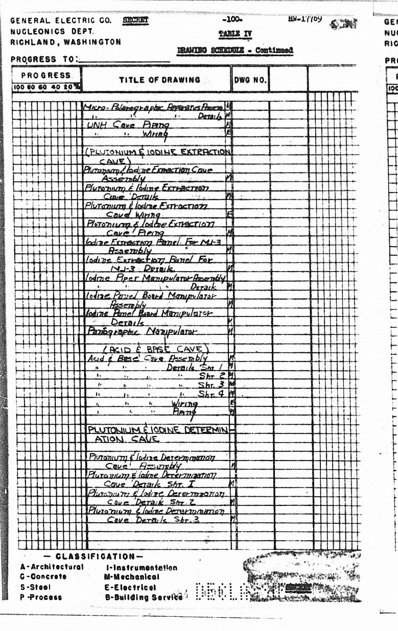
GENERAL ELECTRIC CO. NUCLEONICS DEPT. R ICHLAND, WASHINGTON
PROGRESS TO:.__________
- 100-
TAELS IV
HV-lY7 oy
IfiAVUO acaongg - Coutiaa®*
LPRO GRESS
100 90 90 40 10%
T ITLE OF ORAWING [DWG NO.
UN(~! Cave PiPt£ k m /y .
V A ttn
[Pluto vmivi ^ g K re o m o ^+4C 4 U E
°fuTa^nrr^ J h d - 7t f ftTM cTIOTJ C n u t*A^r\e*~rn£>/y a
f l u T £ n w m i . i f a d i n t - E t t h S t c im i -C t i k * . . . 'D t t u k
T T44 -
P luT <m tcm ) ^ (c rim e F ^ ry -n r-n n -yyC a i/c ______
P fo r6’* H j - m f iT W f- T l^ in
44- d is i / 1* * P ip tinA i-tor FtTtnacTNn^ Xw /~ /tp»- A i7 -3
4 rH R ____ . f f c z t n i t i l y --------------L ._____
/(uJiTi-e. C x rn ^ fto 7 7 F$m?irJ Fab-Q x i m U Is 4-
( ty jm e F]j > e .r [^ [m itp u /n T to b ’ ftx sc+ n llifO tra ifz .
io J l'* 4 L p B ‘i } e j B c - irJ In 73h
h4
if (id iTie M B t^/P oIo T‘ D graz/c ^
. f k i & y ts p ix t . . M ^ T u p J s m r .
/ R c ' p c w i jf ^ E s s . ^ 3kSL Th 6 /^ r
S * r gShr. 3
ii___S R 4 T
i t e tr f- t -r 4
E^UTQMlUNV £ \O DlUe ftETEgUtVl AT\OM . C A U L ________________
P/isroniLny fIcJrtia /)e r <f >-7 man nr?Cqc/g' f - j r ' . im ib / y
P f(iT C > f- iC d /T )* ' D t T t r t T f l f r T l C iT ?
Ootyg 0^73tJc 5 R . Xp J ijrr .T i'it T r; f j 1’ad'nrrf. Dr*rehTnrttQTf37]
C Due*________ A n f r . __________P i i j i c t ' r i U i - n ] C f tx lt iH * . D t * T L * b in f V f r r i 6 7 }
kL S h r <L 4
■Cay.e. b c x & u l^ . ^ h r * Z
- C LA S S IF IC A T I O N —A -A rch i tec tu ra l M ns t rum on tc t tanC -Concrete M-Mtchon lco lS -S t i« l E -E lo c t r l c o lP -Proc0&6 B-Bu i ld ing Serv ice 1 ?i:n )
• ••• •

lH ltH lllHm»inii.iw i..i«^.»i>ii)'iin>»-> pi'.l * n ) in I . . I , ii i i i i il u 11 it t- t ir
GENERAL ELECTRIC CO. fflPPBP NUCLEONICS DEPT.RICHLAND, WASHINGTON
BW-177&9
PROGRESS TO L
PROGRESS 10010 eoTo
m m m s c u m • ceptua»a
TITLE or DRAWING DWG NO.
B u m u ia y
ELoaC * c L
jQkul
G L O JC D HQCfo A P B M C K IU S
f e r r Ekk.fhucmbl'f j j h -----zpcIdACCL
S h. c
D^*raiJ% "**CL i L t *.C k n tk U M f
C k k t t i f r iH f * . . T uA a £ a z kU tJA T S A\‘?r(FT7?r*
* - + ~ - • 1 * 1
' / » Q M i CT^i r -» AO g w C uSJH
\ H k k J S t e 2 .H luQ rt3pJ izr2 iaar£<C iJM H
tZ .lrtrfr i Ncynd F l t>JT)Q \ „H r^ ej t ‘J~nO ‘F .R <!T f 7. r f iM b n o A ^ 'm -rv y r tr /d OMU
f ja y ^ d - M a u s L -W itin o ._________'G77R* £ F1ljt\kgc4'<~. T flTr? $THC UKJH
__________________
WU^CFAJLP^Va^Q L I^ UPPfrfcttTMC
(pLP iST.C T L V T R g Q ^ U \ P K L H T
A f tk /e / *
V
J L
- C L A S S IF IC A T IO N —A-Arch i tec tu re ! M netrum ente t lonC -Concrete M-MechanicelS-Steel E -E lec t r lco lP ^Process B-Building S erv ice
• >
- ■» -4
" 1~
f - * — .
’ — ^
v**t*

PROGRESS T I T L E OF DRAWING
L?ubul±JH&mrcaajtc>c . ^ r
CoiirflTmTinTjuaf CuUcic H irer
C g y ry i^ ir&r^ J . Cukt>l\
OohTti*n m a t e d L.Vy ivaarciSwj^£jA
GENERAL ELECTRIC CO. NUCLEONICS DEPT. RICHLAND* WASHINGTON
PROGRESS TO:
S3E - 1QC- W*»TT«>,
W TT
BRANDO SC im ia * Cent lmicd
- CLASSIFICATION- A-Architectural f-lfi»tri»ainta!loriC -O o n c r t l t IMtocfconlcotS - S t « t l E -E U ctr lco lP -Process B-tiultdln? Service
I

t t e J I l x
W & -
t,,.a v S - ' v •
■ . r < r « v *
•>
; 7 , x ^ r ^
M$m m -- - . . . . - .H "
4 *
.1
C L AS $ IF »C ATI OH' J ©A-ArtH I I«c foro l M na t rum en le t io f i .C -Concrete M-Htchon lca l ' : ' \ ; * . *S - S U t l E -E l«c t r lc« t ^ r j . : i i i •/>.'. 0r» r»..............- Q ft t w i c e V ’ *"• - - ^ V i

ISECRET
I«
-104- ' Hw-17769
TABLE V
wjmmm design status
Major Items of Installed Equipment A. Cubiclo and Sample Storage
1. Support
Status
Complete2. Steel Structure Complete3 • Service Piping 50*• 4. Electrical Wiring - Lighting 1$5. Ventilation 1%
B. Spectrographic Arc cava 1, Stool Structure 2# Disposable Spark Chamber 3 # Chanbor Positioning Device 4. Elcctr5.cal Wiring 5t Radiation Lock for Dumping
C* Cubic1 o Air-Lock & Arcing Cavo Doors 1. Doors & Operating Mechanisms 9$2. Electrical Wiring 501
D. Decontamination Cave 1. Steel Structuro Comploto2. Sink Details Complete3 • Service Piping Complete4. Electrical Wiring See Cubicle
S. Transfer & Determination Cavos 1. Concroto Support
Wiring
Complote2. Steel Support • 1%3 • Steel Structuro 1%4* Sorvico Piping 5<#5. Eloctrical Wiring6. Load Glass Viewer Complete7. Vontilation 1%
F, Glovod Hoods1. Stool Support2. Wooden Structuro3. Metal Structuro4. Sorvicoe, Electrical & Ventilation
3(E, 4, 5 & 7) So© Above
G. Dccontanination Sinks1. Sample Carrier Decontamination Sink Support 80$2. Sample Carrier Decontamination Sink Glovod
Hood
SECRET•• • «
• «, • ;• • \v •

7
SECiOl'
II.
III.
-105- HM-17765
TABLE V
BQUIR-ffiNT DESIGN ST/JUS - ContinuedStatus
3. Service Piping4. Electrical Wiring5. Ventilation6. Decontamination Lise Sisk Frame and Support 75$7. Decontamination Line Sink Do tails 75$8. Gloved Hood Structure 75$9. Service Piping 75$10. Electrical Wiring
H. Stainless Steel Hood Exhaust Filters1. Filter Box Details2. Filter Cartridge Details
Major Items Installed Aftor Building Completion and Items Requiring Outside Design & Development
A. Bono to Control Transport System (Guides & Rolling Stock)1. Guido Layout2. Guide & Switch Modification Details
Fltahod Tractor
9. Traileri
B. RCT Control System
1. Master Control Board2. Local Control Boards3* Automatic Airlock Operating Circuits 4. Automatic Sequence Selector
C. Cubiclo Periscopes1. Station Viewing Periscopes (3 types)2. Plug Type Periscope (2 typos)3* Overall Cubicle View Periscope 4, Overall Tunnel View Periscope
80$5$75965$1%
By Inst. Division
25$15$15$
Itom3 of Do termination Apparatus - Installed After Building CompletionA. Vertical Lift Mechanism
1. Assembly and Details 60$2. Eloctrical Wiring
B. Sampling Apparatus1« Pipot Operating Mechanism2. Pipot Changing Mechanism ( 75563. Electrical Wiring
SECRET
i n • ••*
11 » »•« •••• •»• • •. «••». ••
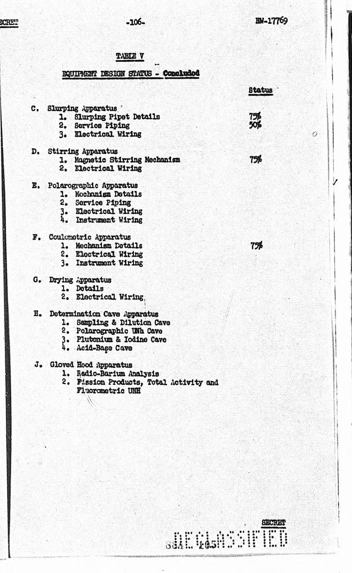
106- Bf-17769n
TABUS V
EQPIPMEHT OSSItaT STATUS - Copolndod
S ta tus
C. Slurping Apparatus ’1 . Slurping P ip e t D etails 75J&2 . Service Piping 50jt3 . E le c tr ic a l Wiring
D. S tir r in g Apparatus1* Magnetic S t i r r in g Mechanism 1%2 . E le c tr ic a l Wiring
E. Polarographic Apparatus1 . Mechanism D etails2 . Service Piping3 . E le c tr ic a l Wiring4 . Instrum ent Wiring
F . Coulcxaotric Apparatus1. Mechanism D eta ils 75$2 . E le c tr ic a l Wiring3 . Instrum ent Wiring
G. Drying Apparatus1. D etails2* E le c tr ic a l Wiring,
1
H. Determination Cave Apparatus1* Sampling & D ilu tion Cave2 . Polarographic Vtth Cave3* Plutonium & Iodine C&ve4 . Acid-Base Cave
•
J* Gloved Hood Apparatus1* Radio-Barium Analysis2 . F issio n Products, T otal A c tiv ity and
F luorooetric UKH
• «::S8ALlii5 i#!.!J
• M l
• ••
SECRETt ••• ••§ « « • • •• « *:: : s• <M
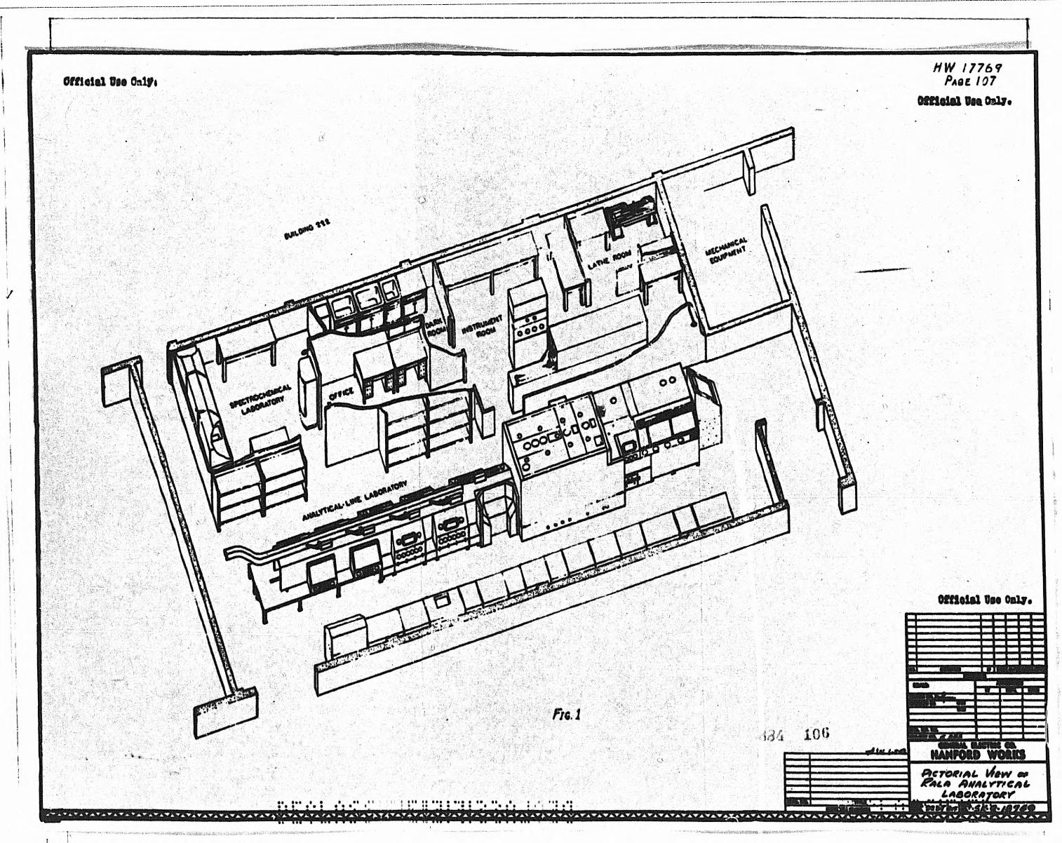
E• • ' • " • • - ■ ' ■ " n r i m i i i »W.‘« T ^V ItW
Official Oia OnlfiH W 1 7 7 6 7
Page 107Offtalal U«a OaUi
/
I !
j t ik 1 0 U
* -
Official Oh Only,“
i .......B 1i ......... . -™m1............... -.mr fLl_— i i
&CTO*tAL \A*W m Jrsu* fhtAirrrcAL
LAAOffATOXr
fVVVV^W^i^W^VW.VTOggs;1

*
MCTfWMI
, -7 v*mi -•<.' '*T
m s g s m i m m *®mm#v SAMteBQ . ;9 AM H J?y t& C W rV M tT JO N ( SAMPLE, O ISP tSSM ] C **m**m a v W?W :m X M g % j& ; l •-• M m iS S c a K M o a /wsmw/ovtf r.y • -N-r**- • 3 <■ '
■ v ,t, :.xP* * . v
mskmh
\« m{
> Y * . * v - . t -
■ ■■■:; -;'A- . V' 'Y. S ife Y£# if ' • V'i.nV'i& \ ’ iYi* « !& TM jS
HW/776?Pa h s /OB
UmtiAsstF/ep
«. * ‘- »• -/y-.-tf:.■ . ' ' :
• *■ ..?•**:. *. :V- ?..
•-•X--'?V
cw rxoL ahMbl
AfflU YT/CAtv L/NEstAtm. y#V -
T/MC7V& TM /LEP FLAT'JS/tO
REMOTE CONTROLLED TRANSPORTSCapppox iM /x /u t.) ’ i —
v: ■. ;■
,- i ■ ■ ' , 11 ' ^ . : ■' t J-i 4 , .•... ...•- -• t '• . __ -t.____ .. -.
.... -
1 ® . - . . w , ;V ' L. ' - A *, ; • ■■ ■ . ;■ ••' (* * ' '.*/* ’ *■ %xi. . ■ !- -:- "T"p *••> ■ ■ •i.v ' V>a f -*■ ''-■■ " ! -r f
\ .'; >.},}- Y U : - ; f , . ; ■■::/[;■■, . • v.... .• V j ' ilrS*' i'lf
f .’ {"1'
S a S f f ir ~ iC •• vS W hON *~wT w n r t
1 . • ! m ; a * £ s t N c e m a w » m s W ffiK M S ^
HANFORD EN6INKR WORKS
3 K E T U 1 " ;■ / 9 C 7 " i5X5
a6VT. i; IMS
' in F ’ . _ i f - . . . ■.
W ...
• I W n a h '
—J—
i

^tfcsjsnwsfcflscamatsms* -•MNT**! t
omolftl Oat Only.
t ' ■• v » . > y v' y,//m. ' VNy
=M
ussjaa A - A
//W 1776 9 Page 109
Offloial Uaa Oalf•
ii6 -j ICS^M clU Oh Oily,
P i C T Q g t A i , & r r - T i n R i ^ Q F M J - 3 C U B lC l P
pgAvw «t-C4TC|w*» H n '•• ?. • •1 • “TT™T^nnr" • • ; . ^

r**»l

r vmji/um. 4 . ' ^M. 1
r w w 9 ^ « A N U » MW&V'-'*-'

r•"*■ *' ' l • >' “i *-j*syrnri • .
wVs****' ' ,-; -:-.'*>-v '-% v: -
l U
HYJI7769 Page. 112
Unclassified
*u » : s
gg 77777^1 - vS/rTif/ i / / J9B
HANFORD WORKSrmrrtp/c or arramwirmiCAVCfirUDY, fZ>P HJ-3

W tt& iitS iC a lau'
—-i
J- / C •* \
-V
.*•■•;• »v \ • * fc' V * v
; r V ••; •; : .-V - t '-: . ' '
\ * . i• •.*•.; i :- -V '
//H/ 1777,7 Pace 113
U nclassified
T * * > :<■i « '<• j
? A ’ r A T A V A T A T j L T A i A V A V A T A T A V A V A V A T A T A T A T A T A T A T 4 W A ' » A ^ A V A ' »
•vS *
s

I
r ------ C U X . T S Q & L . J f « .«***!v . mcnmt.mtium,
U*i■n* + * * ' v ~ ~
*
• ••« ► * *..!..

m*
■ f*
i
Y*rht0j Motion Mtcffontom # ' 2 ' t iT lo i H l ' i i t l t
• <=LA M P L E
— h e . ' • -
s C a m ctfcS rAnofiJ < *
D i s p o s a l - S t a t l o w
V 7 /■ /= > * 9 SIC- 2 - 1 3 1 4 )**! I»«>. <•■»«■• * * * 3
hW
17
76
9
Pa 3£. i£
Undnsf/A
/to

V arhco t M e d ia n M ec A tm ism ii H ' t ' t i n o t * * * * / * / * / —
. . . . .M 'C ro Cov/of»efrtc Apparatus P u rs e r ' *• H ' i - f B T l i
• «
• X&*!••• t—:* io •
P’lO. JO
N t * . t \ i | x \ | f y
C u B iC L E - Sta tv o u a
M.'cb o - Cou L O M E T e /c A p p a r a t u s
S f c - 3 - IQ742
4
i

••■Hi*-"* .............. .... . . . - . . . . . . . . . .... . .. .. . ,” ...... r
•• *•
C! • t ' i >*
» . / :
Mrr: • •
• • • «
B u re t Typ* P tp e tY e r. P/pst C h m p in f S tock
rsk-z-min, Sk-t-/87m £ s * - z - tA 7 i* n
Pipe Yat/S* S' "(4 -{£)
( S k - Z - / 8 7 Z 5 J
)/?'*/?<t f tpatnm kfech^nism (H~2- m7Z0 £ H T / A l l t l
r , o . //
JURICLCS tatio n s 3,6 f /« f
P u im a p y Sa m p l in g , Secondapy S&mpumc. t Plutonium ( looiwe Det. Cave
SK- 2 - / 8 7 4 0

sp *5 *£ ' f Nr * n5 & • %to
O E T C R M iN A n O N C * * *Station 19
D IL U T IO N j S A M P L IN G S '*
$ K -2 - 18 7 4 3VHK 1 Jr* : S
a iw M * (

I
Peoqent Rock
H'+HTJOVert Mahon Meet) Rmi mt$7iL
SunfT ype* Hf.et'tor f t o p t O b**# ,*.? & /*€ *
£*-±-'87/7. S*-±-/£//o. /*S<-± m48T/7Sarvpfe Disposal
AsZGrr?.______- - ^ - ' 37^5 y H-?-/5730
I'.!!, Support Shf/vet
■ t
&■"
I r*H-
M oyntfic S tirrer 1 H-e-J8T/6
R e a g e n t__R ackmi&L ?{****■ A&;/ tj)J£4'-2 -/872£
■i t
Ptoet Rock
Air Ovfvmtt Jh'rrer etIodine Centri/ofol
f#*9 ‘ _Iodine Pone! Board
Ptfitf Col!c?1H-l-lA 7+a
HooK Manipulator
P ip t l Morn puio+or
Bottle Moeipulo to r
D e t e r m in a t io n Ca v e £ £ ^ St a t io n i,4 ^ ^
P l u t o n iu m Ex t r a c t io n s Io o in e V<Z E xtractio n $ ^
SK-2 - 1 8 7 4 4 -. 'i> ■ i‘ o
f— *.. (4H H D
I

OBCUSi' -320-
STATIC® 16
#
A. Vortical Motion Mechanism:H-2-18720, E.2-18721
B. Air Driven Stirrer* Twin Shaft Typo;B-3-M56, H-34157
C. Plpot Back:SK-2-18722, SR.2-18723
D. Iodine Extraction Panel:Rough Sketch Included
E# Control Panel:H-2-18793
P. Bottle Back:Aloe #18232* 6 plaoo s.s. bottle rack
G. Canplo Disposal - Plpot Cleaning Assembly; Rough Sketch included In report on Station 9 (SK-2-187V7)
H. Variac:5 Angere Variac
I. Modified Drying Block:Originally 0* E« Schenectady Works Drawing M-5a-455 Modified As Per A* a. Tanga on September 21* 19 9
J# Waste Carton£• Micro Buret:
Aloe #20-110* 1 nl. Site* Koch Micro BuretL. Distribution Panel:
B-2-18792M. Dispensing Rock:
Undetermined
HV-I7769
SECRET

D IS P E N S IN G MS A C K -
d is t r ib u t o n p a n e l
• l '
ps- M/cffo su«e r ^
• ••• i « • •
• •* ••• «
* * (
w a s reCARTON
(A^) ver tic al n o t io nMECHAN/SM
m o d i p ie d
ORViNG B lock" * i :
JO.
uv
c
V C R I AC
AIR DRIVEN STtRRCR
£ y P /P E T R A C K
fP ) ' IO D IN E E X TR A C TIO N PANEL
! * ' ^ 3 / ^ ' v > v V / I
:> 4 ■ — M - 'F
CONTROLP A N E L
BOTTLERACK
G SAMPLE* d is p o s a l -P/PET CLEANING ASSEM.
; * > :
F ig. J4
G l o v e s H o o d S TATIOkl / 6 - - j
lootuc E yre a c t /ok/ f Pl u t o h iu wD/SX P Z E P A R A T IO k l
S K -2 - I3 7 4 S
H ~ 0\ 0

• * *• • • •
• • » •
:• t •
• i i . . . . . VW% « •a*• ♦ »• «
VrX i * *0
0&*+ASUy & / / / * *
i/fader*
{*+.■£ / * £ & 7 *1 * f i n k
/^ r P: ,+* tA/fttfk
t f s j r t T Y c S ? " r t rc — ' ---------------- ••*
PVj s / ’iP S a r / f / v
jr" & //s
d L S 'i‘ ’ i ' .4ytr.i W t l - ± X ±
____ i > S+n/ * i j
4 ’*• AvutU* Tmi*
2 Shfauc" " " ■ %/r <+ ....■■■—■■
A'0+ t /?**:& rsfS- •s&TJtXWMyjizJ
S 3*w /» /« & h p o % Q I A s a • n » .
wWW / “
C9«rr*l &s>H■ ^ '- r - a w — >'-W
Zay fcy*
i v<w f/?.<* */82J2
. A i r i . s c X __________
* ^
5 t.
/=/<$. Z5-
Glo v e d Wood Statio ns it, la A s o
Ba r iu m
S k - 2 - 1 3 7 4 6
8E
/ / . - / vK.4, ftiSaWH tefeNfyH

SECRET 123- HW-17769
Simon 19
A* Plpet Rack,SK-2-18722, SK.2-18723
B. Slurp - Plpet Cleaning Assembly;Sketch Included
C. Control Panel,E.2-18793D. Bottle Bach -
Aloe #18232, 6 place S.S. Bottle Hock
E. Stainless Stool Floor Flan:‘ H-2-18774F. Waste Carton -
Ice Croon Carton
0, Tissue Wipe Dispenser - Ufadeterninod
»
Ew Evaporating Incp - Fisher - Scientific Co. #11-504-5 Drying Loup
1. Supply Rack:SK-2-18724J. Angle Iron Supports -
Undetermined
K. Distribution Panel:E-2-13792L« Reagent Lines -
Rot Determined (May Be Lucoflex)
SECRET«• ••• :• •«
»« • i>« • •••• •

KEAG ENT LIMES
DISTRIBUTION PAMEL
1*1 PET PACK
> SAMPLE DISPOSAL- r CLEANING ASSEM.
C , CONTROL PANEL
D aornePACK
£ STAINLESS PLOOR PA N
WASTE CARTON
G l o v e d H o o d j j *
S t a t io n isF l u OROPHOTOMETP tC U N H , TOTALSActivity And Fission Products * *
SK- 2 - / S747
J u S l* * ' 4- / * - * *

u j c v r e . sAaupgg.
S ample
(
P lP C T S , DETAILS 0 ( | ) @ ©4><-z-\enzs~
- g i g g - T H O L O q g , i s ie ^ p p .^
iaOM C O B E
r r :L il * K K I M \ M a l<f Y* * * • « % c ^ H r t « i . „
I ^S f * «■» fn v j
b , J ^ C K
/ ^ e o p o s p o _ f i , a t p e p g Q ^ P H g N r h o l o e . ^
S » C - S - i B 7 4 a
■ Jk .* ^ . / r - s o
■iMWirtJWWri a .i't.TDWii'.iiiiiBMiaa* n m w * — » ——• - •»

m •tistcui t JVC aw A & A -* < - CMt W A
STATION LAYOUTn - i lJ K n &' c ; ; , ?• - MM
' m . i

4,;iv
a
M / » M « w<• A i v «
d f a rr# /t » / n a»/// k OQ*t*¥hr •4 <VHr/ra
JkmC'tyita4#.4r4
. f
.4 9I ** *< «
•4T>
/ f . / fif« i4 /
2//
. /' /
//1 / / /2 £ / /45 t £ / 4
StlLDturtfiftoa
Vertical M 4#|/ 5 « i tUemtor s*r** <?*i+ h o c k p h t* fhwrttcofl C f a w f o r $e/V*v
. . . .O r _ M a t j * i a i
. ■/'?•.
i ' W f4 | ?*«•»/*
MatV a tsi
r$S r a t $Dvr ofC *
^ f s m a r k st f " 8 m /$7Z f
tSnterShUt<kM*Shi* Dvrvt MfrrtMWV-St* M*+*t ■ *HofonQotd* Ptvt* •Hot** MovttMf Ph* . 'M*f*rQ«4k Corphr **CavpkrfVf . -L*<A****trf*bbrM*i S*ft Sc {* *4/414//C/-0 JW 4 9 / vT«/»*r ; - * #&4e4r«v»0A>rAfcA .' - 4r£lAficnSmtc*
m
% 4'**hs: *•4'4* t / f Y •£*#•«/#> - *
• -
S * * t m tfr * * f v £ 7 | #
££ 4 t l 4 W 4 I I 3 f » 3
Moontirtq Strew - 9*j ^M*t*rScrew ( h k tm tc) m */*» mUrcw%(Mt$.fMd m rt**mS e a s * m + M c * } «. •9 tn ~ (6 o * t m t* i SHX 4/*A *4 | /*••U t another/M h+rM ri; |* « / //!#•5<rc*o • * . J *•>/**/ 4 .4#
»*s
f. , ••*«■#* I 4/-t vA/4 1 AA. 44> /s / . a a
ir.$ * $ " ( &
/47t4• 4 4 1 t e :
7 W 1 7 7 6 9Pm e 127
U f f C L AS S l F t t D
I' I
n m c f r .
/. r I r f f l
h tr ttr v *rhee/a*h*4>
Ha n f o r d w o rks
M J-3Vrmr/CAL M en cm M r cm
AtUMMLY i 0 /u Or Mat
M tlll-Tint.szszszSkSSZSSSSSS ^ ^ faSZSszi z!4 * *’r
|S r / /-2 - /# ^a z w a:•. .*• • : : • • :. ::« ::: : :* : s • ; ; ; ; ;>!.• !,. v *f» •• 1 ,„•»• •

SECRET 128- Htf-17769
BIBLIOGRAPHT
REF .HO, TITIE FROM «. TO DATE BOMBER
1. The Effoots of Badia- tlon on Electronic Equipment
P. R. B e U to File
8/25A7 BAB-270
2. laboratory Equipment Blueprint List
J. X. Figonshau to B. K. Curtis
6/2/48 BH-9093
*
3. Minute e of Gloved Box Discussion Mooting
M. K. Harmon to File
12/20/48 EW-11962
if. Bala Project Specification Letter Ho* 2 k Health Instrumentation
0. V. Golset to D. D. Streld
5/26/49 HH-13490
5. Bala Project Spocifica- 0. V. Smisct totlon Letter Ho. 35 Special D. D. Streld • Instrumentation
5/27A9 HW-13510
6.«
Bala Project Specification Letter Ho. 3s Baubling Requirements
0. V. Smlset to D. D. Streld
5/27A? KW-13517
7*
■ «■*».
Bala Project Specification Lottor Ho. 36 Analytical Equipment Requirements
0. V. Smlset to D. D. Streld
5/27 A 9 HW-13523
e.•
Bala Project Specification Lottor Ko. 60 Hotioe of Completion of Preliminary Specif icationa
0. V. aaiset to D. D. Streld
5/27A9 HW-13526
9. Rola Project Specification Loxter Corrections
0. V. Smlset to D. D. Streld
6/17A9 8M-13685
1C.
X
1
Test of Dense Concrete vith iron Punchlngs for Cave Construction
Donald F. Oacfcir, 7/llA9Kenneth B. Ferguson,Dudley G. Seay, Charles B. Webster to S. L.Hull, Director
ADt-4319
•11.
•
Bala Sample Sixes A. I. Bushey to File 10/24A9 HW-14061
12.••
•
•
Gpocial Equipment Devolop- D. V. Pearce to Filo nent Bala Analytical Laboratory
10/24 A 9 HW-14062
*SECRET
'
4 • • • t. 4 • • • •1 • • • • •
t 1 • • • • •. 4 • . • • 4 •
• • • « • • • • • • •J J S t : f f l
»l> A . 1

SECRET - 12? -
4
HW-17769
BIBLIOGRAPHY - ContinuedREF .NO. TITIE FROM & TO DATE NUMBER
13* Request for Shloldlng Calculations and Calculations of B.T* U,. Produced
0* E. Halm to J. M. Promo & John Veeks
11/1/49 BDC-1496
14. Status of Rola Ano /-- tical Methods
A. H. Bus hey - D. F. Shepard
11/9/1*9 W-I5O3I
15. Equipment and Space Re-, quiromonts for the Rala Spoctrochemical Facilities
J. A. Parodi to Pile
11/14/49 HW-15079
16. Minutes of Analytical Section Mooting Rolating to Rala Lab orator:/’ Dosign
0. P. Amackor to Pile
12/6A9 HW-15304
17. Rala Analytical Mothods - Progress Report I
D. F. Shepard • J# M. Fouts
12/15/49 HW-15409
18. Minutes of Mooting Relating to Rala Sailing Equipment Design
J. M. Fouts to Pile
12/16A9 HW-15451
19. Olovod Box Placement in Rala Laboratory, Bench and Canopy Arrangement instead of Hoods
. 0. P. Amacker to P. 0. Tobb
12/16A9
20. Sanplo Storage J. M. Fouts to J. K. Figenshau
12/19A9 HW-15501
21. Time Schedule of Rala Analytical Equipment Design and Development
W. M. Harty to D. V. Pearce
12/22A9 HW-15483
22. Minutes of Mooting Relating to Rala Sailing Equipment Dosign
J« M. Fouts to Pile
12/28A9 HW-15527
23# Rala Laboratory Equipment Droving Schedules
W. M. Earty to C. H. Bolt, Jr.
12/30A9
24, Cloved Box Placement in P.ala Laboratory, Bench
J« M. Smith, Jr. to J. M. Pouts
1/3/50and Canopy Arrangement Instead of Hoods
SECRET•• ••• •• • • • •• • •• •• • t •• » • • • • • • • * «
m • • • • # • • •’♦ ! 5 •. * r> V'• fc * J • • ' '■>• • • • »»•

SECRET -I3O- HW-17769
BIBLIOGRAPHT - Continued
REF.NO. TITLE FROM & TO DATE NUMBER
25. Reply to HDC-1498(Request fo r Shielding C alculations and Calcu la tio n s of B.T.U, Products)
J , L, Weeks, J r . to C, H. Holt & G. E, Halm
1A /30 EDc-1576
26m Construction of Cheap S h ie ld s: A Survey
Theodore Rockwell, I I I
1/16/50 ohil-243
27. Rala A naly tica l Laborato ry - Design Manpower - Requirements
D. W, Pearce to T. V. Hauff
1/24/50 HW-15761
2C. Sampling of Rala Solutio n s
H, R. Schmidt to A. H. Bushay
1/24/50 nw -15762
29. Prelim inary 1IJ-3 Labo ra to ry Drawings
W, M, Harty to C. H. H olt, J r .
1/24/50
30* Rala Shielding Calcula t io n s
D. V. Poarce to W. M. Harty
1/30/50 HW-15820
31. Proposed Stuqplo Flow Through MJ-3 A naly tical Laboratory
W. N. Carson, J r , - T. J . B irc h i l l - A. C. Weyerts to F ile
2/1/50 hh- 15777
32, R ala P ro je c t S pecificat io n L e tte r No, 21, Rev, 1 , A naly tical Space Ro-
' quiremonts
W. M. Harty - 0 . V. SmiBet to C. H. H olt, Jr*
2/2/50 Htf-15870
33 • Woekly Mooting Minutes of MJ-3 Contact Engineoro Group, February 2 , 1950
0 . V, Smiset to F ile
2/3/50 m - 15873
, Rala A nalytical Laborato ry - Design Progress
J . K. Flgenshau - J , M. Fouts to F i le
2/8/50 HW-15918
35. P ro jo c t C-3^3-MJ-3-222-T Laboratory Addition
E, W. Sackondorff to A»E• C, , A ttnt! R, W, Stuck
2/8/50
36. MJ-3 A naly tical Laborato ry Design Raviov Comm ittee
D, W. Poarco to A, H. Bushay, L. M. Khights
2/14/50
37. Rala A naly tical Laborato ry - Design Progress
J» K. Figonshau - J , M. Fouts to D, W, Poarco
2/15/50 HW-16060
• • . \ \ x. i ' i ; •1 1 « v • •»»1 * ♦ • • * • •« • • • • • • • 1
« • • t ».» •
: m s• l • • •
SECRETtl\\t '
V**W

SECBLT -131' HW-17769
BIBLIOGRAPHY - Continued
RDF .110. TITIE
38. MJ-3 LaboratoryCubicle Design, Procurement, Construction and Cost
39* Minutes of the Third Mooting of tbs MJ-3 Analytical laboratory Do sign Review Conmittco
40. MJ-3 Laboratory Shielding Calculations
4-1. The Cculometric Determination of Acid
42. Rala Analytical Laboratory - Design Progross
43. Mooting Minutes of MJ-3 .\nalytical Laboratory Design Review Caaaitteo, February 17/ 1950
44 • Iodine Determination for tho Rala Project
45. Rala Analytical Laboratory RCT System Remote Control Requirements
46. Minutes of the Second ! tooting of tbD MJ-3 Analytical Laboratory Design Roviow Camnittoe
Rala Analytical Laboratory - Design Progress
Rala Projoct Specification Letter Ho. 36, Rov. 1, Analytical Equipment Requirements
Modifications to MJ-3 Oubicio Facilities
FROM & TO DATE NUMBER
W. M. Harty to C. H. Holt, Jr.
2/2lt/50
E, M. Kindorman to D. W. Poorco
2/27/50
D. W. Pearce to J. L. Wooks, Jr.
2/20/50
W. N. Carson, Jr. - Roy Ko to File
3/1/50 HW-17dt6
J. K. Figenshau - J. M. Fouts to D. W. Pearco
3/1/50 HW-17131
0. P. Amackor to D. W. Poorco
3/3/50 HW-17095
W. H. Carson, Jr. H. R. Schmidt
3/7/50 HW-17090
W. N. Carson, Jr. to File
3/10/50 HW-17160
P. F. X. Dunigan to D. W. Pearco
3/15/50 HW-17231
J. X. Figenshau - J. M. Fouts to D. W. Poarco
3/15/50 HW-17309
W. M. Harty - 0. 7. Smioot to C. H. Holt, Jr.
3/17/50 HW-17254
J. M. Pouts to J. M. Fox, Jr.
3/22/50
M * « » 1 «• • • » • •• • • • • «* • • « •• • • • • *•I »♦» ■ •••
t •• *•*»•!: ; *. •. »•: 1 :
SECRET* 111 *•m:
»

• * » i — »»<•*-»» m-..■«■■»««ftw1****— v ,f »•—v — —■/—*-** -*»—-*»**»r
SECRET -132- n u -17769
BBUOGTAHff - C ontinued
REF.IIC. TITLE FROM & TO DATE NUMBER
5 0 . M o d ific a tio n o f MJ-3 C u b ic le F a c i l i t i e s
J . M. Fox, J r . t o - J . M. F o u ts
3 /2 3 /5 0
51* M inutes o f M eeting on 222-T A dd ition
J . M. F o u ts t o D. W. Poarco
3 /2 3 /5 0
52 • M inutes o f th o F o u r th M ooting o f th e MJ-3 A n a ly tic a l L ab o ra to ry Dosign Roviow C o m itto o
D. F . S hepard t o D. W. P ea rce
3 /2 3 /5 0 iw-17334
5 3 . M inutos o f th o F i f t h M ooting o f th o M J-j • A n a ly tic a l L ab o ra to ry D esign Review C o m itto o
0 . p . Amackor to D. W. Poarco
3 /2 4 /5 0
5 4 . I n v e s t ig a t io n o f MJ-3 Labo ra to ry C ubiclo D esign , Procurem ent, C o n s tru c tio n and C ost
J . M. Fox, J r . to C. H. H o lt , J r*
v .
3 /2 7 /5 0
55* Sas^plo S ica s f o r th o MJ-3 P ro cess
E. M. Kinderman to H. R. Schm idt
3 /2 8 /5 0 HW-17356
5 6 . MJ-3 L abora to ry V e n t i la t io n Exhaust
J . M. Sm ith to 0 . V. t ta is o t
3 /2 9 /5 0
5 7 . R ala A n a ly tic a l L aborato ry - Design P ro g re s s
J . K. F igonshau - J . M. flou ts to D. W, P earce
4 /1 /5 0 HW-17397
r e . 222-T L abora to ry A ddit io n Program
C. H. H o lt , J r . to E. W. S ockendorff
4 /6 /5 0
t \ M inutes o f M ooting on i.CT' C o n tro l System , MJ-3 L abora to ry
J . M. F o u ts to L . M. K nigh ts
4 /1 7 /5 0
6 0 . Radiolantfaanun P r o je c t F . G. Tabb - J . M,S p e c if ic a t io n L o t t e r Ho. Sm ith to C. II. H o lt, 2 4 , Rev. 1 , H e a lth I n s tm - J r . m en ta tion
4 /1 7 /5 0 hw- 17559
6 l . MJ-3 L abora to ry S h ie ld in g C a lc u la tio n s
J . L . Weeks to D. W. P e a rc e
4 /1 7 /5 0 HDC-1735
6 2 . r .a la /A naly tical Laborato r y - Dosign P ro g ro ss
T . J . B i r c h i l l - J . M. F o u ts to
4 /1 7 /5 0 EH-17580
i
D. W, P eorco
SECRET
: / L V i ' n S & M i U L . i . :j I <
$
HH
6;
61
6;
6

ft V. n««» w —
. T
SECRET HW-17769
BIBLIOGRAPHY - ConcludedREF .NO. T O T E FROM & TO DATE NUMBER
63. Feasibility Stud;* of the Proposed Renote Control Transport System for the Radio-Lanthanum Analytical Laboratory
R. 0 . Hoff to D. V. Pearce
4/19/50
>
Hw-17567
64-, Appendices I and II to Document Ho. EW-17567
R. 0 . Hoff to D. W. Pearce
4/25/50 HH- 17582
65. Cements - C -343 Cubicle Drawings
J. M. Fox, Jr. 4/29/50
6 6. Rala Analytical Laboratory - Design Progress
J. K. Figonshau - J. M. Pouts to D. W. Pearce
5/1/50 Htf-17656
67. Analytical Control Monthly Report for April, 1950
L. M, Khlghts to D, W. Pearco
5/12/50 BH-17787
6 8, Report of trip to Ob- servo Remote Control Equipment
J, K. Figonshau to L. M. Knights
5/29/50 HW-17818
69, Terminal Roport on the Rodiolanthanum Laboratory, II, Analytical Methods Research and Adaptation
H, R. Schmidt - W. W. Marshall
HW-18150