U- U - - UNT Digital Library
194
/ STATUS OF LMFBR REHEAT IN WESTERN EUROPE--1972 Report of the United States of America LMFBR Sodium Reheat Team Visit to France, Germany Netherlands, and May 22-Jun (FRG), United Kingdom e 6, 1972 Division of Reactor Development and Technology metadc784183 States Atomic Energy Commission -- % A'R/zoOs WASH-1219 A -R O O rc - - r U- U - O O United
-
Upload
khangminh22 -
Category
Documents
-
view
1 -
download
0
Transcript of U- U - - UNT Digital Library

/
STATUS OF
LMFBR REHEAT IN WESTERN EUROPE--1972
Report of the United States of America
LMFBR Sodium Reheat Team Visit
to France, Germany
Netherlands, and
May 22-Jun
(FRG),
United Kingdom
e 6, 1972
Division of Reactor Development
and Technology metadc784183
States Atomic Energy Commission
-- %
A'R/zoOs
WASH-1219
A -R
O
O
rc - - r
U- U -
O
O
United

The cover shows a schematic of the heat-transfer systems for
the European sodium-cooled fast breeder reactor, SNR-300,to be located near Kalkar, West Germany.
WASH- 1219Liquid Metal Fast
Breeder Reactors(UC- 79)
STATUS OFLMFBR REHEAT IN WESTERN EUROPE- -1972
Report of the United States of AmericaLMFBR Sodium Reheat Team Visit
to France, Germany (FRG),Netherlands, and United Kingdom
May 22-June 6, 1972
March 1973
Division of Reactor Developmentand Technology
United States Atomic Energy Commission
For sale by the Superintendent of Documents, U.S. Government Printing OfficeWashington, D.C., 20402


PREFACE
The decision by the AEC to have a representative group of LMFBRsteam-generator experts visit Europe to determine the status of LMFBR
sodium/steam cycles in Europe was based on the need for additional infor-mation needed to determine if sodium reheat could be successfully developed
for the LMFBR Demonstration Plant Nuclear Steam Supply System at theTennessee Valley Authority John Sevier Power Plant. Information obtained
by the members of the team was used by the management of the LMFBRdemonstration plant to help arrive at the final decision to locate the demon-
stration plant at a new site on the Clinch River near Oak Ridge, Tennessee.
The discussions with European counterparts and visits to their estab-lishments left the team members with the impression that the Europeansconsider that a prerequisite to successful LMFBR demonstration and to
commercial reality is a comprehensive, coordinated, and disciplined devel-
opment program with considerable emphasis on testing to the degree neces-
sary for ensuring successful operation of plant components and systems,
involving full-scale testing in some cases, large-model testing in others,
and component- part testing in many cases . Most impressive were the large-scale sodium-water reaction tests being conducted in France, Germany,
and the U.K. and the large steam-generator model testing in France and
Netherlands. Such programs provide encouragement to this country to vig-
orously pursue its program to provide safe, reliable and economic com-mercial LMFBRs, based on extensive development and testing of component
parts, components, and systems using in-depth engineering and strongquality- as surance practices.
The exchange of information with our friends overseas and their
gracious hospitality were most gratifying to all the members of the team
and not soon to be forgotten. The work of Max Weber, of the Argonne
National Laboratory, in compiling and editing the manuscript has been most
appreciated.
John G. Yevick John A. FordRobert V. Laney John S. McDonaldRaymond E. Hoskins Robert S. McQueenWilliam F. Rolf Louis A. SturialeEdgar Rodwell
i


TABLE OF CONTENTS
NOMENCLATURE. ....................
Page
.. . xiv
I. SUMMARY. ... . . ............... .. . . . . . . . . . . .
A.
B.
C.
D.
E.
F.
Status of Reheat in Western Europe.................
Steam Generator and Associated Systems Design . . . . . . .
1. Phenix . . . . . . . . . . . . . . . . . . . . . . . . . . . . . . . . .
2. French CFR Steam Generators . . . . . . . . . . . . . . . . .
3. PFR....... ...................................4. SN R -300 . . . . . . . . . . . . . . . . . . . . . . . . . . . . . . . .
Steam-generator Development . . . . . . . . . . . . . . . . . . . .
Turbine Development for Steam Reheat. . . . . . . . . . . . . .
French Approach to Developmental Testing . . . . . . . . . . .
Sodium-Water Reaction Programs and Test Sites . . . . . . .
G. Demonstration Plants . . . . . . . . . . . . . . . . . . . . . . . . ..
H. Commercial Plants . . . . . . . . . . . . . . . . . . . . . . . . . . .
II. INTRODUCTION. .............. . . . . . . . . . . . . . . . . .
III. EUROPEAN STATUS AND POSITIONS ON SODIUM REHEAT. .
1
1
2
2233
4
6
6
7
7
8
9
13
A. Introduction......... . . . . . .......
B. Status of Sodium Reheat . . . . . . . . . .
1. Status Summary . . . . . . . . . . . . .
2. Status Comparison . . . . . . . . . . .
a. French...................b. British . . . . . . . . . . . . . . . . .c. SNR Consortium. . . . . . . . . . .
C. Reasons Expressed for the Plant-cycle
1. Introduction and Summary . . . . . .
2. SNR Consortium. . . . . . . . . . . . .3. French.......................4. United Kingdom . . . .. ..... ....
. . . . . . . . . . . . . . 13
. . . . . . . . . . . . . . 13
. . . . . . . . . . . . . . 13
. . . . . . . . . . . . . . 14
. . . . . . . . . . . . . . 14
. . . . . . . . . . . . . . 15
. . . . . . . . . . . . . . 16
Selection. . . . . . . . 16
. . . . . . . . . . . . . . 16
. . . . . . . . . . . . . . 17
. .... . .. ..... 17
. . .0.0. ..... ....18
IV. STEAM GENERATORS AND ASSOCIATED SYSTEMS DESIGN. .
A. Summary. . . . . ................... . . .. . . ...........
111
19
19
TABLE OF CONTENTS
Page
B. France.. . . . . .. ..................................... 20
1. Introduction. . . . . . . . . . . . . . . . . . . . . . . . . . . . . . 202. Phenix Steam Generators. . . . . . . . . . . . . . . . . . . . . 21
3. Steam Generators under Development for 1000-MWePlant. ... . . . . . .. .. . . . . . . . . . . . . . . . . . . . . . . 28a. Babcock-Atlantique. . . . . . . . . . . . . . . . . . . . . . . 28b. Stein Industrie........ .......................... 28c. Comparison of Phenix-type, B-A, and Stein Industrie
Commercial Units . . . . . . . . . . . . . . . . . . . . . . . 31d. Les Renardieres Steam Generator Test Facility . . . 31
e. Sodium-Water Reaction Test Facility at Cadarache . 32
C. United Kingdom: PFR Steam Generators. . . . . . . . . . . . . 32
1. Description . . . . . . . . . . . . . . . . . . . . . . . . . . . . . . 32
2. PFR Startup Procedures . . . . . . . . . . . . . . . . . . . . . 39
D. SNR Steam Generators . . . . . . . . . . . . . . . . . . . . . . . . . 41
1. Introduction . . . . . . . . . . . . . . . . . . . . . . . . . . . . . . 41
2. Steam-generator Design. . . . . . . . . . . . . . . . . . . . . . 41
3. Steam-generator Tube Leak and Rupture-disk
Considerations . . . . . . . . . . . . . . . . . . . . . . . . . . . . 484. Sodium-reheat Component and Systems Considerations . 505. M iscellaneous . . . . . . . . . . . . . . . . . . . . . . . . . . . . 50
V. DEVELOPMENT PROGRAMS FOR STEAM-GENERATIONSYSTEMS AND RELATED COMPONENTS. . . . . . . . . . . . . . . 51
A. Summary and Comparison. . . . . . . . . . . . . . . . . . . . . . . 51
B. France.. . . . . .. ..................................... 51
1. Phenix Steam-generator System Development . . . . . . . 51
2. Steam Generator under Development for 1000-MWPlant.... ................... ....... .. ... 53
a. Babcock-Atlantique. . . . . . . . . . . . . . . . . . . . . . . 54
b. Stein Industrie........ .......................... 543. Valves . . . . . . . . . . . . . . . . . . . . . . . . . . . . . . . . . 54
C. United Kingdom. . . . . . . . . . . . . . . . . . . . . . . . . . . . . . 56
D. Germany--INTERATOM . . . . . . . . . . . . . . . . . . . . . . . 58
1. Development of SNR Steam Generator. . . . . . . . . . . . . 58
2. Valves . . . . . . . . . . . . . . . . . . . . . . . . . . . . . . . . . 58
iv

TABLE OF CONTENTS
Page
E. Netherlands......... . . . . . . . . . .... 0 ...... . . 59
1. Tests on SNR Steam-generator Thermal Model atHengelo. .... ... .. ................ . ..
2. Steam-generator Development Test at Apeldoorn(TNO)..................................
3. Component and Weld Surface Cleaning... .... ...
VI. SODIUM-WATER REACTION PROGRAMS AND TEST SITES
A. Summary and Comparison... ............... ....
B. France....................................
59
62
63
65
65
67
Large-leak Test Facilities . . . . . . . .
Large-leak Test Results. . . . . . . . . .Large-leak Mathematical Models . .Large-leak Future Plans . . . . . . . . .Large-leak Test Instrumentation . . . .
Large-leak Test Facility Operation . .
Relief Systems . . . . . . . . . . . . . . . .Design and Analysis for Sodium-WaterSmall-leak Test Facilities . . . . . . . .Results of Small-leak Tests . . . . . . .Leak Detection.... ....... . . . . . . . .
Reactions .
C. United Kingdom... . ...... 0. . .. . ..... .0.... 0...
Large-leak Test Facilities . . . . . . . . . . . . . . . . . . .Large-leak Test Results. . . . . . . . . . . . . . . . . . . . .
a. Test 1...... ...............................
b. Test 2....... ...............................c. Test 3........ ..............................
Large-leak Mathematical Models . . . . . . . . . . . . . . .Large-leak Future Plans . . . . . . . . . . . . . . . . . . . .
Operation of Large-leak Test Facility. . . . . . . . . . . .
Large-leak Test Instrumentation . . . . . . . . . . . . . . .
Simulant Tests . . . . . . . . . . . . . . . . . . . . . . . . . . .
Relief Systems . . . . . . . . . . . . . . . . . . . . . . . . . . .Design and Analysis for Sodium-Water Reactions . . . .Small-leak Test Facilities . . . . . . . . . . . . . . . . . . .
Small-leak Test Results . . . . . . . . . . . . . . . . . . . ..Wastage Models . . . . . . . . . . . . . . . . . . . . . . . . . .Leak Detection . . . . . . . . . . . . . . . . . . . . . . . . . . .Damage Location and Assessment ...................
V
1.2.
3.4.5.6.7.8.9.
10.11.
. . . 67
. . . 67
. . . 696969
. . . 69
. . . 697071
71
. . 72
. . . 74
1.2.
3.4.5.6.7.
8.9.
10.
11.12.
13.14.
747476767777777878
7979797980808081

TABLE OF CONTENTS
Page
D. SNR Consortium . . . . . . . . . . . . . . . . . . . . . . . . . . . . 81
1. Large-leak Test Facilities . . . . . . . . . . . . . . . . . . 812. Large-leak Test Results. . . . . . . . . . . . . . . . . . . . 833. Large-leak Mathematical Models . . . . . . . . . . . . . . 864. Large-leak Future Plans . . . . . . . . . . . . . . . . . . . 87
5. Operation of Large-leak Test Facility. . . . . . . . . . . 876. Large-leak Test Instrumentation . . . . . . . . . . . . . . 87
7. Simulant Tests . . . . . . . . . . . . . . . . . . . . . . . . . . 888. Relief Systems 889. Design and Analysis for Sodium-Water Reactions . . 89
10. Small-leak Test Results . . . . . . . . . . . . . . . . . . . . 9011. Leak Detection . . . . . . . . . . . . . . . . . . . . . . . . . . 91
VII. LMFBR DEMONSTRATION PLANTS . . . . . . . . . . . . . . . . . 92
A. Summary and Comparison. . . . . . . . . . . . . . . . . . . . . . 92
B. France--Phenix . . . . . . . . . . . . . . . . . . . . . . . . . . . . 96
1. Description . . . . . . . . . . . . . . . . . . . . . . . . . . . . 96
2. Status of Construction . . . . . . . . . . . . . . . . . . . . . 99
C. U.K.--PFR. . . . . . . . . . . . . . . . . . . . . . . . . . . . . . . . 100
1. Plant Description . . . . . . . . . . . . . . . . . . . . . . . 100
2. Status of Construction . . . . . . . . . . . . . . . . . . . . . 1033. Steam-generator System. . . . . . . . . . . . . . . . . . . . 104
D. SNR.. .......... .................................... 105
VIII. COMMERCIAL PLANTS . . . . . . . . . . . . . . . . . . . . . . . . . 110
A. Summary and Comparison. . . . . . . . . . . . . . . . . . . . . . 110
B. France.. .. ... .. ................................... 111
C. United Kingdom. . . . . . . . . . . . . . . . . . . . . . . . . . . . . 117
D. Germany . . . . . . . . . . . . . . . . . . . . . . . . . . . . . . . . . 118
IX. STEAM-GENERATOR TEST SITES . . . . . . . . . . . . . . . . . . 121
A. Summary and Comparison. . . . . . . . . . . . . . . . . . . . . . 121
B. Les Renardieres Steam-generator Test Facility, France . 121
1. Facility Description. . . . . . . . . . . . . . . . . . . . . . . 1212. Status.. . . . . .. . ................................ 1223. Future Facility Usage . . . . . . . . . . . . . . . . . . . . . 125
vi

TABLE OF CONTENTS
Page
C. U.K. Steam-generator Testing . . . . . . . . . . . . . . . . . . . . 125
D. Hengelo Sodium Component Test Facility, Netherlands . . . . 126
1. Facility Description . . . . . . . . . . . . . . . . . . . . . . . . 1262. Status.......... .................................. 1333. Sodium Leak . . . . . . . . . . . . . . . . . . . . . . . . . . . . . 133
4. Additional Problems . . . . . . . . . . . . . . . . . . . . . . . . 1345. Steam-generator Testing . . . . . . . . . . . . . . . . . . . . . 135
6. Future Facility Usage . . . . . . . . . . . . . . . . . . . . . . . 1357. Leak-detection Experience. . . . . . . . . . . . . . . . . . . . 136
E. 5-MWt Test Facility, Bensberg, Germany. . . . . . . . . . . . . 136
X. OTHER TEST SITES . . . . . . . . . . . . . . . . . . . . . . . . . . . . . 138
A. TNO--Central Technical Institute Facilities at Apeldoorn,Netherlands. . . . . . . . . . . . . . . . . . . . . . . . . . . . . . . . . 138
1. Introduction........ .............................. 1382. Corrosion Loops... . ... . .......................... 1393. Chemistry Loop . . . . . . . . . . . . . . . . . . . . . . . . . . . 1404. Thermal-shock Loop. . . . . . . . . . . . . . . . . . . . . . . . 141
5. Cold-trap Design . . . . . . . . . . . . . . . . . . . . . . . . . . 142
6. Pump Loop . . .. . . . . . . . . . . . . . . . . . . . . . . . . 143
7. Sodium Cleaning. . . . . . . . . . . . . . . . . . . . . . . . . . . 145
8. Miscellaneous . . . . . . . . . . . . . . . . . . . . . . . . . . . . 145
9. Laboratory Visits. . . . . . . . . . . . . . . . . . . . . . . . . . 145
10. IHX Tube Plugging and Welding. . . . . . . . . . . . . . . . . 145
11. Valves . . . . . . . . . . . . . . . . . . . . . . . . . . . . . . . . . 146
B. EDF Les Renardieres Test Facility. . . . . . . . . . . . . . . . . 146
C. CEA--Cadarache Nuclear Research Center. . . . . . . . . . . . 147
1. Introduction........ .............................. 1472. Component Test Facilities . . . . . . . . . . . . . . . . . . . . 148
a. HR-1 Building . . . . . . . . . . . . . . . . . . . . . . . . . . 148
b. HR-4 Building . . . . . . . . . . . . . . . . . . . . . . . . . . 1503. Corrosion Test Facilities--SEML . . . . . . . . . . . . . . . 1514. Rapsodie. . . . . . . . . . . . . . . . . . . . . . . . . . . . . . . . 152
D. INTERATOM, Bensberg, Germany. . . . . . . . . . . . . . . . . . 153
1. Nitriding of Materials . . . . . . . . . . . . . . . . . . . . . . . 153
2. SNR Pump-test Facility. . . . . . . . . . . . . . . . . . . . . . 153
3. SNR Rotating-plug Test . . . . . . . . . . . . . . . . . . . . . . 155
vii

TABLE OF CONTENTS
Page
APPENDIXES
A. Itinerary of U.S. LMFBR Sodium Reheat Team . . . . . . . ..
B. Agendas........ ...................................
1. CEA/EDF: Saclay, May 23. . . . . . . . . . . . . . . . . . . .2. United Kingdom Atomic Energy Authority: Dounreay
Experimental Reactor Establishment . . . . . . . . . . . . .3. Meeting USAEC- Team, INTERATOM, Bensberg,
Germany; Sodium Reheat Cycle Design; May 29-30,1972...........................................
4. TNO/NERATOOM- -Hengelo, Netherlands, June 1. . . . .a. Mechanical . . . . . . . . . . . . . . . . . . . . . . . . . . . .
b. Operational . . . . . . . . . . . . . . . . . . . . . . . . . . . .
c. Electrical . . . . . . . . . . . . . . . . . . . . . . . . . . . . .
d. Water Chemistry . . . . . . . . . . . . . . . . . . . . . . . .e. Measurements . . . . . . . . . . . . . . . . . . . . . . . . . .
f. Steam Generators . . . . . . . . . . . . . . . . . . . . . . ..
g. Detection of Water Leaks in Steam Generators... ..5. CEA, Cadarache, France, June 6..
C. Participants............................. 0...........
1.2.3.4.5.6.7.8.9.
Saclay: May 23 .... . . . . . . . . . . ... . . . . . . .
Clamart, France: May 24 . . . . . . . . . . . . . . . .
Dounreay, Scotland: May 25 and 26 . . . . . . . . . .
Bensberg, Germany: May 29 and 30. . . . . . . . . .Apeldoorn: May 31 . . . . . . . . . . . . . . . . . . . . .
Hengelo, TNO/NERATOOM, June 1 . . . . . . . . . .The Hague, Netherlands: June 2...............
Marcoule, France (Phenix): June 5 . . . . . . . . . .
Cadarache, France: June 6...................
D. Address List of Places Visited . . . . . . . . . . . . . . . . . . .
REFERENCES..... ........... . . . . . .. . . . . . . . . . . . . . .
156
157
157
157
158159159159159160160160160
. . . . . . . . . . 160
162
. . 162. . 162. . 163
163164
... . 164164
. . 164
.0 ... 165
166
168
viii

LIST OF FIGURES
No. Title Page
1. Flow Diagram for LMFBR Nonreheat System . . . . . . . . . . . . 9
2. Flow Diagram for LMFBR Sodium-reheat System . . . . . . . . . 9
3. Flow Diagram for LMFBR Steam-reheat System. . . . . . . . . . 10
4. Arrangements for Sodium-reheat Steam Generator . . . . . . . . 10
5. Phenix Steam Generator . . . . . . . . . . . . . . . . . . . . . . . . . . 21
6. Phenix Steam Generator- - Water Inlet Header . . . . . . . . . . . . 23
7. Temperature Profiles for Phenix Steam Generator; NormalPower Level (563 MW); Cold Condition . . . . . . . . . . . . . . . . 25
8. Temperature Profiles for Phenix Steam Generator; 0.25 ofNormal Flow Pressure: 168 bars; Cold Condition . . . . . . . . . 26
9. Temperature Profiles for Phenix Steam Generator; 0.25 ofNormal Flow Pressure: 42 bars; Cold Condition. . . . . . . . . . 27
10. Babcock-Atlantique Steam Generator. . . . . . . . . . . . . . . . . . 29
11. Stein Industrie Steam Generator . . . . . . . . . . . . . . . . . . . . . 30
12. Schematic of Heat-removal System for PFR Steam Generator 33
13. Temperature/Heat Diagram for PFR Steam Generator . . . . . . 33
14. PFR Steam-generator Heat Exchangers . . . . . . . . . . . . . . . . 35
15. Internal Thermal Sleeve for PFR Superheater and Reheater . . 36
16. U.K. PFR Tube-to-Tube-sheet Butt/Fillet Joint . . . . . . . . . . 38
17. Prototype of SNR Steam Generator . . . . . . . . . . . . . . . . . . . 43
18. Plots of Sodium Flow for SNR Steam Generator. . . . . . . . . . . 45
19. NERATOOM Tube-to- Tube-sheet Connections Developed forSNR Steam Generator . . . . . . . . . . . . . . . . . . . . . . . . . . . . 46
20. Phenix Secondary-system Isolation Valve. . . . . . . . . . . . . . . 55
21. Assembly Arrangement of Phenix Secondary-system Isolation
V alve. . . . . . . . . . . . . . . . . . . . . . . . . . . . . . . . . . . . . . . 55
22. SWISH Loop Thermocouple Connections to Steam-generatorTube.. . . . . . . . .. . . . . . . . . . . . . . . . . . . . . . . . . . . . . . 63
23. Sodium-Water Reaction Test Loop for Phenix Modules . . . . . . 68
24. BSB Type DV Rupture Disks Used at Les Renardieres Steam-generator Test Site . . . . . . . . . . . . . . . . . . . . . . . . . . . . . 70
ix

LIST OF FIGURES
No. Title Page
25. Schematic of Small-leak Sodium-Water Reaction Facility atCadarache.. . . . . .. . . ................................... 71
26. French Small-leak Test Results for 24 Cr- 1 Mo-1 Nb . . . . . . 72
27. Location of Leak-detection System in Phenix Secondary
Circuit................................................. 73
28. Leak-detection System for Phenix Steam Generator . . . . . . . . 73
29. Super-NOAH Rig, Simplified Flow Sheet . . . . . . . . . . . . . . . . 75
30. Plot of Pressure vs Time for PFR Steam-generator Super-
NOAH Sodium-Water Reaction Test 2 . . . . . . . . . . . . . . . . . 76
31. INTERATOM Large-leak Test Facility . . . . . . . . . . . . . . . . 82
32. Relief System for INTERATOM Large-leak Test Facility . . . . 83
33. Plot of Pressure vs Time for INTERATOM SNR Sodium-
Water Reaction Tests 4 and 5. . . . . . . . . . . . . . . . . . . . . . . 83
34. Plot of Pressure vs Time for INTERATOM SNR Sodium-
Water Reaction Test 3 . . . . . . . . . . . . . . . . . . . . . . . . . . . 84
35. Location of Thermocouples in Reaction Zone for INTERATOMSNR Sodium-Water Reaction Test 3. . . . . . . . . . . . . . . . . . . 85
36. Thermocouple Temperature Readings for Locations Shown in
Fig. 35 for INTERATOM SNR Sodium-Water Reaction Tests . . 85
37. Plot of Pressure vs Time- -Prediction vs Experiment--forINTERATOM SNR Sodium-Water Reaction Test 3 . . . . . . . . . 86
38. Plot of Temperature vs Time--Assumed, Calculated, and
Measured--for INTERATOM SNR Sodium-Water ReactionT ests. . . . . . . . . . . . . . . . . . . . . . . . . . . . . . . . . . . . . . . 86
39. Plot of Pressure vs Time-- Theoretical vs Experimental--for
INTERATOM SNR Sodium-Water Reaction Test 4 . . . . . . . . . 87
40. German Rupture Disk . . . . . . . . . . . . . . . . . . . ... . . . . . . . 88
41. Flow Diagram for Phenix System . . . . . . . . . . . . . . . . . . . . 93
42. Flow Diagram for PFR System. . . . . . . . . . . . . . . . . . . . . . 94
43. Flow Diagram for SNR System. . . . . . . . . . . . . . . . . . . . . . 95
44. Portion of Phenix Secondary Sodium System, Showing Some
Features to Minimize Effects of Sodium-Water Reaction. . . . . 98
45. Organization of the SNR Project . . . . . . . . . . . . . . . . . . . . . 105
x

LIST OF FIGURES
No. Title Page
46. Sodium-reheat and Steam-reheat Parameters for 780-MWe,3000-rpm Turbine . . . . . . . . . . . . . . . . . . . . . . . . . . . . . . 112
47. EDF 1000-MWe LMFBR Concept: Heat-balance Diagram forSodium Reheat. . . . . . . . . . . . . . . . . . . . . . . . . . . . . . . . . 114
48. EDF 1000-MWe LMFBR Concept: Heat-balance Diagram forSteam Reheat . . . . . . . . . . . . . . . . . . . . . . . . . . . . . . . . . 115
49. Cost Savings vs AT between Primary and Tertiary. . . . . . . . . 119
50. EDF Les Renardieres Steam-generator Test Facility--FlowDiagram . . . . . . .. . . . . . . . . . . . . . . . . . . . . . . . . . . . . . 123
51. EDF Les Renardieres Test Site.. ................. . .. 124
52. First Steam-generator Module Tested and Removed from theLes Renardieres Facility . . . . . . . . . . . . . . . . . . . . . . . . . 125
53. Model of Hengelo Steam-generator Test Facility . . . . . . . . . . 126
54. Furnaces, Air Preheaters, and Central Chimney of HengeloSteam-generator Test Facility . . . . . . . . . . . . . . . . . . . . . . 127
55. Mixing Tee Used at Hengelo Steam-generator Test Facility. . . 128
56. Sodium System Schematic Diagram, 50-MW Sodium Component
Test Facility, Hengelo . . . .,. . . . . . . . . . . . . . . . . . . . . . . 129
57. 50-MWt Sodium Component Test Facility, Hengelo. . . . . . . . . 130
58. Cutaway View of Steam Hall at 50-MWt Sodium ComponentTest Facility, Hengelo . . . . . . . . . . . . . . . . . . . . . . . . . . . 131
59. Plan View of 50-MWt Sodium Component Test Facility,Hengelo........... ..................................... 132
60. Section of Loop Showing Specimens for High-velocity Sodium
Tests at Pump-bearing Clearances, TNO-CTI, Apeldoorn. . . . 140
61. TNO-Apeldoorn Thermal-shock Loop . . . . . . . . . . . . . . . . . 141
62. Vessel-nozzle Thermal-shock Model, TNO-CTI, Apeldoorn. . . 142
63. Schematic of 5000-m3/hr Pump-bearing Thermal-shock-test
Container, TNO-CTI, Apeldoorn . . . . . . . . . . . . . . . . . . . . . 142
64. Visco-seals in Tandem Arrangement. . . . . . . . . .. . . . . . . . 143
65. Visco-seal Principle.. . . . . .............................. 143
66. TNO-CTI 280-m3/hr Pump Loop at Apeldoorn. . . . . . . . . . . . 144
67. Cadarache Nuclear Research Center . . . . . . . . . . . . . . . . . . 149
68. Prototype Pump and Drive. . . . . . . . . . . . . . . . . . . . . . . . . 154
xi

LIST OF TABLES
No. Title Page
1. Parameters for LMFBR Demonstration Plants: U.K., France,and Germ any . . . . . . . . . . . . . . . . . . . . . . . . . . . . . . . . 11
2. Comparison of West European Plant-cycle Status . . . . . . . . . 13
3. French Commercial LMFBR Steam-cycle Conditions . . . . . . . 15
4. Nominal Phenix Steam-generator Characteristics . . . . . . . . . 23
5. Comparison of French Commercial 1000-MWe LMFBR Steam-generator Concepts.. . . . . .. . ............................. 31
6. Main Parameters for Heat-transport System . . . . . . . . . . . . 34
7. U.K. PFR Steam Generator: Material Composition . . . . . . . . 38
8. U.K. PFR Steam Generator: Tube and Tube-sheet
Dimensions. . . . . . . . . . . . . . . . . . . . . . . . . . . . . . . . . . . 38
9. SNR Straight-tube Steam-generator Data . . . . . . . . . . . . . . . 42
10. Summary of Demonstration-plant Design Conditions. . . . . . . . 92
11. Summary of PFR Parameters . . . . . . . . . . . . . . . . . . . . . . 101
12. Stein Industrie 1000-MWe Concept; Phenix-type Steam-
generator Data; Sodium Reheat vs Steam Reheat . . . . . . . . . . 112
13. Stein Industrie 1000-MWe Concept Using Phenix-type Steam
Generators: Weight Comparison of Sodium Reheat vs Steam
Reheat............. ...................................... 112
14. Differential Costs of Stein Industrie 1000-MWe LMFBRConcept: Sodium-reheat Plant minus Steam-reheat Plant. . . . 113
15. EDF 1000-MWe LMFBR Concept of Sodium Reheat vs SteamReheat: Steam-generator Data. . . . . . . . . . . . . . . . . . . . . . 113
16. EDF 1000-MWe LMFBR Concept; Differential Costs; Sodium-reheat Plant minus Steam-reheat Plant . . . . . . . . . . . . . . . . 114
17. System Parameters for EDF 1000-MWe LMFBR Optimization
Studies........... ...................................... 116
18. Fixed Design Values for EDF Optimization Studies . . . . . . . . 117
19. Capital Costs Associated with EDF 1000-MWe LMFBROptimization Studies. . . . . . . . . . . . . . . . . . . . . . . . . . . . . 117
20. Cost Change with SNR-1000 vs Reference Design I. . . . . . . . . 119
21. Legend for Figs. 57 and 58 . . . . . . . . . . . . . . . . . . . . . . . . 132
22. Design Characteristics of 5000-m3/hr SNR Prototype PrimarySodium Pump on Test at Bensberg . . . . . . . . . . . . . . . . . . . 155
xii


NOMENCLATURE
xiii

APDA
B-A
BNDC
BSB
CEA
CEGB
CFR
CGVS
CTI
DNB
EDF
GAAA
INTERATOM
LMFBR
LWR
NERATOOM
PFR
SEML
SNR- 300
TNO
TNPG
UKAEA
NOMENCLATURE
Atomic Power Development Associates, U.S. Designer of Fermi Fast Breeder
Babcock- Atlantique, French manufacturer of steam generators
British Nuclear Development Company, one of two U.K. consortia for design and
construction of nuclear power plants
Black, Sivalls, and Bryson, U.S. manufacturer of sodium steam-generator rupture
disks
Commissariat a l'Energie Atomique (French AEC)
Central Electricity Generating Board (United Kingdom National Electric Utility)
Commercial Fast Reactor, U.K. designation for first large-scale (about
1300-MWe) LMFBR
Circuit d'essais de Generateur de Vapeur chauffes au Sodium
TNO Central Technical Institute
Departure from nucleate boiling
Electricity de France (National French Electric Utility)
Groupement Atomique Alsacienne Atlantique (private nuclear design and construc-
tion firm)
German industrial consortium for design and construction of reactors
Liquid-metal-cooled Fast Breeder Reactor
Light-water reactor
Netherlands industrial consortium for nuclear power design and fabrication
Plutonium Fast Reactor, U.K. LMFBR Demonstration Plant located at Dounreay,
Scotland
Section Etude Metalle Liquide, division for liquid-metal studies at Cadarache,
France
Schnelle Natriumgekihlte Brutreaktor, 300-MWe LMFBR Demonstration Plant to
be located in Germany
Nederlandsche Organizatie voor Toegepast- -Natuurwetens choppelijk Onder zoek- -
Netherlands Organization for Applied Scientific Research
The Nuclear Power Group, one of two U.K. industrial consortia for designing and
constructing nuclear power plants
United Kingdom Atomic Energy Authority
xiv

1
I. SUMMARY
The U.S. Sodium Reheat Team trip was made to those WesternEuropean countries designing and constructing LMFBR demonstration plants(and presently designing LMFBR commercial units) for the purpose of de-termining the directions being taken by these countries to provide acceptablequality steam to commercially available steam turbines. Based on this in-formation, evaluations can be made by the U.S. nuclear industry to better
guide the U.S. in its program to develop a safe, reliable, and economicalcommercial LMFBR. Visits were made to France, Germany, Netherlands,and the United Kingdom. Though the agendas emphasized steam-generator
development, other areas such as sodium isolation valves, turbines, and
demonstration-plant progress were covered, as well as general test
capability.
A. Status of Reheat in Western Europe
The European nations visited (France, Germany, Netherlands, and
United Kingdom) initially chose sodium reheat for their LMFBR demonstra-tion plants as the means for re superheating steam exhausted from the high-pressure turbine (Phenix, SNR and PFR), the decisions being based mainly
on availability of standard turbine design and utility preference. However,reevaluations have been made or are being made by all the countries. Areevaluation by the SNR Consortium (Belgium, Germany, Luxembourg, and
Netherlands) convinced them that it would be more economic and more
reliable to use steam reheat in the SNR- 300 LMFBR demonstration plant.Also, though their reference for the commercial SNR- 1000 is steam reheat,
a final evaluation will be made before final selection. The French
(CEA/EDF) are using sodium reheat in the 250-MWe Phenix LMFBR dem-onstration plant. The French EDF, in conjunction with the CEA and theFrench nuclear industry, has made a decision to use steam reheat rather
than sodium reheat in their commercial 1200-MWe LMFBR. This decisionwas based on a slight economic edge for steam reheat and improvement inplant reliability and availability. France, Germany, and Netherlands con-
sidered nonreheat as too costly.
The U.K. CEGB/AEA/TNPG groups are using sodium reheat in the250-MWe PFR-LMFBR demonstration plant. For commercial LMFBRs,an evaluation is in process to determine whether to undertake the develop-
ment of large-scale turbines (1000 MWe or larger), providing an opportu-nity at the same time to reassess the need for sodium reheat as contrastedto steam reheat or nonreheat. At the time of the visit, the reference CFRdesign used two standard 600-MWe turbines operating in parallel and uti-lizing sodium reheat.
All the groups visited indicated that, though sodium reheat repre-sented added complexity and required some system and component devel-
oping, varying in degree, none expected that sodium reheat presents
2
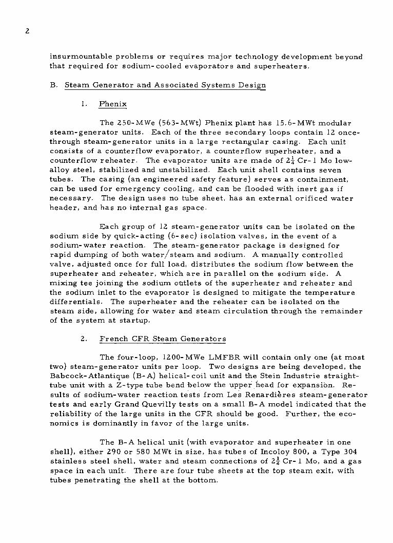
insurmountable problems or requires major technology development beyondthat required for sodium- cooled evaporators and superheaters.
B. Steam Generator and Associated Systems Design
1. Phenix
The 250-MWe (563-MWt) Phenix plant has 15.6-MWt modularsteam-generator units. Each of the three secondary loops contain 12 once-
through steam-generator units in a large rectangular casing. Each unitconsists of a counterflow evaporator, a counterflow superheater, and acounterflow reheater. The evaporator units are made of 2 Cr- 1 Mo low-
alloy steel, stabilized and unstabilized. Each unit shell contains seventubes. The casing (an engineered safety feature) serves as containment,can be used for emergency cooling, and can be flooded with inert gas ifnecessary. The design uses no tube sheet, has an external orificed waterheader, and has no internal gas space.
Each group of 12 steam-generator units can be isolated on thesodium side by quick-acting (6-sec) isolation valves, in the event of asodium-water reaction. The steam-generator package is designed for
rapid dumping of both water/steam and sodium. A manually controlledvalve, adjusted once for full load, distributes the sodium flow between thesuperheater and reheater, which are in parallel on the sodium side. Amixing tee joining the sodium outlets of the superheater and reheater andthe sodium inlet to the evaporator is designed to mitigate the temperaturedifferentials. The superheater and the reheater can be isolated on thesteam side, allowing for water and steam circulation through the remainderof the system at startup.
2. French CFR Steam Generators
The four-loop, 1200-MWe LMFBR will contain only one (at mosttwo) steam-generator units per loop. Two designs are being developed, theBabcock-Atlantique (B-A) helical-coil unit and the Stein Industrie straight-tube unit with a Z-type tube bend below the upper head for expansion. Re-
sults of sodium-water reaction tests from Les Renardieres steam-generatortests and early Grand Quevilly tests on a small B-A model indicated that thereliability of the large units in the CFR should be good. Further, the eco-nomics is dominantly in favor of the large units.
The B-A helical unit (with evaporator and superheater in oneshell), either 290 or 580 MWt in size, has tubes of Incoloy 800, a Type 304stainless steel shell, water and steam connections of 24 Cr- 1 Mo, and a gasspace in each unit. There are four tube sheets at the top steam exit, withtubes penetrating the shell at the bottom.
3
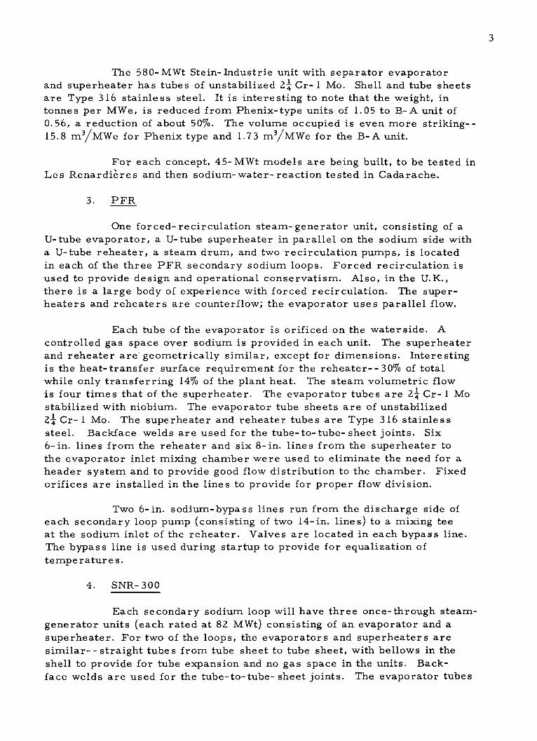
The 580-MWt Stein- Industrie unit with separator evaporator
and superheater has tubes of unstabilized 24 Cr- 1 Mo. Shell and tube sheets
are Type 316 stainless steel. It is interesting to note that the weight, intonnes per MWe, is reduced from Phenix-type units of 1.05 to B-A unit of
0.56, a reduction of about 50%. The volume occupied is even more striking--
15.8 m3/MWe for Phenix type and 1.73 m3/MWe for the B-A unit.
For each concept, 45-MWt models are being built, to be tested inLes Renardieres and then sodium-water-reaction tested in Cadarache.
3. PFR
One forced- recirculation steam-generator unit, consisting of a
U-tube evaporator, a U-tube superheater in parallel on the sodium side with
a U-tube reheater, a steam drum, and two recirculation pumps, is located
in each of the three PFR secondary sodium loops. Forced recirculation isused to provide design and operational conservatism. Also, in the U.K.,
there is a large body of experience with forced recirculation. The super-
heaters and reheaters are counterflow; the evaporator uses parallel flow.
Each tube of the evaporator is orificed on the water side. A
controlled gas space over sodium is provided in each unit. The superheaterand reheater are' geometrically similar, except for dimensions. Interestingis the heat-transfer surface requirement for the reheater--30% of total
while only transferring 14% of the plant heat. The steam volumetric flowis four times that of the superheater. The evaporator tubes are 2 Cr- 1 Mo
stabilized with niobium. The evaporator tube sheets are of unstabilized24 Cr- 1 Mo. The superheater and reheater tubes are Type 316 stainlesssteel. Backface welds are used for the tube-to-tube- sheet joints. Six
6-in. lines from the reheater and six 8-in. lines from the superheater to
the evaporator inlet mixing chamber were used to eliminate the need for a
header system and to provide good flow distribution to the chamber. Fixedorifices are installed in the lines to provide for proper flow division.
Two 6-in. sodium-bypass lines run from the discharge side of
each secondary loop pump (consisting of two 14-in. lines) to a mixing tee
at the sodium inlet of the reheater. Valves are located in each bypass line.
The bypass line is used during startup to provide for equalization of
temperatures.
4. SNR- 300
Each secondary sodium loop will have three once-through steam-generator units (each rated at 82 MWt) consisting of an evaporator and a
superheater. For two of the loops, the evaporators and superheaters are
similar-- straight tubes from tube sheet to tube sheet, with bellows in theshell to provide for tube expansion and no gas space in the units. Back-face welds are used for the tube-to-tube- sheet joints. The evaporator tubes

4
are orificed, and each unit has a protective shroud around the tube bundle.
The third loop will have helical-coil evaporators and superheaters. It ap-
pears that the steam-generator material used in all cases is niobium (1%)--
stabilized 24 Cr-1 Mo with 0.5% nickel. In all cases, steam separators are
installed between the evaporator and the superheater, which allows for 95%
quality steam exit into the superheater. SNR- 300 will not have sodium re-
heaters. It will use steam reheaters, reheating steam from the IP turbine
section to the LP turbine sections. The steam generators are being designedand built by NERATOOM, a Netherlands nuclear-industry consortium. A
50-MWt model of the straight-tube steam generator incorporating a sodium
reheater (initially planned for SNR-300) is being tested by the Netherlands
Research Institute, TNO, at Hengelo.
The helical- coil unit (again with no gas space) will have no tubesheets; tubes will penetrate the lower and upper heads through thermal
sleeves and will be externally headered. Though the Germans/Dutch favor
modular units, the size of the helical- coil units for the commercial LMFBRmay range as high as 250 MWt.
The German sodium-water reaction tests indicate that the pres-
ence of a gas space in the steam-generator unit allows secondary pressure
pulses to resonate to high peaks. The Germans depend on rapid rupture-
disk failure and flow-through of reaction products to keep the pressure peaks
under control. The absence of a gas space also eliminates level control.The Germans chose the once-through steam generator as less costly, elimi-
nating recirculating pumps, steam drums, pipes, valves, and controls. Suf-
ficient experience has been obtained on waterside dryout and corrosion to
provide confidence in the once-through units. Further, most of their fossil-
fired units use once-through boiler units. The Dutch/German concept con-
trasts with the British, who have a gas space in the PFR units, and theFrench, who plan gas spaces in their 1200-MWe LMFBR. In the opinion ofthe British and French, the gas space mitigates the initial pressure wave.
C. Steam-generator Development
For the demonstration plants, both the French and the SNRConsortium decided that it was necessary to test steam-generator com-
ponents on a large enough scale to provide a meaningful proof test me-
chanically, thermally, and hydraulically of each design. Tests are being
conducted by the French in the Les Renardiere s facility and by the SNR
Consortium in the Hengelo facility. The British have been negotiating for
CFR steam-generator model testing at the Hengelo facility. Alternatively,
they have explored the construction of their own steam-generator test
facility. No decision was reached at the time of the visit. The French and
the SNR Consortium are both proceeding to qualify two steam-generatormanufacturers and their designs through the testing of 50-MWt steam-
generator models.
5
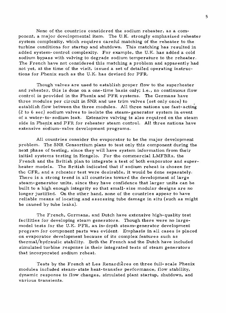
None of the countries considered the sodium reheater, as a com-
ponent, a major developmental item. The U.K. strongly emphasized reheatersystem complexity, which requires careful matching of the reheater to theturbine conditions for startup and shutdown. This matching has resulted inadded system- control complexity. For example, the U.K. has added a coldsodium bypass with valving to degrade sodium temperature to the reheater.The French have not considered this matching a problem and apparently hadnot yet, at the time of the visit, issued a set of detailed operating instruc-
tions for Phenix such as the U.K. has devised for PFR.
Though valves are used to establish proper flow to the superheater
and reheater, this is done on a one-time basis only; i.e., no continuous flowcontrol is provided in the Phenix and PFR systems. The Germans havethree modules per circuit in SNR and use trim valves (set only once) toestablish flow between the three modules. All three nations use fast-acting(2 to 6 sec) sodium valves to isolate the steam-generator system in eventof a water-to- sodium leak. Extensive valving is also required on the steam
side in Phenix and PFR for reheater steam control. All three nations haveextensive sodium-valve development programs.
All countries consider the evaporator to be the major developmentproblem. The SNR Consortium plans to test only this component during thenext phase of testing, since they will have system information from their
initial systems testing in Hengelo. For the commercial LMFBRs, theFrench and the British plan to integrate a test of both evaporator and super-heater models. The British indicated that if sodium reheat is chosen forthe CFR, and a reheater test were desirable, it would be done separately.
There is a strong trend in all countries toward the development of largesteam-generator units, since they have confidence that larger units can be
built to a high enough integrity so that small-size modular designs are nolonger justified. On the other hand, none of the countries appear to havereliable means of locating.and assessing tube damage in situ (such as mightbe caused by tube leaks).
The French, Germans, and Dutch have extensive high-quality testfacilities for developing steam generators. Though there were no large-
model tests for the U.K. PFR, an in-depth steam-generator development
program for component parts was evident. Emphasis in all cases is placed
on evaporator development because of its complex features such as
thermal/hydraulic stability. Both the French and the Dutch have includedsimulated turbine response in their integrated tests of steam generatorsthat incorporated sodium reheat.
Tests by the French at Les Renardieres on three full- scale Phenixmodules included steam- state heat-transfer performance, flow stability,
dynamic response to flow changes, simulated plant startup, shutdown, and
various transients.

6
The British, French, and Germans have conducted, and are continuingto independently conduct, extensive sodium-water/steam reaction analysisand testing with a major objective of developing advanced analytical methodscapable of describing the behavior of such reactions. Consensus was that,
for the near future, each new concept would require large-leak testing.
All the countries visited have developed mixing tees or mixing
chambers for mixing sodium streams of two unequal temperatures and do
not consider this a major developmental item. The British, French, andGermans have developed and are testing advanced rupture-disk designs
capable of operating several years at normal conditions without loss ofcapability to rupture at predetermined levels during an emergency. All thenations are developing hydrogen detectors capable of quickly detectingwater/steam leaks. In situ calibration is being used in all cases. Fast-acting sodium- isolation valves have been tested extensively by the Frenchand the Germans for valves of up to 600-mm (~24-in.) diameter--in a valve
loop at Les Renardieres by the French, and in the INTERATOM (Bensberg)full- scale pump test loop by the Germans.
Industrial consortia are dominant in steam-generator design and
fabrication. Such consortia include INTERATOM (Germany), NERATOOM(Netherlands), and Babcock-Atlantique and Stein Industrie (France). Large-model testing and much of the sodium-water reaction testing are being
performed by government groups such as EDF and Les Renardieres (steam-
generator test), TNO at Hengelo (steam-generator test), CEA at Cadarache
(sodium-water reaction test), and UKAEA at Dounreay (sodium-water
reaction test).
D. Turbine Development for Steam Reheat
The Dutch, French, and Germans do not consider turbine develop-
ment for steam reheat to be a problem. High-pressure turbines would be
similar to those used for fossil-fired plants, and the low-pressure turbines
are similar to those used in the light-water- reactor (LWR) industry. Steam
reheaters and moisture separators are similar to those used in the LWR
industry. Both the Dutch and French estimate a 1000-MWe steam-reheat
turbine to be lower in cost than a 1000-MWe sodium- reheat turbine. TheGermans expect no difficulty in building 3000- rpm steam- reheat units upto 800 MWe and see no reason for not being able to extend this to 1000 MWe.
E. French Approach to Developmental Testing
The French divide their tests into four categories:
1. Tests on reduced-scale models whose results are extrapolated
to prototype conditions: for Phenix: 1/4- scale models of reactor jacket;1/10-scale entire reactor unit for hydraulic tests; hydraulic tests of full-scale tubes for 1/4 segment of IHX.

7
2. Tests of prototypes in an environment simulating actual environ-
ments: full-scale tests of Phenix primary and secondary sodium pumps in
water loops.
3. Prototype tests in actual environment: Phenix reactor fuel-
handling equipment; Phenix steam- generator modules; small equipment
such as control mechanisms; full- scale valve tests in sodium.
4. Safety te sts: Phenix steam- generator hydrogen- detection
system; sodium-water reaction tests.
F. Sodium-Water Reaction Programs and Test Sites
Major sodium-water- steam reaction programs have been and are
being conducted by the British, French, and Germans. Testing is central-ized at one location and under the direction of one engineer. In the UnitedKingdom, this testing is done by the UKAEA at Dounreay under A. Bray;
in France, by the CEA, at Cadarache under Lions; and in Germany byINTERATOM at Bensberg under Dumm. Full-scale tube ruptures inrepresentative steam-generator models using many tubes is supplemented
by extensive mathematical modeling and by small-leak testing. Each newconcept is tested.
At Cadarache, the French plan to perform sodium-water reaction
tests in the two 45- MWt steam-generator models (B-A and Stein Industrie)after they have been tested in the Les Renardiere s steam-generator test
facility.
The value of such testing is evidenced by following results obtained:
1. Effects of cover gas in the steam generator.
2. Optimum design and location of rupture disks.
3. Reaction-product dumping capability of the dump system.
4. Amount of reaction products left behind.
5. Capability for system recovery.
6. Pressure and temperature peaks--their location and duration.
7. Effects of steam-versus-water leaks.
8. Means of correlating mathematical models to tests.
G. Demonstration Plants
At the time of the visit, it was estimated that both PFR and Phenix
would be on line in 1973. SNR-300 was yet to start construction.

8
Important to note is the extensive developmental and proof-testing
conducted by each nation.
The French have conducted full- scale tests, at Cadarache, of thePhenix reactor fuel-handling mechanisms; at Les Renardieres, full-scale
tests of Phenix steam-generator modules; full- scale water tests of thePhenix pumps; full- scale water test of a 1/4 Phenix IHX segment; full- scale
sodium-valve tests conducted in a sodium loop at Les Renardieres; andnumerous other component and subcomponent tests in sodium, water, or gas.
The British have emphasized the developmental testing of componentparts. For example, steam-generator tube-to-tube- sheet joint developmentwent through 2 years of testing. Radial vibration of tubes against tube sup-ports was tested, as well as fretting of tubes against tube supports from
vertical expansion. A 6000-gpm sodium pump was tested in sodium at
Risley at one-half the head and one-third the flow of the PFR pump. At thetime of the visit, the PFR rotating plug had been exhaustively tested atDounreay.
The Germans performed or were performing full- scale SNR- 300
pump and valve tests in a 600-mm (24-in.) sodium loop at INTERATOM,Bensberg; full-scale gas and sodium tests of the SNR rotating plug; large-
scale sodium-water reaction testing at Bensberg; small- scale steam-
generator testing at Bensberg. At Hengelo, the Dutch were in the processof testing a 50-MWt steam-generator model (compared to 82 MWt inSNR- 300) and a 50-MWt SNR- 300 IHX.
H. Commercial Plants
Though all of the nations have announced intentions of buildingcommercial LMFBRs, there have been no. firm commitments. The latest
announcement by the British is that a commitment will be made in the lat-
ter part of the 1970's. The French may make a commitment in 1975.
Successful operation, in the near term, of both PFR and Phenix will
be a prerequisite for making commercial commitments. The commercial
Phenix-type design appears to be quite active and may well be the first
committed as indicated above. Reference designs have been made for a1200-MWe LMFBR with four sodium loops. In July 1971, it was announced
that an association of three utilities was formed with the intention of buildingsuch a plant. The utilities are EDF, ENPEE (1'Ente Nazionale Per l'EnergiaElettrica, Italy), and RWE (Rheinisch- Westfalisches Elekrizit.tswerk A. G.,
Germany).
Only the French have made a firm commitment of steam reheat for
their 1200-MWe LMFBR. The Germans are using steam reheat for refer-
ence, but have made no final decision, and the British, using sodium reheatas reference, are in the process of reevaluating.

9
II. INTRODUCTION
Three thermodynamic systems can be considered for an LMFBRplant: (1) nonreheat, (2) sodium reheat, and (3) steam reheat with livesteam or extraction steam. Moisture separation means can be used withany of the schemes. A nonrehe-' system is shown in Fig. 1, a sodium-reheat system in Fig. 2, and a steam-reheat system in Fig. 3. Sodium-reheat arrangements can be made in several ways, as shown in Fig. 4.The United Kingdom Plutonium Fast Reactor (PFR) and the French-Phenixreactor use the parallel-series arrangement. Table 1 compares the mainthermodynamic parameters for the three European demonstration plants.
SUPERHEATER
INTERMEDIATE I
EACTOR HEAT
REIACONDENSER
EVAPORATOR
DEAERATOR
HIGH-PRESSURE LOW-PRESSUREH THEATERS HEATERS
HP = High-pressure turbineL P= Low-pressure turbine
GEN. Generator
Fig. 1. Flow Diagram for LMFBR Nonreheat System
SUPER- HP IP LP LP LP GEN.HEATER
REACTOR CONDENSER
IHX LOW-PRESSURE
I HEATERS
YEVAPO-RATOR DEAERATOR
HP = High-pressure turbineIP = Intermediate-pressure turbine
HIGHPRESSURE LP= Low-pressure turbineHEATERS GEN. - Generator
IHX - Intermediate heat exchanger
Fig. 2. Flow Diagram for LMFBR Sodium-reheat System

10
STEAMREHEATER
SUPERHEATER HP IP LP LP LP GEN.
INTERMEDIATEREACTOR HEAT
EXCHANGER CONDENSER
EVAPORATOR
DEAERATOR
I I HIGH-PRESSURE LOW-PRESSUREI i HEATER S HEATERS
HP = High-pressure turbineP - Intermediate-pressure turbine
LP - Low-pressure turbineGEN. = Generator
Fig. 3. Flow Diagram for LMFBR Steam-reheat System
FROM REHEAT SODIUMIHX TRIM VALVE
_W = _= W
REHEAT SODIUM MIXING TEECONTROL VALVE
0 0
W- 0
TO IHX
PARALLEL-SERIES PARALLEL-SERIES SERIES
NOTE: STEAM/FEEDWATER LINES NOT SHOWN
Fig. 4. Arrangements for Sodium-reheat Steam Generator

11
TABLE 1. Parameters for LMFBR Demonstration Plants: U.K., France, and Germany
FrenchU.K. PFR Phenix SNR
Thermal output, MWt 600 563 720Electrical output, MWe 270 250 300Reactor outlet temp, OF 1044 1050 1000Reactor inlet temp, *F 752 750 700Sodium temp, steam generator out, OF 400 662 644Sodium temp, steam generator in, OF 990 1022 977Feedwater temp, OF 550 475 545Steam temp, high-pressure turbine, *F 955 955 950Steam pressure at main turbine, psig 2300 2400 2400Type of reheat Sodium Sodium SteamReheat steam temp out, OF 960 955 428Reheat pressure at turbine, psig 440 500 132Steam generator type F.C.a O- Ta O- Ta
Modular No Yes YesNo. of units or modules 9 b 1 0 8 c 1 8 d
aF.C. = Forced recirculation; O- T = Once-through.bThree evaporators, one per loop; three superheaters, one per loop; three sodium
reheaters, one per loop.cEach of three secondary circuits contains a steam-generator unit consisting of
36 modules--12 evaporators, 12 superheaters, and 12 reheaters- -located in a boxlikestructure (see Item 9, Fig. 5).
dNine superheaters, three per loop; nine evaporators, three per loop.
The visit of the United States LMFBR Sodium Reheat Team from
May 22 through June 6, 1972, was made to determine the status of reheat
in LMFBR demonstration and commercial plants in France, Germany,
Netherlands, and the United Kingdom. In the process of determining this
status, discussions were also held on steam-generator design and develop-ment, associated components and systems design and development, sodium-water reaction testing, steam-generator testing, and demonstration-plantstatus.
Ten sites were visited, as indicated in Appendix A. These includedtwo 250-MWe LMFBR demonstration plants (the U.K.-PFR and the French
Phenix) and two 50-MWt steam-generator test sites: one at Les Renardieres,France, and one at Hengelo, Netherlands.
Members of the team were as follows:
John G. Yevick (Team Leader)
Office of Program Analysis
Division of Reactor Development and Technology
U.S. Atomic Energy Commission
Washington, D.C.
Robert V. Laney, Associate Director
Engineering Research and Development
Argonne National Laboratory
Argonne, Illinois

12
Raymond E. Hoskins, SupervisorEnergy Research Section
Tennessee Valley AuthorityChattanooga, Tennessee
William Francis RolfManager of Engineering
Commonwealth Edison
Chicago, Illinois
Edgar Rodwell, Project Manager
Steam Generator DevelopmentLiquid Metal Engineering Center
Atomics International
Canoga Park, California
John A. Ford, Head*
Systems Section
Atomic Power Development Associates, Inc.Detroit, Michigan
John S. McDonald, Manager
FBR Heat Transfer Systems Components
Atomics International
Canoga Park, California
Robert S. McQueen, Manager**
Heat Transfer Equipment Engineering
General Electric CompanySunnyvale, California
Louis A. Sturiale, Manager
Liquid Metal Components, Engineering DivisionWestinghouse Electric CompanyTampa, Florida
*Now with Division of Reactor Development and Technology, Atomic Energy Commission.**Now Principal Project Engineer, Breeder Reactor Plant Engineering.

13
III. EUROPEAN STATUS AND POSITIONS ON SODIUM REHEAT
A. Introduction
Each of the Western European LMFBR development programs,
specifically the French, British, and the West- German/Dutch/Belgian
Luxembourg Consortium (hereinafter referred to as the SNR Consortium),
has some form of resuperheated steam. The following paragraphs coverthe status of the reheat programs, the results of economic studies, and the
overall reasoning that has led to the present reheat status of the above
European countries' LMFBR development programs.
B. Status of Sodium Reheat
1. Status Summary
Initially, all the Western European LMFBR programs includedthe development of sodium reheat. The sodium-reheat plant cycle had been
selected early in each program as the basic cycle for the plant, primarilybecause the standard turbine design apparently required some reheat.
Utilizing fossil-fired reheat was most adaptable to the use of sodium reheat,
and the user preferred this cycle. All the Western European programs have
carried out development work on at least the heat-transfer components;
some programs have carried the development effort through to the point of
inclusion of sodium reheat in the respective demonstration plants, as indi-
cated in Table 2.
TABLE 2. Comparison of West European Plant-cycle Status
Demonstration Plant Commercial PlantScheduled Steam-generator Committed Steam-generator
West European Size, Service Model Test Service Model TestProgram MWe/Name Cycle Date Completed Size, MWe Cycle Date Completed
French 250/Phenix Sodium reheat 1973 a. Small heat-transfer model 1000 Steam reheat Not announced a. Plan to test atest of -5000 hr completed (now being 45-MWt helical-before 1972. designed) tube model in
b. Three modules (E, S, and 1973.RIa of Phenix steam gen- b. Plan to test aerator with -6000 hr to 45-MWt straight-be completed in 1972. tube model in
1974.British 250/PFR Sodium reheat 1973 No model testsb 1300 Decision on cycle to be Not announced May test a full-length
made in early 1973.c (now being and tube-diameter,(Present reference-- designed) partial-tube-sheetsodium reheat.) segment model, prob-
ably around 1974.SNR Consortium 300/SNR-300 Steam reheatd 1978 Three-module 50-MWt steam- 2000 Steam reheat is Not announced No test plans or(West Germany, generator model (E, S, and RI present reference. (making trade- schedule announced.Netherlands, test to end in 1973; now on off studies)Belgium, test.eLuxembourg)
aE evaporator; S = superheater; R - reheater.bAlthough the British did not do a scale-model test of complete PFR steam generators, heat-transfer stability tests were made along with fabrication tests. Also, the British,
like the West Germans and French, did do a model test of the response of the demonstration plant's steam-generator system to sodium-water reactions by simulating tubefailures. (See Section V for details of steam-generator development programs.)
cPresent reference is sodium reheat.dThe SNR Consortium was initially committed to a sodium-reheat plant cycle and initiated a steam-generator development effort that included sodium reheat. In 1971, the
program was reoriented to develop steam generators without sodium reheat. SNR-300 plant is being designed with a steam-reheat cycle.eFollowing completion of tests of the early-design SNR steam-generator model, a 50-MWt helical-tube evaporator model for SNR-300 will be tested, scheduled to be com-
pleted in 1974.IThe SNR Consortium's commercial-plant reference size is 2000 MWe.

14
At this time, for commercial LMFBRs, the French and prob-
ably the German LMFBR programs have elected to use steam reheat in
lieu of sodium reheat. The British are reevaluating their reference CFR
sodium reheat. The SNR Consortium will make a reevaluation prior to a
final decision.
Experience with sodium-reheat equipment and components at
this time is limited to the data obtained from model and module sodium-
loop tests by the French in the Phenix plant's steam-generator development-
test effort, and the Dutch have started to test an early design of the SNR-300
steam-generator system, which includes a sodium-reheater model, though
the SNR-300 does not have sodium reheat- -instead, it has steam reheat.
(For more details on tests on the steam-generator loop, see Section IV.)
Although European experience with sodium reheaters in test loops appears
successful, no plant to date has operated with a sodium-reheat cycle. The
first plant experience with a sodium-reheat system will be in 1973, when
both the U.K.-PFR and the French-Phenix demonstration plants are sched-
uled to operate.
2. Status Comparison
Table 2 indicates the status of the plans for the plant cycles for
the various West European demonstration and commercial plants. Also
indicated in the table are the status and plans for the related steam-
generator test programs. (For more details on steam-generator test pro-
grams, see Section V.)
a. French
The French have developed a sodium-reheat system fortheir LMFBR demonstration plant- -Phenix, a 250-MWe (nominal) unit
scheduled for service in 1973. The steam-generator model consisting of
three full-sized modules (evaporator E, superheater S, and reheater R) of
the Phenix plant's steam-generator design will have completed more than
6000 hr of testing in a steam-generator test loop by the middle of 1972
(tests scheduled to end in July 1972). The Phenix plant contains three loops
with a 36-module steam generator in each loop: 12E, 12S, and 12R.
For the French commercial plant, the designers have de-termined that (1) the large number of modules used in Phenix is uneconom-
ical and (2) the sodium-reheat plant cycle is not as economical as the
expanded- steam- reheat plant cycle, and (3) there is a reliability advantagewith its concomitant availability advantage in favor of steam reheat. Con-
sequently, the steam-generator development plans for the commercial plant
call for testing two different once-through steam-generator designs, neither
of which includes sodium reheat.

15
The commercial plant's steam-generator model is a 45-MWt
Babcock-Atlantique design with helical tubes. This first model is to be
tested in 1973. The commercial plant's layout incorporating this type of
design will have one or two steam generators in each of the four plant loops.
Each steam generator will consist of one evaporator and one superheater
combined in a single shell.
The commercial plant's alternative steam-generator model
is a 45-MWt Stein Industrie design with straight tubes. It is to be tested in
1974. The commercial plant's layout using this alternative type of design
will have one steam generator in each of the four plant loops. Each steam
generator will consist of one evaporator and one superheater, each in a
separate shell. The preliminary data for the commercial plant's steam
cycle are shown in Table 3.
TABLE 3. French Commercial LMFBR Steam-cycle Conditions
Main steam *C-F 510-950bars-psig 165-2378
Main steam flow kg/sec-106 lb/hr 1040-8.4
Intermediate-pressure-turbine *C-F 164-329
exhaust steam to steam reheater bars-psig 7-87
Reheated steam to low pressure * C-F 285-545
turbines bars-psig 6.6-81
Steam from high-pressure C- F 473-883turbine to steam reheater bars-psig 85-1218
The turbine will be a 3000-rpm tandem-compound machine
with a Peerless-type steam dryer (similar to Westinghouse PWR). (For
additional details on plant cycle, see Section IX.)
b. British
The British demonstration plant (PFR), rated at 250 MWe
(nominal), is scheduled to start up in 1973 and will use a sodium-reheat
plant cycle. As noted in Table 2, the British, in lieu of testing models of
the PFR steam generators, have performed supporting tests to ensure de-
sign and fabrication requirements and have made extensive analyses in-
cluding the development of comprehensive operating procedures.
Reference plans for the British Commercial Fast Reactor
(CFR) call for the utilization of two 650-MWe "standard" high-temperaturereheat turbine generators (T-G's) with reheat steam supplied by sodium
reheaters. Experience with the development of PFR operating procedures,
including those concerning startup, transients, and shutdown, have caused

16
concern that these problems may be multiplied with the two parallel turbine-
generator units in the CFR plant. The British are now in the process of re-
evaluating the plant cycle of the CFR. Plans are to reach a decision on the
CFR plant cycle in early 1973.
Large-scale model tests of the CFR plant's steam genera-
tors will be made if the CFR incorporates a new steam-generator concept.
No firm plans or schedule were presented, but general ideas were discussed,
and it is assumed that the schedule for such model tests would be about 1974.
(See Section V for more details on British steam-generator testing
considerations.)
c. SNR Consortium
As noted in Table 2, the initial design of the SNR-300demonstration plant included a sodium-reheat cycle. The design of the
plant progressed to the point where a 45-MWt straight-tube, bellows-in-
shell steam-generator model, which included a sodium-reheat module, was
fabricated for testing at Hengelo. The model, including the sodium reheater,
was installed in the Hengelo Test Loop late in 1971. The decision to elimi-
nate sodium reheat in SNR was also made in 1971. Redesign of either the
model or the loop to accommodate elimination of the reheater would have
taken too long and been too expensive.
After completion of the tests on this steam-generator
model, probably 1973, an SNR 50-MWt helical-tube evaporator will be in-
stalled and tested. Its testing is scheduled to be completed in 1974.
The commercial SNR plant reference design uses a steam-
reheat plant cycle similar to that now being designed for SNR-300. There
were indications that the SNR Consortium would review the commercial
SNR cycle decisions prior to final choice.
C. Reasons Expressed for the Plant-cycle Selection
1. Introduction and Summary
This section discusses the economic and technical reasoning
that led the various Western European nations to the present reference
cycles.
The overall observation is that all the Western European pro-
grams have reconsidered, or are now in the process of reappraising, the
initial selection of the sodium-reheat plant cycle for the future plants now
in the design stage. The general reason expressed for the initial selection
of sodium reheat for the Western European programs, and specifically for
the demonstration plants, was that the sodium-heat transfer system was

17
designed around a "standard" turbine-generator (T-G) steam cycle. This
"standard" T-G cycle was developed for fossil-fueled plants and included
reheat requirements that had been optimized for fossil-fueled plants.
Two of the demonstration plants, the PFR plant of the British and the
Phenix plant of the French, were developed to use 250-MWe (nominal)
"standard" T-G units. Also, initial studies indicated favorable economics
for a sodium-reheat cycle.
2. SNR Consortium
In 1971, the SNR Consortium decided to switch from a sodium-
reheat cycle to a steam-reheat cycle for the SNR-300 demonstration plant.
Both NERATOOM and INTERATOM studies indicated that the economics ofthe steam-reheat cycle were more attractive than those for sodium reheat.
NERATOOM, which made parametric economic studies for the
SNR-300 plant only, indicated that the studies showed about 1*% total-energy-
production cost advantage for the steam-reheat cycle over the sodium-
reheat cycle. It was indicated that the complexity of the sodium-reheat
cycle was of concern and a small economic penalty could be taken to avoid
the problems specific to the sodium-reheat cycle.
INTERATOM made-parametric economic studies of various
plant cycles for both the SNR-300 and 1000-MWe plants. Results of theINTERATOM study indicated a 0.25 and 0.3% total-energy-production cost
advantage for steam reheat over sodium reheat for the SNR-300 and1000-MWe plants, respectively. It was indicated that had the economics
been in favor of sodium reheat by the same magnitude, sodium reheat would
have been recommended.
3. French
The French made the decision (in 1971) to change the reference
plant cycle from sodium reheat to steam reheat. The change, for the French,
applies to the commercial 1000-MWe plant cycle and not to the French dem-
onstration plant Phenix, because the change was made after the Phenix plant
was well along in the construction stage.
The French economic studies for the 1000-MWe plant indicated
a one- to two-percent total-energy-production cost advantage for the steam-
reheat cycle over the sodium-reheat cycle. This economic incentive, plus
the French assessment of the potential availability advantage (roughly esti-mated in the range of 1/2 to 1%) in favor of steam reheat, were the reasons
indicated for deciding to use the steam-reheat cycle in lieu of sodium re-
heat for the 1000-MWe French commercial plant. Earlier preliminarystudies indicated nonreheat was economically unacceptable, and it wasdiscarded at an early stage in the French commercial-plant considerations.

18
4. United Kingdom
The British have not made a final decision on the type of com-mercial LMFBR steam cycle. The stated plan is to make the plant-cycle
decision for the 1300-MWe CFR in early 1973.
Reference design for the CFR is to use two "standard" 650-MWe
T-G's in parallel, and sodium reheat. The experience gained on PFR indi-
cates that the startup and shutdown thermal-transient control systems and
procedures would make the parallel operation of the two CFR T-G's difficult.
Also, the British are studying the reliability and operational considerations
associated with the added components and systems in the sodium-reheat
system and apparently plan to weigh this against reliability considerations
of developing T-G concepts associated with steam-reheat or nonreheat
cycles. Reliability, operation, equipment vendors' capability, and energy-
generation costs are factors considered in the studies.

19
IV. STEAM GENERATORS AND ASSOCIATED SYSTEMS DESIGN
A. Summary
European LMFBR R&D programs, in general, emphasize testing oflarge sodium-component prototypes or large-scale models, such as pumps,heat exchangers, and valves. The French have tested full-scale steam
generators for Phenix, and the SNR Consortium is testing large steam-generator models for the SNR-300. The French are fabricating two 45-MWtmodels of a different design than Phenix for their commercial LMFBRplant. Full-scale sodium valve tests have been performed by all the na-tions for their LMFBR demonstration plants. Full-scale multitube steam-generator sodium-water reactions have been and are being conducted by
France, Germany, and the U.K. The various component tests are indicative
of a general desire to verify component and system reliability by prooftesting before operation. In this respect, the SNR Consortium emphasized
that all major SNR components have been or will be tested at full scale oras close to full scale as possible. This includes testing of heat exchangers,pumps, and valves.
Full-scale proof testing of components has not been pursued in thePFR program. There are indications that the British will test a largesteam-generator model if their first commercial LMFBR plant adopts a
steam-generator concept different from the PFR.
To date both the French and the SNR Consortium have tested the
steam generator as part of a system. In this approach, the component
performance can be individually determined in addition to the verificationof the component's interaction with the system and other components. The
French and the SNR Consortium have in operation 50-MWt facilities fortesting large steam generators- -namely, the CGVS at Les Renardieres andthe Hengelo Steam Generator Test Facility in the Netherlands.
The Phenix steam generators are once-through, modular, serpentine-
type units. The SNR-300 steam generators are modular, straight-tube units,
which incorporate a bellows in the shell for differential expansion. The PFR
evaporator, superheater, and reheater are basically variations of a rather
conventional U-tube bundle. Phenix and PFR are both sodium-reheat plants;the SNR-300 uses steam reheat. The design philosophy for Phenix, aimed
at achieving high availability, was dominated by consideration of a potential
sodium-water reaction. This is evidenced both by the extreme modulari-zation of the steam generator (108 modules per three-loop plant) and by
features provided for removal of modules from the loop, such as rollers
installed on each module assembly. As stated by the French, sufficientuncertainties and unknown consequences were associated with the sodium-water reaction to have warranted conservatism in the Phenix design. The
French feel that the tests for Phenix have provided sufficient confidence in

20
steam-generator performance and reliability to enable a less conservative
and more economical approach for the large commercial plants. This willbe confirmed in Phenix operation.
In France, Babcock-Atlantique (B-A) and Stein Industrie are each
developing large, full-size steam generators for the 1200-MWe Phenix-type commercial-plant. A 45-MWt model of B-A's 600-MWt unit has been
designed and fabricated, and is scheduled for testing at Les Renardibresin February 1973; testing of a Stein Industrie 45-MWt model is presently
scheduled for completion by the end of 1974. One of these steam generators
will be selected as the reference design for the 1200-MWe plant by early1975. Results of the Les Renardieres tests will be an influential factor inthe choice.
None of the countries visited considered the sodium reheater, as acomponent, to be a major developmental task. The U.K. steam generator,
which includes sodium reheat, is characterized by an extensive control
system and detailed operating procedures to ensure proper match of so-dium reheater with turbine operation. (See Section IV.C.2 for details.)
In summary, the Europeans are well into the hardware and opera-
tional phase of steam-generator development for the near-term LMFBR
power plants. Emphasis is on large-scale model testing with emphasis on
the verification of performance and the development of sodium-water
reaction-analysis technology.
Although the steam generators being developed may not be prototypic
of commercial-plant units, the experience obtained from large-scale test-ing and from the operation of the demonstration-plant units will provide an
excellent springboard from which to design and/or develop commercialLMFBR steam generators.
B. France
1. Introduction
Phenix is a sodium-cooled fast-breeder-reactor demonstration
plant scheduled for criticality in 1973. The first reactor in the French
LMFBR development program was the Rapsodie experimental reactor, which
has been operative at the Cadarache Nuclear Research Center since 1967.
Rapsodie has become, in the main, a fuel-development facility similar tothe U.S. EBR-II reactor. Rapsodie has no electrical power-generating
equipment (i.e., no steam generators); in 1970, the thermal power of thefacility was increased from 20 to 40 MW.
Phenix, with a plant rating of 250 MWe (563 MWt), represents
the transition to electrical power generaL:,n ad will provide the industrial

21
experience essential for development of the larger commercial power
plants. The Phenix plant uses a sodium-reheat cycle; the 1200-MWe plant
design will use a steam-reheat cycle.
2. Phenix Steam Generators
The steam generators developed for the Phenix are not proto-
typic of the steam generators being developed in France for the large com-
mercial LMFBR plants. For the three-loop Phenix reactor there are
108 steam-generator modules: 36 evaporators, 36 superheaters, and 3 6 re-heaters. Each loop contains 12 sets of once-through steam-generator
modules. (See Fig. 5.)
12
11
10
S67
STEAMGENERATOR1 sodium inlet2 outlet collector3 water separator
4 sodium outlet5 to hydrogen
separator6 rupture disk
7 water drain valve
8 water inlet
9 insulated casing
10 superheatedsteam
11 to reheater12 reheated steam
A reheaterB superheaterC economiser-evap.
Fig. 5. Phenix Steam Generator

22
Modular steam generators were preferred for the Phenix be-
cause of economic and reliability considerations. The use of modules was
intended to limit or decrease the consequences of sodium-water reactions.
A significant benefit derived from modularization of the steamgenerators was that a full-scale modular system could be prooftested at
Les Renardieres. Prooftesting with full-scale modules would permit directverification of the thermal-hydraulic performance and vibration charac-teristics. Also, in the event of any sodium-water reaction during the tests,the observed behavior of a full-scale module would be of potential benefitto Phenix operation. A successful test of a Phenix module at Les Renardieres
for more than 6000 hr has substantiated the design choices.
With modules, in-service maintenance tasks would be mucheasier to perform. For example, in the event of a tube failure, tasks suchas physically locating the leaking tube and/or removing the failed module
from the loop would appear to be less difficult with modules. Simplifyingmaintenance activities, or in essence, decreasing the time required for
maintenance would provide a realistic and practical way to increase com-
ponent and plant availability. Presumably, fabrication of modules (versus
full-size units) could be more stringently controlled, and this specific con-trol should result in a higher-quality unit. The French stressed that high
integrity was essential for safe sodium systems. Nevertheless, it is in-teresting to note that the French commercial plant will not be modularized
(see Section IV.B.3).
For safety purposes, the modules for each loop and the waterand sodium headers are installed inside an insulated, self-supported, rec-tangular containment box. The modules themselves are not insulated. In
the event of loss of the water/steam system, the box can be opened and air-cooled by natural convection. For firefighting purposes, argon could be
substituted for the air atmosphere. Each evaporator, superheater, andreheater module is a counterflow heat exchanger, consisting of a seven-
tube bundle. The units do not require tube sheets because the tubes are
bent and penetrate the shell, terminating in an outside water or steam
header. Local thermal shielding is provided at the welded tube-shell junc-
tion to guard against damaging thermal shocks. Orifices are installed inthe inlet to the water tubes (evaporator), at the header, to ensure stable
operation at low power levels. Nominal steam-generator characteristicsare presented in Table 4.
To permit tube plugging in the event of a leak, a small nipple
is provided at each tube end (see Fig. 6). Direct access to the orificed
tube end is achieved by removing the nipple. For other than in-place re-
pair, the modules can be removed to a work area for repair and/or re-
placement. The individual modules are mounted on small rollers for easeof removability.
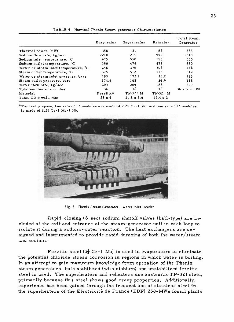
23
TABLE 4. Nominal Phenix Steam-generator Characteristics
Total SteamEvaporator Superheater Reheater Generator
Thermal power, MWt 356 121 86 563Sodium flow rate, kg/sec 2210 1215 995 2210Sodium inlet temperature, *C 475 550 550 550Sodium outlet temperature, *C 350 475 475 350Water or steam inlet temperature, *C 246 375 308 246Steam outlet temperature, *C 375 512 512 512
Water or steam inlet pressure, bars 193 172.7 36.2 193Steam outlet pressure, bars 174.9 168 34.9 168Water flow rate, kg/sec 209 209 186 209Total number of modules 36 36 36 36 x 3 = 108Material Ferritica TP-321 M TP-321 MTube, OD x wall, mm 28 x 4 31.8 x 3.6 42.4 x 2
aFor test purpose, two sets of 12 modules are made of 2.25 Cr-1 Mo, and one set of 12 modulesis made of 2.25 Cr-1 Mo-1 Nb.
pU
Fig. 6. Phenix Steam Generator--Water Inlet Header
Rapid-closing (6-sec) sodium shutoff valves (ball-type) are in-cluded at the exit and entrance of the steam-generator unit in each loop to
isolate it during a sodium-water reaction. The heat exchangers are de-
signed and instrumented to provide rapid dumping of both the water/steam
and sodium.
Ferritic steel (24 Cr-1 Mo) is used in evaporators to eliminatethe potential chloride stress corrosion in regions in which water is boiling.In an attempt to gain maximum knowledge from operation of the Phenix
steam generators, both stabilized (with niobium) and unstabilized ferriticsteel is used. The superheaters and reheaters use austenitic TP-321 steel,primarily because this steel shows good creep properties. Additionally,experience has been gained through the frequent use of stainless steel inthe superheaters of the Electricite de France (EDF) 250-MWe fossil plants

24
with 565*C (1050 F) superheated steam. Welding problems have been en-countered in welding stabilized Croloy, but welding feasibility has been
established. EDF confirmed that Stein Industrie intends to use unstabilizedCroloy for the 1200-MWe steam generator.
Steady-state temperature profiles are shown in Figs. 7-9. The
French were confident that the Phenix steam generators could safelyhandle
plant transients. The worst transient occurs when a feedwater pump trips
off. Since sodium can continue to flow, the evaporator dries out. The evapo-
rator is then hit with 150 C water from the emergency feedwater supply,
developing the worst transient case. Thermal-shock tests have been con-
ducted to ensure that there will be no failure for such a condition. This
transient was repeated for about 22-24 cycles before failure occurred.
The French expressed concern about the movement between the
tubes and shell caused by differential expansion and also about the effect of
plugged tubes where the tube penetrates the shell. The latter concern wasdue to a potential for fatigue failure. Large forces are imposed on this
penetration if no relative motion between the tube and its support is as-sumed. Calculations indicate that the Phenix modules are safe for several
thousand cycles if this motion occurs. The problem was originally antici-
pated in the superheater and reheater, where both the tubes and the tube
supports were stainless steel. No such problem is now believed to exist,
however.
A butterfly-type control valve is used to proportion the sodium
flow between the superheater and reheater. This flow-control valve is set
during the initial operation and not varied with load. Phenix has a mixingtee at the sodium outlet of the superheater and reheater. However, the
French stated that this tee is not essential because the temperature dif-ferentials expected between superheater and reheater sodium outlet (Figs. 7-
9) are not excessive. This temperature difference does not change in mag-
nitude during a turbine trip. Large thermal transients induced by turbine
trips would not occur, since the steam flow is quickly reduced in sufficient
time to prevent damage. A steam-side bypass around the reheater is pro-
vided. The steam flow is turned off within 0.2 sec, and this provides suf-
ficient time to prevent damage to the steam generator. Means are provided
on the steam side to isolate both the superheater and the reheater, allowing
water and steam circulation through the evaporator, moisture separator,
feedwater heaters, and reheaters.
EDF indicated that the steam-generator tests at Les Renardieres
model or prototype the Phenix-plant system conditions as closely as possi-
ble. This includes transients such as turbine trip. Although everytransientcould not be simulated at Les Renardieres (because of possible damage to
the sodium heaters), EDF calculations indicate that the Phenix steam gen-
erators could safely accommodate the turbine-trip transient. Rapid shutdown

PRESSURE: I CM= I BAR
BROKEN CURVES' TEMPERATURE OF INSIDE AND OUTSIDE WALLS
186.621,- I
350.0-
- s
30
LENGTH, m40
-47.9L
I I
I I
37. I
I I L50 56.28 0
SODIUM TEMPERATURE
STEAM.TEMPERATURE
175.17
PRESSURE
SUPERHEATER
I0
LENGTH, m
-1550.01
-5I2.I
1475.9
I I
I II I.
308.01-
1
SODIUM TEMPERATURE
STEAMTEMPERATURE
37.20- ---- PRESSURE
REHEATER
-J5 5 0 .0
A512.0
I .~3404
I I I20 26.21 0 10 20.49
LENGTH, m
Fig. 7. Temperature Profiles for Phenix Steam Generator; Normal Power Level (563 MW); Cold Condition
N
600
500E
400[
I-
QW
F-
PRESSURE
SODIUM TEMPERATURES . .--
. . . - - '75.75
.. "''" .-- '"' WATER TEMPERATURE
EVAPORATOR
3001
0 I0 20, ,

. PRESSUF-- - - - - - - - - -- ---------- U
Sc
PRESSURE, I CM = I BAR
BROKEN CURVES= TEMPERATURE OF INSIDE AND OUTSIDE WALLSSODIUM
I I TEMPERATURE ..
RE IEM
--------------- 168.50..--. PRESSURE168.54 1 --- i---- - RES E
54.7 . 8449.8-
)DIUM TEMPERATURE - - ' STEAM TEMPERATURE
.. - ......-.-." -- 3-7--- .7 0-.. :.--.-- . -7
WATER TEMPERATURE
EVAPORATOR
I0 20 30
LENGTH,m
40
-- I.
I II II II II II II II I
I I
L50 56.28 0
SUPERHEATER
10
LENGTH, m
1519.81j512.Og
I II I
'4 I
'443.1 LI II II II II II I
I II II I.I I
I I,2550rI II II II II I
SODIUMTEMPERATURE
STEAMTEMPERATURE
9.50I PRESSURE - - -
REHEATER
-1519.8.1506.2
18.42
SI II20 26.21 0 10 20.49
LENGTH, m
Fig. 8. Temperature Profiles for Phenix Steam Generator; 0.25 of Normal Flow Pressure: 168 bars; Cold Condition
500
0 400
a.
300
200
16947r
- I
306.7-
- I
17
- 70
0
I I I1 .I I
. .
._--.'

PRESSURE: I CM= I BAR
BROKEN CURVES: TEMPERATURE OF
48.49- - - ------- - - - -_______ PRESSURE-------------------
4.5
SODIUM TEMPERATURE
S. ..-
500
U. 400
I-
aw
300
200
-I
1770
464.4
-I
456.0
I
S375.0
INSIDE AND OUTSIDE WALLS
SUPERATURE
'.-' STEAM TEMPERATURE
44.30-- PRESSURE
42
SUPERHEATER
513.0 I1512.0
1
442II
444.2
1328.0I
II II II II 11 I
SODIUMTEMPERATURES
-- STEAMTEMPERATURE
9.30
PRESSURE
REHEATER
I I I
50 56.28 0 10LENGTH, m
I I I20 26.21 0 10 20.49
LENGTH, m
Fig. 9. Temperature Profiles for Phenix Steam Generator; 0.25 of Normal Flow Pressure: 42 bars; Cold Condition
WATER TEMPERATURE
EVAPORATOR
-4513.0-1502.9
18.38
0 I0 20 30LENGTH, m
40
_. _. w trs Tr "f1r T1 r
...
I i
l . . . . l 1
- ---
..--

28
transients have been conducted at Les Renardieres to ensure this capabil-ity. Turbine trip, followed by loss of water and steam flow, will be simu-
lated during the last test phase at Les Renardieres.
Instrumentation used in the module tests included orifices in
the tube inlet, both to measure flow and to provide hydraulic stability. (The
orifice size was calculated for the smallest usable orifice initially andenlarged as the tests progressed.)
3. Steam Generators under Development for 1000-MWe Plant
Two French companies--Babcock-Atlantique and Stein Industrie--have joined Commissariat a L'Energie Atomique (CEA) and EDF in a steam-
generator program. Because of economics, the Phenix steam generators
will not be used in the 1000-MWe commercial LMFBR plants. Economic
studies conducted by the French indicate that for a large plant the numberof required modules would make the cost of components, piping, and in-
strumentation prohibitive. The decision to proceed with the large units for
the commercial plant was also based on the excellent experience obtained
in the steam-generator tests at Les Renardieres, the sodium-water reac-
tion tests at Cadarache, and the sodium-water reaction analyses at Saclay
and Cadarache. Operational experience and sodium-water activities have
indicated that (1) sodium-water leaks could be detected at an early stage,(2) the relief system is effective, and (3) the tubes and tube-to-tube-sheetjoints could be satisfactorily made for reliable service.
a. Babcock-Atlantique (Fig. 10)
The tube bundles for the B-A steam generator are helically
coiled. This type of generator is suited to a steam cycle without sodium
reheat. Sodium at 1020 F and water at 465F enter the unit and produce
superheated steam at 950 F (2450 psi). The tubes are made of Incoloy 800,
the water and steam connections of 24 Cr-1 Mo. The shell is of Type 304
stainless steel. The tubes--of which there are 174 if the steam generator
is 290 MWt or about 348 if 580 MWt--are 25-mm OD x 2.5-mm wall thick-
ness. A small 1.5-MWt model has been tested at Grand Quevilly to deter-
mine thermal performance and stability. Also, nonsodium waterside testshave been performed at Les Renardieres. A model (see Fig. 10) with 24tubesforming three rows between two concentric shells will go on test inLes Renardieres in February 1973.
b. Stein Industrie (Fig. 11)
The Stein Industrie steam generator is a counterflow unit
using straight tubes with a Z-type expansion bend in the gas space below
the upper head. Each module is 580 MWt; four units would be required fora 1000-MWe plant. The steam-generator reference material for the tubes

29
SuperheatSteam
Level 18.8 m
-. ,Na
Separator
Na
HelicalTube s - 0-1011
aN
Single N
HelicalTube
Thermal RupturebSleeve Disc o1 45 MWt Model
- ,0 -w .For Lea Renardi'eresfee Test Facility
Tubesheet RuptureDisc
Tube-
- Na
Level 0
Feedwater See Detail "X"
One of 4 feedwater tubesheets
Feedwater toroidal header
Feedwater y
Na .Exit Pipe
Detail "X"
Note: - '2200 indicates Diameter =2200 millimeters
Fig. 10. Babcock-Atlantique Steam Generator (two units in parallel; each 290 MWt)

Superheat Level - 22 m.Steam
Tubesheet
Separator Reverse tbend
Na
SingleTube
1440- 9- 1884
041
Sw
Rupture
Disc
RuptureDisc Na.
Levei
See Detail "X"
Feedwater
Orifice
,4- -4
ii
-# 645
Superheater Evaporator
45 MWt - ModelFor Les Renardi'eresTest Facility
Detail "X"
Note: -#565 indicates Diameter =565 millimeters
Fig. 11. Stein Industrie Steam Generator (580-MWt unit)
30
ibe

31
is unstabilized 2 Cr-1 Mo. Each evaporator has 1400 tubes of 18-mm OD x3-mm wall thickness. Each superheater has 463 tubes of 21.3-mm OD x
2-mm wall thickness. Shell and tube sheets are Type 316 stainless steel.
A 45-MWt (see Fig. 11) model will be tested at
Les Renardieres in 1974. This model will have a 44-tube bundle. After
completion of these tests, the model will be shipped to Cadarache for use
in sodium-water reaction tests.
c. Comparison of Phenix-type, B-A, and Stein Industrie
Commercial Units
Table 5 compares on a per-MWe basis, the weight, volume,
and heat-transfer area for the commercial LMFBRs--Phenix type; B-A large
unit; and Stein Industrie large unit.
TABLE 5. Comparison of French Commercial 1000-MWe LMFBR Steam-generator Concepts
No. of Modules Total No. of Modules Weight, Volume, Heat-transferConcept per Loop for Four Loops Tonnes/MWe m3/MWe Area,a mZ/MWe
Phenix 36 144 1.05 15.8 11B-A 1-2 4-8 0.56 1.73 8.65SteinIndustrie 1 4 0.70 1.4 8.3
aOn OIS of tube.
d. Les Renardieres Steam Generator Test Facility
France has built and is operating many sodium facilities
in support of the LMFBR development. Facilities of interest to steam-
generator development and visited by the Sodium Reheat Team are locatedat two major sites: Cadarache, operated by the CEA; and Les Renardieres,operated by the EDF. Les Renardieres is the site of the 50-MWt steam-
generator test facility (CGVS). The French considered it necessary to
operate such a facility (1) to test industrial-scale steam-generator com-ponents under conditions simulating an LMFBR plant, and (2) to confirmthe endurance of the component over long time periods. Features of the
CGVS facility are:
(1) A gas-heated boiler, capable of heating sodium to
about 1200 F. The primary sodium test circuit is designed to simulate
temperature transients.
(2) A water/steam circuit, where the steam produced
by the steam generator is expanded, condensed, and returned to the steam
generator. This loop also includes water treatment for condensate and
makeup water.

32
The characteristics of these circuits are:
Sodium
Maximum heater power 50 MWt
Maximum sodium temperature 1200*FMaximum sodium flow rate 1000 m
3/hr
Water/steam
Steam pressure (at outlet) 2450 psi
Maximum steam outlet temperature 1050*F
Feedwater temperature 480-535FFlow 80 tons/hr
The test schedule for CGVS provides for the Phenix steam-
generator tests to be completed in 1972, the Babcock-Atlantique 45-MWsteam generator to be on site by November 1972, and tests of theStein Industrie 45-MWt model to be completed in 1974.
Steam-generator tests will concentrate on commercial-
operation aspects and the resultant operating problems. The steam-
generator models will be tested under various plant transient conditions,
including turbine-trip and reactor-scram events.
e. Sodium-Water Reaction Test Facility at Cadarache
The CEA's sodium-water reaction test facility is located
at the Cadarache Technical Center. The sodium-water reaction studies
are focused primarily on large-leak tests. However, small leaks of water
in sodium have been investigated for the Phenix steam generator. The
large-leak investigations are concentrated on the experimental and theo-
retical analysis of effects of a large leak on the steam generator and the
associated sodium loop. Preliminary large sodium-water tests are carried
out in simplified models to develop theoretical codes for predicting the
time and pressure histories associated with a reaction. Further tests are
performed in a full-size evaporator model to confirm predictions for the
Phenix steam generator. Section VI.B contains further information on this.
C. United Kingdom: PFR Steam Generators
1. Description
The Prototype Fast Reactor (PFR) is a 250-MWe sodium-
cooled fast reactor located at Dounreay, Scotland. The power output ofthe PFR is based on the requirement that it should be the smallest reac-tor capable of providing, with confidence, the information necessary for theinstallationand operation of commercial fast reactors in the United Kingdom.The main features of the PFR, relative to the steam system, is the use of
single-wall-tubed heat exchangers and steam conditions of 960F and 2300 psi,and a forced-recirculation system.

33
The PFR uses three heat-transfer loops. The steam generators
are shell-and-U-tube heat exchangers with provisions for isolating the effects
of a sodium-water reaction. Figures 12 and 13 present a schematic of the
2300 psiq, 1000 *F
- -674 *F
LPT IP HPTARN
SUPPLY
500psi , 600 F
_ _16
LPT=LOW-PRESSURE TURBINE 0~m 2I PT =INTERMEDIATE -PRESSURE TURBINE a -- REHEATERHPT=HIGH-PRESSURE TURBINEUE
NEEDLE
-BYPASS II-
4 ~~~VALVEIIIIII
MIXING TEE 6" (2) _ 6(6ORIFICE
1040F 14" (2)
TO IH X705 *F 14 (2)
24
Fig. 12. Schematic of Heat-removal System for PFR Steam Generator
TEMPERATURE
6W C562C (1 044F)
550 C, 169 kg/cm2(2 400 p.s.i.s.)
- 532C (990F)
T.S.V. CONDITIONS 514C' 516C (960FI
500C 513-C (955F) /163 kg/cm 2 (2 315 p s i.s.) (957F) N 32 5 kg/cm2
49 ,30 0O O
450C - 910 k 6as I 455-C (851F)N1 ;1
400C1752'F) CO370"C
(69 F) 1 250 kg/sec (9 91 - 106 lbs /hr ) 353C
350C (668'F) 173 kg/cm 2 (2 465 p s I a )353C (668F) 174 kg/cm
2 (2 475 p si a I
343'C (650F)
300CDRMH34 8 kg/cm 2 305C (581*F)30C DRUM HEATING (495 p s i a)
288C (550F) CONTRA-FLOW
PARALLEL FLOW EVAPORATORS CONTRA-FLOW SUPERHEATERS REHEATERS
250C0 10 20 30 40 50 60 70 80 90 100
% HEAT TRANSFERRED
Fig. 13. Temperature/Heat Diagram for PFR Steam Generator 1 (600 MW). (Numbers
do not necessarily coincide with Figs. 12 and 42 or Tables 5, 10, and 11.)

34
PFR heat-removal system and a temperature/heat diagram for the plant,
respectively. While the reheater and its associated reheat system were themajor topic for discussion during the visit, a brief description of the heatexchangers is included here for information.
The choice of the PFR steam generators was influenced by what
was considered to be the necessity of demonstrating that single-wall sodium-to-water/steam heat exchangers could be designed and operated safely with
high availability. The Nuclear Power Group (TNPG) and the Central Elec-
tricity Generating Board (CEGB) feel that the single-walled-tube approachis correct for commercial LMFBRs. To increase assurance of success, aconservative steam-generator design using forced recirculation was se-lected for PFR, which, in comparison with once-through systems, has alarge body of experience available in the U.K.
Figure 14 shows the steam-generator evaporator, superheater,
and sodium reheater. These units, together with a conventional steam drum,circulating pump, piping, and other appurtenances, form a forced-circulationsteam generator. The major design parameters are listed in Table 6.1*Temperatures, transition steam conditions, dryout, etc., were all con-
sidered reasonably predictable by calculation and development within thetime available. The operational safety margins appeared much greater in
comparison with those for once-through systems, since they were affectedless by sudden plant-parameter changes and possible water contamination.
The prime design and development considerations were com-
ponent simplicity and reliability of the sodium/steam-water interface,
essential ingredients to achieve high structural integrity, minimizationof water leaks, and high availability. High-quality seamless tubing sub-jected to stringent nondestructive testing was used in the heat exchangers.To further ensure sodium-water interface integrity, no tube welds were
TABLE 6. Main Parameters for Heat-transport System (from Tables 10 and 11)
Thermal output, MWt 616Electrical-generator output (gross), MWe 305Sodium temperature at core inlet, C-F 425-797Sodium temperature at core outlet, C-*F 585-1085
Sodium temperature at steam-generator inlet, C-F 560-1040Sodium temperature at steam-generator outlet, C-F 374-705Steam temperature at high- and intermediate-pressure turbine stop-valves, C-*F 537-1000Feedwater temperature to drum, C- F 288-550Sodium flow through core and breeder, kg/sec-106 lb/hr 2920-23.2Sodium flow through three secondary circuits, kg/sec-106 lb/hr 2920-23.2Steam generation rate, kg/sec-106 lb/hr 250-1.983Steam flow to reheaters, kg/sec-106 lb/hr 171-1.361Water-circulation rate in evaporators, kg/sec-106 lb/hr 1250-9.22Steam pressure at main turbine stop-valve, bars-psig 159-2300Steam pressure at intermediate-pressure cylinder inlet, bars-psig 30-435
*Superscript numbers refer to references listed at the end of this report.

Fig. 14. PFR Steam-generator Heat Exchangers
permitted under sodium. This latter criterion limited the size and geome-
try of the units to the use of maximum available single lengths of seamless
tubing.
The heat exchangers are all vertically mounted shell-and-tube
units using U-shaped tubes (see Fig. 14). The evaporator with 1-in.-ODtubesuses parallel flow between the water in the tubes and sodium in the shell;the superheater and reheater operate with counter flow. Another main dif-ference between the components is the method of arranging the tubes--the,v orator has a large single tube sheet and header; the steam units (re-heater and superheater) have concentric annular tube sheets and headers.
35
52 -s S*GE
,.ELAEA.E2- . UE mUD SIDESOD'UDT T-EVLA2LV UUES
GAUGE HYDRGEN L EVIS GAUGES
.ELLOW. B ELLOWS
2-SODWM/WATER REACTIONS 5001 ENOZ005ZLES ON sOowMsLET BIOS
DET--T0 SEEATE
TSEEWSREJEATEI LJ!I 1
.SDIUSLEL
tuef t
onAINNOZZLL
SUPERHEATER EVAPCTATN
REACTION NOZZLE
"|JCTM
gom - OGMOUT&T.
6*1 1.0.SHELL
WATER
RAIN
NOZZLE

36
The annular tube sheets are separated by an internal thermal sleeve (ex-
pansion compensator)
- T400F
NOT TO SCALE
Fig. 15
Internal Thermal Sleeve for
PFR Superheater and Reheater
designed to cope with the 400 F AT (calculated) be-tween the tube sheets (see Fig. 15). All the unitsuse trapped-gas spaces between the sodium-free
surfaces and the tube sheets. A double-valve ar-
rangement injects or vents argon cover gas. Thissystem is operated only during startup to compen-
sate for thermal expansion of the sodium.
The shell design pressure of the PFR is500 psig. The British indicated that this designpressure was selected by judgment, and they back-fitted their analysis to this original selection. Theadequacy of the shell design to contain sodium-water reactions has been confirmed by large water-
leak tests in the Super-NOAH rig at Dounreay. Thedesign pressure for the steam generator.is ap-proximately twice the design pressure of the test
vessel, which has already withstood 11 sodium-
water reactions (see Section VI.C).
One of the unique features of the heater ex-
changers is the pressure relief connection from the shell to the sodium-
water-reaction effluent system. The relief connection consists of a hinged
plate supporting a nickel membrane, which serves as the sodium seal; the
plate itself is held by a shear pin, designed to fail at approximately twicethe normal circuit operating pressure. The nickel membrane is supported
over most of its area, avoiding the creep problems to which a bursting disk
would be subjected at high sodium temperatures. Another advantage of the
relief-connection design is that the stressed component (the shear pin) canbe maintained (replaced, etc.) from outside the shells without disassembly
of the unit or sodium dumping. A safety-lock mechanism is used during re-
placement of the shear pin.
The main flange seal on the heat exchangers is a two-stage,
stainless steel asbestos seal-wound gasket. There is a leak-detection
groove between the two gaskets.
The sodium reheater is similar to the superheater, but withdifferent tube size, tube spacing, and shell dimensions. The reheater usesstainless steel. The tube sheet is made of Type 321 austenitic material,and the tubes of Type 316 austenitic material. The temperature differen-
tial between the two tube sheets is 400 F. An internal thermal sleeve (ex-pansion compensator) connects the two tube sheets and is designed to lessen
the effect of the large AT (see Fig. 15). If the units were to be redesigned,
greater accessibility to the tube bundles would be incorporated.

37
Large transients in the reheater are associated with a turbinetrip. When the turbine trips, the reheater is taken out of service imme-
diately, whereas the evaporator and superheater are not. This will cause
rapid transients in the reheater. The reheater steam-side transient is ofparticular concern. The tube sheet may be relatively cold due to the flow
from the high-pressure turbine, while the sodium temperature is relativelyhigh. Thermal shock tests have not been performed on components. Re-liance on the adequacy of the unit has been placed instead ontwo-dimensional,finite-element stress analysis.
The reheater heat-transfer surface is 30% of the total steam-generator surface and transfers 14% of the reactor heat. The overall heat-transfer coefficient is 300 Btu/ftZ-OF, as contrasted to 1000 Btu/ftZoF forthe superheater. Twenty-five percent of the cost of the steam-generatingcomponents is in the reheater. The steam reheater assumes a significantpenalty in pressure drop; each psi costs about $5,000. An important factorin reheater design is its steam volumetric flow- -four times that of the
superheater with only one-third of the superheater sodium flow. This hasresulted in a 0.250-in, ligament between the tubes. This arrangement pre-sents special design and development problems in the areas of tube support,tube-sheet design, and inspection.
The selection of materials for the different heat exchangersrequired the consideration of two potential problems. The first was carbonand mass transfer on the sodium side; the second was the accelerated cor-
rosion (by chloride concentration on the waterside) of materials commonlyused in sodium systems. The British selected 24 Cr-1 Mo stabilized withniobium for the evaporator. Type 316 stainless steel tubes were selected
for the superheater and reheater (with tube plate and shell probably Type 321stainless steel) since, at the time of material selection, mass-transfer dataand strength properties were not available above 475C for the low-alloysteel. The U.K. (CEGB, TNPG, and UKAEA) is evaluating ultimate mate-rial selections for LMFBR steam generators. Particular emphasis isplaced on the use of existing technology and better operability for steam
temperatures to 495*C (925 F). There was no discussion at the meeting
concerning the British using Incoloy 800 in any of the PFR steam genera-
tors. The material composition for tubes and tube sheets is shown in
Table 7. The dimensions of tubes and tube sheets are shown in Table 8.
The tube-to-tube-sheet weld is shown in Fig. 16. The tube-to-tube-sheet joints (as well as the rest of the steam generator) had tobe designed to withstand the pressure and temperature changes associatedwith an estimated 300 emergency shutdowns due to reactor faults, 100 emer-gency shutdowns due to turbine faults, and 1500 normal controlled plantshutdowns and restarts.

38
TABLE 7. U.K. PFR Steam Generator: Material Composition
Chemical Composition, %
Evaporator Superheater and Reheater
Tube Tube Sheet Tube Tube Sheet
Carbon 0.06-0.10 0.12 max 0.04-0.08 0.04-0.08Silicon 0.15-0.35 0.15-0.35 0.40-0.75 1.00 maxManganese 0.40-0.60 0.40-0.60 1.00-2.00 2.00 maxSulphur 0.020 max 0.040 max 0.030 max 0.030 maxPhosphorus 0.020 max 0.040 max 0.030 max 0.030 max
Nickel 0.30-0.80 - 13.00-14.00 12.00-14.00Chromium 2.00-2.50 2.00-2.50 16.00-17.00 16.00-17.50Molybdenum 0.90-1.10 0.90-1.10 2.00-2.60 2.00-2.60Niobium 1.20 max - - -
TABLE 8. U.K. PFR Steam Generator: Tube and Tube-sheet Dimensions
Evaporator Superheater Reheater
Tube OD, mm 25 15.8 20.7
in. 0.984 0.622 0.815
Tube-wall thickness, mm 2.3 2.0 1.3
in. 0.090 0.079 0.051
Tube-sheet diameter, mm 2230 1860 1720
in. 87.8 73.2 67.7
Tube-sheet thickness, mm 460 204 177
in. 18.1 8.0 7.0
Free from crevices, the
.4 Tube sheet weld has a smooth profile. Eachweld was automatically made with
a rotating TIG torch. Also, each
weld was inspected and radio-
graphed. Thalium-170 sources were
used varying from 0.5-mm diam-Tube eter x 0.5 mm long to 1-mm diam-
eter x 1 mm long. Fine-grainedFig. 16. U.K. PFR Tube-to-Tube-sheet Butt/Fillet Joint X-ray films in plastic cassettes
produced a cone-shaped film with
an overlap. Exposure time varied from about 12 to 30 min, depending on
size and life of isotope. Each weld was helium-leak-tested. Production
welding records of current, voltage, speed, and dimensions were kept as
quality-control measures for assessing any changes, errors and other
variables. Each day's work was cleared for inspection--visual; radiog-raphy, leak testing. Less than 2% of the welds were rerun for weld faults,
and less than 7% for profile. Leak testing of about 6000 joints showed only

39
two defective joints, associated with tube-sheet inclusions. For a descrip-
tion of weld development, flow-distribution tests, and tube-fitting tests, seeSection V.C.
2. PFR Startup Procedures
Information was provided by TNPG regarding methods for both"cold" and "hot" startup of PFR. Cold-startup procedures are applicable
after plant shutdown for 200 hr or more (e.g., shutdown for a turbine over-haul) with main and auxiliary systems shut down and drained. The hot-startup procedure is used when the plant has been shut down for 10 hr orless and the turbine high-pressure casing temperature is 400C or above.The cold-startup procedure will be described first, after which the modifi-
cations appropriate for hot startup will be discussed.
Initial conditions for cold startup include the following: primaryand secondary sodium systems charged with sodium temperature at 320-
350*C, one primary sodium pump at 30% flow with other two pumps onstandby, all secondary pumps available for operation, sodium bypass to re-heaters closed, leak-detection systems in service, condenser steam space and
cooling-waterside drained, low-pressure feed train and deaerator drained,
feed pumps and high-pressure heaters isolated and drained, boiler drumsempty and blowdown valves shut, and turbine at rest with stop valves shut.
The initial step in the startup routine is to fill the low-pressurefeed system between the main condenser and the boiler feed-pump sections
with demineralized water and to clean up the system before deliveringwater to the boilers. The auxiliary boiler pump is then started up on re-circulation to the deaerator with the pump's main discharge valve shut.The auxiliary boiler feed-pump valves are opened, and the drum circuitsare flushed and then filled to the specified drum level. The boiler circu-lating pumps on the three drum circuits are started, and the heat inputfrom these pumps raises drum-water temperature while the evaporators
are isolated from the drum circuits. The temperature of the feedwater-
deaerator section rises to about 180 C in 7 hr, and steam-drum tempera-
ture rises to about 350C in 22 hr. After the drum-water temperature
matches evaporator sodium temperature, the evaporator is pressurized
with steam from the top of the boiler drum and water is then admitted to
the evaporator. Circulation through the evaporator is established with
drum-evaporator circuit conditions of 1600 psi and 320C. Primary andsecondary sodium-pump flows are then established at the minimum flowof 20%, after which the reactor is made critical. Reactor power is raisedto provide steam for pipe warming, gland sealing, and turbine runup.
While the foregoing activities are underway, the oil services forturbine power, control systems, bearing cooling, and lubrication are brought
in, as are the generator cooling system, condenser circulating water, aux-iliary steam-pipe warming system, and emergency boiler feed pump.

40
The superheaters are then brought into service through the
following sequence: (1) Set the primary-outlet temperature control at
320*C, and the dump depressurizer valve at 1100 psi (the depressurizer
setting ensures a superheat potential of approximately 30*C); (2) open thesuperheater outlet valves; (3) open the inlet-valve bypasses; (4) open theinlet valves. Pipe-warming steam is now supplied from the superheaters,
and so the superheater bypasses are shut. The final steps of the startup
operation are to (1) raise the vacuum in the condenser, (2) admit steam to
the turbine, and (3) bring the turbine to 3000 rpm for synchronization and
load acceptance. With full vacuum on the condenser, surplus "dump steam"
from the deaerator is rejected to the condenser rather than to waste.
Steam is admitted to the turbine by partially opening the throttle valves
and cracking the stop valve, allowing turbine speed to rise to 500 rpm.
Warming of the turbine is initially at this speed. Steam-temperature con-trol and dump-valve settings are gradually increased, and the turbine speed
raised in stages to 1000, 1700, and 3000 rpm. After turbine valves arefully opened, the generator is synchronized with the grid and loaded to5-10%. The 5% load is required to prevent low-pressure blade flutter, and
the 10% upper limit is dictated by the capacity of the reheater bypasses.
The next stage of the startup operation is to commission the
reheaters and establish full steam conditions to the intermediate-pressure
turbine. Reheaters are brought into service by first opening the inlet-
valve bypasses and then the outlet and inlet valves themselves. The re-
heater bypasses are closed when the steam inlet temperature is within
83*C of the intermediate-pressure cylinder temperature. Steam is not
admitted to the reheater until it has a minimum 30C of superheat (for
protection against chloride stress corrosion). After full steam conditionsare achieved, the autopressure control is engaged and the load increased
toward full load in accordance with the planned startup profile.
The hot-startup sequence begins with conditions that include
primary and secondary sodium temperatures of 350*C, all primary and
secondary sodium pumps in service at 20% flow, the low-pressure feed
train and all high-pressure heaters in service, the cooling-waterside of
the condenser charged, all evaporators and drums in the circuits filled
with water at 2400 psi and 350 C, superheaters pressurized at drum pres-
sure with outlet valves closed and bypasses open to dump, turbine bypasses
shut, reheater bypasses shut on the steam side, turbine glands sealed, andgenerator gassed with cooling in service.
With these conditions, and all safety-circuit checks completed,the reactor is made critical. Superheaters are brought into service, and
steam pressure and temperature controllers are engaged. Power is raised
by adjusting the set points. During the shutdown periods (up to 10 hr), the
steam needed for auxiliary service such as gland seal will have been gen-erated by decay heat. After a power level of about 45 MWt is reached
41
(corresponding to a limit of 10% auxiliary boiler feed pumps), the mainboiler feed pumps are brought into service and power continues to be
raised. The superheaters are brought into service by opening the outlet
valves, and steam dump is transferred from the superheater bypasses to
the turbine bypass system by appropriate opening and closing of the isola-tion valves. The boiler feed pump is run up on a closed discharge valveto full pressure and then brought into service by opening the discharge valvewhile the auxiliary boiler-feed-pump discharge valve is gradually closed.To bring the reheater into service and establish full steam conditions tothe intermediate-pressure turbine, the procedure previously described
for the cold startup is used. Turbine runup, synchronization, and loadingare accomplished in a manner similar to that followed in the cold-startup
operation.
D. SNR Steam Generators
1. Introduction
The SNR is a 300-MWe LMFBR demonstration plant under de-velopment by a Dutch-German- Belgian industrial consortium- -NERATOOM,
INTERATOM, and BelgoNucleaire, respectively.
The SNR uses a steam-reheat cycle. Each of the three second-ary heat-transfer loops contains six modules: three evaporator modulesand three superheater modules. Steam reheaters are located between theintermediate- and low-pressure sections of the turbine.
The NERATOOM (Dutch) share of the SNR program was to de-sign and supply major components for SNR such as pumps, intermediate
heat exchangers, and steam generators. An early decision was made to
test a full-size tube segment model of the steam generator, a scaled-downintermediate heat exchanger, and a full-size pump. The steam generatorand IHX were to be tested at the Hengelo test site, and the pump atBensberg, Germany.
2. Steam-generator Design
NERATOOM is developing two steam-generator concepts forthe SNR plant: a straight-tube unit and a helical-coiled-tube unit. Two
loops of the SNR will use the straight-tube units; the other loop will use
helical-coiled steam-generator modules.
The straight-tube steam-generator design that has been de-
veloped incorporates a bellows in the shell to accommodate differentialthermal expansion. Dimensions and other pertinent data on the steam gen-erator are summarized in Table 9. Reference 2 describes the unit ingreater detail. The steam-generator prototype presently under test at

42
Hengelo is shown in Fig. 17. (Testing at Hengelo was delayed in April/May 1972 by a sodium leak. Operation was resumed in the middle of June.)
TABLE 9. SNR Straight-tube Steam-generator Data
Feedwater inlet, *C- F 253-487Main stream, *C-*F 500-932
bars-psig 167-2400
EvaporatorsNumber 9Feedwater flow per module, kg/sec-10 6 lb/hr 69.4-0.56Heat-transfer area per module, m2-ft2 220.8-2377Tube OD x wall, mm-in. 17.2 x 2-0.68 x 0.079Overall height, m-ft 21-69
Superheaters
Number 9Steam flow per module, kg/sec-106 lb/hr 84.5-0.67Heat-transfer area per module, m2 -ftz 167.2-1800Tube OD x wall, mm-in. 17.2 x 2.9-0.68 x 0.114Overall height, m-ft 18-59
The design has a shroud around the tube bundle to enhance
sodium-flow distribution. The shroud also reduces pressure effects andpotential wastage damage on the shell resulting from a sodium-water reac-tion. Sodium enters and exits the tube bundle in expanded portions of the
shell at the upper and lower ends of the steam generator. The shell-sidesodium flows downward; the tube-side water/steam flow is upward. The
tubes are approximately 20 m long with tube support grids spaced at 1-mintervals. There is no gas space in the steam-generator modules. Thetube sheets at both ends of each module are protected against thermal
shock from the main sodium stream by thermal shielding. Rupture disksare located directly opposite the sodium inlet and outlet on each module.
The need for close coupling of rupture disks with potential leak sites was
based on sodium-water reaction investigations (both experimental and
analytical studies). The rupture-disk locations have also been influenced
by the structural limitations of the bellows in the shell. A backup ring
provides structural support for the bellows.
The modular approach is favored because it reduces the risk
of extensive damage due to tube leaks. INTERATOM feels there is insuf-
ficient evidence upon which to base a less conservative design. However,INTERATOM would, for economic reasons, be inclined to use larger
modules if operating experience provides a sound basis for such a move.
Small leaks will be corrected by in-place repairs (although a satisfactoryprocedure for accomplishing this has not been developed). For large leaks,however, the faulted module will be replaced with a spare unit. Such a re-
placement would require 2-4 months; this estimated repair time would in-
clude the time necessary for replacing all rupture disks in the system andfor performing all necessary inspections.

STEAM
SODIUM -
BELLOWS IN SHELL
SODIUM ..
SHROUD
Flow stability of the evaporatorunits is maintained with orifices in thetube inlets. Earlier tests of KNK unitswith steam pressures of 1200-1350 psiindicated that flow stability could bemaintained in a low-pressure once-through arrangement with the use oforifices. The higher steam pressureof SNR, along with the orifices, shouldprovide a satisfactory stability margin.
The once-through arrangement
is preferred over the recirculation
steam-generator arrangement, pri-marily because of (1) the estimatedeconomic advantage and (2) the exten-
sive satisfactory experience in Germany
with once-through units. Most conven-tional steam generators (fossil-fired)
in Germany are of the once-through type,and experience has been satisfactory.The question of corrosion and DNB-dryout effects has been examined. Toinvestigate this question, experience ofconventional plants has been reviewed,laboratory results have been studied,
and discussions have been held with
specialists in feedwater chemistry.Where once-through feedwater chem-istry is used, no problems have beenobserved.
An oxygen level of about 50 ppbWATERORSTEAM (up to perhaps 200 ppb maintained in
the feedwater system) helps stabilizemagnetite in the low-temperature partsof the feedwater chain. This general
Fig. 17. Prototype of SNR Steam Generator area of concern developed as the re-
sult of erosion-corrosion effects thathad been observed in preheaters and at the evaporator inlet. Maintainingthe oxygen levels noted above, together with reduction of inlet velocitiesto 2 m/sec or less, has resolved the-latter problem.
The SNR steam generator will be operated with 95% qualitysteam at the inlet to the superheater under 100% load and 83% quality atlow loads. A separator will be used between the evaporator and superheater
sections (a single separator per loop). The reason for adopting this approach
43

44
is that calculations performed by the Dutch indicate that, with the original
20-30*C superheat at the evaporator exit, normal operating variations in
sodium flow would produce steam-temperature fluctuations as high as 100*Cat 25% load (for a flow perturbation of about 3%). Curves summarizing theresults of this study are presented in Fig. 18.
The material for the steam-generator module is 24 Cr-1 Mo
stabilized with 1% niobium and is considered by NERATOOM to be asweldable as unstabilized 2 Cr-1 Mo. NERATOOM has developed tech-
niques for welding tube-to-tube sheet joints based on internal butt welding,which avoids crevices. The tube-to-tube-sheet joints (see Fig. 19A) are
made by inserting each tube approximately 2 mm into the tube sheet. The
position to the tube end and the internal-bore welding electrode must beprecise. The Dutch have produced a number of weld specimens in devel-
oping the adopted procedure; 300 of these tube-weld specimens have been
destructively examined to verify weld quality. Vacuum-melt forgings were
used for the tube sheet.
Brazing techniques have also been developed for tube-to-tube-
sheet joints (see Fig. 19B). In principle, the technique is cheaper thanwelding, but if the first brazing operation is not successful, expensive re-
pairs are required. To braze, the tubes are inserted roughly halfway into
the tube-sheet holes. The tubes use small chambers on their OD for con-
taining the Microbraze. In contrast, for the welded joint, the tube is in-
serted into the tube-sheet hole only 2 mm. No filler is required for the
tube-to-tube-sheet weld. Ultrasonics were specified as the primary in-
spection method for the braze joint. NERATOOM stated that 0.5-mm2
defects are detectable; the acceptance criterion is based on accepting
defects of 1 mm2 . The brazing operation for the entire tube sheet re-
quires 1 hr. The reheater for Hengelo was fabricated in this manner andrequired no repairs. NERATOOM stated that although they were not
needed, repair techniques have been developed. Radiographic techniques
are used for inspecting the welded tube-to-tube-sheet joints. Based on
the advanced status of welding techniques and the advanced status of weld-
ing repairs as compared to brazing repair, the decision was made that
tube-to-tube-sheet joints in the SNR steam generator would be welded.
Sodium-water reaction tests in support of this design have
been performed at Bensberg using a full-scale-tube, 6-m-long segmentalmodel. The model has been subjected to series of single-tube failure tests
(see Section VI.D).
NERATOOM considers the straight-tube design extrapolable to
larger units of approximately 250 MWt; however, doubt was expressed asto the extrapolation of the shell bellows to much larger sizes.
NERATOOM is presently developing an alternative steam-
generator design for SNR with helical tubes and no tube sheets. The
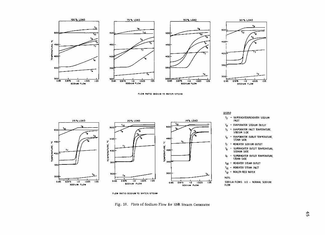
500
W 450
W
I 400
350
3001 1 I I IJ0.95 0.975 1.0 1.025 1.05
SODIUM FLOW
100% %LOAD
TB
T8
TS-T7
-T6
75/ %LOAD
Tg
500 T
T8450 -
T7
400T6
350
T4
I I I0.95 0.975 1.0 1.025 1.05
SODIUM FLOW
50% LOAD
TT
Ts
T6
T7
T4
0.95 0.975 1.0 1.025 1.05SODIUM FLOW
30% LOAD
T9
500
450 -6
400 -
350
T4300
0.95 0.975 1.0 1.025 1.05SODIUM FLOW
FLOW RATIO: SODIUM TO WATER/STEAM
25% LOAD
T
TT
450 6
TT7400-
350
300
0.95 0.975 1.0 1.025 1.05SODIUM FLOW
SOC
450
S400-
w
3500
3
500
450
4 400
aac~R
T4
0.95 0.975 1.0 1.025 1.05SODIUM FLOW
300 T 4
0.95 0.975 1.0 1.025 1.05SODIUM FLOW
LEGEND
T2 - SUPERHEATER/REHEATER SODIUMINLET
T4 - EVAPORATOR SODIUM OUTLET
T5 - EVAPORATOR INLET TEMPERATURE,SODIUM SIDE
T6 - EVAPORATOR OUTLET TEMPERATURE,STEAM SIDE
T7 - REHEATER SODIUM OUTLET
T8 - SUPERHEATER OUTLET TEMPERATURE,SODIUM SIDE
T9 - SUPERHEATER OUTLET TEMPERATURE,STEAM SIDE
T10 - REHEATER STEAM OUTLET
Tl - REHEATER STEAM INLET
T12 - BOILER-FEED WATER
NOTE:
SODIUM FLOWS: 1.0 - NORMAL SODIUMFLOW
FLOW RATIO: SODIUM TO WATER/STEAM
Fig. 18. Plots of Sodium Flow for SNR Steam Generator
U,
500
450
400
350
20% LOAD
TT
T-T
- T6
TT
v
oc
D
a
ac
W
d
2
W
H
14% LOAD
TT g
T6
-T

TO X-RAYMACHINE Il
SOURCE
/ TUBESI
OLDER TUBE
A. WELDED JOINT
HEET
ULTRASONIC PROBE
I I
TUBE HEETNICROBRAZE
B. NICROBRAZE JOINT
Fig. 19. NERATOOM Tube-to-Tube-sheetConnections Developed for SNR
FILM-
FILM HOL
Steam Generator Studies and test programs on the
helical-coil design have paralleled thosefor the straight-tube design. Flow investigations are being made to de-termine vibration of the helical coils (which are more flexible than straighttubes) and sodium-side pressure-drop data, for which limited informationis presently available.
The Hengelo model will subsequently be used as the sodium-
water reaction model for the Bensberg sodium-water reaction tests. Fab-rication areas specific to this design that may cause some concern are
(1) the bending of the tubes and (2) the preparation and connection of thetube end pieces needed to connect the helical coils to the head. NERATOOM,however, does not consider the tube-to-head joints for the non-tube-sheet
design to be a problem. Although there is confidence in existing technol-
ogy, the technique would require some proof testing on a prototypic single
tube-to-head connection.
Fretting tests between tubes and tube supports have been com-
pleted by TNO at Apeldoorn, Netherlands, and have led to finalizing clear-
ances between tubes and tube supports. To avoid self-welding of 24 Cr-1 Mo
material, a 0.4-mm diametrical clearance has been determined as a good
compromise between self-welding, vibration, and fretting considerations.
NERATOOM considers the helical-tube design to be capable ofextrapolation to greater sizes that the straight-tube design, which, asstated earlier, may be limited to about 250 MWt. In addition to the shell
46
individual tubes penetrate the shell of the
steam generator at the bottom and topheads. One loop of the SNR will have threeevaporator and three superheater modulesof this design; the other two loops will usesteam-generator modules of the straight-tube configuration. As with the straight-
tube unit, the helical-tube unit has no gasspace. Further, it has no bellows in theshell. The tubes are of larger diameter.Small sodium flows are introduced adja-cent to the tube sheets to aid in maintainingcirculation and to facilitate leak detectionin this area. Injection fittings at the upperend of the helical-tube unit will be used forthe introduction of either steam or hydrogenfor calibrating hydrogen-leak detectors. A50-MWt evaporator prototype of this helicaldesign is being fabricated and will be testedat the Hengelo facility in 1973-1974.

47
bellows, other limitations of the straight-tube design are: (1) the difficultyin maintaining tube-sheet quality in larger sizes and (2) the limited capacityof the vacuum-melt furnaces. Similarly, the heat treatment of the tube-to-
tube-sheet joints is time-consuming; one must preheat the tube sheet to
make a ring of welds, then cool to inspect, etc.
NERATOOM is also considering a single-shell design for boththe superheater and evaporator. This is particularly suitable to the helical-
coil design, which does not require a long shell. One disadvantage of such
a design is the single-tube wall thickness and tube diameter for both theevaporator and superheater. The helical-coil design of this type requirestube-to-tube welds to obtain the required tube lengths. The present design
is based on 20-m (about 66 ft) sections of tube lengths, which are trans-portable without a serious problem (35-m sections have been considered).Although 60-m-long (about 198 ft) tubes are available, they are difficult totransport. NERATOOM indicated that the helical tubes were almost equalin length, despite the different coil diameters. The maximum differencebetween tube lengths is 2 ft.
The relative cost between the straight-tube and helical-coil
designs was not known for large sizes, but based on their experience withthe Hengelo models, NERATOOM considers the fabrication costs of thehelical-tube design to be more favorable than the straight-tube design inlarge sizes. Individual tubes can be plugged in both designs, although thetechniques are different. The helical-tube design has tubes penetrating the
shell and terminating in headers on the outside. Plugging would be per-formed at the header. Ultrasonic transducers can be passed through thetubes of either unit for inspection; however, the coiled-tube unit has betteraccess for initial insertion of an ultrasonic probe.
The helical-coil design uses a 5-mm-thick shroud surroundingthe tube bundle. Effects of pinhole-type tube leaks are considered to beminimized at the shell by this shroud. A 30-mm sodium annulus betweenthe shroud and the shell also serves as a buffer against pinhole-leak effects.
The current Bensberg sodium-water reaction test model does not contain
a shroud because of interference with the required test instrumentation.
NERATOOM has begun a study on a double- and/or triple-walled-tube steam generator. The ultimate objective of this study is to
increase the integrity of a steam generator to a point where the secondarysodium circuit could be eliminated. The steam generator would be insidethe primary containment, and the design would be such as to virtually pro-hibit a sodium-water reaction. Both helical- and straight-tube designs will
be evaluated. NERATOOM does not believe a single-wall tube will meetthe needs of secondary-circuit elimination. Long-term studies in the U.K.
are underway to determine if a single-wall-tube steam generator can bedesigned in a manner to eliminate the secondary sodium system. The

48
multitube design would attempt to provide a leak-detection capability be-
tween the concentric tubes. Studies will initially concentrate on fabrication
techniques.
3. Steam-generator Tube Leak and Rupture-disk Considerations
INTERATOM does not provide a gas space over the sodium in
the SNR steam-generator modules. Cover gas is maintained in the pump
and in the expansion (surge) tank of the secondary loop. Experiments and
analytical studies have indicated that the presence of a cover-gas space
can result in very high pressures due to sodium hammer effects if sodium-
water reactions occur in the steam generator. The gas space contributes
to a delay in depressurization of the system through a delay in bursting of
a rupture disk and results in higher reaction-zone temperatures and trans-
mission of stronger pressure pulses to adjoining modules, the secondary
system, and the IHX. Without a cover-gas space, rapid depressurizationthrough the relief system occurs in the event of a tube leak, and the design
can therefore be based on the guillotine failure of a single tube. Studiesdid indicate that the depressurization-pressure pulsation problem might
be alleviated with proper design of the gas space. However, the control of
level and pressure in the gas space may present some difficulties.
INTERATOM considered the difficulties manageable within the current
state of control technology.
The initial pressure pulse that results from a guillotine tube
rupture dissipates within less than 10 msec and is of such little energythat the steam-generator structure is not affected by the burst. The sec-
ondary pressure peak is of longer duration and must be treated as a static
load in the structural analysis. The bubble growth occurs at such a rate
that a second tube failure would have to occur within 30 msec to have any
significant effect on the pressure transient.
If a large leak occurs, INTERATOM proposes that the faulted
steam-generator module be replaced by a spare unit. Reaction products
would have to be removed from the loop. Removal procedures have not
yet been developed. In the event of small leaks, the unit will be repaired
in place. At present, there is no way of accurately evaluating the extent
of damage and required repairs. There is concern that small leaks mayplug themselves and become extremely difficult to detect after cooldown.
Such an experience occurred in the 5-MWt steam-generator test facility.
Following a tube leak, the water system would be blown down
while sodium remains in the system for a period of time. Sodium would
not be dumped immediately after detection of the leak, because of concernover a possible secondary sodium-water reaction in the dump tank. The
cyclone separator has a capacity of about 6 m3 of sodium, which is greater
than the volume of one module. Test results, as well as other analytical

49
studies and laboratory results, indicate that no caustic corrosion should be
expected as a result of the large leak. The steam generator should empty
in about 40 msec. Only small amounts of reaction products are expected
to be transported to adjacent units. Maximum temperatures observed in
the reaction zone to date have been about 100 0 C. The rupture relief lines
are 250 mm in diameter, and lengths to the cyclone separator are about20 m for the line at the upper end of the modules and 40 m for the line at
the lower end.
Calculations indicated that with cover-gas space in the steamgenerator, large leaks cause pressures of 140 atm within the hydrogen
bubble. However, the sodium hammer effect in the presence of the covergas can result in a pressure of up to 500 atm. Tests have indicated the
bellows can withstand about 150 atm without failing. (For more detail,see Section VI.D.)
Statistics on tube-failure rates (the sources of these statisticswere vague) have indicated that the most pessimistic failure rate that can
be reasonably assumed for small leaks in a steam generator is one tubefailure per year. INTERATOM assumes a gross failure rate of one to
two tubes for the life of the plant.
The sodium operating pressure is 8 atm, and the rupture-disk
burst pressure is 17 atm. The waterside blowdown period is estimatedat 30-40 sec following automatic shutdown in response to disk-burst indi-
cation. The rupture disks are 150 mm in diameter and 1.1 mm thick. The
estimated life of the rupture disk is approximately 6 yr, taking account ofcorrosion and age-hardening effects. The disks are in the shape of a sec-tor of a sphere with the convex side facing the sodium. Analytical studies
indicate that for disks of the present size and larger, the peak pressure is
about the same. The present rupture-disk diameter and collector-pipedimensions have been adopted as a tradeoff between peak pressures andloadings on the relief piping. A number of tests have indicated that therupture disk fails consistently around the electron-beam seam weld that
joins the disk to its ring. Rupture disks of this type have now accumulated
17,000 hr under normal operating conditions in KNK. The disk material
is niobium-stabilized stainless steel. The rupture disks, after breaking
cleanly, pass down the relief pipe and are found in the cyclone separator.
In the initial arrangement, a single rupture disk was located in
each of the sodium headers--i.e., the sodium-inlet header to the super-heaters and reheaters, the sodium-outlet header to the superheaters and
reheaters, the sodium-outlet header from the superheater and reheater
modules, and the evaporator-discharge header. Experimental studies, to-
gether with analytical studies, indicate that with the reference arrangement,pressure oscillations occurred that would cause bellows failure. Bringing

50
the rupture disks closer to the tube-failure site (two rupture disks in series
at each end of a module unit) could eliminate the pressure oscillations andthereby protect the bellows.
4. Sodium-reheat Component and Systems Considerations
INTERATOM considers that sodium reheat has a "slight" tech-nical disadvantage, compared with plants using the other cycles. Theprimary reasons contributing to this view are: (1) Startup of a sodium-reheat plant is more complicated than plants using other cycles, and (2) theextra sodium heat-transfer area in the steam generator increases the risks
of tube leaks and resultant possible sodium-water reactions. They haveanalyzed the reheater component for all design transients, including hot-shock conditions. They consider the reheater to present a less difficultdesign problem than the evaporator. The stresses resulting from the de-sign transients considered are acceptable, and, although the dimensionsdiffer, the conceptual layout of the reheater is similar to that of the evapo-rator and superheater. In establishing design transients, they assumedthat the secondary-system pump coastdown to 5% flow required 50 sec.
5. Miscellaneous
INTERATOM indicated that, for commercial LMFBRs, theywould consider the use of four loops for reasons of safety and plantarrangement. Such an approach would permit them to operate with three
loops while the fourth loop was down for repairs.
The occurrence of a fire at KNK in spring of 1971 was briefly
discussed. An electrical submerged-type tubular heater element in a
region of flow stagnation experienced a short that resulted in a melt-through of the shell wall of the heater and loss of about 500-600 kg of
sodium. The result was a sizable fire.

51
V. DEVELOPMENT PROGRAMS FOR STEAM-GENERATION SYSTEMS
AND RELATED COMPONENTS
A. Summary and Comparison
All the countries visited were able to show an in-depth program ofengineering, development, and testing directed toward their demonstration-plant steam generators. In many areas, development work for their demon-stration plants had been completed, and ongoing work is being directedtoward their commercial plants.
Each European program had focused its early development worktoward a single reference design. At present, the French are directingtheir current work toward two new designs for the commercial LMFBR,and the Dutch-German program has established an alternative design,which will be used in one loop of the SNR. The British are also looking atalternative steam-generator design concepts for the CFR.
The French and Dutch-German programs have taken the approachof performing proof tests of large-scale models. The British did not per-form a steam-generator model test of the PFR steam generator. For the
CFR, the British plan a steam-generator model test, if the steam-generatorconcept is different from that of the PFR. This test may be in an existingEuropean facility or in a new facility to be built in the U.K.
The French program and the SNR Consortium program showed acoordinated program of testing in support of many areas of steam-generationsystem design. In particular, extensive work had been performed on rupturedisks and valves. The existence of an in-depth development program support-ing the PFR design was made evident in the discussions. This sectionreports on the information made available in support of the PFR, SNR, andPhenix demonstration plants.
B. France
1. Phenix Steam-generator System Development
Development programs supporting the design of the Phenixsteam generators and the Phenix plant systems included a 5000-hr test atthe Grand Quevilly 5-MW test facility, and full-scale module testing atLes Renardieres for over 6000 hr.
The CGVS has a capacity of 50 MWt. The Phenix steam genera-tor (CGVS) first tested at this facility was made of unstabilized 2 Cr-1 Mo.This unit, after completion of test, was removed from the building and waslocated outside in the open atmosphere. A Phenix steam-generator module,using stabilized 2* Cr-1 Mo plus niobium, was on test.

52
Steam-generator test instrumentation includes orifices used tomeasure flow and also to provide hydraulic stability. Thermocouples areplaced at the inlet of each tube and on the outside of the shell. There areno thermocouples in sodium.
The Les Renardieres facility flow is controlled by valves,whereas in the Phenix plant, flow is controlled by the pump. Maximumsize of valves being used by the French is 300 mm. These valves will betested at Les Renardieres, where valves up to 500 mm can be tested.
EDF indicated that the Les Renardieres steam-generator facilitytests Phenix modules, simulating conditions as close as possible, includingtransients such as turbine trip. However, not every transient would orcould be simulated because of possible damage to the sodium heaters. EDFstated that Phenix could handle the turbine trip. Rapid- shutdown transientshave been conducted to ensure this capability. Turbine trip followed bywater and steam-flow stoppage has not been simulated in the Phenix test.This was planned as the last test phase at Les Renardieres for the summerof 1972.
Tests completed to date in the CGVS include (1) steady-stateheat-transfer performance, (2) flow stability, (3) dynamic-response tests(e.g., response to ramp or step changes in flow), (4) simulated plantstartup, (5) simulated plant shutdown, and (6) simulation of various plantnormal, upset, and emergency operating transients. Preparations were
underway for the final emergency transients, such as loss of secondarysodium pump. Tests in which plant operating conditions have been simulatedhave essentially duplicated the planned Phenix conditions, except for the
turbine-trip case. In Phenix, turbine trip results in reheat-steam-flowstoppage; in CGVS, reheat steam flow continues because of present limita-tions in test-loop flexibility.
The French are satisfied with test results to date. There isevidence of good mechanical integrity of the Phenix steam generators.
Heat-transfer performance has been essentially as predicted. Once-
through, steam-generator flow stability has been demonstrated (with evap-orator tubes having inlet orifices) down to pressures of 90 bars. On thebasis of testing to date, EDF believes that plant operations with sodiumreheat can be carried out in a satisfactory manner.
The Phenix test was scheduled to end in July 1972; Babcock-Atlantique was to have a 45-MWt unit on the site by November 1972 andbegin testing by February 1973.
The French consider that the main results to be derived fromsuperheater and reheater component testing are in the area of metallurgicaland mechanical effects. Heat-transfer performance and flow-distribution

53
effects can be predicted with acceptable accuracy, and testing of an evap-orator together with analytical modeling can provide needed controlinformation.
The French position regarding required sizes of test units isthat an assembly of units totaling 45 MWt will provide the necessary con-fidence that full-size units will perform satisfactorily in a commercial
plant. Test units of this size will have essentially the same characteristicsas plant units in the areas of steady-state heat transfer, flow stability and
distribution, metallurgical effect, and (to a large extent, depending upondesign) mechanical behavior. With the test units having tubes of the samedimensions as the commercial units, the dynamic performance of the modelswould be similar to that of the plant units. The differences in shell timeconstant due to differences in wall thickness should be a second-order
effect, which can be accounted for in analyzing test results for plant-performance predictions.
The French have a mixing-tee arrangement, which can beeither single- or double-stage. The design has a divided-honeycombarrangement parallel to the pipe flow. One of the flows to be mixed entersperpendicularly to the mixing chamber; the other flows through the pipeand the honeycomb. This type of mixing tee has been tested with 200 C
differential temperatures in the fluids and has performed satisfactorily.
The French are using BSB membrane-type rupture disks,purchased in the United States. A major factor in the life of the rupture
disk is the fact that it must not operate near the yield point if a long lifeis expected. The French situate the rupture disk approximately 1 m awayfrom the flow stream.
They have tested a number of these disks and found considerablescatter in the test data; they plan to change the membrane in the plant whenthey have performed further tests. They have two new types of rupturedisks under consideration: the BSB modified, which is a welded arrange-
ment, and a device of their own, which is welded in a special support with
a cutter at the back. They feel that this membrane can be calibrated better.
In the 1000-hr tests on these disks, different types of tests are performed,including thermal and pressure cycling. The disks are about 200 mm in
diameter and are made of Type 316 stainless steel. They believe that, ofthe BSB disks, the RB 90 is the best. The test arrangement being used by
the French contains two disk assemblies and three chambers containinggas and sodium.
2. Steam Generator under Development for 1000-MW Plant
Two French companies- - Babcock-Atlantique and SteinIndustrie--have joined CEA and EDF in a common program.

54
a. Babcock-Atlantique
The tube bundles are helical. This generator, 290 MWt (iftwo units per loop) or 580 MWt (if one unit per loop), is most suited to asteam cycle without sodium reheat. The main stage of this developmentis the construction of a 45-MWt mockup for endurance testing in 1973 atthe Les Renardieres EDF steam-generator test facility. This model willconsist of a 24-tube bundle forming three rows between two concentricshells, with a 1-m external diameter. It is fed by hot sodium at 550 C(1022 F) and water at 2400C (554 F) and produces steam at 167 bars(2455 psig) and 510 C (950 F). The tubes are made of Incoloy 800, thewater and steam connections of 2.25 Cr-1 Mo. The model, after test atLes Renardieres, will be sent to Cadarache for a sodium-water reactiontest.
b. Stein Industrie
This steam generator is a counterflow module having a
bundle of straight tubes with a Z-type expansion bend in the gas spacebelow the tophead. The steam generator consists of separate evaporatorand superheater units. Such a module has 580-MWt power, or four unitsfor a 1000-MWe plant. It is proposed to fabricate the steam generator with
a stabilized ferritic steel (2.25 Cr-1 Mo-0.4 Nb-0.4 V).
A 45-MWt model will be tested at Les Renardieres in 1974.This model will have a 44-tube bundle. After the Les Renardieres test, themodel will be shipped to Cadarache for sodium-water reaction tests.
3. Valve s
The French CEA and EDF are cooperating in the development
of LMFBR valves. The valves being developed include (a) shutoff valves,
(b) flow-regulation valves, and (c) trimming valves. The design require-
ments for a number of these valves are dictated by the steam-generator
system design. A specific example is the large secondary-system sodium-water isolation valve. This unique valve is manufactured by Neyrpic. Thevalve operates by the rotation of the main assembly through 900 and a
downward motion of 30 mm. The assembly includes a toggle arrangement,which closes the valve. This valve is shown in Fig. 20, and the operatingmechanism is outlined in Fig. 21. The valve is located in the 494-mm-IDsecondary-system line, and the valve has an internal-port diameter of
380 mm.
Valve-testing facilities located at Les Renardieres include avalve loop and a sliding friction testing machine. These facilities and
current valve-development work are described in Ref. 3.
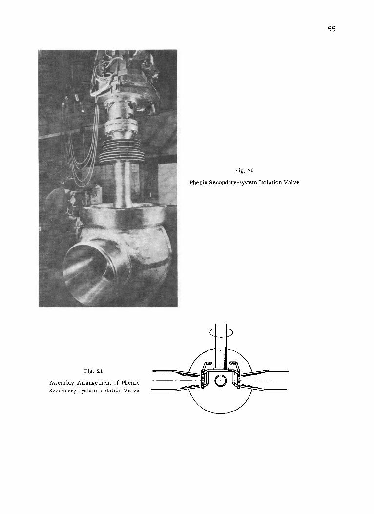
55
Fig. 20
Phenix Secondary-system Isolation Valve
Fig. 21
Assembly Arrangement of Phenix
Secondary-system Isolation Valve
i

56
C. United Kingdom
The British steam-generator development problems requiring workare outlined in Ref. 1. Though an outline of the British development pro-grams that have been or are being conducted in support of the PFR Steam
Generator design was not presented, the following information was obtained
in response to specific questions.
Hydraulic-stability analysis and test were not required for the super-
heater or reheater, but the fabricator has performed hydraulic-stability
analyses and tests for the evaporator, using three tubes in parallel. These
tests were done without orifices. Instabilities were present only if dryoutwas achieved in one tube, where dryout is defined as the point inside the
tube at which the tube is no longer wetted. Though confident that they maynot be needed, orifices have been installed in the evaporator tubes with a
pressure drop equal to the tube-side pressure drop without the orifices.
This approximately doubles the steam-side pressure drop.
The stability tests were electrically heated. Many dryout testshave been performed. The margin of 1.6* is satisfactory, since it repre-
sents the condition that would exist with heavily fouled tubes and one com-
pletely cleaned tube.
Magnetite is an iron oxide layer (FezO 3 ) formed inside the tube in
the absence of oxygen. A design goal was to avoid cracks in the magnetic
layer. The tests indicated a dryout of approximately 20C. This is notconsidered sufficient to crack the magnetite layer. However, tests will be
performed with various water qualities to see what water-quality range
can be used for off-normal operating conditions. A problem is the unknown
corrosive mechanisms that may exist at the dryout point, even though the
AT is relatively small.
There is a 10/ continuous blowdown from the steam drum. This re-
sults in a 1001 concentration of solids in the recirculation system. The
system is dosed and has a pH of 9-9.5. If blowdown is required after a
sodium reaction, blowdown will be done from both the drum and the evap-
orator. With this arrangement, safety valves are needed on the evaporator
as well as on the steam drum. Such safety valves have been provided in
the PFR.
A significant amount of weld development has been performed inparallel with the design and fabrication of the plant units. Initially, many
problems were encountered with minute cracks in the tailoff of the tube-
to-tube-sheet welds. This problem was resolved by connecting the weldingtorch to a computer, which programs the runoff so that the cracks are
minimized. Finally, a small dental-type drill is used in any suspect area
*Margin of 1.6 presumably means the margin of recirculation available.

57
for cleanup and final finish. Cracks observed were 10 mils long and 2 milsdeep. The cracks are probably due to chromium in the tube. The chromiumcarbide balance must be correct. Also, the commercial Type 316 stainless
steel specification has too wide a range for chromium and ferrite. TNPG
establishes its own specification.
Research and development for the tube-to-tube-sheet welds was
done over a 2-year period. The tube holes were bored and welds made(see Fig. 16). The degree of penetration into the tube sheet was veryimportant and had to be controlled to 2 mils. Before being welded, the
tube was lightly rolled into the tube sheet to ensure good contact and uni-form current. The initial weld-development work was on single tubes, thenon seven-tube arrays using full-scale U-tubes, and finally on weld sectionscontaining 100 full-scale U-tubes. This last series essentially meant fabri-
cating partial tube bundles.
A special "mouse" has been developed for measuring wall thicknessin the PFR steam generators. This is either an ultrasonic or eddy-current
mouse, which measures wall thickness to within 10 mils. This probe will
not go through the inside two rows of the units, because the bends are too
tight. Development work is being done by instrument developers in Germany
to permit the mouse to go through the inner two rows. The mouse isgreased, and the grease helps to maintain the contact during passage of the
mouse through the tubes.
The British have worked on nondestructive test (NDT) developmentat Dounreay in parallel with the large sodium-water-reaction test work in
Super-NOAH.
The work done on flow visualization for the PFR steam generatorswas with plastic models of 5/16 scale. A water-flow test of one of thesecondary loops will provide further information.
Fretting work has been done in 6000C (1112F) sodium containing
10 ppm oxygen. Separate high-amplitude sliding and tapping tests were
performed for the reheater and superheater; one simulated the expansionand contraction due to thermal effects, and the other simulated vibration
effects. No damage of concern was found in these tests. The tests will bereported after information is obtained from the secondary-loop water-flow
tests.
Proposals are being negotiated for a U.K. facility for heat-exchanger
testing. Also under consideration is the use of available European facilities
such as Hengelo. Economics of a test facility dictate a facility much
smaller than 200 MWt. A rig is being considered to handle full- size andfull-length tubes, but only a segment of the unit. The British consider it
important to pay careful attention to adequately instrumenting the testprogram.

58
The British expressed a need for a steam-generator systems test.For a nonreheat system, this would involve an evaporator and a super-
heater with associated piping and valves. For a sodium-reheat system,the evaporator and superheater could be tested together and the reheatertested separately, simulating other system inputs obtained from theevaporator-superheater test. Such tests would be systems tests andinstrumentation and control tests, rather than proof tests of prototypemodels.
The U.K. has abandoned the PFR primary-system hydrodynamicwater test. They intend to perform a water-flow test of one of the secondaryloops, which may have been done by the end of August 1972. The informationto be obtained from this water-flow test would include vibration, accelera-tion, level changes, gas entrainment, and pump performance. The Britishfeel they have assurance that gas entrainment will not occur in the primarycircuit as a result of model testing they have performed.
D. Germany- -INTERATOM
1. Development of SNR Steam Generator
The Dutch are taking the lead in the development of SNR steamgenerators. The major steam-generator-related development atINTERATOM is on sodium-water reactions (this work is reported inSection VI.D).
INTERATOM has a 5-MWt steam-generator test facility atBensberg. Results were satisfactory, but larger-scale tests were necessaryto obtain extrapolable results. Stability tests were performed in the 5-MWtmodel in which sodium flow was varied while the water flow was keptconstant.
INTERATOM has also performed steam-generator water-flowtests at one-third scale. These tests were for water-distribution andvibration effects. Particular emphasis on the tests was on the inlet region.
2. Valves
A special butterfly valve for use in sodium has been developedfor isolating the SNR steam generators. This valve has been tested in600- and 350-mm sizes. The valves are of an unconventional offcenterdesign with a sloped seat and nearly no friction at the seat. The valvesused for isolating the steam generators can be operated in 10 sec. Normalflow velocity of the sodium is about 6 m/sec.
The freeze seal on the valve stem has been satisfactorilytested. The freeze seal is backed up by a stuffing box. Leakage of the350-mm valve has been measured at 1 m3/hr at a AP of 1 atm. The

59
isolation valves prevent sodium-water reaction products from entering theintermediate heat exchanger. These valves are not intended to isolate thesystem for maintenance purposes. Valve closure results in a sodiumhammer of only 4-5 bars.
A 350-mm isolation valve has been tested under thermal-shockconditions, 4-5'C/sec over 100 C with no observable malfunction of thevalve. This valve has had a test life of about 5000 hr under various condi-tions. The valve has been operated under cavitation conditions at 15 m/sec,and erosion and pits have been observed on the spindle and behind the disk.The valve continued to function, and there was no damage to the bearingaround the valve stem. Cavitation was the result of low pressure duringpump test. Relocating the valve to a high-pressure region has avoidedfurther cavitation.
The 600-mm valve has been tested for 1500 hr. It has not beensubjected to thermal-shock tests.
The 250-mm sodium-flow-trim valve (nondrainable) for SNR isa single-blade gate valve. Tests on a 200-mm trim vlave for KNK wereconducted in Karlsruhe. Based on these tests, further tests for SNR trimvalves were not needed.
The SNR primary valves are a Neyrpic French design. A600-mm valve of this type was scheduled to be tested in July 1972. A450-mm valve has been tested with a 5-liter/hr leak rate. This is a split-
ball rotating valve. In the open position, the ball is rotated to where thereis essentially unrestricted passage through the valve. To seat the valve,it is rotated 900 and the shutoff disks are cammed into position on the valveseats by vertical motion of the valve stem, which operates a series ofmechanical linkages attached to the disks. (See Figs. 20 and 21.)
E. Netherlands
1. Tests on SNR Steam-generator Thermal Model at Hengelo
At present, the straight-tube steam-generator design for theSNR and the reference IHX design for SNR are being tested in the HengeloSteam Generator Test Facility. The steam generator consists of a straight-tube evaporator, superheater, and reheater. The superheater and reheaterare in parallel, both in series with the evaporator. The reheater is nolonger included in the SNR reference steam generator. Approximately3 weeks of steaming operation had been attained with the facility at thetime of the team visit, and a thermal power of up to 25 MWt had beenachieved.
The overall performance of the steam-generator model up tothe 25% load condition, reached for a short period of time, is close to

60
predictions. Some areas had lower heat transfer; others had higher. Adetailed analysis was yet to be made. The nucleate boiling region of theevaporator heat transfer was better than predicted; the mist flow andtransition region of the evaporator yielded poorer heat transfer than
predicted.
The superheater and reheater performances were in goodagreement with prediction. The differences in heat transfer in the evapo-rator agreed with the qualitative results obtained from the Apeldoorn
single-tube SWISH experiments. No instabilities were noted in the units.However, instability measurements were not made at very low load. Noorifices are included in the tube of the units. At 25 MWt, the superheater-inlet steam quality is 907.
There have been no reheater problems during startup. Proper
temperatures are maintained, since the steam temperature coming out ofthe reheater and superheater is very close to the sodium temperature under
all loads. A steam bypass is used similar to the bypass arrangement usedfor large fossil plants during startup and up to approximately 30% load.
The Hengelo steam-generator tests will (1) confirm the heattransfer, (2) detect any possibility of instability on the waterside, (3) collectdetailed results of the effectiveness of the thermal baffles in protecting thetube sheets (about 100 thermocouples were installed in the Hengelo modelfor this purpose), and (4) monitor the shell bellows to confirm that thedisplacements are as predicted.
Steam-generator tests that have been performed include full-scale water-flow distribution tests at Apeldoorn to obtain information on
radial-flow patterns and temperature distributions. These tests also pro-vided detailed information to assist in the stress analysis of the units. TheDutch considered an important factor in obtaining a good distribution is tohave the tolerances and s tr aightne s s e s of the tubes maintained to fine
tolerances. One area in which they have done a lot of work is in the
thermal baffles that protect the tube sheet and the shell. These are multi-layered labyrinth-type baffles and have been tested to ensure they meetrequired performance.
The Dutch believe they have no reliable data on sodium-sidepressure drop. They indicated that the testing program they planned for
the 50-MWt helical-coil evaporator was part of a development programfor the helical-coil unit, which was similar to that which had been performed
for the straight-tube unit.
The Dutch cannot test a large superheater, due to the sodiumflow required for the superheater test and the lack of a suitable steamsource onsite. Although the future test will be of an evaporator alone, some

61
of the NERATOOM staff feel that system tests are still important. Peopleat Hengelo stated that there is a trade-off in benefits between componentsize and system information to be obtained.
The evaporator, in comparison with the other units, has majorproblems associated with fabrication, heat transfer, and stability. The testof as large a unit as possible is required to prove the evaporator capabilityto the maximum, including the adequacy of fabrication. If tests of otherunits were desirable, it would be sufficient to test the superheater, if it isof the same design as the reheater.
Testing philosophy was discussed. The Dutch stated that theywould feel it necessary to perform an overall systems test first. With aninitial systems test and with confirmatory plant operation, future testsneed only be for large components rather than systems, unless there wasa major change in the system arrangement. The Dutch stated that 50-MWt
tests could be extrapolated to commercial-size units, and there are noplans to test a larger unit than could be tested at Hengelo. If a new typeunit is to be designed, their approach would be to test it as a component atHengelo at the 50-MWt level and then extrapolate this unit to larger sizes.
Many minor problems have been experienced during the heatupof the steam generator, and the Dutch were interested in the demands of areactor system with respect to startup of the steam generator. Problemsexperienced have been with the evaporator when steam condenses in theunit and some water drips to the lower sections. This can cause thermalshocks and large differences in temperatures. Also, problems haveoccurred in obtaining exactly the right evaporator temperature beforeintroduction of feedwater.
It was initially difficult to obtain the proper AT's on the tubesheets, and it now takes approximately one-half day to preheat the steamgenerator from a cold condition to a minimum power condition. It is easier
on a hot start to go down to 2000C and restart very quickly.
The Dutch were interested in knowing if it is worthwhile toeither artificially foul the waterside of the steam generator or conductvery long-duration tests at steady state to determine fouling. Such testsare being considered.
Cold thermal shocks are planned on the present units, about110 C in 20 sec. Actual operation provides the most severe thermal shocks,such as those ensuing after turbine trip and reactor scram. These shockshave been unintentional and include a transient induced by steam safety-valve operation, which occurred during the sodium fire. The maximumshock that can be imposed at the steam generators intentionally is 5C/sec.

62
No vibration testing or measurements are being performed inthe steam-generator test. Vibration and flow- distribution measurementswere made in models tested in water at Apeldoorn. Only preheat-startupand steady-state tests up to 25 MWt have been conducted on the presentunits.
The hydrides and free-hydrogen concentration in the system
change with temperature. Thus, the Dutch are concerned at Hengelo that
the leak-detection system may have difficulty in detecting the hydrogen
due to a sodium-water reaction. The method proposed is to measure theinlet and outlet conditions of the unit. Under consideration is the control
of hydrogen level in the system by flushing out the argon cover gas from
the expansion-tank cover space. Plans are to install a hydrogen detectorin the gas space in the expansion tank, to measure the hydrogen concentra-
tion in the system, flush out the argon and associated hydrogen, put cleanargon in, and allow the gas space to fill up with free hydrogen from the
system. There is some question as to the possibility of such a systemproviding control of the loop hydrogen. (Note: The suggestion of having a
hydrogen sink in the secondary system was previously advanced by
Gene Hill of Varian. This was not discussed at the meeting.)
The hydrogen level at Hengelo is 0.5-1.0 part per million (ppm)ranging up to 2.0 ppm. The Dutch intend to control the hydrogen level in
the sodium by flushing the gas space to a level of approximately 0.1 ppm.
The purging rate and other factors were yet to be determined, as well as
the sensitivity of the hydrogen meter.
2. Steam-generator Development Test at Apeldoorn (TNO)
The SWISH loop, originally used for supercritical water tests,
is now being used for subcritical heat-transfer studies simulating an SNR
10-m-long, 8-mm- inner-diameter, 2-mm-thick-wall steam-generator
tube. For reasons of strength the SWISH loop steam-generator tube ismade of Type 347 stainless steel, so that it is capable of 300 bars and550 C on the steam side. Sodium surrounds the steam-generator tube,
which is filled with water. The TNO Metallurgical Institute specified the
Type 347 stainless steel for supercritical pressures. The loop is operated
at 6000C; it is a 0.5-MWt loop with 5-m3/hr capability and is used for heat-
transfer studies. The electrical heat source for the loop consists of100 5-kWt heaters. The loop is divided for instrumentation into four1-m-long sections and three 2-m-long sections. The subcritical tube is
operated from 40 to 190 bars. Flow, power, and subcooling can be changed.
Low flow conditions are simulated by a bypass arrangement. Temperaturesare measured at the inlet and outlet of the 10-m-long tube, as well as at
many points in the upper three 2-m-long sections. At these points, tempera-
tures are measured on the inside and outside of the wall as well as of the
water. The thermocouple connections to the steam-generator tube are

63
shown in Fig. 22.
leg not insulated.
WATERr
The thermocouples are 20 mils in diameter with the hotThere are 100 nonreplaceable thermocouples, spaced at
5-cm intervals in each of the top/STEAM-GENERATOR TUBE three 2-m sections of the tube.
-0.080" TEST ENVELOPE
- 0.070
0S020
SO'IUM
7
V
/
TEST ENVELOPE
ATR SODIUM Tc
ST EAM-GENERATOR TUBE
Tube fabrication alone (with-out design) cost about $10,000 andtook 9 months to complete. Stabilityphenomena and other phenomenaassociated with the Hengelo steamgenerators are studied in the SWISHloop. Void fractions can be measuredby high-speed photography and byX ray at the exit of the tube. Water-side AP measurements are alsomade. Studies to date have indicatedno instabilities on the single tube--
not even under low-load conditions.
Tests indicate that existing methods
of prediction result in DNB at toohigh a quality. Also, the measuredheat flux with DNB was higher thanpredicted.
Fig. 22. SWISH Loop Thermocouple Con- Low-load conditions havenections to Steam-generator Tube been simulated by a bypass arrange-
ment. For the helical-coil steam-generator concept, the SWISH loop will be converted from the single straighttube to two helical tubes, each of full length but of different coil diameters.
The Dutch stated that they had performed fretting tests insodium. The tests had established design clearances. The Dutch experi-enced fretting and metal transfer in these tests. For design, they had toestablish a clearance that was neither too small, so that fretting took
place, nor too large, so that vibration was possible. They established a0.4-mm diametral clearance for the steam generators.
Water-test facilities are located at Apeldoorn. These facilitieshad been used for waterflow tests of the SNR test-model steam generatorsand IHX's. The flow-test model was 0.8 full scale. Only the evaporatormodel was tested. The flow-test facility is currently being used to test amockup of the degasifier at the bottom of the SNR reactor core.
3. Component and Weld Surface Cleaning
Component cleaning is accomplished with an initial nitrogenflow, followed by a slowly increasing moisture content until all the sodium
rBoss
TUBE
BRAZE TC
1
I

64
has reacted. The unit is operated and maintained in this oxidized condition.An alternative method used is to heat the component and vacuum-distill thesodium.
The experience with welding sodium- contaminated piping hasnot been good, even after the sodium film was removed one to two feet from
the weld. The heat from welding melts the sodium, which flows into theweld area. The resulting welds do not meet requirements. Specifically,
the root pass has been found to have defects. These defects were observedusing double-wall X rays and dye tests.
Discussion took place on the means of cleaning a system before
welding. At Hengelo it has been determined that clean surfaces are neces-
sary to achieve welding standards. One method is to mechanically clean
the surface before welding. There is also concern about welding in remote
locations or in drain-tank nozzles when there is sodium in the system.
According to the Dutch, this area of technology has received limited
attention in the nations with LMFBR programs.

65
VI. SODIUM-WATER REACTION PROGRAMS AND TEST SITES
A. Summary and Comparison
The British, French, and Germans have had major sodium-waterreaction programs in progress for a number of years. These programsare continuing and even expanding. Each of these countries has delegatedthe direction of these programs to a single engineer: British, UKAEA:A.Bray; French, CEA: N. Lions; and Germany, INTERATOM: K. Dumm.
The French at Cadarache, the Germans at INTERATOM in Bensberg, andthe English UKAEA at Dounreay have conducted large-scale sodium-waterreaction testing of full-scale tube ruptures in representative steam-generator models using many tubes, and plan to continue such testing foreach new steam-generator concept.
Based on the French and German experience with small-diametermodular units not containing a cover-gas space, relief is required at ornear the steam generator. The Germans found that including a cover-gas
space in a modular unit results in excessive oscillatory pressure peakshaving a period such that they are reflected as a static loading on the shell.For this reason, none of the designs for SNR have a cover gas. The French,on the other hand, are considering large units with a cover-gas space forthe commercial plant, and all the British designs, including the PFR, use
cover-gas spaces. Both the Germans and French find that the initial sharppressure peak is of such a short duration with respect to the shell naturalperiod that it is not significantly reflected in strain of the shell. This initialpeak was not present in the British tests. However, the method used toinitiate the reaction is such that the peak would not be expected. The Britishare now modifying their injection system to more closely simulate an actual
tube rupture.
The large-leak tests indicate that the reaction with water moreprobably goes to sodium hydroxide and hydrogen, rather than sodium oxide
and hydrogen. For the steam-sodium reaction, the German tests showed
that the pressure effects are considerably different than the corresponding
water reaction, indicating that the reaction mechanism is not the same for.
both cases. The German large-leak results indicate that for the samefailure, a steam leak is potentially more damaging than a water leak.
All countries consider the rupture of a single tube to be the maxi-mum initial accident. However, the British design basis is a single tubefollowed by six additional tubes failing within 20 sec. Although propagationof a large leak to other tubes is considered an unlikely problem in modular
units, this potential problem is increased for larger units where high-temperature tube failures might occur.
The maximum temperatures measured during the large-leak tests
were 1300*C in the French tests and 1000-1100*C in the German tests. The

66
difference might result from the difference in size and geometry between
the two test sections. Also, a film of sodium is left on the tubes following
expulsion of the sodium by the reaction, and this film reacts with steam
from the leaking tube, causing high temperatures.
Turnaround times for the large-leak facilities vary considerably
between the three countries: 4-5 weeks for the British NOAH, 6-12 months
for the British Super-NOAH, 3-4 months for the Germans, and 1 month for
the French. The variation in turnaround time appears to be affected by the
size of the test section, the facilities available for cleanup, the procedures
used, and the priority of the program compared to other programs competing
for manpower.
Mathematical models that reasonably agree with experimental re-sults have been developed in all three countries for predicting the effects
of large leaks. The German and French models include the effects of the
compressibility of the sodium; the British model does not. A sophisticated
treatment of the reaction mechanism using a diffusion-mass transfer model
is provided in the British model. All codes are one dimensional and provide
for variations in water leak rate as a function of reaction pressure. The
hydrogen-bubble temperature used in these models is generally 100 0 C.
Experience with simulant testing in Germany and Britain indicates
that these tests are worthwhile, but cannot duplicate a sodium-water reac-
tion. Simulation could possibly be used to duplicate a predetermined
sodium-steam reaction and may be beneficial in the shakedown of a large
sodium-water reaction facility. Such tests can provide results for major
changes in the test-section geometry. However, quantitative simulation of
a reaction is not possible.
Existing steam-generator sodium-water- reaction relief-system
designs usually consist of a knockout tank and a cyclone-type separator and
have proved adequate for containing the effluent solid and liquid reaction
products. Rupture-disk technology appears well in hand, with special
designs developed where creep is not a problem, and replaceability has
been provided.
All three countries have conducted small water and steam-leak tests
at the same site as the large sodium-water reaction tests, and they are
building or have built larger small-leak facilities of a size similar to
APDA's Rig 10.4 Tests in France indicate that sodium velocity is an im-
portant parameter for wastage. The Germans have succeeded in confirming
the APDA wastage data for water leaks within 20%, and leaks with high-temperature steam produced greater wastage rates than equivalent leaks of
water. The French are concerned that corrosion at the site of a very small
leak could lead to a large leak problem.

67
The reference hydrogen leak-detection system is a hydrogen-diffusion tube made of nickel; most countries use an ion vacuum pump onthe tube. The British currently use a thermal-conductivity cell, but theyare taking a second look at changing to an ion pump. Work on acousticdetection is still in progress in all countries; however, its feasibility isstill inconclusive. Experience in the Hengelo steam-generator test facilityindicates that fluctuations in the background hydrogen level in the sodium
could be a problem for leak detection. The Dutch are attempting to reducethis background level by using a gas-space diffusion device to removehydrogen. The Germans, Dutch, and French are working on advancedhydrogen-diffusion tube-leak detector technology.
In addition to this report, Refs. 5 and 6 contain detailed informationon the sodium-water reaction programs and results for these three countries.
B. France
The French have been conducting sodium-water reaction tests for a
number of years and are planning a continuing and expanding program inthis area. Most of these tests are conducted by the CEA at Cadarache.However, some special small-leak testing is being conducted at theLes Renardieres and Chatou facilities of EDF, and digital-computer analy-sis is being done at Saclay.
1. Large-leak Test Facilities
Sodium-water reaction test facilities at Cadarache are capableof testing full-scale steam-generator tubes in a model of the steam gener-ator. More detailed descriptions of the test rig appear in Refs. 7-9, and aschematic is shown in Fig. 23. For Phenix, the tests consisted of one full-scale module of seven tubes. Each test consisted of rupturing one tube out
of the seven. Water flow rate from the ruptured tube in the full-scale
sodium-water reaction test facility was measured indirectly by checkingthe flow in a ruptured tube in a separate device and comparing this with a
formula used for the actual test facility. The single tube to be ruptured is
cut by a hydraulic shearing device, which deforms the tube during the
shearing. The actual cross-sectional area of the tube cut was determined
after the test. There was no indication as to how the effects of the reaction
on the cross-sectional area were accounted for.
2. Large-leak Test Results
The test results have been previously reported in Refs. 7-10,and no new results were presented. The results are discussed briefly inSection B.8 below.

EXPANSION TANK--- S
T
PLUGGING - -
INDICAJOR t
I- -
COLD
TRAPPRO]
III T T - (
n1I cr7 rrT I 1
UIJLIRPTLR IC -
- INLET RUPTURE DISC- OUTLET RUPTURE DISC
DRAIN TANK
, SPARK PLUG LEAK DETECTOR
PRESSURE SENSORIMMERSED THERMOCOUPLESTHERMOCOUPLES IN WELLS
URGE'ANK
H20
CONDENSERLw
its. f 1 /
TOTY PE PHEN IX MODULE 4f
CYCLONESEPARATOR
WALL THERMOCOUPLES* FLOWMETERS
STRAIN GAUGES
Fig. 23. Sodium-Water Reaction Test Loop for Phenix Modules
00
-
1
_ 77 71111177 117T

69
3. Large-leak Mathematical Models
Sodium-water/steam analyses are accomplished by means of
digital computation at Saclay and by analog at Cadarache. The French
model is described in detail in Refs. 7 and 10.
4. Large-leak Future Plans
The Babcock-Atlantique (coiled-tube) steam-generator sodium-water reaction tests have been initiated. A progression of five shots hasbeen made, using only one tube in a simplified model. The number of tubes
and extent of modeling will be increased as more information is gained onthe characteristics of the one-tube sodium-water reaction test. A new
large test facility adjacent to the existing facility is being constructed. Theframework was underway. This new facility will initially be used to testfull-scale tubes of Babcock-Atlantique (coiled-tube) and Stein Industrie
(straight-tube) steam generators. There is a planned sequence: (1) Use
the existing test facility to the fullest extent possible; (2) proceed to
larger models in the new facility; and (3) eventually test the 45-MWtevaporator models shipped from Les Renardieres--the Babcock-Atlantique
unit and the Stein Industrie unit. These units would be shipped to Cadarache
already instrumented to a large degree after completion of steam-generator
tests at Les Renardieres.
5. Large-leak Test Instrumentation
To measure the sodium-water reaction wave front, the French
used 0.35- to 0.50-mm-OD thermocouples. These thermocouples have to
be replaced after two sodium-water reactions. A more detailed description
of the instrumentation is given in Ref. 7.
6. Large-leak Test Facility Operation
Approximately one month is required to reconstitute the test rig
in preparation for another test.
7. Relief Systems
Phenix uses BSB rupture disks, shown in Fig. 24, which have
been working satisfactorily. Three pairs of these 150-mm-dia disks are
in each of the three steam-generator units, a seventh being located at the
surge tank. Advanced rupture disks under development at Les Renardieresand Saclay for the 1000-MWe Phenix-type reactor plant will be 200-250 mm
in diameter.
A tour of the sodium-water reaction test site at Cadaracheshowed a one-stage separator at the bottom of the stack. The reaction

Argon Injection
(Intermediate iArgonChamber Chamber
ps
The first large-leak ex-
periments produced serious pressure
and velocity effects and severe dam-
- - - age because no surge tank was located
Spark Plugs for close to the sodium-inlet side of theLeak Detection
sodium-water reaction model. After
Fig. 24. BSB Type DV Rupture Disks Used at initial experiments, a surge or buffer
Les Renardieres Steam-generator tank was provided and the resultant
Test Site pressure at the IHX was reduced from
about 21 bars to about 9-10 bars. An
expansion tank contains the sodium pump, but this did not reduce the peak
pressures because the tank is located on the sodium-discharge side of the
steam generator. As a consequence of the test results, the Phenix design
was provided with a surge tank located on the sodium inlet to the steam
generator. The normal pressure in the Phenix surge tank is 8-10 bars.
The Phenix design is based on the rupture of only one tube. Lions indicated
that the Phenix IHX (designed for 15 bars) is the limiting component with
respect to failure from a reaction.
In addition to the buffer tank, protection against sodium-waterreaction pressures is provided by (a) a system of seven rupture disks persteam generator (mounted two in tandem at each of seven points to protect
against inadvertent failure), discharging to a separator; (b) a sodium dumptank, to receive secondary sodium from steam generators; (c) quick-closing,nonautomatic sodium valves, to isolate the steam generator from the
70
N',
wI
products on the ground have amounted
to approximately 5 mg/m2 for each
shot. The test facility takes up pipeexpansion between the sodium-water
reaction unit and the separator by
means of a sliding-pipe connection
using a graphite seal. N. Lions (incharge of the sodium-water reaction
program) indicated that a rupture
disk, which initially was in the Phenix
surge tank in the gas space, has been
relocated at the bottom, in sodium.
There was no confidence that the disk
would work in the gas space. Further,
excessive corrosion of the disk may
result in the cover gas. The Phenix
pump tank also has a pressure relief
valve.
8. Design and Analysis for
Sodium-Water ReactionssoDiu.

71
remainder of the secondary systems; and (d) a hydrogen-detection system
for each steam generator, fitted with a sodium-selector valve, which can
sample any of 12 modules or take a mixed sample from all simultaneously.
The 1000-MWe steam generators are designed to have a gasspace within the steam generator. The gas volume and pressures will be
varied using a sodium-level control.
9. Small-leak Test Facilities
Special tests are being conducted at the Les Renardieres facilityon caustic corrosion in small cracks. The test rig for this work is entitled
"Cacau." Small cracks are fabricated by tension fatigue using helium-mass-spectrometer and ultrasonic measurements to determine when a crack has
penetrated the wall and what the leak rate through the crack is. The thimblerepresenting a steam-generator tube is then put in a sodium-filled pot(3 liters of sodium), and pressurized water (169 bars, 2350 psig) is providedinside the tube. A helium leak rate equivalent to 10~ -4l/sec is achieved.
Caustic corrosion occurs in the crack, forming a brittle plug. The French
- Nitrogen are afraid that failure of thisplug could cause a large sodium-
water Reservoir Sodium water reaction. Materials toReheater - - be tested in this facility are
Croloy, followed by Type 321stainless steel. The tubes are
immersed in sodium for- Flowmeter E. M. Pump m i SOdum f
---eEMPp1600 hr or more and then ex-
amined. Hydrogen-detectioncapability is provided.
Test Section Sample Tube
* Ii Wastage tests are
L. _
Injector -
]s Disk- Economizer
-" FilterNitrogen
Nitrogen Cold .
Trap --
- 2 DischargeReservoir
Fig. 25. Schematic of Small-leak Sodium-WaterReaction Facility at Cadarache
being conducted at Chatou (in
addition to Cadarache) usingholes as small as 20 microns,
which are drilled with a laser
beam. The wastage tests at
Cadarache are conducted in
the facility shown in Fig. 25.
10. Results of Small-leak Tests
Most small-leaktests are conducted at Cadarache.The pinhole wastage tests havebeen conducted for the pastseveral years. Several

72
specimens having pinhole effects were shown. Lions indicated that the
sodium flow velocity is important, as illustrated in Fig. 26 (from Ref. 8).If the velocity is less than a certain value (about 3-5 ft/sec), damage
could be obtained in adjacent tubes. Small-leak (pinhole) tests have been
conducted at a rate of three or four per week. This indicates that the CEA
has accumulated a large amount of small-leak data.
+_
" A 0.3 -
S A 0.05-0.3 - _ -*
100
I
B
5mme28x 4
I
10EE
b-
m1
0.10,1
A
Leakage Flow g/sec
Fig. 26. French Small-leak Test Results for 2 Cr-1 Mo-1 Nb
11. Leak Detection
Leak detection in the Phenix modules is provided by a 0.3-mm-
thick hydrogen-diffusion membrane, made of nickel. An ion pump is coupled
with a sodium-sampling manifold system. The manifold system samples theinlet and outlet of each module or a mixed sample from a group of 12 mod-ules. The location of the leak-detection system in the Phenix secondary
circuits is shown in Fig. 27, and the system itself is shown in Fig. 28.
Mass spectrometers had previously been used, but have been dropped in
favor of the ion pump. The French have measured hydrogen-diffusion rates
through the tubes of a module equal to 10 mg/hr per module. This worksout to a diffusion rate of approximately 0.2 mg/hr per square meter. Ini-tially, when the unit is first started up, the rate is three to four times as high.
Sodium WaterSymbol Tube
Velocity,m/sec Temp.* C Temp.* C Pressure, bars
o A 2.5-3 350 320 170
* B 2.5-3_33
"
"+
100
A 0.8-1 - r -r
I
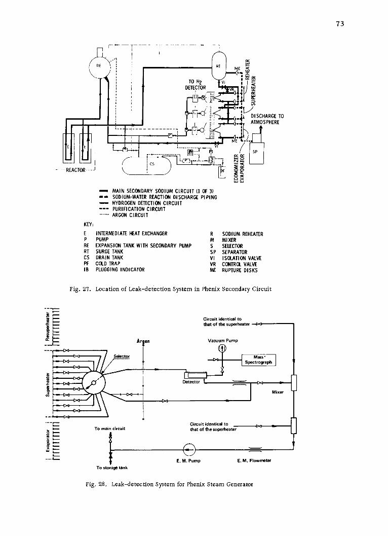
73
RE RT ME
TO H2 viDETECTOR v W
--- 1 DISCHARGE TOATMOSPHERE
E E .. I-- SP
- --REACTOR-- Z
- MAIN SECONDARY SODIUM CIRCUIT (1 OF 3)- SODIUM-WATER REACTION DISCHARGE PIPING- HYDROGEN DETECTION CIRCUIT
PURIFICATION CIRC~itTARGON CIRCUIT
KEY:
E INTERMEDIATE HEAT EXCHANGER R SODIUM REHEATERP PUMP M MIXERRE EXPANSION TANK WITH SECONDARY PUMP S SELECTORRT SURGE TANK SP SEPARATORCS DRAIN TANK VI ISOLATION VALVEPF COLD TRAP VR CONTROL VALVEIB PLUGGING INDICATOR ME RUPTURE DISKS
Fig. 27. Location of Leak-detection System in Phenix Secondary Circuit
--
Circuit identical tothat of the superheater -0
Arson Vacuum Pump
Selector Mass'
Spectrograph
tl aDetector 0--' 0
c J Mixer
C"" Circuit identical to
-- To main circuit that of the superheater
TostraeIan
vaI-
W
E. M. Pump E. M. FlowmeterTo storage tank
Fig. 28. Leak-detection System for Phenix Steam Generator

74
Regarding other types of steam-generator leak detection, the
EDF engineers indicated that acoustic techniques for locating a leak in the
steam generator will be used as a confirmatory test. Apparently this con-
cept is in the development stage and will be used only as a backup system.
Present plans are to insert the acoustic sensors in the sodium rather than
on the vessel. At present the Phenix steam generators use no acoustic
detection. Plans are underway to obtain results from acoustic tests in the
Phenix core for use in future sodium-water reaction tests. Steam-generator
background noise is quite high, a serious detriment to acoustic detection.
The French leak-detection work is reported in Refs. 3 and 11.
C. United Kingdom
The British have been engaged in sodium-water reaction testing on
a continuous basis for a number of years and are now pursuing a program
in support of the CFR. Alan Bray is the chief investigator in this work.
1. Large-leak Test Facilities
The purpose of the large sodium-water reaction testing in the
Super-NOAH test facility is to develop calculational techniques for pre-dicting the effects of large sodium-water reactions. The third test in the
Super-NOAH facility was due to be run in the second half of 1972. A leak
through the packing of a water valve prevented running the test while the
team was at Dounreay. The Super-NOAH facility consists primarily of a
large vessel, 21 ft high and 3 ft in diameter. Also included are a water-injection system and a relief system consisting of a large dump tank
followed by a cyclone separator. Figure 29 is a simplified flow sheet of
the Super-NOAH test rig. Tube bundles are installed in the reaction vessel
to simulate the section of the PFR evaporator to be modeled. The Britishhave purchased a spare reaction vessel for this facility.
The injection system for Super-NOAH consists of a tube con-
taining a longitudinal defect. The tube diameter is larger than that of a
normal PFR evaporator tube so that the cross-sectional area for flow is
twice that of an evaporator tube, and a double-ended rupture of a single
tube is simulated. Before test initiation, the sodium fills the injection tube
up to the level of the sodium in the test vessel. Argon cover gas blankets
the section of the injection tube between the sodium and the rupture disk
that isolates the water reservoir from the injection tube. More detailed
descriptions of the NOAH and Super-NOAH facilities are given in Refs. 12-17.
2. Large-leak Test Results
The results of the first test in Super-NOAH were described in
the IAEA working-group meeting on sodium-water reactions at ArgonneNational Laboratory in 1968.5 The pressure instrumentation did not functionduring that test. The large-leak test results from Super-NOAH were
scheduled for publication in 1973.

\BURSTINGBUST. DISC.ING
DISC.
1C
STORAGEVESSEL
1I
I I
I I
II
III I
SUR'V ES
IIIIIi
FIjTER FITER
SODIUM PIPEWORK.
-- -- WATER PIPEWORK.
BURSTING r '- - - - - - - - - -- - -- - - - - - -1
DISC. -
-1 A ---- s-- --
BURSTING I
DISC. 1
III
I
FLAME IIARRESTER I I
I 1FLAP\ I
I-REACTION
VALVES -- D.PTEST VESSEL CELL.
I IIGE IIISE PRESSURIZER -SEL II
I 1 1
II I
IIII
II____ L
--- D-- HAND OPERATEDVALVE.
RELIEF VALVE.
NON - RETURNVALVE.
MAG. VALVE OPERATINGA PNEUMATIC VALVE.
- CONDENSATE POT.
Fig. 29. Super-NOAH Rig, Simplified Flow Sheet
U
C
STORAGE--VESSEL
B
L_________1
-

76
a. Test 1
Test 1 was conducted in Super-NOAH at the end of 1968.
It consisted of a water leak rate of 10-15 lb/sec for 12 sec. The sodium
and water were at 300 C (572 F), and the rupture simulated a single-tube
rupture of a 3/4-in.-OD tube, which was for an earlier design of the PFR
evaporator. The water pressure was 2300 psi. A small leak occurred in
the injection system before the large reaction was to be initiated. For this
reason, initiation of the large leak was accelerated at the expense of havingthe recorder for the reaction pressures jam; therefore no pressure infor-
mation was obtained. Very little damage occurred to the tubes, and there
was no dimensional change to the shell. Based on calculations, the peak
pressure was on the order of 300 psi, while the shell is designed for 500 psi.
b. Test 2
Test 2 simulated a leak in the bottom end of the evaporator,
and the same temperatures and pressures were used as in Test 1. This test
used a duplicate of the PFR effluent system, whereas in Test 1 no centrifugal
separator had been employed. The tube size was the same as that for the
PFR evaporator. The waterflow started at 90 lb/sec and decayed down to
60 lb/sec. Approximately 200 lb of water were injected. The cyclone
separator extracted 220 lb of sodium, and virtually no sodium was dis-
charged from the effluent system. No white cloud or flame appeared during
this test, whereas a spectacular cloud and ball of fire were evident during
Test 1 (in which the cyclone separator had not been installed). Reaction
products in the relief line reached velocities of 150. ft/sec at about 0.3 sec,
dropping to about 50 ft/sec at about 2 sec after the initial injection.
500
a Z 400
3:ooJWa 300CfW
2O 200
W 00(nJ
a-0 2
TIME, sec3
Fig. 30. Plot of Pressure vs Time for PFRSteam-generator Super-NOAHSodium-Water Reaction Test 2
tiating the reaction in which sodium
The pressure transient re-sulting from Test 2 is shown in
Fig. 30.
During this test, the shell
liner deformed and failed in the
reaction region. The maximum
pressure experienced by the shell
was 400 psi. No large initial pres-sure peaks were recorded, only a
very slow buildup to a peak pressurefollowed by a decay. This result is
contrary to the results being pre-
dicted by the U.S. codes and showsa much longer duration of the high-
pressure peak. The method of ini-
and cover gas are in the injection tube
could cause this behavior. Therefore the British are redesigning their
- 1 1 - -

77
injection system so that water will be immediately adjacent to the defect
when the test is started. The reactions at the bottom of the evaporator are
located between the bottom two support grids. Considerably more reactionproducts were retained in the test vessel during Test 1 than was experiencedin Test 2. Based on the pressure profile measured during Test 2, the Britishare getting good agreement between their mathematical model and the test
results.
c. Test 3
Test 3 was about to be run and consisted of a simulation of
a rupture at the top end of the evaporator at the interface between the sodium
and the cover gas. The temperature for this test will also be 300 C.
Two tests on preweakened tubes were conducted in NOAH:
one test using a flattened tube and another test using two thinned tubes.
However, no effect on these tubes was seen. Additional discussions of testresults are given in Refs. 12-18.
3. Large-leak Mathematical Models
The British mathematical model is a one-dimensional model,which includes accounting for the back pressure of the reaction and theconvective mass and heat transfer between the reactants. Prediction of thewater leak rate is based on experimental work conducted by Henry, pub-
lished in an American journal. Water-leak-rate measurements have been
made using a turbine flowmeter and a drag-plate-type flowmeter. These
measurements were made during special tests of waterflow through a
defected tube. The model predicts well the results of the Super-NOAH tests.
4. Large-leak Future Plans
Alan Bray felt that the large integral proof-test approach tosodium-water reactions was not the best approach, unless the customer
demanded it. He felt that simple geometry tests and tests directedpartic-
ularly to confirming the analytical model and developing design guidelines
would be more beneficial. The British are planning to perform some simple
geometry tests during shutdown of the Super-NOAH.
Additional tests to be run in Super-NOAH are as follows:
Test 4. This test simulates a defect at the bottom of theevaporator and uses a sodium temperature of 450 C and water tempera-
ture of 350 C.
Test 5. This test simulates a rupture at the bottom of theevaporator. The conditions will duplicate Test 2, with a sodium and

78
water temperature of 300 C. The duration of the test will be extended to
approximately 20 sec to test for the possibility of local high temperatures
in the unit during an extended reaction. Approximately 2000 lb of waterwill be injected.
Test 6. This test will simulate the rupture of more than one
tube by using a 3-in.-dia water-injection pipe. The leak rate will be about200-250 lb/sec.
Test 7. This test will simulate a rupture in a tube immediatelyadjacent to the shell of the reaction vessel. All previous tests used a
rupture in the center of the tube bundle in the reaction vessel.
Additional tests up to Test 13 or 14 are planned on other
designs to be considered for the CFR. For these tests the British willprobably have to extend the facility. Until they have sufficient confidence
in predicting the pressures, they expect to require tests approaching fullscale. Tests including preweakened tubes in the reaction area are also
planned.
5. Operation of Large-leak Test Facility
The staff for the Super-NOAH facility is six engineers and five
or six technicians. Hardware cost is approximately . 10,000 ($26,000) per
test. The best estimated turnaround time for the facility is 5-6 months,
although this has not yet been achieved. The average turnaround time for
Super-NOAH for the first several tests has been 1 year. However, some
smaller testing has been done in the facility between each of the largetests. Steam cleaning uses a one-to-one mixture of steam and nitrogen by
volume, followed by a water wash. It takes approximately 2 days to washthe vessel and 1 week for cleaning after the solid products and sodium
have been removed. The removed sodium is cleaned by filtration.
The turnaround time for NOAH tests was 4-5 weeks. The
larger-scale Super-NOAH tests require 4-5 months for removal of the
bundle. With a leak at the bottom of the reaction vessel, approximately
1 tons of sodium are ejected to the dump tank. The remaining productsare very viscous, with a nominal melting point of 300*C. The vessel is
cooled down, the bottom head removed, and the solid reaction productschipped out. The bottom is then reinstalled, and the sodium is melted outand drained. The vessel and internals are then steam-cleaned and rinsed
with water. Alan Bray stated that a turnaround time of a few months for a
test program involving 500 lb of water was completely out of the question.
6. Large-leak Test Instrumentation
The type of strain gauges used on the reaction vessel are
Hawker-Sidley Dynamics Ltd. flame-sprayed strain gauges. Additional
instrumentation information is provided in Refs. 12-17.

79
7. Simulant Tests
A plan for gas-water model testing, including a model of the
entire secondary system, has been submitted for approval and funding.
The gas-water tests would be done in three stages from small to full size.
Estimates for conducting the full-size gas-water tests indicate that the costis approximately the same as conducting sodium-water reaction tests. Thetests will be conducted in the same geometry as the sodium-water reactiontests.
8. Relief Systems
The relief system for PFR consists of a collection manifold,which goes to the secondary dump tank in each loop. The relief line leavesthe top of the dump tank and goes to the cyclone separator, which has its
own retention tank.
The British conducted rupture-disk tests, using both gas and
water. However, they feel that the rupture properties of the disks are notimportant. They are interested in the rupture-disk design developed by
INTERATOM and sold by Albert Zeifle, A.G., in Germany. The rupturedisks used in the PFR depend on a shear pin. The shear pin, which operateson a hinged member, can be replaced. The rupture disk itself, therefore,only serves as a seal and is not subject to high stresses. A safety-lock
mechanism is used during replacement of the shear pin.
9. Design and Analysis for Sodium-Water Reactions
The British are concerned about the impact forces on the upper
head of the steam generator from the impinging slug of sodium resulting
from a reaction. They prefer not to discuss a maximum-credible-leak con-
cept, but rather deal in probabilities of occurrence. Bray felt that a single-tube rupture with later propagation would be the maximum reaction thatcould be expected. PFR uses sodium-side isolation valves, which are
closed in 1-2 sec and are actuated by rupture-disk failure. The valves
are butterfly-type units. The shell design pressure of the PFR is 500 psi.
This was selected by judgment, and the British have been backfitting theiranalysis to this original' selection. Bray believed that a spare tube bundle
was desirable for the plant, but he recognized that economics and design
would be the prime factors in making such a selection.
10. Small-leak Test Facilities
The small-leak facility, similar in size and scope to theAPDA Rig 10, was scheduled for completion in the fall of 1972. The Britishanticipate that they will be able to conduct two injections per test run in a2" week period. In this facility, they intend to examine steam leaks and pro-
duce damaged tubes to send to those involved in developing inspectiondevices

80
for detecting wastage in a steam generator. The small-leak tests will beconducted using about 0.1-in.-ID stainless steel capillary tubes, which willbe heated by passing current through the capillary. A 1/2-in, rupture diskis in series with the capillary. During an injection, argon gas will first be
discharged; then the rupture disk will be broken, and the injection fluid willbe slowly changed over to liquid water. Following an injection, the sodiumflowing back into the capillary tube can be frozen and then remelted for
another injection.
11. Small-leak Test Results
The British have observed the shape of reaction products andfeel that earlier tests performed demonstrated that there is an optimum
jet size for maximum damage. A particularly important factor is that
steam leaks give greater wastage than water leaks for the same quantityof water involved, as also indicated in tests at APDA. In the plannedwastage work, they intend to look particularly at reheater steam conditionsfor wastage. At this time, the effect of reheat steam conditions on wastage
is not known. Previous small-leak test results are reported in Refs. 12,
13, 19, and 20.
12. Wastage Models
The British had tried to characterize small-leak shapes with
X rays, but this work was unsuccessful and has been terminated. A number
of erosion theories are now popular for explaining small-leak damage.
Harwell is studying jet shape and reaction-particles, and is using flow teststo simulate sodium-reaction water jets and directing work to help establish
an erosion model.
13. Leak Detection
Hydrogen in sodium is detected in PFR by diffusion of hydrogen
through a nickel membrane, followed by measurement with a thermal-
conductivity cell. The British are now looking at an ion-pump-type detec-
tor again. The diffusion tube (13/16-in. OD) will also be used in the covergas. The British intend to calibrate the PFR hydrogen-detection systems
in situ. Water will be injected in the evaporators, and hydrogen in the
reheater and superheater. They have performed response-time and sen-
sitivity tests of the hydrogen detectors in special tests in Super-NOAH by
injecting the water and hydrogen in both stagnant and flowing sodium. They
found differences in the results between injection of hydrogen as opposed towater. This is due to the different types of bubble formation and their effect
on the reaction. Injections are required to calibrate the hydrogen detectors
in the plant. Large leaks are detected by pressure detectors in the gasspace. Additional studies on leak detection are reported in Ref. 21.

81
14. Damage Location and Assessment
The British are working on NDT development to determine the
amount of damage from wastage after a leak. This is being performed by
others at Dounreay in parallel with the small-leak tests to be conductedsoon. In addition to providing a surge volume, the argon blanket systemin the reheater, evaporator, and superheater assists in locating leaksdetected during plant operation. If a small leak is confirmed during oper-ation, a controlled dump of the steam side will be followed by isolation of
the steam generator and pressurization of the steam side with argon, whichwill bleed through the leak. Sodium level will then be changed and, usingacoustic detectors, the level of the leak will be located. Helium will thenbe used on the shell side to try to locate the tube that has failed.
D. SNR Consortium
Most sodium-water reaction testing and analysis for the SNR Con-sortium are being performed by INTERATOM in Germany. Some leak-detection work and large-leak analysis work is being done in the Netherlandsin addition to the leak-detection experience being obtained in the Hengelofacility. The INTERATOM experimental program on sodium-water reactionand leak detection started in 1968. Computer codes have been devised to
predict the performance of large steam/water leaks, but many questions
remain, such as self-sealing of a leak, deformation of steam-generator
internals, maximum reaction temperature, performance of the bellows inthe straight-tube design, chemical- reaction mechanisms, rupture-diskbehavior, and other factors pertaining to what actually happens during thedesign-basis accident, a guillotine failure of a single steam-generator tube.
1. Large-leak Test Facilities
The German sodium-water reaction facility (ASB plant) at
INTERATOM was constructed in 1968 to deal with the safety problemsassociated with sodium-water reactions in steam generators, such as the
total rupture of one or more tubes and small water leaks (pinholes).
The tests led to layout criteria for the steam generator and the
development of leak-detection systems.
The test facility consists of five main parts:
a. A 200-mm-dia sodium loop (30 bars, 550 C) with storage
tank (11 m3 ), centrifugal pump (120 m3/hr, 6 bars), combined heater and
cooler (150 kW), surge tank, and cold-trap system.
b. Pressurized-water system with a main vessel (0.5 m3 ,280 bars, 450 C) for large-leak tests and a small vessel for pinhole tests.Water- and steam-injection rates up to 40 and 10 kg/sec, respectively, arepossible.

82
c. Test sections (steam-generator model with maximum
possible dimensions of 5800-mm length and 700-mm diameter) and several
small-leak test sections.
d. Reaction-products separation system with a centrifugal
separator and a wash column (10 m3 each).
e. Cleanup system of four cold traps.
Since 1968, the following tests have been performed:
a. Twelve large sodium-water reaction tests in a 0.260-m3
vessel to understand the reaction behavior in vessel geometries.
b. Five large sodium-water reaction tests in an about
1:3 scale model (1.7 m3 ) of the straight-tube steam generator of the
SNR-300.
c. More than 50 small-leak tests and several tests on leak
detection (development of acoustic methods; performance and calibration
of hydrogen-detection systems).
The sodium-water test rig is shown in Fig. 31 and currently
has installed in it an 81-tube bundle simulating the straight-tube SNRsteam-generator design. A comparison between the large-leak model andthe steam generator is as follows:
Length, m
Diameter, mmNo. of tubes
Steam Generator
23
600211
Large-leak Model
5.6325
81
63
69
7 4
5
KEY
1. 120-m3 /hr pump2. Surge tank3. Heater/cooler (150/100 kW)
4. Cold traps (4)
5. Storage tanks
6. 500-liter water-steam pressure vessel7. 30-liter water-steam pressure vessel8. Temperature-gradient section9. Large-leak test section
10. Small-leak test section11. Reaction-products tanks
Fig. 31. INTERATOM Large-leak Test Facility
The tube bundle in the model is pressurized up to 180 atm by
steam, water, or gas. The steam-generator shell bellows was also modeled
in this test rig. The initial design used pressure relief located in the mainloop, not at the steam generator. These early tests determined the necessity

83
to provide pressure relief at each end of each steam-generator unit. The
test rig was modified to provide this capability. The relief-line diameter
is one-fourth that of the diameter of the reaction vessel.
The first three shots were conducted with the initial pressure-
relief system. Strong pressure peaks were observed in the sodium. The
cause of the pressure peaks was determined to be the dynamics of the hydro-
gen bubble. Relief is necessary be-
fore major acceleration of the sodium
slug has occurred. This considera-
tion led to the present configuration
with the rupture disk at the sodium
inlet and outlet of each steam-
generator unit. The facility relief
system is shown in Fig. 32.
Additional informationon the test facility is given in
Refs. 22-25.
2. Large-leak Test Results
In their large-leak test-ing, the Germans started at lower
leak rates and built up to larger leakif rates as follows:
Test 1: 5 kg/sec
Test 2: 9.5 kg/sec
Test 3: 12 kg/secFig. 32. Relief System for INTERATOM
Large-leak Test Facility Test 4: 18 kg/sec
The peak pressure observed for Test 4 was 51 atm. Results from Test 5,
which was a steam leak, showed that the pressure results are considerably
different, as indicated in Fig. 33.
TEST 5:
E STEAM, 4.5 kg/sec0
Fig. 33 w 50 - ------- -- TEST 4:WATER,
Plot of Pressure vs Time for INTERATOM 18 kg/secSNR Sodium-Water Reaction Tests 4 and 5 Cr
0 ,
0 5-8 15-20TIME, msec

84
The pressure results from a steam leak are similar to those
measured during injections of gas into water, and the pressure peak must
be applied to the shell as a static load.
All tests would indicate that the sodium reacts with water to
form NaOH plus -H 2 , including injections made with superheated steam.
The maximum temperature is 100 0 *C, rather than the 1300-1400 C re-
ported by Lions in Ref. 7. This difference might be attributed to geometry
differences, although it might also be due to variations in heat transfer to
the tube, the presence of fog flow, or inertia of sodium in the system. (The
Germans had 81 tubes in their test unit; the French had only seven.) This
temperature is used in the mathematical models for the reaction. The
Germans expect that, for larger models, this temperature may become
even lower because of heat loss to the tubes and other structures.
Originally, pressure relief was off the main piping by two
450-liter vessels, each containing a rupture disk. After the first test,
the Germans changed to pressure relief directly from each module, since
very large pressure oscillations were experienced in the sodium, as de-
scribed above. The frequency of these oscillations was such that the load
on the steam-generator shell was essentially static rather than dynamic,
and the bellows was not designed for such high pressure applied statically.
At first, the Germans thought the oscillations were due to not having a
bellows in the shell of the model. However, it was later shown to be a
result of hydrodynamic effects in
the sodium. If pressure relief100 atm PRESSURE OSCILLATIONS occurs soon enough (before signifi-
E IN SODIUM cant acceleration of the sodium slug),
IrIno oscillations will result. The re-
! fsults of Test 3 illustrating these
oscillations are shown in Fig. 34.
Although the peak pressures
PRESSURE in the sodium reached 100 atm,
15-20 pressure in the real steam generatorTIME, msec could go to 150 atm from a tube rup-
ture. (Note Section IV.D.3, whichFig. 34. Plot of Pressure vs Time for INTERATOM indicates that with a gas space,
SNR Sodium-Water Reaction Test 3 pressures could reach 500 atm.)
These oscillations were damped outby the time the pressure wave reached the IHX. Strain measurements
made on the shell reflected the shell response to these pressure oscillations
as being essentially a static load. Response of the strain gauges also showed
that the initial short-duration pressure peak did not affect the shell struc-turally and could be neglected from a structural standpoint.
Measurements (see Figs. 35 and 36) indicate that the hydrogen
bubble appears to expand isothermally rather than adiabatically. During

85
the German tests, the tubes surrounding the water-filled tube were filled
with nitrogen. Thermocouples installed away from the steam generator
wall would fail. No secondary tube failures have occurred during a reac-
tion, despite very high apparent heat-transfer coefficients. Measurements
on a tube wall, as shown in Figs. 35 and 36, were used to determine the
heat-transfer coefficient.
T/C ITEMP, 1100*C------
TUBE T/C020WALL
H 2 BUBBLETEMP /
550 - ------
T/C3 -SODIUM/3503
TEMPTUBE IN 150 500
REACTION ZONE TIME, msec
Fig. 35 Fig. 36
Location of Thermocouples in Reaction Thermocouple Temperature Readings forZone for INTERATOM SNR Sodium- Locations Shown in Fig. 35 for INTERATOMWater Reaction Test 3 SNR Sodium-Water Reaction Tests
An overall heat-transfer coefficient of 1.15 x 10⁴ W/mZ- K wasobtained from many tests. The overall coefficient calculated for hot hydro-
gen would be only 1 x 10³ W/mZ-oK. The Germans feel that the high apparentcoefficient is due to the reaction between flowing steam and a sodium film on
the surface of the tubes. They calculate a film thickness of 0.2-0.25 mmafter expulsion of the sodium; this agrees with earlier calculations on the
KNK steam generator and measurements made during sodium-boiling ex-periments at Ispra. Temperatures up to 1300 C were measured in the
relief pipes at a very late stage after passage of the hydrogen bubble.This is apparently due to a reaction between the remaining sodium filmand the steam from the leaking tube. Failure of thermocouples away from
the wall (T/C 1) can be ascribed to these high coefficients.
The rupture disk fails within 5-7 msec, the hydrogen bubble
enters the relief line 150 msec after the tube break, and the unit is com-
pletely emptied in 500-700 msec. Measurements on the spark-plug probes
and thermocouples in the relief line indicate that the sodium slug actually
is initially well defined. However, there appears to be a fog-flow regionat the interface between the hydrogen bubble and the slug. This two-phaseflow results in higher flow-resistance factors and higher pressuresmeasured at later times than are predicted by the model, as illustrated
in Fig. 37.
Because of the higher resistance, the velocity of the effluentin the relief lines is much lower and the measured values of loading on the

86
relief line were approximately one-
PREDICTION tenth of those predicted. This load-EXPERIMENT
ing was measured using strain gauges
on the supports for the cyclone
0 0 separator.
The maximum water leak rate200 800
TIME, msec injected was during Test 4, when18 kg/sec of water was injected for
Fig. 37. Plot of Pressure vs Time--Prediction 4 sec. The Germans feel that one
vs Experiment-for INTERATOM SNR must inject for more than 1 sec toSodium-Water Reaction Test 3 obtain the temperature effects that
may occur later in the reaction; how-
ever, for verifying a mathematical model and predicting pressure effects,
1-sec injection times appear adequate.
Previous large-leak test results are published in Refs. 22-25.
3. Large-leak Mathematical Models
The Germans feel that several series of sodium-water reaction
tests and several years of analysis using computer codes have confirmed
their assumptions and the analytical procedure used.
The Germans did blowdown tests to obtain the steam-water flow
rate using temperature and pressure measurements at the injection nozzle.
Bubble volume was calculated by measurements of sodium displacement.
With measurements of hydrogen pressure and knowing the water-injection
rate combined with bubble volume, the reaction temperature can be cal-
culated if a particular reaction is assumed (Na + H2 O-NaOH + 2H2 ). Fig-
ure 38 compares the temperature calculated as indicated above, the
temperature actually measured in the reaction zone, and the temperature
assumed for the mathematical model.
ASSUMED
~890 - --
Fig. 38
Plot of Temperature vs Time--Assumed, Cal- taI CALCULATED
culated, and Measured--for INTERATOM SNR W
Sodium-Water Reaction Tests /MEASURED
~100TIME, msec
When the temperature in the bubble was calculated, the apparent
temperature curve derived indicated a hydrogen temperature below the so-
dium or steam temperature. Some temperature information was lost during

87
the test, but two points were obtained to corroborate the rest of the data.
The Germans expect that if they apply the calculated temperature to the
mathematical model, they may get better agreement between prediction
and test results. They think that the difference between the calculated and
measured temperatures may be a result of the formation of sodium hydride
initially during the reaction.
The Germans are interested in incorporating the reaction-
kinetics model developed by the British (based on mass transfer through
the hydrogen bubble) into their own code, since their own code does not
predict the results very well at early
times between 2 and 6 msec. The
140- 4 ------ THEORETICAL decrease in pressure immediatelyEXPERIMENTAL
\Efollowing the first pressure peak is
120- considerably overestimated by themathematical model, as shown in
E loo Fig. 39. This discrepancy may be
WI0due to (1) the assumption that the
S8O bubble is in the form of a wafer,
completely filling the cross section60 of the model, or (2) the fact that not
all water reacts initially as predicted40 in the British model.
20 The German mathematical
model is described in Refs. 22 and 25,00 10 20 30 and the Dutch model in Ref. 26.
TIME, msec
4. Large-leak Future PlansFig. 39. Plot of Pressure vs Time--Theoretical vs
Experimental--for INTERATOM SNR
Sodium-Water Reaction Test 4 The next unit to be testedin the large-leak facility is the
helical-coiled unit. Possible deformations of the bundle, which could reduce
the effective relief area are among the areas under study. The Germans feel
that only the steam generator needs to be modeled, and not the system, since
with the rupture disk at the component, they do not feel they will have severe
pressure oscillations in the system external to the steam generator.
5. Operation of Large-leak Test Facility
Normally it has taken the Germans 3 or 4 months to clean up
the system and make repairs between tests. Deducting the need for repairs,
the turnaround time could be reduced to 2 months.
6. Large-leak Test Instrumentation
The Germans measure hydrogen bubble pressure and other pres-sures at 16 locations. Temperatures are measured at 20-30 locations, and

88
the velocity of the sodium in the relief lines is measured using contact
probes and thermocouples. The thermocouples used are 0.5-mm-dia
Chromel-Alumel grounded-junction types. Their response time in liquidlead is 17-20 msec. Sodium-ejection velocity was measured in the reliefline using spark plugs to give signals, backed up by thermocouple meas-urements. Hydrogen velocity was obtained from this measurement. Thesteam-generator model shell used hermetically sealed SG-425 Microdotstrain gauges.
Additional information on large-leak test instrumentation is
provided in Refs. 22-25.
7. Simulant Tests
Before large-leak Test 4, seven reaction-simulation tests wereconducted in the steam-generator model filled with water. Nitrogen was
injected at 180 atm. No quantitative results were possible. Although qual-
itative results were obtained, quantitative simulation does not appear
possible. The tests did show the effect of changing the location of therupture disk. Oscillations of pressure similar to those experienced in the
reaction tests were obtained. These occurred at different frequencies than
those in the reaction tests. The computer codes predicted that these oscil-lations would occur in the gas-water testing. The Germans feel that simu-lant testing cannot replace the sodium-water reaction tests. These testscannot simulate complete rupture of one tube and result in a completely
different picture of pressure in the reaction zone. The acceleration of the
injected gas is very important. Simulant tests could possibly be used to
simulate a steam leak into water and are useful for rig shakedown.
8. Relief Systems
The rupture disks used by the Germans (shown in Fig. 40) are
capable of withstanding a vacuum on
DISK EJECTED INTHIS DIRECTION
ELECTRON
SEAL 150mmWELD
DISK-SPHERICALSHAPED
SODIUM
Fig. 40. German Rupture Disk (manu-factured by A. Ziefle)
the sodium side. The estimated life
of the ruptured disk is about 6 years,
taking into account the corrosion and
age-hardening effects. The disks
(replaceable) are in the shape of a
sector of a sphere with the convex
side facing the sodium. The diskcollapses consistently by buckling atthe circumferential electron-beam
weld between the disk and its flange
ring, and the complete rupture disk isexpelled into the cyclone separator.In all experiments, the rupture disk
was found in one piece in the separator
tank, wound up like a sausage.

89
Analytical studies, conducted to determine pressures as a
function of rupture-disk size, indicate that above the present size, the
peak pressure is fairly constant. The present rupture-disk diameter and
collector-pipe dimensions have been adopted as a tradeoff between peak
pressures and loadings on the relief piping. Rupture disks of this typehave now accumulated 17,000 hr under normal operating conditions in KNK.
The disk material is niobium-stabilized stainless steel. The sodium oper-ating pressure is 8 atm, and the rupture-disk burst pressure is 17 atm.
The waterside blowdown period for the SNR is estimated at 30-40 secfollowing automatic shutdown in response to disk-burst indication.
As noted in Section IV.D, the length of the 250-mm-dia rupture-
discharge collection headers to the cyclone separator is about 20 m for the
line at the upper end of the modules and 40 m for the line at the lowermodule. The diameter of the lines between the rupture disks and headersis 150 mm.
9. Design and Analysis for Sodium-Water Reactions
INTERATOM does not provide a gas space over the sodium inthe SNR steam-generator modules. Cover gas is maintained in the pumpand in the cold-leg expansion (surge) tank of the secondary loop. However,
the exact location of the tank was not indicated. Experiments and analytical
studies have indicated possible adverse effects due to sodium hammer, which
can result from sodium-water reactions in the presence of a gas space inthe steam generator. The gas space contributes to a delay in depressurizingthe system through a delay in bursting of a rupture disk. This results in
possible higher reaction-zone temperatures and stronger pressure pulses
transmitted to adjoining modules and throughout the secondary system,including the IHX.
Analyses conducted for the British by the Germans indicate thatfor steam-generator concepts proposed for the British CFR, using a cover-gas space, pressures as high as 500-600 atm could occur at the tube plates
from sodium hammer for conditions in which the pressure in the hydrogen
bubble was only 150 atm. These peak pressures would occur as an
oscillation.
Without a cover-gas space, rapid depressurization occurs inthe event of a tube leak, and the Germans believe the design can thereforebe based on the guillotine failure of a single tube. Studies indicated that the
depressurization-pressure pulsation problem might be alleviated with
proper design of gas volumes. However, the control of level and pressure
in the gas space would present significant difficulties.
The initial peak pressure resulting from a guillotine tube rupturein a system without a gas space dissipates within less than 10 msec and is of
such little energy that the steam generator is not affected structurally by the

90
burst. Also, the Germans predict no significant forces on adjacent tubes
during the very early times. The secondary pressure peak is of longerduration and must be treated as a static load in the structural analysis.
The bubble growth occurs at such a rate that it would be necessary for asecond tube failure to occur within 30 msec for it to have any significanteffect on the pressure transient.
As noted in Section IV.D, if a large leak occurs, INTERATOMproposes that the affected steam-generator module be replaced by a spare
unit. This will require 2-4 months. Resulting reaction products and loop
contamination would have to be removed. Procedures for such removalhave not yet been developed. For small leaks, the unit will be repaired in
place. However, the water header must be cut to gain access for plugging.
At present, there is no way of accurately evaluating the extent of damage
or the amount of repairs to be made, nor is there a way to verify that
repairs would be effective. There is concern that small leaks may plug
themselves and become extremely difficult to detect after cooldown. Suchan experience occurred in the 5-MWt steam-generator test facility.
British statistics on tube failure rates indicated that the most pessimistic
failure rate that can reasonably be assumed for small leaks in a steam
generator is one tube failure per year. INTERATOM assumes a failurerate of one or two tubes per unit for the life of the plant.
Following an identified tube leak, the water system would beblown down. The isolation valves isolating the steam generators from theremainder of the secondary system would be closed, and the sodium would
be held in the system for a while, after which sodium would be dumped intoa contaminated sodium dump tank. Sodium would not be dumped immedi-
ately after detection of the leak because of the concern over a possible
secondary sodium-water reaction in the dump tank. The sodium cyclone
separator can hold about 6 cubic meters of sodium, which is greater than
the volume of one module. Test results, as well as other analytical studies
and laboratory results, indicate that no caustic corrosion should be expected
as a result of the large leak. The steam generator should empty in about
40 msec. Only small amounts of reaction products are expected to be
transported to adjacent units.
10. Small-leak Test Results
Though there was no discussion of small-leak test results,target specimens were available that indicated a strong similarity between
the types of damage obtained in the German and U.S. tests. Dumm stated
that they had conducted several tests using water duplicating the APDA
wastage test conditions and obtained results within 20% of the APDA data.
For this reason, the Germans planned to explore ranges in parameters
beyond that covered in the APDA tests. Some previous test results appear
in Ref. 25.

91
11. Leak Detection
In the helical-coil steam generator, small sodium flows are
introduced adjacent to the tube sheets to aid in maintaining circulation and
facilitate leak detection in this area. Injection devices at the upper end of
the helical-tube unit will be used for the injection of either steam or hydro-gen for calibrating hydrogen-leak detectors. The reference detector for
the SNR program is a nickel diffusion tube with an ion pump. The licensingauthorities want the SNR designers to have the signals from the hydrogendetectors go directly to the reactor safety system.
Dutch tests at the Apeldoorn Laboratory indicate that a whole
spectrum of elements are coming through the 1/4-mm-thick Type 316stainless steel diffusion tube operated at 300*C, and they are investigatingthis phenomenon. The spectrum includes hydrocarbons. The Dutch also
indicate that certain elements, such as sodium peroxide, formed at high
oxygen contents can severely corrode the nickel membrane.
The TNO people at Hengelo have found significant variationsin hydrogen in the sodium using their in-sodium hydrogen detectors, asdescribed in detail in Section IX.

92
VII. LMFBR DEMONSTRATION PLANTS
A. Summary and Comparison
Table 10 summarizes important characteristics of Phenix, PFR, and
SNR; Figs. 41-43 are flow diagrams for these systems. Phenix and PFRemploy sodium-reheat systems that enable them to use standard turbine-generator sets. The earlier SNR reference design involved sodium reheat,
but this approach has been replaced by a steam-reheat cycle in which steamexiting from the turbine high-pressure cylinder is used in reheating steamfrom the intermediate-pressure exhaust, which, when reheated, supplies
the low-pressure turbine units.
TABLE 10. Summary of Demonstration-plant Design Conditions
Phenix PFR SNR
Number of loops
Power, MWThermalGross electrical
Sodium temperatures, C-*F
Reactor inletReactor outlet
Secondary hot leg
Secondary cold legTotal sodium flow rates,
kg/sec-10 6 lb/hrPrimary
SecondarySteam cycleSteam temperature, C-*F
ThrottleIP cylinder inlet
Steam pressure, bars-psigThrottleIP cylinder inlet
Steam generator
TypeDesign
Recirculation rateGas blanket in unit
Number per loopEvaporator
SuperheaterReheater
Water/steam temperature, *C-*F
Feedwater inletEvaporator exit
Superheater exit
Reheater exit
Sodium temperature, C-*F
Superheater/reheater inlet
Superheater/reheater exitEvaporator exit
Three Three
563233
672305
400-752560-1040550-1022350-662
2760-21.92210-17.5Sodium reheat
512-954512-954
163-234533-470
O-T
(1)
No
121212
246-475375-707512-954512-954
550-1022475-887350-662
425-797585-1085560-1040374-705
3230-25.52860-22.6Sodium reheat
537-1000537-1000
159-230030-435
F.R.(2)4.62:1Yes
OneOne
One
288-550356-674538-1000538-1000
560-1040523-873374-705
Three
736312
377-711546-1015520-968335-635
3400-26.93140-24.9Steam reheat
500-932305-581
167-240040-565
O-T
(3)
No
ThreeThree
253-487360-680500-932
520-968
335-635
NOTE- O-T = Once-through.F.R. = Forced Recirculation.(1) Module = S-shaped shell and seven S-shaped tubes.(2) U-tube.(3) Straight tube in two loops. Helical coil in one loop.

-{] SURGE TANK
955*F
lj 586 F _ _ _ _ _ _ _ _*qHPBYPASS A
I - - - I.
6 + DEAERATOR
FEEDWATER
TRAIN
- REHEATER
- SUPERHEATER
- EVAPORATOR
- HIGH-PRESSURE TURBINESODIUM
IP - INTERMEDIATE-PRESSURE TURBINE
LP - LOW-PRESSURE TURBINE
G - GENERATOR
C - CONDENSER
NOTE: REACTOR TEMPERATURE, 1050/750 F
STEAM AND FEEDWATER
Fig. 41. Flow Diagram for Phenix System NoJ
TO
IHX
530 psig
955 F 1S.
TURBINE
BYPASS
H P IP LP Gwpw 245 0 psig
I LfE.
448*F
R
S
E
I-P
IN - -lir M-
s
r
I6 71' F
2573 psig
MOISTURE
SEPARATOR
709'F
R.

H
1040"F
TO
IHX
- -jr705 F
TURBINE BYPASS
DRUM
2600 psig
- 550F FEEDWATER
-4
- 1FCP
CH
2
6 LINES
6 LINES
STEAM FLOW TO HIGH-PRESSURE TURBINE 1.983 x 10⁶
lb/hrSTEAM FLOW TO REHEATER 1.361 x 10
6 lb/hr
WATER CIRCULATION RATE 9.22 x 10⁶ lb/hr -5x
1000 F1000 F 435 psig
FED0 psig
IP IP G
O L.P.PUM580PF
O 3 480 psig
w C
C EW
FEED WATER
PUMPS AND
LEGEND: HEATERS
SODIUM
STEAM AND FEED WATER
- - STEAM AND FEEDWATER HEADER
VALVEFCP FORCED-CIRCULATION PUMP
NOTES: 1. PFR IS LOAD FOLLOWING; STEAM PRESSURE
AND TEMPERATURE = CONSTANT
2. SODIUM CIRCUIT SHOWN IS ONE OF
THREE CIRCUITS
3. STEAM GENERATOR - FORCED CIRCULATION
4. REACTOR = 1085/797 F
Fig. 42. Flow Diagram for PFR System
4p
ro
I

520"C968* HDV STEAM REHEATER
#2 3750 t/h 165 ata
30 MWt L SUPERHEATERS 495C105 FC3/LOOP OP923 F
4060 t/h 193t/h
O-i- IP IP LP LP-
#3 LOOP IHX
REACTOR 3 I EVAPORATORS 66 t/h NKL = 312 MWe
711 F 3/LOOP36C
80 MWt = CORE IN EINII STATE
762 MWt = POSSIBLE POWER OF A FOLLOWUP COREt/h
(DESIGN OF HEAT TRANSFER SYSTEM)3 Cata = ATMOSPHERES; 1 ata = 14.7 psi 8t/h = tonnes/hr; 1 tornne 2200 lbHP = HIGH-PRESSURE TURBINELP = LOW-PRESSURE TURBINEIP = INTERMEDIATE-PRESSURE TURBINE 1259 t/h
180*C3566"
Fig. 43. Flow Diagram for SNR System
U

96
INTERATOM indicated that the change in SNR reference design wasmade primarily for economic reasons. U.K. (on the basis of engineeringto date) and the French (on the basis of system tests at Les Renardi'eres)feel that the Phenix and PFR sodium-reheat systems will operate in a
satisfactory manner. An SNR-type steam-reheat system has not been
tested; however, the Germans feel that this system will operate satis-factorily. They are confident that SNR could operate satisfactorily withsodium reheat, based on tests at the Hengelo facility. SNR will use a tur-
bine consisting of standard cylinders that have never been employed in a
single turbine assembly before. SNR will have a steam reheater similarto those used in LWR plants.
The French and Germans have had extensive, successful experience
with once-through steam generators and will use this concept in Phenix and
SNR. The British have had limited experience with once-through units, butconsiderable experience with recirculation units. In the interest of con-
servatism, PFR will have forced-recirculation steam generators.
The British and French construction programs are moving well
toward completion. SNR construction was expected to begin in the fall of1972. PFR sodium fill was scheduled for March 1973, and criticality was
expected by June 1973. The target date for Phenix sodium fill, as of theteam visit, was September 1972. Criticality was expected by March 1973,
and power operation by summer 1973.
B. France--Phenix
1. Description
Phenix, a 250-MWe sodium-cooled fast-neutron prototype re-actor, located at the French Nuclear Production Center at Marcoule, about
35 km north of Avignon, was visited by the team on June 5.
The reactor is located on the bank of the Rhone, which supplies
cooling water. The fuel-handling building, reactor building, steam-generator
building, and turbine hall are located from north to south along the river-
bank. The reactor building is of conventional design, constructed to with-
stand an internal pressure of 40 mbar. Table 10 summarizes important
features of Phenix; Fig. 41 is a heat-transfer and steam-system flow dia-gram. Structural and facilities design, reactor and fuel-element design,
and fuel handling are described in Nuclear Engineering International,
July 1971 (pp. 557-580).
Phenix is a pool-type reactor, the main tank containing, in
addition to core, blanket, and shield, three primary loops with three main
sodium pumps, six intermediate heat exchangers (IHX's), and 850 tons of

97
sodiumunder a controlled argon atmosphere. The primary tank (11.5-m diam-
eter) is enclosed within two other vessels (a stainless steel leak tank and
a carbon steel containment tank), the spaces in between being charged with
nitrogen. The containment tank, essentially a cavity liner, is cooled on its
outer surface with approximately 3/4-in.-ID water pipes horizontally coiledaround and welded to the vessel.
The secondary coolant circuit consists of three independent
loops. Each loop, with its main pump located at the high point, feeds aonce-through steam-generator unit, with evaporator, superheater, and re-
heater sections. There are valves in each of the three loops to isolate the
steam generator and to dump the sodium, water, and steam in the event of
a sodium-water reaction. Each of the three loops consists of 12 identical15.7-MWt units. Each of the 12 units consists of 12 evaporators, 12 super-heaters, and 12 sodium reheaters.
In the event of a failure in one secondary loop, it is planned touse IHX isolation valves to isolate the secondary side of the two IHX's inthe affected loop. In addition, sodium flow through the primary side of thetwo IHX's would be interrupted by mechanically moving a sleeve to coverthe IHX sodium-intake area. The reactor would then be operated on twoloops while repairs are made. It is expected that a steam-generator modulecan be removed and replaced in 10 days to 2 weeks. In the event of a leak
in the steam generator, only that portion of the module containing the leak,
i.e., evaporator, superheater, or reheater, would be replaced. Withdrawal
space is provided in the steam-generator building.
Water-reaction tests at Cadarache were made on a Phenix
prototype test unit consisting of one full-scale module of seven tubes. Each
test consisted of rupturing one tube out of the seven. The Phenix design is
based on the rupture of only one tube. These tests on the Phenix module at
Cadarache indicated that peak pressure at the IHX may reach 100-150 bars.
In Phenix there is a spherical expansion tank with an argon-gas
cover on the discharge side of the steam generator. This tank contains the
secondary sodium pump. Also, the secondary sodium system contains a
"buffer" or surge tank at the sodium inlet to the steam generator, with an
argon cover gas. The buffer tank was added after sodium-water reaction
tests indicated that it should be included to reduce the secondary-system
peak pressure resulting from a sodium-water reaction in the steam gen-erator. Further tests verified the effectiveness of the buffer tank (seeFig. 44).
The flow-dividing valves for Phenix are not power-operatedcontrol valves, which would be required to change position during plantoperation. They are trim valves, set once to properly divide the sodiumflow between the reheater and the superheater.

98
SECONDARYPUMP
EXPANSION 550 C BUFFER TANK
TANK C0
A
rFLOW-DIVIDING VALVE
REHEATER -RUPTURE
DISKSSUPERHEATER |
ATMOSPHEREEVAPORATOR |
A
IHX IHX
MtXTNG TEE B SEPARATOR
g SODIUM-WATERBLOWDOWN TANK
A. Sodium Isolation Valves (45-m 3 CAPACITY)
B. Sodium Dump ValvesDUMP TANK
Fig. 44. Portion of Phenix Secondary Sodium System, Showing SomeFeatures to Minimize Effects of Sodium-Water Reaction
The steam generator is isolated by valves designed to close in
about 6 sec upon the sensing of a severe sodium-water reaction in the
steam generator. The closure of these valves limits the sodium-waterreaction residual impurities in the secondary sodium circuit and prevents
such impurities from entering the IHX in undue amounts.
The time required to drain a secondary sodium loop for thePhenix plant is about 30 sec.
In addition to the buffer tank, protection against sodium-waterreaction pressures is provided by (1) a system of seven rupture disks persteam generator (mounted two in tandem at each of seven points to protect
against inadvertent tube failure), discharging to a separator; (2) a sodium
dump tank to receive secondary sodium from steam generators; (3) quick-
closing sodium valves to isolate the steam generator; (4) a hydrogen-
detection system for each steam generator, fitted with a sodium-selector
valve, which can sample any one of 12 modules or take a mixed sample
from all simultaneously. Phenix does not use the advanced rupture disk
being developed at Les Renardieres and Saclay. The French are using
Black, Sivalls, and Bryson (BSB) disks, which have been working satis-
factorily. Six of these 150-mm-dia disks are in each steam generator,
and a seventh is at the surge tank.
The reference design for leak detection is the hydrogen-diffusion
detector tube in sodium. Vacuum ion pumps are used in conjunction with a
0.3-mm-thick nickel membrane. A mass-spectrometer system had pre-
viously been used. The vacuum ion pumps with the nickel membrane were
yet to be installed at Phenix. They were being tested elsewhere.

99
2. Status of Construction
The manpower employed on the project is supplied by the CEA,
the EDF, and an industrial group (The Groupement Atomique Alsacienne
Atlantique--GAAA). There were said to be about 700 workers onsite,
mostly on a 54-hr workweek.
All principal primary components, including pumps, IHX's, and
the rotating plug, were installed in the tank. Two of three pump motors
are in place. Main secondary sodium piping appeared complete, with one
circuit completely insulated, one partly insulated, and one bare, but withheater and leak detection in place.
Two of the three 12-module steam generators were in place
and connected; 11 of 12 modules of the third steam generator were in place,
with connecting piping being welded. The 12th module was on the floor ready
to go in. Secondary pumps and buffer tanks were in place, connected, and
insulated. Main steam and reheat piping was complete to the turbine build-
ing, but not yet insulated. In the turbine building, the final fit-up of steam
piping and valves was in progress. The high-pressure turbine was in place;
medium- and low-pressure rotors were in place, with work in progress on
alignment, couplings, and bearings. The generator was in place.
Additional obs ervations showing the following construction
status:
a. Much electrical-cabling work remained to be done, including
some main-cable pulling and extensive hookup.
b. Control-room consoles were in place, with connecting up
in progress.
c. Sodium storage tanks, blowoff tanks, and cold traps ap-
peared completed.
d. Fuel-handling system and equipment were in the final
stages of installation. Irradiated-fuel interim- examination cells were
structurally complete, but lacked windows, manipulators, and other
equipment.
e. Structural cells for component storage, cleaning, and re-
pair appeared finished, except for viewing windows, through-wall manipu-
lators, and other outfitting.
f. The pump and IHX removal coffin was on hand in the fuel-handling building. (The same coffin is used for both components.)
g. Neutron-measuring chamber-insertion devices, located
under the outer reactor containment, were in place.

100
h. Hydrogen-detector piping from each ,steam-generator
module appeared complete, but the detectors themselves and the ion pumps
were not installed. Detectors were still on test.
i. The three secondary sodium storage tanks contained so-
dium (150 tons per secondary loop).
The latest schedule showed that sodium fill was to take place
in September 1972, criticality by March 1973, and power operation bysummer 1973. The observed status of construction supported these dates.
Note: Phenix as of January 1973:
a. Sodium filling completed.
b. Cold- and hot-flow tests scheduled first half of 1973.c. Criticality expected in June 1973.
C. U.K.--PFR
Until 1968, the responsibility for the design and construction of
PFR, together with the associated R&D, rested with the UKAEA, although
British industrial companies, many of whom are members of the BritishNuclear Forum, played a significant role. With the reorganization of the
nuclear industry, responsibility for the design and construction of all re-
actors passed to two nuclear consortia: TNPG and BNDC. TNPG wassubsequently awarded the contract to complete PFR, with BNDC member
companies contributing a significant fraction of the components.
1. Plant Description
Important features of PFR are summarized in Table 11, and a
heat-transfer and steam-system flow diagram is pictured in Fig. 42. The
PFR incorporates a single-tank design in which the entire primary circuit
is contained in a 12.2-m-dia, 15.2-m-deep cylindrical vessel (40 x 50 ft).
This tank, its leak jacket, and all its components are suspended in a con-
crete-vault from a roof structure. All connections to other parts of the
circuit pass through this structure, eliminating any penetrations of the
main tank. The hexagonal core and breeder assemblies are located in a
honeycomb pattern on the diagrid, which is suspended from the roof. Out-
side the shield and extending to the top of the tank is the reactor jacket,which has in its upper part six pods containing the IHX's in three pairs.
The reactor jacket directs coolant flow and separates the hot sodiumemerging from the core from the cooler sodium in the outer part of thetank. Between the pairs of IHX's, but outside the jacket, are the threeprimary-sodium centrifugal pumps, which have outlet pipes leading to the
underside of the diagrid. Their drive motors are mounted above the roof.

101
TABLE 11. Summary of PFR Parameters
Max MWt, core
radial breeder
axial breeder
Gross MWe
Net MWe, max
designStation net efficiency, %Reactor inlet, *C-*FReactor outlet, *C-*FSecondary-sodium IHX out, *C-F
IHX in, *C -*FPrimary flow, kg/sec-10 6 lb/hrSecondary coolant flow, kg/sec-106 lb/hr
Turbine
Steam pressure, bars -psigSteam temperature, *C -*F
IP inlet pressure, bars-psig
IP inlet temperature, *C-*F
Steam generator
No. of steam generators
MWt eachFeedwater, *C-F
Forced-recirculation rate
Superheater sodium-outlet, *C-*F
Pumps
Flow per pump, gpmDelivery head, psiMotor speed, rpmMotor bhpOutput speed from fluid coupling to pump
shaft, rpm
Working temperature, *C-*F
Fuel transfer pot
Max heat dissipation, kWt
Bucket surface temperature, *C -*F
Primary circuitDiameter of primary tank, ftWeight of sodium in tank, tonsCover gas
Operating pressure of cover gas, psig
Primary18,500117
9602200
6163422
30529025442.3425-797
585-1085560-1040374-7053230-25.52860-22.6
159-2300
537-100030-435537-1000
3224
288-5504.62:1468-873
Secondary16,50064990895
200-960 200-990
400-752 370-700
15580-1076
401000Argon1

102
TABLE 11 (Contd.)
Secondary circuit
No. of circuits
Weight of sodium per circuit, tons
Cover gas
Fuel and breeder subassemblies and core
No. of fuel pins per subassembly
Outside diameter of fuel pin, in.Fuel-cladding thickness, in.
No. of subassemblies- in core, inner zone
outer zone
No. of radial breeder subassembliesNo. of radial breeder reflector subassembliesLength of fuel in pin, in.Length of upper axial breeder, in.Length of lower axial breeder, in.
Overall length of fuel pin, in.
Total length of subassembly, ft
Lattice pitch (triangular), in.Weight of mixed-oxide fuel in core, tonnes
Weight of PuO2 in core, tonne
Max subassembly rating, MWt
Max center-pin can temperature, *C- F
Design burnup, % max
Residence time, days
Irradiation period, daysFuel-transfer period, days
Decay period, days
Rods
No. of control-rod positions, tantalum
No. of shutoff-rod positions, boron
No. of safety-rod positions, boron
3
85
Argon
3250.23
0.015304852
8235
164
9012.5
5.704.00.90210650-12007123847
2
30
5
51
The sodium coolant fills the main tank and is in constant cir-
culation. The coolant flows upwards through the core and breeder and over
the inner lips of the pods into the IHX's, where it gives up the heat gained
in the core to a separate, secondary sodium circuit. From these IHX's, it
flows over the outer lips of the pods and into the pump intakes. It is then
driven through the pumps to repeat the cycle.
The secondary circuit consists of three separate loops, each
loop being connected to two IHX's. After passing through an isolating valve,the hot sodium flow is shared between superheater and reheater sections ofthe steam generators and then recombined to pass through the evaporator
section. From the evaporator, it is returned to the IHX by a secondarymechanical pump through expansion tanks and a further isolating valve.

103
Each steam-generator unit consists of a separate superheater,
reheater, and evaporator. The design and operation of this unit are dis-
cussed in Section IV.C. The general arrangement is similar in all nineunits,
though there are dimensional differences. The hot sodium enters at the
bottom and flows upwards through a central duct. At the top of the duct,the sodium flows down an inner annulus, which contains the return legs of
the U-tubes. The sodium then emerges through ports into an outlet header.
Annular inlet and outlet headers at the top of the unit deliver and collect
the steam, which then passes to the turbine. TNPG stated that a forced-recirculation-type steam generator was adopted because this was considered
to be the most conservative approach. Most boilers in U.K. power plantsare of the recirculation type, and several years ago--when the design choicewas made--the British felt there were too many areas of uncertainty in
once-through steam generators.
The choice of a sodium-reheat cycle permits the use of a con-
ventional 300-MWe turbine set at PFR. It is a 3000-rpm tandem machine
with one high-pressure, one intermediate-pressure, and two double-flow,
low-pressure cylinders. Steam conditions at the stop valve are 2300 psi
and 538*C (1000*F) with single reheat to 516C (960F).
Several features specific to the steam-generator system and
its operations are discussed in Section VII.C.3.
2. Status of Construction
PFR construction was nearing completion at the time of the
team visit. It was estimated that the system would be filled with sodium
by March 1973, and criticality was predicted by June 1973. Some civil workswere still in progress. The main reason that the PFR is behind schedule
is late delivery of components. As of May 25, five out of the six IHX's hadbeen installed and two out of the three primary pumps installed with the
third pump were being assembled. The evaporator tube bundles were in-
stalled. The superheater and reheater tube bundles were to be delivered
in June 1972. These units were completed, but were being kept at the
manufacturer's plant until the last possible moment to prevent the possi-
bility of chloride stress corrosion of the stainless steel during storage at
the site.
Reheater and IHX tube bundles have been in fabrication 22 years,from a firm-design point. Tube-to-tube-sheet weld development caused
considerable delay. TNPG representatives indicated that mounting the topshield on a structure above the floor and checking'out assembly fit-ups and
circuitry in this position had been very advantageous. The previous planhad called for checkout to occur after the shield was positioned in the roof.
Delay in roof delivery caused the British to take the approach indicated
above, and a number of fixes became necessary during checkout. It would
have been difficult and time-consuming to have accomplished the same
work with the shield in place in the roof.

104
The U.K. has abandoned the PFR primary-system hydraulic
water test because of the fear that they could not remove the water that
entered defects in the honeycomb insulation inside the mounting. However,
they were going ahead with a waterflow test of one of the secondary loops.*
The information to be obtained from this waterflow test will cover the
areas of vibration, liquid-level changes, gas entrainment, and pump per-
formance. The British felt they have assurance that gas entrainment will
not occur in the primary circuit as a result of the model testing they have
performed. The steam system will be tested and commissioned using an
auxiliary boiler.
3. Steam-generator System
Several auxiliary features (valves, rupture disks, and leak-
detection devices) of the steam generator deserve special attention.
Bypass lines with valves have been provided on both the sodium
and steam sides of the reheater. The primary function of these valves is to
facilitate the matching of main and reheat steam temperatures to turbine
rotor temperatures during startup and shutdown. The sodium bypass had
been added recently and consists of two 6-in. lines with a double-valve
arrangement in each line (see Fig. 12). The bypass line runs directly
from the cold-leg pump discharge to the reheater inlet line. The size was
selected as 6 in. because a 6-in. ball valve was available. These valves
are used either fully open or fully closed. The sodium lines from the re-
heater and superheater to the evaporator are orificed to ensure good flow
distribution between these units.
A steam bypass line around the reheater has a 50% flow ca-
pacity. This bypass ensures that exit steam from the high-pressure cylinder
has at least 50 F superheat before being admitted to the reheater. A valving
arrangement downstream of the bypass helps keep up the steam pressure in
the reheater (see Fig. 12). This valve consists of a main valve in the line
and a "pressure-sustaining" bypass valve. The latter is a proprietary
needle valve used for up to 15% flow and aids in keeping the pressure on
the steam side of the reheater higher than the pressure on the sodium side.
The differential pressure between the steam and sodium sides is monitored
and, when the AP drops to 20 psi, the steam side is backfilled with argon(during shutdown operations).
TNPG and CEGB feel that satisfactory modes of PFR startup
and shutdown have been established. The startup (up to about 20% power)
would be manual and not by the use of a computer. Once the system startup
characteristics are better known, the system can be programmed
automatically.
*As of January 1973, this test was completed.

105
The steam-generator rupture disks incorporate shear pins,
which determine the burst pressure. The shear pin, which operates on a
hinged member, can be replaced. A safety-lock mechanism is used duringreplacement of the shear pin. The design of the rupture-disk arrangement
is not proprietary. The bursting disks in the relief system have crosswires, which rupture and initiate an automatic steam dump. In addition to
the main relief system, a smaller relief system is provided for intermediateleaks. This system has a 1.5-in. line and relieves to the argon stack. Thisrelief line is opened by pressure transducers in the argon-gas space.
Safety valves permit blowdown of both drum and evaporator in the event of
a large tube leak.
Small tube leaks are detected by measuring the hydrogen con-
centration formed by the reaction between steam or water and sodium.The hydrogen is allowed to diffuse through a heated nickel membrane (inthe form of a coiled tube) into an argon-gas purge flow; a katharometer(a standard instrument that measures changes in thermal conductivity)then measures the concentration of hydrogen in argon. The nickel mem-branes are included in all blanket-gas spaces in the steam-generator unitsand in one position below the bulk sodium level at the evaporator exit. Onthe basis of rig tests, these systems are expected in most cases to detectleaks with sizes well below the level of concern. The detectors in the
cover gas have three katharometers (for a two-out-of-three indication),
and the under-sodium detector has four diffusion tubes, one of which is aspare. The U.K. intends to calibrate the PFR hydrogen-detection systemin situ. Water will be injected in some locations, and hydrogen in others.
They have performed response-time and sensitivity tests of hydrogen de-
tectors by injecting water and/or hydrogen.
D. SNR
The design, development, construction, and operation of SNR arebeing undertaken as an international venture involving Germany, Belgium,and Netherlands. Cooperation occurs at four levels- -government, national
laboratories, industry, and utilities. The general project organization is
pictured in Fig. 45. The industrial consortium consisting of INTERATOM,
PROJECT COMMITTEE
RMANY - BELGIUM - THE NETHERLANDS - LUXEMBOURG
GOVERNMENT NATIONAL LABS INDUSTRY UTILITIES
BASIS PROGRAM INDUSTRIAL PROGRAM
KARLSRUHE (G) INTERATOM (SIEMENSI (G) R W E (G)MOL (8) BELGONUCLEAIRE (B) SYNATOM (B)PETTEN IN) NERATOOM (N) S E P (N)BELGONUCLEAJRE B)T N 0 N S N R-300LUXATOM (L) DESIGN ORDER
REACTOR PHYSICS CONSTRUCTOR OPERATIONFUEL ELEMENT DEVELOPMENT
REACTOR SAFETY HEAVY NA COMPONENTSADVANCED CONCEPTS TEST FACILITIES
S N R- 1000
Fig. 45
Organization of the SNR Project(Nuclear News, March 1972)

106
Belgonucleaire, and NERATOOM has the responsibility for design and con-
struction of SNR. The research centers of Karlsruhe, Mol, TNO, and
Petten support the industry effort and contribute basic research. The re-
actor owner and operator SBK (Schnell Brueter Kernkraftgesellschaft),
comprised of three utilities--RWE of Germany, Synatom of Belgium, and
SEP of Netherlands--will place the order for SNR and will be the operator.
At the time of the visit, SNR construction was expected to begin in the fall
of 1972, and the start of power operation was scheduled for 1978.*
Table 10 lists important operating characteristics of SNR, and
Fig. 43 is a general flow diagram for the system. The SNR is a loop-typereactor with three main primary and secondary circuits and a rotating-
plug refueling system. All free-sodium surfaces in the reactor vessel, as
well as in the pumps and tanks of the primary cooling system, are covered
with a protective cushion of argon at a slight positive pressure. The sec-
ondary cooling system also has an argon cover gas, which is maintained at
a higher pressure than that in the primary cooling system because theprimary pump, being in the hot leg, would otherwise produce a higher pres-
sure on the shell side of the IHX tubes and could cause leakage of radio-
activity into the secondary system.
Heat produced in the reactor core is transferred from the double-
walled reactor vessel through three main primary coolant circuits to the
IHX's. The core inlet and outlet temperatures are 380 and 550*C, re-
spectively. The IHX's are straight-tube units designed to permit the
identification of leaking bundles without dismantling and cleaning the entire
IHX. Because of cavitation considerations, the primary pumps are located
in the hot leg. The primary piping is arranged above a minimum admissible
sodium level of the reactor tank, preventing the possibility of siphoning and
subsequent loss of forced-convection core cooling after a major pipe rup-
ture. For the same purpose, the primary pump and the IHX's are surrounded
by steel guard tanks. Shutoff valves in the inlet and outlet pipes allow a
separation from the reactor vessel whenever repair and maintenance of
primary components are necessary. These valves, however, have no safety
purpose.
The SNR will be equipped with six emergency heat exchangers in-
serted into the reactor vessel close to the radial blanket of the core so that
their heat-transfer surface is located lower than the outlet nozzles of theprimary circuits.
Three main secondary loops, with IHX inlet and outlet temperatures
of 340 and 525*C, transfer the heat to the steam generators. In contrast to
the primary circuits, the three main secondary pumps are located in the
cold leg. The steam generator consists of three evaporator modules and
*As of January 1973, the construction contract had been signed. Government contributions had yet to be
finalized.

107
three superheater modules per loop. The steam-generator design (devel-
oped by the Dutch) consists of a straight-tube unit that incorporates a
bellows in the shell to accommodate differential thermal expansion. (Dimen-
sions and other pertinent data on the steam generator are presented in Sec-
tion IV.D.) Two loops will use units of this design; the third loop will have
steam generators with helical-tube design. In this alternative steam-
generator design, the tube sheets have been eliminated. The individualtubes penetrate the shell of the steam generator at the lower and upper
heads.
The SNR steam generators are of the once-through type. The once-through arrangement is preferred over the recirculation steam-generator
arrangement primarily because of economics. Most conventional steam
generators in Germany are of the once-through type, and experience hasbeen satisfactory. Corrosion and DNB-dryout effects have been examined
and are not considered a problem. The SNR steam generator will be op-
erated with 95% steam quality at the superheater inlet at 100% load and
83% quality at low loads. A separator (with constant 5% drain flow) will beused between the evaporator and superheater sections (a single separator
per loop). This approach was adopted to better control steam temperatures
between the evaporator and superheater sections.
The live steam leaves the superheaters at 500*C and 170 atm and is
conveyed to the turbine hall through three live-steam mains. After passingthe steam through a mixing section, the mains distribute it to the four tur-
bine inlet valves. Steam-reheater units are located between the intermediate-
and low-pressure sections of the turbine. The steam is expanded in a
300-MWe single-shaft condensation turbine with a directly coupled, three-
phase ac generator, and then condensed in the condenser, which is cooled
by river water.
The live-steam conditions attainable in the plant permit the use of
conventional turbine parts. The turbine is made up of a single-flow, high-pressure part and a double-flow, intermediate- and low-pressure parts.
Steam is resuperheated in a steam reheater located between the intermediate-
and low-pressure turbine sections. Steam is supplied from the exhaust of
the high-pressure turbine. Two steam reheaters are envisaged to be located
vertically alongside the turbine. This turbine is designed for stationary
high-pressure operation and has nozzle-group regulation.
The feedwater is preheated in seven stages up to about 246C by
means of steam bleeds from the turbine and, after further preheating toabout 253*C by the waste condensate from the separator between the evap-
orator and the superheater, is fed into the steam-generating unit.
In the event of turbine trip, the Germans follow a procedure that isnormal practice in fossil-fueled plants. The main steam supply bypasses

108
the turbine and is throttled to a lower pressure. The steam at reducedpressure then enters the reheat steam line and returns to the reheater.
Thus, the reheater sees essentially a constant steam temperature at its
inlet, and steam pressure remains above sodium pressure following trip.
The steam flow exiting from the reheater then is dumped to the condenser.
(There is 100% steam-dump capacity in the system.) With turbine trip, thereheater can experience a transient of 70*C in 10 sec. Thermal shields
placed between the active sodium stream and the lower tube plate provideadequate protection against excessive stresses resulting from temperaturetransients.
The steam generators of each circuit are housed in a separate
building, in an air environment. INTERATOM indicated that the German
licensing authorities are considering the need for use of an inert atmosphere
in place of air. Because of safety considerations, the SNR plant would beshut down if one loop is out of service. Emergency cooling can also be
maintained by natural convection through one of the three main coolant cir-
cuits or through the backup emergency heat exchangers in the reactor vessel
through which the decay heat is transferred to air coolers. The use of the
emergency heat exchangers installed in the reactor vessel is avoided, except
in extreme emergency conditions, because of the adverse system tempera-
tures that would result when they are in service.
A decay-heat removal system is provided for each steam-generating
unit. The system includes two water-storage tanks (300 tons total) andfour emergency feedwater pumps located in the turbine building. Steam-
generator flow is dumped to a decay-heat condenser and then returned tothe feedwater stream. To ensure the decay-heat removal, four emergency
feed pumps are provided. Three are directly connected, one to each steam-generating unit, and the fourth is a reserve unit that can be connected asnecessary to each of the three steam generators. The pumps are electri-
cally driven through hydraulic regulating couplings and can also be operatedfrom the emergency power supply. Pressures are maintained at 165 atm
for as long as possible. Each loop has a decay-heat condenser with 3% of
total capacity. For the first 45 hr, decay-heat removal requires 100 tons
of water.
Valves of the butterfly type are used in the secondary sodium sys-tem to isolate the steam generators in the event of a major sodium-water
reaction. Such isolation minimizes the introduction of sodium from the hot
leg into the steam-generator area, where entry of the sodium might promote
further reactions with steam or water after the initial expulsion of sodium.
The second function is to reduce the possibility of transporting sodium-water reaction products into the secondary system.
Gate-type trim valves, identical to valves in service in the sodium-cooled KNK reactor, are located on the sodium supply lines to the individual

109
evaporator modules. These valves balance the sodium flow between thethree evaporators at full-flow conditions. Once set, the valves remainedfixed in position. Trim valves are not incorporated in the individual super-heater, since temperature swings resulting from flow maldistributions areacceptable.
INTERATOM does not provide a gas space over the sodium in theSNR steam-generator modules. Cover gas is maintained in the cold-legpump and in a hot-leg expansion (surge) tank of the secondary loop. Ex-periments and analytical studies have indicated that the presence of acover-gas space in the steam-generator units could result in very highpressures due to sodium hammer effects if sodium-water reactions occur
in the steam generator. The gas space contributes to a delay in depres-surization of the system through a delay in bursting of a rupture disk andresults in higher reaction-zone temperatures and transmission of strongerpressure pulses to adjoining modules, the secondary system, and the IHX.Without a cover-gas space, rapid depressurization occurs in the event ofa tube leak, and the design can therefore be based on the guillotine failureof a single tube.
Each evaporator and each superheater module has two sets ofdouble-rupture disks, one set at the upper and one set at the lower end ofthe unit. Two cyclone separator units are associated with each secondary
loop. The cyclone separator can hold about 6 m3 of sodium, which isgreater than the volume of one module. The rupture relief lines are of250-mm diameter, and lengths to the cyclone separator are about 20 m for
the line at the upper end of the modules and 40 m for the line at the lowerend. The rupture disks are 150 mm in diameter and 1.1 mm thick. Theestimated life of the rupture disk is approximately 6 years, taking accountof corrosion and age-hardening effects. The disks are in the shape of a
sector of a sphere with the convex side facing the sodium. Analyticalstudies indicate that for disks of the present size and larger, the peakpressure is about the same. The present rupture-disk diameter andcollector-pipe dimensions have been adopted as a tradeoff between peak
pressures and loadings on the relief piping.
The sodium operating pressure is 8 atm, and the rupture-disk burst
pressure is 17 atm. Following a tube leak, the water system would be blowndown, while sodium remains in the system for a period of time. Sodiumwould not be dumped immediately after detection of the leak because of
concern over a possible secondary sodium-water reaction in the dump
tank. The waterside blowdown period is estimated at 30-40 sec followingautomatic shutdown in response to disk-burst indication.

110
VIII. COMMERCIAL PLANTS
A. Summary and Comparison
France, U.K., and Germany have moved well into studies of com-mercial plants. France, Germany, and Italy have entered an agreementunder which two LMFBR plants will be constructed. The reference steamcycle for these two plants involves steam reheat. Design effort is under-way on the U.K. 1300-MWe Commercial Fast Reactor (CFR). The referencedesign for this plant at present involves sodium reheat. The reference1300-MWe CFR uses two standard 650-MWe turbine generators operatingin parallel. Concern has developed that this parallel arrangement maycause operating difficulties. CEGB and TNPG are therefore currentlyreevaluating the general area of future power-plant requirements to deter-
mine the size and operating conditions for which turbine-generator setsshould be standardized in the future.
Comparisons of sodium-reheat and steam-reheat arrangements for
commercial plants were studied by both CEA snd EDF. Preliminary studiesindicated that nonreheat was economically unacceptable, and this concept
was discarded at an early stage in their commercial-plant considerations.In addition, the high moisture of the nonreheat turbine end point of 13- 14%
was a problem. Nonreheat turbines would have to operate at 1500 rpm,costing 30-40% more than 3000-rpm turbines. Phenix-type steam genera-tors were assumed in the CEA study; large steam generators designed byBabcock-Atlantique were assumed in the EDF studies. Both studies indi-cated an economic advantage of steam reheat over sodium reheat amounting
to 2-4% of total plant cost. Both CEA and EDF stated that the "reliability"advantages of steam reheat over sodium reheat, relative to having lesssodium- to-water/steam heat-transfer surface and providing easier plantstartup, were important in any evaluations made of steam cycles for com-
mercial LMFBRs.
In Germany, INTERATOM studied a number of different steamcycles for a 1000-MWe commercial plant. The Germans concluded thatsteam reheat, which uses high-pressure cylinder exhaust to reheat exhauststeam from the intermediate-pressure unit to the low-pressure units (asteam separator is also employed in this arrangement, with two high-pressure preheating stages), was most economical. This case offered anadvantage over sodium reheat of about 0.3% of total plant cost for an
assumed 1-mill/kWhr fuel-cycle costs for a 1000-MWe plant. INTERATOMregards this cost differential to be significant. They also cited as a "slight
technical advantage" of steam reheat the simpler startup operation andreduced sodium-to-water/steam heat-transfer surface area.
INTERATOM is now studying 1000- to 2000-MWe plants trying tofind where economies can be realized by additional development work. Thereference design is the steam-reheat cycle. When the next plant design is

111
undertaken, the economic parametric studies described above will be re-peated to determine if they still hold true. The opinion was expressed thatthe testing already completed at Hengelo provided grounds for believingthat sodium reheat could operate satisfactorily in a commercial plant.
CEGB did not wish to offer an opinion or preference as to sodiumreheat, steam reheat, or nonreheat. As a result of work done on PFR, they
feel they understand the sodium-reheat system and are confident of itssatisfactory performance in both PFR and commercial plants. Other sys-
tems have not been studied to the same level of detail as sodium reheat.Startup operation of a sodium-reheat plant is more complicated thandesired, but with experience this operation could become routine.
B. France
The French are planning to start construction of a 1200-MWe pro-totype power plant in the mid-1970's. A cooperative agreement has beenestablished with Germany and Italy under which the first commercial-sizedplant would be constructed in Germany and a second in France.
Commercial-plant trade studies have been carried out by both CEAand EDF. One CEA study was for the purpose of selecting a steam-
generator design for the 1200-MWe plant. (The steam-generator designsconsidered are discussed in Section IV.B.) The study compared Phenix-type modules with large units designed by Stein Industrie and Babcock-Atlantique. The economic results of the study favored the use of largeunits over the modules. The decision to proceed with the large units forthe commercial plant was also based on the excellent experience obtainedin the steam-generator tests at Les Renardieres, the sodium-water testsat Cadarache, and sodium-water analyses at Saclay and Cadarache, whichindicated that (1) sodium-water leaks could be detected at an early stage,
(2) the relief system was effective, and (3) the tubes and tube-to-tube-sheetjoints would be satisfactorily made for reliable service.
CEA conducted an additional study for the purpose of choosing a
steam cycle. Figure 46 compares sodium-reheat and steam-reheat param-
eters for a 780-MWe, 3000-rpm turbine used as reference in early economic
studies .
Stein Industrie conducted 1000-MWe studies for CEA, consideringthe use of Phenix-type steam generators in four loops of about 550 MWt
each. There were 18 modules per Phenix-type enclosure per loop andeight IHX's per plant. Steam-generator data for this plant are shown inTable 12. Table 13 shows a weight comparison of the sodium-reheat and
the steam-reheat plants. Differential costs are shown in Table 14. Theeconomics showed a slight advantage for steam reheat. Though economicswas not a significant factor, this plus the reliability/availability advantagesfavored steam reheat.
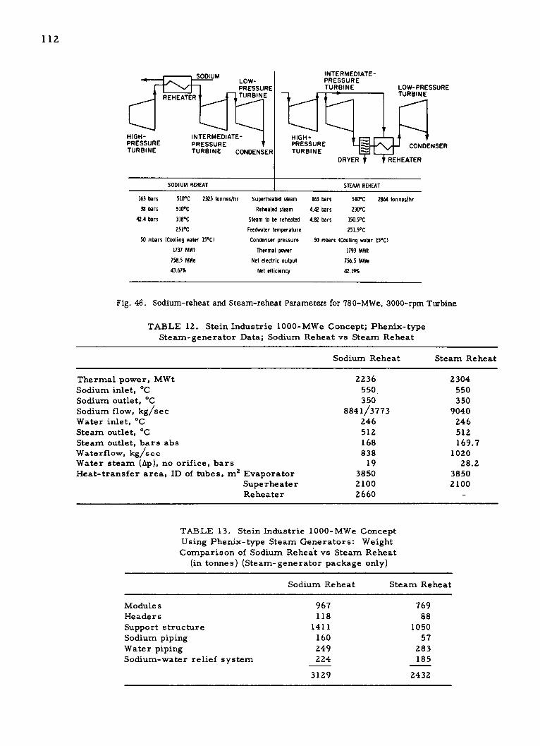
LO W-
PRESSURE
REHEATER TURBINE
HIGH- INTERMEDIATE-PRESSURE PRESSURETURBINE TURBINE CONDENSER
INTERMEDIATE-PRESSURETURBINE LOW-PRESSURE
TURBINE
HIGH-PRESSURE CONDENSERTURBINE
DRYER REHEATER
SODIUM REHEAT STEAM REHEAT
163 bars 510 C 2325 tonnes/hr Superheated steam 163 bars 510 C 2864 tonnes/hr38 bars 510 C Reheated steam 4.42 bars 230 C
42.4 bars 318 C Steam to be reheated 4.82 bars 150.5 C251 C Feedwater temperature 251.5 C
50 mbars (Cooling water 15*C) Condenser pressure 50 mbars (Cooling water 15 C)
1737 MWt Thermal power 1793 MWt758.5 MWe Net electric output 756.5 MWe43.67% Net efficiency 42.19%
Fig. 46. Sodium-reheat and Steam-reheat Parameters for 780-MWe, 3000-rpm Turbine
TABLE 12. Stein Industrie 1000-MWe Concept; Phenix-typeSteam-generator Data; Sodium Reheat vs Steam Reheat
Sodium Reheat Steam Reheat
Thermal power, MWt 2236 2304Sodium inlet, *C 550 550Sodium outlet, *C 350 350Sodium flow, kg/sec 8841/3773 9040Water inlet, *C 246 246Steam outlet, *C 512 512Steam outlet, bars abs 168 169.7Waterflow, kg/sec 838 1020Water steam (tp), no orifice, bars 19 28.2Heat-transfer area, ID of tubes, m 2 Evaporator 3850 3850
Superheater 2100 2100Reheater 2660 -
TABLE 13. Stein Industrie 1000-MWe Concept
Using Phenix-type Steam Generators: Weight
Comparison of Sodium Reheat vs Steam Reheat(in tonnes) (Steam-generator package only)
Sodium Reheat Steam Reheat
Modules 967 769Headers 118 88
Support structure 1411 1050Sodium piping 160 57Water piping 249 283Sodium-water relief system 224 185
3129 2432
112

113
TABLE 14. Differential Costs of Stein Industrie 1000-MWe LMFBRConcept: Sodium-reheat Plant minus Steam-reheat Plant
106 Francs $106
Steam generator 30.5 6.5Piping 14.33 3.0Buildings 1.25 0.26
Differential cost -46.0 9.76
Turbine-generatora 8.5 1.8
Total differential cost 37.5 7.87
or
37.5 francs/kWe (capital cost)
Energy differential cost 18.3 francs/kWe gl ~$3.7/kWe
including steam reheaters.
As of July 1971, EDF had partially optimized sodium-reheat andsteam-reheat 1000-MWe LMFBR designs. The cost comparisons were
based on the vendor's detailed estimates for many items (Babcock-Atlantique
quotes on the steam generator, for example). The system parameters for
the sodium-reheat and steam-reheat cases compared are presented inTable 15, and differential costs are summarized in Table 16. Heat-balancediagrams for the two cases (power levels slightly different from conditionsgiven in Table 15) are presented in Figs. 47 and 48. Babcock-Atlantique
steam-generator designs are used in both cases. In, this design, the evapo-rater and superheater tubing is continuous and is in a single shell. Thesuperheater and evaporator on the sodium side are in parallel with the
sodium reheater for the sodium-reheat plant. In such a configuration, the
reheater is operating with a greater sodium-side A T than is optimum for a
plant-size configuration. However, this factor was not of major influence
in determining the results of the study.
TABLE 15. EDF 1000-MWe LMFBR Concept of SodiumReheat vs Steam Reheat: Steam-generator Data
Sodium Reheat Steam Reheat
Power (core), MWt 2250 2330Power, MWe 962 962Plant efficiency, % 42.75 41.25Primary temperature, reactor
inlet/outlet, *C 400/560 400/560Secondary temperature, steam-
generator outlet/inlet, *C 350/550 350/550Feedwater temperature, *C 250 258Feedwater pressure, atm 215 215Steam temperature, *C 510 510Steam pressure, atm 163 163Reheat inlet temperature, *C 318 164Reheat pressure (inlet), atm 42 6.9Reheat outlet temperature, *C 510 285Reheat pressure (outlet), atm 37.8 6.5
Steam flow, tonnes/hr 3023 3810

114
TABLE 16. EDF 1000-MWe LMFBR Concept; Differential Costs;Sodium-reheat Plant minus Steam-reheat Plant
+106 Franc s
Building and siteReactorFuel handlingPrimary pumpsIHXAuxiliariesSecondary pumpsSodium pipingAuxiliariesSteam generatorsSteam pipingTurbineSteam reheatCondensersFeedwater heaters
Total
- 106 Francs
3.1
6.40.8
23.213.0
1.35
}47.85
2.1
0.20.30.72.00.2
8.8
0.9
15.2
Col. 1 - Col. 2 = 32.65 x
for steam-reheat plant.
PRESSURE, TEMPERATURE,bars *C
ENTHALPY, FLOW,kJ/kg tonnes/hr r- --
6.88 200CONDENSER 3016.9 2291.5
0.050I2381.2 1881.43I
- LP - -
S2
1.811 143.82158.4 201.24
137.1 2423.3
I 10.85 58.4 .85 108.2245 2423.3 451.3 24233
138. 423.3
S231.1 211820 .4
2400.55
HP - HIGH-PRESSURE TURBINE
IP - INTERMEDIATE-PRESSURE TURBINELP - LOW-PRESSURE TURBINES 13 DOUBLE FLOIB - DEAERATOR
TPA - FEEDWATER PUMP TURBINE DRIVE
106 francs or about $6.9 million savings
37.6 5103400 2001.5 REHEATER.
I 42 311.1BAII 3004.9 2001.5 TL
I- ------ --- -- UNA
I I rATI I 163 510
3325.1 3141.5
IP - - HP
SUPERHEATER
S4I 1S5 IS6 EVAPORATORIIS3II L ---------
1.02$0.2 I - --- - ----
L. 13.5 364.5 22.05 433.4 421311.1 166.4 246.461.0 200.2 3110.5 111.55 3316.6 121.65 3004.61240 1013.4 3141.5
B TP
1.15 112.1 I 88.4 150.5 I 411.4 215.1111.1 3141.5 111.4 111.4 W17.1 3141.5 921.1 3141.5
TIM.43111.5
114.413 .4 436.4
416.5 223.5645.2 360.65 956.5 240
POWER OUTPUT - 1022 MWe- 2331 MWt
W)
BCOCK-LANT IQUEIT
Fig. 47. EDF 1000-MWe LMFBR Concept: Heat-balance Diagram for Sodium Reheat

64.4 413.3PRESSURE, TEMPERATURE, 516658.6
bars *C
ENTH ALPY, FLOW,
k J/kg tonnes /hr STEAM REHE ATER 8.08 184.2 ST EA M
2140.5 2541.8 fSEPA RA TOR 183 561
62.4 'C I2.83256871?33838.
CONDENSER
237 2055.7 03 322.217.61.2
LP HP a IP
883.2 1.6
131. 2541.3 21
S1 S2 t5 215.2028.6 141 1. 4S5
1POW.R2OUTPUT-.113 8.15. 2541..8 T.PCA S. 5.64
10..85 58..1 L8. 108..4
6.4
5121B6.
POWER OUTPUT - 104
HP - HIGH-PRESSURE TURBINEIP - INTERMEDIATE-PRESSURE TURBINELP - LOW-PRESSURE TURBINES 13 DOUBLE FLOW)B - DEAERATOR
TPA - FEEDWATER PUMP TURBINE DRIVE
Fig. 48. EDF 1000-MWe LMFBR Concept: Heat-balance Diagram for Steam Reheat
BABCOCK-ATLANTI QUEEVAPORATORB SUPERHEATER
?15.6 251.T22.4 51.2
26 MWe- 2410 MWt
U
. . v ... .
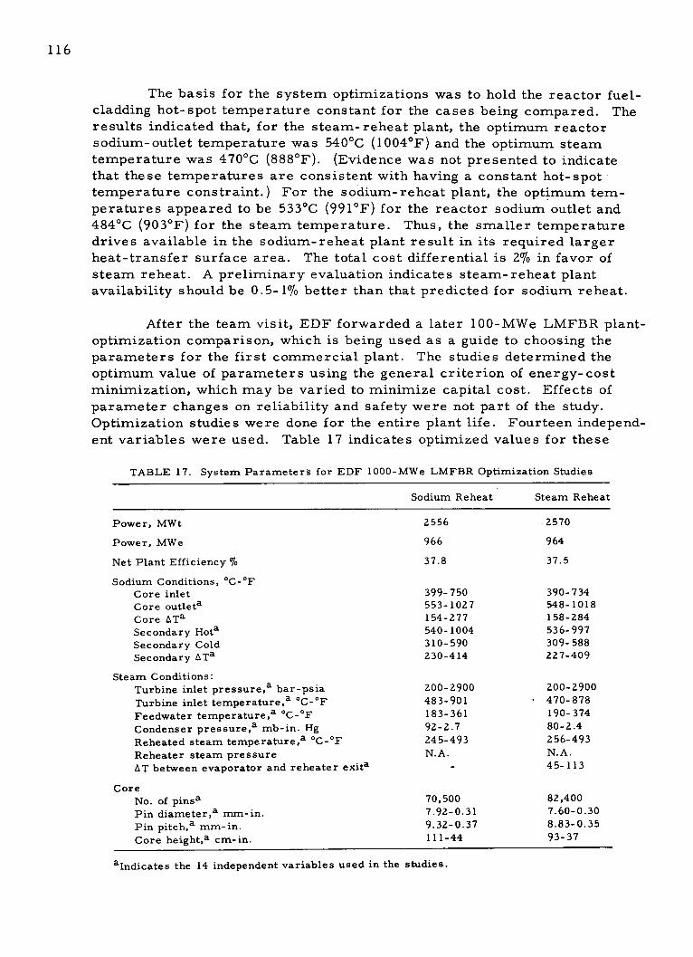
116
The basis for the system optimizations was to hold the reactor fuel-cladding hot-spot temperature constant for the cases being compared. Theresults indicated that, for the steam-reheat plant, the optimum reactorsodium-outlet temperature was 540 C (1004 F) and the optimum steamtemperature was 470 C (888 F). (Evidence was not presented to indicatethat these temperatures are consistent with having a constant hot-spot'temperature constraint.) For the sodium-reheat plant, the optimum tem-peratures appeared to be 533 C (991 F) for the reactor sodium outlet and484 C (903 F) for the steam temperature. Thus, the smaller temperaturedrives available in the sodium-reheat plant result in its required largerheat-transfer surface area. The total cost differential is 2% in favor ofsteam reheat. A preliminary evaluation indicates steam-reheat plantavailability should be 0.5-1% better than that predicted for sodium reheat.
After the team visit, EDF forwarded a later 100-MWe LMFBR plant-optimization comparison, which is being used as a guide to choosing theparameters for the first commercial plant. The studies determined theoptimum value of parameters using the general criterion of energy-costminimization, which may be varied to minimize capital cost. Effects ofparameter changes on reliability and safety were not part of the study.
Optimization studies were done for the entire plant life. Fourteen independ-
ent variables were used. Table 17 indicates optimized values for these
TABLE 17. System Parameter's for EDF 1000-MWe LMFBR Optimization Studies
Sodium Reheat Steam Reheat
Power, MWt
Power, MWe
Net Plant Efficiency %
Sodium Conditions, *C-*F
Core inletCore outletaCore ATaSecondary HotaSecondary ColdSecondary ATa
Steam Conditions:Turbine inlet pressure,a bar-psia
Turbine inlet temperature,a C-*F
Feedwater temperature,aoC-*FCondenser pressure,a mb-in. HgReheated steam temperature,a C-*F
Reheater steam pressureAT between evaporator and reheater exita
CoreNo. of pinsaPin diametera mm-in.Pin pitch,a mm-in.
Core height,a cm-in.
alndicates the 14 independent variables used in the studies.
2556
966
37.8
399- 750553-1027154-277540- 1004310- 590230-414
200-2900483-901183-36192-2.7245-493N.A.
70,5007.92-0.319.32-0.37111-44
2570
964
37.5
390- 734548-1018158-284536-997309- 588227-409
200-2900- 470-878
190-37480-2.4256-493N.A.45-113
82,4007.60-0.308.83-0.3593-37

117
14 parameters (marked with the letter a) for both a sodium-reheat LMFBRand a steam-reheat LMFBR. Table 18 indicates fixed input values to theoptimization studies. The reference 1000-MWe LMFBR (Phenix type,excluding steam generators) used in the studies is based on GAAA
(Groupement Atomique Alsacienne Atlantique) concepts developed in con-junction with component and tur ine fabricators, and may not be fullyrepresentative of the 1200-MWe LMFBR being planned. The turbine used
in the study consisted of five sections (HP, IP, and three LP sections).
TABLE 18. Fixed Design Values
for EDF Optimization Studies
Max cladding temperature, *C- F 670-1238Load factor 0.69
Burnup, MWd/t 100,000Fuel-fabrication cost, $/kg 300Plutonium price, $/g 8Total electric power, MWe 1000Net electric power, MWe 965
Costs associated with the optimized designs are shown in Table 19.
TABLE 19. Capital Costs Associated with EDF 1000-MWeLMFBR Optimization Studies
Sodium Reheat Steam Reheat
106 Francs $106 106 Francs $106
The total costs associated with each of these plants are:
Capital cost 1321 260 1276 251First charge of fuel 209 42 199 40Direct construction costs:
Civil works 105 21 100 20Reactor maintenance and refueling 169 34 171 34Sodium circuits, steam circuits, and
steam generators 265 53 236 47Turbines and steam-plant equipment 109 22 113 23Electric installations 96 19 93 19
744 149 713 143
C. United Kingdom
A reference design for the 1300-MWe Commercial Fast Reactor
(CFR) has been established, and the design effort is underway. At the timeof the visit, British plans called for the start of CFR construction in 1974,*
*Note: Issue of Atom 191, p. 161, Sept 1972, has a statement of Aug 8, 1972, by Davis, member ofU.K. Cabinet, that the. first full-size order is to be placed in the latter part of the 1970s.

118
with power operation scheduled to begin in 1979. The PFR concept issuitable--with some modification--for use in the CFR.
The 1300-MWe CFR would require the use of two standard 650-MWeturbine generators operating in parallel. Based on design work done todate, CEGB has become concerned that such an arrangement may resultin operational complications. TNPG and CEGB are therefore currentlyreevaluating the general area of future power-plant requirements to deter-mine the size and operating conditions for which future turbine-generatorsets should be standardized and to identify turbine-generator developmentrequirements. In this study, operability and high availability are of greaterimportance than small economic differences.
CEGB did not wish to offer an opinion or preference as to sodiumreheat versus steam reheat versus nonreheat. As a result of work done onPFR, an understanding has been obtained of the sodium-reheat system and
there is confidence in its satisfactory performance for both PFR and com-mercial plants. Other systems have not been studied to the same level ofdetail, and therefore there is little recognition of potential problems.Though startup operation of a sodium-reheat plant is complicated, withexperience, operation with sodium reheat can become routine.
D. Germany
In 1971, INTERATOM made economic comparisons of various steam
cycles for SNR-300 and an SNR 1000-MWe system. 2 7 The different plantarrangements and steam cycles considered were:
Case I: Sodium reheat, with three high-pressure feedwater preheat-ing sections (this was taken to be the reference case).
Case II: Similar to CaseI, with a reduction to two high-pressurepreheating stages.
Case III: Steam reheat, using exit steam from the high-pressurecylinder, with two high-pressure preheating stages.
Case IV: Steam reheat, using high-pressure cylinder exhaust toreheat exhaust steam from the intermediate-pressure unit to the low-pressure units. A steam separator is also employed in this arrangement,with two high-pressure preheating stages.
Case V: No reheat, with direct expansion of steam from a lowerlive steam pressure, with two high-pressure preheating stages.
These cases were compared under conditions of constant reactorexit temperatures and system parameters, which presumably were opti-mized in each case with respect to cost. In optimizing system. parameters,

119
pressure drops in the primary and secondary loops were held constant.All cases were normalized to the same net electrical output from the plant.With primary temperatures fixed and a specified steam temperature, othertemperatures through the system were optimized for minimum total costof IHX and steam generators. Fuel-cycle costs were treated parametrically.Unavailability costs were not included. A discount rate of 14% and capacityfactor of 0.8 were used in the study. A 17-year basis for amortization wasused, with interest at 8% and taxes at 2.5%.
Results of the study are presented in Table 20 and Fig. 49. Thecosts are given in terms of percent of total plant cost. The steam-plant-line item includes the cost of the turbine generator. The turbine-generatorcosts were essentially constant for the conditions studied for the differentcases. The safety-board requirement that the turbine hall be located wellaway from the steam-generator buildings penalized the reheat cases becauseof the longer pipe runs involved. Costs for the IHX and steam generator
were predicated on proposals or cost estimates provided by suppliers.
TABLE 20. Cost Change with SNR- 1000 vs Reference Design I(in percent of plant cost at constant MWe)
Case: I 11(a) II(b) II(c) II(d) III IV(a) IV(b) IV(c) V
Plant-cost Fraction
IHX and steam generator 0 -0.71 - -1.72 -2.24 -2.54 -1.63 -1.39 -2.32 -2.61 -2.16
Reactor plant (withoutIHX and steam generator) 0 +0.13 ? +0.50 +0.68 +0.60 +0.67 +0.84 +0.99 +1.25
Steam plant 0 -0.49 -0.32 -0.32 -0.24 -0.69 -1.12 -1.09 -0.85 -1.41
Total Cost Change (with various fuel-cycle costs)
0.2 pfenning/kWhr 0 -1.01 -1.56 -1.79 -1.72 -1.41 -1.48 -2.11 -1.93 -1.64
0.3 pfenning/kWhr 0 -0.97 -1.47 -1.66 -1.54 -1.26 -1.29 -1.89 -1.66 -1.30
0.4 pfenning/kWhr 0 -0.94 -1.39 -1.52 -1.35 -1.10 -1.11 -1.67 -1.38 -0.96
20 40 60 80No TEMP/STEAM TEMPT, C
Fig. 49
Cost Savings vs AT between Primary andTertiary. Note: One pfenning ~ 3 mills
100
Case IV (steam reheat using high-pressure cylinder-exhaust steam
to reheat IP steam) offered an advantage over sodium reheat amounting to
UI-U0
JIL
U.0
1' -1.0-w
? -1.5-U)
z
can -2.00
- CASE HCASE S
SNR-300 0.5 PFENNIG/kWh
SNR-I0000.3 PFENNIG/kWh -'
\ /

120
approximately 0.3% of total plant cost for an assumed 1-mill/kWhr fuel-cycle costs for a 1000-MWe plant. INTERATOM regards this cost differ-ential to be significant. If the results had been reversed, i.e., if the resultshad indicated 0.3% in favor of sodium reheat, sodium reheat could well havebeen retained as the reference design. Turbine generators could be pro-vided for all cases considered in the study, either in the form of standardunits or by assembling together various parts of standard turbines. Non-reheat with lower steam pressure looked promising, but economically itwas found to be more sensitive to the effects of unfavorable fuel-cycle andthe rmal- efficiency conditions.
INTERA TOM is now studying 2000-MWe plants trying to find where
economies can be realized by additional development work. The referenceis steam reheat utilizing HP exhaust to heat IP exhaust steam. When thenext plant design is undertaken, the economic parametric studies describedabove will be repeated to verify the reference choice. It was indicated thatscale-up to the 2000-MWe plant from the SNR-300 should not present anymajor problem. The first component feasibility limit will probably be the
electric generator.
INTERATOM cited a "slight technical advantage" of steam reheatbecause of the simpler startup operation and reduced sodium-to-water/
steam heat-transfer surface area. NERATOOM expressed the opinion thatthe testing already completed at Hengelo provided grounds for believingthat sodium reheat could operate satisfactorily in a commercial plant ifthis cycle was eventually adopted.

121
IX. STEAM-GENERATOR TEST SITES
A. Summary and Comparison
Large steam-generator test facilities in the 50-MWt range have
already been constructed and are in operation, at Les Renardieres in Franceand Hengelo in Netherlands, the latter being part of the SNR Consortium ef-fort. Both groups decided that testing of large steam-generator models wasnecessary before final fabrication and installation of the demonstration-
plant steam generators.
These decisions contrast with the earlier, British decision, whichwas to fabricate and install demonstration-plant steam generators withoutadvance testing of a large model. The British consider that if the firstcommercial LMFBR adopts a steam-generator design different from thatof PFR, a large-model test will be necessary. The building of a newfacility in the U.K. or utilization of Hengelo is being considered.
Although the Hengelo test facility is approximately 2 years behindthe Les Renardieres facility, the SNR Consortium schedule allows moremargin between start of steam-generator model testing and the start ofoperation of the demonstration-plant steam generators (6 years comparedwith 32 years).
Both existing facilities are gas-fired, with bypass loops to providetransient simulations, and both contain most of the equipment within abuilding. At Les Renardieres, the gas-fired heater is inside the building;at Hengelo, outside. Construction costs and schedules were also similarand are recorded below.
B. Les Renardieres Steam-generator Test Facility, France [Circuitd'Essais a Grande Puissance de Generateurs de Vapeur Chauffesau Sodium (CGVS)]
1. Facility Description
The facility was built by, and is operated by, the French nationalelectric utility, Electricite de France (EDF). The facility (50-MWt capacity)is designed to test the performance of sodium-heated steam generators understeady-state and transient conditions. The choice of 50 MWt was stated to bea compromise between desiring to test steam generators as near LMFBRplant sizes as possible, and minimizing the facility construction and oper-ating costs. The facility cost $20 million, and the fuel (gas) costs areapproximately $4000/day. From initiation of design to operation at powerin early 1970 took 3 years. Approximately 6000 hr of steam-generatortesting had been achieved by the time of the U.S. reheat team visit.

122
According to the French, a steam-generator assembly (evapo-
rator, superheater, and reheater) of 50-MWt capacity should provide con-
fidence that full-size LMFBR steam generators will perform satisfactorily.
Test models of this size have essentially the same characteristics as full-
size units in the areas of steady-state heat transfer, flow distribution,
stability, metallurgical effects, and mechanical behavior. With the testmodels having tubes of the same diameter and wall thickness, though some-
what shorter than LMFBR plant units, the dynamic performance should be
extrapolable to the larger unit. Differences in the shell time constant due
to differences in shell-wall thickness should be a second-order effect,
which can be accounted for when extrapolating test results to plant conditions.
On the sodium side of the facility, the sodium heater is gas-
fired, supplying up to 650 C sodium. There are two centrifugal, variable-
speed sodium pumps, connected in parallel, and a 15-MWt, fan-drivensodium cooler. The sodium loop contains several bypass circuits to permit
the rapid changes of flow and/or temperature necessary in the transient
tests. The sodium circuit is fitted with electrical-resistance heaters to
maintain 150 C temperature.
Although the Phenix steam generators are of subcritical pres-
sure, the facility is designed to permit testing of possible future
supercritical-pressure units. The facility includes a mixing tee for mixing
sodium flows of different temperature. One of the flows enters along the
centerline of a mixing chamber and passes through approximately half the
tubes of a honeycomb of tubes. The other flow enters the chamber at right
angles and is baffled to flow through the other half of the tubes in the
honeycomb, transferring heat to or from the other flow in the process.
Physical mixing of the two flows takes place downstream of the honeycomb.
The mixing tee has been tested with 200 C difference between the two flows
and has performed satisfactorily.
The entire facility and test steam generator, with the exception
of the sodium-water reaction discharge stack, are enclosed within the
facility building which is 58 x 28 x 40 m high. The facility requires a staffof 50, including five operating crews of four men each.
A flow schematic of the facility is shown in Fig. 50. A generalmap of the EDF Les Renardieres research facility is shown in Fig. 51.
Further information on the facility is available in Refs. 28 and 29.
2. Status
Testing of the Phenix steam-generator modules was nearing
completion at the time of the visit. A complete, full-size Phenix module,including evaporator, superheater, and reheater, built of unstabilized
24 Cr-l Mo steel, has been tested under steady-state conditions, without

PRESS REDUCERSA N 1-1 4 Ct.DESUPE GREATER P"5(0 P"5b DESUPE GREATER
----. h' T " 400 C T -"385 C & .MIXER M ,3 e. A- - COOLING
50b565 C P - 1b
f- H~ESUPEHHEATER S3 T.1 110 C
HOT By PASS40C500 C CONDENSER
> s - "; l : PRESS RED
NATURAL 0 P 806 P 80hGAS - COOLER T !.30 C T 400 C -0
;:.1 's~l".:T -400 C
AIR AIR ", , . 167b, PRESS RED EUEH AE C
P4 " q 65 C EXTRACTIONS(OIIuM NY?7STEAM/WATER PUMPSHI All IIC O'F S1 SEPARATOR
/TMWAE
CONDENSED
SEPARATOR WAERIN
S1 S2 TETN
I 00C
- ~S30MOMInER
410"C r , DEGASSIFIER SDU
P -200t,
fMxE T- 160 ; -=1CM IX E H0
A T E M
S2*CPRE HEATERS AE
CIRCUL ATION FEEDWA TE RCOLGP1MsPUMPS C.OO-- NG
Fig. 50. EDF Les Renardieres Steam-generator Test Facility--Flow Diagram

EXPLANATION OF THE GENERAL MAP
I - Entrance2 - Administrative Center3 - Housing for staff on duty4 - Medical and Welfare Center. The Restaurant5 - 1.000 kV experimental-line station6 - Power-lines building7 - Ageing-test Imesg - M.A.I. Hall and terminal station of computing center9 - Erosion-Corrosion test shop
10 - Offices AI I - COn circuit shop and Sodium
12 - CO circuit shop extension, and Sodium13 - Civil-engineering shop
14 - Offices B15 - Material-testing hail17 - A.D.E - Experimental building19 - A.D.E - Chmatron19 - A.D.E. test shop20 - Sodium-exchanger test circuits31 - Extra-High Voltage laboratory32 - Transformer heat-build-up station33 - Tests under artificial pollution34 - Revolving-machinery test station35 -- Mechanical and climatic test stands36 - Extra-high power test station (S.T.G.P.)37 - S.T.P.G. reactances and transformers38 -- 400.001 volt sub-station
39 - 225.000 volt sub-station40 - 65.000 vott sub-station41 - Compressor building42 - 20.00/60.000 volt building43 - Medium-power building44 - Short-circuit alternator buiding
45 - High-power test station
- ----- General Map
Existg buildings
"- -... Foreseen buiddngs
C I~- - --- U -UC --- -- ;o
® -
-- 1 -s -I~~~ -- - - NAAC - - - -- --
Fig. 51. EDF Les Renardieres Test Site. Note: Steam-generator test facility is in Bldg. 20. Other sodium facilities are in Bldgs. 11 and 12.
N

125
any major problems, and is now removed from the facility building. Aphotograph of this module is shown in Fig. 52. The second module, under
test, is made of stabilized 24 Cr-1 Mo steel.
Sodium temperature distribu-tion is determined by thermocouplesmounted on the outside of the shell.
Thermocouples are mounted at the
inlet and outlet of each tube, whichalso contains an orifice for flow
measurement and flow stability.
The orifice size was varied duringthe test program, starting with the
- smallest orifice possible (highest
P ,pressure drop).
Fig. 52. First Steam-generator Module Tested and Tests completed to dateRemoved from the Les Renardieres Facility include:
a. Steady-state heat-transfer performance.
b. Flow stability.
c. Dynamic response tests (e.g., response to ramp or step
changes in parameters).
d. Simulated plant startup and shutdown.
Transient testing has been reserved to the end and was to beperformed during the summer of 1972. Because of possible damage to thesodium heater, the facility cannot duplicate all the possible Phenix tran-sients. Turbine trip can be simulated, except that the steam would continue
to flow to the reheater.
Information on the performance of the steam generators under
test is included in Section V.B.
3. Future Facility Usage
A 45-MWt model of the Babcock-Atlantique helical-tube designwas scheduled for delivery to the Les Renardieres site in November 1972and should be ready for testing in February 1973. The test of the Stein In-dustrie straight-tube, 45-MWt model should be completed by the end of 1974.
C. U.K. Steam-generator Testing
As noted before, if the British change the design of the steam gen-erators for the first commercial LMFBR, they will test a 30- to 50-MWtmodel in a test facility to be built in the U.K. or will test the unit at Hengelo.

126
As of the visit, an option had been negotiated or was in the process of being
negotiated to have the model tested at the Hengelo facility in Netherlands.
D. Hengelo Sodium Component Test Facility, Netherlands
1. Facility Description (see Figs. 53 and 54)
NERATOOM, the Dutch nuclear-industry group, is responsible
for the design, development and fabrication of the IHX's, steam generators,
and pumps for the SNR demonstration plant. To test a model IHX and a
model steam generator, a 50-MWt test facility has been constructed at
Hengelo, in East Holland, and was in the process of being transferred to
TNO (Netherlands Organization for Applied Scientific Research) as thefacility operator.
Although stated to be a nominally 50-MWt facility, the maximum
heat input to the test steam generator is 55-MWt, and to the IHX, 70-MWt,
because of the regenerative arrangement of the facility. Only a small
extrapolation in size will be necessary from test results to SNR conditions
for the steam generator (SNR unit = 82 MWt). Maximum values of main
parameters of the facility are 650*C (1202*F) sodium temperature, 1800-m3 /hr (7900-gpm) sodium flow, 600 C (1112oF) steam temperature, and 215 bars
(3160 psi) steam pressure.
I II
1I-
Fig. 53. Model of Hengelo Steam-generator Test Facility
a
C h +
Irv
s wa s art ^,
fit
i" r F
r
Ell

127
Thermal shocks can be pro-
duced, with a maximum rate of shock
of 10F/sec over a 20-sec period.
LMFBR plant transients, such as
turbine trip or reactor scram, may
be more severe. More severe tran-
sients than the above 10*F/sec havebeen applied to the steam-generatormodel as a result of facility incidents,e.g., due to safety-valve operationduring a sodium leak and fire de-
scribed below.
The heat is dumped by means
of an air-cooled condenser, waterside
pressure being kept above air pres-
sure to preclude air leaking into thewater circuit. Full-flow demineral-
ization is provided. A turbine can be
simulated by control of steam-
expansion valves downstream of the
Fig. 54. Furnaces, Air Preheaters, and Central superheater and reheater under test.
Chimney of Hengelo Steam-generatorTest Facility The facility is capable of
simulating startup, shutdown, andturbine trip using a turbine simulator. This includes simulation of reheater
conditions during startup and partial load. The turbine simulator consistsof nine cams, which actuate various control devices. The main controls ofthe simulator are throttling valves, plus water attemperation of the steam.
Each cam represents a controlled parameter as the y axis and its variation
with main steam flow as the x axis. These parameters include reheater-inlet steam temperature, condenser pressure, deaerator pressure, and
reheater steam flow. A turbine trip can be simulated using this system.
The simulator is presently set up for use only above 20% load.
A trim valve on the sodium system is provided to obtain a
3:7 flow ratio between the reheater and superheater, respectively. The
valve is not changed following the initial setting, nor is it changed with
load. No consideration appears to have been given to special provisions
during startup to maintain a higher pressure in the steam side of the re-
heater than the sodium side.
The sodium circuits can be electrically trace-heated, and thewater/steam system preheated by means of a 5-MW auxiliary boiler.
The gas-fired heater consists of three units, with the capacityof each part no more than twice the capacity of similar units from whichthey were extrapolated. In each heater, 27 parallel sodium tubes coil in

128
close contact with each other to form the inner wall of the combustion
chamber near the top of the heater. Thus, no refractory is required, and
no continued sodium flow is necessary to remove stored heat in the furnace.
The convection system is a six-pass system, with concentric
coils of sodium tubes near the bottom of the heater. The Type 304 stainless
steel tubes have an ID tolerance of 0.02 mm to ensure correct flow distri-
bution. The tubes are connected to 75-mm (6-in.)-ID toroidal headers, and
the three parallel heaters are connected, top and bottom, by valved piping
loops. The furnaces are of Swiss design (Bertrams) and Dutch fabrication
(N. V. Mashinfabriek, Breda). The furnace is kept preheated above 200*C
to prevent chloride corrosion from a nearby salt plant, even when no sodium
is in the unit. About 0.1 mm of corrosion was experienced in about 1 year
on the external surface of the furnace sodium-outlet pipe. This occurred
after installation and before startup, when the system was at ambient
conditions.
Most of the facility is enclosed, with separate sections for thesodium plant, the steam/water plant, and the steam-generator model. The
sodium plant and steam/water plant are separated by two concrete block
walls, which enclose the stairs and elevator. The three-unit, gas-fired
sodium heater, the steam condenser, and the sodium/water reaction-
products vessel are outdoors.
The facility includes. a data-logging unit with 500 channels and
a sampling rate of 10,000 points per second. Data logging is performed in
a room separate from the control room, to protect proprietary data of the
steam-generator designer/fabricator. A data readout, but not logging,
capability has been added to the control room.
A patented mixing tee used at the facility was described (and
is shown in Fig. 55). No thermal shielding is included. The tee was tested
in water models, and no experiments have been performed on the tee insodium. The tee is designed for sodium temperature differences up to
4000C.
MIXING REGION A sodium flow schematicof the facility is shown in Fig. 56.
Artist's sketches of the facility areprovided in Figs. 57 and 58. (Thenumbered items in Figs. 57 and 58
LINE B HAS SODIUM UNDERGOING J STAGNANT SODIUM are identified in Table 21.) TheTRANSIENT; LINE A SODIUM MUST AT TEMPERATURE
NOT CHANGE IN TEMPERATURE OF LINE A layout of the major components isRAPIDLY A
shown in Fig. 59. Further infor-
Fig. 55. Mixing Tee Used at Hengelo Steam- mation on the facility is available
generator Test Facility in Ref s. 29-31.

AT - 170~2200C
MAX 6500C AT 230 kg/sec MAX AP = 0.8 atmMAX 370 kg/sec AT 6350C MAX 370 kg/sec REHEATED STEAMMIN 50 kg/sec.-
TCV 118B SUPERHEATED STEAM
WET STEAM STEAM MAX
I X = 095%- 600C AT 215 atmMAX 6500C AT 220 kg/secMAX 350 kg/sec AT 6300C
TC MIN ALLOWABLE 370 C I--TV
118AI
EVAP
SH
60ft RH
---- HX-
){ r I - FEEDWATERAIRMAX 300
0C
COOLER 235 atm13.5 Mw H112 BUF BUF BUF 33 kg/sec
FILL AND STEAM TODRAINL R E HEHAT ER
DAN"HOLDUP" TCV 125 -- '-- - --- - $ - -R AE
t-rVESSEL FILL
H114 AND DRAIN FILL AND DRAIN FILL AND DRAIN
TCV
FILL 119
3-MODULE HEATER AND SODIUM PUMP FILL AND MAX ALLOWABLE AP = 2.0 atmNOM 53 Mw DRAIN MAX 430 kg/sec DRAIN AT 170 ~300
0C AT 350 kg/secMAX 58 Mw
AT = 170 -300 0C
MAX AP = 15 atmMAX 370 kg/sec
Fig. 56. Sodium System Schematic Diagram, 50-MW Sodium Component Test Facility, Hengelo
N

WJ
x V
2~j
T~~ I
td - ~
'"7
i
fv ry
t
r
o , t.
Fig. 57. 50-MWt Sodium Component Test Facility, Hengelo. (See Table 21 for explanation of numbers.)
'I
W Sodium Component TeF'DESG AND ONSTRUCTED BY
Z77A 7"
IL .x ~. I 7
:w

17
0 Y
Fig. 58. Cutaway View of Steam Hall at 50-MWt Sodium Component Test Facility,Hengelo. (See Table 21 for explanation of numbers.)
131
f
2-1-7.
N,
1"
0
w i.

132
TABLE 21. Legend for Figs. 57 and 58
Sodium test hall
Steam hall
Sodium furnaces (three)
Main building
Control room
Steam-generator box
Evaporator
Superheater
Reheater
Sodium circulation pump
Cold trap
Dump tanks
Expansion vessel
14.
15.
16.
17.
18.
19.
20.
21.
22.
23.
24.
25.
Pipe bridge
Sodium furnace
Air preheater
Chimney
Auxiliary boiler
Deaerator steam system
Steam separator
Main entrance, steam hall
Main entrance, sodium test hall
Test instrumentation room
Power-supply room
Intermediate-heat exchanger frame
OFFICES WORKSHOPS
STE AMHALL MEDICAL OFFICE
STEAM GENERATOR CELL SECURITY OFFICE
SODIUMHALLZ SODIUM
COOLER
PIPING BRIDGESNATURAL GASCONTROL
STATION
CNESR
CONDENSERS
Q SODIUM- //HE ATE RS
iDOCKCANAL
Fig. 59
Plan View of 50-MWt Sodium Com-ponent Test Facility, Hengelo
1.
2.
3.
4.
5.
6.
7.
8.
9.
10.
11.
12.
13.

133
2. Status
Facility design started toward the end of 1966 and was exten-
sively revised in 1967. Construction started in June 1968 and was com-
pleted toward the end of 1971, although sodium was added to some componentsin April 1971. Steam-generator testing started in February 1972. Facility
cost was $15.3 million. A staff of 50 is required, including 20 operators and
seven workshop technicians.
A building extension is now being incorporated to provide anadditional steam-generator test bay, so that one model can be installedwhile another is under test, thereby reducing the turnaround time between
models to be tested. This improvement was undertaken because the SNR
demonstration plant will include two different steam-generator designs,both to be proved out by a test model at Hengelo. Another change to bemade will be moving the cold traps into a separate cell to facilitate re-moval and replacement, which are proving to be more frequent operationsthan originally anticipated.
The components now under test are the SNR IHX, and thestraight-tube steam generator that will be used for two of the three SNRdemonstration-plant loops. The steam generator installed at Hengelo in-
cludes a reheater unit in parallel with the superheater. The reheater has
already been deleted from the SNR design, but it was too late to change the
Hengelo model installation.
At the time of the visit, three weeks of steaming operation hadbeen attained, with thermal power up to 25 MWt. The maximum steam con-
ditions attained were 170 bars (2500 psig) and 510 C (950F). In April 1972
a small leak in the sodium system at the IHX destroyed several cable trays,causing a shutdown of 6-7 weeks. The facility was expected to be startedagain at the end of June 1972.
3. Sodium Leak
Thermal-shock tests at Apeldoorn showed that the original IHXhead seal using a metal O-ring was not adequate during thermal transients.
For this reason, the IHX model installed in the test facility was disconnectedfor modification. The modification consisted of a seal weld to replace the
O-ring. While the IHX was being modified, some of the sodium lines had tobe cut and capped. Before cutting and capping one of the lines, the Dutchestablished a freeze seal about 12 m (40 ft) long to backup an isolation valve.
The freeze seal was established by removing the insulation on the line andallowing the line to cool; no auxiliary cooling of the line was used. Theline remained frozen for several weeks.
The leak occurred when the cap was cut off for reconnection ofthe line. It is estimated that 10-100 liters of sodium leaked out of the pipe.

134
Sodium carbonate was used to extinguish the fire, but restrictive access to
the leak made firefighting difficult. Additional platforms for access were
being installed. Also, special covers over cable trays are being installed.
It has been postulated that the leak through the freeze seal
occurred because a gas pocket formed in the freeze seal due to contraction
of the sodium as it solidified. Later, the isolation valve leaked slightly and
the liquid sodium came through the gas pocket of the freeze seal to the loca-
tion of the leak. The program delay resulting from the leak was caused by
sodium spilling into cable trays underneath the leaking pipe, destroying
many facility cables. These cable trays were covered with sheet metal,
but the sodium entered at locations where vertical connections had been
made to the cable tray. The Dutch feel strongly now that electrical cabling
should be routed away from the main sodium system to avoid such problems
in the future.
4. Additional Problems
After filling, plugging of the sodium cold traps was experienced.
The first cold trap plugged soon after system purification was started, and
this unit was removed and examined. It was determined that very little of
the total capacity of the unit contained sodium oxide. The cooling designof these cold traps was poor, causing the plugging problem. The second
cold trap also plugged in a similar fashion. A third cold trap, with modi-fications to the cold-trap internals and cooling system, has now been in-
stalled. The possibility of recycling cold traps is also being studied.
Difficulty has been experienced in obtaining exactly the right
evaporator temperature before introduction of feedwater and in obtaining
the proper AT's on the tube sheets. It now takes approximately one-half dayto preheat the steam generator from a cold condition to a minimum-power
condition. On a hot start, it has been found easier to go down to 200 C and
restart very quickly.
The Dutch have had poor experience with welding sodium-
contaminated piping, even after the sodium film was removed back 1-2 ft.
The heat from welding melts the sodium, which flows into the weld area.
The resulting welds do not meet their requirements. Specifically, the rootpass has been found to have defects. These defects were observed using
double-wall X rays and dye tests.
Additional problems include failure of some trace-heating ele-
ments and many small problems with valves and other equipment. No
problems were encountered with the loop-support system, and good flow
distribution was confirmed in the sodium heater.

135
5. Steam-generator Testing
The steam-generator tests are intended to (1) confirm the heat
transfer, (2) detect waterside instabilities, (3) confirm effectiveness of
the thermal baffles protecting tube sheets (approximately 100 thermocouplesinstalled for this purpose), and (4) confirm the predicted movement of the
shell bellows.
The overall performance of the steam-generator model up to the25% load condition, reached for a short period of time, is close to predic-
tions. The steam-generator test results are discussed in detail in
Section V.E.
The instrumentation for the reheater in the present installationis not as great as for the superheater, since the reheater is of less interest,
being similar to the superheater. Besides size, the only difference between
the superheater and reheater is that the reheater tubes have larger diametersand thinner walls. No problems have been experienced to date with the re-heater. There is a cold-sodiumbypass to the superheater and reheater in-
let. This was originally intended to be used for control of temperatures to
these units; however, it has not been used during current operation. Proper
temperatures are maintained, since the steam temperature coming out of
the reheater and superheater is close to the sodium temperature under allloads.
No vibration testing or measurements are being made in the
steam-generator test. Vibration and flow-distribution measurements were
made in models tested in water at Apeldoorn.
6. Future Facility Usage
Following completion of testing of the present units, the helical-
tube SNR evaporator will be tested. The Dutch are not interested in futuretests of an entire steam-generator system since they expect to obtain sys-
tems information in the present systems test, which was set up to study the
dynamic behavior of the system. Only an evaporator on as large a scale as
possible will be tested. In comparison with the other units, the evaporator
has major problems associated with fabrication, heat transfer, and stability.
The test of as large a unit as possible is required to prove the evaporator
capability to the maximum extent possible, including the adequacy of fabri-
cation. If tests of other steam-generator units were desirable, it would be
sufficient to test the superheater, assuming the reheater to be of the samebasic design. Reheater conditions could be established in the superheater
test.
Consideration is being given to artificially fouling the watersideof the steam generator or to conducting very long-duration tests at steady
state to determine fouling.

136
The tests of the helical-coil tube model should be completed in
early 1974. The Dutch were negotiating with the British and Italians con-
cerning the possibility of their using the Hengelo facility for componenttesting in 1974 and 1975. The test on the SNR IHX should be completed by
mid-1973, when capacity would be available for testing other IHX units.
7. Leak-detection Experience
Significant variations in hydrogen in the sodium have beenfound using in-sodium hydrogen detectors. These detectors use nickel-
membrane diffusion tubes with an ion pump, developed in Apeldoorn. The
system has a high background of hydrogen, which fluctuates frequently be-
tween 0.5 and 1 ppm. The fluctuations are in large part due to temperature
changes, with higher hydrogen levels occurring at higher temperatures.
These high background levels make it difficult to detect a leak; however,
since the Dutch have a hydrogen detector at both the inlet and outlet of each
module, they can detect a leak by the difference. However, the high back-
ground level and the fluctuation require that the readings be interpreted to
determine if a leak has occurred. Also, nonoperability of the cold trapwould result in the hydrogen level of the sodium increasing rapidly from a
very low value to approximately 1 ppm.
Cover-gas hydrogen detectors will be installed in the surgetank to help detect hydrogen levels. Hydrogen will be scavenged from the
system above set points. Hydrogen gas has been injected to calibrate the
in-sodium detectors, which have responded well to the injections. Some
evidence of hydrogen diffusion through the steam-generator tubes from
waterside corrosion has been seen. A background level of 0.1 ppm is the
target for the facility. No accoustic-leak detectors are included.
E. 5-MWt Test Facility, Bensberg, Germany
In support of the overall German sodium-reactor program, including
the KNK reactors, the INTERATOM 5-MWt test facility at Bensberg has
tested many components, including steam-generator models, earlier and
smaller in capacity than the models now being tested at the 50-MWt facility
at Hengelo, Netherlands.
The sodium heater is gas-fired to provide up to 580 C sodium, and
the flow rate provided by the pump is 180 m3/hr. The main components of
the sodium loop are fabricated from niobium-stabilized 24 Cr-i Mo steel.
The water-steam loop is designed for 250-bar, 550 C steam andfeedwater at 10-m3 /hr and 300 bars. Heat is dumped through an air-cooled
condenser.

137
The facility includes three test rigs: a 700-mm-dia, 10-m-high
vessel for tests of fuel-handling equipment, a test rig with an argon circuitfor testing sodium-vapor traps, and a fuel-element and control-rod test rig.
Operation of the facility started in 1965. Since then it has testedsteam generators, IHX's, pumps, valves, cold traps, carbon traps, pluggingmeters, fuel-handling devices, control rods, and vapor traps. The facilityis still in use for testing such components, including a single-shell once-through steam generator.

138
X. OTHER TEST SITES
A. TNO- -Central Technical Institute Facilities at Apeldoorn, Netherlands
1. Introduction
The TNO (Nederlandsche Organisatie voor Toegepast-
Natuurwetenschappelijk Onderzoek, i.e., the Netherlands Organization forApplied Scientific Research), is a government organization, which has two
sources of income--the government and the industry. The TNO Central
Technical Institute (C TI) is one of 40 institutes in TNO. As one of its many
functions, the TNO-CTI has the responsibility for sodium-technology basic
research in the Netherlands. NERATOOM supports the industrial portion
of sodium-technology development. The two are meshed. For example,
NERATOOM built the Hengelo Steam Generator Test Facility, which is to
be operated by the TNO-C TI.
Van Gasselt (10 years with C TI), head of the Sodium Technology
Section, reports to K. A. Warschauer, the head of the Division of Physical
Transport Phenomena. About 200 employees are employed by CTI at
Apeldoorn.
The Apeldoorn Facility has eight sodium loops; seven of the
eight are automatically operated 24 hr a day. Twelve people run all the
loops. Each loop can be dumped automatically at certain preset limits.
TNO-CTI designs its own loops, but uses two or three constructors for
fabrication and erection. CTI is responsible for loop safety and its own
safety criteria. The cost of the loops at Apeldoorn is: for each of the
two isothermal corrosion loops, 300,000 guilders; the anisothermal loop,
800,000 guilders; the chemistry loop (6 months to build), 500,000 guilders;the pump testloop, 1,000,000 guilders; the SWISH loop, 1,500,000 guilders; thethermal-shock loop, 800,000 guilders; and the Arend loop, 450,000 guilders.
(One guilder equals 31 cents.) Following are the loops:
a. Two small isothermal corrosion loops.
b. One anisothermal corrosion loop.
c. A chemistry loop.
d. A loop called SWISH, originally designed for supercriticalsteam R&D, now used for subcritical work for the SNR
sodium-cooled steam generators (this loop is described
in Section V.E).
e. A thermal-shock loop.
f. A pump-test facility, which also can be used for thermalshocks.
g. A loop called Arend, named after one of the people workingfor TNO.

139
Apeldoorn also has sodium-analytical capabilities, capabilityfor postoperational cleaning components free of sodium, and a workshop.
Further, there is an extensive waterflow distribution and vibration test
loop to simulate shell-side conditions of IHX's steam generators, and re-
actor plenums.
Apeldoorn facilities, in existence for 6 years, have lately been
expanding. The CTI Division of Hydrodynamics and Aerodynamics and theTNO-Metallurgical Institute of TNO, which was at Delft, are located, orwill be located, at Apeldoorn. Corrosion studies that normally would be
carried on by other divisions of the CTI are temporarily under the re-sponsibility of Van Gasselt of the Sodium Technology Section.
2. Corrosion Loops
The oxygen content and the mass velocity can be varied in the
corrosion loops, and the linear velocity can be varied from 0.5 to 5 m/sec.These loops have been used to test nicrobrazed tube-to-tube-sheet joints
for the SNR steam generator and to study the effects of corrosion and car-
burization of Type 304 stainless steel when oil from pump seals leaks into
sodium, as has occurred. Self-welding, cavitation, and fretting corrosionstudies are still being carried on at Delft.
The isothermal corrosion loops have been used to test 2* Cr-1 Moand 9 Cr-1 Mo specimens in Type 316 stainless steel corrosion loop.Specimen-to-loop surface was 1/500. At 500*C, no carbon transfer was
found with 2* Cr-1 Mo, but at greater than 500*C, decarburization was
found. With 9 Cr-1 Mo, it was difficult to find decarburization. However,oxidation did occur. The oxygen content was 20-25 ppm. To start with,
the actual carbon in the 2* Cr-1 Mo was 0.12%; after decarburization at500*C, it was 0.02%. Test results are to be published in the TNO quarterly
reports. Findings above 500*C essentially do not agree with Thorley of the
UKAEA, who indicates decarburization begins at 450*C, and do not agreewith the U.S. Babcock & Wilcox tests, which indicate decarburization begins
only at 540*C . Original condition (heat treatment) of steel may be important,
i.e., how dispersed the carbides are in the original heat. Various heat treat-
ments will be tested to try to get some correlation with Thorley and B&W
in their experiments.
In the process of testing hydrodynamic bearing materials inhigh-velocity sodium, about 30 m/sec (100 ft/sec), with samples 50C below
isothermal loop temperature of 580*C, a sodium chromite deposition phe-
nomenon was observed. Specimens are 50 mm wide, 1 mm thick, and about
200 mm long, and there is one specimen on each side of the sodium flowpassage (see Fig. 60). The spacing of the opening is 1 mm. Sodium chro-
mite deposits have been measured as 0.1 mm thick. The deposition phe-nomenon occurred in a time period of 4-5 hr. As the deposition took place,
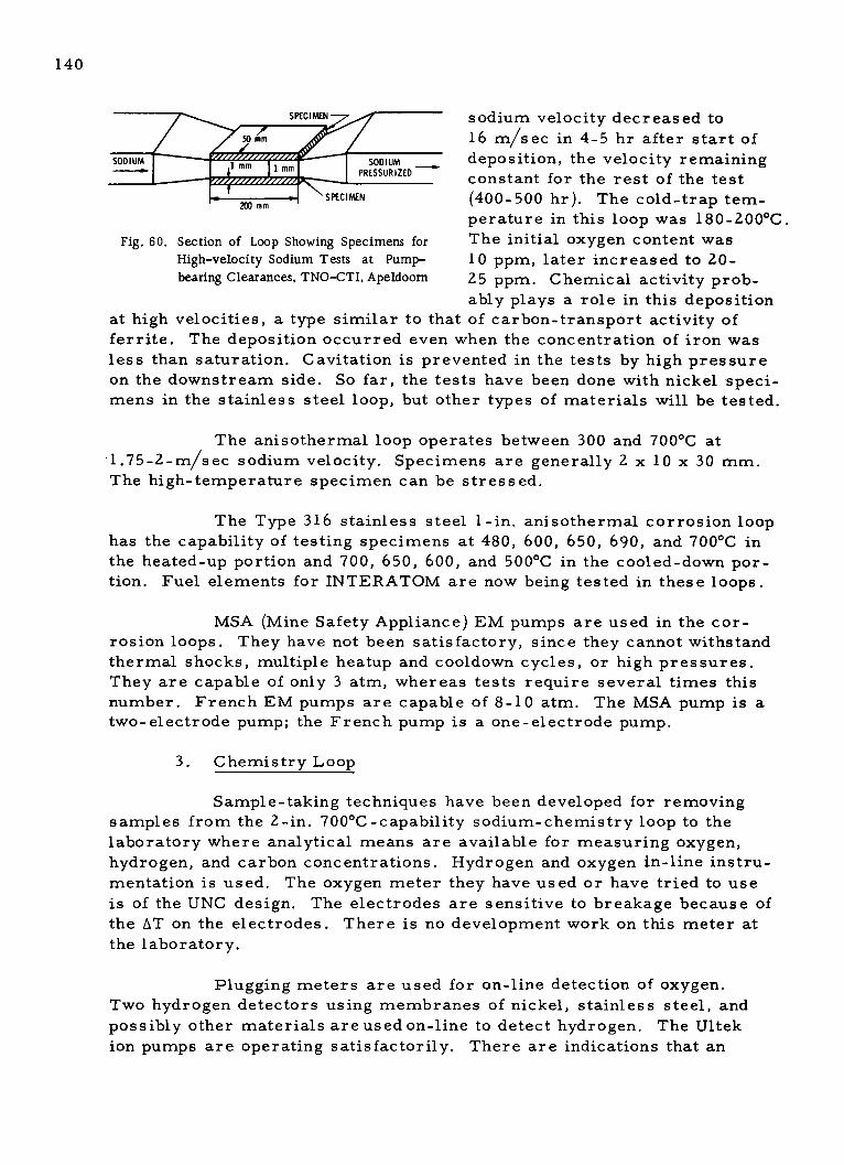
140
SPECIMEN sodium velocity decreased to
S0mm 16 m/sec in 4-5 hr after start of
SODIUM 1 mm 1 mm SODIUM deposition, the velocity remainingPRESSURIZED constant for the rest of the test
-SPECIMEN(400-500 hr). The cold-trap tem-
perature in this loop was 180-200*C.
Fig. 60. Section of Loop Showing Specimens for The initial oxygen content wasHigh-velocity Sodium Tests at Pump- 10 ppm, later increased to 20-bearing Clearances, TNO-CTI, Apeldoorn 25 ppm. Chemical activity prob-
ably plays a role in this deposition
at high velocities, a type similar to that of carbon-transport activity offerrite. The deposition occurred even when the concentration of iron wasless than saturation. Cavitation is prevented in the tests by high pressureon the downstream side. So far, the tests have been done with nickel speci-mens in the stainless steel loop, but other types of materials will be tested.
The anisothermal loop operates between 300 and 700*C at1.75-2-m/sec sodium velocity. Specimens are generally 2 x 10 x 30 mm.
The high-temperature specimen can be stressed.
The Type 316 stainless steel 1-in. anisothermal corrosion loophas the capability of testing specimens at 480, 600, 650, 690, and 700*C inthe heated-up portion and 700, 650, 600, and 500*C in the cooled-down por-tion. Fuel elements for INTERATOM are now being tested in these loops.
MSA (Mine Safety Appliance) EM pumps are used in the cor-rosion loops. They have not been satisfactory, since they cannot withstand
thermal shocks, multiple heatup and cooldown cycles, or high pressures.
They are capable of only 3 atm, whereas tests require several times thisnumber. French EM pumps are capable of 8-10 atm. The MSA pump is atwo-electrode pump; the French pump is a one-electrode pump.
3. Chemistry Loop
Sample-taking techniques have been developed for removing
samples from the 2-in. 700*C-capability sodium-chemistry loop to thelaboratory where analytical means are available for measuring oxygen,hydrogen, and carbon concentrations. Hydrogen and oxygen in-line instru-mentation is used. The oxygen meter they have used or have tried to useis of the UNC design. The electrodes are sensitive to breakage because of
the AT on the electrodes. There is no development work on this meter atthe laboratory.
Plugging meters are used for on-line detection of oxygen.
Two hydrogen detectors using membranes of nickel, stainless steel, andpossibly other materials are used on-line to detect hydrogen. The Ultek
ion pumps are operating satisfactorily. There are indications that an

141
entire spectrum of elements is coming through the 1/4-mm-thick Type 316
stainless steel diffusion tube operated at 300*C, and the Dutch are in the
process of investigating this phenomenon. The spectrum includes hydro-
carbons. The Dutch also indicate that certain elements such as sodium
peroxide formed at high oxygen contact can severely corrode the nickel
membrane. The sample harps used in the chemistry loop were shown and
are fairly sophisticated. An on-line distillation apparatus was being de-veloped in the chemistry loop. Several of these have been sold by the
Dutch to other European countries. The automatic plugging indicator in the
chemistry loop is of the English Electric design. The chemistry loop hastwo EM pumps.
4. Thermal-shock Loop
The 2-in.-dia thermal-shock facility (see Fig. 61) has been inexistence for 9 years; it is fairly extensive. Many subcomponents designed
for Hengelo and for SNR haveTH+ Tc been thermally shocked in this
fii ilit-i E. va l a of th1 cBUFFER
r -- - - - - OR MIXING - - - - - SUBJECTED TOTHERMAL TRANSIENTS
(REMAINDER OF LOOP
Q 10 IS ISOTHERMAL)
SPECIMEN 1 SPECIMEN 2
A B C D
X X PROGRAMMEDVALVES
EC "dH
COOLER HEATER
LcJL y . x eLs LIjJJ. U'.LLLLS
are:
D PUMP
a. The O-ring seals
they had originally intendedto use in the intermediate heat
exchanger for SNR.
b. Full-size bearings
for the SNR 5000-m 3/hr sodiumpump.
C. Specimens of ves-sel nozzle attachments.
d. Multiple tube-to-
tube-sheet connections for their
steam-generator facility.
The thermal-shock
IQQloop is capable of about
100C/sec from 550 to 380*C.
TRANSIENT OPERATION: Total capability is 300C/secfor 10 sec. The AT's for this
VALVES A & C ARE PROGRAMMED FROM FULLY OPEN TO FULLY CLOSED AS VALVES B & DARE PROGRAMMED FROM FULLY CLOSED TO FULLY OPEN. SPECIMEN 1 THEN RECEIVES A facility are specified byCOLD SHOCK FROM TH TO TC, AND SPECIMEN 2. A HOT SHOCK FROM TC TO TH. NERATOOM. The flow is
Fig. 61. TNO-Apeldoorn Thermal-shock Loop 5 m3/hr . A 2 -in. mixing tee
for the thermal-shock loop
was described, in which the mixing thermal sleeve comes in at the elbow.
Specimens to be shocked are generally contained in a 2-m-dia insulated
chamber, which can be filled with nitrogen in the event of a sodium leak.

142
When thermally shocked at 120*C in 3 sec, the Hengelo IHX
O-ring seal was damaged in
RINGREPRESENTING
NOZZLE
E
LZ
REPRESENTI NVESSEL
-4 in.
-2 in,
T 1 in
SODIUM
Fig. 62
Vessel-nozzle Thermal-shock M
TNO-CTI, Apeldoorn. (Series ofzie models can be tested on this
about two cycles. As a result, the O-ring wasreplaced with a seal weld.
G The model used for thermal shock ofvessel-nozzle specimens is shown in Fig. 62.It consists of a 2-in.-dia, 2-ft-long center
tube, representing the shell. The nozzles
are represented by 0.25-in.-thick plates
formed into rings welded to the center tube.-29 in.
Six of these 0. 2 5-in. segments were welded
to the tube at 4-in. intervals. Thermal shock-
ing of vessel-nozzle welds has been successful.
The only effects observed are those on the air
side. Inclusions present in the weld will come
out, leaving a vacancy that apparently does not
affect the quality of the weld.
Seven full-scale bearings for the
SNR 5000-m 3/hr pumps are being thermallyshocked, primarily to determine the effect on
the hard surfacing (see Fig. 63). Stellite 6[odel, applied by welding and by spraying has beennoz- under test. A cermet hard facing is yet to be
rig.) tested. Van Gasselt indicated that Stellite
sticks, but cermets do not. Cermets grind,
but keep running. The team was shown a series of full-scale bearings for
the 5000-m 3/hr SNR pump, which were or are being thermally shocked.The first Stellite 6 bearing was testedfor 5000 hr, then thermally shocked, THERMOCOUPLES
a2nd it aeartd t he in ond sha e
though a rigid inspection is yet to be
made.
The thermal-shock facility
is usually used in conjunction with the
SWISH unit. Sodium from the thermal-shock loop is used to heat the outsideof the SWISH loop. This loop also hasa hydrogen detector and has water-
chemistry capability.
5. Cold-trap Design
TNO has had difficulty with
cold traps. Original designs used a
packing that extended across the crosssection of the cold trap and was very
ineffective due to crystallization for a
- 16 in.--
SODIUM -JOURNAL
BEARING
- -SODIUM
THERMOCOUPLES
NOTE: ACTUAL LOCATION OF SODIUM INLETAND OUTLET NOZZLES NOT KNOWN.
Fig. 63
Schematic of 5000-m 3 /hr Pump-bearing Thermal-shock-test Con-tainer, TNO-CTI, Apeldoorn

143
short distance at the entrance to the packing, blocking cold trapping above
this point. The Hengelo cold traps have been replaced twice. A third series
of tests was being conducted at Apeldoorn. A more effective cold trap could
be obtained if the packing was put into an annulus. The Arend loop was being
used for cold-trap testing. The cold trap was cooled with air. The cold trapon test had an annular packing.
6. Pump Loop
The pump-loop capability at Apeldoorn was 280 m3/hr, 85.5-m
head, and design temperature of 600*C. Since commissioning in July 1968,
the pump had operated for about 10,000 hr. The 280-m 3/hr pump had two
interchangeable sodium-lubricated hydrostatic bearings with a mixed-flow
impeller and shaft sealing in the gas phase. The gas seal initially consisted
of a mechanical seal-type, then a visco-seal. The visco-seal (shown in
Figs. 64 and 65) was developed by Stork. Referring to Fig. 66, a speciallygrooved bushing, flexibly mounted on the shaft, rotates within an outer sta-
tionary bushing. A high-viscosity lubricant is applied as shown. The specialgroove pattern allows for a pumping action during shaft rotation, forcing the
lubrication into the annulus and providing a seal between the cover gas and
the upper atmosphere. Correct design of grooves also prevents lubricant
leakage. The lubricant also keeps the flexible rotating bushing centered on
the shaft.
Apparently the visco-seal can be operated under a vacuum.
A static seal is needed when the shaft is not rotating; this also allows for
maintenance of the visco-seal. The visco-seal has the advantages of long
life, nonleakage of lubricant, low cost, ease of assembly, and low sensitivity
STORK DOUBLE VISCO4SEAL
LUBRICATING OIL
SE-ALING ORL
-CLEAN ARGON
SEALIG OI
FAKK.
spiral er.....as
rotaing ris
directionofort .of g
0 "
I-alss ebrio prsar
prasar. builtIto oil th
f reae
ereer raaunr,
Fig. 64. Visco-seals in Tandem Arrangement
L
Fig. 65. Visco-seal Principle

144
PUMP
66 in.
FLOWMETER MIXING TEE
6 in. M 6 in.
3 in. BO E
THERMAES HOCK I 3 in.
S - SEMIVARIABLE FLOWORIFICE
3 in.PROGRAMMED VALVE
U AMOTOR-OPERATED VALVE
Fig. 66. TNO-CTI 280-m3 /hr Pump Loop at Apeldoorn
to contaminants in the lubricant. Two seals in tandem provide for 100% seal
reserve, argon flushing between the seals, and helium-leak tests. A disad-
vantage of the visco-seal is its complex lubrication supply and pressuriza-
tion system. It is possible that a lubrication-system pump can be driven by
the pump shaft, reducing some of the complexity.
The pump loop has been used for testing pump seals, bearings,
bearing materials, bearing clearances, vibration, cavitation, pump drives,
and moments of the axis.
The pump loop has thermal-shock capability (see Fig. 66).
Normally, the main sodium flow is through a semivariable-flow resistance.
A thermal-shock vessel, cooled by a blower, is located in a bypass line.
For thermal shocks, a sufficiently large temperature difference is created
between the sodium in the main circuit and that in the thermal-shock vessel.
This is done by heating or cooling the thermal-shock vessel at zero bypass
flow. Meanwhile, the temperature in the main circuit is controlled by run-
ning or stopping the pump. As soon as the desired temperatures are
reached, the pump is operated at the desired speed and the programmed
valve in the bypass circuit is operated so that the correct flow is initiated
through the thermal-shock vessel to provide the desired thermal shock on
the pump. A thermal shock of 200*C can be obtained in 3 sec.
Stork started manufacturing sodium pumps 9 years ago; the
first were 4700-rpm pumps with three bearings. The present ones are9 6 0-rpm pumps. Stork has built the SNR 5000-m3/hr, 9 6 0-rpm pump,being tested at Bensberg. The hydrodynamic tests of the hydrostatic bear-ing for the pump are done at Delft. Initially these tests are done in water.
Final tests of bearings are in sodium.

145
The Apeldoorn pump-test facility was being altered to be ableto test SNR core components at 200C per 4 sec at 280 m3/hr. This test
was scheduled to be done at the end of 1972.
7. Sodium Cleaning
Van Gasselt indicated that sodium cleaning is accomplished by
first vacuum-distilling in place, then removing the equipment, placing it in
water, drying it, and finally cleaning it with acetone. This is representativeof TNO sodium cleaning, satisfactory for laboratory use.
8. Miscellaneous
A NERATOOM 12-in. control valve will be tested at Apeldoorn
and then installed in Hengelo for further testing. The purpose of the valve
was not specified.
9. Laboratory Visits
A visit was made to the section of the laboratory used to full-
scale water-test the flow distribution and vibration of the Hengelo IHX andsteam generators using plastic models. A plastic model of the SNR reactor
vessel was being tested, simulating a degassing section. This was not dis-
cussed. The loops were made of 12 -in. -dia Plexiglas.
Also shown was a water tunnel (not part of sodium technology).
The water velocity could reach 22 m/sec. The test section was 1 m 2 in
cross section; maximum flow volume was 22 m 3/sec. The tunnel was- used
to study wind loadings on structures such as buildings. It could be used for
testing submarines and for cavitation studies. It may have been used to test
Hengelo and SNR component models.
A control room for the thermal-shock test facility was visited.A cold stream of sodium was mixed with a hot stream of sodium from the
isothermal portion of the loop to alternately shock components (see Fig. 61).
10. IHX Tube Plugging and Welding
Tests have been conducted on SNR IHX explosive plugging and
welding. For welding, it was necessary to have very clean walls at the
tube-to-tube-sheet connection, and it was also necessary to have a good
design of the plug. Small amounts of oxygen were applied to the tube wallto oxidize the sodium.' A rotating brush was used to remove the residue,
after which welding could be done.

146
11. Valves
An eccentric offcenter 6-in, butterfly-type valve based on a
Camflex valve has been redesigned for use at Apeldoorn. The valve com-
pany is Masoneilan, which has offices in Norwood, Mass. The originalbodies were cast. Apeldoorn purchased the valve internals and actuator
and provided its own forged body and freeze seal. The original valve, de-signed for use in the oil industry for fused salt flow, cost 5000 guilders.With a TNO body and freeze seal, the cost was 10,000 guilders (about
$3,000). A chief reason for doing their own work on the valve body was theneed for providing quality assurance not available on the outside.
B. EDF Les Renardieres Test Facility
The EDF Research and Development Directorate has several R&D
Test Services:
1. Electrical Equipment
2. Machinery and Automated Production
3. Network Engineering
4. Data Processing and Applied Mathematics
5. General Technology, Applications of Electricity, and Hydraulics.
Services 1, 4, and 5 are located at Les Renardieres. The others
are located at Chatou, Clamart, and Saint Denis.
Personnel in the R&D directorate comprise 801 engineers and tech-
nical and administrative executives, and 1272 supervisors, technicians,and administrators.
The General Technology Services has three departments:
1. Material Studies
2. Nuclear Technology
3. Applications of Electricity.
The Nuclear Technology Department has four divisions or groups:
1. Thermal Reactor Technology
2. Fast Reactor Technology
3. Sodium-heat Steam-generator Test-circuit Operation (CGVS)
4. Erosion-corrosion Tests.

147
The CGVS is described in Sections V.B and IX.B. The Fast ReactorTechnology Division is responsible for studies on sodium components.
Sodium testing is conducted in two sodium-test buildings. Tests include:
1. Corrosion loops
2. Materials creep in sodium
3. Valve tests
4. Steam-generator rupture disks
5. Insulation
6. Journals, bearings, and gears.
A chemistry laboratory provides for sodium monitoring and analysis.
Material testing is divided into several phases. Steam-generator
decarburization tests and carburization tests are done in the large Icare
loop. Fatigue testing of steam-generator tube-to-tube-sheet joints is con-
ducted, as well as other technology tests such as those for tube supports.
The Icare loop is a small loop for the study of carburization anddecarburization of steam-generator materials. It consists of a mockup ofa Phenix secondary loop on a small scale. Parameters studied in this loopare surface area, temperature and temperature gradients, sodium velocity,surface-to-flow ratio, and time. The most important parameters were
temperature and temperature gradient, sodium velocity, and time. The
scaling down from the Phenix system was done using nondimensional pa-
rameters so that the test results would be valid for Phenix.
C. CEA--Cadarache Nuclear Research Center
1. Introduction
A large segment of the test facilities for the French LMFBR
program is located at the Cadarache Nuclear Research Center (CNRC).
Located at Cadarache are Rapsodie, a 40-MWt fast reactor;
Harmonie, a 2.5-kWt neutron-source reactor; Masurca, 1 5-kWt (max)
critical assembly; a Van de Graaff accelerator; a Plutonium Technologyworkshop, for developing LMFBR fuels; the CABRI test reactor, used tosimulate LMFBR core excursions; and technological test buildings.
The team visit to Cadarache was made mainly to discuss andobserve the sodium-water reaction analysis and test facilities and to visitthe sodium-component support facilities. As such, it directed much of its
attention to:

148
a. Sodium-water reaction analysis and test.
b. Component test facilities.
c. Sodium systems corrosion analysis and test.
A short visit was also made to Rapsodie.
2. Component Test Facilities (technological tests)
The component test facilities are located in several buildings
(see Fig. 67): HR-1--1300 m2 , 30 m high (1400 ft2 , 100 ft high); HR-2--850 m2 (10,000 ft2 ); HR-4--1200 m2 (13,000 ft2 ).
HR-1 includes sodium tests of main reactor components (pumps,
heat exchangers, fuel-handling machines, control-rod drives, etc.). The
building uses two 15-ton traveling-bridge cranes and a 60-ton semigantry
crane.
HR-2 contains test equipment for mechanical, hydraulic, and
thermal tests not involving sodium. Water loops are used to test for flow,
vibration, contraction, and mixing problems. These include small-scale
tests of Phenix reactor-vessel and fuel subassemblies.
HR-4 has a 10-ton traveling-bridge crane and houses sodium
test rigs to aid in the design and calibration of sodium detection and to
provide sodium heat-exchange and safety tests; friction, wear, and weld
tests; and acoustic detector tests. In addition, a small area called ZEFIR,
250 m2 (2700 ft2 ), is used to study sodium-air reactions and model studies
of reactor structures.
The team visited the HR-1 and HR-4 buildings.
a. HR-1 Building
The LMFBR component test facilities in this building
include:
(1) A Rapsodie core mockup, not in use, but available if
circumstances indicate the need, after an incident, to reactivate the mockupto determine how to bring Rapsodie back on line.
(2) A series of test facilities consisting of seven pots
(pot-type containers), all with static sodium. Two of the pots are used for
fuel handling: one for the Phenix IVHM (Internal Vessel Handling Machine),
and one for the Phenix elevator mechanism. A total of 930 fuel-transferoperations were made with the IVHM with sodium temperature between
250*C (482*F) and 360C (680*F). The elevator mechanism was operated

i 1 -
pe
li.6.CdrceNula eerhCntr ra1lamni;Ae ,Msra
~~~A e 3, Ra so ie Are 4, Te h ol g Tes Buil ings A. *R 1 Bt .,^ " _ " . HR- . .. ya, ' ."t
.0

150
for 1000 cycles. A third pot is used to test control rods for Phenix and
Rapsodie. Two prototype control-rod mechanisms were cycled 1000-2500 cycles. A fourth pot is used to study the convection of argon in the
cover gas. A fifth pot is used for testing of instrumentation. The use ofthe other two pots was not indicated.
(3) A test rig, available for testing sodium-vapor traps.The rig is a vertical unit having four layers of Raschig rings. Sodium
vapor enters at 450*C and leaves at 150*C.
(4) A sodium facility, for testing Phenix dummy subas-semblies. Filters are located in each inlet of these subassemblies, proto-typing the filters that will clean the sodium of Phenix as it goes through thedummy core (now installed in Phenix).
(5) A test loop, available for testing the Phenix sodium-system insulation.
(6) A sodium rig for endurance and thermal-shock test of
Phenix-type subassemblies of all types. Each test is run for 1000 hr with
160*C AT. Two test sections are used. The subassemblies are removed
each 100 hr for inspection. A final design prototype is tested for 8000 hr.The subassemblies are full scale and prototypal to a large extent, exceptfor dummy pins.
(7) A two-section rig, used for testing fuel subassembly
orifice cavitation. The orificing for Phenix is similar to that in EBR-II,where the diagrid has a fixed orifice. The fuel-subassembly nozzle also
has orifices. The relative orientation of the fixed orifice in the diagrid
tube between the two diagrid plates and the nozzle holes determines the
orificing.
b. HR-4 Building
The HR-4 sodium-technology building contains 20 to 40 dif-
ferent sodium rigs. Most of these were not described. Pontier (CEA) de-
scribed several of the rigs.
(1) A test loop is used to determine the self-welding
characteristics between fuel pins, providing for 1-mm relative movements.
(2) A second loop is used for testing small EM pumps.
(3) A third loop is used for wear measurements.
(4) A fourth and fifth rig are used for testing fuel-handlingbearing mechanisms.
151
(5) A sixth rig tests mechanical connections, which are
presumably the sliding fittings between Phenix piping from the pumps to
the high-pressure plenum of the reactor vessel. This mechanical connec-tion (probably a sliding fit) connects the pump to the core inlet plenum,allowing relative freedom of movement. The system consists of a spherein a cylinder and enables (a) pump structure strains to be reduced as muchas possible, (b) leaks to be reduced, and (c) the pump to be dismantled andassembled, simply by inserting the sphere into the cylinder. A prototypearticulated sleeve was first tested in water. The piping runs in the primarytank are short without any bends, using a sliding connection. This connec-tion is tested for leakage, vibration, and other characteristics.
(6) Three rigs were shown that have been used for sodium-boiling studies. They were not in use, since it had been determined thatsodium boiling was no longer a problem.
(7) A large test area is devoted to ultrasonic testing witha series of five rigs for ultrasonic flowmeters: (a) an ultrasonic detectorfor onset of boiling, (b) an ultrasonic detector for under-sodium scanning,(c) an ultrasonic detector for measuring vibration (in the order of 1 mm),(d) a rig for ultrasonic level measurement, and (e) a rig for ultrasonic
temperature measurement.
Pontier indicated that 80-100 people were responsible foroperating both HR-1 and HR-4, including engineers, technicians, and op-erators, with five operators per shift around the clock for each of thetwo buildings.
3. Corrosion Test Facilities--SEML
Section Etude Metalle Liquide (SEML) consists of 35 people atCadarache headed by Champeix. There are four groups:
a. One group in SEML does corrosion studies under Baque,who was not present. There are eight loops of two types: one for flow-
through around samples, and the second where the sample is the loop itself.
b. SEML conducts chemistry studies of sodium, particularlysodium analysis of carbon and oxygen. (A short presentation regarding the
sample type of loops was made in Detroit during winter 1971-1972.)
c. SEML has a metallurgical group, which conducts electron-microscopy and microprobe work under Lafon.
d. SEML has a physical-chemistry group under Trouve, who
led the SEML discussion. This group studies impurities in sodium and isjust beginning to work on this problem. Ferritic versus stainless steel

152
loops, in which the loop itself is the sample, have been operating for about18 months. The walls are analyzed for deposits of carbon. No analysis
was available as of June 6. A loop was scheduled to be cut up by the end of
June 1972. Temperatures and the ratios of surface areas have been modeledwithin these loops to represent the Phenix secondary system.
A radioactive mass-transport loop was scheduled to be operating
within 1 year. The loop will be Type 316 stainless steel. No work had been
done to date by SEML on the effects of sodium-water reactions on materials.
SEML was beginning to study the sodium-oxygen-hydrogen system to deter-mine the natural components of such a system in a representative LMFBR.
SEML will start studies on the sodium-carbon-oxygen system and hopes tostart studies on the sodium-nitrogen-oxygen system. The SEML people donot conduct any studies or tests of rupture-disk or hydrogen-meter mem-brane material.
The team toured the corrosion loops. There are four carbon-transfer loops, where the loop is the sample itself. The cost of each loopis about 200,000 francs ($40,000).
4. Rapsodie
The team visited Rapsodie, which had just finished a 60-day run.
Mr. Gajac conducted the group in the reactor building, where refueling wasin progress using two refueling machines, one to bring in fuel and one toremove fuel. In this manner, the refueling time was cut by approximatelyhalf. When asked about tritium, Mr. Gajac indicated that this was not a
problem. Traces of tritium had been found in the oil of the pump bearing,
but not in the secondary system. When asked how the fuel-pin leaks were
located, Mr. Gajac indicated that a small group of approximately four sus-pect subassemblies could be isolated and removed from the core. The
details of how to detect the failed subassembly were not revealed. Also,
how the group of four suspects was located was not revealed.
The Rapsodie building was originally designed for 2.4 bars
(~35 psig). This pressure design is too high. A recalculation indicated thatthe maximum amount of sodium (the basis for the original pressure design
is similar to EBR-II containment) that could escape from the reactor is on
the order of 200 kg.
Mr. Gajac indicated that the recycle time for one fuel elementis 70 min. An entire refueling is made in about 4 days from shutdown tostartup. Experimental s ubas s emblie s complicate the refueling.

153
D. INTERATOM, Bensberg, Germany
1. Nitriding of Materials
Nitriding of ferritic and austenitic steels in a nitrogen covergas was reported in a Monaco paper. 3 2 Although the Germans did not have
definite plans to use nitrogen cover gas in the steam generator, nitrogenwas used in a steam-generator test at Bensberg as an inert atmosphere inan enclosure around the steam generator. Nitriding effects in the presenceof sodium were observed. Tests were made to confirm this observation
using the following materials:
a. 2* Cr-1 Mo unstabilized and stabilized with niobium andwith niobium and 0.5% nickel.
b. Type 304 stainless steel.
c. Inconel 600.
d. Type 347 stainless steel.
e. Type 321 stainless steel.
These tests were conducted at 500, 550, and 600C for times
up to 800 hr, and provided information on kinetic behavior of the nitridingprocess. The tests confirmed that hydrogen apparently had no effect onnitriding, but that sodium in the presence of nitrogen influenced nitriding.
The work on nitriding has been extended to determine the effectsof nitrogen in the SNR cover gas, in the range of 350-500 C. A literature
survey indicates many values for nitrogen impurity in argon, but gives no
indication that nitriding of components will occur. Grosser 32 will studyeffects of nitrogen in the range of 500-20,000 ppm. He noted that theUKAEA at Risley has such a program for PFR with temperatures rangingto 600 C. SNR does use nitrogen in the primary-system cells. They do notanticipate that they will have any difficulty with nitriding in the refueling
cell, where the temperature would be in the range of 300-400 F. To date,one test with 4000 ppm of nitrogen at 500C has shown no evidence of nitriding.
2. SNR Pump-test Facility
The pump-test facility, made of Type 304 stainless steel, is
designed for 650C. The pump-test stand is shown in Fig. 68. The charac-teristics of this pump are shown in Table 22. The 600- and 350-mm steam-
generator isolation butterfly valves were tested in this loop.
The actual SNR pump will have a head of about 140 m. The
pump uses hydrostatic bearings and is driven by a synchronous motor with

154
ac converted to dc and then back to ac to control the pump speed. The pump
was tested in a water-test facility at Stork in Hengelo, Netherlands, in
October 1969 using demineralized deaerated water.
Tests in sodium at Bensberg started in the fall of 1970 andwere completed in July 1972. Except for minor difficulties, the experi-
ence with the pump drive has been good. Present plans are to use thistype of drive for the SNR pump.
/500 K , / PCv at .Jsm/eLt-AMOWTOR
MA/Mg
~-- FL//D COUPI/M6
POMP MOaTO //kW/
f viri TOR UE CaMvfrF"e
Lr
Fig. 68. Prototype Pump and Drive
v
J

155
TABLE 22. Design Characteristics of 5000-m3/hr SNR PrototypePrimary Sodium Pump on Test at Bensberg
(mechanical, free-surface)
Metric Units
Capacity
Design temperature
Working temperature
Specific weight of sodiumat working temperature
Total head
NPSH required
Impeller- -single-suction diameter
Argon pressure
Shaft seal
Rpm
Rpm control, o
Type of speed control
Pump-casing designpressure
Double shell of pumpcasing
Argon pressure betweenthe two shaft seals'
Structural material
Engineering Units
22,000 gpm
1076 F
1040*F
5000 m3/hr
580*C-
560*C
820 kg/m3
85 m
10 m
880 mm
0.5-1.5 atm (abs)
51 lb/ft3
280 ft
33 ft
35 in.
7.4-22 psia
Mechanical or visco
960
3 to 100
Frequency changeror fluid coupling
11 atm (abs) at 580*C.Vacuum at 200 C.
1.8 atm (abs) at 500*C.Vacuum at 200*C.
1.5 atm (abs) and vac-uum at 80*C.
162 psia at 1076*C.Vacuum at 392 F.
26 psia at 1076*F.Vacuum at 392 F.
22 psia and vac-uum at 176*F.
X 6 Cr Ni 18-11(U.S. 304 SS)
Stork-Hengelo,Netherlands
Manufacturer
3. SNR Rotating-plug Test
Adjacent to the pump-test facility is a full-scale mockup of the
SNR triple-rotating shield plug and refueling machine used to check out the
SNR fuel-handling system. The fuel elements will be transferred in sodium-
filled pots. Dry tests have been conducted for about 1 year. Sodium testing
was scheduled to begin during summer 1972. Sodium-vapor deposition will
be an important part of the test.

APPENDIX A
of U.S. LMFBR SodiumReheat Team
Monday, May 22
Tuesday, May 23
Wednesday, May 24
Thursday, May 25
Friday, May 26
Monday, May 29
Tuesday, May 30
Wednesday, May 31
Thursday, June 1
Friday, June 2
Monday, June 5
Tuesday, June 6
Location
U.S. Embassy, Paris
Saclay, France
Les Renar.dieres, France
Clamart, France
Dounreay, Scotland
Dounreay, Scotland
Bensberg, Germany
Bensberg, Germany
Apeldoorn, Netherlands
Hengelo, Netherlands
The Hague, Netherlands
Marcoule, France (Phenix)
Cadarache
Visit
Meeting of Team
CEA, EDF
EDF
EDF
TNPG
UKAEA
CEGB
TNPG
UKAEA
CEGB
INTERATOM
INTERATOM
TNO
TNO/NERA TOOM
NERATOOM
CEA/EDF
CEA
156
Itinerary
157
APPENDIX B
Agendas
1. CEA/EDF: Saclay, May 23
09:15
10:00
10:15
10:40
12:45
13:45
Afternoon
Welcome to visitors
Steam generators for Phenix and 1000/1200-MWe powerplant
Sodium or steam reheat in case of using a 1000-MWePhenix-type steam generator (CEA)
Coffee break
Sodium or steam reheat with a Babcock-Atlantique steamgenerator (EDF)
General discussion
Departure to Les Renardieres
Arrival at Les Renardieres and lunch
Visit to the 50-MW steam-generator test facility atLes Renardieres
2. United Kingdom Atomic Energy Authority: Dounreay Experimental
Reactor Establishment
Program for the visit of the USAECFast Reactor Sodium Reheat Team on May 25-26, 1972
Thursday, May 25
11:40 Arrive Wick Airport
Coach to DERE
12:30 Arrive DERE
Welcome and introduction to the Establishment byDirector, DERE
In attendance: Mr. P. Mummery, Director, DERE
Mr. C. W. Blumfield, Deputy Director,DERE
Messrs. W. Macrae and D. Taylor, TNPG
Mr. W. Kemmish, CEGB
Mr. J. Williamson, TOD
& If

158
13:00 Luncheon, Director's Dining Room
Director Mummery and Messrs. Blumfield, Macrae, Taylor,Kemmish, R. H. Campbell, A. D. Evans, and Williamson
14:00 Coach to PFR Site
TNPG Conference Room No. 1
Discussions with Messrs. Campbell, Macrae, Taylor,Kemmish, and Williamson
16:45 Coach to Pentland Hotel and Royal Hotel
18:00 Coach trip to Dunnet Head, returning to Royal Hotel for 19:30
19j 5 Dinner, Royal Hotel, Thurso
20':00 Messrs. Blumfield, Macrae, Taylor, Kemmish, andWilliamson
Friday, May 26
09:00 Coach, Pentland Hotel and Royal Hotel to DERE
09:25 Arrive DERE- - PFR Site
TNPG Conference Room No. 1
Continue discussions and visit the Prototype Fast Reactor--Messrs. Macrae, Taylor, Kemmish, and Williamson
13:00 Luncheon, Director's Dining Room
Director Mummery and Messrs. Blumfield, Macrae, Taylor,Kemmish, and Williamson
14:00/14:00 Coach to Wick Airport14:15
15:45 Depart Wick Airport
3. Meeting USAEC- Team, INTERATOM, Bensberg, Germany; SodiumReheat Cycle Design; May 29-30, 1972
Place of meeting: Atrium II
Beginning: 09:30
Monday, May 29
09:30 a. SNR design and development program
b. Large (1000-2000 MWe) LMFBR plant application and design
(1) Economic considerations
(2) Technical considerations

159
(3) Programmatic efforts
(4) Design
13:00 Lunch
14:30 Continuation of discussion
17:30 Dinner, Goethehaus
Tuesday, May 30
09:30 Continue discussion
13:00 Lunch
14:30 Visit APB plants
4. TNO/NERATOOM-- Hengelo, Netherlands, June 1
a. Mechanical
(1) Repairs of sodium systems and/or components
(a) Philosophy(b) Methods and/or procedures
(2) Valves and valve choice
(a) Frozen seal versus bellows seal(b) Control valves design and manufacturers
(3) Means of compensating thermal expansion
(a) Bellows, etc.
(b) Connection of systems of different temperature
b. Operational
(1) Sodium quality and quality control
(a) Definition of cleanliness in primary and secondary
circuits(b) Measurement, sampling techniques
(c) Recyling problems
(d) Component design (cold traps, plugging meters)
(2) Heating of components where allowable temperature dif-
ferences are limited
(a) Mode of internal heating
(b) Necessary means for safe operation
c. Electrical
(1) Trace heating problems and design
(a) Type of elements used, specific allowable heat loads,lifetime experience

160
(b) Control systems(c) Fixation to piping
(d) Temperature specifications of piping
(2) Cabling. Cabling protection against fire and sodium spills.
d. Water Chemistry. Requirements of feedwater for LMFBRsteam generators, degree of alkalinity.
e. Measurements
(1) Strain-measurement techniques
(a) High temperature out of sodium
(b) High temperature in sodium environment
(2) Flow- measuring techniques
(a) Calibration of (big) sodium flowmeters
(b) Measurement methods
f. Steam Generators
(1) Cycle design choice for LMFBR
(a) Outlet quality of evaporator, problems of water separa-tion, recirculation, control concepts
(b) Starting up from different conditions
(2) Steam-generator testing
(a) Extent of test programme
(b) Instrumentation
g. Detection of Water Leaks in Steam Generators
(1) Methods
(2) Experience of detection of leaks; mode of leak versus
signal
(3) Influence of hydrogen diffusion through tube walls, espe-cially in steam generators; production of hydrogen onwater side
5. CEA, Cadarache, France, June 6
08:45 Pickup at the Guest House
09:00- 09:15 Meet Mr. Estavoyer and staff in Bldg. 212 Conference
Room
09:15- 10:15 Discussions of the sodium-water reaction with Messrs.Lions and Biscarel in Bldg. 212 Conference Room
10:15- 11:30 Inspection of the test a- a led by Messrs. Lions and
Falgeyrette s

11:35- 12:15
12:30- 14:15
14:30- 15:15
15:30- 16:30
16:30
Inspection of Test Halls HR-1 and HR-2 led by Mr. Pontier
Lunch at the Guest House
Discussion and inspection of the SEML led by Mr. Trouve
Inspection of Rapsodie led by Mr. Gajac
Departure
161
16Z
APPENDIX C
Participants
1. Saclay: May 23
Name Or ani zation
Emile Rodet
Gilbert Cornu
Maurice Barberger
Pierre Zaleski
Henri Procaccia
Etienne Cambillard
Marcel Robin
Lucien Duchatelle
Jean Birault
Louis Vautrey
Claude Moranville
Georgel Le Guelte
Pierre LeCocq
Louis Valibus
A. De Montardy
EDF/Equipment
EDF/Equipment
EDF/Equipment
EDF/Coordinator, Fast Reactor Activities
EDF/Des.ign and Research
CEA
CEA/Assistant Head Mechanical & ThermalStudies Leader
CEA
CEA
CEA
CEA
CEA
EDF/Chief, Liquid Metals Division, ChatouResearch & Development Center
EDF/Design and Research
' EDF/De sign and Research
2. Clamart, France: May 24
Name
P. Zaleski
J. Faure
M. Cravero
P. LeCocq
A. Rafalovitch
R. Lheureux
G. Cornu
Organization
EDF
EDF
EDF
EDF
EDF
EDF
EDF

163
3. Dounreay, Scotland: May 25 and 26
Name Organization
R. H. Campbell
D. Taylor
W. Macrae
P. Mummery
C. W. Blumfield
J. A. Bray
Simpson
Tregoni
J. Williamson
W. Kemmish
A. D. Evans
G. Malcolm
4. Bensberg,
TNPB/Deputy Managing Director (5/25 only)
TNPG/Manager Engineering Design-- PFR
TNPG/Project Manager--Fast Breeders
DERE/Director
DERE/Deputy Director
DERE/Chief Sodium Water Reactor Analysis &Tests
DERE
DERE
Technical Operations Directorate
CEGB/Head, Fast Reactor Engineering
DERE/Head, PFR Division
DERE
Germany: May 29 and 30
Organization
W. Ratzel
W. Jansing
K. Dumm
R. Fischer
H. Metzner
Trenz
A. Brandstetter
D. Grosser
G. Slopianka
Seitz
INTERATOM/Chief, LMFBR Heat TransferSystems and Auxiliary Branch
INTERATOM/Chief, LMFBR Large FastFacilitie s
INTERATOM/Chief, Sodium Water ReactorAnalysis and Test Branch
INTERA TOM/Chief, Design Optimization Branch(all reactors)
INTERATOM/Chief, LMFBR Design Branch
INTERATOM
INTERATOM/Manager, LMFBR EngineeringDepartment
INTERATOM/Nitriding specialist
INTERATOM/Proje ct management- - visitcoordinator
Kraftwerk Union/Turbine specialist
Name

5. Apeldoorn: May 31
Name
M. L. G. van Gas sett
Ervin L. Chirer
Organization
TNO/CTI- Head Sodium Technology
TNO/Metallurgical Institute
6. Hengelo, TNO/NERATOOM, June 1
Name
N. A. Doets
D. E. L. Kruyt
A. R. Braun
A. J. van't Hoft
G. Huijben
Romeny
Smit
Organization
C TI/TNO
C TI/TNO
CTI/TNO- -Manager
NERATOOM N. V.
C TI/TNO
CTI/TNO (Electrical
CTI/TNO (Operation
Hengelo Test Facility
7. The Hague, Netherlands: June 2
Name
Wil J. C. de Cle r cq
W. W. Nij s
G. A. de Boer
Ruyte rman
Bakema
M. de Hes
P. W. Piet Hein Ludwig
Organization
NERATOOM
NERATOOM
NERATOOM
NERAT OOM
NERA TOOM
NERATOOM
NERATOOM
8. Marcoule, France (Phenix): June 5
Name
J. Befre
T. Le Marechal
Andy J. Polliart
Henry Noel
Organization
CEA/DCP
EDF/Phenix
CEA/DCP
CEA/DCP
164

165
9. Cadarache, France: June 6
Name Organization
Estavoyer
R. Pontier
G. Gajac
Trouv
Baqu6
N. Lions
Biscarel
CEA/Deputy Director
CEA/Test Facilities Chief
CEA/Chief of Rapsodie Operations
CEA/Chief of Physical Chemistry in SEML
CEA/Chief of Corrosion Studies in SEML
CEA/Chief of Sodium Water Reaction Tests
CEA/Sodium Water Reaction Tests
Note s:
1. R. Stella, USAEC Scientific Representative, U.S. Embassy, Brussels,Belgium, accompanied the team to Bensberg, Apeldoorn, Hengelo, andThe Hague.
2. J. LaFleur, USAEC Scientific Representative, U.S. Embassy, Paris,France, accompanied the team to Saclay, Les Renardieres, Clamart,Marcoule, and Cadarache.
3. S. Rousso, USAEC Scientific Representative, U.S. Embassy, Paris,France, accompanied the team to Saclay, Les Renardieres, and Clamart.

166
APPENDIX D
Address List of Places Visited
1. Centre d' Etude sNucleaires (CEN) de SaclayCommissariat a l'Energie Atomique (CEA)
Boite Postale No. 29 1- Gif- sur- Yvette
(Seine- et- Oise), France
2. Electricity de FranceLes Rendardieres
Route de Sens pres de Moret-sur-Loing77- Ecuelle sFrance Phone--422-48-20
3. Electricity de FranceDirection des Etudes et Recherches17, Avenue du Genral de Gaulle
92- ClamartFrance Phone- - 644- 15- 15
4. Dounreay Experimental Reactor Establishment (DERE)Dounreay, Thur so
Caithne s s, ScotlandUnited Kingdom Phone-- Thurso 2121 xt. 7242
5. INTERATOM506 Bensberg/Ko1n
Friedrich Ebert-StrasseFederal Republic of Germany Phone--0-22-04-51
6. TNO- - Head- - K. A. WarschauerDivision of Physical Transport PhenomenaChemical Laboratory372 Arnhemseweg
Apeldoorn Phone-- 05760-31700
7. TNO- - Hengelo Steam Generator Test Site
Head--A. R. Braun50 MW Component Test Facility
PetroleumhavenstraatHengelo (0) Phone-- 05400- 10860 or 20163
8. NERATOOMLAAN vanNieuw Oost Indic 129- 135P.O. Box 539The Hague
Netherlands Phone-- 07 0-8 14821

167
9. Centre de Marcoule
Commissariat a 1'Energie AtomiqueBoite Postale No. 10630, Bagnols- sur- Ceze, France
10. Commissariat a 1'Energie Atomique (CEA)Centre d' Etudes Nucleaires de CadaracheB. P. 1, St. Paul-lez-DuranceFrance

168
REFERENCES
1. D. Taylor, "Prototype Fast Reactor Heat-transport System," IAEA-SM-130/52, Sodium-Cooled Fast Reactor Egnineering: Proceedings of aSymposium on Progress in Sodium-Cooled Fast Reactor Engineering Heldby the International Atomic Energy Agency in Monaco, 23-27 March 1970,International Atomic Energy Agency, Vienna (1970).
2. W. J. C. deClercq and N. J. VanWaveren, "Steam-generator and Inter-mediate Heat-exchanger Development," IAEA-SM-130/72, Sodium-Cooled FastReactor Engineering: Proceedings of a Symposium on Progress in Sodium-Cooled Fast Reactor Engineering Held by the International Atomic EnergyAgency in Monaco, 23-27 March 1970, International Atomic Energy Agency,Vienna (1970).
3. J. Beaufrere, A. deMontardy, and J. Nedelec, Study and Testing of SmallComponents of Secondary Circuits of Sodium-Cooled Fast Reactors, EnergieNucleaire, French 14(1) (Jan-Feb 1972).
4. H. V. Chamberlain et al., Studies of Material Wastage Resulting fromReactions of Water in Sodium, APDA-254 (June 1970).
5. Summary Report and Papers of the IAEA Specialists' Meeting on Sodium-Water Reactions, 18-21 May 1971, Melekess, USSR, CONF-710548 (July 1972).
6. Minutes of IAEA Working Group Meeting on Sodium-Water Reactions,Chicago, Ill. (Nov 1968).
7. A. Lacroix et al., "Safety Investigations on Sodium-Water Steam
Generators--Calculation Method and Experimental Results," InternationalConference on Fast Reactor Safety, Aix-en-Provence, September 1967,CEA-CONF 670 916, VI-16.
8. M. G. Robin et al., "Development in France of Steam Generators Heatedby Liquid Sodium," Proceedings of Sodium-Cooled Fast Reactor Engineeringin Monaco, March, 1970, IAEA-SM-130/31, pp. 505-525.
9. L. Vautrey et al., "Engineering Components for a Sodium-Cooled FastPower Reactor," London Conference on Fast Breeder Reactors,BNES Paper 5B/6 (May 1966).
10. A. Lacroix, N. Lions, and C. Trimouille, Study of Sodium-Water Reactionin the Evaporator Module of Phenix, Comparison Between ExperimentalResults and Analogic Calculation, Heat Exchangers Conference, Instituteof Fuel (French).
11. J. Birault et al., "Detection of Small Leaks by Hydrogen Measurementsin a Sodium-heated Steam Generator," Proceedings of the InternationalConference on Sodium Technology and Large Fast Reactor Design:November 7-9, 1968, ANL-7520, Part I, pp. 345-373.
12. J. A. Bray, A Review of Some Sodium-Water Reaction Experiments, J. Brit.Nucl. Soc. 10(2), 107-119 (Apr 1971).

169
13. J. A. Bray, A Review of the Sodium-Water Experiments at Dounreay, UKAEA,Risley, TRG-Report 1932(D) (1969).
14. J. A. Bray and J. M. Simpson, Sodiwn-Water Reaction Test in a Model H/X,NOAH, TRG-Report 3752L (Dec 1966).
15. J. A. Bray, "Some Notes on Sodium/Water Reaction Work," Summary Reportand Papers of the IAEA Specialists' Meeting on Sodium-Water Reactions,18-21 May 1971, Melekess, USSR, CONF-710548, pp. 187-205 (July 1972).
16. J. A. Bray et al., Failure of a Pressurized Water-Tube Bundle in aPFR H/X Model, DERE Industrial Group, TRG-Memo 3807L (Oct 1964).
17. Sodium-Water Reaction Test Rig, Nucl. Eng., 457-458 (Dec 1965).
18. K. G. Eickhoff et al., "Engineering Development for Sodium Systems,"
London Conference on Fast Breeder Reactors, BNES Paper 5B/5 (May 1966).
19. D. W. Adaway, The Corrosion of Stainless and Ferritic Steels by SodiumWater Reactions, TRG-Memo-3018(D) (Sept 1965).
20. R. A. Davies, J. A. Bray, and J. M. Lyons, "The Corrosion of Steels inthe Vicinity of a Sodium-Water Reaction," Symposium on Alkali MetalCoolants, Vienna, Nov 28-Dec 2, 1966, SM-85/15.
21. R. A. Davies, J. L. Drummond, and D. A. Adaway, Detection of Sodium-Water Leaks in PFR Secondary Heat Exchangers, Nucl. Eng. Int., 493-495(June 1971).
22. K. Dumm et al., "Status of Sodium-Water Reaction Test Work at INTERATOM,"Proceedings of the International Conference on Sodium Technology andLarge Fast Reactor Design: November 7-9, 1968, pp. 374-383.
23. K. Dumm et al., Experimental and Theoretical Investigations of Na-H2 0Reactions in Tubes, paper to European Nuclear Energy Agency, Ispra,Italy (1966).
24. K. Dumm et al., The Reaction of Sodium and Water in Tubes, ATKE 14-58(1966).
25. K. Dumm, Sodium-Water Reactions: Effects of Small Water Side Leaks onthe Sodium-Conducting Part of a Steam Generator, INTERATOM TM-130(Aug 24, 1965).
26. P. W. Ludwig and P. H. Van Waveren, The Calculation of the Results ofa Sodium-Water Reaction Having Regard to the Compressibility of Sodium,Organization for Industrial Research, TNO, Den Haag, Netherlands (1968).
27. R. Fischer, K. Geruschkat, and W. Ratzel, Comparison of Various SteamCycles and Optimization of the Steam Temperatures for Sodium CooledFast Reactors, Atomwirtschaft (Apr 1971).
28. J. P. Milliat, P. LeCocq, J. Beaufrere, M. Chauvin, "High Power TestLoop for Sodium-Heated Steam Generator," Progress in Sodium-CooledFast Reactor Engineering, IAEA, Monaco (Mar 1970).
170
29. R. J. Gimera, Report on Fast Reactor Activities of Federal Republic ofGermany, Netherlands, France, and the United Kingdom (Mar 1970;unpublished).
30. 50 Mw Sodium Component Test Facility, Nuclear Engineering International(Dec 1970).
31. J. A. Leppard, Assignment to 50 Mw Sodium Component Test Facility,Hengelo, Netherlands, October 11-December 17, 1971 (unpublished).
32. D. Grosser, "Nitriding of Ferritic and Austenitic Steels in a NitrogenCover-gas Containment for a Sodium-heated Steam Generator," IAEA-SM-130/49, Sodium-Cooled Fast Reactor Engineering: Proceedings of aSymposium on Progress in Sodium-Cooled Fast Reactor Engineering Heldby the International Atomic Energy Agency in Monaco, 23-27 March 1970,pp. 417-430, International Atomic Energy Agency, Vienna (1970).


41s

1