
nuclear power stations - UNT Digital Library
692
INFORMATION MANAGEMENT FOR NUCLEAR POWER STATIONS PROJECT DIRECTOR: DANIEL W. HALPIN, PHD, 0 RO-5270-3 UC-78 SC EG I T-78-164 PREPARED FOR: THE UNITED STATES DEPARTMENT OF ENERGY CONTRACT EY-76-S-066270 FORMERLY CONTRACT ~40-l) 5270 MARCH 1978 APPENDIX A-D GEORGIA INSTIT UTE OF TECHNOLOGY SCHOOL OF CIVIL ENGINEERING ATLANTA GEORGIA 30332 piSTRl~~ll~~ 08 ~flfs ~ccUXBNT LS UNmmq
-
Upload
khangminh22 -
Category
Documents
-
view
0 -
download
0
Transcript of nuclear power stations - UNT Digital Library

INFORMATION MANAGEMENT
FOR
NUCLEAR POWER STATIONS
PROJECT DIRECTOR: DANIEL W. HALPIN, PHD,
0 RO-5270-3 UC-78 SC EG I T-78-164
PREPARED FOR: THE UNITED STATES DEPARTMENT OF ENERGY CONTRACT EY-76-S-066270 FORMERLY CONTRACT ~ 4 0 - l ) 5270
MARCH 1978 APPENDIX A-D
GEORGIA INSTIT UTE OF TECHNOLOGY SCHOOL OF CIVIL ENGINEERING ATLANTA GEORGIA 30332
p i S T R l ~ ~ l l ~ ~ 08 ~ f l f s ~ c c U X B N T LS U N m m q

DISCLAIMER
This report was prepared as an account of work sponsored by an agency of the United States Government. Neither the United States Government nor any agency Thereof, nor any of their employees, makes any warranty, express or implied, or assumes any legal liability or responsibility for the accuracy, completeness, or usefulness of any information, apparatus, product, or process disclosed, or represents that its use would not infringe privately owned rights. Reference herein to any specific commercial product, process, or service by trade name, trademark, manufacturer, or otherwise does not necessarily constitute or imply its endorsement, recommendation, or favoring by the United States Government or any agency thereof. The views and opinions of authors expressed herein do not necessarily state or reflect those of the United States Government or any agency thereof.

DISCLAIMER
Portions of this document may be illegible in electronic image products. Images are produced from the best available original document.

INFORMATION MANAGEMENT FOR NUCLEAR POWER STATIONS
APPENDIX A-D
Daniel W. Halpin, Ph.D. Project Director
School of Civil Engineering Georgia ~nstitute of Technology
Atlanta, Georgia 30332
NOTICE
This Rporl war prcpand o an account of work sponsored by the United States Government. Neither the United Stater nor the United Slates Department of Energy, nor any of their employecr, nor any of their contractors, subcanlracton, or their employccr, maker any warranly, express or implied, or anumcs any hgal liability Or rerporlri~ilily for the accuracy, complctcnen or uufulncn of any in iomt ion , apparatus, product or p r m n diulorrd, or rcprevnla thal its u p would not infringe privately owned righla.
. . . March - 1978
PREPARED FOR THE DEPARTMENT OF ENERGY UNDER CONTRACT NO. EY-76-S-05-5270
FORMERLY E-(40-1)-5270 PROGRAM MANAGER:. CHARLES A. THOMPSON

NOTICE
This r e p o r t was prepared a s an a c c o u n t o f work sponsored by t h e United S ta tes , Government. Neither che Unlted SLates nor thc Unitad
, S t a t e s Departmentof Energy, nor any of t h e i r employees, nor any of t h e i r con t rac to r s , sub-contractors, o r t h e i r employees, makes any warranty, e x p r e s s o r implied, o r assumes any l e g a l l i a b i l i t y o r r e s p o n s i b i l i t y f o r t h e accuracy, completeness, o r usefulness of any information, apparatus, product or process d isc losed o r r epresen t s t h a t i t s u s e would not i n f r i n g e p r i v a t e l y owned r i g h t s . Addit ional copies of t h i s r epor t can be obtained from t h e National Technical Information Service (NTIS) , Springf ie ld , ~ i r g i n i a 22161, USA.
his r e p o r t c o n s i s t s of f i v e volumes numbered 0R0-5270-1 through
0R0-5270-5. Volume I (ORO-5270-l) , t h e P r o j e c t Descr ip t ion , b r i e f l y
desc r ibes the purpose, approach and r e s u l t s of t h e study. An extens ive
desc r ip t ion of the study appears i n Volume 11, System Design Concept
(ORO-527 0-2) . This volume, cons i s t ing of Appendices A-D, and t h e
o the r appendices (.E and F) , conta in support ing m a t e r i a l upon which the
concepts a n d . r e s u l t s of Volume I1 a r e based. The appendices are bound
a s t h r e e separa te volumes wi th t h e fol lowing des ignat ions :
(1) Appendices A-D ORO-527 0-3
(2) Appendix E 0R0-5270-4
(3) Appendix F ORO-5270-5
Copies of a l l f i v e volumes can be obtained from the National Technical
Information Serv ice . (NTIS) , Spr ingf ie ld , Vi rg in ia 221 61, USA. Fur ther
d e t a i l s regarding the contents of t h e volumes appear a s Exhibit I a t
t h e end of Volume I.
The information developed and t h e r e s u l t s r e a l i z e d during t h i s
s tudy a r e the j o i n t e f f o r t ' of a number of organiza t ions and consu l t an t s .
I n d i r e c t i n g t h i s s tudy, Georgia I n s t i t u t e of Technology was a s s i s t e d . .
by Construction Sys tans Associa tes , Inc. (Atlanta, Georgia) and Daniel
I n t e r n a t i o n a l ~ o r ~ o r a t i o n (Greenvllle, South Carolina) . Both f i r m s
served a s t echn ica l advisors t o the p r o j e c t . .Duke Power Company provided
t h e u t i l i t y viewpoint and played a major r o l e i n providing information
and a s s i s t i n g personnel t o t h e program. Other f i rms and u t i l i t i e s
iii
providing personnel and information to the p ro jec t on a consulting
ba s i s include: . .
(1) Southern Company Services, Inc. , Birmingham, Alabama
(2) Ebasco Services, Inc. , Atlanta, Georgia
(3) ~ luo r -p ionee r , Inc . , Chicago, I l l i n o i s
( 4 ) Gilber t Associates, Inc. , Reading, Pennsylvania
I n addi t ion, numerous u t i l i t i e s and nuclear construction support
groups were interviewed during the course of t h e study and provided
valuable informit ion and i n s igh t s regarding ex i s t i ng methods o f ' .
. .
operation.
ACKNOWLEDGEMENTS
.Appendices A through D were produced a s a coopera t ive e f f o r t
and a r e based on t h e a p p l i c a t i o n a r e a d e s c r i p t i o n s developed by members
of the p a r t i c i p a t i n g organiza t ions during Stage I of t h e p r o j e c t ,
Individuals con t r ibu t ing t o o r r e spons ib le f o r por t ions of t h e Ap-
pendices a r e a s follows: ;
Appendix A -- R. Lumadue, Duke Power, Team Leader R. Comer, Georgia Tech P. Coplen, Georgia Tech H. Finlon, Duke Power Company .R. A. Lewallen, Daniel I n t e r n a t i o n a l corpora t ion William Wolter, CSA, Inc.
. Appendix B . -- D. Halpin, Georgia Tech, T& Leader P. Coplen, Georgia Tech . . C. Steinbrecher , Georgia Tech F. Spears, Georgia Tech
Appendix C -- C. R. Mashburn, Daniel I n t e r n a t i o n a l Corporation, Team Leader
D. Drachman, Georgia Tech F. Spears, Georgia Tech
Appendix D -- A. M. Burger, CSA, Inc. , Area Leader G: Massey, Duke Power Company C. Yang, CSA, Inc.

THIS PAGE WAS INTENTIONALLY ,
L E F T BLANK
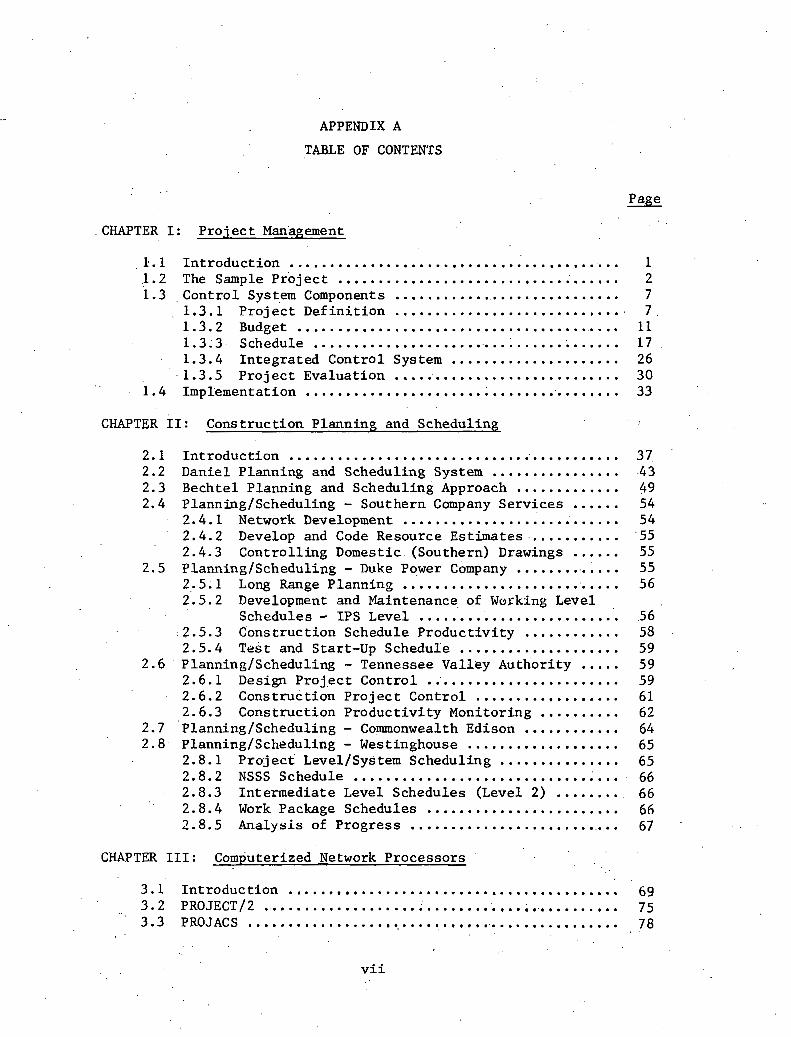
APPENDIX A
TABLE OF CONTENTS
Page
CHAPTER I : Pro j e c t Management
......................................... 1 I n t r o d u c t i o n 1 . ................................... 1 2 The Sample P r o j e c t 2 1.3 . C o n t r o l System Components ............................ 7
. 1.3.1 P r o j e c t D e f i n i t i o n ............................. 7 . ......................................... 1.3.2 Budget 11 1 . 3 ; 3 Schedule ....................................... 17
. 1.3.4 I n t e g r a t e d Cont ro l System ..................... 26 1 . 3 . 5 P r o j e c t Evalua t ion ............................. 30 ........................................ 1.4 Implementation 33
CHAPTER I.1: Const ruc t ion P lanning and Scheduling l
2.1 In t roduc t ion ......................................... 37 2.2 Danie l Planning and Scheduling System ................ 43 ............. 2.3 Bechte l Planning and Scheduling Approach 49 2.4 PlanningIScheduling - Southern Company Se rv ices ...... 54
2.4.1 Network Development ........................... 54 ........... 2.4.2 Develop and Code Resource Es t imates 55 2.4.3 Con t ro l l i ng Domestic (Southern) Drawings ...... 55 ............. 2.5 Planning/Scheduling - Duke Power Company 55 ........................... 2.5.1 Long Range Planning 56 2.5.2 Development and Maintenance of Working Level ......................... Schedules - IPS Level 56 2.5.3 Cons t ruc t ion Schedule P r o d u c t i v i t y ............ 58 2.5.4 Tes t and Star t -up Schedule .................... 59
2.6 PlanningIScheduling - Tennessee Val ley Author i ty ..... 59 2.6.1 Design P r o j e c t Cont ro l ........................ 59 2.6.2 Cons t ruc t ion P r o j e c t Cont ro l .................. 61 2.6.3 Cons t ruc t ion P r o d u c t i v i t y Monitor ing .......... 62
2.7 PlanningIScheduling - Commonwealth Edison ............ 64 2.8 PlanningISckleduling - Westinghouse ................... 65
2.8.1 P r o j e c t LevelISys t e m Scheduling ............... 65 2.8.2 NSSS Schedule ................................. 66 2.8.3 In t e rmed ia t e Level Schedules (Level 2) ........ 66 2.8.4 Work Package Schedules ........................ 66 2.8.5 Analys is of P rog res s .......................... 67
CHAPTER 111: Computerized Network P roces so r s . .
3.1 . I n t r o d u c t i o n ......................................... 69 ............................................... 3.2 PROJECTI~ 75 3 .3 PROJACS 78 . .................................................
, .
. . v i i

Page
3.3.1 General ....................................... 78 ............... . .. 3 .3 .2 Advantages of PROJACS Scheduling 79 ............... 3.3.3 Report Processor C h a r a c t e r i s t i c s 83 ................. 3.4 MCS -.Construction.Managkment System 94 .................... 3.4 .1 M.C.S. Summary Desc r ip t ion 94 . 3.4.2' Schedule. Module ................................ 95 .............................. 3.5 MSCS - ~ c ~ o n n e l l Douglas 106
3.5 .. 1 Desc r ip t ion : MSCS .............................. 108 3.5.2 Resource F a c i l i t i e s ........................... 109 ............................................... 3.6 PREMIS 114 ................. 3.6.1 Network Crea t ion and Ana lys i s 116
. . 3 . 6 . 2 E r r o r De tec t ion .......... ., .................... 11.7 3.6.3 ' Time Ana lys i s ................................. 110 .............. 3.6.4 Resource Ana lys i s and Scheduling 119 ........ 3.6.5 Nonexc. eedab le Resources and Thresholds 120 ....................... 3.6.6 Resources on A c t i v i t i e s 121 3.6.7 Scheduling R u l e s / P r i o r i t i e s ................... 121 ...................................... 3.6.8 Updating 121 . .................................... 3'.6.9 Report ing 122 ................... 3.7 P r o j e c t Management System (PMS IV) 125 ............................... 3.7.1 Network Processor 125 ................. 3.7.2 Resource A l l o c a t i o n Processor 129 ' . ................................... 3.7.3 Cost Processor 129 .............................. 3.7.4 Report Processor 141
CHAPTER I V : P r 6 j e c t s e r v i c e s
4.1 I n t r o d u c t i o n ......................................... 145 4.2 . P a y r o l l ............................................... 145 ........................................... 4.3 Accounting 147 4.4 Personnel ............................................. 149 ..................................... 4.5 Computer Se rv i ces 150 4.6 E x i s t i n g a n d . P r o j e c t e d Sys tems- ....................... 151
................... . 4.7 P r o d u c t i v i t y Report ing and Cont ro l 154 4.7.1 Dulce Power Company - P r o j e c t P l a n n i n g a n d '
Performance . Program : Man- our Quanti ty . Analysis System and Quant f ty Corlcrol System ... 154
... 4.7.2 Danie l I n t e r n a t i o n a l P r o d u c t i v i t y Report ing 161
v i i i

CHAPTER I
* Pro jec t Management
1.1 Int roduct ion
The success of an engineering p r o j e c t depends on the e f fec t ive -
ness of i ts management. P ro jec t management must supervise the design
e f f o r t , ident , i fy design p r i o r i t i e s thrqugh planning and scheduling,
and evaluate . progress. Management has both q u a l i t a t i v e and q u a n t i t a t i v e
functions- i n t h i s regard. The ef ,fect iveness of q u a l i t a t i v e management
is a funct ion of the manager's a b i l i t y t o u t i l i z e human resources. The
engineering manager's q u a l i t a t i v e o b j e c t i v e i s t o accomplish an effec-
t i v e and ' technical ly sound engineering design r e s u l t i n g i n a minimum
t o t a l p ro jec t cos t (design, const ruct ion, and opera t ion cos t s ) . Quanti-
t a t i v e management r e l a t e s t o schedule and budget compliance a s w e l l a s
,. .* product iv i ty measurement. The q u a n t i t a t i v e ob jec t ive i s t o complete
t h e p ro jec t on time and wi th in budget. Q u a l i t a t i v e and q u a n t i t a t i v e
aspects of proj e c t management a r e c lose ly r e l a t e d a t t h e proj e c t planning
stage'. . A design p ro jec t must be planned and budgeted i n such a manner
t h a t a schedule can be met while achieving a good engineering design. . .
During the l i f e of the p r o j e c t , progress i s evaluated with respec t t o
the e a r l y planning and budgeting which becomes a b a s i s f o r p roduc t iv i ty
measurement. The q u a l i t a t i v e and q u a n t i t a t i v e ob jec t ives c o n f l i c t s ince
one constant ly const ra ins t h e o the r , Without a schedule or budget con-
s t r a i n t , a good design might evolve gradually through a t r i a l and e r r o r .
process. However, t h e companies who support p r o j e c t s could not af ford
* This Chapter was w r i t t e n by M r . William Wolter.

t h i s . type of evoPu.tionary~~development. For t h i s reason, a p ro jec t
always has a set of d i a l problems: (1) maximize design e f fec t iveness ,
and (2) minimize cos t and elapsed t i m e . Because of the duai .problems,
p r o j e c t managers' need a systematic technique t o use as , a . t o o l f o r
maximizing . t o t a l management e f fec t iveness . The system described i n
the ' fol lowing sec t ions ' is a combination of techniques which a r e a l ready
i n use. The system is intended t o be used a s an a i d t o t h e management
of the engineering- por t ion of a l a r g e design-construct p ro jec t . RePe-
vance t o t o t a l p ro jec t management, inc luding const ruct ion, is emphasized
b u t no t d e t a i l e d . A s a sample p r o j e c t , a t y p i c a l power p 1 a n t . i ~ used
t o i l l u s t r a t e t h e va r ious components of the management system. While
viewing t h e system f o r power p l a n t design management, app l i ca t ion t o
o ther indus t r i a l - type design p r o j e c t s can be rea l i zed .
1 . 2 The Sample P r o j e c t
. . A pro jec t is a temporary organizat ion which %s created t o accom-
p l i s h an objective. When its work i s completed, the p r o j e c t i s closed
o u t o r disbanded. A pro jec t may be compared t o a company w h i c h - s t a r t s
wi th a small of key personnel. The company expands i n personnel
and equipment f o r 70-80% of i t s l i f e and then quickl$ ditllinishes as the ,
objec t ive reaches f i n a l achievement. Consider. a t y p i c a l power p l a n t
(over 500 MW) which must be designed arid donsrruc~ed. Tu +ccmpl iah
t h i s ob jec t ive , a p r o j e c t is created. The power .p lan t p ro jec t can be . .
divided i n t o i t s major subprojects: ENGINEERING and CONSTRUCTION.
,-. ENGINEERING designs t h e numerous systems which opera te the p l a n t ,

purchases permanent equipment, and produces cons t ruc t ion drawings.
' CONSTRUCTION bu i lds the p l a n t i n accordance wi th the cons t ruct ion
drawings. Then ENGINEERING must publ ish p l a n t opera t ion manuals and
f u r n i s h e x p e r t i s e f o r s t a r t i n g t h e power p lan t . When const ruct ion i s
complete and the p l a n t i s i n f u l l opera t ion , the ob jec t ive is completed,
and the p r o j e c t is terminated.
Because of t h e high i n i t i a l investment cos t of a power p l a n t (seve-
r a l hundred m i l l i o n d o l l a r s ) , it i s necessary t o expedi te engineering
and const ruct ion as.much a s f e a s i b l e s o t h a t an e a r l y commercial opera-
t i o n d a t e can be r e a l i z e d (about 8-10 years f o r nuclear p l a n t s from s t a r t ' .
of eng inee r ing) . . This r equ i res t h a t engineering and const ruct ion phases
have considerable overlap i n time. Foundations a r e o f t e n constructed
bef.ore super-s t ruc ture des igns a r e completed. S i t e f a c i l i t i e s a r e given
tenta t ive .ar rangements p r i o r t o design of such systems a s f u e l handling,
rad waste handling, and a u x i l i a r y systems i n order t o expedi te earth-. . .
work drawings and 'enable the s t a r t of cons t ruct ion . Typical time-phases
of the p r o j e c t a r e i l l u s t r a t e d i n Figure 1'. 1. Examination .of the p r o j e c t
phases w i l l b r ing out the s ign i f i cance of phase overlaps: 1
1. Proposal phase -- .Prel iminary es t imates , schedules, and t echn ica l
q u a l i f i c a t i o n s of the company a r e presented t o t h e p o t e n t i a l c l i e n t i n a
b i d ' t o obta in an engineering and/or cons t ruc t ion con t rac t .
2. 'Preliniinary engineering - Design parameters a r e e s t ab l i shed and
major equipment is purchased such a s the nuclear steam supply system
(NSSS), tu rb ine genera tor , o ther mechanical equipment, main power and
a u x i l i a r y power transformers. Design parameters a r e e s t ab l i shed a s

YEAR '* .
0 2 . . 4 6 8 10 -
PROPOSAL
PRELIMINARY ENGINEERING
DEFINITIVE ENGINEERING
CONSTRUCTION I
FIGURE 1 . 1 : . TIME-OVEEAP OF PROJECT PHASES
systems a r e defined and a s major equipment i s se lec ted . As 'des ign
parameters become f i n a l i z e d , d e f i n i t i v e des ign ( for f a b r i c a t i o n and
const ruct ion) can proceed. Expediting of the p r o j e c t schedule r e q u i r e s
producing const ruct ion drawings a s e a r l y a s poss ib le , usua l ly before
completion of the prel iminary engineering phase.
3 . D e f i n i t i v e <Engineering-- Construct ion drawings a r e produced
and equipment purchases a r e completed during t h i s phase. Designers
and draftsmen use design information generated i n the Prel iminary
Engineeying Phase t o prepare cons t ruc t ion drawings. Huwever, t h e
cons t ruct ion phase sometimes p laces schedule demands on drawing pro-
duction and equipment de l . ive r i e s a t t h e expense of good engineering.
For 'example, s t r u c t u r a l engineers a r e compdlled t o proceed wi th f i n a l
s t e e l pr ' ior t o knowledge of s p e c i f i c equipment loads , o r even systems'
conf igura t ions . This r e s u l t s i n expensive, overly-designed s t r u c t u r a l
lllembers and a high p r o b a b i l i t y of des ign modif ica t ion a f t e r drawings
have been re leased f o r f a b r i c a t i o n . The impact .of p r o j e c t scheduling
problems is f i r s t r e a l i z e d i n the d e f i n i t i v e engineering phase because
of (1) the need f o r des ign parameters requi red t o s t a r t design, and
(2) pressure from the cons t ruct ion phase t o produce drawings. The d u a l
problems of the p ro jec t a r e e x p l i c i t . The engineers are l .a t tempt ing t o
produce a design of good q u a l i t y . On t h e o t h e r hand, they a r e con-
s t r a i n e d by a t i g h t schedule. I n the absence of a sys temat ic technique
t o a s s i s t i n iden t i fy ing design p r i o r i t i e s e a r l y i n the p r o j e c t , one
o r both of the dua l problems must be s a c r i f i c e d , . .

4. Construction -- The constru,ct ion phase requ i res the l e a s t . .
explanation. Although the re a r e a l t e r n a t i v e const ruct ion sequences,
t h e a l t e r n a t i v e s . a r e r e s t r i c t e d by s i t e condi t ions , c l ima t ic condi t ions ,
a r e a a c c e s s i b i l i t y , a v a i l a b i l i t y of l abor , and precedence c o n s t r a i n t s
(earthwork before foundations; foundations before supers t ruc tu re , e t c . ) .
Because.of t h e r e s t r i c t e d na tu re of a const ruct ion sequence, and be-
cause of t h e r e l a t i v e l y high' c o s t of const ruct ion vs. engineering,
t h e const ruct ion schedule w i l l e s t a b l i s h time parameters f o r completing
t h e d e f i n i t i v e engineering phase. To e f f e c t i v e l y schedule d e f i n i t i v e
engineering, the const ruct ion schedule must be conceived during the
prel iminary engineering phase.
5. Start-Up -- Start-up should be t h e r e s p o n s i b i l i t y of the en-
g inee rs who designed the p lan t systems (mechanical, piping, instrumenta-
t i o n and con t ro l , and e l e c t r i c a l ) . Since the p ro jec t schedule is t o be
expedited whenever poss ib le , systems and equipment checkout begins
before power p lan t const ruct ion I s completed. An e f f i c i e n t l y scheduled
p r o j e c t w i l l have allowed f o r t h e time and sequence of p lan t s tar t -up.
When a l a r g e engineering p r o j e c t , having'complex system designs,
is character ized by considerable phase overlapping, a management system
f o r def in ing and con t ro l l ing the p ro jec t is necessary. An e f f e c t i v e
p r o j e c t management system should provide the too l s f o r def in ing,
budgeting, scheduling, supervising, and evaluat ing t h e p r o j e c t . A s . .
mentioned previously, t h e funct ions of management a r e both q u a l i t a t i v e
and q u a n t i t a t i v e . Engineers a r e r igorous ly t r a ined f o r t echn ica l com-
petence 'and a r e conscientious i n s t r i v i n g f o r high q u a l i t y performance.

A management system, a t b e s t , can enhance t h e t echn ica l a spec t s of
design. The system's most t a n g i b l e purpose is t o a s s i s t i n quant i ta -
t i v e engineering management, more s p e c i f i c a l l y , t o answer the follow-
ing quest ions:
1. .Exactly what work has t o be done?
2. What, i s the est imated cos t of the work?
3 . I n what order o r sequence should the work be done?
4 . 'What . -resdurces w i l l be required over t h e l i f e of the p r o j e c t ?
5. How should the p r o j e c t ' s progress be evaluated? . .
The management system described here has the fol lowing major components, .:
which w i l l be descr ibed ' sepa ra te ly : PROJECT DEFINITION, BUDGET, SCHED-
ULE, AND PROJECT EVALUATION. The system combines the major components
i n t o a dynamic t o o l which i s u s e f u l during a l l p r o j e c t phases, The
system provides a means. f o r modiEying the p r o j e c t and f o r management' . .
d e c i s i o n . s n a l y s i s . . .
1 . 3 Control System .Components
. .
1.3. l P r o j e c t Def in i t ion
The components of the p r o j e c t management system w i l l be described
i n terms of the sample power p l a n t p r o j e c t . The f i r s t s t e p i n design
management i s t o de f ine the p ro jec t : What and how much work has t o be
done? To do t h i s , a s p e c i a l kind of o u t l i n e i s developed c a l l e d a
work breakdown s t r u c t u r e , an o u t l i n e of success ive l e v e l s of work
packages. Each work package . . r ep resen t s a well-defined por t ion ,of the

t o t a l work (Figure 1 .2) . The f i r s t l e v e l of the work .breakdown
s t r u c t u r e i s the t o t a l power p l a n t p r o j e c t . The power p lan t p r o j e c t
i s composed of . two . ma j o r subpro j e c t s, ENGINEERING and CONSTRUCTION,
whi=h form the se=ond l e v e l of the work breakdown s t r u c t u r e . The . .
t h i r d l e v e l subdivides the second lcivel, t he f o u r t h subdivides the
t h i r d , e t c . , u n t i l a d e s i r a b l e l e v e l of d e t a i l i s reached. The most ' *
d e t a i l e d work package' should be the d e t a i l requi red t o monitor and
c o n t r o l t h e job. . Figure 1 .2 i l l u s t r a t e s the work breakdo,- froul the
Power P lan t P ro jec t l e v e l , through Engineering Design l e v e l s , down t p
t h e d e t a i l of s e l e c t i n g a s p e c i f i c i tem of equipment o r preparing a . .
flow shee t drawing. A fundamental c h a r a c t e r i s t i c of a work breakdown
s t r u c t u r e is t h a t each work package i s a segment of i ts next h ighes t
level ' , o r conversely, a work package can b e eirpanded t o more d e t a i l e d
l e v e l s . For example, the "condensate System Design" i s c'omposed ,of
t h e fol lowing (from Figure 1 .2) :
System D e f i n i t i o n
Pfpe Design
Ins t rumenta t ion and E l e c t r i c a l Design
Equipment S p e c i f i c a t i o n
Under "System Def in i t ion ," the t ang ib le products of t h a t Work Package
a r e l i s t e d :
System Descr ip t ion
Design C r i t e r i a Study
Flow Sheet Drawing
Components L i s t i n g

FIGURE 1 .2 : WORK BREAKDOWN STRUCTURE PROJECT L ENGINEERING .a CONSTRUCTION a
INSTRUMENT & CONTROL SY S T E B
DEFINITION ELECTRICAL SPECIFICATION DESIGN
I I - I
DESIGN CRITERIA FLOW SHEET CONDENSATE LOW PRESSURE DESCRIPTION STUDY DRAWING HOTWELL P W FEEDIJATER DEAERATOR
HEATER
S T W CYCLE P R ~ C E S S MECHANICAL SYSTEMS
MAIN STEAM SYSTEM DESIGN
AUXILIARY ELECTRICAL
. SYSTEMS
I
CONDENSATE SYSTEM DESIGN
REHEAT STEAM SYSTEM DESIGN

The work,breakdown s t r u c t u r e enables the manager t o evaluate the content
of a design.package a t any l e v e l of d e t a i l . Knowing t h e content of any
. design package is probably . . the most valuable information provided b.y the
work breakdown s t r u c t u r e . The. work breakdown s t r u c t u r e is. a means f o r
achieving a re f ined systems a n a l y s i s of a complex engineering design. . .
It becomes an important t o o l f o r communication between successive manage-
ment l e v e l s , and f o r desdgn coordination among severa l engineering dis-
c ip l ines . I n genera l , a broad s c a l e l e v e l -of the work breclkcluw~i struc-
t u r e w i l l be more i n t e r d i s c i p l i n a r y than a mofe d e r a i l e d w u ~ k package.
The types of personnel involved i n the l e v e l 4 work package, "Condensate ,
System Design," a r e a s fo,llows:
Mechanical ~ n , ~ i n e e r s
E l e c t r i c a l Engineers
.. C i v i l Engineers
S t r e s s Analysis S p e c i a l i s t s
Pfping Designers
Draftsmen .
Spec i f i ca t ion Wri ters
N o t u n t i l t h e s i x t h l e v e l is reached is t h e r e s p o n s i b i l i t y defined t o *
an ind iv idua l . A piping supervisor is, f o r example, responsible f o r a
flow shee t drawing. The work breakdown s t r u c t u r e can i l l u s t r a t e t o an
engineering s p e c i a l i s t , who is highly q u a l i f i e d but l imi ted i n *range of
exper t i se , exac t ly where h i s work f i t s i n the o v e r a l l p ro jec t . It a l s o
shows.him t h e impact of h i s design on c lose ly r e l a t e d design areas .

I n e f f e c t , the work breakdown s t r u c t u r e is a working t o o l f o r a l l
p ro jec t personnel.
. .
' 1 . 3 . 2 . Budget
Development of t h e work breakdown s t r u c t u r e is the proposed method
f o r a t t a in$% pro jec t . .de f in i t ion . How can t h i s t o o l be used i n quanti-
t a t i v e .management? It t e l l s what work has t o be done and o f f e r s va r ious
l e v e l s of d e t a i l f o r .descr ib ing the work. By est imating the cos t of
completing each work package, the manager can s t a t e i n q u a n t i t a t i v e
terms (do l l a r s , manhours, e t c . ) how much work has t o be done by the
p ro jec t .
. Assume t h a t the Power Plant Manager has requested a manhour esti-
mate from h i s p ro jec t engineer. The engineering p r o j e c t organizat ion
. i s charted i n Figure 1 . 3 . ~ r a d i t i o n a l l ~ , the chief engineer £rom ,each
d i s c i p l i n e would be asked f o r an es t ima te of t h e engineering cos t f o r
h i s a r e a of r e s p o n s i b i l i t y . The chief mechanical engineer, f o r ins tance ,
can c l a s s i f y h i s r e s p o n s i b i l i t y i n t o two categor ies : drawings and non-
drawings. The drawings a r e the end products of mechanical and piping
design. The non-drawing a c t i v i t i e s inc lude conceptual system designs
and equipment spec i f i ca t ion . Based on pas t experience, he knows about
how many drawings w i l l be required t o design a power p lan t of a p a r t i c -
u l a r s i z e , and he has reLalned manhour daca f o r each type of drawing.
' He a l s o knows t h a t in the pas t h i s non-drawing manhours have been a
c e r t a i n percentage of h i s t o t a l mechanical design e f f o r t . With t h e ,
above da ta , he can 'est imate the ' t o t a l manhours f o r t h i s design and,

W A G E R . .
. .
PROJECT ENGINEER
I
CONSTRUCTION MANAGER (SUPERINTENDENT)
I
FIGURE 1 .3: PROJECT 1 , ORGANIZATION 3 CHART -
I
B .
CHIEF CHIEF CHIEF
CIVIL MECHANICAL ELECTRICAL
ENGIEEER ENGINEER ENGINEER
CHIEF INSTRUPIENTATION ENGINEER
-
ENGINEER ENGINEER ENGINEER

based on previous experience can a l l o c a t e those manhours among the.
s p e c i a l t y personnel who work f o r him (.pipe designers, process systems.
engineers., tank and v e s s e l designers, e t c . ) . Using h i s t o r i c a l da ta , '
t h e engineering estimate is quickly compiled and held wi th in acceptable
to le rance f o r e s tab l i sh ing a prel iminary budget.
A more exacting method f o r obta in ing a manhour budget is proposed
a s follows:
Step 1. Develop a work brqakdown s t r u c t u r e .
Step 2. Estimate the manhours and personnel required t o complete
each work package a t the most d e t a i l e d l e v e l ( l e v e l 6 of
. . Step 3. By summing t h e es thha tes of the d e t a i l e d work packages one
. l eve l ' lower , obta in an es t imate f o r t h e work packages at each . . l eve l of the work .breakdown s t r u c t u r e .
Step 4. Compare t h e engineering estimate achieved by using the
work breakdown s t r u c t u r e with t h a t obtained using h i s t o r i c a l
da ta , and check f o r s i g n i f i c a n t devia t ions between t h e two
est imates.
Step 1 fo rces a comprehensive s tudy of t h e p ro jec t scope of work.
Step 2 enables t h e engineer o r one of h i s supervisors t o es t imate t h e
manhours required t o complete. a t ang ib le product of .design, such a s a . .
s p e c i f i c group of drawings o r an ana lys i s of a . spec i f i c system. S t e p 3
allows a .summarization f o r the benef i t of thos,e.who do not r e q u t r e ' t h e
work a c t i v i t y d e t a i l of l e v e l 6. Summarization of the manhour e s t i m a t e
a t l e v e l s :3 or 4 po in t s out t h e major a reas of.management concentra t ion

f o r the p ro jec t . Step 4 .veri.f ies t h a t t h e es t imate i's .reasonable,
o r shows t h a t it is above o r below t h e average job of i h a t s i z e . . . .
Applying an es t imate t o a work breakdo& s t r u c t u r e is i l l u s t r a t e d
by ~ i g u r e ' 1'. 4. I n Figure 1.4, the r e s p o n s i b i l i t y f o r th ree work pack-
ages i s divided among t h r e e chief engineers, each i n a d i f f e r e n t d i s -
c i p l i n e . A f u r t h e r refinement of r e s p o r ~ s i b i l f t y ean be obtained by
adding a succeeding l e v e l t o the 'work 'breakdown s t r u c t u r e . By sub-
d iv id ing t h e work packages i n t o s p e c i f i c t a sks , t h e ' j o b can be defined '
and budgeted. in g r e a t e r d e t a i l . . For instanc'e, t h e chief mechanical
engineer. can div.ide h i s budget' among h i s more spec ia l i zed supervisors . . . .
i n terms gf t h e work of : l e v e l 5 .(Figure. 1.5). . Applying the . .
. .. es t imate t o the w o r k p ~ c k a g e is a good' test t b see i f th;! d e t a i l e d
level of thk work breakdown s t f u c t u r e is s u f f i c i e n t fo'r job cbn t ro l .
I f a work package must, be subdivided t o ob ta in a good e s t i m a t e , . t h e n
t h e subdivis ion i's necessary f o r job coqtrol . '
Using t h e work breakdown s t r u c t k e a s an est imating b a s i s enables
s p e c i f i c documentation of t h e scope of the work t o be performed .under
t h e engineering con t rac t and provides a d i r e c t t i e of t h a t scope of work
t o t h e est imated cost . Subsequent changes t o t h e work scope a r e in-
e v i t a b l e and a r e brought about by t h e c l i e n t , design dec i s ions , economics,
equipment se lec t ion , regula tory requirements, and s i t e condit ions. Such
changes can be documented r e a d i l y by modYfying o r adding t o t h e work
breakdown s t r u c t u r e and by assess ing t h e c o s t of t h e modified o r add i t iona l
work packages. A t , a l l t i m e s , , a c l i e n t can be made aware of how h i s design
money .is being .spent and of a l l dev ia t ions from t h e i n i t i a l est imate.
14 ' .

FIGURE 1 .4 : ESTIMATE DEVELOP1,SENT WITH A WORK BREAKDOWN STRUCTURE
( C h i e f D i s c i p l i n e R e s p o n s i b i l i t y ) '
"X" INDICATES PARTICIPATION IN DESIGN EFFORT
STRU CTUR
LEVEL 3--------------- DESIGN
TURBINE STEAl.1
. . STEAM CYCLE SYSTEYIS
f
.
I I
I . - -...
MAIN CON- REHEAT STEAH DENSATE STFSLE.1.
..,.
I
X I
X X
X X X
-7 1L X X
i
X . x

CH
IEF
M
ECII
. E
NG
INE
ER

By analyzing such a change on a design system b a s i s , t h e t o t a l p ro jec t '
cos t of a change i n work scope can be more accura te ly determined, The . .
pro jec t engineer o r p r o j e c t manager may f ind t h a t the systems ana lys i s
of p ro jec t cos t i s & e f f i c i e n t means of conveying t o a c l i e n t t h a t an
a d d i t i o n a l one thousand d o l l a r s spent i n design might r e s u l t i n severa l
thousand . d o l l a r s savings i n const ruct ion and operat ion. Thus, t h e work
breakdown s t r u c t u r e and the es t imate can become a communication medium
between the c l i e n t and t h e engineer, and provide a p o t e n t i a l means of
: involving t h e c l i e n t i n engineering decis ions . This promotes a good
working r e l a t i o n s h i p between t h e c l i e n t and engineer, which r e s u l t s i n
b e t t e r p lan t - design and .mutual s a t i s f a c t i o n .
The est imate f o r the cos t of engineering i s normally reviewed by
bath the p ro jec t manager and the c l i e n t . After necessary adjustments
a r e made and'approvals a r e obtained, a manhour budget can be es tab l i shed ,
based on the est imate. Then, the p r o j e c t is 'well defined i n terms of
what and how much. work has t o be done.
1 . 3 . 3 Schedule
The next component of the c o n t r o l system is the schedule. I t s .
,purpose i s t o t e l l when t h e work has t o be done i n order t o meet the . .
: required p ro jec t completion . . date. ( I t i s assumed t h a t a r e a l i s t i c :projec t . . . . . , completion date. has been .previously accepted by both the engineer and t h e
c l i e n t . ) The d 'escr ip t ion of the p ro jec t phases i n Section 1.2 presents, '
overview of , the proj 'ect schedule. The phases a r e reviewed A s follows: :

1. Proposal
2. Prel iminary Engineering
3. Def i n - i t i v e Engineering
The necess i ty f o r d e t a i l e d planning of each p r o j e c t phase is based
on t h e t i m e over laps between phases, t y p i c a l of a mul t iphase p ro jec t
i n genera l , and a parer plan t p ro jec t i n p a r t i c u l a r . The performance
during each phase depkhds on Lllr sucecooful corn.pl~tinn of work i n t h e ,
preceding phase. For example, among other a c t i v i t i e s i ' n t h e prel iminary r
engineering phase, t h e st em-generator ( b o i l e r ) and the turbine-generator I
a r e purchased. These major purchases e s t a b l i s h t h e b a s i s f o r t h e power I
p l a n t genera l arrangement and f o r d e t a i l e d design of t h e steam-turbuie
p ip ing systems.
The engineering schedule inc ludes t h e ,preliminaryengifiekri~lg alrd
d e f i n i t i v e engineering phases. A primary ob jec t ive gf scheduling engin-
eer ing i s t o . e f f i c i e n t l y support t h e const ruct ion phase. Schedule devel-
opment normally begins e a r l y i n t h e p r o j e c t by e s t a b l i s h i n g key events,
ind ica t ing completion of s i g n i f i c a n t amounts of work. Parameters set
f o r the engineering schedu le . a r e normally cdnst ruct ion s t a r t d a t e s f o r
which engineering drawings, p lan t equipment, and const ruct ion mate r i a l s
a r e required. The p r o j e c t engineer should e s t a b l i s h t a r g e t da tes f o r
key events wi th in engineering which would assure compliance with the
const ruct ion s t a r t a c t i v i t i e s . Trad i t iona l ly , an engineering supervisor
of each d i s c i p l i n e might be asked t o schedule h i s drawing production

and equipment procurement . i n accordance with. given t a r g e t da tes . : The
eng'ineer c& then p red ic t h i s manpower requirements over the l i f e of
the p ro jec t . For t h i s , he r e l i e s on previous experience and h i s t o r i c a l
d a t a which 'he has ' col lec ted i n the past:. Like t h e es t imate t h a t is
based e n t i r e l y . on h i s t o r i c a l ' ,data, t h e schedule i s accepted a s reasonable,
a n d i s checked agains t t h e key event d a t e s which were es tab l i shed by
. . management.
separa te scheduling . . e f f o r t s by each 'engineering disc ip l . ine can,
'however, lead t o problems i n proj e c t design coordination. For ins tance ,
a s i n Figure 1.6, the chief c i v i l engineer schedules h i s foundation de-
s ign and d r a f t i n g baaed on a prel iminary const ruct ion schedule. I n a . . . .
s imi la r 'fashion, the chief . mechanical enginee'r schedules h i s p l a n t
equipment purchases based on the const ruct ion i n s t a l l a t i o n schedule.
I n the simple example ' i l l u s t r a t e d by Figure 1.6, the mechanical equip- . . . . .
ment f a b r i c a t i o n drawings (from t h e manufacturer) a r e neededby the c i v i l
engineer t b design . t h e foundations, but t h e purchase of equipment is . . . .. ..
scheduied..too l a t e 'by .the mechanical engineer . to accommodate t h e need. . . . . .
I f the design schedule is not s a t i s f i e d , n e i t h e r is t h e const ruct ion sched-
u le . Thus, the s i t u a t i o n may r e s u l t i n a more c o s t l y const ruct ion se-
quence. A systematic method i s now described-which is intended t o be used
a s a t o o l t o promote i n t e r d i s c i p l i n a r y communication while scheduling
engineering design.
The proposed technique of scheduling u t i l i z e s a mult i-discipl ined
e f f o r t and is based on t h e work. breakdown s t r u c t u r e previously deireloped.
Also, c e r t a i n const ruct ion schedule parameters must be determined, t o
19

F I G U R E 1.6: INDIVIDUAL D I S C I P L I N E SCHEDULING PROBLEMS
C I V I L ENGR I DESIGN FOUNDATION
I FAERBCATE & DELIVER REIFFORCING STEEL
MECHANICAL ENGR SELECT 6 PURCHASE 3QUIPMENT
FORM S POUR FOUNDATION L I
I F STALL E<UI?MENT
I I
MECHANICAL BNGR
t FABRIQITE S DELIVER EQUIPMENT
U"IV1L EFGR & DELIVER REIN- INSTALL DESlGN FOUNDATION OK4 6 POUR FOUNDATION
ORIGINAL SCHEDULE (BY DISCIPLINE)
ACTUAL PROGRESS
.- SELECT & PURCHASE EQUIPMENT
I
I FABRICATE

, .
i n c lude :
1. P r o j e c t completion d a t e
2. Required start of cons t r .uc t ion
3 . S t a r t and completion d a t e s of major c o n s t r u c t i o n a c t i v i t i e s .
The s t e p s followed by t h e schedul ing engineer a r e as fo l lows:
S tep I . S e l e c t an approprka te l e v e l of t h e work breakdown s t r u c t u r e
~o schedule engineer ing . The d e t a i l l e v e l s e l e c t e d should
t ang ib ly d e s c r i b e des ign work packages. From F igu re 1.4,
, l e v e l 4 is s e l e c t e d because it i s t h e h ighes t (most sum-
marized) l e v e l which d e f i n e s a s i n g l e end-product of en-
gine,er ing. Work packages a t l e v e l 4 a r e des ign system
orient'ed.
S tep 2. F0.r each work package a t t h e l e v e l s e l e c t e d i n Step 1,
develop a l o g i c a l p l a n t o engineer t h a t work package.
The planning l o g i c should be t h a t of t h e ch i e f engineer
ass igned t o t h a t work package, perhaps, compiled by a
schedul ing s p e c i a l i s t . Planning a c t i v i t i e s w i l l be der ived
from a more d e t a i l e d l e v e l of t h e work breakdown s t r u c t u r e .
For example, the summary l e v e l f o r ' scheduling has been de-
f i n e d a s l e v e l 4. I n .Figure 1.7, a planning network has been . .
cons t ruc t ed from l e v e l 5 'work packages, which become planning
a c t i v i t i e s . , Precedence r e l a t i o n s h i p s are def ined by t h e
l o g i c a l ,arrows i n t h e drawing,
Step 3 . . ~ e t e r m i n e t h e precedence r e l a t i o n s h i p s bCtween t h e summary
l e v e l work packages. The execut ion of each l e v e l 4 work

FROM FINAL STEAM Dbl . TO START-UP CYCLE HEAT SYSTEM DEFINITIOF BALANCE
I I PRELIM DRAWINGS I
I TO BID P I l I N G I TO PIPING
FROM I CONTRACT I CONTRACTOR
PRELIMINARY PLANT GENERAL I
PIPE DESIGN ARRANGEMENT TO P I P E DRAWINGS I FABRICATOR
I I I INSTRUMEW 5 ELECTRICAL I I I TO FOUNDATIONS \ DESIGN 4 EQUIPMENT SPECIFICP-TIOM & PURCHASE .
FABRICATE & DELIVER FOR CONSTRUCTION
DENOTES AN INPUT TO OR OUTPUT FROM ANOTHER WORK PACKAGE
FIGURE 1.7: CONDENSATE SYSTEM PLANNING NETWORK

package has a l o g i c a l p lan represented by a precedence
network a s i n Figure 1.7. For each a c t i v i t y i n the net-
work, determine what inpu t s a r e required t o accomplish t h e
. work and what happens t o t h e end products (drawings, design
' d a t a , equipment s e l e c t i o n ) generated by engineering f o r t h e
work' package. The inter-work package r e l a t i o n s h i p is il-
l u s t r a t e d i n Figure 1.7.
Step 4. From the precedence r e l a t i o n s h i p s determined i n Step 3,
I ' consider a l l outputs from engineering t o construktion. A ,
requi red d a t e f o r each engineering-construct ion i n t e r f a c e
is derived from the "preliminary" cons t ruct ion schedule.
Step 5. Apply a l l "fixed" dura t ions (predic ted elapsed time) t o
each of t h e planning a c t i v i t i e s . Perhaps the most prevalent
example of a "fixed" dura t ion i s t h e time requi red f o r a
manufacturer t o f a b r i c a t e an i t e m of equipment (such a s a
pump). Such an elapsed t i m e cannot be a l t e r e d except
. ' through expen s ive expedit ing . Step . 6 . Construct a time-scaled c h a r t ( e i t h e r Gantt o r network)
a t . the summary l e v e l determined i n Step . 1 ( l e v e l 4 i n the
example). Use more d e t a i l i f necessary t o show the. r e l a t i o n -
sh ips derived i n Step 3 . Allow f o r a reasonable elapsed-
* time dura t ion f o r a c t i v i t i e s not having a "fixed" dura t ion ,
...... ... - . . . . . . . . . . . ...................... "Drawing a time-scaled.precedence network i s not an easy task . It is not
suggested ' t h a t t h i s time-scaled drawing be a t o t a l l y encompassing diagram. For t h i s reason, the su-ry P e v e 1 ~ i s ~ u s e d " w h ~ n ~ ~ ~ poss ib le . The drawing, however, w i l l se rve s e v e r a l purposes, s i n c e it: (continued next page)

Step 7. Determine "variable" a c t i v i t y dura t ions ( a c t i v i t i e s
which may be expedited by p r o j e c t ac t ion) wi th in the
d a t e parameters set by t h e time-scaled drawing.
Step 8. Determine scheduled s t a r t and completion d a t e s f o r each ..
a c t i v i t y of each l e v e l 4 network developed i n Step 2 .
Step 9. Al loca te resources t o t h e schedule by ass igning the
engineering manhour es t imate f o r each work package, by
d i sc ip l i i r e , t o each a c t i v i t y , and d i s t r i b u t i n g the a l l o -
ca ted manhours bver t h e elapsed t i m e of each a c t i v i t y .
A manpower u t i l i z a t i o n schedule f o r each engineering
d i s c i p l i n e can be developed by summing manhour require-
- ments per day, week, o r month of the p r o j e c t dura t ion .
.. . Figure. 1 .8 s h m s t h e re l a t ionsh ip : between the budget, . .
schedule, and resource a l l o c a t i o n .
Actual ly s t e p s 1-9 are j u s t the beginning of scheduling a @ o j e c C
The schedule changes continuously a s engineering progress i s rea l i zed
and a s the scope of cons t ruc t ion becomes b e t t e r defined. The "preliminary"
cons t ruc t ion schedule i s derived without d e f i n i t i v e design drawings and
i s based only on p a s t experience and l imi ted s i t e knowledge. Inev i t ab ly ,
t h e cons t ruc t ion p lan w i l l b e a l t e r e d , and new p r i o r i t i e s w i l l r e s u l t f o r
engineering. It is imperat ive, however, t h a t throughout , t h e l i f e of the
a ) provides a prel iminary overview of the engineering schedule; b) po in t s out obvious scheduling problems immediately; c ) provides a communication media thrqugh which each p r o j e c t member may
examine the pre l iminary schedule; and d) he lps determine "variable" a c t i v i t y dura t ions requi red t o meet the
sche.dule.
p r o j e c t , the p r o j e c t manager, p r o j e c t engineer , . . chief eng inee r s of
s e p a r a t e d i s c i p l i n e s , and supe rv i so r s have an i n t e l l i g e n t means of
p r e d i c t i n g when t h e work has t o be done, and how many men w i l l be
r equ i r ed i n t h e succeeding months.
The schedule.becomes t h e t o o l f o r execut ing t h e scope of work.
Changes t o . t h e scope of work shoul-d be r e f l e c t e d by modifying t h e
schedule. This i s done s y s t e m a t i c a l l y by r e v i s i n g t h e network ac-
t i v ? t i e s , a d j u s t i n g s t a r t . a n d completion d a t e s , a n d , a l l o c a t i n g re-
sources f o r a f f e c t e d work packages. The modular technique of devel-
.oping a s m a l l network f o r each des ign system ( i d e n t i f i e d by a l e v e l 4
work package) enab le s ea sy seg rega t ion of s c h e d u l e . r e v i s i o n s . The
schedule i s used t o monitor p rog res s by r ep lac ing t h e scheduled s t a r t
and completion ' d a t e s w i t h a c t u a l d a t e s a s a c t i v i t i e s a r e ' executed. Each
t ime such updat ing is done, t h e d a t e s of t h e remaining a c t i v i t y schedule
must be ad jus t ed t o r e f l e c t t h e a c t u a l d a t e s r e a l i z e d t o d a t e . I f com-
p l e t i o n d a t e s f a l l behind schedule, succeeding a c t i v i t i e s ' d u r a t i o n s
must be shor tened and./or planning l o g i c must be r e v i i e d i n o r d e r t o
meet t h e p r o j e c t completion dkte . Computer scheduling programs a s de-
s c r ibed i n Chapter 1.11 a r e a v a i l a b l e and a l low e f f i c f e n t updat ing and
p rog res s documentation. I
The r e source u t i l i z a t i o n schedule becomes t h e b a s e l i n e f o r measuring
p rog res s i n terms of cos t ( i n manhours). Each time a schedule update i s
made, a c t u a l r e sou rce us,age should be recorded a g a i n s t each work package !
which was completed o r is i n progress . For each.work package i n p rog res s ,
an e s t i m a t e of manhours r equ i r ed t o complete t h a t work package should be

made. Then t h e percent complete of any work package i s . . equa l t o the
( a c t u a l t o d a t e manhours) divided by ( a c t u a l t o d a t e + es t imate t o com-
p l e t e manhours). Percent complete can be ca lcu la ted f o r any summary
l e v e l of t h e work breakdown s t r u c t u r e . Also, by summarizing a c t u a l and
e s f imated manhours f d r each engineering d i s c i p l i n e , percent complete can . .
b e ca lcu la ted f o r c i v i l , mech,anical, and e l e c t r i c a l engineering, e t c .
Resource u t i l i z a t i o n d a t a a r e used i n p r o j e c t evaluat ion a s explained
i n Sec'tton 1.3.5.
1 . 3 . 4 In tegra ted Control System
The c o n t r o l system components have been defined a s follows:
- 1. P r o j e c t d e f i n i t i o n -- An o u t l i n e of work t h a t llas t o .bedone
by t h e p ro jec t i n the form of a work breakdown s t r u c t u r e .
2. Budget -- Derived from an es t imate of each work package i n the
wn& breakdown s t r u c t u r e , an approved a l loca . t ion of resources ( d o l l a r s ,
manhours, e t c . ) t o the p ro jec t .
3 . Schedule -- Based on a l o g i c a l sequence of' work.packagek of the
work breakdown s t r u c t u r e and on t h e a l loca ted budget, a p red ic t fon of
.. when each work package w i l l be s t a r t e d and completed, and a ' requi red
. d i s t r i b u t i o n of resources over the l i f e of t h e p r o j e c t . :
These t h r e e components, when used together , become a comprehensive system
f o r management con t ro l . Figure 1.8 i l l u s t r a t e s t h e inretlrla~ionahi~o . .
of the components. Within t h e system, the work is defined, budgeted,
and scheduled. From the re.source u t i l i z a t i o n scheduie, a cash 'flow pre -
d i c t i o n is derived. ;

ENGINEERING CONTRACT 1 \1
WORK BREAKDOWN STRUCTURE
LOGIC NETWORK - SCHEDULE
- +a U W w w - 7 4 0 Z = u C I V I L n. x - MECH
ELECT =IsE# RESOURCE SCHEDULE
I- - BUDGEi BY WORK A C T l V l N AND BY D l S C i P L l N E -
FIGURE 1.8: MANAGEMENT SYSTEM FOR PROJECT CONTROL
I I TOTAL PROJECT CASH FLOW

A s engineering progresses , the scope of work becomes more ref ined
and i s almost ,&ways modified. Changes t o , t h e work d e f i n i t i o n en te r
t h e system through t h e work breakdown s t r u c t u r e . Then, the budget and
- . schedule are adjus ted accordingly. Revisions t o schedule a r e continuous-
l y considered, The most s i g n i f i c a n t schedule rev i s ions impact the .. .
budget. For ins tance , expedit ing t h e work can r e s u l t i n a higher cost
(overtime, temporary job-shop ass i s t ance , e t c . ) . 'sometimes a r i g i d
schedule causes addf tiofis t o the work d e f i n i t i o n . The schedule' can . .
, d i c ta te ' tha t ' ,mutual ly exclus ive design a l t e r n a t i v e s be completely en-
- . gineered w i t h equipment purchased p r i o r ' t o the s e l e c t i o n .of the f i n a l .
a l t e r n a t i v e . I* t h i s si2tuation, t h e schedule i s used t o determine how
' much p a r a l l e l design e f f o r t i s necessary i n order t o assure operat ion
d a t e compliance. Then, the a d d i t i o n a l work i s fac tored i n t o t h e work . .
breakdown s t r u c t u r e , budgeted, and scheduled l i k e any other scope of
work modificat ion. , When analyzing a design a l t e r n a t i v e , the impact
t o the p ro jec t can be t raced from i n i t i a l in t roduct ion through con-
s t r u c t i o n and s tar t -up. I n shor t , the impact on cash flow of any pro-
posed ac t ion can be presented t o a c l i e n t .
Changes. . t o p r o j e c t scope deserve s p e c i a l a t t e n t i o n because of t h e i r
cumulative impact on t o t a l p ro jec t evaluation. . Changes t o p r o j e c t scope . ..
a r e changes i n con t rac tua l commitment, and such changes almost always
requ i re budget and schedule adjustments. To e f f e d t i v e l y c o n t r o l the
p r o j e c t , t h e p r o j e c t manager and/or p r o j e c t engineer must document and
c a r r y out a l l scope add i t ions o r ' d e l e t i o n s . A good cl ient-engineer
r e l a t i o n s h i p depends on timely n o t i f i c a t i o n of budget and schedule
adjustments r e s u l t i n g from scope changes. With a l a r g e engineering
budget (lC0,OOO-1,000,000 manhour s ) , documenting r e l a t i v e l y small
changes t o scope is e a s i l y neglected. However, t h e complexity of an
engineering p r o j e c t of l a r g e magnitude v i r t u a l l y p r o h i b i t s i n i t i a l work
de f in i t ioh , which is 100% complete. It is f o r t h i s reason t h a t the p r o j e c t
scope should be documented a s e a r l y i n t h e p r o j e c t a s poss ib le i n order
t o formulate a b a s i s . f o r p o t e n t i a l scope, budget, and schedule adjus t -
ments. I f changes t o scope, along wi th t h e i r impacts t o budget and
schedule, a r e documented and relayed t o t h e c l i e n t throughout the l i f e
of t h e p ro jec t , there w i l l be no s u r p r i s e s of budget overrun o r l a t e
schedule. F ~ r ' ~ r o j e c t f inancing purposes, t h e c l i e n t must be allowed '
t o eva lua te t r ends i n t o t a l p r o j e c t cos t which emanate from changes of
engineer ing , scope.
~ m ~ l e m e n t a t i o n of the management system a s a supervisory t o o l
depends on the e f f e c t i v e n e s s of the schedule. 'planning l o g i c must be
co r rec t , .and work a c t i v i t i e s must be i n s u f f i c i e n t d e t a i l t o con t ro l
t h e p ro jec t . The schedule must be a comprehensive rep resen ta t ion of
t h e scope of work f o r t o t a l ~ r o j e c t con t ro l . Furthermore, a change i n . .
p r o j e c t scope should be r e f l e c t e d by an updated schedule, a s should
be a l l problems assoc ia ted with t h e work i n progress . I f scope and
budge t . a re both included i n t h e schedule, then i t fol lows t h a t the
p ro jkc t can b e con t ro l l ed , monitored, and axialyzed on the b a s i s of the
schedule. Although t h e work breakdown s t r u c t u r e and t h e budget may be .
used s,eparateLy .as valuable management t o o l s , t h e proposed system im-
plementation depends on a good schedule.
1.3.5 P r o j e c t Evaluat ion
When work is i n progress, and progress i s reported aga ins t the
schedule,, then p r o j e c t management and t h e c l i e n t can eva lua te the
c u r r e n t s t a t u s of the p r o j e c t wi th r e spec t t o the cu r ren t de ' f in i t ion .
The last p h r a s e i s underl ined because i t po in t s out- an iinportant bene-
f i t from implementing this management system: e f f e c t i v e progress eval-
ua t ion . Management e f f e c t i v e n e s s depends on the a b i l i t y t o p inpoint
cu r ren t p r o j e c t . s t a t u s with r e spec t t o the cu r ren t p r o j e c t d e f i n i t i o n .
The system provides the base l ine f o r evaluat ing progress. Questions t o
,be answered a r e a s follows:
1. How much work. has been scheduled t o da te? . '
2. How much work has been done t o da te?
3. What is the .budge t f o r the work done t o d a t e ?
I . .What has been the a c t u a l cos t of t h e work t o da te?
.. The management system answers q u e s r i u ~ ~ s 11uuLe~ 1 ~ L J . 3. 111mberb 2 and . .
4 a r e answered by c o l l e c t i n g progress d a t a wi th regard t o the schedule
and the budget t o complete the p r o j e c t a s introduced i n Sect ion 1 . 3 . 3 .
For t h e b e s t r e s u l t s i n p r o j e c t evaluat ion , progress da ta should
be c o l l e c t e d f o r the most d e t a i l e d work packages of - t h e work breakdown
s t r u c t u r e . I d e a l l y , these work packages would be the a c t i v i t i e s i n the
schedule which provide the b a s i s f o r re'source a l l o c a t i o n , ~ c c u r a t e
d a t a c o l l e c t i o n is extremely important and i t must be emphasized t h a t
t h e cos t of performing each a c t i v i t y must be documented on a r egu la r
b a s i s (weekly per iods a t minimum). Sect ion 1.3.3 indica ted t h a t an
es t imate t o complete each work package must be obtained f o r a l l a c t i v i t i e s

i n p rog res s f o r t h e fo l lowing reasons :
1 . It enab le s a percent . complete measurement of t h e a c t i v i t y o r
work package based on obje ,c t ive d a t a (as opposed t o e s t ima t ing pe rcen t
complete d i r e c t l y ) , where, % complete = c o s t t o d a t e (manhours) t o t a l expected c o s t (manhours)
2. It provides a c u r r e n t p r o j e c t i o n of manhour t o t a l s which must
'be a p p l i e d t o t h e updated schedule.
P rog res s r e p o r t i n g d a t a may be summarized at any l e v e l of t h e work
breakdown s t r u c t u r e , by engineer ing d i s c i p l i n e . F igure 1 . 8 i l l u s t r a t e s
. - . p o s s i b l e r e p o r t summary l e v e l s . The informat ion , l i s t e d below, is use-
f u l i n eva lua t ing a p r o j e c t :
1 . Actua l v s . Scheduled Pe rcen t Complete -of Work
. 2. Ac tua l vs . Budgeted Cost of Work Performed
3 . Ef f i c fency = Budgeted Cost of Work Performed Actua l Cost of Work Performed
, , 4 ... Schedule Compliance Measurement = Actua l % Complete of Work Scheduled % Complete of Work
5. T o t a l ' P ro j ec t Cost Trend = T o t a l Budget + E f f i c i e n c y
6 . Percent Complete .(Trended) = Cost t o Date (Manhours) T o t a l P r o j e c t Cost Trend (Manhours)
7. T o t a l P r o j e c t Dura t ion Trend = Schedule Dura t ion Schedule Compliance Measurement
The e v a l u a t i o n components should be examined c a r e f u l l y . The a c t u a l per-
cen t comp.lete used in t h e Item 1 comparison i s n o t t h e same as pe rcen t ' .
complete of t r e n d i n Item 6 . The a c t u a l pe rcen t complete is based on t h e
f oll.owi.ng :
T o t a l p r o j e c t e d c o s t .= ( ,ac tua l c o s t t o d a t e ) + (est imated c o s t t o
complete a c t i v i t i e s i n p rog res s ) + (budgeted c o s t f o r
a c t i v i t i e s n o t s t a r t e d ) .

� he percent complete '(trended) i s based on t o t a l 'project cost
. . trend .= ( . to ta l budget) f (efficiency) . -If t he e f f ic iency is less than 1.0, the . t o t a l p ro jec t cos t trend provides
an expected upper bound on the t o t a l cost . The t o t a l p ro jec t cost' provides . .
t h a t cost which is s t i l l within reason t o obtain, where ' f u tu r e a c t i v i t i e s
. a r e iinhiased by current e f f i c iency . Early i n - the p ro jec t , the manager
might p lace more confidence i n the unbiased calcula t ion. Huwcver, l a t e r
i n the p ro jec t , the trend ca lcu la t ion w i l l become more accurate.
.How does the p ro jec t manager use the evaluation a s a management
too l? F i r s t . h e examines t h e trends. W i l l the p ro jec t ' f i n i s h within
.budget; i f not , how many weeks behind or ahead of schedule is expected?
He might then examine the "Milestone ~ u r & a r ~ " evaluation (Figure 1.8)
and f ind t h a t out ,of ten milestone work packages, only one i s demon:
s t r a t i n g poor performance. The manager .can f ind the root of the problem
by t racing i t through the work breakdown s t ruc tu r e Lcr the moot detai led.
work package without having t o review the t o t a l evaluation a t tha t l eve l . .
of d e t a i l . Now he can become involved i n solvine the problem a t a greater
degree of d e t a i l without having to manage'the p ro jec t a t t ha t l e v e l of
d e t a i l .
The system j u s t described o f f e r s t he a b i l i t y t o monitor 'and control ,
i n a quan t i t a t ive manner, the budget and schedule. Through the work
breakdown s t ruc tu r e , it o f f e r s a means of comprehetlsive p ro jec t def ini -
t ion . Through i t s evaluation technique, the system o f f e r s management 'by
exception, enhancing the q u a l i t a t i v e aspects of management. he manage-
ment system provides a t o o l designed t o help maximize t o t a l management
effect iveness fo r time and budget constrained projects .
1.4 Implementation
An example of a work breakdown s t r u c t u r e f o r t h e engineer ing of
a t y p i c a l power p l a n t is given i n t h i s s e c t i o n . I n t h e example, t h e '
. .
p r o j e c t manager wants t o s tudy t h e scope of t h e condenser ,cool ing water
des ign . He is e s p e c i a l l y i n t e r e s t e d i n t h e condenser cool ing c i r -
c u l a t i n g water system. . he a c t i v i t i e s r equ i r ed t o des ign t h e system
a r e , e x t r a c t e d from the work breakdown s t ruc ' tu re . Also provided i s a
l is t of o the r kyst.ems, under d i f f e r e n t c a t e g o r i e s of t h e work breakdown
s t r u c t u r e , which i n t e r f a c e t h e condenser coo l ing water mechanical sys-
t ems.
' ~ o l l o w i n ~ the work breakdown s t r u c t u r e i s a d e t a i l e d planning
l o g i c diagram which would assist i n scheduling t h e work a c t i v i t i e s
a i d r equ i r ed manpower t o complqte t h e condenser coo l ing c i r c u l a t i n g
water system :design;
The complexity of i nco rpora t ing two t o f i v e hundred l o g i c a l plan- ,
; n i n g . d i a g r a m s . i n t o a meaningful a c t i v i t i e s schedule is beyond t h e scope
of t h e time-scaled "PERT-chart" o r Gan t t (Bar) c h a r t . Commercial computer
packages a r e a v a i l a b l e . which would adequate ly ma in t a in t h e e n t i r e manage-
ment .system t o inc lude work breakdown s t r u c t u r e , budget, schedule , and
p rog res s ' r epo r t ing . Most of t h e schedul ing systems a r e based on , C r i t i c a l
P a t h Method (CPM) o r Program Evalua t ion and Review Technique (PERT). The
key t o e f f e c t z v e computer set-up of t h e management,system i s t o develop
a numbering o r ,coding system f o r t h e work a c t i v i t i e s which is a rep're-
s e n t a t i o n of t h e work breakdown s t r u c t u r e . To i l l u s t r a t e t h i s , r e f e r e n c e
i s made t o t h e work breakdown s t r u c t u r e example. The numbers on each work

package a r e organized i n such a manner t h a t the f i r s t d i g i t i s repre-
s e n t a t i v e of " ~ n g i n e e r i n g , I 1 the second d i g i t s t ands f o r the maj o r .c
category wi th in Engineering, and the t h i r d and four ill d i g i t s make up
t h e ."System1', number. The s e q u e n t i a l s o r t i n g c a p a b i l i t y of the computer
enables :reporting on ' any category o r summary l e v e l of the work' break-
down s t r u c t u r e such as the "Condenser Cooling Ci rcu la t ing Water
System." By the same type of coding system, the r e s p o n s i b i l i t y s t ruc -
t u r e can be c rea ted by computer s o r t i n g . I n f a c t , t he e n t i r e system
f o r p r o j e c t c o n t r o l , as i l l u s t r a t e d i n Figure 1.8, c a n be r e a l i z e d
using a scheduling and resource a l l o c a t i o n computer package.

LEVEL 1 PO'VlER PLANT PROJECT I
WORK PACKASE CODE NUMBER ENGINEERING u
Y L E V E L 3 EAOOOq EsWOO I rCO000 1 eDO000 1 EEOOOO I EFOOOOl EGOOOOl EHOOOO 1
1 -- ELOOOO 1 EPOOOO
WRBINE- STEAM- STEAM CYCLE STEAM CYCLE PLANT CONDENSER ILa.TERIALS PLANT ELECTRICAL STRUCTURAL S I T E YATERIALS b GENERATOR GENERATOR PROCESS PROCESS SF- 1 AUXILIARY COOLING M T E J HP.NDLING CONTROL AUXILIARY TRANSIIISSION S Y S T E S DEVELOPNEW DRAPTINC EqUIP!iERT SYSTEMS SYSTDIIS MECIIANICAL PORT HECH. MECIUNICAL MECHANICAL SYSTEMS SYSTEMS , ELECTRICAL SYST0lS (AREAS) SYSTEMS PROCURRIENT
SYSTENS SYSTEMS S Y S T M S SYSTEW SYSTEMS (AREAS) -
SERVICE AIR POTABLE
LEVEL 4 E ~ I O O I EFOZW I E F 0 3 0 0 I E F 0 4 0 0 I I E F 0 5 0 0 I E F 0 6 0 0 I
CONDENSER E F 0 7 0 0
COOLING WllDEN3ER
COOLING WATER CONDENSER
COOLING CIR- COOLIWC COOLING S W D I E S COOLING
TOUW TRPA'RIWT CULATIllG TOWER FIRE TOlfER AREA-
MKE-UP lUVER WATER S Y S T M S ~ S T M PROTECTION
LOCAL CONTROI
- SYSTEMS
E P 0 4 1 0 I P
L E V E L 5 E . SYSTEM SYSTEM EQUIPMENT
DEFINITION INSTRIMWTA- PIPING SPECIFICATION. TION AND DESIGN AND PURCHASE ELECTRICAL
I L E V E L 5 .. EFo421 I I
ZFO431I F 0 4 4 1 1 I tlU44-2-l
PIPING PIPING PIPING CIRCULATING
I LAYOUTS AND
I NG I ::"FICA- I / WATERPWIP 4
AURADEMENTS SPECIFIULTIO
EXPANSION OF CONDENSER COOLING C I R C U L A T I N G WATER SYSTEM TO LEVEL 6
FIGURE 1 .9 : POWER PLANT PROJECT ENGINEERING WORK BREAKDOWN STRUCTURE

t SYSTEM D E F I N I T I O N - - ---
W I N . -. - . . . . -
SYSTEM INSTRUNENTATION 8 ELECTRICAL- -------
PREPARE SYSTEM DIGITAL H PFEPAII . ELECTRICAL AND ANAIM: CONTROL DIAGRAI!S S f l i m X T I C DIAGRAM
TO E~! l333
no ,111 - g :eo K* - g PURCHASE CONTROL SYSTEM
, TO ~ ~ 3 3 1 3 DRAFTING
L A Y W T SKETCH 2 0 w - p o
KENT DATA I
COMPLETE now DIAGRAM SKETCH W I ~ I INSTRUMENTATION 2 0 rlll - 4 0 HH - MSE
F I U F L P I P I N G L A 7 G I T SKETCH
TO ~ ~ 9 0 3 0 DRAFT1 NG
TO S I TE ~ ~ 3 7 9 0 DEVELOPHENT
PRELU4IHARY F W I I DIACIUH SKETCII 6 0 1IH - WSE
CONDENSER DATA^ COOLING DATA PLAIZI' ABRANGE- '
4 PRELII INAXX L I N E S I Z I N G 1 4 F m A L LINE S I Z I N G AND S T R E S S ANALYSIS . 4 0 1M - i P H H -F'J P
CONDENSER #COOLING WATER S~STZM D E S C R ~ I O N 60 - NSD
P I P I N G DESIGN - --- E F 0 4 4 1 . 2 + -- ,
. .', . DEFINE CONDENSER COOLING WATER LEGEND PUHP S P E C I F I C A T I O N S
t lEE - ?IECHANICAL SYSTEMS EIlGINEER - PI - P I P I N G ENCINEER '7 E O U I P I E N T S P E C I F I C A T I O N A I D PURCHASE - ------------ -- P t - P I P I N G DESIGNER - I S - 1tlSTRUI.IENTATION ENGINEER -
' EB - ELECTRICAL ENGINEER - tm - :IANIIOURS (ESTIIIATED)
P I P l h C : . W T E R I A L SPECIFICATION STUCY?, 0 0 rm, - F'J
FIGURE.I.10: COXEENSER COOLING CIRCULATING WATER SYSTEM PLmTING TAGIC DIAGRAM
/ PRCXUE,NT
D E F I t l E CONDENSER COOLING WATER P I P I N G S P E C I P I C A T I O N S 2 0 w - P J
TO €?9gr)3 t4ATERI L L S AND EQUIPMENT

CHAPTER I1 '
. . Construct ion Planning and Scheduling
2.1 I n t r o d u c t i o n . .
The work breakdown s t r u c t u r e (WBS) used t o organize a c t i v i t y dur ing
' t h e engineer ing phase provides t h e f ramework f o r schedul ing dur ing t h e
engineer ing and c o n s t r u c t i o n phases. I n f a c t , both engineer ing and
c o n s t r u c t i o n schedules tend t o i n t e r a c t as des ign d e t a i l p rog res ses
and a r e g r e a t l y impacted 'by the work breakdown procedure. A t t h e out-
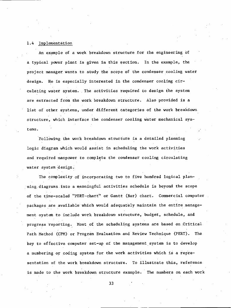
s e t of a p r o j e c t a mi l e s tone event schedule i s e s t a b l i s h e d . ThZs is a
ve ry h igh l e v e l schedule and i s designed t o i n d i c a t e when major even t s .
such as t h e completion. of t he P re l imina ry Sa fe ty Analys is Report (PSAR) ,
completion of major p r o j e c t e lements (e .g . , completion of t u r b i n e b u i l d i n g ) ,
and p l a n t s t a r t -up . a r e t o occur . A t y p i c a l mi l e s tone event schedule f o r
a nuc lea r p l a n t is shown i n F igure 2.1. Based on t h e , m i l e s t o n e event
schedule, des ign requirements and d a t e s f o r a v a i l a b i l i t y of des ign docu-
mentat ion can be e s t a b l i s h e d . These d a t e s i n con juc t ion w i t h WBS approach
gene ra t e a de'sign schedule. The engineer ing and des ign schedule t y p i c a l l y
c o n s i s t s a t any po in t i n time of s e v e r a l thousand des ign a c t i v i t i e s . The
des ign schedule, i n t u r n , becomes t h e b a s i s f o r procurement and c o n s t r u c t i o n
schedules. ' The c o n s t r u c t i o n schedule which d e r i v e s from t h e des ign sched-
u l e u s u a l l y c o n s i s t s of from 6 t o 8 thousand a c t i v i t i e s and i s commonly
' r e f e r r e d t o a s t h e DEFINITIVE SCHEDULE. There i s c o n t i n u a l i n t e r a c t i o n
between t h e engineering-design, t he procurement, and t h e c o n s t r u c t i o n
schedules and de l ays i n one i n e v i t a b l y f eed back and l ead t o changes i n
BUILDING m BUILDING
GENERATOR BUILDING
. FIGURE 2.1: PROJECT MILESTONE SCHEDULE
t h e o thers . This dynamic r e l a t i o n s h i p between the schedules means
t h a t the d e t a i l s of these schedules a r e i n a constant s t a t e of f lux .
This leads t o a continuing updating requirement and ma'intenance of
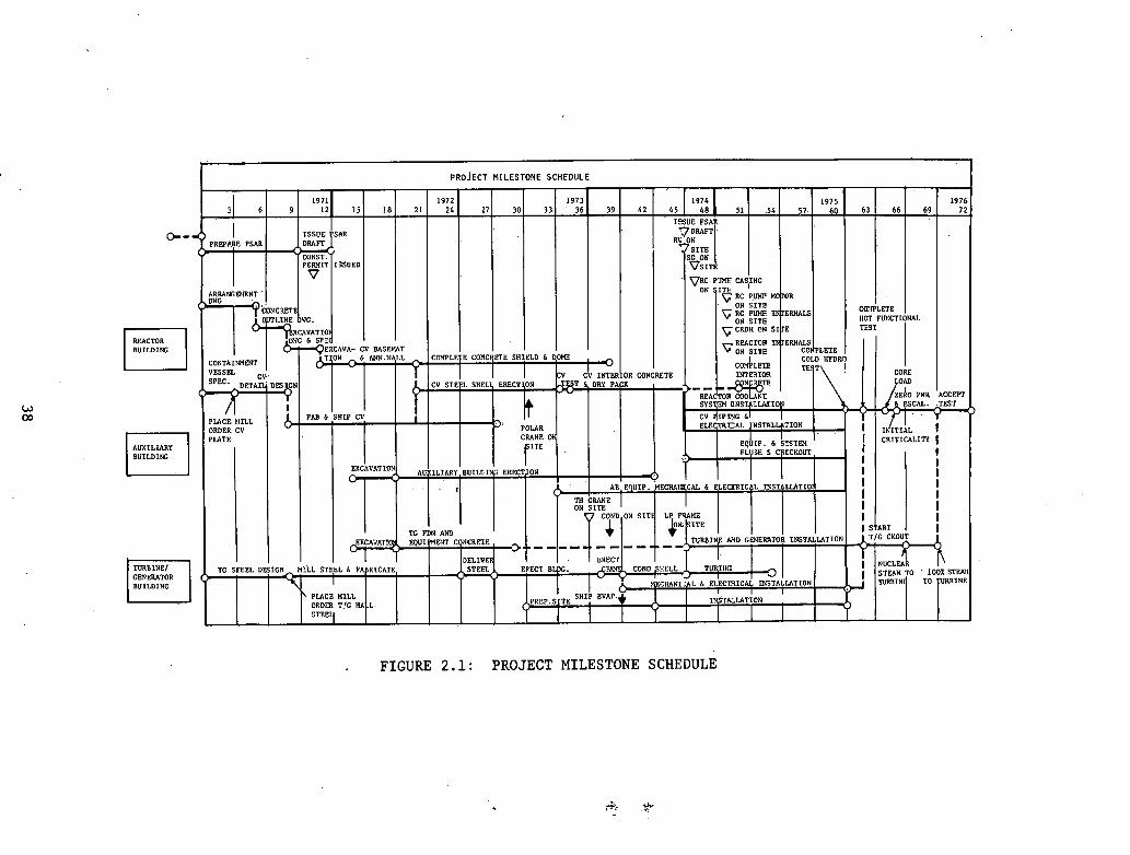
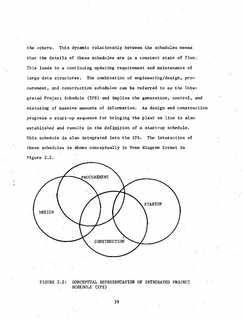
l a r g e d a t a s t ruc tu res . The combination of engineeringldesign, pro-
curement, and const ruct ion schedules can be r e f e r r e d t o a s the In te-
gra ted P r o j e c t Schedule (IPS) and impl ies t h e generat ion, control-, and
s t a tus ing of massive amounts of information. A s design and cons t ruc t ion
progress a s tar t -up sequence f o r b r i n g i n g ' t h e p l a n t on l i n e i s a l s o
es tabl ished ' and r e s u l t s i n the d e f i n i t i o n of a s t a r t -up schedule.
This schedule i s a l s o in tegra ted i n t o t h e IPS. The i n t e r a c t i o n of
these schedules ..is .shown conceptually i n Venn diagram format i n
Figure 2.2.
FIGURE 2.2 : CONCEPTUAL REPRESENTATION OF INTEGRATED PROJECT SCHEDULE (IPS)

Schedules i n excess of 30,000 a c t i v i t i e s have been developed i n an
* attempt to i n t e g r a t e these complementary phases. . I n p rac t i ce , however,
t h i s i n t e g r a t i o n is usua l ly i n concept only and in te r f low of d a t a i s ac- \.
complished manually. Southern Company Services, f o r example, maintains d
, an engineerdng schedule f o r each p r o j e c t using the P r o j e c t 2 network
processor (see chapter 3 ) , while a separa te cons t ruc t ion schedule i s
maintained us ing a separa te schedule procceaor. 1nterar:tion betwccn
these two schedules i s accomplished manuaily.
Since these schedules a r e i n a dynamic s t a t e of change and revis ion,
s h o r t e r .range' cons t ruc t ion schedules f o r c o n t r o l over an immediate time . . hori'zon such a s a quar ter or month must be derived from the d e f i n i t i v e
, .
schedule. This l eads t o the concept of scheduling l e v e l s with the mile-
s tone schedules a t Level 1, the d e f i n i t i v e schedule a t ' l e v e l 2, and \
s h o r t e r range schedules a t l e v e l s 3 and below. .These lower l e v e l d e t a i l i
scherhiles can take the form of networks o r d e t a i l e d bar char t s . A s wi.S..l
be ezplained i n a l a t e r sec t ion , Daniel I n t e r n a t i o n a l Corporation u t i l i z e s
an Intermediate ~ a n g e Bar Chart Schedule (IRBCS) a t l e v e l 3,. covering a
three-month period, a Short Range Bar Chart Schedule (SRBCS) a t l e v e l 4,
which is u t i l i z e d f o r weekly schedule purposes, a n d . a Work Order concept .
a t l e v e l 5 which d e f i n e s ind iv idua l work packages t o be ass$gned t o f i e l d tI
crews f o r accomplishment.**- The use of mi les tone and d e f i n i t i v e schedules -
t o cons t ruc t ion at levels 1 and 2 10 faitly.st;lnrlarrl throughout
*Such a network was developed a t the Hatch I1 plan t of Georgia Power t o in te - g r a t e the cons t ruc t ion and s tar t -up schedules using t h e IMPERT schedule
I
processor. **See foo tno te next page.
t h e i ndus t ry . The d e f i n i t i o n of l e v e l 3 and below v a r i e s from con- . ..
s t r u c t o r t o cons t ruc to r . Stone and Webster u ses a s l i g h t l y d i f f e r e n t
. . .system a s shown i n Table 2.1. The t a b l e i n d i c a t e s four . leve ls of
"Basic Planning and Con t ro l ~ocumen t s . " The u s e of " leve ls" t o
e s t a b l i s h measures f o r c o n t r o l l i n g c o n s t r u c t i o n a l s o imp l i e s a s t r u c -
t u r e f o r d a t a c o l l e c t i o n and aggregat ion. f o r r e p o r t i n g purposes. I n
t h e Stone and Webster system, t he lowest 1 e v e l . o f d e f i n i t i o n and, there-
f o r e , t h e f i r s t p o i n t of d a t a a c q u i s i t i o n , i s a t l e v e l 4. Data .aggre-
ga ted a t l e v e l 4 f e e d s the f r a g n e t schedules and o t h e r reports a t
l e v e l 3. A s k a i l a r p roces s a l l ows aggrega t ion of in format ion a t
l e v e l s 2 and l . a s necessary .
I n t h e fo l lowing s e c t i o n s , p lanning and schedul ing systems e i t h e r
p r e s e n t l y being u t i l i z e d o r p ro j ec t ed f o r use w i l l be d iscussed . The
scheduling o r i e n t a t i o n of t h e systems v a r i e s accord ing t o t h e organiza- . .
t i o n a l viewpoint ..of t he suppor t o rgan iza t ion . The u s e of t h e planning
and ' s chedu l ing f u n c t i o n ' t o support c o n s t r u c t i o n a c t i v i t y . p r e d o m i n a t e s
i n t h e Danie l and Bechtel' systems. The u t i l i t y viewpoint emphasizes,
c o n t r o l of a number of func t ions , as r e f l e c t e d by . t he Commonwealth Edison,
Duke, TVA, and Southern Company Se rv ices systems. The system used by
westinghouse emphasizes t h e vendor ' s viewpoint i n product ion scheduling.
**The u s e of l e v e l s t o d e f i n e c o n s t r u c t i o n l e v e l d e t a i l should n o t b e c o n f u s e d w i t h t h e - d e f i n i t i o n of l e v e l s of work breakdown s t r u c t u r e presented i n Chap- t e r I. I n both c a s e s t he h igher t he l e v e l , t h e . g r e a t e r ' t h e d e t a i l . However, no a t t empt i s made t o cause l e v e l 4 of t h e engineer ing WBS t o l i n k wi th .
l e v e l 4 c o n s t r u c t i o n schediiles i n t h e f i e l d .

. .
L e v e . 1 ~ of . .
Planning & Cont ro l Bas ic Documents Desc r ip t ion . and Use
Level 1 P r o j e c t Summary N e t - Summary of e n t i r e p r o j e c t work p l a n and schedule. Used
by Pro j e c t Hanager when r e p o r t i n g ' s c h e d u l e s t a t u s t o c l i e n t . ,
Level 2 Area o r D i s c i p l i n e Semi-detailed summary of Nctworlco each hiii 1 ding o r a r e a l m a j ~ r -
df s c i p l i n e . Used by P r o j e c t Engineer and Cons t ruc t ion Manager t o provida o v e r a l l p r o j e c t v i s i b i l i t y t o supe rv i so r s .
Level 3 Engineering and Pro- De ta i l ed p l an and schedules curement Schedule f o r each d i s c i p l i n e o r Drawing Schedule c r a f t . Used by supe rv i so r s Fragile t s t o c o n t r o l t h e product ion
of work.
Level 4 Material Cont ro l De ta i l ed l i s t i n g of d e l i v e r a b l e . Reports material and equipment. Used
by s u p e r v i s o r s t o i d e n t i f y and account f o r d e l i v e r a b l e i tems.
TABLE 2.1: BASIC PLANNING AND CONTROL DOCUMENTS

2.2 Daniel Planning and Scheduling System
The follow,ing information is based on interviews and m a t e r i a l s
developed during v i s i t s t o the Daniel Callaway.project site. The
p r o j e c t is being constructed f o r Union power and i s a Standard Nuclear
Unit Power P lan t System (.SNUPPS) p r o j e c t with design being done by
Bechtel Corporation. The l e v e l s of planning and scheduling i n t e r e s t
and repor t ing a r e a s follows:
(1) Milestone Summary Schedule l e v e l
(2) . Pro jec t Master CPM ( ~ e f i n i t i v e ) Schedule
(3 ) . Intermediate ' ~ a n g e . Bar Chart (3 month) schedule
( 4 ) Short Range Bar Chart Schedule
(5) Process Pro jec t Work Orders
The ~ i l e s t o n e Summary Schedule includes major const ruct ion events
a s we l l a s projec,ted pre-operat ional acceptance, f u e l loading, and
system s tar t -up 'dates. The d a t e s a r e developed j o i n t l y by t h e Con-
s t r u c t i o n Manager and the Constructor ( i .e . , Daniel) . This schedule
es tabl ' i shes the b a s i c p ro jec t ob jec t ives and provides a b a s i s f o r high
, l e v e l r epor t ing .on const ruct ion progress. The schedule is usua l ly main-
ta ined i n a bar char t format and de f ines event desc r ip t ions and d a t e s
a s w e l l a s major a c t i v i t y desc r ip t ions and durat ions.
The P r o j e c t Master ( C r i t i c a l Path Method)* Schedule provides t h e next
l e v e l of d e t a i l below t h e Milestone Summary Schedule. This n e t k r k schedule
i d e n t i f i e s a l l const ruct ion ind s tar t -up work a s ,defined in t h e des,ign
*The C r i t i c a l Path Method w i l l be r e f e r r e d t o a s CPM throughout t h e remainder of t h i s ~ ~ ~ e n d i x .

documentation and shows the l o g i c a l r e l a t i o n s h i p b e k e e n a l l work
a c t i v i t i e s . . The h t e r f ace between the const ruct ion network and . the
des ign ' and procurement networks i s maintained manually. The Architect-
Engineer i s respons ib le for i d e n t i f y i n g d rawhgs and re leas ing them J.n
t i m e t o support the cons t ruc t ion schedule. A t t h e Callaway p ro jec t
t h i s i s accomplished using a Bechtel developed system ca l l ed CEBUS,
The l e v e l of d e t a i l i n t h i b clef i n i c i v e sclledula is
'.expanded as.data becomes ava i l ab le . I n d i v i d u a l ' a c t i v i t i e s a r e estab-
l i s h e d based on t h e fol lowing c r i t e r i a :
(1) Physica l ly defined u n i t of work
(2) Single d i s c i p l i n e wi th in a defined a r e a . ' ' .
(3) Management accoun tab i l i ty
(4) Compatibi l i ty with Cost Code System ,.
(5). Packaging t o r e t a i n conti.nuity
The t o t a l s i z e . o f this network ranges between 3 and 10,thousand I .
a c t i v i t i e s . This schedule provides a b a s i s f o r the 3 month I n t e r -
mediate Range- Bar Chart Schedule (TRBCS). It a l s o e s t a b l i s h e s the
primary framework witU,n which design, procurement, and t e s t a c t i v i t i e s
must be u l t i m a t e l y coordinated.
This schedule i s processed automat ica l ly using t h e computer. The
CPM.system used at the callaway ' job u t i l i z e s t h e PROJACS processor. The
fol lowing information i s required f o r network spec i f i ca t ion , and i s
, t y p i c a l of CPM processors i n general :
(1) Activi ' ty Code and Descript ion
(2) A c t i v i t y Duration

. . (3) Calendar and Work Week-Speci f ica t ion
(4) , ~ c t i v i t ~ Progress S t a t u s
(5) A c t i v i t y E a r l y S t a r t and E a r l y F i n i s h Information
(6) A c t i v i t y Late S t a r t and Late F i n i s h Informat ion
(7) Organiza t ion Code
(a) ,, A r e a / ~ u i l d i n g / E l e v a t i o n
(b) Organ iza t iona l R e s p o n s i b i l i t y
( c ) D i s c i p l i n e
(d) Account Codes
User r e p o r t s genera ted by t h e system inc lude :
(1) Schedule Reports
(2) Work S t a t u s Reports
(3) Exception Reports
(4) Resource U t i l i z a t i o n Reports
(5) Schedule Ana lys i s Reports
( 6 ) Milestone Repor ts
The In te rmedia te Range B a r Chart Schedule (IRBCS) is used t o
schedule over a 3 month per iod . Th i s schedule breaks t h e CPM a c t i v i t i e s
def ined i n t h e P r o j e c t Master ( D e f i n i t i v e ) Schedule i n t o c o n t r o l l a b l e ,
s i n g l e r e s p o n s i b i l i t y work i tems. The IRBCS' .is t o t a l l y de r ived from t h e
'CPM master a n d . i s used as a b a s i s f o r updat ing t h e CPM p r o j e c t master
schedule. The IRBCS i s a manually prepared and updated bar c h a r t ,
Daniel top l e v e l management review the p r o j e c t s t a t u s as r e f l e c t e d i n
t he IRBCS on a monthly b a s i s .

. ' Data u t i l i z e d i n the development of t h i s schedule include:
(1) Work I t e m Descr ip t ion . .
(2) Work I t e m ' Percent Complete
(3) Pro jec ted Work I t e m Completion Date
(4) Work I t e m Quanti ty
(5) Work Item as a percent of t o t a l CPM master a c t i v i t y
( 6 ) ' q u a n t i t y I n s t a l l e d t o Date
(7) Work I t e m remaining dura t ion
The Shor t Range Bar Chart Schedule (SRBCS) i s one l e v e l of d e t a i l
below the t h r e e month schedule. This schedule serves a s the b a s i s f o r
d a i l y and weekly c r a f t meetings. Each t a s k on the :schedule i s the respon-
s i b i l i t y of a s i n g l e foreman who is held accountable . fo r i t s s a t i s f a c t o r y
completion. This s c h e d u 1 e . i ~ prepared.'.and updated 'manually wi th in the
framework e s t a b l i s h e d by the IRBCS. This schedule provides a source of . .
d a t a f o r . u p d a t i n g t h e IRBCS and a b a s i s f o r f i e l d s t a t u s repor t ing . uara
requi red f o r genera t ion of t h i s schedule includes:
(1) Time Frame covered by SRBCS
(2) Work Zone and Area
(3 ) - ' supervisor ' s N a m e
(4) Task Descript ion
(5) Assigned Foreman's Name
( 6 ) Average Number of Men Kequlred
The Daniel Work Order System is constructed around a Work Order
Package which c o n s i s t s of s e v e r a l CPM master schedule a c t i v i t i e s . .The 8
work order package de f ines a u n i t which is common t o both the c o s t
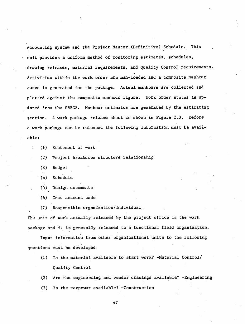
Accounting system and the Pro jec t Master (Defini t ive) .Schedule. This
u n i t provides, a uniform method of monitoring estimates, schedules,
drawing r e l e a s e s , ma te r i a l requirements, and Qual i ty Control requirements.
A c t i v i t i e s within t h e work order a r e man-loaded and a composite manhour
curve is generated f o r the package. Actual manhours a r e co l l ec ted and
p lo t t ed aga ins t the composite manhour f igure . Work order s t a t u s is up-
dated from t h e SRBCS. Manhour es t imates are generated by t h e es t imat ing
sect ion. A work package re lease sheet is shown i n Figure 2 . 3 , Before
a work package can be re leased the following information must be ava i l -
a b l e :
: (1.) Statement of wo:k
(2) Pro jec t breakdown s t r u c t u r e r e l a t i o n s h i p
(3) Budget
(4) ' schedule
(5) Design documents'
(6) Cost account code
(7 ) Responsible organizat ion/ individual . .
The u n i t of work a c t u a l l y released hy t h e p ro jec t o f f i c e is t h e work
package and it i s genera l ly re leased t o a func t iona l f i e l d organizat ion.
Input information from other o rgan iza t iona l u n i t s t o t h e fol lowing
quest ions must be developed:
(1) Is the m a t e r i a l a v a i l a b l e t o start work? -Material Controi/
Quali ty Control
(2) Are the =ngineering and vendor drawings ava i l ab le? -Engineering
(3) Is t h e manpower.available? -Construction

PROGRAM TITLE
TASK TITLE CHARGE NO. . .
TASK LEADER . .
ACCEPTED BY DATE
GROUP OR DEPT. SUPERVISOR APPROVAL DATE
PROGRAM MANAGER AUTHORIZED BY DATE
I TASK :
~CHEDULED START DURATION OF EFFORT
DESCRIPTION
END REQUIREMENTS : ---~--*..s*A----
4
BUDGET :
LABOR H O m OTHER DIRECT (MATERIAL, TRAVEL)
WORK PACKAGE COMPLETED:
HOURS EXPEND ED DATE COMPLETED
FIGURE 2 . 3 : WORK PACKAGE RELEASE SHEET

(4) Is the equipment ava i l ab le? -Construction
( 5 ) Are the procedures ava i l ab le? -Quality Control/Quali ty As-
surance, Engineering/Construction QA/QC
( 6 ) Has the budget been es tab l i shed? -Cost Control
(7). . when ' i s t h e a c t i v i t y scheduled t o s t a r t ? C?mplete? Schedtiling?.
(8) Have const ruct ion p r e r e q u i s i t e s been' completed? - ~ o n s t r u c t i o n /
.Scheduling
(9) .Has the r a t e of progress (budget expenditure) been f o r e c a s t ?
Scheduling/Cost Control
During t h e const ruct ion and i n s t a l l a t i o n process, the re may be ,I.
severa l hundred work i n process a t any ' pa r t i cu la r time. Re-
p o r t s ind ica t ing which work package CPM master a c t i v i t i e s are scheduled
t o s t a r t wi th in the next 90 days a s we l l a s exception r e p o r t s ind ica t ing
those a c t i v i t i e s scheduled t o s t a r t but delayed a r e generated t o support ,
. the system.
2 . 3 Bechtel. Planning and Scheduling ~ p p r o a c h
The Bechtel planning and scheduling philosophy is described' i n the
publicatj.on, "Power P lan t Construction - Planning. a d Scheduling Proce-
dures. " 'The concepts. out l ined i n t h i s r e p o r t a r e pr imar i ly oriknted to-
wards .scheduling of const ruct ion al though Bechtel a l s o opera tes a s a
design-constructor . . The sy$.tem defines, f i v e scheduling func t ions required
t o implement a const ruct ion c o n t r o l environment: .
(1) Development of P ro jec t Master Schedule
I (2) Development and Maintenance of 3 month schedules
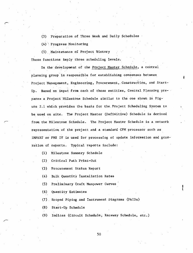
(3) p r e p a r a t i o n .of Three Week and Da i ly Schedules
(4) ": P r o g r e s s Monitoring . .
( 5 ) ~ a f i t e n a n c e of P r o j e c t H i s t o r y . .
These f u n c t i o n s imply t h r e e schedul ing l e v e l s .
I n t he development of the P r o j e c t Master Schedule, a c e n t r a l
p lanning group i s r e s p o n s i b l e f o r e s t a b l i s h i n g consensus.between I
P r o j e c t Management, Engineering, Procurement, ~ o n s t r u & i o n , and S t a r t -
Up. Based on i n p u t from each of t h e s e e n t i t i e s , c e n t r a l P1ann.j-ng pre- -
p'ares a P r o j e c t Mi les tone Schedule s i h i l a r t o the' one shown in Fig-
u r e 2.1 which p rov ides t h e b a s i s f o r t h e . P r o j e c t Sdhsduli.ng System t o t
be used on site. The P r o j e c t Master ( D e f i n i t i v e ) Schedule is de r ived
from t h e Mi les tone Schedule. The P r o j e c t Master Schedule i s a network
r e p r e s e n t a t i o n of t h e p r o j e c t and a s tandard CPM processor such as
W E R T o r PMS I V is used ' f o r process ing of update informat ion and gcne-
.ra ' t ion of r e p o r t s . Typica l r e p o r t s i n c l u d e :
(1) Miles tone Summary Schedule
(2) C r i t i c a l Pa th Print-Out
(3) Procurement S t a t u s Keport
(4) Bulk Quant i ty I n s t a l l a t i o n Kates
(5) P re l imina ry C r a f t Manpower Curves '
( 6 ) Quant i ty Es t imates
(7) . Scoped Pip ing and Instrument Diagrams (P&IDS)
(8) s t a r t - u p Schedule
(9) I n d i c e s (Ci rcu i t Schedule; Raceway Schedule, e t c . )
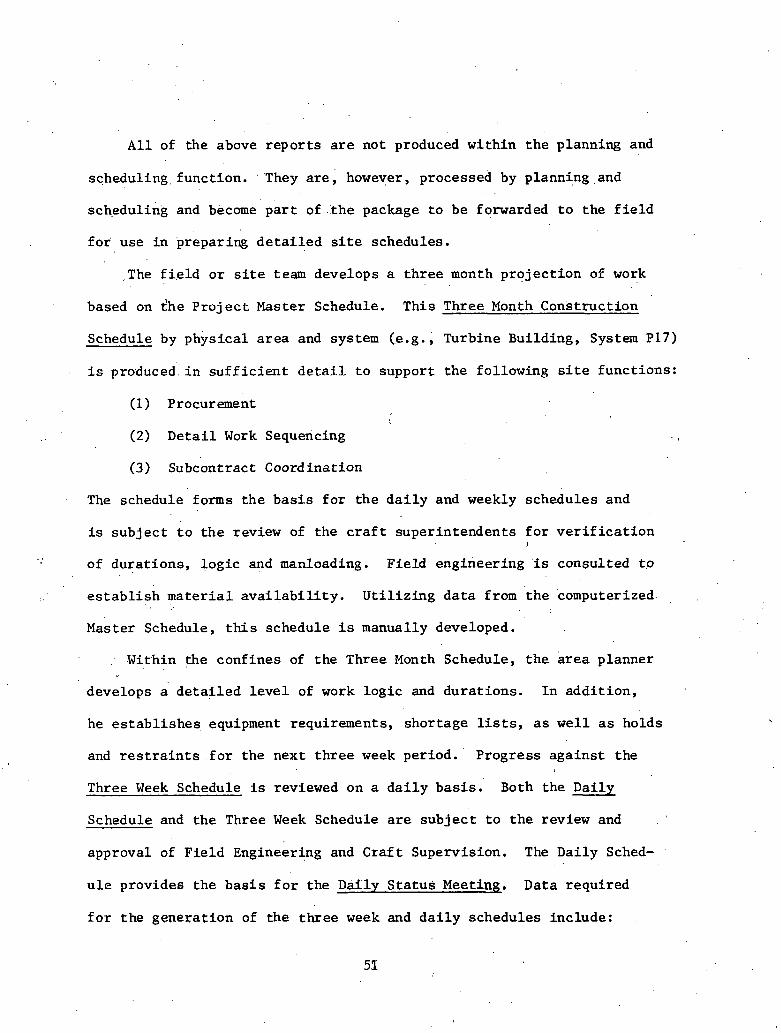
A l l of the above r e p o r t s a r e not produced within t h e planning and
schedul ing, funct ion. . They a r e , however, processed by planning,and . .
scheduling and become p a r t of .:the package t o be forwarded t o the f i e l d
f o r use i n preparing d e t a i l e d s i t e schedules.
,The f i e l d o r s i te team develops a t h r e e month p ro jec t ion of work . .
based on $he P r o j e c t Master Schedule. This Three Month Construction
Schedule by.physica1 a r e a and system (.e.g., Turbine Building, System P17)
i s produced i n s u f f i c i e n t de,tai.l, t o support t h e following s i te functions:
(1) Procurement
(2) D e t a i l Work Sequencing
(3) Subcontract Coordination
The schedule forms t h e b a s i s f o r t h e d a i l y and weekly schedules and
is sub jec t t o t h e review of the c r a f t superintendents f o r v e r i f i c a t i o n J
of dura t ions , l o g i c and manloading. Field engineering 'is consulted t o
e s t a b l i s h m a t e r i a l a v a i l a b i l i t y . U t i l i z i n g d a t a from t h e 'computerized . .
Master Schedule, t h i s schedule i s manually developed.
Within the confines of the Three Month Schedule, t h e a r e a planner
develops a d e t a i l e d l e v e l of work log ic and dura t ions . I n add i t ion ,
he es tabl ishes , equipment requirements, shortage lists, a s w e l l a s holds
and r e s t r a i n t s f o r the next t h r e e week period. Progress aga ins t the
Three Week Schedule is reviewed on a d a i l y b a s i s . Both the Daily
Schedule and the Three Week Schedule a r e sub jec t t o t h e review and
approval of F ie ld Engineering and Cra f t Supervision. The Daily Sched-
u l e provides t h e b a s i s f o r the Daily S t a t u s Meeting. Data required
f o r the genera t ion of the th ree week and d a i l y schedules include:
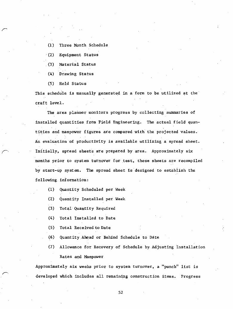
(1) Three Month Schedule
(2) Equipment S t a t u s
c3) Materi-a1 S t a t u s
(4) rawin in^ S t a t u s
(5) Hold S t a t u s . .
This schedule i s manually generated i n a form t o be u t i l i z e d g t the
craft l e v e l .
The a r e a p lanner monitors progress by c o l l e c t i n g summaries of
i n s t a l l e d q u a n t i t i e s . from F ie ld Engineering. The a c t u a l f i e l d quan-
t i t i e s and manpower f i g u r e s a r e compared. with' t he projec ted values . . .
An evaluat ion .of p roduc t iv i ty i s a v a i l a b l e u t i ' l i z i n g a spread shee t .
initially, spread s h e e t s a r e prepared by area . Approximately six
months. p r i o r t o system turnover f o r test, t h e s e s h e e t s a r e recompiled
by s tar t -up sys ten . T h e spread shee t i s d e s i g n e d t o e s t i b i i s h the
following . information :
(1) Quanti ty Scheduled per Week
(2) Quanti ty I n s t a l l e d per Week
(3) Total. Q u a n t i t y Required
( 4 ) T o t a l I n s t a l l e d t o Date
(5) T o t a l Received t o Date
( 6 ) Quant i ty . Ahead o r Behind Schedule t o Date
- ( 7 ) Allowance f o r Recovery of Schedule by. Adjusting I n s t a l l a t i o n
Rates apd Manpower
Approximately s i x weeks p r i o r t o system turnover, a "punch" list i s
developed which inc ludes a l l remaining cons t ruc t ion items. Progress
52

i s then monitored on each item ind iv idua l ly u n t i l the system i s
complete f o r turnover.
F ie ld Engineering i s responsible f o r the accuracy of the quant i ty
es t imates and v e r f f i e s t h a t ma te r i a l has been purchased. The repor t ing
. . of i n s t a l l e d q u a n t i t i e s is the r e s p o n s i b i l i t y of the Craf t Superintendent.
R.ecords of i n s t a l l e d q u a n t i t i e s a r e maintained by F ie ld Engineer.ing. The
area planner has the r e s p o n s i b i l i t y of advising the Pro jec t Off ice of the
e f f e c t s .of schedule delays .
The f i e l d planning group has the r e s p o n s i b i l i t y f o r maintenance of
e p r o j e c t h i s to ry . T h i s , i s accomplished by documenting a c t u a l progress in^
terms of an.I1As-Built" Schedule. This schedule is developed us ing the .
Pro jec t Master Schedule by noting a c t u a l dura t ions and "as-built" log ic .
on t h i s schedule. I n addi t ion , t h e following information together with
i t s impact on schedule i s recorded:
(1) Mater ia l Delays
(2) S t r i k e s or Shutdowns
(3) S h i f t work
(4) Extended Work Weeks
(5) Weat her Conditions
( 6 ) Engineering Delays
(7) Innovations enhahcing product iv i ty
(8) Outside agency delays
This proj.ect record is maintained manually by p ro jec t planning and receives
input from Fie ld Supervision, Field Engineering, and the Start-up group.

2.4 Planning/Scheduling - Southern Company Services
The fol lowing notes on the Southern Company Services approach t o
planning and scheduling of , engineering e f f o r t were ext rac ted from a
s e r i e s of interviews and notes obtained d u r i n g . a v i s i t t o t h e ~ i r m i n ~ h a m
of f i c e of Southefn company Services.
The Design scheduling group rece ives a l i s t of " In te r face ~ c t i v i t i e s " . -
f r & the Construction Scheduling group. The e a r l y s t a r t d a t e s f o r these
a c t i v i t i e s e s t a b l i s h the s i te required da tes for .procurement and design
information. The design e f f o r t is then modeled by about 5000-6000 ac- ':*
t i v i t i e s covering the t ransf er of information wi th in t h e design e f f o r t
( ra ther than t h e physical products of the design e f f o r t - drawings, specs,,
e t c . ) . The CPM network is segregated by d i s c i p l i n e and covers on ly the .
design e f f o r t being done at Southern. vendor des ign e f f 6 r ~ s are ~ I e d
' t o the p r o j e c t network using i n t e r f a c e events. The CPM f o r design i s
developed independently from the CPM f o r procurement and t h e CPM f o r
const ruct ion. Each CPM is done using precedence logic . The networks
a r e processed separa te ly using the Pro jec t 2 Network Scheduling package.
Once processing i s complete, i n t e r f a c i n g between t h e two networks is 1
accomplished manually. The design CPM is used t o monitor des ign.progress ,
and prepare va r iance repor t s .
2.4.2 Develop and Code Resource Estimates
Manhour es t imates f o r engineering e f f o r t a r e developed descr ib ing
t h e work i n terms of work packages (see Chapter .1) . These work packages
a r e defined both i n terms of const ruct ion and engineering work elements
(engineering l o g i c networks and Schedule A c t i v i t y Codes). There a r e
about 2,'500 a c t i v i t i e s t h a t have es t ima tes associa ted with"them. These
es t imates can be segregated i n t o d r a f t i n g and engineering manhours f o r
each of seventeen d i f f e r e n t d i s c i p l i n e s . Actual manhour expenditures
a r e co l l ec ted by work package and compared t o p ro jec t ions .
2.4.3 Controll ing D.omestic (Southern) Drawings
The. p r o j e c t planner i s responsible f o r co l l ec t ing the input shee t s
l i s t i n g the s p e c i f i c drawings required from t h e appropr ia te des ign , mana-
. . gers. A drawing list i s c 'mpiled by responsible p r o j e c t engineers. Each
drawing has t h r e e associa ted da tes : The f o r e c a s t / a c t u a l f i n i s h da te ,
the required f i n i s h da te , and the t r a n s m i t t a l da te . The source of the
"required" d a t e is the const ruct ion schedule. The source of t h e "forecas t /
ac tual" date ' i s the des ign schedule. The drawing f i l e i s updated on a
per drawing bas i s .
2.5 Planning/Scheduling - Duke Power Company
The following no tes on the Duke approach t o planning were ext rac ted
from a s e r i e s of notes and in terviews obtained during v i s i t s t o Char lo t t e
and the McGuire. Nuclear S ta t ion cons t ruc t ion si te. This information
emphasizes the use of the scheduling network a s a - const ruct ion management

t o o l . ' This . i s i n c o n t r a s t t o ' t h e previous s e c t i o n on t h e Southern Company
which emphasizes.. t h e u s e of the ' network in. con t ro l l ing t h e engineering
e f f o r t only.
2.5.1 L o n g Range Planning
The p r o j e c t i s defined i n t e r m s of a l ist of manageable t a sks ' 1 *
(systems, serucrures, l l c e ~ ~ u l i ~ g , etc. ) , Each' task for which ~ q i i i p m e n t b 4 .
must be procured i s i d e n t i f i e d i n terms of the equipment, quant i ty , ,
r e s p o n s i b i l f t y , and loca t ion . The s t a r t , . f i n i s h , and dura t ion of each
const ruct ion. t a s k is . i d e n t i f i e d by t h e Planning Section i n t h e Construc-
t i o n Division. The s t a r t , f i n i s h , and dura t ion of t h e design e f f o r t
necessary t o support the cons t ruc t ion e f f o r t f o r each is i d e n t i f i e d
separa te ly by the planning s e c t i o n i n t h e design d iv i s ion . The two
es t ima tes a r e then manually i n t e r f a c e d t o form an In tegra ted Pro jec t
Schedule (IPS). The IPS provides the b a s l s f o r coordination of design,
procurement, const ruct ion, and, test schehul8s. ,
2.5.2 Development and Maintenance of Working Level Schedules
-- ' I PS Level
The primary purpose of t h e IPS is t o coordinate the design and
procurement e f f o r t s such t h a t t h e needs of const ruct ion a r e s a t i s f i e d . i
Each design t a s k i s defined i n terms of t h e following:
(1) A c t i v i t i e s - Work on a t a s k by an organizat ion wi th in the
scheduled s t a r t and complete d a t e s of the t a sk ,
(2) Milestone - A spec i f i ed p iece of work t h a t i s t o be. f in i shed

by a scheduled da te .
( 3 ) Requirement - , A request f o r information, e t c . , . needed by a
organizat ion t o support the completion of an a c t i v i t y .
( 4 ) Commitment - A "requirement" turned around and shown t o the
organizat ion responsible f o r supplying the i n f ormation, e t c .
The milestones a r e key events noted aver t h e e n t i r e dura t ion of
the task . A c t i v i t i e s , requirements, and commitments a r e subordinate
t d the milest.ones. Commitment da tes a r e es tab l i shed t o i d e n t i f y
required i s s u e d a t e s f o r drawings, purchase orders, and s i m i l a r ,docu- .
ments. Act iv i ty and commitment r e p o r t s a r e projec ted on a th ree ( 3 ) .
month look ahead b a s i s every two (2) months. These r e p o r t s provide t h e
bas i s f o r systematic review, s t a t u s , p o t e n t i a l exception determination,
and not ing changes. A l l a c t i v i t i e s and commitments a r e updated by those
organizat ions responsible and checked by those organizat ions es tab l i sh ing
the requirements. The scoping and scheduling of work wi th in the a c t i v i t y .
is l e f t t o t h e d i s c r e t i o n of the responsible organizat ion. The,complete-
ness ,of the end product i s v e r i f i e d by t h e receiving organization. '
Reports generatkd by the working l e v e l schedule include:
(1 ) Requirements vs. commitments
(2) Commitment Exception Report
( 3 ) ~ c t i v i ty ~ x c e ~ t ion Report
( 4 ) Commitment C r i t i c a l Items Report

Construction Schedule Product iv i ty
The schedule f o r s i te work (at McGuire Nuclear S t a t i o n f o r example)
i s es tab l i shed on a n a r e a b a s i s , u s i n g a s t a r t and completion d a t e and
.a given q u a n t i t y o f work to be performed. The s t a r t and' completion
d a t e s of an' "ac t iv i ty" are i n p u t t o the "MAPS" Program. A s used here
an a c t i v i t y is a given funct ion on a system wi thin a given a r e a ( i . e . ,
p ip ing- f i r e p ro tec t ion system-auxiliary bui ld ing) . The qilantity of . C
work (pipe welds and j o i n t s ) is es tab l i shed by the s i te planning and
scheduling group,, - The quan t i ty of work divided by t h e time a v a i l a b l e
equa l s t h e required production r a t e . Actual production r a t e s a r e
monitored aga ins t projec ted production rates on a weekly b a s i s , The
f ' required production rate i s increased or decreased based on .the re-
maining time a v a i l a b l e .vs . t h e remaining work to. be completed ( i . e . ,
a type of l i n e l e v e l i n g ) . The required production r a t e is mul t ip l i ed
by a u n i t manhour f a c t o r and coxlver Led t o manning requirements. The
schedule is es tab l i shed assuming the a v a i l a b i l i t y of drawings and
mate r i a l s . Exceptions and bot t lenecks a r e handled i n the weekly s t a t u s
meetings at tended by c r a f t foremen, f i e l d engineering, and planning.
When a system is 95% complete, i t is dropped from t h e r a t e t abu la t ion
program. S t a t u s is then maintained on an i t e m by i t e m bas i s using a
d e t a i l e d punch l i s t u n t i l the system is complete and goes through check-
ou t and f lush .

I
2.5.4 Test and Start-Up Schedule
The test and s tar t -up sequence, is modeled using a CPM network t o
note the interdependencies of the system t e s t sequence, e.g., hydro
and func t iona l tests. T h i s l o g i c i s prepared by the Construction Planning
Group working. with d a t e s estab1ish:ed by t h e Operations Group. The Opera-
t i o n s Group (Start-Up) uses a s t a t u s board t o note the expected s t a r t
d a t e s of key t e s t a c t i v i t i e s and t h e i r p r e r e q u i s i t e system completions.
. 2 . 6 Planning /Scheduling - TVA
The following discuss ion of the TVA approach t o planning and .
scheduling i s based on a TVA pub l ica t ion e n t i t l e d , "Tennessee Valley
Authority - OEDC - Pro jec t Control" and a s e r i e s of interviews .with
planning and scheduling personnel i n Knoxville.
2.'6.1 Design Projec t Control
The design e f f o r t is'managed and control led separa te ly from the
const ruct ion e f f o r t because the s t r u c t u r e and flow of work d i f f e r s .
The i n t e r f a c e point between t h e two a r e a s i s es tab l i shed a t the a c t i v i t y
l eve l . The . f i r s f s t e p i n i n i t i a t i n g a p r o j e c t i s the development of
Conceptual Studies. . Once the need f o r new capaci ty has 'been i d e n t i f i e d
by the Division of Power Resource Planning, t h e P r o j e c t . Control s t a f f . ,
along wi th Cost and Estimating sec t ionk and t h e Design D.ivision .branches,
have the r e s p o n s i b i l i t y f o r examining v i a b l e a l t e r n a t i v e s by comparing
designs, schedules, and egtimates. Both the d e s i r a b l e and undesi rable
f e a t u r e s of each a l t e r n a t i v e a r e noted i n a r e p o r t t o upper management

t o assi 'st i n f i n a l s e l e c t i o n .
Once the p r o j e c t go-ahead has been given, a p ro jec t team i s
formed wi th in ' t h e Division- of Engineering Design t o control. p ro jec t
planning and scheduling. This group i d e n t i f i e s va r tous engineering,
des ign and procurement a c t i v i t i e s required t o complete the p ro jec t .
,These ' a c t i v i t i e s a r e ' then broken down i n t o t a sks such a s preparat ion
. 'of engineering drawings, . c r i t e r i a documents, and procurements. , . . .
~ h e s e networks,: c o n s i s t bf about 5,000 a c t i v i t i e s wi th about 3-4 tasks
per ' ac t iv i ty . . Estimates of manhours a r e prepared f o r each t a sk and
dura t ions are assigned t o each a c t i v i t y . A c t i v i t i e s a r e then r e l a t e d
i o g i c a l l y by determining information p re requ i s i t e s . The r e s u l t i n g
a c t i v i t y networks a r e then. processed using an in-house program ca l l ed P
The Network Report is t h e b a s i s f o r a s e r i e s of "Activi ty Produc-
t i o n Reports" where a comparison of a c t u a l vs. planned progress i s made
r e l a t i v e t o a r epor t ing period wi th in the schedule (data d a t e ) . Progress
r. on the design e f f o r t i s es tab l i shed based on the sub jec t ive .
. judgment of
the l i n e supervis ion (Division of Design Engineering) . These product ion
r e p o r t s a r e broken down i n t o t e n informational l e v e l s t h a t range from 1
complete d e t a i l t o a t h r e e l i n e summary f o r the e n t i r e projec t . The i highest s*ry l e v e l groups design drawings and documents, NSSS , and
procurements.
Successive information levels a r e a s follows:
(1) Engineering Organization
(2) Engineering Organization - Discipline*
, *This l e v e l is used by the Branch Chief , the Pro jec t Manager, and the Pro jec t Engineer.

(3 ) Building or Area
(4) P ro jec t Ac t iv i . t i e s ' (i. e. , groups of drawings)
(5) Drawing/Purchase Order
(6, 7, 8 ) ' Levels reserved from s p e c i a l s o r t s
(9) Task
An es t imate of the manhours required t o complete each t a sk is .made.
The u t i l i z a t i o n r a t e i s approximated by s e l e c t i n g one of n ine curves
w.hich is f i t t e d t o the t a s k durat ion.
The "Activi ty Production Reports" inc lude the f o l l m i n g formatted
output:
(1) Design ~ r o d u c t i v i t y / ~ a r C h a r t
( 2 ) Duration Update Report
(3 ) Act iv i ty Production Report
(4) Manhour Exception Report
(5) Trend Analysis Report
2 . 6 . 2 Construction Pro jec t Control
The const ruct ion e f f o r t , while postdating t h e design e f f o r t , provides
the b a s i s f o r scheduling drawing r e l e a s e s and procurement d e l i v e r i e s . -
The Division of Construction provides t h e i n i t i a l p r o j e c t schedule.which
i n tu rn provides the b a s i s f o r a l l subsequent scheduli.ng e f f o r t s . There
1s a j o i n t e f f o r t by the projec t c o n t r o l s t a f f of the Design and Con-
s t r u c t i o n ~ e ~ a r k e n t s t o monitor a n d coordinate work throughout the
proj e c t development cycle..
The construct ion schedule is prepared through a s e r i e s of successive
i t e r a t i ons . A s the vendors a r e se lected f o r major procured items (NSSS), , .
general arrangement or equipment drawings a r e prepared by the successful
bidder or by the Design Division (.TVA). This information provides the
b a s i s f o r iden t i fy ing t he bas ic work u n i t s or components of the p ro jec t .
These components a r e defined a s activit i-es. There a r e approximately
3000 construction , a c r i v i ~ i t ? u Idea t i f i cd for a. nirc1.ear plan t proj.ecL.
Each a c t i v i t y can be subdivided i n t o taslcs (about seven per a c t i v i t y
. on the average). The a c t u a l schedule or network i s developed on the
ba s i s of t he a c t i v i t i e s . A s d e t a i l design drawings become avai lable ,
the s t ruc tu r e o f ' a c t i v i t i e s and tasks t ha t make up the ,construction
schedule is ref ined. P
2 . 6 . 3 Construction Productivity Monitoring
During t he process of developing the construction schedule, est imates
of manhours and mate r ia l quan t i t i e s a r e made fo r each task. These e s t i -
mates a r e used along with h i s t o r i c a l productivity r a t e s t o e s t ab l i sh the
v a l i d i t y of the durat ion assigned t o t he a c t i v i t y . ' These quant i ty es-
timates are spread over the durat ion of the a c t i v i t y using one of the
n ine standard curves tha t bes t approximate t he u t i l i z a t i o n of the par t ic-
' u la r resource f o r a pa r t i cu l a r task. Once a d i s t r i bu t i on i s , s e l e c t e d f o r
a given type of t ask (e.g., pipe i n s t a l l a t i o n ) , the same ,curve i s used
f o r a l l t a sks of t he same type. The assignment of product ivi ty r a t e
curves provides a project ion of product ivi ty and forms a bas i s f o r pro-
duc t iv i ty repor t ing and evaluation. The production and co l lec t ion of

resource u t i l i z a t i o n i s broken down i n t o t h e fol lowing l e v e l s of
inf o m a t ion summary :
(1 . ) Tota l p ro jec t
( 2 ) ' Unit number
( 3 ) Major proj e c t f e a t u r e
( 4 ) Engineering d i s c i p l i n e
( 5 ) system of each d i s c i p l i n e
( 6 ) A c t i v i t y
(7) Sor t
(8) Sort
( 9 ) . Tasks .
The b a s i s f o r c o l l e c t i n g and summarizJng planned and a c t u a l progress
up th rou ih t h i s h i e r a r c h i c a l information s t r u c t u r e u t i l i z e s , the r e l a t i v e
number of manhours.assigned t o each t a s k t imes t h e a c t u a l progress f o r
the t a s k measured by a c t u a l q u a n t i t i e s i n s t a l l e d . The Produc t iv i ty Report
'forms the bas i s f o r Cost Control. Reports generated by the system in-
clude :
1 ) Labor Product iv i ty Bar Chart
(2) Manhour ' History Report
( 3 ) Unit Manhour Report
( 4 ) Duration Update Report
(5) , Act iv i ty Production Report
(6) Except ion Report
(7) Overview of P ro jec t S t a t u s
(8) Two Week Look Ahead - Schedule Tasks

(9) Weekly, Progress ' ~ e ~ o r t
(10) Trend Analysis
2.7 ~ lann ing /Schedu l ing - Commonwealth Edison
The r o l e of planning and scheduling r e l a t i v e t o p ro jec t con t ro l
begins by developing an i n i t i a l Milestone Schedule. This e f f o r t c o n s i s t s
of o u t l i n i n g 20 o r . 3 0 key events throughout the p r o j e c t w f ~ I ~ h e a v y em-
phas i s on t h e e a r l y y e a r s . This i s t h e h ighes t l e v e l of summary sched-
u l e and i s develbped a s e a r l y a s poss ib le . .This schedule serires a s the
b a s i s f o r developing more d e t a i l e d schedules and f o r repor t ing s t a t u s t o
upper management.
Using the Milestone Schedule a s a base, a CPY n e t of approximately
1000 a c t i v i t i e s i s developed. This ne t r e f l e c t s predominantly const ruct ion
a c t i v i t i e s . Its purpose is t o e ,s tabl isb demand d a t e s f o r design and pro-
curement and. t o provide an o u t l i n e of schedule requireu~euts t o construc-
t i o n subcontractors. This schedule i s a c t u a l l y developed over the l i f e
of the p ro jec t . During e a r l y phases of the p ro jec t , the schedule has
a high l e v e l of d e t a i l i n t h e e a r l y a c t i v i t i e s and only a g ross l e v e l
of d e t a i l in l a t e r a c t i v i t i e s . A s work progresses, more d e t a i l i s added
L and the labor a c t i v i t i e s become more p rec i se ly defined. This l eads t o A
I
a r o l l i n g wave inc rease i n d e t a i l a s the p r o j e c t progresses.
The schedule covers the e n t i r e p ro jec t , but is reviewed by upper
management on a t h r e e ( 3 ) month look ahead bas i s . Each const ruct ion sub-
. con t rac to r is respons ib le f o r developing h i s own schedule which i s t i ed
manually t o the Master Schedule (most use t h e same CPM processor - PMS IV).

Design and procurement e f f o r t s a r e not covered by t h e CPM. Although
the CPM network is the one mo9t important item produced by the pro-
cessor, most r epor t s issued t o u s e r s are i n t h e form of bar c h a r t s .
2.8 Planning/Scheduling - Westinghouse
The rollowing notes 'were prepared from some system desc r ip t ions
and procedures issued by Westinghouse i n i t s r o l e a s Lead Reactor
Manufacturer on the Clinch River Breeder Reactor P l a n t p ro jec t . From
the 'vendor l s .po in t of v i e w , four func t ions are considered during plan-
ning and scheduling :
(&) P r o j e c t l e v e l d e f i n i t i o n
(2) Preparat ion of NSSS schedule
(3) prepara t ion of in termedia te l e v e l schedules
(4) Development of work package schedules . .
(5) Analysis of progress
2.8.1 Pro jec t Level/System Scheduling
The Pro jec t aster Schedule (Level 1) is a high l e v e l schedule f o r
building const ruct ion and f o r major component des ign and procurement.
It def ines the fabr ica txon schedules required t o support t h e const ruct ion
schedule. This schedule is not segregated . . by work packages o r p a r t i c i p a n t s .
It i s prepared by the A r c h i t e c t / ~ n g i n e e r and approved by the p r o j e c t o f f i c e .
This schedule conta ins NSSS milestones submitted and agreed t o by the
Lead Reactor Manufacturer (LRM). These milestones represent con t rac tua l
ob l iga t ions and requ i re the approval of the p ro jec t off i c e t o change.
. < .
2 . 8 . 2 NSSS .Schedule
The NSSS schedule inc ludes a l l elements of t h e p r o j e c t work
breakdown s t r u c t u r e t h a t a r e wi th in t h e Lead Reactor Manufacturer ' s
(LRM) scope. The NSSS miles tones from t h e Level 1 schedule a r e included .
as p a r t of t h e NSSS Schedule. This schedule i d e n t i f i e s NSSS c o n t r o l
milestones. These d a t e s r epresen t d a t e s t h a t have t o be m e t i n order
t o insure completion of the conttace: miles to~~rs . a d are thc r e c p ~ n - ~
k i b i l i t y of the LRM. 330th t h e Project /sysrem and ASSS acliedLlcs arc . .
processed manually.
2 . 8 . 3 ~ n t e r m e d i a t e Level Schedules (Level 2 )
' ~ h e s e schedules .a re maintained f o r systems, subsystems,. and
components t h a t f a l l under t h e LRM's scope. These schedules a r e '
o r i en ted t o .elements ,of the con t rac t work bveakdown s . t r u c ~ u r e far
performance measurement and repor t ing. The types of a c t i v i t i e ~ de-
p i c t e d on Level 2 schedules in lude ,design phases, design reviews, tech-
n i c a l documentation, procurement chains, f a b r i c a t i o n r e l e a s e s , fabr ica-
t i o n phases, component s i te d e l i v e r i e s , and component system i n t e r f a c e s .
Events and a c t i v i t i e s a r e updated monthly. These schedu1.e~ a r e processed
using t h e PMS I V network processor.
2 . 8 . 4 Work Package Schedules
The work packages represen t t h e lowest l e v e l of work scope f o r
which schedules ' a r e developed. Work package milestones represent physical
a c ~ o ~ ~ l i s h m e n t s and are d i s c r e t e and v e r i f i a b l e t a sks . Work package

. .
miles tones i d e n t i f y completed work f o r which earned monies a r e calcu-
l a t e d . The work package schedule is subordinate t o and supports one
Level 2 schedule. Work package schedules a r e reviewed every t h r e e
months and p r o j e c t work f o r the next n h e months. They a r e a l s o pro-
cessed using the PMS I V CPM program.
I
2.8.5 Analysis of Progress
Milestone (event) s t a t u s i s summarized, reviewed, and analyzed
a s p a r t of the schedule update process. The following l e v e l s of mile- , .
s tones a r e considered:
(1) mjbr p r o j e c t milestones (Level 1 schedule)
(2) .Top l o g i c mi les tones (NSSS miles tones)
(3) Summary l o g i c mi les tones - A l l top l o g i c mi les tones p l u s
purchase Order placement and de l ive ry d a t e s f o r major items.
(4) Control mi les tones - A l l summary l o g i c milestones p l u s those
d a t e s necessary . to con t ro l procurement placements, equipment, and con-
s t r u c t i o n package d e l i v e r i e s . . .
Control ~ n i l e s t o n e s which a r e of i n t e r e s t include: '
(1) Conceptual Design Release
(2) .Prel iminary Desi$ Release
(3) F i n a l Design Release
(4) . E.quipment Spec i f i ca t ion Release
(5) Purchase Order Placement
(6) Delivery dat'es - m a t e r i a l o r components
Network l o g i c or i .ents the above mentioned events , in terms of
preceder and successor r e l a t i o n s h i p s and. t ime sequences the a c t i v i t i e s . .
necessary to' complete each milestone. The updating of the LRM schedule
i s done j o i n t l y ~ 5 t h a l l o rgan iza t ions supporting the manufacturing
process (Westinghouse - LRM, Westinghouse - Advanced Reactor Division,
General E l e c t r i c Company, e t c . ) , on a monthly bas is . The r e s u l t i n g n 9
r e p o r t s inc lude Control Milestone, S ta tus , Schedule Narrat ive, and '
Problem Analysis. The schedule repor t ing and a n a l y s i s i s done j o i n t l y
wi th t h e c o s t ' repor t ing and a n a l y s i s repor t ing. It is based on t h e lowest
l e v e l of the work breakdown s t r u c t u r e and the cos t account (which con- .
sists of a group'ing of work packages). T h i s is the l e v e l where the
a c t u a l c o s t of work performed i s compared t o the budgeted c o s t of work
performed and t h e budgeted cos t of work scheduled. A variafice a n a l y s i s
i s prepared based on the comp.arison of these numbers. Cost and sched-
u l e comparisons are a d d i t i v e up chrough the h i e r a r c h i c a l structure of
t h e schedule. Variance r e p o r t s are a l s o suular ized up through the
h ierarchy i n t h e same way. Monthly meetings a r e . held by the Project . ..- . Manager t o review t h e s t a t u s of schedule (and c o s t ) performance, the
s t a t u s of p a r t i c i p a n t i n t e r £ aces and commitments', and t o i d e n t i f y any
c o r r e c t i v e a c t i o n s required.

Computerized Network Processors
3.1 In t roduct ion '
The planning and scheduling systems described i n the previous
chapter depend upon computerized network processors t o handle the
ca lcu la t ion of l a r g e d e f i n i t i v e l e v e l schedules. : s ince ' t h e incept ion
of the C r i t i c a l Path Method (,CPM) as a scheduling t o o l , a l a r g e number.
of such processors have been developed t o implement a wide range of
scheduling fea tu res . The complexity of nuclear power p lan t cons t ruc t ion
has led t o networks ranging in s i z e up t o 30,000 a c t i v i t i e s . Many
processors a r e n o t capable of handling such l a r g e networks o r a r e very
i n e f f i c i e n t . Several processors have es tab l i shed a high degree of . .
u t i l i z . a t i o n i n the nuclear power const ruct ion f . ie ld due t o t h e i r a b i l i t y
t o process l a r g e ne.tworks e f f i c i e n t l y and provide a wide range of sched-
u l ing repor t s . This chapter w i l l d i scuss six o f these processors, a s
follows :
(2) PROJACS
(4) MSCS
(5) Premis
(6) PMS I V
These, systems a r e represen ' ta t ive of those being used' on nuclear p ro jec t s .
They. a l s o incorpora te f e a t u r e s which management has found t o be d e s i r a b l e

for planning and scheduling as w e l l as cost and cash flow control.
The following chart indicates some of those features and provides a
basis for comparing the various systems. I t a l so shows a t a glance
the capabilit ies'and some of the' technical specifications given for
each- system.
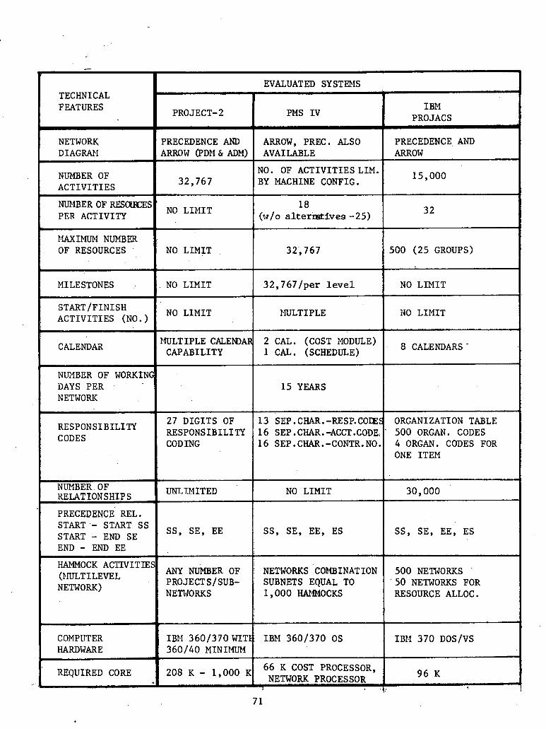
I
m
TECHNICAL FEATURES
I
NETWORK DIAGRAII
NUMBER OF ACTIVITIES
I
NUMBER OF RES-S PER ACTIVITY
IIAXIFIUFI NUMBER OF RESOURCES
L
14ILESTONES
STARTIFINISH ACTIVITIES (NO. )
b
CALENDAX
I
NUXBER OF WORKING DAYS PER NETWORK
r
RESPoNSIBILITY CODES
r NUMBER OF KELAT ION SHIP S
PRECEDENCE REL. START - START S S START - END SE END - END EE
I
HAMMOCK ACTIVITIES (PIULT ILEVEL NETWORK)
COMPlTTER HARDWARE
1
REQUIRED CORE
I
I BPI PRO JACS
I
PRECEDENCE AND ARROW
15,000
3 2
500 ( 2 5 GROUPS)
NO LIMIT
iJO LIMIT
CALENDARS .
ORGANIZATION TABLE - 500 ORGAN. CODES
4 ORGAN. CODES FOR ONE ITEM
30,000
S S , SE, EE, ES
500 NETWORKS 50 NETWORKS FOR RESOURCE ALLOC.
ID11 3 7 0 DOS/VS
96 K v
PROJECT- 2
PRECEDENCE AND ARROW @DM & ADM)
3 2 , 7 6 7
' NO LII,IIT
NO LIMIT
NO LIMIT
NO LIMIT
1lULTIPLE CALEMIAR CAPABILITY
2 7 DIGITS OF RESPONSIBILITY CODING
UNT,TMITED
SE, EE
NUMBER OF PROJECTS/ SUB- NETWORKS
IB14 3 6 0 1 3 7 0 WITIJ 3 6 0 1 4 0 MTNIMUM
EVALUATED SY STIDIS
PMS IV
ARROW, PREC . ALSO AVAILABLE
NO. OF ACTIVITIESLIM. BY MACHINE CONFIG.
18 (w/o altermtives -25)
3 2 , 7 6 7
3 2 , 7 6 7 / p e r l eve l
PNLTIPLE
2 CAL. (COST NODULE) 1 CAL. (SCHEDULE)
15 YEARS
13 SEP.CHAR.-RESP.COIES 16 SEP .CHAR. -ACCT .CODE 16 SEP.CHAR.-CONTR.NO.
NO LIMIT
S S , SE, EE, ES
NETWORKS CONBINATION SUBNETS EQUAL TO 1,000 W4blOCKS
IBM 3 6 0 1 3 7 0 OS
66 K COST PROCESSOR, 208 - lsooO NETWORK PROCESSOR
I 1

t
.
TECHNICAL FEATURES
- ,
NETWORK DIAGRAM
NUMBER OF ACTIVITIES
NO. OF RESOURCES PER ACTIVITY
MAXIllUFI NliMBEK OF RESOURCES
I
IlILESTONES
. STARTIFINISH ACTIVITIES (NO.)
CALENDAR
7
EVALUATED SYSTEMS
NO. OF WORKING DAYS PER NETWORK
r
RESPONSIBILITY C ~ E S
L
NUMBER OF RELATIONSHIPS
PRECEDENCE REL. S T A R T - S T A R T S S START - END SE END - END EE
HAMMOCK ACTXVITTIES (MULTILEVEL NETWORK)
COl,fPUTER HARDWARE
REQUIRED CORE -
K & H PREPlIS
d
ARROW, PRECEDENCE
PDM - 6 4 , 0 0 0 ADM - UNLIIIITED
: &O I b -- 7
J
NO LIMIT
NO LIMIT
NO LII4IT
8 CALENDARS IJSER DEFINABLE
HSCS
PRECEDENCE AND ARROW (PDPI & ADM)
PDM - 60,000 ADPl - 4 2 , 8 0 0
1 2
150
NO L I M I T
NO L I M I T
1 CALENDAR HOURLY, DAILY, WEEK.LY
CONST. MGT. SYSTEMS MARK I1 (MCS)
ARROW, PRECEDENCE
30,000
10
99
30,000
1 CALENDAR 7 YEARS
10 - 5 YEARS ( 6 days/w) 1 2 - 6 YEARS (5 d a y d w ) 15 - 7 YEARS ( 4 daydw)
10 D I G I T VARIABLE COnE
'
SS, SE, EE
MULTIPROJECT CAPABILITY
IBM 3 6 0 1 4 0 OR 3 7 0 1 1 3 5 OR ABOVE
9 4 - 350 K
8 CHAR.RESP./LOC.CODE 8 D I G I T ACCOUMT NO. 8 D I G I T PURCHASE
O m E R NO.
6 0 , 0 0 0
SS, SE, EE, ES
UNLIIIITED NUMBER OF NETNORKS
IBEl 360/370 OS
1 2 0 K
USER DEFINABLE
UNLIMITED
SS, SE, EE! E S 1
t
UNLIMITED
IBM 3 6 0 1 3 7 0 0s l V S 2
I
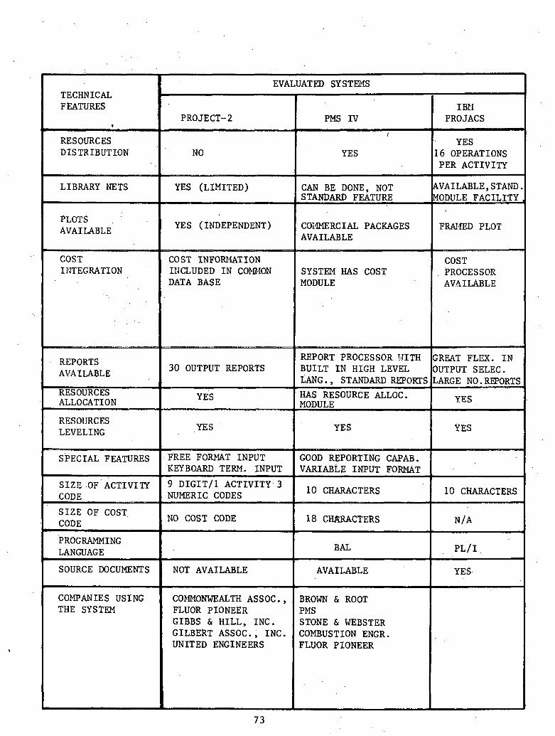
RESOURCES D I S T R I B U T I O N
PLOTS , '
YES (INDEPENDENT) COiGlERCIAL PACKAGES FRAI.fED PLOT
SYSTEM HAS . COST
30 OUTPUT REPORTS
S I Z E O F COST, CODE
PROGRAMMING LANGUAGE
SOURCE DOCUMENTS
COFIPANIES USING THE SYSTEM
NO COST CODE
NOT AVAILABLE
COIDIONWEALTH ASSOC. , FLUOR P I O N E E R G I B B S & H I L L , I N C . G I L B E R T ASSOC. , I N C . UNITED ENGINEERS
. . ;
18 CHARACTERS
BAL
AVAILABLE
BROWN & ROOT PPIS STONE & WEBSTER COMBUSTION ENGR. FLUOR P I O N E E R
N / A
p L / I
YES.

!
I
PLOTS AVAILABLE
COST INTEGRATION
REPORTS AVAILABLE
RI?!ZRRCES ALLOCATION
RESOURCES LEVELING
FEATURES
S I Z E OF ACTIVITY CODE
S I Z E OF COST CODE
PROGRAMMING LANGUAGE
I
SOURCE DOCUMENTS
COlIPANIES USING THE SYSTEM
b
TECHNICAL FEATURES
RESOURCES DISTRIBUTION
LIBRARY NETS
A
I - K&H
FREMT
YES
YES
MSCS
NO
NO
EVALUATED SYSTEMS
CONST. 11GT . SYSTEMS MARK I1 (MCS)
NO ( STRAIGHT LINE),
YES
YES k ii I
YES
USER SPECIFIED OR STANDARD REPORTS
YES
YES
18 A/N
BAL 1 1:
YES, COMPUNET CALCOMP AUTONET
VERY GOOD INTEGRATED (COPES)
5 EDIT REPORTS 19 STANDARD REPORTS SPECIAL REPORTS YES, 150 RESOURCES AVAILABILITY
NO
UPDATE REPORT, ACTION REPORT (KEYPUNCHING)
10 CHARACTERS NUMERIC/ALPHA
COBOL, FORTRAN, BAL
BROWN & ROOT BECHTEL CORP. KAISER ENGR. THE AUSTIN CO. THE BADGER CO. A.G. McKEE CO. PROCON, INC. TISHMAN REALTY CO. THE LI'L'WIN CO. P,D.M. ST=
NO
HAS COST MODULE ONE TO ONE RELATIONSHIP
USER SPECIFICATION OF THE SCHED. REPORT TITLE AND CONTENT
YES, AVAILABLE (MULTIPROJECT)
REPORTING ADJUSTED BY THE USER
10 DIGITS
8 ALPHANUMERIC
FORTRAN
AVAILABLE
UNITED ENGINEERS & CONSTRUCTORS RECENTLY PURCHASED MARK I1 VERSION FOR USE ON ALL THEIR POWER DIVISION PROJECTS

' 3.2 PROJECT{^*
PROJECT12 i s a t o t a l software package f o r network based p r o j e c t
scheduling and control . Over 40 t abu la r and graphic repor t s can be
produced t o provide the s p e c i f i c information needed by each l e v e l of
management wi th in an organizat ion. It has t h e capabi l i ty t o process
a c t i v i t y on arrow o r a c t i v i t y on node networks using soph i s t i ca ted . .
scheduling algori thms. PROJECT12 can be e a s i l y i n s t a l l e d on most
hardware and has a user or iented free-format command language. A s a
scheduling too l , PROJECT/2 o f f e r s network p l o t t i n g , CPM scheduling,
progress con t ro l , c o s t processing, resource a l l o c a t i o n and const ra in ing,
and mul t iprojekt f ea tu res . A l i s t i n g of t h e major processors and
t h e i r c a p a b i l i t i e s f o l l m s .
The Basic Network Processor t akes the b a s i c network data and
e s t a b l i s h e s t h e network log ic . This Processor handles t h e p r o j e c t . .
calendar,, s p e c i f i c a t i o n s , t h e expanded a c t i v i t y desc r ip t ions , and the
code assignments. Using t h e 1.1ulticalendar option, as many a s 100
d i f f e r e n t calendars can be accommodated and scheduled wi th in a
s i n g l e network. ' ~ o d i f i c a t i o n k t o network l o g i c a r e handled by t h i s . . :
The CPM Schedule Processor c a l c u l a t e s and d i sp lays both the Basic
Schedule, a c r i t i c a l path schedule based upon network l o g i c , and t h e
Current Schedule, a c r i t i c a l pa th schedule t h a t considers a c t u a l progress
*Materfal contafned i n this s e c t i o n 2s. based upon and/or excerpted from "A System f o r .Network Based Project Scheduling and Control'' by Pro jec t of tware & Dwelopment, Inc , , 14 . Story S t r e e t , CamGr.+.dge, Mass, 02138.

t o d a t e a s w e l l a s t h e network logic . This Processor a l s o produces
inpu t forms f o r updating, 'lists a c t i v i t i e s t h a t must have ac t ion between
spec i f i ed da tes , .andproduc&s many types of schedules and bar char t
r epor t s . . ,
I n t h e Target Processor, a f t e r a Current Schedule has been cal-
cu la ted , i t may be compared t o a v a r i e t y of o ther benchmark o r Target
Schedules. Up t o 3U user-detitled 'l'a'lfgec Schedules may be rerained axid
compared t o the Current Schedule, ' e i t h e r by a c t i v k t y o r by summary gr'oup.
Target Schedules may be produced i n t abu la r o r bar char t formats. The'
Target Processor a l s o ptoduces a list of a c t i v i t i e s targeted f o r ac t ion
as of a s p e c i f i e d date .
r The Resource Al locat ion Processor a ss igns resources t o ac t iv i t ies
and ' d i s t r i b u t e s resources over schedules. An a c t i v i t y can have any
number of resources assigned t o it, and a resource may be assigned t o
any number of a c t i v i t i e s . Resource a l l o c a t i o n r e p o r t s may be generated
project-wide, by a c t i v i t y , o r by resource. Dis t r ibuted resource usage
(cumulative or t i m e i n t e r v a l ) i s output i n t a b u l a r and/or graphic format.
The Cost Processor handles a l l d a t a r e l a t e d t o t h e inpu t , ca lcu la t ion ,
and output of p r o j e c t cos ts . It genera tes cashflow histograms and cumu- /-
I
l a t i v e S-curves.over the p r o j e c t schedules based upon estimated and
a c t u a l c o s t . It can compare the La tes t Revised .cos t t o t h e p r o j e c t
Budget i n d e t a i l e d o r summarized forms. The Cost Processor can ,also
produce Earned Value r e p o r t s based upon progress and a payments schedule.
The Resource Constraining Processor computes and saves up t o 50
schedules based upon resource l i m i t a t i o n s , time c o n s t r a i n t s , and a c t i v i t y
resource. a l loca t ions . The scheduling is performed v i a a dynamic
user-control led procedure r e s u l t i n g i n a 'most economical use ..of com- . .
puter t i m e . Resource Schedules can be displayed or saved a s Target
Schedules.
The Mul t iprojec t Processor combines the Data Bases of two or more
separa te p r o j e c t s i n t o a. Mul t iprojec t Data Base. The Mult iproject pro-
cessor can produce a l l of the standard PROJECTI~ r e p o r t s f o r the com-
bined. Mul t iprojec t and balance .resources over a l l p ro jec t s . . I n addi t ion ,
i t can t r a n s f e r ~ u l t i p r o j e c t Resource Constrained schedules back i n t o t h e
Data Bases of the individual member p r o j e c t s . .
P R O J E C T / ~ ' S Network.Graphics Processor produces plotter-drawn net-
work diagrams. Only t h r e e commands a r e necessary t o output your s tored
da ta a s a p lo t t ed network. Many opt ions , including a c t i v i t y s e l e c t i o n ,
paging by codes, t i m e sca l ing , and con t ro l of shee t s i z e and r e l a t i v e
loca t ion of a c t i v i t i e s on the p lo t t ed pages v ia zoning, a r e ava i l ab le .
Milestones a r e indicated by s p e c i a l nota t ions , and c r i t i c a l paths can
be highlighted i n red or wi th double l i n e s .
The system parameters of PROJECT12 show i t s v e r s a t i l i t y and use-
fu lness a s a i , lannipg, scheduling, and management too l . I n p l o t t i n g
and scheduling networks i t can handle up ' t o 32,000 a c t i v i t i e s wi th ho,
p r a c t i c a l . l i m i t . on t h e number of r e la t ionsh ips a t . t h e a c t i v i t y o r net-
work l eve l . For a c t i v i t y i d e n t i f i c a t i o n , PROJECT/^ uses 9 numeric
characters r a t h e r than alphanumeric i d e n t i f i c a t i o n , which .most of , t h e
indust ry has preferred . .For a c t iv5ty desc r ip t ions , 48 alphanumeric
characters a re allowed wi th unlimited s p i c e f o r s u b l i s t i n g s . ' PROJECTl2' '
7 7
also. has a one calendar per p r o j e c t c a p a b i l i t y with t i m e segments
being i n ' hours., days, o r weeks.
The, inpu t s on t h e PROJECT/^ system a r e ae ry simple. I n add i t ion
t o f ree . fo rmat commands, t h e system has .the , capab$ l i ty ' to v e r i f y and
run a f e a s i b i l i t y check. on a l l input s tatements. There is a l s o a
u s e r defined e r r o r over r ide t h a t g ives a l i s t i n g of a l l e r r o r s i n . t d
~ . . an input . Somc o the r f e a t u r e s a r e an open end de tec to r with automatic
c losure and l i s t i n g s and a mul t ip le loop d e t e c t o r t h a t i s o l a t e s each
loop.
The PRoJECT/2 system has a mul t ip ro jec t c a p a b i l i t y of an un-
l imi ted scope. A l l ou tpu t s and r e p o r t s enunierated under each processor
a r e a v a i l a b l e f o r each p r o j e c t or f o r the t o t a l .
PROJECT/l was t h e parent program f o r PROJECT12 and i s b a s i c a l l y
i d e n t i c a l . to i ts more v e r s a t i l e and expanded successor.
3 . 3 PROJACS* , .
3 . 3 . 1 General
'Limited manpower, expedited requirements, c o s t con t ro l s , shortages
of resources, and energy l i m i t a t i o n s have a l l increased the need f o r im- '\
proved aqd soph i s t i ca ted planning and c o n t r o l t o o l s f o r ' p r o j e c t manage- S:
ment. Regardless of the s i z e of the const ruct ion p ro jec t , the p ro jec t
managers must p ian t h e ' a c t i v i t i e s , a s s ign t h e resources, and develop the
schedule f o r t h e job. ,
t
' b a t e r i a l contained i n t h i s s e c t i o n is based upon and/or e x c e r ~ t e d from "1E&l System/370 P r o j e c t Analysis and Control S y ~ t e m , ~ ' General Information, iIGH19-1055-1.

The IBM program PROJACS (Project Analysis and Control System) has
been se lec ted by many const ruct ion companies t o he lp p ro jec t managers
perf o m more. &f f i = i e n t l y , ' with g r e a t e r c o n t r o l of t h e whole p ro jec t . . ..
Though s o p h i s t i c a t e d , . t h e system is easy t o use, quick t o opera te ,
a n d ' f l e x i b l e i n providing the manager j u s t t h e information he needs
i n an easy t o read. r epor t . It is presen t ly being used on the Callaway
Nuclear s t a t i o n , two SNUPPS u n i t s being constructed. by Daniel In te r -
na t iona l Corporation.
3.3.2 . Advantages of PROJACS Scheduling . .
The primary advantage,of computerized scheduling i s t h e speed and
accuracy in processing t h e massive number of ca lcu la t ions necessary
and the f l e x i b i l i t y of t h e repor t ing of t h e r e s u l t s t o provide t h e
managers a t va,rious levels only the information they r e q u i r e to'
. . perform t h e i r functions.
The system provides many f e a t u r e s , such as:
(1) A convenient. set of forms on which t o c o l l e c t and submit da ta .
(2) Accurate and rapid c a l c u l a t i o n s of da tes , f l o a t s , d a i l y re-
source requirements.. .'
(3 ) . A highly f l e x i b l e repor t processor. Provided a r e a bas ic
set of s tandard repor.ts p lus the a b i l i t y f o r ' t h e user t o format h i s
. , own repor t s .
(4) 3av l ; l g Lht! dares and t l o a t s from one a n a l y s i s . t o be used i n
comparison. with r e s u l t s from l a t e r analyses. . .
(5) True exception repor t ing by s e l e c t i n g t h e a c t i v i t i e s whose
7 9
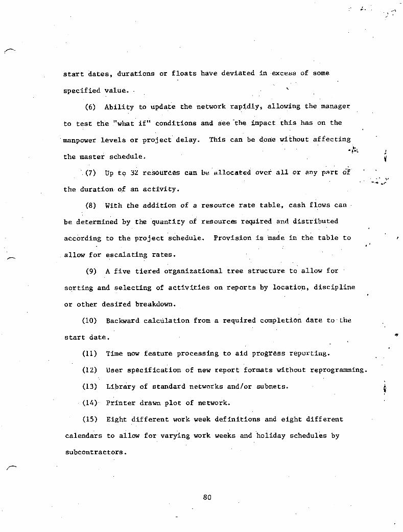
start d a t e s , dura t ions or f l o a t s have devia ted i n .excess of some
s p e c i f i e d value. - \
. .
(6) A b i l i t y to upd.at'e . . the network rap id ly , allowing t h e manager . .
t o test the ."what i f " condi t ions and see 'the impact t h i s has on the
manpower l e v e l s o r p r o j e c t ' delay. This can be dofie without af f e c t i n g I.
* b * ; I
t h e master schedule. i . (7) Up t o 32 resources can be allocated over all or any part ~ f ' -
. . - 5' - -*LC
t h e dura t ion of an a c t i v i t y .
(8) With t h e a d d i t i o n of a resource r a t e t a b l e , cash flows can
be determined by 'the ' quant i ty of resources r q i r e d and d i s t r i b u t e d
accbrding t o t h e p r o j e c t 'schedule. Provis ion is inade i n t h e t a b l e t o I
* '
allow f o r e s c a l a t i n g r a t e s .
(9) A f i v e t i e r e d o rgan iza t iona l t r e e s t r u c t u r e t o a l low f o r
s o r t i n g and s e l e c t i n g of a c t i v i t i e s on r e p o r t s by loca t ion , d i s c i p l i n e
o r o ther d e s i r e d breakdown.
(10) Backward c a l c u l a t i o n from a required completiOrl date toatlze
s t a r t d a t e . *
(11) Time now f e a t u r e processing t o a i d progress repurtl i~g.
(12) User s p e c i f i c a t i o n of new r e p o r t formats without reprogramming.
(13) ~ i b r a r y of s tandard networks and/or subnets. p (14). Pri 'nter drawn p l o t of network.
(15) Eight d i f f e r e n t work week d e f i n i t i o n s and e i g h t d i f f e r e n t
calendars t o allow f o r varying work weeks and hol iday schedules by
subcontractors.
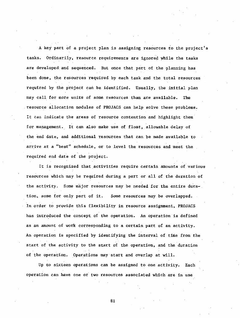
A key p a r t of a p r o j e c t p lan i s ass igning resources t o t h e p r o j e c t ' s
tasks . 0rdinar21y, resource requirements a r e ignored while t h e t a s k s . .
a r e developed:and sequenced. But once t h a t p a r t of t h e planning has
been done, . the resources requi red by each t a s k and t h e t o t a l resources
required by the p ro jec t can be i d e n t i f i e d . Usually, the i n i t i a l p lan
may c a l l f o r more u n i t s of some resources than a r e ava i l ab le . The
resource- a l l o c a t i o n modules of PROJACS can help so lve these problems.
It can i n d i c a t e t h e a r e a s of resource content ion .and h i g h l i g h t them
f o r management. It can a l s o make use of f l o a t , , a l l o w a b l e de lay of
t h e end da te , and a d d i t i o n a l resources t h a t can be made a v a i l a b l e t o
a r r i v e a t a "best". schedule, o r t o l e v e l t h e resources and m e e t t h e
required end d a t e of the p r o j e c t .
It i s recognized t h a t , a c t i v i t i e s r e q u i r e c e r t a i n amounts o f ' va r ious
resources which may.be requi red dur ing a p a r t o r a l l of t h e dura t ion of
t h e a c t i v i t y . Some major resources may be r?eeded f o r t h e e n t i r e dura-
t i o n , some f o r only p a r t of i t . Some resources may be overlapped.
1 n order to provide t h i s f l e x i b i l i t y i n resource assignment, PROJACS
has introduced the concept of the opera t ion . An o p e r a t i o n ' i s defined
a s an amount of work corresponding t o a c e r t a i n p a r t of an a c t i v i t y .
An opera t ion is s p e c i f i e d by iden t i fy ing the i n t e r v a l of time from t h e . .
s t a r t of the a c t i v i t y t o the s t a r t of the opera t ion , and the ' du ra t ion . .
of t h e operat ion. opera t ions m a y . s t a r t and overlap a t w i l l .
Up t o s ix teen opera t ions can be assigned t o one a c t i v i t y . Each
opera t ion can have one o r two resources associa ted which a r e i n use

throughout i t s dura t ion . Therefore, up' t o 32 resources c a n b e d i s t r i b -
u ted over t h e d u r a t i o n of' t h e a c t i v i t y .
The opera t ions are not taken i n t o cons idera t ion during the network
a n a l y s i s and c a l c u l a t i o n . Therefore, t h e i r s t a r t and f i n i s h d a t e s a r e ,
computed wi th r e f e r e n c e t o the s t a r t d a t e of t h e r e l a t e d a c t i v i t y . r
An opera t ion i s , def ined by an i d e n t i f i c a t i o n ( a c t i v i t y code + sequence I/
number), a d e s c r i p t i o n (24 c h a r a c t e r s ) , a de lay and a dura t ion ( t h e . .. . . * . '. 4 ,
combination o f , t h e s e two d a t a i tems i s c a l l e d the opera t ion span), .
and up t o two ' resource codes and the corresponding amounts requi red t o
perform t h e opera t ion . I f the resource i s . of the carried-forward type, . . t h e amount i s s p e c i f i e d a s an i n t e n s i t y . The amount~corresponds t o a
permanent need during t h e e n t i r e performance of the oper'ation. . I f the
resource is of t h e used-by-job type, the amount i s spec i f i ed a s t h a t
quan t i ty which is consumed per work u n i t .
It has a l r eady been noted t h a t t h e opera t ion concept al lows spec-
i f i c a t i o n of the way v a r i o u s resources a r e planned f o r an a c t i v i t y . Some
o the r i n t e r e s t i n g f a c i l i t i e s a r e provided by t h e in t roduc t ion of t h i s con-
cep t . Some a c t i v i t i e s can cause resource generat ion; for ' example, an
a c t i v i t y which corresponds t o the manufacturing of p ipes w i l l gener,ate . . 1
a given amount of t h e resource c a l l e d "Pipe." This resource w i i l b'e 11
used by o t h e r a c t i v i t i e s corresponding t o p ipe - f i t t ing . This. f a c i l i t y , . .
used l a t e r oi by the ~ e s o k r c e Al locat ion Processor, al lows solv ing 'some
scheduling problems which could n o t have been solved previously.
Within each a c t i v i t y , c e r t a i n opera t ions can be s p e c i f i e d a s
a l t e r n a t e s i n case of resource shortages. This o t h e r f a c i l i t y , used
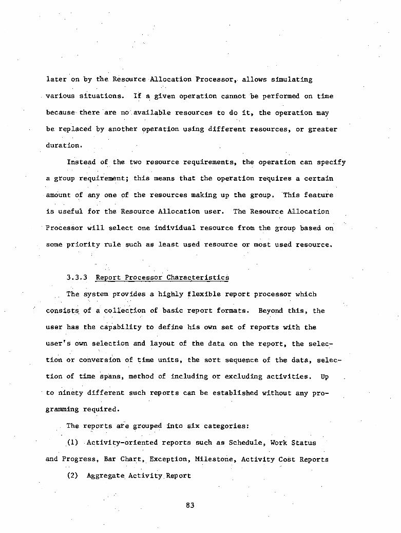
l a t e r on by the Resource.Allocation Processor,. allows simulat ing
var ious s i t u a t i o n s . I£ a given opera t ion cannot .be performed on time
because- the re ' a r e no.' a v a i l a b l e resources t o do it, t h e opera t ion may
be replaced by another operat ion using d i f f e r e n t resources, o r g r e a t e r . .
durat ion. . .
~ n s t e a d of the two resource requirements, the operat ion can speci fy . .
a group re'quirement; t h i s means t h a t t h e opera t ion requ i res a c e r t a i n
amount of any one of the resources making up t h e graup . 'This f e a t u r e . .
is use fu l f o r t h e Resource Al locat ion user . The Resource Al locat ion
. ~. ~ r o c e s s o r w i l l select one ind iv idua l resource from t h e group based on
some p r i o r i t y rule such a s l e a s t used resource o r most used resource.
. .
3.3.3 Report Processor C h a r a c t e r i s t i c s
The system provides a h ighly f l e x i b l e r e p o r t processor which . .
consists of a c q i ~ & ' t i o n of bas ic r e p o r t formats. Beyond t h i s , t h e
use r has the c a p a b i l i t y t o def ine h i s own set of r e p o r t s wi th t h e
u s e r ' s OF s e l e c t i o n and layout of t h e d a t a on the repor t , the selec-
t i o n o r conversion of t i m e u n i t s , t h e s o r t sequence of the da ta , selec-
t i o n of t i m e spans, method of including o r excluding a c t i v i t i e s . Up .
t o n inety d i f f e r e n t such r e p o r t s can be es tab l i shed without any pro-
gramming required.
The r e p o r t s a r e grouped i n t o s i x ca tegor ies :
,(I) -Act iv i ty-or iented r e p o r t s such a s Schedule, Work S t a t u s
and Progress, Bar Chart, Exception, ~ i l e s t o n e , Ac t iv i ty Cost Reports . .
(2) Aggregate. ~ c t i ~ i t ~ , ~ e ~ o r t

(3) Resource U t i l i z a t i o n Report
(4) ~ i n a n c i a l Reports
(5) Network Diagram
( 6 ) Display Reports
Below w e .have described some standard r e p o r t formats. It should be
emphasized t h a t these a r e provided only a s a t y p i c a l &le of how
t h e r e p o r t can look. Any o r g a n i i a t i o n of t h i s or any of t h e o ther
d a t a elements from the f i l e can be included. Also, opera t ions c a n . b e .
included i n many of t h e r e p o r t s below the a c t i v i t y l i n e .
Schedule Report
The Schedule Report can provide the following infoknation regard-
less of opt ions exercised f o r each work item included i n the repor t :
(1) A c t i v i t y Code - I d e n t i f i c a t i o n of a c t i v i t y of t h e work i t e m .
(2) Descript ion - This space i s provided f o r t h e v e r b a l iden-
t i f i c a t i o n of t h e work, i t e m ,
(3) Current Duration - Work items not y e t begun w i l l h a v e . t h e i r
t o t a l dura t ion input by t h e planner. Work i n progress w i l l have dura-
t fons ca lcu la ted by. the formula: Current Duration = (Data Date - Early
S t a r t ) + Remaining Duration. 1 i
. (4) Calendar and ..Work Week Ind ica to r s - These i n d i c a t o r s show t h e .. .
number of working days i n a week, the f i r s t working day 0.f t h e week and
whether ho l idays . a r e observed i n t h e schedule.
(5) A f l a g t o i n d i c a t e completed o r in-progress a c t i v i t i e s .
C = Complete, P = I n Progress.

( 6 ) Ear ly and Late S t a r t and Completion Dates - These d a t e s a r e
computed by the scheduling program based on the network and dura t ions
. input i n t o the computer .' (7) ' ' ~ o t a l F loat - The f l o a t i n d i c a t e s t h e span of time a work
. .
i tem c a n ' s l i p without a f f e c t i n g the o v e r a l l p r o j e c t completion da te .
(8). Free F loa t -. This f l o a t i n d i c a t e s t h e span .of time a work
. i t em can s top without a f f e c t i n g the s t a r t of any succeeding a c t i v i t i e s .
(9) Scheduled Dates - Those d a t e s t h a t a r e f ixed due t o con-
t r a c t u a l agreements. A code i n d i c a t e s i f the s t a r t o r f i n i s h ' d a t e
is requested ahd the mode of r egu la t ion .
The s e l e c t i o n and format of t h e Schedule Report is t o t a l l y f l e x i b l e .
Any: da ta i n the f i l e can be displayed i n any order on . the .page. Options
a r e a v a i l a b l e f o r s o r t i n g 'and s e l e c t i o n of t h e a c t i v i t i e s t o be included.
Opt ions
These. options may be exerc ised individuadly o r i n var ious comb'ha- ;.
t i o n s . Each opt ion has . severa l a l t e r n a t i v e s which permit . a v a r i e t y of . .
r e p o r t s foc<ssing on any des i red sub jec t .
'! A l i s t i n g of opt ions and a l t e r n a t i v e s fol lows:
(1). Span Dates - E i t h e r a complete o r p a r t i a l r e p o r t may be re- . .
quested a s fol lows:
(a) A' complete r e p o r t would inc lude a l l work i tems i n t h e
network. Thus, it would inc lude work a l ready completed, work
i n progress , and remaining work fo r . t h e e n t i r e p r o j e c t dura t ion .
(b) By s e l e c t i v e u s e of span dates,, t he r e p o r t i a y be l imi ted
only t o work i t e m s scheduled during a user spec i f i ed time
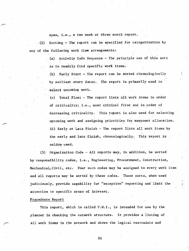
span, i . e . , a two week o r t h r e e month repor t .
(2) Sor t ing - The r e p o r t can be spec i f i ed f o r ca tegor iza t ion by
any of t h e fol lowing work i t e m arrangements: . .
(a) A c t i v i t y Code Sequence - The p r i n c i p l e use of t h i s s o r t
. . i s . t o r e a d i l y f i n d s p e c i f i c work i t e m s .
(b) Ear ly S t a r t - The r e p o r t can be so r t ed chronologica l ly r \ '
" . . .
by earliest . s t a r t da tes . he r e p o r t is pr imar i ly used t o '
select u p c o m i ~ .work.
(c) T o t a l F loa t - The r e p o r t l ists ' a l l work items i n order
of c r i t i c a l i t y ; i .e . , most c r i t i c a l f i r s t and i n .order of
decreas ing c r i t i c a l i t y . This r e p o r t i s a l s o used f o r s e l e c t i n g
upcoming work and ass igning p r i o r i t i e s f o r manpower . a l l o c a t i o n .
(d) Ear ly o r Late F i n i s h - The r e p o r t l is ts a l l work items by
the e a r l y and l a t e f i n i s h , chronologica l ly . This r epor t is
seldom . . used.
(3) organ iza t ion Code - A l l r e p o r t s .may, i n add i t ion , be so r t ed
by r e s p o n s i b i l i t y codes, i. e. , Engineering, Procurement, Construction,,
~ e c h a n i c a l , .C iv i l , etc. Four such codes may be assigned tb. every work i tem
and a l l r e p o r t s may be so r t ed by t h e s e codes. These s o r t s , when used
jud ic ious ly , provide c a p a b i l i t y f o r "exception" repor t ing and l i m i t t he b
a t t e n t i o n t o s p e c i f i c a r e a s of interest.
Precedence Report
This r e p o r t , which i s c a l l e d P. W. I., i s intended f o r use by the
planner i n checking the network s t r u c t u r e . It provides a l i s t i n g of
a l l work i i e m s in t h e network and shows t h e l o g i c a l r e s t r a i n t s and
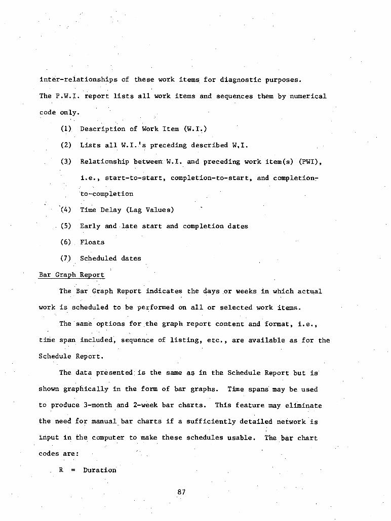
i n t e r - r e l a t i o n s h i p s of these work i t e m s f o r d iagnos t i c purposes.
The P.W.I. r e p o r t l ists a l l work i t e m s and sequences them by numerical
code only.
(1) ~ e s c r i ~ t i o n of Work Item (W.I.)
(2) L i s t s a l l W . I . 's preceding described W . I .
(3) Relat ionship between:. W. I. and preceding work i tem(s) (PWI) ,
i . e . , s t a r t - t o - s t a r t , completion-to-start, and completion- . .
to-completion
~.
( 4 ) Time Delay (Lag Values)
. (5) Early a n d . l a t e s t a r t and completion d a t e s
(6) . F l o a t s
(7) Scheduled da tes
Bar Graph Report
The ~ a r ~ i a ~ h Report i n d i c a t e s the days o r weeks i n which a c t u a l
work i s scheduled t o be performed on a l l o r s e l e c t e d work i t e m s .
Thesame opt ions f o r t h e graph r e p o r t content and format, i .e.,
time span included, sequence of l i s t i n g , e t c . , a r e a v a i l a b l e a s f o r the
Schedule Report . The d a t a p r e s e n t d i s the same as i n the Schedule Report bu t is
shown graph ica l ly i n the form of bar graphs. Time spans' may be used
t o produce 3-month and 2-week ba r c h a r t s . This f e a t u r e may e l imina te
the need f o r manual. bar c h a r t s i f a s u f f i c i e n t l y d e t a i l e d network ' is
lriput i n the comput.er t o make t h e s e schedules usable . The b a r c h a r t
codes a re : . .
, .
. R = , Duration

- = ~ o t a l F l o a t
F = Free F l o a t
A = Actual
* = Operation
Work S t a t u s and Progress Report . . li
v .
This r e p o r t conta ins the fol lowing informarion:
(1) Descr ip t ion - I d e n t i f i c a t i o n (Work Item) number and desc r ip t ion
of work.
. ( 2 ) operat ion Code and Descript ion - o hose opera t ions 'wl~ich make
up the a c t i v i t y are l i s t e d .
(3) c u r r e n t D u r a t i ~ n - The dura t ion of t h e a c t i v i t y , a s discussed /C.
i n the Schedule Report. Also; the dura t ion and.delay of the operat ion
a r e shown.
( 4 ) The resources assigned t o the opera t ion and t h e i r quan t i ty
are shown.
(5) ,The progress s t a t u s ' o f t h e a c t i v i t y is shown.
(6) Early start and f i n i s h da tes f o r t h e a c t i v i t y and opera t ions
a r e given., . .
(7) The d a t a d a t e on which progress was reported. I I
(8) ' The remaining dura t ion a s input by. t h e planner and i s t h e . .
estimate of the t i m e required t o complete t h e a c t i v i t y . . . .
(9) Percent work done. The value used in the c o s t processor
to, c a l c u l a t e cur ren t cos ts .

The Work S ta tus and Progress Report is sub jec t t o the same sequencing
o r s o r t i n g c a p a b i l i t y a s the Schedule and Bar Graph Reports.
Resource U t i l i z a t i o n Report
'Th i s r e p o r t p r o j e c t s histograms of resource requirements on a period
and cumulative bas is . Where the Resource Al locat ion Report shows resource
usage per work i t e m d a i l y f o r each resource, t h e Resource U t i l i z a t i o n ,
Report shows t h e t o t a l p r o j e c t resource requirements on a weekly and
cumulative b a s i s and by individual resource. The r e p o r t conta ins the
f 011owi.n~. in£ ormation:
' (1) Resource i d e n t i f i c a t i o n and code
( 2 ) * Period Scale, Cumulative Scale. . S c a l e s a r e provided f o r
g raph ica l d i sp lay of resource needs f o r t h e period, usua l ly weekly,
and cumulative . '
(3) . .Amou'nt or Resource - The ca lcu la ted quant i ty is based upon I
input d a t a f o r . a l l work i t e m s . %*
The Resource u t i l i z a t i o n Report provides a p i c t o r i a l r ep resen ta t ion
of resource u t i l i z a t i o n . It may be used . to p ro jec t manpower needs f o r
the p ro jec t by c r a f t . and . i n . t o t a l . I f d o l l a r s a r e input a s a resource, ' .
a cash f l o w i s depicted wi th each r e p o r t run. s ince t h e data is d i r e c t l y . .
r e l a t e d t o the schedule, manpower aa~d cash flow pro jec t ions a r e automat-
i c a l l y updated with each schedule update,
~ c t i v i t ~ Cost Report .
This repor t provides estimatqd and a c t u a l c o s t s by work i t e m . The
following in.£ ormation i s included :

, .
i 1 (1) Work i t e m code and d e s c r i p t i o n . I
i : ( 2 ) Current and Remaining Dbration - T h i s can be e i t h e r ca lcu la ted
o r i n p u t as a manual over r ide if the est imated remaining dura t ibn is
d i f f e r e n t ' from t h a t ca lcula ted . 8 ,
i (3) Estimate c o s t - The cos t of t h e a c t i v i t y is derived from the
I . .
Estimate Integrated. Schedules; and input i n t o t h e scheduling program. ! No omp put at ions o r p ro jec t ions are made by t h e computer. It w i l l only
, . l ist the amount hanual ly input i n t o t h e system'. .
'
.. ,
( 4 ) c u r r e n t Cost '- The a c t u a l c o s t .plus any e s t ' h a t e t o complete.
(5) Actual Cost - The a c t u a l c o s t per a c t i v i t y , when a v a i l a b l e , t
may be manually inpu t i n t o t h e system f o r comparison with est imated t
c o s t . These f i g u r e s a r e not ca lcu la ted or projec ted by t h e computer
but a re . manually input .
. . ( 6 ) Work done value - The percent complete times cur ren t cos t .
(7) Work i tem e a r l y s t a r t and f i n i s h da tes .
Organization Cost Report
This r e p o r t summarizes by Organization .Code t h e d i s t r i b u t i o n of . .
monthly cos t s . The r e s u l t is a cash requirements p ro jec t ion of the
... . pro jec t . . .
The in£ ormation g n t a i n e d is:
(1) Organizat ion code and d e s c r i p t i o n
(2) Period start - The month and year
(3) Current cos t - The a c t u a l p l u s estimate-to-complete
( 4 ) Actual cos t - A s repor ted t o the system o r a s ca lcu la ted by
t h e c o s t processor from t h e percent work done.
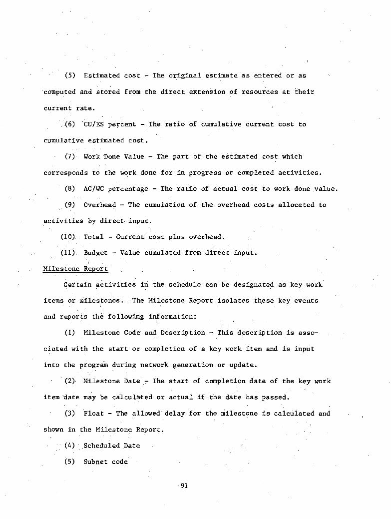
(5) Estimated c o s t - The o r i g i n a l e s t ima te a s entered o r a s . .
.computed and s to red from the d i r e c t extension of resources a t t h e i r
cu r ren t r a t e . . . .
: ( 6 ) CUIES percent - The r a t i o of cumulative cu r ren t cos t t o
cumulative est imated c o s t .
(7).. Work one Value - The p a r t of t h e est imated c o s t which
corresponds t o the work done f o r i n progress o r completed a c t i v i t i e s .
(8) AC/WC percentage - The r a t i o of a c t u a l c o s t t o work done value .
'(9) Overhead ,- The cumulation of the overhead c o s t s a l l o c a t e d t o
a c t i v i t i e s by d i r e c t . input .
(10): ~ o t a l - ~ u r r e n t " c o s t p l u s overhead. . .
. .
(11) Budget - Value cumulated from d i r e c t input .
Mile st one ~ e p o r t
Cet ta in i c t i v i t i e s i n the schedule can 'be designated a s key work
i tems o r milestones'. . The Milestone Report i s o l a t e s these key events
and repor t s t h e following information: , , ,
(1) Milestone Code and Descr ip t ion - This 'descr ip t ion i s asso-
c i a t e d wi th the s t a r t . o r completion of a key work i t e m and i s inpu t
i n t o the during network genera t ion o r update.
' ( 2 ) Milestone Date ,- The s t a r t of completion d a t e of the key work
i t e m . d a t e m a y be ca lcu la ted o r a c t u a l i f t he d a t e has passed.
(3) l lo at - The allowed delay f o r the mi les tone i s ca lcu la ted and . .
shown i n the Milestone Report. . .
(4) , scheduled Date . . . . .
(5) Subnet code

(6) Work Item 1den t i f i c a t i o n - T h i s i s the W.I. number o f the
re levan t schedule work i t e m .
(7) Milestone l e v e l code.
The obj e c t i v e of t h i s r epor t i s t o provide management in£ ormation , of
job progress a t a high summary l e v e l . This i s t h e computerized vers ion
of the Manual ~ i l e s t o n e Report discussed elsewhere i n the guidel ines .
Except ion Report
.Th i s i s probably the s i n g l e most innovative add i t ion t o the repor t . .
processor. The system provides t h e f a c i l i t y to ' save the d a t e s from
any t i m e a n a l y s i s o r resource a l l o c a t i o n run i n a separa te s torage area .
Af ter making changes i n the network, or a f t e r fol lowing a t i m e ana lys i s
wi th a resource l eve l ing run, the exception repor t can be run t o analyze
t h e r e s u l t i n g change i n t h e d a t e s , dura t ions or f l o a t s . These changes
can be d isplayed together wi th t h e before and a f t e r d a t a from which
they a r e derived. It is a l s o poss ib le t o s e l e c t and repor t on ly those
a c t i v i t i e s whose d a t e s or f l o a t s have deviated by some spec i f i ed value
o r whose va lues a r e l e s s than o r g rea te r than some quant i ty .
A t y p i c a l format of an Exception Report i s a s fol lows:
(1) Act iv i ty code and desc r ip t ion .
(2) Previous Duration - The dura t ion saved from an . e a r l i e r ana lys i s . n
(3) .Current ~ u r a t i o n s - The dura t ion ca lcu la ted i n the preSent
ana lys i s .
(4) Varia.tion Duration - The d i f fe rence i n the cur ren t and previous
values .

(5) Previous Finish Date - The e a r l y f i n i s h d a t e from a p r e v i o u s . .
run. . .
(6) ~ a r l ~ Finish - The d a t e ca lcu la ted i n t h e present ana lys i s . . ..
(7) Var. F in i sh - The d i f fe rence i n t h e previous and cur ren t
da tes .
(8) previous Float - The value ca lcu la ted i n e a r l i e r analyses.
' (9 ) Total F loa t - A s ca lcu la ted i n t h e present ana lys i s ,
(10) : Var. Float - The d i f fe rence i n t h e above two items.
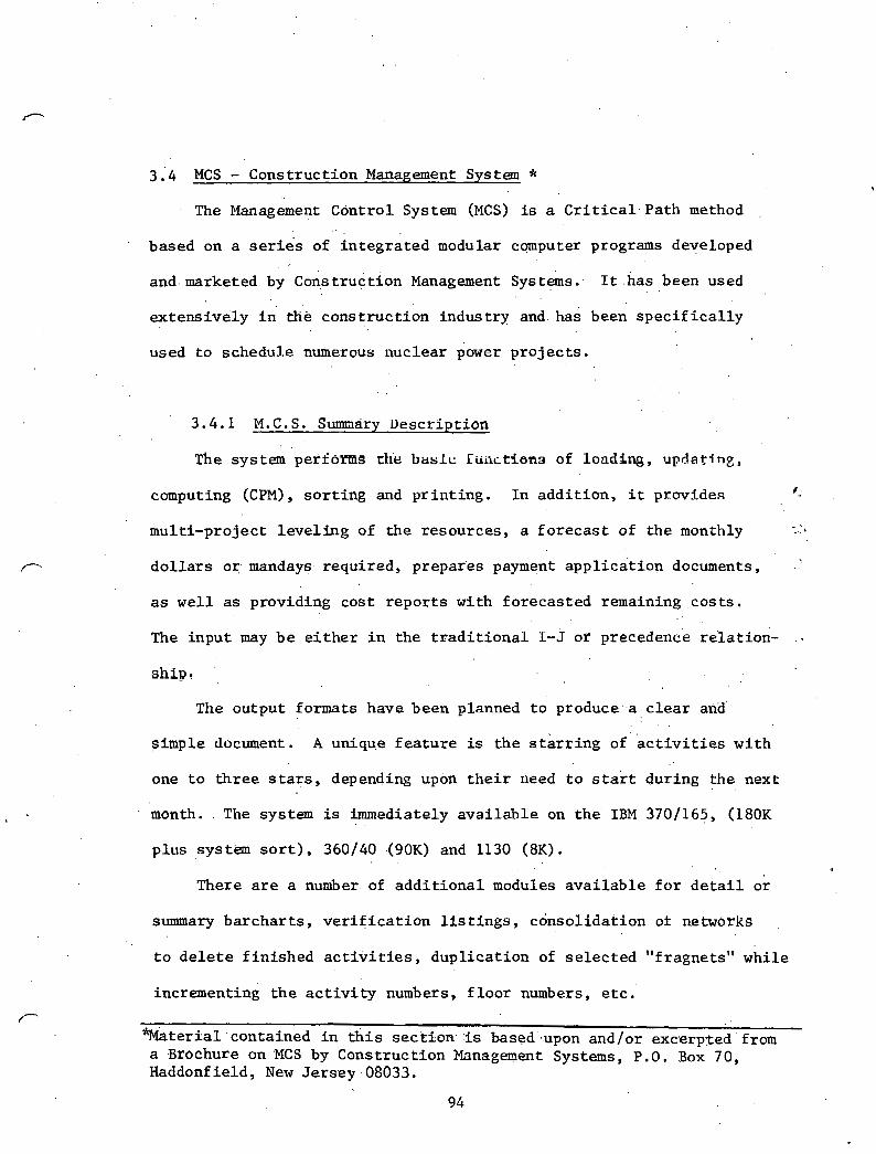
3 .'4 MCS - Construction Management System * The Management Control System (MCS) is a C r i t i c a l Path method
based on a series of in tegra ted modular cqnputer programs developed
a n d marketed by cons t r u c t i o n Management sys t&s . . It .has . . been used . .
extens ively i n r h k constructiLn indust ry and. has been s p e c i f i c a l l y
used t o schedule numerous nuclear power p ro jec t s .
3.4.1 M.C.S. Summary Descript ion
The system p e r f o m s dlt! b a s l c Iiinctisna of loading, updat ing ,
computing (CPM) , s o r t i n g and p r in t ing . I n add i t ion , i t provides *..
mult i -projec t l e v e l i n g of the resources, a f o r e c a s t of the monthly
d o l l a r s o r mandays. required, prepafes payment app l i ca t ion documents,
a s we l l a s providing cost r e p o r t s with forecas ted remaining cos t s .
The input may b e e i t h e r i n the t r a d i t i o n a l I-J or re'lation- ..
ship,
The output formats have been planned t o produce -a c l e a r and'
simple document. A unique f aature is t h e s t a r r i n g o f a c t i v i t i e s wi th
one t o t h r e e s t a r s , depending upon t h e i r need t o s t a r t during the , . next
month. The system is immediately a v a i l a b l e on t h e IBM 3701165, (180K
plus system s o r t ) , 360140 (90K) and 1130 (8K). . .
There a r e a number. of a d d i t i o n a l modules a v a i l a b l e f o r d e t a i l or
summary ba rchar t s , v e r i f i c a t i o n l i s t i n g s , consol idat ion ot networks
t o d e l e t e f in i shed a c t i v i t i e s , dup l i ca t ion of se lec ted "fragnets" while
incrementin6 t h e a c t i v i t y numbers, f l o o r numbers, e t c .
%latertal .contained i n t h i s sec tson- -is based ;upon and/or excerpted from a Brochure on MCS by Construction Management Systems, P.0, Box 7.0, Haddonfield, New Jersey.08033.
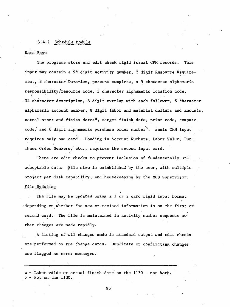
Data Base
The programs s t o r e and e d i t check r i g i d format CPM records. This
inpu t may conta in a 9* d i g i t a c t i v i t y number, 2 d i g i t Resource Require-
ment, 3 character Duration, percent complete, a 5 cha rac te r alphameric
r e s p o n s i b i l i t y /.resource code, 3 charac te r alphameric loca t ion code,
32 charac te r desc r ip t ion , 3 d i g i t overlap. with each fo l lower , 8 cha rac te r
alphameric account number, 8 d i g i t l abor and m a t e r i a l d o l l a r s and amounts,
a c t u a l s t a r t , a n d f i n i s h datesa , t a r g e t f i n i s h da te , p r i n t code, compute
b code,' and 8 d i g i t alphameric purchase order number . Basic CPM inpu t -.
r equ i res only one card. Loading i n Account Numbers, Labor Value, Pur-
chase Order Numbers, " e tc . , r equ i res t h e second inpu t card.
There a r e e d i t checks t o prevent inc lus ion of fundamentally un-' , % .
, .
acceptable data. F i l e s i z e is es tab l i shed by t h e u s e r , wi th m u l t i p l e
p r o j e c t per d i s k c a p a b i l i t y , and housekeeping by t h e MCS Supervisor .
F i l e Updating
The f i l e may b e updated using a 1 or 2 card . r i g i d inpu t format
.depending on whether t h e new o r r ev i sed information is on the f i r s t o r
second card. The f i l e is maintained i n a c t i v i t y number sequence s o
t h a t changes a r e made rap id ly .
. A l i s t i n g of a l l changes made is s tandard output and e d i t checks
a r e 'performed on the change cards. Dup~licate o r c o n f l i c t i n g changes
a r e f lagged a s e r r o r messages.
a - Labor valrte o r a c t u a l f i n i s h date* on t h e 1130 - not both. '
b - Not on the 1130.

After the changes a r e read, they a r e merged with the main f i l e
and the r e s u l t s a r e s to red i n the "subordinat'e f i l e . " Error messages
a r e produced f o r a l l requested changes t o t h e f i l e which have not been
accomplished. The 1130 system allows 1500 change cards t o be loaded a t
one t i m e whi le t h e l i m i t f o r the 360 i s t h e s i z e of the user defined
main d a t a fi1.e.
calendar Genera t ion
The calendar program produces a p ro jec r rime v s ca le rda r d a t c
t a b l e (up t o seven years ) wi th t h e f l e x i b i l i t y of handling from a 1
t o 7 day work week. I n add i t ion , s tandard holidays such as Christmas
and New Year's may be s t a t e d , a s w e l l a s v a r i a b l e holidays.
Computation Routine
The normal CPM c a l c u l a t i o n of the Early S t a r t and Late SLarL:
times f o r eadl a c t i v i t y i n t h e f i l e is accomplished by a series of
e igh t rou t ines . These rou t ines provide such funct ions a s conversion
of the .mul t ip le fol lower record information i n t o log ic statement (I-J
form), counting of fol lowers and then predecessors f o r determination of
11 open ends," a s w e l l a s f o r use i n the "loop" d iagnost ic . To improve
computation time, a topological sequencing i s included s o t h a t mul t ip le
i t e r a t i o n s are not required i n t h e forward and backward pass. One of
these programs a l s o provides f o r s e t t i n g an a r b i t r a r y Early S t a r t , Early
Finish and Late S t a r t of any a c t i v i t y p r i o r t o the beginning .of a
computation. A f i n a l program w r i t e s the computed times from the work
, !
t a b l e s i n t o the main record. The user may s e l e c t t o complete the campu-
t a t i o n even i f there a r e "open ends" o r d a t a card e r ro r s .

The .provides f o r mul t i -projec t resource level ing (merging)
mul t ip le p r o j e c t s and computing of up t o 100,008 a c t i v i t i e s .
Loop Diagnost ic
This . sophis t'icated program determines which a c t i v i t i e s cons t i t d t e
s i n g l e o r m u l t i p l e loops. A l l a c t i v i t i e s on a l l loops a r e pointed out
a t one time a s opposed t o i d e n t i f y i n g one ' loop' f o r each computation.
S o r t i n g
The 360 system packages u t i l i z e .the I B M ' s y s t e m s o r t s . The 1130
s o r t program is an e f f i c i e n t program f o r s o r t i n g up t o 8 keys of the
record.
Ex t rac t ing
This program provides f o r e x t r a c t i n g s p e c i f i c records f o r s e l e c t i v e
s o r t i n g , resource l eve l ing , p r i n t i n g , cos t fo recas t ing ; e t c . Its
ualn purpose i s t o reduce computing time when t h e e n t i r e content of
a f i l e is not requi red f o r succeeding opera t ions . Extrac t ion c r i t e r i a
may b e da tes , f l o a t , r e s p o n s i b i l i t y and l o c a t i o n coding, account code
number o r any of t h e l a s t e ight cha rac te r s i n t h e a c t i v i t y desc r ip t ion .
This very f l e x i b l e program provides f o r , p r i n t i n g up t o 5 d i f f e r e n t
CPM formats, wh i l e t o t a l i n g a t two l e v e l s . There a r e q u i t e a number of
P r i n t o r No P r i n t Options.
Typical Run Times
The average run time t o compute (CPM Early and Late da tes ) and p r i n t
a 3,000 a c t i v i t y precedence network is approximately:

IBM 1130 . ' . - 60 minutes
IBM 360140 - 14 minutes
I B M , 360150 . - 5 minutes
IBM 370/165 - 2 minutes
Other sys t& modules' a r e genera l ly o f . propor t ional speeds.
Resource Leveling
Execution of t h i s program usua l ly fol lows completion of an
acceptable CPb1 computation. There a r e two l i m i t s ava. l lable, a lower
l i m i t and upper threshhold. The program attempts t o schedule a l l ac-
t i v i t i e s wi th in t h e lower l i m i t of user inpu t resource a v a i l a b i l i t y
l e v e l s . The program at tempts t o schedule the a c t i v i t y a t i t s ea r ly
IC. start o r a s c l o s e a s poss ib le t o 'it, wi th in the lower l i m i t s set by
t h e user . I f t h e l a t e s t a r t would be exceeded due t o a l i m i t a t i o n of
resources, t h e lower l i m i t is exceeded ' and t h e a c t i v i t y . is scheduled as
c l o s e a s poss ib le t o i ts e a r l y s t a r t wi th in t h e upper l i m i t . I f in- I
s u f f i c i e n t resources a r e a v a i l a b l e a t t h e upper l i m i t . t h e schedule w i l l
b e extended u n t i l such time as these resources a r e ' again avai lable .
A l l ' following a c t i v i t i e s would then have t h e i r e a r l y start dates
bumped accordingly.
Cash/Expendi.ture Forecast ing
This program c a l c u l a t e s the amount of d o l l a r s forecas ted t o be
required f o r each month of t h e p r o j e c t f o r both labor and m a t e r i a l and
can compute . i n t e r e s t during const ruct ion and re ten t ions . An a l t e r n a t e
of t h i s prograin is a monthly incremental and cumulative f o r e c a s t of .
r- . e i t h e r d o l l a r s o r mandays on both an ea r ly and l a t e s t a r t b a s i s .

These programs a r e executed a f t e r resource l e v e l i n g , . t h e d o l l a r s
o r mandays f o r e c a s t on an ea r ly start b a s i s would .betheincrementa1
aad cumulative do l l a r / r&ources required on an optimum b a s i s t o com-
p l e t e the p ro jec t & schedule:
These f o r e c a s t s may b e run f o r the e n t i r e p r o j e c t o r s e l e c t i v e l y
p e r t r ade , r e s p o & i b i l i t y , loca t ion , e t c .
The input is the bas ic CPM d a t a f i l e wi th e i t h e r m a t e r i a l and labor
d o l l a r s and/or crew s i z e .
Cost Reporting
Actual c o s t s f o r each work package ( a c t i v i t y o r a group of s i m i l a r "
a d t i v i t i e s .combined i n t o one account code] a r e accrued i n a s e p a r a t e
c o s t f i l e . The remaining c o s t s are derived from t h e CPM d a t a f i l e s
and added t o the a c t u a l c o s t s t o produce t h e t o t a l probable cos t f o r
each work package. 'These t o t a l probable c o s t s a r e compared t o the
' est imate t o produce a dev ia t ion f o r use i n exerc is ing con t ro l . A vir-
t u a l l y . unlimited . number of c o s t r e p o r t s a r e ava i l ab le , t a i l o r e d spec i f i c -
a l l y f o r var ious l e v e l s of management. This near u l t ima te f l e x i b i l i t y
is achieved through t h e use r speci fy ing which' account codes a t what
l e v e l a r e t o be included i n any repor t . Detai led a n a l y t i c a l and
reference repor t s a r e a l s o ava i l ab le .
The,Progress Payment Report may be a by-product of t h e regu la r CPM
Updating. I n add i t ion t o providing d e t a i l e d support of' a con t rac to r ' s
payment app l i ca t ion , t h i s program accounts f o r the number and amounts
f o r each Change Order to the con t rac t . t o da te , pre-payments f o r m a t e r i a l s
on s i t e , r e t a inage percentage, previous payments, ne t amount due, e t c .
99

B a r c h a r t
This system module provides a conversion of t h e calendar information
i n the CPM schedule i n t o t h e f a m i l i a r ba rchar t form,. wi th an "Xu repre-
s e n t i n g a day, week, 2 weeks o r month s e l e c t i v e l y , and an op t iona l "dash"
t o t h e r i g h t wi th the same time, u n i t represent ing t h e f l o a t associa ted
wi th each a c t i v i t y . Unlike many programs, however, the use r may speci fy
whether the ba rchar t is t o be d printouL ul: sc lcc tcd actlvitjac or. whet-her
mul t ip le a c t i v i t i e s a r e t o b e summar.ized i n t o one bar . Variable' s c a l e s
are a v a i l a b l e wherein a ba rchar t symbol represen t s a day, week, 2 weeks
o r a month.
Network P l o t t e r .
Both d e t a i l e d o r .summazy s c a l a r o r non-scalar networks may be
produced a t speeds substanei i i l ly g r e a t e r than manual d r a f t i n g . Curves
may a l s o be p l o t t e d r e l a t i n g items i n t h e d a t a base, as : cost-time,
manpower-time, time-percent complete, e t c .
U t i l i t y Programs. .
There a r e a number of programs t o produce s p e c i a l d a t a l i s t i n g s a s
w e l l as f i l e manipulation, c a l c u l a t i o n of t h e l abor va lue f o r each ' ac-
t i v i t y from t h e wage r a t e app l i cab le during any period of t i m e and the
maildays assoc ia ted with the a c t i v i t y , dumping of a f i l e or any por t ions
of a f i l e onto cards , etc. I n add i t ion , consol idat ion of d a t a and auto-
genera t ion of f ragnets a r e a v a i l a b l e , as a r e v e r i f i c a t i o n l i s t i n g s ,
change l i s t i n g s , e r r o r p r i n t o u t s and diagnost ics .
MCS Supervisor
This supervisor program opera tes under c o n t r o l of t h e computer

operat ing system and d i r e c t s the execution of a l l system programs,
Entry t o the main l i n e programs is through the MCS Supervisor. Upon ,
completion of each program i t e x i t s back t o the MCS Supervisor o r i f
d i rec ted , t o o the r . associa ted programs.
One of the prime r e s p o n s i b i l i t i e s of the Supervisor is f i l e a l lo -
ca t ion and maintenance. Data f i l e s may be v a r i a b l e i n s i z e and the name
of each f i l e , i t s s i z e and s t a r t i n g address is s to red by the MCS Super-
v i s o r . This program a l s o provides f o r housekeeping; tt both adds and
d e l e t e s f i l e s and provides, on reques t , a p r i n t o u t of the f i l e names,
s i z e s , and' addresses. t .
Reports
The system conta ins t h e c a p a b i l i t y f o r producing an extens ive
v a r i e t y .of d iagnost ic and output r epor t s . These r e p o r t s may b e t a i l o r e d
a s needed to t h e s p e c i f i c app l i ca t ion . Spec i f i ca t ions provide f o r in-
' cluding only those a c t i v i t i e s on the r e p o r t a s des i red a s w e l l a s sup- .'
press ion of most of the d a t a f i e l d s i f needed. There a r e b a s i c a l l y 5
d i f f e r e n t ca tegor ies of r epor t s .
(1) Diagnostics: These repor t s inc lude a ve r i f . i ca t ion l i s t i n g . .
showing a l l of the changes planned t o be input a s well a s add i t ions o r . .
the f u l l l i s t i n g of i n i t i a l loading; t h i s includes e r r o r messages where
a l p h a b e t i c charac te r s appear i n numeric f i e l d s , i l l e g a l charac te r s ,
embedded blanks i n numeric ac t ion f i e l d s , e t c . ; a complete l i s t i n g of
a l l changes a s input i n t o the da ta f i l e s ; a t o t a l f l o a t by e a r l y s t a r t .
l i s t i n g wi th fo l lowers . (successors) and a f u l l l i s t i n g of the . f i l e by
a c t i v i t y number order wi th fol lowers (successors) f o r ana lys i s of the

computations; a predecessor l i s t i n g is a v a i l a b l e which includes
each predecessor ' s t o t a l f l o a t and ea r l ) p r o j e c t s t a r t day. In I
add i t ion , dur ing the next u s e of the program, t h e r e a r e a number of
, e r r o r messages p r i n t e d out f o r such th ings a s open ends, a complete
lobp d iagnos t i c , opera tor e r r o r s , c o n t r o l card format e r r o r s , e t c .
(2 ) Schedules: These are a v a i l a b l e i n a wide v a r i e t y . These
schedules may b e so r ted by any one of t h e d a t a f i e l d s and may include
o r exclude any a c t i v i t y . o r f i e l d . A s p e c i a l f lagging f e a t u r e is pro-
vided wherein one, two o r th ree a s t e r i s k s appear next t o an a c t i v i t y
when i ts e a r l y s t a r t . a n d t o t a l f l o a t f a l l wi th in user s p e c i f i e d boun-
da r ies . These schedules a r e o f t en produced by p r o j e c t , by prime respon-
s i b l e department, by supervisor , by repor t ing period, by c r i t i c a l i t y ,
by resource type, e t c . ' They include an i n d i c a t i o n whether t h e e a r l y
s t a r t and f i n i s h f o r the a c t i v i t y has been detcrinined by resource lbvel ing,
whether t h e e a r l y s t a r t and f i n i s h , l a t e s t a r t and f i n i s h have 'been pre-
set by the user . The schedules may conta in information concerning the
purchase order o r account number, labor and mate r i a l d o l l a r s f o r each
a c t i v i t y , the number of mandays o r i g i n a l l y es timated and mandays remaining
f o r each a c t i v i t y , (summarized by supervisor , by department, by p r o j e c t ,
e t c . ) The a c t i v i t y information may a l s o include t h e estimated payment
d o l l a r va lue f o r the a c t i v i t y which when extended by i t s percent complete
w i l l show the amount of money which has been "earned'." The r e p o r t form
is s o designed t h a t t h e necessary updating information such a s remaining
dura t ion, percent complete, s t a r t and f i n i s h d a t e s , may be recorded
adjacent t o the e x i s t i n g information s o t h a t the keypunching may be
102
d i r e c t l y accomplished from the marked up schedule. The formats
have been c a r e f u l l y designed t o por t ray t h e maximum amount of informa-
t i o n obta inable on one l i n e without having t o go t o voluminous two l i n e
or more r e p o r t p r i n t o u t s .
(3) Updating: A s p e c i a l form is provided t o d i sp lay the f u l l
contents of the d a t a record a s w e l l a s providing a means f o r keypunching
d i r e c t l y from a f u l l schedule. I n .ac tual p r a c t i c e , the v a r i a b l e informa-
t i o n is usua l ly t r ans fe r red from t h e ind iv idua l repor t ing departments
schedules onto t h e master updating schedule a t which t i m e i t ,is scanned
... f o r correc tness and subsequent impact upon the schedule, resources, or ' '
cos t . Since t h i s form is formated i d e n t i c a l l y wi th t h e da ta cards
number 1 'and 2 (with the card columns shown), keypunching and subse- F
quent v e r i f i c a t i o n may b e accomplished d i r e c t l y from t h i s r e p o r t by
'. * opera tors completely unfamil iar wi th t h e system.
(4) Resources: These r e p o r t s may be produced p r i o r t o o r fo l -
lowing resource level ing. 'Such r e p o r t s a r e bel ieved t o be unique i n
t h a t they may b e print:ed f o r every day, averaged f o r every week or
month, and may be produced i n e i t h e r t abu la r or g raph ica l form. The
r e p o r t s may be obtained s e l e c t i v e l y by r e s p o n s i b i l i t y , resource type,
loca t ion , e t c . , e i t h e r unleveled-leveled, holding t h e p r o j e c t dura t ion
t o determine t h e number of resources required or holding t h e l i m i t of
t h e a v a i l a b l e resources and determining t h e p r o j e c t completion d a t e
predic ted upon those resources.
(5) Expenditure Forecast ing: These. r e p o r t s a r e divided i n t o two
ca tegor ies , an expenditure f o r e c a s t d iagnos t i c and the month by' month . .
expenditure f o r e c a s t . The d iagnos t i c shows t h e amount of labor
and/or material money f o r each a c t i v i t y and i t s associa ted codes
and the t h e span over which the money i s scheduled to . be expended.
The expenditure. f o r e c a s t shows t h e l abor o r m a t e r i a l , o r t o t a l d o l l a r s
expected t o be expended f o r every month, f o r each p ro jec t . It includes
a provision f o r ca lcu la t ing the interest during const ruct ion, r e t e n t i o n
withheld from invoic ing f o r l a t e r payment a s w e l 1 . a ~ the t o t a l bookings.
( 6 ) 'Cost Reports: These r e p o r t s include a c o s t a u d i t f o r d e t a i l e d
a n a l y s i s of the cur ren t l a b o r and m a t e r i a l c o s t s compared t o . the .p re -
vious i s s u e . f o r both t h e es t imate , a c t u a l s remaining and devia t ions . , .
thereof . I n add i t ion , the r e p o r t s are a v a i l a b l e f o r varying l e v e l s h ,
. .
of management. Reports can be generated showing only those a c t i v i t i e s
o r accounts which a r e expected t o dev ia te by more than X d o l l a r s from
t h e es t imate f o r ' labor or matejriai o r both. A f u l l p r i n t o u t of the
p r o j e c t e s t ima te is a v a i l a b l e , as is a p r in tou t of the progress payments
due t o each vendor o r subcontractor . This r e p o r t i s the byproduct of
updating t h e schedule and may b e automat ica l ly obtained. The cos t
information is contained in a separa te c o s t f i l e with remaining cos t .
information t r a n s f e r r e d from . the 'main data. f i l e . . .
(7)- Networks: A computer d r iven p l o t t e r network r e p o r t is a t i m e
sca led .graph of e i t h e r a f r a g n e t ,qf a smal l p r o j e c t or a t o t a l p ro jec t .
It is q u i t e f l e x i b l e . i n t h a t t h e u s e r s p e c i f i e s t h e l lor izonta l and
v e r t i c a l s c a l e t o b e used and includes a provision . f o r speci fy ing which
a c t i v i t i e s w i l l appear upon which l i n e s . It a l s o includes a f e a t u r e
wherein the c u r r e n t s t a t u s of the o r i g i n a l network may be portrayed

. i n the form'of a v e r t i c a l l i n e from t h e cur ren t d a t e down t o each
a c t i v i t y i n the network s o t h a t ahead o r behind schedule a c t i v i t i e s
may be quickly seen a s dev ia t ions from the v e r t i c a l l i n e . The system
i s designed f o r a . f ixed p l o t t e r .and where the network would overflow
in ' t i m e , a second and subsequent shee t would be p l o t t e d f o r la . te r taping
. . . . . . . . . . -. . . . . . . . . . . - . . . . together.
. . . . - - . . . . . . . . . . . . .
The r e p o r t s have been designed f o r maximum f l e x i b i l i t y and
modificat ion by the u s e r . ' The b a s i c d a t a record conta ins four unused
words (32 b i t s - 4 bytes) s o t h a t such a d d i t i o n a l a c t i v i t y information '
a s quant i ty , e t c . may be added t o t h e b a s i c d a t a record and included on
user modified repor t s . The system provides f o r using mul t ip le copies
of any r e p o r t merely by enclosing a s many r e p e t i t i v e p r i n t command
cards a s may be des i red f o r any r e p o r t o r v a r i a t i o n thereof.

3.5 MSCS - McDonnell Douglas*
MSCS is an in tegra ted family of computer programs providing
C r i t i c a l Path Method .(.CPM) o r ~ r e c e d e n c e ' n ~ l a n n i n ~ Method (PPM) cal-
c u l a t i o n s , a c t i v i t y c a s t i n g , resource a l l o c a t i o n , and a complete l i b r a r y
of s tandard r e p o r t s and p l o t t e r graphics enhanced by a s e l e c t i o n c r i t e r i a
language al lawing t h e user t o e a s i l y design h i s r e p o r t s t o s u i t h i s re7
The program was designed a s a comprehensive information handling
system with extens ive d iagnost ics , v e r s a t i l e 30 year calendar, and
reduced complexity of input so t h a t the user system i n t e r f a c e is mini-
mized. The software des ign of MSCS i s modular t o f a c i l i t a t e i n t e g r a t i o n - of.new app1ica:tion modificat ion and t o al low t h e user t o s e l e c t only
those c a p a b i l i t i e s required a t t h e t i m e of processing.
The major modules and t h e i r d e s c r i p t i o n follow.
Executive . --- Module - This master c o n t r o l module s e l e c t s the va r ious MSCS
modules and c o n t r o l s t h e i r opera t ions .
Update and Master F i l e Maintenance Module - Encompassed i n t h i s module
are f e a t u r e s f o r updating, e d i t i n g , and maintaining the IISCS master and
background f i l e s . Also inc luded .a re f e a t u r e s which al low f o r punching
and copying the master f i l e , bui ld ing mul t ip ro jec t f i l e s and d a t a e d i t i n g .
Critical Pa th Time Calcula t ions Module - Two networking techniques, ADM
and PDM, a r e supported, both of which perform standard s t a r t and f i n i s h ,
t o t a l f l o a t and f r e e f l o a t ca lcu la t ions . MSCS a l s o allows ' the use r t o . .
employ a c t u a l s t a r t and completion d a t e s , a time-now s p e c i f i c a t i o n , and
*Mate r ia lcon ta ined i n t h i s s e c t i o n is. .based upon and/or excerpted from "MSCS - P r o j e c t Management," by McDonnell Douglas Automatic Company, S u i t e 144, Two ~ o r t h a i d e 75, Atlanta. GA Phone (404) 355-0610.
106
a host of ex te rna l ly imposed cond i t iona l da tes (mandatory s t a r t ,
mandatory completion, expected completion, not- later- than f i n i s h , .
and' not-earlier-than.start). ADM i d e n t i f i e s a c t i v i t i e s by f ive -d ig i t
I1 11 I and "J" nodes (s&etimes ca l l ed events i n PERT terminology) and
operates under the bas ic p r i n c i p l e t h a t no ac t iv i ty .may begin from a
node u n t i l a l l a c t i v i t i e s i n t o t h a t mode a r e completed. . .
PD14 def ines the ind iv idua l r e l a t i o n s h i p of each a c t i v i t y (or work
item) t o each a c t i v i t y t h a t immediately precedes o r cons t ra ins i t (.pre-
cedent work i t e m , o r PWI). Various "lag fac to r s" de f ine t h e type of
r e l a t i o n s h i p of the s t a r t o r f i n i s h o& one work i t e m t o another.
' Resource Al locat ion Module - This module schedules a c t i v i t i e s based
on resource a v a i l a b i l i t y . The scheduling b a s i s is t h e r e l a t i v e p r i o r i t y '
of the a c t i v i t i e s vying f o r sca rce resources. . Rela t ive p r i o r i t y is
I dynamically ca lcula ted and is a func t ion of user-applied p r i o r i t y numbers,
:": t o t a l f l o a t , a c t u a l resource requirements and a c t i v i t y dura t ions .
~ e n e r a l Report ~ r o c e ' s s o r Mod* - - This module produces an extens ive number
of s tandard r e p o r t s and provides t h e f a c i l i t y through s e l e c t i v e c r i t e r i a
t o develop repor t s ' t a i l o r e d t o user spec i f i ca t ions . Major c a p a b i l i t i e s
are:.
Standard Reports - MSCS contains a comprehensive set of s tandard
repor t s s u f f i c i e n t t o s a t i s f y most requirements. Extensive s o r t
c a p a b i l i t i e s a l l m f o r the s e l e c t i o n of cascaded s o r t s ( f i v e l e v e l s )
each repor t reques t , each run.
Selec t ion C r i t e r i a - This f e a t u r e al lows f o r use r - t a i lo r ing of
r epor t content and format through t h e . u s e of s p e c i a l MSCS inpu t
c o n t r o l words. It provides f o r t h e s e l e c t i v e p r i n t i n g o r exclusion . .
of a c t i v i t y information on r e p o r t s , t h e s o r t i n g and processing .of
r e p o r t s us ing user-defined c o n t r o l information and the use r assign-
ment of s p e c i a l t i t l e s t o r e p o r t s .
Off-Line P l o t t e r Graphics - MSCS produces magnetic t apes compatible
wi th o f f - l ine p l o t t e r s . These t apes conta in s u f f i c i e n t information
t o p l o t resource usage and cash requirement curves, p l o t t e d bar
c h a r t s and network diagrams. Information f o r p l o t t e r s may be
t r ansmi t t ed t o a user ' s computer f o r remote p l o t t i n g .
Report Wri ter Macro Language - With t h i s f e a t u r e you can format o r
r e f orniat r e p o r t s . according t o your s p e c i f i c requirements. The macro
language a l lows f o r t h e genera t ion of completely new r e p o r t s wi th
r e l a t i v e ease and speed.
MSCS Flow - A s a modular system, MSCS can be executed i n whole o r i n p a r t .
by use r option. Only those modules requi red f o r a given type of processing
a r e se lec ted . Module s e l e c t i o n i s con t ro l l ed through use r inpu t parameters
and does not r e q u i r e manipulat ion of I B M Job Control Language.
3.5.1 Descr ip t ion: MSC.S
MSCS is a f u l l - s c a l e CPM-resource program. It accepts arrow o r
precedence n o t a t i o n , . l e v e l s resources wi th in dura t ion c o n s t r a i n t s o r
a l l o c a t e s w i t h i n resource c o n s t r a i n t s . Cost f e a t u r e s inc lude updating
and progress r epor t ing ; up t o 18,000 a c t i v i t i e s , mul t i -projec t scheduling
wi th up t o 25 independent networks; up t o 12 resources per a c t i v i t y .

MSCS is a v a i l a b l e a t d a t a cen te r s t h a t a r e p a r t of McDonnell
~ o u g l a s s ' Computer Telecommunications Network. The most powerful t o o l
is t h e a b i l i t y t o a d j u s t the scheduling t o optimize o r con t ro l resource
usage. By inpu t t ing a maximum' resource pool f o r each resource, a c t i v i t i e s
may be delayed i f necessary t o maintain a c e i l i n g on r e s t r i c t i v e resources.
The programs accept s p l i t t i n g the a c t i v i t i e s i n t o severa l segments
of minimum length.
For scheduling, a c t i v i t i e s a r e considered i n one of- four s t a t e s or
l i n e s :
( I ) Waiting line - fo r ' scheduling an a c t i v i t y t h e wait ing l i n e
must meet both t h e following conditions.:
a . The time is g r e a t e r than e a r l y s t a r t .
b. A l l precedence a c t i v i t i e s of t h i s a c t i v i t y have been completed.
(2) Process l i n e - an a c t i v i t y remains i n t h e process l i n e t h e same
': number of l e g a l work u n i t s a s i t s remaining dura t ion , providing each
spec i f i ed resource is s'imultaneously ava i l ab le .
(3) F i n i s h l i n e - a f t e r an a c t i v i t y has spent i ts required dura t ion
i n the process Line i t is a scheduled a c t i v i t y ;
(4) Non-scheduled l i n e - these a r e a c t i v i t i e s not moved i n t h e
wait ing l i n e because. of p~ecedence c o n s t r a i n t s o r t h e i r e a r l y s t a r t time.
3.5.2 Resource F a c i l i t i e s
Resource Ava i lab i l i ty Pool - Several options a r e a v a i l a b l e t o the user
f o r con t ro l l ing the pools a t a v a i l a b l e resources. Pools may be scheduled
t o constant value or t o stepped values. The u s e r ' s manual provides de-
t a i l e d explanations and examples.
109

Resource Leveling Options - MSCS aliows two methods of l eve l ing a
p r o j e c t .
(1) ' Time l imi ted - Hold the p r o j e c t end d a t e a s ca lcu la ted by
CPM ( e a r l i e s t f i n i s h ) . Resource pools a r e maintained whenever i t is
poss ib le but are exceeded i f i t is necessary t o complete the p r o j e c t
on t i m e .
(2) Resource limited - The resdurce pools a r e che primary con-
s t r a i n t . The p r o j e c t end d a t e 'is delayed i f i t becomes necessary t o
schedule t h e a c t i v i t i e s wi th in the resource l i m i t a t i o n .
An ex tens ive number of r e p o r t s and v a r i a t i o n s can ' b e produced .by ,.?
MSCS f o r management evaluat ion, a s fol lows :
Update Report
This r e p o r t l ists a l l d a t a input intoMSCS. Data s h o ~ n h e r e h a s been :
v a l i d i t y checked; where noted, e d i t i n g t akes place. Errors a r e l i s t e d
on the r e p o r t and are summarized and c l a s s i f i e d a t the end of the repor t
f o r easy reference . This r e p o r t may be used a s an input document when
d e l e t i n g and modifying MSCS da ta . ,Card columns a r e l i s t e d i n the r e p o r t
heading f o r d i r e c t keypunching, and space is provided i n t h e r e p o r t body
f o r input of both progress information and d a t a changes. When using
t h e Update Report a s & input document, a l l user-def ined f i e l d s may be
modified, including ac t iv i ty 'numbers . It is only necessary t o input
correc ted information when modificat ions take place.
Network. Report
A l l user input a c t i v i t y information along with. ca lcu la ted remaining

durat ion, s t a r t , f i n i s h , and t b t a l f l o a t va lues , i s contained i n t h i s
r epor t . I t may be sor ted and grouped by any character o r group of
charac te r s input t o o r ca lcu la ted by MSCS. The Pro jec t Report is .
s i m i l a r i n format to the Network Report bu t l acks completed a c t i v i t i e s ,
CPM dummy a c t i v i t i e s , resource da ta , cos t .data, and PDM r e l a t i o n s h i p
Leveled Pro jec t Report
Reports produced a f t e r resource l eve l ing conta in the scheduled s t a r t ,
and f i n i s h .times r e s u l t i n g from t h e resource l eve l ing process but
continue t o show ea r ly s t a r t and l a t e f i n i s h a s reference da tes . The
. t o t a l f l o a t previously p r in ted on r e p o r t s i s replaced by remaining
f l o a t which is the d i f fe rence between the CPM o r .PDM ca lcu la ted l a t e
f i n i s h and the scheduled f i n i s h d a t e r e s u l t i n g from resource level ing.
:,.' A l l but one MSCS r e p o r t s a r e automat ica l ly changed t o t h i s new format
' a f t e r resource . l eve l ing is p:arfobned. The one exception, t h e Pro jec t ' . '
. , . .
Report, can be. requested i n the resource l eve l ing format. It is then
c a l l e d a Sample Leveled Pro jec t Report.
Bar Chart
The MSCS bar c h a r t s show t h e time r e l a t i o n s h i p of a c t i v i t i e s i n a con-
vent ional format. A l l MSCS ca lcu la t ions a r e shown f o r each a c t i v i t y
through t h e use of s p e c i a l symbols s e l e c t e d by t h e user . I n t h e sample,
the "E" represents the period over which the a c t i v i t y w i i l occur i t
scheduled by e a r l y s t a r t and e a r l y f i n i s h . The plus (+) and minus (-)
s i g n s represent p o s i t i v e and negat ive t o t a l f l o a t . Resource leveled
and pasteup bar c h a r t s a re a l s o ava i l ab le .

Action Rep o r t
This rel jort l ists a l l a c t i v i t i e s which must show a c t i o n (progress)
during a subsequent user-defined time period. Poss ib le progress is
l i s t e d i n t h e column headed "Action," along wl th t h e d a t e on which,
t h e progress should take place. The repor t may a l s o be used as a
progress input document with keypunch car'd columns l i s t e d i n t h e repor t
heading and space provided wi th in the r e p o r t f o r progress information.
The r e p o r t may be so r ted and the da ta grouped according t o use r require-
ment and can b e requested s o only c r i t i c a l a c t i v i t i e s a r e contained. . .
The Action Report is an ,excel lent t o o l f o r c o l l e c t i n g progress 'feedback . i
information.
'Work Log.
The Work Log Report shows f o r each day (week or hour may be requested)
t h e a c t i v i t i e s which may be i n progress. Each time an a c t i v i t y is
included i n a day's schedule, the remaining dura t ion shown f o r t h e ac-
t i v i t y is adjus ted f o r t h a t day. The Work Log Report is s i m i l a r i n
format t o work logs a use r might produce by manual methods.
P l o t t e d 'Bar Charts
MAPS is a program wi th in MSCS which p l o t s ba r char t s on o f f - l ine p l o t t e r s .
The MAPS output i s not l imi ted i n dimension by computer p r i n t e r s and
theref o re can be used t o show e n t i r e p r o j e c t s i n a bar char t format
aga ins t a continuous time reference l i n e . MAPS bar c h a r t s can be used
t o compare t a r g e t schedules t o schedules c'alculated by MSCS.
Miles tone Reports
A c t i v i t i e s may b e defined a s milestones and repor ted upon a t d i f f ' e rent

l e v e l s . Nine milestone l e v e l s a r e allowed by MSCS and cascading of
these mi les tone l e v e l s is a v a i l a b l e by u s e r option.
Resource 'Ac t iv i ty Report
The Resource Ac t iv i ty ~ e ~ o r t groups a c t i v i t i e s by resource code. . I f an
a c t i v i t y r equ i res more than one resource type, t h e a c t i v i t y is included
i n each of i ts . r e source groupings.
C ompunet Network P l o t s
compu~etTM, a p r o p r i e t a r y computer program which i n t e r f a c e s with MSCS,
produces p l o t t e d network diagrams ( e i t h e r ADM o r PDM) on o f f - l i n e p l o t t e r s .
A f e a t u r e of the prog.ram is the p l o t t i n g of non time-phased networks.

3 . 6 PREMIS*
PREMIS i s t h e l a t e s t , most powerful genera t ion of CPM processors
f o r the K&H Computer Systems Company. It is a comprehensive p r o j e c t
resource elraluation management information system t h a t uses t h e prece-
dence o r t h e arkow technique. t o represent t h e l o g i c a l i n t e r r e l a t i o n s h i p s
between t h e a c t i v i t i e s t h a t make up a p ro jec t . This system i s marketed
and sold i n t h e USA by Informatics. PREMIS runs on Informatics IBM
370/138 under 05/V52. Informatics c l i e n t s can also access and use -
. . PREMIS a t , , a time sharing terminal o r a t a remote job en t ry terminal .
PREMIS has in tegra ted modules . t o do time-analysis, resource sched-
u l ing , comparative repor t ing .(using t a r g e t s ) , summary repor t ing, multi- . , p r o j e c t scheduling, and c o s t processing.
1 'r
PREMIS can provide management with information in a clear and con-
cise form on which t'o base dec i s ions necessary t o ensure t h a t resources . . i
a r e a v a i l a b l e when required by the p r o j e c t , the p r o j e c t is completed on
schedule, and t h e p ro jec t i s completed wi th in c o s t and manhour budgets.
The resource-analysis and scheduling c a p a b i l i t i e s of PREMIS can
provide management with i n s i g h t s i n t o the fol lowing p r a c t i c a l a l t e r n a t i v e s :
I f the a v a i l a b l e resources a r e used, by how much w i l l t h e .projec t
complet ion.date be extended? (manpower-constrained, resource-
l imi ted)
I f the p ro jec t completion da te i s t o be m e t , what e x t r a resources
( i f . any) w i l l be required? (time-constrained)
I f overtime i s worked on the p r o j e c t , by how much w i l l t h e completion
d a t e be brought forward? (combination of time and manpower con-
s t r a i n i n g )
"Material contained i n t h i s s e c t i o n i s based upon and/or excerpted from "Premis; An Overview," copyr2ght 1976 by Informatics, Inc . , Doc 8035 110.

What i s t h e cash flow on t h e p ro jec t? - And how does i t vary a s
c o n s t r a i n t s change?
Is each individual item, and the p r o j e c t a s a whole, over o r under
or . on budget?
. How w i l l a design change a f f e c t the p r o j e c t schedule, the resources
required, and t h e budget ?
I f p r o j e c t A i s given top p r i o r i t y , . how w i l l t h i s a f f e c t p r o j e c t s
B, C , and D ?
I f a c t i v i t y schedule dates are changed, what w i l l be the e f f e c t on
the pgoject schedule and resources? .
Using the network diagram and other p ro jec t d a t a (resources,
resource-constraints , cos t s , e t c . ) , PREMIS can s imula te var ious s i t u a -
' t i o n s and provide management wi th meaningful and r e a l i s t i c information
on which t o base decisions.
Extremely f l e x i b l e report-generation f a c i l i t i e s a r e an i n t e g r a l
p a r t of PREMIS and can be used t o s e l e c t only that information re levan t
t o t h e va r ious l e v e l s of management receiving t h e repor ts .
The s o r t i n g and report-generat ion f a c i l i t i e s of PREMIS can be used
t o provide v i r t u a l l y any format of d e t a i l e d r e p o r t s f o r operat ions on
s i t e and summary r e p o r t s f o r management,.
I n add i t ion t o soph i s t i ca ted project-scheduling and s o r t i n g and
report-generation techniques, PREMIS a l s o has in tegra ted input and update
generat ion f a c i l i t i e s t h a t can accept a v a r i e t y of formats of input and
update da ta a t t h e a c t i v i t y o r d e t a i l l e v e l s , which.are converted t o a
standard format wi th in PREMIS f o r processing,

.Overal l c o n t r o l of t h e va r ious (generat ion and p ro jec t scheduling)
modules of PREMIS,is d i rec ted by a S y s t b Control Language (SCL). Va- . .
r i o u s sets of SCL.contro1 cards can be s to red on d i s k and r e c a l l e d by a
s i n g l e c o n t r o l statement. Pro ject-scheduling modules can be defined and . .
r e t r i e v e d i n t h e same way.
I n summary, PREMIS may be'rhoughk of a s a PROJECT MANAGEMENT and
3.6.1 Network Creation and Analysis
Input
Ac t iv i ty Coding: PREMIS has an Input ene era tor module (GEN) which l e t s
def ine t h e format of input most s u i t a b l e t o your needs, o r you can use
a set of Standard Input . . .
The s i z e s , . i n PREMIS, of t h e input genera l ly used i n
p r o j e c t c o n t r o l a r e a s follows:
a c t i v i t y i d e n t i f i c a t i o n (Precedence)
up t o 18 alphanumeric charac te r s
node i d e n t i f i c a t i o n up t o 8 alphanumeric charac te r s (I-J)
a c t i v i t y desc r ip t ions no p r a c t i c a l l i m i t
a c t i v i t y codes f o r s o r t i n g no p r a c t i c a l l i m i t on t h e number of and s e l e c t i n g alphanumeric charac te r s ; and they
may be grouped i n any s e r i e s of combinations f o r s e l e c t i o n , . sor t ing , and page-skipping , i f required.
a c t i v i t y dura t ions may be i n days, weeks, hours, o r smal ler u n i t s of t i m e f o r applica- t i o n s such a s maintenance sched- ul ing. These. may be used . i n

combinations on the same a c t i v i t y ; e.g., weeks and days; and d i f f e r e n t a c t i v i t i e s wi th in t h e same network may have d i f f e r e n t . t i m e u n i t s .
a c t i v i t y r e l a t i o n s ( l inks t o normally up t o 200, depending on preceding a c t i v i t i e s ) how much other data is s to red f o r
an a c t i v i t y .
Network Generation Using Jdbrary Modules
I n any l a r g e p ro jec t , the re may be severa l groups of tasks o r a c t i v i t i e s
t h a t a r e s imi la r i n l o g i c a l i n t e r r e l a t i o n s h i p s and descr ip t ions . For
example, t h e log ic f o r the design, manufacture and i n s t a l l a t i o n of a
pump may be b a s i c a l l y the same eGen.though t h e pump s p e c i f i c a t i o n s may
d i f f e r . . .
PREMIS has a l i b r a r y module f a c i l i t y t h a t you can use t o c r e a t e
a s tandard module f o r a pump and s t o r e the module away i n a l i b r a r y on
d i s k o r tape under a unique 6-character name. The module can then be
. c a l l e d from the l i b r a r y f o r use i n an a c t u a l p r o j e c t by means of a s i n g l e
card, and can be modified t o g i v e the s p e c i f i c pump name and t o inc rease
o r decrease i ts dura t ions o r resource l e v e l s , e t c . , before inclus2on i n
the p ro jec t network.
3 . 6 . 2 Error Detection
PREMIS has extensive standard e r r o r de tec t ion rou t ines ; and,'in
add i t ion , you can de f ine e x t r a condit ions f o r your p a r t i c u l a r app l i ca t ion .
Each standard e r r o r i s i d e n t i f i e d by a unique number and each number
has an explanatory message.

.Standard messages r e l a t i n g t o each number a r e a l ready included in
PREMIS, but you can change the message t o something more,meaningful t o
.your appl ' icat ion. This 2s e s p e c i a l l y important when PREMIS i s being used
i n a fo re ign country, s i n c e t h e e r r o r messages can be redefined i n the
language of t h e user .
Conditions can be defined, using t h e e r r o r numbers, t o abor t the
run, depending on t h e ser iousness of t h e e r r o r .
Some t y p i c a l e r r o r messages are :
ERROR I N NUMERIC FIEZD
DUPLICATE ACTIVITY
INVALID START (no predecessors)
INVALTD END (no successors)
.UPDATE CARD UNMATCHED
UNSPECIFIED ACTIVITY
RELATION - ACTIVITY
CARD CODE UNKNOWN
LOOPS DETECTED I N THE NETWORK
With the l a s t message, a l l t h e a c t i v i t i e s and r e l a t i o n s comp;ising the
loop ( o r 1 o o p s ) ' a r e detec ted . The 'loops a r e broken down i n t o subloops,
and an ind ica t ion is given a s t o which a c t i v i t y is most l i k e l y t o be
causing the loop.
3.6.3 Time Analysis
A l l t he usua l r e s u l t s such a s E a r l i e s t S t a r t , E a r l i e s t F inish ,
La tes t S t a r t , La tes t Finish , Tota l F loa t , Free F l o a t and others , such
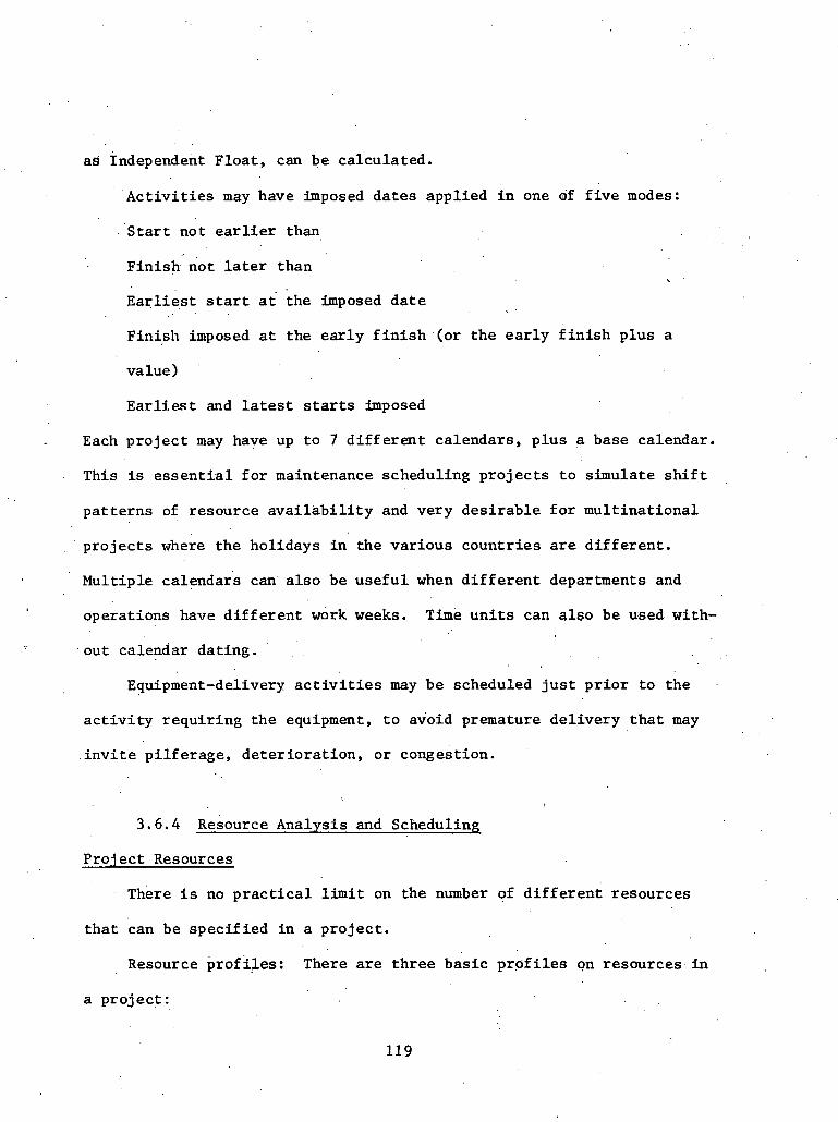
as: lndepend.ent Float , can be ca lcula ted .
A c t i v i t i e s may have imposed da tes applied i n one df f i v e modes:
S t a r t not e a r l i e r than
Finish not l a t e r than
~ a = l i & s t s t a r t a t ;he imposed d a t e
Finish .imposed a t the e a r l y f i n i s h (or t h e e a r l y f i n i s h p lus a
value)
E a r l f e s t and l a t e s t starts imposed
Each p r o j e c t may have up t o 7 d i f f e r e n t calendars, p lus a base calendar.
This is e s s e n t i a l f o r maintenance scheduling p r o j e c t s t o simulate s h i f t
pa t t e rns of resource a v a i l a b i l i t y and very des i rab le f o r mul t inat ional
' p r o j e c t s where t h e holidays i n the var ious coun t r i e s a r e d i f f e r e n t .
Mult iple calendar's can a l s o be u s e f u l when d i f f e r e n t departments and
operat ions have d i f f e r e n t work weeks. T i m e u n i t s can a l s o be used. with-
. o u t calendar dat ing. ' . .
Equipment-delivery a c t i v i t i e s may be scheduled j u s t p r i o r t o the .
a c t i v i t y requ i r ing t h e equipment, t o avoid premature del ivery t h a t may
i n v i t e p i l f e r a g e , de te r io ra t ion , o r congestion.
3 . 6 . 4 Resource Analysis and Scheduling
Pro jec t Resources
here i s no p r a c t i c a l l i m i t on the number of d i f f e r e n t resources
t h a t can be spec i f i ed i n a p ro jec t .
Resource prof iAes: There a r e t h r e e bas ic prpf i l e s on resources . i n
a p ro jec t :

Fixed o r constant - where t h e r e is a constant a v a i l a b i l i t y ' o f
t h e resource. throughout the p r o j e c t .
3 : resource. a v a i l a b i l i t y
' 2
1
0
time
Stepped - where the a v a i l a b i l i t y b u i l d s up a t the beginning of
t h e p ro jec t and drops down toward t h e end.
resource 2 a v a i l a b i l i t y
1:
,o t ime
Cyclic - t y p i c a l of maintenance p r o j e c t s dependent on shift-working.
resource 2 a v a i l a b i l i t y 1
time
3.6.5 Nonexceedable ~ e s d u r c e s and Thresholds . .
P r o j e c t s , o r p a r t s of' p r o j e c t s , w i l l be e i t h e r t i m e l imi ted ( t o meet
a set schedhle) or resource-limited (constrained by the a v a i l a b i l i t y of
resources) . I n def in ing resources, resources can be defined a s non-
exceedable ( f o r ins tance , t h e physica l layout of a p lan t may make i t
impossible t o have more than one overhead crane a v a i l a b l e t o 'an a c t i v i t y )

or exceedable up to a threshold (a ce r t a in c r a f t can be scheduled
to work. up t o 2 hours overtime per day). I n scheduling, another way
t o compensate f o r the unava i lab i l i ty of a spec i f i c resource is t o
specify a n , a l t e r n a t i v e resource (for example,'engineers can make up
a shortage of draftsmen).
3 . 5 . 6 ~ e s o u r k e s on Ac t iv i t i e s
Up t o 200 d i f f e r en t ' resources can be r e l a t ed t o an ac t i v i t y . These
resources' can be specif ied a s " t o t a l work content" (man-days) o r
" r a t e constantt ' (men per day).
Complex resources - .Levels of resources on an a c t i v i t y may vary
during the ac t i v i t y .
S p l i t t a b l e and t i ed a c t i v i t i e s - Certain a c t i v i t i e s can be tagged
. ' as s p l i t t a b l e , a s necessary, f o r resource-leveling. T h i s allows resources
t o be taken dff one a c t i v i t y f o r use by o the r s . , Ac t iv i t i e s can be tagged
a s t i e d t o other a c t i v i t i e s ; t h a t is, they must s t a r t a s soon a s the
immediately preceding a c t i v i t i e s a r e complete.
3 . 6 . 7 Scheduling Rules /Pr io r i t i es
A wide va r i e ty of scheduling r u l e s a r e avai lable , and t he user
can def ine h i s own ru les . P r i o r i t i e s can be assigned spec i f i c a l l y t o
a c t i v i t i e s , t o groups of a c t i v i t i e s , or t o projects .
3.6.8 Updating
A s a p ro jec t progresses, repor ts ' come i n showing which a c t i v i t i e s

a r e completed, p a r t i a l l y completed, changed, e t c , Pe r iod ic reana lys i s
of the network provldes management with a r egu la r up-to-date assessment
of the p r o j e c t ' s t a t u s , whether i t is on schedule o r w i l l be l a t e ,
which a c t i v i t i e s need t o be expedited, and where e x t r a e f f o r t should be
made t o keep t h e p r o j e c t on schedule,
The usua l updating of a network, such a s a c t i v l t y de le t ion , ac-
t i v i t y modif ica t ion, and. t h e repor t ing of . a c t u a l starts and completions
can be done.
PREMIS has s tandard conventions and formats fo r 'upda tes , bu t the
Update Generator ,(UGEN) 'lets you d e f i n e your own update s p e c i f i c a t i o n s , ." . .
and the i n p u t Generator (GEN) lets you design ' the input f o , m a t s of t h e - <
update cards , i f you wish t o .
Any of t h e r e s u l t s of a p a r t i c u l a r update can be s tored a s
h i s t o r i c a l d a t a and used t o produce "Comparative or Target Reports"
which compare t h e cur ren t s i t u a t i o n with the s i t u a t i o n a s of previous
updates.
3.6.9 Report ing
Reporting usua l ly takes p lace i n th ree stages,:
(1) Select ion of Data: Selec t ion of s p e c i f i c information f o r a
r e p o r t is done using the Selec t ion Generator (S'GEN).
Examples: .
Selec t key milestone a c t i v i t i e s a t t h e a c t i v i t y l e v e l f o r repor t ing
v e r t i c a l l y t o any higher l e v e l i n t h e h i e r a r c h i c a l s t r u c t u r e .
S e l e c t a c t i v i t i e s with less than a spec i f i ed c r i t i c a l i t y value

. .
and occurring wi th in a ' c e r t a i n t i m e frame.
A v i r t u a l l y unlimited range of poss ib le condit ions and combinations
of condit ions is a v a i l a b l e t o l e t you e l iminate a l l i r r e l e v a n t a c t i v i t i e s
a s w e l l a s i r r e l e v a n t da ta f o r t h e se lec ted a c t i v i t i e s .
I n f a c t , i t is poss ib le t o scan any column o r group of columns
.(including the desc r ip t ion) on the a c t i v i t y records i n the master f i l e
and t o s e l e c t o r r e j e c t based on any condit ion o r combination of con-
d i t i o n s .
(2) Sort ing of Data: Sor t ing of a c t i v i t i e s i n t o any des i red
sequence i s done using SGEN. Sort ing can be on any column or combina-
t i o n of groups of columns on t h e a c t i v i t y master f i l e record.
Typical s o r t s are :
a c t i v i t y number sequence
department /scheduled s t a r t l a c t i v i t y number
t o t a l f l o a t / a c t i v i t y number
subsystem/project/subnet/activity scheduled s t a r t
department ac ross subsystem and/or p r o j e c t and then scheduled
s t a r t , e t c .
(3) Report Writing: You have complete c o n t r o l over the format of
reports ' by using t h e Report Generator (RGEN).
,Typ ica l r e p o r t s a re : '
Activi ty l i s t i n g s containing inpu t da ta , 'computed values , and 'der ived
va1u.e~ ,(such a s extended desc r ip t ions from codes o r other a c t i v i t i e s )
Bar c h a r t s containing any of the above. with any s c a l e f a c t o r and any
bar-'char t' symbols

Resource t a b l e s showing resources required a t t h e system, sub-
system, p r o j e c t , subnet, o r a c t i v i t y l e v e l s on usage, e a r l y s t a r t ,
l a t e s t a r t , o r average of ' e a r l y and l a t e s t a r t
Cumulative, cos t or ma te r i a l usage curves based on scheduled s t a r t
Summary bar c h a r t and key milestone r e p o r t s f o r higher l e v e l s i n
t h e management s t r u c t u r e . Summarizing may be based on a c t i v i t y se-
l e c t i o n codes, or .by repor t ing on the a c t i v i t i e s defined, i n t h e logic , . . . .
a s summary (or hammock) ' a c t i v i t i e s , or by a combination o f . the two
~ a r g e t schedule r e p o r t s .comparing t h e cur ren t s t a t u s with any of
severa l previous update s i t u a t i o n s (up t o 50 previous t a r g e t schedules *,
can be s to red on the master f i l e ) .

3.7 P r o j e c t Management System (PMS lY)*
Pro jec t Management System (ZmS TV) A s a set of foui: programs,
o r processors , which a r e designed as a comprehensive system t o guide
and manitor p ro jec t s . The use r makes his s e l e c t i o n , accord2ng t o h i s
requirements, among t h e f i r s t t h r e e processors , but draws the r e p o r t s
he wants only from the four th . For f u r t h e r information on t h e capa-
b i l i t i e s of PMS I V Y s e e t h e c h a r t a t t h e end of t h i s chapter . There
fol lows here an o u t l i n e of t h e job performed by each 'processor and of
t h e way t h a t the processors r e l a t e t o each o the r .
3 . 7 . 1 Network Processor
The Network Processor (.W) performs PERT a n a l y s i s of a c t i v i t y
networks and precedence a n a l y s i s of precedence networks, using a deck . .
of d a t a and s p e c i f i c a t i o n c a r d s a s inpu t . It e d i t s the inpu t and c r e a t e s
,. o r updates from it an ed i t ed master f i l e . From t h e master f i l e i t gene-
r a t e s and analyzes the networks submitted by t h e u s e r , and s e l e c t i v e l y
sets up output f i l e s t o pass t o one of t h e o the r processors.
An .ou t l ine of the s t r u c t u r e of t h e Network Processor i s given
here. The Network Processor congi.sts of four procedures. These a r e
programs which accept a s input either da ta cards or f i l e s output by
a preceding procedure, A processpng run may be h a l t e d a f t e r any procedure
is complete; then, using t h e fAles estahl$,shed by th i . s procedure, t h e
run may b e res 'wed a t ti latex time. o r on a separa te computer.
"Material contained i n t h i s s e c t i o n is based upon and/or .excerpted from "Introduction t o P ro jec t Management System 'IV," Program' Product #GH20-0855-1.

F I G U R E 3.1: INFORMATION FLOW I N THE NETWORK PROCESSOR
/ ORDER / PERTGEN 'EDITTIME
c o n t r o l and ~ n p . ~ a t a Cards-
t I v ORDER PERTGEN
EDITTIME
PERTGEM: Input : Sorted 6 a t a s e t ,
o l d master f i l e Act ion: Updating, s k e l e t o n
a n a l y s i s Output: New master f i l e ,
E r r o r s h l i s t i n g s , c a l e n d a r - PERTGEN E r r o r
EDITTME : ORDER: Input : Data cards In?ut : Edi ted d a t a s e t Act ion: E r r o r checking Action: S o r t i n g
PROCESS PROCESS : E r r o r
Output : Edited d a t a s e t , Output: Scsrted d a t a s e t Input : New n a s t e r f i l e , l i s t i n g s
p rocess . r q . c a r d s Action: PERT a n a l y s i s Output : L i s t i n g s , t i m e i n t e r -
media te d a t a s e t , c a l e n d a r
Cont ro l Cards
C o n t r o l Cards

The advantage of t h i s system s t r u c t u r e i s t h a t computer usage
can be optimized. Each procedure has i t s own requirements f o r core
s torage and input/output devices , s o ' tha t i t may sometimes be advan-
tageous t o run t h e procedures 'on d i f f e r e n t computer configurat ions.
Al ternat ively , when t h e ' u s e r runs the procedures sequen t ia l ly a s
job s t eps of the operat ing System, he can t e s t the condit ion codes
. t h a t a r e set by each. procedure. . These condit ion codes have values
t h a t vary with the s e v e r i t y of e r r o r s detected. by the procedure, an'd
i f any procedure r e t u r n s an unacceptable condit ion code va lue , the
use r may s top processing.
A d e s c r i p t i o n of the four procedures fol lows below.
The job of t h i s procedure is t o check the format of the input
cards and t o cor rec t them where poss ib le . It is designed t o g ive
1 . '" the u s e r as much con t ro l a s poss ib le over e d i t i n g and e r r o r handling,
and d i s t ingu i shes e r r o r s of varying importance.
(2) ORDER
The second procedure i s ORDER. It s o r t s t h e edi ted d a t a cards
by type number wi th in subnet wi th in network. It accepts the f i l e
EDITOUT from the procedure EDITTIME, and produces XORDER t o be passed
t o the next procedure. ' The s o r t i s performed by the Operating System
s o r t using intermediate work f i l e s ca l l ed SORTWKOI, 4 2 , -03, e t c .
Therefore t h e use r should optimize this procedure by giving t h e s o r t
a s much core s torage a s poss ib le , and he. w i l l need t o a l l o c a t e more
work£ i l e s i n some cases.

The t h i r d procedure is c a l l e d PERTGEN. I f the re i s no e x i s t i n g
master f i l e , t h e procedure c r e a t e s one by copying the sor ted input f i l e
XORDER, passed by t h e procedure ORDER, onto a f i l e ca l l ed XNMF. I f an
o ld master f i l e e x i s t s , i t is ca l l ed XOMF and PERTGEN updates i t with
t h e records on XORDER t o form XNMF. The new master f i l e can then be
passed t o t h e f o u r t h procedure, PROCESS, or i t can be updated again by . PERTGEN, i n ' which .case i t w i l l , of course, be c a l l e d XOMF.
PERTGEN reads XNMF and c a r r i e s out comprehensive e r r o r de tec t ion
rou t ines on t h e da ta . . It a l s o c a l c u l a t e s . skele ton d a t a which is w r i t t e n ' r
onto XNMF.. Two t a b l e s a r e set up, organized by subnet, which contain
respec t ive ly a l l events from which an a c t i v i t y begins and a l l events a t
which an a c t i v i t y terminates., The user must speci fy the s t a r t , end,
and i n t e r f a c e events he wants, and a l l o t h e r s w i l l be detec ted a s e r r o r s . ,'
Duplicate cards and network l o g i c e r r o r s such a s loops and incor rec t up-
da tes a r e l ikewise detec ted .
PERTGEN o f f e r s the u s e r the f a c i l i t y of d e l e t i n g and modifying.
records on the master f i l e by the submission of update cards with the
appropr ia te update code and iden t i fy ing f i e l d s ; n o ' o t h e r f i e l d s need
be present on the update cards. Master f i l e records may be dele ted o r
modified ind iv idua l ly ; the use r may a l s o ' d e l e t e a l l records which belong
t o a spec i f i ed network or subnet. Records may a l s o b e added t o the
master f i l e . A l l of these methods. of adding t o , de le t ing From, and,
modifying t h e master f i l k may be used on a s i n g l e processing run. It
is the re fo re simple t o c o n t r o l the master f i l e even when it i s la rge .
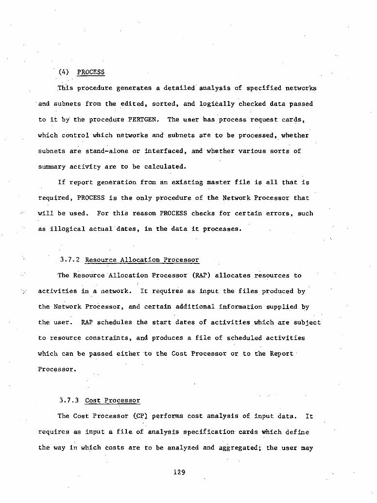
(4) PROCESS
.This procedure genera tes a d e t a i l e d ' a n a l y s i s of spec i f i ed networks
,and subnets from the ed i t ed , sor ted , and l o g i k a l l y checked d a t a passed
t o it by' the procedure PERTGEN, The use r has process reques t cards ,
which con t ro l which networks and subnets are t o be processed, whether
subnets a r e stand-alone o r in te r faced , and whether var ious s o r t s of
summary a c t i v i t y a r e t o be calculated.
I f r e p o r t generat ion from an e x i s t i n g master f i l e is a l l t h a t i s
required, PROCESS i s t h e only procedure of the Network Processor t h a t
w i l l be used. For t h i s reason PROCESS checks f o r c e r t a i n e r r o r s , such
" a s i l l o g i c a l a c t u a l ' d a t e s , i n the d a t a it processes. . .
3 .7 .2 Resource Al locat ion Processor
The ~ e s o u r c e 'Allocation Processor (.RAP) a l l o c a t e s resources t o
. a c t i v i t i e s i n a network. It requ i res as input the f i l e s produced by
the Network Processor, and c e r t a i n a d d i t i o n a l information supplied by
the user . RAP schedules the s t a r t d a t e s of a c t i v i t i e s which a r e sub jec t
t o resource c o n s t r a i n t s , and produces a f i l e of scheduled a c t i v i t i e s
which can be passed e i t h e r . t o , the Cost Processor o r t o the Report
Processor.
3 .7 .3 Cost Processor
The Cost Processor CCPL performs cos t a n a l y s i s of input data . It
requires a s input a f i l e of ana lys i s s p e c i f i c a t i o n cards which de f ine
the way i n which cos t s a r e t o be analyzed and aggregated; the user may
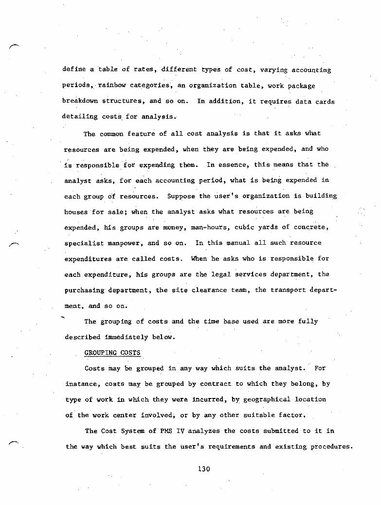
def ine a ' table of rates, d i f f e r e n t types ,of c o s t , varying accounting
per iods , . rainbow .catggories, an organizat ion t a b l e , work package
breakdown s t r u c t u r e s , and s o on. I n add i t ion , i t requ i res d a t a cards . .
d e t a i l i n g cos ts . f o r analysis . .
The common f e a t u r e of a l l cos t ana lys i s is t h a t it asks what
resources a r e being expended, when they a r e being expended, and who
i s responsible ' fo r expending them. I n essence, t h i s means t h a t the
ana lys t asks, f o r each accounting period, what i s beinb expended i n
each group 0.f resources. Suppose the user's o rgan i i a t ion i s build.ing . .
houses f o r s a l e ; when t h e ana lys t asks what resources a r e being
expended, his groups a r e money, man-hours, cubic yards of concrete,
s p e c i a l i s t manpower, and s o on. I n t h i s manual a l l such resource
expenditures a r e c a l l e d c o s t s . When he asks who is responsible f o r
each expenditure, h i s groups a r e che l e g a l s e r v i c e s department, the
purchasing. department, t h e s i t e c learance team, the t r anspor t depart-
, . ment, a n d s o o n . - The grouping of c o s t s and t h e time base 'used a r e more f u l l y
described immediately below.
GROUPING COSTS'
Costs may be grouped i n any way which s u i t s t h e ana lys t . For
ins tance , c o s t s may be grouped by con t rac t t o which they belong, by
type of work i n which they were incurred, by geographical loca t ion
of the work center involved, o r by any other s u i t a b l e f a c t o r .
The Cost System of PMS I V analyzes the c o s t s submitted t o it i n
t h e way which bes t s u i t s the user ' s requirements and e x i s t i n g procedures.

It al lows the a n a l y s t t o submit c o s t s which a r e simultaneously
assigned t o many groups and then t o t a l s c o s t s e i t h e r wi th in each
group o r ac ross a s many groups a s t h e u s e r wants.
ACCOUNTING PERIODS
A cos t a n a l y s i s i s nqrmally requi red t o show the time when each
cos t has occ.urred o r w i l l occur. The standard p r a c t i c e i s t o e s t a b l i s h
an accouneing period of a week, a month, a quar t e r , o r of any o t h e r
convenient length, and t o a s s ign c o s t s t o t h e accounting per iods i n
which they f a l l . The Cost Processor al lows t h e user complete freedom
to . s p e c i f y . t h e accounting per iods he wants; thus it i s easy f o r h i m
t o use the Cost Processor without a l t e r i n g his cur ren t procedures.
The user desc r ibes eai=h c o s t t o t h e Cost Processor by a t t ach ing
; codes t o i t . These codes a r e of two types: t h e f i r s t type is used
t o group c o s t s and t o spec i fy how they are t o be summarized.and .broken .
- down, and the second type s p e c i f i e s t h e u n i t s i n which . the c o s t is . .
expressed.. This s e c t i o n descr ibes the seven methods of grouping . .
c o s t s of fered by t h e Cost Processor.
( 1 ) WORK PACKAGE
A p r o j e c t can normally be divided i n t o p a r t s f o r the purpose of
analyzing cos t s . Each p a r t i s an i tem of work, more o r l e s s d i s -
t inguishable from the rest of the p r o j e c t , t o which the use r can
conveniently ass ign c o s t s . These i tems o t work a r e c a l l e d work
, , packages, and t h e u s e r may spec i fy a t o t a l of over 1,000,000. of
them t o the Cost Processor. A work package might be, "Clear and
bulldoze s i t e 1" or " ~ o n s t r u c t house 4 a t s i te 1 from foundation t o

2nd f loor , " o r any o t h e r i d e n t i f i a b l e i tem of work a t a 'convenient '
l e v e l of d e t a i l . Na tu ra l ly , t h e s i z e of a work package may vary
g r e a t l y w i t h t h e needs of each user .
Charge. Number
A charge number i s an i d e n t i f i c a t i o n code given t o a work package.
A cos t i s assigned t o a work package by a t t ach ing the proper charge
number t o it. So wi th in the Cost System t h e charge fiurnber simply
i d e n t i f i e s a work package, al though normally t h e u s e r e s t a b l i s h e s a
system of charge numbers which r e l a t e s in some way t o h i s e x i s t i n g
procedures.
Work Breakdown S t ruc tu re (WBS)
A of any complexity w i l l r e q u i r e a n a l y s i s a t var ious
l e v e l s of d e t a i l , .according t o the requirements of d i f f e r e n t l e v e l s of
management w i t h i n the, u s e r ' s organiza t ion . It is t h e r e f o r e usual t o
order t h e work packages i n t o l e v e l s , forming a Work Breakdown S t r u c t u r e
o r P r o j e c t Analysis Table. A work package a t one l e v e l may then be
p a r t of a work package a t a h igher l e v e l ; t h e work package a t l e v e l 1
may be the complete p ro jec t t o be analyzed. Work packages a t the
lowest l e v e l a r e normally items of work, o r jobs, which can e a s i l y
be con t ro l l ed and measured;
The Cost Processor accepts a WBS of a s many a s n ine l e v e l s , and
c o s t r e p o r t s are a v a i l a b l e t o d i sp lay cos t s ' a t any WBS l eve l . Some
cos t r e p o r t s show only c o s t s a t tached d i r e c t l y t o charge numbers a t . .
a p a r t i c u l a r l e v e l . Others d i s p l a y f o r any WBS l e v e l except the lowest

a l l c o s t s d i r e c t l y chargeable t o charge numbers a t t h a t level ,and a l l
c o s t s sunkmizing i n t o t h a t l e v e l according t o the WBS, .
(2) PERFORMING DEPARTMENT
A second way of analyzing a p r o j e c t is by department performing
each sec t ion of the work. A performing department might be a team
of l abore r s under a foreman, the .group responsible f o r bui ld ing s i t e .
1, the management se rv ices department, o r any o the r p a r t of the u s e r ' s
organizat ion t o which c o s t s can conveniently be assigned, e i t h e r
d i r e c t l y o r i n summary.
Organization Analysis Table (OAT) .. . . .
It i s . usual t o order' t h e performing departments i n t o l e v e l s , thus ,
forming an Organization Analysis Table. A performing department a t
one l e v e l may then be p a r t . o f a performing department a t a higher
,':$ . level ; the organizat ion a t l e v e l 1 may. be the 0,rganization responsible
"::r f o r the whole p ro jec t . The performing department a t the lowest l e v e l . .
is normally the u n i t responsible f o r a de f inab le job. The s i z e of
the lowest l e v e l department w i l l vary widely from user t o use r ,
depending upon t h e complexity of the p ro jec t being analyzed.
(3) RESOURCE CODE
A t h i r d method of analyzing a p ro jec t i s by the r e s o u r c e s ' i t uses ,
According t o the importance of each i t e m t o t h e u s e r , . h e decides whether
t o cos t i t . s e p a r a t e l y o r t o . . aggregate . it wi th o t h e r s i n t o a s i n g l e
resource. For ins tance , one user might .separare ly c o s t d i e s e l o i l ,
kerosene, and gasolfne, while another u s e r might consider :.all such
f u e l a s a s i n g l e resource. '

. Project team s i t e 1
. - . - - , . . ?
Carpenters r section
A
-- - - <
D44 Team 1 (Foreman P)
J
I I I I
FIGURE 3 . 2 : SAMPLE ORGANIZATION ANALYSIS TABLE
h
I D22
Cotlstruction team i
. I . _
I %
2
D 43 Team 3 Foreman Z)
b 4
D4 1 Team 1 (Foreman X)
4
Clearance t earn
D 3 1 Clearance a &
bulldozing
D42 Team 2 (Foreman Y)
A
I
I Grading
r -
t earn
w
Drainage
I-
T4asons section
T

The Cost Processor permits t h e user t o spec i fy any number of
resource codes; i n e f f e c t , it al lows t h e user t o choose the level of
d e t a i l of r epor t s .
(4) COST CATEGORY CODE
A fourth,method is t o ass ign c o s t s t o a p a r t i c u l a r combination of
performing department, resource code, and (optionally) cos t ing code.
This combination is given a cos t category code which the user
a r b i t r a r i l y s e l e c t s . Normally, the cos t category code i n d i c a t e s the
resource which t h e performing department a p p l i e s t o a work package.
This is t h e standard or intended use of the c o s t category code,
but t h e user may, of course, employ it i n any other more convenient
way, o r not a t a l l . There i s no system-imposed l i m i t on the number
of cos t category codes which may be def ined.
(5) RAINBOW CATEGORY CODE
. . This code, the f i f t h poss ib le method, is defined i n the same way. *
a s the cos t category code and i s thus a code a s s i g n e d . a r b i t r a r i l y t o
a p a r t i c u l a r combination of performing department, resource code, and
(opt ional ly) cos t ing code. Although it is , i n e f f e c t , the same a s
the c o s t category, the computer system keeps t h e two types of code
' separa te and the re a r e standard output r e p o r t s based on t h e rainbow
category codes only.
(6) CONTRACT NUMBER
The s i x t h grouping code of ' t h e Code Processor is the con t rac t
number. T h i s code allows' the use r ' t o group work p:ackages, and i t is
a t tached no t ' t o the ind iv idua l cos t - records. but t o the charge numbers

which i d e n t i f y the work packages. The user ' may give a con t rac t number
t o one o r more 'charge numbers, and thus gather i n one repor t a l l the , .
c o s t s of a p a r t i c u l a r contrac t .
(7) GROW 'OR SUBNET' NAFE . .
A s e v e n t h . a l t e r n a t i v e i s t o a s s i g n each c o s t t o a group or subnet.
When a c o s t a n a l y s i s is being performed independently of a PERT t h e
a n a l y s i s , c o s t s 'may be divided into, groups by a t t ach ing t o each an
a r b i t r a r i l y chosen group name. When c o s t a n a l y s i s fol lows PERT t h e
a n a l y s i s , t h e PERT subnet names are used a s t h e group names, although
both subnet and group names may be mixed i n t h e 'same c o s t a n a l y s i s
. . i f the user wants.
. .
A c o s t is an amount o f , a resource which the use r expends. Normally
c o s t s a r e expressed as u n i t s of money; but they may be expressed i n
o the r u n i t s when t h e user p re fe r s . The type of u n i t i n which each
c o s t is expressed is indicated t o t h e Cost Processor by a code a t tached
t o each cos t record.
A d i f f e r e n t d iv i s ion of c o s t s i s by t h e s o r t of expenditure which
each cos t r epresen t s ; c o s t s may be expenditure which has a c t u a l l y oc-
curred, . o r has. been budgeted, o r i s a n t i c i p a t e d , and so on'. he' type
of expenditure t o which each cos t belongs is indicated t o the Cost
Processor b y a . f u r t h e r code a t tached t o each c o s t record. This code '
is the Cost Type code,
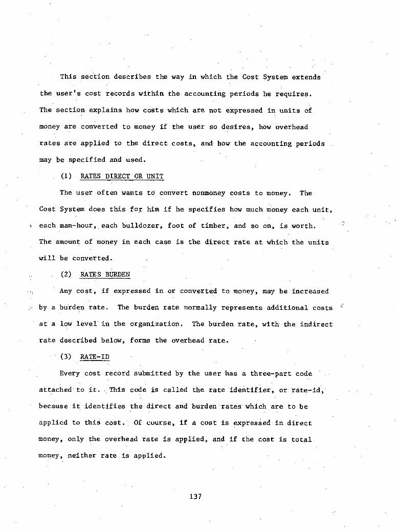
This sec t ion descr ibes the way in which the Cost System extends
the u s e r ' s cost records wi th in the accounting per iods he requires .
The s e c t i o n expla ins how c o s t s which a r e not expressed i n u n i t s of
money &re converted t o money i f the use r so d e s i r e s , how overhead
r a t e s a r e applied to the d i r e c t c o s t s , and. how the accounting periods
may be spec i f i ed and used.
(1) RATES DIRECT OR UNIT
The user of ten wants t o convert nonmoney c o s t s t o money, The
Cost System does this f o r h i m i f he s p e c i f i e s how much money each u n i t ,
each man-hour, each bulldozer, f o o t of timber, and so on, is worth.
The amount of money i n each case is t h e d i r e c t rate a t which the u n i t s
w i l l be converted.
. v (2) RATES BURDEN
. . , Any c o s t , i f expressed i n or converted t o money, may be increased
..;: by a bu'rden r a t e . The burden r a t e normally represen t s a d d i t i o n a l c o s t s '.
a t a low l e v e l ' i n the organizat ion. The burden r a t e , with the i n d i r e c t
r a t e described below, forms the overhead r a t e . . .
(3) RATE-ID
Every c o s t . r e c o r d submitted by the use r has a three-part code .
' a t t ached t o i t . T h i s code is ca l l ed the r a t e i d e n t i f i e r , o r rate-id' ,
because i t i d e n t i f i e s t h e d i r e c t and burden . r a t e s . which, a r e t o be . .
applied t o t h i s cos t . . 01: course, i f a c o s t is expressed i n d i r e c t
money, only the overhead r a t e i s appl ied , and i f the cos t is t o t a l
money, ne i the r r a t e is applied.

(4) COSTING CODE
The cos t ing code is the ' t h i r d component of t h e ra te- id , and has
no use a p a r t from it. The f i r s t two p a r t s of t h e ra te - id a r e the
performing department and resource codes, whf ch means tha t the
app l i cab le , r a t e s . may be var ied by performing department or resource;
, t h e cos t ing code is made a v a i l a b l e t o c a t e r f o r cases where the ap- . .
p l i c a b l e r a t e does' .not depend on these fac tors . . .
.. (5) RATE TABLE
The Rate TabJe is a t a b l e which s e t s out what . d i r e c t and burden
r a t e s apply t o each rate-id. Since every' c o s t is given a ra te - id ,
t h e Cost Processor is ab le . t o r e f e r t o t h i s t a b l e , using the ra te - id ,
whenever a c o s t r equ i res conversion t o money. or the add i t ion of a
burden, rate.
6 UNIT ADJUSTMENT FACTOR (DEPARTPENT EFFICIENCY FACTOR)
The user may a t t a c h t o any ra te- id i n the fate cable a U I I ~ L adJusC-
ment f a c t o r . The f a c t o r i s defined as a percentage, and i t is applied
only t o es t imate c o s t s which a r e expressed a s a number of men, of hours,
o r of overtime hours, before t h e c o s t s a r e converted t o money.' For
ins tance , i f f o r a p a r t i c u l a r ra te- id the user s p e c i f i e s a UAF of 85%,
a l l es t ima te overtime-hour c o s t s which have t h a t r a t e I D a r e reduced
by 15% by the Cost System before they a r e converted t o money.
The UAF is normally used t o make allowance f o r t h e v a r i a t i o n i n
e f f i c iency between work-centers, and s o is sometimes ca l l ed the depart-
ment e f f i c i e n c y f a c t o r . . .
(7) INDIRECT RATE
Any. cos t which is expressed i n , o r converted to , money may b e
. . increased by an i n d i r e c t r a t e . The i n d i r e c t r a t e normally represents
a d d i t i o n a l c o s t s a t a higher l e v e l i n the organizat ion. For example,
suppose general and adminstrat ive overheads, d i r e c t o r ' s f ees , and ,
s o on a r e estLmated t o add 20% t o a l l d i r e c t cos t s . Then t h e use r
might de f ine an i n d i r e c t r a t e of 20% by which c o s t s would be extended
t o t o t a l , money. If both a burden and an i n d i r e c t r a t e a r e ' d e f i n e d
f o r a cos.t, t he cos t is extended by t h e burden r a t e and the sum thus
ca lcula ted i s f u r t h e r extended by the i n d i r e c t r a t e .
(8) CHARGE NUMBER RATE TABLE
The Charge Number Rate Table is the t a b l e which de f ines the use r ' s
i n d i r e c t ' r a t e s t o t h e Cost Processor. 'The t a b l e r e l a t e s the i n d i r e c t
::', r a t e s t o charge numbers; t h a t is, c o s t s whlch a r e accountable t o a
' p a r t i c u l a r charge number may be extended by t h e i n d i r e c t r a t e defined
f o r t h a t charge number. Thus, whereas the burden r a t e i s a t tached
t o the . rate-id i n t h e r a t e t a b l e , the i n d i r e c t rate is a t tached t o
work packages i d e n t i f i e d by charge numbers. I n d i r e c t r a t e s may vary
by charge number accounting period and cds t type.
(9 ) ACCOUNTING PERIODS
Except a t the h ighes t l e v e l of summarization, c o s t . a n a l y s i s normally
shows t h e time when c o s t s a r e incurred, and s o c o s t s a r e assigned t o
. the ,day, week, month, quar te r , o r year i n which they f a l l , The t i m e . .
period which t h e cos't ana lys t chooses is c a l l e d t h e accounting per iod.
Accounting periods a r e , f o r var ious reasons, not always of the
same length. For ins tance , the might be the calendar month,
o r the user 'may d i v i d e t h e year i n t o e igh t periods of four weeks and
four periods of f i v e weeks.
The Cost Processor allows the u s e r - complete 'freedom t o set out
an accounting calendal: which suirs h i s r e q u l ~ u e ~ ~ ~ s . H e luay, separa te ly
de f ine a v i r t u a l l y unlimited number of accounting per iods , ,and may
spec i fy the span o f . each ind iv idua l ly . I f . he p r e f e r s not t o speci fy . .
an accounting calendar, t h e Cost Processor w i l l cons t ruc t oile f o r him
i n which the accounting period is t h e calendar month.
(11) CONVERSION. FACTOR
When a c o s t is submitted a s a number of men or man-hours, the
Cost System may convert i t t o man-accounting-periods. Normally a
five-day, 40-hour week is defi.~led, so a c o s t of 400 man-hours i s
converted t o man-accounting-periods a s 10 man-weeks . The Cost System takes account of holidays and nonwork days i n
performing t h i s conversion. I n t h e example above, i f Wednesday .was
t h e b i r thday of the managing d i r e c t o r and s o a holiday, the c o s t of
400 man-hours. would be converted t o man-accounting-periods a s the
c o s t of 12.5 man-weeks.
(12) ALLOCATION OF COSTS TO ACCOUNTING PERIODS'
When a c o s t f a l l s i n t o more than .one accounting period', the Cost
Processor a l l o c a t e s i t according t o the number of workdays i n each

period or part-period spanned. This method of a l l o c a t i o n is applied
.to a l l cos t s , not only t o man-hour cos ts .
3 .7 .4 Report Processor
The Report Processor (RP) accepts the f i l e s produced by any of the
th ree preceding processors, o r independent d a t a from outs ide th& system.
From the f i l e s , . t h e use r may generate e i t h e r s tandard o r modified re-
por t s . A range of s tandard r e p o r t s is provided, b u t t h e user may
speci fy h i s own r e p o r t s using options t o s e l e c t , s o r t and suppress da ta ,
and t o con t ro l format.
Figure 3..3' shows the ways i n which da ta may flow through the system
t o the Report Processor. . .
The 'Report Processor is a c o l l e c t i o n of programs which p r i n t
*. repor t s from f i l e s of da ta crea ted by t h e Network, Resource Allocation,
ir and Cost Processors o r from an independent source. This in t roduct ion
descr ibes i t i n t h r e e sec t ions . The f i r s t s e c t i o n descr ibes the bas ic
way of using the processor; the second s e c t i o n expla ins how the use r
can, t o sane extent ; c o n t r o l r epor t format and content; and t h e t h i r d
s e c t i o n descr ibes how the use r can p r i n t r epor t s which he has defined
completely.
(1) THE BASIC REPORT PROCESSOR
The bas ic , Report Processor c o n s i s t s of a c o n t r o l program and be- . .
tween 50 and 60 report-writ ing programs. The c o n t r o l program reads
one or more con t ro l cards "and executes t h e repor t-wri t ing programs
s p e c i f i e d 011 them. The u s e r needs t o make no modif ica t ion t o any

I Network p roces so r
Report p roces so r
FIGURE 3 .3 : THE PFIS IV SYSTEi.1

program i f h e wishes t o process h i s da ta i n t h i s way. I f he .executes
the standard, unmodified report-writ ing programs, h e can obta in any
of a wide range of cos t , PERT, precedence, and resource a l l o c a t i o n
repor t s which may d isplay d a t a not only i n lists and t ab les , bu t a l s o
i n graphs, histograms, and char t s . For many purposes the standard
repor@ a r e s u f f i c i e n t .
(2) CONTROL OVER THE STANDARD REPORTS
The user can con t ro l the p r i n t i n g of t h e s tandard repor t s by
submitting f u r t h e r con t ro l cards. Broadly, t h e c o n t r o l cards may be
used t o s e l e c t da ta , and t o c o n t r o l r epor t formats. Data may be se-
l ec ted by speci fy ing an acceptable set of group o r subnet names, an
acceptable range of values f o r p a r t i c u l a r f i e l d s , a . list of unacceptable
values f o r p a r t i c u l a r f i e l d s , o r a p a r t i c u l a r acceptable value f o r a
p a r t i c u l a r , f i e l d . , Data may be se lec ted a t a par . t icular l e v e l of sum-
marizat ion wi th in the t i m e or cos t ana lys i s systems. The format of Y
r e p o r t s can, t o some e x t e n t , be control led . The user may spec i fy the
heading l i n e t o appear on each page, and may specffy the s c a l e t o be
, used f o r p r in t ing histograms. For c o s t r e p o r t s only, the user may
spec i fy c e r t a i n . o ther format d e t a i l s and a s c a l i n g f a c t o r .
Reports can be w r i t t e n t h a t w i l l process reques t cards t h a t
speci fy complete s o r t i n g , formatt ing, and paging parameters.
Note. t h a t some o r a l l of these c o n t r o l cards a r e l i k e l y t o be
used each time the Report Processor is used. This meth.od of c o n t r o l l i n g
the content and 1ayo.ut of r epor t s is f l e x i b l e and simple. It makes i t
poss ib le t o const ruct a report-writ ing program of genera l app l i ca t ion ,

b u t on any occas'ion t o d i r e c t i t t o a p a r t i c u l a r set of data . For
t h i s reason t h e ,use r w i l l probably continue t o use c o n t r o l cards even
i f he has adopted t h e methods (described immediately below) of com-
p l e t e l y designing h i s own repor t s . . .
(3) REPORT DESIGN BY THE USER
The user i s encouraged t o compose h i s own report-writ ing programs:
H e may do th is ' i n one of two ways. ,FIrsr, he can rake a s~aurla~rl yiu-
gram and adapt i t . H e can a l t e r t h e content and pos i t ions of headings,
t h e s e l e c t i o n and .ordering of data , and t h e .symbols used on - c h a r t s .
~ e ' can .p r in t s e l e c t e d data more prominently; f o r ins tance , he might
p r i n t c e r t a i n PERT a c t i v i t i e s , or c e r t a i n charge numbers, with s p e c i a l
spacing, under l in ing, o r f l a g s . Normally, t h i s s o r t of adaption i s
extremely simple, p a r t i c u l a r l y in t h e case of PERT time and precedence ,
repor ts . Second, he may design and w r i t e h i s own program. The Report
Processor o f f e r s t h e use r what is, i n e f f e c t , a very high-level language,
designed t o make report-writ ing a s easy a s poss ib le . The user w i l l f ind
t h a t wr i t ing hirs m n programs ranges from t h e extremely simple t o the
r a t h e r d i f f i c u l t . To const ruct a PERT t i m e report-writ ing program
.whose o u t l i n e s a r e s i m i l a r t o those of a s tandard repor t might take
j u s t a f q minutes., However, i t would n a t u r a l l y take longer t o compose
a soph i s t i ca ted c o s t r e p o r t program.
CHAPTER N
P r o j e c t Services
~ u r ~ o s e , Approach, and Def in i t ions
. .
4.1 In t roduct ion
On a cons t ruct ion p r o j e c t the s i z e of a nuclear power s t a t i o n ,
~ r o j e c t Services normally performs the fol lowing funct ions :
Payro l l
Timekeeping
...? Accounting :'>
Personnel
. . Computer Services . .
While no t providing the same p o t e n t i a l f o r improved performance through . .
b e t t e r information management a s m a t e r i a l t racking o r f i e l d cons t ruct ion Y.
'2 con t ro l , t hese a r e never the less e s s e n t i a l funct ions which must be per-
formed. I n f a c t , payro l l and accounting a r e normally t h e Eirst funct ions
t o be computerized a t a cons t ruct ion s i t e .
4 .2 Payro l l
The primary funct ion of p a y r o l l processing i s t o provide weekly
. paychecks and earning statements t o c r a f t and overhead employees; pay- L .
r o l l must a l ~ o comply wit11 Federal , S t a t e , and l o c a l r egu la t ions re-
garding repor t ing of taxes , provide requi red r e p o r t s t o unions, and
provide l abor c o s t d a t a t o Cost Engineering. To be more s p e c i f i c , a
cons t ruct ion p a y r o l l system should provide the funct ions of accumulating .

hours worked a t var ious r a t e s of pay, ca lcu la t ing yay f o r s t r a i g h t . . .
t ime and overtime, deducting required taxes and other items; repor t ing , . employee ded&tions and: &nployer contr ibut ions t o union ' b e n e f i t funds ,
. . . . . .
repor t ing withholding .. . t&x deducted, producing a b i l l i n g f o r t h e owner,
and accumulating c o s t d a t a f o r u s e by t h e Labor Cdst System.
. . . Payro l l .has t h e fol lowing r e l a t i o n s h i p s t o o the r functions:
. .
Taxes - i n t e r f a c e s wi th 941/W2 rax r e y u i l i u g funeeiona
Average Rates - compures average raLe f o r each c r a f t and passes
t h i s d a t a t o t h e Labor Cost System
Personnel d a t a - may i n t e r f a c e wi th personnel systems t o repor t
vacat ion days and s i c k days, record termination da te , s a l a r y increases ,
e t c .
TO perform these funct ions , a p a y r o l l system r e q u i r e s t h e following . .
data:
Foreman's' Time Cards ( c r a f t )
Weekly Employee Time Cards ( s a l a r i e d and non-exempt)
P a y r o l l P r e l i s t (or list of a l l employees and t h e i r hours worked)
New Hires /Terminations
Salary/ Rate Changes.
The fol lowing d a t a is generated whi le processing t h e payrol l : . .
Gross Pay and Deductions
Employer Contributions
Average C r a f t Rates
Owner's B i l l i n g

'he. fol lowing s t e p s a r e followed i n performing t h e payrol l :
Process c r a f t .employee hours from Foreman's Daily Time Cards
onto Daily Time Check and Weekly Summary Sheet. Verify wi th Attendance
Clock records.
Post hours worked t o Payro l l P r e l i s t as fol lows:
- from ail^ Time Check and Weekly Summary Sheet ( c r a f t )
- from weekly Employee T i m e Cards ( s a l a r i e d and non-exempt)
Process p a y r o l l P r e l i s t aga ins t Payro l l System, producing p a y r o l l
checks and assoc ia ted repor t s .
The ,following r e p o r t s a r e t y p i c a l l y produced from a p a y r o l l
system:
Payro l l P r e l i s t . '
P a y r o l l Checks and Earnings Stubs
Payrol l ' Regis ter
* , Tax Summary
C r a f t Summary
Union Fringe Benefi t Supplement
4 . 3 Accounting
Accounting a t a cons t ruct ion s i t e c o n s i s t s pr imar i ly of t h e accounts
payable funct ion , although some of t h e accounts r ece ivab le funct ions may
a l s d appear. This discuis ' ion i s r e s t r i c t e d t o accounts payable only.
The purpose of the accounts payable funct ion is t o provide prompt
processing and payment of vendor invoices , inc luding payment and re-
por t ing of taxes. Accounts payable r e l a t e s t o o the r funct ions a t t h e

const ruct ion s i te a s follows:
Purchase Orders - received from Purchasing
Mate r ia l Receiving Reports - received from Warehousing
Expenditures - pass t o Cost Engineering
The. following d a t a is required f o r accounts payable:
Purchase Orders
Receiving Reports . ,
Vendor.. 1 n ~ o i c e s
Xn processing accounts payable information, t h e following da ta is
generated :
Discounts
Tax r a t e s and accrued t a x
Accounts payable processing includes the following elements:
Check i n v o i c e . a g a i n s t Purchase Order f o r u n i t p r i c e , quan t i ty ,
f r e i g h t , and discount terms
Check invoice a g a i n s t receiving repor t f o r quan t i ty and f r e i g h t
terms
Calcu la te discounts and determine taxable r a t e s
Calcula te accrued t a x and n e t due t h e vendor
Complete Invoice Approval Form ( include c o s t code)
Prepare weekly m a t e r i a l b i l l i n g s f o r owner
The fol lowing items a r e produced a s outputs of t h e accounts
payable funct ion :
Accounts Payable Checks
Check Regis ter

Accounts Payable Register
~ c c o u n t s Paid Register
Cost Dis t r ibu t ion by Check Regis ter
Mater ia l B i l l i n g
Tax D i s t r i b u t i o n Report
Vendor L i s t ing
4 .4 Personnel
Personnel systems a t const ruct ion sites are usual ly f a i r l y
simple, involving manual record f i l e s o r simple computer f i l e s . More soph i s t i ca ted systems may be used a t t h e cons t ruc to r ' s o r
u t i l i t y ' s home o f f i c e ; these systems may provide on-line inquiry
i n t o a d a t a base containing a wide range of employee information. - \
However, access to t h i s personal employee information should be re-
. ' .' s t r i c t e d f o r privacy reasons; thus , access t o the company's person-
n e l management system is usual ly not a v a i l a b l e t o a const ruct ion
projec t .
One p r o j e c t surveyed uses a simple computer f i l e ' t o record the
following information: t i t l e , name, department, d a t e of h i r e , d a t e
of l a s t increase , percent o f . last inc rease , and cur ren t salary. , Re-
por t s can be produced,. with o r without cur ren t s a l a r y , i n var ious
sequences . While they may not involve d a t a processing, t h e following funct ions
a r e usual ly p a r t of the personnel opera t ion a t a const ruct ion site: ,
S a l a r i e d
~ e c r u i t ing
Wage Adminis t r a t i o n
Record Keeping
Cra f t
Labor Rela t ions (Closed Shop)
Recrui t ing (Open Shop)
Record'Keeping
Training
4 .5 Computer Services
This fufiction normally c o n s i s t s of performing da ta ent ry and
e d i t i n g , using remote job ent ry (RJE) f a c i l i t i e s t o run systems on
the home o f f i c e computer, and ' p r in t ing , burs t ing , deco l l a t ing , and
d i s t r i b u t i n g t h e var ious repor t s . A l l t h i s sounds simple enough,
u n t i l t h e volume of work is considered. A t one p ro jec t . surveyed, ,
19 d i f f e r e n t systems were being run on a regular b a s i s from t h e job-
s i t e RJE terminal . Five fu l l - t ime opera tors were used' , f o r d a t a ,ent ry , . .
t h e computer terminal was used f o r t h r e e s h i f t s per day, and' the p r i n t
volume reached 7,500,000 p r i n t l i n e s per month during peak const ruct ion
a c t i v i t y .
Another a l t e r n a t i v e a v a i l a b l e t o a const ruct ion s i t e involves
t h e use of an on-s i te computer. This is normally thought of a s a
minicomputer, although wi th the volume of work occurring a t a nuclear
const ruct ion s i t e , a smal l t o medium genera l 'purpose computer can

probably b e j u s t i f i e d . A s p l i t of computing funct%ons between t h e
job s i t e and t h e home o f f i c e may b e used, wi th t h e simpler funct ions
being performed a t ' t h e job s i te , whi le t h e home o f f i c e computer pro-
v ides s e r v i c e f o r l a r g e f i l e searches, p a y r o l l processing f o r a l l
company p r o j e c t s , e t c .
4'.6 Exis t ing and Projec ted Systems
For the u t i l i t i e s and const ruct ion companies whose systems were
s tud ied , a l l a r e cu r ren t ly using t h e same b a s i c types of systems f o r
support ing p r o j e c t se rv ices . These a r e t y p i c a l l y stand-alone systems,
running i n a batch environment, using s e q u e n t i a l f i l e s . Transact ions . .
. may be passed from one system t o another using magnetic t a p e . o r . o the r . '
types of sequen t i a l t r ansac t ion f i l e s .
One exception t o t h e above statement i s t h e Tennessee Valley
, Authori ty, which is cur ren t ly developing a P r o j e c t Cost Accounting
subsystem, t o be run a s an i n t e g r a l p a r t of MAPIS (Materials Management
System). See Chapter I1 of Appendix B f o r a d e s c r i p t i o n of t h e MAMS
system.
The f o l 1 a w i n g . i ~ a b r i e f descrip. t ion of t h e systems c u r r e n t l y i n
use a t s e v e r a l p r o j e c t s : . .
Daniel I n t e r n a t iona l
Farley Nuclear P lan t - Alabama Power Company
- P a y r o l l - Weekly processing of timecards t o produce employee
paychecks; f eeds average c r a f t rates ' t o ~ a b o r Cost
System (Payrol l system .is unique t o t h i s p r o j e c t ) .

- Accounts Payable - Twice-we.elly processing. of ou t s tanding in- . . . .
voices -and prepara t ion of 'payment checks.
(P ro jec t uses RJE terminal t o access Southern Services Datacenter
i n At lanta . )
Callaway P r o j e c t - Union E l e c t r i c
- P a y r o l l - Weekly processing of s tandard Daniel p a y r o l l system
(with enhancements f o r union b e n e f i t s repor t ing) t o
produce employee paychecks; feeds average c r a f t r a t e s
t o Labor Cost System.
- Accounts Payable - Weekly processing arid payment of invoices
under the c o n t r o l of the P r o j e c t A c ~ ~ u n t a n t (individ- . . . .
u a l invoices may be se lec ted f o r payment o r held u n t i l
LIE next cycle) . Expenditure t r ansac t ions a r e passed
t o the Mate r ia l Cost System manually.
(Projec t uses W E te rminal t o access Union E l e c t r i c Uatacenter i n
S t . Louis).
Enrico -Fermi Unit I1 - D e t r o i t Edison
- p a y r o l l - Standard Daniel p a y r o l l system run weekly t o pay a l l
Daniel employees and some subcontractor employees; . .
Labdr Cost System not used. due t o t h i s being a con-
s t r u c t i o n management job.
- Accounts Payable - Performed by De t ro i t Edison.

(Projec t u s e s WE terminal t o access Daniel I n t e r n a t i o n a l Datacenter
i n Greenvi l le , South Carolina) .
Wolf Creek Pro jec t - Kansas Gas and Elec t r ic /Kansas C i ty Power
and Light ,
- The Payro l l and Accounts Payable systems used on t h i s job are
e s s e n t i a l l y i d e n t i c a l t o those used a t Callaway.
( P r o j e c t . u s e s RJE te rminal t o access D a n i e l I n t e r n a t i o n a l Datacenter
i n Greenvil le , South Carol ina) .
Duke Power Company
. , A l l ' p a y r o l l and accounting funct ions a r e performed a t the company
headquarters i n Char lo t te , North Carolina. .Hours worked by each em-.
, ployee a r e repor ted by each p r o j e c t ' s Payro l l Sect ion weekly v i a a
scannable, document; these' documents a r e read by an o p t i c a l scanner.
The p a y r o l l f o r a l l p r o j e c t s 'is run biweekly; t h e checks a r e p r in ted .
i n Char lo t te . and del ivered t o t h e p ro jec t s .
Accounts Payable i s handled almost e n t i r e l y i n Char lo t te . Invoices
a r e approved by each p r o j e c t ' s Accounting Sect ion and forwarded t o
Char lo t t e f o r weekly processing.. The P l a n t Accounting System ' (run i n . . ,
Char lo t te) p icks up Labor Cost da ta from the Payro l l System and Mate r i a l
Cusl: d a t a from Accounts Payable and merges these two . to produce a t o t a l
p i c t u r e of p ro jec t cos t .
4.7 Produc t iv i ty Reporting and Control
W e have discussed six canned systems which can be purchased
from var ious so£ t w a r e houses. This is' the approach taken by most of
t h e companies surveyed. It was found t h a t o f t e n t h e canned'packages
do no t inc lude a l l the systems needed and t h e con t rac to r o r u t i l i t y . '
sometimes f i n d s it necessary t o design ad hoc systems t o f i l l i n the
gaps. The fol lowing two sec t ions a r e examples of two of these. types
of systems. Each d e a l s with the problem of p roduc t iv i ty repor t ing
and ana lys i s . These r e p o r t s show the d i f f e r e n t approaches taken by
Duke Power Company and Daniel I n t e r n a t i o n a l t o so lve these thorny * a-
problems.
4.7.1 Duke Peer Company - Pro jec t Planning and Performance
Program: Manhour Quanti ty Analysis System and Quantity
Control System
~ a r l ~ i n the const ruct ion phase of McGuire Nuclear S i t e , i t became
apparent t o management t h a t a r e a l i s t i c b a s i s f o r evaluat ion of con-
s t r u c t i o n performance was necessary. Published s tandards f o r s i m i l a r
work i n indus t ry w e r e ava i l ab le , and some h i s t o r i c a l information f o r
previous non-nuclear work i n Duke Power ' .existed. However, t h e r e 'was .
no r e a l l y good information based s t r i c t l y on Nuclear Power Construction
a s Duke Power performs it. It was a l s o des i red t h a t a method of com-
par ison among var ious work crews performing s i m i l a r tasks be provided.
Fur ther , a means of p ro jec t ing and t abu la t ing t h e schedule of work -
performed over the est imated dura t ion of the task , with an updating
of a c t u a l work accomplished t o monitor . progress, would be worthwhile.
A l l of these f e a t u r e s would be use fu l both i n managing the cur ren t job
and i n making es t imates m o r e , r e a l i s t i c f o r f u t u r e const ruct ion.
The Man-hour Quanti ty Analysis System and the Quantity Control
System a r e two modules of the Pro jec t Planning. and Performance Program
( P 4 ) , a t o t a l management concept aimed a t con t ro l l ing and optimizing
the c o s t and dura t ion of const ruct ion generat ing f a c i l i t i e s .
Purpose and Scope
This is a computer app l i ca t ion designed t o e s t a b l i s h a uniform
method of c o l l e c t i n g , t abu la t ing , and repor t ing manhours and completed
q u a n t i t i e s of work as w e l l a s d isplaying p ro jec t ions of work schedules
and s tandards aga ins t which .the progress and p roduc t iv i ty may be measured.
. T.he.Man-hour Quantity Analysis System i s designed t o do t h e follow-
(1) Provide a b a s i s f o r evaluat ing t h e m a ~ b r per u n i t of
quant i ty completed f i g u r e f o r each account (by crew) aga ins t a standard
man-hour per u n i t f igure .
(2) Provide s t a t u s r e p o r t by account and crew t o i n d i c a t e the
p roduc t iv i ty of each account r e l a t i v e t o the standard f i g u r e associa ted
with each account.
(3) Provide a h i s t o r i c a l f i l e : . t o be referenced by f u t u r e major
generat ing p r o j e c t s t o i n d i c a t e an a c t u a l man-hour per u n i t i n s t a l l e d
product iv i ty f i g u r e f o r each account.
The Quantity Control System i s aimed a t achieving t h e following:
(1) Forecast es t imates of quan t i ty completions by bi-weekly

per iods and pos t a c t u a l q u a n t i t i e s completed aga ins t these ' es t imates .
(2) Determine, by ind iv idua l account ana lys i s , how t h e t o t a l
p r o j e c t i s progressing.
(3) Prepare, on an exception b a s i s , r e p o r t s showing the a c t i v i t i e s
which are behind schedule.
System ~ e s c r i ~ t i o n
The r e s p o n s i b i l i t y f o r s e t t i n g up the account masters and bi-weekly
period. quan t i ty es t ima tes rests with t h e 'P-4 s e c t i o n a t each s i t e , . a s
does the subsequent input of a c t u a l d a t a and the handling of output
r epor t s . 5 r
There a r e b a s i c a l l y two types of input: , .
(1) Man-hours expended by account
(2) Quant i t i e s of work performed i n t h a t account
~ c t u a ~ . t i m e shee t s a r e coded by P-4 personnel f o r work order and account .
number; This i s both t o insure accura te coding by a small, c e n t r a l ,
wel l - t ra ined group, and t o a i d the P-4 group i n keeping up wi th the
a reas i n which d i f f e r e n t crews a r e working.
Q u a n t i t i e s of work are given 'on a 2-week bas i s , being entered and
run on the Thursday o r Friday a f t e r t h e p a y r o l l run is .made. Quan t i t i e s
f o r formwork, r ebar , and steel a r e derived fromltake-offs of const ruct ion
drawings. These q u a n t i t i e s a r e given a s t h e work is performed. Actual
concrete yardage is used. This is taken from concre te placing t i c k e t s .
P iping, welding, placement of mechanical equipment, and other more
spec ia l i zed a c t i v i t i e s and accounts a r e repor ted v i a va r ious documents
P . and i n t e r p r e t e d by the 'p-4 s e c t i o n f o r purpose of inpu t t o t h e Man-hour

and Quantity systems. I n some ins tances , no s p e c i f i c documentation
is app l icab le and the P-4 people are t ra ined t o determine q u a n t i t i e s
by v i s u a l observation.
A formal Construction Department Procedure. has been published and
issued covering the adminis t ra t ion and mechanics of these two systems
a s performed a t the const ruct ion site.
Performance standards were es tab l i shed both empir ica l ly and from
reference t e x t s , p lus judgment of const ruct ion management. A l l s tandards
have been subject t o r ev i s ion a s a c t u a l experience provides more s p e c i f i c
information. Theoret ica l ly , a s one const ruct ion s i t e is completed, the re
is enough good d a t a f o r a l l . a c c o u n t s s o t h a t the performance a t t h a t s i te . .
can be used i n es tab l i sh ing r e a l i s t i c but somewhat more ambitious stan-
" dards and goals f o r the next site. The s p e c i f i c method of development
' $ of the . i n i t i a l s tandards a t McGuire is a s follows. . .
I n developing the standards used a t McGuire, t h r e e sets of bas ic
f i g u r e s were,obtained o r ca lcula ted:
(1) Man-hours per u n i t of production'based on a c t u a l performance
at 'Marsha11 1 and 2 .
(2) Man-hours p e r u n i t of production based on.ac tua1 performance
a t Allen 1 and 2.
(3) Derivations from standard textbook f i g u r e s f o r s i m i l a r ac-
t i v i t i e s (Source: ~ o n s t & c t i o n Estimates and Costs - H..E. Pulver) .
The proposed.standards, then, w e r e based on these t h r e e sources, p lus
d iscuss ion with personnel a t McGuire, M t Holly Storage, Yard, and Char- . .
l o t t e Construction Services. There were c e r t a i n s p e c i f i c considera t ions

' -due t o the ' l i m i t e d a v a i l a b i l i t y of data : . .
(1.) Reactor .bui ld ing and a u x i l i a r y bu i ld ing were considered t h e
same as the t u r b i n e bui ld ing, f o r most steel and concrete s i t u a t i o n s ,
where no d i r e c t information on these s t r u c t u r e s was ava i l ab le . This
was discussed wi th va r ious people i n the department and t h e consensus
was t h a t i t would be acceptable i n t h e i n i t i a l development of s tandards.
A s a c t u a l experience provides b e t t e r information, t h e s tandards a r e
being updated.
(2) ~ e n e r a l l ~ , i n s e t t i n g the f i g u r e s ,
(a) I f a l l t h r e e f . igures were c l o s e , t h e lowest, o r most
s t r i c t , w a s taken.
(b) . I f the re 'was wide v a r i a t i o n among a l l th ree , an average
was taken.
(c) I f Marshall and Allen genera l ly agreed, and book f i g u r e
w a s s i g n i f i c a n t l y d i f f e r e n t , t h e book f i g u r e was thrown out
and a standard f i g u r e s l igh . t ly lower (more s t r i c t ) than
Marshall o r Allen was proposed.
(3) While i t would have been p re fe rab le t o use Oconee information
i n many ins tances where nuclear type const ruct ion was involved, t h i s was
not done because t h e r e w a s not s u f f i c i e n t information of t h i s type
a v a i l a b l e from Oconee records. This f a c t only f u r t h e r serves t o point
out the n e c e s s i t y f o r good d a t a base information of t h i s type.
Output r e p o r t s are d e t a i l e d i n a previous sec t ion , and cover a
mul t i tude of t o p i c s and summaries of man-hour and quan t i ty data . The
d a t a may be organized by crew, by account t o t a l , o r by exception
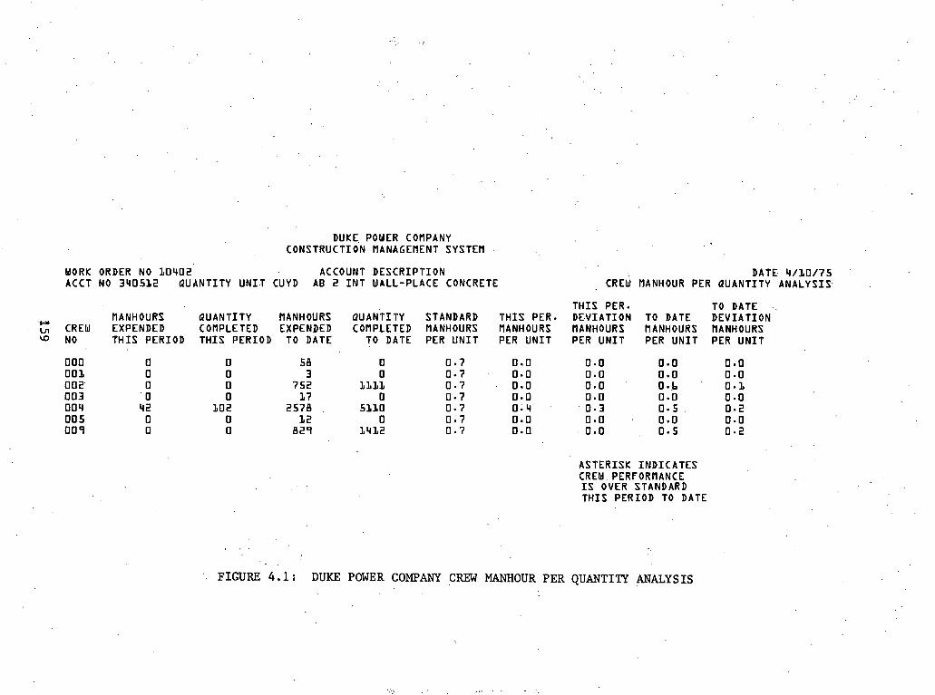
DUKE, POUER COMPANY CONSTRUCTION MANAGEMENT SYSTEM
WORK ORDER NO 10'402 ACCOUNT D E S C R I P T I O N ACCT NO 3U05L2 QUANTITY U N I T CUYD AB 2 I N T WALL-PLACE CONCRETE
'F CREW
w NO
MANHOURS EXPENDED T H I S PERIOD
Q U A N T I T Y MANHOURS COMPLETED EXPENDED T H I S PERIOD TO DATE
QUANTITY COMPLETED
TO DATE
0 0
LLLL 0
5110 0
1'412
STANDARD MANHOURS PER U N I T
T H I S PER. MANHOURS PER U N I T
DATE '4/L0/75 CREW MANHOUR PER QUANTITY A N A L Y S I S
T H I S PER. TO DATE D E V I A T I O N TO DATE D E V I A T I O N MANHOURS NANHOURS MANHOURS PER U N I T PER U N I T PER U N I T
ASTERISK I N D I C A T E S CREW. PERFORMANCE
. . I S OVER STANDARD T H I S PERIOD TO DATE
. .
FIGURE 4.1: DUKE POWER COMPANY CREW MAMIOUR PER QUANTITY ANALYSIS

DUKE POWER COMPANY CONSTRUCTION MANAGEMENT SYSTEM
QUANTITY BY BIWEEKLY PERIOD
WORK ORDER NO 10432 ACCOUNT D E S C R I P T I O N ACCOUNT NO 340512 QUANTITY U N I T CUYD AB 2 I N T WALL-PLACE CONCRETE
BIWEEKLY P E R I O D
0 1 0 2 03 0 4 0 5 Ob 0 7 0 a
QUAVT ITY COM'LETED BY 2ERIOD
0 158 515 bLL 3 a0 L ib '
99 0
QUANTITY EST IMATED BY PERIOD
7 9 80
383 383 . 3'83 383 L3b
. L3b
QUANTITY D E V I A T I O N BY PERIOD
-79 7 8
122 228 -23
-237 -37
-L3b
QUANTITY COMPLETED TO DATE
0 158 bb3
L274 1b34 1780 1879 1879
QUANTITY EST IMATED TO D,ATE
7 9 159 542 925
1308 1bSL 1827 . 19b3
QUANTITY D E V I A T I O N TO DATE
DATE 4/11/75
ASTERISK I N D I C A T E S THAT WORK COMPLETED I S LESS THAN E S T - BY PERIOD TO DATE
FIGURE 4.2 : DURE POWER COMPANY QUANTITY BY BIWEEKLY E E R I O REPORT

condit ion t o show p o t e n t i a l problem areas . The r e p o r t s a r e subdivided
and d i s t r i b u t e d t o app l i cab le foremen and managers by t h e P-4 sec t ion
a s deemed s u i t a b l e f o r t h e i r s p e c i f i c needs and i n t e r e s t s . It is
t h e ob jec t ive t o supply only t h a t info 'matfon'needed and used, and
not t o burden'any superviso,r or manager with e x t r a mate r i a l .
A number,of one-time a n a l y t i c a l r e p o r t s f o r s p e c i a l management
purppses, such a s Pro jec t ~ e v i e w Meetings, a r e taken from t h e rdu t ine
computer output r epor t s described here in , and these two systems a l s o
f u r n i s h much of the d a t a used in preparing t h e site 's Quar ter ly S t a t u s
Reports.
' 4.7.2 Daniel I n t e r n a t i o n a l Product iv i ty Reporting
, For const ruct ion p r o j e c t s of the s i z e , complexity, and, dura t ion
of nuclear power p l a n t s , i t i s d e s i r a b l e t o be ab le t o measure work
. performance, both i n q u a l i t y and quant i ty , of t h e work crews on a ).
rou t ine bas i s .
The an-hour .Quantity Analysis System uses t h e computer t o c o l l e c t ,
so r t , . compute, and p r i n t out information which al lows evaluat ion of
man-hours per u n i t of quant i ty completed by crews and comparing t h i s 1
t o a standard.
The Quantity Control System s i m i l a r l y uses the computer t o a s s i m i l a t e
information on the q u a n t i t i e s of each element of work, es t imates of
amounts completed per bi-weekly period, and measurement of a c t u a l
progress aga ins t the est imated q u a n t i t i e s .

PIAN-.HOUR QUANTITY AlJALY S I S -
AND . .
QUANTITY CONTROL SYSTEMS
3 f
DETAIL - OUTPUT SmIIIARIES PROJECT REPORTS b XANAGEIIENT
FIASTER DATA UPDATES ERROR CORRECT,ION
- -
P-4
GROUP
r
CREW
FOREHEN
b - .
BI-WEEKLY PROJECTION ENTRY OF STANDARDS
a A
REPORT: NG OF POSTING OF HOUR! ACCOUNT NOS,
[TINE SHEETS& WO NOS, DETER- P-4
Q- QUANTITIES , MINATION OF WORK INPUT REPORTING P E R F O W D FORMS
'I
i
CHARLOTTE
4 TRANSPIISSION OF DATA S I T E
COMPUTER COMPUTER
TEFJIINAL I
* i .
FIGURE 4 . 3 : DAMIEL 14.AN-HOLX AND QUANTITY ANALYSIS AND Q0ALITY COIJTROL .SYS.TDI . 9 ,
SENIOR FACILITES & ' PLArnIING ENGINEER
. b
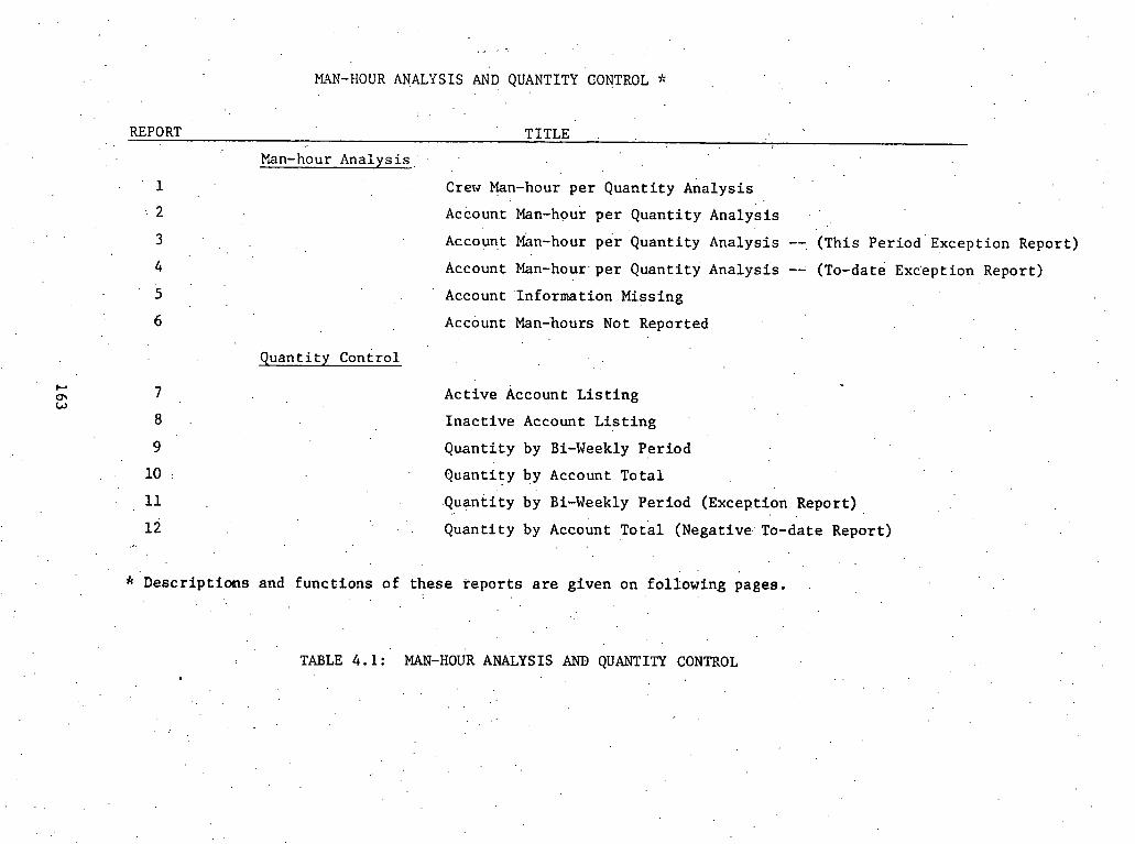
,., < - '
MAN-HOUR ANALYSIS AND QUANTITY CONTROL *
REPORT TITLE .
Man-hour Ana lys i s ,
. ' 1 Crew Man-hour p e r Quant i ty ~ n a l ~ s i s
.- 2 Account Man-hour p e r Q u a n t i t y Analysis ' ,
Account Man-hour per Quant i ty Analysis --, (This ~ e r i o d ' E x c e p t i o n Report)
4 Account Man-hour. pe r Quant i ty Analysis -- (TO-date Exc'eption Report)
5 ' Account ' Information Missing
6 Account Man-hours Not Reported
Q u a n t i t y Control
7 Act ive Account L i s t i n g
8 I n a c t i v e Account L i s t i n g
9 Quant i ty by Bi-Weekly Per iod
10 : Quant i ty by Account T o t a l . .
11 .Quantity by Bi-Weekly Per iod (Exception Repor t ) ,
12 . ' . Quant i ty by ~ c c o u n t TO t a l (Negative.. To-date Report) .,.
* Desc r ip t i ons and func t ions o f t he se r e p o r t s a r e given on fo l lowing pages. .
TABLE 4.1 : ' MAN-HOUR ANALYSIS AND QUANTITY CONTROL . -
. .
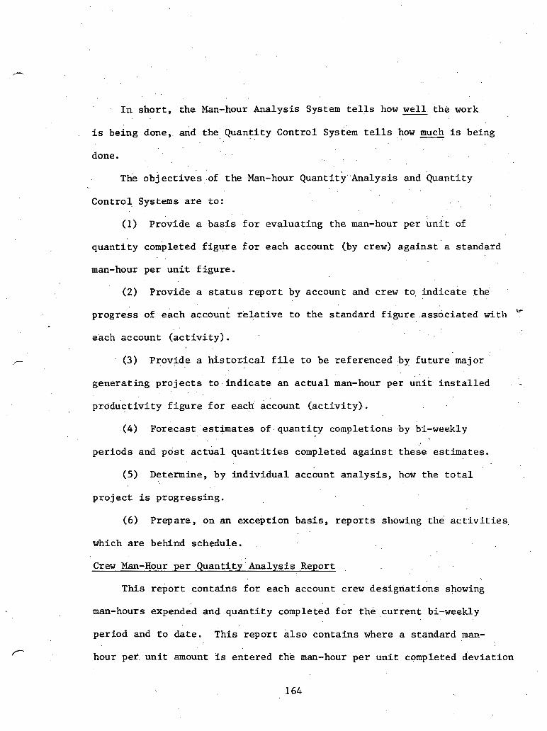
' . I n s h o r t , the Man-hour Analysis System te l l s how wel l t h e work
i s being done,. &d the, Quanti ty . . Control system te l l s how much i s being
done. . .
The o b j ~ c t i v e s o f t h e Man-hour ~ u a n t i t y ~ n a l ~ s i s . and Quantity
Control Systems a r e to :
(1) Provide a b a s i s f o r evaluat ing the man-hour per u n i t of
quan t i ty completed f i g u r e f o r each account (by crew) a g a i n s t a standard
man-hour per u n i t f igure .
(2) Provide a s t a t u s r e p o r t by account and crew to, i n d i c a t e t h e
tr progress of each account r e l a t i v e t o t h e standard f i g u r e .assdciated with
each account ( a c t i v i t y ) .
(3) Provide a histor . ica1 f i l e t o be referenced by f u t u r e major
generat ing p r o j e c t s t o i n d i c a t e an a c t u a l man-hour per u n i t i n s t a l l e d . . .
produc t iv i ty f i g u r e f o r each account ( a c t i v i t y ) .
(4) Forecast estimates of quant i ty c o ~ ~ ~ l r t i o ~ s by bi-weekly
per iods and p o s t a c t u a l q u a n t i t i e s completed a g a i n s t these est imates.
(5) Determine, by ind iv idua l account a n a l y s i s , how the t o t a l
p r o j e c t is progressing.
(6) Prepare, on an exception bas i s , r e p o r t s showing the a c t i v T t i e s
which are behind schedule.
C r e w Man-Hour per Quant i ty 'Analys is Report , .
This r e p o r t contains f o r each account crew des ignat ions showing
man-hours expended and q u a n t i t y completed f o r th& c u r r e n t bi-weekly
period and t o da te . This r epor t a l s o conta ins where a standard man-'
hour pef u n i t amount i s entered t h e man-hour per u n i t completed d e v i a t i o n
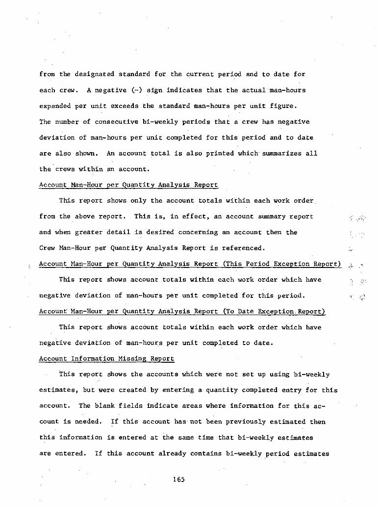
from the designated standard f o r t h e cur ren t period and t o d a t e f o r
each crew. A negative (.-) s ign i n d i c a t e s t h a t t h e a c t u a l man-hours
expended per u n i t exceeds t h e standard man-hours per u n i t f igure .
The number of consecutive bi-weekly per iods t h a t a crew has negative
devia t ion of man-hours per u n i t completed f o r t h i s period and t o d a t e
a r e a l s o shown. An account t o t a l i s a l s o p r in ted which summarizes a l l
t h e crews wi th in an account.
Account Man-Hour p e r Quanti ty Analysis Report
This r epor t shows only t h e account t o t a l s wi th in each work order
from the above repor t . This is, i n e f f e c t , an account summary r e p o r t 2.. i . Y .:, ( , '
and when g r e a t e r d e t a i l i s des i red concerning an account then the
C r e w Man-Hour per Quant it y Analysis Report i s referenced. I t > .
. Account Man-Hour per Quanti ty Analysis Report (This Period Exception Report) *:
T h i s r epor t shows account t o t a l s wi th in each work order which have I .- <!:. ,.,. . .
negatTve devia t ion of man-hours p e r . u n i t completed f o r t h i s period. :' ...-, .C1,
Account' Man-Hour per Quantity Analysis Report (To Date Exception.Report)
This r epor t shows account t o t a l s wi th in each work order which have
negative devia t ion of man-hours per u n i t completed t o date .
Account Information Missing Report
This r epor t shows t h e accounts which w e r e no t set up using bi-weekly
es t imates , but were crea ted by en te r ing a quan t i ty completed e n t r y f o r t h i s
account. The blank f i e l d s ind ica te aTeas where information f o r t h i s ac-
count is needed. I f t h i s account has not been previously est imated then
t h i s information is entered a t the same t i m e t h a t bi-weekly estimates
a r e entered. I f t h i s account a l ready contains bi-weekly period es t imates

t hen t h i s ' in£ ormation i s . en t e red s e p a r a t e l y .
Account Man-Hours Not Beported
This r e p o r t .shows crews with.in accounts (.By Work Order) t o which
q u a n t i t y w a s r e p o r t e d f o r t h e c u r r e n t bi-weekly per iod b u t no man-hours
expendedwere r epo r t ed f o r t h i s crew. A form may be used t o pos t man-
hours expended t o t h e s e crews. I f t h e man-hours were recorded t o t h e
wrong account-crew, then t h e s e man-hours must be s u b t r a c t e d ' o u t .of
t h i s account-crew and recorded t o t h e c o r r e c t account-crew. Th i s con-
d i t i o n -can a l s o e x i s t when man-hours a r e r e p o r t e d and q u a n t i t y is not
,* r epo r t ed f o r an ' accoun t . The same c o r r e c t i o n pr.ocedure a p p l i e s .
. . Act ive Account L i s t i n g Report
This r e p o r t shows t h e a c t i v e accounts (account w i t h unreported
q u a n t i t y e s t ima ted bi-weekly pe r iods ) t o which a c t u a l q u a n t i t y com- .
p l e t e d should b e r epo r t ed . It i s n e c e s s a r y . t o r e f e r t o t h e Man-Hour
Quant i ty Ana lys i s System f o r t h i s account t o determine t h e crew numbers
t o u se i n each account f o r r e p o r t i n g q u a n t i t y completed.
I n a c t i v e Account L i s t i n g Report
This r e p o r t shows accounts which do no t have any unrepor ted q u a n t i t y
e s t ima ted bi-weekly p e r i o d s remaining. These accounts may s t i l l b e a c t i v e
and completed q u a n t i t y ' m a y . b e r e p o r t e d a g a i n s t t h e s e accounts f o r t h e
c u r r e n t bi-weekly per iod b u t this a l s o inc ludes an e s t i m a t e f o r t h e
a d d i t i o n a l bi-weekly per iod . The r eason f o r t h i s account be ing on t h e
i n a c t i v e account list is shown b e s i d e each account .
Quant i ty by Bi-Weekly Per iod Report
Th i s r e p o r t shows f o r each account by bi-weekly pe r iod t h e q u a n t i t y . .

est imated and completed Cfor each period and t o date) along wi th t h e
devia t ion of the a c t u a l completed quan t i ty from t h e est imated quant i ty .
An a s t e r i s k w i l l i n d i c a t e t h a t t h e designated bi-weekly period has a
negative -quant i ty devia t ion f o r t h i s period o r . to date .
Quantity by Account To ta l Report
This report: shows the cur ren t s t a t u s of a l l accounts wi th in work
order regarding t h e ' t o d a t e a c t u a l completed quan t i ty vs . t h e est imated
t o d a t e quant i ty . Also shown i s the t o t a l est imated quan t i ty remaining
t o be completed and t h e number of est imated bi-weekly periods remaining.
This r epor t i s a summarization of t h e Quantity by Bi-Weekly Period Report.
Quantity by Bi-Weekly Period - (Exception Report)
This r e p o r t shows t h e accounts and accompanying bi-weekly pe r iods
f o r which a c t u a l quan t i ty completed f i g u r e s have been worked h t w h i c h . , ( . . I
do not contain an est imated quan t i ty amount.. It w i l l be necessary t o ;',
repor t an est imated quan t i ty f i g u r e t o the bi-weekly periods shown on
t h i s r epor t .
Quantity by Account Tota l - ( ~ e g a t i v e To Date Report)
This r e p o r t shows t h e accounts wi th a negative devia t ion (meaning
behind schedule) of the, t o d a t e quan t i ty completed aga ins t the est imated
quantity.. This r epor t w i l l show on a summary b a s i s t h e accounts which
a r e behind schedule and t h e Quantity By Bi-Weekly Period keport can show
, which bi-weekly periods were a c t u a l l y behind schedule.


INFORMATION MANAGMENT FOR NUCLEAR POWF,R STATIONS
APPENDIX B
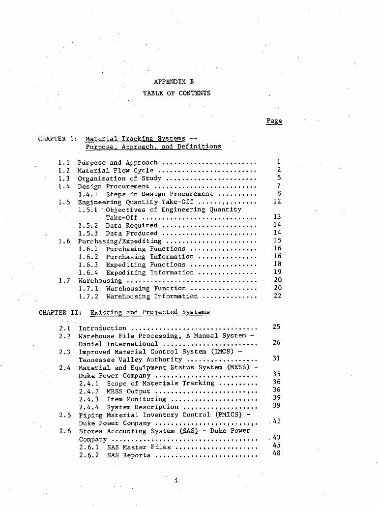
APPENDIX B
' . TABLE OF CONTENTS
Page
CHAPTER 1: M a t e r i a l Tracking Systems .. Purpose. Approach. and D e f i n i t i o n s
........................ 1.1 'Purpose and Approach 1 1.2 M a t e r i a l Flow Cycle ......................... 2 1.3 Organiza t ion of Study ....................... 5 1.4 Design Procurement .......................... 7
1.4.1 Steps i n ' ~ e s i ~ n Procurement .......... 8 1.5 Engineering Quant i ty Take-Off ............... 12
1.5.1 ' Objec t ives of Engineering Quant i ty ..
Take-Off ............................. 13 1.5.2 Data Required ........................ 1 4 1.5.3 Data Produced ........................ 14
1.6 Purchasing/Expedit ing ....................... 15 1.6.1 Purchasing Funct ions ................. 1 6 1.6.2 Purchasing Informat ion ............... 16 1.6.3 Expedit ing Funct ions ................. 18 1.6.4 Expedit ing Information ............... 19
1.7 Warehousing .................................. 20 1.7.1 Warehousing Funct ion ................. 20 1.7.2 Warehousing Informat ion .............. 22
CHAPTER I1 : Exi s t ing and P ro jec t ed Systems
2.1 I n t r o d u c t i o n ................................ 2.2 Warehouse F i l e Processing. A Manual System - ........................ Danie l I n t e r n a t i o n a l 2.3 Improved Mate r i a l Cont ro l System (IMCS) -
.... ............. ~ e n a e s s e e ' v a l l e y Author i ty ; 2.4 M a t e r i a l and Equipment S t a t u s System (MESS) - .......................... Duke Power Company .......... 2.4.1 Scope of M a t e r i a l s Tracking
2.4.2 MESS Output .......................... ...................... 2.4.3 Item Monitoring ................... 2.4,4 System Desc r ip t ion 2.5 Piping M a t e r i a l Inventory Cont ro l (PMICS) -
Duke Power Company .........*............(.l( . . 2.6 Sto res Accounting System (ShS) - Duke Power
.. ............... Company ....L..~............. 2.6.1 SAS Master F i l e s .....................
. . . 2.6.2 SAS Reports ..........................

2.7 Punch L i s t Program - .Georg ia . Power Company. . ;5 3 2.8 Quan t i t y ~ r a d k i n ~ system (QTS) - Bechtel
Power' Corpora t ion ' .......................... 5 6 2 . 9 M a t e r i a l Cont ro l Module - GPU Serv ices . . . . . 5 9 2.10 Material Management In£ ormation System
(MMIS) - ~ l b r i d a Power Corporat ion . . . . :;. . 60 2.10.1 System Development ...,.,.......... 60 2.10.2 MMIS Output ....................... 6 1
2.11 Material Management System (.HAMS) - Tennes- see Va l l ey Author i ty ...................... 67 2.11.1 ~ n g i n e e r i n g Subsystem ..,,......... 69 2.11.2 Procurement Subsystem ............. 7 2
' 2.11.3 Power S t o r e s Inventory Subsystem .. 76 .
2.'11.4 Accounts Payable Subsystem ........ 7 7 2.12 . Major P r o j e c t Management system (MPMS) - '
' ,
,Georgia power Company . . . . . . . . . . . . . . . . . . . . . 8 0 2.13 S t r u c t u r e of Numbering S y s t m s .......,..., .. 82
2.13.1 QTS ................................ 83 2.13.2 System i n U s e a t Vogt le Nuclear
Power P l a n t ....................... 84 2.13.3 MPMS ............................... 3 5 2.13.4 Punch L i s t ........................ 9 2
CHAPTER 111: Problems w i t h E x i s t i n a Systems
3 . 1 I n t r o d u c t i o n ............................... 95 3 . 2 Problems with Numbering Systems ..........,. 96 3.3 Problems wi th Input Required - Data Ac-
q u i s i t i o n ............................ 9 8 3.4 Problems wi th Output U s a b i l i t y - Timel iness
and Form of O/P' ............................ 9 9 3 .5 Problems wi th Implementation . . . . . . . . . . . . . . . 101 3.6 Problems of I n t e g r a t i o n Between. Systems .... 102 3 . 7 Problems Concerning O v e r - ~ e k i ~ n of System . . 103 3 .8 Organ iza t iona l Problems .................... 104
References ..................... ...................... 107
ADDENDA
Addendum A: App l i ca t ion Area Ou t l ines Quan t i t y Take-Off Purchasing/Exped j t i n g Warehousing
Addendum B: Support ing Material f o r M a t e r i a l and Equipment S t a t u s System (MESS)
Addendum C:: Supporting M a t e r i a l f o r P ip ing M a t e r i a l Inventory Cont ro l System (PMICS)

Addendum D: Support ing M a t e r i a l f o r S t o r e s . . ~ c c o u n t i n ~ System (SAS)
Addendum 'E: .Supporting M a t e r i a l f o r Punch L i s t ' Addendum F: suppor t i ng Material f o r M a t e r i a l
,Management Informat ion System Addendum G: Support ing M a t e r i a l f o r Numbering Systems
iii

T H I S PAGE WAS INTENTIONALLY
LEFT BLANK I ' .
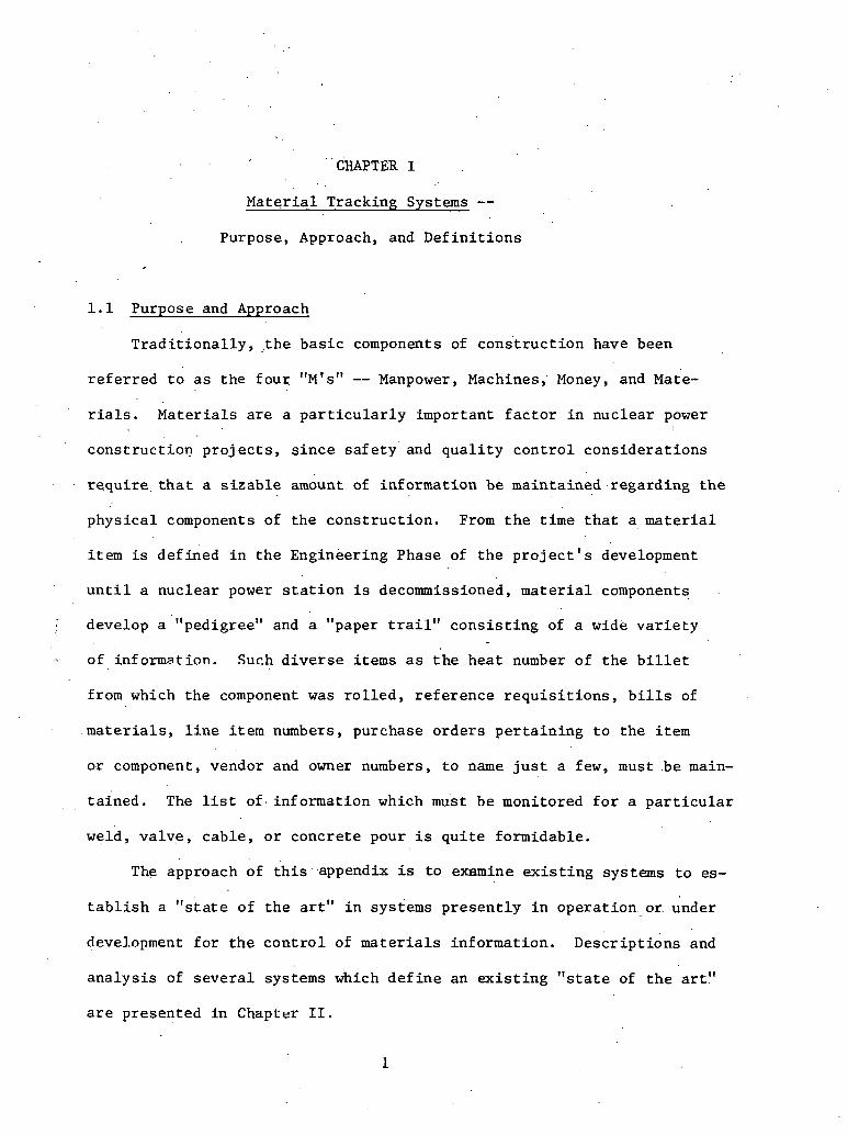
. . . . CHAPTER I
M a t e r i a l Tracking Systems --
Purpose, Approach, and D e f i n i t i o n s
1.1 Purpose and Approach
T r a d i t i o n a l l y , : the b a s i c components of c o n s t r u c t i on have been
r e f e r r e d t o a s t h e f o u r "M' s " -- Manpower, Machines,' Money, and Mate-
r i a l s . M a t e r i a l s a r e a p a r t i c u l a r l y important f a c t o r i n nuc lear power
cons t ruc t ion p r o j e c t s , s i n c e s a f e t y and q u a l i t y c o n t r o l cons ide ra t ions
r e q u i r e . t h a t a s i z a b l e amount of in format ion be ma in t a ined . r ega rd ing t h e
phys i ca l components of t h e cons t ruc t ion . From t h e t ime t h a t a m a t e r i a l
item is def ined i n t h e Engineering Phase of t h e p r o j e c t ' s development
u n t i l a nuc lea r power s t a t i o n i s decommissioned, m a t e r i a l components
: develop a "pedigree" and a "paper t rai l" c o n s i s t i n g of a wide v a r i e t y
',.. of informat ion . Such . . d i v e r s e i t e m s a s t h e h e a t number of t h e b i l l e t
from which the component was r o l l e d , r e f e r e n c e r e q u i s i t i o n s , b i l l s of
. m a t e r i a l s , l i n e i tem numbers, purchase o r d e r s p e r t a i n i n g t o t h e i tem
o r component, vendor and owner numbers, t o name j u s t a few, must .be main-
, t a ined . The l i s t of in format ion which must be monitored f o r a p a r t i c u l a r
weld, v a l v e , cab le , o r conc re t e pour i s q u i t e formidable.
The approach of t h i s appendix i s t o examine e x i s t i n g systems t o es-
t a b l i s h a " s t a t e of t h e a r t " i n systems p r e s e n t l y i n ope ra t ion o r under
deve1,opment f o r t h e c o n t r o l of m a t e r i a l s in format ion . Desc r ip t ions and
a n a l y s i s of s e v e r a l systems which d e f i n e an e x i s t i n g " s t a t e of t h e art! '
a r e presented i n Chapter 11.

1.2. M a t e r i a l Flow Cycle
I n o r d e r t o p rov ide a framework f o r t h i s s tudy , i t i s necessary t o
d e f i n e t h e l i f e c y c l e of ma te r i a l . i t ems which a r e t o be monitored and
c o n t r o l l e d . As ,noted , t h i s cyc l e begins when t h e i t e m o r m a t e r i a l compo-
nent i s inco rpora t ed i n t o t h e des ign by t h e eng inee r , and ends when e i t h e r
the,component ' is r ep laced o r t h e e n t i r e system is d e a c t i v a t e d . The periods
dur ing which t h e informat ion environment surrounding a component i s most
a c t i v e and dynamic a r e dur ing ' t he des ign , psocure~~lenL, c o n s t r u c t i o n , and
s t a r t - u p phases. During t h e s e p e r i o d s , t h e b a s i c component "pedigree"
i s e s t a b l i s h e d . Therefore , our i n v e s t i g a t i o n w i l l concen t r a t e on
t h e s e p e r i o d s of t ime. D i s c r e t e a c t i o n s which a f f e c t t h e informat ion
"weight1' a s s o c i a t e d wi th each m a t e r i a l i t e m a r e shown i n t h e f low diagram P.
of F igure 1.1. A s t h e i t e m t a k e s on 4 g r e a t e r l e v e l of d e t a i l , t he
d a t a con ten t a s s o c i a t e d w i t h i t i n c r e a s e s .
Four p a r t i a l l y overlapping a p p l i c a t i o n a r e a s a r e r equ i r ed and
' performed d u r i n g t h e component f l o w cycle shown in Figure 1 .1 . nl i r ing
t h e fo l lowing d i s c u s s i o n , t h e s e a p p l i c a t i o n a r e a s w i l l be r e f e r r e d t o
as :
(1 ) , Design Procurement'
(2 ) Engineer ingIQuant i ty Take-Off
(3) Purchas ing/Expedi t ing
(4) R e c e i v i n g / ~ a r e h o u s i n g
Addendum A c o n t a i n s abbrevia ted o u t l i n e s of t h e fo l lowing d e s c r i p t i o n s .
A c t i v i t i e s 1 t o 8 i n t h e f i g u r e a r e normally considered t o be wi th in
r . t h e Design Procurement f u n c t i o n as de f ined i n i t s broades t sense .

I 1. comvonent 12. component i s 3.Requisi t ion i s . 5.Purchasing re- 6.Purchase Order
I des ignated on a takenlof f drawing prepared, l i s t i n g a ) Engineer ques t s quota t ions drawinn. and l i s t e d on a M f u l l mater ia l spec from vendors. d i s t r i b u t e d .
I -
I I B i l l of Materials QC requirements. c ) Cost Engineer endor s e l ec t ed .
FIGURE 1.1: LIFE CYCLE OF A MATERIAL COMPONENT
I. -
* * 12.BOMispre- sen ted t o ware-
+house f o r i s s u e (FMR used). i a.
-)
9. QC inspec tor checks f o r con- f ormance, approveq; o r p laces "Hold.
&
)
7. Expedit ing t r acks de l i ve ry s t a t u s u n t i l i t em a r r i v e s .
18.Component ac- cepted by s t a r t - up, t r a v e l e r compl. & f i l e d .
&
+ * . 8 . Item a r r i v e s & warehouseman v e r i f i e s and records r ece ip t .
10. Receiving, Re- p o r t i s i s sued
find din t r i bu t ed .
11.Componentis s t o r ed - records e s t a b l i s h loca- t i o n .
17.Record of + i n s t a l l a t i o n re-
corded in,progrese r epo r t i ng system.
_) 15. Subcomponent i n s t a l l e d and +
1 3 . m o r BOM ~ s e d t o update
r 14. Engr. & QC approval f o r
system checkout, + t r a v e l e r signed.
16. Trave ler pu t on hold pending
t a l l a t i o n . +:nventory records (deduct) . -)ins
1

A c t i v i t i e s 2 and 3 p e r t a i n d i r e c t l y t o t h e Engineer.ing/Quantity Take-
Off a p p l i c a t i o n a r e a . Purchasing/Expedit ing i s performed t o procure
and move t h e m a t e r i a l i t e m s t o t h e c o n s t r u c t i o n s i t e ( a c t i v i t i e s . 5
through 8) . ~ e c e i v i n g /warehousing i s concerned wi th how t h e m a t e r i a l
is handled, s t o r e d , and i s sued a f t e r a r r i v i n g on t h e s i t e . Th i s appl ica-
t i o n area is descr ibed i n a c t i v i . t i e s 8 through 15. Ac t i . v i t i e s 15 through
1 8 p e r t a i n t o t h e m a t e r i a l i n t e r f a c e wi th o t h e r major f u n c t i o n s , t o in-
c lude Qua l i t y Cont ro l , F i e l d I n s t a l l a t i o n , and acceptance of t h e , i n -
s t a l l e d m a t e r i a l by t h e Start-Up team. . .
The a c t i v i t i e s shown i n F igu re 1.1 a r e o r i e n t e d ' in p a r t i c u l a r
t o t h e procurement of d i s c r e t e .components,, such as pumps, t ransformers ,
major spoo l s , e t c . , , .from a f a b r i c a t o r . a t a remote l o c a t i o n , which a r r i v e
ready , f o r i n s t a l l a t i o n . Bulk m a t e r i a l s which a r e used t o f a b r i c a t e
c o n s t r u c t i o n .components on - s i t e ( i . e . , used i n f i e l d f a b r i c a t i o n ) have
a s l i g h t l y d i f f e r e n t c y c l e , This i s ind ica t ed by t h e PMICS (Piping
M a t e r i a l Inventory Contrnl S y s t ~ m ) d e s c r i b ~ d i n Chaptcr 11. Typica l
of t h o s e i t e m s which a r e bulk procured t o suppor t f i e l d f a b r i c a t i o n
a r e s m a l l bo re (2% inch:d iameter and below) spool m a t e r i a l , s t r u c t u r a l
s t e e l f o r f i e l d - f a b hangers , cement, aggrega te , and c e r t a i n e l e c t r i c a l
cab le s . Engineering personnel e s t i m a t e q u a n t i t i e s of bulk.mater ia1-s
requ$red f o r f i e l d f ab r i ca t ed : i t e m s based on drawings. ~ e ~ u i s i t i o n s
a r e prepared , approved, and t h e m a t e r i a l s ard .procured. A s bu lk mate-
r i a l s a r e i s s u e d i n t h e f i e l d , a running account i s maintained i n d i c a t i n g
t h e amount i s s u e d a g a i n s t t h e o r i g i n a l quant i- ty rece ived . I f t h c l e v e l

of m a t e r i a l d rops below a r eo rde r p o i n t , engineering. is n o t i f i e d
and c o r r e c t i v e a c t i o n i s taken .
1 .3 Organiza t ion of Study
I n o rde r t o s tudy t h e problem of Ma te r i a l Tracking, each of t h e
f o u r ap;lication a r e a s descr ibed above w i l l .be examined i n d e t a i l .
F i r s t , each of t h e a r e a s w i l l be des ined i n a g e n e r a l format w i t h empha-
sis as fo l lows:
(1) Descr ip t ion
(2) Obj e c t i v e
(3) Implied Sub-Functions
(4) ' Data Required
(5) Data Generated - Reports t o Users
..". (6) Rela t f onship t o Other Funct ions
. . The emphasis . i n these d i s c u s s i o n s w i l l be t o e s t a b l i s h a base l i n e
o r r e f e r e n c e p o i n t a g a i n s t which e x i s t i n g and p ro j ec t ed systems can be
eva lua ted . These a p p l i c a t i o n a r e a d e f i n i t i o n s h i l l hopefu l ly provide
a frame of r e f e r e n c e i n terms of which t h e systems presented i n
Chapter I1 can be viewed. Ou t l ine d i s c u s s i o n s of each of t h e app . l i ca t ion
a r e a s suppor t ing t h e n a r r a t i v e d i s c u s s i o n of t h i s chap te r a r e presented
i n Addendum A. Given t h e g l o b a l d e s c r i p t i o n of t h e f u n c t i o n e s t a b l i s h e d
i n t h i s chap te r , .and t h e e x i s t i n g s t a t e of t h e a r t p resented i n Chap-
t e r 11, problems and s h o r t f a l l i nhe ren t i n t h e e x i s t i n g systems w i l l be
d iscussed i n Chapter 111.

¨ his chap te r w i l l cons ider t h e v a r i o u s ' i n t e r £ aces between t h e
M a t e r i a l Tracking System and o t h e r major systems such a's the. P r o j e c t
Cont ro l System, t h e P l a n t Performance Cont ro l Systeni, and t h e F i e l d .
, ~ e ~ o r t i n ~ / ~ d n t r o i System. The g e n e r a l r e l a t i o n s h i p between Mate r i a l
Tracking and o t h e r major systems i s shown i n .Figure 1 . 2 , It. can be
seen t h a t t h e informat ion conta ined i n t h e M a t e r i a l Tracking programs
f o r m p a r t of a s torehouse of information. This s torehouse , o r d a t a
base , is r e fe renced by p r o j e c t management, p l a n t performance c o n t r o l ,
and f i e l d c o n t r o l , which form t h e p r o j e c t cons t ruc ' t ion team. I n t h e
next f o u r , s e c t i o n s , t he f o u r f u n c t i o n s w i t h i n M a t e r i a l Tracking w i l l
b e i n g e n e r a l terms.
PROJECT MANAGEMENT
PEWORMANCE CONTROL
1 MATERIAL TRACKING
DATA SYSTEM
BASE FIELD
FIGURE 1 .2 : MAJOR SYSTEM RELATIONSHIPS
6

1.4 Design Procurement
During t h e des ign /cons t ruc t ion of a nuc lear power p l a n t , a number
of r e l a t i o n s h i p s have been developed. The f i v e b a s i c approaches a r e :
1n-house e f f o r t - T o t a l des lgn , procurement, and c o n s t r u c t i o n i s
c a r r i e d ou t by t h e u t i l i t y ' s personnel . Duke Power Company
works on t h i s b a s i s .
Turnkey . p r o j e c t -. T o t a l des ign , procurement, and c o n s t r u c t i o n by a n
engineer c o n s t r u c t o r a c t i n g as agent f o r t h e u t i l i t y . The
Vogtle p r o j e c t i s being b u i l t by Bechtel f o r t h e ~ e o k ~ i a Power
Company on t h i s b a s i s .
~n~ineer-architect/contractor - Design is c a r r i e d ou t by a n engineer
a r c h i t e c t engaged by t h e u t i l i t y and c o n s t r u c t i o n is completed
by a gene ra l c o n t r a c t o r a l s o engaged by t h e u t i l i t y . The Cal la -
. ' way p r o j e c t being b u i l t f o r Union E l e c t r i c i s designed by Bechte l
A' and i s being b u i l t by Danie l I n t e r n a t i o n a l .
1 - I n t h i s s i t u a t i o n t h e des ign
is c a r r i e d ' o u t by a n - e n g i n e e r a r c h i t e c t employed by t h e u t i l i t y
and cons t ruc t ion is c a r r i e d out by subcon t r ac to r s employed by
t h e u t i l i t y , wi th t h e . u t i l i t y a c t i n g as Cons t ruc t ion Manager.
The Hatch p r o j e c t is being cons t ruc t ed by t h e Georgia Power
Company based on a des ign by Bechtel wi th a number of major sub-
c o n t r a c t o r s a c t u a l l y c a r r y i n g ou t t h e cons t ruc t ion .
Owner des ign - The u t i l i t y c a r r i e s o u t t h e major des ign , a c t s a s a
Cons t ruc t ion ,Manager, and subcon t r ac t s o u t t h e a c t u a l c o n s t r u c t i o n .
The Diablo Canyon P r o j e c t was designed by P a c i f i c Gas and E l e c t r i c

with Guy F. Atkinson supplying . . grading and completing major
c i v i l work, Pullman Kellogg. . . cmple t%ng t h e power piping, Foley
ca r ry ing out t h e e l e c t r i c a l work, and a number of o the r minor
subcontrac tors doing o the r miscellaneous work.
This l is t does not encompass a l l r e l a t i o n s h i p s a s t h e r e a r e of course
addttiona.1 relationships which over lap . a t varying degrees.
During t h e design process , engineering personnel i n t e r a c t wi th
vendor designed . sys tens groups, in-house const ruct ion .advisors , c l i e n t .
p r o j e c t . personnel , . mater ia l advisors on m a t e r i a l a v a i l a b i l i t y , . procure-
ment personnel of the engineering f i rm o r of ' t h e c l i e n t purchasing
group, and other . groups f u l f i l l i n g v i t a l and responsible r o l e s .
Because of the var ious "rnodus operandi," it i s d i f f i c u l t t o desc r ibe
a s ing lk system without inadver ten t ly d e l e t i n g someone e l s e ' s con-
cept . But t h e r e a r e c e r t a i n bas ic p ieces of information t h a t mlia t
be accounted f o r i n some fashio11. They may go by a d i f f e r e n t name
o r they may be p a r t of another p iece of information. These "pieces"
flow i n genera l ly t h e same d i r e c t i o n bu t perhaps by d i f f e r e n t pa ths .
1.4.1 Steps in Design Procurement
The following d e s c r i p t i o n of the Design Procurement funct ion i s
intended t o descr ibe the p ieces of information required and their flow.
Not.only are t h e r e a number of func t iona l s t e p s which must be completed,
bu t i n many cases a number"of d i f f e r e n t organizat ions must be transcended,

The ensuing p o l i t i c a l c o n f l i c t s c r e a t e d o f t e n complicate m a t t e r s .
To a i d t h e r eade r , t h e flow c h a r t of F igure 1.3 has t h e same se-
quenced numbers a s t h e fo l lowing paragraphs and suppor t s t h e fo l lowing
d i scuss ion :
(1) Once a des ign and s p e c i f i c a t i o n s , a long wi th any p e r t i n e n t
d e s c r i p t i o n , a r e complete, i t is necessary t o cont inue t o develop
d a t a which completely d e s c r i b e s t h e i n q u i r y o r b id package t o
be s e n t o u t . The des ign and s p e c i f i c a t i o n s must be complete and a b l e
t o stand, on - t h e i r own a s r ega rds what i s going t o ' b e b u i l t . The
drawings a r e t h e main p a r t of t h e des ign .
(2) A ~ a k e - o f f and B i l l of M a t e r i a l s (B.O.M.) must be prepared.
The des ign engineer o r a group very c l o s e t o t h e des ign group w i l l u s u a l l y
make t h e take-off and prepare t h e B i l l of Ma te r i a l s . Sometimes, es-
. . p e c i a l l y with regard t o " c i v i l " type items, a B i l l of M a t e r i a l s - i s not
; necessary , s i n c e a l i s t of p a r t s and i t a s is no t p a r t of t h e des ign .
The take-off provides d e t a i l e d d a t a t o be shown i n a Proposa l Form o r
on p r i c i n g s h e e t s used by some companies. The l i s t i n g from t h e take-off
is a l s o used i n making a complete t a b u l a t i o n of a l l p r i c e s rece ived .
The R.O.M. could be used s i m i l a r l y i n developing a t a b u l a r format
t o compare a l l p r i d e s i n determining t h e s u c c e s s f u l . bidder . .
(3) An i n i t i a l meeting w i t h t h e Procurement p.er sonnel and engineer
i n charge o'f . coord ina t ing a l l a s p e c t s of t h e des ign i s .held. The time-
t a b l e f o r completing t h e i n q u i r y package, r e c e i v i n g b i d s and eva lua t ing
them, and then making the award, i s determined. This "Package Schedule"
is adhered t o a s c l o s e l y a s poss ib l e . A r e q u i s i t i o n number i s obta ined

-
esign & Specifications compl. I
.t & Bill of materials I
I
v Prepare cover letter Proposal Form, review gen. spec. & conditions provided by Proc. , pre- pare Instructions to Bidders, and complete requisition obtaining all Engineering approv- /als.
I
tractual terms
e Review Engr. package 1 for completeness, prepare
-
Recommendation made to Procurd- ment - Award made - Regrets sent out
all commercial aspects. Attach gen. spec. and conditions (provisions )
Engineering Function
,
Procurence Function a ~oint
I !Engr./Proc. Function
F I G U R E 1.3: INFORMATION FLOW, D E S I G N PROCUREMENT

. .
and t h e r e q u i s i t i o n process ing proceeds.
(4) Engineering must now l i s t a l l i tems , 'd rawings , and documents '
which w i l l make, up t h e engineer ing des ign package. An " I n s t r u c t i o n s -.
t o Bidders" i s prepared by Engineering t o ' f u l l y d e s c r i b e t h e bid process ,
t h e l o c a t i o n of t h e job , expected schedule of c o n s t r u c t i o n , f a b r i c a t i o n
o r d e l i v e r y , bidder r e s p o n s i b i l i t i e s and q u a l i f i c a t i o n s , coord ina t ing
eng inee r ' s name and te lephone number, and o t h e r p e r t i n e n t information.
(5) Procurement r'eviews the eng inee r ' s package f o r completeness,
cons ider ing what t h e b idder w i l l need t o b i d t h e job , and then p repa res
most o f ' t h e Proposa l Form, reviewing i t s development w i t h t h e des ign ' '
engineer . This commercial d a t a r e l a t e s t h e c o s t back t o des ign and w i l l
l a t e r be re ferenced on t h e purchase o rde r . Procurement a l s o develops
a s e t of General P rov i s ions (o r General S p e c i f i c a t i o n s ) f o r t h e job
and a t t a c h e s those t o t h e package. These s t a n d a r d s r e f e r e n c e p e r t i n e n t
bu i ld ing codes (ACI, AISC, e t c . ) , m a t e r i a l and performance s p e c i f i c a - '.'
t i o n s such a s ANSI, and ASTM paragraphs.
(6) The prepared m a t e r i a l w i t h a l l necessary approvals i s de-
l i v e r e d t o Procurement f o r conso l ida t ion of m a t e r i a l ( r educ t ion of
p r i n t s , e tc .) and mai l ing t o .b idders .
( 7 ) The i n q u i r y package i s s e n t out, by Procurement t o t h e
s e l e c t e d b idders . During t h e t ime per iod a l l o c a t e d f o r tfie p r e p a r a t i o n
of t h e b id , ques t ions r e l a t i n g t o t h e des ign are .answered by Engineering
and any o t h e r ques t ions a r e answered by Procurement..
(8) The b i d s a r e r ece ived , cop ie s made, and s e n t . t o Engineering
f o r eva lua t ion , tabulation, and recommendation f o r award.

(9) Engineering . rev iews t h e b i d s and i n c a s e s of ques t ions con-
t a c t s t h e b idde r f o r c l a r i f i c a t i o n . I f any changes t o t h e des ign a r e ,
f o r e s e e n a t t h i s p o i n t , c o s t p r o j e c t i o n s a r e made. A t a b d a t i o n is
made, a n d ~ n ~ i n e e r i n ~ Management de t e rmines t h e most v a l i d b id ' .
( u s u a 1 . l ~ t h e lowes t , . s ince a l l a r e p r e q u a l i f i e d ) and makes recommenda-
t ions t o Procurement,.
(10) Procurement a l s o reviews t h e b i d s from a bus ines s ,vk6wpoint
f o r any d i s c r e p a n c i e s and a d v i s e s Engineering of sa le : Any non-
compliance i s f u l l y reviewed and f u r t h e r in format ion is reques ted from
t h e b idde r , i f a p p r o p r i a t e .
(11) Award is announced and v e r b a l l y made t o t h e succes s fu l b idde r .
A t t h e same t ime, t h e unsuccess fu l b idde r s a r e contac ted and informed ,
of t h e award.
1 .5 Engineering Quant i ty Take-Off
The q u a n t i t y Take-Off a p p l i c a t i o n a r e a is considered by many t n
be t h e most impor tan t of a l l c o n s t r u c t i o n a c t i v i t i e s . Quant i ty Take-Of f
p rovides t h e b a s e informat ion i n t h e form of a m a t e r i a l l i s t o r B i l l of
M a t e r i a l f o r a c t i v i t i e s such a s procurement, e s t ima t ing , planning,
schedul ing , c o s t c o n t r o l , p rog res s r e p o r t i n g , warehousing, e t c . Quan-
t i t y Take-Off is t h e sys t ema t i c counting o r measuring of a s p e c i f i c
i t e m from a drawing o r s p e c i f i c a t i o n o r both, and t h e r eco rd ing of
t h e s e counts and measurements. A p a r t i c u l a r i t e m i s u s u a l l y c l a s s i f i e d
accord ing t o i ts c o s t code o r sometimes by s p e c i f i c a t i o n d i v i s i o n . The
B i l l of M a t e r i a l (B.O.M.) i s a n organized set of d a t a d e s c r i b i n g a
\ .
q u a n t i t y of m a t e r i a l by i t s . composition, by t h e assembly t o which
i t belongs, and by t h e end product of t h e assembly.
Quant i ty Take-Off .is performed by t h r e e groups throughout t h e
p r o j e c t ' s d u r a t i o n . They a r e : Primary Engineering,.Subcontractor En-
g inee r ing , and S i t e Engineering. Primary Engineering has t h e respon-
s i b i l i t y f o r Quanti ty Take-Off f o r major components. When subcon t r ac to r s
have f a b r i c a t e d i tems w i t h i n t h e i r c o n t r a c t , they must p repa re a B.O.M.
f o r t h e i r sub-components. A l l o t h e r items a r e t h e r e s p o n s i b i l i t y of
S i t e Engineering.
1.5.1 Objec t ives of I3ngineering Quant i ty Take-Of f
The f i r s t , a n d most important o b j e c t i v e of Quant i ty Take-Off is
t o supply an accu ra t e l i s t i n g of m a t e r i a l q u a n t i t i e s f o r complet ion of . .
t h e p r o j e c t w i t h i n t h e schedule. Within t h i s o b j e c t i v e , t h e primary . .
!. s t r e s s . is upoh accuracy and time o r schedule. 1 f q u a n t i t i e s are inac-
c u r a t e l y taken from t h e drawings and s p e c i f i c a t i o n s , t h e end r e s u l t
w i l l be d e l a y s i n c o n s t r u c t i o n a c t i v i t i e s and c o s t l y manhours c o r r e c t i n g
t h e take-off e r r o r . S ince Quan t i t y Take-Of f is a r a t h e r l eng thy a c t i v i t y ,
. c a r e f u l coo rd ina t ion must b e c a r r i e d ou t w i t h i n t h e planning and sched-
u l i n g s o t h a t , Quant i ty Take-Off proceeds on a t ime ly b a s i s w i t h i n
t h e schedule.
The second o b j e c t i v e of Quant i ty Take-Off i s t o . s e r v e as a su,pport
a c t i v i t y f o r o t h e r p r o j e c t a c t i v i t i e s . Quant i ty Take-Off in format ion
provides . t h e base f o r many o t h e r a c t i v i t i e s ' i n completing t h e p r o j e c t . The ill' of Ma te r i a l developed by Quant i ty ~ a k e - o f f should be u t i l i z e d
by a s many o t h e r p r o j e c t groups a s p o s s i b l e t o minimize t h e redundancy
of t ak ing o f f t he ' s ame m a t e r i a l s e v e r a l t imes. Thus i t i s important
' t h a t t h e format ' o f the ' B.O.M. be s t r u c t u r e d so t h a t a s maiy p r o j e c t
groups as p o s s i b l e can u s e i t , i . e . , p r e sen t ing t h e q u a n t i t i e s ac-
co rd ing , t o QA/QC. s t a t u s , c o s t code, schedule a c t i v i t y , e t c .
1.5.2 Data Required
, ' l n urder t o complete che Quaneiey Take-Off , ' d a t a is requ i r ed
from t h r e e g e n e r a l a r e a s . Quant i ty Take-Of f , f i r s t of all,, rre.cpxi.re.s
d e t a i l e d , up-to-date drawings and s p e c i f i c a t i o n s . . Any master i d e n t i f i c a -
t i o n lists. f o r p ip ing , equipment, e t c . must a l s o be a v a i l a b l e t o ensure
un i fo rmi ty of ' i d e n t i f i c a t i o n . Secondly, f o,r t h e purpose of s e t t i n g , . .
take-off p r i o r i t i e s . and coord ina t ion w i t h c o n s t r u c t i o n a c t i v i t i e s , a
r d e t a i l e d s t a t u s r e p o r t on p rev ious ly procured i t ems and' scheduled
a c t i v i t i e s in format ion is needed. Th i rd , c o s t account in format ion
f o r proper l i s t i n g of B.O.M. items and t h e i r a p p r o p r i a t e codes i s
e s s e n t i a l . .
1.5.3 Data Produced
The end r e s u l t of t h e Quant i ty Take-Off a c t i v i t i e s i s a group of
r eco rds , namely: the B i l l of M a t e r i a l s , r e q u i s i t i o n s , e x p e d i t e r e q u e s t s ,
, r e q u e s t s f o r c l a r i f i c a t i o n and info,rmation, .and bulk-ordered m a t e r i a l . .
r eco rds . The B i l l of M a t e r i a l , t h e most important r e s u l t , . was p rev ious ly
d i scussed . he r e q u i s , i t i o n t a k e s t h e Bill, of M a t e r i a l in£ ormation and
s u k a r i z e s it i n t o ' ba s i c m a t e r i a l groups normally suppl ied by a s p e c i f i c
vendor. The r e q u i s i t i o n i s used by Purchasfng f o r t h e i s s u i n g - o f pur-
chase o r d e r s and change o rde r s . I n some i n s t a n c e s , t h e o r i g i n a l take-off
person w i l l i s s u e e x p e d i t e r e q u e s t s t o t h e p a r t i c u l a r exped i t i ng
group handling m a t e r i a l f o r which he i s r e spons ib l e . A l o g is g e n e r a l l y
kept of t h e s e r e q u e s t s so t h a t s t a t u s can be monitored. The r eques t f o r
in£ ormation and c l a r i f i c a t i o n u s u a l l y a r i s e s i n t h e take-off s t a g e and
i s an e x c e l l e n t way t o record d e c i s i o n s made by Engineering o r o t h e r s
concerning c o n f l i c t . Ma te r i a l s t h a t a r e taken-of f and ordered wi th no
s p e c i f i c l i n e , system, e t c . assignment a r e recorded and monitored through
bulk inventory records .
' Reports i s sued by Quant i ty Take-Off g e n e r a l l y a r e i n t h e form of
s t a t u s r e p o r t s . ~ u a n t i t ~ Take-Off i s s u e s s t a t u s r e p o r t s f o r B .O.M. ' s * .
i s sued , r e q u i s i t i o n s i s sued , expedi t ing r e q u e s t s , r e q u e s t s f o r informa-
. t i o n , and b u l k m a t e r i a l s inventory . These r e p o r t s a r e e s s e n t i a l f o r
review by top management of t h e Quanti ty Take-Off f u n c t i o n so t h a t
q , t h e r e i s a n e f f e c t i v e i n t e r f a c e w i t h o t h e r groups.
I n t h e m a t e r i a l cyc l e ; Purchasing and Expedi t ing e s t a b l i s h two . .
a of t h e v i t a l l i n k s between Design Engineering and t h e a c t u a l c o n s t r u c t i o n
func t ions . - The Purchasing f u n c t i o n invo lvcs s e l e c t i o n of b idde r s , ob-
t a i n i n g and e v a l u a t i n g quo ta t ions , i s s u i n g purchase o r d e r s and change
orders , . and main ta in ing v a s t f i l e s on procurement, c o s t t r ends f o r
m a t e r i a l s and s e r v i c e s , and b idde r s . Expedi t ing t a k e s t h e r e s p o n s i b i l i t y
of i n s u r i n g t h e t ime ly d e l i v e r y of t ,hese m a t e r i a l s and s e r v i c e s .

1.6.1 Purchasing Funct ions
The . . Purchas ing f u n c t i o n s can be d iv ided i n t o f i v e broad ca t egor i e s :
(1) s e l e c t i o n of b idde r s , (2) . s o l i c i t i n g and process ing quo ta t ions ,
(3 ) i s s u i n g purchase o r d e r s and change o rde r s , (4) main ta in ing procure-
ment f i l e s , and (5) t r a n s f e r r i n g of Purchasing informat ion . S e l e c t i o n
and e v a l u a t i o n of p rospec t ive b idde r s may involve i n v e s t i g a t i n g a v a i l a b l e
s u p p l i e r s and c o n t r a c t o r s a s t o t h e i r r e p u t a t i o n , dependab i l i t y , f i n a n c i a l
c o n d i t i o n s , and any' o the r p e r t i n e n t " t r a c k record" informat ion t h a t
would he lp t o e s t a b l i s h t h e b i d d e r ' s qua l i f j . c a t ions . Equal ly important .
is the ma in t a in ing of a n up-to-date b idde r s ' 3.j.st f o r r e f e r e n c e through-
o u t t h e p r o j e c t . These l i s ts can a l s o be used on f u t u r e p r o j e c t s when
cond i t i ons permi t . Following t h e s e l e c t i o n of t h e b idde r s f o r a p a r t i c -
ular m a t e r i a l i t em o r s e r v i c e , q u o t a t i o n s a r e reques ted . ' Often quo ta t ions
' a r e no t submit ted i n a . t ime ly manner and must be exbedi ted i n o rde r t o
speed up t h e Purchasing f u n c t i o n . However, once a quo ta t ion i s r ece ived ,
i t is checked . for conformance w i t h t h e desigl i concept and a succes s fu l i
bidder is s e l e c t e d . A purchase o r d e r i s then i s s u e d f o r t h e m a t e r i a l
o r s e r v i c e t o t h e s e l e c t e d b idder . I f t h e q u o t a t i o n was f o r an ad-
d i t i o n o r d e l e t i o n t o an e x i s t i n g purchase o r d e r , a change o rde r i s
i ssued .
1 .6.2 Purchasing Information
The above a c t i v i t i e s g e n e r a t e a tremendous amount of in format ion C -.
Ehat must t hen be organized and maintained i n procurement f i l e s . Pe r i -
o d i c a l l y , problems a r i s e due t o d i s c r e p a n c i e s i n t h e purchase o r d e r s

and o t h e r f i l e s t h a t i n t e r f a c e wi th purchase o rde r s . However, i t i s
most important t h a t a l l procurement informat ion be kept a s a c c u r a t e as
p o s s i b l e t o prevent e r r o r s i n .purchasing and d e l i v e r y , These e r r o r s
.cou.ld b e c o s t l y i n c o n s t r u c t i o n t ime a s w e l l a s i n overhead expendi tures .
Through thg purchas ing process , in£ ormation on purchasing l ead t ime
t r ends , sho r t ages , o r va lue engineer ing may be genera ted . This informa-
t i o n should be passed a long t o t h e a p p r o p r i a t e management group. Lead
t ime. t r e n d s and sho r t ages may s e r i o u s l y a f f e c t t h e c o n s t r u c t i o n schedule,
and t h e r e f o r e f i e l d ' cons t ruc t ion management should be kept a b r e a s t of
such ma t t e r s . Value engineer ing informat ion may be genera ted ' from
b idde r s and should be s e n t through Design Engineering f o r eva lua t ion .
Purchasing i s heav i ly r e l a t e d t o o t h e r management f u n c t i o n s from
t h e t i m e of r e c e i p t of r e q u i s i t i o n th rough d e l i v e r y . I n i t i a l l y , manu-
. f a c t u r e r r e l e a s e d a t e s and job s i te d e l i v e r y d a t e s f o r a p a r t i c u l a r
it, m u s t be coord ina ted and e s t a b l i s h e d w i t h c o n s t r u c t i o n supe rv i s ion . .
and scheduling. Af t e r i n c l u s i o n i n t o t h e purchase o rde r o r change
o rde r , the.completed o r d e r may have t o r e c e i v e . f i n a 1 approval from
Design Engineering. The impor tance 'of t h e item w i l l d i c t a t e whether
o r ' n o t an i n t e r f a c e wi th Design Engineering i s necessary . Purchas ing ' s
r e l a t i o n s h i p wi th t h e M a t e r i a l Cost System i s t o r e l a y purchase o rde r I
and change o rde r commitment amounts a long wi th t h e a p p r o p r i a t e c o s t
coding. Purchasing must a l s o i n t e r f a c e "on o rde r information" wi th
Warehousing and M a t e r i a l Control . The i n t e r f ac ing of in format ion wi th
Cost Cont ro l and Warehousing is t h e important beginning - i n "quan t i t y
t racking" t h e l i f e of a p a r t i c u l a r i t em i n t h e s e .groups. Upon r e c e i p t
o f ' t h e i t e m , Warehousing must r e p o r t t o Purchasing, and, u n l e s s a
d i screpancy e x i s t s , t h e l i f e of t h e i t e m ends f o r t h e Purchasing
f u n c t i o n . Of cours.e, d i s c r e p a n c i e s between m a t e r i a l o r d e r and t h a t
which was r ece ived do o c c a s i o n a l l y occur . The c l u e h e r e i s t o fo l low
through on a l l i tems and make c e r t a i n a l l a r e reso lved . Often, t h e
d i s c r e p a n c i e s may be c r i t i c a l t o t h e u s e of t h e m a t e r i a l i tem.
'The above f u n c t i o n s and . t h e i r r e l a t i o n s h i p s w i t h o t h e r f u n c t i o n s
o u t s i d e of Purchasing can 'be summarized i n terms of d a t a r e q u i r e d and
d a t a generated ' . Data requi rements i nc lude manufac turers ' r e l e a s e
d a t e s and c o n s t r u c t i o n d e l i v e r y d a t e s , approved b idde r s ' l i s t , pur-
chase r e q u i s i t i o n s , and m a t e r i a l r e c e i v i n g r e p o r t s . Data generated . .
. .
w i t h i n t h e Purchasing f u n c t i o n inc ludes q u o t a t i o n eva lua t ions , purchase
o r d e r s , cha'nge o r d e r s , and procurement f i l e s .
The r e p o r t s genera ted by Purchasing p lay a n important r o l e i n
e f f e c t i v e l y c a r r y i n g ou t t h e v a r i o u s Purchasing f u n c t i o n s and t h e
i n t e r f a c i n g r e q u i r e d wi th o u t s i d e f u n c t i o n s .
1.6.3 Expedi t ing Funct ions
The Expedi t ing f u n c t i o n s invo lve two b a s i c a c t i v i t i e s . F i r s t ,
Expedi t ing must t a k e whatever a c t i o n i s necessary t o ensure t h e t imely
1
d e l i v e r y of materials and s e r e i c e s . The Expedit ing group u s u a l l y
r e c e i v e s a l ist of d e l i v e r i e s that a r e t o be expedi ted. This i s
. u s u a l l y done through phone c a l l s , l e t t e r s , o r d i r e c t pe r sona l c o n t a c t s .
The l ist , i n some i n s t a n c e s , is genera ted through a computer p r i n t o u t ,
showing purchase o r d e r s and t h e i r d e l i v e r y d a t e s . However, a manual r

"log" system may genera te t h e items t o be expedi ted. The second
f u n c t i o n i s t h a t which r eco rds t h e . r e s u l t s of Expedi t ing, o r updat ing
t h e c u r r e n t s t a t u s of m a t e r i a l l o c a t i o n s and expected d e l i v e r y d a t e s .
Th i s d a t a i s e i t h e r i n p u t i n t o t h e computer system o r recorded i n
t h e manual "log" bo0.k. The expected d e l i v e r y d a t e may r e p r e s e n t ' ,
' t he o r i g i n a l scheduled r e l e a s e d a t e o r d e l i v e r y date. , o r i t could
r e p r e s e n t a 'var ia t ion . . Both f u n c t f o n s a r e v i t a l s i n c e they keep
p r o j e c t management informed and i n c o n t r o l of a l l d e l i v e r i e s .
Through i ts two func t fods , Expedi t ing i s r e l a t e d t o o t h e r o u t s i d e . .
func t ions . Expedi t ing keeps Engineering, M a t e r i a l Cont ro l , and Sched-
u l ing ' i n fo rmed of c u r r e n t s t a t u s and r e v i s e d d e l i v e r y d a t e s of on-
o r d e r m a t e r i a l and s e r v i c e s . Also, t h e Expedi t ing group a i d s Ware-
housing and M a t e r i a l Cont ro l i n i d e n t i f y i n g shipments rece ived . . This
f u n c t i o n becomes e s p e c i a l l y important when Expedit ing has been informed . .
of a sho r t age , damage, o r o t h e r d i screpancy i n t h e d e l i v e r y .
1.6.4 Expedi t ing Inforinat ion
A s in Purchasing, Expedi t ing f u n c t i o n s have v a r i o u s d a t a r equ i r e -
ments and i n t u r n gene ra t e d a t a w i t h i n t h e func t ion . I n o r d e r t o i n s u r e
t imeiy d e l i v e r y and update on m a t e r i a l s t a t u s , Expedi t ing . needs such . .
in format ion a s (1) purchase o rde r s t a t u s r e p o r t s , and (2) r e p o r t of
warehouse r e c e i p t s . Then t h e Expedi t ing f u n c t i o n i s s u e s r e p o r t s on t h e
s t a t u s and l o c a t i o n of m a t e r i a l s and t h e i r expected d e l i v e r y d a t e s .
The generated informat ion may be compiled i n t o an Expedit ing Report
which summarizes t h e d a t a on a monthly o r q u a r t e r l y b a s i s .

The P u r c h a s h g and Expedi t ing f u n c t i o n s r evo lve around t h e purchase
order number. A l l r e p o r t i n g and corresponding a r e t i e d d i r e c t l y t o t h i s
number, and . i t becdmes t h e m a t e r i a l ' s " i d e n t i t y " wh i l e t r a v e l i n g through
Purchasing and ~ x p e d i t i n g . Therefore i t is important t h a t i t be des igned ,
t o con ta in as much d e ' s c r i p t i v e informat ion a s p o s s i b l e , and y e t n o t . b e so
l a r g e and complicated t h a t it becomes d i f f i c u l t t o u se . An i n d i v i d u a l
shouid be a b l e t o qu ick ly detcrmine t h e p r o j e c t number, s a f e t y r e l a t i o n ,
work c a t e g o r y ( c i v i l , mechanical, e t c . ) , and change order number from
t h e purchase o r d e r nuniber.
1.7 Warehousing
Warehousing' i n a l a r g e nuc lear power p l a n t c o n s t r u c t i o n p r o j e c t
i s a h i g h l y complex undertaking. It invo lves t h e r ece iv ing , i n spec t ing ,
s t o r i n g , accoui l t ing o f , and d i s b u r s i n g of owner and c o n t r a c t o r m a t e r i a l s .
The r e c e i v i n g r e c o r d s which a r e developed and mai.nt.ai ned become p a r t
o f t he permanent p l a n t r eco rds . Poss ib ly , a t some f u t u r e , t ime, i t may ,
become neces sa ry to. de te rmine t h e d e t a i l s surrounding t h e r e c e i p t of
a p a r t i c u l a r i t e m .
1 .7 .1 Warehousing Funct ion
The warehousing s e c t i o n of t h e c o n s t r u c t i o n p r o j e c t must r e c e i v e
a l l incoming goods. Warehousing must have s u f f i c i e n t manpower, eqii ip -
ment, and space t o qu ick ly and e f f i c i e n t l y p roces s t h e a r r i v i n g ship-
ments, which must be checked f o r c o r r e c t q u a n t i t y and type of m a t e r i a l .
While Warehousing de termines t h e type of m a t e r i a l i n gene ra l terms, t h e
2 0

exac t conformance o r non-conformance i s determined by Qua l i t y Cont ro l /
Qua l i t y Assurance,
Af t e r i t has been e s t a b l i s h e d t h a t t h e c o r r e c t t y p e and q u a n t i t y
of m a t e r i a l has been r ece ived , it i s necessary t o mark each i n d i v i d u a l
p i e c e t o a l l o w easy i d e n t i f i c a ' t i o n . The m a t e r i a l s must then be s t o r e d
s o t h a t they can be e a s i l y found and i d e n t i f i e d , bu t a l s o i n compliance
wi th t h e a p p r d p r i a t e ANSI s p e c i f i c a t i o n . ( i . e . , temperature, humidity,
d u s t , . . e t c . ) .
Having rece ived and s t o r e d t h e m a t e r i a l s , Warehousing must be
a b l e t o i s s u e t h e m a t e r i a l s i n response f o f i e l d m a t e r i a l r eques t s .
They m u s t ' i s s u e t h e c o r r e c t ma t , e r i a l s and i n s u r e t h a t t h e person r e -
ce iv ing them has t h e app ropr i a t e a u t h o r i t y t o do so. I n a d d i t i o n t o
m a t e r i a l s and equipment, Warehousing must a l s o be a b l e t o t r a c k a l l
t o o l s necessary f o r t h e c o n s t r u c t i o n ~ p r o c e s s .
I n o rde r t o e f f i c i e n t l y c a r r y o u t t h e primary t a s k s ass igned t o
i t , Warehousing must develop a number of i n t e r n a l systems and procedures .
Secu r i ty must be main:tained t o a s u f f i c i e n t degree t o minimize t h e f t
and b i l f e r a g e . ~ a t e r i a l s ' c h e c k e d i n t o t h e system must s t i l l be t h e r e
when r equ i r ed . A s t o c k coding system must be developed and main ta ined .
A l l outbound shipments must be prepared f o r t r a n s p o r t a t i o n . Where
necessary f o r s p e c i f i c m a t & ia l , s , a minimum/maximum s t o c k system must
be developed and ma'intained. ' A l l of t h e s e procedures a r e necessary t o
h e l p i n s u r e t h a t t h e c o r r e c t m a t e r i a l s a r e a v a i l a b l e when they a r e
r equ i r ed .
I n achieving its ob jec t ives , Warehousing i n t e r f a c e s with many
o the r a reas . Close coordinat ion i s r e i u i r e d wi th Quali ty Assurance
and Qua15ty Control i n ord.er t o i s o l a t e non-conforming items a s 'soon . .
a s poss ib le . The - p r o j e c t Management team must be in£ o h e d o f . a r r i v a l s
of , m a t e r i a l s o t h a t s h o r t ' t e r m crew assignments c a n ' b e worked out a s
e f f i c i e n t l y i s possible." planning and scheduling should be kept in- # .
formed of the. a r r i v a l s t a t u s of important items so t h a t t h e i r 'updated ' .
schedules w i l l be a s a c c u r a t e a s poss ib le . Information should .be
a v a i l a b l e ' a s requested by Accounting t o maintain a smooth f low of
vendor payments. ANSI s to rage l e v e l i s determined by t h e Design/Procure-
ment department and must be maintained by Warehousing. Insuring. the cor-
r e c t types and q u a n t i t i e s of a r r i v i n g m a t e r i a l s r e q u i r e s c l o s e coordina-
t i o n wi th .Purchas ing and Expediting. Proper d i s t r i b u t i o n of rece iv ing
r e p o r t s and pa,cking s l i p s w i l l be insured by workiag wi th Document
Control. The ~ ~ t a Base ' funct ion se rves as a central . reference point
f o r a l l p a r t i c i p a n t s and must t h e r e f o r e be informed of t h e l a t e s t
changes i n m a t e r i a l s t a t u s .
1.7.2 warehousing Information
I n order f o r Warehousing t o , perform . i t s func t ions adequately,
c e r t a i n d a t a inpu t s a r e requi red . Of primary importance a r e t h e quanti-
t ies and types of equipment a r r i v i n g , and the l eng th of t i m e befbre
. t h e i r incorpora t ion wi th in t h e p r o j e c t . This information must be
suppl ied i n order t h a t su f ' f i c i en t space and manpower can be a l loca ted .
I n add i t ion , the.ANS1 s to rage l e v e l must be determined t o insure the con- P
s t r u c t i o n of t h e c o r r e c t type of s to rage f a c i l i t i e s .

. I
The input d a t a i s c o r r e l a t e d wi th t h e a c t i v i t i e s occurr ing .wi th in
Warehousing, and s e v e r a l p i eces of in format ion are generated and recorded:
q u a n t i t i e s and l o c a t i o n of i t ems w i t h i n t h e warehouse system; q u a n t i t y of
.items a r r i v i n g ; . q u a n t i t i e s of i t e m s i s sued ; d a t e of - a r r i v a l ; d a t e of
i s sue ; and t o whom i tems a r e i ssued . This , and o t h e r , in format ion ' i s
assembled and i ssued i n t h e form of construc$ion equipment inventory
r eco rds , s t o c k on hand r e p o r t s , s t o c k c a t a l o g s , s m a l l - t o o l s inventory
s t a t u s r e p o r t s , e t c .

. .
, .
THIS PAGE. WAS INTENTIONALLY
LEFT BLANK

.CHAPTER I1
Exi s t ing ' and :Pro jec ted Systems
2.1" ' I n t r o d u c t i o n I
Approximately 60 nuc lear s t a t i o n s a r e p r e s e n t l y l i censed t o
ope ra t e w i th in t h e U.S. ~ u i t e obviously a v a r i e t y of systems have I
been developed t o cope w i t h t h e need t o procure and i n s t a l l m a t e r i a l s .
w i t h i n t h e context of t h e a p p l i c a t i o n a r e a s presented i n , C h a p t e r I, . .
some f u n c t i o n s a r e supported by s o p h i s t i c a t e d and t e s t e d computerized
systems. 1n . o t h e r instances ' , v i a b l e and e f f i c i e n t manual' systems have . .
. been developed which s a t i s f a c t o r i l y meet t h e needs of management. I n
some cases , vo ids e x i s t and. procedures a r e n o t w e l l documented. I n . .
such cases , . in format ion i s passed by word of mouth and is no t docu-
mented 'or r e t r i e v a b l e . Th i s s i t u a t i o n l e a d s t o a c e r t a i n "muddling
through" i n which p ro jec t and system s t a t u s is unc lea r and management
must..work i n t u i t i v e l y , o f t e n a t g r e a t c o s t and w i t h cons ide rab le
l o s s of p roduc t iv i ty . This l a c k of c lear -cu t in format ion t r a n s f e r
l e a d s t o de lays .
I n t h i s chap te r , a n overview of e x i s t i n g o r planned systems is pre-
sen ted . ~ l t h o u ~ h th is ' . p r e s e n t a t i o n could not poss ib ly be comprehensive,
t h e systems and procedures descr ibed r ep resen t a f a i r c ros s - sec t ion of
i ndus t ry th ink ing regard ing t h e b e s t means of c o n t r o l l i n g and t r a c k i n g
m a t e r i a l s . Information regard ing t h e s e systems has been developed
during t r i p s and in t e rv i ews wi th u t i l i t i e s throughout t h e Eas t e rn U.S.
and u t i l i z i n g publ ished m a t e r i a l s r ega rd ing systems i n t h e U.S. and Canada..
Some of t h e systems presented a r e th.emselves i n t h e des ign s t a g e .
and have n o t been implemented on an a c t u a l nuc lea r job. For t hose
systems which a r e o p e r a t i o n a l , an a t tempt has been made t o d e s c r i b e
systems "hich appear to' be s u c c e s s f u l and respons ive t o t h e needs of .
:management' w i t h i n t h e u t i l i t y , ' a t t h e d e s i g n e r ' s of f i c e , and i n . t h e . . '
. . .
c o n s t r u c t o r ' s . f i , e l d o rgan iza t ion .
2 . 2 Warehouse F i l e Process ing , a Manual System - Daniel I n t e r n a t i o n a l
~ a t 6 r i a . l p;ocessing i s n o t always c a r r i e d out on a computer.
A manual system used by companies s6ch as Danie l Cons t ruc t ion Company
i n a g e n e r a l con t r ac to r - cons t ruc t ion management-owner r e l a t i o n s h i p i s
desc r ibed i n t h i s s e c t i o n . A manual system r e q u i r e s t h e e x i s t e n c e of
f o u r m a i n t y p e s of f i l e s : . - (1) A purchase o r d e r f i l e arranged by i s s u i n g f.irm, purchase
order number, and m a t e r i a l c o n t r o l r e p o r t s ;
(2) ' Stock record, c a r d f i l e s arranged by i tem c l a s s , s u b c l a s s ,
and i tem number.;
(3) Pu rchase .o rde r f i l e s arranged by vendor; and
( 4 ) ~ o l l o w - u p f i l e on maintenance and in spec t ion .
I n i t i a l p r e p a r a t i o n of t h e warehouse f i l e s is as i l l u s t r a t e d i n
F igu re 2.1. D i s c i p l i n e eng inee r s w i t h i n t h e prime c o n t r a c t o r ' s organiza-
t i o n p repa re m a t e r i a l c o n t r o l r e p o r t s and r e q u i s i t i o n s . The m a t e r i a l
c o n t r o l r e p o r t s a r e rece ived by t h e m a t e r i a l c o n t r o l s e c t i o n and a r e
used t o p repa re in-s torage .main tenance and i n s p e c t i o n f i l e ca rds .
Before be ing f i l e d i n (:I) and (3) (.see above) , r e q u i s i t i o n s a r e f i r s t
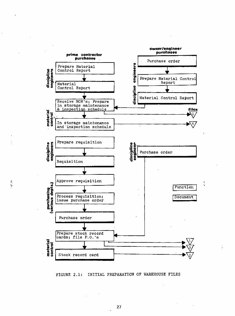
r ...-. -. --...."I.".
pumhases
purchases
prepare Mate r ia l l! f E Control Report
0 ' 0 .- 0 c .-
Sf P 0" .2 P Mater ia l
fi Control Report 0 C .-
I - - Y ,I
g. Mater ia l Control Report
. I n s t o r age maintenance and ' inspec t ion schedule
'E 1 Prepare r e q u i s i t i o n 0 L .- - Pas 8.g' %-' Requis i t ion
I
c. ( ~ p p r o v e r e q u i s i t i o n 1
Process r e q u i s i t i o n ;
Purchase o rder
I J
1 Document 1
* Prepare s t ock record ca rds ; f i l e P.O.'s * Stock record card b g
FIGURE 2.1: INITIAL PREPARATION OF WAREHOUSE FILES
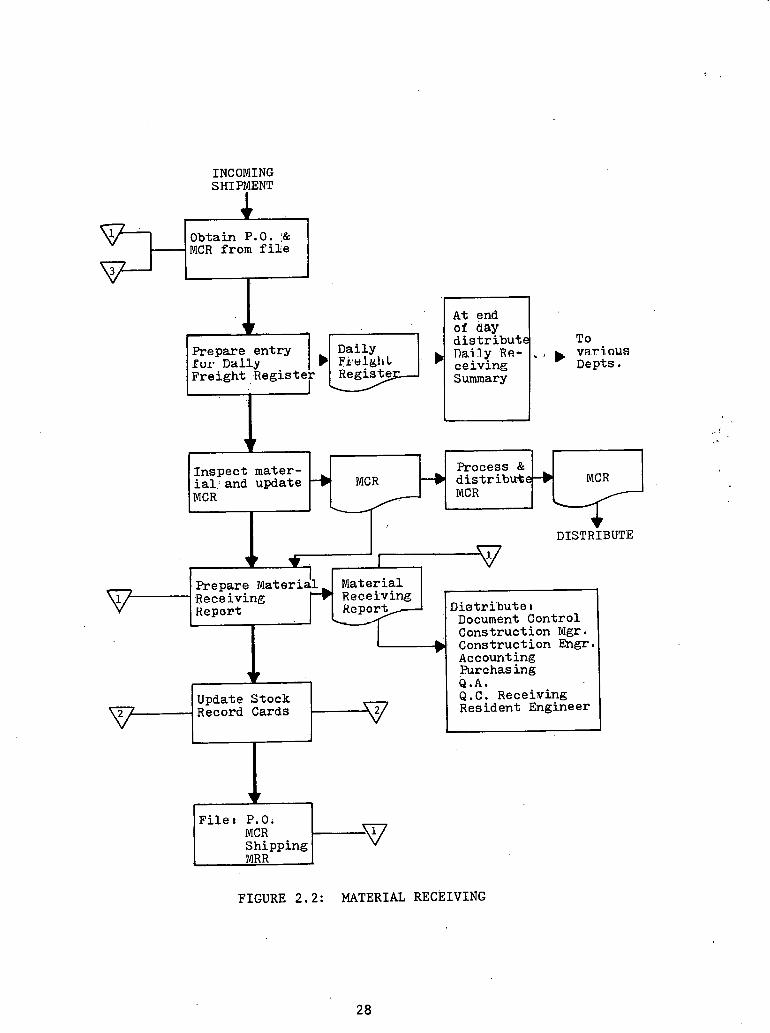
INCOMING SHIPMENT
Obtain P.O. :& MCR from file
I
Prepare entry Pur D a l l y Freight Register
Daily T 0 var i-nus Depts .
-I
Inspect mater- Process & ial: and update -) MCR --)I distribuke-, MCR MCR MCR
DISTRIBUTE
w I I I 1 Prepare ~ateriil Material Receiving 4 Rece?ving - Heport Diatri'buta I
Document Control
I Construction Mgr. h Construction Engr. -
Accounting hrchas ing Q.A.
Update Stock Q.C. Receiving Record Cards Resident Engineer
Filer P.0;
Shipping
FIGURE 2.2 : MATERIAL RECEIVING

paterial Issue: FIGURE 2 . 3
I Material I Requisition.
I Annotate - 1 Card I
FRM
I
.
Refile Stock Record 4

. Legend : FIGURE 2 . b . . .
UE Union Electr ic
S&P . Sverdrup and P a r c e l
m Purchase Order F i l e s by i s s u i n g f i r m , P.O.#'s and MCR' s (Material e 0 n t r O l r e p o r t s )
Stock Record Card F i l e s by i t e m c lass /Su,bclass / i t e m #
Purchase Orders by vendor I
v Follow-up f i l e (maintenance & i n s p e c t i o n )
Funct ion
Document

routed through v a r i o u s departments f o r approval and t o Purchasing f o r
p repa ra t ion of t h e purchase o rde r and s t o c k r eco rd c a r d s , a f t e r which
e n t r i e s f o r f i ' l es ( I ) , ( 2 ) , and (3) are prepared. The owner/engineer
performs s i m i l a r func t ions f o r t h e i r purchase of t h e major p i e c e s of
equipment.
The m a t e r i a l r e c e i v i n g sequence is i l l u s t r a t e d i n F igu re 2 . 2 .
Purchase o r d e r s and m a t e r i a l c o n t r o l r e p o r t s a r e both drawn f o r each
incoming shipment. The d a i l y f r e i g h t r e g i s t e r i s annota ted and mate-
r i a l s a r e inspec ted f o r compliance w i t h t h e m a t e r i a l c o n t r o l r e p o r t .
A m a t e r i a l r ece iv ing r e p o r t i s prepared and f i l e d o r d i s t r i b u t e d t o
t h e a p p r o p r i a t e departments. Stock record c a r d s a r e updated and re-
f i l e d . F i n a l l y , t h e purchase o rde r , m a t e r i a l c o n t r o l r e p o r t , shipping
t i c k e t , and m a t e r i a l r e c e i v i n g r e p o r t a r e p rope r ly f i l e d , k j
The m a t e r i a l i s s u i n g c y c l e begins w i t h a f i e l d m a t e r i a l r e q u i s i t i o n
presented t o t h e warehouse. The i tems a r e obta ined , t h e f i e l d m a t e r i a l
r e q u i s i t i o n annota ted , t h e s t o c k record card updated and r e f i l e d . Only
then is t h e m a t e r i a l i s s u e d . and t h e f i e l d material r e q u i s i t i o n f i l e d .
2 . 3 lrnproved ~ a t e r i s l ' con t ro l System (IMCS) - Tennessee Val ley Author i ty
The ,IMCS (Improved M a t e r i a l Cont ro l System) i s t h e f i r s t s t a g e i n
computerizing m a t e r i a l t r ack ing f o r t h e Tennessee Valley Author i ty .
Eventua l ly i t w i l l be modified and incorpora ted i n t h e Mate r i a l Management
System program. A s i t i s now cons t ruc t ed , IMCS computerizes many of t h e
func t ions performed manually.

Material Cont ro l , as de f ined f o r IMCS, c o n s i s t s of t h e fol lowing
seven f u n c t i o n s wi th a s s o c i a t e d o rgan iza t ions :
(1) The i d e n t i f i c a t i o n of d .e l iverable l i n e i tems and t h e co l l ec -
t i o n , c o n s o l i d a t i o n , s t o r a g e , and maintenance of in format ion necessary
t o c o n t r o l and provide r e l e v a n t management informat ion concerning t h e
m a t e r i a l du r ing i t s procurement and d e l i v e r y r.yc1.e~. Expedi t ing and
M a t e r i a l Con t ro l , P r o j e c t Cont ro l , and Engineering would be coordinated
a t t h i s po in t .
(2 ) The i d e n t i f i c a t i o n , s t o r a g e , formal r e c e i p t , pos t ing of
l edge r s , p r i c i n g , and accounting summarization of ' d e l i v e r e d ma te r i a l s . ' ,
Receiving and i s s u e warehouses, P r o j e c t Se rv i ces , and 1nspec.tion' En-
g i n e e r i n g would be a s s o c i a t e d wi th t h i s func t ion .
( 3 ) Determining t h e a v a i l a b i l i t y of permanent m a t e r i a l f o r a
' c o n s t r u c t i o n a c t i v i t y , t h e i d e n t i f i c a t i o n of s u b s t i t u t e s where needed
and p o s s i b l e , and r e s e r v i n g permanent m a t e r i a l f o r approved a c t i v i t i e s
t o a s s u r e a v a i l a b i l i t y . ~ o o r d i n a t t o n wi th Engineering, i s s u e warehouses,
and P r o j e c t Con t ro l would be needed a t t h i s p o i n t .
(4) I d e n t i f y i n g and l o c a t i n g m a t e r i a l s approved f o r i s s u e . I s s u e
warehouses a r e coord ina ted a t t h i s s t e p .
(.5) Pos t ing i s s u e s t o l e d g e r s , p r i c i n g , a s s ign ing permanent p l a n t
account numbers t o i s s u e s , and summarizing i s s u e s . Coordinat ion wi th
i s s u e warehouses and P r o j e c t Services , is r equ i r ed ,
(6) C o l l e c t i n g , conso l ida t ing , and process ing informat ion f o r
c o n t r o l l i n g . . and provid ing management informat ion about i s sued permanent
m a t e r i a l . Engineering and i s s u e warehouses a r e r equ i r ed here .

(7) , P o l i c i n g and c o n t r o l l i n g i s sued and approved f o r i s s u e per-
manent m a t e r i a l s . This l a s t f u n c t i o n must be coordinated w i t h Engineering.
There w i l l be a g r e a t many advantages i n implementing t h e IMCS
system. It w i l l p rovide up-to-date informat ion from a s i n g l e source
on t h e s t a t u s and a v a i l a b i l i t y of m a t e r i a l t o a l l o rgan iza t ions on s i t e . , .
This w i l l permit t h e engineers t o r e s e r v e permanent m a t e r i a l f o r s p e c i f i c
a c t i v i t i e s . Redundant card systems w i l l be e l imina ted wi th an automated
ledger system e l imina t ing t h e use of l edge r ca rds . The need f o r p u l l i n g
and sea rch ing c0ntra.c.t f o l d e r s t o i d e n t i f y m a t e r i a l a t t h e t ime of r e c e i p t
and formal process ing w i l l b e e l imina ted . Receiving documents w i l l be
prepared by computer and m a t e r i a l w i l l . b e p r i ced a t . t he t ime of r e c e i p t .
Thus r e c e i p t p r o c e s s i n g . w i l 1 be speeded up and w i l l enable t h e u s e of
more d i scoun t s . Computer r e t r i e v a l of s t o r a g e l o c a t i o n informat ion
w i l l be provided. Readi ly a c c e s s i b l e r eco rds of i s sued permanent mare-
r i a l w i l l be mafntained; p a r t i c u l a r l y what m a t e r i a l was i ssued t o whom
f o r what purpose and when. On s e l e c t e d i tems, s p e c i f i c t r a c k i n g a f t e r
warehouse i s s u e i s p o s s i b l e . It w i l l have t h e c a p a b i l i t y a t t h e p o i n t
of r ece iv ing and warehousing t o explode a l i n e item i n t o i t s i n d i v i d u a l
components. Th i s is p a r t i c u l a r l y important i n t r a c k i n g c o n s t r u c t i o n
s t a t u s ' a f t e r issuance. The explos ion d e c i s i o n i s made by F'ield Engin-
ee r ing . IMCS w i l l a l s o have t h e a b i l i t y t o accept and t r a c k s p a r e p a r t s
and t o t r a c k m a t e r i a l f o r o ther p l a n t s .
.The fo1,lowing example i l l u s t r a t e s t h e s i m p l i c i t y which is i n t r o -
duced by us ing IMCS. The lef t -hand column shows t h e S teps i n s t o r i n g . .-- m a t e r i a l a s performed by hand, and t h e right-hand column shows t h e s t e p s

as c a r r i e d ou t by IMCS.
STORAGE OF. MATERIAL-
MANUAL . . IMCS '.
1. Obtain a c q u i s i t i o n document f i l e .
2. ..' Obtain packing s l i p when availab1.e.
3 . Check shipment f o r overages, :
sho r t ages , o r damages.
-- Overages a r e determined from t h e a c q u i s i t i o n document.
--' Shor tages are determined from shipment packing s l i p .
-- Dalnages a r e determined from i n s p e c t i o n .
1. Check shipment f o r overages, shor tages , o r damages.
4 . Perform a l l r equ i r ed engineer ing i n s p e c t i o n s .
-- I n s p e c t i on , requi rement found i n a c q u i s i t i o n f i l e .
-- Overages a r e determined from . the worksheet.
-- Shortages a r e determfned from shipment packing s l i p .
-- Damages a r e determined from inspertinn.
Perform a l l r equ i r ed engineer in i n spec t ions .
-- In spec t ion code on worksheet
Determine s t o r a g e l o c a t i o n .
-- Previous s t o r a g e l o c a t i o n s on worksheet.
-- S p e c i a l s t o r a g e requirement$ a r e found on worksheet.
5 . Determine s t o r a g e l o c a t i o n . 4. . S t o r e and t a g m a t e r i a l .
-- Ava i l ab le on l edge r card . 5. Record r e c e i v i n g i n £ ormat ion . -- Ava i l ab le on p rev ious ly
completed r e c e i v i n g r e p o r t s . 6. Input recorded informat ion -- Spec fa l s t o r a g e requirements (computer p r i c e s and type r e -
' a r e found i n a c q u i s i t l o n f i l e . c e iv ing r e p o r t s and t r ansmi t t a : l e t t e r s ) .
6. S t o r e and t a g m a t e r i a l . . .
7. Hand p repa re r e c e i v i n g r e p o r t .
. -- Copy informat ion from a c q u i s i - t i o n document.
---Record r e c e i v i n g informat ion .
8. P r i c e r e c e i v i n g r e p o r t s .
9. Type r e c e i v i n g r e p o r t s .

2.4 M a t e r i a l and Equipment S t a t u s System (MESS) - Duke Power Company
I n o rde r t o c o l l e c t , s o r t , and p r i n t a l l of t h e informat ion
from concept t'hrough des ign , manufacture, sh ipping , and r ece iv ing
a c t i v i t i e s , . t h e .Mater ia l and Equipment S t a t u s System has been developed
by Duke Power. The object ' ives of t h e program.are a s ' fo l lows:
( I ) , Consol ida t ion of a l l in format ion i n t o a s tandard form f o r u s e
by a l l departments and M i l l Power* t o improve communication and accounta-
b i l i t y .
(2) El imina t ion of ex t raneous departmental l ists and correspondence
by providing 2 c e n t r a l . f i l e f o r main ta in ing a r eco rd of t h e s t a t u s of
m a t e r i a l and equipment.
(3 ) Access t o t h e c e n t r a l f i l e from remote l o c a t i o n s ( y i a CRT
o r t e l e t y p e ) .
( 4 ) Objec t ive eva lua t ion of vendors based on a l i s t i n g of
promised, d e l i v e r y d a t e s , a c t u a l d a t e s , e t c .
. (5) Crea t ion of except ion r e p o r t s f o r ill Power "expedi t ing."
(6) Crea t ion of s t a t u s r e p o r t s , p a r t i c u l a r l y except ion r e p o r t s
of l a t e d e l i v e r y i tems t o s imp l i fy exped i t i ng and scheduling.
(7) Timely r e l e a s e o f i tems based on "required manufac turer ' s
r e l e a s e , date" l i s t i n g .
(8) Maintenance of i n d i v i d u a l i t em s t a t u s .
(9) Reg i s t e r .of g e n e r a l on - s i t e s t o r a g e l o c a t i o n ,
* M i l l Power f u l f i l l s a l l purchasing func t ions of major i t ems f o r t h e Duke Power Company. '

2.4.1 Scope of M a t e r i a l s Tracking
A s t h e MESS system was developed, it became apparent t h a t a l l
i t ems w e r e not t o he included i n t h e system., The o r i g i n a l pur-pose i
had been t o . i n c l u d e only t h o s e i tems which, from a " d e l i v e r y s t andpo in t ,
were. e s s e n t i a l . o r p o t e n t i a l l y c r i t i c a l ( t he re had never been the in -
t e n t i o n to .make i t . a n a l l - i n c l u s i v e system). To main ta in some s o r t
' of cons i s t ency , t h e fo l lowing g u i d e l i n e s were developed t o e s t a b l i s h ' y
which items were no t t o be included i n t h e system:
(1 ) Items n o t d i r e c t l y involved i n t h e ope ra t ion of t h e p l a n t .
4
. ,- (2 ) I tems' cons idered t o 'be "stock" i n n a t u r e (i. e . , no t l i k e l y
t o p re sen t problems of supply o r d e l i v e r y ) .
(3) I t e m s which, i n t h e judgment of c o n s t r u c t i o n and engineering
personnel , would have a s h o r t d e l i v e r y t ime even though d i r e c t l y in-
. . volved i n p l a n t ope ra t ion .
( 4 ) Items considered t o be "she l f" i t e m s ( i . e'. , numerous o r low
i n va lue ) . (5) I tems a s s o c i a t e d on t h e i r r e q u i s i t i o n wi th a s p e c i f i c p l a n t
system bu t n o t considered t o be. i r r e p l a c e a b l e .
2.4.2 MESS Output
The MESS 'system i s capable of p r e s e n t a t i o n of t h e r e s u l t s o f . i ts
c o l l e c t i o n 'and s o r t i n g f u n c t i o n s i n 21 r e p o r t formats . The r e p o r t
numbers and c o n t e n t s are a s fo l lows:
(1) L i s t s a l l new m a t e r i a l o r equipment e n t e r i n g t h e system.
Serves as a complete review of t h e previous r e p o r t p e r i o d ' s a c t i v i t i e s .
(2a) Master l ls t of a l l i tems s o r t e d on purchase o rde r number.

(2b) .Mas te r l i s t of a l l items kor ted on engineering item number.
(2c) Master l is t of a l l i t e m s s o r t e d . on vendor number.
. . ( 2 d ) Master list of a l l i tems s o r t e d on l i n e item number.
(3) L i s t s a l l i t ems wi th changed manufac turer ' s r equ i r ed r e l e a s e
d a t e s . 1
(4) L i s t s a l l i tems having a manufacturer r equ i r ed r e l e a s e d a t e '
w i t h i n t h e next 30 days. This r e p o r t a c t s as a n I1engineer.ing t i c k l e r . "
(5) L i s t s a l l i t e m s which have n o t been r e l e a s e d by t h e "required
manufacturer r e l e a s e da t e . "
( 6 ) ' L i s t s a l l i t ems wi th promised d e l i v e r y d a t e s exceeding t h e
s i t e want d a t e .
(6A) ~ i s t s " a l l i tems showing r e v i s i o n s t o t h e d e l i v e r y d a t e s .
, . initially . . t h e completed r e p o r t was s e n t t o vendors wi th i n s t r u c t i o n s t o
i n d i c a t e any changes necessary . However, it seemed t h a t no changes were
being made, implying t h a t t h e vendor had no t looked a t t h e r e p o r t .
Therefore , t h e r e p o r t s were r ev i sed t o e l i m i n a t e a l l d a t e s . Th i s format
was s e n t t o t h e vendor w i t h i n s t r u c t i o n s t o f i l l i n t h e missing informa-
t i o n , t hus in su r ing a t l e a s t a minimal amount of thought and a re-evalua-
t i o n of t h e vendor1 s proj ec ted d e l i v e r y d a t e .
(7) L i s t s a l l i tems which have not been .reviewed by t h e p ro j ec t ed
expedi t ing d a t e . Corporate p o l i c y d i c t a t e s t h e maximum time i n t e r v a l
between expedi t ing d a t e s to. be s i x t y days. . .
(8) L i s t s a l l m a t e r i a l promised f o r d e l i v e r y between s p e c i f i e d d a t e s .
This r e p o r t is u s e f u l t o Warehousing f o r p r o j e c t i n g space requirements .
(9) L i s t s a l l i t ems which.have not been rece ived by t h e promised

d e l i v e r y d a t e .
(10) L i s t s a l l i t e m s which have been rece ived a t each p l a n t s i t e
(master f . i l e , p r i n t o u t ) .
(11) L i s t s a l l i t e m s where t h e purchase o rde r has no t been re -
ceived by t.he t a r g e t da t e . . .
(12) L i s t s a l l material rece ived dur ing t h e p r e v i o u ~ weclc.
(14;15,16) . R e l a t e s t o drawing c o n t r o l between vendor and engineering.
(17,18) L i s t s s a f e t y - r e l a t e d m a t e r i a l and equipment by QA area of
r e s p o n s i b i l i t y .
Table 2.1 i n d i c a t e s t h e d i s t r i b u t i o n of each r e p o r t t o d i v i s i o n s . ,
w i t h i n t h e company. Addendum B con ta ins t h e s e r e p o r t s f o r c l o s e r exami~a -
Note: Reports 14-18 a r e n o t a t p re sen t a c t i v e l y used.
+ P a r t i c u l a r l y u s e f u l f o r t h e cons t ruc t ion s i t e personnel . . .
12
+
A
TABLE 2.1 : DISTRIBUTION CHART
*Home O f f i c e suppor t f o r c o n s t r u c t i o n s i t e .
3 8
10
:*
A
9
+ + * *
11
* *
6A
* t
6
* k
7
* *
2d 8
+
5 .
* * * * * t - k - * *
3
-
Co. D i v i s i o n
CONSTRUCTION SITE . .
CONSTRUCTION SERVICES*
MILL' POWER
DESIGN ENGINEERING i
4 2a 1 2b
* * + * * * * * *
* * k d : k
2c
* * * * . . *

2.4 .3 Item Monitoring
. - . The monitor ing of an i tem is d i v i d e d i n t o two t ime phases dea l ing
wi th procurement and d e l i v e r y . The'procurement phase is concerned wi th
t h e s t a t u s of an item From , t h e t ime b i d s ' a r e reques ted u n t i l t h e pur-
chase o r d e r i s r e l eased . he system provides l i m i t e d monitor ing of t h i s .. .
cyc le .due t o : t h e v a r i a b l e n a t u r e of t h e s e a c t i v i t i e s . Although not
comprehensive i n scope, t h e system s u p p l i e s v a r i o u s procurement r e p o r t s
t o a s s i s t i n c o n t r o l l i n g t h e r e l e a s e by t h e Purchasing Department of
items on a t imely b a s i s .
The primary f u n c t i o n of t h e d e l i v e r y phase i s t o monitor t h e d e l i v e r y
s t a t u s of items a f t e r t h e purchase o rde r has been r e l e a s e d . To d o . t h i s
e f f e c t i v e l y , t he d e l i v e r y s t a t u s must be reviewed p e r i o d i c a l l y so t h a t
shipment de l ays o r manufacturer promised d e l i v e r y d a t e s i n c o n s i s t e n t w i th
schedule requirements may be noted . in t ime f o r c o r r e c t i v e a c t i o n . This .. .
phase a l s o provides a f a c i l i ' t y f o r sys temat ic mon i to r ing on a p e r i o d i c :
. b a s i s of .%terns on which d e l i v e r y requirements a r e c r i t i c a l t o t h e con-
s t r u c t i o n schedule.
2 .4 .4 System Desc r ip t ion
The r e s p o n s i b i l i t y of s e t t i n g up a m a t e r i a l o r equipment i tem on
t h e mas ter f i l e i s handled by t h e Cons t ruc t ion Cont ro l Sec t ion . The
Design ~ n g i n e e r i n g Department r o u t e s a l l s p e c i f i c a t i o n s and item s h e e t s .
t o t h e Cons t ruc t ion Department. A l l p e r t i n e n t . i n f o r m a t i o n is provided
i n t h e d e f i n i t i o n of an item on t h e s p e c i f i c a t i o n o r "item" s h e e t .
- The Control Sec t ion i n t h e ~ o ' n s t r u c t i o n Department p r e s e n t l y . h a s t h e
r e s p o n s i b i l i t y ' of e n t e r i n g a l l i n i t i a l d a t a i n t o t h e MESS system, a l though

Design Engineering may a t some t i m e assume some. of t h i s r e s p o n s i b i l i t y .
I n t h e example i n t h e ' preceding paragraph, t h e d a t a .are entered on-l ine
through a cathode r a y tube t e rmi .na l , and immediately c r .ea te a master record
f o r t h e s p e c i f i e d iteni. A l l o t h e r d a t a e n t r i e s by t h e Control s e c t i o n
a r e made t o an . e x i s t i n g master record and t h e change i s . . i n e f f e c t a t t h e
t ime of t h e . e n t r y ( i . e , , r e a l t ime p roces s ing ) .
When a new e n t r y bas been made to the. master f i l e hy the above
mentioned procedure, a r e p o r t i s generated and s e n t t n t h e plant s i t e .
Personnel a t t h e p l a n t sit@ f i l l i n , t h e r equ i r ed cons t ruc t ion d e l i v e r y
d a t e ( i f .it has .not a l r eady been provided on t h e i tem s h e e t ) and r o u t e
t h e r e p o r t t o t h e M a t e r i a l Management (Construct ion. Cont ro l ) s e c t i o n ,
.where t h i s d a t a i s en te red t o t h e master f i l e .
After M i l l Power r e c e i v e s t h e spec i f ' i ca t ions o r i t em s h e e t s
from t h e Construct i o n ' Department, they s o l i c i t p roposa ls from vendors
f o r t h e i tems shown on t h e s p e c i f i c a t i o n s . These proposa ls a r e then
s e n t t o t h e Engineering Department f o r approval i f a p p l i c a b l e . When the
i t e m s h e e t s and recommendation f o r purchase a r e r e l e a s e d by Design En-
g inee r ing , t h e Cons t ruc t ion Control s e c t i o n adds a l l known a d d i t i o n a l
in format ion t o t h e master r eco rd , o r , i n some cases , Design Engineering
e n t e r s some of t h e informat ion d i r e c t l y .
Upon r e c e i p t ' o f a r e q u i s i t i o n , M i l l Power should e n t e r a l l p e r t i n e n t
in format ion r e l a t i n g t o t h e ' p u r c h a s e o r d e r r e l e a s e . This in format ion
al lows t h e system t o s e t up a cr0s.s re fe . rence f i l e , p rovid ing access t o
i tems .on t h e f i l e by use of t h e purchas,e o rde r and l i n e i t em number a s
an a l t e r n a t i v e t o t h e p l a n t code o r engineer ing i tem numher. -
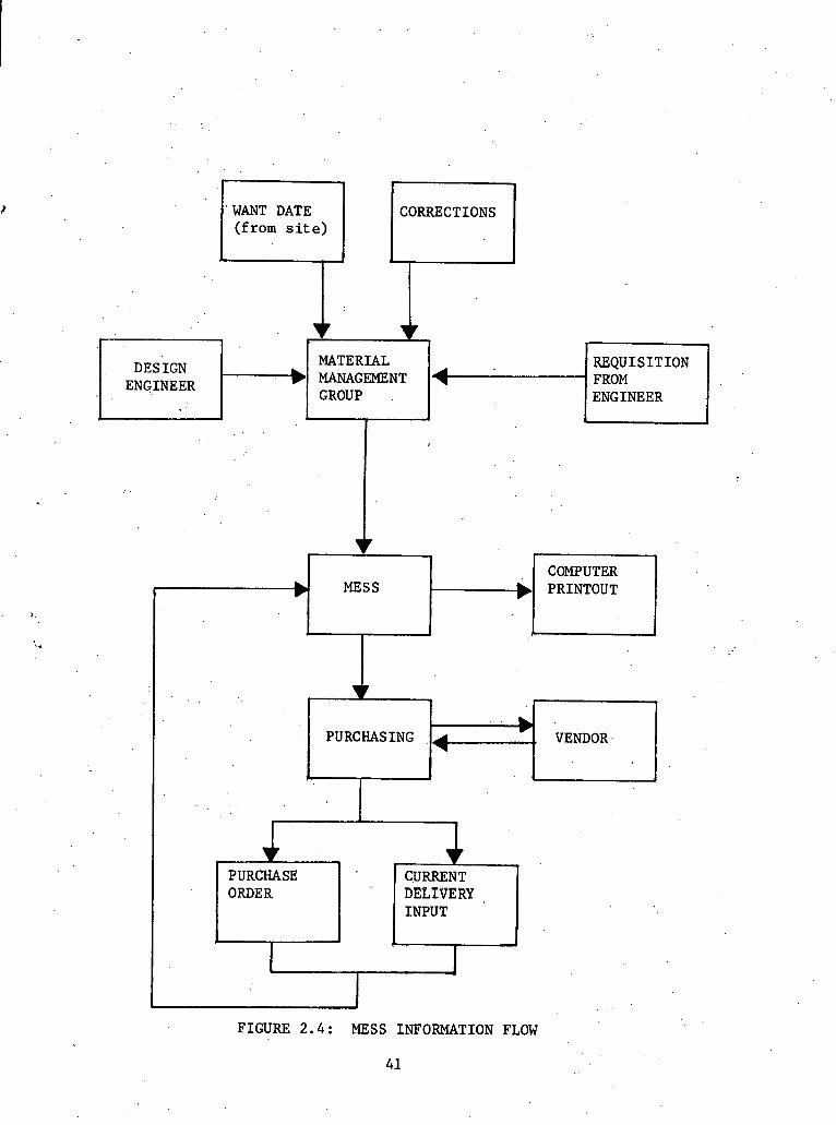
FIGURE 2.4: MESS INFORMATION FLOW
41
WANT DATE CORRECTIONS (from site)
GROUP ENGINEER A
b MESS
VENDOR
-
PURCHASING
k
4 *.
PURCHASE ORDER
CURRENT DELIVERY INPUT
I e .
I I
2
M i l l Power then r e q u e s t s t h a t . t h e .vendor acknowledge t h e o rde r
and e i t h e r confirm t h a t he can meet t h e r equ i r ed d e l i v e r y o r supply a
r e v i s e d d a t e . Th i s becomes t h e o r i g i n a l promised d e l i v e r y d a t e and
remains permanently on t h e record . The vendor i s a l s o asked t o f u r n i s h
. : t h e d a t e on which he must r e c e i v e r e l e a s e fo r ' manufacture i n o rde r t o
. . -
meet t h i s ' o r i g i n a l da t e .
A s soon as 'MiP1 Power r e c e i v e s t h e a c k n o ~ l c d ~ e m e n t , i t is entered
i n t o the MESS master f i l e . ' .Any o t h e r corrt5spondence from the'ven.dor . .
r ega rd ing d e l i v e r y d a t e s , e t c . is a l s o en tered .
The r e c e i v i n g d a t e , s t o r a g e l o c a t i o n , q u a n t i t y rece ived , and
q u a l i t y a s su rance s t a t u s a r e en t e red by t h e personnel a t t h e p l a n t s i t e
through a t e l e t y p e . Th i s in format ion , l i k e a l l o t h e r e n t r i e s by the
Cont ro l Sec t ion , is done on- l ine and becomes p a r t of t h e master f i l e . I
A l l on-hand i t e m s , , w i l l be shown on t h e M a t e r i a l On Hand Report f o r
t h r e e (3) months and a f t e r t h a t per iod of t i m e w i l l he a v a i l a b l e on1.y
on a r eques t basf s.
The f low of informat ion . i n t h e system is summarized i n F igu re 2.4.
2.5 Pfp ing M a t e r i a l Inventory Cont ro l (PMICS) - Duke Power Company
The P ip ing M a t e r i a l Inventory Cont ro l System was developed f o r
Duke Power Corpora t ion ' s Engineering Design Div i s ion and i s t y p i c a l of
.systems developed t o handle bulk procurement of p i p e spool m a t e r i a l
needed f o r f i e l d f a b r i c a t i o n , It c o n s i s t s of a r e l a t i v e l y simple' pro-
gram which keeps t r a c k of p ip ing matef.ia1 purchased a n d ' a l l o c a t e d ,
P i p e is ordered i n l a r g e bulk q u a n t i t i e s based on t h e .P&ID drawings
3
be fo re t h e d e t a i l e d i some t r i c drawings a r e developed. This in format ion
i s recorded i n t h e PMICS system. Long l ead t imes i n some h igh ly spe-
c i a l i z e d p ipes make i t necessary t o proceed i n t h i s fash ion . A s t h e
d e t a i l e d i some t r i c drawings are prepared, t h e q u a n t i t i e s of p a r t i c u l a r ?
types of p i p e a l l o c a t e d t o each drawing a r e recorded i n t h e PMICS sys-
. tem.
A s can be seen from Addendum C, a g r e a t d e a l of in format ion is
contained i n t h e r e p o r t . I n both ordered and a l l o c a t e d p o r t i o n s of t h e
r e p o r t , accumulated q u a n t i t i e s a r e kept and can be weighed a g a i n s t
each o the r f o r purchasing purposes. The l o t number is an " i n t e l l i g e n t " ''
'number i n which each of t h e c h a r a c t e r s has a d e f i n i t e meaning. The
system is run on t h e Duke Power company's IBM 360 system.
2 .6 S to re s Accounting System (SAS) - Duke,Power Company
Of t h e many i tems involved i n t h e c o n s t r u c t i o n of a nuc lear power .'
p lan t , ' a good number f a l l o u t s i d e t h e scope of t h e MESS system. These
a r e smal le r i t ems included i n t h e s t r u c t u r e and consumable items needed
f o r t h e cons t ruc t ion process . I n t h e i n t e r e s t of good p r o j e c t manage-
ment, i t is important t o account f o r and p r o p e r l y c o n t r o l t h e s e items.
The l a r g e q u a n t i t i e s .of t h e i t ems involved e s t a b l i s h e s .an environment
s i m i l a r t o . t h a t of a ' r e t a i l s t o r e (,Duke Power Company a l s o engages i n
t h e r e t a i l s a l e s of some l a r g e e l e c t r i c app l i ances ) . To account f o r
t h e s e smal le r items., a computerized s t o r e s accounting system (SAS) was
implemented. SAS keeps t r a c k of t h e fo l lowing types of .company s t o r e s :
- . Appliance repair p a r t s
E l e c t r i c and hydro ope ra t ion

Water o p e r a t i o n T r a n s p o r t a t i o n ope ra t ion Cons t ruc t ion ' department m a t e r i a l s ~ e e l s ' and drums Steam s t a t i o n o p e r a t i o n s I
. .
A s SAS was developed, i t w a s t o perform t h e fo l lowing func t ions
as r e l a t e d t o construction'activities:
(1) Maintenance of magnetic t a p e s i n t h e Datacenter w i th d e t a i l
summary s t o c k l e d g e r s f o r eadh s t o r e s t ype and s t o r e s l o c a t i o n .
( 2 ) updat ing of t h e s e l e d g e r s each,week by r ece iv ing and pos t ing
of a l l s t o r e s a c t i v i t y i npu t t r a n s a c t i o n s .
(3) P r e p a r a t i o n of t h e fo l lowing s t o c k s t a t u s r e p o r t s :
1 Semi-weekly purchase Order S t a t u s L i s t i n g Weekly System S t o r e s Ledgers Weekly Transac t ion L i s t i n g Monthly Ldcat ion S t o r e s 'Ledger
(4) Recomputation weekly of t h e system-wide average u n i t c o s t s
of s t o c k i t ems and i d e n t i f i c a t i o n of s i g n i f i c a n t v a r i a t i o n s between
(a) prev ious c o s t and new purchase o r d e r c o s t and (b) purchase o rde r
c o s t and i n v o i c e c o s t .
( 5 ) P r e p a r a t i o n from purchase o r d e r s of. punch-printed m a t e r i a l
r e c e i p t ca rds ' and p r i n t e d material r e c e i v i n g r e p o r t s t o f a c i l i t a t e and
automate t h e subsequent r e p o r t i n g on s t o r e s r e c e i p t s and invo ices .
(6) P r e p a r a t i o n o f , phys i ca l inventory worksheets and punched-printed
c a r d s t o f a c i l i t a t e t h e t ak ing and r e p o r t i n g of s t o r e s i n v e n t o r i e s .
(7) P r e p a r a t i o n of q u a r t e r l y comparative r e p o r t s of s t o r e s turn-
over r a t i o s and inventory ana lyses f o r each s t o r e s c l a s s by l o c a t i o n and
t h e e n t i r e company.

(8) Prepa ra t ion of month-end.s tores d i s t r i b u t i o n l i s t i n g s and
updat ing and output o f ' work o r d e r e n t r i e s .
2 .6 .1 SAS aster F i l e s
The S t o r e s system has four magnetic t a p e master f i l e s . They are a s
fol lows:
Purchase Order F i l e : Th i s f i l e i s set up from c a r d s punched from
the.Accounting Department copy of a l l M i l l Power Supply Company purchase
o r d e r s f o r SAS. s t o r e s i tems, M i l l Power Supply Company sh ipping o r d e r s ,
l o c a l purchase o r d e r s , o r consigned, lamp r e q u i s i t i o n s . Records s e t up . .
may subsequent ly be changed by purchase o rde r change o r d e r s if t h e
o r i g i n a l pu rch i se o rde r d a t a ' i s changed. Purchase m a t e r i a l r e c e i p t s
and purchase invo.ices are matched a g a i n s t , a n d posted t o t h e purchase
o rde r records when rece ived . M a t e r i a l r e c e i p t s are p r i ced , from t h e
. . purchase o rde r p r i c e and purchase invo ice p r i c e s and q u a n t i t i e s a r e
match& and cbmpared. ~ w i c e ' w e e k l ~ , t h e Purchase Order S t a t u s L i s t i n g " '
is made, showing t h e s t a t u s of each o rde r and c a l l i n g a t t e n t i o n t o
p r i c e and q u a n t i t y d i s c r e p a n c i e s between purchase o rde r s , r e c e i p t s , and
invoices . Records a r e au toma t i ca l ly d e l e t e d on a sys temat ic b a s i s
a f t e r f i n a l r e c e i p t fo l lowing invo ice pos t ing and check-out. Purchase
o rde r d a t a on t h i s f i l e c o n s i s t s of t h e fo l lowing:
S t o r e s l o t number S to re s l o c a t i o n number Purchase o rde r number Purchase o r d e r d a t e Purchase o rde r b a s i c u n i t p r i c e Q u a n t i t i e s , o rdered , , rece ived , invoiced Amounts, o rdered , r ece ived , invoiced Last r e c e i p t and invo ice d a t e s , r e f e rence , and codes .
A s s d h l y F i l e : This f i l e conta ins a record of f requent ly used
major u n i t s . o f . c o n s t r u c t i o n showing, f o r each major u n i t or assembly,
t h e number and q u a n t i t i e s of individual ,items of s t o r e s making up t h e .
assembly. . The puipose of t h e f i l e i s t o f a c i l i t a t e expansion of assembly
r e q u i s i t i o n s ; in to ind iv idua l i t e m r e q u i s i t i o n s f o r each item included i n
t h e assembly. Since many of t h e items included i n assemblies a r e bulk
charge o u t items, alfeady.chafged out of s t o r e s t o t h e bulk charge ac-
counts, t h e computer makes provision t o c r e d i t t h e bulk charge accounts
ins tead of t h e s t o r e s account f o r a l l c r e d i t r e q u i s i t i o n s f o r bulk
charge items.
Stores Unit. Cost F i l e : This f i l e contains one u n i t cos t and de-
s c r i p t i o n record f o r each SAS s t o r e s l o t number. It i s ' u s e d t o p r i c e
t r ansac t ions for a l l s t o r e s locat ions . System-wide u n i t c o s t s a r e
rCcomputed weekly f o r ' a l l i t e m s having new purchase r e c e i p t s or journal
e n t r i e s and t h e new un i t cos t is used t o p r i c e t r ansac t ions received
during t h e same week. New items a r e set up on t h i s . f i l e by means of ,
EDP s t o r e s o rders issued by t h e General Off ice S to res ~ c c o u n t i n g Depart-
ment. Unit c o s t records conta in t h e fol lowing data :
Stores l o t number S t o r e s . d e s c r i p t i o n and u n i t of i s s u e Current s y s t em-wide quant i t y and value Current u n i t c o s t Unit c o s t h i s t o r y Quarter t o dat'e average u n i t cos t Year t o d a t e average u n i t cos t ~ a ' s t y e a r ' s average u n i t c o ~ t Previous four, quar te r ending a c t u a l u n i t c o s t s Last invoice a c t u a l u n i t c o s t .
Current r e s a l e p r i c e ' ' .
Miscellaneous d a t a
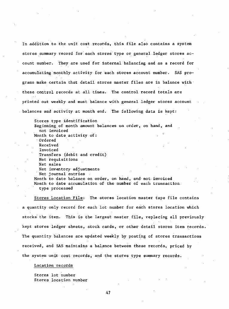
I n a d d i t i o n t o t h e u n i t c o s t . records , t h i s f i l e a l s o c o n t a i n s a system
s t o r e s summary record f o r ' e a c h s t o r e s ' t y p e o r g e n e r a l . l e d g e r s t o r e s ac-
count number. They a r e used f o r i n t e r n a l ba lanc ing and as a r eco rd f o r
accumulating'monthly a c t i v i t y f o r each s t o r e s account number. SAS pro-
gramsmake c e r t a i n t h a t d e t a i l s t o r e s master f i l e s a r e i n balance wi th
t h e s e c o n t r o l r eco rds a t a l l t i m e s . The c o n t r o l record t o t a l s a r e
p r i n t e d o u t weekly and must ba lance w i t h g e n e r a l l edge r s t o r e s account
ba lances and a c t i v i t y a t month end. The fo l lowing d a t a i s kept :
S t o r e s type i d e n t i f i c a t i o n ~ e g i n n i n g . of month amount ba lances on o rde r , on hand, and
n o t invoiced Month t o d a t e a c t i v i t y o f :
Ordered Received Invoiced Trans fe r s (deb i t and c r e d i t ) N e t r e q u i s i t i o n s Net s a l e s Net inventory ad jus tments N e t j o u r n a l e n t r i e s
Month t o d a t e ba lance on o r d e r , on hand, and, not. invoiced Month . to d a t e accumulation of t h e number of each t r a n s a c t i o n
. ' t y p e processed
S t o r e s Locat ion F i l e : The s t o r e s l o c a t i o n master t a p e f i l e con ta ins
a q u a n t i t y only record f o r each l o t number f o r each s t o r e s l o c a t i o n which
s t o c k s t h e item. This is t h e l a r g e s t m a s t e r . f i l e , r ep l ac ing a l l p r ev ious ly
kept s t o r e s ledger s h e e t s , s t o c k ca rds , o r o t h e r d e t a i l s t o r e s i t e m r eco rds .
The q u a n t i t y ba lances a r e updated weekly by pos t ing of s t o r e s t r a n s a c t i o n s
r ece ived , and SAS ma in ta ins a ba lance between t h e s e records , p r i ced by
t h e system u n i t c o s t r eco rds , and t h e s t o r e s t y p e summary r eco rds .
Locat ion r eco rds
S to re s l o t number S t o r e s l o c a t i o n number

Current q u a n t i t i e s on . hand and on o r d e r Curren t month's a c t i v i t y of q u a n t i t i e s
Received ' from s u p p l i e r s N e t .cbmpany t r a n s f e r s N e t usage and s a l e s .
L a s t f o u r weeks a c t u a l normal usage and an average f o r t h i s pe r iod
Quar te r t o d a t e t o t a l usage Year ' t o d a t e t o t a l usage L a s t yea r ' s t o t a l usage .previous ba lance on hand h i s t o r y
~ u a r t e r t o d a t e average ba lance on hand . , Year t o d a t e average ba lance on hand
' . L a s t ' s average ba lance on 'hand L a s t month end average balance on hand Previous f o u r q u a r t e r ending a c t u a l ba lances on hand
Insu rance code, No. of weeks h i s t o r y coun te r , l a s t i s s u e d a t e , p rev ious week's u n i t c o s t , and o t h e r misce l laneous codes and d a t a
2.6.2 SAS Reports
The SAS system produces t h e fo l lowing r e p o r t s a p p l i c a b l e t o con-
s t r u c t i o n a s a r e s u l t of i t s s o r t i n g and ca ta loguing func t ion :
Semi-weekly Reports :
M a t e r i a l Receiving Reports (Normal Purchase Order): Th i s r e p o r t
is p r i n t e d tw ice 'weekly. Both cop ie s a r e s e n t t o t h e o rde r ing
l o c a t i o n f o r l a t e r s t o r e s i n v o i c e process ing .
Material Recefving Card: These ca rds a r e p r i n t e d twice weekly.
rans sac ti on E r r o r L i s t i n g : This l i s t i n g is p r i n t e d twice weekly
f o r g e n e r a l account5ng and s e r v i c e p a r t s d i v i s i o n s . SAS t r a n s a c t i o n s
a r e checked f o r v a l i d i t y and reasonableness by computer programming
p r i o r t o pos t ing t o master f i l e s , Some a r e r e j e c t e d because of
i n v a l i d d a t a and o t h e r s may be ques t ionab le bu t a r e posted. Both
t y p e s a r e l i s t e d ' f o r i n v e s t i g a t i o n andlor c o r r e c t i o n .

. .
Purchase Order S t a t u s . L i s t i n g : This l i s t i n g is prepared twice
weekly f o r g e n e r a l accounting and M i l l Power Supply Company. It
i s a s t a t u s l i s t i n g ' of a l l SAS purchase o rde r s ; ,po in ts o u t any !
d i sc repand ie s i n q u a n t i t i e s and amounts .between 'orders , r e c e i p t s ,
and invo ices ; i n d i c a t e s o t h e r p o s s i b l e e r r o r s ; and e x p r e s s e s . a n
age f a c t o r of ou t s t and ing o r d e r s .
Weekly Reports : ,
System S to re s Ledger: This l i s t i n g i s a p r i n t o u t of t h e SAS s t o r e s
master f i l e s . It. is prepared f o r Se rv i ce P a r t s 'Divis ion, General , ' I .
s t o r e s ,: ~ i s t r i b u t i o n , Bui ld ings , and Water Operat ions, T r a n s i t ,
, , c o n s t r u c t i o n f i e l d o f f i c e . I
. .
. s t o r e s Transac t ion L i s t i n g : This r e p o r t p rovides a d e t a i l e d l i s t i n g
of each s t o r e s t r a n s a c t i o n rece ived from t h e f i e l d o r c r e a t e d by
t h e computer, suppor t ing t h e summary a c t i v i t y t o t a l s and ba lance
changes on t h e pe r iod ic s t o r e s l edge r . It a l s o provides a n e r r o r
column where, by means of codes, a t t e n t i o n i s c a l l e d t o a c t u a l o r
probable i r r e g u l a r i t i e s encountered dur ing the. p rocess ing of each
t r a n s a c t i o n . It is prepared f o r g e n e r a l accounting and t h e s t o r e s
i o c a t i o n . , . . .
Sto res Ma te r i a l Requests: Each week, m a t e r i a l r e q u e s t s a r e p r i n t e d
on a ' b a s i s coord ina ted with. t r a n s p o r t a t i o n ' s c h e d u l e s . Automatic
o rde r ing has been programmed t o au toma t i ca l ly gene ra t e r eo rde r i n t e r -
v a l s f o r each a p p l i c a b l e s t o r e s l oca t ion . A l l copies. a r e s e n t ' t o , .
. . General S to re s f o r f u r t h e r d i s t r i b u t i o n .
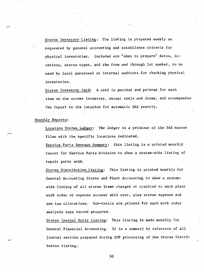
S t o r e s . I iwkntory -L i s t i ng : The l i s t ing i s prepared weekly as .
reques ted . by gene ra l accounting and e s t a b l i s h e s c r i t e r i a f o r
p h y s i c a l i n v e n t o r i e s . Included a r e "when t o prepare" d a t e s , lo -
c a t i o n s , s t o r e s t ypes , and t h e from and through l o t number, t o be
used by l o c a l personnel o r i n t e r n a l a u d i t o r s f o r checking phys i ca l
i n v e n t o r i e s .
S t o r e s Inventory Card: A card i s punched and p r i n t e d f o r each
item on t h e s t o r e s inventory , .except r e e l s and drums, and accompanies
t h e r e p o r t t o t h e l o c a t i o n f o r automatic SAS r e e n t r y .
Monthly Reports:
~ o c a t i o n S t o r e s Ledger: The l e d g e r i s a p r i n t o u t of t h e SAS master
f i l e s w i t h t h e s p e c i f i c l o c a t i o n s i n d i c a t e d ,
S e r v i c e P a r t s Revenue Summary: This l i s t i n g i s a p r i n t e d monthly
r e p o r t f o r Se rv i ce P a r t s D iv i s ion t o show a system-wide l i s t i n g of
r e p a i r p a r t s so ld .
S t o r e s D i s t r i b u t i o n L i s t i n g : This l i s t i n g i s p r i n t e d monthly f o r
General Accounting S t o r e s and P l a n t Accounting t o show a system-
wide l i s t i n g of a l l s t o r e s i tems charged o r c r e d i t e d t o each p l a n t
work o r d e r o r expense account w i t h c o s t , p l u s s t o r e s expense.and
uge tax a l l o c a t i o n s . s u b - t o t a l s a r e p r i n t e d f o r each work o rde r
a n a l y s i s t a p e record prepared.
S t o r e s J o u r n a l Ent ry L i s t i n g : This l i s t i n g is made monthly f o r
General F i n a n c i a l Accounting, It is a summary by r e f e r e n c e of a l l
j o u r n a l e n t r i e s prepared du r ing EDP process ing of t h e S t o r e s D i s t r i -
b u t i o n l i s t i n g .

. . Inventory Value Report: . Thi s r e p o r t is prepared f o r General Ac- . .
counting, General S t o r e s , . a n d . S e r v i c e P a r t s D i v i s i o n . . This i s a
. . summary f o r each l o c a t i o n showing va lbe on hand. f o r each type of
s tock .
Quar t e r ly Reports :
S to re s Turnover and Inventory Analysis : Th i s r e p o r t is p r i n t e d
f o r General Accounting and General S to re s . It i s f o r u s e i n ana-
l y s i s . and c o n t r o l of i n v e n t o r i e s and a c t i v i t y a s , t o c l a s s of s t o r e s ,
i n d i v i d u a l s t o r e s r e s p o n s i b i l i t y l o c a t i o n s , a n d . r e t a i 1 and company
grand t o t a l s :
Annual Reports :
Sto res Cost. Analysis : This r e p o r t i s p r i n t e d f o r General Accounting
. . and M i l l Power Supply Company. Th i s a n a l y s i s i n d i c a t e s ( f o r each
l o t number) t h e cu r r en t system inventory q u a n t i t y , va lue , u n i t cos t
h i s t o r y , and c o s t change percentage. Summaries a t t h e end of each
s t o r e s type , each steam p l a n t , and system t o t a l show t h e c u r r e n t
inventory v a l u e a t t h e c u r r e n t u n i t c o s t , t h e inventory v a l u e based
on each ca tegory of prev ious u n i t c o s t h i s t o r y , and i ts d i f f e r e n c e , .
from t h e v a l u e of c u r r e n t u n i t c o s t .
Use Q £ System '-- An Example ---- ~
Of i n t e r e s t i s t h e u s e of t h e computerized system i n a c t u a l nuc lea r
power p l a n t cons t ruc t ion . A s i t e v i s i t revea led t h e fo l lowing sequence , .
of events .

, When ? a t e r i a l i s r ece ived , a . r ece iv ing record i s f i l l e d o u t and . .
a Duke Power company l a b e l ' i s placed on t h e item. ( s ee Addendum D ,
Exh ib i t i ) . Of t h e informati0.n on t h e r e c e i v i n g r eco rd , on ly t h e o rde r
number, . . l o t number, and. q u a n t i t y rece ived a r e en tered . i n t i SAS. Before
being e n t e r e d , t h e handwri t ten copy is pu t i n t o typed form, This has
helped t o i n c r e a s e t h e accuracy of t h e informat ion a s i n p u t i .nto t h e . . .
computer. The i n p u t i s v i a CRT. Copies of t h e r ece iv ing r eco rd a r e .
kept a t t h e warehouse, and s e n t t o Purchasing f o r i nvo ice approval , t o
t h e MESS inpu t s t a t i o n , and t o Engineering f o r n o t i f i c a t i o n of , a r r i v a l .
In a d d i t i o n , warehouse make,s cop ie s and f i l e s them on s i t e under t h e
vendor name, i t em number, d a t e re ,ceived, and shipment number. Items
a r e more e a s i l y l oca t ed i f they can be r e c a l l e d on t h e s e bases .
The warehouseman p l aces t h e m a t e r i a l s i n t o t h e warehouse and
p l a c e s a Duke .~ 'ower l a b e l on t h e i n d i v i d u a l i tems. Thc Duke Power
l a b e l i n c l u d e s t h e vendor company name, t h e o rde r number, t h e Duke
i tem number, t h e d a t e r ece ived , t h e shipment number, d e s c r i p t i o n of t h e
m a t e r i a l , and t h e ANSI s t o r a g e l e v e l . I n t h e case of NSSS i tems, t h e
item number becomes t h e vendor i tem number t o h e l p prevent confusion.
To withdraw m a t e r i a l s from t h e warehouse, a warehouse s t o c k order
must b e f i l l e d ou t ( s ee Addendum D, Exh ib i t 2): Of t h e informat ion on
t h i s ca rd , t h e l o t number, amount, account number, group,number, and .
crew number a r e en tered i n t o SAS, The o r i g i n a l warehouse s t o c k o rde r
is s e n t t o t h e Main O f f i c e i n c h a r l o t t e f o r documen ta t ion , con t ro l .
The SAS system p r i n t s ' 25 r e p o r t s f o r t h e Duke Power Company. The
two most widely used r e p o r t s on t h e s i t e . a r e an inventory (updated weekly

on microf iche , q u a r t e r l y on. 'paper) and breakdown by crew number of
t h e m a t e r i a l s used (reviewed du r ing weekly foremen's .meet ings) . By
e n t e r i n g group and l o t 'number, SAS s u p p l i e s on- l ine informat ion w i t h
r e s p e c t t o q u a n t i t i e s of i tems on hand, i t ems on o r d e r , t h e system
average p r i c e , and t h e number used. Although SAS's c a p a b i l i t i e s a r e
much g rea t e r , . t h i s t ype of in format ion i s most widely used by t h e . .
f i e l d warehousing opera t ion .
2.. 7 Punch L i s t 'Program - Georgia Power Company
Georgia Power Company i s p r e s e n t l y u s ing a program c a l l e d
"Punch L i s t " a s a s t a t u s scheduling t o o l dur ing t h e i r c o n s t r u c t i o n
and s t a r t -up phases a t p l a n t Hatch near . B a d e y , Georgia. The program
t r a c k s t h e s t a t u s of components from t h e time they a r r i v e i n t h e ware-
house u n t i l they a r e turned over t o t h e s t a r t - u p team. I n a l l , 1 6 d i f -
f e r e n t s t e p s can be monitored.
I n t h e des ign of t he Punch L i s t system i t was decided t h a t no t
a l l i tems. were t o be l i s t e d t n t h e program. No C i v i l / S t r u c t u r a l items
a r e included i n t he program. E lec t r i ca l . componen t s f o r some ins t ruments
a r e l i s t e d on. another schedule. P r e s e n t l y , approximately 35,000 Mechan-
i c a l itehs a r e monitored by t h e program.
For Mechanical i t ems t h e fo l lowing informat ion is maintained:
Equipment number I some t r i c drawing number Revision (of above) Area S i z e Purchase o rde r number , Purchase ardcr Ptcm number

Mark number Weld s p e c i f i c a t i o n number Required d a t e Scheduled s h i p d a t e Received d a t e Temporary Turnover number System Turnover number F l u s h number need d a t e Pre-op number need d a t e Est imated e a r l i e s t f l u s h Es t imated earliest pre-op
I n a d d i t i o n , t h e fo l lowing s t a t u s p o i n t s can be monitored:
Hold Document Received . .
I n b u i l d i n g ' . I n s t a l l e d
. NDE (Non-Destructive . Tes t ing ) Hydro (Hydro t e s t ) CAT (Cons t ruc t ion Acceptance T e s t ) Temp T.O. (Temporary turnover ) Perm T . 0 . (Permanent turnover ) Sys T. 0. (system tu rnove r ) Opera t iona l p a i n t e d Welded I n s u l a t e d ~ i n ' o pul lod (Pina hnvo boen pul lod from hqngors)
.Addendum E, Exh ib i t 1, shows a t y p i c a l p r i n t o u t . f o r t h e Punch L i s t .
To compile a l l t h e informat ion f o r a program such a s Chis, s e v e r a l
major s o u r c e s of in format ion were used. Master p a r t s L i s t i s a n in-
ventory program used by t h e Southern Company System. It was developed
by General E l e c t r i c and is a Primary sou rce of in format ion t o t h e team
which w i l l o p e r a t e t h e p l a n t . It l is ts a l l major items which a r e r e -
qu i red f o r p l a n t ope ra t ion . . A s soon a s purchase o rde r d a t a i s developed,
. in format ion regard ing major i tems i s inpu t t o t h e program t o i n i t i a l i z e
H L program master f i l e s ' .
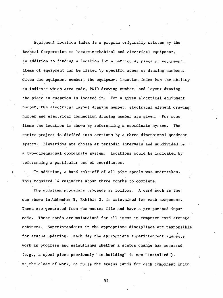
Equipment Loca t ion . Index i s a program o r i g i n a l l y w r i t t e n by t h e
Bechtel Corporat ion t o locat.e..mechanical and e l e c t r i c a l equipment,
I n a d d i t i o n t o f i n d i n g a l o c a t i o n f o r a p a r t i c u l a r p i ece of equipment,
i t e m s of equipment can be l i s , t e d by s p e c i f i c zones o r drawing numbers.
.Given t h e equipment number, t he ' equipment l o c a t i o n index has t h e a b i l i t y
t o ind ica t ' e which a r e a code, P&ID drawing number, and l ayou t drawing
t h e p i e c e i n ques t ion i s l o c a t e d i n . For a given e l e c t r i c a l equipment
number, . t h e e l e c t r i c a l l ayou t drawing number, e l e c t r i c a l element drawing
'number and e l e c t r i c a l connect ion drawing number a r e given. . F o r some
items t h e l o c a t i o n is shown by r e fe renc ing a coo rd ina t e system. The
e n t i r e p r o j e c t is d iv ided i n t o s e c t i o n s by a three-dimensional quadrant
system. E leva t ions a r e chosen a t p e r i o d i c i n t e r v a l s and subdivided by
a two-dimensional coo rd ina t e system. Locat ions could be ind ica t ed by
r e fe renc ing a p a r t i c u l a r s e t of coo rd ina t e s .
I n a d d i t i o n , a hand take-off of a l l p i p e spoo l s was undertaken.
This r e q u i r e d . 1 4 engineers about t h r e e months t o complete.
The updat ing procedure proceeds a s fol lows. A ca rd such a s t h e
one shown i n Addend* E, Exh ib i t 2 , i s maintained f o r each component,
These a r e genera ted from t h e mas ter f i l e and have a pre-punched input
code. These. c a r d s a r e maintained f o r a l l items i n computer ca rd s t o r a g e
cabine ts . . Super in tendents i n t h e a p p r o p r i a t e d i s c i p l i n e s a r e r e s p o n s i b l e
f o r s t a t u s updat ing. Each day t h e a p p r o p r i a t e super in tendent i n s p e c t s
work i n p rog res s and e s t a b l i s h e s whether a s t a t u s change has occurred
(e . g . , a spool p i e c e p rev ious ly " i n ..building1' is now " i n s t a l l e d " ) ,
A t t h e c l o s e of work, he p u l l s t h e s t a t u s c a r d s f o r each component which

logged a s t a t u s change and p l a c e s a mark i n t h e a p p r o p r i a t e p o s i t i o n
on t h e l e f t s i d e .of t h e ' card . For i n s t a n c e , i f t h e instrument w i t h
code F2N22-N313C TX2N22-274 i s now i n s t a l l e d , having ' p r ev ious ly been
" i n bu i ld ing , " he p u l l s t h e pre-punched ca rd wi th t h i s code and checks
t h e b lank next t o 3 6 / ~ . A f t e r a l l c a r d s a r e pu l l ed and checked f o r
i t e m s w i t h changed s t a t u s , t h e ca rds a r e g iven t o a key punch ope ra to r .
The ope ra to r punches a one (1) i n t h e column, i n d i c a t i n g t h e n e " s t a t u s .
I n t h e above example, a "1" would be puriched i n column 36 of t h e pre-
punched ins t rument card . An a c t i o n code and number is punched i n
columns 54-55 (C = change s t a t u s , A = add component s t a t u s ) . The
code C1 i n . columns 54-55 i n d i c a t e s t h e s t 'a tus i s changed i n t h e master
list,. Following key punching of each card t o update s t a t u s , they a r e
read on to a d i s k e t t e and run a g a i n s t a v e r i f i c a t i o n program.on-si te t o
de te rmine whether any key punch e r r o r s have been made. I f t h e r e a r e
no e r r o r s , t h e d a t a i s s e n t from s i t e t o t h e hos t computer f o r processing.
Following process ing , a replacement card is punched, re turned t o t h e s i t e ,
and f i l e d i n t h e ca rd s t o r a g e c a b i n e t t o be used f o r f u r t h e r s t a t u s change
updates.
Reports can be p r i n t e d on many d i f f e r e n t s o r t s . I n a l 1 , ' i t is pos-
s i b l e t o make up t o seven nes ted s p e c i f i c a t i o n s . This pe rmi t s t h e pro-
duc t ion of a l l necessary management r e p o r t s .
2.8 bant tit^ Tracking System (,QTS) - Bechtel Power c o r p o r a t i o n
The' Quant i ty Tracking.System i s a n organized method,of t r a c k i n g
bulk q u a n t i t i e s of m a t e r i a l which w a s developed and implemented by t h e
56

Bechte l Power Corporat ion. The' system t r a c k s q u a n t i t i e s from. t h e
e a r l y s t a g e s of a nuc lear p o w e r ' f a c i l i t y u n t i l p r o j e c t completion, and
.Bechtel u ses i t a s a b a s i c element i n p r o j e c t c o n t r o l ,
F ive g e n e r a l a r e a s of m a t e r i a l s a r e p r e s e n t l y being t racked by
t h e Q. T.S. system. They a r e a s fol lows:
Ceneral Quanti ty Area S p e c i f i c Q u a n t i t i e s Tracked
Pip ing ( l a r g e and smal l ) Concrete ( c i v i l / s t r u c t u r a l )
E l e c t r i c a l
~q 'uipment Instruments
Welds, hangers , and v a l v e s Forms, r e b a r , conc re t e , and
embedments Trays, condui t , wi re , and
c a b l e Mechanical, e l e c t r i c a l , c i v i l A l l t ypes
The Quanti ty Tracking System is opera ted by t h e " f i e l d c o n t r o l
group" which: is d i r e c t e d by t h e M a t e r i a l Cont ro l Superv isor . F ive
Mate r i a l Cont ro l Coordinators a r e under t h e supe rv i so r . The i r main respon-
s i b i l i t i e s a r e t o c o l l e c t and inpu t t h e s t a t u s c a r d s f o r updat ing t h e sys-
t em. These c a r d s a r e grouped a s c o n s t r u c t i o n d a t a system ca rds , conc re t e
pour ca rds , p u l l c a r d s , connect ion ca rds , and equipment s t a t u s cards .
~ k i e ' fol lowing diagram, ~ i ~ u r e 2.5, d e p i c t s t h e M a t e r i a l Cont ro l group
t h a t Bechtel p l ans t o s e t up on t h e Vogtle Nuclear P l a n t s .
Summarizing t h e f low c h a r t , t he M a t e r i a l Cont ro l group i n t e r f a c e s
wi th t h e owner's f i e l d ,opera t ions , q u a l i t y assurance , planning 'and sched-
u l i n g , . c o n s t r u c t i o n , c o s t . engineer ing , and t h e home o f f i c e , ~ l s o , t h e
c o s t and schedule ~ o n t r o l groups' CPM pr,ograms, Manpower Analys is Pro-
gram, Action Program (manual l a b o r performance), and q u a n t i t y f o r e c a s t
l e d g e r s a r e suppl ied needed information. Supplying of in format ion t o
v a r i o u s groups i s accomplished through a number of s o r t s ,
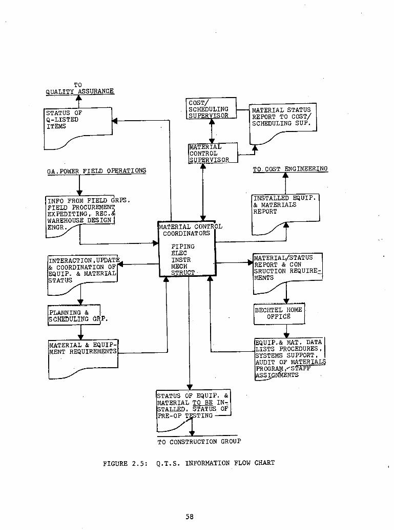
T O CONSTRUCTION GROUP
F I G U R E 2.5: Q . T . S . I N F O R M A T I O N FLOW CHART
T 0 Q U A L I T Y ASSURANCE
COST/ r
S T A T U S O F Q - L I S T E D I T E M S -
S C X E D U L I N G - M A T E R I A L S T A T U S
4 SUPERVISOR REPORT TO COST/
SCHEDULING S U P .
-MATERIAL CONTROL
GA.POWER F I E L D O P E R A T I O N S T O COST E N G I N E E R I N G
1 I N F O FROM F I E L D G R P S . I N S T A L L E D E Q U I P . F I E L D PROCUREMENT & MATERIALS E X P E D I T I N G , REC . & REPORT WAREHOUSE D E S I G N j 7 ,
M A T E R I A L CONTROL COORDINATORS
b P I P I N G
I E U C INTERACTION, UPDATE INSTR *MATERIAL/STATUS & COORDINATION OFI MECH )REPORT & CON E Q U I P . & M A T E R I A L I S T R U C T S R U C T I O N R E Q U I R E t S T A T U S A 4
PLANNING & BECIITEL IIOME SCHEDULTNG GqP. O F F I C E * 1
MATERIAL & EQUIP-' MENT REQUIREMENTS,
E Q U I P . & MAT. DATA L I S T S PROCEDURES, SYSTEMS S U P P O R T , A U D I T O F MATERIA PROGRAM ,' S
I m F 9
~ N ~ ~ I E N T S

Presen t u ses of t h e system inc lude : . . ( I ) q u a n t i t y base f o r e s t ima te s /
forecas ts ; . (2) q u a n t i t y . r e p o r t i n g ; . (3) ' c o s t t r end base;: ( 4 ) m a t e r i a l
p r i c i n g base ; , ( 5 ) m a t e r i a l b i l l i n g informat ion; (6) h i s t o r i c a l q u a n t i t y
base; (7) des ign s t a t u s t o o l ; (8) planning d a t a base; (9) exped i t i ng
l i s t ; (10) f i e l d s t a t u s t o o l ; (11) a c t i o n card gene ra to r ; (12) m a t e r i a l .
pre-ordering base; and (13) system punch list.
Much o f . t h e mechanics of t h e QTS system wi th r e s p e c t t o hardware
used and r e p o r t s produced i s t h e same a s i n systems p rev ious ly descr ibed .
The r e a d e r , is r e f e r r e d t o t hose r e p o r t s f o r d e t a i l s .
2 .9 Ma te r i a l Cont ro l Module - GPU Se rv i ces
The m a t e r i a l c o n t r o l module w a s developed by GPU Se rv ices Corpora-
t i o n a s p a r t of a comprehensive planning t o o l . . The d e t a i l s of o p e r a t i o n
a r e similar . to t he previously.mentioned MESS system wi th t h e added
.. a b i l i t y t o s o r t ' on work package des igna t ions . The module permi ts t h e
assignment of d i r e c t r e s p o n s i b i l i t y f o r on-time procurement, no t on ly
t o a work package, bu t , i f r equ i r ed , t o an i n d i v i d u a l w i t h i n t h e respon-
s i b l e o rgan iza t ion . By uniquely i d e n t i f y i n g a l l s i g n i f i c a n t equipment
i tems , i nc lud ing p ipe spoo l s and ins t ruments , a s t hey a r e I n i t i a l l y
en t e red on. t h e f low diagrams, each item can be t racked from procuremr&t
through exped i t i ng and f i n a l d e l i v e r y t o t h e storeroom.
The t h r e e r e p o r t s t h a t a r e prepared by t h e Mater ia l ' Cont ro l Record
. . are:
(1) Master L i s t i n g : This is a l i s t i n g of t h e e n t i r e f i l e s o r t e d
by work package and i n d i c a t i n g t h e fo l lowing d a t a elements; system code,
d e s c r i p t i o n , QA/QC code, drawing number, r e s p o n s i b l e o rgan iza t ion o r
i n d i v i d u a l , . vendor name, purchase o rde r , q u a n t i t y d a t a , . purchase order
d a t e s , package number,, FPC account and s p e c i a l codes.
(2) Warehousing Report: A l i s t i n g of a l l ordered i tems inc luding
q u a n t i t y d a t a , which have not ' been r ece ived , When t h e i t e m a r r . i ves , . . .
t h e q u a n t i t y , b i n l o c a t i o n , and s tandard s t o c k number a r e wr i t t . en i n
t h e b lank space and t h e r e p o r t then becomes. t h e d a t a i n p u t
document f o r t h e subsequent computer run. ' .
(3) Expedi t ing Report: Th i s i s a s u b s o r t of t h e mas ter l i s t i n g
i t emiz ing t h o s e i tems which a r e overdue o r due t o s h i p i n t h e next
90 days f o r exped i t i ng review and update . When t h e exped i t i ng func t ion
a c q u i r e s more c u r r e n t expected d e l i v e r y informat ion , i t is w r i t t e n i n
t h e b lank spaces provided and t h e r e p o r t then becomes t h e d a t a input
document f o r t h e subsequent computer run.
2.10 M a t e r i a l Management Informat ion System (MMIS) - F l o r i d a Power Cur pur.aClwl1
The M a t e r i a l Management Information System developed by t h e Y l o i i d a
Power Corpora t ion i n conjunct ion w i t h Arthur Andersen Assoc ia tes i s a
comprehensive m a t e r i a l t r a c k i n g system fo l lowing t h e m a t e r i a l c y c l e
from purchase th rough .ma te r i a1 i s s u e . The most s i g n i f i c a n t f e a t u r e - of
t h i s system is i t s a t tempt t o f o r e c a s t materia1,demand.
2.10.1 System Development
MMIS was developed o r i g i n a l l y f o r t h e t ransmiss ion and d i s t r i b u t i o n
department. There i s a p p l i c a t i o n i n c o n s t r u c t i o n p r o j e c t s on a nuc lear 7

power p l a n t s c a l e a l s o . To determine f o r e c a s t a b i l i t y , m a t e r i a l s were
d iv ided i n t o t h r e e . b r o a d c a t e g o r i e s : t hose used 0-1l.weeks per yea r ,
t hose used 12-29 weeks per yea r , and those used 30-52 weeks per yea r .
~ t e m k were dbserved . f o r . a pe=.iod of two y e a r s t o determine i n what ca t e -
g o r i e s they should be placed. It was determined t h a t t hose items used
between 0 and 11 weeks, were very d i f f i c u l t t o f o r e c a s t . hose used
'. between 12 and 29 weeks per year were f o r e c a s t e d manually; t h a t i s ,
i n t u i t i v e assumptions were made. Those used between 30 and 52 weeks
per year were p red ic t ed us ing a model developed based on p a s t performance
of m a t e r i a l s . Th i s model i nc ludes b a s i c minimum q u a n t i t i e s , gene ra l
long term t r e n d s , and seasonal v a r i a t i o n s . Although t h e major con-
s t r u c t i o n a s p e c t s of nuc lea r power p l a n t s a r e no t c o n t i n u a l l y ongoing
a c t i v i t i e s , f o r many of t h e longer term a c t i v i t i e s g e n e r a l t r e n d s could
be es tab l i shed . . This would a l low u s e of t h e f o r e c a s t i n g model b u i l t
. ' , i n t o t he MMIS system., . .
'The MMIS system i s very s i m i l a r t o t h e M a t e r i a l Management System' . .
used by the Tennessee Valley Author i ty . It ope ra t e s on t h e same cen- .
t r a l i z e d computer system and r e q u i r e s a c e n t r a l i z e d warehouse arrangement.
2.10.2 MMIS Output
Some of t h e r e p o r t s ' produced by MMIS a r e a s fol lows:
Warehouse Stock Reports :
System Stock Status: Each p a r t s t o r e d i s shown by warehouse, t h e 12
months n e t usage, i t em type , l e a d time i n weeks, economic order
q u a n t i t y , s a f e t y s tock , r e o r d e r ' po l i cy , p ro j ec t ed weekly usage,
amount on hand, amount s t aged (committed f o r p a r t i c u l a r usage) ,
61

n e t a v a i l a b l e , p r o j e c t e d number of weeks supply on hand, amount
on o r d e r , and pro jec ted .weeks ' supply on o r d e r .
I n t e r S t o r e s T rans fe r P t e l i s t ; I n a c e n t r a l i z e d warehouse' system
wi th m u l t i p l e s a t e l l i t e warehouses, i t becomes necessary t o t r a n s f e r
m a t e r i a l s between warehouses. To opt imize u s e of equipment, r o u t e s
a r e c r e a t e d w i t h c e r t a i n l i m i t s on weight and volume. The p r e l i s t
shows which items a re t o be moved t o which l o c a t i o n s w i t h i n t h e !-
rclilte parameters . Tn a.drli t ion, i t shows the nrdpr p n l i f y , amn~lnt.
on hand, a n m n t s t aged , n e t a v a i l a b l e , weeks supply on
hand, p r o j e c t e d usage over t h e next few weeks,. r eo rde r index,
s t anda rd packing q u a n t i t y , s tandard packing weight, s tandard
packing . volume, . suggested t r a n s f e r q u a n t i t y , .and t h e cumulat ive
.weight and volume t o b e t r a n s f e r r e d .
I n t e r s t o r e s T rans fe r L i s t i n g : The a c t u a l document used i n t h e
t r a n s f e r p o l i c y i s a l ' so produced. Shown a r e t h e l o c a t i o n , ' amounts . .
t o be shipped, wi th room l e f t t o show d i sc repanc ie s .
S t o r e s M a t e r i a l Requ i s i t i on : Used t o r e q u i s i t i o n . m a t e r i a l f rom
vendors. It i s a n in-house document and s h o w s ~ p o s s i b l e ca ta logue
numbers a s . w e l l a s d i f f e r e n t p o s s i b l e vendors.
Cycle Count L i s t : U'sed t o hand v e r i f y q u a n t i t i e s s t o r e d wi th
q u a n t i t i e s recdrded in t h e computer.
Cycle Count R e c o n c i l i a t i o n Report: Us'ed t o v e r i f y t h e a c t u a l count
d a t a placed i n t o the computer.
Open Purchase Order S t a t u s : produced on a r e g u l a r b a s i s , i t h e l p s
t o i n s u r e t h a t . a l l vendors f u l l y meet t h e i r o b l i g a t i o n s .
Model Ana,l_y_s is Reports :
Forecas t 'Performance .Report: . The' a b i l i t y of MMIS t o f o r e c a s t a n t i c -
i p a t e d need i s one of i ts primary s t r e n g t h s . It is important t o d e t e r -
mine how w e l l t h e model has performed. Th i s r e p o r t p r e s e n t s a v a r i e t y
of in format ion t o assist i n t h i s a n a l y s i s . Shown are o r d e r po l i cy ,
es t imated demand, a c t u a l demand, and t h e va r i ance . Semiannual
.usage is shown i n a c t u a l usage 'and usage f o r e c a s t e d by t h e model.
' 'The demand f i l t e r u n i t is a r easonab le range developed d i r e c t l y from
h i s t o r i c a l r eco rds , Records f o r the, p a s t year a r e maintained and t h e
number of t imes t h e demand f i l t e r has been v i o l a t e d ( t r i p p e d ) is ,':
noted and t h e number a c t i v e is a l s o shown. The t r a c k s i g n a l is an
i n d i c a t o r of how w e l l t h e model f o r e c a s t s t h e a c t u a l usage. Th i s is
of g r e a t i n t e r e s t t o t h e des igne r s of t h e model i n a s s e s s i n g i t s
c a p a b i l i t i e s . For t h e previous month, r eco rds a r e kept a s t o t h e
numher crf s t o c k o u t s a n d . number. of o r d e r s f i l l e d .
Forecas t Analys is Report: A complete p r o j e c t i o n over a series of
s e v e r a l weeks i s presented . Lead t imes, q u a n t i t i e s on hand, fo re -
ca s t ed amounts, scheduled r e c e i p t s , and t h e .p ro jec ted amounts on
hand . a r e shown.
Fo recas t Simulat ion ~ e p o r t - Summary: A summary i s produced f o r
each p a r t kept on t h e system. Analysis . c an be made on t h e v a l i d i t y
of t h e f o r e c a s t i n g model by examining t h e a c t u a l usage, f o r e c a s t
usage, va r i ance , dmand f i l t e r t r i p s , mean average d e v i a t i o n based
?n u n i t s and do1lar.s; :and t h e . ave rage t r a c k i n g s i g n a l ,
Forecas t S imula t ion" Report ' - ' D e t a i l : A breakdown on a week by week
b a s i s of t h e summary repor t .'shown..above.
Stock Outs and Manual:Allocafion'Listing: This repor t shows what
s tock o u t s might be a n t i c i p a t e d p r i o r t o t h e de l ive ry of add i t iona l
p a r t s ,
Commitment Planning Report by P a r t Number f o r t h e Commitment Year ( ):
F O ~ any p a r t i c u l a r year the commitments can be shown on a -monthly
bas i s .
~ i s t o r i c a l Usage Report by P a r t Nuriber f o r ' the Pas t 1 2 Months:
Inventory Reports:
Inventory Control Summary by Inventory Categories : A summary repor t
broken do* by inventory ca tegor ies . It shows inventory balance,
cu r ren t monthly usage, 12 months n e t usage, annualized turnover
r a t i o , va lue of s a f e t y inventory, va lue of average inventory, and
t h e va lue of t h e maximum inventory.
Inventory Control Summary by Storeroom: The sanie information a s
above is 'shown broken down by storerooms.
Inventory Control Summary by Inventory Order Pol icy . -'System . Wide:
The same information as. above is shown broken down by inventory
order pol icy ,
Inventory ~ o n t i o l . Summary by Inventory Order Pol icy - Storerooms:
The sanie information a s above. i s shown broken down by inventory
order pol icy on a storeroom b a s i s ,
Inventory Value by Storeroom:
Inventory Adjustments f o r ' t h e Period 'Ending ' ( ) : Each storeroom i s

analyzed a s t o averages'..and sho r t ages on a monthly and. a . y e a r l y . .
b a s i s .
Route Capacity Report: To opt imize t h e u s e of a v a i l a b l e f l e e t equip-
ment, d e l i v e r y r o u t e s have been e s t a b l i s h e d between t h e central ware-
house.and ou t ly ing warehouses. These r o u t e s a r e based on a demand- ! . . I
I capac i ty a n a l y s i s .
Qua r t e r ly A c t i v i t y Report by Storeroom:
Obsolete Ma te r i a l : I n t h e c o n s t r u c t i o n p roces s of a nuc lea r power
p l a n t , some m a t e r i a l s become o b s o l e t e due t o des ign changes. These
m a t e r i a l s a r e shown and i t is i n d i c a t e d ,how much d o l l a r volume is . .
l oca t ed i n which warehouses.
Slow Moving Mate r i a l : Some m a t e r i a l s a r e used only ve ry i n f r e q u e n t l y .
I n such c a s e s i t may not be necessary t o main ta in a s t o c k i n a p a r t i c -
u l a r warehouse. Th i s r e p o r t w i l l he lp t o a s s e s s whether o r n o t
. e l imina t ion from a c t i v e warehousing i s p o s s i b l e .
Bin Locator Report: P r e c i s e warehouse l o c a t i o n is presented i n t h i s
. . r e p o r t .
. , . . Buyer Reports : . .
- purchase ~ ~ r e e r a e n t S t a t u s Report: This' r e p o r t h e l p s t o a s c e r t a i n ' t o
what degree a purchase agreement has been c a r r i e d ou t . It c o n t a i n s I .
such informat ion as q u a n t i t i e s r ece ived , q u a n t i t i e s r e l e a s e d , c u r r e n t
ba lance , r e s p e c t i v e percentages , s t a r t d a t e , and e x p i r a t i o n d a t e .
Vendor A c t i v i t y Report: This r e p o r t h e l p s t o a s s e s s vendor per for -
mance. Each vendor has t he number of o r d e r s , average number of days

t o acknowledge, promises r ece ived , promises changed, number of
overshipments , number of p a r t i a l shipments, number of e a r l y ship-
ments, number of l a t e shipments , and number of d u p l i c a t e shipments.
Purchase Order: Automatical ly produced by t h e computer.
Purchase Order - Receiving Report: Automatical ly produced by t h e
computer .
Expedi tor Reports :
Open Order S t a t u s Report : Th i s r e p o r t p r e s e n t s in format ion t o
h e l p ana lyze i f any a c t i o n should be taken on open purchase o r d e r s .
Some of t h e ' i n f o r m a t i o n presented is: Purchase Order s t a t u s , requi red
d a t e , exped i t i ng s t a t u s , exped i t i ng d a t e , changed d a t e s , number of t
change., new promise d a t e , and o t h e r i d e n t i f i c a t i o n informat ion .
Request f o r Acknowledgement L e t t e r : Th i s l e t t e r i s au toma t i ca l ly
produced when no acknowledgement t o an i s sued Purchase Order i s r e -
ceived.
Request £ o r De l ive ry Date V e r i f i c a t i o n L e t t e r :
Request f o r Revised Del ivery Date L e t t e r : Th i s l e t t e r i s produced
when a p a r t i c u l a r . shipment is p a s t due.
Management Reports:
Purchasing Department S t a t u s Report ; Th i s r e p o r t c h r o n i c l e s t h e
, a c t i v i t i e s of t h e Purchasing Department.
Purchas ing Department. Monthly A c t i v i t y Report : Same a s above, only i n
more d e t a i l .

Vendor Lead Time Varian;~: Th i s r e p o r t p re sen t s .vendor l e a d t imes
'and shows v a r i a n c e s between changes on t h e same vendor f o r t h e same
item.
Appendix F con ta ins samples of many of t h e above mentioned r e p o r t s .
2.11 ,Mater ia l ~ a n a ~ e m e n t Sys tem (MAMS) - Tennessee Valley Author i ty
The M a t e r i a l s Management System be ing developed by t h e Tennessee
Valley Author i ty w i l l b e a t o t a l l y i n t e g r a t e d system encompassing a l l
phases i n the, c o n s t r u c t i o n p r o c e s s . . F igu re 2.6 shows what MAMS w i l l
encompass dur ing i t s s e v e r a l phases. Under d e t a i l e d development a t
t h i s t ime a r e s i x subsystems, w i th the o t h e r s t o be implemented a t a
l a t e r d a t e . ,The s i x subsystems a r e : ( l ) , E n g i n e e r i n g - designed t o
suppor t t h e m a t e r i a l management f u n c t i o n s of t h e Div i s ion of Transmission
Planning and Engineering i n t h e O f f i c e of Power; (2) Procurement - t o
a s s i s t t h e Div is ion o f Purchasing f o r b e t t e r con t ro l . over procurement
and exped i t i ng a c t i v i t i e s ; ' (3) Power S t o r e s Inventory - i nc ludes a l l
m a t e r i a l . func t ions f o r ' r ece iv ing , s t o r i n g , . and i s s u i n g .ma te r i a l s tock ;
(4 ) Accounts P a y a b l e ; ' ( 5 ) P l a n t Accounting - a s s i s t s t h e Div i s ion of
Finance i n meeting t h e a s s e t r eco rds requirements of t h e FP.C; and
(6) C l a s s i f i c a t i o n - mainta ins m a t e r i a l s p e c i f i c a t i o n s f o r TVA-wide
. . use.
T h e , h e a r t , o f t h e proposed system is t h e development of an ex tens ive
d a t a communications network t o al low o rgan iza t ions t o t r ansmi t t o and r e -
ce ive d a t a from a c e n t r a l d a t a base, Terminal devices a r e l oca t ed a t
s t r a t e g i c p o i n t s i n u se r o r g a n i z a t i o n s t o connect i n t o t h e communications

MATERIALS MANAGEMENT SYSTE$
Piagram of MateFials 'Ma~gement Applications.,
Engineering (TR P&E)
Maintenance
Plant Maintenance :
Transporta- Classification
*:. . Future. £unctions
FIGURE 2 . 6 : MATERIALS MANAGEMENT SYSTEM (MAMS)
network. The c e n t r a l da ta . .base 2s l oca t ed i n the Computing .Center and
con ta ins a l l a c t i v e f i l e s of in format ion about t h e s t a t u s of m a t e r i a l s .
2 .11.1 Engineering Subsystem '
The Engineering Subsystem begins t h e m a t e r i a l s management process ; l
it i s designed t o cap tu re m a t e r i a l s p e c i f i c a t i o n s dur ing des ign and t o
make t h e informat ion a v a i l a b l e t o o t h e r subsystems l a t e r i n t h e process .
I n a d d i t i o n , t h e subsystem a i d s t h e des ign p roces s by o f f e r i n g t h e p r o j e c t
engineer t h e a b i l . i t y t o c a l l ou t computer s t o r e d model b i l l s of m a t e r i a l s ,
used f o r p a s t p r o j e c t s . The subsystem provides t h e c a p a b i l i t y t o c o n t r o l
t h e s t a t u s of m a t e r i a l c a l l e d f o r on b i l l s of m a t e r i a l because of i n t e r -
f a c e s wi th t h e procurement inventory c o n t r o l and accounts payable system * .
, l a t e r i n t h e . process .
. . The Transmission System Planning (TSP)'Branch i n i t i a t e s t h e engin- .
' ee r ing procurement p roces s b y . r e q u e s t i n g p re l imina ry work order e s t i m a t e s
from t h e t h r e e engineer ing branches. The.branch a s s i g n s t h e work o r d e r
t o a p r o j e c t engineer . Then, t h e p r o j e c t engineer reviews t h e s ing le -
l i n e drawing and does t h e necessary work t o e s t a b l i s h a computer d a t a
base f o r t h e b i l l s of m a t e r i a l . The p r o j e c t engineer a d j u s t s t h e work
o r d e r b i l l of m a t e r i a l f i l e t o correspond wi th requirements of t h e s ing le -
l i n e work o rde r drawing and p repa res pre l iminary work o rde r e s t i m a t e s . f o r
TSP. TSP reviews ' t h e pre l iminary e s t i m a t e s and r e q u e s t s a f i n a l p r i n t e d
work o rde r e s t ima te . From a . t e rmina l , t h e p r o j e c t engineer i s s u e s a
command t o p r i n t work. o rde r e s t i m a t e s ' a n d a b i l l . o f m a t e r i a l summary,

The p r o j e c t engineer exainines'.the'&ork o r d e r e s t i m a t e s ,and s i n g l e - l i n e
.drawing t o deter inine i f a l l major i t ems a r e ' reserved . I f t h e major
i t e m s ' have n o t been l o c a t e d w i t h i n TVA, a purchase r e q u i s i t i o n is
reques t ed . The p r i n t e d purchase r e q u i s i t i o n s a r e approved by t h e d i v i s i o n
d i r e c t o r and. are re tu rned t o t h e p r o j e c t engineer . A command i s issued
from t h e t e r m i n a l t o r e l e a s e t h e purchase r e q u i s i t i o n s t o t h e Procurement
Subsystem, he p r o j e c t t hen awaits approval of t h e work o rde r by t h e TVA
Board of D i r e c t o r s .
Once the - p r o j e c t i s approved by t h e Board, TSP p repa res a spec i f i-
c a t i o n drawing and forwards it t o t h e p r o j e c t engineer . ' The p r o j e c t
eng.ine&r examines t h e iriventory d a t a base ' t o d e t e d n e . i f c e r t a i n s p e c i a l . .
i t ems l i k e r e l a y s , ' cur ren t t ransformers , p o t e n t i a l t ransformers , e t c . ,
could b e ob ta ined ' f rom w i t h i n TVA. I f t h e i t ems a r e no t a v a i l a b l e
w i t h i n TVA, a purchase r e q u i s i t i o n i s typed a t t h e t e r m i n a l w i t h t h e
MAMS system provid ing complete d e s c r i p t i o n s and l a t e s t p r i c e s . A t about
t h e same t ime, t h e p r o j e c t engineer r e c e i v e s drawings .from t h e vendors
f o r major equipment t h a t w a s r e q u i s i t i o n e d e a r l i e r and forwards both t h e
s p e c i f i c a t i o n and vendor drawings t o t h e v a r i o u s s e c t i o n s w i t h i n t h e
branch f o r u s e i n developing c o n s t r u c t i o n drawings. A s des ign p rog res ses ,
and a s more, of t h e i t e m s i n t h e b i l l s of m a t e r i a l a r e i d e n t i f i e d , t h e
p r o j e c t engineer adds them t o t h e computer-stbred b i l l s of i n a t e r i a l .
A t a p p r o p r i a t e i n t e r v a l s , t h e p r o j e c t engineer r e q u e s t s t h a t purchase
r e q u i s i t i o n s be p r i n t e d a t t h e t e r m i n a l s and sends them through t h e ap-
p rova l p roces s . The p roces s of p r i n t i n g r e q u i s i t i o n s , g e t t i n g them ap-
proved, and t r a n s f e r r i n g them t o t h e m a t e r i a l r e q u i s i t i o n f i l e con t inues
70

. .
u n t i l t h e des ign is complete. Af t e r des ign is c o m p l e t e , , t h e work o rde r
b i l l of m a t e r i a l d a t a base L s made a v a i l a b l e t d t h e Div is ion of Power'
Cons t ruc t ion and t h e P l a n t Accounting Branch f o r u se i n t h e i r subsystems.
There a r e seven p r i n c i p a l elements i n t h e engineer ing subsystem.'
The inventory d a t a base provides a s i n g l e c e n t r a l i z e d source f o r inventory
informat ion . The d a t a base i s made u p of r eco rds t h a t i n d i c a t e 'such in-
formation as s t o c k s t a t u s , q u a n t i t i e s o n , o r d e r , f u t u r e requirements , and
p a s t usage f o r each i tem i n a stor.eroom. It forms a subse t of t h e MAMS
d a t a base and i s designed t o l i n k up wi th o t h e r s u b s e t s i n t h e system.
The M a t e r i a l Data Base provides a s i n g l e c e n t r a l i z e d source f o r
m a t e r i a l s p e c i f i c a t i o n s , e l imina t ing t h e need f o r each o r g a n i z a t i o n t o
keep i t s own f i l e s . Information such a s phys i ca l c h a r a c t e r i s t i c s ,
manufacturers , and u n i t s of measure i s maintained i n t h e d a t a base.
Th i s d a t a base i s accessed by every subsystem t h a t u s e s m a t e r i a l s p e c i f i -
c a t i o n s and is t h e r e f o r e updated cont inuous ly .
The Model B i l l of Ma te r i a l p rovides a mechanism f o r qu ick ly es-
t a b l i s h i n g a complete b i l l of m a t e r i a l f o r new'work o rde r s . It repre-
s e n t s t h e m a t e r i a l s t h a t a r e l i k e l y t o be needed t o b u i l d t y p i c a l sub-
s t a t i o n o r t ransmiss ion l i n e s t r u c t u r e s ,
The p l a n t Records F i l e ' s t o r e s t h e f i n a l a d j u s t e d b i l l s of m a t e r i a l
f o r p l a n t s t r u c t u r e s . It is updated when mod i f i ca t ions a r e made t o one
of t h e s t r u c t u r e s .
The Requ i s i t i on Data Base i s a temporary holding f i l e f o r r e q u i s i t i o n s
from t h e t ime they a r e prepared by . t h e o r i g i n a t i n g o r g a n i z a t i o n u n t i l ' t h e
Cont rac t i s awarded. , ,

The Work o r d e r B i l l ' o f - M a t e r i a l Data Base con ta ins b i l l s of m a t e r i a l
f o r work o r d e r s t h a t a r e i n a c t i v e s t a t u s - t h a t is , planned work o r d e r s
and approved work o rde r s .
The engineer ing subsystem has seven p r i n c i p a l ou tput f u r ~ s :
B i l l of M a t e r i a l Summary: A working document f o r t h e engineer i n t h e
e l e c t r i c a l , c i v i l , and communications branches,
Ret i rement F i l e Display: ~ n a b l e s t h e Div i s ion of 'Transmission, Plannlng . .
and ,Eng inee r ing t o determine i f major r e t i r e d o r planned t o be re -
t i r e d f T l e s could be used on a c u r r e n t work.order .
Inventory F i l e Disp lay : ' Enables the. D iv i s ion of Transmission, Planning
a n d ~ n g i n e e r i n g t o d e t e r m i n e i f m a j o r itemsneededforaworkorder
a r e a v a i l a b l e in TVA- storerooms.
B i l l of M a t e r i a l Display: Shows t h e s t a t u s of a l l i t ems on a p a r t i c u l a r
b i l l of m a t e r i a l .
Work Order Est imate: Used by t h e Tranmission Planning Branch t o sub- --
s t a n t i a t e reques ted funds f o r a p r o j e c t .
Purchase Requ i s i t i ons : Used by t h e p r o j e c t engineers i n t h e e l e c t r i c a l ; . .
c i v i l , and communications branches t o procure m a t e r i a l s ' r e q u i r e d f o r
khe p r o j e c t . .
M a t e r i a l . S t a t u s Report: Used t o b r ing t o t h e a t t e n t i o n of t h e managers
on TRPbE any a c t i v i t y o r problems t h a t need a c t i o n i n t h e m a t e r i a l
management process .
2 .11 .2 Procurement Subsystem
The second major subsystem i s the 'procurement subsystem. It i s de-
s igned t o p rov ide up-to-date s t a t u s of each r e q u i s i t i o n assigned ' t o

s
ptirchasing. Computerizing t h e purchasing f u n c t i o n i n a c e n t r a l d a t a
base has a number of s i g n i f i c a n t b e n e f i t s , V e r i f i c a t i o n f o r i tem noun
names, d e s c r i p t i o n cons i s t ency , and accuracy is au toma t i ca l ly ensured.
R e s p o n s i b i l i t y f o r problems w i t h mismatched and misd i r ec t ed invoice
d a t a is centered i n t h e Accounts Payable Subsystem. Redundant d a t a
e n t r y is e l imina ted by provid ing ready acces s bv a l l u s e r s t o i t e m -
r e a u i s i t i o n - c o n t r a c t s t a t u s , i nc lud ing e x ~ e d i t i n g , i n spec t ion , drawing
requiretnents, and payment s t a t u s . Consol ida t ion of l i k e l i n e i tems
i s permi t ted ' t o accomplish l a r g e purchase d i scoun t l eve rage , and
f u r t h e r reduce paper handl ing. Stock a v a i l a b i l i t y a t o t h e r l o c a t i o n s
w i l l have been screened a s a f e a t u r e of t h e power S t o r e s Inventory Sub- . .
system t o e l i m i n a t e redundant r e q u i s i t i o n s . I n t e r d i v i s i o n reviews of
quotes and b i d s a r e monitored and de l ays a r e h igh l igh ted . The r e q u i s i - . .
t i o n e r can p r e s e l e c t a p p l i c a b l e q u a l i t y a s su rance s t anda rds ; a f t e r r e -
c e i p t , t h e f i e l d can i n d i c a t e QA and i n s p e c t i o n r e s u l t s . "Emergency"
te lephone r e q u i s i t i o n s a r e reduced because i tem need requi rements a r e
e l e c t r o n i c a l l y t r ansmi t t ed from t h e r e q u i s i t i o n p o i n t . Standard t imes
a r e s to red w i t h i n t h e system t o au toma t i ca l ly monitor progre.ss. Workload
planning, ba lanc ing , and s t a t u s r e p o r t s a r e provided a t a l l management
l e v e l s . Vendor performance informat ion i s accumulated a s a byproduct of
t h e r e c e i v i n g process .
Many of t h e purchasing processes c a n ' b e r e v i s e d when t h e u s e of
computers i s introduced. Open market purchases r e q u i r e t h e most f l e x i -
b i l i t y and can make t h e most u s e of i n d i v i d u a l purchasing agent t e rmina l s .
Each day t h e purchasing agen t can review t h e r e q u i s i t i o n . d a t a base f o r

h i s next assignment. He may then r eques t in format ion on a s p e c i f i c
r e q u i s i t i o n ' (p r i ce h i s to r ,y , .vendor h i s t o r y , e t c . ) and i n d i c a t e t h e
d i s p a s i t i o n . Review of t h e r e q u i s i t i o n is logged and award of t h e
c o n t r a c t ( i nc lud ing vendor, d a t e wanted, exped i t i ng , and . qua l i t y as-
surance requirement s ) is i n p u t i n t o t h e r e q u i s i t i o n . da t a ' base.
Adver t i sed purchases d i f f e r from t h e open market i n t h a t a more
complicated f low w i t h a lower volume is involved. Requ i s i t i ons from
u s e r o r g a n i z a t i o n s a r e r e t r i e v e d by a subsystem program and a r e used
t o p r i n t a d a i l y b i d work s h e e t and r e q u i s i t i o n s t a t u s r e p o r t . Each
morning, a long w i t h h i s d a i l y s t a t u s r e p o r t , t h e purchasing agent
r e c e i v e s i n v i t a t i o n t o b id worksheets f o r r e q u i s i t i o n s which were f i r s t
i n t h e p r i o r i t y queue. A r e q u i s i t i o n s t a t u s prog.ram w i l l a l s o schedule
t h e r e q u i s i t i o n e r ' s review t iming and w i l l f l a g overdue recommendations.
AS recommendations a r e made on r e q u i s i t i o n s and c o n t r a c t s awarded, t h e
r e q u i s i t i o n e r l e a v e s , t h e r e q u i s i t i o n d a t a base f o r t h e open c o n t r a c t
d a t a base.
The exped i t i ng f u n c t i o n is c a r r i e d ou t i n a combination automatic /
manual method. Some n o t i c e s a r e genera ted au toma t i ca l ly ; o t h e r s a r e
s e n t upon r e q u e s t of t h e exped i t i ng u n i t .
The p r i n c i p a l e lements of t h e procurement subsystem c o n s i s t of a l l
. t h r e e d a t a bases . The Requ i s i t i on Data Base c o n t a i n s informat ion .(sup-
p l i e d by M a t e r i a l s Management r equ i . s i t i on ing o rgan iza t ions ) necessary f o r
purchasing t o a c t . The Open Cont rac t Data Base s e r v e s as. a r eco rd f o r
awarded c o n t r a c t s which have not been d e l i v e r e d and pa id . When payment
is made and d is ' c repancies r econc i l ed , t h e c o n t r a c t r eco rd w i l l be w r i t t e n
74

t o a h i s t o r y f i l e . Vendor ' in format ion (addresses , h i s t o r y of per f or-
mance) i s contained i n the'.Vendor Master Data Base. P e r i o d i c a l l y t h e
d a t a bases w i l l be purged a f t e r being recorded on annual magnetic
t apes .
The proposed des ign of t h e procurement subsystem does n o t l o c k
i n a n y ' p a r t i c u l a r types of r e p o r t s , a l lowing t h e u s e r t o t a i l o r t h e
output t o . h i s needs. A number o f ' r e p o r t s w i l l however be b u i l t i n t o t h e
system a t concept ion.
Requ i s i t i on Receiving Log: L i s t s a l l r e q u i s i t i o n s rece ived by purchasing.
Requ i s i t i on Queue: L i s t s t h e r e q u i s i t i o n s ass igned t o purchase agen t s
and t h e p r i o r i t y of each.
Purchase Requ i s i t i on Information: Contains a l l s t o r e d informat ion about
a purchase r e q u i s i t i o n .
p r i c e H2s tor ies : Contain p r i c e s on a p a r t i c u l a r 'commodity.
' ' Vendor Performance: Shows d e l i v e r y and q u a l i t y performance f o r t h e p a s t .
purchases f o r t h a t commodity.'
~ e ~ u i s i t i o n S t a t u s : Ou t l ines t h e s t a t u s of r e q u i g i t ions .
I n v i t a t i o n t o Bid Worksheet: Shows a l l in format ion r e q u i r e d f o r process ing
t h e r e q u i s i t i o n .
Expedi t ing Notice: Produced when t h e c o n t r a c t performance d a t e o r need
performance d a t e i s w i t h i n six months o r o t h e r s p e c i f i e d period.
Workload Input Report: A supervis ,or"s r e p o r t f o r scheduling t h e purchase
a g e n t ' s workload in h i s , s e c t i o n .
C r i t i c a l Date Del ivery L i s t : Shows t h o s e c o n t r a c t s wh3ch a r e s e r i o u s l y
l a t e in d e l i v e r y .

2,11 .3 "Power ' S t o r e s I n v e n t o r y :Subsystem
'The Power S t o r e s Imrentory Subsystem a l lows any .organiza t ion ' wi th
a t e r m i n a l d e v i c e . t o have a c c e s s t o m a t e r i a l s t o c k r e c o r d s a t a l l in-
ventory l o c a t i o n s . Receiving . r e p o r t s are p rep r in t ed on t h e te rmina l
dev ice a t t h e r e c e i v i n g loca t ion 'when t h e m a t e r i a l is r ece ived . Orders,
r e c e i p t s , and i s s u e d a t a from remote storerooms a r e e l e c t r o n i c a l l y t r ans -
mi t t ed . A v a i l a b i l i t y of m a t e r i a l f o r f u t u r e p r o j e c t s is c o n t r o l l e d by
n o t i f y i n g s f o r i s when r e q u i s i t i o n s must be r e l e a s e d . ate rial . . r e c e i p t s
. a r e au toma t i ca l ly p r i ced by matching them t o t h e o r i g i n a l c o n t r a c t
r eco rds ' s t o red i n t h e MAMS d a t a base. ~ e ~ u i s i t i b n s . a r e du toma t i ca l ly .. . .
screened a g a i n s t t h e MAMS d a t a base and r e q u e s t s f o r d .el ivery a r e p r i n t e d
when a p p r o p r i a t e . The s toreroom f u n c t i o n s a r e c a r r i e d p u t much a s has
been desc r ibed i n t h e S to re s Accounting. System d e s c r i p t i o n .
I n t h e des ign of t h e system, t h e r e a r e . a number of o u t p u t s which
have been placed i n t o it.
R e q u i s i t i o n Analys is Report : Shows t h e r e q u i s i t i o n s en tered i n t o t h e
MAMS system on t h e previous day.
Inventory Analysis Report: Item usage i s l i s t e d ' in descending o r d e r by
d o l l a r va lue used pe r year .
Stock S t a t u s Report: Stock s t a t u s ; and s tock .wh ich h a s no t moved i n . a
p a r t i c u l a r per iod of t i m e a r e shown.
Order Var iance and Overdue Order Book: Items which have no t been d e l i v e r e d
w i t h i n t h e time s t i p u l a t e d on t h e c o n t r a c t a r e l i s t e d .
Requirements 'Generation. 'Repiirt : A f o r e c a s t r e p o r t , i t l ists monthly r e -
quirement s f o r i tems f o r t h e next s i x months. !
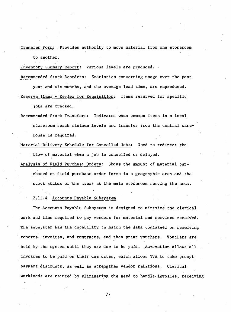
Trans fe r Form: Provides a u t h o r i t y t o move m a t e r i a l from one storeroom
t o another .
Inventory Summary Report: Various l e v e l s a r e produced.
Recommended s t o c k ' Reorders: S t a t i s t i c s concerning usage over t h e p a s t
year and six months, and t h e average l e a d time, a r e reproduced.
Reserve Items - Review f o r Requis i t ion : I tems reserved f o r s p e c i f i c
jobs a r e t racked.
Recommended Stock Transfers : I n d i c a t e s when c o q o n items i n a l o c a l
storeroom reach minimum l e v e l s and t r a n s f e r from t h e c e n t r a l ware- . .
house i s requi red .
' ~ a t e r ~ a l Del ivery Schedule f o r Cancelled ~ o b s : Used t o r e d i r e c t t h e
f low of m a t e r i a l when a job i s cance l l ed o r delayed.
.Analysis of F i e l d Purchase Orders,: Shows t h e amount of m a t e r i a l pur-
chased on f i e l d purchase o rde r forms i n a geographic a r e a and t h e
s t o c k status of t h e i tems a t t h e main storeroom se rv ing t h e a r e a .
2.11.4 Accounts payable subsystem
The Accounts Payable Subsystem is designed t o minimize t h e c l e r i c a l
work and t ime r equ i r ed t o pay. vendors f o r m a t e r i a l and . s e r v i c e s receiv'ed.
The subsystem has t h e c a p a b i l i t y t o match t h e d a t a contained on r e c e i v i n g
repor ' ts , i nvo ices , and c o n t r a c t s , and then p r i n t vouchers , Vouchers a r e
he ld by t h e system u n t i l t hey are due. t o be paid. .Automation a l lows " a l l
i nvo ices t o be pa id on t h e i r due d a t e s , which a l lows TVA t o t a k e prompt
payment d i scoun t s , a s ' w e l l as s t r eng then vendor r e l a t i o n s , C l e r i c a l
workloads are .red.uced by e l imina t ing t h e need t o hand le - invo ices , r e c e i v i n g
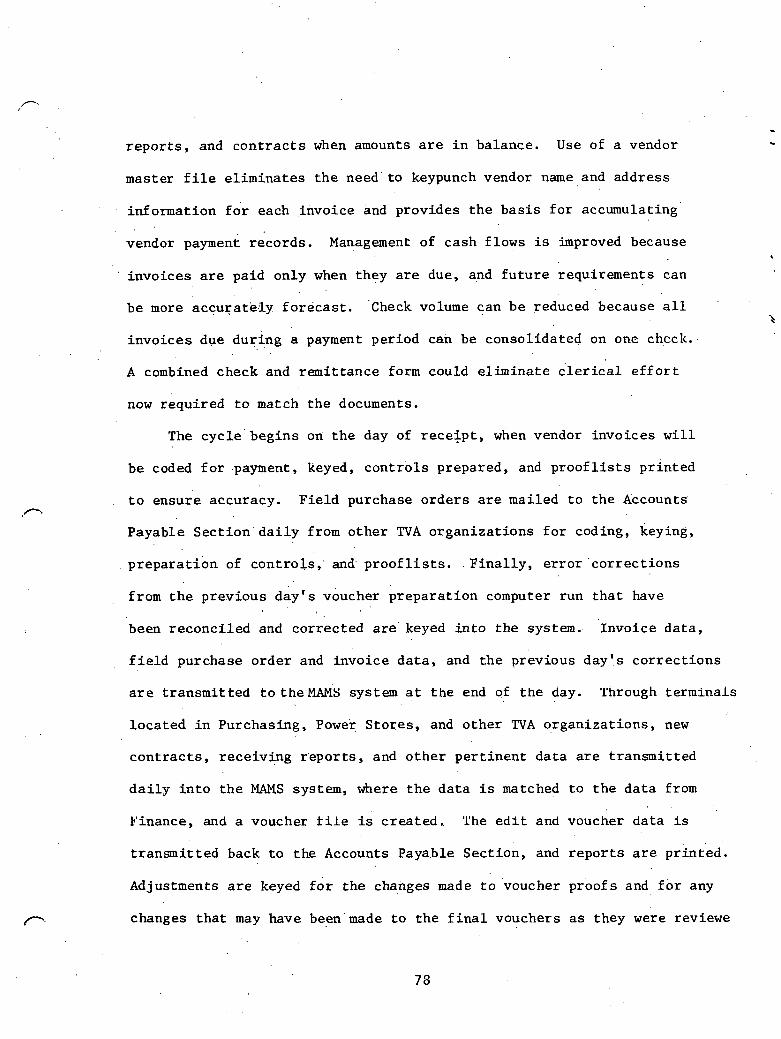
r e p o r t s , and c o n t r a c t s when amounts a r e i n balance. Use of a vendor
master f i l e e l i m i n a t e s ' the ' .need ' t o keypunch vendor name and address
informat ion f o r each invo ice and provides t h e b a s i s f o r accumulating'
vendor r eco rds . Management of cash f lows is improved because
invo ices are pa id only when they a r e due, and f u t u r e requirements can
b e more a c c u r a t k l y f o r e c a s t . Check volume can b e reduced because a l l
i n v o i c e s due du r ing a payment per iod cah be consol ida ted on one check.
A combined check and r emi t t ance form could e l i m i n a t e c l e r i c a l e f f o r t
now requ i r ed t o match t h e documents.
The cyc le : beg ins on t h e day of r e c e l p t , when vendor i nvo ices w i l l
b e coded f o r -paymeht, keyed, c o n t r o l s prepared , and proof l i s ts p r i n t e d
t o ensure accuracy. F i e l d purchase o r d e r s a r e mai led t o t h e Accounts' ,-
Payable S e c t i o n ' d a i l y from o t h e r TVA o r g a n i z a t i o n s f o r coding, keying,
p r e p a r a t i o n of c o n t r o l s , ' and. p r o o f l i s t s . . F i n a l l y , e r r o r ' c o r r e c t i o n s
from t h e p rev ious day ' s voucher p r e p a r a t i o n computer run t h a t have
been r e c o n c i l e d and co r rec t ed a r e ' k e y e d i n t o t h e system.. Invo ice d a t a ,
f i e l d purchase o r d e r and invo ice d a t a , and t h e previous day ' s c o r r e c t i o n s
a r e t r ansmi t t ed t o theMAMS system a t t h e end of t h e day. 'l'hrough t e rmina l s
l o c a t e d i n Purchasing, Power S to re s , and o t h e r TVA organ iza t ions , new
c o n t r a c t s , r e c e i v i n g r ' epor t s , and o t h e r p e r t i n e n t d a t a a r e t r ansmi t t ed
d a i l y i n t o t h e MAMS system, where t h e d a t a i s matched t o t h e d a t a from
Finance, and a voucher t i l e is c r e a t e d . The e d i t and voucher d a t a is
t r a n s m i t t e d back t o t h e Accounts Payable Sec t ion , and r e p o r t s a r e
Adjustments a r e keyed f o r t h e changes made t o voucher and f o r any
changes t h a t may have been'made t o t h e f i n a l vouchers a s they were reviewe

and c e r t i f i e d , Nonmater ial .vouchers are p r e p a r e d ' o u t s i d e of t h e MAMS
system, b u t . w i l 1 merge w i t h : m a t e r i a l vouchers a t - t h i s p o i n t and w i l l . .
e n t e r i n t o the"process .
A t t h e end of t h e day, t h e voucher ad jus tments and nonmater ial
vouchers a r e t r ansmi t t ed back t o . t h e .MA.Ms.'. system and a r e used t o update
an accounts payable d a t a base. P e r i o d i c a l l y , vouchers due a r e p u l l e d
of f of t h e accounts .payable d a t a base and a r e used t o p r i n t checks,
r emi t t ance advices , and a check r e g i s t e r . ' A t t h e same . t ime, t h e open
con t r ac t - d a t a base arid t h e accouhts payable d a t a base are used t o pre-
pa re s e v e r a l management r e p o r t s . The open c o n t r a c t d a t a base and t h e
vendor mas ter d a t a , b a s e a r e used cont inuous ly f o r s ea rch and d i s p l a y
i n r e sea rch ing c o n t r a c t o r payment s t a t u s on any invo ice o r r e c e i p t .
The p r i n c i p a l elements of t h i s subsystein c o n s i s t . o f t h r e e major
bases . The Vendor Master Data Base provides a c e n t r a l sou rce of informa-
t i o n p e r t a i n i n g t o vendors. The Open Con t rac t s Data Base con ta ins a
complete record of a l l m a t e r i a l c o n t r a c t s awarded by TVA and s t o r e s
. . them u n t i l p rope r ly f u l f i l l e d o r cance l l ed . The Accounts Payable Data
Base s t o r e s voucher d a t a u n t i l t h e payment due d a t e a r r i v e s .
The Accounts Payable Subsystem .outputs a number of forms and r e p o r t s
t o a i d t h e payment of vendors.
Vouchers - Voucher Proofs: I n d i c a t e t h a t a manual review of documents is requ i r ed
f o r c e r t i f i c a t i o n . , . , . . .
Checks 'and .K&mittarice Advices : .. .
Commitments Reljorts : Shows ' . t h e commitments , t h a t .vendors have t o TVA.

Cash R e q u i r a e n t s : P r e d i c t s cash . requirements f o r t h e next 1 2 months.
Contract Follow.-Up.Report:., Print.ed a t t h e rece iv ing loca t ion , i t l i s t s
those c o n t r a c t s missing documents requi red f o r payment,
Unpaid.Vendor Queries: A CRT query can be made of t h e system t o deter- .
mine i f payment .has .been made. . .
. .
.2.12 Major Pro j c c t Managcmcnt- Syatcm (MPMS) - Georgia Power, Company
The Southern Company is developing a d a t a b a s e system which is
r e f e r r e d t o a s t h e Major P r o j e c t Management System (MPMS) . I n a sense,
i t i s a n outgrowth of ce r t a i l i : . ex i s t ing programs on-l ine i n the system
a t va r ious c o n s t r u c t i o n . s i t e s . Not a l l t he p l a n t s under cons t ruct ion
u t i l i z e a l l t h e e x i s t i n g programs. I t i s hoped t h a t i n 'two years the
d e t a i l e d design of MPMS w i l l be complete.
F ive primary a r e a s have been i d e n t i f i e d along wi th t h e i r r e spec t ive
f i r s t l e v e l a reas . They a r e a s fol lows:
Scheduling
Document Control
Veqlor Drawing Control System Domestic Drawing Control System Procurement Control 'Reports
Mat e,r i . a l C.on t r o &
Equipment /Mater ia l I d e n t i f i c a t i o n System (EMIDS) Procurement Tracking System Warehousing System Start-Up rackin in^
c o s t - . '
Commitments . .
Expenditures Est imating

Labor.
. Manpower Data P r o d u c t i v i t y
A f u r t h e r breakdown' i n t o components which have been i d e n t i f i e d but may .
no t be p a r t of t h e f i n a l system des ign i s included i n t h e e x h i b i t s f o r
t h i s s e c t i o n . The two d e t a i l e d breakdowns are on.the.Equipment/Material
I d e n t i f i c a t i o n System and Procurement Tracking system. The two l ists ,
a r e composed of d a t a components which suppor t management and should be
a v a i l a b l e f o r quick r e t r i e v a l .
I n t h e development 'of ; the o v e r a l l system, t h e p re sen t des ign is
t o develop each sub-system s e p a r a t e l y . s o t h a t i t w i l l s tand on i t s own.
Af t e r i n d i v i d u a l sub-systems a r e o p e r a t i o n a l , they w i l l be i n t e g r a t e d
i n t o t h e t o t a l d a t a base system. The l o g i c being used i n t h e develop-
ment of each ' system u t i l i z e s t h e fo l lowing s t e p s :
(1) General system d e s i g n memo
(2) Func t iona l s p e c i f i c a t i o n s
(3) D e t a f l program/system d e s i g n
( 4 ) Wri te and t.est sof tware package
( 5 ) Develop u s e r s manual
( 6 ) Develop implement a t i o n procedures
( 7 ) I n i t i a l implementat i on and t e s t i n g
The .prnje.c.,t. development people admit t h a t t h e MPMS system has bugs
i n some'segments and probably has been over-designed i n o t h e r a r e a s . .
But i t has been we l l thought through concep tua l ly and ' through .more re-
f i n i n g and development i t should be an e x c e l l e n t . t o o l wi th which management
. . . .

c a n c o n t r o l t h e c o n s t r u c t i o n 'of a power p l a n t and b u i l d . a b e t t e r
product more e f f i c i e n t l y .
. .
. .
2.13 S t r u c t u r e . 6 f Numbering -systems
The o b j e c t i v e s ' o f a numbering system f o r m a t e r i a l c o n t r o l a r e
e s s e n t i a l l y two-fold. The f i r s t and primary o b j e c t i v e i s t o g i v e a
s t anda rd ized ' i d e n t i t y t o a m a t e r i a l o r s e r v i c e q u a n t i t y i o t h a t i t is
unique, qu ick ly i d e n t i f i a b l e , and can be e a s i l y communicated. The
second o b j e c t i v e i s t o bu i ld i n t o t h a t i d e n t i t y t h e a b i l i t y t o l i n k i t
. t o o t h e r systems' a t a l l s t e p s of t h e l i f e cyc l e .of t h e i d e n t i f i e d mate- . 4
r i a l o r s e r v i c e . . ..
IA t h e h i g h l y computerized f i e l d of nuc lea r cons t ruc t ion , t h e
computer i s t h e t o o l .that Z s used f o r t r ack ing and c b n t r o l l i n g products . .
f'rom inc.ept ion through ' s t a r t -up . Thus, a n ef f i c i e n i i d e n t i t y number
a
f o r m a t e r i a l and s e r v i c e q u a n t i t i e s i s of key importance now and i n
, . f u t u r e t r a c k i n g systems.
' P r e s e n t l y , no numbering system e x i s t s which e s t a b l i s h e s a unique
number t h a t c a r r i e s through t h e e n t i r e l i f e c y c l e of a m a t e r i a l o r
component. M a t e r i a l q,uant it i e s a r e g iven B i l l of M a t e r i a l numbers,
r e q u i s i t i o n numbers, purchase o rde r numbers, 'mater ia .1 t r ack ing numbers,
c o s t 'accounting numbers, . e t c . Each t ime a q u a n t i t y 'which must be uniquely
t racked changes i d e n t i t y , t h e r e i s a l o s s of e f f i c i e n c y . and. . t h e t a s k of
t r a c k i n g i s complicated. The reason t h i s problem exists stems from t h e
tremendous 'amount of i n f o r & t i o n ' a s s o c i a t e d with components and t h e
number of a c t o r s a n d . o r g a n i z a t i o n s .which c o n t r i b u t e component d a t a . The

amount of information ga ins momentum through t h e l i f e c y c l e of a
g iven i tem' and/or . a c t i o n . . The' fo l lowing i s a l i s t of b a s i c in£ orr ia t ion
ca , tegor ies which a r e a s s o c i a t e d with. m a t e r i a l i tems:
(1): P r o j e c t number (2) P ip ing and Instrument Drawing (P&LD) '
(3) S p e c i f i c a t i o n s ( 4 ) Schedule work a c t i v i t y (5) . c o s t accounting (6) '. Purchasing and vendor numbers (7) Vendor drawing numbers (8) IS0 drawing 'numbers (9) Locat ion ( spool , system, a r e a , ' bu i ld ing ) (10) Sa fe ty o r non-saf,ety r e l a t e d s t a t u s (11) Class o r group of, equipment o r m a t e r i a l (12) Warehousing and s t o r a g e in£ ormation' (13) Or ig in (pr imary engineer ing , s i t e , .home o f f i c e , (14) Other s p e c i f i c o r non-standard d e s c r i p t i o n
e t c . )
It i s ev iden t t h a t a s i n g l e . i d e n t i t y number which c o n t a i n s a l l of t h e
above informat ion w i l l be tremendously long and cumbersome t o use . I
. I.' The numbering system employed by Bechte l i n t h e i r Quant i ty Tracking
System i s an example of t h i s type of an i n t e l l i g e n t numbering s t r u c t u r e .
The Bechtel 11-d ig i t number g iven t o p ipe , v a l v e s , o r hangers i n t h e
Large P i p e Tracking System con ta ins system and spool number ( l o c a t i o n ) ,
a r e a ( l o c a t i o n ) , and drawing number (IS0 and P&ID). There a r e a l s o
va r ious numbering systems i n e x i s t e n c e f o r r e q u i s i t i o n s o r schedule ac-
t i v i t i e s which a r e p a r t i a l l y used du r ing m a t e r i a l l i f e cyc l e s . For
i n s t a n c e , t h e Cons t ruc t ion group a t .Georgia Power Company u s e s a six-
d i g i t schedule a c t i v i t y code f o r c o n s t r u c t i o n a c t i v i t i e s . a n d has made i t
f l e x i b l e enough f o r f i l i n g , c o s t . accounting, . purchase o r d e r s , and even
engineer ing c o s t coding.

2.13.2 Sysfeni ' ir i 'Use.:af 'Vogt le Nuclear Power 'P l an t
The' area of document.. c o n t r o l . i n t e r f a c e s . d i r e c t l y . with. m a t e r i a l
t r ack ing . The amount of d a t a a s s o c i a t e d wi th procurement 'documents
and r equ i r ed c ros s - r e fe renc ing n e c e s s i t a t e s a s e p a r a t e numbering system.
This system s t a r t s i n . d e s i g n and is f i n a l l y u t i l i z e d i n t he f i e l d and
by p r o j e c t management. An' example of an a c t i v e system being u t i l i z e d .
p r e s e n t l y i n t h e c o n s t r u c t i o n of Vogt le Nuclear P l a n t £ o r G e o r g i a Power
Company is g i v e n a s E x h i b i t s 1 and 2 i n Addendt1.m G . Only a few sample
s h e e t s a r e inc luded on t h e d e t a i l e d breakdown of ' sub-ca tegory s u b j e c t
and number. The system w a s j o i n t l y developed by Bech te l ' s E & I Divi-
s i o n ( E l e c t r i c a l and I n d u s t r i a l ) i n conjunct ion wi th G.eorgia Power and ,
Southern. Company Se rv ices personnel . The a c t u a l number i s a s i x - d i g i t
alphanumeric number which i s h i e r a r c h i c a l l y ranked wi th most s p e c i f i c
in format ion a t t h e r i g h t . The number can be u t i l i z e d a t any l e v e l '
which a l lows c e r t a i n g e n e r a l d a t a and corraspondence t o be f i l e d a t
t h a t r e v e l . The number can be used manually and i s ' adap tab le . t o computer
u s e a s wel l . P r e s e n t l y t h e computerized u s e of t h e number i s p r imar i ly
as a l i s t i n g and scheduling s e r v i c e . S t a t u s , of completeness of documents .
(according t o a predetermix-ied number) is being looked a t now. Paragraphs
3 . l . t o 3 . 6 i n .Addendum G d e s c r i b e t h e system, numbering components, i n i -
t i a t o r r e s p o n s i b i l i t y f o r t h e number, f i l i n g r e s p o n s i b i l i t y , s p e c i f i c a t i o n /
purchase o rde r f i l i n g system, and o t h e r f i l i n g usages .
The s h e e t e n t i t l e d "FILE NUMBE.R AND DESICNATORS" g i v e s the. complete
l is t Cat p r e s e n t ) of t h e t h i r d element codes being considered f o r t h e f i l e
number, Sheets C3-17through C3-61/62 a r e t y p i c a l subcategory l i s ts which

comprise t h e master c o n t r o l document. . ~ o m ~ a r i s o n , c a n . be made. between
t h e two groups composed of s h e e t s ~3-17 through C3-21:/22 and s h e e t s C3-55
through C3-'61162.. The f i r s t . g r o u p is t h e Spec./P.O. F i l e and t h e second
i s t h e Subjec t F i l e .
' The b a s i c codes wh ich . a re proposed f o r u s e i n MPMS a r e a s fo l lows:
SAC -- Schedule A c t i v i t y Code ,
. . COA -- ' C l a s s i f i c a t i o n of Accounts ESC -- Engineering. System Code EMN -- ~ ~ u i ~ m e n t at e r i a l Number SUAC -- ' Star t -up A c t i v i t y Code RUC -- Retirement Unit Code
The.SAC.code i s t h e key t o t h e whole system. It r e p r e s e n t s a c t u a l
c o n s t r u c t i o n a c t i v i t i e s of approximately two weeks d u r a t i o n and i n t e r -
r e l a t e s a11 a c t i v i t : i e s t o t h e a c t u a l . c o n s t r u c t i o n of t h e p l a n t . ~ l l
o t h e r ' a reas support t h e cons t ruc t ion f u n c t i o n of bu i ld ing t h e p l a n t .
The SAC code i s segmented. The f i r s t t h r e e d i g i t s of t h e , s ix-d ig i t ',.
number r ep re sen t major c o n s t r u c t i o n c a t e g o r i e s . A sample master , .
schedule l i s t i n g SAC numbers i s a t t a c h e d a s Exh ib i t 3 , AddendumG,
and a sample SAC code master c o n t r o l shee t is a t t a c h e d a s Exh ib i t 4 ,
Addendum G. Th i s s h e e t ' d e p i c t s t h e codes and t h e sub-component ca t e -
gories . . The remaining t h r e e d i g i t s a r e s i p p l y used f o r sub-category . .
breakdowns. The MPMS f i l i n g . .system being implemented on - s i t e is based
on t h e SAC codes. Even purchase o t d e r s w i l l be f i l e d accord ing t o t h e i r
SAC code. . ..
The' SAC code w i l l appear o n ' d e s i g n drawings Cbut no t on .gene ra1 '
arrangement type d rawings ) ; , on purchase o rde r s , on' .correspondence, on

a l l schedules , and o n . equipment m a t e r i a l 1ist.s t i n Procurement Tracking
'System). Scheduling i n i t i a l i z e s t h e ' u s e o f . t h e SAC codes .when they
p e p a r e t h e schedules . A t t h e same t i m e , Engineering begins t o pos t
t h e SAC codes' on t h e drawings., There i s a s t and ing l ist . of . code numbers
which is u t i l i z e a from p lan t . t o p lan t ; The fo l lowing f i g u r e , F igu re 2.7,
d e p i c t s the usage of t h e SAC code and shows how it binds t h e suppor t , .
a c t i v i t i e s t oge the r . Only SAC codes c r o s s t h e boundaries a s shown.
F i l i n g i s a dependent suppor t a c t i v i t y f o r any o t h e r a c t i v i t y , . and
t h e r e f o r e is n o t shown as a s e p a r a t e a c t i v i t y i n t h e f i g u r e . The
maximum number of SAC'S f o r a p r o j e c t is. approximately 30,000.
The C l a s s i f i c a t i o n of Account (COA) code i s u t i l i z e d f o r accounting
purposes and t h e f i r s t t h r e e d i g i t s 'correspond t o t h e 13 Fede ra l Power
Commiss3on (FPC) accounts . The f o u r d i g i t s a f t e r t h e decimal a r e t i e d
i n t o the ESC code. A t y p i c a l COA code would be 312.5211. A SAC code
only r e f e r e n c e s a s i n g l e COA. There a r e approximately 1 ,000 COA numbers.
The Engineering System Code (ESC) is a f o u r d i g i t number used by
~ n g i n e e r i n ~ t o schedule t h e i r des ign a c t i v i t i e s . A c h e c k l i s t i s deve-
loped based on ESC codes so t h a t m a t e r i a l s l i s t e d f o r a p a r t i c u l a r system
can be eva lua t ed . ' A l l eng inee r ing c o s t s ' a r e ' posted to' a n ESC code (time-
s h e e t s , e t c . ) , , w h i c h t h h e n d up i n a COA code. ESC codes a r e posted on
drawings i n o r d e r t o make s u r e t h a t a l l system i n t e r f a c e s a r e co r r ec t ed
in t h e des ign process. . The number-of ESC codes i s determined by t h e .
number of systeins, A t p r e s e n t , t he . . . t o t a l is as fo l lows:
70. S t r u c t u r a l 100 Mechanical 8 0 E l e c t r i c a l
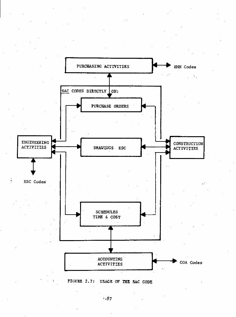
PURCHASING ACTIVITIES ++ EbfN C o d e s i . :
ACTIVITIES. COA Codes
I
SAC CODES DIRECTLY
PURClIASE ORDERS ' -
FIGITRE 2 . 7 : USAGE OF TRE SAC CODE
. ENGINEERING. ACTIVITIES
* 4 DRAWINGS ESC 4
_I
I L
ESC Codes'
.
,
C
SCHEDULES . TIME & COST
r.
, .

t o t a l l i n g 250 ESC codes. .These are . t hen grouped i n t o about 1.50 work
packages.
The Equipment /Mater ia l Number' (EMN) code i s referenced t o SAC code
numbers and t o . p u r c h a s e o rde r s . A major p i ece of equipment i s . a s s i g n e d
a n EMN code which s t a y s w i t h i t from then on. The fo l lowing i s a
d e t a i l e d d e s c r i p t i o n of t h e EMN,
I
AA - - - I T%E G/C T /D LID
A = Alpha. X = Alpha-numeric
I MARK NUMBER
, . EMN
I
Meanings of Codes:
A. .DSC -- ( D e t a i l S p e c i f i c a t i o n s code) . The two a lpha c h a r a c t e r DSC.is an a r b i t r a r i l y ass igned code which is used t o d i f f e r e n t i a t e non-interchangeable i t e m s having . the same EMC. Conversely, &o i tems having t h e same DSC and EMC (Mark Number) a r e i n t d r ~ h a n ~ e a b l e .
-- (-Group or Class Code). The two a lpha c h a r a c t e r . G / C , ' i s ..a preass igned code. ' to i d e n t i f y t h e gener8 l c l a s s of equipment and m a t e r i a l and, i n t h e c a s e of ins t ruments , ins t rument systems,
-- (Type Desc r ip to r Code),. Th i s i s a two a lpha charac-
. ter' t h a t , ..when' added t o t h e G / C , w i l l . d e f i n e t h e . .
. : t y p e of equipment o r m a t e r i a l .

D. LID -- ( ~ o c a t i o n ' . I d e n t i i i c a t i o n Code). . The'. t h r e e d i g i t alp,hanumeric cha rac te r LID is used t o d i f f e r e n t i a t e i t e m s o f ' a given'EMC s o a s t o provide both a unique
. i d e n t i f i c a t i o n ' and l o c a t i o n ' (on a drawing) f o r t h e i t e m . .LID numbers may be used with Mark Numbers; however, uniqueness . i n an item number. i s es tab l i shed only by' EMC p lus LID, ' The LID wkll be genera l ly numeric cha rac te r s . '
E. EMC -- (Equipment Mate r i a l Code). .This is a four charac ter code t h a t . c o n s i s t s of t h e G/C and T/D codes, Each EMC w i l l . y t e l d only .one equipment o r ma te r i a l type desc r ip t ion .
F. Untque ID -- This i s t h e EMC p l u s a non-blank LID. For
. . example, t h i s i s t h e key t o a c c e s s i n g . t h e corm- puter s t o r e d records i n a separa te program, Cable Routing.
G. ,Mark Number -- Consis ts of the DSC p lus EMC codes. The Mark Number is d i f f e r e n t ' f o r each item of, equipment which is d i f f e r e n t , but it must be t h e same f o r mul t ip le o r " l ike" items which a r e in terchangeable . Once aMark Number has been associa ted with a t echn ica l descr ip t ion , . ' t h e u s e of t h a t Mark Number wi th in a given p r o j e c t must.always be associa ted wi th t h e same t e c h n i c a l desc r ip t ion .
. . The EMN is sti.11 lacking . t h e b a s i c , in io imat ion needed i n a q u a n t i t y ' s
number, Hqwever, the approach of segmenting and grouping a number may
' be t h e c l u e t o providing a l a r g e amount of information i n a compact,
e f f i c i e n t numerical format.
The Equipment Mate r i a l Number code is s i m i l a r t o the SAC i n the
sense t h a t i t c rosses some system boundaries. It is p r in ted on the
output s h e e t s of the Equipment and Matersial ~ d e n t i f i c a t i o n System
(EMIDS) . It se rves a s t h e main input. t o EMIDS. Aseignment d a t e s of
each number are . retained.. Assl;gnmerit . r e s p o n s i b i l i t y of t h e code f a l l s .
t o t h e d i s c i p l i n e responsib le f o r i d e n t i f y i n g t h e equipment type and
c l a s s . The EMN code w i l l .be sho+ni' on'. the ' fo l lowi~ lg dociuients:

Funct ional Control Diagrams (FCD1s) Wiring Diagrams Line Diagrams (unique I . D . only) Cable P u l l Cards (unique I .D. only) Raceway I n s t a l l a t i o n Cards (unique I . D . only) D e t a i l Drawings D e t a i l I n s t a l l a t i o n Drawings System Design Spec i f i ca t ions Test Spec i f i ca t ions Procurement Spec i f i ca t ions (mark numbers only) Bills of m a t e r i a l s (mark numbers only) Data sheet^ (mark, numbcrs only) Requis i t ions (mark numbers only) Vendor drawings (.ere t h e drawings a r e required a s i n s t a l l a t i o n
drawings) MPMS Equipment I .D. P r in tou t ("Equipment Lis t" )
The Start-Up Act iv i ty Code (SUAC) w i l l probably be a t h r e e o r four
d i g i t number h i e r a r c h i c a l l y assigned. It w i l l be used t o des ignate
' s t a r t - u p a c t i v i t i e s i n t h e s tar t -up network. I n t h i s context , it w i l l
s e r v e . a s a schedule and s t a t u s c o n t r o l during t h e s tar t -up phase of t h e
p lant . Whether c o s t s w i l l be co l l ec ted a t i ts l e v e l a s they a r e a t t h e
SAC l e v e l (lowest l e v e l c o s t s a r e co l l ec ted) is not known a t present .
Detai led information regarding t h e SUAC w i l l be forthcoming during l a t e r
phases 'of . MPMS aevelopment.
The ~ e t i r e m e n t Unit Code (RUC) i s s t i l l a t e n t a t i v e candidate
code. More iriformation .on i ts u s e and prime funct ion w i l l be obtained
l a t e r a s . i t s r o l e is b e t t e r d.ef ined.
not her numbering system used i n document con t ro l is a s .shown 'on
t h e fol lowing page.; ( . . .

Plan t Designator Sequen t i a l # f o r drawing s! 5,1-11 ilOO1 .
Design d i s c i p l i n e r e s p o n s i b l e f o r drawing en. Unit a t p l a n t S i z e of drawing paper P l a n t f . i n o p e r a t i n g Div i s ion of power
company No. of ' Operat ing ~ i v i s i o n i n power
. , company , ' Type of p l a n t (nuc lear , hydro, f o s s i l
f u e l , pumped s t o r a g e , o r combination)
. . The number above r e p r e s e n t s a t y p i c a l domest ic drawing number. The
fol lowing number i s a t y p i c a l number r e p r e s e n t i n g a vendor drawing
ass igned number: ! : I .
P l a n t Designator Gen. Uhi t . .
drawing iI by P.0;
. . . . I - m
Purchase Order s e q u e n t i a l il
The sequential '-numbers a r e ass igned .iri.:.blocks by P r o j e c t Procurement
and input i n t o th.e Document Cont ro l ,sys.tem by t h e processor of t h e . .
drawing.

2.13.4 Punch L i s t
The numbering system' i'n t h e :Punch L i s t -Program provides . .
in format ion r e q u i r i n g drawings and component a v a i l a b i l i t y . f o r sys tems ' .
t o be scheduled i n t h e coming week. A t y p i c a l i npu t code is a s £pl lowi:
MPL Code . A ;. :
1 C -F2N22-N313C. TX2N22-274. u
. 8 . . .
IS0 Code
Equipment t y p e hange ' s t a t u s
Means g e n e r a l c o n t r a c t o r provides need d a t e '. .
The code is i n p u t on f i v e d i f f e r e n t long s h e e t s which r e p r e s e n t 80 l i n e s
each f o r ca rd input . . he letter and name r e s p e c t i v e l y f o r t h e ' t y p e s of ,- . .
. c o m p o n e n t s a r e a s f o l l o w s :
Spool p i eces Valves Equipment H a n g cr o Welds Ins t ruments R e s t r a i n t s Small bore hangers Small bore v a l v e s Maj o r e l e c t r i c a l equipment
system' output f o i a t s t h e fo l lowing component , a t t r i b u t e s ( s e e Output
Report i n Appendix F ) :
(1) Type (2) .Equipment urnh her (3) IS0 Drawing Number (4) Revision (5) Area (6) S i z e ' '
(7) P.O. .Number' (8) P.O. 'Item Number' (9) P.O. Sub. Item .
(10) Mark Number
Hold ~ o c u m e n t a t i on Received I n Building I n s t a l l e d NDE Hydro CAT ,
Temp. T.O. Perm. T.O.
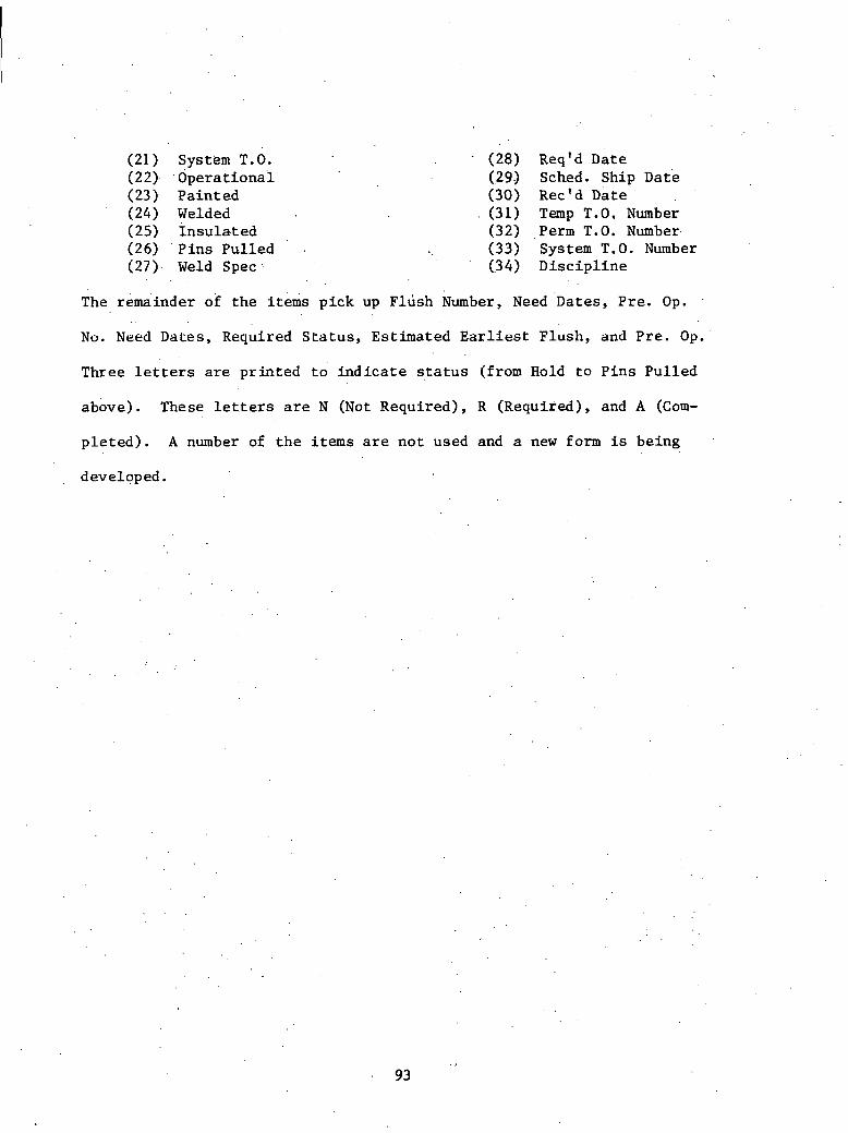
(21) System T.O. - (28) Req'd Date (22). . d p e r a t i o n a i (29J Sched. Sh ip ate (23) P a i n t e d (30) Rec'd ate (24) Welded . (31) Temp T.0, Number ( 25) 1 n s u l a t ed (32) .Perm T.O. Number- (26) ' P i n s P u l l e d . (33) System T.O. Number (27). Weld Spec ,. (34) D i s c i p l i n e
The remainder o f t h e items p i c k up FlGsh Number, Need - ~ a t e s , P r e . Op.
No. Need Dates, Required S t a t u s , E s t i m a t e d E a r l i e s t F l u s h , and P r e . Op.'
Three l e t t e r s are p r i n t e d t o i n d i c a t e q t a t u s (from Hold t o P i n s P u l l e d
above) . These le t ters are N (Not Requi red) , R (Required) , and A (Com-
p l e t e d ) . A number of t h e items a r e n o t used and a new form is b e i n g .
developed.


Problenis ' w i t h E x i s t i n g 'Syst&ms
3 . 1 In t roduc t ion
A s c.an be seen from t h e previous pages, t h e sample of ,systems
examined du r ing t h e course of t h i s s tudy runs t h e f u l l gamut from a
s i m p l i s t i c manual system t o a t o t a l l y i n t e g r a t e d system such a s t h e
M a t e r i a l Management System used by t h e Tennessee Val ley Author i ty .
The fo l lowing c h a r t summarizes w h a t gene ra l s e c t i o n s i n t h e l i f e c y c l e
t h e system covers and a s u b j e c t i v e eva lua t ion a s t o l e v e l of s o p h i s t i c a -
t i o n '(on' a s c a l e of 1 t o 5, where 1 = low).
Design , Ware- System Procurement Purchasing Expedit ing housing Evalua t ion
MESS . X X 4 . . PMICS' " X 2 .
S AS X 4
' MPMS X X . X X 5 Punch L i s t X 4 QTS " X X X X
~ a n u a l x x x x 1 Mat e r i a 1 Con-
t r o l Module X ' X X ' 4 MMI S X X X X 5 MAMS X X X X 5 IMCS X X . . . X 4
TABLE. 3.1
From t h e above c h a r t i t is obvipus t h a t t h e r e i s a g r e a t d e a l of ove r l ap
between t h e v a r i o u s systems. Most of t h e e f f o r t s which c r e a t e d t h e s e
systems were independent ventures .

I n s p i t e of t h e f a c t t h a t a number of d i f f e r e n t groups proceeded
i n t h e development of m a t e r i a l t r a c k i n g systems, t h e r e a r e q u i t e a few
problems which a r e cormion t o a l l systems. How should t h e m a t e r i a l s be
. t r acked , what s o r t of numbering system should' be u t . i l i z e d ? How should
. t h e d a t a b e c o l l e c t e d and what s o r t of methods should be used t o i n s u r e
t h a t t h e c o l l e c t e d informat ion is c o r r e c t ? How should t h e output be
, s t r u c t u r e d f o r e a s e of f i n d i n g t h e des f r ed inf o r m a t l o ~ l ? WliaL sur L UL .
hardware should be implemented t o achieve a s a t i s f a c t o r y response t ime :
whi l e s t i l l keeping c o s t s under c o n t r o l ? ,.What . s o r t of r e s i s t a n c e was
encountered from ' p ro j ec t management when t h e ' e x i s t i n g syskenls were . ..
a l t e r e d ? Was it necessary t o change t h e company o rgan iza t ion i n order . , t o implement' t h e new system? I n a d d i t i o n t o t h e s e r a t h e r gene ra l prob- r lems, many of t h e i n d i v i d u a l s in te rv iewed had s p e c i f i c sugges t ions as
t o what problems i n t h e n u t s and b o J t s range were encouncerecl when su~ut!
of t h e e x i s t i n g systems were set up ( t h e s e have n0.L been inc luded , a s
t h e l e v e l of d e t a i l of t h i s r e p o r t i s 11ot g r e a t enough).
3 . 2 Problems wi th Numbering Systems
I n developing numbering systems, two main c o n s i d e r a t i o n s a r i s e . . ,
The f i r s t is t h c development of t h e number i t s e l f , should t h e number
be a random number o r a so-ca l led " i n t e l l i g e n t " number? An i n t e l l i g e n t
number would con ta in informat ion a s t o the. o r i g i n of t h e component de- . .
sc r ibed . Such dat 'a as isome.tr ic drawing code, system, equipment type ,
a c t i v i t y codes , . e t c , would be i n t r i n s i c , The primary d i f f i c u l t y which
a r i s e s i n a number des ign suc.h a s , t h i s is what happens when some of t he

in£ ormation contained i n t h e number i s r e v i s e d . The . des ign /cons t ruc t ion
of a nuc lea r p l an t is don& on a f a s t t r a c k b a s i s ; t h a t is, des ign
i s only p a r t i a l l y complete (u sua l ly 20%) when a c t u a l c o n s t r u c t i o n begins.
A s t h e des ign proceeds, r e v i s i o n of items a l r e a d y i n t h e c o n s t r u c t i o n
phase i s i n e v i t a b l e . Should a new number be implemented, o r should ,
t h e o ld one be r e v i s e d ? Should t h e d e c i s i o n be made t o r e v i s e t h e number,
i t becomes necessary t o implement t h e change through a l l l e v e l s from
des ign engineer ing t o vendor. Needless t o say, a g r e a t d e a l of con-
f u s i o n a r i s e s dur ing t h e t r a n s i t i o n t o t h e new change. This is sub-
s t a n t i a l l y complicated when i t i s r e a l i z e d t h a t t h e p r o c e s s , of r e v i s i o n
is a c o n t i n u a l l y ongoing process . It becomes obvious t h a t f o r c e r t a i n
l a r g e components i n t e l l i g e n t numbers would be t h e b e s t way t o proceed.
The choice of numbers on bulk items f o r such th ings a s purchase o r d e r
o r r e q u i s i t i o n number could be done on e i t h e r a random o r i n t e l l i g e n t
! b a s i s . Duke Power Company has determined t h a t f o r bu lk i tems t h e u s e
of i n t e l l i g e n t numbers f o r r e q u i s i t i o n s o r purchase o r d e r s r equ i r ed too
much e f f o r t f o r . t h e b e n e f i t s ' gained.
The second major d i f f i c u l t y wi th numbering systems i s a t tempt ing
t o main.tain t h e same number through a l l s t e p s . i n t h e m a t e r i a l cyc l e .
Usual ly t h i s is not ' too d i f f i c u l t w i th in t h e same o rgan iza t ion . But
of t e n t h e r e a r e a g r e a t many d i f f e r e n t 0 ,rganizat ions involved, each
wi th t h e i r own accounting method, Imposing a u n i f i e d numbering system
w i l l r e q u i r e t h a t t h e f i r m s whose systems d i f f e r from t h a t imposed
change t h e i r system o r main ta in a d u a l system. Obviously both of t h e s e

r e q u i r e a d d i t i o n a l e f f o r t which w i l l be r e f l e c t e d i n t h e p r i c e s of
t h e products o f f e r e d ,
3 . 3 problems w i t h I n p u t . Required - Data Acqu i s i t i on . .
I n t h e p roces s of making . . many of t h e systems desc r ibed h e r e i n .. .
work, a g r e a t d e a l of in format ion must b e . c o l l e c t e d and "input" i n t o . .
t h e system.. A s a r e s u l t , many problems a r i s e , ~ e f &ing what inf orma.-
t i o n is needed i s important . An i n c o r r e c t de te rmina t ion could e i t h e r
r e s u l t i n i n s u f f i c i e n t d a t a being c o l l e c t e d , r e s u l t i n g i n a d d i t i o n a l
e f f o r t s i n d a t a c o l l e c t i o n being r equ i r ed , o r too much information
being c o l l e c t e d and cons ide rab le energy being wasted. A. concerted
e f f o r t must be made i n t h e c a s e of each system t o o rgan ize a d a t a
c o l l e c t i o n system which w i l l e f f i c i e n t l y c o l l e c t t h e necessary informa-
. t i o n a t t h e c o r r e c t l e v e l of d e t a i l .
I n t h e p roces s of c o l l e c t i n g inpu t , accuracy i s v i t a l . No system
can be more a c c u r a t e than what is f e d I n t o i t ; garbage in-garbage uuL.
The b e s t way t o mainta$ c o r r e c t n e s s is t o i n s u r e i t s accuracy a t t h e
source. I n s p i t e of t h i s , however, some s o r t of checking system should
be implemented. Dupl ica t ing t h e e n t i r e c o l l e c t i o n p roces s may'not be
warranted, s o some s o r t of random checks should be used. I n t h e .case
of h igh - r i sk i t e m s , . however, i t may be necessary t o double-check th.e . .
e n t i r e ' c o l l e c t i o n procedure. I n any case , because of a snowballing
e f f e c t , i t i s much e a s i e r t o main ta in v e r a c i t y by ca tch ing e r r o r s be fo re
they e n t e r a system, r a t h e r than t r y i n g t o p inpoin t a n e r r o r a l r eady i n
P a system. Some e r r o r s do g e t i n t o any system. A s a r e s u l t , some s o r t
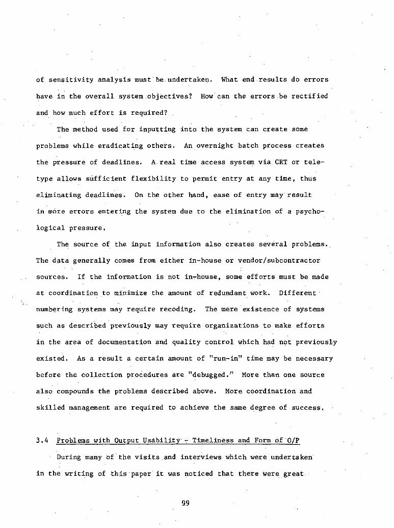
of s e n s i t i v i t y a n a l y s i s .must: be . undertaken. What end . r e s u l t s do e r r o r s
have i n t h e o v e r a l l system . o b j e c t i v e s ? How' can t h e e r r o r s .be r e c t i f i e d
and how much e f f o r t is r e q u i r e d ? , .
. . The method used f o r i n p u t t i n g i n t o t h e system can c r e a t e some
problems wh i l e e r a d i c a t i n g o t h e r s . An overn ight ba t ch process c r e a t e s
t h e p re s su re of deadl ines . A r e a l t ime acces s system v i a CRT o r t e l e -
t y p e a l lows s u f f i c i e n t f l e x i b i l i t y t o permit e n t r y a t any time, thus
e l imina t ing dead l ines . On t h e o t h e r hand, ea se of e n t r y m a y ' r e s u l t
i.n more e r r o r s en t e r fng t h e system due t o t h e e l i m i n a t i o n of a psycho-
l o g i c a l pressure ' ,
The source of t h e inpu t in format ion a l s o c r e a t e s s e v e r a l problems.
The d a t a g e n e r a l l y comes from e i t h e r in-house o r vendor /subcont rac tor
sources . I f t h e informat ion is no t in-house, some e f f o r t s must be made
a t coo rd ina t ion , to minimize t h e amount of redundant work. D i f f e r e n t . .. .
numbering systems may r e q u i r e recoding. The mere ex i s t ence of systems
such as desc r ibed 'previou'sly .may r e q u i r e o r g a n i z a t i o n s t o make e f f o r t s
i n t h e a r e a of documentation and q u a l i t y c o n t r o l which had no t previously
e x i s t e d . A s a r e s u l t a c e r t a i n amount of "run-in" t ime may be necessary
be fo re t h e c o l l e c t i o n procedures are "debugged.." More t h a n one source
a l s o compounds t h e problems desc r ibed ab0v.e. More coord ina t ion and
s k i l l e d management .are requi red t o achieve t h e same deg ree of success .
3 . 4 Problems wi th Output Usabil.ity:'- T imel iness and 'Fcirm of .O/P
During many of ' t h e v i s i t s . and in t e rv i ews which were under taken . .
i n t h e w r i t i n g of t h : i s - p a p e r i t w a s no t i ced t h a t t h e r e were g r e a t . :
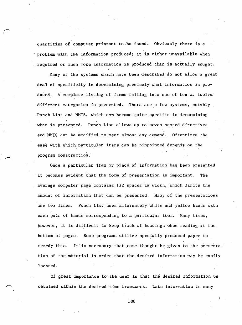
q u a n t i t i e s of computer p r i n t o u t t o . be found. Obviously t h e r e i s a
problem w i t h . the informat ion produced; i t is e i t h e r unava i l ab l e when
r equ i r ed o r much more informat ion is produced than i s a c t u a l l y sought.
Many of t h e systems which have been descr ibed do not a l l o w a g r e a t . .
d e a l of s p e c i f i c i t y i n det.ermining p r e c i s e l y what in format ion is .pro-
duced. A complete l i s t i n g of items f a l l i n g i n t o . one of t e n o r twelve'
d i f f e r e n t c a t e g o r i e s i s presented . There a r e a few systems, no tab ly
Punch L i s t and MMIS , which can become q u i t e s p e c i f i c i n de te rmining
what is presented . punch L i s t ' a l l ows up t o seven nes t ed d i r e c t i v e s
and MMIS can be modif ied t o 'meet a lmost any demand. o f t en t imes t h e
e a s e w i t h which p a r t i c u l a r items can be pinpointed depends on t h e
. . program cons t&c t ion . . .
Once a p a r t i c u l a r i tem o r p i e c e of in format ion has been presented
. ' i t becomes ev iden t t h a t t h e form of p r e s e n t a t i o n is important . The
average computer page c o n t a i n s 132 spaces i n width, which l i m i t s t h e
amount of in format ion t h a t can be presented . Many.of t h e p r e s e n t a t i o n s
u s e two l i n e s . Punch L i s t u s e s a l t e r n a t e l y wh i t e and yel low bands wi th
each p a i r of bands corresponding t o a p a r t i c u l a r i t e m . Many t imes,
however, it i s d i f f i c u l t t o keep t r a c k of headings when reading a t t h e .
bottom of pages. some programs u t i l i z e s p e c i a l l y produced paper t o
remedj t h i s . 1 t . i ~ necessary t h a t some thought be g iven t o . t he p tesenta-
t i o n of t h e m a t e r i a l in o rde r t h a t t h e d e s i r e d informat ion may be e a s i l y
l o c a t e d ,
Of g r e a t importance t o t h e u s e r i s t h a t t h e d e s i r e d informat ion be
P o b t a i n e d ' w i t h i n t h e d e s i r e d ' t i m e framework, La te informat ion is many

t imes as good a s no &formation.. The timespan w i t h i n which informat ion
i s d e s i r e d can be d iv ided i n t o two c a t e g o r i e s : t hose a t r e g u l a r i n t e r - ,
v a l s and those a t i n s t a n t demand. Much of t h e in£ ormation used i n
a d m i n i s t r a t i o n i s r equ i r ed a t . r e g u l a r i n t e r v a l s , i . e . , end of week f o r
p a y r o l l , end of month f o r vendor payment, e t c . This in format ion can
. be.produced on overn ight ba tch bases . The necessary d a t a a r e d e l i v e r e d
t o a c e n t r a l l o c a t i o n and t h e r equ i r ed informat ion is r ece ived t h e r e a f t e r . .
A t t h e product ion end o'f management, however, c r i t i c a l s i t u a t i o n s a r i s e
and certain information is needed immediately. Many t imes t h i s informa-
t . ion can be determined from t h e r e g u l a r l y produced r e p o r t s , Sometimes,
however, t h e publ ished information may not be r e c e n t enough o r no t
con ta in what is d e s i r e d . I n such cases , t h e i d e a l s o l u t i o n is a t e l e -
t ype o r CRT connect ion d i r e c t l y w i th t h e computer. I n t h i s way informa-
t i o n can be r e t r i e v e d immediately. The primary d isadvantage i s t h e
c o s t involved. Real t ime hookups become economical on ly i f a g r e a t
d e a l of usage i s made of them. I f t h e informat ion d e s i r e d is of g r e a t
s i g n i f i c a n c e , however, t h e c o s t may become j u s t i f i e d .
3.5 Problems wi th Implementation
Implementation problems can be d iv ided i n t o two broad a r e a s --
t hose a t t r i b u t a b l e t o u s e r a.cceptance and those a t t r i b u t a b l e t o personnel
t r a i n i n g . User acceptance problems .can vary widely depending on how
g r e a t t h e need f o r some s o r t of mod i f i ca t ion i s , If t h e uppe r . eche lons
of t h e management' do no t g e t t h e in£ ormation they. need o r '. s e e a . b o t t l e -
neck a t some po in t because of an i a fo rma t iona l problem, no doubt some

s o r t of t r a c k i n g system may .be t h e ' . r e s u l t . Lower l e v e l s , however, do
n o t have t h e same overview'.6f t h e s i t u a t i o n ' a n d hdnce may no t a p p r e c i a t e
why c e r t a i n changes are .be ing c a r r i e d ou t . They may even b e l i e v e t h e
a l t e r a t i o n t o be a s t e p i n t h e n e g a t i v e ' d i r e c t i o n , r e q u i r i n g more
e f f o r t w i t h no d i s c e r n i b l e improvement; I n t h e e a r l y s t e p s of imple-
menta t ion , i t is important t h a t t h e r e s u l t s be a s a c c u r a t e a s poss ib l e .
User r e l i a n c e on t h e t r a c k i n g systems w i l l on ly occur i f t h e r e s u l t s
a t t a i n e d . a r e b e t t e r t han t h e e x i s t i n g methods. It is a t t h i s p o i n t , .
'however, t h a t t h e system s t i l l r e q u i r e s ex t ens ive debugging and there-
f o r e does n o t g i v e t h e bes t r e s u l t s . , Most of t h e s e problems, however,
can be circumyented i f upper l e v e l management shows a s t rong i n t e r e s t
i n t h e s u c c e s s f u l implementation of any m a t e r i a l t r a c k i n g system. r. . . Personnel t r a i n i n g problems a r e t h e same a s faced by any a t h e r
l e v e l of management. Af t e r doing t h i n g s one way f.or a longer per iod
of t ime, i t g e n e r a l l y t akes a formal t r a i n i n g e f f o r t t o conver t t o
another system. Th i s t r a i n i n g should be c a r r i e d out ' from program in-
cept ion . High turnover among personnel can become q ,u i t e expensive. . .
Many of t h e s e t r a i n i n g s e s s i o n s can last some t ime and involve a .degree
of expense. I f this must be repea ted f o r t h e same p o s i t i o n o f t e n , then . .
much money must be expended and t h e e f f i c i e n c y of t h e system s u f f e r s .
3 . 6 Problems of I n t e g r a t i o n Between Systems
A s can be seen from TaBle 3 . 1 , many of t h e systems ove r l ap , Trans-
f e r : of i n f o n i a t i o n between' sys.tems i s i n most c a s e s a manual process .
P. The M a t e r i a l and Equipment S t a t u s System (MESS), P ip ing M a t e r i a l Inventory

C ~ n t r o l System (PMICS) , and t h e S t o r e s ' Accounting System (SAS) a r e
a l l developed and. used by t h e Duke Power Company. The' r e l a t i o n s h i p s
" in terms of m a t e r i a l s covered can be i l l u s t r a t e d a s fol lows:
OVERLAPPING RESPONSIBILITIES
,FIGURE 3 . 1 : INTERRELATIONSHIPS BETWEEN MATERIAL TRACKING SYSTEMS
Although t h e r e is some over lap , i t . i s not p o s s i b l e t o d i r e c t l y t r a n s f e r
in format ion between SAS, MESS, and PMICS. I f i t i s d e s i r a b l e t o do .
,. t h i s , t h e informat ion must f i r s t be recompiled be fo re i t can be used
. by any of t h e o t h e r programs. Two of t h e systems reviewed h e r e i n
make t o t a l i n t e g r a t i o n a p a r t of t h e program s e t up. The Material
Management System of t h e Tennessee Val ley Author i ty and t h e Major P r o j e c t
Management System (MPMS) of t h e Georgia Power Company a r e bo th s t i l l v e r y
much i n t h e planning s t age . The o t h e r systems reviewed were s e t up t o
perfo'rm a s p e c i f i c f u n c t i o n r a t h e r than i n t e r a c t ' w i th t h e complete
p r o j e c t management s t r u c t u r e .
3.7 ~ r o b l k s Concerning Over-Desfgn . of System
The development of many of ' t he , sys t ems included i n t h i s . r e p o r t
proceeded i n t h e fo l lowing fash ion . A.need was d i sce rned by e i t h e r

p r o j e c t management o r u p p e r l e v e l company management; systems a n a l y s t s
were a s s igned t o r e s e a r c h and d e v e l o p ' s o l u t i o n s ; and t h e ' system w a s
. implemented i n t h e f i e l d . The' problem of over-design e n t e r s when
it i s s e e n t h a t t h e people who des ign t h e system a r e no t t h e ones who
u s e it. A s t h e a n a l y s t s . examine t h e s i t u a t i o n , they must r e l y on . .
f i e l d . i n t e r v i e w s and pe r sona l assumptions. T h e s e ' i d e a l i z a t i o n s a r e .
t hen incorpoFntcd , i n to t h c system design. When used i n p r a c t i c a l ap- . .
p l i c a t i o n , however, i t i s sometimes found t h a t t h e assumptions made
i n t h e off ice;are . . n o t borne ou t . Georgia Power Company's Punch L i s t
has t h e c a p a b i l i t y of , t r a c k i n g t h e s t a t u s of 16 d i f f e r e n t
p o i n t s i n t h e c o n s t r u c t i o n process . When f i n a l l y used by t h e job s i te
personnel , on ly f o u r o r f i v e of t h e s e p o i n t s were a c t u a l l y used. It
was found t h a t t h e b e n e f i t s reaped were not worth t h e e f f o r t of main-
t a i n i n g exac t in format ion on a l l of t h e 16 p o i n t s . It was poin ted out . .
. . t h a t i t may have been of i n t e r e s t t o main ta in a l l p o i n t s i n o r d e r t o
e s t a b l i s h a h i s t o r i c a l record .
3 . 8 Organ iza t iona l Problems' . .
Many t imes i n . t h e . p r o c e s s of implementing sys tqns , it becomes
obvious t h a t the o r g a n i z a t i o n a l make-up of t h e company does no t lend
i t s e l f t o a n e f f e c t i v e u s e of a m a t e r i a l t r a c k i n g syst'em. Also i t may
become ohvious t h a t t h e b rgan iza t i . ona l . y e l a t i o n s h i p s a l r e a d y i n u s e can
be improved. I n many c a s e s a c e n t r a l i z a t i o n procedure i s involved. A
company may have a . geographical . a r e a hroken up i n t o zones wi th each zone
a c t i n g more o r ' less independent ly. I n t h e ' p rocess of implementing a

n ia t e r i a l t r ack ing system it may become obvious t h a t t h e r e is much
d u p l i c a t i o n of e f f o r t ; many of : . the ' ina te r ia -1s are purchased by a l l s e c t o r s
even though not r equ i r ed by each. C e n t r a l i z a t i o n may s t r e a m l i n e m a t e r i a l
procurement e f f o r t s by reducing d u p l i c a t i o n of e f f o r t and reducing in-
v e n t o r i e s . The M a t e r i a l Management System used by t h e - F l o r i d a Power
Corporat ion reduced t h e i r i n v e n t o r i e s 40 per c e n t by c e n t r a l i z i n g t h e
warehousing system. Previous ly a d e c e n t r a l i z e d zone system had been
used. , I n t h e p roces s of r e a l i g n i n g co rpo ra t e s t r u c t u r e company p o l i t i c s
may play a s i g n i f i c a n t r o l e i n determining what i s f e a s i b l e and what i s
no t . These f a c t o r s may on occas ion be s i g n i f i c a n t and . in any case . shou ld . .
. no t be discounted.

THISPAGE WAS INTENTIONALLY
LEFT BLANK

REFERENCES
Bon tade l l i , James, ~ e n n e s s e e Val ley Author i ty (IMCS)', Personal Communication,. 4-19-77..
Borman, Dick, F l o r i d a Power Corporat ion, Pe r sona l In te rv iew, 9-6-77.
Daniel I n t e r n a t i o n a l Corpora t ion , "Mater ia l and Equipment Receiving," Procedure AP-IX-02, Cons t ruc t ion procedures produced f o r in- t e r n a l use.
Daniel I n t e r n a t i o n a l Corporat ion, "Warehouse ~ r o c u r e m e n t ' ~ o c u ~ e n t s F i l i n g System," procedure AP-IX-01, Cons t ruc t ion procedures produced f o r i n t e r n a l use .
Dixon, Tom, ~ l o r i d a Power Corporat ion, Pe r sona l In t e rv i ew, 9-7-77.
~ o u r o u g h , .Ron, Georgia Power Company, Pe r sona l In t e rv i ew, 8-3 1-77.
Duke power Company, "Accounting Procedure Manual, Sec t ion X-1 , Sto res , " I n t e r n a l procedure manual, 11-1-67.
Gar ro t , Henry, Georgia Power Company, Personal communication, 4-19-77.
.Georgia Power Company, "Vogtle Nuclear P l a n t P r o j e c t References Manual," I n t e r n a l procedure manual, 10-1 1-74, Rev. 1976.
Georgia Power Company, "Mater ia l c o n t r o l C l a s s i f i c a t i o n s - Vogtle Nuclear Power P lan t , " I n t e r n a l document.
~ e o r ~ i a Power Company, "Schedule A c t i v i t y Code Index, P l a n t ~ c h e r e r , " I n t e r n a l document.
Lumadue, R. B. , a ate rial and Equipment s t a t u s . system,'.' February 24, 1976, I n t e r n a l system d e s c r i p t i o n a t Duke Power .Company.
Lumadue, R, . B , , Duke Power Company, personal ' ~ornmunication, 4-5-77.
Lynn, Robert , Duke Power Company, Personal Communication CMESS, PMICS, SAS), 4-5-77.
Manley,'Max,. Duke Power Company, Personal Communication (MESS, PMICS, SAS) , 4-24-77 ,.
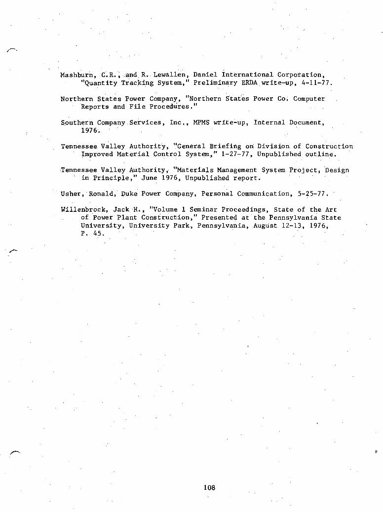
. .. . . Mashburn, . C. R. , . and R. Lewillen., - Danie l ~ n t k r n a t i o n a l Corporat ion,
11 Quan t i t y c rack in^ System," Pre l iminary . . ERDA . write-up, 4-1.1-77.
Northern S t a t e s Power Company, "Northern S t a t e s Power Co. Computer Reports and F i l e Procedures."
Southern Company Se rv ices , Inc . , MPMS write-up, I n t e r n a l Document, 1976.
Tennessee valley Author i ty , " ~ e n e r a l B r i e f i n g on Div i s ion of Construct ion Improved M a t e r i a l Cont ro l System," 1-27-77, Unpublished o u t l i n e .
:Tennessee Va l l ey Au:thority; ateri rials Management System P r o j e c t , ' ~ e s i ~ n "
i n P r i n c i p l e , " June 1976, Unpublished r e p o r t .
Usher, . ~ o n a l d , puke Power Company, Personal Communication, 5-25-77 . Willenbrock, J a c k -H., "Volume 1 Seminar Proceedings, S t a t e , of t h e A r t . . of 'power P l a n t ~ o n s t r u c t i o n , " Presented a t ' t h e ~ e n n s ~ l v a n i a S t a t e
U n i v e r s i t y , U n i v e r s i t y Park, ~ e n n s ~ l v a n i a , .August 12-13, 1976; P. 45.

Quantity Take-Of f
PurchasingIExpedit'ing
Warehousing

Exhibit 1
. .
APPLICATION AREA: Quantity,Take-Off
INDEX
1.0 Descriptian
2.0 Objective
3.0 Functions . . . .
. . ' ,3.1 evel lo^ accurate quantities for purchase of material .on a timely'basis as required by the schedule.
3.1.a ~escri~tion of functions 3.1.b Relationship with other functions and application
areas . . , . 3 . 1 Data requirements
'3.1. d Data genezated within the function 3.1.e Processing 3,l. f .Reports to users

1.0 Descr ip t ion . .
Among t h e a p p l i c a t i o n s considered, Quantity ~ake-'Off can be considered a keystone of t h e o v e r a l l system. It provides t h e ma te r i a l l i s t o r b i l l of ma te r i a l (B.O.M.) f o r many subsequent a c t i v i t i e s , such a s procurement, es t imat ing , planning, scheduling, c o s t con t ro l , progress r epor t ing , warehousing, and documentation. The b i l l of ma te r i a l (B.O.M.) o r p a r t s l ist descr ibes what goes i n t o an assembly. Quanti ty Take-Off i s performed by th ree o r more groups f o r procurement and then repeated by many more groups during t h e l i f e of the p r o j e c t f o r o t h e r app l i ca t ions . The primary engineering f irm has t h e r e s p o n s i b i l i t y f o r t h e major components. Subcontractors with f a b r i c a t i o n c o n t r a c t s have t o prepare a B.O.M. f o r t h e i r sub-components wi th r e l a t e d documentation. S i t e engi- neering has t o procure t h e remaining components not previously defined and ordered t o complete t h e p l a n t . Subsequent a c t i v i t i e s such a s es t imat ing , e t c . l i s t e d above repeat t h i s Quanti ty Take-Off procedure t o perf o m t h e i r t a sks .
2.0 Object ive , .
The f i r s t o b j e c t i v e of Quantity Take-Off i s t o supply an accura te . l i s t i n g of m a t e r i a l q u a n t i t i e s requi red f o r completion of t h e
p r o j e c t wi thfn t h e schedule. The second o b j e c t i v e would be t o provide information t o t h e o the r app l i ca t son a r e a s a s requi red t o accomplish t h i s end r e s u l t . The b i l l of ma te r i a l developed by Engineering should be u t i l i z e d by a s many of t h e o t h e r departments a s poss ib ie t o minimize t h e redundancy of taking o f f , t h e ma te r i a l f o r ' t h e i r purposes.
3.1 Develop accura te q u a n t i t i e s f o r purchase of ma te r i a l on a t imely b a s i s .as requi red by t h e sdhedule.
3.1. a ,Descr ip t ion of funct ions
(1) Plan s t r u c t u r e of b i l l of ma te r i a l (B.O.M.) i n o r d e r ' t o permit explosion t o component l e v e l o r summary t o h ighes t l e v e l of end product ( see Figures A . l . l and A.1.2):
. (2) Perform d e t a i l e d Quan t i ty Take-Off and accura te ly record on spread s h e e t s f o r incorpora t ion i n t o b i l l
' of ma te r i a l . B.O.M. is defined a s t h e organizing of da ta descr ib ing a quan t i ty of m a t e r i a l a s t o what . raw mate r i a l is i n each component, components used i n an assembly, and t h e assembly used i n each end product.
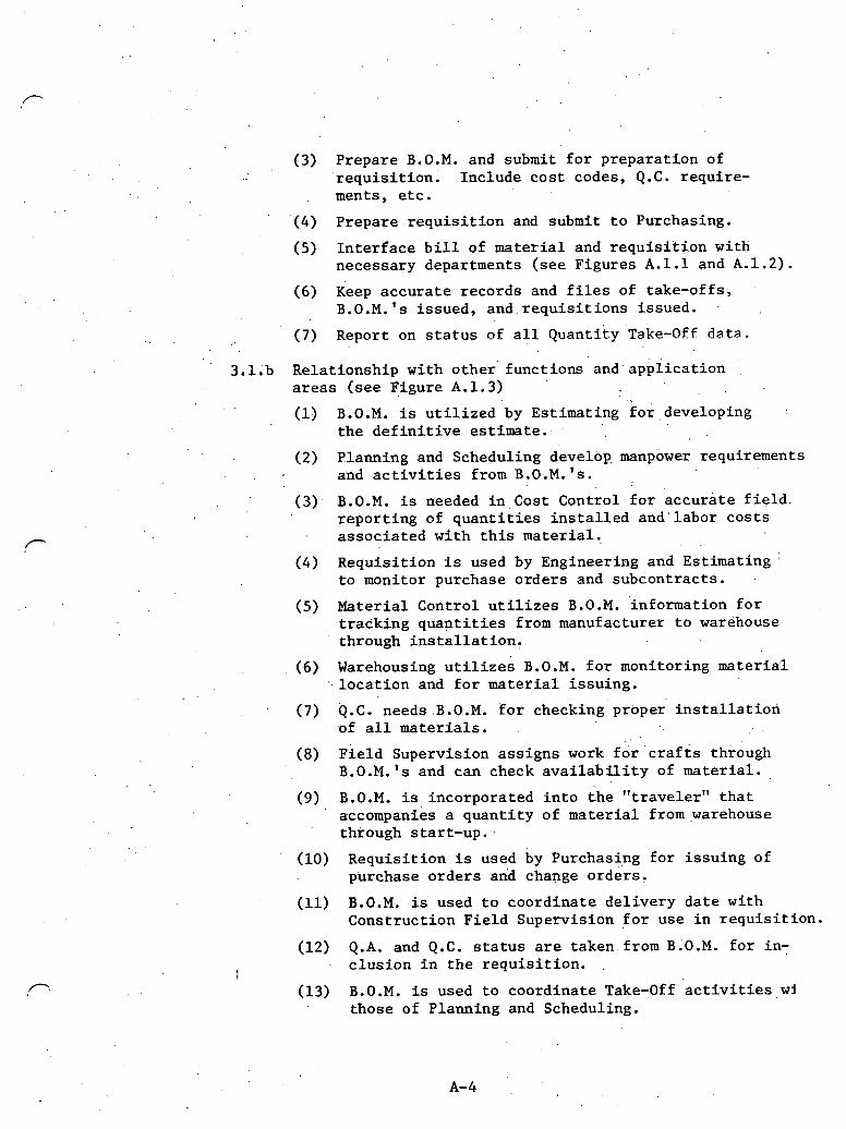
(3) Prepare B.O.M. and submit f o r prepara t ion of r equ i s i t ion . Include c o s t codes, Q.C. require- ments, e t c .
' (4) Prepare r e q u i s i t i o n and submit t o Purchasing.
(5) I n t e r f a c e b i l l of m a t e r i a l and r e q u i s i t i o n with necessary departments ( see Figures A . l . l and A.1.2).
(6) Keep accura te records and f i l e s of . take-offs,
. , B.O.M.'s i s sued, a n d . r e q u i s i t i o n s i ssued.
. . (7) Report on s t a t u s bf a l l q u a n t i t y ' ~ a k e - o f f da ta .
3.1. b Rela t ionship wi th o the r ' funct ions and. a p p l i c a t i o n a r e a s ( see Figure A.1.3.)
. . 1 B.O.M. is u t i l i z e d by Est imating fo r ,deve lop ing
t h e d e f i n i t i v e est imate. .
(2) Planning and Scheduling develop. manpower requirements and a c t i v i t i e s from B.O.M. ' s .
( 3 ) . B.O.M. i s needed i n c o s t Control f o r accura te f i e l d . r epor t ing of q u a n t i t i e s i n s t a l l e d and ' l abor c o s t s a s soc ia ted wi th t h i s ma te r i a l . P . .
(4) ~ e ~ u i s i t i o n is used by Engineering and Est imating : t o monitor purchase o rde r s and subcontrac ts .
(5) Mater ia l Control u t i l i z e s B.O.M. ' information f o r t r ack ing q u a n t i t i e s from manufacturer t o warehouse through i n s t a l l a t i o n ,
(6) Warehousing u t i l i z e s B.0 .M. f o r monitoring material , . l o c a t f o n and f o r m a t e r i a l i s su ing .
(7) Q.C. needs .B.O .M. f o r checking' proper' i n s t a l l a t i o r i of a l l ma te r i a l s .
(8) ~ i e l d Supervision ass igns work f o r ' c r a f t s through B..O.M.'s and can check a v a i l a b i l i t y of mater ia l .
(9) B.O.M., i s incorporated i n t o t h e " t r ave le r " t h a t . ' accompanies a quan t i ty .of ma te r i a l from,warehouse
through s tar t -up .
. ( l o ) Requis i t ion is used by Purchasi.ng f o r i s su ing of purchase o rde r s and change orders .
(11) B.O.M. is used t o coordinate de l ive ry d a t e with Construct ion F i e l d Supervision f o r use i n r e q u i s i t i o n .
(12) Q.A. and Q.C. s t a t u s a r e taken from B.O.M. f o r in-
I c l u s i o n i n the r e q u i s i t i o n . .
(13) B.O.M. i s used t o coordinate Take-Off. a c t i v i t i e s wi those of Planning and Scheduling.

I 3 . l . c Data requirements
(1) Specif $ca t ions .
I (2) A l l drawings t h a t a r e r e l a t e d t o s p e c i f i c d i s c i p l i n e s
o r i n t e r f a c e w i t h o t h e r d i s c i p l i n e s .
(3) Master i d e n t i f i c a t i o n lists, such .as p ip ing l i n e l i s t , e t c .
(4) S t a t u s r epo r t s . on engineer ing procured i tems and subcon t r ac t s .
(5) Schedule.
(6) Cost accounts .
3.1.d Data genera ted w i t h i n t h e f u n c t i o n
(1) B i l l of m a t e r i a l s .
(2) Requ i s i t i ons .
(3) Expedit ing r eques t s . . .
(4) , Requests f o r c l a r i f i c a t i o n and in£ ormation. (R. C . I. ) . (5) Bulk ordered m a t e r i a l inventory r eco rds and c o s t
t r a n s f e r s of bu lk m a t e r i a l .
3.1. e Process ing ( s t e p s of p repa ra t ion )
. , (1) B i l l of m a t e r i a l s (see Figure A. 1 .2) . . . ' . . a . Review drawings and s p e c i f i c a t i o n s and perform
take-.of f . b. Review c o s t accounts and schedule t o determine
s t r u c t u r e of B.O.M. ( s e e F igure A.1.2, B.O.M. sample).
(2) Requ i s i t i ons ( s e e F igu re A. 1 .4) . a . Need B.O.M. f o r p repa ra t ion . b. Assign r e q u l s i t i o n number from l o g and c o s t codes. c . Determine d e l i v e r y d a t e s , Q.A. o r Q.C. s t a t u s .
( s e e F igure A.1.4, r e q u i s i t i o n sample).
(3) Expedi t ing ( s e e F i g u r e A.1.5). a . Q u a n t i t y Take-Off man o r r e q u i s i t i o n e r i s s u e s ' exped i t i ng r eques t on a l l m a t e r i a l s f o r which
he i s r e spons ib l e . b. Maintain kxpedi te r e q u e s t log . c . Forward r eques t t o exped i to r ( s e e F igu re A.1.5).
(4) Request f o r c l a r i f i c a t i o n and , in fo rma t ion ( s e e F igure .A.1.6). a. I s s u e R . C . I . form f o r c o n f l i c t s o r c l a r i f i c a t i o n
dur ing take-off phase. ' b . 'Assfgn number and r eco rd i n l o g book.

c. Used for documenting Take-Off when necessary (see Figure A.1.6).
. . . (5) Bulk order materials tnventory
. . . a. .Material without specific end use at time of
purchase. b. Keep inventory files. . .
.; .c. When material is assigned, record quantity,
. . cost account, and B.O.M.
3.1.5 ' Reports to users
(I) Status reports for: a. B.O.M.'s issued. b. Requisitions issved. c. Expediting reports. d , , Requests fox information. e. Bulk ordered materials.

Exhibi t 2
APPLICATION AREA: Purchasing/Expedit ing . .
INDEX
1 0 Descr ip t ion
2.0 Objec t ives
2.1 Purchasing
2.2 Expedit ing
3.1 purchasing
3.1.a ~ e s c r l g t i o n .
3.1.b ~ e l a t i o n s h ' i p t o o t h e r func t ions . 3 . l . c Data requ.irements 3.1.d Data generated wi th in t h e func t ion 3.1.e Reports t o use r s
3.2 Expedit ing
3.2.a Descr ip t ion ' 3.2.b Rela t ionship wi th o t h e r func t ions
3.2.c Data requirements 3.2.6 Data. generated w i t h i n t h e f u n c t i o n 3.2.e Reports t o u s e r s
' 4.0 Code number o r keys
4.1 Requ i s i t i on number
4.2 Purchase o rde r number
4.3 ' Change o rde r number
5.0 Documentation

1 .0 D e s c r i p t i o n
Purchasing/Expedit ing r e s p o n s i b i l i t i e s are t o a s s u r e t h a t purchas ing , exped i t i ng , and t r a f f i c f u n c t i o n s a r e c a r r i e d ou t i n accordance w i t h e s t a b l i s h e d procurement p o l i c i e s and pro- cedures .
2.0 o b j e c t i v e s
2.1 purchasing: To main ta in a l i s t of b idde r s , r eques t and e v a l u a t e q u o t a t i o n s , i s s u e purchase order.^, main ta in procurement t i les , t ake a c t i o n t o . c l o s e o u t purchase
, o r d e r s , and t r a c k purchas ing t r e n d s which .might a f f e c t m a t e r i a l procurement l e a d time.
2.2 Expedi t ing: , To ensure t h e t imely d e l i v e r y of material and s e r v i c e s .
3.0 Funct ions . .
3.1 Purchas ing
3.1.a Descr ip t ion : Purchasing i s r e s p o n s i b l e f o r t h e fo l lowing func t ions :
(1) S e l e c t i o n and e v a l u a t i o n of p rospec t ive b idders .
(2) Updating p rospec t ive b i d d e r s ' l ist.
(3 ) V e r l f i c a r i o n t h a t r e q u e s t s ' for quo ta t ion a r e com- p l e t e .
(4) S o l i c i t a t i o n of quo ta t ions from p r o ~ p e c t ~ v e sources of supply.
. (5) .Evalua t ion of q u o t a t i o n s and recommendation of b idde r s e l e c t i o n .
( 6 ) I ssuance of purchase o r d e r s t o t h e s e l e c t e d b idder .
(7) I ssuance of change o r d e r s t o p rev ious ly i s sued pur- chase o rde r s .
(8) Maintaining r equ i r ed procurement f i l e s .
(9) Taking a c t i o n as r e q u i r e d t o a s s u r e t h a t purchase o rde r d i s c r e p a n c i e s are c losed .
(10) Keeping p r o j e c t management informed of purchasing t r e n d s which might a f f e c t m a t e r i a l procurement l e a d t i m e .
(11) Maintaining l l s t i n g of major m a t e r i a l s i n s h o r t supply t h a t could a f f e c t t h e p r o j e c t schedule.
.. (12) rans sf e r of valui engineering, information t o .
design engineering ' tha t i s generated i n s o l i c i t a - t i o n of .'quotati.ons.
3.1.b Relat ionship t o o ther funct ions
. ( I ) Obtain approvals of purchase orders and change ' . orders from Design Engineering, when. necessary,
before issuance.
(2) Mater ia l commitments -- i n t e r f a c e s wi th mate r i a l cos t system by feeding it' commitment amounts and co'st codes.
(3) On order information -- i n t e r f a c e s with warehousing/ Materfal Control by passing, on o rder .information.
(4) A s s i s t i n resolving discrepancies between invoices and .recefving repor t s .
(5) Receipts -- i n t e r f a c e s with Warehousing/Material . Control by e i t h e r receiving o r sending receiving .. repor t s .
( 6 ) coordination wi th const ruct ion, Scheduling, and , DesLgn Engineering a s t o manufacturer 's r e l e a s e
. . da tes and required del ivery dates . ,
I
3.1 . c Data requirements
(1) Manufacturer's r e l e a s e da tes and required del ivery da tes ,
(2) Approved bidders.' l i s t .
(3) Purchase r e q u i s i t i o n s .
' ( 4 Mater ia l receiving repor t s . 1
3.1.d Data generated wi th in t h e funct ion
. . (1') Quotation evaluations.
(2) Purchase orders.
(3) Change orders .
(4) Procurement f i l e s .
3.1.e Reports t o use r s
. , . (1) Purchase order s t a t u s repor t .
(2.) Report of warehouse ' r e c e i p t s .
(3) Commitments t o mate r i a l cos t .
(4) Master f i l e l i s t i n g . . .
(5) Master f i l e update l i s t i n g .

. .
3.2 Exp.edit i n g
3.2.a Description: Expediting i s respons ib le f o r t h e fol lowing functions: . . .
(1) Taking a c t i o n as necessary t o ensure t h e timely d e l i v e r y of mate r i a l and se rv ices .
(2) Updating cur ren t s t a t u s . of 'mater ia l loca t ions and expgcted de l ive ry da tes .
3.2 .b' Relat ionship t o o the r funct ions
' . (1) Shipment i d e n t i f i c a t i o n -- i n t e r f a c e s with. Warehousing/Material Control to. a s s i s t i n i d e n t i f y i n g shipments received.
(2) Ma'terial S t a t u s -- i n t e r f a c e s with ~ n g i n e e r i n ~ , Mater ia l Control, and Scheduling f o r cur ren t s t a t u s / r e v i s e d del ivery- d a t e s o f on-order mater ia l .
3.2.c ~ a t a requirements
(1) Purchase order s t a t u s repor t .
(2) Report of warehouse r e c e i p t s .
3.2.d Data generated wi th in t h e funct ion
(1) Locations ot mater ia l i n t r a n s i t .
(2) Expected delivery dates.
3.2.e Keports t o users
(1) Expediting repor t .
4.0 Code number o r keys
4.1 Requis i t ion number,
. . (1) Pro j e c t 'number (2) Safety-related: SR
' Non sa'£ety-related: NS, (3) Work category
00001-24999 C i v i l . ..
25000-25999 Open f o r warehouse use 26000-26999 Rental equipment
I e t c . (4') Change code (01, 02, e t c . )

4.2. Purchase order number: same as requisition number; no change code.
. 4.3 'Change order: same as purchase order number with change code. . .
5.0 Documentation

Exhibit 3
APPLICATION AREA: Warehousing
INDEX
3.0 Functions
3.1.a Description 3.1.b Relationship to other functions and application
areas 3 . l . c Data requirements 3.1.d Data generated within the function 3 . 1 . e Processing 3.1.f Reports to users
4 . 0 Code' number or keys
5.0 Documentation
1.0 Description
Receiving, inspecting, storing, accounting of, and disbursing owner and contractor materials. The receiving reco:ids which are developed and maintained will become part of the permanent plant records.
Ob j ec tives
To provide the facilities and personnel necessary to receive and assure proper storage of materials and equipment at the job site and proper disbursement to the field. To check and receive material purchased by owner and contractor.
Functions
3.1.a Description
(1) Receive all material and equipment.
(2) Check individual shipments for compliance with purchase .orders with respect to quantities and type.
(3) Mark individual pieces to permit ready identification.
( 4 ) Store material and equipment in such a way so as to permit easy access.
(5) Store material and equipment at appropriate ANSI level.
. ( 6 ) " Issue the correct materials in response to field material requests.
: (7) Insure that materials and equipment are issued only to those with sufficient authority to receive them.
(8) Maintain sufficient security around materials and .. 'eqilfpmerit so,as to minimize t'heft and pilferage.
(9) Operate tool rooms.
(10) Maintain a physical inventory.
(11) Maintain a minimum/maximum stock system where required.
(12)' Maintain a stock ordering system.
(13) Handle all outbound shipments.
(14) Establish the existence of damage to received shipments.
3.1.b Relationship to other functions and application areas
(1) Q.A/Q.C. -- close coordination required to establish conformity or non-conformity as early as possible.
(2) Project Management -- inform of arrival of materials to permit work to proceed smoothly.
(3) Planning/Scheduling -- inform of arrival status of materials to permit accurate updating of schedules.
(4) Accounting -- supply arrival status to permit proper payment/billing of vendors.
( 5 ) ~esign/Procurement -- establish proper ANSI storage level.
(6) Purchasing/Expediting -- close coordination required to insure that the correct quantities and types of material have arrived.
7 Document Control -- ~~q~dgnacion required to insure that appropriate distribution of receiving reports, shipping tickets, etc. is achieved.
( 8 ) Data ~ase/~ata Dictionary -- help insure that the Data Base cbritairls the correct: sta tus .recci.rrcd illaterials and equipment.
3.l.c Data requirements
(1) Quantities of materials and equipment arriving to forecast space and manpower required.
(2) ,ANSI storage level to establish storage environment.
(3) Approximate time of removal of materials and equipment from warehousing system to forecast space and manpower requirements.
3.1.d Data generated within the function
(I) . Quantities of items within the warehousing system.
(2) Location'of items within the warehousing system.
(3) Quantity of items issued.
(4) ~ata' of receipt.
(5) Date of issue.
(6) To whom items were issued.
3.1.e Processing
(1) Updating of data generated within the system.
3.i.f Reports to users
(1) Rail car logs.
(2) Construction equipment inventory records.
(3) Stock on hand reports.
(4) Stores catalog.
( 5 ) Small t o o l inventory s tatus .
4.0 Code number or 'keys '
4 . 1 Varies widely depending on system used. See the state-of-the- Art report.
5.0 Documentation . .
5.'1 Varies widely depending on system ,used. See the State-of-the- Art report.

ADDENDUM B .
SUPPORTING MATERIAL FOR
. . MATERIAL AND EQUIPMENT STATUS SYSTEM (MESS)
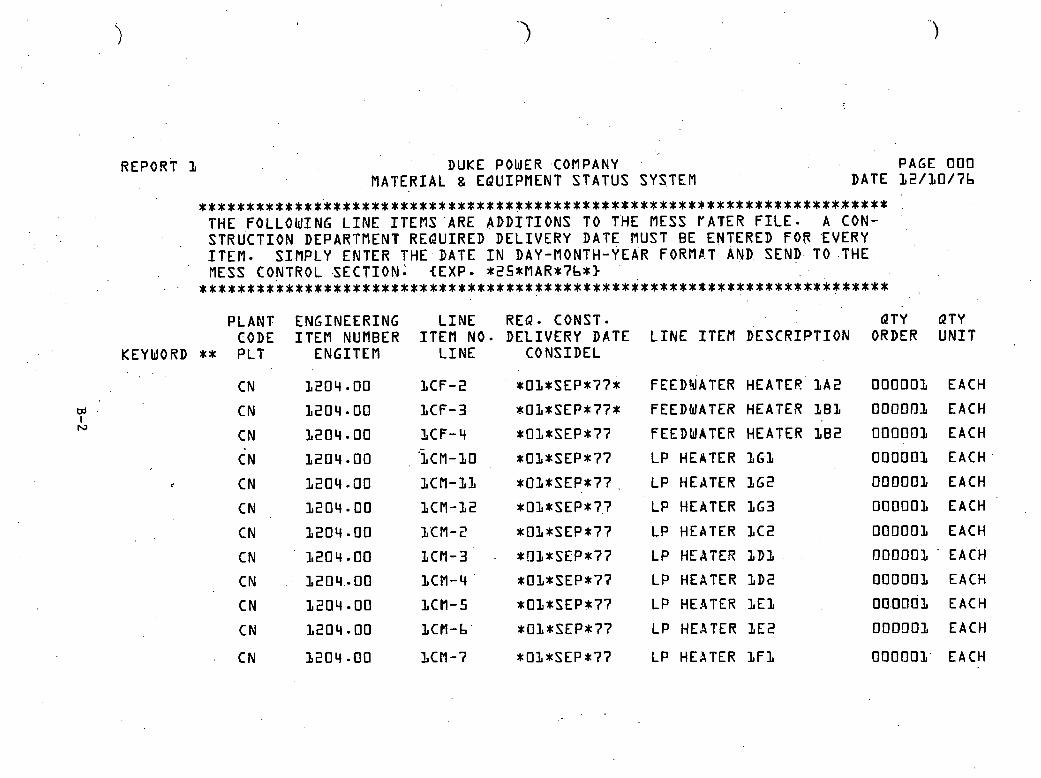
DUKE POWER .COMPANY MATERIAL sl EQUIPMENT STATUS SYSTEM
PAGE 0 0 0 DATE 1 2 / 1 0 / ? b
. . . . . . . . . . . . . . . . . . . . . . . . . . . . . . . . . . . . . . . . . . . . . . . . . . . . . . . . . . . . . . . . . . . . . . . . . . THE FOLLOWING L I N E I T E M S 'ARE A D D I T I O N S TO THE MESS I'ATER F I L E * A CON- STRUCTION DEPARTMENT REPUIRED D E L I V E R Y DATE MUST BE ENTERED FOR 'EVERY I T E M - S I M P L Y ENTER T H E . D A T E I N DAY-MONTH-YEAR FORMAT AND SEND. TO .THE ME.SS CONTROL -SECTION: (EXP- *25*VAR*?b*3
. . * * * * * * * * * * * * * * * * * * * * * * * * * * * * * * * * * * * * * * * * * * * * * * * * * x * * x * * * * * * * * * * * * * * * * * * *
PLANT ENGINEERING L I N E R E Q - CONST* QTY QTY CODE I T E M NUMBER I T E M NO- D E L I V E R Y DATE L I N E I T E M D E S C R I P T I O N ORDER. U N I T
KEYWORD ** P L T ENGITEV L I N E CONSIDEL . .
CN 3 2 0 4 . 0 0 1 C F - 2 *01*SEP*??* FEEDYATER HEATER. L A 2 OOOOOI EACH
CN 3 2 0 4 80 I C F - 3 *OL*SEP*??* FEEDWATER HEATER ZBZ OOOOOI EACH
* O l * S E P * ? ? FEEDWATER HEATER 1 8 2 0 0 0 0 0 1 EACH
CN 1 2 0 4 - 0 0 'LCM-LO * O l * S E P * ? 7 L P HEATER 161 0 0 0 0 0 1 EACH
:. CN I 2 0 4 -00 L C f l - L L *OL*SEP*??. ~ L P HEATER 1 G 2 OOOOOI EACH
CN 1 2 0 4 0 0 I C M - 1 2 *OL*SEP*?.? L P HEATER 1 G 3 0 0 0 0 0 1 EACH
CN 1 2 0 4 0 0 ZCM-S *01*SEP*?? L P HEATER 1 C 2 OOOOO1 EACH
CN ' 1 2 0 4 - 0 0 I C M - 3 . *!lZ*SEP*77 L P HEATE!? ZDZ OOOOOZ ' EACH
CN : 1 2 0 4 . - 0 0 LCM-4 * O l * S E P * ? 7 L P HEATER I D 2 OOOOOl EACH
CN 1 2 0 4 - 0 0 LCM-5 *01*SEP*?? L P HEATER 1 E 1 0 0 . 0 0 0 1 EACH
CN L 2 0 4 = 0 0 I C H - b *OL*SEP*?? L P HEATER LEE! OODOO1 EACH
CN 3 2 0 4 - 0 0 l C M - 7 * O l * S E P * ? 7 L P HEATER 1 F 1 0 0 0 0 0 1 ' EACH

REPORT 2A - PLANT CODE - CK
DUKE POWER COMPANY MATERIAL S EQUIP f lENT STATUS SYSTEM
PAGE 0 0 3 DATE 1 2 / 0 4 / 7 b
................................................................. T H I S L I S T I N G I S INTENDED TO BE USED AS A REFERENCE GUIDE TO RELATE TO I N D I V I D U A L MATERIAL 8 EQUIPMENT I T E M S ON THE COM- PUTER F I L E . .................................................................
PURCHASE REQUIRED O R I G I N A L ORDER L I N E I T E M ENGINEERING Q T Y QTY VENDOR CONST MFG NURBER NUMBER I T E M NUMBER ORDER U N I T L I N E I T E M D E S C R I P T I O N NUMBER DEL DATE DEL DATE
EACH R A D W A S T E P R O C . I N S T 8 C O N T R O L 7 3 1 2 0 0 0 1 1 5 SEP 8 2 1 5 SEP 8 3 EACH DECON-&SMEAR TEST E Q U I P . 7 3 1 2 0 0 0 1 1 5 SEP 8 2 1 5 SEP 8 3 EACH R E S I N DEWATERING TANK S K I D 7 3 1 2 0 0 0 1 195 SEP 8 4 1 5 SEP 8 5 EACH LOT OF 2 7 VALVES 7 3 1 2 0 0 0 1 4 5 SEP 8 4 1 5 SEP 8 5 EACH ADD-STOR-TANKgTRANS EQUIP . 7 3 1 2 0 0 0 1 1 5 SEP 8 4 1 5 SEP 8 5 EACH TV OBSERVATION PACKAGE ' 7 3 1 2 0 0 0 1 1 5 SEP 8 4 1 5 SEP 8 4 EACH f l I X I N G PUMP S K I D 7 3 1 2 0 0 f l E 1 5 SEP 8 4 1 5 SEP 8 5 EACH F I L L P O R T . AND S T A T I C M IXER 7 3 1 2 0 0 0 1 1 5 SEP 8 4 1 5 SEP 8 5 EACH COPPER U N I T AND CONTROL 7 3 1 2 0 0 0 1 1 5 SEP 8 4 1 5 SEP 8 5 EACH CEMENT STOR-8TRANS.SYSTEM 7 3 1 2 0 0 0 1 1 5 SEP 8 4 1 5 SEP 8 5 EACH TRANSFER CART 8 CONTROLS 7 3 1 2 0 0 0 1 1 5 SEP 8 4 1 5 SEP 8 5 EACH LOTON BRIDGE CRANE 7 3 1 2 0 0 0 1 1 5 SEP 8 4 1 5 SEP 8 5 EACH RADWASTE PROC.INST.ICONTROL 7 3 1 2 0 0 0 1 1 5 SEP 8 4 1 5 SEP 8 5 EACH DECON-8SMEAR TEST EQUIP . 7 3 1 2 0 0 0 1 1 5 SEP 8 4 1 5 SEP 8 5
EACH HOTWELL PUMPS 9 0 5 5 0 0 0 3 0 1 AUG 8 0 1 8 J U L 8 0 EACH CONDENSATE BOOSTER PUMPS 9 0 5 5 0 0 0 3 0 1 AUG 8 0 2 5 J U L 8 0 EACH HOTWELL PUMPS 9 0 5 5 0 f l 0 3 01 AUG 8 2 2 3 J U L 8 2 EACH CONDENSATE BOOSTER PUMPS 9 0 5 5 0 0 0 3 0 1 AUG 8 2 3 0 JUL 8 2
CURRENT MFG
DEL DATE
1 5 SEP 8 2 1 5 SEP 8 2 1 5 SEP 8 4 1 5 SEP 8 4 1 5 SEP 8 4 1 5 SEP 8 4 1 5 SEP 8 4 1 5 SEP 8 4 1 5 SEP 8 4 1 5 SEP 8 4 1 5 SEP 8 4 1 5 SEP 8 4 1 5 S E P 8 4 1 5 SEP 8 4
0 1 JUN 8 1 0 1 JUN 8 1 0 1 JUN 8 3 0 1 JUN 8 3
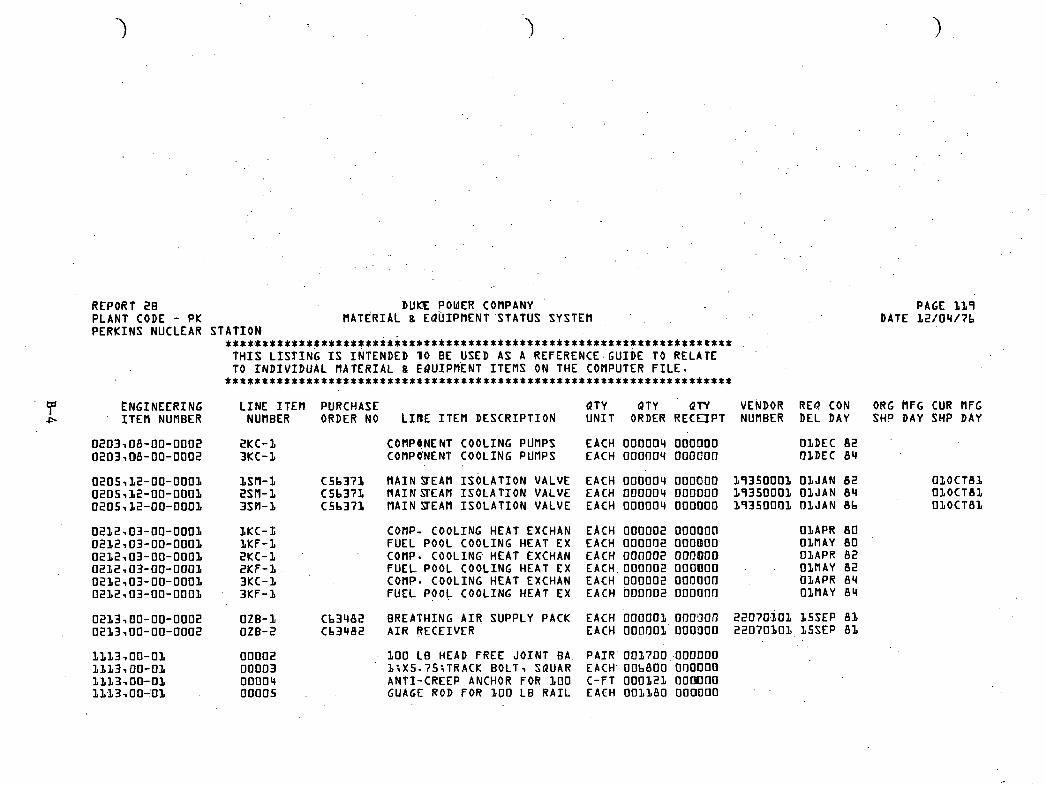
REPORT 2 8 DUKE POWER COMPANY PLANT CODE - PK MATERIAL 8 EQUIPMENT 'STATUS SYSTEM . . PERKINS NUCLEAR STATION
*t***tit**t*****t**e*i*it*******w**************************%****t*** T H I S L I S T I N G I S INTENDED 1 0 BE USED AS A REFERENCE.GUIDE TO RELATE TO I N D I V I D U A L MATERIAL 8 EQUIPMENT ITEMS ON THE COMPUTER F I L E . .....................................................................
f NGINEERING L I N E I T E t l PURCHASE QTY QTY QTY VENDOR RE0 CON I T E M NUMBER NUMBER ORDER NO L I R E I T E M DESCRIPTION U N I T ORDER RECEIPT NUMBER DEL DAY
asn-a 2.SM-1 3sm-1
COMPtlNENT COOLING PUMPS EACH 0 0 0 0 0 4 OOOOOO OLDEC 8 2 COMPQNENT COOLING PUMPS EACH 0 0 0 0 0 4 0 0 0 0 0 0 fl1DEC 8 4
M A I N STEAM ISOLATION VALVE M A I N SEAM I S O L A T I O N VALVE MAINSTEAM I S O L A T I O N VALVE
COflP- COOLING HEAT EXCHAN FUEL POOL COOLING HEAT EX COtlP- COOLING HEAT EXCHAN F U E L POOL COOLING HEAT EX conp. COOLING HEAT EXCHAN FUEL POOL COOLING HEAT EX
BREATHING AIR. SUPPLY PACK A I R RECEIVER
1 0 0 LB HEAD FREE JOINT BA l i X 5 . 7 5 i T R A C K BOLT, SaUAR ANTI-CREEP ANCHOR FOR LOO GUAGE ROD FOR 1 0 0 L B R A I L
EACH 0 0 0 0 0 4 OOOQOO EACH 0 0 0 0 0 4 DODO00 EACH 0 0 0 0 0 4 OODOOO
EACH 0 0 0 0 0 2 0 0 0 0 0 f l EACH 0 0 0 0 0 2 0 0 0 @ 0 0 EACH 0 0 0 0 0 2 OOOOOO EACH 0 0 0 0 0 2 0 0 0 0 0 0 EACH 0 0 0 0 0 2 0 0 0 0 0 0 EACH 0 0 0 n 0 2 oooonn
EACH 0 0 0 0 0 1 0 0 0 3 0 i l EACH OOflOO1 0 0 0 3 0 0
P A I R 0 0 1 7 0 0 OOODOO EACH OOb8OO 0 0 0 0 0 0 C-FT 0 0 0 1 2 ~ oomno E A C H o o n a o o n ~ a o o
O1APR 8 0 OLMAY 8 0 O1APR 8 2 OlPlAY 8 2 OLAPR 8 4 OlMAY 8 4
PAGE 1 1 9 DATE 1 2 / 0 4 / 7 b
ORG 'MFG CUR MFG SHP DAY SHP DAY

REPORT 2 C DUKE POWER COMPANY VENDOR O L 0 2 2 7 0 L HATERIAL g EQUIPMENT STATUS SYSTEM MECHANICAL PRODUCTS CO
****~i*~ti*******tt****t)*t**$*******i**i************************* T H I S L I S T . I N G I S INTENDED TO B E USED AS A REFERENCE GUIDE TO RELATE TO I N D I V I D U A L M A T E R I A L . 8 EQUIPMENT I T E M S ON THE COM- PUTER F I L E - . . . . . . . . . . . . . . . . . . . . . . . . . . . . . . . . . . . . . . . . . . . . . . . . . . . . . . .
PURCHASE REQ ORDER L I N E I T E M ENGINEERING PLANT QTY d T Y CONST NUMBER NUMBER I T E M NUHBER CODE ORDER U N I T LINE I T E M D E S C R I P T I O N DEL DAY
0 b 0 0 7 2 K R 3 8 2 VALVE 0 b 8 0 7 2 K R 3 8 3 VALVE 0 b 8 0 7 2 2 K R 3 8 2 VALVE 0 b 8 0 7 2 2 K R 3 8 3 VALVE
b EACH CONST. FLOM CONTR. V A L V b 5 0 C T 7 b L EACH CONST. FLOW CQNTR VALV L 5 O C T 7 b L EACH CONST*FLOU CONTR-VALV 1 5 0 C T 7 b b EACH C0NST.FLOW CONTR-VALV 1 5 0 C T 7 b
Ob i3202 R V 2 7 3 VALVE MC i E A C H CONST. FLOW CONTR. VALV b S n C T 7 b
ORIG MFG
SHP DAY
PAGE '010 DATE L 2 / 0 4 / 7 b
CURRENT MFG
SHP DAY
LATEST EXP DAY
O b b 7 7 b H V O S i VALVE h c b . EACH 3 / 4 FLOW CONTROL VALV i S N O V 7 b 05NOV7b 05NOV7b 2 7 0 C T 7 b O b 8 7 7 b M V 0 9 2 VALVE . M C . b EACH 1 . 5 FLOU CONTROL VALV 15NOV7b OSNOV7b 05NOV7b 2 7 0 C T 7 b
- - . . O b 8 7 7 b M V 0 9 3 VALVE .MC 4 EACH 3 / 4 FLOW CONTROL VALV L5NOV7b OSNOV7b 05NOV7b 2 7 0 C T 7 b
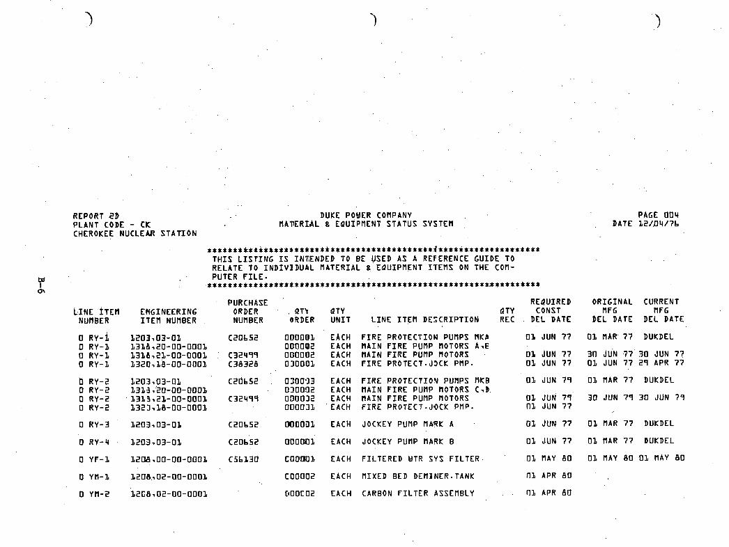
REPORT 2b DUKE POWER COMPANY PLANT CODE - C K MATERIAL 8 EQUIPMENT STATUS SYSTEM CHEROKEE NUCLEAR S T A T I O N
*********tt*****w****t*i*************i******~****************i*** T H I S L I S T I N G I S I N W N D E D TO B E USED AS A REFERENCE GUIDE TO RELATE TO I N D I V I D U A L MATERIAL 8 EQUIPMENT I T E M S ON THE C o n - PUTER F I L E .
*******************a********************
- PURCHASE REQUrRED LINE ~ T E H ENGINEERING ORDER ' . QT'I QTY d T Y CONST
NUMBER I T E M NURBER NURBER gRDER U N I T L I N E I T t 3 l D E S C R I P T I O N REC . DEL DATE
0 RY-i 1203,03-01 C 2 0 b 5 2 OOOOO1 EACH F I R E PROTECTION PUnPS MKP 03 JUN 7 7 0 R Y - 1 1 3 1 8 7 2 0 - 0 0 - 0 0 0 3 0 0 0 0 0 2 EACH M A I N F I R E PUMP MOTORS A -E 0 R Y - 1 1 3 1 1 , 2 & - 0 0 - 0 0 0 1 . C 3 2 4 9 9 0 0 0 0 0 2 EACH M A I N F I R E PUf lP MOTORS 03 JUN 77 0 R Y - 1 1 3 2 0 7 1 8 - 0 0 - 0 0 0 1 C 3 8 3 2 8 0 3 0 0 0 1 EACH F I R E PROTECT - J3CK PMP - 01 JUN 7 7
EACH EACH EACH EACH
EACH
EACH
EACH
EACH
FIRE PROTECTION P U ~ P S MKB 01 JUN 7 9 M A I N F I R E PUMP MOTORS C,B. MAIN FIRE PUMP MOTORS 01 JUN 7 4 ' F I R E PROTECT-JOCK PMP- nx JUN 7 7
JOCKEY PUMP MhTK A Of JUN 77
JOCKEY PUMP MBRK B 0 1 JUN 7 7
F I L T E R E D WTR SYS F I L T E R . 0 1 MAY 8 0
M IXED BED DEMINER - TANK 01 APR 8 0
PAGE 0 0 4 DATE L 2 / D 4 / 7 b
O R I G I N A L CURRENT M FG M FG
b E L DATE DEL DATE
0 1 MAR' 7 7 DUKDEL
30 JU'N .77 30 JUN 77 0 1 JUN 7 7 2 9 APR 77
0 1 MAR 7 7 DUKDEL
30 JUN 74 30 JUN 7 9
0 1 MAR 7 7 DUKDEL
01 MAR 7 7 BUKDEL
01 M A Y ab . o 1 M A Y 8 0
0 YM-2 1 2 C 8 , 0 2 - 0 0 - 0 0 0 1 C100C02 EACH CARBON F I L T E R ASSEMBLY . . O 1 APR 8 0

REPORT 3 DUKE POWER COMPANY SPONSORING ENGINEER - X X X MATERIAL 8 EQUIPMENT STATUS SYSTEM
PAGE 944 DATE 99/99/99
. . . . . . . . . . . . . . . . . . . . . . . . . . . . . . . . . . . . . . . . . . . . . . . . . . . . . . . . . . . . . . . . . . T H I S REPORT L I S T S THE L I N E I T E M S WHICH H'AVE A NEW OR .CHANGED MANUFACTURER REQUIRED RELEASE DATE. .................................................................
td PURCHASE M I L L P R REQ CURRENT RE0 I 4 ENGINEERING L I N E I T E M ORDER PLANT VENDOR QTY QTY PURORD MFG MFG CONST
I T E M NUMBER NUMBER NUMBER CODE C I N E I T E M D E S C R I P T I O N NUMBER ORDER U N I T RELDAY SHPDAY SHPDAY DELDAY
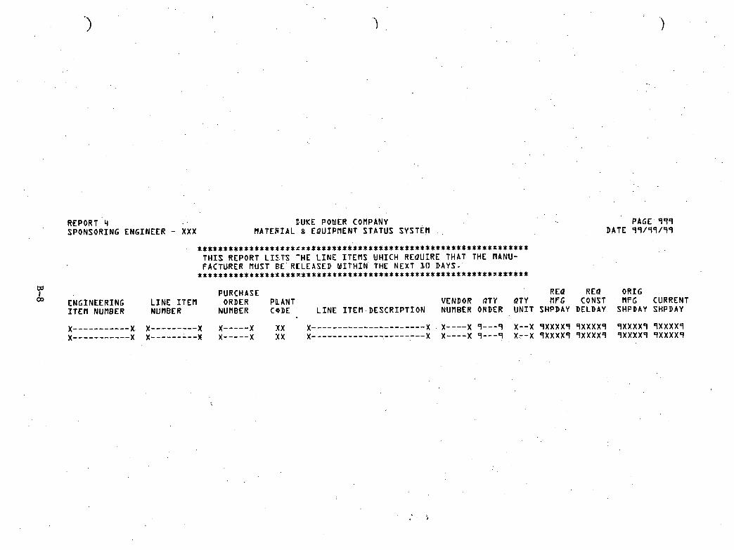
REPORT '4 PUKE POMER COMPANY PAGE 999 SPONSORING ENGINEER - X X X R A T E R I A L 8 EQUIPMENT STATUS SYSTEM . . DATE 99/99/99
t S t * * t * * * * t t * * * l $ * * r * * * * * * s * * * * * + t * * * * * * * * * * * * * * * * * * * * * * * * * * x * * * * * * T H I S REPORT L I Z T S 'HE L I N E I T E M S U H I C H REQUIRE THAT THE I lANU- FACTURER MUST BE RCLEASED W I T H I N THE NEXT 20 DAYS.
* * * * * * * * * * * * * * * * * * * x * * * * * * * * * * * * * * * * * * * * * * * * * * * * * * * * * * * * * x * * * * * *
td I PURCHASE REQ RE0 ORIG
ENGINEERING L I N E I T E M ORDER PLANT VENDOR 87.1' QTY MFG CONST MFG CURRENT I T E M NUMBER MUMBER NUMBER CoDE L I N E 1 T E M . D E S C R I P T I O N NUNBE.R ORDER U N I T SHPDAY DELDAY SHPDAY SHPDAY
x--------- x x----- x xx x---------------------- X . X----X 9- - -9 X--X 9XXXX4 9XXXX9 9XXXX9 9XXXX9 x----------- X X--------- x----- x X X x---------------------- x x---- X 9---q X.--X 9XXXX9 9XXXX9 9XXXX9 9XXXX9
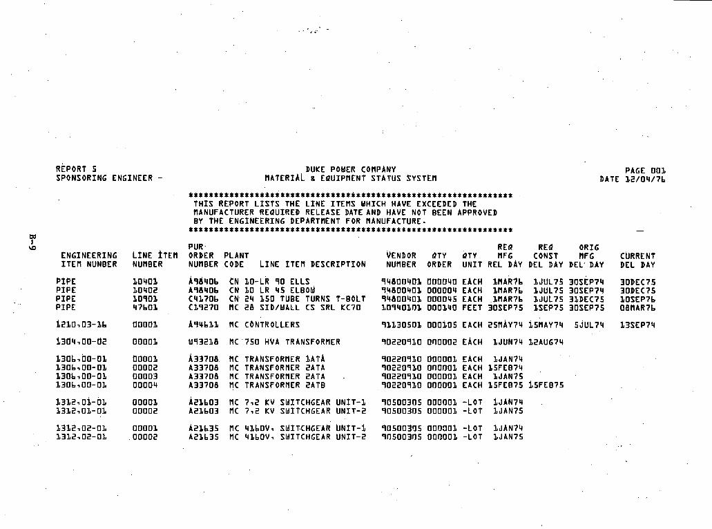
REPORT 5 SPONSORING ENGINEER -
w I
\O ENGINEERING I T E M NUNBER
P I P E P I P E P I P E P I P E
L I N E TEN NUMBER
DUKE POWER CONPANY MATERIAL 8 EQUIPMENT STATUS .SYSTEM
PAGE 0 0 1 DATE L 2 / 0 4 / 7 b
t * * t * t ~ * t * * * * * t t * i * * * * * * * * * * $ * t ~ * * * i * * * * * * * T H I S REPORT L I S T S THE L I N E I T E N S WHICH HAVE EXCEEDED THE NANUFACTURER REQUIRED RELEASE DATE AND HAVE NOT BEEN APPROVED BY THE ENGINEERING DEPARTNENT FOR MANUFACTURE. ................................................................. -
PUR - REQ RE4 ORIG ORDER PLANT VENDOR dTY ~ T Y MFG CONST NFG CllRRENT NUMBER CODE L I N E I T E M DESCRIPTION NUMBER ORDER U N I T REL D A Y DEL DAY DEL, D.AY DEL DAY
A 9 h 4 0 b t N 10 -LR 9 0 ELLS 9 4 8 0 0 4 0 1 CIfl0040 EACH LHARi'b 1 J U L 7 5 3 0 ~ ~ ~ 7 4 30DEC75 A 9 8 4 0 6 CN LO LR 115 ELBOW 9 4 8 0 0 4 0 1 0 0 0 0 0 q EACH 1f lAR7b 1 J U L 7 5 30SEP74 30DEC75 C 4 L 7 0 b CN 2 4 1 5 0 TUBE TURNS T-BOLT 9 4 8 0 0 4 0 3 0000115 EACH 1MAR7b 1 J U L 7 5 31DEC75 1OSEP7b C 1 9 2 7 0 MC 2 8 SID/WALL CS SRL KC70 1 0 9 4 0 1 0 1 OOO1UO FEET 30SEP75 LSEP75 30SEP75 O8f lAR7b
~ 9 l l b 1 1 NC C.ONTROLLERS 9 1 1 3 0 5 0 1 0 0 0 1 0 5 EACH 2 5 N A ~ 7 4 1 5 ~ ~ ~ 7 1 1 5 J U L 7 4 13SEP74
W93218 MC .?SO HVA TRANSFORHER 9 b 2 2 0 9 1 0 0110002 EACH. 1JUN74 L2AUG74
A 3 3 7 0 8 MC TRANSFORHER ~ A T A 9 0 2 2 0 9 1 0 0 0 0 0 0 1 EACH 1 J A N 7 4 A 3 3 7 0 8 MC TRANSFORHER 2ATA 9 0 2 2 0 9 1 0 0 f l 0 0 0 1 EACH I S F E E 7 4 ,
A 3 3 7 0 8 MC TRANSFORHER 2ATA . 9 0 2 2 0 9 1 0 0 0 0 0 0 1 EACH 1 J A N 7 5 A 3 3 7 0 8 RC TRANSFORHER 2ATB 9 0 2 2 0 9 1 0 0 0 0 0 0 1 EACH 1 5 F E B 7 5 i 5 F E B 7 5
~ 2 1 b 0 3 MC 7-12 k~ SMITCHGEAR U N I T - 1 9 0 5 0 0 3 0 5 0 0 0 0 0 1 -LOT I J A N 7 4 A 2 1 b 0 3 MC 7 - 2 KV SldITCHGEAR U N I T - 2 9 0 5 0 0 3 0 5 0 0 0 0 0 1 -LOT 1 J A N 7 5
A 2 1 b 3 5 NC 41bOVq SMIT~CHGEAR UNIT -$ 9 0 5 0 0 3 0 5 0 0 0 3 0 1 -LOT l J A N 7 4 A 2 1 b 3 5 MC 4Lbf lV, SMITCHGEAR U N I T - 2 9 0 5 0 0 3 0 5 0 0 0 0 0 1 -LOT l J A N 7 5

REPORT b PLANT CODE -CK CHEROKEE NUCLEAR
D U K i POWER tOMPANY MATERIAL 8 EdUIPflENT STATUS SYSTEM
STATION
PAGE 0 0 1 ATE 1 2 / 0 4 / 7 b
************t********************************************~** THE ITEMS L ISTED HAVE A nANUFACTURER SHIPPING DATE WHICH EXCEEDS THE REQUIRED CONSTRUCTION DELIVERY DATE BY MORE THAN 3 0 DAYS. ........................................................ w
1 t-'
0 ~NGINEERXNG I T E M NUMBER
LINE ITEH PURCHASE QTY QTY QTY VENDOR REQ CON NUMBER ORDER NO L I N E JTEM DESCRIPTION U N I T ORDER R E C E I V NUfleER DEL DAY
ORG MFG SHP DAY
CUR flFG SHP DAY
00001, CSbS37 24 SLUICE GATE 0 0 0 0 2 C5b537 3 0 SLUICE GATE 0 0 0 0 3 C5b537 3 b SLUICE GATE
EACH 00000 l1 ' 0 0 0 0 0 3 9 4 0 8 0 1 0 1 OBJUL7L EACH 0 0 0 0 0 1 0 0 0 0 0 0 9 4 0 8 0 1 0 1 O3JUL7b EACH 0 0 0 0 0 1 0 0 0 0 0 0 9 4 0 0 0 1 0 1 OLJUL7b
UAIN COND. /RELATED E a u I P l MAIN COND -/RELATED EQUIP2 MAIN COND./RELATED E Q U I P 3
EACH 0 0 0 d 0 1 EACH 0 0 0 0 0 1 EACH 0 0 0 0 0 1
HOTWELL P U ~ P S C.ONDENSATE BOOSTER PUflPS HOTWELL PUMPS CONDENSATE BOOSTER PUMPS HOTWELL PUflPS CONDENSATE BOOSTER PUMP
EACH 0 0 0 0 0 3 EACH 0 0 0 0 0 3 EACH 0 0 0 0 0 3 EACH 0 0 0 0 0 3 'EACH 0 0 0 0 0 3 EACH 0 0 0 0 0 3
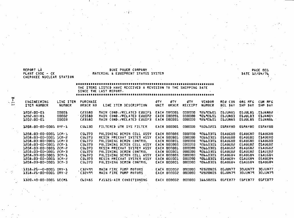
REPOiRT bA DUKE POWER COMPANY . PAGE 001 PLANT CODE - CK MATERIAL 8 EQUIPMENT STATUS SYSTEM DATE L2/04/7b ,
CHEROKEE NUCLEAR STATION I
................................................................ THE ITEMS LISTED HAVE RECEIVED A REVISION TO THE SHIPPING DATE SINCE THE LAST REPORT. ********************%************$***************************
b: I .. . ENGINEERING LINE ITEM PURCHASE QTY ~ T Y QTY VENDOR REQ CON ORG VFG CUR MFG
~1 ITEM NUMBER NUMBER ORDER NO LINE ITEM DESCRIPTION UNIT ORDER RECEIPT NUVBER DEL D A Y SHP D A Y SHP. D A Y * . .
L20S-00-01 OOOOL C23580 MAIN COND-/RELATED EQUIP1 EACH 00fl001 000000 92b90b01 OlJUN81 OIJULBL .OLJAN82 L202700-01 00002 C23580 MAIN. COND./RELATED EQUIP2 EACH OOODDL 000000 92b90b01 OLJUN83 OLJUL83 OLJAN84 1202700-01 00003 C23580 MAIN COND-/RELATED EQUIP3 EACH 000001 000000 92b90bOL OLJUNBS O1JUL85 OLJAN8b
L208,OO-00-0001 OYF-L C5b130 FILTERED WTR SYS FILTER EACH 000301 000000 950b0202 OLRAYBO OLVAYBO OLflAYBO
POLISHING DEMIN CELL A S S Y RES.IN PRECOAT SYSTEM ASSY POLISHING DEMIN CONTROL POLISHING DEMIN CELL A S S Y RESIN PRECOAT SYSTEM ASSY POLISHING DEMIN CONTROL POLISHING DEMIN CELL ASSY RESIN.PRECOAT SYSTEM ASSY POLISHING DEMIN CONTROL
EACH OOOOOS EACH O O O O O 1 EACH 000001 EACH 000005 EACH 000001 EACH OOOOOL EACH 000005 EACH 000301 EACH OOOOOL
: i318-22--0-0002 D R Y - 1 -C32499. MAIN FIRE PUMP MOTORS EACH 000002 000000 92820805. OLJUN77 30JUN77 30JUN77 '13L8,2L-00-000L ORY-2 C32499 MAIN FIRE PUMP MOTORS EACH 000002 000000 92820805 ObJUN79 30JUN79 30JUN79
- .. . 1 3 i 0 ~ ~ 0 - 0 0 - 0 0 0 1 ~ E C M L Cb5485 FJ1L21-AIR CONDITIONING EACH 000002 OOflOOO Lbb50201 OlFEB77 !llFEB77 OlFEB77
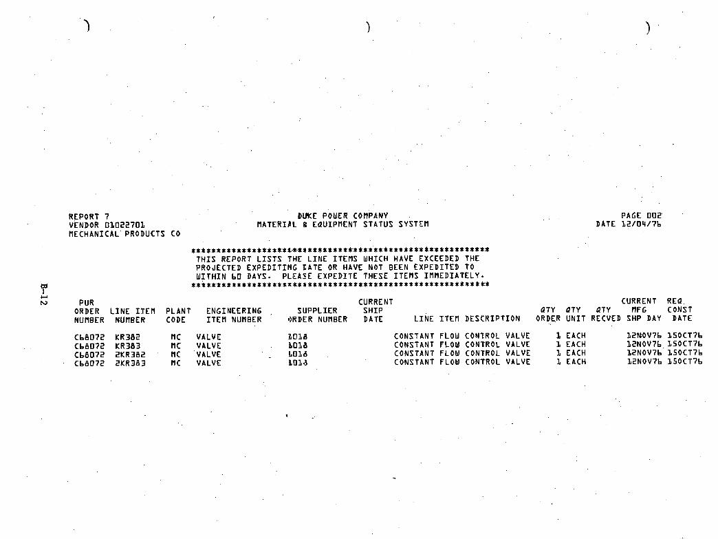
REPORT 7 D~KE POUER COMPA.NY VENDOR 0 1 0 2 2 7 0 1 MATERIPL g EQUIPMENT STATUS SYSTEM MECHANICAL PRODUCTS CO
* * * $ * * * * * * * * * * * * * * * 1 : * . * 1 * * * * * t * * * * * * * * * * * * * * * * * * * * T H I S REPORT L I S T S THE L I N E I T E M S WHICH HAVE EXCEEDED THE PROJECTED E X P E D I T I H G I A T E OR HAVE NOT BEEN EXPEDITED TO W I T H I N bO DAYS. PLEASE EXPEDITE THESE I T E M S IMMEDIATELY.
. . . . . . . . . . . . . . . . . . . . . . . . . . . . . . . . . . . . . . . . . . . . . . . . . . . . . . . . . . .
PAGE 0 0 2 '
DATE 1 2 / 0 4 / 7 b
w N PUR CURRENT CURRENT REQ.
ORDER LINE ITEN PLANT ENGINEERING . SUPPLIER SHIP QTY Q T Y QTY MFG CONST MUNBER NUMBER CODE I T E M NURRER ORDER NUMBER DATE L I N E I T E M DESCRIPTION ORDER U N I T RECVED SHP DAY DATE
C b 8 0 7 2 K R 3 8 2 MC VALVE LD1B C b 8 0 7 2 K R 3 8 3 HC VALVE L O l d C b 8 0 7 2 2 K R 3 8 2 MC ' V A L V E LO16 C ~ A O ~ Z 2 ~ ~ 3 8 3 M C VALVE b o l a
CONSTANT FLOW CONTROL VALVE 1, EACH I 2 N O V 7 b L 5 0 C T 7 b CONSTANT FLOW CONTROL VALVE I EACH 12NOV7b I S O C T 7 b CONSTANT FLOW CONTROL VALVE I EACH 12NOV7b I 5 0 C T 7 b CONSTANT FLOW CONTROL VALVE I EACH 12NOV7b I S O C T 7 b
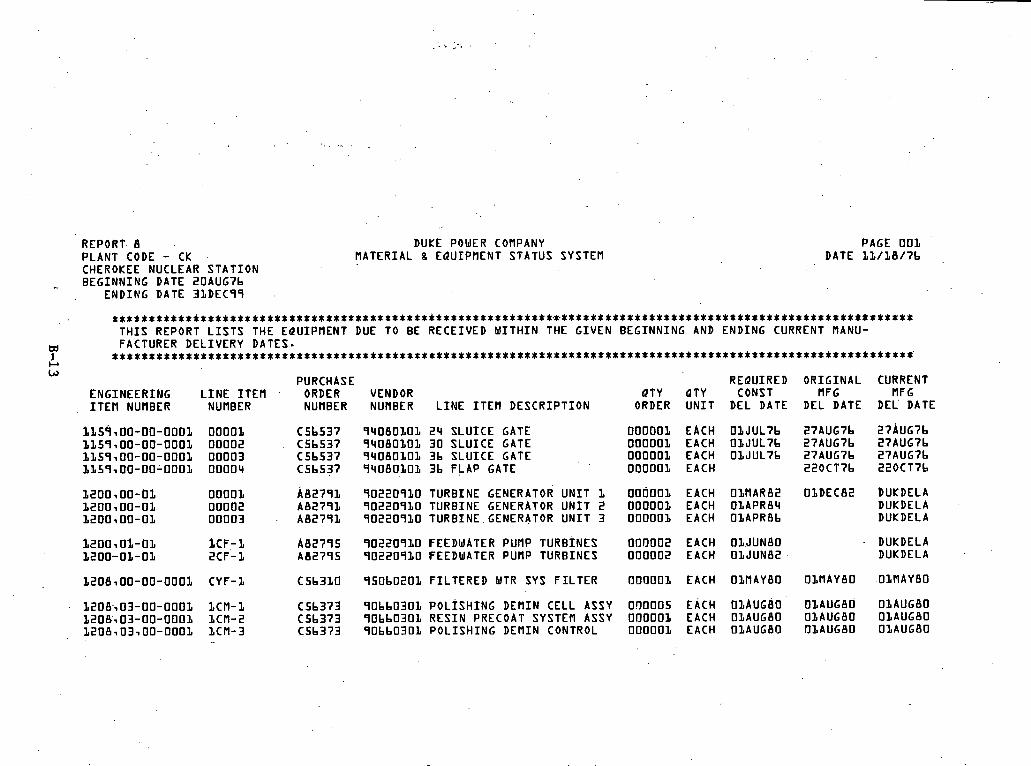
REPORT. 8 DUKE POWER COMPANY PAGE 001 PLANT CODE - CK . MATERIAL 8 EQUIPMENT STATUS SYSTEM DATE 11/18/7b ,
CHEROKEE NUCLEAR STATION BEGINNING DATE 20AUG7b ...
ENDING DATE 31DEC99 .
...............................................................................................................
THIS REPORT LISTS THE EQUIPMENT DUE TO BE RECEIVED WITHIN THE GIVEN BEGINNING AND ENDING CURRENT MANU- td FACTURER DELIVERY DATES- 1 .............................................................................................................. C1 LJ
PURCHASE REQUIRED ORIGINAL CURRENT ENGINEERING LINE ITEM . ORDER VENDOR OTY QTY CONST MFG MFG
, ITEM NUMBER NUMBER NUMBER NUMBER LINE ITEM DESCRIPTION ORDER UNIT DEL DATE DEL DATE DEL' DATE
f ISq100-00-0001 00001 C5b537 94080101 24 SLUICE GATE 000001 EACH 01JULib 27AUG7b 27AUG7b 1159,OO-00-0001 00002 C5b537 94080101 30 SLUICE GATE 000001 EACH O1JUL7b 27AUG7b 27AUG7b LL59100-00-0001 00003 C5b537 9408010L 3b SLUICE GATE 000001 EACH OLJUL7b 27AUG7b 27AUG7b 1L59100-00-0001 00004 C5b537 9408010L 3b FLAP GATE 000001 EACH 220CT7b 220CT7b
1200100-of 00001 A82791 90220910 TURBINE GENERATOR UNIT 1 000001 EACH ObMAR82 O1DEC82 bUKDELA 1200100-01 00002 A82791 90220910 TURBINE GENERATOR UNIT 2 000001 EACH OLAPR84 DUKDELA 1200100-01 00003 . A82791 90220910 TURB1NE.GENERATOR UNIT 3 000001 EACH OLAPR8b DUKDELA
12001 01-01 iCF-1 A82795 90220910 FEEDWATER PUMP TURBINES 000002 EACH OIJUNBO DUKDELA 1200-01-01 2CF-1 A82795 90220910 FEEDWATER PUMP TURBINES 000002 EACH OlJUN82 DUKDELA
1206100-00-0001 CYF-1 C5b31O 950b0201 FILTERED WTR SYS FILTER OOflOO1 EACH OlMAYBO ObMAYBO O1MAYBO
1208103-00-0001 I C M - 1 C5b373 90bb0301 POLISHING DEMIN CELL ASSY 0Q0005 EACH OLAUGBO OLAUGBO ObAUGBO 1208103-00-0001 1CM-2 C5b373 90bb030L RESIN PRECOAT SYSTEM ASSY 000001 EACH OlAUGBO OlAUGBO OLAUGBO 1208 i03 i00-0001 LCM-3 C5b373 90bb030L POLISHING DEMIN CONTROL 000001 EACH OlAUGBfl flLAUG8O O1AUG80

REPORT 9 BUKE POWER COMPANY VENDOR 9 7 8 8 0 9 0 1 MATERIA - 8 EQUIPMENT STATUS SYSTEM R E L I A N C E E L E C T R I C CO
*t*******i*****t******i¶**t*SttS********i***i*****.%*******%***%** T H I S REPORT L I S T S THE EQUIPMENT.WHICH HAS NOT BEEN RECEIVED BY 30 DAYS AFTER THE CURRENT MANUFACTURER S H I P P I N G DATE. PLEASE
m E X P E D I T E THESE D E L I V E R l E S I M f l E D I A T E L Y . 1 **********************w********* i** i**** i************************** c.' c.
PUR ORDER L I N E I T E M PLANT ENGINEERING SUPPL IER QTY QTY QTY NUMBER NUMBER CODE ITEM NUMBER ORDER NUMBER LINE ITEM DESCRIPTION ORDER UNIT REC
LOWER CONT.COOLING FAN f lTRS. LOWER CONT-COOLING F A N MTRS-
4 EACH 4 EACH
PAGE OSb DATE 1 2 / 0 4 / 7 6
R E 0 CURRENT CURRENT CONST MFG S H I P P I N G
DEL D A Y SHP DAY DATE
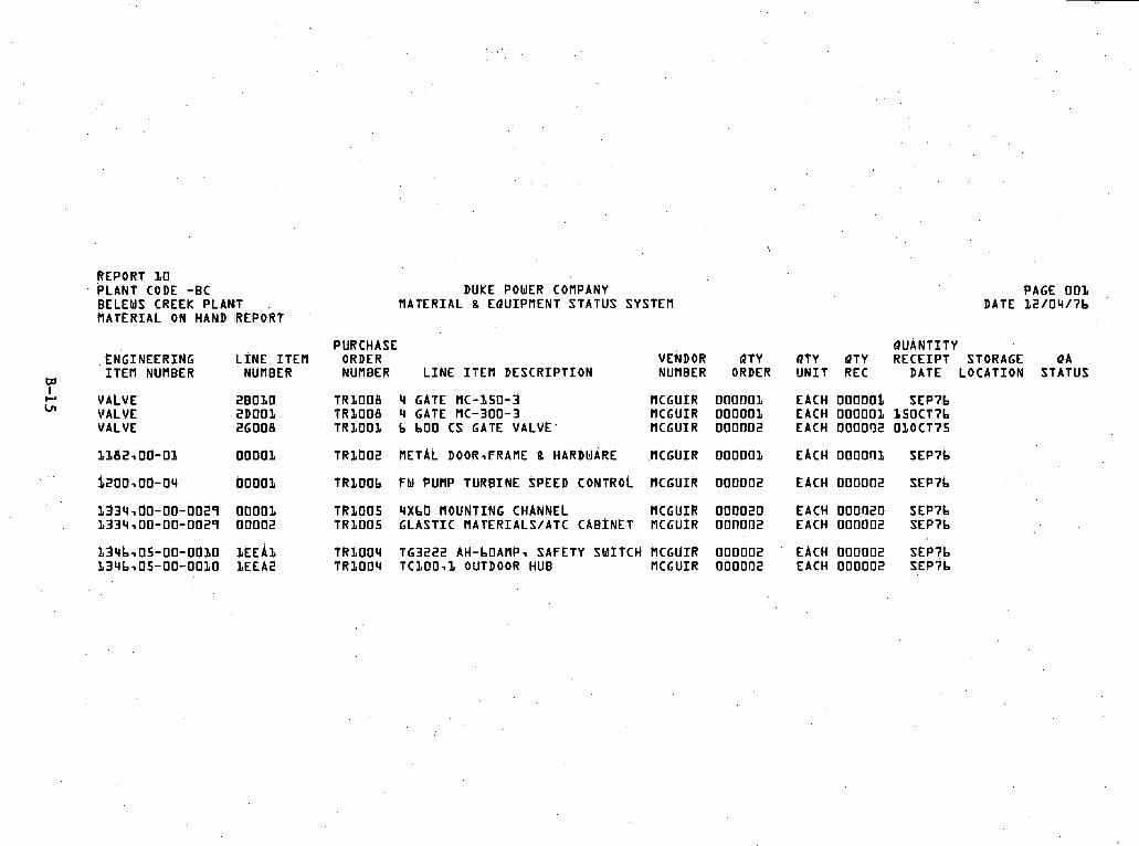
REPORT 10 PLANT CODE -BC BELEWS CREEK PLAMT MATERIAL ON HAND IREPORT
LN'GINEERING LINE ITEM I T E M NUMBER NUMBER
VALVE VALVE VALVE
DUKE POWER COMPANY MATERIAL g EQUIPMENT STATUS SYSTEM
PURCHASE ORDER VENDOR QTY NUMBER L I N E I T E M D E S C R I P T I O N NUMBER ORDER
TR1OOB 4 GATE MC-150 -3 MCGUIR 000001 T R 1 0 0 8 4 GATE MC-300-3 MCGUIR 000001 TR1OOZ b LOO CS GATE VALVE' MCGUIR 0 0 0 0 0 2
TR1t lO2 RETAL DOOR-FRAME 8 HARDMARE MCGUIR 0 0 0 0 0 1
TRZOOb FW PUt lP TURBINE SPEED CONTROL MCGUIR 0 0 0 0 0 2
T R l 0 0 5 4XbO MOUNTING CHANNEL MCGUIR 0 0 0 0 2 0 T R 1 0 0 5 G L A S T I C MATERIALS/ATC CABINET MCGUIR 0 0 n 0 0 2
T R I O 0 4 T G 3 2 2 2 AH-LOAMP, SAFETY SWITCH MCGUIR 0 0 0 0 0 2 T R 1 0 0 4 T C b O O - l OUTDOOR HUB MCGUIR f l 0 0 0 0 2
PAGE 001 DATE 1 2 / 0 4 / 7 b '
QUANTITY RTY QTY R E C E I P T STORAGE QA U N I T REC DATE LOCATION STATUS
EACH 00000i S E P 7 b EACH OOOOOI I 5 0 C T 7 b EACH 0 0 0 0 9 2 0 1 0 C T 7 5
EACH 0 0 0 0 n l S E P 7 b
EACH 0 0 0 0 0 2 S E P 7 L
&ACH 0 0 0 0 2 0 S E P 7 b EACH 0 0 0 0 0 2 S E P 7 b
EACH 0 0 0 0 0 2 SEP?L EACH 0 0 0 0 0 2 S E ? 7 b

REPORT PLANT CODE -CK DUKE POWER COflPANY CHEROKEE NUCLEAR STATION VATERIAL 8 EQUIPVENT STATUS SYSTEfl
*****t*********~****t************************************************% T H I S REPORT L I S T S THE L I N E I T E f l S WHICH DO NOT HAVE AN ISSUED PURCHASE ORDER BEFORE THE ENGINEERING DEPARTPlENTS TARGET PURCHASE ORDER RE- LEASE DATE.
. . . . . . . . . . . . . . . . . . . . . . . . . . . . . . . . . . . . . . . . . . . . . . . . .
TARGET REQUIRED ENGINEERING L I N E I T E M QTY QTY PUR ORDER COMST I T E f l NUflBER NUflBER LINE ITEM DESCRIPTION ORDER UNIT REL DATE DEL DATE
f ~ i 3 ~ 0 0 - 0 1 0 0 0 0 2 1 0 0 LB HEAD FREE JOINT BARS 0 0 1 9 5 0 PAIR OLSEP75 1 1 1 3 1 0 0 - 0 1 0 0 0 0 3 lXS.75;-TRACK BOLTTSQUARE NUT 0 0 7 8 0 0 EACH OLSEP35 L I L 3 1 0 0 - 0 1 ODOOll ANTI-CREEP AhCHOR FOR 1 0 0 L B RL 0 0 0 2 2 5 C-EA OLSEP7S 1 1 1 3 ~ 0 0 - 0 1 ODD05 GUAGE RODS FCR lOOLB R A I L 0 0 1 1 8 0 EACH OLSEP'S
2 1 1 3 ~ 0 0 - 0 2 0 0 0 0 1 CROSS T I E S 8X7;-8Xb;-1OOLB RL 0 0 0 2 2 5 C-EA OLSEP'S
LOO LB HEAD FREE JOINT BARS oo1oon 1x5-75;-TRACK BOLTSTSQUARE NUT 0 0 4 0 0 0 ANTI-CREEP AMCHORS ZOOLB RL 0 0 0 1 1 ? GUAGE RODS FOR 11OLB AREA RL 0 0 9 2 0 0 NO 8 TURNOUTZ 0 0 0 0 1 8 SMITCH STAND: ooCiolte
CROSS T I E S 8X7;8Xb;-10OLB RL 0 0 5 3 0 0 CROSS T I E S BX7;8Xb;-LOOLB RL 0 0 b 4 0 0 T I E S FOR NO b TURNOUT OOOOL4 T I E S FOR NO 3 TURNOUT 0 0 0 0 0 4
PAIR EACH C-EA EACH EACH EACH
EACH EACH SETS SETS
PAGE 0 0 1 DATE 2 2 / 0 4 / 7 b
SPONSOR ENGINEER I N I T I A L S
IWP I UP. IWP IWP
IWP
I'WP IWP IWP IWP Ih lP IWP
IWP . IMP IWP IMP
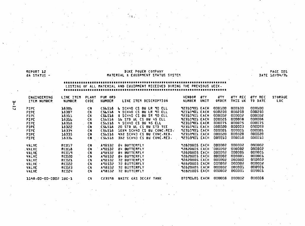
DUKE POWER- COMPANY MATERIAL 8 EQUIPMENT STATUS SYSTEN
REPORT 1 2 QA STATUS -
PAGE 0 0 1 DATE 1 2 / 0 4 / 7 b
.................................................................. L I S T I N G OF ALL MATERIAL AND EQUIPMENT RECEIVED DURING THE PREVIOUS WEEK. . ..........................................................................
L I N E I T E M PLANT PUR ORD VENDOR QTY QTY NUMBER CODE NUMBER L I N E I T E M DESCRIPTION NUMBER U N I T ORDER
ENGINEERING I T E M NUMBER:
QTY REC T H I S WK
Q T Y REC STORAGE TO DATE LOC
P I P E P I P E P I P E P I P E P I P E P I P E P I P E ' P I P E P I P E
b SCH40 CS BW LR 9 0 E L L 4 SCH40 CS BW LR 9 0 E L L 8 SCH4O CS BW SR 9 0 E L L 1b STD WL CS .BW 4 5 E L L 4 SCH4O CS BW 4 5 E L L 2 0 STD WL CS BW STD TEE LOX4 SCH40 CS BW.CONC.RED*' 4 x 2 SCH40 CS BW CONC-RED- 3 x 2 SCH40 CS BW CONC-RED-
9 2 3 1 0 9 0 1 EACH 9 2 3 1 0 9 0 1 EACH 9 2 3 1 0 9 0 1 EACH 9 2 3 1 0 9 0 1 EACH 9 2 3 1 0 9 0 1 EACH 9 2 3 1 0 9 0 1 EACH 9 2 3 1 0 9 0 1 EACH 9 2 3 1 0 9 0 1 EACH 9 2 3 1 0 9 0 1 EACH
VALVE VALVE VALVE VALVE VALVE VALVE VALVE VALVE
8 4 BUTTERFLY 8 4 BUTTERFLY 8 4 BUTTERFLY 8 4 BUTTERFLY ? 2 BUTTERFLY 7 2 BUTTERFLY 7 2 BUTTERFLY 7 2 BUTTERFLY
9 2 8 2 0 8 0 5 EACH 9 2 8 2 0 8 0 5 EACH 9 2 8 2 0 8 0 5 EACH 9 2 8 2 0 8 0 5 EACH 9 2 8 2 0 8 0 5 EACH 9 2 8 2 0 8 0 5 EACH 9 2 8 2 0 8 0 5 EACH 4 2 8 2 0 8 0 5 EACH
WASTE GAS DECAY TANK 07590bOB EACH

DUKE POWER COHPANY REPORT 1 4 P E R K I N S NUCLEAR S T A T I O N MATERIAL s EQUIPMENT STATUS SYSTEM
; INEERING I N C 9 2 9 5 0 b l COMBUSTION EN( POWER SYZTEMS
G 00 ENGINEERING
I T E M NUMBER
NSSS NSSS NSSS NSSS NSSS NSSS NSSS NSSS NSSS NSSS NSSS, NSSS NSSS NSSS NSSS NSSS NSSS NSSS NSSS . NSSS NSSS NY- -
D I V
* * * * * * * * * * * * * * C S * * * * * * * * * * * * * * * * * * * * * * * * * * & * * * * * * * * T H I S REPORT L I S T S THE STATUS OF A L L DRAWIYGS.
* * * * * * * * * * * * * * C * * * * * + i * * * * * t * * * * * * * * * * * * * * * * * * * * * * * * *
L I N E I T E M NUMBER L I N E I T E M D E S C ? I P T I O N
CORE SUP BAR ASSY UP GUIDE STRUC ASSY REAC VESSEL NOZZLE PADS RV COLUMN INTEGRAL SUPP P L A T E S R I U N I V L I F T I N G R I G ASSY R I UPPER GUIDE STRUC SUPP PADS REAC I N T E R N S H I P P I N G R I G R I CORE SUPP BARREL STOR PADS CEA CONTR E L E D R I V E f lECHANISf l CEA CONT E L E D R I n E C H I N S T R U CEA CEDM POWER SUPPLY CEA CEDM S E R V I C I N G EBUIPMENT CEDn COOLING S'HROUDS HSHT SURVEI SPECIREN COMP ASSY NSHT STEAM GENERPTOR ASSEMBLY NSHT STEAM GENERLTOR SUPP STRU NSHT STE GEN S H I P E R f C E Q U I P NSHT S T E GEN S E R l E Q U I P REA CO PUM LOCA SUP S K I COL SN CEA CHANGE PLATFGRM DRY S H I P P I N G EQUlP f lENT REFUEL ING POOL SEAL ASSEMBLY
BTY
PAGE, 0 0 2 D'ATE 1 2 / 0 4 / 7 b
SCHEDULED ACTUAL SCHEDULED ACTUAL CURRENT QTd REC DATE REC DATE REL DATE REL DATE MFG SHP. U N I T FROM n F G FROM MFG BY ENGR BY ENGR DATE
EACH ,
EACH EACH EACH EACH .s E3' EACH SET EACH SET EbCH SET E PCH SET E b CH EbCH EbCH SET SET. EACH.' . EACH EACH
DUKDELA ' DUKDELA
DUKDELA DUKDELA DUKDELA DUKDELA DUKDELA DUKDELA DUKDELA DUKDELA DUKDELA
' DUKDELA . ' DUKDELA
DUKDELA DUKDELA DUKDELA DUKDELA DUKDELA DUKDELA DUKDELA DUKDELA Dl.lKDELA
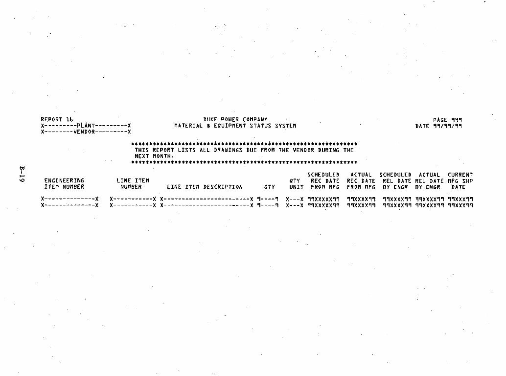
DUKE POWER COMPANY MATERIAL 8 EQUIPMENT STATUS SYSTEM
PAGE 999 DATE 99/99/99
. . . . . . . . . . . . . . . . . . . . . . . . . . . . . . . . . . . . . . . . . . . . . . . . . . . . . . . . . . . . . . . . T H I S REPORT L I S T S A L L DRAWINGS DUE FROM THE VENDOR DURING THE NEXT flONTH. ...............................................................
m I C, SCHEDULED ACTUAL SCHEDULED ACTUAL CURRENT w ENGINEERING LINE ITEM QTY REC D A T E REC D A T E REL DATE REL D A T E ~ F G SHP
I T E M NUMBER NUMBER L I N E I T E M D E S C R I P T I O N Q T Y UNIT FROM MFG FROM MFG BY ENGR BY ENGR DATE

REPORT I b DUKE POUER COMPANY PAGE 999 X-------------PLANT---------- X MATERIAL 8 EQUIPMENT STATUS SYSTEM DATE 99/99/99 X------------ VENDOR---------- x
* * + t * * * ~ * * * ~ * n $ , t t * * * * * $ 1 : t * 1 : * t t t i * $ $ t 1 : * t * t $ $ * $ t 1 : $ * 1 n ~ * $ $ * $ * $ * * x $ * $ $ 1 r * * n * T H I S REPORT L I S T S . D R A W I N G S U H I C H WERE SCHEDULED FOR SUBMISS ION TO DUKE BY T H I S DATE CSDREL3 AND HAVE NOT BEEN SUBMITTED BY THE VENDOR. THESE I T E M S ARE THEREFORE LATE .
***$$*$****$****$************************%*******m**********R*********
SCHEDULED ACTUAL SCHEDULED ACTUAL CURRENT ENGINEERING L I N E I T E M P T Y REC DATE REC DATE RELDATE RELDATE MFG SHP I T E M NUMBER NUMBER L I N E I T E M D E S C R I P T I O N PTY U N I T FROM MFG FROM MFG BY ENGR BY ENGR DATE
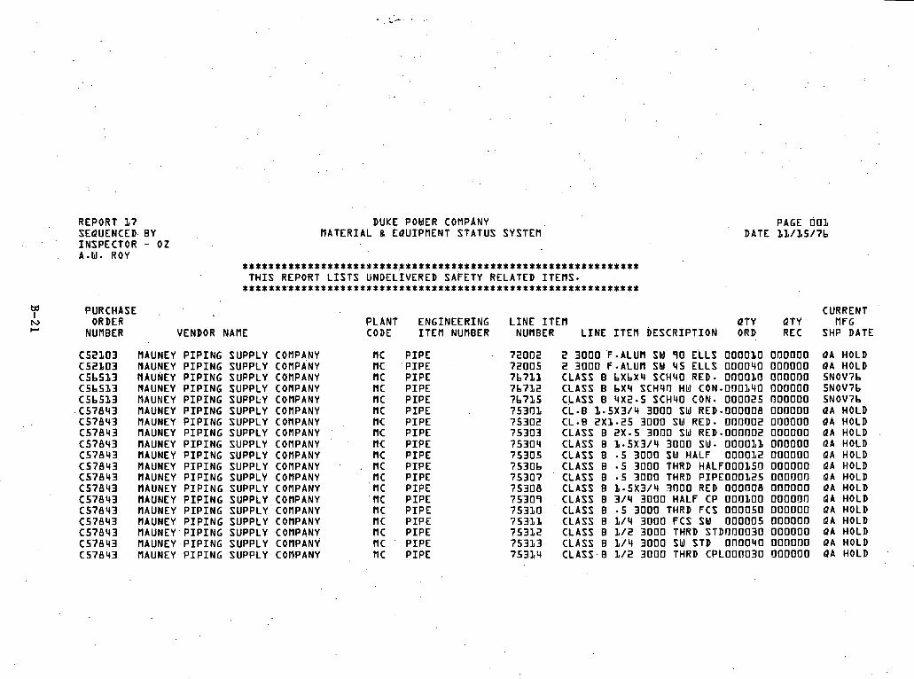
REPORT 1 7 SEQUENCED. BY INSPECTOR - 0 2 A.W. ROY
PURCHASE ORDER
NUMBER
DUKE POWER COMPANY MATERIAL g EQUIPMENT STATUS SYSTER
VENDOR NAME
. . . . . . . . . . . . . . . . . . . . . . . . . . . . . . . . . . . . . . . . . . . . . . . . . . . . . . . . . T H I S REPORT L I S T S UNDELIVERED SAFETY RELATED ITEMS. .............................................................
HAUNEY P I P I N G SUPPLY COMPANY HAUNEY P I P I N G SUPPLY COMPANY NAUNEY PIPING SUPPLY CQMPANY MAUNEY P I P I N G SUPPLY COMPANY RAUNEY P I P I N G SUPPLY COMPANY MAUNEY P I P I N G SUPPLY COMPANY MAUNEY P I P I N G SUPPLY COMPANY nAUNEY P I P I N G SUPPLY COMPANY MAUNEY P I P I N G SUPPLY COMPANY MAUNEY P I P I N G SUPPLY COMPANY MAUNEY P I P I N G SUPPLY COMPANY IIAUNEY P I P I N G SUPPLY COMPANY IIAUNEY P I P I N G SUPPLY COMPANY IIAUNEY P I P I N G SUPPLY COMPANY MAUNEY P I P I N G SUPPLY COMPANY IIAUNEY P I P I N G SUPPLY COMPANY MAUNEY.P IP ING SUPPLY COMPANY MAUNEY P I P I N G SUPPLY COMPANY MAUNEY PIPING SUPPLY COMPANY
DATE
PLANT ENGINEERING L I N E I T E M QTY CODE I T E M NUMBER NUMBER L I N E I T E M DESCRIPTION ORD
P I P E P I P E -
P I P E P I P E P I P E P I P E P I P E P I P E P I P E P I P E P I P E P I P E P I P E P I P E P I P E P I P E P I P E P I P E P I P E
PAGE 007, 1 1 / 1 5 / 7 b
CURRENT QTY MFG REC SHP DATE
2 3 0 0 0 'F-ALUM SU 9 0 ELLS 0 0 0 0 1 0 0 0 0 0 0 0 2 3 0 0 0 F -ALUM SW 4 5 ELLS 0 0 0 0 4 0 0 0 0 0 0 0 CLASS B b X b X 4 SCH40 RED- 0 0 0 0 1 0 0 0 0 0 0 0 CLASS B b X 4 SCH40 HbJ CON.O!l0140 0 0 0 0 0 0 CLASS B 4X2.5 SCH40 CON. 0 0 0 0 2 5 0 0 0 0 0 0 C L - B I . 5 X 3 / 4 3 0 0 0 SW RED.000008 0 0 0 0 0 0 C L - B 2 x 1 - 2 5 3 0 0 0 SW RED. 0 0 0 0 0 2 0 0 0 0 0 0 CLASS B 2X.5 3 0 0 0 SW RED.000002 0 0 0 0 0 0 CLASS B 1 - 5 X 3 / 4 3 0 0 0 SW- 0 0 0 0 1 1 0 0 0 0 0 0 CLASS B - 5 3 0 0 0 SW HALF 0 0 0 0 1 2 0 0 0 0 0 0 CLASS B - 5 3 0 0 0 THRD H A L F 0 0 0 1 5 0 0 0 0 0 0 0 CLASS B * 5 3 0 0 0 THRD P I P E 0 0 0 1 2 5 0 0 0 0 0 0 CLASS B 1 . 5 ~ 3 1 4 3 0 0 0 RED OOOOOB oooooo CLASS B 3 / 4 3 0 0 0 HALF CP 0 0 0 1 0 0 0 0 0 0 0 0 CLASS B - 5 ' 3 0 0 0 THRD FCS 0 0 0 0 5 0 0 0 0 0 0 0 CLASS B 1 / 4 3 0 0 0 FCS SW 0 0 0 0 0 5 0 0 0 0 0 0 CLASS B 1 / 2 3 0 0 0 THRD S T D 0 0 0 0 3 0 0 0 0 0 0 0 CLASS B 114 3000 sw STD o n n 0 4 0 ' 0 o f l 0 0 0 CLASS.0 1 / 2 3 0 0 0 THRD C P L 0 0 0 0 3 0 0 0 0 0 0 0
QA HOLD QA HOLD 5NOV7b 5NOV7b 5NOV7b QA HOLD QA HOLD QA HOLD RA HOLD QA HOLD QA HOLD QA HOLD QA HOLD QA HOLD QA HOLD QA HOLD QA HOLD QA HOLD QA HOLD

REPORT 18 SEQUENCED BY PURCHASE ORDER
PURCHASE IQ ORDER
NUMBER
DUKE POWER COMPANY R A T E R I A L 8 EQUIPMENT STATUS SYSTEf l
* * * * * * * * * * * * * * * * * * * * * * * * * * * * * * * * * * * * * * * * * * * * * * * * * * * * * * * * * * * Y * % T H I S R E P O R T ' L I S T S UNDELIVERED SAFETY RELATED I T E M S -
* * * * * * * * * * * * * * * * * * * * * * * * * * * * * * * * * * x * * * * * * * * * * * * * * * * * * * * * * * * * i * *
, .. . . ,
PAGE 0 0 2 DATE 1 2 / 3 7 / 7 b
INSPECTOR ENGINEERING VENDOR NAf lE NAME------- CODE I T E M NUMBER L I N E I T E M D E S C R I P T I O N
NOT ON F I L E NOT ON F I L E NOT OM F I L E NOT ON F I L E NOT ON F I L E NOT ON F I L E NOT ON F I L E NOT ON F I L E NOT OW F I L E NOT OW F I L E NOT ON F I L E NOT ON F I L E NOT ON F I L E NOT ON F I L E NOT ON F I L E NOT ON F I L E NOT Oh! F I L E NOT ON F I L E NOT ON F I L E NOT ON F I L E NOT ON F I L E
CURRENT RFG
SHP DATE
MECHANICAL DRAFT COOLING TOblER 2 4 " 54GA.CORRUGATED S T L - P I P E 2 4 " %4GA.CORRUGATED S T L - P I P E . 2 4 " L4GA-CORRUGATED S T L - P I P E 2 4 " ;4GA.CORRUGATED S T L - P I P E 2 4 " 44GA.CORRUGATED S T L - P I P E 24" ;'+LA-CORRUGATED S T L - P I P E ?'I" 34GA.CORRUGATED S T L - P I P E NO. 8 LEFT-HAND CROSSOVER $40. 8 LEFT-HAND TURNOUTS NO. 8 RIGHT-HAND TURNOUTS 5 /BWZQ.X5" T I E PLUG LOO/BUNDLE 7 x 9 " 'S td ITCH T I E S / N O - 8 TURNOUTS 7 x 9 " SWITCH TIES/NO.B TURNOUTS 7 "XS"XLO 'T I f lBERS FOR CROSSINGS 7 "XqnXB ' -b " CROSS T I E S 7"Xq"XB"-b" CROSS T I E S BUMPING POST STEEL FLANGEWAY 5 / 8 " X 1 Z n S P I K E S 5/Ew,:<b" S P I K E S Ci?SO/KEG>

ADDENDUM C
, SUPPORTTNG MATERIAL FOR
PIPING MATERIAL INVENTORY CONTROL SYSTEM (PMICS)

DUKE POWER COMPANY PIEING MATERIALS INVENTORY
PLANT: CATAWBA DATE: 04/12/77
(a) ORDERED UNIT REL . B/M 'b) LINE QNTY ACCUM . REMARKS HDNGS : CODE NO SH NO ITEM// ORDERED QNTl .
.............................................................................................................. ASSIGNED UNIT SYS. SBM B/M Q N ~ ACCUM . DATE REMARKS HDNGS : CODE NO SR NO ITEM/) ASSIGNED QNTY . NEEDE~
(c) (d) (e)
Pipe Grade (Grade'B carbon steel)
Lot Number (Intelligent No.)
Schedule (Schedule 80)
Pipe Size (Inches - eights, 4-118 inches) Material Description (90' long radius elbow)
Material Type (Fitting)
Welding Type ---I Pipe Type (Seamless)
Pipe Grade
Material Specification I
(a) Release Number (b) Bill of material
sheet number (c) System number (d) Summary bill of mate-
rial (accumulated material for given sys- tem in. a given area)
(e) Bill of material. item I number I
CN100303DElFOB040 B C.S. 234 WPB SMLS E F I FTG 90 LR ELL BW 04-3 SCH 80
ORDERED: 0 0128 0 0217 0 0283
ASSIGNED: 1 BB02 1 BB02 1 BB02 1 BE02 1 B302 1 BB02
FBS FBS FB S
06/15/77 14S1-BBClO7 11-24-76 I
Iscmetric Drawing No. 1 Date ~rawn-

ADDENDUM D
SUPPORTING MATERIAL FOR
STORES ACCOUNTING SYSTEM (SAS)

C 0 M P A N Y NAME . W e s t I ~ g h o u ~ e
ORDER NUMBER W-35924
p o 172547 ITEM f l o l so I85 U N I T ' 1
i:::: BOXES 'OF MISC, PARTS
. .
FOR UNIT #I STORAGE LEVEL C H 0 i s t A d n B 0 x e s
D Crane
CATAWBA STORES LABEL

8743 DATE STORES R E Q U I S I T I O N NO,
STORES LOC.NO. . . . . . . . . . . .
CATAWBA 162
STORES LOCATION T R I
2
S T .
8337 SYSTEM SAFETY RELATED '
1050 YES NO . . . .
COUNTY TAX CODE . . . . . . . . DRAWING NUMBER
D E S C R I P T I O N
. . ., . lwmTIR USED FOR: I t e m or Mark N o .
GROUP
R e s p . N o . L o c a t i o n N o . ENGR . A P P R .
W.O. No .
LOT NUMBER
DES CRPPTION
. . . . . . . . . . . . . .
AMOUNT
. . .
QUANTITY
ACCOUNT NO.
. . . . . . . . . . . .
USED FOR: I t e m .of M a r k No .
. . . . . . . . . . . . . . .
TAX CODE
GROUP
Issued by: " " "
. . .
I A u t h o r i z e d S i g n a t u r e C r e w N o . R e c e i v e d by :
LOT NUMBER AMOUNT
. . . . . . . . . . . . . . . . . .
ACCOUNT NO. . TAX CODE
. . . . . . .

T H I S PAGE WAS INTENTIONALLY
LEFT BLANK

ADDENDUM E
SUPPORTING MATERIAL FOR
PUNCH LIST


PUNCH LIST PROGRAM INPUT CARD
4 4 4 4 4 4 4 4 4 4 4 4 4 4 4 4 4 4 4 4
5 5 5 5 5 5 5 5 MECHANICAL PUNCHLEST
5 5 5 5 5 5 5 5 5 5 5 5
9 5 9 9 9 9 9 9 9 9 9 9 9 9 1 9 9 1 3 9 9 9 ~ ' 9 9 9 9 9 9 9 9 9 9 9 9 9 9 9 9 9 9 9 9 9 9 9 9 9 9 9 9 ID 31.31 11 14 15 1; I 1 I( I8 M 41 42 U U 45 U 4 l U-4l 5l S l $1 13 54 55 55 51 51 59 60 61 62 63 M 61 66 61 61 69 I0 i l 11 11 14 15 16 I1 I1 1% 10 LEWIS 70545

. 1 '
THIS' PAGE: , ..
WAS INTENTIONALLY LEFT BLANK
ADDENDUM F
SUPPORTING MATERIAL FOR
MATERIAL MANAGEMENT INFORMATION SYSTEM.

MATERXALS MANAGOlENT INFORMATION SYSTEM PURCHASXNG DEPARTMENT STATUS REPORT
REPORT NQ* PUSMRO1, PAGE I PREPARED 4-fl3-75 AS OF 0.2-28-75
BUYER D E S C R I P T r O N T H I S MONTH LAST MONTH
OPEN ORDER STATUS
ORDERS I S S U E D 0 5 OPEN ORDERS 4 5 PAST DUE I I
PROJECT ORDER STATUS
.' ORDERS I S S U E D 0 2 OPEN ORDERS L ,2 PAST DUE I . I
SYSTEM R E Q U I S I T I O N . S T A T U S
R E Q U I S I T I O N S RECEIVED R E Q U I S I T I O N S PROCESSED R E Q U I S I T I O N S I N PROCESS R E Q U I S I T I O N S PAST DUE
E X P E D I T E ACTION STATUS
ACKNOWLEDGEMENT REQUEST E X P E D I T E S 0 I N T E R I M REQUEST E X P E D I T E S 0 PAST DUE ORDER. E X P E D I T E S I

V A T E R I A L S ~ A N A G E F ~ E N T INPORf lAT ION S Y M a PURCHASXNG DEPARTMENT:. .
'MQNTHL.Y ACTIY.XTY. REPORT"' '.: . . . .:, : REPORT NO. pus~aeuz . PAGE . I PREPARED. 4 - 0 3 4 7 5 AS. OF 0 2 - 2 8 - 7 5
---- . T U $ YEAR --- T H I S ' , YEAR MONTH: TO DATE
---* L A S T YEAR --- THIS YEAR MONTH. TO DATE
DEPARTMENTAL PROCESSrNG A C T I V I T Y
SYSTEM REQUISITIONS 2 2 7 RECEIVED L 0.
. . 0
15 PROCESSED n o 0. IN PROCESS. a 5 PAST DUE 0
PURCHASE ORDERS I S S U E D 4 PROJECT 0 0 L GENERATION CONSTRUCTION 0 0 2 PRODUCTION S U P P L I E S a M A I N T . 0 0
LL TRANSMISSION SUBSTATION 8 D I S T . 0 0 2 MISCELLANEOUS ---- ! 0 ---- 0 ----
2 0 TOTAL 0 0
OPEN PURCHASE ORDERS PROJECT 0 GENERATION CONSTRUCTION 0 PRODUCTION S U P P L I E S & M A I N T . 0 TRANSMISSION SUBSTATION 8 D I S T - 0 MISCELLANEOUS 0
---- TOTAL 0
PAST DUE ORDERS 2 PROJECT R 0 0. GENERATION CONSTRUCTION' II 0 2 PRODUCTrON S U P P L I E S . 8 flATNT.. a 0 4 TRANSfl IS.SION. SURS.TATION 8, D I S T Q 0 Q VXSCELLAMEOU!$
-7-m". 0. ' 0
~ i . .7- ----?
B TOTAL . a. o
EXPEDITXNG '3 ACKNOULEDGEMENT REQUEST E X P E D r T E S D 0 2 TNTERIM REQUEST E X P E D I T E S D 0 S PAST DUE ORDER EXPEDXTES Q 0

~ A ~ E R I A L S R A N A G E R E N T I ~ F O R ~ A T I O N S Y S T E M REPORT NO* PUSbOR03 PAGE 1 PREPARED 4-03-7s VENDOR LEAD T I N E VARIANCE AS OF 02-28-75
LEAD BUYER PART PART ORDER VENDOR P/O P/O T I N E DATE NEM FROR DATE ---LEAD TIRE---
NO. NO DESCRIPTION U / I QTV NANE NO. DATE UKS REPD DATE RECD VARIANCE INDEX
2 0 0 5 0 4 2 b NUT THIIIBLEYE j / 4 EA
4 6 1 4 6 1 1 4 SLV SE EARE RED E A L4Ob18 SLV SE BARE YEL E A 1SSL8O LUG COMP LB T I N 2H EA
b? OLbOSL BOLT ANC BENT 5 / 8 EA ObLOb1 BOLT ANC BENT 1 x 2 4 EA 0 1 1 0 7 8 BOLT ANC BENT 1 - b / 4 EA 0 1 1 0 8 4 BOLT ANC BENT 1 - 1 / 9 EA 0 5 0 4 2 b NUT THInBLEYE 3 / 4 EA
0 5 0 5 4 4 THIMBLE GUY 1/12 E A 0 5 0 5 4 5 THIMBLE GUY 5 / 8 E A 1 4 0 1 1 4 SLV SE BARE RED E A 1 4 0 1 1 b SLV SE BRRE RED EQY 1 4 0 1 1 7 SLV SE BARE YEL E A
nCCORNIC 00050000 Ob/20 /74 FLAG6 OOZOOOOO 0 2 / 0 1 / 7 5 HUGHES 0 0 1 0 0 0 0 q 0 2 / 0 8 / 7 5
HUGHES 0 0 1 6 0 0 0 5 0 2 / 0 8 / 7 5 HUGHES OOlOOOOb 0 2 / 0 8 1 7 5 GESCO 0 0 1 0 0 0 0 1 0 2 / 0 1 / 7 5
GRAYBAR GRAYBAR GRAYBAR GRAYBAR GRAYBAR .GRAYBAR GRAYBAR GRAYBAR GRAY BAR GRAYBAR GRAYBAR
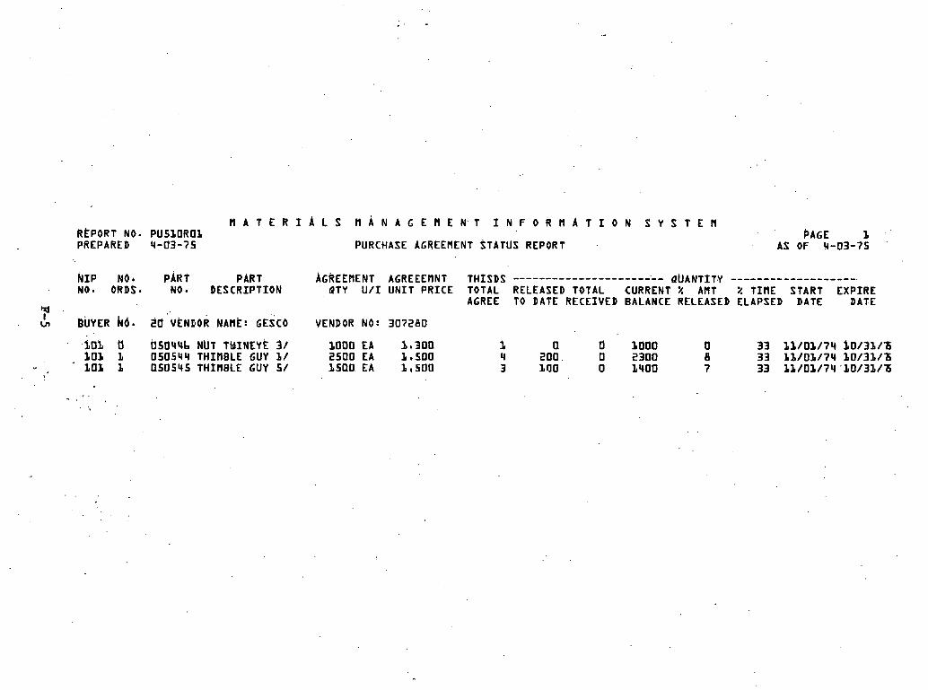
~ A T E R ~ A L S M A N A G E R E N T I N F O R R A T I O N S Y S T E M RtPORT NO. PUSLOROL PAGE f PREPARED 4-03-7s PURCHASE AGREEMENT STATUS REPORT AS OF 4-03-75
k I P Noh PART PART AGREERENT AGREEERNT THISDS ....................... ~UANTITY ------------------- NO* ORDS* NO DESCRIPTION QTY U / I UNIT PRICE TOTAL RELEASED TOTAL CURRENT % ART % TIRE START EXPIRE
4 AGREE TO DATE RECEIVED BALANCE RELEASED ELAPSED DATE DATE
I cn BUYER k0. 20 VENEOR N A H ~ : GESCO VENDOR NO: 307280
fl bSb44b NUT TMINEY~ 3/ 1000 EA 1.300 1 0 d 1000 0 33 11/01/74 b0/3f/'6 ZOP L 050544 THIPlBLE GUY f / 2500 EA 1.50Q '4 200 0 2300 B 33 11/0L/74 b0/31/Z
" - . L O 1 f 050545 THIRBLE GUY 5/ 1500 EA be500 3 LTJO 0 1400 7 33 11/01/74 'b0/3f/Z
' , . . . .

ATE RIALS ~ A N A G E ~ ~ N T I N F O R ~ A T I C N REPORT NO. PUSLOR04 VENDOR A C T I V I T Y REPORT PREPARED 4 - 0 3 - 7 5 PAST TUELVE IlONTHS
NO.. OF AVG. # o . ~ ~ Y s I N F O . PROflISES V E ~ D O R NARE CLASS. NAIIE ORBER: ACKNOYLEDGE TRACES RECEIVED
FLAGG GLY HARDWARE I 2 o L
HUGHES SLEEVES-COtlPRESSION . II 2 L 0
S Y S T E h PAGE 1
AS OF 0 3 - 3 1 - 7 5

STORES M A T E R I A L R E Q U 1 S l T l O N
CEANGE 10
DATE PREPARED 8-30-76
REQUISITION NO. 9 0 1 8 8 3 2 CANCEL CODE . I
LPART NO. ORDER QTY. U / I STD.PKG. FPC OTHER STRM LEAD TIME WEEKS DATE REQUIRED ' BUYER INSP. TYPE SPEC. HAND+
030553 5 EA 1 0000 000 1 5 4 0 1 0 0 0 2 9 9 2 9 9 16 1 2 / 2 7 / 7 6 2 0 01 A 00
VENDOR NO. N I P NO. DATE REQUIRED CATALOG NO. ORDER QUANTITY U N I T P R I C E DISCOUNIS TERMS F.O.B. S H I P VIA
S H I P TO ADDRESS: ALTERNATE ADDRESS: FLUR D A POWER CORP -STOREROOM 6 SR 4 2, 1 M I e N O l 0 WILDWOOD
. wlulwooo, F L a . 32f85
I L C A T W NUMBERS
1. 4 . 7, 2. 5. 8. I
INTERIM EXPEDITE
A - D
B E
C F i
ES CAMB !A .................... KOPPERS .................... 0,,090
157.100 NET DES T 35/20/76 APPROVALS AND SPECIAL NOTES (NOT FOR EDP)
INVEhTORY CONTROL PURCHASING
PART DESCRIPTION: .
' P O L E WOOD 55 FTI C 3 i
SPECIAL INSTWCTIONS:

PURCHASING DEPT. P ,0, BOX 1 4 0 4 2 W. PETERSBURG, FLORIDA 3 3 7 3 3 .' Pm01 PoO. DATE 1 0 / 0 4 / 7 5 FLORIDA POWER
CORPORATIOU PURCHASE ORDER 0 0 1 0 6 6 5 9
TO: SEARS 6 ROEBUCK CO, TRUCK TIRE CENTER 1 8 2 0 MASSARO BLVD. TAMPA, F'LA. 3 2 2 0 8
PROJECT NAME B/H N I P NO, TYPE STATUS VENDOR NO. STRM DATE REQ.
000 , 53 MISC 7 7 9 5 3 2 . 2 9 9 1 0 / 2 3 / 7 6
41IP TO: FLORIDA POWER CORP. - STOREROOM SR 4 6 2 , 1 M I , NO. OF WILDWOOD' WILDWOOD, FLA, 3 2 7 3 3
INTERIM EXPEDITE DATES
- --
I
ITEM O l l l ER PART NO. DESCRIPTION u / I ORDER QTY PRICE/TERMS
01 0000 000 1 5 4 0 1 0 0 0 2 4 9 7 1 8 0 1 4 ANTI-FREEZE 6 COOLANT - P E W N 3 N T TYPE, DR 8 178. ETHYLENE GLYCOL BASE WITH CHEMICAL
1 INHIBITORS TERM NET SEE PKG 5 4 GAL. DRUM
1 I . . S l I P VIA: FOB: VENDOR
DO mlT BILL FLmIDA SALES AND USE TAX FXFW . . TION CERTIFICATE NO, 62-rn5029-33
I NS TRUCT I ONS 1, PLEASE SHOW PURCHASE ORDER NO, ON ALL PACKAGES,
FLORIDA POWER CORPORATION
INVOICES, SHIPPING PAPERS AND CORRESPONDENCEB 2 1 ASE SU M I T INVOICES I N TRIPLICATE TO P . 0 , BOX
42, B-$ ACCOUNTS PAYABLE SECTION, S T . PETERS- BY
BURG, FLORIDA 33733, - - - .- A

PeOe DATE 1 0 / 0 4 / 7 5
FLORIDA POWER CORPORATI ON PURCHASE ORDER - R E C E I V I N G REPORT . . ,I SEARS 6 ROEBUCK CO.
TRUCK T I R E CEN'L'ER 1820 k W i S A R 0 BLVD. W A PLA. 3 2 2 0 8
S H I P TO: - PLORIDA POWER CORP\ - STOREROOM
S R 4 6 2 , 1 M I ; NO. O F WILDWOOD WILDWOOD ,' FLA. 3 2 7 8 5
2 1 5 9 9 3 0
PROJECT NAME B/M N I P NO.. BUYER TYPE STATUS VENDOR NO. STRM DATE REQD
000 . 6 3 M I S C SYS ' 7 7 9 5 3 9 299 f 0 / 2 9 / 7 6
.
ITEM OTHER PART NO. DESCRIPTION u / I ORDER QTY QTY REC'D
. oi moo 000 15401 000299 . . 7 1 8 0 1 4 ANTI-FREEZE 6 COOLANT - PERMANENT WE,' DR 8 ETHYLENE GLYCOL BASE WITH CHEMICAL
S r D PKG 1 I N H I B I T O R S . B I N K-070-A 5 4 GAL. DRUM
. .
FOB: S H I P VIA: VENDOR
S P E C I A L INSTRUCTIONS:
m l A R K s :
SHIPMENT COLLECT DRAFTING REC'D VIA CAR NO. REC'D BY CODE

H A T ~ R I A L s ~ A ~ N A ~ G E ~ E N T I N F O R ~ A T I O ~ J S Y S T E M REPORT k0b PU300ROB PAGE b PREPARED 3-15-75 OPEN OR'DER STATUS REPORT AS OF 3-15-75
ORDER TYPE : TRANSMISSION ..................... PURCHASE ORDER STATUS---------------------------------------- LINE ITEM STATUS-------------------------
P/O P/O P/O REQUIRE EXP EXP ITEM CHG NO* NEW PRM CHG. DEL PART PART ORDER NO* RECD RECEIPT BAL
T NO. STATUS DATE DATE S T A T D A T E NO. D A T E CHG DATE BY STA NO. DESCRIPTION ~ T Y U/I REC DATE Q T Y DUE
r 0 VENDOR NAME: FLAGG VENDOR NO: 2840b7 BUYER hO: 20
00100000 SYS 750201.750315 0 1 + OK 05044b ~ U T TWINEYE 3 /4 300 EA 300 0 2 OK 05042b NUT THIMBLEYE 3 300 EA 1 750220 300
VENDOR NAME: GESCO VENDOR NO: 307280 BUYER E O : 20 00L00003 SYS 750208 750315 IUI Ok
02 0 K
VENDOR NAME: GRAYBAR VENDOR UO: 325944 BUYER bO: ZO 00050002 ROU 741230 750203 P - l 750215 0 1 750201 1 750210 VEN PAST
0 2 750201 1 750210 VEN PAST
VENDOR NAME: GRAYBAR ' VENDOR NO: 325444 0005000b ROU 740101 750415 A - 1 750215 DL
0 2 0 3 04 05 Ob 07 0 8
.09 10
BUYER KO: b7 0 K OK OK 0 K OK OK OK OK OK OK
Cl50544 THIMBLE GUY' 1/12 050545 THIMBLE GUY 5/8
CLAMPS SUSP BRZ CLAMPS SUSP BRZ
O1105L BOLT AMC .BENT 5 O1lObL BOLT A M C BENT 1 011078 BOLT A M C BENT 1 0110154 BOLT ANC BENT 1 05044b NUT TWINEYE 3/4
.05042b NUT THInBLEYE 3 050545 THIMBLE GUY 518 050S44 THIMBLE GUb 1/12 140117 SLV SE BARE YEL LVOLJ4 SLV SE BARE RED
200 'EA 100 EA

F L O R I D A POWER CORPORATION I
PURCHASING D E P T -
P * O * BOX 1 4 0 4 2
3 2 0 1 3 4 ~ ~ STREET SOUTH . S T - PETERSBURG, FLAW 3 3 7 3 3 . .
FEBRUARY 1 5 1 1 9 7 5 ACKNOWLEDGEMENT REQUEST 1
G R A Y B A R E L E C T R I C COMPANY, ' I N C . P - 0 - BOX 3 2 1 0 T A M P A . F L 3 3 6 0 1
SUBJECT: OUR ORDER NUMBER 0 0 0 5 0 0 0 6 DATED: 0 1 / 0 1 / 3 4
SHIP TO: WILDWOOD F L 3 2 9 6 1
WE HAVE RECEIVED NO ACKNOWLEDGEMENT OF T H I S ORDER; PLEASE ..+
ACKN0WLEDGE;ORDER AND G I V E DATE ORDER WILL B E D E L I V E R E D .
! - REPLY HERE:
. a
DATE: BUYER: 6 7 SIGNED:

. . . F L O R I D A P0WER:CORPORATION . .
' PURCHASING D E P T -
P - 0 - BOX 1 4 0 4 2
3 2 0 1 3 4 T H STREET SOUTH
FEBRUARY 2 2 1 1 7 7 5 .
S T - PET.ERSBURG1 F L A - 33' I N T E R I M STEP C OF C I N T E R I M E X P E D I T E REQUES'
SUBJECT: OUR ORDER NUMBER. 0 0 0 5 0 0 0 4 DATED: 1 L / L 5 / 7 4 . .
SHIP-TO: WILDWOOD^ FL 3 z q b ~ . .
. .
WILL YOUR SCHEDULE.. 'FOR D E L I V E R Y BE M A I N T A I N E D ?
,p. REPLY HERE I T E M BY I T E M
. . DATE: BUYER: 50 S I G N E D :

*W
a
K
-I
LL
W
. I-
r
H
w
A
K
W.
3 a
m
x
Z
0
H
.I
-
a
w
0
C-
N
an
3
ww
o
OA
T
u
il
w
EZ
X
WH
O
3m
m
o
a
LL V
I u
vl
I-
PV
W
n-
I-
-
Wd
Ed
E
r
CO
O
I- u)
Ud
A
V)
il W
Nm
d
mm
I
>
W'
wi
lm
Z
OO
H
. J
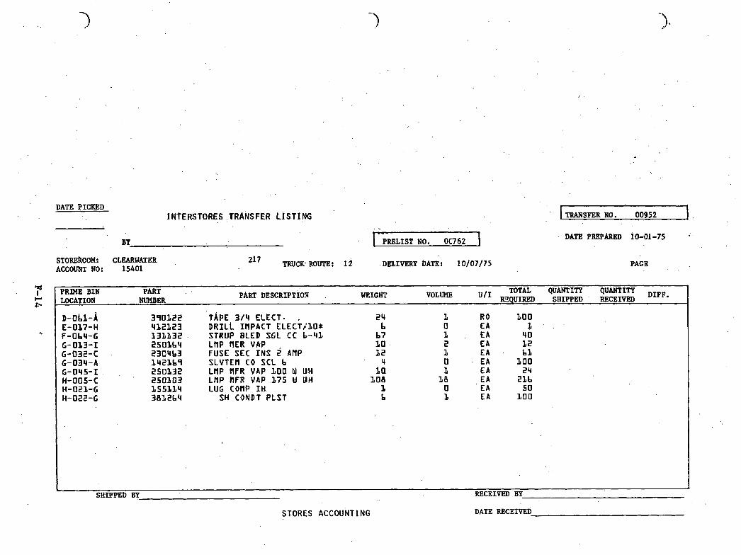
DATE PICKED INTERSTORES ,TRANSFER L t S f 1 ffi TRANSFER NO. 00952 1 .
. . PRELIST NO. 0 0 6 2
STOREROOM: CLEARWATER ACCOUNT NO: 1 5 4 0 1
2 l 7 TRUCK-ROUTE, l i DELIVERY ~ A T E S 1 0 / 0 7 / 7 s PAG B
PART PRlME BIN PART DESCRIPTIOlJ WEIGHT VOLUME TOTAL QUANTITY QUANTITY DIFP.
LOCATION NUMBER KCQUIRED SHIPPED . RECEIVED 1 TAPE 3 1 4 ELECT* DRILL IflPACT E L E C T ~ ~ O * STRUP BLED SGL CC b-42 LflP flER VAP ,
FUSE SEC I N S 2 AHP SLVTEH CO SCL b LflP PlFR YAP 1 0 0 W UH LflP PlFR YAP 1 7 5 W UH LUG conp IH
SH C O N D T PLST
4 t a
BOB 1 b
SHIPPED BY RECEIVEB BY
STORES ACCOUNT1 NG DATE RECEIVED

STORES MATERIAL REQUISITION DATE PREPARED 9-30-75
REQUISITION I PART NO ORDW QTY u / I STO.PKG. ACCOUNT NO. STRM LEAD TIME WEEKS DATE REQUIRED BUYER
142411 3 1 4 0 EA 2 5 1 5 4 0 1 299 6 1 1 / 1 7 / 7 5 4 0
6, 13. KY 0 8 4 - 6 1 - 7 1 A S L 0 0 -
9 . POSSIBLE VENDORS . .
NDOR NO. VENDOR NAME CATALOG NOS, N I P N I P / U N I T P R I C E DISCOUNTS T W M S FOB LAST ORDER DATE
S H I P TO ADDRESS: FLORIDA POWER COW.-STREROOM SR 4 6 2 , 1 M . N O . OF WILDWOOD WILDWOOD, PLA. 3 2 7 8 5 .
. -
-' . ... . , . . .- .
I APPROVALS AND SPECIAL NOTES (NOT FOR EDP)
INTERIM E W E D I T E A D B E C ' F .
PURCHASING
PART DESCRIPTION:
SLVTEN 1 P ACSR 4 .
SPECIAL INSTRUCTIONS:
VENDOR NUMBER N I P NO. DATE REQUIRED CATALOG NO. ORDERQUANTITY UNIT P R I C E DISCOUNTS TERMS FOB SKIP, VIA
CATALOG NUMBERS 11. BY YDS4RL . 4 . 7 . '
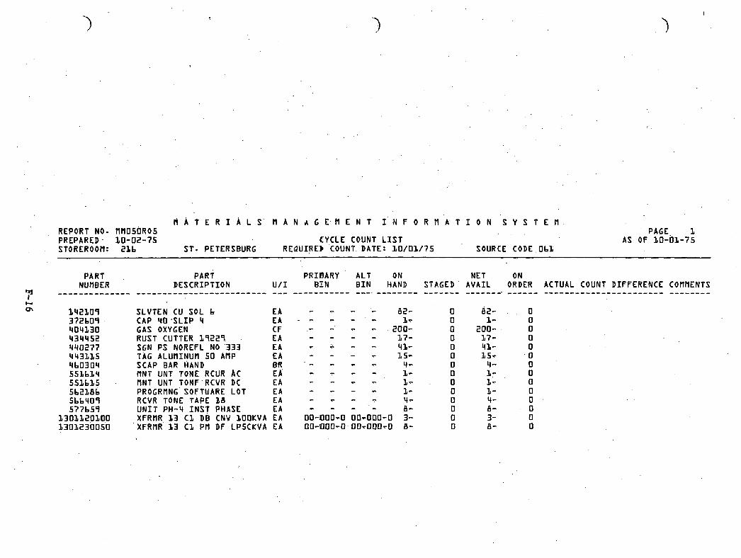
M A T E R I A L S M A N A G E H E N T I k F O R f l A T I O N S Y S T E f l REPORT NO. M H 0 5 0 R 0 5 PAGE 1 PREPARED 1 0 - 0 2 - 7 5 CYCLE COUNT L I S T AS OF 1 0 - 0 1 - 7 5 STOREROOfl: 21b ST. PETERSBURG REQUIRE) COUNT DATE: 1 0 / 0 1 / ? 5 SOURCE CODE O b l
PART PART PRIBARY ALT ON NET ON NUMBER D E S C R I P T I O N U / I B I N B I N HAND S T A G E D ' A V A I L ORDER ACTUAL COUNT D IFFERENCE COflRENTS _---_-_-_--_-- ......................... --- ----------- ---. -------- ------- -------. ------ ....................... --------
SLVTEN CU SOL b E A CAP 4 0 ' S L I P 4 EA *
GAS OXYGEN C F RUST CUTTER 1 9 2 2 9 E A SGN PS NOREFL NO '333 E A TAG ALUf l INUM 5 0 ARP E A SCAP B A R HAND BR f lNT UNT TONE RCUR A C E A MNT UNT TOHF'RCVR DC E A PROGRMNG' SOFTWARE LOT E A RCVR TONE TAPE 38 E A U N I T P H - 4 I N S T PHASE E A X F R f l R . 1 3 C l DB CNV IOOKVA EA XFRMR 13 C 1 P f l DF LPSCKVA EA

M A T E R I A L S M A N A G E H E N T I N F O R M A T I O N S Y S T E M REPORT NO. PU030R09 PAGE 1 PREPARED 9-20-75 OPEN. P . 0 - ORDER STATUS - PART NO SEQUEPJCE AS OF 9-20-75
ITEM D A T E -LATEST ' ORDER REC NO D A T E QUANTITY BAL PART NO. STR PO NO. PART D E S C R I P T I O N VENDOR NAME NO, REQUIRED PROM DATE QUANTITY U I I N D REC RECEIVED RECEIVED DUE
I 3 0 2 270 00100577 COVER BLANK SMALL 2.71 ANCHOR 03 09/24/75 09/24/75 200 EA
1302 239 00100733 COVER BLANK SMALL 2.73 KEARNEY 0 1 09/24/75 09/24/75 bOO EA
130b 294 00100734 COVER PLATE GLASS METAL PROD 0 1 09/15/75 09/15/75 500 € A L30b 299 00100752 COVER P L A T E GLASS METAL PROD 0 1 09/30/75 09/30/75 2200 EA
I 3 1 0 299 00100742 HUB 1 I N ANCHOR
1314 270 00100577 HUB 1-1/2 I N
1314 299 00100bb0 HUB 1-2/12 I N
ANCHOR
ANCHOR
131b 270 00A10347 HUB 2 I N
ANCHOR ANCHOR ANCHOR
' , 131b 299 00ALC398 HUB 2 I N 131b 249 00100731 HUB 2 I N 131b 299 001C0655 HUB 2 I N
1318 270 00100577 HUB 2-&/2 I N
1318 294 OOlOObbd HUB 2-1/2 I N ANCHOR

M A T E R f A L S REPORT NO. P ~ ~ O R O ~ PREPARED 1 2 - 2 8 - 7 4
STOREROOM: MONTICELLO ORDER P O L I C Y : S/FOf iEC/LOW/TR
7J PART EVAL r NUMBER PART D E S C R I P T I O N PERS
1 5 6 1 0 9 COVER I N S U L b 2 - 1 / 2 5 1 . 1 5 0 1 2 8 CON NT CU STR 2 - 4 5 1 2 3 0 4 8 9 FUSE NR PLUG 3 0 AMP 5 1 0 7 0 1 0 b BRKT 'DB L A CUTOUT 5 1
H . A N ~ G E M E N T I N F O R ~ A T . I O N S Y S T E N PAGE 10
FORECAST S I M U L A T I O N REPORT - SUMMARY: AS OF 1 2 - 2 7 - 7 4
E V b L U A T I O N PERIOD USAGE ---- ----- - ---- -------------- A C T U L FORECAST VARIANCE -------- ---------- ---------
DERAND F I L T E R
T R I P S -------
MAD ------------------ U N I T S DOLLARS ------- ---------
AVERAGE TRACKING REPORT
S I G N A L MESSAGE .---------- ---------
0 a 0 4 REGRESSN 0 . 3 2 AVERAGE 0 - 3 7 REGRESSN 0 . 4 7 AVERAGE
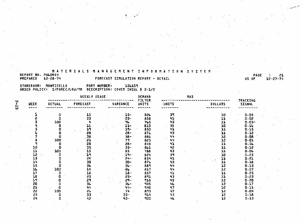
H A T E R I A L S M A N A G E M E N T I N F O R ~ A T I O N ' S Y ~ T E H REPORT hO. PUbORO4 PREPARED 12-28-74 FORECAST S IMULATION REPORT - D E T A I L
STOREROOM: HONTICELLO PART NUMBER: 15b109 ORDER POL1C.Y: S/FOREC/LOW/TR DESCRIPT ION: COVER I N S U L b 2-I/2
~ E E K L Y USAGE DEMAND ........................................ MAD q F I L T E R ................................ 1 C1 WEEk ACTUAL FORECAST VARIANCE U N I T S -- - - -------- ------------- ------------ ------ U N I T S - - - - - - - - DOLLARS I0 -----------
PAGE . 21 AS OF. 32-27-74
TRACkING SIGNAL ---------
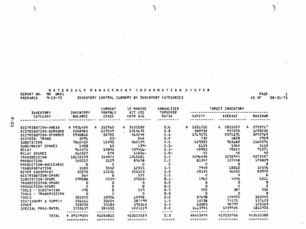
R A T E R I A L S ~ A N A G E ~ E N T I N F O R M A T I O N S Y S T E ' ~ ~ REPORT k O * f lR O R 0 1 PAGE 1 PREPARED 9 - 1 3 - 7 5 INVENTORY CONTROL U R R ~ R Y BY INVE~JTORY CATEGORIES A S OF 08-31-75
CURRENT - 32 hONTHS ANNUALIZED INVENTORY INVENTORY MONTHLY NZT USE TURNOVER
CATEGORY BALANCE USAGE CU?R AUG R A T I O -------------------_._ ------------- ---------- ------------ ---------- DISTRIBUT ION-OHEAD 4 4 9 5 b 4 0 4 DISTRIBUTION-UGROUND 2 5 0 8 9 8 3 D ISTRIBUT ION-XFORMER 5 9 4 0 8 b d D I S T R I B . TRANS 5 2 9 1 SUBSTAT ION 7 0 b 0 4 2 2 SUBS/RA INT SPARES 1 4 0 0 RELAY 9 6 4 5 7 5 RELAY SPARES 2 b 2 8 2 7
,TRANSNISS ION l o b 7 2 5 5 9 PRODUCTION 18001.7 PRODUCTION-NUCLEARQC 0 TRANSPORTATION' 3 5 8 0 METER E Q U I P f l E N T 5 ' 2278 '
D I S T R I B U T I O N - S P A R E 2 b 4 SUBSTATION-SPARE 2 9 9 8 0 8 TRANSMISSION-SPARE 0 PRODUCTION-SPARE 0 TOOLS - SUBSTAT ION 4 9 8 TOOLS - T R A N S f l I S S I O N 0 TOOLS 3 0 1 2 2 5 STATIONARY 8 SUPPLY 2 5 b L b 1 OTHER 3 5 8 2 3 5 SPECIAL PROJ - N A T R L 5 7 5 3 b 5 9 ----------
TOTAL 5 3 9 5 7 9 D 5 4 ---------- ------- ---
TARGET 'INVENTORY .................................... SAFETY AVERAGE MAXIMUR ----------- ------------- ---------

H A T E R I A L S ~ A N A G E ~ E N T I N F O ~ R A T I O N S Y S T E H REPORT kO. Rfl070R02 PREPARED 8-29-75 INVENTORY CONTROL SUMMARY BY STOREROORS
CURRENT 1 2 PIONTHS ANNUALIZED .. TARGET INVENTORY INVENTORY flONTHLY NET USE TURNOVER v---------------------------
StOREROOH BALANCE USAGE CURR AUG RATIO SAPETY AVERAGE f lAXIl lUH --------------- ----------- ------- ---------- *-------- ----- . t *-----.. ------- '4 I ST-PETERSBURG 6253321 ," CLEARUATER 4557331
TARPON SPRINGS 82b5L5 WALSINGHAH 7138b1 OCALA 2324399 ISONTICELLO 202dOba
- . LAKE. ldALES 3509b18 AVON PARK 275430
- HAINES CITY 250737 UIMTER PARK 3bS824b ALTAMONTE SPR3NGS 2b77903 CO NWlAY b02117 DELANO 1156152 MINTER GARDEN 232329 STORES ACCTG 0 CRYSTAL RIVER-PROD I374 ANCLOTE-PROD is r3sm CENTRAL REPAIR b72050 CENTRAL STOREROOR 8892322
' NO. OF: STOCKOUTS ---------
NO. OF ORDERS F I L L E D ------
S~RVICE LEVEL % -------
99.7 99.2 99.b 99.7 99.6
100 0 99.9
bOO.0 .99.9 99. L 99.b 99.7
100.0 99.3
0.0 0.0
99.b 0.0
300.0

I ~ A T E R I A L S ~ A N A G E N E N T I N F O R H A T I O N s r s t ~ a REPORT NO. Plfl070R14 PAGE 1 PREPARED 7-07-75 ROUTE CAPACITY REPORT AS OF Ob-30-75
TRUCK
'-4 ROUTE
I ----- rQ h, 3 1
12 13 . b 'I 15 2 1 22 23 24 2 5 3 1 3 2 3 3 3 'l 3 5
CAPACITY TRUCK ---------------
TYPE MEIGHT VOLUME ----- ------ ------ FLATBED 1b0000 FLATBED 1b0000 FLATBED 200000 FLATBED 1b0000 FLATBED 3b0000 FLATBED 1b0000 FLATBED 1bOOOO FLATOED 200000 FLATBED 1bOOOO FLATBED lbOOOO FLATBED 0 FLATBED 0 FLATBED 0 FLATBED 0 FLATBED D
TOTAL
CAPACITY FACTORTWEIGHT ~IONTH YTD --------------------------------.
AnOUNT 2 AMOUNT % ----------- -----------
- - -- - - -
CAPACITY FACTOR-VOLUNE HONTH YTD - ...................................
ANOUNT % ANOUNT %

REPORT NO- MM070RO8 BIN LOCATOR REP.ORT PREPARED 10-03-75'
PART NO BIN LOC DESCRIPTION U/O B I N LOC
010052 J - O ~ ~ - G BLT M G HH 3/4XL-L/2 EA J-043-G C-053-F C-053-F
010201 J-040-1 BOLT MACH 1/4X2-L/2 EA J-0q0-1
010204 J-050-C BOLT MACH 3 /8 X 1 EA J-050-C
010224 J-046-L BOLT MACH L / 2 X 1 EA JcO4b-L
0 1 0 2 2 5 . J-075-F BOLT MACH L/?XL-1/4 EA J-075-F C-049-.J C-049-J
'010226 J-075-E BOLT MACH 1 / 2 X l - L / 2 EA . J-075-E NO-ACT- .NO-ALT-
. 030228 .,K-027-D BOLT MACH 1 / 2 X 2 E A ' K-029-D
010230 E-003-D BOLT MACH 1/2X2-1/2 EA E-003-D
010232 K-027-D BOLT MACH L / 2 X . 3 EA K-027-D
0102;42 . - - ' . BOLT MA.CH 5/8X1-1/4 E A - - 01.0252 NO-LOC- BOLT MACH 3/4X1-1/2 EA NO-LOC-
. . 010256 D-004-M
" 010314 E-064-J NO-ALT-
010316 J-043-A NO-ALT-
010320 . J-045-A NO-ALT-
BO.LT MACH 3 /4X2- f / 2 EA D-004-M
BOLT MACH L/2X3-L/2 EA E-064-J NO-ALT-
BOLT MACH E/2 X 4 EA J-043-A NO-ALT-
aOLT MACH L / 2 X 5 EA J-045-A NO-ALT-
010324 D-002-1 BOLT MACH 1/12 X 6 EA D-002-1 NO-ALT- a NO-ALT-
030326 K-029-G BOLT MACH 1 / 2 X 7 EA K-029-G
010328 G-033-A BOLT MACH 1 / 2 ,X, 8 EA G-033-A .
010332 F-006-N BOLT,MACH 1 / 2 X 1 0 EA F-006-N
PAGE

THIS PAGE WAS INTENTIONALLY
LEFT BLANK

ADDENDUM G
SUPPORTING MATERIAL FOR
NUMBERING SYSTEMS

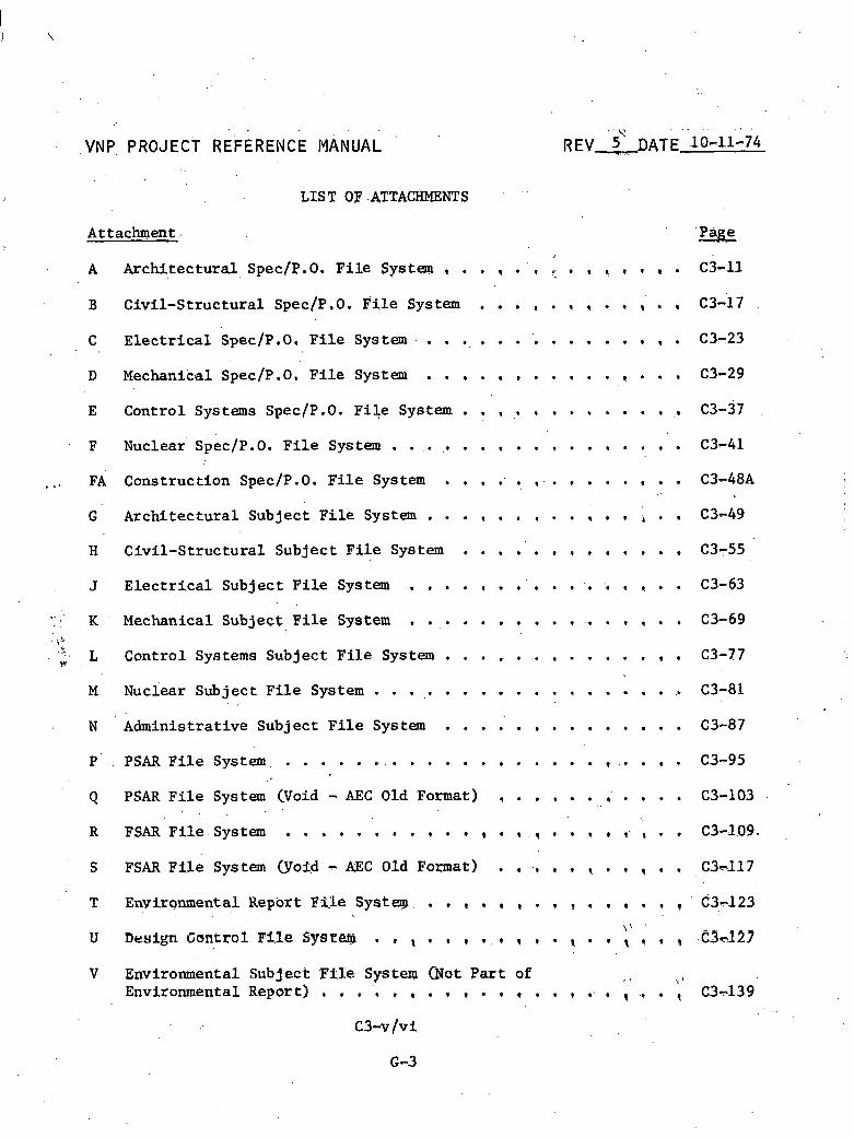
VNP, PROJECT REFERENCE MANUAL
LIS T OF .ATTACHMENTS ' ' '
Attachment .. 'Page
A A r c K e c t u r a l S ~ ~ C / P . O . F i l e System . . . , . ' , ; . , . , . . . ~3-11
B C iv i l -S t ruc tu ra l ~ p e c / ~ . O . ~ i l e System . . . . , , . . , . , ~3- 'I 7
C E l e c t r i c a l Spec/P.O, F i l e Sys t em. . . ., . . . '. , . . . . , , . C3-23
D Mechanical Spec/p.O. F i l e System . . , . , . . . , . . , . . . C3-29
E Cont ro l Systems Spec/P.O. F i l e System . . , ,. . . . . . . . . ,, (23-37
F Nuclear' SpecjP. 0. F i l e System . . . . . . . . . , . . . . . . . . C3-41
. FA Cons t ruc t ion Spec/P.O. F i l e System . . , , , , . . , , . , , . . C3-48A
G A r c h i t e c t u r a l Sub jec t F i l e System . . . , . , , . . , . . 1 . . C3-49
H C i v i l - S t r u c t u r a l Sub jec t F i l e System . . , . . . , . . , . . , C3755
. . J E l e c t r i c a l Sub jec t F i l e System . . . , , . . ' . . . , , , , . . C3-63
s , . K Mechanical Subjec t F i l e System . . . . . . , , . . . . , , . . C3-69
,5
L Cont ro l Systems Sub jec t F i l e System , . . , . . , . . . . . , , C3-77 I,
M Nuciear Sub jec t F i l e System . . . ,. . . . . . . . , . . . . . .. C3-81
N Adminis t ra t ive Sub jec t F i l e System . . . . . . . . , . . . . . C3-87
P ' . P S A R F i l e S y s t e m , . . . . . . . . . . . . . . . . . . . , . . . . . C3-95
Q PSAR F i l e System (Void - AEC Old Format) , . . . . . ,' . . . . C3-103
R FSAR F i l e System . . . . . , . . , . , , . , . , , , . , ,. , , , C3-1.09.
S FSAR F i l e System (YoPd'- AEC Old Format) . , ,, . . , . , , . , C3-117
T Environmental Report F%Ie Systeqo . . , , . , , . . , , . , . . , ' 6 3 . ~ 1 2 3
I : '
U Design Control F i l e SySI32i!i . , , , . , . , , , . , . , , , , , . C 3 ~ 1 2 7
V Environmental Subjec t F t l e Sg.stesl (yot P a r t of ! I , I Environmental Report] . . , '. . , . , , . , , . . , .. , , ., . , C 3 ~ 1 3 9

... .
VNP PROJECT. REFERENCE MANUAL . . . t r
.3 , D A T E 1-7n74
PART C ENGINEERING
SECTION 3 NIJMBERXNG AND FIZXNG SYSTEMS
The purpose of t h i s s e c t i o n is to provide t h e information necessary ' for ass igning and maintaining a numbering and f i l i n g system t h a t i s ' u s e d i n iden t i fy ing , f i l i n g , and r e t r i e v i n g documentation pe r ta in ing to t h e Vogtle Nuclear P lan t p ro jec t .
This s e c t i o n incorpora tes procedures f o r ass igning c o r r e c t f i l e numbers t o p r o j e c t documents, and i d e n t i f i e s t h e persons responsible f o r making such assignments. Also included is a d e s c r i p t i o n of t h e f i l i n g systems f o r t h e va r ious ca tegor ies of documents, the persons responsible f o r maintaining , t h e p r o j e c t f i l e s , and a d e t a i l e d l i s t i n g of c e r t a i n f i l e numbering systems assoc ia ted wi th the p ro jec t (Attachments A through V),
3.3 NUMBERING AND .FILING RESPONSIBILITY
3.3.1 NUMBERING RESPONSIBILITY
P r o j e c t f i l e numbers a r e assigned t o a l l incoming, outgoing, o r i n t r a - p r o j e c t documents except Bechtel drawings ,and vendor data . (These use t h e s e p a r a t e numbering systems and number assignments explained i n P a t t C, Sections 4 and 5 of t h i s manual.). A l l incoming documents, r egard less of o r i g i n o r d e s t i n a t i o n , are given a n appropr ia te f i l e number by t h e p r o j e c t adminis t ra tor . .The numbers se lec ted a r e then checked f o r accuracy by t h e ,
a s s i s t a n t p r o j e c t engineer and/or engineering group supervisor (EGS). For projec t -or iented documents, t h e p r o j e c t adminis t ra tor a ss igns f i l e n h b e r s only t o those generated by p ro jec t management or by support depart- ment personnel. Engineering-generated documents a r e assigned f i l e numbers by the respons ib le engineer, t h e EGS, or t h e l i c e n s i n g engineer.
3.3.2 FILING RESPONSIBILY3Y ,
Except f o r Bechtel drawings and vendor d a t a , which are the r e s p o n s i b i l i t y of t h e drawing and d a t a ' con t ro l 8ect.i,onl most o t h e r p r o j e c t documents a r e kept ;fn f i l e s .maiptained by the p r o j e c t s e c r e t a r y , kccess t o these f i l e s is l imi ted t o the proje.c.t secxe tq r t . a l . s t a f f , and a l l p ro jec t personnel wish? ltng t o retrtwe or depos i t documents must do so through a member of t h i s s t a f f . The p r o j e c t admimistrator ' is responsible f o r s e v e r a l f i l e s , which conta in t h e remabder of t h e p r o j e c t documents, (Refer t o paragraphs 3.5 and 3.6 f o r d e t a i l s '.of f s l i n g systems).
C3-1
6-4

VNP PROJECT REF,ERENCE MANUAL
3.4 FILE NUMBERS 1
The elements of the f i l e number i n d t c a t e t h e appropr ia te p r o j e c t , d i s c i p l i n e , feliing system, and ei . ther the docingent ca tegory and mibcategory wt th in t h e f i l i n g system, o r n m e r e c a l sequence. un less otherwise spec i f i ed , t h e f i i e number assigned t a a p ro jec t document i s composed o f . f i v e elements. The elements c o n s i s t of alphanumeric des ignators t o ident2fy t h e document and its r e l a t e d f i l i n g system. These f i l e number elements and des ignators a r e shown i n Figure C3-.l,
~ l t h o u ~ h t h e f i l e numbers and t i t l e s l i s t e d i n Attachments A through V must not be changed a f t e r being assigned, add i t ions o r ' d e l e t i o n s t o t h e f i l e system a r e permissible. The VNP P r o j e c t Reference Manual Change Request form must be used t o i n i t i a t e any such change t o the f i l e system. Apprwal of t h e requested change must be obtained before t h e f i l e .and manual a r e revised. (For the complete Pro jec t Reference Manual change procedure, r e f e r t o the Preface of t h i s manual).
F i l e numbers t b t a r e no longer needed s h a l l have t h e t i t l e i n t h e l i s t i n g l i n e d out ( d t h a broken l i n e ) and the word "DELETED" added a t t h e end of t h e t i t l e . Although such numbers a r e not reassigned, t h e f i l e f o l d e r s t h a t contain documents a r e kept i n t a c t f o r record purposes, and r e t a i n t h e dele ted numbers .
v
New f i l e numbers required f o r t h e p r o j e c t a r e assigned by the p r o j e c t :' I ' adminis t ra tor i n conjunction with t h e responsible EGS, and with t h e approval ,; of the p ro jec t engineer and p ro jec t manager.
i '
The f i r s t element 0-f the f i l e number i d e n t i f i e s t h e ' p r o j e c t (Figure C3-1) , and is the same $or a l l p ro jec t document f i l e riumbers except lBechte l drawings. (Refer t o P a r t C , : Section 4 of t h i s manual.)
Under c e r t a i n condit ions, a p r e f i x is used wi th f i l e numbers t o i n d i c a t e the p l a n t u n i t t o which a document a p p l i e s , The use of t h i s p r e f l x is mandatory f o r engineering r e q u i s i t i o n f i l e numbers (Part C, Section 8 of t h i s manual), but such a p r e f i x is used on an as-required b a s i s f o r o ther documehts. The u n i t pref lxes a r e as fol lowst
1 = Unit 1
2 = Unit 2
3 = Unft 3
A 3 Comon t o u n i t s 1 and 2
B ~i Conupon t o u n i t s 3 and 4
C 3 Cornon t o e n t i r e p lan t

. . . . . .
VNP PROJECT REFERENCE MANUAL REV 4 DATE: 54-74
FILE NUMBER' ELEMENTS.' AND DESIGNATORS
Typical F5le Number, X 3 B C. 1 2 T T T ' i - T
t e n - o e c t 2nd element - D2,scipline
4 t h element - Category 3rd element - .F i le System
, 5 t h element - Subcategory
1st - X = Becbtel Job 9510, Southern Services , Inc , con t rac t for element the Georgia Power Company Alvin W. Vogtle Nuclear P lan t
2nd element
3rd element
1' = ~ r c h i t e c t u r a l Disc ip l ine 2 = Civ l l rS t ruc t u r a l Disc ip l ine 3 = E l e c t r i c a l Disc ip l ine 4 = Mechanical Disc ip l ine (,Including P lan t Design) 5 = Control Systems Disc ip l ine 6 = Nuclear D i s c i p l i n e . .
7 = Administrat ive 8 = Environmental (Not p a r t of Envlro~uuental Report) 9 = Construction
A = Specif icat ion/Purchase Order (Spec/P.O.) F i l e System B = Engineering and Administrat ive Subject F f l e S y s t m s C = Design Calcula t ion F i l e System D = Bechtel Drawing F i l e System li = PSAR F i l e System (Void - AEC Old Format) * F = FSAR F i l e System (Void - AEC old Format) * G = Georgia Power Construction Drawings H = Environmental Report (ER) F i l e System * J = Design Control F i l e System * K = Scope Change F i l e System * L = Document Review Notice Control and F i l e System * ,M = PSAR 'Bile S y s t m * N = FSAR F i l e System * S = ~ n g i n e e r i n g Study F i l e System
4th A, B, etc.; .Q1, = Main category headings wi th in a f i l e e l emen t 0,2, e t c , ; o r system, 'or a numerical sequence, Refer
001, OQ2, e t c . t o Paragraph 3.4.4, , .
5 t h 01, 02, e tc , . ; = 3uhcategory of a f i l e system, or a numer- element. ..I, .2, e t c , ; e r i c a i sequence, Refer t o Paragraph 3.4.5,
o r A, B, e t c .
*Auxiliary Administrat ive F i l e Sys tern
Figure C3-1. F i l e Number Elements and Designators
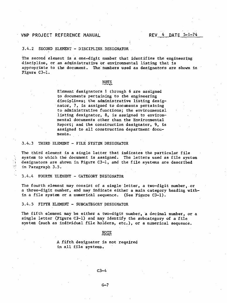
. . . . : . . . .
VNP PROJECT REFERENCE MANUAL REV - 4 DATE 5 ~ 1 - 7 4
3',4.2 SECOND ELEMENT - DISCIPLINE.DESIGNATOR .
The second element is a onerdfgi t number t h a t $dent i f ies the ' engineering d i s c i p l f n e , o r .an admin t s t ra t ive or .env$ronm&tal l l l s t ing t h a t i s appropr ia te t o the document. .The' numbers used a s des ignators a r e shown i n Figure C3-1.
Element des ignators I through 6 a r e assigned t o documents pe r ta in ing t o the engineering d i s c i p l i n e s ; t h e admin i s t ra t ive l i s t i n g desig-
. na to r , 7 , is assigned t o documents pe r ta in ing t o adminis t ra t ive funct ions ; t h e environmental . ' .
l i s t i n g des ignator , 8, i s assigned to environ- mental documents o ther than t h e Environmental Report; and t h e const ruct ion des ignator , 9, is assigned t o a l l const ruct ion department.docu- ments. ,
.3.4.3 THIRD ELEMENT - FILE SYSTEN DESIGNATOR
The t h i r d element is a s i n g l e letter t h a t i n d i c a t e s t h e p a r t i c u l a r f i l e system t o which the document is assigned. The letters used a s f i l e system
r des ignators a r e shown i n Figure C3-1, and t h e f i l e systems are described i n Paragraph 3.5.
' 3.4.4 FOURTH ELEMENT - CATEGORY DESIGNATOR
The f o u r t h element nay c o n s i s t of a s i n g l e . letter, a two-digit number, o r . a three-digit.number, and may i n d i c a t e e i t h e r a main category heading with- i n a f i l e system or a numerical sequence. (See Figure C3-1).
3.4.5 FIFTH ELEMENT - SUBCATEGORY DESIGNATOR
The f i f t h element may be e i t h e r a t w o d i g i t number, a decimal number, o r a s i q g l e l e t t e r e i g u r e C3-1) and may i d e n t i f y t h e subcategory of a ' f i l e systexi~ Csuch a s ind iv idua l f i l e holders, . e t c , ) , o r a numerical sequence,
A f i f t h des ignator $.s not . required t n a.11 f i l e systems* ,

VNP PROJECT RE.FERENCE. MANUAL
3. '5 FILE WSTEMS
The f f l e . system t o which a document 3,s: assigned i.s i d e n t i f red by t h e t h i r d element of t h e f f le number, R e f e r t~ - paragraph 3,4.3, and see Pigure C3-1.
NOTE
One copy of a l l attachments t o any p r o j e c t correspondence s h a l l be maintained i n t h e sub jec t f i l e o r i n t h e speci f ica t ion/purchase order f i l e . One copy of t h e t r a n s m i t t a l letter only i s f i l e d i n t h e master chron f i l e . (Refer t o P a r t B, Section 4 of t h i s manual).
The spec/P.O. f i l e system conta ins s p e c i f i c a t i o n s , r e q u i s i t i o n s , purchase -.
orders , and r e l a t e d documents. These f i l e s a r e reserved f o r only those m a t e r i a l s developed subsequent t o t h e completion of the specif i c a t i o n in- house reviews (but including t h e document review n o t i c e s f o r these reviews). Documentation developed p r i o r t o t h i s time normally i s f i l e d i n appropr ia te sub jec t f i l e s . However, if t h e appropr ia te f i l e s do not e x i s t , the mate r i a l may be r e t a i n e d i n t h e spec/P.O. f i l e system. The f i l e systems and desig- na to r s f o r thd spec/P.O. f i l e s a r a l i s t e d i n ~ t t a c h m e n t s A through FA. The spec/P.O. f i l e system l i s t e d i n these attachments is t h e master l i s t f o r t h e p r o j e c t spec/P.O. f i l e s . . E n t r i e s i n these lists t h a t a r e marked "DELETED" cannot be reused, ' a d do not appear on t h e s p e c i f i c a t i o n c o n t r o l log. When an. e n t r y . is t rans£ er red t o a d i f f e r e n t f i l e number on the list, t h e contents o t t h e corresponding o r i g i n a l t i i e a r e t r a n s f e r t e d accordingly. The o r i g i n a l f Z l e is re ta ined wi th a cross-ref e r e i c e t o t h e d i f f e r e n t f i l e number.
The cross-f i l i n g of any t echn ica l d a t a from t h e spec/P.O. f i l e s t o t h e sub jec t f i l e system may be accomplished by a responsible EGS, who must then n o t i f y t h e p r o j e c t adminis t ra tor of such ac t ion. A l l c o s t d a t a i s t o remain f.n t h e spec/P.O. f i l e system,
NOTE - P a r t C , Secti-on 8 of thks manual conta ins an explanatton of t h e spec&£ication, purchase premorandm, and requi.s$:t ion numberi.ng sys t q s , t h e speck.ffcatipn con t ro l log , and t h e f s relationsh$.p t o Geqrgi:a ,Power Corppany purchase orders..
A r e q u i s i t i o n is assigned t h e same f t l e number a s i ts corresponding spec- i f i c a t f o n , except f o r a p r e f i x iden t i fy ing t h e applecable p l a n t u n i t (Paragraph 3.4.1) and a "dash letter" added t o t h e f i l e number t o i n d i c a t e when t h e r e i s more than one vendor. The dash le t ter "-A" des ignates the second vendor, "-B1' t h e t h i r d vendor, etc.
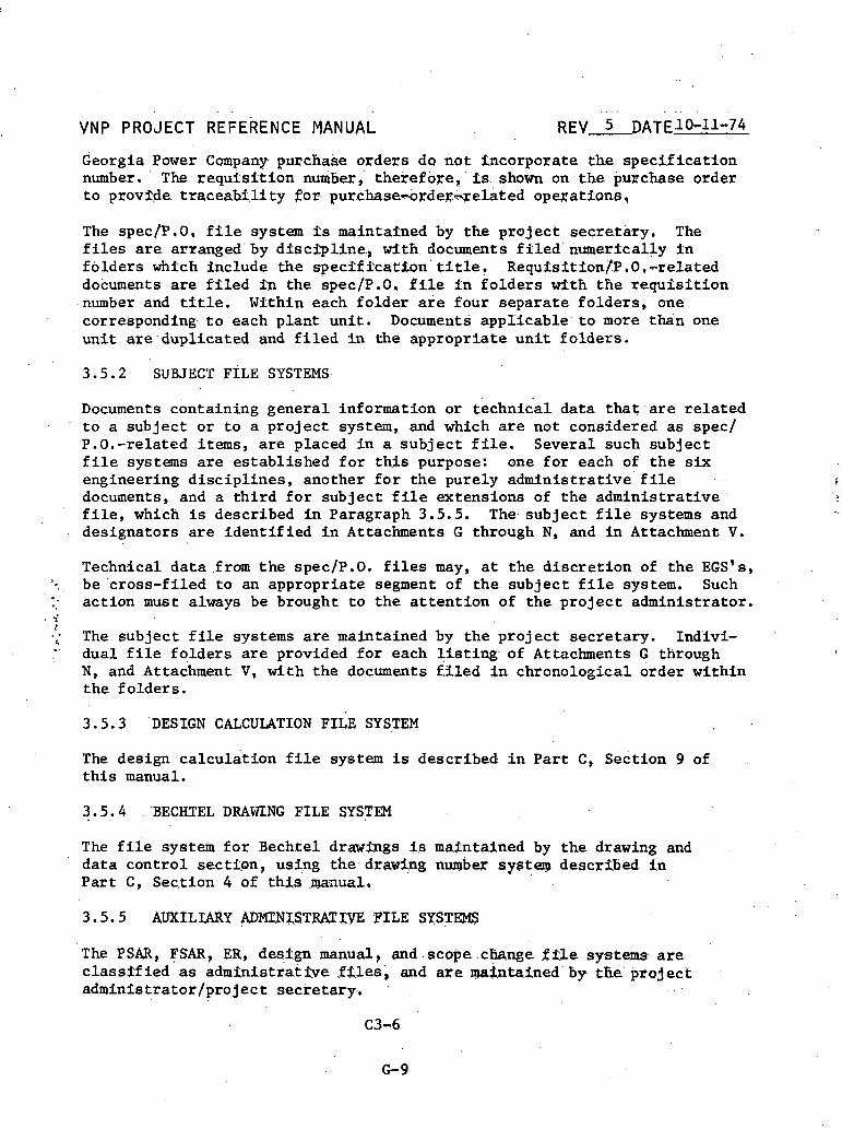
Georgia Power Company pllrchake orders d o . n o t incorpora te the spec i f i ca t ion number. ' The r e q u i s f t i o n numb=,' thekefore, ' 2s. shown on ' t h e purchase order t o provMe t r a c e a b t l i t y $or purchase-+rder&xelated opwat fons ,
The spec/P.O, f i l e system 2s maintafned by the pro jec t sec re ta ry . The f i l e s a r e arranged by d i s c i p l i n e , wi th documents f i l e d numerically i n f o l d e r s which lnclude the specff fca tson t i t l e , Requfsftion/P.O,-related documents a r e f i l e d f n the spec/P.O, f i l e i n f o l d e r s with t h e r e q u r s i t i o n number and t i t l e , Within each f o l d e r a r e four separa te f o l d e r s , one corresponding t o each plant u n i t . Docume~lts appl icable t o more than one u n i t ate duplicated and f i l e d i n the appropr ia te u n i t f o l d e r s .
3 . 5 . 2 SUBJECT PILE SYSTEMS
Documents containing genera l information or technic'al da ta t h a t a r e r e l a t e d t o a subject o r t o a proj.ect system, and which are not considered a s spec/ ,P.O.-related items, a r e placed i n a s u b j e c t f i l e . Severa l such sub jec t f i l e systems are es tab l i shed f o r t h i s purpose: one f o r each of t h e s i x engineering d i s c i p l i n e s , another f o r t h e purely adminis t ra t ive f i l e c documents, and a t h i r d f o r sub jec t f i l e extensions of t h e a d m i n i s t r a t i v e , f i l e , which is described i n Paragraph 3 . 5 . 5 . .The. sub jec t f i l e systems and des ignators a r e i d e n t i f i e d i n Attachments G through N, and i n Attachment V.
Technical d a t a .from t h e spec/P.O. f i l e s may, a t t h e d i s c r e t i o n of t h e EGS's, . be ' c ross - f i l ed t o an appropr ia te segment of t h e sub jec t f i l e system. Such :: ac t ion must always be brought t o t h e a t t e n t i o n of the p r o j e c t adminis t ra tor .
a -i r .; The sub jec t f i l e systems a r e maintained by t h e p r o j e c t sec re ta ry . Indlvi- ;' dual f i l e f o l d e r s a r e provided f o r each l i s t i n g of Attachments G through
N, and ~ t t a c h m e n t V , . w i th t h e documents f.3led i n chronological order wi th in t h e fo lde rs .
3 . 5 . 3 'DESIGN CALCULATION FILE SYSTEM
The design c a l c u l a t i o n f i l e system is described i n P a r t C, s e c t i o n 9 of t h i s manual.
3 . 5 . 4 BECHTEL DRAWING FILE SYSTEM
The f i i e system f o r Bech.te1 drawings is mat.ntained b.y t h e drawing and d a t a c o n t r o l sec t ton , using the.draw%.ng n d w s y s t q descrtbed I n P a r t C, Sec,tion 4 of t h i s .mnual ,
3 . 5 . 5 AUXILIARY ADMT.NICSTRATW FILE SYSTEMS
The PSAR, FSAR, ER, destgn manual, and . s c o p e . c b n g e f k l e systems are c lass f f ied as adminis t ra t fve .f i.les, and are w i n t a i n e d ' by the' p r o j e c t adminfs t ra tor /projec t sec re ta ry . , . .
C3-6
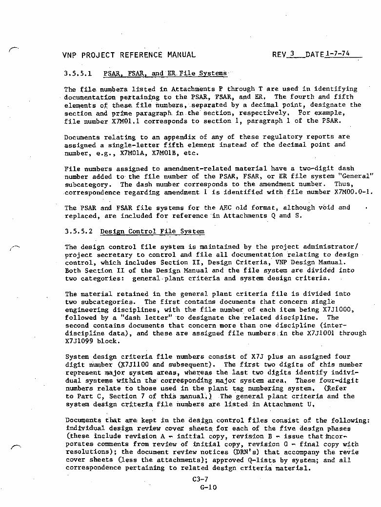
. .
VNP PROJECT REFERENCE MANUAL REV 3 , DATE 1-7-74
3.5.5.1 P S a , FSAR, and ER. F i l e Systciws,'.
The f 2 l e numbers l f s t e d i n Attachments P through T a r e used i n iden t i fy ing documentation pe r ta in tng t o t h e PSAR, FSAR, and ER, The f o u r t h and f i f t h e l w e n t s of t h e s e f f l e numbers, separa ted by a decimal point , des ignate the s e c t i o n and prime paragraph i n the sec t ion , respect ively . For example, f i l e number X7MOl.l corresponds t o s e c t i o n 1, paragraph 1 of t h e PSAR.
Documents r e l a t i n g t o an appendix of any of these regu la to ry r e p o r t s a r e assigned a s i n g l e - l e t t e r f i f t h element ins tead of t h e decimal point and number, e.g., X7MOlA, X7!MOlB, e t c .
F i l e numbers assigned t o amendment-related m a t e r i a l have a two-digit dash number added t o the f i l e number of t h e PSAR, FSAR, o r ER f i l e system "General" subcategory. The dash number corresponds t o t h e amendment number. Thus, .correspondence regarding amendment 1 i s i d e n t i f i e d w i t h , f i l e number X7M00.0-1.
The PSAR and FSAR f i l e systems f o r t h e AEC old format, although void and a
replaced, a r e included f o r r e f e r e n c e ' i n Attachments Q and S.
Design c o n t r o l F i l e System
The design c o n t r o l f i l e system is maintained by t h e p r o j e c t adminis t ra tor1 p r o j e c t s e c r e t a r y t o con t ro l and f i l e a l l documentation r e l a t i n g t o design con t ro l , wh2c.h includes Section 11, Design C r i t e r i a , VNP Design Manual. Both Section I1 of the Design Manual and t h e f i l e system a r e divided i n t o two ca tegor ies : g e n e r a l . p l a n t c r i t e r i a and system design c r i t e r i a .
The material r e t a i n e d i n t h e genera l p l a n t c r i t e r i a f i l e i s divided i n t o two subcategories. The f i r s t contains documents t h a t concern single engineering d i s c i p l i n e s , with t h e f i l e number, of each item being X7J1000, followed by a "dash letter" t o des ignate t h e r e l a t e d d i s c i p l i n e . The second conta ins documents t h a t concern more than one d i s c i p l i n e ( in te r - d i s c i p l i n e d a t a ) , and these are assigned f i l e numbers..in t h e X7J1001 through X7J1099 block.
System design c r i t e r i a f i l e numbexs cons i s t of X7J p lus an assigned four d i g i t number CX7J1100 and subsequent). The f i r s t two d i g i t s of t h i s number represen t major system areas, wheseqs t h e l a s t two d i g i t s i d e n t i f y indivi - dual systems wi th in t h e corresponding major: system a rea , These Pour-digit numbers relate t o those used i n t h e p l a n t tag numbering system, (Refer t o P a r t C, Section 7 of tUs manual,) The genera l p l a n t c r i t e r i a and the system design cr;ite.ria f i P e numbexs are l i s t e d 2n A t t a c h e n t U ,
Documents, that age k q t i.n the desggn c o n t r o l Pi-les cons i s t of t h e following: f n d b t d u a l degfgn rwt.ew ewer sbets; f o r each of t h e f i v e desrgn phases Cthese 2nclude r w T s i o n A - i n i t t a l copy, r w f s l o n B - i s s u e t h a t h c o r - pora tes comments from review of f n i t i a l copy, revis2,on 0 - f i n a l copy with reso lu t ions ) ; t h e document revfew n o t i c e s (DRN~.~) t h a t accompany. the r e v i e cover shee t s ( less t h e at tachments); approved Q-lists by system; and a l l correspondence pe r ta in ing t o r e l a t e d design c r i t e r i a material.

. . . ... . . . . . . . . . . . . . . .
VNP PROJECT REFE.RENCE MANUA.L . , REV. 3 DATE 1-7-74
3.5.5.3 Scope Change F i l e System. . . .
The scope change f i l e number doew'not 'use the fouxth and fgfth elements a s category and subcategory .des$gnators. - h s t e a d , only a f o u s t h element is used, and tt f s a t h r e e - d i g i t .number' CQ01-999). whtch, tndfca tes the-consec- u t i v e numbers of the scope changes, For" examp'le; a scope change number could be X7K.207. The kcope c G n g e f l l e system' i s matntkined by t h e p r o j e c t admints t ra tor .
3.5.6 DOCUMENT REVIEW NOTICE (DRN) CONTROL AND FILE SYSTEM
Document' review no t i ces , which t h e proj 'ect adminis t ra tor d i s t r i b u t e s f o r review and approval of inchouse documents, a r e recorded i n t h e DRN con t ro l log. This c o n t r o l log, maintained by t h e 'projec t adminis t ra tor , has e n t r i e s cons i s t ing of a DRN log number, t h e f i l e number and t i t l e of t h e r e l a t e d document, and t h e DRN i s s u e and r e t u r n due dates . A t t h e con- c lus ion of each review, t h e completed D R N ' s a r e placed i n ; t h e i r r e spec t ive f i l e s . Those f o r s p e c l f i c a t i o n s . a r e k e p t . i n t h e specfi.0, f i l e ; DRN's . f o r P ro jec t Reference lfanuial. (PRM) ..documents. go . i n t o a f i l e maintained by t h e p ro jec t adminis t ra tor ; and t h e DRN's f o r design c r i t e r i a (with the a t tached mate r i a l ) a r e a l s o kept i n a f i l e . m a i n t a i n e d by the p r o j e c t adminis t ra tor . A l l D R N ' s f o r t h e PRM a r e discarded one month a f t e r t h e document has been published and issued (or later a t t h e d i s c r e t i o n of t h e
. pro jec t manager o r p ro jec t admin i s t ra to r ) . Each d e s i g n . . c r i t e r i a DRN s h a l l .. remain i n the f i l e s f o r 90 days following t h e acceptance of t h e corres-
ponding design review/resolution form.& A t t h a t time, d i s p o s i t i o n of t h e i ' .
'2 DRN (with t h e a t tached mate r i a l ) s h a l l be determined. by t h e p r o j e c t &+ . &. engineer.
The DRN log numbet is composed of f i v e elements, and c o n s i s t s o f . t h e , follow- ing designators: X - i n d i c a t e s p ro jec t ; two-digit number (01-1 9) - iden t i - f ies o r ig ina t ing d i s c i p l i n e l t y p e of document ' (from l ist i n DRN c o n t r o l log) ; L - i d e n t i f i e s f i l e system designation; three-digi t number (001-999) - corresponds t o sequen t ia l DRN number w i t h i n . i t s category; two-digit number (01-99) - corresponds t o . r ev i s ion of r e l a t e d document, The f o u r t h and f i f t h . elements a r e separa ted by dashes.
3.5.7 GEORGIA POWER CONSTRUCTION DRAWXNGS FXLE SYSTEM
The f i l e system f o r Geqxgia Rower. Corspany . const ruct ton drawings i s . m i n - ta ined by the . drawing qnd- d a t a c o n t r o l g ~ w p ,
3.5.8 ENGINEERING STUDY FXLE SYSTEM
The engineering study £Ale s ~ t a $.s .described An Pa,rt B, . $ectton'.12. of t h2.s manual .
C 3 4

. . . . , . . . . . . ,
VNP PROJECT REFE.RENCE' MANUA.L
3 , 6 'PIASTER CHRON 'LOG AND ' FGLE '
The master chron l o g (NCL) is a record of incoming and outgoing p ro jec t docments l i s t e d chronologtcal ly, and mafntained by t h e p ro jec t administra- t o r . A master chron f t le CMCF] , kept by the p r o j e c t sec re ta ry , contains a copy of each document l i s t e d on t h e MCL except drawing change no t i ces , ca l - cu la t ions , e s t ima tes , meeting notes , conference notes , and s t u d i e s , which a r e f i l e d in ind iv idua l admin i s t ra t ive f i l e s . The MCL and MCF a r e described i n P a r t By Sect ion 4 of t h i s manual.

Change Notice CN-C3-28 . Da tea d &7 6
. . . . . . . .
VNP PROJECT REFERENCE MANUAL . . . . . . . . . . . . . . . . . . . . . . . . . . .
CIVIE-STRUCTURAL SPECJP., 61 F I L E SYSTEM
A, SITE DEVELOPMENT CATEGORY. .
X2AAOl S i t e Survey' 0 2 ' Subsurf a c e Explorat ion' and 'Laboratory .Test ing 03 Furnishing and Oonstruction of Onsite Railroad 04 Fencing 'and Gates 05 Furnishing and ConstructAon of O f f s f t e ~ a f ' l r o a d 0 6 Asphalt Paving of Roads, Walks, and Parking Areas 07 F in i sh Grading
EARTHWORK CATEGORY
S i t e Prepara t ion and Earthwork Furnish and I n s t a l l Storm Sewers
UTILITY SYSTEMS CATEGORY
Yard F i r e Pro tec t ion Pipe and F i t t i n g s Sewer Pipe and F i t t i n g s Construction Water and Potable Water Lines F i r e Hydrants and Valves F i r e Pro tec t ion Hoses and F i t t i n g s Sani tary Waste Treatment P l a n t (Procured and ciosed Out 11-11-76) F i r e Protec t ion Hose Cabinets .
. . Potable . Water and Construction Water. Valves. 1 8 @ & & h g - e d - T ~ 4 ~ g ~ t ~ ~ e i % t y e e - DELETED Sani tary Waste Treatment P lan t
CIRCULATING WATER AND MAKEUP WATER SYSTEMS CATEGORY
X2ADO1 Ci rcu la t ing Water Pipe 02 Plant Makeup and Discharge Water Pipe 03 Traveling Screens 04 In take S t ruc tu re Appurtenances
~ t t a c f n a e n t B.. Civi l -St ructura l Spec/? ,O, FLle Sys tm ' . (J bf ' 5)
. C3-17
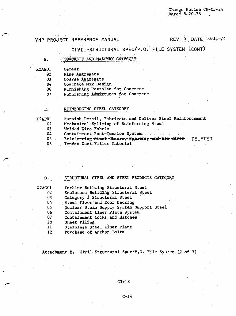
Change Notice CN-C3-24 ~ q i e d 8~20.~76
F..
Cwent FSne Agg~egat e Coarse ;+ggregate Concrete Mix Design Furnishing ~ o z z o l a n f o r Concrete ~ u r n i s h i n g Admixtures f o r Concrete
REINFORCING STEEL CATEGORY.
Furnish Deta i l , Fabr icate and Deliver S t e e l Reinforcement ~ e c h a n i c a 1 : ~ p l i c i n g of Reinforcing S t e e l Welded Wire Fabr ic
.Contai~ment. Post-Tension. Sys.tem.. . . . . . . .
~ ~ ~ g ~ e e & ~ & ~ - - 6 p , e c e r s ~ - t t r r d - T h 4 J 4 ~ e 4 DELETED Tendon Duct F 2 l l e r Mater ia l
G. STRUCTURAL STEEL AND STEEL PRODUCTS CATEGORY
Turbine Bullding S t ruc tu r a l S t e e l Enclosure Buildtng .S t ruc tu r a l S t e e l Category 1 St ru c tu r a l S t e e l S t e e l Floor and Roof Decking Nuclear Steam Supply System Support S t e e l Containment Liner P l a t e System Containment.Locks and Hatches Sheet P i l i n g S t a in l e s s S t e e l ~ i n e r P l a t e Purchase of Anchor Bolts
Attachment 8 , Ciyi l -St ructura l S p e c f P , ~ . F f l e S y s t q C2 of 5)

Change Notice CN-C3-31 ~ a t e d 1-25-77
. . . "" " . ' ' " ' '
YNP PROJECT REFERENCE JYANUAL R E Y , . 5,; DATE.. . 1 ~ 1 - 7 4 . - . . . . . . . . . . . . . . . . . . , . . . . . .
CIYI L-STRUCTURAL SPE.C/P ,.Q. F ILE SYSTEM CCONT) . .
H, NISCELLANEOUS METAL AND.'EMBEDDED ITEMS CATEGORY*,
Mtscellaneous Category 1 . S t e e l Platforms, ratings Handra2.l~ Catch Basin Frame and Gratjngs, Manhole Cover and 'Frames' Miscellaneous Category 2 S t e e l Turbine Pedes ta l r eve ling Studs .
Equipment Anchor Bolts Miscellaneous S t a i n l e s s S t e e l ~ u e l Transfer Tube Housing ~ x p a n s i o n Bellows Lead Shielding 'Miscellaneous Grating ~ i s c e l l a n e o u s Handrails Fuel Pool Gates New and Spent Fuel Storage Racks .
J. MISCELLANEOUS NON-XETAL PRODUCTS CATEGORY
x 2 ~ J 0 2 Expansion J o i n t F i l l e r and Sealer 03 . . Sl ide Bearings 04 Chemical Waterproofing 06 Water Stops
I<. WELLS CATEGORY
X2AKO1 Class 1 TBst Water N e l l 02 Makeup Water Wells 03 ' Standby Nuclear Ser)li.ce Makeup Pumps and .Wells
Attachment' B. Civi l -St ructura l ,Spec/P,O, F i l e System C3 of 51

Change Notice CN-C3-31 D s ted .l-25-77
. . . , . , , . .
VNP PROJECT REFERENCE MANUAL REV - 5 DATE 10-11-74 . ... . . .. . . .- . .
c IYI L-STRUCTURAL SPEC/P , O. F I:LE SYSTEM (CONTI,
L. IQ$+INE FACXLITTES' CATEGORY.
X2ALQ1 ' Boat Kau.se
MISCELLANEOUS SERVICES CATEGORY
Unloading and I n s t a l l i n g Heavy Equipment Concrete Testing Laboratory Service S t e e l Testing Laboratory Services Special Concrete Chemical and Property Testing Specia l Testing Aer ia l Photography Instrumentation f o r Heave and Settlement Measurements Obtaining and Recording Foundation Settlement Data Survey
Attachment B,' Cty2.1-Structural ~ p e c / ~ , Q , F$le System C4 of 5)

. C hange .Notice CN-C3-24 ..Dated'@:d&76 .
. . . . . . , . . . . . . . . . . . .
VNP PROJECT. REFERENCE MANUAL . . . . . REV 3 . D A T ~ . l - 7 ~ 7 4 .
P, C~V.~L-STKUCTURAZ, CONsTRU(;TXON '#ID ERECTTON "CONTRACTS CATEGORY'
X2APOl Construction spect f %cation for : ; C i ~ t l - S t r u c t u r a l Work Forming,Placing, ~ i n i s h i n ~ , and Curing Concrete Placing of Retnforcing S t e e l ~ r e c t i o n of s t r u c t u r a l S t e e l Erecting Miscellaneous Metal. E r ec t ing Piping I n s t a l l a t i o n of Waterproofing Mate r ia l
and Water Stops I n s t a l l a t i o n of Corrugative M e t a l Piping I n s t a l l a t i o n of Trumpet ~ s s i b l y
. .
.Attachment B. Ctvt l -St ructura l Spe.c/P.O; F i l e System 0 of 5 ) ,
' '

VNP PROJECT REFERENCE MANUAL REV 4 DATE - 5-1-74
S t t e Envf ronment , General Seismology, General Geology, General Hydrology, General Meteorology, General S o i l and Foundation Inves t iga t ion Topography ~ o u n d a t i o n Sett lements S o i l s Report
X2BBO1 Plant Survey 0 2 Aer ia l Surveys
C. S I T E PREPARATZON
S i t e ' Preparat ion, General Clear ing and Grubbing Rough Grading Temporary Access Roads, Park3ng, Storage, Laydown Temparary Rat1 Spurs. ~ e m ~ o r a s ~ Drainage ~ e b r i s Bas.3.n~ River. Road Realrgnment .
Attachment H. C iv i l -S t ruc tu ra l Subject F i l e System (1 of 7 )

.,, . . .
VN.P PROJECT REFERENCE MANUAL ' REV 3 DATE'J-7-74
D, . ' TEMPORARY CONSTRUCTION FACTLITTES
X2BDO1 Temporary Construction F a c l l i t t e s , General 02 off i c e and Warehsuse, General 03 U . t i l i t * e s , General 04 . Construction E q u i ~ e n t
E. SITE DEVELOPMENT (Permanent)
S i t e Development, General (Planning and P.lant Arrangement) Earthwork and B a c k f i l l Drainage and Storm Drain System F in i sh Grading and Paving Roads, Parking, Storage R a i l Spurs Perimeter Fencing and Enclosures Dewatering
F. YARD UTILITY SYSTEMS (Permanent)
X2BFO1 Yard U t i l i t y Systems (Permanent), General 0 2 Water Supply System 03 Onsite Water W e l l 04 F i r e p ro tec t ion System 0 5 Sani tary Sys tem 06 Plant Eff luent System . .
0 7 8ue.Pfi44-Gerueea~e- Changed t a X2BLQ7
~e tachment H. Civi l -St ructura l Subject F i l e System (-2 of 7) -
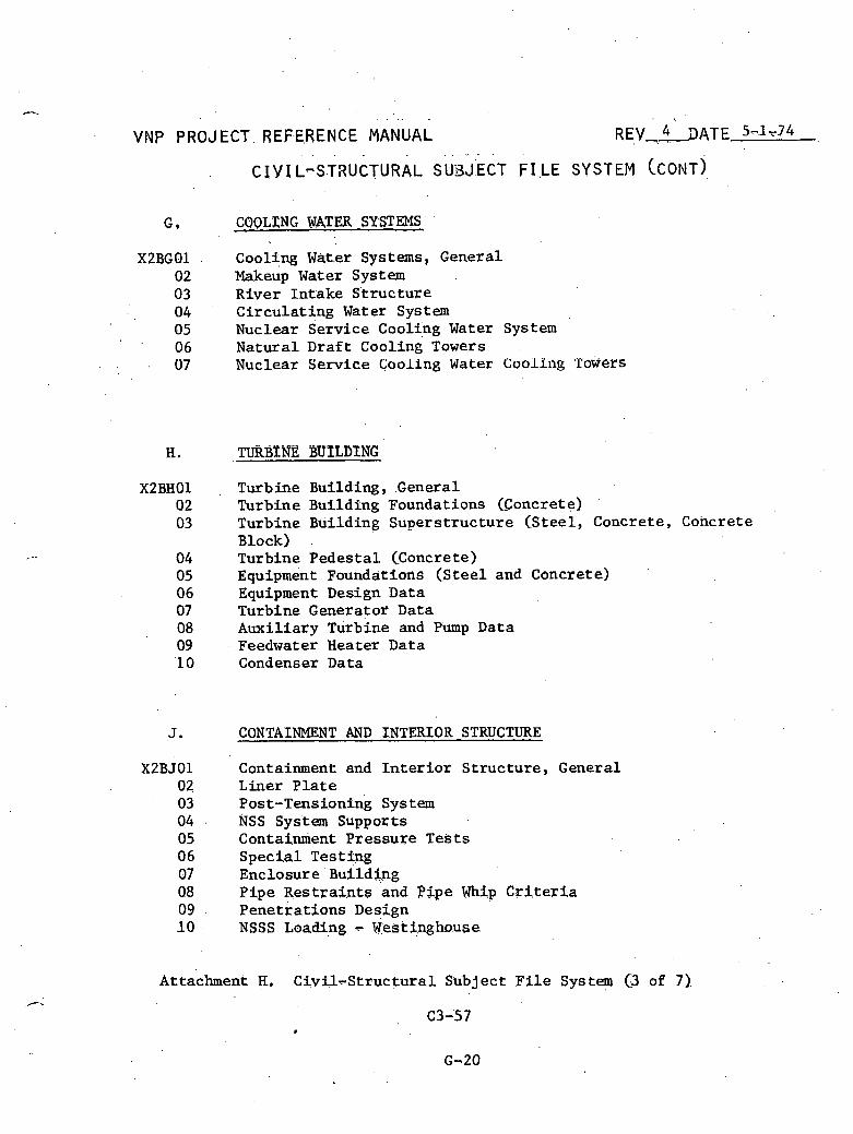
VNP PROJECT. REFERENCE MANUAL REV ,,4'- 9ATE 55-1~74
G, CQQLXNG WTER SYSTEMS
X2BGO1 Cooling Water Systems, General 02 Makeup Water S ys t em 03 River In take S t ruc tu re 04 Ci rcu la t ing Water System 0 5 Nuclear Service Cooling Water System 0 6 Natura l Dra f t Cooling Towers 07 Nuclear Service Cooling Water Coolitlg 'Tacj.efS
TURBINE BUPLDENG
Turbine Building, General Turbine BuildTng Foundations (Concrete) Turbine Building Supers t ructure (Stee l , Concrete, Concrete Block) . ~ u r b i n e Pedes ta l (Concrete) ~qu ipment Foundations (Steel and Concrete) Equipment Design Data Turbine Generator Data Auxi l iary ~ u r b i n e and Pump Data Feedwater Heater Data Condenser Data
CONTAINMENT AND INTERIOR STRUCTURE
Containment and I n t e r i o r S t ruc tu re , General Liner P l a t e Post-Tensioning System NSS System Supports Containment Pressure Tes t s Spec ia l Test ing Enclosure Building Pipe R e s t r a i n t s and Pipe Whip Criteria Penet ra t ions Design NSSS Loading - Westinghouse
Attachment H, C i v t l ~ S t r u c t u r a l Subject F i l e System (3 of 7)
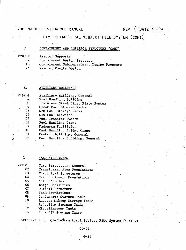
VNP PROJECT REFERENCE MANUAL
X2BJ11 ~ e a c t o r suppor t s 12 '. 'Containment Design P r e s s u r e 13 Containment Subcompartment Design P r e s s u r e 14 Reac tor Cavi ty Design
K. AUXILIARY BUILDINGS --
Auxi l i a ry ' Building, General Fuel Handling Building S t a i n l e s s S t e e l Liner P l a t e System , '
Spent Fue l S torage Racks New Fue l S torage Racks New Fuel E leva to r Fue 1 Trans fe r Sys tern Fuel Handling Crane Radwaste P a c i l i t i e s Cask Handling Bridge Crane Con t ro l Building, General .
Fuel Handling Building, General
L. YARD STRUCTURES
Yard S t r u c t u r e s , General Transformer Area Foundations E l e c t r i c a l S t r u c t u r e s .
. .
Yard Equipment Foundations Yard Manholes Barge ~ a c i l i ' t i e s O u t f a l l S t r u c t u r e Tank F o u n d a t i . ~ n s Coadensat e Storagc Tanlcc Reactor Makeup S to rage Tanks Refuel ing S torage Tanks Miscel laneous Tanks Lube 051 S to rage Tanks
Attachment H. C i v i l - S t r u c t u r a l Sub jec t F i l e System (:4 of 7)
C3-58

. . R E V 4 DATE 5-1-74 *
. . . . . . .
C I Y IL -STRUCTURAL SUBJECT F - I LE SYSTEFl (CONT).
X2BMQl Turblne Building Cranes '
02 . Containment S t r u c t u r e .Polar Crane 03 Miscellaneous Cranes and Hoists 04 . Cask Handling Crane 05 Fuel Handling Crane
, 0 6 . Manipulator Crane
N. SUPPORT BUILDINGS,
X2BNOl Administration and s e r v i c e Building 02 Warehouse I 03 Warehouse 11 04 ' Guard House
P.. , CONSTRUCTION MATERIALS
Aggregate Concrete Reinforcing S t e e l S t r u c t u r a l S t e e l MI scellaneous S t e e l Corrosion Control S t ruc tu ra l . S t e e l Sidi.ng Waterproofing Stee.1 Decking Precas t Concrete Cancxet . e . Block Coatings
Attachment H. C iv i l -S t ruc tu ra l Subject F i l e System (5 of 7)
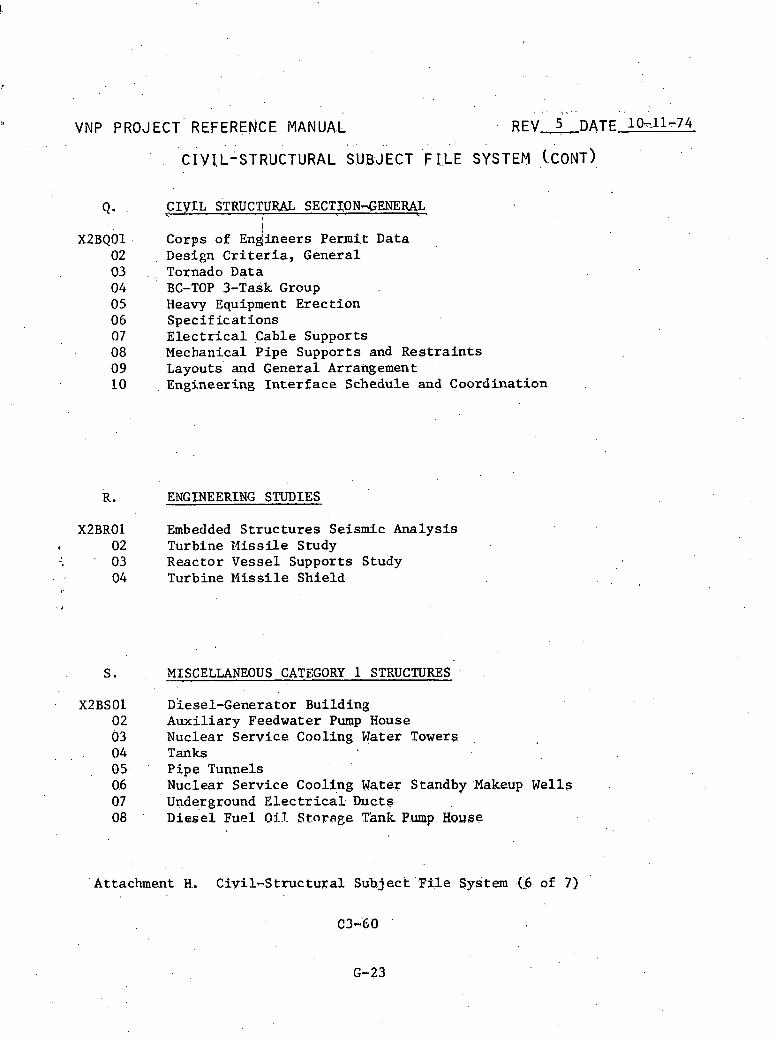
Y VNP PROJECT' REFERE.NCE MANUA.L
CIYIL STRUCTURAZ, SECTTON-GENERAL I
I
4 n d n e e r s Permit Data Corps of C g' Design Criteria, General Tornado Data BC-TOP 3-Task Group Heavy Equipment E rec t ion S p e c i f i c a t i o n s E l e c t r i c a l Cable Supports Mechanical P ipe Supports and R e s t r a i n t s Layouts and General Arrangement Engineering I n t e r f a c e Schedule and Coordina t ion
R. ENGINEERING STUDIES
X2BRO1 Embedded S t r u c t u r e s Seismic Analysis I 02 Turbine t , l iss i l e Study
' 03 Reactor Vesse l Supports Study 04 Turbine Missile Sh ie ld
MISCELLANEOUS CATEGORY 1 STRUCTURES
Diesel-Generator Building Aux i l i a ry Feedwater Pump House Nuclear Se rv i ce Cooling Water Towers Tanks P ipe Tunnels Nuclear Se rv i ce Cooling Nater Standby Makeup Wells Underground E l e c t r i c a l Ducts ~ i k e l Fuel O i l - Stnsage Tank. Pump House
Attachment H. C i v i l - S t r u c t u r a l Sub jec t ' F i l e System .(:6 of 7)

Change Not ice CN-C3-29 Dated .12-16~7 6
VNP PROJECT REFERENCE MANUAL REV 4 . DATE 5-1-74
Concre te Forming Reinforc ing S t e e l S t r u c t u r a l S t e e l Misce l laneous S t e e l Embedded S t e e l P ipe Supports E l e c t r i c a l Trays and Bus Duct Supports Equipment L i s t MCS, Genera l
DISCIPLINE ADMINISTRATION
Man-Hour Budgets Consul tan t Costs computer Cos ts Pianpower Schedules .Time Charges ,
Schedules - General Es Llma tes CEBUS Scope Changes and Trends
11- SCSI Coordinat ion
V, GPC CONSTRUCTION
X2BVO1 Gener a1 02 Temporary 03 ' Bech.te1 cons true t i o n 04 Georgia Pqw.er Cons t ruc t ion 05 ~ h e ' m a l ' Power Q r g a n i - z a t i ~ n
Attachment. K. ' c i v i l - s t r u c t u r a l Sub jec t F i l e System (7 of 7)


INFORMATION MANAGEMENT FOR NUCLEAR POWER STATIONS
APPENDIX C

TABLE OF CONTENTS
Page
CHAPTER I: Purpose. Approach. and ~ e f i n i t i o n s
1 ................................. Purpose and Approach M a t e r i a l I n s t a l l a t i o n Charac t e f i i s t i c s . .......:..:.... 3 Component Informat ion ................................ 7 Methodology f o r Defining Informat ion Flow ............ 10 Flow Graph Notat ion ................................... 11 Mechanical M a t e r i a l I n s t a l l a t i o n Cycles .............. 14 1.6.1 Mechantca1.- Bulk m a t e r i a l s ................... 1 5 1.6.2 Mechanical - Small components .................. ' 2 1 1.6.3 Mechanical - Large components ................. 23 C i v i l M a t e r i a l ~ n s t a l l a t i o n Cycles ................... 25 1.7.1 C i v i l - Bulk m a t e r i a l s ........................ 25 1.7.2 C i v i l - Small components ...................... 28 1.7.3 C i v i l - Large components .- ..................... 31 E l e c t r i c a l M a t e r i a l I n s t a l l a t i o n Cycles .............. 3 3 1.8.1 E l e c t r i c a l - Bulk materials ................... 33 1.8.2 E l e c t r i c a l - Small components ................. 35 1.8.3 E l e c t r i c a l - Large components ................. 37 Methods Engineering .................................. 41
. ' CIWTER 11: E x i s t i n g and P ro jec t ed Systems
2.1 I n t r o d u c t i o n ......................................... 45 2.2 Danie l F a r l e y #1 ..................................... 45 ... 2.'2.1 Mechanical 'Equipment/Piping/Instrumentation 48
. . .2.'2.2 Heat Number Cross Reference Program ........... 50 2; 2.3 ~ l e c t r i c a l S t a t u s Programs .................... 51 2.2.4 Non-Conformance ~ e ~ o r t s ........................ 51
2.3 Danie l Callaway 111 ................................... 52 2.3.1 P ip ing and Related Component Cont ro l System ... 52 2.3.2 E l e c t r i c a l I n s t a l l a t i o n System ......:......... 57 ...................................... 2 . 4 . Danie l Fermi /I2 63
2.5 Nuclear Power Serv ices P.M.P. 71 . ........................ 2.6 GPU P r o j e c t 'Control System ........................... 7.2 .
2.7 McDonnell Douglas COMPAID ............................ 74 . 2.8 Northern S t a t e s Power .ITS 79 . . . ............................ 2.9 Bechte l QTS (Quant i ty Tracking System) ............... 81 2.10 Georgia Power Punch L i s t ............................ 83
. CHAPTER 111: Problems w i t h E x i s t i n g Systems .................. 85

Page
REFERENCES .................................................... 87
ADDENDUM A: BULK P I P E MATERIAL INPuT/OUTPUT DATA
ADDENDUM B: MECHANICAL (SMALL COMPONENT ) INPUT /OUTPUT DATA
ADDENDUM C: PfJXIIAMICAL (LARGE C O E P O N ~ T ) IMl?UT/OUTrUT DATA
ADDENDUM D: CIVIL (BULK MATERIAL) INPUT /OUTPUT DATA
AUUKNUUM Kf C I V I L (SMALL COMPONENT) INPUT/OUTPUT DATA
ADDENDUM F: C I V I L (LARGE COMPONENT) INPUT/OUTPUT DATA
ADDENDUM G: ELECTRICAL (BULK MATERIAL) INPUT/OUTPUT DATA
ADDENDUM H: ELECTRICAL (SMALL COMPONENT) INPUT/OUTPUT DATA
ADDENDUM I: ELECTRICAL (LARGE COMPONENT) INPUT/OUTPUT DATA
ADDENDUM J : APPLICATION AREA OUTLINES METHODS ENGWEERING

CHAPTER I
F i e l d c o n s t r u c t i o n Cont ro l
Purpose, Approach, and D e f i n i t i o n s
1 Purpose and Approach
The n b j e c t i v e of a l l c o n s t r u c t i o n a c t i v i t y is t o r e a l i z e a f i n i s h e d
f a c i l i t y a t t h e s e l e c t e d s i t e through t h e placement of m a t e r i a l by l a b o r
and equipment resources . The process by means of which m a t e r i a l s and
components a r e def ined dur ing t h e engineer ing phase, procured, and moved
t o a s t o r a g e l o c a t i o n a t t h e p r o j e c t s i t e has been developed i n Appen-
d i x B. F i e l d c o n t r o l is concerned w i t h t h e A c t i v i t i e s r equ i r ed f o r
t h e i s suance and movement of t hese materials from t h e warehouse, lay-
down a r e a , o r s t o r a g e l o c a t i o n t o t h e i n s t a l l a t i o n l o c a t i o n . F u r t h e r ,
i t encompasses methods of i n s t a l l a t i o n and procedures f o r turn-over t o
, t h e accep t ing s t a r t - u p team. The m a t e r i a l c y c l e i l l u s t r a t i n g t h e i n t e r -
f a c e between M a t e r i a l racki in^ and F i e l d Cont ro l a c t i v i t i e s is shown
i n F igure 1.1.
This process i s t h e backbone of in format ion f o r a l l c o n t r o l func-
t i o n s . A l l in format ion process ing requirements i n t e r f a c e w i t h t h i s
m a t e r i a l path. Depending upon t h e type of m a t e r i a l , t h e i n d i v i d u a l . .
funct , ions occu r r ing a long t h e m a t e r i a l c y c l e vary . Therefore , two types
of func t ions can b e i d e h t i f i e d : (1) t hose which a r e common t o a l l mate-
r i a l c y c l e s , and (2) t hose which a r e unique t o t h e c y c l e of a g iven c l a s s
of m a t e r i a l . For i n s t a n c e , p r e p a r a t i o n of a r e q u i s i t i o n and t h e i n h e r e n t
II take-off" procedure t o develop q u a n t i t i e s a r e ' f u n c t i o n s which are common
1
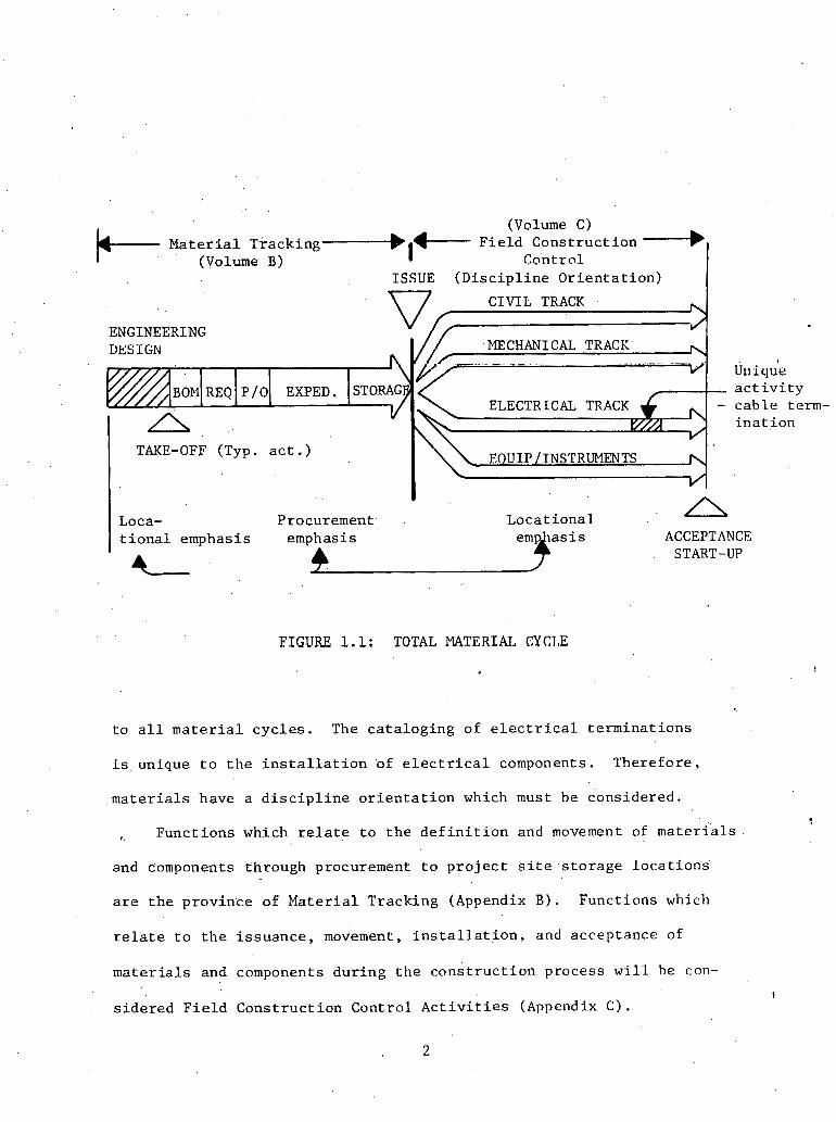
. .
(Volume C)
k- Mat;;;;t:?;;king I +- F i e l d Cons t ruc t ion 4
Control ISSUE ( D i s c i p l i n e Or i en ta t ion )
FIGURE 1.1: TOTAL MATERIAI, CYCLE
CIVIL TRACK
ENGINEERING DESIGN MECHANICAL TRACK
Uriique
t o a l l m a t e r i a l c y c l e s . The ca t a log ing of e l e c t r i c a l t e rmina t ions
i s unique t o t h e i n s t a l l a t i o n 'of e l e c t r i c a l components. Therefore ,
m a t e r i a l s have a d i s c i p l i n e o r i e n t a t i o n which must be considered.
, Funct ions which r e l a t e t o t h e d e f i n i t i o n and movement of m a t e r i a l s
and components through procurement t o p r o j e c t s i t e s t o r a g e loca Lions'
a r e t h e province of Ma te r i a l Tracking (Appendix B). Funct ions which
r e l a t e t o t h e i s suance , movement, i n s t a l l a t i o n , and acceptance of
m a t e r i a l s and components du r ing t h e cons t ruc t ion process w i l l be con-
EXPED . a c t i v i t y
s ide red F i e l d Cons t ruc t ion Control A c t i v i t i e s (Appendix C).
ELECTRICAL TRACK - cab le t e r a i n a t ion
TAKE-OFF (Typ. a c t . )
Loca- Procurement Loca t iona l A
t i o n a l emphasis emphasis ACCEPTANCE START-UP L
P / O BOP1 REQ

By examining the m a t e r i a l cyc l e s of major component c l a s s e s , t h e
b a s i c m a t e r i a l c y c l e s f o r each d i s c i p l i n e w i l l b e def ined . The major
d i s c i p l i n e s , (1) C i v i l , (2) Mechanical, and (3) E l e c t r i c a l , each have
component d e l i v e r y c h a r a c t e r i s t i c s which s e t them a p a r t . Within each
d i s c i p l i n e , m a t e r i a l and component c l a s s l e a d t o vary ing i n s t a l l a t i o n
c h a r a c , t e r i s t i c s . Therefore , w i t h i n a d i s c i p l i n e s e v e r a l i n s t a l l a t i o n
cyc le s a r e p o s s i b l e . . The r e p o r t d e f i n e s t h e i n d i v i d u a l Cons t ruc t ion
Cont ro l cyc l e s f o r each m a t e r i a l c l a s s s t a r t i n g w i t h i s suance from
t h e warehouse and cont inuing through acceptance and s t a r t -up . The
i n d i v i d u a l modules i n ' each cons t r u c t i o n c y c l e w i l l b e i d e n t i f i e d and
c r i t i c a l d a t a f e d t o and genera ted by each of t h e s e func t iona l .modu les
w i l l be developed.
1 .2 M a t e r i a l I n s t a l l a t i o n Charac t e r i s t i c s
Once an i tem is i s s u e d from s i t e s t o r a g e , t h e i n s t a l l a t i o n ac-
t i v i t i e s which a r e r equ i r ed t o i n s t a l l , check, -and t u r n .it over ( a s an
end-item o r p a r t of a system) vary based on t h e m a t e r i a l type and c l a s s .
The s i n g l e t r a c k dep ic t ed i n F igure 1.1 f o r t h e m a t e r i a l procurement and
t r a c k i n g a c t i v i t y d ive rges i n t o d i s c i p l i n e t r a c k s depending upon the.
type of m a t e r i a l and i t s placement technology. The f o u r t r a c k s which,
: c h a r a c t e r i z e t h e i n s t a l l a t i o n technology and s k i l l s r equ i r ed a r e :
(1) C i v i l
(2) Mechanical
(3 ) E l e c t r i c a l
(4 ) Equipmeilt / I n s trumen t a t i o n

Within t h e s e d i s c i p l i n e t r acks , t h e de l ive ry a c t i v i t i e s vary according %
t o the conf igura t ion i n which t h e m a t e r i a l a r r i v e s a t the s i t e and is
s tored . The d e l i v e r y a c t i v i t i e s a s soc ia ted with the processing and
i n s t a l l a t i o n of cement and aggregate d i f f e r from those requi red f o r
t h e i n s t a l l a t i o n of s t e e 1 ladders , s t a i r cases ' , and g r i l l s . Although
these m a t e r i a l s a r e considered a s c i v i l d i s c i p l i n e items f o r ' ins t a l l a -
t i o n , they r e q u i r e d i f f e r i n g i n s t a l l a t i o n technologies. S imi la r ly ,
the sequence of t a s k s involved i n i n s t a l l i n g a switch box d i f f e r s
From those. r equ i red f o r c u t t i n g and pul l ing ' cable. Moreover, some
i m a t e r i a l s a r e transformed i n t o new conf igura t ions by v i r t u e of the .
I +%
processing they undergo t o r e a l i z e cons t ruct ion . They a r e mixed,
bent , ' c u t , s t r i p p e d , pul led , welded, o r processed i n some way which
causes them' t o be transformed. Such m a t e r i a l s a r e usua l ly procured
and s t o r e d on t h e s i t e i n bulk q u a n t i t i e s and a r e transformed by a
cons t ruct ion technology at t h e s i t e . These m a t e r i a l s a r e normally
r e f e r r e d t o as bu lk mate r i a l s . I n t h e remainder of t h i s r e p o r t , mate-
r i a l s which a r e Grocured i n bulk q u a n t i t i e s and a r e transformed phys-
i c a l l y a t the cons t ruc t ion s i t e w i l l b e r e f e r r e d t o a s bulk ma te r i a l s .
Some i tems are procured i n r e l a t i v e l y l a r g e numbers, b u t r a t h e r
than being transformed phys ica l ly they a r e i n s t a l l e d t o become p a r t
of a l a r g e r system. Such items a s smal l switches and l i g h t i n g f i x t u r e s
a r e good examples of t h i s m a t e r i a l c l a s s . These items can b e thought .
of a s components s i n c e they a r r i v e a t the s i t e i n an e s s e n t i a l l y
f i n i s h e d conf igura t ion ready f o r i n s t a l l a t i o n . The physica l

t ransformat ion a s s o c i a t e d wi th t h e i r i n s t a l l a t i o n i s minimal. They
w i l l b e r e f e r r e d ' t o as s m a l l components.
The t h i r d c l a s s of m a t e r i a l s w i t h i n each of t h e d i s c i p l i n e s which
e x h i b i t s s p e c i a l d e l i v e r y c h a r a c t e r i s t i c s c o n s i s t s of r e l a t i v e l y l a r g e
sub-assemblies o r systems which have been p r e f a b r i c a t e d i n va ry ing
degrees by a vendor a t an o f f - s i t e l o c a t i o n . .These items a r r i v e a t
the s i t e ready f o r i n s t a l l a t i o n . Items such as pumps, compressors,
t ransformers , p re fab r i ca t ed o r s t r u c t u r a l s t e e l , and b u i l d i n g c ladding
a r e t y p i c a l of t h i s ca tegory . These items w i l l b e considered large
components. Table 1 . l ' g i v e s a break-out by d i s c i p l i n e and material
c l a s s of some t y p i c a l items which gene ra t e d a t a s t r u c t u r e s and must
b e c o n t r o l l e d on t h e , s i t e dur ing cons t ruc t ion .
The i n s t a l l a t i o n cyc le s a s s o c i a t e d w i t h b u l k m a t e r i a l always
i n c l u d e a s e t of t a s k s which t ransform t h e p l lys ica l c o n f i g u r a t i o n of
t h e m a t e r i a l . . Component c y c l e s ( f o r bo th l a r g e and s m a l l components)
do' n o t i n c l u d e t h i s t ransformat ion sequence. Large components such
a s h e a t exchangers, l a r g e p r e f a b r i c a t e d spoo l s , and r e a c t o r v e s s e l s
a r e i n some cas& assembled a t t h e s i t e . These a r e n o t b u l k items, . .
however, and t h e r e f o r e r e t a i n the c l a s s i f i c a t i o n of l a r g e components
i n t h i s breakdown. Reinforc ing s t e e l can b e considered a bu lk i t em
o r a comp0nen.t. I f t h e s t e e l is con£ igu red t o a. major degree ( i . e . ,
b e n t o r c u t ) a t t h e ' s i t e , i t w i l l b e cons idered a bu lk i tem. R e i a -
f o r c i n g s t e e l d e l i v e r e d t o t h e s i te pre-bent and ready f o r i n s t a l l a t i o n
w i l l b e c l a s s e d as a s m a l l component. The same r a t i o n a l e a p p l i e s t o

COMPOMENTS/D I S C I PLINES
IN F 1 NAL CONF I GURAT.1 ON
FOR INSTALLATION ,
TABLE 1.1: TYPICAL K4TERIALS BY DISCIPLINE AND DELLVERY CLASS
I NSTRUMENTV.
TNSTRUMENT EXAMPLES : SMALL FLOW
METEPS
INSTRUMENT EXAMPLES : LARGE AUTOMATIC
CUT-OFF SWITCHES
CRITICAL ITEM (INPUT FORM)
BULK (TRANSFORMED)
*SMALL COMPONENTS (INSTALLED IN
LARGER SYSTEM)
*LARGE COMPONENT (INSTALLED)
MECHANICAL
SHEET METAL P I P E WELDING ROD INSULATION
SCREENS F I L T E R SMALL VALVES DUCTS (PREFAB)
LARGE SPOOLS LARGE VALVES PUMPS COMPRESSORS A/C UNITS SPECIALIZED
EQU I PMENT
CIVIL
CEMENT AGGREGATE RESTEEL BACKF I LL
CADWELD MASONRY TENDON3 CONDUITS
STRUC a
STEEL STRUC, 8
M I SC METALS . L INERS T I L T - U P
PANELS
ELECTRICAL
CABLE
BOXES SWl TCHES RACEWAYS TERM1 NATION BOARDS
TRANSFORMER MASTER SWITCHES B R E A K E B RACEWAYS GENERATORS TURBINE-GENERATORS EXC I TOR MOTORS
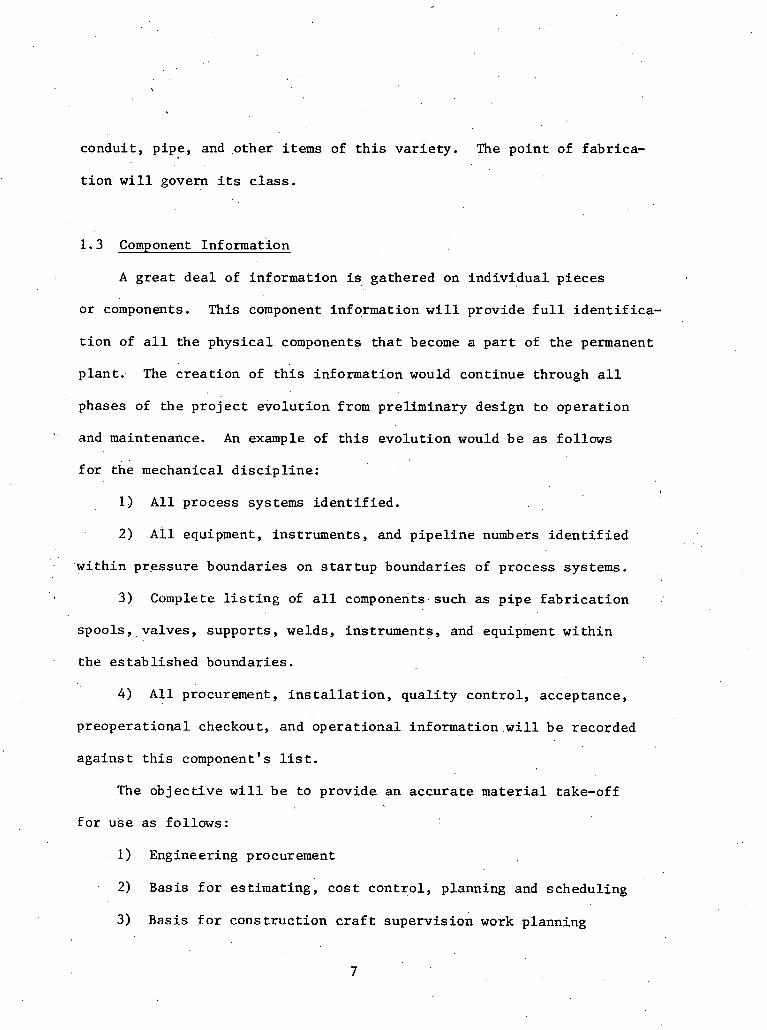
condui t , p ipe , and o t h e r i t ems of t h i s v a r i e t y . The p o i n t of f ab r i ca -
t i o n w i l l govern i t s c l a s s .
1 . 3 Component Informat ion
A g r e a t d e a l of in format ion is ga thered on i n d i v i d u a l p i eces
o r components. This component in format ion w i l l p rovide f u l l i d e n t i f i c a -
t i o n of a l l t h e p h y s i c a l components t h a t become a p a r t of t h e permanent
p l a n t . The c r e a t i o n of t h i s in format ion would cont inue through a l l
phases of t h e p r o j e c t e v o l u t i o n from p re l imina ry des ign t o o p e r a t i o n
and maintenance. An example of t h i s evo lu t ion would b e as fo l lows
f o r t he mechanical d i s c i p l i n e : ,
1 3 A l l p rocess systems i d e n t i f i e d .
2) ~ l l equipment, ins t ruments , and p i p e l i n e numbers i d e n t i f i e d
. w i t h i n p re s su re boundaries on s t a r t u p boundar ies of p roces s systems.
3 ) Complete l i s t i n g of a l l components~such as p i p e f a b r i c a t i o n ..
s p o o l s , , v a l v e s , suppor t s , welds, ins t ruments , and equipment w i t h i n
t h e e s t a b l i s h e d boundaries .
4 ) A l l procurement, i n s t a l l a t i o n , q u a l i t y c o n t r o l , acceptance ,
p r e o p e r a t i o n a l checkout, and o p e r a t i o n a l in format ion w i l l b e recorded
a g a i n s t t h i s component ' s l i s t . The o b j e c t i v e w i l l b e t o p rov ide an a c c u r a t e m a t e r i a l take-off
f o r u s e a s fo l lows :
1 ) Engineering procurement
2) Basis f o r e s t ima t ing , c o s t c o n t r o l , planning and schedul ing
3) Basis f o r c o n s t r u c t i o n c r a f t s u p e r v i s i o n work planning

4) I n s t a l l a t i o n progress repor t ing
5) Tracking QC acceptance of work
6 ) Preopera t ion checkout
7) Operations su rve i l l ance , maintenance, spa re p a r t s l i s t i n g
8) Permanent p l a n t record
A second ob jec t ive would be t o reduce the redundancy t h a t e x i s t s now
i n the t r a d i t i o n a l approaches, when most of t h e above s t a t e d groups
o r i g i n a t e t h e i r take-offs ind iv idua l ly t o support t h e i r purposes,
The b a s i s of t h e component information i s a B i l l of Material . .
To accomplish t h i s .a B i l l of Mater ia l procedure has t o be es tabl ished
and accura te ly adhered to. The B.O.M. has t o be capable of exploding
i n t o lowest l e v e l subcomponent d e t a i l o r cascading up t o a summary
level .
The B.O.M. information is a v a i l a b l e t o t h e f i e l d engineers fo r
.the fol lowing purposes:
ater rial A v a i l a b i l i t y and Work Planning
The f i e l d engineer can review the cur ren t s t a t u s of mate r i a l s
and determine what arbas can be worked and d i r e c t t h e re lease of
.work packages ;
Work Package
'I'his grouping 'of in£ ormation is ref e r red t o by var ious names.
such as "Traveler , I ' "Work Order," "Construction Act iv i ty ," o r "Task
Assignment." The B i l l of Mate r i a l al laws a l o g i c a l approach t o the
establishment of t h e work' package.

Construction. Department Technical Assistance
Many ques t ions a r e presented t o f i e l d engineering r e l a t i n g t o
mate r i a l s p e c i f i c a t i o n s , de l ivery delays , s p e c i f i c problems concerning
QC holds,, e t c . ' The f i e l d engineer can review t h e information t o a i d
him i n researching the quest ions.
Progress Monitoring
Various departments monitor t h e i n s t a l l a t i o n of components b u t
the f i e l d engineer i s responsible f o r d i r e c t i n g and accepting ' the
work a s i t pr.ogresses. The const ruct ion group 'and QC department
w i l l be recording t h e i n s t a l l a t i o n and acceptance of work i n t h e ,
system, allowing t h e f i e l d engineer t o c lose ly monitor progress f o r
h i s area of r e s p o n s i b i l i t y .
The c r a f t supervis ion can u t i l i z e t h e component information
, f o r the following purposes:
Work A v a i l a b i l i t y . .
The const ruct ion department w i l l be a b l e t o review the m a t e r i a l
a v a i l a b i l i t y or q u a l i t y c o n t r o l to:determine changed information.
Crew Task Assignment . .
Spec i f i c assignments can be made t o t h e foreman by t h e use of t h e
work package.
Progress Monitorinz
The const ruct ion department w i l l record the e rec t ion s t a t u s of
t h e component, allowing the c r a f t supervis ion t o monitor progress of
t h e work package.
Crew Produc t iv i ty
The c r a f t supervis ion can review a c t u a l charged manhours versus
es t imated manhours f o r each work package. Comparisons can be made of
est imated p roduc t iv i ty versus a c t u a l p roduc t iv i ty .
1.4 Methodology f o r Defining Information Flow
Since the information s t r u c t u r e which c o n t r o l s cons t ruct ion is
u l t ima te ly t i e d t o t h e in£ ormation s t r u c t u r e of ind iv idua l m a t e r i a l s ,
development of requi red information i n p u t and output is t i e d t o t h e
i n d i v i d u a l events and a c t i v i t i e s i n a given m a t e r i a l i tem's l i f e
cycle. That is , information is generated and requi red a t each s t e p
L-- of t h e i n s t a l l a t i o n process. Therefore a d e f i n i t i o n of the da ta re-
qui red t o c o n t r o l cons t ruc t ion must s t a r t wi th a thorough i n v e s t i g a t i o n
of the i n s t a l l a t i o ~ l process requi red t o move m a t e r i a l i tens from i s s u e
through acceptance. The sequence of de l ive ry events and a c t i v i t i e s
must b e s t u d i e d t o f i n d the d a t a requi red and the d a t a generated by
each s t e p of the process.
'1n the fol lowing s e c t i o n s , flow diagrams f o r t h e i n s t a l l a t i o n of
t y p i c a l items f o r each de l ive ry c l a s s i n each d i s c i p l i n e w i l l be deve-
loped. The information requirements and dynamics p e c u l i a r t o e a c h ' .
de l ive ry sequence (i. e. , i n s t a l l a t i o n process) s . tep w i l l b c defined and
discussed. These t y p i c a l componetlt sequences w l l l Ire i ~ l v ea ~igated t o
e s t a b l i s h t h e requi red information flow a t each po in t i n the i n s t a l l a t i o n
sequence. The component types t o be s tud ied a r e :

. .
(1) Mechanical - Bulk '
' (2) Mechanical - Small component
(3) Mechanical - Large component
( 4 ) C i v i l - Bulk - Reinforcing s t e e l
(5) C i v i l - Small component - Cadwelds
( 6 ) . C i v i l - Large component - S t r u c t u r a l s t e e l
(7) E l e c t r i c a l - Bulk - Wire and cable
(8) E l e c t r i c a l - Small component - Termination connectors
(9 ) E l e c t r i c a l - l a r g e Component - Motors
. Detai led 1nf ormation 1 n / 0 u t Sheets f o r t h e s e cons t ruc t ion con t ro l
cycles a r e included i n Addendum A through Addendum I.
1.5 Flow Graph Notation
A g raph ica l modeling format f o r work s t a t e s and m a t e r i a l and
inf ormat ion flow modeling can be developed us ing ' t h r e e b a s i c modeling
shap,es represent ing: '
1) The a c t i v e s t a t e . ( s q u a r e node model) of a work task.
2) The i d l e s t a t e ( c i r c l e o r node model) of a delay pos i t ion .
3) The d i r e c t i o n a l flow ( a r c model) of a resource e n t i t y a s i t
moves between i d l e and a c t i v e s t a t e s .
,The symbols used ( see Table 1 .2) f o r each 'modeling element a r e
designed t o b e simple and h e l p f u l i n developing schematic r ep resen ta t ions '

of the material de l ive ry opera t ion being modeled. Two b a s i c shapes
(squares and c i r c l e s ) a r e used t o model ac t ive , and pass ive mate r i a l
s t a t e s ; together wi th d i r e c t e d a r r m s (arcs) f o r flow d i r e c t i o n , they
he lp t o p r o v i d e ' a q u i c k . v i s u a l grasp of the s t r u c t u r e of the m a t e r i a l . .
de l ive ry cycle.
There, a r e two types of work t a sks , t h e constrained and t h e un-
constrained. An unconstrained work t a s k requ i res only t h a t the s i n g l e
a c t i v i t y preceding i t be completed. It has only one incoming a rc . 'l'he
const ra ined a c t i v i t y , on the o the r hand, has more than one a c t i v i t y pre-
ceding ' i t ( s e v e r a l incoming a r c s ) . Therefore i t i s necessary t h a t a l l ,:,
preceding a c t i v i t i e s be completed, Di f fe r ing t i m e dura t ions o r o ther ?
f a c t o r s o f t e n do not br ing a l l preceding a c t i v i t i e s t o a simultaneous
completion. This cons t ra ins t h e s t a r t of the a c t i v i t y i n ques t ion t o
t h e l a t e s t , completion time of the preceding a c t i v i t i e s . Thus a t o t a l
of t h r e e symbols is required f o r t h e modeling of the s t r u c t u r e and
resource e n t i t y flow of cons t r u c t i o n operat ions.
TABLE 1.2: BASIC MODELING ELEMENTS
0 The normal work t a s k modeling element, which may or may not be unconstrained
NORMAL i n i ts s t a r t i n g l o g i c and i n d i c a t e s a c t i v e processing of m a t e r i a l flow u n i t s .
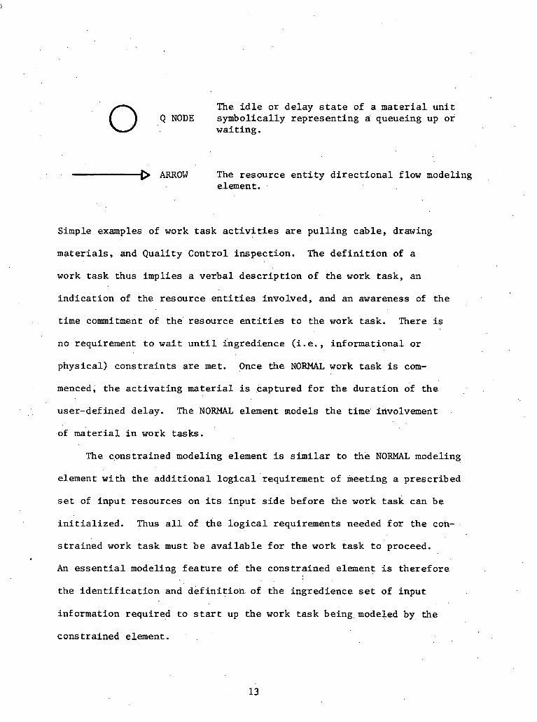
0 .. The i d l e or delay s t a t e of a m a t e r i a l u n i t Q NODE symbolical ly represent ing a queueing up or
wait ing.
. . . .-D ARROW The resource e n t i t y d i r e c t i o n a l flow modeling element .
Simple examples of work t a sk a c t i v i t i e s a r e p u l l i n g cable, drawing
mate r i a l s , and Quali ty Control inspect ion. The d e f i n i t i o n of a
work t a sk thus implies a ve rba l desc r ip t ion of the work t a sk , an
ind ica t ion of the resource e n t i t i e s involved, and an awareness of t h e
time 'commitment of the' resource e n t i t i e s t o the work task. There is
no requirement t o wa i t u n t i l ingredience ( i . e . , informational o r
physical) c o n s t r a i n t s a r e m e t . Once the NORMAL work t a s k i s com-
menced, t h e a c t i v a t i n g mate r i a l i s .captured f o r t h e dura t ion of t h e ; .
. , user-defined delay. The NORMAL element models t h e t i m e ' involvement
of mate r i a l i n work tasks.
The c,onstrained modeling element is s i m i l a r t o the NORMAL modeling
element wi th t h e a d d i t i o n a l l o g i c a l requirement of meeting a prescr ibed
s e t of input resources on i ts input s i d e before the work t a sk can be
i n i t i a l i z e d . Thus a l l of the l o g i c a l requirements needed f o r t h e con-
s t r a i n e d work t a sk must be a v a i l a b l e f o r t h e work t a sk t o proceed.
An e s s e n t i a l modeling f e a t u r e of the constrained element is the re fo re
the i d e n t i f i c a t i o n and d e f i n i t i o n . o f the ingredience s e t of input
in£ ormation required t o s t a r t up t h e work t a s k being. modeled by, the
cons t r a ined element.

The i d l e o r pass ive s t a t e of a resource is modeled by a c i r c l e
t o denote a QUEUE node ( o r Q node). The Q node is t h e graphical form;
i t has an obvious s i m i l a r i t y t o the concept of u n i t s being i d l e i n
a wai t ing l i n e queue. Usually t h e t i m e a m a t e r i a l is delayed i n the
i d l e s t a t e i s unknown and depends on e x t e r n a l condit ions i n a con- I
s t r u c t i o n opera t ion r e l a t i n g t o var ious work t a s k s t a t e s and dura t ions
and on the e f f i c i e n t . d e s i g n . and management of the opera t ion, a s w e l l
a s information requirements. The QUEUE node a c t s a s a s to rage loca t ion
f o r fesources enteTlng An i d l e s t a t e and r e l e a s e s the resources t o ehe
following node whenever the node ingredience l o g i c i s s a t i s f i e d .
An arrow o r d i r e c t e d ARC is used t o model the d i r e c t i o n of re-
source e n t i t y flow between t h e var ious a c t i v e s t a t e "square nodes"
and the pass ive s t a t e "queue nodes." The ARC modeling element enables
t h e l o g i c and s t r u c t u r e of the opera t ion t o be developed. The ARC
has no t i m e delay p r o p e r t i e s and simply models e n t i t y flow d i r e c t i o n .
The m a t e r i a l t r a n s i t t i m e , once i n i t i a t e d , is instantaneous.
The t h r e e modeling elements ( i . e . , the NORMAL and QUEUE nodes and
t h e ARC) are ' t h e b a s i c model-building elements. These elements can
h e combined in s e v e r a l ways t o niodel m a t e r i a l flow cycles, a s shown
i n the next s e c t i o n s .
1.6 Mechanical Mater ia l I n s t a l l a t i o n Cycles
.The t h r e e mechanical m a t e r i a l i n s t a l l a t i o n cycles t o be discussed . a r e those f o r f i e l d f .abricated pipe (bulk) , smal l valves (small com-
ponents), and pumps ( l a r g e components). Each of these m a t e r i a l c l asses

has an a s s o c i a t e d h igh d a t a d e n s i t y o r ped ig ree which is r e q u i r e d
dur ing i n s t a l l a t i o n and which l e a d s t o t h e gene ra t ion of f u r t h e r
in format ion dur ing the process ing cyc le .
I
1.6.1 ~ e c h a n i c a l - Bulk m a t e r i a l s
Bulk p i p e o r spoo l m a t e r i a l has been s e l e c t e d f o r c o n s i d e r a t i o n
s i n c e a l a r g e amount of t h e d a t a a s s o c i a t e d wi th t h e p i p e p o r t i o n of
many s p o o l l i n e s is genera ted i n t h e f i e l d . This occurs s i n c e almost
a l l of t h e sma l l t o medium s p o o l l i n e s are f a b r i c a t e d i n t h e f i e l d ,
'and a t some p l a n t s a l l p ip ing i s f a b r i c a t e d in-place. Typica l ly t h e
number of s p o o l p i e c e s r equ i r ed f o r a nuc lea r u n i t is on t h e o r d e r . .
of 10,000 sma l l s p o o l s (2" diameter and below) and 5,000 l a r g e spoo l s
(2Y1 diameter and above). . This r e p r e s e n t s about 250,000 t o 350,000 LF
of p ip ing (2) . Each of t h e s e spoo l p i e c e s has a 'long d a t a " t a i l " by ' .
t he" t ime systems a r e turned over t o t h e p l a n t o p e r a t i o n a l f o r c e . C e r -
t a i n p o r t i o n s of t h i s d a t a are a v a i l a b l e a t t h e t i m e t h e m a t e r i a l i s
i s s u e d from s i t e s to rage . Typ ica l ly , t h i s d a t a i s compiled i n t o a
c e n t r a l f i l e which is c a l l e d a " t r ave l e r . " The " t r a v e l e r " becomes
t h e c e n t r a l l o c a t i o n f o r d a t a p e r t a i n i n g t o a g iven s p o o l p iece .
The t r a v e l e r a t t he t ime a b u l k p i e c e of s m a l l bo re s p o o l m a t e r i a l
i s i s sued f o r f a b r i c a t i o n c o n s i s t s of t h e fo l lowing d a t a i tems:
(1) Sequence Form
(2 ) Weld Record .
, ' (3) D e t a i l f a b r i c a t i o n drawings ( I some t r i c s )
(4) F a b r i c a t i o n B i l l of Materials

( 5 ) ' Index and Instrumentat ion
(6) Mate r i a l Record (Heat No.)
( 7 ) Welder.1.D. and Qua l i f i ca t ion
Typical work order f i l e s f o r f a b r i c a t i o n and-e rec t ion of spool l i n e s
a r e shown i n Figure 1.2.
SMALL BORE FABRIC AT1 ON
. . r Y ~ i n e svool
11ndex & ,Inst. 1 B.O.M.
I Drawing ,
I Weld rec .
Sequence - L_
INSTALLATION SPIALL AND LARGE BORE LINES
Line ,--l
I n t h i s case, the B i l l of Mater ia l (B.O.M.) a c t s a s the f i e l d r e q u i s i t i o n
I
[ ~ n d e x & I n 2 t . I R.O.M.
required t o withdraw the ,mater ia l . A l l forms i n the work order f f l e a r e
(Drawing
Flange rec .
f i l l e d i n a s i s s u e , weld-out, and i n s t a l l a t i o n occur.. I n t h i s sense,
1
they record informafion generated during the i n s t a l l a t i o n cyc le a s w e l l
a s providing informat'ion required f o r f a b r i c a t i o n and i n s t a l l a t i o n .
en era ti on' of tlie work order f i l e r equ i res access. t o the following
items of information:
Sequence - - -

( 1.) .Pr?.mary Engineering Drawings
(2) Drawing Change Notices
(3) Engineering Change Notices (ECN)
(4) F i e l d Change Requests (FCR)
(5) S p e c i f i c a t i o n s
(6) Other work order f i l e s (e .g . , o t h e r spoo l p i e c e s , f a b r i c a t i o n
W.O., e r e c t i o n W.O., pneumatic ins t rument W.O., hanger W.O.,
e t c . )
(7) Rcquis i t i o n s
(8) Purchase Orders
(9) Expedi t e Reports
(10) M a t e r i a l ~ e c e i v i n ~ Reports
( 1 1 ) . Bulk M a t e r i a l S t a t u s ( a v a i l a b i l i t y )
(12) QC informat ion
The work .order f i l e t r i g g e r s i s suance of t h e m a t e r i a l s and t h e beginning
of the f a b r i c a t i o n sequence. The f a b r i c a t i o n , i n s t a l l a t i o n , and ac-
ceptance c y c l e is shown g r a p h i c a l l y i n F i g u r e 1.3.
The t o t a l c y c l e c o n s i s t s of 1 3 work, t a s k s , a s fo l lows :
(1) I ssuance of p ipe m a t e r i a l and weld m a t e r i a l
(2) Movement of m a t e r i a l t o f a b r i c a t i o n shop
(3) Cut ,.and pe r f o m weld end prep.
(4) QC i n s p e c t i o n (in-shop)
(5) Move t o i n s t a l l a t i o n l o c a t i o n
(6) .Up and center - tack welds
( 7 ) Final. weld
17

Weld rod i n f o Info In: Shop schedule
Wcrk space Sequence a v a i l a b l e i n f o
Isometr ic
B.O.M.
Veld record
Index and I n ~ t r u . records Schnduling records number Welder MH
Space a v a i l - Val ida t ion Heat number record
ab:e M i l l t e s t n m b e r
Beat no. I H i l l t e s t
no. I MOVE TO INsTp.LlA- ' TION
I n e t o ~ t g e Resdy f o r v e l d I n shop
Weld record l o c a t i c n resdy Space a v a i l a b l e (trsveler:
E r e c t i m W.O. ready I
PEW. , 'TURNOVER
FIGURE 1.4': BULK PIPE MATERIAL CYCLE

(8) QC i n s p e c t i o n (X-ray)
(9) Cons t ruc t ion Acceptance T e s t (CAT)
(10) Flush
( 11) T,emporary turnover
( 1 2) Permanent tu rnover
(13) System turnover
I n a d d i t i o n t o t h e 1 3 main l ine a c t i v i t i e s , rework a c t i v i t i e s
a r e a s s o c i a t e d w i t h t h e QC i n s p e c t i o n a c t i v i t i e s (4) and (8), as w e l l
a s w i t h the Cons t ruc t ion Acceptance T e s t , t h e f l u s h , temporary, perma-
nen t , and system turnover a c t i v i t i e s . The purpose of flow diagramming
is t o d e t e c t and document informat ion in-flow and out-flow. Associated
wi th each of t h e . 20 work t a s k s a r e two sets of in format ion . The 40
s e t s of Information In/Out a r e desc r ibed i n d e t a i l i n Addendum A.
I n some cases , . t h e r e a r e n u l l sets s i n c e t h e informat ion genera ted
'. from a work t a s k completion o r r equ i r ed f o r commencement.of a work
task is no t c r f t i c a l o r s i g n i f i c a n t enough t o b e inc luded i n t h i s
d i scuss ion of t h e informat ion s t ruc tu re ' . C e r t a i n r e p r e s e n t a t i v e
informat ion types have been inc luded on some of t h e Information I n /
Out symbols. The work o r d e r f i l g in format ion i t s ' e l f (e .g . ,. sequence
informat ion , e t c . ) r e l e a s e s t h e s tar t of a c t i v i t y I s s u e s p o o l mater ial ' .
An a n a l y s i s of t h e Information In/Out i n d i c a t e s t h a t c e r t a i n c l a s s e s
of in format ion are e i t h e r r equ i r ed o r genera ted as fo l lows:
( 1) Design r e l a t e d i n £ ormation '
(2 ) Material c h a r a c t e r i s t i c s ( i nc lud ing weld m a t e r i a l )
(3 ) Scheduling informat ion (space , manpower a v a i l a b i l i t y )

(4) Stock c o n t r o l information
( 5 ) Inspect ion r e l a t e d information ( t o inc lude acceptance/ re jec t ion)
(6) Work completion e n t r i e s
(7 ) P roduc t iv i ty information
(8) Cost information
(9) Worker q u a l i f i c a t i o n information
Every t i m e a work t a s k commences o r completes, information of this
v a r i e t y i s e i t h e r requi red o r generated and . theref o r e must b e re-
t r i eved o r passed from o r t o the information s t r u c t u r e . Addendum A
conta ins d e t a i l e d l i s t i n g s .
The Isometr ic Drawings a r e a t y p i c a l example of design-related
information. They i n t e r p r e t t o the f a b r i c a t o r i n the shop t h e informa- .
t i o n on the primary design documents (e. g . , Piping and Ins trument
Drawings) s o t h a t h e can u t i l i z e t h i s schematic information i n a three- .
dimensional format . , ate rial information such as' h e a t numbers and . .
m i l l t e s t r e p o r t s f o r the bulk s t o c k become p a r t of the completed
spool l i n e ' s information s t r u c t u r e . The a v a i l a b i l i t y of manpower and
space i n the f a b r i c a t i o n shop a s w e l l a s a c t i v i t y requirements from
higher l e v e l schedules d i c t a t e the shop schedule and, theref ore , in-
f luence t h e procesging of m a t e r i a l s ' a n d f a b r i c a t i o n p r i o r i t i e s . Upon I
i s suance from s i t e s to rage , s t o c k c o n t r o l records must b e updated t o
i n d i c a t e reduct ion i n inventory l e v e l s . Quali ty Control information .
generated during inspec t ion must b e recorded and d i c t a t e s whether re-
work and a d d i t i o n a l e f f o r t i s required . Af te r completion of each work
t a sk , t h e ques t ion of whether a s t a t u s change i s recorded must be

considered. Work completion l e a d s a l s o t o t h e t a b u l a t i o n of t o t a l
manhour and c o s t expendi tures . P r o d u c t i v i t y informat ion can b e de-
r i v e d from t h i s c o s t and manpower r epo r t ing . A s p a r t of t h e q u a l i t y
c o n t r o l , t h e q u a l i f i c a t i o n of t he welder and h i s l a s t r e t e s t become
a m a t t e r of record . . . .
1 .,6.2 Mechanical - Small components
Small va lves have b e e n , s e l e c t e d as an example of s m a l l components
because of t he d a t a needed t o c o n t r o l t h i s process and t h e s h e e r
number of t h e s e types of devices . There a r e normally 20,000 va lves
and s p e c i a l t y i tems t o b e i n s t a l l e d i n t h e p i p i n g systems o f ' a nuc lea r
p r o j e c t . F igu re 1 .4 s chemat i ca l ly r e p r e s e n t s t h e i n s t a l l a t i o n of
va lves .
I n t h e beginning of t h e process , a work o rde r i s , p r e p a r e d . When
the va lve i n s t a l l a t i o n is needed, t h e work o rde r is i s sued t o t h e
f i e l d . The' foreman sends a r e q u i s i t i o n t o r e t r i e v e t h e a r t i c l e
and i t i s brought t o t h e a r e a of i n s t a l l a t i o n . The va lve ' is ' p laced
and f i t t e d and permanently i n s t a l l e d . A t t h i s t ime i t is in spec t ed
f o r conformance t o the .d rawings and s p e c i f i c a t i o n s . The i tem then
is r u n through a group of t e s t s and is f i n a l l y r e l e a s e d o r tu rned over
permanently. . ' '
There a r e many d a t a elements t h a t a r e a s s o c i a t e d w i t h t h e in-
s t a l l a t i o n of a sma l l va lve . These can b e d iv ided i n t o t h r e e main
c a t e g o r i e s . F i r s t t h e m a t e r i a l i t s e l f is t r acked by such d a t a a s
purchase o rde r , system number, v i t a l i t y , e t c . Second, the personnel
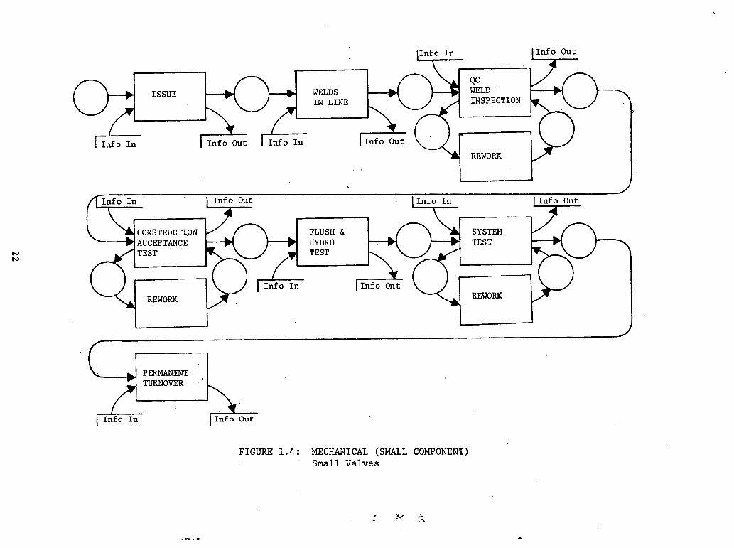
I
IS SUE WELDS I N LINE * I
FIGURE 1.4: MECHANICAL (SMALL COMPONENT) Small Valves

add d a t a t o t h e ped ig ree such a s welder q u a l i f i c a t i o n number, procedure,
method of i n s t a l l a t i o n , t i m e used, and cond i t i ons of i n s t a l l a t i o n .
Thi rd , QC and t e s t i n g add p e r t i n e n t in format ion t o t h e i t e m , such a s
acceptance r e p o r t s , r e j e c t i o n r e p o r t s , minor v a r i a t i o n r e p o r t s , in-
process r e p o r t s , e t c . Each adds p e r t i n e n t and important in format ion
t o t h e ped ig ree of t he i n s t a l l a t i o n . For a 'mbre. complete list of in-
p u t s and ou tpu t s of each ope ra t ion , s e e Addendum B.
1 . 6 . 3 Mechanical - Large com_ponent$-
Large pumps have been s e l e c t e d f o r i n s p e c t i o n because they a r e .
t h e i tems i n t h i s ca tegory wi th the most d a t a a s s o c i a t e d w i t h them.
F igure 1..5 shows the i n s t a l l a t i o n of t h e s e components.
The u n i t f i r s t n u s t be . schedu led f o r work. Because of s i z e , a
f o r k l i f t must b e scheduled as w e l l a s the:.heavy equipment crane. The
* personnel who ope ra t e t h i s equipment must be scheduled and s e t a s i d e
. f o r t h i s work i n advance. Because.of t h e m u l t i - d i s c i p l i n a r y n a t u r e
of s e t t i n g a pump, d e c i s i o n s must be made a s t o t h e type of c r a f t s
needed and t h e number .of each t o b e used.
Before t h e pump can b e p laced , a n equipment pad must b e b u i l t t o .
hold t h e item.' This must b e done i n accordance w i t h proper manufacturer
drawings and s p e c i f i c a t i o n s .
When- t he pump is r e l e a s e d f o r i n s t a l l a t i o n , a f o r k l i f t and &ane
must t r a n s p o r t i t t o i t s l o c a t i o n and wait w h i l e t h e pre-placement ' .
f i t t i n g is performed; subsequent ly , i t is i n s t a l l e d i n i t s f i n a l posi-
t i o n . There is usua l ly some rework and poss ib ly some drawing chang.es

WORK ORDER
. .
FINAL P R E - P L A C m , PLACEMENT
INSTALLATION OF PUMP
l ~ n f o o u t
I I
"FIGURE 1.5: MECHANICAL (LARGE COMPONENT) Pumps
t h a t a r e necessary i n order t o accomplish t h i s .
A t t h i s p o i n t , QC documents :the work, i nc lud ing any c a l i b r a t e d
t o o l s o r s p e c i a l ' p r o c e d u r e s employed, and accep t s o r r e j e c t s t h e
i n s t a l l a t i o n by v i r t u e of t h e s p e c i f i c a t i o n s and procedures .
It should b e mentioned t h a t t h e system w i l l probably con ta in
e l e c t r i c a l c o n t r o l s and ope ra to r s t h a t . w i l l need t o be connected.
These are mentioned i n t h e e l e c t r i c a l s e c t i o n s which c a n ' b e consul ted
t h e r e f o r f u r t h e r in£ ormation.
A f t e r a l l work is complete, t h e pump w i l l undergo t h e same
t e s t i n g a s any o t h e r component. Informat ion from t h e s e tests w i l l
b e a t t ached t o t h e pump. A l l in format ion is turned over t o t h e
Start-Up Group f o r f i n a l t e s t i n g and r e l e a s e t o t h e customer.
Addendum C con ta ins a l i s f i n g o f . i n f o r m a t i o n genera ted i n t h e in-
s t a l l a t i o n of a pump.
1 . 7 C i v i l M a t e r i a l I n s t a l l a t i o n Cycles
1 . 7 . 1 C i v i l - Bulk m a t e r i a l s
. A t y p i c a l b u l k m a t e r i a l w i t h i n t h e c i v i l d i s c i p l i n e is r e in -
f o r c i n g s t e e l . C e r t a i n i n s t a l l a t i o n s r e q u i r e t h a t r e b a r b e ordered
i n bu lk q u a n t i t i e s and f a b r i c a t e d a t t h e job s i t e . An example would
b e when r e b a r must b e formed i n an unusual shape o r f i t t e d around a n
i r r e g u l a r o b j e c t which r e q u i r e s f i e l d dimensions and f a b r i c a t i n g .
This method ' e l imina tes cos t l y f a b r i c a t i o n e r r o r s and schedule de l ays .
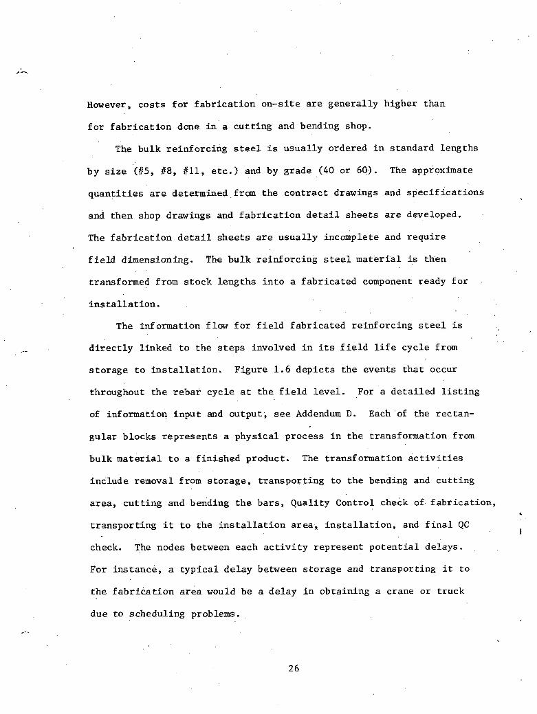
Hawever, c o s t s f o r f a b r i c a t i o n on-s i te a r e genera l ly higher than
f o r f a b r i c a t i o n done i n a cu t t ing and bending shop.
The bulk re in fo rc ing steel is usua l ly ordered i n standard lengths
by s i z e '(85, il8, / I l l , e t c . ) and by grade (40 or 60.). The approximate
q u a n t i t i e s are determined, from t h e con t rac t drawings and s p e c i f i c a t i o n s
and then shop drawings and f a b r i c a t i o n d e t a i l shee t s a r e developed.
The f a b r i c a t i o n d e t a i l shee t s a r e usua l ly incomplete and r e q u i r e
f i e l d dimensioning. The bulk re in fo rc ing steel m a t e r i a l is then
transformed from s t o c k lengths i n t o a f abr ica ted component ready f o r
i n s t a l l a t i o n .
The information flow f o r f i e l d fabr ica ted re in fo rc ing steel is
d i r e c t l y l inked t o t h e s t e p s involved i n i ts f i e l d l i f e cycle from
s to rage t o i n s t a l l a t i o n . Figure 1.6 d e p i c t s the events t h a t occur
throughout t h e rebar cycle a t t h e f i e l d l eve l . For a d e t a i l e d l i s t i n g
of information inpu t and output , see Addendum D. Each of the rectan-
gu la r blocks represen t s a physica l process i n t h e transformation from
bulk material t o a f in i shed product. The transf.ormation a c t i v i t i e s
inc lude removal from s to rage , t ranspor t ing t o t h e bending and cu t t ing
area , c u t t i n g and bending t h e ba r s , Quali ty Control check of f a b r i c a t i o n , 4
t r anspor t ing i t t o the i n s t a l l a t i o n a r e a , i n s t a l l a t i o n , and f i n a l QC I
check. The nodes between each a c t i v i t y represent p o t e n t i a l delays.
For ins tance , a t y p i c a l de lay between s torage and t ranspor t ing i t t o
the f a b r i c a t i o n a rea would be a delay i n obtaining a crane o r t ruck
due t o scheduling problems.

S h o p drawings, spec;; other drawings, 1 2 3
C
H O I S T OR S T R A N S P O R T TO CUT & BEND
BENDING & BARS
CUTTING AREA
r1nf o Out In fo ~n
CORRECTIONS
5 6
FABRICATION I N S T f i L A T I O N
CORRECTIONS
.... F I G U R E 1 .6: CIVIL (BULK)
Reinforcing S t e e l

The r e i n f o'rcing s t e e 1 transformat.ion process i s usua l ly i n i t i a t e d
by some phys ica l requirement being m e t . The requirement could be t h a t
formwork i n t h e p a r t i c u l a r a r e a should be 50% complete before f a b r i c a t i o n
is begun. Another requirement may b e t h a t a s p e c i a l embedded item must
b e i n s t a l l e d . When shipments a r e behind schedule, t h e rebar de l ive ry
t o the job s i t e w i l l s t a r t the f a b r i c a t i o n cycle. Generally, some ,
phys ica l requirement d i c t a t e s the s t a r t of the r eba r f i e l d l i f e cycle.
Addendum D l ists, i n d e t a i l , t he information inpu t and ou tpu t
f o r the r e in fo rc ing s t e e l f i e l d l i f e cycle . Typical information input
f o r a l l a c t i v i t i e s i n the cyc le inc ludes : shop .drawings and f a b r i c a t i o n !. .
shee t s , work a c t i v i t y numbers, crew number assigned, c o s t c,ode number,
t i m e a l l o t t e d f o r t h e a c t i v i t y , and n o t i f i c a t i o n t h a t the previous ac-
t i v i t y is complete. However, the h o i s t i n g and t ranspor t ing a c t i v i t i e s '
t y p i c a l l y r e q u i r e pounds and quan t i ty of r eba r t o be l i f t e d lor t rans-
ported, pick-up and d e s t i n a t i o n points , and usage time requi red i n ad-
d i t i o n t o the previously l i s t e d i n p u t items. Typical output information *
inc ludes items such as: manhours, equipment hours, m a t e r i a l s t o be
charged a g a i n s t t h e work a c t i v i t y number and c o s t code number, s t a r t
and completion d a t e s , crew or equipment s t a t u s , and n o t i f i c a t i o n of ac-
t i v i t y completion.
C i v i l - Small components
Cadwelds a r e an example of a smal l component w'ithin the c i v i l d is -
c i p l i n e . Cadwelds f i t t h e d e f i n i t i o n of a smal l componen.t s i n c e they
a r r i v e a t the job s i t e i n a n e s s e n t i a l l y f i n i s h e d s t a t e and a r e transformed
28

s l i g h t l y during t h e i n s t a l l a t i o n process . Cadwelds are used t o
weld c r i t i c a l r e b a r j o i n t s i n l i e u of over lapping t h e ba r s . The
welding process , which is e s s e n t i a l l y a chemical r e a c t i o n , i s t h e
minimal t ransformat ion t h a t t a k e s p l ace .
The r e i n f o r c i n g s t e e l vendor t y p i c a l l y i n c l u d e s cadwelds i n
t h e i r shop drawings and i n d i c a t e s t h e l o c a t i o n of each weld. The
cadweld q u a n t i t i e s a r e i n i t i a l l y determined by c o n t r a c t drawing take-
of f and then v e r i f i e d through the shop drawing process . Cadwelds a r e
u s u a l l y packaged' when they a r r i v e a t t h e job s i t e and must b e s t o r e d
i n a s ecu re and p r o t e c t e d environment due t o t h e chemical r e a c t a n t s I
involved.
The in£ ormation f l a w . involved wi th cadwelds is d i r e c t l y l i n k e d
t o t h e a c t i v i t i e s 'of t h e i r l i f e c y c l e , from job s i t e s t o r a g e t o in-
s t a l l a t i o n . Th i s cyc l e i s shown i n F igu re 1 .7 . Again t h e r e c t a n g u l a r
boxes r e p r e s e n t phys i ca l processes , and t h e nodes a r e i n d i c a t i o n s of
t y p i c a l de lays . The l i f e . c y c l e a c t i v i t i e s f o r cadwelds a r e fewer i n
number due t o t he i tem no t being involved i n a f i e l d f a b r i c a t i o n process .
Typica l f i e l d a c t i v i t i e s a s s o c i a t e d w i t h cadwelds inc lude : removal
from s t o r a g e , t r a n s p o r t i n g t o t he work a rea , Qua l i t y Cont ro l check
p r i o r t o i n s t a l l a t i o n , i n s t a l l a t i o n , a n d f i n a l QC check. A t y p i c a l
de lay encountered i n t h e cadweld a c t i v i t i e s may b e t h e i n a b i l i t y t o . .
o b t a i n approval of ' a p a r t i c u l a r cadweld mechanic from QC. S a t i s f y i n g
some phys i ca l requirement i n i t i a t e s t h e cadweld cyc le . I n g e n e r a l ,
t h e main requirement would b e t h a t t h e r e q u i r e d ' r e i n f o r c i n g s t e e l is
. i n s t a l l e d and ready f o r cadwelding. '
2 4
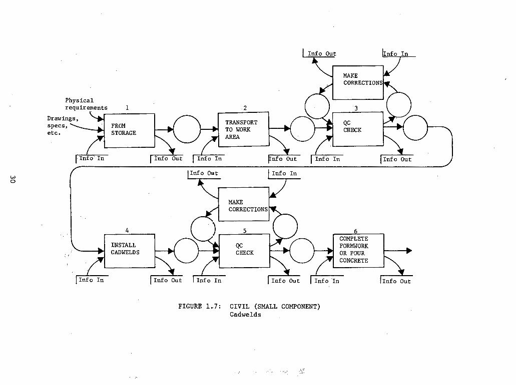
CORRECTIONS
Physical requirements 1 2 3
FROM TRANSPORT Qc
STORAGE TO WORK CHECK AREA
Info In
MAKE CORRECTIONS
F I G U R E 1.7: C I V I L (SMALL COMPONENT) C a d w e l d s

~ddendum E g ives a d e t a i l e d l i s t i n g of in format ion i n p u t and out-
pu t r equ i r ed a t , each a c t i v i t y . Most a c t i v i t i e s i n t h e cadweld .cyc le
r e q u i r e informat ion inpu t such a s : shop drawings, work a c t i v i t y number,
c o s t code number, crew number ass igned , scheduled d u r a t l o n of t h e ac-
t i v i t y , cadwelder q u a l i f i c a t i o n approval , and n o t i f i c a t i o n t h a t t h e
previous a c t i v i t y is complete. The t r a n s p o r t a t i o n and h o i s t i n g ac-
t i v i t i e s p lay a minor r o l e i n t h e cadweld c y c l e due t o t h e i r r e l a t i v e l y
sma l l s i z e i n comparison t o t he bulk r e b a r case . However, s i n c e cadwelds
a r e c r i t i c a l i tems, Qua l i t y Cont ro l p 1 a y s . a l a r g e r o l e i n approving s t o r -
age and i n s t a l l a t i o n . I n a d d i t i o n t o t h e above i n p u t in format ion , ~ u a l i t ~
Cont ro l would r e q u i r e welder q u a l i f i c a t i o n s f o r a l l mechanics i n s t a l l i n g
t h e cadwelds. ~ ~ ? i c a l ou tpu t i n f o r m a t i o n , i n c l u d e s : manhours, equipment
hours , o r m a t e r i a l s t o b e charged a g a i n s t t h e work a c t i v i t y number and
. c o s t code number, start and completion d a t e s , crew o r equ ipmen t . s t a tu s ,
... and n o t i f i c a t i o n of a c t i v i t y completion. . .
1 . 7 . 3 C i v i l - Large components
The p roces s of e r e c t i n g s t r u c t u r a l steel i n a nuc lea r power p l a n t
i s s i m i l a r t o convent iona l cons t ruc t ion . The major d i f f e r e n c e is t h e
c l o s e check kep t on Qua l i t y Control . I n i t i a l l y , a work o rde r must be
prepared. Th i s documentation process would d e s c r i b e t h e "piece" of
construction needed t o be completed. Some of t h e informat ion which
must b e a v a i l a b l e might be t h e amount of m a t e r i a l r equ i r ed , a n approximate
e s t ima te a s t o t h e manpower r equ i r ed , consumables r equ i r ed , e t c . Much
of t h i s same information then becomes ou tpu t and i s f u n n e l e d - t o t h e .

a p p r o p r i a t e depar tments t o s t a r t t h e coo rd ina t ion of t h e f i e l d e r e c t i o n
process . Addendum F c o n t a i n s a d e t a i l e d l i s t i n g . A f t e r t h e work o rde r has been prepared , t h e m a t e r i a l s must be
i s sued . It is important i n t h i s s t e p for t h e c o r r e c t m a t e r i a l s t o be
i ssued . The warehouse must b e supp l i ed w i t h which p i e c e s a r e r equ i r ed
and when t h e y a r e , r e q u i r e d . The informat ion which is recorded might be
which' p i e c e s are i s s u e d , t o whom they a r e i s sued , a t whose a u t t l u r l z a ~ i o ~ ~ ~ ,
what t h e amount' remaining i n s t o c k is, e t c .
Qua l i t y ' c o n t r o l i n t e r s t h e sequence a t t h i s po in t . S t r u c t u r a l s t e e l
is considered. a l a r g e component, p a r t i c u l a r l y i n l a r g e and more complex
members, and is t h e r e s u l t t h e r e f o r e of some s o r t of f a b r i c a t i o n process .
Although t h e f a b r i c a t i o n process was c a r r i e d ou t under a Qua l i t y Cont ro l
environment, i t must be v e r i f i e d t h a t t h e steel w i l l f i t 'ia ehe s t r u c t w e
as b u i l t . Therefore , such informat ion as a s - b u i l t drawings, f a b r i c a t i o n
drawings, f a b r i c a t i o n l o c a t i o n , e t c . would be needed. A L ~l i is point
t h e information produced would c o n s i s t of t h e diulensions of t h e f a b r i -
ca t ed p i e c e and i t s s t a t u s .
I n o r d e r t o e r e c t t h e s t e e l , i t must be moved t o t h e a c t u a l s i t e
of e r e c t i o n . Information necessary i n this s t e p i ~ l c l u d e s t h e a v a i l a b i l i t y
of manpower, weight of t h e p i ece f o r determining r igg ing equipment, s i z e ,
e t c . The informat ion recorded might i n c l u d e t h e crew involved, equipment
used, e t c .
The e r e c t i o n of t h e steel is t h e end o b j e c t i v e of t h e s e e f f o r t s .
I n order t o i n s u r e proper e r e c t i o n , drawings w i l l be r equ i r ed , a long wi th
approximate q u a n t i t i e s , in format ion as t o f a s t e n e r s (welding rods , b o l t s ) ,

information a s t o q u a l i f i e d welders, e t c . .Af te r being placed, the
s t e e l w i l l be inspected t o keep t r a c k of equipment used, ~ e l d e r s ' r n a k i n ~
s p e c i f i c welds, t h e crew which erec ted the piece, e t c .
P .After e r e c t i o n a f i n a l Quali ty Control check is' made. It i s
necessary t o know the e l eva t ion of t h e s t e e l , i ts ,o r i en ta t ion , f a s t en ing
condit ion, e t c . Information output would c o n s i s t of a d e s c r i p t i o n of the
work done and how c lose ly i t complies wi th t h e des ign s p e c i f i c a t i o n .
F igure 1 .8 d e p i c t s the work process flow from Prepare Work Order t o
QC F i n a l Check.
1.8 E l e c t r i c a l Mater ia l I n s t a l l a t i o n Cycles
Three e l e c t r i c a l m a t e r i a l ' d e l i v e r y cycles have been chosen, be-
cause of the d a t a dens i ty a s soc ia ted with them. Wire and cable w i l l
. be used a s . an example of bulk mater ia ls , . te rminat ions w i l l be used a s
5 an example of small components, and e l e c t r i c motors w i l l be used a s an
exam?le of l a r g e components.
1.8.1 E l e c t r i c a l - Bulk m a t e r i a l s
Bulk wire has been se lec ted a s an example of t h i s category because
o f . its da ta dens i ty and t h e l a rge ambunt of i t placed i n a nuclear p lan t .
I t i s not uncommon t o r equ i re the p lac ing of four t o f i v e mi l l ion f e e t of
cable i n a nuclear p lan t . - T h i s can keep 100 men busy handling r e e l s ,
p u l l i n g . c a b l e , and removing empty r e e l s t o t h e wire yard. The p u l l is
i n i t i a t e d by forming a p u l l package, which inc ludes inf ormatioqal cards
on each wire t o b e pul led . These cards inc lude cab le number, rouking,

- D o c u m e n t a t i o n i n f o
PREPARE I S S U E
x - WORK ORDER
MOVE TO (F F I N h L + ERECTION ERECTION . b
AREA CHECK
I n f o I n
FIGURE 1 . 8 : CIVIL (LARGE COMPONENT) Structural steel
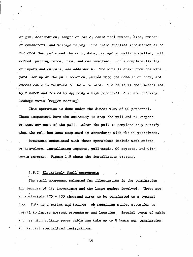
o r i g i n , d e s t i n a t i o n , l e n g t h of cable , cab le r e e l number, s i z e , number
of conductors , and v o l t a g e r a t i n g . The f i e l d s u p p l i e s in format ion as t o
, t h e crew t h a t performed t h e work, d a t e , , f oo tage a c t u a l l y i n s t a l l e d , p u l l
method, p u l l i n g f o r c e , t ime, and men involved. For a complete l i s t i n g
of i npu t s and ou tpu t s , s e e ~ddendum G. The w i r e is drawn from t h e wi re
yard , s e t . up a t tlie p u l l l o c a t i o n , p u l l e d into t h e condui t o r t r a y , and
excess c a b l e i s r e tu rned t o t h e w i r e yard. The c a b l e i s then i d e n t i f i e d . .
by f l o a t e r and t e s t e d by applying a h igh p o t e n t i a l t o i t and checking
leakage r a t e s (negger t e s t i h g ) . This ope ra t ion i s done under t h e d i r e c t view of'QC personnel .
These inspec. tors have t h e a u t h o r i t y t o s t o p t h e ' p u l l and t o i n s p e c t
o r t e s t any p a r t of t h e p u l l . Af t e r t h e p u l l i s complete they c e r t i f y
t h a t t h e p u l l has been completed i n accordance w i t h t h e QC procedures .
Documents a s s o c i a t e d wi th t h e s e ope ra t ions inc lude work o r d e r s
o r t r a v e l e r s , i n s t a l l a t i o n r e p o r t s , p u l l . c a r d s , QC r e p o r t s , and ,wi re
usage r e p o r t s . F igure 1 .9 shows t h e i n s t a l l a t i o n process .
1 .8.2 E l e c t r i c a l - small' components
The 'small component s e l e c t e d , f o r i l l u s t r a t i o n i s t h e te rmina t ion
lug because of i t s importance and t h e l a r g e number involved. There are
approximately 125 - 135 thousand w i r e s t o b e te rmina ted on a t y p i c a l
job. This i s a s t r i c t and t ed ious job r e q u i r i n g s t r i c t a t t e n t f o n r o
d e t a i l t o . insure c o r r e c t procedures and l o c a t i o n . S p e c i a l types of c a b l e
sudh a s high v o l t a g e power c a b l e can t a k e up t o 8 hours per t e rmina t ion
1 and r e q u i r e s p e c i a l i z e d i n s t r u c t i o n s .

PREPARE ISSUE WORK ORDER \JORK
I Info Out 1 I n f o In I ~ n f o O u t I I n f o I n 1 1 n f o O u t
RECORD AS MEGGER COMPLETE,
AND FLOATED T3STED GENERATES TERMINATIONS
L
FIGURE 1.9: ELECTLICAL (BULK MATERIAL) Cable Pulling

The termination i s i n i t 2 a t e d by a termination card s e n t t o t h e
f,ield.. This card contains information on loca t ion , s i z e of conductor,
diagram of connection number, c i r c u i t number, and type of connection.
7
The craftsman is assigned the connection, l o c a t e s i t , terminates i t
according t o the diagram of 'connect ion, and repor t s h i s a c t i v i t i e s .
The QC inspector then v e r i f i e s t h e termination and genera tes a
h i s t o r i c a l document t o v a l i d a t e t h e work.
Forms involved i n t h i s process inc lude termination reques t forms,
termination repor t s , and QC repor ts . A list of inpu t s and outputs
generated ,from these operat ions is shown i n Addendum H.
Figure 1.10 dep ic t s the work process.
1.8.3 E l e c t r i c a l - Large components
The i a s t type of component t o be considered w i l l be t h e " l a rge
cornpollent" c l a s s . Motors a r e t y p i c a l of t h i s c l a s s . A work order i s
prepared. upon demand and sen t t o the f i e l d . The foreman reques t s t h e
r e l e a s e of t h e i t e m which is then t ranspor ted t o the work a rea and s e t
on i t s foundation. Conduit is then brought t o t h e motor and terminations
a r e made. Qual i ty Control inspec t s t h e work and re leases i t f o r f u r t h e r
t e s t i n g . The motor is then hi-potted, which involves placing a high
p o t e n t i a l across the l i n e t o observe l o s s and check systems. The motor
i s then re leased t o Operat ional Testing.
I n each of the operati.ons above, c e r t a i n information i s needed and
information i s generated. See Addendum I f o r l i s ts of ' inpu t s and outputs

Info I n 11nfo O u t
FREP ARE WORK ORDER TERMINATION
-
TEXMINb.TION O 3 F I C E LOG
FIGURE 1.13: ELECTRICAL (SMALL COMP3NENT) Terminations

assoc ia ted with each. Figure 1.11 fol lows the i n s t a l l a t i o n of t h e
l a r g e e l e c t r i c a l items.
Within the e l e c t r i c a l d i s c i p l i n e , m a t e r i a l s can be segregated i n t o
the ca tegor ies mentioned previously. It i s ' f e l t t h a t the processes
performed a n d . t h e inputs and ou tpu t s can be more e a s i l y understood i f
explained i n a work o r i e n t a t i o n . On any job t h e e l e c t r i c a l d i s c i p l i n e
i s separa ted i n t o t h r e e d i s t i n c t groups. The conduit crews i n s t a l l a l l
conduit , t r ay , and phys ica l equipment. The w i r e pu l l ing crews a r e respon-
s i b l e f o r i n s t a l l i n g wi re and cable , and t h e te rminators terminate the
wi re l e f t by the wire crews t o the equipment l e f t by the conduit crews.
A l l componen.ts used by any one group flow t o the f i e l d and a r e
i n s t a l l e d i n exact ly the same way because they a r e used by t h e same
people i n the same types of systems. To expla in accura te ly the . rout ing
., of equipment t o i n s t a l l a t i o n , one would need t o expla in n a t how bulk
m a t e r i a l s a r e h.andled i n genera l bu t r a t h e r how bulk m a t e r i a l s a r e I
handled by the conduit pleople, how bulk m a t e r i a l s a r e handled by wire
pu l l ing crews, and how bulk m a t e r i a l s a r e handled by the te rminat ion
crews. The,same process would hold t r u e f o r small components and
l a r g e components. See Table 1.3 f o r a breakdown o f ' t h e s e ca tegor ies .

lIn£o I n \Info Out
PREPARE ISSUE WORK ORDER W-WHCU SE
TRANSPORT TO
TERMIKATZ
P n f o i n 1 out I ~ n t o ~n In fo O u t 5-
REWORK
FIGURE. 1.11: ELECTRICAL (LARGE COMPONENT) Motors
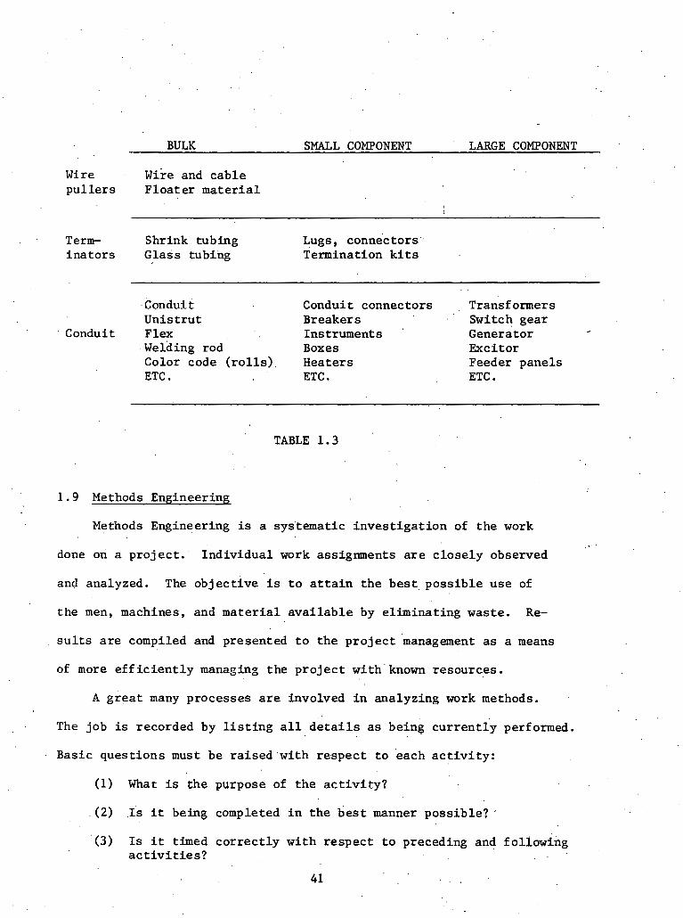
BULK SMALL COMPONENT LARGE COMPONENT
Wire wire and cable p u l l e r s F loa te r m a t e r i a l
Term- Shrink tubing Lugs, connectors.. i n a t o r s Glass tubing Termination k i t s
. .
kon'dui t Conduit connectors Transformers Unis t r u t Breakers Switch gear
Conduit Flex Instruments ' ~ e n e r a t o r - . welding rod Boxes Excitor Color code ( r o l l s ) . Heaters Feeder panels ETC , ETC . ETC .
TABLE 1.3
1.9 Methods Engineering
Methods Engineering is a sys'tematic i n v e s t i g a t i o n of the work
done on a p ro jec t . Individual work assignments a r e c lose ly observed
and analyzed. The object ive i s t o a t t a i n the b e s t poss ib le use of
the men, machines, and mate r i a l a v a i l a b l e by elimina.ting waste. Re-
s u l t s a r e compiled and presented t o the p r o j e c t management a s a means
of more e f f i c i e n t l y managing the p r o j e c t wi th ' known resources.
A g r e a t many processes a r e involved i n analyzing work methods.
The job is recorded by l i s t i n g a l l d e t a i l s a s being c u r r e n t l y performed.
Basic ques t ions must be ra i sed 'with respec t t o 'each a c t i v i t y :
(1) What is the purpose of the a c t i v i t y ?
(2) 1s i t being completed i n t h e b e s t manner poss ib le?
(3) Is i t timed c o r r e c t l y with respect t o preceding and following a c t i v i t i e s ?
4 1 . .

(4) Is it placed i n t h e optimum loca t ion ( i f t h e r e is a choice)?
(5) A r e t h e personnel performing t h e work the b e s t q u a l i f i e d individuals?
The job layout , too l s , equipment used, m a t e r i a l s used, m a t e r i a l flow,
and s a f e t y a s p e c t s must be evaluated. It may b e , poss ib le t o rearrange '
a c t i v i t i e s r e s u l t i n g i n b e t t e r sequencing. There may a l so be some
opportunity f o r s implifying a c t i v i t i e s and f o r achieving g r e a t e r ease
and speed. It is important t o inc lude a l l persons who have a n . i n h e r e n t
i n t e r e s t . i n ' t h e ana lys i s . Las t ly , t h e ' changes r e s u l t i n g must be sold . .
t o management f o r e f f e c t i v e implementation. . .
.A good working r e l a t i o n s h i p i s required wi th o ther funct ' ional areas . .
s o a s t o permit.achievement of t h e b e s t poss ib le r e s u l t s . Close coordina-
t i o n i s required wi th Quali ty Control/Quality Assurance t o b e s t t i m e when
these funct ions should be accmpl i shed , s o a s to minimize the e f f o r t re-
quired t o uncover.concea1ed i t e m s . P r o j e c t management must be sold on
t h e v a l i d i t y of t h e r e s u l t s of the s tud ies . I f management i s not com-
p l e t e l y convinced, then implementatibn w i l l probably be less than rotal .
Cost Control can prove or d isprove t h e v a l i d i t y of making the suggested
changes by ind ica t ing i f c o s t s have increased o r decreased. The measure-
ment of t h e c o s t s may have to. be modified t o r e f l e c t t r u e c o s t s i f methods ,,
have been changed.' The changed methods may r e s u l t i n significant savings
i n time, and thereby a l t e r schedules, which could involve the Planning
and Scheduling funct ion. Changing methods may a l s o r e q u i r e d i f f e r e n t
types of equipment o r d i f f e r e n t sequences of equipment, necess i t a t ing
consul ta t ion wi th Construction Equipment Control.

I n o rde r f o r Methods Engineering t o be e f f e c t i v e , a g r e a t d e a l
of in format ion i s requ i r ed and produced. Required . . in format ion can be
brokea down i n t o f i v e broad ca t egor i e s : t h e p r o j e c t p h y s i c a l l ayou t ,
t h e p r o j e c t o rgan iza t ion , t h e p r o j e c t estimate, t h e system f o r a s s ign ing
and scheduling work, and t h e p r o j e c t manpower requirements . The pro-
duced informat ion c o n s i s t s of d e t a i l e d p r o d u c t i v i t y informat ion on in-
d i v i d u a l a c t i v i t i e s a d proposed mod i f i ca t ions .
Methods Engineering involves c ros s ing i n t o t h e p o l i t i c a l a r ena
of p r o j e c t management, and must t h e r e f o r e be approached w i t h t h e utmost
s e n s i t i v i t y . I n i t i a l meetings should be scheduled wi th t h e P r o j e c t
Manager, . A s s i s t a n t P r o j e c t Manager, Cons t ruc t ion Manager, . . and t h e
Cont ro ls Manager t o d i s c u s s t h e parameters of t h e program. Next, i t
i s important t o become completely f a m i l i a r w i t h t h e d a t a requirements .
Upon reviewing t h e a v a i l a b l e informa t i o n and meeting w i t h p r o j e c t
management, o b j e c t i v e s and s t r a t e g i e s f o r implementing a Methods
Engineering program should be proposed.
I n ana lyz ing a c t i v i t i e s ,. s e v e r a l r e p o r t s inay . b e 'used. A weekly
t a b u l a t i o n of t h e d e t a i l e d breakdown of elements f o r t h e crew ' showing
t h e ma in work a c t i v i t i e s is produced. Also, a weekly tabu . la t ion covering
each crew's performance f o r t he c u r r e n t pe r iod and f o r t h e two preceding r
pe r iods , w i t h a three-week s l i d i n g average f o r each of t h e major e l e -
ments (D i rec t A c t i v i t y , Support A c t i v i t y , and Delays) , i s produced.
The t y p i c a l Manpower A c t i v i t y Analys is Report w i l l c o n s i s t o f :
(1) a cover l e t t e r ;
(2) a me-page summary g iv ing a multi-element breakdown f o r each
day of the period along with the current and previous repor t . .
s t a t i s t i c s and with the changes f tam period t o period;
(3) l i s t i n g s o£ the crews i n each c r a f t , giving the percentage of
breakdowns f o r both crew and c r a f t , along with the pro jec t
breakdowns; and
( 4 ) . l i s t i n g s of the crews i n each c r a f t , giving major elemental
breakdowns f o r t he previous th ree week period along with
t h e t o t a l p ro jec t major elemental s t a t i s t i c s .
Graphs may be presented a t spec i f i ed i n t e rva l s ; these should show
the t h r e e major elements (Direct Act ivi ty , Support ~ c t i v i t y , and ~ e l a ~ s ) '.,'
f o r each week f o r t h e t o t a l p ro jec t and f o r each c r a f t .

CHAPTER I1
Exist ing and Projected Systems
'
Several systems which fol low t h e mate r i a l cycle from s i t e s to rage
t o s tar t -up w i l l be presented i n t h i s sec t ion. Some of these systems
a r e i n operat ion while o thers a r e under development. Table 2.1 sum-
mar'izes t h e major t racking systems s tud ied and the l e v e l of coverage.
Systems a r e described i n terms of what d i s c i p l i n e components they t r a c k
and during which period of the l i f e cyc le of t h e m a t e r i a l they main-
t a i n s t a t u s . Codes a r e a s follows:
(1) "1" = System t racks component from engineering t o r e c e i p t and
s torage on site. Normally, t h i s l e v e l t racking includes information
,. regarding requ i s i t ion ing , purchase order , expedit ing, r e c e i p t , and .
- . . . . - . . - . . p r o j e c t s i t e s to rage locat ion. I
I I
(2) "2" - System provides s t a t u s information regarding mate r i a l
from i s s u e t o i n s t a l l a t i o n .
(3) "3" - System t racks .components from i n s t a l l a t i o n through ac-
cep tance by s tar t -up.
This r epor t i s concerned with those systems which a r e included i n
Codes 2 or 3 .
2 .2 Daniel Far l e y #l
The following is a list of computer s t a t u s programs t h a t are p resen t ly
i n operat ion a t Farley Nuclear P lan t Unit 1 , Dothan, Alabama f o r monitoring

CODES: 1 - Tracks ~ n g i n e e r i n g & Procurement 2 - Tracks c o n s t r u c t i o n I n s t a l l a t i o n 3 - Tracks Start-Up/Pre-Op
1
Danie l Danie l Danie l Nuclear General McDonnell- Far l ey Callaway Fermi Pow. Ser. , P u b l i c Douglas
MAJOR COMPONENTS Unit !I1 Unit #1 Uni t #2 P.M.P. Ut i l i t i e s Cornpaid.
CIVIL Concrete ' Pours Forms Rebar Concrete Embedments Cadwelds S t r u c t u r a l S t e e 1 .Equipment
COMBINED Paint-Ar ch/Equip /P ipe Insulate-Arch/Equip /Pipe
MECHANICAL Equipment P i p e Spools Large 1-2
S m a l l 1-2 Welds 1-2 V a l v e s / S p e c i a l t i e s 1-2 Hangers/Supports 1-2 Pneu. Ins t ruments 1-2 Loose M a t e r i a l s HVAC Equipment
Ductwork
Raceway Cable 1-2 Cable Tray/Suppor ts E1,ec. Ins t ruments 1-2
OTHER Minor ~ u i i d i n g s Minor Sys t ems
TABLE 2.1 : REVIEW OF EXISTING COMPUTERIZED '
COMPONENT INFORMAT I O N SY STEMS . . .

CODES: 1 - Tracks Engineering 6 Procurement 2 - Tracks c o n s t r u c t i o n I n s t a l l a t i o n 3 - Tracks Start-Up/Pre-Op
Northern . Bechte l Ga.Pow. S t a t e s Pro- Corp. Punch
MAJOR COMPONENTS posed ITS Q. T. S. L i s t
CIVIL Concrete Pours Forms Rebar Concrete Embedments Cadwelds S t r u c t u r a l S t e e l Equipment
COMBINED ~ a i n t - ~ r c h / ~ ~ u i ~ ' / ~ i ~ e Insulate-ArchIEquip /Pipe
MECHANICAL Equipment 1-2-3 P ipe Spools Large 1-2-3
Small 1-2-3 Welds 1-2-3 V a l v e s / S p e c i a l t i e s 1-2-3 Hangers/Suppor ts 1-2-3 Pneu . Ins t ruments 1-2-3 Loose Materials HVAC Equipment
Duc w o r k
ELECTRICAL Equipment 1.-2-3 Raceway ' 1-2-3 Cable 1-2-3 Cable Tray/Suppor ts Elec. Ins t ruments 1-2-3
OTHER Minor Buildings Minor Systems
TABLE 2.1: REVIEW OF EXISTING COMPUTERIZED COMPONENT INFORMATION SYSTEMS (continued )

. .
t h e components f o r permanent p l a n t i n s t a l l a t i o n . . . . . .
o Mechanical Equipment S t a t u s
o Large Bore Off -Si te P r e f a b r i c a t e d P ip ing Spool S t a t u s '
o Radiographs S t a t u s f o r t h e Large Bore P r e f a b r i c a t i o n
o Small Bore S i t e P r e f a b r i c a t e d P ip ing Spool S t a t u s
, . o Hanger/Support S t a t u s f o r Large Bore P r e f a b r i c a t e d Off-Si te
o Hanger/Support S t a t u s f o r Small Bore Enginee'red and P r e f a b t i c a r e d
On-S i t e
o Valve S t a t u s
o Pneumatic Instrument s t a t u s
o Weld Hi s to ry
o Welder ~ u a l i f i ca t ion lwe lde r Performance
o Heat umber Cross Reference Program ,
o E l e c t r i c a l Equipment S t a t u s
o E l e c t r i c a l In s t rumen ta t ion S t a t u s
o E l e c t r i c a l Cable Program
o Nonconformance Rep o r t (NCR) S t a t u s and Trends
T a b l e 2 . 2 i s a l i s t of systems now i n u s e f o r F a r l e y U n i t 1. The .
t a b l e i n d i c a t e s the frequency of- r e p o r t s arid t h e approximate number of
p r i n t l i n e s . The automation of inf ormati011 a t F a r l e y has a monthly out-
p u t of 4,324,400 p r i n t l i n e s .
2.2.1 Mechanical Equipment/Piping/Instrumentation I
To p rope r ly manage much of t h e informat ion necessary f o r t h e con-
,- s t r u c t i o n of Fa r l ey , Danie l had t o c o n s o l i d a t e and organize informat ion
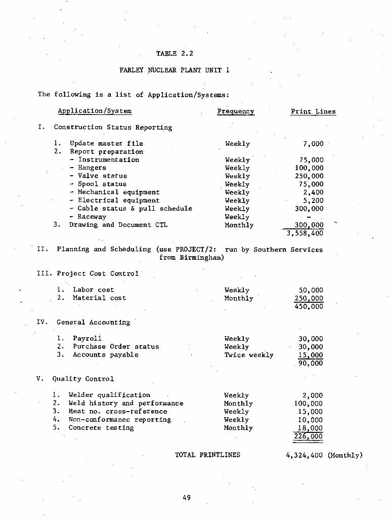
TABLE 2.2
FARLEY NUCLEAR PLANT UNIT 1
The fo l lowing is a l i s t of Applicat ion/Sys terns :
Appl ica t ion /Sys tern
I. .Construct ion S t a t u s Report ing
1. Update master f i l e 2. Report preparat ion.
- Ins t rumenta t ion . - Hangers
- Valve s t a t u s - Spool s t a t u s - Mechanical equipment - E l e c t r i c a l equipment - Cable s t a t u s & p u l l schedule - Raceway
3 . ~ r a w i n g and ~ o c u m e n t CTL
Frequency P r i n t Lines
Weekly
. . Weekly Weekly Weekly Weekly Weekly Weekly Weekly Weekly Monthly
11. Planning and Scheduling (use PROJECTl2: r u n by Southern Se rv i ces from Birmingham)
111. P r o j e c t Cost C o n t r o l ' ,
1. Labor c o s t 2. Material c o s t
I V . General Accounting
1. P a y r o l l 2. Purchase Order s t a t u s 3 . Accounts payable
V. Q u a l i t y Cont ro l
1. Welder quali ' f i c a t i o n 2. Weld h i s t o r y and performance 3 . Heat no. c ross - re ference 4. Non-cmfonnancc r e p o r t i n g 5 . Concrete t e s t i n g
Weekly 5,0,000 Monthly
Weekly Weekly Twice weekly
Weekly Monthly Weekly Weekly Monthly
TOTAL PRINTLINES 4,324,400 (Monthly)

coming from a v a r i e t y of sources. Alabama power had u t i l i z e d Bechtel
Corporation i n designing the containment and a u x i l i a r y areas , while
Southern Company Services designed t h e t u r b i n e h a l l and outs ide areas .
Each A/E' had d i f f e r i n g . r epor t and component i n d e n t i f i c a t i o n methods.
I n addi t ion separa te con t rac t s were placed f o r l a r g e bore p ipe prefab-
r i c a t i o n and l a r g e bore s i z e hanger and support p re fabr ica t ion . Each
company had separa te r e p o r t formats and idenf i f l c a tion systems. In
addi t ion , Daniel had t o develop a weld numbering sys t&, e s t a b l i s h con-
t r o l over welds, welders, radiographs, e t c . , t o meet t h e q u a l i t y as- . .
surance requirements. - 4 To properly coordinate t h i s informatior- from var ious sources i n
d i f f e r e n t r e p o r t formats, a set of r e p o r t s wi th common headings was pre-
pared. The i n t e n t of these r e p o r t s w a s t o c o n s o l l d a ~ e a l l a v a i l a b l e
-. information.
v
2,2.2 Heat-. Number Cross ~ G e r e n c e Program
A method was developed t o a i d t h e Quali ty Control engineers with
v e r i f i c a t i o n of heat numbers. Components used f o r c r i t i c a l piping sys-
tems have heat number o r manufacturing code numbers engraved on them
. . and recorded on i n s t a l l a t i o n records .- The QC engineer must match the I
number on t h e component with the number on the record and then v e r i f y
t h a t proper m i l l test r e p o r t s a r e on f i l e i n Document Control.
A cross re fe rence r e p o r t was developed l i s t i n g hea t numbers, manu-
fac tu r ing c o n t r o l numbers, purchase order, and desc r ip t ion of the item
wi th t h e c a p a b i l i t y of s o r t i n g numerically by any column o f infirmation.
The QC department i n s p e c t s t he components when they a r e rece ived a t
t h e warehouse, approves m i l l c e r t i f i c a t i o n and keypunches t h e informat ion
i n t o the program. Once each week t h e program i s run i n t h e v a r i o u s s o r t
c a p a b i l i t i e s and' provided t o the QC engineer .
2 . 2 . 3 E l e c t r i c a l S t a t u s Programs
Bechtel Corporat ion, a s t h e a r c h i t e c t / e n g i n e e r f o r t h e containment . .
and a u x i l i a r y a r e a s , provided automated engineer ing programs t o suppor t
i n s t a l l a t i o n of raceway and cable . To t h e s e programs Daniel added an
.automated s t a t u s program f o r equipment, e l e c t r i c a l ins t ruments , and s i t e , .
information f o r c a b l e s t a t u s . The update , s t a t u s i n p u t , and r e p o r t s are
handled by t h e f i e l d e l e c t r i c a l engineer ing department. I
The f i e l d e l e c t r i c a l ' engineer ing department alsd. provides l abo r
t ime charges and progress q u a n t i t i e s t o t h e s i te c o s t engineer ing depar t -
.: ment.
2.2.4 on-conformance Reports .
To p rope r ly monitor t h e l a r g e volume of non-conformance r e p o r t s
t h a t . w e r e i n i t i a t e d a t t he s i te and t o inform a l l t h e involved p a r t i e s . .
i n a t imely manner, t h e NCR S t a t u s and Ana lys i s 'program w a s developed. . .
The types of NCR's w e r e coded i n t o t h e program t o i n d i c a t e t r e n d s t h a t
might b e developing and a l s o t o ana lyze i f any one ~ n u f a c t u r e r o r group
was r ece iv ing a n unusual ly ' l a r g e number of NCR' s.
2 . 3 Daniel Callaway #1
The computerized Piping and Related Components Contr0.1 System .
w i l l maintain des ign and s t a t u s information. on each of the fol lowing
component types: spools , va lves , hangers, equipment, and instruments.
This system w i l l conta in a l l mechanical components wi th t h e i r r e l a t e d
s t a t u s and d e s c r i p t i v e information. The repor t ing phase of the system
.has been d&igned with t h e usef i n mind. In add i t ion , ra number nf sys- J
terns f o r use by the e l e c t r i c a l d i s c i p l i n e s w e r e . a l s o developed. The
Elestr; rra.1. . T n s t a l l a t i o n Sys tern maintains the s t a t u s of cables , termina-
t i o n s , raceways, equipment, and instruments.
2 . 3 . 1 Piping and Related Component Control System
S p e c i f i c i n t e r - r e l a t i o n s h i p s w i l l be e s t ab l i shed through the use
of the weld numbers which w i l l provide automated monitoring of asso-
c i a t e d components. lor e x u p l c , a va lvc i c t o b~ ~ ~ ~ ~ l r i e d t o a piece of
p ipe and the weld is i d e n t i f i e d t o each item. I f the. w e l d IS fdade:a~lcl
accepted by Quali ty Control , then i t is apparent t h a t t h e two pieces
. i (valve and p ipe) w e r e proper ly i n s t a l l e d . The system w i l l t he re fo re be
a b l e t o check t h e appropr ia t e s t a t u s condi t ions of each i t e m t o v e r i f y
t h a t t h e s e items were rece ived, i ssued, and repor ted by the f i e l d a s
: i n s t a l l e d . hi's type of r epor t ing w i l l provide the p ro jec t with automated
monitoring c a p a b i l i t i e s . The r e p o r t s t h a t w i l l be a v a i l a b l e from the sys-
t e m f a l l i n t o t h r e e genera l c l a s ses : D e t a i l Component Reports, Exception
Type Reports, and F i l e ~ a i n t e n a n c e / A u d i t T r a i l Reports.
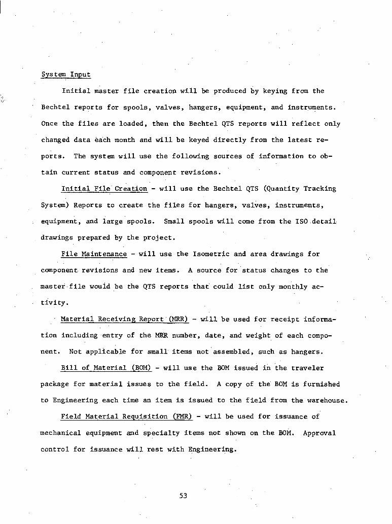
System Input . .
I n i t i a l master f i l e c rea t ion w i l l be produced by keying from the 4.
' Bechtel r epor t s f o r spools, va lves , hangers, equipment, and instruments.
Once the f i l e s a r e loaded, then the Bechtel QTS r e p o r t s w i l l r e f l e c t only
changed d a t a each month and w i l l be keyed d i r e c t l y from t h e l a t e s t re-
por t s . The system w i l l use the following sources of information t o ob-
t a i n current s t a t u s and component revis ions .
I n i t i a l F i l e ' Creation - w i l l use the Bechtel QTS (Quantity Tracking
system) Reports t o c r e a t e t h e f i l e s f o r hangers, va lves , instruments,
.. equipment, and l a r g e spools. Small spools w i l l come from t h e ISO.detai1.
drawings prepared by t h e p ro jec t .
F i l e Maintenance - w i l l use the Isometric and a r e a drawings f o r
component. revis ions and new i t e m s . A source f o r s t a t u s changes t o t h e
mas te f . f i l e would be the QTS r e p o r t s tha t ' could list only monthly ac-
t i v i ty . Mater ia l Receiving Report (MRR) - w i l l be used f o r r e c e i p t in£orma-
t i o n including .ent ry of the MRR number, da te , and weight of each compo-
nent . Not appl icable f o r small items not assembled, such a s hangers.
B i l l of Mater ia l (BO14) - w i l l u s e the BOM issued i n t h e t r a v e l e r
package f o r mate r i a l i s s u e s t o the f i e l d . A copy 'of the' BOM is furnished
t o Engineering each time an i t e m i s issued t o t h e f i e l d from the warehouse.
Field Mater ia l Requis i t ion (FMR) - w i l l be used f o r issuance of
mechanical equipment and s p e c i a l t y items not shown on t h e BOM. Approval
con t ro l f o r issuance w i l l rest wi th Engineering.
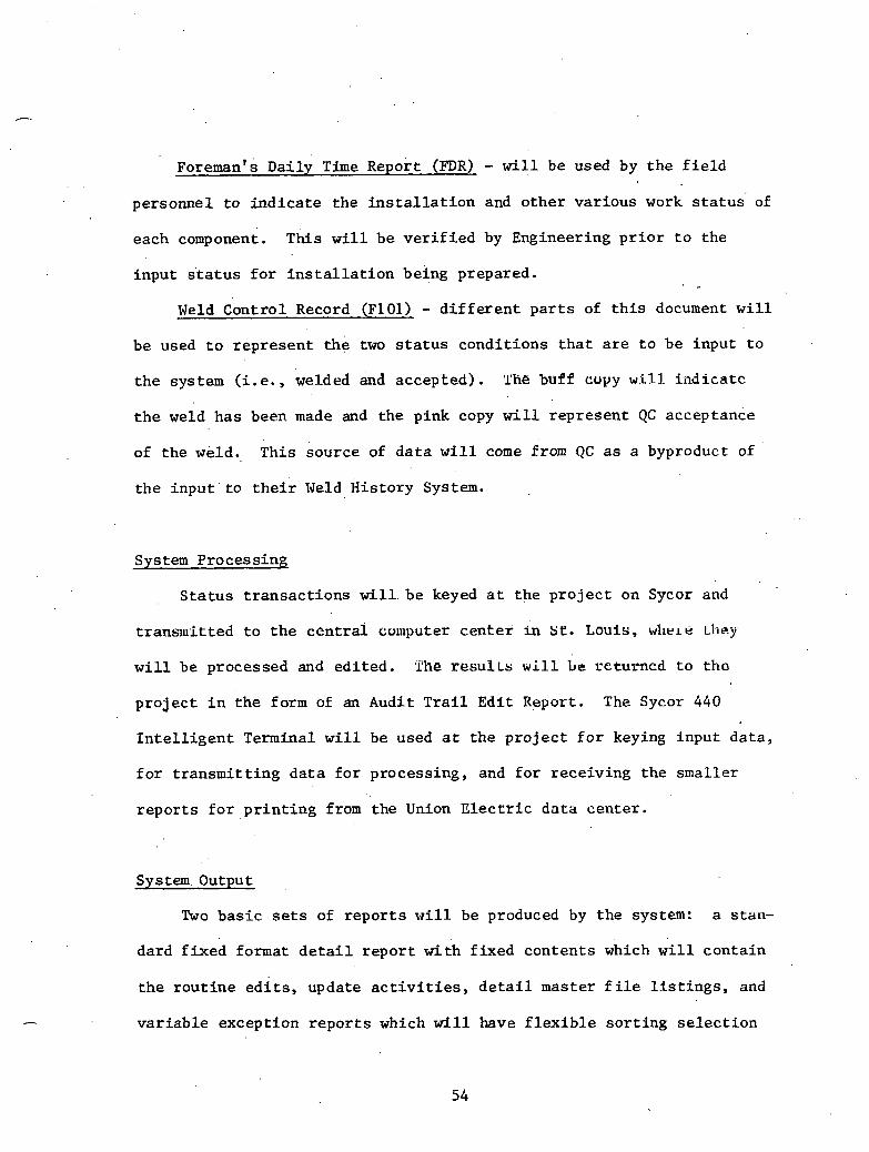
orem man's Daily Time ~ e ~ o r t (.FDR) - w i l l be used by the f i e l d
personnel t o i n d i c a t e the i n s t a l l a t i o n and o the r var ious work s t a t u s ' of
each component. This w i l l be v e r i f i e d by Engineering p r i o r t o the
input s t a t u s f o r i n s t a l l a t i o n being prepared.
Weld Contro l Record (F101) - d i f f e r e n t p a r t s of t h i s document w i l l
be used t o r ep resen t t h e two s t a t u s condi t ions t h a t a r e t o be input t o
t h e system (i.e., welded &d accepted). sl'he buff cuyy w:i,l.I. kndicatc
t h e weld has been made and the pink copy w i l l r ep resen t QC acceptance
of t h e weld. This source of d a t a w i l l come from QC a s a byproduct of
the i n p u t ' t o t h e i r Weld His tory System.
System Process ing
S t a t u s t r ansac t ions w i l l be keyed a t t h e p r o j e c t on Sycor and
t ransmit ted t o t h e c e n t r a l 'couputer cen te r in st. Louis, w l l e ~ e Ll.icy
w i l l be processed and ed i t ed . *the r e s u l ~ s w i l l L e rcturncd t o tho
p r o j e c t i n t h e form of an Audit T r a i l Edi t Report. The Sycor 440
I n t e l l i g e n t Terminal w i l l be used a t the p r o j e c t f o r keying input da ta ,
f o r t r ansmi t t ing d a t a f o r processing, and f o r rece iv ing the smaller
r e p o r t s f o r p r i n t i n g from the Union E l e c r r i c d a t a center .
System, Output
Two b a s i c sets of r e p o r t s w i l l be produced by the system: a s tan-
dard f i x e d format d e t a i l r e p o r t wi th f ixed contents which will conta in
t h e r o u t i n e e d i t s , update a c t i v i t i e s , d e t a i l master f i l e l i s t i n g s , and
v a r i a b l e exception r e p o r t s which w i l l have f l e x i b l e s o r t i n g s e l e c t i o n

c r i t e r i a . These w i l l b e t h e s p e c i a l r e q u e s t r e p o r t s t h a t a r e r equ i r ed
by t h e p r o j e c t when they need t o review c e r t a i n component i t ems .by
a rea , system, o r o t h e r s e l e c t i o n c r i t e r i a ,
Some of t h e p o s s i b l e s o r t sequences t h a t t h e r e p o r t s might u s e
a r e : a r e a code, component I D , system code, s t a r t -up number, MRR number,
received ' d a t e , ISO, va lve g e n e r i c mark number, and c l a s s / s e , rv i ce ' l i n e
number. Ce r t a in . combinations . of t h e s e s o r t sequences might be used
i n t h e r e p o r t s e l e c t i o n process .
The fol lowing a . b r i e f d e s c r i p t i o n of t h e r e p o r t s t h a t a r e
proposed f o r t h i s system.'
Spool and Rela ted Component S t a t u s - this r e p o r t w i l l l ist a l l
spoo l s on t h e d s t e r f i l e a long wi th t h e i r r e l a t e d components. The
purpose of t hese r e p o r t s is t o p rov ide component s t a t u s as. they a r e
r e l a t e d t o each o t h e r through a common weld.number.
Valve D e t a i l s - t h i s r e p o r t w i l l con ta in a l l va lves w i t h t h e i r
r e l a t e d s t a t u s . ~ n c l u d e d on t h i s r e p o r t w i l l be r e l a t e d d a t a , such as:
Generic Mark,number, MRR number, P.O. number,. weight , rece ived d a t e , , .
a r e a number, &d r e l a t e d - . spoo l sequence number. The purpose of t h i s
r e p o r t w i l l ' b e t o i d e n t i f y a l l va lves and t h e i r r e s p e c t i v e s t a t u s f o r
t r ack ing and monitor ing.
Hanger D e t a i l s - this. r e p o r t w i l l con ta in a l l hangers w i t h t h e i r
r e l a t e d s t a t u s . Included on t h i s r e p o r t w i l l b e r e l a t e d d a t a , such as
a r e a number, Q c l a s s , MRR number, ' and r e l a t e d spool sequence number.
The purpose df t h i s r e p o r t w i l l be t o i d e n t i f y a l l hangers and t h e i r
r e l a t e d s t a t u s f o r monitor ing and t r ack ing .

Equipment Log - this r e p o r t w i l l contain a l l mechanical equipment
w i t h r e l a t e d s t a t u s . Also included on t h i s r epor t w i l l be r e l a t e d data ,
such a s spec number, desc r ip t ion , MRR number,, weight, d a t e received, area
number, and r e l a t e d spool sequence number. The purpose of th. is r epor t
is t o d e f i n e and monitor a l l mechanical equipment components.
Instrument Index - this repor t w i l l l ist a l l ins t ruuent components
(only mechanical items a r e present ly considered) with t h e i r r e l a t e d
s t a t u s . Also included on t h i s r epor t a r e some other da ta , such a s
desc r ip t ion , P&ID number, spec number, a rea code, design class cud&, .*r
panel l rack number, IS0 number, Q c l a s s , and associa ted spool sequence . f -
number. The purpose of t h i s r e p o r t w i l l be t o i d e n t i f y a l l instruments
and t h e i r s t a t u s f o r t racking and monitoring.
EditIUpdate (Audit T r a i l ) - t h e r e w i l l be s e v e r a l of these r e p o r t s
produced, each f o r t h e s p e c i f i c master f 5 l e maintenance being performed.
The repor t w i l l provide a reference f o r ,a l l edit errors , , successful up-
d a t e s (changes and, addi t ions) , and d e l e t e s t o the master f il.es . Each
repor t w i l l show the before and a f t e r contents of each changed record.
A l l e d i t e r r o r s encountered w i l l be l i s t e d f o r each t ransact ion. Correc-
t ions w i l l be made on t h i s r epor t and returned t o Data Processing f o r .
re-entry. During t h e update cycle the re w i l l be c e r t a i n exception c r i - . .
t e r i a t h a t w i l l be monitored. These items, such as: i n s t a l l e d but not
received, a l ready received, or received aga ins t d i f f e renr a r e a nuu~bers,
w i l l be repor ted out separa te ly from t h e ed i t lupda te repor t s . This r epor t
w i l l be used by the Mechanical Engineering System Coordinator t o t r ack
down p o t e n t i a l problems, and w i l l provide an automated source f o r

referencing inva l id e n t r i e s or f o r var ious o ther problem condit ions.
Exception Summaries - these r e p o r t s w i l l show var ious da ta so r ted
i n se lec ted sequences depending on the type request from t h e user depart-
ment. The volume of output can be excessive; therefore , limits such a s
l i n e counts o r time w i l l be placed i n these programs t o b e t t e r c o n t r o l
t h i s output . -Examples of these type of r epor t s are : items on hold,
i t e m s - n o t received, items i n s t a l l e d , systems completed, remaining welds,
a l l components i n given area (s ) , a l l materials ava i l ab le , a l l m a t e r i a l s
ava i l ab le but not issued, a l l va lves by Generic Mark number, footage of
a given l i n e wi th in a system, p ipe s i z e t o t a l s f o r each s t a t u s by a r e a
and/or system, items not i n s t a l l e d p a s t s tar t -up, spools received
aga ins t d i f f e r e n t a rea number, sub-assembly (module) i t e m l i s t i n g s ,
and . i t e m s shown a s welded but no s t a t u s shown f o r received, i ssued,
and/or i n s t a l l e d .
2.3.2 ~ l e c t r i c a l I n s t a l l a t i o n System
The computerized E l e c t r i c a l I n s t a l l a t i o n system' w i l l maintain
dcoign and s , t i i ~ u s informarion on each of the following component types:
cab le and termination, raceway, equipment ( e l e c t r i c a l ) , and instruments
( e l e c t r i c a l ) . The four programs w i l l opera te independently i n t h e a r e a
of processing design and s t a t u s information, but w i l l be dependent on
each other f o r information.
Cable and Termination - the program w i l l be set up using the . .
Bechtel Power Corporation's EE-553 Program Computer Tape wi th s i t e
added information. Figure 2.1 shows the system information flow and

est imated q u a n t i t i e s t o be handled i n t h e system. Figure 2.2 in-
d i c a t e s t h e . i n t e r f a c e between t h e cable and raceway programs.
Raceway - t h e program w i l l be set up using t h e Bechtel Power
Corporat ion's EE554 Program Computer Tape wi th site added information.
Figure 2.3 shows the system information flow and estimated q u a n t i t i e s
t o be handled by t h e system.
Equipment - E l e c t r i c a l - t h e program w i l l be s e t up using Bechtel
Power corpora t ion ' s hard copy of t h e i r "Equipment indexi' f o r e l e c t r i c a l
equipment. The j o b s i t e program w i l l u t i l i z e the fol lowing information
from the Bechtel p r in tou t : equipment number, i t e m I D and desc r ip t ion ,
loca t ion , QC, separa t ion, s p e c i f i c a t i o n number, and connection drawing
number. I n add i t ion t o t h e above i tems, t h e j o b s i t e program w i l l a l s o
have the fol lowing inputs : present locat ion, s to rage requir'ements,
equipment s t a t u s , Quali ty Control inspector number and da te , and remarks.
The i n p u t of t h e j o b s i t e items w i l l be by means of "£eedbackU from t he
E l e c t r i c a l Engineering Department. Revisions t o t h e Bechtel information
w i l l be input once a month a t t h e s i te based on update information from
Bechtel. See Figure 2.4 f o r system information flaw.
Instruments - E l e c t r i c a l - t h e program w i l l be s e t up using a
Bechtel Power Corporation hard copy of t h e i r "Instrument Index" f o r
E l e c t r i c a l .Instrument ac t ion. The w i l l u t i l i z e the following
information from the Bechtel p r in tou t : instrument number, desc r ip t ion ,
QA, s epara t ion group, P&ID drawing number, s p e c i f i c a t i o n number, loca t ion ,
panel o r rack number, connection drawing number. I n add i t ion t o t h e above
items, the j o b s i t e program w i l l a l s o have t h e following .inputs: instrument

CALLAWAY CABLE AND TERMINATION PROGRAM SYSTEM INFORMATION FLOW
Each cable can have three (3).work orders: (1) Pull cable (2) Terminate one end
I (3) Terminate other end . -
F
.. - -- - - -- - - - .- - - . - FIGURE 2 . l
. S.& P. A/E
r * CABLE PROGRAM REPORTS
C
CABLE PULL CARD
r
U I
0 , . 4
CRAFT -WORK E? ORDERS CI
f v f'
When all raceways have been ELECTRIC installed he will issue request . COORDlNATOK to pull cable.
He checks equipment status, - then issues request to
terminate.
, BECHTEL A/ E

CALLAWAY INTERFACE BETWEEN CABLE AND RACEWAY PROGRAM SYSTEM INFORMATION FLOW
RACrnJAY
When raceways that contain a cable are ins ta l led , then request for cable to be pulled can be issued.
FIGURE 2 . 2 _. _ __ _. .

CALLAWAY RACEWAY PROGRAM SYSTEM INFORMATION FLOW
RACEWAY ,
REPORTS PROGRAM
> d
.RACEWAY INSTALL
.
Work assignment.
zi p:
v
AREA . - Creates card to ENGINEER 7 COORDINATOR I pass to AreaEng.
Creates request. Issues ins tallation record. t
One work assignment may have many raceways. ,
One raceway may have many work assignments. Program will sort all work assCgnments related to a raceway.

CALLAWAY .ELECTRICAL EQUIPMENT PROGRAM SYSTEM INFORMATION FLOW.
. .BASIC ENGINE RING INFO !L ELEC. EQUIPMENT ELEC .
PROGRAM ENG . . .
. .. . .. . . ; . . . '
2 . . > . . .,.:... . ... . ., REPORTS 2. storage requirement
3. equlprne~lL s t d l u s 4. Q.C. inspection no.
and date 5. remarks -'.
'T.
CALLAWAY ELECTRICAL INSTRUMENT PROGRAM 5,
SYSTEM INFORMATION FLOW
-:::;I, PROGRAM
Inputs: 1. instrument status 2. Q.C. inspector no
REPORTS and date 3 . remarks
FIGURE 2 . 4

s t a t u s , Quali ty Control inspector nuniber and da te , and remarks. The
input f o r the j o b s i t e added items w i l l be by means of "feedback" from
the E l e c t r i c a l Engineering Department. Revisions t o the Bechtel informa-
t i o n w i l l be input once a month a t t h e s i t e based on update information
from Bechtel. See Figure 2.4 f o r system information flow.
2.4 Daniel Fermi /I2
.The Component Control System w i l l ' provide domponent information
t o a i d const ruct ion i n s t a l l a t i o n and s tar t -up of the power f a c i l i t y .
Daniel I n t e r n a t i o n a l w i l l employ s e v e r a l automated systems a t Fermi I1
f o r De t ro i t Edison. The planned p ro jec t Construction Control systems
w i l l be a s follows:
(1) Component Control System
( 2 ) Document Indexing and Re t r i eva l
( 3 ) Mater ia l S ta tus Control
(4) Engineering Documents Regis ter
( 5 ) Scheduling - PROJACS
( 6 ) F i e l d generated documents
(7) Payro l l . .
The following i s a d iscuss ion of the component Control System t h a t
w i 1 . l be emplbyed a t Fermi 11 a s i t r e l a t e s t o Construction Control.
The bas ic informatfon re la t ing ' t o a repor tab le component w i l l be
s to red i n the computer i n an organized format s o t h a t i t can be re t r i eved
I and sor ted i n a v a r i e t y of ways. Figure 2.5 s h m s t h e genera l layout
of t h e Component Control System. The component number i s the b a s i c

.COMPONENT. CONTROL SYSTEM BASIC SCOPE
SPECIFIC DATA APPLICABLE .
TO ONE MODULE
COMMOii ' DATA TO ALL MODULES
FIGURE 2.5
c4 W
B .z E-c Z W z 0
! 2 . o U
LARGE BORE SPOOLS
SMALL BORE SPOOLS
VALVES
HANGERS/SUPPORTS - - -
INSTRUMENTATION %-
i:.
WELDS .(*
MECHANICAL EQUIPMENT
I
i
DUCTWORK x,: -
CABLE TRAYS
CABLES
CABLE TRAY HANGERS
A
ELECTRICAL EQUIPMENT
CONDU ITS
-l

I i d e n t i f i e r f o r a l l i t e m s . . here i s a block. of d a t i . which is maintaiaed
t h a t is common t o a l l components. The components a r e then broken down
i n t o modules which c a t e r t o the p a r t i c u l a r needs of var ious types of
components. The' volume of . information t o -be handled by. t h i s system is
immense. Figure 2.6 i l l u s t r a t e s t h e magnitude o f . d a t a - t o be con t ro l l ed
by t h e Component Control System. Two sub-systems can be a t tached t o t h e
Component Control System if des i red . These sub-systems a r e the Welder
Performance System and . the Welder. Qua l i f i ca t ion System; and they can
funct ion j o i n t l y with the "Welds" module.
Re t r i eva l of. information from t h e Component Control Syqtcm may
be performed by subcontrac tors , Est imating, Warehousing, QC/Engineering,.
Cost Control, Scheduling, Start-Up groups,. and t h e Operations group.
The inf'ormation must be updated by t h e same groups wi th t h e exception
of subcontractors . The key update group w i l l . b e Estimating, s i n c e
they w i l l be ' responsib le f o r i n i t i a t i n g each component ent ry . Input
supplied by t h i s group inc ludes .p lan t system i d e n t i f i c a t i o n , permanent
p lan t loca t ion , s a f e t y c l a s s i f i c a t i o n s , design document references , ,and
component l e v e l data. The d e l e t i o n o r r ev i s ion of a component w i l l
be con t ro l l ed by t h i s group. able .2 .3 l ists t h e d a t a .elements i n the
Component Control System which are common t o ' a l l modu.les. Figure 2 .7
is a sample input sheet f o r ' t he da ta .
Software on Danie l ' s c e n t r a l computer f a c i l i t y w i l l support da ta
communications with t h e j o b s i t e , high volume Batch processing, remote
job ent ry , and general ized inquiry / repor t preparat ion. The fol lowing
types, of s tandard repor t s w i l l be generated:

Large Bore Spools
Small Bore Spoo l s
Valves
Hangers /Supports
In s t rumen ta t i on : F a b r i c a t e d r a c k s Rack mounted L o c a l l y mounted A i r ope ra t ed v a l v e s Tubing 318" and under Tubing 112" Supports
Mechanical ~ q u i p m e n t
Ductwork
Cable Trays
Cables
Cable Tray Hangers
E l e c t r i c a l Equipment
Conduits
TO BE COMPLETED
TOTAL PLANT
23 0 3,000 2,000 1,000
100,000 L.F. 110,000 L.F.
6,000
35,920 L.F.
36,300 L.F.
3,730,000 L.F.
4,500
490 (Major)
489,000 L.F.
FIGURE 2.6 : ESTIMATED ITUMBER OF COMPONENTS FOR EVERY MODULE

TABLE 2.3
DATA ELEMENTS
Unique I d e n t i f i c a t i o n PIS Number (Plant Info. System) Vendor I D Building /Area Elevation Drawing Number Scheduled to Receive Received Date QC Hold I n s t a l l e d o r Erected Completion Sign Off Cost Code S t a r t Up Number IS0 Number Safety Class (ASME) Mater ia l B i l l of Material Number Vendor. P a r t -Number Warehouse Locat ion Date Issued Field Requisi t ion Number Hydro Test Code Check Documentation Compl.
SUBCONTRACTOR RELATED DATA ELEMENTS
24. Engineering Hold 25. Contractor Cost Code 26. Contractor Schedule No. 27. Fabric. Work Package 28. Erection Work Package 29. ' Estimated bunhours 30. Actual Manhours .


o S ta tus of a l l components
o Summary types of r epor t s
o Building/elevation s o r t s f o r planning
o Start-Up Number s o r t
o Welder Performance Report
High l e v e l compilers such a s COBOL, Data Base Management Systems,
conrmunications, and remote job en t ry software a r e c u r r e n t l y a v a i l a b l e
on t h e c e n t r a l computer a t Greenvil le , South Carolina. Remote job
en t ry software w i l l permit t h e j o b s i t e t o submit jobs t o the c e n t r a l
computer, have t h e c e n t r a l computer execute the reques t based on p r i o r i t y
and resource a v a i l a b i l i t y , and t ransmit t h e r e s u l t s back t o t h e p r o j e c t
si te.
The o v e r a l l p ro jec t Construct ion Control system is i l l u s t r a t e d
i n Figure 2.8. This shows a n o u t l i n e of the b a s i c scope of t h e o v e r a l l
system and the r e l a t ionsh ips which w i l l be implemented i n computerized
format. The broken l i n e s represent manual flow and dependency of in-
formation between individual sub-system. Ultimately t h e r e l a t i o n s h i p
between the Component Control System and t h e Document Indexing and Re-
: t r i e v a l System.wil1 have g rea t importance t o t h e s tar t -up and opera t ion
of the p lan t . one contains the engineering information f o r every com-
ponent and the o the r conta ins a l l a v a i l a b l e documentation f o r every
component. The key i's the component number, but s e v e r a l o the r s w i l l
be used f o r searching. For example, the following d a t a w i l l be i n both
.systems: system number, loca t ion (building, e l eva t ion) , s ta r t -up
number, type of component, drawing number, e t c . One of the most important
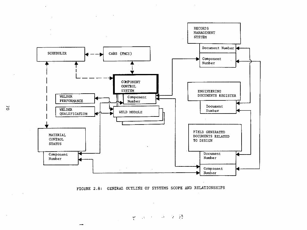
RECORDS MANAGErnNT SY STEl4
I I Klq - - j y l D o c u m e n t N u m b e r 4
FIGURE 2.8: GENERAL OVTLINE OF SYSTEMS SCOPE AND RELATIONSHIPS
C o m p o n e n t Nunb e r
MATERIAL CONTROL STATUS
. -
, . 'C' . , . - - a,.? . 1.
F I E L D GENERATED DOCUMENTS RELATED TO DESIGN
4
N u m b e r t N u m b e r
- C o m p o n e n t 4
\ J
I I t
I L----.,
CC+IPONENT
D o c u m e n t I WELDER N u m b e r
I QUALIFICATION *
I
I CONTROL SYSTEM
WELDER ENG I Y E ERING DOCUL'IENTS REGISTER I PERFORMANCE

b e n e f i t s of the r e l a t i o n s h i p between these two sub-systems w i l l be
t o determine t h a t a l l req&red documentation f o r every.component
was generated and i s avai lable .
2.5 Nuclear Power Services P.M.P.
During the i n i t i a l construction phase of Fermi 11, Nuclear
Power Services, Inc. had implemented a Piping Management Program
t o handle q u a n t i t i e s , c o s t s , and procurement functions. The program
was discontinued with the shutdown of const ruct ion i n 1974. Daniel
In te rna t iona l was se lec ted a s Construction Manager t o r e s t a r t the
const ruct ion of F e d I1 i n l a t e 1976, and has u t i l i z e d information
i n t h e Piping Management Program t o help' e s t a b l i s h t h e i n s t a l l e d
por t ion of the p lan t .
This program cons i s t s of sub-programs f o r spools , hangers, valves, i
and some miscellaneous i t e m s . Under t h i s system, d a t a prepara t ion
and take-off w a s prepared by NPS personnel i n N e w York. The repor t
cycle was s e t up on a one-month b a s i s with t h e s h o r t e s t t u r n around
cycle of 7 t o 10 days (cycle t i m e includes sending information-processing
i n New York and receiving p r i n t o u t s a t t h e p r o j e c t s i t e ) .
The information was entered i n t o the program by four input card .
, types. Input card 'type 1: T i t l e card f o r pipPng drawings.
3: T i t l e card f o r hanger drawings. .
5: Pipe spools, va lves , miscellaneous, hangers, and information.
7 : Pipe spools, valves, miscellaneous, hangers, . .
.. and. information,. . .

The program.maintained del ivery information, vendor s t a t u s , i n s t a l l a t i o n
s t a t u s , bui ld ing zone, b a s i s f o r required del ivery , and d e s c r i p t i v e in-
formation f o r the p ipe spools, valves, and hangers. Welds were a l s o
included and. r'ef erenced back t o isometric drawings.
2.6 GPU P r o j e c t Control System
The GPU P r o j e c t Control System c o n s i s t s of f i v e separa te computer
programs. The f i v e programs are : Accounting, Estimating and Cost Re-
por t ing , Expenditure Forecast ing, scheduling, and Mater ia l Control. f.
A l l f i v e programs a r e based on t h e work package i d e n t i f i c a t i o n numbers
and purchase order numbers, which provide a coding and s o r t i n g mechanism
f o r data manipulation. A l l repor ts , . were desiglled t o s a t i s f y a three-
t i e r e d hierarchy of end user: ..
(1 ) CorporateIInteragency - one page func t iona l r epor t combining
numerous work packages i n t o e igh t (8) func t iona l groupings f o r manage-
ment overview. Also, a one page overview repor t of the same information
by prime Federal Power Commission (FPC) account c l a s s i f i c a t i o n .
(2) Pro jec t Management - a t h r e e o r four page summary l e v e l r epor t
by work package f o r exception ana lys i s .
(3) ~ i e l d l ~ o r k i n g l e v e l - d e t a i l e d r e p o r t s by purchase order,
d o l l a r commitments, FPC subaccounts, e t c . , sor ted by work package.
The da ta i s input a t t h e const ruct ion s i te and transmitted v i a s i te
terminals t o the c e n t r a l computer complex' f o r processing. The edi ted
l is t is automatical ly t ransmit ted back t o the s i t e terminals for e r r o r
cor rec t ion and review. Low volume output r e p o r t s a r e p r in ted a t t h e

const ruct ion s i t e , while d e t a i l e d high. volume r e p o r t s a r e p r in ted on
high speed p r i n t i n g equipment i n d i s t r i c t of f i c e s .
Accounting Module
The accounting module records a l l of t h e commitments and expenditures
f o r each p ro jec t . Each commitment and expenditure is coded by purchase
order number, work package number, and FPC account number.
Estimating and Cost Reporting Module
This module compares the cu r ren t month's es t imate wi th t h e p r i o r
month's es t imate and the base es t imate f o r t h e job. The cur ren t es,timate
inc ludes a c t u a l t o d a t e expenditures and commitments a s w e l l a s adjus t - .:
ments authorized by t h e p r o j e c t c o s t engineer. Some of t h e standard
monthly r e p o r t s a re : a summary by e i g h t funct ion groups, a summary by
FPC Prime Accounts, a Package Analysis (summary l e v e l ) , a D e t a i l Package
Analysis by FPC subaccounts, a commitment ledger , and Directory of autho-
r i z e d . account and packages.
Expenditure Forecast ing Module
The module permits the end-user t o f o r e c a s t t h e an t i c ipa ted f u t u r e
expenditures by work package. The program permits the use r t o a s s ign a
s tandard f o r e c a s t "profi le" of expenditure t o each work package o r t o
input a hand-tailored expenditure p r o f i l e .
Schedule Module
GPU only pu t s "once through" work i n t h e schedule network. This
inc ludes only d i r e c t labor wi th immediate crew support t h a t is planned
wi th in a t y p i r a l es t imat ing crew make-up. It does not include i n d i r e c t
labor , overhead, and support labor . The module u t i l i z e s c r i t i c a l pa th
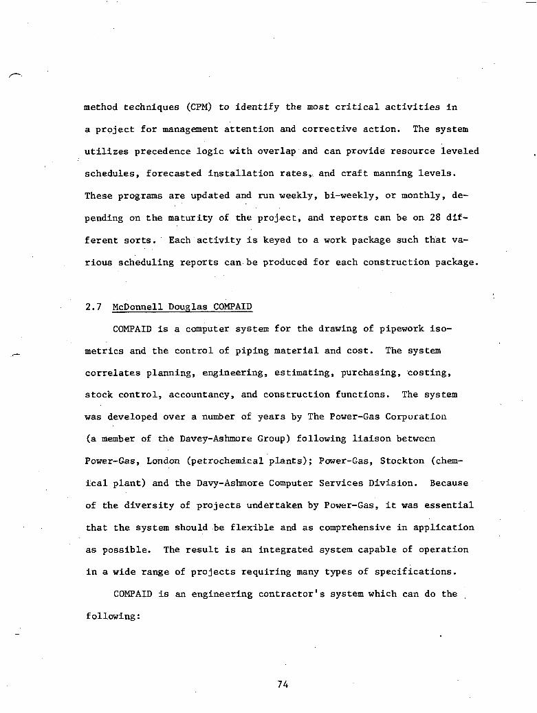
method techniques (CPM) to i den t i fy the most c r i t i c a l a c t i v i t i e s i n
a pro jec t f o r management a t t en t i on and correct ive action. The system
u t i l i z e s precedence log ic with overlap and can provide resource leveled
schedules, forecasted i n s t a l l a t i o n r a t e s , and c r a f t manning leve l s .
These programs a r e updated and run weekly, bi-weekly, o r monthly, de-
pending on t h e maturi ty of the p ro jec t , and repor ts can be on 28 d i f -
f e r e n t s o r t s . ' Each 'ac t iv i ty is keyed t o a work package such t ha t va-
r ious scheduling repor ts can.be produced f o r each construction package.
2.7 McDonnell Douglas COMPAID
COMPAID is a computer system f o r the drawing of pipework iso-
metrics and t he con t ro l of piping mate r ia l and cost . The system
co r r e l a t e s planning, engineering, est imating, purchasing, costing,
s tock control , accountancy, and construction functions. The system
was developed over a number of years by The Power-Gas Corporation
(a member of the Davey-Ashmore Group) following l i a i s o n between
Power-Gas, London (petrochemical p lants) ; Power-Gas, Stockton (chem-
k a l p lan t ) and the Davy-Ashore Computer Services Division. Because
of the d ive r s i t y of p ro jec t s undertaken by Power-Gas, it was e s sen t i a l
t ha t t he system should be f l e x i b l e and a s comprehensive i n appl icat ion
a s possible. The r e s u l t is an integrated system capable of operation
i n a wide range of p ro jec t s requiring many types of spec i f i ca t ions .
COMPAID is an engineering con t rac tor ' s system which can do the .
following :
o Draw piping i sometr ics
o Produce B i l l s of Mater ia ls '
o Prepare order documents
o Do prel iminary mate r i a l take-of f s I o Produce varfous con t ro l r e p o r t s f o r piping mqte r i a l s
o Estimate' labor and mate r i a l f o r p ip ing p r o j e c t s
o Compare a c t u a l labor and m a t e r i a l c o s t s wi th p ro jec t ions
The system is ava i l ab le f o r l e a s e through McDonnell Douglas Automation
Company. They provide t h e fol lowing :
(1) F u l l u s e r documentation of the system covering: systems,
programs, operat ing procedures, piping component numbering system, and
genera l user manuals together wi th f u l l program l i s t i n g s and flow char ts .
(2) .Implementation and t e s t i n g of user machine.
(3) Training f o r user s t a f f . , COMPAII) i s a v a i l a b l e on IBM, Control Data, and Univac computers.
The isometric drawings can b e produced o f f - l i n e bu t , i n a multi-
programming environment, the p l o t t i n g can be done wi th a sepa ra te program . .
using a tape u n i t and about 2K (1CL.1900 S e r i e s ) of core. The system i s
cons.tructed on the "building block" p r i n c i p l e which means t h a t i t can
be used f o r m a t e r i a l take-offs only o r f o r i sometr ic drawings p l u s
m a t e r i a l take-off. Addit ionally, m a t e r i a l c o s t , f a b r i c a t i o n , and erec-
t i o n c o s t can be included a s can schedule requirements and var ious forms
of ma te r i a l and s tock contro l .

Inputs
Spec i f i ca t ions : When piping s p e c i f i c a t i o n s have been w r i t t e n
i n the standard manner by t h e engineer, t h e b a s i c code f o r the type
of component s p e c i f i e d i s se lec ted from t h e code .d i rec to ry and t h e
s i z e r a n g e . f o r t h a t . type of p ipe entered. I f t h e r e is more than one
type of p i p e i n t h e b a s i c speci f , ica t ion he e n t e r s a l l t h e bas ic codes
f o r these wi th t h e s i z e ranges. He then does t h e same f o r f langes ,
f i t t i n g s , bends, bo l t ing , .and gaskets. The computer then. generates
t h e code numbers f o r a l l t h e items t h a t could be covered by t h a t
s p e c i f i c a t i o n and pu t s these i n t o i t s s t o r e .
Prel iminary Mater ia l Take-Offs: A prel iminary mate r i a l take-off
can be made from an engineering flow shee t o r layout . The take-off man
w r i t e s do- f o r each l i n e the amount of pipe, e t c . and t h e computer w i l l
t o t a l a l l l ike m a t e r i a l f o r ordering. A s t h e job progresses f u r t h e r ,
more accura te m a t e r i a l take-offs can be made and input t o the machine,
and the computer w i l l produce a repor t showing the laresr: requlremeuLs,
t h e previous requirements and t h e balance.
Isometric Drawing and Mater ia l L i s t : Working from a model o r
genera l arrangement drawing the draftsman f i r s t e n t e r s the parameters
of the ' l i n e and, then,. s t a r t i n g from one end, works along the pipe from
one change of d i r e c t i o n t o t h e next, ind ica t ing the component required.
Care. has been t'aken t o simplify d a t a preparat ion. A l l input docu-
ments a r e c a r e f u l l y val idated before acceptance by t h e machine, and
incor rec t e n t r i e s a r e l i s t e d and returned t o t h e user f o r immediate
act ion.
Operation
Order Control: On request the computer w i l l examine t h e l a t e s t
estimated requirements, take i n t o considera t ion the quant i ty of f r e e
s tock i n s t o r e s , and produce add i t iona l o rders were necessary. The 1
required del ivery dates a r e included. i Progress Control: On request , a r epor t i s produced which i n d i c a t e s
the q u a n t i t i e s of m a t e r i a l on order .but not y e t de l ivered, with required
and expected dates .
.. - . Production Drawing and Information: One form of mate r i a l take-off
includes miniinum d i r e c t i o n a l d e t a i l s which enable isometric drawings t o
be produced. The isometric includes a f u l l material! l i s t divided i n t o
shop and s i t e items, f u l l l i n e parameters, and any s p e c i a l notes t h a t I
apply genera l ly t o t h e drawing. The computer compares t h e mate r i a l
required t o produce the i sometr ics with t h e mate r i a l de l ivered t o the .. .
f a b r i c a t o r axid produces (a) a list of t h e isometrics ' which can be com-
p le ted , (b) a mate r i a l l ist f o r the s a i d i sometr ics , ( c ) a l ist of the
outstanding l i n e s and (d) a mate r i a l list f o r the ou'tstanding l i n e s
wi th expected del ivery da tes t o enable t h e f a b r i c a t o r t o p lan h i s , f o r -
ward loading.
Stock Control: On request , the computer w i l l produce r e q u i s i t i o n s 1
on s t o r e s t o d e l i v e r mate r i a l t o spec i f i ed des t ina t ions . This m a t e r i a l
may have entered s t o r e s temporarily u n t i l t h e opening of a s i te , or ''it
may be s tock a s returned from previous contrac ts . The computer keeps
a paper record of the s t o r e s s tock posi t ion . This enables s t o r e s t o
insure t h a t s tock a l loca ted t o a contrac t is not issued except f o r t h a t
contrac t .
Data F i l e s : The computer keeps a mate r i a l p r i c e l i b r a r y , a sched-
u l e of f a b r i c a t i o n and e rec t ion r a t e s , and a s p e c i f i c a t i o n f i l e f o r
i ts own use.
Fabr ica t ion and Erection Cost: Fabr ica t ion and e r e c t i o n c o s t a r e
produced automat ica l ly from the i sometr ic input da ta and t h e contrac tor
rates. This inc ludes paint ing and insu la t ion cos t . Feedback from s i t e
on the completed operat ions enables s t r i c t c o n t r o l of construction.
output
o pr ice-descr ip t ion l i b r a r y
o Spec i f i ca t ions
o Material take-off d e t a i l s with summary
o Valve schedule
o .Order documents
o Comparison of a l l o c a t i o n and requirements
o Current p o s i t i o n of materfa l on order
o Purchase Order expedit ing repor t
.Q Stores d ispatchladvice riotes
o Isometr ic drawing and mate r i a l l ist
o Line f a b r i c a t i o n schedule
o Stock p o s i t i o n
o Line schedule
o Mater ia l t o t a l s f o r ba tch of i sometr ics
o L i s t of missing p r i c e s
o Fabr ica t ion/erect ion schedules
o Estimated f a b r i c a t i o n and e rec t ion work content

o Comparison of estimated and measured work content
o Analysis of measured f a b r i c a t i o n and e rec t ion work content
o Insu la t ion q u a n t i t i e s and cos t r epor t s
, o Pa in t q u a n t i t i e s r epor t
Summary
The Rust Engineering Company, Birmingham, Alabama, has made severa l
trial runs and i.s now depending f u l l y on the COMPAID system i n a paper
m i l l i n s t a l l a t i o n using t h e mate r i a l con t ro l without t h e d r a f t i n g
service . To d a t e they a r e very s a t i s f i e d with t h e system performance.
The quant i ty take-off people f i n d the input shee t s easy t o use a f t e r . .
, a s h o r t period of use, It is a d e f i n i t e improvement over the manual
s tock cards system used f o r many years t o a l l o c a t e the mate r i a l .
Requisi t ions a r e s t i l l rewr i t t en before t ransmit t ing t o Purchasing be-
cause t h e computer form is not accepted by. t h e Purchasing Department.
The const ruct ion supervision use t h e B i l l of Materials p r in ted by the
computer arid l i k e the . summaries ava i l ab le .
2.8 Northern S t a t e s Power ITS
Northern S t a t e s Power has developed a system' t o account f o r t h e
purchase, de l ivery , . i n s t a l l a t i o n , and t e s t i n g of a l l i t e m s contained
i n the computer f i l e s . There a r e eleven (11) f i l e s maintained i n ' t he
computer.
(1) The Master Punch L i s t f i l e c o n s i s t s of a l l known problems,
discrepancies, and punch list items with emphasis oh systems nearing
pre-op tes t ing . . I t t r acks only unresolved items and can s o r t r e p o r t s
by r e s p o n s i b i l i t y , by system, by pre-op d e f i n i t i o n , by document,
and. by p r i o r i t y code and/or da te .
(2) The Summary Black & Veatch Purchase Order f i l e l is ts a l l
purchase o rde r s i ssued by Black & Veatch f o r u n i t s 1 and 2. Reports
can be i ssued based on s t a t u s of equipment no t received a t s i t e ,
s t a t u s of a l l equipment purchased, equipment s t a t u s by schedule a c t i v i t y
number, equipment s t a t u s f o r con t rac to r s , and s t a t u s of equipment t o be
de l ive red of f - s i t e .
(3) The Valve F i l e s l i s t ind iv idua l ly a l l va lves by tag number.
Reports can be issued on s t a t u s by tag number, s t a t u s by purchase order '4
number, s t a t u s of undelivered valves , and s t a t u s of motor-operated and
c o n t r o l valves. *
( 4 ) The Accessory ~ ~ u i ~ m e n t / ~ n s t r u m k t f i l e s list a l l instruments
by tag number. The issued repor t s can s o r t on s t a t u s by purchase order
number, undelivered s t a t u s by purchase order number, staLus Ly con-
t r a c t o r , l o c a l instrument s t a t u s , and s t a t u s by accessory equipment
code.
( 5 ) Component Equipment f i l e s l i s t equipment i n d e t a i l f o r s t a t u s
information. They i s s u e r e p o r t s t h a t can s o r t by s t a t u s . b y purchase
o rde r number, undelivered s t a t u s by purchase order number, s t a t u s f o r
con t rac to r s , and l i s t i n g of equipment by system.
( 6 ) The Schematic Drawing f i l e s l ist schematic drawings i n the
d e t a i l r equ i red f o r turnover of e l e c t r i c a l systems from the con t rac to r
t o t h e QC engineer . The r e p o r t checks e l e c t r i c a l systems c h e c k l i s t
.- s t a t u s .
(7) The Specia l Data f i l e s combine d a t a from the Valve, Acces-
sory Equipment, and Component Equipment f i l e s . Combining d a t a from
mul t ip le f i l e s o f f e r s an expanded range i n repor t ing s t a t u s . These
f i l e s i s s u e exception r e p o r t s t h a t can s o r t on s t a t u s by s tar t -up pre-
op d e f i n i t i o n ~ ; component and accessory equipment i n s t a l l a t i o n , check-
out s t a t u s ; component and accessory equipment i n s t a l l a t i o n , checkout
s t a t u s by area; and s t a t u s by schematie drawing number.
(8) Sta tus of p ipe and hanger pieces furnished by Black & Veatch.
(9) The Door S ta tus Report lists t h e s t a t u s of a l l doors fur-
nished by Black & Veatch.
(10) The S t r u c t u r a l S t e e l f i l e is used t o maintain de l ive ry s t a t u s
of a l l pieces. Its r e p o r t s show s t a t u s by a r e a number, s t a t u s by shop
number. (vendor's shop con t ro l number), and s t a t u s by load number
(vendor's b i l l of lading number).
(11) Current s t a t u s of a l l computer f i l e s .
2.9 Bechtel QTS (Quanti ty Tracking System)
QTS is a system developed by the Bechtel Corporation t o keep t r a c k
of mater ia l . It was o r i g i n a l l y designed t o supplant independent sys teks . ,
used by each of the t h r e e major power p lan t const ruct ion d iv i s ions with-
i n Bechtel (San Francisco, Washington area , and Los Angeles). These
th ree formerly independent e n t i t i e s were combined i n t o the Thermo-
Nuclear Power Organization. It then became necessary t o s tandardize
the information exchange between these d iv i s ions . Preliminary designs
ca l l ed f o r a n ' a l l - i n c l u s i v e system. Implementation proved so d i f f i c u l t

t h a t in te r im systems were develpped t o be used p r i o r t o implementation
of the o v e r a l l system.
The b a s i c t h r u s t of t h e QTS system is t o t r ack items i n order t o
determine through which p a r t of t h e procurement cycle they have pro-
ceeded. Only items .designated a s unique we're tracked i n t h i s system.
The method of t racking q u a n t i t i e s is based on a p r i n c i p l e known a s the
increas ing accuracy method. Each quant i ty has a t h e o r e t i c a l f i n a l
number. A s t h e p r o j e c t matures from design through const ruct ion, the
numbers begin t o get c lose r and c lose r t o t h i s n e t quant i ty (which is '
of course modified as changes . occur) . Tracking q u a n t i t i e s accura te ly
allowed the development'of use fu l cash flow predic t ions .
The b a s i c i n t e r a c t i o n of QTS i n the procurement - cyc le can b e s t
be shown by Figure 2.9. ' The bas ic card produced f o r t h e QTS system . .
w a s a f ive-part card ind ica t ing r e c e i p t , i s s u e , i n s t a l l a t i o n , and a
f i l e copy.
The use of QTS allowed an evaluat ion of vendors. Sor ts on vendor
number w e r e poss ib le . With the. accumulation of de l ive ry da ta deter -
mina.tions could be made a s t o the r e l a t i v e r e l i a b i l i t y of d i f f e r e n t
vendors. I n evaluat ing l a t e d e l i v e r i e s , however, resource c o n s t r a i n t s
w e r e considered. A s ati example, i f work is proceeding i n a p a r t i c u l a r
a r e a and some component has a r r ived af t e r . work had moved t o another
a rea , i t may not delay the job i f t h e de l ive ry was one or t e n days
l a t e , provided resumption of work was constrained t o begin more than
t e n days l a t e r .

ENGINEERING SUPERVISORY
. .
FIGURE 2.9: INTERACTION OF QTS I N THE PROCUREMENT CYCLE
2.10 ~ e o r ~ i a Power Punch L i s t . .
The.Punch L i s t Program h a s been reviewed i n d e t a i l i n Appendix B.
I n terms o f f i e l d c o n s t r u c t i o n c o n t r o l , 1 4 d i f f e r e n t complet ion p o i n t s
can b e m ~ n i t o r e d . They a r e I n B u i l d i n g , I n s t a l l e d , NonDestruct ive T e s t i n g ,

Hydro T e s t , Construction Acceptance Test, Temporary ~ u r n o v k ,
Permanent Turnover, . . System Turnover, Operational, Painted, Welded,
1ksulat ed, and P ins Pulled. ' or f ut ther detai ls the reader i s ref erred
to page 52 of Appendix R.

CHAPTER 111
Problems with Exis t ing Systems
The g r e a t number of simultaneous a c t i v i t i e s t h a t take p lace on
a nuclear power p lan t s i te requires a we l l coordinated master plan.
Area Engineers i n charge. of the var ious work a reas must be organized,
knowledgeable of schedule. requirements, and have t h e managerial s k i l l s
t o e f f i c i e n t l y complete the work a t hand.
To enable the f i r s t l e v e l management t o complete t h e work, ' c e r t a i n
.items of information a r e needed t o maintain a smooth, o rde r ly flow of ' .
const ruct ion a c t i v i t y . These items of course vary from d i s c i p l i n e t o
d i s c i p l i n e and work face t o work face . Basica l ly , however, ma te r i a l ,
manpower, money, and.equipment a r e necessary f o r t h e accomplishment of
a work task . Direc t ion on how, when, and where i s supplied through
management based .on the i tems of information at .hand.
I n terms of materials, the f i r s t l e v e l manager must be aware of
any design changes being made or a l ready made t o the work being per-
formed. .He must make an irrmiediate decis ion whether t o s top work and
. 'complete .other work o r go ahead with Quali ty Assurance's approval of
the work a t hand. This manager's primary concern is not with c o s t s , but
h i s immediate supervisor i s very concerned with cos t s . A t t h i s l e v e l
code numbers a r e transformed i n t o names and desc r ip t ions . Regulations
a r e verbal ized r a t h e r than quoted by number. The manager must a l s o be
informed of shortages of ma!terials on hand. I f he is aware of any

material inadequacies, he can make more ef f ic ient use of the manpower
on hand.
Most of the problems inherent in the systems discussed i n th is
report have already been discussed i n the section on material tracking
systems and the reader i s invited to review that material.

REFERENCES
(1) Bonny, J. B. and Joseph P. F r e i n , E d i t o r s , Handbook of Cons t ruc t ion Management and Organizat ion, - New York: Van Nostrand Reinhold Company, 1973, page 6 .
(2) Budwani, Ramesh, " ~ u c l e a r P l a n t .Lead Time, Costs , Labor, and Mate r i a l Takeoffs," Power Engineering, A p r i l 1974..
(3 ) Budwani, Ramesh, "Nuclear Power Plants ," ,Power Engineering, June. 1975.
(4) Ni l sen , Arthur L., "SACCS: Schedule and Cost Control System," AACE B u l l e t i n , February 1975.
(5) Kanga, B. K., "SNWPS: An Experience i n . . ." C i v i l Engineering, J u l y 1977.

ADDENDUM A , '
BULK PIPE MATERIAL INPUT /OUTPUT DATA

RATIONALE -FOR INPUT/OUTPUT INFO. SHEETS
Answer t h e fo l lowing ques t ions based on in£ ormation needed
o r genera ted f o r : t h e fo l lowing a r e a s :
1. Design r e l a t e d
2. M a t e r i a l c h a r a c t e r i s t i c s
3 . Scheduling
4. Stock c o n t r o l
5. Sa fe ty r e l a t e d
6. I n s p e c t i o n r e l a t e d . .
7. ,Work completion e n t r i e s
P. 8. P r o d u c t i v i t y r e l a t e d (manhours o r equipment)
* 9. Cost
10. worker ' q u a l i f i c a t i o n s
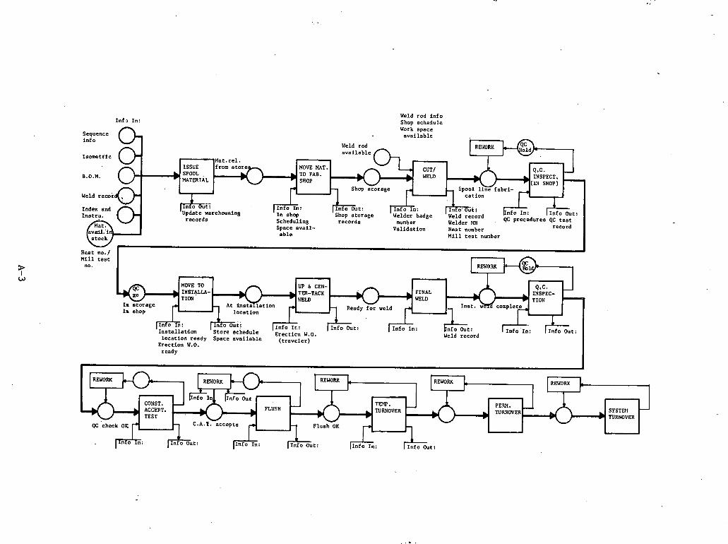
Inf J In: n
Weld rod info Shop schedule Work soace
available
HOVE HAT.
records Schedulins records Welder Mi Space avail- Validation Heat number able M i l l t e s t nunber
Aeat no./ I n i l 1 t e s t
no. I
Weld record
ready I 1
PEW. TUWOVER SYSTnI -
'cieck fi 4 C.A.T. accepts w

Input /Output Sheet
MECHANICAL (BULK MATERIAL) P i p e
A c t i v i t y
~ s i u e spoo l m a t e r i a l
(1.1
In£ orniat i on I n
sequence informat ion (Schedule)
Isomerr i c s drawings
B.O.M.
Weld record
In£ ormation Out
Update, warehouse inventory
Foreman of i s su ,e
Account number
Date of i s s u e
Index and Ins t rumenta t ion
Requirements
ate rial a v a i l a b i l i t y
Q.A. Process s h e e t
Move m a t e r i a l t o Work spac.e a v a i l a b i l i t y Shop s t o r a g e r eco rds £ a b r l c a t i on shop
(2) Normal f i t i n t o w6rk . . . . schedule
Cut IPrepare end Welder badge number Weld record weld
(3 Welder q u a l i f i c a t i o n l Welder MI v a l i d a t i on
Heat number 1
Weld rod a v a i l a b l e M i l l t e s t number
Welding pr oc ednr e s
at er ia l record
Q.C.: i n s p e c t i o n . . Q.A. procedures Report (hold o r r e l e a s e ) . (in-shop)
( 4 1 A l l weld informat ion
A l l m a t e r i a l d a t a
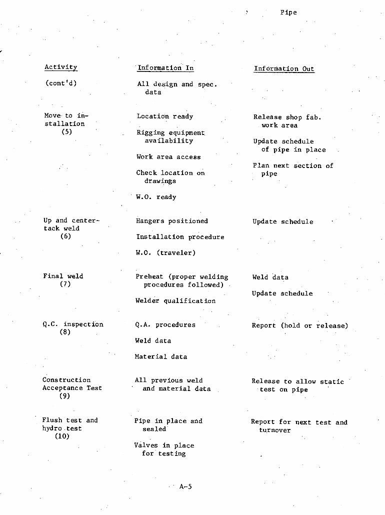
. k Pipe
A c t i v i t y
(cont ' d )
Move. t o in- s t a l l a t i o n
(5)
1nf o m a t i o n ' I n Information Out
A l l des ign and spec. d a t a
Locat ion ready Release shop fab. work a r e a
. Rigging equipment. a v a i l a b i l i t y Update schedule
of p ipe i n p l a c e Work a r e a acces s
P l an next s e c t i o n of Check l o c a t i o n on p ipe
drawings
' W.O. ready
Up and cen te r - Hanger s posf t ioned Update schedule t ack weld
( 6 ) I n s t a l l a t i o n procedure
W.O. ( t r a v e l e r )
F i n a l weld (7) '
Preheat (proper welding Weld d a t a procedures fol lowed)
Update schedule welder q u a l i f i c a t i o n
Q.C. i n spec t ion Q. A. procedures (8)
Weld d a t a
Report (hold o r r e l e a s e )
Ma te r i a l d a t a
Cons t ruc t ion A l l previous weld Release t o a l low s t a t i c Acceptance Test and m a t e r i a l d a t a . t e s t on p i p e
( 9 )
Flush t e s t and hydro . t e s t
(10)
P ipe i n p l a c e and sea led '
Report f o r next t e s t and turnover
Valves i n p l ace f o r ' t e s t i n g
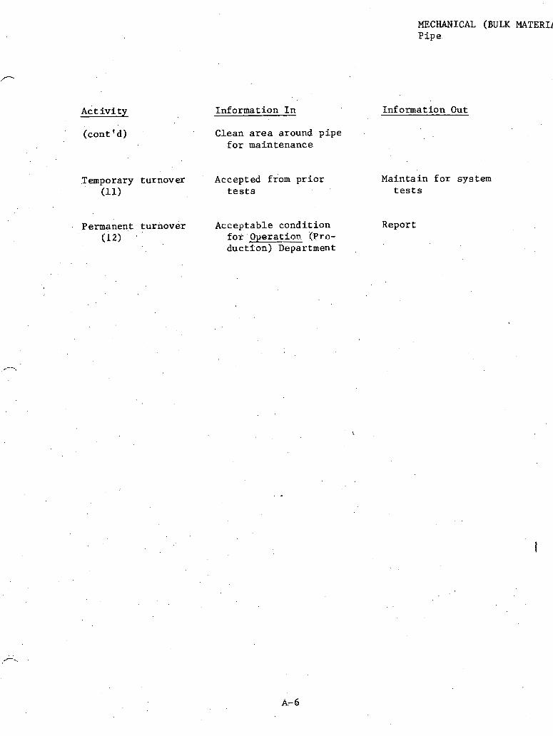
A c t i v i t y
(cont 'd )
MECHANICAL (BULK MATERIl Pipe.
Inforniat ion I n Information Out
Clean a r e a around p ipe f o r maintenance
Temporary turnover Accepted from p r i o r Maintain f o r system (11) t e s t s t e s t s
Permanent tu rnover Acceptable cond i t i on Report (12) f o r 'Operation '(Fro-
duc t ton ) Department
MECHANICAL (SMALL COMPONENT) INPUT /OUTPUT DATA

l T n f n Tn 1 Info Out
ISSUE VELDS IN LINE
QC WELD INSPECTION
REWOW.

. , Input/Output Sheet
MECHANICAL (SMALL COMPONENT) Small va lves
Information I n Information Out
I s s u e F i e l d r e q u i s i t i o n Foreman of i s s u e (1)
Schedule Account number
I sometr ic drawings , ' System number .
Index Date of i s s u e
Area of i n s t a l l a t i o n . .
warehouse record update
Valve number P r i o r i t y
Welds ' i n l i n e ( 2 )
Weld l o c a t i on
l so metric drawings
Welder q u a l i f i c a t i o n no.
Rod h e a t no., s i z e , type . .
Batch number
System number
Area e l e v a t i o n
Condit ion
Number of amps used
Rate of t r a v e l
Heat of " r e pass"
. ,
Q . C , weld inspec- N o t i f i c a t i o n R e s u l t s o f : t ion Visua l In spec t ion
(3) Outputs from "welds Liquid ~ e n e ' t r a n t Tes t i n l i n e " a c t i v i t y . . ' Ul t r a son ic Inspec t ion ,
X-Ray t e s t Inprocess v e r i f i c a t i o n of : Weld speed Heat o f ' "repass"

A c t i v i t y
( con t ' d)
Informat ion I n
c o n s t r u c t i o n Ac- ' . Notif iCa t ion of c o w ceptance t e s t pletiun
Q.C. r eco rds
System s t a t u s
F lush and Hydro test
(5)
System test (6)
Product ion completion r e p o r t s
Q.C. r eco rds
S p e c i f i c a t i ons
Previous record^
Permwent turnover . A l l Q.C. and Produc-
(7) t i o n documeats co customer
MECHANICAL (SMALL COMPONEN' Small va lves
Information Out
Amps used and v o l t s Rod number Length of pas s S l ag embedment .
Carbon content
Acceptance
T e s t r e s u l t s
Tes t number
Acceptance r e p o r t

ADDENDUM C

INSTALL BASE PAD
I Info I n r1n f o Out I Info In 11nfo Out I In fo I n
f 11n:o I n
TO FIT u
r PRE-PLACENNT
INSTALLATION FITTING
REWORK
I A REWORK L 11nfo;t 1 1 ~ 1n In fo Out
1 - SYSTEM TEST
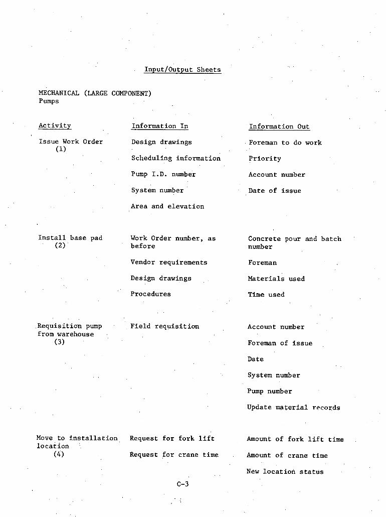
Input/Output Sheets
MECHANICAL (LARGE COMPONENT) Pumps
Ac t iv i ty Information I n , .
I s sue Work Order Design drawings (1). . .
Scheduling information
Pump I . D . number
System number
. . Area and e l e v a t i o n
I n s t a l l base pad Work Order number, a s (2) ' before
Vendor requirements
Design drawings
Procedures
.Requis i t ion pump . . Fie ld r e q u i s i t i o n f ro& warehouse .,
(3)
Move t o i n s t a l l a t i o n , Request f o r fo rk l i f t l o c a t i o n :.
( 4 ) Request f o r crane time
Information Out
. Foreman t o do work
P r i o r i t y
Account number
Date of i s s u e
Concrete pour and batch number
Foreman
Mater ia ls used
Time used
Account number
Foreman of i s s u e
Date
System number
Pump number
Update ma te r i a l records
Amount of fo rk l i f t time
.Amount of crane time
New l o c a t i o n s t a t u s
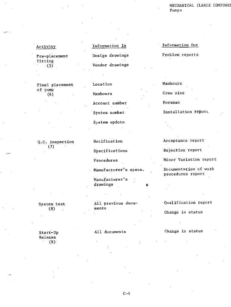
MECHANICAL (LARGE COMPONEI Pumps
A c t i v i t y Information I n
Pre-placement Design drawings f i t t i n g
(5) vendor drawings
F i n a l placement . o f Pump
( 6 )
Locat ion
Manhours
Information Out
Problem r e p o r t s
Manhour s
C r e w s i z e
Accoun L number Foreman
Systelil number
3y stem updato
Q.C. i n s p e c t i o n N o t i f i c a t i o n (7)
S p e c i f i c a t i o n s
System test (8)
s tart '-up Release
(9)
I n s t a l l a t i o n repori
Acceptance r e p o r t
Re jec t ion r e p o r t
Procedures Minor Var i a t ion r e p o r t
Manufacturer 's specs . , Documentation of work procedures r e p o r t
~ a n u i a c t u r e r ' s drawings 0
All previous docu- Q ~ i a l i f i c a t i on r e p o r t ments
Change i n s t a t u s
A l l dvcuments Change i n s t a t u s

ADDENDUM D
CIVIL (BULK MATERIAL) INPUT/OUTPUT DATA

Shop drawings, specs, other drawings, 1 2 . 3
CCT & BEND TRANSPORT TO
CORRECTIONS
6 -
INSTALLATION
CORRECTIONS
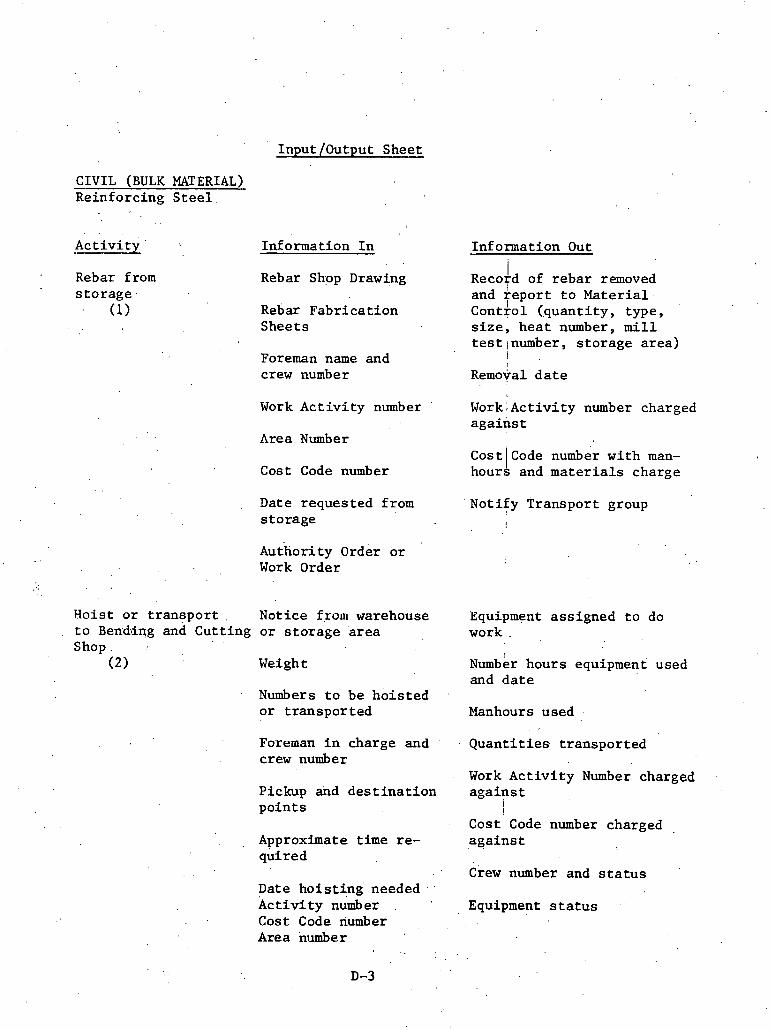
Input /Output Sheet
CIVIL (BULK MATERIAL) Reinforcing S t e e l
. .
Act iv i ty ' Information I n
Rebar from Rebar Shop Drawing s to rage
(1) Rebar Fabr ica t ion Sheets
Foreman name and crew number
Work Ac t iv i ty number
Area Number
Cost Code number
Date requested from s to rage
~ u t h o r i t ~ order o r '
Work Order
Hoist o r . t r a n s p o r t . Notice from warehouse t o Bending and Cutt ing o r s to rage a rea Shop. .
(2) Weight
Numbers t o be ho i s t ed o r t ranspor ted
Foreman I n charge and ' .
crew number
Pickup dnd d e s t i n a t i o n po in t s
, Approximate t i m e re- quired
Date hoist ing ' needed k c t i v i ty number Cost Code riumber Area number
Information Out i
~ e c o t d of r eba r removed and r e p o r t t o Mater ia l
I Control (.quantity, type, s i z e , hea t number, m i l l testlnumber, s to rage area)
I
Removal d a t e
Work;Activity number charged aga ins t
Cost 1 Code number wi th man- hours and m a t e r i a l s charge
Notify Transport group I
Equipment assigned t o do work .
~umb&r hours equipment used and d a t e
Manhours used .
Quant i t i e s t ranspor ted
Work A c t i v i t y Number charged a g a i n s t
i i
Cost Code number charged agains:t . .
Crew number and s t a t u s
Equipment s t a t u s

CIVIL (BULK MATERIAL) Reinforc ing st e e l
Informat ion I n Informat ion Out Act i v i ' t y
Manhours used a g a i n s t each Cost Code
Rebar i n c u t t i n g and bending a r e a
Cut and bend b a r s
(3) A c t i v i t y number A c t i v i t i e s worked and code
a g a i n s t t ime Cost Code numbers
Date completed and ' d a t e s t a r t e d Shop Drawing
c o r r e c t i o n s o r c o n f l i c t s a r i s i n g from f a b r i c a t i o n
C n t and bending s h e e t
Crew assignment f o r bending and c u t t i n g Bending and c u t t i n g com-
p l e t e t o Ma te r i a l Control ~ u r a t i o n f o r t h e acLlvity crew n w b e r and s t a t u s
N o t i f i c a t i o n t o Q.C. A r e a number
~ n s p e c t i o n Report Cont rac t drawings and s p e c i f i c a t i o n s
Q.C. check f a b r i c a t i o n
(4) Area number and d e s c r i p t i o Shop drawings
A c t i v i t y number . Correc t ions . o r approval
Crew number i n s t a l l i n g b a r s Area number
C r e w number doing f a b r i c a t i o n and foreman .
Date complete
Pour d a t e
Cor rec t ions and/or con- f l i c t s ( f a b r i c a t i o n )
Cor rec t ions complete I n s p e c t i o n Report Make c o r r e c t i o n s t o f a b r i c a t i o n
(5) Manhours a g a i n s t Cost Code number and Work A c t i v i t y numl
Crew number ass igned
Wark A c t i v i t y number C r e w number and s t a t u s .
Area number
Cost Code number

Reinforcing steel
Activity
Hoist to instal- lation area
(6)
Information In Information Out
Q.C. approval Equipment assigned to work
Lbs. to be hoisted Manhours
Crew number and fore- man assigned Equipment hours
Pickup and destination Quantities hoisted points
$ . Work Activity'number charged
Time required Cost Code number charged
Date needing hoisting Crew number and status
Activity number Equipment status
Cost Code number
Area number
Place rebar (7 )
Q.C. check .instaLlation
(8)
Formwork ready
Crew number assigned
Tools availability
Activity number and. .
duration
Cost code number
Rebar hoisted and ready
Cut sheets
Notification to Q.C. of completion
Manhours against Work Activity number and Cost Code number
Date completed and date started
Corrections or conflicts arising from installation
Installation completion to Material Control
Shop drawings Crew number and status
Contract drawings Tools status
Notification from in- Inspection Report stallatioi~ c ~ e w
Notification of pour Shop drawings and cut approval sheets

A c t i v i t y
( con t ' d)
Informat ion I n
Cont rac t drawings and s p e c i f i c a t i o n s
A c t i v i t y number
Area number
Crew number doing in- s t a l l a t i o n
Date completed
Pour d a t e
Correc t ions and/or con- . £ l i c t s from instal . l .a t ion
Make i n s t a l l a t i o n I n s p e c t i o n Report c o r r e c t i o n s
(9) Crew number a.ssigned
Work A c t i v i t y number and d u r a t i o n
Area number
Cost Code number
C l V lL (BULK MATERIAL) Reinforc ing s t e e l
Information Out,
.Correc t ions complete t o Q . C .
Manhours a g a i n s t A c t i v i t y number, Cost Code numbers
Crew number and s t a t u s
Tools s t a t u s
Tools a v a i l a b l e

ADDENDUM E
CIVIL (SMALL COMPONENT) INPUT/OUTPUT DATA

C IRRECTIONS
Physical requirements 1 1 2 -
Drawings, TRANSPORT specs, \ FRrn STORAGE etc .
Info In
I l f o 3ut Info In
MAKE CORRECTIONS
4
, INSTALL CADWELDS
-- [ ~ n f o In

Input /Output Sheet
CIVIL (SMALL COMPONENT) Cadwelds
A c t i v i t y . Informat ion I n
Cadwe1.d~ from Rebar shop drawing s t o r a g e and cadweld l i s t i n g
(1) Work Order
Foreman name and crew number
Transpor t t o .
work a r e a (2)
Informat ion Out
Record of cadwelds removed and r e p o r t t o M a t e r i a l Cont ro l ( s i z e , q u a n t i t y , ba lance re- maining, S to rage Area number)
Date cadwelds i s s u e d Work A c t i v i t y number
Area number
Cost Code number
Notice from warehouse o r S torage Area
~ u a n t i t i e s t o b e t r ans - por ted
Hours a g a i n s t Work Ac- t i v i t y number
Hours a g a i n s t Cost Code number
M a t e r i a l s , aga ins t Cost Code number
Notify Transpor t group
Equipment ass igned t o do work
Number of hour s equipment 'used a g a i n s t Cost Code-
,Foreman i n charge and Date equipment used crew number
Hours a g a i n s t A c t i v i t y . Pick-up and d e s t i n a t i o n numb e r p o i n t s
Hours a g a i n s t Cost Code Time r equ i r ed number
Date t r a n s p o r t i n g needed
'Crew number and s t a t u s
Equipment s t a t u s A c t i v i t y number
Cost Code number Q.C. approval of f i e l d s t o r a g e
Area number
E-3

C l V lL (SMALL L U W U N C N ' L
Cadweld s
Informat ion Out
I n s p e c t i o n Report
Cadwelds approved
Cadwelds missing
Cadwelds n o t approved
A c t i v i t y
Q.C. check (3)
Contrac t drawings and s p e c i f i c a t i o n s
Shop drawings and cadweld l ist
A c t i v i t y number
Area number
Crew nuniber
Area number
Foreman and crew number t o perform i n s t a l l a t i o n
Welder. q u a l i f i c a t i o n s f o r a l l 'mechanics
Date from s t o r a g e
F i e l d s t o r a g e approval
Cor rec t ions complete I n s p e c t i o n Report Make c o r r e c t i o n s ( 4 )
Hours . aga ins t Cost Code numbc Crew number assigned
Hours a g a i n s t A c t i v i t y numbe: Work A c t i v i t y number
Crew number, s t a t u s Cost Code number
Area number Tools s t a t u s
Tools a v a i l a b l e
~ e b a r ready
Formwork ready
Not i fy Q.C.' o f .completion I n s t a l l cadwelds (5) . .
Hou'rs a g a i n s t A c t i v i t y numbe \
. .
Crew number ass igned Hours a g a i n s t Cost Code numb
Date s t a r t e d and completed Welder qualifications f o r crew
Record o f c o n f l i c t s and c l a r i f i c a t i o n s Tools a v a i l a b l e
I n s t a l l a t i o n t o Materia! Cont ro l
A c t i v i t y number
Durat ion of work.
E-4

Cadwelds
A c t i v i t y . Informat ion I n In£ ormation Out
(cont ' d) Cost Code number C r e w number and s t a t u s
A l l c o r r e c t i o n s com- Tools s t a t u s . p l e t e
Shop drawings and '
cadweld l ist
c o n t r a c t drawings and s p e c i f i c a t i o n s
Q.C. check (6 )
N o t i f i c a t i o n of com- I n s p e c t i o n Report p l e t i o n
' . Cadwelds approved Cont rac t drawings and s p e c i f i c a t i o n s Cadwelds n o t approved
Shop drawings and cadweld l is t
A c t i v i t y number
Area number
Crew number and foreman
welder q u a l i f i c a t i o n s .
Record of c o n f l i c t s and c l a r i f i c a t i o n s
Make c o r r e c t i o n s ( 7 2
In spec t ion Report
C r e w number assigned
Work A c t i v i t y number
Cost Code number
Area number
Tools a v a i l a b l e
Area number
Crew number
Cor rec t ions complete
Hours a g a i n s t Cost Code number
Hours a g a i n s t A c t i v i t y number
Crew number and s t a t u s
. . Tools s t a t u s

ADDENDUM F
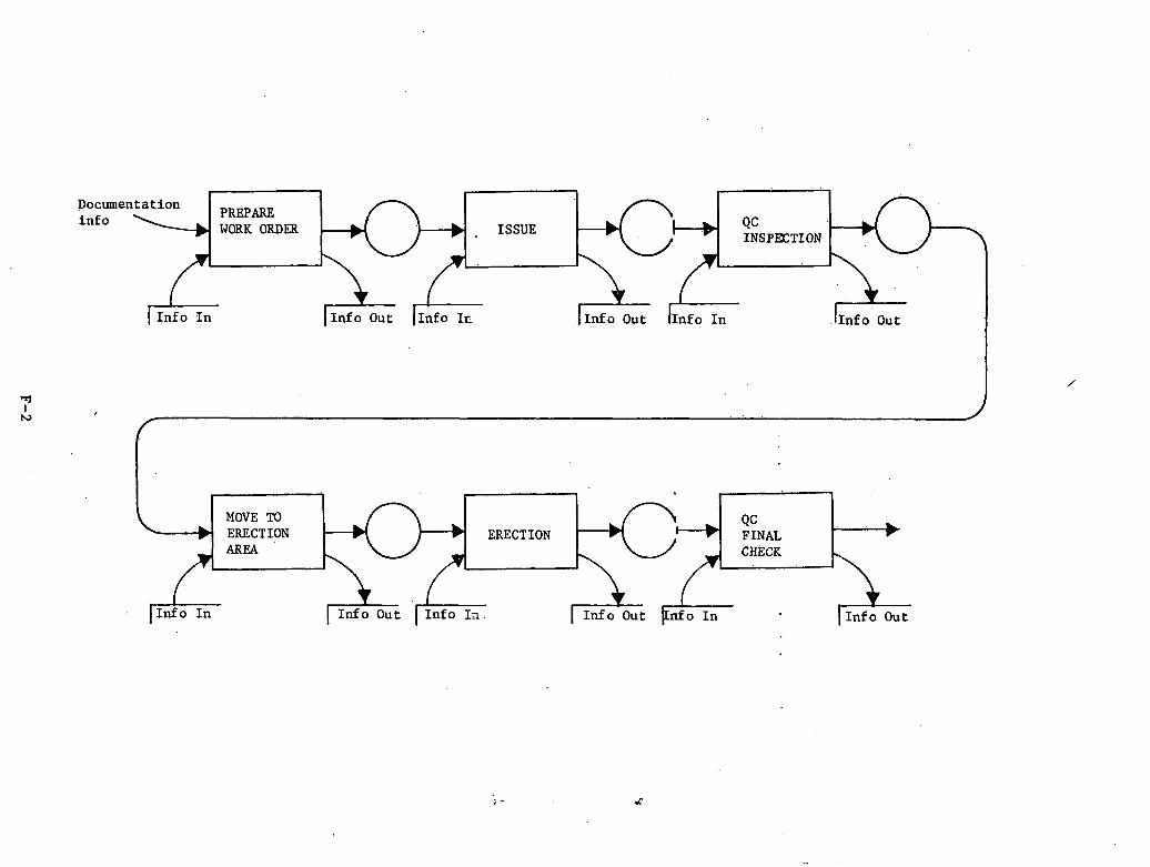
Documentation i n £ o PREPARE
WORK ORDER ISSUE
In fo I n 1 In fo Out (1nfo Ir- ( I n f o Out 11nfo I n 11nfo ou t I
MOVE TO ERECTION ERECTION AREA
In fo I n
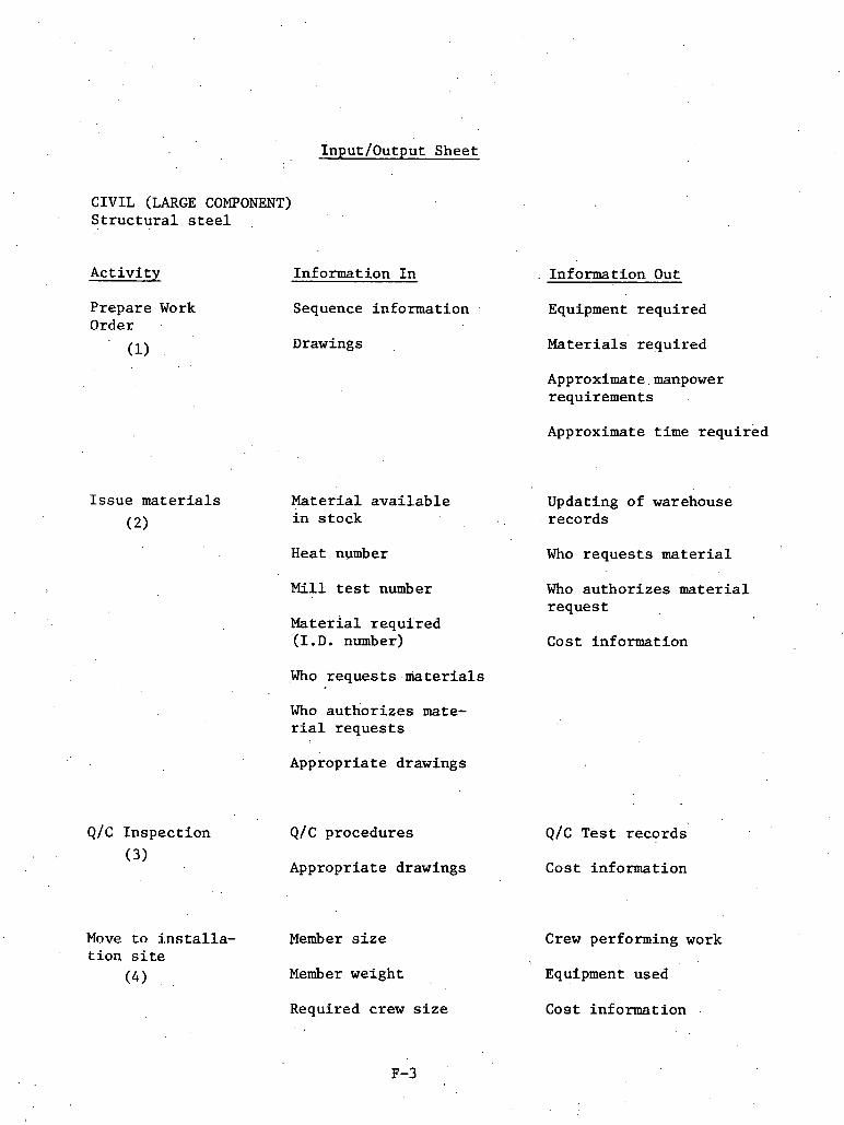
Input/Output Sheet
CIVIL (LARGE COMPONENT) Structural steel
Activity
Prepare Work Order
Issue materials
(2)
Information In
Sequence information
Drawings
. Information Out
Equipment required
Materials required
Approximate.manpower requirements
~~~roxim=te time required
Material available Updating of warehouse in stock records
Heat number Who requests material
Mill test number
Material required '(I. D. number)
Who authorizes material request
Cost information
Who requests materials
Who authorizes mate- rial requests
Appropriate drawings
Q/c Inspection Q/C procedures Q/C Test records
Appropriate drawings
. . Move to installa- Member size
tion site
( 4 ) . , Member weight
Required crew size
cost' information
Crew performing work
Equipment used
Cost information

A c t i v i t y
(cont ' d)
~ n s t a l l a t i o n (5)
Informat ion I n
Required equipment s i z e s
I n s t a l l a t i o n l o c a t i o n
Drawings
Required crew s t e e
. . ~ e ~ u i r e d equipment s i z e s
Member s i z e
CIVIL (LARGE COMPONENT: S t r u c t u r a l s t e e l .
Information Out
Crew performing work
Ecluipme~zt used
Cost in format ion
- Q / c in format ion
Member weight
Q/C F i n a l Inspec- Q / C procedures Q/c Tes t r eco rds
Appropr ia te drawings Cost in format ion

ADDENDUM G

PREPARE ISSUE WORK ORDER WORK
I Info In
REWORK
pnfo O u t
Qc PLnL WIRE EETURN
INSPECTION EXCESS WIRE .
RUNG OUT MEGGER AND FLOATED TESTED
TErnlINATIONS - -

InputIOutput Shee ts
ELECTRICAL .(BULK .MATERIAL) ~ G i k c a b l e
A c t i v i t y Information I n Information Out
p repa re Work CKTs put i n packages Work Order number Order ( t r a v e l e r ) f o r p u l l
. ( I ) L i s t of work t o precede Routings s p e c i f i e d W. 0 . p u l l . (condui t
i n s t a l l a t i on )
. . ~ n s t r u c t i ons
V i t a l i t y
To & from l o c a t i o n s
Est imated l e n g t h s
System number
I s s u e Conduit s t a t u s . ,. (2) Q.C. s t a t u s
Manpower a v a i l a b i l i t y
Ma te r i a l a v a i l a b i l i t y
Engineers o r f i e l d r eques t
Requests w i re Length r equ i r ed from yard
(3) Type r equ i r ed
Area and e l e v a t i o n of usage
Forellla11 r e spons ib l e
Work as'signment t o supe r in t enden t ..
Memo t o Q.C. f o r process i n s p e c t i o n
Transmi t t a l number
New s t a t u s i n f i e l d
Spool number
. Length l e f t ' a t i s s u e
Update.wire l o g
Update w i r e l o c a t i o n l o g .
W.O. package used f o r
G-3

A c t i v i t y
P u l l s w i r e ( 4 )
Returns excess wire t o yard
(5)
Megger t e s t ( 6 )
Information I n
Ma te r i a l s
Manpower
.Equipment
Q.C. jnspef.tnr
Wire used
CKTs uscd f o r
ELECTRICAL (BULK MATERIAL) .Bulk cab le
Information Out
Q.C. r e p o r t
P u l l t ens ion
CLEW LllaL p ~ = r I i ~ r ; ~ ~ ~ e i l work
Type and no. of p u l l i n g instrument
Wire r e e l numbers
Lengths o f ' each r e e l by CKT (c;,-'t>
P u l l .date
I n s p e c t o r ' s number
Wire l ogs updated
Megger test r e s u l t s
Accept o r r e j e c t
System vnl-taga
Test vo l t age
'l'emperature
Humidity
Weather
Tes t equipment number
Tes t equipment c a l i b r a t i o n d a t e
T e s t e r ' s name
,4+"
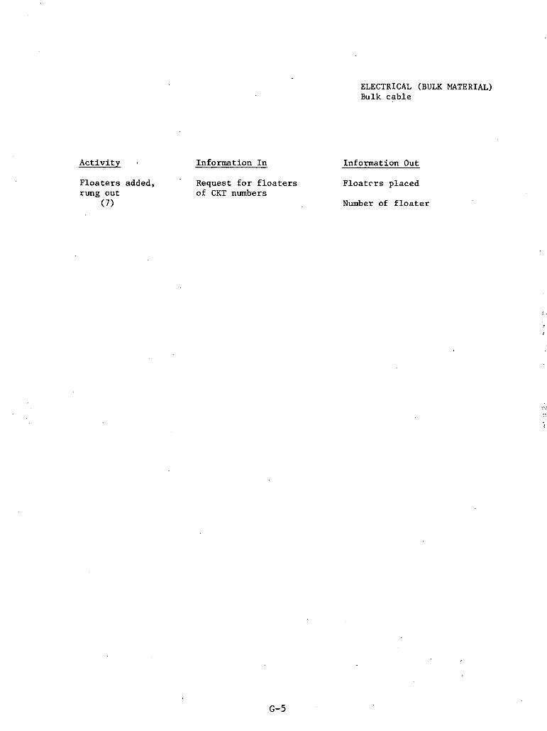
ELECTRICAL (BULK MATERIAL) Bulk cab le
A c t i v i t y . Information I n Information Out
F l o a t e r s added, ' Request f o r f l o a t e r s F l o a t e r s placed rung out of CKT numlsers
(7) Number of f l o a t e r

ADDENDUM H
ELECTRICAL (SMALL COMPONENT) INPUTIOUTPUT DATA

TERMINATION OFFICE LOG
Info In
.Info In- +-
PREPARE WORK ORDER ASSIGNMENT TERMIMTION

. Input/Output Sheets
ELECTRICAL. (SMALL COMPONENT) Termina t Tons
Activity
Prepare Work Order
(1)
To field, (2)
. Terminates (3)
To field office ( 4 )
Information In
Request
Wire installed report
Wire meggered and floated
QC papers
W.O. package
Assigns worker
For eman assigned
Materials
Information Out
Work order
Diagram of connections
Termination. location
Transmittal of W. 0. package
Priorities
Assigns worker
Name
Tool number
Lug used
Connected by drawing no.
Time
Qualification number
Tool calibration date
Notifies Q'. C.
Notifies status

A c t i v i t y
Q.C. inspect ion. (5)
Log, complete ( 6 )
Information I n
' Data from terminat ion shee t
ELEC'I'KICAL (SMALL COMPONENT) Terminations
Information Out
V e r i f i e s (3 ) outputs
Signs
Keport and. sepor i: number generated
~ 0 t P f i e S Production
Ctatua of r i ~ u l L s
Log complete

ADDENDUM I
ELECTRICAL (LARGE COMPONENT) INPUT/OUTPUT DATA

--. I I n f o I n 11nfo out
PREPARE WORK ORDJIR ISSUE
1 1 d o o u t I ~ n f o ~n
IX STALL COrnUIT TEFmINATE
I
QC INSPECTION
O u t -

lnput /Output s h e e t s
. .
ELECTRICAL (LARGE COMPONENT) Motors
A c t i v i t y
Prepare Work Order,
(1)
I s s u e (2)
I s s u e from warehouse
(3)
Transport t o f i e l d
( 4 )
Se t i n p l ace (5)
Information I n
Pad ready
Manpower a v a i l a b l e
Memo r e q u e s t i n g work
Mate r i a l a v a i l a b l e
Ma te r i a l r e q u i s i t i o n
' Request . t o work
Work Order. number
Information Out
Work Order
Person i s s u e d t o and d a t e
Date i s s u e d
Storage cond i t i ons
S t a t u s change
Schedule f o r k l i f t T ranspor t a t ion c o s t s
Schedule b r idge c rane
I n s t a l l a t i o n i n s t r u c - t ions
I n s t a l l e d by whom
I n s t a l l e d w i t h what t o o l s
Ca l ib ra t ed when
How p ro tec t ed
Q.C. n o t i f i e d

Activity
Install conduit, terminate
(6) ,
Q. C. inspection (7 )
Hi-pot test of system
(8)
Information In
Notice to conduit for installation
Notice to wire pull for installation
Notice to terminators for installation
Design Documents
Specifications
ET..ECTRICAL (LAR~E COMPONENT) Motors
Information Out
Conduit Installation Report
Wire Installation .Keport
Teimination form
Notification of each co Q.C.
Verifies installation
Assigns no. to report
Results of test
Record of conditions
Tggly ~ i s r t l
Calibration dates
People involved

ADDENDUM J
APPLICATION AREA OUTLINE ,
METHODS ENGINEERING

Exhibit 1
APPLICqTION AREA: ~ e t h o d s Engineering
' ' INDEX
2.0 Objectives
3.0 Functions. . .
3.1 Methqd~ Engineering
3 . l a Description , 3.lb Relationship t o other functions and app l ica t ion
a reas 3 . l c Data requirements 3. ld Data generated within t h e function 3 . l e Processing 3. l f Reports , t o users
4.0 Code number o r keys
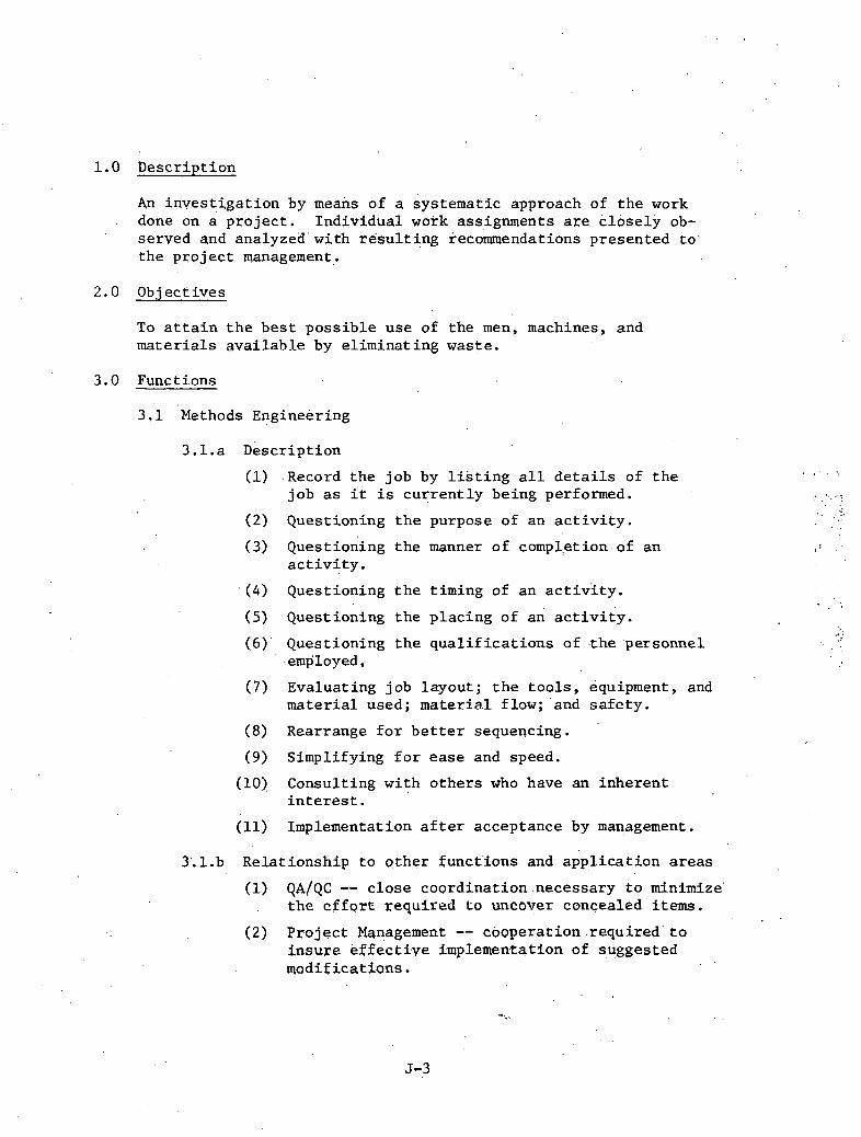
1.0 Desc r ip t ion
An i n v e s t i g a t i o n by meaizs of a sys t ema t i c approach bf t h e work - done on a p r o j e c t . I nd iv idua l work assignments a r e k l o s e l l ob-
se rved and analyzed ' w i t h . r e s b l t i n g kecokmendations p re sen ted ' t o . t h e p r o j e c t management.
2.0 Ob j ecf i v e s
To a t t a i n t h e b e s t p o s s i b l e u s e of t h e men, machines, and m a t e r i a l s available by e l imina t i n g waste .
3.0 Funct ions
3 .1 ' ~ e t h o d s Engineering
3.1.a Desc r ip t ion
(1) .Record t h e job by l i s t i n g a l l d e t a i l s of t h e job as i t i s c u r r e n t l y be ing performed.
(2) Quest ioning t h e purpose of an a c t i v i t y .
(3) ~ u e s t i o n i n ~ t h e manner of comp1,etion. of an a c t i v i t y .
. ( 4 ) Quest ioning t h e t iming of an a c t i v i t y .
(5) Quest ioning t h e p l a c i n g of an a c t i v i t y .
( 6 ) ' Quest ioning t h e q u a l i f i c a t i o n s of . the personnel ,employed,
(7 ) Evalua t ing job l ayou t ; t h e t o o l s , equipment, and m a t e r i a l used; material flow; 'and s a f e t y .
(8) Rearrange f o r b e t t e r sequencing.
(9) Simplifying f o r ease and speed.
(10) Consul t ing w i t h o t h e r s who have an i n h e r e n t i n t e r e s t .
(11) Implementation a f t e r acceptance by management.
3'.l.b Re la t ionsh ip t o o t h e r funct ' ions and a p p l i c a t i o n a r e a s
(1) QA/QC -- c l o s e coo rd ina t ion .necessary t o minimize' . t h e c f f o r t required t o uncover concealed i t e m s .
(2) P r o j e c t Management -- coopera t ion . r e q u i r e d ' t o i n s u r e e f f e c t i v e implementation of guggested mod i f i ca t ions .

( 3 ) Cost Cont ro l -- w i l l prove o r d i sprove Llie . . .economic a d v i s a b i l i t y of making t h e suggested
changes.
(4) ? lanning/Scheduling -- s i g n i f i c a n t sav ings i n t ime r e q u i r e d ' t o 'complete t a s k s may permit up- grad ing of schedules o r resequencing of event s.
(5) Cons t ruc t ion . equipment c o n t r o l -- d i f f e r i n t types of equipment o r d i f f e r e n t sequences may be r equ i r ed .
3 . l . c Data requirements
(1) The p r o j e c t p h y s i c a l l ayou t .
(2 ) The p r o j e c t o rgan iza t ion .
(3) The p r o j e c t e s t i m a t e .
(4) The system f o r a s s i g n i n g and schedul ing work.
(5) P r p j e c t manpower requirements .
'3.1.d Data genera ted w i t h i n Methods Engineering
(1) De ta i l ed p r o d u c t i v i t y i n £ ormation on i n d i v i d u a l a c t i v i t i e s .
(2) Proposed mod i f i ca t ions of methods.
3.1.e P roces s ing
(1) Schedule a n i n i t i a 3 meeting wi th t h e P r o j e c t l q a ~ l a g e ~ , ~ s s i s t a n t P r o j a c t Manag~r, Const ruc t ion Manager, and t h e Cont ro ls Manager t o d i s c u s s para- meters of t h e program.
(2) Review and become f a m i l i a r w i th t h e d a t a req'ui'rements.
(3) Upon reviewing t h e p h y s i c a l l ayou t and meeting wi th p r o j e c t management, develop w r i t t e n obj ec t i , ves and a s t r a t e g y f o r implementing a Methods Engineering Program.
3.1.f ~ e ~ o r t s t o u s e r s
(1) A weekly t a b u l a t i o n of t h e d e t a i l e d breakdown of .
elements f o r t h e c u r r e n t pe r iod , f o r each crew, showing t h e m3in work a c t i v i t i e s .
(2) A weekly t a b u l a t i o n cover ing each crew's per f ormarlce f o r t h e c u r r s n t per iod and f o r t h e two preceding periods w i t h , a three-week s l i d i n g average f o r each of t h e thr6,e-,'major e lements (D i rec t A c t i v i t y , Su p o r t A c t i v i t y , and Delays) . B
(3) The t y p i c a l I?anpawer' Ac t iv i ty . Analysis Report . w i l l cons i s t of :
- A cover . l e t t e r ' . ' - One-p,age summary givi,ng a m u l t i - e l b e n t braakdown
f o r each day of the ' .per iod along wi th the. current and previous r e p o r t pe r iod ' s . s t a t i s t i c s , alqng with the 'changes from per iod t o period.
- Lis t ings of ' the crews i n each c r a f t , g iv ing per- centage of breakdowns f o r both crew and c r a f t along with t h e t o t a l p r o j e c t breakdowns.
- Lis t ings of t h e crews i n each c r a f t , g iv ing major elemental breakdowns f o r t h e previous three-week per iod along wi th t h e t o t a l p ro jec t major elemental s t a t i s t i c s . '
- Graphs may be presented a t a spec i f i ed i n t e r v a l which show t h e t h r e e major elements (Direct A c t i v i t y , Support Ac t iv i ty , and Delays)' f o r each week f o r the t o t a l p r o j e c t and f o r each c r a f t .


INFORMATION MANAGEMENT FOR NUCLEAR POWER STATIONS
APPENDIX D

TABLE OF CONTENTS
Page
CHAPTER I: . Quality Assurance
1.1 Introduction ........................................ . 1 1 .2 Quali ty Assurance ................................... 3
. 1 .3 Quality Assurance Organization ...................... 4 1 . 4 Basis f o r a Quality Assurance Program ............... 7 1 .5 Scope of t h e Quality Assurance' Program .............. 8 1 .6 The Role of the QA/QC Program ........................ 1 4
CHAPTER 11: Quality Control
2.1 Quality Control Procedures .......................... 17 2.2 Procedure Writing ................................... 18 2.3 Vendor Location Quality Control ..................... 22 2 .4 C i v i l Quali ty Control ............................... 23
2.4.1 Foundation Prepara t ion ....................... 28 2 .4 .2 Assembly and Erection of S t r u c t u r a l S t e e l .... 28 2.4.3 S t r u c t u r a l S t e e l Bolted Connections .......... 29 2.4.4 Welds ........................................ 31 2.4.5 Rebar Ins t a l l a t ion ........................... 32 2.4.6 Erection of Forms and Shoring ................ 32 2.4.7 Quality Control Procedures f o r Concrete ...... 33 2.4.8 Post-Placement Concrete Quali ty Inspection ... 3 5
2.5 Mechanical Quality Control .......................... 37 2.5.1 Materials Inspect ions ........................ 39 2.5.2 Equipment I n s t a l l a t i o n ....................... 40 2.5.3 Shop Fabr ica t ion ............................. 40 2.5.4 Hanger I n s t a l l a t i o n .......................... 41 2.5.5 Alignment and Coupling ....................... 41 2.5.6 Welding Procedures ........................... 42 2.5.7 Heat Treatment ............................... 44 2.5.8 Equipment Cal ibra t ion ........................ 44
2.6 E l e c t r i c a l Quality Control .......................... 45 2.6.1 Bidder Qua l i f i ca t ions ........................ 45 2.6.2 Vendor Survei l lance .......................... 46 2.6.3 QC Receiving Procedure ....................... 47 2.6.4 QC F i e l d Inspect ions ......................... 47 2.6.5 Instrument Ca l ib ra t ion ....................... 51 2.6.6 Inspection of Conduit ........................ 52 2.6.7 Grounding Equipment Inspection 52 . ............... 2.6.8 \.{ire Pu l l ing In-Process Inspect ion ........... 53 2.6.9 High P o t e n t i a l (Hi-Pot and Megger) Test ing ... 53 2.6.10 Termination Inspection ...................... 54 2.6.11 QC Turnover ................................. 54
2.7 Conclusion .......................................... 55

Page
CHAPTER 111: Document Control
3..1 In t roduct ion ....................................*.*.. 5 9 3 . 2 Qual i ty Assurance Record System ...................... 63 3 . 3 Document Management System ........................... 64
3 .3 . .1 ~ o c u i e n t Index System ... ... ..................... 6 5
3 . 3 . 2 Document Index and R e t r i e v a l System ........... 6 6
3 . 3 . 3 Document Management and Re t r i eva l System ...... 68
3 . 4 Recommendations ....................................... 69
3 . 4 . 1 Quali ty Assurance Records Management System ... 69
3 . 4 . 2 Mater ia l Receiving Inspect ion ................. 7 0
3 . 4 . 3 QCManpower Pro jec t ion ...... :................. 7 0
3 . 4 . 4 Ver i f i ca t ion of Mater ia l Traceab i l i ty . . . . . . . . . 7 1 -I 'l
3 . 4 . 5 ~onconfo&ance Trend Analysis . . . . . . . . . . . . . . . . . 11
3 . 4 . 6 Vendor Qua l i f i ca t ion .......................... 7 1
3 . 5 Fie ld Generated Document System ...................... 7 2
CHAPTER I V : Start-Up
4 . 1 In t roduct ion ......................................... 7 5
4 . 2 Start-Up Scope ....................................... 75 4 . 3 Start-Up Descript ion ................................. 7 6 4 . 4 Descript ion of General Programs t h a t Support S t a r t -
up ................................................... 8 2 4 . 5 Design I n t e r f a c e wi th Start-Up ....................... 8 5 4 . 6 Construction I n t e r f a c e wi th Start-Up ................. 89 4.7 Other I n t e r f a c e s with Start-Up ....................... 9 1 4 . 8 Information Developed a t the S t a t i o n ................. 9 1
4 . 8 . 1 Sta t ion Equipment Uata Base (Duke) . .' . . . . . . . . . . 92 11.8.2 S t a t i o n Modification0 . 8 b . l b a b b , , b b i b b b , . . , . . . . 94 4 . 8 . 3 Instrument Data Base .......................... 95 4 . 8 . 4 Nuclear P lan t R e l i a b i l i t y Uata ................ 96 4 . 8 . 5 P a r t s and Supply Catalog ...................... 98 4 . 8 . 6 Work Request Program .......................... 99 4 . 8 . 7 Instrument P r e - I n s t a l l a t i o n a l Checkout ........ 100
4 .9 Need f o r a11 In tegra ted Data System ................... 101
ADDENDUM A NRC Requirements Descript ion ADDENDUM B Sample Types of Permanent and Non-Permanent Records ADDENDUM C F ie ld Generated Document System Example Reports ADDENDUN D Duke Power Company: Data Base Management Control and
Engineering System ADDENDUM E Duke Power Design Document L i s t ADDENDUM F Mechanical Instrumentat ion and Control L i s t ADDENDUl4 G

CHAPTER I
Qua l i t y Assurance
1.1 In t roduc t ion
The high technology and need f o r s a f e o p e r a t i o n c h a r a c t e r i s t i c
of nuc lea r ,power p l a n t cons t ruc t ion has l e d t o unprecedented r equ i r e -
ments i n t h e a r e a of q u a l i t y c o n t r o l and documentation. This l e v e l
o f . c o n t r o l and i n s p e c t i o n has been a common p r a c t i c e i n t h e aero-
space, i n d u s t r y fo r many yea r s . The demands on t h e p a r t of t h e t r a v e l i n g
p u b l i c and government r egu la to ry bodies t o i n s u r e t h e sa feness of a i r -
c r a f t have l e d t o what i s g e n e r a l l y acknowledged as t h e h ighes t q u a l i t y
c o n t r o l s tar idards i n use . Other manufacturing a r e a s such as t h e ap-
p l i a n c e indus t ry have been under p r e s s u r e by,consumer groups t o improve
monitoring and c o n t r o l of product q u a l i t y . F igure 1.1 below q u a l i t a -
. - , t i v e l y i n d i c a t e s t h e l e v e l of q u a l i t y c o n t r o l exe rc i sed by v a r i o u s in-
d u s t r i e s on a s c a l e of 0-100 wi th t h e aerospace indus t ry a t 100.
I
Nuclear Aerospace
\r
FIGURE 1.1: COMPARATIVE LEVELS OF QUALITY CONTROL

The l e v e l of q u a l i t y con t ro l pract iced i n conventional con-
s t r u c t i o n is low due t o t h e problems of t h e s i t e , t h e conservative
l e v e l of design, and many. o the r f a c t o r s which tend t o inf luence the . ,
cost-safeness re la t ionsh ip . Due t o t h e p o t e n t i a l f a i l u r e hazard
inherent i n nuclear power p lan t s , the publ ic and t h e government have
required a considerably higher l e v e l of q u a l i t y . c o n t r o 1 and documenta-
t i o n on nuclear const ruct ion p ro jec t s . Thfs requlremear is high and
increas ing i n i t s r e s t r i c t i v e n e s s and cos t impl ica t ions . Largely
because of . the d e s i r e t o reduce the p robab i l i ty of nuclear accidents ,
t h e p o s i t i v e c o s t r e l a t i o n s h i p f avorfng nuclear vs . f o s s i l f u e l puwer i.
p l a n t s has been dec l in ing a t an accelera ted r a t e . The re la t ionsh ip
between s a f e t y , regula t ion, and q u a l i t y con t ro l requirements Is shown
i n Figure 1.2. . The demand f o r a g r e a t e r guarantee of s a f e operat ion
has led t o a h igher l e v e l of q u a l i t y control . 'This, i n tu rn , has .
generated a requirement f o r b e t t e r document control . Start-up of the
1 , '?.;
,. .~ i . "?~. .* FIGURE 1.2 : NUCLEAR CONSTRUCTION ENVIRONMENT

p l a n t i s c l o s e l y l i nked t o documentation of systems and acceptance
based on t h i s documentation by t h e s t a r t - u p teain. Th i s volume ad-
d r e s s e s t h e in format ion requi rements which a r e genera ted by t h e q u a l i t y
control ' , document c o n t r o l , and s t a r t - u p a p p l i c a t i o n a r e a s . The presen ta -
t i o n i s organized s e q u e n t i a l l y s t a r t i n g w i t h a d i s c u s s i o n of f a c t o r s in -
f l uenc ing q u a l i t y a s su rance and i t s r e l a t i o n s h i p t o q u a l i t y c o n t r o l d i s -
cussed i n t h i s chap te r . Qual i ty c o n t r o l i n s p e c t i o n c r i t e r i a f o r v a r i o u s
types of components is presen ted i n Chapter 2. The requirements f o r
document c o n t r o l (Chapter 3 ) and t h e in format ion environment i n t r i n s i c
t o t h e s t a r t - u p f u n c t i o n complete t h e in format ion a p p l i c a t i o n a r e a s d i s -
cussed i n t h i s volume. This sequence approximates ch rono log ica l ly t h e
l i f e c y c l e of a d a t a element o r group which is genera ted du r ing en-
g inee r ing or q u a l i t y c o n t r o l , passed t o document c o n t r o l , and e v e n t u a l l y
is r e q h i r e d t o r e l e a s e a system f o r s t a r t -up .
1 . 2 Qua l i t y Assurance
The ~ u a i i t ~ Assurance Program is a w r i t t e n set of procedures t h a t
i s c o n d i t i o n a l t o t h e s p e c i f i c d e s i g n s t anda rds , .codes, and p r a c t i c e s '
adopted by t h e p r o j e c t . These procedures w i l l v a r y i n format , d e t a i l ,
and s u b j e c t m a t t e r depending upon t h e i n d i v i d u a l s r e s p o n s i b l e , The t a s k
of o u t l i n i n g o r d e s c r i b i n g a s p e c i f i c q u a l i t y a s su rance system l o s e s
meaning without minute a t t e n t i o n ' t o d e t a i l : Major a s p e c t s considered
s i g n i f i c a n t t o t h e understanding of how a QA/QC program o p e r a t e s i n a
I 1 t y p i c a l " environment w i l l be p re sen t ed ,

A q u a l i t y a s su rance program i s t h e fo rma l i za t ion of t h e des ign ,
c o n s t r u c t i o n , and ope ra t ion of a nuc lea r power p l a n t t o a s s u r e com-
p l i a n c e t o s t anda rds r equ i r ed t o :
(1) Operate t h e p l a n t r e l i a b l y ;
(2) Prevent a c c i d e n t s t h a t might cause undue r i s k ' t o t h e h e a l t h
and s a f e t y of t h e pub l i c ;
(3 ) M i t i g a t e t h e consequences of such a c c i d e n t s i f they were ro
occur ; and
( 4 ) Determine the cause of an a c c i d e n t or mal func t ion such t h a t
c o r r e c t i v e and p reven t ive a c t i o n can be taken.
This r e q u i r e s documentation and p r e c i s e d e f i n i t i o n by means of w r i t t e n
- .. . procedures invo1ved;in a l l a c t i v i t i e s a f f e c t i n g t h e q u a l i t y of s t ruc -
t u r e s , systems, and components. Th i s documentat i on w i l l be r equ i r ed
throughout t h e e n t i r e process of i n s t a l l a t i o n , inc luding des igning ,
purchasing, sh ipping , handl ing, s t o r i n g , f a b r i c a r l n g , c leaning , Tn-
s t a l l i n g , e r ec t ing , ' i n spec t ing , t e s t i n g , ope ra t ing , main ta in ing , r e -
p a i r i n g , r e f u e l i n g , and modifying.
1 . 3 Qua l i ty Assurance Organiza t ion
The c r i t e r i a governing t h e organ ' izat ion of a q u a l i t y assurance
program i s s t a t e d i n lOCFR50 Apperidix By "The persons and o rgan iza t ions
performing q u a l i t y a s su rance f u n c t t o n s s h a l l have s u f f i c i e n t a u t h o r i t y
and o r g a n i z a t i o n a l freedom t o i d e n t i f y q u a l i t y problems; t o i n i t i a t e , . .
recommend, o r provide s o l u t i o n s ; and t o v e r i f y implementation of t h e
s o l u t i o n s . Such persons and o r g a n i z a t i o n s performing q u a l i t y assurance

func t ions s h a l l r e p o r t t o a management.leve1 such t h a t t h i s . r equ i r ed
a u t h o r i t y and o r g a n i z a t i o n a l freedom, inc luding s u f f i c i e n t independence
from c o s t and schedule when opposed t o s a f e t y cons ide ra t ions , a r e pro-
vided."
A s allowed, t h i s o rgan iza t ion may , t ake v a r i o u s f o m s , but t y p i c a l l y
an o rgan iza t ion a s i n F i g u r e 1.3 is adopted:
FIGURE 1 . 3 Q/A Q/C PROJECT ORGANIZATION
The o r g a n i z a t i o n a l c h a r t i l l u s t r a t e s t h e d i r e c t a d m i n i s t r a t i v e l i n e s
-
QA/QC PRO.TECT ORGANIZATION
of a u t h o r i t y f o r QA t o Corporate ... Management. . .. QA personnel i n des ign
- PROJECT MANAGER
or i n the . f i e l d may r e c e i v e QA scheduling d i r e c t i o n £.ram P r o j e c t Manage-
CORPORATE QA MANAGER
ment, but personnel c o n t r o l and a u t h o r i t y would r e s t w i th Corporate
~ 1 ~ 1 ~ d g ~ ~ ~ e l l L .
--- '1
I
2 I CONSTRUCT I O N QC GROUP
A
SITE QA '
4 C
- - - LINES' OF COMMUNICATION/REPORTING
LINE OF AUTHORITY /RESPONSIBILITY

The c h a r t a l s o p o r t r a y s Qua l i t y Cont ro l as a s e p a r a t e organiza-
t i o n a l group from Qual i ty Assurance. Func t iona l ly , QC is viewed, i n
most i n s t a n c e s , as . t h e implementation of t h e Qual i ty Assurance Pro-
gram. The QA group assumes r e s p o n s i b i l i t y f o r developing and wricirlg
t h e QA.manua1 d e s c r i b i n g t h e Qua l i t y Assurance Program. Included i n
t h i s manual is a d e s c r i p t i o n of t h e ' r e s p o n s i b i l i t i e s of t h e QA group
and t h e QC group.
The m a j o r i t y of p r o j e c t s a s s i g n s the QA group t h e r o l e of d e t e r -
mining QA p o l i c i e s , t r a i n i n g of QA r e l a t e d personnel , and performing
1
a u d i t s ; t h e QC group assumes t h e t a s k s of i n spec t ion , t e s t i n g , review, -:
a n d d o c u m e n t a t i o n i n t h e f i e l d . A c t u a l p r o c e d u r e s ' a r e w r i t t e n b y t h e .. QC group and reviewed by . t h e QA group. Management of t h e QC group i s
, through P r o j e c t Management; c o n f l i c t s compromising q u a l i t y a r e resolved
through t h e QA s i t e group.
v a r i a t i o n s of t h e QA/QC o rgan iza t ion s t r u c t u r e aye mare rnddff f ra- I .
t.ions i n emphasis r a t h e r t han t o t a l change. The QC group performs a l l
i n spec t ions , t e s t i n g , review, and documentation, whi le t h e a c t u a l approval
of a l l r e s u l t s i s ves t ed i n t h e QA s i t e group. A l l documentation f lows
through t h e QA .group. , The r e l a t i o n s h i p s of t h e QA group. and QC group
t o P r o j e c t and co rpo ra t e Management a r e t h e same a s shown i n t h e prcvious t
a s t r u c t u r e . The d e c i s i o n t o u s e e i t h e r approach i s depend'ent upon t h e
s i t u a t i o n and circumstances.

1 .4 Basis f o r a Qual i ty Assurance'Program
It i s t h e r e s p o n s i b i l i t y of a p l a n t owner t o e s t a b l i s h , execute ,
and enforce a q u a l i t y assurance program as p a r t of t he P re l imina ry
Sa fe ty Analysis Report. A s a minimum c r i t e r i o n , , t h e q u a l i t y assurance
program.must be c o n s i s t e n t wi th t h e fo l lowing s tandards :
lOCFR 50 Appendix B C r i t e r i a f o r Nuclear Power P1ant.s and Fuel Reprocessing P l a n t s
ANSI N45.2 Qual i ty Assurance Program Requirements f o r Nuclear Power P l a n t s
Packaging, Shipping, .Receiving, Storage, and Handllng of Items f o r Nuclear Power P l a n t s (during t h e cons t ruc t ion phase)
ANSI N45.2.3 Housekeeping dur ing t h e Cons t ruc t ion Phase of Nuclear Power P l a n t s
ANSI N45.2.5 Supplementary Qua l i t y Assurance Requirements '
f o r I n s t a l l a t i o n , In spec t ion and Tes t ing of S t r u c t u r a l Concrete and S t r u c t u r a l S t e e l during t h e Cons t ruc t ion Phase of Nuclear Power P l a n t s
ANSI N45.2.6 Qualif i c a t i o u s of Inspec t i o n , Examination, and Tes t ing Personnel f o r t h e Cons t ruc t ion Phase of Nuclear Power P l a n t s
ANSI N45.2.8
ANSI N45.2.9
Supplementary Qua l i t y Assurance Requirements f o r I n s t a l l a t i o n , I n s p e c t i o n and Tes t ing of Mechanical Equipment and Systems f o r t h e Cons t ruc t ion Phase of Nuclear Power P l a n t s
Requirements f o r t h e Co l l ec t ion , Storage, and Maintenance of Qua l i t y Assurance Records f o r Nuclear Power P l a n t s
ANSI N45.2.10 Qua l i t y Assurance Terms and D e f i n i t i o n s
ANSI N45,2.11 Qua l i t y Assurance Requirements f o r t h e Design of Nuclear power P l a n t s
ANSI N45.2.12 Requirements f o r Audit ing of Qua l i t y Assurance Programs f o r Nuclear Power P l a n t s

ANSI N45.2,13 Qua l i t y Assurance ltequirements f o r Cont ro l of Procurement of Equipment, Ma te r i a l s , and Ser- v i c e s f o r Nuclear Power P l a n t s
ANSI N45.2.17 Qual i ty Assurance Requirements f o r Cont ro l of t h e Welding Process f o r Nuclear Power P l a n t Cons t ruc t ion
The above l i s t i n g of s t anda rds is a sample o f . t h e b a s i c requi rements .
Add i t i ona l r e f e r e n c e s can be found i n Appendix A. . .
1 . 5 Scope of t h e Qua l i t y Assurance Program
The Q u a l i t y Assurance Program must d e s c r i b e adequate ly t h e p o l i c i e s ,
procedures , methods, o r i n s t r u c t i o l l s f o r any p r o j e c t r c l a t e d a c t i v i t y
a f f e c t i n g q u a l i t y . Th i s can extend beyond t h e boundar'ies de f ined a s a
minimum i n n a t i o n a l l y accepted design, an3 c o n s t r u c t i o n s t anda rds , a s
w e l l a s t h e s p e c i f i c codes gdverning t h e des ign , cons t ruc t ion , and
ope ra t ion of a nuclear power p l a n t .
F igu re 1.4 i l l u s t r a t e s t h e v a r i o u s components of a ni.~c.l..ear p r o j e c t
t h a t must be proper ly documented by a QA program, These.components are
r e fe renced from codes and s t anda rds f u r a QA program, and they a r e t he
commonly accepted minimums.
To p re sen t a more d e t a i l e d pe r spec t ive of t h e requirements of
a QA program, t h e fo l lowing l is t of components d e s c r i b e s t h e expecta-
t i o n s of a QA program a s p a r t of a PSAR:
Organiza t ion -- Define t h e a u t h o r i t y and d u t i e s of persons 'and o rgan iza t ions performing t h e QA functkons;
Provide o r g a n i z a t i o n a l c h a r t s o u t l i n i n g f u n c t i o n a l . r e s p o n s i b i l i t i e s incduding those of t he owner, the -
a rch i t ec t - eng inee r (AIE), t h e nuc lear steam system s u p p l i e r (NSSS) , t h e ' cons t ruc to r , and t h e construc- t ion manager;

CONTPtOL OF >IEASL;RING & T E S T E Q U I P -
STOEIAGE, .4ND S I I I P F I N G
I N S P E C T I O N , T E S T & OPERATING STATUS
NON- CCNFOR?.IANCE ITE? lS
b
T E S T CONTROL ,+ I
A
h j + r ~ r + m.
i
A
. . I N S P E C T I O N ! + QljALITY 4 ) A S S U R W C E 4 b A U D I T S
ur, ) . PEIOGaP.1 4
b
COUTRDL O F S P E C I A L I D E N T I F I C A T I O N + . .ORGANIZATIONS P R O C E S S E S AND CONTROL O F
; * MATERIALS, P A R T S ;
PROCURmIENT .. CONTROL ?ROC EDL'RES CONTROL OF PUR- AND DlQ-\I.JINGS DOCU?lENT C&ISED MATERIAL, CONTROL
E Q U I P f E N T , AND S E R V I C E S
4 I
. . .
QUALITY ASSURANCE RECORDS
I
I n d i c a t e what p o s i t i o n has o v e r a l l a u t h o r i t y and t h e l i n e s of r e p o r t i n g communication;
Describe t h e exten't and method of de l ega t ing QA a u t h o r i t y and r e s p o n s i b i l i t y t o e x t e r n a l c o n t r a c t o r s o r vendors;
Qua l i t y Assurance Program -- Assure t h a t t h e QA program w i l l be documented by w r i t t e n p o l i c i e s , procedures , and i n s t r u c t i o n s ;
Define t h e e x t e n t of t h e s tandards , codes, o r prac- t i c e s t o be used by the QA prvgt:am;
I d e n t i f y t h e s a f e t y r e l a t e d s t r u c t u r e s , systems, and components c o n t r o l l e d by t h e QA program;
Descr ibe the QA program implementatiofi schedule;
Summarize corporate ' QA p o l i c i e s , goa l s , and ob- j e c t i v e s ;
Provide f o r t h e adequate i n d o c t r i n a t i o n and t r a i n i n g of i n d i v i d u a l s performing QA/QC r e l a t e d t a sks ;
Document t h e q u a l i f i c a t i o n s f o r a l l QA/QC r e l a t e d p o s i t i o n s ;
Assure r e g u l a r management review of t h e QA program by groups i n t e r n a l and ext.ern;il t o t h e owner's o rgan iza t ion ;
Conduct r e g u l a r a u d i t s of c o n t r a c t o r QA programs;
Maintain QA program desc r ip t ' i ons c u r r e n t .
Design Con t ro l -- Assure t h a t des ign bases , r e g u l a t o r y requirements , codes, and s t anda rds a r e c o r r e c t l y t r a n s l a t e d i n t o s p e c i f i c a t i o n s , drawings, procedures , o r i n s t r u c t i o n s ;
Control d e v i a t i o n s from such s tandards ;
Describe mea s i i r ~ s t n assure . v e r i f i c a t i o n o r checking of des ign adequacy, such a s des ign reviews, a l t e r n a - t i v e c a l c u l a t i o n methods, o r performance of qua l i f i- c a t ion t e s t i n g ;
I d e n t i f y and c o n t r o l des ign i n t e r f a c e s among p a r t i - c i p a t i n g des ign groups ;

Contro l des ign and f i e l d changes f o r review and approval by t h e o r i g i n a t i n g des ign o rgan iza t ion .
Procurement -- Assure t h a t t h e procurement of m a t e r i a l , equipment, Document o r s e r v i c e s i nc ludes adequate documentation o r Cont ro 1 r e f e r e n c e t o q u a l i t y assurance s tandards ;
Spec i fy r equ i r ed s u p p l i e r o r vendor documentation;
Describe review, s u r v e i l l a n c e , o r approval of s u p p l i e r ' s QA program and'^^ r eco rds ;
E s t a b l i s h document and procedural c o n t r o l f o r spa re ' o r replacement i tems, c o n s i s t e n t w i t h o r i g i n a l
equipment s t anda rds . I n s t r u c t i o n s , -- Assure t h a t a l l documented i n s t r u c t i o n s , procedures , Procedures , . and drawings a f f e c t i n g q u a l i t y w i l l i nc lude q u a n t i t a - and Drawings t i v e (such a s dimensions, t o l e r a n c e s , and ope ra t ing
l i m i t s ) and q u a l i t a t i v e (such a s workmanship samples and weld r ad iog raph ic samples) acceptance c r i t e r i a .
Document Cont ro l -- Descr ibe measures t o c o n t r o l t h e d i s t r i b u t i o n and i s suance of documents s u c h . a s i n s t r u c t i o n s , procedures , drawings;
Ident ' i fy documents t o be c o n t r o l l e d and t h e o r i g i n a t i n g group r e s p o n s i b l e f o r review, approval , and changes ;
Maintain a master document index t o prec lude t h e u s e of ou tda ted o r i n a p p r o p r i a t e documents;
Review documents f o r adequacy and l e g i b i l i t y ;
Implement method f o r document s to rage , r e t e n t i o n , and r e t r i e v a l .
' ,.
Contro l of -- In spec t procured items o n - s i t e o r a t s e r v i c e ; Purchased Mate r i a l , Audit , review, and c e r t i f y s u p p l i e r p e r i o d i c a l l y f o r Equipment, conformance t o s t anda rds . and Se rv i ces
I d e n t i f i c a t i o n -- Describe measures, methods, o r coding schemes used and Cont ro l t o i d e n t i f y c o n t r o l i t ems , inc luding p r e f a b r i c a t e d o f Mate r i a l s , assemblies , t o prevent u s e of i n c o r r e c t p a r t s ( i . e . , P a r t s , and hea t number, p a r t number, s e r i a l number, ba tch number, Components e t c . )

Maintain a . record .of i d e n t i f i c a t i o n t r a c e a b l e t o t he i t e m throughout f a b r i c a t i o n , i n s t a l l a t i o n , and opera t i o n ;
Re la t e t h e i d e n t i f i c a t i o n method t o t h e a p p r o p r i a t e .drawing, s p e c i f i c a t i o n , o r t e c h n i c a l document;
Provide t r a c e a b i l i t y t o s p e c i f i c test o r i n spec t ion r eco rds a s r equ i r ed by codes, s t anda rds , or s p e c i f i c a - *
t i ons . Contro l of -- Assure t h a t s p e c i a l p rocesses , such a s welding, hea t * S p e c i a l t r ea tmen t , non-destruct ive t e s t i n g , c l ean ing , a r e Processes conducted under c o n t r o l l e d cond i t i ons i n accordance'
wi th w r i t t e n procedures and a p p l i c a b l e codes, s t anda rds , and spe i i i f i ca t ions ;
Assure q u a l i f i c ' a t i o n of personnel and equipment used t o a p p r o p r i a t e codes, s t anda rds , and s p e c i f i c a t i o n s ;
Define procedures and q u a l i f i c a t i o n s f o r s p e c i a l pro-,. c e s ses not covered by e x i s t i n g codes o r s t anda rds .
In spec t ion -- Implement a program f o r t h e in spec t ion of a c t i v i t i e s a f f e c t i n g q u a l i t y by i n d i v i d u a l s independent of t h e work completed;
Descr ibe w r i t t e n procedures LCJ s p e c i f y t h e in spec t ion , measurement, t e s t i n g , or q u a l i f i c a t i o n as necessary t o v e r i f y q u a l i t y ..and conformance t o t e c h n i c a l s t anda rds p r i o r t o perfo,rming t h e in spec t ion ;
Spec i fy mandatory hold p o i n t s which requir .e wi tness ing o r i n s p e c t i o n by t h e Authorized I n s p e c t o r ;
Maintain c u r r e n t record of i n spec to r 's. q u a l i f i c a t i o n o r c e r t i f i c a t i o n ;
Assure t h a t rework i tems a r e inspec ted i n accordance t o o r i g i n a l i n s p e c t i o n requirements .
Test Cont ro l -- E s t a b l i s h a t e s t program t o i d e n t i f y a l l t e s t i n g r equ i r ed t o demonstrate t h a t s t r u c t u r e s , systems, and components w i l l perform s a t i s f a c t o r i l y i n s e r v i c e ;
Inc lude , a s a p p r o p r i a t e , p ro to type q u a l i f i c a t i o n t e s t s , proof t e s t s p r i o r t o i n s t a l l a t i o n , pre-opera t i o n a l t e s t , and o p e r a t i o n a l t e s t s a s r equ i r ed t o v e r i f y ' cont inued s a t i s f a c t o r y performance during ope ra t ion ;

Assume p r e r e q u i s i t e s f o r a t e s t hake been met; aijequate i n s t rumen ta t ion . a v a i l a b l e ; q u a l i f i e d per- sonnel used;
Document and . rev iew t e s t . r e s u l t s w i th t h e r e s p o n s i b l e a u t h o r i t y t o a s s u r e s a t i s f a c t i o n of s t anda rds . '
Control of Measuring -- E s t a b l i s h means t o a s s u r e t h a t measuring and Tes t t o o l s , gauges, ins t ruments , t e s t equipment, and Equi.pment i n spec t ion dev2ces a r e p r e s e n t l y c o n t r o l l e d and
c a l i b r a t e d t o r equ i r ed l i m i t s ;
Define a b a s i s f o r c a l i b r a t i o n i f no n a t i o n a l s tandard e x i s t s ;
Evalua te t h e v a l i d i t y of prev ious i n s p e c t i o n s i f a measuring dev ice i s found t o be ou t of c a l i b r a t i o n ;
Maihtain r eco rds i n d i c a t i n g c a l i b r a t i o n s t a t u s and schedule f o r p e r i o d i c c a l i b r a t i o n .
Hand l i n g , -- E s t a b l i s h a method t o c o n t r o l t h e handl ing, s to rage , S torage , and shipping, inc luding c leaning , packaging, and and Shipping p re se rva t ion of m a t e r i a l i n accordance w i t h codes,
s t anda rds , procedures , drawings, o r s p e c i f i c a t i o n s t o prevent damage, d e t e r i o r a t i o n , and l o s s ;
Assure proper a t t e n t i o n t o s p e c i a l markings o r l a b e l i n g adequate t o i d e n t i f y procedures f o r handl ing, sh ipping
, o r s to rage .
. . Inspec t ion , -- Define methods t o i n d i c a t e t h e , s t a t u s of i n s p e c t i o n s Test,, and and t e s t s performed wi th markings such a s t a g s , Operat ing stamps, l a b e l s , o r o the r means; S t a t u s
Ou t l ine t h e a u t h o r i t y of i n d i v i d u a l s involved i n t h e a p p l i c a t i o n o r removal of t h e marking systems;
C l e a r l y i d e n t i f y t h e non-conformancy items.
Non-Conforming -- ~ e s c r i b e means t o c o n t r o l non-conforming m a t e r i a l ; M a t e r i a l s , p a r t s , o r componenrs; P a r t s ; o r Components Document procedure £or t h e d i s p s s i t ion of non-con£ ormance
m a t e r i a l ;
E s t a b l i s h non-conformance n o t i f i c a t i o n procedure;

Provide f o r means t o c o n t r o l f u r t h e r process ing , d e l i v e r y , or i n s t a l l a t ion;
Develop a non-conformance a n a l y s i s o r q u a l i t y t rend r epor t ing mechanism.
Cor rec t ive -- E s t a b l i s h measures t o a s s u r e t h a t cond i t i ons such Action a s f a i l u r e s , d e v i a t i o n s , mal func t ions , and de-
' ' f i c i e n c i e s a r e promptly i d e n t i f i e d and co r rec t ed .
Qual i ty Assurance -- Assure s u f f i c i e n t r eco rds a r e maintained t o Records f u r n i s h evidence of a c t i v i t i e s concerning q u a l i t y ;
Provide t o management t he r e s u l t s of reviews, in - spec t ions , t e s t s , a u d l t s , monitor ing of work per- formance, m a t e r i a l a n a l y s i s , and personnel q u a l i f i - c a t i o n logs ;
. .
E s t a b l i s h . r e c o r d requirements f o r s t o r a g e r e t e n t i o n , . and s e c u r i t y i n t h e f a c i l i t y t o minimize damage from,
d e t e r i o r a t i o n and prevent l o s s e s ,
Audits ,-- Conduct comprehensive planned and p e r i o d i c a u d i t s t o v e r i f y compliance t o a l l a s p e c t s of the'QA program;
Assess t h e e f f e c t i v e n e s s of t h e QA program;
Schedule e x t e r n a l a u d i t s of t he QA program and pr in- c ipal cuncrac cur s ;
Document a u d i t r e s u l t s f o r review by management f o r t h e a r e a aud i t ed w i t h .follow-up. a c t i o n and re -audi t i n d e f i c i e n t a r e a s .
1 .6 The Kole of t h e QA/QC Program
I n t r i n s i c a l l y , a QA/QC program w i l l no t gua ran tee t h e r e l i a b l e
ope ra t ion of a nuc lea r p l an t o r prev.ent a c c i d e n t s from occurr ing . De-
c i s i o n s involv ing . t h e des ign of t h e p l a n t , i t s process and s p e c i f i c a t i o n s
u l t i m a t e l y de te rmine p l an t performance. However, sound des ign d e c i s i o n s
must be s a t i s f a c t o r i l y executed i n p r a c t i c e and t h i s is where' QAIQC
emerges a s a formalized process t o i n s u r e compliance t o des ign
s p e c i f i c a t i o n s . The major r o l e of QA/QC is 'ef~fdrcement : enforcement of q u a l i t y
r e l a t e d a c t i v i t i e s t o s t anda rds , p r a c t i c e s , codes, and s p e c i f i c a t i o n s . . .
adopted by t h e p r o j e c t . QA/QC must demonstrate t h a t a l l work a f f e c t i n g
q u a l s t y must be inspec ted o r c e r t i f i e d by q u a l i f i e d i n d i v i d u a l s and t h e
r e s u l t s fo rma l ly documented. Enf orcement assumes t h r e e traits:: t h e
q u a l i f i c a t i o n of i n d i v i d u a l s ; t he i n s p e c t i o n o r review of q u a l i t y , r e -
3.a t e d a c t i v i t i e s ; and the documentation of r e s u l t s .
The q u a l i f i c a t i o n of i n d i v i d u a l s is t h e f i r s t and most c r i t i c a l
l i n k i n t h e enforcement cha in . Any i n d i v i d u a l , inc luding worker and
J i n s p e c t o r , - in a q u a l i t y r e l a t e d a c t i v i t y must q u a l i f y a g a i n s t s t anda rds
f o r t r a i n i n g , experience, and performance. Performance measures a r e
a c t u a l working t e s t s which v e r i f y t h e l e v e l of work q u a l i t y expected. , .
d The second l i n k i s more methodical ; f o r t h e in spec t ion , t e s t i n g , o r
review of q u a l i t y r e l a t e d a c t i v i t i e s , w r i t t e n procedures must c l e a r l y . .
i n d i c a t e a n o r d e r l y p a t t e r n f o r i n spec t ion , t e s t i n g , o r review a s
we l l a s t he l e v e l of i n d i v i d u a l q u a l i f i c a t i o n r equ i r ed f o r compliance.
The methods used may be a s s i m p l e . a s a v i s u a l i n s p e c t i o n o r as complex
a s a t e s t i n g procedure wi th ex t ens ive a n a l y t i c a l c a l c u l a t i o n s ,
The t h i r d l i n k , documentation of procedures , t e s t r e s u l t s , and
in spec t ions , is perhaps t h e weakest. The s t r a i n stems from t h e avalanche
o f documents t h a t must be maintained i n an o r d e r l y manner over t h e
f i v e (5) t o e i g h t (8) year l i f e of t h e p r o j e c t , Current e s t i m a t e s
of 1 . 2 m i l l i o n t o 2.5 m i l l i o n documents a r e common wi th expec ta t ions
of i nc reased volume as s t anda rds and r e g u l a t i o n s change over time.
Not only must t h e s e documents be s t o r e d , but t h e r e t r i e v a l mechanism
m u s t . e s t a b l i s h a c l e a r a u d i t t r a i l o r p a t h r e c r e a t i n g a l l q u a l i t y
r e l a t e d a c t i v i t y a f f e c t i n g a system o r sys tem's components from
d e s i g n t o ope ra t ion .
With t h e major emphasis of QA/QC on en£ orcement and t h e t h r e e
I * t ra i t s of q u a l i f i c a t i o n , inspec t i o n , and .documentation, l i t t l e a t t en t ton
. .
i s g iven t o the' p r even t ive r o l e of QA/QC, providing in£ ormation on
s i m i l a r q u a l i t y r e l a t e d i tems a f t e r a malfunct ion. The prevent ive
n a t u r e of QA/QC i s i n f e r r e d , and i s n o t a d i r e c t requirement of a
QA/QC program., The i n f e r e n c e i s taken from' QA/QC1s r e s p o n s i b i l i t y t o
monitor q u a l i t y t o , ". . . prevent a c c i d e n t s t h a t could cause undue r i s k
t o t h e h e a l t h and s a f e t y of t h e pub l i c ; .. . I 1 and t h e r e t e n t i o n of
documents ' I . . . which m u l J be of s i g n i f i c a n t v a l u e i n determining the
cause of a n acc iden t o r mal func t ion of an itein." I f a v a l v e or weld
f a i l s i n ope ra t ion , i t i s o f t e n d e s i r a b l e t o perform a prevent ive re -
i n s p e c t i o n of o t h e r i t ems p o t e n t i a l l y i n f e r i o r i n qua l i t y such a s o t h e r welds
by t h e same welder; o t h e r welds by t h e same, i n s p e c t o r ; o the r welds from
t h e same vendor; o t h e r welds w i th t h e same f i l l e r m a t e r i a l ; and o the r .
welds us ing ' s i m i l a r NDE ' techniques o r equipment.
Accepting a p reven t ive r o l e f o r QA/QC would no t r e c e i v e u n i v e r s a l
agreement a s a func t ion f o r QA/QC. The r a t i o n a l e i s based upon Q A / Q C 1 s
int imacy w i t h both documentation requi rements and a u d i t t r a i l concepts .
It is t h i s merger of documentation needs and mul t i -pa th a u d i t t r a i l s
t h a t w i l l p r e sen t QAIQC wi th i t s most p re s s ing cha l lenge .

CHAPTER I1 .
Qual i ty Cont ro l
2.1 Qua l i t y Cont ro l P r o c e d ~ r e s
The phys i ca l i n spec t ion of bulk mat-erial , f a b r i c a t e d components,
p l a n t systems, and t e s t i n g gear i s a n ongoing f u n c t i o n throughout t he
cons t ruc t ion period and i s c a r r i e d ou t by. teams specia: l ly t r a i n e d and
q u a l i f i e d i n t he a r e a of ' q u a l i t y c o n t r o l . S ince t h e inspec ted items
: J themselves have vary ing c h a r a c t e r i s t i c s based on d i s c i p l i n e ( e . g . ,
mechanical,, e l e c t r i c a l , e t c . ) , d i s c i p l i n e o r i e n t e d QC teams and in-
s p e c t o r s c a r r y out i n spec t ions a t vary ing p o i n t s i n t he i t e m ' s l i f e
cyc le . F ive p o i n t s i n a m a t e r i a l i t e m l s . l i f e c y c l e a r e of . i n t e r e s t :
(1) S p e c i f i c a t i o n and procedure wr i t i ng : During engineering
o r p r i o r t o commencement of c o n s t r u c t i o n i n s t a l l a t i o n , s p e c i f i c a t i o n s
and procedures regard ing i n s t a l l a t i o n and procedures f o r i n s p e c t i o n
a r e w r i t t en .
(2) In spec t ions regard ing compl'iance wi th the s p e c i f i c a t i o n s
a r e c a r r i e d out a t t h e vendor ' s l o c a t i o n f o r s a f e t y r e l a t e d i tems
which ' a r e f a b r i c a t e d o f f - s i t e .
(3 ) In spec t ions a r e conducted upon r e c e i p t of m a t e r i a l a t t h e
s i t e warehouse o r s to rage l o c a t i o n .
( 4 ) In-process i n spec t ions a r e c a r r i e d ou t dur ing t h e i n s t a l l a t i o n
process .
(5) Following i n s t a l l a t i o n , f i n a l q u a l i t y c o n t r o l i n s p e c t i o n s
a r e made and f i n a l d i s p o s i t i o n of a l l q u a l i t y c o n t r o l r eco rds i s made.
I n t h e fo l lowing s e c t i o n s , e x a m p l e s . o f . t h e in spec t ion format and
requi rements a t each of t h e s e p o i n t s f o r C i v i l , Mechanical, and
E l e c t r i c a l w i l l be presented and d i scussed .
2 . 2 Procedure Wr i t i ng
. . Writ ing QA/QC procedures i s c r i t i c a l t o t h e smooth c o n s t r u c t i o n
and u l t i m a t e l i c e n s i n g of a nuc lea r power p l a n t . It r e q L i r e s t h e mar- '
r i a g e of a myriad of NRC and U t i l i t y requirements i n such a manner a s
, t o produce t h e exac t procedure t o spec i fy , o rde r , . t r anspor t , r e c e i v e ,
handle, i n s t a l l , i n s p e c t , and/or test every nuc lear c l a s s m a t e r i a l on
t h e s i t e . The procedures w i l l determine t o a , l a r g e e x t e n t t h e success
of t he c o n t r a c t o r on t h e job. They w i l l d i c t a t e t h e manpower needed, t he
d i r e c t QA/QC budget, t h e c r a f t p roduc t iv i ty , and t h e schedule accuracy.
I n s h o r t , every department and a c t l v i t y w i l l be a f f e c t e d .
The method f o r w r i t i n g procedures g r e a t l y impacts t h e d a t a s t r u c t u r e
of a nuc lea r power p l a n t and t h e r e f o r e m u s t ' b e considered c a r e f u l l y .
The power u t i l i t y has t o t a l r e s p o n s i b i l i t y f o r t h e QA/QC programs of
every c o n t r a c t o r working on t h e s i t e . The u t i l i t y can subcont rac t t h i s
work t o 'someone e l s e , such a s an a r c h i t e c t l e n g i n e e r (A/E) o r an inde-
pendent c o n t r a c t o r . The primary r e s p o n s i b i l i t y , however, s t i l l r e s t s
wi th the u t i l i t y . The A/E n o p a l l y f i r s t w r i t e s up t h e s p e c i f i c a t i o n s
f o r the b id package which is reviewed and accepted by t h e u t i l i t y . When
t h e c o n t r a c t f o r c o n s t r u c t i o n has been l e t , t h e c o n s t r u c t o r (who a l s o
has a u t i l i t y approved QA program) must then begin t o develop t h e pro-
cedures t h a t s h a l l be used f o r t h e c o n s t r u c t i o n of t h e p l a n t . The

merging of . t h e s e requi rements t o . r e a l i z e approved QC procedures i s
shown schema t i ca l l y i n F i g u r e 2,l.
By t h i s time t h e group w r i t i n g t h e procedures has s i x major
groups of codes, s p e c i f i c a t i o n s , and requirements t o m e e t . Table 2.1
l is ts the major s t anda rds ; a n exp lana t ion of each is found i n Appen-
d i x A . It w i l l be no t i ced t h a t t h e r e a r e t h r e e main groups 'of regula-
t o r y .docum&t.s r e l a t e d t o nuc lear power p l a n t c o n s t r u c t i o n , F i r s t
t h e r e a r e t h e ,NRC r u l e s and r e g u l a t i o n s . These a r e t h e b a s i c a u t h o r i z i n g
documents f o r nuc lear c o n s t r u c t i o n . They form t h e b a s i s f o r a l l regu-
l a t o r y a c t i v i t y . Second, t h e "Se lec ted 'Codes and Standards" must be
cons idered . The NRC tries t o u s e i n d u s t r y s t anda rds i n s t e a d of deve-
lop ing t h e i r own wherever p o s s i b l e . ~ h e s e documents and s t anda rds a r e
r e f e r enced i n t h e NRC r e g u l a t i o n s found i n T i t l e 10.
Th i rd ly , t h e r e a r e "Guides and Information." These a r e c l a r i f i ca -
t i o n s of t h e prev ious NRC requi rements and gu ides on how t o submit EPA
r e p o r t s , t h e PSAR, FSAR, and o t h e r necessary documents.
Af t e r t h e procedure has been w r i t t e n , i t must be reviewed and
approved by the U t i l i t y o r h i s r e p r e s e n t a t i v e . This i s t o i n s u r e t h a t
a l l of t he QA/QC programs on the s i t e a r e compat ib le wi th t h e PSAR sub-
mi t t ed a t t h e beginning of t h e p r o j e c t . Once t h e procedure has been
inco rpo ra t ed , it becomes law and must be ' followed t o t h e l e t t e r u n t i l
i t i s r e v i s e d .

FIGURE 2 . 1 : QC PROCEDURE DEVELOP1,lEiJT
2 0
h 2
U T I L l T Y APPROVED
. U T I L I T Y
REQUIREMENTS
L
NRC REQUIREMENTS
1 >
I
SPECIFICATIOTJS A N S I COOES COl?PORP.TE CONTFWCT I EEE CODES C0NS'L'KUC'~OR
DOCIJPIENT S ASEiE CUUES Q A BY A / E
Y A
* f i . . k
OTHER CODES EPA, ECT
QC ' PROCEDURE
WRITTEN A
h
>lANUFACTUKEI:S E!!UIREMEIJTS
COKKECT ERRORS
REVIEWED BY U T I L I T Y
?.
KEPRESENTA - T I V E
1 L
D I S T R I B U T E

TABLE 2.1: IMPORTANT 30CUMENTS RELATED TO NUCLEAR POWER PLANT CONSTRUCTION AND OPEMTION
I. NRC R:lles & Regula t ions 11. S e l e c t e d Codes & Standards 111. InEormation & Guides
Code of F e d e r a l Regu la t ions -- ASME B o i l e r and P r e s s u r e V e s s e l Code TID 14844 -- C a l c u l a t i o n of D i s t a n c e T i t l e 1 0 F a c t o r s f o r Power & T e s t Reac to r S i t e s
P a r t 20 - Standards f o r Pro- t e c t i o n a g a i n s t R a d i a t i o n
P a r t 50 - Lccensing of Produc- t i o n & U t i l i z a t i o n F a c i l i t i e s
PSAR T e c h n i c ~ l S p e c i f i c a t i o n s
F SAR
P a r t 55 - O p e r a t o r s ' L icenses
P a r t 71 - Packaging of Radio- a c t i v e P i a t e r i a l f o r Trans- p o r t and T r a n s p o r t a t i o n of R a d i o a c t i v e M a t e r i a l Under C e r t a i n C o n d i t i o n s
P a r t 73 - P h y s i c a l P r o t e c t i o n of P l a n t s and M a t e r i a l s
P a r t 100 -. Reac to r S i t e C r i t e r i a
S e c t i o n I1 - M a t e r i a l s S p e c i f i c a t i o n s S e c t i o n 111 - Kuclear Power P l a n t
Components Sect ion ' V - Nondes t ruc t ive Examina-
t i o n S e c t i o n V I I I - P r e s s u r e .vessels S e c t i o n I X - Welding and Brazing
Q u a l i f i c a t i o n s S e c t i o n X I - Rules f o r I n s e r v i c e
I n s p e c t i o n of Nuclear Power P l a n t Components
IEEE-279 - C r i t e r i a f o r P r o t e c t i o n Systems f o r Nuclear Power Genera t ing S t a t i o n s
IEEE-336 - I n s t a l l a t i o n , I n s p e c t i o n , and T e s t i n g Requirements f o r I n s t r u - menta t ion and E l e c t r i c Equipment During t h e C o n s t r u c t i o n of Nuclear Power Genera t ing S t a t i o n s
ANSI N18. S e r i e s - Design C r i t e r i a , S a f e t y , and Opera t ions of Nuclear Power P l a n t s
NRC Regula to ry Guides
ORNL Techn ica l Manuals
ORNL Compila t ion of Nuclear S t a n d a r d s
NCR Standard SAR Format
Guide t o t h e P r e p a r a t i o n of Environmental Repor t s f o r Nuclear Power P l a n t s
WASH 1283 - Guidance on Q u a l i t y Assurance Requirements During Des ign and Procure- ment Phase of Nuclear Power P l a n t s (Gray Book)
WASH 1309 - Guidance on Q u a l i t y Assurance Requirements During t h e C o n s t r u c t i o n Phase of Nuclear Power P l a n t s (Green Book)
WASH 1284 - Guidance on Q u a l i t y Assurance Requirements During, the Opera t ions Phase of Nuclear Power P l a n t s (Orange Book)
ANSI N45.2 S e r i e s - Q u a l i t y Assurance NRC Standard Review P l a n s Program Requirements f o r Nuclear Power P l a n t s
SNT-TC-1A - Recommend P r a c t i c e f o r Nondes t ruc t ive T e s t i n g P e r s o n n e l Q u a l i f i c a t i o n and C e r t i f i c a t i o n
TABLE 2.1: IMPORTANT DOCUMENTS RELATED TO NUBLEAR POWER PLANT CONSTRUCTION AND OPERATION

2 . 3 Vendor Locat ion Q u a l i t y Cont ro l . .
Qual i ty c o n t r o l a c t i v i t i e s a t vendor l o c a t i o n s cons is t ' of s i x
(6) b a s i c a c t i v i t i e s . These a c t i v i t i e s a r e p r a c t i c a l l y i d e n t i c a l f o r
bu lk , small, and l a r g e m a t e r i a l s . The a c t i v i t i e s a r e a s fo l lows:
(1) N o t i f i c a t i o n t o QC t h a t vendor m a t e r i a l s a r e ready f o r
i n s p e c t ion .
( 2 ) QC v e r i f i c a t i o n t h a t vendor f a b r i c a c i u l ~ I a c i l i t i e s , eoolg,
equipment, and m a t e r i a l s meet requirements . (3) QC v e r i f i c a t i o n t h a t product has been f a b r i c a t e d i n compliance
w i t h a l l requirement.^, inc luding phys i ca l c o r r e c t n e s s , i d e n t i f i c a t i o n ,,, ,
of i tems, e t c .
( 4 ) QC v e r i f i c a t i o n t h a t s to rage and sh ipping procedures meet
requi rements .
( 5 ) Compilation and s u b m i t t a l of i n s p e c t i o n r e p o r t s t o QC manager
f o r approval .
(6) F i l i n g r e p o r t s w i t h Document Cont ro l .
The requi rements t h a t a Qua l i t y Cont ro l i n s p e c t o r checks are u s u a l l y
d e t a i l e d i n t h e Qua l i t y Cont ro l procedures , These procedures a r e d e t a i l e d
f o r t h e v a r i o u s types of vendor f a b r i c a t e d items. Such m g t e r i a l s a s
r e i n f o r c i n g steel, misce l laneous s t e e l , s t r u c t u r a l s t e e l , and p r e c a s t
' concre te members w i l l have i n d i v i d u a l requirements which s p e c i f i c a l l y
d e a l w i t h t h a t m a t e r i a l ,
N o t i f i c a t i o n t o ~ u a l i t ~ Cont ro l t h a t a vendor ' s m a t e r i a l s a r e
ready f o r i n s p e c t i o n u s u a l l y f lows from Cons t ruc t ion Supervis ion. The
vendor w i l l n o t i f y ' and coord ina t e t he inspec t i o n w i t h Cons t ruc t ion

F i e l d Supervis ion and they , i n t u r n , c o n t a c t Qua l i t y Control . This
n o t i f i c a t i o n i s the s i g n a l f o r t h e ' i n i t i a l i z a t i o n of t he i n s p e c t i o n
process t h a t w i l l , i n most. c a s e s , fo l low a m a t e r i a l i tem from f a b r i c a -
t i o n through t e s t i n g and o p e r a t i o n a l turn-over.
The t h r e e v e r i f i c a t i o n a c t i v i t i e s involve checking whether o r '
not a yendor has complied w i t h t h e v a r i o b s requirements f o r t h e m a t e r i a l
being suppl ied . An important "spin-off" of t h e v e r i f i c a t i o n a c t i v i t i e s
is t h e c a s e of non-compliance. When t h i s occurs , t h e vendor makes t h e
c o r r e c t i o n s needed and c a l l s f o r a r e i n s p e c t i o n .
The f i n a l s t e p s of the QC vendor i n s p e c t i o n d e a l wi th compiling
a n i n s p e c t i o n r e p o r t and forwarding i t t o t h e a p p r o p r i a t e QC manager.
The r e p o r t i s reviewed and, i f no c o r r e c t i o n s a r e , needed, i s i ssued
t o Document Cont ro l f o r d i s t r i b u t i o n ,
. . An example of t h e QC a c t i v i t i e s and t h e i r r e l a t i o n s h i p s f o r ,. . .
r e i n f o r c i n g s t e e l i s shown i n F igu re 2.2 . Table 2 .2 l is ts t h e information.
i npu t and output a s soc i a t ed with each a c t i v i t y .
,2.4 C i v i l ~ u a l i t ~ . Cont ro l .
he philosophy and development . of t h e QC p lan cannot be over-
emphasized. Qual i ty assurance and c o n t r o l measures l i t e r a l l y c o n t r o l
a nuc lear power p l an t c o n s t r u c t i o n s i t e . The c i v i l cons t ruc t ion e f f o r t
i nc ludes excavat ion, foundat.ions, conc re t e work, s t r u c t u r a l s t e e l , and
nuc lear containment which c o n s t i t u t e s ha l f of t h e t o t a l f i e l d e f f o r t .
The m a t e r i a l s r equ i r ed t o complete t h i s e f f o r t on a t y p i c a l s i n g l e u n i t
p r o j e c t i .nclude 175,000 cubic yards of conc re t e , 18,000 tons of r e i n f o r c i n g

F I G U R E 2 .2 : QUALITY CONTROL A C T I V I T I E S V e n d o r L o c a t i o n Inspect ion R e i n f o r c i n g S teel
9
N.C. N.C.*
4 . ,
4
'I . * N O T I F I C A T I O N QI:: V E R I F I E S QC V E R I F I E S THAT VEIJDOP, T U T F A C I L I - FABRICATION
. NEEDS qc )TIES, TOOLS, ~ ~ E E T S I N S P E C T I O N ETC .MEET R Y T S R E Q U I R E I E N T S
. . - i IAAl
b
I . . .
1J.C. 1d.C.
A A
v f Z ?
QC V E R I F I E S CQ1.P I L L F I L E i J I T H STO%IGE' AND II~SPECTION DOCR.IENT S H I P P I N G MEET r CONTROL X E Q U I R D l D I TS
f .
I n f o -1 I n f o In I n f o I n

TABLE 2.2 : QC VENDOR LOCATION INPUT/OUTPUT SHEET
A c t i v i t y Information I n
NO t i f i c a t i o n : for Rebar complete: QC inspec t i o n Area number
(1 Drawing number -
end in^ Sheet number Date i n s p e c t i o n needed by Delivery d a t e Vendor l o c a t i o n atid de-
s c r i p t i v e i n f o -Contac t a t vendor
QC v e r i f i e s ' t h a t f a c i l i t i e s , t o o l s , equipment, mechan- i c s meet r equ i r e - ments
(2)
QC v e r i f i e s t h a t f a b r i c a t i o n meets requirements
(3 ) :
' QC v e r i f i e s s t o r a g e and sh ipping meets requi rements
( 4 )
Compile r e p o r t and submit
( 5 )
Requirements t o be met: Codes number Standards number Drawings number S p e c i f i c a t i o n s number Bending Shee ts number
Equipment and t o o l t e s t s , c e r t i f i c a t i o n s , and c a l i b r a t i o n
Mechanics' c e r t i f i c a t i o n s
Requirements t o be met ( s e e 2 above)
M i l l t e s t s and numbers Heat numb e r s Date f a b r i c a t i o n complete
Requirements t o be met ( s e e 2 above)
S to rage l o c a t i o n Shipping equipment Method of sh ipping Date s t o r e d Date t o s h i p
Inspec t ion c h e c k l i s t Vendor Rebar inspec ted : 'Area number Drawing number B a l d i n g Sheet number
1.nformation Out
Date s e t f o r i n spec t ion QC i n spec to r assigned
Compliance Report P a r t i a l Compliance Report Non-Compliance Report
Compliance Report P a r t i a l Compliance Report Non-Complianc e Report
Compliance Report P a r t i a l Compliance Report Non-Compliance Report
Date t o QC Manager Date of approval c o r r e c t i o n s needed Date t o Document Cont ro l D i s t r i b u t i o n r e p o r t s
Date of i n s p e c t i o n QC i n spec to r In spec t ion number

A c t i v i t y I n f o m a t i_~~nA", Information Out
F i l e with Document In spec t ion r e p o r t number F i l e number Cont ro l . . Number of cop ie s and D i s t r i b u t i o n & cop ie s
(6) d i s t r i b u t i o n Date d i s t r i b u t e d . . Date rece ived . S igna ture s h e e t s

s t e e l , 8,000 tons of s t r u c t u r a l s t e e i , and over 1% m i l l i o n square f e e t
of formwork. These f i g u r e s i n d i c a t e t o some.degree t h e magnitude of
t h e work involved. The f i g u r e s do n o t , however, begin. t o i n d i c a t e t h e
complexity t h a t i s involved wi th t h e a d d i t i o n of QAIQC. Throughout
t h i s s e c t i o n r e f e r e n c e s a r e made t o drawings which con ta in dimensions
and s p e c i f i c a t i o n s . The t y p i c a l power p l a n t r e q u i r e s over 100,000 of
t hese drawings. The fo l lowing breakdown of c i v i l f u n c t i o n s a t t e m p t s
t o convey t o t h e r eade r t he informat ion environment i n which t h e mass
of da t a p e r t a i n i n g t o QA/QC monitor ing w i t h i n 'a p r o j e c t must be pro-
cessed.

2.4 .1 Foundation P r e p a r a t i o n . .
Foundations a r e a c r i t i c a l f a c t o r i n nuc lea r power f a c i l i t i e s
i n t h a t any d i f f e r e n t i a l s e t t l emen t o r t i l t could cause p re s su re
l e a k s , t r a c k s i n t h e s t r u c t u r e , o r upse t the ope ra t ion of t h e r e a c t o r
gene ra t ing system. For t h i s reason C las s I s t r u c t u r e s u s u a l l y r e q u i r e . .
bedrock f o r a foundat ion base. A l l o t h e r s t r u c t u r e s a r e r equ i r ed t o 1
meet c e r t a i n s p e c i f i c a t i o n s of foundat ion q u a l i t y t h a t a r e t e s t e d by
t h e normal ASTM s t anda rd t e s t . A f u l l a n a l y s i s of foundat ion s o i l s
i s made t o i n c l u d e in-place mois ture , d e n s i t y , and v i s u a l d e s c r i p t i o n ,
a s w e l l a s a p a r t i c l e s i z e d i s t r i b u t i o n a n a l y s i s , l i q u i d l i m i t (an
a r b i t r a r y moi s tu re content t h a t def i n e s t he boundary between l i q u i d
and p l a s t i c s t a t e s of t he s o i l ) , and p l a s t i c l i m i t ( s i m i l a r t o l i q u i d
l i m i t , s e p a r a t i n g t h e p l a s t i c and semi-solid phases of t h e s o i l ) .
QC moni tors t h e r e s u l t s of a l l tests t o i n s u r e compliance wi th
spec i f i c a t i o n s .
2 .4 .2 Assembly and E r e c t i o n of S t r u c t u r a l S t e e l
S t r u c t u r a l s t e e l forms t h e suppor t ive framework 6f a bu i ld ing and
is there ' fore s u b j e c t t o very r i g i d s tandards f o r QC. S t r i c t adherence
to ' d rawings i s r e q u i r e d fo,r s i z e and shape of a l l members. Connections 1
must a l s o conform e x a c t l y t o drawings o r p l a n s p e c i f i c a t i o n s . Alignment
of members t o main ta in squareness mugt be accomplished a s e r e c t i o n pro-
g r e s s e s . Bearing p l a t e s f o r a l l columns must be l e v e l , a l i g n e d , and
cleaned p r i o r . t o g rou t ing . ' Major damage t o members such a s k inks , bends,
o r d i s t o r t i o n r e q u i r e s replacement . Other minor imperfec t ions o r gouges

i n edges a r e removed by g r ind ing o r by .welding and then g r ind ing ,
A l l r e - en t r an t . co rae r s must a l s o be ground t o )it' r a d i u s . A t complet ion.
of e r e c t i o n a l l d i s c r e p a n c i e s and non-conformance r e p o r t s a r e l i s t e d
and reviewed be fo re f i n a l approval is given.
2 .4 .3 S t r u c t u r a l S t e e l Bolted Connections . .
I n s t r u c t u r a l s t e e l framihg the u n i t i s only a s s t rong a s t h e
connect ions between members. This n a t u r a l l y develops a need f o r QC
t o monitor t h i s a s p e c t of s tee l . cons t ruc t ion . The QC r e p o r t f o r a s i n g l e
.. j o i n t is re ferenced t o a s p e c i f i c drawing and a l s o s t a t e s t h e i n s p e c t o r ,
d a t e o f . i n s p e c t i o n , s t r u c t u r e , d i sc repanc ie s , non-conformance r e p o r t s , . .
and a f i n a l approval . S ince t h e r e a r e many d i f f e r e n t types of bo l t ed
j o i n t s t h e procedures and checkoff i t ems f o r QC a r e r e c i p r o c a l l y much
more complicated. The f i r s t phase of i n s p e c t i o n involves checking a l l
b o l t s , n u t s , and washers f o r conformance t o t h e grades , s i z e s , and
types s p e c i f i e d i n t h e drawings. The f a s t e n e r s must a l s o bear t h e
p re sc r ibed coa t ing , ga lvaniz ing , o r p a i n t a s enumerated i n t h e drawings
a s we l l as being f r e e of any r u s t , co r ros ion , o r imperfec t ions . I n t h e
connect ion being inspec ted t h e proper sumber of b o l t s must be used and
r e s t squa re ly a g a i n s t t h e member on each end. Any enlarg ing of h o l e s
t h a t i s r equ i r ed t o o b t a i n a proper f i t f o r f a s t e n e r s must be accomplished
by approved methods which p r o h i b i t t h e u s e of c u t t i n g to rches . .On any
slope. which exceeds. 1 u n i t i n 20 a beveled washer must be used t o o b t a i n
square f i t . The b o l t l e n g t h w i l l conform t o des ign s p e c i f i c a t i o n s o r
t o a l e n g t h which extends beyond the f a c e of t h e n u t when t igh te l ied ,

whichever is g r e a t e r . Other s t anda rds must a d d i t i o n a l l y be app l i ed
t o h igh s t r e n g t h bo l t ed connect ions. Due t o c o m p r e s s i b i l i t y no gaske t
m a t e r i a l i s allowed between bo l t ed p a r t s . ' Requirements s t a t e t h a t a l l
p a r t s should f i t t oge the r s o l i d l y a f t e r b o l t i n g . On a l l washers and
load bear ing s u r f a c e s , t he s u r f a c e s should be f r e e of d i r t , o i l , l o o s e
s c a l e s , p i t s , and any o t h e r r a i s e d markings which could a f f e c t t h e
d i s t r i b u t i o n of stress or t h e s t r e n g t h of t h e connect ion. Only pa in t
; i s al lowed on c o n t a c t s u r f a c e s and then only i f s o s t a t e d i n t h e s p e c i f i c -
a t i o n s o r on members less than 24'' deep.
The b o l t s o n a connect ion a r e t i gh tened by an approved method i n
a sequence t h a t begins a t t h e most r i g i d l y f i x e d p a r t of t h e connect ion.
A f t e r i n i t i a l t i g h t e n i n g a l l b o l t s a r e "touched up" o r r e t i gh tened t o
remove any s l a c k caused by c o n t r a c t i o n of t h e j o i n t dur ing t i g h t e n i n g .
A l l f a s t e n e r s must receive a f i n a l check f u r tTghtness and co~lfvrmaace
t o predetermined to rque s p e c i f i c a t i o n . I f a j o i n t should f a i l t h e torque
t e s t it i s marked and then r e - t e s t e d . A l l 'equi,pment used i n t i g h t e n i n g
t h e b o l t s must be in proper ho.rking o rde r . The wrench used in ' t i gh t en ing
b e a r s a un ique i d e n t i f i c a t i o n number so i t s u s e can be t r aced through
a g iven s t r u c t u r e should a d e f e c t be found i n i t s mechanism o r wear
cause i n a c c u r a t e torquing of b o l t s .

2 .4 .4 Welds
Welds on a l l s t r u c t u r a l and mechanical u n i t s a r e monitored very
' c l o s e l y due t o t h e wide range of weld s t r e n g t h s t h a t can occur i f proper
procedures a r e not used. To begin s u r v e i l l a n c e of a weld t h e ends t o
be joined must b e ' f i t up and c leaned . To begin t h e weld t h e r a t e of
f low on t h e purge gas must be checked before prehea t ing i s begun. The
r o o t i s then s e t and welded i n p l ace . On each succes s ive pas s an
i n t e r p a s s temperature must .be checked and e n t e r e d , o n a c h a r t . A
s e r i e s of f i n a l i n s p e c t i o n s 'must be made on t h e weld be fo re f i n a l ap- . .
proval is passed. The p e n e t r a t i o n t e s t i s run; which involves c leaning
a weld with wire brushes and s o l v e n t s , then coa t ing i t wi th a red dye,
then c l ean ing w i t h s o l v e n t s aga in and spraying a whi te powder subs tance
over t h e weld. I f any cracks a r e i n t h e meta l o r t h e weld they w i l l
appear a s a r ed l i n e on t h e s u r f a c e of t h e powder subs tance .
A pos t weld' hea t t rea tment is a l s o r u n on t h e weld. This involves
wrapping t.he j o i n t wi th a hea t ing element and r a i s i n g i t s temperature
. t o t h e po in t of r e c r y s t a l l i z a t i o n and holding i t t h e r e f o r s e v e r a l
hours. This a l lows t h e me ta l t o s h i f t t o r e l i e v e i n t e r n a l s t r e s s and
then r e c r y s t a l l i z e . A rad iograph t e s t is a l s o run . t o i m u r e a q u a l i t y
weld before f i n a l .

2.4 .5 Rebar I n s t a l l a t i o n
Due t o t h e important r o l e t h a t re inforcement p.lays i n . t h e s t r e n g t h
of a c o n c r e t e member, a s t r i c t s e t of s t anda rds e x i s t s t o govern i ts
placement and cond i t i on . QC makes both p rog res s ive and f i n a l in-
spec t ions of re inforcement i n every pour. References a r e made t o
a ' s p e c i f i c drawing t o i n s u r e t h a t r ,einforcement conforms t o proper
length , g rade , d iameter , and shape. Codes must be m e t which s p e c i f y '
t h e l e n g t h of l a p s p l i c e s , cover , spacing, and wi re f a b r i c over lap .
QG must a l s o check t h e cond i t i on of t h e reinforcement t o a s c e r t a i n
t h e absence of co r ros ion , seams, m i l l s c a l e , mud, o i l , l o o s e mor t a r ,
and o t h e r subs tances which might a f f e c t t h e bond s t r e n g t h of t h e , .
re inforcement . F i n a l approval of a l l re inforcement must be obta ined
be fo re a pour can be made.
2 .4 .6 Erec t ion . of Forms and Shoring
Forms and sho r ings a r e s u b j e c t t o both p rog res s and f i n a l QC
i n spec t ions . Forms a r e c r o s s checked wi th drawings t o determine
proper t o l e r a n c e s and dimensions. The forms must be c l e a n and proper ly
coa ted ' t o prevent adhesion t o t h e conc re t e su r f aces . Once d e b r i s and
water are removed and t h e proper snap t i e s , water s e a l s , chomfers,
and f i l l e t s a r e i n s t a l l e d a s r equ i r ed , f i n a l approval is g iven and
pouring of conc re t e can begin.

2.4 .7 . Q u a l i t y Control. Procedures f o r .Concre te
Due t o t h e v a r i e d c h a r a c t e r i s t i c s of c o n c r e t e which invo lve
many d i f f e r e n t s t r e n g t h s and p r o p e r t i e s , a ve ry r i g i d system of QC
i s r e q u i r e d t o a s c e r t a i n t h a t each pour .meets t h e s t anda rds set i n
t h e s p e c i f i c a t i o n s . For each pour on a p r o j e c t an i n d i v i d u a l in -
spec t ion r e p o r t is f i l l e d ou t which inc ludes t h e product ion f a c i l i t y ,
inspec t o r , d a t e of i n spec t ion , d e s c r i p t i o n and number of pour , and
a l l . of t h e fo l lowing t e s t and acceptance c r i t e r i a . When t h e conc re t e
i s r ece ived on s i t e t h e s tandard test (ASTM) i s run t o i n s u r e i t s
q u a l i t y a t d e l i v e r y .
These t e s t s i n c l u d e a slump t e s t which invo lves p l ac ing t h e
conc re t e i n a n e a r l y c y l i n d r i c a l form, then removing t h e form and
measuring t h e d i s t a n c e t h e top s u r f a c e drops . Th i s i s a test which
measures cons i s t ency of t h e m i x and g i v e s a numerical v a l u e t o t h e
workab i l i t y , of t h e conc re t e . A i r c o n t e n t test is another measure
f o r q u a l i t y c o n t r o l which involves measuring the.amount of a i r which .
is d i spe r sed o r en t r a ined i n t h e mix. A i r c o n t e n t i n a mix p l a y s an
important r o l e i n workab i l i t y , pe rmeab i l i t y , and s t r e n g t h . There-
f0r .e i t is a n i n t e g r a l p a r t of q u a l i t y c o n t r o l . Un i t weight is a l s o
an important t e s t i n c a l c u l a t i n g in -p lace bu i ld ing weights a s w e l l a s
u n i t d e n s i t y which i s p r o p o r t i o n a l t o s t r e n g t h of a mix. The f i n a l
t e s t , run on c o n c r e t e r ece ived is t h e c a s t i n g , cu r ing and. t e s t i n g of
sample c y l i n d e r s . These c y l i n d e r s a r e cured t o s imu la t e f i e l d con-
d i t i o n s and then t e s t e d f o r compressive s t r e n g t h . -This test g i v e s a c t u a l
proof of rhe concrere meeting deslgi i s t anda rds .

I n a d d i t i o n t o t h e s e sampling t e s t s , each component i s checked
t o i n s u r e i t s q u a l i t y be fo re mixing. The canent is checked a s t o
type, manufac turer , and c e r t i f i c a t e number a s w e l l a s t he q u a n t i t y
procured, method of unloading, and s t o r a g e v e s s e l . The aggrega te
( a l l s i z e s ) i s a l s o monitored t o i nc lude source , q u a n t i t y , c e r t i f i c a t e
number, s t o c k p i l e o r s i l o number, and t h e procedures f o r proper st;-
r a g e (cont inuous we t t i ng , e t c . ). A l l admixtures must a l s o be checked
t o i nc lude type, source , and method of s t o r a g e t o guard a g a i n s t any
p o s s i b l e coritaitdiIati0n.
The c o n d i t i o n of t h e d e l i v e r y v e h i c l e is a l s o important i n
determining t h e q u a l i t y 'of t h e conc re t e . A r e p o r t must be f i l e d
which i n c l u d e s i n t e r i o r drum cond i t i on .and wear, compliance wi th
s t a t e d manufac tu re r ' s suggested mixing and a g i t a t i n g speed, and ac-
curacy of gauges, measuring amount of mixing and water i n j e c t i o n .
A s a backup system a d a i l y l og is kept f o r cach b a t c h ' p l a n t ,
The log denotes a l l m a t e r i a l i t ems l i s t e d above and a l s o inc ludes
a s c a l e check, beginning and ending t ime of each pour, t o t a l yards
produced per pour, amounts of i c e used i n ba tch ing , and t h e t o t a l
amount of conc re t e batched per day.
2.4 .8 Post P1acement"'Concrete Q u a l i t y In spec t ion
The r ece iv ing and acceptance phase of QC f o r conc re t e must be
complete be fo re a pour i s begun, However, once a pour i s i n p l ace
a n e n t i r e l y new s e t of c r i t e r i a must be s e t up t o monitor f i n i s h i n g ,
cu r ing , form removal, and r e p a i r s . These r e p o r t s must be re ferenced
. . t o a c e r t a i n p r o j e c t , s t r u c t u r e , d a t e , i n s p e c t o r , and drawing n h b e r .
I n add5t ion t o t h e s e re ferences , p e r t i n e n t f a c t o r s on t h e day of t h e
pour must a l s o b e ' l i s t e d which i n c l u d e average wind v e l o c i t y , atmos-
phe r i c temperature, average r e l a t i v e humidity, and temperature of
t he conc re t e .
The QC involved with f i n i s h e s on conc re t e s u r f a c e s i s d i c t a t e d .
by requirements of tQe drawing o r work package. These requ$rements
vary from a ' c e r t a i n g rade of roughness f o r f r i c t i o n t o a p a r t i c u l a r l y
smooth s u r f a c e which might r e c e i v e a ' s p e c i a l f l o o r covering o r mem-
brane a t a l a t e r d a t e . There a r e some o t h e r QC requirements which .
' . p r o h i b i t t h e u s e of d r y cement t o smooth over i r r e g u l a r i t i e s and
absorb mois ture on t h e s u r f a c e because i t would a f f e c t t h e d u r a b i l i t y
of t h e f i n i s h . One f i n a l QC measure i s t o check a l l s u r f a c e s f o r
proper d ra inage s lope .
The cur ing of 'concrete' i s very c r u c i a l t o t h e s t r e n g t h developed
of a pour. . Since most procedures f o r t h e cu r ing of conc re t e a r e
s tandard ized , t h e only QC -involvement is monitor ing t h e a p p l i c a t i o n
of t h e s e processes . ' T h i s i s accomplished by a d a i l y check of items
c r i t i c a l f o r cur ing cond i t i ons . The most important f a c t o r involved
would be t h e type of cur ing method used, such a s : ponding ( f looding

s u r f a c e ) , wet sand, w e t s t r a w o r hay, .waterproof paper, p l a s t i c
f i l m , a b s o r p t i v e mats (cont inuous ly wet) , cont inuous s p r i n k l i n g ,
l i q u i d c u r i n g compounds, o r , c o n t i n u o u s steam (below 150° I?). Some
o t h e r £ .actors monitored a r e mean d r y bulb tempera ture each day and
t h e high and low conc re t e ' s u r f a c e tempera tures ,
Seve ra l f a c t o r s r e l a t e d t o form removal r e q u i r e QC monitor ing.
P o s s i b l y t h e one most important cons idera t i o n is t h e t ime e lapsed
be fo re form ,removal. I f forms a re removed e a r l y , specimen t e s t s
must be r u n t o de te rmine in-place s t r e n g t h . These test r e s u l t s
a r e eva lua ted by a n engineer t o determine i f any damage was caused
by t h e e a r l y removal. On f l o o r s l a b s and beams,shoring must be
rep laced t o prevent exces s ive c reep during t h e e a r l y cur ing s t a g e s .
Immediately a f t e r a l l form remova1,curing i s begun and a l s o honey-
combing a s w e l l as o the r damages a r e noted and r epor t ed f o r r e p a i r s .
Concrete r e p a i r s become necessary when t h e conc re t e t a i l s t o
p a s s QC. The r e p a i r s a r e a l s o monitored by QC tu i n s u r e t hey a r e
made p rope r ly . I f c o n c r e t e is u n s a t i s f a c t o r y a s formed, i t must be
s t r i p p e d down t o sound conc re t e . I f pa t ches a r e minor t h e a r e a must
be kept wet f o r 24 hours be fo re pa tch ing , coated wfth epoxy compourld
i f necessary , and then patched wi th t h e . ;roper g r o u t u i x . I f major
(deep) pa t ches a r e requi red , anchors , keys, o r d o v e t a i l s must be
used t o i n s u r e proper bonding. Curing must be s t a r t e d immediately
a f t e r a l l pa tch ing . Patching of c o n c r e t e marks t h e end of QC monitor ing
and i s t h e r e f o r e followed by a l i s t i n g of. a l l d i sc repanc ie s , non-con-
formance r e p o r t s , and f i n a l approval of t h e pour,

2'. 5 Mechanical Qua l i t y Control
QC document a t i on r equ i r ed on ' a t y p i c a l nuc lear power pro j ec t i s
v e r y l a r g e and complex: I n t h e welding a r e a a lone hundreds of pages
of documentation a r e maintained on each welded p ipe . With thousands
of welds i n a t y p i c a l p l a n t , t h e d a t a genera ted f o r each weld becomes
iqnense. The backup documentation i s so important t h a t i f i t cannot
be found f o r a c e r t a i n weld, t h e weld i s o f t e n c u t o u t and re-welded.
The documentation is s o d e t a i l e d t h a t one can e s t a b l i s h t h e name of
each welder who worked a given weld, when, f o r how long, w i th what
rod, and every o t h e r d a t a element t h a t might be p e r t i n e n t .
To document t h e i n s p e c t i o n processes t y p i c a l l y found i n t h i s a r e a ,
i t i s h e l p f u l t o fo l low t h e work f low from beginning t o end a s fo l lows:
(1) M a t e r i a l s i n s p e c t i o n s
(2) Equipment i n s t a l l a t i o n i n s p e c t i o n s
(3 ) Sho'p f a b r i c a t i o n in spec t ions
(4) Hanger i n spec t ions
(5) Alignment and coupl ing i n s p e c t i o n s
(6) Welding p roces s i n spec t ions
( 7 ) Heat t rea tment .
(8) Equipment c a l i b r a t i o n s
The following. s e c t i o n s d i s c u s s i n g r e a t e r d e t a i l t h e - types of in-
spec t ions t h a t a r e t y p i c a l l y u t i l i z e d by t h e mechanical QC s e c t i o n of
a nuclear power p l an t p r o j e c t , F igu re 2 . 3 g i v e s an i l l u s t r a t i o n of
this flow.
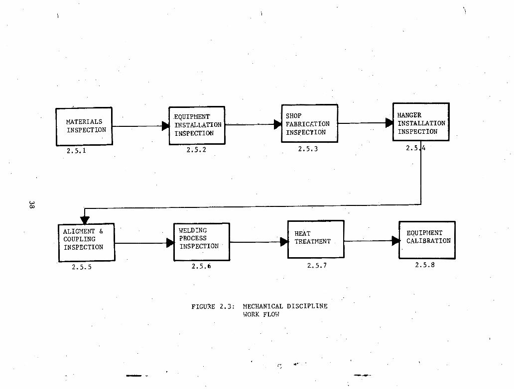
I
IN STALLAmoN - -. . - . . .. .. -- ) FABRICLTION 1 INSLALLHl IUN
I N SPECTION INSPECTIW INSPECTION INSPECTIO1.I ?
I .
- - - e 11.
FIGU3E 2 . 3 : MECHANICAL DISCIPLINE WORK FLOTJ
. EOUIPT.IENT CALIBRATION
ALIQ4ENT h WELDING COUPLING TROCESS I N SPECTION INSPECTION
HEAT t TREATMENT .
* r h
2.5.6 2.. 5. 7 2.5.8 2.5.5
2 .5 .1 M a t e r i a l s In spec t ions
~ a t h r i a l s t y p i c a l l y rece ived i n t h e mechanica l .a rea inc lude
t u r b i n e s , pumps, l a r g e and small bo re p ip ing . A s i tems a r e r ece ived ,
they must be inspec ted and accepted by QC i n s p e c t o r s . There a r e t h r e e
gene ra l a r e a s t h a t a r e important t o i n spec t upon r e c e i p t . These a r e a s
can be c l a s s i f i e d a s General Condit ion, P r o t e c t i o n , and Paperwork.
The f i r s t a r e a inspec ted i s t h e "General Condition" of rece ived
. , .products. This inspect . lon documents t h a t the m a t e r i a l s were rece ived
i n good cond i t i on and t h a t t h e i n s t r u c t i o n s on t h e Purchase Order were
c a r r i e d ou t . An in spec to r i s r equ i r ed t o i n spec t f o r . t h e cond i t i on of
t he meta l . This i nc ludes checking f o r bx ida t ion , s c r a t c h e s , and den t s ,
o r any o t h e r s i g n s of mistreatment t h a t might i n d i c a t e improper packing
o r shipping procedures . i
The m a t e r i a l must be packed i n such a way a s . t o be p ro t ec t ed from
,, . , ' . t h e elements and acciclerital damage a s r equ i r ed by t h e s p e c i f i c a t i o n s
and i n s t r u c t i o n s on t h e Purchase Order. Th i s could inc lude such t h i n g s
a s s e a l i n g t h e ends w i t h a p r o t e c t i v e covering, proper c r a t i n g , p r o t e c t i v e
co.verings o r coa t ings . I f r equ i r ed , . p a r t of t h e p r o t e c t i o n could inc lude
s p e c i a l environments such a s limits on humidity and temperature o r , use
of a n i n e r t gas purge. ~.
The r e c e i v i n g in spec to r must a l s o check t h a t a l l documentation has t
been r ece ived . Th i s i nvo lves m i l l c e r t i f i c a t i o n , l e t t e r s of compliance,
i n s t r u c t i o n s , s p e c i f i c a t i o n s , drawings, and any o ther ' documents s p e c i f i e d
i n t h e Purchase Order.

2.5 .2 Equipment I n s t a l l a t i o n
Because of t he . impor t ance of much of t h e equipment, i n spec t ions
a r e made t o i n s u r e prop'er i n s t a l l a t i o n , Typical i n s p e c t i o n s t h a t would
be made a r e f i t - u p in spec t ions , f l a n g e in spec t ions , alignment and
coupling . i n s p e c t i o n s . A£ t e r t h e equipment is i n t a l l e d , cont inued
i n s p e c t i o n s might i nc lude motor r o t a t i on i n s p e c t i o n s and l u b r i c a t i o n
in spec t ions .
The f i t - u p i n s p e c t i o n i s made t o i n s u r e t h e equipment is l eve l ed
p rope r ly and t h a t t h e manufac tu re r ' s recommendations have been fol lowed.
Th i s i n s u r e s ' t h a t t h e w a r r a n t i e s w i l l be v a l i d and w i l l a l s o decrease 1 7
down t i m e on t h e equipment du r ing p l a n t ope ra t ion due t o improper i n -
s t a l i a t i o n . . .
Flange i n s p e c t i o n s d e a l w i t h t h e connect ion of p ip ing in su r ing
a t i g h t seal and proper fi:t of t h e equipment t o t h e pipe. This n l g o
i n s u r e s . t h e proper amount 'of c l e a n l i n e s s is maintained i n t he sys tem.
2.5.3 Shop F a b r i c a t i o n
C e r t a i n items must be f a b r i c a t e d i n t h e shop be fo re being taken
t o t h e f i e l d t o b e i n s t a l l e d . When t h i s is t h e case, . i n spec t ions must
.be performed b.efore t h e system can b e r e l ea sed t o t h e f i e l d f u r i n -
s t a l l a t i o n . These i n s p e c t i o n s inc lude a l l welding r e l a t e d in spec t ions ,
dimension v e r i f i c a t i o n , and f i n a l checks. The t o p i c of weld r e l a t e d
inspectZons w i l l not be t r e a t e d here but r a t h e r i n a f u t u r e s e c t i o n
on weld in spec t ions .

When t h e 'system i s being p u t t o g e t h e r , hold p o i n t s a r e e s t a b l i s h e d .
These a l low t h e QC i n s p e c t o r s t o v e r i f y t h a t t h e des ign documents have
been c o r r e c t l y t r a n s l a t e d d imens ional ly i n t o a f i n ighed product . The
i n s p e c t o r s a l s o check t h e gene ra l q u a l i t y ' of t h e work.
A s t he system is completed and ready t o be t r a n s f e r r e d t o t h e
f i e l d , a f i n a l i n s p e c t i o n t akes p l a c e checking t h a t t h e work i s ac-
cep tab le and t h a t t h e support ing paperwork i s i n order .
,, . .
I
2.5 .4 Hanger Ins t a l l a t ion - .
Hangers i n s t a l l e d t o support p ip ing must be r i g i d l y in spec t ed .
Usual ly a group of hanger des igns i s approved f o r a s p e c i f i c p l a n t .
A c e r t a i n hanger can be des igna ted t o .support a c e r t a i n s e c t i o n of
piping o r t he des igner could a l low t h e f i e l d t o choose t h e most
s u i t a b l e hanger. I n e i t h e r ca se t h e hanger must be p h y s i c a l l y des ig-
natdd i n t he f i e l d a s t o i t s type. An i n s p e c t o r w i l l i n spec t hangers
f o r conformance t o drawings, and check t o s e e t h a t t h e proper welding
and m a t e r i a l documentation e x i s t s t o suppor t t h e work.
2.5.5 , - ~ ~ i g n m e n t and cbupling
Alignment and coupling i n s p e c t i o n s d e a l wi th t h e l i n k of t h e
d r i v i n g mechanism t o t h e d r iven element. They ensure t h a t minimum
l e v e l s of v i b r a t i o n and runout a r e main ta ined . . .
A f t e r . t he equipment i s i n s t a l l e d , i t must be maintained i n
o p e r a t i o n a l cond i t i on p r i o r to o p e r a t i o n , This i nc ludes r o t a t i o n of .
t h e motor a t s e t i n t e r v a l s t o r e l i e v e s t r a i n s w i th in t h e system. \
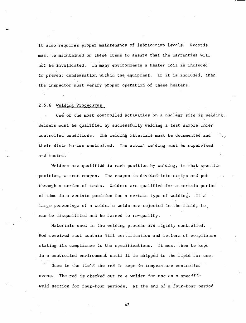
I t a l s o r e q u i r e s proper maintenance of l u b r i c a t i o n l e v e l s . Records
must be main ta ined on these items t o a s s u r e t h a t t h e war ran t i e s w i l l
no t be i n v a l i d a t e d . I n many environments a h e a t e r c o i l i s included
t o prevent condensa t ion w i t h i n the, equipment. I f i t i s inc luded , then
t h e in spec to r must v e r i f y proper ope ra t ion of t h e s e h e a t e r s .
2.5.6 Welding Procedures
On6 of t h e most c o n t r o l l e d a c t i v i t i e s on a nuc lear s i t e i s welding.
Welders must be q u a l i f i e d by s u c c e s s f u l l y welding a t e s t sample under
c o n t r o l l e d cond i t i ons . The welding m a t e r i a l s must be documented and ;.
t h e i r d i s t r i b u t i o n c o n t r o l l e d . The a c t u a l welding must be superv ised
and t e s t e d .
Welders a r e q u a l i f i e d i n each p o s i t i o n by welding, i n t h a t s p e c i f i c
p o s i t i o n , a t e s t coupon. The coupon i s d iv ided i n t o s t r i p s and puL
through a . s e r i e s of t e s t s . Welders a r e q u a l i f i e d f o r a c e r t a i n period .
of t ime i n a c e r t a i n p o s i t i o n f o r a c e r t a i n type of welding.. . I f a.
l a r g e percentage of a welder ' s welds a r e r e j e c t e d i n t he f i e l d , h e . . .
can be d i s q u a l i f i e d and be fo rced t o re -qua l i fy .
M a t e r i a l s used i n t h e welding p roces s are r i g i d l y c o n t r o l l e d .
Rod r ece ived must con ta in m i l l c e r t i f i c a t i o n and l e t t e r s of compliance
s t a t i n g i t s compliance t 6 t h e s p e c i f i c a t i o n s . It must then be kept
i n a c o n t r o l l e d environment u n t i l i t is shipped t o t h e f i e l d f o r use .
Once i n t h e f i e l d t h e rod is kept i n temperature c o n t r o l l e d
ovens. The rod i s checked out t o a welder f o r u s e on a s p e c i f i c
weld s e c t i o n f o r four-hour pe r iods . A t t h e end of a four-hour per iod

t h e rod is then put back i n t h e o v e n . t o d r y out u n t i l t h e next day.
The af te rnoon ' rod i s checked ou t from ano the r oven. ~ e m ~ e r a t u r e i n
t h e oven i s recorded p e r i o d i c a l l y . a n d kept a s a permanent r eco rd .
A rod c o n t r o l i s s u e l ist is kept and r e c o r d s t h e beak number, t h e
welder t h e rod was i ssued t o , t h e d a t e and time, t h e weld t h e rod was
going t o be used on, t h e rod consumed, and t h e s t u b s r e tu rned .
Welding i n . t he f i e l d is Pnspected a t r e g u l a r i n t e r v a l s , The
i n s p e c t i o n w i l l i nc lude checking t h e v o l t a g e , the amperage, t h e
' i n t e r p a s s temperature, t h e r a t e of t r a v e l , t h e rod ' used, t h e carbon
con ten t , purge g a s f low r a t e , and t h e g e n e r a l appearance of t h e ,work. "
Each r e p o r t is f i l e d a g a i n s t t h e p a r t i c u l a r weld. Also i n t h e packet
of p e r t i n e n t weld documentation f o r p ip ing a t a c k i n s p e c t i o n a s we l l
! a s a r o o t pas s i n s p e c t i o n w i l l appear .
Each of t h e s e in spec t ions r e q u i r e s t h e s i g n a t u r e of a q u a l i f i e d ,
. . i n spec to r . To be q u a l i f i e d , an i l l spec tor must have a n eye examination , ,
and must t ake a t e s t and demonstrate a complete knowledge of t h e appl-i-
c a b l e codes and s tandards .
During t h e weld p roces s c e r t a i n t e s t s a r e r u n on t h e weld s e c t i o n .
These inc lude radiograph, u l t r a s o n i c , and d i e pene t ran t t e s t i n g . These
types of t e s t s check f o r weaknesses i n t h e me ta l a n d , a r e kept a s a n
h i s t o r i c a l record .
A l l of t h e above i n s p e c t i o n r e p o r t s a r e kept f i l e d a g a i n s t a
s p e c f f l c weld. They c e r t i f y t h a t th.e weld has been e f f e c t e d proper ly .

2.5.7 . ÿ eat Treatment
Af t e r a weld h a s been made i t i s o f t e n r equ i r ed , because of t h e
' special o p e r a t i o n a l c o n d i t i o n s , t o be s t r e s s r e l i e v e d . This is done
by wrapping t h e weld a r e a wi th a hea t ing b l anke t , i nc reas ing the tempera- . .
t u r e t o j u s t below t h e c r i t i c a l temperature of 1000 t o 1200' F , and . '
holding. it t h e r e f o r a few hours . Af t e r t h e hea t ing process i s complete
t h e meta l i s a l l o w e d . t o coo l s lowly, t h u s completing t h e p roces s .o f
s t r e s s r e l i e f annea l ing .
The types of r e c o r d s kept a r e tempera ture graph, d a t e s , h e a t r a t e ,
h e a t i n g ' t i m e , and coo l ing r a t e i n OF/hr. These r e c o r d s a r e a l s o f i l e d - :
w i t h the weld informat ion f o r a s p e c l f i c weld.
2.5.8 Equipment C a l i b r a t i o n
A l l equipment used tu v e r i f y c o n s t r u c t i o n procedures is requi red
t o be c a l i b r a t e d p e r i o d i c a l l y . Types of equipment t h a t would t y p i c d i . 1 ~
be c e r t i f i e d i n c l u d e to rque wrenches, pyrometers, carbon t e s t e r s , amp
and v o l t gauges, and rod oven temperature gauges. Many t imes on a
job s i t e t h e r e is a c a l i b r a t i o n and s t a n d a r d s l a b t h a t c a l i b r a t e s a l l
t ,he gauges.and t o o l s on t h e s i t e . Each t o o l i s numbered and daked a s
t o t h e l a s t d a t e of c e r t i f i c a t i o n . These t e s t s i n s u r e t h a t the t o o l s
used i n t h e f i e l d a r e c o r r e c t and a c c u r a t e by measuring them a g a i n s t
a known s t anda rd .

2 . 6 ' E l e c t r i c a l Qual i ty Control
The QA/QC documentation' r equ i r ed f o r t h e e l e c t r i c a l d i v i s i o n
of t he average nuc lear power p l an t encompasses 100,000 s h e e t s of r e p o r t s ,
i n spec t ions , procedures , and d i s p o s i t i o n s . Many s h e e t s of t h a t documenta-
t i o n w i l l never be used. A t t he p r e s e n t t ime, r e g u l a t o r y bodies have
not made i t c l e a r w h a t backup paper i s requi red t o adequate ly document
t h e QA/QC programs. A s a r e s u l t of t h i s , t h e g e n e r a l consensus wi th in
t h e indus t ry i s t o documerit everything t h a t could p o s s i b l y be quest ioned.
It i s r e a l i z e d t h a t some support paper can always be d is regarded i f
found t o be too ex tens ive , buL i f necessary paper i s not a v a i l a b l e ,
i t can be d i s a s t r o u s .
I n the fo l lowing pages, t h e QC process w i l l be examined from be-
g inning t o end, expla in ing , t o some e x t e n t , how t h i s ,paper is genera ted ,
, . why i t i s .needed, and how i t is used. To accomplish t h i s , t h e f o l l o d i d g
f i v e main t o p i c s wi1.l be d i scussed a s they r e l a t e t o the e l e c t r i c a l . .
. QA/QC d i v i s i o n :
1 ) Bidder q u a l i f i c a t i o n s
2 ) Vendor s u r v e i l l a n c e
3 ) QC procedure upon r e c e i p t of m a t e r i a l s
4 ) QC f i e l d i n spec t ion
5)' QC fo l lowing i n s t a l l a t i o n
1.0 CFR 50 Appendix. B, t he Bib le of nuc lea r Q u a l i t y Control , s t a t e s
i n T i t l e Seven t h a t "Measures s h a l l be e s t a b l i s h e d t o a s s u r e t h a t purchased
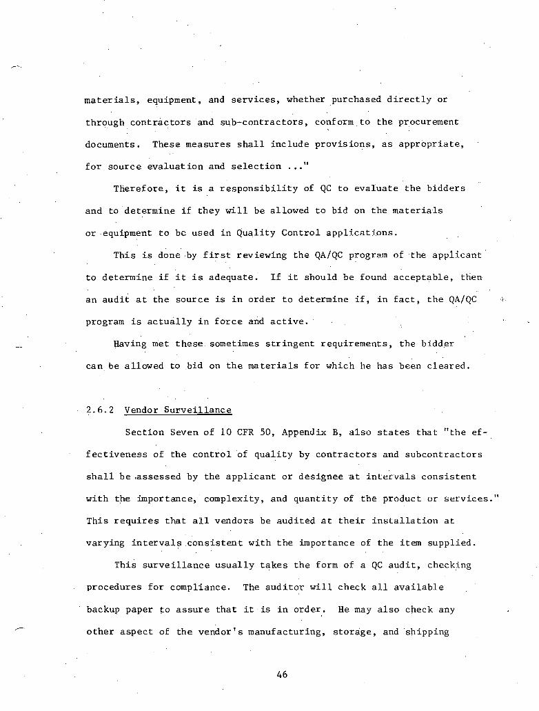
m a t e r i a l s , equipment, and s e r v i c e s , whether purchased d i r e c t l y o r
through c o n t r a c t o r s 'and sub-cont rac tors , con£ orm . t o t h e procurement
documents. These measures s h a l l i nc lude p rov i s ions , a s a p p r o p r i a t e ,
f o r sou rce e v a l u a t i o n -and s e l e c t i o n . . ." Therefore, i t is a r e s p o n s i b i l i t y of QC t o eva lua t e t h e b idders
and t o de te rmine i f t hey w i l l be allowed t o b id on t h e m a t e r i a l s
o r -equipment t o be used i n Qua l i t y Cont ro l appl j , ca t ions .
This is done'.by f i r s t reviewing t h e QAIQC program of the a p p l i c a n t
t o determine i f i t i s adequate . I f i t should be found accep tab le , then
a n a u d i t a t t h e sou rce is i n o rde r t o determine i f , i n f a c t , t h e QAIQC!
program i s a c t u a l l y i n f o r c e and a c t i v e .
Having met t h e s e , sometimes s t r i n g e n t requi rements , t h e b idder
can be allowed t o b id on t h e m a t e r i a l s f o r which he has been c l ea red .
2.6.2 Vendor S u r v e i l l a n c e
Sec t ion Seven of 10 CFR 50, Appendix B, a l s o s t a t e , s t h a t " the e f -
f e c t i v e n e s s of t h e c o n t r o l of q u a l i t y by c o n t r a c t o r s and subcon t r ac to r s
s h a l l b e <assessed by t h e a p p l i c a n t o r des ignee a t i nLe rva l s c o n s i s t e n t
w i th the importance, ' complexity, and q u a n t i t y of t h e product u r s e rv i ces . "
This r e q u i r e s t h a t a l l vendors be aud i t ed a t t h e i r i n s t a l l a t i o n a t
vary ing i n t e r v a l s . c o n s i s t e n t w i t h t h e importance of t h e item suppl ied . . .
his s u r v e i l l a n c e u s u a l l y t a k e s t h e form of a QC a u d i t , checking
procedures f o r compliance. The a u d i t o r w i l l check a l l a v a i l a b l e
backup paper t o a s s u r e t h a t i t . is i n o rde r . He may a l s o check any
o t h e r a spec t of t h e vendor I s manufactur ing, s t o r a g e , and -shipping
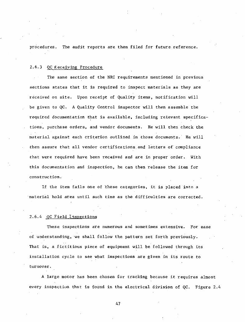
procedures . The a u d i t r e p o r t s a r e t hen f i l e d f o r f u t u r e . r e f e r e n c e .
2 .6 .3 QC % ece iv ing Procedure
. . The same s e c t i o n of t h e NRC requirements mentioned i n prev ious
s e c t i o n s s t a t e s t h a t i t is r equ i r ed t o i n spec t m a t e r i a l s a s they a r e
rece ived .on s i t e . Upon r e c e i p t of Qua l i t y items, n o t i f i c a t i o n w i l l
be g iven t o QC. A Qua l i ty Cont ro l i n spec to r w i l l then assemble t h e
r equ i r ed document a t ion t h a t i s a v a i l a b l e , i nc lud ing r e l e v a n t spec i f i ca -
t i o n s , purchase o rde r s , and vendor documents. He w i l l then check t h e
m a t e r i a l a g a i n s t each c r i t e r i o n o u t l i n e d i n t hose documents. ' H e w i l l
then a s s u r e t h a t a l l vendor c e r t i f i c a t i o n s , and l e t t e r s o f ' compliance
t h a t were r equ i r ed have been rece ived and a r e i n proper o rde r . With
t h i s documentation and in spec t ion , he can then r e l e a s e t h e i t e m f o r
cons t r u c t i o n ..
I f t h e i tem f a i l s one of ' these c a t e g o r i e s , it is placed i n t n a
m a t e r i a l hold a r e a u n t i l such t ime a s t h e d i f f i c u l t i e s a r e c o r r e c t e d .
2 . 6 . 4 QC F i e l d I n s p e c t i o n s
These in spec t ions a r e numerous and sometimes ex tens ive . For ea se
of understanding, .we s h a l l fo l low t h e p a t t e r n s e t f o r t h p rev ious ly .
That is, a f i c ' t i t i o u s p i ece of equipment w i l l be followed through i t s
i n s t a l l a t i o n c y c l e t o s e e what i n s p e c t i o n s a r e g iven i n i t s r o u t e t o
turnover .
A l a r g e motor has been chosen f o r t r ack ing because i t r e q u i r e s almost
every inspec t ic~i l that i s found i n t h e e l e c t r i c a l d i v i s i o n of QC. F i g u r e 2 .4
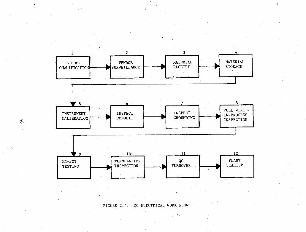
7 5 6 - 7 8 L
PULL WIRE - INSTRLPlENT INSPEC? INSPECT IN-PROCESS CALIBRATION ' CON'DUI'7 GROUNDING
INSPECTION
_r J
6
1 2 . 3 ' 4
10 11 12 . h
HI-POT TERMLIJATIOK QC PLANT
TESTING INSPZCTION TURNOVER STARTUP
.
FIGURE 2 . 4 : QC ELECTRICAL WORK FLOW
MATERIAL STORAGE
?
BIDDER QUALIFICATION
VENDOR MATERIAL
) S U R V E I L W C E RECEIPT ' .
* A t ' . . - . . 1
t

\ .
TABLE 2.3: QC ELECTRICAL INPUT/OUTPUT SHEET
A c t i v i t y Information I n Information Out I
Bidder q u a l i f i c a t i o n Vendor QA/QC program Approval QA/QC program (1) S p e c i f i c a t i o n s (Vendor)
M a t e r i a l requi rements Q u a l i f i c a t i o n s t a t u s
Vendor sur - Spec i f i c a t i o n of vendor V e r i f i c a t i o n of vendor v e i l l a n c e QAIQC program QA/QC program
(2). S p e c i f i c a t i o n s ' Report of Audit Procedures
. Audit po in t s
Mate r i a l r e c e i p t (3 1
Mate r i a l s t o r a g e ( 4 )
Instrument c a l i - bra t ion
(5)
N o t i f i c a t i o n of r e c e i p t Purchase o r d e r S p e c i f i c a t i o n s Proc.edures Ma te r i a l requi rements
' C e r t i f i c a t i o n L e t t e r of compliance B i l l of l a d i n g
Manufacturers ' r equ i r e - ments
S p e c i f i c a t i o n s Procedures
P e r i o d i c inspec t i o n Specif i c a t i o n s Procedures Known r e f e r e n c e b lock
Acceptance r e p o r t Non-Conformance Report (NCR) Minor V a r i a t i o n Report (MVR) Hold t ag , i n c . IIold Area
l o c a t ion
. .
V e r i f i c a t i o n of dondi t ions NCR MVR old . t a g
C e r t i f i ca t i -on .
NCR
Inspec t conduit Conduit i n s t a l l a t i o n Conduit In spec t ion Report ( 6 ) form NCR
MVR S p e c i f i c a t i o n s . . Hold t ag Procedures
Drawings "Approved f o r pu l l " s t a t u s
In spec t grounding Equipment I n s t a l l a t i o n MVR (7 Report NCR
S p e c i f i c a t i o n s Hold Froccdurca EquipmenL I n s t a l l a t i o n In- Drawings s p e c t i o n Report
(cont inued)
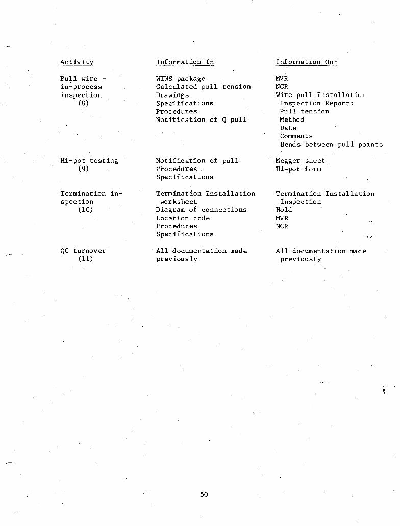
A c t i v i t y Information I n Information Out
P u l l wi re - WIWS package MV R in-process Calcu la ted p u l l t ens ion NCR i n s p e c t i o n Drawings Wire p u l l I n s t a l l a t i o n
(8 S p e c i f i c a t i o n s Inspec t i on Report : Procedures P u l l t ens ion N o t i f i c a t i o n of Q p u l l Method
Date Comment s Bends between p u l l p o i n t s
Hi-po t t ' e s t i ng ( 9 )
Terminat i on in: spec t i o n
(1 0)
N o t i f i c a t i o n of p u l l ProceddPee . S p e c i f i c a t i o n s
Termination I n s t a l l a t i o n worksheet
Diagram of connect ions Locat ion code Procedures Spec i f i c a t i o n s
Megger shee t HI-po t Fo.r.m
Termination I n s t a l l a t i o n ~ n s p e c t i o n
Hold MVR NCR
QC turnover A l l documentation made A l l documentatTon made (1 1) p rev ious ly previous ly
shows the in spec t ions along the pa th . of procurement, i n s t a l l a t i o n ,
and ' primary t e s t i n g . Input and Output i tems f o r each a c t i v i t y i n t h e
cyc l e a r e . t o be found i n Table 2 . 3 . ' Since t h e procedures of i n spec t ion
up t o QC.rece ip t a t . t he warehouse have been d iscussed i n some d e t a i l
i n t he preceding s e c t i o n s , we w i l l begin a t S t ep F ive , Instrument
C a l i b r a t i o n , and proceed through t o S tep Eleven, o r QC Turnover.
/
2.6.5 In s trument C a l i b r a t i o n
A l l ins t ruments and t o o l s c r i t i c a l t o t h e proper ope ra t ion of
the tnoLvr .must be p e r i o d i c a l l y checked, c a l i b r a t e d , .and c e r t i f i e d
t o determine t h a t they a r e w i t h i n to l e rance . A few examples w i l l be . .
c ' i t ed .
I f t h e motor hold down b o l t s must be torqued down t o a s p e c i f i c
pressure , then t h e torque wrench used must be c a l i b r a t e d t o g ive ac- /
c u r a t e r ead ings w i t h i n s p e c i f i e d l i m i t s . The wrench, t h e r e f o r e , must
be' l ; e r iod ica l ly t e s t e d and c a l i b r a t e d a g a i n s t a known q u a n t i t y t o as-
s u r e accuracy of . i n s t a l l a t i o n .
Within the e l e c t r i c a l d i v i s i o n , t e rmina t ion of h igh v o l t a g e c a b l e
is very c r i t i c a l . I f mechanical w i r e s t r i p p e r s a r e u s e d , ' t h e y m u s t be
c a l i b r a t e d t o a s s u r e t h a t t h e jaws don1 t "nick" t h e conductor , t h u s r e -
ducing t h e ' c r o s s - s e c t i o n a l a r ea of t h e c a b l e and causing e l e c t r i c a l s t r e s s
p o f n t s i n t h e c a b l e i t s e l f . I f a hydrau l i c crimping t o o l i s used t o i n - \
s t a l l the lug , i t must be c a l i b r a t e d t o a s s u r e t h a t it w i l l no t break
s t r a n d s i n the connect ion.

Each of t h e s e ope ra t ions r e q u i r e s t h e t o o l s o r ins t ruments t o be
c a l i b r a t e d . p e r i o d i c a l 1 y and a c c u r a t e r eco rds kept of t h e r e s u l t s .
Reference 1 0 CFR 50, Appendix B, Sec t ion .12.
2.6.6 I n s p e c t i o n of Conduit
There a r e t y p i c a l l y s i x thousand q u a l i t y r e l a t e d condu i t s i n a
n ~ ~ r . l e a r p l a n t , A t e s t program must be i n s t i t u t e d t o assure char: c11e
c.onduit i s i n s t a l l e d , supported, and grounded i n accordance wi th t h e
s p e c i f i c a t i o n s and drawings.
A sampling p l a n i s u s u a l l y s e t up t o i n s p e c t a r ep re se r l r a t i ve
number of i n s t a l l a t i o n s . Th i s p l an i s tadhered t o u n l e s s t h e r e j e c t i o n
r a t e i n c r e a s e s . I n t h a t c a s e t h e in spec t ion r a t e could go t o 100%.
The i n s p e c t o r t y p i c a l l y i n s p e c t s t h e condui t as t o r o u t i n g accuracy , .
us ing t h e condui t drawings a s a source; t h e type of support system,
u s ing drawings of approach hangers a s a r e fe rence ; and tlie growlding
method, a s s u r i n g himself and documenting t h a t t h e metliod of grounding
is i n accordance w i t h t h e s p e c i f i c a t i o n s and approved i n t h e procedures .
The i n s t a l l a t i o n must a l s o be v i s i b l y , p h y s i c a l l y documented wi th t ape
on the p i p e i n d i c a t i n g c o l o r code f o r ; t t a l i t y and marks om t h e support
system i n d i c a t i n g t h e type i d e n t i f i c a t i u n of t he h a i ~ g e r f o r r e f e r e n c e . fi
Grounding Equipment In spec t ion
Qua l i t y equipment must be grounded t o i n s u r e proper ope ra t ion and
s a f e t y . It is t h e r e s p o n s i b i l i t y of QC i n s p e c t o r s t o a s s u r e t h a t t h e

grounding i s as r equ i r ed i n t h e s p e c i f i c a t i o n s and procedures . A r e p o r t
i s i ssued t o t h a t e f f e c t and kept a s documentation f o r t h a t equipment.
2.6.8 Wire P u l l i n g In-process In spec t ion
There a r e two types of i n s p e c t i o n processes . The f i r s t i s t h e
hold po in t v a r i e t y , where t h e work p roces s is accomplished and no f u r t h e r
work proceeds u n t i l the i t l spec t ion t a k e s p l ace . This type has been i l l u s -
t r a t e d i n t h e previous two types of i n spec t ions , namely, i n condui t
i n s p e c t i o n and grounding equipment i n spec t ion . The second is. a s u r v e i l l a n c e
type of ' i n s p e c t i o n o r "in-process' ' type. I n t h i s type t h e i n s p e c t o r '
watches t h e work i n p rog res s and documents t h e p roces ses used. . .
Wire p u l l i n g is a .prime example of a n "in-process" type of in-
spec t ion . A s wi re i s being pu l l ed , t h e in spec to r would check t h e
* p u l l t ens ion and method used and would document any problems t h a t
L might a r i s e . If a problem came up t h a t th rea tened t h e i n t e g r i t y of
t h e wire , he has t h e a u t h o r i t y t o shu t t h e p u l l down u n t i l t h e problem
has been c l e a r e d up.
2.6.9 High P o t e n t i a l (Hi-Pot and Megger) Tes t ing
Af t e r a c i r c u i t has been pul led and c e r t i f i e d b y ' f h e w i r e p u l l i n g
i n s p e c t o r , a vo l t age i s a p p l i e d a c r o s s each conductor , u s u a l l y e q u a l . t o
approximately 1% ~11e upera t fng volrage, and t h e c u r r e n t leakage t o
ground is measured. Th i s proves t h e i n t e g r i t y of t h e wi re and in su la -
t i o n . I f t he i n s u l a t i o n has been scraped o f f , t h i s t e s t w i l l i n d i c a t e
a p r n h l em ' w i t h the wire.
53
This t e s t i s done on every wire and cab le , and , t he r e s u l t s a r e
recorded i n a f i l e w i t h other in format ion on t h e c i r c u i t f o r r e f e rence .
2.6.10 Terminat ion I n s p e c t i o n
A f t e r t h e i n s t a l l a t i o n i s complete and t h e t e rmina t ion has
been made, a QC Znspector is requ i r ed t o i n s p e c t t h e te rmina t ion . This
process is a l s o . d6ie bji uslrig a s a p l i n g of approxima~ely,PO7~ of all
t e rmina t ions ( i . e . , a s i n condui t i n s p e c t i o n s ) . The in spec to r checks .
t h a t t h e c i r c u i t is l a i d down on t h e c o r r e c t t e rmina l a s per t h e
"Diagram of Connections" drawing. Be checks t h a t t h e lug is t h e cor- . ,
r e c t s i z e f o r t h e wire used, and t h e t e rmina l on which t h e connect ion
has been made i s t h e c o r r e c t one. The inspec tor checks t h a t t h e wires
a r e formed n e a t l y i n t h e c a b i n e t and t h a t they meet a l l of t h e o the r
requi rements t h a t might be imposed by t h e drawing and t h e procedures
manual.
2.6.11 QC Turnover
A f t e r a l l t h e previous i n s p e c t i o n s have been passed, t h e i tem
is ready f o r tu rnover t o s t a r t -up . To do t h i s , a l l support documentation
t h a t has been accumulated on a p a r t i c u l a r item i s assembled and p u t i n t o
a QC turnover package,

2.7 Conclusion
The q u a l i t y c o n t r o l procedures which have been b r i e f l y desc r ibed
' i n t h e preceding s e c t i o n s imply t h e maintenance and updat ing of l a r g e
volumes o f ' d a t a . Neglect of t h i s d a t a maintenance r e s p o n s i b i l i t y can
l ead t o a c h a o t i c s i t u a t i o n . Use of manual methods'to handle t h i s
requirement i s c o s t l y , time-consuming, and i n e f f i c i e n t . This d a t a
environment is c l e a r l y w e l l s u i t e d t o t h e u s e of computerized methods.
A cursory examination of t h e preceding s e c t i o n s on q u a l i t y c o n t r o l
i n d i c a t e s t h a t l a r g e r e g i s t e r s of d a t a must be maintained f o r :
(1) ~ n d i v i d u a l welds completed . .
(2) Weld rod c o n t r o l
' (3) , Welder q u a l i f i c a t i o n
( 4 ) Receiving in spec t ion of m a t e r i a l s and' vendor c e r t i f i c i t i o n / l e t t e r s of compliance
(5) Hangers i n s t a l l e d
(6) Ind iv idua l c i r c u i t s i n s t a l l e d and c a b l e s pu l l ed
( 7 ) Tool c a l i b r a t i o n r eco rds
(8) I n s t a l l a t i o n hold po in t and " i n process" i n s p e c t i o n d a t a
(9) E l e c t r i c a l i n t e g r i t y (high p o t e n t i a l ) . t e s t s
(10) ~ e i n f o r c i n g s t e e l , c o n t r o l
Although t h i s l i s t is not exhaus t ive and is r e a l l y j u s t t h e " t i p of
t h e iceberg ," it i n d i c a t e s t h e massive amouqts of d a t a which m u s t be
acqui red , processed, and r e t r i e v e d .
'
The ,number of drawings r equ i r ed f o r a s i n g l e nuclkar, p l a n t is i n
excess of 100,000 and accounting f o r t h e s e drawings i s a major a c t i v i t y .

.Some drawings have as Tdany a s six' o r seven r e v i s i o n s which r each t h e
f i e l d s i te and must be d i s t r i b u t e d and c o n t r o l l e d . Over two m i l l i o n
documents must be r e t a i n e d i n t he . fo rm of "as -bui l t " documentation of
t h e p l a n t . A t y p i c a l p l a n t con ta ins 20,000 v a l v e s , 45,000 welds, and
20,000 instruments ' , a l l of which r e q u i r e e x t e n s i v e "as -bui l t " docu-
mentat ion. This l e v e l of in format ion flow and a c c o u n t a b i l i t y is un-
precedented i n "conventional" cons t ruc t ion . Access t o and r e t r i e v a l
of t h i s in format ion is c r i t i c a l to t h e proper c o n t r o l o f ' n u c l e a r power
c o n s t r u c t i o n p r o j e c t s .
The d a t a base concept provides a s u i t a b l e environment f o r a .
s o p h i s t i c a t e d user -or ien ted d a t a r e t r i e v a l system. Data used and
genera ted a t t he p r o j e c t l e v e l i s s t o r e d and maintained i n a h ighly
i n t e g r a t e d s t r u c t u r e i n s t e a d of i n s e p a r a t e a p p l i c a t i o n f i l e s .' h his ' '
approach pe rmi t s o r g a n i z a t i o n of d a t a i n a h i e r a r c h i c a l o r r e l a t i o n a l
system. For example, g iven t h e scheduling network. number of a n a c t i v i t y
of i n t e r e s t , o t h e r information such a s a s s o c i a t e d c o s t codes, r equ i r ed
r e sou rces , equipment u t i l i z e d , a s s o c i a t e d pour numbers, b i l l s of mate-
rials, m a t e r i a l s ' purchased, and m a t e r i a l r ece ived can be r e t r i e v e d .
The d a t a a r e organjxed around s t r a t e g i c a l l y s e l e c t e d "keys" a t
s e v e r a l h i e r a r c h i c a l l e v e l s . Typical keys a r e c o s t code numbers,
a c t i v i t y numbers, TPNS (Tota l P l an t Numbering System) numbers, s t a r t u p
numbers, drawing numbers, purchase o rde r numbers, concre te pour numbers,
personnel badge numbers, equipment numbers, work l o c a t i ons , and vendor
codes. This o r g a n i z a t i o n i n s u r e s t h e r e t r i e v a b i l i t y of d a t a which
c r o s s e s s e v e r a l l e v e l s of d a t a s t r u c t u r e . Reports can be prepared
us ing t h e in£ ormation maintained by s e v e r a l departments . The s t r u c t u r e
a l s o provides t h e means f o r a sys t ema t i c approach t o c o l l e c t i o n and
u t i l i z a t i o n of in£ ormation.
The system being designed must be capable of information r e t r i e v a l
i n r e a l t ime v i a d i s p l a y t e rmina l s . Report r e t r i e v a l language i s de-
s igned so t h a t nonprogramming personnel can u s e t h e system. Except ional
and ad hoc r e p o r t s can be processed w i t h i n a few minutes o r hours de-
pending on t h e complexity of t h e r e p o r t .
Data base schema des ign has t o r e f l e c t t h e o p e r a t i o n a l c h a r a c t e r i s -
t i c s of t he p r o j e c t . The d e f i n i t i o n of every d a t a element has t o be i n
terms of i ts r e l a t i v e p o s i t i o n i n t he schema and t h e s i t e , a s w e l l a s
according t o i ts con ten t , maintenance r e s p o n s i b i l i t y , and s e c u r i t y ,
requirements . The r e l a t i o n a l grouping of d a t a i s e s t a b l i s h e d according
t o r epo r t ing and update experience. A comprehensive d a t a d i c t i o n a r y
a , is being developed t o maintain t h e d a t a i n t h e schema. Thc p r o j e c t
c o n t r o l manager w i l l have a d a t a base a d m i n i s t r a t o r i n , h i s group who
i s f u l l y r e s p o n s i b l e f o r maihtenance and management of t h e d a t a base
and f o r i t s usage. Every use r r e c e i v e s a subschema of t h e d a t a base
conta in ing the informat ion he needs. The schema o r subschema has
mapping char a c t e r i s t i c s t h a t s t r u c t u r e t h e d a t a and d e f i n e r e l a t i o n -
s h i p s w i t h i n t h e s t r u c t u r e . F igure 2.5 ' i n d i c a t e s t h e concept of
~ e l a t i o n s h i ~ s between d a t a and a p p l i c a t i o n s through a schema. I n
F igure 2.6, a simple example of t h e h i e ra rchy of a conc re t e pour schema
i s shown. The informat ion is d i r e c t l y r e l a t e d t o every pour number and,
through cross- re ferenc ing , t o a c o s t code o r schedule a c t i v i t y n m b e r .

The informat ion can be r e t r i e v e d i n t h i s format . I f a r e p o r t is r e -
qu i r ed r e l a t i n g t h e informat ion t o f a c i l i t y components, t h i s can a l s o
be summarized. One might be i n t e r e s t e d i n a r e p o r t parameter such a s
t h e u n i t manhours pe r cub ic yard of conc re t e p laced i n t h e o u t s i d e
w a l l s of a n a u x i l i a r y bui ld ing dur ing January and February a t E1.lOO.
Th i s in format ion can b e r e t r i e v e d provided t h e d a t a i s a v a i l a b l e and
proper r e l a t i o n s h i p s have been e s t a b l i s h e d . he d a t a base a p p l i c a t i o n
i s most u s e f u l when a l a r g e v a r i e t y of except , ional r e p d r t i n g i s r e -
qu i r ed .
This set of d a t a and t h e elements thereof i n f l u e n c e t h e speed
of c o n s t r u c t i o n . QC and q u a l i t y assurance c o n t r o l d a t a a r e t y p i c a l of
t h i s t ype of in format ion . Other elements a r e r equ i r ed f o r f i n a l in -
spec t ion and l i c e n s i n g i n s p e c t i o n s . F i n a l l y , t h e ope ra t ion of t h e
p l a n t r e q u i r e s t h a t c e r t a i n informat ion be r e a d i l y a v a i l a b l e f o r
maintenance and s a f e t y purposes. I t , t o r i n s rance , a weld r u p ~ u ~ e s , ~
i t w i l l be important t o de te rmine immediately who made t h e weld and
what o t h e r welds were made dur ing t h e same t ime per iod . Maintenance
of t h i s massive amount of d a t a r e q u i r e s a s t r u c t u r i n g which a l lows
immediate r e t r i e v a l based on a wide v a r i e t y of a c c e s s c r i t e r i a . It
i s t h e o b j e c t i v e of - t h i s r e s e a r c h t o des ign a n informat ion con t ro l
system which w i l l be. respons ive t o t h e s e requirements-.
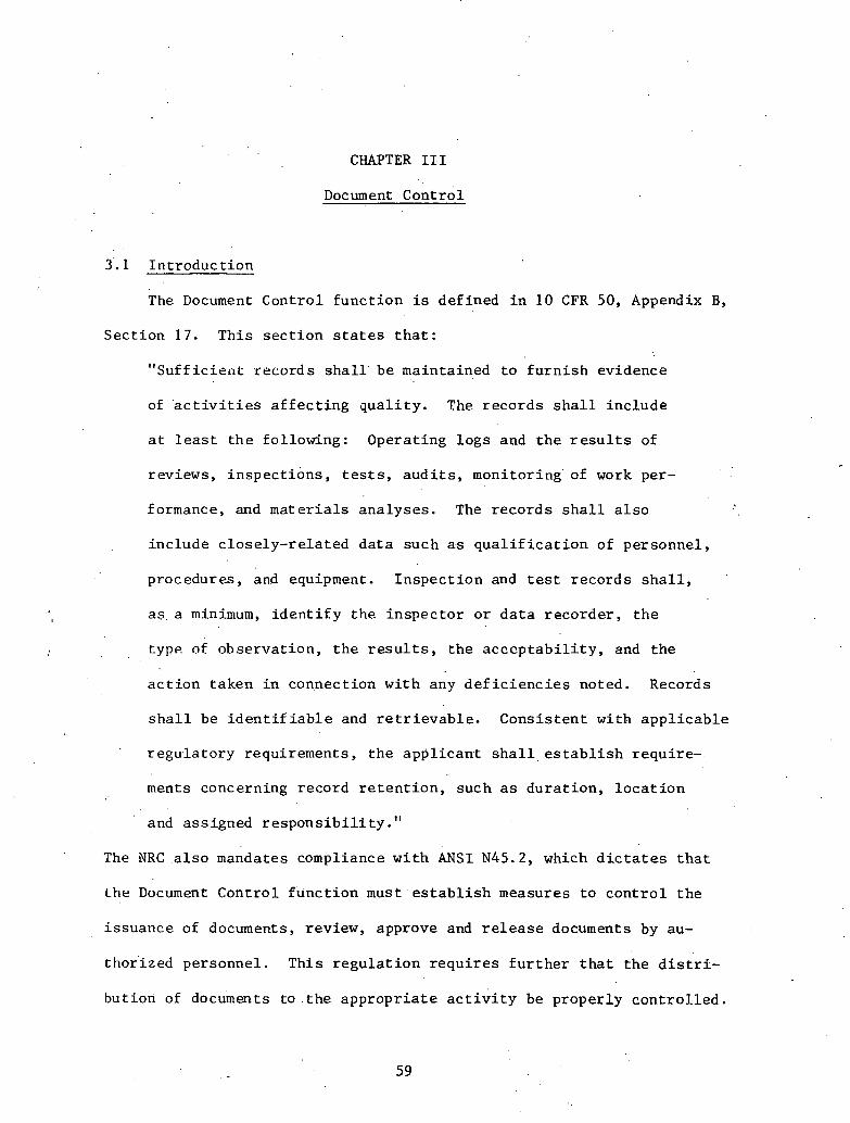
CHAPTER I11
Document c o n t r o l
3.1 I n t r o d u c t i o n
The Document Cont ro l f u n c t i o n is def ined i n 10 CFR 50, Appendix B y
Sec t ion 17 . Th i s s e c t i o n s t a t e s t h a t :
11 Suff i c i e a t r eco rds s h a l l be maintained t o f u r n i s h evidence
of ' a c t i v i t i e s a f f e c t i n g q u a l i t y . The r e c o r d s s h a l l i nc lude
a t l e a s t t h e fol lowing: Operat ing l o g s and t h e r e s u l t s of
reviews, i n s p e c t i o n s , t e s t s , a u d i t s , monitor ing ' of work per-
formance, and m a t e r i a l s ana lyses . The r e c o r d s s h a l l a l s o
inc lude c l o s e l y - r e l a t e d d a t a such a s q u a l i f i c a t i o n of personnel ,
procedures , and equipment. I n s p e c t i o n and t e s t r eco rds s h a l l ,
a s . a minimum, i d e n t i f y the i n s p e c t o r o r d a t a r eco rde r , t h e
type of obse rva t ion , t h e r e s u l t s , t h e a c c c p t a b i l i t y , and t h e
a c t i o n taken i n connect ion wi th any d e f i c i e n c i e s noted. Records
s h a l l be i d e n t i f i a b l e and r e t r i e v a b l e . Cons i s t en t wi th a p p l i c a b l e
r e g u l a t o r y requirements , t h e a p p l i c a n t s h a l 1 , e s t a b l i s h requi re - .
ments concerning record r e t e n t i o n , such a s d u r a t i o n , l o c a t i o n
and ass igned r e s p o n s i b i l i t y ." The NRC a l s o mandates compliance w i t h A N S I N45.2, which d i c t a t e s t h a t
Lhr Document Concrol f u n c t i o n must e s t a b l i s h measures t o c o n t r o l t h e
i s suance of documents, review, approve and r e l e a s e documents by au-
t ho r i zed personnel . Th i s r e g u l a t i o n r e q u i r e s f u r t h e r t h a t t h e d i s t r i -
but ion of documents t o . t h e a p p r o p r i a t e a c t i v i t y be p rope r ly control . led.

The Document Cont ro l system must i n s u r e c h a n g e s - a r e reviewed by t h e
o r i g i n a t i n g o r g a n i z a t i o n , ma in t a in c u r r e n t and updated d i s t r i b u t i o n
l is ts , and review documents f o r l e g i b i l i t y adequacy. ,Document Cont ro l
h a s been . e s t a b l i s h e d t o meet t h e s e government requi remehts and organiza-
t i o n s and d u t i e s a r e r egu la t ed by them.
I n t h e i n d u s t r y today, t h e amount of documentation r equ i r ed
v a r i e s from s i t e t o s i t e , bu t can be as l a r g e as 8 m i l l i u n clocuu~e~l~
s h e e t s . ~ e c a u s e of t h e l a r g e volume of documents and t h e complicated
c o n t r o l measures needed, t h e Document Cont ro l departments a r e in-
c r e a s i n g i n s i z e and complexity. F igu re 3.1 i l l u s t r a t e s t he volume
of documents t h a t is c r e a t e d on a t y p i c a l s i te i n t h e c o n s t r u c t i o n
phase of a p r o j e c t .
There a r e many documents t h a t must be c o n t r o l l e d . These inc lude :
(1) Design Documents - drawings, s p e c i f i c a t i o n s , des ign
v e r i f i c a t i o n . .
(2 ) Vendor, Suppl ie r Documents - drawings, s p e c i f i c a t i o n s ,
manuals, i n s t r u c t i o n s , QA documents.
(3) Cons'tructor Documents - f i e l d 'generated drawings, i n s t r u c t i o n s .
(4) QA/QC Documents - C e r t i f i c a t i o n I n s p e c t i o n r eco rds , Non-Con-
formance Repor ts , a u d i t s , s p e c i f i c a t i o n s , manuals.
(5) Start-Up Documents - s p e c i f i c a t i o n s , lay-out , r e s u l t s ,
c e r t i f i c a t i o n s , procedures .
( 6 ) General Documents - memos, correspondence.
See F i g u r e ' 3 . 2 f o r i n t e r f a c e s .
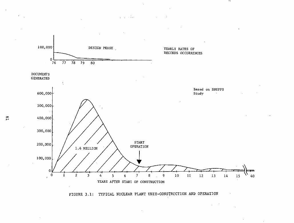
1 0 0 , 0 0 0 . DESIGN PHASE .,
0 76 77 78 79 80
DOCUMENTS GENERATED
YEARLY RATES OF RECORDS OCCURREXCES
Based on SNUPPS S t u d y
YEARS AFTER START OF CONSTRUCTION
FIGURE 3.1: TYPICAL NUCLEAR PLANT UNIT-CONSTRUCTION AND OPERATION

SUBCONTRACTORS
FIGLXE 3 . 2 : MAJOR SOURCES AND RECEIVERS OF DOCUMENTS
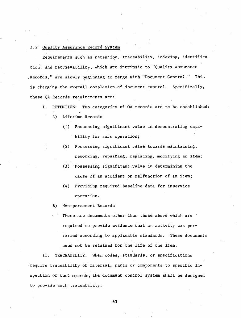
3 . 2 g u a l i t y Assurance Record System
Requirements such as r e t e n t ion , t r a c e a b i l i t y , indexing, i d e n t i f i ca -
t i o n , and r e t r i e v a b i l i t y , which a r e i n t r i n s i c t o "Qual i ty Assurance
Records," a r e s lowly beginning t o merge w i t h "Document Control ." This
is changing t h e o v e r a l l complexion of document, c o n t r o l . S p e c i f i c a l l y ,
t h e s e QA Records requirements a r e :
I. RETENTION: Two c a t e g o r i e s of QA r eco rds a r e t o be e s t a b l i s h e d :
A) Life t ime Records
(1) Possess ing s i g n i f i c a n t v a l u e i n demonstrat ing capa-
b i l i t y f o r s a f e ope ra t ion ;
( 2 ) Possess ing s i g n i f i c a n t v a l u e towards main ta in ing ,
reworking, r e p a i r i n g , r ep l ac ing , modifying an it-;
( 3 ) . Possess ing s i g n i f i c a n t v a l u e i n determining t h e
cause of an acc iden t or mal func t ion of a n i t e m ;
( 4 ) Provid ing requi red b a s e l i n e . d a t a f o r '&se rv i ce
ope ra t ion .
B) Non-permanent Records
These a r e documents o t h e r ' t han those above which a r e
r equ i r ed t o provide evidence t h a t an a c t i v i t y was per-
formed accord ing t o a p p l i c a b l e s tandards . These documents
need not be r e t a i n e d ' f o r t h e l i f e of t h e i tem.
11. TRACEABILITY: When codes, s t anda rds , o r s p e c i f i c a t i o n s
r e q u i r e t r a c e a b i l i t y of m a t e r i a l , p a r t s o r coniponents. t o s p e c i f i c in-
spec t ion o r t e s t records, t he document c o n t r o l system . s h a l l be designed
t o provide such t r a c e a b i l i t y .

11.1. INDEXING: QA r eco rds s h a l l be l i s t e d i n an index t o
i n d i c a t e , a s a minimum, r eco rd r e t e n t i o n time, where t h e record i s t o
be s t o r e d , and t h e 1oca t ion .o f t h e record w i t h i n t h e s t o r a g e a r e a .
I V . . IDENTIFICATION: QA r e c o r d s s h a l l p rovide s u f f i c i e n t in -
format ion t o permit i d e n t i f i c a t i o n between t h e record and t h e i tem
o r items, o r a c t i v i t y t o which i t a p p l i e s .
V. R~~TRIEVABILITYI Storagcl cysLems s h a l l provide fnr t h ~ a r -
c u r a t e r e t r i e v a l of in format ion without undue d e l a y ,
I n o r d e r t o meet t h e s e f i v e requirements , a system has emerged
t h a t i s more t h a n a document c o n t r o l system. It might more appro-
p r i a t e l y be l a b e l l e d a document management system. Examples of
permanent and non-permanent r e c o r d s can be f o u n d . i n Appendix D.
3 . 3 Document Management System
E f f o r t s t o develop an adequate "document management system" have
been undertaken by many of the'member groups of t h e p1.ant c o n s t r u c t i o n
team. ' The u t i l i t y systems department , t h e c o n s t r u c t o r , t h e des igner
( a s i n t h e c a s e of Bech te l ' s Records Management System, RMS); and
p r i v a t e o r g a n i z a t i o n s (e.g. , Zytron, F l o r i d a Computing) have been
working t o develop a comprehensive approach t o document management.
I n gene ra l , t h r e e c l a s s i f i c a t i o n s o r l e v e l s of c a p a b i l i t y have emerged:
I. Document Index System: s imp les t , l e a s t c o s t , most d i r e c t .
11. Document Index and R e t r i e v a l System: more complex.
111. Document Management and R e t r i e v a l System: i n developmental
s t a g e only; . c u r r e n t l y not a v a i l a b l e .
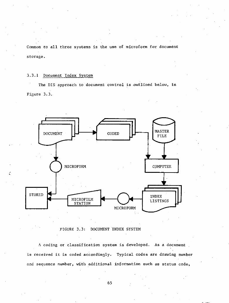
Common t o a l l t h r e e systems i s t h e use of microform f o r document
s to rage .
3.3.1 Document Index Sys tem
The DIS approac l~ . to document c o n t r o l i s .out l ined below, i n
Figure 3 . 3 .
STORED 0s
I
~.
PIICROFILM
t . I
DOCUMENT -
MICROFORM , v
.FIGURE 3.3: DOCUMENT 'INDEX SYSTEM
- FILE
MICROFORM COMPUTER
I .
A
h coding o r c l a s s i f i c a t i o n system i s developed. A s a document
b CODED MASTER
i s rece ived i t is coded accordinsly. Typica l codes a r e drawing number
D
and sequence number, with a d d i t i o n a l in format ion such a s s t a t u s code,
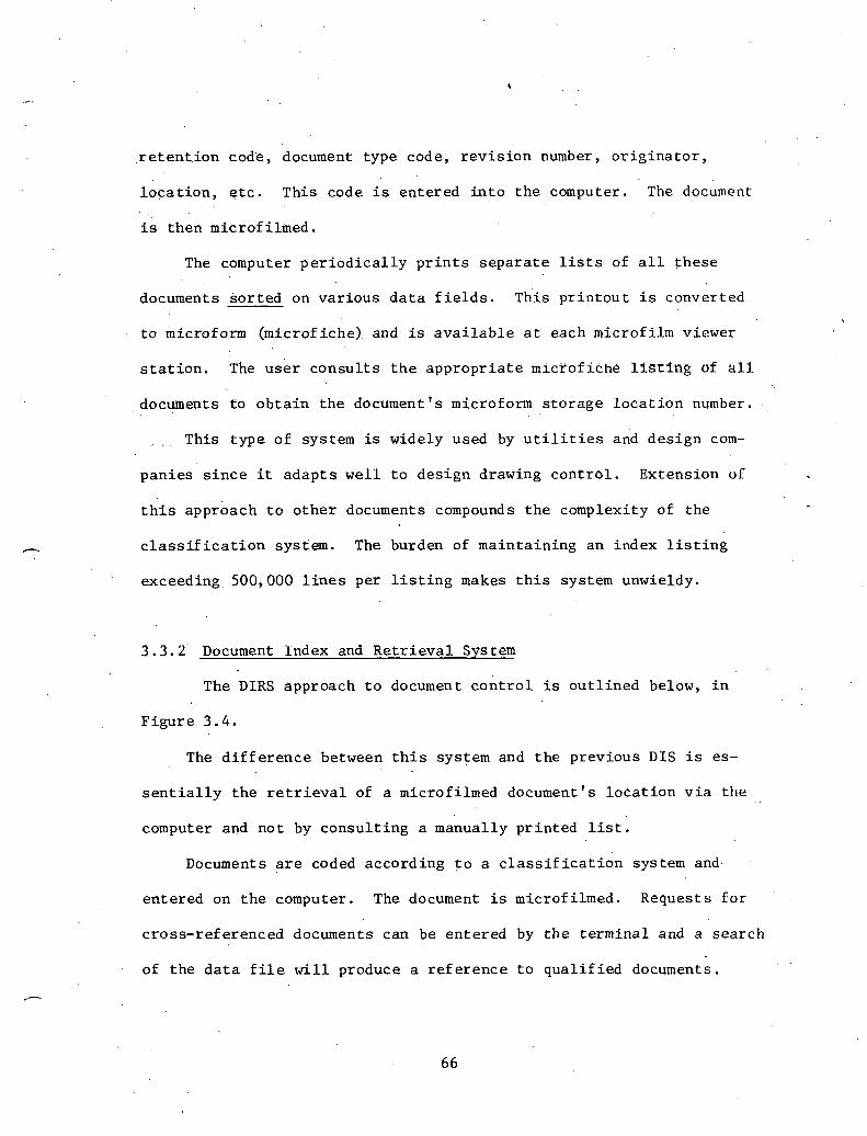
r e t en t . i on code, document type code, r e v i s i o n number, o r i g i n a t o r ,
l o c a t i o n , e t c . This code i s entered i n t o t h e computer. The document
i s then microfi lmed.
The computer p e r i o d i c a l l y p r i n t s s e p a r a t e l is ts of a l l t h e s e . .
documents s o r t e d on v a r i o u s d a t a f i e l d s . his p r i n t o u t i s converted
t o microf o m (microf iche) . and is a v a i l a b l e a t each microf i l m viewer
s t a t i o n . The u s e r c o n s u l t s t h e a p p r o p r i a t e mlcfof iche l f s c i n g of a l l
documents t o o b t a i n t h e document's microform s t o r a g e l o c a t i o n number.
. . . This t ype of system is widely used by u t i l i t i e s and des ign kom-
pan ie s s i n c e it a d a p t s w e l l t o des ign drawing c o n t r o l . Extensiorl of
t h i s approach t o o t h e r documents compounds t h e complexity of t he
c l a s s i f i c a t i o n system. The burden of main ta in ing an index l i s t i n g
exceeding.500,OOO l i n e s per l i s t i n g makes t h i s system unwieldy.
3 . 3 . 2 ' Document Index and R e t r i e v a l Sys tern
The DIRS approach t o document c o n t r o l i s o u t l i n e d below, i n
F igu re 3 . 4 .
The d i f f e r e n c e between t h i s system and t h e previous DIS i s es-
s e n t i a l l y t h e r e t r i e v a l of a microfilmed document's l o c a t i o n v i a t h e
computer and n o t by consu l t i ng a manually p r i n t e d l i s t .
Documents a r e coded accord ing t o a c l a s s i f i c a t i d n system and.
en t e red on t h e computer. The document i s microfi lmed. Requests f o r
c ross - re ferenced documents can be en te red by t h e te rmina l and a search
of t h e d a t a f i l e w i l l produce a r e f e r e n c e t o q u a l i f i e d documents.
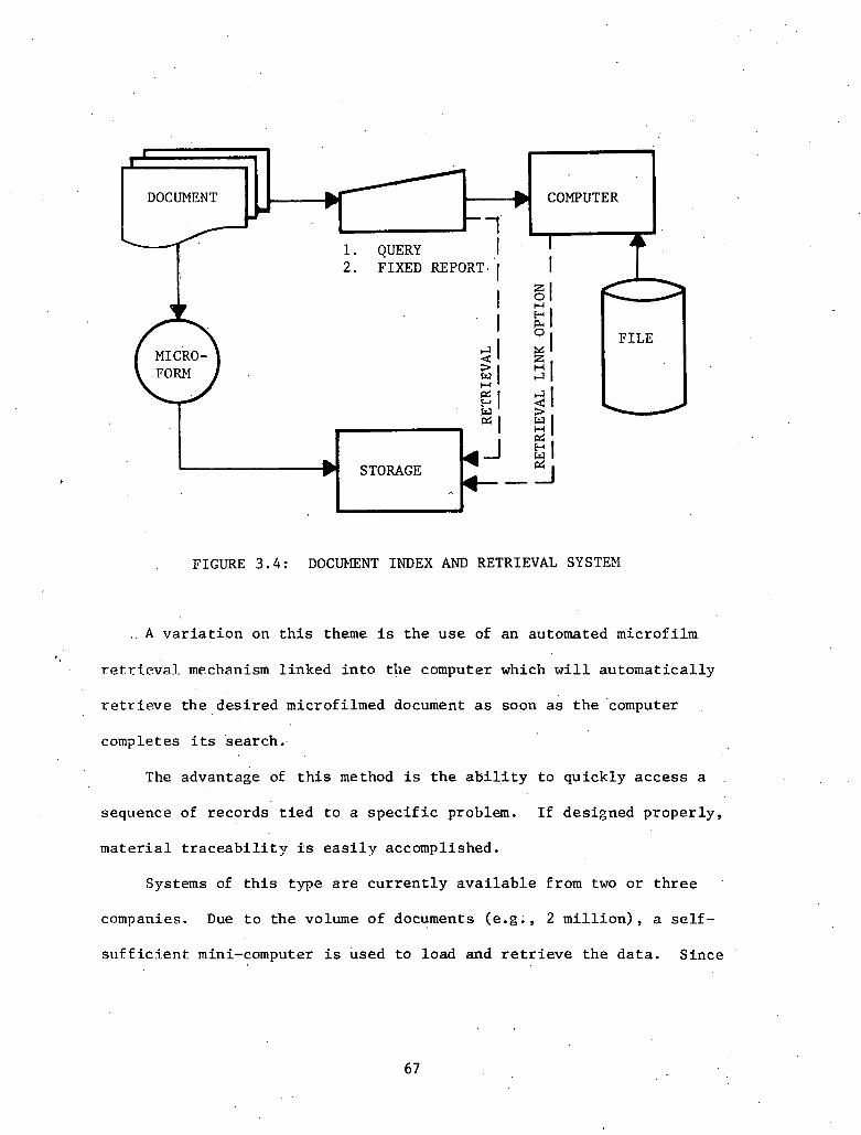
. FIGURE 3 . 4 : DOCUMENT INDEX AND RETRIEVAL SYSTEM
A v a r i a t i o n on t h i s theme is t h e u s e of an automated microfi lm
' . retri.eva.l. mechanism l inked i n t o t h e computer which. w i l l au toma t i ca l ly
r e t r i e v e t h e d e s i r e d microfilmed document as soon a & t h e 'computer
completes i ts search .
The advantage of t h i s method is t h e a b i l i t y t o qu ick ly a c c e s s a
sequence of r eco rds t i e d t o a s p e c i f i c problem. I f designed p rope r ly ,
m a t e r i a l t r a c e a b i l i t y i s e a s i l y accomplished.
Systems of t h i s type a r e c u r r e n t l y a v a i l a b l e from two o r t h r e e
companies. Due t o t h e volume of documents ( e .g . , 2 m i l l i o n ) , a s e l f -
s u f f i c i e n t mini-computer i s used t o load and r e t r i e v e t h e d a t a . S ince

t h i s i s a r e l a t i v e l y new product , it w i l l be a t l e a s e three yeacs
b e f 0 r e . a u s e r e v a l u a t i o n is a v a i l a b l e .
3 . 3 . 3 Document t4anagement and R e t r i e v a l System
The DMRS approach t o document c o n t r o l i s shown conceptua l ly
i n F igure 3.5.
Since fiils syurtlll Is 111 ~ l ~ a clcvalopmcntal otngec, d ~ t a i l ~ r ! jn-
formation is not a v a i l a b l e . The concepe is a n extension of t h e DIRS
w i t h t h e added f e a t u r e of a da t abase l i n k t o a component c o n t r o l /
management system. The i n t e n t is t o l i n k t h e requirement f o r informa-
t i o n o r documentation t o a component and then d e t e r n ~ i n e i f the' docu-
mentat ion has a c t u a l l y been completed.
COMPONENT CONTROL SYSTEH
INDEXING &
DOCUMENT IUNAGEMENT & RETRIEVAL
FIGURE 3.5: DOCUMENT MANAGEMENT AND RETRIEVAL . SYSTEM

3 . 4 Recommendat i ons
There a r e c e r t a i n a r e a s of QA/QC t h a t would b e n e f i t from a con-
s t r u c t i o n informat ion management system. Some of t h e more prominent
a r e a s a r e :
(1) Qua l i t y Assurance Records Management
, ( 2 ) Ma te r i a l Receiving Inspec t ion
( 3 ) QC Manpower P r o j e c t i o n
( 4 ) V e r i f i c a t i o n of Material. T r a c e a b i l i t y
( 5 ) Nonconformance Trends
( 6 ) Vendor Q u a l i f i c a t i o n
Each of t h e above w i l l be d i scussed below.
3 . 4 . 1 Qua l i ty ~ s s u r a n c e ' Records Management System
This is t h e most c . r i t i c a 1 need i n QA/QC. A s mal func t ions
occur , QA/QC i s r equ i r ed t o r e t r i e v e a l l " r e l a t ed" documentation.
P r e s e n t l y , this r e t r i e v a l i s a manual s ea rch of a l l f i l e s u n l e s s t he
sea rch can be l o g i c a l l y l i m i t e d t o a c e r t a i n s e c t i o n of t h e f i l e .
While manpower . is provided t o conduct t h i s s ea rch when necessary ,
i t . i s g e n e r a l l y acknowledged t h a t t h e s e manual s ea rches may no t be
e n t i r e l y complete. S ince c e r t a i n informat ion i s n e a r l y impossible
t o . r e t r i e v e , some ques t ions a r e never asked o r go unanswered. This .
need i s recognized and systems have been developed t o provide some
3 .4 .2 M a t e r i a l Receiving Inspec t ion
The t r a c k i n g and r e c e i p t of m a t e r i a l s , i n most i n s t ances , i s a
manual process . Delays i n i n s p e c t i o n by QC can be caused by unexpected
equipment d e l i v e r y s i n c e t ime is l o s t i n searching f o r t h e i n s p e c t i o n
requi rements f o r . t h e equipment.
There .a re s e v e r a l p o s s i b l e s o l u t i o n s t o t h i s problem and one d i r e c t
approach is t o u t i l i z e Lhe niareriaf Y r e c c l v i l ~ g system. ) f o n t vandors
w i l l n o t i f y Receiving a week or two i n advance of a c t u a l d e l i v e r y d a t e .
This in format ion , made a v a i l a b l e t o QC, would p rov ide s u f f i c i e n t lead
t ime t o i n s u r e a l l s p e c i f i c a t i o n s are prepared f o r t h e r e c e i p t in-
spec t ion .
3.4.3 QC Manpower P ro j ec t io r l
. . Since t h e qua .1 i f i ca t ions of many QC i n s p c c t o r s a r e h ighly s p e - "
c i a l i z e d , a c e r t a i n amount of lcad t ime is necessary ' t o h i r e and c e r t i f y
t h e i n s p e c t o r . It can happen t h a t c o n s t r u c t i o n w i l l h i r e a person
q u a l i f i e d f o r a c e r t a i n s p e c i a l p rocess . Unless QC has an i n s p e c t o r
a v a i l a b l e f o r t h i s s p e c i a l p rocess , no work can be done.
I n o r d e r t o a r ~ t i c i p a t e t h i s problem, two i n t e r f a c e s would be help-
f u l . One would provide a c i o s e t i e w i th c o n s t r u c t i o n ' s workforce pro-
j e c t i o n s (by number of i n d i v i d u a l s , no t manhours), and t h e second
would. l i n k t o t h e personnel r e q u e s t system. Information from both
can a s s i s t QC i n main ta in ing a s t a f f i n g l e v e l s u f f i c i e n t t o keep pace
w i t h t h e c o n s t r u c t i on workforce.
3 . 4 . 4 V e r i f i c a t i o n of M a t e r i a l T r a c e a b i l i t y
Standards r e q u i r e t h a t QA/QC must demonstrate t r a c e a b i l i t y of
c e r t a i n items o r m a t e r i a l . This is a t ed ious c l e r i c a l p roces s t h a t
a t t imes may be overlooked o r d e f e r r e d t o a l a t e r time. Merged wi th a
r eco rds management system, t h i s p roces s could be automated, Included
would be items such a s mix and batch numbers, h e a t number, weld f i l l e r
m a t e r i a l , welder q u a l i f i c a t i o n , measuring instrument c a l i b r a t i o n ,
t e s t r e s u l t s , as w e l l as nonconformance r e p o r t s ,
3 . 4 . 5 Nonconformance Trend A n a l v d s
Nonconformance tr.ending is a v a i l a b l e , bu t a t t imes i s l i m i t e d
i n t h e d a t a a v a i l a b l e f o r a n a l y s i s . Nonconformance t r end ing has a ,
p o t e n t i a l l y l a r g e impact on a p ro j ec t ' s ' pe r fo rmance . The problem i s
t o f i n d t h e s i g n i f i c a n t v a r i a b l e , be i t t h e vendor, the i n s p e c t o r ,
t h e worker, t h e system, o r even the s p e c i f i c a t i b n of t h e m a t e r i a l .
3 . 4 . 6 Vendor Q u a l i f i c a t i o n
There a r e t imes when QA/QC d i scove r s a problem r e f l e c t i n g back
t o t h e vendor. N o t i f i c a t i o n t o procurement u s u a l l y is l o s t i n t h e
mass of paperwork. I d e a l l y a QC s t a t u s f l a g ( c o n t r o l l a b l e by QC)
could be s e t i n a vendor mas ter f i l e t o prevent f u r t h e r procurement
u n t i l t h e problem is reso lved . This f l a g could a l s o be used t o auto-
m a t i c a l l y t r i g g e r a l i s t of a l l i tems on o r d e r , d e l i v e r y , o r even in-
s t a l l e d f o r f u r t h e r i n spec t ion i f needed.
3 . 5 F i e l d ~ e n e r ' a t e d Document System
This sys t em 'has been implemented on t h e Enrico Fermi nuc lear power
p l a n t site. Its primary purpose is t o c o n t r o l Qua l i t y Cont ro l paper-
work. The f i e l d documents c o n t r o l l e d by t h i s system a r e generated by
t h e Qua l i t y Con t ro l Department, Engineering, and subcon t r ac to r s . The
documents c o n t r o l l e d a r e p a r t of t h e d e s i g n documentation of t h e p l a n t
and, s i n c e they a r e dynamic i n n a t u r e , t h e c o n t r o l of t h e o r i g i n a t i o n ,
follow-up,. and complet ion i s very important f o r t h e cuns t ruc t i o n e f f o r t .
The . fo l lowing documents a r e T y p i c a l of t h e types of r e p o r t s der ived
from ' t h i s ' d a t a :
Devia t ion D i s p o s i t i o n ~ e ~ u e ' s t S u r v e i l l a n c e Report Design Change Request Request f o r , C l a r i f i c a t i o n of Informat ion A s B u i l t Documents Design Change Not ice .
Fie ld ~ o d i f i c a t i o n Request
The system p rov ides key informat ion about every document. This
in format ion inc ludes s t a t u s , r e l a t i o n t o components, drawings, des ign
documents, and r e l a t i o n t o ' i n d i v i d u a l groups and d i s c i p l i n e s a t t h e
p r o j e c t . The documents a l s o have a s s igned ca t egory c l a s s i f i c a t i o n
which is important t o evaluate t h e t y p e s of a c t i v i t i e s and d i s c i p l i n e s
which a r e most a f f e c t e d by t h e s e documents.
The system s e r v e s t h e fo l lowing purposes:
(1) S t a t u s c o n t r o l of a c t i v e documents r e l a t e d t o des ign
(2) V e r i f i c a t i o n t h a t t h e documents were included i n new
permanent drawing r e v i s i o n
( 3 ) ~ a i n t e n a n c e of t h e l i s t of cokporients which were a f f e c t e d by
t h e s e changes
( 4 ) Maintenance of a l i s t of permanent drawings a f f e c t e d by t h e s e
documents
( 5 ) S t a t i s t i c a l eva lua t ion of major c a t e g o r i e s , a r e a s , o r con-
d i t ions which cause d e v i a t i o n
Seve ra l thousand documents o f . t h e s e types a r e genera ted on a
p r o j e c t s i t e , and i t i s necessary t o t r a c k a l l such documents through
t h e i r l i f e cyc l e . Samples of t h e r e p o r t s and forms a r e ,shown i n
Addendum C. The Qua l i t y Cont ro l Department is f u l l y r e s p o n s i b l e f o r
t h e document maintenance i n t h e system. The- system i s implemented
us ing an i n t e l l i g e n t t e rmina l i n combination w i t h a l a r g e computer
master f i l e . The t e rmina l e d i t s and v a l i d a t e s t h e informat ion and
prepares i t f o r t r a a s u i s s i o n t o t h e master f i l e .

THIS PAGE I I WAS INTENTIONALLY . . - . I
i
I
LEFT BLANK I
CHAPTER I V
Start-Up
4 . 1 I n t r o d u c t i o n
S ta r t -up of a nuc lear power gene ra t i ng f a c i l i t y i s a long and
c.ornp1.e~ t a s k . It may invo lvc a group of over 250 t e c h n i c a l l y t r a i n e d
persons working f o r a per iod in exces s of six yea r s . During t h i s pe-
r i o d , s t a r t - u p programs a r e e s t a b l i s h e d which g e n e r a t e and p roces s
v a s t amounts of in format ion and d a t a . V i r t u a l l y a l l procedures ,
d,ata systems, and informat ion f i l e s t h a t a r e r equ i r ed f o r commercial
o p e r a t i o n a r e a c t u a l l y developed du r ing t h e s t a r t - u p phase of a
nuc l ea r s t a t i o n . This chap te r examines t h e s e procehures , d a t a , and
- in format ion requi rements .
4 . 2 Star t -up Scope
The t e r m s t a r t - u p i s o f t e n used t o d e s c r i b e t h e t r a n s i t i o n of a
nuc lear f a c i l i t y from t h e c o n s t r u c t i o n phase t o t h e o p e r a t i o n phase.
Th i s d e f i n i t i o n i s a c c u r a t e , bu t t o understand s t a r t - u p , i t must be
.expanded upon.
I n most companies, t h e ope ra t i ng group i s . a c t u a l l y r e s p o n s i b l e
f o r p l a n t s t a r t - u p . Th i s ensu re s a smooth t r a n s i t i o n from t h e s t a r t -
up phase LU commercial ope ra t i on . Pn t h i s c h a p t e r , t h e s t a r t - u p group
w i l l be de f ined a s t h e ope ra t i ng group du r ing t h e s t a r t - u p phase of
a nuc lear s t a t i o n .

The s t a r t - u p phase of a nuc lea r s t a t i o n t y p i c a l l y l a s t s f o r
s e v e r a l y e a r s . even be fo re cons t ruc ' t ion begins , s t a r t - u p personnel
need t o be involved i n t h e development of an i n t e g r a t e d "cons t ruc t ion
s t a r t -up" .schedule. T h i s . schedule i s ext remely ' important because 'il:
c o o r d i n a t e s c o n s t r u c t i o n and s t a r t - u p a c t i v i t i e s t h a t may s p a n ' a s many
a s 1 2 yea r s . S t a r t -up i s complete when the p l a n t i s proven t o meet
a l l r equ i r ed r egu la t ions ' f o r s a f e commercial opera t i.on.
4 . 3 Start-Up Desc r ip t ion
One of t h e i n i t i a l major t a s k s of t h e s t a r t - u p group i s . t o . e s t a b l i s h
t h e s t a r t -up o rgan iza t ion . It is ve ry important t o assemble a s t a f f
which is adequate ly q u a l i f i e d f o r t h e v a r i o u s t e c h n i c a l p o s i t i o n s t h a t
e x i s t a t ' a nuc lea r s t a t i on . This o r g a n i z a t i o n a l development l a s t s
throughout t h e s t a r t - u p phase and u l t i m a t e l y determines t h e success
of the s t a r t - u p group. F igu re 4 .1 i s a t y p i c a l nuc lea r p l a n t srganiza-
The f i r s t phase of p l a n t s t a r t - u p involves t h e t r a n s f e r of systems/
s t r u c t u r e s from t h e c o n s t r u c t i on group t o t h e s t a r t - u p group. Systems
a r e t r a n s f e r r e d t o t h e s t a r t - u p group f o r maintenance, f o r operaLiuu,
and f o r t e s t i n g . To accomplish t h i s t a sk , a turnover procedure i s .
developed t o a s s u r e t h a t t h e r e is. complete understanding of who has
r e s p o n s i b i l i t y £or p l a n t equipment a t a l l times. Usually a L U L L L U J ~ ~
package is put t oge the r f o r each system. Types of in format ion t h a t
may be found i n t h e s e packages a r e system boundary d e s c r i p t i o n s ,
system drawings, Q u a l i t y Assurance acceptance documentation, r e f e r e n c e

MANAGER l-l OPERATING SUIERINrEN-
T E C r n I W . SERVICES SUPERINTEN- SUPERINENDEN
MINISTRATIV
- i
M E W IO\I ' ME=CA.- ADMIN . ENGINEER PERSOINE MAIN- K4IN- - SERVICES
TENAWCE TENAKCE ENGINEER )PERSONEL
SHIFT ?ERSOW-
SITE . HEALTH - HEALTH . PHYSICS PHYSICIST PERSONNEL
INSTRU-
TECHNIC TECHNIC SERVICES SUPPORT ENGINEER PERSINNEL
1 P*
FIGURE 4.1: NUCLEAR STATION START-UP ORGANIZATION

documents, and turnover except ions . A l l t r a n s f e r s even tua l ly become
permanent. It may be necessary , however, t o , t r a n s f e r some systems
t empora r i l y . Th i s a l lows t h e s t a r t - u p group t o t e s t , ope ra t e , and
main ta in t h e system a t a time p r i o r t o f i n a l c o n s t r u c t i o n completion.
A t the. complet ion of f i n a l c o n s t r u c t i o n work on a system, t h e s t a r t - u p
group should v e t i f y t h a t a l l c o n s t r u c t i o n work is complete and t h a t
c o p i e s of a l l r e i e r e n c e documents f o r t h e system a r e a v a i l a b l e iiiefore
accep t ing f i n a l t u rnove r .
~ e f b r e systems a r e turned over t o t h e s t a r t - u p group, system
boundaries , and tu rnove r packages boundaries w i t h i n t h o s e systems, 2
should be completely de f ined . This t a s k o f t e n becomes the respon-
s i b i l i t y of t h e s t a r t - u p group r e q u i r i n g cons ide rab le t ime and r e sea rch .
System scoping should be accomplished, i f p o s s i b l e , i n t h e des ign phase
of t h e p r o j e c t .
Also, 'before systems a r e turned over t o t h e s t a r t - u p group, t h e
s t a r t - u p group should v i s u a l l y i n s p e c t t h e system i n t h e f i e l d . Many
problems a r e e a s i l y s een i n t h e f i e l d and i t i s o f t e n advantageous t o
c l e a r t h e s e problems be fo re system t r a n s f e r . This pre- turnover check
may be r e f e r r e d t o a s acceptance t e s t i n g . Data Shee ts o r work r eques t
forms may be used t o document t h e s e tests a s i s s p e c i f i e d i n t h e appro- r I I ! j
p r i a t e p r o j e c t procedure.
F lush ing t o remove f o r e i g n d e b r i s from p i p e s , t anks , pumps, and
ins t rument l i n e s may be completed by c o n s t r u c t i o n or t h e s t a r t - u p group
depending on the l i n e s of r e s p o n s i b i l i t y . F lush ing is completed and
documented i n accordance wi th e s t a b l i s h e d procedures . Hydro t e s t i n g
of systems u s u a l l y fo l lows f l u s h i n g and i n s u r e s t h a t t h e r e a r e no
l e a k s and t h a t t h e system can s a f e l y handle des ign p re s su re .
Because of t h e many a r e a s of i n t e r f a c e between cons t ruc t ion and
s t a r t - u p groups dur ing s y s t e m / s t r u c t u r e turnover , i t i s important t h a t
t h e s e groups communicate and work c o n s t r u c t i v e l y toge the r . I n t h i s
e f f o r t , c o n s t r u c t i o n / s t a r t - u p i n t e r f a c e meet ings a r e he ld on a r e g u l a r
b a s i s (u sua l ly weekly) t o coo rd ina t e work a c t i v i t i e s .
An eng.ineer i s u s u a l l y ass igned t h e r e s p o n s i b i l i t y f o r t h e
i n i t i a l ope ra t ion of a p a r t i c u l a r system. The engineer must become
f a m i l i a r w i t h t h e system, i t s subsystems and i t s i n t e r f a c e wi th o t h e r .
systems. He must a l s o i n s u r e t h a t a l l c o n s t r u c t i o n work is complete,
t h a t acceptance t e s t i n g i s complete, and t h a t f l u s h and hydro a r e
complete. The system i s then ready f o r p r e o p e r a t i o n a l maintenance
~ h i c h inc ludes instrument c a l i b r a t i o n , ins t rument loop checks, and
mechanical ali$runent of components. Following p r e o p e r a t i o n a l main-
tenance, main components may need t o go through a n opera te -ad jus t c y c l e
t o br ing t h e components t o f u l l performance.
The engineer w i l l nex t be involved w i t h p r e o p e r a t i o n a l t e s t i n g of
t h e system us ing d e t a i l e d , step-by-step t e s t procedures . Major objec-
t i v e s of p reope ra t iona l t e s t i n g are a s fo l lows :
(1) To v e r i f y t h a t systems meet des ign requirements and commit-
ment s.
(2) To v e r i f y t h a t a l l s a f e t y and c o n t r o l systems meet l i c e n s e
requi rements t h a t a r e p r e r e q u i s i t e s t o i n i t i a l f u e l loading and power
ascens ion t e s t i n g .

(3) To b r i n g . systems t o t h e b e s t . performance p o s s i b l e du r ing
co ld p l a n t cond i t i on .
P reope ra t ion t e s t i n g requi rements a r e g iven i n t h e s t a t i o n FSAR docu-
ment. Nuclear s a f e t y r e l a t e d systems a r e r equ i r ed t o be p , reopera t iona l ly
t e s t e d and i t is h i g h l y d e s i r a b l e t o t e s t a l l systems p reope ra t iona l ly .
Besides v e r i f y i n g system performance, p r e o p e r a t i o n a l t e s t i n g a l s o
g i v e s s t a t i o n pe r sonne l an oppor tun i ty Co ga in exper ience In operaclng
s t a t i o n equipment be fo re a c t u a l s t a t i o n ope ra t ion .
Af t e r a l l i n d i v i d u a l systems have been t e s t e d , ho t f u n c t i o n a l
t e s t . i ng can begin. Hot f u n c t i o n a l t e s t i n g v e r i f i e s i n t e g r a i e d planc .
o p e r a t i o n under ho t ,' no-load cond i t i ons b e f o r e nuc lea r f u e l ' i s loaded.
Hot' ope ra t ing c o n d i t i o n s a r e achieved by us ing r e a c t o r coolan t pumps
t o g e n e r a t e h e a t i n t h e pr imary water and p r e s s u r i z e r h e a t e r s t o in-
c r e a s e p r e s s u r e i n t h e primary system. ,
Some p l a n t s choose t o p e r f o m h o t f u n c t i o n a l r e s t i n g a f t e r f u e l
is loaded, u s ing t h e r e a c t o r t o h e a t water t o ope ra t ing temperature
and p re s su re . I n t h i s case , a n i n t e g r a t e d system t e s t is completed
p r i o r t o l oad ing f u e l .
I n t e g r a t e d system o r ho t f u n c t i o n a l t e s t r e s u l t s a r e one of many
Nuclear Kegulatory Commission (NRC) requirements t h a t a r e reviewed by
t h e NRC be fo re i s s u i n g an ope ra t ing l i c e n s e t o t h e s t a t i o n . This
l i c e n s e must be obta ined be fo re f u e l can b e l o ~ d e d i n t o t h e r e a c t o r .
The NRC sends a review committee t o t h e s t a t i o n t o observe s t a r t - u p
t e s t i n g and t o randomly review documented test r e s u l t s .

Af te r f u e l i s loaded, a l l systems a r e v e r i f i e d a s ready f o r power
ascens ion . Reactor power is then inc reased i n ,predetermined s t e p s ,
with tests performed p r i o r t o each i n c r e a s e . ,Power a scens ion con-
t i n u e s u n t i l t h e r e a c t o r r eaches 100 pe rcen t power. The f i n a l respon-
I s i b i l i t y of ' s t a r t - u p v e r i f i e s t h a t s a f e and c o n t r o l ope ra t i on can be
I maintained a t 100 percent r e a c t o r power.

4.4 D e s c r i p t i o n of General Programs t h a t Support S t a r t-Up
There a r e many programs which must be d e ~ e ~ o p e d dur ing t h e ' s t a r t -
up phase of a n u c l e a r s t a t i o n . They imply a d a t a s t r u c t u r e which w i l l
s u p p o r t . s t a r t - u p . ' These programs must suppor t s t a r t - u p a c t i v i t i e s as
w e l l a s f u r t h e r p l a n t ope ra t i ons . Programs a r e a l s o developed t o
e n s u r e t h a t t h k S a f e t y of employees and t h e p u i l i c is main ta ined , ' a t . .
.. . . . . a l l t i m e s . F i n a l l y , must be developed i n o r d e r t o comply
. . . .
w i t h government r e g u l a t i o n s . . .
An e x t e n s i v e t r a i n i n g program i s p a r t of t h e s t a r t - u p phase of
a nuc l ea r s t a t i o n . A l l s t a t i o n pe r sonne l should r e c e i v e t r a i n i n g i n e ,
t h e a r e a s of r ad i ' a t i on p r o t e c t i o n and b a s i c s t a t i o n o p e r a t i o n and
a d m i n i s t r a t i o n . I n a d d i t i o n , t e c h n i c a l groups r e c e i v e a d d i t i o n a l
t r a i n i n g i n t h e i r a r e a s of r e s p o n s i b i l i t y . The main o b j e c t i v e of t h i s
program is t o develop a w e l l t r a i n e d and experienced s t a f f t h a t is
capab le of handl ing t h e complex. o p e r a t i o n of a nuc l ea r s t a t i o n .
One of t h e most time-consuming a c t i v i t i e s du r ing s t a r t - u p i s
t h a t of deve loping procedures . The procedures t h a t must b e developed
are des igna t ed chemis t ry , h e a l t h phys i c s , ope ra t i ng , ins t rument , pe-
r i o d i c t e s t , maintenance, p r e o p e r a t i o n a l , and emergency. The number
of procedures developed i s w e l l over 1000 per u n i t . Some companies
choose t o have o u t s i d e vendors a s s i s t i n procedure w r i t i n g .
With t h e v a s t number o f documents a t a n u c l e a r s i t e , a document
c o n t r o l system must b e developed. Types of in format ion i n t h i s system
are d,rawings, manufacturer ' s manuals, r e f e r e n c e m a t e r i a l and c o n t r o l l e d
documents. A d i s t r i b u t i o n . index l i s ts a l l documents t h a t a r e i n t he
document c o n t r o l system. Copies of a l l documents coming t o t h e
s t a t i o n a r e s e n t t o e i t h e r a master f i l e o r a p l a n t f i l e . I f needed, a
s a t e l l i t e f i i e s can be s e t up t o keep informat ion c l o s e t o wher.e it
i s needed.
'Another important f i l i n g system must keep t r a c k of a l l Qual i ty
Assurance (QA) r eco rds . Many types of in format ion a r e genera ted by
QA dur ing t h e des ign , c o n s t r u c t i o n , s t a r t -up , and o p e r a t i o n of a nu-
c l e a r s t a t i o n . This in format ion must b e c o l l e c t e d , s t o r e d , and main-
t a ined i n accordance w i t h a p p l i c a b l e r e g u l a t o r y . requirement s. These
requirements must be met p r i o r t o ob ta in ing a n ope ra t ing l i c e n s e .
. Ear ly i n t h e s t a r t - u p phase, a M a t e r i a l s Management System is
e s t a b l i s h e d . This system should ma in t a in an adequate s t o c k of a l l
r e p a i r p a r t s and consumables t o suppor t t he p l a n t 'maintenance e f f o r t .
The methods of procurement a r e e s t a b l i s h e d us ing s tandard ized r e q u i s i -
t i o n f oms. To keep t r a c k of s p a r e p a r t s and consumables, an inven to ry
system and. a warehousing system a r e e s t a b l i s h e d . M a t e r i a l c o n t r o l and
s t o r a g e environments must meet Qua l i t y Assurance acceptance c r i t e r i a .
A s s t a r t - u p progresses , maintenance work a c t i v i t i e s begin t o .
a c c e l e r a t e a t a h igh r a t e , n e c e s s i t a ' t i t ~ ~ the development of a maio-
. tenance program. The h e a r t of t h i s program i s a work o rde r o r work
r eques t form which coord ina t e s , c o n t r o l s , and documents a l l maintenance
work a c t i v i t i e s . Th i s form can a l s o be u s e d . t o r eco rd equipment h i s t o r y
i n an. e f f o r t t o de te rmine p reven t ive maintenance measures, Also, because
some equipment r e q u i r e s t e g u l a r maintenance, a p e r i o d i c maintenance
schedule should be developed and adminis te red through t h e maintenance program.

A ve ry important program, ' t ha t should be developed dur ing s t a r t -
up, l ists a l l major components such a s ins t ruments and va lves . This
program may t a k e t h e form of a master component l i s t o r an equipment
d a t a base. Whatever t h e form, i t s purpose is t o keep t r a c k of and t o
provide informat ion on a l l s t a t i o n components. This in format ion sup-
p o r t s t h e a c t i v i t i e s of a l l p l a n t groups. The 'master component l ist t
should i n c l u d e a l l in format ion regard'ing per t i .nent i n s t a l l a t i o n , pm- . -
chas ing , and mainrenance daLa.
During s t a r t - u p , a s t a t i o n chemis t ry program must be e s t abl.i.shed
t o accomplish t h e fo l lowing t a s k s :
(1) Prov ide p o t a b l e d r ink ing water f o r s t a t i o n personnel
(2) Monitor was te d i scha rge p o i n t s
( 3 ) E s t a b l i s h a s tock of process expendable i tems
(4 ) Tes t and o p e r a t e - waste, sampling, and chemical a d d i t i o n
systems used dur ing s t a r t - u p
(5) Maintain wet lay-up of systems . 4
I n a d d i t i o n , a . h e a l t h phys ics program i s developed (1) t o measure
and c o n t r o l t h e r a d i a t i o n exposure of personnel , ( 2 ) t o cont inuous ly
.eva lua te and review t h e r a d i o l o g i c a l s t a t u s of t h e p l a n t , ( 3 ) t o make
recommendations f o r c o n t r o l o r e l imina t ion of r a d i a t i o n hazards , (4 ) t o
t r a i n personnel i n r a d i a t i o n s a f e t y , (5) t o a s s i s t a l l personnel i n a.
c a r r y i n g o u t t h e i r r a d i a t i o n s a f e t y r e s p o n s i b i l i t i e s , and (6) t o proLect
t h e h e a l t h and s a f e t y of t h e p u b l i c both o n - s i t e and i n t h e surrounding
s i t e a r e a .

. . . ,; > ;... ... 4 .5 Design I n t e r f a c e w i t h S ta r t -Up . .# : . . ,,.; ..: : . . . . ..I: . . '. . ->;. . . . . . . . . . . - . . . . . . . . . .i ;_.< . . . . ... : .. .: ,: :,,. ., . .
A g r e a t , d e a l of i n f o r m a t i o n f o r s t a r t - u p and o p e r a t i o n i s deve- .:JG:,::.c ....... -...:.... ... --+a,,;:: : .:..: ' ,., -.:,>, .;?'..:::. . . ..:. . - . : ;;.,, .;L;; ;. :;>:::
. . 7 :
:,. b . . . . . . . . . ... . ......." loped d u r i n g t h e d e s i g n phase. T h i s i n f o r m a t i o n i s g e n e r a t e d d u r i n g ' . . . . . . . . . -.?-: I,.> -, % . . . C
.._ . ..' . . . . .... ;:.. . ::;r , . . , . , .' . d e t a i l d e s i g n of systems and components. In format ion such a s component
type , purchase s p e c i f i c a t i o n s , component s t o r a g e requ i rements , drawing
r e f e r e n c e s , and equipment numbers a r e a l l p a r t of t h e mass of informa-
t i o n t h a t is determined d u r i n g d e s i g n . Design i n f o r m a t i o n is g e n e r a t e d
t o meet t h e needs of t h e des igner . . It is, however, impor tan t t o func-
t i o n s performed by t h e s t a r t - u p and c o n s t r u c t i o n groups .
I d e a l l y , t h f s i n f o r m a t i o n shou ld be a v a i l a b l e i n t h e . form of a
d a t a b a s e a c c e s s i b l e t o a l l g roups r e q u i r i n g t h i s in fo rmat ion . The
d e s i g n d a t a b a s e used a t Duke Power ( F i g u r e 4.2) p r o v i d e s a n easy means
by which t h e s t a r t - u p group can o b t a i n needed in format ion . A l is t of
a v a i l a b l e s o r t s makes i t e a s y t o o b t a i n i n f o r m a t i o n i n c e r t a i n areas.
S p e c i a l p r o v i s i o n s have a l s o been made t o p r o c e s s s p e c i a l r e q u e s t s o r t s
a s t h e need arises. Bddendum D g i v e s a l is t of a l l f i l e s i n t h e Duke
Power d e s i g n i n f o r m a t i o n d a t a base. Standard s o r t s t h a t a r e most o f t e n
used by s t a t i o n p e t ~ o n n e l p r o v i d e fn format ion i n t h e fo l lowing r e p o r t
f o r m a t s :
(1) Cable r o u t i n g .
(2) E l e c t r i c a l system s t a t u s
( 3 ) E l e c t r i c a l s p e c i f i c a t i o n s ..
(4) E l e c t r i c a l load
( 5 ) E l e c t r i c a l one l i n e drawings
(6) Valve list

s f
DESIGN DEPARTMENTS
L >
CONSTRUCTION DEPARTMENT
_. .
I
START-UP / OPERATION '
. * . <---, , r . . e . ' . .. .-
. -..-_ 2 '
' \
I .i. . .-. FIGURE 4.2: CONCEPTUAL DIAGRAM OF DESIGN
DATA BASE INTERFACES . .

(7) Valve c r o s s r e f e r e n c e
(8) Valve s t a t u s
(9 ) Annunciator l i s t
(10) Monitor l i g h t ' l ist
(11) S t a t u s i n d i c a t i o n l i g h t l i s t
(12 ) ' Wire t a b u l a t i o n s
(13 ) Event r eco rde r list
(14) Mechanical p i p e hanger l i s t
(15) Var i a t ion Not ices and nonconforming i tems
Appendix E l is ts t h o s e Duke Power des ign drawings and documents
t h a t a r e s en t t o t he s t a t i , on from t h e des ign element. This l i s t in-
c ludes drawings and manuals o r i g i n a t i n g w i t h i n Duke a s w e l l a s vendor
drawings and manuals*. Each ca tegory of in format ion r e c e i v e s a n alpha-
numeric code t h a t s e r v e s a s a d i s t r i b u t i o n code. Also, each manual and
each drawing r e c e i v e s an i n d i v i d u a l alpha-numeric code f o r i d e n t i f i c a t i o n
purposes . ' A l l documents coming t o t h e s t a t i o n v i a t h e des ign d i s t r i b u -
t i o n a r e c o n t r o l l e d by t h e p l a n t mas t e r f i l e . .
One c o n t r o l l e d document t h a t i s of prime importance t o t h e s t a r t -
u p ~ o p e r a t i n k group i s t h e ~ e c h a n i c a i Ins t rumenta t i on and Cont ro l L i s t .
The b a s i c element i n t h i s l i s t i s ' t h e ins t rument . Each instrument i s
i d e n t i f i e d by a unique number :, I
V = Unit des igna t ion .
* vendor manuals no t shown i n Appendix E.

WW =. system d e s i g n a t i o n
XX = Ins t rument type
YYY = LOO^ number , . . .
Z = I d e n t i f i e s m u l t i p l e i n s t rumen t s of t h e same type i n t h e
same loop
Appendix F shows t h e d a t a elements t h a t a r e g iven i n t h i s l i s t . 1 +
Thi s list i s e v e n t u a l l y r ep l aced by an equipment d a t a base t h a t w i l l be
c o n t r o l l e d by s t a t i o n personnel .
The S t a t i o n Problem Report i s ano the r major c o n t r o l document.
Th i s r e p o r t p rov ides a mechanism f o r i n i t i a t i n g c o r r e c t i v e a c t i o n on a . . ,,,
probleq a s s o c i a t e d .wi th a p re -ope ra t iona l nuc lea r u n i t . 'It provides a
conc i se s ta tement of problems which cannot be r e so lved i n a t imely manner
by informal means. These problem r e p o r t s a r e genera ted by s t a r t - u p /
ope ra t ing personnel and a r e t hen rou ted t o t h e des igne r f o r r e s o l u t i o n .
Each problem r e p o r t r e c e i v e s a unique number:.
X = Unit number
YYY = Sequen t i a l number ass igned a s r e p o r t s a r e processed
Th i s form c o n s i s t s of s t a t emen t s of problems, recommended s o l u t i o n s ,
economic j u s t i f i c a t i o n , and p r i o r i t y . Af t e r des ign document r e s o l u t i o n I 1
of t h e problem; t h e completed S t a t i o n Problem Report i s r e tu rned t o t h e
s t a t i o n t o ' b e f i l e d .

4 .6 Cons t ruc t ion I n t e r f a c e with-Start-up
An i n t e g r a t e d schedule must be developed t h a t coo rd ina t e s ac-
t i v i t i e s between cons t ruc t ion and s ta r t -up . Th i s schedule should 'be
developed a s soon a s p o s s i b l e be fo re o r j u s t a f t e r c o n s t r u c t i o n begins
a t t h e s i t e . The composite c o n s t r u c t i o n / s t a r t - u p network can exceed
* ' 30 ,000 . ind iv idua l a c t i v i t i e s . The i n t e g r a t e d schedule should be en-
t e r e d i n t o a computer where updated informat ion can be maintained i n a n
a v a i l a b l e and e a s i l y r e t r i e v a b l e form.
Developing a schedule of. this magnitude i s an extremely complex
t a sk . A l l cons t ruc t i o n and s t a r t - u p a c t i v i t i e s must be i d e n t i f i e d .
I t i s u s u a l l y h e l p f u l i f s t a r t - u p numbers o r codes a r e ass igned t o t h e s e
a c t i v i t i e s i n o r d e r t o e a s i l y i d e n t i f y a sequence of events . Some of t h e
major a c t i v i t i e s t h a t should be included, i n t h i s schedule a r e : ,
(1) I n s t a l l a t i o n
( a ) NDE
. (3 ) ~ y s t e m / ~ t r u c t & e turnover
( 4 ) Acceptance t e s t i n g
(5) F lush
(7 ) C a l i b r a t i o n
(8) P reope ra t iona l t e s t i n g
Before a system is turned over from c o n s t r u c t i o n t o t h e s t a r t - u p
.group, a turnover package must be assembled f o r t h a t p a r t i c u l a r system.
*The composite network 'on Hatch I1 Nuclear P l a n t u t i l i z e d a network of t h i s s i z e .

The main purpose ,of t h e turqover package i s , t o document syst.em o r turn-
over boundaries and system s t a t u s p r i o r t o turnover . The turnover
. . - package may a l s o be used t o . t r a n s f e r system documents t o t h e s t a r t - u p
group. Typ ica l in format ion t h a t is found i n a tu rnover package i s l i s t e d
below:
(1) System boundary d e s c r i p t i o n s
(2) Equipment r eco rds v e r i f i c a t i o n
(3 ) Mechanical des ign and i n s p e c t i o n s t a t u s
(4) E l e c t r i c a l des ign arid i n s p e c t i o n s t a t u s
( 5 ) Pip ing d e s i g n and i n s p e c t i o n s t a t u s
(6) In s t rumen ta t ion des ign and i n s p e c t i o n , s t a t u s '
( 7 ) S u p p o r t / r e s t r a i n des ign and i n s p e c t i o n s t a t u s
(8) System draw.ings
(9) ~ a n u f a c t u r e r s ' drawings and manuals
(10) S e t p o i n t in format ion
(1 1) Turnover except ions
(12) Cleared turnover except ions
(13) Temporary turnover documentation
(14) P r o v i s i o n h l tu rnover documentation . .
(15) F i n a l t u rnove r documentation
(16) V a r i a t i o n Not ices
(1 7 ) on-~onfbrmin~ Item Repor ts

4.7 Other I n t e r f a c e s w i t h ~ t a r t - U p
I n a d d i t i o n t o des ign and c o n s t r u c t i o n groups, vendor and regu-
l a t o r y o rgan iza t ions a l s o i n t e r a c t wi th s t a r t - u p . The deg ree t o which
s t a r t - u p i n t e r f a c e s wi th o u t s i d e vendors w i l l depend on t h e needs of t h e
i n d i v i d u a l s t a r t - u p o rgan iza t ion . The major i n t e r f a c e w i t h vendors i s
i n r e l a t i o n t o vend0.r supp l i ed equipment. I n some i n s t a n c e s , vendors
a l s o provide s t a r t - u p suppor t pe r sonne l t o a s s i s t t h e s t a t i o n s t a r t - u p
group.
The Nuclear Regulatory 'Commission (NRC) sends a review committee
t o each nuc lear p l a n t apply ing f o r an o p e r a t i n g l i c e n s e . Required docu- .
ments must be on hand, i n o r d e r , and a c c u r a t e . Of p a r t i c u l a r importance \
t o t h e NRC i s t h e s t a t i o n Qua l i t y Assurance (QA) program. The QA program
must fo l l ow r e g u l a t o r y requi rements such a s 10CFR50, ANSI ~1 '8 .7-1972,
and ANSI W45: 2-1971. A s noted i n Chapter 2 , ANSI N45.2.9 o u t l i n e s t h e
requi rements f o r c o l l e c t i o n , s t o r a g e , and maintenance of QA r eco rds .
The s t a t i o n QA department.may o r may n o t be cons idered p a r t of t h e s t a r t -
up group.
4 .8 Informat ion Developed a t t h e S t ,a t ion
A d e t a i l e d i n v e s t i g a t i o n of a l l a r e a s of in format ion development
during s t a r t - u p of a nuc l ea r s t a t i o n i s beyond t h e scope of t h i s d i scus-
s i o n . Th i s s e c t i o n w i l l , however, d e s c r i b e some of t h e major d a t a systems
i n u se a t nuc l ea r s t a t i o n s . These d a t a systems r e l y heav i ly on informat ion
t h a t is t r a n s f e r r e d t o t h e s t a t i o n from o u t s i d e groups , The d i s c u s s i o n
i s based on s y s t e m s . u t i i i z e d by Duke rower.
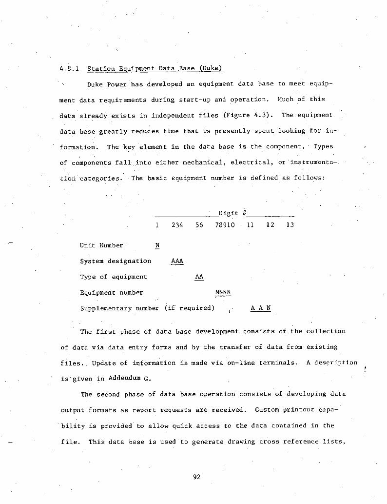
4 .8 .1 S t a t i o n Equipment Data ~ a s e (Duke)
Duke Power ' ha s developed an equipment d a t a base t o meet equip-
ment d a t a requi rements dur ing s t a r t - u p and ope ra t i on . Much of t h i s
d a t a a l r e a d y e x i s t s i n independent f i l e s (F igure 4 . 3 ) . The. equipment :
d a t a base g r e a t l y reduces t i m e t h a t 5s p r e s e n t l y s p e n t looking f o r in -
formation. The key element i n t h e d a t a base i s t h e component. . Types
of components , f a l l - i n t o e i t h e r mechanical , e l e s t r i c a l , o r ' instrumen'ta-. . .
t i&i .categor ' ies . ' The b a s i c equipment number i s de f ined a s fo l l ows :
.> .<
D i g i t # . .
1 234 56 73910 . 11 1 2 13
Unit Number - N
System d e s i g n a t i o n .- AAA
Type of equipment - AA
Equipment number
Supplementary. number .(if r e q u i r r d ) , . A A N
The f i r s t phase of d a t a base development c o n s i s t s of t h e c o l l e c t i o n
of d a t a v i a d a t a e n t r y forms and by t h e t r a n s f e r of d a t a from e x i s t i n g
f i l e s . . Update of i n £ o rmi t ion i s made v i a 'on- l ine t e rmina l s . A d e s r r i p t i o n $
The second phase of d a t a base o p e r a t i o n c o n s i s t s of developing d a t a
ou tpu t fo rma t s a s r e p o r t r e q u e s t s are r ece ived . Custom p r i n t o u t capa-
b i l i t y is provided t o a l l o w qu ick a c c e s s t o t h e da.ta conta ined i n t he
f i l e . T h i s d a t a base i s u s e d ' t o g e n e r a t e drawing c r o s s r e f e r e n c e l i s ts ,

NANUFACTURE. DRAWING INDEX
EQUIPMENT L1S.T
MECHANICAL IFJSTRUMENT LIST
ELECTRICAL EQUIPmNT LIST
EVENT RECORDER LIST
ANNUNCIATOR LIST
STATUS LIGHT LIST
MONITOR LIGHT LIST
COMPUTER I / O SUMMARY
VALVE LIST
I N S T R ~ E N T CHECKLIST/STATUS
ALARMS AND SETPOINTS MANUAL
LIST
I- NUCLEAR PLANT RELIABILITY DATA
1 SAFETY RELATED LIST
[ , DllKE DRA!*IING INDEX
FIGURE 4 . 3 : EQUIPPENT DATA BASE .
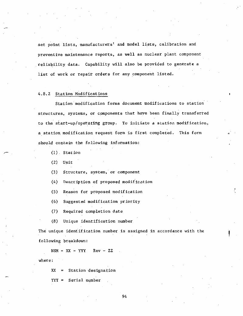
set p o i n t l is ts , manuf a c t u r e r s t and model l i s ts , c a l i b r a t i o n and
p reven t ive maintenance repor t . s , a s w e l l a s nuc lea r p l a n t component
r e l i a b i l i t y d a t a . C a p a b i l i t y w i l l a l s o be provided t o gene ra t e a
l i s t of work o r r e p a i r o r d e r s f o r any component l i s t e d .
4 .8 .2 S t a t i o n ~ o d i r i c a t i ons
S t a t i o n mod i f i ca t ion forms document mod i f i ca t ions t o s t a t i o n
s t r u c t u r e s , systems, o r components t h a t have been f i n a l l y t r a n s f e r r e d
t o t h e s t a r t - u p / o p e r a t l n g group. To i u t t i a t e a s ~ a t i o ~ ~ mod i f i ca t ion ,
a s t a t i o n , m o d i f i c a t i o n requ:est form is f i r s t completed. Th i s form .3
should con ta in t h e fo l lowing information:
(1). S t a t i o n
(2) Unit
(3) S t r u c t u r e , system, ' o r component
(4) Desc r ip t ion of proposed modif ' icot ion
(5) ~ e a s o n f o r proposed mod i f i c a t i o n
(6) Suggested mod i f i ca t ion p r i o r i t y
(7) Required completion d a t e
(8) Unique i d e n t i f i c a t i o n number
The unique i d e n t i f . i c a t i o n number is ass igned i n accordance w i t h t h e
fo l lowing breakdown:
NSM - XX - YYY Rev - ZZ
where :
XX = S t a t i o n -des igna t ion
YYY = S e r i a l number

ZZ = Revision number
The mod i f i ca t ion process may involve i n t e r f a c e wi th s e v e r a l s t a t i o n
groups a s w e l l a s g e n e r a l o f f i c e pe r sonne1 , ' r egu la to ry agencies , and
vendors. T~his i n t e r f a c e should be documented and p u t t oge the r i n t o a
modif i c a t i o q package. The rnodif i c a t i o n package should con ta in t h e
fo l lowing1 types of information:
(1) Modif ica t ion r eques t form
( 2 ) Documentation of s a f e t y eva lua t ion
(3 ) Summary of s o l b t i o n
( 4 ) Nuclear Regulatory Commission a u t h o r i z a t i o n f o r mod i f i ca t ion
( 5 ) mended t e c h n i c a l s p e c i f i c a t i o n s e c t i o n s
(6) Qua l i t y Assurance review
( 7 ) Procedures used t o implement mod i f i ca t ion ,
( 8 ) Drawings t h a t a r e a p p l i c a b l e
(9 ) FSAR r e v i s i o n s
4 . 8 . 3 . Instrument Data Base
An instrument d a t a base has been developed t o keep t r a c k of
i n s t r~ lmen t c a l i b r a t i o n s t a t u s and t o s e r v e a s a qu ick informat ion
r e fe rence . Types of in format ion included i n t h i s d a t a base a r e :
(1) Unit number
( 2 ) System
( 3 ) Instrument i d e n t i f i c a t i o n number
( 4 ) Type instrument
( 5 ) Manufacturer '

( 6 ) Model number
(7) Loop s t a t u s
(8) System s t a t u s .
( 9 ) References
Th i s d a t a base a l s o makes i t easy t o s o r t ins t ruments by c a l i b r a t i o n
s t a t u s , manufac turer , system, type instrument o r by model number.
4.8 .4 Nuclear P l a n t R e l i a b i l i t y Data'
The ' ~ u c l e a r P l a n t R e l i a b i l i t y Data (NPRD) System was developed
by t h e Edison E l e c t r i c I n s t i t u t e t o c o l l e c t r e l i a b i l i t y d a t a on nuc lear
s t a t i o n , sa f e t y - r e l a t e d equipment. The o b j e c t i v e of t h i s program i s
t o supply - r e l i a b i l i t y d a t a r e p o r t s t o nuc lea r u t i l i t i e s , r e g u l a t o r y
agencies , and t o t h e d e s i g n e r s of n u c l e a r , s a f e t y - r e l a t e d equipment.
Nuclear u t i l i t i e s throughout t h e United S t a t e s are p a r t i c i p a t i n g i n
t h i s program by f i l l i n g ou t s tandard format i npu t r e p o r t s . Four s~,andard
format i n p u t r e p o r t s a r e used:
(1) G.enera1 u n i t i n£ ormation
( 2 ) Engineering d e s c r i p t i o n of system/component
( 3 ) Quar t e r ly ope ra t ing r e p o r t s
( 4 ) ' F a i l u r e r e p o r t s . .
Types of in format ion t h a t a r e r equ i r ed f i r t h e engineer ing d e s c r i p t i o n
a r e l i s t e d below.:
(1) Type of nuc lea r u n i t
( 2 ) Nuclear Steam system Suppl ie r
( 3 ) NPRD system o r component code

(4) U t i l i t y ' s component o r system code
(5) . In-serv ice d a t e
(6) Manufacturer s e r i a l number . .
(7) Supplier /vendor s e r i a l number
(8) Sa fe ty c l a s s code
(9) Normal Operat ion mode
(10) ' Environment code
(1 1 ) Appl icable manufacturer code o r s tandard
(1 2) Manufacturer r e f e r e n c e number
(13) Model number
(14.) Source drawing. o r document number
A f a i l u r e r e p o r t must be prepared f o r each f a i l u r e of a s a fe ty -
r e l a t e d systein o r component. Types of in format ion t h a t a r e needed f o r
t h i s form .are:
(1) Type of nuc lea r u n i t
( 2 ) Nuclear Steam System Supp l i e r
(3 ) NPRD f a i l u r e code
(4) U t i l i t y ' s component o r system i d e n t i f i c a t i o n number
(5) Number of t imes component has S a i l e d . .
(6) Date of f a i l u r e
(7) Date f a i l u r e ended
(8) System s t a t u s a t t ime of f a i l u r e
(9) F a i l u r e d e s c r i p t t o n code * (10) Cause of f a i l u r e code * (11) c o r r e c t i v e a c t i o n code *
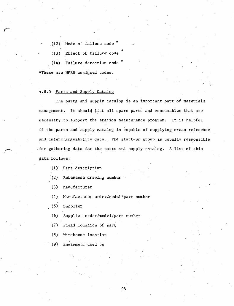
* . (12) Mode of f a i l u r e code
* (13) 'Egfect of fa i lu re . ' code
* (14) F a i l u r e , d e t e c t i o n code
*These. are NPRD a;si&oed codes.
4 .8 .5 P a r t s and Supply C a t a l o g
The p a r t s and supply c a t a l o g is a n impor tan t p a r t of m a t e r i a l s
management. It should l i s t a l l s p a r e p a r t s and consumables t h a t a r e
neces sa ry t o suppor t t h e s t a t i o n maintenance program. It i s h e l p f u l
i f t h e p a r t s and ' supply c a t a l o g is capab le of supply ing c r o s s r e f e r e i ~ c e
and i n t e r c h a n g e a b i l i t y d a t a . The s t a r t - u p group. i s u s u a l l y r e s p o n s i b l e
f o r g a t h e r i n g d a t a f o r t h e p a r t s a n d supply c a t a l o g . A list of t h i s . .
d a t a fo l l ows :
(1) P a r t . d e s c r i p t i o n . .
' (2) ~ e f e r e a c e drawing number
( 3 ) Manufacturer
(4) Mariufacturer o rder /model /par t number
(5) Supp l i e r
( 6 ) Supp l i e r o rde r /model lpar t number
(7.). F i e l d l o c a t i o n of p a r t
(8) Warehouse l o c a t i o n . .
' . (9) E&ipment used on
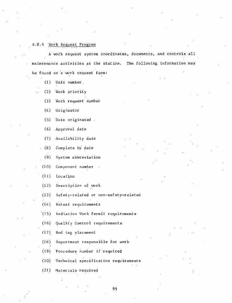
4 . 8 . 6 Work Request Program
A work reques t system coord ina t e s , documents, and cont r 'o l s a l l
maintenance a c t i v i t i e s a t the s t a t ion . The fo l lowing in£ ormation may
be found on a .work reques t f o m :
(1) Unit number.
( 2 ) Work p r i o r i t y
(3) Work r eques t number
(4 ) Or ig ina to r
(5) Date o r i g i n a t e d ,
( 6 ) Approval d a t e
( 7 ) , A v a i l a b i l i t y d a t e
(8) Complete by' d a t e
(9) system abbr 'ev ia t ion
( I 0) Component number
(1 1) Location
(12) Descr ip t ion of work
(13) Safe ty- re la ted or non-saf e ty- re la ted
(14) ~ e t e s t requirements
(15 ) Radia t ion Work Permit requi rements
(1 6) Qualj-t'y Cont ro l requi rements
( 1 7) . Red tag placement
(18) Department r e s p o n s i b l e f o r work
(19) Procedure number i f ' r equi red
(20) Technical s p e c i f i c a t i o n requirements
(21) Ma te r i a l s r equ i r ed

(22) S p e c i a l too ls /equipment
(23) Clearance t o begin work
(24) Act ion t aken
(25) Performed by
(26) Reviewed by . .
.'(27') T e s t s r e s u l t s s a t i s f a c t o r y o r no t s a t i s f a c t o r y
(28) ~ e a i t h Phys i c s remarks
(29) Q u a l i t y Cont ro l remarks
(30) Accepted by
(31) ' Job s u p e r v i s o r
(32) Approved by
4.8.7 Instrument P r e - I n s t a l l a t i o n a l Checkout
A s i n s t rumen t s a r r i v e on s i t e a p r e - i n s t a l l . a t i o n a 1 c h e c k o u ~ i s
performed t o v e r i f y t h a t the c o r r e c t i.n.struments were shipped and t o
v e r i f y t h a t , a l l i n s t rumen t s can be c a l i b r a t e d w i t h i n a c c e p t a b l e ranges .
P r e - i n s t a l l a t i o n checkout a l s o a l l ows instrument t e c h n i c i a n s a n oppor-
t u n i t y t o become . f ami l i a r wi th i n s t rumen t s and c a l i b r a t i o n pr.ocedures.
The f i f s t p a r t of t h e ins t rument p r e - i n s t a l l a t i o n ' test r e p o r t c o n t a i n s
b a s i c ins t rument i n£ ormation t h a t i s u s u a l l y f i l l e d out.. by c o n s t r u c t i o n
personnel :
(1) . S e r v i c e d e s c r i p t i o n
(2) Mark 'number
( 3 ) D e t a i l number
(4) 'Diagram number

( 5 ) P r o c e s s
(6) Ins t rument t y p e
( 7 ) C a t a l o g number
(8) Manufac tu re r
(9 ) Tap l o c a t i o n
(10) I tem number
(12) P r e s s u r e range
(14) M a n u f a c t u r e r s
(15) S i z e
(16) Flow
(17) Temperature r a n g e
(13) S c a l e . .
(1 9) Tnp~i t . signal range
(20) Output s i g n a l r a n g e
AEte,r c a l i b r a t i o n , a d d i t i o n a l d a t a i s e n t e r e d on t h e form t o document
c a l i b r a t i o n ' r e s u l t s . '
4.9 Need f o r an I n t e g r a t e d Data System
An i n t e g r a t e d d a t a b a s e sys tem c o u l d b r i n g t o g e t h e r d a t a from t h e
d e s i g n e r , t h e c o n s t r u c t o r , r e g u l a t o r y a g e n c i e s , and from s t a t i o n s t a r t - u p /
o p e r a t i o n g roups . I n f o r m a t i o n f o r a d a t a b a s e sys tem t h a t i s r e q u i r e d f o r
s t a r t - u p and o p e r a t i o n ' i s shown on F i g u r e 4 . 4 . . . .
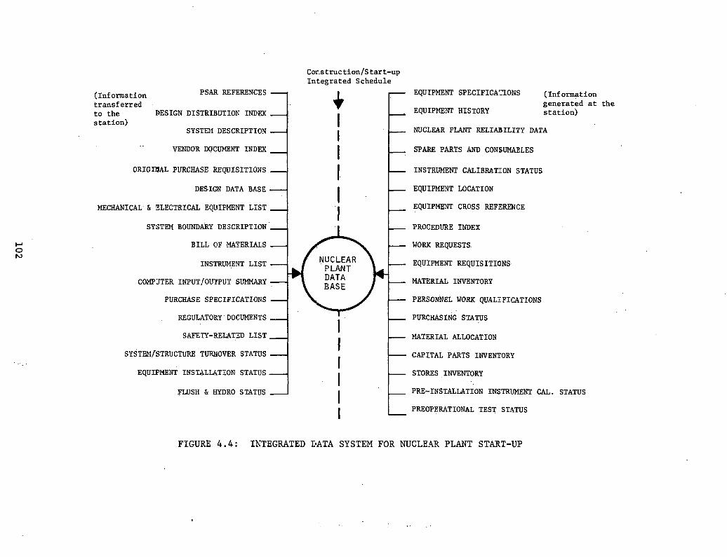
~ o r . s t r u c t i o n / S t a r t - u p I n t e g r a t e d S c h e d u l e
( I n f o r m a t i o n PSAR REFERENCES EQUIPMENT SPECIFICATONS ( I n f o r m a t i o n
t r a n s f e r r e d g e n e r a t e d a t t h e
t o t h e DESIGN DISTRIBUTIOK INDEX EQUIPMEYI' HISTORY s t a t i o n )
s t a t i o n ) SYSTEM DESCRIPTIOX NUCLEAR PLANT RELIABILITY DATA
VENDOR DOCUMENT INDEX I SPARF, PARTS AND C O N S W L E S
ORIGRIAL PURCHASE REQUISITIONS I INSTRUMENT CALIBRATION STATUS
DES.IGN DATA BASE EQUIPMENT LOCATION
MECHANICAL'& ZLECTRICAL EQUIPMENT LIST EQUIPM?JNT CROSS REFZRENCE
SYSTEM BOLlNDAkY DESCRIPTION ' PROCEDURE INDEX
BILL OF MATERIALS WORK REQUESTS.
INSTRZMENT LIST EQUIPMENT REQUISITIONS
COMPJTER INPUT/OUTPUT SUMMARY MATERIAL INVENTORY
PURCHASE SPECIFICATIOKS PERSONNEL WORK QUALIFICATIONS
REGULATORY DOCUMENTS I
I PURCHASING STATUS
SAFETY-REULTED LIST 4 I. I MATERIAL ALLOCATION
SYST~~I/STRUCTURE TURNOVER STATUS CAPITAL PARTS INVENTORY
EQUrPMENT INSTALLATION STATUS STORES , INVENTORY
FLUSH & HYDRO STATUS 1 I PRE-INSTALLATION INSTRUMENT CAL. STATUS
I / PREOPERATIONAL TEST STATUS
FIGURE 4.4: INTEGRATED IlATA SYSTEM FOR NUCLEAR PLANT START-UP

One of t h e major advantages i n t h i s d a t a base system is t h e capa-
b i l i t y of gene ra t i on of s t a r t - u p o r i e n t e d r e p o r t s . ' P r e sen t ly , most of
t h e . in format ion t h a t is s e n t t o t h e s t a r t - u p group i s i n t h e format used
by .another department. Thus, much in£ ormation i n t h e s e r e p o r t s i s redun-
dan t and no t p rope r ly formated f o r s t a r t - u p usage. Also, needed informa-
t i o n has o f t e n been omi t ted . The computer o f f e r s t h e c a p a b i l i t y of .
r e t a i n i n g t h i s in format ion and making i t a c c e s s i b l e t o s t a r t - u p i n t h e
proper format . There is, of course , no one format f o r in format ion t h a t
could s a t i s f y a l l s t a r t - u p needs. In format ion must be s o r t e d i n d i f f e r e n t
ways t o meet d i f f e r e n t s t 'ar t -up requi rements . Therefore , a d a t a base ,
can be extremely h e l p f u l i n meeting t h e s e needs.
Another problem with e x i s t i n g d a t a systems i s t h a t t h e s t a r t - u p
group has no easy method of adding new o r a d d i t i o n a l inf.ormation. For
example, t h e des igne r may supply a l i s t of a l l i n s t rumen t s t o t h e s t a r t -
up group. This l is t could con ta in ins t rument s p e c i f i c a t i o n s , model, and
s e t p o i n t s - bu t it would n o t c o n t a i n c a l i b r a t i o n s t a t u s . Genera l ly , t h e
ins t rument group a t t h e s t a t i o n deve lops i t s own method f o r keeping t r a c k
of c a l i b r a t i o n s t a t u s . . T h i s r e s u l t s i n a d d i t i o n a l manhours and redun-
dancy of in format ion .

T'HIS PAGE WAS INTENTIONALLY 1
LEFT BLANK

ADDENDUM A
NUCLEAR REGULATORY COMbIISSION RULES, REGULATIONS, AND REQUIREMENTS
A SLJKMARY
~ t i t r o d u c t i o n
The fo l lowing i s a s h o r t d e s c r i p t i o n and exp lana t ion of
s e l e c t e d documents whi'ch 'have important bear ing on t h e s t r u c t u r e
and content . of the'qA/i)C program of a nuc lea r power p l a n r . I r is
t h e purpose of: t h i s compi la t ion t o p r e s e n t t h e m a t e r f a i such t hae
t h e i n t e r r e l a t i o n s h i p s and r e g u l a t o r y imp l i ca t ions of t h e s e docu-
ments a r e made c l e a r . , The r e c o g n i t i o n and proper a p p l i c a t i o n of
t h e s e documents i s e s s e n t i a l t o t h e s u c c e s s f u l execut ion of a
n u c l e a r power p l a n t p r o j e c t .
I. Nuclear Regulatory Commission Rules and -- Regula t ions .
T i t l e 10 - Chapter I Code of F e d e r a l Regula t ions .
This document is t h e b a s i c foundat ion . docuuent f o r a l l NRC r e g u l a t i o n a c t i v i t i e s . . The fo l lowing group 02 'major "pa r t s " p l a y 'a s i g n i f i c a n t r o l e i n : the w r i t i n g of procedures f o r con- s t r u c t i o n of nuc lea r power p l a n t s .
A. P a r t 20 -- Standards f o r P r o t e c t i o n Agains t Radia t ion
These s t a n d a r d s are d i r e c t e d towards t h e u t i l i t y and s t a t e r e s t r i c t i o n s on r a d i a t i o n exposure, methods f o r determining ac- cumulated exposure, and t h e need f o r pe r sona l monitor ing r equ i r e - ments. It a l s o s t a t e s exposure l i m i t s f o r d i f f e r e n t ca ses . S p e c i f i c a t i o n s are g iven f o r r a d i a t i o n i d e n t i f i c a t i o n and marking. Th i s s e c t i o n d e a l s w i t h a d m i n i s t r a t i v e procedures on how t o d e a l w i t h r a d i o a c t i v e m a t e r i a l s and what r e c o r d s must be kept about t h e i r usage and d i s p o s a l .
.B.. P a r t 50 -- Licens ing of Product and U t i l i z a t i o n F a c i l i t i e s ( s u c h as Nuclear Power P l a n t s )
Th i s s e c t i o n s p e c i f i e s t h e c l a s s i f i c a t i o n of l i c e n s e s t o u s e rad ioac tTve m a t e r i a l s and t h e procedures t o o b t a i n each. These i n c l u d e t h e PSAR and FSAR.

Also included a r e r u l e s f o r des ign a c t i v i t i e s , t echn ica l s p e c i f i c a t i o n s , and c e r t a i n 1 , h l t a t i o n s on const ruct ion permits and l i censes . S p e c i f i c a l l y t h e p a r t inc1udes'specifi.cations and requirements f o r the following::
General Design C r i t e r i a Environmental Pol icy and Procedures' Emergency Plans and Requirements Quali ty Assurance C r i t e r f a Preliminary Safe ty Analysts Report (PSAR) Fina l Safe ty Analysis Report (FSAR) Technical Spec i f i ca t ions Technical Spec i f i ca t ions on Emissions
C. P a r t 55 -- Operators Licenses
This p a r t descr ibes . the requirements, r u l e s , and regu la t ions f o r the issuance of an opera to r ' s l i c e n s e , It a l s o . c o n t a i n s t h e terms and condi t ions upon which t h e Commission wi-11 i s s u e these l i censes .
D. Par t 71 -- Packing of Radioactive Mate r ia l f o r . Transport and Transportat ion of .Radioact ive Mater ia ls under Cer ta in Conditions
he regu la t ions i n t h i s p a r t apply t o each person authorized by s p e c i f i c l i c e n s e s issued by t h e Commission t o receive , possess, use o r t r a n s f e r 1 icensed .mate r i a l s t o a c a r r i e r f o r t r anspor t of such mate r i a l ou t s ide the confines of h i s p lan t . It governs a l l packaging and t r anspor t .of r ad ioac t ive mate r i a l s ,
E. P a r t 73 -- Physical P ro tec t ion of P l a n t s and Mater ia ls
This p a r t d e t a i l s the p ro tec t ion necessary t o be given t o a l l ma te r i a l s and p l a n t s t h a t use nuclear mate r i a l s . It d e t a i l s t h e p ro tec t ive b a r r i e r s and intrus'ion de tec t ion devices a t f ixed sites t o provide e a r l y de tec t ion of an a t t a c k . .I t also examines deter rence t o a t t a c k by means of armed guards and e s c o r t s . and l i a i s o n communica- t i o n wi th law enforcement a u t h o r i t i e s capable of ' rendering a s s i s t a n c e t o counter such a t t acks .
F. Pork 100 -- Reaetsr S i t e C r i t e r i a
This p a r t s p e c i f i e s s i t i n g requirements,. including, geological s t u d i e s necessary and weather requirements.
i.j

11. Selected Codes and Standards
The fol lowing codes and s tandards a r e among those most prominently appl ied t o nuclear power p l a n t s , .They 'are t o varying degrees designated by t h e NRC a s mandatory p a r t s of app l i ca t ions r e l a t e d t o s a f e t y and q u a l i t y considera t ions . There is c u r r e n t l y underway a major n a t i o n a l e f f o r t t o expand t h e s e standards and t o develop add i t iona l s tandards t o g r e a t l y i n c r e a s e ' t h e scope now i n exis tence . More t h a n ' l 4 0 new s tandards and codes f o r nuclear app l i ca t ions a r e now i n preparat ion. The following codes' and s tandards form the b a s i s f o r most ' of . the cur ren t q u a l i t y assurance p r a c t i c e s (although q u a l i t y assurance is only one of t h e major a reas covered by these documents) ..
A. ASME Boi le r and Pressure Vessel Code
This code has long been t h e standard f o r design p r a c t i c e of t h e power, chemical, and pet ro leum' lndust ry . It c o n s i s t s of eleven (11) p r i n c i p a l s e c t i o n s wi th va r ious mandatory and nonmandatorg appendices. Only some of the s e c t i o n s a r e d i r e c t l y app l i cab le t o nuclear power p lan t s . The major s e c t i o n s which cur ren t ly apply t o nuclear power p l a n t p r a c t i c e s inc lude t h e following :
Sect ion I1 -- Mater ia l Spec i f i ca t ions Sect ion 111. -- Nuclear Power Plant Components Section V -- Nondestructive Examination Section V I I I -- Division 1 - Pressure Vessels
~ i v i s i o n 2 - Alte rna t ive Rules f o r Pressure Vessels Section = -- Welding and Brazing Q u a l i f i c a t i o n s -- Section X I Rules f o r Inse rv ice . Inspec t ion of Nuclear Power
Plant Components
B. IEEE Standard 279 - C r i t e r i a f o r P ro tec t ion Systems f o r Nuclear Power Generating S t a t i o n s
This is t h e p r i n c i p a l s tandard i n genera l use t o meet regula tory requirements f o r p l a n t p ro tec t ive system design. It provides require- ment s f o r prepara t ion of formal design bases, app l i ca t ion of s i n g l e f a i l u r e c r i t e r i a and design a n a l y s i s , and equipment t e s t i n g by type and c l a s s i f i c a t i o n . Requirements a r e a l s o ou t l ined f o r i s o l a t i o n , s i n g l e random f a i l u r e p ro tec t ion arialysis , on-line t e s t i n g , projection of t h e p o s s i b i l i t y of mul t ip le f a i l u r e s r e s u l t i n g from s i n g l e c r e d i b l e events , system c a p a b i l i t y f o r sensor checks, and design f e a t u r e s t o provide ind iv idua l channel removal, o r bypass from se rv ice during opera t ion.
C . ANSI N45.2 - Qua1it.y Assurance Program.Requirements f o r Nuclear Power' P l a n t s
This i s t h e l ead document of a s e r i e s which includes many substandards. The lead document is e s s e n t i a l l y a more r e s t r i c t i v e vers ion of 10CFR50,

Appendix B. The ''daughter" s tandards a r e a l l reBated t o q u a l i t y assurance and include t h e following:
N45.2.1 Cleaning of Fluid Systems and Associated Components f o r Nuclear Power' P l a n t s
N45.2.2 Packaging, Shipping, Receiving, Storage, and Handling of I t e m s f o r Nuclear Power P l a n t s
N45,2.3 Housekeeping During t h e Construction Phase of Nuclear Power p l a n t s
N45.2.4 I n s t a l l a t i o n , Inspect ion and Test ing of Instrumentat ion and E l e c t r i c Equipment During t h e Construction of Nuclear Power Generating s t a t i o n s calso an IEEE Standard)
N45.2.5 Supplementary Quali ty Assurance Requirements f o r I n s t a l - l a t i o n , Inspect ion and Test ing of S t r u c t u r a l Concrete and S t r u c t u r a l S t e e l During t h e Construction Phase of 'Nuclear Power P lan t s
N45.2.6. Qua l i f i ca t ions of Inspect ion, Examination and Test ing Personnel f o r the Construction Phase of Nuclear Power P l a n t s
N45.2.8 Supplementary Quali ty Assurance Requirements f o r I n s t a l - l a t i o n , Inspection and Test ing of Mechanical Equipment and Piping f o r t h e Construction Phase of Nuclear Power P l a n t s
N45.2.9 Requirements f o r Col lec t ion, Storage, and Maintenance of Quality Assurance Records f o r Nuclear Power P l a n t s
N45.2.10 Quality Assurance Terms and Def in i t ions
N45.2.11 Quality Assurance Requirements f o r t h e Design of Nuclear Power P l a n t s
N45.2.12 Requirements f o r Auditing of Quali ty Assurance Programs f o r Nuclear Power P l a n t s
N45.2.13 Q u a l l ~ y Assurance Requirements f o r Control of Procure- ment of Items and Services f o r Nuclear Power P l a n t s
.2.14 Supplementary Quali ty Assurance Requirements During t h e Design and Manufacture of Class I E Instrumentat ion and E l e c t r i c Equipment f o r Nuclear Power Generating S ta t ions
N45.2.15. Requirements f o r the Control of Hoist ing, Rigging, and Transporting of Items a t Nuclear power P lan t S i t e s .
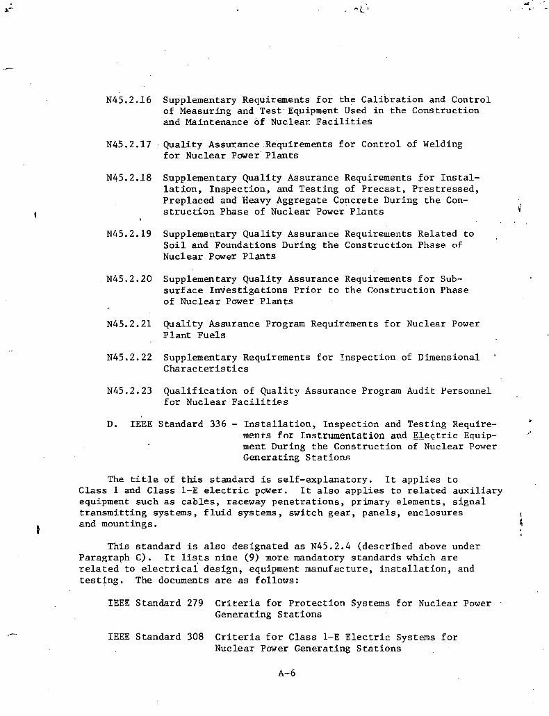
N45.2.16 Supplementary Requirements f o r t h e c a l i b r a t i o n and Control of Measuring and T e s t . Equipment Used i n t h e Cons t ruc t ion and Maintenance of Nuclear F a c i l i t i e s
N45.2.17 . Qua l i ty Assurance .Requirements f o r Cont ro l of Welding f o r Nuclear Power' P l a n t s
N45.2..18 Supplementary Qua l i t y Assurance Requirements f o r I n s t a l - . l a t i o n , In spec t ion , and Tes t ing of P r e c a s t , P r e s t r e s s e d , Preplaced and Heavy Aggregate Concrete During t h e Con- s t r u c t i o n Phase of ~ u c l e a r Power P l a n t s c;
b . .
N45.2.19 Supplementary Qua l i t y Assurance Requirements Rela ted t o S o i l and Foundations During t h e Cons t ruc t ion Phase of Nuclear Puwer P l a n t s
N45.2.20 Supplementary Qua l i t y Assurance Requirements f o r Sub- s u r f a c e I m i e s t i g a t i o n s P r i o r t o t h e Cons t ruc t ion Phase of Nuclear Power P l a n t s
N45.2.21 Qua l i t y Assurance Program Requirements f o r Nuclear Power P l a n t F u e l s
N45.2.22 Supplementary Requirements f o r I n s p e c t i o n of Dimensional '
C h a r a c t e r i s t i c s
N45.2.23 Q u a l i f i c a t i o n of Qua l i t y Assurance Program Audit Personnel f o r Nuclear F a c i 1 i t i e . s
D. IEEE Standard 336 - I n s t a l l a t i o n , I n s p e c t i o n and Tes t ing Require- men ts f nr Instrumentation and E l e c t r i c Equip- ment During t h e Cons t ruc t ion of Nuclear Power Generat ing S t a t i o n s
The t i t l e of this s t anda rd is se l f - exp lana to ry . It a p p l i e s t o Class 1 and Class 1-E e l e c t r i c power. It a l s o a p p l i e s t o r e l a t e d a u x i l i a r y equipment such as c a b l e s , raceway p e n e t r a t i o n s , primary elements , s i g n a l t r a n s m i t t i n g systems, f l u i d systems, swi t ch g e a r , pane l s , enc losu res
0 and mountings.
This s t a n d a r d i s a l s o des igna ted a s N45.2.4 (descr ibed above under Paragraph C). It lists n i n e (9) more mandatory s t anda rds which a r e r e l a t e d t o e l e c t r i c a l des ign , equipment manufacture, i n s t a l l a t i o n , and t e s t i n g . The documents a r e as fo l lows:
IEEE Standard 279 Criteria f o r P r o t e c t i o n Systems f o r Nuclear Power Generat ing S t a t i o n s
IEEE Standard 308 C r i t e r i a f o r Class 1-E E l e c t r i c Systems f o r Nuclear Power Generat ing S t a t i o n s

IEEE Standard 317 E l e c t r i c P e n e t r a t i o n Assemblies i n Containment S t r u c t u r e s f o r Nuclear Fueled Power, Generat ing S t a t i o n s
IEEE Standard 323 Guide f o r Q u a l i f i c a t i o n of Class 1 E l e c t r i c Equipment f o r Nuclear Power Generat ing S t a t i o n s
IEEE Standard 334 Guide f o r Type T e s t s of Continuous-Duty Class 1 Motors I n s t a l l e d I n s i d e t h e Containment of Nuclear Power Generat ing S t a t i o n s
IEEE Standard 338 Trial-Use Criteria f o r t h e P e r i o d i c Tes t ing of Nuclear Power Generat ing S t a t i o n P r o t e c t i o n Systems
IEEE Standard 344 Trial-Use Guide f o r Se ismic Qualification of Class 1 E l e c t r i c Equipment f o r Nuclear Power Generat ing S t a t i o n s
ANSI N18.2 Nuclear Sa fe ty Criteria f o r t h e Design of S t a t i o n a r y P res su r i zed Water Reactor P l a n t s
ANSI B31.7 Nuclear Power P l a n t . P i p i n g
Note: ANSI B31.7 is inc luded in t h i s l i s t i n g . However, a proposed r e v i s i o n t o lOCFR50 contained i n t h e Fede ra l Reg i s t e r , Vol. 39, No. 187, would remove t h e r equ i r e - ments t o comply w i t h B31.7. S e c t i o n 111 of t h e ASME Boi l e r and P res su re vessel Code would b e invoked . i n i t s p l ace .
. .
. ANSI N18. S e r i e s
This is a s e r i e s of ANSI s t anda rds which i s based on cons ide ra t ions of nuc lea r des ign c r i t e r i a . Some 'of t h e s t a n d a r d s which a r e , i n c l u d e d i n t h i s group a r e t he fo l lowing:
N18.1-1971 S e l e c t i o n and Tra in ing of Personnel f o r Nuclear Power P l a n t s .
N18.2-1973 Nuclear Sa fe ty Criteria f o r t h e Design of S t a t i o n a r y PWR P l a n t s
N1S. 2a Nuclear Sa fe ty C r i t e r i a f o r t h e Design of S t a t i o n a r y PWR P l a n t s (Supplement and Revision t o AJSI N18.2-1971)
N18.3-1972 Fuel Assemb:ly I d e n t i f i c a t i o n
N18.4 Vibra tory Ground Motion f o r t h e Design Earthquake
N18.5-1974 Earthquake Ins t rumen ta t ion C r i t e r i a f o r Nuclear Power P l a n t s
N18.6 Decay Energy Release Rates Following Shutdown of Uranium-Fueled Thermal Reac tors
N18.7-1972 Admin i s t r a t i ve Con t ro l s f o r Nuclear Power P l a n t s (.Under ' Rev. )
N18.8 C r i t e r i a f o r P repa ra t ion of Design Bases f o r Systems t h a f Perform P r o t e c t i o n Funct ions i n Nuclear Power
,GeneratAng S t a t i o n s
N18.9-1972 Program f o r Tes t ing B i o l o g i c a l Sh ie ld ing i n Nuclear React o r P l a n t s
N18.10 F i r e P r o t e c t i o n C r i t e r i a f o r Safety-Related S t r u c t u r e s and Equipment f o r Water-Cooled and Moderated Nuclear Power Generat ing P l a n t s
N.18,17-1973 I n d u s t r i a l S e c u r i t y f o r Nuclear Power P l a n t s .
Of p a r t i c u l a r i n t e r e s t i n t h e above s e r i e s is ANSI N18.1, which t h e NRC h a s accepted as a b a s i s f o r s e l e c t i o n and t r a i n i n g f o r nuc lea r power p l a n t personnel .
ANSI N18.1 - c o n t a i n s requi rements f o r q u a l i f i c a t i o n s of managers, s u p e r v i s o r s , t e c h n i c a l suppor t personnel , o p e r a t o r s , t e c h n i c i a n s , and o t h e r personnel neces sa ry f o r o p e r a t i o n of l i c e n s e d nuc lea r power plants . . D e f i n i t i o n and guidance a r e provided f o r t r a i n i n g of personnel , i nc lud ing -.
t h o s e t o b e l i c e n s e d by t h e NKC f o r r e a c t o r ope ra to r and sen-lor reactur ope ra to r q u a l i f i c a t i o n s . Minimum educat ion and, exper ience s t anda rds . f o r
, . s e l e c t i o n and t r a i n i n g of pe r sonne l a r e a l s o provided.
F. SNT-TC- 1A - Recommended Yract i c e f o r Nondes t r u c t f v e Tes Ling Personnel Q u a l i f i c a t i o n and C e r t i f i c a t i o n
r:
This document is a c o l l e c t i o n of s e v e r a l s e p a r a t e p u b l i c a t i o n s on 1;
t h e v a r i o u s methods of nondes t ruc t ive t e s t i n g ; i . e . , radiography, u l t r a - s o n i c , dye pene t r an t , magnetic p a r t i c l e , e t c . Each s e c t i o n covers t h e i n d i v i d u a l techniques , l i m i t a t i o n s , a p p l i c a t i o n s , procedures , and s t anda rds f o r i n t e r p r e t a t i o n of r e s u l t s f o r one of t h e v a r i o u s t e s t i n g methods d e s c r i b e d i n t h e s tandard .
111. Information and Guides
There i s a v a i l a b l e a wide v a r i e t y of documents which a r e fntended t o a s s i s t i n i n t e r p r e t a t i o n of r egu la to ry requirements and preparat5on of m a t e r i a l f o r permit and l i c e n s e a p p l i c a t i o n s , These documents suggest methods by which owners of nuclear power p l a n t s may meet NRC require- ments, and t h e y . r e f l e c t cu r ren t NRC thinking.
Compliance with t h e fol lowing documents is not always requi red by regu la t ing agencies ; however, adherence t o t h e sqggest ions, methods, and procedures described 2n t h e s e documents provides a method of so lv ing problems which is acceptable t o t h e NRC. U s e of a l t e r n a t i v e methods must be demonstrated t o be equivalent t o the s a t i s f a c t i o n of the NRC. It is genera l ly advisable t o fol low t h e guides a s much a s poss ib le . This minimizes de lays i n r egu la to ry reviews which might otherwise be encountered i f s t r ange o r untes ted methods.of problem s o l u t i o n a r e employed.
A. TID '14844 - Calcula t ion of Distance Factors f o r Power and T e s t Reactor S i t e s
This document descr ibes .a method of a n a l y s i s of t h e r e s u l t s of maximum c r i t i c a l ' a c c i d e n t s (MCA) t o determine predic ted dose r a t e s and d i s t a n c e f a c t o r s f o r exclusion a r e a s , low populat ion zones, and popu- l a t i o n cen te r s . Acceptance r e l e a s e r a t e s a r e given f o r key f i s s i o n products t o provide a b a s i s f o r conservat ive c a ~ c u l a t i o n s . S u i t a b l e
. allowance is made f o r major recognized in tang ib les . Also, acceptable a n a l y t i c a l methods a r e ou t l ined f o r c a l c u l a t i n g i n h a l a t i o n doses and e x t e r n a l gamma 'doses based on a d e f i n i t i v e model f o r atmospheric d i f - . . . fus ion and d i spe r s ion of f i s s i o n products f o r opera t ing r e a c t o r s . Assumed s a t u r a t i o n values under these condi t ions a r e s t a t e d f o r s p e c i f i c i so topes of p a r t i c u l a r importance; e .g. , iodi,ne, xenon, and krypton.
B. NRC Regulatory Guides (Safe ty Guides)
Formerly c a l l e d Safe ty Guides, t h e s e documents a r e issued by t h e Nuclear Regulatory Commission. They a r e d i r e c t e d toward f requent ly r ecur r ing s a f e t y and regu la to ry ques t ions and cover a wide v a r i e t y of subjec ts , ' such a s l o s s of coolant acc ident a n a l y s i s , personnel s e l e c t i o n and t r a i n i n g , ana lys i s of steam l i n e breaks f o r BWR's , on-s i te meteorology programs and o the r s . There a r e over 100 Regulatory Guides cu r ren t ly , i ssued and i n use. They a r e organized i n 'a s tandard format which includes a prel iminary d i scuss ion of problems and a formally s t a t e d regula tory pos i t ion . There a r e more guides' under development. There a r e now t e n major d i v i s i o n s , and of p a r t i c u l a r importance a r e t h e following :
Divis ion I Power Reactor Guides Division I11 Fuel and Mate r i a l s F a c i l i t i e s Guides

D i v i s i o n I V Environmental and S i t i n g Guides ~ i v i s i o n V Materials and P l a n t P r o t e c t i o n Guides D iv i s ion V I I I Occupat ional Hea l th Codes Div i s ion IX A n t i t r u s t Review Guides D i v i s i o n X General Guides
C. ORNL Technica l Manuals
There are a number of p u b l i c a t i o n s o f g e n e r a l t o p i c a l i n t e r e s t t o des igne r s and owners of nuc lea r power p l a n t s . These have been prepared and i s s u e d through t h e Oak Ridge General Engineering Div i s ion . Typ ica l of t h e s e r e p o r t s a r e t h e fo l lowing:
1. ORNL-TM-3645 - "Nuclear P ip ing Design"
Th i s document add res ses t h e ~ i p i n g des igne r who must r e c o n c i l e t h e requi rements of the ASEE B o i l e r arld P r e s s u ~ e V e s s e l Code, Sec t ion 111, w i t h s i m i l a r requirements of A N S I
.S tandard Code f o r P r e s s u r e P ip ing , B31.7, "Nuclear Power Piping." Various requi rements of t h e Codes a r e i n t e r p r e t e d and guzdance is g iven f o r t h e p r e p a r a t i o n of nuc lea r power p l a n t p ip ing des ign s p e c i f i c a t t o a s .
2. OW-TM-3782 - "The S e l e c t i o n and Procurement of P r e s s u r e Re l i e f Valves f o r Light Water-Cooled Nuclear Reactor Systems" '
Thi s document i s devoted t o t h e des ign , s e l e c t i o n , and s p e c i f i c a t i o n of r e l i e f va lves f o r v a r i o u s r e a c t o r appl ica- t i o n s . It d e s c r i b e s t h e b a s i c types of va lves which a r e c u r r e n t l y a c c e p t a b l e f o r r e a c t o r s e r v i c e . Sugges t ions a r e provided f o r maintenance and t e s t programs f o r bo th PWR and BWR r e a c t o r systems.
D. S tandard Format and C0nten.t of Sa fe ty Analysis Reports f o r Nuclear Power P l a n t s , prepared by t h e NRC Regulatory S t a f f
This p u b l i c a t i o n d e s c r i b e s o rgan iza t ion and con ten t s of PSAR1s and FSAR'S. It i n c l u d e s d e t a i l e d requirements f o r des ign d e s c r i p t i o n (12 chap te r s ) , o p e r a t i o n and t e s t i n g (2 chap te r s ) , acc iden t a n a l y s i s , and QA program d e s c r i p t i o n (1 chap te r each) . Represen ta t ive s u b j e c t s are o u t l i n e d f o r t e c h n i c a l s p e c f f i c a t i o n s and d e s c r i p t i o n of gene ra l des ign , c o n s t r u c t i o n , and opera t ion . NRC Regulatory Guide 1.70.6 covers SAR format and content of SAR1s.
E. Guide t o t h e P r e p a r a t i o n of Environmental Reports f o r Nuclear Power P l a n t s (Regulatory Guide 4.2)
Each a p p l i c a n t proposing t o b u i l d a n u c l e a r power p l a n t is requ i r ed t o submit a r e p o r t d e t a i l i n g t h e impact on t h e e n t i r o y e n t by t h e p l a n t .
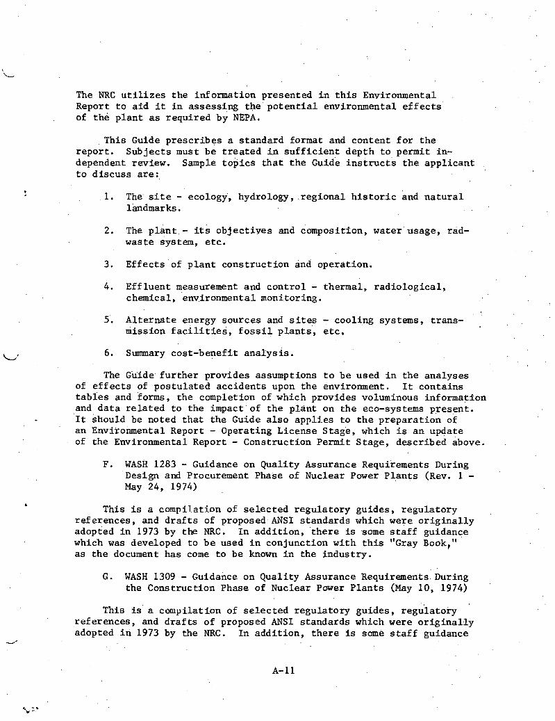
The NRC u t i l i z e s the information presented i n t h i s Environmental Report t o a i d i t i n assess ing the p o t e n t i a l environmental e f f e c t s of the p lan t as required by NEPA.
This Guide p resc r ibes a standard format and content f o r t h e repor t . Subjects must be t r e a t e d i n s u f f i c i e n t depth t o p.ermit in- dependent review. Sample top ics t h a t t h e ~ u i d e i n s t r u c t s t h e appl icant t o d i scuss a r e : '
1. The' s i t e - ecology, hydrology, . .regional h i s t o r . i c and n a t u r a l lkndmar ks .
2. The p l a n t . - its obj e c t i y e s and compositi on, water ' usage, rad- waste system, e tc .
3. Ef fec t s of p l a n t const ruct ion and operat ion.
4. Eff luent measurement and c o n t r o l - thermal, r ad io log ica l , chemical, 'environmental monitoring.
5'. Al te rna te energy sources and s i t e s - cooling systems, t rans- mission f a c i l i t i e s , f o s s i l p l a n t s , e t c ,
L' 6. Summary cost-benef i t ana lys i s .
The Giiide. f u r t h e r provides assumptions t o be used i n t h e analyses of e f f e c t s of pos tula ted accidents upon the environment. It conta ins t a b i e s and forms, the completion of which provides voluminous information and d a t a r e l a t e d t o the impact 'of t h e p lant on the eco-systems present . '1t should be noted t h a t the Guide a l s o app l i es t o t h e prepara t ion of an Environmental Report - Operating License Stage, which is an update of the Environmental Report - Construction Permit Stage, described above.
F. WASH 1283 - Guidance on Quali ty Assurance Requirements During .Design and Procurement Phase of Nuclear Power P l a n t s (Rev. 1 - May 24, 1974)
b
This is a compilation of s e l e c t e d regula tory guides, regula tory references , and d r a f t s of proposed ANSI s tandards which were o r i g i n a l l y adopted i n 1973 by the NRC. I n add i t ion , ' t he re is some s t a f f guidance which was developed t o b e used i n conjunction wi th t h i s "Gray Book," a s the document has come t o be known i n the indust ry .
G. WASH 1309 - Guidance on Quali ty Assurance Requirements.During the Construction Phase of Nuclear Pawer P lan t s (May 10, 1974)
This i s a compilation of s e l e c t e d regula tory guides, r e g h a t o r y '
references , and d r a f t s of proposed ANSI standards which were o r i g i n a l l y adopted i n 1973 by the NRC. I n addi t ion , t h e r e is some s t a f f guidance

which was developed t o be used i n conjunct ion w i t h t h i s "Green Book," as t h e document has come t o b e known i n ' t h e indus t ry . .
H. WASH 1284 - Guidance on Q u a l i t y Assurance Requirements During t h e Opera t ions Phase of Nuclear Power P l a n t s (October 26, 1973)
This document ' (commonly r e f e r r e d to as t h e "Orange ~ o o k " ) w a s i s s u e d a t about t h e same t i m e a s t h e Gray. Book and Green 'Book d e s c r i b e d . above. Its . c o n t e n t s are gene ra l ly s i m i l a r t o t h o s e documents except t h a t it is d i r e c t e d m 0 r . e toward o p e r a t i o n a l cons ide ra t ions . Together
1
i' j !
t h e s e t h r e e documents comprise t h e " ~ a i n b o w Se r i e s . " Recent ly i t became !i known t h a t ' \ a n a d d i t i o n a l "Yellow Book" and "White Book" a r e be ing prepared.
I. Standard Review Plans
These are i s s u e d by t h e NRC and a r e numbered t o correspond t o t h e . i n d i v i d u a l s e c t i o n s of t h e S a f e t y Analys is Report . They, a r e used a s . . d e t a i l e d c h e c k l i s t s by t h e D i r e c t o r a t e of Licens ing i n reviewing t h e a p p l i c a t i o n fo . r .comple teness . An incomplete a p p l i c a t i o n ( a D i r e c t o r a t e of Licens ing judgment) may. r e s u l t i n -the r e t u r n of t h e a p p l i c a t i o n w i t h a n a t t endant l i c e n s i n g de lay .

SAMPLE TYPES OF PERMANENT
AND N .9N-PERi iPT : RECOaDS

The fo l lowing is a .list of t y p e s of Qua l i t y Assurance r eco rds with
t h e minimum. r e t e n t i o n p e r i o d s i n d i c a t e d according t o ANSI N45.2.9-1974,
1 1 Requirements f o r C o l l e c t i o n , S torage , and Maintenance of Qua l i t y A s -
su rance R e c o r d s . f o r Nuclear Power P lan ts :"
! RECORD TYPES !
A. 1 Design Records
Appl icable Codes and Standards Used i n Design
AS-cons t r u c t e d Drawhgs
Design Ca lcu la t ions and Record of Checks
Design Change Requests
.-. Design Devia t ions
Design Procedures and Manuals
Design Reports
Design Keview Keports ,
Drawing Cont ro l ,Procedures
Purchase and Design S p e c i f i c a t i o n s and Amendments
QA System Audit Reports
Reports of Engineering S u r v e i l l a n c e of F i e l d
I A c t i v i t y
S a f e t y Analys is Report
S t r e s s Reports
Systems Desc r ip t ions
' Systems Process and Ins t rumen ta t ion Diagrams
,- - Technica l Analys is , Evalua t ions , and Reports
NON- 9 LIFETIME PERMANENT - .
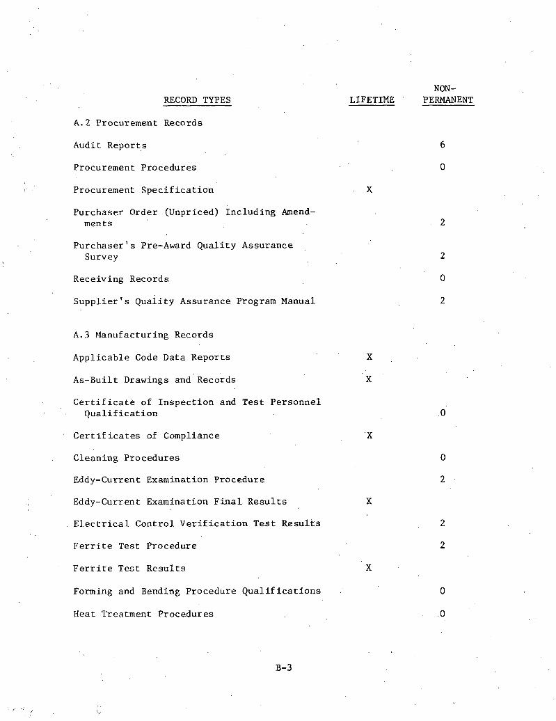
RECORD TYPES
A.2 Procurement Records
Audi t report,^
Procurement Procedures
Procurement S p e c i f i c a t i o n
P u r c h a s e r Order ( Jnpr iced) I n c l u d i n g Amend- ments
P u r c h a s e r ' s Pre-Award Q u a l i t y Assurance Survey
Rece iv ing Records
S u p p l i e r ' s ~ u a i i t ~ Assurance Program Manual
A.3 Manufactur ing Records
A p p l i c a b l e Code Data R e p o r t s
As-Bui l t Drawings and Records
C e r t i f i c a t e .of I n s p e c t i o n and T e s t P e r s o n n e l Q u a l i f i c a t i o n
C e r t i f i c a t e s of Compliance
NON- LIFETIME PERMANENT
Clean ing Procedures
Eddy-Current Examinat i o n Procedure
Eddy-Current Examination F i n a l R e s u l t s X
E l e c t r i c a l C o n t r o l V e r i f i c a t i o n T e s t R e s u l t s
F e r r i t e Tes t P rocedure
F e r r i t e Tec t R e s u l t s X
Forming and Bending Procedure Q , u a l i f i c a t i o n s
Heat Treatment Procedures
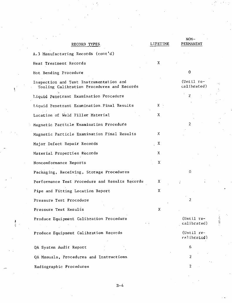
RECORD TYPES
A.3 'Manufacturing Records ( con t ' d )
Heat Treatment Records
Hot end in^ Procedure
I n s p e c t i o n and Tes t Ins t rumenta t ion and Tooling C a l i b r a t i o n Procedures and Records
, Liquid Pene t r an t Examination Procedure
Tdi.quid Pene t r an t Examination. F i n a l R e s u l t s
Locat ion of Weld F i l l e r Ma te r i a l
Magnetic ~ a r t ' i c l e Examinat i on Procedure
Magnetic P a r t i c l e Examination F i n a l Resu l t s
Major Defect Repair Records
M a t e r i a l P r o p e r t i e s ~ e c o r d s
Nonconformance Reports
packaging, Receiving, S torage Procedures
Performance Tes t Procedure and Resu l t s Records
P ipe and F i t t i n g Locat ion Report
P r e s s u r e Tes t Procedure
P r e s s u r e Tes t ~ e s u l t s
Produce Equipment C a l i b r a t i o n Procedure - .
Produce Equipment C a l i b r a t i o n Records
QA System Audit Report
QA Manuals, Procedures and Lns t ruc t ions
Radiographic Procedures
NON- LIFETIME PERMANENT
( U n t i l re - /,
c a l i b r a t e d )
(Un t i l re - <; I (
c a l i b r a t e d ) j ' (.Until re - calihratcd)

RECORD TYPES.
A . 3 Manufacturing Records ( son t ' d )
Radiographic Review Forms and Radiographs
U l t r a s o n i c Examination Procedures ..
U l t r a s o n i c Examination F i n a l Resu l t s
Welding Mate r i a l s Cont ro l Procedures
Welding Personnel Q u a l i f i c a t i o n
Weldlng Procedure Q u a l i f i c a t i o n s and Data Reports
NON- LIFETIME ' PERMANENT
Welding Procedures
Work Process ing and Sequencing Documents
A.4 Ins t a l l a t i on -Cons t ruc t ion Records
A. 4 .1 Receiving and Storage . .
In spec t ion Reports f o r s t o r e d I tems
Nonconformance Reports
Receipt In spec t ion Reports on I tems
Receiving, S torage , and I n s p e c t i o n Procedures
S to rage Inventory and I s suance Records
Vendor Qual i ty Assurance Releases
A . 4 . 2 C i v i l
Aggregate Tes t Reports
Batch P l a n t Operat ion Reports
Cement Grab sample Reports
Check-Of f Shee ts f o r 'fendon I n s t a l l a t i o n
Concre,te Cylinder Tes t Reports and Char t s

NON- RECORD TYPES
A. 4.2 C i v i l (cont ' d)
Concrete Design M i x Repor ts
Concrete Placement Records
Inspec t ion Repor ts f o r Channel P r e s s u r e T e s t s
j / M a t e r i a l Proper ty Rep0rt.s on Containment L ine r '
and Accessor ies
M a t e r i a l Proper ty Repor ts on Metal Containment S h e l l and Accesso r i e s
M a t e r i a l P rope r ty Reports on Reinforc ing S t e e l
M a t e r i a l Proper ty Repor ts on Reinforc ing S t e e l S p l i c e Sleeve M a t e r i a l
ate rial P rope r ty Repor ts on S t e e l Embedments I n Concrete
M a t e r i a l Proper ty Repor ts on S t e e l P i l i n g
M a t e r i a l Proper ty Repor ts on S t r u c t u r a l S t e e l and Bol t ing
M a t e r i a l Proper ty Reports on Tendon ~ a b r i c a t i o n M a t e r i a l
P i l e Drive Log
P i l e Loading Tes t Reports
0 Procedures f o r Containment Vesse l Pressure- Proof Test and Leak .Rate T e s t s and R e s u l t s
Reinforc ing S t e e l S p l i c e Operator Q u a l i f i c a t i o n Reports
Releases t o P l a t e Concrete
LIFETIME PERMANENT
Repor ts f o r P e r i o d i c Tendon I n s p e c t i o n

NON- LIFETIME , PERMANENT RECORD TYPES
R e p o r t s of High-Strength . B o l t Torque T e s t i n g
Slump T e s t R e s u l t s
. I , S o i l Compaction T e s t R e p o r t s
U s e r ' s T e n s i l e T e s t Repor t s on R e i n f o r c i n g S t e e l
U s e r ' s T e n s i l e T e s t R e p o r t s on R e i n f o r c i n g S t e e l S p l i c e s
A . 4 . 3 Welding
F e r r i t e T e s t P r o c e d u r e s
F e r r i t e T e s t R e s u l t s . X
Heat Treatment P r o c e d u r e s
Heat Trea tment Records
L iqu id P e n e t r a n t T e s t P r o c e d u r e s
L iqu id P e n e t r a n t T e s t l?in.al o s u l t s X
Magnetic P a r t i c l e T e s t P r o c e d u r e s
Magnet ic P a r t i c l e T e s t F i n a l R e s u l t s
Major We,ld R e p a i r P r o c e d u r e s and R e s u l t s X
Rad iograph ic T e s t P r o c e d u r e s 2
Rad iograph ic T e s t F i n a l R e s u l t s
U l t r a s o n i c T e s t P r o c e d u r e s
U l t r a s o n i c .TesL F:lnal R e s u l t s
Weld Fit-Up R e p o r t s
Weld L o c a t i o n Diagrams

RECORD TYPES
-A. 4 . 3 Welding (cont ' d )
Weld Procedures
Weld Procedures Q u a l i f i c a t i o n s and R e s u l t s
(1 Welding F i l l e r Metal M a t e r i a l Reports
I I Welding ~ a t b r i a l s Con t ro l Procedures
Welding Personnel Q u a l i f i c a t i o n s
Chemical Composition User's Tes t (Drab Samples) f o r Thermal I n s u l a t i o n
Chemical T e s t s of Water Used f o r Mixing I n s u l a t i o n cement
Cleaning Procedures and R e s u l t s
NON- LIFETIME PERMANENT
Code Data Reports
Cons t ruc t ion L i f t i n g and Handling Equipment Tes t Procedures , In spec t ion and 'rest uara
Data Shee ts o r Logs on Equipment I n s t a l l a t i o n , I n s p e c t i o n , and Alignment . - ,
~ o c u m e n t , a t ' i ~ n of Systems Check-Off (Logs o r Data Shee ts )
," E r e c t i o n Procedures f o r Mechanical Components
i I 4 Hydro-Test Procedures and Resu l t s X
I n s t a l l e d L i f t i n g and Handling Equipment Procedures , In spec t ion and Tes t Data
Lubr i ca t ion Procedures X
Lubr ica t fon Records
M a t e r i a l P rope r ty Records

RECORD TYPES NON-
LIFETIME PERMANENT
( U n t i l re- c a l i b r a t e d )
A . 4 . 4 Mechanical ( c o n t ' d )
M a t e r i a l P r o p e r t y T e s t ~ e ~ o r t s f o r Thermal I n s u l a t i o n X
P i p e and F i t t i n g L o c a t i o n R e p o r t s X $
P i p e and F i t t i n g s M a t e r i a l P r o p e r t y R e p o r t s X
P i p e Hanger and R e s t r a i n t Data X
S a f e t y Va lve Response T e s t P r o c e d u r e s X
1 . S a f e t y Va lve Response .Test R e s u l t s
A. 4 . 6 G e n e r a l
Nonconformance Repor t s
S p e c i a l Tool C a l i b r a t i o n Records
S p e c i f i c a t i o n s and Drawings
A . 5 P r e o p e r a t i o n a l and S t a r t u p T e s t Records
Automat ic Emergency Power Source T r a n s f e r P r o c e d u r e s and R e s u l t s X
Final. Systems Adjustment ~ a t a X
F l u s l ~ i n g Procedures and R e s u l t s 2
H y d r o s t a t i c P r e s s u r e T e s t P r o c e d u r e s and R e s u l t s X
I n i t i a l Heatup, Hot F u n c t i o n a l and Cool- down P r o c e d u r e s and R e s u l t s
I n i t i a l P l a n t ~ 6 a d i n g Data
I n i t i a l R e a c t o r C r i t i c a l i t y T e s t P r o c e d u r e s a n d R e s u l t s X
I I n s t r u m e n t AC Systems and 1 n v e r t e r s . T e s t Procedi i res and Kepor t s X

RECORD TYPES
A.5 P r e o p e r a t i o n a l and S t a r t u p Tes t Records (cont ' d )
Main and A u x i l i a r y Power Transformer Tes t Procedures and ~ e s u l t s
NON- LIFETIME PERMANENT
o f f - s i t e Power Source Energ iz ing Procedures and Test Rqports X
f l n -S i t e Emergency Power Source Energizing Procedure .and Tes t Reports X
P l a n t Load Ramp Change Data X
P l a n t Load Step Change Data X
Power Transmission Subs t a t ion Tes t Procedures and R e s u l t s X
P r e o p e r a t i o n a l Tes t Procedures and R e s u l t s X
Primary and Secondary Aux i l i a ry Power ,Lese Procedures and Resu l t s X
Reactor P r o t e c t i o n System Tes t and R e s u l t s X
S t a r t u p Logs X
S t a r t u p Problems and Reso lu t ions
S t a r t u p Tes t Procedures and Resu l t s
S t a t i o n B a t t e r y and DC Power D i s t r i b u t i o n Tes t Procedures and Reports
Y
'I System L u b r i c a t i n g O i l Flushing Procedures i
Water Chemistry Reports
A. 6 Operat ion Phase A c t i v i t y Records
A. 6.1 Opera t ion , Maintenance and Tes t ing
.Records and Drawing Chariges R e f l e c t i n g P lan t Design ~ o d i f i c a t i o n k Made t d Systems and ' ~ ~ u i ~ m e n t De- s c r ibed i n t h e F i n a l S a f e t y Analys is Report X

. NON- RECORD TYPES - LIFETIME PERMNENT
A . 6.1 O p e r a t i o n , Maintenance, and T e s t i n g (con t ' d )
New and Spent F u e l I n v e n t o r y , T r a n s f e r s of F u e l , and Assembly H i s t o r i e s X
P l a n t R a d i a t i o n and Contamina t ion Survey Records X
Off - S i t e ~ n v i r o n m e ' n t a l Moni to r ing Survey Kecords X
R a d i a ~ i o n ' E x p o s u r e Records of A l l P l a n t P e r s o n n e l , and O t h e r s Who E n t e r R a d i a t i o n C o n t r o l Areas X
R a d i o a c t i v i t y L e v e l s of Liquid and Gaseous Waste Released t o Environment X
T r a n s i e n t o r O p e r a t i o n a l Cyc l ing Records f o r Those P l a n t Componen.ts That Have Been Designed t o Opera te S a f e l y f o r a Limited Number of T r a n s i e n t s o r O p e r a t i o n a l Cycles X
C u r r e n t I n d i v i d u a l P l a n t S t a f f Member Q u a l i f i c a - t i o n s , Exper ience , T r a i n i n g , and R e t r a i n i n g Records X
Reac to r Coolant System In- ,Service I n s p e c t i o n Record X
Minutes of Meet ings of t h e P l a n t Nuclear S a f e t y Committee and Company Nuclear Re.view Board , X
Normal Nuclear U n i t O p e r a t i o n , I n c l u d i n g Power L e v e l s and P e r i o d s of O p e r a t i o n a t Each Power Leve l
P r J n c i p a l Maintenance A c t i v i t i e s , including In- s p e c t i o n , Repai.r , Subst j . t ,u t i o n o r Replacement on P r i n c i p a l I t e m s of Equipment P e r t a i n i n g t o Nuclear S a f e t y
Al ,~~uia la l Occurrence ~ e c o r d s
P e r l o d i c Checks, ~ n s ~ e c t i o n s and C a l i b r a t i o n s Performed ' t o Verify cha t S u r v e i l l a n c e Xequire- ments a r e Being Met
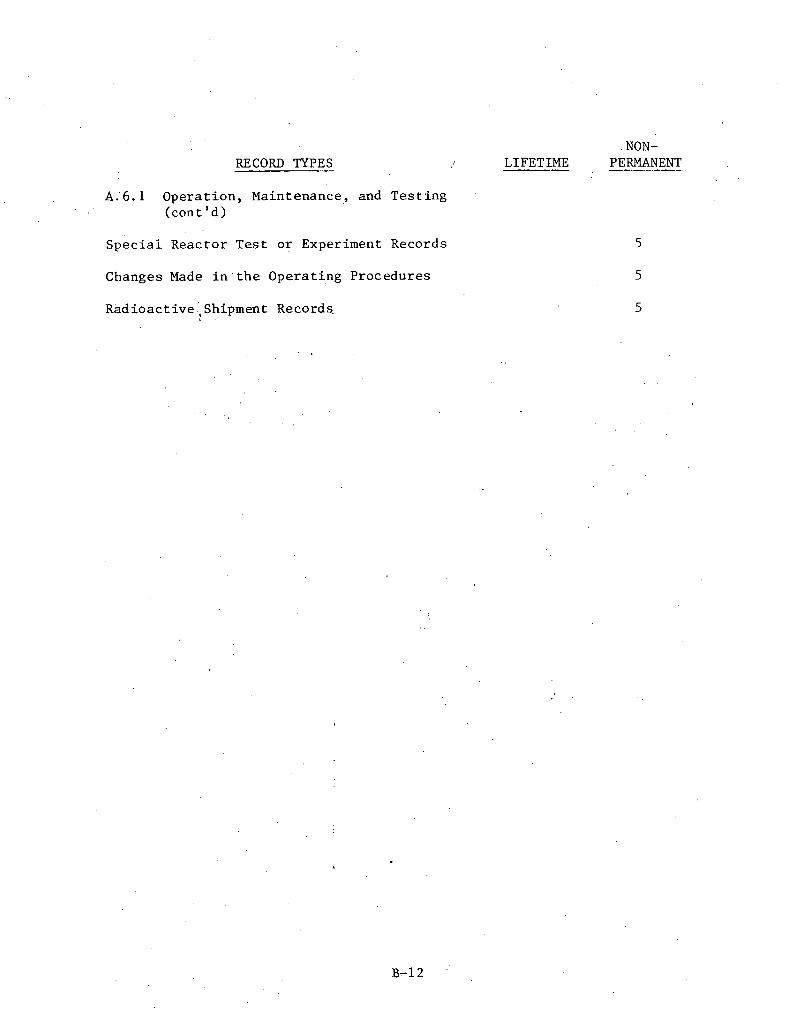
RECORD TYPES
A . ' 6 . 1 . O p e r a t i o n , Maintenance, and T e s t i n g (con t ' d )
S p e c i a i R e a c t o r T e s t o r Experiment Records
Changes Made i n ' t h e O p e r a t i n g P r o c e d u r e s
R a d i o a c t i v e ;Shipment Records,
. NON- LIFETIME PERMANENT -

ADDENDUM C
FIELD GENERATED DOCUMENT SYSTEM
EXAEIPLE REPORTS

1
NONCONFORMANCE REPORT - DANIEL CONSTRUCTION COMPANY OF ALABAMA I
.Form 360-3 (Rev. 2-76) NCR NO, Page - of
I (A) To: Or ig ina tor : Date: F i l e :
CB.) 'NCR Coding : NCR Category
(B1) Computer Coding
Supplemental Correc t ive Action Reqiiired : YES NO
) Major Category Sub Category Di sc ip l ine Action j Start-Up System No. r . .
(C) I d e n t i f i c a t i o n Of Item, System, Component Superintendent
(D) Nullcu~lIu~u~allct:
1
ASME Code Related YES NO 1 DCCA QCN Date I
(E) D i spos i t i on Use as is Resolve ( a s fol lows) Repair Rework
I i DCCA PDE " Date
DCCA QCM Date
I Qc Inspector Date
(G)J Remarks: Refer t o Page
Cor rec t ive Action Required YES NO
DCCA QCM Date
APCO QA Date
(F) Rework Inspec t i on S a t i s f a c t o r y Unsat i s fac tory (See remarks)
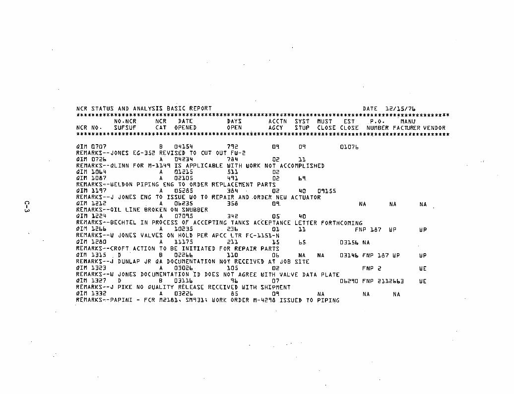
NCR STATUS AND A N A L Y S I S B A S I C REPORT DATE 12 /15 /7b ...................................................................................................
NO NCR NCR DATE DAYS ACCTN SYST MUST E S T . P v O . MANU NCR NO. SUFSUF CAT OPENED OPEN AGCY STUP CLOSE CLOSE NUMBER FACTURER VENDOR * * * * * * * * * * * * * * * * * * * * * * * * * * * * * * * * * * * * * * * * * x * * * * * * * * * * * * * * * * * * * * * * * * * * * * * * * * * * * * * * * * * * * * * * * * * * * * * * * * *
Q I M I1707 B 04154 792 09 09 01076 REMARKS--JONES EG-352 R E V I S E D TO CUT OUT FW-2 Q I M 0726 A 04234 764 02 1 1 REMARKS- -QL INN FOR fl-1149 I S A P P L I C A B L E W I T H WORK NOT ACCOMPLISHED Q I M LO64 A 01225 531 02 Q I M 1087 A 02105 491 02 69 REMARKS--WELDON P I P I N G ENG TO ORDER REPLACEMENT PARTS Q I M 1197 A 05285 364 0 2 110 09355 REMARKS--J JONES ENG TO I S S U E WO TO R E P A I R AND ORDER NEW ACTUATOR Q I M 1212 A 0b235 358 09 N A N A N A REMARKS--OIL L I N E BROKEN ON SNUBBER Q I M 1224 A 07095 342 0 5 'lo REi lARKS--BECHTEL I N PROCESS OF ACCEPT ING TANKS ACCEPTANCE L E T T E R FORTHCOMING Q I M 12bb A 10235 236 0 3 11 F N P 187 WP WP REMARKS--W JONES VALVES ON HOLD PER APCC L T R FC-1151-N Q I M 1280 A 11175 211 1 5 65 03156 NA REMARKS--CROFT A C T I O N TO B E I N I T I A T E D FOR R E P A I R PARTS Q I M 1315 D B 02266 110 06 NA NA 0314b FNP 187 WP WP REMARKS--J DUNLAP JR QA DOCUMENTATION NOT R E C E I V E D AT JOB S I T E QIM 1323 A 0302b LO5 0 2 F N P 2 WE REHARKS--W JONES DOCUMENTATION I D DOES NOT AGREE W I T H VALVE DATA P L A T E Q I M 1327 D B 03116 96 0 7 06290 FNP 2132bb3 WE REMARKS--J P I K E NO Q U A L I T Y RELEASE R E C E I V E D W I T H SHIPMENT Q I M 1332 A 03226 8 5 09 N A N A N A R E M A R K S - - P A P I N 1 - FCR M2181, SM931; WORK ORDER M-4298 I S S U E D TO P I P I N G

CARDPUNCH DATA NCE STATUS REPORT
D a t e D u e O u t
S h e e t o f
C a r d P u n - h P r i n : V e r i f y
Y e s q o , Y e s No
S y s tern P r e p a r e d By D e l i v e r T o
ESTIMATED CLOSURE
)ATE NC3 3lJST B E =LOSED TO
DIS-
-
PURCHASE ORDER
ACT. A m .
i
I i
39
!
33 34 28 %1
1
2 OAT7
f
DATE NUMBER. . , 40 ..... 35 29
<
32
SUB- S, m-
36
I
C I P , J CLOSSD
NO CAT. DATE NCR
1
37
J
, 38
c AT 23 24 18
OPENED u P
8 19 25 22
1
28 17 13
SUP NCR L
t
21
I
L i
I
BER
9 1'2
C + 1112 26 1 4
I
10 3 27 15116
I I I
1 4
I
5 6
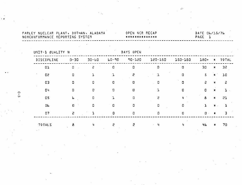
F P R L E Y NUCL.EAR P L A N T , DOTHAN, ALABAMA OPEN NCR RECAP D A T E 06/25/76 NCNCONFORUANCE R E P O R T I N G SYSTEM x * c * x u * * * u u * % a x PAGE 1 . . . . . . . . . . . . . . . . . . . . . . . . . . . . . . . . . . . . . . . . . . . . . . . . . . . . . . . . . . . . . . . . . . . . . . . . . . . . . . . . . . . . . . . . . . . . . .
U N I T - L Q U A L I T Y N DAYS OPEN . . . . . . . . . . . . . . . . . . . . . . . . . . . . . . . . . . . . . . . . . . . . . . . . . . . . . . . . . . . . . . . . . . . . . . . . . . . . . . . . . . . . . . . . . D I S C I P L I N E ?-30 30-63 60-70 70-120 129-,250 150-180 ~ . a + * T O T A L '
T O T A L S
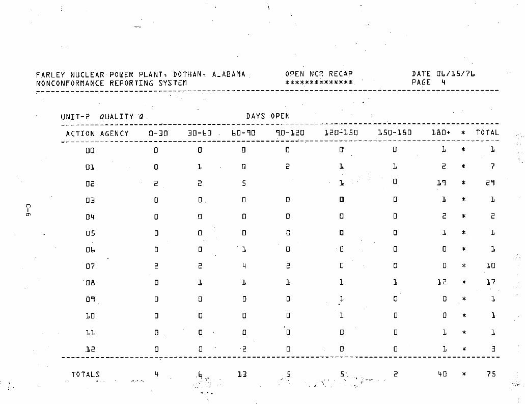
F A R L E Y NUCLEAR.POWER PLANT, DOTHAN, A-ABAUA . OPEN NCR REC4,P DATE Ob/L5/7b NONCONFORMANCE REPORTING S-YSTEM # * t t ~ * t x ~ t ~ t * * . -PAGE 4 ...............................................................................................
U N I T - 2 Q U A L I T Y Q DAYS OPEN .......................................................................................... A C T I O N AGENCY 0-30 30-b!l . 60-90 90-120 120-150 150-LBO LBO+ * TOTAL , ..........................................................................................
DO 0 0 0 0 0' 0 1 * 1
TOTALS .. .

FARLEY NUCLEAR POWER PLANT, DOTHAN, ALABAMA LSD- 8.05= 8 X B A R - 3 3 . 2 3 = 1 3 DATE 5 / 3 1 / 7 b NONCONFORMANCE REPORTING SYSTEM - STATUS 2 S D - l b - 0 9 = l b P L O T S . COCCUREN- PAGE L 4
AND A N A L Y S I S LEGEND 3 S D - L 4 . 1 4 = 2 4 CES) 5 3 4 6 U N I T - L O U A L I T Y - Q D I S C I P L I N E r M MAJOR CATEGORY-A ...................................................................................................
'------*---------------------------------------------------------------- : LSD 2 0 %f
: * * * * * .----------------------------------------------------------------------- : XBAR
* * ....................................................................... L S D
*

NONCONFORMANCE REPORTING SYSTEM U N I T - L D I S C I P L I N E - M E C H A N I C A L Q U A L I T Y - Q PAGE 15 BREAKDOWN BY MAJOR CATEGORY DATE .Ob/OL/?b ..................................................................................................
....................... BREAKDOWN OF CATEGORY A ....................... SUBCATEGORIES OCCURRENCES
00 7 01 5 2 02 1 03 - b 06 b 0 8 L 4 3 09 435 10 a 11 1 15 16 1b 1 17 b L 18 ' 12 L9 b 2 0 52 ...........................
TOTAL 807 ........................... ....................... BREAKDOWN OF CATEGORY B ....................... SUBCATEGORIES OCCURRENCES
0 0 1 01 L 02 5 Ob 1 0 7 2 08 3 0 9 4 15 2 20 L
P E R I E N T OF CATEGORY O.8b L.44 0.12 0.74 0-74
17.71 53.93 0.99 0-12 1.98 0.12 7.55 1;- 48 0.74 b.44
PERCEN- OF CATEGORY 5.00 5.00
E5.00 5.00
1.0.00 L5.00 20.00 LO. 00 5.00
PERCENT 3 F D I S C I P L I N E 13. bb 4.94 0.09 0.57 0.57
L3 59 Lt1.34 0.76 0.09 1-52 0.09 5.79 1.14 0.57 4.94
PERCENT OF D I S C I P L I N E 0.09 0.09 0.47 0.09 0 19 0.28 0 38 0-19 0 -09
PERCENT OF TOTAL NCRS 0.1'4 1.1L 0.02 0 - 12 0.12 3-05 9-30 0.17 0.02 0.34 0.02 1.30 0.25 0.12 1.1L
PERCENT OF TOTAL NCRS 0.02 0.02 0. L O 0.02 0 - 04 O.Ob 0.08 0.04 0.02

F A R L E Y NUCLEAR POWER P L A N T , DOTHAN, ALABAMA I S D - 2 . 4 . 1 = 2 XBAR- 2 . 4 9 = 2 , D A T E 5 / 3 1 / 7 h NONCORFORP~ANCE R E P O R T I N G S Y S T E M - S T A T U S 2SD- q . 8 2 = 5 P L O T S COCCUREN- PAGE 3
AND A N A L Y S I S LEGEND 3SD- 7 . 2 3 = 7 5 3 L b U N I T - L Q U A L I T Y - Q D I S C I P L I N E - C MAJOR CATEGORY-A * * * * * * * * * * * * * * * * x * * * * * * * * * * * * * * * * * * * * * * * * * * * * * * * * * * * * * * * * * * * * * * * * * * * * * * * * * * * * * * * * * * * * * * * * * * * * * * *
. --" .----*-*-----------------*---------------------------------------------. * * * * * * XBAR L:-*----------*-*-*-I-f-*-------*-----*-*-*-?-*-*-?-*-*-5-*-------------: I S D o.. . . . . . . . . . . . . . . . . . . . . . . . . . . . . . . . . . . . . . . . . . . . . . . . . . . . . . . . . . . . . . . . . . . . . .
J F f l A f l J J A S O N D J F M A M J J A S O N D J F M A V J J A S O N D 1 9 7 4 1 9 7 5 1 9 7 b

NOMCONFORMANCE REPORTING SYSTEM U N I T - 1 D I S C I P L I N E - C I V I L Q U A L I T Y - Q PAGE LO BREAKDOWN BY MAJOR CATEGORY DATE Ob/O1/7b ..................................................................................................
....................... BREAKDOWN OF CATEGORY A . ....................... SUBCATEGORIES OCCURRENCES
0 1 2 0 0 3 1 Ob 2 0 8 47 09 2 4 LO L 15 L 4 19 1 20 57 ..........................
TOTAL 157 .......................... ....................... BREAKDOWN OF CATEGORY B ------- -- ----. ---------- SUBCATEGORIEE OCCURRENCES
00 3 0 2 L(
07 2 08 1 0 9 3 ..........................
TOTAL 13 ..........................
PERCENT OF CATEGORY 6-36 0.63 1.27
29 93 15.28 0-63 8.91 0.63
3b.30
PERCENT: OF CATEGORY 23 C7 30- ' ib 1 5 38
7.b9 23 -07
PERCENT OF D I S C I P L I N E 2.13 0.21 0.4E
LO. 0: 5.11 0.21 2.9E Dv 21
12.15
PERCENT OF TOTAL NCRS 0.21 0.02 0.04 1 00 0.51 0.02 0-29 0.02 1 .21
PERCENT OF P I S C I P L I N E PERCENT OF TOTAL NCRS 0. b3 O.Ob a. 8s a 0.08 0.. 42 0.04 D .21 0.02 Q. b3 O.Ob

FARLEY h'UCLEAR POWER PLANT, DOTHAN, ALABAMA I S D - 7 9 3 = B X B A R - L 2 ; 9 8 = L 3 DATE 3 / 4 / 7 5 NONCONFCRMANCE REPORTING SYSTEM - STATUS 2 S D - L 5 . 8 b = l b PLOTS IOCCUREN- . PAGE i b
AND ANALYSIS LEGEND 3 S D - 2 3 . 7 9 = 2 4 CES) 3 3 5 U N I T - 1 O U A L I T Y - Q D I S C I P L I N E - U MAJOR CATEGORY-A .................................................................................................
LSD
XBAR
L S D

Types : FLANGE COllTROL RECORD
TORQUE VALUE
(2)
G.4SKET M.4T1L
( 2 )
1
- 1 . These i t e n s w i l l b e completed by t h e Mechanical QC I n s p e c t o r p r i o r -
t o disassembly of a f l a n g e j o i n t . - -
2. The Mechanical QC Inspec tor w i l l w i t n e s s a ~ d document t h e d i s - assembly of t h e f l a n g e j o i n t by complet ing t h e s e i tems. -
7
3. These i t e n s w i l l b e completed when reassembly is completed. - -
Upon completion of t h i s form, t h e Mechanical QC I n s p e c t o r s h a l l - forward t h e form t o t h e Mechanical QC Engineer f o r h i s review - and approva l .
7
-
I 1
QUANTITY PER (2)
XCCPT.
(3)
STUD SIZE (2)
CONNECTION NUMBER
(1)
---
I
'IZE
(2)
liEJ,
(3)
CALIBRATION NO. (3)
COMPLETION DATE (3)
DRAWN DATE APPROVED
AEEPROVED
REV.
A
DATE
n A REV.
INSF,
(3)
REFERENCE ROTE REFERENCE NOTE
FLANGE RATING (1)
CLASS OF PIPE (1)
TYPE OF NAT'L (1)
TORQUE WRENCH
APPROVED DATE
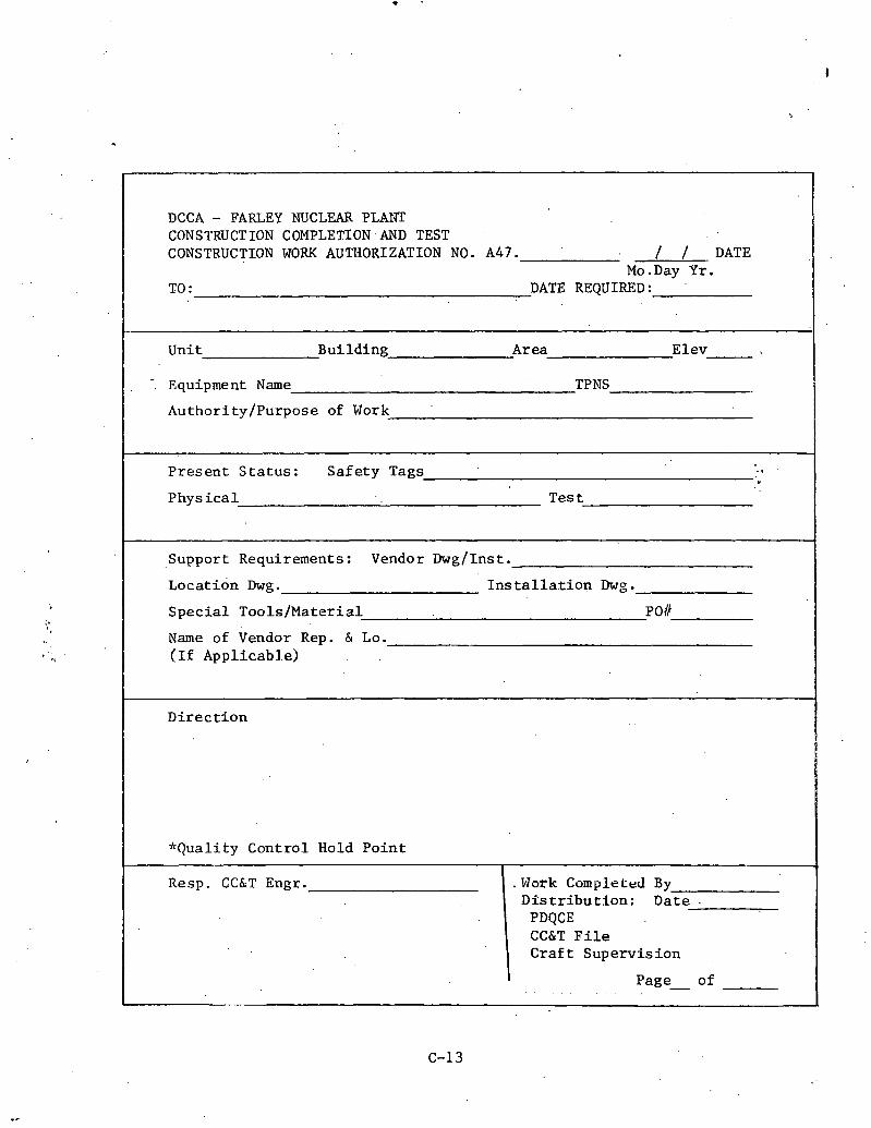
DCCA - FARLEY NUCLEAR PLANT CONSTRUCT I O N COMPLETION AND TEST CONSTRUCTION WORK AUTHORIZATION NO. A47. / / DATE
Mo.Day Y r . TO : DATE REQUIRED :
Unit Bui ld ing Area Elev
- Equipment Name TPNS
Author i ty /Purpose of Work
P r e s e n t S t a t u s : S a f e t y Tags - . P h y s i c a l T e s t
Support Requirements: Vendor Dwg/Inst.
Loca t ion Dwg. I n s t a l l a t i o n Dwg . S p e c i a l Too l s /Ma te r i a l PO#
Name of Vendor Rep. & Lo. (If Appl icab le )
D i r e c t i o n
*Qual i ty Cont ro l Hold P o i n t
Resp. CC&T Engr . .Work Completed By D i s t r i b u t i o n : Da te .
PDQCE CC&T F i l e C r a f t Supe rv i s ion
Page- of

FARLEY NUCLEAR PROJECT INITIAL RUN OF
ROTATING EQUIPMEXT DATA SHEET
F I L E TPMS TPNS
STARTUP SYSTEM: NO. NAME
EQUIPMENT NAME - - .. , f i
NAMEPLATE DATA :
MANUFACTURER SERIAL NO.
MODEL NO. TYPE RPM
S I Z E CAPACITY TDH . ' -!
VOLTAGE CURRENT
PREREQUISITES : DATE TEST ENGR.
QC PROCEDURE 5 . 6 . 4 . 2 MOTOR ROTATION TEST
QC PROCEDURE 5.6.3.10 EC)UIPblENT LUBRICATION
I
QC PROCEDURE 5.6.3.9 ALIGNMENT & COUPLITJG -
ELECTRI CAT, DATA
STARTING CURRENT AMPS VOLTAGE VOLTS
RUNNING CURRENT ! h V S APPROX. FLOW 1.
QC INSPECTOR
REMARKS :
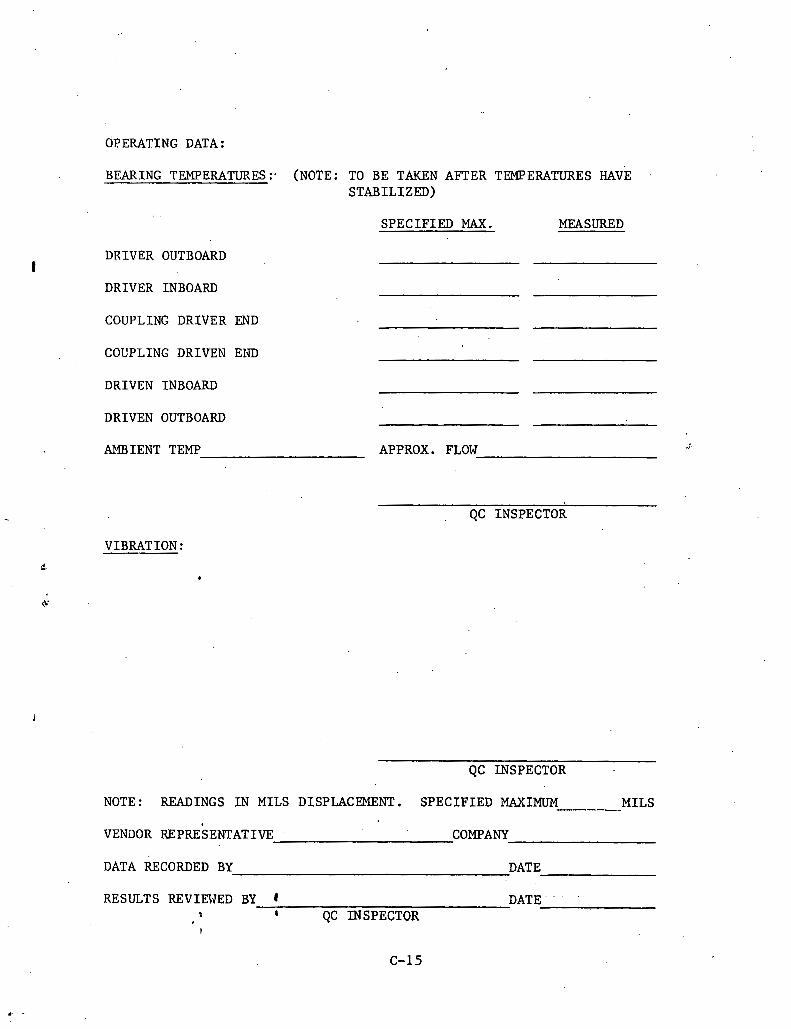
OPERATING DATA :
BEARING TEMPERATURES:* (NOTE: TO BE TAKEN AFTER TEMPERATURES HAVE STABILIZED)
SPECIFIED MAX. 'MEASURED
DRIVER OUTBOARD !
DRIVER INBOARD
COUPLING DRIVER END
COUPLING DRIVEN EIJD
DRIVEN INBOARD
DRIVEN OUTBOARD
AMBIENT TEMP APPROX. FLOW J
QC INSPECTOR
VIBRATION :
C. 0
QC INSPECTOR
NOTE: READINGSINMILSDISPLACEMENT. SPECIFIEDMAXIMUM - MILS
VENDOR REPRESENTATIVE COMPANY
DATA RECORDED BY DATE
RESULTS REVIEWED BY DATE"' '
8 QC INSPECTOR I

DOCUMENTATION TURNOVEX REQUEST
A. To.: DCCA QCDS
P l e a s e p r e p a r e - t h e f i l e ( s ) l i s t e d on Attachment I f o r Formal . . . Turnover and -forward them t o t h i s o f f i c e f o r review.
APCO PLANT MANAGER DATE d
B. To: APCO P l a n t .Manager
The f i l e ( s ) which accompany t h i s form a r e r e l ea sed t o you ( a s r eques t ed /wi t h excep t ions a s 1:is t e d on Attachment 11) .
DCCA QCDS DATE
APPROVED APCO NPD DATE A .,, . ' .
u'?
C. APCO Product ion Department acknowledges r e c e i p t of t h e f i l e ( s ) l i s t e d j.n Attachment I of t h i s r eques t (wi th t h e except ion of t hose l i s t e d on Attachment 11) and accep t s r e s p o n s i b i l i t y f o r t h e proper s t o r a g e and maintenance of t h e s e f i l e s .
1 !
APCO PLANT MANAGER DATE
DISTRIBUTION : DCCA F i l e - O r i g i n a l APCO P l a n t ~ a n a ~ e r - Copy APCO QA s u p e r v i s o r - Copy
, DCCA QCDS Superv lsor - . Copy APCO Nuclear P r o j e c t D i r e c t o r - Copy

FARLEY NUCLEAR PROJECT CONSTRUCTION WORK REQUEST
FILE TPNS A47. WORK NO. REQUESTED. CONPLETION DATE
WORK TO BE PERFORMED BY CONSTRUCTION UNDER: BLUE. TAGS OR ORANGE TAGS
REASON FOR WORK;
BOUNJIARIES OF SYSTEM RETURNED:
CCdT RETEST REQUIREMENTS
START-UP RETEST REQUIREMENTS
STATUS OF SYSTEM AND REMARKS
WORK REQUEST APPROVALS :
NAME TITLE DATE 1 1 O r i g i n a t o r 2 S t a r t - u p S u p e r v i s o r 3 ) NPD (As A p p l i c a b l e ) 4 ) - CCdT S u p e r v i s o r
WORK COMPLETION APPROVALS :
1 1 D i s c i p l i n e E n g i n e e r . 2) QC Manager 3) CCdT S u p e r v i s o r 4 ) S/U S u p e r v i s o r (As a p p l i c a b l e )
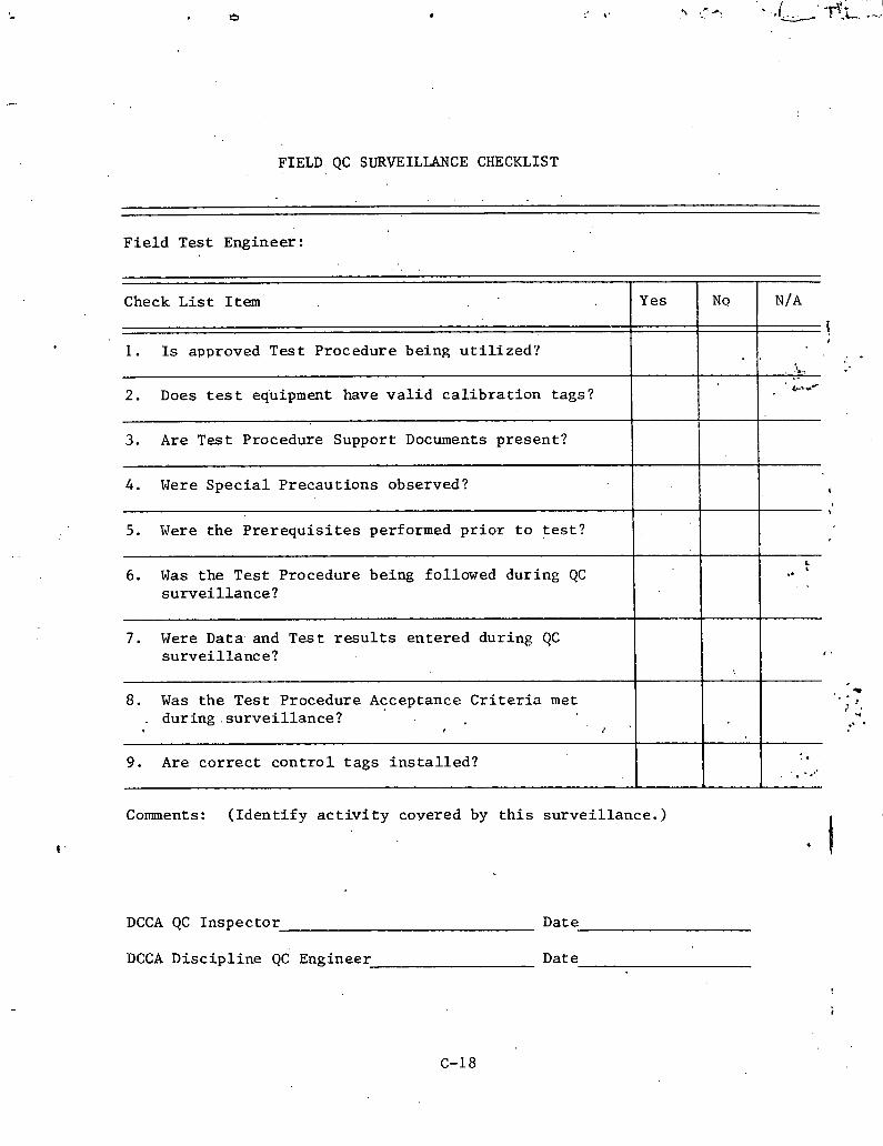
FIELD QC SURVEILLANCE CHECKLIST
F i e l d Test Engineer:
N /A Check L i s t Item
1. Is approved Tes t Procedure being u t i l i z e d ?
3. A r e T e s t Procedure Support Docunents present?
2. Does t e s t equipment have v a l i d c a l i b r a t i o n tags?
Yes
. i, ."
' 6.4-
No
f , . . .
4. Were S p e c i a l Precaut ions observed? t
5. Were t h e P r e r e q u i s i t e s performed p r i o r t o t e s t ?
7. Were Data and Tes t r e s u l t s entered during QC s u r v e i l l a n c e ?
.
6. Was the Tes t Procedure being followed during QC s u r v e i l l a n c e ?
8. Was the Tes t Procedure Acceptance C r i t e r i a met . during . s u r v e i l l a n c e ?
L 6 ..
Comments: ( I d e n t i f y a c t i v i t y covered by t h i s su rve i l l ance . )
9. Are c o r r e c t c o n t r o l t a g s i n s t a l l e d ?
DCCA QC Inspector Date
DCCA Disc ip l ine QC Engineer Date
. . . I - .,.

DANIEL CONS TP.UCTION COMPANY OF UABAMA
FARLEY NUCLEAR PROJECT
CIVIL
MECHANICAL
STRUCTURE/AREA TURNOVER SUMMARY ELECTRICAL
1 .0 ~ e s c r i p t i o n
1.1 St ruc tureIArea (Name)
1.2 ~ o c a t i o n (Define 1.1 us ing column l i n e s , coo rd ina t e s , e t c . )
. .
2.0 Completeness
2.1 The ' ~ t r u c t u r e / ~ r e a de f ined i n 1 .0 above is complete except a s noted i n 2.2.
p ro j e c t D i s c i p l i n e Engineer Date
2.2 Except i o n s :
3.0 Qua l i t y
3.1 There a r e no ou t s t and ing QC Punch l i s t Items o r Nonconformance Reports a g a i n s t t h e S t ruc tu re IArea de f ined i n 1 .0 above. F i n a l i n spec t ions (copies a t t a c h e d ) a r e complete and accep tab le except a s noted i n 3 . 2 .
P r o j e c t D i s c i p l i n e QC Engineer . Date
3.2 Except. ions :
. .
c-i 9

4.1 A l l Document Control F i l e s r e l a t i v e . t o the S t r u c t u r e l ~ r e a defined .in 1 . 0 a r e accounted- f o r and complete except a s noted i n 4.2.
QCDS Supervisor Date I ' v
4.2 Exceptions : 4
5.0 Review
5.1 QC Manager Date
5.2 Disc ip l ine Manager are
. .
6.0 Acceptance
6.1 APCO Nuclear Pro jec t Director
Date 6.2 APCO Plant Manager
. B abate
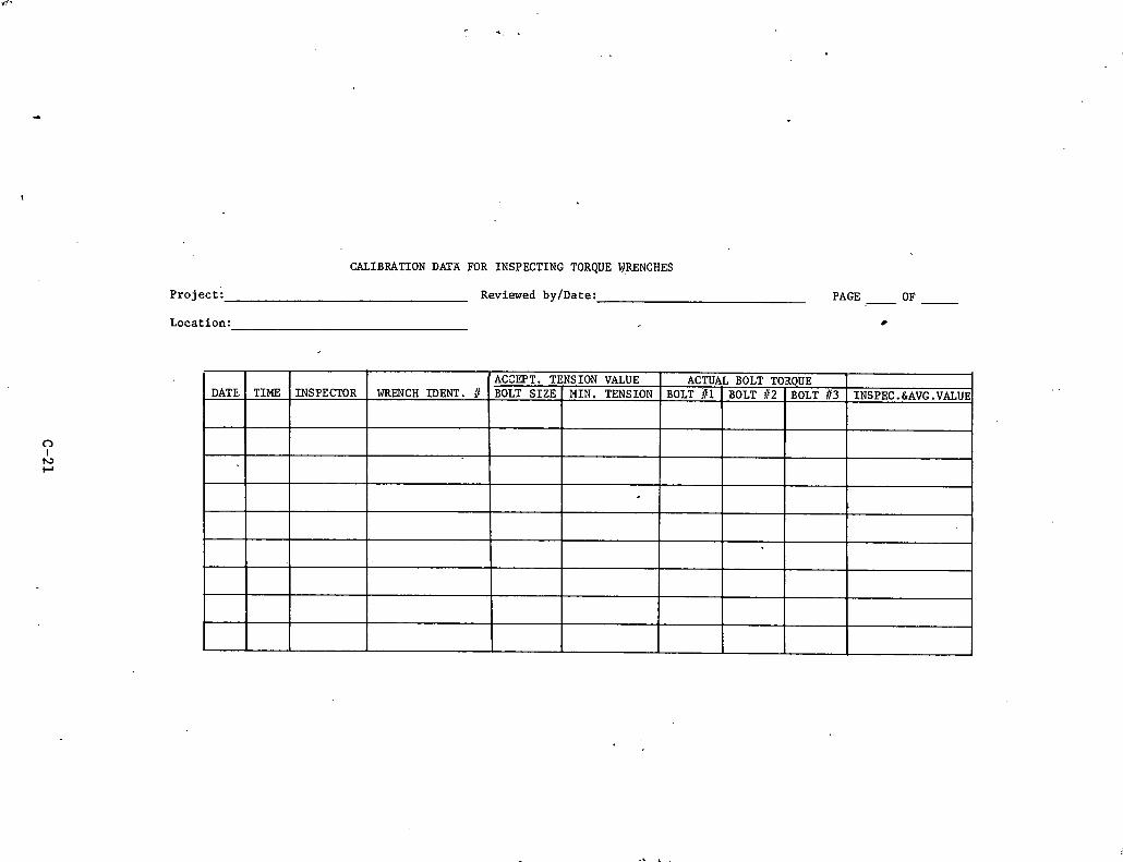
CALIBRATION DATA FOR INSPECTING TORQUE WRENCHES
P ro j ec t : Reviewed by/Date: PAGE - OF
Location:
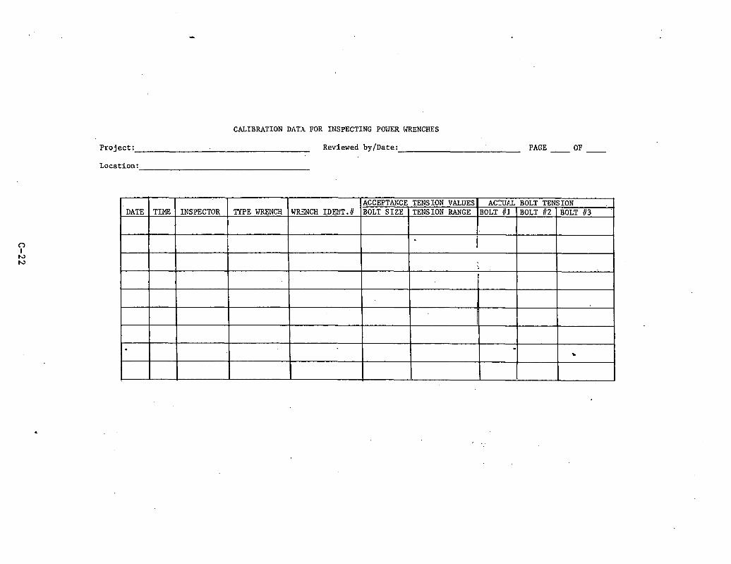
CALIBRATION DATA FOR INSPECTING POVER WRENCHES
P ro j ec t : Reviewed by/Date: PAGE - OF -
Location:

ADDENDUM D
DUKE POWER COMPANY
DATA BASE MANAGEMENT CONTROL AND ENGINEERING SYSTEM F I L E L I S T

.DUKE POWER COMPANY DATA BASE MANAGEMENT CONTROL AND ENGINEERING SYSTEM
FILE LIST
FILE I D DESCRIPTION
I n t e g r a t e d Schedule F i l c Drawing F i l e Schedule I n t e r f a c e Requirements F i i e Spec i f i c a r i o n Schedule Motor and Load F i l e Valve F i l e Annuncia tor F i l c E l e c t r i c a l Device F i l e Time Records Cable S t a t u s F i l e Cable F i l e Valve, Item F i l e L i c e n s i n g il e E v e n t s Recorder F i l e Mechan ica l P i p e Hanger F i l e Eng. S e r v i c e s 1977 Cos t E s t i m a t e F i l e Drawing-System Schedule Drawing Symbol F i l e System Cable I n f o F i l e System F i l e Experiment F i l e Wire L i s t F i l e Da ta Base F i l e s F i l e Data Base R e p o r t s F i l e V a r i a t i o n Not i c e and Non-Corl.forrn,inp;
I t e m s F i l e Engineer ing A p p l i c a t i o n s S t a t i o n B a t t e r y Report Delayed .Sys,tem S t a t u s System Data S e t s F i l e G r a p h i c s J o b F i l e G r a p h i c s Number F i l e . G r a p h i c s O p e r a t o r Number F i l e F a i l u r e Mode and E f f e c t A n a l y s i s M i s c e l l a n e o u s Work. Reques t s M a t e r i a l F i l e I n v e n t o r y Equipment F i l e
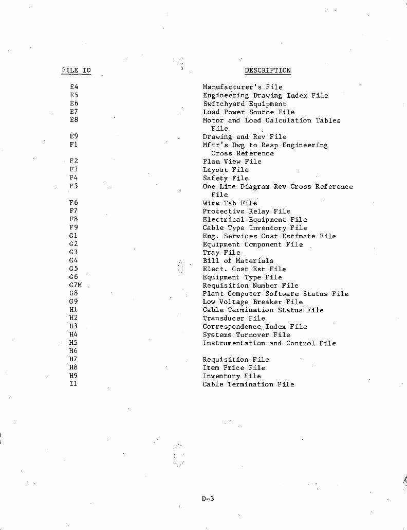
DESCRIPTION
Manufac turer ' s F i l e ~ n g i n e e r i n g Drawing Index F i l e Switchyard Equipment Load Power Source F i l e Motor and Load C a l c u l a t i o n Tables
F i l e Drawing and Rev F i l e M f t r ' s Dwg t o Resp Engineer ing
Cross Reference P l a n View F i l e Layout P i l e ~ a f e t l F i l e One Line Diagram Rev Cross Reference
P
F i l e Wire Tab F i l e Pro t e c t i v c Relay F i l e ~ l e c t r i c a l Equipment F i l e Cable Type Inventory F i l e Eng. S e r v i c e s Cost Es t imate F i l e Equipment Component F i l e ,
Tray F i l e
/\$ . , B i l l of M a t e r i a l s \ I E l e c t . Cost Es t F i l e
Equipment Type F i l e R e q u i s i t i o n Number F i l e
' , P l a n t Computer Sof tware S t a t u s F i l e Low Vol tage Breaker Fi1.e Cable Terminat ion S t a t u s F i l e Transducer F i l e Correspondence., Index F i l e Systems Turnover F i l e In s t rumen ta t i on and Cont ro l F i l e
R e q u i s i t i o n F i l e I t e m P r i c e F i l e Inventory F i l e Cable Terminat ion F i l e


ADDENDUM E
DUKE POWER DESIGN DOCUbENT LIST
(MCGUIRE NUCLEAR STATION)
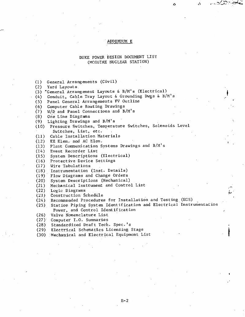
ADDENDUM E
DUKE POWER DESIGN DOCUMENT LIST (MCGUIRE NUCLEAR STATION)
(1) General Arrangements ( C i v i l ) (2) Yard Layouts (3) 'General Arrangement Layouts & B / M 1 s ( ~ l e c t r i c a l ) (4) Conduit, Cable Tray Layout 6 Grounding Uwgs 6 B/M' s (5) Panel General Arrangements FV Ou t l ine (6) Computer Cable Routing Drawings (7) W / D and Pane l ~ o n n e c t i o n s and- B/M' s (8) one Line Diagrams (9) Light ing Drawings and B / M 1 s (10) P r e s s u r e Switches, Temperature Switches, Solenoids Level
Switches, L i s t , e t c . (11) Cable I n s t a l l a t i o n M a t e r i a l s (12) EE E l e m . and AC Elem. (13) P l an t Communication Systems Drawings and B / M 1 s (1'4) Event Recorder L i s t (15) System Desc r ip t ions ( E l e c t r i c a l ) (16) P r o t e c t i v e Device S e t t i n g s (17) Wire Tabu la t ions (18) In s t rumen ta t ion ( I n s t . D e t a i l s ) (19) ' Flow Diagrams and Change Orders (20) System Desc r ip t ions (Mechanical) (21 ) Mechanical Instrument and Cont ro l L i s t ,A*.
(22) Logic Diagrams !.% . .
( 2 3 ) C o n s t r u c t i o n ~ c h e d b l e (24) Recommended Procedures f o r ~ n s t a l l a t ion and Tes t ing , (EG'S) . . (25) S t a t i o n p i p i n g System I d e n t i f i c a t i o n and E l e c t r i c a l ~ n s t r u k e n t a t i o n
Power, and Con t ro l I d e n t i f i c a t i o n (26) Valve Nomenclature L i s t (27) ' Computer 1 .0 . Surtimaries . .
(28) Standardized Dra f t Tech. Spec. ' s (29) E l e c t r i c a l Schematics Licens ing Stage (30) :Mechanical and E l e c t r i c a l Equipment L i s t i

ADDENDUM F
MECHANICAL I N S T R ~ I ~ T A T I O N AND CONTROL L I S T
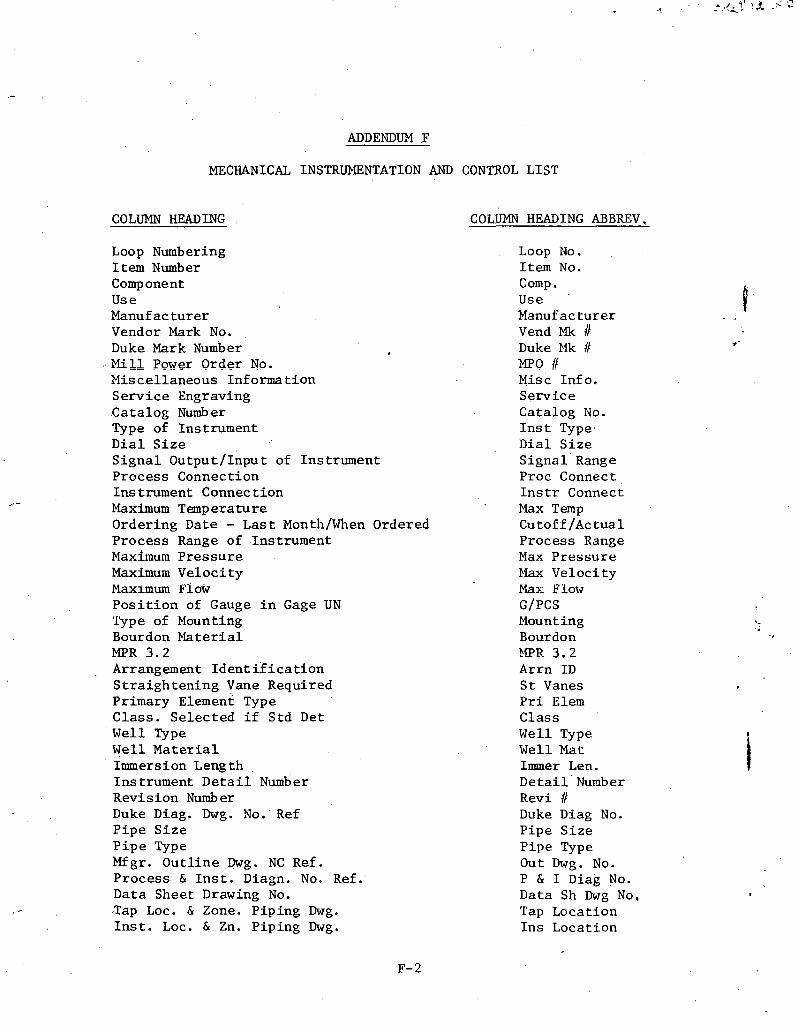
ADDENDUM F
MECHANICAL INSTRUPIENTATION AND CONTROL LIST
COLUMN HEADING COLUMN HEADING ABBREV.
Loop Numbering Item Number Component U s e Manufacturer Vendor Mark No. Duke Mark Number M i l l Power Order No. Misce l laneous Informat ion S e r v i c e Engraving Cata log Number Type of Instrument D i a l S i z e S i g n a l Output/Inpu t of Instrument Process Connection I n s trument Connec t i o n Maximum Temperature Ordering Date - L a s t ~onth /When Ordered Process Range of Instrument Maxitnum P r e s s u r e Maximum Ve loc i ty Maximum Plow P o s i t i o n of Gauge i n Gage UN Type of Mounting Bourdon Platerial MPR 3 . 2 Arrangement Iden t i f i c a t i o n S t r a i g h t e n i n g Vane Required Primary Element Type C las s . Se l ec t ed i f S td Det Well Type W e l l M a t e r i a l Immersion Length Instrument D e t a i l Number Revis ion Number Duke Diag. Dwg. No. Ref P i p e S i z e P i p e Type M g r . O u t l i n e Dwg. NC Ref. Process & I n s t . Diagn, No. Ref. Data Sheet Drawing No. -Tap Loc. & Zone. P ip ing Dwg. I n s t . Loc. & Zn. P ip ing Dwg.
Loop No. Item No. Comp . U s e .
Manufacturer Vend Mk Duke Mk /I MPC) Jt ~ i s c Info . Se rv i ce Catalog No. I n s t Type, D i a l S i z e S i g n a l Range Proc Connect , I n s t r Connect Max Temp Cutoff /Actual Process Range Max P r e s s u r e Elax Veloc i ty Max: Flow G/PCS Mount i ng Bourdon ?PR 3 . 2 Arrn I D S t Vanes P r i Elem Class W e l l Type Well M a t Immer Len. ~ e t a i l ' Number Revi /I Duke Diag No. P ipe S i z e P ipe Type Out Dwg. No. P & I Diag No. Data Sh Dwg No, Tap Locat ion I n s Locat ion

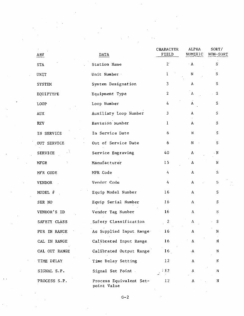
STA
UNIT
SYSTEM
EQUIPTYPE
LOOP
AUX
REV
I N SERVICE
OUT SERVICE
SERVICE
MFGR
MFR CODE
VENDOR .
MODEL .
SER NO
VENDOR'S ID
SAFETY CLASS,
PUR I N RANGE . .
CAL I N RANGE
CAL OUT RANGE
TIME DELAY
SIGNAL S.P.
'PROCESS S.P.
DATA -.
S t a t . i o n Name
CHARACTER
.- FIELD -
U n i t Number . 1
System D e s i g n a t i o n 3
Equipment Type 2
Loop Number 4
A u x i l i a r y Loop Number 3
R e v i s i o n umber
I n S e r v i c e Date
Out of S e r v i c e Date
S e r v i c e Engraving
Manufac tu re r
MFR .Code
Ventlor Ctstle
Equip Model Number
Equip S e r i a l Number
Vendor Tag Number
, S a f e t y C l a s s i f i c a t i o n
As Suppl ied I n p u t Range
C a l i b r a t e d I n p u t Range
C a l i b r a t e d Output Range
Time Delay S e t t i n g
S i g n a l S e t P o i n t
P r o c e s s E q u i v a l e n t Se t - p o i n t Value
ALPHA SORT/ NUMERIC NON-SORT -
. A S' ;
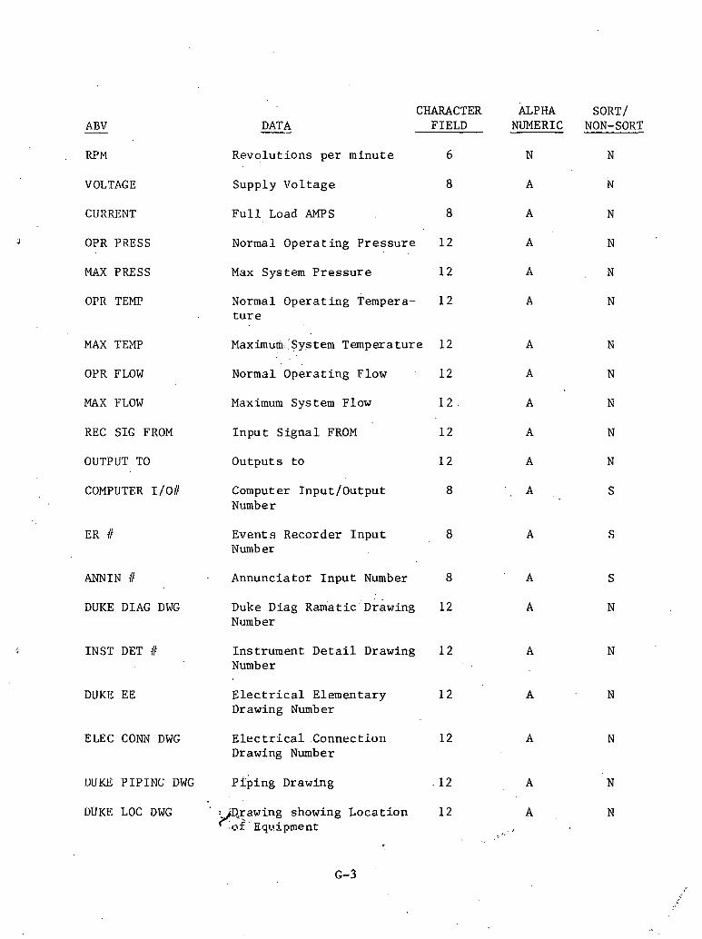
CHARACTER FIELD
ALPHA NUMERIC
SORT/ NON-SORT DATA ABV -
RPM
VOLTAGE
CURRENT
OPR PRESS
MAX PRESS
OPR TEMP
R e v o l u t i o n s p e r m i n u t e 6
Supply V o l t a g e 8
F u l l Load AMPS 8
Normal Opera t ing P r e s s u r e 12
Max System P r e s s u r e 12
Normal O p e r a t i n g Tempera- 1 2 t u r e
MAX TEMP
OYR FLOW
Maximum Sy.stem Temperature 12 A
Normal O p e r a t i n g Flow 12 A
MAX FLOW Maximum System Flow
REC SIG FROM I n p u t S i g n a l FROM
OUTPUT TO Outpu ts t o
COMPUTER I / O # Computer Inpu t /Outpu t Number
Event s Recorder I n p u t Number
A N N I N Annuncia tor I n p u t Number
. . DUKE D I A G DWG Duke Diag Ramat i c - rawi in^
Number
INST DET // Ins t rument Detail Drawing Number
DUKE EE E l e c t r i c a l Elementary Drawing Number
ELEC CONN DWG E l e c t r i c a l . C o n n e c t i u ~ i Drawing Number
DUKE PIPING DWG p i p i n g Drawing
DUKE LOC DWG ' p * f a w i n g showing L o c a t i o n of Eq1.1ipment

ALPHA SORT/ CHAPACTER FIELD DATA - NUMERIC NON-SORT ABV -
MANF OUTLINE M a n u f a c t u r e r ' s O u t l i n e Drawing
M a n u f a c t u r e r ' s I n s t r u c t i o n Book
MANF INST BK
P h y s i c a l L o c a t i o n of Equipment
PHYS LOC
C a l i b r a t i o n Frequency
L a s t ' C a l i b r a t i o n Da te
CAL FREQ '
TJAST CAT.
NEXT CAL
PM FREQ
Next C a l i b r a t i o n Da te
P r e v e n t i v e Maintenance Frequency
L a s t PM Date LAST PM &
NEXT PM Next PM D a t e
D a t e S p a r e s Ordered SPARES ORDERED
MINIMAX Minimum/Maximum S t o c k i n g L e v e l
Duke Stock Number STOCK NU.
M a t e r i a l s Sequence Number . .
R e s p o n s i b l e Group o r Dept.
Equipment S t a t u s
R e p a i r Order Number
SEQ NUMBER
RESP GROUP
EQUIP STATUS
REPAIR ORDER