Sub-Stations - JC Bose University
17
569 569 569 569 569 # CHAPTER CHAPTER CHAPTER CHAPTER CHAPTER Sub-Stations 25.1 Sub-Station 25.2 Classification of Sub-Stations 25.3 Comparison between Outdoor and Indoor Sub-Stations 25.4 Transformer Sub-Stations 25.5 Pole-Mounted Sub-Station 25.6 Underground Sub-Station 25.7 Symbols for Equipment in Sub-Stations 25.8 Equipment in a Transformer Sub-Station 25.9 Bus-Bar Arrangements in Sub-Stations 25.10 Terminal and Through Sub-Stations 25.11 Key Diagram of 66/11 kV Sub-Station 25.12 Key Diagram of 11kV/400 V Indoor Sub-Station Intr Intr Intr Intr Introduction oduction oduction oduction oduction T he present-day electrical power system is a.c. i.e. electric power is generated, trans mitted and distributed in the form of alternating current. The electric power is produced at the power stations which are located at favourable places, generally quite away from the consumers. It is delivered to the consumers through a large network of transmission and distribution. At many places in the line of the power system, it may be desirable and necessary to change some characteristic (e.g. voltage, a.c. to d.c., frequency, p.f. etc.) of electric supply. This is accomplished by suitable apparatus called sub- station. For example, generation voltage (11 kV or 6·6 kV) at the power station is stepped up to high voltage (say 220 kV or 132 kV) for transmission of electric power. The assembly of apparatus (e.g. transformer etc.) used for this purpose is the sub-station. Similarly, near the consumers localities, the voltage may have to be stepped down to utilisation level. This job is again accomplished by a suitable apparatus called sub- station. Yet at some places in the line of the power system, it may be desirable to convert large quantities of a.c. power to d.c. power e.g. for
-
Upload
khangminh22 -
Category
Documents
-
view
3 -
download
0
Transcript of Sub-Stations - JC Bose University

569569569569569
��
C H A P T E RC H A P T E RC H A P T E RC H A P T E RC H A P T E R
Sub-Stations
25.1 Sub-Station
25.2 Classification of Sub-Stations
25.3 Comparison between Outdoor andIndoor Sub-Stations
25.4 Transformer Sub-Stations
25.5 Pole-Mounted Sub-Station
25.6 Underground Sub-Station
25.7 Symbols for Equipment in
Sub-Stations
25.8 Equipment in a Transformer
Sub-Station
25.9 Bus-Bar Arrangements in
Sub-Stations
25.10 Terminal and Through Sub-Stations
25.11 Key Diagram of 66/11 kV Sub-Station
25.12 Key Diagram of 11kV/400 V IndoorSub-Station
IntrIntrIntrIntrIntroductionoductionoductionoductionoduction
The present-day electrical power system isa.c. i.e. electric power is generated, transmitted and distributed in the form of
alternating current. The electric power isproduced at the power stations which are locatedat favourable places, generally quite away fromthe consumers. It is delivered to the consumersthrough a large network of transmission anddistribution. At many places in the line of thepower system, it may be desirable and necessaryto change some characteristic (e.g. voltage, a.c.to d.c., frequency, p.f. etc.) of electric supply. Thisis accomplished by suitable apparatus called sub-station. For example, generation voltage (11 kVor 6·6 kV) at the power station is stepped up tohigh voltage (say 220 kV or 132 kV) fortransmission of electric power. The assembly ofapparatus (e.g. transformer etc.) used for thispurpose is the sub-station. Similarly, near theconsumers localities, the voltage may have to bestepped down to utilisation level. This job is againaccomplished by a suitable apparatus called sub-station. Yet at some places in the line of the powersystem, it may be desirable to convert largequantities of a.c. power to d.c. power e.g. for

570570570570570 Principles of Power System
traction, electroplating, *d.c. motors etc. This job is again performed by suitable apparatus (e.g.ignitron) called sub-station. It is clear that type of equipment needed in a sub-station will dependupon the service requirement. Although there can be several types of sub-stations, we shall mainlyconfine our attention to only those sub-stations where the incoming and outgoing supplies are a.c. i.e.sub-stations which change the voltage level of the electric supply.
25.125.125.125.125.1 Sub-StationSub-StationSub-StationSub-StationSub-Station
The assembly of apparatus used to change some characteristic (e.g. voltage, a.c. to d.c., frequency,p.f. etc.) of electric supply is called a sub-station.
Sub-stations are important part of power system. The continuity of supply depends to a consid-erable extent upon the successful operation of sub-stations. It is, therefore, essential to exerciseutmost care while designing and building a sub-station. The following are the important points whichmust be kept in view while laying out a sub-station :
(i) It should be located at a proper site. As far as possible, it should be located at the centre ofgravity of load.
(ii) It should provide safe and reliable arrangement. For safety, consideration must be given tothe maintenance of regulation clearances, facilities for carrying out repairs and maintenance,abnormal occurrences such as possibility of explosion or fire etc. For reliability, consider-ation must be given for good design and construction, the provision of suitable protectivegear etc.
(iii) It should be easily operated and maintained.
(iv) It should involve minimum capital cost.
25.225.225.225.225.2 Classification of Sub-Stations Classification of Sub-Stations Classification of Sub-Stations Classification of Sub-Stations Classification of Sub-Stations
There are several ways of classifying sub-stations. However, the two most important ways of classi-fying them are according to (1) service requirement and (2) constructional features.
1. According to service requirement. A sub-station may be called upon to change voltagelevel or improve power factor or convert a.c. power into d.c. power etc. According to the servicerequirement, sub-stations may be classified into :
(i) Transformer sub-stations. Those sub-stations which change the voltage level of electricsupply are called transformer sub-stations. These sub-stations receive power at some voltage anddeliver it at some other voltage. Obviously, transformer will be the main component in such sub-stations. Most of the sub-stations in the power system are of this type.
(ii) Switching sub-stations. These sub-stations do not change the voltage level i.e. incomingand outgoing lines have the same voltage. However, they simply perform the switching operations ofpower lines.
(iii) Power factor correction sub-stations. Those sub-stations which improve the power factorof the system are called power factor correction sub-stations. Such sub-stations are generally locatedat the receiving end of transmission lines. These sub-stations generally use synchronous condensersas the power factor improvement equipment.
(iv) Frequency changer sub-stations. Those sub-stations which change the supply frequencyare known as frequency changer sub-stations. Such a frequency change may be required for indus-trial utilisation.
(v) Converting sub-stations. Those sub-stations which change a.c. power into d.c. power arecalled converting sub-stations. These sub-stations receive a.c. power and convert it into d.c. power
* Although most of the motors in operation in the world today are a.c. motors, yet one can find d.c. motorswhere fine speed control is required or where these were installed before the development of a.c. machinery.

Sub-Stations 571571571571571
with suitable apparatus (e.g. ignitron) to supply for such purposes as traction, electroplating, electricwelding etc.
(vi) Industrial sub-stations. Those sub-stations which supply power to individual industrialconcerns are known as industrial sub-stations.
2. According to constructional features. A sub-station has many components (e.g. circuitbreakers, switches, fuses, instruments etc.) which must be housed properly to ensure continuous andreliable service. According to constructional features, the sub-stations are classified as :
(i) Indoor sub-station (ii) Outdoor sub-station(iii) Underground sub-station (iv) Pole-mounted sub-station
(i) Indoor sub-stations. For voltages upto 11 kV, the equipment of the sub-station is installedindoor because of economic considerations. However, when the atmosphere is contaminated withimpurities, these sub-stations can be erected for voltages upto 66 kV.
(ii) Outdoor sub-stations. For voltages beyond 66 kV, equipment is invariably installed out-door. It is because for such voltages, the clearances between conductors and the space required forswitches, circuit breakers and other equipment becomes so great that it is not economical to install theequipment indoor.
(iii) Underground sub-stations. In thickly populated areas, the space available for equipmentand building is limited and the cost of land is high. Under such situations, the sub-station is createdunderground. The reader may find further discussion on underground sub-stations in Art. 25.6.
(iv) Pole-mounted sub-stations. This is an outdoor sub-station with equipment installed over-head on H-pole or 4-pole structure. It is the cheapest form of sub-station for voltages not exceeding11kV (or 33 kV in some cases). Electric power is almost distributed in localities through such sub-stations. For complete discussion on pole-mounted sub-station, the reader may refer to Art. 25.5.
25.325.325.325.325.3 Comparison between Outdoor and Indoor Sub-Stations Comparison between Outdoor and Indoor Sub-Stations Comparison between Outdoor and Indoor Sub-Stations Comparison between Outdoor and Indoor Sub-Stations Comparison between Outdoor and Indoor Sub-Stations
The comparison between outdoor and indoor sub-stations is given below in the tabular form :
S.No. Particular Outdoor Sub-station Indoor Sub-station
1 Space required More Less
2 Time required for erection Less More
3 Future extension Easy Difficult
4 Fault location Easier beacuse the Difficult because theequipment is in full view equipment is enclosed
5 Capital cost Low High
6 Operation Difficult Easier
7 Possibility of fault escalation Less because greater Moreclearances can be provided
From the above comparison, it is clear that each type has its own advantages and disadvantages.However, comparative economics (i.e. annual cost of operation) is the most powerful factor influenc-ing the choice between indoor and outdoor sub-stations. The greater cost of indoor sub-station pro-hibits its use. But sometimes non-economic factors (e.g. public safety) exert considerable influencein choosing indoor sub-station. In general, most of the sub-stations are of outdoor type and the indoorsub-stations are erected only where outdoor construction is impracticable or prohibited by the locallaws.
25.425.425.425.425.4 T T T T Transforransforransforransforransformer Sub-Stationsmer Sub-Stationsmer Sub-Stationsmer Sub-Stationsmer Sub-Stations
The majority of the sub-stations in the power system are concerned with the changing of voltage levelof electric supply. These are known as transformer sub-stations because transformer is the main

572572572572572 Principles of Power System
component employed to change the voltage level. Depending upon the purpose served, transformersub-stations may be classified into :
(i) Step-up sub-station (ii) Primary grid sub-station
(iii) Secondary sub-station (iv) Distribution sub-station
Fig. 25.1 shows the block diagram of a typical electric supply system indicating the position ofabove types of sub-stations. It may be noted that it is not necessary that all electric supply schemesinclude all the stages shown in the figure. For example, in a certain supply scheme there may not besecondary sub-stations and in another case, the scheme may be so small that there are only distribu-tion sub-stations.
(i) Step-up sub-station. The generation voltage (11 kV in this case) is stepped up to highvoltage (220 kV) to affect economy in transmission of electric power. The sub-stations which ac-complish this job are called step-up sub-stations. These are generally located in the power housesand are of outdoor type.
(ii) Primary grid sub-station. From the step-up sub-station, electric power at 220 kV is trans-mitted by 3-phase, 3-wire overhead system to the outskirts of the city. Here, electric power is re-ceived by the primary grid sub-station which reduces the voltage level to 66 kV for secondary trans-mission. The primary grid sub-station is generally of outdoor type.
(iii) Secondary sub-station. From the primary grid sub-station, electric power is transmitted at66 kV by 3-phase, 3-wire system to various secondary sub-stations located at the strategic points inthe city. At a secondary sub-station, the voltage is further stepped down to 11 kV. The 11 kV linesrun along the important road sides of the city. It may be noted that big consumers (having demandmore than 50 kW) are generally supplied power at 11 kV for further handling with their own sub-

Sub-Stations 573stations. The secondary sub-stations are also generally of outdoor type.
(iv) Distribution sub-station. The electric power from 11 kV lines is delivered to distributionsub-stations. These sub-stations are located near the consumers localities and step down the voltageto 400 V, 3-phase, 4-wire for supplying to the consumers. The voltage between any two phases is400V and between any phase and neutral it is 230 V. The single phase residential lighting load isconnected between any one phase and neutral whereas 3-phase, 400V motor load is connected across3-phase lines directly. It may be worthwhile to mention here that majority of the distribution sub-stations are of pole-mounted type.
25.525.525.525.525.5 Pole-Mounted Sub-Station Pole-Mounted Sub-Station Pole-Mounted Sub-Station Pole-Mounted Sub-Station Pole-Mounted Sub-Station
It is a distribution sub-station placed overhead on a pole. It is the cheapest form of sub-station as itdoes not involve any building work. Fig 25.2 (i) shows the layout of pole-mounted sub-stationwhereas Fig. 25.2 (ii) shows the schematic connections. The transformer and other equipment aremounted on H-type pole (or 4-pole structure).
The 11 kV line is connected to the transformer (11kV /400 V) through gang isolator and fuses. The lightning arrest-ers are installed on the H.T. side to protect the sub-stationfrom lightning strokes. The transformer steps down the volt-age to 400V, 3-phase, 4-wire supply. The voltage betweenany two lines is 400V whereas the voltage between any lineand neutral is 230 V. The oil circuit breaker (O.C.B.) installedon the L.T. side automatically isolates the transformer fromthe consumers in the event of any fault. The pole-mounted Sub-Station

574574574574574 Principles of Power System
sub-stations are generally used for transformer capacity upto *200 kVA. The following points maybe noted about pole-mounted sub-stations :
(i) There should be periodical check-up of the dielectric strength of oil in the transformer andO.C.B.
(ii) In case of repair of transformer or O.C.B., both gang isolator and O.C.B. should be shut off.
25.625.625.625.625.6 Under Under Under Under Undergrgrgrgrground Sub-Stationound Sub-Stationound Sub-Stationound Sub-Stationound Sub-Station
In thickly populated cities, there is scarcity of land as well as the prices of land are very high. This hasled to the development of underground sub-station. In such sub-stations, the equipment is placedunderground. Fig. 25.3 shows a typical underground sub-station.
The design of underground sub-station requires more careful consideration than other types ofsub-stations. While laying out an underground sub-station, the following points must be kept in view:
(i) The size of the station should be as minimum as possible.
(ii) There should be reasonable access for both equipment and personnel.
(iii) There should be provision for emergency lighting and protection against fire.
(iv) There should be good ventilation.
(v) There should be provision for remote indication of excessive rise in temperature so that H.V.supply can be disconnected.
(vi) The transformers, switches and fuses should be air cooled to avoid bringing oil into thepremises.
25.725.725.725.725.7 Symbols for Equipment in Sub-Stations Symbols for Equipment in Sub-Stations Symbols for Equipment in Sub-Stations Symbols for Equipment in Sub-Stations Symbols for Equipment in Sub-Stations
It is a usual practice to show the various elements (e.g. transformer, circuit breaker, isolator, instru-ment transformers etc.) of a sub-station by their graphic symbols in the connection schemes. Sym-bols of important equipment in sub-station are given below :
* For capacity greater than 200kVA, transformer is installed on steel platform adjoining to the H-poleconstruction.
Sub-Stations 575575575575575
S.No. Circuit element Symbol
1 Bus-bar2 Single-break isolating switch
3 Double-break isolating switch
4 On load isolating switch
5 Isolating switch with earth Blade
6 Current transformer
7 Potential transformer
8 Capacitive voltage transformer
9 Oil circuit breaker
10 Air circuit breaker with overcurrent tripping device
11 Air blast circuit breaker
12 Lightning arrester (active gap)
13 Lightning arrester (valve type)

576576576576576 Principles of Power System
S.No. Circuit element Symbol
14 Arcing horn
15 3-φ Power transformer
16 Overcurrent relay
17 Earth fault relay
25.825.825.825.825.8 Equipment in a T Equipment in a T Equipment in a T Equipment in a T Equipment in a Transforransforransforransforransformer Sub-Stationmer Sub-Stationmer Sub-Stationmer Sub-Stationmer Sub-StationThe equipment required for a transformer sub-station depends upon the type of sub-station, servicerequirement and the degree of protection desired. However, in general, a transformer sub-station hasthe following main equipment :
1. Bus-bars. When a number of lines operating at the same voltage have to be directly con-nected electrically, bus-bars are used as the common electrical component. Bus-bars are copper oraluminium bars (generally of rectangular x-section) and operate at constant voltage. The incomingand outgoing lines in a sub-station are connected to the bus-bars. The most commonly used bus-bararrangements in sub-stations are :
(i) Single bus-bar arrangement(ii) Single bus-bar system with sectionalisation
(iii) Double bus-bar arrangement
A detailed discussion on these bus-bar arrangements has already been made in Art. 16.3. How-ever, their practical applications in sub-stations are discussed in Art. 25.9.
2. Insulators. The insulators serve two purposes. They support the conductors (or bus-bars)

Sub-Stations 577577577577577and confine the current to the conductors. The most commonly used material for the manufacture ofinsulators is porcelain. There are several types of insulators (e.g. pin type, suspension type, postinsulator etc.) and their use in the sub-station will depend upon the service requirement. For ex-ample, post insulator is used for bus-bars. A post insulator consists of a porcelain body, cast iron capand flanged cast iron base. The hole in the cap is threaded so that bus-bars can be directly bolted tothe cap.
3. Isolating switches. In sub-stations, it is often desired to disconnect a part of the system forgeneral maintenance and repairs. This is accomplished by an isolating switch or isolator. An isolatoris essentially a knife switch and is designed to open a circuit under no load. In other words, isolatorswitches are operated only when the lines in which they are connected carry *no current.
Fig. 25.4 shows the use of isolators in a typical sub-station. The entire sub-station has beendivided into V sections. Each section can be disconnected with the help of isolators for repair andmaintenance. For instance, if it is desired to repair section No. II, the procedure of disconnecting thissection will be as follows. First of all, open the circuit breaker in this section and then open theisolators 1 and 2. This procedure will disconnect section II for repairs. After the repair has beendone, close the isolators 1 and 2 first and then the circuit breaker.
4. Circuit breaker. A circuit breaker is an equipment which can open or close a circuit under**normal as well as fault conditions. It is so designed that it can be operated manually (or by remotecontrol) under normal conditions and automatically under fault conditions. For the latter operation,a relay circuit is used with a circuit breaker. Generally, bulk oil circuit breakers are used for voltagesupto 66kV while for high (>66 kV) voltages, low oil circuit breakers are used. For still highervoltages, air-blast, vacuum or SF6 circuit breakers are used. For detailed discussion of these break-ers, the reader may refer to chapter 19.
5. Power Transformers. A power transformer is used in a sub-station to step-up or step-downthe voltage. Except at the ***power station, all the subsequent sub-stations use step-down transform-ers to gradually reduce the voltage of electric supply and finally deliver it at utilisation voltage. Themodern practice is to use 3-phase transformers in sub-stations ; although 3 single phase bank of
* For example, consider that the isolators are connected on both sides of a circuit breaker. If the isolators areto be opened, the C.B. must be opened first.
** An isolator cannot be used to open a circuit under normal conditions. It is because it has no provision toquench the arc that is produced during opening operation. Hence the use of circuit breaker is essential.
*** where a step-up transformer is used to step-up generation voltage to a high value (say 132 kV or 220 kV ormore) for transmission of electric power.

578578578578578 Principles of Power System
transformers can also be used. The use of 3-phase transformer (instead of 3 single phase bank oftransformers) permits two advantages. Firstly, only one 3-phase load-tap changing mechanism canbe used. Secondly, its installation is much simpler than the three single phase transformers.
The power transformer is generally installed upon lengths of rails fixed on concrete slabs havingfoundations 1 to 1·5 m deep. For ratings upto 10 MVA, naturally cooled, oil immersed transformersare used. For higher ratings, the transformers are generally air blast cooled.
6. Instrument transformers. The lines in sub-stations operate at high voltages and carrycurrent of thousands of amperes. The measuring instruments and protective devices are designed forlow voltages (generally 110 V) and currents (about 5 A). Therefore, they will not work satisfactorilyif mounted directly on the power lines. This difficulty is overcome by installing instrument trans-formers on the power lines. The function of these instrument transformers is to transfer voltages orcurrents in the power lines to values which are convenient for the operation of measuring instrumentsand relays. There are two types of instrument transformers viz.
(i) Current transformer (C.T.) (ii) Potential transformer (P.T.)
(i) Current transformer (C.T.). A current transformer in essentially a step-up transformerwhich steps down the current to a known ratio. The primary of this transformer consists of one ormore turns of thick wire connected in series with the line. The secondary consists of a large numberof turns of fine wire and provides for the measuring instruments and relays a current which is aconstant fraction of the current in the line. Suppose a current transformer rated at 100/5 A is con-nected in the line to measure current. If the current in the line is 100 A, then current in the secondarywill be 5A. Similarly, if current in the line is 50A, then secondary of C.T. will have a current of 2·5 A.Thus the C.T. under consideration will step down the line current by a factor of 20.
(ii) Voltage transformer. It is essentially a step down transformer and steps down the voltageto a known ratio. The primary of this transformer consists of a large number of turns of fine wireconnected across the line. The secondary winding consists of a few turns and provides for measuringinstruments and relays a voltage which is a known fraction of the line voltage. Suppose a potentialtransformer rated at 66kV/110V is connected to a power line. If line voltage is 66kV, then voltageacross the secondary will be 110 V.
7. Metering and Indicating Instruments. There are several metering and indicating instru-ments (e.g. ammeters, voltmeters, energy meters etc.) installed in a sub-station to maintain watch overthe circuit quantities. The instrument transformers are invariably used with them for satisfactoryoperation.
8. Miscellaneous equipment. In addition to above, there may be following equipment in asub-station :
(i) fuses(ii) carrier-current equipment
(iii) sub-station auxiliary supplies
25.925.925.925.925.9 Bus-Bar Arrangements in Sub-Stations Bus-Bar Arrangements in Sub-Stations Bus-Bar Arrangements in Sub-Stations Bus-Bar Arrangements in Sub-Stations Bus-Bar Arrangements in Sub-Stations
Bus-bars are the important components in a sub-station. There are several bus-bar arrangements thatcan be used in a sub-station. The choice of a particular arrangement depends upon various factorssuch as system voltage, position of sub-station, degree of reliability, cost etc. The following are theimportant bus-bar arrangements used in sub-stations :
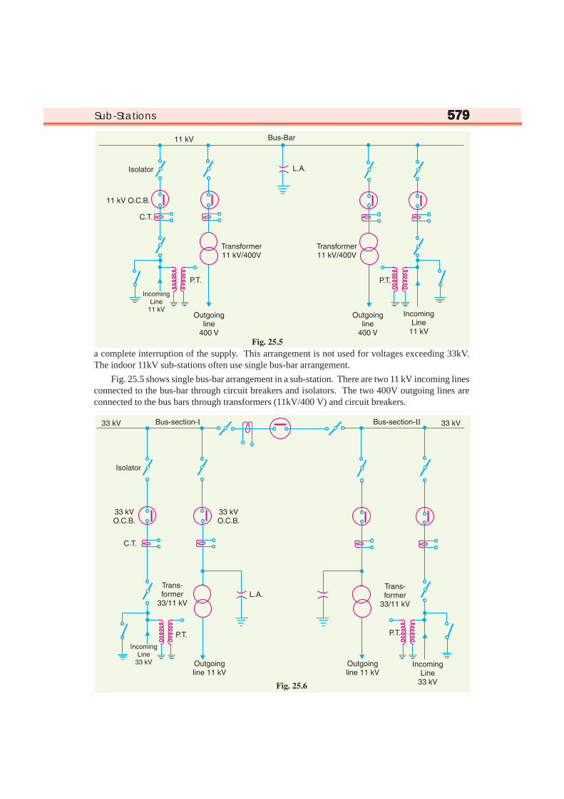
(i) Single bus-bar system. As the name suggests, it consists of a single bus-bar and all theincoming and outgoing lines are connected to it. The chief advantages of this type of arrangement arelow initial cost, less maintenance and simple operation. However, the principal disadvantage ofsingle bus-bar system is that if repair is to be done on the bus-bar or a fault occurs on the bus, there is
Sub-Stations 579579579579579
a complete interruption of the supply. This arrangement is not used for voltages exceeding 33kV.The indoor 11kV sub-stations often use single bus-bar arrangement.
Fig. 25.5 shows single bus-bar arrangement in a sub-station. There are two 11 kV incoming linesconnected to the bus-bar through circuit breakers and isolators. The two 400V outgoing lines areconnected to the bus bars through transformers (11kV/400 V) and circuit breakers.
580580580580580 Principles of Power System
(ii) Single bus-bar system with sectionalisation. In this arrangement, the single bus-bar isdivided into sections and load is equally distributed on all the sections. Any two sections of the bus-bar are connected by a circuit breaker and isolators. Two principal advantages are claimed for thisarrangement. Firstly, if a fault occurs on any section of the bus, that section can be isolated withoutaffecting the supply from other sections. Secondly, repairs and maintenance of any section of the bus-bar can be carried out by de-energising that section only, eliminating the possibility of complete shutdown. This arrangement is used for voltages upto 33 kV.
Fig. 25.6 shows bus-bar with sectionalisation where the bus has been divided into two sections.There are two 33 kV incoming lines connected to sections I and II as shown through circuit breakerand isolators. Each 11 kV outgoing line is connected to one section through transformer (33/11 kV)and circuit breaker. It is easy to see that each bus-section behaves as a separate bus-bar.
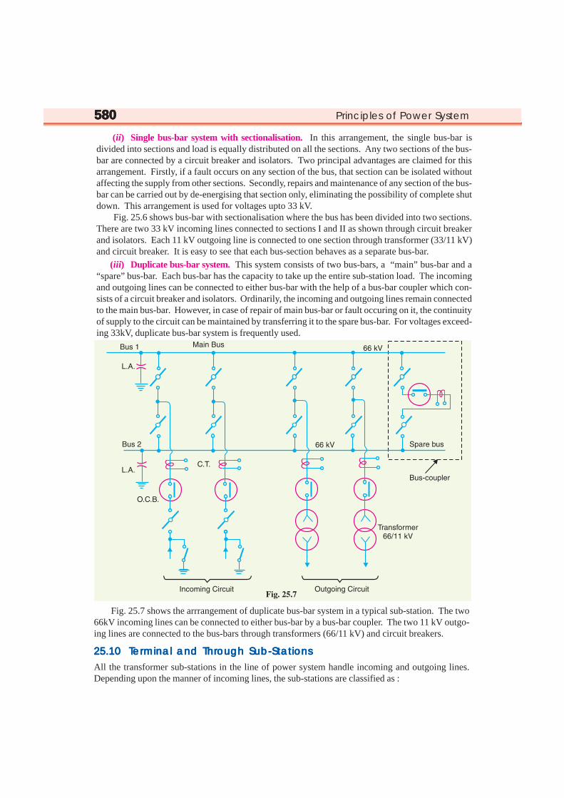
(iii) Duplicate bus-bar system. This system consists of two bus-bars, a “main” bus-bar and a“spare” bus-bar. Each bus-bar has the capacity to take up the entire sub-station load. The incomingand outgoing lines can be connected to either bus-bar with the help of a bus-bar coupler which con-sists of a circuit breaker and isolators. Ordinarily, the incoming and outgoing lines remain connectedto the main bus-bar. However, in case of repair of main bus-bar or fault occuring on it, the continuityof supply to the circuit can be maintained by transferring it to the spare bus-bar. For voltages exceed-ing 33kV, duplicate bus-bar system is frequently used.
Fig. 25.7 shows the arrrangement of duplicate bus-bar system in a typical sub-station. The two66kV incoming lines can be connected to either bus-bar by a bus-bar coupler. The two 11 kV outgo-ing lines are connected to the bus-bars through transformers (66/11 kV) and circuit breakers.
25.1025.1025.1025.1025.10 T T T T Terererererminal and Thrminal and Thrminal and Thrminal and Thrminal and Through Sub-Stationsough Sub-Stationsough Sub-Stationsough Sub-Stationsough Sub-Stations
All the transformer sub-stations in the line of power system handle incoming and outgoing lines.Depending upon the manner of incoming lines, the sub-stations are classified as :

Sub-Stations 581581581581581
(i) Terminal sub-station (ii) Through sub-station(i) Terminal sub-station. A terminal sub-station is one in which the line supplying to the sub-
station terminates or ends. It may be located at the end of the main line or it may be situated at a pointaway from main line route. In the latter case, a tapping is taken from the main line to supply to thesub-station. Fig. 25.8 shows the schematic connections of a terminal sub-station. It is clear thatincoming 11 kV main line terminates at the sub-station. Most of the distribution sub-stations are ofthis type.
(ii) Through sub-station. A through sub-station is one in which the incoming line passes‘through’ at the same voltage. A tapping is generally taken from the line to feed to the transformer toreduce the voltage to the desired level. Fig. 25.9 shows the schematic connections of a through sub-station. The incoming 66 kV line passes through the sub-station as 66kV outgoing line. At the sametime, the incoming line is tapped in the sub-station to reduce the voltage to 11 kV for secondarydistribution.
25.1125.1125.1125.1125.11 Key Diagram of 66/11 kV Sub-Station Key Diagram of 66/11 kV Sub-Station Key Diagram of 66/11 kV Sub-Station Key Diagram of 66/11 kV Sub-Station Key Diagram of 66/11 kV Sub-Station
Fig. 25.10 shows the key diagram of a typical 66/11 kV sub-station. The key diagram of this sub-station can be explained as under :

582582582582582 Principles of Power System

Sub-Stations 583583583583583(i) There are two 66 kV incoming lines marked ‘incoming 1’ and ‘incoming 2’ connected to the
bus-bars. Such an arrangement of two incoming lines is called a double circuit. Eachincoming line is capable of supplying the rated sub-station load. Both these lines can beloaded simultaneously to share the sub-station load or any one line can be called upon tomeet the entire load. The double circuit arrangement increases the reliability of the system.In case there is a breakdown of one incoming line, the continuity of supply can be main-tained by the other line.
(ii) The sub-station has duplicate bus-bar system; one ‘main bus-bar’ and the other spare bus-bar. The incoming lines can be connected to either bus-bar with the help of a bus-couplerwhich consists of a circuit breaker and isolators. The advantage of double bus-bar system isthat if repair is to be carried on one bus-bar, the supply need not be interrupted as the entireload can be transferred to the other bus.
(iii) There is an arrangement in the sub-station by which the same 66 kV double circuit supply isgoing out i.e. 66 kV double circuit supply is passing through the sub-station. The outgoing66 kV double circuit line can be made to act as incoming line.
(iv) There is also an arrangement to step down the incoming 66 kV supply to 11 kV by two unitsof 3-phase transformers; each transformer supplying to a separate bus-bar. Generally, onetransformer supplies the entire sub-station load while the other transformer acts as a standbyunit. If need arises, both the transformers can be called upon to share the sub-station load.The 11 kV outgoing lines feed to the distribution sub-stations located near consumers locali-ties.
(v) Both incoming and outgoing lines are connected through circuit breakers having isolatorson their either end. Whenever repair is to be carried over the line towers, the line is firstswitched off and then earthed.
(vi) The potential transformers (P.T.) and current transformers (C.T.) and suitably located forsupply to metering and indicating instruments and relay circuits (not shown in the figure).The P.T. is connected right on the point where the line is terminated. The CTs are connectedat the terminals of each circuit breaker.
(vii) The lightning arresters are connected near the transformer terminals (on H.T. side) to pro-tect them from lightning strokes.
(viii) There are other auxiliary components in the sub-station such as capacitor bank for powerfactor improvement, earth connections, local supply connections, d.c. supply connectionsetc. However, these have been omitted in the key diagram for the sake of simplicity.
25.1225.1225.1225.1225.12 Key Diagram of 11 Key Diagram of 11 Key Diagram of 11 Key Diagram of 11 Key Diagram of 11 kkkkkV/400 V Indoor Sub-StationV/400 V Indoor Sub-StationV/400 V Indoor Sub-StationV/400 V Indoor Sub-StationV/400 V Indoor Sub-Station
Fig. 25.11 shows the key diagram of a typical 11 kV/400 V indoor sub-station. The key diagram ofthis sub-station can be explained as under :
(i) The 3-phase, 3-wire 11 kV line is tapped and brought to the gang operating switch installednear the sub-station. The G.O. switch consists of isolators connected in each phase of the 3-phase line.
(ii) From the G.O. switch, the 11 kV line is brought to the indoor sub-station as undergroundcable. It is fed to the H.T. side of the transformer (11 kV/400 V) via the 11 kV O.C.B. Thetransformer steps down the voltage to 400 V, 3-phase, 4-wire.
(iii) The secondary of transformer supplies to the bus-bars via the main O.C.B. From the bus-bars, 400 V, 3-phase, 4-wire supply is given to the various consumers via 400 V O.C.B. Thevoltage between any two phases is 400 V and between any phase and neutral it is 230 V. Thesingle phase residential load is connected between any one phase and neutral whereas 3-phase, 400 V motor load is connected across 3-phase lines directly.

584584584584584 Principles of Power System
(iv) The CTs are located at suitable places in the sub-station circuit and supply for the meteringand indicating instruments and relay circuits.
SELF - TESTSELF - TESTSELF - TESTSELF - TESTSELF - TEST
1. Fill in the blanks by appropriate words/figures :
(i) A sub-station ................. some characteristic of electric supply.
(ii) Most of the sub-stations in the power system change.................. of electric supply.
(iii) An ideal location for the sub-station would be at the ............... of load.
(iv) Pole-mounted sub-stations are used for ............ distribution.
(v) The voltage rating of the transformer in a pole-mounted sub-station is............. .
(vi) Single bus-bar arrangement in sub-stations is used for voltages less then ................
(vii) For voltages greater than 33kV, .............. bus-bar arrangement is employed.
(viii) The kVA rating of transformer in a pole-mounted sub-station does not exceed..................
(ix) An indoor sub-station is ................ expensive than outdoor sub-station.
(x) Fault location is ................ in an outdoor sub-station than in indoor sub-station.
2. Pick up the correct words/figures from brackets and fill in the blanks :(i) Outdoor sub-station requires ............ space. (more, less)
(ii) The possibility of fault escalation is .......... in outdoor sub-station than that of indoor sub-station.
(more, less)
(iii) Majority of distribution sub-stations are of ................. type. (pole-mounted, indoor, outdoor)

Sub-Stations 585585585585585(iv) Power factor correction sub-stations are generally located at the ........ end of a transmission line.
(sending, receiving)
(v) Underground sub-stations are generally located in................. (thickly populated areas, villages)
ANSWERS TO SELF-TESTANSWERS TO SELF-TESTANSWERS TO SELF-TESTANSWERS TO SELF-TESTANSWERS TO SELF-TEST
1. (i) changes (ii) voltage level (iii) centre of gravity (iv) secondary (v) 11 kV/400 V (vi) 33 kV(vii) duplicate (viii) 200 (ix) more (x) easier
2. (i) more (ii) less (iii) pole-mounted (iv) receiving (v) thickly populated areas
CHAPTER REVIEW TOPICSCHAPTER REVIEW TOPICSCHAPTER REVIEW TOPICSCHAPTER REVIEW TOPICSCHAPTER REVIEW TOPICS
1. What is a sub-station ? Name the factors that should be taken care of while designing and erecting a sub-station.
2. Discuss the different ways of classifying the sub-stations.
3. Give the comparison of outdoor and indoor sub-stations.
4. What is a transformer sub-station ? What are the different types of transformer sub-stations ? Illustrateyour answer with a suitable block diagram.
5. Draw the layout and schematic connection of a pole-mounted sub-station.
6. Draw the layout of a typical underground sub-station.
7. Write a short note on the sub-station equipment.
8. What are the different types of bus-bar arrangements used in sub-stations ? Illustrate your answer withsuitable diagrams.
9. What are terminal and through sub-stations ? What is their purpose in the power system ?
10. Draw the key diagram of a typical 66/11 kV sub-station.
11. Draw the key diagram of a typical 11 kV/400 V indoor sub-station.
DISCUSSION QUESTIONSDISCUSSION QUESTIONSDISCUSSION QUESTIONSDISCUSSION QUESTIONSDISCUSSION QUESTIONS
1. What is the need of a sub-station in the power system ?
2. Why are pole-mounted sub-stations very popular ?
3. Where we erect a terminal sub-station ?
4. Why do we use isolators on both sides of circuit breaker ?
5. What is the utility of instrument transformers in sub-stations ?