Fusion Nuclear Science Pathways Assessment - UNT Digital ...
290
Prepared for the U.S. Department of Energy under Contract DE-AC02-09CH11466. Princeton Plasma Physics Laboratory PPPL-
-
Upload
khangminh22 -
Category
Documents
-
view
0 -
download
0
Transcript of Fusion Nuclear Science Pathways Assessment - UNT Digital ...
Prepared for the U.S. Department of Energy under Contract DE-AC02-09CH11466.
Princeton Plasma Physics Laboratory
PPPL-
Pamela Hampton
Text Box
PPPL-
gczechow
Typewritten Text
Princeton Plasma Physics Laboratory Report Disclaimers
Full Legal Disclaimer
This report was prepared as an account of work sponsored by an agency of the United States Government. Neither the United States Government nor any agency thereof, nor any of their employees, nor any of their contractors, subcontractors or their employees, makes any warranty, express or implied, or assumes any legal liability or responsibility for the accuracy, completeness, or any third party’s use or the results of such use of any information, apparatus, product, or process disclosed, or represents that its use would not infringe privately owned rights. Reference herein to any specific commercial product, process, or service by trade name, trademark, manufacturer, or otherwise, does not necessarily constitute or imply its endorsement, recommendation, or favoring by the United States Government or any agency thereof or its contractors or subcontractors. The views and opinions of authors expressed herein do not necessarily state or reflect those of the United States Government or any agency thereof.
Trademark Disclaimer
Reference herein to any specific commercial product, process, or service by trade name, trademark, manufacturer, or otherwise, does not necessarily constitute or imply its endorsement, recommendation, or favoring by the United States Government or any agency thereof or its contractors or subcontractors.
PPPL Report Availability
Princeton Plasma Physics Laboratory:
http://www.pppl.gov/techreports.cfm Office of Scientific and Technical Information (OSTI):
http://www.osti.gov/bridge
Related Links:
U.S. Department of Energy Office of Scientific and Technical Information Fusion Links

THE FUSION NUCLEAR
SCIENCE PATHWAYS
ASSESSMENT PPPL REPORT: FNS-PA core members listed, C. E. Kessel (chair, PPPL), M. S. Tillack (UCSD), V. S. Chan (GA), M. A. Abdou (UCLA), L. R. Baylor (ORNL), L. Bromberg (MIT), R. Kurtz (PNL), S. Milora (ORNL), W. R. Meier (LLNL), J. V. Minervini (MIT), N. B. Morley (UCLA), F. Najmabadi (UCSD), G. H. Neilson (PPPL), R. E. Nygren (SNL), Y-K. M. Peng (ORNL), D. Rej (LANL), R. D. Stambaugh (GA), G. R. Tynan (UCSD), D. G. Whyte (MIT), R. S. Willms (ITER, LANL), J. R. Wilson (PPPL), B. Wirth (Univ. of Tennessee), K. M. Young (ret, PPPL)

Table of Contents
1. The Fusion Nuclear Science Pathways Assessment, Introduction and Summary............................................................................................................................................................ 8 1.1 Introduction .....................................................................................................................................8 1.1.1 Description of a Demonstration Fusion Power Plant (Roll back) .....................................10 1.1.2 Divertor.......................................................................................................................................................14 1.1.3 First Wall and Blanket ..........................................................................................................................15 1.1.4 Vacuum Vessel .........................................................................................................................................17 1.1.5 Power conversion system...................................................................................................................17 1.1.6 Neutronics and Material Damage ....................................................................................................18 1.1.7 Toroidal and Poloidal Field Magnets .............................................................................................19 1.1.8 Heating and Current Drive .................................................................................................................20 1.1.9 Tritium Fueling, Pumping and Handling ......................................................................................20 1.1.10 Plasma.......................................................................................................................................................21 1.1.11 Measurement and Control ...............................................................................................................23 1.1.12 Near Term Research Activities for Fusion Nuclear Science (Roll forward) ...............24
1.2 Materials Science and Technology..........................................................................................24 1.2.1 Structural Materials...............................................................................................................................24 1.2.2 Blanket Materials....................................................................................................................................26 1.2.3 Superconductor Materials ..................................................................................................................27 1.2.4 Diagnostic Materials...............................................................................................................................27 1.2.5 Material Compatibility .........................................................................................................................27 1.2.6 Design Criteria, Licensing, and High-‐Temperature Material Issues.................................28
1.3 Power Extraction and Tritium Sustainability ....................................................................28 1.3.1 PbLi Liquid Metal Breeder..................................................................................................................29 1.3.2 Plasma Exhaust and Blanket Effluent Tritium Processing ...................................................29 1.3.3 Helium Cooling of High Heat Flux Surface of the First Wall And Blanket......................30 1.3.4 Ceramic Breeder .....................................................................................................................................30
1.4 Plasma Facing Component and Plasma Material Interactions.....................................31 1.5 Safety and Environment ............................................................................................................33 1.5.1 Computational Tools.............................................................................................................................34 1.5.2 Fusion Source Terms ............................................................................................................................34 1.5.3 Qualification of Fusion Components in the Fusion DEMO....................................................35 1.5.4 Waste Management ...............................................................................................................................35 1.5.5 Integrated Safety in Design and Licensing ..................................................................................35
1.6 Magnets ...........................................................................................................................................36 1.7 Heating and Current Drive Systems ......................................................................................37 1.8 Fueling, Pumping and Particle Control Systems ...............................................................38 1.9 Measurement Issues ...................................................................................................................39 1.10 Conclusion ...................................................................................................................................47 1.11 Appendix ......................................................................................................................................50 1.12 Footnotes .....................................................................................................................................61 1.13 References ...................................................................................................................................62
2. Research and Development Needs for Fusion Energy: Materials Science........65 2.1 Introduction ..................................................................................................................................66 2.2 Materials Research Needs Assumptions and Planning Process...................................66

2.2.1 Critical Issues ...........................................................................................................................................68 2.2.2 Reduced-‐Activation Ferritic/Martensitic Steels .......................................................................68 2.2.3 Nanostructured Ferritic Alloys.........................................................................................................69 2.2.4 Tungsten Alloys.......................................................................................................................................70 2.2.5 Silicon Carbide Composites................................................................................................................70 2.2.6 Vanadium Alloys .....................................................................................................................................71 2.2.7 Vacuum Vessel Steels............................................................................................................................72
2.3 Research Needs ............................................................................................................................73 2.3.1 Near-‐Term .................................................................................................................................................73 2.3.2 Intermediate and Long-‐Term............................................................................................................78 2.3.3 Major Facility Needs..............................................................................................................................79
2.4 Tritium and Blanket Materials................................................................................................85 2.4.1 Critical Issues ...........................................................................................................................................85 2.4.2 Tritium Permeation Control ..............................................................................................................85
2.5 PbLi Manufacturing.....................................................................................................................87 2.6 Ceramic Breeder Pebble Manufacturing .............................................................................88 2.7 Beryllium Neutron Multiplier Manufacturing ...................................................................88 2.8 Research Needs ............................................................................................................................90 2.8.1 Near-‐Term .................................................................................................................................................90 2.8.2 Intermediate and Long-‐Term............................................................................................................91
2.9 Magnet Materials .........................................................................................................................93 2.9.1 Critical Issues ...........................................................................................................................................93 2.9.2 Electrical Insulators...............................................................................................................................93 2.9.3 Structural Materials...............................................................................................................................95
2.10 Research Needs..........................................................................................................................96 2.10.1 Near-‐Term...............................................................................................................................................96
2.11 Diagnostic Materials ................................................................................................................98 2.11.1 Critical Issues.........................................................................................................................................98
2.12 Research Needs..........................................................................................................................99 2.12.1 Near-‐Term...............................................................................................................................................99 2.12.2 Intermediate and Long-‐Term .........................................................................................................99 2.12.3 Facility Needs .....................................................................................................................................100
2.13 Corrosion Compatibility ...................................................................................................... 101 2.13.1 Critical Issues......................................................................................................................................101 2.13.2 Research Needs..................................................................................................................................102 2.13.3 Intermediate and Long-‐Term ......................................................................................................104
2.14 Design, Licensing and Safety .............................................................................................. 105 2.14.1 Critical Issues......................................................................................................................................105 2.14.2 Research Needs..................................................................................................................................106
2.15 References ................................................................................................................................ 110 3. Research and Development Needs for Fusion Energy Power Extraction and Tritium Sustainability ..................................................................................................................................... 115 Nomenclature .................................................................................................................................... 116 3.1 Introduction ............................................................................................................................... 117 3.1.1 Plasma chamber and in-‐vessel considerations.......................................................................118 3.1.2 Ex-‐vessel Components and Systems Considerations...........................................................120 3.1.3 Assumptions and guiding principles...........................................................................................121 3.1.4 Outline ......................................................................................................................................................122
3.2 Near Term Research Needs (1-5 year timeframe) ........................................................ 123 3.2.1 PbLi Based Blanket Flow, Heat Transfer, and Transport Processes .............................124
3.2.2 Plasma Exhaust and Blanket Effluent Tritium Processing ................................................131 3.2.3 Helium Cooling of High Heat Flux Surfaces Blanket/FW ....................................................140 3.2.4 Ceramic Breeder Thermomechanics and Tritium Release................................................144 3.2.5 Blanket Mockup Thermomechanical/Thermofluid Testing Facility.............................150 3.2.6 Irradiation effects on blanket material and component functions ................................152 3.2.7 Fuel Cycle Development Facility...................................................................................................154 3.2.8 Bred Tritium Extraction Facility (BTEF)...................................................................................155 3.2.9 ITER TBM/FNSF Design and Safety/Licensing R&D............................................................158
3.3 During ITER Operations (10-20 Year Timeframe)........................................................ 161 3.3.1 ITER TBM modules experiments and Post Irradiation Examination............................161
3.4 Conclusions................................................................................................................................. 166 3.5 References................................................................................................................................... 167
4. Research and Development Activities for Fusion Energy: Plasma-Material Interactions and Plasma-Facing Components in a Fusion Nuclear Science Device .......170 4.1 Introduction ............................................................................................................................... 170 4.2 PFC Configurations and PMI in Confinement Devices .................................................. 170 4.3 Evolution of PMI and PFC Materials in an FNS Environment ...................................... 174 4.3.1 Problem Definition...............................................................................................................................174 4.3.2 Issues ........................................................................................................................................................174 4.3.3 Problem Importance ..........................................................................................................................176 4.3.4 Current Approaches ...........................................................................................................................176 4.3.5 Gaps Analysis.........................................................................................................................................178
4.4 PFC-PMI Engineering Issues and Decisions .................................................................... 185 4.4.1 ITER...........................................................................................................................................................186 4.4.2 High Level Choices for PFCs............................................................................................................186 4.4.3 Heat Loads to PFCs .............................................................................................................................188 4.4.4 Solid Walls ..............................................................................................................................................189 4.4.5 Liquid Walls ...........................................................................................................................................191 4.5.7 Actively-‐cooled PFCs and Probes on Existing and Near Term Devices........................196 4.5.8 Support for Novel Heat Transfer and Pumping Schemes ..................................................196 4.5.9 Development of Liquid Metal PFCs..............................................................................................196 4.5.10 Detailed Subsystem Design Studies ..........................................................................................197 4.5.11 Facility Needs: ....................................................................................................................................198
4.6 Appendix...................................................................................................................................... 199 4.7 References................................................................................................................................... 207
5. Research and Development Activities for Fusion Energy: Safety and Environment .............................................................................................................................208 5.1 Introduction ............................................................................................................................... 208 5.2 R&D Needs for Safety Computer Code Development.................................................... 209 5.2.1 Overview .................................................................................................................................................209 5.2.2 Research Activities..............................................................................................................................211
5.3 R&D Needs for Tritium and Activation Product Source Term Research ............... 212 5.3.1 Overview .................................................................................................................................................213 5.3.2 Tritium Retention in Plasma Facing Component Materials ..............................................213 5.3.3 Research Activities: ............................................................................................................................214
5.4 R&D Needs for Dust Source Term Research .................................................................... 217 5.4.1 Overview .................................................................................................................................................217 5.4.2 Research Activities..............................................................................................................................217

5.5 R&D Needs for Probabilistic Risk Assessment ............................................................... 219 5.5.1 Overview .................................................................................................................................................219 5.5.2 Research Needs ....................................................................................................................................220
5.6 R&D Needs for Occupational Safety.................................................................................... 220 5.6.1 Overview .................................................................................................................................................221 5.6.2 Research Activities..............................................................................................................................222
5.7 R&D Needs for Waste Management.................................................................................... 222 5.7.1 Overview .................................................................................................................................................222 5.7.2 Research Activities..............................................................................................................................223
5.8 R&D Needs for Integrated Safety in Design and Licensing ......................................... 224 5.8.1 Overview .................................................................................................................................................224 5.8.2 Research Activities..............................................................................................................................225
5.9 Summary...................................................................................................................................... 225 5.10 References ............................................................................................................................... 228
6. Research and Development Activities for Fusion Energy: Magnets R&D for FNS*..............................................................................................................................................230 6.1 State-of-the-Art.......................................................................................................................... 230 6.2 Future magnet technology: magnet technology for FNS............................................. 231 6.3 Research Activities for Magnets for FNS ........................................................................... 232 6.4 Superconducting Materials ................................................................................................... 232 6.4.1 LTS .............................................................................................................................................................232 6.4.2 HTS.............................................................................................................................................................234 6.4.3 HTS Material and Cable Design.........................................................................................................235 6.4.4 Structural Material..............................................................................................................................238 6.4.5 Insulation ................................................................................................................................................238 6.4.6 Joints .........................................................................................................................................................238 6.4.7 Magnet Protection...............................................................................................................................240 6.4.8 Prototype Magnet Development...................................................................................................240 6.4.9 R&D Strategy .........................................................................................................................................241
6.5 R&D Tasks ................................................................................................................................... 241 6.5.1 SC Wire and Tape Development Program ...............................................................................242 6.5.2 High Current Conductors and Cables Development Program .........................................242 6.5.3 Advanced Structural Concepts and Structural Materials and Structural Concepts for HTS.........................................................................................................................................................................242 6.5.4 Cryogenic Cooling Methods for HTS Magnets .........................................................................243 6.5.5 Magnet Protection...............................................................................................................................244 6.5.6 Joints for demountable coils ...........................................................................................................244 6.5.7 Technology demonstration .............................................................................................................245
6.6 Copper Machines....................................................................................................................... 245 6.7 Facilities....................................................................................................................................... 246 6.8 Scale of Effort for FNS .............................................................................................................. 247
7. Research and Development Activities for Fusion Energy: Issues for Heating and Current Drive Systems in a DEMO Environment ..................................................249 7.1 Introduction ............................................................................................................................... 249 7.2 Requirements for Heating and Current Drive ................................................................ 249 7.2.1 Physics Requirements (This section also includes economic considerations) ........249 7.2.3 Efficiencies..............................................................................................................................................250
7.3 Heating and Current Drive Systems ................................................................................... 251

7.3.1 NBI .............................................................................................................................................................251 7.3.2 ECH ............................................................................................................................................................252 7.3.3 LHCD ..........................................................................................................................................................253 7.3.4 ICRF ...........................................................................................................................................................253 7.3.5 Source Issues .........................................................................................................................................254 7.3.6 NBI .............................................................................................................................................................254 7.3.7 ECH ............................................................................................................................................................255 7.3.8 LHCD .........................................................................................................................................................256 7.3.9 ICRF ...........................................................................................................................................................256
7.4 Transmission Issues ................................................................................................................ 256 7.4.1 NBI .............................................................................................................................................................256 7.4.2 ECH ............................................................................................................................................................256 7.4.3 LHCD .........................................................................................................................................................257 7.4.4 ICRF ...........................................................................................................................................................257
7.5 Launcher Issues......................................................................................................................... 257 7.5.1 NBI .............................................................................................................................................................257 7.5.2 ECH ............................................................................................................................................................257 7.5.3 LHCD .........................................................................................................................................................258 7.5.4 ICRF ...........................................................................................................................................................258
7.6 Opportunities for Near Term R&D...................................................................................... 258 7.6.1 NBI .............................................................................................................................................................258 7.6.2 ECH ............................................................................................................................................................258 7.6.3 LHCD .........................................................................................................................................................259 7.6.4 ICRF ...........................................................................................................................................................259
7.7 Summary...................................................................................................................................... 259 7.8 References................................................................................................................................... 260
8. Research and Development Activities for Fusion Energy: Fueling, Pumping and Particle Control for FNS-PA .........................................................................................261 8.1 Introduction ............................................................................................................................... 261 8.2 Fueling and Burn Control....................................................................................................... 261 8.2.1 Fueling: ....................................................................................................................................................261 8.2.2 Burn Control: .........................................................................................................................................262
8.3 Exhaust Control - Pumping and Recycling, Divertor Concepts.................................. 263 8.3.1 Particle Exhaust Control...................................................................................................................263 8.4.1 Profile Control.......................................................................................................................................266
8.5 References................................................................................................................................... 268
9. Research and Development Activities for Fusion Energy: Issues for Integration of Measurements into FNSF..........................................................................269 9.1 Introduction ............................................................................................................................... 270 9.2 Plasma Measurements............................................................................................................ 270 9.2.1 Quality of Measurement Required ...............................................................................................272 9.2.2 Requirements from the device designers and technology community ..............................274 9.2.3 Requirements from diagnostic developers and operators .....................................................274 9.2.4 The issues of calibration, reliability and robustness..................................................................275 9.2.5 Some specific diagnostic short-‐term R&D activities ..................................................................276
9.3 Close-In Instrumentation for Non-Plasma Measurements......................................... 278 9.3.1 Vacuum Vessel Integrity...................................................................................................................278 9.3.2 Vacuum Quality ......................................................................................................................................279

9.3.3 First Wall and Divertor Material Monitoring ...............................................................................280 9.3.4 Magnets ....................................................................................................................................................280 9.3.5 “Halo” currents.......................................................................................................................................280 9.3.6 Heating Systems.....................................................................................................................................280 9.3.7 Measurements of the Fueling Pellets Prior to Entering the Plasma ....................................281 9.3.8 Blanket Modules ....................................................................................................................................281 9.3.9 In-‐Vessel Inspection ..............................................................................................................................282 9.3.10 Remote Maintenance ........................................................................................................................282
9.4 Summary...................................................................................................................................... 283 9.5 Acknowledegments ...................................................................................................................... 283 9.6 References ..................................................................................................................................... 283 9.7 Appendix 1:.................................................................................................................................. 285 9.8 Appendix 2:................................................................................................................................. 286

1. The Fusion Nuclear Science Pathways Assessment, Introduction and Summary
C. E. Kessel (chair), M. S. Tillack, V. S. Chan, M. A. Abdou, L. R. Baylor, L. Bromberg, R. Kurtz, S. Milora, W. R. Meier, J. V. Minervini, N. B. Morley, F.
Najmabadi, G. H. Neilson, R. E. Nygren, Y-K. M. Peng, D. Rej, R. D. Stambaugh, G. R. Tynan, D. G. Whyte, R. S. Willms, J. R. Wilson, B. Wirth, K. M. Young
1.1 Introduction With the strong commitment of the US to the success of the ITER burning plasma mission, and the project overall, it is prudent to consider how to take the most advantage of this investment. The production of energy from fusion has been a long sought goal, and the subject of several programmatic investigations and time line proposals[1]. The nuclear aspects of fusion research have largely been avoided experimentally for practical reasons, resulting in a strong emphasis on plasma science. Meanwhile, ITER has brought into focus how the interface between the plasma and engineering/technology, presents the most challenging problems for design. In fact, this situation is becoming the rule and no longer the exception. ITER will demonstrate the deposition of 0.5 GW of neutron heating to the blanket, deliver a heat load of 10-20 MW/m2 or more on the divertor, inject 50-100 MW of heating power to the plasma, all at the expected size scale of a power plant. However, in spite of this, and a number of other power plant relevant technologies, ITER will provide a low neutron exposure compared to the levels expected in a fusion power plant, and will purchase its tritium entirely from world reserves accumulated from decades of CANDU reactor operations. Such a decision for ITER is technically well founded, allowing the use of conventional materials and water coolant, avoiding the thick tritium breeding blankets required for tritium self-sufficiency, and allowing the concentration on burning plasma and plasma-engineering interface issues. The neutron fluence experienced in ITER over its entire lifetime will be ~ 0.3 MW-yr/m2, while a fusion power plant is expected to experience 120-180 MW-yr/m2 over its lifetime. ITER utilizes shielding blanket modules, with no tritium breeding, except in test blanket modules (TBM) located in 3 ports on the midplane [2], which will provide early tests of the fusion nuclear environment with very low tritium production (a few g per year). The technical gaps that exist between the ITER plasma and nuclear regime and that of the demonstration power plant regime must be bridged with additional research and facilities. It is well understood that the traditional materials used in present tokamak experiments and ITER will not be acceptable in a strong fusion nuclear environment. It is also understood that the components (e.g. blankets, divertors, etc.) in a fusion power plant will become significantly more complex in order to provide the multiple functions of extracting heat for thermal conversion, breeding tritium for fuel, protecting various lifetime components from neutron damage, and controlling heat and particle loads, all at significantly higher duty factors. The fusion environment is also complex with strong nuclear heating and damage,
high temperatures, strong fluid-solid interactions, high tritium concentrations, and high magnetic fields, and well as large variations of these parameters from the first wall to the vacuum vessel. The tritium fuel cycle must be established to provide the tritium consumed, compensate decay and losses, and accumulate a startup supply for the next plant. In addition, the tritium containment must meet strict licensing criteria for the protection of workers and the public. The demands of the plasma to provide a steady state source of neutrons (and alpha heating) for time-scales of 1 year, are well beyond those on present tokamaks and ITER, and finding self-consistent configurations for the core plasma, the edge and divertor region, and plasma material interface that allow the generation of power and simultaneously the handling of plasma power and particles is a major challenge. An aspect that is largely absent from fusion activities to date is that of reliability, availability, maintainability, and inspectability (RAMI), but one that is an absolute requirement of a power producing facility. The development of this area requires an evolution from exploration to validation to demonstration, in an iterative process for each component or subsystem in the plant. The Fusion Nuclear Science Pathways Assessment activity is targeting the identification of research activities necessary to advance fusion nuclear science within the US fusion program. In particular, the research should establish the technical basis for a fusion nuclear science facility (FNSF) and ultimately a demonstration fusion power plant (DEMO). Here and throughout the report, the FNSF is a generic term applied to a confinement facility that has nuclear characteristics intermediate between ITER and a DEMO. This activity follows the Priorities, Gaps, and Opportunities: Toward a Long Range Strategic Plan for Magnetic Fusion Energy (Greenwald report) [3] and the Research Needs for Magnetic Fusion Energy Sciences (ReNeW report) [4], with the intention of identifying, in greater detail, research activities that can take place over the next 5-10 years. Greater emphasis is given to the 5 year time frame, and longer times scales out to 10 years and beyond, are addressed more generally. Naturally there is an emphasis on the fusion nuclear science, but this will include both research to access the required plasma conditions and enabling technologies that support this. There are a number of perspectives that can be taken when identifying the research required to advance the fusion program closer to a fusion energy source, in particular, “rollback” from a vision of the fusion power plant or demonstration facility, and “roll forward” from where we are now and what we anticipate ITER, the Asian long pulse tokamaks, and present confinement facilities can provide. Both of these are used in this activity to provide an adequate meeting in the middle. In section 2, a DEMO parameter table will be used to motivate required research to establish the basis of the various assumptions, projections, and criteria used in power plant studies. Section 3 will briefly describe and summarize the findings for a series of topical areas, deemed critical for the success of fusion nuclear science. Specific research activities will be described in detail in following sections of this report. The topical areas are strongly correlated to the ReNeW areas, addressing Themes 3 and 4, Taming the Plasma-Material Interface and Harnessing Fusion Power.
Materials science and technology Power extraction and tritium sustainability
Plasma facing components and plasma materials interactions Safety, environment, and RAMI Enabling technologies, this includes;
Magnets Diagnostics Heating and current drive Fueling, pumping, and particles
Section 4 will cover the topic of plasma duration and sustainment, pertaining to the need for a steady state source of neutrons, highlighting areas of plasma science research that are considered critical to the success of a FNSF. The FNSF, which will be referred to heavily here and in the subsequent sections, is a confinement facility whose purpose is to bridge the gap between the ITER plasma and fusion nuclear environment and that of DEMO. In conjunction with the research program that precedes it, and is in parallel with it, the FNSF must provide a technical basis for DEMO by demonstrating
1) tritium breeding, extraction, fueling and exhaust, and processing, reaching a tritium breeding ratio of > 1, providing self-sufficiency
2) the heat extraction and electricity production 3) the integrated blanket (first wall, breeding zone, shield, and vacuum vessel)
concept 4) the power and particle handling in the plasma chamber, the divertor and first
wall concepts 5) the long plasma durations 6) all support technologies (magnets, pellet injector, heating and current drive,
vacuum systems, remote maintenance, diagnostics, etc.) 7) reliable, safe, maintainable, and inspectible operation
The precise parameters of a FNSF are not certain, but some proposals can be found for reference [5-8]. An important activity to pursue in the US fusion program will be to define better the missions for a FNSF, to develop the metrics by which we judge options for a FNSF, and begin designing this facility in more detail. Several features must be advanced in a FNSF and through a series of phases in its operation, since the range of parameters between the ITER and DEMO environments is quite large. Some of the proposals are used to obtain device parameters to help in identifying research goals, however, this activity did not address what the FNSF should be, nor does it endorse any particular proposals.
1.1.1 Description of a Demonstration Fusion Power Plant (Roll back) The DOE and its advisory committees often refer to a demonstration power plant, or DEMO, as an ultimate goal used for long-range program planning. However, the precise characteristics of this device are a subject of ongoing debate, with no commonly accepted reference concept. Different countries have adopted differing strategies and goals for their DEMOs.
In the early 1990’s, the ARIES Team, aided by an external utility advisory board, sought to define the criteria for practical fusion power and the essential characteristics of a demonstration power plant in the United States [9]. This led to the creation of a set of top-level goals for fusion energy development [10], and the following mission statement: “The Fusion DEMO demonstrates that fusion power is a secure, safe, licensable, and environmentally attractive power source that is ready for commercialization at an economically superior cost.” In more recent years, detailed R&D planning efforts have been undertaken by advisory committees such as the FESAC Greenwald panel [3]. With rapid progress toward a burning plasma demonstration in ITER, the term “DEMO” has become even more deeply embedded in the vernacular of fusion planning activities, although a reference design of a demonstration power plant still has not been established in the US. To aid their R&D planning, the Greenwald panel was compelled to adopt a generic definition of DEMO acceptable to the research community, largely based on the Starlite study [9]. The following are excerpts from their 2007 final report.
“To answer the charge, the panel needed a working definition for DEMO and an outline of its characteristics. Given the time span, it was not possible or reasonable to try to predict precisely how DEMO would be implemented, thus we chose to use a broad definition to ensure that the program does not foreclose options prematurely. In U.S. planning, DEMO is the last step before commercialization of fusion energy. DEMO must provide power producers with the confidence to invest in commercial fusion power plants, i.e., demonstrate that fusion is practical, reliable, economically competitive, and meets public acceptance. In addition, DEMO must operate reliably and safely on the power grid for long periods of times (i.e., years) so that power producers gain operational experience.”
“The U.S. DEMO must use and demonstrate the same technologies that will be incorporated in a fully-commercial power plant. This requirement is fundamental in determining the features of the DEMO and may or may not be adopted by other countries in their definition of a DEMO. If the basic technologies are changed following the DEMO, then another DEMO must be built before the design and construction of the commercial plant. A private investor will not accept risk of failure or reduced performance due to unproven and undemonstrated technologies. Additionally, it may be impossible to insure and/or license such a plant.” “This requirement allows for the performance levels to be reduced from a fully commercial plant as specified in the remaining DEMO requirements. For example, a reduced level of thermal efficiency, availability and component lifetime in the DEMO (owing to less competitive cost of electricity) allows the components to be designed slightly different and operate at lower temperatures and stresses. There is no requirement that specifies the component operating conditions must be exactly prototypical. However, through operation of the DEMO, a high level of confidence must be gained so that the first commercial plant is assured to meet the more stringent commercial power plant requirements. If performance levels are reduced from that of a

full commercial plant, then the ability to extrapolate must be clearly demonstrated.” The US still does not have a reference design concept for a demonstration power plant. The continuing need to refine our planning of FNS research requires an increasingly detailed understanding of the technologies and parameters for a DEMO. To that end, a “master table” of parameters was assembled to serve as a “roll back” point of reference for the FNS Pathway Assessment. To accommodate the uncertainty in the design and operating parameters, the table sometimes includes ranges of parameters. Recent ARIES studies of advanced fusion power plants were utilized as a guide to the selection of possible DEMO technologies [11, 12]. Different design concepts embody different parameter requirements. In some cases, two different sets of parameters are included for a “more conservative” power core based on the dual-cooled (He and PbLi) ferritic steel blanket (DCLL) [13] and a more aggressive power core based on PbLi-cooled SiC/SiC composite structures [14]. While SiC/SiC composites are still in an early stage of development, the long-term appeal of a very low activation power core has led to continued interest in power plant design studies and materials R&D programs. In both cases, the divertor is assumed to be a He-cooled W-alloy structure with W plasma-facing armor. The performance characteristics of this divertor choice are not fully understood at this time, due to the rather immature state of materials research on tungsten alloys; nevertheless, the appeal of tungsten as a high-temperature high-performance divertor material and the absence of a compelling alternative leads us to retain this material choice as the leading candidate. Most of these studies have assumed a tokamak or spherical tokamak configuration, but studies of stellarators and reversed-field pinches have been performed to understand their power plant implications and to highlight issues and R&D priorities specific to those concepts. Here we characterize the plasma properties for the tokamak-based power plant, for which there have been studies examining a wide range of design choices. The table consists of 9 subsections:
1) Divertor 2) FW and blanket 3) Vacuum vessel 4) Power conversion system 5) Neutronics and materials damage 6) TF/PF magnets 7) Heating & current drive 8) Tritium fueling, pumping, and handling 9) Plasma
These subsections list key characteristics and parameters, together with three essential additional columns used to explain the justification for the choice of the parameter, the current status of our understanding, and the R&D needs associated with that parameter. Each section was reviewed by members of the FNS-PA committee as well as community experts. Figure 1 shows a layout of the fusion power core, and exploded view of the radial build.

As mentioned above, our operating definition of “DEMO” may allow us to relax some parameters from the full “10th of a kind” power plant values derived from conceptual power plant studies. Notable examples include component lifetime, fusion power, power density and thermal conversion efficiency. The extent to which this scaling can be exploited is highly uncertain, as the risk tolerance of future fusion power plant operators cannot be measured at this time. The strong dependence of key parameters, such as component temperature and stress distributions, on plant characteristics implies increasing risk that important failure modes or operating limitations may be missed under scaled conditions. In order to account for the possibility of relaxed parameters, the table includes several footnotes identifying the most likely parameters and their relaxed values (derived primarily by “expert judgment”).
Figure 1. View of the ARIES-AT fusion power core, indicating the primary components, and exploded view of the radial build for a sector, FW and breeding blanket (pink), stabilizing shells (yellow), second breeding blanket (gray), high temperature shield (blue), and divertor (red).
Availability is a critical parameter for the success of a fusion electric generating station, and one that is notably absent from the table. The immature state of development of fusion as an energy source makes it nearly impossible to estimate the real availability of a fusion power core. Goals used in power plant systems studies for the purpose of estimating the future cost of electricity typically range from 75% to 85%. It is expected that the value demonstrated in DEMO will be closer to 50%. The demonstration power plant parameter table is shown in Appendix A, and is the basis for the discussion that below.

1.1.2 Divertor The divertor region of a tokamak power plant will be subjected to very high local heat flux as a result of the large power flows and small region of deposition that is anticipated. Since a portion of the total fusion power escapes into the divertor, it is very desirable to extract heat at a high temperature for efficient power conversion. The combined requirements of high thermal conductivity, high temperature and low activation limit material choices significantly. At present, tungsten and its alloys are considered attractive structural materials. However, much R&D will be required to develop the material and demonstrate adequate performance and reliability in components. Figure 2 contains an example cross section of a power core (taken from ARIES-AT [11]) showing the location of the upper and lower divertor, and also shown are the internal details of a particular divertor plate design concept that uses He jet cooling and local enhancement of heat transfer to accommodate over 15 MW/m2 at the plasma strike points [17].
Figure 2. Cross-section of the ARIES-AT power core (left) with divertors at top and bottom, and internal details of a He cooled divertor plate design with W-alloy structure (right).
Helium has been a favored primary coolant in US power plant studies for many years. Water is generally disfavored due to temperature restrictions, chemistry and safety concerns. Most likely the pressure of a water coolant would need to be of the same order of magnitude as He. Helium is neutronically inert, and does not constrain the temperature window of operation. Its main drawback is limited heat transfer coefficient, but studies have shown that clever design can overcome this difficulty [18,19]. The application of free surface liquid coolants in direct contact with the plasma remains a part of the US fusion research portfolio. There are several options for materials and configurations. Many open issues remain regarding their performance, interactions with reactor-grade plasmas, and integration into a fusion power core. Due to the absence of a clear reference concept and the immature state of knowledge on system integration, we did not include parameters for this class of divertor.

Beyond basic research into materials and alloy development, fabrication techniques must be developed and reliable operation demonstrated in small-scale subcomponent experiments. Those experiments require high-temperature loops in which the appropriate loading and boundary conditions can be maintained, including cycling (e.g. to warm or cold shutdown) and transient operation. One of the largest uncertainties in divertor development relates to the expected loading conditions in a power plant. Our predictive capability in edge plasma physics remains very poor. An accurate knowledge of steady, transient, and off-normal heat and particle fluxes is essential in order to make progress on power plant divertor development. New concepts for divertor configurations, e.g., snowflake and super-X, have been proposed and may have some potential for reducing peak heat loads.
1.1.3 First Wall and Blanket During the past 20 years, the US fusion program has gravitated toward a preference for liquid breeder blankets as opposed to solid ceramic breeders with He or water coolant. Liquid breeders offer advantages in simplicity, flexibility and performance. Breeding is generally much greater in liquid breeder blankets and tritium extraction can be performed outside the power core, further simplifying the design. The use of the liquid breeder as coolant (“self cooling”) has one serious drawback: large and highly uncertain effects of the magnetic field on flow distributions and pressure drop. The effects of MHD flow on heat and mass transfer are also highly uncertain, and could be dramatic. Because it attempts to minimize the effects of MHD on blanket performance, the dual-cooled lead lithium (DCLL) blanket has been favored as a subject of design and R&D studies see Fig. 3 [20]. It uses SiC insulating inserts within liquid metal flow channels, and cools the first wall and other blanket structures with a separate He stream.
Figure 3. Dual cooled blanket internals (left) and ARIES-AT SiC blanket cross-section (right).
The DCLL blanket can be operated over a range of temperatures. The more aggressive designs push the PbLi outlet temperature to the compatibility limit of PbLi and SiC, perhaps even exceeding the creep strength temperature limit of the steel structure. Less aggressive designs can be deployed in which lower outlet temperature is used, also leading to lower power conversion efficiency. In the table, we provide parameters for the more aggressive ARIES-ST DCLL design concept. Pure SiC power core designs have been explored since ARIES-I [21]. Their appeal lies in the inherently low activation, which provides the best possible safety and waste characteristics for a fusion energy system. Their drawbacks include an immature database on the use of SiC/SiC composites in power systems (including a limited database on neutron irradiation effects), and the limited thermal performance in plasma-facing components due to low thermal conductivity, aggravated by irradiation. The ARIES-AT study [14] used PbLi as both coolant and breeder in the blanket as well as the divertor. Blanket parameters in the table are based on this design, which is shown in Fig. 2. The use of SiC in divertors can work only if the peak surface heat flux is rather low – of the order of 5 MW/m2. More recent studies have considered a hybrid design in which He-cooled W divertors are used with a PbLi/SiC blanket to allow access to parts of design space with higher peak heat flux in the divertor. Ceramic breeder blankets remain a viable option, and are still being pursued vigorously in international fusion programs.. The parameter ranges are not provided here, because there has not been a self-consistent integrated power plant design in the US using ceramic breeders in over 2 decades. The main research issues center on the thermomechanical behavior of pebble beds of ceramic breeder and beryllium, and tritium release characteristics under thermal and irradiation conditions. More details on solid breeder blankets can be found in Chapter 4 on Power Extraction and Tritium Sustainability. For the mainline dual-cooled blanket, understanding and predicting the flow field and its effects on heat and mass transfer remains the largest near-term R&D need. Even though SiC inserts are expected to reduce the MHD pressure drop as compared with conducting channel walls, still there is the potential for large pressure drops and flow imbalances caused by three-dimensional perturbations found in any real system. Modeling capabilities have progressed dramatically in the past 20 years, but our ability to accurately model flow fields in complex fully three-dimensional components, in complicated tokamak magnetic fields, is not sufficient to guarantee the success of any given design. A program of experimental verification is needed in combination with continued modeling efforts. This program should progress from small-scale individual effects simulations (such as explorations of various manifold designs) toward more complex small-scale components and full systems tests. Especially for the issue of tritium and corrosion mass transport, proper accounting for the entire flow loop materials and conditions is needed. Finally, as is true for the divertor, the large uncertainties in plasma power flows hinder our ability to design the first wall and establish its feasibility. Basic MHD and thermomechanical studies should continue in order to improve our understanding and

modeling capabilities, but the final goal to establish and validate a first wall and blanket system requires a more accurate description of the loading conditions under both normal and off-normal operations.
1.1.4 Vacuum Vessel The vacuum vessel of a power plant is subjected to different environmental conditions and different requirements as compared with ITER, which will use water-cooled 316SS at a temperature below 150 C. The radiation dose to the vessel in a power plant probably excludes austenitic stainless steels as a result of activation and neutron-induced swelling. The vessel rarely has been studied in great detail in integrated conceptual power plant studies. In ARIES tokamak designs, the vessel consists of faceplates strengthened by internal ribs and filled with actively cooled shielding materials. It is not used to support the weight of in-vessel components. It maintains vacuum, supports the maintenance of sectors through large ports, and provides a shielding function for the superconducting magnets. It serves as a pressure boundary and heat sink in case of LOCA and a containment boundary for radioactive materials (including tritium). Shown in Fig. 4 is the ARIES-AT vacuum vessel, with its large radial port for full sector maintenance.
Figure 4. View of the vacuum vessel for the ARIES-AT power plant design, showing the large ports for radial maintenance, and a sector with the TF coil and its support structure.
The vacuum vessel is a complex and important component whose reliability is essential for the success of fusion. It is expected to last the life of the plant, but provisions must be made for repair in case of failure. R&D is required primarily in the area of material selection, fabrication, rewelding, and annealing. More detailed designs for FNSF and DEMO may raise additional near-term R&D needs.
1.1.5 Power conversion system Conversion of fusion power to electricity is the purpose of a fusion power plant. Fortunately, thermodynamic power conversion systems currently planned or in use with
other commercial power generating plants can be coupled to a fusion energy source. Typically, the primary coolants are passed through an intermediate heat exchanger, after which the systems can be nearly identical to existing technologies. Special concerns over tritium containment exist as a result of its mobility and uniquely large inventories in a commercial fusion system. High conversion efficiency is expected to be necessary in order to allow fusion to compete with other forms of power generation. This is a result of the high capital cost of fusion as well as the larger recirculating powers expected. Low conversion efficiency requires an even larger power core, which drives costs even higher. The goal of most recent studies has been to approach or exceed 50% if possible. Two primary system types that have been examined are the supercritical steam Rankine cycle and the gas Brayton cycle. In most cases, He is considered as the medium for the Brayton cycle, but the use of supercritical CO2 has enjoyed increased attention recently [22] and may also be found suitable for fusion. Its primary advantage is high conversion efficiency at somewhat reduced temperature as compared with alternative cycles. Concerns over limited availability of He in the future probably will not limit its use in the power cycle, where the volumes are modest as compared with superconducting magnets cooled by liquid He. Most of the R&D needs for power conversion systems are shared in common with other technologies, and can be expected to continue without direct support from the fusion program. The heat exchanger is an exception due to the unique materials issues for fusion and the importance of tritium containment. The primary heat exchanger is essential for success of a fusion power plant, and its design is intimately tied to design decisions for all power core components.
1.1.6 Neutronics and Material Damage Neutronics is concerned with the transport and conversion of energy from fusion neutrons, and includes the production of heat, tritium, gamma rays and radioactivity in power core materials. Modeling capabilities have become very sophisticated in recent years; however, important uncertainties still remain in some aspects of neutronics design and analysis. These are especially critical in cases where small changes can have a large impact. Some of the important issues requiring further R&D include tritium breeding, neutron streaming and activation. These are issues that depend strongly on details in the design and materials compositions, and can have a large impact on system feasibility or attractiveness. In most cases adequate nuclear cross section data are available. Validation of model predictions is needed in integral experiments, including integrated facilities such as ITER and FNSF. Determination of material damage limits is more complicated, because it depends not only on an accurate determination of the environment, but also the response of materials to the unique forms of damage caused by the fusion environment. Damage affects many aspects
of materials performance, including mechanical behaviors (yield strength, creep strength, fracture mechanics) and functional aspects such as electrical and thermophysical properties. Dose limits depend on the operating conditions as well as details in the design. They also depend on the subtle relationship between property changes and failure rates, which are not known in most cases. It is extremely difficult to reduce the complex evolution of materials in the fusion environment to a small set of design limits. Often times the parameter of choice for determining operating limits in design studies is the maximum allowable displacements per atom, or “dpa”. In other cases, He generation or transmutation limits apply. For example, in SiC/SiC composites, a damage limit is more likely to arise from loss of carbon due to transmutations rather than displacement damage. All of these limits are “soft”, and subject to many caveats. Damage goals and limits in the table are intended to serve as rough guidance, and by no means to imply a firm requirement. The continued exposure of materials in fission spectrum reactors is required to inform materials selection, and some partial integration of multiple materials where possible. The exposure of materials to high-energy (fusion-like) spectra is required to establish individual material responses to damage with the associated gas production. Ultimately, materials need to be exposed to the integrated fusion environment in the form of integrated components, that is, in a fusion nuclear science facility itself, where exploration is carefully staged to build to DEMO conditions. Although structural materials have received the greatest attention in the study of fusion neutron effects, all power core materials including the first wall, breeding zone, support/shielding, and the vacuum vessel require assessments in the appropriate environments of temperature, stress, magnetic field, neutron exposure, and fluid interface (e.g., the vacuum vessel is usually at low temperature, the neutron energy spectrum is soft and may produce very little gas, water may be present, structures may require rewelding, and the vessel serves as a primary containment boundary for radionuclides).
1.1.7 Toroidal and Poloidal Field Magnets NbTi and Nb3Sn are traditional materials for low temperature superconducting magnets in fusion devices. NbTi is used in lower field regions, whereas Nb3Sn is used in high field regions [15]. ITER, KSTAR and EAST are using these conductors, with ITER’s current density and maximum field parameters the highest, at 14-16 MA/m2 (averaged over entire coil) at 12.6-13 T. The power plant designs for low temperature superconductors are more aggressive than for ITER, pursuing superconductor current density closer to its critical value, strain sharing between superconductor and structure, advanced quench protection, higher allowable stresses due to steady state operation, and advanced coil cooling techniques. Advantage is taken of the steady state plasma operation, over ~ 1 year, assumed in these studies, versus the cyclic inductive operation of ITER. These assumptions lead to maximum parameters of 35 MA/m2 at 16 T for the ARIES-RS power plant design [15]. Recent studies have explored the use of high-temperature superconductors [11], such as YBCO, which may offer potential advantages in fabrication, quench stability and
operations. In this study the magnet reached maximum parameters of 65 MA/m2 at 11 T. More on these topics can be found in the Chapter 6 on Magnets.
1.1.8 Heating and Current Drive The heating and current drive systems in power plant studies have a number of unresolved issues; 1) materials and lifetime, 2) power density and first wall area requirement, and 3) electrical efficiency. Present day materials used for launchers, mirrors or other plasma facing structures are not acceptable in a fusion nuclear environment due to activation and material irradiation resistance. Therefore the materials will have to be changed to those that are candidates for the first wall and blanket, namely tungsten and low activation ferritic martensitic (RAFM) steel. It is not known how these materials will perform for the heating and current drive function, or what the lifetime of these components will be. The power density that a given source can push through the first wall depends on the type of heating system (ranges from 12-50 MW/m2), and the primary impact of this is the reduction of first all area available for tritium breeding. In some studies these launching structures have been placed off the outboard midplane, and analysis indicates they can maintain good performance. The electrical efficiency affects the recirculating power, and involves the source, transmission, and coupling to the plasma (depending on the source). The example cited in the table is from ARIES-AT [11] where lower hybrid and ion cyclotron fast wave (ICRF) were used. The other sources available for a tokamak power plant are electron cyclotron and neutral beams. The choices made for the specific source are based on current drive location and efficiency in the plasma. The feasibility of these sources for the power plant regime should be addressed in ITER and a FNSF. The powers required are determined for a steady state target plasma configuration, and generally do not include the power required for control or startup self-consistently, although excess power is usually included to provide startup based on 0D analysis.
1.1.9 Tritium Fueling, Pumping and Handling The fueling of tritium is done with high field side pellet injection to obtain the deepest penetration possible, based on present knowledge. The transport behavior of particles in the plasma is not well understood, making it difficult to predict precisely the depth and profile of the injected fuel. Present experiments have examined this and compared with models for the pellet ablation and transport, showing reasonable agreement, but projecting to the power plant regime is uncertain. ITER will provide valuable information on this physics in the burning plasma regime. Some level of deuterium gas injection will also be necessary to control the divertor density. It is expected that the high density regime of power plants will make edge fueling of the core plasma extremely inefficient. This plays a central role in determining the burnup fraction of tritium in the plasma. This burnup fraction is estimated assuming an overall residence time for the tritium in the plasma, which is highly uncertain. The fusion power and burnup fraction are used to determine the amount of tritium (and deuterium) that must be fueled. The exhaust of tritium (and deuterium), and also helium ash, is estimated from this information, with an assumption for the neutral pressure in the divertor and any helium enrichment. The fueling and pumping requirements are usually found to be conventional [20], however these estimates are based on a number of
assumptions that require demonstration. The pumping is accomplished with cryopumps. Subsequent to the exhausting of the gases from the divertor, the hydrogen isotopes must be separated, purified and re-injected as pellets. More on the status of these systems can be found in the Chapter 8 on Fueling, Pumping and Particle Control.
1.1.10 Plasma Power plant studies have examined, to varying degrees, plasma configurations as part of their overall design [11,12,15]. These studies are typically motivated to explore the impact of specific plasma regimes or assumptions on the power plant solution. The analysis for the plasma involves equilibria (fixed and free boundary), heating and current drive, ideal MHD stability and resistive wall mode (RWM) analysis, vertical stability and feedback control, poloidal field coil determination, divertor power handling and radiation from the plasma core, divertor pumping and fueling requirements, core energy transport, stability of neoclassical tearing modes (NTMs), and startup analysis. In virtually all cases, plasmas are expected to operate in steady state for times of order of 1 year, between scheduled maintenance. This is a tremendous increase in plasma duration and duty cycle over present operating tokamaks, and even that anticipated for ITER. This requirement not only affects the plasma itself, but all support systems, and components that come in contact with the plasma, that must operate for this duration non-stop, including heating and current drive, fueling/pumping and particle control, plasma facing components, magnets, and diagnostics. It is necessary to demonstrate steady state plasmas, for the power plant assumption to be viable, that operate for times much longer than the longest core plasma time scale, the resistive current diffusion time, both for operation below the no-wall beta limit (conservative physics) and operation above the no-wall beta limit (aggressive physics), if possible. Longer time scale limitations are expected to come from plasma material interactions such as erosion and re-deposition, dust or debris generation, tritium co-deposition, or the associated lifetime limits of plasma facing components. The benefits of plasma shaping (elongation, triangularity and squareness) are well established in terms of pedestal pressure, ideal MHD limits, and energy transport. It is desirable to push these parameters to high values in order to raise plasma beta and increase the fusion power density. However, plasma elongation is limited by the placement of conducting structures, feedback control coils, and power required for control, while triangularity is limited by its effects on the divertor physics and inboard space for neutron shielding. Establishing high values that are consistent with all plasma functions and control is required. In addition, the strong triangularity normally results in double-null operation since it tends to force the X-points inside the first wall. The ability to maintain the vertical position balance between both divertors for particle and power handling, and divertor conditions (detachment) must be demonstrated. The self-consistent set of parameters βN, bootstrap fraction (fBS), and q95 must be established with 100% non-inductive current (bootstrap plus externally driven component) at levels to support a viable power plant with sufficiently low recirculating power. Operation above the no-wall beta limit has been assumed for some power plant studies, and provides a
significant improvement by increasing the fusion power density and the bootstrap current, leading to more compact and economical designs. It is not clear whether this regime will be accessible for steady state plasmas. At the same time, the plasma must have a self-heating level, expressed as the alpha particle power divided by the injected power, ranging from 5-10. Although the former set of parameters can be demonstrated in a non-nuclear tokamak, the later requires a burning plasma, and introduces a strong nonlinearity in the plasma configuration, which must be demonstrated prior to a DEMO. Power plant plasma operating points are always found near (or even above) the Greenwald density limit, in order to provide sufficient fusion power with reasonable energy confinement. Although this limit has been exceeded under special conditions, it provides a serious limitation in routine operation of all experimental tokamaks. Operation in the high n/nGr regime needs demonstration in conjunction with the several other attributes noted already. Controlling the plasma power and controlling the particles are interdependent and will require 1) radiating sufficient power from the core plasma, requiring intentional impurities, 2) radiating sufficient power in the divertor region, requiring some form of detachment from high density and impurities, 3) injecting fuel and impurities, and 4) exhausting unburnt fuel, helium and impurities. Although some of these attributes have firm experimental demonstrations and a growing theoretical basis, they are often not simultaneous, nor are they in the relevant regimes to project to power plants. Some of these features can be demonstrated in a non-nuclear tokamak, while demonstration of sufficient control of all features simultaneously will require a burning plasma that actually depends on these features. The ratio of effective particle confinement time to energy confinement time allows the determination of the self-consistent helium concentration in the plasma. It is well known from studies that this parameter can not exceed 10-15 without significant loss of burning plasma operating space, due to the dilution of DT fuel by helium. Experiments have shown this parameter can reach levels as low as 3-5. However, this parameter, defined as the particle confinement time divided by (1-R), where R is the recycling coefficient, requires a more detailed examination, since more physics than recycling is actually involved in determining its value. This same parameter is used to define tritium burnup and fueling and pumping requirements. The understanding of the fuel and helium particle behavior, in the core plasma and scrape-off layer is limited. Implicit in the plasma configurations in power plant studies is the assumption of simultaneous achievement of several parameter values (including βN, H98, fBS, 100% non-inductive, frad,core, frad,div, n/nGr, Q, etc.). What consistently emerges is the need to demonstrate these simultaneous parameters, and in fact determine the combinations allowed by the physics constraints. Many parameter combinations can be demonstrated in non-nuclear tokamaks under steady state conditions, to the extent possible (10-1000 s in present and long pulse Asian tokamaks), as a first step in proving their viability. ITER will provide a separate series of simultaneous parameters in the burning plasma regime, as well as plasma interactions with PFCs, on long time scales up to 500-3000 s. There will remain a need for demonstration of the high fusion gain regime in steady state, with simultaneous plasma parameters, power and particle handling, and with reliable long duration.
Power plant studies have assumed that plasma disruptions, or any other process leading to a loss of the plasma, are highly infrequent, based on the premise that research would largely eliminate this threat before a power plant was constructed. Engineering designs could then proceed without addressing this as a loading condition (thermal load on first wall and divertor, and electromagnetic loads from plasma motion, thermal quench, and current decay). ITER is including disruptions as a loading condition, and consequently has a strong vacuum vessel for absorbing the primary forces, and must carefully design and reinforce the shielding blanket modules. The blankets of a power plant will be more complex due to the need to breed tritium, and cannot tolerate large structural fractions that would compromise this function. However, detailed engineering design for a power plant that includes this loading condition has not been performed, although an assessment was done for the ARIES-RS design [16]. In addition, research is required to minimize or eliminate disruptions for tokamaks to reach attractive availabilities. The viability of the divertor solution in power plant studies has rested on assumptions for the power scrape-off width, which have changed significantly over time. The present understanding is that these are in fact narrow (~ few-several mm’s for power plants), and lead to high peak heat fluxes on the divertor target. This heat flux also depends on the poloidal flux expansion in the divertor and the angle of the divertor target with respect to the poloidal flux line at the separatrix. The latter requires a high level of precision in placing the targets, and will have a limit. An assumption is also made about the fraction of power that enters the scrape-off layer that is radiated in the divertor, and these are typically high at 75-90%, while ITER is assuming 70% for partial detachment. In addition to the geometry and radiation factors affecting the heat flux, there are steady, transient, and off-normal heat loads that must be accounted for. The transient and off-normal loads have generally not been treated in power plant studies and requires significantly better quantification in order to do so. Solutions are expected to require trade-offs in the loading conditions that are tolerable, and materials and design. The maintenance scheme pursued in most power plant studies has involved the radial removal of full sectors in order to minimize the maintenance time. This requires the outboard leg of the TF coils to be positioned far from the plasma. This has had the fortuitous effect of making the toroidal field ripple extremely low in power plant designs, virtually eliminating the ripple losses. However, power plant plasmas are likely to be susceptible to fast particle MHD modes which can redistribute these particles to larger minor radius, or out of the plasma. This area has not been addressed in this regime.
1.1.11 Measurement and Control Measurement requirements have not been examined in power plant studies, and only a small fraction of the first wall area is typically supplied to this function. The safety and operation of burning plasmas, for very long times, will require precise control of the plasma and monitoring of the engineering systems. These will require complex plasma diagnostics and instrumentation embedded in the high radiation environment. Because of conflicts for space at the first wall, the plasma diagnostics will be less numerous and have less resolution than on current tokamaks. They will have to be extremely reliable, maintain precise calibration

and have redundant components available. Determining the necessary set of measurements is a key physics issue. Once that is done, the needs for developments of new, or significantly improved, instrumentation can be addressed. A similar development program for the instrumentation to support the control of all the engineering systems addressed in this report will also be required. More details on the required efforts will be found in chapter 9 on Measurement Issues.
1.1.12 Near Term Research Activities for Fusion Nuclear Science (Roll forward) The Fusion Nuclear Science Pathways Assessment was initiated to establish the research that needs to begin now and proceed over the next 5 to 10 years to advance the technical basis to a point that allows a fusion nuclear science facility (a confinement facility) to be designed, constructed and operated. The purpose of such as device is to provide the platform for examining all fully integrated components and processes in the fully integrated fusion environment. The sections that follow this introduction will describe in detail, required research activities that are needed to advance the program in fusion nuclear science, based largely on our present perspective of potential materials, designs, and concepts. This perspective is the result of several years of design studies, and some amount of experimental R&D, performed in the US and abroad. It is found that these research activities are reasonably generic to the various magnetic configurations for magnetic fusion energy (MFE) development, and therefore the tokamak has been used as a reference where it is required. ITER design has had an important influence on the research needs, particularly where the plasma to engineering interface is strong. The specification of research includes motivation for why this is necessary, specific activities to be performed, and the facilities required to perform this research. In some cases a progression of technical requirements from present day to DEMO were used to provide some focus for the R&D, and these will be noted. Below are brief explanations of what each of the topical areas covers, and a summary of the key research activities. The facility requirements to perform this research are reported in detail in the separate chapters, and are collected in Table 1, at the end of this section.
1.2 Materials Science and Technology The characterization of material properties and material behavior in their service environment is a basic requirement of any engineering design. Fusion will require the use of several unconventional materials in a uniquely harsh environment, requiring that new material databases and design approaches be established. A wide range of materials must be developed including structural, tritium breeding, insulating, plasma facing, diagnostic, and superconducting. A significant amount of unirradiated characterization is required and dominates the near term research, while the exposure to a fusion relevant neutron source becomes more critical for qualification in the medium and longer term.
1.2.1 Structural Materials Structural materials included reduced activation ferritic martensitic (RAFM) steel, nano-structured modification of RAFM steel, tungsten alloys, silicon carbide composites, and

vanadium alloys. For these materials the near term refers to the development required for a test blanket module (TBM) [23] on ITER or first phase of an FNSF where the irradiation effects are low (< 10 dpa). RAFM steel is considered the highest priority for structural materials in the first wall and blanket, and possibly the shield. Required research activities are
1) fabrication technology development (industry involvement), 2) characterization of elevated-temperature deformation modes 3) compatibility in a flowing PbLi environment, 4) development of high-temperature design criteria 5) development of nondestructive examination techniques and procedures for flaw
evaluation in first-wall/blanket structures. The nano-structured modifications of this alloy are important for accessing higher operating temperatures, and have significant potential for higher strength, and radiation resistance, but are at a less mature stage of development. Required research activities are
1) improvement of low-temperature fracture toughness and material anisotropy 2) development of joining technologies that produce joints with properties similar
to the base material 3) investigation of scale-up technologies to enable production of industrial-scale
quantities of material at lower cost 4) exploration of nanocluster stability under irradiation
Tungsten and tungsten alloys are the favored plasma facing structural or armor material at this time, however these materials require significantly better characterization of their non-nuclear properties. Required research activities are
1) perform a critical analysis of the existing tungsten database 2) carry out fundamental studies of deformation and fracture 3) explore strategies employed in other metallic systems for modifying strength,
ductility and radiation response 4) determine the basic radiation damage characteristics of tungsten alloys
SiC composites are potentially very attractive materials for fusion structural applications, although there are many critical technical issues to be resolved. Vanadium alloys also have significant issues for their development. Research on these materials should be at a level sufficient to maintain them as potential alternatives to RAFM steel. The vacuum vessel (VV), which lies behind the blanket and shield, is a lifetime component, provides the vacuum interface and additional neutron shielding, and is the first containment barrier for tritium and other radionuclides. It operates in an environment that is very different from the first wall in terms of temperature, neutron energy spectrum and fluence, stresses, and may have water cooling. This environment makes the use of RAFM steel undesirable due to complex welding requirements, and yet austenitic stainless steels are still unacceptable due to poor radiation resistance. Near term research should focus on an integrated materials-design engineering approach to specifying materials for the VV that should include the following elements; 1) projected VV geometry and operating (T, stress

history, including anticipated cycling) conditions, 2) activation constraints, 3) projected vessel loading and stress analyses, 4) cooling water chemistry, 5) minimum thickness to meet shielding requirements, 6) evaluation of mechanical properties, radiation effects and corrosion properties while maintaining structural integrity for the machine lifetime, and 7) evaluation of fabrication welding and assembly issues. Although the near term research activities listed above will begin the development of material databases, over the longer term mechanical property, corrosion, fabrication, and irradiation effects databases will need to be established that meet the requirements of appropriate regulatory and licensing authorities. For research identification, the materials were assumed to ultimately receive lifetime neutron doses of up 50 dpa in FNSF [5], and possibly reaching 150 dpa in DEMO [5, 24], and would need to be tested and qualified in a fusion-relevant neutron source that allows for accelerated testing and development of mechanistic understanding of irradiation effects. The need for a fusion relevant neutron source is particularly acute because neutron-induced degradation such as volumetric swelling, irradiation enhanced creep, phase instabilities, helium embrittlement and solid transmutation effects become significant beyond ~10 dpa. For all of the candidate structural materials at neutron doses > 50 dpa there is essentially no information on behavior in the regime where several of these degradation mechanisms operate. The single material irradiation effects should be established before exposing integrated components (e.g. blanket, divertor) that are comprised of these materials in a FNSF or DEMO, and this is anticipated to be a requirement for approval and licensing.
1.2.2 Blanket Materials A number of functional materials will need to be used in the blanket and their materials properties must be established. These materials include tritium permeation barriers, corrosion barriers, electrical insulators, tritium breeders (PbLi liquid metal and ceramic solid), and flow channel inserts (FCI) for thermal and electrical insulation. Near term research activities are:
1) Development of tritium permeation barrier coatings with high radiation resistance for RAFM steel
2) Characterization of material properties and fabrication of SiC FCIs, including radiation effects
3) Demonstrate a viable manufacturing process for PbLi liquid metal that can provide uniform and controllable properties, impurity identification, and compositions in sufficient quantities
4) Fabrication methods need to be developed to produce lithium solid ceramic pebbles meeting requirements for size, shape, density, microstructure, mechanical strength, yield strength, and production rate
5) Manufacturing of beryllium pebbles (for use with solid ceramic breeders) with higher yield and lower cost
All these materials require significant un-irradiated development, which will largely satisfy the needs for the test blanket module program on ITER or first phase of a FNSF, but will

need to be assessed in a fusion relevant neutron environment as part of the database development for a FNSF and DEMO.
1.2.3 Superconductor Materials Superconducting magnet development has been one of materials development from the beginning, with unique basic materials and elaborate manufacturing processes required to produce a winding for production of magnets. Two primary areas are targeted, electrical insulators and internal structural materials. Research should pursue the development of inorganic and ceramic insulators with the following properties:
1) higher specific insulation performance 2) compatibility with heat treatments 3) high radiation resistance
The internal structural material that surrounds the conductors, and which must survive the heat treatments during its manufacture, can be improved over those developed in the ITER program, research should pursue
1) development of Incoloy series material with higher strength and toughness at cryogenic temperatures, that is even less prone to SAGBO than Incoloy 908
2) develop a 300 series steel with similar strength and toughness as 304LN or 316LN, but which retains its properties after the very long heat treatments required
1.2.4 Diagnostic Materials An integrated effort that combines the FNSF and DEMO relevant diagnostic design (required by Diagnostics area) with the supporting diagnostic materials R&D is necessary. Some common materials used in near plasma diagnostics today include polyimide resin, stainless steel and copper, glass fiber insulation, silica fiber optics, mineral insulation, scintillation materials, metallic mirrors, organic insulation, dielectric mirrors, and window and insulating ceramics. A number of key irradiation induced property changes must be evaluated across the broad suite of diagnostic materials anticipated for use in these devices. Among the most critical are volumetric swelling and thermal conductivity degradation, radiation induced conductivity in insulating ceramics, radiation induced electrical degradation, radiation induced electro-motive force, color center formation and radio-luminescence and surface effects that reduce the optical quality of magnet materials. The near term focus is survivability assessments at lower irradiation dose, and intermediate to long term research would pursue the FNSF and DEMO levels of exposure.
1.2.5 Material Compatibility The focus of material compatibility is on the PbLi liquid metal interaction, characteristic of the Dual Coolant Lead Lithium (DCLL) blanket concept. Exposure of the flowing breeder to both structural (RAFM steel) and insulating materials (SiC flow channel insert) is required, over relevant temperatures, to establish corrosion physics and mass transfer. In

addition, the interaction of PbLi at elevated temperatures with heat exchanger, tritium extraction materials, and tritium permeation barrier (or other coating) materials is required. Ultimately these experiments would lead to combined effects experiments including tritium, MHD (magnetic fields), and irradiation, referred to in the Power Extraction and Tritium Sustainability area.
1.2.6 Design Criteria, Licensing, and High-‐Temperature Material Issues The fusion environment provides several unique features in terms of operating temperatures, neutron irradiation and associated material damage, plasma interface, combined loading conditions, and the materials themselves, that are not a part of any existing standard material or application design code. An extensive effort will be required to prepare such a structure for a fusion DEMO, with the FNSF as a critical link for assessing the requirements and demonstrating the chosen approaches. Near term activities will require the development of design rules for magnetic fusion energy devices, which requires that in each primary component category (vacuum vessel, in-vessel components, structural components, magnets, and tritium systems) the following be addressed,
1) detailed operating parameters of a FNSF be established, 2) classification approach of all components and supports be provided 3) review of existing nuclear and non-nuclear code rules and standards that may be
used directly or with some modification for fusion 4) investigate prior licensing methodologies for fusion facilities 5) investigate any code rules specific to plasma facing components 6) general non-destructive examination code rules.
Qualifying materials under high temperature will require development of a database on material behavior, and phenomenological models for projecting laboratory data to fusion device environments. Required research includes characterizing and modeling phenomena of tensile creep rupture, low cycle fatigue, creep-fatigue crack growth, and fracture toughness creep resistance at high temperature and in a neutron irradiation environment. The safety and licensing of a fusion device is intimately coupled to databases of material properties and expected behaviors in the service environments. Based on expectations of technical material required (design of plasma facing components, structure and systems, high temperature materials qualification, safety analysis report, transient accident analysis, environmental report, emergency plan, security plan, inspection, test, analysis acceptance criteria)from ITER and fission experience, in the near term, pre-application licensing activities should be undertaken. These should focus on defining requirements for FNSF-specific license applications based on preliminary design level detail. Next, a licensing framework based on safety goal policies to ensure that design, construction, and operation are consistent with safety performance goals will have to be proposed and developed.
1.3 Power Extraction and Tritium Sustainability This topic includes the FW, breeding blanket, shield and vacuum vessel, which together

absorb the majority of heating power and breed all the tritium. Research activities include all the multi-functionality of the separate parts of the build and its integration including heat removal, breeding, neutron shielding, and vacuum maintenance. For the specification of research activities, the focus was the Dual Coolant Lead Lithium (DCLL) blanket as the primary concept, and a solid ceramic breeder blanket concept as secondary, reflecting the proposal test blanket module (TBM) program examined in 2006 [32]. The proposed research proposed is relatively generic and applicable to other liquid and solid breeder based blanket concepts, and tritium processing systems in general. Four areas were identified as the highest priority, 1) PbLi based blanket flow, heat transfer and transport processes, 2) plasma exhaust and blanket effluent tritium processing, 3) helium cooling of high heat flux surfaces of the first wall and blanket, and 4) ceramic breeder thermomechanics and tritium release. Within each of these a series of specific research activities are described.
1.3.1 PbLi Liquid Metal Breeder For the PbLi blanket flow, heat transfer and transport processes, near term (non-nuclear) required research with a liquid metal facility includes:
1) the complex dependences of liquid metal MHD pressure drop, with actual fusion relevant materials like RAFM steels and SiC flow channel inserts (FCI), under prototypical conditions of magnetic field and temperature
2) the corrosion, mass transport, and impurity control of PbLi in contact with metals and SiC FCI’s, with emphasis on integrated aspects applicable to a whole blanket module, which would include the coupling of MHD fluid flow and corrosion and mass transport models to develop predictive capability
3) research to establish methods for impurity and corrosion product control in the PbLi is required
4) extraction of tritium from PbLi at high temperature by a vacuum permeator (permeation of tritium through a metallic membrane), while having little or no impact on the fluid’s power conversion, must be demonstrated
5) control of polonium (transmutation of Pb to Bi, and Bi to Po) and other transmutation products in the breeder is required to maintain a very low concentration of this isotope in the event of a spill of the liquid metal
1.3.2 Plasma Exhaust and Blanket Effluent Tritium Processing Tritium sustainability is a critical demonstration for fusion to be a viable energy source. The fusion tritium plant can be composed of two major cycles and a series of smaller plant functions. The focus is on the major cycles of fueling and exhaust from the plasma chamber, and tritium breeding and extraction. Both of these cycles include processing, which involves separating hydrogen from other materials, D and T water treatment, isolating D and T, and storing D and T. Major areas for research and development are
1) in-vessel exhaust processing 2) vacuum and fueling subsystems 3) tritium containment and handling 4) tritium accountability and nuclear facility operations

5) tritium extraction and processing 6) in-vessel tritium characterization, recovery, and handling
With the exception of large quantity tritium recovery from breeding and its processing, activities in support of ITER will address all of these areas, and provide a significant advance for tritium systems over the previously successful operations of TSTA, TFTR, JET (and other facilities in Canada, Japan and EU). Most of this initial work can be performed on existing facilities. A FNSF may not necessarily require scale-up of tritium handling capacity over ITER, but will introduce the breeding cycle, tritium in the power conversion/rejection system, and higher duty cycle requirements. DEMO will provide a strong scale-up in tritium handling capacity in all areas. A flexible facility for fuel cycle development is considered the most cost effective approach to experimenting and demonstrating methods for tritium handling and processing, both in support of ITER and a FNSF. In addition, a breeder tritium processing facility is needed to establish the techniques for this largely unaddressed area. Since the safety elements of tritium and its handling are already being enforced with ITER, and the technologies required to meet licensing constraints will only become more challenging, dedicated tritium research is considered mandatory. An important recommendation is to initiate a design study for a continuous operation tritium plant system for a DEMO-scale reactor. Such a study is currently lacking and will help further solidify the critical gaps between the state-of-the-art ITER plant and what is needed for FNSF/DEMO operations.
1.3.3 Helium Cooling of High Heat Flux Surface of the First Wall And Blanket For the helium cooling of high heat flux surfaces of the first wall and blanket, high pressure He is the coolant used both in the DCLL and solid ceramic breeder blanket concepts, along with reduced activation ferritic martensitic (RAFM) steel as the structure. The required research activities include:
1) the quantification of the steady, transient, and off-normal heat loads and their distribution from operating tokamaks on the first wall
2) a joint activity is recommended between boundary plasma physics and FW/blanket design that targets minimization of transient and non-uniform heat and particle loads simultaneous with He-cooled first wall design development
3) an experimental facility for coupled high heat flux and helium flow is required, to examine integrated mockups of FW panels and their associated features of heat transfer enhancement, fabrication of armor and heat sink, and minimization of structure thickness for tritium breeding. This would have a strong modeling and experimental validation activity as well as contribute to the overall reliability database and understanding of failure effects in blanket/FW systems.
1.3.4 Ceramic Breeder The ceramic breeder thermomechanics and tritium release are key research areas for a blanket concept that utilizes pebble beds of solid lithium ceramic and beryllium (neutron

multiplier) that are surrounded by structure, cooled by helium, and have a He purge gas passing through them to remove tritium. The behavior of the solids in the pebble bed are quite sensitive to temperature, generally exhibiting a window for their successful operation. Required research includes:
1) establish a database of thermal and thermomechanical properties by varying the temperature, packing density, surface roughness, stress/strain, and shape of the pebbles, as well as time at those conditions. It is preferred to provide as prototypical a test assembly as possible in terms of materials, coolant, and temperature and its gradient. These are non-nuclear experiments and no tritium generation or release occurs. This would be accompanied by model development and validation.
2) extension to experiments in fission reactors (e.g. HFIR) where subassemblies can be used including helium coolant and purge streams. Tritium would be generated in these experiments and its release characteristics identified.
For the medium term (5-10 year time frame) the emphasis in power extraction and tritium sustainability would move toward more multi-effect and integrated components development and testing to provide data for modeling, safety, reliability, and qualification of the TBM on ITER and/or a FNSF. The facility requirements would grow at this stage to provide the simultaneous environment of temperature, magnetic field, material interaction, mechanical loading, surface loading, and mocked up nuclear bulk heating. The test elements would now be partially to fully integrated components (FW, breeder with FCI, RAFM steel structure, associated manifolding and He coolant, etc.). In parallel, smaller partially integrated tests would be pursued in fission reactors. The combination of these highly integrated non-nuclear tests, fission partial integrated tests, and any individual material tests with a fusion relevant neutron source would provide the technical data basis for approval, licensing, and safety assessments. The ITER TBM, or first phase of a FNSF, might only require the first two, while the higher neutron fluence FNSF experiments would likely require all three contributions to the extent possible. Ultimately all the research noted above would transition from preparing for a TBM on ITER and/or a FNSF, to actual experiments on these facilities.
1.4 Plasma Facing Component and Plasma Material Interactions Plasma facing components and their functioning in the more integrated systems of the first wall, divertor, and launchers and diagnostics, is a critical feasibility area for fusion. This includes the plasma materials interaction physics, which is fundamental to establishing physics boundary conditions and material evolution under these conditions. High heat and particle fluxes, steady and transient conditions, material erosion, redeposition, and migration, dust/debris production, tritium implantation, retention and permeation, in conjunction with the fusion nuclear environment provide a challenging multi-load requirement for design. The research activities have been separated into three categories, 1) evolution of PFC materials in linear plasma simulators, 2) PFC configurations and PMI in confinement devices, and 3) PFC/PMI engineering issues and decisions. PFC evolution is focused on the 1) mixed material formation and evolution of the near
surface, 2) neutron irradiation effects on implanted D, T, and He behavior, and material thermomechanical properties, and 3) effects of transients and thermal gradients in PFC materials. The roles these processes play in determining a PFC service lifetime are not known, and research needs to be performed to examine these issues. PMI facilities can provide a platform for this research with high duty cycle and flexibility in materials, impinging species, and loading conditions, albeit with limitations in representing the toroidal environment precisely. Present facilities must be extended to examine the environmental conditions anticipated in a FNSF or DEMO, including:
1) active temperature control of material samples 2) longer exposure durations 3) higher steady and transient heat loads on material targets 4) in-situ diagnosis of the material surface and deeper layers 5) heating of ions to increase the particle incident angle distribution 6) ability to test irradiated samples and tritium effects.
The area of PFCs and PMI in confinement devices targets the integrated environment of the toroidal system, ultimately combining the long plasma durations, material erosion, high material temperatures, and steady and transient heat loading. Required research on present US devices (and on long pulse Asian tokamaks) should include:
1) ex-situ and in-situ PFC diagnosis to assess erosion and migration, hydrogen retention and their evolution
2) significant expansion of heat flux and scrape-off layer profile measurements 3) examination of the more relevant elevated temperature PFCs to examine the
impacts on hydrogen retention, recycling, and other surface phenomena 4) greater experimental run time devoted to these PMI physics issues
Research on PFC’s ability to withstand transient loading conditions is critical to establishing viable designs for a FNSF and beyond. Greater attention needs to be paid to other PFCs such as the first wall, heating and current drive launchers, and diagnostics. A significant boundary plasma (pedestal-SOL-target) and plasma material interaction modeling effort is required in conjunction with experiments to provide predictive capability and take the most advantage of an extensive edge diagnostic initiative. The development of attractive plasma configurations must begin to integrate the heat exhaust and erosion control as part of its simultaneous demonstration of parameters. Emphasis in near term research should be given to establishing robust disruption free scenarios with minimal or no ELM transient heating, in parallel with coordinated research on PFC engineering design and testing in confinement devices. The PFC engineering issues and decisions addresses the integrated solutions for a divertor, first wall, or other PFCs. Tungsten is considered the primary choice for plasma facing material due to its high melting temperature, low sputtering yield, low tritium co-deposition, and high strength, however the available data on material forms (e.g. powder metallurgy and advanced alloys) for fusion applications is relatively sparse. In order to begin to establish a basis for its use as a PFC, required research on unirradiated tungsten based solid PFCs should include:
1) assess of tungsten PFC through development and testing of small mockups

2) optimize heat transfer and performance of tungsten PFCs under steady, and cyclic loading and testing of small mockups
3) establish the operating space for tungsten solid PFCs and alternatives to expand this operating space
4) establish loading conditions and other constraints for other in-vessel components (RF launchers, diagnostics) and evaluate approaches to fusion relevant materials, active cooling, high temperatures, plasma interactions and neutron damage, and plan a testing program with mockups and exposure in existing confinement devices
5) similar research for the first wall should take place, addressing its particular loading conditions (different from the divertor) and the viability of RAFM steels for this surface, the need for a separate armor material, and the inclusion of tritium permeation coating, by developing and testing small mockups.
Near term activities should also address the use of high temperature surfaces, approaching those expected in FNSF or DEMO, and the use of actively cooled PFCs on existing or near term confinement experiments. In light of the uncertainty in solid material PFCs in the divertor, alternatives require examination, and these near term efforts should include:
1) examination of advanced magnetic configurations (snowflake and super-X) on existing and near term experiments to establish their viability for an integrated solution to the divertor
2) development of lithium divertor configurations for testing on existing and near term experiments.
In support of the activities noted above, detailed subsystem design studies are necessary for isolating potential solutions, examining a wide range of loading scenarios, optimization of configurations for power and particle handling, enabling design and construction of mockup tests on off-line facilities and assemblies for testing on existing confinement experiments. These activities should maintain a close coordination with the basic materials activities cited in Materials science.
1.5 Safety and Environment The safety and environment area is traditionally concerned with the licensing, commissioning, normal operations, off-normal conditions, and decommissioning and disposal of a fusion facility. Because of strong US and international fusion community support for producing a safe and environmentally friendly power source, safety has been strongly internalized in all areas of US fusion research as evidenced by the pursuit of low activation materials, minimization of lithium interactions, targeting of low decay heat materials and designs, minimization of radioactive waste, particularly any high level waste, and attention to tritium inventories and confinement. Five key areas were identified in the Greenwald report [3] for safety and environment, and near term research listed below supports these, 1) computational tools to analyze fusion systems in off-normal or accident situations, 2) understanding and quantifying the fusion source terms for licensing, 3) qualification of fusion components in the fusion DEMO environment necessary for design validation and safety demonstration, 4) waste management, and 5) integrated safety in

design and licensing.
1.5.1 Computational Tools The updating, expansion, and integration of existing simulation tools MELCOR (thermal hydraulics), TMAP (tritium behavior), and MAGARC (superconducting magnets), extensively used for assessing plant behavior during accident evolution, is needed to address the increasingly complex requirements of ITER and what is expected of FNSF and DEMO. Increased efforts in verification and validation of existing models and their upgrades, including multidimensional effects, is also required as part of this effort.
1) fusion modifications to MELCOR be included in base code at Sandia National Laboratory
2) add the TMAP code to MELCOR for fusion applications 3) validation activities for MELCOR using experimental data, from R&D proposed
in other FNS areas, needed for licensing/approval of ITER TBM and a FNSF 4) in the longer term, utilize the fission development of a full spectrum risk
assessment code in combination with above codes, for fusion licensing needs
1.5.2 Fusion Source Terms Identification of radionuclide source terms inside the vacuum vessel is critical to estimating their inventories and assessing the implications of normal and accident scenarios. The retention of tritium in plasma facing components (PFCs), tritium permeation through PFCs, and the effects of neutron and gamma irradiation on tritium behavior in PFCs are highlighted for experimental examinations in a linear plasma device, and with fusion relevant PFC candidate materials, tungsten and RAFM steel. This can include coatings and their modifications during irradiation.
1) Modifications of TPE experiment to accommodate US/Japan TITAN activities, including experiments with tritium and irradiated samples
2) Testing of tritium retention in advanced functional materials (coatings) for TITAN program
3) Examination of plasma driven tritium permeation in TPE at relevant conditions for the ITER TBM and FNSF
Tritium permeation barriers, both in-vessel and ex-vessel, and tritium extraction from the PbLi breeder are strongly safety related topics. Permeation barriers can take several forms, and they must function in their specific environment that can include neutron and gamma irradiation, magnetic and high voltage fields, temperature and thermal variations, corrosion, and fluid flow. More research is needed to develop environment specific long lifetime barriers. The extraction of tritium from PbLi has not been established, while the requirements for removal efficiency are high in order to keep the tritium concentration in the breeder low enough to meet permeation loss limits. Research in these areas has been identified in the Materials Science and Power Extraction and Tritium Sustainability areas, however experiments with tritium will require an appropriate facility such as the STAR facility.

Dust provides another critical source term for radionuclides, and dust production could be large in the long duration and high duty cycle plasmas for FNSF and DEMO. Dust is expected to arise from plasma material interactions, however the data on dust to date requires significantly better organization and characterization. The emphasis should shift from carbon and beryllium to fusion relevant PFC materials. The explosibility of dust will be studied soon for carbon and tungsten, and these efforts should be extended to characterize the mixed material dusts, along with explosive modeling activities to augment safety codes. More extensive experiments are required that include mixed materials, for example ferritic steel and tungsten, with a range of plasma erosion and impurity concentrations, and gas species expected (D, T, He, H). Magnitudes of dust generated and rates of production are poorly understood, and cleanup methods that minimally impact availability are needed. In addition to the above, characterizing how this dust can be mobilized is critical to determining credible safety assessments.
1.5.3 Qualification of Fusion Components in the Fusion DEMO The qualification of fusion components in the fusion DEMO environment will be required to validate the design and to demonstrate safety roles of key components. Separate effects and integral irradiation data testing in fission reactors, fusion relevant neutron source, a FNSF and ITER, could provide a portfolio of performance testing data. Probabilistic risk assessment (PRA) is becoming a standard component of fission power plant licensing, and it is certain fusion will have the same requirements. The most deficient area for development of a fusion reactor PRA capability is the qualified failure rate data. Although some data has been collected from existing facilities, significantly more is necessary. Both qualitative and quantitative data can be used, and a sustained effort in this area is required. Opportunities for data are 1) the wide range of test stands that would be used in FNS research activities, 2) ITER and the TBM activities on ITER, and 3) a FNSF. An additional aspect of this area is maintainability and inspectability data accumulation, which is closely related to failure rate data, but focuses on operations, processes, procedures, and methods that can affect availability as well as worker safety.
1.5.4 Waste Management Although MFE has successfully developed reduced activation materials for use in a fusion reactor, which produce low level waste after their exposure, the total volume of waste at decommissioning can be large. Methods to recycle or clear materials for reuse (primarily in the nuclear industry) are of greatest importance to commercial fusion power, and not likely to be important for a FNSF. There are several trade-offs depending on the materials in the power plant and its level of activation. Since this area is expected to become more important over the longer term, some effort is needed to investigate the required infrastructure and energy requirements to make recycling a viable option for fusion.
1.5.5 Integrated Safety in Design and Licensing The integration of safety into all aspects of fusion facility design, including non-confinement device facilities, is critical to the progressive development of safety standards

for fusion. ITER itself, and the ITER TBM program are experiencing regulatory requirements that are power plant prototypical and the US fusion safety program can benefit from direct involvement in them. The sustained involvement in FNSF design studies and ultimately “prepare to build” FNSF design activities is necessary for advancements in this area.
1.6 Magnets Magnets can be divided into three types, based on the conductor material, Cu, low temperature superconductors (LTS) and high temperature superconductors (HTS). Since magnets are an enabling technology, they are typically focused on the needs of a particular device design. As an example, for a tokamak, the DEMO will have only superconducting toroidal and poloidal field coils, while a FNSF has an option to use Cu or superconductors. A tokamak DEMO and FNSF may require in-vessel Cu coils for various control functions. On the other hand, a spherical tokamak DEMO is expected to require a Cu toroidal field coil with superconducting poloidal field coils [12]. The lifetime and reliability of magnets is critical for any fusion device, since they are lifetime components (30-40 full power years for a tokamak power plant) and failure of a toroidal field magnet is considered a non-credible event due to its severe impact on the devices availability. Required near term research and development areas that will lead to improvements for both LTS and HTS are:
1) superconducting wires and cables 2) mechanical support structure 3) insulation properties 4) structural materials 5) quench detection and instrumentation 6) for HTS only, demountable joints
The development of superconducting coils for fusion has been dominated by ITER, utilizing the Nb3Sn and NbTi low temperature superconductors (in cable-in-conduit conductor, CICC), and both KSTAR and EAST are using similar technology. The pulsed nature of these devices has set the requirements for the conductor, which differentiates them from those conductors developed for high energy physics, which has been driving recent LTS research to higher current density at high field, and which operate in steady state. For long plasma pulse lengths that do not depend on inductive drive and fast ramp-rates, improvements in the conductor and structural support compared to an ITER coil are possible. HTS coils for fusion applications have not been tested. HTS development has been primarily driven by electricity transmission line applications. The needed research and development for fusion would require a focus on:
1) high engineering current density cables 2) minimal strain degradation 3) stabilization against quenching 4) reduction of maximum temperature in case of a quench
5) low AC losses, and 6) efficient cooling 6) integration of the HTS tapes with structure, insulation and cooling, the
development of joints for large cables or conductors made from HTS tapes, and magnet protection are required
The available magnetic field from HTS is much higher than with LTS, and hybrid magnets could be attractive for these applications. A major possibility for HTS conductors is the ability to make a demountable coil, which would allow new approaches to the fusion core maintenance and reliability. Fusion relevant HTS conductors are at an early stage of development; however, HTS offer potential attractive features over LTS in terms of j/B operating space, lower refrigeration requirements, increased magnetic field, and the possibility of demountable coils. The identification of a next step US facility will better define the research path for magnet development, whether utilizing Cu conductor, improving and optimizing the LTS CICC option and its structures, or pursuing the development of a new magnet technology, including demountability, based on HTS.
1.7 Heating and Current Drive Systems Heating and current drive systems are used to drive some fraction of the plasma current, heat the plasma in startup and flattop phases, provide rotation to the plasma, and provide varying roles in feedback control of the plasma operating point (in conjunction with other systems, such as particle control or error field correction). Heating and current drive includes sources, transmission, launching structures and coupling requirements. These systems penetrate the vacuum vessel, shield, breeding blanket and first wall to interface the plasma. The materials traditionally used for these systems, sufficiently close to the plasma, must be changed to match those proposed for fusion blankets, namely reduced activation ferritic martensitic (RAFM) steels for structure, and tungsten for high electrical conductivity. In addition, any insulators or other functional materials must be removed from the region close to the plasma or made radiation resistant. These systems provide the largest part of the recirculating power requirement, and so its overall efficiency is critical to an economical power plant in the future, in spite of the fact that it may not be the highest priority in a near term FNSF. Present technologies for the four major heating systems (neutral beams, electron cyclotron, lower hybrid and ion cyclotron) show relatively low overall efficiencies, and these would require improvement to hold down recirculating powers. These efficiencies are actually the product of a series of individual efficiencies for the source, transmission, and coupling (where applicable). The power densities that can be passed through the first wall is also different among the sources and impacts the first wall area required for a given power input. The source technologies must demonstrate advances in reliability, lifetime, and maintenance in order to operate for the long durations and high duty cycles expected for an FNSF or DEMO. Demonstrations on ITER are important for determining their viability in future devices. Research in this area concentrates on a series of incremental improvements to each system, which individually may not be large, but can provide a strong cumulative effect on the source’s practicality.

1. Neutral beam injection: improvement of the neutralizer 2. Electron cyclotron: transmission efficiency, consistent gyrotron construction,
development of mirror-less launchers and operation at high temperatures of the blanket
3. Lower hybrid: minimize transmission losses, enhance klystron efficiency, fusion relevant materials, operation at high temperatures of the blanket
4. Ion cyclotron: antenna design and material choices, operation at high temperatures of the blanket
1.8 Fueling, Pumping and Particle Control Systems Fueling, pumping and particle control includes the injection of fuel and impurities, the exhaust of unburnt fuel, helium, and impurities, and the associated processing. It also includes the controlling of various particle inventories and particle profiles in the plasma. Fueling must penetrate the plasma sufficiently deeply to deliver D and T to the hot central region of the plasma. For the tokamak this has been shown to be possible with high field side (HFS) launched pellets that take advantage of the magnetic field gradient to push fuel deeper than the ablation depth. The projection of demonstrated experimental results to ITER, FNSF and DEMO are possible, but still uncertain due to the change in expected pedestal height, density, temperature, and interaction with ELMs or other MHD. Demonstration on ITER in the burning plasma will be critical, although technology improvements in steady state pellet injectors and higher pellet speeds will likely be required for FNSF. Fueling will be an important method for controlling the plasma fuel mixture and radiative impurity concentration, and divertor properties via gas injection of deuterium and impurities. Efficient pumping must be consistent with the power and particle handling inside the vacuum vessel. The primary candidate is cryopumps for impurities, helium and hydrogenic species. Research is necessary to establish continuous operation of cryopumps for the long periods associated with FNSF and DEMO. Continuous cryogenic diffusion pumps have been developed and prototypes tested, but more research is required to make these a viable candidate to replace the batch regeneration method used on ITER. This can reduce the number of pumps required. It is important to examine the possibility to use exhaust gas directly in producing fuel pellets, by cryogenically separating impurities and He. This allows a significant reduction in processing and tritium inventory. ITER does not reuse any plasma exhaust directly. Burn control will be a coupled enterprise between the core plasma, the pedestal, and the edge and divertor particle balances. Particle transport in the core plasma, and scrape-off layer, is poorly understood. Although simulating the FNSF and DEMO plasma regimes is difficult, more research is required to establish 1) core particle transport among species, 2) core fueling efficiency of pellet and gas injection, 3) transport of ablated pellet particles, 4) pellet interaction with the pedestal and ELMs, 5) helium transport in the plasma core, edge and divertor, 6) the cycling of fuel and impurities between the walls and the plasmas under strong screening, and 7) particle retention in the walls at the relevant operating temperature.
Plasma particle transport modeling requires significantly better validation efforts against experiments to understand these areas and establish the methods for particle control, via the particle actuators discussed here.
1.9 Measurement Issues Measurements provide a critical role in establishing the plasma characteristics, the operational state of engineering subsystems, protection of hardware, and plasma and plant control. There will be limited access to the plasma because of tritium breeding requirements so that plasma diagnostics will have to become fewer in number and provide less detailed information, than is presently available on confinement devices. The severe environment of nuclear radiation and high temperatures require a strong integration into the design of an FNSF or DEMO. Diagnostic components near the plasma pose the greatest difficulty in extrapolation to future devices. New measurements are required to observe phenomena not previously considered critical (e.g. material erosion and dust). ITER is already posing several significant challenges for plasma diagnostics, many of which have still to be resolved. Some near term activities that can take place on present day devices include:
1) establish measurements required for an FNS 2) utilize existing tokamaks to examine control with reduced numbers of
measurements and reduced measurement quality to determine minimum levels required
3) establish the use of simulation tools to augment measurements 4) test measurement capabilities for a FNSF close to operational boundaries
where plasma configurations are expected to be 5) develop diagnostic needs for off-normal event identification and control action 6) make judgments on the ability to use various diagnostic methods, that are
heavily relied upon nowadays, in the FNSF environment (e.g. neutral beams) 7) develop methods for real-time assessment of plasma chamber information
(material erosion, dust production, state of divertor target surface) In the integration of plasma diagnostics into an FSNF device, reliability and redundancy (requiring more access) will have to be considered. Calibration, in real-time for the very long plasma pulses and duty-cycles expected for FNSF and DEMO, will have to be integrated into the systems. Some alternative measurement techniques such as those dependent on neutral beams, and even magnetics will almost certainly be required.
Development of the instrumentation for the engineering systems that must be monitored is relatively immature. It will require integrating instrumentation into the system’s design, particularly within the shielding boundary. It is anticipated that some measurement techniques will be developed and tested on test stands for integrated components and integrated environments. Necessary measurements include those for vacuum vessel integrity, vacuum quality, first wall and divertor target monitoring, magnet temperature and cryogenic sensors, a potentially wide range of sensors used in heating and current drive systems, fueling pellet characteristics, and the neutron, tritium, temperature, fluid properties, and strain gauge measurements in the blanket modules. The in-vessel inspection and maintenance will require measurement techniques which will function in the high-gamma
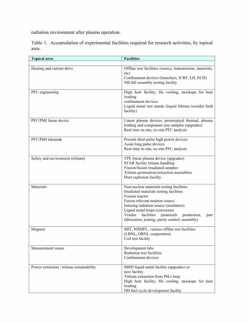
radiation environment after plasma operation.
Table 1. Accumulation of experimental facilities required for research activities, by topical area.
Topical area Facilities Heating and current drive Offline test facilities (source, transmission, materials,
etc) Confinement devices (launchers, ICRF, LH, ECH) NB full assembly testing facility
PFC engineering High heat facility, He cooling, mockups for heat loading confinement devices Liquid metal test stands (liquid lithium toroidal field facility)
PFC/PMI linear device Linear plasma devices, prototypical thermal, plasma loading and component size samples (upgrades) Real time in-situ, ex-situ PFC analysis
PFC/PMI tokamak Present short pulse high power devices Asian long pulse devices Real time in-situ, ex-situ PFC analysis
Safety and environment (tritium) TPE linear plasma device (upgrades) STAR facility tritium handling Fission/fusion irradiated samples Tritium permeation/extraction assemblies Dust explosion facility
Materials Non-nuclear materials testing facilities Irradiated materials testing facilities Fission reactor Fusion relevant neutron source Ionizing radiation source (insulators) Liquid metal loops (corrosion) Vendor facilities (materials production, part fabrication, joining, purity control, assembly)
Magnets MIT, NHMFL, various offline test facilities (LBNL, ORNL cooperation) Coil test facility
Measurement issues Development labs Radiation test facilities Confinement devices
Power extraction / tritium sustainability MHD liquid metal facility (upgrades) or new facility Tritium extraction from PbLi loop High heat facility, He cooling, mockups for heat loading HD fuel cycle development facility
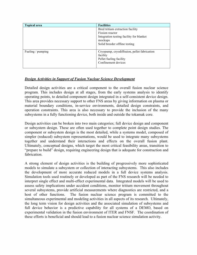
Topical area Facilities Bred tritium extraction facility Fission reactor Integration testing facility for blanket mockups Solid breeder offline testing
Fueling / pumping Cryopump, cryodiffsuion, pellet fabrication facility Pellet fueling facility Confinement devices
Design Activities in Support of Fusion Nuclear Science Development Detailed design activities are a critical component to the overall fusion nuclear science program. This includes design at all stages, from the early systems analysis to identify operating points, to detailed component design integrated in a self-consistent device design. This area provides necessary support to other FNS areas by giving information on plasma or material boundary conditions, in-service environments, detailed design constraints, and operation constraints. This area is also necessary to provide the inclusion of the many subsystems in a fully functioning device, both inside and outside the tokamak core. Design activities can be broken into two main categories; full device design and component or subsystem design. These are often used together to complete point design studies. The component or subsystem design is the most detailed, while a systems model, composed of simpler (reduced) subsystem representations, would be used to integrate many subsystems together and understand their interactions and effects on the overall fusion plant. Ultimately, conceptual designs, which target the most critical feasibility areas, transition to “prepare to build” design, requiring engineering design that is adequate for construction and fabrication. A strong element of design activities is the building of progressively more sophisticated models to simulate a subsystem or collection of interacting subsystems. This also includes the development of more accurate reduced models in a full device systems analysis. Simulation tools used routinely or developed as part of the FNS research will be needed to interpret single effect and multi-effect experimental data. Integrated models will be used to assess safety implications under accident conditions, monitor tritium movement throughout several subsystems, provide artificial measurements where diagnostics are restricted, and a host of other functions. The fusion nuclear science program is committed to the simultaneous experimental and modeling activities in all aspects of its research. Ultimately, the long term vision for design activities and the associated simulation of subsystems and full device behavior is a predictive capability for all systems of a DEMO, based on experimental validation in the fusion environment of ITER and FNSF. The coordination of these efforts is beneficial and should lead to a fusion nuclear science simulation activity.
Plasma Duration and Sustainment* A FNSF, and ultimately DEMO, will require very long duration plasmas (days to a year), with few to no interruptions from off-normal events, or large transients, that can result in a loss of the plasma or significant erosion of the plasma facing material. These devices require sufficient levels of plasma performance to provide neutron fluxes over time that will advance the fusion nuclear aspects for that research to be successful. Components that interact with the plasma must be designed to withstand the loading conditions for these long durations, which also now include neutron heating and damage. A series of plasma physics topics, considered critical to the success of the fusion nuclear science mission, will be briefly described below. Detailed R&D activities can be pursued by the plasma science program, while here we would like to bring attention to certain areas because of their importance to the FNS program. Plasma Duration and Duty Cycle A FNSF will require very long plasma pulses and very high duty cycles (short down time between pulses). These are significant advances compared to the present tokamak operations. Demonstration of integrated core plasma performance with fully (or nearly) non-inductive current sustainment approaching the level of FNSF (based on FDF[6]) baseline scenario has been realized for a significant fraction of a resistive current diffusion time [25, 26, 27]. Neither plasmas near or above the no-wall beta limit, with 100% non-inductive current, have been demonstrated for several resistive current diffusion times. Furthermore, this time scale must be exceeded by orders of magnitude for the FNSF mission. Both the present US tokamaks (pulse lengths ~5-10 s) and the Asian long pulse tokamaks (pulse lengths ~300-1000 s) can, in combination, address the development of integrated plasma configurations with flattop durations that exceed this timescale. If the physics limiting the duration of 100% non-inductive high performance plasmas can be resolved, other longer time scale phenomena will need to be addressed as pulse limiting candidates. These are typically attributed to the plasma edge and materials interaction, such as erosion/re-deposition, dust or debris production, tritium retention in plasma facing components (PFCs), and lifetime limitations of PFCs, which can include the first wall, divertor, and launching or diagnostic structures. An additional part of achieving long duration plasmas for neutron exposure is to reduce the down time between pulses, which affects the preparation between pulses of various subsystems such as coils, conditioning of plasma facing surfaces, or cooling of high heat flux surfaces. The demonstration of high duty cycle may be difficult on existing tokamaks. Finally the avoidance and/or highly reliable mitigation of off-normal events, such as disruptions, will be required to access long pulse lengths, which is discussed next. Avoiding Off-Normal Events Frequent disruptions cannot be tolerated in an FNSF or DEMO. Each disruption will contribute significantly to the erosion of plasma-facing surfaces. In addition, a disruption will lead to loss of operating time, in order to assess the cause and consequences of the

disruption and then to regain satisfactory operating conditions. Even rapid shutdowns generated by a disruption mitigation system must be minimized, owing to their potential for wall erosion or melting and subsequent downtime. Strong electromagnetic forces on conducting structures will result, and runaway electron populations can be generated leading to first wall damage. A FNSF will need accurate and reliable methods for real-time identification of stability boundaries where disruptions could occur, with sufficient advance warning to avoid crossing the boundaries. Several levels of prediction should be developed, including empirical characterization of operating limits and real-time assessment of the plasma operating state and its MHD stability limits. Disruption precursors, if they exist, should be identified and control techniques demonstrated to avoid the disruption. A list of disruption parameter scalings are shown in Table 1, taken from [6], and using the proposed FDF as an example for a FNSF. These show the evolution from present tokamak experiments toward DEMO. The physics basis R&D and injection technology development for disruption mitigation that is needed to support ITER should be applicable for a FNSF. Furthermore, tests of the physics basis and technologies in JET (or JT-60SA) with high levels of plasma current (4-6 MA) and thermal energy should provide a ‘pre-FNSF’ test opportunity for validating disruption mitigation and runaway electron mitigation concepts that will be directly applicable to FNSF. The FNSF and DEMO engineering design activities, with their more complex first wall, blanket and divertor configurations need to examine disruption loading in more detail to assess the impact on structural and thermal solutions, and establish the tolerance, if there is any, for these events. Present tokamaks can contribute significantly in these areas, and a multi-year research activity with the goal of operating a full run campaign (15-20 run weeks) with very few to no disruptions should be pursued. Table 1. Disruption scaling parameters comparing present tokamaks, ITER, a FNSF, and DEMO. Device DIII-D JET ITER
350 2.0
DEMO 10 17
FDF-b 36
FDF-a 133 Wth = Thermal energy (MJ) 2.0 16 325 824 78 100
tQ = Thermal quench time (ms) 1.1 1.4 3.0 3.4 1.3 1.3 AW = Wall area (m2) 64 169 717 760 164 164 Wth/AW/tQ
1/2 (MJ/m2/s1/2) 0.9 2.5 8.3 18.6 13.2 16.9 AD = Divertor area (m2) 2.4 4.1 8.8 9.9 3.8 3.8 Wth/AD/tQ
1/2 (MJ/m2/s1/2) 29 104 673 1423 572 726 tC = Current quench time (ms) 3.2 8.3 36 30 7.3 7.3 GRE = Runaway electron gain 1.5x101 2.2x10⁴ 1.9x10¹⁶ 1.1x10¹³ 1.5x1
07 1.5x10⁷
mD = Deuterium mass to achieve Rosenbluth density (g) 5.9 27 160 145 31 31
Transient Heat and Particle Loading The plasma facing components, which include the divertor, first wall, and launching or diagnostic structures, can experience steady, transient, and off-normal heat and particle
loading. The steady loading is generally considered calculable, and the off-normal loading was mentioned earlier. The transient loading, stemming primarily from edge localized modes (ELMs), can cause large short time scale spikes of energy and particle deposition superimposed on the steady deposition. These transients contribute to limiting the component lifetime through material erosion, and thermal shock effects which degrade the material properties. An attempt at the quantification of the loading associated with ELMs has been performed for ITER, and indicates the need for reduced magnitudes or elimination to allow acceptable PFC lifetimes. This quantification must continue for FNSF and DEMO. A number of plasma physics areas require better understanding to allow this quantification and in most cases also apply to steady loading and the power and particle handling overall, including 1) the width of the layer in the scrape-off that carries the power to the divertor, 2) radial plasma transport in the SOL, heat and particle loads to the first wall, 3) the high density divertor detachment regime, its sustainment, its efficiency in radiating power, and its response to transients, and 4) the practicality of ELM magnitude reduction techniques (e.g. resonant magnetic perturbations, pellet pacing), small ELM regimes, and/or ELM elimination (e.g. QH-mode, Li, and I-mode operation). Several of these issues will be covered in more detail in the Section 4 on Plasma Facing Components and Plasma Material Interactions. Advanced magnetic configurations, such as the snowflake [28] or Super-X divertor [29] configurations may provide solutions for the severe loading problems in the divertor. So far the snowflake has been examined in experiments, demonstrating the magnetic flux expansion effects on heat flux reduction. These approaches will need to show their consistency with other requirements including particle pumping/control, radioactive power dispersal, and core plasma parameters. Accessing increased plasma performance (operating above the no-wall beta limit) Accessing plasmas that exceed the no-wall beta limit improves the attractiveness of tokamak power plants by increasing its fusion power density and reducing the amount of externally driven current (increasing the bootstrap current fraction). For a FNSF, higher beta can increase the neutron wall load, which accelerates the exposure of the various components being tested. The physics basis for stable operation above the no-wall limit is not fully developed. Evidence is emerging that present-day experiments exhibit a combination of stabilization due to strong shaping, rotation, thermal ion, and fast ion effects [30]. Research is needed to ensure these effects scale to a FNSF and DEMO, and to demonstrate robust control of strongly shaped plasmas. The coupling of resistive wall modes (RWM) with error fields frequently leads to locked modes and plasma disruption. The issue of RWM stabilization for advanced tokamak operation above the no-wall beta limit is intimately connected with the issue of error field correction. In DIII-D and JT-60U experiments, reduction of magnetic field asymmetries allowed sustained stable operation up to βN values close to the ideal-wall limit even with slow plasma rotation (<0.5% of the Alfven frequency) [31,32]. Uncorrected error fields and the associated plasma response can bring the rotating plasma to rest and allow islands to form, leading to potentially disruptive locked modes. Dynamic error field correction is in routine use for operation above the no-wall beta limit in DIII-D and NSTX [33]. However, these plasmas have not been sustained for multiple resistive current diffusion times and more work is required to determine if this regime is
viable for a FNSF and power plants. Benchmarking of the RWM stability codes against experimental data should continue. Arguably the best approach to measure the RWM characteristics to be compared with theoretical predictions is to use active RWM spectroscopy techniques in stable plasmas above the no-wall beta limit. High and low NBI torque injection, near no-wall beta limit and near ideal-wall beta limit, various collisionality levels and fast ion population characteristics should be explored. Particle Transport and Control Particle behavior in fusion plasma, and inside the vacuum vessel, is a critical area needing significantly more attention, as it impacts many aspects of a FNSF and DEMO. The list of impacts includes injection of fuel particles sufficiently deeply, injection of intentional impurities to control the core plasma radiated power, injection of gas and impurities into the SOL and divertor to control radiation there, the exhausting of unburnt fuel, helium and impurities, eroded materials and their migration, tritium consumption and retention in PFCs, and core plasma particle transport in the multi-species, low collisionality, zero loop voltage regime. A particular area, referred to as tritium burnup, involves the fraction of injected tritium that is actually consumed in fusion reactions versus being exhausted. The smaller this number is, the larger the fueling, exhaust, and processing tritium inventory will be. Safety requirements favor low tritium inventories throughout the plant. Due to strong particle screening (very low neutral penetration depths) expected for the plasma densities typical of FNSF or DEMO, recycling from the walls can not be relied on to return unburnt fuel to the region of the plasma where fusion has a high probability (extremely low fueling efficiency), however predicting this parameter is very difficult. Specific research needs are noted below.
1) Combination of the heat flux power width data from all tokamaks to produce a size scaling with the greatest accuracy possible. In addition a significant effort should be made to determine the underlying transport mechanisms that are responsible for the experimental heat flux width observations.
2) Comprehensive measurements of the divertor as a function of density and input
power should be made, including 2D measurements of the flow and drift fields that contribute to the detachment physics and its stability.
3) The divertor and plasma facing component materials will experience erosion,
migration and redeposition of material throughout the vessel. Because of the high duty cycle envisioned, remote dust detection and removal techniques will be required, however this technology is in its infancy. For better prediction and management of these issues a better understanding of the SOL plasma is required. This includes 1) better understanding of radial plasma transport to surfaces throughout the vessel, which leads to erosion and charge-exchange neutrals, 2) the flow of SOL plasma and how it carries material and deposits it far from its original location.
4) All contemporary tokamaks retain some fraction of their hydrogenic fuel in their
plasma facing components (PFCs). Tritium recovery from PFCs at the efficiency and rate required to support the desired FNSF availability has not been demonstrated on current tokamaks. Technology for achieving a low tritium retention rate (< 1%) and the development of methods for fast and efficient tritium recovery from PFCs will be essential prerequisites for a FNSF. The most promising approaches are operating the first wall at high temperature to reduce retention and oxygen bake to recover the tritium in between operations. These techniques will need to be explored and validated.
5) An important topic is the compatibility of integrated 100% non-inductive current
drive, high performance core plasmas with detached divertor operation. This compatibility is mitigated through the pedestal density and pressure, and understanding what self-consistent solutions exist is needed.
In-Vessel Coils for Feedback Control of the Plasma Non-axisymmetric coils may be necessary in a FNSF for several reasons, (dynamic) error field correction, resonant magnetic perturbation ELM suppression, non-resonant magnetic field torque application for (e.g. QH-mode ELM free regime access), and resistive wall mode (RWM) suppression. In addition, it is beneficial to locate vertical position control coils inside the vacuum vessel for higher plasma elongation. A key issue for installing in-vessel coils in a burning plasma device such as a FNSF is to identify a design that meets all the key physics requirements and that can be designed to interface with other critical internal vacuum vessel components such as blanket modules, electrical and cooling delivery systems, plasma diagnostics and divertor modules. The coil system must be an integral part of the basic machine design beginning with the early conceptual stage since trade-offs will be needed in both the machine and the coil design. In general, for a FNSF and DEMO, these coils must be located behind the breeding blanket and shield, but inside the vacuum vessel to be as close to the plasma as possible. Robust and Highly Reliable Plasma Control FNSF must operate in true steady state with the frequency of loss-of-performance events (including disruptions) approaching zero during long pulse operation of the device. This level of reliability requires well-characterized and highly controllable operating scenarios, and extremely robust dynamic control with sufficient and quantifiable performance margin. This level of performance reliability has not been required on operating experimental devices, and significant research is needed to develop the methods to achieve it. The characteristics of the blanket structure required for a FNSF will strongly affect controllability of both axisymmetric stability and the nominal equilibrium, since field penetration times through the surrounding structure place significant limits on magnetic control. If the blanket penetration time is sufficiently long, it is possible that in-vessel control coils will be needed to provide the necessary robust control, requiring significant
R&D to develop that challenging solution. In particular, determining the optimum values for the plasma shape that can be robustly controlled for FNSF requires further work. The double null (DN) configuration, associated with strong plasma shaping, must balance heat and particle loads between the divertors, as well as possible, to maintain divertor conditions that optimize power and particle control. Once robust control can be quantified and ensured for each relevant controllability boundary, operation of the fully integrated system must be sustained with the same robustness. Integrated control must combine axisymmetric and nonaxisymmetric magnetic control with current drive, fueling, and pumping required to regulate the profiles and burn operating point. Relevant levels of robustness with minimal disruptivity must be demonstrated in all scenarios expected in FNSF. Finally, methods for managing off-normal events, such as hardware faults, must be developed and qualified. Such faults must be predicted if possible (and responded to if not), in order to trigger recovery or alternate scenarios, or a rapid shutdown. None of the requisite fault prediction, recognition, or response algorithms have yet been developed. Fast Particle Behavior Fast particles, such as alpha particles from fusion, high energy ion tails from ion cyclotron, or from neutral beam injection can induce MHD instabilities in the plasma which can ultimately re-distribute the fast ions or lead to loss from the plasma. If these ions are lost from the plasma they can produce damage to the first wall and high heat loads. Although a burning plasma experiment may have to await ITER operation, the development and validation of fast particle MHD stability theory and simulation tools can provide guidance on the stability thresholds, the nonlinear evolution and actual fast particle response, and control approaches to mitigate the effects of such instabilities. *contributions from T. Evans, A. Garofalo, D. Humphreys, G. Jackson, J. Kinsey, T. Luce, R. Nazikian, C. Petty, T. Petrie, T. Strait, C. Skinner, P. C. Stangeby, J. Wesley, and M. Van Zeeland; comments by A. E. Hubbard, M. Greenwald, R. Maingi, and D. Whyte.
1.10 Conclusion The pathway to a demonstration power plant (DEMO) can be provided by a base program in research and development for fusion nuclear science and plasma science, successful operation of the ITER burning plasma program, in conjunction with an intermediate confinement facility (FNSF). The plasma science program is well established with a wide range of experimental facilities, theory and modeling activities, and strong connections to the international plasma programs. The plasma science program has established a set of research needs [3,4] to provide a predictable high performance steady state plasma for fusion energy, that is consistent with the plasma material interface, and the experimental facilities are pursuing the physics understanding to provide this. The fusion nuclear science program also has established a set of research needs [3,4], however, it possesses few experimental activities to test and demonstrate concepts, establish required databases, or validate models. Without integrated activities in experiment, theory and modeling, and
design and fabrication, it is not possible to establish the technical basis for a fusion nuclear science facility or a DEMO. The goal of the Fusion Nuclear Science Pathways Assessment (FNS-PA) is to establish a series of research activities, and the facilities required to do this research, that can begin now and that will advance this technical basis over the next 5-10 years. A consensus technical definition of the FNSF is missing, and an important activity to pursue in the US fusion program will be to better quantify the missions for, and metrics by which we judge, a FNSF, and begin the process of defining and designing this facility in more detail. A prioritization among potential materials, concepts, and designs based on present day understanding, has allowed a focus for research activities, which affords a tractable development portfolio. Both the DEMO rollback (based on power plant studies) and the test blanket module proposal (TBM) have converged to the Dual Coolant Lead Lithium (DCLL) as the primary near term blanket concept. This uses PbLi liquid metal as breeder and coolant, and helium as primary structural coolant. Reduced activation ferritic martensitic steel (and its modifications) is the primary structural material. This design includes the SiC flow channel insert (FCI) as a required functional material to provide electrical and thermal insulation between the breeder and structural material. There may be other functional materials such as tritium permeation barriers, corrosion barriers, or others, which are not defined at present. From DEMO rollback, and partially on concepts developed for ITER, the helium cooled solid tungsten design is the primary concept for the divertor, however, this area is sufficiently uncertain that liquid surface concepts and advanced magnetic geometry approaches are retained as strong alternatives. Examination from both the DEMO rollback and near term research indicate that efforts are needed to define the shield and vacuum vessel more precisely. With these primary candidates an extensive list of research activities have been identified, ranging from basic material properties and behavior, to progressively more integrated behavior. Integration includes, the combining of materials into a component (e.g. structural material, breeder, FCI, helium) with specific functionalities, and testing in an environment that includes as many factors (e.g. temperature, magnetic field, pressure, mechanical loads, tritium, irradiation, surface and bulk heating, vacuum) to their prototypical (of FNSF or DEMO) levels as possible, and ultimately the integration into a fusion device. It should be noted that many areas of critical research are necessary regardless of the specific blanket and divertor design assumptions, although these benefit from the research focus to some extent as well, such as safety and environment issues, all tritium handling, magnets, heating and current drive, measurement issues, and fueling and pumping. A list of facility requirements identified to support the research activities are given in Section 4, Table 1. Enabling technologies that support plasma operation (magnets, heating and current drive, fueling and pumping, and diagnostics), whose failure or lack of advancement can severely interfere with the fusion nuclear science mission, require research to prepare their integration into the fusion nuclear environment, in some cases requiring entirely new materials. Both the DEMO rollback and the roll forward research activities point to the need for research on these systems. Improvements in reliability, efficiency, cost, and long duration operation are required in all systems.
In a FNSF or DEMO, the plasma will be required to provide levels of duration, performance, and integration with its environment that are well beyond those achieved in routine operation of confinement devices, including those projected in ITER. The identified plasma science issues are strongly correlated with those that were identified in the rollback DEMO examination in terms of critical assumptions that must be made to project to the power plant regime, and the roll forward research activities, particularly in areas where plasma engineering interface issues dominate. These plasma issues can provide a significant vulnerability to the fusion nuclear science mission and the fusion energy mission, and coordination between plasma science and engineering design activities is required. The FNS-PA has successfully developed a range of research activities for fusion nuclear science to begin to move toward a credible technical basis for fusion energy production. These are motivated by rolling back from DEMO power plant studies and rolling forward from established research needs. This includes identification of facilities for experimental activities, and coincident modeling activities that both support the experiments and evolve to a predictive capability.
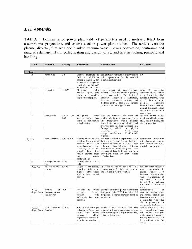
1.11 Appendix Table A1. Demonstration power plant table of parameters used to motivate R&D from assumptions, projections, and criteria used in power plant studies. The table covers the plasma, divertor, first wall and blanket, vacuum vessel, power conversion, neutronics and materials damage, TF/PF coils, heating and current drive, and tritium fueling, pumping and handling. Symbol Definition Value(s) Justification Current Status R&D needs
1. Plasma A aspect ratio 3-4 Shallow minimum in
COE led ARIES to choose a higher A for maintenance simplicity (valid only for "normal" tokamaks and not ST's).
design studies continue to explore aspect ratio dependencies for the standard tokamak configuration
NA
κ elongation ~1.9-2.2 Elongation helps achieve higher beta limits and provides larger operating space.
regular aspect ratio tokamaks have reached 2.7 in highly optimized plasmas, ~ 2 is more typical. The physics of achievable elongation is understood, involving conducting structure and feedback control. This is a designable parameter, still with upper limits.
using W conducting structures in the blanket and feedback coils behind the shield, primarily forces on W, how to make electrical connections inside blanket sectors and connect/disconnect coils at the back of the sectorfor maintenance
δ triangularity 0.6 / 0.75-0.85
Triangularity helps achieve higher beta limits in combination with elongation.
there are differences for single and double null, in achievable triangularity. The triangularity would influence inboard divertor plasma behavior, and affects neutron shielding on inboard side. Triangularity affects other physics parameters such as pedestal height, energy confinement, ELM/H-mode regimes.
establish optimal values consistent with elongation, MHD stability limits, and divertor operation
[1] βN normalized beta 3.0 / 4.5-5.5 Pushing above no-wall beta limit leads to more compact devices and higher bootstrap current. Remaining below the no-wall beta limit should provide more robust plasma configurations.
has been sustained in experiments at 4.0 for 2 s, and ~3.5 for 1-2 s with high non-inductive fractions of ~60-70%. These only reach about 1-2 current diffusion time durations. Steady state plasmas near the no-wall beta limit have not been established either for many current diffusion times.
demonstrate sustainment with plasmas at or above the no wall limit and 100% non-inductive current
βT average toroidal beta
5-9% Derived from βT = βN * I/aB
Palpha/Pinput measure of self-heating
5.5-9.5 Degree of self-heating, related to fusion gain, higher bootstrap current leads to lower injected powers.
TFTR and JET are 0.01 and 0.02. ITER plans to produce 2 in inductive operation, and 1 in non-inductive operation
this parameter reflects a strong nonlinearity in plasma behavior as it increases, demonstrating viable configurations at high values is critical prior to DEMO, in particular with 100% non-inductive current
Pdiv,rad/ (Palpha+Pinput)
fraction of transport power into divertor
~0.5 Required to obtain consistent divertor solution with sufficiently low peak heat flux.
examples of radiated power concentrated in divertors exist, ITER is targeting ~0.5 for partially detached operation based on simulations
demonstration of maximum possible values and control through gas injection is required. This is correlated with other divertor parameters for self-consistent solution
Pcore,rad/ (Palpha+Pinput)
core radiation fraction
0.18-0.3 Sum of line+brem+cycl radiation, self-consistent values with plasma parameters, adding impurities to enhance to help divertor solution.
values as high as 90% have been obtained with minor degradation of core confinement, specific impurities are best, but control is an issue
demonstration of plasmas at controllable core radiation levels with good confinement and sustained for long time-scales. Must be consistent with FW design
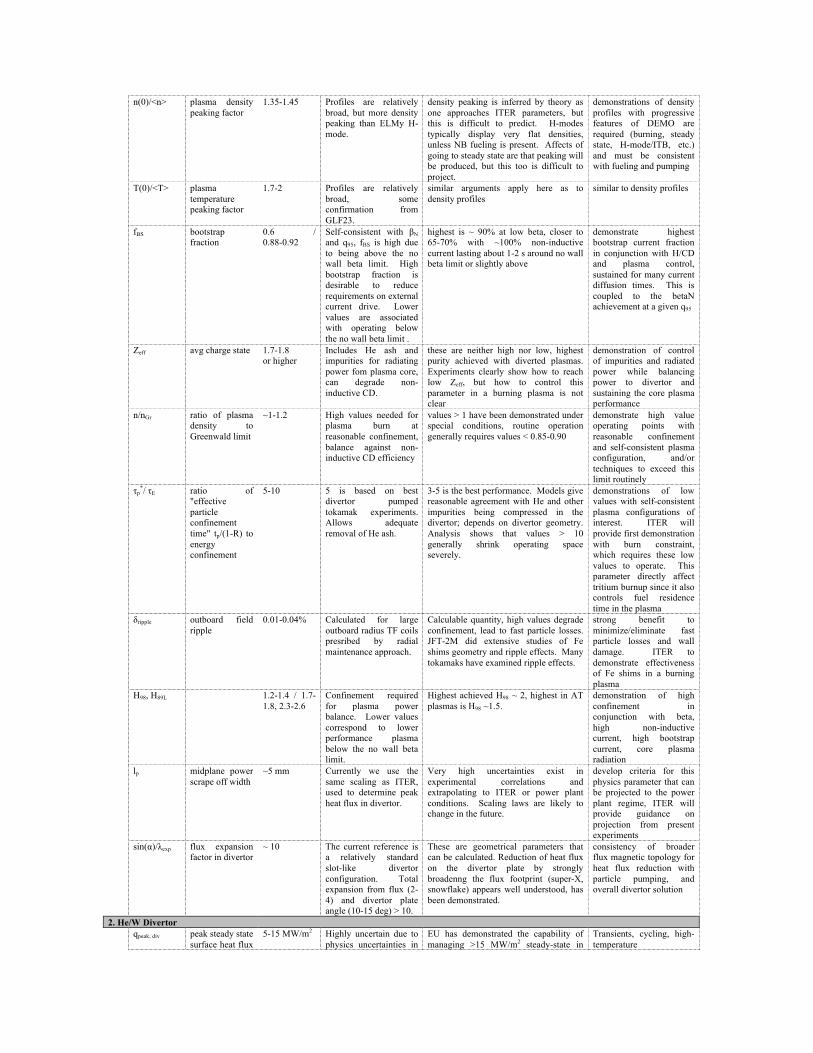
n(0)/<n> plasma density peaking factor
1.35-1.45 Profiles are relatively broad, but more density peaking than ELMy H-mode.
density peaking is inferred by theory as one approaches ITER parameters, but this is difficult to predict. H-modes typically display very flat densities, unless NB fueling is present. Affects of going to steady state are that peaking will be produced, but this too is difficult to project.
demonstrations of density profiles with progressive features of DEMO are required (burning, steady state, H-mode/ITB, etc.) and must be consistent with fueling and pumping
T(0)/<T> plasma temperature peaking factor
1.7-2 Profiles are relatively broad, some confirmation from GLF23.
similar arguments apply here as to density profiles
similar to density profiles
fBS bootstrap fraction
0.6 / 0.88-0.92
Self-consistent with βN and q95, fBS is high due to being above the no wall beta limit. High bootstrap fraction is desirable to reduce requirements on external current drive. Lower values are associated with operating below the no wall beta limit .
highest is ~ 90% at low beta, closer to 65-70% with ~100% non-inductive current lasting about 1-2 s around no wall beta limit or slightly above
demonstrate highest bootstrap current fraction in conjunction with H/CD and plasma control, sustained for many current diffusion times. This is coupled to the betaN achievement at a given q95
Zeff avg charge state 1.7-1.8 or higher
Includes He ash and impurities for radiating power fom plasma core, can degrade non-inductive CD.
these are neither high nor low, highest purity achieved with diverted plasmas. Experiments clearly show how to reach low Zeff, but how to control this parameter in a burning plasma is not clear
demonstration of control of impurities and radiated power while balancing power to divertor and sustaining the core plasma performance
n/nGr ratio of plasma density to Greenwald limit
~1-1.2 High values needed for plasma burn at reasonable confinement, balance against non-inductive CD efficiency
values > 1 have been demonstrated under special conditions, routine operation generally requires values < 0.85-0.90
demonstrate high value operating points with reasonable confinement and self-consistent plasma configuration, and/or techniques to exceed this limit routinely
τp*/ τE ratio of
"effective particle confinement time" tp/(1-R) to energy confinement
5-10 5 is based on best divertor pumped tokamak experiments. Allows adequate removal of He ash.
3-5 is the best performance. Models give reasonable agreement with He and other impurities being compressed in the divertor; depends on divertor geometry. Analysis shows that values > 10 generally shrink operating space severely.
demonstrations of low values with self-consistent plasma configurations of interest. ITER will provide first demonstration with burn constraint, which requires these low values to operate. This parameter directly affect tritium burnup since it also controls fuel residence time in the plasma
δripple outboard field ripple
0.01-0.04% Calculated for large outboard radius TF coils presribed by radial maintenance approach.
Calculable quantity, high values degrade confinement, lead to fast particle losses. JFT-2M did extensive studies of Fe shims geometry and ripple effects. Many tokamaks have examined ripple effects.
strong benefit to minimize/eliminate fast particle losses and wall damage. ITER to demonstrate effectiveness of Fe shims in a burning plasma
H98, H89L 1.2-1.4 / 1.7-1.8, 2.3-2.6
Confinement required for plasma power balance. Lower values correspond to lower performance plasma below the no wall beta limit.
Highest achieved H98 ~ 2, highest in AT plasmas is H98 ~1.5.
demonstration of high confinement in conjunction with beta, high non-inductive current, high bootstrap current, core plasma radiation
lp midplane power scrape off width
~5 mm Currently we use the same scaling as ITER, used to determine peak heat flux in divertor.
Very high uncertainties exist in experimental correlations and extrapolating to ITER or power plant conditions. Scaling laws are likely to change in the future.
develop criteria for this physics parameter that can be projected to the power plant regime, ITER will provide guidance on projection from present experiments
sin(α)/λexp flux expansion factor in divertor
~ 10 The current reference is a relatively standard slot-like divertor configuration. Total expansion from flux (2-4) and divertor plate angle (10-15 deg) > 10.
These are geometrical parameters that can be calculated. Reduction of heat flux on the divertor plate by strongly broadenng the flux footprint (super-X, snowflake) appears well understood, has been demonstrated.
consistency of broader flux magnetic topology for heat flux reduction with particle pumping, and overall divertor solution
2. He/W Divertor qpeak, div peak steady state
surface heat flux 5-15 MW/m2 Highly uncertain due to
physics uncertainties in EU has demonstrated the capability of managing >15 MW/m2 steady-state in
Transients, cycling, high-temperature

in the divertor the edge plasma and divertor. Transient values for a power plant unknown.
He-cooled W finger mockups. Long-term survival is less certain.
demonstration. Materials research as well as component engineering, thermomechanical and reliability studies are needed. Tokamak divertor edge physics relevant to a power plant needs to be established.
Coolant
coolant material helium He has safety and performance advantages over other coolants. Neutron streaming is an issue, but can be managed.
High-pressure He loops for fusion exist in various countries, including the US. The technology is mature due to implementation in the fission industry.
Operating experience with fusion-relevant materials and components is needed to establish reliability.
pHe,div coolant pressure ~10 MPa Tradeoff between improved heat transfer vs. higher primary stresses. Desirable to use same pressure as the blanket and power conversion system.
10 MPa is well within established norms for He-cooled systems.
NA
[2] Tin,div/Tout,div coolant inlet/outlet temperature
600/700 C High temperature desired for high Brayton cycle efficiency. Operating temperatures are a delicate balance between low-temperature limits (usually caused by embrittlement) and high-temperature limits (usually caused by creep or corrosion)
HTGR and VHTR outlet as high as 1000 C planned. The issue for us is materials limits, including heat exchanger, and compatibility.
materials R&D is needed to establish temperature limits and extend them (both on the high and low ends)
Armor
armor material pure W High temperature capability, resistance to erosion
Studies over the past 10 years have demonstrated the advantage of using W. Materials programs are ramping up to provide more data.
New fabrication techniques may offer improved properties. R&D on joining and machining needed. If W doesn't work, options include LM divertors or graphite.
TW,min minimum allowable W armor temperature
800 C DBTT concerns (avoid excessive cracking).
Uncertain. Need lower values for a robust system.
Materials development for lower DBTT. Fracture mechanics studies needed to determine whether this limit is appropriate.
TW,max maximum allowable W armor temperature
2190 C 2/3 the melting point, to retain some level of strength. Recrystallization of armor is considered acceptable.
2/3 melting is probably conservative. Need further studies of the consequences of extreme temperature in the armor.
Testing of prototypical elements under nornal and off-normal conditions is required to demonstrate performance and reliability.
Structure
structure material
W alloy (e.g. VM-W, LA10, W-TiC) and steel alloy (e.g. HT9, ODS-HT9)
Large temperature gradients require the use of multiple materials to remain within temperature operating windows. Inlet coolant (at 600 C) flows through steel manifold and jets. Jet flow impinges on W-alloy operating at a temperature above the DBTT.
All W alloys appear to have limitations. ODS steels offer significantly better properties, but fabrication remains a concern.
W alloy development is needed. Fabricable ODS steels are needed. Material properties are needed for design and analysis.
TFS,min minimum allowable FS temperature
350 C DBTT concerns (avoid cracking).
active area of investigation internationally
Fracture mechanics studies are needed to determine whether this limit is appropriate.
TFS,max maximum allowable FS temperature
650-700 C Loss of yield strength and creep strength at elevated temperature. Depends on stress state (i.e., unstressed
active area of investigation internationally
Testing of prototypical elements under nornal and off-normal conditions is required to demonstrate performance and
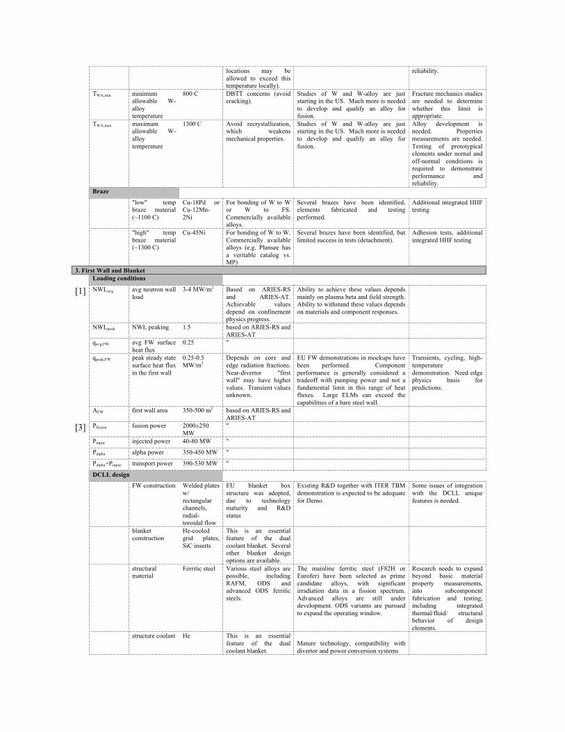
locations may be allowed to exceed this temperature locally).
reliability.
TWA,min minimum allowable W-alloy temperature
800 C DBTT concerns (avoid cracking).
Studies of W and W-alloy are just starting in the US. Much more is needed to develop and qualify an alloy for fusion.
Fracture mechanics studies are needed to determine whether this limit is appropriate.
TWA,max maximum allowable W-alloy temperature
1300 C Avoid recrystallization, which weakens mechanical properties.
Studies of W and W-alloy are just starting in the US. Much more is needed to develop and qualify an alloy for fusion.
Alloy development is needed. Properties measurements are needed. Testing of prototypical elements under nornal and off-normal conditions is required to demonstrate performance and reliability.
Braze
"low" temp braze material (~1100 C)
Cu-18Pd or Cu-12Mn-2Ni
For bonding of W to W or W to FS. Commercially available alloys.
Several brazes have been identified, elements fabricated and testing performed.
Additional integrated HHF testing
"high" temp braze material (~1300 C)
Cu-45Ni For bonding of W to W. Commercially available alloys (e.g. Plansee has a veritable catalog vs. MP)
Several brazes have been identified, but limited success in tests (detachment).
Adhesion tests, additional integrated HHF testing
3. First Wall and Blanket Loading conditions
[1] NWLavg avg neutron wall load
3-4 MW/m2 Based on ARIES-RS and ARIES-AT. Achievable values depend on confinement physics progress.
Ability to achieve these values depends mainly on plasma beta and field strength. Ability to withstand these values depends on materials and component responses.
NWLpeak NWL peaking 1.5 based on ARIES-RS and ARIES-AT
qavg,FW avg FW surface heat flux
0.25 "
qpeak,FW peak steady state surface heat flux in the first wall
0.25-0.5 MW/m2
Depends on core and edge radiation fractions. Near-divertor "first wall" may have higher values. Transient values unknown.
EU FW demonstrations in mockups have been performed. Component performance is generally considered a tradeoff with pumping power and not a fundamental limit in this range of heat fluxes. Large ELMs can exceed the capabilities of a bare steel wall.
Transients, cycling, high-temperature demonstration. Need edge physics basis for predictions.
AFW first wall area 350-500 m2 based on ARIES-RS and ARIES-AT
[3] Pfusion fusion power 2000±250 MW
"
Pinput injected power 40-80 MW "
Palpha alpha power 350-450 MW "
Palpha+Pinput transport power 390-530 MW "
DCLL design
FW construction Welded plates w/ rectangular channels, radial-toroidal flow
EU blanket box structure was adopted, due to technology maturity and R&D status
Existing R&D together with ITER TBM demonstration is expected to be adequate for Demo.
Some issues of integration with the DCLL unique features is needed.
blanket construction
He-cooled grid plates, SiC inserts
This is an essential feature of the dual coolant blanket. Several other blanket design options are available.
structural material
Ferritic steel Various steel alloys are possible, including RAFM, ODS and advanced ODS ferritic steels.
The mainline ferritic steel (F82H or Eurofer) have been selected as prime candidate alloys, with significant irradiation data in a fission spectrum. Advanced alloys are still under development. ODS variants are pursued to expand the operating window.
Research needs to expand beyond basic material property measurements, into subcomponent fabrication and testing, including integrated thermal/fluid/ structural behavior of design elements.
structure coolant He This is an essential feature of the dual coolant blanket.
Mature technology, compatibility with divertor and power conversion systems

coolant-breeder material
PbLi LM offers higher performance, PbLi has less MHD than Li and is safer
Exact composition is still uncertain. Significant R&D has been done over the past few years.
Li would be a stronger option for MFE if effective MHD insulators were developed, but this is currently considered a low priority
flow channel insert material
SiC Poor thermal and electrical properties are desired, well within the established database. Good compatibility with PbLi and radiation damage resistance are needed.
Candidate materials are available. Demonstration of electrical, thermal and chemical compatibility properties; mockups needed to test performance.
FW armor and coatings
bare, W coating
Most designs assume bare walls are acceptable, but the edge plasma conditions may require some form of protection.
W coating or W armor have been considered in designs, and extend the capabilities against transients. Very limited research has been performed on power-plant relevant duplex structures.
DCLL operating conditions
Tin,FW/Tout,FW coolant inlet/outlet temperature
385/430 C Chosen to keep steel within its temperature window of operation.
pHe,FW coolant pressure 10 MPa Tradeoff between improved heat transfer vs. higher primary stresses. Desirable to use same pressure as the divertor (and the power conversion system).
10 MPa is well within established norms for He-cooled systems.
PHe,blkt structure coolant pressure (DCLL)
10 MPa Same as divertor and power conversion system
10 MPa is well within established norms for He-cooled systems.
Tint,SiC PbLi-SiC interface max. allowable temperature
>1000 C Based on limited data. to date, a hard upper limit has not been established.
Tint,FS PbLi-FS interface maximum temperature
>470 C some data is available, but there is uncertainty in the limit. PbLi corrosion of steel is dominated by dissolution rather than chemistry.
some data exist in loops without magnetic fields.
Experiments in a prototypical loop would be very useful, since geometry, temperature gradients and MHD are all factors.
PbLi-cooled SiC/SiC design
FW/blanket construction
Large annular boxes with double-pass poloidal cooling
high-velocity FW cooling to manage surface heat flux, in series with bulk blanket to provide maximum outlet temperature. Simplest possible construction.
structure material
SiC/SiC composite
similar structures have been fabricated with SiC/SiC composites, but not this particular design concept.
Fabrication of mockups
structure coolant PbLi PbLi is a unique coolant, with special advantages for fusion.
MHD effects remain highly uncertain in complex 3d geometries. Relatively low speed is expected to help maintain acceptable pressures.
coolant-breeder material
PbLi
FW armor and coatings
bare or W coating
Most designs assume bare walls are acceptable, but the edge plasma conditions may require some form of protection, especially if transient energy bursts (large ELM's) exist.
Some research on W coating of SiC exists.
PbLi-cooled SiC/SiC operating conditions
Tin,FW coolant inlet temperature
650 C >600 C SiC temperature is required to maintain thermal conductivity
Tout,FW coolant outlet temperature
>1000 C void swelling above 1000 C

pHe,FW coolant pressure <2 MPa uncertain due to MHD effects. 2 MPa limit helps keep SiC composite within primary stress limit (<200 MPa).
Tint,SiC PbLi-SiC interface max. allowable temperature
>1000 C based on limited data. to date, a hard upper limit has not been established.
Other generic blanket parameters
Li6 enrichment natural-90% Based on detailed neutronics analysis for a particular design.
Enrichment is not considered difficult. On-line control of enrichment may be required. For solid breeders, this would be difficult to accomplish, requiring a neutron poison (thus exacerbating difficulty breeding)
None known.
permeation barrier material
none The use of flowing PbLi with a vacuum permeator for extraction provides low vapor pressure enabling T permeation levels within regulatory requirements.
Tritium permeation remains a concern, and research is ongoing to determine the effectiveness of applied barriers (e.g. alumina or erbia).
System demonstration of acceptable permeation rates
4. Vacuum vessel structure ferritic or
modified austenitic steel
Prefer to use a well-understood structural material, to be used as face plates and ribs. Designed to be reweldable.
Steel is generally identified in design studies, but the exact alloy has not been chosen. Procedures for heat treatment, if necessary, of a large and complex structure like a vacuum vessel are not well defined.
Alloy selection is still needed. Issues remain with radiation damage of steel alloys at low temperature.
structure temperature
200 ˚C
welding technique
TIG, FSW Depends on material choice. Friction stir welding offers the possibilty to reduce or eliminate the need for high-temperature heat treatments in some alloys.
no data on fusion-relevant alloys choice of reference alloy. demonstration of fabrication and rewelding of reference alloy.
coolant water Could be He if high-temperature operation and/or bakeout are required. Cooling requirements on the vessel are very modest.
coolant pressure low very low nuclear heating
rate requires very modest heat removal
shield material WC, borated steel
5. Power conversion system and balance of plant power cycle Brayton High efficiency is
essential for econnomics, due to high capital cost and recirculating power of fusion systems. Supercritical steam Rankine cycle is a possible alternative offering reasonably high conversion efficiency.
The Brayton cycle is mostly established technology, but requires rather high coolant outlet temperature. One unique feature for fusion is tritium control in the conversion system.
Tritium permeation and control research is needed to establish safe operating regimes.
power cycle coolant
He Safe coolant, headroom for increased efficiency in advanced designs. He Brayton cycle with He reactor coolant offers some unique advantages. Supercritical steam Rankine or supercritical CO2 is a possible alternatives. CO2 offers the possibility of high efficiency at lower primary coolant outlet temperature.

coolant pressure 15 MPa chosen for high conversion efficiency
existing technology NA
DCLL design
[4] To turbine inlet temperature
680 C use of advanced steel in the piping provides adequate creep strength for these temperatures.
Higher is better. Improvements in high-temperature materials will help increase this number.
high-temperature materials R&D
[4] hth gross thermal conversion efficiency
45% Depends on coolant outlet temperature and other factors. Value includes pressure drop in the conversion system components.
Parameter assumptions are all achievable with near-term technology, with some optimism over future improvements.
Recuperator development would help improve efficiency most.
heat exchanger materials
high-temperature steel or Ni-based alloy
high temperature heat exchangers have been developed for the nuclear industry.
Compatibility with PbLi is a unique issue.
demonstration of chemical compatibility of heat exchangers with fusion coolants and in-vessel materials
SiC/PbLi power core
To turbine inlet temperature
1050 C Improvements in high-temperature materials will help increase this number.
high-temperature materials R&D for the piping and IHX are needed.
hth gross thermal conversion efficiency
60% Depends on coolant outlet temperature and other factors. Value includes pressure drop in the conversion system components.
Parameter assumptions are all achievable with near-term technology, with some optimism over future improvements.
Recuperator development would help improve efficiency most.
heat exchanger materials
arc-cast Mo alloys, SiC/SiC composites, C/C composites
see Schleicher et al, Fusion Tech. 39 (2), 823-827, March 2001.
high temperature heat exchangers have been developed for the nuclear industry. Compatibility with PbLi is a unique issue.
demonstration of chemical compatibility of heat exchangers with fusion coolants and in-vessel materials is needed.
Common parameters
hturbine He turbine or compressor efficiency
92% commercially available commercially available NA
PbLi pump efficiency
90% assumes mechanical pump (large, high-efficiency, high-temperature LM pumps are uncommon and inefficient for PbLi)
commercially available in moderately small units
full-scale pumps may require some R&D, but most likely to be performed by vendors
recuperator effectiveness
96% High effectiveness is a key determinant of high conversion efficiency in a Brayton cycle. We assume a very high value is achievable to enable 45% efficiency with <700˚C coolant temperature.
90% is common, whereas 96% is pushing technology limits. We assume some future improvements by the time a commercial fusion power plant exists.
Highly efficient heat exchanger design and demonstration, to be performed by vendors.
cryoplant power 35 MW Based on ITER values low level of detail provided in conceptual design studies. More can be added as designs are specified in more detail.
NA
auxiliary systems power (misc)
30 MW Based on several contributing parts, excluding coolant pumping (which is handled separately)
low level of detail provided in conceptual design studies. More can be added as designs are specified in more detail.
NA
6. Neutronics and materials damage steel damage
limit 100-200 dpa Uncertain extrapolation
based on irradiated materials tests at lower fluence. Data lacks dpa + He effects. This limit is reached on outboard midplane where neutron flux is highest.
Some confidence in material behavior up to 30-40 dpa (and equivalent He). Speculative above 100 dpa.
Some "learning by surveillance" is expected in future nuclear devices.
[1] steel damage goal
60-70 dpa Peak wall load of 4 MW/m2, 2 yr lifetime at 80% availability, 10 dpa per MW-yr/m2
Damage goals depend on many design trade-offs. Higher fluences help reduce downtime due to scheduled maintenance. Values much above 100 dpa have diminishing effect on COE. Values lower than 30-40 dpa would be detrimental to availability.
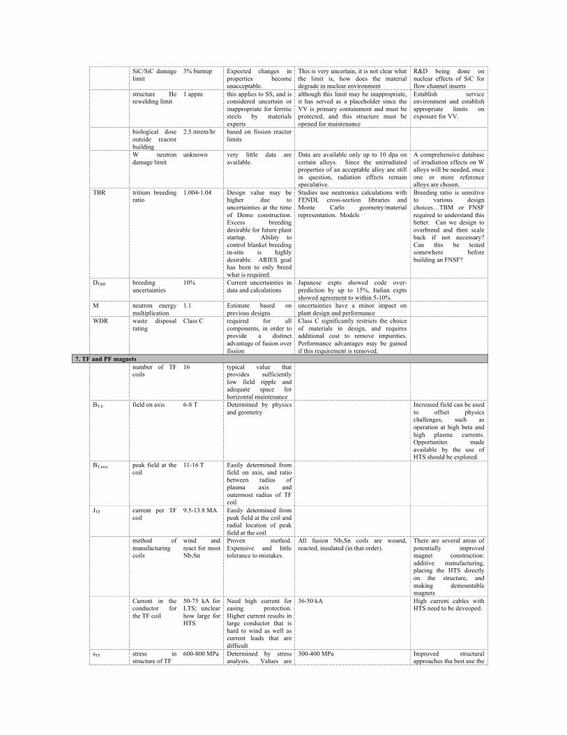
SiC/SiC damage limit
3% burnup Expected changes in properties become unacceptable.
This is very uncertain, it is not clear what the limit is, how does the material degrade in nuclear environment
R&D being done on nuclear effects of SiC for flow channel inserts
structure He rewelding limit
1 appm this applies to SS, and is considered uncertain or inappropriate for ferritic steels by materials experts
although this limit may be inappropriate, it has served as a placeholder since the VV is primary containment and must be protected, and this structure must be opened for maintenance
Establish service environment and establish appropriate limits on exposure for VV.
biological dose outside reactor building
2.5 mrem/hr based on fission reactor limits
W neutron damage limit
unknown very little data are available.
Data are available only up to 10 dpa on certain alloys. Since the unirradiated properties of an acceptable alloy are still in question, radiation effects remain speculative.
A comprehensive database of irradiation effects on W alloys will be needed, once one or more reference alloys are chosen.
TBR tritium breeding ratio
1.004-1.04 Design value may be higher due to uncertainties at the time of Demo construction. Excess breeding desirable for future plant startup. Ability to control blanket breeding in-situ is highly desirable. ARIES goal has been to only breed what is required.
Studies use neutronics calculations with FENDL cross-section libraries and Monte Carlo geometry/material representation. Models
Breeding ratio is sensitive to various design choices…TBM or FNSF required to understand this better. Can we design to overbreed and then scale back if not necessary? Can this be tested somewhere before building an FNSF?
DTBR breeding uncertainties
10% Current uncertainties in data and calculations
Japanese expts showed code over-prediction by up to 15%, Italian expts showed agreement to within 5-10%
M neutron energy multiplication
1.1 Estimate based on previous designs
uncertainties have a minor impact on plant design and performance
WDR waste disposal rating
Class C required for all components, in order to provide a distinct advantage of fusion over fission
Class C significantly restricts the choice of materials in design, and requires additional cost to remove impurities. Performance advantages may be gained if this requirement is removed.
7. TF and PF magnets number of TF
coils 16 typical value that
provides sufficiently low field ripple and adequate space for horizontal maintenance
BT,0 field on axis 6-8 T Determined by physics and geometry
Increased field can be used to offset physics challenges, such as operation at high beta and high plasma currents. Opportunites made available by the use of HTS should be explored.
BT,max peak field at the coil
11-16 T Easily determined from field on axis, and ratio between radius of plasma axis and outermost radius of TF coil
JTF current per TF coil
9.5-13.8 MA Easily determined from peak field at the coil and radial location of peak field at the coil
method of manufacturing coils
wind and react for most Nb3Sn
Proven method. Expensive and little tolerance to mistakes.
All fusion Nb3Sn coils are wound, reacted, insulated (in that order).
There are several areas of potentially improved magnet construction: additive manufacturing, placing the HTS directly on the structure, and making demountable magnets
Current in the conductor for the TF coil
50-75 kA for LTS; unclear how large for HTS
Need high current for easing protection. Higher current results in large conductor that is hard to wind as well as current leads that are difficult
36-50 kA High current cables with HTS need to be deveoped.
sTF stress in structure of TF
600-800 MPa Determined by stress analysis. Values are
300-400 MPa Improved structural approaches tha best use the

average of cross section, rather than peak over element
materials
<jTF> TF current density (over the winding pack, not including strcuture)
110-135 MA/m2
(31 for LT SC, 67 for HT SC) Determined by superconducting current density (fraction of critical (current sharing), about 0.7 Ic), required quench protection (determined by maximum temperature of superconductor after energy dump, which is determined by number of circuits, maximum discharge voltage, current density in copper)
60 MA/m2 (in the winding pack) for KSTAR; 80 MA/m2 in the winding pack in EAST). High current density made possible by use of high performance SC, advanced quench protection (low copper content) and strong sheath material.
Need to investigate optimal structural methods for magnets. Integration of conductor with structure. Means of decreasing the manufacturing costs of fusion magnets, especially toroidal.
Parameters
He inlet 4.5 K for liquid helium, 30-50 for gasoues helium
Typical value for He. For HTS, gaseous helium cooling is needed as there are no liquids in this temperature range
Need to determine the stability of He-gas cooled HTS magnets
temperature headroom
1-2 K Temperature margin before external heating applied to conductor.
temperature margin
1 K Difference between local He temperature and current sharing temperature at any time and anywhere in the conductor.
Required for stability For HTS, this value can be much larger. This requires additional research, as the material has much higher heat capacity than at low temperature, but still relatively small compared to liquid helium.
energy headroom
600 mJ/cc For LTS, determine by stability of SC.Not relevant for steady state conditions
Limits and protection for HTS magnets needs to be understood.
energy margin 300 mJ/cc for LTS; much larger for HTS.
Energy required to reach critical condictions anywhere in the coil, required for stability against thermal excusions that can drive the magnet normal
500 mJ/cc Limits and protection for HTS magnets needs to be understood.
fraction of critical j, normal
0.7 Operation near critical reduces the amount of superconductor required.
fraction of critical j, disruption
0.8 Avoidance of quench when plasma disrupts
How high it can be for HTS needs to be investigated, especially in the case of gaseous cooling of the supeconductor.
Damage limits
magnet organic insulation limit
1011 rads Highest limit for organic insulators that have low values of shear. Based on degradation of mechanical properties.
Demonstrated to a few 1010 rads with good interlaminar shear strength; determine limits for inorganics; determine limit for high performance organics.
Need to determine limit for high performance organics.
magnet inorganic insulation limit
1011 - 1014 rads
Determined by swelling Few magnets have been built with inorganic insulators. Use is probably limited to plate-type magnets.
Need to determine better limits for inorganic insulators.
magnet heating limit
2 mW/cm3 for LTS. Can be much higher for HTS.
Instantaneous heating of SC which is being held at ~5K for LTSC, and ~40K for HTSC. Although higher local heating rates can be tolerated, they result in large cryogenic loads.
1-2 mW/cm3 Determine characteristics of SC magnets operating at 30-50 K
magnet superconductor
1019 n/cm2 for E>0.1 MeV, used for both Nb3Sn and YBCO
Limit could be higher for HTS. Determine
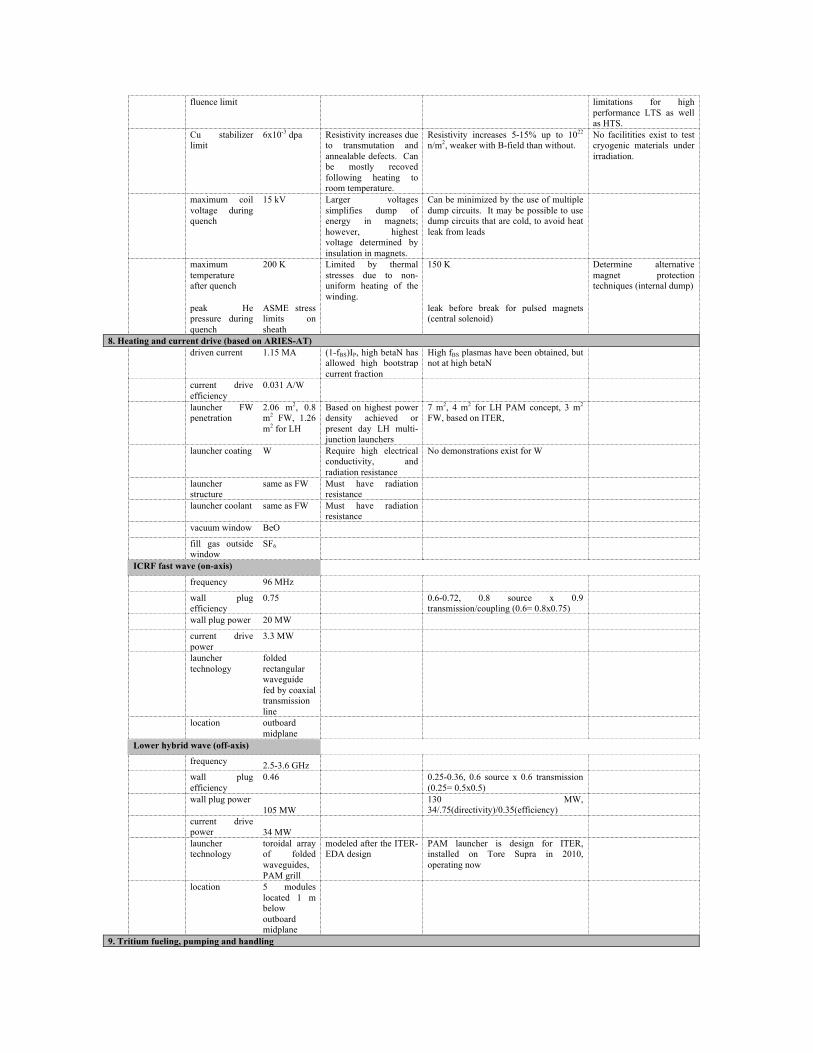
fluence limit limitations for high performance LTS as well as HTS.
Cu stabilizer limit
6x10⁻³ dpa Resistivity increases due to transmutation and annealable defects. Can be mostly recoved following heating to room temperature.
Resistivity increases 5-15% up to 1022 n/m2, weaker with B-field than without.
No facilitities exist to test cryogenic materials under irradiation.
maximum coil voltage during quench
15 kV Larger voltages simplifies dump of energy in magnets; however, highest voltage determined by insulation in magnets.
Can be minimized by the use of multiple dump circuits. It may be possible to use dump circuits that are cold, to avoid heat leak from leads
maximum temperature after quench
200 K Limited by thermal stresses due to non-uniform heating of the winding.
150 K Determine alternative magnet protection techniques (internal dump)
peak He pressure during quench
ASME stress limits on sheath
leak before break for pulsed magnets (central solenoid)
8. Heating and current drive (based on ARIES-AT) driven current 1.15 MA (1-fBS)IP, high betaN has
allowed high bootstrap current fraction
High fBS plasmas have been obtained, but not at high betaN
current drive efficiency
0.031 A/W
launcher FW penetration
2.06 m2, 0.8 m2 FW, 1.26 m2 for LH
Based on highest power density achieved or present day LH multi-junction launchers
7 m2, 4 m2 for LH PAM concept, 3 m2 FW, based on ITER,
launcher coating W Require high electrical conductivity, and radiation resistance
No demonstrations exist for W
launcher structure
same as FW Must have radiation resistance
launcher coolant same as FW Must have radiation resistance
vacuum window BeO
fill gas outside window
SF6
ICRF fast wave (on-axis)
frequency 96 MHz
wall plug efficiency
0.75 0.6-0.72, 0.8 source x 0.9 transmission/coupling (0.6= 0.8x0.75)
wall plug power 20 MW
current drive power
3.3 MW
launcher technology
folded rectangular waveguide fed by coaxial transmission line
location outboard midplane
Lower hybrid wave (off-axis)
frequency 2.5-3.6 GHz
wall plug efficiency
0.46 0.25-0.36, 0.6 source x 0.6 transmission (0.25= 0.5x0.5)
wall plug power 105 MW
130 MW, 34/.75(directivity)/0.35(efficiency)
current drive power 34 MW
launcher technology
toroidal array of folded waveguides, PAM grill
modeled after the ITER-EDA design
PAM launcher is design for ITER, installed on Tore Supra in 2010, operating now
location 5 modules located 1 m below outboard midplane
9. Tritium fueling, pumping and handling

trtitium burn fraction
5-30% Depends on several factors such as neutral particle penetration and recycling from walls, and is highly uncertain. The lower limit assumes the triton only spend τP ~ τE in the plasma with a high probability of fusion, while the upper limit assumes this is 10x longer
ITER's fueling and pumping capacity can support tritium burnup values less than 1%. Edge plasma simulations are used to approximate behavior for ITER, but these are uncertain.
the density in this regime should be high and neutral penetration should be very low, indicating that tritium does not re-enter the plasma efficiently and undergo fusion after its initial pellet injection, in spite of high recycling from the walls. This requires quantification of particle processes in the plasma edge and boundary regions.
T fueling rate 4 - 25 SLPM DT
Based on 1750 MW fusion power and burn fraction of 5-30%
TSTA ran at 6 SLPM, ITER designing for 120 SLPM
T release as gas/vapor to the environment
10 gm T/year Based on estimates leading to most exposed individual at the site boundary receiving 10 mREM dose/year
T extraction method
vacuum extractor
tritium partial pressure over LiPb
20 Pa
T breeder inventory
10-15 g PbLi has very low solubility. Calculation is from ARIES-AT and -ST.
T process inventory
1 kg ITER design
tritium vessel wall inventory
1 kg ITER limit
tritium reserve inventory
2 kg Estimate for plant operability
duty factor 50%
tritium processing reliability
95% expert judgement (Willms)
10. Instrumentation Requirement for
access at first wall
Combination of instrumentation and its shielding for measurement and control
Present tokamak experiments have large first wall area fractions (~30%) consumed by a number of diagnostics
Develop full requirements for the plasma measurements found to be necessary for device control and ancillary equipment and necessary blanket coverage.
plasma diagnostics for radiation environment
Many current diagnostics will not be able to function in the FNSF environment
development of appropriate instrumentation, starting with qualification or replacement of magnetic measurements inside the vacuum vessel

1.12 Footnotes
[1] Conservative physics power plants with normalized beta as low as 2.75 have been designed. The self-consistent neutron wall load may drop below 2.5 MW/m2 in this case. Neutron fluence at scheduled replacement intervals also would be expected to drop.
[2] Coolant inlet/outlet temperatures might be relaxed by 100-150 ˚C in order o demonstrate a reduced-performance (potentially lower risk) variant of the reference blanket. This design variant could in principle be easily modified to a higher performance version if high-temperature materials performance and compatibility are demonstrated.
[3] Fusion power in the DEMO might be scaled to ~75% of the full value, or ~1500 MW. [4] Reduced turbine inlet temperatures and reduced conversion efficiency would result from
the relaxation of blanket outlet temperatures described in footnote 2.

1.13 References [1] Fusion Power by Magnetic Confinement, ERDA-76/110/1, published S. O. Dean Journal of Fusion Energy 17 (1998) 263; FEAC Report on Program Strategy for US Magnetic Fusion Energy Research, DOE/ER-0572T, 1992; A Plan for the Development of Fusion Energy, report to FESAC, 2003; these and several others can be found at http://fire.pppl.gov/fusion_library.htm [2] L. Giancarli et al Fusion Engineering and Design 85 (2010) 1829; L. Giancarli et al Fusion Engineering and Design 81(2006) 393. [3] M. Greenwald et al., “Priorities, Gaps and Opportunities: Towards A Long-Range Strategic Plan For Magnetic Fusion Energy. A Report to the Fusion Energy Sciences Advisory Committee,” October 2007. [4] R. Hazeltine et al “Research Needs for Magnetic Fusion Energy Sciences”, report of the Research Needs Workshop (ReNeW), June 2009; http://burningplasma.org/renew.html [5] M. Abdou et al Fusion Technology 29 (1996) 1. [6] R. Stambaugh et al Fusion Science and Technology 59 (2011) 279. [7] Y-K. M. Peng et al Fusion Science and Technology 56 (2009) 957. [8] J. Menard et al Nuclear Fusion 51 (2011) 103014. [9] L. M. Waganer, F. Najmabadi, M. S. Tillack, and the ARIES Team, “What Must DEMO
Do?,” 16th IEEE/NPSS Symposium on Fusion Engineering, Champaign IL, Oct. 1995 (IEEE/95CH35852) pp. 1157-1161; UC San Diego Report UCSD-ENG-005 (1997), http://aries.ucsd.edu/LIB/REPORT/STARLITE/final.shtml.
[10] J. Kaslow, M. Brown, R. Hirsch, R. Izzo, J. McCann, D. McCloud, B. Muston, A.
Peterson, S. Rosen, T. Schneider, P. Skrgic and B. Snow, “Criteria for practical fusion power systems,” Journal of Fusion Energy 13 (2/3) 1994.
[11] F. Najmabadi et al., “The ARIES-AT advanced tokamak, Advanced technology fusion
power plant,” Fusion Engineering and Design 80 (2006) 3–23., and papers in this volume.
[12] F. Najmabadi, et al., “Spherical torus concept as power plants:/the ARIES-ST study,”
Fusion Engineering and Design 65 (2003) 143–164., and papers in this volume. [13] M. S. Tillack, X. R. Wang, J. Pulsifer, S. Malang, D. K. Sze, M. Billone, I.
Sviatoslavsky, and the ARIES Team, “Fusion power core engineering for the ARIES-ST power plant,” Fusion Engineering and Design 65 (2003) 215–261.
[14] A. R. Raffray, L. El-Guebaly, S. Malang, I. Sviatoslavsky, M. S. Tillack, X. Wang, and
the ARIES Team, “Advanced power core system for the ARIES-AT power plant,” Fusion Engineering and Design 80 (2006) 79–98.
[15] F. Najmabadi et al, “Overview of the ARIES-RS Reverse Shear Tokamak Power Plant”
Fusion Engineering and Design 38 (1997) 3, and papers in this volume. [16] J. Crowell and J. Blanchard, Fusion Technology 39 (2001) 434. [17] M. S. Tillack, A. R. Raffray, X. R. Wang, S. Malang, S. Abdel-Khalik, M. Yoda and D.
Youchison, “Recent US Activities on Advanced He-Cooled W-Alloy Divertor Concepts for Fusion Power Plants,” Fusion Engineering and Design 86 (2011) 71-98.
[18] P. Norajitra, R. Giniyatulin, T. Ihli, G. Janeschitz, W. Krauss, R. Kruessmann, V.
Kuznetsov, I. Mazul, V. Widak, I. Ovchinnikov, R. Ruprecht and B. Zeep, “He-cooled divertor development for DEMO,” Fusion Engineering and Design 82 (15-24) October 2007, 2740-2744.
[19] J. D. Rader, B. H. Mills, D. L. Sadowski, M. Yoda, S. I. Abdel-Khalik, “Experimental
and Numerical Investigation of Thermal Performance of Gas-Cooled Jet-Impingement Finger-Type Divertor Concept,” Fusion Science and Technology 60 (1) July 2011, 223-227.
[20] N. B. Morley, Y. Katoh, S. Malang, B. A. Pint, A. R. Raffray, S. Sharafat, S.
Smolentsev and G. E. Youngblood, “Recent research and development for the dual- coolant blanket concept in the US,” Fusion Engineering and Design 83 (2008) 920-927.
[21] R. W. Conn, F. Najmabadi, et al., “ARIES-I: A Steady-State, First-Stability Tokamak
Reactor with Enhanced Safety and Environmental Features,” Nuclear Fusion Supplement, 3, 659-670 (1991).
[22] http://www.sco2powercyclesymposium.org/ [23] M. A. Abdou et al, UC Los Angeles report UCLA-FNT-216 (2006), revised (2007). [24] M. A. Abdou et al Nuc Fus 27 (1987) 619. [25] C.T. Holcomb, et al., Phys. Plasmas 16, 056166 (2009) [26] F.G. Rimini, et al., Proc. IAEA Fusion Energy Conf. (2008) [27] Y. Sakamoto, et al., Nucl. Fusion 45, 574 (2005) [28] Ryutov 2007, Phys. Plasmas 14, 064502
[29] M. Kotschenreuther, P. Valanju, S. Mahajan, L.J. Zheng, L.D. Pearlstein, R.H. Bulmer, J. Canik and R. Maingi 2010 Nucl. Fusion 50 035003 [30] A.M. Garofalo, et al., Nucl. Fusion 47 1121 (2007) [31] H. Reimerdes, et al.,, Phys. Rev. Lett. 98, 055001 (2007) [32] M. Takechi, et al., Phys. Rev. Lett. 98, 055002 (2007) [33] D.A. Gates, et al., Nucl. Fusion 49 104016 (2009)

2. Research and Development Needs for Fusion Energy: Materials Science Richard Kurtz, Pacific Northwest National Laboratory Brian Wirth, University of Tennessee, Knoxville Expert Panel: Mohamed Abdou, University of California, Los Angeles Patrick Calderoni, Idaho National Laboratory Rion Causey, Sandia National Laboratory (retired) Peter Lee, Florida State University Brad Merrill, Idaho National Laboratory Joe Minervini, Massachusetts Institute of Technology Neil Morley, University of California, Los Angeles Bruce Pint, Oak Ridge National Laboratory Don Rej, Los Alamos National Laboratory Arthur Rowcliffe, Oak Ridge National Laboratory (retired) Shahram Sharafat, University of California, Los Angeles Lance Snead, Oak Ridge National Laboratory Bob Swindeman, Oak Ridge National Laboratory (retired) Mark Tillack University of California, San Diego Irving Zatz, Princeton Plasma Physics Laboratory
2.1 Introduction Recent workshops and planning exercises designed to identify knowledge gaps and research needs for development of a practical fusion energy system have stressed the enormous materials challenges that must be overcome.1, 2 For example, it was noted in the ReNeW study that “Fusion materials and structures must function for a long time in a uniquely hostile environment that includes combinations of high temperatures, reactive chemicals, high stresses, and intense damaging radiation.”2 In a similar vein the Greenwald report concluded that both materials and plasma facing components research are Tier 1 priority.1 As defined by the Greenwald panel a Tier 1 priority indicates a situation in which “solution not in hand, major extrapolation from current state of knowledge, need for qualitative improvements and substantial development for both short and long term.”1 Those studies adequately documented the critical role materials play in many components, systems, and structures for any future fusion plasma device. While structural materials significantly determine fusion energy feasibility, many other materials (e.g. breeding, insulating, superconducting, plasma facing and diagnostic) must be successfully developed for fusion to be a technologically viable power source. The purpose of the present study was to further prioritize and organize the various recommendations from previous studies to focus near-term research on the most important technical issues to enable full participation in ITER and to lay the foundation for conceptual design of a Fusion Nuclear Science Facility and eventually a demonstration fusion power plant (DEMO).
2.2 Materials Research Needs Assumptions and Planning Process The objective of the Materials Working Group was to utilize the results from recent comprehensive planning exercises to broadly identify priority materials research topics that should be addressed in the near-term as opposed to intermediate or long-term time frames. It was recognized that intermediate and long-term materials research would eventually be needed, but can be deferred. For this planning activity near-term was defined as less than 5 years from the present, intermediate-term was taken as 5 – 15 years and long-term was taken as greater than 15 years. The overarching goal of all of the research is to inform the design, construction and eventual operation of a Fusion Nuclear Science Facility (FNSF), which was identified as a plasma device with performance characteristics intermediate between ITER and DEMO. For this exercise DEMO was considered to be the last fusion facility prior to operation of a commercial fusion power plant. The technology gaps between DEMO and a commercial fusion power reactor were assumed to be small. The working group was subdivided into six subgroups in order to identify the materials research needs with a reasonably high degree of granularity. The subgroups and key individuals coordinating the input from each subgroup are given in Table I. The full group of people contributing to this planning effort is listed as authors of this report. To categorize near-term versus long-term research topics a three-tiered materials development and research strategy was adopted. It was assumed that the primary goal of near-term materials research should develop a sufficient database and knowledge to facilitate detailed engineering design and eventually construction of test blanket modules for ITER. The research, needed facilities and any industrial partnerships between national

laboratories and universities should be oriented toward a successful TBM program. It was further assumed that near-term materials
Table 1. Materials Subgroups
Subgroup Chairs Structural R Kurtz, PNNL
B Wirth, UTK Tritium & Blankets B Merrill, INL
N Morley, UCLA Magnets J Minervini, MIT Diagnostics L Snead, ORNL Corrosion & Compatibility B Pint, ORNL Design Criteria, Licensing, & Safety
S Sharafat, UCLA
research should support the two leading blanket concepts being developed in the U.S., namely the helium cooled solid breeder and the lead-lithium/helium cooled liquid breeder concept also known as the dual coolant lead-lithium concept. It was recognized that for TBM the total neutron fluence for first-wall/blanket structural materials would be ≤ 3 dpa and 30 appm helium so the irradiation effects database for structural materials is probably sufficient to enable reasonable engineering design and adequate prediction of TBM performance. Consequently the emphasis of near-term materials research should focus on addressing those technical issues for which insufficient data exists to support detailed engineering design. It was judged that TBM development is a necessary precursor step toward development of a base blanket for FNSF. Proposed deployment strategies for FNSF envisage a staged approach with the potential for multiple blankets during the lifetime of the facility. The total expected neutron fluence on first-wall/blanket structures in the initial operating phase is anticipated to be ≤ 10 dpa. In order for FNSF to successfully fulfill its mission of testing materials and blanket concepts to enable the design, construction and operation of DEMO it was concluded that prime candidate materials and blankets needed to demonstrate safe, reliable and efficient performance to at least 50 dpa in FNSF. At such neutron doses there is a definite need for additional irradiation effects data derived from a neutron source that duplicates or effectively simulates the actual fusion neutron environment in terms of primary knock-on spectrum and production of transmutation products, most notably helium and hydrogen, and provides a mechanism for accelerated testing to permit evaluation of a wide range of materials. An evaluation of possible irradiation sources that could provide the needed data is provided in this report. It was assumed that first generation materials used to design and build DEMO would consist of those materials with favorably demonstrated performance in FNSF to a neutron fluence of at least 50 dpa. It was also assumed that for DEMO to fulfill its mission as a demonstration of a commercial fusion energy source, then materials, components, and structures must achieve a lifetime neutron fluence of at least 150 dpa with an acceptably

high level of reliability and margin of safety. As with FNSF it is very important to develop an adequate irradiation effects database to inform the design and construction of DEMO. Thus, a fusion-relevant irradiation source is required to enable accelerated testing of a range of materials and subcomponents. Finally, an implicit assumption in all of the research proposed in this report is close integration of theory and modeling with experiments. It was recognized that the need to perform experiments, particularly irradiation experiments, cannot be replaced by theory and modeling alone. Conversely, a purely experimental approach is also not feasible given the substantial cost to perform irradiation and other types of experiments. Theory and modeling is not considered a standalone activity but is assumed to be an integral part of all of the research activities described below enabling the ability to re-evaluate existing data, optimize the design and execution of new experiments, and effectively interpret the results from those experiments.
2.2.1 Critical Issues Several recent reviews have highlighted the importance of structural materials for development of safe, reliable and economically attractive electrical energy production from potential future fusion power systems.3-6 A key challenge is development of high-performance structural materials that provide for an economically attractive fusion power system while simultaneously achieving safety and environmental acceptability goals.4 Radioactive isotope inventory, and release paths are important considerations in designing for safety. Development of low or reduced-activation materials is central to ensuring that structural materials removed from service will not require long-term geological disposal and may offer the potential for recycle, thereby minimizing impact on the environment.5 There are four candidate materials systems that appear to possess the potential to simultaneously meet requirements for high-performance and low or reduced activation goals.4 These materials systems include reduced-activation ferritic/martensitic (RAF/M) steels (and nanostructured ferritic alloy variants), fiber reinforced silicon carbide composites, vanadium alloys, and tungsten alloys. While considerable progress has been made in international research programs to develop these materials systems for fusion applications there remain several gaps in the databases that must be addressed in both near-term and long-term research programs. The critical issues remaining to be addressed for each of the candidate systems are briefly summarized below.
2.2.2 Reduced-‐Activation Ferritic/Martensitic Steels Reduced-activation ferritic/martensitic steels are the leading reference structural materials for future fusion power reactors in essentially all of the international materials research programs.7 This is because these steels are much more technologically mature than the other candidate materials systems.7 Considerable work has been performed outside the U.S. to develop and qualify the fabrication technology of RAF/M steels for ITER test blanket modules.8 Recent research efforts have focused on 1) manufacturing and welding technology, 2) measurement and modeling of radiation-induced hardening and embrittlement at low-temperatures, 3) characterization of the effects of helium on microstructural evolution and mechanical properties, 4) development of high-temperature

structural design criteria, 5) fundamental mechanical properties with increased consideration of the effects of thermal aging, fatigue and creep-fatigue interaction, and 6) compatibility with coolants such as lead-lithium and development of coatings.7-10 Recent reviews of the state of RAF/M steel development have sumamrized what remains to be done to determine if these steels will be suitable for fusion power system applications.7-10 A conclusion from these reviews is that more work is needed to develop and qualify the manufacturing and joining technologies needed for ITER test blanket modules and next step fusion devices.8, 10 This is particularly true in the U.S. where no significant work has been done in these areas. Other critical issues include 1) additional work on fatigue and creep-fatigue mechanical property characterization and high-temperature design rule development,8, 9 2) development of nondestructive examination techniques and procedures for flaw detection and sizing,9 3) further detailed assessment of irradiation-induced changes in mechanical properties,7, 9 4) further exploration of RAF/M steel compatibility with potential coolants and breeding materials such as flowing lead-lithium and solid ceramic breeding materials, also including the possible development of corrosion and/or permeation barrier coatings,7 and 5) particularly important for next-step device and DEMO applications is quantifying the effects of high levels of transmutation products such as helium and hydrogen on mechanical properties over the entire anticipated operating temperature window7, 9
2.2.3 Nanostructured Ferritic Alloys Nanostructured ferritic alloys (NFA) are a new class of material that offers the potential to operate at considerably higher temperatures than RAF/M steels and may be much more radiation tolerant. Nanostructured ferritic alloys are Fe-Cr alloys that derive their unique properties from the presence of an ultrahigh density of Y-Ti-O rich particles.11 The high number density of small (~5 nm diameter) particles efficiently impedes glide and climb of dislocations, which gives rise to exceptional high-temperature strength.11, 12 These particles also provide vacancy-interstitial recombination centers serving to mitigate displacement damage, and they potentially act as effective sinks to trap helium in small, high-pressure gas bubbles.11 As noted by Odette and Hoelzer11 the development of NFAs for fusion applications is in the very early stages. While these materials possess many attractive features, as noted above there are significant challenges that must be addressed before practical application is feasible. Some of the more important technical issues remaining to be addressed have been summarized by Odette, Alinger and Wirth.12 Their list of significant challenges includes the following 1) the high cost of mechanical alloying compared to more conventional melt-processing methods, 2) the difficulty of joining to obtain properties similar to the base material, 3) fabrication of product forms with isotropic microstructures and properties, 4) alloy homogeneity, 5) low fracture toughness for unirradiated material, 6) lack of a robust database on a host of critical properties such as creep rates and rupture times, fatigue and creep-fatigue, fatigue crack growth, and corrosion, 6) limited characterization of the effects of irradiation on microstructure and property evolution, and 7) fundamental understanding of NF composition and structure, and how to control these variables to achieve optimal

properties.12 A similar set of critical issues and future research activities has also been enumerated for the European Union program on NFA development.13
2.2.4 Tungsten Alloys Tungsten has received considerable attention as a promising material for plasma facing components (PFC) of advanced fusion devices because it is the only realistic structural material for divertor applications due to its excellent thermo-physical properties. The main advantages of tungsten are its high melting point, good thermal conductivity, low sputtering and erosion yield , high strength, low thermal expansion, and high resistance to swelling. However, an important drawback in structural applications is that the ductile-to-brittle transition temperature (DBTT) of pure tungsten is ~800°C, and it increases significantly due to recrystallization and neutron irradiation that produces rradiation-induced hardening. Three key factors14 that should be considered when developing a research program include 1) tungsten and its alloys manifest intrinsically low cleavage toughness and extrinsically low grain boundary cohesive energy, 2) the behavior of tungsten alloys in PFC structures will be determined not only by the material itself, but also the processing and fabrication routes used to make components, and 3) tungsten and its alloys will be part of a complex system that is highly loaded, both thermally and mechanically, and that suffer a wide variety of degradation mechanisms. As discussed by Rowcliffe14 there are a number of critical issues that must be addressed to successfully develop tungsten for divertor applications including creep strength, fracture toughness, microstructural stability, low and high cycle fatigue, oxidation resistance, and the effects of neutron irradiation.
2.2.5 Silicon Carbide Composites It has been recognized for many years that SiC composites are very attractive structural materials for fusion power systems, but present a large number of technical and development challenges that must be overcome before practical applications are possible. Two potentially appealing attributes of SiC composites are 1) the ability to operate at much higher temperature than for metal alloys15 and 2) a very low-level of long-lived radioisotopes that significantly enhances the environmental attractiveness of a SiC-based fusion reactor.15 The focus of research for the past decade has been to develop radiation resistant composites.16 As noted by Nozawa et al16 and Snead et al17 substantial progress has been made toward understanding the response of SiC composites to neutron irradiation and the development of materials resistant to that environment. The current generation of advanced SiC composites appear to be stable to neutron doses of up to tens of dpa17 and capable of operating at temperatures greater than 1000 °C.17 Recent development efforts have focused on improving the engineering properties of SiC composites through exploration of advanced processing technologies.16 More recently there has been a shift toward development of the industrial basis for composite production, and extensive characterization of properties over a wide range of conditions to build a database.16 Recent reviews15-17 of the status of SiC composite development have highlighted several crucial issues that must be addressed to make these materials realistic candidates for fusion structural applications. Data and models to predict time-dependent deformation processes
such as slow crack growth have been developed,15 but need to be refined to account for situations when composite fibers are not aligned with the loading axis. Another critical issue related to the development of improved time-dependent deformation models includes determination of the composite strength limit.16 Nozawa et al16 suggest that the strength limit needs to be correlated with failure behavior, including construction of a strength anisotropy map and lifetime evaluation for fatigue and creep loading conditions. A key need for structural applications is development of robust and reliable joining technologies.15,
17 Because fusion structures must tolerate very significant heat loads traditional mechanical joining methods are not suitable.17 A number of joining technologies are under investigation, but little is known about their response to even low-dose irradiation. Hermeticity is also a major issue for first wall and blanket applications requiring containment of high-pressure coolants.15 Consequently development of sealing layers resistant to the effects of irradiation and cyclic thermal and mechanical loads is required. Other crucial areas that need thorough investigation include 1) the effects of gaseous and solid transmutation products on properties, 2) degradation of thermal and electrical conductivity, 3) better definition of irradiation-induced creep, and 4) development of structural design criteria for inherently brittle materials.15-17 The potential effects of gaseous and solid transmutation products are particularly significant. Evaluation of various blanket concepts indicates that helium production would be between 30 and 170 appm/dpa depending on design details, which are many times higher than for metallic structural materials.15, 17_ENREF_13 In addition, solid transmutations also may substantial effect composite properties. In the fusion neutron spectrum burn-out of SiC occurs non-stoichiometrically,15 and burn-in of impurities such as Al, Mg, Li, Be and P occurs.15, 17 Snead et al17 estimate for an MFE fusion reactor spectrum and a neutron fluence of 100 dpa the total amount of solid transmutants will be about ~3900 appm, with about 60% of the total being Mg.
2.2.6 Vanadium Alloys Similar to SiC composites, vanadium alloys are a potentially appealing low-activation alternative structural material to RAF/M steels and NFAs.18 This alloy system is attractive largely because of its low induced activation along with reasonably good high-temperature strength, and ability to tolerate high thermally induced stresses.18 The worldwide research effort on vanadium has concentrated on developing a V-Cr-Ti alloy with 4-5% Cr and 4-5% Ti as the reference composition.18 A significant technical challenge with vanadium alloys is their affinity for gaseous impurity elements such as C, O, N and H. Vanadium is highly reactive with these elements and in sufficient concentrations they can severely degrade mechanical properties.18 The only viable breeder/coolant available for use with vanadium alloys is liquid lithium. Use of lithium as a breeder/coolant is beneficial in one sense because lithium has a stronger affinity for oxygen than vanadium, reducing the likelihood of oxygen embrittlement. On the other hand vanadium has a greater affinity for carbon and nitrogen than lithium so transfer of these impurities from the coolant to vanadium is a concern.19 Recent vanadium alloy research has focused on development of fundamental fabrication technology with emphasis on joining by gas tungsten arc and laser welding methods.19 As noted above the properties of vanadium alloys can be altered by exposure to lithium so this has received considerable attention, particularly during long-term thermal
creep experiments or corrosion studies where exposure to high-temperature lithium occurs.19 Characterization of the thermal creep performance of vanadium alloys in vacuum and liquid lithium environments has been a priority research topic for many years.18, 19 The results of these investigations suggest that the high-temperature creep strength of the reference composition may not be adequate, and has motivated the search for improved strength through thermo-mechanical processing or introduction of ultra-fine particles of Y2O3 or YN.19, 20 Radiation effects research has explored the effect of low-dose, low-temperature neutron irradiation on mechanical properties. Such work has pointed to the need to reduce the lower temperature limit, which has been pursued by exploring the effects of various alloy additions and heat treatment approaches.20 With liquid Li as the breeder/coolant one of the critical issues facing use of vanadium alloys as structural materials is the need for a coating to electrically isolate the vanadium structure from flowing Li. Immersion tests of bulk specimens in Li have shown that Er2O3 and Y2O3 are promising coating candidates, but much more work remains to done.19 Recent review papers18-20 have summarized the level of maturity of vanadium alloys for fusion applications. The remaining major critical issues identified in these broad surveys includes 1) a need for more data on thermal and irradiation creep, 2) improved understanding of the effects of irradiation on fracture properties, 3) a paucity of data on the effects of helium on microstructure and property evolution at all temperature, particularly in concert with neutron irradiation, 4) refinement of the reference alloy composition and thermo-mechanical treatments to improve strength and render interstitial impurities such as C,O, and N benign, 5) a better understanding of the effects of impurity transfer between the vanadium structure and Li breeder/coolant, and 6) the development of a robust and stable MHD insulator coating. The last critical issue being of particular importance since without an effective coating the vanadium-lithium concept is not feasible for fusion.
2.2.7 Vacuum Vessel Steels As a primary safety barrier and ultra-high vacuum boundary, the vacuum vessel (VV) must maintain the highest levels of mechanical integrity. It is a multi-function component which must provide adequate neutron shielding of the TF and PF coils and provide an effective heat sink in the event of loss of ancillary cooling loops. It must support all the high temperature power core elements and be capable of sustaining electromagnetic loads during various types of plasma disruptions and potential seismic loads. It must be designed, constructed and operated within an accepted code or standard. For a 1000MWe power plant the outer diameter will be in the 15-20m range and constructed from double-walled plates ~0.05m thick, the total weight being in the range 3000-5000 tons. Because of the size of the vessel and the type of welded construction envisaged, materials composition selection is dominated by the need to meet both long term activation requirements, safety issues related to short-tern decay heat and the need for reliable welding and inspection technologies.
For ITER, the same material (316LN-IG) was selected for both the VV and for the blanket/shield. Activation requirements were driven primarily by safety and maintenance needs, rather than by meeting the requirements for long term waste disposal by shallow land burial. The specifications for Co, Mn and Ta for the French breeder program material

316LN-SPH were modified to reduce short term neutron activation concerns while remaining within the requirements of the RCC-MR Code specification. For the ARIES-AT power plant conceptual design studies it was decided initially to adopt the same structural material for multiple components as a way to reduce the cost of materials development and the qualification of welding and fabrication procedures. A reduced activation ferritic–martensitic steel (F82H) was initially selected as the potential prime candidate VV material. However, the operating temperatures anticipated for the VV ( 200-250oC) are in the range for maximum radiation hardening for such steels and significant upward shifts in DBTT can be expected. A second difficulty is that steels such as F82H require a carefully controlled post–weld heat treatment to obtain the required high toughness microstructure with through-thickness uniformity. The technologies employed in the LWR industry of furnace treatment of large welded ring forgings are not applicable in this case. In summary, there are significant drawbacks to using a tempered martensitic steel for the VV because of a) the difficulty of carrying out in situ post-weld tempering treatments with a well-defined heat cycle to obtain the required microstructure during construction and b) problems with managing the radiation-induced shifts in DBTT during operation. The ITER solution to use an austenitic stainless steel, while very attractive because of the extensive fabrication, welding and mechanical properties database with 316LN-IG, and the absence of radiation-induced DBTT shifts, is not acceptable because of the long-term activation products stemming from Ni and Mo.
2.3 Research Needs
2.3.1 Near-‐Term a. Reduced activation ferritic-martensitic steels. A major assumption in planning near-term research needs is that such research should support the development of TBMs for ITER and a first-generation base blanket for FNSF. The neutron fluence anticipated for both environments is expected to be modest (< 10 dpa).21 A conclusion of the working group is that the most important research to be performed on RAF/M steels in the near-term includes 1) fabrication technology development, 2) characterization of elevated-temperature deformation modes such as fatigue, creep and creep-fatigue interaction, 3) exploring in more detail compatibility in a flowing PbLi environment (see Section VII for more detail), 4) development of high-temperature design criteria (see Section VIII for more detail), and development of nondestructive examination techniques and procedures for flaw evaluation in first-wall/blanket structures.
Given the relatively modest neutron irradiation conditions for both TBM and first-generation FNSF the need for additional irradiation effects data should be restricted to filling gaps in the knowledge base. Since essentially no work has been done in the U.S. to develop RAF/M steel fabrication technology it is anticipated that the most likely fabrication technologies to be employed will result in microstructures that may respond differently to
neutron irradiation than RAF/M steel base metal. Consequently there is a need for selected low-dose irradiation studies to qualify various fabrication procedures. In common with other international parties, U.S. TBMs will utilize RAF/M steel as the primary structural material. The current leading candidate compositions F82H (Japan) and Eurofer-97 (EU), are based upon the widely used T91 composition, but with special compositional and microstructural specifications tailored for improved performance in the fusion environment. Future refinements to the F82H and Eurofer-97 compositions will involve additional restrictions on the levels of elements such as Co, Nb and N to reduce coolant radioactivation, facilitate maintenance and minimize remote handling requirements. The complexity of the TBM designs requires the development of highly specialized fabrication technologies. In a recent TBM planning and costing study it was concluded that U.S. vendors should be engaged to develop the fabrication technologies needed to meet 1) the specific requirements of the U.S. TBM designs, 2) to develop the capability to fabricate sub-size mock-ups required for engineering and design validation testing, and 3) to construct both prototypical TBMs and the final test articles for ITER testing.21 The possible benefits of alternative fabrication technologies such as investment casting and laser-melt rapid prototyping to more easily produce the geometrically complex TBM structural elements while maintaining design tolerances and microstructures should also be investigated. In addition to meeting the required specifications on dimensional tolerances and flaw populations, the fabrication procedures must meet the microstructural specifications which have been selected to produce the levels of strength, fracture toughness, creep and fatigue resistance required to ensure adequate structural integrity throughout the D-T testing phase of ITER. Additional conclusions reached in the TBM planning study included research to 1) evaluate and develop nondestructive examination technologies and procedures for flaw detection and evaluation, 2) evaluate and qualify the mechanical performance of various types of HIP-bonded and welded joints, and 3) develop a low-dose, neutron irradiation performance database for as-fabricated structural components produced by U.S. and international vendors.21 Although neutrons are not produced in the H-H phase of ITER testing, it is necessary to evaluate the fully developed composition and fabrication technologies needed for the D-T phase. Finally, the TBM study also concluded that considerable potential for collaboration with international partners in the development of fabrication technologies, the qualification of mechanical performance of bonded joints and in developing the materials irradiation performance database exists and should be exploited to the maximum extent possible.21 b. Nanostructured ferritic alloys. As noted above considerable progress has been made in developing NFAs for both advanced fission and fusion reactor structural applications. These materials are attractive alternatives to conventional RAF/M steels because of their superior high-temperature creep strength, high sink strength for helium and potential to mitigate irradiation damage by providing numerous point defect recombination sites. Because of the enormous potential of these materials for advanced first-wall/blanket designs it is recommended that near-term research be performed to address the knowledge gaps. The main areas of research that should be pursued include 1) improvement of low-

temperature fracture toughness and material anisotropy, 2) development of joining technologies that produce joints with properties similar to the base material, 3) investigation of scale-up technologies to enable production of industrial-scale quantities of material at lower cost, and 4) exploration of nanocluster stability under irradiation. Known problems with NFAs are the relatively high DBTT and low upper shelf energy in the unirradiated state. The high level of strengthening imparted by the high-density nanoclusters may exacerbate this problem. In addition, the methods traditionally employed to hot consolidate and subsequently thermo-mechanically process the mechanically alloyed powders frequently result in anisotropic microstructure and properties. This can lead to considerable variation in strength, ductility and fracture resistance. The lack of suitable joining technologies has been a limitation to broad application of these materials as structural components. Conventional welding technology will not result in a joint with acceptable properties relative to the base material. Initial work has been conducted on solid-state joining techniques such as friction stir welding. While this technique shows considerable promise much more work is needed in this area. Finally, the current knowledge of processing conditions and reproducibility of small heats favor scale-up to larger heats, but similar to fabrication technology development for RAF/M steels this activity would probably be most efficiently performed by establishment of partnerships between universities, national laboratories and appropriate industrial vendors. The objectives of such research should be to look for more cost effect alternatives to mechanical alloying, with thermo-mechanical treatment approaches being preferable, and to expand the relatively limited NFA fabrication experience.
c. Tungsten alloys. Rowcliffe performed a detailed assessment of the challenges facing development of tungsten alloys for divertor structural applications.14 Four research topics were identified to advance the state of tungsten alloy development in the near-term. The four research topics included; 1) perform a critical analysis of the existing tungsten database, 2) carry out fundamental studies of deformation and fracture, 3) explore strategies employed in other metallic systems for modifying strength, ductility and radiation response, and 4) determine the basic radiation damage characteristics of tungsten alloys.14 An expanded description of each of these research topics is given below.
A fundamental conclusion of Rowcliffe’s analysis is that an in-depth analysis of the existing tungsten literature data is needed to clarify the state of knowledge in several areas.14 The existing database on fracture of tungsten and the factors affecting the DBTT is fragmented and a wide range of experimental techniques are being used to assess fracture resistance and measure DBTT. The variables controlling the transition from transgranular to intergranular fracture and the factors causing de-lamination, the effect of interstitial impurities, grain size and texture, and the influence of processing methods need to be better understood. The effectiveness of various mechanical alloying mechanisms appears to be poorly known. There appear to be potential improvements in ductility and toughness possible through reduction of grain size, so opportunities for improving fracture properties by grain size engineering need to be explored. Finally, recovery and recrystallization behavior is poorly understood, particularly the role of initial grain size, texture, dislocation density, time and temperature.

Fundamental studies of deformation and fracture are needed.14 The principles for microstructural design for higher ductility including the influence of grain size, texture, particle dispersions, and grain boundary dispersions needs to be elucidated. Atomic scale modeling of brittle fracture should be performed to better understand the role of crack tip plasticity, relative importance of dislocation nucleation versus dislocation mobility from a crack tip and the influence of interstitial and substitutional solutes on these events. Lastly, the dependence of deformation and fracture modes on grain size when reduced to the ultra fine or nano-crystalline level is needed. Coupled with this work should be research designed to understand the thermal and irradiation stability of nano-engineered microstructures. Recently there have been a plethora of new approaches for altering the strength and ductility of metallic alloys.14 Considerable insight can be gained by employing first principles density functional theory calculations to identify potential ductilizing alloy additions and design new materials. DFT calculations have shown that rhenium seems to lower the Peierls barrier for dislocation motion and other solutes may have similar effects. In addition, experience from recent NFA research should be exploited to determine if introduction of nano-dispersoids may be a viable approach to improve recrystallization behavior and radiation damage tolerance. Finally, ductile phase toughening and grain boundary engineering techniques should be examined. The fourth major research area is achieving a better understanding of radiation damage in tungsten alloys. Due to its inherent brittleness little work has been performed to study radiation damage in tungsten, consequently the studies proposed here should be deferred until progress has been made toward developing tungsten alloys with more attractive mechanical performance. As noted by Rowcliffe microstructures optimized for improved ductility and toughness will alter the basic radiation response of tungsten-based materials and may increase radiation tolerance.14 There is a clear need to better understand primary damage, defect production and cluster formation, migration and trapping of gases, interaction of point defects with dislocations, and attendant hardening mechanisms. In addition, radiation-induced segregation and phase stability and the potential for non-hardening embrittlement mechanisms ultimately need to be explored. The goal of this research should be to develop the basic principles for design of damage resistant microstructures including the effects of grain size reduction to the nano-crystalline regime, the utility of nano-scale clusters to provide point defect recombination centers and trap deleterious elements such as helium.
d. Silicon carbide composites. While SiC composites are potentially very attractive materials for fusion structural applications the number of critical technical issues that must be resolved is large and comparable to those mentioned above for NFA and W alloys. Given that there are several possible materials for fusion structural applications it is the opinion of the working group that research on SiC composites should be performed in the near-term to maintain these materials as potential alternatives to RAF/M steels and NFAs. The current level of worldwide research on SiC composites for structural applications relative to RAF/M steels appears to be appropriate considering the degree of risk associated with SiC. Emphasis should be given to experimental and modeling studies that do not

require high fluence neutron irradiation. Critical issues such as joining technology development, compatibility with tritium breeding materials such as PbLi and Li ceramics, and differential swelling in composites at low doses with appropriate levels of helium production seem to be ideal topics for near-term investigations. Technical issues such as transmutation produced gases and solids should be deferred until a fusion relevant neutron source is available to carry out such studies.
e. Vanadium alloys. Similar to SiC composites the number of critical issues facing successful development of vanadium alloys for fusion structural applications is significant. Because the operating temperature window for RAF/M steels may be shrinking due to increasing concerns about the effects of helium on low-temperature fracture resistance and the postulated effects of helium on high-temperature creep-rupture strength it is prudent to maintain a near-term research effort on vanadium alloys as a back-up for RAF/M steels. The emphasis of near-term research should be to resolve critical issues that do not require high-dose neutron exposures. Perhaps the most significant near-term issue that should receive the majority of resources is a development of an effective and robust MHD insulator coating. While progress has been made identifying potential candidate coatings such as Er2O3 and Y2O3 considerable work needs to be done establish the suitability of these coatings in a flowing Li environment. A secondary objective of near-term compatibility research should be to establish long-term interactions between vanadium alloys and flowing lithium. Such is needed because leading MHD insulator coating concepts include a vanadium over-layer to isolate the insulating layer from liquid lithium. Consequently potential mass transfer between the vanadium alloy structure and the lithium breeder/coolant could represent a life-limiting degradation mode.
f. Vacuum vessel steels. An integrated materials-design engineering approach to specifying materials for the VV of future fusion machines must include the following elements; 1) projected VV geometry and operating (temperature, stress history, including anticipated cycling) conditions, 2) activation requirements, 3) projected vessel loading and stress analyses, 4) cooling water chemistry, 5) minimum thickness to meet shielding requirements, 6) evaluation of mechanical properties, radiation effects and corrosion properties while maintaining structural integrity for the machine lifetime, 7) evaluation of fabrication welding and assembly issues.
In the near-term it is important to develop credible approaches for selection of a VV material in the design of the proposed Fusion Nuclear Science Facility. A credible approach must be based on currently available alloys for which a sufficient database exists to permit a proper evaluation of vessel lifetime. A general set of criteria may be stated as follows; 1) the concentrations of major alloying elements must meet the activation criteria for low-level waste disposal and minimization of decay after-heat, 2) mechanical property requirements must be met based on design requirements and stress analyses including regions exposed to neutron streaming, 3) good welding behavior by TIG and e-beam with the potential to fabricate thick sections with acceptable through-thickness uniformity, 4) development of high toughness weld microstructures without requiring PWHT, 5) resistance to general corrosion, stress corrosion cracking (SCC) in 200-300 °C water, and irradiation assisted SCC.

A close collaboration between the design and the materials communities will be necessary to address the short-term objective of defining existing materials that meet the above criteria. An initial assessment should be conducted on the following set of materials; 1) reduced activation stainless steels that qualify for shallow land burial, 2) ASME carbon steel pressure vessel steels, 3) ASME low alloy LWR pressure vessel steels, 4) reduced activation bainitic steels, and 5) reduced activation ferritic-martensitic steels. Based on this initial assessment, a prime candidate material may emerge for which additional confirmatory data is needed to cover the proposed operating conditions for current conceptual designs. Potential areas for additional experimental work include mechanical properties, especially at high temperature in creep-fatigue deformation regimes, weldability, corrosion resistance and low-dose radiation effects. In addition, the potential for in situ annealing to recover radiation damage to the VV material needs to be evaluated. The available information on radiation damage annealing on current materials should be reviewed. There is, for example, a considerable amount of interest in this topic from programs involved in the development of materials for spallation targets. A set of annealing parameters designed for full or partial property recovery needs to be defined and the viability of a full-scale operation to recover VV properties needs to be assessed. Low-dose radiation damage annealing experiments will probably be needed to complete the data-base on a specific candidate alloy.
2.3.2 Intermediate and Long-‐Term For the intermediate to long-term leading up to construction of an FNSF it will be necessary to focus on development of materials that will meet all the requirements of a recognized Code. Thus robust mechanical property, corrosion, fabrication, and irradiation effects databases will need to be established that meet the requirements of appropriate regulatory authorities. For materials far from the plasma (e.g. VV materials), the neutron fluence falls rapidly so irradiation effects such as swelling and helium embrittlement are not as significant. Other technical issues that are difficult to anticipate at this time may require resolution. On the other hand, materials that will ultimately receive lifetime neutron doses of up 50 dpa in FNSF, or 150 dpa in DEMO, will need to be tested and qualified in a fusion-relevant neutron source that allows for accelerated testing and development of mechanistic understanding of irradiation effects. The need for a fusion relevant neutron source is particularly acute because neutron-induced degradation such as volumetric swelling, irradiation enhanced creep, phase instabilities, helium embrittlement and solid transmutation effects become significant beyond ~10 dpa. For all of the candidate structural materials at neutron doses > 50 dpa there is essentially no information on behavior in the regime where several of these degradation mechanisms operate. This is especially true for the effects of helium, and other solid and gaseous transmutants, on microstructural evolution. In addition, many degradation mechanisms do not exhibit linear behavior with neutron dose, which indicates it is not possible to reliably extrapolate material behavior far beyond the range of the database. Volumetric swelling is a good example of non-linear behavior. For many materials there is an incubation period in which little swelling occurs as the microstructure evolves to render the material more prone to rapid swelling. After a critical dose, swelling

increases rapidly to a nearly constant rate. However, it is important to note that this incubation dose also depends sensitively on a host of factors such as neutron flux, temperature, initial microstructure and crystal structure of the material.
2.3.3 Major Facility Needs 1. Non-nuclear structural integrity benchmarking facilities During the ReNeW planning exercise, it was recognized that a wide range of non-nuclear facilities would be needed to test and qualify materials, components and structures for development of TBMs, and future plasma devices such as FNSF and DEMO. The size and scale of the needed facilities ranges from relatively small to quite large. Facilities are needed to perform complete physical and mechanical property characterization of materials before and after irradiation. Those designed to carry out post-irradiation examinations may not be physically large but due to radiological considerations may carry significant capital investment requirements. Many such facilities already exist in the U.S. and internationally, however some are very old and may need to be refurbished or replaced in order meet the needs of an expanded fusion materials research effort. As noted in ReNeW, large-scale facilities will be needed to perform full-scale structural integrity testing and qualification of components for TBMs, FNSF and DEMO. The precise timing as to when such facilities need to be available is difficult to predict given uncertainties in the pace of fusion power development, so no recommendations are presented in this report. 2. Fusion-relevant irradiation sources The need for a fusion relevant neutron source to test and qualify materials for DEMO has been recognized for over thirty years.22-24 During the 1980s, a detailed study examined issues and experiments for fusion nuclear technology that set requirements and evaluated volumetric and point neutron sources.25 Later that decade the IEA convened an international working group to evaluate both plasma-based sources (reversed-field pinches, high-density Z pinches, and beam-plasma mirror configurations) and accelerator-based sources (D-Li and spallation). The group recommended that three options, a D-Li source, a spallation source, and a beam-plasma neutron source, be investigated further.26 Subsequent analysis concluded that differences in materials damage parameters were not great enough to permit a selection of a preferred alternative on the basis of displacement rate, primary recoil spectrum, and important gaseous and solid transmutations.27 That is, all three alternatives met the requirements for producing a neutron source whose damage parameters were sufficiently close to those experienced in the first wall of a fusion reactor that none could be rejected on this basis alone. A follow-on IEA review in 1992 concluded that the D-Li neutron source concept was preferred because of its relatively lower flux of high-energy neutrons beyond 14 MeV (the so-called high energy neutron tail) and most mature technology base.28 The beam plasma source was found to provide the best simulation of a fusion reactor, but the scientific feasibility of the source was still in question. The spallation source was found not generally favored by the materials community and that it would be “a viable candidate only if it can be attained at much less expense than the alternatives.”26 While no significant irradiation facility was constructed in the intervening years, interest renewed during the ITER construction era. Construction of an International Fusion
Materials Irradiation Facility (IFMIF) was proposed, based upon two 5-MW, 40-MeV D+ linear accelerators and liquid Li target system.29, 30 In 2008 the EU Fusion Facility Review placed the construction and operation of an IFMIF as the highest priority fusion technology facility required for DEMO design.31 IFMIF gained further momentum as part of the ITER Broader Approach (BA), with ~$210M already committed by Japan and the EU between 2007-2014 for the Engineering Validation and Engineering Design Activities (EVEDA) phase that will produce a complete engineering design and construct the accelerator prototype, a liquid lithium test loop, and the high flux test module for engineering validation.32 Construction of the EVEDA Lithium Test Loop (ELiTe) was completed in 2010 at the JAEA Oarai Center. At CEA Saclay, the 1:1 scale Linear IFMIF Prototype Accelerator (LIPAc) reached an important milestone in 2011 when the installation's injector produced its first proton beam.33 To date, there have been no additional financial commitments for IFMIF after the completion of EVEDA in 2014. The BA is an agreement between Europe and Japan, but is open to the other five ITER partners. Similar needs for a fusion irradiation facility were articulated by the U.S. community as one of nine unprioritized initiatives in a 2007 FESAC report.1 That report recognized the IFMIF mission and the need to assess the potential for alternative facilities that could reduce or possibly eliminate the need for US participation as a full partner in IFMIF. These recommendations were amplified in the 2009 DOE FES Research Needs Workshop (ReNeW) report that called a fusion-relevant neutron source an essential mission requirement.2 ReNeW specifically cited three sources (which incidentally were identical to those in the 1989 IEA study26) as examples of options that need to be further evaluated and selected based on technical attractiveness and cost effectiveness. ReNeW also recognized the later possibility for an FNSF, but emphasized that bulk material property data from a fusion relevant neutron source would inform the design, construction and licensing of such a facility. a. Options evaluation. The usual set of technical options for a fusion-relevant neutron irradiation source was considered for the FNS-PA: D-T plasma sources, accelerator-driven systems, fission reactors, and ion beams. For each option, we consulted with subject matter experts (SMEs) for the following information: 1) self-consistent performance parameters including neutron flux, instantaneous dpa, in situ helium and hydrogen production rates, test material irradiation volume, test material temperature range and precision; 2) date when the facility would operate at these parameters, assuming a technically-driven schedule; 3) expected facility duty factor; 4) order-of-magnitude capital and operation costs to fusion sponsors; 5) current technology readiness levels (TRL) and any enabling R&D required over the next 5-10 years; 6) top 2 to 5 key points made by proponents; and 7) top 2 to 5 criticisms from others, and the proponents' rebuttals to those criticisms. Key parameters are listed in Table II. We did not convene peer reviews of costs, schedules, and TRLs provided by the SMEs.
b. Schedule to produce 50 dpa data for FNSF. A fast track plan to get to a net electric DEMO in 2037 includes an FNSF that would begin operation in 2025. To inform the design of this FNSF, one would need to produce 50 dpa in multiple specimens and test those specimens by the end of this decade. From Table I, only high-power fast-neutron research
reactors and ion beam facilities could easily meet this requirement, while the Gas Dynamic Trap (GDT) axisymmetric mirror, IFMIF, the two U.S. spallation sources (SNS and LANSCE-MTS), and the HFIR fission reactor are projected to do so in the 2020 – 2022 timeframe. Additional considerations, such as irradiation volume, temperature control, neutron spectrum, in-situ helium generation, cost, and risk, are needed before selecting a preferred alternative.
Proponent SMEs estimate that the GDT could produce 50 dpa (in the highest neutron flux test volumes nearest to 1-m2 ports) after 4.2 years of operation that could begin as early as 2016. Principal advantages of the GDT are its simple construction and maintenance, natural divertor and low heat load, ability to produce a D-T fusion reactor spectrum with steady-state operations without disruptions or ELMs, and its relatively large irradiation volume. Technical challenges include its low TRLs – the steady-state neutral beams would need to reliably operate at full power for more than 6,000 hours per year. Proponents note that long-pulse steady-state neutral beams in the range of 80 keV are being developed in China and Korea, and at lower voltage in India, and they expect to have operating beams in two years. The long-pulse source used on DIII-D (previously on TFTR) is already steady state cooled for the most difficult component, the accelerator. Princeton studies have long determined the needed modifications to the TFTR neutral beams and concluded that systems could be capable of reaching 1000 s pulses with a high degree of confidence.34 Physics challenges include demonstration of performance at full plasma parameters, Te in particular. Scaling based on existing achievements would generate 0.3 MW/m2 of neutron flux.35-37 The results are consistent with theoretical predictions of electron heat loss suppression by a strong flaring of the magnetic field.38 The dimensionless scaling shows that the physics will allow reaching the required plasma parameters. The test of a full-scale hydrogen prototype could be performed in 18 months. The simplicity of the system allows for a high pace of development and tests.39
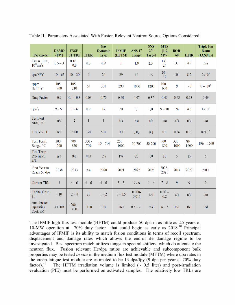
Table II. Parameters Associated With Fusion Relevant Neutron Source Options Considered.
The IFMIF high-flux test module (HFTM) could produce 50 dpa in as little as 2.5 years of 10-MW operation at 70% duty factor that could begin as early as 2018.40 Principal advantages of IFMIF is its ability to match fusion conditions in terms of recoil spectrum, displacement and damage rates which allows the end-of-life damage regime to be investigated. Best spectrum match utilizes tungsten spectral shifters, which do attenuate the neutron flux. Fusion relevant He/dpa ratios are achievable and subcomponent bulk properties may be tested in situ in the medium flux test module (MFTM) where dpa rates in the creep-fatigue test module are estimated to be 13 dpa/fpy (9 dpa per year at 70% duty factor).41 The HFTM irradiation volume is limited (~ 0.5 liter) and post-irradiation evaluation (PIE) must be performed on activated samples. The relatively low TRLs are

commensurate with the extreme radiation environment, Li technology, and construction of what will be the highest-power accelerator system in the world; however, significant investments are well underway to mature IFMIF TRLs to acceptable levels by 2014 through the EVEDA Project. The Spallation Neutron Source (SNS) and the LANSCE Materials Test Station (MTS) utilize existing MW-class proton accelerator facilities that operate at 90% availability over 4000-5000 hours per year in support of non-fusion DOE missions in materials, nuclear science, and radioisotope production. Advantages for fusion materials studies include the ability to test bulk properties, relatively low electrical power costs (spallation sources are highly efficient in producing neutrons)42 and leverage with non-fusion funding agencies. The irradiation volumes in SNS and MTS, while macroscopic, are limited, commensurate with their low costs to fusion sponsors. Principal technical issues include the proportion of high-energy (>14 MeV) neutrons, temperature control, solid transmutation, and pulsed irradiation. Proponent SMEs have calculated primary knock-on atom spectra and the impact of the pulse structure of the proton beam on temporal characteristics of the atomic displacement rate. With respect to both of these features, analyses show that conditions are consistent with those of a steady-state fusion reactor first wall.43 The broad range of He and H generation rates in spallation sources than under DT fusion can be exploited to critically assess computational models of He and H effects. The relatively high TRLs are indications of proven performance in meeting primary missions. Fusion materials irradiation studies on these facilities could provide a pathway for scientific understanding needed to more effectively use large volume engineering facilities when they become available. The SNS first target station could produce up to 50 dpa after seven years of irradiation that could begin as early as 2015. Materials specimens are placed near the nose of the target, just above and below the 1-GeV proton beam. Principal technical issues include the effects of the proton-material interactions, which results in helium to dpa production ratios of approximately 80 appm He/dpa in Fe (8× higher than in a fusion first wall). Atomistic simulations indicate that primary damage production from very high-energy SNS neutrons is not qualitatively different than 14 MeV DT fusion neutrons.44, 45 Instrumented irradiation capsules have been used at the HFIR reactor for many years and the designs are well developed. The capsules for SNS would see similar heating rates and much of the current design approach could be used. The development of the systems for SNS will require normal engineering development, but no significant R&D has been identified for the application at the first target station. The design concepts for the second target station irradiation facility have not been well developed and it is not clear yet if any R&D will be desired. The MTS is a long-pulse spallation source that is being designed specifically for fast neutron irradiations of fission fuels and materials. MTS utilizes the existing LANSCE 1-MW proton beam capability. MTS would produce 50 dpa after 5.5 years of operation that could begin as early as 2017. IFMIF-like damage and He rates would be achieved on MTS with a 2× LANSCE linac power upgrade. With that upgrade 50 dpa would be achieved after 2.8 years of operation that could begin as early as 2019. Fusion relevant He/dpa ratios are feasible with spallation targets specifically designed for irradiation applications (the mission
of MTS).46 An initial assessment of the evolution of the elemental makeup of several fusion-material-candidate alloys reveal classes of alloys for which transmutant in-growth during MTS irradiations should not be a concern.47 System requirements identified for fusion materials irradiation applications include items, such as high-intensity beam dynamics modeling, high-reliability accelerator operation, high-current superconducting radiofrequency systems, cryogenic distribution systems, and high-power RF sources.48 Fast fission research reactors exist in Russia and Asia are available for irradiation services. The BOR-60 Reactor49 is currently capable of producing 50 dpa in two years of operation.50 Significant advantages of BOR-60 are its immediate ability for high-dose uniform irradiation over large samples with a well-characterized spectrum. Bulk properties can be evaluated. Technical limitations are the very low He and H buildup, the long times to set-up agreements with non-U.S. facilities and to receive samples back, transmutation gas production rates that are similar to mixed spectrum reactors, and in handling activated samples. Fusion relevant He generation can be achieved in fast reactors by isotopic tailoring of specimens. For example, irradiations in the Fast Flux Test Facility (FFTF) of Fe-Cr-Ni alloys doped with 59Ni resulted in enhanced He production due to the 59Ni(n,α)56Fe reaction and production of He/dpa ratios from 0.2 to 62 appm He/dpa.51 Thermal spectra fission research reactors do exist in the U.S. With a Eu2O3 shield, the HFIR reactor52 is currently capable of producing a fast neutron flux (E > 0.1 MeV) of 4.9×10¹⁸ neutrons/m2-s and 50 dpa after approximately 11 years of operation.53 The well characterized fast neutron flux, stable gamma flux and heating profile contribute to HFIR’s track record of fusion irradiation. As with fast reactor neutron sources, in situ He generation is much lower than in a FNSF and DEMO; however, higher He generation has been obtained with isotopic tailoring, as well as the deposition of thin layers of materials that produce a uniform He deposition zone of up to 8 microns deep in adjacent steel substrates under mixed neutron irradiation.54, 55 High damage regimes with variable He/dpa ratios can be investigated in a very short time with ion beam facilities. With multiple beams (self-ion and gas ion beams), displacement damage and gas effects are separable, and different recoil energies can be explored. Ion beams have proven useful in basic science studies to examine unit processes. There is little to no sample activation, which simplifies PIE. Technical issues include the impact of damage rates that are 100 to 1000 times too high, the strong spatial gradients in damage production and gas generation, and an inability to obtain bulk property data because of the small irradiation volumes. Correlation with neutron damage is also a challenge. There are many facilities around the world with multi-ion-beams and ion-beam-TEM capabilities.56 The state-of-the-art facility is the JANNuS triple-beam in France,57 where 24 MeV Fe ion implantation into Fe results in a peak damage rates of approximately 105 dpa/fpy (~ 10 dpa/hour!) with a beam flux of 8×10¹⁵ ions/m2/sec. He/dpa or H/dpa ratios from 0 to over 1000 appm/dpa are possible. Irradiation volumes are 3 – 4 micrometers depth by 20 mm square area. With 3-MeV protons, the volume is increased to ~40 micrometers depth by 20 mm square area, with damage rates of ~200 dpa/fpy.

c. Schedule to produce 150 dpa data for DEMO. A fast track plan to get to a net electric DEMO in 2037 requires design activities between 2022 and 2030.2 To inform design, one would need to produce 150 dpa in multiple specimens and test those specimens by the end of the design effort. From Table I, only the GDT, IFMIF, the 2-MW MTS, BOR-60, and JANNuS could meet this requirement. Current projections for FNSF facilities indicate damage rates of up to 20 dpa/fpy, with operational duty factors between 0.1 and 0.3.58-60 At these rates, it will take at least 25 years to achieve damage levels of 150 dpa after an FNSF comes on line.
2.4 Tritium and Blanket Materials
2.4.1 Critical Issues One overall knowledge gap identified in recent fusion planning studies by Greenwald et al.1 was in the “Understanding of the required elements of the complete fuel cycle, particularly tritium breeding and retention in vessel components.” This knowledge gap includes the development of materials for breeding modules and control of tritium permeation in high temperature blankets. In reviewing the research in this area and the findings of The Materials Science Panel of the Research Needs Workshop (ReNeW), the Tritium Material Issues sub-group identified two areas of research that should be pursed in order to reduce this knowledge gap. First, tritium permeation control is a vital issue for tritium production and safe operation, a materials development effort must begin to develop low solubility, low permeability structural materials, or claddings (e.g., permeation barriers), as identified in numerous US reactor blanket design studies (e.g. ARIES-CS61). At this time, the US does not have a materials development program for permeation barriers. Second, a materials development effort must be started with the objective of producing liquid and ceramic tritium breeding materials of sufficient quality to be of use to an ITER Test Blanket (TBM) or a Fusion Nuclear Science Facility (FNSF), let alone a DEMO. The US presently has two leading concepts for a DEMO breeding blanket, the: 1) Dual Coolant Lead Lithium (DCLL), and 2) Helium Cooled Ceramic Pebble Bed (HCPB) blankets. The US cannot manufacture the basic breeder materials for these blanket concepts. We propose research and development efforts in these areas in the following sub-sections of this report.
2.4.2 Tritium Permeation Control Coatings are essential for the realization and the operation of reactors beyond ITER.62 To enhance the performance limits, regardless of the future blanket concept, major components of the reactor have to be foreseen with functional coatings. These coatings can serve as electrically insulation to mitigate magneto-hydrodynamic forces in self-cooled liquid metal systems. They can also serve as tritium permeation and corrosion barriers for the blanket/primary heat transport system, reducing corrosion of and tritium permeation through ferritic steel structures into system coolants or the reactor building, while still permitting higher operational temperatures.

In Europe, early development work on coatings concentrated mainly on alumina/FeAl coatings for RAFM steels. These coatings are intended to serve as tritium/corrosion barriers for the EU Helium Cooled Lead Lithium (HCLL) blanket concept. Several processes for forming this coating were studied. Apparently, the most successful process was the “Hot-Dip Aluminizing Process”, where permeation reduction factors (PRF) of ~100 were achieved for 120 to 150 µm thick layers. The formation process involves “dipping” the RAFM steel into a pool of molten aluminum, and then applying a HIPing process to achieve the desire coating microstructure. New activities in the EU are also testing erbium-oxide as anti-permeation coating and tungsten-based scales as corrosion barriers including sandwich coatings of Er2O3 or Al2O3 together with W as anti-permeation and/or corrosion barriers. At Research Centre Karlsruhe, the coating process development changed during the years from scientifically orientated to more industrially relevant deposition techniques for large components as required in fusion technology. This new process of Galvano-Al (ECA) is based on the electro deposition of aluminum from an organic electrolyte where Al is existing as an Al(CxHy) complex. In Japan, recent Li immersion tests of bulk specimens identified Er2O3 and Y2O3 as promising candidate ceramics especially for systems based on vanadium alloys.62 EB-PVD, Arc Source Plasma Deposition and RF sputtering demonstrated the feasibility of coating V–4Cr–4Ti with Er2O3 and Y2O3. Especially, high crystalline Er2O3 coating fabricated with Arc Source Plasma Deposition onto a substrate at higher temperature were shown to be stable in Li to 1000 h at 700°C. While these permeation barriers prove to be effective in laboratory experiments, the effectiveness of some of these barriers appears to be diminished in a reactor or intense radiation environment. For example, in the LIBRETTO-3 experiments,63 permeation barrier concepts were tested with the tritium produced by liquid breeder material contained in a test capsule. One irradiation capsule was coated on the inside with a 0.5 to 1.5 mm thick layer of TiC followed by a 2 to 3 mm thick layer of Al2O3. The combined TiC and Al2O3 layer only resulted in a PRF of 3.4. There is emerging data from fission reactor research that SiC coatings are effective tritium permeation barriers that also demonstrate very good resistance to radiation effects. Dense carbon layers, such as pyrolytic carbon, have given similar results. It is unclear at this time whether the reduced effectiveness of other types of barriers is due to neutron or gamma radiation, but given the need for permeation barriers both inside and outside of the reactor research into these barriers is needed in this area. Finally, given the extremely low solubility and permeability of tritium in tungsten, a concerted effort to develop either tungsten alloys ductile enough to can serve as a structural materials for blankets, piping or heat exchangers of a fusion HTS, or tungsten claddings for ductile structural material for these components must be pursued. Regarding a cladding, one possible method for forming a thick-tungsten clad on a ductile structural material may be the laser direct deposition process.64
2.5 PbLi Manufacturing Lead-lithium alloys are the main candidate breeder material for liquid blanket concepts in the U.S. as well as the majority of other countries involved in fusion R&D. The alloy composition is near the eutectic composition to minimize the melting point of the material.65 Production of large quantities of PbLi is an underlying requirement for fusion technology development. Whether procured through industrial sources or produced within the R&D program, the produced material characteristics will have to be established according to quality assurance (QA) requirements for nuclear grade material. The main technical challenge is to identify and develop a manufacturing route (production method, sampling and analysis techniques, etc.) that is compatible with large-scale production, while allowing the type of control on the final product specifications that will be required by the nuclear grade specifications. Past and ongoing R&D activities have identified control of Li content, impurities, and material homogeneity as the three most important manufacturing issues to be resolved. Each of these is briefly summarized below.
a. Composition control. Composition of the alloy determines its physical and chemical properties. The properties most affected by the Li content are the melting point, the volatility and the hydrogen affinity. The latter is particularly important in fusion applications because it directly determines tritium transport properties in the breeder material, and therefore the main design parameters such as tritium inventories and tritium extraction systems efficiencies.
Lithium is chemically reactive and affects many other properties to some extent, such as material compatibility. Unfortunately most experimental activities have been carried out without careful control of the PbLi composition, so composition effects are not easy to quantify. Wide discrepancies in measurement of the eutectic composition have been reported in the literature, such that the commonly accepted composition has been proven to be incorrect. This is due to the fact that most production methods result in hypereutectic compositions. Hubberstey65 summarized the composition of PbLi batches used in past R&D activities. Lithium at% varied from 15.7 at% to 17.0 at% with uncertainties as high as ±5 at%. The currently accepted eutectic title is 15.7 at% Li.66 b. Impurity control. A second issue is control of metallic impurities in the alloy, which are contained in the ores from which the alloy components are extracted. The development of a manufacturing process needs to be compatible with stringent fusion R&D requirements and yet capable of producing large amounts of materials at reasonable cost.
The main motivation for impurity control is to control activation. A second motivation is their effect on blanket breeding performance, since impurities are neutron absorbers and reduce tritium generation. Impurity control could also determine the practical feasibility of specific manufacturing processes once the cost is included. Finally, the role of impurities in determining material properties, such as tritium solubility or corrosion behavior requires further investigation.
c. Homogeneity control. Segregation of hypereutectic phases has been detected in the past, but an effort to perform a comprehensive study started only recently in the EU.66 This directly impacts operational procedures related to planned or accidental thermal cycles of blanket loops and auxiliary systems since such phases melt at higher temperatures than the eutectic composition. Also, the safety analysis of such freezing events would be greatly complicated by inhomogeneity of tritium and activated impurities inventories. The most worrisome consequence would be retention of inhomogeneity in the liquid phase, such as stratification in loop dump tanks, which could lead to an effective composition of the alloy in flowing channels different from the reference composition. If such phenomena indeed occur they would be time dependent, possibly leading to an overall deterioration of the material performance if active controls are not in place.
2.6 Ceramic Breeder Pebble Manufacturing The main line of ceramic breeder materials research and development is based on the use of the breeder material in the form of pebble beds. The pebbles are quasi-spheroid, with mm-scale dimensions. Such particles have a better margin against thermal cracking, can easily fit into complex blanket geometries, and can better accommodate volumetric swelling and expansion. The EU and Japan have developed three materials that are the leading candidates for their respective DEMO reactors. They include Li4SiO4 pebbles produced by melt-spraying, Li2TiO3 pebbles produced by extrusion-spheroidizing-sintering, and Li2TiO3 pebbles produced by a wet process. Research on Li4SiO4 fabricated by melt-spraying has shown that the majorities of the fabricated pebbles are crystallized and exhibit some cracks and pores. Since cracks and pores adversely affect mechanical properties, a better-controlled process is needed to enhance not only pebble mechanical properties, but also the yield of the process. As blanket designs mature, further consideration must be given to development of improved materials that are less expensive to prepare, are easier to fabricate into desired shapes, exhibit excellent thermal, mechanical, chemical as well as irradiation performance, and demonstrate tritium release at lower temperatures.
2.7 Beryllium Neutron Multiplier Manufacturing Beryllium, in the form of ~1 mm-diameter spheres or pebbles has been identified as a neutron multiplier for solid breeder blanket design concepts. To date, the only demonstrated production method for making these pebbles has been the rotating electrode process (REP), but there are some significant drawbacks to that process including 1) low yields for the desired pebble size range, 2) difficulty achieving the desired porosity and grain size, 3) inherent production rate limitations, and 4) high cost due to low yields and production rates. Private U.S. industry has performed internally funded research to explore high-yield, lower-cost production methods with the objectives to 1) demonstrate feasibility of at least one new method as an alternative to REP, 2) supply material needed to perform the necessary research by all interested parties, and 3) furnish sufficient quantities for ITER TBMs. While these efforts have met with some success, more remains to be done as discussed below.
5. SiC flow channel insert fabrication and characterization Flow channel inserts (FCIs) are being developed for the DCLL blanket concept to provide electrical and/or thermal insulation between flowing PBLi and the electrically conducting RAFM steel structure. Such insulation is critical to reduce magnetohydrodynamic pressure drop and control other deleterious MHD affects. FCIs also thermally insolate the PbLi flow from the RAFM steel to allow higher outlet temperatures and better thermal conversion efficiency than would be possible if the PbLi temperature is limited by RAFM steel corrosion or strength limits. Silicon carbide is a prime candidate due to its relatively low electrical conductivity and apparent compatibility with PbLi at elevated temperatures.
The performance requirements for FCI have been identified as 1) adequate thermal and electrical insulation, 2) compatibility with PbLi, 3) leak tightness for PbLi, 4) mechanical integrity, and 5) retention of properties during prolonged operation [ref]. Specific blanket designs will have specific ranges of minimum insulating properties, which could be significantly affected by the operating temperature and neutron irradiation. The effects of displacement damage on mechanical, thermal, and physical properties of high purity SiC are relatively well understood with exceptions of electrical conductivity and irradiation creep. The effects of nuclear transmutation are largely unknown although they are anticipated to be significant for insulating properties, corrosion behavior, and other properties.
Ceramic structures, either composites or porous ceramics, are prone to microcracking when mechanically stressed. A small crack in ceramics other than fiber composites leads to immediate failure unless the cracking itself relieves the stress. Continuous fiber ceramic composites can tolerate a very high microcracks density; however, those microcracks may allow infiltration of PbLi spoiling the FCI insulating characteristics. Therefore, it is essential that the probability of cracking and/or failure of FCI is properly addressed as a function of mechanical stress. Moreover, intrusion of liquid metal into and through the microcracks should be studied taking the potential MHD effect on wetting into consideration.
There are two promising FCI materials concepts currently envisioned for near-term deployment. The first is based on a 2D woven-fabric SiC fiber/SiC matrix composite, and the second consists of porous SiC foam. Both of these concepts have demonstrated acceptable performance for most of the conditions anticipated for DCLL modules in ITER, which will be a significantly less demanding environment than a power reactor PbLi blanket [Ref]. However, optimum material margin, failure probability, and the acceptable impact on tritium breeding are ensured. Moreover, even for use of industrially established SiC materials in less-demanding operating conditions, fabrication technology for real size components including non-straight segments and manifolds needs to be fully developed and the baseline performance verified. For the purpose of performance verification, adequate test methods for properties of complex-shaped components will need to be examined.
2.8 Research Needs
2.8.1 Near-‐Term a. Tritium permeation control. In the next five years, a permeation barrier research activity should begin with a theoretical investigation aimed at understanding how barriers work and how they are defeated by radiation. The object of this investigation should answer basic questions such as:
• What is there about silicon carbide that makes it radiation resistant? • What is there about most oxides that make them strongly affected by radiation? • What is there about the present barriers that give them a good performance in the
laboratory? Is it an extremely low solubility? Is it surface effects such as dissociation or recombination? Is it a low diffusivity?
Based on the answers to these questions, a bench-top-scale research program is being proposed for the investigation of RAFM steel permeation barrier coatings. This program should not only attempt to reproduce the EU’s success with aluminized coatings, but start to build the required expertise and equipment, primarily at the university level, for studying the Galvano-Al (ECA), Laser Cladding, and other based coating/cladding process. The testing of developed specimen coupons from this research program should be made available for permeation testing in either simple permeation cells, ion sources, or in linear plasma sources, such as PISCES or TPE. b. PbLi manufacturing. In the near-term, the U.S. should initiate an R&D program to develop and demonstrate a viable manufacturing process with the goal of ensuring that sufficient nuclear grade material will be available to meet anticipated future needs. There are two possible routes that could be followed. The first one is to carry out research aimed at optimization of the alloy fabrication and handling process within a national laboratory. In this approach analysis procedures would be developed to certify material and the results used for manufacturing process optimization. Batches of material could be used for related R&D tasks, such as compatibility testing. As part of this approach a quality assurance process is started to certify ‘nuclear grade’ material and to compare available products, and industry is contacted in an effort to shift activities to commercial enterprises for large batch fabrication. Preliminary assessment of this route indicates that it is probably cost intensive in the first two years due to capital equipment investments. The risk associated with this approach is low because it allows for internal capability deployment as an alternative to commercial industry involvement and would not rely on international collaboration.
A second development pathway would be to establish a quality assurance process that seeks to procure material from commercial sources. Analysis procedures are developed to certify that procured material meets ‘nuclear grade’ certification. The goal is to identify a commercial partner capable of producing large batches within specification limits. Preliminary analysis of this approach suggests less cost intensive but carries a high level of risk because of the lack of alternative to a commercial vendor if QA requirements cannot be met, or there is no interest in industry in producing the material.
c. Ceramic pebble manufacturing. At this time the U.S. does not have the capability to manufacture these breeding materials. The following near-term manufacturing R&D activities should be pursued to correct this deficiency. First, powder preparation and fabrication methods need to be developed to produce lithium ceramic pebbles simultaneously meeting performance requirements for size, shape, density, microstructure (open and closed porosity), yield, mechanical strength, and production rate. Pebbles should be near theoretical density to ensure maximum smear pebble bed density for tritium breeding, while allowing sufficient open porosity for tritium release. The breeder material needs to be 6Li enriched to achieve desirable tritium breeding. This requirement impacts the selection of fabrication process and precursor material. The fabrication processes should be scalable to produce requisite quantities for DEMO. Also, consideration should be given to recycling processes, particularly recovery of 6Li from unburned breeder. Second, a laboratory testing and characterization program to ensure that breeder pebbles meet the minimum characteristics described above should be initiated.
d. Be pebble manufacturing. Near term research should focus on establishment of a viable high-yield, lower-cost production method for making Be neutron multiplier pebbles. This can be accomplished on equipment that produces batches of pebbles on the order of one kg in size. The next objective should be to scale-up this process so that it can supply the material for the ITER TBMs. This will require a production unit that has a batch size on the order of 10 kg.
In parallel, there should be an effort on process and material refinement to achieve optimal performance. Recent studies show that 1) finer grain size pebbles give better tritium release, 2) beryllide intermetallic compounds release tritium faster than Be metal, and 3) beryllides have potentially higher temperature performance than Be metal. These findings point the way to the medium-term R&D projects. Investigating ways to refine the grain size of Be pebbles, undertaking a pebble production method for beryllide intermetallic compounds, such as TiBe12 or ZrBe13, and examining alternative forms of neutron multiplier material should all be considered. Alternative forms include pellets, tablets, gravel, and others. The utilization of these other forms may offer significant cost reductions over spherical pebbles. e. SiC flow channel insert fabrication and characterization. The fabrication and materials/components design based on the current material concepts are considered near-term R&D. A robust approach should involve a combination of science-based investigations providing a foundation to better understand the behavior of materials, property evolution, and understanding of basic phenomena, and the evaluation and analysis of properties toward materials/component qualification for specific engineering designs. Radiation effects R&D is both near-term and medium-term. The focus of near-term research should be on relatively simple radiation effects on current generation materials.
2.8.2 Intermediate and Long-‐Term a. Tritium permeation control. In the intermediate to long-term timeframe, successful samples from the bench-top-scale research program should be subjected to irradiation testing as part of the materials research being proposed in this document. Irradiated
specimens from this program should also be tested in hydrogen permeation/retention devices similar to those identified above. However, depend on the level of irradiation that these specimens have been exposed to, it is very likely that new permeation devices will be required, or existing devices will have to be modified to accommodate additional radiation shielding.
During this phase of testing, the impact of an ionizing radiation field on the permeation barriers should be investigated. This testing should be covered under the Power Extraction and Tritium Sustainability portion of this report. The preferred method for performing these tests would be in a small accelerator driven neutron/gamma source (AND/GS) facility. Any permeation or Sievert’s cell developed for testing of irradiated coating samples can also be installed in such facilities to study permeation with or without the neutron source on. b. PbLi manufacturing. In this timeframe, activities should shift to validation of large-scale operation of PbLi flowing systems with the construction of a forced convection loop to test fusion blanket components. This activity should be coordinated with others requiring a similar capability, such as the investigation of tritium extraction from PbLi. Analytical techniques as well as QA procedures developed in near-term research should be transferred, while the development focus should shift to online detection instruments and operational QA procedures.
c. Ceramic pebble manufacturing. The irradiation behavior of fabricated pebbles needs to be determined. The focus of this research should be on tritium release characteristics, swelling and creep properties, microstructural stability (sintering and phase changes), thermo-mechanics and thermal conductivity.
d. Be pebble manufacturing. Once the neutron multiplier needs for solid ITER TBMs has been satisfied, and work has been completed to further refine the production processes to optimize material and its form from both technical and cost viewpoints, the final steps to ensure long-term viability for next step fusion devices include further scale up of the production process to quantities on the order of one ton, and developing a recycling process for irradiated materials.
Current power reactor conceptual designs indicate that approximately 300 tons of pebbles will be needed for a single reactor. This is an enormous quantity and will require a large scale-up of pebble production equipment, as well as a scaling up of the entire Be industry. As there is no shortage of Be-bearing ores, pebbles can, therefore, be produced if the demand exists. There are, however, possible ways to significantly reduce the cost of Be extraction. If the breeder blanket market for pebbles develops as described, then there would be large potential cost savings from a more efficient method of beryllium extraction. Concerning recycling it is expected that the Be material in a fusion breeder blanket will need to be replaced every five years. Due to the extremely large quantities of neutron multiplier material envisioned for DEMO there is a strong incentive to develop recycling technology. Research to date has been mostly paper studies, with only one very small

laboratory-scale experiment conducted between Japan and Kazakhstan. Recycling research should be a component of an intermediate to long-term research portfolio. e. SiC flow channel insert fabrication and characterization. Radiation effects R&D is an intermediate to long-term activity. Transmutation effects studies using high-energy neutron irradiation should be the focus of the research in this timeframe.
2.9 Magnet Materials
2.9.1 Critical Issues Development of advanced superconducting (SC) magnet technology is crucial to development of a reliable and economically attractive fusion power system. Magnet systems for current generation SC fusion devices are expensive and lack features such high reliability, high maintainability, ease of manufacture, and mass production technology, which are deemed essential for successful development of fusion energy. Advancing the state-of-the-art in magnet technology will require significant progress in high-temperature SC development, improvements in electrical insulation and improvements in magnet structural materials. Minervini et al discuss the critical issues and research needed for development of advanced high-temperature SC technology. In this section we summarize the critical issues and research needs associated with magnet insulation and structural materials.
2.9.2 Electrical Insulators Fusion magnet systems must be electrically insulated to prevent leakage current and arcs due to magnet voltages during charging, discharging, and quench dump. The insulation must be able to withstand voltages as high as 25 kV, during quick magnet discharge following a detection of a quench, in order to prevent damage from overheating the conductor. Insulators also act as a structural element in maintaining winding pack stiffness, but allowing local expansion, strain sharing, and load bearing in a conductor in plate design, in order o transfer the conductor generated loads to the structure. Where insulators can develop tensile loads, they must have adequate shear strength to prevent tearing. In the layers of a magnet closest to the fusion plasma the insulation must also be able to withstand both instantaneous and cumulative neutron and gamma irradiation. The ability to withstand this radiation is frequently the magnet limit that determines the thickness of the radiation shield. Organic insulators have substantially lower fluence tolerance than inorganic insulators. This is because organic insulators are limited by chemical changes due to bond breaking, while for inorganic insulators the life is determined by swelling caused by gas generation by nuclear transmutations or displacement damage to structure of the material. For organic insulators, the bond breaking can be described in terms of g-values, or the number of radicals, atoms or bonds broken per 100 eV of absorbed energy. Since the

mechanism for different types of irradiation are similar, the g-values from these different forms of radiation are comparable. Therefore, the relevant number for characterizing irradiation damage from neutrons, gammas and electrons are in terms of energy density dissipated in the material, or Grays. For inorganic insulation, neutrons do the damage, and thus the relevant number is neutron fluence.67 Both organic and inorganic materials are under consideration for use as insulation material in commercial fusion reactor studies in the U.S. Most superconducting magnets are presently manufactured using fiber-reinforced epoxy, which imposes relatively low limits on the allowable radiation dose. The radiation limit for organic insulators is on the order of 108 rads for fiber-reinforced epoxy and 109 rads for polyimide based insulation. These limits are for the case when the insulator needs to withstand substantial shearing forces. In the absence of shear, it is possible to increase these limits, by as much as a factor of ten.68 The fluence limit for inorganic insulators is determined by swelling. For practical insulators the maximum radiation dose ranges from 1011 rads to 1014 rads depending on whether the insulator is in sheets or in powder form. The corresponding neutron fluence (>0.1 MeV neutrons) is 1024 to 1027 n/m2. When compared to LTS materials, HTS materials may have the potential of substantially relaxing the design restrictions placed on the material by irradiation damage to insulation, the stabilizer and nuclear and AC heating of the cryogenic environment. However, the information available today only indicates that irradiation damage limits of HTS material itself are not lower than for the LTS materials. The main technical challenges to be resolved for electrical insulators include; 1) attainment of higher specific performance in the insulation, 2) identifying insulator materials compatible with SC winding heat treatments, and 3) improving insulation radiation damage resistance. Each of these challenges is summarized briefly below. a. Higher specific insulation performance. The transmission line practice of allowing 2 kV/mm in an epoxy-glass system and 10 kV/mm in kapton has not yet been adopted by the fusion community. An obvious and inexpensive next-step in reducing the volume and cost of insulation would be to halve the thickness of the insulation. This can be done either by halving the number of glass fabric plies from two to one, or by using plies of half the thickness. For rectangular, potted winding packs, the inter-turn thickness can be reduced from 1.6 mm to 0.8 mm. This has a second benefit of reducing the bending in the corners of the conduits, because of reduced insulation compliance. It has a third benefit of reducing the cusp area in which it is hardest to avoid resin-rich regions. In an ITER TF-like design with individual ground wraps around each conductor, insulation thickness is also useful as a cushion between the conductor and plate, during a quench, when the conductor expands from overpressure and heating. The overall goal should be to reduce the insulation thickness by a factor of 2.5 for square conduits in winding packs and by 1.5 for conduits in plates. These goals can be restated as validating design to 1.25 kV/mm, nominal, in winding packs and to 2 kV/mm in conductor in plate. For smaller, multipole magnets, such as those used in Heavy Ion Fusion Drivers, it should be possible to develop all polyimide systems with peak electric fields of 5 kV/mm on quench.

b. Compatibility with heat treatment. The process of insulating a winding can be simplified if insulation can be applied during winding, then the winding and its insulation go through the heat treatment together. The cost savings in winding and insulation are counterbalanced by any damage to the insulating material or degradation during the winding and heat treatment. Significant testing has been done in Europe on different glasses and ceramics, showing that ceramics and some variants of S-glass show little degradation during heat treatment.
Another difficulty in putting the insulation through the heat treatment is the possibility of contaminating the surface of the conductor conduit with sizing or water vapor. Outgassing of water from the insulation has been blamed for the embrittlement of the magnet structural material, although this was never established. A specific goal of a near-term research effort would be to demonstrate at least two orders of magnitude safety margin in water-outgassing for an insulation and Incoloy system. c. Insulation radiation resistance. The improved electrical performance goals should be demonstrated at radiation dosages up to 109 rads in 3x3 stacks of rectangular and at radiation dosages of greater than 1010 rads for a circular conductor in plate. This represents a factor of ten improvement over ITER.
2.9.3 Structural Materials Structural materials are required in order to contain the large Lorentz loads of the magnetic pressure vessel, to contain pressurized He in a CICC, especially during quench, and to contain off-normal forces (e.g. earthquakes). Structural materials must avoid excessive rigidity in the wrong locations, during thermal cooldown and quench heating. They must be compatible with coil winding, and, where applicable, with winding separation for insulation and with conductor heat treatment. The material properties most relevant to magnet material structural integrity are the tensile properties, fatigue crack growth behavior, and the magnitude and temperature dependence of the fracture toughness. The choice of wind and react, using a winding method where the conductor needs to be heat treated in place, requires a material that has a thermal coefficient of expansion similar to the superconductor, in order to minimize strains associated with differential thermal contraction. In the past, the U.S. developed a nickel-based alloy, Incoloy 908,69 that matches well the thermal contraction between heat treatment temperature and operating temperature. Alternative materials, low-carbon austenitic steels, have been developed in Europe and Japan. In particular, JK2LB alloy,70 which was developed by Kobe Steel has been sufficiently characterized for the analysis. Because of the manufacturing method employed for the structure in recent DEMO conceptual designs71 the use of weld material properties is more appropriate than those of the base metal. In effect the entire structure is treated as one very large weld. The properties of the weld material of the chosen material, 9HA, are very good. The yield and tensile strengths are slightly lower than those of the base metal, Incoloy 908, but the ductility and fatigue crack growth properties are outstanding. By comparison, very little

information is available on the weld characteristics relevant to JK2LB, although since it is close to conventional steels, it is not expected to be a significant issue. There are two technical concerns with selection of Incoloy 908 for magnet structures. Firstly, Incoloy 908 is not a low-activation material because the Nb content is relatively high, which renders it a less attractive choice than JK2LB from an activation perspective. The high Nb content also makes recycling and reuse of Incoloy 908 problematic. In contrast, JK2LB can be reused one year after cooldown. Furthermore, if it is desired to recycle the material, JK2LB can be recycled hands-on after one day, while Incoloy 908 must be recycled by remote maintenance procedures. Secondly, because of the high Ni content, Incoloy 908 is substantially more expensive that specialty steels. For these reasons, low-carbon austenitic steel, such as JK2LB, was selected as the baseline material for the structure of recent DEMO conceptual design magnets.
2.10 Research Needs
2.10.1 Near-‐Term For electrical insulators a focused development effort involving the coordinated activities of universities, national labs and industry should be undertaken with the goals described above. This should include development of inorganic insulating systems and ceramic insulators. Industrial partners have proposed the development of superior insulating materials with simultaneous improvements in insulation strength and radiation resistance. The fusion program should support these industrial proposals. a. Higher specific insulation performance. Means for achieving a lower insulation thickness should be investigated. Advanced options, including the use of nanoparticles in the insulation, should be pursued, due to the large potential for increased insulation life. The affect of radiation on these advanced concepts should also be investigated.
b. Compatibility with heat treatment. An ideal insulating material should be able to undergo the heat treatment process of low-temperature superconductors. Presently, this is not the case substantially increasing the effort (and cost) to add the insulator following SC heat treatment. Most likely ceramic insulators should be investigated, as the heat treatment process is likely to damage organic insulators. After heat treatment, however, it may be possible to vacuum pressure impregnate the winding. For high temperature superconductors, this is not the case, as the heat treatment of the superconductor takes place before making the cable (that is, the available tapes have already undergone heat treatment).
c. Insulation radiation resistance. Improvements in radiation resistance have usually been achieved by identifying and testing improved materials. The fusion program should test and confirm the radiation resistance of insulation systems, in particular those that are specifically under compression with limited shear stresses.
Planar inorganic insulation, applicable to both high-temperature SC plate magnets and copper plate magnets, should be developed. In the case of YBCO (2nd generation materials) there is limited insulator built-in within the superconductor itself. For the option where the superconducting material is deposited directly on the structural plates, it may be possible to build thicker insulators that could withstand the energy discharge voltages. For copper coil designs with plates, the development of either flat plate insulation or sprayed-on insulation should be developed. The fusion program should also measure the relation between improvements in insulation material properties and insulation system performance. For magnet structural materials relatively high performance 300 series steels will remain the low-cost choice in both the near and intermediate term. Although very difficult, it may be possible to develop an alloy in the near term with a combination of higher strength and toughness than Incoloy 908, but with the same excellent strain compatibility with superconducting materials. For rocket applications, aluminum becomes competitive, because of its weight advantages. There are several issues that remain in determining the best structural materials in all fusion magnets. These issues include 1) Incoloy 908 development, 2) Code qualification of Incoloy 908, and 3) Code qualification of aluminum alloys. A property database has been developed for Incoloy 908 base metal, welds, and transition joints that has proven to be adequate for ITER. To reduce the ultimate cost of Incoloy 908, an adequate database for ASTM code qualification needs to be generated. A quantitative goal of cost minimization of Incoloy 908 would be to generate broad acceptance of the material and reduce the specific cost by a factor of two from $40/kg to $20/kg. d. Improved SAGBO resistance of jacket material. Fusion programs, beginning with the US-DPC magnets and concluding with the ITER CS Model Coil have developed the procedures for welding and heat treatment of Incoloy 908 so that embrittlement by Stress-Aggravated Grain Boundary Oxidation (SAGBO) does not occur. However, the risk of accident can be greatly reduced if a variation on the Incoloy 908 alloy were developed with the same or even better mechanical properties, but more resistance to oxidation. Incoloy 908 can develop SAGBO at high tensile stress with an oxygen content of 0.1 ppm. The goal of a material development program would be to develop an Incoloy series that is simultaneously stronger and tougher than 908 at cryogenic temperature and less susceptible to SAGBO.
e. Toughness of 300 series steel after heat-treatment. 300-series steels such as 304LN or 316LN are substantially less expensive and better qualified than Incoloy 908 for most applications. However, for the long heat treatments needed for Nb3Sn superconductors they are less well characterized. The superiority of Incoloy 908 over 316LN is that it was designed to be compatible with superconductor heat treatments, over a broad range of temperatures and times. This is particularly important for internal fin designs, which tend to require heat treatments of 250-300 hours. For example, the fracture toughness of Incoloy 908 is 235 MPa m1/2 after 275 h at 700°C. The toughness of 300-series base metal and welds is known to degrade significantly, during long heat treatments.

In order to survive the heat treatment, using 316LN, a low carbon steel, enriched with nitrogen was used. Reed and Walsh [ref] have shown that chrome carbide embrittlement can be avoided by reducing the carbon content of 316LN. A similar, low-carbon, high-nitrogen 316LN has been used at the National High Field Magnet Laboratory. This material was designed for only a 90 h heat treatment, and required very low carbon content and consequently a high specific cost of $26/kg. The goal of this steel development program would be to characterize a 300 steel whose strength and toughness would be no worse than that of 304LN with a weld toughness of at least 250 MPa-m1/2 after a 700°C heat treatment of 260 hours, and a specific cost of no more than $10/kg.
2.10.2 Major Facility Needs The U.S. has some of the most advanced insulation development efforts. These efforts would have to be substantially increased to investigate the potential of improved insulation. At the present time, most of the insulation improvement efforts are concentrating on near term issues for ITER. There are facilities for the irradiation and testing of the insulators. However, the irradiation sources and testing facilities (with slightly activated samples) exist mostly overseas.
2.11 Diagnostic Materials
2.11.1 Critical Issues The development of improved capability to interrogate fusion plasma performance represents a critical need for the development of fusion power, and certainly one that is very daunting on par with demonstrating the ability to generate and sustain burning plasma. Many systems are necessary for diagnosing the magnets, microwaves, fusion plasma, plasma facing components reactions, etc, and Table III summarizes the diagnostic system and parameters measured, along with the diagnostic materials, anticipated for ITER. While current magnetic fusion plasma devices do not generate substantial fluxes of either displace or ionizing radiation, a particular challenge for fusion reactor generations in ITER and beyond is developing understanding necessary to predict the lifetime performance of the individual diagnostic systems. In particular, the increase in ionizing dose expected in moving beyond ITER raises significant concerns for diagnostic systems utilizing organic insulation (e.g., polyimide resin) or fiber optic cabling. Likewise, the substantial increase in neutron wall loading expected in moving from ITER to DEMO raises significant concerns
for amorphous or crystalline ceramics for electrical insulation or substrates for mirrors or diagnostic applications. A number of key irradiation induced property changes must be evaluated across the broad suite of diagnostic materials anticipated for use in advanced fusion reactor and FNSF designs. Among the most critical are volumetric swelling and thermal conductivity degradation, radiation induced conductivity in insulating ceramics, radiation induced electrical degradation, radiation induced electro-motive force, color center formation and radio-luminescence and surface effects that reduce the optical quality of magnet materials. The challenge moving forward will be to formulate integrated effort that combines power-reactor-diagnostic design with the supporting diagnostic materials R&D. Clearly, DEMO and follow-on power reactors cannot support the number or complexity of diagnostic systems that are being considered for ITER, and in some cases, the plasma conditions will necessitate entirely new diagnostic systems. Moreover, many of the phenomena that are anticipated to limit diagnostic performance may be temperature sensitive. Thus, while a materials science based program to evaluate the development and lifetime performance of diagnostic systems in irradiation environments is critically important, it must be focused and well coupled to component design since many degradation phenomena could be sensitive to geometry and test conditions.
2.12 Research Needs
2.12.1 Near-‐Term It is important to note that the issues raised within the current study are the same as raised within the Greenwald study1. It is also important to note that in the time since that study, an impressive amount of work has been performed in the area of ITER diagnostics. However, only limited work has targeted the irradiation hardening or survivability of diagnostics for extended ITER application. Therefore, one conclusion for near term research is the evaluation of survivability, or lifetime limits, for the diagnostic component materials listed in Table III. In particular, the irradiation response of these materials should be evaluated for fast neutron fluences up to ~3x1025 n/m2 and for ionizing doses up to 109 Gy, at dose rates in the range of <1 Gy/s to 100’s of Gy/s.
2.12.2 Intermediate and Long-‐Term A large amount of research will be required in the intermediate- to long-term, mostly focused on the irradiation response of materials utilized in the optical systems. More specifically, this involves exposing candidate diagnostic materials to both displacive and ionizing radiation fields that have flux and energy levels characteristic of those environments anticipated in FNS and DEMO. These levels are anticipated to involve fast neutron fluences in the range of 50-150x1025 n/m2 and to involve ionizing doses up to 1011 Gy, at dose rates in the range of <1 Gy/se to 100’s of Gy/sec. Post-exposure measurements

are required to characterize the dimensional stability, and changes to the thermal, electrical and optical properties. This experimental based characterization should be closely integrated with computational modeling to provide a basis for understanding property evolution and to develop operating lifetime predictions.
2.12.3 Facility Needs a. Non-Nuclear Structural Integrity Benchmarking Facilities
The primary facility for non-nuclear testing of diagnostics required is a source of ionizing irradiation capable of accommodating prototype sensors at continuous DEMO dose rates of 100’s of Gy/s to total doses in the range of 109 to 1011 Gy. Irradiation test volumes of two cubic meters within a high temperature (800°C) vacuum environment are required.
b. Fusion Relevant Irradiation Sources There is no emergent need for a 14 MeV neutron source for irradiation of diagnostic irradiation. The required irradiation doses listed above (tens of dpa, or up to about 150x1025 n/m2) can be provided by any available mixed spectrum fission reactor, fast spectrum fission reactor, or spallation source. However, the irradiation volume, ability to achieve appropriate irradiation temperature, ability to perform in-situ experiments, and uniformity of neutron flux must be appropriate to the experiment.
Table III. Diagnostic Systems, Parameters, and Example Materials Types for the ITER system. (adapted from Costley72) ITER Selected Diagnostic System Parameters Measured Magnetic Diagnostics
Materials
Coils and loops mounted on the interior surface of the vacuum vessel. Halo current sensors mounted on the blanket shield module supports. Coils mounted between the vacuum vessel skins. Rogowski coils and loops mounted on the exterior surface of the vacuum vessel. Coils mounted in the divertor.
Plasma Current, Plasma Position and Shape, Loop Voltage, Plama Energy, Locked-modes Low (m,n) MHD Modes, Sawteeth, Disruption Precursors, Halo Currents, Toroidal Magnetic Field, Static error field of PF and TF, High Frequency macro instabilities (Fishbones, TAE Modes)
Pick-Up Cable: Enameled Cables Polyimide Resin Rogowski Coil: Stainless Copper Glass Fiber Insulation Fiber Optic Sensor: Silica
Fusion Product Diagnostcs Radial Neutron Camara, Vertical Neutron Camara, Micro-fission Chambers (N/C) Neutron Flux Monitors (Ex-Vessel) Gamma-Ray Spectrometer Activation System, Lost Alpha Detectors (N/C) Knock-on Tail Neutron Spectrometer (N/C)
Total Neutron source strength, Neutron/Alpha source profile, Fusion Power, Fusion power density, Ion temperature profile, Neutron fluence on the first wall, nT/nD in plama core, Confined alpha particles, Energy and Density of escaping alphas.
Stainless/Copper Magnesium Oxide or other MI
Optical/IR (Infra-Red) Systems Core Thomson Scattering Edge Thomson Scattering, X-Point Thomson Scattering, Divertor Thomson Scattering Toroidal Interferometer. Polarimeter (Poloidal Field Measurement) Collective Scattering System
Line-Averaged Electron Density Electron Temperature Profile (Core and Edge) Electron Density Profile (Core and Edge) Current Profile Devertor Electron Parameters Confined alpha particles.
Scintillation Materials Metallic Mirrors Organic Insulation
Bolometric Systems Bolometer arrays mounted in the ports, in the divertor and in the vacuum vessel.
Total Radiated power, Divertor radiated power Radiation profile (core and
Ceramic Substrate Eg “gold on Mica”

divertor) Spectroscopic and Neutral Particle Analyzer Systems H Alpha Spectroscopy, Visible Continuum Array Main Plasma and Divertor Impurity Monitors, X-Ray Crystal Spectrometers, Charge eXchange Recombination Spectroscopy (CXRS) based on DNB, Motional Stark Effect (MSE) based on heating beam, Soft X-Ray Array (N/C), Neutral Particle Analysers (NPA), Laser Induced Fluorescence (N/C)
Ion temperature profile, Core He density, Impurity density profile, Plasma rotation, ELMs, L/H mode indicator, nT/nD & nH/nD in the core, edge and divertor, Impurity species identification, Impurity influx, Divertor He density, Ionisation front position, Zeff profile, Line averaged electron density, Confined alphas, Current density profile.
Metallic Mirrors Mineral Insulation Dielectric Mirrors
Microwave Diagnostics Electron Cyclotron Emission ECE) Main Plasma Reflectometer Plasma Position Reflectometer, Divertor Interferometer/Reflectometer, Divertor EC absorption (ECA), Main Plama Microwave Scattering, Fast Wave Reflectometry (N/C)
Plasma position and shape, Locked Modes Low (m,n) MHD Modes, Sawteeth, Disruption Precursors, Plasma Rotation, H-mode indicator Runaway electrons, Electron Temperature Profile, Electron Density Profile, High Frequency microinstabilities, Divertor electron parameters.
Mineral Insulated Cables Mirror Window Ceramics Insulating Ceramics
Plasma-Facing Components and Operational Diagnostics IR/ Visible Camaras, Thermocouples, Pressure Gauges, Residual Gas Analysers, IR Thermography (Divertor), Langmuir Probes
Runaway electrons: energy and current Gas pressure and composition in divertor Image and temperature of first wall Gas pressure and composition in main chamber and duct, Escaping alphas, Ion flox, ne and Te at divertor plates, Surface temperature and power load in divertor.
Mineral Insulated Cables Diodes Mineral Insulated Thermocouples Fiber Optics (silica) Insulating Ceramics
Systems with implementation difficulties, and the physical parameters that currently have an uncertain measurement capability, are shown in italics. N/C: new concept technique.
2.13 Corrosion Compatibility
2.13.1 Critical Issues Corrosion and compatibility may also limit first-wall and blanket upper temperature limits. Chemical interactions of coolants, breeder materials and structural alloys involve multiscale-multiphysics phenomena. The traditional approach to study corrosion has been almost entirely empirical, based on static coupon testing and flowing coolant in a temperature gradient. However, empirical correlations of corrosion rate to coolant temperature and flow velocity do not capture the fundamental physical mechanisms involved and, therefore, do not provide predictive capability outside the range of the experimental measurements. Thus a significant opportunity exists to improve the scientific understanding of corrosion through controlled experiments combined with physical models based on advanced computational thermodynamics and kinetics codes. These models can be used to design integrated flow experiments that can also be greatly enhanced by use of sophisticated in situ diagnostic and sensor technologies. Corrosion and compatibility are also closely linked with thermal-mechanical conditions, like environmentally assisted cracking, but these issues have not yet been addressed for fusion materials and conditions. A parallel effort to develop of a science-based approach to coatings for fusion applications also presents a great opportunity.

For the DCLL blanket, one of the issues that has not been significantly investigated is the compatibility of the SiC flow channel insert (FCI) and the reduced activation ferritic-martensitic (RAFM) or dispersion strengthened (ODS) ferritic steel channel wall. Thermodynamically, SiC is not particularly stable, and there is a possibility for mass transfer between the ceramic and metal. This issue is currently being investigated by capsule experiments, but these experiments need to be followed by testing in a thermal gradient where the change in solubility with temperature can be incorporated into the experiment. In addition, there has been significant work on developing a coating that could provide corrosion resistance in PbLi, but this coating has not been evaluated in flowing PbLi. The DCLL blanket concept takes advantage of the potential high-temperature compatibility of PbLi with SiC in the form of flow channel inserts inside RAFM steel channels.73 In this way the PbLi is allowed to go to higher temperature ~700°C, higher than the microstructural stability limit of the RAFM steel. These flow channel inserts can extend though manifold and return pipes all the way to the tritium extraction and heat exchanger systems, but within these components the hot PbLi must come in contact with the heat exchanger tubes and permeation windows. Therefore, a critical issue for DCLL blanket is to find suitable materials for the heat exchanger and tritium extraction ancillary systems. Group V refractory metal alloys, or possibly even SiC tubes especially for very high temperature blanket applications, are being considered as potential candidates for such applications because of their high tritium permeability, good high temperature mechanical properties, and anticipated compatibility with PbLi at 700°C and above. Use of Group V metals in contact with high-temperature PbLi is potentially challenging because 1) there is limited data on compatibility with liquid metals such as PbLi, 2) these elements react vigorously with gaseous impurities such as O2, N2, COX and CHX, which can degrade mechanical properties, 3) at 700°C and low oxygen partial pressures Group V metals do not form a protective scale, and 4) refractory metals will tend to reach equilibrium with reactive gases at some time during the service life of the structural component. Near-term research in this area is warranted because present day refractory metal alloys contain reactive metal alloying elements that can profoundly affect the thermodynamic relationships between reactive gases and the metal, the kinetics of gas-metal reactions and post-exposure mechanical properties. In addition, other factors such as fabricability, weldability, fracture toughness, cost and the potential for dissimilar metal corrosion (refractory to ferritic steel transition) should be considered in evaluating the feasibility of using refractory metals in these applications.
2.13.2 Research Needs 1. Near-term a. Blanket materials compatibility with PbLi. Blanket material compatibility research should be approached in an incremental manner in order to facilitate fundamental understanding. An operating blanket is an extremely complex compatibility environment including the potential for the magnetic field (including magnetohydrodynamic (MHD) effects) and radiation to alter compatibility. However, each complicating factor must be evaluated in a controlled manner for understanding to develop. Initially, well-controlled experiments are needed to understand basic mechanisms and relate results to fundamental
theory. For example, the dissolution rate of Fe and Cr in PbLi as a function of temperature should relate to their solubility. Once the basic mechanisms are understood, predictive models can be used to design next-generation experiments to validate the models. The next steps are to move to more complicated issues such as radiation and magnetic fields, perhaps in a joint facility where other issues (e.g. tritium transport/removal, MHD effects) are addressed simultaneously. With a well-understood baseline, these additional effects on compatibility will be easier to understand and quantify in more sophisticated predictive models.
The near-term effort to investigate compatibility in thermal convection loops should begin with a maximum loop temperature of ~500°C with a RAFM (or comparable FM steels) loop with hot and cold leg specimens of RAFM, SiC and coated RAFM. A nearly mono-metallic loop is the most precise way to study compatibility in this system. Also, the liquid velocity in a thermal convection loop is similar to that planned in the DCLL. Tensile specimens could be used to evaluate creep or tensile properties after exposure. The loop should be constructed to allow specimens to be removed at appropriate intervals, and continued exposures for ~5,000 h should be targeted. Subsequent loops should increase the temperature at ~50 °C intervals with more corrosion resistant alloys being used for the loop at higher temperatures and ODS alloy specimens included. Depending on the results, the ultimate goal would be to take the loop temperature to 800 °C, perhaps with much shorter test intervals, to fundamentally determine the maximum possible operating temperature for a PbLi cooled system. Such temperatures would be much higher than any results currently reported. Quartz, FeCrAl or Mo alloys should be used for loop construction at higher temperatures to inhibit dissolution in PbLi. Capsule experiments for FeCrAl and coatings containing Al on FM steels have shown excellent compatibility with PbLi up to 800°C. Issues with chemistry/impurity control of the PbLi should also be investigated. The objective should be to generate clear and fundamental compatibility and mass transfer data that can then be coupled with more extensive models based on a more complete understanding. Note compatibility testing of RAFM steels should be limited to maximum temperature of ~600°C since this is near the microstructural stability limit for these materials. Compatibility testing at temperatures above 600°C should focus on materials such as SiC and ODS steels, which are thermally stable up to 800°C. Loop test results should resolve issues about the solubility of Fe and Cr in PbLi with widely varying results reported in the literature. Finally, it would likely establish an upper temperature limit for future design work with PbLi and scaling the DCLL blanket concept to the DEMO-scale. If the results are not promising, new designs or new materials could be considered. Furthermore, it would focus further development on materials with acceptable compatibility. b. Ancillary system material compatibility with PbLi. No significant work has been done to fully assess available materials. In the near-term a study is needed to evaluate and prioritize various materials and coatings for construction of a practical PbLi/helium heat exchanger
and vacuum permeator. This work should be carried out in conjunction with the design community. (Depending on the overall time frame, this objective could be in the 5-15 year plan.) However, this work was not included in first objective because very little preliminary work has been done in this area that should be completed before proceeding to a flowing Pb-Li experiment. Also, these systems may not require the highest temperatures that need to be evaluated for the blanket.
Some alloys already exist, but others will have to be developed. For example, tungsten heat exchanger tubes could serve as a tritium permeation barrier, while potentially providing PbLi and helium compatibility, but a workable tungsten alloy does not exist and would need to be developed. A tantalum alloy could potentially be developed for permeator tubes but coatings for these tubes would be needed to limit oxygen diffusion into the tantalum. One possibility that should be investigated is the process developed for aluminized permeation barriers on ferritic steels. To evaluate materials for these systems, the functional requirements and critical materials properties need to be defined and candidate materials selected. Literature searches and thermodynamic evaluations may assist in narrowing the list. Finally, PbLi capsule (isothermal) experiments can be used to screen compatibility before flowing PbLi experiments are warranted. Materials for these applications could be evaluated in the later years of the thermal convection loop facility. For some applications that require compatibility with both PbLi and a second medium (air, He, water), a more specific experiment may be needed to evaluate performance in this dual environment. c. Helium cooled solid breeder and other blanket concepts. No current work is being conducted to support this concept as He is considered relatively inert coolant at the temperatures of interest (300°-500°C). (Helium may be favored as a coolant to avoid issues between Be and water coolant.) If this concept were to gain interest, scoping studies should be conducted to determine stability of Li-containing ceramics in this environment and interaction between dissimilar materials in this system. It has already been demonstrated that RAFM steels are typically compatible with the breeder materials in this temperature range.
d. Transmutation effects on corrosion. In anticipation of future coupled experiments investigating the effect of radiation on PbLi corrosion, initial scoping experiments can explore the potential effect of transmutation products on compatibility. This work would start with a literature survey and thermodynamic/neutronic assessments and conclude with capsule testing of modified PbLi compositions to assess the effect of transmutation products on corrosion.
2.13.3 Intermediate and Long-‐Term By maintaining contact with the design community, compatibility research can progress with the other research areas if the same basic blanket concepts are further developed and refined. If changes occur or a new concept emerges, it may be necessary to repeat the basic studies with new systems (e.g. different coolants or structural materials). If the DCLL

concept continues to progress, it will likely be possible (and attractive) to combine compatibility experiments with other studies (e.g., tritium, MHD) in more sophisticated experimental facilities and eventually blanket mockups. These evaluations could include new or competing materials solutions. In the absence of data on the effects of these (and other) complicating factors present in the blanket, a first approximation is that these factors will have a quantifiable effect on corrosion that can be considered in predictive models. If particularly severe interactions are discovered, such as radiation-accelerated corrosion, it may be necessary to design and build more specific experimental facilities to gain a more fundamental understanding of these interactions, including new mechanisms and associated reaction rates.
2.14 Design, Licensing and Safety
2.14.1 Critical Issues Since a Fusion Nuclear Science Facility will be designed as a nuclear reactor, it must meet all design, qualification, safety and licensing requirements typically applied to fission reactors. This requires all component design and fabrication to meet strict nuclear-based design codes and a rigorous quality control and assurance process. However, there exists a lack of knowledgebase and a lack of extensive operating experience for fusion components, as compared to fission reactors. Furthermore, ASME code rules do not cover design, construction, operation and inspection of magnetic confinement fusion energy devices. Over the past few years, an activity has been ongoing within the ASME Section III Codes and Standards Organization to develop rules specifically for fusion energy devices. Development of new design codes and rules for plasma-facing components in fusion energy devices is complicated further due to the need to develop high-temperature structural design criteria for safe operation in high-neutron irradiation environments. Current licensing methodology used by the US NRC for LWRs is limited to moderate temperatures of ~300 °C, however plasma-facing components (FW/BL) are expected to operate around 450 °C and a better fundamental understanding of the physical phenomena that control the mechanical behavior of structural materials at elevated temperatures are needed [Greenwald Report, p.182]. Considering that fusion test reactors do not exist, a science-based understanding of high temperature synergistic effects of multiple deformation processes (e.g., thermal creep, creep fatigue, cyclic mechanical fatigue, ratcheting) need to be developed and validated in confirmatory tests (e.g., in neutron irradiation environments). The methodology used by governing engineering bodies, such as the ASME for qualifying operation of structures at high temperatures is based on empirical testing. Due to lack of fusion test reactors the development of science-based methods for qualifying structural material for high temperature operation will be necessary to avoid very costly testing-based empirical approaches. For safety and licensing requirements, a fusion reactor must demonstrate safe operation of both, the components closest to the plasma as well as that of the engineered safety systems, e.g., vacuum vessel, cryostat, tritium and building systems. In particular, safety behavior

prediction tools are needed to demonstrate safety of integral off-normal events. The Greenwald Report identified the lack of “… knowledge base for fusion systems sufficient to guarantee safety over the plant life cycle - including licensing and commissioning, normal operation, off-normal events…” as a primary gap for DEMO [Greenwald Report, p.192]. However, detailed regulatory requirements and associated regulatory guidance applicable to fusion reactors currently do not exist. Identification and detailed accounting of such future regulatory requirements is necessary, prior to assessment of licensing specifications for establishing a licensing framework for fusion energy devices (FNSF/DEMO). Complex and extensive verification and validation tools and supporting safety performance databases will be required to fulfill licensing and regulatory requirements. In the end, successful design, construction, and operation of FNSF allows assessment of all issues related to the development of technical and regulatory licensing requirements of engineering and safety systems, will demonstrate the viability of chosen approaches, and provide important “precedence” for DEMO design and regulatory requirements.
2.14.2 Research Needs Three main categories of research activities are required in the near term to enable the design, qualification and licensed safe operation of a FNSF. These activities include the development of design rules within the code standards for magnetic fusion energy devices, the development and validation of materials behavior at elevated temperatures for assessing structural integrity, and the development of safety and licensing regulatory responsibility. The key research needs within each of these three areas is summarized in the following. a. Development of design rules for magnetic fusion energy devices. The BPV Standards Subcommittee on Nuclear Power (Subcommittee III) of ASME (American Society of Mechanical Engineers) Section III (Nuclear Power Plant Components) Code Section has approved and formed a “Subgroup on Fusion Energy Devices (Division 4),” which is charged with developing rules for the construction of fusion-energy-related components such as vacuum vessel (vacuum or target chamber), cryostat and superconductor structures and their interaction with each other. Other related support structures, including metallic and non-metallic materials, containment or confinement structures, fusion-system piping, vessels, valves, pumps, and supports will also be covered. The rules will contain requirements for materials, design, fabrication, testing, examination, inspection, certification, and stamping.74 The new rules will be titled “Magnetic Confinement Fusion Energy Devices (BPV-III)” and be in Division 4 of Section III (Nuclear Power). A new Work Group on Fusion Energy Devices was started in 2010 (W.K. Sowder, Chair), which is currently developing its membership and working group support structure.74 A Division 4 Fusion Device Roadmap is under development to guide the formation of a “Fusion Device Project Plan.” The Fusion Device Project Plan assumes that a complete set of new Code rules is needed for future fusion energy devices and thus focuses on tasks necessary to develop fusion energy specific code rules.
Based on the “Subgroup on Fusion Energy Devices (Division 4)” approach a two phase approach needs to be set up for FNSF-AT-specific design code development: (1) identify necessary ASME code cases for modifying or for developing new rules for structural materials followed by (2) actual development of new design codes based on material properties and structural performance under typical FNSF-AT loading conditions. Phase (2) will also include development of new tests, analysis and validation tools including fabrication and NDE. To detail the required activities for developing a comprehensive set of design and construction code rules for any single component of fusion energy devices is premature due to lack of design and operational details for fusion energy devices. The pre-conceptual design state of fusion energy devices allows, at best outlining necessary administrative and technical work activities. The following list is based in part on the ASME Section III - Rules for Construction of Nuclear Facility Components75 and ASME Organization and Operation of the ASME B&PV Committee76 and a Report on ASME Section III Division-4 by W.K. Sowder:77
I. Develop a project team for establishing strategies and identifying integral needs for
FNSF-specific code development in close collaboration with the ASME Subgroup on Fusion Energy Devices (Division 4). This team must include members from the five primary fusion component working groups:
1. Vacuum Vessel 2. In-vessel Components 3. Structural Components 4. Magnets 5. Tritium Systems
II. Establish detailed operating parameters for the FNSF-AT device and for all tritium
related and auxiliary facilities.
III. Develop a system for classification of all components and supports.
IV. Perform a detailed review of established nuclear and relevant non-nuclear code rules and standards of ASME(US), EN & RCC-M5 (European), JSME (Japan) to identify fusion relevant standards and rules which can be directly employed, or modified, or which can serve as a start for developing new codes and standards for design, fabrication, construction, inspection, and operation of FNSF-AT. Crosscheck this review against the classified components and supports of Step III.
V. Investigate, prior regulatory and licensing entities design methodology of fusion devices, such as TFTR, NSTX, FIRE and ITER and adopt or develop rules for selecting design rules for designing components (designers can chose from a variety of design rules when designing a component, therefore strict guidelines must be established to limit selection of “design code rules”).
VI. Investigate bonding, joining, welding and post weld heat treatment code rules in
particular for in-vessel components including coatings (which are unique to PFCs in fusion devices).
VII. Component-specific and general non-destructive examination (NDE) code rules
need to be developed including fusion energy neutron exposed structural materials, components, coatings, and joints.
The design codes development project team and associated technical work groups have to be liaison closely with the Sub-Group Magnetic Confinement Fusion Energy Devices Code Committee. This sub-group, which has been approved by the ASME Board of Nuclear Codes and Standards consist of (1) Stakeholder Task Group, (2) Work Group on Design, (3) Work-Group on Materials, (4) Project Team on Design Specifications, (5) Project Team on Design Rules, (6) Task Group on Fabrication, and (7) Task Group on NDE. In addition a Stakeholder Task Group needs to be formed to include stakeholders (e.g., DOE) needs. All members of the Magnetic Confinement Fusion Energy Devices Code Committee Organization are volunteers who will have to be identified and elected to serve while being supported by their employers. FNSF-AT must thus not only develop the project team and work activities for development of FNSF-specific Design and Construction Codes, but must also facilitate the establishment of the ASME Magnetic Confinement Fusion Energy Devices Sub-Group.
b. High temperature materials research to support design qualification. The overarching goal of high-temperature (H-T) materials development is to develop and validate understanding of material behavior at elevated temperature in support of design qualification and development of regulatory technical bases for assessment of license submittals on structural integrity of fusion energy device components. Beyond validation of material behavior, phenomenological models need to be developed to extrapolate laboratory data to complex fusion energy reactor operating environments. Critical research activities include understanding, characterizing and modeling the phenomena of tensile, creep rupture, low-cycle fatigue, creep-fatigue (C-F) crack growth, and fracture toughness creep resistance in high temperature fusion energy reactor materials operating in a neutron irradiation environment subject to creep deformation. The US NRC (NRC PIRT, NUREG/CR-6944, Vol. 4) has identified subcritical-crack growth due to creep or C-F loading as a phenomenon of high importance and low knowledge.78 Currently used time-independent creep crack growth procedures are not applicable to H-T metallic materials. Advanced ferrtic-martensic alloys (T91, Gr91) and Fe-Ni-Cr higher temperature alloys, such as Alloys 800H and 617, which are leading candidate materials of construction for NGNP components show significant time-dependent (non-steady state) primary and tertiary creep regimes.79, 80 Development of time-dependent C-F crack growth predictive tools based on appropriate creep deformation behavior of high temperature fusion reactor alloys (e.g., ferritic martensitic alloys) in high neutron irradiation environments are necessary. It goes without mentioning that creep and C-F cracking can occur at structural discontinuities and weldments, which also need to be addressed by H-T testing and modeling efforts.

High temperature materials development in support of design qualification should include, at a minimum the following major administrative and technical work activities:
I. Establish an organizational team to develop a roadmap for all PFC High-
Temperature materials (e.g., F82H, W-alloys) design and construction code rules.
II. Establish six working groups for H-T materials critical issues (includes weldments, joints, and other structural discontinuities):
1. Work Group on creep-fatigue, 2. Work-Group on creep & C-F crack growth, 3. Work-Group on simplified design methods, 4. Work-Group on alternative C-F design methods, 5. Work-Group on material and structural ratcheting 6. Work-Group on NDE and ISI.
III. Establish framework for developing predictive models and confirmatory tests to validate all high temperature deformation processes, in particular creep and C-F cracking under high neutron irradiation environments.
IV. Actual development of creep and C-F design rules for all PFC materials.
V. Development of ratcheting design rules for all PFC materials.
VI. Damage Mechanism Model Development for High-Temperature and high neutron irradiation.
c. Safety and licensing needs. Based on the DOE Standards for Safety of Magnetic Fusion Facilities Requirements81, fusion facilities shall be designed, constructed, operated, and removed from service in a way that will ensure the protection of workers, the public, and the environment, by minimizing radioactive inventories; limit pressure, decay heat and chemical energy sources; implement defense-in-depth strategy; employ low activation materials; follow well established QA procedures; and minimize public and worker operational exposure.
Development of an FNSF-AT-specific safety and licensing framework requires that FNSF-specific data and technical insight is provided to assist the licensing agency in developing confirmatory tools for reviewing and licensing plant applications. The necessary inputs to the regulatory entity (e.g., DOE) would include, at a minimum the following “Request of Authorization” documents and technical support material:
1. Design of Plasma Facing Components, Structure, and Systems 2. High Temperature Materials Qualification 3. Safety Analysis Report (of components, all systems, and enclosures) 4. Transient and Accident Analysis 5. Environmental Report
6. Emergency Plan 7. Security Plan 8. Inspection, Test, Analysis Acceptance Criteria
In summary, first pre-application licensing activities have to be undertaken, which focus on defining requirements for FNSF-AT-specific license applications based on Preliminary Design level detail. Next, a licensing framework based on safety goal policies to ensure that design, construction, and operation are consistent with safety performance goals will have to be proposed and developed. The necessary inputs to the licensing agency would include, at a minimum the advanced technical reports as outlined above.
2.15 References
1. M. Greenwald and et al, 2007. 2. R. Hazeltine and e. al., 2009. 3. S. J. Zinkle, Physics of Plasmas 12 (058101), 1-8 (2005). 4. E. E. Bloom, J. T. Busby, C. E. Duty, P. J. Maziasz, T. E. McGreevy, B. E. Nelson,
B. A. Pint, P. F. Tortorelli and S. J. Zinkle, Journal of Nuclear Materials 367-370 A, 1-10 (2007).
5. S. J. Zinkle, Fusion Engineering and Design 74, 31-40 (2005). 6. S. J. Zinkle and J. T. Busby, Materials Today 12 (11), 12-19 (2009). 7. N. Baluc, D. S. Gelles, S. Jitsukawa, A. Kimura, R. L. Klueh, G. R. Odette, B. van
der Schaaf and J. Yu, Journal of Nuclear Materials 367-370 A, 33-41 (2007). 8. J. F. Salavy, G. Aiello, P. Aubert, L. V. Boccaccini, M. Daichendt, G. De Dinechin,
E. Diegele, L. M. Giancarli, R. Lasser, H. Neuberger, Y. Poitevin, Y. Stephan, G. Rampal and E. Rigal, Journal of Nuclear Materials 386-388 (Compendex), 922-926 (2009).
9. R. J. Kurtz, A. Alamo, E. Lucon, Q. Huang, S. Jitsukawa, A. Kimura, R. L. Klueh, G. R. Odette, C. Petersen, M. A. Sokolov, P. Spatig and J. W. Rensman, Journal of Nuclear Materials 386-388 (Compendex), 411-417 (2009).
10. H. Tanigawa, K. Shiba, A. Moslang, R. E. Stoller, R. Lindau, M. A. Sokolov, G. R. Odette, R. J. Kurtz and S. Jitsukawa, (Compendex) (2011).
11. G. R. Odette and D. T. Hoelzer, JOM 62 (Compendex), 84-92 (2010). 12. G. R. Odette, M. J. Alinger and B. D. Wirth, Annual Review of Materials Research
38 (Copyright 2010, The Institution of Engineering and Technology), 471-503 (2008).
13. N. Baluc, J. L. Boutard, S. L. Dudarev, M. Rieth, J. B. Correia, B. Fournier, J. Henry, F. Legendre, T. Leguey, M. Lewandowska, R. Lindau, E. Marquis, A. Munoz, B. Radiguet and Z. Oksiuta, Journal of Nuclear Materials, doi:10.1016/j.jnucmat.2010.1012.1065 (2011).
14. A. F. Rowcliffe, Report No. DOE-ER-0313/48, 2010.
15. Y. Katoh, L. L. Snead, C. H. Henager Jr, A. Hasegawa, A. Kohyama, B. Riccardi and H. Hegeman, Journal of Nuclear Materials 367-370 A (Compendex), 659-671 (2007).
16. T. Nozawa, T. Hinoki, A. Hasegawa, A. Kohyama, Y. Katoh, L. L. Snead, C. H. Henager Jr and J. B. J. Hegeman, Journal of Nuclear Materials 386-388 (Compendex), 622-627 (2009).
17. L. L. Snead, T. Nozawa, M. Ferraris, Y. Katoh, R. Shinavski and M. Sawan, Journal of Nuclear Materials, doi:10.1016/j.jnucmat.2011.1003.1005 (2011).
18. R. J. Kurtz, K. Abe, V. M. Chernov, D. T. Hoelzer, H. Matsui, T. Muroga and G. R. Odette, Journal of Nuclear Materials 329-333, 47-55 (2004).
19. T. Muroga, J. M. Chen, V. M. Chernov, K. Fukumoto, D. T. Hoelzer, R. J. Kurtz, T. Nagasaka, B. A. Pint, M. Satou, A. Suzuki and H. Watanabe, Journal of Nuclear Materials 367-370 (Copyright 2007, The Institution of Engineering and Technology), 780-787 (2007).
20. J. M. Chen, V. M. Chernov, R. J. Kurtz and T. Muroga, Journal of Nuclear Materials, doi:10.1016/j.jnucmat.2011.1002.1015 (2011).
21. M. A. Abdou, N. B. Morley, A. Ying, C. P. C. Wong, T. Mann, S. Tourville and U. S. I. T. B. M. Team, Report No. UCLA-FNT-216, 2007.
22. T. H. Batzer, G. W. Hamilton and E. B. Hooper, 1974. 23. E. W. Pottmeyer, Jr., presented at the Proceedings of the First Topical Meeting on
Fusion Reactor Materials, 29-31 Jan. 1979, Netherlands, 1979 (unpublished). 24. D. Liska and M. D. Machalek, presented at the 1980 Conference on the Application
of Accelerators in Research and Industry, 3-5 Nov. 1980, USA, 1981 (unpublished). 25. M. A. Abdou, P. J. Gierszewski, M. S. Tillack, K. Taghavi, K. Kleefeldt, G. Bell, H.
Madarame, Y. Oyama, D. H. Berwald, J. K. Garner, R. Whitley, J. Straalsund, R. Burke, J. Grover and E. Opperman, Fusion Technology 8 (Compendex), 2595-2645 (1985).
26. D. G. Doran and L. E. Leiss, Journal of Fusion Energy 8 (3/4), 137-141 (1989). 27. D. G. Doran, F. M. Mann and L. R. Greenwood, Journal of Nuclear Materials 174
(Compendex), 125-134 (1990). 28. T. Kondo, D. G. Doran, K. Ehrlich and F. W. Wiffen, Journal of Nuclear Materials
191-94 (Compendex), 100-107 (1992). 29. IFMIF, 2004. 30. P. Vladimirov and A. Moslang, presented at the 11th International Conference on
Fusion Reactor Materials (ICFRM-11), 7-12 Dec. 2003, Netherlands, 2004 (unpublished).
31. T. Hartkopf and e. al., 2008. 32. P. Garin, E. Diegele, R. Heidinger, A. Ibarra, S. Jitsukawa, H. Kimura, A. Moslang,
T. Muroga, T. Nishitani, Y. Poitevin, M. Sugimoto and M. Zmitko, (Compendex) (2011).
33. R. Arnoux, (ITER, 2011). 34. L. R. Grisham, O. N. Bowen, F. Dahlgren, J. W. Edwards, J. Kamperschroer, R.
Newman, T. O'Connor, S. Ramakrishnan, G. Rossi, T. Stevenson, A. von Halle and K. E. Wright, Fusion Engineering and Design 26 (Compendex), 425-430 (1995).

35. A. Molvik, A. Ivanov, G. L. Kulcinski, D. Ryutov, J. Santarius, T. Simonen, B. D. Wirth and A. Ying, Fusion Science and Technology 57 (Compendex), 369-394 (2010).
36. A. A. Ivanov, A. D. Beklemishev, E. P. Kruglyakov, P. A. Bagryansky, A. A. Lizunov, V. V. Maximov, S. V. Murakhtin and V. V. Prikhodko, Fusion Science and Technology 57 (Compendex), 320-325 (2010).
37. P. A. Bagryansky, A. V. Anikeev, A. D. Beklemishev, A. S. Donin, A. A. Ivanov, M. S. Korzhavina, Y. V. Kovalenko, E. P. Kruglyakov, A. A. Lizunov, V. V. Maximov, S. V. Murakhtin, V. V. Prikhodko, E. I. Pinzhenin, A. N. Pushkareva, V. Y. Savkin and K. V. Zaytsev, 555 North Kensington Avenue, La Grange Park, IL 60526, United States, 2011 (unpublished).
38. D. D. Ryutov, presented at the Fifth International Conference on Open Magnetic Systems for Plasma Confinement, 5-9 July 2004, USA, 2005 (unpublished).
39. T. C. Simonen, 555 North Kensington Avenue, La Grange Park, IL 60526, United States, 2011 (unpublished).
40. S. P. Simakov and U. Fischer, (Compendex) (2011). 41. P. Vladimirov, A. Moslang, U. Fischer and S. Simakov, Journal of Nuclear Materials
367-370 (Copyright 2007, The Institution of Engineering and Technology), 1574-1579 (2007).
42. E. J. Pitcher and S. A. Maloy, in OFES ReNeW Workshop (University of California, Los Angeles, Los Angeles, CA, 2009).
43. E. J. Pitcher, Fusion Engineering and Design (in press) (2011). 44. R. E. Stoller, presented at the International Workshop on Basic Aspects of
Differences in Irradiation Effects Between FCC, BCC and HCP Metals and Alloys, 15-20 Oct. 1998, Netherlands, 2000 (unpublished).
45. R. E. Stoller and L. R. Greenwood, presented at the Proceedings of the Eighth International Conference on Fusion Reactor Materials (ICFRM-8), 26-31 Oct. 1997, Netherlands, 1999 (unpublished).
46. E. J. Pitcher, Journal of Nuclear Materials 377 (Copyright 2008, The Institution of Engineering and Technology), 17-20 (2008).
47. E. J. Pitcher and e. al., presented at the 8th International Topical Meeting on Nuclear Applications and Utilization of Accelerators, ACCAPP'07, July 29, 2007 - August 2, 2007, Pocatello, ID, United states, 2007 (unpublished).
48. W. Henning and C. Shank, 2009. 49. RIAR, (Russian Federation Research Inst. of Atomic Reactors, Dimitrovgrad,
Russian Federation, 2001). 50. V. N. Efimov, edited by R. F. R. I. o. A. Reactors ((unpublished briefing package)). 51. L. R. Greenwood, F. A. Garner and B. M. Oliver, Journal of Nuclear Materials 212-1
(Compendex), 492-497 (1994). 52. ORNL, (Oak Ridge National Laboratory, Oak Ridge, TN). 53. L. L. Snead, (2011). 54. R. J. Kurtz, G. R. Odette, T. Yamamoto, D. S. Gelles, P. Miao and B. M. Oliver,
Journal of Nuclear Materials 367-370 A (Compendex), 417-422 (2007). 55. T. Yamamoto, G. R. Odette, P. Miao, D. T. Hoelzer, J. Bentley, N. Hashimoto, H.
Tanigawa and R. J. Kurtz, Journal of Nuclear Materials 367-370 A (Compendex), 399-410 (2007).
56. M. Fluss and W. King, 2009. 57. CEA, (Saclay, France, 2008). 58. V. S. Chan, R. D. Stambaugh, A. M. Garofalo, J. Canik, J. E. Kinsey, J. M. Park, M.
Y. K. Peng, T. W. Petrie, M. Porkolab, R. Prater, M. Sawan, J. P. Smith, P. B. Snyder, P. C. Stangeby and C. P. C. Wong, Nuclear Fusion 51 (Compendex) (2011).
59. Y. K. M. Peng, J. M. Canik, S. J. Diem, S. L. Milora, J. M. Park, A. C. Sontag, P. J. Fogarty, A. Lumsdaine, M. Murakami, T. W. Burgess, M. J. Cole, Y. Katoh, K. Korsah, B. D. Patton, J. C. Wagner, G. L. Yoder, R. D. Stambaugh, G. Staebler, M. Kotschenreuther, P. Valanju, S. Mahajan and M. Sawan, presented at the 23rd IAEA Fusion Energy Conference, Daejon, Korea, 2010 (unpublished).
60. R. D. Stambaugh, in 31st Annual Meeting and Symposium (Fusion Power Associates, Washington, D.C., 2010).
61. B. J. Merrill, L. A. El-Guebaly, C. Martin, R. L. Moore, A. R. Raffray and D. A. Petti, Fusion Science and Technology 54 (Compendex), 838-863 (2008).
62. T. Shikama, R. Knitter, J. Konys, T. Muroga, K. Tsuchiya, A. Moesslang, H. Kawamura and S. Nagata, Fusion Engineering and Design 83 (Compendex), 976-982 (2008).
63. R. Conrad, M. A. Futterer, L. Giancarli, R. May, A. Perujo and T. Sample, presented at the Sixth International Conference on Fusion Reactor Materials (ICFRM-6), 27 Sept.-1 Oct. 1993, Netherlands, 1994 (unpublished).
64. K. C. Schoeffel and Y. C. Shin, presented at the ASME International Conference On Manufacturing Science and Engineering (MSEC 2007), 15-18 Oct. 2007, New York, NY, USA, 2007 (unpublished).
65. P. Hubberstey, T. Sample and M. G. Barker, presented at the Fifth International Conference on Fusion Reactor Materials (ICFRM-5), 17-22 Nov. 1991, Netherlands, 1992 (unpublished).
66. C. Palomo, L.Serrano, S. Duran, J. Quinones, M. Fernandez, I. Barrena, E. Conde, A. Quejido, J. M. G. de Salazar and L. Sedano, (Compendex) (2011).
67. K. Bittner-Rohrhofer, P. Rosenkranz, K. Humer, H. W. Weber, J. A. Rice, P. E. Fabian and N. A. Munshi, presented at the 2001 Joint Cryogenic Engineering Conference and International Cryogenic Materials Conference, 16-20 July 2001, USA, 2002 (unpublished).
68. L. A. El-Guebaly, Fusion Engineering and Design 38 (Compendex), 139-158 (1997). 69. C. H. Jang, Massachusetts Institute of Technology, 1995. 70. K. Hamada, H. Nakajima, K. Kawano, K. Takano, F. Tsutsumi, S. Seki, K. Okuno,
N. Fujitsuna and M. Mizoguchi, IEEE Transactions on Applied Superconductivity 16 (Copyright 2006, The Institution of Engineering and Technology), 787-790 (2006).
71. L. M. Waganer, K. T. Slattery and J. C. Waldrop, Fusion Science and Technology 54 (Copyright 2009, The Institution of Engineering and Technology), 878-889 (2008).
72. A. Costley, presented at the 19th IAEA Fusion Energy Conference, Lyon, France, 2003 (unpublished).
73. S. Malang, A. R. Raffray and N. B. Morley, Fusion Engineering and Design 84 (Compendex), 2145-2157 (2009).
74. ASME, (American Society of Mechanical Engineers (ASME), 2011). 75. ASME, (2011).

76. ASME, (2011). 77. W. K. Sowder and R. W. Barnes, in ANS Fusion Energy Division Newsletter (ANS,
2010). 78. M. Shah, in VHTR R&D FY11 Technical Review Meeting (Albuquerque, New
Mexico, 2011). 79. R. W. Swindeman, P. J. Maziasz and C. R. Brinkman, presented at the International
Joint Power Generation Conference, Miami, FL, 2000 (unpublished). 80. R. W. Swindeman, V. K. Sikka, P. J. Maziasz and D. A. Canonico, presented at the
Proceedings of the 1998 ASME/JSME Joint Pressure Vessels and Piping Conference, Jul 26 - 30 1998, San Diego, CA, United states, 1998 (unpublished).
81. (U.S. Department of Energy, May 1996, 1996).

3. Research and Development Needs for Fusion Energy Power Extraction and Tritium Sustainability
Neil Morley, UCLA Scott Willms, ITER Mohamed Abdou, UCLA Expert Panel (in alphabetical order) Larry Baylor, ORNL Jake Blanchard, UW Pattrick Calderoni, INL Yutai Katoh, ORNL Siegfried Malang, Consultant, Linkenheim, Germany Brad Merrill, INL Mark Tillack, UCSD Art Nobile, LANL Bruce Pint, ORNL Mohamed Sawan, UW Sergey Smolentsev, UCLA Dai-Kai Sze, UCSD Clement Wong, GA Alice Ying, UCLA OUTLINE
I. Introduction II. Immediate FNST Research Needs (1-5 year timeframe) III. Medium term FNST research needs (5-10 year timeframe) IV. During ITER operations (10-20 year timeframe) V. Conclusions

Nomenclature BHP Biological Hazard Potential BTEF Bred Tritium Extraction Facility DCLL Dual Coolant Lead-Lithium Blanket DEM Discrete Element Method DEMO Concept for demonstration fusion power reactor DPA Displacements Per Atom FCDF Fuel Cycle Development Facility FCI Flow Channel Insert FEM Finite Element Method FNSF Fusion Nuclear Science Facility FNST Fusion Nuclear Science and Technology HCCB Helium Cooled Ceramic Breeder Blanket ITER Major international tokamk burning plasma experiment MHD Magnetohydrodynamcis NWL Neutron Wall Load PbLi Lead-Lithium alloy (Pb with 15.7 at% Li) PMI Plasma Materials Interactions SiC Silicon-Carbide ceramic RAFS Reduced Activation Ferritic Steel TBM Test Blanket Module TBR Tritium Breeding Ratio
3.1 Introduction As a practical energy source, a fusion power plant must create the tritium fuel it uses by capturing fusion neutrons in lithium, and operate at high temperature so that the fusion energy can be converted efficiently to electrical power or other possible end uses. Research and development is needed to establish the scientific foundations of practical, safe and reliable processes and components that 1) harvest the heat produced by fusion, 2) create and extract tritium from lithium, 3) manage tritium (and other radionuclides) that circulates in the plant, and (4) confine other activated waste products produced from parasitic neutron capture and transmutations. A continuous effort of experimental research and predictive model development focused on the phenomena and interactions occurring in fusion nuclear components is essential to effectively progress toward practical fusion energy, train scientists and engineers in the areas of tritium sustainability and power extraction, and to prepare for integrated component testing as part of the ITER test blanket module program and in a dedicated Fusion Nuclear Science Facility. The primary focus of this paper is to identify near term (1-5 year), medium term (5-10 year) and ITER term R&D necessary to prepare the science basis and technological readiness for safe and reliable 1) power handling and extraction, 2) fusion fuel cycle operation, and 3) tritium breeding and extraction. These near, medium and ITER terms can roughly be mapped onto a science-based development framework, depicted in Fig. 1, which has been evolved in the US fusion nuclear science and technology community over several decades [1, 2]. This framework recognizes the progression from basic properties and theory through the testing of components and the development of design codes and predictive capabilities necessary to design and construct a fusion demonstration (DEMO) reactor. Fig. 1 has much in common with the concept of Technical Readiness Levels used by NASA and in other fields [3], but with an additional explicit emphasis on developing scientific understanding and predictive capabilities necessary for fusion. This strategy is particularly attractive given that fusion conditions are exceedingly difficult to completely simulate outside of a fusion device itself. Establishing a predictive capability that can be used to design and license DEMO components is a key goal of power extraction and tritium sustainability R&D. Even with a considerable database of scaled experimental results up to and including integrated testing in a fusion nuclear device, complete DEMO conditions will not be attained prior to DEMO itself. Verified and validated theory and numerical simulations capable of extrapolating to DEMO conditions will be necessary. Four main modeling categories are considered: (1) heat, mass and momentum transfer, (2) thermomechanics and stress analysis, (3) neutronics and nuclear responses, (4) failure modes, rates and effects. Advances in all these areas are required and validation of codes is a key goal of all experimental activities described below.

Fig. 1. Science based framework for FNST research and development, as developed by FNST community (Adapted from Ref. [2])
Success of the development framework relies on multiple effect and synergistic effects experiments including unit cell and component mockups using fusion relevant materials, temperatures, and simulated conditions of present day component designs. The infrastructure to allow such tests is lacking in the present program and needs to be expanded in the near-term. This includes test facilities that can provide key elements of the fusion nuclear environment such as temperatures, head/particle loads, forces, magnetic fields, and irradiation conditions. Such facilities are essential pre-requisites before initiating integrated testing. Integrated testing of tritium breeding blanket test modules and first wall/blanket systems will be necessary to establish the effects of a fusion nuclear environment on performance, reliability and safety. Participation in the ITER Test Blanket Module (TBM) program represents the first opportunity to perform such tests and is a key element of an effective power extraction and tritium sustainability R&D program. Beyond ITER-TBM, a dedicated fusion environment test facility that can extend the integrated testing conditions to long pulse and moderate neutron fluence is essential to prove the engineering feasibility and reliability of complex in-vessel components prior to DEMO. This develop will require a dedicated facility referred to here as the Fusion Nuclear Science Facility (FNSF).
3.1.1 Plasma chamber and in-‐vessel considerations Tritium breeding, and power extraction, and shielding of the vacuum vessel and ex-vessel components (e.g. superconducting magnets) are key functions of the plasma chamber surrounding the burning plasma, including the breeding blanket with integrated first wall, shield, and divertor components. The various components of the plasma chamber (see Fig. 2) are subjected to an extreme fusion nuclear environment with many challenging conditions: (a) an intense flux of 14 MeV neutrons that access many high-energy threshold nuclear reactions to produce highly non-uniform nuclear heating, tritium, helium and other
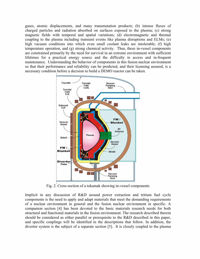
gases, atomic displacements, and many transmutation products; (b) intense fluxes of charged particles and radiation absorbed on surfaces exposed to the plasma; (c) strong magnetic fields with temporal and spatial variations; (d) electromagnetic and thermal coupling to the plasma including transient events like plasma disruptions and ELMs; (e) high vacuum conditions into which even small coolant leaks are intolerable; (f) high temperature operation, and (g) strong chemical activity. Thus, these in-vessel components are constrained primarily by the need for survival in an extreme environment with sufficient lifetimes for a practical energy source and the difficulty in access and in-frequent maintenance. Understanding the behavior of components in this fusion nuclear environment so that their performance and reliability can be predicted, and their licensing assured, is a necessary condition before a decision to build a DEMO reactor can be taken.
Fig. 2. Cross-section of a tokamak showing in-vessel components
Implicit in any discussion of R&D around power extraction and tritium fuel cycle components is the need to apply and adapt materials that meet the demanding requirements of a nuclear environment in general and the fusion nuclear environment in specific. A companion section [4] has been devoted to the basic materials research needs for both structural and functional materials in the fusion environment. The research described therein should be considered as either parallel or prerequisite to the R&D described in this paper, and specific couplings will be identified in the descriptions that follow. In addition, the divertor system is the subject of a separate section [5]. It is closely coupled to the plasma
through plasma/wall interactions and has a role in power extraction and tritium management. Fusion has very demanding safety and reliability, availability, maintainability, and inspectability (RAMI) requirements. This is especially important for in-vessel components where: (1) access and replacement is very difficult, (2) redundancy is not possible, (3) any small failures or coolant leaks can lead to overheating or can spoil the vacuum needed for plasma initiation and operation. The R&D opportunities described in the following sections will naturally result in opportunities to collect information on RAMI and safety as well as failure modes, frequencies and effects. As mockups and components begin to operate and possibly fail during multiple effects and partially integrated testing, the conditions and modes of failure will be identified, understood, and documented. Improved test conditions and components can then be designed and introduced for further testing to build a RAMI database and predictive capability. From a safety perspective, information from fundamental constitutive behavior and reaction rates to complex systems behavior and failure modes will be acquired and will form the database for safety source terms and modeling. Hazard mitigation strategies will be identified and tested as part of the program.
3.1.2 Ex-‐vessel Components and Systems Considerations Key components can be located outside the vacuum vessel (and plasma chamber). These “ex-vessel components” perform 1) tritium extraction from breeder materials, 2) tritium processing of plasma exhaust and bred tritium, and 3) power extraction and utilization. These systems are closely integrated as shown on Fig. 3. Key ex-vessel constraints are 1) the radioactive hazards from tritium and other transmutation products hazards must be mitigated, 2) tritium inventories throughout the plant must be minimized, efficiently processed, and strictly accounted for, and 3) heat carried by gas or liquid metal coolants must be efficiently utilized for electricity production or process heat. These systems are coupled to the in-vessel systems and must therefore function together. However, for ex-vessel components there is more opportunity to investigate and demonstrate their performance individually. And there is more opportunity to utilize traditional systems design approaches such as redundancy to meet availability requirements.

Fig. 3. Primary fusion fuel handling systems and interfaces
3.1.3 Assumptions and guiding principles The development strategy in this paper assumes that plasma physics parameters (e.g. first wall heat and particle load, neutron wall load, tritium burn fraction, ELM and disruption frequency and intensity, etc.) will be improved beyond those expected for ITER. This will, to some extent, reduce the technological challenges while maintaining a connection between what is envisioned for DEMO and what appears achievable today. Further, it is not practical to fully develop every blanket/FW, divertor, and heat transport and tritium processing component concept. But there is significant technical risk with many components, so primary and secondary options are identified to help ensure at least one will succeed. In the case of the blanket systems, the lead-lithium based Dual-Coolant Lead Lithium (DCLL) blanket is the primary US option based on the design and R&D work that has occurred in the past decade. The DCLL has been evolved during power plant, ITER-TBM and other studies [6-8]. The DCLL uses flowing PbLi as both breeder and coolant for the breeding zones, while utilizing high pressure helium to cool all structures including those surrounding the breeding zone. Flow channel inserts made of a SiC-composite in all liquid metal ducts serve as electrical and thermal insulator, enabling a liquid metal exit temperature about 200K higher than the maximum temperature of the steel structure. By this method the thermal efficiency in the power conversion system can approach 45%, compared to values of ~40% for entirely He-cooled blankets. R&D on aspects of the

DCLL, on lead-lithium as a generic liquid metal breeder, multiplier and coolant, and on helium cooling are applicable to a number of concepts currently proposed in the international community [9]. As a secondary blanket/FW option, a stationary, helium-cooled, pebble bed, ceramic breeder, beryllium multiplier based FW/Blanket concept is considered. Such blankets use lithium ceramics typically in pebble bed form with a circulating purge gas to remove the tritium. Ceramic breeders have markedly different feasibility issues and so represent a strategic alternative to the liquid breeder systems. Ceramic breeder blankets have been investigated for many reactor systems and for ITER-TBM [10], and are the current focus of the majority of international R&D programs on breeder blanket systems. Even so, it should be noted that both blanket systems utilize high pressure helium coolant for the first wall, as well as reduced activation ferritic/martensitic (RAFM) steel as the structural material. A plasma exhaust tritium processing system for DEMO has not been developed. While the details of such a system cannot presently be defined, at least an initial design could be developed. This would be a valuable step in better defining R&D needs. It would be particularly valuable in highlighting issues which will not be addressed by ITER. Performing this design is included as part this paper’s package of proposed activities.
3.1.4 Outline “Power extraction and tritium sustainability” was identified as a key area in both the Greenwald Report [11] and subsequent ReNeW [12, 13]. This area is classified as part of the larger area of development known as Fusion Nuclear Science and Technology (FNST). Fusion development in general, including all aspects of plasma physics research, requires authoritative information on FNST to evaluate technological readiness and identify paths toward a successful DEMO. The remainder of the paper will set out recommendations for an R&D effort to prepare the US for a decision to move forward with a DEMO. In the near term, four main areas of FNSF research have been identified. These are:
• PbLi Based Blanket Flow, Heat Transfer, and Transport Processes • Plasma Exhaust and Blanket Effluent Tritium Processing • Helium cooling of high heat flux surfaces Blanket/FW • Ceramic Breeder Thermomechanics and Tritium Release
In the medium term, the proposed focus shifts to integrated testing facilities where experimental mockups can be tested in multiple effect environments. Key activities center around the following:
• Blanket Mockup Thermomechanical/Thermofluid Testing Facility • Fuel Cycle Development Facility • Bred Tritium Extraction Facility • Irradiation effects testing on blanket material and functions
Such R&D on mockups and multiple effect functions will be needed before any fusion nuclear environment testing can proceed, and will be essential for understanding and interpreting such integrated experimental results. In addition, during the medium term, the design and analysis of ITER TBM/FNSF experiments will be performed. The focus of such experiments is described herein in the ITER term section.
• ITER TBM Experiments and Post Irradiation Examination • Fusion Nuclear Science Facility Design, Mission, Strategy and Testing Program
ITER-TBM will most likely represent the first opportunity to do integrated fusion environment testing from which we can learn about prompt thermofluid, thermomechanical and electromagnetic responses of, and beginning of life irradiation effects on, the performance in-vessel blanket/FW components and materials. Beyond this, although the timing is difficult to predict at this stage, a dedicated FNST test environment will be necessary. The parameters and strategy for such a facility is described. ITER-TBM will likely be the first opportunity to do integrated fusion environment testing. From this we will learn about thermofluid, thermomechanical and electromagnetic behavior of in-vessel blanket/FW components and materials. Also, initial irradiation effects information will be collected. This will be important, early information in blanket/FW performance and development. However, to complete development, testing in a facility such as the Fusion Nuclear Sciences Facility (FNSF) will be necessary. The parameters and strategy for this facility are described herein. In every research stage, an emphasis on pathways that improve the safety and reliability, and not just the performance, must be sought out and emphasized.
3.2 Near Term Research Needs (1-‐5 year timeframe) In the near term, the emphasis is placed on R&D that enables basic understanding, rapid advancement towards more multiple-effect phenomena, and that allows opportunities for innovation and success. This includes addressing critical R&D issues to enable decisions concerning design, component and materials selction for an FNSF device. This R&D phase requires building both core test facilities and trained work force capable of advancing the program to the integrated testing stage in FNSF and ITER (TBM). The scope is mainly determined by the number and kind of FW/blanket and tritium system concepts and coolants it should address as each will have unique development issues. To be realistic, we have limited the concepts to a primary and secondary option to serve as the focus, but with an eye to keep the R&D as generic and scientifically based as possible in order to be relevant in general. Four main thrust areas have been identified:
• PbLi Based Blanket Flow, Heat Transfer, and Transport Processes • Plasma Exhaust and Blanket Effluent Tritium Processing • Helium cooling of high heat flux surfaces Blanket/FW

• Ceramic Breeder Thermomechanics and Tritium Release Each is described in terms of three main topics:
1. Explanation, Justification and Status 2. R&D Task Description 3. Facility Needs and Dependencies with other tasks
3.2.1 PbLi Based Blanket Flow, Heat Transfer, and Transport Processes The DCLL is identified as a primary US liquid metal based FW/blanket option, with PbLi itself being a generic liquid breeder and coolant medium applicable to other liquid metal blanket concepts as well [14]. PbLi in the blanket will absorb the majority of the nuclear heating in the blanket system. This energy will be either transported by the PbLi flow to the heat exchanger and will be transported via conduction and convection to the helium used to cool the structure. In either case the flow dynamics of the PbLi plays a crucial role in the transport and recovery of this energy and therefore on the temperature and temperature gradients in the blanket structures. In addition the flow of PbLi dominates the transport of tritium and activated corrosion products throughout the system. PbLi in liquid metal blankets, whether flowing slowly for tritium removal, or more rapidly for power extraction will experience magnetohydrodynamic (MHD) forces at least 3-5 orders of magnitude greater than viscous and inertial forces of ordinary hydrodynamic flow, dominating their flow physics. There is currently one PbLi loop in the US with capability to perform MHD and transport related experiments, but its current operating temperature is limited to 380C due to material restrictions from the use of austenitic steel. There are several PbLi flow facilities in the EU but only one small one in Riga geared towards studying MHD effects (on corrosion). There has been recent construction of PbLi facilities in KO and CN but parameters and research programs are not well known. To date, there has been no SiC flow channel inserts experiment done in a flowing LM test facility and none of the experimental facilities noted have a magnetic field in excess of 2 T. Thermofluid MHD modeling for liquid metal blankets has been slowly improving in various areas including the attainment relatively large Hartmann number (103-104) in fully 3D laminar MHD calculations and some flexibility to study complex geometry effects and multiple materials (FCIs) [9, 15]. At the same time various research codes aimed at understanding flow fluctuations and quasi two dimensional MHD turbulence resulting from unstable buoyancy driven and shear flows has also been made, pushing towards relevancy on other important parameters such as Grashof and Magnetic Interaction Parameter. Transport models for calculating the corrosion and deposition using relevant MHD velocity profiles have also been developed of late to help understand corrosion behavior. R&D is necessary to continue to extend this knowledge and predictive capability and several critical and near term R&D tasks are identified below.

3.2.1.1 Develop understanding of the pressure drop, flow and distribution in PbLi blankets with prototypic conditions and materials A program of enhanced thermofluid MHD experiments and modeling with prototypic temperatures and materials is needed to understand pressure drop and flow profiles / flow distribution in PbLi based blankets. The MHD pressure drop is one of the key considerations for any type of a LM blanket, whose importance was recognized from the very beginning of the blanket studies. Typically, the maximum pressure drop in the blanket module is limited to ~2 MPa. To keep the pressure drop below this limit, special insulating techniques are needed to electrically decouple electrically the flowing liquid metal from the conducting structural walls. In the case of the DCLL, this takes the form of a SiC flow channel insert (FCI) that slips inside the steel channel and insulates the majority of the PbLi flow from the electrically conducting walls. This FCI insulation technique however is not necessarily effective to significantly reduce the so-called 3D MHD pressure drop caused by the axial electric currents, which are mostly closed in the bulk liquid and are associated with the developing flows, e.g. those in manifolds, elbows, bends, contractions/expansions etc. or those subject to a non-uniform (fringing) magnetic field. Additionally, the MHD effects also have direct impact on the temperature distribution in the blanket, including temperature field in the liquid, solid structure and at the liquid-solid interface. The latter is especially important as the blanket performance is strongly dependent on the material limits. Thus the analysis of the temperature field must be linked with the analysis of MHD flows, coupled with that of the helium coolant that cools the FW and other structures of the DCLL. Use of SiC flow channel inserts (FCIs) to reduce overall pressure drop in MHD channel flow has been proposed but never tested. Experiments and simulation are needed to establish the:
• long term behavior of prototype FCIs including movement, cracking, wetting and infiltration at prototypic temperatures and pressures.
• impact of 3D flow elements, the gaps and overlap regions between adjacent FCIs, and the
• flow distribution between parallel channels when using FCIs for pressure drop control
These flow channel inserts are poorly conducting in order to provide the needed insulation. Poorly conducting walls are known to allow for greater fluctuations and unstable flow in large breeder channels and must be further investigated to determine:
• onset and stability of buoyancy driven secondary flows driven by internal heating with strong spatial gradients
• stability of shear flows inside FCIs with low electrical conductivity • impact of unsteady flows on heat and mass transport in large poloidal flow channels
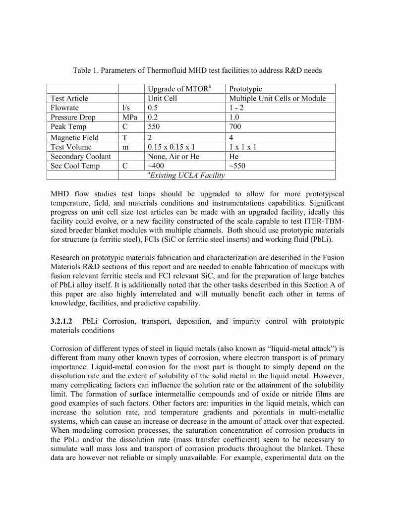
Table 1. Parameters of Thermofluid MHD test facilities to address R&D needs Upgrade of MTORa Prototypic Test Article Unit Cell Multiple Unit Cells or Module Flowrate l/s 0.5 1 - 2 Pressure Drop MPa 0.2 1.0 Peak Temp C 550 700 Magnetic Field T 2 4 Test Volume m 0.15 x 0.15 x 1 1 x 1 x 1 Secondary Coolant None, Air or He He Sec Cool Temp C ~400 ~550 aExisting UCLA Facility MHD flow studies test loops should be upgraded to allow for more prototypical temperature, field, and materials conditions and instrumentations capabilities. Significant progress on unit cell size test articles can be made with an upgraded facility, ideally this facility could evolve, or a new facility constructed of the scale capable to test ITER-TBM-sized breeder blanket modules with multiple channels. Both should use prototypic materials for structure (a ferritic steel), FCIs (SiC or ferritic steel inserts) and working fluid (PbLi). Research on prototypic materials fabrication and characterization are described in the Fusion Materials R&D sections of this report and are needed to enable fabrication of mockups with fusion relevant ferritic steels and FCI relevant SiC, and for the preparation of large batches of PbLi alloy itself. It is additionally noted that the other tasks described in this Section A of this paper are also highly interrelated and will mutually benefit each other in terms of knowledge, facilities, and predictive capability. 3.2.1.2 PbLi Corrosion, transport, deposition, and impurity control with prototypic materials conditions Corrosion of different types of steel in liquid metals (also known as “liquid-metal attack”) is different from many other known types of corrosion, where electron transport is of primary importance. Liquid-metal corrosion for the most part is thought to simply depend on the dissolution rate and the extent of solubility of the solid metal in the liquid metal. However, many complicating factors can influence the solution rate or the attainment of the solubility limit. The formation of surface intermetallic compounds and of oxide or nitride films are good examples of such factors. Other factors are: impurities in the liquid metals, which can increase the solution rate, and temperature gradients and potentials in multi-metallic systems, which can cause an increase or decrease in the amount of attack over that expected. When modeling corrosion processes, the saturation concentration of corrosion products in the PbLi and/or the dissolution rate (mass transfer coefficient) seem to be necessary to simulate wall mass loss and transport of corrosion products throughout the blanket. These data are however not reliable or simply unavailable. For example, experimental data on the

saturation concentration vary by several orders of magnitude making any theoretical predictions suspect. Deposition of corrosion materials, another mass transfer process, is often considered as a mechanism opposite to corrosion but in fact it is significantly different from corrosion in many ways and is much less understood than corrosion itself. Both corrosion and deposition can have significant effect on blanket operation and performance. In fact, three practical issues associated with corrosion/deposition limits in liquid-metal blankets are: (1) thinning duct walls in the hot section of the liquid-metal loop, (2) deposition of corrosion products in the cold section of the loop (e.g. heat exchanger, pumps, valves) that might cause loop plugging, and (3) transport of radioactive corrosion products that limit maintenance processes. At present, the limits of 5 µm/year loss rate associated with radioactive transport and 20 µm/year associated with plugging are accepted, while possible loss of structural integrity due to the wall thinning in the hot section is not considered as a serious concern. Unlike solubility-driven corrosion mechanisms, in deposition processes a significant amount of corroded material does not deposit on the walls but is transported through the entire loop with the flowing liquid in the form of suspended particles. The formation of particles in the bulk liquid, followed by particle-particle and particle wall interactions need to be studied both theoretically and experimentally with the main goal to develop appropriate models for nucleation, particle agglomeration and sticking of particles on the solid surface in various flow conditions. Magnetic traps or other particle removal systems seem to be the necessary components of liquid-metal circuits in fusion applications. If no measures are taken to extract the solid phase from the liquid, the particles will build up in time in the liquid increasing a risk of plugging the loop not only in the cold but also in the hot section, especially where the PbLi flow reenters the strong magnetic field. As a matter of fact, in almost all corrosion/deposition experiments, magnetic traps are used. Other systems such as cold traps and wire mesh filtering may also be required to help control various impurities and corrosion products. Interfacial phenomena between SiC and the flowing PbLi at elevated temperatures in the presence of applied magnetic field is another research area where possibilities of the LM attack needs to be addressed. The existing experimental data on interaction between SiC and PbLi are scarce and contradictive. However no wetting or poor wetting at temperatures up to 700°C have been demonstrated in almost all experiments. Further experiments are needed to address wetting phenomena and possible PbLi ingression at higher temperatures, longer exposition times in both static and dynamic conditions with and without a magnetic field. A program to study the basics phenomena of PbLi corrosion has been proposed as part of the basic materials R&D chapter of this report and covers the majority of the issues discussed here. It should be considered to be in parallel with the additional research proposed here, which is more focused on integrated phenomena. For example, the dissolution rate itself seems to be strongly affected by the flowing liquid metal, thus requiring experiments with the flowing PbLi in prototypic geometries in the presence of a magnetic field. Additionally, the wetting of PbLi to SiC FCIs plays a strong role in the performance of FCIs over a long exposure period. It is proposed to utilize the PbLi/MHD flow loop facility discussed in the previous section to additionally
• perform corrosion/redepostion measurements under prototypic multi-material and MHD conditions. Specific coupon based corrosion/deposition experiments could be performed as well as post exposure analysis of unit cell experiments with characteristic steels and SiC FCI mockups. Such analysis would include destructive sectioning of parts of the hot leg, cold leg and FCIs to example corrosion and deposition behavior under more integrated, prototypic MHD flow conditions.
• development of impurity and corrosion product control methodologies suitable for PbLi flow loops for ITER-TBM scale applications.
• development and coupling of MHD flow and corrosion/deposition transport models. The determination of temperature limits based upon corrosion requires an understanding and a predictive capability that can determine the rate of activate corrosion product transport, wall thinning and tube plugging due to cold leg deposition. To achieve such a predictive capability, the fundamental theory, models and rate data from corrosion experiments need to be coupled with transport models of the PbLi flow which include accurate simulation of MHD flow velocity profiles (which differ very much from ordinary hydrodynamic turbulent flow) and complete representation of cold leg features including the bends, contractions, heat exchanger, pump, cold/magnetic traps and other features that may influence deposition rates
3.2.1.3 Extraction of tritium products from PbLi at high temperature, efficiency and longevity Tritium management is a fundamental issue for blanket performance assessment because it is linked with all aspects of plant operation, from fueling (tritium breeding ratio, tritium availability, etc) to power extraction (heat transfer capability, heat cycle efficiency, etc) to safety (tritium inventory, tritium release, etc). The first requirement for blanket design and analysis is the availability of a complete material properties database for the chosen breeding material. The material properties and behaviors involved in tritium transport in liquid breeders are: solubility, diffusivity and mass transport coefficient. The accurate determination of the tritium solubility, defined as the concentration of dissolved tritium corresponding to its partial pressure at equilibrium over the liquid surface, is the first fundamental design data need. R&D activities are ongoing in the US as part of the US/Japan TITAN collaboration to define this important parameter for PbLi. In addition to this, it is necessary to study the more complex phenomena involved in the transport and extraction of tritium from the blanket, which are key issues in determining the sustainability of the fusion fuel cycle. Such phenomena are strongly correlated with the liquid flow and therefore must be addressed in a forced convection experiment that is capable to reproduce blanket relevant conditions in hydro-dynamically scaled geometries. In the US DCLL concept the helium coolant removes the blanket’s first wall (FW) heat load from the plasma and the neutron heat generated in the structure, but the breeder material removes the heat generated within its own volume. The main impact on issues related to tritium control is that the circulation rate of the breeder is much higher, allowing the application of an advanced system for tritium extraction based on the phenomena of tritium permeation through metallic membranes, one side of which is maintained in Ultra-High
Vacuum conditions (vacuum permeator). The perceived advantages of the vacuum permeator compared to other extraction systems proposed for PbLi are:
• Maintains both the tritium inventory and concentration in the blanket at levels low enough to eliminate the need of permeation barriers and yet satisfy the regulatory requirements for tritium losses in the environment. This conclusion is supported by calculations performed for the ARIES-CS safety analysis. This could be a major breakthrough in fusion technology, since the development of tritium barriers that are both compatible with the breeder material and resistant to neutron irradiation has been so far unsuccessful
• The membrane materials are compatible with breeder outlet temperatures higher than the limits imposed by the RAFS structural materials, allowing the improvement in the power plant power conversion efficiency envisioned in the DCLL concept.
• Tritium is extracted from the metallic membrane as molecular T2 rather than tritiated water T2O. Elemental tritium can be processed directly as fusion fuel without the further separation process required for tritiated water, which increases the complexity, cost, and processing time of the fuel cycle.
Near-term activities compatible with a 5 year R&D project are outlined below. The activities main objective is the experimental demonstration of the feasibility of the vacuum permeator concept and the assessment of its performance applied to fusion energy systems, in particular in terms of tritium management (extraction efficiency) and control (tritium release to the environment), through verification and validation of models. The activities do not include multiple effects and integrated components testing, such as the effect of MHD on tritium transport and neutron irradiation. The envisioned activities are organized around the design, fabrication and operation of a forced convection lead-lithium eutectic loop for tritium extraction testing as described in Table 2. These tests primarily entail the measurement of the permeator efficiency for the selected membrane materials as a function of the flow velocity, membrane temperature, and impurity concentrations as a function of time. Other fundamental parameters for the concept applicability, such as the tritium partial pressure over liquid/gas interfaces and the inventory in the membrane bulk are inherently derived from the efficiency measurement. In principle the tests could be performed initially with non-radioactive hydrogen isotopes (H,D). However, given the large capital expense required in the construction of the PbLi loop it would be preferable to select from the beginning a facility that is compatible with tritium handling, such as the STAR facility at the INL or facilities at SRNL. Ultimately tritium tests are required to ensure feasibility at the very low concentrations relevant to fusion blankets. Previous experience in the EU has also shown technical limitations in the possibility of operating a loop based on gas contacting saturation, given the high partial pressures required for hydrogen detection.

Table 2. Test loop design and construction
Loop Parameters Design Range Total PbLi mass 200-1000 Kg Pipe diameter 1-3 cm Mass flow rate 0.1-1.5 kg/s Max temperature 750
Table 3. Metallic membrane material selection
3.2.1.4 Polonium and other transmutation products control in irradiated PbLi Additionally, it should be noted that as lead is irradiated by high energy neutrons, polonium is generated by a two step process:
1. Transmutation of Lead-atoms to Bismuth-atoms 2. Transmutation of Bismuth-atoms to Polonium-atoms.
The critical issue involved with a certain Po concentration in the liquid metal breeder lead-lithium is the release of Po into the building atmosphere in case of a liquid metal spill. Since Po is an alpha-emitter, the Biological Hazard Potential (BHP) of this element is extremely high. Early analyses over-estimated the release of Po to a large degree. In recent years, all investigations show that the problem of Po release is largely reduced by two facts: (1) Detailed neutronic investigations including the updated cross sections showed that the effect of the neutron flux distribution inside the blanket and the impact of LM circulation in the external loops reduced the Po generation rate orders of magnitudes lower than earlier calculations. (2) Experiments performed with Po tracer in PbLi showed that Po release is dictated not by the relatively high partial Po pressure itself but by the much lower vapor pressure of a PbPo compound. However, the concentration of Po in the liquid metal breeder has still to be maintained at a very low value. The extraction of Po to such a low concentration would be a very difficult process which would have to be performed on-line since there is a continuous generation of Po from the Bi impurities in the liquid metal breeder.
Permeator tube materials Ferritic/martensitic steel Alloy (eg, 8-12%Cr) Vanadium Alloy (eg, V-4Cr-
4Ti) Zirconium Metal, alloy, coated Tantalum Metal, alloy, coated Niobium Metal, alloy, coated

Fortunately, there is a better way to avoid in-tolerable high Po concentrations. In technically pure lead, there is already a certain concentration of bismuth, usually in the range of 20 to 200 wppm. If the Bi-concentration is maintained below a concentration of ~ 10 wppm, it is not necessary to extract Po at all. By this method, the generation of Po is reduced by a large degree, reducing in this way the issue of activated waste. Experiments performed in the EU showed that there are methods available to extract on-line Bi to such a low concentration. However, it is mandatory to perform dedicated experiments to verify the suitability of such methods for the operation in a fusion power plant. It is conceivable to perform such experiments in one of the PbLi flow facilities proposed for tritium control, MHD or corrosion studies.
3.2.2 Plasma Exhaust and Blanket Effluent Tritium Processing A commercial fusion system will require proper handling of DT fuel and reaction products. Only a fraction of the tritium burns on each pass through the reactor, so most of the tritium must be processed and fed back into the reactor. No appreciable tritium exists in nature, so neutrons from the fusion reactor must be used to breed tritium, and this tritium must be recovered, processed and fed to the reactor. Radioactive tritium must be effectively contained to prevent harm to workers, the public or the environment. To identify research needs, the requirements of future machines must be compared with the present knowledge base.
Table 4. Tritium systems status and future requirements
Parameter State-of-the-art Need for ITER Need for DEMO
Flowrate 6 liters/min 120 liters/min 120 liters/min Recycle requirement 24 hr 1 hr 1 hr Tritium inventory 100 gm 4000 gm 6000 gm Duty Cycle 10% 5% 50% Gaseous tritium release requirment
<0.02 g/y <1 g/y < ? g/y
Fusion power None 400 MW 2000 MW Tritium breeding requirement None None
(1.4 kg tritium burned per year)
Must breed all tritium
Containment The same worker, public, and environment limits Compared here is the current state-of-the-art experience for key parameters with the future needs of ITER and expected needs for DEMO. As shown, substantial experience already exists, and ITER itself is represents a large step forward for tritium processing systems. But significant extension of the knowledge base will be necessary to realize commercial fusion. Processing rates will need to be increased by more than an order of magnitude. The time to produce on-spec product will need to be reduced by about an order of magnitude. And duty cycle requirements will require not only increasing the reliability of systems, but also converting them from manually operated experimental systems, to automated production
systems. Systems will have to be adapted to cope with operations in a nuclear environment. And while there is essentially no experience with recovering fusion-bred tritium, DEMO will require this on a routine basis. Meeting these future needs will require both development of new technologies and extensions and refinements of existing technologies. It should also be noted that the ITER tritium systems will largely be a production system with little opportunity for experimentation outside what is needed for operations. 3.2.2.1 Area Descriptions and R&D Needs To effectively identify areas where R&D is needed, the following areas are considered:
1. Fuel processing 2. Vacuum and fueling 3. Tritium containment and handling 4. Tritium accountability and nuclear facility operations 5. Tritium extraction from the breeding system 6. In-vessel tritium characterization, recovery and handling
The present knowledge base for each of these areas is based on experience developed in a number of facilities. For example, the Tritium Systems Test Assembly at Los Alamos National Laboratory [16] was constructed and operated as fusion fuel processing integrated prototype. Tritium systems at the Tokamak Fusion Test Reactor at the Princeton Plasma Physics Laboratory [17] and the Active Gas Handling System at the Joint European Torus [18] were integrated with DT fusion reactors. And a number other facilities in the US, Canada, Japan, the EU and elsewhere have contributed important information to this area. However, these systems were typically tested at best 1/20th scale of ITER, so considerable additional work remains to meet the requirements of ITER, DEMO and other future facilities. The overall R&D strategy in tritium R&D proposed in this report is summarized as follows:
• Near-Term o Stand-alone development both with and without tritium o Design of a FNSF/DEMO tritium processing plant
• Medium-Term o Integrated (and stand-alone) development in the FCDF o Stand-alone confirmation of results in tritium experiments
• ITER and FNSF o Demonstration of technologies developed in the FCDF and other
facilities with tritium in a fusion environment The tables below indicate R&D needed in the near and medium term as well as summarize contributions which will result from the ITER project. The near term R&D can mostly be performed in existing facilities. But ultimately this R&D needs to come together in facilities dedicated to these topics. Later sections in this report will show how the medium term R&D listed in this section should be performed dedicated facilities.
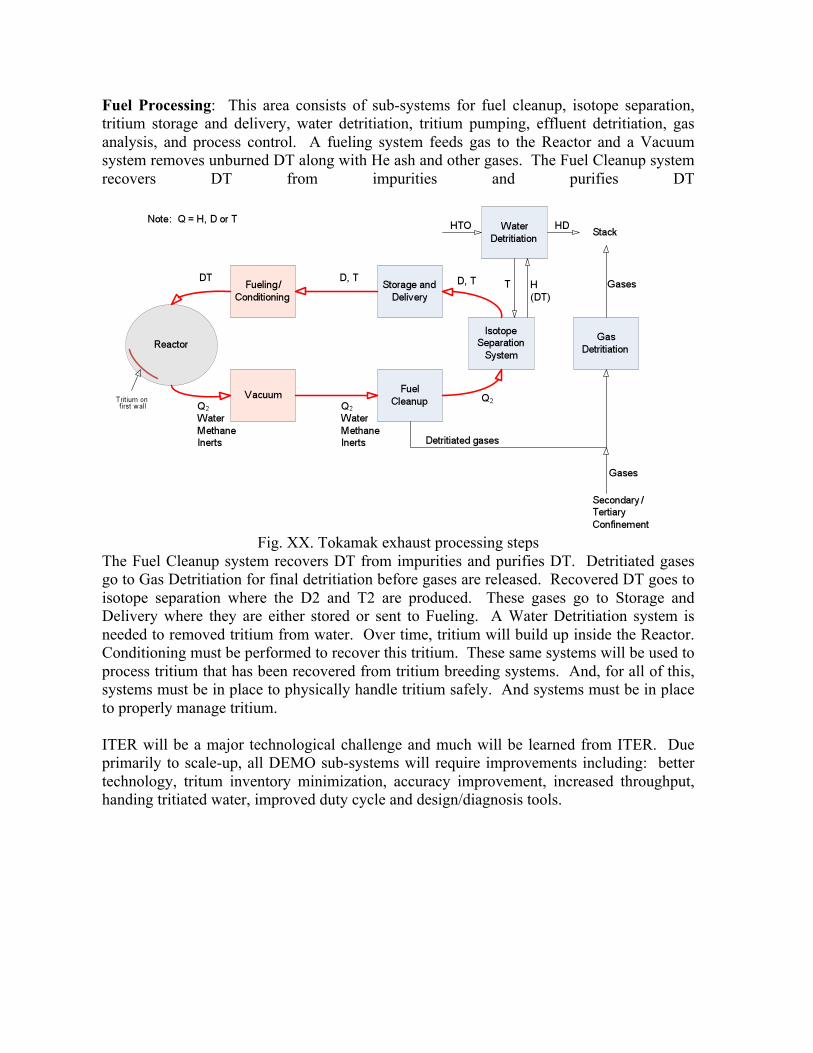
Fuel Processing: This area consists of sub-systems for fuel cleanup, isotope separation, tritium storage and delivery, water detritiation, tritium pumping, effluent detritiation, gas analysis, and process control. A fueling system feeds gas to the Reactor and a Vacuum system removes unburned DT along with He ash and other gases. The Fuel Cleanup system recovers DT from impurities and purifies DT
Fig. XX. Tokamak exhaust processing steps
The Fuel Cleanup system recovers DT from impurities and purifies DT. Detritiated gases go to Gas Detritiation for final detritiation before gases are released. Recovered DT goes to isotope separation where the D2 and T2 are produced. These gases go to Storage and Delivery where they are either stored or sent to Fueling. A Water Detritiation system is needed to removed tritium from water. Over time, tritium will build up inside the Reactor. Conditioning must be performed to recover this tritium. These same systems will be used to process tritium that has been recovered from tritium breeding systems. And, for all of this, systems must be in place to physically handle tritium safely. And systems must be in place to properly manage tritium. ITER will be a major technological challenge and much will be learned from ITER. Due primarily to scale-up, all DEMO sub-systems will require improvements including: better technology, tritum inventory minimization, accuracy improvement, increased throughput, handing tritiated water, improved duty cycle and design/diagnosis tools.

Table 5. Fuel Processing R&D needs in the near and midTerm
And expected ITER contributions
Topic 1-5 Years 5-10 Years ITER Fuel cleanup Hydrogen purification tests for
technology selection matched to torus vacuum developments Process control Tritiated water processing
Stand-alone testing with and without tritium
Integrated testing in fusion environment
Isotope separation Modeling for optimal column configuration/ arrangement taking into account multiple ISS duties, inventory minimization and operability
Process control Integrated testing in fusion environment
Fuel storage and delivery
Rapid storage and delivery tests
Tritium testing including in-bed accountability Optimization of gas acceptance/supply strategies
Integrated testing in fusion environment
Water detritiation Develop tritium-compatible water splitting technology
Small-scale demonstration of integrated system under prototypical conditions Demonstration of stackable HD
Integrated testing in fusion environment
Fuel pumping (~1 atm)
Development of higher throughput, higher reliability tritium compatible pumps
Testing of pumps with tritium Integrated testing in fusion environment
Effluent detritiation Testing of wet scrubbers Testing of water adsorber effluent dew point under realistic conditions
Comparison of options after testing with tritium Development of strategies and technologies for room cleanup systems
Integrated testing in fusion environment
Gas analysis Development of practical, reliable, tritium-compatible instruments-especially ISS control instruments
Testing of instruments with tritium
Integrated testing in fusion environment
Process control Overall fuel cycle computer model
Implementation of control loops on model with view to operability and tritium tracking (use gas analysis results)
Benchmarking of model in integrated fusion environment
Vacuum and fueling: Vacuum and fueling sub-systems are composed of torus vacuum pumps, roughing pumps, gas puffing, pellet fueling, disruption mitigation and ELM pacing. Torus vacuum pumping must maintain low divertor pressure (~10 Pa) while removing helium ash that will be generated by the fusion burn. The fueling system must provide DT fuel to the burning plasma and also provide gas to the scrap off layer and divertor to
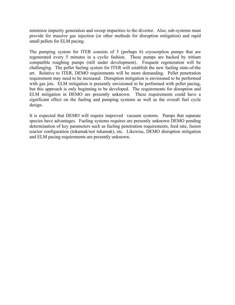
minimize impurity generation and sweep impurities to the divertor. Also, sub-systems must provide for massive gas injection (or other methods for disruption mitigation) and rapid small pellets for ELM pacing. The pumping system for ITER consists of 5 (perhaps 6) cryosorption pumps that are regenerated every 5 minutes in a cyclic fashion. These pumps are backed by tritium compatible roughing pumps (still under development). Frequent regeneration will be challenging. The pellet fueling system for ITER will establish the new fueling state-of-the art. Relative to ITER, DEMO requirements will be more demanding. Pellet penetration requirement may need to be increased. Disruption mitigation is envisioned to be performed with gas jets. ELM mitigation is presently envisioned to be performed with pellet pacing, but this approach is only beginning to be developed. The requirements for disruption and ELM mitigation in DEMO are presently unknown. These requirements could have a significant effect on the fueling and pumping systems as well as the overall fuel cycle design. It is expected that DEMO will require improved vacuum systems. Pumps that separate species have advantages. Fueling systems requires are presently unknown DEMO pending determination of key parameters such as fueling penetration requirements, feed rate, fusion reactor configuration (tokamak/not tokamak), etc. Likewise, DEMO disruption mitigation and ELM pacing requirements are presently unknown.
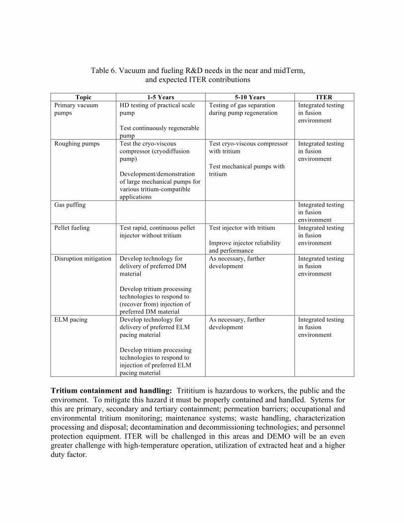
Table 6. Vacuum and fueling R&D needs in the near and midTerm, and expected ITER contributions
Topic 1-5 Years 5-10 Years ITER
Primary vacuum pumps
HD testing of practical scale pump Test continuously regenerable pump
Testing of gas separation during pump regeneration
Integrated testing in fusion environment
Roughing pumps Test the cryo-viscous compressor (cryodiffusion pump) Development/demonstration of large mechanical pumps for various tritium-compatible applications
Test cryo-viscous compressor with tritium Test mechanical pumps with tritium
Integrated testing in fusion environment
Gas puffing Integrated testing in fusion environment
Pellet fueling Test rapid, continuous pellet injector without tritium
Test injector with tritium Improve injector reliability and performance
Integrated testing in fusion environment
Disruption mitigation Develop technology for delivery of preferred DM material Develop tritium processing technologies to respond to (recover from) injection of preferred DM material
As necessary, further development
Integrated testing in fusion environment
ELM pacing Develop technology for delivery of preferred ELM pacing material Develop tritium processing technologies to respond to injection of preferred ELM pacing material
As necessary, further development
Integrated testing in fusion environment
Tritium containment and handling: Trititium is hazardous to workers, the public and the enviroment. To mitigate this hazard it must be properly contained and handled. Sytems for this are primary, secondary and tertiary containment; permeation barriers; occupational and environmental tritium monitoring; maintenance systems; waste handling, characterization processing and disposal; decontamination and decommissioning technologies; and personnel protection equipment. ITER will be challenged in this areas and DEMO will be an even greater challenge with high-temperature operation, utilization of extracted heat and a higher duty factor.
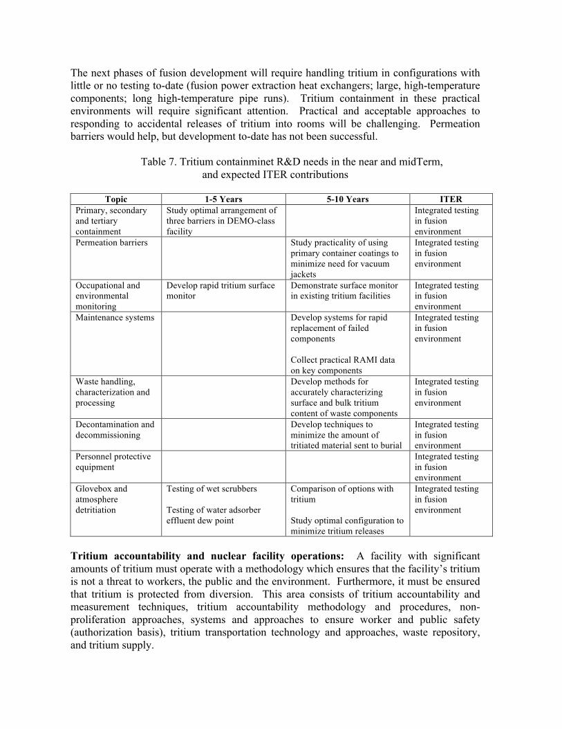
The next phases of fusion development will require handling tritium in configurations with little or no testing to-date (fusion power extraction heat exchangers; large, high-temperature components; long high-temperature pipe runs). Tritium containment in these practical environments will require significant attention. Practical and acceptable approaches to responding to accidental releases of tritium into rooms will be challenging. Permeation barriers would help, but development to-date has not been successful.
Table 7. Tritium containminet R&D needs in the near and midTerm, and expected ITER contributions
Topic 1-5 Years 5-10 Years ITER
Primary, secondary and tertiary containment
Study optimal arrangement of three barriers in DEMO-class facility
Integrated testing in fusion environment
Permeation barriers Study practicality of using primary container coatings to minimize need for vacuum jackets
Integrated testing in fusion environment
Occupational and environmental monitoring
Develop rapid tritium surface monitor
Demonstrate surface monitor in existing tritium facilities
Integrated testing in fusion environment
Maintenance systems Develop systems for rapid replacement of failed components Collect practical RAMI data on key components
Integrated testing in fusion environment
Waste handling, characterization and processing
Develop methods for accurately characterizing surface and bulk tritium content of waste components
Integrated testing in fusion environment
Decontamination and decommissioning
Develop techniques to minimize the amount of tritiated material sent to burial
Integrated testing in fusion environment
Personnel protective equipment
Integrated testing in fusion environment
Glovebox and atmosphere detritiation
Testing of wet scrubbers Testing of water adsorber effluent dew point
Comparison of options with tritium Study optimal configuration to minimize tritium releases
Integrated testing in fusion environment
Tritium accountability and nuclear facility operations: A facility with significant amounts of tritium must operate with a methodology which ensures that the facility’s tritium is not a threat to workers, the public and the environment. Furthermore, it must be ensured that tritium is protected from diversion. This area consists of tritium accountability and measurement techniques, tritium accountability methodology and procedures, non-proliferation approaches, systems and approaches to ensure worker and public safety (authorization basis), tritium transportation technology and approaches, waste repository, and tritium supply.
Accountability measurements are performed by in-bed calorimeters, Pressure-Volume-Temperature methods, and other approaches. Processing times are long and accuracies are limited. Accountability methods rely on periodic reconciliation between “book” inventory versus “physical” inventory. Proliferation/divertion is influenced by “attractiveness levels”. Nuclear facility authorization basises are derived from various codes (e.g. DOE, NRC and IAEA) which have no experience with practical fusion energy. Risk-based assessments are used for calculation of dose to the public. Presently under consideration for the ITER torus are tritium accountability measurements based on “inventory-by-difference”, and measurement errors will propagate to large uncertainties. Direct methods of estimating tritium inventories need to be developed. Likewise, the large scale of DEMO will challenge all nuclear facility operation areas.
Table 8. Tritium accountability R&D needs in the near and midTerm and expected ITER contributions
Topic 1-5 Years 5-10 Years ITER
Tritium accountability measurement techniques
Study limitations of existing measurement techniques considering use in DEMO-class machine
Develop improved measurement techniques and procedures
Integrated testing in fusion environment
Tritium accountability methodology and procedures
Develop methods for ensuring operability, safety and non-proliferation in DEMO-class machine
Collect lessons learned
Non-proliferation approaches
Develop policies appropriate for DEMO-class machine
Collect lessons learned
Authorization basis (systems and approaches to ensure worker and public safety)
Develop methods for ensuring worker, public and environmental safety for DEMO-class machine
Collect lessons learned
Tritium transport technology and approaches
Develop technology for practically moving large quantities of tritium
Integrated testing in fusion environment
Waste repository Develop packages for practical and safe disposal of DEMO-class materials
Integrated testing in fusion environment
Tritium supply Develop policies and agreements to ensure the practical development of fusion Consider non-traditional tritium sources
Monitor ITER tritium consumption

Extract tritium from the Breeding System: To be useful, bred tritium must be extracted from the breeding material. Less soluble materials make it easier to extract tritium but may suffer from containment issues. More soluble materials may make containment more straightforward, but will make tritium extraction more difficult. It is envisioned that solid breeders will have tritium extracted from the breeder materials by sweeping helium through the breeder. Limited fundamental experiments have been performed. Liquid breeders will flow the breeder and the tritium away from the torus, and a yet-to-be-determined process will extract the tritium. Data-to-date suggest that tritium recovery from the breeding material with acceptable tritium inventory is feasible, but this has not been performed in an integrated fashion with tritium containment. Only preliminary tests have been performed. Tritium extraction methods need to be selected and tested. And it needs to be shown that tritium can be reduced to levels such that tritium can be adequately contained. Extraction of tritium from Be will need to be addressed. Testing in concert with 14 MeV neutrons, high burn up and high heat flux are needed.
Table 9. Tritium extraction R&D needs in the near and miDTerm and expected ITER contributions
Topic 1-5 Years 5-10 Years ITER
Tritium extraction from breeder materials
Perform basic tests of liquid and solid breeder tritium extraction
Perform tritium testing of liquid and solid breeder tritium extraction techniques
Test in ITER TBM program
Tritium recovery from blanket coolants/heat transfer media
Following results of tritium extraction tests, develop technology for tritium recovery from coolant/heat transfer media
Test in ITER TBM program
Tritium extraction diagnostics
Develop technology for measure tritium concentration in liquid breeder materials
Test in ITER TBM program
Blanket system tritium handling and containment
Estimate tritium losses in harsh, blanket environment and propose practical tritium containment approach
Test proposed approach Test in ITER TBM program
In-vessel tritium characterization, recovery and handling: Tritium will be retained within the reactor. Calculations have shown that tritium can rapidly accumulate at certain ITER conditions. Methods are needed to characterize in-vessel tritium. Also needed are methods to recover in-vessel tritium and handle in-vessel components which have deposited tritium. Experience has been gained with tritium experiments on TFTR and JET. Stand-alone experiments have shown that tritium buildup on carbon machines is significant and less so on tungsten machines. Higher first wall temperatures will help.

Presently there is no W PFC testing data in a DEMO-like nuclear environment. The tritium hold-up on W divertor and first wall under DEMO-relevant conditions needs to be determined. Increasing the fusion burn up fraction (physics issue) will help in this area.
Table 10. In-vessel tritium characterization and recovery R&D needs in the near and midTerm and expected ITER contributions
Topic 1-5 Years 5-10 Years ITER
In-vessel tritium characterization
Develop methods for determining quantities of in-vessel tritium
Further develop methods for determining quantities of in-vessel tritium
Integrated testing in fusion environment
In-vessel tritium control and removal
Develop methods for preventing in-vessel accumulation of tritium Develop methods for recovery of in-vessel tritium
Develop methods for preventing in-vessel accumulation of tritium Develop methods for recovery of in-vessel tritium
Integrated testing in fusion environment
In-vessel component waste handling
Develop techniques for recovery of large amounts of tritium from in-vessel components
Integrated testing in fusion environment
Mitigation of in-vessel off-normal event effects on tritium systems
As necessary, develop new separation techniques for processing torus effluent following a DM event
Integrated testing in fusion environment
3.2.3 Helium Cooling of High Heat Flux Surfaces Blanket/FW In designing fusion power reactors, high-pressure helium coolant is typically employed to remove heat deposited in the first wall (FW), divertor and blankets. The typical FW heat flux assumed for various power reactor design studies and a fusion DEMO is ~0.5 MW/m2, while that for the diverter is on the order of 10 MW/m2. Because of the higher heat flux most of the attention within the fusion technology community has focused on the DEMO divertor design (which is discussed elsewhere in this report [5]). However, the FW/Blanket of the DEMO is a critical component as well. The FW/blanket is integrated, so that it is not possible to design them separately. Compared with the divertor, the FW typically receives the lower heat flux, but the area of the FW is large and efficient cooling is required at temperatures high enough for power conversion. For steady state operation, the FW/blanket has to have a robust design so that it will withstand the high coolant pressure, have a surface material capable of handling the interaction with the plasma, and be suitable for removing the heat deposited at the surface and in the bulk from neutron absorption. The coolant and its peak temperature must be suitable for use in a system with high power conversion efficiency. It is necessary to minimize the volume fraction of RAFM steel and any other heat sink or armor materials such that the necessary tritium breeding ratio can be obtained. The component must have adequate lifetime and be maintainable and replaceable. In addition, the FW components
will need to function properly during all the non-steady-state operational phases of a tokamak, including startup, shutdown and all expected transient events. In addition, recent developments in ITER have cast some uncertainty on the assumption that the FW heat flux will be relatively uniform. The ITER FW wall heat flux being used to design the FW is very non-uniform, divided into several groups: one with normal heat flux of 1-2 MW/m2, and a second group with enhanced heat flux of 3.5-5 MW/m2. This type of concentrated heat flux is not compatible with any existing DEMO or power reactor first wall design. While there is much known about helium cooling for fusion high heat flux components [19] and other applications, the area is still far from mundane. The challenge for fusion in designing helium cooled components comes from several uncertainties:
• FW steady heat/particle flux conditions • Frequency and severity of transient conditions • Minimum practical FW thickness • Performance of designs with significant cooling channel complexity (see for
example [20, 21] and heat transfer enhancement • Impact of RAFM steel manufacturing techniques.
These uncertainties will require a very large design margin that will likely make a fusion power system unattractive. R&D is essential to reduce these uncertainties and develop an understanding of the limits and dominant failure modes of such a He cooled system such that designs can be improved, especially given the stringent reliability constraints on the blanket/FW. A systematic investigation is proposed to assess these limits given the use of prototypical RAFM structural material, knowledge of heat flux handling enhancement techniques, and further quantification of requirements and conditions between physics and engineering. It is expected that these recommendations overlap significantly with those made for PMI/PFC in general [5]. They are included here specifically to emphasize the needs of the first wall integrated with the blanket, which share a common helium coolant stream and structure.
3.2.3.1 Quantification of FW steady and transient conditions A concerted effort is recommended in order to better quantify the chamber wall heat flux distributions. Such an investigation should utilize operating tokamak experiments under different plasma operation scenarios with improved diagnostics to better understand the edge and scrape off layer physics that determine power and particle loading magnitude and footprint on the first wall. This quantification must be based both on experimental data and modeling support, such that credible projections can be made for FNSF and DEMO designs. The same effort should be made for transient conditions. A realistic extrapolation of physics conditions expected to an FNSF device should be made, covering types and frequency of expected transient events including disruption, mitigated disruption, ELM conditions, VDE, MARFE, etc.

3.2.3.2 Design study on FW/Blanket designs with local high surface heat flux A joint boundary physics (section C.1) and FW/blanket subsystem design study should be initiated to assess design details and practical performance limits. This effort should include peak heat flux projections and other non-uniform radial transport, chamber wall front face surface topology and distance from plasma, coolant heat transfer and heat removal characteristics, impacts to tritium breeding and the structural support and maintenance of the FW/blanket module. A focused effort to assess the likely reliability of such systems should be a part of this effort, including a determination of the most significant uncertainties and sensitivities that can be addressed by subsequent R&D and design evolution. Detailed thermomechanical, thermofluid, and thermalhydraulic calculations of component module designs will be necessary to evaluate both current and innovative designs. Techniques which may extend the high heat flux performance should be examined in detail, including such ideas as:
• Designs that shorten the FW flow path • Designs that increase the wall/coolant heat transfer area • Designs that utilize normal flow heat exchangers with reasonable flowrates and
pressure drops • Use of advanced materials (such as layers of oxygen dispersion strengthened ferritic
steels on the FW) in a practical fashion, • Operation of components beyond elastic design rules by using sophisticated
elastic/plastic structural analysis to demonstrate performance, reliability and safety • FW armors and armor joining techniques
In addition, potential designs should also be evaluated from the perspective of pressure drop, flowrate and pumping power, coupling of FW helium flow to the blanket with acceptable power balance characteristics, and an analysis of the complexity and flow stability of routing of helium coolant to and in the inboard and outboard FW/blanket modules. 3.2.3.3 Experimental study of heat transfer enhancement and flow stability An experimental study should be initiated on the effectiveness of heat transfer enhancement techniques and flow stability for FW/blanket cooling channel mockups, including analysis and modeling validation. Such mockups should utilize prototypic RAFM steels such that mockups represent the performance subject to the true thermophysical properties of RAFM steel, the practical constraints of fabricating with such a material, as well as contribute to the reliability and failure mode database for fusion components. The methods of fabrication should consider the need of integrating FW panel and internal blanket coolant plates within the overall blanket. The experimental program should remain closely coupled to C.1 and C.2 such that benchmarks are performed in concert with evolving FW designs and analysis, high priority heat removal techniques, and understanding of tokamak edge physics used to project heat flux distributions. A useful starting point might be a campaign to help evaluate the trade off of FW, armor and heat sink thickness from the perspective of minimization to

reduce FW peak temperature and improve tritium breeding potential reliability, with the needs for reliability over long performance periods, number of cycles and transient events. 3.2.3.4 Facility requirements and coupling to other tasks Task C.3 above will require a dedicated high heat flux and helium flowloop test stand where experimental investigation of helium cooling technologies can be accomplished. The helium coolant flow loop should be on the scale of that required for an ITER-TBM sized mockup such that it can cool realistic sized mockups (~1 m2 FW area), as well as serve as a prototype for the ITER TBM, including proving loop reliability and performance in advance of deployment as a TBM.
Table 11. Helium flow loop characteristics sized for a DCLL Test Blanket Module (adapted from Ref. [28])
Heat Flux / He coolant loop parameters Test Article Individual Channels/FW plates Flowrate kg/s 0.5 Flow Velocity m/s 60 Operating Pressure MPa 8 Pressure Drop MPa 0.24 Peak Temp C 550 Test Volume (max) m 0.5 x 1 Steady Heat Flux MW/m2 1-5
Again, a strong overlap with recommendations for the divertor development is expected. The unique needs of the first wall include a larger area with somewhat reduced heat flux when compared with the divertor, and integration with the blanket component. As such, the size of the coolant loop and the surface heat flux source may have different requirements that should be considered if the recommended facilities for divertor and FW/Blanket testing are combined into one testing facility. For structural and armor material development (covered in detail in Ref. [4]), RAFM and tungsten properties, fabrication and joining should be emphasized. Some FW concepts propose the use of a relatively thin layer of oxygen dispersion strengthened (ODS) ferritic/matensitic facing the plasma that can be operated at higher temperature than the underlying RAFM base material from which the majority of the structure is fabricated. A materials development program should be include the joining of RAFM steel to ODS steel and ODS steel to W-alloy such that a robust multilayer FW design can be fabricated and tested. The limited use of advanced materials for plating the FW seems more realistic than an entire construction of FW/blankets from advanced materials that are difficult to fabricate and weld, and whose database is not nearly as extensive as for the current generation RAFM steel. Based upon a relatively simple analysis of an 8 MPa helium-cooled first wall channel, increasing the heat flux capability to significantly higher values will be a challenge. Demonstration of the heat removal capability in such a way compatible with the other functions of the FW/Blanket will be required for a successful FNSF and DEMO design. If necessary, water could be considered as the first wall and divertor coolant for the FNSF and

DEMO designs if the chamber wall surface heat flux conditions prove to be inconsistent with helium capabilities, however, no specific R&D in this regard is proposed at this time. It is also clear that advancement of FW/blanket power extraction and tritium sustainability from a technological perspective is strongly tied to the plasma operating conditions. In particular, knowledge of the plasma side conditions in terms of the steady state, transient, and off-normal heat and particle loading is required to find a window of plasma and technological conditions in which practical and reliable blankets/FW systems can be achieved. R&D activities addressing conditions from the plasma side and development of components from the technological side must be more coupled in the future or practical solutions for fusion energy needs will not emerge. How such coupling should be best coordinated is not clear, but options like a Fusion Nuclear Science Facility (FNSF) design center, or some other coupled plasma / engineering centers dealing with disruption mitigation and survivability for example could be considered.
3.2.4 Ceramic Breeder Thermomechanics and Tritium Release Ceramic breeders, by their nature, are brittle and prone to cracking under external mechanical loadings. These breeders, in the form of packed beds of pebbles, are loaded into a box-like structure for tritium fuel production in a fusion reactor. When subjected to nuclear heating and neutron damage in a reactor, a strong mechanical loading arises from the differential thermal expansion and swelling between breeder pebbles and their containing structure. Research efforts have therefore been aimed at developing a thorough understanding and characterization of the ceramic breeder pebble bed thermomechanics. Such an understanding is essential to providing confidence in the performance and lifetime of a ceramic breeder blanket design. In particular, a significant effort of the pebble bed thermomechanics study is on the development of modeling simulation tools. Maintaining the breeder temperature within its temperature window for tritium release is crucial for predictable performance and lifetime of the breeder unit. Proper temperature analysis requires careful characterization of thermal properties of the pebble beds. The pebble-bed experiments demonstrated that the effective thermal conductivity depends on the volumetric compressive strain; changes in thermal conductivity occurred between compacted and un-compacted systems. These measured phenomena indicate that thermo-mechanical modeling must also consider full, non-linear coupling between thermal and mechanical analysis. The progress already achieved worldwide holds the promise of a pebble bed thermomechanics framework that will contribute substantially to the success of the ceramic breeder blanket development. In this framework, the continuum modeling approach using finite element method (FEM) analysis and empirically derived material constitutive equations is capable of correctly characterizing the stress load to which a breeder pebble bed unit may be subject during the operations. The discrete element method (DEM) approach analyzes this load and determines the possibility fraction of pebble cracking based on the crush load data of pebbles or the degree of sintering depending on the local contact stress. The combined analyses warrant a high confidence of success to the assembly and design of breeder units in a blanket. Experiments should also be conducted to assess the manner of

pebble relocations and packing rearrangement when pebble cracking occurs. Since there is no perfect packing state, it is important to learn if the breeder unit will continue to function in accord with the original design goals under all complex operating conditions. The ultimate objectives of the pebble bed thermomechanics include to delineate a near-equilibrium packing state as the initial state, quantify breeder unit thermomechanics parameters during operations, understand how these properties vary as packing state alters and the degree of variation, and ensure breeder functions as it is intended to in the fusion operational phase spaces. Since creep will lead to stress relaxation, further development incorporating creep models for high temperature DEM simulation is desired. This may increase the peak stress margin if stress relaxation is taken into account. Despite the scale of the experiments conducted so far, validation experiments are still necessary in regards to current continuum FEM models. Moreover, validation and refinement of simulations with regards to pebble damage crush properties are desired in particular in view of damage mechanisms. There may be merits to perform crush load tests for irradiated pebbles at operating temperature ranges (room to 850C/900C). It holds forth promising on the continued pebble bed thermomechanics study in fine details a higher confidence to the ceramic breeder lifetime performance in a blanket. The helium-cooled ceramic breeder blanket, utilizing pebble beds of both beryllium as a neutron multiplier and a lithium ceramic as the breeder, is a much studied breeding blanket system. It has been adopted by many ITER partners as their primary blanket option for ITER testing as part of the ITER-TBM program, and is considered in the US as one of the near-term base breeding blankets for the FNSF. In such blankets, layers of ceramic breeder and beryllium pebble beds are placed between steel plates with embedded channels for high pressure helium coolant. The nuclear heat deposited in the blanket must conduct through the pebble beds and into the cooling plates. Temperature limits (discussed below) on the breeder and multiplier materials place limits on the size of these layers, and heat transfer and thermal control are serious feasibility issues for ceramic breeder blankets. The tritium bred in the ceramic breeder is removed by a lower pressure helium purge/sweep gas. Tritium must diffuse out of the ceramic breeder into the purge to allow in-situ tritium recovery. The thermomechanical behavior of the pebble bed regions represents a key issue for developing this line of blankets and needs to be characterized under realistic operating conditions. This is due to in part to the fact that the tritium release characteristics and inventory in ceramic breeder and Be strongly depend on temperatures. Operating ceramic breeder beyond its upper limit can induce sintering, which traps tritium leading to a huge tritium inventory, while operating at too low a temperature results in slow diffusion of tritium out of the breeder material and high tritium inventory in the ceramic. Differential thermal expansion due to temperature gradients creates stress/strain conditions that affect the pebble bed effective thermal conductance and subsequent temperature distribution. This is particularly important for Be pebble beds, in which heat transport is strongly influenced by factors affecting the solid to solid heat transfer, such as the contact area. These temperature-driven processes impose operating limits on the pebble bed temperatures, and require acceptable accuracy in the prediction of the pebble bed spatial and temporal temperature profiles over the lifetime of the blanket. This requires the knowledge of the
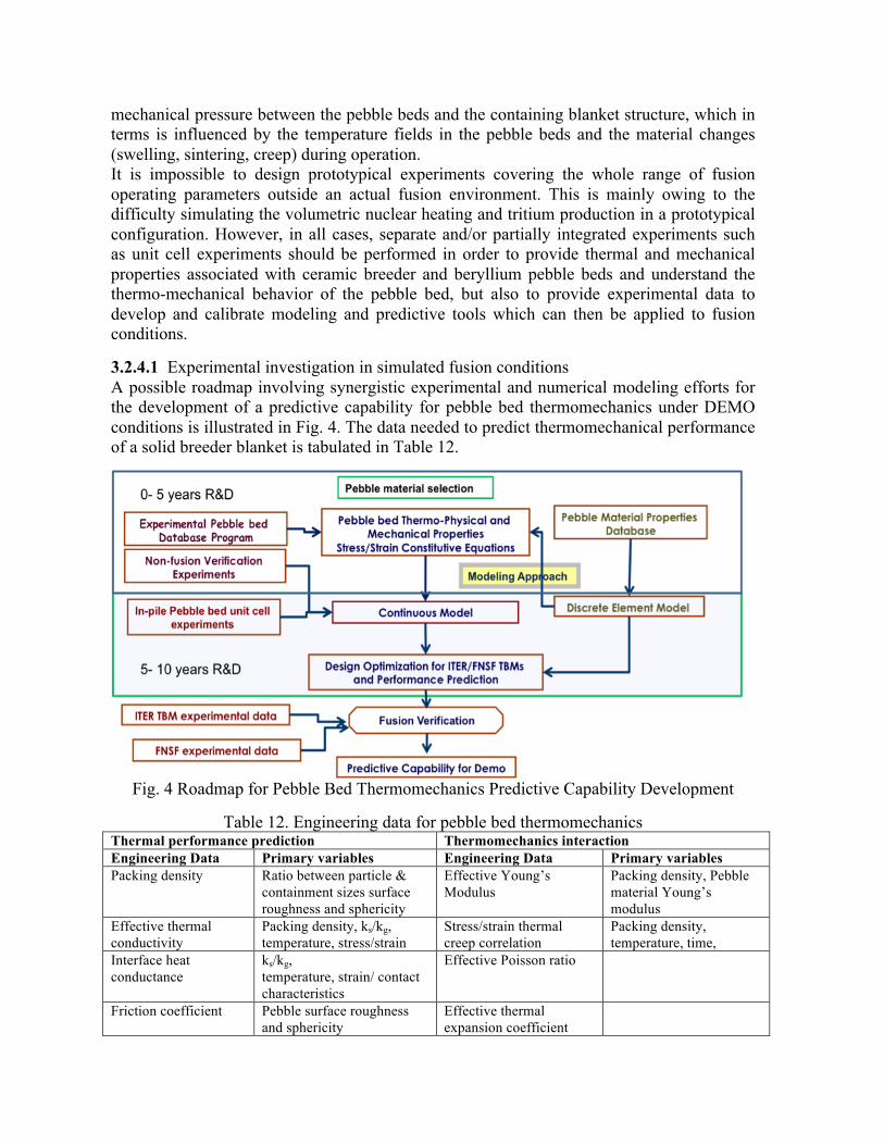
mechanical pressure between the pebble beds and the containing blanket structure, which in terms is influenced by the temperature fields in the pebble beds and the material changes (swelling, sintering, creep) during operation. It is impossible to design prototypical experiments covering the whole range of fusion operating parameters outside an actual fusion environment. This is mainly owing to the difficulty simulating the volumetric nuclear heating and tritium production in a prototypical configuration. However, in all cases, separate and/or partially integrated experiments such as unit cell experiments should be performed in order to provide thermal and mechanical properties associated with ceramic breeder and beryllium pebble beds and understand the thermo-mechanical behavior of the pebble bed, but also to provide experimental data to develop and calibrate modeling and predictive tools which can then be applied to fusion conditions. 3.2.4.1 Experimental investigation in simulated fusion conditions A possible roadmap involving synergistic experimental and numerical modeling efforts for the development of a predictive capability for pebble bed thermomechanics under DEMO conditions is illustrated in Fig. 4. The data needed to predict thermomechanical performance of a solid breeder blanket is tabulated in Table 12.
Fig. 4 Roadmap for Pebble Bed Thermomechanics Predictive Capability Development
Table 12. Engineering data for pebble bed thermomechanics
Thermal performance prediction Thermomechanics interaction Engineering Data Primary variables Engineering Data Primary variables Packing density Ratio between particle &
containment sizes surface roughness and sphericity
Effective Young’s Modulus
Packing density, Pebble material Young’s modulus
Effective thermal conductivity
Packing density, ks/kg, temperature, stress/strain
Stress/strain thermal creep correlation
Packing density, temperature, time,
Interface heat conductance
ks/kg, temperature, strain/ contact characteristics
Effective Poisson ratio
Friction coefficient Pebble surface roughness and sphericity
Effective thermal expansion coefficient
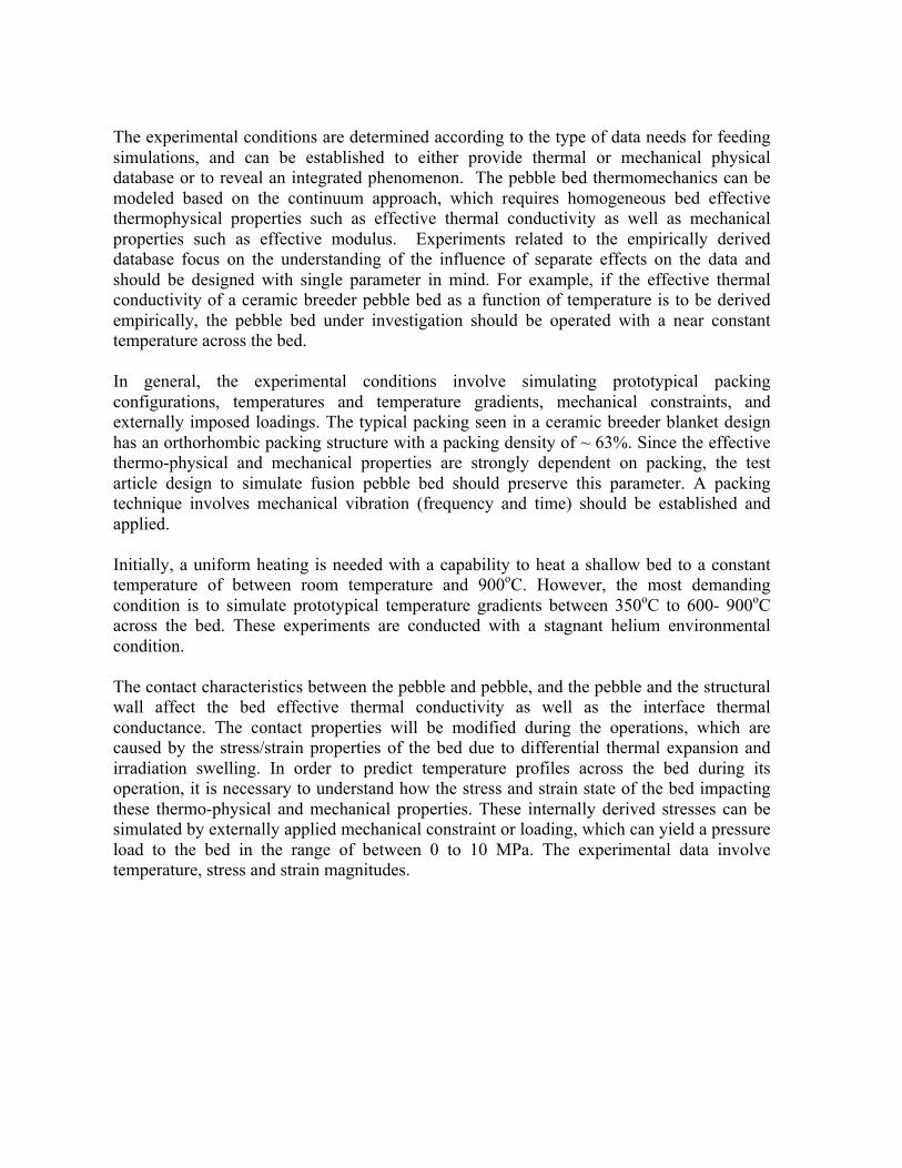
The experimental conditions are determined according to the type of data needs for feeding simulations, and can be established to either provide thermal or mechanical physical database or to reveal an integrated phenomenon. The pebble bed thermomechanics can be modeled based on the continuum approach, which requires homogeneous bed effective thermophysical properties such as effective thermal conductivity as well as mechanical properties such as effective modulus. Experiments related to the empirically derived database focus on the understanding of the influence of separate effects on the data and should be designed with single parameter in mind. For example, if the effective thermal conductivity of a ceramic breeder pebble bed as a function of temperature is to be derived empirically, the pebble bed under investigation should be operated with a near constant temperature across the bed. In general, the experimental conditions involve simulating prototypical packing configurations, temperatures and temperature gradients, mechanical constraints, and externally imposed loadings. The typical packing seen in a ceramic breeder blanket design has an orthorhombic packing structure with a packing density of ~ 63%. Since the effective thermo-physical and mechanical properties are strongly dependent on packing, the test article design to simulate fusion pebble bed should preserve this parameter. A packing technique involves mechanical vibration (frequency and time) should be established and applied. Initially, a uniform heating is needed with a capability to heat a shallow bed to a constant temperature of between room temperature and 900oC. However, the most demanding condition is to simulate prototypical temperature gradients between 350oC to 600- 900oC across the bed. These experiments are conducted with a stagnant helium environmental condition. The contact characteristics between the pebble and pebble, and the pebble and the structural wall affect the bed effective thermal conductivity as well as the interface thermal conductance. The contact properties will be modified during the operations, which are caused by the stress/strain properties of the bed due to differential thermal expansion and irradiation swelling. In order to predict temperature profiles across the bed during its operation, it is necessary to understand how the stress and strain state of the bed impacting these thermo-physical and mechanical properties. These internally derived stresses can be simulated by externally applied mechanical constraint or loading, which can yield a pressure load to the bed in the range of between 0 to 10 MPa. The experimental data involve temperature, stress and strain magnitudes.

Table 13. Experimental requirements for studying solid breeder material system thermomechanics
Parameters Descriptions Material needs Candidate US ceramic breeder pebbles (Li4SiO4, Li2TiO3, or else),
Beryllium pebbles, RAFS structural material as pebble containing structures (If coolant channels are to be embedded in the RAFS structure, joining/welding fabrication techniques are needed for RAFS)
Mechanisms for simulating nuclear heating
For out-of-pile laboratory experiments – electric/quartz heaters, RF heating possible for ceramic breeder pebble beds Neutrons from fission reactors for in-pile experiments
Diagnostics High temperature stress and strain gauges, thermocouples, LVDT (linear variable displacement transducer), load cell, advanced displacement measuring techniques
It is essential to incorporate an active cooling mechanism to provide a prototypical thermal boundary condition in the experimental setup. Particularly if the experiments are to address the effect of cyclic operations (such as ITER pulsed operations) on the pebble bed thermomechanics, the time constant of the tested system should closely represent the time constant of a typical blanket pebble bed material system in order to reproduce temperature, stress, and strain evolutions. Ideally, this should be a helium loop facility, which operates at the blanket coolant operating conditions. Typical operating conditions of various scaled helium loop facilities are shown in Table 14 (note that these facilities are similar in scale to what is proposed in section II.C for first wall heat transfer testing, it is possible their missions could be combined). Other concerns on thermal ratchetting, and pebble/fragment-relocations are the resultant heat transfer properties in case of inclined or even vertical beds.
Table 14. Helium-loop facilities parameters
Small scale Medium scale 1:1 TBM scale Nom. Pressure (MPa) 8 8 8 Max. He temp. 500 500 500 Mass flow rate (kg/s) 0.175 0.35 1.4 TBM He flow scale 1/8 1/4 1 3.2.4.2 Models development and validation in simulated conditions Various modeling techniques have been developed to characterize pebble bed thermomechanics and the associated effective heat transfer properties for analyzing spatial and temporal temperature profiles over the region. These include a classical continuum finite element method and a discrete element method (DEM). A predictive capability based on finite element approaches is the ultimate tool for a large-scale design analysis. However, in order to simulate the process, empirically derived constitutive correlations, which describe properties of a packed sphere assembly as functions of pressures, temperatures and loadings, are required. The DEM takes the material properties of breeder spheres and uses them to model the mechanical state of each individual sphere in a packed assembly through appropriate, physically-based contact interaction laws. It provides insightful information for each contact, such as force, displacement, and the likelihood of sphere breakage. The drawback is that the number of spheres simulated in DEM is limited by computer power. Nevertheless, an increased degree of confidence, that the pebble bed/structural wall interface can be maintained, can be attained by analyzing the macroscopic stress and strain

magnitudes using a continuum model and the resultant microscopic inter-particle contact force by means of discrete element method simulation. However, these models must be calibrated with experimental data. Ideally, fully prototypical experiments covering the whole range of possible operating parameters would provide 100% confidence in predicting the behavior of the pebble bed blanket under the full range of operating conditions in a fusion reactor. Because of practicality, cost and laboratory constraints, and also of the possibility of unknown factors, a fully calibrated predictive capability will not be achieved until it is benchmarked against the data from a long term operation in a fusion environment. Model development and simulation goals include:
1. Identification of conditions or initial mechanical states of the ceramic breeder pebble bed/structural wall system such that the integrity of the interface can be warranted at high confidence during the operations
2. Determination of the thermo-mechanical performance of the pebble beds (without effect of irradiation): constitutive equation, creep law, influence of packing factor, etc.
3. Give main guide lines for the structural design of TBM and for the pebble fabrications relevant to pebble bed thermomechanics
4. Provide predictive tools (as a FEM model) for the pebble beds thermo-mechanical simulations
3.2.4.3 Facility requirements and coupling to other tasks Basic materials research on the production and characterization of ceramic breeder and beryllium pebble materials are described in detail of the materials chapter of this report. This work is important in parallel with the research described here. Prototypic foreign produced breeder material can be obtain for many of these tests but it is highly desirable to additionally characterized US produced materials to establish its database. Helium cooled unit cell thermomechanics test facilities will be necessary. It is possible to consider using smaller helium loop facilities for initial unit cell experiments while scaling up then to prototypic helium flow loop facilities needed for TBM scale mockup experiments. Such a helium loop then is similar in parameters to those described for first wall cooling experiments and it may be possible to combine their scope into a single facility used for TBM mockup experiments for both FW and breeder cooling. Medium term FNST Research Needs (5-10 year timeframe) In a fusion power extraction and tritium fuel cycle R&D program where the activities described in Section II are being actively pursued, the medium term 5-10 year time frame plays an important role in the overall fusion development strategy. This period serves as a buffer time to complete and digest R&D begun in the near term, especially as unanticipated findings may require repeating or redirecting some efforts. And also as a point where various separate effect experimental and verified modeling capabilities can make a turn towards addressing more multiple-effect phenomena. This effort includes the fabrication and testing of geometrically complex and heterogeneous component mockups designed to provide data for modeling, safety and reliability studies, and to qualify experimental designs to be tested in ITER-TBM and base blanket and tritium handling components for FNSF.

To address this, it is envisioned that facilities established in the near term could be upgraded and/or combined to provide the necessary multiple effect or near prototypic scale test environments. In particular the following main facilities and activities have been identified.
• Blanket Mockup Thermomechanical/Thermofluid Testing Facility • Fuel Cycle Development Facility • Bred Tritium Extraction Facility • Irradiation effects testing on blanket material and functions • ITER TBM/FNSF design and safety/licensing R&D
Such R&D on mockups and multiple effect phenomena will be needed before any fusion nuclear environment testing can proceed, and will be essential for understanding and interpreting such integrated experimental results.
3.2.5 Blanket Mockup Thermomechanical/Thermofluid Testing Facility Blanket/FW components and their associated heat transport and tritium processing loops are complex, multifunction systems that have many joints, material interfaces and must function reliably under difficult environmental conditions. A dedicated test facility is envisioned where blanket/FW components can be tested under combined loading conditions for long periods of time. The key aspects of such tests will be to:
• acquire precise measurements of thermomechanical and thermofluid performance of mockups for comparison to and validation of simulation capabilities, and
• gain failure modes, frequencies and effects data for representative blanket systems,
with prototypic materials, temperatures, and under simulated fusion loading conditions. Measurements of mockup and loop temperature, strain, and coolant flow would be used for quantitative comparison against simulations. Compatible sensors and their integration into test modules will be a key requirement for performing such measurements. In addition, longer term processes such as corrosion, transport and deposition would also be quantifiably measured with concentration measurements and witness plate samples. Hydrogen transport and permeation can also be investigated in an integrated fashion The facility itself will combine many features of test facilities described in the previous sections, and could conceivably physically relocate the very same PbLi, helium loops and magnetic facilities from separate and multiple effects test facilities into one location for their integration. The test module loading would include the following conditions:
• FW heat flux • Nuclear heating simulation via embedded heaters, surface heaters, or induction
heaters (this will require careful study and integration with the experimental mockups themselves)
• Magnetic field: high field, and variable field direction • Mechanical loads: weight, pressure, vibration, impulses (for example via pulsed
current in magnetic field)

• H/D loading (see below) It should accommodate mockup modules as large as a 2 m x 2 m to allow testing of full size prototypes. The loading conditions should be available in steady state for long term experiment operations, which means the power consumption will be significant, especially depending on the type of magnet employed. It is conceivable that at a later stage of operations, that tritium could also be introduced into the system for studying more integrated study of tritium transport and inventory behavior. In this case, the facility would have to be designed with this in mind from the beginning, which would add to the complexity and cost. 3.2.5.1 Table of Loads Such a test facility would serve both as a place to perform mockup experiments in simulated fusion conditions, but also as a test and qualification facility for test blanket module experimental designs that could then be licensed and deployed to integrated fusion environment testing facilities such as the ITER-TBM or FNSF (described in detail in section IV). While test modules that are intended for ITER, in particular, are experiments themselves, still both ITER requirements, licensing requirements, and common sense dictate that these experiments are should be expected to fail in the basic operations such that they hinder the operation and availability of ITER itself and its plasma physics mission elements. Aggressive testing and “testing to failure” experiments will need to be performed in just such an out of pile test facility as proposed here designed to accommodate and tolerate such failures. In this way, partially integrated testing in this out of pile test facility can contribute to the mockup and component reliability and failure modes and effects database in a significant way. Such data will likely be a requirement of any qualification and licensing procedure for ITER-TBM and FNSF facility. This includes not just the TBM itself, but also the ancillary heat transport and tritium transport systems that will be considered extensions of the vacuum vessel (1st containment boundary) that contain radioactive products (tritium and other activated materials) of fusion. These loops and processes will also have to be proven prior to their acceptance into service in ITER of FNSF. One could consider such a facility in light of the mockups and test facilities built for large uncertain ITER components such as the ITER divertor, FW/shield, and magnets.
Fig. 5. Integrated Thermomechanics / Thermofluid MHD Test Facility progression
3.2.6 Irradiation effects on blanket material and component functions Neutron irradiation will have impact on the properties and behavior of all manner of materials used in blanket components. The evolution and degradation of structural materials is described in detail elsewhere, including the important fundamental effects of neutron irradiation on the mechanical and electrical properties SiC (in which we are interested from the perspective of a suitable material for flow channel inserts). But the behavior of functional materials and integrated effects is also important from the perspective of breeding blanket performance. In particular, unit cell experiments where a breeding cell is mocked up in a fission reactor (or other neutron source) can help shed light on the functional materials degradation/evolution, integrated behavior, and breeder burn-up.
B1. PbLi breeder unit cell experiments Initial tests of tritium permeation and removal via a vacuum permeator have been described in the preceding section. But important differences can exist from tritium experiments where tritium diffuses into the PbLi stream as opposed to being bred there via an energetic reaction with a neutron, as well. Bred tritium is produced simultaneously with insoluble helium. There is considerable speculation as to whether this helium will form micro bubbles that then in turn may act as trap sites for tritium near bubble surfaces. In such a case is there a sort of enhanced solubility for tritium that leads to different permeation and tritium extraction behavior? Similarly, permeation of tritium in general may be altered due to secondary gamma and charged particles altering surface dissociation and recombination processes, possibly leading to an enhanced permeation when compared to rates measured without irradiation. Lastly, bred tritium is energetic (Q value is 4.78 MeV for Li6(n,a)t
reaction) and tritium and helium bred near surfaces with SiC flow channel inserts or structural walls with any permeation or corrosion coatings will implant in and damage those surfaces to some degree. The combination of these effects, and others that are as yet unanticipated, need to be investigated through appropriate experiments in neutron irradiation facilities prior to integrated fusion environment testing Such experiments would have to be carefully planned and evaluated for the appropriate scope and neutron source. But it is conceivable that a small unit cell experiment with, for example, concentric tubes of steel and SiC filled with PbLi could be deployed in a US fission reactor. The experimental setup could be coupled to a small, flowing PbLi loop and helium purge loop out of the reactor. Measurements of both in-situ tritium production and permeation, and tritium extraction and concentration ex-situ are envisioned for such a PbLi unit cell experiment, as well as detection of helium bubbles. Thermomechanical and neutronics simulations could also be validated against such an integrated PbLi unit cell experiment. Such external loops using sodium or high temperature pressurized water have been considered in the past at the Advanced Test Reactor at the Idaho National Laboratory, and the utilization of small gas loops used for thermal barrier control are routine on existing experiments. The scale of such an upgrade to US test reactors could be significant but of the same order integrated facilities and experiments proposed in this section. 3.2.6.1 Tritium Release, Permeation Characterization and In-Pile Tests for Pebble Bed Assembly Once tritium is generated inside the ceramic breeder pebble, it is released to the purge gas through several transport mechanisms including bulk diffusion, dissolution, desorption and adsorption at the surfaces, chemical or irradiation induced trapping, and pore diffusion. Tritium atom at the surface can react with hydrogen and oxygen and form different molecular species such as HT, T2, T2O, and HTO. These molecular species, which are the main species transported by the helium purge gas stream to the tritium extraction system, can permeate at different rates and degrees through the tritium containing structures to the surrounding media such as the high temperature, high pressure helium coolant. An accurate tritium analysis requires the integration of the tritium inventory and release over the complete tritium generation domain and tritium diffusion through various materials, purge gas flow and temperature contours within the blanket space. Several experiments have been conducted to quantify ceramic breeder tritium release and inventory characteristics involving different microstructures as well as at different operating temperatures. They are typically studied in two different experimental settings:
1. Out of-pile laboratory experiments in which tritium production through exposure to neutron irradiation, followed by out-of-pile tritium desorption through stepwise iso-thermal or ramp annealing tests in laboratory set-ups. If irradiation doses are very low, tritium transport parameters reflect BOL conditions.
2. In-pile purge flow experiments, in which on-line monitoring of transient tritium release during temperature, purge gas composition, purge flow rare and tritium generation rate transients is characterized. In general such experiments are closer to breeding blanket conditions, as they allow the application of a wide range of

temperatures and purge gas conditions, and the study of long term performance issues like irradiation damage and lithium burn-up.
Nevertheless, more partially integrated tests involving interaction of the breeding pebble bed assembly with the blanket structure for an integrated performance on tritium release, mechanical integrity and stability still need to be conducted, and preferentially verified at higher lithium burn-up/higher fluence.
3.2.7 Fuel Cycle Development Facility ITER will have an integrated fusion fuel cycle, but it will be tied to a fusion reactor with an experimental program which must be supported. So, ITER will have a limited capacity for technology development and experimentation outside of its core mission. By contrast, TSTA was an integrated facility dedicated to developing technologies and approaches needed for the fusion fuel cycle. This facility operated with a substantial tritium inventory (140 g), and, not being tied to an operating fusion reactor, alternate technologies could readily be installed and operated to test, understand, optimize and demonstrate technologies. This facility successfully laid the basis for operating with large quantities of tritium without harming workers, the public or the environment.
The tables in the section II.B, Plasma Exhaust and Blanket Effluent Tritium Processing, identified remaining fusion fuel cycle R&D needs. Considering past experiences, it appears that the R&D identified in the tables above could most effectively be performed in an integrated HD (non-tritium) Fuel Cycle Development Facility (FCDF). This opinion is driven by the present consideration that the most pressing need is not for new tritium data. Rather, tritium-relevant HD experiments performed in a flexible facility that can readily perform a variety of experiments. As needed, tritium experiments can be performed in stand-alone, experiments in other facilities. Successful technologies might even be included in the ITER design to be proven in that environment provided that any impact on the ITER core mission is judged to be acceptable.
Thus, the vision is for a facility which includes most or all of the technologies needed for the fusion fuel cycle. They would be interconnected, so systems-level experiments can be performed. The facility would be flexible so that alternate technologies can readily be installed. The cost of such replacements would be greatly reduced by not processing tritium. The proposed facility would, of course, be capable of performing stand-alone experiments such as developing and proving new fuel cleanup technologies. But, thereafter, the technology could be operated in the context of an integrated processing loop so that impacts on isotope separation and other systems could be experimentally determined.
Process control would be a key focus of this facility. This would include low-level control loops, automation and interlocks. Success in this area will have a strong positive influence on future fusion experiments. This is because improved control will enable operations with
reduced tritium inventories and with increased reliability. Thus, this will have the double benefit of increasing both safety and productivity.
The key systems envisioned for development in the FCDF are listed and briefly described in Table 15. Generalized, key overall operating parameters for the facility are given in Table 16.
3.2.8 Bred Tritium Extraction Facility (BTEF) There has been no testing of tritium recovery from liquid blankets with tritium. For tritium recovery from solid breeders there has been very limited testing with tritium. Tritium testing of these systems will be an essential step in tritium breeding development. This is because tritium will be needed to study radiolytic reactions and tritium confinement, and to full assessment of process effectiveness. None of the existing or planned/proposed facilities will be appropriate for this research. Thus, it is proposed that a Bred Tritium Extraction Facility (BTEF) be constructed to perform tritium research on recovery of tritium from fusion breeder materials. It is not envisioned that this facility would actually breed tritium (though this would be a strong advantage if a neutron source could be available). Rather, it is envisioned that the facility would artificially inject or dissolve tritium into breeder materials. Then the effectiveness of technologies to recover this tritium would be tested and optimized. This facility would have only the minimal tritium infrastructure necessary to perform these tritium recovery experiments.

Table 15: Key Systems to Be Integrated and Developed in FCDF
System Purpose Example Objective
Primary Processing Systems
Reactor Vacuum Maintain reactor vacuum during fueling
Optimize cyclic behavior or traditional cryopumps or develop continuously regenerable system
Roughing Pumps Back Reactor Vacuum system Develop systems capable of rapid reactor vacuum
pump regeneration
Fuel Cleanup Recover hydrogen isotopes from water and methane, and purify hydrogen isotopes
Develop automated water and methane processing systems. Develop simple purification system.
Isotope Separation Separate hydrogen isotopes
Develop automated hydrogen separation systems which respond properly to realistic fusion operating scenarios
Storage and delivery
Safely store and deliver hydrogen isotopes
After receiving material from Isotope Separation, develop low-inventory methods for “just-in-time” blending and delivery of hydrogen isotopes
Fueling Deliver hydrogen isotopes within the scrape-off layer Develop rapid and reliable pellet injectors
Secondary Processing Systems
Process and Glovebox Detritiation
Recovery dilute hydrogen isotopes from glovebox atmosphere and primary process gases
Develop low-cost, low environmental impact, highly reliable detritiation systems
Room Air Detritiation Systems
Recovery very dilute hydrogen isotopes from room air
Develop low-cost, high-throughput, seldom-used, safety-related system
Support Systems
Analytical Systems
Perform chemical composition measurements
Develop cost-effective, practical measurement techniques for process control
Control Systems Operate integrated systems safely and effectively
Develop and demonstrate high-level control strategies necessary for routine, reliable operations. Demonstrate proper responses to off-normal and simulated emergency conditions.
To roughly estimate the size of this facility, it is considered that the full facility would envision a scale up to the breeding rate of DEMO. If DEMO generates 3 GW of fusion power and BTEF is 1/5th scale relative to DEMO, the tritium breeding rate would be 0.4 Pa m3/s of T2. This number would be used to determine other processing rates

associated with a given breeder concept. For instance, for ceramic breeders it is expected that the helium sweep gas flowrate will be adjusted to keep the tritium concentration approximately 0.1%. Thus, under these assumptions, BTEF would have a helium flowrate of 400 Pa m3/s. Breeding loops operate at elevated temperatures, so a key element of the facility would be working at these temperatures.
Table 16: Generalized Operating Parameters for FDCF
System Parameters
Primary processing systems
Average total flowrate 200 Pa m3/s
Average pressure 1.5 bar
Composition Burn and Dwell:
Primarily H2 with He, D2 and impurities
Glow Discharge Wall Conditioning:
Primarily He with HD and impurities
Glow Discharge Wall Conditioning:
Primarily D2 with impurities
Disruption mitigation gases:
TBD
Bake Out:
HD and impurities
Vacuum Vessel Pumpout:
Primarily air/N2 with HD and impurities
Secondary processing systems
Average total flowrate Glovebox and Process
500 m3/hr
Room:
5000 m3/hr
Average pressure 1 bar
Composition Primarily air/N2 with HD and impurities

Note: “impurities” are hydrocarbons such as methane, water, Ar, Ne, N2, and possibly Ne
3.2.9 ITER TBM/FNSF Design and Safety/Licensing R&D The need to perform integrated testing of blanket/FW, divertor, shield components and materials in a true fusion environment prior to proceeding to a fusion DEMO is included in the fusion development plans worldwide and is certainly advocated here. While there may be some variety of opinions on the relative benefits of testing blanket/FWs in ITER as part of the ITER-TBM program, or building a dedicated plasma-based component test facility (FNSF, CTF, VNS, etc.), it is clear that significant preparation is required in advance to plan, design, build and qualify module scale experiments for deployment in the plasma/nuclear environments of ITER and FSNF. R&D described in the preceding sections and the companion sections of this volume includes much of what is needed to prepare for test blanket module experiments. In addition during the medium, an effort on design, analysis and then fabrication of the first TBM experiments and ancillary heat and tritium transport loops will be necessary. The activities here include:
• Design and analysis of different TBM experimental modules for different ITER operational scenarios
• Auxiliary Equipment Unit/PbLi flow system/Tube Forest design • Helium coolant loop design • Tritium extraction and control design • Operational, investment protection, safety protection and control systems and
procedures design • Diagnostic/Sensor design and integration • Integrated modeling of test blanket modules and system performance, including
failure modes and effects analysis. In particular, this last bullet is an important piece, where the simulations capabilities developed during the R&D phases are brought together in a coherent way such that the integrated performance of the TBM and supporting systems can be simulated. This integrated modeling capability will be critical for analyzing the TBM performance (1) prior to final design and fabrication, and (2) during operations in ITER such that the experiments can be safely controlled and scientifically understood. Simulation capabilities will have to meet ITER acceptance and French licensing verification and validation standards in order for simulation results to be acceptable. A similar case exists when one considers a Fusion Nuclear Science Facility, with the mission to provide a test environment for in-vessel fusion components (see for example Ref. [2]). Significant prior R&D, design and analysis will be required in all the areas described above for ITER-TBM, as well as other areas needed for n the design of the higher fluence, very long pulse FNSF base machine itself. Such areas include:

• Vacuum vessel design, strategy, material in higher fluence environment • Base FW/blanket/Divertor design and testing, including inboard blanket • He coolant accident pressure and surge control • Maintenance and replacement approach • Plasma and machine diagnostics and control
If one considers an aggressive schedule where an FNSF is brought on line substantially in parallel with ITER, licensing of such an experimental machine using the prototypic materials and in-vessel component designs hitherto untested in a relevant fusion nuclear environment will be a challenge. This will increase substantially the need for a prior R&D and demonstration program in partially-integrated mockup facilities in order to make the safety, reliability and licensing case for the facility itself. Such testing is sure to be extensive. In addition, a staged approach to the operation and licensing of the facility will be necessary, with approval to proceed from hydrogen, to low fluence (<10 dpa), to moderate fluence (<20 dpa), to higher fluence coming after the completion and examination of the previous phase. Having ITER TBM test results can help make the licensing case for an FNSF depending on the relative timelines. Primary ITER-TBM experiments will likely begin around 2022 during the HH phase, and culminate around 2030 in the DT phase.

Fig. 6. onceptional drawings of ITER Test blanket module systems in ITER. (A) 3 testing port extensions into the vacuum vessel. (B) Piping from port cell area to the helium flow loop systems in remote location. (C) TBM and TBM frame. (D) TBM, tube forest (in cryostat interspace) and Auxiliary Equipment Unit (in port cell) for a US DCLL TBM

3.3 During ITER Operations (10-‐20 Year Timeframe) ITER construction and operation will a huge accomplishment and represent a significant step forward in many engineering areas associated with fusion. In particular the tritium plant and processing systems will strongly contribute to the knowledge base needed for a DEMO reactor. In the area of power extraction and tritium breeding however, little of the materials, coolants and designs utilized for the ITER blanket/FW are relevant to for DEMO. ITER uses low temperature water to cool a copper alloy first wall heat sink with beryllium armor. The blanket system is a water stainless steel shield with no tritium production or high grade heat power extraction capability. However, ITER does provide 3 equatorial ports to allow for relevant tritium breeding blanket testing as a critical element of the ITER mission. Test Blanket Modules (TBMs) inserted in ITER represent a principal strategy by which ITER will provide the first experimental data on blanket/FW function in an integrated fusion environment. This is why successful TBM experiments in ITER represent an essential step on the path to DEMO in all the ITER Parties’ fusion development plans. Even with this testing capability, the neutron fluence in ITER is not large compared to DEMO requirements and will not be adequate to study the impact of long term operation of materials and components in an integrated fusion environment with accumulated radiation damage and material changes. The need for a facility with the mission to test, develop, and qualify Fusion Nuclear Components (fusion power and fuel cycle technologies) in prototypical fusion power conditions is strongly advocated. Such a Fusion Nuclear Science Facility (FNSF) should provide the necessary integrated testing environment with:
• high neutron and surface fluxes • steady state plasma (or long pulse with short dwell time), • large test area and volume, and • significant “cumulative" neutron fluence.
The testing strategy for these integrated fusion environment experiments in ITER and FNSF is describe below.
3.3.1 ITER TBM modules experiments and Post Irradiation Examination The principal mission of a US ITER Test Blanket Module (TBM) program is to develop, deploy, and operate ITER TBM experiments to acquire experimental data on, and operational experience with, the integrated function of blanket and first wall (FW) components and materials of interest to the US in a true fusion environment. This data is essential for validation of scientific understanding and predictive capabilities; demonstration of the principles of tritium self-sufficiency in practical systems; development of the technology necessary to install breeding capabilities in next-step machines; and providing the first integrated experimental results on reliability, safety, environmental impact, and efficiency of fusion energy extraction systems. In terms of US interests, a strong US TBM program will help to:
• Build knowledge, experience, and competence in fusion nuclear and tritium technologies that are vital to continued fusion development in the US; and to the feasibility, practicality, and safety of DT fusion energy devices
• Maximize the US return on investment in ITER – including its major capabilities for integrated fusion environment testing (worth billions of dollars)
• Capitalize on the substantial resources invested by the other ITER Parties, and allow some US influence on their tritium breeding technology programs
The unique conditions of ITER that allow for meaningful integrated testing of blanket components and material systems (see Fig. 6 and Table 17) include:
• large test ports (maximum height of TBM ~ 2 m, similar to the size of typical blanket modules in a future power plant);
• plasma exposure with typical plasma radiation, particle loads, and startup/termination;
• nuclear volumetric heating and beginning of life radiation damage with spatial gradients;
• transient and off-normal plasma events such as disruptions, ELMs, VDEs, etc.; • strong and spatially complex magnetic field (~ 5 T) of the same order as in power
plants; • true fusion neutron energy spectrum as in power plants; and • strong confinement of radioactivity, allowing realistic tritium concentrations.
R&D tasks to prepare for ITER-TBM experiments [7] have already been included in the research programs described in Sections II and III. This includes simulations of the component and system performance that will most certainly be a part of the licensing case for each TBM, but also serves as a key tool in using, understanding and interpreting experimental data from the TBMs.
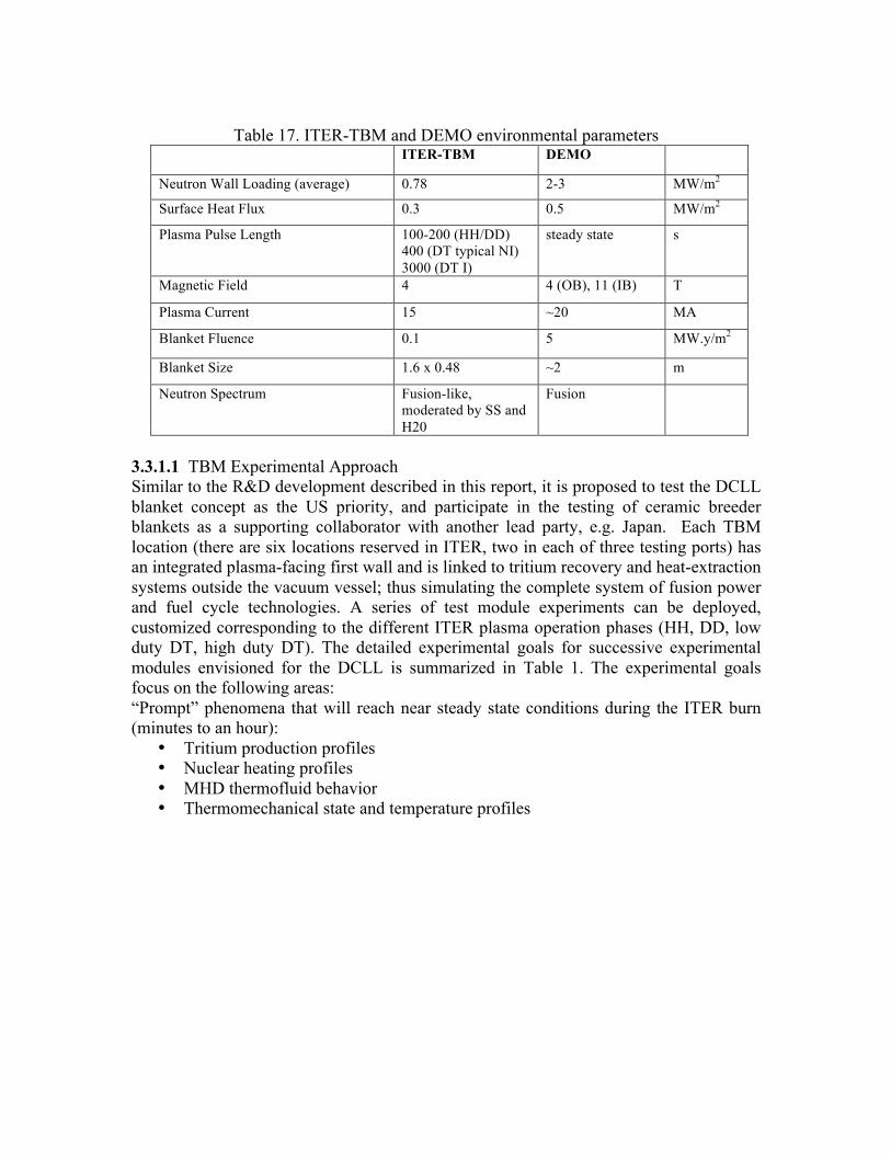
Table 17. ITER-TBM and DEMO environmental parameters
ITER-TBM DEMO
Neutron Wall Loading (average) 0.78 2-3 MW/m2
Surface Heat Flux 0.3 0.5 MW/m2
Plasma Pulse Length 100-200 (HH/DD) 400 (DT typical NI) 3000 (DT I)
steady state s
Magnetic Field 4 4 (OB), 11 (IB) T
Plasma Current 15 ~20 MA
Blanket Fluence 0.1 5 MW.y/m2
Blanket Size 1.6 x 0.48 ~2 m
Neutron Spectrum Fusion-like, moderated by SS and H20
Fusion
3.3.1.1 TBM Experimental Approach Similar to the R&D development described in this report, it is proposed to test the DCLL blanket concept as the US priority, and participate in the testing of ceramic breeder blankets as a supporting collaborator with another lead party, e.g. Japan. Each TBM location (there are six locations reserved in ITER, two in each of three testing ports) has an integrated plasma-facing first wall and is linked to tritium recovery and heat-extraction systems outside the vacuum vessel; thus simulating the complete system of fusion power and fuel cycle technologies. A series of test module experiments can be deployed, customized corresponding to the different ITER plasma operation phases (HH, DD, low duty DT, high duty DT). The detailed experimental goals for successive experimental modules envisioned for the DCLL is summarized in Table 1. The experimental goals focus on the following areas: “Prompt” phenomena that will reach near steady state conditions during the ITER burn (minutes to an hour):
• Tritium production profiles • Nuclear heating profiles • MHD thermofluid behavior • Thermomechanical state and temperature profiles
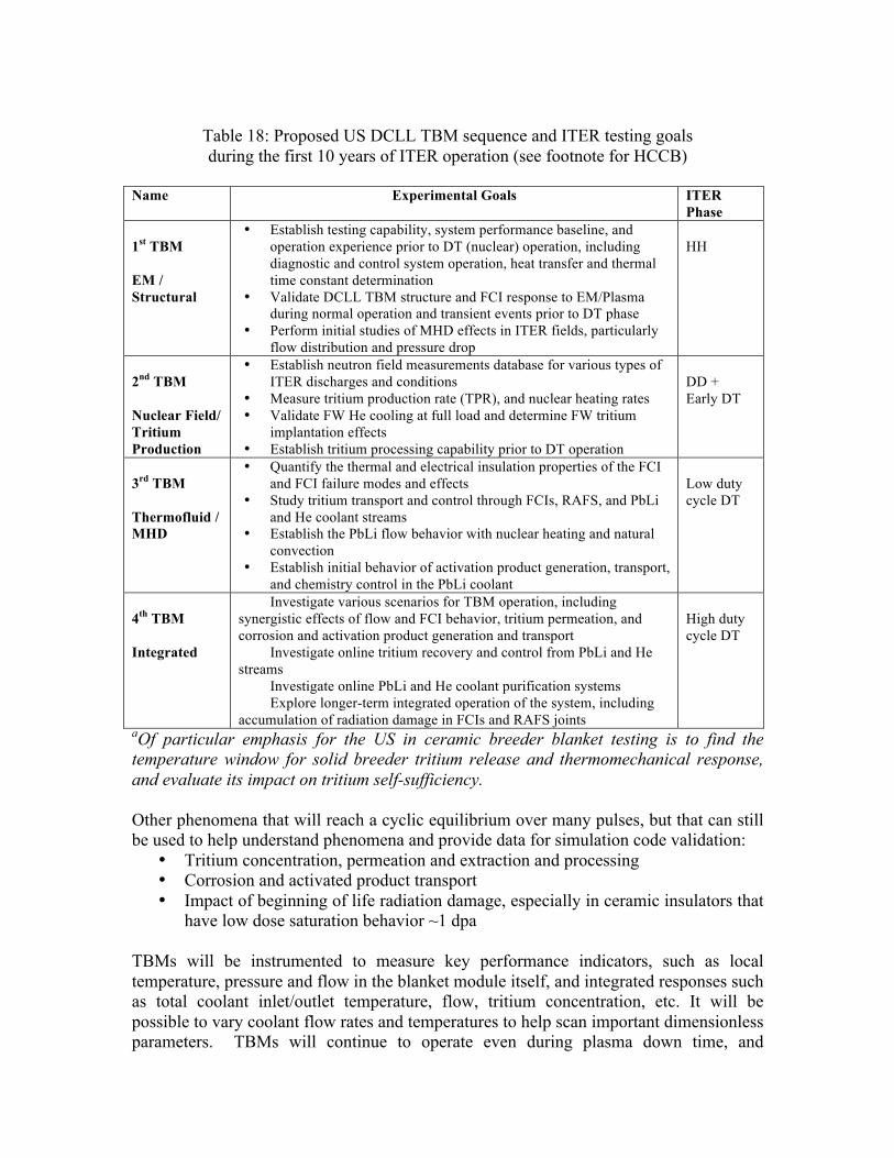
Table 18: Proposed US DCLL TBM sequence and ITER testing goals during the first 10 years of ITER operation (see footnote for HCCB)
Name Experimental Goals ITER
Phase 1st TBM EM / Structural
• Establish testing capability, system performance baseline, and operation experience prior to DT (nuclear) operation, including diagnostic and control system operation, heat transfer and thermal time constant determination
• Validate DCLL TBM structure and FCI response to EM/Plasma during normal operation and transient events prior to DT phase
• Perform initial studies of MHD effects in ITER fields, particularly flow distribution and pressure drop
HH
2nd TBM Nuclear Field/ Tritium Production
• Establish neutron field measurements database for various types of ITER discharges and conditions
• Measure tritium production rate (TPR), and nuclear heating rates • Validate FW He cooling at full load and determine FW tritium
implantation effects • Establish tritium processing capability prior to DT operation
DD + Early DT
3rd TBM Thermofluid / MHD
• Quantify the thermal and electrical insulation properties of the FCI and FCI failure modes and effects
• Study tritium transport and control through FCIs, RAFS, and PbLi and He coolant streams
• Establish the PbLi flow behavior with nuclear heating and natural convection
• Establish initial behavior of activation product generation, transport, and chemistry control in the PbLi coolant
Low duty cycle DT
4th TBM Integrated
• Investigate various scenarios for TBM operation, including synergistic effects of flow and FCI behavior, tritium permeation, and corrosion and activation product generation and transport
• Investigate online tritium recovery and control from PbLi and He streams
• Investigate online PbLi and He coolant purification systems • Explore longer-term integrated operation of the system, including
accumulation of radiation damage in FCIs and RAFS joints
High duty cycle DT
aOf particular emphasis for the US in ceramic breeder blanket testing is to find the temperature window for solid breeder tritium release and thermomechanical response, and evaluate its impact on tritium self-sufficiency. Other phenomena that will reach a cyclic equilibrium over many pulses, but that can still be used to help understand phenomena and provide data for simulation code validation:
• Tritium concentration, permeation and extraction and processing • Corrosion and activated product transport • Impact of beginning of life radiation damage, especially in ceramic insulators that
have low dose saturation behavior ~1 dpa TBMs will be instrumented to measure key performance indicators, such as local temperature, pressure and flow in the blanket module itself, and integrated responses such as total coolant inlet/outlet temperature, flow, tritium concentration, etc. It will be possible to vary coolant flow rates and temperatures to help scan important dimensionless parameters. TBMs will continue to operate even during plasma down time, and
phenomena associated with magnetohydrodynamics, tritium and corrosion product transport, etc. can continue to be studied. Following exposure to the ITER environment, each TBM and sections of the support loops can undergo extensive post irradiation examination (PIE) to ascertain additional information about the behavior of the system including information on corrosion and degradation of the structures, breeders and insulators. TBMs should not jeopardize the operational availability of ITER, so testing to failure is not a viable approach. However, there is an advantage in the reduced volumetric/surface heating conditions in ITER. Tests can be made with less sensitivity to variations in performance, meaning a “failed” condition that would have led to a shutdown in an FNSF or a DEMO, may be tolerated in ITER and allow operations to continue. This reduced sensitivity to the success of experimental components makes ITER-TBM an attractive candidate to perform first fusion environment testing, so called “fusion break-in” [2]. 3.3.1.2 ITER fuel cycle and fuel processing. In addition to TBM, operation of ITER itself will yield invaluable information on large-scale DT processing and tritium accountancy in a working fusion environment. The ITER fuel cycle will in a number of ways be prototypic of systems needed for DEMO or power reactor. Valuable data will be collected on fuel cycle systems in the following areas:
• Operation at higher flowrates and shorter recycle times • Regulatory compliance • Large tritium inventory • Processing technology demonstration • RAMI • Tritium safety data • Integrated operations in fusion environment
Much will be learned in each of these areas and a detailed description of this is beyond the scope of this paper. But one area just to highlight how different ITER will be has to do with its large tritium inventory and highly integrated operations. Previous facilities were designed and operated with very small tritium releases (to the environment), and ITER is being designed with traditional operational confinement strategies. However, previous facilities had sufficiently limited tritium at risk so that in worst-case scenarios, analysis showed that the entire tritium inventory could be released without exceeding regulatory requirements for such circumstances. ITER’s tritium at risk is increased to levels so that traditional approaches will be challenged at off-normal conditions. Thus, so alternate solutions will need to be design, implemented and demonstrated. The data collected on ITER in the listed areas will be quite valuable in developing the database necessary to move to DEMO. In some areas such as working with large tritium inventories, it is hoped that little beyond ITER will need to be developed. But in other areas, DEMO will be a significantly greater challenge. RAMI is an example of this.

But in other areas the information generated by ITER will fall far short of that necessary to design DEMO. Examples of this are:
• Tritium breeding • Processing of bred tritium
Thus, while ITER will be a very important contributor on the pathway to DEMO, the other facilities described in the paper (especially the FCDF, BTEF and FNSF) will also be needed for to develop the full fuel cycle capabilities necessary for DEMO.
3.4 Conclusions Harnessing fusion power has a good foundation as significant work has been performed in this area in the US and elsewhere. But progress toward DEMO will require significant advances in the fusion fuel cycle and power extraction. ITER, FNSF and later DEMO will be significant extensions beyond present capabilities and parameters requiring the successful operation of many systems that till now have never been fabricated, demonstrated, or tested in a relevant in-service environment. Most notably, while tritium breeding is indispensable for development of fusion power, to date no tritium has been bred in a fusion relevant fashion. To accomplish this and other objectives necessary to harness fusion power, this paper has identified requisite R&D needs and associated facilities. The R&D was organized using a methodical development framework approach which melds science, experimentation and modeling that will:
• Provide the database and underlying scientific understanding • Enable development and validation of predictive capabilities • Allow test mockups and components in relevant environment
This development will take time, so the research needs were organized into activities to be performed in the near-term, the intermediate-term and during ITER operations. Links between this proposed research, research in basic materials and PFC/PMI areas, have been identified. The facilities necessary to accomplish this work are:
• Blanket Mockup Thermomechanical/Thermofluid Testing Facility • Bred Tritium Extraction Facility • Fuel Cycle Development Facility • Irradiation effects testing on blanket material and functions • ITER Fuel Cycle • ITER TBM • Fusion Nuclear Sciences Facility
Studies on the performance limits and reliability of blanket/FW components under realistic requirements of normal and transient plasma operating conditions, and on the design of a continuous operation DEMO tritium plant are also recommended.

The need to perform testing in a fully integrated fusion environment is highlighted, including participating in ITER test blanket module experiments and beginning work to plan a Fusion Nuclear Science Facility that will allow integrated component and materials testing in near prototypic conditions. Practical ITER-TBM and FNSF mission and testing strategies are proposed such that there is a reasonable approach to testing experimental components in a fusion environment. The proposed work will be challenging, as it will progress into a harsh nuclear environment well beyond the existing experimental database. But, through analysis and careful testing under progressively more integrated fusion relevant conditions, there is expectation of a successful outcome. Performing this work will develop the scientific and technological know-how necessary to harness fusion power in the ITER era. And, it will result in skilled individuals prepared to move forward to DEMO and the first practical use of fusion power.
3.5 References [1] M. Abdou, et. al., "Technical Issues and Requirements of Experiments and
Facilities for Fusion Nuclear Technology," Nuclear Fusion, 27(4): 619-688 (1987). [2] M. Abdou, S. Berk, A. Ying, Y.K.M. Peng, S. Sharafat, J.D. Galambos, S. Malang,
E. Proust, S.J. Booth, L. Giancarli, P. Lorenzetto, Y. Seki, V.V. Filatov, G. Shatalov, A. Sidorendov. "Results of an International Study on a High-Volume Plasma-Based Neutron Source for Fusion Blanket Development," Fusion Technology, 29: 1-57 (1996).
[3] M. S. Tillack, A. D. Turnbull, L. M. Waganer, S. Malang, D. Steiner, J. P. Sharpe, L. C. Cadwallader, L. El-Guebaly, A. R. Raffray, F. Najmabadi, R. J. Peipert Jr., T. L. Weaver, and the ARIES Team, "An Evaluation of Fusion Energy R&D Gaps using Technology Readiness Levels," Fusion Science and Technology, 56 (2): 949-956 (2009).
[4] R. Kurtz, B. Wirth, “Research and development needs for fusion energy materials,” this volume (2011).
[5] G. Tynen, D. Whyte, R. Nygren, “PFC/PMI section” this volume (2011). [6] M. S. Tillack, S. Malang. "High-Performance PbLi Blanket," 17th IEEE
Symposium on Fusion Engineering, Oct. 6-9, 1997, San Diego, CA (1997). [7] M.A Abdou, N.B. Morley, A.Y. Ying, C.P.C Wong, T. Mann, S. Tourville, and the
US ITER Test Blanket Module Team. “US ITER Test Blanket Module Program, Volume I: Technical Plan and Cost Estimate Summary,” University of California Los Angeles Report, UCLA-FNT-216 (2007).
[8] A. R. Raffray, L. El-Guebaly, S. Malang, X. R. Wang, L. Bromberg, T. Ihli, B. Merrill, L. Waganer, ARIES-CS Team. “Engineering Design and Analysis of the ARIES-CS Power Plant,” Fusion Science and Technology 54 (3): 725-746 (2008).
[9] N.B. Morley, Y. Katoh, S. Malang, B. Pint, A.R. Raffray, S. Sharafat, S. Smolentsev, G. E. Youngblood. “Recent research and development for the dual
coolant blanket concept in the US,” Fusion Engineering and Design, 83(7-9): 920-927 (2008).
[10] A. Ying, M. Abdou, P. Calderoni, S. Sharafat, M. Youssef, Z. An, A. Abou-Sena, E. Kim, S. Reyes, S. Willms, R. Kurtz. “Solid breeder test blanket module design and analysis,” Fusion Engineering and Design, 81(1-7): 659-664 (2006).
[11] M. Greenwald, R. Callis, D., W. Dorland, D. Gates, J. Harris, R. Linford, M. Mauel, K. McCarthy, D. Meade, F. Najmabadi, W. Nevins, J. Sarff, M. Ulrickson, M. Zarnstorff, S. Zinkle. "Priorities, Gaps and Opportunities: Towards a Long-Range Strategic Plan for Magnetic Fusion Energy", FESAC report DOE/SC-102 (2007).
[12] R. Hazeltine et al. “Research Needs for Magnetic Fusion Energy Sciences,” Report of the Research Needs Workshop (ReNeW), Bethesda, Maryland – June 8-12 (2009).
[13] W.R. Meier, A.R. Raffray, R.J. Kurtz, N.B. Morley, W.T. Reiersen, P. Sharpe, S. Willms. “Findings of the US research needs workshop on the topic of fusion power,” Fusion Engineering and Design, 85(7-9): 969-973 (2010).
[14] S. Malang, A.R. Raffray, N.B. Morley, “An example pathway to a fusion power plant system based on lead–lithium breeder: Comparison of the dual-coolant lead–lithium (DCLL) blanket with the helium-cooled lead–lithium (HCLL) concept as initial step, Fusion Engineering and Design, 84(12): 2145–2157 (2009).
[15] S. Smolentsev, R. Moreau, L. Bühler, C. Mistrangelo, “MHD thermofluid issues of liquid-metal blankets: Phenomena and advances,” Fusion Engineering and Design, 85(7-9): 1196-1205 (2010).
[16] Anderson, J. and J. Bartlit; “The Development of Tritium Technology at the Tritium Systems Test Assembly”; Proceedings of the Twelfth Symposium on Fusion Technology, Julich, Germany, Sept 13-17, 1982.
[17] Anderson, J. L., C. Gentile, M. Kalish, J. Kamperschroer, T. Kozub, P. Lamarche,
H. Murray, A. Nagy, S. Raftopoulos, R. Rossmassler, R. Sissingh, J. Swanson, F. Tulipano, M. Viola and D. Voorhees; “Operation Of The Tokamak Fusion Test Reactor Tritium Systems During Initial Tritium Experiments,” Fusion Engineering and Design, 28:209-214 (1995).
[18] R. Lässer, A. C. Bell, N. Bainbridge, D. Brennan, B. Grieveson, J. L. Hemmerich,
G. Jones, D. Kennedy, S. Knipe, J. Lupo, J. Mart, A. Perevezentsev, N. Skinner, R. Stagg, J. Yorkshades, G. V. Atkins, L. Dörr, N. Green, M. Stead and K. Wilson; “Overview of the Performance of the JET Active Gas Handling System during and after DTE1,” Fusion Science and Technology, 46(2-4): 307-312 (1998).
[19] C.B. Baxi and C. Wong. “Review of Helium Cooling for Fusion Reactor Applications,” General Atomics Report GA-A23181 (1999) and Fusion Engineering and Design, 51-52: 319-324 (2000).
[20] L.V Boccaccini, P Norajitra, P Ruatto, F Scaffidi-Argentina. “Comprehensive structural analysis of the HCPB DEMO blanket under thermal, mechanical, electromagnetic and radiation induced loads,” Fusion Engineering and Design 39-40: 843-849 (1998).

[21] C.P.C Wong, J.-F. Salavy, Y. Kim, I. Kirillov, E. Rajendra Kumar, N.B. Morley, S. Tanaka, Y.C. Wu. “Overview of liquid metal TBM concepts and programs,” Fusion Engineering and Design 83(7-9): 850-857 (2008).
[22] Y-K. M. Peng et al Fusion Science and Technology 56 (2009) 957. [23] R. Stambaugh et al Fusion Science and Technology 59 (2011) 279. [24] J. Menard et al Nuclear Fusion 51 (2011) 103014. [25] Presentations in past FNST community meetings,
http://www.fusion.ucla.edu/FNST/meetings.html (2008-2010).

4. Research and Development Activities for Fusion Energy: Plasma-‐Material Interactions and Plasma-‐Facing Components in a Fusion Nuclear Science Device
G.R. Tynan, R. Nygren D. Whyte, J.P. Allain, V. Chan, R. Doerner, R. Kurtz, R. Majeski, W. Meier , B. Merrill, N. Morley , H. Neilson,
M. Peng, T. Rognlien, M. Shimada, M. Tillack, B. Wirth
4.1 Introduction The design choices and subsequent performance of plasma facing component (PFC) materials and heat removal approaches will be critical to the successful design, operation and eventual completion of the research program of a Fusion Nuclear Science (FNS) device. PFC design and performance is governed by plasma-material interactions (PMI) and irradiation effects which drive the evolution of the near-surface region in the PFCs. This evolution in turn controls the performance and evolution of the heat removal systems and associated structural elements of the PFCs, and the self-consistent integration of PFCs with the high performance long duration core plasmas that are inherent in such a device. Each of these elements of the PFC challenge are interlinked, and yet they also are sufficiently distinct to warrant separate consideration. This report summarizes the issues, gaps, research needs and key decisions that need to be addressed and resolved in order to enable the credible design of a FNS device which will provide the basis for a DEMO device. This summary is organized as follows. We first present the issues that arise when considering the integration of PFCs with the high performance core plasma due to the simultaneous PMI and irradiations effects inherent in a FNS device. Recommendations for work in existing confinement experiments, along with key decision points are given. Next, we identify key PMI issues that arise in such a device and discuss how these issues can begin to be addressed in the near-term using an engineering science approach with off-line facilities and modeling which can provide data for use in the design of FNS PFC systems. These considerations are then used to inform a discussion of the engineering design issues, choices and tradeoffs that will have to be resolved in the design of a FNS device PFC system.
4.2 PFC Configurations and PMI in Confinement Devices The choice of PFC configuration is intimately connected with the design of plasma operating regimes and core plasma performance in FNSF and DEMO. This stems from the fact that in confinement devices the plasma (core & boundary) are strongly coupled to the plasma-facing surfaces. This is a well-established empirical observation in present confinement experiments, and its root causes are easily understood. The confined plasma is essentially self-fueled from the surfaces and the short spatial & time scales of recycling
guarantee that almost all eroded materials from the PFCs have been previously eroded and transported. Therefore to a large extent PMI is self-regulated. Also the “failure” of plasma confinement, for example a disruption, can easily lead to macroscopic failure of the PFC; and conversely the failure of a PFC can lead to unacceptable termination of the plasma, for example by the injection of large particulates or components. While these coupled plasma-material effects are critical to confinement devices they are effectively absent from linear-plasma devices; this necessitates considering both the PFC capabilities and the properties of the confinement device, present or future, when considering FNS-PA requirements. A tabulated compilation of the key characteristics of present US tokamaks, an example FSNF (FDF or FNSF-ST) and DEMO can be found in the Appendix organized by aspect ratio. These tables summarize key parameters, including pulse length, total erosion, ambient temperature and transient heating, which occur in existing devices and estimated for several different FNSF conceptual designs. A careful and informed examination of the key parameters in these tables leads to a number of observations & recommendations.
1) When considering many critical PMI parameters, including pulse length, total
erosion, ambient temperature and transient heating, the step from present devices to FNSF is not only very large but also relatively larger than the step from FNSF to DEMO. On the positive side this indicates an FNSF mission will be an excellent opportunity to assess PMI DEMO issues. Conversely, this fact implies that reliable PMI/PFC performance is necessary – even critical - for a successful FNSF. Substantial risk mitigation and scientific advance in the PMI/PFC area must be considered an integral part of developing an FNSF.
2) Present short-pulse, high power density US tokamaks can achieve FNSF/DEMO relevant “instantaneous” SOL/divertor conditions such as heat flux, divertor opacity, density, erosion rate, etc. The present fleet of US tokamaks should be better exploited to assess PMI/PFC science in relevant conditions by investing in better diagnostic coverage, innovative PMI diagnostics and/or experimental time.
3) The integrated nature of SOL physics and PFC/erosion limits, particularly through
the choice of operating density, inextricably link the design of non-inductive scenarios and PMI/PFC performance. Due to the self-regulated nature of PMI in confinement devices this mutual dependence largely cannot be examined in linear plasma devices. A broad portfolio of appropriate experimental tools, including both confinement devices and off-line single-effect and multi-effect facilities, are needed coupled with improved models in order to tackle the PMI science issues of an FNSF. This portfolio should include present tokamaks (domestic and international) and new devices which have the required capabilities to address the issues outlined below in relevant conditions (see Tables in Appendix). New devices could include dedicated small-scale tokamaks or staged phases of an FNSF facility to tackle a)

Integrated net erosion control on >106 s timescale, including the accumulation of material debris, b) PFC viability for > 106 s timescale against both quiescent and transient heat loading compatibly integrated with high power density non-inductive core scenarios, and c) Control of fuel/tritium accumulation in PFC materials on >106 s timescale compatibly integrated with the requirements of core fueling and density control.
Specific Issues & Recommendations
1) There is large uncertainty in the SOL radial width for power exhaust and, as a consequence, there is significant uncertainty in the particle and power loads that will be imposed on the divertor of an FNSF device. This is unacceptable since this parameter is necessary to have any confidence in predicting SOL response and divertor conditions and performance.
A vigorous program that provides at minimum reliable scaling, if not prediction, of the SOL radial power width in FNSF and DEMO is required.
2) The present leading PFC divertor configuration is at/near double-null with vertical
divertor targets to promote access to a high-recycling regime. While this configuration is relatively optimized and understood, it is possible that further optimization is possible through increasing divertor length or manipulating the null geometry (e.g. snowflake), particularly for the low-aspect ratio pathway where surface area is more limiting. However any such modifications must be compatible with flux expansion limitations due to PFC alignment and plasma control requirements.
3) The PFC configuration outside the divertor is important but receives relatively
little attention. Critical issues are dealing with transient heating from MHD events, erosion of launcher structures, and the impact of PFCs on blanket performance. Improved diagnosis and understanding is needed of the PMI issues on components that lie outside the divertor in order to resolve the related engineering challenges of designing the first wall components.
4) While tungsten is the present leading candidate as the PFC material due to its
erosion resistance and (relatively) favorable neutron response, it is premature to down-select PFC materials for FNSF. It is therefore important to keep graphite and liquid metals on the table for evaluation in present and future devices.
5) Advancing integrated PMI science in confinement devices continues to be
strongly hindered by a lack of quality measurements. A renewed emphasis should be placed on deploying standard boundary diagnostics with greater coverage, providing resources for time/labor intensive characterization of materials in tokamaks and developing innovative PMI diagnostics which can be deployed on present tokamaks and FNSF & DEMO within the constraints of continuous operation and severe neutron environment.

6) Quiescent heat exhaust/erosion and accessing non-inductive scenarios are tightly coupled. With the constraint of fixed global power density (P/S) raising the operating density increases collisionality and radiation efficiency, easing heat exhaust requirements, but simultaneously impacting core scenarios through the Greenwald density limit and current drive. The divertor temperature must be lowered to control erosion. The use of impurities for radiative dissipation can impact the pedestal. PMI and PFC limits of heat exhaust and erosion control must be an integral part of the development of advanced non-inductive core/pedestal scenarios, rather than an issue examined “after the fact”. This requires a higher level of confidence in predicting or scaling pedestal/SOL/divertor behavior.
7) Transient heat exhaust becomes increasingly daunting in FNSF and DEMO due to
the inherent increase in energy normalized to surface area W/S. FNSF designs have W/S similar to ITER which informs us that type-I ELMs cannot be tolerated in these devices. W/S then increases 3-4x for DEMO, to a level such that even uniform dissipation of energy to surfaces will result in PFC damage; disruptions present at least as equally severe challenges. The PFC damage limits are fundamental to the materials and cannot be “engineered” away. This has severe implications for integrated pathway development of PFCs. We then conclude:
a. It is critical to develop robust disruption-free scenarios that have a
stationary pedestal without intermittent heating from ELMs. Note that this means abandoning the standard path of type-I ELMy core plasma predictions as used for ITER. If this capability cannot be achieved then either
b. Solid-material PFCs must be abandoned and self-healing liquid PFCs that
can withstand there loads are developed or
c. The tokamak path is abandoned for the stellarator, introducing a 3-D boundary, divertor and PFC configuration. Near-term emphasis should be on establishing (or discrediting) the ELM-free, disruption free high performance scenario.
8) The effect of high ambient and operating temperatures are unexplored in an
integrated manner in confinement devices yet will be a necessary aspect of an FNSF. In particular, operating temperature will have a very large impact on controlling tritium fuel inventory. Present tokamaks with near room temperature PFCs exhibit fuel retention at a rate which is at least 10,000x larger than acceptable in FNSF or DEMO.
Upgrades to existing tokamaks, or developing new facilities/device, which allow high operating temperature for materials should be implemented.

4.3 Evolution of PMI and PFC Materials in an FNS Environment The composition, morphology, microstructure and macroscopic thermomechanical performance of PFC materials will evolve considerably during the operation of a FNS device due to PMI modification of the near surface region, neutron irradiation damage of both surface region and bulk materials, and due to deuterium, tritium and helium implantation and migration within these materials. Significant migration of materials within the edge and SOL plasma will also occur during long discharges expected in a FNS device, resulting in large changes in composition and morphology of the near surface region due to erosion, transport and redeposition processes. As a result of these effects, the basic material properties of the PFCs will be strongly modified, making it difficult to reliably predict the thermo-mechanical responses of the PFCs to the edge plasma of the FNS device. Without confident prediction of these responses, the risk increases that a particular design may not research the required performance to carry out the FNS device mission.
4.3.1 Problem Definition Fundamentally the question is: Do we have materials to build PFC components that can be confidently expected to meet the performance requirements of a FNS Device in light of the multpiple effects discussed in the Introduction above? Providing an affirmative answer to this question will require significant advances and new capabilities in material science, edge plasma physics, and plasma surface interactions using single-effect and multi-effect off-line experimental facilities combined with experiments on confinement devices, and focused theory and modeling. The scope of this section is restricted to the region between the plasma facing surface, through the near-surface region (defined here roughly as the plasma ion implantation depth), and reaching ultimately to the cooling channels located rougly 1 cm below the surface. Achieving a reliable predictive understanding of this region requires clear advances in understanding of materialsi in the extreme environment of FNS device PFCs. In addition, it requires a clear understanding of the edge and SOL plasma physics issues that govern the imposition of the thermal and particle loads on the PFCs as well as plasma-related issues such as large-scale time-averaged plasma flows that govern material erosion, migration and redeposition. Other key issues pertaining to structural and blanket materials and design are out of this scope; likewise the integration of PFCs with a high performance core plasma are out of this scope as well. These issues are taken up in subsequent sections of this report.
4.3.2 Issues There are several key issues arising from distinct mechanisms that largely govern the PFC materials evolution as well as the resulting impact of that evolution on the PFC performance. We briefly introduce these issues here to provide context for the subsequent discussion and recommendations.
Mixed material formation and evolution: Due to the presence of impurities and possibly due to the use of multiple materials within the FNS device, mixed materials will form on the first wall and PFCs. Key questions that arise then include: What is composition, morphology, thermo-mechanical properties of near surface region due to the erosion & re-deposition of materials and incorporation of plasma impurities into the near surface region. How will the edge plasma and SOL flow within a FNS device, how will these flows impact material erosion and redeposition processes? Neutron-irradiation effects on PMI and PFCs. Energetic neutrons will induce damage cascades that ultimately provide new trapping sites for deuterium, tritium and helium within the PFC materials, and which also will modify the transport and diffusion of these species within the material. Damage-induced changes in materials microstructure will lead to changes in the bulk thermo-mechanical properties of the PFCs. These changes will in turn modify how the material response to the loads imposed on it by the plasma. Effects of thermal transients and gradients on materials: There will inevitably be thermal transients in the FNS device PFCs due to startup/shutdown cycles, changes in operational conditions, impurity and D/T generation or trapping within the material, He density gradients which give gradients in volumetric swelling which thereby introduce differential stresses; similar differential stresses will also occur due to thermal gradients; Surface morphology changes can occur e.g. due to blister formation on surface which lead to surface deformation. Self-consistent evolution of PMI/PFCs: Given the mixed material, neutron irradiation and transients and spatial gradient effects discussed above, what is the condition to which the PFCs self-consistently evolve? Does the surface-to-channel system ever really reach a steady-state? What are the relevant spatio-temporal scales for surface and bulk armor evolution? For example, for a given plasma heat flux, a change in thermal diffusivity of the material will result in a change in the surface termperature; such a change in turn will impact the PMI effects that the surface then experiences. In addition, energetic fusion neutrons will induce He formation and transmutations within the region of interest; these may have effects on the thermomechanical property evolution. These changes also have important impacts not only on the bulk materials but on the joining regions that inevitably will be present in actively cooled PFCs. In addition to their immediate impact on defive operation and performance, these issues and mechanisms can have a significant impact on tritium retention and permeation, and thus potentially impacts the fuel self-sufficiency as well as the licensing of such a device. Furthermore they will impact, and perhaps dominate, the first wall and PFC lifetime, reliability & performance. They are also likely to impact the safety and reliability of such a device, and play a role in the MTBF, MTTR and licensing. As discussed elsewhere, they will also affect core plasma performance and thus impact the success of a FNS device in achieving its program goals. These issues are largely consistent with those summarized in the ReNeW Report. Particularly Research Thrusts 9, 10, 11, 12 focus on these issues, while Thrust 14 touches
on the need for significant improvements in materials that will enable fusion energy. All of these Thrusts are related to and synergistic with the issues we have identified in this report for the successful design and operation of a FNS Device.
4.3.3 Problem Importance The challenge and significance presented by the design and performance of PFCs for a FNS device has been recognized in other recent studies of magnetic fusion energy. In the Greenwald report, this challenge was recognized as one of four major Themes that must be tackled in moving towards fusion energy, and was designated as Theme B: Taming the Plasma-Material Interface. In that document, the challenge was described as achieving a
“state of knowledge … sufficient to design and build, with high confidence, robust material components that interface with the hot plasma in the presence of high neutron fluxes”.1
Several aspects to this challenge were also identified in the Greenwald report, including:
• understanding and controlling processes that couple the plasma to the wall;
• understanding the materials and processes that can be used to design replaceable components that survive in the thermal and neutron irradiation flux environment of a burning plasma without degrading the performance of the system; and
• understanding the plasma interactions, neutron loading and materials to allow design of RF antennas and launchers, control coils, final optics and any other diagnostic equipment that can survive and function within the plasma vessel.
The Greenwald report recognized, and we reiterate again here that the issues surrounding the design and operation of the PFCs are severe, do not have solutions in hand and/or require major extrapolations from existing knowledge. Without such solutions, a FNS device cannot be designed, built and successfully operated. Thus clearly a significant research and development effort focused on the relevant issues is needed.
4.3.4 Current Approaches PMI and PFC issues are currently studied using a variety of experimental, theoretical and modeling approaches. Experiments are generally carried out in one of three classes of devices: 1 M. Greenwald et al, “Priorities, Gaps and Opportunities: Towards a Long-‐Range Strategic Plan for Magnetic Fusion Energy”, October 2007, Report to the US DOE Fusion Energy Sciences Advisory Committee.

• Single effect off-line devices: capable of studying one important effect under highly controlled conditions. Examples include ion beam and electron beam devices for materials erosion and damage studies and thermal loading studies.
• Multi-effect off-line devices: capable of simultaneous study of two or more important effects under highly controlled conditions. The most common example is probably the plasma-based divertor simulator in which erosion, redeposition and mixed material studies can be performed.
• Full-scale confinement devices: some materials and PFC studies can be performed in large scale confinement devices. These studies range of exposure of material samples within dedicated experimental stations, to post-mortem analysis of divertor and first wall materials after a large number of plasma discharges. Detailed in-situ diagnosis is usually not possible, and the number of dedicated experiments available for such studies is also usually limited.
Modeling of the relevant PMI processes likewise occurs at a variety of scales and approaches. Detailed ab initio calculations based upon fundamental physics are possible under a very limited set of spatio-temporal scales and can be used to study e.g. damage cascades from energetic particle-materials interactions. Molecular Dynamics approaches extract effective interaction potentials between pairs of particles, and then uses these to model a still limited but larger range of spatio-temporal scales. Materials damage theory can be used to capture the dynamics and evolution of defects, and attempt to link these microstructure changes to the large scale long term evolution of materials constitutive relations and ultimately to the material thermo-mechanical engineering performance. Existing Experimental Capabilities & Comparison with Expected DEMO PMI-PFC Conditions The PMI and PFC conditions anticipated in FNS and DEMO device concepts are significantly more severe that those encountered in existing off-line simulators. As shown in Table 1, the ion flux to the PFCs is expected to be ~10x higher, the thermal flux to the PFC is expected to be at least 10 MW/m2 in essentially a steady-state. Steady state surface temperatures will likely exceed 500 deg C, resulting in very large changes in thermally driven surface and near surface processes such as D/T/He diffusion and trapping. Furthermore, the PFC and PMI materials will be subjected to neutron damage effects. Early phase operation of a FNS will likely require materials that can be operated with lower neutron displacement damage (i.e. ~1-10’s of dpa with volumetric He production). With increased device performance, the damage levels will increase to higher levels that depend in part in device plasma performance, discharge length and duty cycle. Displacement damage levels of 25-50 dpa and higher are likely, with He production. No existing devices can produce such radiation damage conditions and most existing plasma simulator devices could not accommodate materials that had been damaged in this way (we note that the TPF at Idaho is the exception to this rule). Thus PMI and PFC performance of radiation damaged materials clearly stands out as a key question that has very little or no data from experiment.

A FNS device will also require actively cooled PFCs operating in a steady-state plasma thermal load. Peak thermal loads will likely exceed 10 MW/m2 and will likely have coolant (most likely He gaseous coolant) operating at a minimum of 500-600 deg C. As a result, in the presence of the expected thermal loading, the operating temperature of the high heat flux PFCs will be significantly higher than experienced in any existing confinement experiment. Furthermore, there will be large thermal gradients (of order 103 deg C/cm) over the centimeter-scale region lying between the surface and coolant channel. This region will also be exposed to significant radiation damage effects which will in turn modify the thermo-mechanical material responses to stress fields and thermal heat fluxes. These multiple and simultaneous effects will likely lead to significant new PMI and PFC materials evolution as discussed in the Issues section of this report.
4.3.5 Gaps Analysis Experimental Capabilities: While the understanding of the Plasma-Material Interface has developed significantly in recent years, there are still very significant gaps in this knowledge base. As noted earlier, in an FNS Device the plasma fluence will increase by factors of 103-104 over values currently encountered in confinement experiments, and the composition of the plasma change to include injected radiating impurity species and a non-negligible amount of helium ash due to core plasma fusion events. As discussed above, the temperature of the surrounding material surfaces will be much higher that those encountered in today’s confinement machines, where inertial cooling of plasma-facing components that lie roughly at room temperature is the norm. These and other, as yet to be determined, parameters can cause drastic changes in the way material surfaces responds to an incident plasma. Our current knowledge base is insufficient to reliably predict how the PMI and PFC materials evolution, tritium retention, and integrated core plasma performance will respond to these changes.
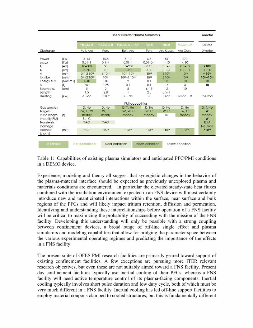
Table 1: Capabilities of existing plasma simulators and anticipated PFC/PMI conditions in a DEMO device. Experience, modeling and theory all suggest that synergistic changes in the behavior of the plasma-material interface should be expected as previously unexplored plasma and materials conditions are encountered. In particular the elevated steady-state heat fluxes combined with the irradiation environment expected in an FNS device will most certainly introduce new and unanticipated interactions within the surface, near surface and bulk regions of the PFCs and will likely impact tritium retention, diffusion and permeation. Identifying and understanding these interrelationships before operation of a FNS facility will be critical to maximizing the probability of succeeding with the mission of the FNS facility. Developing this understanding will only be possible with a strong coupling between confinement devices, a broad range of off-line single effect and plasma simulators and modeling capabilities that allow for bridging the parameter space between the various experimental operating regimes and predicting the importance of the effects in a FNS facility. The present suite of OFES PMI research facilities are primarily geared toward support of existing confinement facilities. A few exceptions are pursuing more ITER relevant research objectives, but even these are not suitably aimed toward a FNS facility. Present day confinement facilities typically use inertial cooling of their PFCs, whereas a FNS facility will need active temperature control of its plasma-facing components. Inertial cooling typically involves short pulse duration and low duty cycle, both of which must be very much different in a FNS facility. Inertial cooling has led off-line support facilities to employ material coupons clamped to cooled structures, but this is fundamentally different

from the environment in an actively cooled device, where thermal gradients will exist throughout the PFC. These thermal gradients will invoke stresses in the material and this stress may significantly alter the plasma-material interface, both from the viewpoint of the plasma (such as possible increased material loss during transient events) as well as the material (such as material cracking leading to changes in thermo-mechanical properties). Existing high-heat flux facilities, such as the electron beam facility at SNLA, use actively cooled components and are actively pursuing component testing for ITER. This capability should be incorporated into the entire PMI research arena. Pulse duration is another area where existing confnement facilities fall short of conditions necessary to support the FNS mission. While off-line plasma simulators routinely have discharges lasting several hours, this is still well short of the days or weeks duration associated with a FNS facility. Clearly the shorter pulse length of existing confinement devices makes matters worse. Increasing the duration of discharges will allow for understanding the evolution of the plasma-material interface into a steady state, or equilibrium, condition. Morphology changes have been observed to occur over timescales approaching hours and how the altered surface morphology feeds back onto the plasma-material interactions and thermo-mechanical behavior of the surface is not well understood. As the duration of exposure increases, more emphasis will be need to be placed on developing real time, in-situ diagnostics. Only by probing both the surface and the plasma during the exposure can one hope to understand the complex interplay between changes in the material and the influence of those changes on the incident plasma. Modeling Capabilities Simulation of PMI is typically separated into three areas: the scrape-off layer (SOL) plasma and neutrals, the electrostatic sheath region just above the material surface, and the material itself, including the surface layers and some distance into the bulk (from a few microns to mm). The main workhorse codes for the SOL use 2D multispecies fluid models for the plasma, though Monte Carlo impurity models are sometimes used and kinetic main species plasma models are beginning to appear. Neutrals are treated via Monte Carlo or fluid models. Sheath region models are inherently kinetic to include ion orbit effects, using either Monte Carlo techniques with many species and prescribed EM fields, or self-consistent particle-in-cell techniques for the main plasma. Material codes are comprised of a range of models, from Monte Carlo with binary collisions, continuum diffusion models, to molecular dynamics models. Individually, these simulations have given confidence that we understand some of the very basic PMI issues to roughly a factor of ~2, though sometimes better. For example, this level of understand applies to (1) agreement with D-alpha measurements confirming that strong particle recycling occurs at surfaces; (2) core impurity content can be reasonable well reproduced with physical and chemical sputtering models, though radial plasma transport coefficients must be assumed; (3) material erosion and local re-deposition on small samples are close to measurements; and (4) hydrogen concentration profiles within (undamaged) materials have the expected scale lengths (check this; need
references?). Many of these comparisons have been done in carbon-walled machines, though some include Mo- or W-coated devices. New Research Needs If the US is to credibly move towards a FNS program that culminates in the design, construction and operation of a FNS device, an array of OFES support activities also needs to be upgraded accordingly. Near-term issues that will need to be addressed in a coordinated experimental, modeling and technology development effort prior to the fabrication of a FNS facility include:
• neutron effects on the performance of the plasma-facing armor and other material surfaces,
• the impact of active temperature regulation, high heat fluxes and realistic operating temperatures on PMI,
• retention and permeation of tritium into the PFCs and the resulting impact on tritium self-sufficiency and device safety,
• evolution of the physical and chemical properties of plasma exposed surfaces toward steady state, and
• the effects of plasma transients on the this equilibrium (stable or unstable) surface state.
The goal of this coordinated effort must be the development of an understanding of the fundamental mechanisms of PFC materials evolution in the FNS device environment. This understanding must be well enough developed and validated that the PFC design activity can then use the results to aid in the design and performance prediction for the FNS PFCs. In parallel to this more science-focused program element, it must be recognized that no solution has yet been identified for the PFCs of an FNS device operating at full parameters. Thus in addition to understanding the fundamental scientific basis of the plasma-material interface, a technological development program must be aggressively pursued and focused on development of a range of materials, joining and fabrication technologies and active cooling schemes that have sufficiently high reliability and maintainability to allow the FNS device to satisfy its mission elements. Enhancements are needed in single-effect off-line facilities such as ion-beams for materials erosion and damage studies, in multiple effect plasma simulator devices which provide the opportunity to thoroughly investigate some of the multiple PMI effects encountered within toroidal confinement devices. Usually the parameters within a simulator can be independently controlled, allowing independent parameter variation studies for comparison to plasma-material interface models. These single and multiple effect devices have limitations that should be addressed in a FNS Program. For example, most single effect and plasma simulator facilities lack the capability to make extensive in-situ real-time studies of the near surface region during ion or plasma bombardment. Furthermore, simulators do not currently have the capability to impose FNS device relevant thermal loads during PMI experiments. Such devices usually cannot handle radiation damaged samples which would most likely be activated. Furthermore, simulators examine the response of material targets, or coupons, to plasma bombardment

and while this approach has been sufficient to replicate conditions in existing confinement devices, it completely fails in providing the conditions needed to study bulk materials issues during high heat flux plasma exposure. Thus such new facilities would need to employ component style mock-ups employing active temperature control in support of a FNS facility. While such modifications can be envisioned and likely implemented, they will add to the cost of research in off-line facilities. However, by employing active temperature control of test pieces, the thermal gradients within the material can replicate those expected in actual plasma-facing components and will permits validation of fabrication technology, including joining techniques, graded material interfaces and fuel permeation into coolants. In the discussion below we outline critical requirements for these new experimental capabilities. In addition, we also discuss the key modeling and materials science and technology research requirements that are needed to support a FNS Program. In-situ Real-time measurements of PMI Effects: Addition of in-situ real-time diagnostics to off-line facilities are needed to provide data that can elucidate not only the fundamental damage mechanisms in the complex plasma edge environment but also the particle-induced material evolution during steady state and transient plasma events. Of particular interest is how the near-surface PMI effects couples to bulk material evolution at depths of a few microns or more. Off-line facilities can also introduce appropriate energetic particle beams to study the bulk/surface interface to elucidate radiation damage effects on retention, diffusion, segregation, permeation and phase transformation (among other mechanisms). Such diagnostics must cover a wide spectrum of depth scales from the first few 100’s nm (where sputtering and recombination are dominant) to regions about 1 micron and then 10’s of microns into the bulk. These probes must be coupled to study dynamic materials effects at the PWI and in addition provide appropriate geometric (e.g. poloidal, toroidal) coverage in tokamak devices. In-situ probing can also integrate with surface analysis in-vacuo after plasma shots when diagnosis during plasma shots is not possible. Ideally these capabilities could couple in-situ PMI diagnostic in tokamak environments to off-line multi-diagnosed plasma and ion-based in-situ materials testing and characterization facilities with multi-scale surface response and plasma-edge computational codes closing the multi-scale spatio-temporal chasm of PMI to scale designs of materials for a FNS facility in the future. More Capable Multi-Effect Plasma-based PMI and PFC Simulators: The first recommended improvement to multi-effect plasma simulators would be the achieving a better replication of the plasmleconditions present at the plasma-material interface. Plasma simulators typically use electron impact ionization to generate plasma, resulting in a low ion-temperature plasma that cannot be independently controlled. The ion energy incident on the target is then achieved by applying a negative potential to the target. While this does allow independent variation of the ion energy, it unfortunately, results in a fairly uniform mono-angular bombardment of the surface. Heating the ion population in a linear simulator to relevant energies will provide a spectrum of incidence angles that will more closely resemble the angular spread in confinement machines.

Another current limitation in plasma simulators is the steady-state power deposited on targets is typically delivered by the plasma itself, again limiting independent control of this parameter. Presently, transient power deposition events are being investigated using laser systems; however developing techniques to vary the incident steady state power flux to a plasma exposed surface independent of the ion flux and/or ion energy would benefit investigation of changes to the thermo-mechanical behavior of the component during the plasma expsoure. Finally, the set of real-time, in-situ diagnostics available on simulator facilities will need enhancement to quantitatively understand the coupling at the plasma-material interface. Perhaps the most challenging aspect of PMI to investigate in support of a FNS program is the importance of simultaneous neutron and plasma bombardment. Due to the significant amount of damage being produced in the ion implantation zone (typically a few 10s of nanometers deep), it is doubtful the additional small amount of damage created by neutron bombardment of this region will have a significant impact on near-surface PMI responses (although we note that this supposition must be confirmed by experiment). However, damage and transmutations created between the implantation zone and the coolant channel could alter the thermo-mechanical behavior of the component which would, in turn, modify the builk material gradients and stresses and would at the same time modify the surface termpature for a fixed thermal load. Additionally, damage and transmutations during plasma exposure could alter the diffusion and trapping of fuel atoms throughout the material, further impacting thermo-mechanical response. It will be imperative at some point in the pathway to a FNS facility, to couple a plasma simulator to a neutron source to ensure that some unanticipated synergistic effects do not arise. In summary, off-line facilities currently cannot examine the following important issues:
• Current ion-beam facilities missing multi-scale diagnostics (time, space), need for more in-situ and real-time surface and emission plume characterization. (Critical for boundary condition on surface-response computational codes that are coupled with plasma edge and core computational codes.)
• In-situ capability to examine composition-driven surface morphology evolution, irradiation-driven phase transformations, and material self-organization.
• Single effect off-line facilities and role that dynamic in-situ facilities can play in understanding time-dependent material modification mechanisms. How can complementary diagnostics probing both surface and evolving erosion plume elucidate on irradiation-driven modification effects.
• Role of flux vs fluence dependence of plasma-based surface and near-surface modification. Role of flux and fluence on synergistic multi-particle effects (e.g. He and H).

• He retention and recycling, edge plasma impurities and magnetic plasma sheath effects on particle transport and re-deposition
Materials Science and Technology Requirements: The fabrication of PFCs from refractory materials such as tungsten requires resolution of technological issues involving refractory solid materials processing and testing development such as tungsten alloy machinability, bonding properties, process/fabrication and irradiation damage characterization capability. We emphasize that until solutions to these issues are found and tungsten based PFCs are determined to be a credible solution to the FNS Program requirements, alternative materials options for the PMI must be considered. These options may include other solid materials choices; alternatively solutions lying outside solid materials need to be examined as well.. In particular, liquid-based materials such as liquid metals should be examined as candidate PMI material systems until such a time that a solid materials choice can provide a reliable solution. Clearly such systems are much less well developed and defined and entail a significant element of risk and development required. Modeling Requirements: The peak heat flux to divertor and wall surface is a critical parameter impacting the feasibility and design of the divertor of the FNS, and yet there is no clear understanding of the physics that determines this quantity which, as a result, is usually projected using empirical studies. For the design of FNS, it will be essential to understand the physics governing the divertor and first-wall heat and particle loads; such understanding will require a careful program of confinement device experiment, theory and modeling. A more lengthy discussion of this issue can be found in the Integration section. A second key question requiring new modeling work involves the long-time equilibration of PMI in which the concentration of plasma-deposited and implanted species within the material, and subsequent evolution of the material and sheath come to a new state. This problem requires the development of well-coupled SOL-sheath-material models and then validation of these models against off-line and confinement device experiment. It will also be important to improve the transport models for the plasma and the materials where damage from high-energy particles, especially neutrons, must be included. The coupled model should be extensively validated with data from US devices and by building collaborations with operating long pulse superconducting confinement devices. A third element needed for an FNS device is likely the need for a kinetic model of the SOL plasma owing to the higher energy of the plasma in FNS and thus a reduced collisionality which then invalidates the fluid models on which existing SOL models are based. While such models have begun to be developed, they have focused mostly on the pedestal region, which is weakly collisional; the SOL is characterized by a rapid transition from long to short mean-free paths, which is computationally more demanding. It is worth noting at this point that the above modeling issues present examples where the essential elements of the problem to be modeled are multi-scaled, in that spatio-temporal

scales cutting across many orders of magnitude are linked. This is not unlike many core plasma physics issues; thus techniques and approaches that are already being developed for the core region may be applicable to the PMI and PFC region as well. It is distinctly possible that the heat flux presented by conventional divertor approaches will simply be impossible to handle, and thus research into alternate heat-flux handling configuration should be supported. Modeling can play a vital role here and could guide the evaluation and possible choice for testing in existing confinement devices. Possible new concepts include configuration changes such as the super-X and snowflake divertor designs, extended radiative divertor designs, liquid walls, and other possible concepts. Research into liquid divertors/walls will bring in the need to model the flow of the liquids in a strong magnetic field, which is especially challenging for liquid metals.
4.4 PFC-‐PMI Engineering Issues and Decisions PFC-PMI Engineering Issues and Decisions covers primarily the response of plasma facing components (PFCs) to thermal and mechanical loads. Our approach is to examine the constraints by which designers establish design requirements and the issues and decisions that arise in trying to meet these requirements. The sections that follow summarize these issues and decisions. The last part of this section on PFC-PMI Engineering Issues and Decisions gives an outline of R&D activities and related needs for facilities. The experimental activities supporting the development of actively cooled PFCs in the US has three branches. The first is the development of water-cooled PFCs for ITER and previously for Tore Supra. While the goal of this development does not have applications for a DEMO, the nature of the activities is significant in how it has defined the approach for qualifying PFCs for deployment. The second and third branches, covered later, are respectively helium-cooled refractory PFCs and PFCs with liquid surfaces and those cooled by molten salt or liquid metals. The path forward to a DEMO involves these latter branches, but the US investment in either of these is quite limited. Modeling is not called out as a separate activity here, but is fundamental to the effort to successful development of PFCs. Our capability to predict the performance of these future PFCs can only come from an R&D path that includes high heat flux testing of PFCs that is closely coupled with detailed modeling that incorporates the complex conditions for PFCs. We anticipate that high heat flux and other testing in the future will be coordinated with modeling to provide benchmark data and that the testing program will evolve into an activity where the test conditions are developed to confirm predictive models. The modeling is not called out separately in the following sections but is noted in the R&D Outline (last section). In a DEMO or an FNSF we anticipate that any structures that face the plasma will have to be actively cooled. This will include a class of component such as RF launchers and guard limiters and perhaps the mirrors or other end fittings on diagnostics. We can expect that the requirements (heat loads, etc.) for this class of specialty PFCs will be defined and may include operating conditions such as electric fields that differ from other

PFCs. Our experience in this area is limited. Can RF launchers (antennae and mirrors) operate successfully at high temperature? If launcher has the same (PFC) material as the first wall and/or divertor, how do the electric field and other local loading conditions, increase the heat and/or particle loads and what mitigating strategies are possible? These are not called out separately in this document but the needs are recognized and the introduction of actively-cooled structures facing the plasma represents a new area of needed development. The last part of this section on PFC-PMI Engineering Issues and Decisions gives an outline of R&D activities and related needs for facilities.
4.4.1 ITER ITER integrates active-cooling, a D/T plasma and metal PFCs including tungsten in the divertor. While we do not consider the range of temperature and materials other than tungsten relevant for a DEMO, ITER is fusion’s first nuclear system and the experience with detailed designs of the PFCs in ITER and the design integration of these subsystems is providing us a tremendous amount of experience about the integration of PFCs into this complex system. Uncertainties in the physics of how power is exhausted at the edge of the plasma have driven the design of the ITER PFCs. We have also seen the first wall (FW) change significantly in response to changes in the design requirements.
1. The realization that convected power (particles, rather than radiation only) from the plasma would contact the walls and cause halo currents, led to a total redesign of the FW with the FW fingers now running in the toroidal rather than poloidal direction.
2. Accommodating the paths of disruptions considered as possible threats led to an increase of ~10X (~5MW/m2) in the peak transient heat loads to the FW.
The design solution currently in place in ITER for the roughly 40% of the FW where are the use of (a) hypervapotron cooling (for greater margin against burnout
than other water cooling techniques) and (b) strongly shaped FW panels with the edges of the FW panels recessed to mitigate against misalignments and the “leading edge problem” shown in Fig 1. Specifically, a protrusion (e.g., misaligned edge of a PFC) into the plasma edge will intercept a huge parallel heat flux.
4.4.2 High Level Choices for PFCs As we consider possible research pathways for PFCs, several high level choices regarding the options are apparent. Three such areas for PFCs are summarizes briefly below. solid or liquid walls? Each system has tremendous challenges to resolve. Less is understood about how to
integrate liquid surface systems. No designs yet based on a new view of the plasma edge.
Figure 1. “Leading edge” problem: Any protrusion into the edge of the plasma intercepts a huge parallel power following magnetic field lines and overheats (red).

Need better understanding of physics in plasma edge. We need “push back” from fusion technology experts to specify what is acceptable to
manage power reliably for a DEMO or FNSF. We are investigating tungsten-based PFCs even as we recognize the challenges such
as improving ductility and understanding the evolution of microstructure in a DEMO. Liquid PFCs have issues regarding the control of the free surfaces and successfully
integrating such systems, and our knowledge base is quite limited. There is interest in both the beneficial effects of lithium at the edge of the plasma, and
for liquid walls as the “default path” for development in parallel with solid walls. We can anticipate that at some point, one of these options will be favored. The issue is at when and what are the implications for an FNSF. If we assume that a single FNSF would not be able to test both liquid and solid walls, then this decision comes well before the decision to build a single FNSF, or there is a sequenced plan to recover if one pathway falters. Obviously the decisions here imply requirements for R&D and for a level of confidence in one or more options brought to readiness on the path toward an FNSF. Disruptions and large ELMs? The decision to build [FNSF or a DEMO] with goal of reliable, repeatable
operation and high availability has obvious requirements regarding plasma disruptions and large ELMS. This implies the simple decision tree below for a tokamak or any other concept.
Figure 2. Simple decision tree regarding disruption and ELM mitigation.
Were the criteria in Fig. 2 not fulfilled for advanced tokamaks, the decision away from this path would be extremely difficult and this simple diagram emphasizes the importance of this area of research. The other bullets from above would also apply here: No designs yet based on a new view of the plasma edge; Need better understanding of physics in plasma edge; and need “push back” from fusion technology experts to specify what is acceptable to manage power reliably for a DEMO or FNSF. Low activation materials? Fusion has promised an attractive plant with materials that can be recycled. Low activation is an important part of the public perception of fusion and of the
attractiveness of fusion to the power industry and governments. Hypothesis: Some compromise away low activation materials would reduce the resources and time needed to develop materials. Can/should we consider such a trade-off? If so, then … - What are the “costs” in terms of attractiveness to public, industry and
governments? - What are the benefits in an accelerated schedule and less investment for R&D?

The issue here is one of costs meaning funding for R&D traded against a “programmatic cost” associated with the redefinition of interim goals that might alter support for the program.
4.4.3 Heat Loads to PFCs Our capability to predict the heat loads in a future FSNF or DEMO is severely hampered by uncertainties in the details of how the plasma transports power from the edge to the PFCs, e.g., there is very limited understanding of λq despite this being critical in predicting wall heat fluxes. These are uncertainties in physics that must be significantly reduced before we have a credible path forward to an FNSF or DEMO because the engineering needed to deal with the possible range of heat loads and how they might be distributed on the PFCs would be unacceptable as a design basis. To handle power from the plasma we need:
• an approach to distribute the heat, e.g., radiating power from the edge, configurations that permit flux expansion in the divertor, etc.; and
• heat loads that we can accommodate with realistic engineering solutions for the design, e.g. cooling, materials, fabrication, etc.
Our understanding of heat loads for future PFCs has improved, but the basis for predicting heat loads has big uncertainties. Peak heat loads for a given operating regime are proportional to the width (λq) of
the zone at plasma edge, i.e. “near” SOL (scrape-off layer) that convects most of the power to the wall. But projections of λq and how λq scales with power are uncertain. [Maybe λq ∝ 1/power. Research on this topic is ongoing at MIT, GA and other institutions.]
Transients (ELMs, disruptions) set maximum transient heat loads. There is significant convected power beyond the near SOL of the plasma and this
power will reach the wall. The three primary concerns regarding how heat loads affect the performance of PFCs are 1) the maximum temperature of the PFC, which is at the plasma-facing surface, 2) the range of operating temperature, and 3) thermal gradients and uneven thermal expansion that produce stress. The maximum temperature of the plasma facing material is important for several reasons. It affects whatever chemistry is involved in the recycling of fuel from the walls. Also, the microstructure of the near surface region evolves under conditions of thermal stresses, thermal gradients, implantation of other species (D and T and impurities from the plasma) as well as damage from ions and neutrons, and this evolution depends on processes including diffusion, motion of dislocations, trapping and others that have dependencies on temperature. Issues relate to recycling and retention of tritium are covered elsewhere.
The thermal gradient in a plasma facing material is proportional to the heat load, for which there is considerable uncertainty. The peak temperature increases with the thickness between the plasma facing surface and the coolant. Beyond a minimum thickness (e.g., 3 mm to mitigate against variations in materials and quality in thinner-walled structures), the additional thickness of PFC armor is there to mitigate against erosion. Also, the thermal expansion of the hotter portions of a PFC causes stresses. Problem points where designers often find high stresses are the edges of joints between dissimilar materials and the corners and edges that contain volumes, such as the first wall structure in a breeding blanket module. Pushing limits with design improvements for divertors has been the subject of recent work in the US design study activity ARIES.[1] The ARIES Team has investigated designs such as the tapered T-tube divertor, modified divertor finger, W-pin first wall concept and design features such as heat transfer enhancement with jets + fins, external transition joints, fingers-in-plate designs, and external transition joints, and design approaches such as 3D elastic-plastic analysis with thermal stress relaxation, application of accumulated strain limit, birth-to-death modeling with fabrication steps, operating scenarios and off-normal events and (in future) thermal and irradiation creep, crack growth and low-cycle fatigue and irradiation damage effects. With regard to PFCs, we have begun studies on actively-cooled solid walls and, to a very limited extent, studies of liquid-surface PFCs. With this limited knowledge base, we recognize basic limitations in materials (melting or unacceptable stresses) and some that stem from the integration of materials into structures and subsystems (e.g. an integrated first wall and breeding blanket.) For divertor targets, the design solutions proposed for solid divertor targets for a DEMO are typically in the range of 10-20 MW/m2. For the FW the steady state loads have typically been in the range of 3 MW/m2 or less. However, the implications of the basis for power handling with the newer understanding of the plasma edge now being applied to ITER were not used in past design studies.
4.4.4 Solid Walls We emphasize tungsten as the base for plasma facing materials because the magnetic fusion program is heavily invested in tungsten through the implicit commitments from our vision for advanced fusion reactors. In divertors for DEMO and power plants, the high temperature of the coolant, higher temperatures of the materials and high radiation doses preclude the use of copper or copper alloys, while ferritic steels do not have the required thermal conductivity (~100 W/m-K) combined with adequate strength at the desired maximum allowable temperature (>1000°C). Refractory materials offer the only possibility as structural materials. Tungsten alloys are attractive if some can be developed to operate under irradiation within a reasonable temperature window. Divertors in most recent design studies in the US and the EU for a DEMO or power plants utilize a He-cooled W-alloy configuration to provide high temperature operation. Other refractory materials or their alloys are excluded due to neutron activation. A paper by Raffray [2] reviews the development of divertors for DEMO and one by Tillack [3] reviews progress on helium-cooled PFCs.

The most active current R&D efforts in joining and coating with tungsten are the development of the HEJM divertor modules led by Karlsruhe Institute of Technology (at FKZ). Obviously, a high temperature braze is necessary and the resulting joint must be robust and resist any significant degradation due to thermal aging or neutron irradiation. There is no activity in the US on joining of tungsten other than some intermittent projects that arise through DOE’s SBIR Program. We consider two applications, one for divertors and specialty PFCs such as RF launching structures and a second for first wall systems. We expect the former to have higher heat loads but more flexibility in design because the FW structure must be integral with the breeding blanket for acceptable neutronics to get sufficient breeding ratios.
Solid walls + high-temperature coolant ⇒ refractory materials (high-efficiency power conversion)
Divertors in most recent US and EU design studies for DEMOs or power plants utilize W armor and He-cooled W-alloy heat sinks.
W-based metals are attractive if we develop materials that can operate in a reasonable temperature range and severe conditions (irradiation, etc.) and remain robust against failure. This is a challenging goal.
Possible approaches:
1. Limit W parts (e.g. armor tiles or coatings or graded materials). 2. Limit loading conditions to permit robust performance of these parts. 3. Use armor or coatings supported on robust ductile materials.
Currently the issue of whether it will be possible to design a bare metallic wall with a material other than tungsten facing the plasma is an open question. A W-armored FW would have lower heat loads than a divertor but is also integral with the blanket. Two main issues are:
1. What is the underlying structure, e.g. an advanced ferritic alloy? (See comment below)
2. What type of plasma facing material for a FW is appropriate? Pure W only? Can coatings and graded structures be considered?
Can we use ferritic alloys for the first wall structure? The desire for permanent structure and concerns about cost, fabrication and compatibility have favored iron-based alloys, e.g., advanced ferritics. But, the description of the power exhaust from the plasma edge now being used for ITER suggests that the heat loads to the FW will be higher than values of ~0.5 MW/m2 representative of older design studies. With higher heat loads, the design basis for iron-based alloys may not have adequate thermal conductivity. The equation below indicates that for a heat load of 5 MW/m2 (the peak transient now used in ITER), the temperature difference from the heated surface through a 3-mm wall to a cooled surface would be ~450 C. This temperature difference (ΔT) is about 30 C per mm of wall thickness and per MW/m2 of power absorbed. Of course this ΔT is reduced

for a thinner wall, but designers have typically taken 3 mm as a minimum wall thickness to mitigate against variations in materials and quality in thinner-walled structures. Further thickness of PFC armor is added to mitigate against erosion.
Figure 3. Calculation shows the large increase in temperature from the coolant side
to the plasma side of a ferritic wall.
The pathway with solid walls has challenges in the development of materials and sub-systems. We must face inherent limitations in materials, such as the thermal conductivity of ferritic alloys, either by modifying the loading conditions or finding other materials.
4.4.5 Liquid Walls There are several candidates for liquid metal-based PFCs, including gallium, tin, lithium, and tin-lithium eutectics. Among these, lithium and probably the tin-lithium eutectic should provide a low recycling surface, while other liquid metals are high recycling. A flowing liquid metal PFC would have limited residence time (less than a second to ~tens of seconds) in a fusion reactor, before removal and recirculation. Hence erosion, helium and neutron damage, and tritium retention are not significant issues (provided that low recycling liquid metals, such as lithium, can be adequately purged of tritium before recirculation). PMI issues (sputtering, evaporation) would be limited to the liquid metal PFC, whereas the solid substrate supporting the liquid would only be subject to neutron damage. The separability of PMI and neutron damage considerably simplifies material qualification for reactors. The possibility of using thin layers of liquid permits intensely cooled systems, with the plasma-exposed surface closely coupled to the underlying coolant (either helium, or a flowing liquid metal). Evaporation is one primary limit. Figure 4 shows rates used in the APEX design activity.[4] The APEX activity looked at several possibilities for liquid surface systems and included development of a divertor design with a molten salt rather than a liquid metal.[5] We extract the peak allowable temperature from the evaporative limit and this
Figure 4. Evaporation rates for liquid metals.
temperature sets the limit for allowable net heat absorbed over the path that the liquid surface is exposed to the plasma. (This statement is an oversimplification because the impurity term is an integrated value of what the plasma tolerates.) If the flow is fast, then MHD forces on a liquid metal will likely dominate the distribution of flow velocities and this will control the heat transfer. If the flow is slow, as in some concepts with capillary flow, then viscosity will likely control the flow rate. Among the promising ideas for liquid surfaces are concepts where a body force can drive the flow, as in approaches proposed by Zakharov[6] and by Ruzic[7]. MHD effects dominate liquid metal flow in magnetic fusion devices. We have made progress understanding the effects of the MHD on liquid metal flow, but the capability to do predictive modeling of complex configurations is still beyond current capability. Development of liquid metal PFCs is in an early stage. There are very few, relatively small, liquid metal PFC test facilities in the U.S. Only a few liquid metal systems have been tested in tokamaks, with a focus on lithium as a tool to reduce hydrogen recycling and high-Z impurities. The implementation of liquid metal PFCs in tokamaks has been predominantly in static or evaporative systems.[8] Additional tokamak devices (FTU and T-11M) have demonstrated withstanding heat loads above 2 MW/m2 using capillary porous systems (CPS) for liquid lithium PFCs. [9,10] Much higher power loading (>50 MW/m2) has been demonstrated in evaporatively-cooled test stands, or with self-generated flows,[11] but not in operating tokamaks. The use of fast flowing liquid metal jets, for example, has been tested in only one or two very small devices. Prominent issues for both high and low recycling liquid metals include the entire problem of introducing the liquid metal to, and removing it from, the reactor, and inducing stable flow to transport the fluid from inlet to outlet. MHD effects caused by the excitation of electrical currents in the liquid metal PFC must not cause macroscopic influx of the liquid metal into the plasma. Sputtering and evaporation must be kept to acceptable levels including temperature-enhanced erosion. Heat removal must be effective. Coverage of the underlying substrate by the liquid metal, in the case of slow flow, must be complete, since the substrate will not be designed for exposure to plasma. For jets or open-surface channel flow, splashing and surface variations must be eliminated. For capillary systems, clogging and non-uniform coverage must be avoided. The design of inlet manifolds and fluid collection systems is a challenge for either type of system. Tritium migration through the liquid metal into underlying coolant channels must be investigated; since different liquid metals have differing affinities for hydrogen, this work is specific to each candidate liquid metal and eutectic. Finally, for lithium, the physics consequences of low recycling walls for tokamak equilibria must be thoroughly explored, since the consequences for reactor design can be considerable. This last issue closely and explicitly links liquid metal PMI and the fusion core. 4.4.6 Concluding Comments – Failure Modes In evaluating the requirements for R&D, we must somehow assess the magnitude of effort that will be needed to assess failure modes and then understand how the answers might set lower limits on the funding needed to complete the development and the pace

of the R&D needed to undertake a decision to build an FNSF. For example, as we consider the implications of how W/W divertors and W/FS first walls might fail, the level of failure that would be considered for licensing differs from a failure that simply causes prolonged delay in operation. A coating failure that appeared to be systemic in nature with more events expected might require some global rework and an extended delay of operation, but such a failure might not imply and problem with safety or licensure. Concerns about our knowledge base in how PFCs (and other components) can fail lead to several types of questions that must be addressed in developing PFCs.
(1) How will we determine the expected modes and rates of failure? (2) What degree of confidence in our predictive capability via modeling with some
confirming data will be necessary to build an FNSF and then a DEMO? What data will be needed for approval to build, and what can be accumulated during operation?
(3) How are radiation damage likely to affect failure modes and rates, and how does this affect the answers for (1) and (2)?
Some experts who participate in the fusion program and have extensive experience with commercial development outside fusion believe that the fusion program does not yet recognize the magnitude of this task. 4.5 Conclusions and Recommendations We have identified and summarized the key issues that arise when considering the integration of a FNS device plasma core with the first wall, divertor, and heat removal system of such a device which, together, form the PFC system. These issues are critical to the mission success of an FNS device in the sense that adverse PFC impact on core plasma performance or PFC failure can jeopardize or even prevent successful demonstration of the FNS device mission. A substantial research effort focused on both basic scientific and engineering technology advances is needed before a credible FNS device design can be completed. These advances must provide confidence that:
• An FNS device can integrate high performance core plasmas with acceptable net erosion control, including effects from the accumulation of material debris, on >106 s timescales using DEMO-relevant PFCs and heat removal concepts.
• These PFCs must be viable for > 106 s timescale against both quiescent and transient heat loading and must be compatibly integrated with high power density non-inductive core plasma operational scenarios,
• They must demonstrated control of fuel/tritium accumulation in PFC materials on >106 s timescale compatibly integrated with the requirements of core fueling, density control, and tritium self-sufficiency.
4.5.1 PMI/PFC studies in Confinement Devices:
There are a number of near-term research approaches in existing confinement devices which could improve our understanding of the scientific and engineering technology questions that govern these key issues. These include:
• Using the present fleet of US tokamaks more effectively to assess PSI/PFC science in relevant conditions by investing in either better diagnostic coverage, innovative PSI diagnostics and/or experimental time.
• Recognizing that PSI and PFC limits of heat exhaust and erosion control must be an integral part of the development of advanced non-inductive core/pedestal tokamak operational scenarios, rather than an issue examined “after the fact”. This requires a higher level of confidence in predicting or scaling pedestal/SOL/divertor behavior.
• Successful development of robust disruption-free scenarios that have a stationary pedestal without intermittent heating from ELMs. Note that this means abandoning the standard path of type-I ELMy core plasma predictions as used for ITER. If this cannot be achieved then, if MFE is have a viable pathway to energy, then either solid-material PFCs must be abandoned and self-healing liquid PFCs are developed or the tokamak path is abandoned for the stellarator, introducing a 3-D boundary, divertor and PFC configuration effects.
• Upgrades to existing tokamaks, or developing new facilities/device, which operate at DEMO-relevant PFC temperatures for materials should be implemented in order to demonstrate integration of required core plasma performance with a reactor-relevant PFC system.
4.5.2 PMI/PFC Studies in Off-line Facilities: Improvements in single-effect and multi-effect experiments, performed in linear plasma simulators and ion beam and electron beam facilities, combined with improved modeling efforts, are also needed to provide a sufficient design basis for a FNS device PFC system. Recommended improvements include:
• Addition of in-situ real-time diagnostics to both ion-beam and plasma divertor simulator facilities are needed to provide data that can elucidate the particle-induced material evolution during steady state and transient plasma events. Of particular interest is how the near-surface PMI effects couples to bulk material evolution at depths of a few microns, and how these mechanisms impact hydrogenic and helium isotope retention, migration and permeation
• More fully replicate the plasma conditions present at the plasma-material interface by heating the ion population in a linear simulator to energies that provide a spectrum of ion incidence angles that will more closely resemble the angular spread in confinement machines.
• Couple FNS device-relevant steady state power fluxes to plasma exposed surfaces in plasma divertor simulators in order to develop a predictive understanding of the thermo-mechanical behavior of PFCs during the plasma exposure.
• Study radiation-damaged material response to plasma exposure at high heat flux. Perhaps initial studies could use suitable ion beams to mockup neutron induced damage; when coupled with materials damaged in fission reactors and, later on, in spallation neutron sources such studies would provide data for use in validated predictive modeling of FNS device PFC system performance.
4.5.3 PMI/PFC Modeling Needs: These experimental capabilities need to be matched by developments of improved PMI and PFC modeling which should be validated using both confinement and off-line experimental studies. Key modeling capabilities that need to be developed include:
• An understanding of the physics that leads to the particle and thermal loads on the divertor target and first wall
• Long-time equilibration of the SOL, pre-sheath, sheath, and near-surface PMI region.
• Suitable kinetic models of hot SOL plasmas that will be found in FNS devices, as well as modeling f novel emerging divertor concepts such as the Super-X and Snowflake divertor concept.
• Edge and SOL main plasma and impurity flows coupled to material erosion, migration, redeposition and subsequent mixed materials surface formation.
4.5.4 PFC Engineering R&D, Issues and Decisions: The outline here appliers to immediate research needs 1-5 years, and for each of the research areas below, the following comments apply.
• Experimental investigation in simulated fusion conditions • Application of heat transfer enhancements for He-cooled FW and other PFCs • Models validated in simulated conditions • In depth evaluations of subsystems and incorporation of these efforts into systems
modeling (longer term goal but should be started now) • Primary emphasis is on validity of simulations even at the expense of having non-
prototypic materials or fabrication processes that are as yet unconfirmed for industrial applications.
• Close interaction and collaboration is needed with the efforts in both modeling and experiments to further the knowledge and understanding of the plasma boundary and to further the knowledge and understanding of how tritium breeding blankets behave as an integrated system.
4.5.5 Performance Limits for Unirradiated He-cooled W-based Divertors and Specialty PFCs
1. Assess the limits for the current concepts for tungsten-based PFCs through subsystem studies and the development and testing of small mockups. Include samples with surface modifications due to PSI such as fuzz or He bubbles.
2. Through subsystem studies, identify ideas for potential improvements for tungsten-based PFCs in their heat transfer, performance under cyclic loading and overall robustness and test representative small mockups
3. In collaboration with the safety, power handling and design study activities, identify what, if any, alternative paths and tradeoffs in performance are possible for solid walls if development of tungsten-based PFCs appears to be infeasible or has unacceptable development cost.
4. Work with specialists involved with the functional requirements for in-vessel components such as RF launchers, antennae, coils and plates for field modifications and diagnostics to evaluate the requirements for these systems to operate with

active cooling, high temperature walls and ion damage and (in future) neutron damage. Identify the development needs. Start a program aimed at deployment of relevant upgraded technical solutions for use in existing devices and upgrades as part of the learning needed for integrated solutions in the future.
4.5.6 Heat Transfer and Performance of He-cooled Ferritic FWs with integrated surrogate blankets (for Pb-Li)
1. With well coordinated efforts in experiments and modeling of He-cooled ferritic FWs with surrogate blankets, develop and perform tests that simulate the structural constraints and heat transfer from the FW.
2. Assess the limits in performance of ferritic FWs with plasma-facing coatings to retard tritium permeation through subsystem studies and the development and testing of small mockups
3. In close collaboration with the US TBM program (assumed), develop and perform HHF tests on TBM FW samples to complement US R&D on ITER TBM
4.5.7 Actively-‐cooled PFCs and Probes on Existing and Near Term Devices 1. Cooperative programs with existing and near term experiments to develop and
deploy a definitive hot wall experiment (may require heat removal and plasma facing surfaces that are useful for this test but do not extrapolate to an FNSF or DEMO)
2. Cooperative programs with existing and near term experiments to develop and deploy actively cooled PFCs
3. Cooperative programs with existing and near term experiments to develop and deploy actively cooled materials probes
4.5.8 Support for Novel Heat Transfer and Pumping Schemes 1. Cooperative programs with existing and near term experiments to develop the
heat removal technology for novel divertor schemes such as the snowflake and super-X divertors
2. Cooperative programs with existing and near term experiments to develop concepts for upgraded lithium divertor modules or full divertors on NSTX and TPX
3. Development of proof-of-principle tests to enable deployment of novel PFCs in existing and near term devices
4.5.9 Development of Liquid Metal PFCs 1. A multi-laboratory effort to investigate substrate optimization (for slowly flowing
liquids), including capillary effects, as well as general chemical effects, corrosion (including corrosion of neutron irradiated materials), wetting, etc. is needed.
2. Design and engineering of practical devices for injecting, controlling and removal of liquid metals, in the presence of fusion-relevant magnetic fields.
3. Design and engineering of systems to remove heat from liquid metal PFCs, for slowly flowing liquid metals. Fast flowing liquids (e.g. jets) would carry the heat load with the fluid.
4. Following test stand qualification, liquid metal systems must be tested in a plasma confinement device, with discharge durations in excess of the residence time of the fluid in the system.
4.5.10 Detailed Subsystem Design Studies These activities summarize the calls for subsystem studies and assessment noted previously. These are likely to be continuing topics that evolve from more general assessments of interfaces and requirements to more detailed evaluations of options for subsystems that begin to incorporate predictive capability for performance. The point here is that such activities should begin in the near term and then mature.
1. (from A1 and A2) Assess the limits for the current concepts for tungsten-based PFCs through subsystem studies, and identify ideas for potential improvements for tungsten-based PFCs in their heat transfer, performance under cyclic loading and overall robustness
2. (from A3) In collaboration with the safety, power handling and design study activities, identify what, if any, alternative paths and tradeoffs in performance are possible for sold walls if development of tungsten-based PFCs appears to be infeasible or has unacceptable development cost.
3. (from A4) Work with specialists involved with the functional requirements for in-vessel components such as RF launchers, antennae, coils and plates for field modifications and diagnostics to evaluate the requirements for these systems to operate with active cooling, high temperature walls and ion damage and (in future) neutron damage. Identify the development needs.
4. (from B1and B2) Assess the limits in performance of Ferritic FWs with plasma-facing coatings to retard tritium permeation through subsystem studies and the development and testing of small mockups With a well coordinated efforts in modeling of He-cooled ferritic FWs with surrogate blankets, develop tests that simulate the structural constraints and heat transfer from the FW.
5. (from E) MHD modeling of liquid metal transport at high Hartmann and Reynolds numbers with fusion relevant fields, configuration and magnetic field gradients, including the effect of plasma MHD on the stability of liquid metals.
6. (from F1) Identify important interfaces and modifications such as changes in materials and requirement for active cooling that will permit their use with high temperature walls. Identify early “win-win” applications, e.g., He-cooled mirrors or reciprocating probes, where the capability for heat removal or other adaptation can increase the functional range of the diagnostic for near term deployment.
7. Coordinate with design studies effort and cross talk with champions of novel PFC concepts to define the R&D in fusion nuclear technology and system integration issues and to establish the level of confidence as R&D and deployment proceed.
8. (part of larger activity that includes PFCs) Work with specialists on in-vessel systems including diagnostics to develop an activity that raises awareness of the requirements for plasma diagnostics and in-vessel instrumentation for safety,

control and understanding of the performance of PFCs (and other in-vessel subsystems).
9. (part of larger activity that includes PFCs) Work with design studies to assess the implications of PFC concepts for system interfaces such as remote handling, tritium managements and safety.
4.5.11 Facility Needs: 1. High heat flux test stand for divertor and specialty PFC tests (Topic A) and for
development and proof testing of PFCs and probes for near term deployment (Topic C) and testing of novel concepts for heat removal with solid walls (Topic D, solid walls)
a. steady state heat load of 10 MW/m2 absorbed over at least 0.05 m2 [upgrade to larger area and more total power in ~10 years]
b. capability for overlaying transient heat loads (TBD ELMS and disruptions) onto targets receiving steady state heating or thermal cycling
c. helium cooling with He in test targets at 600C, 8-10MPa and XX g/s and heat rejection for ~1 MW of power [upgrade to more power in ~10 years]
d. extensive diagnostics for distribution of surface temperature, bulk temperatures, strain/displacement, coolant calorimetry, etc.
2. High heat flux test stand for FW testing with dual coolants (Topic C) and for testing
of novel concepts with liquid surfaces (Topic D, liquid surfaces) a. steady state heat load of 5 MW/m2 absorbed over at least 0.1 m2 [upgrade to
larger area and more total power in ~ 10 years] b. capability for overlaying transient heat loads (TBD ELMS and disruptions)
onto targets receiving steady state heating or thermal cycling c. helium cooling with He in test targets at 600C, 8-10MPa and XX g/s and heat
rejection for ~1 MW of power [upgrade to more power in ~10 years] d. auxiliary liquid metal or molten salt loop with preheater and HX to supply
coolant or heating to back of an integrated FW module [specs TBD] e. extensive diagnostics for distribution of surface temperature, bulk
temperatures, strain/displacement, coolant calorimetry, etc. f. flash heating or other capability to measure the thermal conductance of
coatings and novel materials.
3. A comprehensive liquid metal test stand capability. a. A liquid metal loop feeds and drains a target surface, with appropriate flow
rates over the surface. b. A relevant magnetic field and preferably a low and adjustable field angle to
the surface. c. High heat flux testing should be available, method TBD. [Magnetic field may
preclude e-beams; overlap with 2 above needs to be resolved.] d. Ability to perform simultaneous PMI studies, at least on a time scale
appropriate to the residence time of the fluid on the target surface, is desirable

e. Comprehensive diagnostics of the liquid metal surface behavior should be available.
4. Electromagnetic load test stand (old FELIX test stand at ANL in 1980’s is
example) used to benchmark code calculations. [Alternate opinion may be that code capability has outstripped of test stands to provide useful data.]
5. Shake table to assess displacements of PFCs (and integrated blankets) to simulate seismic events. [This need is indentified only tentatively and needs further review with those in Safety.]
4.6 Appendix This appendix provides supporting technical materials for the discussion and recommendations. The information is organized by confinement device showing present US tokamaks, an example FNSF (FDF or FNSF-ST) and an example conventional aspect ratio DEMO (ARIES-RS or ARIES-ST). Following each table is a brief discussion of key physics or technology issues. For clarity the tables have been separated according to aspect ratio pathway. Notes and references are cited throughout the tables and catalogued at the end of the tables. Table A.1 Main parameters of confinement devices High aspect ratio pathway
Description Parameter Alcator C-Mod DIII-D FDF ARIES-
RS Major radius R (m) 0.67 1.7 2.49 ~5.52 Aspect ratio R/a 3 2.8 3.5 4
Heating power P (MW) 8 24 108 430 Fusion gain Q 0 0 <5 ~ 22
Toroidal field B (T) 5.4 2 6 8 Plasma current Ip (MA) 1.25 1.4 6.7 11.3 Safety factor q*,cyl 3 3 2.9 2.8 Elongation κ ~ 1.7 ~1.8 2.3 1.9 Greenwald
fraction n20 /nGr 0.6
(assumed) 0.6
(assumed) 0.6 ~0.9
Density n20 5 0.7 2.5 1.7 Pulse length Tpulse (s) ≤ 3 ≤ 10 ~2x10⁶ ~ 3x10⁷
Low aspect ratio pathway
Description Parameter NSTX-U FNSF-ST ARIES-ST Major radius R (m) 0.93 1.3 3.2 Aspect ratio R/a 1.65 1.7 1.6
Heating power P (MW) 20 59 624 Fusion gain Q 0 1.7 ~100
Toroidal field B (T) 1 2.9 2.1 Plasma current Ip (MA) 2 6.7 29 Safety factor q*,cyl 3.5 4.1 2.8

Elongation κ 2.6 2.8 3.4 Greenwald
fraction n20 /nGr 0.6
(assumed) 0.28 0.7
Density n20 1.1 1.03 1.6 Pulse length Tpulse (s) ~2 ~2x10⁶ ~3x10⁷
Due to the scaling of Greenwald density limit with size, i.e. n~1/R at fixed safety factor and B, the DEMO design points are typically pushed to near the Greenwald limit for reactivity. Safety factor qcyl~3 is required for obtaining sufficient absolute plasma pressure and fusion power density. Pulse lengths for FNSF and beyond requires non-inductive scenarios and represent single biggest relative change. Table A.2 Boundary plasma , SOL characteristics and power dissipation High aspect ratio pathway
Alcator C-Mod DIII-D FDF ARIES-
RS Plasma surface area S (m2) 8 56 124 454
Global power density P/S
(MW/m2)
1 0.35 0.87 ~ 0.95
Magnetic pitch at outer midplane
BZ / BT (~ ε/q*) at q*~3
0.11 0.12 0.1 0.1
Power width at outer midplane
λq// (mm) a 2.1 5.6 ~7 ~12
SOL parallel heat exhaust area
A//SOL
(10-3
m2) b 1.9 14 ~21 ~80
Maximum SOL parallel heat flux
q// (MW/m
2) ( P /
A//SOL)
4300 1700 ~5200 ~5300
Upstream SOL temperature
TU (eV) c 170 171 ~260 ~330
Upstream SOL density nU (1020 m-3) d 2.5 0.37 0.9 1.3
SOL collisionality ν*SOL 5.5 2.1 4.2 ~4 Intrinsic T drop to
divertor TU/TT =
f(ν*) 2.3 1.2 1.8 1.7
Req. volumetric loss fraction for TT=10 eV
fpower ≡ qrad / q// h
64% 74% 74% 77%
Req. volumetric dissipation in SOL l
Prad,SOL/VSOL
(MW m-
3)
790 140 235 140
Req. radiation rate coefficient
Lrad,SOL l
10-40 MW m-3
1.8 1.35 0.86 0.72

Low aspect ratio pathway
NSTX-U FNSF-ST ARIES-ST Plasma surface
area S (m2) 42 83 630
Global power density P/S (MW/m2) 0.48 0.71 0.99
Magnetic pitch at outer
midplane
BZ / BT (~ ε/q*) at
q*~3 0.17 0.13 0.22
Power width at outer midplane λq// (mm) a 5.4 7.1 18.6
SOL parallel heat exhaust
area
A//SOL (10-3 m2)
b 11 15.6 164
Maximum SOL parallel heat flux
q// (MW/m2) ( P / A//
SOL) 1800 3800 3800
Upstream SOL temperature TU (eV) c 146 198 256
Upstream SOL density
nU (1020 m-3) d 0.56 0.52 0.81
SOL collisionality ν*SOL 2.7 2.3 3.5
Intrinsic T drop to divertor TU/TT = f(ν*) 1.35 1.27 1.53
Req. volumetric loss fraction for
TT=10 eV
fpower ≡ qrad / q// h 70% 75% 75%
Req. volumetric dissipation in
SOL l
Prad,SOL/VSOL (MW m-3) 150 180 90
Req. radiation rate coefficient
Lrad,SOL l 10-40 MW m-3 8.6 6.9 0.9
DEMO point designs push to neutron wall loading ~ 4 MW/m2 which sets the global heating power density P/S ~ 1 MW/m2 regardless of configuration. The P/S, characteristic radial width lq and the plasma density determine the intrinsic SOL parameters. The upstream/midplane SOL temperature {∝ (P/Re)2/7 }, see ref. c below} is relatively constant due to the strong dependence of heat conduction with temperature. The SOL collisionality uniquely determines the “intrinsic” decrease in temperature from upstream to the divertor target [c.f. Stangeby], i.e. that which would occur without any volumetric dissipation in the SOL. Because the divertor target T must be decreased to ~10 eV to control erosion, this sets the requirement for the volumetric power loss fraction in the SOL. In turn this sets the required volumetric radiative power density in the SOL, pSOL Prad,SOL/VSOL. Because radiation scales as n2 the required radiation rate coefficient, Lrad = pSOL/n2 is a figure of merit describing the difficulty of achieving the required radiative dissipation in the SOL. Lsol is affected by the radiative species atomic physics and its concentration.
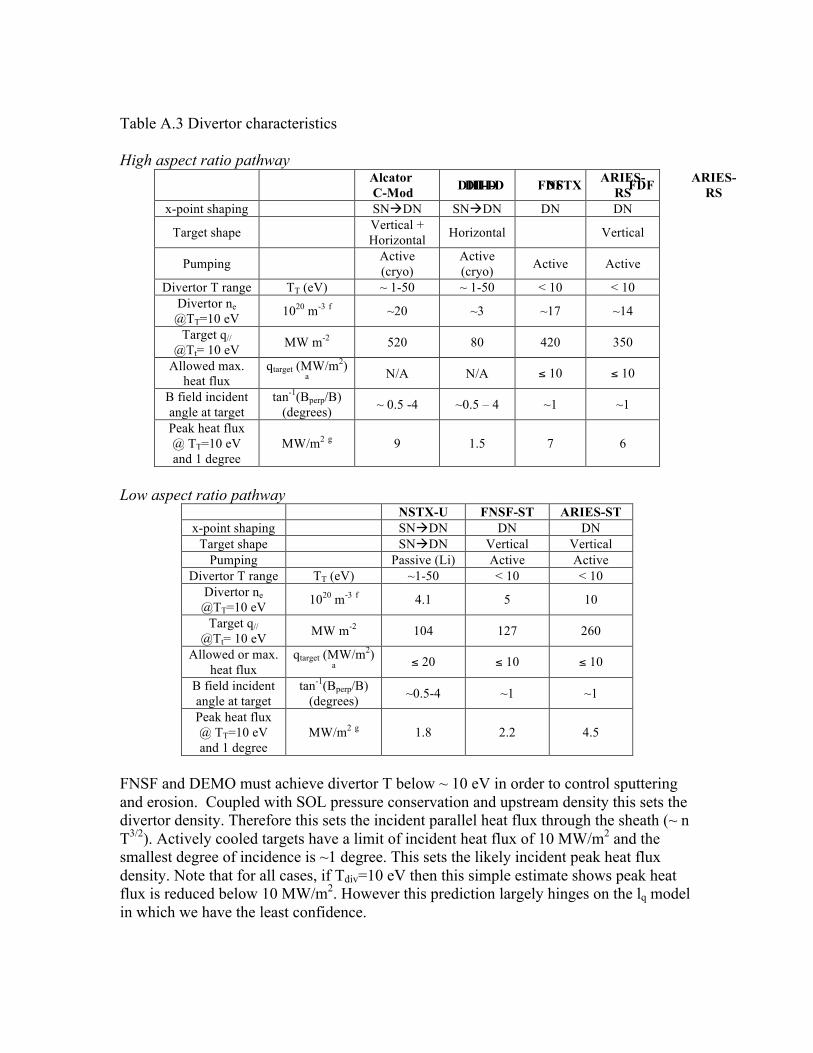
Table A.3 Divertor characteristics High aspect ratio pathway
Alcator C-Mod DIII-D NSTX FDF ARIES-
RS DIII-D FDF ARIES-
RS x-point shaping SNDN SNDN DN DN
Target shape Vertical + Horizontal Horizontal Vertical
Pumping Active (cryo)
Active (cryo) Active Active
Divertor T range TT (eV) ~ 1-50 ~ 1-50 < 10 < 10 Divertor ne @TT=10 eV 1020 m-3 f ~20 ~3 ~17 ~14
Target q// @Tt= 10 eV MW m-2 520 80 420 350
Allowed max. heat flux
qtarget (MW/m2) a N/A N/A ≤ 10 ≤ 10
B field incident angle at target
tan-1(Bperp/B) (degrees) ~ 0.5 -4 ~0.5 – 4 ~1 ~1
Peak heat flux @ TT=10 eV and 1 degree
MW/m2 g 9 1.5 7 6
Low aspect ratio pathway
NSTX-U FNSF-ST ARIES-ST x-point shaping SNDN DN DN
Target shape SNDN Vertical Vertical Pumping Passive (Li) Active Active
Divertor T range TT (eV) ~1-50 < 10 < 10 Divertor ne @TT=10 eV 1020 m-3 f 4.1 5 10
Target q// @Tt= 10 eV MW m-2 104 127 260
Allowed or max. heat flux
qtarget (MW/m2) a ≤ 20 ≤ 10 ≤ 10
B field incident angle at target
tan-1(Bperp/B) (degrees) ~0.5-4 ~1 ~1
Peak heat flux @ TT=10 eV and 1 degree
MW/m2 g 1.8 2.2 4.5
FNSF and DEMO must achieve divertor T below ~ 10 eV in order to control sputtering and erosion. Coupled with SOL pressure conservation and upstream density this sets the divertor density. Therefore this sets the incident parallel heat flux through the sheath (~ n T3/2). Actively cooled targets have a limit of incident heat flux of 10 MW/m2 and the smallest degree of incidence is ~1 degree. This sets the likely incident peak heat flux density. Note that for all cases, if Tdiv=10 eV then this simple estimate shows peak heat flux is reduced below 10 MW/m2. However this prediction largely hinges on the lq model in which we have the least confidence.

Table A.4 Quiescent PMI characteristics & requirements High aspect ratio pathway
Alcator C-Mod DIII-D FDF ARIES-
RS Material Mo + W Graphite C / W W Cooling Inertial Inertial Gas Gas Ambient
divertor material T
Tambient (K) ~300 - 900 ~300 > 800 > 1000
Ionization MFP for divertor
material atoms λMFP (mm) k 0.02 0.3 0.02-0.06 0.02
Divertor material ion gyroradius
ρI (mm) e 0.3 0.3 0.1 – 0.4 0.2
Gross erosion rate
mm per pulse with 1% yield 2x10⁻⁴ 6x10⁻⁵ ~100 ~1600
Tritium or fuel recycled per
pulse Mtritium (kg) j 3x10⁻³ 10-2 40 x103 2x10⁶
Low aspect ratio pathway
NSTX-U FNSF-ST ARIES-ST Material Li+Graohite C / W W Cooling Inertial Gas Gas Ambient
divertor material T
Tambient (K) ~300 > 800 > 850
Ionization MFP for divertor
material atoms λMFP (mm) 0.3 0.05-0.2 0.02
Divertor material ion gyroradius
ρI (mm) e 0.5 0.05-0.2 0.1
Gross erosion rate
mm per pulse with 1% yield 8x10⁻⁵ ~40 ~1200
Tritium or fuel recycled per
pulse Mtritium (kg) j 10-2 8x10³ 2x10⁶
Long pulse devices must have active cooling. The blanket/PFC requirements for ambient T above 500K precludes water cooling, so it assumed that gas cooling is used. The ionization mean-free path (MFP) of sputtered divertor atoms is sub-mm, meaning that the ions travel distances much smaller than characteristic poloidal length of the divertor plasma, i.e. divertor plasma of interest are extremely opaque to neutrals. An important consideration is the role of prompt redeposition since this is a key in limiting net erosion. For example if the ionization MFP is less than its gyroradius, this assures prompt redeposition of the sputtered impurity atom due to simple gyromotion. At fixed Tdiv the incident particle flux is also constrained which allows one to estimate the total “depth” of material eroded by sputtering if one assumes a sputter yield. For week-year pulses this number becomes extremely large compared to the allowed thickness of the divertor target

with active cooling (5-10 mm). This is the motivation behind: 1) decreasing Tdiv to decrease or eliminate physical sputtering 2) exploiting that net erosion should be much less than gross erosion in regimes with short ionization MFP. Because recycled fuel is essentially equal to incident plasma particle flux density, the total mass of fuel (tritium in a DT device) “cycled” through the PFC materials can be calculated. Safety limits will likely limit the in-vessel inventory of tritium to ~kg. Therefore the number of kg’s cycled through PFCs provides an estimate of the relative requirements on allowed tritons lost through retention per incident fuel ion before the fuel retention would interrupt the pulse due to regulatory limits. From the listed numbers this ratio must be less than ~10-4 in an FNSF and 10-6 in a DEMO. Table A.5 Transient PMI characteristics & requirements High aspect ratio pathway
Alcator C-Mod DIII-D FDF ARIES-
RS Max.
confinement H98 1.5 1.5 1.6 1.6
Norm. pressure βN (thermal) 2.5 3.7 3.7 4.1 Stored energy Wth (MJ) 0.5 2.1 71 624 Energy density Wth /S (MJ/m2) 0.06 0.04 0.57 1.35
Transient heating
Wth /S/τ1/2 (MJ/m2/s1/2) ~2.3 ~1.1 ~18 ~40
Runaway gain ~exp(2.5 Ip) 22 33 2x10⁷ 2x10¹²
Low aspect ratio pathway
NSTX-U FNSF-ST ARIES-ST Max.
confinement H98 1.5 1.25 1.5
Norm. pressure βN * 5.1 3.3 7.3 Stored energy W (MJ) 1.7 22 1120 Energy density W /S (MJ/m2) 0.04 0.26 1.78
Transient heating
W/S/τ1/2 (MJ/m2/s1/2) ~1.3 8.2 56
Runaway gain ~exp(2.5 Ip) 140 2x10⁷ 3x1031
* for pre-DEMO aspect ratio devices thermal and fast populations are added for total pressure and energy A key limit for PFCs, both the divertor and at the main-wall, is the safe dissipation of stored energy in the case of its transient release due to instability, e.g. ELMs and disruptions. These events tend to release the energy on ~ms timescales which implies that the limit for materials will be large increases in surface temperature because this timescale is much shorter than timescales associated with thermal heat conduction transport in the PFCs. The PFC has a high probability of failure if certain temperatures limits are passed. The simplest figure of merit is the global energy density, i.e. the total stored energy normalized to the plasma/wall surface area S. If one assumes a transient timescale tis the safe dissipation of stored energy in the case of its transient release due to instability, e.g. ELMs and disruptions. These events tend to release the ener2/s1/2. For example for ARIES-RS this implies that completely uniform dissipation of the plasma

stored energy over the wall on a 1 ms timescale will be at the thermal limit of solid materials. Table A.6 PMI diagnosis
Alcator C-Mod DIII-D NSTX FNSF ARIES/
DEMO
Ion flux Probes & recycling light Yes Yes Yes How? How?
SOL turbulence Probes/GPI Probes/BES Probes/GPI
Divertor T Probes DTS/probes Probes How? How?
Heat flux footprints
2010 Joint Facility Expts. Yes Yes Yes How? How?
Impurity influx into plasma
S/XB divertor spectroscopy Yes Yes Yes How? How?
Instrumented retracting
material probes
Erosion, deposition Yes Yes Yes How? How?
Special capabilities
500 °C W divertor (2013)
Divertor Thomson
Liquid lithium divertor
In-situ ion beam
surface diagnosis
(2012)
Axisymmetric isotope
tracing
In-situ dust diagnostic
RF Plasma potential
It is unclear how long-term monitoring of divertor conditions is achieved a near steady-state DT device. Refractory optics are disallowed due to neutrons (like in ITER). Solid probes in the divertor are also likely disallowed due to the high erosion rates. Notes and references for Tables
a) Based on Kallenbach multi-device ITPA analysis and Stangeby, et al “Relation between the upstream density and temperature widths in the scrape off layer and the power width in an attached divertor,” Nucl. Fusion 50 (2010) 125003. Power width (mm) ~ T width ~ 3.1(a/e). This closely agrees with experimental results from FY2010 Joint Facility Research Target on SOL Thermal Transport. Values from fits of e-folding width of divertor heat flux mapped to OMP, evaluated at q*~3-4 in H-mode plasmas.
b) P.C. Stangeby “The Plasma Boundary of Magnetic Fusion Devices” Eq. 5.51 which assumes exhaust to both divertor legs. By
definition the total power is the product of q// and A//SOL.
c) Stangeby Eq. 5.7 based on Spitzer-Harm parallel thermal conductivity
where L == phere L == sed on Spitzer-Harm pa0,e ~2000
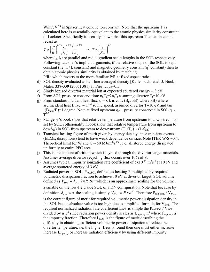
W/m/eV7/2 is Spitzer heat conduction constant. Note that the upstream T as calculated here is essentially equivalent to the atomic physics similarity constraint of Lackner. Specifically it is easily shown that this upstream T equation can be recast as
where ls, lr are parallel and radial gradient scale-lengths in the SOL respectively. Following Lackner’s implicit arguments, if the relative shape of the SOL is kept constant (i.e. ls / lr constant) and magnetic geometry constant (q* constant) then to obtain atomic physics similarity is obtained by matching P/Re which reverts to the more familiar P/R at fixed aspect ratio.
d) SOL density evaluated as half line-averaged density [Kallenbach, et al. J. Nucl. Mater. 337-339 (2005) 381) at n/nGreenwald=0.5.
e) Singly ionized divertor material ion at expected sputtered energy ~ 3 eV. f) From SOL pressure conservation: nuTu=2ntTt assuming divertor Tt=10 eV g) From standard incident heat flux: q = x k nt cs Tt (Bperp/B) where xB) where
ard incident heat fluxcs ~ T1/2 sound speed, assumed divertor T=10 eV and tan-
1(Bperp/B)=1 degree. Note at fixed upstream q// + pressure conserved in SOL q ~ T1/2.
h) Stangeby’s book show that relative temperature from upstream to downstream is set by SOL collisionality nbook show that relative temperature from upstream to dowfrad) in SOL from upstream to downstream (TT/TU) ~ (1-frad)2.
i) Transient heating figure of merit given by energy density since transient events (ELMs, disruptions) tend to have weak dependence on size. Note ITER W/S ~0.4. Theoretical limit for W and C ~ 50 MJ/m2/s1/2 , i.e. all stored energy dissipated uniformly to entire PFC area.
j) This is the amount of tritium which is cycled through the divertor target materials. Assumes average divertor recycling flux occurs over 10% of S.
k) Assumes typical impurity ionization rate coefficient of 5x10-14 m3s-1 at 10 eV and
average sputtered energy of 3 eV. l) Radiated power in SOL, Prad,SOL defined as heating P multiplied by required
volumetric dissipation fraction to achieve 10 eV at divertor target. SOL volume defined as which is an approximate scaling for the volume available on the low-field side SOL of a DN configuration. Note that because by definition the scaling is simply . Therefore Prad,SOL / VSOL is the correct figure of merit for required volumetric power dissipation density in the SOL but its absolute value is too high due to simplified formula for VSOL. The required normalized radiation rate coefficient LSOL is simple the Prad,SOL / VSOL divided by ndiv
2 since radiation power density scales as fimpurity n2 where fimpurity is the impurity fraction. Therefore LSOL is the figure of merit describing the difficulty in obtaining sufficient volumetric power dissipation to reduce the divertor temperature, i.e. the higher LSOL is found then one must either increase increase fimpurity or increase radiation efficiency by using different impurity.
4.7 References
1. M.S. Tillack et al., Pushing the limits of He-cooled high heat flux components,
TOFE-19 Nov 2010 2. A.R. Raffray, R. Nygren, D.G. Whyte, S. Abdel-Khalik, R. Doerner, F. Escourbiac, et
al., High heat flux components – readiness to proceed from near term fusion systems to power plants, FED 85 (2010) p93-108 doi:10.1016/j.fusengdes.2009.08.002
3. M.S. Tillack, A.R. Raffray, X.R. Wang, S. Malang, S. Abdel-Khalik, M. Yoda, D. Youchison, Recent US Activities on Advanced He-Cooled W-Alloy Divertor Concepts for Fusion Power Plants, Fusion Eng. & Des. 86 (2011) 71-98
4. M.A. Abdou et al., On the exploration of innovative concepts for fusion chamber technology, Fus. Eng. & Des., 54/2 (2001) p181-247; also M.A. Abdou, The APEX Team, Fus. Eng. Des. 54 (2001) 181; see also papers on UCLA website www.fusion.ucla.edu
5. R.E. Nygren et al., Liquid Surface Divertor Designs for Fusion Reactors, 20th IEEE/NPSS Symposium on Fusion Engineering, ISBN 0-7803-7909-8 (2003) 284-287; also R. E. Nygren, et al., A Fusion Chamber Design with a Liquid First Wall and Divertor, Ibid 288-295
6. L. E. Zakharov, Magnetic propulsion of intense lithium streams in a tokamak magnetic field, Phys. Rev. Lett. 90 (2003) 045001.
7. D. Ruzik et al., ”Lithium / Molybdenum Infused Trenches (LiMIT): A heat removal concept for the NSTX inner divertor,” 2nd Int. Symp. on Lithium Applications for Fusion Devices (to be published)
8. R. Majesk, R. Doerner2, T. Gray1, R. Kaita1, R. Maingi3, D. Mansfield et al., Enhanced Energy Confinement and Performance in a Low-‐Recycling Tokamak, Phys. Rev. Lett. 97 (2006) 075002
9. M.L. Apicell, V. Lazarev, I. Lyublinski, G. Mazzitelli, S. Mirnov, A. Vertkov, Lithium capillary porous system behavior as PFM in FTU tokamak experiments, J. Nucl. Mater. 386-‐388 (2009) 821
10. S. Mirnov, Plasma-wall interactions and plasma behaviour in fusion devices with liquid lithium plasma facing components, J. Nucl. Mater. 390-91 (2009) 876-885
11. R. Kaita, R. Majeski, T. Gray, H. Kugel, D. Mansfield, J. Spaleta, J. Timberlake et al., Low recycling and high power density handling physics in the Current Drive Experiment-Upgrade with lithium plasma-facing components, Phys. Plasmas 14, (2007) 056111

5. Research and Development Activities for Fusion Energy: Safety and Environment
5.1 Introduction The Fusion Energy Sciences Advisory Committee’s (FESAC’s) report published in 2007 entitled: “Report on Priorities, Gaps and Opportunities: Towards a Long-Range Strategic Plan for Magnetic Fusion Energy”, identified a number of knowledge gaps regarding Magnetic Fusion Energy’s (MFE’s) development path from the International Thermonuclear Experimental Reactor (ITER) to a Demonstration Reactor (DEMO). The FESAC panel stated that the scientific and technical safety challenge for fusion is to: “Demonstrate the safety and environmental potential of fusion power to preclude the technical need for a public evacuation plan, and to minimize the environmental burdens of radioactive waste, mixed waste, or chemically toxic waste for future generations.” The identified safety gap regarding this technical challenge is that “the knowledge base for fusion systems” is presently “(in)sufficient to guarantee safety over the plant life cycle - including licensing and commissioning, normal operation, off-normal events, and decommissioning/disposal.” This panel suggested, that for safety, the solutions are: “foreseen but not yet achieved, moderate extrapolation from current state of knowledge, need for quantitative improvements and substantial development(s) (are required) for (the) long term.” Extrapolations beyond ITER were identified in five key safety areas:
1. Computational tools needed to analyze the response of a fusion system to an off-
normal event or accident. While the US Fusion Safety Program has developed a series of advanced system level computational tools to analyze the response of a fusion system to an off normal events; however, for DEMO new models in the areas of tritium transport, dust and hydrogen explosions, magnet arcing, and the data required to validate and verify these new models is required.
2. Understanding and quantifying the fusion source term will be required for licensing activities. Two fusion source terms with greatest uncertainty are dust and tritium. In terms of dust, the key uncertainties are the magnitude of dust generated in the machine, its location and the potential for explosive dust mixtures in the presence of hydrogen and air in certain accident sequences. In terms of tritium, for high temperature breeding blankets, the key tritium issues include accountancy, control and permeation. R&D is needed (e.g., tritium permeation barriers—it is important to point out that tritium barriers will behave different under irradiation relative to out-of-pile) to help better define and hopefully resolve the issue prior to DEMO.
3. Qualification of fusion components in the fusion DEMO environment will be required to validate the design and to demonstrate safety roles of key components. Separate effects and integral irradiation testing in a fusion component test facility (CTF), fission reactors, particle accelerators, combined with ITER, could provide
a portfolio of high damage (> 10 dpa) performance testing data for licensing case to qualify DEMO components.
4. A waste management strategy for fusion must be developed. Beyond the need to avoid producing high level waste, there is a need to establish a more complete waste management strategy that examines all the types of waste anticipated for DEMO, given a more restricted regulatory environment for disposal of radioactive material in the future. DEMO designs should consider waste reduction (recycle and reuse) as much as possible, and the inclusion fusion-specific radioisotopes in the US Nuclear Regulatory Commission (NRC) guidelines for the release of clearable materials.
5. Experience with large scale remote handling will be important prior to DEMO. Remote handling of large components will be instrumental to the success of fusion. Activation levels in a commercial plant will be much higher than in ITER, and ITER will have significant downtime relative to a commercial plant (and will not be under the same time constraints as a commercial plant), thus additional experience with remote handling of large components is desirable prior to DEMO.
In the following sections of this chapter, we address the near term safety research needed to help close these gaps as we see them today. The R&D topics of computer code development, source definition, probabilistic risk assessment and occupational safety, waste management, and integrated safety in design and licensing are covered.
5.2 R&D Needs for Safety Computer Code Development
5.2.1 Overview One major focus over the history of the fusion safety program (FSP) has been the development of fusion specific best estimate computer codes that could be applied to both fusion reactor design and licensing activities. By using state-of-the-art fission safety codes and adapting them for fusion needs, or by developing fusion-specific computer codes where no comparable codes existed, we developed the first self-consistent systems level safety analysis codes for D–T fusion facilities, with the objective of demonstrating that these facilities can meet the fusion safety standard of not requiring a public evacuation plan for that facility. The most requested or applied fusion safety computer codes developed by the FSP include,
• MELCOR - a fully integrated, engineering level thermal-hydraulics computer code that models the progression of accidents in fission and now fusion power plants, including a spectrum of accident phenomena such as reactor cooling system and containment fluid flow, heat transfer, and aerosol transport,
• ATHENA/RELAP – a multi-fluids thermal-hydraulics code developed for design and accident analysis of cooling systems fusion reactor systems,
• MAGARC - a coupled electromagnetic, radiant energy transport and heat conduction code developed to analyze magnet arcing accidents,

• TMAP - a tritium migration code that treats multi-specie surface absorption and diffusion in composite materials with dislocation traps, plus the movement of these species from room to room by air flow within a given facility.
The results obtained by the application of various versions of these codes form the safety and licensing basis for the International Thermonuclear Experimental Reactor (ITER) {1} and the US ITER Dual Coolant Lead Lithium (DCLL) Test Blanket Module (TBM) {2}. These codes have also been used in the US in support of the APEX {3,4}, ALPS {5},and ARIES {6,7} design studies. Requests for copies of these codes from the ITER International Organization (IO), Commissariat a I'Energie Atomique (CEA), Centro de Investigaciones Energéticas, Medioambientales y Tecnológicas (CIEMAT), and Karlsruhe Institute of Technology (KIT) have been received and versions of these codes sent to these organizations. The MELCOR {8} thermal-hydraulics code is currently under development at the Sandia National Laboratory (SNL) for the US Nuclear Regulatory Commission (NRC). The MELCOR code is used to model the progression of severe accidents in light water nuclear reactors. A number of versions of the code have been released since the first version (1989), with the latest official release being 2.1. In the early days of the ITER program (prior to 1995), the MELCOR 1.8.2 code was chosen as one of several codes to be used to perform ITER safety analyses. The MELCOR code was selected because of its ability to self-consistently modeling all of the phenomena required for analysis thermal-hydraulic accidents in a fusion reactor, which include transient fluid flow and pressures, structural temperatures (i.e. first wall, blanket, divertor, and vacuum vessel) resulting from energy produced by radioactive decay heat and/or chemical reactions (oxidation), and transport of aerosols (dust). From 1994 to 1997, the Idaho National Laboratory (INL) FSP introduced a number of ITER-requested fusion-related modifications in the MELCOR 1.8.2 code, including the capability to address water freezing, air condensation, beryllium, carbon and tungsten oxidation in steam and air environments, flow boiling in the coolant loops, radiation in enclosures, and HTO transport. Because this version of MELCOR was developed for, and used in all, ITER safety studies, MELCOR 1.8.2 underwent verification and validation (V&V) and placed under configuration control as a quality level 1 safety analysis code in INL’s software Quality Assurance (QA) program. As the INL FSP became more involved in safety studies for advance fusion reactor concepts, that used coolants other than water (e.g., PbLi, FLiBe, and helium), a multi-fluids version of MELCOR was developed based on version 1.8.5 of MELCOR (1998) and the multi-fluid equation-of-state package of the RELAP5 code {9}. This version of MELCOR is being used in the US DCLL TBM Preliminary Safety Report (PrSR). However, the V&V of this version of MELCOR is very limited. Development of the TMAP code began, at a very low level of effort, in the early 1980s with the first V&V’d version of this code being issued in 1992 as TMAP4. Several

updates have been made to this code since, with the most recent version, TMAP7, being released in 2004. TMAP has been used in all of the above mentioned design and licensing studies to assess tritium inventories and permeation into the reactor building. Recently, TMAP7 is being integrated into a suite of codes by CIEMAT to produce a modeling tool that can simulate the fueling system and tritium processing plant of a fusion reactor, in particular ITER. The MAGARC code {2} development started in 1998 and was specifically developed to analyze a beyond design basis accident in superconducting Toroidal and Poloidal field coils known as an unmitigated magnet quench event. MAGARC development has continued by incorporating more realistic internal arcing models, and magnet material properties. Recently, electromagnetic and radiant energy transport capabilities were added to MAGARC in order to model arcs in magnet superconducting busbars. MAGARC has been used in ITER safety assessments, but due to the lack of magnet arcing data, this code has undergone only limited V&V. There are three reasons for giving this overview. First, the fusion safety computer codes developed by the US FSP have been used for reactor licensing calculations and are in use internationally. Second, in some cases these computer codes have undergone only limited V&V because of either a lack of benchmarking data and funding, in particular the multi-fluids version of MELCOR 1.8.5. In some cases, the software configuration control is lacking just because of inadequate funding. Third, these computer codes are becoming outdated, not only because of their development in some cases stopped more that two decades ago, but because they have also been written in FORTRAN 77, which is becoming an outdated source code language.
5.2.2 Research Activities In the next five years, there are two code development activities that need to be pursued. First, for the past five years, the NRC has requested that the fusion modifications to MELCOR become part of the base code being developed at SNL. However, due to lack of funding, we have been unable to fulfill this request. Recently, the SNL MELCOR code developers gave the INL FSP remote access to the MELCOR 2.x base code to add our fusion modifications. This development activity would have three significant benefits to the fusion program. First, MELCOR 2.x is written in FORTRAN 95 software language. This newer language allows for future development that can take advantage of evolving computer operating systems and math libraries. Second, by merging the fusion modifications with the MELCOR 2.x base coding, fusion gains access to the most recent code developments at SNL, plus our code version will reside in a software configuration control system that meets licensing standards at no cost to fusion. Third, MELCOR code developers are looking into parallelization techniques for MELCOR 2.x. This would dramatically improve the execution speed of MELCOR, which for typical ITER safety calculations can take as long as one month wall clock time to complete a seven day accident calculation.

Second, the capabilities of the TMAP code need to be added to MELCOR for fusion. This would result in a more self-consistent accident analysis tool, because TMAP does not have the capability to calculate fluid flow and temperature. The version of MELCOR 1.8.2 being used by ITER only addresses transport of tritium as HTO, an assumption that is coming under criticism from experts advising the French Nuclear Regulatory Agency as not being conservative. Based on past code development experience, modifying the source codes of these programs from F77 to F95, verifying that the changes are correct, and documenting the results will require at least 1.5 FTE per year for the next five years. Some of this work could be accomplished by base program funding. However, due to lack of funding at the present levels, even a code development of 0.25 FTEs per year is not sustainable. In the five to fifteen year timeframe, experimental data should be developed for validating evolving fusion safety computer codes, in particular the multi-fluids version of MELCOR. Some of this validation can come from R&D being proposed in the Power Extraction and Tritium Sustainability (PE & TS) area. Whether or not the facilities being proposed can also be used to simulate accident conditions in an FNSF can not be determined at this time. However, the validation of this code for licensing FNSF and the DCLL ITER TBM is required. This effort could require ~10 FTEs over this 10 year time period. An additional safety code development activity required for an FNSF is the development of a fusion tritium plant capability. Because the multi-fluids version of MELCOR can treat cryogenic fluids, modeling a fusion fueling and tritium plant should be possible within MELCOR, provided that both of research activities defined above are completed and specific engineering level models for cryogenic-separation components are added to the MELCOR code. This effort could require an additional 5 FTEs over this 10 year time period to develop, V&V and document this capability. Regarding DEMO, it is difficult to envision possible changes in computer hardware and software over the next 30 years. However, as will be discussed in the Probabilistic Risk Assessment (PRA) section of this chapter, one thing we can rely on is that the US NRC will license a DEMO and that the NRC is relying more heavily on a complete PRA safety analysis of the nuclear power plants for licensing. At the present time, the NRC is developing for fission a full spectrum risk assessment computer code at the INL called SAPHIRE {11}. With this tool, accident types and probabilities are defined through a fault tree logic tree. What these fault trees need, and is presently supplied primarily through expert opinion, are reactor thermal-hydraulic consequences (and timing) of a specific system failure modes. By combining the capabilities of the SAPHIRE, with a thermal-hydraulic accident analysis code, such as MELCOR, a very powerful PRA licensing capability would emerge that would be of interest to both fusion and fission. This would be a costly and time-consuming effort (~20 $M over 15 years), but it could be shared with other parties and such a code would improve safety assessments.
5.3 R&D Needs for Tritium and Activation Product Source Term Research

5.3.1 Overview The management of the radioactive isotope of hydrogen, specifically tritium, throughout a fusion device during operation and accidental conditions is a main topic of the experimental activities in support of safety analysis at INL FSP’s Safety and Tritium Applied Research (STAR) facility. Many uncertainties still exist regarding physical and chemical properties of tritium in materials and the understanding and modeling of processes that impact tritium inventories and permeation. For example, the effect of neutron or gamma radiation on tritium diffusion in structural and functional materials, such as coatings, is a well-known issue still requiring further investigation. In this section, experimental activities in support of the INL FSP that are fundamental to fulfill its program’s mission are addressed. Many of the items have strong synergism with other aspects of fusion technology development, or are only a portion of a larger experimental program. The relation between safety related tests and more general performance validation of components is somewhat arbitrary. The capability of the INL STAR will be used as a reference in identifying which type of tests should be performed directly in support of safety analysis and which should be deferred to other programs, such as materials development. Possible upgrades and extension of STAR current capabilities required to perform these tests will also be discussed.
5.3.2 Tritium Retention in Plasma Facing Component Materials Plasma materials interactions (PMIs) between a fusion plasma and plasma facing components (PFCs) determine the in-vessel inventory of tritium in a fusion system, which is a fundamental parameter for safety analyses. Much of the recent experimental and design efforts in fusion have moved away from carbon PFCs specifically because of the safety issue of high hydrogen isotope retention in co-deposited layers produced by PMIs with these components. This is an example of how a safety concern impacts US and international plasma physics research, which finds carbon-based PFCs acceptable, through PMI R&D. Aside from plasma physics experiments, such as tokamaks, linear plasma column devices such as PISCES at the University of California at San Diego (UCSD) have been designed and operated to define PFC material properties, including hydrogen isotope retention. Most plasma experiments are not capable of handling relevant quantities of tritium because of the specialized and expensive infrastructure required for handling radiological material. In the US, the Tritium Plasma Experiment (TPE), now at the INL STAR facility, has been constructed for the specific purpose of testing PFC materials with tritium, and assessing the impact of isotopic effects by comparing TPE results to similar test results with facilities using hydrogen and deuterium plasmas. There are several reasons that tritium is expected to behave differently than the lighter hydrogen isotopes. One is its higher mass, which is relevant when considering phenomena associated with ion implantation or diffusion in solid materials. But others are related to chemical properties relevant to interface phenomena, such as chemisorption. In several instances the additional energy associated with the tritium beta decay has been shown to promote (or accelerate) self-catalyzing reactions that are otherwise irrelevant for the non-radioactive isotopes.

Although the phenomena studied in TPE are similar to those studied in experiments in other PMI programs, the impact of tritium properties on safety analysis best characterizes TPE experiments as part of Fusion Safety. However, the operation of TPE in the near-term is also crucial for the development of fusion technology, and as a consequence the main objective of the INL FSP is to increase the experimental capability and availability of TPE in order to collect as much data as possible within the lifetime of its aging components. Ongoing or planned R&D tasks include the investigation of:
1. Tritium retention in PFC candidate materials, providing inventory source terms for safety analysis.
2. Tritium permeation through PFC candidate materials, providing source terms for tritium transport outside the vessel.
3. The effect of neutron irradiation on tritium transport in PFCs candidate materials, affecting both inventory and permeation source terms.
5.3.3 Research Activities: Tritium retention: Tritium retention is the continuation of the PMI related mission of TPE that started with its initial construction at SNL 30 years ago. After relocation to INL additional diagnostics have been added to the experiment to better characterize plasma parameters, including a refurbished Langmuir probe. Post-test diagnostics based on tritium detection, such as the Imaging Plate technique, have also been developed to provide tritium implantation and permeation profiling data that is not available through the Thermal Desorption Spectroscopy (TDS) normally employed in PMI experiments to determine hydrogen retention. Recently, modifications to TPE’s plasma source have been made to remove carbon-based components that interfered with testing of non-carbon materials in TPE, such as tungsten. However, the TPE design and mode of operation are still those conceived of 30 years ago, which relay heavily on hands-on maintenance, manual sample manipulation and manual plasma control – all leading to a relatively low TPE availability and a low level of test specimen radioactivity that can be tested in TPE. Significant effort and investment are required to maintain TPE’s essential capabilities, while increasing its productivity if the facility is to fulfill its mission of characterizing the new generation of PFC candidate materials envisioned for DEMO, that will irradiated to significant levels of dpa. Some of the necessary upgrades include, in order of complexity and with decreasing priority, are:
- Improved sample holder manipulation (gate valve, retractable bellows) to allow continuous vacuum pumping during sample changes
- Upgraded cooling system to allow higher plasma fluxes on samples - Addition of plasma spectroscopy diagnostics - Staged modification of the plasma source for higher performance - Modification of power supplies control and data acquisition system to allow
remote operation from outside the controlled Radiological Boundary - Significant modifications of TPE for handling highly irradiated DEMO
relevant material samples, including shielding and a remote sampling handling system.

The first three modifications are needed in the next five year timeframe for US/Japan TITAN activities and are estimated to cost ~ 1.0 $M. Neutron irradiation effects on tritium retention in PFC materials have already begun under the US/Japan TITAN collaborative program. Given TPE’s and STAR’s capability of handling samples irradiated at the Oak Ridge National Laboratory’s (ORNL’s) High Flux Isotope Reactor (HFIR) are being tested for tritium retention. The current, and near term (2-3 years), focus of the TITAN program is on fundamental properties of bulk tungsten as a PFC candidate material for fusion energy systems (DEMO), including the effect of neutron damage. Assuming that successful material fabrication and irradiation programs within the TITAN activity produce samples of advanced functional materials (e.g., alloys, coatings, compliant layers, etc) in the 3-5 year timeframe, their testing with tritium is essential for validation purposes and should be the focus of near term TPE activities. The remaining three modifications are needed in the 5 to 15 year time period to study tritium retention in highly activated FNSF and ITER TBM materials, and are expected to cost about 2 to 3 $M. With these modifications, tritium retention in highly activate tungsten and ferritic steel PFC structures and co-deposited layers produced by erosion of these materials can be studied in TPE using realistic conditions of mixed hydrogen and helium plasmas. Modifications to add shielding to TPE, and a remote sample handing system is estimated to cost an additional 3 to 4 $M. Plasma driven tritium permeation: Extension of current TPE capabilities to measure the flux of tritium implanted on sample materials that permeates in the coolant fluid will be required for this R&D activity. The initial step in developing this capability is planned in the near term (2 years), involving modification of the sample holder to allow for active cooling with variable rate helium flows (modification item 1 above). Characterization of permeation properties for advanced and functional tungsten materials, including the effect of neutron damages, is being planned in the mid-term (3-7 years) as part of the next US/Japan collaborative program now under evaluation. However, to ensure relevance to fusion systems (FNSF), significant modification of the current TPE sample holder design will be required to test at anticipated PFC conditions. An example of this would be the high pressure envisioned in blanket and divertor FW cooling systems (modification item 2 above). The modifications would also have to be integrated with the permeation tests requirements, which would include a tritium gas sampling system on the coolant side of the sample. The characterization of plasma-driven tritium permeation in Reduced Activation Ferritic Steel (RAFS) first wall (FW) components is as important to safety research as tritium retention. Preliminary analyses have shown {7} that a large fraction of tritium implanted in the FW will permeate into the FW helium coolant rather than being recycled back into the VV and processed by the chamber exhaust system. Characterizing plasma driven permeation for a RAFS FW would become a priority in the mid to long-term (3-10 years) in support of the safety analysis of the ITER-TBM or a low performance FNSF. This activity should include the characterization of any coatings or functional material layers on RAFS (for example, tungsten) aimed at the reduction of the permeation (i.e., in-vessel tritium barriers), and their performance degradation after neutron or gamma exposure.

Tritium permeation barriers: The development of tritium barriers for non-FW components, and in particular for the systems housing the breeder material in which tritium is generated, has been a topic of R&D activities for as long as 30 years. With the addition of dual cooled blanket concepts, such as the DCLL blanket, the focus has expanded to include the blanket and first wall coolant systems (usually helium). What differentiates the coolant system from other part of the tritium processing cycle (for example, the chamber exhaust system) is primarily the fluid high temperature, which is necessary to ensure acceptable power cycle efficiency. However, even for the simplest conditions of the helium coolant channels (highly inert chemistry) no material has yet been identified that would provide reliable resistance to tritium permeation through the lifetime of the components. The results for materials that would operate in contact with liquid breeders (lithium, lead-lithium alloy) or sweeping gases on ceramic breeder beds are even less promising. The challenge presented to fusion system design that must rely on permeation barrier to limit the release of tritium to the environment is therefore considerable, and will require a synergistic effort in all aspects of fusion technology, from material development and testing, to components design and performance validation and safety analysis. The urgency and priority of such a large investment project depends on many factors, some of which outside of strictly technical matters, such as public perception related to acceptable tritium release limits. In the long-term it is commonly accepted that a DEMO must ultimately rely on tritium barriers to be a competitive source of energy at the commercial level. For FNSF it may depend on design choices, but the lack of a viable engineering solution to limit tritium release will impose very stringent limitations on design windows for many blanket parameters, such as coolant outlet temperature. Permeation barrier development and testing is address in the Tritium Materials Issue subsection of the Materials Science chapter. Some of the proposed permeation tests will be conducted in an Accelerator Driven Neutron Source (ADNS) the can produce both neutrons and gammas. Because these tests will be conducted in a radiation environment, a proposed complement of tests should be conducted using tritium. If this can not be accomplished in the ADNS facility, the bench-top-scale permeation cell experiment should be constructed at the STAR facility for permeation barrier testing. This experiment could be constructed and tests run for a cost of ~ 1 $M over the next five years. Tritium extraction: Tritium extraction from breeding materials is not strictly a safety related R&D item but rather refers to blanket development and performance assessment. However, the tritium control in breeder blankets is a fundamental safety issue because of tritium inventories and blanket system permeation. The operation of a test facility for tritium extraction systems is therefore deemed as a high priority item for the safety analysis of FNSF and DEMO. A PbLi tritium extraction test loop facility is being proposed in the Power Extraction and Tritium Self-sufficiency R&D chapter. The proposed facility should have enough flexibility to test multiple extraction concepts, contain multiple test sections of different materials, multiple cooling loops with different fluids, and use tritium for limited verification experiments. An innovative extraction
method proposed in the US is referred to as ‘vacuum permeator’. This particular concept has important implications for safety as it has the potential to be the only method proposed so far that could limit the release of tritium to the environment to level acceptable for licensing an FNSF, and even a DEMO, without the need of tritium barriers, with application to both PbLi and Helium cooling systems. If the proposed R&D is not flexible enough to address tritium tests, then a small tritium extraction and permeation barrier experiment is being proposed for the STAR facility. This experiment would cost in the 1 to 3 $M range and should be constructed and tests performed in the 5 to 10 year time frame in support of safety data needed for the ITER DCLL TBM and FNSF.
5.4 R&D Needs for Dust Source Term Research
5.4.1 Overview Dust is created in tokamaks through a variety of plasma-surface interactions. In next step devices (e.g. ITER, FNSF, or DEMO), dust quantities are expected to be large due to more energetic plasma-wall interactions, longer pulse duration, etc. The presence of dust in these devices presents several safety concerns. One is radiological; dust will contain both tritium and activation products, and these could potentially be released to the environment in the event dust is mobilized (e.g. during a loss of vacuum accident). Another is chemical reactivity. Dust residing on hot surfaces is a particular concern here, as chemical reactions in steam or air may produce gases that lead to overpressure and vacuum vessel rupture. Mobilized dust, especially in combination with combustible gases, also presents a risk of explosion. Finally, at least in ITER, toxicity of beryllium is a concern. As a result, considerable efforts have focused on characterizing dust from existing tokamaks and performing safety related research on dust, including sampling and characterization (size distribution, surface area) of dust from operating tokamaks, dust explosion testing, and chemical reactivity testing.
5.4.2 Research Activities Despite a relatively large effort to sample and characterize dust in existing tokamaks, this data is presently scattered throughout numerous publications and often presented in insufficient detail to adequately inform safety codes. A proposed International Atomic Energy Agency (IAEA) dust database may help alleviate this issue, but a larger concern is that statistical analysis techniques employed to characterize dust size distributions are not standardized across facilities. In some cases this leads to the drawing of rather different conclusions about the importance of various sized particles with respect to safety. An effort to organize existing dust data and develop suitable analysis methods is recommended, at an estimated cost of 300 $K over the next two years.

A primary difference between the proposed FNSF and existing (or planned) devices is the presence of a reduced activation ferritic martensitic (RAFM) steel walls. It can be expected then that a large quantity of steel dust will be produced in such a device. In preparation for FNSF, the focus of dust related research should shift from materials such as carbon and beryllium to steel. Previous experiments have been carried out on the explosibility of carbon and tungsten dusts, and a facility will come online at INL in FY 2012 to perform similar experiments on beryllium dust. It is recommended that following those experiments, the facility be used to conduct a more comprehensive set of FNSF-relevant experiments on mixed materials, including steel and tungsten dusts and various gas compositions, including hydrogen. Concurrently, a dust explosion modeling effort is needed, which has not accompanied previous experiment campaigns. Though many safety codes have very mature aerosol transport models, the ability of such codes to model explosions is an important need that is currently lacking. These tasks would cost on the order of 2.0 – 3.0 $M over the next five years. Longer term (5-15 years), it will be necessary to draw some conclusions regarding the quantity of dust that might be produced in FNSF. There is considerable uncertainty surrounding this issue for ITER and other next-step devices. As a result, ITER has established safety-based administrative limits on the total mass of dust present, 6 kg each for Be, C, and W dust on hot surfaces and 1000 kg total dust in-vessel. Though various automated cleaning methods are under investigation, it is likely that dust removal (e.g. via mobilization, vacuuming, and filtering) will necessitate a lengthy interruption in operations. More energetic plasma-surface interactions and higher dust concentrations (resulting from the smaller volume) may necessitate more frequent cleaning in FNSF, to the detriment of a high availability that may be desired for that facility. Thus, reducing uncertainty regarding dust production should be a high priority for future research. The best source of this information will be ITER, once it is operational. Particularly in the initial phase of operation with hydrogen, ITER dust data should be leveraged whenever possible to refine estimates of dust production that would apply to FNSF. It is recommended that arrangements be made to sample and characterize ITER dust. In addition to the usual size and surface area measurements, this campaign should include direct observation of dust and co-deposits on surfaces. The latter is important since presently the quantity of dust is assumed equivalent to the amount of eroded material; if the latter is in fact largely immobilized in co-deposited layers rather than as loose dust, the administrative limits now in place are overly conservative, since only mobilizable dust is really a safety concern. In the event that conservative administrative limits cannot be entertained for FNSF, and relevant PMI information cannot be obtained from ITER in the time period required, additional experiments will be needed to address dust generation for FNSF. This would include a PMI experiment with RAFM steel at FNSF-relevant conditions, that would be capable of producing sufficient quantities of dust to both characterize the size and surface area distributions, but also to obtain quantitative information about the amount of loose

dust versus co-deposited material that might be expected for FNSF. The cost of such a facility would be from 3 to 5 $M, and should be available for operation in the 5 to 15 year time period. Finally, some comments on “mobilizable” dust are in order. The primary safety issue related to dust (e.g. radioactive releases and explosions; chemical reactions on hot surfaces are a notable exception) requires that the dust first be mobilized. The many modeling and experimental campaigns related to dust resuspension (some directly supporting fusion safety, others not) typically employ commercially available dust, the size distribution, morphology, and composition of which are not always representative of tokamak dust. Resuspension depends strongly on the nature of particle-surface contact, and surface materials in these experiments are also not representative of tokamak conditions (high temperature wall materials with co-deposited layers). Thus, a better quantitative understanding of fusion-relevant dust resuspension can only be obtained from a resuspension experiment using relevant samples, e.g. dusty materials from the RAFM PMI experiment mentioned above. The estimated cost of such a resuspension facility is 2 $M over 5 to 15 year time period.
5.5 R&D Needs for Probabilistic Risk Assessment
5.5.1 Overview In 2009, the US Nuclear Regulatory Commission (NRC) published a memo regarding the licensing of fusion power plants {12}. The NRC recommended pursuing assertion of regulatory jurisdiction over commercial fusion energy power generation devices. Additional research of the scope of NRC and Department of Energy (DOE) activities has shown that fusion experiments that do not produce electricity would continue to be licensed by the DOE, and the US NRC {13} would license commercial fusion energy devices (power plants). Given that bound, it is noted that in 2007 the NRC published a final rule on licensing fission power plants. This rule is referred to as the combined construction and operating license (COL) approach and is meant to streamline the licensing process. As well as continuing to require the traditional Safety Analysis Report (SAR) that contains detailed analyses of worst-case accidents, a new COL requirement is that the SAR must contain a description of the plant-specific probabilistic risk assessment (PRA) and its results (see 10CFR52.79). The new COL approach is already in use for the Watts Bar unit 2, as well as the Summer and Vogtle fission power plant construction projects. The COL is expected to be the primary licensing approach for a fusion, as well as fission, power plant. The largest concern in applying PRA tools to a fusion design is the sparse component failure rate data values available to quantify a fusion PRA. The FSP has collected component failure rate data from published data sources and analyzed selected operating experience data from fusion facilities (e.g., TSTA, DIII-D). ENEA has analyzed some facility data (e.g., TLK, JET), and JAEA has analyzed some systems in the TPL facility. The data recording at fusion facilities is voluntary and in some cases has been

incomplete. These engineering data on facility operations are valuable to fusion development and need to be more rigorously collected and documented.
5.5.2 Research Needs The failure rate data values calculated by the FSP have been submitted to an International Energy Agency (IEA) database. The FSP needs to re-acquire this database and maintain it at INL; keeping a living database could cost 0.1 FTE/year. The overall collection and analysis activity shall continue using base program funds so that a complete database is available when needed for next step machines. Reliability data come in two types, qualitative information on what provides longer component lifetimes, including investigation of failure modes, and the quantitative data discussed above that is used in PRA. The qualitative data include information about issues such as best welding and joining techniques, best materials to provide component longevity, irradiation stability, and coolant compatibility. Qualitative data also includes the manner in which components fail (the failure modes) and the mechanisms of component failure. These qualitative data demonstrate the knowledge base of incorporated or inherent reliability of components. If the FNSF uses PbLi and helium coolants, both qualitative and quantitative reliability data will be required. Cooling systems are part of the confinement boundary and must be addressed in safety assessments. Existing reliability data on these cooling systems used in fission is sparse compared to that for water-cooled systems. Therefore, building cooling loops to gain experience in high temperature coolants like PbLi and helium will give qualitative reliability insights. Successful PbLi and helium flow loops will demonstrate that technology lessons of qualitative reliability are mastered and that the fusion designers are making use of appropriate technology and design principles. The Power Extraction and Tritium Sustainability working group is proposing the building and operation of PbLi and Helium cooling and tritium extraction loop systems. Failure rate data from these systems should be collected for FNSF and DEMO application. This activity will require from 1 to 2 $M over the next 15 year period of time. ITER plans on collecting all of its operating experiences – reliability of systems and components, repair times for manned and remote activities. These data are valuable and the US domestic agency needs to obtain these data along with the system design descriptions, system modifications, and system operating time data to allow engineering evaluation of the data. The results should be added to the failure rate database. The work to analyze these data will require 0.25 FTE/system of interest. ITER has performed reliability studies on 27 systems thus far. The analysis work would be initiated in the later years of ITER operation (that is, the 15 year time frame) after ITER has accumulated a large amount of operating time.
5.6 R&D Needs for Occupational Safety
5.6.1 Overview An important safety aspect at fusion facilities is personnel safety. This is true for both DOE and NRC regulators. One of the key issues for personnel safety is occupational radiation exposure (ORE) and other exposures to hazards – magnetic fields, toxic chemicals, electromagnetic radiation, and other hazards. The fundamental protection principles for workers are well known: time, distance, and shielding. The FSP approach to reliability, availability, maintainability, and inspectability (RAMI) is from the fundamental worker protection of reducing worker exposure time in performing any task in a hazardous zone of a fusion facility. Obviously, reliable components are visited less often and for shorter visit durations than those that fail often. Reliable components and systems help keep worker exposures low. The ITER engineering data to be collected on system operations are expected to supplement the existing US data collection activity for PRA failure rate data and greatly enhance the maintenance and repair information presently existing on tokamak devices. Maintenance and inspection data tend to be more difficult to obtain than failure rate data, so ITER detailed collection of its experiences will fill in a gap in the data. In the near term, the existing failure rate dataset, together with handbook and expert opinion data on repair times) will allow fusion analysts to assess the occupational safety of an FNSF and also support ITER prior to startup, and in the future, the ITER data will position fusion to meet COL needs by quantifying a PRA for a DEMO power plant as well as support occupational safety studies. Fusion in-vessel components have always posed an issue in regard to component failure rate data and maintainability data. Operation in actual fusion environments gives the best indicator of component reliability. Very few tokamaks presently use actively cooled in-vessel components; most tokamaks have used graphite and carbon-fiber composite tiles that yield no operating experience data useful to future devices. ITER experiences with constructing, operating, and maintaining all types of blanket modules will be useful to support future development and will be collected by the ITER team. Personnel safety is an important aspect of module replacement; while remote handling is needed there is always the possibility of human intervention for repairs to remote equipment. Blanket module replacements also tend to require long downtimes. These downtimes tend to increase the exposure hazard to workers and decrease the availability of a fusion power plant thus reducing its economic attractiveness. Qualitative reliability lessons in structural alloy preparation and qualification, metal joining, inspection techniques, and construction techniques for cleanliness of the finished product will all be useful for building FNSF blankets that operate safely and reliably. Enhanced reliability would mean longevity and less frequent replacements; this reduces personnel exposures and increases the availability of fusion power plants. ITER remote maintenance experiences should help identify best practices to improve maintainability, by reducing outage times to replace modules. These lessons will also verify that reliability and maintainability are built in to the FNSF blanket modules by incorporating ITER design lessons.

5.6.2 Research Activities Maintainability and inspectability data should be collected from published data and analyzed from existing tokamak system experiences in the next 5 years. The FSP base program will fund this task. Data analysis should be performed on the ITER international project in the next fifteen years to apply the already-developed modeling and analysis tools to next step machines. An effort to collect, analyze and store such system and component data in the failure rate database could require 0.25 FTE/year over the five-year time period. In the longer term beyond 5 years, ITER operating experience data would require 0.25 FTE/system analyzed. Collecting the blanket replacement experiences on ITER could cost perhaps 0.1 FTE/year of ITER blanket replacement operations in the 5 to 15 year time frame.
5.7 R&D Needs for Waste Management
5.7.1 Overview For decades, the DOE Office of Fusion Energy and Science has had a policy that radwaste from fusion power should have a low impact on the environment. As pointed out in the next section, this policy was codified in the DOE Standard for Safety of Magnetic Fusion Facilities, by stating that wastes, especially high-level radioactive wastes, shall be minimized. In practice, MFE fusion plant design studies world wide have examined the use of reduced activation materials and the fusion materials research programs have responded by developing reduced activation structural materials, such as RAFS. These materials exclude, as much as practically possible, the use of alloying or impurity elements that would disqualify a particular reactor component from being buried as low level waste (LLW)2. However, after ~40 years of experience in designing fusion power plants, the sizable volume of activated material and the limitation of future shallow land burial sites has demonstrated that the approach used for fission to dispose of radwaste will not work well for fusion {14}. To understand the size of the problem, the quantity of activated steel that must be disposed of during the decommissioning of a fusion power plant equals that of 13 Eiffel Towers {15}. Recent studies {15,16} in the fusion community have investigated options for reducing the volume of waste that would need to be buried, which are recycling and unconditional clearance (i.e. declassification to non-radioactive material). Recycling processes include storing radwaste in continuously monitored facilities, segregation of various materials, crushing, melting, and re-fabrication. This process requires a very specialized foundry 2 The U.S. Nuclear Regulatory Commission (NRC) has defined three more categories for LLW: Class A, B, and C. For each type, there is a specific disposal requirement. Class A is the least contaminated category and least hazardous type of waste. The LLW containers are placed 8m or more deep in the ground and only meet the minimum packaging requirements. An intrusion barrier, such as a thick concrete slab, is added to Class C waste trenches. Class A LLW is intended to be safe after 100 years, Class B after 300 years, and Class C after 500 years.

that utilizes radiation-hardened robotics equipment. There is also one drawback to this option, and that is that the material of a given component that would qualify for shallow land burial after a single use may not qualify for shallow land burial after undergoing reuse. This is because the radioactive level of a troublesome radioisotope in a metal alloy increases with exposure time in a neutron radiation field. If the hazardous radioisotope is an activation product of a major constitutive element of the alloy, then this element would have to separating from the alloy and then replaced with fresh material during the smelting process. However, the separated material may also not qualify for disposal as LLW. If the hazardous radioisotope is an activation product of an impurity, then new methods of purifying the constituents to lower levels of this impurity will have to be developed to make reuse of the alloy practical. Clearance criteria3 have been recently developed by US-NRC {13}. Supposedly, under this option, a solid material can be reused without restriction, recycled into a consumer product, or disposed of in a landfill, if it meets the limits defined by the regulatory authorities. An example is related to building concrete rubble that could be used in the base for road construction or as an additive for manufacturing new concrete for nuclear buildings. In the USA, conditional clearance is for reuse of materials in the nuclear industry, but not for reuse in the general commerce. At present, the experience with recycling and clearance is limited, but will be augmented significantly by advances in spent fission fuel, fission reactor dismantling, and bioshield clearing before fusion is committed to commercialization in the future. While recycling/clearance is a tense, contentious political situation, there has been some progress. For instance, limited scale recycling within the nuclear industry has been proven feasible in Europe and at several U.S. national laboratories. A clearance market currently exists in Germany, Spain, Sweden, Belgium, and other countries in Europe. In the U.S., the free release has been performed only on a case-by-case basis during decommissioning projects since the 1990s {17}
5.7.2 Research Activities A small dedicated R&D program should be started in the next 15 years to investigate the required infrastructure and energy requirements to make recycling a viable option for fusion. This study should assess the quantity of waste generated by recycling and if this waste no longer qualifies for LLW, then quantity the amount of waste being generated in relationship to that from the fission industry. Through national and international reactor design studies, reactor component design criteria should include the possibility for component disassembly into parts that can be reused without disallowing that part from eventual LLW. Given that FNSF will be a one of a kind, relatively small fusion reactor, building FNSF from low activation metals should be sufficient. An estimate on how much this activity would cost is about 100 $K per year over the course of the 15 year time period. 3 Criterion has not yet been issued as official NRC public policy for the unconditional release of cleared materials.

5.8 R&D Needs for Integrated Safety in Design and Licensing
5.8.1 Overview As discussed in the findings of the Research Needs Workshop (ReNeW), a critical element overlapping gap identification and prioritization is the importance of adequate safety integration into all levels of fusion facility design, including not only power plants but also proposed test facilities such as IFMIF, FNSF, etc. The importance of such integration is presently being demonstrated as the detailed design and construction of ITER proceeds. A basis of functional requirements established in the DOE Fusion Safety Standard {17} was implemented into the ITER design and safety assessment. The general policy of this standard is that fusion facilities shall be designed, constructed, operated, and removed from service in a way that will ensure the protection of workers, the public, and the environment. Accordingly, the following points of safety policy shall be implemented at fusion facilities:
• The public shall be protected such that no individual bears significant additional risk to health and safety from the operation of those facilities above the risks to which members of the general population are normally exposed.
• Fusion facility workers shall be protected such that the risks to which they are exposed at a fusion facility are no greater than those to which they would be exposed at a comparable industrial facility.
• Risks both to the public and to workers shall be maintained as low as reasonably achievable (ALARA).
• The need for an off-site evacuation plan shall be avoided • Wastes, especially high-level radioactive wastes, shall be minimized.
These goals are achieved by: 1) minimizing radioactive inventories; 2) limiting pressure, decay heat and chemical energy sources; 3) implementing defense in depth strategy; 4) employing low activation materials; 5) following well established QA procedures; and 6) minimizing public and worker operational exposure. During the Conceptual Design Activity (CDA) and Engineering Design Activity (EDA) of the ITER project, the US Fusion Safety Program (FSP) was heavily involved in ITER Safety development and assessment. Unfortunately, since the ITER Project has moved into the licensing and construction phase in France, the only insight that the FSP has into the ITER licensing process has been indirectly gained through the ITER Test Blanket Module (TBM) Program. TBMs to be tested in ITER are part of the ITER licensing process and in a sense are also receiving a license to operate. The US DCLL TBM is a prototype of a DEMO (or FNSF) blanket module. This module has three cooling systems that are miniaturized DEMO tritium breeding, extraction, and heat transport systems. The TBM’s and their support systems are being held to the same regulatory requirements for component classification, quality assurance, component acceptance testing, operation, and decommissioning and disposal as the ITER reactor. TBM hazard assessment, normal operation and accident radioactive release and associated public and worker consequence analysis are being required. This information is contained in a Preliminary Safety

Analysis Report (PrSR) that can be accessed by the French Nuclear Regulatory Authority (Autorité de Sûreté Nucléaire, ASN). However, at the present time, there is no designated funding to allow this licensing process to continue. Responding to the ITER International Organization’s (IO’s) request for changes in the safety documentation or to respond to request from the ASN is presently being performed on base program funding and a level of about 120 $K per year, to the detriment of other FSP activities, in particular computer code development.
5.8.2 Research Activities Given the importance associated with keeping the option open for the US to test its TBM concept in ITER and the depth of knowledge gained by participated in an actual fusion licensing process, in the next five years a staff level of effort of about 0.5 Full Time Equivalent (FTE) or ~160 $K per year needs to be directed towards the DCLL TBM licensing effort. In addition, if the US is going to construct and license an FNSF within the next twenty years, a conceptual design study for FNSF should begin in this same time period, with safety as a key component in this design activity. Based on experience from ITER design activities, an estimate of an FTE per year will be required from safety for this activity. In the five to fifteen year timeframe, should the FNSF design effort proceed through the engineering design and licensing phase, the cost associated with the required safety and QA activities would need to be covered by an increase in funding. The cost of safety, QA, and licensing of a nuclear facility typically runs between 3 to 5% of the total project budget. During the ITER EDA, for example, the safety cost was between 3 to 4% of the total project cost. During the US DCLL TBM costing exercise, the cost of producing the required information to issue a PrSR was estimated at cost of at least 4 FTEs. The number to date is close to this estimate. Therefore, for a 2 $B facility, expect the cost of developing the required safety design and licensing support be ~ 60 to 80 $M over the course of the design construction and commissioning for the reactor.
5.9 Summary FESAC has identified five key areas for safety and environment R&D, which are:
1. New computational tools in the areas of tritium transport, dust and hydrogen explosions, magnet arcing, and the data required to validate and verify are required to analyze the response of a fusion system to an off-normal event or accident.
2. Understanding and quantifying the fusion source terms of dust and tritium, regarding potential for explosive dust mixtures and tritium permeation, will be required for licensing DEMO.
3. Qualification of fusion components in the fusion DEMO environment will be required to validate the design and to demonstrate safety roles of key components.

4. A waste management strategy for fusion, beyond the need to avoid producing high level waste, needs to be established that examines all the types of waste anticipated for DEMO, and should consider waste reduction (recycle and reuse) as much as possible.
5. Experience with large scale remote handling will be important prior to DEMO.
In this chapter, we address in detail the near term safety research needed to help close the gap in these areas as we see them today. R&D topics of computer code development, source definition, probabilistic risk assessment and occupational safety, waste management, and integrated safety in design and licensing were covered. A summary of the R&D activities identified are listed in Table 1. This table also includes the timeframe for the R&D, estimated costs, priority level (listed 1-5, with 1 being the highest priority), and where the listed activity has an overlap with other FNS-PA R&D areas. The total of these estimated activities represent a 2.5 $M plus up per year over existing funding levels in the first five year timeframe, which increases to a 4 $M plus up over existing funding levels for the following 5-30 year period of time. It is interesting to note, although maybe coincidently so, that the proposed R&D funding level is comparable to that of the actual US fusion safety research budget during the ITER EDA of 5 $M per year.

Table 1: Summary R&D Needs
Research Topic
Research Activity
Timeframe (yr)
Estimated Cost
Priority rating (1-5)
Overlapping FNSF-PA activity
Safety Computer Code Development Update MELCOR fusion and TMAP source language and merge codes 5 2 $M 1 None
Add cryogenic models to and V&V MELCOR/TMAP 5-15 3-4 $M 2 None
Develop self-consistent PRA computer code 15-30 20 $M 5 None Tritium and Activation Product Source Term Research TPE modification for high availability and performance 15 2-3 $M 1 None
TPE modifications for highly activated samples 5-15 3-4 $M 2 None TPE advanced and functional materials permeation experiments 15 2 $M 3 None
Tritium permeation in RAFS first wall materials 5 1 $M 2 M Single effect tritium barriers test 5 1 $M 2 PE & TS Single effect tritium extraction from PbLi 5-10 2-3 $M 4 PE & TS Integrated tritium extraction test in PbLi blanket (with ADNS source)
5-15 10 $M* 5 PE & TS
Dust Source Term Develop and standardize statistical characterization 2 300 $K 1 None Mixed material explosion testing 5 1 $M 2 None ITER Dust and co-deposit Characterization 10-15 $00 $K 2 None RAFM-PMI dust generation facility 5-15 3-5 $M 4 PFC/PMI Dust resuspension loop 5-15 2 $M 5 None Probabilistic Risk Assessment
Install, maintain the IEA component failure rate database at INL 5 0.3 $M 1 None
Harvest data from operating the PbLi and Helium test loops 15 1-2 $M 2 PE & TS
Analyze ITER system data for failure rates (~24 systems) 10-20 2-3 $M 5 None
Occupational Safety Harvest maintainability and inspectability time data from literature
5
1 $M
5
None
Harvest maintainability and inspectability time data from ITER experiences for systems of interest (~24 systems)
15 1-2 $M 2 None
Harvest blanket replacement data from ITER experiences 15 1 $M 3 None
Waste Management Detailed study of fusion was disposal, recycle, and release 15 1.5 $M 4 None
Integrated Safety in Design and Licensing ITER TBM licensing 5 1 $M 2 None FNSF design selection safety support 5 2 $M 1 None FNSF safety and licensing 15 60 $M 2 None

5.10 References
{1} N. Taylor, et al., “Preliminary Safety Report (RPrS): English translation of the
Rapport Préliminaire de Sûreté (RPrS) V2.0 submitted to the French Nuclear Safety Authorities in March 2010,” ITER Document 3ZR2NC, March 25, 2010.
{2} B. J. Merrill, qt al., “US Dual Coolant Lead Lithium ITER Test Blanket Module Preliminary Safety Report,” Idaho National Laboratory Report, INL/EXT-‐10-‐18169, Rev. [1], July 8, 2011.
{3} B. J. Merrill, et al., “Safety Assessment of Two Advanced Ferritic Steel Molten Salt Blanket Design Concepts,” Fusion Engineering and Design, 72, 2004 page 277-‐306.
{4} B. J. Merrill, T. D. Marshall, H. Y. Khater, S. Malang, C. P. C. Wong, “Safety Evaluation of the Evolve Blanket Concept,” Fusion Science and Technology, 44, 2, September 2003, pp. 375-‐381.
{5} B. J. Merrill, D.-‐K. Sze, H. Y. Khater, and E. Mogahed, “Safety Implications Of CliFF Liquid Metal First Walls,” Fusion Engineering and Design, 63-‐64, 2002, p. 285.
{6} D.A. Petti, et al., “ARIES-‐AT safety design and analysis,” Fusion Engineering and Design, 80 (2006) 111–137.
{7} B. J. Merrill, et al., “Safety Assessment of the ARIES Compact Stellarator Design,” Fusion Science and Technology, Vol. 54, October (2008).
{8} R.O. Gauntt, et al., MELCOR Computer Code Manuals Vol. 1: Primer and Users’ Guide Version 1.8.6, NUREG/CR-‐6119, Vol. 1, Rev.3, Sandia National Laboratory, September 2005.
{9} RELAP5 DEVELOPMENT TEAM, RELAP5/MOD3 Code Manuals, NUREG/CR-‐5535, INEL-‐95/0174, Idaho National Engineering Laboratory, September 1986.
{10} B. J. Merrill, “Modeling an Unmitigated Quench Event in an ITER Toroidal Field Magnet,” Fusion Technology, 37, May 2000, pp. 231-‐246.
{11} C. L. Smith, et al., “Systems Analysis Programs for Hands-‐On Integrated Reliability Evaluations (SAPHIRE) Quality Assurance Manual,” Idaho National Laboratory Report, INL/EXT-‐05-‐00655
Rev. 1, August 2008. {12} R. W. Borchardt, “Regulation of Fusion-‐Based Power Generation Devices,”
policy issue memo SECY-‐09-‐0064, US Nuclear Regulatory Commission, April 20, 2009.
{13} L. El-‐Guebaly, L. C. Cadwallader, W. K. Sowder, “Challenges of Fusion Power Plant Licensing: Differences and Commonalities with Existing Systems,” presented at the 19th Topical Meeting on the Technology of Fusion Energy, Las Vegas, NV, November 7-‐11, 2010.
{14} L. El-‐Guebaly, et al., “Goals, challenges, and successes of managing fusion activated materials,” Fusion Engineering and Design 83 (2008) 928–935.
{15} V. Massaut, et al., “Open technological questions of the back-‐end of the fusion materials cycle,” Proceedings of the 26th Symposium on Fusion Technology,

Porto Portugal, September 2010 (to be published in Fusion Engineering and Design).
{16} M. Zucchetti, et al., “An integrated approach to the back-‐end of the fusion materials cycle,” Fusion Engineering and Design 83 (2008) 1706–1709.
{17} DOE STANDARD, Safety of Magnetic Fusion Facilities: Requirements, DOE-‐STD-‐6002-‐96

6. Research and Development Activities for Fusion Energy: Magnets R&D for FNS* J.V. Minervinia, L. Bromberga, J.H. Schultza, M. Takayasua, D.C. Larbalestierb and P.J. Leeb aMIT Plasma Science and Fusion Center, Cambridge MA bFSU National High Magnetic Field Laboratory, Tallahassee FL Abstract This paper reviews US R&D requirements for magnets to be used in a post-ITER fusion machine that would have a nuclear mission. The state of the art of magnets is presented, followed by potential magnet options in the near (< 10 years) and middle term (> 10 years), followed by a description of the different components and system integration issues. The characteristics of an R&D program for investigate these issues is described, followed by a description of the present US facilities.
6.1 State-‐of-‐the-‐Art The state of the art in fusion superconducting magnet systems is ITER [http://www.iter.org/]. The technology for ITER was developed in the 90’s, and although there are still some issues with the superconductor, the technology has been used successfully in model coils and in other smaller fusion experiments in Asia (EAST [J. Wei, W.G. Chen, W.Y. Wu et al., The superconducting magnets for EAST tokamak, IEEE Transactions on Applied Superconductivity 20 556-559 (2010)] and KSTAR [K. Kim, H.K. Park, K.R. Park et al., Status of the KSTAR superconducting magnet system development, Nuclear Fusion 45 783-9 (2005)]. The time scales of the FNS that is investigated in this R&D program are near term (design in the next 10-15 year), and longer term (> 15 year). For any machine whose design needs to be frozen in the next 10-15 years, it is likely that the ITER low-temperature superconducting (LTS) technology would have to be used. Improved superconductors exist, and they may be used, especially if the machine has a limited rate-of-change of field compatible with reduced AC losses in the superconductor. For pulsed
*This material is based upon work supported by the Department of Energy under Award Numbers DE--FC02--93ER54186 and DE-FG02-06ER54881. Disclaimer: This report was prepared as an account of work sponsored by an agency of the United States Government Neither the United States Government nor any agency thereof, nor any of their employees, makes any warranty, express or implied, or assumes any legal liability or responsibility for the accuracy, completeness, or usefulness of any information, apparatus, product, or process disclosed, or represents that its use would not infringe privately owned rights. Reference herein to any specific commercial product, process, or service by trade name, trademark, manufacturer, or otherwise does not necessarily constitute or imply its endorsement, recommendation, or favoring by the United States Government or any agency thereof. The views and opinions of authors expressed herein do not necessarily state or reflect those of the United States Government or any agency thereof."

machines with a large number of pulses, the structural material of choice would be low Coefficient-Of-Expansion (COE) Incoloy 908, to reduce SAGBO (Stress-accelerated-grain-boundary-oxidation) sensitivity, but it would be necessary to restart Incoloy 908 production. In addition, structural designs could be reoptimized, for example, in the case of a long pulse machine that does not depend on inductive drive and with limited pulsing. In this case, different structural options could be more attractive than those chosen for ITER.
6.2 Future magnet technology: magnet technology for FNS Future superconducting magnets for fusion applications require improvements in materials and components to significantly enhance the feasibility and practicality of fusion reactors as an energy source. [F. Najmabadi, Assessment of options for attractive commercial and demonstration tokamak fusion power plants, Fusion Technology 30 1286-1292 (1996)] The fusion program should be developing magnet technologies that are specifically focused on substantially lowering the cost and increasing the availability of the magnets required in fusion power systems.[J.V. Minervini and J.H. Schultz, US Fusion Program Requirements for Superconducting Magnet Research, IEEE Trans Appl Superconductivity 13 1524-8 (2003)] The replacement of a failed toroidal field coil or a major poloidal field coil in a DEMO or fusion reactor is considered to have such an impact on reactor down time (several years) and economics that this has to be designed to be not a credible event. There are primarily three ways in which advances in magnet technology can lower the cost of experiments and fusion power production: 1) by providing conductor and magnet performance which substantially increases or optimizes the physics performance so as to allow a smaller or simpler device, e.g. increased magnetic field or some special magnetic field configuration, 2) by lowering the cost of the superconductor and magnet components and/or assembly processes, and 3) by optimizing the configuration of the magnet systems, so that the cost of other fusion subsystems may be reduced. In addition to magnet design issues, there are R&D opportunities in materials. [V.J. Toplosky, R.P. Walsh, K. Han, Fatigue properties of modified 316LN stainless steel at 4 K for high field cable-in-conduit applications, AIP Conference Proceedings 1219 9-16 (2010); R.P. Walsh, K. Han, V.J. Toplosky et al., Mechanical properties of modified JK2LB for Nb3Sn CICC applications, AIP Conference Proceedings 1219 17-24 (2010)] For magnets, the insulation and structural material issues are addressed in the materials section elsewhere in this report. In this section, only magnet and superconducting issues will be discussed. An integrated program of advanced magnet R&D focuses on developing alternative approaches that could allow for incremental improvements, or radical approaches that could substantially affect other systems. One agent of radical change could be the use of High Temperature Superconductor (HTS) materials and magnet systems. While the materials offer the opportunity for higher magnetic fields and operating temperatures and margins, they also offer enormous potential for Magnetic Fusion Energy (MFE) research experiments, and potentially transformative technological innovation, if demountable TF magnets could be developed. [L. Bromberg, M. Tekula, L. A. El-Guebaly, et al., Options

for the use of high temperature superconductor in tokamak fusion reactor designs, Fusion Engineering and Design 54,167-180 (2001)] A program which fulfills the research gaps and research activities described here can potentially revolutionize the design of magnetic fusion devices for very high performance in compact devices with simpler maintenance methods and enhanced reliability.
6.3 Research Activities for Magnets for FNS Substantial development and experimental steps must be taken to develop High Temperature Superconductors (HTS) for fusion applications. In addition to HTS, there are other magnet opportunities for improving magnets for fusion applications. We expect that it will be possible to achieve two goals:
• Halve the cost of magnet systems • Explore alternate magnet configurations such as demountable TF magnets
Improvements can be made in the following components:
1) Superconducting wires and cables (both LTS and HTS) 2) Mechanical support structure (both for LTS and HTS)
(a) External (b) Conductor
3) Insulation (see the materials section) 4) Structural materials (see the materials section) 5) Quench detection and instrumentation (both for HTS and LTS) 6) Demountable joints for HTS.
In item 2) above, we distinguish between external magnet structure such as a structural case or plate supporting a winding and structure integral with the conductor, e.g. the conduit material for a cable-in-conduit-conductor (CICC). If important quantitative and achievable goals can be realized for all of these components individually, it should be possible to reduce the cost and perhaps the complexity of fusion devices dramatically. In the following sections we describe issues, opportunities and goals for a few of these important aspects of superconducting magnets and components. In addition, better manufacturing and system integration techniques, for example, using rapid prototyping techniques or demountable superconducting magnets, could help decrease costs through improved manufacturability, reliability and maintainability. We focus primarily on application of High Temperature Superconductors (HTS) to fusion magnets because their application is judged to have the largest future impact on machine performance and operation. However, we include some issues associated with LTS and copper machines.
6.4 Superconducting Materials
6.4.1 LTS The bulk of the development of Low Temperature Superconductors has been for and been supported by the High Energy Physics (HEP) community. However, HEP needs, primarily for the highest possible critical current density at the highest magnetic field, only partly overlap with the needs of the fusion community. Furthermore, as the needs of
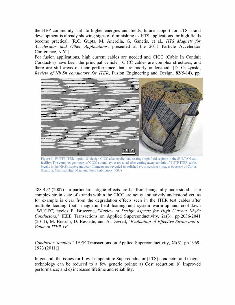
the HEP community shift to higher energies and fields, future support for LTS strand development is already showing signs of diminishing as HTS applications for high fields become practical. [R.C. Gupta, M. Anerella, G. Ganetis, et al., HTS Magnets for Accelerator and Other Applications, presented at the 2011 Particle Accelerator Conference, N.Y.] For fusion applications, high current cables are needed and CICC (Cable In Conduit Conductor) have been the principal vehicle. CICC cables are complex structures, and there are still areas of their performance that are poorly understood. [D. Ciazynski, Review of Nb3Sn conductors for ITER, Fusion Engineering and Design, 82(5-14), pp.
488-497 (2007)] In particular, fatigue effects are far from being fully understood. The complex strain state of strands within the CICC are not quantitatively understood yet, as for example is clear from the degradation effects seen in the ITER test cables after multiple loading (both magnetic field loading and system warm-up and cool-down “WUCD”) cycles.[P. Bruzzone, "Review of Design Aspects for High Current Nb3Sn Conductors," IEEE Transactions on Applied Superconductivity, 21(3), pp.2036-2041 (2011); M. Breschi, D. Bessette, and A. Devred, "Evaluation of Effective Strain and n-Value of ITER TF Conductor Samples," IEEE Transactions on Applied Superconductivity, 21(3), pp.1969-1973 (2011)] In general, the issues for Low Temperature Superconductor (LTS) conductor and magnet technology can be reduced to a few generic points: a) Cost reduction; b) Improved performance; and c) increased lifetime and reliability.
Figure 5. EUTF5 ITER “option 2” design CICC after cyclic load testing (high field region) in the SULTAN test facility: The complex geometry of CICC strand layout revealed after cutting away conduit of EUTF ITER cable, breaks in the Nb3Sn superconductor filaments are revealed in polished cross-sections (images courtesy of Carlos Sanabria, National High Magnetic Field Laboratory, FSU)

Superconducting magnets represent a large fraction of the cost of current and planned fusion devices. Superconducting strand costs, especially beyond Nb-Ti (<1$/kA·m), are high, partly due to the extensive R&D normally associated with new conductor designs, raw material costs, and conductor processing costs, which are labor intensive, and sometimes of low yield. [L.D. Cooley,A.K. Ghosh, R.M. Scanlan, Costs of high-field superconducting strands for particle accelerator magnets, Superconductor Science & Technology 18 R51-65 (2005)] Coil fabrication costs are also high because the superconductor properties are often sensitive to handling, and the coil fabrication steps may stress or damage the superconductor. In addition, the brittle Nb3Sn superconductor must be formed after coil winding by a long multi-step heat treatment which finishes with a high temperature reaction heat treatment (at about 650 °C for up to 200 hours) which complicates the fabrication process and extends the fabrication schedule significantly. [P.L. Bruzzone,Wesche, F. Cau, Results of Thermal Strain and Conductor Elongation Upon Heat Treatment for Nb3Sn Cable-in-Conduit Conductors, IEEE Transactions on Applied Superconductivity 20 470-3 (2010)] There are other substantial costs associated with the need for cryogenic refrigeration at the 4.5 K level and nuclear shielding. Some magnetic configurations require very high field quality and therefore the conductor must be amenable to being positioned accurately. A strong benefit results from higher magnetic field since fusion power is proportional to B4. Higher operating current density could reduce the size of the winding pack, as would better quench protection systems, thus reducing overall system cost. Improvements in the ability to absorb higher nuclear flux and fluence could reduce the whole machine size and cost if better insulation systems could be developed or if superconductor stability could be increased in order to reduce the size of the radiation shield protecting the magnet. Better ways of integrating advanced insulations need to be developed to decrease the manufacturing costs. For reactor scale devices, and even for a burning plasma experiment, the size, complexity of access, and probable need for remote maintenance of the magnet system, preclude the economical exchange of coils, so the magnet coils must operate with the utmost reliability and availability. Improved performance can allow for more operating margin and thus increase system reliability. An extremely important benefit could be achieved if demountable superconducting joints could be easily and reliably made.
6.4.2 HTS Whereas the development of high performance LTS strand has been driven by the HEP community, the development of long-length high-current HTS technology has been, until FY10, driven by the OE (Office of Electricity Delivery and Energy Reliability) of the Department of Energy with a focus on transmission-line application [Haught D., et al., Overview of the U.S. Department of Energy (DOE) High-Temperature Superconductivity Program for Large-Scale Applications, International J Applied Ceramic Tech 4 197-202 (2007)]. However, support from OE has been dramatically curtailed, and further development would need to be performed primarily from increased industrial support and from DOE-HEP (at the expense of LTS development).

6.4.3 HTS Material and Cable Design 25 years after the discovery of HTS, the development of long-length engineering quality HTS materials now offer a revolutionary path forward in the design of magnetic fusion devices that could lead to very high performance in compact devices, with simpler maintenance methods and enhanced reliability. The HTS materials are already sufficiently advanced to be considered for next-step fusion applications and we be used for ITER current leads.[P. Bauer et al., "Test of a 10 kA HTS Current Lead for ITER,"IEEE Transactions on Applied Superconductivity, 21(3), pp.1074-1078 (2011)] The HTS superconductors have the ability to optimize magnetic fusion devices for very high field operation and/or relatively high cryogenic temperatures. They can be used with any magnetic field configuration including 3-D shaped devices. Since some HTS materials can operate at cryogenic temperatures approaching that of liquid nitrogen (77 K), one can consider as realistic the option to build electrical joints into the winding cross-section that can be connected, unconnected and reconnected on site. A fusion device with HTS magnets could be disassembled and reassembled to allow for maintenance and change of internal components. Magnetic field strength limits the achievable plasma pressure needed for fusion — higher B would allow more compact devices, or significantly ease control requirements. Recently, the NHMFL has achieved a 35 T field using HTS tapes at low temperatures [H.J. Weijers, U.P. Trociewitz, W.D. Markiewicz, et al., High Field Magnets With HTS Conductors , IEEE Trans. Appl. Supercond 20 576 (2010)]. Superconducting magnets are required for almost any magnetic configuration of a practical fusion reactor, and the SC magnet system of large-scale fusion devices is about one-third of the core machine cost. Today’s experiments, including ITER, utilize SC magnet technology that is decades old. Accurate fabrication of complex magnets is also a crucial cost and performance issue for stellarators. There have been substantial R&D investments in HTS by the Department of Energy Office of Electricity Delivery and Energy Reliability (OE) and high energy physics. The industry is at present providing substantial quantities of HTS tapes. In the US, all production has moved to the 2nd generation materials, using YBCO and ReBCO superconductors, away from BSCCO-2223 material that formed the basis for 1st generation HTS conductors. These materials are available from 2 suppliers in the US, at an approximate cost (2010) of $40/m for 100 A tapes at liquid nitrogen temperature, or about $400/kA·m. [NavigantConsulting, High Temperature Superconductivity Market Readiness Review. 2006; Available from http://www.energetics.com/meetings/supercon06/pdfs/Plenary/07_Navigant_HTS_Market_Readiness_Study.pdf] Despite their great promise, high temperature superconductors are still a young technology (Nb3Sn, the conductor used for the ITER TF and CS coils, was first tested at high field in December 1960, over 25 years before the discovery of HTS). The demands for fusion applications require investigation beyond those of existing programs. [see, for

example, The limits on high temperature superconductors that reflect the early stage of their development are:
1. Cost 2. Performance 3. Piece length 4. Strength 5. Production Capacity
Although high temperature superconductors are not yet a sufficiently established industry to provide conductor for the most demanding fusion applications, the rate of progress in performance has been impressive. [T. Lehner, Development of 2G HTS Wire for Demanding Electric Power Applications, presented in ENERMAT: New Materials for Energy, June 20-21, 2011, Santiago de Compostela, Spain] This is especially true for YBCO which is a material of enormous promise for high temperature and high field applications. This is a transformative material with the potential for raising field, current density, and temperature simultaneously (see Figure 6), while lowering refrigeration requirements. Achievement of these goals would offer a realistic vision for making an economical future commercial fusion reactor. High temperature superconductors could be used in ultrahigh field magnets and could be developed in the moderate-term. Even now, however, the properties and piece lengths are being commercially produced in a range sufficient for use in even low-field fusion devices, e.g. an ST, or with non-planar coils, e.g. helical or stellarator. Most of the commercially produced HTS tapes are made for electric power utility applications. Involvement of the fusion magnet community with the HTS manufacturers could result in wires that are more amenable to high current conductor fabrication. The goal of a high temperature superconductor research program is the production of high effective-current density strands in long lengths, the cabling of ever larger numbers of strands until the 30-70 kA levels needed by magnetic fusion are attained. Cabling of strands or wrapping tapes about a core can increase the effective ampere-meters of an unjointed conductor by orders of magnitude, as has been demonstrated by recent high-voltage transmission line HTS cable demonstration projects, which use multiple tapes wrapped about a cylindrical former/coolant line. This approach has too low an overall current density for a fusion magnet and one central purpose of a fusion conductor/magnet development program would be to develop conductor concepts such as CICC with an adequate combination of current density, field, and cost at reasonably elevated temperature. A round wire form of multifilamentary YBCO similar to that successfully developed for 2212 would be a better choice for a fusion conductor but would require a significant investment to address the fundamental grain boundary materials science needed to understand how to relax the present very stringent, quasi- single-crystal technology required for today’s YBCO coated conductors. Although such a breakthrough seems far away at present, the resulting benefits would be so valuable that combining an effort to

develop a multifilamentary round wire with the development of a reduced $/kA·m cost would be an excellent long-term investment. The superconducting cable design needs to address several key requirements, including (a) high engineering current density, (b) minimal strain degradation, (c) proper stabilization against quenching, (d) reduction of the maximum temperature in case of a quench, (e) low AC losses, (f) efficient cooling. For HTS tapes, if relevant conductors can only be made as thin, flat tapes, better methods must be developed to produce compact, high current density cables, from this non-ideal geometry. Some progress has been made assembling cables using the Roebel pattern from the flat tapes. This serves to increase the overall current capacity, but still has several drawbacks. Some of the expensive superconducting material is lost in the zigzag cutting process and the cable requires development of special machinery to weave the tapes together. Although cables of several kA’s can be fabricated this way, they are still about an order of magnitude too low in current for large-scale fusion magnet applications. A different approach receiving some attention is the manufacturing of the cables by stacking multiple tapes. The tapes could be twisted, providing for some transposition and to decrease loop currents. [Takayasu, L. Chiesa, L. Bromberg and J.V. Minervini, HTS Twisted Stacked-Tape Cable Conductor, submitted for publication, Superconducting Science and Technology (2011)] The tape stacks could be embedded in round copper pipes (with an appropriate groove), reducing what is a rectangular shape, difficult to wind as CICC, to a round cable. The principle has been demonstrated in short samples, with no noticeable degradation of the YBCO tapes for reasonable twisting pitches. [Takayasu,
Figure 6. Comparison of engineering current densities for a variety of production superconductors (plot continuously maintained at http://magnet.fsu.edu/~lee/plot/plot.htm).
M., J.V. Minervini, L. Bromberg, Torsion strain effects on critical currents of HTS superconducting tapes, AIP Conference Proceedings 1219 337-44 (2010)]. Another variant of this kind of cable has been proposed and demonstrated by van der Laan too. Alternatively, better ways to integrate the HTS tapes with the structure, insulation, and cooling of the magnet should be explored. The requirements for magnet protection under those circumstances, with conductors operating at higher temperature and well cooled, needs to be determined.
6.4.4 Structural Material The structural material issues are discussed in the materials section of this report.
6.4.5 Insulation The insulation material issues are discussed in the materials section of this report.
6.4.6 Joints Joints between very large, multi-strand cables of the type required for fusion applications are very difficult to make and to achieve simultaneously the conflicting goals of low resistance, low ac loss, and high stability. In order to know that a joint is "superior", it should simultaneously decrease the DC and AC losses and the size of the joint. Although there is significant experience in the fusion magnet community with making high current, “permanent” joints with large cables made from round wires (LTS), there is no equivalent experience in joining large cables or conductors made from many thin, flat tapes (HTS). The fabrication of high-current HTS samples should be developed in the laboratory, with a structured program for understanding joining methods, dc resistance and interface resistances, current transfer, ac losses, stability. The joint samples should be tested as hairpins and insert coils in order to establish overall properties. Simple resistance tests can be performed relatively easily with existing equipment. Full-scale prototype joint samples can be tested in the Pulse Test Facility after undergoing some modification to change the test environment from forced-flow supercritical helium, to either liquid nitrogen coolant, or intermediate temperatures by cooled helium gas. The greatest programmatic impact will derive from developing a method of joining entire coil cross-sections as a unit while having the ability to be connected, disconnected, and reconnected multiple times with no degradation. This would enable superconducting research facilities in which major components could be readily tested and replaced, and enhance maintainability, availability and inspectability of a DEMO. This is a non-trivial task, since not only should there be excellent electrical connection, but also structural, cooling, and insulating connection. Significant resources are thus warranted to achieve this challenging goal.
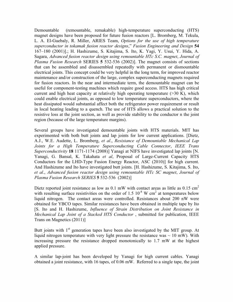
Demountable (remountable, remakable) high-temperature superconducting (HTS) magnet designs have been proposed for future fusion reactors [L. Bromberg, M. Tekula, L. A. El-Guebaly, R. Miller, ARIES Team, Options for the use of high temperature superconductor in tokamak fusion reactor designs,” Fusion Engineering and Design 54 167–180 (2001)].; H. Hashizume, S. Kitajima, S. Ito, K. Yagi, Y. Usui, Y. Hida, A. Sagara, Advanced fusion reactor design using remountable HTc S.C. magnet, Journal of Plasma Fusion Research SERIES 5 532-536 (2002)]. The magnet consists of sections that can be assembled and disassembled repeatedly with permanent or dismountable electrical joints. This concept could be very helpful in the long term, for improved reactor maintenance and/or construction of the large, complex superconducting magnets required for fusion reactors. In the near and intermediate term, the demountable magnet can be useful for component-testing machines which require good access. HTS has high critical current and high heat capacity at relatively high operating temperature (>30 K), which could enable electrical joints, as opposed to low temperature superconductors, where the heat dissipated would substantial affect both the refrigerator power requirement or result in local heating leading to a quench. The use of HTS allows a practical solution to the resistive loss at the joint section, as well as provide stability to the conductor n the joint region (because of the large temperature margins). Several groups have investigated demountable joints with HTS materials. MIT has experimented with both butt joints and lap joints for low current applications. [Dietz, A.J., W.E. Audette, L. Bromberg, et al., Resistance of Demountable Mechanical Lap Joints for a High Temperature Superconducting Cable Connector, IEEE Trans Superconductivity 18 1171-1174 (2008)] Yanagi at NIFS have investigated lap joints [N. Yanagi, G. Bansal, K. Takahata et al, Proposal of Large-Current Capacity HTS Conductors for the LHD-Type Fusion Energy Reactor, ASC (2010)] for high current. And Hashizume and Ito have investigated butt joints. [H. Hashizume, S. Kitajima, S. Ito, et al., Advanced fusion reactor design using remountable HTc SC magnet, Journal of Plasma Fusion Research SERIES 5 532-536 (2002)] Dietz reported joint resistance as low as 0.1 mW with contact areas as little as 0.15 cm2 with resulting surface resistivities on the order of 1.5 10-8 W cm2 at temperatures below liquid nitrogen. The contact areas were controlled. Resistances about 200 nW were obtained for YBCO tapes. Similar resistances have been obtained in multiple tape by Ito [S. Ito and H. Hashizume, Influence of Strain Distribution on Joint Resistance in Mechanical Lap Joint of a Stacked HTS Conductor , submitted for publication, IEEE Trans on Magnetics (2011)] Butt joints with 1st generation tapes have been also investigated by the MIT group. At liquid nitrogen temperature with very light pressure the resistance was ~ 10 mW). With increasing pressure the resistance dropped monotonically to 1.7 mW at the highest applied pressure. A similar lap-joint has been developed by Yanagi for high current cables. Yanagi obtained a joint resistance, with 16 tapes, of 0.06 mW. Referred to a single tape, the joint

resistance is about 1 mW. In their case, the joints are soldered. Their purpose is ease of assembly, rather than maintenance, so there is no need for demountability.
6.4.7 Magnet Protection Quench detection is the Achilles’ heel of a superconducting magnet in an erratic pulsed field environment. The specific weakness of tokamak magnets is the plasma disruption, which is “unscheduled” and varying, making it impossible for its signal to be completely zeroed out predictively, since physical or computational signal balancing must know the disruption spectrum in advance. Arbitrary reliability can be built into the power supply interrupters through series connections and redundancy. However, this is much harder to do for quench detectors, which are built into the coils with signal/noise ratios that are intrinsic properties of the sensors. A simplified way of stating the problem is that the magnet voltages are on the order of 10 kV, while the quench signals one would like to detect are on the order of 100 mV, implying a need for 5 orders of magnitude in noise rejection. Various methods of quench detection needing further development including balanced voltage taps on coil segments, co-wound voltage taps for intrinsic inductive signal cancellation, and co-wound optical fibers which can sensitively measure temperature and strain over a wide range of operating conditions. For HTS magnets operating at high temperature (but likely lower than 77 K) would require a continuous sensor, that is, one that can determine temperature along the cable either continuously or at very short intervals, as the normal zone propagation is slow and local detection of a quench is required. [F. Hunte, H. Song, R. Johnson et al., Multi-purpose fiber optic sensors for high temperature superconducting magnets, presented at the 23rd IEEE/NPSS Symposium on Fusion Engineering - SOFE part 4 (2009)] Alternative magnet protection should be investigated, especially for HTS magnets. One potential technique, used in MRI magnets, is an internal energy dump, reducing the requirement for high voltages and high currents. [L. Bromberg, J.V. Minervini, J.H. Schultz, Internal Quench of Superconducting Magnets by the Use of AC Fields, submitted for publication, IEEE Trans on Magnetics (2011)]
6.4.8 Prototype Magnet Development Although lab scale tests and component development can lead to viable solutions to the issues discussed above, integration of these components into a magnet is non-trivial, and may lead to complications and synergistic effects which result in a magnet that is not able to achieve all its design goals. Therefore, once the OFES strategic planning process identifies a next step U.S. device, the design goals should be then focused on those required by the device concept. Then all development steps can be proven on a relevant scale prototype coil or coils, and tested under full-scale operating requirements. Depending on the scale of the magnet, existing facilities for testing should be used or modified to carry out the test program.
6.4.9 R&D Strategy A number of critical technology areas have been identified to reduce the cost, increase the performance, and improve the reliability of superconducting magnets for fusion applications. The specific goals and criteria outlined here form the basis of an R&D program which should be supported through a significant expansion of the present, very modest, enabling technologies magnet program. This will require coordinated efforts by universities, national laboratories, and industry. A reasonable program structure would include a distribution of efforts ranging from lab scale R&D, prototype component development, full-size magnet tests, and eventually incorporation into a next-step device. By this we mean that any next-step fusion experiment constructed in the U.S. should strongly consider using the best available superconducting magnet technology as a viable option for enhancing the mission of the device. Development of practical conductors and cables suitable for demanding fusion applications is needed for the HTS materials. The fusion program needs to determine whether and how present fragile HTS tape geometry be integrated into high current cables with the high current density needed for fusion experiments. Alternatively, the fusion program could explored whether HTS materials (and in particular, YBCO) can be made into round wires with high critical current density for easier magnet application. Followed the development of the superconductor, a program is need to explore the integration of HTS cables into practical magnet systems for fusion experiment to address the performance, reliability and maintainability required for fusion experiments. A program to develop HTS for fusion would incorporate:
• Fabrication of HTS wires, and integration of wires and tapes into high current density cables. A coordinated program of laboratory R&D in universities, national laboratories and industry.
• Development of magnet components, including improved structural and insulating elements, and assess performance for various fusion applications. Potential applications, which would greatly benefit FNS, include:
• High-field SC magnets for steady-state axisymmetric facilities with demountable joints, giving flexibility to test multiple divertor and nuclear science components.
• HTS tapes integrated into coils with complex shapes for 3-D and other alternate configurations.
• Testing of the most promising applications in prototypes, and ultimately incorporate into new Office of Fusion Energy Sciences (OFES ) research facilities.
6.5 R&D Tasks The following is a short description of the required tasks. The insulator and LTS structural materials are discussed in the materials section of this report.

6.5.1 SC Wire and Tape Development Program In this task, the fusion program would undertake the development of high current superconductors that can tolerate the fusion environment. For HTS, this includes the production of high engineering current density tapes in long lengths. Another important path to explore is whether YBCO conductors could be manufactured as round, multifilamentary wires, more amenable to conventional methods of high-current cable fabrication. Although such a breakthrough seems far away at present, the resulting benefits would be so valuable that modest resources should be applied to address this issue. In addition, production of isotropic tapes with regard to orientation of the magnetic field is desirable. One interesting possibility is to deposit the superconductor directly on the structural material. Presently, the Rare Earth-Barium-Copper-Oxide (ReBCO) materials are deposited by epitaxial means on the Ni-substrates with substantial load-carrying capability. If successful, this technique would obviate the need for cabling and winding. The characteristics of the materials under irradiation would have to be further explored. The present information covers mostly lower fields and higher temperature. [e.g. R. Fuger, M. Eisterer, F. Hengstberger, H.W. Weber,”Influence of neutron irradiation on high temperature superconducting coated conductors,” Physica C: Superconductivity, 468(15-20), 15] Although informative (Fuger et al. observed that coated conductor properties up to 15 T did not degrade under neutron fluence up to 1 × 10²² m-2) , the effect of high levels of irradiation on the performance of these materials at high fields and low temperatures, needs to be performed. An important effect is the impact of irradiation on the anisotropy of the HTS coated conductors. In comparison, the limits of irradiation for LTS (with neutrons) has been well documented. However, it would be of interest to explore the performance of recent high-Jc advanced ternary LTS materials.
6.5.2 High Current Conductors and Cables Development Program High current cables have been developed by the fusion community for large magnet application with LTS. High current HTS cables, with high current density and that can be incorporated in magnets, need to be developed by the fusion community, as the needs for fusion magnets in this area are unique. One of the options is to develop Cable-in-Conduit Conductors with HTS tapes. Means of cooling the superconductor, inexpensive manufacturing, high current density and operating at higher temperature than liquid helium should be developed under this task.
6.5.3 Advanced Structural Concepts and Structural Materials and Structural Concepts for HTS The structural materials required for LTS applications are covered in the material section. In this R&D task, developments of advanced magnet structures are to be explored. Since

it is likely that machines beyond ITER will have long pulse and non-inductive current drive, options of using bucking as a support option for the magnet should be explored. In addition, the use of external structures, such as pre-loading rings or tresses, should be investigated. Rapid prototyping, or “additive manufacturing,” can be used to create unique shapes directly from the Computer-aided Design (CAD) models. One potential use is to manufacture the structural plates of the magnet with the features needed for operation. Multiple material deposition heads create the coil structure in a timely manner to near-net shape such as internal cooling channels, conductor grooves and attachment features. The fabrication cost of fusion magnet structures with this technology has been estimated to be a small fraction of traditional fabrication methods. If it proves too difficult to deposit directly the HTS material on the structure, an alternative approach would be to insert cables made from HTS tapes into grooved structures (plates or shells) with complex shapes. This technique would also ease the manufacture of steady-state magnets with complex 3-D geometries. In any case, the higher temperature margins of HTS allows for different structural-cooling topologies. In particular, it may be possible to cool the superconductors through heat conduction through the structure, with cooling channels that are embedded in the plates. In addition, the use of deposited SC would allow the use of higher performance insulations, such as the built-in insulators required for the epitaxial deposition of the HTS materials. Additional ceramic insulators could be deposited on the magnet components, on top of the superconductor.
6.5.4 Cryogenic Cooling Methods for HTS Magnets It is unlikely that high field fusion magnets will be able to operate with subcooled liquid nitrogen. There are nitrogen-based eutectics that have substantially lower freezing temperatures than subcooled nitrogen, but even those are have temperatures of more than 50 K. Other coolants would be required, operating between 30 and 50 K. It is possible to use conduction cooling of the cable, but eventually the heat needs to be removed by a fluid, most likely a gaseous fluid (such as helium gas). Alternatively, the conductors themselves can be directly cooled by the flowing gas. Gaseous cooling for superconductors is challenging, as the heat removal rate is much lower than for liquid cooling and have much lower volumetric heat capacity. Issues of conductor stability, especially in very long conductors that are subject to nuclear heating, need to be investigated. It is likely that much higher nuclear heating rates can be tolerated in HTS (because of the higher temperature margins), because of lower refrigeration power requirement (because of the higher temperatures). The problem of radiation damage to the superconductor and the insulation, however, still remains.

6.5.5 Magnet Protection In the case of HTS, research in appropriate quench detection techniques has to be carried out. Although adequate techniques will be used in ITER, improved detection techniques could ease quench requirements, in particular the time for dump (and associated peak voltages). At higher temperature with HTS, stability, quench and magnet protection need to be reconsidered, as the heat capacity of the conductors are orders of magnitude higher than those at liquid helium temperature. However, it is necessary to get to temperatures around 50-60 K before the heat capacity is similar to that of liquid helium. In addition, the heat removal rate, in the case of a normal zone, could be much smaller in the case of HTS with gaseous cooling, because of the poor heat surface heat transfer associated with gas cooling. Passive and active quenching methods need to be investigated. One such method is the possibility of quenching substantial sections of the magnets simultaneously through the use of eddy current heating (or hysteresis heating of the superconductor) using AC fields. These means are not needed at liquid helium temperature because of the fast propagation of quenches, even in the presence of helium coolant. The overall design philosophy of off-normal conditions and faults also would have to be developed rigorously to guarantee protection against credible operational events. Design and analysis codes should be revised specifically for fusion magnets operating at these higher temperatures, and confirmed by comprehensive laboratory testing as has been done in the past for liquid helium cooled (LTS ) magnets.
6.5.6 Joints for demountable coils The ability to operate at relatively high cryogenic temperatures and the use of relatively simple structural configurations provide very high stability and rigid operation which, in turn, allows for the consideration of demountable joints. Demountable high-temperature superconducting coils promise unique advantages for tokamaks and alternate configurations. They would enable fusion facilities in which internal components can be removed and replaced easily and remotely, a major advantage for the difficult challenges of magnetic fusion machines. There has been very limited investigation of demountable superconducting magnets. The use of HTS allows for relatively high-resistance joints, with modest cryogenic power consumption. The use of tapes also facilitates certain types of joints such as lap joints, where surfaces of the tapes are pressed together for a non-permanent joint. For the case of tokamaks, two types of joints can be considered, sliding joints and fixed (as with finger joints). In either case, it is necessary to unload the joint region, as the joints have limited load-carrying capabilities. One additional issue that needs to be addressed is cooling of the joint region. The joint region has the largest cryogenic load of the magnet, larger than current leads or nuclear

radiation, and it is deposited in a relatively small volume (thus, high volumetric heat production). As a consequence, it will be necessary to cool the joint effectively. Although it is preferable to cool the joint directly, other cooling options (for example, through heat conduction from the joint region to channels embedded in the structure) should be studied. Both small experiments (bench-top) and larger scale, with full current, need to be performed. Due to the large number of joints that will be required in a fusion experiment, it is important to determine the reliability of the joints.
6.5.7 Technology demonstration The different proposed magnet improvements suited for FNS would have to be integrated and demonstrated by building prototype magnets of different configurations, e.g., planar coils, solenoids, as required by the FNS design. The size of the demonstration would be substantial, and appropriate levels of funding would be required. Design, construction of testing of these magnets would require the commitment of the fusion program, as it would be relatively lengthy. These magnets must then be tested under operating conditions that will demonstrate the feasibility of the concepts and the technology, starting with simple small scale and ending with a near-full size prototype, as was the case with the model coils for ITER. The most promising and useful magnet designs would then be incorporated into plans for FNS.
6.6 Copper Machines There is extensive experience with resistive magnets in the fusion program worldwide. However there is still some R&D that would be required for an FNS mission. Radiation tolerate insulation is one of the R&D issues that would have to be addressed. Copper magnets allow the minimization of the thickness of the nuclear shielding, as the heating concern is very much relaxed at the operating temperatures of resistive magnets. The useful lifetime of the machine due to irradiation is thus due to the nuclear damage of the insulator. Large, flat insulators should be explored as means of increasing the machine lifetime. Demountable joints have been made in the fusion program; however, steady state joints have not. It would be needed to incorporate steady state cooling of the magnet with the joints. Finally, resistive magnet could allow the use of external structures or preloading rings to minimize the stresses in the inboard leg of the toroidal field coil. The means to achieve this have been proposed, but careful analysis of the options is needed, especially because FNS is likely to be steady state cooled, not “adiabatically” cooled as in other present fusion experiments.

6.7 Facilities Laboratory facilities are adequate to begin this program, including, for example, facilities at the MIT Plasma Science and Fusion Center and the National High Magnetic Field Laboratory at FSU. In addition, we expect to collaborate with the High Energy Physics program (e.g., Lawrence Berkeley National Laboratory) and the Applied Superconductivity Group (electric grid-based HTS systems) at Oak Ridge National Laboratory. These laboratories already have complementary HTS programs supported by DOE funding, and it would be advantageous to OFES to collaborate where feasible, leveraging these efforts and facilities. The type of facilities that would be needed for an R&D program for FNS are shown in Table 1. Table 2 summarizes the activities described in this section. Table I. Facilities needed in the near term (5-15 year) and longer term (>15 year) for magnet development for FNS

Table 2 Detailed R&D required for near and long term R&D for FNS.
6.8 Scale of Effort for FNS Initiation of a program of this scope will require investment of resources in funding, personnel, materials, and equipment significantly beyond those allocated to the present modest magnets base program. The HTS materials are relatively expensive at this time, and sufficient quantities of industrial quality conductor must be purchased for the lab-scale program, component development, and eventually prototype magnet development. Research and development on making advanced HTS conductors in alternative geometries requires a robust materials development program, especially for development of round YBCO wires or direct deposition of HTS materials on structures. This is also true to achieve the goals of developing structural materials with the proper alloy chemistry and manufacturing methods. An investment in university based program will also have the benefit of developing the next generation of fusion-materials engineers that will take this technology to the next phase of development.

Table 3 describes the costs associated with the proposed R&D for FNS.
Table 3 Estimated R&D costs for an FNS program
Near term High Jc LTS strands 500K/yr Incolloy production 1000K/yr Optimize structural design 2000K/yr Longer term HTS cables 500K/yr Demountable magnet 2000K/yr Advanced manufacturing techniques 500K/yr Small coil construction 500K/yr Cooling design 250K/yr Insulation 500K/yr Copper machine Cooling design 250K/yr insulation 250K/yr integration 500K/yr

7. Research and Development Activities for Fusion Energy: Issues for Heating and Current Drive Systems in a DEMO Environment
7.1 Introduction All proposals for fusion DEMO reactors require some form of auxiliary heating and/or current drive. This has traditionally been provided by either Neutral Beam Injection (NBI) or by Radio Frequency (RF) Wave Heating and Current Drive. The requirements for successfully applying any of these systems in a DEMO plant are quite challenging and set constraints that require additional Research and Development (R&D) to be performed. The main concerns are material requirements imposed by the DEMO environment (heat and particle bombardment of in-vessel structures as well as the harsh irradiation environment), space requirements (reduction of available blanket for breeding tritium and extracting heat) and the requirement on system energy efficiency to minimize the re-circulating power requirements for the overall plant energy balance. In this document the requirements for and current drive will be set out followed by a brief description of the presently proposed systems to achieve these aims. The issues will be discussed by dividing them into three areas: The source area which converts electricity from the “wall plug” to energy be it RF or NBI to be applied to the reactor, an energy transport system to take the energy from the source to the reactor and the in vessel components which couple the energy to the plasma.
7.2 Requirements for Heating and Current Drive
7.2.1 Physics Requirements (This section also includes economic considerations) Heating and current drive systems are required to bring the plasma up to temperatures required for fusion, sustain the plasma current in steady state and also may be called on for profile control or instability suppression. These roles may require that the heat deposited or current driven be located at a specific place in the plasma, which may change on a variable, perhaps fast, time scale. The amount of power required for the initial heating to ignition does not, of course, significantly effect the overall efficiency since it is only required for a relatively short amount of time. If however, it is substantially in excess of the power required for the steady state sustainment and control it represents a substantial capital investment. The power required for current sustainment is circulating power and thus represents a major constraint upon plant efficiency. The amount of current that needs to be driven by auxiliary power depends on the plasma scenario. Some fraction of the plasma current can be driven by the internally generated bootstrap current. Since this bootstrap current scale as bNq95, plasmas with higher values of bN will have larger fractions of bootstrap current, possibly approaching 100%. Most

configurations require between 10% and 50% of the current to be driven by external means. However, higher bN plasmas are expected to require both increasingly precise pressure and current profiles and suppression of instabilities such as NTM’s or RWM’s. These in turn may just replace current drive power requirements with stability suppression power requirements. 7.2.2 Materials Heating and current drive systems require access through the blanket and shielding to the plasma. This means that components of the systems will be exposed to intense neutron fluxes and, for those systems requiring structures close to the plasma, intense particle and heat fluxes. The plasma facing components of the heating systems will be operating with coolant temperatures ≥ 600 C°. The materials used in present day systems, especially copper for high electrical conductivity, are not considered suitable for the reactor environment and will have to be replaced. Proposed substitute materials, such as tungsten (electrical conductivity ~ 3.5 X copper, and high resistances to sputtering), could be tested in present day devices to demonstrate that, at least in a low neutron environment, they are suitable replacements. Structural materials would need to be replaced with low activation ferritic steels, and insulating materials would need to be eliminated or moved sufficiently far from the radiation environment. If the components near the plasma show significant lifetime limitations (from neutron damage, plasma material erosion, or other effects) they must be configured for efficient removal and replacement.
7.2.3 Efficiencies The overall efficiency of a fusion power plant is governed by several factors. Pamela et al1 give a good summary of this issue, and we will follow their argument here. The efficiency of the heating and current drive systems can play a major role in determining whether a specific realization of a fusion power plant is practical and attractive. The net electric power can be expressed as:
!
Pe = PeG " PeHCD " PeBoP
where PeG is the gross amount of electric power produced, PeHCD is the amount required
to power the heating and current drive systems, and PeBoP is the amount required for the balance of plant (e. g. cryogenics, coolant and breeder pumping etc.) The amount of power required for the heating and current drive can be expressed as:
!
PeHCD = PL + Plosses + Pconv
!
PL = PCD + Pstab Where PL is the power coupled to the plasma, PCD = Ip/hcd is the power required to drive the plasma current Ip at efficiency hcd (and includes losses in coupling), Pstab is the amount of power required for any plasma stabilization or profile control scheme, Plosses is the power lost between the source (klystron, gyrotron, tetrode or NBI source) and the plasma and Pconv is the power lost in converting DC power to RF or NBI power. The following table summarizes ranges of efficiencies for the various systems that will be discussed in more detail below.

Table 2
System hcd (x1020) htrans hconv htot =hcdxhtransxhconv ICRF .3 .7 .9 .19 LH .3 .5 .5 .08 ECH .15 .8 .45 .05 NBI .4 .94 .40 .15 Note the requirements for efficiency (assuming a reasonable recirculating power fraction) grow as the demands increase from near term devices (not important) thru fusion nuclear science facilities (still not very important if Qeng not an important parameter), a break even Pilot Plant (htot ~0 .15) to a DEMO reactor (htot ~ 0.4) assuming in the latter two cases a bootstrap current fraction of ~ 50%). From this it is clear that efficiency will eventually be a major issue.
7.3 Heating and Current Drive Systems
7.3.1 NBI Neutral Beam Injection (NBI) systems heat and drive current by injecting a beam of energetic neutral atoms into the plasma, where they are ionized and transfer their energy and momentum to the bulk plasma. In order to penetrate large, hot, dense plasmas, beam energies greater than 500 keV can be required. Additionally, current drive efficiency increases with beam energy. The NBI system is composed of a plasma source from which an ion beam is extracted, an accelerator section in which the beam is accelerated to its final energy, a neutralizer section where the ion beam is transformed into a neutral one, a deflection region where the un-neutralized ions are removed, and a drift duct where the neutral beam passes into the plasma chamber. At each stage there are inefficiencies; typical source electrical efficiencies are on the order of 0.8 - 2.5 kW per amp of ion beam produced. Beam acceleration can be quite efficient, with total electrical efficiencies, after transmission, power supply, and electron losses, of 80% to 92%. Beam neutralization poses a challenge; conventional NBI uses positive ion beams, which are neutralized by passing thru a gas neutralizer where charge exchange takes place. This process falls rapidly in efficiency for energies above 40 keV/amu (see figure 1). Neutralization of negative ion beams by stripping in a gas cell is relatively independent of energy for energies above 100 keV/amu and is the technique used on the JT-60U 500 keV NNBI system and presently envisioned for the ITER 1 MeV system. This has a practical efficiency of about 59% at optimum neutralizer line density. Additional power is lost due to reionizaton of the neutral beam power after the neutralizer, especially in the drift duct. This can range from 2 – 3 % of the beam power up to perhaps 8 – 10 % in ITER high edge density discharges with high recycling.
Power is also consumed to run the cryosorption and secondary pumping systems, and in providing cooling water, and imperfect transmission of the beam due to beamlet divergence, miss steering of beamlets, and misalignment can lead to losses of 0 to a few additional percent. In systems using gas neutralizers these losses lower the wall plug electrical efficiency, resulting in a projected overall optimum electrical efficiency of about 40% for gas- neutralized negative ion neutral beams, and about 33% for positive ion neutral beam systems. Advanced beam neutralizers, coupled with reductions in vacuum pumping and water cooling power, along with improved beam transmission, could improve the wall plug to plasma edge efficiency to perhaps 45 -- 47% with a transverse supersonic lithium vapor jet neutralizer, and possibly higher with a laser neutralizer, although the technical challenges of a laser neutralizer are much greater than for a lithium jet neutralizer. Both these latter options would also greatly reduce the gas used by neutral beams systems, permitting pumping techniques, which would allow continuous neutral beam operation without the need to stop for cryopanel regeneration, a necessary characteristic of a driver for a reactor. Power can also be lost due to beam ions created by charge exchange in plasma volumes where they are directly lost from the plasma, before exchanging energy or momentum, due to their large orbits. In larger high field and current machines this problem is reduced due to better fast ion confinement.
7.3.2 ECH ECH systems heat and drive current by launching a beam of high frequency (50-200 GHz) microwave energy into the plasma. The microwaves are absorbed directly by the electrons at the Doppler shifted cyclotron resonance or its harmonics. In order to penetrate high-density plasmas heating at the second harmonic is often required. In over dense plasmas (wpe > wce) typical of ST devices mode conversion to Electron Bernstein Waves (EBW) may be required to penetrate to the core plasma. Since absorption of the wave energy is via the cyclotron resonance it increases the perpendicular energy of the electron distribution. Current is driven due to distortions in the distribution function creating an asymmetric resistivity. This effect is counterbalanced by the tendency to drive the particles into a part of vperp/v|| space where they become trapped and cannot carry momentum. Therefore, ECH current drive becomes less efficient as the location moves off axis to regions of higher particle trapping. One of the advantages of ECH is the ability to concentrate the power absorption in a small volume whose location can be easily controlled externally via movable mirrors (presently) or by more advanced techniques. The ECH power source is a gyrotron tube, which converts DC electric power into high frequency microwave power. Gyrotrons have typical efficiencies of ≤50%. The output of the gyrotron needs to be matched into the transmission system. This is typically done in a Matching Output Unit (MOU). While the efficiency of this component can be theoretically quite high in practice it is not. This is an area where near term demonstrated improvement could be made. The transmission system is composed either of corrugated waveguide or is free space “quasi optical” Again theoretical losses can be quite small but in practice, especially with waveguide the theoretical numbers are not routinely achieved. Every bend or inserted component will be associated with losses due to generation of
unwanted mode structure. For the quasi-optical systems every mirror has some loss and if the optical beam is not perfect there will be some divergence and loss. Finally, a launching structure must be provided. The launching structure could be as simple as an open-ended waveguide, however in present applications and in ITER, it typically will have a movable mirror to control the location of the deposition and to aim the wave toroidally to provide directed momentum. To achieve the capability for a large spread in deposition location, the mirror is located close to the plasma and would need to be cooled for steady state operation.
7.3.3 LHCD Lower Hybrid Current Drive (LHCD) has the highest intrinsic current drive efficiency of the presently practical RF schemes. This is because the lower hybrid waves damp, via Landau damping, on the parallel component of the electron distribution. Also the RF acceleration is sufficiently strong so that the collisional drag is overcome and a long collisionless electron distribution function tail is formed to carry the current. Unlike ECH however where the RF waves propagate in the vacuum region as well as the plasma, lower hybrid waves are evanescent in vacuum so a launching structure must be placed close to the plasma edge. To achieve uni-directional waves of the appropriate parallel wavelength a multi waveguide structure is required. Localizing the absorption region is much more difficult since a simple resonance effect is not involved. However, in hot plasmas it naturally lends itself to well off-axis cd. There are many technical challenges in constructing such a structure for a reactor environment. LHCD typically requires RF power in the range of 3-8 GHz. The typical RF source is the klystron, which is a relatively efficient (50-60%), means of converting DC power to microwaves. The transmission system consists of over-moded waveguide having low losses in the straight runs; however bends and any components those are inserted (circulators, directional couplers, splitters DC breaks etc.) add a component of loss to the transmission. The launcher itself is a complicated structure for splitting and phasing the power ending up in multi-waveguides (100’s). Typically a significant amount of power can be dissipated in this structure. It is not unusual to lose 30-40% of the power between klystron output and the mouth of the launcher. Additionally, only a fraction ~ 70% of the power at the launcher mouth is coupled to the plasma in the part of the spectrum that drives current in the desired direction.
7.3.4 ICRF Ion cyclotron (Fast magnetosonic) waves can impart energy to either the ions or the electron depending on the plasma parameters and the wavelength and frequencies involved. Fast waves can damp directly on the electrons and impart energy and momentum just as lower hybrid waves do. However, the RF kick by the wave to individual electrons is weaker than the collisional drag such that a high-energy collisionless tail is not created. This results in lower intrinsic current drive efficiency since there is more dissipation per momentum transferred. Like lower hybrid waves, fast magnetosonic waves are evanescent in the vacuum region; therefore launching structures must be located close to the plasma. For the lower frequencies (30-120 MHz) and longer

wavelengths (~ 1-10 meters) launchers are constructed of current carrying elements rather than waveguides. ICRF transmitters that convert DC power to RF waves have the highest efficiency of any of the systems. RF amplifiers are typically multi-staged objects. The high power tetrodes used in the output stages can have efficiencies in excess of 90%. When all the lower stages, as well as cooling power (It does not appear that cooling power was included in calculating efficiencies of other heating systems. It should be included in all of them) is taken into account efficiencies of >70% can still be achieved. Losses in coaxial transmission lines can be quite small. The main inefficiency comes at the antenna and matching system. Unlike ECH (essentially zero power reflection), LHCD (low power reflected) ICRF power coupling suffers from a large mismatch between the plasma impedance and the characteristic impedance of the antenna. This mismatch in impedance leads to a large power reflection which is compensated for by a tuning and matching network. The large circulating power means a large RF current is present between the plasma and the matching network. This current, which flows in a thin skin layer, leads to ohmic loses which, in present antennas, is minimized by using high conductivity copper. If copper, even in thin, ~200 micron, layers is not suitable in the reactor environment and tungsten is substituted, losses, which in present day antenna structures can be of the order of 10% will increase.
7.3.5 Source Issues The source is defined as that part of the system where AC power of the mains is converted either to a neutral beam or RF energy. Source issues can be divided into two main parts: efficiency and reliability (lifetime). In addition for NBI since there is straight line of sight to the plasma, materials issues can play a role as well.
7.3.6 NBI The ITER neutral beam test facility, which will include a full size ITER ion source with a 100 keV extractor stage, to be followed by a full ITER beamline, is intended to develop and demonstrate a deuterium neutral beam that can deliver 16.5 MW of megavolt neutral deuterium for periods up to an hour. If successful, it will have validated negative-ion-based neutral beams to what is probably their peak performance with current technology using a cesiated plasma ion source, an electrostatic accelerator, and a deuterium gas cell neutralizer. The effective beam power density will be about 36 MW/m2 averaged across the area of the entrance port. The power density could be increased if the negative ion current density could be increased, the divergence could be decreased, the acceleration voltage could be increased, or the neutralization efficiency could be increased. There may be some latitude for further increasing the negative ion current density, either by increasing the extractable current density, or decreasing the neutral line density in the accelerator so as to reduce stripping of the ions to neutrals or positive ions in the accelerator. It is unclear how much improvement might be obtainable this way, but it is likely not more than 10 – 20%.

At present time, it is not expected that the voltage of a large high current electrostatic accelerator could be extended appreciably in excess of a megavolt, and it is probable that significantly higher particle energies would require an RF accelerator, which would greatly reduce the wall plug electrical efficiency of the system (by as much as a factor of 3). The principal venue for augmenting the power density lies with the neutralizer. With a supersonic lithium jet neutralizer, the total gas flowing into the beamline from beam sources could be decreased by 75 – 80 %, leading to reducing premature neutralization in the accelerator, reduced reionization in the beam box, and with the elimination of vanes in the neutralizer, and improved neutralization efficiency with lithium, a total increase in the wall plug efficiency of 15 – 20% if magnetic deflection were used instead of electrostatic deflection. However, a major engineering effort would be needed to produce a practical supersonic transverse lithium jet neutralizer, since extremely good containment and recycling of the lithium is required. A photo-detachment (laser) neutralizer might, in principal, lead to 95 -99% neutralization of the beam, obviating the need for a residual ion dump section. In order for this to be attractive, however, a major development effort would be required to produce extremely high reflectivity mirrors that would survive in the tokamak environment without degradation, and appropriate lasers and resonator configurations so that the laser drive power was not itself large. Under the most optimum conditions, systems like those planned for ITER, but using a lithium jet neutralizer, might reach tokamak wall power densities of 43 MW/m2, with a wall plug electrical efficiency of perhaps 45 – 48%. With a photo-detachment neutralizer operating at 99% neutralization efficiency, the power density for an ITER-like beam might be 60 MW/m2, with a wall plug electrical efficiency which might be either higher or lower than that projected for a lithium jet neutralizer, depending upon the laser and resonator electrical efficiency. Once again, however, it is worth mentioning that the lithium jet neutralizer would require significant engineering development, and the photo-detachment neutralizer would need major advances in physics and engineering.
7.3.7 ECH The Gyrotron is the heart of the ECH source system. A gyrotron is an oscillator that generates high frequency 8 – 170 GHz (existing tubes) microwave radiation. Tubes with output powers of ~ 1MW have been manufactured. Higher power tubes are being developed and plans are in place to eventually have 2 MW per tube. Pulse lengths ≥ 800 s have been demonstrated at full power. The gyrotron is still in a state of technological development with continual improvements being made. While individual tubes have been produced that satisfy the requirements of existing long pulse machines, they have not been manufactured in a production mode. The yield on attempts to produce multiple tubes of similar design is well short of 100%. Standardizing tube requirements might significantly improve this situation. Little data exists on the reliability and lifetime of these tubes as most present applications are for relatively short pulses. Since the remnant electron beam is swept on the anode to reduce heating, fatigue life is an issue. Recent improvements in sweeping technique should improve this situation. The application of

the depressed collector circuitry has increased the efficiency of the latest generation of tubes to ~50% but this is an area in need of further improvement.
7.3.8 LHCD Lower hybrid sources are generally high gain (50dB) klystrons used as amplifiers. Klystrons have been developed and in routine production for many years, albeit at moderate power levels for CW operation. Since Lower Hybrid launchers typically have the power divided into many waveguides the need to develop tubes at power levels of 1MW or above has not arisen. Power levels of 0.3 to 0.7 MW per tube are typical at frequencies from 2.45 to 5 GHz. Efficiencies for klystrons of ~ 50% are typical. Since they act as linear amplifiers, varying the low level input power can control phase and amplitude. However, as with gyrotrons, the efficiency falls when not operated at full power. Using a varying anode supply voltage could ameliorate this drawback.
7.3.9 ICRF ICRF sources typically consist of multi stage amplifiers employing vacuum tubes (typically tetrodes). Frequencies of interest range from 20-120 MHz. Stage gains are usually low compared to klystrons (10-13 dB) to maintain stability so several stages are required. High power cw tubes were developed for the radio industry and are readily available at power levels up to 2.5 MW. When used in appropriate circuit arrangements final stage efficiencies of nearly 100% can be achieved. Overall efficiency including all stages, filament power etc. of 80% can be achieved.
7.4 Transmission Issues
7.4.1 NBI Tokamak operating modes that are characterized by high neutral edge densities, such as those that are often obtained on C-Mod, result in greatly enhanced reionization losses of beam power within the beam transmission ducts. The advent of such operating modes in the planning for ITER has resulted in a upwards revision of the neutral particle efflux from the plasma edge into the beam ducts of a factor of 20 for the worst conditions, resulting in significant (8 – 10%), but not intolerable, power losses in each beam system. While megavolt beams can operate in the presence of these high edges density modes, these modes are certainly not ideal from the beam perspective.
7.4.2 ECH Transmission losses in ECH systems can theoretically be quite small. They occur due to ohmic dissipation in waveguides and components (if a guided transmission system) losses and due to mode conversion to unwanted polarizations (at any discontinuity, bend etc. in path). An especially challenging component is the matching output unit (MOU)

and, if appropriate, its complement at the launcher. While systems for ITER specify transmission losses less than 10% (excluding the MOU), in practice, many existing systems lose more than this. Achieving results nearer the theoretical limit should be possible with extreme care and precision in alignment as well as a minimization of bends and inserted components.
7.4.3 LHCD Transmission losses for LH systems are a major drawback. While use of over-moded waveguide can minimize ohmic losses bends can again lead to losses due to excitation of higher order modes as in ECH transmission systems. In addition, LH systems typically require more inserted components because of the need to split the power more and control phase. Each inserted component adds a small amount of loss. Thirty percent or more of the klystron output power can be lost getting to the launcher.
7.4.4 ICRF ICRF has the smallest transmission line losses (<10%). The lower frequency allows the use of co-axial transmission lines which, if the voltage standing wave ratio VSWR is small, have very low losses. By using pre-matching near the antenna the VSWR can be kept low for the majority of the transmission line run.
7.5 Launcher Issues
7.5.1 NBI NBI does not require structures close to the plasma and hence there are none of the same issues as for rf launchers, however beams need adequate port access to the tokamak, which would act as loss conduits for neutrons in a reactor.
7.5.2 ECH Present ECH launchers utilize movable mirrors close to the plasma to control the location of the deposition of the RF energy in the plasma. These mirrors are composed of a highly reflective surface to minimize losses and must be cooled for long pulse operation. To focus the power and to transition from the feeding waveguide there is usually at least one other (usually fixed) mirror involved. This leads to a relatively large hole in the blanket compared to the dimensions of the feeding waveguide and to the complications added by the motion requirement and cooling. Recently, a resonant waveguide approach has been proposed, that would allow the beam to be steered by its angle of incidence on the entrance to the waveguide. This would reduce the size of the penetration trough the blanket /shielding module. The added difficulty would be in the mechanism to inject the power at the proper angle into the guide.
7.5.3 LHCD The LH launcher is a complicated structure composed of multiple small waveguides that needs to be placed in close proximity to the plasma edge. The challenge of cooling the front of the structure has been solved in the passive active multi-junction (PAM) by the introduction of dummy waveguides which are shallow and provide a path for cooling. The price for this is less directivity and a lower power density, increasing the wall area required and the source power required for a given driven current. Structures still use a large amount of copper that may have to be replaced with tungsten plated ferritic steel in a DEMO launcher.
7.5.4 ICRF The biggest challenges in ICRF are found in the launching structure. Large complicated structures that are fairly close to the plasma are required. ICRF antennas, utilizing current straps, are intrinsically high voltage per unit power objects since in this frequency range the plasma presents much lower radiation impedance than the characteristic impedance of the antenna, meaning large circulating power levels are present in the antenna. Power density is low and they frequently can be the source of plasma impurities. New materials will be required as high conductivity copper is presently used in large quantities. This may be replaced with tungsten plated ferritic steel. Alternative designs using folded waveguides or structures that have lower characteristic impedance, and hence, lower VSWR could improve the power handling and power density.
7.6 Opportunities for Near Term R&D
7.6.1 NBI By far the biggest gains could be achieved with better neutralizers. The most practical improvement path would be to do the engineering development for a robust supersonic lithium jet neutralizer with the necessary containment and recycling of the lithium. The ideal, but far more daunting, neutralizer would be a laser photo-detachment resonator cavity, if one could be developed with adequate photon line density and adequate wall plug electrical efficiency, and sufficient robustness to survive a fusion reactor environment without degradation of the lasers, mirrors, or alignment.
7.6.2 ECH Near term R&D is presently focused on movable mirror launchers, lower loss transmission components and MOU’s as well as more consistent gyrotron construction. The design and testing of a mirror-less steerable launcher in the near term would be a major step forward. Successful ITER operation will demonstrate gyrotron lifetime and ECH maintenance issues. Development of launcher plasma facing components that can operate with coolant temperatures >600 C will be required.

7.6.3 LHCD Major steps forward would include minimization of transmission losses and improvements in klystron efficiency. For LH launchers investigation of fabrication and operational characteristics with DEMO compatible materials would be fruitful. Successful application of LHCD on ITER would go a long ways towards establishing reliability of the technique, both for coupling to the plasma and the high power levels needed in a DEMO. Examination of off-midplane designs should be explored. Development of launcher plasma facing components that can operate with coolant temperatures >600 C will be required.
7.6.4 ICRF Near term R&D issues should focus on the antenna. Material choices, lower impedance designs, minimization of sheaths, and off-mid-plane designs (don’t use valuable tritium breeding space) should all be explored. Development of launcher plasma facing components that can operate with coolant temperatures >600 C will be required.
7.7 Summary ITER will be an ideal test bed for any or all of the heating and current drive schemes. Not only will it demonstrate the physics of the schemes under reactor conditions (size, field, power levels, and power densities) it will give useful information on reliability, lifetime, maintenance and overall system performance for systems of comparable size to those required for DEMO. Only in the area of materials will it still be insufficient since the neutron fluence and total neutron dosage will be significantly smaller. The wall areas required by the heating and current drive systems, in a FNSF or power plant, are strongly influenced by the achievable power density for the source. This competes directly with tritium breeding. Although the larger size of a power plant may alleviate this somewhat, the smaller FNSF could be impacted to a greater extent. It is important to recognize that the need for flexibility of a source to support a wide range of plasma configurations is likely to diminish, ultimately reaching only a single plasma configuration in the power plant (with some startup and shutdown phases). Simultaneously, the sources themselves are becoming less flexible as they are being made more robust to the fusion nuclear and plasma facing environment. Plasma facing components will need to survive the high heat flux and high radiation environment and be compatible with coolant temperatures >600 C. The biggest stretch forward for all systems is increasing over-all system efficiency. While this is not an issue for the proposed next step devices which are proposed to test materials, integrated blankets and divertors, with increasing nuclear exposure and demonstrate tritium breeding, it becomes an issue for any steady state tokamak designed to generate net electrical power. Presently demonstrated efficiencies are barely adequate for a Qeng = 1 device assuming conservative physics operation (~50%). Only devices with extremely high (>90%) bootstrap fractions, aggressive physics operation, are achievable

in steady state with present efficiencies. And these would presumably require additional auxiliary power to stabilize MHD modes and perhaps to tailor the pressure profiles. All aspects of the power chain, generation, transmission and coupling to the plasma need to be improved to high levels to make up for the physics inefficiency in converted coupled power to current.
7.8 References [Pamela, J. et al.] “Efficiency and availability driven R&D issues for DEMO” Fusion Engineering and Design 84 (2009) p 194.
8. Research and Development Activities for Fusion Energy: Fueling, Pumping and Particle Control for FNS-‐PA
8.1 Introduction This section is a description of the fueling, pumping, and particle control research activities required for development of a fusion nuclear science facility (FNSF) to help resolve gaps in fusion nuclear science before developing a prototype fusion power plant. This description is largely motivated from the ReNeW report with additional input from the pathways assessment effort R&D descriptions and facility requirements. The topics covered in this section are:
1. Fueling and fusion burn control – isotopic fueling 2. Exhaust control – pumping and recycling, divertor concepts 3. Particle transport - burn fraction
8.2 Fueling and Burn Control
8.2.1 Fueling: Efficient fueling and density profile control require that a FNSF plasma must be fueled well beyond the separatrix. The most effective means presently developed for doing this is solid DT pellet injection, where for maximum efficiency pellets would be injected from the high field region of the vessel (assuming that FNSF is a tokamak configuration). If the FNSF device is not a tokamak or inner wall injection is not available due to geometry constraints, then high speed pellet injection will be needed and further development of this technology for steady-state fueling would need to be pursued. Predictive understanding of the plasma behavior with pellet injection fueling is needed for the design of a FNSF. This will require further research in present day devices and ITER to develop a quantitative knowledge of pellet ablation and penetration physics, in the presence of energetic ions, as well as the subsequent particle transport following ablation of the pellets. Other possible fueling techniques include central NBI fueling, compact toroid injection, and supersonic gas injection. Of these, only NBI has been shown to provide fairly localized deep core fueling, but it is limited in the amount of fuel ions injected by the beam energy and input power level. Supersonic gas injection has very limited penetration in the plasma, especially with high plasma density operation. Compact toroid injection is the least well developed and needs further development of injectors that can operate at low power consumption without generation of impurities and verification of deep core fueling.

Fueling by pellets offers the potential further advantage over fueling by gas injection of reducing the tritium inventory of the first wall by injecting tritium-rich pellets [1,2], while fueling with gas at the edge with deuterium (and impurities) to maintain optimal divertor conditions. It then should be possible to provide a degree of control over the fusion burn rate in a FNSF by feedback control of the isotopic mix in the core plasma. The time scale over which the hydrogen isotopic mix can be varied is an important consideration and this requires additional research in existing pellet-fueled devices. The overall particle control issue, which includes fueling, is critical for the sustainment of burning plasmas. Pumping divertor neutral particles, the introduction of radiating impurities, the minimization of unintentional impurities, the removal of helium, the fuel mixture in the core plasma, and the radiating divertor and overall power handling all must be simultaneously achieved for the fusion power to be sustained. The demonstration of plasmas that simultaneously achieve these features on present tokamaks and ITER are necessary to develop the particle control strategies required for FNSF. The issue of fueling is complicated by the plasma environment of a FNSF, which couples the density produced by pellets to the modest alpha particle production rate and H-mode operation. The effect of pellets on edge localized modes (ELMs) , which is possibly beneficial if “pellet ELM pacing” is effective in reducing the size of ELMs, and other MHD activity, in particular neoclassical tearing modes, also requires further research in present day machines and ITER to make reliable predictions of the efficacy of pellet fueling in a FNSF. The pellet fueling technologies of steady state solid DT production and pellet cutting and acceleration being developed in the U.S. for ITER [2] will likely be available for a FNSF. The fueling pellet throughput needed for a FNSF will likely be less than for ITER, but for longer durations. The true steady-state nature needed will require some further development of this technology [3]. If higher pellet speeds are needed for deep penetration then the acceleration techniques may need to be enhanced, requiring further research and development.
8.2.2 Burn Control: Achieving self-consistent operating conditions that combine adequate D-T fusion power generation in the core and sufficient heat dispersal for protection of the plasma facing materials requires methods for controlling the operating state of the plasma, including fueling and divertor regulation. Fueling solutions (deeply fueling of solid D-T pellets) must be developed, although full demonstration will likely await the ITER burning plasma experiments. Methods for active control of divertor-target heat flux, radiation power level, and degree of detachment all must be developed and demonstrated. The H-mode plasma edge features a transport barrier referred to as the pedestal, which strongly determines the core plasma properties. High pressure at the top of the pedestal can support high overall performance in fusion plasma. The magnitude of this pressure is a key parameter requiring more accurate prediction for a FNSF and beyond. A key additional issue for the pedestal is that its density and temperature must be consistent

with the high-performance core plasma, fueling, and the divertor where particles and power are received and exhausted. The H-mode edge barrier gradient is generally limited by MHD stability, and its transient collapses, referred to as ELMs, provide severe loading conditions in future devices as the associated burst of energy and particles expelled from the plasma severely limit the lifetime of material surfaces. Similarly, any other large transients, such as a disruption, can result in loss of the plasma configuration, and cannot be tolerated in future devices. It is clear that the fueling system must be compatible with the MHD stability at the edge and not trigger excessive heat flux transients. Additionally, deep core fueling capability for ITER and a FNSF, and beyond, could possibly improve fusion burn performance by peaking the density profile. It would also increase the tritium burn-up fraction and thus potentially reduce tritium retention in the vessel. To meet this capability it may be necessary to engage in further research to improve the deep fueling beyond what is planned now for ITER.
8.3 Exhaust Control -‐ Pumping and Recycling, Divertor Concepts
8.3.1 Particle Exhaust Control Operation of a FNSF in steady state for days at a time, at fusion power production of up to 400 MW, requires that the fuel concentration in the core of the plasma be adjustable and replenished. Other than the limited auxiliary power, a flexible fueling system and efficient pumping system are all that remains to control and sustain the fusion power level in steady-state operation. The fueling and pumping systems must deposit fuel at the required locations, control the density profile to maximize the bootstrap current fraction (for a tokamak configuration), remove helium ash, and control the divertor operating density. Efficient pumping techniques that would enable plasma density operation compatible with proposed heat mitigation solutions and high core and edge plasma performance must be developed and demonstrated. For impurity and helium density control, and for hydrogenic density control, the candidate techniques include cryopumps and low recycling liquid metal walls and divertor. Some engineering issues for cryopumps will have to be addressed including cryopump operation and regeneration during continuous plasma operation. While the concept of low recycling of particles at the plasma edge by using liquid metal walls shows promise, a large number of issues (e.g., its compatibility with high-performance steady-state plasma operation, helium pumping, and off-normal event handling) must be solved and therefore at this time it appears that the cryopumping technique is presently the most relevant to consider for a FNSF. A simplified block diagram of the fuel cycle for a FNSF is shown in Fig. 1. The pumping system, labeled TCP, must be designed to efficiently control the divertor neutral density while pumping helium that is produced by the fusion reactions. In order to simplify the operation of the fuel cycle, it is proposed to directly use the pumped plasma exhaust gas

from the vessel to produce new fuel pellets directly without going through an elaborate exhaust processing system (TEP) as is designed into the fuel cycle for ITER. The exhaust gas that is directly input to the fueling system will need to have any impurities and helium removed by cryogenic separation, which has been demonstrated in pellet injector experiments performed at Tritium Systems Test Assembly (TSTA) in the 1990s [4]. Exhaust gases that are not directly used in the fueling system will need to be pumped and sent through a processing system in order to remove impurities and separate out any remaining hydrogenic isotopes (in particular tritium) for reuse. The ITER fuel cycle does not attempt to reuse any of the plasma exhaust to directly refuel and thus has a very large tritium plant that becomes the largest and highest cost element in the entire fuel cycle. Tritium will of course need to be bred in close coupled lithium containing blankets in order to make up the tritium consumed in the fusion reactions [5]. Consequently, the tritium that is bred (TBM in the block diagram) will need to be processed and fed into the fuel cycle to replenish the injection system when the exhaust tritium fraction that feeds the fueling system becomes depleted. Development will be needed to determine how to manage the flow of tritium throughout the entire facility, including plasma fueling, breeding, and exhaust recovery and reuse. A complete fuel cycle model will need to be developed to assist in the design of the overall system. Conventional cryopumps are designed to be used in ITER in a batch mode with up to 8 operating in parallel, which will require frequent regeneration of the pumps. The frequent temperature cycling required in the batch cryopump adds thermal stresses that may make this type of pump less reliable than desired for long operating lifetimes. Continuous cryogenic diffusion pumps known as snail pumps have been developed in the US fusion program and basic prototypes tested [6, 7]. This type of cryopump can greatly
Fig. 1. Simplified fuel cycle block diagram for a FNSF.
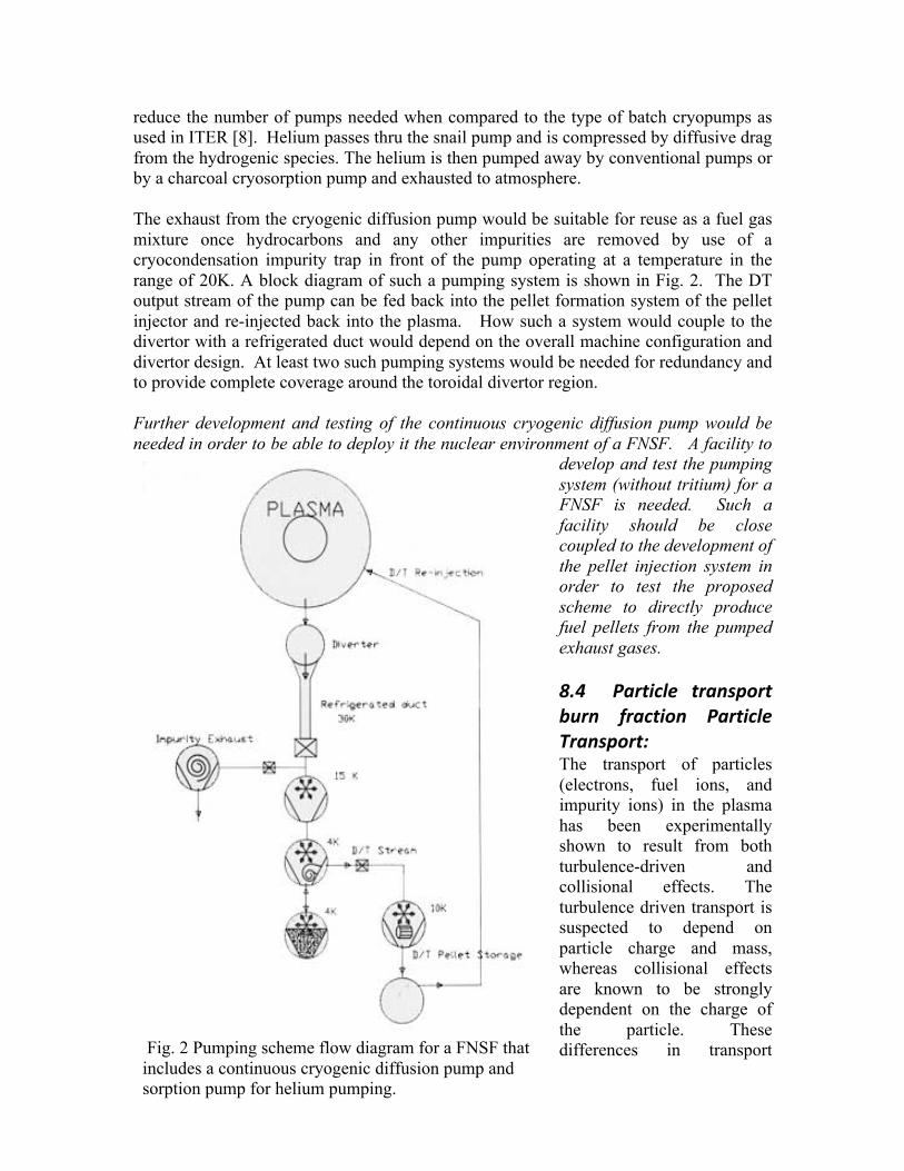
reduce the number of pumps needed when compared to the type of batch cryopumps as used in ITER [8]. Helium passes thru the snail pump and is compressed by diffusive drag from the hydrogenic species. The helium is then pumped away by conventional pumps or by a charcoal cryosorption pump and exhausted to atmosphere. The exhaust from the cryogenic diffusion pump would be suitable for reuse as a fuel gas mixture once hydrocarbons and any other impurities are removed by use of a cryocondensation impurity trap in front of the pump operating at a temperature in the range of 20K. A block diagram of such a pumping system is shown in Fig. 2. The DT output stream of the pump can be fed back into the pellet formation system of the pellet injector and re-injected back into the plasma. How such a system would couple to the divertor with a refrigerated duct would depend on the overall machine configuration and divertor design. At least two such pumping systems would be needed for redundancy and to provide complete coverage around the toroidal divertor region. Further development and testing of the continuous cryogenic diffusion pump would be needed in order to be able to deploy it the nuclear environment of a FNSF. A facility to
develop and test the pumping system (without tritium) for a FNSF is needed. Such a facility should be close coupled to the development of the pellet injection system in order to test the proposed scheme to directly produce fuel pellets from the pumped exhaust gases. 8.4 Particle transport burn fraction Particle Transport: The transport of particles (electrons, fuel ions, and impurity ions) in the plasma has been experimentally shown to result from both turbulence-driven and collisional effects. The turbulence driven transport is suspected to depend on particle charge and mass, whereas collisional effects are known to be strongly dependent on the charge of the particle. These differences in transport Fig. 2 Pumping scheme flow diagram for a FNSF that
includes a continuous cryogenic diffusion pump and sorption pump for helium pumping.
properties among particle species could be leveraged to isolate control of a particular species [9]. To make firm predictions about density peaking and impurity accumulation, research should be targeted on micro-instabilities that are relevant to ITER and a FNSF plasma operating regime. Future experiments should attempt to verify the particle pinch effects predicted by turbulence simulations and should include measurements of both majority and impurity ion particle transport as well as plasma fluctuations. Core fueling efficiency by gas puffing and pellet injection is critically dependent on both normal particle transport and fast transport of the pellet-sourced ions during the injection process; in fact, pellet modification of the plasma profiles may affect the particle transport. Experiments need to be done to determine the effect of pellet injection penetration and launch location and of the particle pinch on the core fueling efficiency, which will have a significant effect of the tritium burn fraction [10]. It is important to understand how the tritium burn–up is affected by the level of localized core fueling in order to optimize the performance of the FNSF. The needed research in this area includes detailed experiments on high-field-side injection, simulations with realistic particle pinch, and the investigation of particle losses due to pellet-induced edge localized modes. It is highly desirable to find a way to explore post-pellet transport in low-collisionality plasmas because the observed and predicted pinch is absent at high collisionality which is common in current day experiments. Particle transport issues that relate to the core-edge coupling include the removal of helium ash from the core plasma through the pumped divertor, the cycling of impurities (both intentional and unintentional) and fuel between the core plasma and plasma material interfaces, particle retention in the solid materials, and the particle behavior in the presence of high power fluxes to the solid materials. The solid plasma facing materials in a FNSF are expected to operate at much higher temperatures than in present tokamak experiments, which may significantly change the retention of fuel in these materials. Present plasma transport codes that include particle models need to be benchmarked with results from experiments on large confinement devices to improve particle transport estimates in modeling the performance of a FNSF plasma. Simulations are needed to accurately estimate the tritium burn-up fraction as a function of localized fuel deposition in a FNSF. Simulations and experimental tests of pellet penetration depth, with velocity and size as a function of the plasma pedestal temperature, combined with the resulting particle transport are also needed.
8.4.1 Profile Control Methods are needed in a FNSF for plasma kinetic profile control (e.g., temperature and density profiles) in plasma operation that includes steady-state fueling and divertor operation (including heat flux, radiation state, impurity and pumping regulation, and control of possible advanced configurations with high multipole moment magnetic topologies). Research is needed in this area to develop methods for and demonstration of

coupled performance in the core and divertor (neutron rate/fusion power, H-mode confinement state, power flow through pedestal into SOL ) [11]. Divertor operation will require development of methods for regulation of the divertor magnetic configuration consistent with a high nuclear fluence reactor environment, which may be particularly challenging for high magnetic multipole configurations (e.g., “Snowflake” or “Super-X” divertors, as discussed in ReNew Theme 3) with stringent requirements on divertor coil proximity and diagnostics. Integrated control methods for simultaneous fueling regulation and burn control need to be developed and demonstrated. Control of the density and impurities and, to the extent possible, their spatial profiles is important for the transient and steady discharge phases of a FNSF. The limits of gas fueling at high neutral opacity and the role of transport in setting the density profile need to be further explored. The fact that the particle transport differs among species could be leveraged to isolate control of particular fueling and impurity species. Questions to be resolved in this topic are: What is the particle transport, including impurity transport, for the various FNSF operating scenarios, and what pellet ablation and fuel deposition models are appropriate? Can diagnostics be developed to determine the core deuterium and tritium ratio to aid burn control and as an adjunct to determining tritium retention? A fusion reactor and indeed a FNSF will produce alpha particles that become He ash. The thermalized He “ash” must be removed from the plasma to avoid quenching the reactions. Helium alpha particle ash removal is a challenge and methods need to be developed for selective removal of thermalized He ions, to the extent possible through enrichment in the divertor. Auxiliary heating schemes as envision for a FNSF can modify particle transport, including impurity transport and density peaking. A predictive understanding of these observations, which would quantify the fueling level and auxiliary power required to achieve specific values, requires further research. In summary, for the particle fueling, pumping, and transport in a FNSF, it is clear that the fueling and pumping requirements are intertwined with the plasma transport and all have an effect on the design of the fueling system, fuel cycle, and tritium consumption and breeding requirements. In order to model how a FNSF will operate it is necessary to understand each aspect and to have an overall fuel cycle model that includes the plasma transport physics to optimize the design. It is recommended that the fuel cycle model being developed for ITER be leveraged to the extent possible and updated for the specifics of a FNSF that includes the pumping and fueling schemes discussed. There is a high priority need for the fusion program to pursue plasma particle transport understanding for the plasma core, edge (SOL), and material interaction. The operation of any FNSF will critically rely on the control of particles. Further development of a continuous pumping system that can directly produce fuel pellets is needed to minimize the size of overall fuel exhaust processing system for a FNSF. Finally it may be necessary to provide deep penetrating fuel pellets for a FNSF if the ITER scheme of inner wall injected pellets is found to not be suitable. In that case development of high repetition rate high speed pellet injection [3] could become a high priority for a successful FNSF.
8.5 References
1. M.J Gouge, “Fueling of ITER-Scale Fusion Plasmas”, Proceedings of TOFE 1998, (1998).
2. L.R. Baylor, S.K. Combs, T.C. Jernigan, et al., “Pellet fueling technology
development leading to efficient fueling of ITER burning plasmas”, Phys. Plasmas 12 (2005) 056103.
3. S.K. Combs, “Pellet injection technology”, Rev. Sci. Instrum. (1993) 1679.
4. P.W. Fisher, “Tritium Proof-of-Principle Pellet Injector”, ORNL TM-11781,
1991.
5. L. El-Guebaly and S. Malang, ‘Toward the Ultimate Goal of Tritium Self-Sufficiency’, ANS 18th TOFE conference, Sept. 29-Oct. 2, 2008, San Francisco, CA
6. C.E. Foster, et al., SOFE 2005 Conference Proceedings.
7. C.A.Foster, "A High Throughput Continuous Cryopump" JVSTA
5(4),2558,Jul/Aug 1987.
8. J.L. Hemmerich, “Primary vacuum pumps for the fusion reactor fuel cycle”, J. Vacuum Sci. Tech. A 6, 144 (1988).
9. Taken in large part from “Alpha Physics Theme 1”, RENEW Report 2010.
10. G. Jackson, private communication
11. G.W. Pacher, H.D. Pacher, G. Janeschitz, et al., Nucl. Fusion 48 (2008) 105003.

9. Research and Development Activities for Fusion Energy: Issues for Integration of Measurements into FNSF Kenneth M. Young, Princeton Plasma Physics Laboratory, P.O. Box 451, Princeton, New Jersey 08543, U.S.A. Réjean Boivin, General Atomics, PO Box 85608, San Diego, California, 92186-5608, U.S.A. David Johnson, Princeton Plasma Physics Laboratory, P.O. Box 451, Princeton, New Jersey 08543, U.S.A. JIM Terry, Massachusetts Institute of Technology, Cambridge, Massachusetts, 02139, U.S.A. Abstract: The measurements to be made in an FNSF (fusion nuclear science facility) tokamak will be committed to the control and protection of the device. The plasma measurements will provide all the data for controlling the plasma through its start-up, plasma development, burning phase and ramp-down. Components of the instruments will have to operate for long periods of time in an intensely unfriendly environment in intense nuclear radiation and at high temperatures close to the plasma. This paper addresses the needs for research and development throughout the magnetic fusion community to ensure a fully functional set of instruments at the beginning of the device’s operation. These needs range from establishing the likely operational modes of the plasma and the measurements to provide the necessary control on operating tokamaks, in addition to development of new or very evolved diagnostic systems to providing the engineering quality for reliable calibration, robustness and reliability. A brief summary of the instrumentation for monitoring the tokamak components is also given, where much less consideration has been given to the environment in which these engineered components will operate. Key Words: Plasma Diagnostics, Tokamaks, Burning Plasmas

9.1 Introduction Operation of a fusion nuclear science facility (FNSF) will be critically dependent on measurements for enabling control and protection of the device. Plasma diagnostics will provide data for controlling and maintaining the plasma. These measurements have been relatively widely discussed, with significant progress having been made in planning the measurements for ITER1. There is already some experience of operation in a radiation environment in TFTR2,3 and JET4. Many of the challenges facing the diagnostics as the fusion program moves towards long-pulse burning plasmas have already been identified5. There are, however, many other measurements monitoring other engineering systems of the device5 with instrument components in the high radiation, high temperature environment which play a key role in the device operation. Much less attention has been paid to ensuring their ability to operate. This paper will address the needs for research and development for both sets of instrumentation with much more detail on the scope required for plasma measurements.
9.2 Plasma Measurements If the mission for FNSF is to develop the operational scenarios by further physics study, it will require the full, comprehensive plasma diagnostic set of the present day with excellent spatial and temporal resolutions, wide coverage and multiple capabilities for measuring the same plasma parameters. On the other hand, if the mission is to control an engineering burning plasma with needs for tritium generation and radiation shielding, it will require the minimum possible diagnostic set, but with extremely robust and reliable measurement capability. In the case of the latter, plasma scenarios would have had to be identified on predecessor devices. These extremes in requirements are obviously incompatible and demand clarity in defining the tokamak’s purpose (a tokamak is assumed to be the most likely choice of device for this next step). Further, if the tokamak’s purpose is to make a burning plasma, then the plasma diagnostics, whose principal role will be for the control of the plasma and protection of the device, must be engineered into the device and its supporting facility from the earliest stages in its design. Sensitive diagnostic components will have to be incorporated into large device parts, mostly replaceable, such as blanket modules or divertor sectors. Clearly they must also be incorporated into the basic machine replacement and maintenance strategies. The status of the plasma measurement capability for future devices was covered very thoroughly in the US DOE ReNeW Report6 published in 2009. Not much has changed since that assessment. Detailed information about the measurements can be found there in pages 61-64 (a summary of the challenges, research opportunities, and research needs for development of sufficient measurement capability), pages 77-81 (research requirements to make necessary advances in measurement capability), pages 235-242 (the Measurement Thrust 1); pages 253-254 (alpha particle diagnostics), and pages 265-269 (diagnostic development needed for plasma control and sustainment). The remainder of this section will make use of relevant information in that report. As some guidance to

readers, a table of measurements currently proposed for ITER, as shown in the ReNeW report page 237, is shown in Appendix 1. These measurements have been categorized according to their role on ITER1. Challenges still exist in preparing some of them to meet the desired measurement quality. Table 1, taken from that report, gives an assessment of the present status of the plasma measurement capabilities for current and future devices. The authors considered that more R&D is needed on current devices in support of new physics studies and to perform validation experiments for future needs.
Table 3
While a lot of design work has been started on diagnostics for ITER, little has been completed and the issues of compatibility of the diagnostics with the necessary shielding are not yet fully resolved. Much of the development of diagnostics for ITER and DEMO requires significantly different engineering from that used on today’s devices, particularly near the first wall of the tokamak. A good summary of the issues for diagnostics in moving forward to a burning plasma experiment is given by Vayakis et al7. The impact of high radiation levels near the first wall will be very severe for diagnostic components which must be mounted there. The radiation causes a real-time increase in conductivity (RIC) of 5-6 orders of magnitude from normal for ceramic insulators like alumina. This RIC clearly impacts component design. Lifetimes of components can also become very short. To illustrate this, making assumptions that the same technologies are applied and the components are in equivalent locations as they will be in ITER, then magnetic diagnostics could survive about 26 weeks, bolometers about 2 weeks and pressure gauges only about 2 days in a device with a flux at the first wall of 2 MW/m2. These components will also have to contend with thermal and mechanical stresses, with the added possibilities of plasma material interactions. The space required at the first wall for the minimum possible control set of diagnostics of DEMO has been estimated to be 3 square meters8. These diagnostics would have to be distributed such that they can provide the necessary data. But it is clear that, at least close to the outer midplane of the tokamak, there will be a confrontation for space for the diagnostics (and heating systems) with the blankets for which breeding of tritium is

optimized in the region with the highest neutron fluxes. At least this amount of space, together with that necessary for other ancillary equipment, must be properly integrated into the sizing of the tokamak in its initial design stage. As the choice of diagnostics and the designs of specific diagnostics advance, with better defined measurement requirements, incorporation of shutters, calibration devices and labyrinths in the shield, the overall space requirements will be refined during the design stage of the tokamak. In addition to the complications for diagnostics caused by radiation, there are issues due to plasma size, its temperatures and the choice of heating method which drastically affect individual systems. Hence some development is needed to ensure a viable set of measurements. Spatial localization and access to the plasma for microwave diagnostics is greatly changed at high temperatures due to relativistic effects. Optical degradation of mirrors close to the first wall may constrain the use of many optical diagnostics. Lack of penetration of a neutral beam at the optimal energy of ~ 100 keV/amu for diagnostics dependent on atomic collisions, makes some spectroscopy inoperable for the core of the plasma. With a high-energy beam (~ 1 MeV, as planned for ITER), measurements of the current density distribution and the confined alpha-particle energy distribution could be feasible (both of these measurements, at least to some degree, can be made in the absence of such a beam by alternative methods presently being developed in Japan and Europe). Development of techniques for real-time measurement of plasma-generated erosion and deposition, and of dust creation, is in its early stages. It typically requires 5 - 10 years to take a diagnostic from a concept to a trusted workhorse. More and more plasma measurements are being fed into the control networks of today’s tokamaks. But little use has been made as yet of the modeling of plasma behavior such as using transport codes, such as TRANSP9, to enhance the quality of the measurements in preparation for the control algorithms. With the lesser battery of measurements being considered for plasma control in FNSF, it is essential that many interpretive and predictive modeling tools should be brought into use and validated10. The next three sections list activities that are needed relatively urgently to define closely what is needed to provide the necessary measurements, and, hence, the operational set of diagnostics, for control and device protection. These activities are assigned to specific parts of the tokamak fusion community. Another section brings up the challenging issues of calibration, reliability and robustness of diagnostic equipment necessary for any future device. Then some near-term specific developments of diagnostics are suggested. A brief indication of a possible spending plan for R&D for plasma measurements is given in Appendix 2.
9.2.1 Quality of Measurement Required Plasma control and machine protection are considered to be the sole purposes of plasma diagnostics on FNSF. To achieve those purposes, the physics community should clarify what quality of measurement is required for such a device. If it is anticipated that some physics studies to determine the preferred operational modes will be needed, then one
might expect a larger set of diagnostics, which might be reduced to a set only providing necessary control data in a later operational phase.
a) The community should consider what measurements are needed for control of the array of operational scenarios to be considered in operation of FNSF. The output from this consideration will be a prioritized list of diagnostics to make these measurements. With this list the engineering team responsible for integrating the diagnostics into the FNSF device can assess the operational risk for each diagnostic. It is understood that as new physics results accumulate the list may have to be modified, and possibly be less demanding.
b) Some operating tokamaks will have to try operation with the plasma control based solely on data directly transferred from plasma diagnostics. Once reliable control has been achieved, then the operators should reduce the available quality of the instrumentation to the minimum level which can provide the necessary control (and protection) data.
c) To enable the process of minimizing the control instrumentation hardware, a large-scale computer simulation effort will be needed to compensate for lack of spatial resolution, etc., making use of interpretive codes, to feed to the control actuators. Examples might be to use the TRANSP9 code in optimizing the profile fits of the data, and EFIT in reconstructing the equilibrium11. The simplest possible codes, or, more probably, look-up tables, are most likely to be needed for the actual control so that extensive preliminary implementation and testing will be necessary.
d) Achieving operational success for FNSF, DEMO or a fusion reactor will require operating the plasma as close to design and operational limits as possible, e.g. the b-limit. This requirement will determine the spatial and temporal quality of the measurements. It is therefore important that experiments on tokamaks should test their operational capability as close as possible to the expected operational limits of FNSF as they can replicate.
e) The plasma in an FNSF will be expected to recover from transient “off-normal” events, such as disruptions or “near-disruptions” (where some mitigation technique has prevented complete plasma quenching). Developing control tools for such events is an active part of the present tokamak program. However, since a full-power disruption is likely to be very damaging, studies of ways to avoid or mitigate its impact must have the highest priority. Careful evaluation of the plasma diagnostic needs to supply the necessary data for control through the event will have to be studied. Controlling, and possibly preventing, harmful ELMs requires a similar effort.
f) A number of key measurements are now made with the support of neutral beams. Among those that can are currently best done with active beam spectroscopy are those for current-density profile, He-ash in the plasma core, and, to some extent, core-impurity levels. If a high-energy (~ 1 MeV) beam is provided for heating the plasma, the current-density profile and the confined alpha-particle distribution should be measurable, but the He-ash and impurity data will be very weak because of the poor plasma penetration of an optimal lower energy (~ 100 keV/amu) diagnostic beam provided for this purpose. A judgment should be

made on the necessity of any one of the measurements, as well as the feasibility of utilizing neutral beams in future devices.
g) The plasma-wall interface will be a critical region for the very high-power plasmas of an FNS device. Presently studies involve post-pulse analysis of the cumulative effects on the wall; real-time measurement techniques are only just being introduced. An attempt must be made to assess the real-time measurements that are needed for plasma-wall interactions, i.e. material erosion and build-up, potential flaking, and dust production. Since the first wall and divertor have very complex geometries, some assessment of the extent of the spatial coverage is also necessary. Ultimately detailed testing on a number of tokamaks with different first-wall materials should be carried out to justify the coverage for the FNS device.
9.2.2 Requirements from the device designers and technology community The plasma measurement equipment close to the plasma in all devices beyond ITER with an intense radiation environment have got to be integrated into the structure and shielding of the device. Thus the instruments must be mechanically integrated into the device design.
From the earliest design point, the facility engineers must take account of the space and mounting required for diagnostic components to meet the measurement requirements. The measurement space requirement may affect the size of the device. The specific diagnostic requirements include relevant access on the tokamak itself, the way that equipment is handled and maintained, optimized signal transmission routes, and specific signal-grounding requirements.
a) In determining the goals of the device, all the measurement needs, and hence
specifications, for device operation (e.g. plasma control, safe shutdown, tritium breeding tests, electrical production tests) should be defined.
b) A variety of actuation techniques will be applied to maintaining the plasma operation. These must be clearly identified. Then the quality of information about plasma parameters that is needed for them to respond appropriately can be defined. As an example, controlling the plasma fueling and potential disruption-mitigation techniques will require information about the fuel ratio in the core and about the rapidly varying temperature and density behavior.
c) It is imperative that an overall integrated maintenance strategy, with its necessary procedures, should be developed.
9.2.3 Requirements from diagnostic developers and operators The operation of FNSF will be significantly different from present-day devices and will be more constrained than ITER. It is very likely that many present-day workhorse diagnostic techniques will not be applicable. Thus it is very important that alternatives should be sought and tested.
a) It is probable that no neutral beams will be installed on the new devices. Hence one must evaluate the possibility of measurement techniques for the current-density profile (q) and core impurities without neutral beams. A radial polarimetry system is presently under development for ITER12 in Japan; x-ray spectroscopy may provide impurity information but only at high-Z.
b) Another disturbing possibility is that magnetic techniques, with sufficient time response, will be too short-lived in the radiation emitted by the burning plasma. RIC may strongly affect their operational ability. They presently provide key plasma control information. New techniques for measuring the plasma position, plasma current and plasma-b will be necessary. (A plasma reflectometry system is been developed in the EU for ITER for determining the horizontal plasma location13.) This is even more probable for magnetic probes usually located on the high-field side of the plasma. Since ferritic steels are likely to be used for the vacuum vessel and other structures, their impact on magnetic sensors should be studied.
c) Many diagnostics make use of the equatorial ports on the mid-plane. Feasibility of operating such diagnostics away from the midplane, or using alternate diagnostic techniques, should be investigated to possibly accommodate the potential requirements of tritium breeding.
d) It is likely that the FNS device should operate, either with the plasma detached from the divertor or with a very low electron temperature in front of the divertor plates to minimize the sheath drop (<~ 7 eV). A study of probes, or other techniques, for measurement of this temperature should be started.
e) For a burning plasma, there must be measurement of the alpha-particles. The measurement should include the source definition, the confined alpha-particle behavior, localization and energy distribution of escaping alpha-particles at the first wall, and the He-ash in the core and as it leaves the plasma. The US has a very active diagnostic program for studying fast ions and this could lead to restarting the program on alpha-particle studies. (Note: A high-power collective scattering system is being used to study fast ions on ASDEX-U with plans for an equivalent installation on ITER14. The EU is also proposing a charge-exchange recombination spectroscopy system to measure thermalizing a-particles in the core15, a technique originally developed by PPPL and UWisc. for TFTR16.)
f) The rapidly growing study of instabilities in the plasma driven by fast-particles will probably be of importance in a burning plasma. No new instrumentation may have to be developed but this should be established. If new techniques are required, they should be developed promptly and applied on operating devices.
9.2.4 The issues of calibration, reliability and robustness The measurement equipment has to operate reliably with very high precision. It will be on FNSF that final demonstration of sufficient capability of the diagnostics for safety licensing for the reactor will be carried out. Those components in or close to, the tokamak must function in a very hostile radiation environment. This section only addresses this region, where the major challenges are.
a) In present-day tokamaks, calibration checks of the instruments in the diagnostic room can be made frequently. Full, end-to-end calibration through a whole diagnostic system can only be done before and after extended operational periods. Problems can sometimes be detected because a couple of diagnostics may measure the same parameter. For FNSF, with very long pulses, where calibration might even change during the life of a pulse, calibration checks will have to be made in real-time. Techniques such as operating “standard” plasma periodically or making step plasma movements to compare neighboring viewing channels might be adaptable to FNSF but could hardly be sufficient. Hence techniques for carrying out calibration checks will have to be developed. Also, since the tokamak will have to be controlled to operate close to its design limits some consideration will have to be given to ways of mitigating the changes observed in in-situ calibration techniques.
b) There are innumerable potential sources of background noise which can invade diagnostics. Hopefully most of these can be limited by good design. However, time-varying wall reflections (affecting optical diagnostics), variation in local temperature, noise generated by high-power rf sources and scattered-gs may impact diagnostic performance. It would be good to consider mitigation of the changes in calibration that could be applied through the analysis codes en-route to the control system. Sophisticated real-time data validation algorithms need to be developed to detect anomalous changes.
c) Up to a point, the physics quality of a measurement technique should dominate in selecting it for use. However, if there is any concern about the inherent robustness of a technique, e.g. it requires very high quality mirror surfaces close to the plasma, an alternative should be considered.
d) The weakest mechanical points in any diagnostic occur where there are joints between components, often mounted on separate support structures. An example is a joint in the (mineral insulated) MI-cable of a magnetic diagnostic. Hence it is important that the in-vessel diagnostic components should be mounted on large replaceable device components. A potential example is that a set of magnetic diagnostics could be mounted on a large blanket-module inserted through the top of the vacuum vessel, such that the first diagnostic cable joints occur at some distance from the vessel. Thus the diagnostic design should be integrated with the blanket and vessel design right from the start.
e) To ensure reliable operation over a very long period, duplication of many diagnostics will be required to provide the necessary redundancy, at least close to the tokamak. The impact of the additional space requirements must be considered in the device design.
9.2.5 Some specific diagnostic short-‐term R&D activities It is clear that some new diagnostic techniques and, certainly, some evolutions of presently operating diagnostic systems will be necessary for an FNS device. In this section, a few suggestions for R&D are presented.

a) There is a strong possibility that replacement systems for magnetic coils for measurement of plasma position, MHD fluctuations and even the plasma current and diamagnetic pressure will be required because of the impact of radiation on electrical insulation. The use of microwave reflectometry from the plasma edges is being applied by ITER to determine its position. Some irradiation testing has been done on modern Hall-probe material17, but testing of measurement performance while under irradiation is critical to assessing the use of Hall probes, which will still require cable connections.
b) The interactions of the high-power plasmas with wall materials can be very damaging. While measurements of erosion, and, if possible, redeposition of material at the first wall and divertor, will be very important for ITER, real-time measurements are in the very early stages of development. Developing new or enhanced methods, which will give real-time information about relevant areas of the wall, will be critical to operation of a high-power long-pulse device.
c) Very many optical diagnostics with wide viewing angles on ITER are dependent on mirrors very close to the first wall. Hence they are liable to damage by deposition, and perhaps erosion, affecting their performance and the calibration of the instrument. Hence, it is essential to continue the ITER-based mirror improvement program18 in support of keeping these diagnostic techniques viable, while simultaneously exploring techniques to replace those dependent on mirrors close to the first-wall.
d) An active US program of studying the impact of radiation on ceramic insulators for use in in-vessel components ceased some years ago. But the increase in the conductivity of the best ceramics is many orders of magnitude at the radiation levels near the first wall in ITER, and will be even higher for the levels for an FNS device. The knowledge base for design makes performance projections, at best, marginal and a new radiation-testing program is essential. Other radiation-induced electrical degradations may also impact the performance both during a pulse and over the lifetime of the components and these should also be investigated. A specific example of concern is the behavior of mineral-insulated (MI) cable, necessary to carry all magnetic diagnostic signals, where studies in Europe and Japan have revealed quite unpredictable behavior which must be understood before designing reliable equipment. Since impurity content drastically affects the ceramics’ behavior under radiation, techniques for selecting and controlling the quality of the insulators will be necessary.
e) In present-day devices, very sophisticated arrays of bolometers are used to provide tomographic reconstruction of the radiation from the plasma. These solid-state detectors are very neutron-radiation sensitive, and a testing program is being carried out in the EU to evaluate new detectors19. If they are considered necessary for an FNS device, then an even more radiation-insensitive set of detectors should be developed.
f) So far the issues of reliability and detailed maintenance procedures have not had very high priority in the diagnosticians’ community. Redundancy was seldom considered. With use on an operating tokamak, the reliability has generally improved but often at a cost of many man-hours. Moving forward to ITER, FNSF and DEMO will force rethinking at the design and installation stage. It would be
wise to adapt engineering practices from other technologies requiring enhanced reliability, such as those involved in the space programs, and commercial aircraft and nuclear submarines.
g) Once the choice of diagnostics for the FNSF has been made, it will be necessary to provide in-situ, real-time calibration sources and techniques for many diagnostic systems (e.g. an intense neutron source). These will have to be developed in good time so that they can be as fully tested in a tokamak environment as the diagnostics which they support. Some developments are already under way for ITER.
9.3 Close-‐In Instrumentation for Non-‐Plasma Measurements For an FNS device to operate safely and at full capability a great number of measurements have to be made at the tokamak in addition to those of the plasma. Many of these measurements will be integrated into the device protection. Some of the measurements, e.g. those of the plasma/first wall interactions, may already be included in the plasma measurement set. However the requirements on accuracies and spatial coverage and localization could be more stringent for detailed understanding of erosion and deposition. The instrumentation for all the engineering systems must be considered in the design of the relevant system, and possibly may affect the design of the tokamak device. The design performance criteria for this instrumentation should be treated similarly to structural design criteria. They must take account of the accuracy of the measurement, the component’s location, the radiation anticipated at that location (with or without additional shielding) and the radiation and temperature sensitivity of its most sensitive part. Note that the same constraints must be considered for selecting and installing any associated actuators, e.g. a motor for moving a mirror or antenna. In addition to concern about the sensors themselves, the radiation-sensitivity of electrical cables and, less likely, of optical fibers may prove critical to the measurement integrity. Areas where one can conceive of a need for measurement close to the tokamak are suggested below; some of these measurements may not need to operate during the burn phase, but their survival through this phase and the capability for trouble-shooting any system failures must also be considered. The concerns expressed above for the plasma measurements about reliability, calibration and robustness (and redundancy) must also apply to the engineering measurements. At this time, without sufficient detail of the specific instrumentation, it is not possible to make an assessment of the funding likely to be needed for this work. The necessary R&D for instrumentation should probably be considered in the R&D programs of the specific engineering systems.
9.3.1 Vacuum Vessel Integrity In the preliminary testing and first period of operation of the device, it will be necessary to check on the vibration and movement of and stresses on various parts of the vacuum vessel, and of the magnetic field coils. Since the forces will become greatest during high-

power D-T operation, it may be necessary to continue the measurements into this phase, but it is doubtful whether the current state-of-the-art sensors, e.g. strain gauges, can withstand the likely radiation environment. Hence a development of instrumentation and development of predictive codes to extrapolate the early data to behavior at the most extreme operational conditions, including disruptions, will be necessary.
9.3.2 Vacuum Quality To achieve the necessary high vacuum quality, there must be a) good measurement of the pressure and the partial pressures of the major residual gas components; b) capability for localizing and repairing remotely vacuum leaks; and c) heating the vacuum vessel and components inside it to high-temperature to provide a bakeout or hot shutdown.
a) While the plasma diagnostics will provide measurements of the pressures and partial pressures of the neutral gas leaving the device during operation, their equipment may not provide sufficient quality of data for evaluating the pump-down and base-pressures prior to the pulses. In addition to the level of radiation hardness required at their location, probably on pumping-ducts, the gauges and gas analyzers must be relatively insensitive to radioactive tritium deposition confusing measurement at the lowest pressures.
b) In addition, instrumentation for protection against overpressure may be required for the device safety.
c) In addition to innumerable welds in the vacuum vessel, there will be a large number of vacuum seals in the mounting of components onto the vessel. Many of these will probably be replaced during the life of the tokamak for maintenance and updating of those components. A complex leak-checking system will have to be applied. The locations and types of seal and the instrumentation to be used should play a role in devising such a system.
d) The bake-out of the vessel and its likely operation with the vessel at high temperature requires significant measurement by thermocouples at many locations. If the heating is by compressed gas, its temperature and flow rate can be measured distant from the tokamak (note: there may be many additional systems providing local heating during bakeout, e.g. for the blanket modules, RF antennas, diagnostic mounting plugs, each requiring monitoring). But determining its success will require good measurement coverage internal to the vessel and a high degree of modeling of thermal conduction and radiation to ensure items reach the necessary temperature. It is possible that the thermocouples, or alternative thermometer technique, will not have to be radiation hard, since they will only be needed before a high-power operation and can possibly be replaced before another operation.
e) Carefully controlled injection of gases, both hydrogenic gases for fuelling and noble gases for control within the divertor will be required. These injectors should be quite close to the vacuum vessel and so they, and their performance monitors, will have to be relatively radiation-hard.
9.3.3 First Wall and Divertor Material Monitoring It is certainly desirable that the behavior of first wall and divertor materials should be understood to help in determining what the optimal materials should be for the Demo device. Hence instrumentation should be provided for this material study beyond that provided by the plasma diagnostics. Temperatures, erosion depth, deposition layers and dust production of parts of the first wall and divertor might be measured to high levels of accuracy. Apart from thermocouples and spectroscopic depth indicators installed in the materials, the instrumentation will most probably be mounted with plasma diagnostics, and therefore remotely instrumented. Cooling fluid flow and temperature as well as stresses in the components may also have to be measured, but these measurements may have to be done outside the device shielding.
9.3.4 Magnets Temperature sensors will be inserted at a number of locations within the cryogenic coils to determine the existence of normal zones in the magnets. While cryogenic sensors will be necessary for liquid-He-cooled coils, the need is probably greater if high temperature superconductors should be selected for use. While design of the coils, their location behind neutron shielding, and proper selection of the insulation should make radiation-induced conductivity (RIC) unimportant, it will be necessary to provide some neutron detectors with the coils.
9.3.5 “Halo” currents Measurements of the currents flowing in connections between in-vessel components and between them and the vacuum vessel (halo-currents): During plasma disruptions, large currents can flow between in-vessel components. These currents are normally measured in current devices by small, dedicated Rogowski coils surrounding the connections. These may be included in the plasma diagnostic set, but it is important to ensure that all connections of concern are monitored because of the potential for damaging electromagnetic forces. The device design should minimize the existence of these currents and hence the need for the measurements.
9.3.6 Heating Systems Until final decisions on the heating and current drive systems to be used have been made, it is necessary to consider the instrumentation needed for all possible heating systems, neutral beams (NB), ion-cyclotron range frequency (ICRF), lower-hybrid-range frequency (LH), electron-cyclotron range (ECH) systems. Possible measurement requirements include:
a) The temperature distributions in RF launchers, both the plasma-facing parts (possibly provided by infra-red detection under plasma diagnostics) and at some

internal locations. There might also be simple detectors for sensing the presence of arcing in the launchers.
b) Reflectometers incorporated inside ICRF and LH launchers to measure the plasma density in the interspace between the launchers and the plasma.
c) While the neutral beams planned for ITER have essentially no measurements along the duct, it is very desirable to have a few optical sightlines in the duct and beam box to obtain velocity profiles by measuring the Doppler shift. There is also a need for measurement of gas emission and wall temperatures in the ducts. The beam box itself will be in a high-radiation region, so measurement capability for current and voltage measurements, and for the temperature and flow rates of the coolant fluids needs careful design. Vacuum pressure measurements and vacuum leak checking will also be needed. Local surface temperatures should also be measured. Other measurements are dependent on the type of advanced neutralizer to be used in the beams.
d) Local gas pressure measurements inside all RF launchers. e) Detection of the sightlines of variable-direction ECH launchers. Care in the
design of the location and shielding of the motors, position/angle indicators and their encoders will be essential.
9.3.7 Measurements of the Fueling Pellets Prior to Entering the Plasma Pellet injectors will certainly be used for fuelling the plasma (relatively low frequency, large pellets) and possibly for ELM control (relatively high frequency, smaller pellets). The injection can be on the high field side, where the pellet will probably be limited in its speed to < 300 m/s20, or on the top or low field side where the speeds are not so limited by the bends in the transmission pipes and may be as fast as < 5 km/s leaving the pellet gun. For acceleration in the gun, the fast pellets will have to be encased in a “sabot” which must be dropped off prior to entering the plasma. Most information about the pellet sizes and speeds will be obtained in pre-operation test stands. A diagnostic chamber will be installed at the exit of the gun which will be armed with optical speed-measurement capability, a microwave cavity for measuring mass, and pressure gauges for monitoring the propellant gas. This chamber and the gun itself will probably be in a relatively high radiation environment. It may be possible to rely on pre-operational testing for operation during the high-flux neutron discharges. (Note that vacuum pumps, with their necessary gauging may also be required quite close to the tokamak.)
9.3.8 Blanket Modules The instrumentation for the blanket modules will depend on the nature of the blanket configuration and on the transferability of measurements from tests in external facilities. It is unlikely that pre-installation neutronics measurements will be very valuable. A first attempt at measurement requirements is given below.
a) Time-dependent neutron measurements at a few (e.g. 5 – 10) locations within a few instrumented blanket modules. Some detectors should measure total local neutron flux, while some should give information about the neutron spectrum (possibly with activation foils within a rabbit system). These detectors could be calibrated at the same time as the plasma diagnostic detectors. The very wide, close and moving nature of the neutron source makes it almost certain that the measurements have to be made throughout the discharges.
b) Temperature of the fluids at different locations in the blanket a. (T ≤ 500°C), at a minimum the entry and exit values.
c) Fluid flow velocity and pressure of two coolants at several locations in the blanket (e.g. high pressure helium gas at 8 MPa and liquid PbLi at 2 MPa). It may not be necessary to make these measurements during the high neutron fluxes, with total flow measurements distant from the tokamak being sufficient.
d) Mechanical integrity of components by observing displacements, probably by strain gauges.
e) Measurement of corrosion products and mass redistribution in coolant loops and heat exchanger.
9.3.9 In-‐Vessel Inspection In-vessel inspection equipment will have to be installed in a highly-activated vacuum vessel for detailed inspections of first-wall components during maintenance periods. For its role in seeking surface damage, its viewing optics will require much greater capability than the plasma diagnostic cameras which will only be able to see a relatively small fraction of in-vessel surfaces. In addition to optical components, there will necessarily be motors and transducers operating in the intense g-radiation environment to locate and identify the cameras’ locations. Some key aspects of the design of this equipment will depend on the expectation of how often, and how soon after an operational pulse, it will have to be deployed. This will set requirements on how long an inspection might take, how many access ports might be required, in addition to those for remote-handling tools, and where the equipment is stored during operation. From the health-monitoring point of view, it may be necessary to have some longer-term surveillance with removable/replaceable coupons at locations in the device where irradiation levels can be assessed locally. This system might have more demanding requirements than the rabbit system likely to be installed for the plasma measurements.
9.3.10 Remote Maintenance Remote maintenance equipment will necessarily operate in the intense g-radiation environment inside the vacuum vessel. The fission-energy industry has much experience in building and operating tools to carry out the relatively simple and well-defined tasks required in nuclear reactors. Considerable technology development has been applied to versatile robotics for manufacturing industries. However, it is likely that the control of
the intricate maneuvers required in a highly-activated vacuum vessel will require considerable R&D in the combining of these technologies, as already demonstrated at JET. Every movement will have to be supported by measurement equipment, mostly providing good visualization to the operators.
9.4 Summary There are many challenges for the measurements necessary for the operation, control and protection for the complex FNSF device. This paper has tried to identify the scope of work required in defining, and then making, the plasma measurements. Much of this work involves experiments on currently operating devices. The paper also tries to address, in less detail, the issue of measurements required to make the engineering systems of the device fully functional in the difficult operational environment close to the plasma.
9.5 Acknowledegments The authors are grateful for discussions with Alan Costley. This work was supported, in part, by U.S. Department of Energy contract DE-AC02-76CH03073.
9.6 References
1. A.J.H. Donné et al., “Progress in the ITER physics basis, Chapter 7: Diagnostics” Nuclear Fusion, 47, S337 (2007).
2. R.J. Hawryluk, “Results from deuterium-tritium tokamak confinement experiments”, Rev. Mod. Phys., 70, 537 (1998).
3. K.M. Young and D.W. Johnson, “Some lessons from the burning plasma diagnostics in TFTR”, AIP Conf. Proc., 988, 9 (2008).
4. P.E. Stott, “Experience on burning plasma diagnostics on JET”, AIP Conf. Proc., 988, 3 (2008).
5. R.E. Nygren, private communication. 6. “Research needs for magnetic fusion energy sciences”, Report of the Research
Needs Workshop (ReNeW), US Dept of Energy (2009). 7. G. Vayakis et al., “Generic diagnostics issues for a burning plasma experiment”,
Fusion Sci. Technol., 53, 699 (2008). 8. K.M. Young, “An assessment of the penetrations in the first wall required for
plasma measurements for control of an advanced tokamak plasma demo”, Fusion Sci. Technol., 57, 298 (2010).
9. R.V. Budny et al., “ Local transport in Joint European Tokamak edge-localized, high confinement mode plasmas with H, D, DT and T isotopes”, Phys. Plasmas, 7, 5038 (2000).

10. S.A. Arshad et al., “Data validation, analysis, and applications for a burning plasma experiment”, Fusion Sci. Technol., 57, 667 (2010).
11. M. Brix et al., “Accuracy of EFIT equilibrium reconstruction with internal diagnostic information at JET”. Rev. Sci. Instrum, 79, 10F325 (2008).
12. K. Kawahata et al., “Development of two color laser diagnostics for the ITER poloidal polarimeter”, Rev. Sci. Instrum, 81, 10D537 (2010).
13. J. Santos, M. Manso, P.Varela, and J. Neuhauser, “Plasma position measurements from ordinary FM-CW reflectometry on ASDEX Upgrade”, Rev. Sci. Instrum, 74, 1489 (2003).
14. M. Stejner et al., “Collective Thomson scattering measurements with high frequency resolution at TEXTOR”, Rev. Sci. Instrum, 81, 10D515 (2010).
15. M. von Hellerman et al., “ Status of the DNB based ITER CXRS and BES diagnostic”, Rev. Sci. Instrum, 77, 10F516 (2006).
16. G.M. McKee et al., “Confined alpha distribution measurements in a deuterium-tritium tokamak plasma”, Phys. Rev. Lett., 75, 649 (1995).
17. I. Duran et al., “Irradiation tests of ITER candidate Hall sensors using two types of neutron spectra”, Rev. Sci. Instrum, 81, 10E122 (2010).
18. Litnovsky, V.S. Voitsenya, A. Costley and A.J.H. Donné, “First mirrors for diagnostic systems on ITER”, Nucl. Fusion, 47, 833 (2007).
19. H. Meister et al., “Optimization of a bolometer detector for ITER based on Pt absorber on SiN membrane”, Rev. Sci. Instrum, 81, 10E132 (2010).
20. L.R. Baylor et al., “Pellet fueling technology development leading to efficient fueling of ITER burning plasmas”, Phys. Plasmas, 12, 05613 (2005).

9.7 Appendix 1: Table of Plasma Diagnostics proposed for ITER, classified by their Operational Role
GROUP 1a Measurements For Machine Protection
and Basic Control
GROUP 1b Measurements for Advanced
Control
GROUP 2 Performance Evaluation and
Physics Plasma shape and position, separatrix-wall
gaps, gap between separatrixes Plasma current, q(a), q(95%) Loop voltage Fusion power βN = βtor(aB/I) Line-averaged electron density Impurity and D, T influx (divertor, & main
plasma) Surface temp. (divertor & upper plates) Surface temperature (first wall) Runaway electrons Halo currents Radiated power (main pla, X-pt & div). Divertor detachment indicator (Jsat, ne, Te at divertor plate) Disruption precursors (locked modes, m=2) H/L mode indicator Zeff (line-averaged) nT/nD in plasma core ELMs Gas pressure (divertor & duct) Gas composition (divertor & duct) Dust
Neutron and α-source profile Helium density profile (core) Plasma rotation (tor and pol) Current density profile (q-profile) Electron temperature profile (core) Electron density profile (core and edge) Ion temperature profile (core) Radiation power profile (core, X-point
& divertor) Zeff profile Helium density (divertor) Heat deposition profile (divertor) Ionization front position in divertor Impurity density profiles Neutral density between plasma and
first wall ne of divertor plasma Te of divertor plasma α-particle loss Low m/n MHD activity Sawteeth Net erosion (divertor plate) Neutron fluence
Confined α-particles TAE Modes, fishbones Te profile (edge) ne, Te profiles (X-point) Ti in divertor Plasma flow (divertor) nT/nD/nH (edge) nT/nD/nH (divertor) Te fluctuations ne fluctuations Radial electric field and field
fluctuations Edge turbulence MHD activity in plasma core
Expect to meet measurement requirements; maybe/maybe not; expect not to meet requirements Indicates at least one primary technique at risk due to mirror degradation

9.8 Appendix 2: Thoughts on Costing of R&D for Plasma Diagnostics Years 1 – 5: Initially ~$1M, final year ~$5M, Total ~$16M): 1st year: a) Exploratory period defining the diagnostic requirements – probably does not require funding for people operating current devices; b) Initiate radiation studies program; c) Solicitation for diagnostic ideas for replacing current diagnostics with doubtful extrapolation to FNSF; d) Evolve alpha-diagnostic program from current US fast-ion studies; e) Start a responsible team for diagnostic development and participation in FNSF design. 2nd -5th year: a) Specific diagnostic/control testing program on operating tokamaks (no additional funding?); b) Purchase, fabrication and testing of samples for irradiation; c) Develop prototypes of new diagnostics and initial tests on operating devices; d) Develop prototype alpha-particle systems; e) Make realistic designs of diagnostics’ interfaces with the tokamak. Years 6 – 10: ~$5M per year: Principal activities: a) Continual evolution of diagnostic/control requirements; b) Radiation testing of diagnostic components; c) Constructing full FNSF - quality operational new and alpha-particle diagnostics and test on operating devices; d) Support of development of necessary new measurement concepts: e) Development program of necessary calibration components and testing in harsh environments; f) Engineering program for ensuring robustness and reliability of diagnostic systems; g) Participation in the FNSF device design. Long-term (year 11 – 15): ~ $5M - ~$20M per year: The activities will follow those of the previous years. The funding necessary for the diagnostic effort will be defined by the schedule of the construction of the FNSF device. The suggested funding range depends on when the R&D activity has to be completed.


The Princeton Plasma Physics Laboratory is operated by Princeton University under contract with the U.S. Department of Energy.
Information Services
Princeton Plasma Physics Laboratory P.O. Box 451
Princeton, NJ 08543
Phone: 609-243-2245 Fax: 609-243-2751
e-mail: [email protected] Internet Address: http://www.pppl.gov