Stanford Synchrotron Radiation Laboratory - UNT Digital Library
Upload
khangminh22Category
view
2download
0
c*! ~ d v e d by 0 Summary and Assessment of METC -
Zinc Ferrite Hot Coal Gas Desulfurization Test Program, hu6 2 9 Volume II: Appendices 8 .PL .
Final Report
V.S. Underkoffler
December 1986 (Revised June 1991)
Work Performed Under Contract No.: DE-AC21-84MC21098
For U.S. Department or nnergy Office of Fossil Energy Morgantown Energy Technology Center Morgantown, West Virginia
BY Gilbert/Commonwealth Reading, Pennsylvania

DISCLAIMER
This report was prepared as an account of work sponsored by an agency of the United States Government. Neither the United States Government nor any agency Thereof, nor any of their employees, makes any warranty, express or implied, or assumes any legal liability or responsibility for the accuracy, completeness, or usefulness of any information, apparatus, product, or process disclosed, or represents that its use would not infringe privately owned rights. Reference herein to any specific commercial product, process, or service by trade name, trademark, manufacturer, or otherwise does not necessarily constitute or imply its endorsement, recommendation, or favoring by the United States Government or any agency thereof. The views and opinions of authors expressed herein do not necessarily state or reflect those of the United States Government or any agency thereof.

DISCLAIMER
Portions of this document may be illegible in electronic image products. Images are produced from the best available original document.

DISCLAIMER
This report wa$ prepared a$ an account of work sponsored by an agency of the - United States Government. Neither the United States Government nor any agency
thereof, nor any of their employees makes any wamnty, express of implied, or assumes any legal liability or responsibility for the accuracy, completeness or usefulness of any information, apparatus, product, or process disclosed, or represents that its use would not infringe privately owned rights. Reference herein to any specific commercial product, process, or service by trade name, trademark, manufacturer, or otherwise, does not necessarily coatitute or imply its endorsement, recommendation, or favoring by the United States Government or any agency thereof. The views and opinions of authors expressed herein do not necessarily state or reflect those of the United States Government or any agency thereof.
This report has been reproduced directly from the best available copy.
Available to DOE and DOE contractors from the Office of Scientific and Technical Information, P.O. Box 62, Oak Ridge, TN 37831; prices available from (615)576-8401, FTS 626-8401.
Available to the public from the National Technical Information Service, U.S. Depamnent of Commerce, 5285 Port Royal Rd, Springfield, VA 22161.

- . . . . .. Distribution Category UC-106 -----I '
Summary and Assessment of METC Zinc Ferrite Hot Coal Gas
Desulfurization Test' Program, Volume 11: Appendices,
Final Report
V.S. UnderkoMer
Work Performed Under Contract No.: DE-AC21-84MC21098
For U.S. Department of Energy
Office of Fossil Energv Morgantown Energy ~ e c h n o l F g ~ Center
P.O. Box 880 Mnrgant.own, West. Virginia 26507-0880
BY Gilbert/Commonwealth
P.O. Box 1498 Reading, Pennsylvania 19603
December 1986 (Revised June 1991)

ABSTRACT
The Morgantown Energy Technology Center (METC) has conducted a test program
to develop a zinc ferrite-based high 'temperature desu1furiza.tion process
which could be applied to fuel gas entering downstream components such as
molten carbonate fuel cells or gas turbines. As a result of prior NETC work
with iron oxide and zinc oxide sorbents, zinc ferrite evolved as a candidate
with the potential for high capacity, low equilibrium levels of HzS, and
structural stability after multiple regenerations. The program consisted of
laboratory-scale testing with a two-inch diameter reactor and simulated
fixed-bed gasifier gas; bench-scale testing with a six-inch diameter reactor
and actual gas from the METC 42-inch fixed bed gasifier; as well as
Laboratory-scale testing of zinc ferrite with simulated fluidized bed
gasifier gas. Optimum operating parameters for zinc ferrite such as
temperatures, gas cornposit ions, and space velocities are discussed. From
the test results, salient features of zinc ferrite were derived and
discussed in regard to system implications, issues ,raised, and technical
requirements.
An assessment of the technical and economic implications of the zinc ferrite
process is presented a s well as suggested programs for potential
commercialization.
This report was prepared under ~ontrac't NO. DE-AC21-84MC21098, Department of
Energy, Morgantown Energy Technology Center.
We acknowledge the interest and constructive suggestions of Dr. Vijendra P.
Kothari and Dr. Thomas Crindley of Morgantovn Energy Technology Center.

TABLE OF CONTENTS
VOLUME I
EXECUTIVE SUMMARY ......................................... 1
.......................................... 1.0 INTRODUCTION 10
1.1 Background of Sorbent Development ............... 11 1.2 Development and Testing of Zinc Ferrite at
METC .......................................... 14
2.0 SUMMARY OF TESTING ................................... 18
2.1 Laboratory-Scale Testing with Simulated Lurgi Gasifier Gas .................................. 18
2.1.1 Investigation of Regeneration Conditions of Iron Oxide/Silica ....... 19
2.1.2 Preliminary Sorbent Comparisons ......... 28 2.1.3 Effect of Temperature on H2S
Absorption ............................ 38 2.1.4 Effect of Steam on H2S Absorption ....... 50 2.1.5 Effect of Steam/Air Ratio on
Regeneration .......................... 56 2.1.6 Absorption of H2S by Vanadium
Compounds ............................. 56 2.1,7 Absorption of H2S by Franklinite Ore .... 63 2.1.8 Evaluation of IFP Zinc Oxide ............ 66 2.1.9 Effect of Zinc Content in Zinc
Ferrite ................................ 73 2.1.10 Evaluation of UCI Zinc Ferrite .......... 76 2.1.11 Absorption of H2S by Nickel ............. 84 2.1.12 Sulfur Pickup by Empty Reactor .......... 85 2.1.13 Parametric Studies of Zinc Ferrite for
Computer Simulation ................... 88 2.1.14 Evaluation of UCI Zinc Ferrite Sorbent
to be Used in Sidestream Tests ........ 98
2.2 Bench Scale Sidestream Testing Using METC Fixed Bed Gas ................................. 107
.................... 2.2.1 Gasifier Run No . 101 111 .................... 2.2.2 Gasifier Run No . 102 121 .................... 2.2.3 Gasifier Run No . 103 132 2.2.4 Gasifier Run No . 104 .................... 143
2.3 Laboratory-Scale Testing Using Simulated KRW Fluidized-Bed Gas ............................. 153
............................ 2.3.1 Introduction 153 ............................ 2.3.2 Test Results 154 ............................. 2.3.3 Conclusions 163

TABLE OF CONTENTS (Continued)
Paue
3.0 DISCUSSION OF SALIENT FEATURES AND ISSUES ............ 164
Sorbent Capacity ................................ 164 Absorption Temperature .......................... 165 Absorption Space Velocity ....................... 166 Purity Level of Exit Gas ........................ 167 Regeneration Temperature ........................ 167 Regeneration Gas Composition .................... 168 Regeneration Space Velocity ..................... 169 Regeneration Products ........................... 169 Change of Sorbent Properties with Regeneration
Cycles ........................................ 170
4.0 OVERALL ASSESSMENT OF ZINC FERRITE TEST PROGRAM ...... 171
4.1 Accomplishments of Test Program ................. 171 4.2 Limitations of Zinc Ferrite ..................... 173 .............................. 4.3 Suggested Programs 175
5.0 REFERENCES .......... ; ................................ 176
VOLUME I1
Appendix
....... Method for Preparing Zinc Ferrite Sorbent 183 ... Process Modeling and Equilibrium Calculations 184 Laboratory-Scale Reactor Drawings ............... 214 Laboratory-Scale Test Summary Sheets and Data ........................................ Curves 216 .......... Sidestream Testing .. Gasifier Run 101 419 .......... Sidestream Testing .. Gasifier Run 102 478 .......... .. Sidestream Testing Gasifier Run 103 566 .......... Sidestream Testing .. Gasifier Run 104 677 ... Laboratory-Scale Testing .. Simulated KRW Gas 738 ...... Feasible Gasifiers Gas Stream Compositions 787
LIST OF FIGURES
Pase Fisure
ES-1 Iron-Carbon-Oxygen Equilibrium Diagram at Atmospheric Pressure ............................ 5
METC Simulated Gas Test Results ................. 16
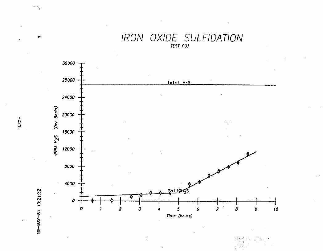
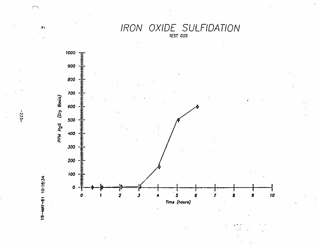
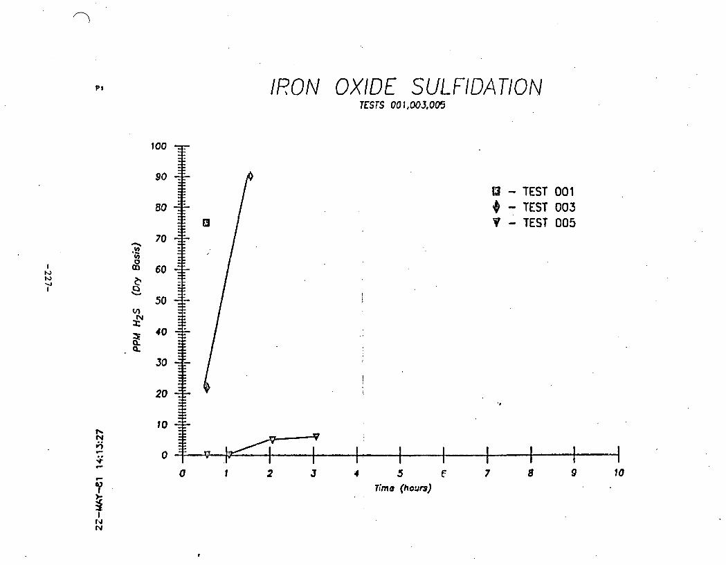
Iron Oxide Sulfidation. Tests 001. 003. and 005 ........................................ 26
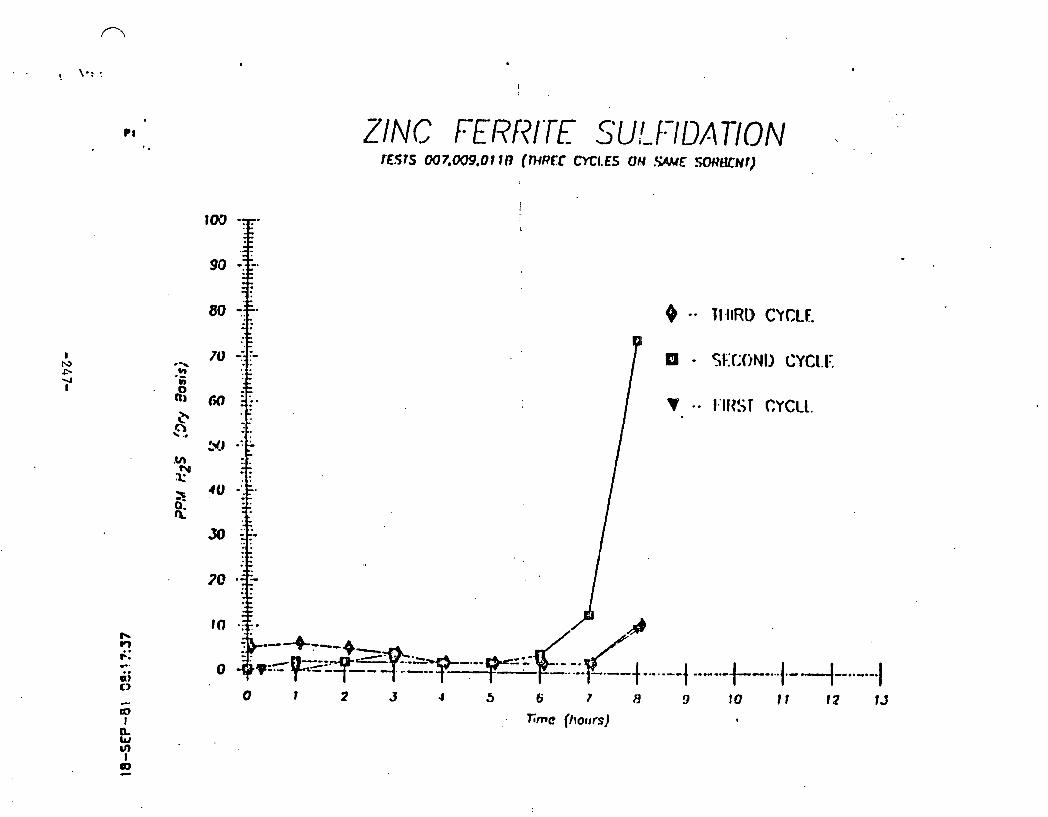
Zinc Ferrite Sulfidation. Tests 007. 009. and OllB (Three cycles on same sorbent) ............. 30
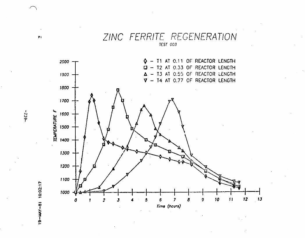
Zinc Ferrite Regeneration. Test 008 ............. 31
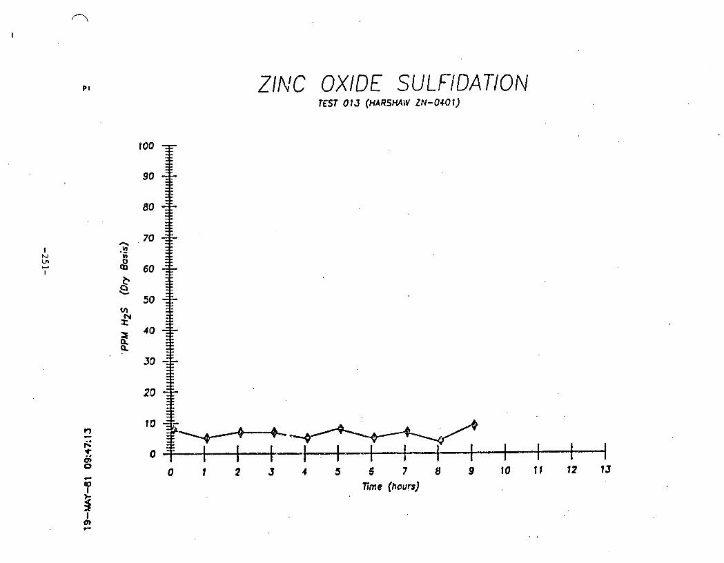
Zinc Oxide Sulfidation. Tests 013 and 015 (Harshaw ZN-0401) ............................... 36
Sorbent Regeneration. Zinc Oxide and Zinc Ferrite ......................................... 37
Zinc Ferrite Regeneration. Test 017 ............. 41
Zinc Ferrite Sulfidation. Tests 021. 023. 024. 026. and 028 .................................... 43
Zinc Oxide Sulfidation. Tests 038. 033. 034. and 032 (Harshaw ZN-0401) ....................... 47
Sulfur Loading. Zinc Ferrite and Zinc Oxide ..... 48
Zinc Ferrite Sulfidation. Tests AVG (16. 21. 47) 043. 051. and 053 ........................... 53
Zinc Oxide Sulfidation. Tests 042R. 046. and 034 (Harshaw ZN-0401) ........................... 55
Zinc Ferrite Sulfidation. Test 047 and 049 ...... 58
IFP Zinc Oxide Sulfidation. Tests 067. 065. 063. and 061 (IFP MEP 682) ...................... 69
IFP Zinc Oxide Sulfidation. Tests 067. 069. and 071 (IFP MEP 682) ........................... 70
Zinc Oxide Sulfidation. Tests 067 and 034 ....... 71
Zinc Oxide Sulfidation. Tests 032. 034. and 036 (Harshaw ZN-0401) ........................... 72
Zinc Ferrite Sulfidation Tests 021. 023. and ....................................... 024 . . . . 74

LIST OF FIGURES (Continued)
F iqu re
2-18
Pase
Zinc F e r r i t e S u l f i d a t i o n (TO80 and T082) Uni ted C a t a l y s t s L-1442 ......................... Zinc F e r r i t e S u l f i d a t i o n (T084, T086, and ................... T088) Uni ted C a t a l y s t s L-1442
Zinc F e r r i t e S u l f i d a t i o n , TO92 Empty Reac tor S u l f i d a t i o n ..................................... Zinc F e r r i t e S u l f i d a t i o n , T e s t TO93 H,S Leaching from Empty S u l f i d e d Reac tor ............ Zinc F e r r i t e S u l f i d a t i o n , T e s t 096 .............. Zinc F e r r i t e S u l f i d a t i o n , T e s t s 103 and 105, Uni ted C a t a l y s t s L-1443 ......................... Zinc F e r r i t e S u l f i d a t i o n , T e s t s 105, 107, and .................... 113, Uni ted C a t a l y s t s L-1443
Zinc F e r r i t e S u l f i d a t i o n , T e s t s 115, 117, and 119, Uni ted C a t a l y s t s L-1443 .................... Zinc F e r r i t e S u l f i d a t i o n , T e s t s 121, 123, and .................... 125, Uni ted C a t a l y s t s L-1443
Zinc F e r r i t e S u l f i d a t i o n , T e s t s 105, 115, and .................... 121, Uni ted C a t a l y s t s L-1443
Zinc F e r r i t e S u l f i d a t i o n , T e s t s 107, 117, and 123, ,United C a t a l y s t s L-1443 .................... Zinc F e r r i t e S u l f i d a t i o n , T e s t s 113, 119, and .................... 125, Uni ted C a t a l y s t s E-1443
Zinc F e r r i t e ~ u l f i d a t i o n , T e s t s 128, 129, and 131, Uni ted C a t a l y s t s L-1504 ................ Proces s Flow-Sheet f o r Hot G a s D e s u l f u r i z a t i o n Bench-Scale T e s t Uni t ........................... Hydrogen S u l f i d e Breakthrough P l o t HGD -- S u l f i d a t i o n T e s t # 01 ........................... Hydrogen S u l f i d e Breakthrough P l o t HGD -- S u l f i d a t i o n Test # 03 ........................... Zinc F e r r i t e S u l f i d a t i o n , S ides t ream T e s t Uni t , Testa 001 and 003 ...............................

LIST OF FIGURES (Continued)
Paae
Zinc F e r r i t e S u l f i d a t i o n , I n i t i a l H,S and SO, Concentrat ion ................................... 117
Sorbent P e l l e t Analys is , G a s i f i e r Run 101 -- Three S u l f i d a t i o n s .............................. 120
Hydrogen S u l f i d e Breakthrough P l o t HGD -- S u l f i d a t i o n T e s t # 06 ........................... 124
Hydrogen S u l f i d e Breakthrough P l o t HGD -- S u l f i d a t i o n T e s t # 08 ........................... 125
Hydrogen S u l f i d e Breakthrough P l o t HGD -- S u l f i d a t i o n T e s t # 09 ........................... 127
Hydrogen S u l f i d e and S u l f u r Dioxide P l o t HGD -- S u l f i d a t i o n T e s t # 11 .................... 128
Hydrogen S u l f i d e Breakthrough P l o t HGD -- S u l f i d a t i o n T e s t # 13 ........................... 136
Hydrogen S u l f i d e and S u l f u r Dioxide P l o t HGD -- S u l f i d a t i o n T e s t # 15 .................... 137
Hydrogen S u l f i d e and S u l f u r Dioxide P l o t HGD -- S u l f i d a t i o n T e s t # 17 .................... 138
Hydrogen S u l f i d e Breakthrough P l o t HGD -- S u l f i d a t i o n T e s t # 19 ........................... 139
P a r t i c u l a t e Analys is S u l f i d a t i o n T e s t s 013, 015, 017, and 019 ............................... 144
Hydrogen S u l f i d e Breakthrough P l o t HGD -d S u l f i d a t i o n T e s t # 20 ........................... 148
Hydrogen S u l f i d e Breakthrough P l o t HGD -- S u l f i d a t i o n T e s t # 22 ........................... 149
Zinc F e r r i t e S u l f i d a t i o n Lab Sca le T e s t Unit ; T e s t s 003, 004, 005, and 006 .................... 157
Zinc F e r r i t e S u l f i d a t i o n Lab Sca le T e s t s 007, 008, 009 and OlOR ............................... 158
S u l f u r Absorption Capaci ty of Zinc F e r r i t e ...... 159

LIST OF TABLES
Table
2-1
2-2
Paae
Summary of Laboratory Scale Testing ............. 20
Investigation of Regeneration Conditions of Iron Oxide/Silica ............................... 24
Hydrogen Sulfide/~inc Oxide Equilibrium Values ........................................ 27
Preliminary Zinc Ferrite Test Runs .............. 29
Preliminary Zinc Oxide Test Runs ................ 35
Effect of Temperature on Zinc Ferrite Performance ..................................... 39
Effect of Temperature on Zinc Oxide Performance ..................................... 46
Effect of Steam on Zinc Ferrite Performance ..... 51
Effect of Steam on Zinc Oxide Performance ....... 54
Effect of Steam/Air Ratio on Regeneration ....... 57
Absorption of H2 S by Vanadium Compounds ......... 59
Percent Total Integrated Intensity of Various Sorbents ........................................ 60
Structural Changes in Various Sorbents .......... 62
Analysis of Fresh and Sulfidized Sorbents ....... 64
Analysis of Enriched Franlel ini te Ore ............ 65
Investigation of IFP Zinc Oxide ................. 67
... Test Runs to Determine Effect of Zinc Content 75
Properties of Initial Zinc Ferrite Samples ...... 77
Summary of L1442 Zinc Ferrite Sorbent Tests Conditions and Results .......................... 79
Analysis of L1442 Zinc Ferrite Sorbent Before and After Testing ............................... 82
.......... Analysis of G-72D and G-65 RS Sorbents 86

LIST OF TABLES (Continued)
Table
2-22 Matrix of Condi t ions f o r S u l f i d a t i o n Tes t ing of L1443 Zinc F e r r i t e f o r Dynamic Simulat ion Study ........................................... 91
Analys is o f L1443 Zinc F e r r i t e Sorbent i n C e r t a i n S u l f i d a t i o n Runs ........................ 92
P r o p e r t i e s of F i n a l Zinc F e r r i t e Samples ........ 103
Summary o f L1504 Zinc F e r r i t e Sorbent T e s t s ..... 105
Condensate Analys is During T e s t 129 ............. 107
Operat ing Condi t ions of Lab-Scale and Sidestream T e s t Unit ............................ 108
Hot Gas Desu l fu r i za t ion T e s t s -- G a s i f i e r ......................................... Run 101 112
Sorbent Analys is A f t e r T e s t 005, Zinc ................ F e r r i t e L-1504, United C a t a l y s t s 119
Hot G a s Desu l fu r i za t ion T e s t s -- G a s i f i e r Run 102 ........................................ 122
Analys is of Minerals by X-Ray D i f f r a c t i o n i n S u l f i d e d Zinc F e r r i t e G a s i f i e r Run 102, T e s t 008 ........................................ 130
Sorbent Analys is of S u l f i d e d Zinc F e r r i t e G a s i f i e r Run 102, T e s t 008 ...................... 131
Hot G a s Desu l fu r i za t ion T e s t s -- Gasi f ie r Run 103 ......................................... 133
Analys is of Minerals by X-Ray D i f f r a c t i o n i n S u l f i d e d Zinc F e r r i t e G a s i f i e r Run 103 .......... 140
Sorbent Analys is of S u l f i d e d Zinc F e r r i t e G a s i f i e r Run 103, T e s t 019 ...................... 141
Hot Gas Desu l fu r i za t ion T e s t s G a s i f i e r .......................................... Run 104 146
Analys is o f Minerals by X-Ray D i f f r a c t i o n i n S u l f i d e d Zinc F e r r i t e G a s i f i e r Run 104 .......... 150
Sorbent Analys is o f Su l f ided Zinc F e r r i t e G a s i f i e r Run 104, T e s t 022 ...................... 151

LIST OF TABLES (Continued)
Table Pase
2-39 Compositions of Gases to be Treated by the Zinc Ferrite Process Development Unit ........... 155
2-40 Sorbent Characterization: Physical and Chemical Properties Air Blown Tests ............. 161
2-41 Sorbent Characterization: Physical and Chemical Properties Oxygen Blown Tests .......... 162

Method for P r e ~ a r i n ~ Zinc Ferrite Sorbent
Screened (-60 mesh, 250 micron) equimolar amounts of Fisher "Certified" ferric oxide and Sherwin-Williams "~igh Surface ~ r e a " zinc oxide were mixed dry with 1 percent of Fisher "Laboratory Grade" bentonite powder in a split sleeve mixer for 30 minutes. The dry mixture was placed in a small cement mixer and sprayed with water from an atomizer until the "plastic" state was reached. The wet mixture was extruded through a pipe with a die face plate using a ram rod pushed with a hydraulic jack. The resulting sorbents were dried at 200°F for several hours then baked at 1,500°F for 3 hours.

. . . . . .. . . a
APPENDIX B . . . :
Process hod el in^ and ~auilibri* Calculations
Process modeling consisted primarily of the calculation of equilibrium H2S
levels for various sorbents at high temperatures. .This can be done either
by minimization of the GIBBS free energy function for a group of reactants,
or by direct calculation of the equilibrium constant for a specified
reaction. The former method is more complex and a1,lows for the interaction
of all possible reactions among the specified components, whereas the'latter
is.simpler and requires that a reaction be specified in terms of products
and reactants. The ASPEN system, using the RCIBBS routine, was utilized for
the more complex GIBBS free energy minimization calculations. A code
(THERMOC) was written for the simpler equilibrium constant method of
calculation.
A. ASPEN - RCIBBS
The RGIBBS,routine computes the phase and/or chemical equilibrium
compositions ,at a user specified temperature and pressure when any
number of feed streams are mixed. The output consists of one vapor
phase and any number of liquid and solid phases. The method o'f
calculation is minimization of GIBBS free energy using an extension of
the Rand algorithm (Gautram and Seider, Part I 1979). After the
equilibrium compositions are computed, an overall energy balance is
performed to compute the heat duty. Since the sulfidation reaction was
the primary area of interest, and it is expected that this reaction is
essentially isothermal, heat effects were not considered at this point.
Heat effects will be an important parameter, however, when'regeneration
reactions are studied. Sulfidation reactions of zinc oxide with a
burgi-type gas were simulated and the results compared with other
sources. In addition, the effect of equilibrium at ambient pressure on
major components was simulated. Of primary interest at this point was
the level of 82 and CO, since these make up the Molten Carbonate Fuel
Cell (McFc) useable fuel.

Equilibrium values of H2S were obtained for the reaction of H2S with
ZnO. A Lurgi air-blown g,asifier gas was used in the input file, and
one atmosphere pressure specified. Runs were made for temperatures of
500 to 650°C in 50°C increments, and for a feed gas with 25 percent
steam and no steam (HZS at 2.7 percent).
Attempts were made to run ASPEN on the METC D E C / V ~ - 1 1 without success.
Due to time limitations, the runs were not repeated and reliance was
placed in calculations from. equilibrium constants.
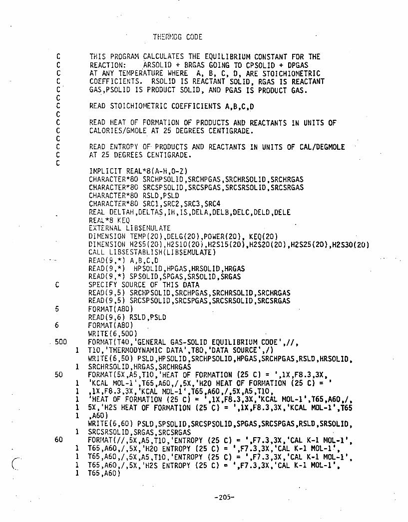
B. THERMOG -.A code that calculates equilibrium values of the components
of the sulfidation reaction of any metal oxide
As mentioned previously, the simpler method of calculating equilibrium
values of a reaction of known components is by the equilibrium constant
method. The equilibrium'constant of an? reaction can be calculated
from the thermodynamic properties of the reactants and products of the
reaction wit'h proper accounting o£ the stoichiometry of the reaction.
Once . . . the . . . equilibrium , constant is calculated at a given temperature, - .-...
equilibrium values of the components of the reaction can be readily
calculated in terms of known values of the remaining components of the
reaction.
A Fortran code written to carry out this calculation on the METC VAX-11
is currently operational. Input requirements include the thermodynamic
properties of all components in the reaction, and the reaction itself
has to be specified. The output is displayed in tabular form as in
Table 1.
Initially, the code was used to determine the effects of various
sources of thermodynamic data on the equilibrium constant for the zinc
cxide reaction. Figure 1 shows the equilibrium constants obtained
using various sources. of data. It was generally found that smalL
discrepancies in thermodynamic data affected the results: however.,
results remained' within a reasonable range. The user can choose input

T)1EnRODWMIC DfiTh WTA BOUlCE
2 3 6 ItECIT OF FORlWTIMf 186 C ) 4 8 . 6 B B KCAL M)L-1 CRC IWHDBOOK 1130 1ERT W FORIlATlOH 186 C ) -67.860 KCRL M L - 1 CRC tiRNDBDOK D l 0 t M T O f FOlMIItIOn ( 8 6 C ) 8 -83.17) KCRL tIOL-1 CRC tU\NDOOOK 10s 1-t OF FOCIIMTXOH (as C ) 4 . 9 1 5 K C ~ L ML-I CRC rmc~ioow
a t s ENTROW t a t CI - t3.800 CCIL K-i ~OL-i CRC IlnnosooK HZ0 UllllOW 4GS C1 - 45.11) CI\L K-1 M L - 1 CRC 1VINDOOOK ZIIO EMROI'Y (a6 CI - 1 0 . 6 ~ ) c n ~ K-i MIL-i CRC ~ ~ N C B W K t E 3 ENTROP'V 1115 C ) - 40.164 CRL K-1 )OOL-1 CRC IWllDBOW
E A T WWCIfW E W T I f f l IS CP A + 8 1 + CTi? + Dl3 El-2 CIIf K-1 UOL-1
HECIT WPIICIN COEFFICIMlS A 8 C D E
0.060806003 0.CBOOOQO80 [email protected] PERRY'S P.3- o . e ~ ~ o c e a ~ a e.~aeaoaoee . - ~ G O O B . B ~ RILLS 0 . 8 8 3 0 9 ~ t 8 9 0.885699980 -194G08.8@ PERRY'S P3-1 a.eacoc6rse . o.cocaaaae noeo.ea KUZ~SCMEUSII
25%
li?. 1E-94
76.6E-M
35.2E-03
0.13
0.37
0.96
a.e 4.4
8.3
IS.
84.
38.
58.
86
TABLE 1

ZNO EQUILIBRIUM CONSTANT
T = SN El = GIBSON x = ICI
FIGURE 1
4
A J: , data felt to .be most accurate and obtain equilibrium values based on
this chosen input data.
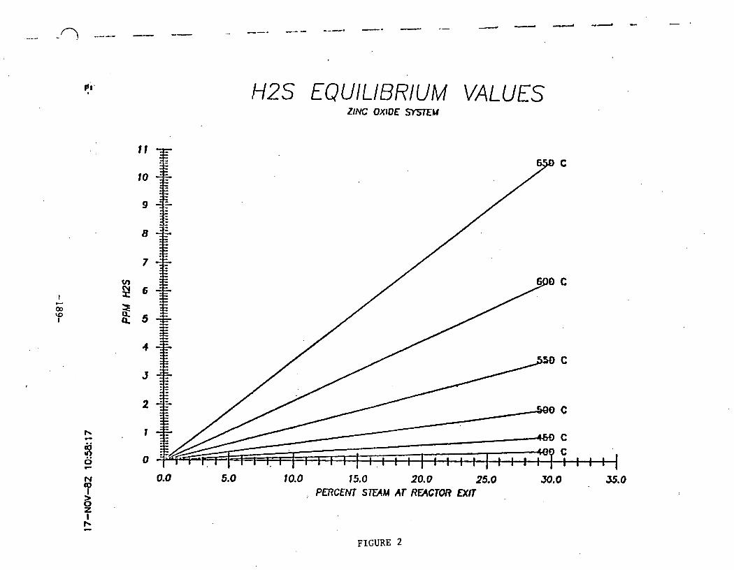
The effect of steam on the H2S equilibrium level is shown in Figure 2.
This plot indicates that sufficiently low levels of H2S (below 1 ppm)
can be obtained at up to approximately 7 percent steam at l,OOO°F. As
temperature increases, the equilibrium H2S level increases, Additional
calculations using two different sets of data were made to determine
the effect of small variations in the thermodynamic properties of zinc
oxide and zinc sulfide on H2S equilibrium values. Th2 results, shown
in Tables 1 and 2 indicate differences in the H2S levels obtained, with
larger discrepancies at higher temperature and steam levels.
The equilibrium code for calculating equilibrium levels of H2S with
zinc oxide was generalized to allow equilibrium calculations for any
gas-solid reaction. This was done primarily to determine equilibrium
levels of H2S with V203. Tables 3 and 4 show the results of
equilibrium calculations using two different values for the heat of
formation of V2S3. Using the National Bureau of Standards' heat of
formation value for V2S3, of 230 Kcal/mol, equilibrium calculations
indicate that H2S levels far below 1 ppm can be achieved. However, if
a correlation by Mills is used to obtain the heat of formation of V2S3
of 125 Kcal/mol, the results indicate that no desulfurization will take
place. This discrepancy makes it difficult to draw conclusions as to
the capabilities of V2S3 in low level desulfurization. This must be
determined experimentally.
In conclusion, two methods have been used to calculate the equilibrium
H2S values expected at Hot Gas Desulfurization conditions. Results are
reasonable :or the most part and come reasonably close to experimental
data obtained in this project and others. Additional calcuLations for
simultaneous shiftlmethanation equilibrium calculations based on
equilibrium constants were conducted for various temperatures. These
are included in the third section of Appendix B.
ti. H2S EQUILIBRIUM VALUES
FIGURE 2

QEMRAL Ms-SOLID ~ O U I L 1 ~ I U H CODE ( Z n O ) TtERnOWtWIIC DATA DATR SOURCE
ZHS MftT OF TOCOIAtIOtl (0s Cl -4D.CO0' KCI\L ROL-1 RILLS UO MAT OF FOAIIATIOH (EG CI -67.796 KCAL ROL-I KUBRSQEU9KI
, ztto I E ~ T OF F ~ I ~ T I O H tnc CI - a a . a ~ e K C ~ L n o ~ - l KUBASCIEUSXI U S tmt OF FolinAf 1014 (as c 8 - -4.oar K ~ L ROL-r RILLS
MS ENTROPY te5 C) 13.800 €AL K-1 MOL-1 H X EMROPY (as C) - 41i.iao CI\L K-1 ~OL-i UIO EHTROPI (25 C) 10.43) UIL K-1 HOL-1 HiLS LILTROPY (25 C) 40.16) CRL K-1 HOL-1
11.71 @ . O Q l 2 2 P I O O 8.86630880@ 0.8WOOBCGe 918090.08 WASC) INSCI 7.81 e.oczocooe e.ecgceoeca e.csoaooeae -460ae.00 HILLS
1 1 . n e.eoi260ao e.aaaaasaae e.900090aaa -116soo.m HILLS 7.17 @.QO25600@ @.@6@419@98 @.00OOOBtS@ [email protected]@ KUBNCMUSI(1
8
I mBERnT\RE MLTh 0 60UIL1BRIUtl EOUILIBRILIII I I E S LELTL 1N WIl ,
r DECUEES C CI\L/CliOLE l ~ ~ ~ ~ ~ t n PERCENT S T E M \O
P 5% 10% 15% 28m 25% 38s
0.18
0.54.
1.4
3.1
6.3
re. at. 36.
66.
85 . i a . a t e i
TABLE 2

mERt3L M8-SOLID EQUILI)IIU~~ CODE (V20j ) 'tMRnODYIiNI1C BATn DATA S W E
UP93tEnT OF FORMTIOtt (E6 C ) * -839.@09 KCAL n0L-1 MU 9 t t ~ I ~ E ~ T OF FO~~~~ .~T IO I# c ' e ~ C ) - 6 7 . 7 ~ ~ KCAL R O L - ~ KUSnSCHLUSKI Vil03tEnT O f FORfVITIOII (86 C ) -891.3@9 KCRL nOL-1 KUOn5CHEMI-JAW I D T S tU9 HEIIT # FUUYlTIOII (85 C ) 0 4 e Y 6 @ KCRL HOL-1 MILL9
CP A o BT + mi! 4 D T ~ 9 n-e WL K-1 ROL-I
EQUILlBR1WI It25 LEVEL I N PPR PERCENT m n n
251
5e .x -11
13.m-09
e0.2E-88
19.6E-@?
13.5E-OG
71.X-06
30.3E65
33. x - 6 4
98eBEd4
ea. 3 ~ 4 3
SO. e E 4
@.I@
@,a@
TABLE 3

U O M I I E f i T OF FORUf iTION (eS C ) OIES.OO@ KCAL MOL-1 n I L L 9 ( C O R R E L A T I M O ~ I C O I I E ~ ~ OF FOR~IATION (06 C ) - -67.705 KCIIL M O L - ~ KUDA~C)IEUS~I Uk?03tEAT OF FORNA7101t (85 C ) -e91.330 KCAL MOL-1 KUDfiSCl(EUSK1-JAHW 107S .HDS ILUlT OF FOAMTtOH (85 C ) +.OO@ K m L ROL-1 fiILL?
U l 3 3 E H f R O W (26 C ) 3 l .QB8 C A L It-1 BOL-1 I P O ENTHOW (26 C ) 0 45.106 C A L K-1 HOL-1 Ui?03Et(fROW (a6 C ) - 83 .448 C A L K - 1 HOL-1
U ~ O P V tas c ) 40.160 WL K-1 NOL-L
R I L L S KUIASC( l fUSC1
~ I I U P n S C M U S X I - J I H 1 w 1m R I L L S
IEAT WIPCICI~Y EOW~IOH IS CP n + a t + ma + ~n + t t -a M L K-1 MI.-1
e9.35 0.89'47E00B ,O.dOtU08808 B . O O 0 8 t t O 3 9 -54209Q.PB B. O F NlNES 7 . ~ 1 0 .4029GCJ0 0.08CBOa808 0.0eQ6C0333 -4GBEQ.08
E 8 . 0 1 n I L L S
O.BlCCE?O@ ' O.QPBOOC030 O.@?OCGO3?9 0. ea A I L L S ( f i V C ) 7.17 O.OCi?E6QI* . O.QfC9COOC3 0.W3EC0300 8809.99 K U 9 ~ U S I I

(I"
FROM SASIC TKERMODYNAP1IC PRINCIPLES FOR THE ZINC OXIDE SYSTEM
The reaction is:
The equilibrium constant can be expressed i n terms of the f ree energy change (Hougen, Watson and Ragatz part I1 p. 983) as follows:
The equilibrium constant can therefore be calculated .by finding the value of A GO, the standard f ree energy change for tho above reaction. ?he standard free energy change for t h e above reaction is the difference between the sum of the A GO f c r the products and the reactants, a t a specified temperature.
The standard free energy change for the products and reactants have been taken from the CRC Handbook of Cheqistry and Physics 61St edition 1980-81 pages 0-71, 0-76, and D-78. The values quoted i n the CRC Handbook are fro. c i r c u l a r of the National Bureau of Standards 500, "Selected Values of Chemical Thermodynamic Properties" , i ssued February 1, 1952.

AGz5oc = -100.04 - (-83.942) = -18.1 Kilocal gmol e
J ! This is the standard free energy change for the above reaction a t 25'~. In r order t o get the A GO a t higher temperatures the procedure i n Hougen, Watson ! and Ragatz part I1 p 986-987 i s used. T h i s procedure u t i l izes the hea t
r capacities, heats of formations, and entropies of the reactants and products a t a known temperature to calculate two integration constants. Once these are known AGO can be calculated a t any temperature using the following equation (HWR p t I1 p. 986 equation 14).
where IH and I, are the integration constants to be calculated. I,, i s calculated frcm the following equation (HWR part I1 p 986 equation 12)
where a, , b, c are the coefficient "del tas" i n the empirical expression fo r heat capacities of products less reactants.
these coefficients are required for each o f the products and reactants i n t h e '
reaction, and are 1 i sted i n Tab1 e 1.
The standard heat of formation for products drld reactants was obtained from the CRC Handbook of Chemistry and Physics 61'& e d i t i o ~ ~ ~?180-8: p a s 0-71,
D-76 and D-78.
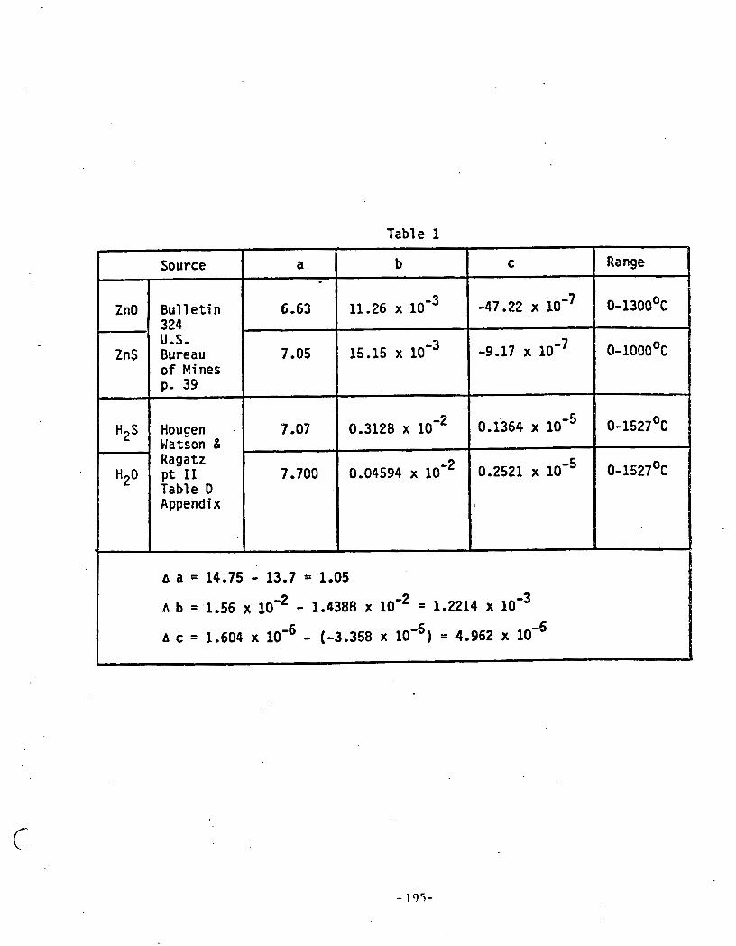
Table 1
m
Range
0-1300~~
0-1000~~
0-1527,~~
0-1527~~
A a = 14.75 - 13-7 = 1-05
b b = 1.56 x - 1.4388 x = 1.2214 x loo3
A c = 1.604 x lom6 - (-3.358 x = 4.962 x 10"
C
-47.22 x
-9 -17 x
0.i364 x lom5
0.2521 x
b
11.26 x
15 -15 x
0.3128 x
0.04594 x
a
6-63
7 -05
9 -07
7.700
r Source
ZnO
ZnS
H2S .
B u l l e t i n 324 U.S. Bureau o f Mi nes p. 39
Hougen Watson & Ragatz p t I1 Table D Appendix
0
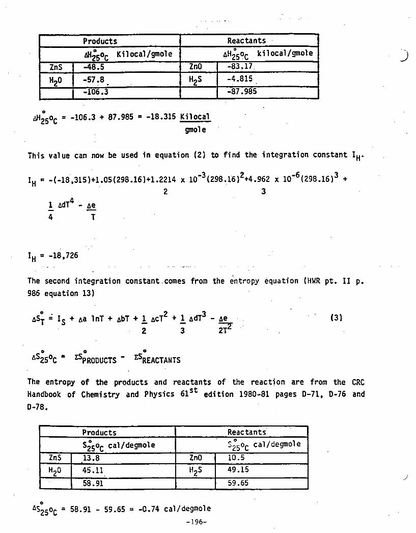
J H 2 5 ~ C = -106.3 + 87.985 = -18.315 Kilocal
T h i s value can now be used i n equation (2 ) to f ind the integrat ion constant I,,.
r Products
&li50C K i 1 ocal / g o 1 e
The second integrat ion constant .comes from the 6ntropy equation (HHR pt. I1 p.
Reactants . . - ~ ~ 2 0 ~ 0 ~
k i 1 ocal /gmot e
ZnS
986 equation 13)
ZnO -48 -5
The entropy of the products and reactants of the react ion a re from the CRC
Handbook of Chemistry and Physics 61st ed i t ion 1980-81 pages D-71. 0-76 and
D-78.
-83.17.
-4 -815
-87.985 "zO
b
-57 -8 . . 1 -106.3
Products
s&oC cal /degmol e
ZnS
"2O
*
Reactants' '25 ' O o C cal/degmole
-13.8
45 -11
58.91
ZnO
H2S
10.5 49.15
59.65

using equation (3) above
Having calculated the two inte.gration constants:
The free energy change a t any temperature can now be calculated using equation (1) e
0 & =Itl + (Aa - Is ) - Aa l n T - dbT - ACT* - A ~ T ~ - - - - T T 2 . 6 12 , 2?
mu1 ti ply by T ,
. , . . . .
A G O = I H + (Aa - IS)T AaT l"T - - A ~ T ' - ACT' - A ~ T ~ - pe - - - 2 6 12 2T
Using equation (4) the free energy change of the reaction can be calculated for any temperature w i t h i n the valid range of the heat capacity values. Table 2 lists the A calculated i n this way.
.A comparison was then made of this data wit.h other publ ished data to compare equilibrium constants. Table 3 shows the data calculated here, the data calculated by Gibson (Louisiana State University, Ph.D, thesis 1977, "Kinetics of the reactions of hydrogen sul fide and carbonyl sul fide w i t h spherical zinc oxide particles") , and data from ICI publ ished i n ' the catalyst Handbook (1970).

Table 2
K e ~
2.20 x lo8 .3..58 x 10
7
8.10 x lo6 2.36 x 10
6
8.31 x 10 5
3.43 x 10 5
1.60 x 10'
8.29 x 10 4
4.67 x lo4 2.83 x 10
4
1.82 x lo4 1.23 x 10
4
8.71 x lo3
6.41 x 10 3
AGO
cal /gmol e
-18,056
-18,078
-18,114
-18,166
-18,232
&18,313
-18,410
-18,524
-18,653
-18,800
-18,964
-19,145
-19,346
-19,564
OK
473
523
573
623
673
723
773 .
823
873
923
973
1023
1073
1123
. O c
v
200
250
300
350
400
450
500 550
600
650
700
750
800
850 *

Table 3
GIBSON
Keq
5.77 lo7
1.20 lo7
3.21 x 10 6
1.04 x lo6
3.97 x 10 5
'1.71 x lo5
8.18 x lo4 4.25 x lo4
2.37 x lo4 1.40 x lo4
8.72 x lo3 5.67 x lo3 3.82 x lo3
0 C.
200
250
300
350
400
450
500. '
550
600
650
700
750
800
850
ICI I Keq
2.08 x lo8
3.48 x lo7 7.12 x lo6 2.04 x 10 6
' 6.65 x lo5
2.64 x lo5
1 . 1 5 ~ 1 0 ~
SAX
Keq
2.20 x lo8 3.58 x lo7 8.10 x lo6
2.36 x 10 6
8.31 x lo5 3.43 lo5 1.60 lo5
8.29 lo4 4.67 x lo4 2.82 x 10 4
1.82 x lo4 1.23 x lo4 8.72 x lo3 6.42 x lo3
r
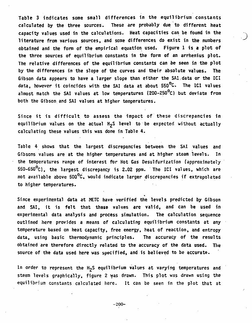
Table 3 indicates some small differences i n the equi l i b r i u m cons tants calculated by the three sources. These are probably due. " to different heat
capacity values used i n the calculations. Heat capacities can be found i n the
l i terature from various sources, and some differences do exist i n the numbers obtained and the form of the empirical equation used. Figure 1 is a plot of the three sources of equilibrium constants i n the. form of an arrhenius plot. The relative differences o f the equilibrium constants can be seen i n the p lo t by the di fferences i n . the slope of the curves and their absol ute vat ues. The Gibson d a t a appears to have a larger slope than either the SAI, data or the ICI data, however i t coincides with the SAI data a t about 550'~- The ICI val ues almost match the SAI values a t low temperatures (200-250~~) b u t deviate from both the Gibson, and SAI values a t higher temperatures.
Since i t i s d i f f i c u l t to assess the impact o f ' these discrepancies i n equil i b r i u m val ues on the actual H2S level to be expected w i t h o u t actual ly calculating these values this was done i n Table 4.
Table 4 shows that the largest discrepancies between the SAX values and Gibsons values are a t the higher temperatures and a t htgher steam levels. In
- the temperatures range of interest fir. Hot Gas Desulfurization (approximately 550-650°c), the largest discrepancy i s 2.02 ppm. The ICI val ues, which are not avail able above 500°c, would indicate larger di screpancies i f extrapol ated to higher temperatures,
. Since experimental data a t METC have verified the level s predicted by Gibson and SAX, it i s f e l t that those values are valid, and can be used i n experimental data anal ysi s and process simulation. The cal cul a t i on sequence outlined here provides a means of calculating equilibrium constants a t any temperature based on heat capacity, free energy, heat of reaction, and entropy data, using basic thermodynamic principles, The accuracy of the resul ts obtained are therefore directly related to the accuracy of the da ta used. The source of the data used here was specified, and i s believed t o be accurate.
In order to represent the H2S equilibrium values a t varying temperatures and '
steam levels graphically, figure 2 yas drawn. T h i s p lot was drawn u s i n g the equilibrium constants calculated here. I t can be seen i n the plot t h a t a t
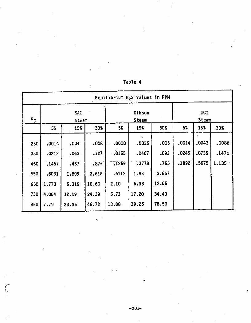
Table 4
I .'
Equilibrium H2S Values i n PPM
OC
250
350
450
550
650
750
850 .
Gibson ICI Steam Steam
5%
SAI
Steam
.0008 I
. -0155
-:I259
-6112
2.10
5.73
13.08
30%
,008
,127
,875'
3.618
10.63
24.39
46.72
5%
-0014
.0212
-1457
.6031
'1.773
4.064
7.79
,0026
,0467 . . ,3778
1.83
6.33
17.20
39.26
15% ----- ,004
.063 .
-437
1.809
,5.319
12.19
23.36
-005
,093
,755
3.667
12-65
34.40
78.53
-0014
,0245
,1892
-0043
i0735
-5675
,0086
-1470
1.135 .
n,

temperatures up t o 450 '~ equ i l i b r i um H2S l e v e l s are Cglow 1 ppm f o r a1 1 steam
l e v e l s up t o 30%. As temperatures. i n c r e a s e a t o v e 4 5 0 ' ~ t h e r e i s an .
accelerated increase o f HpS w i t h temperature, w i t h .i. l a rge increase between
5 5 0 ~ ~ - 6 5 0 ~ a t the high steam leve l . Th is p l o t can be used t o determine t he
t r adeo f f between steam l e v e l and temperature i n order t o stay below 1 ppm H2S.
A computer code has been w r i t t e n t o ca r r y ou t t he ca l cu la t i ons out1 i ned
here and t o produce a t ab le conta' ining the in for ma ti^^ shown i n Table 2 and 4.
The requ i red i npu t inc ludes the f o l lowing:
o Heat o f format ion of products and reactants a t 2 5 O ~
o Entropy o f products and reactants a t 2 5 ' ~
o Heat capaci ty c o e f f i c i e n t s f o r products and reactants
Using t h i s i npu t data the code ca lcu la tes the f r ee energy change a t
various temperatures, the equ i l i b r ium constant, and e q u i l i b r i um H2S l e v e l s a t
var ious steam levels. ' Th is code can now be used t o ' t e s t the e f f e c t o f var ious
sources. and val ues o f thermodynamics data and t he i r e f f e c t on the equi 1 i b r i um
H2S l e v e l s calculated. A sample output i s shown i n Table 5. -. .
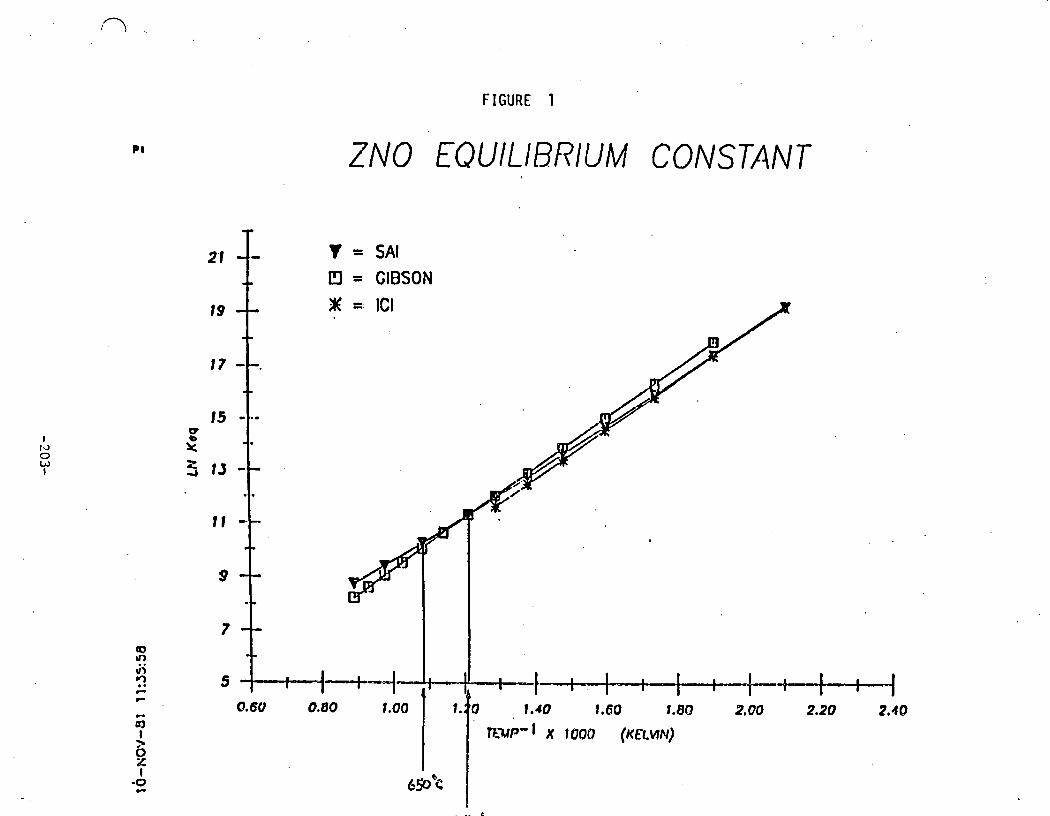

FIGURE 2
H2S EQUILIBRIUM VALUES
0.0 5.0 10.0 15.0 20.0 25.0 30.0 55.0 PERCENT SEAM AT REnCfOU EXIT
T H I S PROGRAM CALCULATES THE EQUIL IBRIUM CONSTANT FOR THE REACTION: ARSOLID + BRGAS GOING TO CPSOLID + DPGAS AT ANY TEMPERATURE WHERE A, B, C, D, ARE STOICHIOMETRIC COEFFICIENTS. RSOLID I S REACTANT SOLID, RGAS I S REACTANT GAS,PSOLID I S PRODUCT SOLID, AND PGAS I S PRODUCT GAS.
READ STOICHIOMETRIC COEFFICIENTS A,B,C,D
READ HEAT OF FORMATION OF PRODUCTS AND REACTANTS I N UNITS OF CALORIES/GMOLE AT 2 5 DEGREES CENTIGRADE,
READ ENTROPY OF PRODUCTS AND REACTANTS I N U N I T S OF CAL/DEGMOLE AT 25 DEGREES CENTIGRADE.
I M P L I C I T REALk8(A-t i ,O-Z) CHARACTER*80 SRCHPSOLID,SRCHPGAS,SRCHRSOLID,SRCHRGAS CHARACTER"8G SRCSPSOLID,SR2SPGASsSRCSRSOLID,SRCSRGAS CHARACTER"80 RSLD ,PSLD CHARACTER*80 SRCl,SRC2,SRC3,SRC4 REAL DELTAli,DELTkS,IH,IS,DELA,DELB,DELC,DELD,DELE R E A t f 8 KEQ EXTERNAL L I BSEMUL ATE DiMENSION TE!tP(20) ,DELG(20) ,POJER(20), K E Q ( 2 0 ) CIMENSION H2S5 ( 2 0 ) , H 2 S 1 0 ( 2 0 j , H 2 S 1 5 ( 2 0 ) ,H2S20(20) ,H2S25(20) ,H2S30(20) CALL L I BSESTABLI SH (LI BSEMULATE) READ(9,*) A,B,C,C .. .
READ(9,*) HPSOLID,HPGAS,HRSOLID,HRGAS READ(9,* ) SPSOLID,SPGAS,SRSOLID,SRGAS SPECIFY SOURCE OF T H I S DATA READ ( 9 ,5 ) SRCliPSOLID ,SRCHPGAS, SRCHRSOLID ,SRCHRGAS READ ( 9,5 SRCSPSOLID ,SRCSPGAS ,SRCSRSOLID ,SRCSRGAS FORMAT ( A80 ) READ ( 9 ,6 ) RSLD ,PSLD F O R W T ( A 8 0 ! . WRITE(6 ,500) FORMAT ( T 4 0 , 'GENERAL GAS-SOLID E Q U I L I B R I U M CODE ' ,// , T?O, 'THERMODYNWIC DATA' ,T80, 'DATA SOURCE' ,/) WRITE ( 6 , 5 0 ) PSLD ,HPSOLID ,SRCHPSOLID ,HPGAS ,SRCHPGAS ,RSLD ,HRSOLID, SRCHRSOLID,HRGAS,SRCHRGAS FORMAT(5X ,A5 ,TlO, 'HEAT OF FORMATION ( 2 5 C ) = ' , l X ,F8.3 ,3X, 'KCAL MOL-1' ,T65 ,A60 ,/ ,5X, 'HZ0 HEAT OF FORMATION ( 2 5 C) = I
,1X ,F8,3 ,3X, 'KCAL MOL-1' ,T65,A60,/,5X,A5,T10, 'HEAT OF FORMATION (25 C ) = ' ,1X,F8.3,3XB 'KCAL MOL-1' ,T65,A60,/, 5X, 'H2S HEAT OF FORMATION (25 C ) = ' ,1X ,F8.3,3X, 'KCAL MOL-1' ,T65 , A60 WRITE ( 6 , 6 0 ) PSLD ,SPSOLID ,SRC$PSOLID ,SPGAS ,SRCSPGAS ,RSLD sSRSOLID, SRCSRSOLID,SRGAS,SRCSRGAS FORMAT(// ,5X ,A5 ,TlO, 'ENTROPY ( 2 5 C) = ' ,F7.3,3X, 'CAL K - 1 MOL-'1' , T 6 5 ,A60 ,/ ,5X, 'H20 ENTROPY ( 2 5 C) = ' ,F7 .3,3X, 'CAL K - 1 MOL-1' , T 6 5 ,A60 ,/ , 5 X ,A5 ,T10, 'ENTROPY ( 2 5 C) = ' ,F7.3,3X, 'CAL K - 1 MOL-1 ' , T65,A60 , / ,5XS1H2S ENTROPY ( 2 5 C) ' ,F7.3,3X9'CAL K - 1 MOL- l ' , T 6 5 ,A60 )
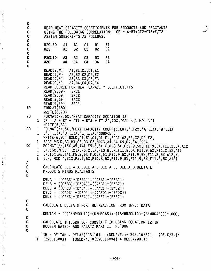
READ HEAT CAPACITY COEFFICIENTS FOR PRODUCTS AND REACTANTS USING THE FOLLOWING CORRELATION: CP = A+BT+CT2+DT3+E/T2 ASSIGN SUBSCRIPTS AS FOLLOWS:
PSOLID A3 B3 C3 03 E3 H20 A4 84 C4 04 E4
READ SOURCE FOR HEAT CAPACITY COEFFICIENTS READ(9,69) SRCl READ (9,69 ) SRC2 READ ( 9,69 ) SRC3 R E A n (9,69) SRC4 FORMAT(A80) WRITE(6,70) FORMAT(// ,5X , 'HEAT CAPACITY EQUATION IS CP = A + BT + CT2 + DT3 + ET-2',10X,'CAL K-1 MOL-1') WRITE (6.80 FORMAT(~I,SX,~HEAT CAPACITY C O E F F I C I E N T S ~ , ~ ~ X , ~ A ~ , ~ ~ X , ' B ~ , ~ ~ X ,'C',13X,'D1 ,13X, , 'E ' ,15X, . . 'SOURCE' ) - - . .
WRITE(6,90) RSLD , ~ 1 , ~ 1 , ~ 1 , ~ l , ~ l , S R C ~ ,AZ , ~ 2 , ~ 2 , ~ 2 , ~ 2 , SRC2 ,? SLD ,A3 ,B3 , C3, D3, E3, SRC3 , A4 , B4 , C4, D4, E4, SRC4 FORMAT(//,lSX,AS ,T41 ,F5.2,5X ,F100b,5X ,F11 .9,5X ,Fll .9,5X ,F11.2,5X ,A12 ,/,l5X, 'H2S ' ,21X,F5.2,5X ,F10.8,5X,F11.9,5X ,F11.9,5X ,F1,1.2,5X,A12 ,/,l5X,R5,T41,F5.2,5X,F10.8,5X,F11.9,5X,Fll .9,5X,Fll.2,5X.A12,/, 15X,'H20 ',21X,F5.2,5X,F10.8,5X,F11.9,5X,F11.9,5X,F11.2,5X,A12~
CALCULATE DELTA A ,DELTA B DELTA C, DELTA D,DELTA E PRODUCTS MINUS REACTANTS
DELA = (!C*A33+(DfA4))-((A*Al)+(B*AZ)) DELB = ((C*B3)+(0*84))-((A*Bl)+(B*B2)) DELC = ((C4C3)+(D*C4))-((A*Cl)+(B*C2)) DELD = ((CfD3) +(DfD4))-((AfD1)+(B*D2)) DELE = I(C*E~)+(D*E~))-((A*E~)+(B*E~))
CALCULATE DELTA ! I FOR THE REACTION FROM INPUT DATA
DELTAH a (((C*HPSOLID)+(D*HPGAS))-((A*HRSOLID)+(B*HRGAS)))*lOOO.
CALCULATE INTEGRATION CONSTANT IH USING EQUATION 12 IN HOUGEN WATSON AND M G A T Z PART 1 I P. ' 986
IH = DELTAH - DELAk( 298.16) - (DELB/2. )*(298.16**2 ) - (DELC/3. )* (298.16**3) - (DELDj4. )*(298.16**4) + DELE/298.16

DELTAS = ( (C*SPSOLID 1 + (D*SPGAS) ) - ( ( A*SRSOt ID ) + (B*SRGAS) )
CALCULATE INTEGRATION CONSTANT IS USING EQUATION. 13 IN HOUGEN WATSON AND RAGATZ PART I1 P, 985
IS = DELTAS - DELA*LOG(298.16) - DELB*(298.16) - (DELC/2.)* (298.16**2) - (DELD/3. If(298.16**3) + DELE/(2.*(298.16**2) )
HAVING CALCULATED INTEGRATION CONSTANTS IH AND IS CAI-CIJLATE DELTA G FOR THE DESIRED TEMPERATURE RANGE 206 'TO 850 CENTIGRADE
DO 10 I=1,14 TEMP( I) = 473 + (1-1 )*50 DELG ( I ) = IH + (DELA - IS )*TEMP ( I ) -DELAfTEMP ( I )*LOG (TEMP ( I ) ) -DELB*((TEMP(I)**2)/2.) - DELCf((TEMP(1)**3)/6,) -DELD*( (TEMP( 1)**4)/12-)-DELE/(z.*TEMP(I)) CONTINUE
CALCULATE EQUILIBRIUM CONSTANT
DO 20 1=1,14 POWER(1) = -DELG(I)/(1.989ZfTEMP(I)) KEQ(1) = EXP(PO.NER(1)) CONTINUE
CALCULATE EQUILIBRIUM H2S COMPOSITIONS NITH VARIOUS STEAM LEVELS
DO 25 I=1,14 H2S5( 1) = ( ( (O.OSMD)/KEQI I ))**(1/~))*(1~6) H2S10(1)= (((O.~O**D)/KEQ(I))**(~/B))*(~E~) H2S15( I)= ( ( (0.15**D)/~EQ(I))**(l/B))*[1~61 H2S20(1)= (((0.20*D)/KEQ(I))**(l/B))*(lE6) H2S25(1)= (((0.25**D)/KEQ(1))**(1/0)~*(1~6) H2S30(1)= (((0.30**D)/KEQ(I))**(1/B))*(lE6) CONTINUE
CONVERT TEMPERATURE FROM KELVIN TO CENTIGRADE
DO 30 1=1,14 TEMP(1) = TU4P(I) -273. CONTINUE
PRINTOUT TABLE OF DELTA G AND EQUILIBRIUM CONSTANTS GENERATED
WRITE(6,ZOO) FORMAT(~H,//,T~,~~HTE~IP~KATURE,T~O,~HDELTA G,T37 ,llHEQUILIBRIUM, T73,28HEQUILI BRIUM H2S LEVEL IN PPM/lH ,T4,9HDEGREES C ,T20, gHCAL/GMOLE ,T39,8HCDNSTAIJT ,T80,13HPERCENT SYEAM//lH ,T62,2H5%, T70,3HlOS,T80 ,3H15X9T90 ,3H20% ,T100,3H25%,TllO ,3H30%/)

300 FORMAT(~H,TB ,~4.0,T20 ,~10.2,~37,2PG10.3,T57,6(2PG10.2) ,/) 40 CONTINUE
STOP END
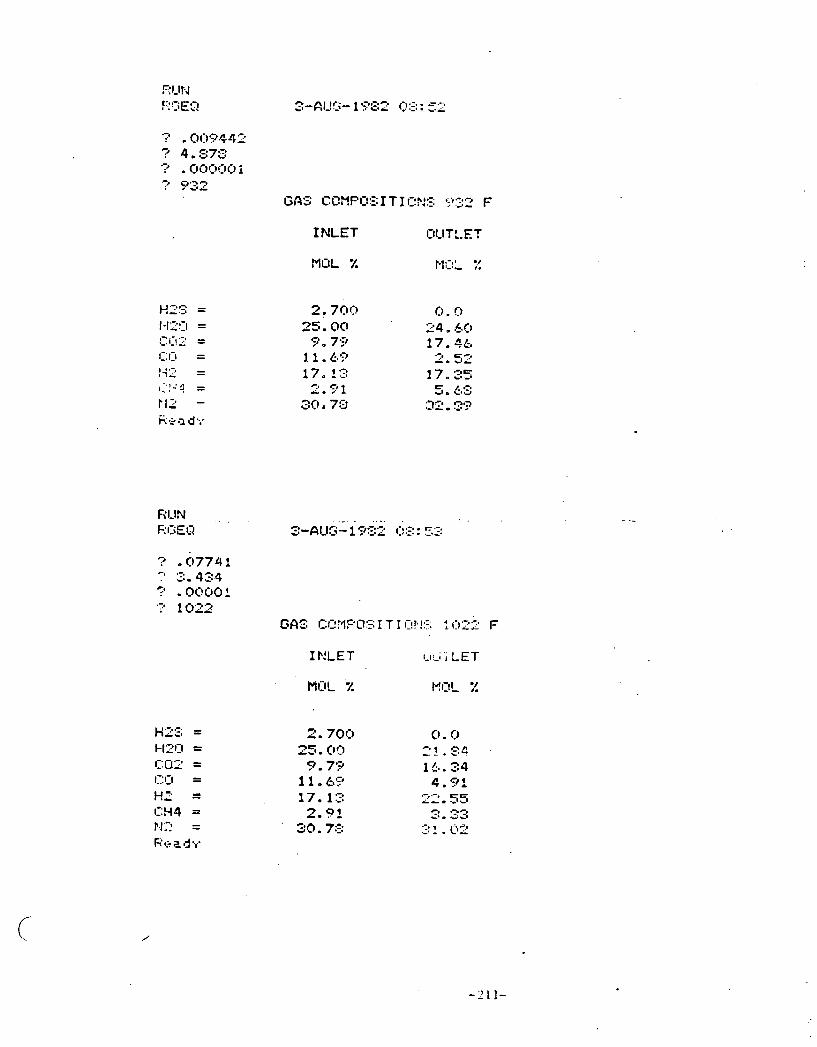
Si mu1 taneous Shi ft/Methana ti on Equi 1 ibr ium Calcul ati'ons
Reference:
H.P. Meissner, C. L . Kusik, W. H. D a l z e l l Equi 1 ibrium Compositions wi th Mu1 t i p l e Reactions
Note: The fol lowing are r e s u l t s obtained from a computer code used t o ca lcu la te simul taneous shi ft/methanation equi 1 i b r i a

GAS COMFOI I T I OtJS 1 1 12 F
I FILET OUTLET
MOL % MOL %
INLET OI,IT:.ET
MOL % M s-, I--, ' ?.!

INLET O!,ITLET
PI!:IL' x M ~ L :?
GAS C I ~ ~ P O ~ IT 1 O:4:3 1 OZZ F
I NLET OlJTLET
MOL % MOL %

INLET O!JTLET
CiA!; CI~MPIIIS 1 T 1 CIN!~ 1202 F
INLET CllJTLET
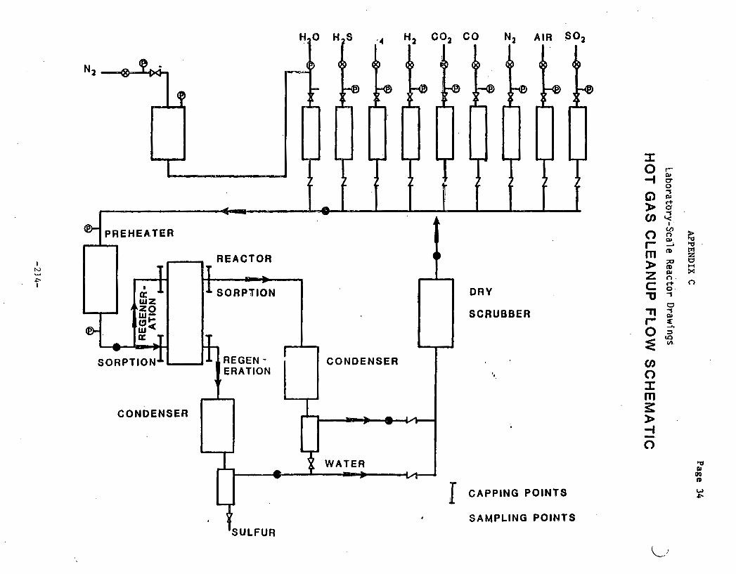
APPE
ND
IX
C Page 34
Laboratory-Sca'l e ~
ea
cto
r Draw
ings
HO
T G
AS
CL
EA
NU
P F
LO
W S
CH
EM
AT
IC

Schematic Drawing of Test Unit

TEST NO. I 001 DATE STARTED 1 7/30688 DATE ENDED 1 7/31 /88 TOTsL HOURS 1 2 8 W E SULFID~11OH
APPENDIX D
Laboratory-Scale Test Summary'.Sheets and Data Zurves
TEST SUI'lMRV SHEET
' PURPOSE
SULFIDATION OF IRON OXIDE EXTRUSIONS FOR RECENERnTlGN E S T S TO VERIFY I I I R PRODUCTS TEST RESULTS I~ UHICH ELEnENTAL SULFUR U S PRODUCED DURI f f i RECENERIITION
60RBEtiT' TYf'£/UEIS)iT I IRON OXIDE/936 C 4tMLV.S I S t SORCEHT NO. I 811x3-1x1 ' BEFORE AFTER SORPENT COIPOSITPOIiI 425 IROI i OXIDE (YOUNCSTOUN .SHEET b TUBE . TOT4L SULFUR (XU/U) t 8.05 6.42 (EXIT)
ON S l L I C 6 SCnFACE flRErP ( f lZ /G) l 6.75 1.87 DENSITY I C 4 1 3 11 3.15 3.37
SORBENT S I Z E 1 1 / 4 INCH DIARETER MTRUSIOIiS PORE UOLUIE I ~ N ~ / c ) 8.4 2.5 . FRETREATflEITT I NONE NlllERCIL nNcILWSIS t SEE APPENDIX . SULFUR LOCIDIliC 1 4.7 f tcfl SUlFuR/Cfl FRESH SORBENT) ELE~ENTRL CIINUSIS t SEE APPENDIX Note: Please disregard
TO 4a0 P P ~ BREAKTHROUGH references to Appendix
QMRCITINC CONDIT EONS
1EnPERATUREI 9800 F(538C)
PRESSURE a MBIEHT
S P K E VELOCITY& 800 HOURLY
fLOU RATE ROLE
WS (6.07DIl3/f l IN) 0 t 1 4 S C F H 8.75
1420 . 'B,K c n ~ n ~ n 7r
AIR '
coa co HZ (1.38Dl l3/RlN) Z.SZSCFH 15%
C H I
Ni? (7.13DN3/fl lM) 15.11SCFH 77.31
. .
for all Test Summary Sheets included llereiri.
E X I T HZ58 ' 200-408 PPfl PLATERU 3000 PPfl cIT BREAKTHROUCH
E X I T 502:
1. SULFUR LWDINC CORRESPONDS TO BREW(THROUQ( Fucn PLQTERU.
2. REdCTOR E n P E R I I N R E PROFILE UAS HOT Knl1ITRlt;ED U IT I I IN 58 DECREES OF 1008 F.
3. T H I S TEST SERUCD TO SHAKEDOUN THE TEST f o u r rwrrr.. ONLY OI~C t I r tLFu icT Ior i uns EX'FERICIICED (H2S REGULATOR REPLACED).
1. IRON OXIDE CRN REDUCE THE SULFUR LEVEL I N A HOT CRS STEECIfl FROll 70C0 PPN TO
203-400 PPR I N Tt;E PRESENCE OF 7X WTERm 2. SULFIDED IRON OXIDE I S READY FOR
RECEliERfiTTION.

TEST SUFmARV S M E t
TEST NO* 1 B e 2 Dhm STnRtED 1 18 /16 /80 DATE ENnED 1 10/24 /88 TOTAL Horns : 3 9 TYPL RECENERATIOH
PURPOSE
UERIFICAtIOP1 Or A IR PRODUCTS TEST RCSVLTS I N UHICH ELEnENTAL SULFUR VnS PRODUCED OUR 11% RECE?IERIITION.
ANQLYSIS SOREEHT T V P E 4 E l O t i t t IRON O X I M / 9 3 6 C - -~ - . GR~EHT NO. 1 811x3 -1x1 BEFORE W TER SORBENT CO~POSI~IONI 42% IRON OXIDE (VOUK~STOUN SHEET 6 TUBE) TOTAL SULFUR o;u/u . 6.42 (EXI T ) e. 16 (EXIT)
ON S f L l c O SURF~ICE RREn tf lE!/CJI 1.97 DElNSIlV IC/CN3) t 3.371
SORBCNT S fZ f 1 1/4 INCH DlAnEtER CX'TRUSIONS PORE WLURE (~IIIJ/C)I 2.5 PRETREPTMENT I HONE '. nln€t?nC n t t n i v s l s I SEE WPENDIX SULFUR REMOMD I ELEnEtl'TFIL CINQLYSIS 1 SEE APPENDIX
OPERATING COIlDETIONS
TENPERATUREl l e e 0 F (S38C)
PRESELlblF: I @VBfENT
SPACE M L O C l T V l COB HOURLV
F LOU RATE nbLE
w9
~ 2 0 4 . 4 I N 9s r AIR te.& D ~ ~ / M I M ) 0.688 SCF~HR 5 1
COB
CO
H8
cw4
)(E
EXIT soat HONE BY TUTUILER t n w ) EXCEPT AT END OF-RUM
EX17 52: 122.1 G
RENARKS
1. DESIRED TEMR6hTURE UAS NOT m I N T A I f E D 2. ESSENlI f iLLY COIIPLEE RECEBERRTION UAS
MHIEVED AS CALCULnlED BY H n f t R I A L BIILANCE. OHD SHOUN BV WALYSIS.
CONCWSIONS

TEST S U M V SHEET
YEST NO. 8 8 6 3 W T E STARTED 1 11 /3 /88 DhTE ENDED 1 11 /3 /80 TOTAL H W a S 1 8.5 TYPE I SULFIDATION
PURPOSE
SULFIDATIOII OF IRON OXIDE CXTRUSIONS FOR SUBSEOUENT RECEtXRATlON TESTS USIHO 00% S T E M AND 1 8 8 AIR.
SORBENT NF&/UEIO(T: IRON OXIDE/936 C ANALYSIS 1 SORBENT NO. 8 811x3-1x1 BEFORE AFTER M R D W COflPOSITlONI 42% IRON OXlDEtV3UNCSTOUN SHEET & TUBE) TOTAL SULFUR (*U/U 11
O~I SILICA SURFACE AREA tna/c I I DENSITY l O l r C R 3 ) 1
SORBENT SIZE I 1 1 4 INCH DXA~ETEW EXTRUSIONS PORE UOLUY ( nnwc )I PRETREAT'?ENt I NOtiZ RlNERfiL M L V S I S I SULFUR LOADINC 8 4.47% ten SULFUR/CR FREW SORBEHT) ELERENTAL AMLYSXS 1
TO 408 PPR DRfAKlMROUW
OPER6TItW CONDlTIOnS DRTRI (DETECTOR TUBE)
TEHPERATUREI 1900 F ( 5 3 8 C j
PRESSURE 1 A~BIEN~
E X I T HZ51 UP TO 1908 PPll PLATEAU l l @ B O PQn 61 BRECYTMROUCM
CX lT So%:
SPACE M L O C l l V : 1013 HOlJfiLV E X I T S Z I
E X I T HZ1
F L W RATE ROLE
W S ( @ . ~ D n 3 / R I H , O . 5 4 5 S C F H 2.7%
W O 8 - 5 2 CR3/RIN 6.9%
A'IR
mi! CO
~2 (1.- ~ r n / n ~ ~ ) e.oz SCFH 14.6%
at4
nz c t . i o ~ m m ~ ~ ) ~ s . i r SCFH 1s.88
1. REMTOR INLET TEW LOU )Y 75-100 F W R X W M e
I. AT SU-1013 AND 2.78 H2S INLET CONCENTRATION ON T M PRESENCE O f 6.91 UATER, STEADY ST6TES DESULFWIZATION W5 RAINTAINED FOR 6 HRS.
2. SULFIDCITIDN CIY( BE COMPLETED I N O H DAV.

TEST SUJlRARY WEE7
TEST no. I m4 DATE SfAIItLb 1 1 0 4 5 / 8 @ D n t L ENDED I 11 /86 /88 TOTAL HOURS 1 20.5 T W E 1 RECENERntlON
SORbEnt TVPCNEICMTU IRON OXIDE/936 i2 SORBENT NO. 1 811x3 -1x1 SORDENT COCIPOSl'TIWlt 42% IRON OXIDE tVOUNCSTOW4 SMEET & TUBE)
on SILICA
SORBENT SlZE 1 9/4 INCH DIAfETER EXTRUSIOIIS PRETREATISEItT 8 )(ONE SULFUR REfKWD I
O P E m t I t C CONDITIONS
T E ~ R A T U R E I ieee F ts je c )
FfOU RATE ROLE
H8S
wo 4.e cn~/nrrc ~9 8 '
~ I R W.SS m,/nxn) 1.1s s c ~ / t m 19 m coa CO
H2
C H I
ma
PURPOSE
RECCMRAl IO l l eF IRON OXID€ EXIRVSIOWS U S I W 9@8 SlEfWl nND 10% R I R .
BEFOOIE AFTER toTnL SULFUE c t u / u ) ~ SUPFOCE ARC@ f R 2 / C ) t DL~ISITY tclcn3) : PORE UOLUNE tnn31c) t I l I tQRRL RNALYSIS t LLENMTRL W L Y S I S t
E X I t 5 0 2 1 CREATER THAI( 3888 PPfl (BY M U I L E I O
E X I T S 2 t 19.41 0
EXIT H a t
COtKLuSlons
1. ELE I lEMnL SULFUR YIELDS ARE S tCNIF ICWTLV L W R U I f H 99%/18% SfL#l+XR RhCESQRRTION.
a.

TEST SWOIMV SHEET
TEST WO. 8 ees M T E S tART fD 8 1 /20/81 DCITE ENDED a 1 /88 /81 TOTAL HOURS 1 9.5 TYPE 8 SULFIWTION
SORBENT TYPE/UEIC MT8 I l lON OXIDE/lOBO a SORBENT NO. t 811x3-1x8 SOIlBEHT CO)1POSITIO~t 42% IRON OXIDEtVOIBICSTOW SHEET L TUBE)
ON S I L I C A
SORBEN7 S I Z E 1 0 4 INCH D I M t E R EXTRUSIONS PREIREATRENT t NONE SULFUR LWDING 8 10.4 8 (en SWUR/C~ ~REUI SORBEM.)
TO 4B9 PPN BREtIITHROUO1
OPERATIW CONDI7IOHS
TEMPERATURE8 1-e F (538 C )
PRESSURE 8 ' Al)O I EN1
SPACE UELOCI tV t 9 0 8 HOURLY
FbOU RnTE tWLE
Mi?S (0.26 DR3/HIN) m.545 SCFH 2.74
H t O 0.52, C U ~ ~ I N 6.91
A I R
coa CO
)rC (1.a DDll / l l IN) 2.92 SCFH 14.6%
C H I
NZ (7.13 DM3/RIN) S.11 SCFH 75*'B11
s
PURPOSE
SULFIDAtIOtr OF IRON OXIDE EXTRUSIONS FOR SUBSEQUENT RECENERATION TESTS USING 58% STEW RND 598 RIR.
TOT AL SULFIJR t LU/U) I SURFACE 6IREAf n2 /C ) t DENSI~V c c / c n 3 ) I PORE UOLUllf ( M 3 / C ) 8 IIINERhL (UYILVSIS t E~EIENTRL m a L v s I s a
BEFORE AFTER
W\T A8 1 DETECTOR TUBE )
E X I T W S 8 6 PPN PUITEAU FOR 3 HOURS D R E R K W O U W AT 4 HOURS YXm 169 PW
E X I T SO28
E X I T S 2 I
E X I T HZ1
1. AT TEST CONDITIWS IRON OXID€ CW REDUCE E X I T HZ9 TO B E L W 10 PPn FQR 3 HOURS AND B E L W 1009 PRl FOR FOR 6 HOURS.

aw bH3
2M
03
203
t@S HAJS US'S tWIWWa lBeC1 UIY
NOS NIY/CYJ 6C.8 Om om
nou UIWrnl~ .
Ydd 802t-8081 rSZH 11x3 . , (3 8ESB 4 0801 r ~YIIIVYWU~A hl N
a3nou3~ mnns U3UlU3U3Ud ats 1~3am
S'L e smH IWlOl 1$/62/t I 034N3 31WQ 1$/6i!/g 8 Q31WlS 31uQ
98 B 8 'ON 15%


oooos $ G. L
009 tn 2 t' b
OOL


IRON OXIDE REGENERATION
0 1 2 .l . 4 5 6 7 8 9 10 11 12 13 Time (hours)
TEST S U R W SHEET
E S T NO. t (87 PATE STARTED 1 1 /30 /81 DATE ENDED I 1/38 /81 TOTAL HOURS 1 92.5 tVPL I W L F I D A t ION
SORBEM S I Z E t . 1 / 4 INCH D I M t T E R EXTRUSIONS PRET~E@T,T~EHT I DRIED IN OUCH 2e0 F O~ERNICHT SULFUR t.OADlN0 8 Z1.3 1 t C n SULFUR/Cn FRESH SORGEM)
TO l W PPR BREAKTHROUGM .
O P E R 6 t I W CONDlTXONS
tmPERI ) t lm€ l IOOO F (S38 C)
PRESSURE I @nDIENT
SFWE UELOCITVI 1 W 8 HOVRW
C~LW RRTE mta ms ca.a orn/nIn) a s t o s m t.78
HE0 . &S13 C W / n I M 6-9s
R I R
COZ
CO
w (1.55 ~n~/ntn, a.rs SWH 14.6%
CHI
HE . (7.W DHYCI1)o 14.W SCFH 7'5.8U
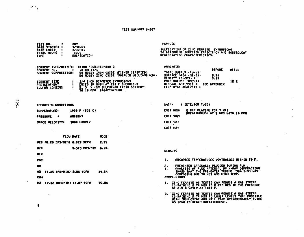
SULFIEATION OF ZINC FERRITE D(TRUS10M TO DETER?lINE SORPTION EFFICILMCV AND SUBSEOUEW REGENERATION CHARfiCTERISTlCS.
T OTAL SULFUR ( R U N ) 1 SURFRCE rrREA tN2/C)8 DENSITY (C/CU3) t PORE uoLunE ( ~ n 3 / ~ ) IIINERAL (VIALYSIS I f Ltf lENT4L at lhLVSIS 8
SEE
BEFORE
EMIT HLSI 2 PPl l P L A T t ~ FOR 7 MRS B R E P I ~ ~ O U C H n t a HRS YITM i e m
ENIT SO21
REIUWKS
8. PREHEAtER UIAWI ILLV PWCCED DURING RUN a 3. nNnLvsts OF PLUG IVITLRIRL DV X-wv D I F f R a C t x o u
SHOUS THAT THE PREHEhTER TUBING ( 3 0 4 8 4 ) UAS CORRODINO DUE TO MIS (Y(D HIGH TEIIP.
CO)(CLUSIOCIS
1. ZINC FERRITE AS TESTED CAn REWCL A GAS S m A n CONTAIWINO 2.18 tes TO a pen Mes In THE PIELSEIKE OF 6.9 8 UAIER AT 1 8 0 Fa
E. ' ZINC FERRITE as T E S ~ CAN REDUCE n cns mum COHTAIHINC 2.7% ms TO LOCRR LEUELS tuan WSSIBLE
' U l t W IRON OXtDE AND UlLL TME APPROXIIIA'IELV TUICE

. . . . TEST SUPan/rRV SHEET 0 '
TEST no. I em DATE STARTED 8 l c 3 1 / 8 1 DATE ENDED I 2/1 /81
.TOTAL HOURS s 1e.S T W E I REGENERATION
REGENERATION Q ZINC FERRITE EX tRUSIOm fROlC TEST 0 8 7 USING 50% A IR IY(D 5 0 8 STEM.
SORDEM W E / Y t I O M : SUlBENt NO. I SORBEW COrOPOSITIOWI
SORDCnl S I Z E I PRETREATMENT I SULFUR REROMD 8
(ZINC FERRITE)/8Be U ~WILVSISI DATCH 8 1 / 1 5 8 ROLE% IRON OXIDE (FISHER CERTIFIED) TOTAl SULFUR (XU/U)I SB ROLE8 ZINC OXIDE (SHERUIN U I L L I W S H S b l SURFNE FlREA ( I IZ /GJI
DENSITV (C /C33) 1 I f 4 INCH DINIEXER EXTRUSIONS PORE UOLWlE IIlN3/G )I DRIED I N W E N AT 280 F OUERNIOlT(DEF0RE 7007) tlIHERAL W L d S I S I
E L E M I n A L flN3LVSIS8
WERATING COHDITIONS DATA* (DETECTOR TUBE)
TEWUMTURE l 1 0 0 0 F 1538 C 1 EXIT WS* 2800 P P ~
PRESSURE 8 M B I E M EX IT SO28 4-9 t
SPACE K L O C I W I 688 HOURLV EX IT Si!I 7 . 8 8 C
E X I T
BEFORE
SEE W E N D I X SEE CIPQENDIX
- wo a.a3 c~3/n1n ses A I R (2.78 DIC)MIN) 6.88 SCFH SO8
COZ
CO
HZ
C H I
W
2. AFTER CORPLETION O f THIS RECEHERWION, ADSORDER TEWERATURE UIIS IIAINTAINED WID SULFIDATIOn REPEATED
COWCLUEIONS
I . RECENERhTlOW TINE APPROXIWtTELV M S N E AS FOR IRON OXIDE.

n s t sunnmv MET
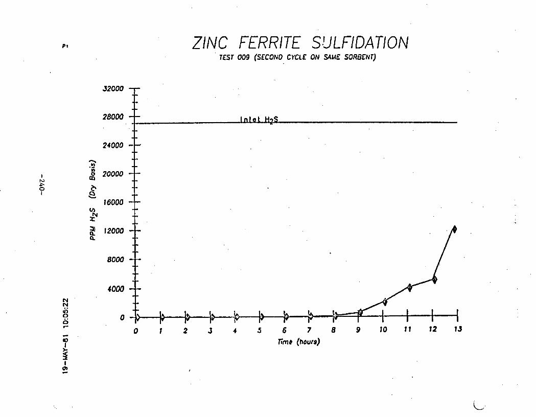
TEST NO* I e09 vnta STRRTED a z/e3/m DATE ENDED 8 2/93/01 TOTAL HOURS 8 11.75 W E I SULFIDATlON
PURPOSE
succ IDRTIOI* OF ztnc r t m r r E ~x rnvs~ons TO FEtERIl lIrL SORPTIWI EFFICIf?"'t AND SUBSEQUENT RECtNERAT10tl CHRRACTERISTICS. THIS I S THE tLCOND SULClDRTlOH CYCLE OF TMIS BATCH OF SORBEttTe
SORBENT tYPE&iEIGHT8 tZINC FERRITE) /Be~ 6 i AHaLV$IS I SORBEHt OK). I D@TCM81/1 BEFORE W t E R SWDENT CORPOSITIO(I se HOLE% IRO( OXIDE FISHER CERTIFIED) T O T R ~ SULCUR( ZU/U ) I
59 WLEI ZINC o x r D r csu~~utn UILLI~UK MSR) SWTACE a!\r!rntn2/c,c DEH51TYt c:cn3 ) I
SORBENT SIZE I 1/4 INCH D 1 - n ~ EXTRUSIONS PORE V O L U ~ C t nn3/c r 1 PRETREATIEHT I DRIED I # OUDI 61 208 F OUERNICHT(BEF~ T8879 NIHLRAL AIALYSISI SULFUR LOCIDIMO 1 18.7 8 CWI SJUW/WI FRESH SORBENT) ELLRENTAL ANRLVSISI
PRESSURE I AMBICHT
F t W RATE POW
HZSC9.25#13/111N)O.S29SCFH Z.78
HLO 1 3 I 6-58
a r R
. Cl '
co
Ha (1.35 DR3/ClIN# 8.86 SCFM 14.6%
C H I
N2 (7.eZ Dn3/ClIN) 14.87 SCFH X . 8 8
DIITAI (DETECTOR TUBE)
EXIT H2S1 2-4 PPN PIATEAU FOR 6 HOURS
BREAKTHROUCH AT 7 WCURS UITH 13 PPW EXIT SO21
EXST S2l
EXIT H t t
1. QnEHEafER TUBE UtlS REP1.hCED PRIOR TO THIS. AUII UITH ??)OTIIER 384 S/S TUBE.
C ~ L U S I O ~ S 1. DESUL'URlZAtION UAS ACHIElSD TO THE SME LEVtL
AS D U ~ X N C THE FIRST CYCLE on YWIS soaornt. 2. BREAKTHROUGH OCCURRED ONE HOLW SOONER WRIS(Q tD(E
SECOND CYCLE.

TEST SUW8RV SHEET
T E H NO. I @I@ DATE S T m L D 1 2/3/88
!:::LE;E9 : 2/3/01 12.5
REGEMRATION OF ZINC FERRITE EXTRUSIONS man TEST 88s USING 588 AIR (UID 588 s m u t .
-BENT TVPE0lliOCM8 (ZINC FERRlTEW80e O W L Y S I S 8 SORBEM NO. ) BATCH $101 SORBEM COIPOSITIONI 59 ROLE8 IRON OMI# (FISHER CERTIFIED) . TOTAL SULFURttU/U):
BEFORE AFIER
59 ROLE8 ZINC W I D E (SHERUIN U ILLXMS HSA) SURFME AREntN2/C)t DEHSITY (C/Cfi3)8
I 1/4 INCH DIARETER EXTRUSIONS SORBEM SIZE PORE .WLU~E~N~WG) : PRETREATMENT 8 M I E D I N OWN AT 2 0 8 F W E R N I W (BEFORE TWBRI f iERnL ANI(LVSIS8
OPERAtlNG CONDITIONS
T E M R A W E I 1000 F (538 C )
PRESSURE 1 M B I E N T
SPACE UELOCITV8 68@ HOURLV
FLW RATE HOLE
W S '
HZ0 2.23 CR3/RIH 69%
AIR (2.78 D-M) 5.88 SCFH 588 .
COZ
co W
a 4
W
DATA1 (DETECTOR TUBE)
EXIT W51 2989-388@ PPll
EXIT Si!: 4.4796 0
EXIT MI
CONCLUSIONS
I. THIS UAS THE SECOND RECLtERATIWt O f THE WE: BATCH OF SORBENT. RECLtLRATION -EARS )IORIUIL.
I
i 2. UIDE SCATTER I N SO2 DATA WJRINO ~CENLRATXON

TEST S U R R W SHEET
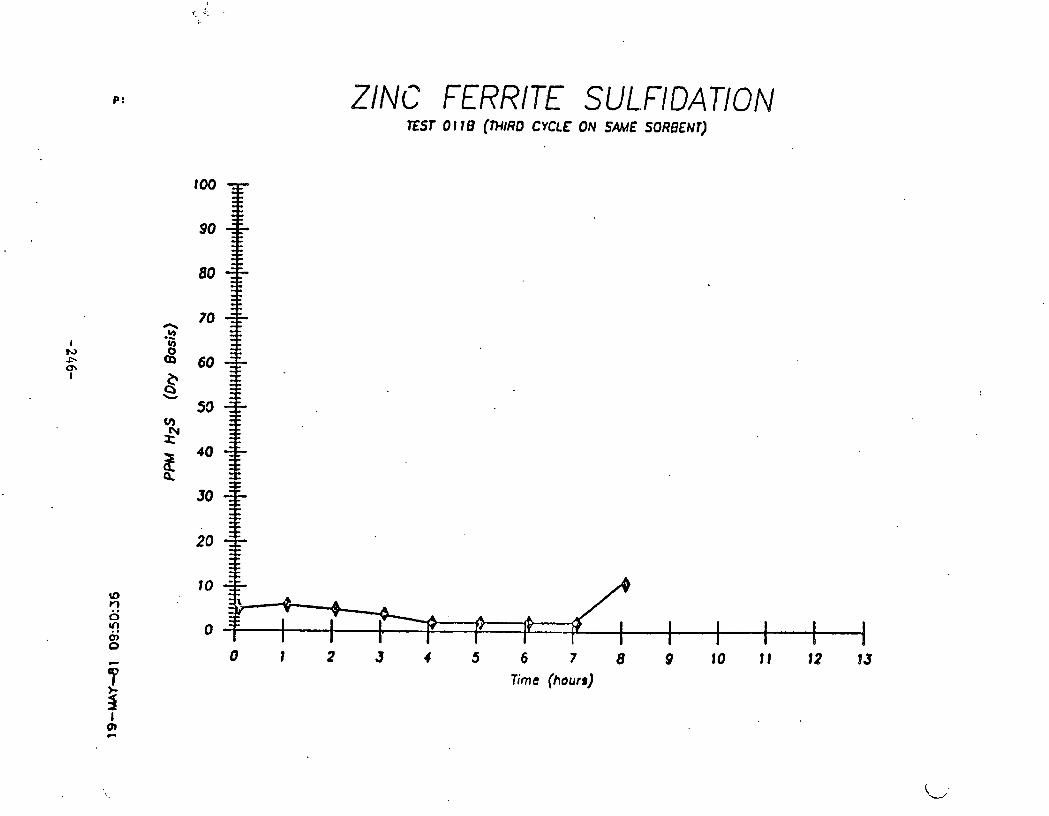
= S t Mb* 8 9111, DATE STARTED 1 e/85/11
ENDED B 2/86/81 TOTAL HOVIIS 1 e.5 WPt I S U V I ~ ~ T I O ~
PURPOSE
SULFIDATI~ OF ZIW ~ERRITE E x t R u s I o n s TO DElERnlNE SORPTION EFFICIENCY aND SUBSEOUENT RECEtlERATIOH CliARACTERIS1lCS. TMIS I S T I E THIRD SULFlDnTfOF CYCLE OF T H I S D A T W OF SORDEMT.
SORBEM T W E M I W I (ZINC FERRITE)/ l@O d AnALYSIS 8 SORDEtfT No. 8 BATCH 8 1 8 1 BECOllE WTER SORBEM COW~SITIO~~ 50 ~OLEI IROW OXIDE (FISW CERTIFIED) TOTAL SULFUR( %U/U ) I
50 nOLE8 Z I W OXIDE ( S N R U I N UILLlrWIS %A) SURrACE c ~ t a t n 2 . ' ~ ) : DENSITY tC,Cn3 1 1
SORDEWT S I Z E . 0 181 IHCM DJcYIEtER EXTRVSIONS PORE VOLll)oC(nfl3/C)I PRETREATMENT 8 DRIED i n ourni AT zem F ~ u n x c n t o r r o ~ t taw) III~IERAL CIHILVSISI SULFUR LOADING 8 . . ELEMENTAL U W L Y S I S I
SPACE W L O C I P I I 1.00@ HWC(W
E X I T H t s :
E X I T SOL1
CLOY RATE MILE
Ha9 (0.2s D R W l l I H P 0.689 SCFH 2-78
COE
I@ (1 -35 D M I W I 9-86 SCFH 14.68
I.. D U R I f f i HEAT UP.FOR THIS AU( THE ABSORDER WS 1NADWRTENTLV UPOSED TO WPROX1IY)TELV 388 WZS FOR 3V RINUTES. THIS OCCtRRED AT CIPPROX. 1OOO
a. m n uas r s m D MTER IT uns ~ E R R I M D THAT THE Hi!; HnS BROUEHTMOUW. 6HD RECEWRATION 1 W l l l A r E D .

PURPOSE TEST NO* I @I 1 8 DATE STMTED 1 2 /06 /81 BnTE ENDED I . 9 /86 /81
SORBENT tYPC/YEIOCI I SORBENt NO. * 8 S O R W t C O m S I T 1 O N I
SORBENt S I Z E 8 PRETREATllENT I SULFUR L O a D I W 8
(ZINC f E l R I T E l / 8 0 e DRTCH 11/1 58 ROLE8 IRON OXIDE (FISHER CERTIFIED1 50 ROLES ZINC OXIDE (SHERUIN U ILL I fU lS HSn)
1 / 4 INCH DIARETER EXTRUSIONS DRIED I N W E N AT 288 F OUERNlCMCDEFORE 1007) 21.38 t (CIO SULFUR4CII FRESH SOClDENT) TO 11 PPll IREAITWOUCH
suLr :onr toN OF ZINC FERRITE EXTRUS:OWS TO DEfERRIHE SORPTION EFFICIEHCV AND SUBSEQUENT RECENEIIATIOW C l ~ A C T E R t S T I C J . TUlS 1s THE rnrna
PRESSURE 1 M B I E N T
SPACE U E L O C I N I 1808 W R L V
CLOU RATE ~ O L O
H2S (0.25 M n / l l I N ) 0.529 SCFH e.78
HZO 0.513 CM3/111W 6.98
l l l R
co2 co HZ (1.75 D l l W l l I N l 8.86 SCFH 14.6%
C H I
NZ (7.02 M 3 0 l l I N ) 1 4 - 0 7 SWM 7S.m
TOTAL SULF W ( t U / U I I SURFnCE AREh ( M / C l t DENSITY cc~en3 ) I
BEFORE
SEE APPENDIX SEE W E W D I X
DATA8 (DETECTOR TUBE1
EX IT H 2 S I 2-6 PfW P U T E M FOR 7 W R S
BRErYMROUGH AT 8 HOURS U ITH 11 PPll EXIT SO21
EXIT sat
1. PRIOR TO WIS RUN CRW @ t l A ) , TME SOR#Hf UAS INADUERTENTLY EXPOSED TO APPROXXlWtELV 39% H2S FOR 38 RINUTES hND T N n I M D I A T E L V RECCMRAtED.
2. M T C R R E C E 1 E ~ T l O N THE SORBENT SEERS TO WAUE RLCOUERED l T S ACT IU l fY AS SEEN BY THE =Sf DATA.
1. SOREENT DEJULTURIZAT:O(( ACTIUITV *PEARS TO DUPLICATE THE h C T l U l f Y OT RUN BQI ( FIRST C V C U ) AFTER A SLIM DECLINE in a c t r v ~ w IN RW oee (SECOND C V C U b e
2. ZlHC FCRRITE APPZhRS TO BE A GOOD REOEWCRABLE SORBENT FOR M2S AT 1000 F. THIS TEST COIICLUWS THE THIRD SULFIDATION In mts smlrr.

TEST SUtWWV SHEET
TEST No* o O l Z n DATE STtWlED 8 2/5/81 DATE ENWD I 2 / 5 / 8 1 TOTAL HWRS 1 12.5 W E I ~ ~ C L N E R A T ~ O ~
PURPOSE
RLCENERfiTlOI~ O f ZINC rERRITE CnRUSIONS FROfl TEST B l I R USI IG SO& AIR N1D 505 STEM. THIS RECEMRRTIOH I S CfiRRIEb OUT TO REUOVE THE HICM LEUEL OF ws INRDUERTENTLY AO~C-CED xn RW erin.
SORDENt TVPE0UEIGHlO tZ1NC FERRlTE)/:Bee 0 . ANALVS I S 8 SORDMt N o * BATCH 8 1 / l SORDENt C ~ l t I O N ~ 5 0 ROLES IRON 3XIDE (FTSMER CERTIFIED)
O E F W AFTER 1 &AL SULFUR( XU/U) 1
50 ROLE8 ZINC OXIDE (WERUIN U 1 L L l M S USA) SURFACE I )REA(M/C) I DENSITV(C/Cn3 )I
SOUBENT S I Z E t 1 /4 INCH D I M E I E R EXTWSlONS PORE UOLME t n n 3 / 6 ) I PREfREMRENT 1 MIED I N WEN 9 1 288 r OVERNICHT (BEFORE T897) l l l t lERAL ANfiLVSISt SULFUR REROMD t 32.9 S (CN SUUUR/C I FRESH SOUDENT) CLEILENTAL 614RLVSISI
OeERntxnc CONDITIONS
~E~~PER~~UREI lee0 F t S 3 8 C )
~ S S U R E I nnsrtrn SPACE VELOCITVI 6 8 8 HWllLV
FLOU RATE n0 l .E
HZ9
W O 2.E3 C1130RIN SO%
R I R (2.78 D l O d I N ) 5.88 SCFH 598
coa co Hi?
C H I
na
DATA1 (D€fECTOR TUBE)
CXlY H 2 S l tB09-3BBB PPN
E X I T SO21 4 - I @ 8
exxt s z c
2. RFVER COnPI.ETIOQ( OF THIS RECENERATIOM, ABSOdlDER TEIIPZRITURE UfiS AAINT61.%ED AND SUUIOI IT IOH REPEBLTED
1. t H I S WS WE 56COHO RECEWRATION OF THE b m BATCH OF 50RUEM. UECENPRb)TIOH A-RS N m L o
2. VIDE !XhTTER I N SO8 DATA Dl!Stl#O RECWERATICH POSS1M.V DUE TO M2!i IPiYERFEkENCE I N DLTECTOCl TUBE RmD1NU.

ZINC FERRITE SULFIDATION
0 I 2 3 4 5 6 7 8 9 10 11 12 13 lime (hours)

ZlNC FERRITE SlJLFlDATlON
il - RUN 005 IRON OXIDE
9 - RUN 007 ZlNC FERRITE
0 ! . , 2 3 . 4 5 . 6 7 8 9 10 11 12 13 Xrne (hours)

ZlNC FERRITE SbLFIDATION EST 007
[3 - RUN 005 IRON OXIDE
9 - RUN 007 ZlNC FERRITE
0001
001 1
OOt 1
OOC f
H13N37 t1013V3tJ JO LL'O 1V PI - A H13N37 U013V3U JO GG'O LV I1 - V H13N31 11013tr3U 10 II'O 1V Zl - 13 H13N31 d013V3U JO L 1'0 1V I1 - @
OOL l
0081
ZINC FERRITE SYLFIDATION
0 1 2 3 4 5 6 7 8 9 10 11 12 13 T;m& (hours)
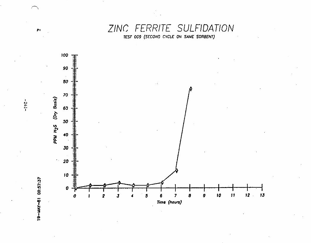
ZINC FERRITE SULFlDATlON EST OG9 (SECOND CYCLE ON SAVE SORBENP)
I I I 1 I 0 0 2 3 4 5 6 7 8 9 10 11 12 . 13
fime (hours)

ZINC FERRlTE REGENERATION TEST 010 (SECOND CYCLE ON SAME SORBr-T)
0 1 2 J c 5 6 7 8 9 10 11 12 13 Erne (hours)

ZINC FERRITE REGENERATION

ZINC FERRITE SULFIDATION
6 7 8 9 10 1 1 12 1J lime (hours)

PPM
H
IS
(Oty
B
asis
)
ZINC FERRITE SULtrlDATION \

TEST We 1 013 DATE STARTED I 3/05/81 DATE ENDED I 3 ~ 8 6 4 8 1
SORBENT ' N P E / U E I W I ZItC O X I D E / l W G SORBENT No. 1 H A R S W ZN040L-E3/16 (SAIOPLE ) SORBENT cowoszTxOi ( r lee t mo
S U B E M S I Z E 1 3/16 INCH DIAI'STER M I R L K I O H S PRETREATRENT I DRIED 61 379 F FOR 2.5 tlOURS SULFUR LOADINW I 98.7 f (GI1 SULFUR/Cfl FRESH SORBENT J
TO 9 PPI BEFaRE SREAKfMOUCH .
PRESSURE 8 AnBlENT
SPm UELOCINP lee@ HWRLV
FLW R e l E M O U
)(@s m e 4 m3/nxnj e.si6 SCFH 2.n;
I420 0.508 C n 3 / I I N 6 . E %
A I R
cw co HZ 11.3L W3/111)0 2.79 S W H 14.-
C M
Na (6.04 M 3 / R s H j 1 4 - 5 9 S W M 7S.8U
PURPOSE
SULFI~~\TION o r zrnc OXIDE EXTRUSIO~ TO Dt fCRnINE SORPTION EFFICIENCV AHD SUBSEQUM REGEMRRlION CWYIRCIERISTICS.
BEFORE t o T n t SULFUR ( IUNU ) 8 SWRFhCE ARE@ OsE/GJl 3.2 DENSITY t ~ a n 3 ) 8 6.39 . PORE VOLUHE (nIl31C ~r b.5 ~ ~ ~ K R ~ L - ~ ~ L v s I s I - ~ SEE W+TNDIX-- ELErSHThL RnRLYSISI SEE M N D I X
DhTAI ( DErECTOR N E E )
EX1T.HES: 5 -9 PQll P L A T E N FOR 9 HOURS
B R E ~ ~ O U G M nt 10 HOURS VITH s o P P ~
E X I T SO28
EXIT sat EX11 HZ8
1. H2S LEVEL REWCED TO APPROX1IU)tELV TH f CEIIEf ODTAIMD U l M ZINC FERRITE.
CONCLUSIONS
1. ZHO I S A GOOD SORBENT AT HIGH TEIPCIIATWES U I T H 6.91 UATER.
8. M I S TEST DATA W R I F I E S M R H O D V N M I C CALCUL6TIOllS fHDICnTlNC WPROXIMRTELV 1 PPR I K S ACHIEWBLE U I T H 6.9 f U.%TER AT 1000 F.

TEST SUfWWV SHEET
T E s i NO. e 9 1 4 DATE S T M E D 1 3/06/81 DATE ENDED 0 3/06/88 T O T ~ L M ~ S 8 ra TYPE t RECCnERATIOW
PURPOSE
RECEMRATION W ZINC OXIDE EXlWS!ONS TO DETERMIHE REGENERATION CHARMXAlST1CS.
- # E M W P E A E f W I ZINC OXIDE/ l89b U , (\NALYSIS: SORBENT NO* 8 WiRSHI\U ;LNB40l-E3/16 (SRIIPLE) BEFORE rY fER SORBLM COWOSITIONI 1 0 0 % U10 TOTAL SULFUR( 8UJU I 1
SURFACE n u m t n a c I DENSIIY(G/CP13)1
SORDEWt S I Z E t 3/16 INCH DIARETER E)(fROSlOHS PORE UOLUME tnn3/c I PRETREATRENT 8 DRIED tat 320 c TOR 2.5 HOURS OEF- ~913) R~MERAL WLVSISI S U L N R REROVED I ' E L C ~ E N ~ A L W~LVSISI
OPERnTlno CONDITIONS
tERMRATURE8 1008 F (53s C )
PRESSURE 8 A n B l E M
SPACE UELOClTV* 688 HOUllLV
FLOU RnTE ROLE
M S
HZ0 8.17 C t n I l l l W UII
A I R tE.71 D R 3 a I N ) 6.7% SCFH SOB
COB
co H2
CHI
fa
DATA1 f MlECTOR TUBE)
E X I T H251 LWABLE TO K A D DUE TO SO2 IMERFEAEHCE
E X I T SO21 3-145
E X I T S E I 8.1687 C
E X I T HZ1
P. so2 LE~ELS RRE MICHER C O W ~ D TO zinc FERRITE WCH LE5S ELEl lEMAL SULFUR PRODUCED.
I. IT ~ P P E ~ twnt MO RECENERATES IN TM SANE wv ma0 IRON OXIDE AND z l r c FERRITE w). A SIRILAR TE.RPERA1URE. UaVE I S OBSERUED 0 AS EXPECTED*
8 . I N SPITE W a 681 S T E M LEUEL I N THE FEED* THC RECENERRTlOM REACTION I S SUFFlCIENTLV LXOTHEROIIC TO PRODUCE A 799 F RISE I N PROCESS CRS TLWCUATWE.

TEST SURllIIRII SHEET
TEST NO* I @15 D N C STARTED I 3/18/81 DATE ENDED 8 3/11/81 t O t A L MOWS r 1 4 t V P 0 I SULTX DIITlON
S W B E H t TYPE/U t IGHt I ZINC OXIDE/1@90 0 SOCIBEHt NO. 8 W S H A U ZNO4OI-E1/16 (S(UIPLE1 M B E M COIIPOEItIO?i* 1 8 8 f ZNO
S O R B M S I Z E I 3/16 INCH D INETOR EXTRUSIONS PRETlKATWENT I DRIED AT 3 2 9 F FOR 2.5 HOURS SULFUR LOADIHU) J 18.8 (W( SULNR/CII FRESH SORBEM)
10 1 4 PPR BEFORE BREAITHROUGH
PRESSURE I NIB xcnt SPACE W L O C I f V I 1889 H W L V
FLW UA~E ROLE
W S (e.24 D K I / I I I I ) @.St6 SCFH 2.7%
NO o.see cnwnxn 6.08
h I R
coa CO
HZ ( I .R DR3/lrIM) 8-79 SCFM 8 4 - 6 8
CHI
t0 (6.84 DR3/lrIN) 84.5e SCFH 75-82
TDTAL DIN OAS F W U RATE 17.- SCFH
totnL MT GAS FLOU RAE 10.11 SCFH
8
TOTAL SULFUR t PU/U ) 8 SWFRCE AREA t 6 2 / C ) I DENSXTV tC/Cn3 I r PORE UOLUIIE ( M 3 / O ) I 8llIERIL WWLVSESI E LERENTAL W L V S I S 8
BEFORE ffttu
RLIIARKS
1. THIS I S M .SECOWD S U L f I D A t I W OF THIS SORBEM.
2. E X I T H2S UIS S L I C M L V LOVER TMN THE FIRST SULFIDATImI.
C ~ L U S I om 1. t n O 15 REcDcERAlLE A t TMESE C ~ D I T X 0 ) ( 9 ~
09 g 2.
OL' -

TEST S W R R V S N E T
t E 9 t NO. 1 816 DATE STRRTED 8 3 d 0 / 8 1 DATE ENDED 1 3 / 2 8 / 8 1 TOTAL HOURS 1 3.6 TYPE I sUV1DAtXO((
SORBLM t W W U E I C M T 1 (Z INC F E I R I t E ) / 6 1 3 0 SORDEN~ NO. 1 BATCH 8 2 / 1 50RDCNT COCROSIflO(8 68 BOLE8 IRON O'YIDE (FISHER CZRTIFIED)
SO ROLL8 ZINC OR1DE ~ S . M E R U 1 ~ U X L L l N l S HSA)
SORBEN1 S X Z 1 3/16 INCH D ~ N E E R LXTRUSIO~K' PREfREATllENT I DRIED I N WEN AC a 8 F OVERttIO(I SINTERINO 1 3 HOURS A t 1509 F SULFUR LOADInC 1 14.1 8 (C)( SULFUR/CII FRESH SORDENT) I
TO 10 PPt l BEFORE BREAITHROUCM
FtW RATE' nOLE
HBSl8*47DR3/[email protected] 2.71
!H~O 3.872 cnwn~w 27.66%
:AIR
COZ (1.70 D013/RIN) 3.6 SCFH 9.6e8
CO (2.83 D113/RIN) 4 - 3 SCFH 11.918
HZ (2.97 DM3/II lH) 6..3 SCFM 17.128
CH4 f8 .51 Dn3/R3N) 1 ,07 S C M a . 9 1 ~
WZ (4.88 DI13/1CfW) l e a 3 4 SCFH 33.098
TOTAL DRY C(\S FLOU RATE - 26.6e SCFH
TOTAL YLT CA5 FLOU lWTE - 37-70 SCFH
PURPOSE
SULFIDAt lON OF ZINC FERRITE EXTRUXONS TO DETERnlNE SCRPTION EFFICIENCY NiD SUBSE- RECErERATlON CVARACTERXSTXCS. USIMC L W G I AXR/HCO cns CWWOSITXO~S WD IWIKASED SPME ~~LOCXTIES.
TOT6L SULFUR (tU/U I I SURFME AREn tn24 1: DEtlSl TV (G/CIl3)1 PORE VOLURE ~n113/c): nINERhL lVUiLISIS8 ELEMENTAL ~INC~LYSISI
5.1 S.68
19.9 SEE WPENDIX
DATA1 ( DETECTOR tUDE )
EX IT M2SI 9-13 PPll P U T E N FOR 2.25 MRS BRElKTHROUCH A f 3.2s MRS U l t H 9 2 5 M
E X I T 502:
EXIT sat E X I T M21
1. 1WCI GAS COneOSIt ION DOES NOT WPCAR TO P U O M A DLFFEREHT RESULT X f t TMlS SULFIMTlON.
2.
1. nCCCLERATED TEST CONDlTlON OF SU*i!W8 REDWED TIRE 7 0 BREAKTHRWGM ABOUT AS EWPECTCD. TESTS C4N M U BE COWLETED I N ONE SHIFT. .
2. H2S LEVEL AT L K I T ONLY SLIGHTLY HlQHER 'IWY( 1 W T ODTfiINED AT SV 1000.

TEST NO. 8 . 017 ' PIRPOSE WTE S T a R t f D 8 3,24811 DATE ENDED a 3 # 2 4 ~ 8 1 REGENERATION OR ZINC FERRITE CMlWUSlONS IOTAL HOURS a S FROM TEST 816 UISI~IC 58% AIR AND 508 STEAM. TVPf 1 RECLWtRfiTIOH 0lND CICCELERATED SPWE MLOCITY OF 1288 HOURLV.
SC7DCNT WPE/UEICHTl , (ZINC FERRXTE)/643 O NMtvSXS: SaPlENT HO. 1 BATCH BEFORE AFTER SOL~EM CORPOSXTIONI SO UOLEI IRON CXIDE ~FISNR CERTIFIED) TOTAL SULFUR t XU/U I I
50 ROLE8 Z1W OXIDE tSHERUlM U I L L I M S MI) SWFACE AREA (Pl2/C 1 1 1.4 DENS1 TY ( C J C R ~ 8 t 4.E
SORIEM S IZE r 3/16 INCH DIMETE~ CX~RUSIONS PRE11:mTnENT t S U U W R E M D D
FLW ROlE HOLE
ws 1120 419 cm~nxn s a @XU is.= c;tt/mINt u.e7 scm set Go2
Cd
M!
CHI
H1
- - - PORE-UOLU~E c n n 3 / c I: 3.7 I l l t K R A L ANALVS I S 1 SEE APPEHDIX ELLIIEtfTI)L M L Y S I S 1
DAT As (DETECTOR T UBE 1
EX17 H t S I
E X I T Sot : 8 -13 8
E X I T S t 1 ,7.7881 C
E X I T HLa
1. 7EtlPERI)lWE UAUE UP TO 1918 F OBSERHD fit X W , 1488-156a THROUCHOUT TME REACTOR.
2. ~ F T E U R E M ~ ~ X N C THE ncmsxom IT UAS ODSERMD mat SORE ACCl.O?lERfITION (SlWTERINa) HAD OCCaRED. O
I COATINO Cb HEHATlTE TED ZNO WS DETECTED OM O f 1 HE EXTRlISIONS.
CO)(CLUSlONS 1. SV-8208 MeV BE TOO HIGH A W C E VELOCITV FOR
REGENEFlATlON. I T IS SUSPECTED THAT I T CAUSED SIHTERiHD I N THIS RUM, R E D W l M SORPtXW AGTXV1N.

TEST SUOlARV SWEET
TEST no. I DATE STARtED 1 DATE W E D 8 TOTAL HOURS : W E
PURPOSE.
SULFIDATION OF' zrnc FERRITE CXTRUSIONS AT 6 e e r TO DETERnINE ?.ORPTlON EFFICICNCV WID SUBSEOUEHT RfCE1IERC)TION CHARMTERISTICS, USING LUROI AIRJHZO CIIS C O R P O S I I I ~ S IY(D INCRECKED SPACE ULLOCITlES.
SORBENT TVPE/UEIO~~I ZINC ~ t ~ l l 1 ~ ~ ) , 6 4 3 a ANALVSIS: SORBENT NO. I BATCH 8801 BOORE W f L R SOODCNT COIlPOSlTIOnl SO ROLE8 IRON'OXIDE (FISHER CERTIFIED) TOTAL SULFUF:(%UtU) I
69 UOLEU Z INC :OXIDE (SHERUIN U I L L I W S HSA) SURFACE AREfitRZ/C)8 DENSITV1C/Cb3):
SORBCWT S I Z E 8 3 /16 INCH D IMETER EX~RUSIONS PORE UOLUIIE t N l 3 t C ) I PRETREATUENT I ORXED IN WEN JIT 2 0 0 F OUERNIW UINERAL ANAC.YSIS8 SULFUA L m D I H Q 8 U (01 SUWW/CI I FRESH SORBENTI ELENHTAL W L V S I S I
OPERATING CO)(DITIONS
TErrpERATURE I 6 8 8 F ( 3 1 6 C )
F LOU RATE IIOL'E
H I S (e.47 D m / R I M t 0.9963 SCFN 2.77
HZ0 3.872 CN3/NIN 27.665;
A I R
CO2 (1.70 M 3 4 I N i 3.6 SCFH 9.681
CO 4 2 - 0 3 m 0 8 I N ) 4.3 SCFH l l . O l 8
H 2 ta.07 M ~ ~ R I N ) 6.3 SCFH r7.12r
C H I (@.St M 3 8 N I N ) 1.87 ECFH 2.918
te ( 4 . ~ 8 mwrr~n) 16.34 sm 33.eou
DATA: ( BETECTa TUBE)
E X I T W S I 6 0 0 8 PP(I I M D I A T E L V
E X I T SO21
EXXT 5 2 1
EXIT e r
8 . N l E R I l l n E D I A l E BREAKf(ROUCH U S ODSERUKD, TERP. uns INCREASED TO 1000. AT THIS TEW. 108 P P ~ UAS DETECTED. RECCHERATION W S CARRIED OUT RUN ~ V I O E nr ieee r. B R E M T H ~ ~ ~ ~ M o c c u m ~ o wtcn se rrrn.
1. S U U I D A t I O N ACTIVITY APPEARS TO DL UERV P W A t 688 F. WOUEUER. It I 9 SUSPECTED TWIT THE D(1RUSIO)O H A M BEBN SINlER€D I N t)(E LAST REGENERATIW AT SU*1288.
t. THE BRE.KTHROUGH ODTAINED a T 1 0 8 0 F aFTER O N L ~ 60 RIl t . IHDICATES W T SORBDl l ACTIVITV HA6 BEEN REDUCED..

TEST SUPlflfiRV SHEET
T€ST No. I 019 bnlf STAR- I 4 / 7 / 8 1 DATE ENDED I 4 / 8 / 8 1 TOTAL HOURS I 3.75 TYPE # SULFIDATION
PURPOSE
. SOftBENt TVPE/ lEICMTt (ZINC FERRITE W 6 4 3 C I\NAlYSIS: SORBEWT NO. I BnTCH tWi? BEFORE W T E R SORBENT COnPOSItlON: 58 ROLES IRON OXIDE (FISHER CERTIFIED1 TOTAL SULFUR ( LU/U 1:
EB m ~ t t ZINC OXIM (SHERUIN U I L L ~ A ~ S MSA) SURFME ~ R E R tnt/c)r 4.4 DENSITY (~ :cn3 )I 5.72
SORBENT S I Z E : 3/16 INCH D I n n L t t R CXTRUSIONS PORE VOLUflE ( M 3 4 C ) I 8.5 PRETREA~ENT I DRIED IN OWEN at 2ee F OUERNI~HT ~ I N C R ~ L ~ N ~ L Y S I S ~ SEE APPEHDIX SULFUR LOADING 8 f ton S L R F W / M FRESH SORBENT) ELENMTAL hNCILYSIS1
OPERRTI)(C CONDlTIO)(S
TEIIPERATWIEI 1900 r (538 C )
BRESSURC 8 C V ~ D I E ~ ~
W W E V E L O C I W I 2Q00 HOURLV
t e s
tuo A I R
COZ
CO
m CHI
m
. LOU RIITC RULE
1@. 4 7 Dfl3rllI)o e.9963 SCFM 2.7%
3.872 CR3I111N 27.66%
Dl lTAl a DElECtOR TUBE)
EXIT HZS: 3 - i e fen PLATEAU FOR 2.5 HRS BREMTHROUCH U I T H 68 PPM AFTER 2.5 HOURS
E X I T SO21
1. PREHEalER PWCCED WTER 1 HOUR INTO THE TEST. TEST UENT OM HOT HOLD OVER MIgcT, W D PREIEfi lER C O I L REPLWED.
2. T H I S RUN W S STLRTED YttDI A FREUI 3fiTCH W SORBMV

TEST SUHRARV SHEET
TEST No* 8 8 2 0 DATE STARtED 8 4 /10 /81 ~ae ENDED 8 4 / 1 0 / 0 l TOTAL HOURS I 6.75 W E I REGEMRATION
PURPOSE
REGEItERI\TION OC ZINC FERRlTE EXTRUSIOIIS FROM =St @I9 USING SPACE ULLOCITV OF 608.
- - - - - - - - SOR~ENT NO. I bntcn-aS/S SORDDIf C O i V % I ~ I O N l 59 HOLE% IRON W I D E (FISHER CERTIFIED) . TOTAL SULFUR:
SO nOLEll ZINC OXIDE (SHERUIN U I L L I r V K MSA) SURFACE IIREfi:.
SORBENT S IZE I 3/16 INCH D IMETER EXTRVSIONS . PREtREfiTMENT I SULFUI) REKOWED 8 . .
OPEWTINC CONDITIONS
TEP~PEW~NRE 8 lee0 F ( 5 3 8 C B
PRESSURE I NIDXENT
SPACE M L O C I W a 6 0 9 HOUULV
. FLOU R 6 t E HOLE
H2S
HE0 2 - 2 3 M 3 / R I N 588
6 I R (2.78 Dl l 3 / l l lNJ 5.88 SCCH 688
mcoi?
. co iH2
, C H I
.HZ
DEHSITV PlI8ERAL ANCIL~SXSI E L M L N r A L RNBLVSISI
BATfiI c ~ ~ ~ t c t o a TUBE)
E X I T H2S8
E X I T SO28 8-12 %
EXXTSi21 4 . 1 6 4 3 C
E X I T HZ1
BEFORE AFTER
1. TEnPERATURE UnUE UP TO 1689 F 0DStRUED.AT INLET W D 1408 F THROUCHOUT THE REMfOU. ,
2. WTER COWLETlON OF M I S RECEI1ERATION. hBSORIER tEnPERATwE UF\S ~~IMAINED WD SUUIDATIW REPEATED
COHCLUSIOHS
1. W R A L REUHERAXON FOR U K E L I N E MRIFICATXON.

TEST me 8 881 DATE STARTED I 4<13/81 M T E ENDED I 4 /13 /81 TOTRL HOURS I 3.75 TYPE I S U F I O A T I c m
=BENT tYPE/UEfOnI f Z IHC F f R R I T E ) / 6 4 3 8 SORBEWT )H). I BATCH 8212 SORBEHT COI\POSITIOMI so nout I R o n OXIDE (FISHER CERTIFIEDI
50 MOLE% ZINC OXIDE fSHERUIN U l L L I A n S HSA)
H T S I Z E 8 3/16 I W H DIAnETER EXTRUSIONS
f LOU ART€ ROLE
WS (0.47 D R W N I M I e.9963 SCFH 2.78
mIR
COE (l.7e DM3/R1W) &6 SCFH 9.688
PURPOSE
SULFIDn l ION OF ZINC FERRITE CxTRUSIONS f O REES'lfiBLISH OnSELINE AFTER RECENERATlO)(. THIS I S THE SEWHO SULFIDATION OT THIS DATCH.
nnnLvs I s I BEFORE CIFTER
T OTAL SULFUR 8 SURFRCE 6REAt DENSITY t PORE uoLunE r Rl)iERnL W R L S I S I ELEREtlTAL RHWVSIS 8
DATda f DETECTOR TUBE)
EXIT H ~ S I 3-5 PPn PLATEAU TOR 2 ws 0REAKTH)OUGM U I T H 1100 PPll M T f R 3 HOURS
EX IT 5 0 2 1
I.. SECOND SIRFIDATION OF THIS DRTCM or sonmtm 2- LURCI CAS CORPSITION USED.
1. NORrYIL ACCELERAftD SULF IMT ION TEST W TERR9 OF OUTPUT DATA.

TEST NO. 1 oi?a DATE Sf(rRtED 8 4 ' 1 4 4 1 DATE ENDED 1 4 4 8 I TOTAL HOURS 1 6.75 TYPE I RECENERAtlW
PURPOSE
RECENEROTION,OF ZINC FERRITE EXTRUSIONS FROll TEST 0 2 1 USING SPACE UELOCITV OF 688.
SORBEM t V P t N E I C H t : t Z INC FERRITElv643 C ANALYSIS: - - - - SORBEM NO. I Bniw 8802 SORBEN1 COI(POSIT10N~ 5 8 ROLES IRON OXIDE (FISHER CERTIFIED) TOTAL SULFUR:
59 ROLES ZINC OXIDE (SHERUIN U I L L I W S HSA) SURFACE 6 R W t
SORIENT S I Z E 8 3/16 INCH D I M L T E R M R U S I O N S PRETREATNEWT 8 S U W RfNOIKD I
OPERATINO COMl I t IONS
TEMPERATWE I 1889 F ( 5 3 8 C )
PRESSURE I M D I E M
SPACE VELOCITY: 6 8 8 H W L V
FLW RATE OLE
Hi?S
. HZO 2.23 cns/n~n s e ~ A I R (2.161 M 3 m l N ) S.88 SCFH 5 8 s
coa co
BEFORE AFTER
DATA: tDEKCTOR TUBE)
EXIT HCSl
EXIT 502: 3.5-12.8 t
EXIT SCI
. EXIT HC:
1. ACTWL n O U S MRf:2.17 C H 3 d I N WTfR.S.73S S#H AIR.
2. fiFTER COnPLETION OF THIS RECEWER~TION. ABSORBER TErPER#TURE UAS RA I t ITA IMD AND SUU lDAT lON REPEATED
COMCLUSlONS
1. NORWL EECEMRQTION.
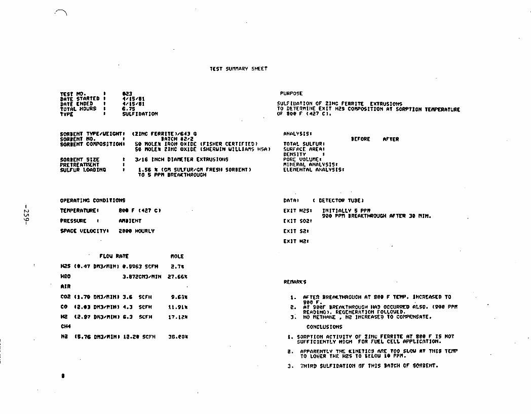
TEST SUnnRAV S M E t
E S T w. I 0 2 3 O N E STARTED 1 4 /15 /81 DATE ENDED I 4/15/81 TOTAL HOURS 8 6.75 t VPE I SULFIDI)TIO)(
PURPOSE
SULFIUnTlON OF ZINC FERRITE txORUSIOHS TO DETERnIIIE E X I T HZ9 C0)IPOSITION 111 SORPTION TEWERATURE OF 808 F ( 4 2 7 C 1.
SORBENt l W E ~ u E 1 m 1 (ZINC FERRITE , 4 4 3 Q AN~LYSISI SOBDENT NO. 8 BATCH 32f2 BEFORE AFTER SORBEW CO~POSHTXOHI 68 M U 8 IRON OXIDE (FISHER CERTIFIED) 10~nt. SULFUR:
SB ME8 ZINC OXIDE (SHERUIN u I L L I f i n s HW) SURFACE AREA( DENS I TY 1
SORBEHI S I Z E I 3 / 1 6 I N C H D I A ~ T € R E X t R \ I S l O c c S PORE -VOLU~IE a PRE 1 RE Aff lENT I flINERQL ftNfiLVSIS1 SULFUR LWDINO I 1.56 % tcfl SWFUR/G~ F R E ~ I S O R B E ~ ~ ) ELENENTAL AHALYSIS)
TO 5 Pf'R DREIUCTHROUCH
OPERATlf f i CONDltlONS
t t ~ ~ ~ ~ i l f l ~ ~ 1 889 C (427 C )
PRESSURE t A)lBItNT
SPACE VEfOCITVl 2 8 8 8 HOURLY
~ L O Y u n f ~ n o u WS (0.47 Dfl3/AIN) 8.9963 SCFH 2.7s
Me0 3.07i!Cm/RIN 27.66R
' A I R
602 (1.7@ Dn3/RI t l ) 3.6 SCFl4 9.6.31
CO i Z . @ 3 D H 3 / n l N ) 4 . 3 SCFW 11.910
H2 (2.97 DR3/RlM) 8.3 X F H 17.128
C H I
Ha (6.36 Dfl3/RIN) la.20 SCFH %S.WX
DATnt t DEtLCTOn TUBE)
EXIT HZSI I n I t I n L L v s P P ~ 908 ~ r n BRE~KTWWI MTER 30 nrn.
E X I T 502,
EX IT 5 2 1
E X I T HZ1
I . M t E R BREMtMROUCH A t 880 F TEW. XNCRTSED TO 960 F.
2. 6 T 908f BREfiKTHROUCH bW3 OCCURRED CILSO. (988 PPR REQDI ffi 1. RECENERnTl Or4 FOLLOUED.
3; NO ?lEVMRM Mi2 INCREASE0 TO COWWSATE.
i. SimPVxon ~CTIUI~Y OF ZINC FERRITE ~7 8 e e F xs neu SUFFlCIEMTLY WIW FOR FUEL CELL WPbXCRTlUN.
flWt3REMTLY T M U lNE t ICS &?b: 1 0 0 JbCU fit THIS TO LOUER THE MZS TO EELOM l e PPR-

TEST SURllAw SHEET
TEST No* I 824 D A f t STARTED 8 4/16/81 DATE ENDED 1 4/16/81 TOThL HOURS 3.25 T VPf 8 SULFIDATIOM
PURPOSE
SULF'lD~TIOl( GF ZINC FERRITE EXTRUSIONS TO DEtERHltE ;EXIT b K S CORPOSITIOW AT SORPTIOII TERPERATlJRE OF 1208 f (649 C ) .
SORBEM TVPE/LYIO(tJ (ZINC fERRlTE)/643 G rWILVS1St SORBUcT NO. 1 BATCH 82/2 BEfORE lY fER SOADENT C~OSITIW 50 HOLES IRON OXIDE (FISHER CERTIFIED) TOTAL SUUWI
SO HOLE% ZlNC OXIDE ( M R U I N U l L L I N l S HSA) SURFACE -1 DENSITY I
SORBENT. SIZE 3/16 INCH DINlEIER EXTRUSIONS P O ~ E VOLUPIEI PRETREATRENT t HIIIERAL N W V S I S : SULNR ~ o n ~ ~ f f i I 15.6 t tcn SULFUR/CA FRESH SORBCMI
TO 15 PPll BREAKTHROUCH -
PR€SSUFE 1 (UID I E M
SPACE mLOCIN: 2000 HOURLV
FLW RATE
H2S (8.47 D113AlINl8.9963 SCFH
IPO 3.872. C113/111N
AIR
coz ' t 1.78 omwn1n) 3.6 SCFH
CO (2.83 W W I I I N ) 4.3 SCFH
HZ (2.97'~~13/Cl1M) 6.3 SCFH
CHI ( 0 . ~ ~ 1 D n w n t n ) L . O ~ SCFH
HE (4.88 DslJ/riIn) 18.34 SCFH
DrrTlll ( DETECTOR TUBE1
EXIT WS8 9-13 PPN PLATEAU
DREhKlWOUCH UITH I S PPCl fit 2.5 HRS EXIT SO21
EXIT s a t
EXIT HBI
CONCLUSI Om.
1. H2S L E M L AT 1208 f ABOUT IUICE TME LEVEL OBTAlHED AT 1088 F.

TEST SURIW)Y SHEET
T E S t NO* t 825 D m SfWTED I 4 / 1 7 / 8 1 D M € ENDED 1 4 /17 /81 TOTAL HOURS I 5 . Z --. .-- - - - WPE I RECL~ERAT lot i
PWPOSE
RZCENERnTlOM OF ZINC FERRITE EXfRUgIONS FROR TEST @24 USING sPncE VELOCITY OF 608.
SORBEWT TVPE/UEICHCI (Z INC FERRITE)/643 C ~ N R L V S I s 1 SORBEM NO. I BATCH 8 2 / 1 BEFORE m E R SORDENT COP~POSITIO~I MJ ROLE% IROH OXIDE (FISHER CERTIFIED) T O T ~ L SULFURI
58 ROLE% ZINC OXIDE (SHERUIN U ILL IA I IS HSA) SURFACE f U E A I I)Ft4Sl t V 8
SORBENT S I Z E I 3 / 1 6 INCH DIAMETER EXTRUSIONS PRETREATRENT .I SuLFUa REHOUED ' I
. R W RRTE ROLE
l l I R Ct.78 DRWRINP 5-88 SCFH SbN
coil
OnTAl (DETECTOR TUBEI
E X I T H2S I
EX17 SO21 3.5-12-8 I
E X I t 5 2 1
E X I T HOI
I . ACTUAL $LOUS UERLl2.17 C m / R I U UATER.S.735 SCFM AIR.
2. AFtERtOf lPLETIOW O f THIS RECMERATIb)(. ABSORBER TENPERnTURE UAS lvI1NlAtNED MID SULFIOIITION REPEATED
CONCLUSIOPS
o . HounaL l ~ ~ ~ ~ ~ t ~ ~ .
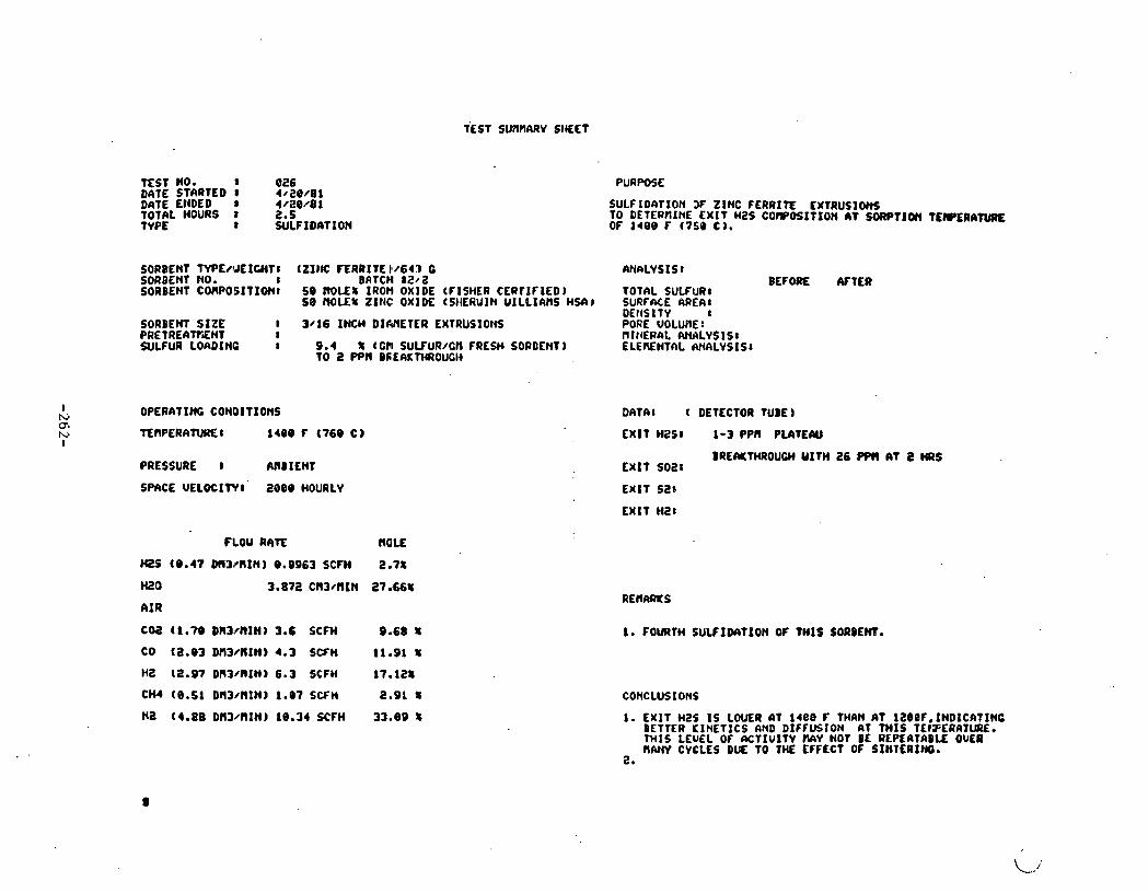
TEST NO. '8 0 2 6 DATE STARTED '8 4 r20 /B1 DATE ENDED a 4/OBr81 TOTlL HOURS 3 2.5 TYPE II W1FIDl)TION
PURPOSE
SULFIDhTION 3f ZINC FERRITE CXtRUSIWiS TO DETERtllNE E X I T H2S COIIPOSITION AT SORPTION T C W E R A N I K OF 1488 F ( 7 5 9 C) .
SORBENT N P E / J E I U ( T I (21)lC fERRITE k/643 C M\nFILYSISI SORBENT NO. 8 BfiTCH t 2 ~ 2 BEFORE WTER SORBEHT CORPOEITIW8 5 8 IK)LEt IRON OXIDE (FISHER CEOt lF IED) IOTAL SULFUR8
50 Z I t lC OXIDE (SIIERUIH UILL IAMS HSCI) SURFACE AREA1 DEttS I T Y I
SORBEM S I Z E I 3 / 1 6 INCH D IMETEA LXTRLIS1OttS P O ~ ~ E -UOLURE : PRET REAWiNT I nIt lERAL MALVSIS: SULFUR LOADINO I 9.4 f t CR SUKUR/Ci l FRESH SORDENT ELENNTAL W A L V S I S I
TO 2 PPH DSEAKTWOUEII
OPERATIIG CONDITIONS
~ ~ ~ P E R A ~ O ~ I 1489 r ( 7 6 9 C )
PRESSURE I AIIBIEHT
SPACE UELOCXWI' 2 8 0 9 HOURLY
FLOU RATE
(0.47 D(13PRIN) 9.9963 SCFH
3.872 . c n 3 / n r n
(1.79 DR3/RIN) 3.6 SCFH
(2.93 Dn3/11IN) 4.3 SCFH
(2.97 Dfl3'RIH) 6.3 SCFH
(9.51 Dfl3/llIN) 1.97 SCFH
(4.88 DR3/ l l INJ 18.34 SCFH
DATA1 ( DETECTOR TUBE)
E X l T H2S I 1 -3 PPn PLATECYI
BREMTHROUCH Y I T H 26 BPll at Z HRS E X I T SO21
E X l T SZn
EX IT Hi!:
R E n m S
1. FOURTH SULF IMT00N OF THIS SORDEM.
CONCLUSIONS
1. E X I T H 2 S I S LWER A t 1488 F THAN l T IZ80F,lNDICATINO BETTER ICINETICS AND DIFFUSION AT TMIS T E t F E R A t W . M I S LEUEL O f 6CTIU lTV NIY NOT BE REPEATABLE OVER U W CYCLES DUE TO THE EFFECT OF SIHTERINO.
a.
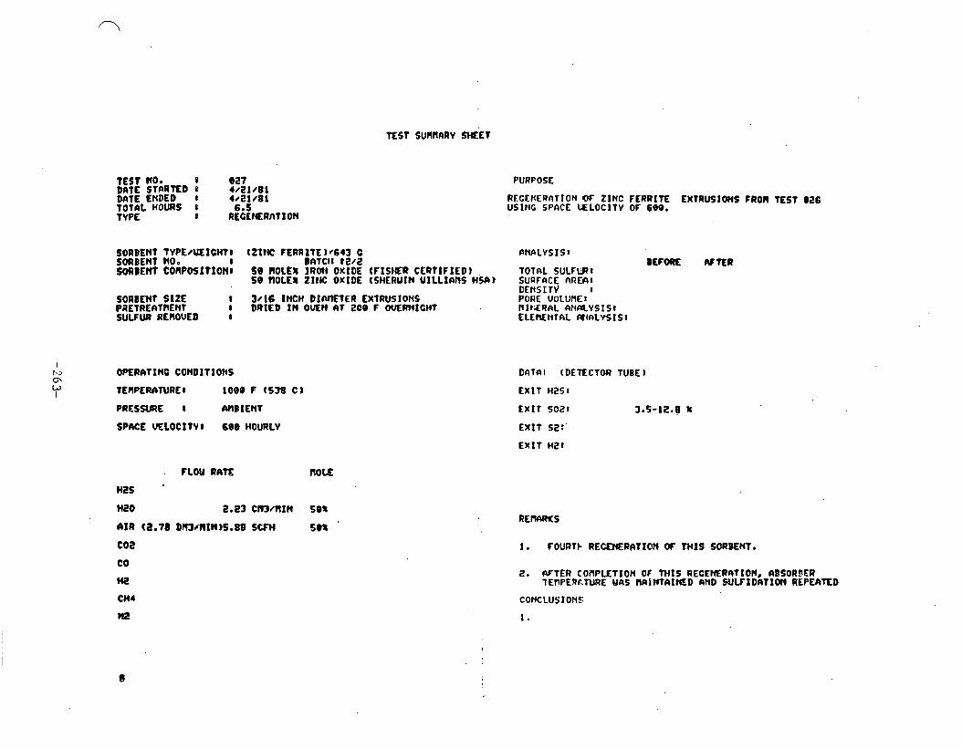
TEST SUMNARV %ET
t E 9 T No* 8 027 DnTE STARED e 4 / B l ~ I B l DnrE ENDED r 4/21/01
PURPOSE
RECtKERnTION OF ZINC FERRITE EXTRUffOnS FROM TEST 026 USlHC SPhCE U L O C I T Y OF 689.
SORBENT TVPE/\~LICHTI (ZINC FERRITL).,643 C ANALYSIS1 SORBENT NO. I BATCII t e / 2 SORDENT COllP091TIONI 58 ROLE% I R o t I OXIDE ( F I S M R CERt lF IED) TOTIIL SULFWt
58 tlOLE8 ZItC OKlDE ISHERUIU UILL I r \ l lS HW) SUQFIlCE nRWI DErtSITJ I
SORBEW S IZE 1 3/16 INCH DIMETER EXTRUSIONS PAETRERTnENT I DRIED IN OWN 6t 200 F ~ R N I C H T SULFUR REROVED I
OPERATINO CONDlTIOHS
TENPEMTURE I 1088 F (538 C l
PRESSRE 8 MBXENT
SPME VELOCITVl 690 HOURLY
. FLQU RATE no= H2S
n20 2.13 crn/rrrn ses I I R (B.78 DllJrnlW)5.88 SCFH 50%
coa CO
H2
CH4
It2
DhTIIl tDElECTOU TUBE)
EX IT H251
EXIT ~ 0 2 1 3.5-12.8 8
EXIT 52:'
EXIT 1421
8. AFTER COAPLtTION OF TMIS RECEMRATION. RBSORPER lL?lPERF.TWE WIlS N A S W A I M D AND W L F I D A T l O n REPEATED
CONCLUSIONl:
1.

TEST SLUWARV SHEET
-ST W * 8 828 DATE STCIRTED @ 4 /22 /81 DATE ENDED I 4/23 /81 TOTAL HOURS I 1.5 W E 8 SULF IPAT I f f l
. PURPOSE
SULFIDATION OF ZINC FERRITE E X T R U S I O ~ TO DETCRfllNE E X I T H2S CORPOSITIW AT SORPTION TE-ATURE OF 1508 f ( 8 1 6 C ) r
SORBENT M / U E I U C T I (2 IN FERRITE , 4 4 3 O WALYSISI SORBENT No* 8 BATCH 0212 BEFORE AFTER SORDENT COflPOSHTIOIIl 5 0 ROLE\ IRON OXIDE (FISHER CERTIFIEDJ TOTAL SULFUR (%U/U 1
5 8 ROLE% ZINC OXIDE (SHERUIN U I L L I M S HSA) SURFnCf AREL < l l 2 / o l 0.5 (!XE NOTE 1 DENSITY ( c / c n 3 )I 4.99
SORBENT S ~ Z E 1 3 / 1 6 IHCH D IMETER CXTRUSIONS PORE UOLUnE (Rfl3/G I 0.7 P R E T f i E A ~ H T I nlNERAL AtdABVSIS 1 SEE 6PPDU)IX SULFUR LOADINC I 6.26 1 tCN SULfuR/Cfl FRESH SORBENT i ELENENTAL fUlALVSIS1
TO 4 PP11 BREU(n(R0UCH
OeERATINC CONDITIOllS I N TEWERATUREI 1 5 0 0 F ( 8 1 6 C 1 0\ 0 I PRESSURE 1 IUIBIENT
FLOU RATE ROLE
H ( @ . 4 7 W 1 3 R l I H ) @ . 9 9 6 3 S C F M 2.18
H t O 3.872 Cn3/ I l lM 27.668
A I R
~ 0 ~ ( 1 . 7 0 ~ 3 / n 1 n 8 3 . 6 SCFM, S . C S ~
CO (2.B3 M13/RlN) 4.3 SCFH 11.91 %
rn (2.97 D ~ W ~ I N ) 6.3 SCFH 17.10r
C H I (@.:;I DC13/RlN) 1.07 SCFH 2.91%
HZ (4.08 M 3 / l l I H ) 10.34 S W H 33.e9 8
EX17 HZS: 4 PPU PLIITEAU FDQ 0.5 IM
. REMRKS
1. F I F T H SULF IDAT IW O f THIS BATCH.
2. SORBCNl OUERHEAXD AT REMTOR E X I T TO 1698 f DURItiC IIUERNICHT HOT HOW.
3. PELLETS FUSED TOGETHER a 7 RID BED BETYEEN T/C s . m D T/C 4 , D M TO OUERHEATIHG.
CONCLiJSIoNS
1. SINTERI3G CMSED REACTOR TO PLUQ.
2. SULFlDAIION AT 1508 F CAUSES UORE RAPID B R W H R O W H PROBA0LV DUE TO SINTERINQ C4US1NQ LOSS OF RCTlUE SURFACE W!EA+
3. I N I T I A L WS LEUELS AT 1689 F M E S T I L L FAIRLY LOU AT 4 PP8.
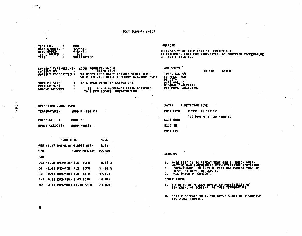
TEST SUMRRV SMET
TEST HO. e 889 D ~ T L STRRTED I 4/24/81 DATE ENDED I 4/84/81 TOTAL MOWS I 8.6 TYPE 8 SULFlDAfION
SULCIDnTION Of ZINC FERRITE EXTRUSIONS TO DLTERRINE f X l T HES COWOSITION AT SORPTION TEAeERATW OF 1589 F (816 C).
SORBEW TVPE~UElCW11 (ZINC FERRIlC)/643 0 R & ~ v s t s 1 SORBEIK NO. I BAT CH 82/3 SORE~WT COIIPOSITIONI 5 9 ~ O L E S IRON OXIDE (FISHER CERTI~IED) TOTAL SULFUR,
5 9 HOLE% ZINC OXIDE (SHERUIW UILLIANS HMV SURFlrCE RRERt DENSITY I
SORBEH~ SIZE 1 3/16 INCH DIMETER EXTRUSIONS PCRE -VOLURE r PRETRELTMENT I HfllERAL AHALYS I S t SULFUR LOADIWQ I 1.56 8 t c ~ SULFUR/~N ~ R E S H SORBEMT) ELEMtiTAL RNRLVSISt.
TO t PPM BEFORE BREfUCtlQOUCH .
BEFORE C V X R
DATdbI 4 DETECTOR TUBEI
EXIT ~ 2 s 8 e pen tnlrrnttv 708 PPR AFTER 39 nlmnes
EXIT 5021
EXIT 521 .
EXIT HZ:
PLOU RATE ROLE
MeS tee47 DIl3/MINl e.9963 SCFM 2.78
HE0 3.178 C(13/RIN 27.6631
AIR
coa ct.7e oromln~ 3.6 SWH 9.65 4
W (e.03 Dl t l /n I I t ) 4.3 SCFH 12-91 1
HZ (8.97DN3/crIH)6.3 SCFH . 17.12%
CHI (@.st D ~ ~ U I H ' ) 1.07 SCFM ' 2.918
) c ~ (1.88 omalm) 1e.m SCFH 33.934
1. MIS ?EST I S TO REPEnt E S T 828 I N W I C H WER- HLATINC W S EXPERIENCED UITH EXCESSIVE SIWTERINO.
2. BRERKTMROUCM I N THIS I U TE9T M S FASTEB THM I H TESt 828 ALSO AT 1589 F.
3 tlEU BATCH OC SORBEM.
1. RRPtD ERERC?'WOUCH IND1U)tfS POSSIDILIW O f SINTERlNC 0C SORBENT hT THIS TEW€RATURf.
2. IS00 F APPERRS TO BE T M WPER L t A I T OF OQERAT1W FOR ZINC FERRITE.

TEST S U N W SHEET
TEST NO. 1 030 DATE S'IMTED 1 4&4/81 DATE ENDED I 4/24/81
SORBEMT SORBENT SORUENT
PURPOSE
REGENERfiTIW OF ZINC FERRITE EXTRUSIONS FRW VEST @i?Q USING SPACE V E L O C I N OF 680.
TVPWUEfWlTI (Z INC FERRITE )I643 C ANALYSIS1 NO. I BRTCH 8203 BEFORE WTER ' CO~POSIT~ON~ se ROLEU man OXIDE ~ F ~ S H E R CERTIFIED) TOTAL SULrUR1
SB ROLE% ZINC OXIDE (SHERUIN UILLlAflS HSR) SURFACE APE&:
SORBEUt S I Z E 8 3/16 INCH DI 'METER EXTRUSIONS PRETliEAVflEM 1 S U L N R RENOMD J
OPERATING COnDITlONS
T ~ R A T U R E I m e F (538 C )
PRESSURE I AMB I E M
SPME VELOCITY1 600 HOWLV
FLW RATE MOLE
H2S
H20 2.23 CN3/ t l lN Sea
orwsrr j - I PORE UOLUt i f l RINERAL AtWLVSIS l LLEnCNTftL L W L Y S I S I
DATA1 ( DOECT OR TUBE )
E X I T H2S8
E X I T SO21 4.0-S.0 8
EXIT S21
EX IT HZ8
I . THIS E S T IS TO REGENERAVE WE LRST SULFIDAT I O n AT isec F FOR ANOTHER BIISELINE TEST at 1000 F TO DETERfllHE I F A PERRANUNT LOSS OF ACTIVITV OCCURRED.
2. RFTER COFIPLETION O f THIS RECENERftTXONr 6DSORBER TEWERFTURE UAS MINTA lNED AND SULFIDIITION REFS6TED
1. THIS RCCENERATION U S SHORTOR DUE TO TH€ SHORT SULCIDATION DURlHC TEST B29.
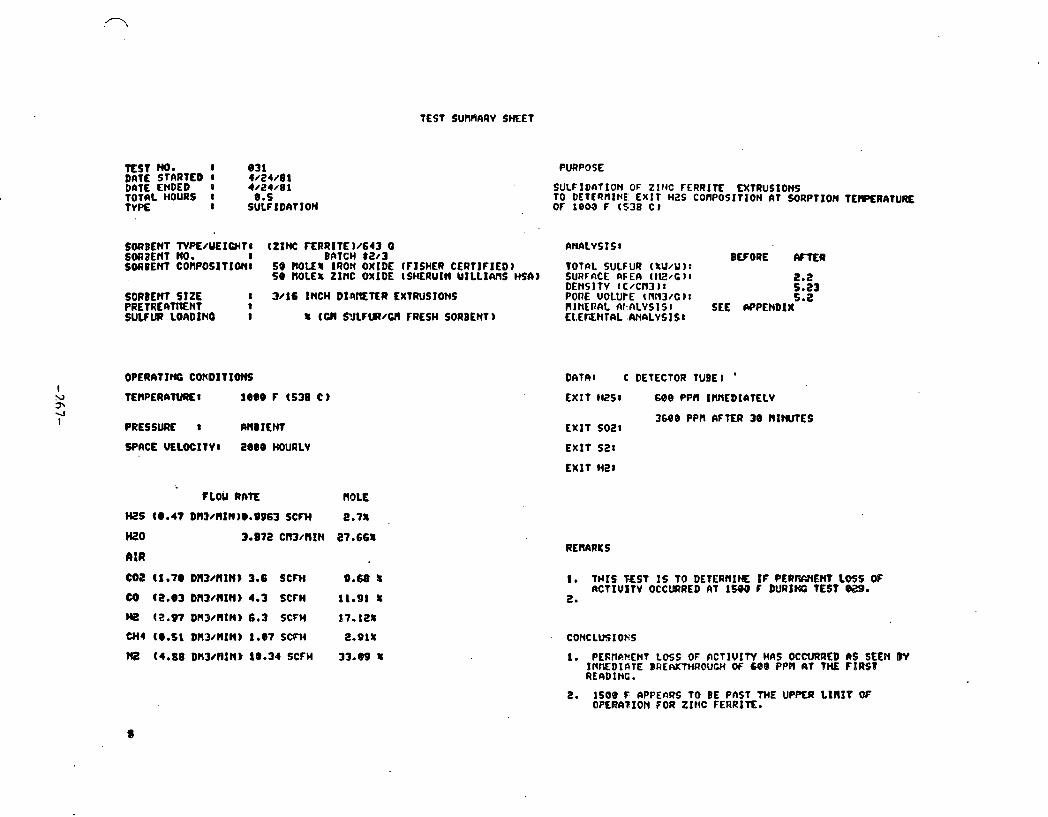
TEST SURHARV S M E T
TEST m* 8 8 3 1 DATE STARTED 8 4/24 /81 ~ n t E ENDED 0 4/24/81 - . . . - -. - - - . - . - - t o r n ~ HOURS I 8.5 TYPE I SULF IDf tTION
PURPOSE
SORBENT NPE/UEICMT I (ZINC ~ R R I T E ) /643 o ana~vs IS I S W ~ E N T NO. 1 BATCH l Z t 3 BLFORE SORBEM COMPOSX~IQ~I sa mu8 IRON OXIDE (FISHER CERTIFIED) t o t n ~ SULFUR (%u/u 1:
59 BOLES ZINC OXIDE ~SHERUIW UILLIMS MA) SURFACE IIFEII I ~ I C ) I t . 2 DEMSITV (C/CN3) t 5.23
SORBEM S I Z E 8 3/16 INCH DIRIETER EXTRUSIONS POnE VOLUtE 4 NN3/C) t 5.B P i Z r t i i ~ f t m ~ ~ t I n l r i ~ n a ~ ~ F ~ L Y S I S I
I SEE WPENDIX---
SULFUR LOADINO 8 (CW S V L f t R / W FRESH SORBENT) ELEriENTAL ANALVSISt
PRESSURE I M 8 I E N t
SPACE VELOCITVI 2888 HOURLV
r LOU R R ~
W S (0.47 Dll3/11IH)@.S963 SCFH
WO 3.872 C M / t l I H
I)IR
COS (I.?@ Dll3/HIM& 3.6 SCFH
CO (2.b3 D l l 3 f l I M ) 4.3 SCFH
Mi? ( 2 . 9 1 Dfl3/HlN) 6.3 SCFM
C H I (0.St Dtl'3/RIN) 1.97 SCFM
WZ (4.m DH3/AlM) 10.34 SCFH
DfiTRt t DETECTOR TUBE 1 ' EXIT ~ t a s r me PPM IH~ED~ATELV
31x9 PPn IIFKER 3 8 RIMES E X I T SO21
E X I T s2:
E X I T H21
RENARKS
I . THIS VEST I S TO DETERNIM If PERRF;HhNT LOSS OF IICTIVSTV OCCWRED AT 1588 f DURING TEST 929.
2.
1. PEfinfiFENT LOSS OF f I C T l V I N HRS OCCURRED AS SEEN W INrlEDtRTE BREMTWOUW OF W@ PPN 811 THE FIRST RERDIHG.
8. 1508 F APPEnRS TO BE PnST TME UPPER L I A I T US OPEWAtION FOR ZIt4C FERRITE.

EST 016
SPACE VELOClN = 2000 HOURLY
2 3 Time (hours)

ZINC FERRITE REGENERATION TEN 017

r 900
900
800
roo
a0
530
N O
380
ZINC FERRITE SULFIDATION
TEMP = 800 F (427 C) PRESS = AMBIENT S.V. = 2000 HOURLY
0 1 2 3
lime (hours)

AltlnOH 0032 = 'A'S 1N318WV = SS3Ud .
(3 6~9) OOZL = dW31
PZO JS2L
OOE - P

PEST 024
TEMP = 1200 F (649 PRESS = AMBIENT S.V. = 2000 HOURLY
2 3 Time (hours)
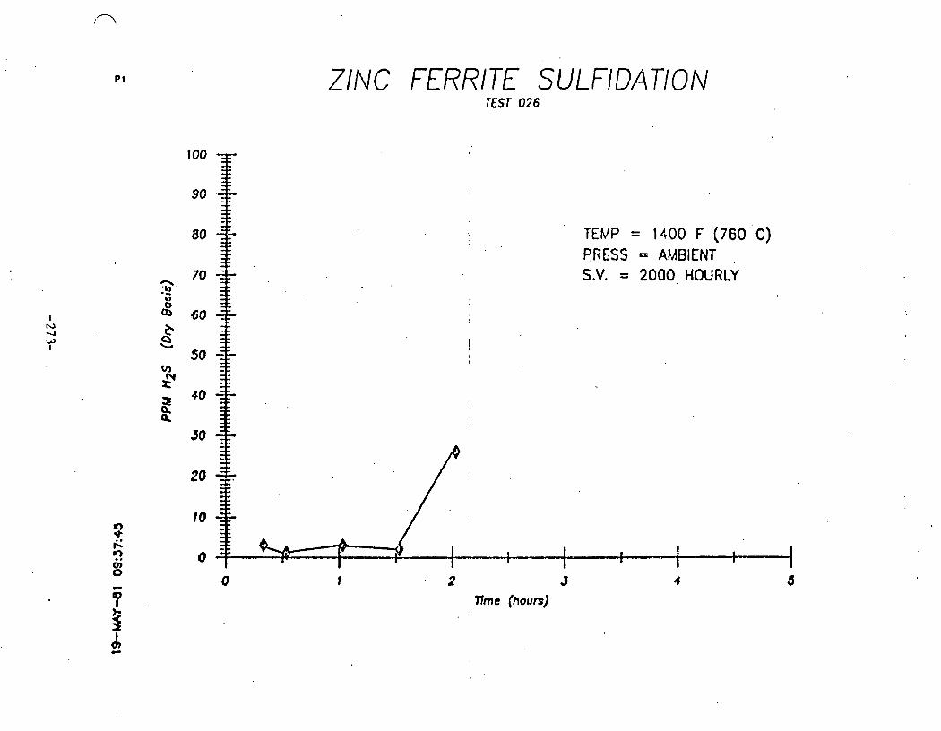
AltlflOH '0002. = 'A'S lN3lEY1V = SS3Ud
(3.09~) A 00PI = dW31 .
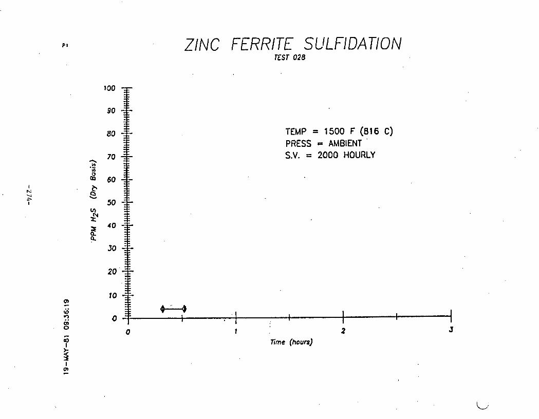
ZINC FERRITE SULFIDATION EST 028
TEMP = 1500 F (816 C) PRESS = AMBIENT '
S.V. = 2000 HOURLY
1 2 Time (hours)
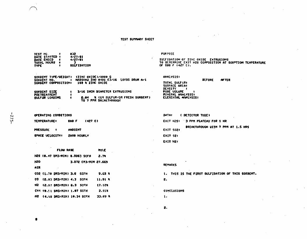
TCST S U M SHEET
TEST N o . t 8 3 2 DATE STfiRTED 1 4/27 /81 DATE ENDED B 4/27 /81 TOTAL W R S 0 3 W E D SUUtDl lT IOte
PURPOSE
S U U I D n T l O n OF ZINC OXIDE KXTRUSIOI(S TO DETERRI~IE EXIT bras c o n p o s r r r o n a t so~prxon TEWERATURE W 000 F (4+7 C ) .
SORDCM TVP~/UEICHTI czxnc oxrwwaeee c C Y ~ L V S I s : SORBCIIT NO. : WRSH~U zm, e a r E W I ~ ~ o r o s DRUM a/n BEFORE WTER SOUBENT CWPOSITIONI 100 1 ZIHC OMlDE T O ~ L SULFUR:
SUAFRCE A R C I I I DEtlSlTV I
SOUBENT S I Z E a 3/16 INCH D IMETER EKTRUSIONS PORE VOLUI1I: 8 PRETREATnEHT : nl NERAL (YkLVSIS: SULFUR LOllDINQ o 6 . 4 t ( G I SULFuR/Cfl FRESH SOUBENT) ELEnENtAL U M L V S I S I
TO 7 PPR 8 R E A K T H R W I
I tw OPLRITXNC COHD~T~ONS M T A t ( ;DC~ECTOR TUIE) V ~n TEMPERATURE: 8@8 F ( 4 2 7 C ) E X I T H2S: 3 PPH PUITEhU FOR 8 HR
BREAKTHRWW UITH 7 Pen (If 1.5 HRS PRESSURE 8 A R B I E M EXIT ~ 0 2 1
SPACE M L O C I W 8 EOBI HOWLV EXKT ~ 2 1
FlW R A E R O E ,
HZS t e e 4 7 D m / I l I N J a.9963 SCFH Z e n
wo A I R
CO2 t l . 7B DN3/lrXN) 3.6 SCFH P.63 f
co (z.83 ~m /n rn ) r , 3 ~ C F H 11.91 a Ha (2.97 OM3/RINl 6.3 SCFH 17.121
C H ~ 19.5 I ~ n 3 / n x n ) 1.07 SCFH 2.91%
,Me (4.118 DMWRXfl I l e . 34 SCFH 33-89 1
1. THIS I S TME FIRST SUVIDAt Im O f T H I S SORBEM.
2.

TEST S W R V SHEET
TEST NO. t 033 DIITE STARTED : 1 / 3 8 / 8 1 DATE ENDED 8 4/30 /81 TOTAL HOURS 8 6 TWPE . 1 RECUERATION
PURPOSE
RECENERRTIOW OF ZINC OXIDE tmus Iom FRW TEST e3a USING SPnCE UELOCITV OF 689.
SORBENT TYPE/YEICHII (Z INC OXIDE)/LOBO B W ~ L W I s 8 SORGENT NO. 8 HRRSWIU ZNO 0 4 0 1 E3/16 LOT 95 M W l W l DEFOQIE AFTER SORBENT CONPQSITIO~: lee r ZIHC OXIDE TOTAL SULFUR:
SURFACE nim: DENSITY n
SORIENT S I Z E 8 3/16 INCH D I ~ ~ EXlRUSlOHS . PRETREATIEMT 1 SULFUR MWUED : t rcn SULFUR/CR FRESH SORBENT)
OPERATING CONDITIOM DATA1 (DE:ECTOR TUBE)
TfWERATURE I l 0 e O f (538 C ) E X I T Has:
PRESSURE 8 RNBIENT EXIT SO28 3.5-18.8 4
~ P ~ C E . VELOCITY: 680 HOURLY E X I T si!: E X I T Ht?:
1. TElrrrPArURE W REACHED 1548 F (838 C).
2. RFTER CO~PLETIO~ OF THIS JECENERATIOII. IIBSORBER TEPIPERArURE UrrS HA lNTA IMD AND SULFIDATIOH UEPEl)tED
c o n c ~ w I ons . .
1. THIS I S THE FIRST RECEMRATION OW TWIS BI)TCM OF SORBENT.

TEST SURRARV SHEET
TEST NO* 8 034 D M € STnRTED I 5 / 0 1 / 8 1 D6TE ENDED 1 5 / 9 1 / 8 1 TOTAL n o u a s I 4 TYPE I SULF f ~ l l T ION
PURPOSE
SULFIDnTlON OF ZINC OXIDE EXTRUSIOHS TO DCTERPllN'I CXtT ti25 COnWSlTlON AT SORPTION TEAPERATWE OF ( 8 B @ F (538 C).
SORBENl. ;YPErUICHTt ( Z I l i C OXIDE ) / t e e 9 G AlCaLVS I S 8 SORBEM 90. I W S H I I M ZNO O4QI E W 1 6 LOT95 DRUn n/ l BEFORE 6fW SORLEHT ~ONPOSITIONI 1 9 9 % ZINC OXIDE TOTClL SULFUR1
S W F O C E AREnl DENSITY I
SORBEHT S I Z E : 3/16 INCH DIn lRTER EXTKUSXONS . P O ~ E U O L U ~ E 1 PRETREnTnENT . 8 RIhTRhL WSrrLYStSt SULFUR CORDINC 8 8.8 1 (C.q SULFUR/WI FRESH SORBEM) ELEtIENTnL AtUILYSISl
TO 3 PPR SRECUI1HAOW;)I
FPW RhTE ROLE
HES (8.47 DnJ/AIW)0.9963 SCFH 2.7%
H20 3.872 CR3/n IN 27.66%
A I R
C02 (l.70 DR3/llIN) 3.6 X F H O.b8 t
CO t2.e3 D r n r n I n ) 4.3 SCFH . 11.01 8
HZ ( 2 . ~ ~ 7 ~m/nlti) 6.3 SCFH 17.12%
CHI (8.51 D I U ~ f l I N l 1.07 SCFH 2.918
W ( 4 . 8 8 B R W l l I N ) 19-34 SCFH 3 3 - 8 9 %
D n T A ~ t DETECTOR TUBE) .
E X I T M2St 8-3 PPn PLATEW FOR 2 HRS
1. THIS I S T I E SECOND S W I D A T I O l ( W THIS 8ATCH W SORBENT.
t.
COHCLUSIONS
I . )rzs c a P C . c l w a t ~ e e @ F IS BETTER WAN AT w F.

TEST SCsrWIlRV SHEET
TEST NO. I 835 DATE STARTED t 5 r 0 1 / 8 1 PATE EtlDED 8 5 / 8 4 / 8 1 TOTAL HOURS 1 7.5 TYPE I RECCNERAT I O N
PURPOSE
RECENERhTION OF ZltcC OXIDE EKTRUSIONS FROR TEST 034
SORBMT TVPE/UEICHTl (Z INC O X I D E ) ~ l 0 @ @ C WALYSIS8 SORBEN1 NO. 8 HARSHAU MO 0 4 8 1 - f W 1 6 LOT 95 DUW A / l SOREENT COWOSI~IO~~I 1 0 0 II ZIM OXIDE TOTAL SULFUR1
SORBENT S f= I 3/16 INCH nrnrtrsca EXTRUSIONS PRETflEflYW ... SULFUR REWED I II t cn suwu.?/cr, rfi
M I . MINERAL MALYSISI lESH SORB€ NT j ELEMENTAL W k L V S I S t
BEFORE AFTER
I IU w OPERATING QOWDITJONS i DATn: (DETECTOR TUBE 1 03 I m w E R A y u u E : 1000 r ( 5 3 0 C ) I E x 1 1 "xi
PRESSURE 1 CUIIIENT ' EX17 SO28 3.7-14.1 8
SPACE U E L O C f N l 608 HOURLV E X I T si?:
. EX IT HZ8
FLOU RATE OLE 1 i
K!O 2.23 CR3/111M 50%
A I R (2.78 D n 3 / l l l N l 5.18 SCFH 5 0 8
C 02 1. T H I S I S ME SECOND RECLtCE4910N CS ?:4Y:5 LRTCH OF SOEPENl.
co : a. RFTER C O W L E T I W OF THIS RECENEAATIO((, ABSORBER
HZ YENPERATLIRE UlrS MINTAIMED (U1D SUlF lD l \T lOt l REPEATED
C H I CONCLUS IONS

TEST NO- 8 036 DATE STARTED 8 , S /05/81 Dn lT ENDED I 5/05/81 TOTAL HOURS 8 3 Tb'fJE I SULFIDIITION
SULFIDClTION OF ZINC OXIDE EMTRUSIOMS TO DETLRnIHE EXIT Hi?S COPIPOSITIOH IIT SORPTIW TfMPERANRE OF 1280 F ( 6 4 9 C).
SORBEM TVPEAEICMTI (ZINC OXIDE)/beee C W L V S I S I 80R8ENf NO. I WIRSHAU N O 9491 €3016 LOT95 DRUn 1)/1 BEfORE WTER SORBOST CORPaSI~IOND 189 8 ZIHC OXIDE TOTAL SULFllR8
StJPFnCE ARE@: DENS1 TY I
SORBENT SIZE 1 3/16 INCH DIMETEA EXTRUSIONS ' CPOllE VOLUME 1 PREfRE1)TnEN? I RI l3RAL ANELVSXSU SULFUR LORDINS t 8.e t t M SULFUR/O) FRESH SORBEM) LLEIIENTAL IIYIILVSISI
TO 11 PPlO BREMTWOUO)
OPERMlNO COHDITIOMS
TEWERAlURt t t2OB F 1643 C)
PRESSUIE 8 anB1EMT
SPACE UELOCItYI a 0 0 HOURLV
W S (ma47 DMl / l IM) e.9963 SCFH 2-78
HZ0 3,.878 CIl3/RIH 27.661
n1R
C02 (1 -79 Dm/RIN) 3.6 SCFH 9.688
co (2.93 m/rrtn) 4.3 SCFH 11.~1 8
w (2.97 ~rn/nln, 6.3 SCFW 17.aza
m 4 (@.St M W M t H 1 1.07 SCFH 2 . ~ 1 %
Ha (4.88 D M m I N I 19.34 SCFH 33.898
MTA: ( DETECTOR TUIE)
EXIT H251 6-15 PPN PUltEAU FOR 2 HRS
BREAKTHROUCM YITH 184 PPN AT 8.5 HRS E X I T SO88
EXIT S28
EXIT H a l
1. THIS I S tM THIRD SUVtDATlObl OF THIS BfiTCH OF SORBENT.
2.
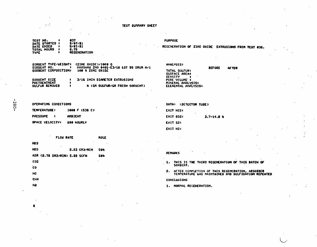
TEST SUMARV SHEET
TEST NO. I e 3 7 DATE STARTED r 5 / 8 1 / 8 1 DATE ENDED 5 / 8 7 / 8 1 TOThL HOURS 1 6.75 TVPE I REGENERATION
PURPOSE
RECCHERATION OF ZINC O X I K EXTRUSIWS FROR TEST e36.
SORBENT tVPE/UEICHTI t Z 1 N O X l D E ) / l W B U RNALVS I S 1 SORBENT NO- 1 H~RWU ZNO 8 4 e 1 - ~ 3 / 1 6 LOT DS DRUN 641 SORDENT COMPOSIT'IONI 100 t ZINC OXIDE TOTAL SULFURI
SURFACE A R E I l
SORBENT SIZE 8 3/16 INCH D I M T E R EXTRUSIONS PRETREAmENT I SULFUR REMOWED 8 U iM SULFUI/CII FRESH SORBENT)
BEFORE f f -R
DATnl (DETECTOR TUBE)
EXIT H a s t
EXIT s o a r 3.7-14.8 u
E X I T HZ1
FLOU RATE ROLE
Has'
mo 2.23 cw~,nrn, se: AJR (2.78 on3/c r rn ) 5.88 SCFH set coa CQ
HZ
CM4
Ha
1. T H I S I S TYIE THIRD RECEWRATIOH OC THIS BATCH O f SORBENT.
2. 63FTER COflPLETlON OF WlS AECEMRATION, RBSORDER TCWPERATUAE UCIS I IAIMl) I l (ED RND SULFIDATIQII REPEATED
CONCLUSIONS

TEST SUMARY SIiEET
TEST NO. I 8 3 8 DnTE STaRTEO I 6 / 0 8 / 0 1 M T E ENDED 8 51'08/81 TOTAL HOURS 1 1 .S W E I SL! lF IDATIOH
SORBEW T V M / U E I C H T I ( Z I N C OXID€) /1008 C SOReENT NO. I HnRQlAU UIO 8 4 8 1 € 3 1 1 6 LOT95 DRVn A t 1 - SOUDOIT C O ~ W S l l ' I O H ~ 1 9 8 S Z I I C OXIDE
SORBLNT S I Z E I 3 / 1 6 I N C H DIAMEDER EXTRUSIONS PRETREATRENT 1 SULFW LOADIHC I 2.0 x t cn S ~ J L F U R ~ FRESH SORB EN^)
TO 2 PPf l BREf4KTHROUCH
I 13 03
OPERATINO C O N D I n O N S
PRESSURE 1 R ~ B ~ E M
SPRCL WLOCSTVI eeeo w w
FLOU R ~ T E OLE
HtS(O.37DR3/ I I IH)O.S363SCFH 2.7%
t@O 3.172 C l l 3 / U I I l 27.66%
R I R
W2 (1.79 M13/111H) 3.6 SCFH 9.69 8
C@ (2.83 m 3 / R I H ) 4.3 SCFH 11.91 8
te (2.97 D113/111H) 6.3 SCFH 17.18~
CHI (0.51 D M ~ J M I ~ ) 1 .*7 SCFH 2.91%
ra t r .se~n~~nxsc) i e , 3 r s c ~ u 33.09%
SULFIDATIOM OF ZINC OXIDE EXTRVSlOHS TO DETERIIINF. E < I T 1425 COtlPOSITION AT S O R P T I W T E n m N R E OF 1409 F (768 C I
n N n L v s I s I BEFORE AFTER
TOTAL S ' J U U R I SURFnCE W E A I DENSITV I PORE V o L u r E I HI t tERhL fUtf+LYZ!S: ELEflEl4TAL W i A L V S l S 1
C X l T HZ51 2 - 3 PPU P l I I T E n U FOR 3 8 R I M E S IREAKTMROUCH U I T H 27 PPN AT I HR
EXIT .so21
C X I t S L I
E X I T HtI
1. T H I S I S 1'ME FOURM S W 1 D I ) T I O N OF T H I S BATCH W SORBUiT
a.
CONCLUS IO)K
1. H Z 5 C W A C I r V AT 1488 F I S LObRR tHIU( AT l a @ @ r.

TEST' Mo. I 039 M T E ' STARTED 1 6 / 1 5 / 8 1 DATE ENDED I 5 / 1 5 / 8 1 TOTAL HOURS 1
I 19
TVPE. RECEIERAT I O N
PURPOSE
RECEHERhTION OF Z I N C OXIDE tXTRUSIOHS FROM TEST 030,
SORBEW TYPE/UEIU(Tl ( Z I N C O X I D E ) / i @ W G ANALVSIS 1 SCU?BENT NO. I H A R S W ZNO 048L' - f3 /16 LOT 9 5 DRUN AN1 BEFORE W T E R SORJENT C O t l P O S I t ~ O N l ~ l ee rr Z I N C OXIDE ~ O ~ A L SULFUR:
S U R F M E AREh:
SDRBENT S I Z E 1 3/16 INCH D f A l l E t b R EXTRUSlOnS PRETREA'TFSNI 1 SULFUR RLROUED 8 8 CWI S U L F l R / M FRESH W B E N T )
ms tK0 2-23 C1)3/AIN 508
AIR (2.78 D N W M I N ) 5.88 SCFH 56)t
COZ
CO
tl2
CH4
HE
DENS IT^ - I PORE VOLUnE I IlIHERCIL n t W L V S l S r E L E M N T R L R N A L V S I S I
I e TNIS I S tHL FOURTH R E W E R A T I O N OF THIS U I T C H OF SORBEHT.
2. REGENERATION ABORTED. a.
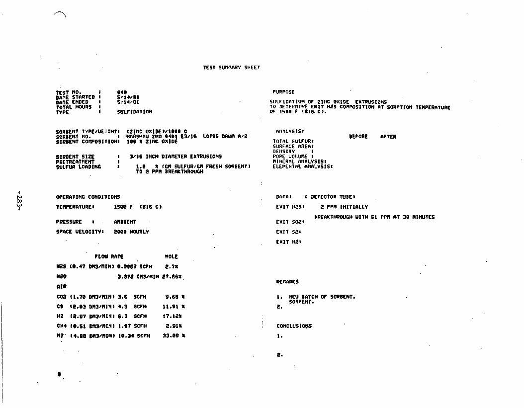
TEST SUPINWV SHEET
TEST NO. e 8 4 8 DATE STARTED 1 5@14 /89 oat E ENDED I 5..14/a1 TOTAL HOURS I 'WPE C S W I D A T I O N
PURPOSE
S O W IDS\TIOH OF Z l I K OXIDE EXTRVSIOHS T O DETEI(llItff W I T WE COHPOSlTlON RT SORPl lOn TEHPtRIITURE OF 1509 F ( 8 1 6 C).
SOREE~IT TYPE/UEJCH~I IZIMC oxtw)/ieeo o A ~ Q L V S IS t SORBENT NO. 1 MnRSHAU ZIIO 8 4 0 1 €3116 LOT95 D A M W i ? BEFORE W t E R SORB€NT COWOSIBIONI 1 e 0 % ZINC OXIDE T O ~ L SYLFURI
SURFACE M E a t o i t t s ~ i i - I
SORBENT S l t E 8 3/86 INCH DIARETER LXtffUSIONS POPE U 0 I . W t PREfREfiTrlEN'T I MI MERQL AI ihLVSISI SULFUR LOADING a 1.8 L ccn IULFURI~ FRESH S ~ B E H T ) EUHLNTAL WLVSISI
TO i? PPR BRE#THROUUI
FCOU RdltE ROLE
M2S (@.I7 Dm/RIN) 8.9963 SCFH 2.78
MO 3.872 cn~ / r r~n 17.66%.
AIR
coa (1.70 m/nrn) 3.6 SCFM 9.68 t
C@ ( 8 . 8 3 D I l 3 ~ R l N ) 4 . 3 SCFH 1 1 . 9 1 %
H a (a.97 0113/nX!t3 6.3 SCFH 17.12 t
C H I (8.5 8 DtlWII1.Y) 1.@7 SCFH 2.91%
HE' (4.08 Wll/nX?4?l) 18.34 SCFH 33.09 3
DREAYtHROUGM U ITH 6 1 PPl l 61 3 0 N I W T C S E X I T 5 0 2 :
EXIT s a t
E X I T H E :
1. NEU BATCH OF SORENT. SORPENT..
L.

T E 9 t NO.' 8 @4 1 DATE STARtED 1 5/20'81 D n t E ENDED I 5 / 2 8 / 8 1 T O T ~ L HOURS 8 HRS TYPE t RECENERATION
SOUEENT NPE/UEXOH~~ (ZIIK: o x I D E ) / i o e e CM soReEu t no. 1 HMSMU ZNO e 4 0 1 - ~ 3 4 6 SORPEHT C W O S I T t O N l 198 % ZINC OXIDE
S O R B E ~ PELLET SIZE8 3/16 INCH DICVIETER EXTRUSIONS PRETREATllENT I WLFUP LOADlD(0 I % ( CII SULFUR/CII F k E W SORBEHT )
AT M S T M T OF RECWRATIOH.
PRESSURE 8 WBIENT
SPRCE' WELOCITY1 608 HOURLV
FLOY RATE nou8 - .
HES . \
HZO , 2.23 cd/nrn se t R I R So88 SCfM 58%
coa co be CHI
be
PURPOSE
RECENERATION Of ZINC OXI# PELLETS fROH TEST 918
rucnLv51SI BEFORE MTUI
TOtfaL SULFUR8 SURFnCE 6REAl DENSITY t POROSITV I X-RAY D I F F R M l l O ) ( l
DRTAI (DETECWR TUBE)
E X I T 64251
E X I T 5 0 2 1 WEROXIMTELY 8
E X I T 5 2 1
E X I T Hz:
I . TMIS IS tl-€ F I F T H REGEMRATION Q( TMIS BATCH Of SoaBENt.
2.
CONCLUSIONS
I .
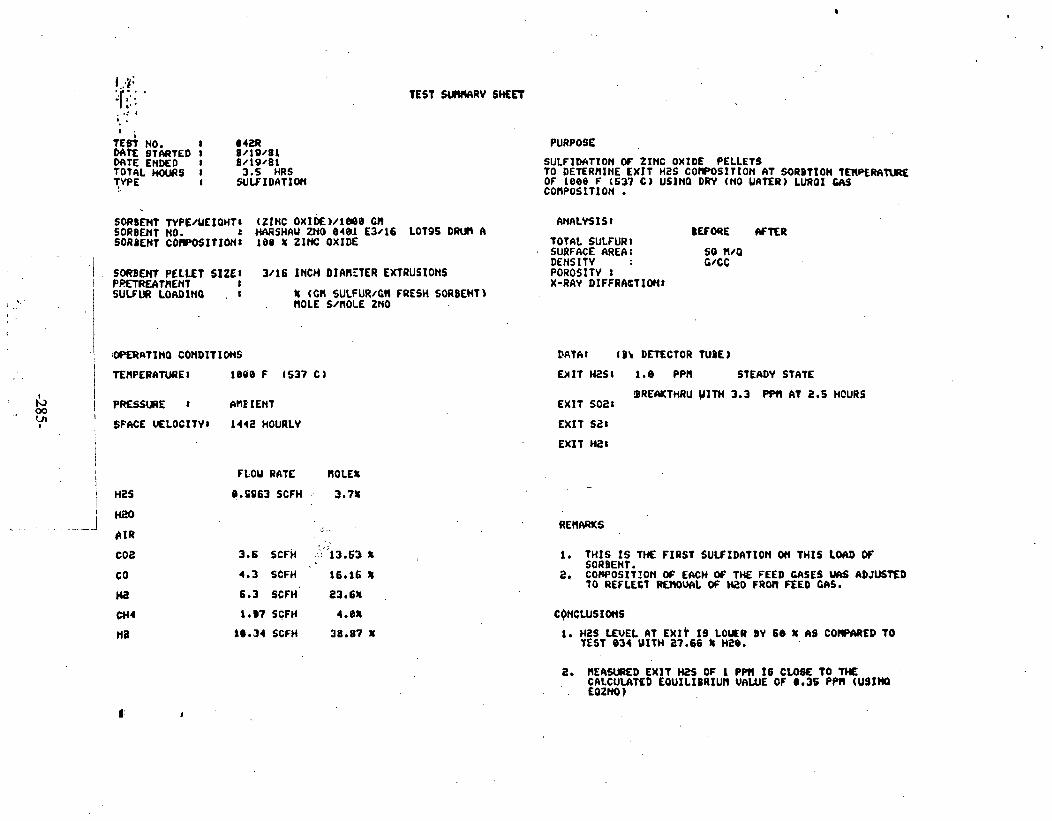
I .,4:
3' .. : . . , .: I
? I .
tE& NO. 8 042R STARTED I 8/19 /81
M T E ENDED I 8 /19 /81 T O ~ ~ L HOURS I 3.5 HRS ? W E I W l F I D A l I O n
TEST SUIlVIRV SMET
PURPOSE
SULFIDir t ION ff ZINC OXIDE PELLETS TO DETERMINE E X I T H2S COtPOSITION AT SORDTION TRIPERAtURE. OF 1088 F (637 C) USlNQ D m (NO UATER) LURQI GAS COflPOSITlON
SORB€HT TVPENEIOWTI (Z INC OXI0€)/1BQ@ CR SORBENT NO. r WIRSHAU p10 0 4 8 1 E3 /16 LOT95 DRUl A SORBENT COCPOSftIONt 100 % ZINC O X I w
PI?ETREATllENT I / SULFUR LORDIM0 , r . .. .
% (Cl l SULFUR/CH FRESH SORBENTI . BOLE S/nOLE ZNO
FLOU RATE ROLE8
O.EO63 SCFH 3.7%
4.3 SCFH 16.16 X
6.3 SCFH 23.68
1 eB7 SCFH 4.0L
1ee.34 SCFH 38.87 %
ANALYS I S 1
TOTAL SULFUR1 SURFACE AREA: DEMS I T V POROSITV I X-RAY DIFFRk6TIOHt
DATA1 (B\ DETECTOR TUBE)
E H I T H a S I 1.8 PPH STEADY STATE
BRErWtTHRU U ITH 3.3 PPf! I IT 1 . 5 HOURS EX1 T 5 0 2 1
EXIT sat EX1 1 H2 1
1. THIS I S 1% FIRST SULFIDATION OII THIS LOO OF SORBENT .
a, c o ~ o s r t r o n oc EMH OF THE FEED CCISES ~ 1 5 ADJUSTED TO REFLECT RfHOUIIL O f Hi?O FROn FEED WIS.
1. HZS LEUEL E X I ~ 19 LOUER 8V 60 t AS C O W E D TO TEST 8 3 4 UITH 37.66 % H20.
2. BE4WRED E X I T HZS OF 1 PPN 18 C W TO THE CIILCULATED E4UIL IBRIUN UAWE OF 0.36 PPII (USIHQ
. . EQZNO)

ZINC OXIDE SULFIDATION
@ - DRY FEED GAS (T042R)
2 J Time (hours)

ZINC OXIDE SULFlDATlON
TEMP = 1000 F (538 C) PRESS AMBIENT .
S.\!. = 2000 HOURLY
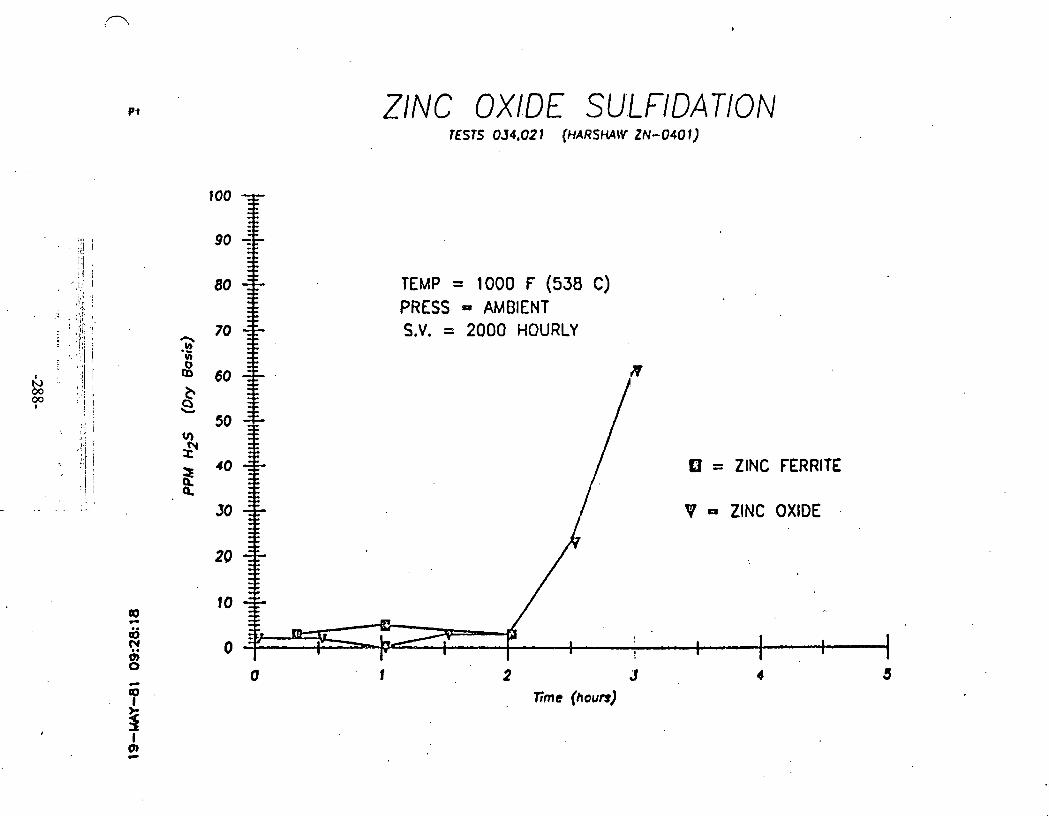
AldnOH 0001 = 'A'S lN318NV = SS3Ud
(3 BIG) A 0001 = dW31

roo0
000
BOO
PO0
600
500
400
300
200
100
0
TEMP '*= 1200 F (649 C) PRESS = AMBIENT L.V. = 2000 HOURLY
2 : 3 lime (hours)

TEST S U W Y M E E T
TEST KO. : 0 4 3 DATE STARTED : 9 / 2 1 / 8 1 DATE EKCiO : 9 / 2 1 / 6 1
SORBEYT TYPi/WLIGHT: (Z INC FERRITE)/643 CH SORBENT KO. : N I X t 1 BATCH i 3 SOXBENT COUPOSITIOH: 5 0 HOLE 1RO3 OXIDE (FISHER CERTIFIED)
50 noLC : ZINC OXIDE (SHERUIN YILLIP~VS)
SORSENT PELLET SIZE: 3 / 1 6 uicn OIAVETER EXTRUSIONS PRET l iATrENT SULFUR LOAD1t;G : 12.53 % (M S S ' L F U I I M FRESH SORBEET)
. .
OPERATIKG COSDITIOHS
TEHPEUTUXE: I 0 0 0 F (537 C)
PRESSURE : M l E N T
S P K E V i L O C I V : 1 4 4 2 HOURLY
UI:FIO:TIOI; OF ZIKC FERRITE P E i L E r s 1 0 D i l t c . ~ I b E E X I T HZS COM?tS l T 1 0 H AT SGRBTIOA TEP?;RA~JRE OF 1 0 9 0 f (537 C) USING DRY (KO YhTERl W R G l GAS LaW5SlTLC!I ,
ANALYSIS: BEFORE . AFTER
TOThL SULFUR: SUEACE ASU; SO 8/G m s ~ n : ' vcc p o a o s ~ n : 1-RAY D I F F L U T I O I :
DATA: ( 8 1 DETECTOR N 9 E )
E X I T HZS: 0.7 PPH STEADY STATE
@liU(TttRU K I T H 2 PP3 AT 2.5 U I T 532:
E X I T SZ: . . . .
E X I T HZ:
FLO'I RATE HOLE%
0.9963 SCFH . 3.7:
3.6 SCFH . 13.53 s
4.3 SCFH 16.16 %
6.3 KFH n.n 1.07 SCFH 4 .CZ
10.30 scfn s.87 %
TOTAL DRY GAS F L W RATE 26.6 SCFH
1. T H I S I S TSE F I R S T WLF lDAT lQW OH W 1 S LUD C F SajEbT. '
2. 5 STPJXES USED OH DETECTOR TUBE SLVPLE PU*.
2. FC~RITE REDUCES W E H2S LEVEL Wh71 TO Mi S?% LEVEL CJ Z I S C OXIDE AT T I E Sku! CONDllIO!fS.
3. Zltic F L K l l T E REDUCfS THE ti25 LEVEL CLOSE TO THE

TEST SUMARY SWEET
: 0 4 4 TEST KO. DATE STARTEO : 8 / 1 4 / 1 1 ,
DATE E!;DCD : 8 / 1 6 / 8 1 701% KVJRS : 3 HRS. TYPE . : W L F l O A T l U N
PURPOSE
SOROEHT TYPE/YEIGHT: (Z1t;C FERRITE Vh : lAOIU~1 /619 G n ~ L Y S I S ; 5078EI;T t;3. • . BEFORE AFTER SORSEIT COY?OSITION: 4 9 HOLE % IRON OXIDE (FISHER CERTIFIED) TOTAL SSLI'EZ:
49 HOLE t ZI t IC O I I O E (SHERWItl UILLIA '4S) SURr'AiE ;AC,A: SO R I G 1.36 ElOLE % ZNYZO; (METC) OEHSlT I : GlCC
SORBEtiT PELLET SIZE: 3 / 1 6 lNCH O I k Y i T E R EXTRUSlONS P070SITY : P7ETREAT:?Ft;T X-,RAY OIF iRACT IC4: SULFUR LOADING : r ~ c n su~~ua/cu FRESH SOIBENT)
)rOL.S S/EOIE PO
OPERATltiG CONDITIONS
TCEPEIUTURE: 1000 F I537 C)
SPACE VELOCITY: ZOO0 HOURLY
DATA: ( 6 7 Oi iCCTOR TUS:)
EXIT n2s: 1.2 TO 7.0 p p n n u o y s r n E F o x 1.5 HRS
e lEhKThRU Y l T H 11.6 P?3 AT 2 HOURS E X I T 532: .
E X I T 9:
U I T n2:
M S
H 2 b
A I R
CO2
to
H2
014
I 2
FLOU RATE HOLE%
XFH C C I M I N .
1.0 SCFH 3.7%
3.88
3.6 SCFH
4.4 sun 6.3 XFH
1.1 SCFH
12.2 SCFU
1. T H I S I S TKk F I R S T SULFIOATION ON THIS WAD OF U a 3 i R T .
- COECLUS!C!iS .
1. PO OfTECTA3LE EFFECT Cf YAYAOIUH 1H TNE Y)R9EhT

TEST SU.Y.%RY SHEET
TEST kO. : 0 4 5 DATE s l ~ a T E 9 : 8/21 /81 DATE Et13ED : 8/25 /81 TOTK n a u . ~ : 10 HRS TYPE : REGENERATION
SORBTHT TIPE/YEIGHT: (ZII:~ OXIDE)/IOCO cn M 2 D i N T KO. : HXRSHAY ZNO O:OI ~ 3 1 1 6 LOT 9 5 own ~ / 1 S37RHT CO.Y.?OSlTION: 10 t ZIEC OXIOE
SORBEfiT PELLET SIZE: 3/16 It lCH OIAYETER EXTRUSlOIiS PRET<iATUILT SULFUR R%5Y E3 : % (CN S'JLFUaILq FRESH SOXSENT)
O r c r a T l n e O l b l T I O Y 5
TEFPERATURE: 1000 F ( 5 3 8 C)
PRESSURE : LWBlEHT
P A C E VELMITY: 600 HOURLY
HZS
K20
A I R
COZ
CO
H2
' i n 4
HZ
-.
FLOU RATE ROLES
PURPOSE
RCGEEIR&T10!8 OF Z l t C OXIDE PELLETS FRO3 TCST OCZ U S l t i i SPACE V E L K ~ T T OF 600.
BEFORE k 7 E R ANALYSIS:
TOT& SULFUR: SURiACE MEA: DLKS1TY : PoaE YOLUYE : l!lt:EICL I.%&LYSIS: tLEHiNTAL IHALY 51s:
DATA: (DETECT02 TUBE)
2. N T E R CO??LETIOH OF THIS RECERER\T~OM, A9SORSiR 1WEPATU;IE U S PAIWTAl!iiO NO SULFIDATIUM EPEATEI,
CO~CLUSIP!4S
1. THIS I S I H E F I R S T RECENERATICI OH THIS B A T U OF soaaEar.
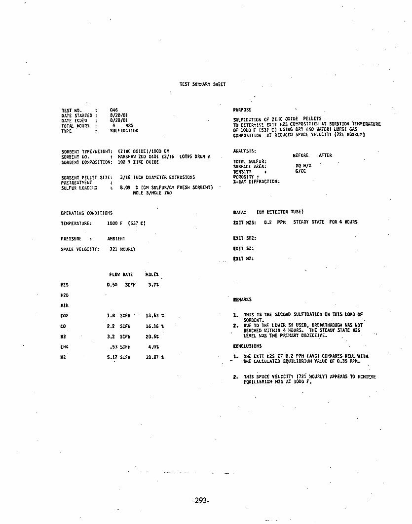
TEST SU?.vARY SHEET
TEST KO. : 046 DATE STARTED : 8/28/81 DATE EcJEO : 8/28/81 TOTK ~ ~ ' J Z S : 4 HRS TYPE : SULF IOATIOtI
PURPOSE <
SORBEN TYPE/YtlGHT: (Z l t iC OX1oE~/100D G?l W L Y S I S : SORBEtiT KO. : HARSHAY 2I:O 0401 E3/16 LOT95 DRU3 A . BEFORE &TER SORSENT CC?!?OSITION: 100 4 ZIEC OXIDE TOTAL SULFUX:
SURFACE MEA: SQ H/G '
DENSITY : C/CC SORBENT PELLET SIZE: 3 /16 INCH DlAYETER EXTRUSIO!IS POROSITY :
X-RAY DIFFMCTIOH: PRiTRtATXiHT SULFUR LOADIIIG : 8.09 % (GH SULFUR/I;'I FRESH SORBENT) '
HOLE S/).IOLE ZNO
0PEUTIt:G COh'OITIOtIS
TEMPEMTURE: 1000 F (53! C)
PRESSURE : AHBlENT
SPACE V E L U ITY: 721 HDlJRLY
H2S
HZ0
A I R
t o 2
to
H 2 ,
LHC
9 2
DATA: (BY CETECTOR TUBE)
EXIT HZS: 0.2 P P n STUDY STATE. FOR 4 HOURS
EXIT f02:
EXIT 52:
. . U l T HZ:
FLOURATE OLE%
0.50 SCFH 3.7%
1.8 SCFH ' 13.53 'L
2.2 SCFH 16-16 'L
3.2 SCFH 23.6%
-53 s l ; F ~ 4 .U:
5.17 SCFH 38.87 2
1. M I S I S THE SECOND SULFIDATlON OH THIS WAD OF SOREErlT.
2. DUE TO TP. LWAER SV USED. BREPXTHROUGH WAS NOT REACHED L ' ITHIH 4 HJURS. 7HE STEADY STATE H Z
;
LEYEL YSS TIE P R I P ! OWECTIYE.
CONCLUSIONS
1. THE E X I T I 2 S OF 0.2 PPH (AVG) COWARES WELL WITH . - THE ULCULATED LCUILIBRIUH YlrLUE OF 0.35 P?H,

TEST KO. : 0 5 7 DATE STARTE1 : 91 1 / 0 1 DATE EtiDEO : 9 1 1/81 TOTAL t'..1aS : 4 HRS TYPE : SULFlOATlOS
PURPOSE
W L F I O A T I O N CF Z f S C FERRITE PELLETS '
YO PZEPARi FCX LLGI!XRAT!CS AT 75% A I R U;J 29 t S T E M FOR E S O X C O ~ A T L 3 1 L I T I
S0Re:tn TTPE/uElGHT: [ZIt;C FERRITE)/6C3 GN . U Y S I S : S040E1iT KO. : M I X I 1 BATCH 8 2 eEFORE AFYER SORBEKT COXPOSITION: SO MOLL: IROV 0 x 1 0 ~ (FISHER CERTIFIED) TOTK suttua t=l;r):
50 t:OLt= Z1!1C OXlOC [SHIRUl!4 YILLIAYS HSA) S U R F R E k ? E I ( M k l : DEt lSITY I C I C C I :
SORBEWT PELLET SIZE: 3 / 1 6 IKCH O I M T T E R .EXTRUSIONS POPI VOL% (&>/GI: PRETREATfl i t lT M IKERIL R;ALY S!f: SULFUZ LOLOIKG : 12.53 t [CJl SULFUR/G!i FRESH SORBEHT) E L E X E t i T L K A L Y S l S:
(FOR 2 tiOU2S Oi RUl;NIt;C)
PRESSUK : hP31EI;T
SPACE VELOCITY: 2003 HOURLY
HZS
H Z 0
A I R
F L W RATE WOLEZ
0.9963 S C M 2.71 .
3.172 C C I E I H 27.66% '
3.6 ' SCFH 9;68 t
4.3 SCFH 11.91 t
6.3 XFH . 17.121
1.07 SCFH 2.91%
10.34 XFH D.09 t
DATA: ( OETECTOP TUBE)
E x r r ms: a 5 ppn FOR 2.5 HOURS
55 PPW AFTER 3 HOUa E X I T Y l2 :
E X f T SZ:
EXIT HZ:
,. . 1. T H I S TEST I S TO P R E P U E F 0 2 E C E n E R \ T l O n AT 75: AIR . 25% S T i X 4 F C 3 RRiSOX C O ! 9 A T I B l L I T Y LYALUATIOY.
COWCLUS I C N S
1. SIAI~LPI) 'SJLFIDAT~BH CO~LLTLD.
TOTAL DRY tM F L V 1 RATE 26.6 S O H

, TEST KO. : 0 0 8 DATE STAaTED : 9/ 2 / 6 1 DATE ENXO : 9 1 2 /11 TOTAL HOURS : 5 HRS TYPE : RLGENERATION
PURPOSE
PECEt;ErUTIO!; OF 21hC FERRITE PELLETS FROn TEST 0 4 7 US115 75 : AIR X!;O 25 STCAY.
SORBENT TYPE/UEItHT: (ZINC ~ E R R I T E ) / ~ ~ ~ 01 UIALYSIS: SORSENT KO. : MIX # 1 BATCH CZ SORBEIT CaxPosITIoN: 50 MOLES 1 ~ 0 t 1 oxroc (FISIIER CERTIFIED) TOTAL SULFUR:
5 0 ROLE: ZINC OXIDE (SHERWIN YILL IAYS tlSA) SURFACE M A :
SORGEtiT PELLET SIZE: 3/16 INCH OIAYETER EXTRUSIONS PIETfiEAT?!Et4I SULFUZ RiXUVEO :
TMPERATURE: 1000 F
PRESSURE : A'43IENT ,
SPACE VELOCITY: 600 HOURLY
BZS
HZ0 . . AIR
coz EO
H 2
CH4
I 2
DEtISlTI : PORE VOLUYI: HI~IERAL RIALYSIS: ELLMLtITAL k!ULY S l s:
DATA: (DETECTOR N B E )
BEFORE H T E R
L X I T S02: ' 9.4 % (AVGI
EXIT HZ:
FLO2 RATE HOLE%
1.11 C C M l N 251:
8.81 SCFH 75%
1. THIS lESr I S TO PlGEtiERkTE USlKG 15 % AIR 25: STLAY TO 1CST C O 9 A T I B I L I T 1 Y I l H RESOX PROCESS
f . fLrPEPANRE YA'IE hT 1t;LET REACHED 1820 F. SltlTERISG D W C E D 5 3 Y i CF TIHE PELLETS AS 03SERVED V l S U A U I .
1. 75 t AIR O U R I S REtEtIERATION AT SY - 600 HOU3LY . CAUSES 100 HIGH A TEPSERAIURE WAVE.
2. LOYER AIR LEVELS SHOULD BE USED.

TEST S U W Y SHEET
TEST LO. : 0 4 9 DATE STARTiO : 9 / 1 1 / 0 1 DATE ENDED : 9 / 1 1 / 8 1 T O T K HO'JRS : 1 HR TYPE : SULF IDATlO!l
SORBERT TYPE/uEIGHT: (21t:C FERRITE)/6:3 c)4 SORBENT SO. : H I X t 1 BATCH i 2 SDaBERT CC>:?OSITIOH: 5 0 K O L E I IRON OXIDE (FISHER C E R T I ~ IED)
53 MULE% Z l S C OXIDE (SHERUIH U I C L I W S HSA)
SORSENT PELLET SIZE: 3 / 1 6 IKCH DILYLTER EXTRUSIOIlS PRETREAT?!EYT SULFUR L0:31t;C : 3.13 t (W SULFUR/(;Y FRESll S01BEtrT)
PRESSUE : A Y l E S T
SPACE YELCCITY: 2 0 0 0 KO'JRLY
HZS
H Z 0
AIR
CO2
.a HZ
. a i 4
HZ
FLOY RATE HOLE%
PURPOSE
SULFIOAT!6!l OF Z l s C FERRITE PELLETS TO Ct!ECK FOR AqY LOSS OF A C T l Y I l T :.=TCR RiGfKERAT10:l U l T H 75: A 1 4 At;O 25 : STLkY FO2 RESOX LO.VPATIBILITY
TOTAL SL'LFUX (:V/U): SURFACE ;RE& (KZ/G): DENSITY (G/CC) : PORE VOLLV i (W/G): MINERAL :.UALY S lS : ELEMENTAL A G L Y S I S :
BEFORE r n E R
DATA: ( DETiCTCR WOE1
LXLT HZS: 6 PP!4 Fa.? 112 HOUR STEAOI STATE'
1150 P P n AFTER 1 HOUR E X I T 532:
E X I T 52:
E X I T H2:
3.6 SCFH 9.68 t
4.3 KFH 11.91 t
6,3 K F H 17.132
1.07 SCFH 2.91%
10.34 K F H 33.09,s
1. RAPID K=EA<TEKOIJGH OSSERYED u I T n HIGH INITIAL H Z S CGSCEnIR\TISH (6PPti).
2.
CONCLUSIOSS
1. LOSS CF ACT1YITY OSSERVEO 1 5 DUE 10 RTGCKEUTIOH - Y I T n 75 t A I R I N TEST o 4 8 CAUSED BY ,SInTERIt& AT EXCCSSIVE TLuJEUTURiS.

TEST KO. : 0 5 0 DATE srnRTE0 : 9/22 /81 DATE L K ~ E O : 9 / 2 3 / 8 1
TEST SUIYARY SHEET
PURPOSE
ILECENERATlOM C; ZIKE FERRITE PELLETS PROW TEST OC3
SORSENT TIPE/UEICHT: (21% FERRITE)/603 GI4 A M L I S I S : SORBEN1 110. : n l % # l BATCH$J/ BfFORE U T C R SOXBE!iT COXPOS ITIOII: 50 ROLES IRON UX lOE (FISHER CERTIFIED) TOTAL SULFUI:
50 r a t s ZIKC OXIDE (SHEWIN YILLIWS HSA) SURFACE CJIEA: DENSITY :
SOIS0:T PELLET SIZE: 3/16 INCH DIMETER EXTRUSIONS PRiTREATEEHT SULFUR RCnOVfO :
PRESSURE : AHSIENT
SPACE VELOCITI: 600 HOURLY
FLOX PATE HOLES
MS
H20 2.23 CC/HIH 50%
A I R 5.88 SCFH 50%
(02
CQ
DATA; [DETECTOR TUBE)
E X I T HZS:
E X l T S O 2 : 10.4 -16%
E X I T U:
E X I T HZ:

TEST KO. : 0 5 1 OITE STIRTEO : 9/30 /11 DATE E~;DED : 9 / 3 0 / 1 l T O T 2 WO;1.?S : 4.0 I R S TYPE : ULFIOATION
SORBLI~T fYPt /Y t lG I IT : fZ1kC tERPITE)/643 &ti ,
s o ~ a t r ; ~ ~ 3 . : MIX r l BATCH P s S3RBEHT CC.Y.?OSITION: 5 0 MOLE % 1ROX OXIDE ( f lSHER CERTIFIEO)
53 HOLE t Zl t iC OXIDE [SHiRVfN Y I L L I k 4 S )
SORBENT PELLET SIZE: 3/16 l X D I DI;3ETER EXTRUS10:lS PRETREATXE!iT SULFUR LOAD1I;C : 7.87 t (GY S'JLfUR/GV FRESH SORaENT)
ROLE S/XOLE ZKO
TWEPATURE: 9 0 0 F ( 4 8 2 C)
PRESSUU : M l CNi
SPhCE VELCEITY: 7 2 1 HOURLY
.HZ0
A I R
co2
. CO
n 2
0 1 4
u2
F L W RATE W O L t t
0 . 5 C O s c m 3.7%
1.8 X F H 13.53 t
2-15 SCFH 16.16 S
3.15 SCFH 23.6:
0.535 SCFH 4.0:
5.17 5CFH 38.87 'L
TOTAL DRY GAS FLO'I RATE m 1 t 3 son
SULFIOZi1ON OF Z l L C FERRITE PELLETS TO OiTEF.'.lSE E X I T WZS COX?OSITIO!I AT SORBTlOr; TESJEPA~~PE OF 9 0 0 F (C82 0 USICG OR1 (?;O WATER) L U R t l GAS CO!QOSITIC% AT RRLCUCEO SPACE VELOCITY OF 7 2 1 HR-1.
AULYSIS: CEFOWE K T E Z
TOTAL SULFUR: SURCAti AXI: SO n/c DEfrSlTI : t/ct POROSITY : X-PA1 OIFF?.ACTIC%:
6 E A K n l R U KITH 53 PPH AT 3.5 WURS EXIT sz:
1. T h I S I S THE SEtONb SULFIOATION 01 THIS LOAD GF soa3FliT.
I*
1. WS LEVEL LPPADKHES ZWD t Q U I L t B R I U 3 LEVEL OF 0.1 PPn,
2. W S L E V R I S LOYER MU) E S T AT 1000 F . MYEVER BXiiKTHDUGJl 1S 2 HOURS SGOXER.
3. KlsET1CS @PEAR SLQUER THA.. AT 1UWF. N T H O U W . L Q U I L 1 8 a l M FRV0.U LOVER US.

TEST SUMARY SHEET
TEST NO. : 0 1 2 DATE STARTEO : 10/01/81 OATE Lt;DEO, : 10/01 /81 TOTALHJURS : 9.15 HRS TYPE : RECtlERATlON
PUaPOSE
RtCEtiERiT1O.Y C i 21f.C FERRlTE PELLETS FRO3 TEST (ISL
SORBEKT TYPE/YEICIT: (Z IEC FERRITE )/6C3 LY . AGLYSIS: SORBEHT KO. : nlx r l BATCH uu SORBENT COX?OSlTIO.Y: 5 0 ROLE: IRO!i OXlOE (FISHER CERTIFlEO) T O T N SULFUR:
SORBEHT PELLET SIZE: 3 / 1 6 lNEH OIAYETER EXTRUSlOIlS PRL1REATr:inT SULFUR RLYJVEO :
OPERATINS CO!~DITIOHS
TWERATURE: 1000 F
PRESSURE : Ct la lENl
SPACE VELOCITY: ba0 HOURLY
OENSITY : . PORE VOLUS: WfsERAL UiALYSlS: ILEk!ENTAL ANALYSIS:
DATA: (DLTECTOJ N E E ]
U I T HZS:
EXIT 532: 10.8-14.4 %
EXIT W:
BEFORE AFTER
E X I T nf:
F LOv RATE . HOLE:
2.23 cc/nIn at 5.88 SCFH 50%
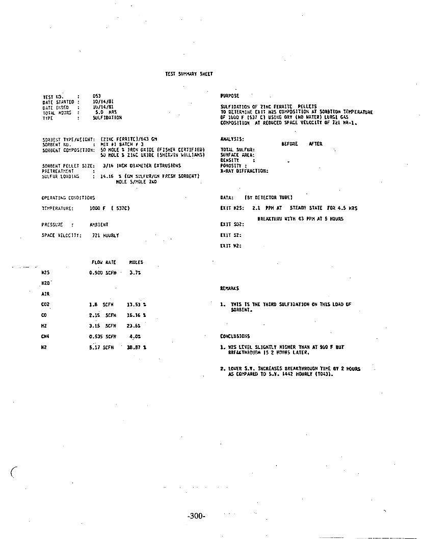
TEST SU?.*ARY SHEET
TEST 1 3 . : 053 DATE ST:RTED : 10/14/81 OAT; Ct?lEO : l D / l C / B l TOTX H7;'RS : 5.0 HRS TlPE : WLFlOXTlON
S3i(3E!;T TY?E/UEIGHT: (ZII IC FERRITE 1/66) G!i YJRBfNT LO. : MIX b 1 BATCH t 3 SORBEtiI CO!:POSITIO%: 50 ?lOlE t IRCK OX IOE If lS1ES C i I T I F l E D )
5;) IX)LE t ZIt iC OXIDE ( S t i i K i l X k ILL IAHS)
SORBEKT PELLET SIZE: 3/16 I N W DIkYETER EXTRUSlCtiS PP.ETREAT?:C,tiT SULFUZ LOAOII;; : 14.16 % (G! SOLFCR/M FRESH SORBENT)
HOLE SIZOLE z&o
PRESSUE : P3 1 EUT
SPACE YELCCITY: 721 HUURLY
- , .: HZS
, HZO-
A IR
cot
co
HZ
M4
N 2
PURPOSE '
SUlFIO&TlO!r OF ZINC FERRITE PELLETS TO OiTtk'il trF. EX I T HZ$ CO!'..DSITION AT SORBTION T ~ ~ E R X T U R E OF 1 0 W F (537 C) USII;G DRY OtO YXTERI LURGI G I J CO.!i?OS1T10!4 AT REOUCEO SPACE VELQClTY O f 1k1 ha-1.
W L Y S I S : BEFOX AFTER
TOTAL SULFUB: SU.VUE =€A: OEUSITY : POROSITI : X-RAY OIFFRACTIOII:
DATA: (BY OETECTOR N B E )
EXIT HZS: 2.1 PPH AT STEADY STATE F O ~ 4.5 nas
BREAKTllRU U I T H 4 3 PP,Y AT 5 HOURS EXIT 532:
fXkT $2:
EXIT HZ:
FLOY RATE ROLL:
O.5CO SCFH . 3.7:
1.8 SCFH 13.53 t
2.15 SCFH 16.16%
3.15 SCFH 23.6:
0.535 SCFH 4,O:
5;17 X F H . 38.87 t
1. THIS I S W E THIRD SULFIDATION ON THIS LOAD GF SORBENT.
2. LOLTR S.V. INCREASES BREAKTHROUGH TIPE BY 2 WRS M taumm TO S.Y. 1442 HOURLY (~043) .

Pc ZINC FERRITE SULFlDATlON EST 051,053
6 - 900 F (482 C) TO51
= 11000 F (537 C) ~ 0 5 3 PRESS = AMBIENT S.V. = 721 H~URLY H2S = 3.7 PERCENT
. H20 = 0 PERCENT

ZINC FERRITE SL~LFIDATION
4 = S.V. 1442 HOURLY ' ~ 0 4 3
El = S.V. 721 HOURLY TO53 Press = AMBIENT Temp = 1000 F H2S = 3.7 PERCENT
2. 3 Erne (hours)

ZINC FERRITE SULFIDATION TESTS AM;(I G.2 1.47).043,05 1,053
= 27 PERCENT STEAM, 1000 F SV=2000 (AvG OF TESTS 16.21.47)
4 - D R I FEED GAS,. 900 F, SV-720 , (T051,)
V = DRY FEED GAS,1000 F,SV=720, (f053)
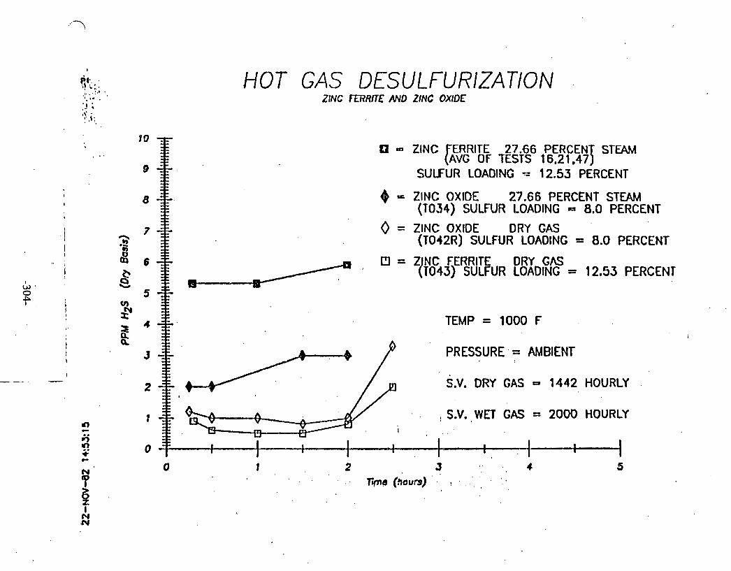
HOT GAS DESULFURIZATION ZINC FERRITE AND ZINC OXIDE
El = ZlNC ERRITE 27.66 PERCEN STEAM [AVG OF TESTS 16.21.47 T
SULFUR LOADING = 12.53 PERCENT
= ZlNC OXIDE 27.66 PERCENT STEAM (1034) SULFUR LOADING = 8.0 PERCENT
0 = ZINC OXIDE DRY GAS (T012R) SULFUR LOADING = 8.0 PERCENT
CT] = Z NC FERRITE DRY GAS 11043) SULFUR LOADING = 12.53 PERCENT
a
TEMP = 1000 F
PRESSURE, = AMBIENT
S.V. DRY GAS - 1442 HOURLY ,
. S.V. WET GAS = 2000 HOURLY !
I
I I I I I I I
I I
1 I i----i

SUL FlDATION
V - ZlNC FERRITE
P) - ZlNC OXIDE
(TO 43)
(TO42 R)
Temp = 1000 F
S.V. = 1442 Hourly
H20 = 0 PERCENT
., H2S a 3.7 PERCENT
2 3 . .
4 7irne (hours)
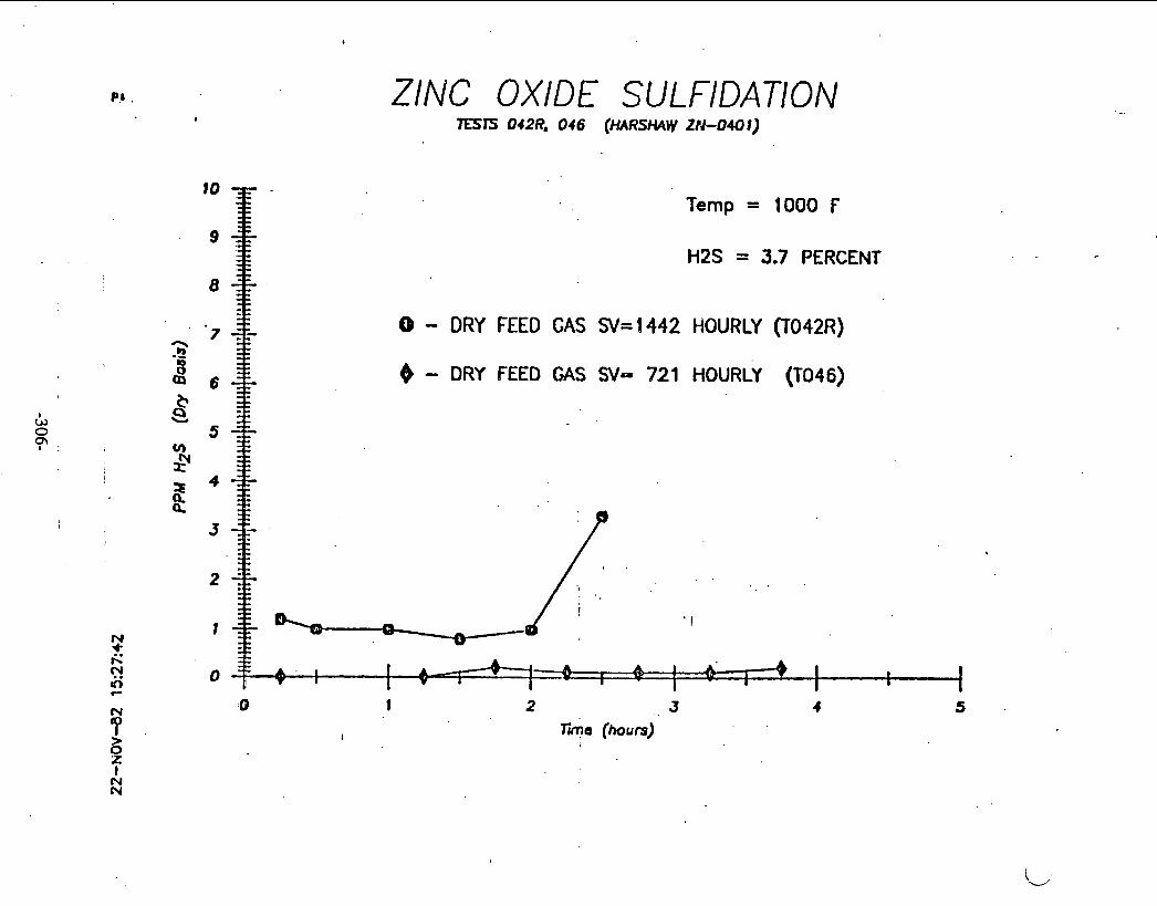
ZINC OXIDE SULFIDATION
Temp = 1000 F
H2S = 3.7 PERCENT
0 - DRY FEED GAS S k i 4 4 2 HOURLY (l042R)
@ - DRY FEED GAS SV- 721 HOURLY (T046)

ZINC OXIDE SULFIDATION m T S 042R, 046 , 034 ( M M W W-0401)
V = 27 PERCENT STEAM IN FEED GAS SV=2000 (TO3
Q = DRY FEED GAS %=I442 (TO42R)
4 - DRY FEED GAS SV- 721. (T046)
Temp = 1000 F
. . . .
. . . .
. . ' , . I . . .
! ,
I I I I
I I I

SULFUR LOADING ZINC FEURITE AND I N OXIDE
W E R A N R E (C)
300 350 400 450 500 550' 600 650 700 .750 800 850 900 950 too0
20 I I I I I I I I I I I I I I I I . -
- kP = ZINC FERRITE FEED H2S 2.7 PERCENT
PPM

TEST SUkY&RY SHEET
TEST KO. : 0 5 4 DATE STXRTEO : 10 /161&1 o i T E Et;CCO : l O / l 6 / 8 1 TOTAL HCURS : 3.25 HRS 'I1PC : SULF IOATlON
SORBE1:T PELLET SIZE: 3 / 1 6 IRCH O I L Y i T E R EXTRUSlOtlS Pi?ETREXT?:Et;T : PLOUCL VI,t;AOIU3 CATALYST F0.9 1 FOUR SULFUR LO1DIt:G : 4.0 t (LX SULFU21GY FP.ESH SORBLNT)
KOLE S/r.CIC 1ti0
PRESSUE : W 3 1 E t l l
SPACE VELOCITY: lOCO HOURLY
F L W RATE UOLL:
HZS 0.500 S C F ~ ~ 2.7:
H Z 0 1.93 CC/t?IN 27.66 t
AIR
W Z 1.8 SCFN 9.79 t
CO 2.15 SCFH 11.69 %
3.15 SCFH 17.13: 0.535 SCFH 2.91%
PURPOSE
BEFORE AFTER
TOTAL SVLFUR: SURFACE AREA: D E I i S I T I : POROSITY : X-RAY DIFFRACTION:
DATA: (BY DETECTOR TUBE)
U I T HZS: I00 PPH FOR 2 H N STEADY STATE
BRECXTHRU Y I T H 126 PPR A T 1.75 H U E X 1 1 S02:
E X I T HZ:
1. V ' L F THE REhCTOR I S F I L L E D Y I T H DiO AVD HALF Y1TH - . VAIUOIUX CATALYST. '2. REOUCTIC!4 K I L L . BE CARRIE0 OUT CY THE CASES AND
FLU:$ SPECIFIED AT L i F T YITHOUT US. 3. F I R S T SULFIDATIOH
COICLus IO I IS
1. YAUAO1U.Y CATALYST DOES tin REDUCE H t S BELOY 10 PPII. TOTAL CRY GAS FLOV RATE 13.3 SCFH TbTA; YET CM FLOV R A l E 18.31 SCFH

TEST KO. : 0 5 5 DATE STARTED : 10/16 /81 DATE E!:I)LD : 1011118L 101% H'J'L7S : 3.5 HRS lYPE : WLFlOXT lON
SORBEST TTPEPJEICHT: Z lKC O X l O E I S W G'i
SRBENT KO. : IURSHAV Z::0 0 4 0 1 E3116 LOT95 D I U n A
SORBENT CO.Y.POS1TIOS:
SORBENT PELLET S12E: 3/16 1fIU DIL.YiTER CXTRUSIONS PRiTREATYEIiT SULFUZ LOAOI!;G : 6.07 % 1C.Y SULFUSIGY FRESY $ORBENT)
HkC S/l:CLE ZkO
PRESSUE : AP31ENT
S P K E IELCC!TY: 2003 EOURLY
M S
HZ0
AIR
a2
CO
H2
a 4
W2
FLVd RATE
0.504 SCFH
1.93 CC/HIII
1.8 SCFH ,
2;15 SCFH
3.15 SCFH
0.535 SCFH
5.17 SCFH
PURPOSE
0ETERYII;E TkE CA?;.3ILITY OF W L F A ZI t lC OXIJE eEC TO L W X R 1 h L I!ZS LEVEL B:LOY 1 0 P?%
TOTAL SULFUR: SURFlCC AqEA: OENSlT l : PORCSllY : X-RAY OIFF%CTIUY:
A T (BY OETECTOR TUBE)
E X I T HZS: 7 PPH FO1 1.5 HRS STL49Y STATE
ERiAKTHRU K I T H 1 3 PP.Y AT 1.75 HRS E X I T 502:
E X I T St:
U l T HZ:
1. I U L F THE P Z X T O R I S F ILLED Y l T H ZHO
2. rnls TEST IS TO VERIFY fE E X I T L E v a OF nzs USING I G l F A B t O CC ZNO.
CONCLUSIONS
1. Zt;0 LQ:EIS 625 BELO2 1 0 P 3 3 FOa 1.5 I!% AT 1203F . TITTX GRT GAS FLOY RATE 13.3 X F H 10TK S I T GAS FLOU RATE 18.33 SCFN

TEST tiO. : 0 5 6 DATE STh7TEO : 1 6 / 2 1 / 8 1 DATE EI:SLO : 1 6 / 2 3 / 8 1 TOTUH~':R$ : 4.75 HRS T I P E : RECLI;ERATIO!I
SOZDCNT TYPE/d i lGHT: 2 .Xi O X I o E / ~ O O C!4 Vr*;AOIUt! ChTALYST/J74 tZ(
SORBEHT KO. r IURSHAV 2C3 Ca01 E3116 LOT95 OZU..I A HARSHh2 YYAI~AOIUX ChTkLY ST Y - 0 7 0 1
SORBEtIT COWOSITION:
SORBEMT PELLFT SIZE: 3 / 1 6 1f;CM OIL%TER EXTIUS1O)lS PRiTCCATXENT : U I l E S'JLFUP. RU.OVE0 :
OPERATIKG CCLDITIO!iS
TEWERATURE: 1 0 0 0 F
PEESS'JRE : AYBIENT
SPACE YELC;ITY: 600 HOURLY
HZ S
HZ0
A I R
C 0 2
CO
n t
CM4
N 2
PURPOSE
BEFORE 1SltR
DATA: (OTfECT32 TUBE)
E X I T HZS:
E X I T 502: 9.2 - 14.2 S
ULf SZ:
E X I T r.2:
5.88 SCFH 50%
I. FIRST REGEF;~&TION OF YXI IA9IUt t CATXLYST.

TEST SU).?CUY SHEET
TEST KO. : 057 DATE STARTED : 10/26/01 DATE 1tioE0 : 1 0 1 2 6 l b l TOTAL HOURS : 3.5 HRs TYPE : W L F I U A T I O N
SORBENT TYPC~~EIQIT: ZIIIC OXIOE/SOO t a VANAOlUU CATALY S t /C74 69
SOIBENT KO. : IURSIIAU ZNO 0 4 0 1 E3 /16 LOT95 0 2 9 3 A HARSHAM VA'IAOIU3 CATALYST Y-0701
SOIBENT COY!OSIT1ON:
SORBEUT PELLET SIZE: 3 / 1 6 INUl OIhVETER IXTRUSIOSS PRETREATMENT : REDUCE VMAO1U.Y CATALYST FOR 1 HOUR SULFUR LOXDIKC : 5.19 t (Gt l SULFURIGY FRESH SO7aENTI
( ROSS S/r.O&C ZFQ
P R E S S U I : AP3IUIT
SPACL VELOCITY: 1 6 0 0 HOURLY-' . .'
PURPOSE.
OETER31hT THE CAPA8 IL ITY OF A VMAL1U.Y ChTALYST TO L0;'E.P T k i H2S LEVEL BELOW 10 PPN G T E Z A Z INC OXlOL €3.
BEFORE AFTER
TOTAL SULFUI: SURFACE AREA: DENSITT : POF!oSln : X-RAY OIFF?JCTION:
OATA: (BY CETtCTOR N B E l
E X I T I Z S : 1 1 - 2 3 PPU FOR 2.5 HRS STiC3Y STATE
BREXKTHRU U l T H 33 P?X AT 3 E7S E X I T SOZ:
E X I T SZ:
FLOY RATE HOLE:
HZ s 0.500 scm 2.7:
HZ0 1.93 CC/UIN 21-66 t
A I R
CO2 1.8 SCFH 9.79 t
CO 2.15 SCFH . 11.69 t
C H I 0.535 SCFH 2.9.lt - Y2 5.17 S C M 20.12 t
TOTAL 0x1 GAS n o 2 RATE 13.3 X F H TOTAL YET GhS FlOW RATE - 18.33 StFI)
1. W L F TEE PLACTOR 15 F l L L E O U l T H 2110 h\O KALF YLTH V h S O LUX CATALYST.
2. REC':CTIOR MILL BE CARRIED om cs THE GASES xsa FLO'iS S?ECIFIEO AT-LEFT UITHOUT HZS.
3. BOTH 2Sb AS5 'VhHAOlUN HAVE BIEW RLGEWEUTCD. ,
4. YCCWD S1LF IDATIOH-
1. YX%lDlL!i CATALYST [V -0701 ) OOfS Y;OT FZOIICE HZS 6ECG;I 10 P P 3 .

TEST SUKUARY SHEET
TEST 110. : 0 5 8 DATE STARTED : 1 0 / 3 0 / 8 1 DATE ENDED : l O / j 0 / 8 1 TOTAL HOURS : 6 HRS
'TYPE : RECEIIERATIOII
SORBENT TYPE/UElGHT: ZI I IC GXIOE/SOO C?l VM;ADIUU CATALYST/575 Grl
SORBENT KO. : KRSHAM ZND W O l E3/16 LOT95 DRUM A HARSHAM Y A M D I U X CATALYST V-0701
SORBENT CO~70SIT1011:
SORSENT PELLET SIZE: 3 / 1 6 ItICH DIhYETCR EXTRUSIONS PRETREkT2!illT : KOHE SULFUR RLYOYED : .
O P E f i T I t i C COtiDITIOHS
TFHPERATURE: 1 0 0 3 F
PRESSURE : hYBIENT
SPACE YELOCITY: 6 0 0 HOURLY
FLW RATE kOLEO
A I R 5.88 'SCFH 50%
C02
PURPOOI
REGTt i i iAT IGN CF 2 1SC OXIDE A'iD VFJlADIUH CATALYST PELLETS FE!! TEST 057.
BEFORE CFTER
TOTAL SULFUR: SUPIACE M E A : D i r i S l T Y : P O ? i VSLUtlE: X1t;EPA: t.sALY S IS : CLLV.L~T:L AGLY SIS:
DATA: [OLTECTOR TUBE)
E X I T H2S:
E X I T 532: 5 - 12 f
EX Ii 52:
E X I T H2:

TEST SUPJURY SHEET
TEST KO. : 0 5 9 DATE STARTED : 11/03 /81 DATE Lt:OEO : 11/03 /81 TOTAL HDCRS : 3 HRS TYPE : WLFIOAT lON
SOXBENT TYPE/UEIGHT; 21RC OXlOE/S90 GH VA'IAOlUH CATALYST/474 GM
SORBENT KO. : PARSHAU ZliO 0 4 0 1 E3/16 LOT95 ORUX A HARSHAU YAMOIUX CATALYST Y-0701
s o q e w COWUSITION:
SORBENT PELLET PRETREAT).'.ENT SULFUR L0ADII;C
SIZE: 3 / 1 6 1l:CH D I M E T E R EXTRUSlONS : REDUCE VkNAOIUH CATALYST FOR 3 HOUR
% (ZLY SULFUR/GY FRESH SORBENT) BOLE S/ROLE Zt10
OPERATING CO!:DITlONS
TVPERAS'JR;: 1200 F ( 6 4 9 C)
PRESSURE AYSIENT
SPACE V E L K I T Y : 1 0 0 0 HOURLY
HZS
H20,
A I R
PURPOSE
0ETEP3ItiE TEE CAPASILITY OF A VXIiA0IU.Y CATALYST TO LOKER Tn: HZS LEVEL BELO2 10 PPX AFTER A Z I N C OXIDE EX. (SCCOWD T l r i )
AKALTSIS:
BEFORE AFTER
TOTA!. SULFUR: . . SUWACE XIEA: DEIISITY : POROSllY : X-RAY DIFFPACTION:
DATA: (BY DETECTOR N E E )
EXIT HZS: 1000-2000 PPn DURIXG REDUCTION
E X I T 502: '
E X I T 52:
E X I T HZ:
. . FLO'A RATE BOLE%
0.500 SCFH 2.7%
1.93 C C M I N 27.66 t
' 1.8 SCFH 9.79.2
2,15 SCFH . 11.69 t
'3.15 SCFH 1 7 . U Z
'0.535 SCFH 2.91%
5.17 SCfH 28.12 %
TOTAL DRY GAS FLOV RATE - 13.3 SCFH TOTAL VET GAS FLOW RATE 9 ' 18.38 SCFH
I. WLF THE REACTOR I S F I L L E D k1TH ZNO RYD HALF W I T H VAKAOIU!i CATALYST.
2. REOUCTION U I U BE CARRIED OUT OX TIG GASES AND FLOUS SPECIFIED AT LEFT WITHOUT H2S.
3. BOTH ZKO &!D Y M A O I U 3 HAVE E i E H REGEHERXTED.
1. H2S LEVEL TOO H lGH (10(10-2000) DUR1)Xi EIJUCTIOH. 2. TEST 2ORTEO.

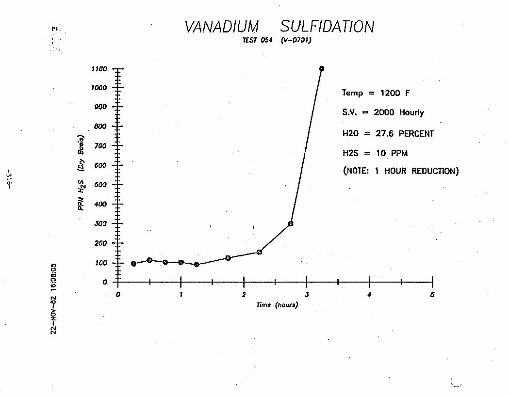
VANADIUM SUL FlDATlON
Temp = 1200 F
S.V. - 2000 Hourly
HZ0 = 27.6 PERCENT
H2S = 10 PPM
(NOTE: 1 HOUR REDUCTION)
I I
I I
I I I I .
I I
I I
I 8 I
0 t 2 3 4 5 lime (hours).
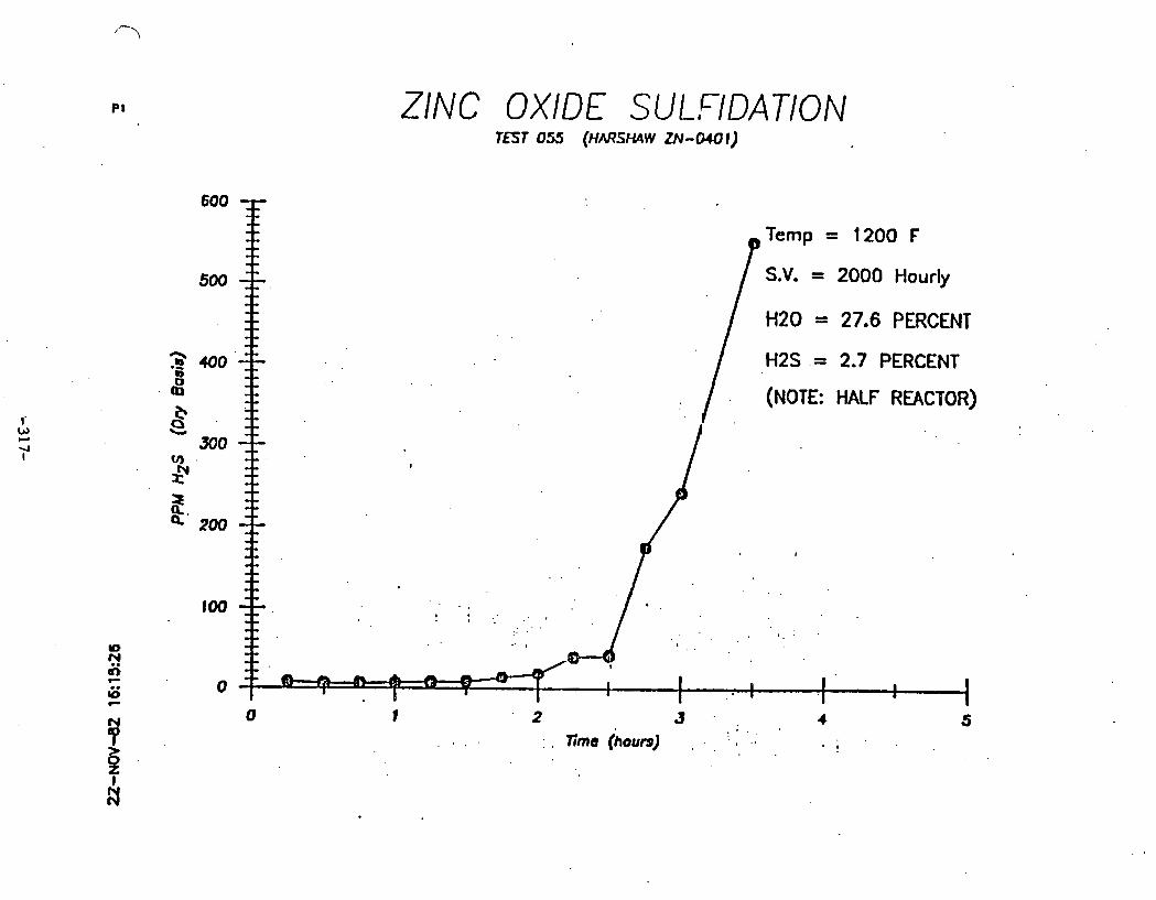
ZINC OXIDE SULFIDATION
600
Temp = 1200 F
500 S.V. = 2000 Hourly
H20 = 27.6 PERCENT
2 400' H2S .= 2.7 PERCENT '6 4 (NOTE: HALF REACTOR)
e Q . b
300 v)
2 a! 2. m
100
Y)
9 rl) P
G 0 C
0 1
P 2 3 . . 4
Y . ' : ' 5
. # . . : . ~ i m e (hours) : - , : , .. . .
H - I
k

VANADIUM SULFlDATlON
1 2 J 7ime (hours)
. - - .
El - TEST 054 (1 HOUR REDUCTION)
I
0 = TEST 057 . (2 HOUR REDUCTION)
Temp = 1200 F S.V. = 2000 Hourly
. . H20 = 27.6 PERCENT
H2S = 10 PPM
6 . . . - I I I I I I I
I I I I I
I I I

VANADIUM SULFIDATION
Temp = 1200 F
S.V. = 2000 Hourly
H20 = 27.6 PERCENT
H2S = 10 PPM
(NOTE: 2 HOUR REDUCTION)
2 3
' Tima (hours)

TEST S U N Y SHEET
TEST NO. : 0 6 0 D n r c STXRTEO : 11/U5/01 DATE EeOEO : 11/05/81 TOTAL HOURS : 1.5 HAS TYPE : SULFlOATlON
SORBENT TYPE/'.'E IGHT: FRAtILINITL ORE/1027 cfl
SORBENT NO. : MIX 2 BATCH r l
PURPOSE
OETERNIsE ~ A E C~?~?'ILITY OF HALF A K O CF F z a L l h l ~ ~ ORE TO L O ~ I ~ t i f R2S LEVEL e E L w 10 p?a
SORBENT CONPOSITION: F R M L I t I I T E ORE SEPARATE0 YACliETlCALLY TOTAL StJLT1:Q: FROH ZINC ORE SUPfACE U E A :
DENSITY : SORBENT PELLET SIZE: SPHiRES LESS THAq 112 INCH OIh'? P O R O S ~ ~ : PRETP.EATnit;T : KONE X-RAY DIFF?2CTIC!4: SULFIa LOIOIEC : S (GY SULFU~IGY FRESH SOZBEST)
HOLE S/IOLE Z1:O
SPACE YELClClTY: 2010 HOURLY
. . . . - . , . . .
FLOY RATE MOLE0
M S : 0.500 SCFH . 2.70
HZ0
A I R
c o 2 1.8 SCFH 9.79 '2
' CO 2.15 E F H 11.69 1
M4 0.535 S C M 2.911
TOTAL DRY GAS FLOI: RATE = 13.3 SCFH TOTAL kET GAS FLOY RATE - 18.33 SCFH
HZS: {OeO p f f l AT 1 5 r ( l ) i U f i S S T U 2 T STATE
E X I T SZ:
. -EXIT HZ:
1. ~ L P THE PSLTOR IS FILLLO u t T n F~A~LI~IITE C?.E
2, BED H1G!iT I S 9 118 INCH.
CO~CLUSIOSS
1. FU!';YLIfI lTE O;IE IN THIS FORV I S KOT A a 0 0 S2UEN1,
2. SUSPECT L a SURFACE h?EA A P?.CBLM.

Institlri Francais du
7
Petrole
I
DIRECTION PHYSICO-CHIMIE APPLIQUEE -
Department of Energy Mergantown Energy Technology Center '
P.O. Box 880 Collins Ferry Road Morgantown, West Virginia 26505
Object : Your letter TG-dp-512h
Dear Mr. GRINDLEY,
'Shank you very much for the sample of IFP desulfurization sorbgnt MEP- 682 and the draft report on the tests you have performed on it.
Concerning your tests and the comparison of the performances of our sorbent with those of Harshaw catalyst we have the following comments and questlxs:
. .
- the IFP sorbent is designed for the removal of the. bulk of the H S from a gazifier effluent before using it in a gas turbine for electricity pro8uction by combined cycles. It 'is not intended .for the removal of traces 0.f H S. "Yo
2 selection criterion used in our work was the sorbent capability to perform a great number of cycles with a good mechanical strength, a sulfur capacity .in the range of 8-15 % weight and a H S concentration level in the treated gas of less than 300 ppm Vol., 2
- you said that Harshaw sorbent is not intended for regeneration and contains no strengthening agents. Are the results on Harshaw sorbent presented in figxes . - L o l l ~ u u'uiair~eu w i k i l xrescl sa~r~ples or atter severai' regenerations '/ We would appreciate if you could send 'us a copy of your report IR-N01133 in which the results of these tests are related i n detail and other reports which could be available on this subject,
- we do not believe that the degradation of IFP .sorbent could be 'attributed to its sulfidation at 64g°C. We have performed ourselves several sulfiaa.Lions up to 800°C without noticing any detrimental effect on the further runs at 500°C or 6C\Z°C. We agree that the Lssts resuits are obtained in the 5 G d ; ~ - 600°C temperature range but we consider that the drop of the sulfur capacity versus temperature given in figure 6 is not representative of the performances of our sorbent when utilized for ,;iaT; it is :csigrled,
- according to our experience the performances and the duration of a regenera- ble sorbent are closely related to the conditions used for its regenera+<m-
( In your teb- the low inlet terii;rature of the oxidizing ;a$ 338OtJ favor~zes the formation O f zinc sulfate whi'ch is later reduced in the sulfidation step
-32 1- Ez 3 lnstltut Franpis du Petrole r et 4 avenue de Bols'-Preau B.P. 3 1 92 aue~! Malna~son 92 506 Pueil Walwaison C.?dex z . ,- --.
7 . . _
telex IFP A 203050 F
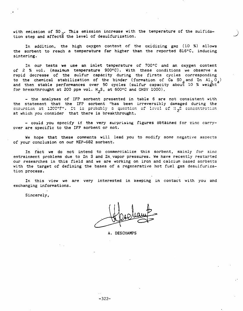
with emission of SO This emission increase with the temperitwe of the sulfida- 2'
tion step and affects the level of desulfurization.
In addition, the high oxygen content of the oxidizing gaz (10 %) allows the sorbent to reach a temperature far higher than the reported 816OC, inducing sintering.
In our tests we use an inlet temperature of 700°C and an oxygen content of 2 % v01. (maximum temperature 900°C). With these conditions we observe. a rapid decrease of the sulfur capacity during the firsts cycles corresponding to the chemical stabilization of the binder (formation of Ca SO4 and Zn A1 04) and then stable performances over 50 cycles (sulfur capacity about 10 76 weig%t for breakthrought at 200 ppm vol. H2S, at 600°C and GHSV 1000).
- the analyses of IFP sorbent presented in table 6 are not consistent with the statement that the IFP sorbent "has been irreversibly damaged during the r. . - . . . -r i -- ..& i 3 n n 0 ~ * 1 . T C :- - - - L . - L ~ . . - -..--&: -- -+- 7 -,.- " . . W U I " L W . . - 1 *--- , , 4 p. Y Y I I I J I C(YC--. "LY.. w L-. sf :: 2S ~2;1ZZ-.:?~tl:r:
at which you consider that there is breakthrought,
- could you spccify if the very s u r p r i s i n g figures obtained for zinc carry- over are specific to the IFP sorbent or not.
We hope that these comments will lead you to modify some negative aspects of your conclusion on our MEP-682 sorbent.
In fact we do not intend to commercialize this sorbent, mainly for zinc entrainment problems due to Zn S and Zn.vapor pressures. We have recently restarted our researches in this field and we are working on iron and calcium based sorbents with the target of defining the bases of a regenerative hot fuel gas desulfuriza- tion process.
In this view we are very interested in keeping in contact with you and exchanging informations.
Sincerely,
A. DESCHAMPS
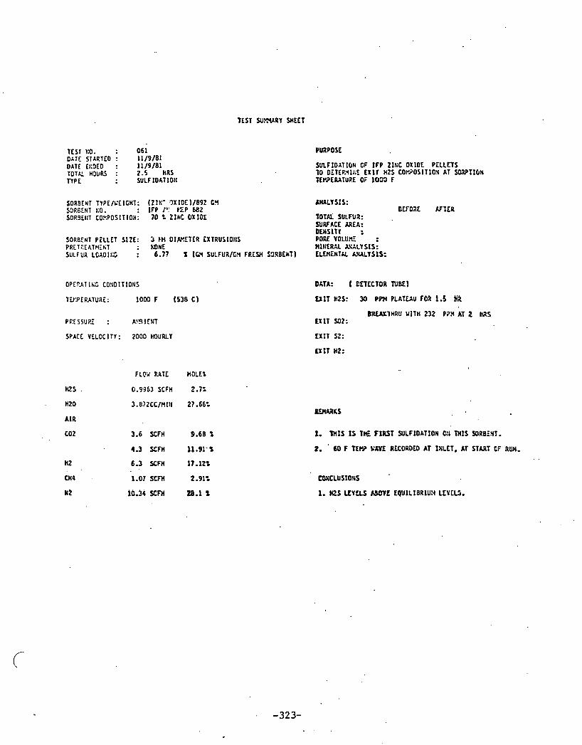
TEST KO. : 0 6 1 DATE STARTED : 11/9 /81 DATE I~:!JEO : 11 /9 /81 TOTK H ~ u R S : 2 - 5 HRS TYPE : SULF IOATION
$ORBENT TYPE/L'ElCHT: iZ1K' ?)XIOE)/892 t Y SORBENT KO. : I F P 1': t'LP 682 SORSEIIT COYPOSITION: 7 0 % ZINC OXIDE
SORBEUT P t L L E T SIZE: 3 tH D I W E T E R EXTRUSIOIIS PRET2EATHEhT : M N E SULFUR LGAOII;: : 6.77 'L (GY SU:FUR/C!i F R L W S0RBCtiT)
PRESSUPZ : A ' 3 1 CNT
SPACE VELOC l T I : 2000 HOURLY
HZ5 .
HZ0
A I R
PUPPOSE
TOTAL SULFUR: SURFACE a E A : DLWSIT I : PORE V D L U R : Rlt lERAL &VAL1 SIS: E L W i H T k k U L Y S I S :
DATA: ( CETECTOR NBEI
E X I T H2S: 30 PPH PLAP~AU COB 1.5 M
BRLAXTHRU WITH 2 3 2 P?H AT 2 IRS EXIT Y12:
EXIT S2:
E X I T HZ:
FLW RATE n u t
0.9363 SCFH 2.7:
3 .8?2CC/f l l I I 27.66:
3.6 SCFH 9.69 t
4.3 SCFH l l . 9 1 - t
6.3 O F H 11.12%
1. tnIS I S THE FIRST WLFIOATION 0th M I S SORBiST.
2. 60 F fEW KEVE RECORDU) AT INLET. AT START (.F RUN.
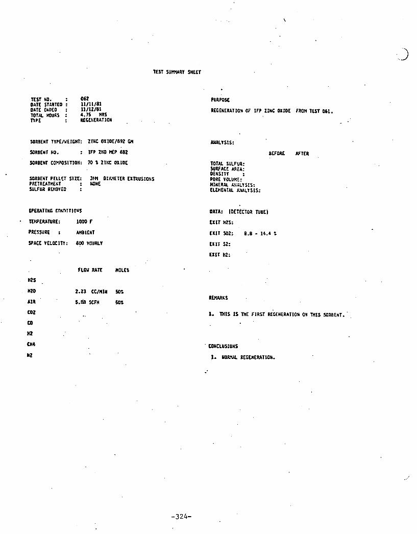
TEST S U W R Y SHEET
TEST KO. : 0 6 2 DATE STARTED : 11/11/81 OATE QOLO : 11/12/81 TOTAL noufis : 4.75 HRS n P f : RLCEKLRATIOW
SORBEN1 KO. : I F P Zt:0 WEP 6 8 2
SORBENT COXPOSITIOtJ: 7 0 1 Z I t X OXlOE
SORBEliT PELLET SIZE: 3bN DIh'lETER EXTRUSIO!lS PRETREATP!'iriT : M N E SULFUR AWOVEO :
FLO;t RATE HOLES
H2S a
nzo 2.23 CC/MIM 50%
A I R 5 . d SCFH 5 0 1
CO2 -. CQ
H2
PURPOSE
RECEIERAT1O.Y Or' I F P ZlNC OXlOE FRON TEST 061,
BEFORE N T E R ,
TOTAL SULFUR: $UffACE AREA: DENSITY : PORE VOLURE: HINERAL &;ALY SIS: ELWENTAL LWLY S IS:
ona: IDE? ScToa TueE l
CONCLUSIONS
1. YORWL REGENERATION.

TEST SUP-YXRY SHEET
TEST KO. : 0 6 3 DATE STARTED : 11/13 /81 DATE. fs9ED : 11/13/81 TOTALHOUPJ : 3.5 HRS TYPE : YJLFIOAT10N
SOlBChT T Y P i / U i l t t i T : (Z lKC O ~ t O E ) / 8 9 2 Cfl SORBEwT NO. : I F P ZKO FSP 682
SULFIOATlON OF I F P ZINC OXIDE PELLETS K C C 8 3 T l?E TO DETEP.Y.I!;E EXIT 142s c o , . o o s ~ ~ r o r a SORPTIW TEWLRATUaE OF 1 0 0 1 F
-- - - T O W SULFUR: SURFACE US: OEYSlTY r - -. - - - . .
SORBEIIT PELLET SIZE: 3 t l OIAYETER EXTRUSIO!iS ' . PORE VOLU?ri . PRiTREATYil lT : KOKE HIEERAL MALY SIS; SULFUR LOAOtllC : 9.00 % (GH SULFUR/LM FRESH SORBENT) ELWENTXL A!&LYSIS:
d
O P f U T l t i t CONDITIONS
TENPEMTURE: ~ D W F ( 5 3 8 ~ )
PRESSURE : W3lE l4T
SPACE VCLOCIT'I: 2000 HOURLY
DATA: 1 ULIECTOR NBEI
EXIT H2S: 5 PPN PLATEAU FOR 2 HZS
B R i U l M R U YITH 20 PP3 AT 2.5 k2S EXIT S02:
E X I T St:
EXIT HZ:. .-
FLOU RATE ROLE=
!QS 0.9963 SCFH 2.7%
. HZ0 . .
A I R
cot
co
n 2
a4
~ 2 '
3.6 SCFH 9.68 i 4.3 SCFH 11.91 t
.6.3 XF)( 17;lt:
1.07 SCFH 2.91f
10.3, SCFH 28.1 ',
l lMXRKS
1. T H I S I S THE YCOMD SULFIDATION ON THIS WB',hT.
. . #
C O L L U S IONS
1. LESS I&! 1 0 PPW HTS FOR 2 HRS.
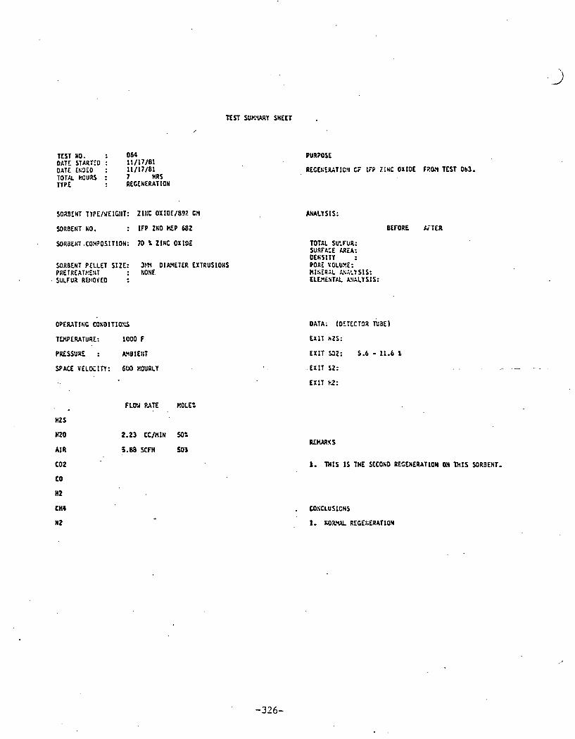
TEST NO. : 0 6 0 O ITC STARTED : 1 1 / 1 7 / 8 1 DATE 1 ~ 3 E 0 : 1 1 / 1 7 / 6 1 T O T R H C U S : 7 HRS TYPE : REGENERATION
TEST SUP.WY SHEET
I
PURPOSE
REGEt;ZGTIC!I CF 1TP 71NC OXIDE F 2 0 3 TEST Ob3.
SORBENT KO. : I F P ZKO N P 682 BEFORE G T E R
SORaENl .COM?OSITION: 7 0 % ZINC OXIDE
XRBENT PELLET SIZE: 3m DIAYETCR EXTRUSIONS PRETREATKC!JT : !:ONE SULFUX RLEIOYEO :
TWERATURE: 1 0 0 0 F
PRESSURE : h9EIE t IT
SPACE V E L K I T r : 6UO HOURLY
FLOY PATE ROLE: , .
HtS
HZ0 2.23 CC/HIN 50:
AIR 5.88 SCFH 501
CO2
co HZ
cn4
W2
TOTAL SULFUR: SURFACE XREA: OEfiSITY : PORE VGLUYE: WISERAL 2;::1SIS: LLL '1LSlkL A3ALY SIS:
DATA: (DETCCTC)R r i a 6 1
E X l T hZS:
E X I T Q 2 : 5 . 6 - 1 1 . 6 %
E X I T S2:
E X 1 1 PZ:
ILECURXS
1. T H I S I S THE SECOLD REGENERATION ON T H I S SRBENT.
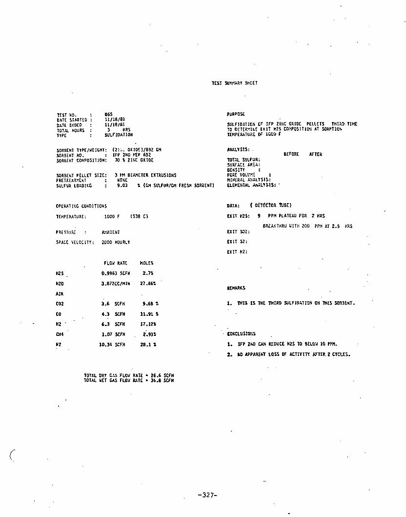
TEST WYYYABY Sh iET
TEST KO. : 0 6 5 onrf STARTEO : 1 1 / 1 8 / 8 1 orrf t c O f O : 1 1 / 1 8 / 0 1 TOTK HOURS : 3 HRS TVPE : SULFIDATION
PURPOSE
SULFIDIT ICS C? IFP Zll;C OXIDE PELLETS T H 1 3 . TIYE. TO OEIE?-ult.C, E X I T kZS C0:'POSITIQI AT SORPTlCh TErPE%Iu?.: OF l G C 6 F
SORBENT TYPE/VEIGHT: (21 i t - OX IDE)/892 G!4 A U L Y SIS: . M B 9 i N T NO. : I F P ZHO KEP 692 SORBitiT COHPOSITION: 1 0 t Z1I:C OXIDE T O T 2 SULFUR:
S U W l t E AREA: OLNSITY :
SOR9EtiT PELLET SIZE:' 3 m DlLYETER EXTRUSIONS PORE V0LC.Y.E PRETkEATYEtiT : rotx RI!ILRIL L'iALYSf S: SULFUR L0:O:t;G : 9.03 % (GY SULFUR/Gfl FREW SOI i lLnT1 LLEREIJTAL S L Y S I S : .
BEFORE AFTEa
OPERAT It:C COtiDITIONS DATA: ( DtffCfOa
SPACE VELOCITY: ZOO0 HOURLY
*f - HZ0
A I R
C02
CO
HZ '
W4
W2
FLW PATE MOLE:
3.6 SCFN .9.68 '0
1.07 SCFH , 2.911
10.34 SCFH 20.1 t
U 1 T HZS: 9 P P 3 PLATEAU FOX 2 ORS
BREXYTNRU :'IT11 2 0 0 P?3 AT 2.5 ).XS U I T 532:
E X l T SZ:
E X l T HZ:
I. W l S IS THE THIRD WLFIDATION ON l H I S S935KT.
X. FP ZNO U Y PlDUCE HZS TO BELCtd 10 PPR.
2. D AP1AR9.T LOSS OF A C T l Y I N KTEP. 2 CYCLES.
TOTAL DRY 1;s FLW RATt 26.6 SCFH TOTAL YET GAS FLOY RATE 3b.8 SCFM

' TEST NO. : 0 6 6 DATE SlARTEO : 1 1 / 2 0 / 8 1 DATE CKOLO : 1 1 / 2 0 / 8 1 TOTAL HOUU : 7.0 HRS TYPE : REGENERATION
SORELNT TYFE/;'EICHT: ZI~IC O X I O E / E ~ ~ cn
SORBEHT KO. : IFP ZKO P ~ P 6 8 2 .
SORBEtlT COY?OSITIOH: 10 2 2It:C OXIDE
, SORBEUT PELLET SIZE: 3PN OlXH iTER EXTRUSIOIS PRETREATHiKT SULFUR IiSlOVED :
OPERAT l lG COt;JlTIONS
T W L R A T U R E : 1000 F
PRESSURE : AYSIEHT
SPACE VLLOCITY: 6 0 0 HOURLY
FLOY UTE MOLE%
M S
HZ0 2.23 C C I U l N 50:
A I R . 5.88 SCFH 50%
eor EO
PURPOSt
REGEHERXT1O:i CF I F P ZINC OXIDE FP.3.Y TEST 065.
TOTAL SULFUB: SUffC.CE S E A : 11.6 D E Y S I T l : PORE VOLCYi: R I ~ E R L L hSkLYS1S: ciwrtirx fia~rsis;
DATA: (OETECTOA N B E )
E X I T H2S:
E X I T 532: 7-12s
U l T S2:
EXIT 142: .

TEST W M Y M E E T
TEST KO. : ' 0 6 7 DATE STh9TF.D : 1 1 / 2 3 / 8 1 DATE l h 9 i D : 11 /23 /81 T U T U h'XtaS : 3 HRS TYPE : W L F I D A T I O N
PURPOSE
SULFlOATIOt I 0; IFP Z lKC OXIDE PELLETS FOUITH t I X i 1 0 DETERYIKE EX!T k 2 S COr.POS1TlG.Y AT S O ~ P T I O N TEPi'EUiTURE CF 1539 F
SOREEET TYPE/b!EltHT: ( Z I f l C OX IOE) /892 GU SORBEYT KO. : I F P Z t i 0 t E P 6&2
k I A L Y S I S : BEFORE AFTER .
S3ROEhi COYPOSIT13N: 7 0 Z I l l C OXIDE TOTAL SULFVR: SURFACE M E A : 11.6 OEWSIT'I :
SORBEKT PELLET SIZE: 3 tN D I M E T E Z fXTRUSI0I;S POE V O L U ~ ~ - PRElRLATP!INT : KOXE MlNERAL CSILY SIS; SULFL:a LOA9If:C : 6.78 % (0.I SULFUR/(;Y F&SH SORSENT) E L E S N T X A1111SIS :
PRESSUPL : A 9 I ENT
SPACE VCL0:ITY: ZOO0 HOURLY
M S
H 2 0
A I R
cot
CO
, HZ
044
t i 2
DATA: ( DETECTCI TUBE)
. .
FLOU RATE MOLE:
0.9963SCFW Z 0 7 X
3.872CC/UIN 27-16:
3.6 SCFH 9.6b t
4 . 3 S C F W 1 1 . 9 1 %
6.3 SCFH 17.12%
1.07 SCFH ? 3 1 t
10.34 SCFH 28.1 t
COECLUSIQHS

TEST KO. : 0 6 8 DATE STARTED : 1 1 / 3 3 / 8 1 DATE t!;Dfo : 1 1 / 3 0 / 8 1 TOTK n o v a : 7.5 HRS TYPE : REGEtIERATIOtI
S3aBEhT TUPE/UEICHT: Z INC OXIOE/892 GH
W43ENT KO. : IFP ZXO MP 632
SOXBENT COXPOSITION: 7 0 % Z l E C O X l D i
S02BEKT PELLET SIZE: 3EN 0IAU.ETER t X T R U S l O I S IRETRiATt I6CT S'ltFuR RC,Y3YLO :
OPERATING CO!:01TIO!IS
TWPEUTURE: 1000 F
PESSURE : N!BlEt;T
SPACE YELOCITI : 630 HOURLY
HZ0 . 2.23 CC/HIN 50%
A I R 5.88 SCFH 50%
PURPOSE
LCCr iERATIC3 CF 1i:P Z1KC OXIDE F?.:n TEST 057.
TOTAL SULFUa: SURFACE XRiA: O E n S l T l : PORE YOLUXE: Ml t iEPAL LYALYSIS: fLEHiHlhL PLALY 51s :
ORTA: (OiTCCTO? TUBE)
EXIT H2S:
ixIr 9 2 : 1 . 5 - l e t
E X I T 52: . .
E X I T HZ:
1. T H I S I S ME FOURTH REGE,;ERATIC% OM T H I S SORBEttT.
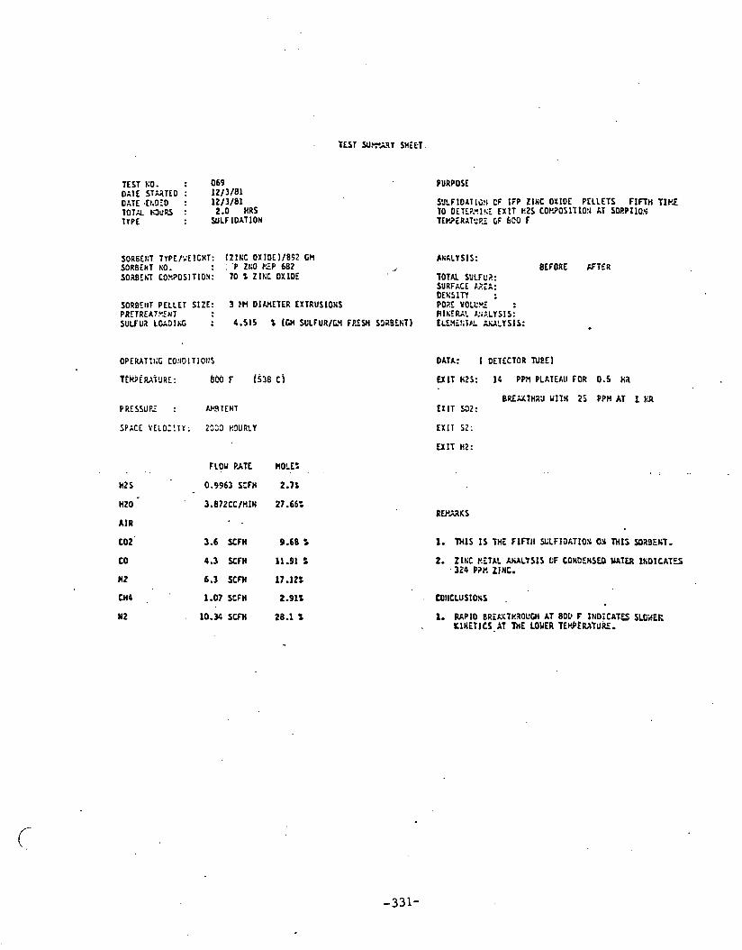
TEST KO. : 0 6 9 DATE ST2TEO : 12/3 /81 OATE .Et.DfO : 12/3 /81 TOTK HJuU : 2.0 HRS TlPC : WLFlOAT lON
PURPOSE
SOR6Et:T TYPE/'.'EICHT: (ZINC OXIOE)/852 GM AlkLY 51s: S O R B ~ N T YO. : :. 'P zt:o PZP 602 BEFORE AFTER . - - - -
SORBEhT CO.C.?OSITION: 70 Z ZILC OXIDE TOTAL SULFC?: SURFACE &.?:A: D E E S l n :
SORBEtrT PELLET SIZE: 3 tt4 OIMETER EXTRUSIONS PO25 YOLL'M PRETREATYrNT H l t i E G t b!i:.LYSIS: SuLFUa L0;Dlr;t : 4.515 % (GM SULFUR/GY FP.FYi SCJZBEET) tLEnLt;lr!L ~uLYSIS :
DATA: [ DETECTOR N E E 1
EXIT H2S: 1C PPa PLhTEAll FOR 0.5 HZ
EXIT S Z :
U I T HZ:
. - FLOW PATE PIOLE:
)rZS 0.9963 SZFH 2.71
CO 4.3 SCfH 11.91 Z
nr 6.3 scm 17.12%
2. Z lEC BEThL AML ' IS IS (iF CONCENSED UATER INDICATES ,324 P?t? ZINC.
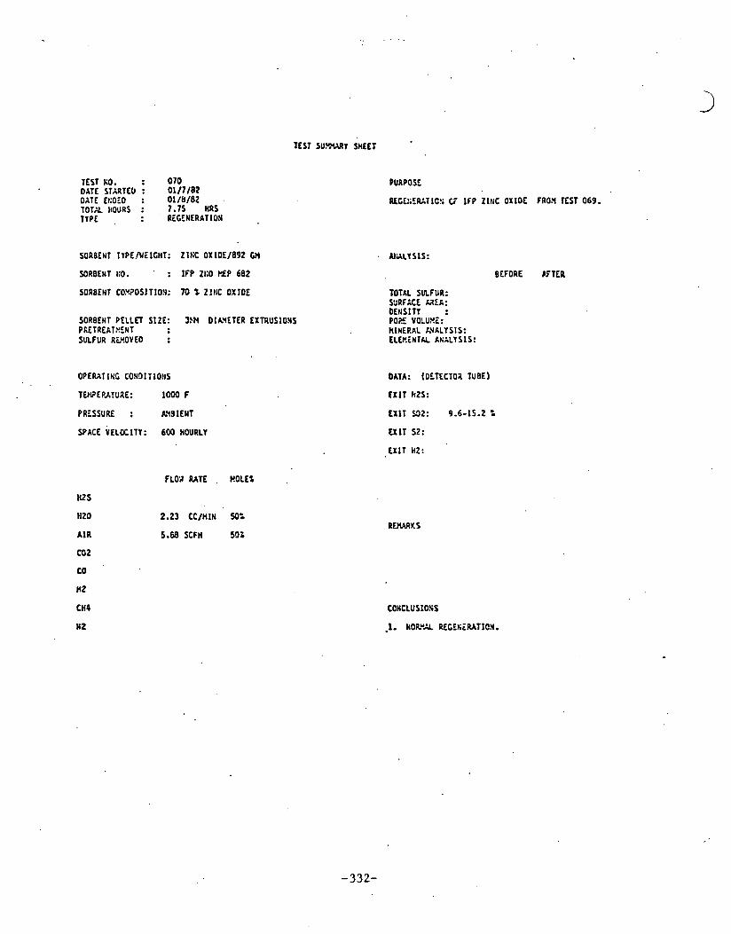
TEST W.?!Y SHEET
TEST KO. 0 7 0 DATE STrRTEO I 0 1 / 7 / 8 2 DATE EcOEO : 0 1 / b / 8 2 . T O T K IIOURS : , 7 - 7 5 HRS l T P E , : EGEWERATION
SORBEHT TTPE/U~ ICHT: Z1tiC OX10E/892 W
SORBEHT t;O . : IFP ZI:O PLP 6 8 2
SORBENT CO.YSOS1TIO.Y: 70 % Z l H C OXIDE
SORBENT P E L L n SIZE: 3?N DIAVETER EXTRUSlOHS PRETREXTXENT SULFUR RMOVEO :
OPERATING CO!iDITIOIIS
TEIVEPATURE: 1 0 0 0 F
PRESSURE : AYSIENT
SPACE YELOCITY: 600 HOURLY
HZ S
H Z 0
A I R
co 2
CO
nz CH4
N 2
FLW RATE . WOLEI
2.23 CC/t i IN 50s
5.68 SCFH 502
PURPOSE .
RCtE:iC,RATLC!; C i I F P Z1f;C OXIOE FROn T E S l 069.
BEFORE K T E R
DATA: (OTTECTOA TUBE)
U I T SZ:
C X l T HZ:
COWCLUSIOSS
-1. UORuA RECTSlRATIOY.
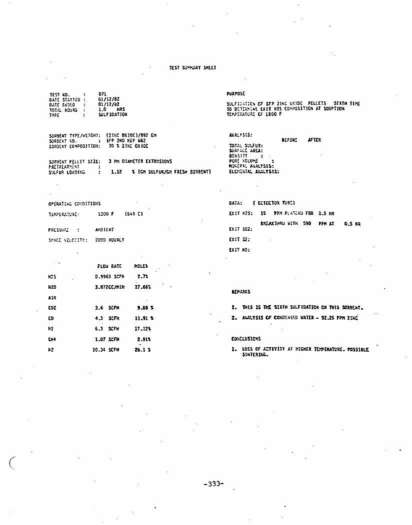
TEST S!J.YPAi(Y SHEET
TEST KO. : 0 7 1 DATE STAXTED : 61/12/82 OAT( tK3EO : 01/12 /a2 TOTK M'JilS : 1.0 HRS T1PE : WLFIDXTIOW
~JLFI::TIC~ CF IF? ~ I K C UXIDE PELLETS SIXTU TIYZ TO DETELu;hC, Ell1 EPS CO"3OSlTlCJ AT SORPTION TEP2E?;IC2E ti 1230 F
SIRBENT TY?E/WEICHT: ( z ~ t i c O X I O E ) / B ~ ~ cn WJ;~LTSIS: U R S i N T l;O. : I F P ZWO P ' P 682 BEFCRE AFTER S318ER COX?OSITIO!l: 7 0 2 ZlSC OXIDE , TOTAL YdLFU3: wa;xc ag:
DEKSITT : 5023El;l PELLET SIZE: 3 Hi OIW.ETER EXTRUSlOlS POWE VGLUYZ PRETREATVLNT )IIt;TF!LL ASALY SIS: S'JLF UR LOACIISC : 1.12 X 1G'l SULPUR/(L'i FRESH S33.BLNT) fCL".SST& U 1 L T S l S :
FLOV RATE
0.9963 SCFH
3.872CC/HIH
3.6 SCFH
4.3 SCFH
6.3 K F H
1.07 SCFH
10.34 K F H
DATA: ( t iTECTOR N 9 t l
U I T ti2S: 1 5 PPH PLATiX'J FOR 0.5 pa
E X I T $2:
1. YHtS I S M SIXTH SULFIDATICI CN THIS S029Ekl.
2. ACLYS1S t' COSOESSCO YATER - 92.25 PPII ZILC
1. LOSS OF ;,71ttTY AT HIGHER TE.YPERATURE. P O S S I B E SlhTERl l i t .

T E S I SUP.YARt SHEET
TEST KO. : 0 7 2 DATE STA1TEO : 01/14 /82 . DATE Eti3ZD : 0 1 / 1 5 / e 2 T O T X kO!iRS : 7.5 HRS TYPE : REGEKERATION
SORSEI~T Tt?E/UEIGHT: Z I I l C OXIOE1892 C!4
SORBEtrT KO. : I F P ZtIO I Z P 682
501BEtn CO?!?OSITION: 7 0 I Z l N C OXlDE
S3R9EtIT PELLET SIZE: 3W OlX14ETER EXTRUS1O:lS PRETP.EAT~!E!IT SULFUA RfROYEO :
OPERATlKt CON31T10!1S
TDIPERATu~E: 1000 F
PPLSSVRE : A~SIEIIT SPACE Y E L K l T Y : 600 HOURLI
HZ S
HZ0
AIR
cot
co HZ
CH4
I 2
FLOV RATE Y.OLE1
2.23 CC/ t t lH 50%
5.W SCFH 50:
PURPOSE
REGCt;EEATLCS C i 1 f P ZINC OXlOE FAOX TEST 071.
AVALY SIS:
BEFORE S T E R
TOTAL .SLZFUR: SURFACE AREA: Ot!iSlTY : PORE VSLUnE: M1r;ERkL ISALY S I S: ELEnLnTAL ~N:U s I S:
DATA: (DiTECTOR TUBE)
EXIT nzs:
E X 1 1 U2: 9.0 - 12.4 '.
U 1 T s2:
E X I T M:

TEST N%ARY SHEET
TEST KO. : 0 7 3 o m srAar;o : 1/21 /e2 OhTE Lk3:D : 1/21 /82 TOTE kJ.J;J : 0.25 H9S 11PE : SULF IDAT!:%
PURPOSE
SULFIOXiIO!i C7 I;? ZINC O X l D i PELLETS 3EYiNTH TlrZ 1 0 OETEP.'tlkE E X I T H2S COY?OS1T10~1 AT SOZ.PTlO!i TCWE?AiURE OF lGCO F h=TiW SJLFIDkTlfJ!i AT 1200 F.
ANALYSlS: BEFORE GIER
10TAL SNFUZ: SURFACE L E A : 11.1
SOISELT PELLET SIZE: 3 bN OIkYETER EXTRUSIONS
DATA: ( 5ETECTC3 TCCE)
EXIT nts: 2asoo ppn AFTER IS nltiurE
P7.iSY;;Z : W31ENT . LXIT SO2;
HZS
HZ0
A I R
CO2
co
HZ
u4
m2
F L W RATE t!OLLI
0.9963 S C M 2.7:
3.872CC/HlN 2 7 -66%
3.6 Y F H 9.68 2
4.3 X F H 11.91 t
1.07 X F H 2.91% - 10.34 K F H 28.1 f 1. 1r.YEOIATE BIi%tH3OUCH I!iOICATES fOB3EHT PROGAEL?
MAS S1l;TCP.ED 1% Tt!i l 2 L O F DECREE R!JN (TEST 071).

TEST SU l tWtY SHEET
TEST KO. : 0 1 4 DATE STARTED : 2/8/82 orrr Et:oEo : 2111182 TOTAL HO'JRS : 12.7s nas TIPE : RECEtiERATIOtI
SORBE~T ?YPE/UEICHT: ZIkC OXIDE/892 63
SORGEHT KO. : I F P ZtIO M P . 6 8 2
SORBENT COHPOSITIOH: X) % Z l t IC OXIDE
SORBEIIT PELLET SIZE: 3)n OI~\ETER EXTRUSIONS PRETREATE!EST SULFUR. RCYOY EO :
SPACE VELOCITY: 6 0 0 HOURLY
A I R
c o 2
PURPOSC-
RfCE~:E&TIQ!r C i I F P ~ l t i ~ OXIOE FRO3 T E S l 073.
TOTAL SULFUR: WPIACE SEX: OENSlT l : PORE VoLU!!L: HIKERkL Ri' iXLISIS: CLEHEtlTAL A ! i rLYs~s :
DATA: (OLTiCTOR 1U5E)
t X I T HZS:
EX11 532: 14 : - 16 t
C X l T S t :
CX lT HZ:
.. - . .

TEST XVVYARY SHEET
TEST KO. : 0 7 5 our STARTED : 4 / 1 3 / 8 2 DATE En3 iO : 4/13 /82 TOTX :.OURS : 4.25 HAS lYPE : SULFIDATION
PURPOSE
u'LTIo~TIo!; CF Zlt;C FERRlTE PELLETS U I T i WY% ZINC c OXlOE CO!iTII;T. .
SO.QS:uT TTPE/YLICHT: ( Z l l C FERRITE)/643 63 CLWLYSIS: s o a 3 i t i l KO. : H l X # 2 BATCH $111 5349E!iT COYPOS1TION: 71.4 kOLE= IRON OXlCE (FISHER CERTIFIED) T O T U SULFUR (=I/U):
28.6 ROLE% Z l k C OXIDE ( S h i a k ' l k U I L L I h Y S HSA) S U F A C E &.PEA ( M I G l : D t t l S I T Y (C ICC) :
SORSEKT PELLET SIZE: 3 / 1 6 INCH DIAU.ETER ErTQUSIO!:S PORE V S L t % I lt:U/G): PfiiT4EXTE!EST . . M I t i E R I L AVAL1SIS: SULFU3 L O X O I t L : 17.24 % SULFUX/GY FRESH SO49EI;T) ELLEEtii&L ;WLYSIS:
OPLRATING CONDITIONS
PRESSURI : AU9 ICNT
S?KE VELCCITY : 2 0 0 0 HOURLY
A I R
eEFORE K T E R
DATA: ( OiTECTOR N S E )
U 1 T H2S: 7 P?n PLATEAU FOR 2 . ?5 !iaS.
S X I T St:
' UlT HZ:
FLOY RATE kOLi:
0.9963 SCFH 2.7%
3.8?2CC/HlN 27.66:
3.6 SCFH 9.68 t
4.3 SCFH 11.91 %
6.3 YrH 17.12%
1.07 XFH 2.91%
10.34 Y F H 28.1 %

TEST NO. : 076 oat STARTLO : 4 / 2 7 / 8 2 OAT5 EnOLO : 4/29 /82 T O T A H lU% : HRS TYPE : RECftlERAT ION
PUIPOSE
RCGE~EZATION CF Z ILC FERRITE P fLLLTS FROX TEST 075
SORBEhl TYPE/h'EIGHT: ( Z l K C FERRlTE)/6;3 GN hHILIS:S: SORSEIIT 1:6. : R I X t 1 BATCH ;1/1 SOa3E4T COUPOSITION: 71.4 K O L E t II?O:l OXIDE (FISHER CERTIFIEO) TOTAL SULFUR:
28.6 HOLE% ZISC UXIOC (SHERUIN U I L L I A N S HSA) SURFACE A?%:
SORBEtJT PELLET SIZE: 3 / 1 6 I t iCH OIkY iTCR EXTRUSIOlIf PRETREATK5HT SULFUR Rt,U.OVEO :
SPACE VELOCI lT: 600 HOURLY
rz s
H20 ,
A I R
co 2
CD
HZ '
CW4
NZ
O E n S l T I : PORE V ~ L U I ~ E : W1f;ERAL hV,YA',Yf!S: ELEniNTAL C I L I S I S :
DATA:. l O i T f C T O 3 N 6 i )
E X I T st:
E X I T F.2:

TEST SU.YWqY W i E T
TEST KO. : 0 7 7 DATE STARTED : 5 / 1 2 / 8 2 o r T r EI:OED : 5 / 1 2 / 8 2 TOTU H N R S : 1.5 HRS TYPE : SULFIOATION
PU;i?DSE
SECCID SULilD:TIC!I OF Z1l:C F E R R l T i PELLETS K l ' i H LOKER 2 l t . i O X l L E CCbTEt;T.
. .... S92SEST LO, : M I X b t BATCH r l l l s3a3~1;~ COxPOSIT lon : 71.4 KOLE: l R O l OXIDE :FISHER CERTIFICD) T o 1 6 1 SULFUR (:,;/r):
28.6 H ? L E t Z l K C OXlDE ( S K ~ R X I l l Y I L L I b H S HSh) S U % i i : i :?LA (Y.?/G): EEt iS lTY (G/CC) :
S9R9ENT PELLET SIZf: 3 / 1 6 INCH DI~,Y.ETER PXTRUSIO!IS P O ? i ViliL'VE (P3/t): PRETRiCTUEET RIYEZI I . C,F.&'_YSIS: SC'LFUR LOA9l t iG : 1.57 1 (GV SULFURIGY F R E W SORBEIIT) ELEt!E!iTAL LGLV 51s:
SPACE VELOCITY: ZOO0 HOURLY
A I R
COZ
CC
nz
C H O
9 2
DATA: ( DETECTCR WE)
U I T h2S: 3.0 P?3 FOa .25 H0UP.S
8EA\7!!;lOUG% w1Td )O P?Y AT -75 HOURS
C X l T Zf? :
3.G X F H 9.68 1
4.3 XFIl 11.91 t
FLW RATE ROLL:
0 .9963 SCFH 2.1:
3.872CCRI IN 27-66:
6.3 YFH 17.12:
1.37 SCFH 2.91%
10.34 X F M 28.1 t 1. P333 PEXFC2"ASCE GI1 SECOND $ULFIDATIOS.POSS)BLY WE 10 I!ICGY~:EE KEGEt~ERhTION.

TEST KO. : 0 7 8 DATE STJRTEO : 5/19/UZ DATE EhBEO : 5 / 2 5 / 8 2 TOTAL I I~JRS : 18.5 HRS TYPE : REGEIIERAT LCN
PURPOSE
REGEKEPATION C i Z lKC FERRITE PLLLETS F P L 9 TEST 0 7 1
SORBENT TYPE/VEIC!IT: ZfCC FERRITE/6:3 C 9 AHALYSIS: SBRBEST KO. : HIX II BATCH CI/I S O ~ B ~ K T CO:~.PGSITIO~I: 71.6 OLE^ IROH OXIOE (FISHER CERTIFIED) TOTN SULFUZ:
28.6 HOLE2 ZINC OXlOE (SHEIY IN Y I L L I K I S HSA) S U E A C E R E A :
SORBENT PELLET SIZE: 3/16 I t l C l l DlA'!U.ETER EXTRUSIONS PRETREATMENT
' OPERATING CCt iCITIOl IS
PRESSURE : A'4SIEtIT
SPACE V E L K I T I : 600 HOURLY '
DENSITY : PORE VCLUXE: HISERAL R I X L Y SIS: ELEnENTAL A!;XLI SlS:
DATA: (OETLCTCX TUBE)
E X I T 532: 13.7 PiRCCliT PAX 1 0 0 P ? 3 AT L\3 G TEST
E X I T SZ:
EXIT nz:
AIR 5 . U SCFH 50:
Coz
co
HZ
1. STEM UAS L.UT OFF K T L t PASSbCi OF EW UvE.
2. A I R FLOW RATE YXS INCREASED U? TD 32 X F H , In CaOER TO ATTErPT L W E R I N G E X I T 502.
C m c L u s i o N s
1. s o 2 LOYEREI) TO 103 P P ~ ar fi~c:c~rc ST=- AW 1NCREASIl lC A I R FLOU U T E S .

TEST 'SUYYYfiY SHEET
TEST KO. : 0 7 9 DATl ST3TED : 5/25/82 DATE E!,3iD : 5/25/82 TOTZ nc3i.s : 2 HRS TYPE : WLFIOXTIOW
PURPOSE
THIRD SCLFlOXTlOg OF ZISC FERRITE PELLETS UITH LOPER Zl t iC OX!GE CO!iTEtiT.
SORBE)IT TTPE/UEICHT: ZII:C FERRITE/643 GH ANkLTS!S: S3;JtHT 1.0. : MIX 02 BATCH # l / l BEFORE AFTER SO?.Bfr;T CO?lPOSIIION: 71.4 MOLE% IY.Og OXlOC (FISHIR'CERTIFI~~) T O T E SELF32 (=Y/Y):
28.6 t:OLEI ZINC OXIDE (SHLaYIN YILL I I -9s HSA) SUZXCE ;IE& (P2'21tl: . -. -.- DENSITY fG/CC) :
SDRSINT PELLET SIZE: 3 /16 INCA OIAYESER EXTRUSLOLS PO= VOLUYI IW/C): P2il2EAT!!E!iT R I K E X L CiCLISIS: SULFU? LOAOlKt 7.84 % ( L 9 SULFUR/GY 'FREYt SORSENT) ELEt!E!.T;L A.ULYSIS:
P R E S S U E : AMd lEHT
SPKE Y 'LC; ITY: ZOO0 HOURLl
. .-
FLOU RATE HOLE%
0.9953 SCFH 2,7t
3.872CC/f l l~ 27.66':
3.6 SCFH . 9 - 6 8 t
4.3 SCFH 11.91 t ,
6 . 3 X F I i 17.12%
1.07 SCFH 2.91%
10.34 Y F H 28.1 t
DATA: ( DETECTOR TUBE)
EXIT HZS: 9.9 PPn AYC FOR 1.5 H l S
BUUTWROUGH KITH 1050 PPH AT 2 H1S. EXIT SrJZ:
E X I T U:
CXIT HZ:
1. LOSS 01' XLFIOATlON CAPACITY OSSERYED I N COWA2lSO9 TO FlfiST SL;LFIDATlO.Y.

PCIHOSITY DETERMINATION L- 11/42 , ,vad3 s 1 -
L-
SAMPLE .WEiGHT -- NORMALIZED TO I gani
k - b ~ f % &ha DATE


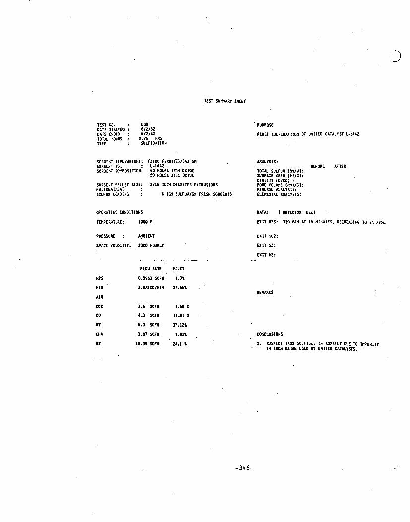
PURPOSE
FIRST U l L F I O I T I I O l OF UtIIlEO CATALYST L- IbbZ iora agRs : 2-75 nas TTPE : SULFIDATION
WilBCIiT li3. : L-1442 SOXjit;T CO"POSITI0N: 50 ROLL% IRON OXIOL
50 MLL: Zll lC OXlDt
BEFORE K T L R TOT& SULFUR t=ul.rl: SURFACE L E A (MZl t ) : OENSITT [GICC~ :
SORSENT PELLET SIZE: 3/16 lllM DlANiTLR LXTRUSIOHS PORE VOLUI~ 0:43/Gl: PaEIREAT.%liT HlHEBAL R:UtSIS: SLZFUI LOAOIKS : 2 ICY SUlFUaIL? FRESH SORBEHT) ELLRENTN IcWLlSlS:
DATA: ( DETECTOR NBi) .
EXIT H2S: 310 PF3 AT 15 MINUTES. DECPUSItL TO 74 PPX.
PRESSURE : A:aICNT E X I T ~ 1 2 :
SPACE VELCCITY: 2000 HOURLY U I T SZ:
EXIT HZ: . . . . , ,- ., - - , . .
as nzo
AIR
LO2
co
n 2
CHb
N i
0.9963 SCFH 2.71
3.872CCIHIH 21.661 . '
3.6 SCFH 9.68% .
4.3 SCFH 11.91 5 .
6.3 YM 17.12%
1.07 SCFH 2.91% . 10.34 X F H 28.1 2 1. SJSPECT IP.03 SULFlOi5 I N U?.3EtiT DUE TO 1rnul([n - I N lROv OXIDE USCO BY UNlTCO CATALISTS.

TEST SUmARY SHEET
TEST t i j . : 0 8 1 DATE ST;.4TE0 : 6 / 0 4 / 8 2 DATE EKo iO : 6 / 7 / 8 2 TOTAL HJ'JRS : 8.25 HRS TYPE : RECENERhTION
SORBEtIT TYPE/uEICHT: IINITEO CATALYSTS Z l I C FERRITE/643 Gb! SOIECNT KO. C-1442 SDZ3ELT COHPOSITIOR: 50.0 MOLE% l R O l OXIDE
50.0 WOLCX ZINC OXIDE
SORBEST P E L L n S IZE : 3 / 1 6 INCH OIAU.ETER EXTRUSIONS PRLTREATHENT SULFUR RClOYEO . :
OPERATING COSOITIOHS
SPACE Y E L K l T I : 6 0 0 HOURLY
PURPOSE
I E G E h l R A T I C s Cz ZINC F L I Z I T E P i L L E T S F t O 3 TEST Obo
AnhLts!s: BETORE ' Cr'lO!
TOTAL SULFUB: SURFXCL :.?:A: DLNSlTl : PORE 'VCLt?!:: WI I IEIAL i.SlLYS!S: LLCP.it;TU A G L I SIS:
DATA: 1OETECTCX N E E )
E X I T n2s:
EXIT 532: 15.4 PERCE~IT rxx. 350 P P ~ AT E ~ D ~ r ' EST
EX11 S2:
E X I T E2:
H Z 0
A I R
C 0 2
CO
HZ
CH4
W 2

TEST 1 0 . : 0 8 2 DATE STARTED : 6 / 1 4 / 8 2 DATE Et;oTO : 6/14 /82 TOT% HO'JRS : 3.5 nRS TYPE : Y L F I O h T I O N
PURPCSE
SECO!;l WLFIJATI IOM OF U l i l T L O CATALYST L-1%2
SO.?~CNT TIPE/VEIGIIT: U t : l l d CATALYSTS 21t:C FERI ITE) /6C3 C:4 @SLY SIS: SORSENT h'3. : 1-1442 BEFORE S T E R SORBLNI COYPOSITIOY: 50 ~:OLEI IFON OX l O i ( P F I ZER Q-6139 1 T O T M SULFUR (:Y/Z):
5 0 ROLE% Z l t i C OXICE (FREKCH P l O C i S S A20651 SURFACE 2% (r21G): A'IERICk'i SYELTIK; 6 R i F l ! d l t t CO. 0Lt;SITY ( C I C C I :
S9R9ENT PELLET S I Z i : 3/16 lNCH OIA'IEIER EX:RUSIOHS P O X \'OLu:rE (.Y.Y31C): PRiTREhi.U.iNT WltlEP-4L A!IXLY S I S: SULFUR LOA9ING : % (GI4 S'JLFFR/C!4 FRESH YIR3ENT) LLv.Tt;TXL RALY SIS:
PRESSUE : AT3 i E tIT
SPACE VELOCITY: ZOO0 HilURLY
tQ S
HZ0
A I R
coz
co
HZ
WQ
HZ
FLCY RATE
0.9963 SCFH
3.872CC/fl lN
3.6 X F H
4.3 SCFH
6.3 SCFH
1.07 SCFH
10.34 S C f H
DATA: ( OETSCTCR T O E )
E X I T t i t s : 10.25 PPH LVG FOa 2 FCUaS.
L X l T 502: Z M P?!4 I N I T I I L Y 0 S T E 1 45 t!II;'JTES
EXIT n t :
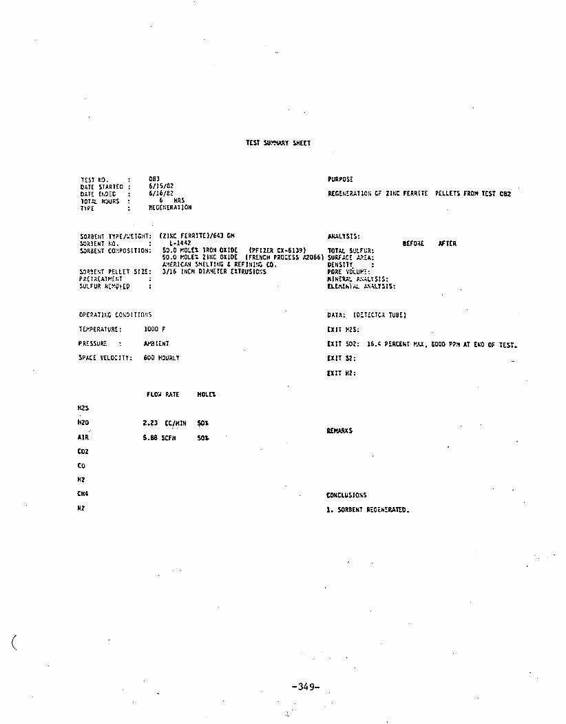
TEST U.WY SHEET
TEST KO. : 0 8 3 o r r E SIhRTCO : 6/15 /02 OAT: It.9fC : 6/16/E2 7 0 7 2 H'JURS : 6 HRS T l P i : REGE tiERATIOH
PURPOSE
REtEt;E?;l IO!; t i Zlt;C FERRITE PELLETS FRO3 l E S T C82
SOaaEtrT Tl?E/';Elt3T: ( Z I L FERRITC)/643 Gt4 W L T S I S : f323ENT KO. : 1 - 1 4 4 2 B E f O I E # T t R S3RaE!iT CO:'.POSITIOI: 53.0 ROLE% IRON OXIDE f PFIZCR CX-6139 1 TOTAL SYLFUR:
50.0 KOLE*: Z l t IC OXLOE (FRENCH PROCESS R 0 6 6 1 SUKFACE L?EA: K!EF!ICW S?IELTIIIG L REFI!II!S LO. OEtISITT~ :
53P.:E!;T PELLET SIZE: 3 /16 l t lCH 01P:4iTER EXTRUS1C::S PORE VOLUt!!: PLCTAEATKE t i 1 F l lYEC l - A G L Y S I S : SULFUR k;YJ\ID : t~ tn th la AS~LISIS:
0PEP.ATlt;G COS9ITIOIIS
TCr.?ERATURE: 1 0 0 0 F
PRESSUL : M l i N T
SPACE VELOCITY: 6 0 3 H9URLY
2.23 CC/MlN . . $OX
5.88 SCFH 5 0 %
DATA: (DLTECTCI TUBE)
E X I T H2S:
E X I T 502: 16.4 PERCENT PAX. 6 0 0 0 P?,Y AT ECI; OF TEST,
E X I T st: - E X I T H2:
CONCLUSIOSS
I. SORBENT RfC iY fPA lED.

TEST W W R Y SHEET
TEST KO. : 0 8 4 DATE STA2TEO : 6/11 /82 OAiE If;CiO : 6/17 /82 TOTX II~'J.;S : 3.25 H I S TYPE : U I L F I O A T I O ~
S g ~ j E t 1 1 TYPEfiEIGHT: ( Z l k C FERRITE) I643 CN AWLYSIS : U R 3 i C T LO. : L-1452 BEFORE LFTER soaa:~;~ CO!!POSITIO!I: 5 0 EIOLEZ IRO!I OXIDE ( P F I ZER CX-6139 I TOT;!- SULFUR (:Y/Wl:
SO ROLE% ZI~IC OXIDE (FRENCH P a o c c s s ~ 0 6 6 ) sui~~c;;t A=.?.~x ( r 2 1 ~ 1 : O E H S l i f (GICCJ :
SOAaENT PELLET SIZE: 3/16 1IlClI DlhYETER EXTRUSIONS ~ 0 2 f YOLIX (?:'r3/tl: PRET.?EhTYENT W1t;EPAL E i i L Y S I S : SULFUX L0A91KG : t (GN S'JLFURIGY F R i W S9RaEI;T) . E L f X E ! ~ T N C.:IXLYSIS:
PRESSURZ : C.VS LENT
SPACE VQOCITY: ZOO0 HOURLY
W S
H 2 0
A I R
t o 2
co
M
a 4
NZ
FLOV RATE
0.9963 S C M
3.872CC/MIN
' 3.6 SCFH
4.3 SCFH
6.3 SCFH
1.07 S C M
10.34 XM
DATA: ( O iT iCTOa NaE)
E X I T HZS: 10 PPX AYS FCA 1.75 E Y d R S t i
B2EFXIHX01JCh AT 2.25 E:WS Y L T K 27 ;?:! E X I T 532:
1. FZhSC!I:3LE PiPIORwASCE AT 1200 f . X I C H T L Y - FASTER BAEACTH2OLlLH AS CC?i'XliD TO SLlLF1Ofi:IOS
AT 1 W O F ( AS EXZiCTtO).

TEST !.O. : 0 8 5 OAT[ ST22TED : ' 6 /18 /82 DATE L!:.)TO ! 6/2:/iJ2
PU7PCSI
RECi!.E?rTlO!; CI ZINC FERRITE PCLLETS FRG3 TEST Caa
SDla iUT TI?E/h'ElGHT: Ub!TED CATALYSTS 211:: FE9RITC/6:3 G!4 AftALYSlS: SOl9EST !3. : L-1442 S023iHT CC.CI?OSITIO!I: 50.0 r(OLf: IPOq OXIDE (P f IZER CX-6139) TOTAL SVLfC?:
50.0 t:OLLI: 21KC OXIDE (FP.EI:CH PROCESS XZOKb] SURFACE A?:;: AYERICkl S"iL1It;S 1 PEF1t;ltiS CO. OE1;SlTl :
S9?3El :T PiLLET SIZE: 3 /16 I f lCH DIA?,V.ETCa EXT~USIOI~S PORE V7LC"Z: PRETREAT!!iST )IIt;3!X XhALY S IS : SYLFG2 PiY3';ED : ELCKL!iT;L ;S;LY SlS:
DATA: (DST iCTCI TUBE)
EXIT t!ZS:
EXIT SO?: 8.4 PLRCEGT PAX ,925 Pi3 AT EtiD O; TiST
E X I T SZ:
EXIT H2:
FLW M T E ROLE:
HZS
HZ0
A I R
COZ
LO
HZ
CH4
N2

TEST SUmARY S n l E T
TEST KO. : 0 8 6 orrf srinrco : 6/22 /82 OAT i E s l i D : 6 / 2 2 / 0 2 TOTR kwks : 3.6 HRS TYPE : WLf I O I T I O H
s ~ ? ? [ ~ I T ~yp: / ; ' t t t t~T: UAITED 'CATALYSTS Z1t:C F f R R I T E / 6 4 3 t!4 AtLLLY S!S: CflYaCUT $3 r L-1442 ELFORE F T E R .,"..-... . ..". . - - -
SOXSEhT CO?:O~SITIO!l:. 5 0 KYLE% IROS OXIDE ( P i l Z E R CX-5139) TOTh: S'XFuR (Yi IY): 5 0 KOLE: 21!:C OXIDE (FREICH PROCESS l-20651 SUiL'ACE h C A (%/GI: kYERICRI SNELTI t;S 6 REF 1:; l l t CO. DENS IT^ (C/SC) : .
SCP.aE!iT PELLE: SIZE: 3 / 1 6 1tlCH O!A%TER CXTCIUS1O:iS PORE VOLU!<f ( 9 3 1 C ) :
SPACE YELOCITY : ZOO0 KOURLY
MS
HZ0
A I R
t o 2
t o
H2
W4
n2
-THROUGH KITH ZCO PPX AT 2 ClURS E X I T sot:
E X I T SZ:
FLOW RATE MOLE:
0.9963 XFH 2.7%
3.872CCl t I lN 27.66:
3.6 SCFH 9.68 %
4.3 SCfH 11.91%
6.3 SCfn U.lZt
1-07 SCFH 2.91%
10.34 XFH 28.1 1: 1. SECO!IO WLFICAT1O.Y RESULTED I R M a E PAPID SXEAXTHaOPCN PAY BE CN I%S lCATIOS OF SItlTLR!!& CAUSISG A DaOP OFF IN PCRFOR~~L%CE.
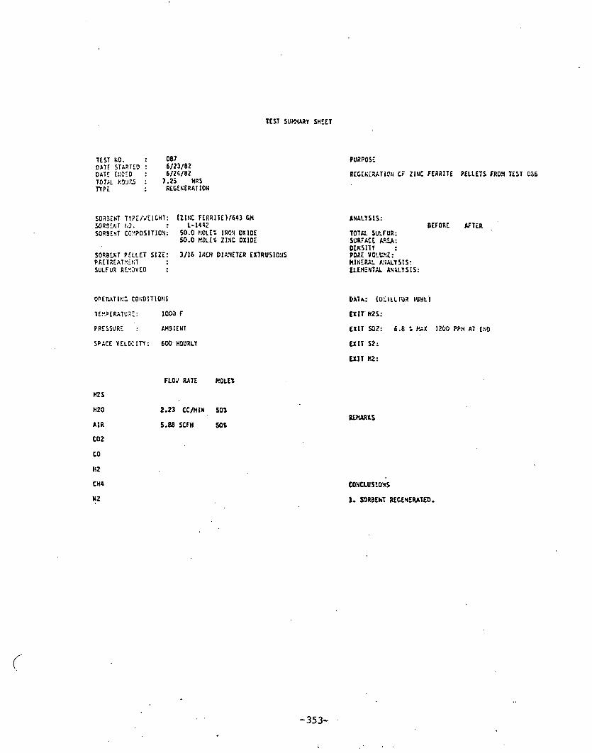
TEST KO. : 0 8 7 o A r E srsrro : 6/23 /82 O ~ T E ~!;CEO : 6 / 2 5 / 8 2
SO3j;tiT T T ? i / J t l t H T : (211:C FLRRITE) /643 GH 9 l R 3 f l i T 1 3 . : 1-1442 SOR9E4T CC:??OSITIC!I: 50.0 kOLE= IRC!t OX IOE
9.0 ROLE% Z INC O X l O i
SO laEkT PCLLET SIZE: 3/16 Ih'CH DIE iETER EXTRUSIO!IS PkLT.?EAT*if;T SULFU3 RLYSVED :
QPElbtTIt:; C0I;DITIOtIS
lEY.?ER\TCJ.Z: 1 0 0 3 f
PRESSURL : N4SIEUT
SPACE Y ELK ln : 6W. H9URLY
M S
H Z 0
A I R
COZ
co
HZ
CH4
WZ
PUZPOSE
RECi t iTZATICI i CF ZINC FERRITE PELLETS FRO9 TEST C36
KNaLTSIS: BEFORE K T i R
TOTAL SULFUR: SL'R'ACF M%: DENSITY : P O X YCLCXC: nI!:Ee: l!;AL?sIs: tLL\ l fHT% RS<SIS:
CIAIA: tui l tcrua lurri
EXIT. nzs:
C X I T SOZ: 6.6 : PAX 1 2 0 0 PPN AT L!1D
C X I T 52:
E X I T Y.2:
F L O l RATE ROLES
2.23 CC/HIN 50%
5.M SCFH 50%
CONCLUS !ONS
1. S9RBEkT REGENERATED.

TEST kJ . : O a 8 DATE STh3TEO : 6 / 2 5 / 8 2 DATE E!;:EO : 6 / 2 5 / 6 2 T O T R HO:'RS : 1 - 7 5 HRS V P E : S U L F I O A T I O t I
SORaEKT TYPE/'.'EICIIT: ( Z I N C F E R a l T E )!6:3 CY S3RBCET SO. : L - 1 4 4 2 S3RaEt;T CO?r?OSITIO!I: 50 blOLEP I R O H OXIO,'
. 5 0 H O L E ' L Z I N C O X I O i
SORDE1:T P E L L E T SIZE: 3 / 1 6 l N C H OIAYETER EXTRUSlC!iS PRfTP.EATV2iT SULFUZ LOAOICC : % (GY SULFUP./GY FRESH SOR3EI;T)
PRESSUX .: A K ~ ~ E N T
SPACE VELX:T:: 2 O W HO'JRLY
M S
H Z 0
A I R
C 0 2
CO
HZ
CH4
N 2
FLW RATE UGLE:
0.9963 SCFH 2.7%
3 . 8 7 2 C C l f l l t l 2 7 -66%
3.6 SCFH 9.68 t
4.3 XFn 11.91 %
6.3 SCFH 1 7 . 1 2 1
1.07 SCFH 2.9!t
10.34 YFH 28.1 :
PURPOSE
T H I R D S X F I D A T 1 lO!i OF U I I I T i C CAThLTST L - 1 4 4 2 AT liC3 i .
DATA: ( CtTECTOR m5E1
E X l T 112%: 10 PPN AT 1 5 E:hU;ES
BRCXKTll2OLC!I nr 1.3 ~S';JL UITH szo ;?P E X I T 5 0 2 : 1C3 P?H AT 1 5 KU.II.~;iCS C.;;'l 10 1 P?!? ;rTEZ
1.5 tias. E X I T S t :
E X l T HZ:
COSCLUSIOHS
I. LOSS O F PEZORuAt tCE OSSERVED AS CO?PA2ED 7 3 F I R S T 7 x 0 SULFIOATIOKS. S'JSPECI LOSS 05: TO SI ITER1t ;G AT 1 2 0 3 F.

TEST SU.?PARY SHEET
TEST NO. : 089 DATE SThRTfO : 6/29/82 DATE LtiSiO : 6/29/82 TOTX tiI)L'RS : 2 HRS TlPE - : WLFlDATION
SORBENT TYPE/UEIGHT: (ZI I IC OXIDE)/50D GU (HYDROGENATION CATALYST)/333 M
SORBENT 110. : G-72D ZINC OXIDE t - 6 5 P J HYDRDGENATI0.Y CATALYST - - - ~-
SORBENT CO?POSITlON: 9 0 WEIGHT Z - 2 x 0 ( G - 7 2 ~ ) 2 7 YEICHT % N I (G65RS)
SORBEHT PELLET SIZE: 3/16 IIIM DIMETER EXTRUSIOSS PRETREATXEHT SULFUR LOA9ICG : % (GM SULFUR/G# FRESH SORBEIiT)
PRESSURE : AYBIENT
SPACE V E L K I T T : 1000 HOURLY FOR ZEO AN0 G-6SRS (APPRSX)
tQs
H20
A I R
6 0 2
CD
HZ
M4
N2
FLOW RATE HOLE:
0.9963 SCFH .2.7:
3.872CC/IIW 27.66%
3.6 SCFH . 9.68 %
4.3 SCFH 1i.91 t
b.3 X F H 17.12%
1.07 SCFH 2.91%
10.3CStFH 2 8 . 1 %
PURPOSE
DETER31SE TEE C:.?A3ILITY OF PICKEL TO RED'JCE HZS LEYEL SELCV ? P?R.
TOTAL SCLFtil 13/21: SUF5XfE AREA ( Y Z / G ) : DEliSITY lC/CC) : PORE YCL1;Y.E ()5Y3/C) : MIIIERAL I-SALI S I S: CLW.TNTX &VAL7 5 IS:
DATA: ( DETECTOR N B E )
EXIT SD2: I;SDETECTMLE
EXIT 52:
EXIT HZ:
I. W T H ERSESTS USED ARE tI%KUFACNRED BY UNITED . . CATALY STS.
1. SlLFUa LEVELS YERE t:OT REDUCED EELOW 1 PPI, SUSPECT P O S S I B L I N OF SULFUl I N THE WIMEL CATALYST IViD/Ol SlLFVR PICKUP FRO3 REACTIU WALLS.
'

TEST SUP."ARY SHEET
TEST K3. : 0 9 0 O A T S T : 7/2/82 DATE Es9EO : 7/2/82 1012 HOLIRS : 1 0 HRS T IPE : SULFIOATIOII
PURPOSE
DETERNl!iE I F OES'JLFIOI?:G OF I l ICKEL CAT&LYS 0CCUP.S IH A LUPG! G S YITHOUT H2S.
S O R B ~ K T TY?E/VEIGHT: (ZIh'C OXIDE )/SO0 GH AliALYsIS; (HYDROGENATION CATALYST 11500 Gn
SORSEtiT KO. : C-720 Z l l lC OXIDE BEFORE XFTER C-65RS HYOROGEtlkTlON CATALYST
S0RBEI:T COPSOSITION: 90 L'EIGHT = 2x3 (G-720) TOTAL SULFUR (YiIY): 27 WEIGHT % ti! (G6SRS) SURFACE AREA ( Y ~ / G ) :
D r c s i r r (c/cc) : SORBEtlT PELLCl SIZE: 3/16 I I C H DIhYETER EXTRUSIO!lS P0P.E VOLUEE ( W I G ) : PRETREATREKT HICERXL A%.';iLYSIS: SULFIa LOADIKt : X (tM SULFUR/GN FRESH SORBENT) ELtWMTAL ANALYSIS:
0PERATLt;t COtiDlTIONS
TrnPERATU2E: 1 0 0 0 F
PRESSURE : hMBIENT
DATA: ( DETECTOR N B E )
EXIT 142s: 30-co PPn
EXIT SQZ: USDETECTKELE
SPACE V E L M I T Y : 1000 IIOURLY FOR 2t;O AKD G-6% (APPROX) E X I T 52:
E X I T HZ: . . .
HZS
HZ0 '
A I R
t o 2
CO
HZ
0 4 '
k 2
3.6 SCFH 9.68 'C .
4.3 ' SCFH ' 11.91 f
6.3 SCFH 17.12%
1.07 SFFY 2.91% .
' 11.33 SCFH 30.8 =
1. BOTH SORSENTS USE0 )rRE PAt:UFAtTUREO BY UHlTED CATALYSTS.
'1. DESULFIDItlS OF I I ICKEL CATALYSf AVD/OR REACTCR XALLS OCURREO. SUB PPH LEVEL TESTItlG M I L L REQUIRE DEDICATE0 'LOU SULFUR' SYSTER. 02 QUARTZ P.EKCTOR TO E L l n l t l A T E POSSISILITY OF SULFUR P I C K UP FP.03 REACTOR li41.L~

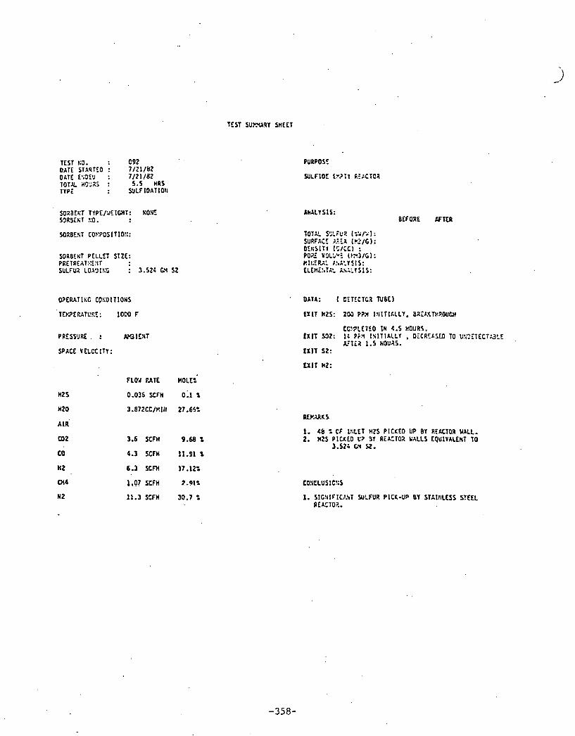
TEST S U W R Y SHEET
TEST OATE onrc T O T X TYPZ
: 0 9 2 1 3 . STxSTEO : 7 / 2 1 / 1 2 fa;!lE!, : 7 / 2 1 / 8 2 . icC';XS : 5.5 HRS
: U L F I O A T I O I I
SORBENT P E L L E T S I Z E : PRETREAT:.::E!!IT SULFUX LOAl)l!;t : 3.52: GY 5 2
PRESS'JRE . : M l E I T
SPACE VELCC I T Y :
A k A L l ' S t S: BEFORE CCTER
TOTAL SSLFUZ (i'il'; 1: SURFACE >-:.:A (!42/C):
OATA: ( CiTECTCR TUBE)
E X I T WZS: 205 P?X l I , l l T I h L L Y . BXEPXTt!ROUCI)
CC!.?LCTEO I N 4.5 HOURS, i X l T 532: 1: P i x I S l T l h L L Y . OfCREASCD TO U ! I ? I T E C T g ? E
&:Ti2 1.5 HOUaS. E X 1 1 S2:
F L W F A T E MOLE:
0.036 SCFH 0:: t
3 . 8 7 2 C C l t ? l l l 27.65:
3.6 S C f H 9.68 t
4.3 SCFH 11.91 %
6.3 S C M 17.12%
1.07 SCFH 2.91%
11.3 S t F H 3 0 . 7 =
1. 46 : CF I!;LET H Z S P I C K E D UP BY P.EhCTOR WALL. 2. HZ5 PICKED L'? 3'1 REACTOX V A L L S EQUIVALENT T O
3.524 L'i Y.

TEST I.@. : 0 9 3 DATE STA?TE3 : 7/22/82 OAT: p;5f3 : 7/22/82 701% ~3"s : 4.5 ' HRS T l P i
OPERAT 1);: C0!:01T10115 .
TLY3EMTUlE : , 1 0 0 0 f
PRISS'JRE : ClH3lEllT
SPACE VELCC ITY :
H2S
HZ0
A I R
CO 2
to
H 2
CK4
N 2
TEST SU,V.uA!tY SHEET
PURPOSE
AllALY SIS:
y o l a S'JLFUP. ( : V l i ' ) : SURFACE &?!i (.U.2/G!: DENS!Tl (CICC) : PORE VOLCYE (kY3 lC) : ElNERAL X$ALYS!S: LLEl'.C!dTXL i n A L Y S!S:
DATA: [ D E T t t T c a Tu~E)
EXIT ~ 2 s : 335 P?!I hb'EffiGE
EX11 502:
EXIT HZ:
FLO'A RATE ROLE%
3.6 SCFH 9.68 %
5.3 SCFH 11.91 .%
6.3 S f F H 17.122
1 .07SCFH 2.91%
11.3 X F H 30.7 % 1. 112s LEhCY.I!dG W P W YO 6E NEAR EQUlCIBRIW UYEL 335 PPX AViRAGE. . .

TEST DATE DATE TOT.? TYPE
LO. : 0 9 4 STARTiO : 7/23 /82 tsdT9 : 7/23/82 - ~:?f iS : 5.75 HRS
: RECECERATION
SO2BEUT PELLET SIZE: PRETRfATI:LST S'JLFU? RLVOVED :
OPERATI 1;; CL'!:D:TIO!IS
TEU3EGTCRE: 1 0 0 0 F
PRESSURE : MIBIENT
SPACE VELOCITY :
HZ5
t i20
A I R
C02
co
HZ
c"4.
H 2
FLOU RATE MOLE%
TEST S'J?rWY SHEET
PURPOSE
REGE!;:;;ATIC!~ CT Lu?TY REACTOR TCST.
2.23 CC/HIN 50:
5.88 SCFH 50%
I N X L I S I S : BEFORE . K T E R
TOTAL 5ULF17: SURFACE U E A : OEKSITV : POX: YOLUUE: HIIIERAL hSALYS!S: E L t Y i S T A L A G L Y S I S :
DATA: (DETECT02 N E E )
EX I T H2S: L'EDETECTMLP
E X I T 532: 7 : Pa, 70 P?fl AT EI:D OF TEST
E X I T 52:
EXIT HZ:
60NCLUS IO!JS
I. REACTOR OESJLFIOEO.
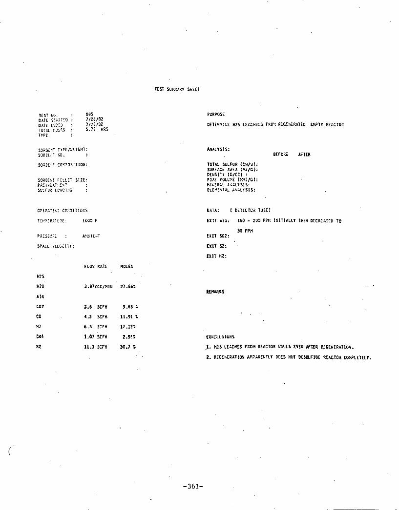
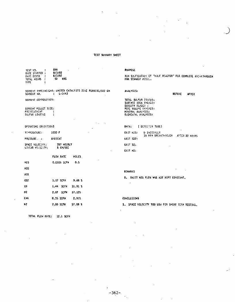
T E S T SUY.WR1 SHEET
: 0 9 6 TEST 1 3 . DATE S!ARTEl : 8 / 3 / 0 2 DATE f!:'JID : 8 / 3 / 8 2 TOTAL HYJaS : 50 HRS TYPE
S019E::T TYPE/uE!CHT: UNITED CATALYSTS ZI!X F C R R I T i / 3 2 2 C!i SCaSEt;T KO. : L - l i 4 3
SO23EYT CCU?OSITIO' l :
S'JgSENT PELLET S I Z E : PZETREATGZXT SGLFUZ LOAD!!;; :
P R E S S U E . : RC3 I ERT
SPACE VELO:!TI: 7 8 7 HO'JiLY L I S C A q YYE?G!TI: 5 C!I/SEC
F L C U RATE' kOLE=
O.CS05 SCFH 0.5 HZ S
H Z 0
A I R
UJ2 1 . 1 7 S C F H 9 . 6 8 2
CO 1.44 SCFH 11.91 t
H Z 2.07 SCFH 17.12%
CH4 0.35 SCFH 2..91:
N 2 7.00 SCFH 57.U t
TOTAL FLOU M T C : 12.1 SCFH
Rut1 S:LFICIITICI': C? 'EALF RCACT3R' F(i7 C O r P L E T i t . i i & < T k R 0 ~ C l FOZ SCK;Ul1T E"3fL.
TOTXL S U L F U I ( ? J / ; r ) : S'JRFACE &?!A (!L?/;): D L C S I T l ( S I C C I : P O E F(JLL'!!L ( ~ . ~ I l i i ) : B I I E R A L h'eALT SIS: ELEkEf TCL P!i:LY S I S :
DATA: 1 O:TE:;23 N E E )
E r n s 2 s : IYITI:LLY 11, P ? Y GaEAI(TkiO' iCH I.:iE? 2 2 kO'~45
tXlT 5 3 2 :
E X I T s2;
E X I T HZ:
REUARKS
1. I t I L E T H 2 S FLO;I Y U &);3 KEPT CONSTl?rT.
COSCLUSIOMS
1. SPACE V E L K I T T TCCl 102 FCR SHO.IT TEFA TEST1t;G.

TEST SUMdRY SHEET
TEST S3. : 0 9 7 DATE S T : 6 / 1 7 / 8 2 GAT! 3 3 3 : &/17 /62 TO?% rijj'as : 6.5 HRS TrPi
PMPOSE
RUN ~ J L F IDIT 1011 OF .1/4 REACTOR' FOR CC"?LEIE eREAKTHROUCH FOX XHXO~IT ~ ~ U I L .
sgaaE!:T T Y P E / ~ E I C M T : U N I T f D CATALYSTS Z l K C FERR17_E/160 GM AKLLYSIS: 53;?!:;: :.3. : L - 1 4 4 3
N R J E K T PELLET S I Z i : PZE:REAT?:E!;T Y:LFL'~ LC191t;L :
PRESSURE : AVSIENT
SPICE V E L C C l n : 6 7 8 0 HCURLY FOX 4 INCH BE0 LI!;EAQ VEL!JC!TY: . 25 W / S E C
F LO;' RATE WOLL'.
H t S 0.93 SCFH 1.5
H Z 0
CO2 5.8 SCFH 9.68 t
7.2 SCFH 1 1 " q l t
10.27 X F H 17.124 .
1-70 SCFH 2.91%
1 0 T x F L W RATE: 60.0 SCFH
TOTAL SULFUR t=YPJ): SURFACE M E A i r l / ~ i OEtlSITT (CICC) : P O E V0LU.U: ( M 3 / C ) : HlNERAL C.Sr\LYS!S: ELWENTAL A U L Y S I S :
DATA: I OETtCTOR TUBE)
E X I T HZS:
E X I T 502:
E X I T St :
E X I T HZ:
REMARKS
BEFDXE K T E R '
1. 4 INCH eED I S TO0 SHOXT. POSSIBLE CtU'4!4EllFiG U U S I H G H 1 L ' 1 ! . 1 T ~ l ~ U S .
2. TEST MAS COXPLETC9 It1 O!X SHIFT.

TEST SUYYYARY SHEET
TEST 13. : 0 9 8 O I T i STARTiO : 8 / 2 4 / 8 2 OXTE C8;I)E0 : 8/24/82 101% SO'J2S : 1 2 HRS T T P i : SULFIOATIOfl
S025EKT TYPE/;'EIGHT: UfI lTCO CATALYSTS Z I K fERPlTE/!b9 G!4 salac!iT XO. : L-I~QJ
S0?3FXT CO!.:?OSITIOI:
SORBEX1 P E L L C l SIZE: PRCT2CAT:JE:lT SULFUX LC;~ISC :
PRESSURE . A'ISIENT .
SPACE YELCCITY: HWRLY FO2 C I H U l BED L1SEA.P Y?-C:!TY: CX/SEC
FLOY RATE HOLE%
MS 0.60 SCFH 1.5
HZ0
A I R
COZ 3.6 SCFH 9.68 3
CO 4.4 X F H 11.91 Z
HZ 6.3 SCFH 17.12%
MC 1.07 SCFH 2.91%
NZ 21.0 SCFH 56.ba %
PURPOSE
RUN QLFIBAT:Gs d~ '114 RECCTOa' FOR C C 9 l E T E BREAKTHROUGH FOX S C H L X E D E L .
DATA: ( CiT iCTOR TUBE)
E X I T HZS: 400 PPX G T C R 1 5 H1t;UTLS
E X I T SOZ:
E X I T SZ:
1. LOIIRED SP:.CE YELOCITY LO'LEREO I!iITlIL l!ZS SLIGHTLY BJT h9T CSOUGB. RO'i T I P 2 1s 1 2 hO'JaS Y H l U l I S T W :O);G FOR W E H!r7 VERATIOt l . POSSlaLC C r A i h E L l K G S T I L L A P733LLr..
TOTAL FLOV RATE: SCFH
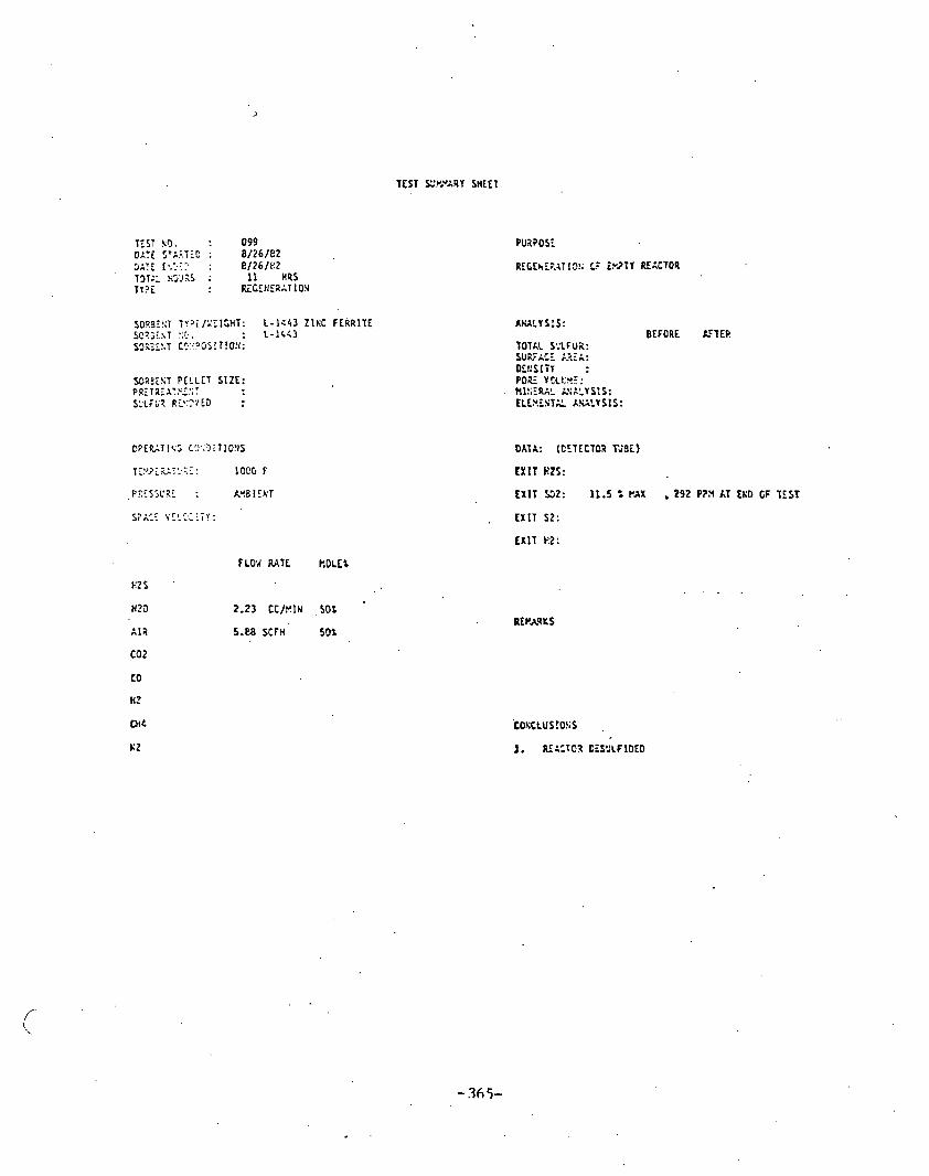
i ? ? i / k ' T I C ! i T : L - 1 c 4 3 Z I N C FERRITE S'!. . h e . : t-iCC3 cc:<?~Gs! T!O! l :
fOii?E!;T P E L L C T SIZE: PP.ETiiZXI.?Z:;T S:LFC? R5:2'/!3 :
FLOY RATE Y,OLE$
E2S .
H25 2.23 CC/t'.lN , so t
i 12 5.m SCFH 50%
C02
LO
H?
MC
KZ
AWLIS:S: BEFORE LcTER
TOTAL S:'LFUX: SU;L'A',T M Z A :
E X I T HZS:
E X I T 5 3 2 : 11.5 t rAx , 292 PZN AT tro GF ITST
, E X l T S Z :
LxlT k2:

TEST WWARY SHEET
TEST KO. : 100 DATE S!A2TE9 : 8/30/&Z 9 2 1 5 !!r9EO : 8 / 3 0 / 6 2 197% 2995 : 3.6 HAS TVPE : REDJCTlO!I
SOa3EKT T~?! /k" lGt lT: UNIT tO CATALYSTS Z lXC FERRlTE/163 Gt4 S023EST hJ. : L-1LC3
SORGE!tT PELLET SIZE: PtETIEATYLST SCLFCX LCA9!LC :
SPhCS V E L K ITY : HOURLY FOR C 1LCU BED L l K i l R YTLCCITY: CH/SEC
FLOU U T E ROLE%
nzs
n 2 o
A I R
COZ 3.8 SCFH 10.39 %
CO 4.4 SCFH 12.03 Z
HZ 6.3 SCFH '17.22%
044 1.07 SCFH 2.92%
hZ 21.0 SCFH 57.42 %
RUN t E O U C T l t v C i 'I/: .'LACTOa' TO OETCPH!tiE LEVEL C i H 2 s LEACti:!L FbX S:Hi?",.JT ROOEL.
70TAL S'JLFUX 1:ur.r): SURFACE LEI, (r21G1: DEHSlTY l C / C C l : PO?C Y O L O Y ~ (.-3/Sl: WIFTRAL 2 IALTS lS : fLm: : rTx ISLVS! S:
DATA: (: DfTiCTOR Nail
rx I T WZS: C P?R AVC
E X I T sat:
E X I T S2:
E X I T HZ: - . .. ..
8 E F O a i K T E R
CONCLUSIO3S
1. 4 PP9 HZS CBTAIHEO OURItiG REOUCTIOS
TOTAL FLO2 RATE: 35.57 SCFH

TEST SP."&RY 3 E E T
TEST SO. : 1 0 1 DATE sT;%Tro : 9 / 1 / 0 2 OnrE L:I):S : 9/1 /82 TO:x E3;'?5 : 4.75 HRS TYPE : W L l ir:TIO!i
SORSEtIT TY?E/YE l t4T : UtIITEO CATALYSTS Z1lIC FERI?ITE/160 CH Soa3is: EO. : L-1243
SORSENT CC!'.POSlTlON:
SORBEST PELLET SIZE: PRETRTAT?LI;T SULFFR LOX9lKG :
PRESSURE : Ak!a!Et!T
SPICE VErC:!::: 55C3 H9UP.LY FOR S INCH BED Ll t iEAR YELLLiTY: 15.5 CF:'/S2C'
FLOW RATE VOLE%
UZ S 1.2 SCFH, 3.2
HZ0
A I R
COZ 3.6 SCFH , 9.6 %
CO 4.4 SCFH 11.7 %
HZ 6.3 SCFH i6.e:
014 1.07 SCFH 2.8%
W 2 21-0 X F H 55.9 Z
TOTI\: FLOY RATE: 37.57 X F H
PURPOSE
RUN U L F ~ O A T I O ' ( 'I/< REhCTDX' FOR COW?LETE BRthK'lnR3UUI
FOR SCHRXJT K33EL.
TOTAL SULFUR ( = ' A h ) : SURFACE h?!A (P!Z/G) : DENSITY (G/CCI . : PORE VOLUVL ( M / G ) : I I N E R A L 21ALYS:S: ELEl4ENThL A S X L I S ~ S :
DATA: I DETECTOX IuBE)
EXIT ti2S: 1 r ; l T I X K25 5759 P?X
EXIT 502:
E X I T SZ:
EXIT nz:
BETCIE AFTER
CODCLUSIOSS
1.- 3.5 INCH BLO TC3 &YURT. POSSIBLE CHXSHEL1SG.

TEST S U P M Y SHEET
: 1 0 2 . PURPOSE JEST r9. OAT[ S l h l 7 E O : 9 / 3 / 8 2 OAT: C \9 f0 : 9 / 3 / 3 2 . RECENERATIC~J C. F;ILS-iLl LOAOEO RfhCTOX TUTZ :.?:PJ : 5.5 nas 1 l P i : REGCt;ERATIOO
S079ErT PELLET SIZE: . PRTTRCAT::E!:T SGLFUZ RC:3';EO :
FLOU RATE noLC:
HZS
H 2 0 2.23 C C I H l N SO:
AIR 5.88 SCFH 50%
to2
CO
HZ
M 4
I t
ANUY s is: ECFORE LcTER
TOTAL SULFUR: SURFACE U Z A : DEuSITT 2 PORE VOLUXE: HlKERAL hV,YILY 51 S: ELLHE!ITAL ::;AL? S1 S:.

TEST SU:*.*ARY SHEET
TCSi t;O. : 1 0 3 our srmro : g/:o/ez Dili 1';3:3 : 9/!0/92 0 t i : C.C. HRS TVPE : su?F IOAT I ON
PURPOSE
S3RBTt;T TYPE/h'EICHT: U l l lTLD CATALY STS Z l t X ' FERRITE/320 C!i AIlALYSIS: S2R'JSXT !;3. : L - 1 4 4 3
SCRBE!:T PELLET SIZE: P;liTXIAT.':iNT SULFCR LC:~:!:C :
TOTAL SULFu2 (%V/Y 1 : SURFACE LEA ( r z / G ) : D E L S l T l ( G l C C l : PORE VOLU>:E IP.WC): Y.I!;ERAL k i A L Y S I S: LLEUEt:TAL ANALYSIS: .
t..;ifi;f i h t C0!;3lr lO:ls DATA: ( DETECT02 TUBE)
Tf!!PEMiill(E: 1 0 0 0 F E X I T 1ZS: 4.5 ,P?S SFTER 10 UlBUTES
SPACE YELCC!Tr: 3 2 4 2 HOURLY FC.9 7 1 K U BE0 E X I T 52: LlS!Al( v i L C i l T Y : 16 C:i/SEC
. . - - E X I T HZ:.
FLOY RATE KILL:
HZ0
A I R
C02 3.6 SCFH 9.3 S
CO ' 4.4 SCFH 11.3 %
HZ 6.3 SCFH 16.252
CHC 1.07 SCFH 2.75:
H 2 21.0 K F H 54.2 t
TOTAL FLOV RATE: 38.77 SCFH
1. ..CO*LETE BREAKTt!;lOUC!l CURVE COY?LLTtO IN M E SHIFT L'lM LOX I N I T I A L HZS.

TEST S U P A R Y Y I E E l
SC23E!:T TI?i / : 'EIGHT: U N I T E D CATALYSTS 2 1 % F L R R I T E I l P O GRAYS SOS3IhT KO. : L-1443 SORSf3T CO?:?~SITIO!1:
SOPSI!IT PELLET S!ZE: P?.ETRCAT?:EST SULFCR RL'YJYEO :
O P E U T I S G CO!!DLTIOYS
TLY.?ER\TURi: 1003 F
PRESSL'E : h Y . 9 l f N T
SPACE Y E L K 1TY : 9s nO9RLY
- . -- . . F L C M PATE H'JLE:
k Z S
A I R 5.89 SCFH 50:
PURPOSE
REtOlERATlC' i C.; F?.ES!!Ll LOIOEO P.EAC,TCa
TOTAL SULFU2: SURFACE AX&: D E K S I T Y : PORE YOLCYZ: H l H L R A L &ALYSIS: ELEEEHTXL A!GLISIS:
BEFORE F F T E R
DATA: l O i T E C T O 1 1113C1
E X I T HZS:
E X I T s 2 :
E X I T HZ:
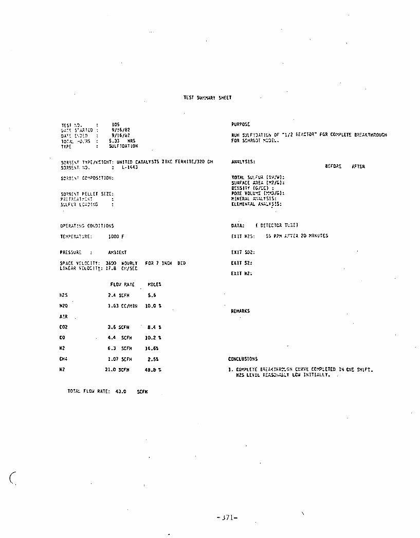
TEST !.3. : 1 0 5 5 0 : 9/!6/t(2 0 . ~ ~ : !*.)I? : 9 / 1 6 / b 2 13:X :3.'35 : 5.33 HRS TYPE : Y l L F J D A T l O N
SCQ3f \T l T ? i / k ' E l C H T : UHITEO CATALYSTS 2 1 D F t R H I T E / 3 2 O Cti S92SIhT. 1 3 . : L - 1 4 4 3
S"?01\7 CC'~?OS!TIo!I:
SO?SEXT P E L L E T SIZE: P 3 f 12I;T:Is: S:'LFCX L.:ng!!;C :
SPACE Y T L K I T Y : 3 6 5 3 HDURLY F 0 2 7 XhCH BED L I k E A R V E L O C I 11: 17.8 t?:/SEC
F L W PATE KOLL:
U S 2.4 SCFH 5.6
W20 1.63 C C / H l N 10.0 %
A!R .
COZ 3.6 SCFH ' 8.4 S
CO 4.4 SCFH 10.2 S
nz 6.3 SCM IC.C%
0: 1.07 SCFH 2.5%
N2 21.0 SCFH 48.8 %
PURPOSE
TOTAL SGV?FUa (%!Ul: S3RFACE &?!A [.Y.2/C): D L E S I T T ( C / C C l : P o x VOLC*5 (.Z'J/t): k I E E R X L 2;:LYSIS: LLEUENTdL LW'-l>!S:
DATA: ( D E T E C T C I i 2 3 I )
E X I T HZS: 55 P?3 :.TT;;Z 20 X l S a J T E 5
RLWRKS
1. C O n L e f E E?EA<:~~EC..C:~ CL'ZYE C C ~ L E T C D tr C:IE NIFT. H2S L E V E L F. IAS246LT LCd I S I T I X L L Y . .
TOTAL F L O v R I T E : 43.0 SCFH
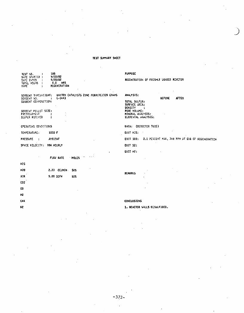
TEST YJPARY SHEET
TEST !;a. : 1 0 6 3;TE STZ?:TD : 9 / 2 0 / 8 2 - - 7 - . : 9 : 9/20 /82 737X. flM1 : 6.0 HRS T l P E : RLCEbERATION
S?29fuT T i?E/2EICHT: UXITEO CATALYSTS 21% F E R I l T E / 3 K ) CI(L!S SS::E~T a3. : L-1443 SOISEST CC!??JS I T :O!I:
O ? i Z T I & S CC!D!TIO!:S
T i Y 3 E U T 9 9 f : 1OOO F
PRCS9JP.f : P-YSlENt
SPACE Y ELCC!TY : 9%. H91:Rl.Y
FLOY RATE . k!OLE= . " '
EZS
HZO 2.23 CC/HlN. 50%
A I R 5-13 SCFH 50%
c o t
co
nz
C H I
WZ
PURPOSE
REGCh'ZRAT!J!; CF FRfSnLY LOAOEO RE1CTO2
ANALYSIS: BEFORE K T E R
TOTAL SULFPZ: SU.WACE LEA: OENSlTY : PORE VOLU!!f: RIhERAL kl;ALYSIS: ELEI..EsTXL i u L Y S 1 S :
DATA: (OETECTJZ rJ?E)
E X I T S2:

Z
"lo
a-
NN
XC
(Da
4
:> 2
h
N N
-mo
. N
3
5 C
P
W
n'
0
LC
W a
ul
;i *
-I
2 5,
5
N
0 \
W
t
If
e
W
I.. 2
- N
2
VI
* -1 2
.c un
.t
0 0
W
4
C
I
z-' J .... - x
0
..l
c . C1
a.
C 0
.- s
5';
"0
($4 m
L
1
x
X
D3
6.n
- $ 9
r)
u
W
C
4 a
:. 0, I..
2
C
0
I-

- I., x
,.
B ;:
t' .*
r.! I.
r>
C
N
' 0
I d
1.7 *
.i fl
13
2
a 2
.r C ;.
lzrr
n* 0
w
e
3 2
I.#
3"
I.,
tf C
I
I#
-
CL
L
.< -1 P
l ll
"2 = a,, V
)O
m
w
W
OL
P(
3: -
l.1
'i f
I
32
x
0 a
I&
a?
N
rn
m
r.! 2
0
S
z V
)
4
2
z Y 0
.
U
r(

TEST SUE:'!!!3Y SHEET
TEST b3. : 1 0 9 DATE STAXTE3 : 9 / 2 4 / 0 2 D A T i f!t!)ED : 4/2C/82 TOTAL HCJPIS : 1.3 6RS TYPE : SJLFIOn7:ON ,
S3RSEKT T Y ? L U E l G H T : U N I T E 0 CATALYSTS Z I K C F E R I I T E / 3 2 0 GN SllR3EST KO. : 1-144)
SOaBEET CCV?OSITIO!i:
S383EtiT PELLET SIZE: PRETCERT?:Z!iT S 1 L F G I LCXDIKC :
SPACE V E L M : T Y : 32C4 HO'JRLY TO;: 7 . l K C H BED L I K E A 2 YT?CCI:Y: 15 Gt:/SEC
PURPOSE
RUN W L F I O A T I C S 0; '1/2 REACTOR' FOR C';?*LEIE B P . E A K T ~ ~ O U L H FOA SCHa03T BS>fL.
A ! I L Y S l S : O E F t Z i K T C R
TOTAL SCLFU:! (%/Y): SURFACE A A i A [ Y Z l G ) : DENSITY ( t / t C ) : PORE YOLUYE (,-.?3/G] : M l t i E R h L h G L Y S: S: ELEHFtIT6' k':::,ISlS:
DATA: ( DETECT02 REi)
E X l T HZS: 17.5 P P 3 I ! i lT1&LLY, OECREkSl!& 10 5.0 P P X A T 2 3 H l l i V T E S
E X I T M 2 :
t X I T S2:
E X 1 7 HZ:
FLO'J R I T E !?OLE':
2.2 SCFH 6 .Z
3.6 SCFH 9.3 S
4.4 SCFH 11.3 S
6.3 S C n l !6.25%
1.C7 SCFH 2.15%
21.0 SCFH 54.2 S
TEPJ'ERATUR! '.'AYE DETiCTEI) D Y R I l i i SJLFID.4TlOW l i S T M O I T E O .
1. SUSPECT 50R35l IT KiDUCCS T3 FE hKD GTALYZED WE%HXWAT\TPON 3 0 PROJUCE TU!PEi-??ilRf L'AYE.
T O T U f L O 2 RATE: 38.77 SCFH
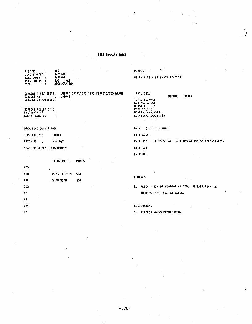
TEST Sur.%Y SHEET
TEST ti0. : 110 O I T i STARTEO : . 9 / 2 9 / 8 2 OITE fs9ZO : 9/29 /82 TOT% HO'JU : 5.0 HRS TYPE : PICENERATION
SO;ISEtIT TYPEPIEIGXT: UNITE0 CATALYSTS Z I E FERRITE/320 6 W . S SOi!aE!IT t:9. : L- I443 53a3 iST CC:!?OSITION:
SORBENT PELLET SIZE: PAETaEAT?!Et:T YJLFUI RE!:uFEO :
O?SR:T It:'. cQt:91TIQt:s
TU'2ERIT'JRE: 1 0 0 0 F
PRESSURE : LY31ENT
SPACE VELOCITY: 984 H W R t Y
WS
HZ0
A I R
CO 2
co
H2
CHb
HZ
PuaPos:
Ri ( iChlRAT1CS CP EYPTY REACTOR
A t f L I S I S : BLFORE K T E R
TOTAL YJLFU?: UIRTx:E ark: DEHSITT : P07E YCLC!!': Ml!iib!I:. k S A I I S 1 S : LLEF!iSTA', A U L T S I S :
FLOY RATE. F!OLE:
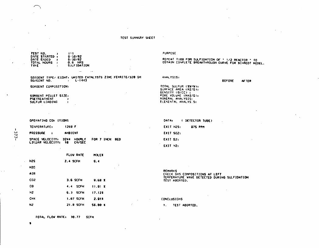
TEST SUHIURY Y E E T
D A T E E W E D I 9,' 38/02 . TOT&L M U R S : 0.6 HRS
T YFE SULFIDATION
SORDENT TYPE/ .'ElGHTt UNITED CATNYSTS ZINC FERRlTE/320 GM SE4GENT NO. : L - 1 4 4 3
SORDENT COMPOSITION:
S(IIDENT PELLET S IZE: PW TREATHENT t SULFUR LOADING
OPERATING C O ~ lrlms
TEkiPERATURE I 1 2 0 8 F I
W 4
PRESSURE : I\HB I ENT 4 I SPACE VELOCITY: 3 2 4 4 HOURLT FOR 7 INCH BED
LI I ;ZkR VELOCITY: 16 C M / Y C
A I R
PURPOSE
REPEAT T I 0 9 F M SUCFIDATION OC ' 1 1 2 REACTOR ' TO OBTAIN COWLETE BREWTHROUOH CURVE FOR SCIlRODT WOML.
I N ~ Y S I S I BEFORE M T E R
TOr4L WCFUR ( I Y W I I SURFACE nREA l M21G I : DENSITY (O/CC) : PORE VOLUME t MH3.'G I I MlNER4L ANfiLYSIS: ELEpiENTAL 4NALYS: S:
DATA: ( DETECTOR TUBE)
E X I T H ~ S I a 7 5 PPH
E X I T Sa2:
EX17 S2:
E X I T HZ:
FLOW RATE H ~ E I
2.4 SCFH 6.4
3.6 SCFH 9.60 1
4 . 4 SCFH 11 .91 I
6 . 3 SCFH l 7 . l 2 1
1.87 SCFH 2 . 9 l X
Z l . B S C F t 4 5 6 . 0 8 X
CHECU ' 6 4 s COMPOSIT IONS A T LEFT TEMPERATURE WAVE OETECTED DURING SULF lDaTION TEST AEOR TED.
CWCLUSfGNS
I. TEST ABORTED.
~ O T A L FLOW R4TEt 30 .77 SCFH
a
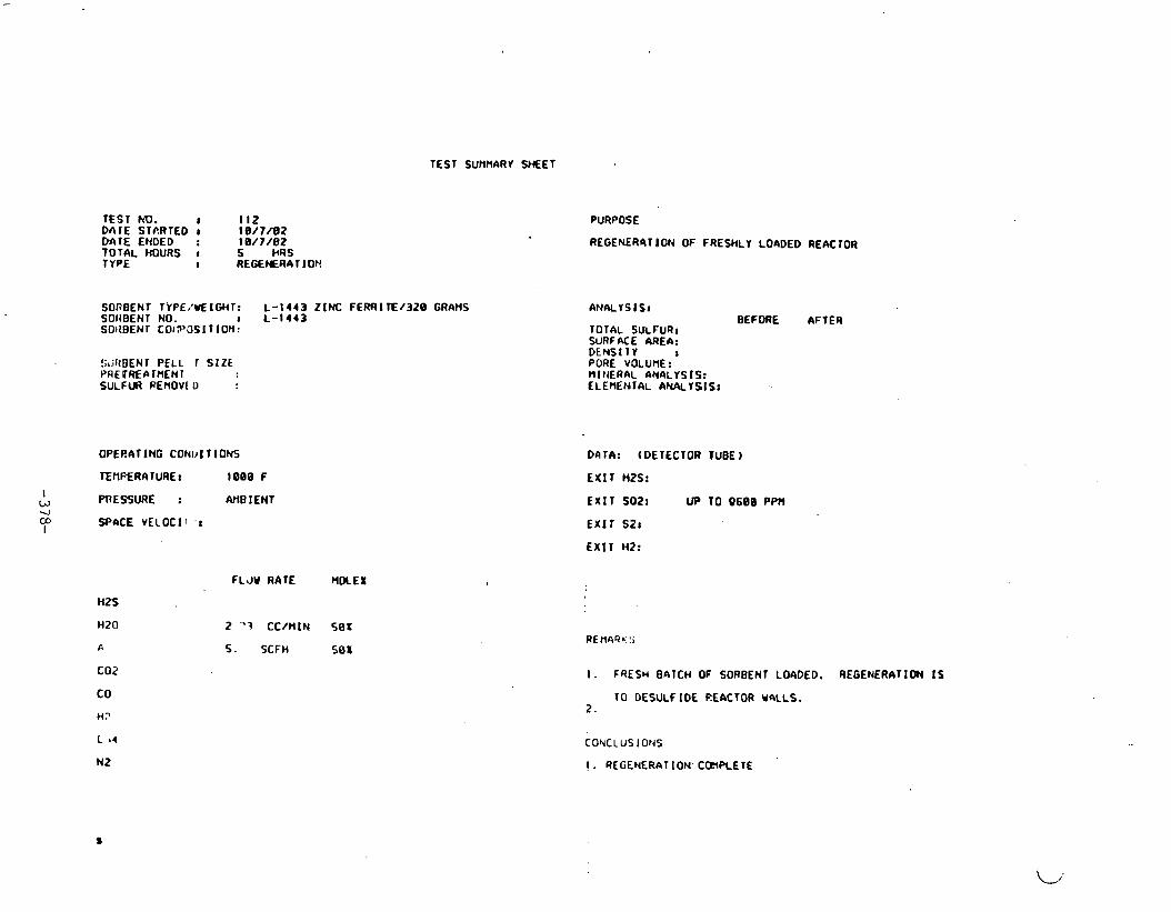
TEST SURMARV YIEET
TEST NO. I I l a DA lE STP.RTED J 18 /7 /82 W T E ENDED : 18/7 /02 TOTAL HOURS r 5 HRS TYPE I REGEPIERA 1 lo t !
SORBEN1 TrPE,'UEIGHT: L -1443 ZINC FERRI K / 3 2 0 GRAMS SOllBENT NO. r L -1443 SOI~BEN r cot ?'as I I I OH :
SuRBENr PELL 1 SIZE PRE DRECI IMEN 1 SULFUR PEnov[ D
OPERATING CONI)l TIONS
I w PRESSURE : M B l ENT .I to I
WhCE VELOCll ' I
tits
HZ0
A
C02
CO
ti?
L 14
NZ
FLJY RATE WREI
2 "7 CC/MlN S0f
5. SCFH 50X
PURPOSE
REGENER4TION OF FRESHLY L O A M 0 REACTOR
BEFORE AFTER TOTAL SULFURJ SURFACE AREA: DENS1 1Y I PORE VOLUME: MlttERAL AMALYS IS : ELEMENrAL ANALYSIS:
DATA: ( DETECTOR TUBE
EX IT HZS:
EXIT SOZ! UP TO 9608 PPtl
E X 1 1 SZJ
EXIT HZ:
I. FRESH 0ATCH OIF SORBENr LOADED. REGENERATION I S
T O DESULFIDE REACTOR waLLs. 2.
CONCLUS I OtdS
I . REGENERAT ION' CQINETE

TEST S W Y Y Z E T
TEST. KO. I 113 BATE STUTED I lB /B /02 DATE Ellrn I 10/0 /02 T O T U ROWS t 0.. 4 1 URS
CGZNT TYPE/\EICHTI UI41TED CArALYSTS ZINC FERRl TE/32B GI4 CAiPENT t40. c L -1443
CⅈENT C O W '1 ION:
S M W T PELLET SIZE: Pi\E TN-A Tt t i t lT I SULFU-1 LOAD I tJG I
WERdrlM COND TIOMS
SPLCE VELOClTlr 3606 HOURLY FOR 7 INCH BED L1 l :EM VELOCITY: 17 .0 CH/SEC
H2S
HM
A I R
to2 co H2
Clt4
NZ
PURPOSE
RUN SULFIDATION OF '112 R E A C T O R ' FOR COI1PLETE 6REAKTWOOG)i FOR SCHRODT b00EL.
TOTfiL SULFUR 4 SV/W 1 : SURFME AREA tHZ/GI : DENSlTY (O/CC) I WRE vot.unE cnn3 /0 )1 M I ~ ~ E R A c AtrALY5 1s t ELEMENTAL ANbLrS IS:
BEFORE A F T E R
FLDU RArE W X E X
2.4 SCFI4 5.6
1-63, CC/Hf N l 0 . R 1
3.6 SCFH 9.4 X
4.4 S tFH 10,2 I
6.3 SCFH 14.6s
1.07 SCFH 2. SX
21 . € ' SCFH 4 Q . 0 X
TOTAL FLOV I ATE: 43 .0 SCFH
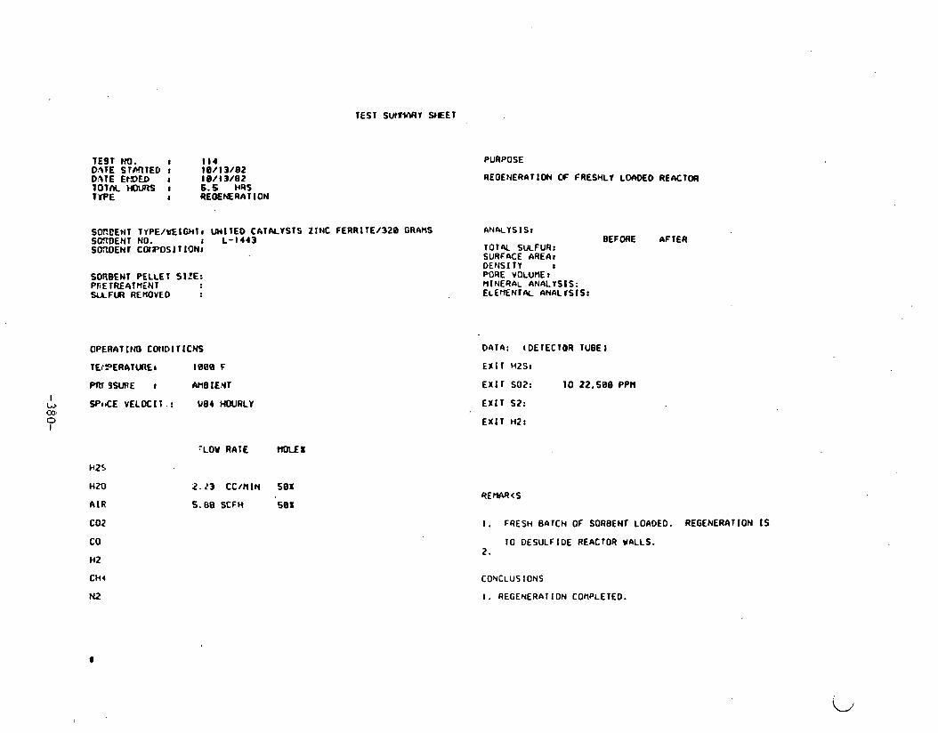
TEST S W Y Y E E T
TEST MI. 8 I 1 4 D.1TE STMTED t 1011 3 /82 D:%TE EtDED I 1 B/ I 3 /82 1 0 T M HnmS J 6.5 HRS T'fPE I REOEMRATION
SW.tENT TYPE/U€IGHTI U H l l E D CATALYSTS ZCNC FERRITE/320 GRAHS SOnOENT NO. r L-1443 SOXIEN1 COrJr)SI T ION8
SORBENT PELLET SIZE: PliETRE4TtlENI SUFlR REMOVED
I w SPICE V E L K I I . : U84 HOURLY 00' 0 I
HZS
HZ0
A I R
C02
CO
HZ
CHI
N2
'LOU RATE t l O l I X
2.23 CC/HlN 501
PURPOSE
REOENERATlO(J OC FRESHLI LOWED REACTOR
ANM'ISIS: BEFORE AFTER
TOTN SULFUR: SURFaCE AREA8 DENS1 T Y I PORE VOLUME: MINERAL ANALYSIS: E ~ E r n N r w ANALfSIS:
EX1 SO?: 1 0 22,500 PPH
EX IT S?:
EXIT HZ:
5.08 SCFH 501
TO DESULFIDE REACTOR UALLS. 2.
CONCLUS~ONS
I. REGENERATION CORPLETED.

TEST No. I 1 1 5 D l t E STARTED I l 0 / ! 4 / 0 2 DATE E W E 0 I 1 O/ 1 4 / 8 2 8 0 T 4 L HOURS I 5.73 HRS I Y F.E I S I A F I D A T I O N
PUFI,=OSE
RUN S U L F l O ~ r l O N OF 'I/2 R E K T O R ' FOR COMPLETE ~ R E ~ K T ~ # ? O W J I ~ FOR S t h R 0 3 T HODEL.
SOIDENT TYPE. iEl'?34T1 U N I T E D CATALYSTS Z I N C F E R R I T E / 3 2 0 GM ANALYSIS: SOROENT NO. : L - 1 1 4 3
. - COrtOE HT COHP* i 1 T IOh fOTfiL SULFUR ( XU/Y l r
SuRFACE M E f i t MZ/G I:
S I Z E : I I
OPERATINO CWDITIONS
- TE.l;?ERhTURE I 1620 F I
W 03 b-
PRESSURE : AHB 1 EHT I
SP.ACE VELOCI T I : 2 0 2 6 HOURLY FOR 7 I K H BED LINEAR VELOCI YI re.@ CH/SEC
h2S
H20
A I R
COZ
CD
Mi!
c h 4
K2
FLOW RATE HOLEX
1 . 3 4 SCFH
0 .02 CC/MIN
2.02 SCFH
2.5 SCFH
3.5 SCFH
8.60 SCFH
1 1 . 8 SCFH
DENSITY I G / C C ) : PORE VOLUME t n n w ~ 1:
HINERAL 6 m L r s f s : ELENENTAL ~ ~ ~ L Y S I S I
BEFORE AFTER
DATA: ( DETECTOR TUBE)
E X I T H2S: UNDETECTABLE I N I T I A L L Y , 16 PPH AFTER 14 MINUTES.
E X I T SO2:
E X I T S2:
E X I T HZ:
REMARKS
I. EXPECTED COMPLETION OF BREAKTHROUGH CURVE I S 7 HRS.
TOTM FLW RATE: 74.2 SCFH
a

TEST S U M Y SKEET
TEST 1.3. I 116 DATE STMTED I 10/ 19 /82 OnTE ENDED : 1 a/ 19/82 T O T ~ L w n s I 6.16 m s 1 YPE : REGEMRAT ION
PURPOSE
REGENERATIW OF FRESHLY LOROE0 REhCTOR
SOM!ENl TrPE/YEIGHTr UNITED CAT4LYSTS Z I M : FERRITE/328 G R W ANALYSIS1 BCRBENl NO. a . L -1443 GaRIiXNT COIIPOSI TIW: TOTAL SULFUR:
SURF4CE AREA:
SOnRENT PELLET SIZE: PRElREATMENl SULFUR REMOVED
OPERATING CONDITIONS
TEUPERATURE: lee0 F
I W
PRES*SURE I AMBIENT aJ h, SPACE VELUCITY: 084 HOURLY I
HtS
H M
A I R
t o 2
co Y Z
CY4
NZ
FLOU RATE RMEX
2 . 2 3 cc/nIn sex
5 .80 SCFH 50%
I DENSITY
M T A I (DElECTOR TUBE)
EX IT HZS8
{EMIT SO21 TO l ee38 PPN
E X l T S Z I
E X l T HZ:
I. FRESH BATCH X SORBEN1 LOADED. REOENERATfmd 1 s
TO DESULFIDE REACTOR MALLS. 2.
COI4CLUS IONS
I. REGENERAT IOM COMPLETED.
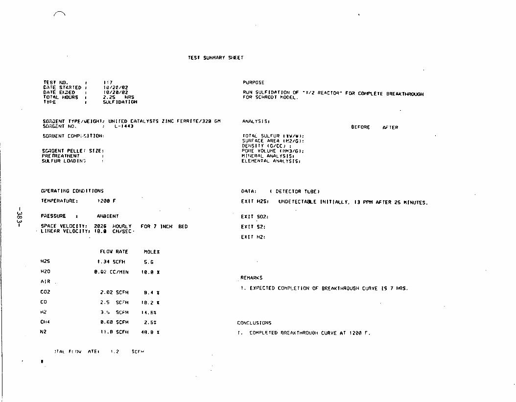
TEST KO. I 1 : 7 LATE STcRTED t l i1/2C/02 DATE Et3ED I IO/Z0/82 T O ~ L HOURS I 2.2s HRS TYtx I WLFIDATION
S0;iJENT TYPE/U€ICH~.I UNl rEO CATALYSTS Z I N C FERRITE/329 GM SOX.ENT NO. :. L -1443
SUGENT PELLE i SIZE: PRE IRELllt{EMT W F U R LOADttr?
MERAT I N G COtU I T IONS
TEMPERATURE: 1200 F
I W co PGESSURE I AHBIENT W I SPACE VELOCllY: 2826 HOURLY FOR 7 INCH BED
LIlIE6.R VELOCITY: 10.0 Cll iSEC .
HZS
HZ0
h l R . c 0 2
co H2
Cti4
N 2
FLOW RnTE
1.34 SCFH
8.02 CC/NIN
2.102 SCFH
2 . 5 SCFH
3.5 SCFt4
8.60 SCFH
I I. R SCFII
PURPOSE
RUN SULFlOaTlON OF '1112 REaCl04' F M U)FBTETE BREMT- FOR SCHRODT KOOEL.
BEFORE &-TER
IOThL SULFUR I IV/W I : SURFACE AREA (E2/G 1: DEHSITY (G / tC J : PORE VOLUME ( l tH3/G 1 : n1trER.w ANALYSISI ELEMENTdL 4N4L IS IS r
D91A: ( DETECTOR TLSE)
EXIT H2S: UNDETECTNXE IMITICKLY. I 3 fWi AFTER 25 MINUTES.
EX IT 502:
EXIT SZ:
EX11 HZ:
REHARKS
I. EXPECTED COtiPCETlON 8 F BREnUTHROUGH CURVE I S 7 M S .
CONCLUS lOtJS
1 . COMPLETED OREAKTHROUBIi CURVE AT 1 ZOO F.

TEST SUMMARY SHfET
l E 6 T NO. I 118 DATE STARTED : 10/22 /82 DATE ENDED I 10'/22/82 TOTAC wuns : 5.5 HRS TYPE : REGENERATION
SDRBENr TYPE/WE IGHI: UNl TED CATALYSTS ZINC FERRI TE/320 GR4MS SOnBENT NO. : L-1443 SORfENT CCMPOSlTlON: .
SORBEN1 PELLET SIZE: rnETREAlMEli7 WLFUR REMOVED
F L ~ ' RATE HOLE g
PURPOSE
REGENERAT ION OF FRESHLY LMMD REACTOR
IOTLIL SULFUR: SURFhCE AREA: DENS1 I Y : PORE VOLUME: H I NERnL ANALYSIS: ELENENIPL ANAL.YSIS:
BEFORE AFTER
DAlrt: ( DETECTiIR 1UBE
E X l r HZS:
. . EXIT SOZJ TO lo, eee PPN
EX11 S2:
EXIT HZ:
REMARKS
I . FRESH BATCH OF SORBENT LOaDED. REGENERATION IS
TO DESULFIDE' REACTOR WrtLLS. 2.
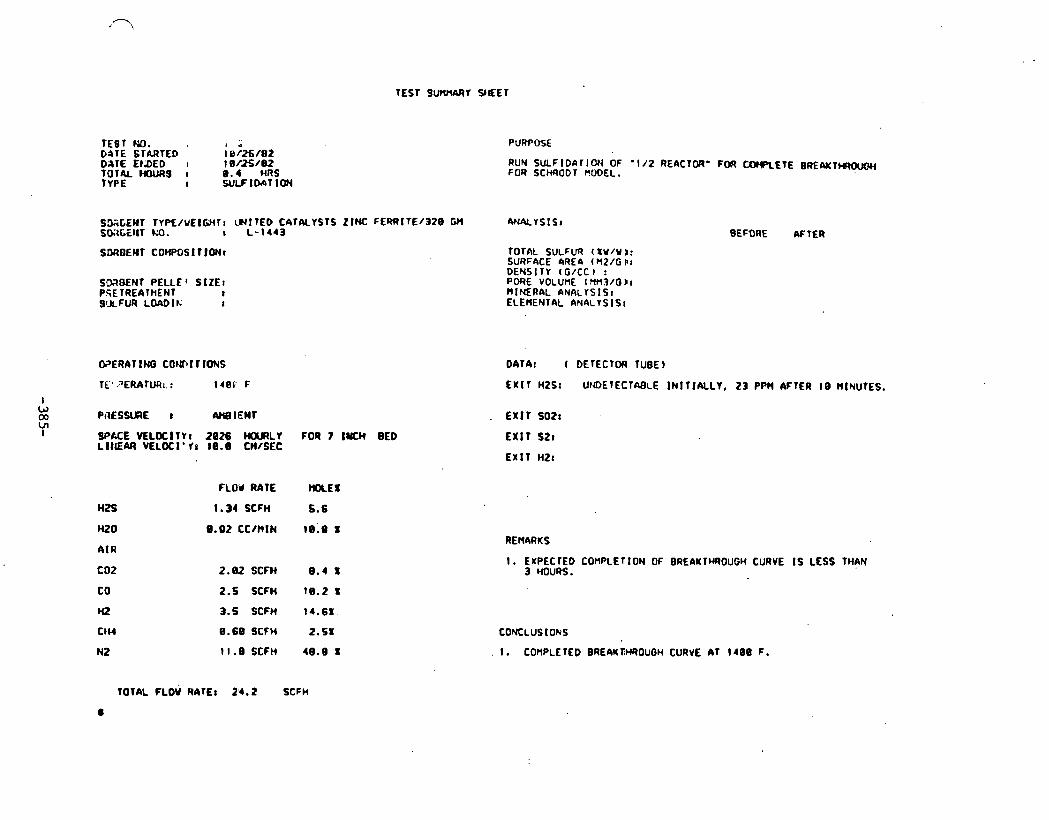
TEST 9UIO(ARY Y f E T
TEBT ND. D ~ T E STARTED i e k / e z DATE EIDED I 18/25/82 TOT& HOW3 I 8.4 HRS
8 WLFIIXc\TlW
RUN SULFIDnTlON OF -112 REACTOR' FOR CO)(PLETE BRENT- FOR SCMODI FOOEL.
SMCEMT TYP€/YElGMT: LHlTEO CATALYSTS ZINC FERRITE/320 GH ANLVYSIS: SD;IGEIIT W. r L -1443
SMBENT PELLEf StZEt PSE TREATMENT I SULFUR LOADIE;
WERATINO CW(Tll1 IONS
TE' .~ERATWI. : crer F
I W 03 PaESSURE 8 W I E N T Ln I SPACE VELOClTY8 2026 H a R L V FOR 7 IUCH BED
L I IEAA VELOCl'fr 10.8 CH/SEC
HZS
HZ0
AIR
C02
CD
HZ
CtW
N2
FLOd RATE ))(KE I
TornL SULFUR ( x w / w I: SURFACE aRE& t H2/G F: DENSITY ( t / f C l r P ~ R E ~ v o L u ~ E - ~ ~ ~ ~ / o )I, MINERAL ANALYSIS: ELEMENTAL ANALYSIS:
BEFORE AFTER
DATA: ( DETECTM TUBE)
EXIT H2S: UIOETECTABLE INITICULY, 23 PPH AFTER 10 HINUTES.
ExI'T SO2:
EXIT S2t
EXIT HZ:
1.34 SCFH 5.6
8.02 CCIHIN I REMARKS
2.aZSCFH 8 . 4 s
2.5 SCFH 10.2 I
3.5 SCFM 14.61.
0.68 SCFW 2.5X
11.0SCFH 4 9 . 9 1
I. EXPECTEO COMPLETION OF BREAKTHROUGH CURVE I S LESS THAN 3 HOURS.
CONCLUSIOkS
. 1 . COMPLETED BREAKBHROUGH CURVE AT 1400 F.
TOTAL FLOW RATE8 24 .2 SCFH
#

TEST SUtBMY SHEET
TE91 tM. I 1.20 DATE SThRTED : 18/25/02 DATE Ef!DED : l@/ZS/'BZ TOTAL HOLEIS 8 3.2s t(RS TYE : R E M M R A 1 lO(.(
SWtl?ENT TYPE/t!EIGt4T: UNITED CATALYSTS ZINC FERRITE/=@ GRMS SOnDENt NO. t L-11443 SOnBENT C0t'M)SITION: .
SOWENT PELLET SIZE: PRETrnATIENT S U F U REtDVED
OFERATINO COtQl TlONS
TEIIPERATURE: l a 9 F
PRESSURE : AHEIENr
SPACE VELOCIlYr 004 HOLRLV
bus HZ0
AIR
C02
t o
ti2
CH4
N2
2.23 CC/MlN 5 8 1
5.08 SCFH 58X
ANALYSIS:
TOTAL SULFUR: SURFACE AREA8 DEI4S 1 1 1 PORE VOLUM: HlNERnL At4ALYS IS: ELEMENTAL ANALYSIS:
BEFORE AFTER
0414: 4 DETECTOR TUBE)
EXIT H2S:
EXIT S02: TO 1 4 . e ~ ~ PPM
E X I t S21
EX11 H2:
1 . FRESH BATCH OF SORBENT LOaDED. REGENERAT ION I S
CONCLUSIONS
I. REGENERATION COHPLErED.
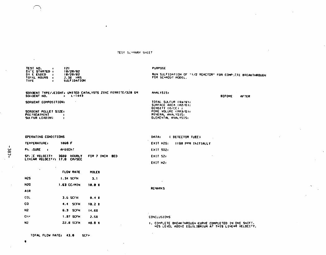
TEST NO. I I 2 1 C2"E STARTED I 18/28 /82 DA E €HOED r 18/28 /82 T0lC.L HOURS I 1.36 HRS
PURPOSE
RUN SULFlDfiTlON OF - IR REfiCTOR' FOR CWi .XTE BREAKTHROWiH FOR SCHRODT n m E L .
SOROENT TYPE/JEIGHTa UNITED CATALYSTS ZINC FERRITE/328 GM ANACYSISI SOliUENT NO. c L -1443
WROENT COHPOS l TION:
SOROENl PELLE 1 SIZE I PAE TREATMENT : Wl FUR LO4DINfi
OPERATING CONDIrlONS
. - w t SPe :E VELOCITY 3606 HOURLY FOR 7 INCH BED
L I NENt VELOC I T l c 1 7.0 CH/SEC
H2S
HZ0
A IR
to;
CO
H2
C t i t
N2
TOTAL SULFUR ( I V / U I : SURFACE AREa l M2/G I: DENSITY ( G / C C I : PORE VOLU~E I HM3/G 1 c MINERAL ANkYSIS : ELEMENT& A%ALYSIS:
M T A r 4 DETECTOR TuEE
EXIT H2S: 1100 PpM i h l l l A ~ L Y
EX IT SO28
EXIT S21
EXIT HZ:
FLOW RATE HOCEX
1.34 XFW 3.1
1.63 cc/ntn 18.0 x REMARKS
3.6 SCFH 0.4 1
4.4 SCFH 18.2 t
6.3 SCFM 14.61
1.07 SCFH 2 .51
22 .0SCFH 4 8 . 8 1
BEFORE AFTER
CONCLUSIONS
I. COnPLETE BREAKTHROUGH CURVE COHPLETED I N ONE SWIFT. H2S LEVEL ABOVE E O U I L ~ ~ R I U H AT THIS LINEfiR VELOCIT~.
TOTAL FLOW RATE: 13 .8 SCFk

TEST S W Y O E E T
TEST NO. I 122 D n l E S l M l E D I 1 1 / 03 /82 OnTE ENDED I 1 1 / 83 /82 T O T ~ L HOURS I 3.75 HRS T W E REGENERA 11 ON
PURPOSE
REGENERATI(X1 UC FRESHLY LOnMO M K T O R
SDROENl TYPE/WEIGHT: UNITED CArALYSTS Z:INC FERRITE/328 GRMS ANALYSIS: SW78ENT NO. : L-1443 BEFORE. AFTER SiIROENT COTIPOS 1 T ION: TOlhL SULFUR:
SURFACE AREA: DENSITY I
S(WBEN1 PELLET SIZE: PRE TREATMENT SULFUR REMOXED I
OQERATING CONDITIONS
TEMPERATUREc 1000 F
PlESSURE I AHaIENT
SPACE' VELOC I 1 Y r 0 8 4 HOURLY
nzs
H23
4 I R
coa CO
HZ
CHI
N2
FLOW RATE MILES
2 .23 CC/HlN 50L
5.80 SCFH 501
PORE -VOLUME: - MINERAL ANnLYSISc ELEoENIM ANALYSISI
D4Thc (DETECTDR IUOE I
. EX IT HZSI
EXIT SO21 1 3 170C0 PP?l
EXIT SZ:
E X I T H Z I
1. FRESH BATCH OF SORBEN1 LOADED. REGENERATION I S
1 0 DESULFICE REACTOR WALLS. 2.
CONCLUSIONS
1 . REGENERATION COMPLETED.

TEST SCmPIARY M E T
TEST NO. I 1 2 3 D h T E STARTED I 1 1 / 2 / 0 2 DA,TE EI;OLD e 1 1 /2/02 TOTAL MOURS : 2.3 HRS TYPE I S&F I D A T I O N
SD;IDENT TYPE/cEIGHTI U N I T E D C 9 T A L Y S f S Z I N C F E R R I l E / 3 2 8 GM SOROENT NO. I L - 1 4 4 3
SORltENT COWOS T ION:
W D E N T PELLET S I Z E : PRE TREATHENT SULFUR LOADING
OPERATING COND TlOblS
TERPERArURE : l i 2 0 8 F
PRESSURE c AMBIENT
SPACE VELOCI lY : 3608 HOURLY FOR 7 INCY BED L I t E A R VELOCITY: 1 T . 0 CM/SEC
HZ S
ti2 0
A I R
rn?
co h2
CH4
N2
FLOW RATE
1 .34 SCFH
1.63 CC/MIN
3 i SCFH
4 .4 SCFH
16.3 SCFH
1 . 0 7 SCFH
2:. 0 SCFH
PURPOSE
RUN SULF IDAT ION OF " ; I 2 R E W T W I ' FOR CCWRETE BREAI(T)(ROUCH FOR SCHAODT MODEL.
BEFORE AFTER
TOTAL SULFUR ( I V / W I I SURFOCE AREO t H2/G I : DENS I T I t G/CC k : PORE VOLURE (HM3/G I: n l N E R A L ANALYSIS, ELEnENTkL ANALYSISr
DCITA: ( D E l E C T M I 1UBE)
E X I T WSc U M X T E C T N ~ L E I N l T l A L L Y , 4 P W W T E R IS MINUTES
CONCLUSIONS
I. BREAKTHROUGH CURVE 9 7 1 2 0 0 F COMPLETED.

TEST SUHtlfiRY 9 d E T
TEST NO. I 124 DATE STNITED I I 1 / @ W E 2 DnTE E N M D r I 8 /BB/02 TOTAL HOURS : 4.20 HRS TYPE REGENERAflON
SOROENT TIPE/WE~GHTI: U I I ITED CATALYSTS ZINC FERRKTE/320 GRAnS SORBENT NO. : L - 1 4 4 3 SORBENT COWOSI I ION:
SORBENT PEI.LE1 SIZE: PRET4E6 lnENI SULFUR REHOVED
OPERATING CONDII IONS
T E H P ~ A T U R E : leee F
PRESSURE : At l0 IENT
SPACE VELOC I TVI 9 8 4 HOURLY
H2S
H 2 0
A I R
C 0 2
c 0
HZ
CH4
Y 2
FLOW RATE M)LEX
2 . 2 3 CCN(IN 5 0 1
5 .AB SCFH 5 0 1
PURPOSE
REGENERATION OF F'RESHLY L O W E D REACTOR
ANALYSIS: BEFORE AFTER
TOTAL SULFUR: SURFME AREA: DENSITY PORE VoLurE: H I N E R ~ L AHALYS IS : ELEflENIAL ANALYSIS:
~ T A : (DEIECIOR TUOEJ
E X I f H2S:
E X I T SO2: TO 36,108 PPH
E X I T S2:
E r l r 1121
REMARKS
I. FRESH BATCH OF SORBENT LOADED. REGENERATION I S
1 0 DESULFIDE RELCTOR WALLS. 2 .
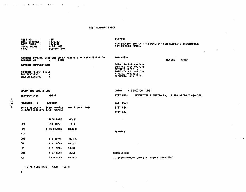
TEST SUIO(ARY M E T
TEST )(O. a 126 DATE SfCYIl'ED : l lM/82
PURPOSE
RUN SULFlOnTlOH ff ' I d 2 REACTOII' FOR C W L E T E BREAKTHRUSH FOR SCHRODV HOD€L.
80RBENT TYP€/WElWT: UNITED CATALYSTS ZlK FERRlPE/328 GN WALYS lS l SDFIBENT NO. I L-1443
SOWENT PELLET SIZE: PRETREATHENT 8 W U R LOADIMQ :
I SP#E VELOCITY: 3600 HWRLY FOR 7 INCH BED LINEAR VELOCITY: 17.8 CHISEC
Ht9
HM'
AIR
COZ
CO
HZ
044
N 2
FLOW RATE
1.34 SCFH
1.63 C C m l N
3.6 SCFH
4.4 SCFH
16.3 SCFH
1 - 0 7 SCFH
22.0 SCFH
TOTAL SULFUR ( I V / W I I SURFACE LIREA tHZ/G): DENSITY lG/CCl r P ~ R E - v o L u M E - ~ ~ & ~ / G , : H l N E R k ANALYSIS: ELEHENTAL ANALYSISr
BEFORE ' AFTER
DATA: ( DETECTOR TUBE 1
E X l T HZS: UNDETECT&SLE INIT IALLY, I0 PPH AFTER 7 MINUTES
E X l T SO21
E X l T SZi
E X l T Wt
CONCLUSlONS
I. BREAKTHROUOH CURVE A: 1408 F COMPLETED.
TOTAL FLOW RATE: 43.0 S tFH
8

TEST SUMMARY S IEE I
E S T t.Q. I I 2 6 M T E STfiRTED I 11118/02 M T E EtVED I 11118/02 1 'OTM HOU2S I 4 HRS IYPE a REOENERAf 10(4
PURPOSE
REGENER&TlON CF FRESHLY LOnDED REnCTOR
SO!'tUENT rYPE/WEIQHTr W I T E D CATALYSTS ZINC FERRITE/320 GRAMS At49LYS I S : SOROENT M). I L-1443 BEFORE AFlER SORBEM1 COIFOSITION: . TOIbL SULFUR:
SURFnCE AREA:
SORBENT PELLET SIZE: PRETREATHENT SULFUR REMOVED
OPERhT lffi CONDITIONS
FLOW RATE WOLEX
H Z 0
AIR
2 23 CC/HIN 5BX
5 . 9 9 SCFH 5 0 1
DArA: (DETECTOR 7UBE
EXIT HZSI
EXIT SO?: TO 17,900 PPH
EX lT S?:
EXIT HZ:
REMARKS
1. FWSH BATCH OF SORBENT LO~DED. REGENERATION I S

TEST W. I 1.17 DATE STARTED I 11 / 2 2 / a 2 DATE ENDED r S 1 / 22 /82 TOTAL HOURS I 1 . 08 MRS
PUBPOSE
BUN SULFIDnTION OF '112 REACTOR' UNTIL BEOINNING OF BAEfiK lhB0UGH FOR SCtiRODT MODEL.
SCl.7OEiNT TYPE/VEIGHtr UNl TED CfiTALYSlS ZINC FERRt TE/328 GH A N f i ~ l S l S r SOROENT NO. : L-1443
SnRDENT PEL11 ' SIZE: PRE fREatMIEIJ1 W L F W LOADI,. j
OPER6TlNG CONDlTlOEtS
rE HPERA TURE I IOOJ IF
PRESSURE : AH0 l EN1
SMCE VELOCIT): 2826 HOURLr FOR 7 INCH BED LINEAR VELOCllYr 10.0 CM/SEC
H2S
H20
AIR
C02
co r42
CH4
Y 2
FLOU RATE
1.34 SCFH
0.02 CC/MlN
2.02 SCFH
2 . 5 SCFH
3.:. ~ C F H
9 . 6 8 SCFH
11.8 SCFU
IOTAL SULFUR ( IU/W I: SURFACE AREA ( W / G I: DENSITY c C / t C ) : PORE VOLWE tu73/G) : HINERAL ANALYSIS: ELEYEYTAL ANAL YSIS:
BEFORE AFTER
M T A : I DETECTOR TUBE)
EX lT Y2S: u~IDETECT~BLE INIT IALLY, 12.PPHAFTER 1Bt l INUTES
E X l i SOZ:
~ x i i S t r
E X l T HZ:
I. RUY UNTIL E X l T H2S REACHES 58 PpM
2. A t END OF RUN SAHPLE SORBENT PELLETS f i T FOUR LOC6TlONS f i ~ 3 % G THE LEfcGTH OF THE BEQCTOR. LABEL EACH SfiMPLE nu0 SEN3 13 PORTION OF E.ACH SGYPLE 10 :
I . SEY/EDax l J l H c l ~ G ) 3. SURFACE AREA/POROSITY (CHIDESTER) 2. TOTAL SULFUR (EonaNosuy)
'CONCLGS IONS
I. SQYPLES OF PELLETS TAKEN AT FOUR LOCQTIONS I N THE BED AFIES SB PP3 BqEAKT4ROUGH AND ~NALYZED FOR TOTAL SULFUR.
TOTAL FLOW RATE: 24.2 Sich
0

ZINC FERRITE SULFIDATION TEST 105 L- 1443 UNITED CATALYSTS
60000
55000
50000
45000
2 -- 40000 Y)
2 e 35000 Q L
30000 v)
- -
2 lso00 Temp = 1000 F (537 C) Z a
20000 STEAM = 10.0 Percent
1500(1 -1 SV - = 3600 Hourly
- LINEAR VELOCITY = 17.8 cm per sec
1 1 1 0 1 2 3 4 5 6
Time (hours)

ZINC FERRITE SULFIDATION TEST 107 L-1443 UNITED CATALYSTS
Temp = 1200 F, (649 C)
STEAM = 10.0 Percent
SV = 3600 Hourly
f 1 LINEAR VELOCITY = 17.8 crn per sec
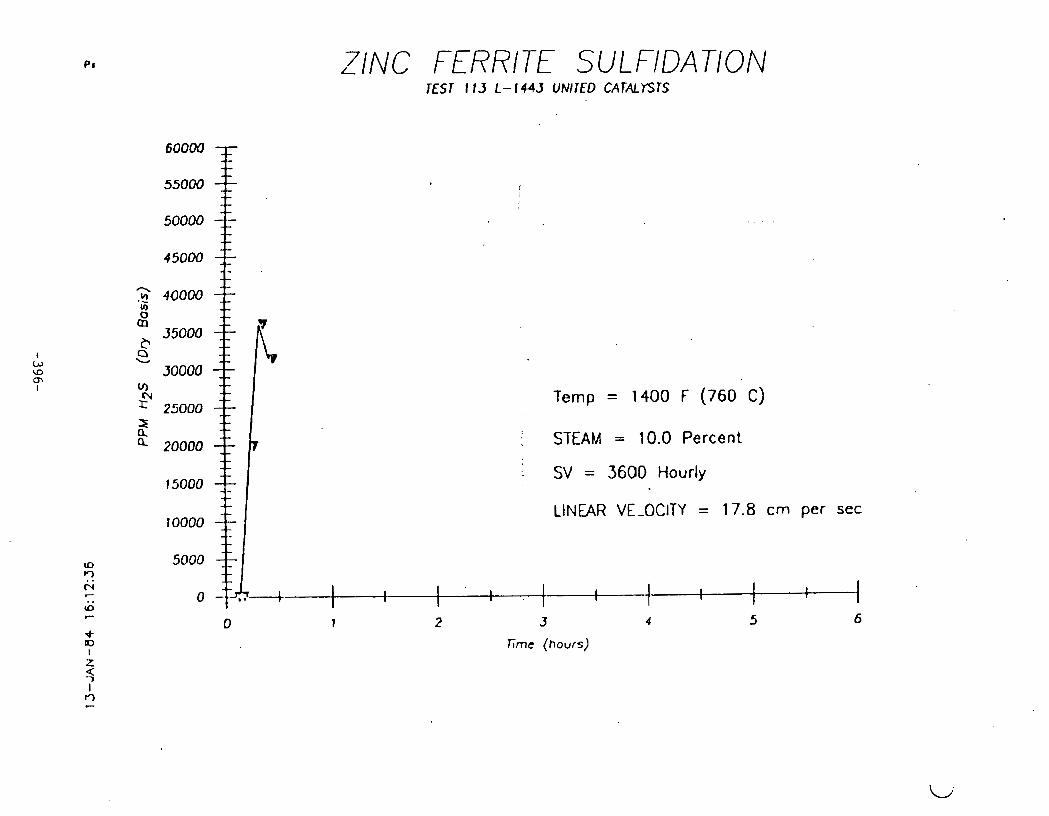
71NC FERRITE SULFIDATION L
TEST I 13 L- 1443 UNITED CATALYSTS
Lrne (hours)
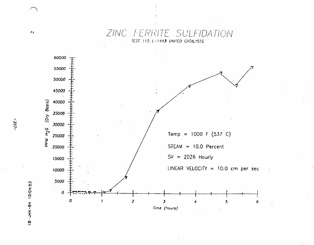
IESI 115 L - 144J UNII'ED CATALYSTS
v)
Temp = 1000 F (537 C)
STEAM = 10.0 Percent
15000 SV = 2026 Hourly
loo00 LINEAR VELOCITY = 10.0 cm per sec .
5000
1 1 I 1 I 1 1 I I I I
0 1 2 J 4 5 6
T h e (hours)

ZINC FERRITE SULFIDATION TESTS 105, 107, t 13 L-1443 UNITED CArAlYSTS
$ = 1400 F (760 C) (1113)
V = 1200 F (649 C) (T107)
EJ = 1000 F (537 C) (T105) I
STEAM = 10 Percent
I I I
I I
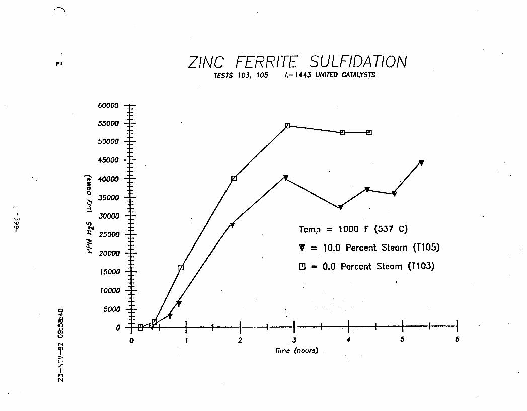
ZINC FERRITE SULFIDATION TESTS 103, 105 t- I443 UNITED CATALYSTS
Tern,~ = 1000 F (537 C)
PI = 0.0 Percent Steam (T103)
I 0 1 3 4 5 6
rime (hours) .

ZINC FERRITE. SULFlDATlON
6 b l M
55000 f
50000
- 450CM 7:
- - Temp = 1000 F (537 C)
STEAM = 0.0 Percent
SV = 3242 Hourly
LINEAR VELOCITY = 16 cm per stc
I I 1 I t-4---t-l
h e . (hours)

ZINC FERRITE SULFIDATION TESTS 103, 105 L - 1 4 4 3 UNIKGCATALYSTS
0 I 2 J 4 5 6
T;me (hours)

ZINC FERRITE SULFIDATION TESTS 105, I07 L-144.3 UNITEDC;41ALYSTS
V = 1200 F (649 C)
- -- D = 1000 F (537 C) - - - - STEAM = 10 PERCENT
I 1 I I
3
Time (hours)
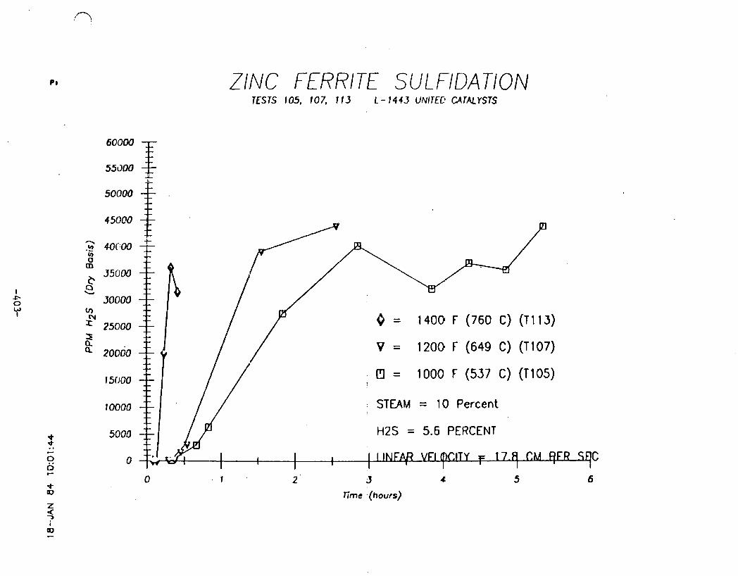
ZINC FERRITE SUL FIDATION TESTS l0.5. 107, 113 L-1443UNITEC'CATALYSTS
0 = 1400 F (760 C) (T113)
V = 1200 F (649 C) (T107)
I3 = 1000 F(537 C) (T105)
STEAM = 10 Percent
H2S = 5.6 PERCENT
C
1 2 ' 3 4 5 6
Time (hours)
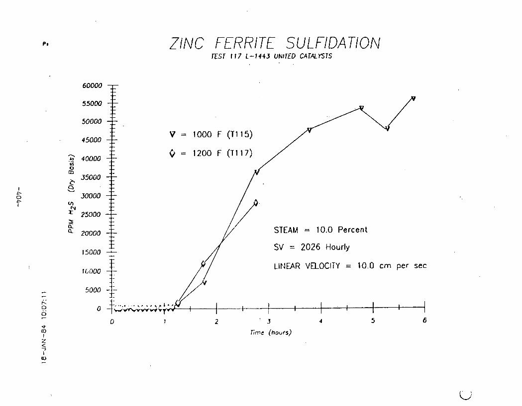
ZINC FERRITE SULFIDATION EST I 17 L- 1443 UNIrED CATALYSTS
STEAM = 10.0 Percent
SV = 2026 Hourly
LINEAR VELOCITY = 10.0 cm per sec

ZINC FERRITE SULFIDATION TESTS 12 1 . 123. 125 L- 1443 UNITED CATALYSTS
STEAM =: 10.0 Percent
SV = 3600 Hourly
LINEAR VELOCITY = 17.8 cm per sec
H2S = 3.1 PERCENT
V ~ W V
3
lime (hours)

2 .- 40000 U)
5 35000
Q + m o o
ZINC. FERRITE SULFIDATION
: STEAM = 10.0 Percent
SV- = 2026 Hourly I I
LINEAR VELOCITY = 10.0 c m per sec I

ZINC FERRITE SULFlDAT/ON
9 00
Temp = 1000 F (537 C) Press = Ambient
S.V. = 2026 Hourly m LINEAR VELOClM 10 CM PER SEC
50 V)
r" S 4 0 Q. a.
20
Time (Pours)

ZINC FERRITE SULFUR LOADING TEST 127
30 - - -
Temp = 1000 F (537 C)
Press = Ambient
S.V. = 2026 Hourly L
2 20 -- 3
LINEAR VELOCITY 10 CM PER SEC V) - 0 - 50 PPM BREAKTHROUGH 2 - is -- C 0 2 2 z I0 --
I 1 I I 1 I I 1
1 I
1 1 I I
0 I 2 3 4 5
Reactor Length (;ncheo)
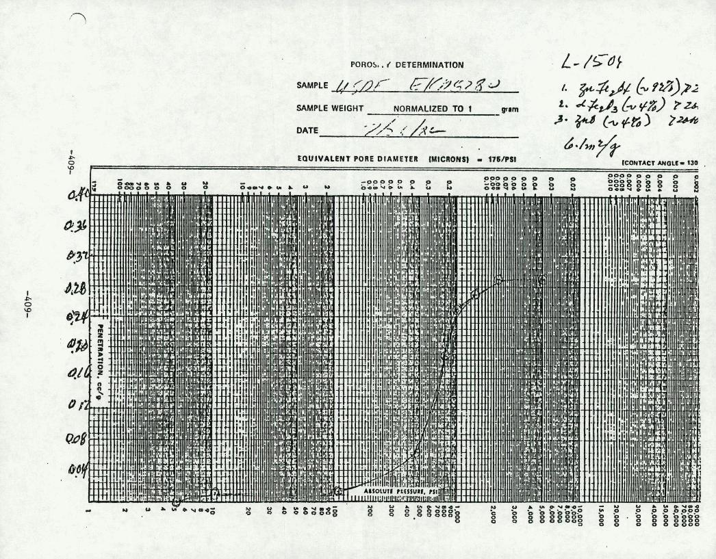

POROSITY OETERMlNAnON
Mt~lprE ~ . / H K LFL) Q2#/ SAMPLE WEIGHT NORMALIZED TO 1 Cam
DATE

. . . . . . . . . . . . " . . . . . . . . .
.. ,, - .. ' - . . , ; . 8 . , : ,. . ......... . . .
' . . :, .i ; .
* b . *.' .'I , . ' S . I .,.
.!. ? ' .:' i. ,, , . , : ; . .:. 8. . . . , ..; .. '
- , I .. . . ? . ' . . . . ' I ' ; . , i > .*. :: . ;< ,! . .... ' . #i. ; i ..,, t.; '. . ' j ~h~~~ && . . . . . . . . . . • ... - 8 s ii'.!i, , I . , .I;: i i, : ':',:.- ; . I. .'. . . . . I. 8 . .,;y4;lt'. .,. : '. . t. - . . I 3 . . . . . . . . . . ... . . SAMPLE WEIGHT ....*..:7. .../ .? : . . y...',. ..... -.,. , , ' ..::'$ ... ;'. . . . . .4. . :., $,! ' . . . . . . . . . . . . . . . ....;..... . ,\~~..!.:!:,. ,:,;* ... 3 . : .... . . ....... I. . t : . , , . , & : DATE . ; I * : ,. . . . . . . . . '::. . a , . ? I . , . .
:.. ..*.:!'. . . . . . . L ' f . . . . . . . . . . . . , .; S ' . *' . 5 . . . . a . . ' . I . . . . . . b.. : . ' . . ' . ,.a. .; . ,. . . . . . . . . . . . . . . . . . . . . . . . . . . . . . . . . . . . . . . .:f'. . . . . . . . . . . . " ! ' . . . . . . . . . .
' .. ... . ;. ; . : .. . ' E Q U ~ V A ~ E N T PORE DIAMETEVI ~ ~ ~ c ~ o ~ ~ ~ - .176fpsl : . . (CCNTACT ANCilE 130°1 . . I .
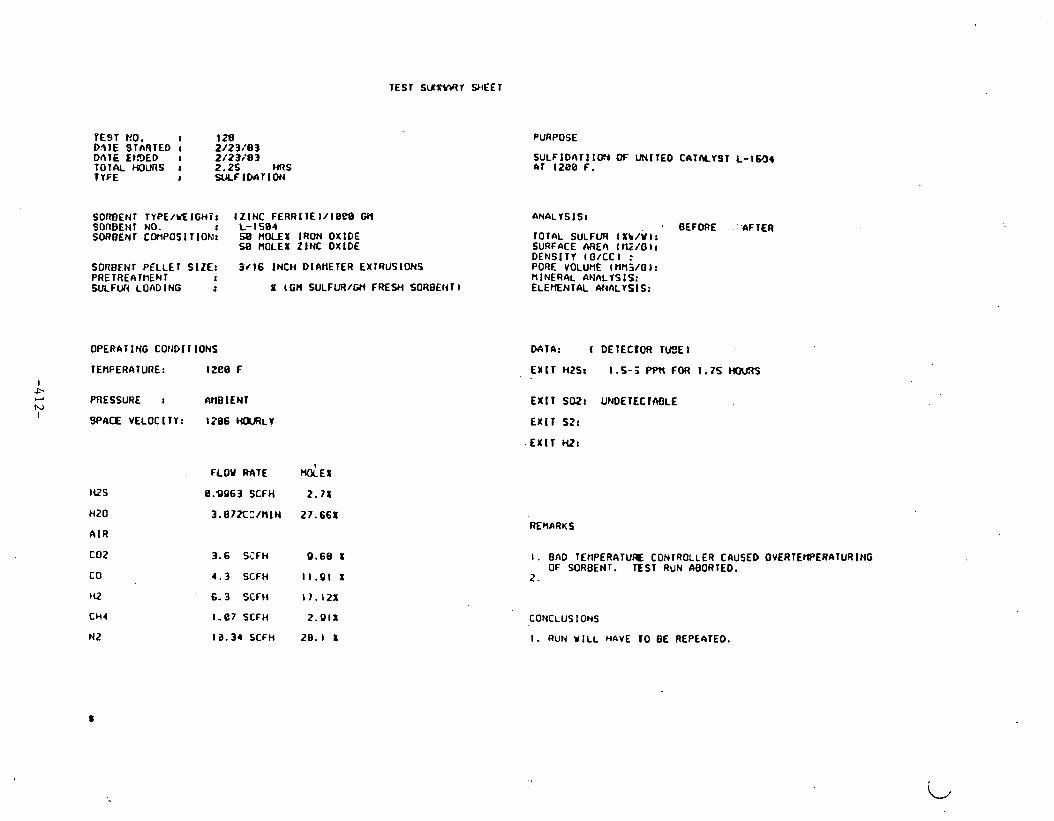
TEST S U S i M Y SHEET
VEST KO. : I28 DAlE STnRTED : 2/23,'83 D n l E EISED 8 2 /23 /83 TOTAL WURS : 2.25 MIS TYFE 8 SULFIDATION
SORBENT TYPE/VEIGHi: (Z INC FERRITEl/ lOCB GH SORBENT NO. : L-1504 SORBENr C~POSIT IOEJ t 58 HOLEX IRON OXIDE
58 HOLE1 ZINC OXIDE
SOR0ENT PELLET SIZE: 3 / 1 6 INCH DIAHETER EXTRUSIONS PRETREAlflENT t SULFWt LOADING : X f GH SULFUR/W FREYl SORBENT )
OPERATING COllDIIIONS
TEHFERATURE: l ~ e e F I .P w h,
PRESSURE : WBIENT I SPACE VELOCITY: 1206 H ~ R L Y
IQS
HZ0
A IR
COZ
co HZ
CH4
N 2
FILOV W T E
8.9963 SCFH
3 . 8 ? X , Z / N l N
3.6 S i F H
4 . 3 SCFH
6.3 SCFH
1 - 8 7 SCFH
13.34 SCFH
PURPOSE
S U L F I D A T I I W OF UNITED CATNYST L - l W 4 4 1 I 2 0 8 F.
ANALYSIS: BEFORE -:'AFTER
r o r n L SULFUR ( r b j w ~ : SURFACE M E I \ t G / O 1 : DENSITY In/cc 1 r
M I A : ( DETECDOR T e E I
E l t T HZSI 1.5-5 PPn FOR 1.75
EX I T SDZt UNDETEClnBLE
EXIT S2:
EXIT HZ:
REMARKS
1 . BAD TEHPERATUR CONTROLLER CAUSED OVERTEHPERAIURING OF WRBENT. E S T RUN ABORTED.
2 .
CONCLUSIONS
I . RUN WILL HbVE 10 BE REPEATED.

TEST S U W Y Y E E T
TEST rm. I 120 DATE STLRTED I 3 /1 /83 DATE ENDED I 3/1 /83 TOTAL HWRS I 6 .25 HRS T YPE I U L F IDAT I O U
SOTcu'EWl TYPE/UEIGHT: t Z lNC FERRIE ) /10D0 GM SOnOEUT NO. r L - I S 0 4 SOROEHl COi90SlTlON: 5 0 W L E I IRON OXIDE
58 MOLE1 ZINC OXIDE
SOZJEHT PELLET SIZE: 3 /16 INCH DIAIIETER ElTRUSIONS PRETREArnEt41 I
WLFW LOADING : I (W SULFUA/GH FRESH SORBEN1 1
OPERATING CONDlT10NS
TEHPERATURE : 1288 F I f. r PRESSURE r AMBIENT W
SPACE VELOC 1 TYr I 2 8 6 UOURLY
HZS
HZ0
A I R
co t
CO
M2
CM4
N2
'FLW RATE
0.OQ63 SCFH
3.B?ZCC/IlIN
3 .6 SCFH
4.3 SCFH
6.3' SCFH
I. 0 7 SCFH
10.34 SCFH
9 .60 S
11.91 1
I ? . I 2 1
2 .011
29. I x
PURPOSE
S~~LFIDATI IOH DF UNITED CATLYYST L-1584 nr 1208 F.
BEFORE AFTER TOTAL SULFUR I%V/WBI SURFACE ARFA I HZ/GDI
PORE -VOLUME - ~ H I W G D : HINERAL ANALYSIS; ELEMENlnC AIWLYSIS-
M T 4 : ( DETECTOR T l B E l
EXIT H2S: 8.5 - 1.6 Pf'H FOR 1.5 MRS
E X l T SOZI 8 PPH
E X l T S21
EXIT HZ:
I. S4HPLE CONDENSAlT FOR ZINC IRON AND SULFATE 4NALYSIS
2. THIS I S A REPE4T OF TEST 128. FRESH SORBENT LOADED.
CONCLUSIONS
1.

TEST HO. I 1 3 0 DATE STARTED 1 3 /04 /83 WLTE ENDED a 3 /84 /83 TOTAL HOURS t 1 6 HRS TYPE t REGEtlERAT I ON
SORBENT TYPE/WElGHT: (Z INC FERRI lE1/1608 Gn SORBENT NO. r L-1584 SORBEN1 COr(POf1TlON: 50 .8 W L E I IRON OXIDE
SB.0 NOLEI ZINC OXIDE
SQRBEN~PELLET SIZE1 3 / 1 6 fN tHD l rWETEREX lRUS lONS PRETREAWENl r SULFUR REMOVED I
OPERATING COM01 TIOMS
I PRESSURE r AHBIENI f. #.-
c' SPACE VELOCllYr 385 HOURLY
I
WS
HZ0
A I R
coz CO
HZ
CH4
N2
2 .23 CC/HlN 5 8 1
5 .88 SCFH 5 0 1
PURPOSE
REGENERATION (W a l H t FERRITE PELLETS FRM JEST 129
a N a L r s l s ~ BEFORE ' ~ F T E R
IOT4L SULFURI SURFACE AREA1 DENS1 1V :
~ 4 1 ~ : (DE~ECIOR r u e € )
EX11 HZSr
EX IT 5021 U4X OF 1.6 PERCENT 61B PPn AT END
EXIT S Z l
EXIT HZ:
REHaRUS
I. AIR FLOW RATE :NCREnSED TO e6.6 SCFH AT 4.75 MRS.
2. DID N o r OBTAIN ~YPICLL r E n p v a v ~ AT s.ea 414 FLOW . CCYCLUS IONS
I. REGEHERfiTION COHPLETE.
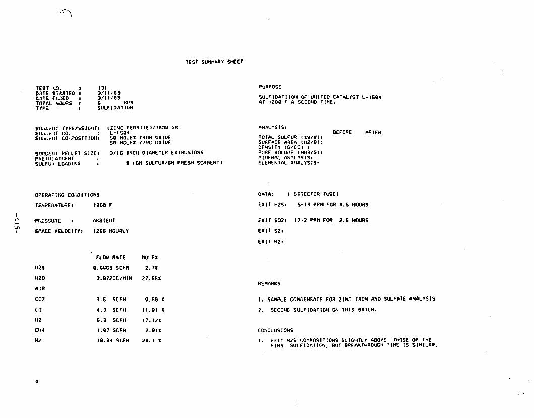
TEST SUtlMARY W E T
SORGENTPELLET SIZE, 3/16 BNCHDlAHETEREXTWSIONS PtiETRI A I IENT r SULFUH LOAD IPJG : I fGH SULFUR/GH FRESH SWBENT)
142s
HZ0
A I R
C02
CO
HZ
C H I
N2
FLOU RATE
B.OC63 SCFH
3.072CC/H IN
3.6 SCFH
4.3 SCFH
6.3 SCFH
1 .07 SCFH
10.34 SCFH
PURPOSE
SULFIDATIIOIJ OF UNITED CATALYST L-1504 4 1 1200 F A SECOND T [HE.
ANALYSIS8 REFORE AFTER
TOTAL SULFUR I XY/W I I SURFACE AREII t ti210 t : DENSITY tG/CCl r PORE VOLUME ItfHV13/Gl1 R l N E R a C ANAL7SISl ELEHENTAL AHIILYSISI
OAT&: f DETECTOR rU9E I
EXIT HZS: 5 -13PPMFOR4 .5HOCl f tS
I . SAWPLE CONDENSAIE FOR Z I N C IRON AND SULFATE 6NALYSlS
2. SECOHD SULFIDATDON W THIS BATCH.
CONCLUSIONS
I. ENIT ~ 2 s C o n P o s l r t o N s SLIGHTLY ABOVE THOSE OF THE FIRST SULFID4TICN, BUT BREAKTHROUGH TIHE IS S l n l L a R .

TEST s u m r Y f E T
D n T f EtIDED 8 3/15/53 T O T N MXmS I 1.75 HRS TYPE I .REGENERAT ION
SOneENT TYPE/WElGH.Tr I ZJNC FERRITE ) / I 0 2 8 GH SORCENT NO. I L-1584 SO3SEt4T COnPOSI I ION8 Sa. 8 MOLEX IRON OXIDE
5 3 . 8 ttOLE1 ZINC OXIDE
SORBENT PELLET SIZE: 3/16 INCH DIAMETER EX IRUSIWS PRETREI\lI:ENI SULFUR REHOVED
OPERnT ING COIIDI T IONS
TEtWERArURE: 1088 F
I PRESSURE : A l lD lEN i E. F o\ SPACE VELOCI T I : 305 HOURLI I
PURPOSE
REGENERATION OF ZINC FERRITE PELLETS FROM TEST 131
BEFORE AFTER r o r A L SULFUR: SURFnCE AREA: DENS1 I Y PORE VOLUME: H I NERAL ANALVS IS: ELEMENTkC ANALYE.IS:
DATA: (DEIECTOF TUBE 1
EXIT h2S:
EXIT S02: 0 X MAX
E X I T SZ:
EX IT Hi?:
2. SMPLE PELLEIS BEFOQE f i r nND AFTER TEP" WAVE AI(D SEND T O J I ~ KING FCR ELECIRON HICROSCOPE ANALISIS.
CONCLUS I OHS
I. REGENER4T ION SIOPPED VttEt4 TEMP UAVE WfiS AT HID-BED.
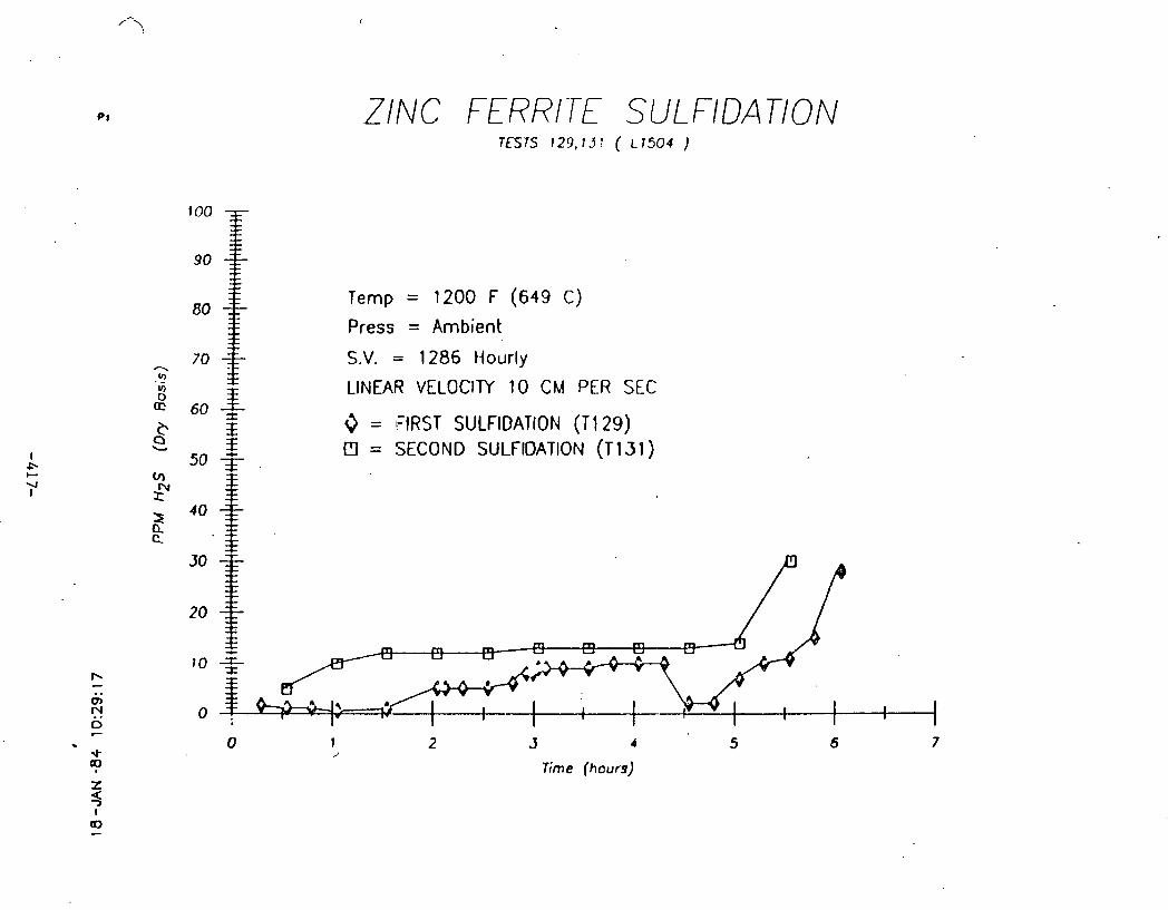
ZINC FERRITE SULFIDATION lES7.S 129,137 ( L 1 5 0 4 )
too
80 Temp = 1200 F (649 C)
Press = Ambient
- Ir, to 7o 1 - S.V. = 1286 tiourly
0
. -
3 LINEAR VELOCITY 10 CM PER SEC 60 *
C 3 3 = FIRST SULFlDATlON ( T I 29) a b 3
50 -1- D = SECOND SULFlOATlON ( T I 39 ) (A
xN Z Q a
h - . . 0,
N 0 C . 0 1 2 3 a 5 6 7 -4- J
? Time (hours)
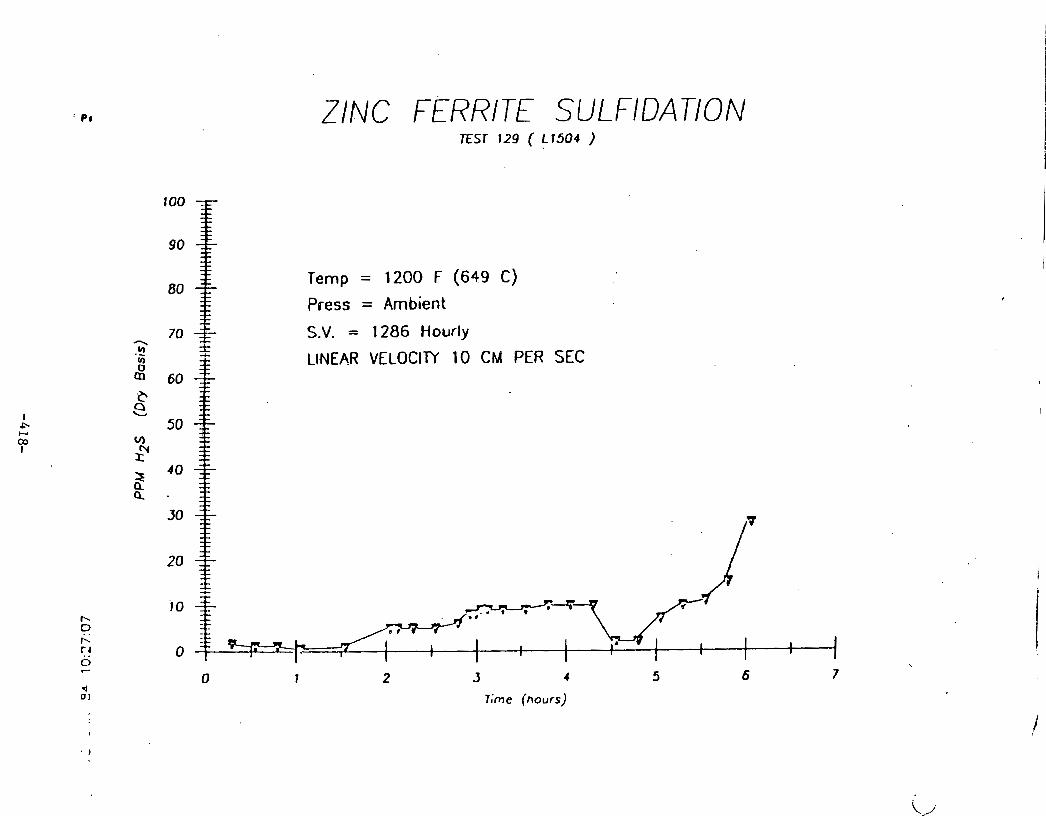
ZINC FERRITE SULFIDAnON
Temp = 1200 F (649 C)
Press = Ambient
S.V. = 1286 Hourly
LINEAR VELOCllY 10 CM PER SEC
Time (hours)

APPEND I X r . E ---
Sidestream Tes t ina - G a s i f i e r Run 101
Hot Gas Desul fur iza t ion Sidestream Test Unit, Fixed-Bed G a s i f i e r Run 101
In t roduct ion
S t a r t i n g i n 1980, laboratory-scale eva lua t ion of developmental, regenerable s o l i d sorbents t o remove s u l f u r compounds from cool gas a t high temperatures has been c a r r i e d on a t METC (1 ,2 ,3 ,4 ,5 ,6 ) . Tests were performed, u t i l i z i n g simulated gases , f o r sorbent screening and development, with t h e long-range o b j e c t i v e of t e s t i n g t h e most promising sorbents i n a bench-size tes t u n i t a t a somewhat l a r g e r s c a l e i n s idestreams of METC coa l g a s i f i e r s . I n i t i a l l y , t h i s would be i n a s ides t ream of METC1s 24 t / d fixed-bed g a s i f i e r and l a t e r , t h e - 2 t / d advanced fluid-bed g a s i f i e r .
The t e s t u n i t was designed, and procurement of components p r a c t i c a l l y com- p l e t e d during FY 82. During FY 83, t h e u n i t was assembled and i n s t a l l e d i n a l o c a t i o n where it could be connected t o e i t h e r g a s i f i e r . Skid-mounting of t h e u n i t g ives it p o r t a b i l i t y should it be des i red t o remove it t o another t e s t s i t e .
The design throughput of t h e s ides t ream t e s t u n i t i s an order of magnitude l a r g e r than t h a t of t h e laboratory-scale u n i t . The bigger s i z e of t h e side- stream t e s t u n i t and t h e t r e a t i n g by it of an a c t u a l hot raw coa l gas were expected t o e s t a b l i s h with much g r e a t e r confidence t h e c a p a b i l i t y of sorbents under t e s t t o achieve t h e des i red goa l of removing s u l f u r compounds t o low l e v e l s (1-10 ppm) of withstanding t h e e f f e c t s of o t h e r contaminants and of being regenerable.
I n p a r t i c u l a r , t h e sorbent , z inc f e r r i t e , which showed promise i n t h e labora tory-sca le t e s t s , was sin,gled out f o r eva lua t ion .
Desian of Sidestream Test Unit
The process and instrument drawing of t h e s ides t ream test u n i t i s shown i n ~ i ' g u r e 1. Figures 2 and 3 a r e pe r spec t ive schematics which i l l u s t r a t e t h e opera t ion of t h e u n i t i n absorpt ion and regenera t ion modes. Figure 4 i s a photograph of t h e u n i t and i t s c o n t r o l panel i n s t a l l e d a t i t s t e s t l o c a t i o n . The d e t a i l e d design b a s i s was by Science Applicat ions Inc . ( 4 ) . Deta i led mechanical engineering des ign was by Tech Engineering and Design of Morgantown and assembly, f a b r i c a t i o n of subs id ia ry components and i n s t a l l a t i o n was by METC s t a f f .
The p r i n c i p a l component i s a 6-inch diameter, 6-foot long r e a c t o r f a b r i c a t e d from Incoloy 800H by National Annealing Box Company and t r e a t e d i n t e r n a l l y with aluminum (a lonized) by Alon Processing, Inc . It i s designed f o r opera- t i o n up t o a p ressu re of 300 p s i g and a temperature of 1,800°F. The r e a c t o r , which has s i x thermocouples i n s e r t e d along i t s length , i s enclosed by a four- zone, clamshell type e l e c t r i c a l l y heated furnace made by Mellen Company.

Coal gas and regenera t ion gas e n t e r i n g t h e r e a c t o r a r e heated by passage through h e l i c a l c o i l s loca ted i n two e l e c t r i c a l l y heated c y l i n d r i c a l furnaces made by Thermcraft, Inc. Gases l eav ing t h e r e a c t o r a r e cooled by water-cooled condensers i n two s tages : t h e f i r s t t o condense t h e higher b o i l i n g t a r s and t h e second t o condense steam and remaining t a r s . On-off va lves f o r t h e hot gases a r e of t h e s l i d i n g d i s c type made by Ever las t ing Valve Company. The valves and p ip ing a r e of 316 s t a i n l e s s s t e e l except f o r t h e 1%-inch diameter l i n e from t h e fixed-bed g a s i f i e r which i s of 309 s t a i n l e s s s t e e l . A l w i n c h '
l i n e of a lonized 304 s t a i n l e s s s t e e l from METCfs advanced fluid-bed g a s i f i e r i s p r e s e n t l y a t t h e engineering s t a g e . The p ip ing i s e l e c t r i c a l l y heated by Chromolox t u b u l a r hea te r s .
Cooled e x i t i n g gas can be continuously sampled and analyzed by a Bendix Corpo- r a t i o n on-line chromatograph f o r major spec ies and by a Basel ine I n d u s t r i e s on-line chromatograph f o r H,S, COS, and SO,. The i n l e t hot c o a l gas can a l s o .
be continuously analyzed by t h e Bendix chromatograph a f t e r passage through an apparatus which condenses out steam and t a r s .
Addit ional provis ion i s made t o sample hot coa l gas a t t h e r e a c t o r i n l e t and outlet f o r p a r t i c u l a t e charact.erizat.i.nn.
Condensates can be dra ined v i a holding v e s s e l s i n t o drums ,so t h a t pe r iod ic sampling and weighing can be c a r r i e d ou t .
Process da ta a r e logged by means of an automatic d a t a a c q u i s i t i o n and con t ro l system (ADACS) and can be d isplayed on a l o c a l t e rmina l .
Operation of Sidestream Test Unit
The s ides t ream d e s u l f u r i z a t i o n u n i t was operated f o r t h e f i r s t t ime dur ing Run 101 of METC's 42-inch, fixed-bed g a s i f i e r ( 7 , 8 , 9 ) . This run took place from June 22 t o J u l y 1. During t h i s 9-day per iod while Arkwright c o a l was f e d t o t h e g a s i f i e r , t h e u n i t was operated i n t h e absorption.mode with upward flow f o r t h r e e s p e l l s with two in termedia te s p e l l s i n t h e regenera t ion mode with downward flow. The schedule of opera t ion i s shown i n Figure 5. The f i r s t two absorpt ions were with air-blown (low-Btu) gas and t h e t h i r d wi th in te rmi t - t e n t l y air-blown and oxygen-blown (medium-Btu) gas .
Reactor furnace temperatures were ad jus ted t o g ive a temperature p r o f i l e along t h e r e a c t o r a s c l o s e a s p o s s i b l e t o l,OOO°F.
The r e a c t o r contained an approximately 4-foot deep l a y e r of z i n c fe r r i t e ex t rus ions weighing 20.4 kg, suppl ied by United Ca ta lys t s , I n c . , with 6-inch l a y e r s of %-inch ceramic spheres above and below, t h e whole he ld i n p lace by support and cover p l a t e s .
Average pressures , temperatures and flow r a t e s of t h e var ious streams f o r t h e t h r e e s u l f i d a t i o n runs a r e shown on ADACS process flow schematics i n Figures 6A, 6B, 7, and 8 .
During s u l f i d a t i o n Runs 001 and 003, approximate r e a c t o r condi t ions were: p ressu re 150 ps ig , temperature 1 1 0 0 0 0 ~ , and space v e l o c i t y 2,000 h i ' , based

on condenser e x i t gas. I n s u l f i d a t i o n Run 005 f o r air-blown opera t ion , condi- t i o n s were t h e same except f o r a lower pressure of about 90 ps ig . For oxygen- blown opera t ion , owing t o t h e l a r g e steam content of t h e gas, t h e space v e l o c i t y was considerably g r e a t e r s ince t h e e x i t gas flow r a t e was maintained constant . The dura t ion of Run 001 was about '29 hours, i n t e r r u p t e d by a few hours when t h e g a s i f i e r was o f f stream. Run 003 was about 25 hours long. The l eng th of Run 005 i s not comparable because of t h e i n t e r m i t t e n t opera t ion wi th a i r - and oxygen-blown gas . But, t ak ing i n t o account t h e d i f f e r i n g r a t e s of mass flow of s u l f u r compounds i n t o t h e r eac to r , t h e equivalent run l eng th i s es t imated t o be roughly t h e same a s t h a t of Runs 001 and'003.
Reactor e x i t gases were cooled t o about 600°F by t h e f i r s t water-cooled con- denser and then t o about 1 3 0 ' ~ by t h e second water-cooled condenser except dur ing oxygen-blown opera t ion when t h e temperature was somewhat higher because of t h e g r e a t l y increased heat load. The pressure drop ac ross t h e r e a c t o r was i n i t i a l l y l e s s than 1 p s i a t t h e beginnings of t h e f i r s t two s u l f i d a t i o n s inc reas ing t o about 5 p s i towards t h e ends. Regeneration r e s t o r e d t h e pres- s u r e drop approximately t o i t s o r i g i n a l l e v e l . The p ressure drop a t t h e beginning of t h e t h i r d s u l f i d a t i o n was somewhat g r e a t e r t h a n t h a t of t h e f i r s t two because of t h e g r e a t e r flow r a t e and only increased t o about 2 p s i a t t h e end because of t h e s h o r t e r run length . The inc reases i n p ressu re drop a r e a t t r i b u t e d mainly t o p a r t i c u l a t e deposi t ion . Coke, r e s u l t i n g from pyro lys i s of t a r s and/oq from carbon monoxide by t h e Boudouard reac t ion : 2C0 + C + CO,, i s probably a l s o a con t r ibu to ry f a c t o r .
The pressure drop ac ross t h e small secondary cyclone g radua l ly increased from 0.2 t o 0.4 p s i dur ing Runs 001 and 003 and then r a p i d l y inc reased dur ing t h e oxygen-blown i n t e r v a l s of Run 005 s o t h a t , a t t h e end of t h i s run, t h e com- bined p ressure drops ac ross t h e cyclone and t h e i n l e t gas l i n e were about 30 p s i . This blockage i s a t t r i b u t e d mainly t o depos i t ion of coke from t a r s i n t h e gas. When t h e run was over, t h e blockage was c l e a r e d by blowing an air-steam mixture through t h e l i n e .
The z inc f e r r i t e sorbent was regenerated twice i n Runs 002 and 004 with a regenera t ion gas t y p i c a l l y c o n s i s t i n g of an about 80120 v o l . percent s t eamla i r mixture a t a temperature of l,OOO°F. Space v e l o c i t y was usua l ly 500-1,000 hr-I based on r e a c t o r flow. Some d i f f i c u l t y was experienced i n c o n t r o l l i n g t h e a i r and steam flows, s o t h a t t h e sorbent temperature occas iona l ly exceeded t h e design maximum of about 1,600°F. Figures 9 and 10 a r e ADACS p l o t s of t h e sor- bent temperature along t h e r e a c t o r throughout t h e regenera t ions . A somewhat lower a i r flow r a t e during Run 004 r e s u l t e d i n a r a t h e r longer regenera t ion t ime of 19 hours compared t o 15 hours f o r Run 002.
The Basel ine I n d u s t r i e s gas chromatograph became fouled towards t h e end of t h e f i r s t s u l f i d a t i o n by o i l d r o p l e t s i n t h e e x i t gas from t h e f i n a l condenser. For f u t u r e t e s t s a s p e c i a l Permapure F i l t e r System was subsequently acquired .
During t h e s u l f i d a t i o n and regenera t ion runs, hydrogen s u l f i d e and/or s u l f u r d ioxide concentra t ions of e x i t gas were measured hourly by d e t e c t o r tubes . Grab samples of e x i t gas and condensates were taken genera l ly a t 4-hour inter- v a l s f o r l abora to ry a n a l y s i s . Major spec ies i n t h e e x i t gas dur ing t h e s u l f i - da t ions were measured continuously by t h e Bendix chromatograph. Also, during t h e s u l f i d a t i o n runs, occas ional samples of hot gas a t t h e r e a c t o r i n l e t and

o u t l e t were taken v i a l - inch Kamyr valves through a p a r t i c l e sampling system t o determine p a r t i c l e loadings and s i z e s . Liquids, which were condensed from t h e s e samples, were analyzed (10) . A t t h e conclusion of t h e l a s t s u l f i d a t i o n run, which was continued well beyond breakthrough, t h e s u l f i d i z e d sorbent was removed, samples being taken a t po in t s along i t s l eng th . Fines were removed by screening. A lump of agglom- e r a t e d sorbent ex t rus ions about 4 inches deep was found near t h e t o p of t h e bed. This appeared t o be caused by coke depos i t ion .
Resul ts
Data Summarv
The var ious process condi t ions and d a t a c o l l e c t e d i n Runs 001 t o 005 a r e summarized i n Figures 11 t o 15.
Absorption of Su l fu r Compounds
Figure 16 i s d p l o t s f t h e hydrogen s u l f i d e concentra t ion of e x i t gas, a f t e r condensation of t a r and water, a g a i n s t on-stream t h e f o r Run 001. Measurements were made with both on-line gas chromatograph and d e t e c t o r tube which agreed q u i t e we l l . U n t i l breakthrough a f t e r about 28 hours, H,S l e v e l s were below 5 ppm averaging about 2 ppm. Af te r Run 001, t h e gas chromatograph became fouled with t a r d r o p l e t s and was subsequently inopera t ive f o r t h i s s e r i e s of runs .
Figure 1 7 compares H2S concentra t ions f o r Runs 001 and 003 a s measured by d e t e c t o r tube . The l e v e l s a r e very s i m i l a r except a t t h e beginning of Run 003 i n which t h e H,S i s i n i t i a l l y high, presumably because of r e s i d u a l s u l f u r compounds l e f t i n t h e sorbent bed a f t e r regenera t ion . The on-stream t ime before breakthrough f o r Run 003 i s about 5 hours less than f o r Run 001, accounted f o r by t h e h igher i n l e t gas H,S concentra- t i o n s . The s u l f u r loadings of t h e sorbent i n Runs 001 and 003, computed from t h e mass flow and H,S concentra t ion of t h e i n l e t gas , were 1 4 . 4 and 17.9 wt percent r e s p e c t i v e l y ( see Figures 11 and 1 3 ) . Because o t h e r s u l f u r compounds inc luding COS were neglected, t h e a c t u a l va lues would be somewhat g r e a t e r . Also neglec ted was s u l f u r pick-up by tlle s t a i n l e 3 o s t e e l d e l i v e r y l i n e .
Figure 18 p l o t s H,S concentra t ion i n e x i t gas aga ins t time on stream for Run 005. H,S l e v e l s while d e s u l f u r i z i n g air-blown gas a r e com- pa rab le t o those i n Runs 001 and 003. With oxygen-blown gas, t h e H2S l e v e l i s about 20 ppm corresponding t o t h e g r e a t e r q u a n t i t y of steam i n t h e gas . A s i n Run 003, H,S i s i n i t i a l l y high which i s a t t r i b u t e d t o r e s i d u a l s u l f u r compounds i n t h e sorbent bed. Some s u l f u r d ioxide was a l s o de tec ted i n t h e i n i t i a l s t ages of Runs 003 and U03 but f e l l o f f more r a p i d l y than t h e i n i t i a l l y high H,S. This i s shown i n Figures 19 and 20.
The l e v e l s were corrobora ted through a n a l y s i s of grab samples by l abora to ry gas chromatograph which a l s o measured COS, CH3SH, CS,, and thiophene. These a r e shown i n Table 1 which a l s o inc ludes major gas spec ies . COS, CH3SH, and CS, a r e much l e s s than H,S, but s i g n i f i c a n t
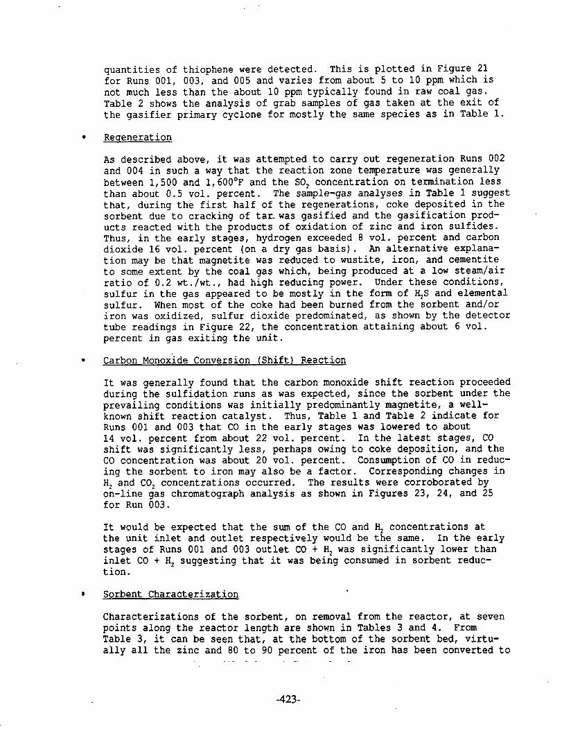
q u a n t i t i e s of thiophene were de tec ted . This i s p l o t t e d i n Figure 21 f o r Runs 001, 003, and 005 and v a r i e s from about 5 t o 10 ppm which i s not much l e s s than t h e about 10 ppm t y p i c a l l y found i n raw coa l gas . Table 2 shows t h e a n a l y s i s of grab samples of gas taken a t t h e e x i t of t h e g a s i f i e r primary cyclone f o r mostly t h e same spec ies a s i n Table 1.
Reaeneration
A s descr ibed above, it was attempted t o c a r r y out regenera t ion Runs 002 and 004 i n such a way t h a t t h e r e a c t i o n zone temperature was genera l ly between 1,500 and 1, 600°E' and t h e SO, concentra t ion on t e rmina t ion l e s s than about 0.5 vo l . percent . The sample-gas analyses i n Table 1 suggest t h a t , during t h e f i r s t ha l f of t h e regenera t ions , coke deposi ted i n t h e sorbent due t o cracking of t a r -was g a s i f i e d and t h e g a s i f i c a t i o n prod- u c t s r eac ted with t h e products of ox ida t ion of z inc and i r o n s u l f i d e s . Thus, i n t h e e a r l y s t ages , hydrogen exceeded 8 vo l . percent and carbon dioxide 16 v o l . percent (on a d ry gas b a s i s ) . An a l t e r n a t i v e explana- t i o n may be t h a t magneti te was reduced t o wus t i t e , i r o n , and cementi te t o some ex ten t by t h e coal gas which, being produced a t a low s teamla i r r a t i o of 0.2 w t . / w t . , had high reducing power. Under t h e s e condi t ions , s u l f u r i n t h e gas appeared t o be mostly i n t h e form of %S and elemental s u l f u r . When most of t h e coke had been burned from t h e sorbent and/or i r o n was oxidized, s u l f u r dioxide predominated, a s shown by t h e d e t e c t o r tube readings i n Figure 22, t h e concentra t ion a t t a i n i n g about 6 v o l . percent i n gas e x i t i n g t h e u n i t .
Carbon on oxide Conversion ( S h i f t 1 Reaction
I t was genera l ly found t h a t t h e carbon monoxide s h i f t r e a c t i o n proceeded dur ing t h e s u l f i d a t i o n runs a s was expected, s i n c e t h e sorbent under t h e p r e v a i l i n g condi t ions was i n i t i a l l y predominantly magneti te , a well- known s h i f t r e a c t i o n c a t a l y s t . Thus, Table 1 and Table 2 i n d i c a t e f o r Runs 001 and 003 t h a t CO i n t h e e a r l y s t a g e s was lowered t o about 1 4 v o l . percent from about 22 vo l . pe rcen t . I n t h e l a t e s t s t ages , CO s h i f t was s i g n i f i c a n t l y less, perhaps owing t o coke depos i t ion , and t h e CO concentra t ion was about 20 vol . percent . Consumption of CO i n reduc- i n g t h e sorbent t o i r o n may a l s o be a f a c t o r . Corresponding changes i n H, and CO, concent ra t ions occurred. The r e s u l t s were corrobora ted by on-line gas chromatograph a n a l y s i s a s shown i n Figures 23, 24, and 25 f o r Run 003.
It would be expected t h a t t h e sum of t h e CO and H, concentra t ions a t t h e u n i t i n l e t and o u t l e t r e s p e c t i v e l y would be t h e same. I n t h e e a r l y s t a g e s of Runs 001 and 003 o u t l e t CO t H, was s i g n i f i c a n t l y lower than i n l e t CO t H, suggest ing t h a t it was being consumed i n sorbent reduc- t i o n .
o Sorbent Charac te r i za t ion
Charac te r i za t ions of t h e sorbent , on removal from t h e r e a c t o r , a t seven p o i n t s along t h e r e a c t o r l eng th a r e shown i n Tables 3 and 4 . From Table 3, it can be seen t h a t , a t t h e bottom of t h e sorbent bed, v i r t u - a l l y a l l t h e z inc and 80 t o 90 percent of t h e i r o n has been converted t o
. - - -

s u l f i d e ; whereas a t t h e t o p of t h e bed, t h e z inc i s p a r t i a l l y converted t o s u l f i d e , but no i r o n s u l f i d e has been formed. It i s apparent a l s o from t h e da ta a t t h e top of t h e bed t h a t t h e o r i g i n a l z inc f e r r i t e has been f i r s t converted t o magneti te and z inc oxide owing t o reduct ion by t h e coa l gas . There i s a sharp t r a n s i t i o n between p o i n t s where i r o n s u l f i d e i s formed and where it i s absent . A t t h e bottom of t h e bed, z inc s u l f i d e i s mostly i n t h e form of beta-ZnS (cubic s p h a l e r i t e ) ; whereas a t t h e top , t h e r e i s more alpha-ZnS (hexagonal w u r t z i t e ) .
Table 4 shows t h a t a t t h e bottom of t h e bed t h e sorbent s u l f u r loading i s about 30 w t . percent , not much l e s s than t h e value of about 35 per- cent f o r complete s u l f i d a t i o n . The sorbent can be seen t o con ta in 2 t o 4 w t . percent of carbon, t h e r e being s l i g h t l y more a t t h e t o p of t h e bed than a t t h e bottom. The higher concentra t ion of 7 w t . percent carbon i n t h e 2 . 4 kg of f i n e s , which were screened through a No. 8 (2.38 mm) screen from t h e t o t a l sorbent removed from t h e r e a c t o r , demonstrates t h a t coke depos i t ion occurs p r e f e r e n t i a l l y a t t h e sorbent p e l l e t sur- f a c e s . Although t h e amount of f i n e s exceeds 10 percent of t h e sorbent , it i s d i f f i c u l t t o d i f f e r e n t i a t e between t h a t o r i g i n a l l y i n t h e r e a c t o r and t h a t formed dur ing sorbent removal by suc t ion with a vacuum hose.
The sorbent s u r f a c e a rea and pore volume a t t h e bottom of t h e bed a r e about ha l f t h e va lues a t t h e t o p , which a r e about t h e same a s those f o r f r e s h sorbent . Thus, a f t e r t h r e e s u l f i d a t i o n s and two regenera t ions , t h e r e i s not a marked change i n t h e s e parameters .
The f u l l y s u l f i d i z e d sorbent a t t h e bottom of t h e bed has about twice t h e crush s t r e n g t h of t h a t a t t h e t o p of t h e bed which i t s e l f i s s ig- n i f i c a n t l y , though not a l o t , l e s s than t h e crush s t r e n g t h of f r e s h sorbent . Since t h e sorbent p r i o r t o removal had been i n con tac t with oxygen-blown gas it should not be i n f e r r e d t h a t i t s c h a r a c t e r i z a t i o n a f t e r Runs 001 and 003 with air-blown gas i s t h e same.
P a r t i c u l a t e Analysis
I n t h e course of t h e opera t ion of t h e hot gas d e s u l f u r i z a t i o n u n i t , a sample of p a r t i c u l a t e s knocked out i n t h e secondary cyclone dur ing t h e f i r s t two s u l f i d a t i o n s was taken and i t s p a r t i c l e s i z e d i s t r i b u t i o n determined. D e t a i l s of t h e f ind ings a r e shown i n Table 5 . Also included i s a chemical a n a l y s i s i n terms of carbon, s u l f u r , and ash . P a r t i c l e s i z e v a r i e d from 4 t o 100 microns with a median of about 30 microns. The carbon content of more than 80 w t . percent i s t y p i c a l f o r fixed-bed g a s i f i e r s .
Other p a r t i c u l a t e samples were taken a t t h e i n l e t and o u t l e t of t h e d e s u l f u r i z a t i o n u n i t by means of alundum e x t r a c t i o n thimbles ( 8 ) . A summary of t h e measurements made of t h e s e sampfes a r e given i n Table 6. The p a r t i c l e loading i s of t h e order of 1 g/Nm being somewhat g r e a t e r a t t h e e x i t . Mean p a r t i c l e s i z e i s genera l ly higher a t t h e i n l e t (3 t o 15 microns) than a t t h e outlet . ( - 3 microns) . Chemical a n a l y s i s indi - c a t e s t h a t t h e i n l e t p a r t i c l e s conta in about 15 w t . percent carbon sug- g e s t i n g t h a t most of t h e p a r t i c u l a t e carbon l eav ing t h e g a s i f i e r i s

g a s i f i e d i n t h e - 100-ft l i n e between t h e secondary cyclone and t h e d e s u l f u r i z a t i o n u n i t . Analysis of t h e o u t l e t p a r t i c l e s i s very s i m i l a r t o t h a t of sorbent f i n e s suggest ing t h a t i n l e t p a r t i c l e s a r e mostly t rapped i n t h e r e a c t o r and sorbent f i n e s a r e en t ra ined i n t h e gas leav- i n g t h e r e a c t o r . P a r t i c u l a t e s i z e d i s t r i b u t i o n s a r e given i n Tables 7 . t o 13.
Condensate Analvsis
Liquor was c o l l e c t e d p e r i o d i c a l l y from t h e condenser through which t h e continuous sample of gases a t t h e e x i t of t h e g a s i f i e r primary cyclone (sampling point S-4) was passed a t g a s i f i e r p ressu re . This condensate, a s c o l l e c t e d , was i n two f r a c t i o n s , one mainly water and t h e o t h e r t a r s . The water f r a c t i o n was analyzed f o r inorganic ions of i n t e r e s t a s shown i n Table 1 4 . An u l t ima te a n a l y s i s of t h e t a r s was c a r r i e d out and i s shown i n Table 15.
A s previous ly descr ibed, gases leaving t h e hot-gas d e s u l f u r i z a t i o n r e a c t o r pass through condenser C I C immediately before e x i t i n g t h e u n i t . The l i q u o r which condenses out d r a i n s i n t o a c o l l e c t i o n v e s s e l and i s dumped, genera l ly every 4 hours, i n t o s t e e l drums. During s u l f i d a t i o n s t h e l i q u o r s e p a r a t e s i n t o water and t a r l a y e r s . I n a few cases , t h e l i q u o r from t h e c o l l e c t i o n v e s s e l before dumping was sampled and t h e aqueous l a y e r analyzed f o r t h e same c o n s t i t u e n t s a s t h e corresponding l i q u o r from S-4 sample po in t . The analyses a r e shown i n Table 16.
The dumped condensate from C I C was c o l l e c t e d i n t h r e e batches: t h a t dur ing air-blown opera t ion from Runs 001, 003, and 005; t h a t dur ing oxygen-blown opera t ion from Run 005; and t h a t dur ing regenera t ion from Runs 002 and 004. The f i r s t two batches were separa ted i n t o water and t a r l a y e r s , weighed, and sampled. The t h i r d batch, which cons i s t ed only of an aqueous phase, was a l s o weighed and sampled.
The aqueous samples were analyzed f o r inorganic ions a s above and a r e shown i n Table 1 7 and 18, r e spec t ive ly . The f i r s t sample was a l s o analyzed f o r comparison by IHI-KEMRON, who measured f o r t h e a d d i t i o n a l ions , s u l f i d e , s u l f i t e , cyanide, th iocyanate , antimony, and l ead , but d i d not inc lude n icke l , cromium, aluminum, selenium, mercury, n i t r a t e , phosphate, and bromide. This a n a l y s i s i s a l s o shown i n Table 1 7 . Included i n Table 18 i s a corresponding a n a l y s i s of t h e steam used f o r regenera t ion . Ultimate analyses of t h e two t a r samples a r e shown i n Table 19.
Perusa l of Tables 1 4 , 16, 17, and 18 permits some t e n t a t i v e deductions t o be made concerning t h e absorpt ion of c e r t a i n elements and i o n s by t h e sorbent during s u l f i d a t i o n and t h e i r subsequent r e l e a s e dur ing regenera- t i o n , bear ing i n mind t h a t t h e amount of aqueous condensate c o l l e c t e d from s u l f i d a t i o n Runs 001 and 003 was about 122 l b s and t h a t from regen- e r a t i o n Runs 002 and 004 about 250 l b s ( see Figures 11 t o 1 4 ) .
The ha l ides F-, C1-, and ~ r - appear t o be removed by a s much a s 70 per- cent from t h e air-blown gas, v i r t u a l l y a l l of t h i s being e x t r a c t e d from

t h e sorbent during regenera t ion . A s i m i l a r propor t ion of t h e a l k a l i meta ls Na and K a l s o appears t o be removed during s u l f i d a t i o n and i s subsequently re leased i n t o t h e regenera t ion condensate.
Addi t ional ly , t h e regenera t ion condensate, a s analyzed, was enriched i n vanadium, calcium, aluminum, mercury, and ammonium i o n i n d i c a t i n g t h a t t h e s e may a l s o have been removed from t h e coal-gas s t ream t o some e x t e n t .
Zinc i o n measured i n both s u l f i d a t i o n and regenera t ion condensates was encouragingly low a t l e s s than about 2 ppm.
I ron i o n i n t h e s u l f i d a t i o n condensate was q u i t e low a t about 20 ppm, i n d i c a t i n g r e l a t i v e l y l i t t l e carry-over from t h e sorbent . The high value i n t h e regenera t ion condensate i n Table 11 does not agree with t h a t i n Table 16, suggest ing poss ib le pickup from t h e s t e e l c o l l e c t i o n drum.
There i s some evidence t h a t selenium and s u l f a t e i o n were removed from t h e coa l gas t o a l a r g e ex ten t but v i r t u a l l y no a r s e n i c . The f a i r l y l a r g e amount of s u l f a t e i o n i n t h e regenera t ion condensate was, of course, expected. A small q u a n t i t y of inorganic ash was contained i n t h e t a r condensates (see Table 19) t r a n s l a t i n g t o about 10 pprn i n t h e gas .
S u l f u r i n Condensate
I n a d d i t i o n t o t h e s u l f u r compounds, $ S f e t c . , measured by gas chroma- tograph i n t h e e x i t gas from t h e hot-gas d e s u l f u r i z a t i o n u n i t , s u l f u r compounds were found i n t h e e x i t gas condensate, both i n t h e water and t a r components. Table 17 i n d i c a t e s t h a t t h e water condensate contained a s much a s 350 pprn of s u l f u r t r a n s l a t i n g t o nea r ly 20 pprn i n t h e gas. From Table 19 it can be seen t h a t t h e t a r condensate contained about 2 w t percent of s u l f u r t r a n s l a t i n g t o about 100 pprn i n t h e gas . Thus, t a k i n g t h i s s u l f u r i n t o account, t h e hot gas l eav ing t h e hot-gas desul- f u r i z a t i o n r e a c t o r contained about 100 pprn above t h a t measured by gas chrrjii~atograph. Moot of t h i s appear8 to be o r g a n i c a l l y bound s u l f u r . It i s of i n t e r e s t t o note t h a t t h e s u l f u r concentra t ion i n t h e t a r conden- s a t e a t t h e u n i t e x i t does not appear t o be l e s s than a t t h e i n l e t ( see Table 15) con t ra ry t o expecta t ions i f t h e sorbent possessed hydrodesul- f u r i z a t i o n a c t i v i t y .
a Comwosition of Reactor Ex i t Gas
I n Tables 20 and 21 t h e components found i n t h e aqueous condensate, Tables 16 and 1 7 , a r e expressed as a concentra t ion of t h e r e a c t o r e x i t gas . Components f r o m t h e t a r condensate a r e not included. The ch lo r ide l e v e l of t h e coa l gas considerably exceeds t h e expected t o l e r a b l e l e v e l of about 1 pprn f o r molten carbonate f u e l c e l l s ; t h e a r s e n i c l e v e l may be acceptable . L i t t l e i s known about t h e e f f e c t of t h e o t h e r components, except f o r s u l f u r compounds.
The l e v e l s of sodium, potassium, and vanadium may be acceptable should t h e coa l gas be used a s gas t u r b i n e f u e l .
- - . ---
-426-

Conclusions
The f i r s t s e r i e s of t e s t s t o evaluate t h e performance of z inc f e r r i t e , hot-gas d e s u l f u r i z a t i o n sorbent i n a side-stream of METC's 24 t / d , fixed-bed coa l g a s i f i e r was c a r r i e d out success fu l ly wi th only minor d i f f i c u l t i e s . The con- c e n t r a t i o n of s u l f u r compounds i n t h e e x i t gas from t h e hot-gas desu l fu r i za - t i o n u n i t was genera l ly l e s s than 10 ppm. However, t h i s d i s rega rds s u l f u r compounds condensing out i n t h e t a r and aqueous condensates which, expressed a s equivalent gas concentra t ion , amounts t o about 100 ppm.
Deta i led d a t a were obtained charac te r i z ing t h e sorbent performance a t var ious s t ages i n t h e adsorpt ionl regenera t ion cyc les . Generally, t h e sorbent behaved a s a n t i c i p a t e d , based on t h e previous labora tory-sca le i n v e s t i g a t i o n . The main d i f f e r e n c e was due t o t h e presence of t a r s i n t h e coa l gas which appeared t o crack i n t h e sorbent , forming coke. An a d d i t i o n a l complicat ion may have been reduct ion of magneti te i r o n t o lower valence s t a t e s . The apparent gradual buildup of p a r t i c u l a t e s and coke caused t h e p ressure drop ac ross t h e r e a c t o r of t h e hot-gas d e s u l f u r i z a t i o n u n i t t o inc rease but it was of manage- a b l e propor t ions and mostly decreased during regenera t ion . The coke appeared t o a c t a s a reducing agent p a r t i a l l y reducing s u l f u r oxides l i b e r a t e d during regenera t ion t o hydrogen s u l f i d e , s u l f u r , e t c . , and thus could be of advantage i n a scheme f o r s u l f u r recovery. However, par t of t h i s e f f e c t may have been t h e r e s u l t of reduct ion of magnetite t o i r o n and t h e consequent formation of hydrogen by t h e steam-iron reac t ion .
The t e s t s e s t a b l i s h e d t h a t d e s u l f u r i z a t i o n performance of t h e sorbent was s a t i s f a c t o r y i n t h e temperature range 1,000 t o 1 , 1 0 0 ° ~ , a t p ressu res up t o 150 p s i g , and a t a space v e l o c i t y of 2,000 h-'.
On removal from t h e r e a c t o r , t h e sorbent contained about 10 percent of ' f ines but most of t h i s may be t h e r e s u l t of breakage i n t h e removal process . The s t r e n g t h of t h e sorbent ex t rus ions appeared t o be unimpaired.
The sorbent was a c t i v e i n promoting t h e carbon monoxide " s h i f t " conversion r e a c t i o n t o hydrogen. I t a l s o absorbed a l k a l i meta ls and h a l i d e s t o a l a r g e ex ten t , subsequently r e l e a s i n g them dur ing regenera t ion . There was some evidence t h a t vanadium, calciunl, and mercury were s i m i l a r l y removed t o some e x t e n t .
P a r t i c u l a t e loading a t t h e r e a c t o r e x i t was measured a t about 1 g / ~ m 3 , t h e par t j .c les t y p i c a l l y having a mean s i z e of about 3 p.
References
1. Grindley, T . , "Development and Tes t ing of Regenerable Hot Coal Gas ~ e s u l f u r i z a t i o n Sorbents fo r Molten Carbonate Fuel Cell Appl ica t ion ," METC, I R NO. 1133 (1981)
2. Grindley, T . , "Report on Tes t ing of I n s t i t u t Francais DuPetrole ( I F P ) Desu l fu r i za t ion Sorbent MEP-682," METC, I R No. 1328 (1982).

Grindley, T., "Development and Testing of Regenerable Hot Coal Gas Desulfurization Sorbents for Molten Carbonate Fuel Cell Application (Continuation) , " METC, IR No. 1386 (1982) . Grindley, T., "Development and Testing of Regenerable Hot Coal Gas Desulfurization Sorbents for Molten Carbonate Fuel Cell Application (Phase 3), " METC, IR No. 1906 (1984) . Steinfeld, G.,. "Hot Gas Desulfurization," Science Applications, Inc., for METC, Final Report Nos. 1-443-13-710-00 (1981) and 1-457-04-369-00 (1982) . (DOE/MC/16545-TI [DE83004283] [19821) . Steinfeld, G., "Status of METC Investigations of Coal Gas Desulfuriza- tion at High Temperature," Science Application, Inc., for METC. Report NO. DO~/MC/16545-1553 (DE84003084) (1984) . Pater, K., "Run No. 101 Test Plan," IR 1648, METC, August 1983.
Pater, K . r Prelhlnary Summary for Run No. 101. IR 1644 August 1983, METC . Romanosky, R. R., J. J. Kovach, Analytical Data Producer Run No. 101. METC, IR No. 1861 (1984).
Bagnell, R. D., C. K. McCurry, and E. E. Childers, "Process Stream Characterization for the Hot Gas Desulfurization Unit During Gasifi- cation Run 101. " METC, .IR No. 1764 (1984) .

ADDENDUM: T0'3APPENDIX:.E
he' Baseline G.C. on-line H2S, COS, and SO2 readings as plotted are correct
only for the points: H2S: 3 ppm; COS: 1.7 ppm; and S02: 5.1 ppm.
Cali.bration curves are available for correction. Corrected plots are given
in Volume 1.
Refer to letter to T. Grindley from E. E. Gorski and P. Johnson, EG&G
Washington Analytical Services Center, Inc. January 30, 1986. Subject:
DOE-METC/EG&G Contract No. DE-AC21-85MC21353; WBS No. 9KEX-10. HGD Project:.
Baseline G~/Integrator Conversion Curves.
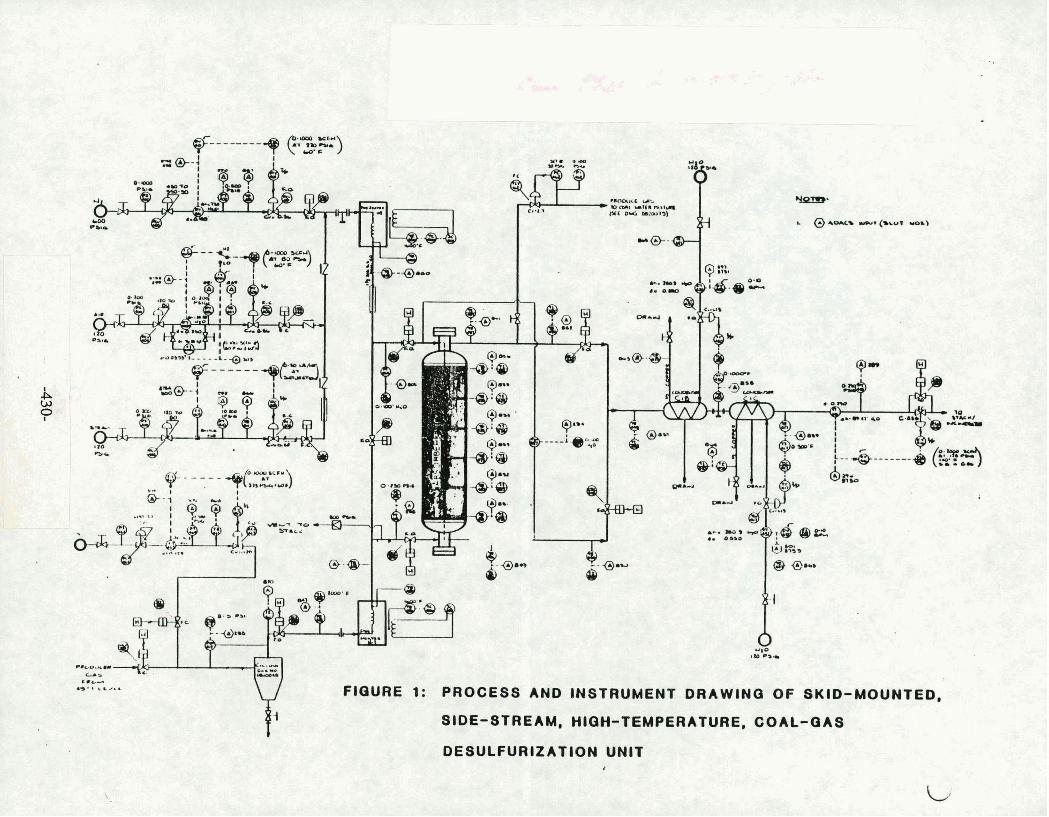
- I @ *or- uu+ (-bar ueb)
'I . -. ., I 8 . .
FIGURE 1: PROCESS AND INGTRUMENT DRAWINO OF SKID-MOUNTED,
SIDE-STREAM, HIQH-TEMPERATURE, COAL-QAS
DESULFURIZATION UNIT a

OT GAS DESLILFURIZATION SIDESTREAM TEST UNIT
ABSORPTION

FIGURE 3:
HOT GAS DESULFURIZATION SIDESTREAM TEST UNIT
REGENERATION

FEaURE 4: HOT a h 8 DESULFURIZATION
SIDESTREAM TEST UNIT I
i AT TEST LOCATION

FIGURE 5: HOT GAS DESULFURIZATION SIDESTREAM TESTINQ 1 0 8 3
.
0 0 1
SULFlDATlON
002
REGENERATION
0 0 3
SULFlDA T l O N m
004
REGENERATION T
0 0 6
SULFID I .T ION
1
F N a . t n a h a I I l l I l l
~ Q Q C J Q Q Q ( 3
o r CP rr I I t
7 I (Y 8 c3Q
' 0 4 I
a W 0 K -I
I- a i"i 0) rn aik r r P r P Y
LL i t t I I I I I I C 13 Q Q Q 0 0 at", t t I 1 I I Z = z s 3s
0 3 5 a m a 0 '-(Y L p m m . rr N W ( Y I I 1 I (Y
I 00 ( 3 0 0 0 ( 0 u IS r z r W a t- Q
111 m t c O O h N ( Y 0 1 ( Y N
I& I l l ) I IL ' 000 0 0 0 a h O D Q ) 1 s 1 1 1 .
I I I I 0 0 0 0 & a d &
. OFF STREAM
KEY;
Ha- (GRAB SAMPLES OF E,XIT O A 8 ) LC- (QRAB SAMPLES O F E X I T C O N D E N S A T E )
<
I I I I 2 3 4 7 , 8
u 6
I 8
1 .
DAY ';
I 6 / 2 3 8 / 2 4 6 / 2 6 8 / 2 8 8127 8128 6 / 2 0 6 / 3 0 0 .
J SCHEDULE OF EVENTS

:RUN . 00 I A
AVERAGE OPERATING PARAMETERS
)19 3 . W REGENERATION Ow 4u*atm:a P R E H E A T E R I r . m
81.-
-0.U'HBO
@ W . ~ B P C O O L E R am.-- W O Y I . . .
ll71 ebb- . I tq?.weF
mmw .*C/H) Oc 1 ~ . # #
I 4 . l m I 8 0 1040.DEW w.DLw b COOLEW
0 1*39.MOF < gtO.Dzw w l e a . # W K C O N D E N S E ;
1 W 3 . W
lW*3CP)IQ 0 . ~ 1 1 0 . 1 . ~ I
91.-
I C O O L E R
PRODUCER
P R E H E A T E R
FIGURE 6 A -.
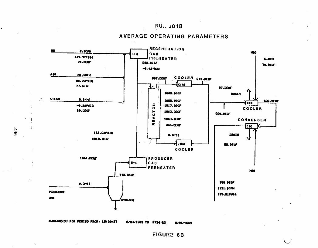
FIGURE 6 B
RU,. J01B t -
AVERAGE OPERATING PARAMETERS
W 8 . m REGENERATCON G A S lg0
6.m
'I).-
IB3.37mtQ P R E H E A T E R 78.-
AIR a.5CFti -3
OQ.10B910 n.DEw
688.OQW:
4 e 4 8 . W
s 7 . w
nfM @ . O M l'
1@09.#aF ORAIM
l@tlE.#aF 3.28P8ta U . E W
= 0 k 0 < W a 'i ,
I lnl7.#w COOLER
IW3.E€CT m.DOaf
1W.DEOf CONDENSER OOB.#CF
e . m t
I ua.afw C O O L E R
PRODUCER GAS P R E H E A T E R
7CB.DCQB
@.we1 1
m00flEIO
Qltl
m
1m.DLw
1131.ICbn
198~UWIQ

. .. RUN 33
AVERAGE OPERATING PARAMETERS
~IIIWI~IB r0 mxm -8 a a ~ m i i mwima vo i a a ~ m
FIGURE 7
w n.m rn 4.-
Il.mw
3B9.mml0 Il.DEw
IIU 31.-
04.41$9!0 01 .DEW
mM 8.- 9
weB.Dl;w
8.TOmHe0,
3 , I
C
- e . #W!O Sl.#W
I I J m l ~ I D
Ioa.a€QF
m.BQw DQBI)!N
Q:
1 b U . m w
1 Q a S . m
I COOLER rn.#BP
CONnEN8ER P
m1w
0 =
COOLER
PRODUCER. O A 8 PREHEATER
@*-I 1
mWQI
w
l(LeO.QLW
1)M.EQF
m.#(IF
mn
I=.-
1 m . m
1 1 1 . ~ 1 0
< w a
I ~ . # O P
1ow.#OT
@.of's1
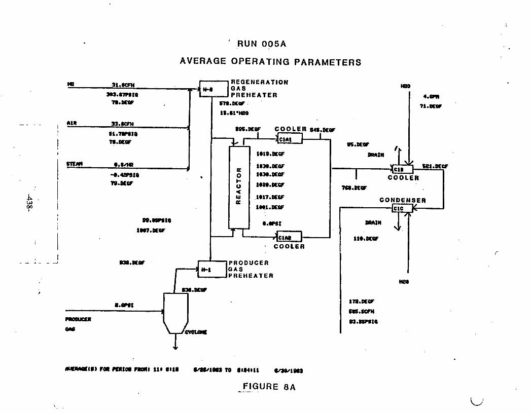
' RUN 005A
AVERAGE OPERATING PARAMETERS
REGENERATION Q A 8 PREHEATER
7 8 e D C O P ~ . # Q F . '
1B.Olmm
nIR 3J.m 1 =.DEW C O O L E R
O i l . ~ t O T8.m I l -4 CIA1
I
mml @*we + a I.W.#aF +*-I@ - 0 1WO.DEQT 'R.DLW 1 8 w . W
< W . 1817 .~Cf K rnl.cus
w.mte @.am1 1a7.mOf I
COOLER
W8.RQC P R O D U C E R QAS '
.PAEHEATER
8.- I -
w
MR#QItIl IOI m f m 11411 111 el18 Ml/lOll ) To 81Mcll -1-
FIGURE 8 A --- .
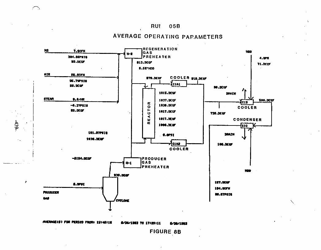
R u t O5B 1
AVERAGE OPERATING PARAMETERS
rn PREHEATER 4 . m
w.omF aL9.8Lw 71.m 6*61°W6
nxn E S . ~ 1
9 6 a t 8 9 4 1 4 PO.#aF
1 Q l t . W
SICRI) @.kW 9
J . m f O rn.BIEQ 10II.DtGb
0 733.tEBT
[email protected] CONDENSER = ~@@#*IKw
[email protected] 0 . ~ 1 l@M. DEW
IUoDEW COOLER
4 I U e W
PREHEAT ER m .
=.#91
8.-E lW.00PC
9 IM.8Wu R O M w.ww1a w
FIGURE 8 B

SlOT UNITS DESGUJPrlW
G 851 PECF ABCSRDER 5' FROR B O T T M U 852 nECF ABSORBER I S * FROR l O T T O l O 853 DEGF ABSMIBF'R 25' FROR BOTTWl A 854 BECF RDSORBER 3' FROR l O l T O R 0 85s OECF A D S O U M I 45' FRrUl BOnW
0 i 2 3 4 5 6 7 8 9 1 0 1 1 d 2 1 3 9 4 f 5 1 6 TIME (HDURS)
START TIME OF PLOT STOP TIME OF PLOT
Figure 9 R U I I 002 Kcgenctr;lt ion Reactor Tcnipcrntr.~rcs

SLOT UNIT9 DESCRIPTION
o as! OECF ABOSRBER S * FRO^ oonon a a s 2 DECF ABSORBER IS* FROH ~ o n m o 8 5 3 MCF ABSORBER esa FRO^ BOTTM 6 854 DECF ABSORBER 35' ?ROH DOTTO(l v ass DECF ABSORBER 4s0 FRO^ BOTTOM
START TIME OF PLOT 0a12a 0 6/28/1983 STOP. TIME OF PLOT 188508 0 6/28/1983
Figure 10 Run 004 Regeneration Reactor T~mperatures

a TEST SUllARV SMEET
SIDEStRUYI TEST UNIT
SUREHT W t E I W 8 (ZINC FERRITEW45 US M#M W)O. 8 LWITED CATALYIS~S L -1~04 SORENT COIPOSItIQIt 5O.e ROLE% IRON O X I E
SO.@ HOLE% ZINC OXIDE
!+ORENT PELLET SIZE1 W16 INCH DI#TER EXTRUSIONS CASIFIER OeERLt I f f i C0M)ITIOWS
CASIFIER WP€ 8 00E0llETC FIXED BED U€LU#W CALUUIls ##Lm t ~ u R 1 C M m#rm IWUIOI e.526 I -/At= rune r ..a.
TEW€mTUR€t 182s F
I 160 PSIQ (WERACE)'
INLET INLET EXIT EXIT mu8 ROLE8 llOLE8 MOLE8
DRV DA5I9 YEt BASIS DRY BRSIS PlET M S I S (OfL FREE) ( O I L FREE) (O IL FREE) (O IL FREE)
1
Hi? 16.e3
CHI 2.51
N! 91.34
OQ! e.63
RATE 8 FU)Y 11MBCFH
PURPOSE
OF FIXED #I, W I F I E R .
SORBENT,WW.YSIS* BEFORE
~ ~ ~ ~ L S U L F ~ R : (NUT) e.13 SURCIICE -8 ( 5 0 WG) 3.13 DENS IT^ - 8 t c l c c ) 6-16 PORE VOLUME8 (CC/O) e.eH316 ELEtWtTAL P)#LVSISI . TOTAL WBO(* (IYT) e.m
EXIT SULFUR OIIT6t
.- . - fiam~~ I 71.2 LBS (ESTICIATED) HVDROCC\CIBO)( I 8 LBS (EStIlYITED)
Rmmcs 1. PAClCED LENGTH I N REACTOR I S 46 7/8 INCHES ZINC FERRITE
BOWOR W D TOP 6. IHCHES ARE 112 INCH CERI\RIC !WKER€S CS-346 t /2 S SR-le789 WITED CATALVSTS
2. OVERALL PACrrO LEffiTM 58 7 4 INCHES 3. FIR- TEST OW FRESH SORBEM 4. EXIT CC WOT OP€RATIffi W R I M THIS TEST. S. Y A M I N EXIT oAS U M DETERIIIWD BY CONDENSE COLLECTED
AHD EXIT CAS SATURATION L E W L BV STEM TABLES. 6. CnS COWOSITION AT INLET I S m C E OF M T A OBTAIKD
BY BENDIX CC 8 4 S(HPLI)# AT 5 4 GASIFIER C V C L W EXIT.

S~R#M WPEAEIIWIJ trim FERRITWIS LBS SOROM NO. I UIITED C l l t A L W 8 L - 1 W wmrr coms1ttwa 50.0 m)LEr IROW OXIDE m.0 noLEl ZI* OXIDE
IWLET EXIT R O W ROLE8
U E t M I S DRY 8nS19
. .- . ..
PURPOSE
F f R 8 t W m R A t I m OF W f D W ffl SIDESTRERII t E 9 T W I T .
MIT SULNR M T A 8
U B t
SO2 t 14 11 IMITIILLY
C O H D M t E AIZUEOU9 I 15101 U S MYDROClYUOH t W t A L 8 1S1.1 LBS
m R K S 1. PRCKED WOW IM REMtOR IS 46 718 IHCHES ZINC FERRITE
BO?ToM (Y(D TOP 6 INCHES ARE 1/k! INCH C W I C W S CS-346 1 4 8 SRle789 UNITED ChThLYSIS
a. OUERALL PRCYEO LENGTH 68 7 / 8 IWCHES 3. FIRST REGENERATION ON W I D E D SORBEWT 4. THERE UERE SOlP: D I F F I C U t t I E S W4TROLLINO M Sl€M lYlO
RND CIIR FiCOUS. M L I D J U S f l M t S I H STEM IY(D l l IR F L W UERE WIDE t o PREUENT MCEEDIHQ i n e F In THE BED.
So S T E M &ND AIR FLWS &ERE ERRATIC DURIHQ M LAOl 7 HOURS DUE To OPERntOA (IDJVSTWMt8.
1. REODERATIO)( CORPLETEDI 8. IMPR@XD F L W COMROL FOR STEAM AWD CIIR (\RE mIRW. 3. .HI- s ' l i n ~ COHILM OR eoum SPACE RLOCIW WE REWIRED
70 P- ~ f W I T l R I t i 0 M SORBEM.
Figure 12
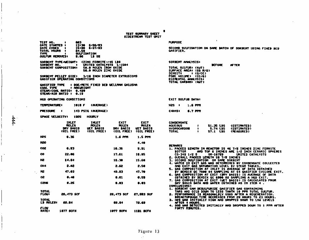
8 TEST m v S H n t
SIDESTREM TEST W I T
TEST no. t m a DATE STARtED 8 138- B/BB/t) DATE € N E D I 16800 8 / 8 7 m TOTAL HOUR) I 84.68 WPE I SUVIDnTIOW S J L F l R -8 8 0 6 LB
WENT t Y P E M I Q H 7 8 (ZINC F E R R I l E ~ / 4 6 LBS SOIIbEM NO. 1 W I T E D CMIIMSTS L-16U WI#M COIPQSITIO)(8 U.@ NOLEI IROn OXID€
w.e ROLEI zrm: OXIDE
S O R W ( V W W I S 8 W O R L (YTER
TOTAL SULFUR1 (UW) SWKRCE AREA8 (SO W Q ) DEHSlTV 8 (Q/CC) POCK UOLUlEl (CC/Q) ELEIEntAL #W.VSISI TOTAL CI\RlbWI ( W T )
EXIT SULFW MTA8
M2S 8 Lo6PWl
C4M498 0.7 PPC)
IllLL? INLET EXIT EXIT C 0 t m t t M T E m u 8 ROLE8 m u 8 M)UI n w a J s 8
DRY B M I S H T BASIS DUY BASIS VET B S I S HYDROCCWBW I (OIL FREE) ( O I L FREE) (OIL FREE) (O IL fR€E) TOTAL 8
PLOY RAIL 1 1077 8CFH
51.35 LBS (ESTIWTED) 5.74 LBS (ESTlNlTED)
57.1 LBS (IEMURED)
REmwKs 1. PIWED ~rn IN m m IS 4s 700 xnms ZINC FERRITE
BOfTOn M D TOP 6 1)(MS M€ IN2 INCH CERARIC SPHERES CS-348 102 S SR-l@78D WIVED CATALYSTS
2. OVERALL P-D U3GTM 558 7 d 1-S 3. SECWD SULfIDI)T10(( OW UME SORBEM 4. WlER I N EXIT UtS Ylri DETERRI(CED W CONMMS&TE COLLECTED
M EXIT O M W T ~ T I O W L E m L BV STEM TABLES. 5. OAS COWOSITIOW IHLET BS AVERAGE OF DATA OBThIHED
BY BEHDIX cc 7eee 8 4 WPLINC AT s 4 U~SIFIER CVCLONE EXIT. 6. W S COCPOSlTIOC( ht EXIT (WW BCISIS) I S A V E M OF DATA
OBT~IHEP w ~ I X cc ~ e e e t e SAIWLIHO HOD EXIT. 7. G(H COIPOSITIOH C)T EXIT ( S T M I S ) I S CIILCULIITED FRM
DRV BNIS Data mo WTER OBT~INED AS In Ira 4 . mNceUSIOW6~1 1. soannt cm m w m r a c n s r F I n ms contnmxw
TARS W P OILS D M TO LESS TMTN 1@ PPH TOTAL SUCFUI. e. m w o # m ~ IS RECISO~LBLY GOOD AFTER n REWRATI~.
BR€IYT+WWH TIRE MCCKIIKD FROH MWRS TO 23 HOURS. 3. HpS VCU IN lT IaLLV H I W WD DROPPED WY)( TO LOU W L S
*TER4MWR9. 4. soa YCII STECTED I N I t x n t L v nm DROPPED DOW TO i wn WER
FOIIW n m s .
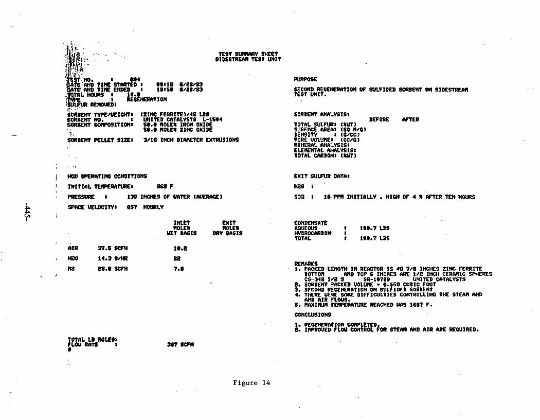
8 :m T r c a m 8 ooelu @am
=,IY(D tIE UOYO 8 101W 6 4 8 4 8 3
8 ItEQEtmmIotl .*. ." RPIWEDB
' . ~ ~ R W C I N#/YEIOHI: czrm: FERRI~E)/~S US SoRBEm NO. 8 UNITED C A l A L W B L - l W 4 ymEHT COIPOSITIQ(I wee I 1 0 L f t I M OXID€ :. . !see ROLE% 21% OXIDE 'i-. .
SORl#M PEI.OLt S I P 8 Y18 INCH DI- D(TRUS10HS
I I N I T I A L m T L R E 8 968F
I PRESfllRE 8 139 I N W S OF WTER (AVERAQE)
I rmn E X I t worn ROLE% VET ms1s DRV OASIS
TOTAL U MU88 FLOUR#R 8 s
PURPOBE
SECOHO REQEISRWIOM W SULFIEED m T dn SX#SIRUIII TEST UNIT*
TOTAL SULFtRI t fW) SURFWE AREbI (SO WQ DEHSIW I (C/CCl PORE. VOLUME, tCC4GI HIHEWlL W,YSISI EUMUITAL W L Y S I S 8 TOtW CARBWI ( M I
'ORE
EXIT S U W OAT68
H29 8
soa 8 16. oprr INITIRLLV . MIW OF 4 r mat m HOURS
eOHDMSm ADUEOUS 8 la@., U S HVDROCI\RBON I TOTAL 8 18e.7 LBS
m m s 1. PRCKED LENQW I N RERCtOR I S 46 7/8 1m;HES ZINC FERRITE
~ o n o r r MD TOP 6 INCHES ARZ: 1Re INCH CERMIC SWQES CS-348 1/8 9 SR-1Q78B U N I W D CATIUWTS
8. SORBOM 3ACKED VOLUlE e.559 CUBIC fOOT 3. SECOND REOEIERATION ON SULFIDEO S O R B W 4. T H E E UEQE SO(Qi DIFFICULTIES COWROLLIN0 T M STEM CY(D
AHD I I R FL-0 6. WIW IEIQERA'ILERE R€ACHED WS 166'P F.
Figure 14
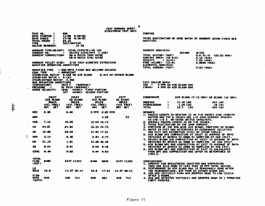
TEST NO. e H S 'Ds r t f S T W K D I 11100 6 / E Q m
D s r t L M # D 1 17:- 6 /30/93 TOTAL HOORS I 83.16 N# 8 S U L f I m T x ~ SW(IR -1 LB S8
8 TEST S U I # R V S H n t
S I M S T R E M TEST W I T PURPOSE
TMIRD S W I D I I T I W OW WTCM OF U S I W F I # b BED GASIFIER.
SOItKM t V P E / U E I W : (ZINC F€RRIT€)/4S LBS SOAKWT IY#LVSISI MEMT no. s U~IEO CATALYSTS L-1-4 BEFORE AFTER M8EM COCPOSITIO(I1 5Q.Q ROLES IROW OXIDE tOtM S U W I ( IW) 8.6-31.41 (22.83 kVC)
60.e MOLES zrm: OXIDE SWME AREA: (SO we) 2.16 (AS) DEMSITV I (WCC) 4.55 ( W I
w w ~ m mlrt SIZLE( 3016 INCH DIHTER EKTRVSIOHS PORE VOLUI~EI (CCKO) e.w19 ((wc) UIS IF IER -TI)(Q OOnDITIOWS ELEMENTAL AIYILVSISI
TOTAL CARBWI ( 8 ~ ) 2.63 ((WC) ClrSIFIER TWE I W/EtC FIXED E D U E L L W UILUSHA COAL W E 8 ARlMlICHT STUWCOI)L IWTXOI @.see OW AIR 2.344 on omcoc BLW S l E M / A I R RATIO 1 Q.193 StEAII/OXVCM RAT101 3.366 MCD WERATI f f i C W D I T I W S EXIT S W U R DsrTAI TLRLRANRLI te12 F t m n ~ ) HZS I 3 P ~ W OW AIR BLOW UK
, PRESSUPE I 91 PSIC (MERACE) C H S D 4 PfW OW AIR BLOW W SPlICL UELOCXTVI 1046 H W L V FIRST PORTIOn
347 HOULlLV SECOnD P O R t I W
~ I R BLOW aa BW ~ I R BLW a BWN llOLES R O E 8 ROLES llOL€S AMWS 1 11.42 LBS
(O IL FEE) (O IL FREE) (O IL FREE) (O IL FREE) )IY-AAUI)( I 1 - 2 8 LBS D(W YET W V W DRV UET DFN YET TOTAL I 12.7 LBS
284 LBS 1e LBS
294 LBS
RES#R(s 1. M K E D LENGTH I N E M T O R I S 4 6 7 4 IWCHES ZINC FERRITE
BOTTOR AM) TOP 6 INCHES M E 102 INCH CERIIWIC !PWRES CS-346 i / a s SR-IQ~~Q WITED c n t n L v s t s .
2. M R A L L WCKED LMCTH I S Sb 708 INCNS. 3. TMIRD SUVIDATIOW ON THE SARE =BENT. 4. FORTIONS O f TM RU( WRE AIR BLOW, PORTIONS 02 BLOW. 5. UJITER I N EXIT GhS DETERlrIWD BV CONDEM%tE COLLECTED
AHD EXIT U I S SATUWITPON LEVEL BV S T E M TABLES. 6. AIR BLOW GAS COlPOSITIW AT INLET I S A K R A C E OF PIITA
OBTAINED W BEHDIX CC 6- 8 1 S I H P L I f f i AT H6D INLET. 7. o m c E n BLOUI cns cowosrtton nt INLET IS AVERACE OF m T a
OBT l I lED BV BEHDIX OC 6- 8 1 SIYIPLINC AT HCD INLET. 8. AIR BLOUI DRV OAS CWOSITIOW AT EXIT I S AVER= OF M T A
~TAINED w BENDIX cc ~ w o r a ~#PLIW A t f f i ~ E x r r . 0. AIR @LOU( YET QRS COWOSITIOH AT EXIT I S C4LCUUlTED
FROR DRV QAS COROSITIOW AWD UATER AS #l'ERRI)(ED I N I n n S.
TOTAL fLW 64eS . 6447 114- 6406 6645 6447 1 l 4 a 3 CWICW910W91 (BCF) 1. SORBEN C#( DE8ULFUllIZE GASIFIER QA9 CWTAINIHG
TARS AWD OILS DM TO LESS w w 10 wn TOTAL SULFUR. LB 8. PERFOR- ON AIR BLWN CAS I S REASONABLY GOOD W n R MOLL 16.e 14.37 30.14 18.9 17 -53 14.373Q.14 T W REOEIIERATIONS. BUT POOR ON OXYGEN B L W W.
30 H a f W S INITIALLY HIOH M D MOPPED WW TO LOU LEWLS FLOU WTER 3 HOURS. RAE 9 4 9 3 4 ~ 714 949 084 3 4 1 1 4 4. soa uns DETECTED INITIALLY two - DOU( TO 1 PWTER (SCFM) FORTY RINUTESe

ZINC FERRITE SULFIDATION
20 19 18 17 16 15 Temp - 1025 F (552 C) - I4 I3 Press - 160 PSlG
4 12 11 a
S.V. = 2000 'Hourly *
10 UI
Q @
El = BASELINE Gc 8 a5 a 7 6 = DETECTOR TUBE
. 6 5 4 3 2 I 0
0 2 4 6 1 10 12 14 16 18 20 22 24 26 211 30 31 34
ma (-n)

ZINC FERRITE SULFlDATlON SIT r n r ~ ~ ~ r ~ T S 001 AND 003
20 - 19 -- 18 -- 17 -- 16 -- 6 15 -- Temp - 1000 F (537 C)
CI 14 --
*$ 13 -- Press - 160 PSlG 12 --
& 11 -- S.V. = 2000 Hourly . b
V)
P DETECTOR TUBE READINGS
E 8 -- V - flRST SULnOAllON 0 4 7 --
6 -- = SECOND SUfflDATlON
1 1 1 1 1 1 ~ ~ 1 , ~ 1 1 , 1 1 , 1 1 1 I I I I I I I ~ ~ ~ 1 1 1 , 1 1 1 1 1 1 1 ~
0 2 4 6 8 10 12 14 16 18 20 2 4 26 28 30 S a
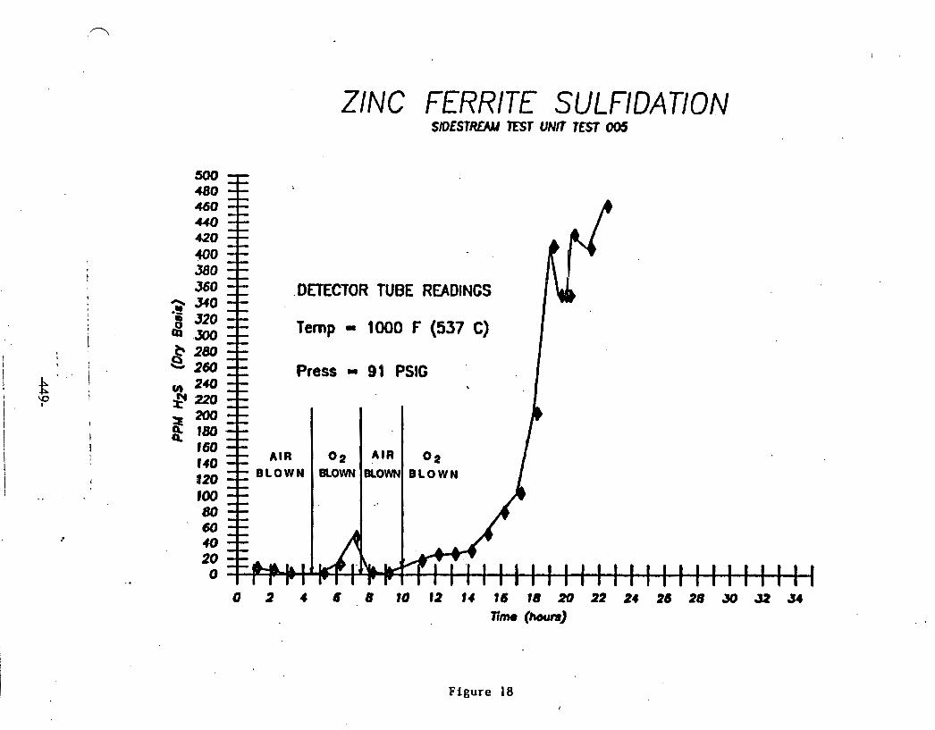
ZINC FERRITE SUL FIDATION
. DnECTOR TUBE READINGS
2 Temp - 1000 F (537 C) I Press - 99 PSIG
B L O W N BLOWN BLOWN B L O W N
Figure 18
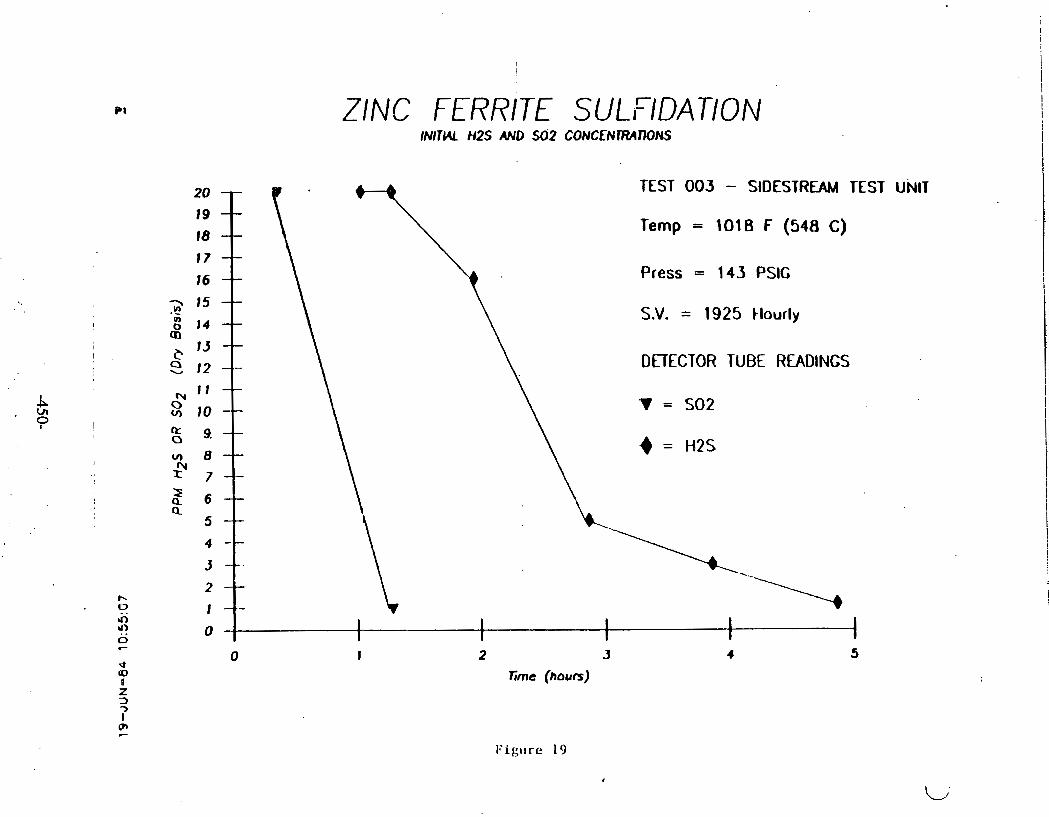
ZINC FERRITE SULFIDATION INlTHL H2S AND SO2 C O N C E N ~ ~ r J s
TEST 003 - SIDESTREAM TEST
Temp = 1018 F (548 C)
Press = 143 PSlC
S.V. = 1925 tlourly
DETECTOR TUBE READINGS
'V = SO2
= H2S
L,
2 3
Time (hours)
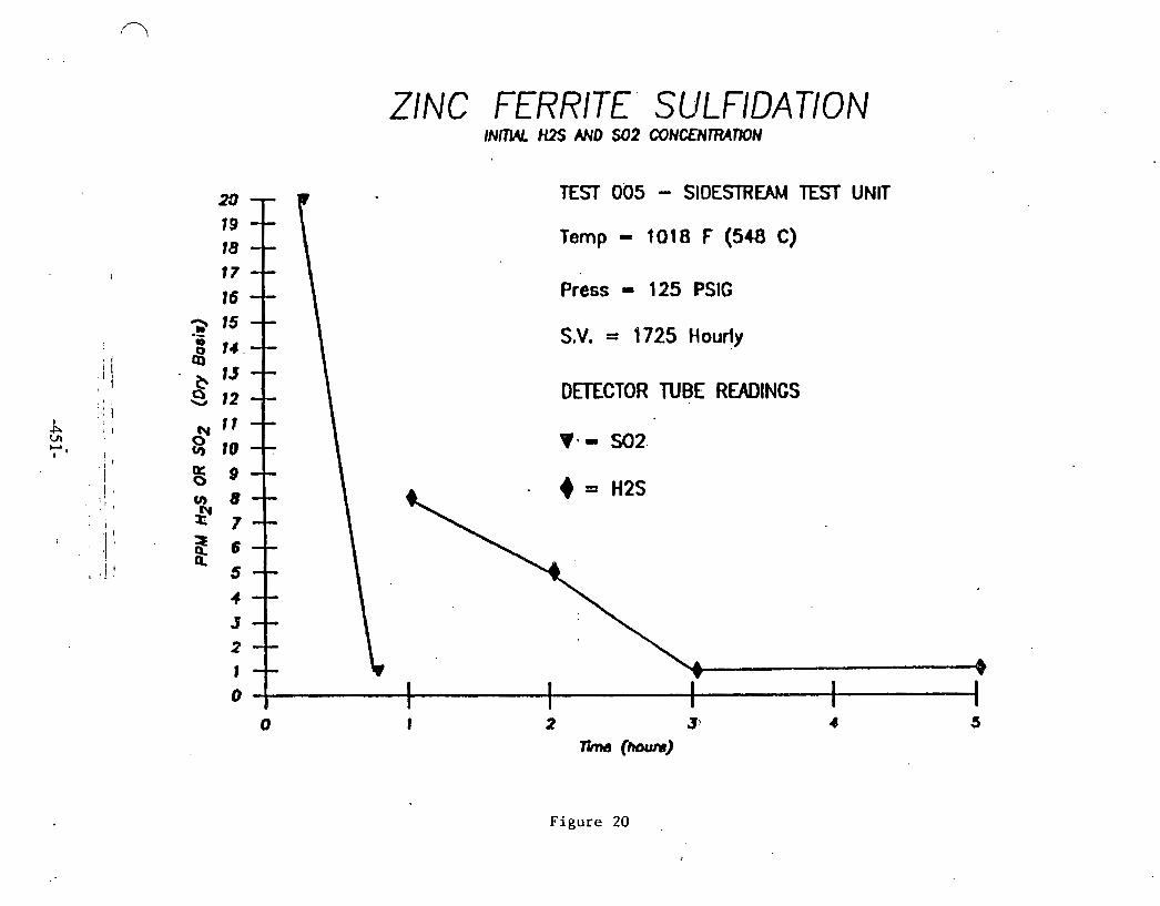
ZINC FERRITE SULFIDATION lNlTUL H1S AND $02 CONCLNlRArnN
Figure 20
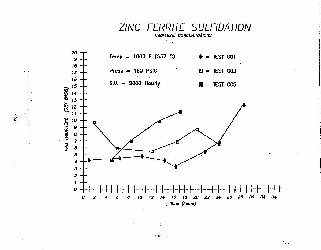
ZINC FERRITE SULFlDATlON ~ H I ~ O J E mucmrma
- -- : Temp = 1000 F (537 C) ~ = T E S T O O l -- -- Press = 160 PSIC 13 = TEST' 003 --
S.V. = 2000 Hourly -- Bi = TEST 005 -- --
-- -- -. 1 1 1 1 1 1 1 I
I 1 1 1 1 1 1 1 1 1 1
I 1 1 1

ZINC FERRITE REGENERATION SULfUR DKlXlOE CONCEU7RATION IN EXIT CAS
=: TEST 002
El - TEST 004
3 0 2 4 6 8 10 12 t4 16 1 8 20
1 run. (h4YI) 8 . 1.
$:
k '* -- DnECTOR TUBE READINGS s 1 1 -- $ lo
-- L
9 -- . NOTE: THE VALUES ARE LOW BEMUSE OF 3 8 - - SO2 DISSOLVED IN CONDENSED WATER.
8 I - - & 6 --
. Figure 22
5 4 3 2 1
-- -- -- -- ---
0 I I I I I 1

TEST 003
SHIFT CONVERSION
Figure 23
30
2 4 e
I I I I
7
- I
INLET -
0 -
0 8
6. - I
0. I 1 I I I I 8.0 5e2 10.4 15.6 20.8 26 e
..
TIME (HOURS)
PEFiCENT CO BENDIX CHROMATOGRAPH
START TIBE 13830100 06/26/1983 STOP TIME 15:00t00 06/27/1983
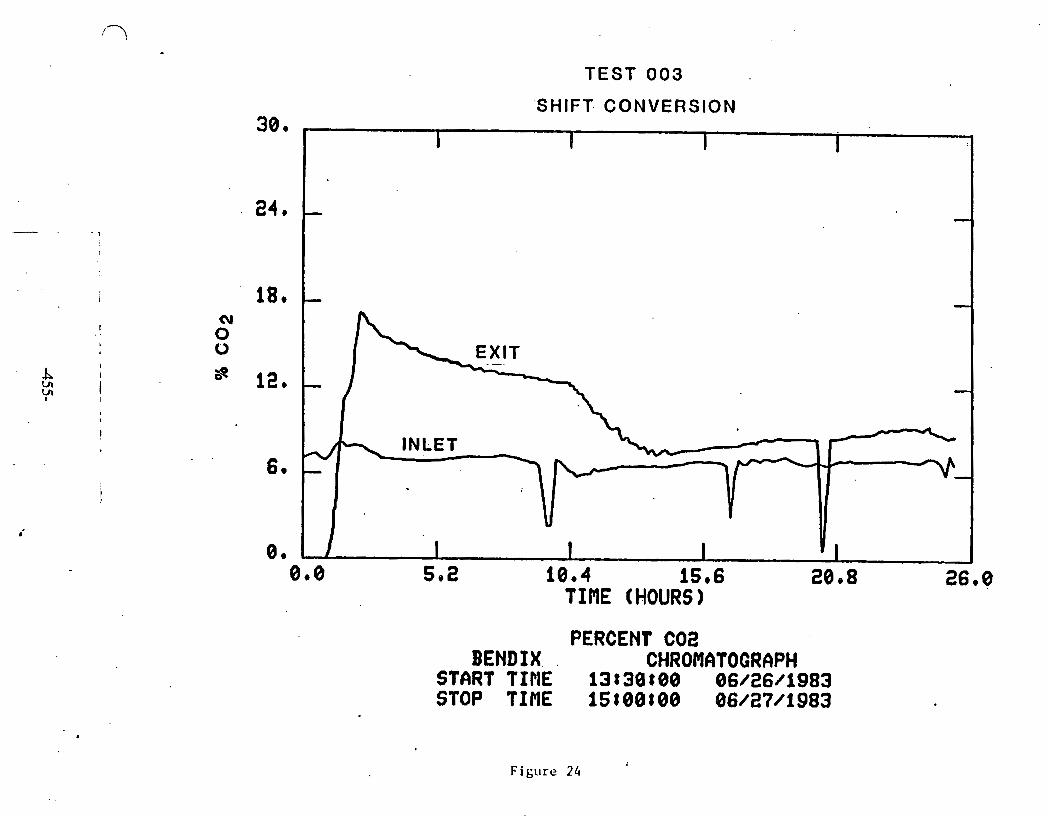
TEST 003
PERCENT CO2 BENDIX. . CHROMBTOGRAPH
START TIME 13~30800 06/26/1983 STOP TINE 1s:o~roo 06/27/1983
'SHIFT. CONVERSION 30. -
Figure 24
24,
18.
I I I I
- -
- -
-
0.0 10.4 15.6 26.8 TIME (HOURS)
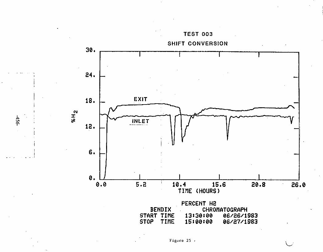
TEST 003
SHIFT CONVERSION
1 i I I
- -
EXIT
--.- -
- -
I I I I 1 I 5.2 ' 10.4 15.6 20.8
TIME (HOURS)
PERCENT H2 BENDPX . CHROflATOGRAPH
START TINE 13838108 06/26/1983 STOP TIME 15888808 86/27/1983
F i g u r e 25

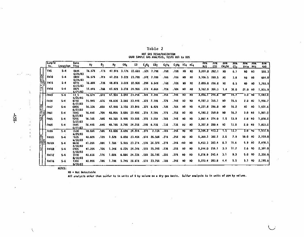
Table 2 HOT U S OESULFURIZATION
GRAB S W L E GAS ANALYSIS. TESTS 001 to 005
NOTES : NO Not Oetectable A l l cnr lys i r other than su'ifur i s i n uni ts o f 1 by volume on r dry gas btsts. Sulfur r ~ l y s l r i s In unlts o f ppm by volum.
TSmp e Oate P n p p n PP PPH PPH PPI PPH Uo.' Locatton rime '2 O? '2 ''4 c0 B H 6 U)Z (zH4 '3'8 1'4 ''4 H:s c cs, (hio NHI "20
fN5 5-4 0645 16.571 .7:1 47.911 3.171 22.661 .32X 7.791 . I 5 1 . I 5 1 NO NO 3.001.8 282.1 NO I NO NO 555.3 6/24/83
fNlO 5-4 0840 16.571 .1€X 47.351 3.221 23.791 .311 7.181 ' . I 6 1 . I 5 1 NO NO 3 .106 ;~ 260.5 NO 3.8 NO NO 864.0 6/24/83
fNl5 1-4 0715 16.881 -131 8 O X 2 9 9 6.641 .161 . I 0 1 YO NO 2.855.0 296.8 NO 6.5 NO NO 1,193.9 6/25/83
fN18 5-4 0895 11.441 . I& 47.921 3.211 24.961 . I 1 1 4.661 . I 5 1 -101 NO NO 3,162.9 301.1 1.4 36.0 21.0 NO 1.955.9 6/75/83
fN49 5-4 13-5 16.671 6 41.901 3.091 23.251 .30X 7.39I . I 5 1 . I 4 1 NO NO 3.496.1 245.8 NO 14.7 3;O-hOr.40JX 6/26/83
lk54 S-4 0740 15.941 .(IS 48.631 3.061 23.441 .321 7.191 . I 7 1 . I 4 1 110 NO 4.187.3 335.1 NO I . 2.0 NO 1,356.? .6121/83
FNSI S-I QBSS 1 6 . 3 3 ~ .6sr 4 7 . 9 ~ 1 '3.151 2 3 . 8 4 ~ . ~ Z X 6,921 a .16r NO NO 4.221.8 286.8 NO 16.2 NO NO 1.931.6 6/27/83
iN6l 5-4 1045 16.441 .TOP 48.001 3.081 23.481 .31S 1.191 . I 7 1 . I 5 1 NO NO 4.180.2 269.0 NO 16.1 3.0 NO 1.961.0 6/27/83
fN65 S-4 1255 1 6 . 6 .58S 48.361 2.99% 23.55X .31X 1.251 6 . I 4 1 NO NO 3,867.4 214.0 1.5 13.9 2 . 8 ' N O 1,818.0 15/27/83
fN69 5-4 I445 16.441 .641: 48.101 2.791 24.251 .29X 6.711 . I 3 1 3 1 NO NO 3.357.9 280.4 NO 13.0 2.0 NO 1,803.0 61 27/81
---fa99 5-4 1510 18.661 .58X 43.80X 3.691 24.911 .311 1,131 . la1 ,251 NO ND 3,f0-13.2 1.5 ~ O - N O ~ . P ~ ~ O ' . 6/29/83
fNlOl S 4 3635 40.82s . I 2 1 1.521 6.051 23.461 .SIX 26.561 .21 I .251 NO NO 5,369.1 302.1 2.6 1.9 58.0 NO 2.109.0 6/30/83 .
FNlO4 5-4 0618 41.051 .081 1 . 5 8 1 . 5.961 23.211 .531 26.311 .21Z .241 /NO NO 5.453.3 283.4 6.3 15.6 5.9 NO 2.478.5 e./JO/83
fN108 ' 5-1 Cb905 41.201 . I 0 1 1.341 6.221 24.341 .55X 25.241 .231 5 NO NO 5.244.0 256.1 3.3 11.1 2.6 NO 2.301.0 C130/83
FNIIZ I-I 1110 10.631 .ITS I .oex 6 . 0 8 ~ ~ 4 . 3 3 ~ .sex z s . 1 9 ~ .zox . z l x NO ND s.zIa.9 240.4 3 . 9.3 5.0 NO z.3ss.o 6/30/83
fN116 S-4 1300 40.891 8 1.191 5.741 26.811 .SIX 23.751 -181 -241 NO NO 5,213.4 283.8 4.4 5.5 5.1 NO 2,195.6 W30181
- f P
$:g
"7 o
.
I
;C
2 u
3
z 2 r
L-r
c u O f b-
L

Table 3
MINERAL ANALYSIS AFTER TEST 005 Z I N C FERRITE L-1504 - UNITED CATALYSTS
NOTES :
1) Bottom/Inlet dur ing s u l f i d a t i o n -- Out le t during regenera t ion . 2 ) Top/Outlet dur ing s u l f i d a t i o n - I n l e t during regenera t ion . 3) Percent T I 1 = Percent To ta l In teg ra ted I n t e n s i t y : D i r e c t l y p ropor t iona l
t o t h e concentra t ion o f t h e c r y s t a l l i n e phase. Amorphous i s not accounted f o r .
( 4 ) F r a n k l i n i t e and magneti te have t h e same c r y s t a l s t r u c t u r e and, t h e r e f o r e , ca~iaol be i e a d i l y d i s t i r ~ g u i s k e d by the d i f f r a c t i o n p a t t e r n .
PYRRHOTITE FeS
ALPHA ZnS
ZINCITE ZnO
0 (1)
6
16
2 3
2 6
3 6
46 (2)
Fresh Sorbent
BETA ZnS
FRANKLINITE ZnFe,O, AND/OR
MAGNETITE Fe,O, ( 4 )
BED HEIGHT
( INCHES) HEMATITE
Fezo,
PERCENT T I 1 (3)
2 5
2 9
27
2 8
32
- -
-
- - - - - - -
4
Trace -
Trace -
Trace
1 4
18
6 -- -
10
4
18
10
19
6 8
7 0
8 9
13
1 2
19
19
24
10
9
-
5 1
5 4
3 6
42
2 5
7
4
-
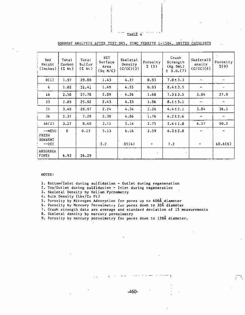
SORBENT ANALYSIS AFTER TEST. 005, ZINC FERRITE L- 1504, UNITED CATALYSTS
NOTES :
Bottom/Inlet during sulfidation - Outlet during regeneration Top/Outlet during sulfidation - Inlet during regeneration Skeletal Density by Helium Pycnometry Bulk Density (Lbs/Cu Ft) Porosity by Nitrogen Adsorption for pores up to 600A diameter Porocity by Mcrcuty Porasimetiy Zur pores down co 30A diameter Crush strength data are average and standard deviation of 15 measurements Skeletal density by mercury porosimetry Porosity by mercury porosimetry for pores down to 120A diameter.
Porosity % ( 9 )
- -
27.9
- 36.1
- 50.2
-
60.6(6)
i Bed 1 Height '(Inches) 1
O(1)
6
16
2 3
2 6
1 36 t
/ 46(2)
1 --RETC i FRESH / SORBENT ! --VCI
ABSORBER FINES
BET Surface Area
(Sq
1.43
1.49
2.09
2.43
2.24
2.30
3.11
3.13
3.2
Total Carbon ( % ~ t )
1.97
1.86
2.58
2.89
3.43
2.37
3.27
0
6.93
Total Sulfur ( % wt)
29.88
31.41
27.78
25.92
28.97
7.29
8.60
0.13
26.29
Skeletal Density (G/cc)(~)
4.37
4.55
. 4.26
4.33
4.34
4.86
5.14
6.16
I. 85(4)
Porosity
0.93
0.93
1.68
1.96
2.26
i. 76 2.75
2.59
-
Crush Strength (Kg DWL) - + S.D.(~)
7.0t3.3
8.4 2 3.5
7.35 3.5
8.1t3.1
4.422.1
4.2 2 2.6
2.42 1.8
6.3f2.8
7.2
SkeletalD ensity
(G/cc)(~)
-
-
3.84
- 3.84
-
4.57
-
-
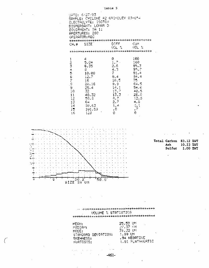
Table S
Total Carbon 83.12 ZWT Ash 10.23 ZWT Sulfur 1 .OO %wT

Table 6
PARTICULATE SAMPLING DATA
HOT GAS DESULFURIZATION TEST UNIT
(1) Carbon 15.5% Ash 82.79%
( 2 ) Carbon 2.73% Ash 97.19%
L
Run #
TOO 1
TO03
TnO3
TO03
TO03
TO05
TO05
T i me
22:OO Hours 6/23/83
16:52 Hours 6/26/83
15:04 Hours 6/26/83
12:40 Hours 6/27/83
14:25 Hours 6/27/83
11:22 Hours 6/29/83
16:06 Hours 83
Sampl e Duration M i nutes
1
30
30
30
' 30
30
3 0
Samp1.i ng Flow Rate 1 i ters/mi n.
13
13
13
13
13
13
11
P a r t i c l e loading I n l e t I E x i t
g/NmJ
flean p a r t i c l e s i z e I n l e t 1 E x i t
- 1.6
-
O
0.3(11
0.3
-
Microns
10.4
15.3
- -
6.0
2.9
-
- -
3,. 9
4.6
-
-
2.8(')
-
-
2.7
2.3
- -
3.8

.e 7 Particle Distribution
1 CtO ! rjg 3c;. 2 5 4 . 1 81.1 .I, . ' c ' ." , .-I :33* T' ;'q :> . -_ 1
75.5 -, .. 1.1.1 , ;:: Ci5.5 e;t;1. 1 tt i',
I . a:.. f - .. '1.1 , Q 44, c:: 7.'. - .., , .:, 2 - - ~ 1 . 1 .I' .- . . .__I
;23.7 1=1.5 3. .: E;. 1 E' ... ? . 4 4.8 4.7 1 3 . L.
T O O 1 INLET
22 .OO HOURS
6/23/83

Table 8 Particle D' . i b u t i o n
TO03 INLET
. 16.52 HOURS
6/26/83

Tab! c. c)
Part ic le D~,,ribution
TO03 OUTLET
18.04 HOURS
6/26/83
. I . . . . . . . . . . \ . . . . . . . . . . . . . . . . . . . . . . I-. : . . . . . r---k-L,
b.-)-'. . . . . . . . . . . 1 1 , , , 1 1 1 , , 1
. . - ' - 1 . . . .5 ' = I ; .J % I 1

Tab]*:- \.O Particle D r : . i ~ . i b u t i o n
7 .:. 1 . 7 1.3 1 . i. . .:a
-6 ; .4 - . . _ a
. . . i. ' . . i ' . . i.. ' . . i.. .:, . i
TO03 OUTLET
12.40 HOURS
6/27/83

Tabli 1 1 Part ic l e bi;t r i b u t i o n
ElqTE: 7 ...--...i- i i 2 i .. r::.> Sat.1pL.E : [I€ #G E:Rl:;tIELL 50 :3.3-7ClCt F.LEI::~'F:~:ILYTE: 1!;1:1TClt.1 @I SFERSHt.IT: LOl.1FtE D Fs:.!!! I F'tIEEIT: TR 1 1 RPEETUEES : 58 ~IFERHTCIR: REC +u++++r++++++++w+++++++f+++++++++++++% u::~. # SIZE DIFF ~ 1 . 1 t . f
U..!OL r. I..!I:II- I: ++++*+++++++~***++**+++*++*+**++++***++
I'
TO03 INLET
14.25 HOURS 6/27/83
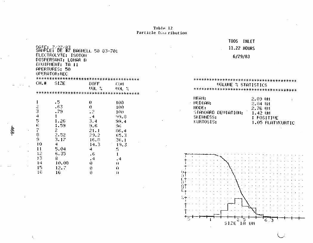
T a b . 1 ~ 12 Particle nisi ribution
D I SPER!!;Ht.IT: LClMHR D EI::IU I F'MEI4T: TH 1 1 FPERTUEES: 513 I:IPEEHTI:IR: REO ++++f*f3ff~B*++*f**++++++++y+++++++++++
*. .. . IX. # SIZE DIFF i. I.1t.1 I
l..!l:lL. 7 . !.!(.!L :.: +++3+++9+++++++++++++++++++++++++++++++
s.1
. .-, . L
. 4 3.4 :i , c; 21.1 .>*q L.. . .L 3
1 E; . :: 14.3 4 . E; .4 0 0 0
TO05 INLET
11.22 HOURS
6/29/83

Tab1 e. 13 Particle 5, ' ; t r ibut io l - .
l:lQTE: 7, 87 . -1
:;QI?pLE: [IE #3 E:F(T;t.IFr:LL 50 83-7(:12 ELEI::TF:l:lLVTE: I5OTl:lt.l D I SFER5PNT: LOIIQR O E131J I F't.1Et.l r : TH 1 1 FPEETIjRES: 51-7 ~:~F'EF:PTISIR: GEC: r++r++++g+ur*urruu+++++~+u++r++++++++++ [:H.# CfI FF c'1Jt.f
l..!l:lL ?: !!OL l.; .......................................
T005. OUTLET
16.06 HOURS
6/29/83

T a b l e 1 4
AQUEDUO PHASE AT HOT GAS OLSVLFURfZATfON 1HLD, TESTS 001 - 005
:;OIES: - 1. Above analysis was made on samples ta'ten a t the sidestredm i n l e t , whether gar war f l ow ing to the t e s t u n i t o r n o t (l.e.. du r ing regenerat ion) .
2. Sampl l ng l o c r t l o n 5-4 i s a f t e r g s s i f i c r cyclone rnd.before humldif l e r .
3. Metals determined by atomic absorption/atomic emlsslon spectroscopy a t DOE/HfTC.
4. Anions and cat fans determlned by Ion chromatography 8 t OOE/JlETC.

Ta~,lr. 15
TAR ULTIMATE ANALYSIS
AT HOT GAS DESlJLFIJRI ZATI9N INLET
NOTES :
t
TEST TYPE
S u l f i d a t i o n
S u l f i d a t i o n
Sul f i d a t i o n
Sul f i d a t i o n
, 1 . Sampl i n g l o c a t i o n S-4 i s a f t e r g a s i f i e r cyclone and before humid i f ie r . 2. Oxygen obtained by d i f f e r e n c e and inc ludes oxygen i n t h e moisture present. 3. Tota l s u l f u r ana lys is obtained by ASTM D-3177-75 a t DOE/METC. 4. Carbon and hydrogen ana lys is by AfTM n-3178-73 a t DOEJMETC. 5. Ni t rogen ana lys is by ASTM 0-3179-73 a t DOE/METC. 6. ' Ash ana l ys i s by ASTH D-3174 a t DOL/METC. 7. BTU content ana lys is by ASTM 0-2015 a t DOE/METC.
TEST NO.
TOO1
TO03
TO05
TO05
SAMPLE LOCATION
S-4
S-4
S- 4
S-4
LAB SAMPLE h'0.
27 943
281 '93
27 948
27 9.1 9
TIME/ DATE
04 00 6/24/83
1300-1400 6/27/83
1100 6/30/83
1500 6/30/83
' ASH !
0.26
: 0.16
!-
1 0.61
0.45
S
1.15
1.11
1.04.
1 . 4 4 '
, H
7.35
7.34
7.65
8.33
T.C.
70.85
75.56
65.36
61.81
N
1.92
2.53
1.74
1.52
0
18,47
13.3
23.60
26.95
B TU
13060
14467
14202
13836

AQUEOUS PHASE CONDENSATE AT HOT CAI OLSULfURlZATlON E I I T . TESTS 0 0 1 - 0 0 5
M I E S : - 1. Srmpllng locrtlon Is ct.condenser ClC knockout.
2. Metals determlned by rtomtc bbsorptlon~rlomtc emlsslon spectroscopy at 00EIMETC
3. Anlonr and crtlons detcrmlned by lon chromatography rt M)E/MfTC.
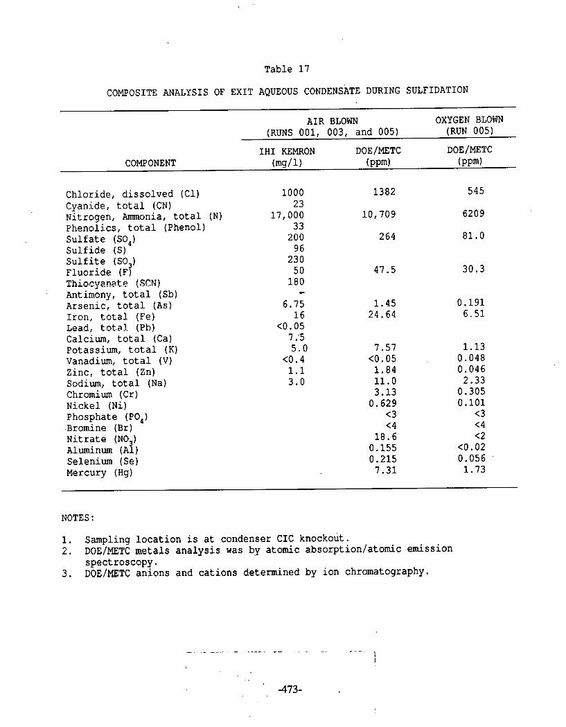
Table 17
COMPOSITE ANALY s I s OF EXIT AQUEOUS CONDENSATE DURING SULFIDATION
AIR BLOWN OXYGEN BLOWN (RUNS 001, 003, and 005) (RUN 005)
IHI KEMRON DOEIMETC DOEIMETC COMPONENT (mg/l) ( PP~) ( P P ~ )
Chloride, dissolved (Cl) Cyanide, total (CN) Nitrogen, Ammonia, total (N) Phenolics, total (Phenol) Sulfate (SO,) Sulfide (S) Sulfite (SO ) Fluoride (F3 Thiocyanate (SCN) Antimony, total (Sb) Arsenic, total (As) Iron, total (Fe) Lead, to ta l . (Ph) Calcium, total (Ca) Potassium, total (K) Vanadium, total (V) Zinc, total (Zn) Sodium, total (Na) Chromium (Cr) Nickel (Ni) Phosphate (PO,) .Bromine (Br) Nitrate (NO ) Aluminum ( ~ 1 ) Selenium (Se) Mercury (Hg)
NOTES :
1. Sampling location is at condenser CIC knockout. 2. DOE/METC metals analysis was by atomic absorption/atomic emission
spectroscopy. 3. DOE~MFTC anions and cations determined by ion chromatography.

Table 18
COMPOSITE ANALYSIS OF EXIT AQUEOUS CONDENSATE FROM REGENERATION RUNS 002 AND 004
DOE/METC RUN 002 & 004 DOE~METC PLANT STEAM I
Zinc (Zn) Chromium (Cr) Iron (Fe) Nickel (Ni) Potassium (K) Sodium (Na) Calcium (Ca) Vanadium (V) Ammonia (NH,) Fluoride (F) chloride (€1) Phosphate (PO,) Bromine (Br) Nitrate (NO,) Sulphate (SO,) Aluminum (Al) Selenium (Se)
- - Mercury (Hg) Arsenic (As)
NOTES :
1. Sampling location is at condenser CIC knockout. 2. DOEIMETC metals analysis was by atomic absorption/atomic emission
spectroscopy. 3. DOEIMETC anions and cations determined by ion chromatography.
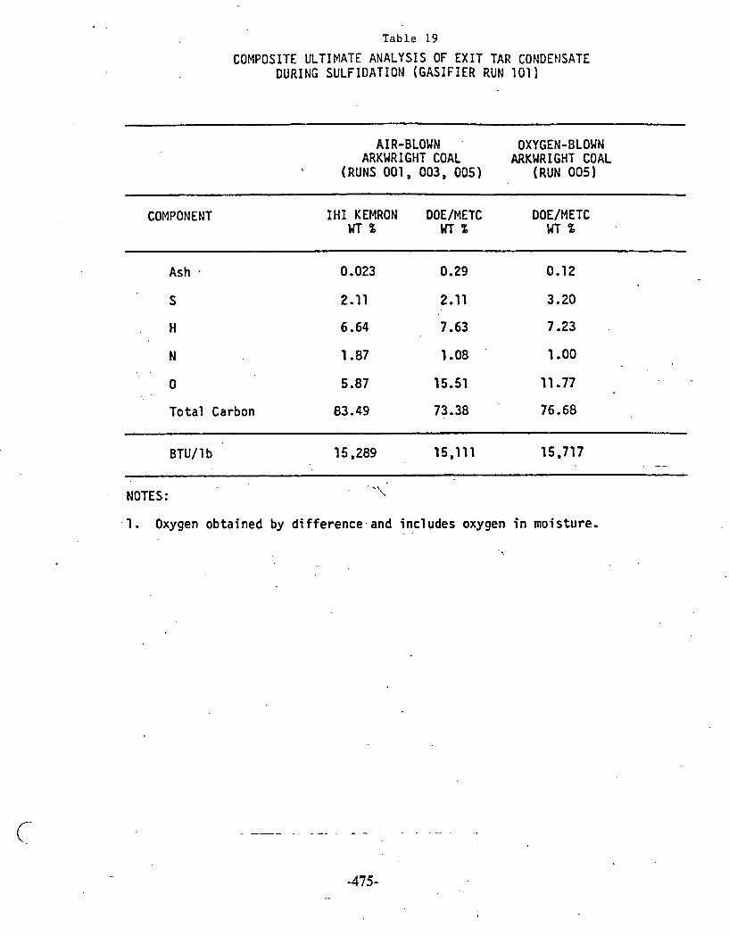
. .
T a b l e 19
COMPOSITE ULTIMATE ANALYSIS OF E X I T TAR CONDENSATE DURING SULF IDAT ION ( G A S I F I E R RUN 101)
AIR-BLOWN ' OXYGEN-BLOWN ARKWRI GHT COAL ARKWRIGHT COAL
(RUNS 0 0 1 , 003, 0 0 5 ) (RUN 005)
COMPONENT I H I KEMRON DOE/METC DOE/METC GITZ WT% WT %
A s h
Total Carbon 83.49 73.38 76.68
BTU/ 1 b 15,289 15,111 15,717 .
. .\ NOTES: \
. I . Oxygen obtained by di fference - and incl udes oxygen i n moisture. . .

Table 20
TRACE COMPONENTS I N EXIT GAS DURING SULFIDATION
A I R BLOWN OXYGEN BLOWN (RUNS 001, 003, and 005) (RUN 005)
IHI KEMRON DOEIMETC DOE IMETC COMPONENT PPmw PPmW PPmw
Chloride ( C l ) Cyanide, t o t a l (CN) Nitrogen, Ammonia, t o t a l ( N ) Phenolics, t o t a l (Phenol) S u l f a t e (SO,) S u l f i d e (S) S u l f i t e (SO ) Fluor ide (FI TliiucyanaLt! (SCN) Antimony, t o t a l (Sb) Arsenic, t o t a l ( A s ) I ron , t o t a l (Fe) Lead, t o t a l (Pb) Calcium, t o t a l (Ca) Potassium, t o t a l (K) .
Vanadium, t o t a l (V) Zinc, t o t a l (Zn) Sodium, t o t a l (Na) Chromium ( C r ) Nickel ( N i ) Phosphate (PO,) Bromine . (Br) N i t r a t e (NO ) Aluminum ( ~ i ) Selenium (Se) Mercury (Hg)
NOTES :
1. Sampling l o c a t i o n i s a t condenser C I C knockout. 2. DOEIMETC meta ls a n a l y s i s was by atomic absorption/atomic emission
spectroscopy. 3 . DOEIMETC anions and ca t ions determined by ion chromatography. 4 . Concentrat ion i n gas phase ca lcu la ted based on a n a l y s i s i n aqueous phase.

Table 21
TRACE COMPONENTS IN EXIT GAS DURING REGENERATION
DOEIMETC RUN 002 & 004 DOE/METC PLANT STEAM COMPONENT PPmw PPmw
Zinc (Zn) Chromium (Cr) Iron (Fe) Nickel (Ni) Potassium (K) Sodium (Na) Calcium (Ca) Vanadium (V) Ammonia (NH,) Fluoride (F) Chloride (Cl) Phosphate (PO,) Bromine (Br) Nitrate (NO,) Sulphate (SO,) Aluminum (Al) Selenium (Se) Mercury (Hg) Arsenic (As)
NOTES :
1. Sampling location is at condenser CIC knockout. 2. DOE/METC metals analysis was by atomic .absorption/atomic emission
spectroscopy. 3 . DOEIMETC anions and cations determined by ion chromatography. 4. Concentration in gas phase calculated based on analysis in aqueous phase.

Sidestream Tes t ina - G a s i f i e r Run 102
Hot Gas Desul fur iza t ion Sidestream Test Unit, Fixed-Bed G a s i f i e r Run No. 102
In t roduc t ion
The high-temperature, s idestream d e s u l f u r i z a t i o n u n i t (1) was opera ted f o r a second s e r i e s of t e s t s , during fixed-bed g a s i f i e r Run No. 102 ( 2 , 3 ) , between September 20 and October 2.
The p r i n c i p a l purpose of t h e s e t e s t s was t o provide hot desu l fu r i zed gas t o a combustion t e s t u n i t t o i n v e s t i g a t e t h e f e a s i b i l i t y of using it a s a f u e l f o r heat engines ( 4 ) . Operation of Sidestream Test Unit
The s ides t ream u n i t was operated i n two per iods with d i f f e r e n t batches of t h e z inc f e r r i t e sorbent . During t h e f i r s t per iod t h e g a s i f i e r was fed with Arkwright coa l , and during t h e second, with B lacksv i l l e c o a l b r i q u e t t e s . The g a s i f i e r was operated i n t h e air-blown mode. The opera t iona l schedule i s shown i n Figure 1.
F i r s t Period
The r e a c t o r contained t h e customary 20.4 kg of sorbent but , con t ra ry t o t h e f i r s t t e s t s e r i e s , r e a c t o r furnace temperatures were set a t l,lOO°F, compared t o 1 , 0 0 0 ° ~ previous ly , which, it was hoped, would i n c r e a s e t h e s u l f u r absorpt ion r a t e and r e s u l t i n longer t imes t o breakthrough. G a s i f i e r p ressu re was about 150 ps ig .
The u n i t was operated f o r two s h o r t absorpt ion s p e l l s (Test Nos. 006 and 008), with an in termedia te regenera t ion (Test No. 007) . Average operat- i n g parameters a r e shown on t h e ADACS flow schematics i n Figures 2, 3, 4A, 4B, and 4C.
In Test po. 006, gas was passed through t h e u n i t a t a space v e l o c i t y of 2,000 h- f o r about an hour, which was then increased t o 8,000 h-', t h e a d d i t i o n a l gas going t o t h e combustor. Af ter a f u r t h e r 2 hours, H,S breakthrough began and gas t o t h e combustor was cut o f f . A renewed . breakthrough occurred a f t e r 2 more hours a t a space ve loc i ty of 2,000 h". Reactor temperatures, pressure drop, and gas flow. r a t e s a r e shown i n Figures 5, 6, and 7 , respect ive ly . I n i t i a l l y t h e r e was a temperature r i s e i n t h e r eac to r of about 100°F, f a l l i n g t o about 50°F l a t e r , a t t r i b - uted t o t h e exothermic p a r t i a l reduction of t h e sorbent and t h e " s h i f t " r eac t ion . The reactor pressure drop gradual ly increased and exceeded t h e maximum instrument reading of about 160 inches of water a t t h e higher space ve loc i ty , well above t h e bed l i f t i n g pressure .
The sorbent was regenerated i n Test No. 007 f o r about 10 hours. Because of t h e low s u l f u r loading it was found necessary t o inc rease t h e a i r / steam r a t i o above normal. Nonetheless, temperatures b a r e l y reached
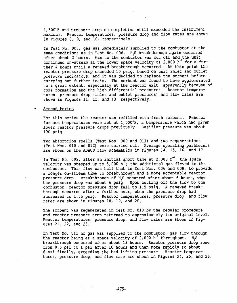
1 , 3 0 0 ° ~ and p ressure drop on completion s t i l l exceeded t h e instrument maximum. Reactor temperatures, p ressu re drop and flow r a t e s a r e shown i n Figures 8, 9, and 10, r e spec t ive ly .
I n Test NO. 008, gas was immediately suppl ied t o t h e combustor a t t h e same condi t ions a s i n Test No. 006. H,S breakthrough aga in occurred a f t e r about 2 hours. Gas t o t h e combustor was cut o f f and t h e u n i t continued on-stream a t t h e lower space v e l o c i t y of 2,000 h-' f o r a fur- t h e r 4 hours u n t i l a renewed breakthrough occurred. A t t h i s po in t t h e r e a c t o r pressure drop exceeded 50 ps ig , based on u n i t i n l e t and o u t l e t p ressu re i n d i c a t o r s , and it was decided t o r ep lace t h e sorbent before ca r ry ing out f u r t h e r tests. The sorbent was found t o have agglomerated t o a g r e a t e x t e n t , e s p e c i a l l y a t t h e r e a c t o r e x i t , apparent ly because of coke formation and t h e high d i f f e r e n t i a l p ressu res . Reactor tempera- t u r e s , p ressu re drop ( i n l e t and o u t l e t p ressu res ) and flow r a t e s a r e shown i n Figures 11, 12, and 13, r e spec t ive ly .
Second Period
For t h i s period the reac to r was r e f i l l e d with f r e s h sorbent . Reactor furnace temperatures were s e t a t l,OOO°F, a temperature which had given lower r e a c t o r pressure drops previous ly . G a s i f i e r p ressu re was about 100 ps ig .
Two absorpt ion s p e l l s (Test Nos. 009 and 011) and two regenera t ions (Test Nos. 010 and 012) were c a r r i e d ou t . Average opera t ing parameters a r e shown on t h e ADACS flow schematics i n Figures 1 4 , 15, 16, and 1 7 .
I n Test No. 009, a f t e r an i n i t i a l shor t t ime a t 2,000 h-', t h e space v e l o c i t y was stepped up t o 5,000 h-'; t h e a d d i t i o n a l gas flowed t o t h e combustor. This flow was ha l f t h a t i n Test Nos. 006 and 008, t o provide a longer on-stream time t o breakthrough and a more acceptable r e a c t o r p ressu re drop. Breakthrough of 4s occurred a f t e r about 6 hours, when t h e pressure drop was about 6 ps ig . Upon c u t t i n g o f f t h e flow t o t h e combustor, r e a c t o r p ressu re drop f e l l t o 1 . 5 ps ig . A renewed break- through occurred a f t e r a f u r t h e r hour, when t h e p ressure drop had increased t o 1.75 ps ig . Reactor temperatures, p ressu re drop, and flow r a t e s a r e shown i n Figures 18, 19, and 20.
The sorbent was regenerated i n Test No. 010 by t h e r e g u l a r procedure and r e a c t o r p ressu re drop re turned t o approximately i t s o r i g i n a l l e v e l . Reactor temperatures, p ressu re drop, and flow r a t e s a r e shown i n Fig- u res 21, 22, and 23.
I n Test No. 011 no gas was suppl ied t o t h e combustor, gas flow through t h e r e a c t o r being a t a space v e l o c i t y of 2,000 h-' throughout . 4.5 breakthrough occurred a f t e r about 19 hours. Reactor p ressu re drop rose from 0.5 p s i t o 1 p s i a f t e r 10 hours and t h e n more r a p i d l y t o about 6 p s i f i n a l l y , exceeding t h e bed l i f t i n g p ressure . Reactor tempera- t u r e s , p ressu re drop, and flow r a t e a r e shown i n Figures 24, 25, and 26.

A second regenera t ion was c a r r i e d out i n Test No. 012 and t h e sorbent removed. No agglomeration was found. Reactor temperatures, p ressu re drop, and flow r a t e s a r e shown i n Figures 27, 28, and 29.
Resul ts
Data Summarv
The var ious prbcess condi t ions and d a t a c o l l e c t e d i n Test Nos. 006 t o 012 a r e summarized i n Figures 30 t o 36.
A b s o r ~ t i o n of S u l f u r C0mp0~ndS
The hydrogen s u l f i d e concentra t ions i n e x i t gas from t h e u n i t dur ing Test Nos. 006, 008, 009, and 011, measured by both d e t e c t o r tube and base l ine gas chromatograph, a r e p l o t t e d i n Figures 37 t o 40; SO, l e v e l s , measured by d e t e c t o r tube , a r e a l s o shown occas iona l ly . H,S i e v e l s before breakthrough a r e genera l ly less than about 5 ppm. Because of t h e higher space v e l o c i t i e s through t h e r e a c t o r , t h e amount of s u l f u r absorbed i n Test Nos. 006 and 008 i s l e s s t h a n ha l f t h a t found previ- ous ly a t a space v e l o c i t y of - 2,000 h-', a l b e i t a t t h e lower tempera- t u r e of - 1 , OOO°F. This i n d i c a t e s t h a t r e s i s t a n c e t o d i f f u s i o n of H2S i n t o t h e sorbent i s very s i g n i f i c a n t a t t h e s e condi t ions .
I n Test Nos. 009 and 011, gas from B l a c k s v i l l e coa l conta in ing more H,S than t h a t from Arkwright coa l was desul fur ized; breakthrough t imes were correspondingly s h o r t e r .
In order t o provide gas t o t h e combustion test u n i t f o r a longer time i n Test No. 009 than i n Test Nos. 006 and 008, t h e space v e l o c i t y was s e t a t - 5,000 h-' i n s t e a d of - 8,000 h-', and desu l fu r i zed gas was suppl ied f o r about 6 hours i n s t e a d of f o r about 2 hours previous ly . The amount of t h i s absorbed i n Test No. 009 i s about t h r e e q u a r t e r s of t h a t i n Test No. 011, i n which t h e space v e l o c i t y was 2,000 h- throughout, again showing t h a t r e s i s t a n c e t o d i f f u s i o n of %S i n t o t h e sorbent i s a s ig- n i f i c a n t f a c t o r . I n Test No. 011, H,S and SO, a r e i n i t i a l l y high, a s expected a f t e r a preceding regenera t ion . Figures 41 t o 44 g ive base l ine gas chromatograph readings f o r H,S, SO,, and COS i n Test Nos. 006, 008, 009, and 011. H2S and SO, measurements a r e genera l ly i n agreement with d e t e c t o r tube measurements ( see Figures 37 t o 40) i n t h e v i c i n i t y of t h e c a l i b r a t i o n po in t s : H,S -- 3 ppm, COS -- 5 ppm, SO, -- 8 ppm. Nonlin- e a r i t i e s i n t h e gas chromatograph g ive r i s e t o cons iderable depar tures between a c t u a l and measured values away from t h e c a l i b r a t i o n p o i n t s . C a l i b r a t i o n curves were cons t ructed t o make c o r r e c t i o n s i n f u t u r e t e s t s .
Breakthrough of COS was found t o occur roughly a t t h e same time a s H,S breakthrough. The I$S, COS, and SO, l e v e l s were corroborated a t a few p o i n t s by l abora to ry gas chromatograph a n a l y s i s of grab samples of e x i t gas . These, t o g e t h e r with va lues f o r methyl mercaptan, carbon d i s u l f i d e and thiophene a r e shown i n Table 1 A . Thiophene was genera l ly l e s s than about 5 ppm.
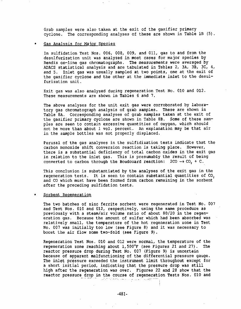
Grab samples were a l s o taken a t t h e e x i t of t h e g a s i f i e r primary cyclone. The corresponding analyses of t h e s e a r e shown i n Table 1 B ( 5 ) .
Gas Analvsis f o r Maior Species
I n s u l f i d a t i o n Tes t Nos. 006, 008, 009, and 011, gas t o and from t h e d e s u l f u r i z a t i o n u n i t was analyzed i n most cases f o r major spec ies by Bendix on-line gas chromatographs. The measurements were averaged by ADACS s t a t i s t i c a l a n a l y s i s and a r e t a b u l a t e d i n Tables 2, 3A, 3B, 3C, 4 , and 5 . I n l e t gas was usua l ly sampled a t two po in t s , one a t t h e e x i t of t h e g a s i f i e r cyclone and t h e o t h e r a t t h e immediate i n l e t t o t h e desul- f u r i z a t ion u n i t .
Ex i t gas was a l s o analyzed during regenera t ion Test No. 010 and 012. These measurements a r e shown i n Tables 6 and 7.
The above analyses f o r t h e u n i t e x i t gas were corroborated by labora- t o r y gas chromatograph a n a l y s i s of grab samples. These a r e shown i n Table 8A. Corresponding analyses of grab samples taken a t t h e e x i t of t h e g a s i f i e r primary cyclone a r e shown i n Table 8B. Some of t h e s e sam- p l e s a r e seen t o conta in excess ive q u a n t i t i e s of oxygen, which should not be more than about I vo l . percent . An explanat ion may be t h a t a i r i n t h e sample b o t t l e s was not proper ly d isplaced.
Perusa l of t h e gas analyses i n t h e s u l f i d i z a t i o n t e s t s i n d i c a t e t h a t t h e carbon monoxide s h i f t conversion r e a c t i o n i s t a k i n g p lace . However, t h e r e i s a s u b s t a n t i a l de f i c i ency of t o t a l carbon oxides i n t h e e x i t gas i n r e l a t i o n t o t h e i n l e t gas . This i s presumably t h e r e s u l t of being converted t o carbon through t h e Boudouard reac t ion : 2C0 + CO, + C.
This conclusion i s subs tan t i a t ed by t h e analyses of t h e e x i t gas i n t h e regenera t ion t e s t s . It i s seen t o con ta in s u b s t a n t i a l q u a n t i t i e s of CO, and CO which must have been formed from carbon remaining i n t h e sorbent a f t e r t h e preceding s u l f i d a t i o n t e s t s .
Sorbent Reaeneration
The two batches of z inc f e r r i t e sorbent were regenerated i n Test No. 007 and Test Nos. 010 and 012, r e spec t ive ly , using t h e same procedure a s previous ly with a s team/ai r volume r a t i o of about 80120 i n t h e regen- e r a t i o n gas. Because t h e amount of s u l f u r which had been absorbed was .
r e l a t i v e l y small , t h e temperature of t h e hot regenera t ion zone i n Test No. 007 was i n i t i a l l y t o o low ( s e e Figure 8) and it was necessary t o boost Llie a i r flow some two-fold (see Figure 9) . Regeneration Test Nos. 010 and 012 were nonnal, t h e temperature of t h e regenera t ion zone reaching about 1 , 5 0 0 ° ~ (see Figures 21 and 27) . The r e a c t o r p ressu re drop dur ing Test No. 007 (Figure 9) i s uncer t a in because of apparent malfunctioning of t h e d i f f e r e n t i a l p ressu re gauge. The i n l e t p ressu re exceeded t h e instrument limit throughout except f o r a s h o r t i n i t i a l period, i n d i c a t i n g t h a t t h e p ressure drop was s t i l l high a f t e r t h e regenera t ion was over . Figures 22 and 28 show t h a t t h e r e a c t o r p ressu re drop i n t h e course of regenera t ion Tests Nos. 010 and - -- - -
2 . - - - - - I

012 f a l l s t o a low value, comparable t o t h a t f o r f r e s h sorbent . A l l t h e regenera t ions were continued u n t i l t h e SO, content of t h e dry e x i t gas contained l e s s than about 0.5 v o l . percent . ( see Figures 31, 34 , and 3 6 ) .
Reactor Pressure Drop
I n c o n t r a s t t o t h e s e r i e s of t e s t s dur ing g a s i f i e r Run No. 101, t h e d i f f e r e n t i a l p ressu re ac ross t h e r e a c t o r was d i r e c t l y measured i n t h i s s e r i e s of tes ts . Figure 6 i s a p l o t of t h i s p ressu re drop during Test No. 006. The p ressure i s i n i t i a l l y low, corresponding t o a space v e l o c i t x of about 2,000 h-I. On inc reas ing t h e space v e l o c i t y t o about 8,000 h- , a f t e r about an hour, t h e pressure rises t o about 80 inches of water and, t h e r e a f t e r , gradual ly inc reases u n t i l it reaches and passes t h e l ~ t l o f t h e i n d i c a t o r . On lowering t h e space v e l o c i t y t o - 2,000 h again, p ressu re f a l l s t o - 30 inches of H,O and then gradual ly inc reases t o - 60 inches of H,O a t t h e end of t h e tes t . The gradual r i s e of pressure drop, i s a t t r i b u t e d t o t h e combined e f f e c t of p a r t i c u l a t e deposi t ion and coke formation i n t h e sorbent . Gas flow r a t e s t o t h e combustor and f l a r e are plutkerl i n Figure 7.
Poss ib ly because of an inadequate regenera t ion i n Test No. 007, t h e p ressure drop i n Test No. 008 ( see Figure 12) was very high throughout at ' a l e v e l of 80 p s i , corresponding t o a space v e l o c i t y of - 8,000 h-', and about 10 p s i f o r a space v e l o c i t y of - 2,000 h-' . Gas flow r a t e s t o t h e combustor and f l a r e a r e shown i n Figure 13.
The p ressure drops during Test Nos. 009 and 011 ( s e e Figures 19 and 25) fol low t h e same p a t t e r n a s i n Test No. 006 and 008. The f l u c t u a t i o n s dur ing Test No. 011, which l a s t e d f o r a longer t ime, were caused by gas surges through t h e r e a c t o r when dumping condensate from t h e e x i t gas condenser.
Reactor Temperatures
I n Test Nos. 006 and 008, t h e average r e a c t o r temperatures exceed t h e furnace s e t t i n g of l,lOO°F by up t o 100°F. This i s a t t r i b u t e d mainly t o t h e exothermic " s h i f t " r e a c t i o n ( see Figures 5 and 11). I n t h e i n i t i a l s t a g e s a mi ld ly hot zone passes through t h e r e a c t o r which i s thought t o be caused by t h e r a p i d reduct ion of z inc f e r r i t e t o magneti te and z inc oxide.
Tes t Nos. 009 and 011 ( see Figures 18 and 24) fo l low t h e same p a t t e r n though t h e furnace s e t t i n g i n t h i s case was 1, 00OQ~.
Sorbent Charac te r i za t ion
The s u l f i d i z e d sorbent a f t e r Test No. 008 was sampled on removal a t p o i n t s along t h e r e a c t o r l eng th . The r e s u l t s a r e shown i n Tables 9 and 10. A t t h e r e a c t o r i n l e t most of t h e z inc oxide has been converted t o s u l f i d e , but a s i g n i f i c a n t amount remains, probably a s a r e s u l t of t h e d i f f u s i o n a l l i m i t a t i o n s d iscussed above. A s u b s t a n t i a l p a r t of t h e so rben t ' s i r o n content i s - - found t o be i n t h e form of cementi te ( i r o n
. - - . -

c a r b i d e ) . A t t h e r e a c t o r o u t l e t t h e so rben t ' s z inc content i s predomi- nan t ly i n t h e form of zinc oxide, a s expected. A l l of t h e i r o n appears i n t h e form of i r o n carbide and no magneti te i s de tec ted ( see Table 9 ) . The values i n Table 9 represent t o t a l i n t e g r a t e d i n t e n s i t i e s and, because of n o n l i n e a r i t i e s i n t h e i r p ropor t iona l r e l a t i o n t o weight f r a c t i o n , they should only be construed a s showing rough amounts. These r e s u l t s from X-ray d i f f r a c t i o n analyses a r e supported by t h e t o t a l sul- f u r and carbon analyses ( see Table 1 0 ) . Su l fu r content i s seen t o f a l l from about 25 w t . percent a t t h e r e a c t o r i n l e t t o near zero a t t h e r e a c t o r o u t l e t . Carbon content v a r i e s from about 5 w t . percent a t t h e i n l e t t o about 8 wt. percent a t t h e o u t l e t . This can be explained by t h e f a c t t h a t , a t t h e i n l e t , a good p a r t of t h e i r o n i n t h e sorbent i s i n t h e form of p y r r h o t i t e (FeSx), whereas a t t h e o u t l e t , no p y r r h o t i t e i s de tec ted .
The su r face a r e a and pore volume of t h e sorbent , p a r t i c u l a r l y towards t h e o u t l e t , a r e s i g n i f i c a n t l y g r e a t e r than f o r t h e f r e s h m a t e r i a l ( see Table 1 0 ) . This i s a t t r i b u t e d t o t h e increased p o r o s i t y r e s u l t i n g from reduct ion of magneti te i n t h e sorbent t o i r o n and i r o n carbide . The increased poros i ty i s accompanied by a s i g n i f i c a n t l y lower crush s t r eng th , which may be t h e main reason f o r t h e l a r g e amount of f i n e s formed i n t h e removed sorbent . The fines which passed through a No. 12 screen amounted t o about a t h i r d of t h e t o t a l sorbent .
Charac te r i za t ion of t h e sorbent , a f t e r regenera t ion i n Tes t No. 012, i s shown i n Tables 11 and 12. The mineral a n a l y s i s ( s e e Table 11) indi - c a t e s t h a t t h e sorbent i s now predominantly i n t h e form of f r a n k l i n i t e and magneti te with minor amounts of hemati te and z i n c i t e p resen t . There appears t o be some enrichment of z i n c i t e towards t h e t o p of t h e r e a c t o r . Analysis f o r t o t a l carbon and s u l f u r ( see Table 12) shows t h a t v i r t u a l l y a l l of t h e carbon, presumed t o be present before t h e regenera t ion , has been burned ou t . However, some r e s i d u a l s u l f u r s t i l l remains, reaching up t o about 2 w t . percent a t t h e bottom of t h e r e a c t o r , which was t h e i n l e t during s u l f i d a t i o n . Most of t h i s r e s i d u a l s u l f u r i s seen t o be i n t h e form of s u l f a t e .
The su r face a r e a and pore volume of t h e regenera ted sorbent a l i t t l e l e s s than f o r f r e s h m a t e r i a l . Crush s t r e n g t h , on average, i s much t h e same a s f o r f r e s h sorbent , though t h e r e i s a s i g n i f i c a n t v a r i a t i o n with bed depth, being less a t t h e t o p of t h e r e a c t o r where t h e sorbent had undergone a smal ler conversion t o s u l f i d e . I n c o n t r a s t t o Test No. 008, only about 2.5 wt. percent of f i n e s , pass ing through a No. 12 screen, were found i n t h e removed sorbent .
P a r t i c u l a t e Analvsis
Samples of i n l e t and o u t l e t gas were taken dur ing t h e s e r i e s of tests t o c h a r a c t e r i z e t h e p a r t i c u l a t e content (6 ) a s descr ibed previous ly . The r e s u l t s a r e summarized i n Table 13. Because of t h e s h o r t test dura t ions i t d id not prove poss ib le t o sample both i n l e t and o u t l e t gas i n a given t e s t . However, one i n l e t sample was taken i n each of Test Nos. 006 and 008 (Tables 1 4 and 1 5 ) , and one o u t l e t sample i n each of Test Nos. 009 and 011 (Tables 16 and 1 7 ) . It should be r e c a l l e d t h a t dur ing Test Nos. 006 and 008 Arkwright coa l was fed t o t h e g a s i f i e r . Table 18 shows

t h e s i z e d i s t r i b u t i o n of a random sample of p a r t i c l e s removed by t h e primary g a s i f i e r cyclone a t t h i s t ime. Table 19 shows t h e s i z e d i s t r i - bu t ion of a s i m i l a r p a r t i c l e sample taken when t h e g a s i f i e r was fed with B lacksv i l l e coa l b r i q u e t t e s a t t h e t ime of Test Nos. 009 and 011. It i s noteworthy t h a t t h e median p a r t i c l e diameter of t h e Arkwright dus t i s s u b s t a n t i a l l y g r e a t e r than t h a t of t h e B lacksv i l l e b r i q u e t t e dus t , 64 p compared t o 38 p. Ultimate analyses of t h e coa l s a r e given i n Table 20.
The p a r t i c l e loadings i n t h e hot gas stream pass ing through t h e pot gas d e s u l f u r i z a t i o n u n i t a r e seen t o be i n t h e range 0.3 t o 0.8 g/Nm with a smal ler loading found i n e x i t gas . Median p a r t i c l e s i z e f a l l s i n t h e range 20 p t o 27 p. It i s not poss ib le t o say whether e x i t p a r t i c l e s i z e i s s i g n i f i c a n t l y d i f f e r e n t from e n t e r i n g p a r t i c l e s i z e when t a k i n g i n t o account t h e d i f f e r i n g coa l feeds t o t h e g a s i f i e r . Chemical analy- s e s (u l t ima te ) of t h e p a r t i c u l a t e loadings ( see Table 13) show t h a t , though e x i t i n g p a r t i c l e s conta in a l a r g e amount of carbon, i n d i c a t i n g t h a t they a r e mostly t h e same a s t h e e n t e r i n g p a r t i c l e s , t h e i r l a r g e r a sh content sugges ts t h a t they conta in some a t t r i t e d sorbent bed par- t i c u l a t e .
Condensate Analvsis
I n another at tempt t o cha rac te r i ze t h e hot gas pass ing through t h e d e s u l f u r i z a t i o n u n i t f o r minor t r a c e c o n s t i t u e n t s , a number of conden- s a t e samples were taken and analyzed ( 5 ) . Table 21 shows t h e a n a l y s i s of a composite sample of water condensate from Test Nos. 006 and 008. The corresponding e x i t gas composition i s c a l c u l a t e d from a knowledge of t h e gas flow through t h e u n i t ( see Figures 30 and 3 2 ) .
Table 22 g ives t h e u l t ima te a n a l y s i s of a composite sample of t h e asso- c i a t e d t a r condensate. A number of samples of t h e t a r condensate were taken from t h e S4 sample point a t t h e g a s i f i e r e x i t . The analyses of t h e s e a r e shown i n Table 23.
Condensate was c o l l e c t e d dur ing Tes t Nos. 006 and 008 a t t h e i n l e t of t h e u n i t a s p a r t of t h e p a r t i c u l a t e sampling. Analyses of t h e water f r a c t i o n s of t h e s e condensates a r e shown i n Table 24. These a r e aver- aged and t r a n s l a t e d t o a gas composition f o r comparison with t h e analy- s i s of t h e composite sample from Test Nos. 006 and 008 i n Table 25. The comparison shows t h a t roughly ha l f of t h e ha l ides and a f i f t h of t h e ammonia i n t h e gas a r e removed, which accords with previous r e s u l t s . The molar propor t ions of ammonia and h a l i d e a r e approximately t h e same suggest ing t h a t t h e mechanism of ammonia removal may be through t h e in te rmedia te formation of an amminochloride. The o t h e r meta ls and ions a r e present i n r e l a t i v e l y small amounts s o t h a t it i s not p o s s i b l e t o say with c e r t a i n t y t o what e x t e n t t h e i r concentra t ions have changed. However, it seems t h a t a s much a s t h r e e q u a r t e r s of t h e a l k a l i and alka- l i n e e a r t h meta ls a r e removed by t h e hot gas d e s u l f u r i z a t i o n process.
The above conclusions a r e corroborated by t h e a n a l y s i s of a composite sample sf condensate from regenera t ion Test No. 007 shown i n Table 26. Corresponding analyses . - . of condensate . - - ~ from regenera t ion - Test Nos. 010

and 012 a r e shown i n Table 27. These a l s o e x h i b i t an enrichment i n t h e same c o n s t i t u e n t s . The analyses of t h e aqueous condensates from t h e s u l f i d a t i o n t e s t s a r e supported by a d d i t i o n a l analyses by I H I Kemron of spot samples taken during Test Nos. 006 and 011. These a r e shown i n Table 28. The c o n s t i t u e n t s measured vary somewhat from t h e ones mea- sured a t METC.
Conclusions
A second s e r i e s of t e s t s t o eva lua te t h e performance of z inc f e r r i t e , hot gas d e s u l f u r i z a t i o n sorbent i n a s ides t ream of METCts 24 t / d fixed-bed g a s i f i e r was c a r r i e d out during Run No. 102. The genera l performance of t h e sorbent was s i m i l a r t o t h a t i n t h e previous s e r i e s of t e s t s dur ing g a s i f i e r Run No. 101 with low molecular weight s u l f u r compounds removed t o l e s s than about 10 ppm.
It was found t h a t , a t t h e higher space v e l o c i t i e s necessary t o provide gas t o t h e METC combustion t e s t u n i t , d i f f u s i o n a l r e s i s t a n c e r e s u l t e d i n t h e sorbent picking up l e s s than hal f t h e a n t i c i p a t e d amount of s u l f u r . This d i f f u s i o n a l resislaiice may be accantuatcd by ths c o n v ~ r s i o n of magneti te i n t h e sorbent t o i r o n ca rb ides .
The formation of i r o n carbides , r e s u l t i n g from t h e high CO/CO, r a t i o i n t h e gas which was desul fur ized , appears t o weaken t h e ' s o r b e n t cons iderably and, upon removal i n t h e s u l f i d i z e d form, it contained a l a r g e q u a n t i t y of f i n e s .
On t h e s e grounds, it appe.ars advisable t o opera te t h e _ d e s u l f u r i z a t i o n process a t condi t ions of gas composition and temperature such t h a t . i r o n i n t h e sorbent i s not reduced from magneti te t o i r o n and i r o n ca rb ide .
Regeneration of sorbent conta in ing i r o n carbides produced a t a i l gas contain- i n g reduced s u l f u r compounds, such a s I$S and COS, and a l s o hydrogen and car- bon monoxide. Treatment of t h i s s tream t o f i x t h e s u l f u r compounds would probably r e q u i r e i t s i n c i n e r a t i o n .
The p a r t i c u l a t e loading of tFe gas s tream t o t h e d e s u l f u r i z a t i o n u n i t was again of t h e o rde r of 1 g/Nm and median p a r t i c l e diameter i n t h e range 20 p n t o 25 p. This combination of p a r t i c u l a t e loading and s i z e r e s u l t e d i n an unacceptable r e a c t o r p ressu re drop, high enough t o l i f t t h e sorbent bed (opera t ion was i n an upward flow mode.)
Future tests were planned t o i n v e s t i g a t e t h e r e a c t o r p ressu re drop more c lose ly , inc lud ing t h e e f f e c t s on it of space v e l o c i t y , p a r t i c l e loading and s i z e , and i r o n carbide and coke formation.
A s i n previous t e s t s , t.he sorhent was found t o remove s i g n i f i c a n t amounts of o t h e r minor and t r a c e c o n s t i t u e n t s from t h e hot gas , i n a d d i t i o n t o s u l f u r . The most no t i ceab le of t h e s e were ha l ides , ammonia, and a l k a l i and a l k a l i n e e a r t h meta ls . The mechanism by which ammonia i s removed i s not c l e a r a t p resen t .

References
1. Grindley, T., "Hot Gas Desulf urization Sidestream Test Unit, Fixed-~ed Gasifier Run No. 101," METC, IR No. 1846 (1984).
2. "Integrated Test Plan for METC Fixed-Bed Gasifier and Cleanup System Test Run No. 102," EG&G, Morgantown, September 1983. ~OE/MC/14521-1467.
3. Pater, K., Preliminary Test Summary -- Run No. 102 (FN), IR No. 1808, March 1984, METC; Process Summary Report Test Run 102 METC Fixed-Bed Gasifier and Full-Flow Cleanup System, IR No. 1983, September 1984, METC .
4. Waltermire; D. D., "METC In-House Combustion Studies on Alternate Fuels for Heat Engines Applications," First Annual Heat Engines Contractorsf Meeting (1984), METC.
5. Romanosky, R. R., and J. J. Kovach, "Analytical Data -- Producer Run No. 102," IR No. 1970, August 1984, METC.
6. Bagnell, R. D., "Particle Sampling in the Hot Gas Stream During Gasifier Run No. 102," IR No. 1757, December 1983, METC.

. .
The Baseline C.C. on-line H2S, COS, and SO2 readings as plotted are correct
only for the points: H2S: 3 ppm; COS: 1.7 ppm; and SO2: 5.1 ppm.
Calibration curves are available for correction. Corrected plots are given
in Volume 1.
Refer to letter to T. Grindley from E. E. Gorski and P. Johnson, EGhG
Washington Analytical Services Center, Inc. January 30, 1986. Subject:
DOE-METC/EG&G Contract No. DE-AC21-85MC21353; WBS No. 9KEX-10. HCD Project:
Baseline ~ ~ 1 1 n t e ~ r a t o r Conversion Curves.

FIGUKE 1
O X I D A N T AIR A I R
0 0 6
SULF IDAT ION
0 0 7
IREGENERATION
0 0 8
S U L P I D A T I O N
0 0 8
SULFlOATlOM
0 1 0
REGENERATION
0 1 1
SULF IDAT ION
0 1 2 .
I : I I I I
O 9 / 2 0 1 G I 2 1 2 I J b l - 7 8 0
D A Y S
I . 9 / 2 0 9 / 3 0 1 0 / 1 1 0 1 2 1013
T E M P 1 1 0 0 ' C 8 V 7 4 0 0
0 2 0 % A I R 8 0 % S T E A M
cm T E M P 1 1 0 O e F
8 V 2 0 0 0 - 7 0 0 0
0 T E M P 1 0 0 0 ~ ~
S V 4 2 0 0
0 2 0 % A IR 8 0 % 8 T ' E A M
D T E M P 1 0 0 0 e F
8 V 2 0 0 0
I
SCHEDULE O F E V E N T S
REOENERATION D 2 0 % A I R 8 0 % S T E A M
C O A L T Y P E B R I Q U E T T E S I B L A C K S V I L L E
H O T B A S D E S U L F U R I Z A T I O R I S l D E S T W E A M T E S T I N G 1 9 8 3
G A S I F I E R RUN 1 0 2
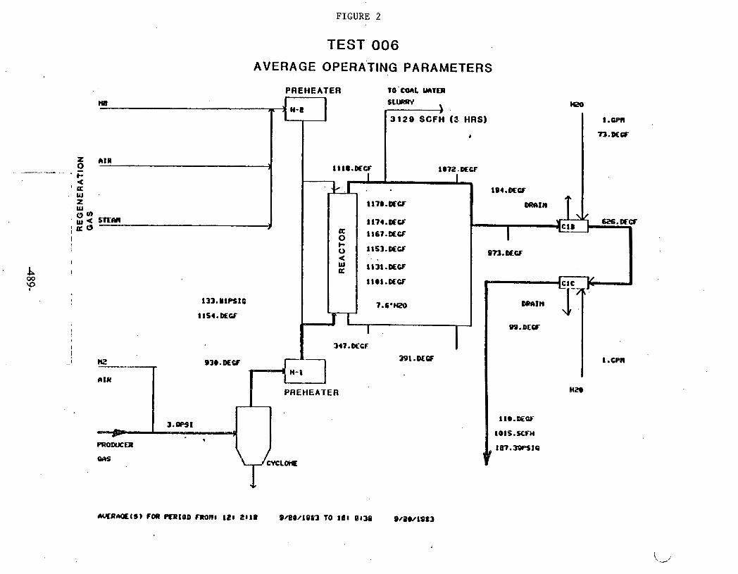
FIGURE 2
BEST' 006
AVERAGE OPERA'TING PARAMETERS
PREHEATER TO 'CQCIL WTCR
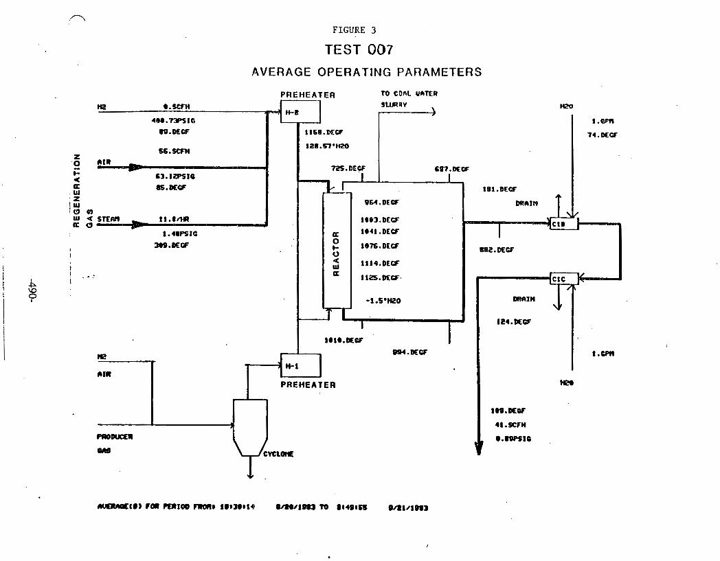
FIGURE 3
TEST 007
AVERAGE OPERATING PARAMETERS
PREHEATER r0 COAL UATER

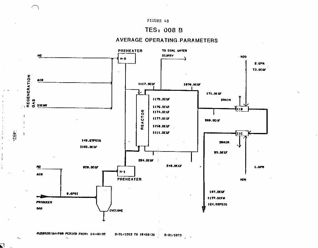
FIGURE 4B
TES.1 008 !3
AVERAGE OPERATING .PARP.METERS
PREHEAT ER

. .
FIGURE 4C
TEST 008 C
AVERAGE OPERATING PARAMETERS
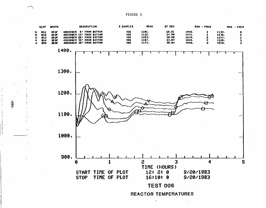
FIGURE 5
SLOT WITS DESC~IPTLO~ r ~ A H P L E O =AN ST MV nzn - m e oww - m o
900 e
0 1 2 3 4 TIflE (HOURS)
START TIPlE OF PLOT 1.28 Z t 0 . 9/28/1983 STOP TINE OF PLOT 16110t 0 9/20/1.983
TEST 006
REACTOR TE.MPERATURES

FIGURE 6
200 I 1 I I I I I I I I I I I I 1 I I I I
- - - - - 160 - -
I
i 120 - - b \O I Y' L
8 0 - -
_I 40 - -
c, 0 I
0 I
1 I I
2 3 4 5 TIPIE (HOURS)
START TIflE OF PLOT 128 2: 8 9/28/1983 STOP TIRE OF PLOT 16t108 0 9/28/1983
TEST 006
REACTOR PRESSURE DROP
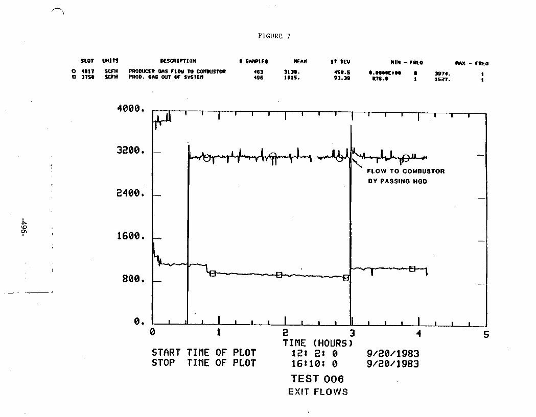
FIGURE 7
0 4@17 SCFH P R O W @ aAS FLW TO C O m V S T M 463 3lm. 4S9.6 e .wmtn a o JKO s m PROD. aas OUT OT svfttn 496 lmts. 93.33 m.e 3974. 1 1 1SEf. 1
TEST 006 EX!T FLOWS
I I I I I I I I I I I I I 1 I . ' I I
- - % FLOW TO COMBUSTOR
BY PASSINO HGD
- -
1
-
-
I I I I 1 I I I I I I I . I I I I I I 1
8
1
0 1 2 3 4 5 -
TIME (HOURS) START TIME OF PLOT 12: 2t 8 9/28/1983 STOP 'TIME OF PLQT 168188 0 9/28/1983

FIGURE 8
0 851 #W 6BOSRBER S a F R C M 8 0 f T 0 ( 1 0 US8 f f ABSOIIBER 16. FROM BOt lOt l o 953 ~ C F r r ~ ~ a n ~ t ~ 2s. ruon BOTTM a ~ S I MCF rBUYIBCR m* FROM ~ot tocr T &I #W &BSO(IBER 46. 1R0)1 BOTTOH
TEST 007
REACTOR TEMPERATURES
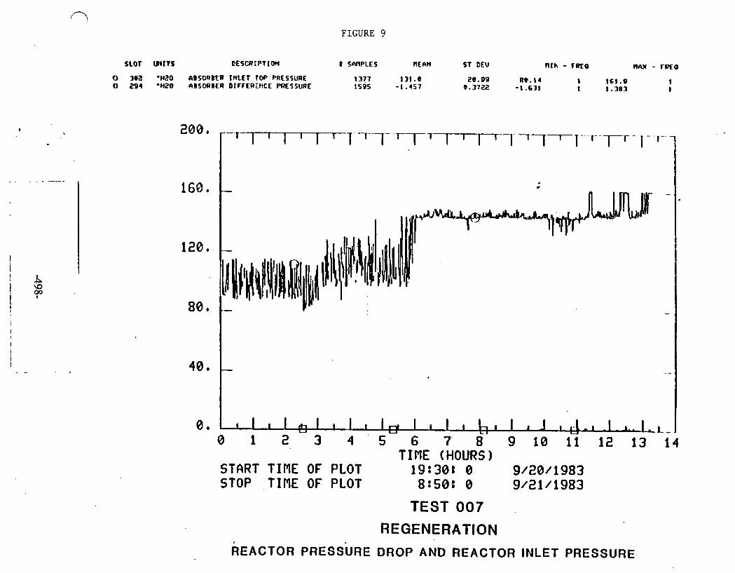
FIGURE 9
SLOT W I T S DESCR:BTIOn 8 SARPLES AEIIN ST DEW R I h - F R O RA)( - TFXO
o 302 .HZO AISORBEB I ~ L E T rw PRESSURE 1377 131.8 20.09 m. 14 1 I61 . W o 291 *HZ0 aB5ORBER DIFPER.iHCE PRESSURE 1595 - I . 4 5 7 0.372;!
I -1.631 1 1.383 I
TEST 007
ass. 7-.T-T .TTI-...,--T -.,-. 7- Tl-l- r -
REGENERATION REACTOR PRESSURE DROP AND REACTOR INLET PRESSURE
160. - - I- - - I"-\
80. -- -
40. - . -
0 . . ~ ~ I , I I l I , I I I I 0 1 2 3 4 ' 5 6 7 8 9 1 0 1 1 1 2 1 3 1 4
TIME (HOURS 1 START TINE OF PLOT 19:308 0 9 /20 / 1983 STOP TIME OF PLOT 8 : 5 0 : 0 9/21/1983
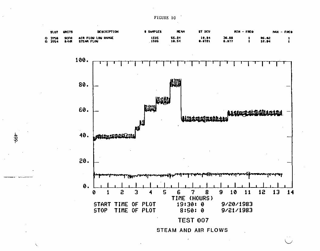
FIGURE 10
0 t 0 . 1 2 3 4 5 6 7 8 9 1 0 1 1 1 2 1 3 1 4
T InE (HOURS) START TIME OF PLOT 19830: 0 9/28/1983 STOP TIME OF PLOT 8tS0: 0 9/21/1983
TEST 007
STEAM AND A I R FLOWS
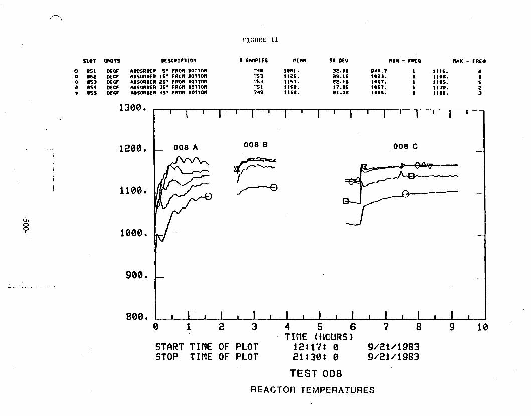
FIGURE 11
SLOT WIJS ~ESCRIP~ION 0 SWLES ntw s t DEW nrn - raro N\K - CUEO
800. 0 1 2 3 4 5 6 7 8 9 10
T IRE (HQURS) START TIME OF PLOT 121171 0 9/21/1983 STOP TINE OF PLOT 218301 0 9/21/1983
TEST O D 8
REACTOR TEMPERATURES

FIGURE 12
SLOT WITS M S ~ I P ~ I O N
INLET AND EXIT PRESSURES
200,
160,
I I I I I 1 I I I I. I I I I I I I I I
- 008 B 008 C -
008 A
1 2 0 * Y -v4- -
-
40, - -
86 1 I t I I I I I I I I I I I I I I 0
I
1 2 3 4 S 6 7 8 9 1
10 TIME (HOURS 1
START TIRE OF PLOT 12g171 8 9/21/1983 STOP TIME OF PLOT 21t30t 8 9/21/1983

FIGURE 1 3
SLOT wtn DE~CRIPTIOM e SRRBLE~ man 9 ~ m nrn - mar mx - FR€B o j n e s m m o . on9 OUT OF ~ v s ' m me t a m . I B I .e 336.4 I 16n1. I o 4@17 s m PROD- 6 ~ 9 CLOU TO CORIUSTOA tea 3818. t e r .6 ents. t 3xx. 1
0 1 2 3 4 5 6 7 8 9 10 TIRE (HOURS)
START TIME OF PLOT 121171 0 9/21/1983 STOP TIME OF PLOT z i t 3 0 1 0 9/21/1983
TEST 008
EXIT FLOWS
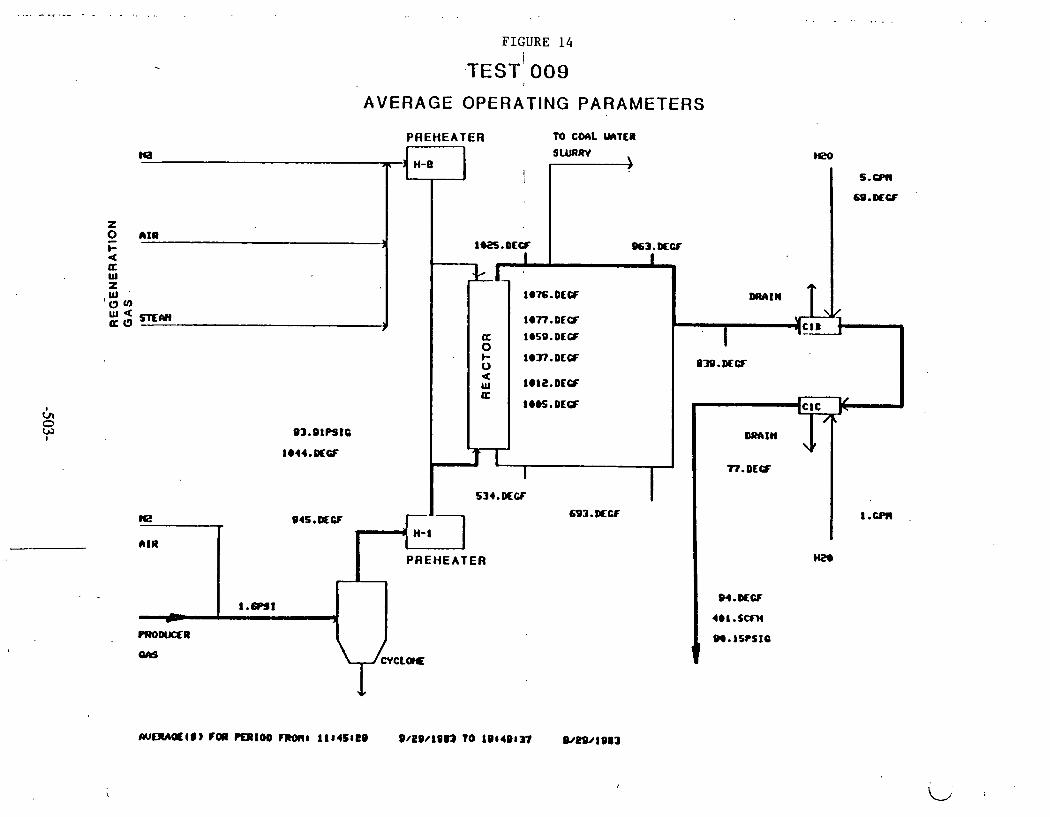
RE
GE
NE
RA
T IO
N
GA
S.

FIGURE 15
TES'I 010
AVERAGE OPE-RATING PARAN1ETERS
PREHEATER TO C M L WlvX )cB I SLURRI Ha0
39I.OWSIQ
1 4 O S a Q F
4l.#TW
I
r?.03PsIC
5.-
41.8t9W0
670.bCCF I .
mlY) , 1t.8M - *
I , 174S.#CS
925. D€cF
972.DtCF
66.7W5IQ lOI6.DECF
1063.DLCF < 266. DECF
1062.DECF a 026. D E W
DRAIN
T I V
I I
-, - 2 3 43.#CC fe - I .CPII
AIR PREHEATER Hn
I%.mCI J ao. s m
PRO^
on8 / CYCLOl(h

FIGURE 16
TEST 0 I r
AVERAGE OPERATING PARA.MEBERS
PAEMEATER 10 COAL UATER

FIGURE 1 7
TEST 012
AVERAGE OPERATING PARAMETERS
PREHEATER . TO C M L Wfil'ER w e . m I smw
1 HtO
78.#CF I e 3 3 . D E V
44.- 11 : .+6 *m
?37.#DC * 2 . ~ 1 0 I
C W . D E V
4 . m
w.mCF
7s.MCF I I
047. DCCF
1 1 . 8 M b 9%. DEW
67.7OPS14 a [email protected]
312.UECf 0 l- II#.DCCF 0 rn.#CF < w ¶Zli?.DECF ' a
II73.DECF
6.19t4i?0 m t n
T v I I
r n . D t W
VG?
1 W.#GF
I
w
@ I .DEW
6 I R
1 .en H-l
PREHEAT ER
- te@
W.#W
8.-
I.mPsIQ
3 mwca
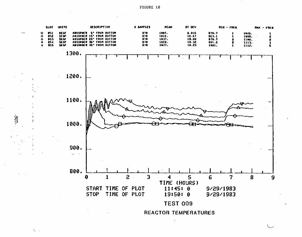
FIGURE 18
o asr b ~ r s C S O Q R ~ s* m n MTTW o 8% DEW L B S O ~ E A i s * rmn BOTTOI~ o as3 BECF CIBSO[)OEI 2s. won BOTTM A 854 DEW mSO(I8ER 36. FROR D O T T M T mi DLCF IUSWER 46. rmn ~ O T T M
1380e
. 1200*
1100.
1080*
9810 / .
800
I il I I 1 I 6 I 1 I I I I I I I I
- -
-
1 -L-L-L- 0 START STOP ~~ TINE TINE 1 OF OF 2 PLOT PLOT 3 TIME 111451 191501 4 (HO'URS 0 0 5 1 9/29/1983 6 7 8 # I 9
91291 1983
TEST 009
REACTOR TEMPERATURES

FIGURE 19
" TEST 009
REACTOR PRESSURE DROP
200, .
160, -
1 2 - -
80, - TOTAL FLOW REDIJCED
FLOW TO COMBUSTOR
-.
0 1 2 I -!
3 4 5 6 7 8 9 TINE (HOURS)
START T I ~ E OF PLOT . 11:4st e 9/29/6983 STOP TIflEOFPLOT isr50t e 9/29/1983
1 I I I I I I I I I 1 I I I I 1 I
-
T

FIGURE 20
S m moo. aM OUT O f Nlm P
o n 4et.t 391.3 e.omo~+ee s 1286. 1 dCCH PSIOW(rR O A I FLW 90 COnlUSTOR 7s5 ~ 0 1 e . 651.4 e . I z m . 1
EXIT FLOW TO
8 1 2 3 4 5 6 7 8 9 TIME (HOURS)
START TIME QF PLOT ill453 0 9/29/1983 STOP TIME OF PLOT 19t58: 0 9/29/1.983
TEST 009
EXIT F L O W S

FIGURE 2 1
0 851 f f nWWBER 5' F R M BOlT011 0 K 2 M W RBSOF)ICR IS' FROH BOtTON 0 853 WCF ABSBnBtR eS9 r R M l BOTTON A 4 DCCF RI)SOftBER 35' FROA B 0 7 1 0 A T 8 S . #f% ABSORBER 45' FRO(( DOtTOn
~ ~ ~ , , I I I I I I I I ~ . I I I I I I I I I I I I I I I I I I I I I I I I ~ I I : 0 1 2 3 4 5 6 7 8 9 10 11 12 13 14 15 16 17 I 8
TINE (HOURS) START TIf lE.OF PLOT 218401 0 9/29/1983 STOP TIME OF PLOT 15830: 0 9/38/1983
TEST 010
REACTOR TEMPERATURES

FIGURE 22
SLOT WITS DLSCRIPTIO~ 0 SMPLES nEW ST Mu RIM - r ~ r a MX - ~ R C O
0 1 2 3 4 5 6 7 8 9 10 11 12 13 14 15 16 17 18 TINE (HOURS)
START T I ~ E OF PLOT zlr40: 0 9/29/1983 STOP TIME OF PLOT 15:30t 0 9/38/1983
TEST 010
REGENERATION REACTOR PRESSURE DROP 'AND REACTOR INLET PRESSURE
L,
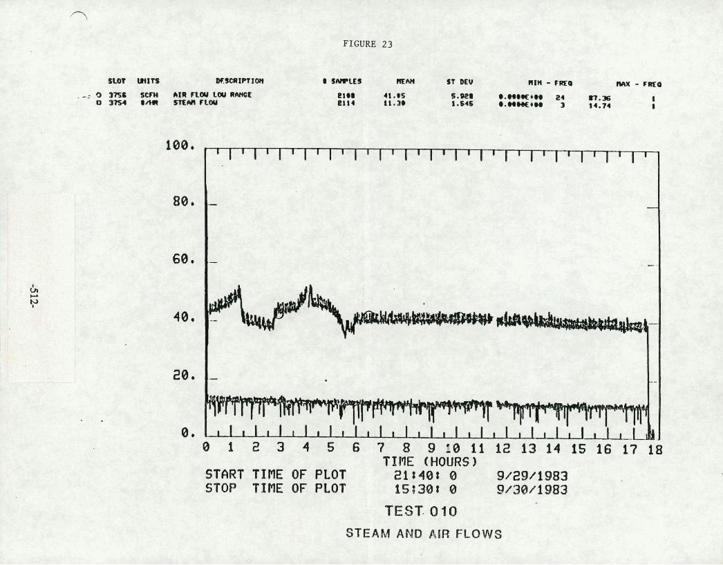
FIGURE 23
TIRE (HOURS) START TIME OF PLOT 218408 0 9/29/1983 STOP TIRE OF PLOT 15t38: 0 9/38/1983
TEST. 010
STEAM AND AIR FLOWS

FIGURE 24
0 851 #OF M O S A B E R 6' FRW 80- 0 I)II NCF IBSORBER I S * -011 B O n 0 1 1 o as3 DL* ~ B M R B E R es* ram #onom A 4 PZCI IBMRBLR as* ~ O ( I B o n o n
~SI MQI AICO(IBLI 45. ERW B o n o n
8 SUlPLLI llCAn Lt DEU
8 1 2 3 4 5 6 7 8 9 18 11 12 13 14 15 16 17 18 19 TIME (HOURS)
START TINE OF PLOT 16t40: 0 9 ~ 3 8 1 1983 STOP TIME OF PLOT iir3ot 0 101 111983
TEST 01 1
REACTOR TEMPERATURES
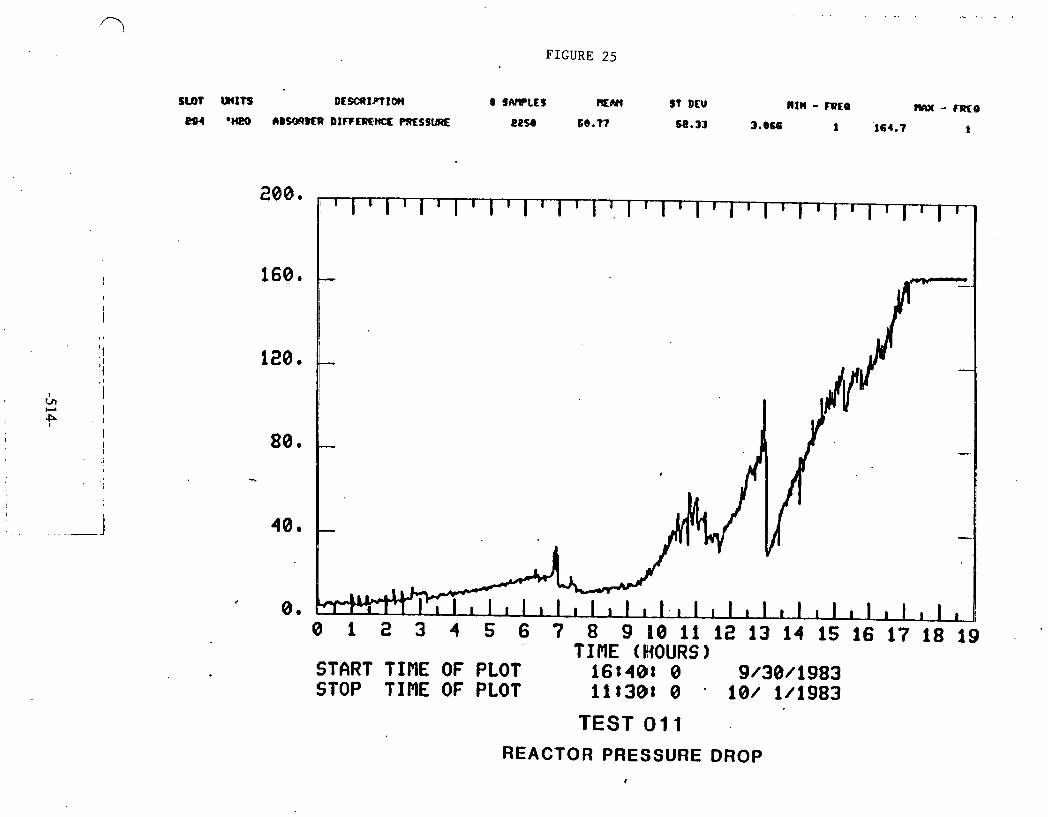
FIGURE 25
S U t WITS DCSXI.PIIffl 8 JARPLtS FEN4 S t Dm nrn - rnra M - ~ Q
eor em (IB- D I F C ~ M X ~ S S L I R E e e u 68.77 68.33 3.0M 1 164.7 1
- - TINE (HOURS)
START TINE OF PLOT f6t40t 0 9/38/1983 STOP TIME OF PLOT 11t30t 0 - 10/ 1/1983
TEST 011 REACTOR PRESSURE DROP

FIGURE 26
s m PROD. ws OUT w SYSIER a 6 a 8160. 43.10 846.1 I 1860. UTH PROOUCLR OAS CLCU TO COCllUQlOR lOSd 3386. 63.- 3244 . 1 5829.
1 1
EXIT FLOWS
4000,
3200.
2400,
1600.
I I I I ~ I ~ I ~ I ~ I ~ I ~ I ~ I ~ I ~ I ~ I ~ I ~ I ~ I ~ I ~ I -
4 4 W&.~~WLULW h i 9 h. - -
- -
800. - v
-
0 . ~ ~ ~ ~ ~ ~ ~ ~ ~ I I I a I ~ 1 l I I I l I I I l I I I l I I I l I I I , ~ 0 1 2 3 4 5 6 7 8 9 10 11 12 13 14 1s 16 17 18 19
TINE (HOURS) START TINE OF PLOT 161408 0 9/38/1983 STOP TIME OF PLOT 11130t 0 101 1/1983
TEST 0 1 1
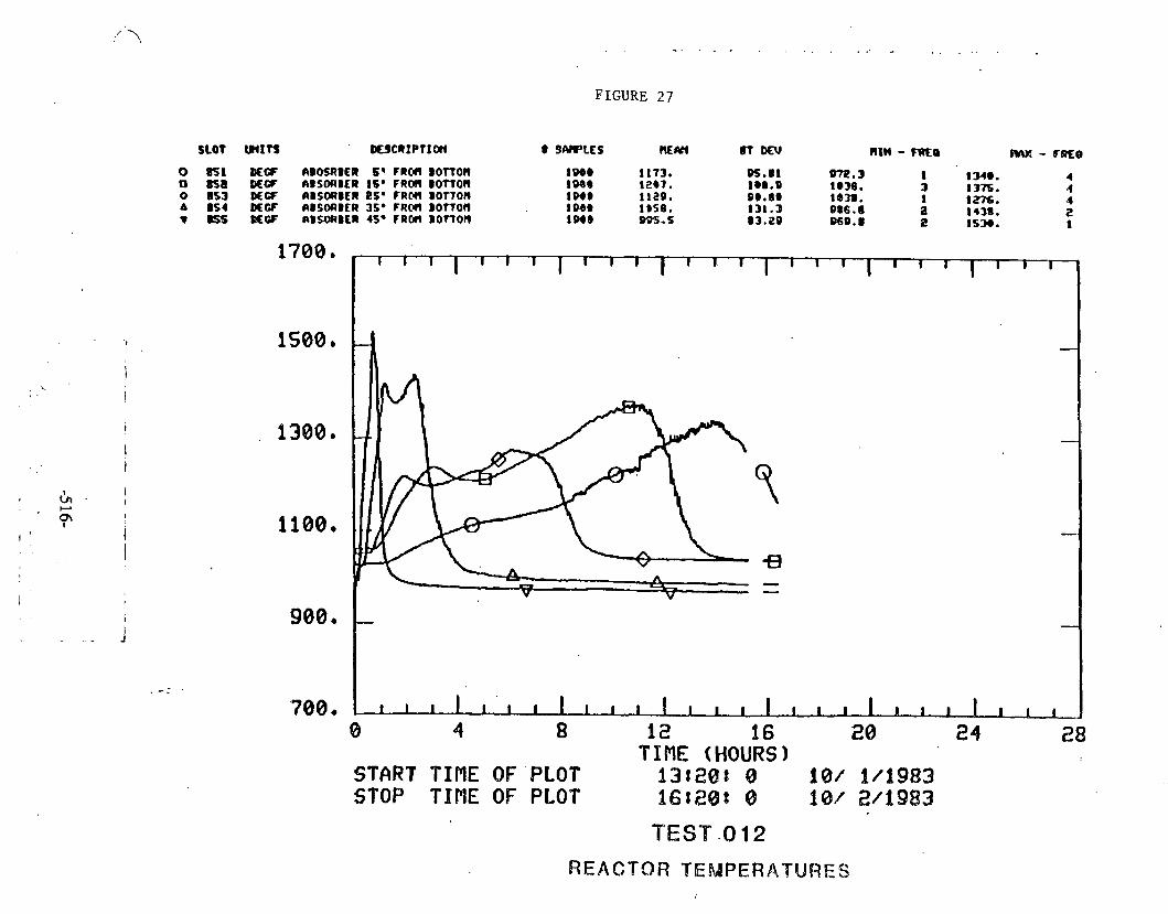
FIGURE 27
0 US8 DEW RB6SRBER 6' F R M B O f f O l l 0 ESB M a A B S W B E R 16. FRCM BOTTOll o ns3 MCF R B S ~ B E R es* ram B o n o n a s DCW RBSOUBER 3s. CAM D o n o n
8SS DLV ABSORBER 45. F R M B O m O n
700 4
8 4 8 12 16 20 24 28 TIME (HOURS)
START TIPlE QF'PLOT 131208 8 18f 14983 STOP TIME OF PLOT 661281 8 8 W 2/6983
TEST -0 12
REACTOR TEMPERATURES

FIGURE 28
SLOT WITS DfSCI) IPI IOW B SAfltyES REM ST DEV RIM - rata MX - r m . a
0 Hi? *JG!O 6BSWBER INLET TOP PRESSLIRE 1'497 11a.2 0 4 * IWO ABSORBER OIFFERENCE PRESQRE 38.99 1873
23.93 4. a95 9.347
I 161. I -28.72 34 183.6
I 1
- -
TIME (HOURS) START T IRE OF PLOT 13:20: 8 18/ 1/1983 STOP T I N E OF PLOT 16:20: 0 101 2/1983
TEST 012
REGENERATION REACTOR PRESSURE DROP AND REACTOR INLET PRESSURE
'. 1
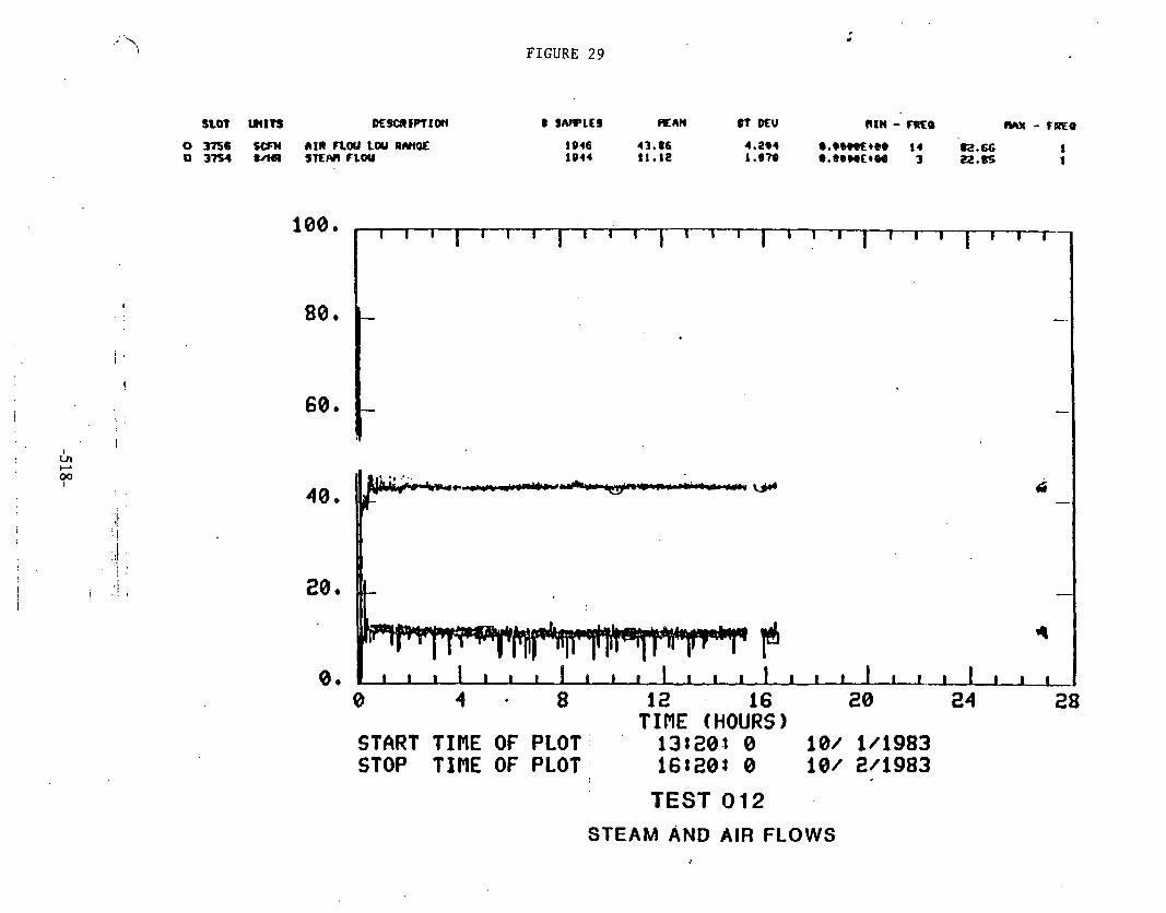
FIGURE 29
n o t arm I K ~ ~ P P T I O I ~ m IWLEI RAN #T mu RIN - m o (#Y - TDRO
TIME (HOURS) START TINE OF PLOT' 138203 0 10/ 1/1983 STOP TIME OF PLOT. 168203 0 101 Wig83
TEST 012
STEAM AND AIR FLOWS ,

8
?:L
.ll.I c
n I
Lil-
.l-*-
-8
%
,9
ec
e b-e
L9-J C
I.t--xe
--.LIIc
ar.
-. +-. C*'. . a
am
*-d*+
r+
C- =
r ...&
v?
a.-
E$;K
t:Ly
Z!":?E
1.8 C
JC
-'-2C3 i.'.u
..
.4 -8 c:.
G.
r-s
~u
au
x
- ell r-.
.-vL;:3 &
ib
l~
:#
C:
,I-.@
L.IN- -L Ll
. as-- -&
;? r
a r2

C
U-r
Urn*
.. 3U
--U
...-.J. E
; E
S%
B%
zpj
2z
Urn O
I*
c-i
-4
-1
W
l

&I
I -1
fI .'b
l %.-
I st
rr:(r1 t
Fz
c> u
ry
C
'1
k:f:d 2
CIX
I--
ui;Ss 5
w1.i
cc Z>""8
cc
;c:cc.-
LI
c
ru
u
-55 g I.
t.1-8 --
Y:c*I
yls
.I L ael:
,-5;
E?;'.L" -I
- "IPA
?!L
-*-a:
a- r. I
* I
LU
P
I
o-e
#*
r - O
IW
LW
Gb
BE3
,-.%
:re CCB
k?; A
c= g+U
J %
?IS . 1.1
=-la La ILL' -.IL
L
'a.
B12 c.l 5,'Z;
yr:;n.lJ
I. -
2 3
a 2
SZ
C
'I CJ
03
=r
t? U
J
3
LT
G
L.1
a
l-
I Al
a:: u
.-a 0
I
M
- cn
:CI -tl I :
I -. * -.b- r. - I-a L7. L1
..Id
W
*-I
111
.-r ;:
UI,-I
C.. I .u
LIIC
I. . 1
L.I
..lC,.
w e-s
as S
r: +
.-La1
a:... lt>
L*,
z: ;,: I Jr.: L.1 r.1
-.--. -
-z
c>
p ..-
t.. *
-4
F :
IS'
Q
C I
-. r-.
Cr * 2-
z! :: k
'.I C
o
u: rr, c.>
- -.I
Ulr
l.rr
; IS' c.
ea
r*
W
* .--* c
r: .-I* -*..
u.
a:;=. .A
=I..K
u
B.rL
.1U
.l Q
tJ
6-
t.
L'a e .* b
3 V
#I
%&
2'5E!G
~
us
aw
an
a-t
--.-4
-c
*-
...... a!..
33
G?
$?
E
ki% %
-!S
fwz-d
;t.c7 t.1,-=-
.-Ja
".
Ed
-a.l~
u)L
tll:cL
~
~'
~c
cL
.l
C.
.
m:afrterr
J~
J
C-
~~
LI
EL
&C

:'"I a-r
65: ;
";$
2 ,
IJ'
;z :';g
n
n
s
x
-+c-
J r
4
c
.c.
ca :,- a;:,
v;;,
.-#.
a <?.
I a
c .. *
L*UI
L7
L.l
c'q
21
-- - .
!.a$"
C
J-4
?
-JIR
3%
$7 :!?
UI
r-.-
-4c
:W-o
~
- ,--
. .' .. .'>
-.
1-.
10
1*
I-<
>
0..
.L
0.2
.14
43
e
a
cis
.-
Sn
*:J
-- -
- *U
TL
E
>t.
.J
"3 -a
--1..-
me
ws
..,a
C.4
ins--+
;
C'
C 1
5%
. 5%
I*@
-4-1
:: :g --.

01
*-- r-a
.. La
1
k- L)
b-- 4
a1 W
CL 8:
lrl
I-
cc
-C
-
+
zr
2
WW
W
lA1
C
US
ZI
UD
1U
L
rcL
'ic
'c'
c3
c3
r3
0
mu
am
c,~

tS .. U
I 1
11
tr
. C
LI
c 1
II. E
l
LIl
c5r W
sL
cs:
re !*I
rc
.- L.1
-c
2
C"
rain
' U
I -. ><
UI
*-. v1 ST. L
Lb
lI
.4
Lt1C
CG
.J . * c
3a
tr
e C
2C
.W
C*
::! $g%f!! *
4r
-
.--
a
Cf. .* ..
c>
z
.* .- -4
t-- w
. S
IJ
e.3 .-. cr e-
%
L; iii
Z.' 2. ,:
:7j E
-.I?C
J
cx:1
1*c
t: I3
1 S
CJ
r
rs
vv
un
-x.
Ir.
1.1
1.1
#. > C
'.. . . -4

Figure 36
TEST NO, 01: DATE A30 T I ! ~ E ' S T ~ T E ~ : 1f::O 14l01183 OQTE 240 l I s E 5N3EQ : 1b:ZQ IOlQZt;
TEST SUMMAR'Y SHE.ET SIDESTREAN TEST U N I T
TOTAL HOURS : 27 TYPE * REEENERAt ICN SULFGP RL?OVE~:
S3RGENT PELLET SIZE: 3116 INCY Dlk!!ETER EXTRUSIONS
HGD CPEPPi:'lG CP?iOITlrYrS
I K E T UCLE?
YET 655;
SOReENT ANALYSIS:
T O T Y SGLVJS: (XUT: SUSFaCE AREA: (SP H i 6 CEXSITY : (GiCC) P09E C'CLU9E: {CC:S) nINE;A? A:;OLYSr$: ELEKENT:; CEXYS!S: T O ~ K cixi18an: (ZYI)
EXIT SULFLI OAT4:
Htf :
AFTER
$32 : b X :N IT IPLLY. Y16HOF 162 AFTEf 4.2iiO':RS !30 PPH AT END OF gUN .
CCKCEVSATE AC;'E1W 18: HYV3C;IR3ON : TOTAL : 379 LES
RERhfiKS 1, F4ZK"l.E DE36TH I N RBCTOR IS 14 718 I N C W : I i ;S FFFI'E
8 0 ~ ~ 3 1 AX3 T2F 5 :StHE: ARE :ft I!;% :5fk*If I'PEiES CS-116 11': S Sii-1CIBO UNITE! f 4 T A l Y j ? S
2. SiRSENT W E E 0 VCLUnE = 0 . 5 3 CS'B!C F 3 1 3. SEtCYO P.QENERA?X,U CY 5VLFI3fG SCRE!~ (SEiCttU BPTt'i: :
:&-rz, 4. t!6lIPVN_IE!l:EV:Pt~ :EiCKEt YAS 1Z30 F. 3, M S T tE:t E5kIN6 GSSiFIEA RUN 102. f iELtT lR C23LED C3D
sr,rc~~37 ~:RP:E; :ro ~E~O'JED. 6. l i e BPPVS GF B~PVIELRI :s;i ;:\I.;;:,E: c!~ iev:! wisr
Of TCE REACTSR. Tq15 5:s ~ L C J ILI-II! CY SIX5 Rl:!4 T36i.

Figure 37
Temp = 1149 F (620 C) 7-
Press = 134 PSlC
S.V. = 2028 Hourly first 0.87 Hour
-$- S.V. = 7270 tlourly Next 2.13 Hours
4- S,.V. = 1908 bloarly Lost 1 . l 3 Hours
-- = Dclector Tube H2S
C] = Baseline CC H2S
... -
-- 4t---------+-
0 . I 2 +--- --+
3 4 +----I
5 Time (hours)

Figure 38
ZINC FERRITE SULFIDATION SIDESIREAM TEST UNIT TEST ' 006
50
I S
4 0
35 - .n H 0 . m
JO -
Temp = 1143 F. (617 C)
Press = 143 PSIC'
- S.V. - 6807 I-iourly for three hours
i? 0 L
25 S.V. = 1803 t-lourly for four hours h c EJ 3
2 ;.I 3
20 = Detector tube H2S I Z
P P
I 15 - = Bascline GC 112s
10 - 81 = Detector tube SO2
5
0 ,

. . Figure 39 . - - . - . . .
, SILIESIREAAI rtsr utur nsr 00.9
-f- Temp -= 104.) F (562 C)
Press = 94 PSlC
I
" f , . - \ .'? @
i 1 .!o - 5.V. = 1 1 78 Hoi~rly for 5.75 tfoiirs
2 S.V. = 1814 tlourly !'or 2.J2 tlotrs cln tJ v)
SO 70 - 4 = DETECTOR rUBE 1125
Q 9
m = QASCLINE 112s

F i g u r e 40
Temp r; 1005 F (5141 C)
Press = 122 I'SIG
S.V. = 1966 Hourly
= L)ETE(:IOH lUDE tI2S
D = DETECTOR run€ so2
0 = OASLLINE CC 1125
rime (hours)

F i g u r e 41 . ... . . - .
. . .
ZINC FERRl lE SUL FIDATION SlDCSlRCAM lESr UNIT' l fS l 006
50 T Femp = 1 149 F (620 C )
I S Press = 134 PSlC
I 0 -f S.V. = 2028 tlourly First 0.87 I4ou
S.V. = 7270 t-lourly Next 2.1 3 tlours
S.V. = 1908 Hotlrly l ost 1.13. Hours
= Boscline CC H2S ':
= Baseline CC SO2
0 I 2 3 2 t - - - - - l
I 5 : lime (hours)
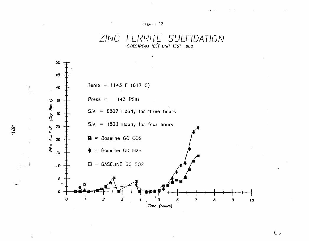
ZINC FERRITE SULFIDAnON SIDESTREAM TEST UNIT TEST 008
Time (hours)
50 - - - -
45 -T-
10
95 -
-- - - --- remp = 1 143 F ( 6 17 C )
-- Press = 143 PSIG -
30 -- S.V. = 6807 Hourly lor three hours - - - -
25 -- S.V. = 180.5 tlourly for four hours
20 - . , - - PP = Baseline GC COS - -
15 -.- 4 = Baseline GC H2S
-, . 10 -- PI = BASELINE GC SO2
- 5 --
0 1 2 9 4 8 5 6 7 8 9 10
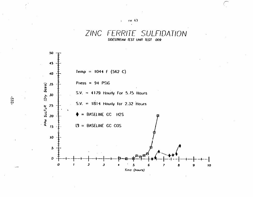
ZlNC FERRITE SULFlDATlON
Temp = 1044 F (562 C)
Press = 94 PSIG
S.V. - 4 179 Hourly For 5.lf~
S.V. = 1 0 1 4 Hourly for 2.32
= BASE1 INE CC 1125
U = BASELINE CC COS
0 1 2 J 4 : 5 6 7 8 fime (hours)

ZINC FERRITE SIJLFIDATION
l ike (hours)

Table 1A
HOT GAS DESULFURIZATION GRAB SAMPLE GAS ANALYSIS AT EXIT
GASIFIER RUN ,102 TRACE^ COHPONENTS
TEST 4 SAflPLE DATE ii=S COS CH:SH CS2 ?h i0 NH; f a ? 820 TYPE NO. TIilE PPH
TOO6 SULFI- 9/29/03 3.04 12.4 NO ND 6.77 70.4 NO - DATION H 6 1 14:30
TO08 H6 2 9/21/83 NO 0.51 ND 0.39 1.50 112.2 NO 5560.9 13: 10
SULf 1 - H6 3 9/21/83 ND 4,71 NO 0.46 1.27 432.9 ND 7771.39 11: 10
OATION HG4 912!/83 (.? 14.7 ND 0.24 0.91 260.4 ND YATER 21:CO IN SIIUPLE
TOO? . . H6 5 9/29/83 TRACE NO NO TRACE 4.70 13.0 NO 2887.8 13: 15
SULF I - H6 b 9/293/3 NO TRACE ND 1.18 3.51 ND ND 2433 14: 15
DATICN H6 7 9/29/83 . NO 5.71 11.06 1.42 Z.34 ND ND 1816.6 l6:45
TO10 ' H6 0 9130183 NO 01:!5
REGENER- H6 9 9/30183 3743 51.4 NO 59.6 NO ND. *7550 11,769 03; 15
ATION H6 10 9/29/83 )4Q00 62.7 10.9 3 . 4 3.0 99.3 115.2 6169 23: 45
NOTES: !. NO = Not Oetertable. 2. Getectable level for H25. CCS, CHJSH, Thiophene, SO2 is 0.2 ppa.
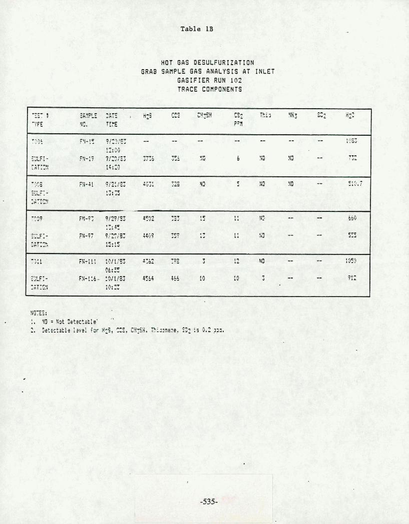
C.I
c -1 x
r-J
c J UI
CY
'4 n
.-a .I:
f- c-t IZ
UJ c.
l*
CL
T. tJ
LrD
CJ
L
I
'fi X
-
OI
W
el
l-
1s I
ii.' :i
~4 ~
PP
P
** ,
--
LG ' 4
r '1
c.
t-
r..
I I
: 2
19
I
.a
I
L3
I
s: .rl
: !z -0
b'.
I t:;
b-
M
w
. '2
C.
<:
BC
SC
~
! r
0-
."
*C
Ld
u,:
r.- r-.
&
A
L..
U. t
IT
U
c1
" "
1-
i>
-4
U
3
I s a
VI
R
Zr
to
r-J
?.*
- 4
1 - r.3
-$
e 9
tll
11 I
40
I0
I I
I I
C-4
a= FZ
r.
*. -4
-4
*. - 2
,,
F'.
0-
r: t.?
C-J
!!,' rr
iz L?
2 -
I I
I
'I
sr lC
)
c: 2
6.r
2
I
4
n-
-cu r
* e
C-4
d-
-a
-n
r * 1
-1
rl
-v
52 ,-,
-o
r
I--, ...
--. *-Y
w-r-.
-. .t I
m
IL
I E
I . c
*
t2 z
'J
-
Pi !'it.
C-t ..
C.4 .. ;!:&
::
t-
r-. tr.
a* I P
Sf
LL- 11.
1 A
5
. c-9
'" ". 'A
. .. -r ..
c.
b4
le
c#
r..
e. ., .-.
.-. 4
... 4
-.I r
.
t I
if C I
ic. c.
L:l
LL
.*
'
<.I 8-3
I -
<1>
* 1


Table 3A
HOT GAS DESULFURIZATION SIDESTREAtl TEST UNIT
TEST OOBA AVERAGE 6C READINGS
DURATION
EASlFIER CYCLCli EXIT
t READ ------ H? CC? C2H6 ES C2 N2 CHI CO TCTEC 6V6 YY AV6 DTY AV6 56 6 X U N BTU -- --- ---- -- -- -. --- -- ----- ------ ------- ------ ----- -----

Table 3B
HOT GAS DESULFURIZATION SIDESTREAH TEST UNIT
TEST 0080
AVERAGE GC READINGS
GAS:F1E1 CYILEYE EXIT
HZ cC2 C 3 5 ~ 2 5 O? WZ CH4 CO TOT& 136 rY 6% ETY hV6 S6 6 BTU U BTU -- -0 -.-- --- -- -- --- -- ----- ------ -n-- ---a- ----- -----

Table 3C
HOT GAS DESULFURIZATION SIDESTREAM TEST UNIT
TEST OOeC AVERAGE GC READINGS
- S X i F I E ? CYCL1:;E EXIT
HZ ~ a : [;gb ' H Z ~ 02 I? CHI CO TC7;lL bV6 8N hplrs D:Y ? V t ss s 3r;i N BfU -- --- ---- *-- a -- - -- ---I- ------ ---*--- ------ ----- -----
HZ Cat CzH6 HIS 02 N2 CHI C0 TOTAL 4% an bV6 bTY AX $6 G !TV ti BfU -- --- ---- --- -- -- --- --. ----- ------ ------- ------ ----- -----

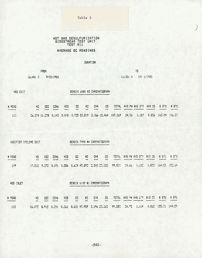
HOD EXIT
t READ ------
HOT GAS DESULFURIZATION SIDESTREAH TEST UNIT
TEST 011
hVERA6E t3C READINGS
FROR
lb:44: 3 91101 1993
BEHCIX 0400 t2 CHROXATCCPAPH -----------------------
H? C02 C a b Hz5 02 NZ CHI CO TOT4L AV6 PU AV6 OTY AVS $6 6 87V N 87U.. - - - ---- --- -- -- --- -- ----- ------ ------- --u-- ----- -----
Hz to: c:Hb ulS , N2 4 CO TOTAL AV6 CW 4V6 STY A!'S $; 6 8TL' N BTU -- --- ---- --- -- -- -- -- ---- ----- ------- ------ ----- ----

-
0
wc
V
) az
c-
CD
C
UL
J!
C
N1
- a
U
0
g C
L~
a
Dm0
W
Lrw
- a
At0
=3
U
U)L
C
U)
wa
rn
OW
W
W
uc
m
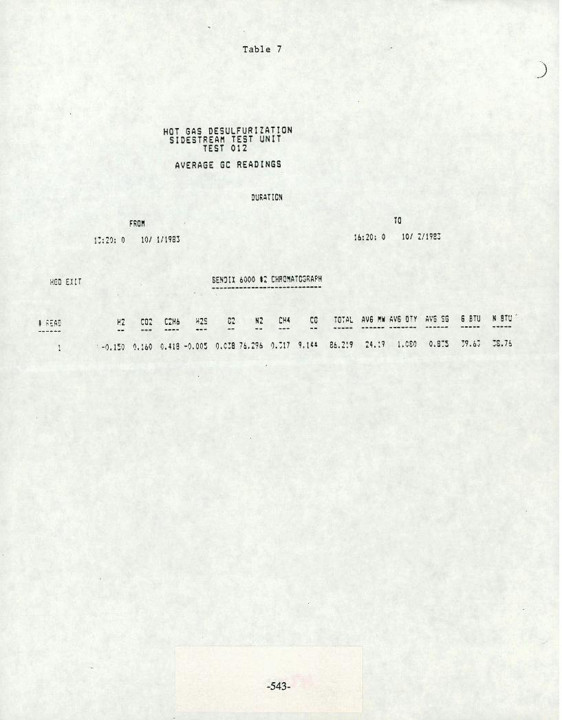
Table 7
HED E X I T
HOT GAS DESULFURIZATION SIDESTREAH TEST UNIT
TEST 012
AVERAGE GC READINGS
8 ;ERD I!: (0; c y 6 ~ 2 s cz ~2 cM4 t o To:A: AV6 I Y bV6 O T Y RV6 SG 6 BTU I BTU ------ -- - - .--. --- -- -- --- -- *--*- ------ ------ ------ ----- ----- : . -0.150 3.160 0,418 -3.00: 9.C:8 76.236 9 . 3 7 9.144 8h. l :P t 4 . : 7 1.CEQ 0.8:s T9,b; 3 - 7 5

TABLE 8A
TEST I TYPE
HOT 6AS DESULFURIZATION GRAB SAHPLE GAS ANALYSIS AT E X I T
GASIFIER RUN 102 RAJOR COHPONENTS
SGWPLE DME . H2 02 12 CH4 CO CzH6 CU2 C2H4 C3H8 i C 1 nC1
NO. TIE VOLUHE I
REGENER- HG 9 9130183 ND 7.05 09.36 ND NO - 3.0 NO ND NO NU ND 03: 45
LTION H6 19 9/29/03 1.91 7.13 75.91 .01 ND No 14.02 NB lib ND NO 23: 45
MITES: 1, 110 o Not Oetectable.

Table 8B
HOT GAS DESULFURIZATION GRAB SAMPLE GAS ANALYSIS AT INLET
GASIFIER RUN 102 HAJOR COMPONENTS '
'53i f SG6FLE l;tE Hz G* !I2 iH4 t C C g Y ~ C32 Cz!!: C;Sg i 2 ~ CCA N C 5 13. 7 IflE 'IOLl'RE Z
-r r r r '3-35 21:C!3: lt.!5 2 . 7 33.22 i 2+.6? 1).Y66.3 3.19 - 9.v; 1- rtn RY ND
12:CG 31",~1- FY-13 9/2Si03 1 5 . 7 3.67 45.7? Z.22 ?+.:a 0.24 6.5; 0,:I C , 13 #a * * - ? P I J T * :-.I :s::c
- tC - 4 ?/2::9: 8 7 -* R + * C . e *.-- " a - . .. vE L I . W V C.6: 4 . * , , J ;-.ud v.-, 6 - 4 2 1' :. i d 4.i: VD 1; :gui-. ::: z SAT:C!I
r
- - C .-9 4 - 9i3f5S . I ? 3.6; 7 2.42 22.47 0.2: 9.C1 9.2 4 . 7 :+I) 10 1;: 45
"+I CT- .-- . FY-97 Ci2?'83 17.Cb 9.52 43.2: !.EQ 22.13 0.17 ?,28 9.07 0 YD #3 * q - nw - 1 . 1 . x 15: 15
-v91i FN-111 10:lfE; 7 G.68 3.3 2.57 X . 3 7 7 3.13 3.1: 9 , : !{!I tt0 Ch: E
"', C ,
:-,,.r .- F?+! 16 tBi :!a; 1 0.71 49.69 2.57 Z1.2 O.Q? 3.C3 0,;s 0,:: PI) :r'3 9 .-*I-( -ri I &&,I :c:3

TABLE 9
A N A L Y S I S OF R I N E R A L S B Y X-RAY D I F F R A C T I O N IN S U L F I D E D Z I N C F E R R I T E
G A S I F I E R R U N 102
FRAMLINITE lnf efl4
BEU OR HEIGHT HENPTITE IIAGNETITE ZINCITE
(INCHES1 Fg03 ~ 1 3 0 4 4 4 ) ZnO ALPHA BETA PYRROHITE: CEMENTITE ZnS ZnS f eS Fe$
NOTES: (1) BottorlInlet. (21 fupl0utlet. (3) Percent TI1 = Percent Total Integrated Intensity1 Directly proportional to the
concentration at the crystalline phase. A~orphous phase is not accounted for. (4) Frrnklinite and Hlrpnetite have the wllr crystal structure and, therefore, cannot
be readily distinguished by the diffraction pattern. -
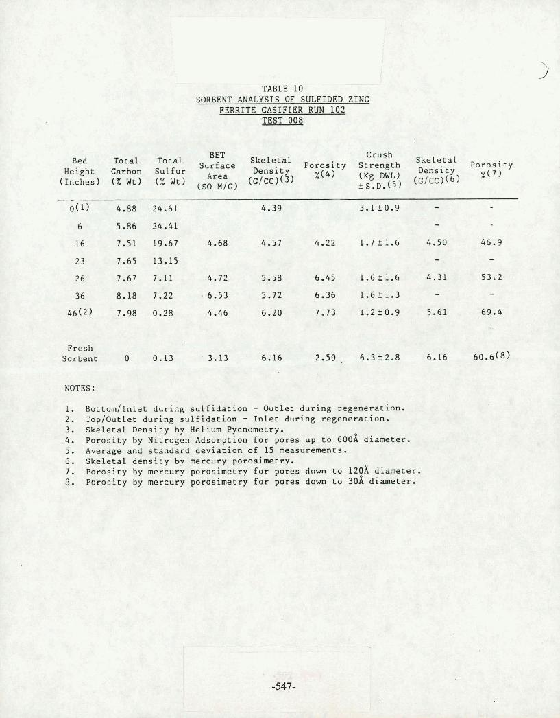
TABLE 10 SORBENT ANALYSIS OF SULFIDED ZINC
FERRITE GASIFIER RUN 102 TEST 008
BET Crush Bed Total Total
Height Carbon Sulfur Porosity Strength
Density SkeLetal Porosity Density %(7)
Area (G/cc)(~) (Inches) ( X Wt) ( % Wt) nlG) x(4) OWL) (G/cc)(6) ?s.D.(~)
Fresh Sorbent 0 0.13 3.13 6.16 2.59 . 6.322.8 6.16 60.6(8)
NOTES :
. Bottom/Inlet during sulfidation - Outlet during regeneration. . ~op/Outlet during sulfidation - Inlet during regeneration. 3. Skeletal Density by Helium Pycnometry. 4. Porosity by Nitrogen Adsorption for pores up to 600A diameter. 5. Average and standard deviation of 15 measurements. 6. Skeletal density by mercury porosimetry. 7. Porosity by mercury porosimetry for pores dawn to 129A diameter.
Paroslty by mercury porosimetry for pores down to 30A diameter.

TABLE 11
ANALYSIS OF MINERALS BY X-RAY DIFFRACTION IN REGENERATED ZINC FERRITE
GASIFIER RUN 102
FEANKLI~ITE Znfe~O4
BED OR HEI6HT HEfjLITITE flA6NETITE ZINCITE ALPHA BETA PYRROHITE
IIKHESI Fe& FC$JOI(~) 2nO ZnS ZnS feS
PERCENT 711 (3)
NOES: 1 Bot tor l In Ia t durinp su l f ida t ion - e x i t durinp reqmeration. (21 Tq lOu t le t during sul f idat ion - i n l e t during regeneration. (3 Percent Tlf = Percent Total Integrated Density; Direct ly proportional t o the
concentration of the crys ta l l ine phase. Amnrphous phase is not accounted for. ( 4 ) Frankl in i te and Hagnetite have the saw crystal structure and, thorefore, cannot
be readi ly distinyuiahed by the d i f f rac t i on pattern.
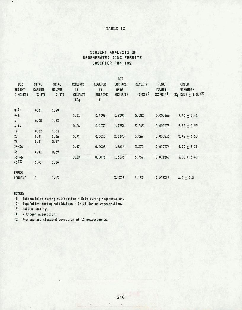
TABLE 12
BED TOTAL HEIGHT CARBOH (INCHES) (Z tlTl
TOTAL ZSULF UR SULFUR AS
(2 YT) SULFATE so4
SORBENT ANALYSIS OF REGENERATED ZINC FERRITE
GASIFIER RUN 102
BfT "LSULFUR SURFACE DEHSITY PORE CRUSH
4s AREA VOLUS STREHGTH SULFIDE (SR It161 ( 6 / ~ ~ ) 3 (CC161'.41 (Kg OWL1 2 S.D. (51
S
HOES: (1) BottorlInlet during rulfidotion - Exit during reqeneration. (2) TopiOutlet during sulfidation - Inlet durinq repeneration. 131 Hhliur Density. (4) Nitrogen Adsorption. (5) average and. standard deviation of 15 wasuresents.
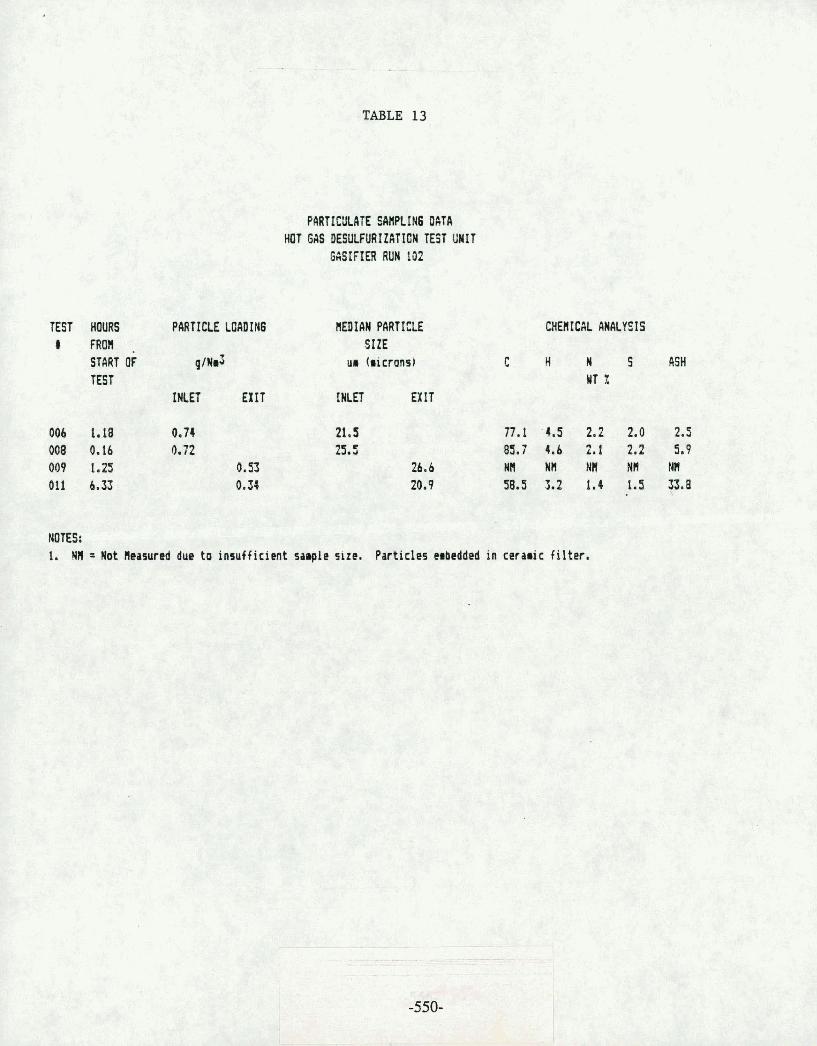
TABLE 13
TEST HWRS PARTICLE LOADING I FROM
STMT OF q / ~ d T EST
I N E T EXIT
PARTICULATE SANPLIN6 OAT4 HOT 6AS DESWURIZATIOW TEST UWIT
GASIFIER RUN 102
nrn1AN PnRTte l r SIZE
ur (microns)
rmn EXIT
CHEI(1CAL ANALYSIS
C H N S ASH WT X
UTES: 1. NH = Not Heosured due to insufficient sample size. Particles embedded in cerraic filter.

Table 14
[iFlTE : 10.~.>7,.'53 ::.fit 1PL E : DE Bfl13t IELL 13 I 920 1 BJ-872 EcECTRI:ILYTE: ~SOTI:I~I CI 15PERSUt IT : LO1 1flR D Et~~UIPIIEtiT: Tk I 1 UFERTURES: 280 OF ERHTOR: AD8 **%Qa***f~~**l***f***t********f~f*t**f* I:.H.# ,S IZE Cr IFF CUtI
[lo1 ;! U:lL z * + * * * * * * f * f * * i * * * * * * * t * ~ * * w * * * * * * * * * * * ~
I 1 4 .1 Ills0 ' 2 3. b:H 2.1 99.3
' 3 6.35 2.3 97.8 I 4 :3 3.4 ::3'5.5
C; 1 - 1 Cl O:3 7 '32. I 8 12.7 13.5 ?:5. 1
&, 1 7 18 17.3 71. E; I s w 20.16 I G . 6 F4.3 ' 5 25.4 13.9 37.7
lrt -. - * J .-'L 9*3 23 :3
11 -113.32 7.1 14.5 I.? 150. :3. 2. 8 .7* 4 13 84 . 2. :3 4.. t' I4 :30 63 . t 1: :3
- 15 lC11.33 1.8 1.7 1 El 128 . 1 0
PARTICULATE SIZE DISTRUTION
TEST 006 INLET
.,Q:ILUI E 5 STUT 3ST I CS ~ + 9 * S f ~ ~ * * * * * % + * * f + * 9 * ~ * * * * * * * * * * * * * * * *
. : . . . . . . . . . . . . . . . . . . . . . . . . . . \ . ---
g . e : 8 ; S I Z E 1I.i isM

1 : 1 13 ...;27..... 33 5kt.IFLE: DE B ~ I ~ ~ I E L L 3 8 T 2 :23-:3::: 1 EI-EI:'TEI:IL'; TE: [$:.OT~:lt.l D I ?.f-'EE:3it IT: LOEIFiR O EI:.~I!IFt~IEt.IT: Ta 1 I RPERTURES: Z C I ~ I:IF'EF:HTOR: EDB + + + + ~ * * ~ ~ g + ~ * * ~ + * * * ~ + + + + ~ ~ ~ + Q + Q + + f f ~ f f f
I : # SIZE DIFF I::I II,I VlIlL :.: l..!l:lL :,:
++++++++++++**+**+******+*+++~+++*++**+ * .
. 1 .-. C .-a .-. . .-@L .O 100 - ..:. 1 3 -1. 7 ... .- ' I Oi l - , . 4 ,- - -.
. . 1.9 .3 V ' . .:#
; 4 C -1 . it4 :.? . I :3'5 ,, 4
5 ,- - -. . c:. 35 2. e; .d -1. .-.. 1 - 15 .5
'2 7 = .-. .. 1 :31;1 7
7 l Q . q:.3 E;. 1 87. % ' ? . 1" &. 7 I 8.5 f-: 1 1
.... Y :3 1 c; 1 1 . 1 - ,. -*;. $;
, 1 Kt .. ,::*it - . 1 6 1 1 . 3 6.1 . ;.3 .-,C 1 1 .-..-I . 4 8 . 2 ~ C I . 2 - -
, I c: .I.? 8, 1' 4 + .?
1 13 - - .- c;. 2 -- -. 4t-l. .lit. ....-. . . . -3
14 -J i n .- - 512.3 I . ri i. 2 I : 1 15 ~4 . .. 1 9 . : I "
- - . 1 c. $13 G4 1.7 i f < . 1 17 1 I:I 1 . E; 4.3 1 6: <: 1 :3 1 ..:--I- -.I. i t 1 - J T . I 1 .:-- - . .:a
1 5 1 ~ 1 . ~ : ~ 4 . ,> L. 7. G - - 21:1.:. 2 - - ;<: 13 .:.. .; -2. 4 "' ] zyg Cl? L . 1 . I .> 1. .li
': : - c '.. ..!iL * .-ah .L 11
PARTICULATE SIZE DISTRIBUTION
TEST 008 INLET'

I:lu : 1 1j.a.' .: 1 ..... :3 3 c .>HI - IFLE : [:I 11 4 EPGt lELL I3cI:+23-2 :3.3-:373 E!.E,I::TF:I:II-~;TE: I Sl~l'lI~lII [I I r5FEF::i:~t IT: LClt'lHR D ECll_lLPtIEtJT: T H 11 kPEETlJREr;: 2:::O ~~IPERHTI:IR: REI: + + + + 8 * + + f + + f f f f ~ + * ~ f ~ + + Y U + t + + ~ + + ~ + Y i : + 3 f + CH.# :SIZE Cl I FF 111 I1.1
C!I:IL :< I.JI:IL :.: ++.~+++++++++++++*++**+++***&+*++*++++~*
1 4 6 1 I;IQ \ - 5 1 j 4 3.1 1 I30 -
' :. E; 35 7 .L . c .,o :3;. 3 4 i . 01, 4.6 9 3 . 4 c- .-o J K t . 111% i . 1 :3:3 8 7
i, 6 1 ',.. 7 .-. I g, 2 :3 f . 7 W 7 1 c; 1 i s 7 J .-. - . I i r. 5 't' . -
1-1 . - -
8 ._I .:~!. 1 ' 9.4 c. 1 . :=: .- .-.E .rC c .-a. 4 11.6 52.4 -. .-, 1 1.1 .:.t 10.7 4I.l :3
1 I -. .- 7 - - 40. .:.L i. 1 .J?r. 1 12 y,1:1 ::: 5. 6; 2 .:
; 13 c4 . - - 3 . 4
-. -. 17.4 14 :jtj. b.3 4.3 14
' 15 1 CI] 5:3 4.1 9 . - a
16 133 5.6 3. c;
PARTICULATE SIZE DISTRIBUTION
TEST 009 EXIT
8 . - . . . . . . . . . . . . . . . . . . . . . . . . . . . . . . .
. . . ( . . \ . . . . . . . . . . , . . . . . . . . . . . . . . . . . . . . . . . . . . .
. . . . . . . . . . . . . . . . . . . . . . . . . . . . . . . . . . . . . . . . . . . . . . . . . . . . . . . . . . . . . . . . . . . . . . . . . . . . . . . . . . . . .
. . . . . . . . . . . . . . . . . . . . . . . . . . . . . . . . . . . . .
. . . . . . . . . . . . . . . . . . . . . . . . . . . . . . . . . . . . .
. . . . . . . . . . . . . . . . . . .
. . . . . . . . . . . . . . . . . . . 1' . . . . . . .
. . . . . . . . . . . . S I Z E I l l 1_1Ia1
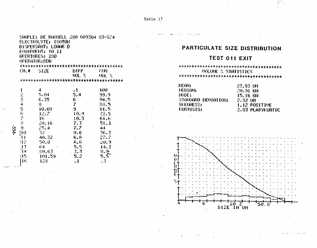
Table 1 7
!:;W IFLE : [,IE E:ril:;I IELL 230 G09304 :23-,<::'74 ELEI::TF~I:IL')TE: I SCITI]~I D 1 SFEESHI IT: Lilt9lrtF: Cl Et;!U I PI 1Et IT : TQ 1 I fiFEETI_IF:ES: 280 I:IPERH TI:IE : RDB ++++r+r+u+~~~~s*+~+*+++sr~+f++++++++++f I::H.# SIZE DIFF 13. 11 1
Ul][. r;;. l..l[lL :.; +++++f++*9ff*+99*f*+O*~*f~***~+*9+*+**S
PARTICULATE SIZE DISTRIBUTION
TEST 011 EXIT

I I I ...' 1 ... ..:: .-j <;Ql IFLE : HI;CIS Bi4l:;liELL RRI:;I.IF: I I ~ H T DI_I::;T 33-2':TE; .FLEl::TRr:lL8r'TE: I S13Tijl.l @ 1 !:FER:::fitl'T: L1311hR U EI.~IUIFIIE~IT: TG I 1 CiFERTI:iF:ES: 560 ISF'EF:HTIIR : RE12 . ~ f f f ~ ~ ~ ~ r ~ ~ . ~ ~ ~ ~ u ~ ~ f f + * ~ ~ ~ ~ ~ + * f f * ~ ~ f + + f + J:I i .U SIZE O IFF 131.11 1
l...b:lL ?: l..!l:lL ;: .. *f+++*f*f+f****Qf++++.:iQ+Q+++ . . . . . . . . . . . . . . . . . .
PARTICULATE SIZE DISTRIBUTION
ARKWRiGHT DUST

Table 19
IIln'TE : 1 1 ..." 1 ....' :33 lPLE : . HI~[ I~> PF(Gt.IELL E:F: I QIJETTE [IIJST :33-:378
EI-EI::TF:I:IL'+TE: I Si:iT[~t.l D I Z.PEESF(t IT: LOElHC, I! EI..II?IPtlElIT: TLi 1 I PFERT[tF.ES: ZGCl
IW'ERHTIIO~~: BEC i + r r ~ s t + ~ ~ + ~ % + s f + ~ + ~ + r : r + ~ ~ t + s * : + + t + + + ~ ~ * : C: t i . # .S IZE 0 IFF i:?Ib(
r ~ i y . z l.!i14 :. +++f+*+f+*+*+**f+++f**f+*++f+*+*+++f+*+
PARTICULATE SIZE DISTRIBUTION
BRIQUETTE DUST

Table 20
ULTIMATE ANALYSIS OF COALS USED DURING GASIFIER RUN 102
COMPONENT
Moisture Ash S H N Total Carbon Volatiles ~ t u / l b
WT %
PITTSBURGH SEAM COAL
ARKWRIGHT BLACKSVILLE
0.39 1.1 7.15 10.55 1.82 3.20 5.12 5.58 3.05 1.30 77.10 73.17 38.35 38.25 13715 13310
BLACKSVILLE BRIQUETTES
0.96 15.33 2.39 1.72 1.29 70.49 34.14 12615

Table 21
TRACE COMPONENTS IN EXIT GAS DURING SULFIDATION GASIFIER RUN 102
TESTS 006 AND 008
AQUEOUS CONDENSATE CALCULATED GAS PHASE ANALY S IS COMPOSITION
COMPONENT PPmW PPmW
Ni 4.15 0.221 V <O. 05 <O. 003 C r 1.21 0.064 K 3.73 0.199 Na 3.06 0.064
F e 11.68 0.622 Zn 4.89 0.260 Ca 1.77 0.099 A 1 0.382 0.020 Se 0.005 0.0002
As 1.52 0.081 IIg (0.2 <0.011 F 64 3.40 C1 1899 101.02 Br 10.8 0.574
13.2 0.702
so4 332 17.662
NO4 < 3 <O .I59
NH4 10074 535.93 Cu (0.02 <0.001
NOTES :
1. Aqueous condensate analysis from Sample # f00811. 2. Sampling location is at condenser CIC knockout. 3. Sample is a composite sample of HGD tests 006 and 008. 4. Metals determined by atomic absorption/atomic emission spectroscopy. 5. Anions and cations determined by ion chromatography,
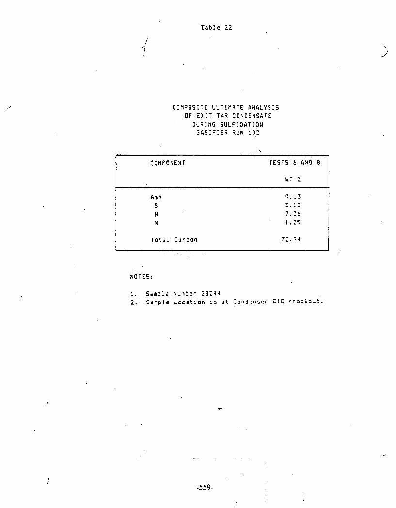
Table 22
C O H P O S I T E ULT1flA:E A N A L Y S I S OF E X I T TAR CONDENSATE
D U R I N G S U L F I O A T I O N G A S I F I E ? RUN 10,:
COnr*O:iENT TESTS b A N D 8
WT %
A s h 0; 1 3 T . T S 4. A d
H 7 . : 6 I
N 1.2:
T o t a l C i r t t o n 7"; 7 4
NOTES:
1 . S a m p l e N u m b e r t B Z S J 2. S d t n p l e L c c d t i o n i.s a t C a n d e n s e r C I C K n o i k c u t .

I-- W
J
Z
U
m
m z
u 0
m -'
2. e
a
a N
z-'
a
IX 3
w LI
e -1
a 3
* 2
: C
0
J
=I m
a
.. 2 :.:
a cs
0 ....
C) L
u
L.2
x m
CI'
r.. .d 4
L
..- :c
Ir s
In
L
--1
a
U
.d c -.
= a3
r2 --
c
=
X
0
e .-.
al C.,
v.
1
>- ..
n; Z ;i!
C
OC
C
-o
n
U
3- e c
U
CI ,I1
.... ....
L U
U
III
m
m
... I..
L
Y
LII
nJ
... a 0
.
wo
n
m
*m
cm u.
E
C
I" ....
.... L
II L
L
**
a :1
LI-
w T,
.ll u
rn
.
Ct
01
nl
I
rz S
L
n .-
.* n) ml
wu
u
.- &
I A
7
I=
n o
e.3 cu ,7
.- P
I rC
u
1.7
r.7
dm
m
u
r4
C
J
U
1
=J.
U
*
I
en
LC
us =t
13
1 W
&
- u- c-
UC
W
-1
L1
Bz .
rr
C-
W
c.1
n.
p:
bl 0
5: -0
4
(13
-1'
a3
CP
0
-
0
2 0
rT
rn o
-- 0
-+ -. -..
14
.
t-
3
4
-0
r-- .
-U
r-
m 0
*+
*
c>
0') m
o
C4
- r-8
-l-
-, 0
0-
r'3 1. > r>
zt:.
L
LII
L'
C
- CL
.n w
- .- 0
4
1
:- <>
.w r-.
ZI
4
.d
La
>-..
U
tn
-4
&K c%
.. 2 *'-
*?
tr
-- - 0
-
t'
-r
r -3 m
r-l . .. -. C
ZI
'I) e "l c
I3
0- -I
c. u
m
c* -I
N
XI
al ul
.d
s .u ..-
4.1
U
I 4
N
nl
3
20
C- 01

TABLE 24
TRBCE CGMPOHENTS IY I X E T SSS OURIN6 SULFIBATION EbSIFIER RUN !92
AQUEOUS CONOENSATE TEST 096 TEST 900 A'JEfl AGE
TEET 396 k 008
CALCULATED 54s PYAS€ COHPOSITION
PPH w P P ~ W P P ~ W FPHU
NOTES: 1. 6ds phase coroosit ion i s ca lculated from average of .Test 006 and Test 908 aqueous condensate
data and gas f l o r r a t e f r a r which the condensate was abtained. 2. Aqueous condensate data obtained f roa HGIi i n l e t p a r t i c u l a t e sawl ing . svstes. 3. Test 006 aqueous condensate ddta f roa sarple 161-9-20-1. 4. Test 000 aqueous condensate data f r a a sdrple (61-9-21-2.

TABLE 25
TRACE CDRPONENTS DURING SULFICATION GASIFIER RUN 102
H6D TESTS 006 AND 008
CALCULATED GAS PHASE CURPOSITIONS INLET EXIT
CHANGE
PPUY PPRW PPRW
NOTES: 1. I n l e t data calculated f r o r aqueous condensate obtained a t H6D i n l e t a t p a r t i c u l a t e
saapl inq tap. Average of saaples 61-9-20-1 and 61 9-21-2 used. 2. E x i t data calculated f r o r aqueous condensate obtained on condenser CIC knockout.
A corposi t a1 tes ts 006 and 008 was used. Saaple llC0011.

Table 26
TRACE COMPONENTS IN EXIT GAS CONDENSATE DURING REGENERATION GASIFIER RUN 102
AQUEOUS CONDENSATE TEST 007
SAMPLE # 100004 SAMPLE # 100008 AVERAGE COMPONENT PPmW PPmw PPmW
Ni 1 . 4 1 1.37 1 .39 V (0.05 <O. 05 (0.05 C r 1.39 1 .33 1.36 K 0.66 0.600 0.63 Na 0.71 0.641 0.67
Fe 82.4 79.0 80.2 Z n 1.83 1 .77 1 .8 Ca 1 . 5 4 1 .43 1 .48 A1 1.68 1.67 1.68 Se 0.039 ~ 0 . 5 ppb (0.02
As 0.538 1 .14 0.84 H9 <o. 2 <o. 2 <o. 2 F 9.3 8.7 9 C 1 . . 404 322 363 B r < 1 108 54.5
270 < 2 136
Sod 2 8 1 25 9 270 0.55 < 3 <1.8
NH4 270 200 235 Cu 0.025 <O - 0 2 (0.022
NOTES :
1. Mekdl3 determined by atomic absorption/atomic emission spectroscopy. 2. Anions and cations determined by ion chromatography. 3 . Sampling location is at condenser CIC knockout.

Table 27 (revision)
TRACE COHPONENTS IN E X I T 6 A S C O N D E N S A T E DURING REGENGRATION
GASIFIER RUN 102
... . 4QUEOUS CONEENSATE
COflPOMENTl TEST 010 TEST 012 PPRW PPHY
I SAllPLE SCIflPLE SAflPLE
I s a a w I
1 t1oooo9 I ~ O O Z B B 1100010 t!ooze? 1
Ni 0*150 0.56 1.Y1 1.90 V 0.197 (0.03 (0.05 (0.05 1 Cr 1.56 I * 1 3. SS K no. sa rp le 1.08 0.703 0,8Si / Na no.saaple 0.959 1.51 0.63! Fe . 272.8 240.0 liC.O 116.9
- - I n - . no.saapie - 6.90 2.90 Ca no.sarple 8.30 :.02 1.11 A1 " no. sa rp le 0.999 0.77
j'I4 I 0.739
.S e ;0.120 0.040 0.121 0.021 ks 0.298 0:30 4.401
HJ . . no.sarp!e 0.259 (6.2 (3 .2
F 26.1 29 28.9 ' i
15 1 C 1 695 888 545 Br 19.9 ( 4 526 I 415
( 2 472 . * NC! '. L i? so4 3659 1043 593 I461 1 PO 4 (3 ( 3 (3
I ( 3
NH4 226 200 26 1 ?bb CU ,<0.02 (0.02 0.02: 0.03 1 I
NOTES: 1. Duplicate rqueoul condensrte a n a l y s i s for Test 610 f r o r sample 1100009 and 1100200. 2. Duplicate aqueous condensate analysis fo r Test 012 f r o a sa rp le t100010 and t100289. 5, ne ta l s determined by a t o r i c rbsorpt ionlator ic e r i s s ion spectroscopy. 4. finions and cat ions deterrined by ion chroaatography. 5 . Sanplinq location i s a t condenser C l C knockout.

TABLE 28
Chloride, Dissolved (C11 Cyanide, Total (Cn) Ni troqen, Asronia, Total IN) Phenol i c s , Total (Phenol1 Sulfate , Oissolved (SO41 Sulf ide (s) Sulf i t e (503) Fluoride, Total (F) Thiacyanate, Total (6CHl Arsenic, Total (As) I ron, Total (Fe) Lead, Total (Pbl Calciur, Total (Ca) Potassiua, Total (Kl Vanadium, Total (I/)
Zinc, Total (Zn) .
Sodiur, Total (Nal
HGD EXIT CONDENSATE GASIFIER R U N 102
IHI-KENRON SARPLE D H62-21-102
H6D TEST 011 LQUEOUS eql l
IHI-KEHRCN SAflPLE 8H62-1A-102
H6D TEST 006 HYDROCARBON
r q / l
NOTES: 1. Samplinq location is a t condenser C1C knockout.
:APPENDIX G * - . - - . * . -.. - - - . - Sidestream Test inu - G a s i f i e r Run No. 103
Hot Gas Desul fur iza t ion Sidestream Test Unit, Fixed-Bed G a s i f i e r Run No. 103
In t roduc t ion
A t h i r d s e r i e s of t e s t s wi th t h e high-temperature, s ides t ream d e s u l f u r i z a t i o n u n i t (1,2) was c a r r i e d out dur ing fixed-bed g a s i f i e r Run No. 103 ( 3 , 4 , 5 ) between November 7 and 18.
The purpose of t h e t e s t s was t o c h a r a c t e r i z e f u r t h e r t h e behavior of zinc f e r r i t e sorbent i n coa l gas from var ious coa l s . A p a r t i c u l a r i n t e r e s t was t o i n v e s t i g a t e more c l o s e l y t h e magnitude and cause of t h e inc rease i n r eac to r d i f f e r e n t i a l pressure dur ing s u l f u r absorpt ion per iods .
Operation of Sidestream Test Unit
The s ides t ream u n i t was opera ted with a s i n g l e ba tch of sorbent i n t h e r e a c t u r f o r four s u l f i d a t i o n perfods and tnree in termedja te regenera t ion per iods . The g a s i f i e r was operated i n t h e air-blown mode and fed with B lacksv i l l e , Arkwright, and Kit tanning coa l s . The opera t iona l schedule i s shown i n Figure 1.
A s usual , t h e r e a c t o r contained 20.4 kg of z inc f e r r i t e ex t rus ions . Reactor furnace temperatures were s e t a t 1,0.0O0~ throughout a l l t h e s u l f i d a t i o n . a n d regenera t ion per iods . A lower minimum space v e l o c i t y than previous ly of 1,000 h-' f o r t h e s u l f i d a t i o n was thought t o g ive a more acceptable r e a c t o r p ressu re drop. The space v e l o c i t y dur ing t h e regenera t ions was about 500 h-l.
Average opera t ing parameters f o r t h e t e s t s a r e shown on t h e ADACS flow sche- mat ics i n Figures 2 t o 13. Because-of i n t e r r u p t i o n s i n t h e g a s i f i e r opera- t i o n , Tests 017 and 019 a r e broken down i n t o p a r t s when t h e s ides t ream u n i t was on stream.
I n Test No. 013, with t h e g a s i f i e r providing gas from Blacksv i l l e coa l a t about 120 ps ig , breakthrough of hydrogen s u l f i d e occurred a f t e r about 46 hours dur ing which t ime t h e H,S l e v e l was about 5 ppm i n i t i a l l y , but d r i f t e d t o about 20 ppm l a t e r . The r e a c t o r pressure drop g radua l ly rose from about 2 inches t o more than 100 inches of water, slowly a t f i r s t , but more rap id ly l a t e r . Pressure drop f l u c t u a t i o n s occurred when condensate was dumped from t h e r e a c t o r e x i t condenser. These were caused by surges of gas through t h e r e a c t o r and consequent movement of t h e sorbent ex t rus ions . This bed movement may have caused some channeling and accounted f o r t h e higher than expected H,S l e v e l s towards t h e end of t h e t e s t before breakthrough. A s before , an inc rease i n r e a c t o r temperatures approaching 100°F, occurred through p a r t i a l sorbent reduct ion and t h e s h i f t r eac t ion . Reactor temperatures, pressure drop, and gas flow r a t e s a r e shown i n Figures 1 4 , 15, and 16.
~ e g e n e r a t i o n of t h e sorbent i n Test No. 014 requi red about 24 hours, t h e steam t o a i r volume r a t i o being about 85/15. Except f o r t h e r e a c t o r i n l e t tempera- t u r e , which peaked sha rp ly up t o about 1, 7 0 0 ° ~ , t h e r e a c t i o n zone temperature - - - - - - - - . - . - - - - & -

reached about 1,300°F, some 100°F lower t h a n des i red . Reactor p ressu re drop gradual ly f e l l , more r a p i d l y a t f i r s t from about 20 t o 2 inches of water . Reactor temperatures, p ressu re drop, and flow r a t e s a r e shown i n Figures 17, 18, and 19.
Test 015, t h e second s u l f i d a t i o n i n which t h e g a s i f i e r provided gas from Arkwright c o a l a t about 120 ps ig , l a s t e d 40 hours and was terminated prema- t u r e l y because of an excessive pressure drop inc rease from about 2 inches , i n i t i a l l y t o about 160 inches of water, f i n a l l y . $S l e v e l s were s i m i l a r t o those i n t h e f i r s t s u l f i d a t i o n , except i n i t i a l l y when both H2S and SO, were high because of s u l f u r compounds l e f t i n t h e sorbent a f t e r regenera t ion . Reactor e x i t condensate was dumped more f r equen t ly than i n t h e previous su l - f i d a t i o n s o t h a t t h e r e s u l t i n g gas surges caused movement of t h e ex t rus ions (presumably) wi th consequent pressure drop decrease, thus extending t h e t e s t longer before an unacceptable pressure drop was reached. A s i n previous s u l f i d a t i o n s , t h e r e was a small temperature r i s e along t h e r e a c t o r l eng th . Reactor temperatures, pressure drop, and flow r a t e a r e shown i n Figures 20, 21, and 22.
Test 016 was t h e second regenera t ion of t h e sorbent . I n t h i s case , t h e steam tu a i r r a t i o was decreased stepwise from 85/15 i n i t i a l l y t o 75/25 dur ing t h e f i r s t few hours t o ensure t h a t t h e temperature i n t h e r e a c t i o n zone reached t h e d e s i r e d l e v e l of about 1,500°F. The dura t ion was consequently r a t h e r s h o r t e r , about 20 hours. Pressure drop was about 70 inches of water f o r t h e f i r s t few hours and then r a p i d l y f e l l t o about 5 inches of water a t t h e same time t h a t t h e s t eamla i r r a t i o was decreased, i . e . , t h e a i r flow was increased. Reactor temperatures, p ressu re drop, and flow r a t e s a r e shown i n Figures 23, 24, and 25.
I n Test 017, t h e t h i r d s u l f i d a t i o n of t h e s e r i e s , gas was provided from Kit tanning coa l a t 120 p s i g f o r about 43 h o u r s . u n t i 1 t h i s coa l was used up. Then, f o r a f u r t h e r 13 hours u n t i l H2S breakthrough, t h e gas came from Arkwright coa l a t about 240 ps ig . H,S l e v e l s were l e s s than 10 ppm f o r t h e Ki t tanning c o a l gas except f o r a s h o r t i n i t i a l per iod when t h e values were again high, r e s u l t i n g from r e s i d u a l s u l f a t e i n t h e sorbent; f o r t h e Arkwright coa l gas $S l e v e l s slowly d r i f t e d up t o t h e 20 ppm l e v e l . Very s u r p r i s i n g l y , t h e r e a c t o r p ressu re drop remained a t t h e low l e v e l of about 5 inches of water f o r t h e e n t i r e dura t ion of the test . A s i n previous s u l f i d a t i o n s , t h e r e was a moderate temperature inc rease along t h e r e a c t o r l eng th because of t h e s h i f t r eac t ion . Reactor temperatures, p ressu re drop, and flow r a t e a r e shown i n Figures 26, 27, and 28.
I n Test 018, t h e t h i r d regenera t ion , t h e s t eamla i r r a t i o was again decreased stepwise from 85/15 t o 75/25 but more r a p i d l y than before, r e s u l t i n q i n a s h o r t e r duratiuxi of about 12 hours. The r e a c t o r p ressu re drop gradual ly f e l l a s before but not a s f a r and was f i n a l l y about 10 inches of water compared t o 5 inches previous ly . Reactor temperatures peaked a t about 1,500°F, t h e design l e v e l . Reactor temperatures, pressure drop, and flow r a t e s a r e shown i n Figures 29, 30, and 31.
Test 019 was t h e four th and f i n a l s u l f i d a t i o n of t h e t e s t s e r i e s . Gas was again der ived from Arkwright coal bu t , i n c o n t r a s t t o Test 015, t h e g a s i f i e r p ressu re was twice a3 - high, - a t 240 p s i g . Because t h e g a s i f i e r was shut down

prematurely, H,S breakthrough d i d not occur and t h e t e s t l a s t e d about 24 hours. The r e a c t o r p ressu re drop, i n i t i a l l y about 4 inches of water, increased a t a much lower pace than i n Tes t 015 even accounting f o r t h e lower pressure drop r e s u l t i n g from t h e h igher opera t ing pressure . $S l e v e l s were l e s s than about 10 ppm. Reactor temperatures, a s usual , showed a moderate inc rease of less t h a n 1 0 0 ' ~ along t h e r e a c t o r length . Reactor temperatures, p ressu re drop, and flow r a t e a r e shown i n Figures 32, 33, and 34.
Resul ts
Data Summarv
The var ious process condi t ions and d a t a c o l l e c t e d i n Test Nos. 013 t o 019 a r e summarized i n Figures 35 t o 41.
Absorption of Su l fu r Com~ounds
Table 1 g ives l abora to ry gas chromatographic analyses , inc lud ing major and t r a c e components, of grab samples of gas e x i t i n g t h e hot gas desul- f u r i z a t i o n u n i t condenser ( 6 ) . Corresponding analyses f o r g rab samples of i n l e t gas from. the, g a s i f i e r cyclone e x i t a r e given i n Tables 2 and 3, covering t h e s u l f i d a t i o n t e s t s only. The values f o r H,S, COS, CS,, and thiophene (C4H4S) respec t ive ly a t both u n i t i n l e t and o u t l e t dur ing t h e s u l f i d a t i o n t e s t s a r e p l o t t e d on semilog p l o t s i n Figures 42 t o 45. On t h e average, H,S i s reduced from a few thousand pprn t o a few ppm, COS from a few hundred pprn t o a few ppm, and CS, and thiophene from a few t e n s of pprn t o a few ppm, s o t h a t t h e t o t a l average l e v e l of t h e s e low molecular weight s u l f u r compounds i s lowered t o l e s s than about 10 ppm.
The hydrogen s u l f i d e concentra t ion i n e x i t gas from t h e u n i t was a l s o measured dur ing t h e s u l f i d a t i o n tests by t h e Basel ine I n d u s t r i e s on-line gas chromatograph and by d e t e c t o r tubes . The values obta ined a r e p l o t t e d aga ins t on-stream time i n Figures 46 t o 49, toge the r with some values f o r s u l f u r d ioxide measured by d e t e c t o r tubes . There i s gen- e r a l l y s a t i s f a c t o r y agreement between t h e H,S values measured by t h e two techniques except when they depar t widely from t h e gas chromatograph c a l i b r a t i o n po in t of 3 pprn $S. A s found previously, t h e H,S and SO, l e v e l s i n gas from regenerated sorbent a r e i n i t i a l l y high but f a l l o f f f a i r l y r ap id ly . The Basel ine gas chromatograph values f o r H,S, COS, and SO, a r e compared i n Figures 50 t o 53. The COS l e v e l s can be seen t o be l e s s than t h e H,S l e v e l s . SO, l e v e l s genera l ly a r e comparable with t h e d e t e c t o r tube values i n Figures 46 t o 49.
The amount of s u l f u r absorbed before breakthrough was considerably g r e a t e r than i n t h e previous tests a t higher space v e l o c i t i e s . A s a weight percentage of f r e s h sorbent , t h e amount i s : Test 013, - 29; Test 015, - 23; and Test 014 , - 1 4 , i n d i c a t i n g a d e c l i n e of s o r p t i o n e f f i c i e n c y wi th cycl ing . It i s d i f f i c u l t t o a t t r i b u t e a t r e n d t o t h i s , however, because of t h e v a r i a t i o n i n s u l f u r content of gas from t h e d i f f e r e n t coa l s .

Gas Analvsis f o r Maior Svecies
I n a d d i t i o n t o t h e l abora to ry gas chromatographic a n a l y s i s of major spec ies i n i n l e t and e x i t gas given i n Tables 1 and 2, gas t o and from t h e u n i t was analyzed by Bendix on-line chromatographs. The measure- ments, averaged by ADACS s t a t i s t i c a l ana lys i s , a r e shown i n Tables 4 t o 16. The gas l i n e t o chromatograph 6,000 # 1 became p a r t i a l l y blocked during t h e t e s t s s o t h a t t h e readings from chromatograph 6,000 # 2 give a more r e l i a b l e i n d i c a t i o n of t h e i n l e t gas composition.
Some of t h e s u l f i d a t i o n e x i t samples i n Table 1 i n d i c a t e an excess ive oxygen content , which should not exceed about 1 vo l . percent . This may be because a i r was not completely d i sp laced from t h e grab sample b o t t l e s .
A s before, it can be seen t h a t t h e carbon monoxide s h i f t r e a c t i o n pro- ceeds t o a l a r g e ex ten t , i l l u s t r a t e d by Figures 54 t o 56, based on Tables 1 and 2. There i s an apparent small l o s s of t o t a l carbon oxides, presumably because of carbon formation.
4 Analvsis of Reaeneration Exi t Gas
The regenera t ion e x i t gas ( see Tables 1, 5, 7 , and 13) i n t h e f i r s t p a r t of t h e regenera t ions conta ins s u b s t a n t i a l q u a n t i t i e s of hydrogen, carbon oxides, and reduced s u l f u r compounds, predominantly hydrogen s u l f i d e but with some carbonyl s u l f i d e and carbon d i s u l f i d e .
This may be explained by t h e r e a c t i o n of t h e regenera t ion gas with i ron / i r o n carbidelcarbon i n t h e sorbent . Towards t h e end of t h e regenera- t i o n , s u l f u r i n t h e regenera t ion e x i t gas i s mainly i n t h e 'form of su l - f u r d ioxide with no hydrogen and carbon monoxide and l i t t l e carbon dioxide p resen t .
ADACS p l o t s of CO,, H,S, O,, CO, and ,H, i n t h e regenera t ion gas from t h e r e a c t o r e x i t condenser a r e shown i n Figures 57 t o 61 (Test No. 014) and Figures 62 t o 66 (Test No. 018) .
Eorbent Charac te r i za t ion
The s u l f i d i z e d sorbent a f t e r Test No. 019 was sampled, on removal, a t p o i n t s along t h e r e a c t o r l e n g t h and charac te r i zed by var ious techniques. The r e s u l t s a r e shown i n Tables 1 7 and 18. A s found previous ly ( 2 ) , a t s i m i l a r gas condi t ions , t h e sorbent i s seen t o con ta in l a r g e amounts of cementi te , p a r t i c u l a r l y towards t h e r e a c t o r o u t l e t . P y r r h o t i t e i s only found near t h e r e a c t o r i n l e t where t h e r e i s a l s o some unsu l f id ized magneti te . The bulk of t h e z inc oxide a t t h e r e a c t o r i n l e t has been .
converted t o s u l f i d e ( see Table 1 7 ) .
Table 18 shows t h a t t h e sorbent conta ins up t o 25 w t . percent s u l f u r a t t h e r e a c t o r i n l e t . Carbon content , lower a t t h e i n l e t , exceeds 7 w t . percent towards t h e o u t l e t . Values of su r face a r e a and pore volume a t t h e r e a c t o r i n l e t a r e comparable t o those of f r e s h so rben t . Values towards t h e r e a c t o r o u t l e t s i g a i f i c a n t l y exceed those f o r f r e s h sorbent which may be accounted f o r by t h e reduct ion of t h e sorbent t o cementi te .

Similar ly , sorbent crush s t r e n g t h i s comparable t o t h a t f o r f r e s h sor- bent a t t h e r e a c t o r i n l e t , but i s s i g n i f i c a n t l y lower a t t h e o u t l e t (see Table 1 8 ) . About a t h i r d of t h e sorbent passed through a No. 12 screen a s f i n e s . This d i s i n t e g r a t i o n i s mostly a sc r ibed t o t h e formation of cementi te and i t s weakening e f f e c t .
P a r t i c u l a t e Analvsis
During Test Nos. 013, 015, and 017, samples of i n l e t and o u t l e t gas were taken t o c h a r a c t e r i z e t h e p a r t i c u l a t e content ( 7 ) . I n t h i s s e r i e s , both i n l e t and o u t l e t samples were obtained f o r each t e s t (though not a t t h e same time) t o g e t some idea of t h e change i n p a r t i c u l a t e loading and s i z e d i s t r i b u t i o n f o r t h e gas i n pass ing through t h e r e a c t o r . The r e s u l t s a r e summarized i n Table 19. D e t a i l s of p a r t i c u l a t e s i z e d i s t r i - bu t ion a r e given i n Tables 20 t o 25.
The p a r t i c u l a t e loading of t h e i y l e t gas was s i m i l a r f o r t h e t h r e e tests, approximately 1 t o 2 g/Nm . The median p a r t i c l e s i z e was highest f o r Arkwright coa l gas, - 26 pn (Test No. 015), somewhat less f o r B lacksv i l l e c o a l gas, - 21 pm (Test No. 013) , and least f o r Kittanning cva l gas, - 13 pn (Test No.. 017) . For each t e s t , a s i g n i f i c a n t propor- t i o n of t h e p a r t i c u l a t e appeared t o be removed by t h e sorbent bed, reaching about 80 w t . percent i n Test No. 017.
Larger p a r t i c l e s a.ppear t o be removed p r e f e r e n t i a l l y , so t h a t t h e median p a r t i c l e s i z e a t t h e o u t l e t i s s i g n i f i c a n t l y l e s s than a t t h e i n l e t , - 22 pm f o r Arkwright coa l gas , - 1 4 pm f o r B lacksv i l l e coa l gas , and - 5 pn f o r Ki t tanning coa l gas .
There appears t o be a pos i t ive c o r r e l a t i o n between t h e median p a r t i c u l a t e s i z e i n t h e i n l e t gas and t h e r a t e of increase of r eac to r pressure drop i n a given s u l f i d a t i o n t e s t , which was h ighes t f o r Arkwright coal gas, somewhat l e s s f o r Blacksvi l le coal gas, and much l e s s f o r Kit tanning coal gas. Smoothed out pressure drop p l o t s f o r t h e s u l f i d a t i o n t e s t s a r e shown i n Figure 67. The chemical ana lys i s of t h e p a r t i c u l a t e samples, see Table 19, i n d i c a t e s t h a t t h e r e i s l i t t l e d i f fe rence between i n l e t and o u t l e t p a r t i c l e s , leading t o t h e conclusion t h a t l i t t l e a t t r i t i o n was being experienced.
Condensate Analvsis
Reactor e x i t gas condensates were c o l l e c t e d from a l l t h e t e s t s and com- p o s i t e samples analyzed f o r minor and t r a c e c o n s t i t u e n t s ( 6 ) . Values f o r t h e s u l f i d a t i o n t e s t s a r e shown i n Table 26 and f o r t h e regenera t ion t e 3 t s i n Table 27. A check a n a l y s i s taken s e v e r a l months l a t e r f o r c e r t a i n c o n s t i t u e n t s i s a l s o included.
The analyses a r e s i m i l a r t o those obta ined i n previous t e s t s e r i e s . The regenera t ion condensate i s enriched i n most of t h e c o n s t i t u e n t s but par- t i c u l a r l y i n ha l ides , ammonia, and a l k a l i meta ls . Assuming t h a t t h e c o n s t i t u e n t s i n t h e regenera t ion condensate de r ive form t h e gas flowing through t h e r e a c t o r i n t h e preceding s u l f i d a t i o n t e s t , it i s poss ib le t o estimate t h e propor t ion removed by t h e svrbent based on t h e q u a n t i t i e s

of condensate c o l l e c t e d (see Figures 35 t o 41) and t h e condensate a n a l y s i s .
Thus, 7 t o 21 percent of NH4, 27' t o 59 percent of C1, and 40 t o 74 per- cent of Na a r e ca lcu la ted t o be removed from t h e gas by t h e sorbent and re leased i n t o t h e regenera t ion gas .
Table 28 shows t h e analyses of t h e t a r condensate c o l l e c t e d from t h e s u l f i d a t i o n t e s t s a t t h e u n i t e x i t . These t a r s a r e seen t o c o n s t i t u t e up t o 0.8 w t . percent of t h e e x i t gas and conta in up t o 3 .8 w t . percent of s u l f u r . For comparison, analyses of t a r condensates c o l l e c t e d a t t h e u n i t i n l e t (S4 sample point a t g a s i f i e r primary cyclone e x i t ) a r e shown i n Table 29. The s u l f u r l e v e l s i n t h e s e a r e s i g n i f i c a n t l y l e s s than i n t h e e x i t t a r s suggest ing t h a t t h e s u l f u r compounds i n them a r e notably r e f r a c t o r y t o cracking and hydrodesul fur iza t ion . Ultimate analyses of t h e coa l s used i n t h e test s e r i e s a r e shown i n Table 30.
Condensate was a l s o c o l l e c t e d i n t h e course of t a k i n g p a r t i c u l a t e sam- p l e s ( 7 ) . The analyses of t h e aqueous p a r t s a r e shown i n Table 31. These have been t r a n s l a t e d i n t o c a l c u l a t e d gas phase compositions f o r s u l f i d a t i o n Test Nos. 013, 015, and 017 i n Tables 32, 33, and 34 respec- t i v e l y . The o u t l e t gas phase compositions c a l c u l a t e d from t h e composite aqueous condensates i n Table 26 a r e a l s o included. Comparison between c a l c u l a t e d i n l e t and o u t l e t compositions genera l ly s u b s t a n t i a t e s t h e conclusion t h a t a number of t h e gas components, p a r t i c u l a r l y ha l ides , ammonia, and a l k a l i metals a r e removed by t h e d e s u l f u r i z a t i o n sorbent t o some e x t e n t .
I n l e t and o u t l e t t a r condensates from s u l f i d a t i o n Test No. 013 were analyzed by gas chromatograph/mass spectrometer f o r c e r t a i n components a s shown i n Table 35. The p r i n c i p a l s u l f u r compound, benzothiophene appears t o be v i r t u a l l y unaffected. An apparent ly s u r p r i s i n g r e s u l t i s t h a t benzene, to luene , and xylenes a r e removed t o a l a r g e e x t e n t ; whereas, t h e concentra t ions of phenol and c r e s o l s a r e not changed much. This c o n t r a s t s with previous test experience ( 8 ) .
Conclusions
A t h i r d s e r i e s of t e s t s of t h e hot gas d e s u l f u r i z a t i o n u n i t i n , a s ides t ream of t h e METC 24 t / d fixed-bed g a s i f i e r was s u c c e s s f u l l y concluded. The z inc f e r r i t e sorbent underwent t h r e e cyc les of s u l f i d a t i o n and regenera t ion , gas being provided from t h r e e d i f f e r e n t bituminous c o a l s .
The amount of s u l f u r absorbed a t t h e lower space v e l o c i t y of 1,000 h" was comparable t o t h a t found a t 2,000 h-' i n previous tests. A s u b s t a n t i a l amount of t h e sorbent was again converted t o i r o n carbide , which appears t o r e s i s t s u l f i d a t i o n and a l s o markedly reduces t h e crush s t r e n g t h and a t t r i t i o n r e s i s t a n c e of t h e sorbent . I n s p i t e of t h i s , low molecular weight s u l f u r compounds were removed t o a l e v e l of l e s s than about 10 ppm and t h e sorbent recovered v i r t u a l l y a l l i t s absorpt ion capac i ty on regenera t ion . A g r e a t e r number of cyc les w i l l of course be necessary t o demonstrate t h e so rben t ' s l o n g - t e n e f f e c t i v e n e s s .

Reactor p ressu re drop was s tud ied more c l o s e l y i n t h i s t e s t s e r i e s and it was found t h a t t h e r e was a p o s i t i v e c o r r e l a t i o n between t h e median p a r t i c u l a t e s i z e i n gas t o t h e u n i t and t h e r a t e of p ressu re drop inc rease . Very l i t t l e p ressu re drop inc rease was evident dur ing a s u l f i d a t i o n t e s t f o r an i n l e t gas median p a f t i c u l a t e s i z e of 13 pn. P a r t i c u l a t e gas loading was of t h e order of 1 g/Nm. Carbon deposi t ion may a l s o a f f e c t t h e p ressure drop, s o t h e c o r r e l a t i o n should be regarded with caut ion .
Again, it was found t h a t minor c o n s t i t u e n t s of t h e gas , i n a d d i t i o n t o su l - f u r , a r e absorbed, p a r t i c u l a r l y ha l ides , a l k a l i and a l k a l i n e e a r t h meta ls and ammonia.
References
1. Grindley, T., "Hot Gas Desu l fu r i za t ion Sidestream Test Unit , Fixed-Bed G a s i f i e r Run No. 101," I R No. 1846, March 1984, METC.
2 . Grindley, T . , "Hot Gas Desul fur iza t ion Sidestream Test Unit, Fixed-Bed G a s i f i e r Run No. 102," I R No. 1984, September 1984, METC.
3. Pa te r , K . , "Test Plan -- Run No. 103," I R No. 1821, March 1984, METC.
4 . Pa te r , K . , "Prel iminary Test Summary -- Run No. 103," I R No. 1810 May 1984, METC.
5 . Pa te r , K . , "Process Summary Report -- Run No. 103," I R No. 2021, October 1984, METC.
6 . Lamey, S. C . , R . R . Romanosky, and J. J. Kovach, "Analyt ica l Data -- Producer Run No. 103," I R No. 2069, November 1984, METC.
7 . Bagnell, R . D . , and R. J. Anderson, " P a r t i c u l a t e Sampling and Analysis i n Support of Hot Gas Desul fur iza t ion Tes ts and Minimally Clean, Low-Btu Gas Combustion Tes ts During G a s i f i e r Run No. 103," I R No. 1865, November 1984, METC.
8. Green, D . A , , K . E . Leese, and W . J. McMichael, "Po l lu t ion Control i n Coal Gas i f i ca t ion : Tes t ing of Zinc F e r r i t e C a t a l y s t , " Research Triangle I n s t i t u t e f o r METC, Report No. DOE/MC/16441-1406 (1983) .

ADDENDUMiTO APPENDIX G
-. t .;
The Baseline G.C. on-line H2S, COS, and SO2 readings as plotted are correct
only for the points: H2S: 3 ppm; COS: 1.7 ppm; and S02: 5.1 ppm.
Calibration curves are available fo= correction. Corrected plots 'are given
in Volume 1.
Refer to letter to T. Grindley from E. E. Gorski and P. Johnson, EGdG
Washington Analytical Services Center, Inc. January 30, 1986. Subject:
DOE-METC/EG&G Contract No. DE-AC21-85MC21353; WBS No. 9KEX-10. HGD Project:
Baseline G~/Integrator Conversion Curves.

FIGURE 1
TEST 0 1 3 SULFIDATION T E M P 1 0 0 0 ' F
8 V 1 0 0 0
1-1 TEST 0 1 4 REOENERATION 1 6 % A I R 8 6 % 8 T E A M
SULFIDATION 1 7 TEST 0 1 6 SULFIDATION
T E M P 1 0 0 0 . F 8 V 1 0 0 0
17 T E S T 0 1 0 REOENERATION
1 6 % A I R 8 6 % B T E A M
1-1 -1 ( 0 TEST 0 17 BULFIDATION
T E M P 1 0 0 0 ' . F s v 1 0 0 0
TEST o 1(1 REGENERATION 0 REGENERATION 1 6 % A I R
8 6 % B T E A M
C O A L T Y P E
O X I D A N T
SCHEDULE O F E V E N T S
H O T G A S D E S U L F U R I Z A T I O N SIDESTRE. I \M T E S T I N G 1 0 8 3
' G A S I F I E R RUN 1 0 3

FIGURE 2
TEST 3
AVERAGE OPERATING PARAMETERS TO COAL URTCR
H a ---.-
PREHEATER
CIIR --
S T E M - - . . . . . . -
LL7.54PSIC
1 4 6 4 . O E W
559 .DECf
829. OECF
118.65PSIG

Y l t i U K L 3
TEST '44
AVERAGE OPERATING PARAMETERS

FIGURE 4
TEST-015
AVERAGE OPERATINGPARAMETERS
PREHEATER TO COAL W T C R HZ .-p -- .rr SLURRY
-.-_-) Hz0
I
- 1-2
@.GPn
65. D E W
..--. --
0 7 6 . DECF I
A I R ..- - -- 923. DECF
I
a < (3 ?!EMM -.--- - --.----..--.--
17O.DECT
1031 .DEW . DL~AIH
1853.DECf
11O.SIPSIG
1@30. DLGF
I 1 I 1
nit 7 r n . n ~ ~
a10
PRODUCER
GAS :
AuERA6E(6) rm E R I O O FROn8 108 1 8 1 7 1 1 0 0 8 8 ~ 1 , ~ ~ / 1 e ~ ~
t- o <
196S.DECf
I O # . D E f f 820. DCCF
I @ I 7 . D E W .
1 0 1 6 . D L f f

FIGURE 5
TEST C
AVERAGE OPERATING PARAMETERS
PREHEATER TO CON UATER
W O
64.DEcF . .
67.SCFH
1.CPR .
fbI R HZ0 '
- --.- PRODUCER
u s

FIGURE 6
TEST 0 .
AVE,SAGE OPERATING PARAMETERS
PREIIEATER 10 COAL U A E R
C
a I R ----

FIGURE 7
TEST 0 3
AVERAGE OPERATING PARAMETERS
PREtiEATEfl TO CWL UATER

FIGURE 8
TEST "3
AVERAGE OPERATING PARAMETERS
ACICR4C€O) FOR PERIOD FRO111 7, @I19 11/10/1083 TO 81 4145 11/1O/1983
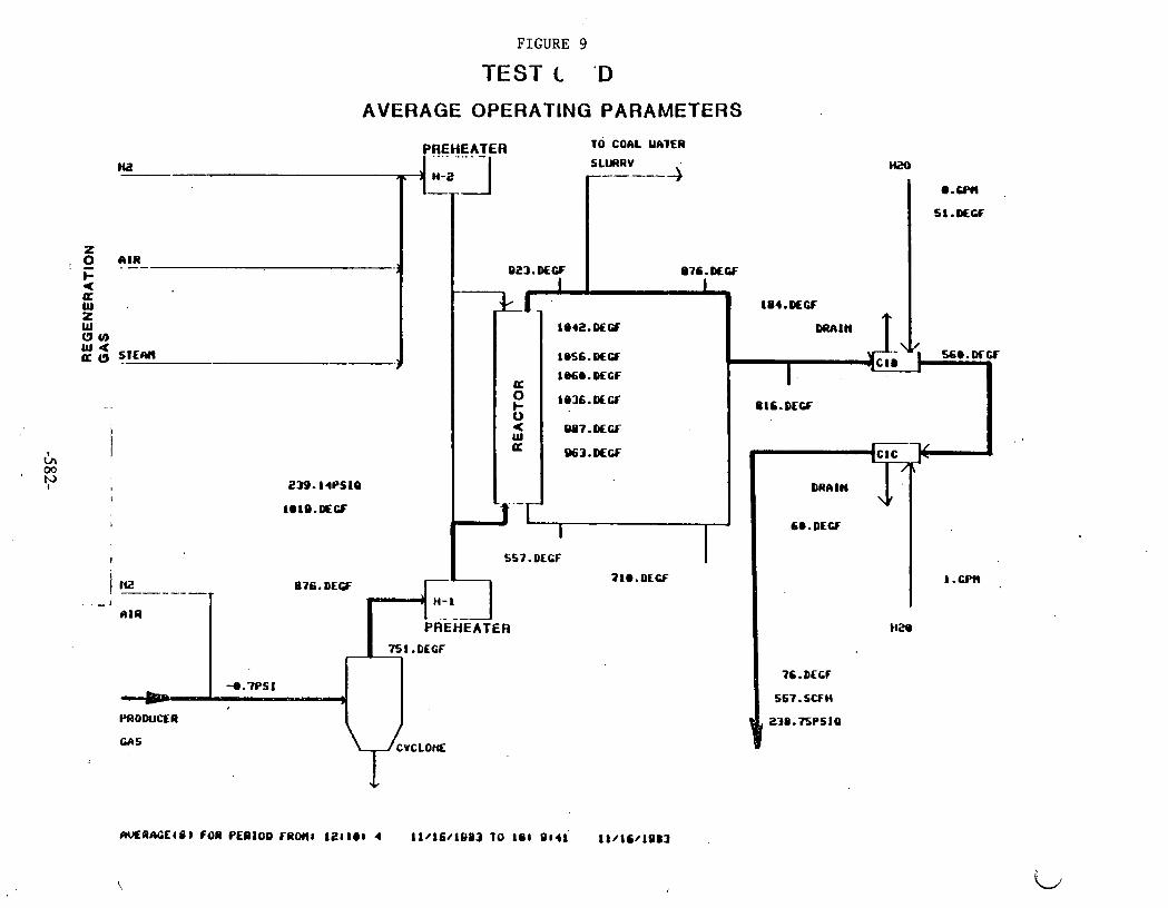
FIGURE 9
TEST C 'D
AVERAGE OPERATING PARAMETERS
rwERAGE(O) FOR PERIOD TAM1 181101 4 11/16/11)B3 TO 141 9141 ll/lC/1983

FIGURE 10
TEST 0
AVERAGE QPERATIMG PARAMETERS

FIGURE 11
TEST ' 9 A
AVERAGE OPERATING PARAMETERS
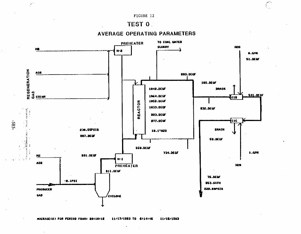
FIGURE 12
TEST 0 .
AVERAGE OPERATING PARAMETERS
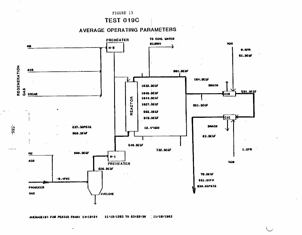
FIGURE 13
TEST 019C
AVERAGE OPERATING PARAMETERS
PREHEATER TO UML Y A n R
SLURRV b
M20 na H-8
e.- Cl.#QF
MIR 3 Wl.#W
I I 1I4.#CF
STEm
. *
' I I
I
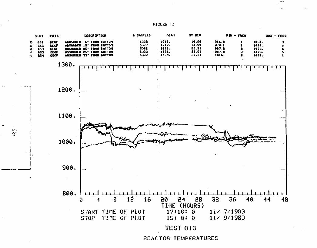
FIGURE 14
0 951 WCF ABOSCIDER So FROR DOT10!9 0 US2 DECF ABSORBER I S ' F R M B O n 0 . 1 o a53 DECF ABSORBER esb FRO* BOP TO^ A 5 3 DLCF ABSORBER 25. F R M & O f f 0 5
. v 9 5 4 DEW ABSORBER So FROH I O V f O J l
I I I
I -
-
-
-
u I 1 A 1 1 - u . 1 -
0 4 8 1 96 20 24 28 32 36 48 44 48 TIME (HOURS)
START TlIllllE OF PLOT 1 ' 7 t i 8 t 8 i i ~ 7/'%983 STOP TIiME OF PILOT 1st 8 % @ 111 9/1983
TEST 013
REACTOR YEMPERA'6URES

FIGURE 15
SLOT UIITS DESCRIPTION 8 SAHPLES UEW ST DEU RIM - FMO nruc - CREO
294 0 ABSORBER DIFFERENCE PRESSURE 5322 28.78 25.63 -8.i!i!O L 164.9 1
0 4 8 12 16 28 2 4 28 32 36 48 4 4 48 T I f lE ( HOURS 1
. START TIME OF PLOT 1721.8: 0 1l/ 7 4 9 8 3 STOP TIME OF PLOT 151 0: 0 111 911983
TEST 013
REACTOR PRESSURE DROP

SLOT WITS DESC~IPT IW
37H SCFH M O D . CAS OUT OF SV6TE)I
8 W L E S n~w st DEU RIM - rare W X - FCIEO
sou4 593.5 a1 .6s 462. I s3s.o 1
0 4 8 12 16 20 24 28 32 36 4 0 44 48 T I ME ( HQURS
START TINE OF PLOT f7118t 8 1 l / 74983 STOP TINE OF PLOT 1st oa 0. i i / 9 4 9 8 3
TEST 013
EXIT FLOW

FIGURE 17
SLOl WITS DE!XRIPIIOH 8 S W L E S MM ST M U Altl - FREO IYU( - CRCO
0 051 DEW ABOSRBLR 5. FRON DOTTCA 3822 IlSI. S(1.25 0 852 lKCF 6BSORBER 16' FROM BOTfG)l
1036. 3822
a 131s. 1131. 74 -64 1039.
1 o 053 (KGF ~BSORIER 2s- FRM IOTTGN 3082
ra 1x3. 1092. 61 -06
1 1b33.
A 1154 ~KCF CDSOAIER 36. FRM BOTTGN 30aa 3
1020. 1211.
164.3 4
V 156 DEW IBSORIER 4s. F R M BOTT01 95s. 0
3022 946.6 1 1367.
61.4a S
004.6 4 1699. 1
0 4 8 12 16 20 24 TIME (HOU2S)
START T INE OF PLOT 17:301 @ 11/ 9 4 9 8 3 STOP TIINE OF PLOT 184408 8 11/18/1983
TEST 014
REACTOR TEMPERATURES

FIGURE 18
b SAWLES REAM Sr DLU BIN - FRCO M X - FRE4
2768 -9.501 5.513 -eo.ati 1 4.1119 I
I.--
-
.-.
.. .
--
LL . -J~-A-~ . -.I. ..
8 4 8 12 16 2@ 24 28 T I M E (HOURS)
STAR"T$IME OF' PLOT 1at363s a I I / Y / ~ S I & I ~ STOP TIPIE OF PLOT 1SU488 8 %1/8@/1983
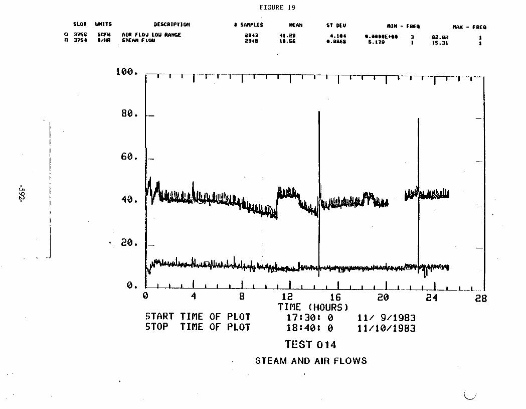
FIGURE 19
SLOT UNITS DESCRIPTI OCI 8 S M P U S M&H ST DEU RIM - FINO HAM - FREQ
0 3756 SCFH' A I R FLO J LOU RAHCE 2843 41.29 4.1@4 @.OB@@Et@@ 3 n 3154 o/m STEW FLW ZOIB 80.56 .a860
82.82 6.170 I 15-31 I
1
TIME (HOURS) START TIME OF PLOT 171308 0 11/ 9/1983 STOP T IRE OF PLOT 181408 0 11/18/1983
TEST 0 14
STEAM AND AIR FLOWS
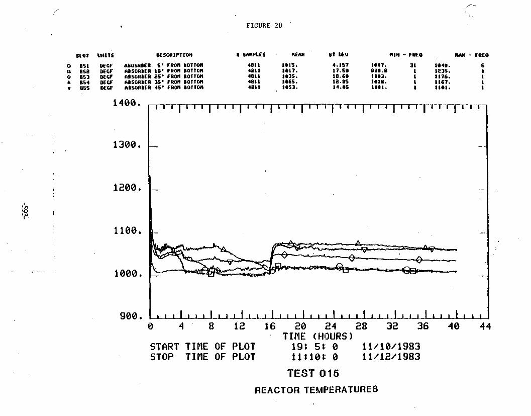
. FIGURE 20 '
SLOT UNITS. DESCRIPTION 8 SMPLES . REAn S t M U RIM - FRLO . (IAX - rmo
0 8 5 1 D€Cf &BOSIBER S e FROH BOTTOH U 8 5 8 DECF &BSORBER 16. F R M BOTTOH 0 8 5 3 DECF RBSORBER 25. FROM BOlfO(( A 8 5 4 DEW ABSORBER Sg FROM BOTfO(l v 8SS OECF 6BHWIBER 45. F R M B O l T M
8 4 8 12 16 20 24 28 32 36 4 0 44 TIPIE (HOURS9
START TINE OF PLOT 19: 5t: 0 11/18/1983 STOP TINE OF PLQT llti0t: 0 11/12/1983
TEST 015
REACTOR TEMPERATURES

FIGURE 21
SLOT W I T S DESCAIPTlOh 8 S W L E S RIM - FRCO IVU( - FREO MAn 6T M U
894 ABSORBER DIFFERENCE PRESSURE 4911 46.59 4 4 -&.9880 1 226. I 1
T IME (HOURS START TIME OF PLOT 191 51 8 11/18/1983 STOP TIME OF PLOT 11 8108 8 61/12/1983
PEST 095
REACTOR PRESSURE DROP

FIGURE 22
SLOT U~ITS USUIIPTIOH 0 SACPLES NIY( s t )CV uln - m e . w - FAEO
375e sccw PQOD. GAS WT ~f S Y S ~ R 4662 6sa.a ac..er e.e.o~z*ee o c10.a I
0 4 8 I2 16 20 24 28 32 36 40 44 TINE (HOURS)
START TIRE OF PLOT 198 51 8 fi/lB/b983 STOP THflE OF PLOT' 114181 8 11/12/1983

FIGURE 23
SLOT WITS DESCI~IPTIO~ 8 SNWLES MEW ST MU m~n - r a ~ a IUU( - CRCQ
0 851 W f f ABOSRBER 6' FROH B0TTCMl 0 852 DECF ABSORBER I S * FROM BGTTO(( 0 853 DEW ABSORBER K* FROM BOTTOM A 4 QECF ABSORBER 35' FROM DOTTO6 v OSS DECF ABSORBER J S * FROM BOTT0((
. .
- .
TIME (HOURS) START TIME OF PLOT 121158 0 11/12/1983
s STOP TIME OF PLOT 8:308 0 11/13/1983
TEST 016
REACTOR TEMPERATURES
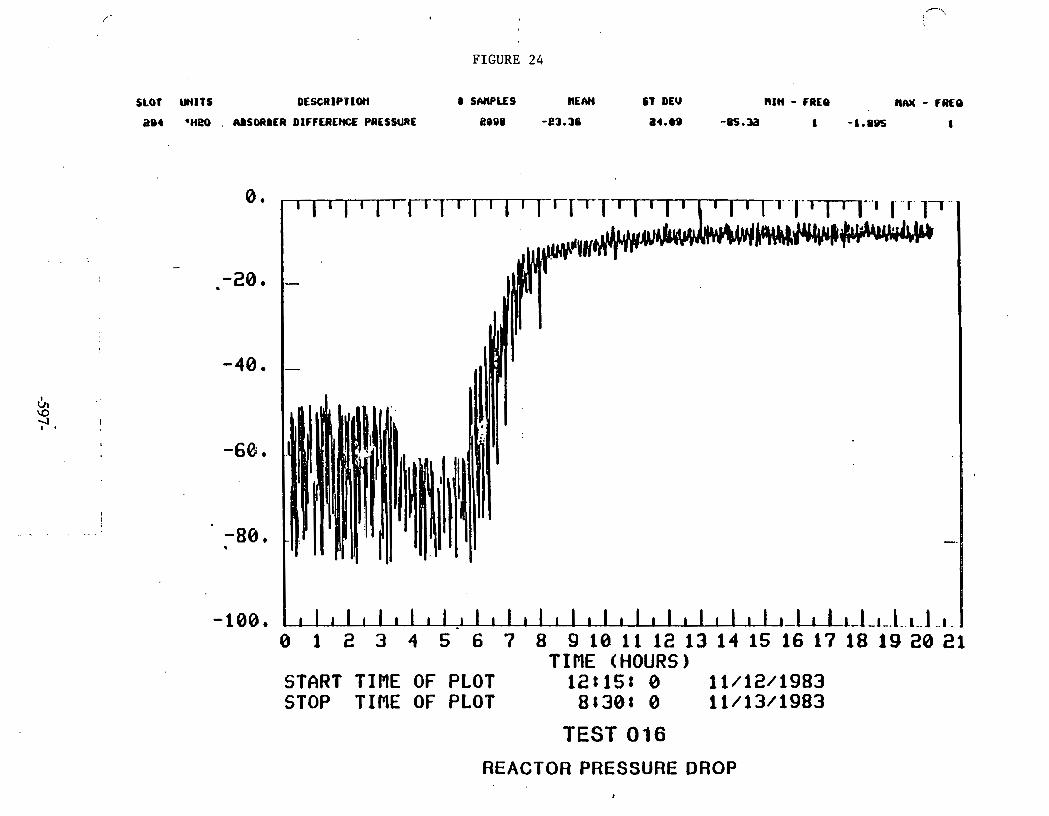
FIGURE 24
SLOT UNITS DESCRIPTIW 8 S W U S HE IVI CT DEU N I ~ - F R E ~ nIU( - fCKO
aec .~eo . AISORBER DIFFEREM PRESSURE e ~ o s - e m 6 a4.m -=.a 1 -1.995 1
-108, I I I r I l I r I I I I L I ~ 1 _ 1 - . 1 . . t . . j . . I -
TIME (HOURS) 0 i 1 2 ' 3 4 5.: 8 9;:;; ;A 1:;:;LJi6 17 18 19 20 2,
START TIME OF PLOT 121158 0 11/12/1983 STOP TIME OF PLOT 81301 0 11/13/1983
TEST 016
REACTOR PRESSURE DROP 2

FIGURE 25
SLOT UIITE DESCRIPTION 0 SWLES =An s t MU n ~ n - FREQ tw - TIKQ
0 3756 SCfM h I R fLOU LOU RhWE a 3154 ow S T E ~ FLW
\D SO
I
I - .
- --.I I
0 1 2 3 4 5 6 7 8 9 10 11 12 13 1 4 15 16 17 18 19 20 21 TIME (HOURS)
START TIME OF PLOT 12815: 0 11/12/1983 STOP TBNE OF PLOT 8:30: 0 11/13/1983
TEST 0 16
STEAM AND AIR FLOWS

FIGURE 26
SLOT W I T S D€LCRIPVPON 8 SMPLES H E M SY DEU H l H - FREO )W - F a 0
O 5S1 N6F klOSABER 6 * F R M B O l T M 0 858 WU: ABSORBER 16' F R M bOTTOf4 0 853 MGF hBSOR&ER 2Sa FAOM BOTTOM A 854 DECF hBSORBER 35. FROh 001TCM v 855 D€CF C:SORBER 45. FROH B O T r M
. .
I I I I I -'-I---- I
-.
0170
0178
017C d
Ec
-.
- ,p-. a
I. - -
I 1 1 I I I 1 a - 8 24 48 72
T 1 ME ( WOURS 1 START TIME OF PLOT 1'7t258 O id/k3/1983 STOP "6%$!E OF PLOT iGt%BS 18 f f /'16/11983
TEST 017
REACTOR TEMPEWAT(dRES

FIGURE 27
8 24 48 72 T IRE (HOURS)
START TOME OF PLOT 171251 0 11/13/1983 STOP TIRE OF PLOT 161608. 0 11/16/1983
TEST 017
REACTOR PRESSURE DROP
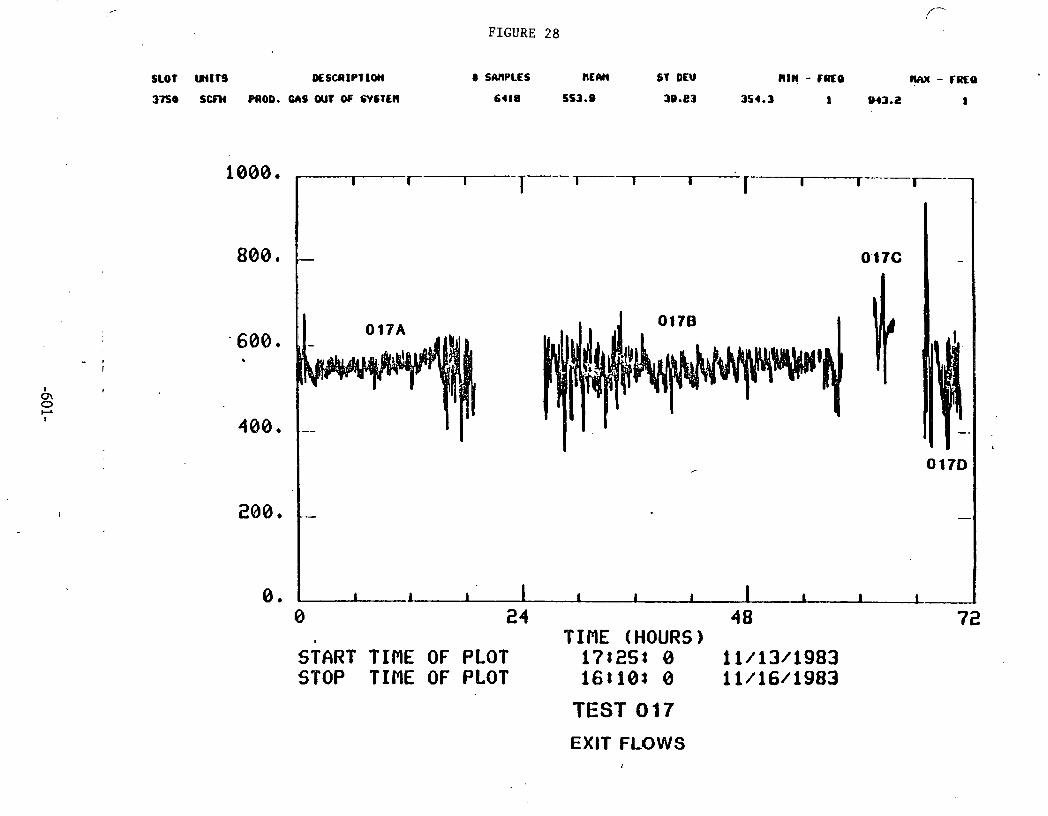
f--
FIGURE 28
SLOT WlfQ M S C A I P l ION 8 SARPLES hEIY( ST DEU MlM - Fa€@ rUuc - fR€Q
3750 s m MOD. GAS wt OF SYSTEM 6418 553.9 3 0 . ~ 3 354.3 I 943.2 I
0 24 48 72 I TIME (HOURS)
START TIME OF PLOT 178253 0 11/13/1983 STOP TINE OF PLOT 168103 0 11/16/1983
TEST 017
EXIT FLOWS

FIGURE 29
I 11111 1s DEECRIPT I ~ ) I I 0 S ~ ~ P L C S . n ~ n n ST' DEW R I M - FREO n.w - ruto
-.[ ,. -. ,-. - .- - -I-- , . ' .,.--,---[... - - - I.
, I ' 1 - . I
I I
. -
\ '. -
------ % .--- --- --- -,--- ---
..-. 1-.J ...- LJ--I--I--L.L.I [-..I .... I . - . I - - . I . . - I ~ . . . ~ - .. 1..-1-.I.... 1..-I ..A I t - -
cE 1 2 3 4 5 6 7 8 9 10 11 12 13 TIME (HOURS)
START TINE OF PLOT 17:40: 0 11/16/1983 STOP TIME OF PLOT 6: 0: 0 11/17/1983
TEST 0.18
REACTOR TEMF?ERATURES

, FIGURE 30
8 1 2 3 4 5 6; 7 8 9 18 l i 1 $ 3 .. TIME (HOURS)
START TIME OF PLOT 1?1401 8 li/fG/1983 STOP TInE OF PLOT 6: $ 8 0 11/17/1983
BEST 0'18

FIGURE 31
SLOT U I l T O OESCRIPtIO)( 8 SANPLES : HE AH 3 1 DEU nlll - FREO ~ R W - 0110
0 1 2 3 4 5 6 7 8 9 10 11 12 13 T IRE (HOURS)
START TINE OF PLOT 17t401 0 11/16/1983 STOP TINE OF PLOT : 6t 01 10 11/17/1983
TEST 018
STEAM AND AIR FLOWS

FIGURE 32
SLOT (114115 DE!XI?IPTION 8 S A W L E S llE AM 9 1 DEU RIM - FREQ ) ( r~( - rma 6 851 DCCF ADOSROCR 5 ' FRO11 80TTOll Cl 952 DECF AOSOROLR I S * FROR 8OtTOll 0 053 UEGF ABSORLER 2 s ' FROll 80110l l a 854 WGF A ~ S O R D L R 3s ' r R o n m o t t o n V 855 M.GF ABSORBER 45' FROM I O T I O l l
rrrrr-,- -r-'-rPTvr'PT -1 -I -l'-l-bTLf-T-l- r l - I - - l -1- 1 I I-r.
.-..
- .
OIOC
. . .
- -I-u-L-LLLI.I-I..~-Lu...I. ..LL L I . L U _ L J I . I - L - L ~ ~ - I I I L . 0 4 8 12 16 20 24 28 32 36 40 4 4
TIRE (HOURS) START TIRE OF PLOT ' 73158 0 11/17/1983 STOP TIME OF PLOT 233388 0 11/18/1983
TEST 019
REACTOR TEMPERATURES

FIGURE 33
SLOT UIITS OESCRIPTION 8 S ~ R P L E S RE AN ST DEU A I ~ - FNO W X - FALO
894 *UO nesoaBta DIFFERENCE PR€BSU)E es54 9 . ~ 7 5 4.m7 -27.17 I 91.71 I
8 4 8 12 16 20 24 28 32 36 40 44 TIME (HOURS)
START TINE OF PLOT 7:15: 8 11/17/1983 STOP TIME OF PLOT 2 3 : 3 8 t 8 lh/18/1983
TEST 019
REACTOR PRESSURE DROP

FIGURE 34
SLOT l N T = DESCRIPVXON I
07fib SWM PROD. GAS OW OF SVSTER
8 SAAQLES a I I N ST D€V RIM - FRCQ N I X - C I K 4
ETlS 570.0 4 0 . e 263.6 1 '195.8 1
8 4 8 12 16 20 24 28 32 36 48 44 T I f lE (WOUWS 1
START TINE OF PLQT ?ti58 8 11/67/1983 . STOP TIPIE OF PLOT 238368 8 %1L/f8/1983
j TEST 069
EXIT FLOW
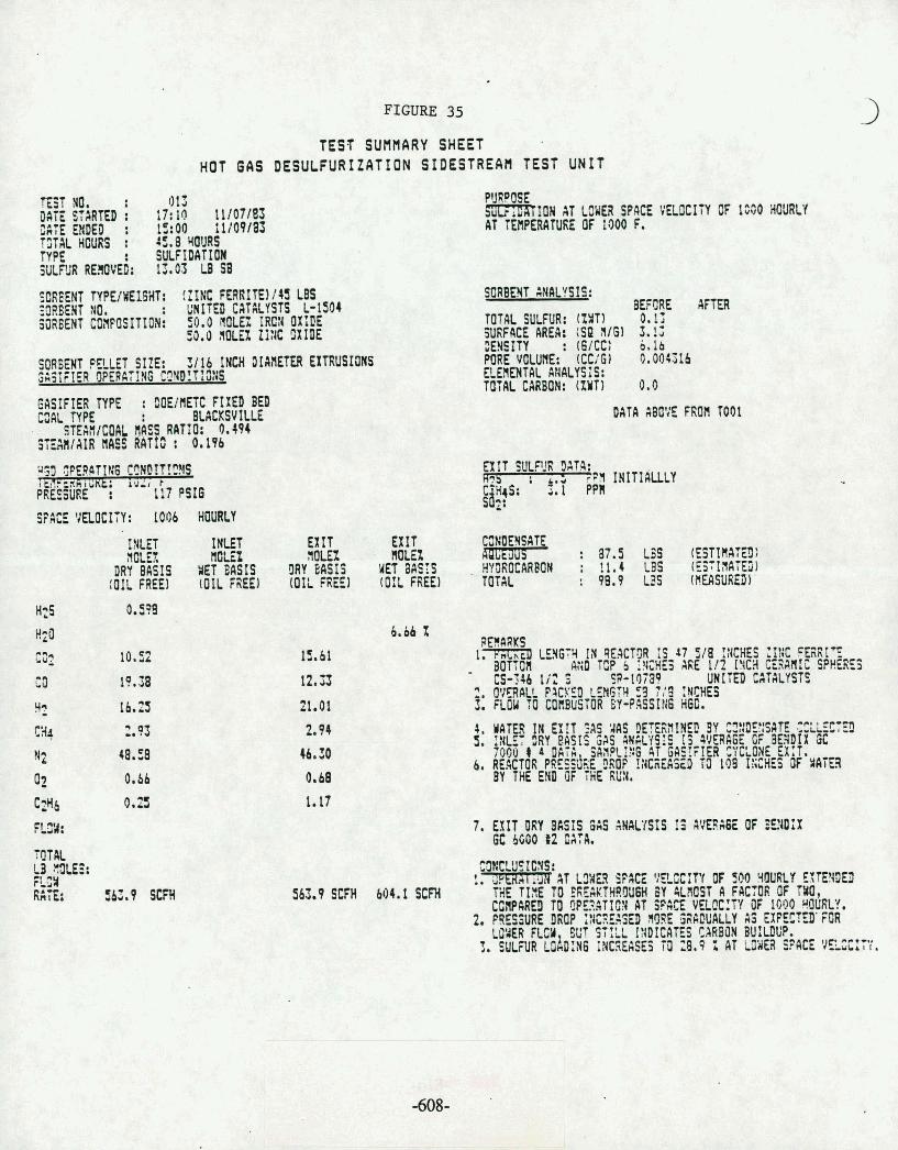
en -s C
O . u
E!%
en- g
y
*
szis 0 t;" M
U
We
n

FIGURE 36
TEST SUntlARY SHEET SIDESTREAH TEST UNIT
S W t E l T lYPVWEI6Wt: (ZINC %RITE!/:S IBS S3REE3T NO. : UICIZJ Cd73bYSTS b-!S14 3382E!lT C23POSI7;JN: 50.0 #REX IRCN OXIJE
50.0 IaEi ZINC OXIBE
I 4 l T I A L TEfVERATrJE: 1029 F
P4@8L?E : 78.3 I#C!iES @F UAmi IAV&qAGE)
STGX VELOCITY: 448 HOURLY
S f 1 1 SULF!! CATA:
%S : UP TO 3 z a t n i l RUH (BY e a c l r ~ x c~ SO2 : H I @ S07( ) 16 Z 1 IrOiTtALLY
o.a .I S ~ Z A T w !IF R E G ~ E ~ ~ A ~ I ~ &
I l E T EX1 t CC:ItE1YcftF 9m.n W L E KT BASIS DRY BASIS
m n r : 272.2 us HYEROCMBI : TOTAL : 272.2 U S
1z.e z S ~ D I X sc DATA :VLIIUBLE:
31.2 Z A t EXIT RERRUffi 1. ?%XED Ln6R :H CEXTQR I S 86 718 IK!iEf Z!A R W I T smyn an0 1 9 ~ b 11cii~l ARE 112 :m c m ~ : SP%~:E:
CS-Jb I/' S 3-107G9 D2t tn 6S:IKYSTS 2. muon r k a VRUX 0 . 3 9 CJBIC RUT Z. FIASi RESiNE3ATTON EM SU F IJEJ 5GEBMT 4. r m 2 : !+5 YIP ~ B Z O ~ ~ J EX!, rm s ; F, FS-
!NTD WE RES3ERATlGN AS ?5$&" %' k 3 8 1 l $ b3 I,. 5. NAXIillM TEYPERRTURE RUCHED U S 1699 f .
1. rZEimmllt1ON COIPLT1. 2. CX2@# APPEARS XI aE PJJB!lalSAS!F:8 Off I 1 3 : N tuS
FIRST 11 %OURS AS OBSERW BY CGZ C=!3AT!CN AT EX::.
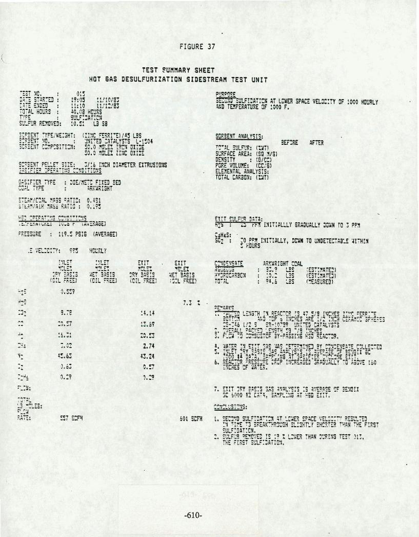
FIGURE 37
TEST fUllHARY SHeET HOT 6AS DESULFURIZATION SIDESTREAH TEST UNIT
SGRSEHT IWALYSIS: 3EERE
T9'AL X!B: (ZITI S2RFACE AREA: (SP 1/61 OElSITY : :EfC) PZE 'JOLW. (CCi61 . ELELNTAL ABALYSIS: TCTR CARBOII: (ZIT)
! XET I!!!-3 EXIT EXIT C-c A8KSRIGHT CC& , -7,v % L 2 ??!!EX 4XEz %El nr?ikuJ : ? ?es :b* wfl?W
i!?Y ?AS :$ ZE: 9AS13 :SY ?ASIS 2Ef 9%!S WvlE3C~S9CY : 3.2 US (EST!flAEJI [ O : L F " ~ ~ ) [!xLrna) i c ; ! . ~ ~ : :~:LREI T I ~ ~ ~ L -*I : or,& LES !=suR~)
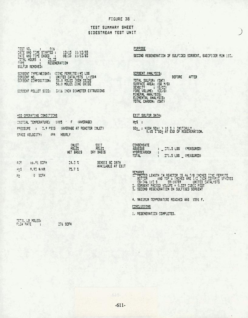
cr: e,
*- t-I
rd
-t: 2r
z
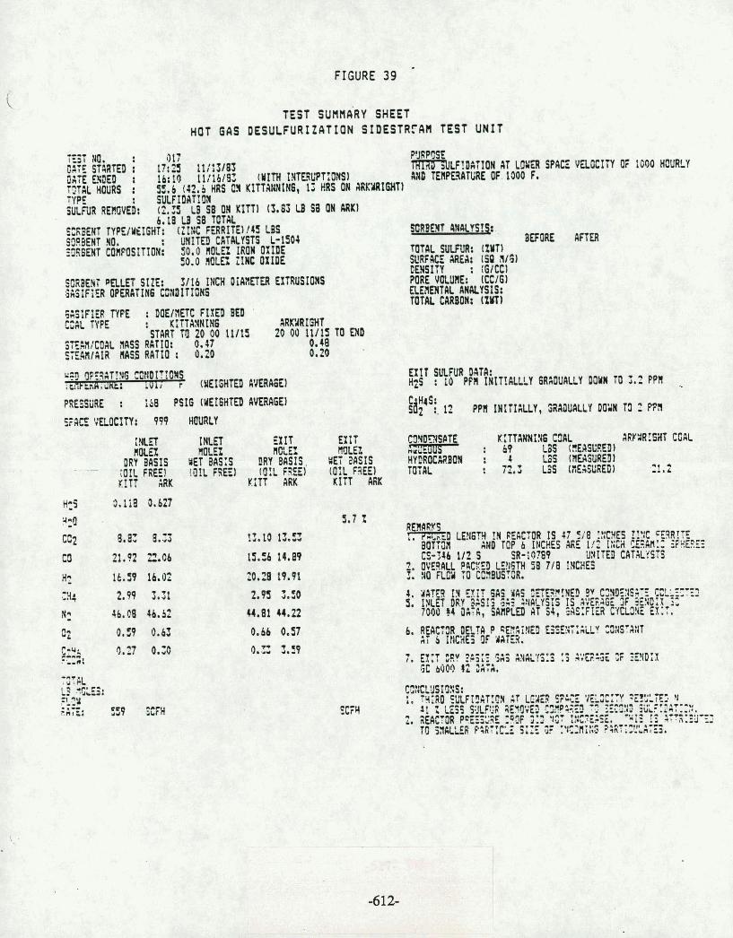
FIGURE 39
TEST sunnfi~y SHEET HOT 6AS DESULFURXZATXON SXDESTR?AH TEST UNIT
SCABENT PalET SIZE: 3 /16 INCW UiAAETER EXTRUSIONS GASIFIER OPERClrIN6 CilMITI[;NS
6 1 3 l F l E R W E : DOE/;IETC FIXED BED '
CCAL TYPE : K I T T A M I f f i ARKYRIGHT START Trl 20 0 0 11/13 2 0 0 0 11/15 TO EX0
SfE,H/MIAL flASS RATIO: 0.07 0.48 . SEMlAlR MSS RATIO : 0.20 0.20
QSIl YE3AT!fSO ma1r:ON xhla i ua: rui i f IXEIGHTEll fi1JERAGE)
PREfSiiRE : iS0 P S I 6 (WEIGH'IED AVERA6EI
:;ACE VELOCITY: 999 HOURLY
I N t n iw "OLE2
E X I T EX IT tlMR Ir OLE1 MLEZ
URY BASIS WET BAS;S DRY B~SIS WET awls - iOIL FREE1 !OR FREE) ( O I L FREE) (O IL F3EEI
K I T T ARK K fTT ARK K I T T MK
'#&Lf!lIATIOI AT LOia SPACE MO TEI IPEMTME OF. 1300 F e
g~solr 4~rrcrsrqt asoE
mnL SWUR: (XYT) Sl!RFKE ClRU: (SO A161 CENSITY : (61CC1 PURE VOLUME: ICC161 ELEf l rnTIK MdLYSIS: TOTAL CARBON: lznr
HOURLY
E X I T SL!fUR DATA: QS : 10 Pfn IMITILLLY GRA~UALLY uanm TO 3.2 P P ~
&' : . 1 PPI INITIALLY, S~A~IUALLY DO'IH 73 : en
C!lYIlrYSP K:TTANNIIIS C D L : 69 L3S (?!!WED1
ARY%R!GWT COAL Hkb- HYDROCMBOW : 1 LSS IIIWSURED) TOTAL : 72.3 U S (fiEmRED) 2 . 2
REI I IWS m t D LENGR !N PERCTOR I S 4 7 9 8 !!!BE5 !!;C fpq!E
BUTfOA AND TOP 6 INCKES AGE 1/2 I:1Cil CEdN.. aPlrEFIE3 CS-546 112 S SR-id709 Uf l ITU) C A T X t STS
9 1 1 V E I q PACEEO LL!tJITH '38 718 !NCHES 2: a nor TO ccsusroa. 0. #A? , [Y 5AS YkS XTR?!NEE 9v d!B5?lSal CCLLEZTf! 3. IN. Et DRY ZSSrS 5% VM-YSIS I S d';EhAG ,3F !i5D;813^,
7000 t 4 PL:k, SMPl.EIi AT W , $AS:FILR t t~ I .3k EX,,.
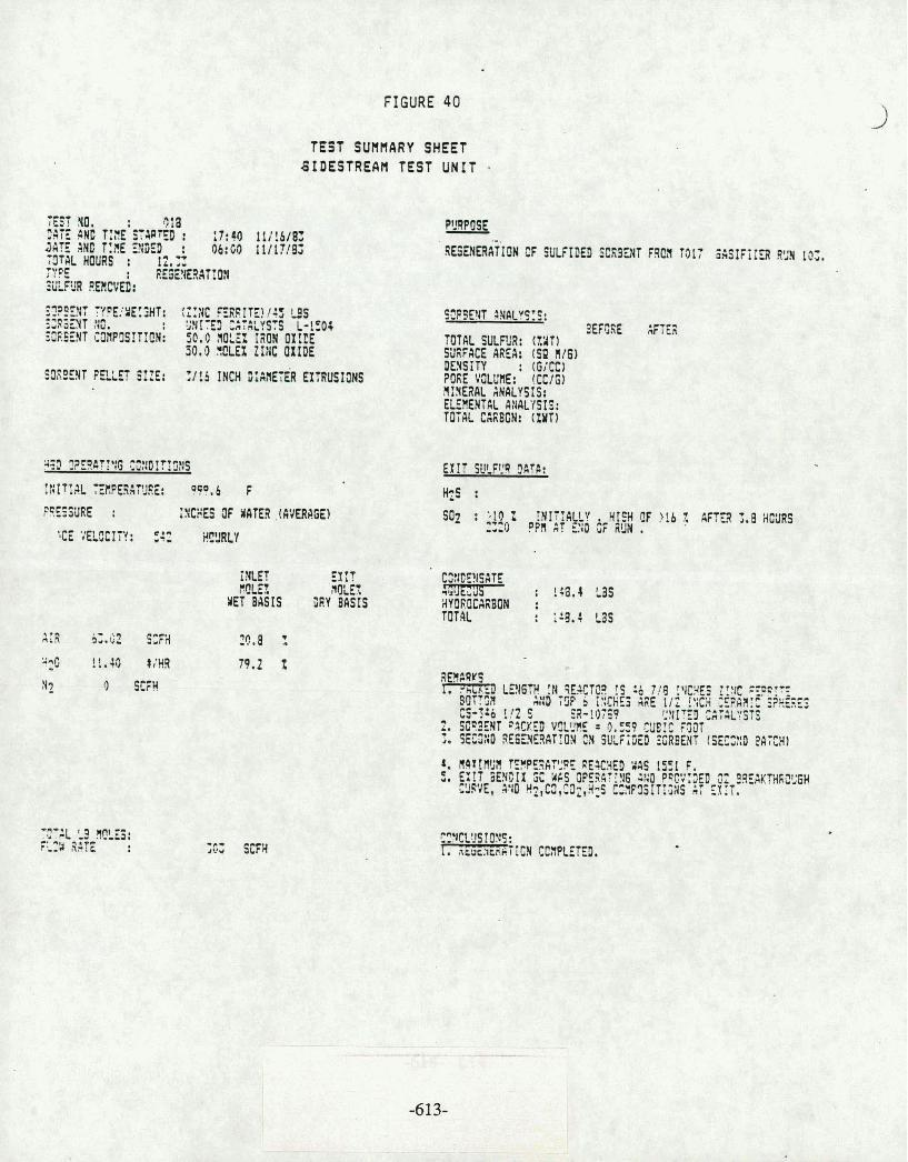
' Nfil 33 OtZ if Ydo (IZZZ SUMH 8': ElW Y 91i 3 HSIH i\ilU:?INi 2 61: : 20s : sq
WlYG Yi3iIlS 11x3
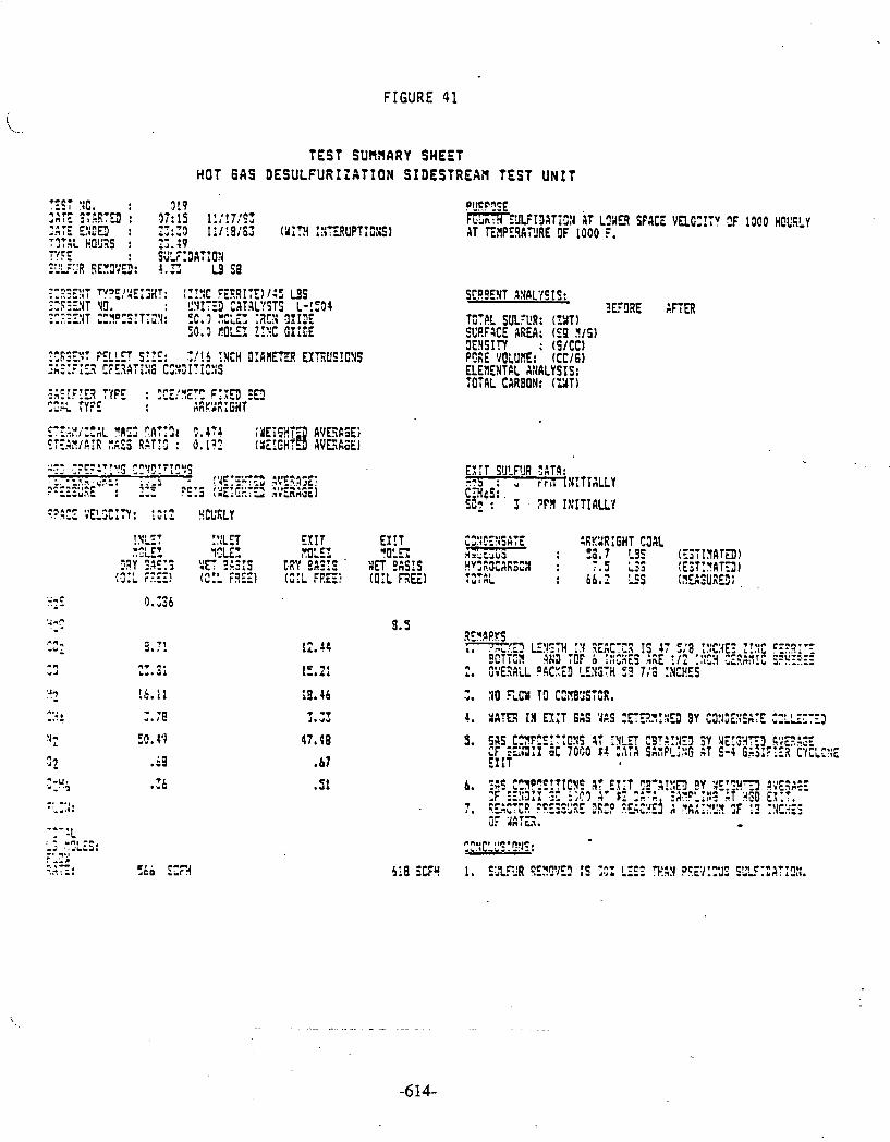
3:
L
8 c
e*8
-c7
. .. 1: Y:CI.
:j Z?.
T.. >. ... ..
a,- I.<
6
.a
.
pt
r.: i=
,*,<
-. ;".Lm
ow
. 7
:
CI.U
I J
c...r
k, .I k'
wn
LII
0.
* C
:8
,-..rc rC
c.
C
UlC
..LIl
z., -rs:
u.a
*:.r
-
11
1
l-
c~
ll
Il
C
.I'.lUI
01
6,:
c'l,4.,. .
m... ,7m
la: 13
C 1
-7 U
C-
CJ
III*..
cL
L,lC
J
V*
*r. .
XL
lrl l..
C*.C
.* L
C I3
-I
u u rc
x r
: - r
err
)-I-.
I, I., ,?
!i!
W ?z
f5 t- LL
.L' s
D
l.. %
- V)
&
e 'J
b - ul :-
m
r: C'J
U
0
C
A
U
L! 0
x
*?
C
V)
W
C
r
a
W
t- a
lI# b
WV
)
XW
V
) rn U
t In
a
a z
.1
0
x u
=3 C
m
.i
ra
C u
V
) u
w 3
C
lL
A 3
V)
W
0
VI
4:
Lo
C
0
x
* C
.1
r- r.. It-
c- - .Ill *-r
VO
,I.l L
98
(J
lc rn:
-.I-
JC
'ILL
x. <:-
-.*
:*
-J
n:. .
1.1 (11
-
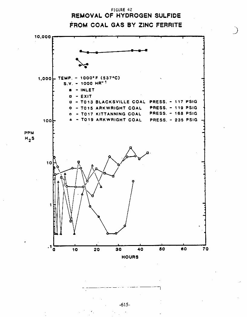
PPM
FIGURE 42
REMOVAL OF HYDROGEN SULFIDE FROM COAL GAS BY ZINC FERRITE
10,000
1,000
100
I I I I . a I
. - &
TEMP. - 1000°F (537OC) S .V . - 1000 HR-1
8 - INLET - 0 - EXIT - TO 1 3 BLACKSVILLE COAL PRESS. - 117 PSlG 0 - TO 15 ARK WRIGHT COAL PRESS. - 119 PSlG '
o - TO17 KITTANNING COAL PRESS. - 188 PSlG 6 - TO19 ARKWRIGHT COAL PRESS. - 235 PSlG 7
-
HOURS
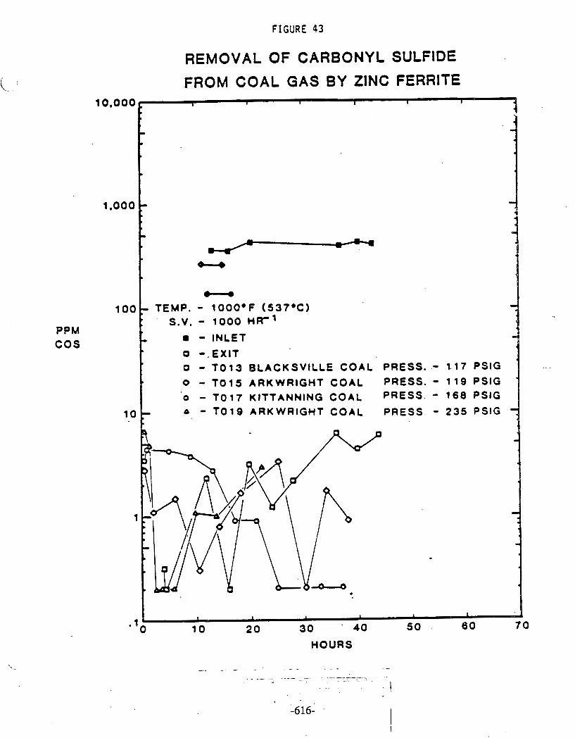
FIGURE 43
PPM C O S
REMOVAL OF CARBONYL SULFIDE
FROM COAL G A S BY ZINC FERRITE
S.V. - 1000 HR-
- INLET
0 - TO 1 3 BL.ACKSVILLE COAL PRESS. .- 1.1 7 PSlG .. .
0 - TO 1 5 ARKWRIGHT COAL PRESS. - 1 1 0 PSlG ' 0 - T o t 7 KITTANNING COAL PRESS. - 1 6 8 PSlG
- T O 1 9 ARKWRIGHT COAL PRESS. - 2 3 5 PSlG
.
HOURS
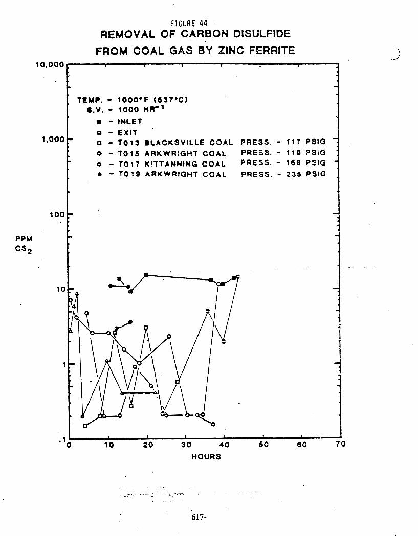
F IGURE 44 '
REMOVAL OF CARBON DlSULFlDE
FROM COAL GAS BY ZINC FERRITE
TEMP. - 1000 'F ( 6 3 t ° C ) 8 .V . - 1 0 0 0 HCT'
8 - INLET
0 - TO13 BLACKSVILLE COAL PRESS. - 717 PSI6 0 - f 0 15 A R K W R I G H T COAL PRESS. - 1 1 9 BSlG
0 - TO17 KITTANNING COAL PRESS- - 168 * S l G - TO19 A R K W R I Q H T COAL PRESS. - 235 PSlG
PPM
cs2 .. -- . .
HOURS

FIGURE 45
REMOVAL OF THIOPHENE
FROM COAL GAS BY ZINC FERRITE
TEMP. - 1000 . f (537.C) S.V. - 1 0 0 0 H r l
m - INLET
o - TO 13 BLACKSVILLE COAL PRESS. - 11 7 PSlG 0 - TO15 ARKWRIGHT COAL PRESS. - 119 BSlG 0 - 7 0 17 'KITTANNING COAL PRESS. - 168 PslG e - TO19 ARKWRIGHT COAL PRESS. - 2 3 5 PSlG
BPM
THIQPHENE
HOURS'

ZINC ' f EKRITE SUL FIDATION SIDESTREAM TESr 013
Temp = 1027 F (552 C)
Press - 1 17 PSlC
4 I S.V. = 1006 Hourly .

Figure 47 -
ZINC FERRITE SUL FlDATlON
z Temp - 1036 f (558 C)
Press = 120 PSIG
S.V. = 995 Hourly
4 = MTECTOR TUnE 1125
I3 = BASELINE GC H2S
0 = DETECTOR TUBE SO2
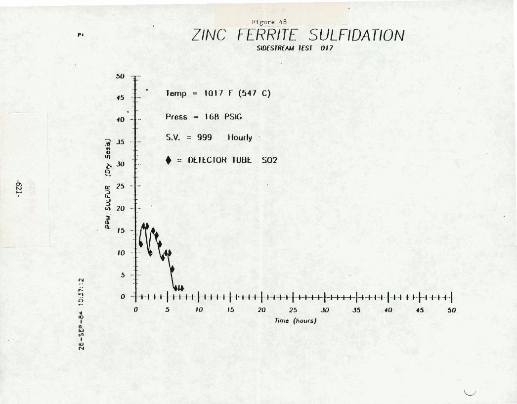
Figure 48
ZINC FERRITE SULFIDAUON
Press = 168 PSlG
S.V. = 999 Hourly . (D
8 6 - llErECTOR TUBE SO2

Figure 49
Temp - 1026 F (552 C)
Press = 235 PSlG
S.V. = 101 2 Hourly
= OETtCTOR TUBE M2S
Q = BASELINE CC H2S

ZINC FERRITE SULFlDATlON SIDESTREAM lfSr 013
T Temp = 1027 F (552 C) Press - 1 1 7 PSlC S.V. = 1006 tiourly
6 = BASELINE CC COS
13 = BASELINE CC H2S 1. = BASELINE CC SO2
5 t 0 15 20 25 JB 35 4 0 45 50
lime (hours)

ZINC FERRITE SUL FIDATION
Z P Temp - 1036 F (558 C)
Press = 120 PSIG
S.V. = 995 Hourly
I - BASELINE GC COS
0 = BASELINE CC SO2
0 5 10 t5 20 25 30 J5 10 I5 50
Erne (hours)

:I. S.V. = 999 I lowly -
0 5 10 15 20 25 JO 35 4 0 45 50 55 rime (hours)
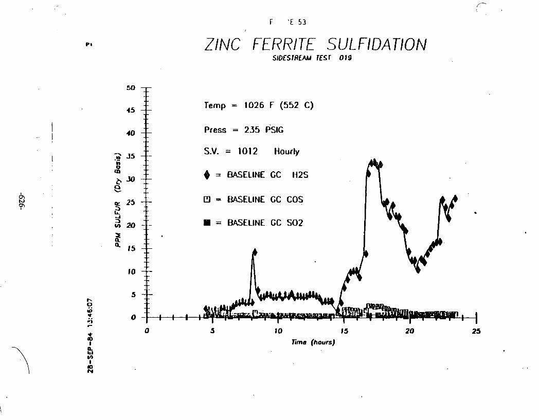
ZINC FERRITE SULFIDATION
45 f Temp = 1026 F (552 C)
40 Press = 235 PSIG
S.V. = 1012 Hourly
= BASELINE GC ti2S
D = W E L I N E CC COS
= BASELINE GC SO2
10 15
Time (hours)

FIGURE 54
SHlfT REACTION ON ZINC FERRITE SORBENT
.30
- 'I , HYDROGEN AT EXIT a3
Time (hours)

FIGURE 55
r SHIFT REACTION ON ZINC FERRITE SORBENT SID~STREAU Esr UNIT mr 017
CARBON DIOXIDE AT EXIT
CARBON DIOXIDE AT INLET 0

FIGURE 55
SHIFT REACTION ON ZINC FERRITE SORBENT SIOESTREAu 7ESf UNlT TEST 017
CARBON MONOXIDE AT INLEi
C'ARf3ON MONOXIDE AT €XI
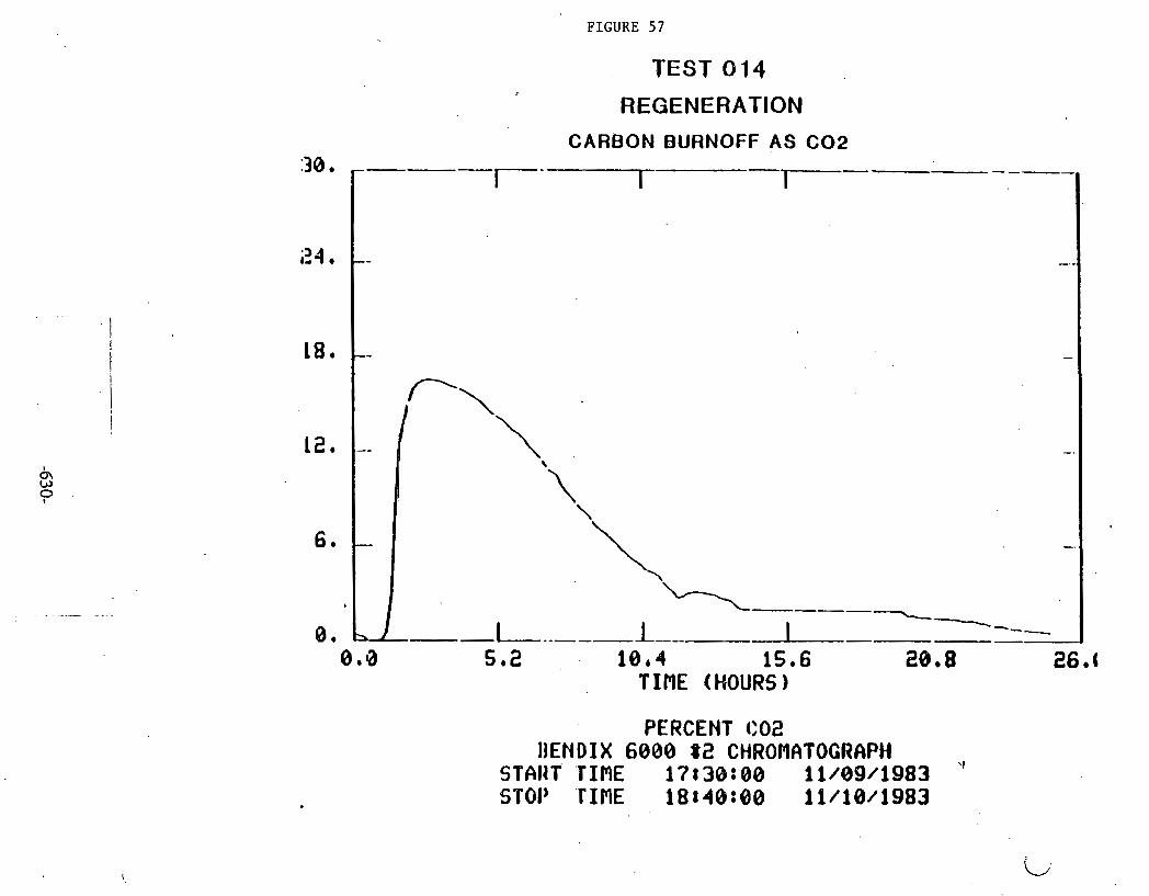
PERCENT C82 IIENDIX 6000 82 CHROMATOGRAPH
STAIIT 'TIME i7r3o:ao 11/09/1983 \I
STOP 'rInE i8t40:oo 1 1 1 1 ~ 1 9 8 3
FIGURE 57
TEST 014
REGENERATION
CARBON BURNOFF AS C 0 2

/- - FIGURE 58
TEST 014
REGENERATION H p S EFFLUENT
l o e $ 1Sb6 TINE (HQURS)
PERCENT W2S BENDIX 6808 $2 CHWOPIATQGRAPH
START TIME 17838888 61/83/1983 STOP TINE 1St488@8 11/18/1983

FIGURE 59
TEST 0 14
REGENERATION OXYGEN BREAKTHROUGH CURVE
5 2 10.4 15.6 20.8 TIBE (HOURS)
PERCENT 02 BENDIX 6888 $2 CWWOMATOGRAPH
S T ~ W T TIME 1?a3atoo 1 i /owi983 I
STOP TIME 1 8 ~ 4 6 8 8 8 16/18/1983

FIGURE 60
TEST 0.14
REGENERATION
CARBON BURNOFF AS CO
8.0 5.2 10e4 15.6 28.8 26e0 I. T IRE (HOURS) *
PERCENT CO BENDIX 6008 8% CiiRQi.IQTOGRfiPb!
START T Z I ~ E 17r3oe08 i 1 m ~ ~ i i 1 ~ 1 3 STOP TIME 18138088 11/18/18Q3

FIGURE 61
TEST 0 14
REGENERATION
HYDROGEN GENERATION
PERCENT ti2 BENDIX 6088 8% CHROPIAVOCRAPH
START T.I[ME 1'P838t@B f 1/09/1983 STOP . T I M E l.8840tOO Il./iO/i983

FIGURE 6 2
TEST 0 18
IREGENEIRATION
CARBON BURNOFF AS C 0 2
r - - I ----------- 1 7-- 7 1-- - -
---. - .---- - - - _ _ _ _ _ _
TIME (HOURS)
PERCENT CQ2 BEND I X k888 82 CHROPII~TOCHCIPH
START TIME 17140:08 11/16/1983 STOP T IDE 86rBQt88 t j . / l%/l983

FIGURE 63
f TEST 018 REGENERATION
H2S EFFLUENT
0 8 * 8 2 6 5 2 ? b 8 10,4 13 ,.G
T IME (HOURS)
PERCENT H2S BENDIX 6080 82 CHROMATOGRAPH
START TIME 17:40:88 i i / f6 /1983 STOP T IRE 06188:88 11/19/1983

FIGURE 64 TEST 0 18
REGENERATION
OXYGEN BREAKTHROUGH CURVE
0.0 5.2 7 * 8 10.4 TIRE (HOURS)
PERCENT 02 BENDIX 6000 82 CHROMATOGRAPH
START TIME 17:40N30 11./16/1983 soroP TIME 06:00:00 11./17/1983

FIGURE 65
REGENERATION
CARBON BURNOFF AS CO
TEST 018 I
0 . 0 5.2' 7.8 10e4 13.0 TIME (HOURS)
PERCEH" CO BENDIX 6000 #2 CHRONATOGRRPH
START TIME 17840;:00 11/16/1983 STOP TIME 06t@0::00 11/1'?/1983

FIGURE 66
TEST 0 18 I
REGENERATION
HYDROGEN GENERATION
PERCENT H2 BENDIX 6000 $2 CHROMATOGRAPH
Sal'4RT TImE 17140180 11/16/1983 s'rop TIME 06t80100 ii/i7./138:3

FIGURE 67
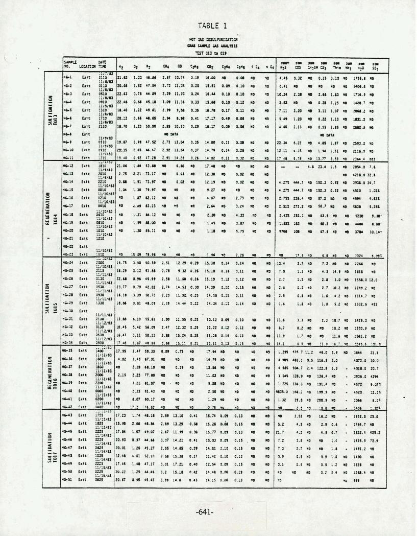
TABLE 1
M ;U u&uwuua~OI aauwuytuynu
i I
S u v U so. wuca rite
M C l L t t i::?U 1 1 l V U
-2 bit OI:O 11lUU
IcCl Lit %tU tw hit mio
I I I W U na.5 t :I10
11ia1u YH h t t 1710
11IWU -7 h t t 2110
YH Wt 11 l9 lU
we, tart ~ I O . l /WU
,ro t r t r ?*lo .1I9IU
-11 c ~ i t :212
* e I Z b t t ;;itU I X I 9 I U
* ~ t t h t t mxo 1 1 I V U
*eu (.it ZZIO l 1 l l W U
*+I5 9 % OOIO I l l l W U
hit 0210
Z 1 22 '"s
~ 0 ~ ~ 0 1 9
12 ot a: 31( CO CF*l C* 1 t n C 1
21.0 1.U U.Y 2.67 10.74 3.19 1 6 m 00 0.08 rO
m.u 1.1 r7.w 2.n 1 l . r 0.20 u.c~ o.a 0.10 m no O.U 1.78 u.n 2.n I1.n o.n 16.u 0.10 0.10 m r tt.w 0." 4s.u 1.m t1.r o.u tr.u o.ro o.u r m 16.U 1.tt ..a 2.. 9 , l 0.28 16.. 0.17 0.U m a m.u 0.64 U.U 2.m 1.18 0.41 17.17 0.88 0.06 m 18.70 1.a w.w 2.u 10.10 o.n 16-17 0.0s 0.06 m n
m p m 19.87 o.n r 7 . s 2.n 11.w 0.n 14.M 0.11 0.08 1 m w:ss o.u r.49 z.rz n.w 0.17 r4 .n 0.14 o.a I la
Y O a . 2 8 2 . 1 . 2 a . 14.02 0.11 a na n 21.86 1.M S3.U ff0 @.LO I 17.48 I I 10 D
2.n 2.21 n.17 no o.w m u.r m 0.w m le
0 . n 1.91 7a.w II 0.00 no 12.19 m 0.01 I IO
: 1 . 7 9 9 7 na w 1 9.27 m na na na
na 1.87e.12 w mo na 4.07 m r.n na no
Y ;= -
.
8 .I)
- b a 4 - =
3 3 33 =
5 - LI- ,= YIC
~ D S O m m a D # m ~ m 12s ens 3 r ~ i l CIZ -98 ry y so?
4.46 0.32 ID 0.1) 3.?O I L7SS.I RO
0.1 I m ma m ma ma.# no 1o.n 2 . r m 2.u 1.u n mc.9 r 3.9 r m o.zn 2.a n l a . ? no 1.11 1.I r 3.11 1.87 w zoaa.2 I
1.49 1.20 m 0.2~ I.U I 1~1.1 n &.as 2.u m 0.3s 1.n 1 2 u t . i m
m Pln
n.r 6.23 m 4.8s 1.17 na ~ 3 . 0 P
:z.u 4.3s m 1.w 1.51 r 2118.0 1
t t r a s . n s :l.n 2.u w 2 w . r m - - 4.8 0.4 1.5 a 20Y.0 7.6
m Ul8.O 12.8
r.zn UA.? m 1~2.3 o.n na ~ , r .oar .?
r . m u r . ~ n a ~ u . a o . t z n asto 1 . a ~
m . na rw 4 . u ~
Ip 4.u~ m.1, na ea a 2.m w 1.24 no n IN L - 3 1 u . u M 1 n 2.m RO 4.n m 1
I* 1-99 a.00 U 10 rU 1.4s 1 1.87 10 4
w 1.s 16.11 10 1 *O 1.18 n r.n e 4
w 1s.a 78.98 l o no *o :.a n 2.26 ma rn 1r.n 1.w w.s* 2.11 : z . a o . n u.10 0.14 0.14 n no 1.29 I . 2 . 9 . a o . z r 1s.10 0.16 0.11 no no
U.M 3.n r(.w 2.~8 11.10 0.21 1s.u 1.12 0.12 mo no
21.77 0 . m u . o 2-74 1 r . s J o . a 18.39 0.10 0.15 w r 16.18 r a 9 e . n 2.23 1 r . t t o . 2 ~ u .uo .11 0.11 no na
1 . o . z o . 1 r . a o . 1 2 0.14 n M
13.U 6.10 R.61 1.40 11.51 0.23 10.12 0.01 0.10 10 M
10.41 5.e sa.m 2.87 12.mo.n 1 r . n o . u 0.12 na mo 106.47 3.11lO.11 2.Y 15.ZbO.U IX.080.14 0.11 II M8
1 8 8 . 2 . S . 0 . 1 1311 1 2 . 1 n0 m0
1 . a om n m t7.w r mu n a . m 4 . 4 3 6 . 1 I I) 14.79IIO MO 10
no z.zrc8.10 no 0.19 n I na no rn 2.1 . a . w ma na 11.o m m w m 1 1.21 a1.47 no . ~0 n I . m 4 w n m 2.u a1.41 w 10 m 2.10 w r w I. a . O M . 7 o 18 M 1.nr n n na
80 z7.2 76.S 80 W W O.?bmE .O 10 . d ~ W
u.u 1.74 ~ . u 2.m ta.10 0.41 u.71 o.m o.u m m 15.r 2.w r8.w 2.m u.? o.a Lr.26 ~b o.rs a a
17.M 1.5119.07 1.171I.W 0.S tS.770.09 0.U lo ID
20.93 o.sr u.u 1.s Ir.21 0 . a 1s.e o . n 0.1, . n o m tD.Ot 1.26 M.27 2.8s I1.U 0.39 1 . 1 3.10 0 . 1 RE MO
U 0 1 1 2 . 1 % 0.37 11.4 0.10 0.11 Ro
17.4 1 . 7 . 1 1.1 7 . o w u.r o.m 0.1s mo a 20.12 l.29 u.a 1.2 1s.u P.u 14,u 0.m 0.11 no r o
2o.n 0 . s 1 s . 4 ~ 2 .n 11.8 0.41 u . 1 s o . m 0.13 n w
ll'o'U -17 L t t MI&
1 l l l W U -11 tact 0110
I l l l O l U W&I# bit M I 6
1:11wu MCZE ult LOW
I&/ bO1U n b 2 1 ts t t UtO
#2Z ts t t l t I l W U
M C Z ~ a ~ t t :st0 .., LW& ~ ~ 2 4 cart 2000
1:IIWU *CZI tstr 2111
1 : l t l l u leu Lair 0 3 0
1 1 I I I I U mc27 tact o u o
:Ii!IIu *z8 tact p m
.IltIIU *CO tltt 1130
*so cat* I I I I S I U
-11 h t r Z:R :Ir:ZlU
trct o~ao !1/:2/R
Hb33 b t t 0Sm 2 1 :2183
6 3 4 Crtt 1 0
*C:S cat* 7 . 111 1 2 I U
*CY (.It 1800 I:/ 12lQ
*n hit IMO IlIttlU
*elm h t t f FUl* *CJI ~ x r t LIOO
Mod0 I.** l1lIYU
- 2 t u UUI irt* O ~ O O
lIllUU M e r t Salt OlM
-3 trit iiiiUU IlItlW
rceu bit' 11s 1:IlU83
HWS t.tt !%4t.,
*W ta t1 0125 i:I14iU
M U ? t.(t OUS 1:IlbIU
H-8 I a t t 102s i 1 l l b l U
.erg rsct z a 5
mCw t ~ t t 3ifSlu l : i l $ l U
-11 tnt ous
z.su 273.2 m 1.7 n 1 sua s.m
z . m z s ~ . ~ m u . 9 m m US 8.m
1.m 1 U MO (0.1 R8 I cY) 8.W
tnr ra m a . m nw 10.1r.
m 1t . r no 6.1 n NO 3026 3-09:
13.4 r . 7 m 7 . ma z z r na 7.9 1 . 1 4 . 3 1 1 9 a w 2.1 1.5 an 2.8 1.0 ID 1134.012.0
2.1 o . a n z . 7 t o . z m 1 x n . z n a
2.5 o . a n 1.6 b . z w 111b.?na
1.6 1 . 8 s 1.0 s . 2 ~ r m . 6 r s ~
1.6 1. 2.1 10.7 10 1429.0 ma
8.7 0.2 na n 1 a . z ~ t m . s m
11.9 1 . 7 ~ 0 A I I . 6 c Q 1 P 1 . 2 ~ 0
14.1 0 9 W !I.* 16:W 22tS.b 131.8 , 1 . m c a r n . 2 c6.o 2.9 m rn n., 1 . 9 8 % U l . i 9 . S I l ~ . S 2 . 0 M2.0 30.0 I
4 . w m . 7 2.c 1tt.a1.a - r o u . o z o . ~
I . a . ID a . r . n u . 0 uw 1 . m nr.1 na 1n.r no . mz c.mc
~ 3 5 . 0 IU,Z 1 1u.9 I* . auo. :z.a% i.n n.rn m o . s r . wa 8.1%
2 1 I . . 1.01 ?.12%
I 1.~2 r 16.2 n - 1 m . r a.o
s.2 4.s na 2.9 0.6 . 1tu.7 m 21.7 4 . J I 4.90.7 1UZ.bWY.Z
7.2 1.m rn no 1.8 - i4a.9 7z.9
7.1 2.7 MO 10 1.8 - I m . 2 M0
0.9 0.9 *O 9 1 1 IO
0.5 0.9 .p o.s 1.2 n r t a u 1 na rm 0.2 9.9 w 11aa.4 r o
w ma 959 I* .
-.
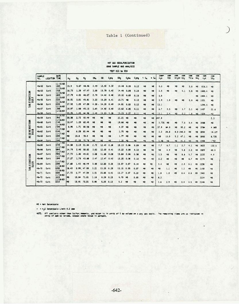
-
Table 1 (Continued)
nln g l r I I m D I O I m m a- t~- Laa7tm %a 9 + 9 ah a c* 9 w 1** q C * ns a '9 at "1. 1 n+ ul
-
LUIIIP * ~ l t f . 9 ~ 10s 1s.) ).a? 68.58 2.W I2.R 0.X U . 4 a . P Q.U u r* 0.1 110 ro ro 0.1 u 618.5 no
ui:stu *em g a i t ~ r n u.n 1.r 47.41 r.a 1s.n 0.42 14 .u o.m 0.16 rp a I . rg 0.1 0.1 no 1 m . r ID
I l i l l l U = YW Lit I8Zl I . 4 . 5 1 ~ 0 7 2.79 I . 0 tt.32 0.Q 0.15 no a . ~ 111IYU
d I W . 1 ID
b i t lils 18.01 3.01 8s.a 1.a 1s.zoo.n II.?I a 0.11 1 10 1.9 I., 0.9 I D l ~ I Y L ll11btU
s IYU b i t 022s I?.% I.W 4r.w 4.0). 14.3s 0 . b 14.81 0.03 0.12 10 a 13.1 111161U
1110.0 No
-87 bit 13oe 19.- 1.a 46.1s 3.m 14.n 0 . a 1a.u @.as 0.11 m RO 4.1 1.1 lo 1.7 1.1 no ~ r n 21.6 !It 1uu
' G I 8 ? x r t 1 . 4 1 9 . :3.21 0.07 0.11 ma n 1 1 1 2 . 4 wa a.2 ? a :szy
6 bit i . 2 1 . no u n t1.n r r u u trr.$ ltlluu
L.1
S re.u c.tc 2 : ~ 10.67 1 . ~ 9 u . 4 no w u 1 9 . n ~ r n . 1 a m r 7 . 0.4 n rn - am 15.8 78.0 na r r 1 . n r r r n w u.o 2 m n o a u 1.7n
NCU 111t ??is 1 4 . l t.tcs1.w 2.n 1 ~ . 4 1 0 . ~ IS.IJO.OI o.w r r 7.7 6.1 I . 1.7 4.1 I 112.5 .uvia
*HI t s o 080s 14-79 2.48 S9.U 3.U U.Q 0.41 1S.U 0.08 0.10 10 rg r e 4.9 rg S.1 1.0 no ZPO (0.9 I l i t 7 t U
-Q h i e two 8r.n 1.w r9.61 1.m 11.u 0 2 s 1s.m 0.w O.P D tto 1.1 m RO I.( 5.7 n~ zza r.9 s l l l l 7 i U ~na b t c rws r?.tt 1 . 4 4 l . U 1.41 u.Qo.Q 1 I . z s 0 . a 0.10 w ID 0.1 a w m 6.1 n z 1 7 4 w 1:i17iN
r ~ i t mo 11.11 1 . 4 J U . 4 9 1.m 12.8~ 0.35 1 s . n 0.07 0.10 no NO 5.4 no no t . ~ 6.1 m z z u u - 0 l l i1UIa S L I C ~ . b i t ~LOD 18.4) o.n. rr n 1.21 1a .s 0.15 1s.1~ 0.01 0.w a no w 1.1 a 1.1 ao m nw qo ur I l i l U U
NCII cSl t OLW 1r.n o.n 43.~9 1.1; t1 .a 0.4; ia.lr o.w 0.10 no w 1.8 1.0 *r 0.4 0.6 r :w w I l l l U U
t . 1 ~ ;am m I . n o a o s c . m r O.W a w 1.1 ::/18t0
2114 rn c ~ n b i t t n o a 18.n nnr o . r s.no.rr s.a a w r mo 2.4 2.1 lo a . a . w z w

HOT GAS DESULFURIZATION GRAB SAHPLE GAS ANALYSIS AT INLET
GASIFIER RUN 103 HAJOR COHPONENTS
*
;EST % SAflPLE DATE H ? 02 N2 CH4 CO C2Hg CJ2 C;H4 t j H 8 .iC4 nCq TYPE KO. TIRE VOWflE 2
FN 5 l i / g i . 3 iS.517 9.644 49.004 2.808 19.588 0.257 10.522 3.1ZO XO fLILFI- NO !4O

TABLE 3
HOT 6AS DESULFURIZATION GRAB SAMPLE 6AS ANALYSIS dT INLET
GASIFIER RUN TO3 . TRACE COMPONENTS
TEST 4 SAllPlE DATE "2s COS a 3 9 (32 Thio NHg TYPE no. TIE PPM
SULFI- FN 5 11/8/83 4528 358.9 7.9 13.1 2.9 ND O6:30-07:00
DATI ON FN 9 1 1/8/83 4329 3JO.O MD 9.2 N'D ND
-
SULFI- FN 59 11/11/83 395 1 2S9 6.1 11.0 19.0 ND ' 06: 15-07: 10
DATION . FN 72 11/11/83 1960 254.0 10.0 14.7 ND . lD I TO15 15:20-15: 40
SULFI- FN 100 11/14/83 2084 138.9 ND 3.0 4.7 ND 06: 10-06:55
DhTION FN 105 11/14/W 2133 137.7 ND 3.6 2 . 7 ND 09: 20-09: 55
TO17 FN 110 11/15/83 2161 135.7 NO 2.2 11.0 NO 06: 25-07: 10
FN 114 11/15/83 2036 122.2 NP ND 15.6 ND 09:4O-10: 15
FN 120 11/13/13 1754 135.8 ND 24 4 1.9 ND .12:30-13:OS
SULFI- FN 145 11/17/83 4898 621.5 . 1.7 18.0 6.9 t D 09: 25- 10: 00
DATIOll FN 150 11/18/83 4311 459.0 2.3 18.0 8.3 ND 019 15: 20- 16: 35
NOTES:
1. HO Not Detectable.

ca I
... .r
I 4-l
1&
1I
t.8
tr: I
..m I

Z
0
b4e
V)
e-'
w
a=
zz N
1 -
H
0
ac
a
3m
ew
L
W~
Q
AC
O
3
0
ml
le
w
w a
V)
OW
WW
a
cw

D--
w
az
z
N3
w
U
0
~X
B-
a
=~
tn
nw
YE';;" 3
U
V) x
t t?)
wd
tm
O
WW
W
am
-- V
)C
a
am
a
WW
W
C
J >
k
-
a
0 V
)
x
"'I 2
@;
r.! C
J

TABLE 7
H6b E X I T
HOT GAS DESULFURIZATION SIDESTREAH TEST UNIT
TEST 016 AVERAGE GC REODINGS
H2 C01 C:t!b H2S 2 ' 142 CHI CO TOTX A1'6 ?W A116 DTY AV6 C6 6 8TU N BTIJ --. --- ---- -- -- . - --- -- --- ----- ------ ------ --- ----

TABLE 8
HOT GAS DESULFURIZATION SIDESTREAH TEST UNIT
TEST 017A AVERAGE 6C READINGS
OUAATION
32 C3t C236 H2S C2. :I2 CHd CO T O T A L A V 6 I*rY SV6 DTY. AVG SE 6 9T'J :: B T U -- --- ---- W W " -- -. -- - ---- ---- ----- ---- ----- ----
H2 CfZ CCH6 HTS 02 I 2 CE4 C3 T 9 T k L A Y 6 JW A V 6 OTY A V 6 il 5 3TC N tTU 3 7 - - ---- --- -- - - -- .- -1-11 -9-2.-1 1--f-- ---- ----- ----
17.752 9.174 9-30? 0.205 0 . 7 3 41.5Z1 T.696 22.026 !32.31? 25.98 1.121 C,s67 175.37 !t0.70
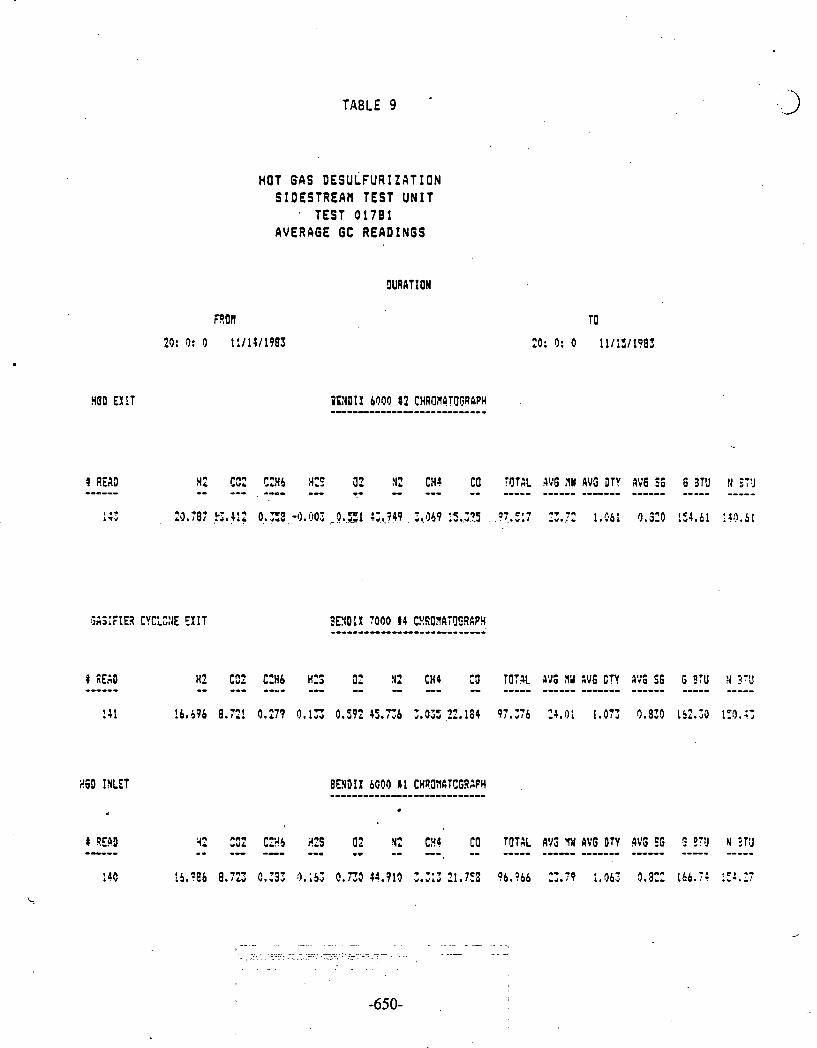
m
U J
h
M
C-I
E.>
-
4
1,
1. 7
0
- rr X
i3 U I -?
4-l -. c.
1.2
r.2 1. ' 0
* '3
r-4
r-
w
Q
w
c..
4
-..
r4
0-
XI
e
ST-.
I 7
-r

TABLE 10 -
HGD E X I T
HOT GAS DESULFURIZATION SIDESTREAM TEST UNIT
TEST 01792 AVERAGE GC READINGS
OURATION
3r12IF:Eil CYCLEXE E X I T
I RE:M H2 (02 CZHC 3 3 0'1 N2 tH4 C3 TJTdL P I G i4W AV6 DTY AYS 56 S STU N bTU ------ -- --- ---- --- - - -** - ,2--- ----* +*---- ----- ----- ----- 47 lb.364 8.331 0.;01 0.6C8 9.00'1 45.373 : .Z9 22.2E4 97.a93 24.19 :.081 0 . 9 3 167.99 LSa.?r!
P * H2 J; C:H6 H2S fit N2 ~ H J Cg ?[lT:L A!16 1'1 A75 DTY PvS 56 5 9TU :! ETU -- -- --- -- -- - -- - ---- ---- ---- ---..-- ---- -----
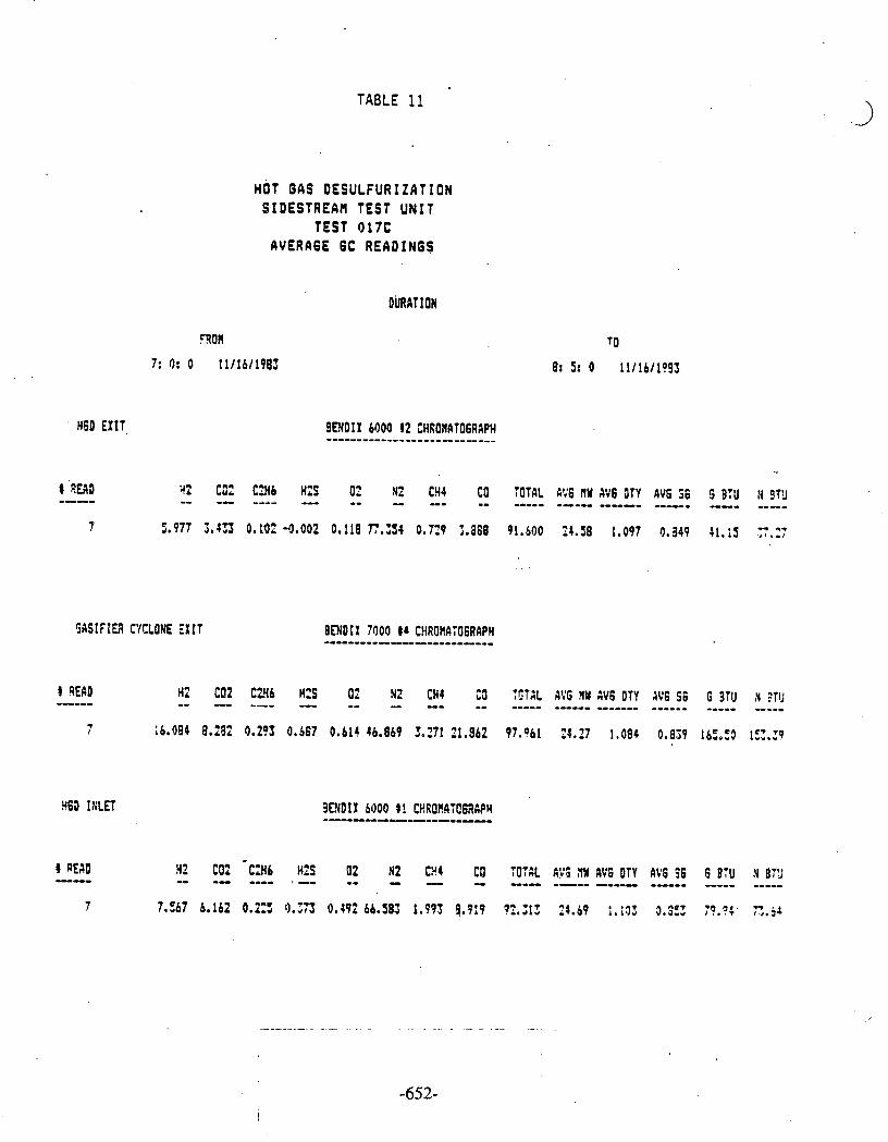


TABLE. 13
HOT 6AS DESULFURIZATION SIDESTREAH TEST UNIT
TEST 018 AVERAGE GC READINGS
9I;RAT ION
EGO EXIT BENUIX boo0 12 CURfll!flTOGRflPY
8 !m - H? - m ' - u 4 U - - TOTAL 4VG !lY 4'16 OTY AV8 56 - G blU 4ETJ
58 .8.609 10.191 9.129 9.6;8 1.722 67.172 0.0T9 0 . 3 1 88.335 24.40 1.091. 0.845 Z6.05 31.18
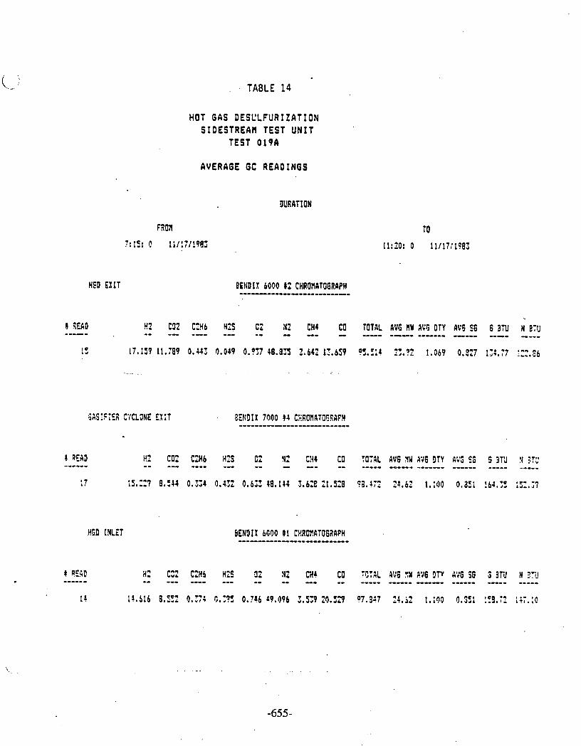
TABLE 14
HOT GAS DESCLFURIZATION SIDESTREAP! TEST UNIT
TEST 0 19A
AVERAGE GC READINGS
BEIIDIX 6000 11 CHROHATOGRAPH -----------------------
H6D INLET
Fl C02 C=Hb H25 C2 N2 3 4 CO f O 3 L dV6 YW s76 D f r I%'; 56 S 3T'J !I 37:' -- -- ---- -- -- - -- -- ----- -0--- ------- ------ ----- -----

tJ
I
.O
*-
I
I..
t.1 I
- I -
x
I
-3'
CD
I
C1
r
n I
o
w I -
r* I
n
c3
I
rJ
C
JI
P
?
C-I
I
0
X I
t.7
m

TABLE 16
HSD EXIT
# REAG
HOT GAS DESULFURIZATION SIDESTREAH TEST UNIT
TEST 019C
AVERAGE GC READINGS
DURATION
2 COZ C2H6 H2S 02 N2 CHI CO TOT41 A V 6 nW AVG DTv A V 6 S6 6 BTU M 213 -- --- ---- --- -- - --- -- ----- -I-- ------ ------ ---- ----
HSD IXLET
Hz CQ C 3 b i(ZS C2 :C tH: CO :S?gL A:'G ?W 4:'G DTY A:'0 EB G 3TC ;4 ??; -- -- ---- -- - -- -- ----- ----- ------ ------ -I- --- 12.779 5.433 0.Z: 11.:1: 0.?25 46.824 3 . 2 2 19.3;0 06.S54 22.78 1.0:8 0.781 1C6.C6 !35.:3

TABLE 17
ANALYSIS OF HINERALS BY X-RAY DIFFRACTION IN SULFIDED ZINC FERRITE
GASIFIER RUN 103
FRANKLINITE ZnFe~04
BED OR HEIGHT HQATITE IIAGNETITE ZINCIX ALPHA BETA PYRROHOTITE CENEYTITE
(INCHES) Fez03 fefl4(41 In0 , ZnS ZnS FeS FezC
PERCENT TI1 (3)
r)(ll So 9 6.8 12.8 37.3 9.2 - 6 23.7 6.9 18.6 33. 4 11.7 1.7
16 l?,6 15.9 21.0 . 21.9 9 . 4 13.3 ?? 2.8 52.9 6.5 2.5 ' - 3 . 2 26 - 55.0 i0 .S (0. S- - -e . h . O 36 - 64.8 - 9.4 - 34.8 46(2) - 62.7 - 1.1 - 36.2
FRESH SCRBEtT I. 89. 6.0 - - - -
tc0;is: (1) Bottoo/Inlat . (2) T~p /Ou t l a t . (3) Psrcant 111 = Pwcent Total ln teqra ted In tens i ty ; O i rec t l y propor t iana l t o the
concentrat ion o f the c r y s t i l l i n e phrse. Arorphous phase is not accounted lo r . ( 4 ) F r a n k l i n i t e and l l r qne t i t e have the same c r y s t a l s t ruc tu re and, therefore, cannot
be r e a d i l y dist inguished by the d i f f r a c t i o n pattern.

- TABLE i8 1
SORBENT ANALYSIS OF SULFIDED ZINC FERRITE
GASIFIER RUN 103 TEST 019
BET Crush 3ed Total Total Surface Skeletal Strength Skeletal
Height Carbon Sulfur Area Density Porosity (Kg DWL) 2 Density Porosity (Inches) ( X Wt) :PI Wt) (sq M / G ) (G/cc)~ % ( 4 ) S.D. (5) (c/cc)~ % (7)
3 6 5.06 0 .28
3 5 4 5 4.22 6.66 7.39 1 .020 .5
& 4 ( L ! 6. :2 0.61 6.21 74.6
Fresh 0 0.13 3.13 6.16 2.59 6.32 2.8 - 60.6(8)
Sorbent
NOTES :
Bottom/Inlet during sulfidation - Outlet during regeneration. Top/Outlet during sulfidation - Inlet during regenerati.on. Skeletal Density by Helium Pycnometry. Porosity by Nitrogen Adsorption for pores up to 600a diameter. Average and standard deviation of 15 measurements. Skeletal density by mercury porosimelry. Porosity by mercury porosimetry for pores down to 120a diameter. Porosicy by m e r c u r y pocosimetry for P O ~ C S down to 30L diamer,sr.

PARTICULATE SARPLING DATA HOT GAS DESULFURIZATION TEST UNIT
GASIFIER R U N 10s
t
TEST HOURS PARTICLE LOADI:i6 . flEIIAN PARTICLE CHER I CAL ANALYSIS I FRON SIZE
START OF g / ~ a z pa (aicronsl C H .Y S ASH TEST MT t
INLET EX I T INLET E l I T
91; !b.6HRS 2.12 21.3 81.1 3.8 2.4 9.1 4.4 01: ?1,1 HRS 1 . 3 14.5 47.9 4.0 :.s Nn 10.2 rl!J 42.5 HRS 9.44P I?. 1 73.0 4.9 4 . 3 Y!l 3.3 O!s . 18.5HRS i .52 26 Ib 79.1 1.4 i . 7 ? , 3 7 . 5 015 15.6 HRS 0 ,381 21.6 72.4 1 .8 2.8 NR
.- 7 . 3
011 -16.6 HRS 2.01 L .a .;I , - 75.9. 4.6 . S . Z . 1!.9 2.J fli? 27.7 HRS 0 . 3 1 5. Z 75.5 2.1 1.4 1.1 r2 .9
YOTES: !In= j o t 3ea;ured due to insufficient s a a p l ~ size.

lIri fE : 12..'2,..':33 SQMPLE: HGCIS Bkl;t.lELL E 1 1 181 83-5157 ELEIITF.I:~LY TE : I S0TUt.l L~:tbiilR D D I SPEE:5QNT : LOMkR D EQIJ I PbIEEII: Tn I I QPERTUfiE5 : 148 OFERGTOR : BAGS **-*- " " .. .
. .. . .. " " .. .. .. .. .. .. . .. .. .. .. . .. .. .. .. ..'.. . . . * * t + ~ + + * ~ * ? r * r * ~ % * ? f % % ~ R ~ i ~
CH.I) .SIZE DIFF 9:1~11 UOL ' / ; I)OL :.
**+*+****3++*9*if3+++*+j:**3*f*;~**i;9****
TABLE 20
PARTICULATE SIZE DISTRIBUTION
TEST 0 13 INLET
+++++*+*++++++*++*+$*++$*+++**+*+**++** VOLUME >: STUT I ST I CS
*x3+f*,+33**f**+*++**a*f9*3**+*******iC**

[~HTE : 12 ....'2... '83 SCIMPLE : HGD GHGIIELL fill1 182 83-953 OLECTfiOLY TE: ISOTOM D I SPEESQt4T: LOHFtRD EQIJ I PElEtlT: TRI I UPERTURES: 140 OPEEnTOR: BUGS 1H*******+*****iC9******3d~+++++*** . . . . . . CH.O SIZE ClIFF C?lN
lJ0L ;: ~!I:IL 2 +*+***+-++***G*d*+******+****+*+**+** ... I
TABLE 21
PARTJCULATE SIZE DISTRIBUTION
TEST 013 E X I T
21 .1 HOURS FROM START OF TEST
t1Eiit.l: 13.42 IJH t1ED IilTJEI: 14.47 UM HI~DE : 22.24 IJtl STlrrIlOliEO DE!IIQTIOH: 2 .2 IJM SKEklt4ESS: .93 N E ~ T I UE KUETOSIS: 2.35 PLQTYKURT I C

l j l i l ~ l 1'?-31J-:j3 snl IFL. E I 83-954 EI.ECTP,OL'~'TEI I SOTOIll 1 U I SPEIISf\I I'C'r LO1 In? U
. EI:!IIIPIYII~I Tn' I I IIFEfl ICRESI '290 OFERn TlnR I JI!. E f t f f t f f f f f f t t f * f f * * f f t t t t f * * f t ? ! t i t S f f & .CIk. W S IZE n.1 FF I::I~II
VDL :: VOL :: t f ~ f * ~ t ~ t E t E t f f t f f * * * * * * t f * t f # * ~ f f E f I I f t * 9
I.
1 4 8 1813 2 5.84 1 . :3 l'obj
; 3 6.35 2.6 98.2 4 8 4 915.6
C 3 1B.08 5.9 91 .E; 6 . 12.7 9.1 . 55.7
' 7 16 12.4 76.6 , 8 20.16 12.7 64.2
TAULE 22
PARTICULATE SIZE DISTRIBUTION
TEST 0 1 5 INLET +-+*+****++***+**++++:,:::+**+***+-**++*+* -- + .....
VOLUME 2 STHT I ST I CS **f+***9~**H*******++*M*9**********
MEilEI : 24.67 Utl EIED I GEI: 25.37 UH NODE : 30.15 UH STnEIOGRD CEU I QT IOEI: 3-84 UH SKEIJtIESS: -97 NEWT IVE KURTOSIS: 1.43 PLflTVKURTIC
. . . . . . I : ; - + - , , 1 1 8 1 I I I . - . ! : : L O . 2
S I Z E Ill UP1
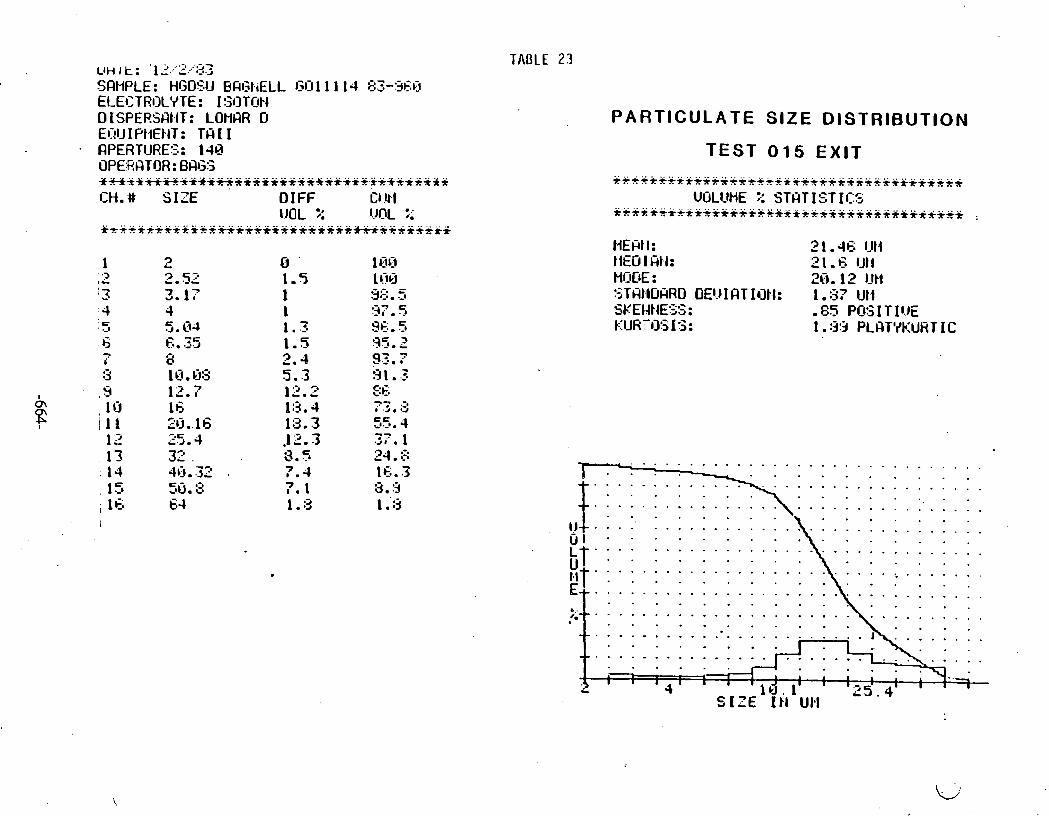
,J" t : ' 1 .' ..'. '" ..;a> 7 -. b' '-'.A
SQMPLE: HGDSIJ ba13kiELL I;I]l 1 1 14 E:3-:3c;Q ELECTROLYTE : I!;OTON 0 I SPERSClt.IT: LOHClR U EC!U I Pt.1EkIT: TIS I I RPERTURES: 148 OPE,RQTOR: BM;S *M**H***+**+=*****+**+***+,5++**++** . . . . . . C H . # SIZE OIFF Cl !rl
lJOL 5 !JnL ;; * *+*********+***************w*****.. . " " . . . . . . . . . . . " .... ... B r T
'-. ' 3 4 5 .-a
6 - i
3 9 , I 0 ill 12
( 1 3 3 14
E 1 -2 , 16
TABLE 23
PARTICULATE SIZE DISTRIBUTION
TEST 015 E X I T
t1EFt.I: 2 1 .46 Ut.1 t IED I cTtl.4: 21 .G IJti HOD€ : 20. 12 lJt1 STHhlOHRO DE1.J I CIT IOEI: 1 -87 UI.1 SKEI4EIESS: -85 PCG I T IUE KIJR-135 IS: 1 .:3:5 PLnTYk:LlRT I C
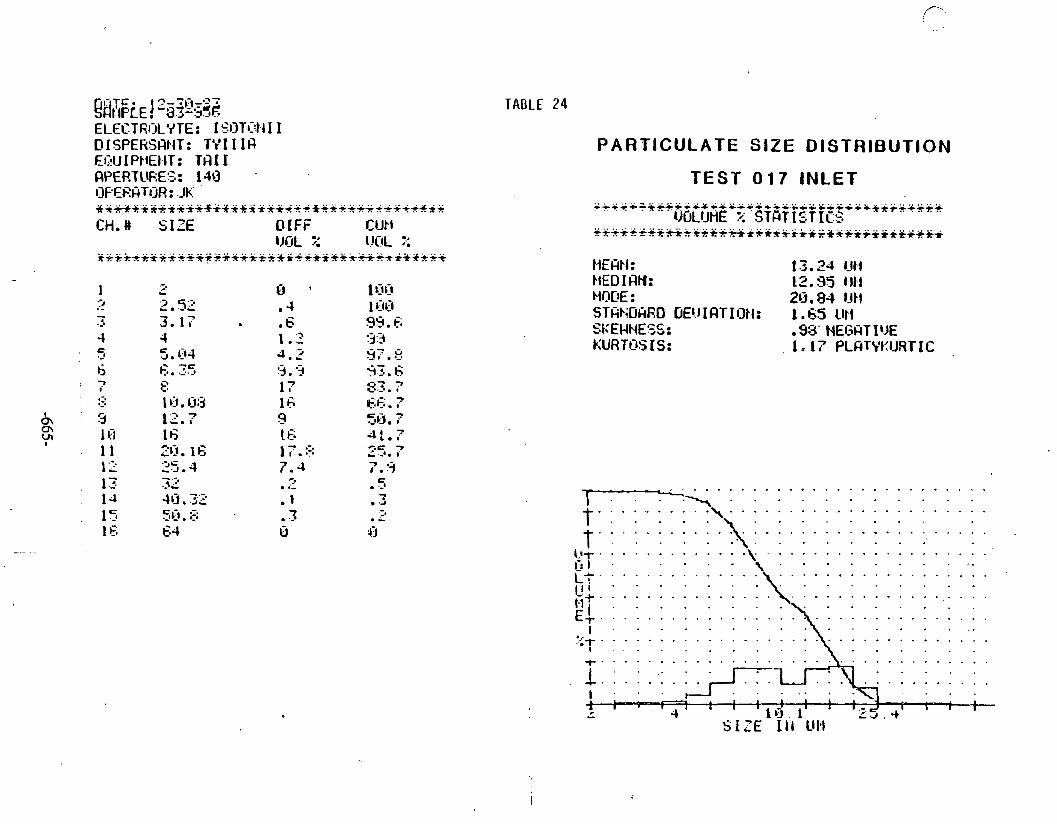
TABLE 24
ELECTEI:ILY TE: I SO TI:^^^ 1 I D ISPERSGIEIT : TY I I I fl EQU I PbEt,IT : Tfl I I QPERTURES: 140 . OFE,I?1iTOR: .Jli.' *+****++*+*+4*+**++++.*+*+-+++-+++++*
CH.# SIZE OlFF Cut1 M L :: I.JClL :.:
+ + + k + + * Q + + f + 3 + + + + ~ t + + & + + + ~ + f + % + ~ i * 3 + p +
PARTICULATE SIZE DISTRIBUTION
TEST 0 1 7 INLET
. . . . . . . . . I... . . . . . . . . . . . ...t.. "
. . . . . . . . . . . . . . . . t . ' . . ' . . . . . . . . . . . . . . . . . . .
. . . . . . . . . . . . . I.:.: ::. 3-
. . . . ! ; : . 1 1 ' 1
1 1 . 1 , .
C 1 1 1 1
1 - 1 I l l d , l l 1 I.-. ~ 5 . 4 SIZE It4 UI.1
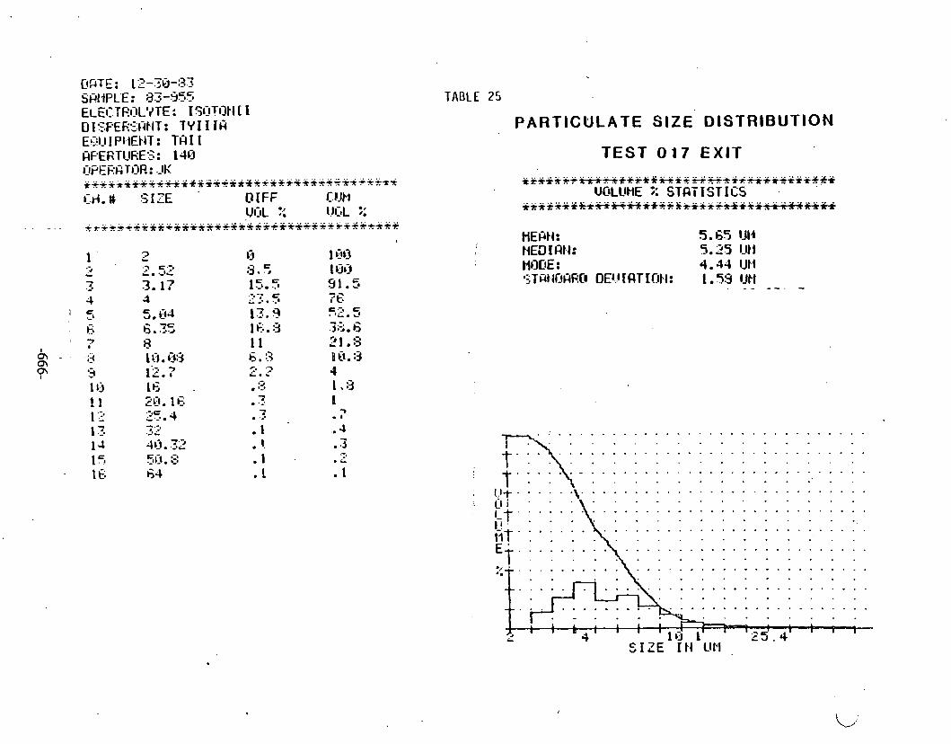
L I ~ T E : 12-313-:33 SfiiiPLE: 83-555 ELEI:.TEI?L'~TE: 15r:iTOEI [ I DISF'ERZH-TIEIT: T Y I I I f i E!,il_l I Pl.lEflT : TQ I 1 HPERTURES: 1-40 UPERGTOR : JK **++****+**+**+ ,x**++*++++*+++*++*fr3 ::
~ r ( . # SIZE 0 IFF C.UJht C)CIL 7.: ~JI:,L ;:
. . . . . . +r+*++*++++***+++*+*+++*+Y+-Q++++++++*+ !
TABLE 25
PARTICULATE S I Z E DISTRIBUTION
TEST 0 1 7 EXIT
. . . . . . . . . . . . . . . . . . . . . . . . . . . . . . . . . . . . . . . . .
. . . . . . . . . . . . . . . . . . .
. . . . . . . . . . . . . . . . . . .
. . . . . . . . . . . . . . . . . . .
. . . . . . . . . . . . . . . . . . .
. . . . . . . . . . . . . . . . . . .
. . . . . . . . . . . . . . . . . . .
. . . . . . . . . . . . . . . . . . . . .
I 2 5 . 4 ' ' ' S I Z E I t l UP1
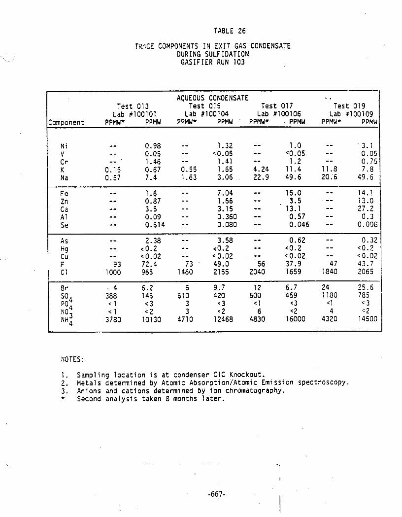
TABLE 26
TI1:;CE CaMPONENTS IN EX I T GAS CONDENSATE DURING SULFIDATION
GASIFIER RUN 103
AQUEOUS CONOENSATE - . Test 013 Test 015 Test 017 Test 019
Lab #100101 Lab #I00104 Lab #I00106 Lab 5100109 Component PPMW* PPMW PPMW* PPMW ' PPMW* . PPMW PPMW* PPMW
NOTES :
1. Sampling l o c a t i o n i s a t condenser C1C Knockout. 2 . Metals determined by Atomic Abso rp t i on~Atomic Emission spectroscopy. 3. Anions and c a t i o n s determined by I on chromatography. * Second ana lys i s taken 8 months l a t e r .
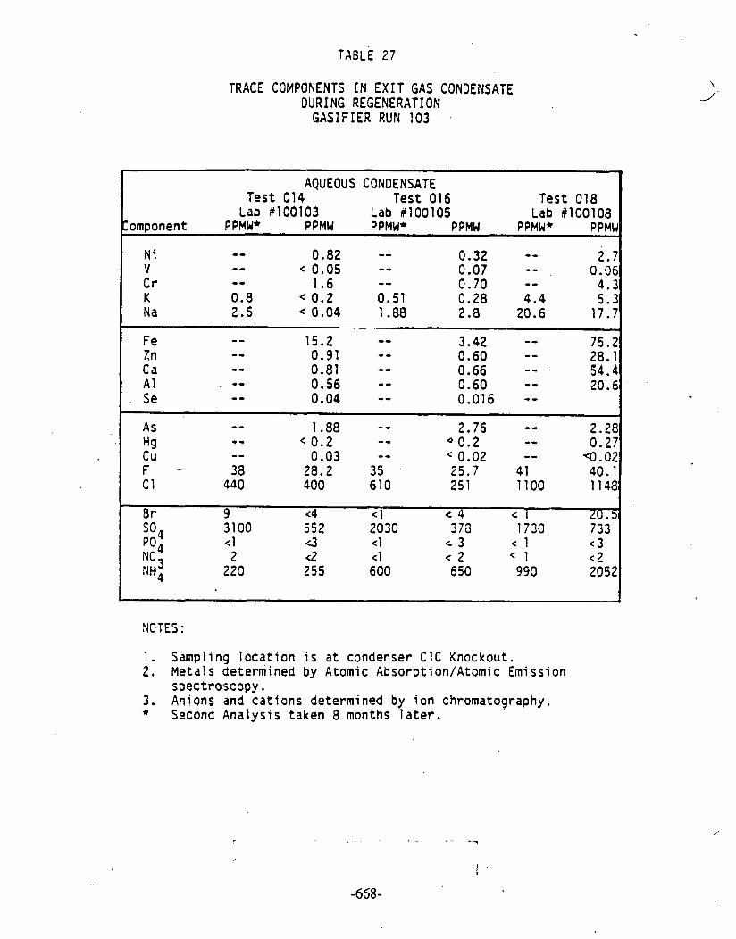
TABLE 27
TRACE COMPONENTS IN EXIT GAS CONDENSATE DURING REGENERATION
GASIFIER RUN 103 .
NOTES :
-
1. Sampling l oca t i on i s a t condenser C1C Knockout. 2, Metals determined by Atomic Absorption/Atomic Emission
spectroscopy. 3 . Anions and cat ions determined by i o n chromatography. * Second Analysis taken 8 months l a t e r .
AQUEOUS CONDENSATE Test 014 Test 016 Test 018
Lab #I00103 Lab #lOOlOS Lab 13100108 Component PPMW* P PMW PPMW* PPMW PPMW* PPMW
N i - - 0.82 - - 0.32 - - - - 2.7 V < 0.05 - - 0.07 - - 0.06 C r -- 1.6 - - 0.70 - - 4.3 K 0.8 < 0.2 0.51 0.28 4 . 4 5.3 Na 2.6 < 0.04 1.88 2.8 20.6 17.7
F e - - 15.2 -- 3.42 -- 75.2 Zn - - 0.91 - - 0.60 - - 28.1 Ca - - 0.81 -- 0.66 -- . - - 54.4 A1 0.56 - - 0.60 - - 20.6
. Se - o 0.04 - - 0.016 -- As - - 1.88 - - 2.76 - - 2.28 H g . - c 0.2 - - 0.2 - - 0.27 C u - - 0.03 - - 0.02 - - q . 0 2 F - 3 8 28.2 35 25.7 4 1 40.1 C 1 440 400 610 25 1 1100 1148
8 r 9 <4 < 1 e 4 c 1 20.5 3100 552 2030 378 1730 733 < 1 3 < 1 c 3 c 1 < 3 2 <2 < 1 < 2 < 1 < 2
220 255 600 650 990 2052
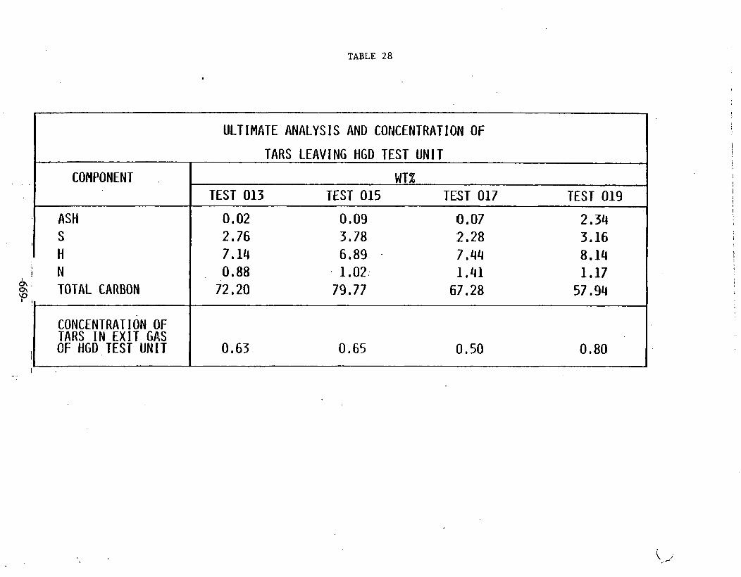
TABLE 28
I
I ULTIMATE ANALYS 1 S AND COliCENTRAT I ON OF
TARS LEAVING HGD TEST UNl T I
.. .. . I COHPOMENT I WT% I I TEST 013 TEST 015 TFST 017 TEST 019
I
ASH S
I H 0.88 1.02; 1.41 1.17
72.20 79 . 77 67.28 57.94
0.63 0.65 0.50 0.80
I N & , 0\
'?' ; TOTAL CARBON
I --
' i
CONCENTRAT I ON OF TARS I N EX IT GAS OF HGD . TEST UNIT

- - - TABLE 29
TAR ULTIMATE ANALYSIS AT HOT GAS DESULFURIZATION INLET
I 1 TEST # SAMPLE DATE ASH S H T.C. N I TYPE # TIHE WT. X I i I Test 013 28344 11 109183 0.25 1.15 7.46 65.63 1.14 ( Sulfidation 0500 I
I
Test 017 28346 . 11/14/83 0.40 0.94 8.07 58.76 1.33 Sulfidation 0500
Test 017 28355" 11/14/83 - 0.77 7.29 74.29 2.19
I sulfidariOn 2 100
I
l~est 019 28349 1 1 / 18/83 0.11 1.23 7.00 76.13 1.32 lsulfidation 0330
. . - . - .. . .
[Test 619 28358* 11/18/83 0.14 1.38 6.37 83.79 2.04 ~Sulfidation 2100
* Limited sample available, sample ran on microsystem.
1. 'Sampling location is S-4 after gasifier cyclone 2. Sample No. 28340 obtained during operation on Airblown Blacksville coal. 3. Sample No. 28346 and 28355 obtained during operation on Airblown
Kittanning coal. 4. Sample No. 28348, 28349 and 28358 obtained during operation on Air-blovn
Arkwright coal.
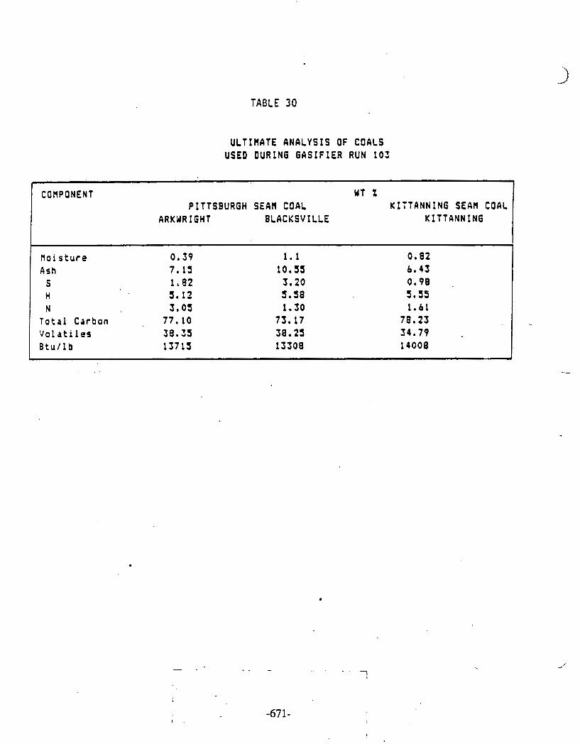
TABLE 30
ULTIflATE A N A L Y S I S OF C O A L S U S E D D U R I N G G A S I F I E R R U N 103
,
C O H P O N E N T W T Z P I T T S B U R G H S E A M C O A L K I T T A N N I N G S E A M C O A L
ARKWR I G H T B L A C K S V I L L E K I T P A N N I N G
tloi sture 0.39 1 .1 0 .82
Ash 7 .15 10.55 6.43 S 1 .02 3 - 2 0 0 .98 . H 5.12 5.58 5.35 N 3 .05 1.30 1.61
Total Carbon 77.10 73.17 78.29 V o l a t i l e s 3 8 . 3 3 38.25 34.79 B t u l l b 13715 13508 14008

TABLE 31
TRACE COMFONENIS IN INLET AND EXIT GAS ACUEOUS CONDENSATE DURING SULFIDATION GASIFIER RUN 3103
1. .4queous condensate data obtained fran HGD i n l e t and o u t l e t part iculate sampling s y s t e m .
2. NS indicates that the canpnent was not measured.
I TEST# I 013 0 13
OUTLFT
11/08/83 1315 137 Min
100304 -11-8-2 -
LOCATION
DATE TIME CURATION
LAB# SFMPLE # ----
INLEr
1: ,/08/83 09 50 160 Min
100303 GI-11-8-1 -
0 13
OUTLFT
11/09/83 1140 145 Min
100305 -11-9-3
~~ --- N i V a K Na -- Fe Zn Ca A1 Se
2
As Hg Cu F Cl
015
INLET
1/11/83 1325 150 Min
100309 GI-11-11-5
PPMW
0.056 0.099 1.32
PPMW
0.14 <O. 05 2.3 0.80 6.1
14.1 <O. 1 4.5 0.19 0.103
-
3.22 <O. 2 0.041
142
PH'lw
0.04 <O. 05 0.10
PPMW
3.8 <O. 05 0.12 3.31
12.2 - 2.8 93.2 8.7 <O. 02 0.004
0.30 0.78 0.151 17
8414
015
afiLET
11/11/83 1040 120 Min
100308 GO-11-11-4 - --
13 < 2
700 < 3
13196
0.82 3.7 - 2.2 17.2 3.3
<O. 02 <O. 005 - 0.07 <O. 2 (0.02 24
96 5
<4 <2
495 < 3
11959
PPMW
0.23 <0.05 3.0
I?!+- Br
017
I!'UT
11/14/83 1005 115 Min
100310 GI-11-14-7 - .
PPMW
1.7 <0.05 0.37
NO3 SO4 Po4 NH4
1.2 0.18 - 5.4
<O. 1 15.8 0.94 0.636 -- 1.66
<O. 2 <O. 02 5 3
2012
26 < 2
470 <3
13402
< 2 465
< 3 7916 --
4.4 1 2.63 8.2 - 4.0 19.8 9.0 0.50 0.005 -- 0.25 <O. 2 NS NS NS - - - NS NS NS NS NS
11.5
20.32 <O. 1 11.96 0.136 0.285 --- 1.66
<O. 2 NS NS NS
NS NS NS NS NS
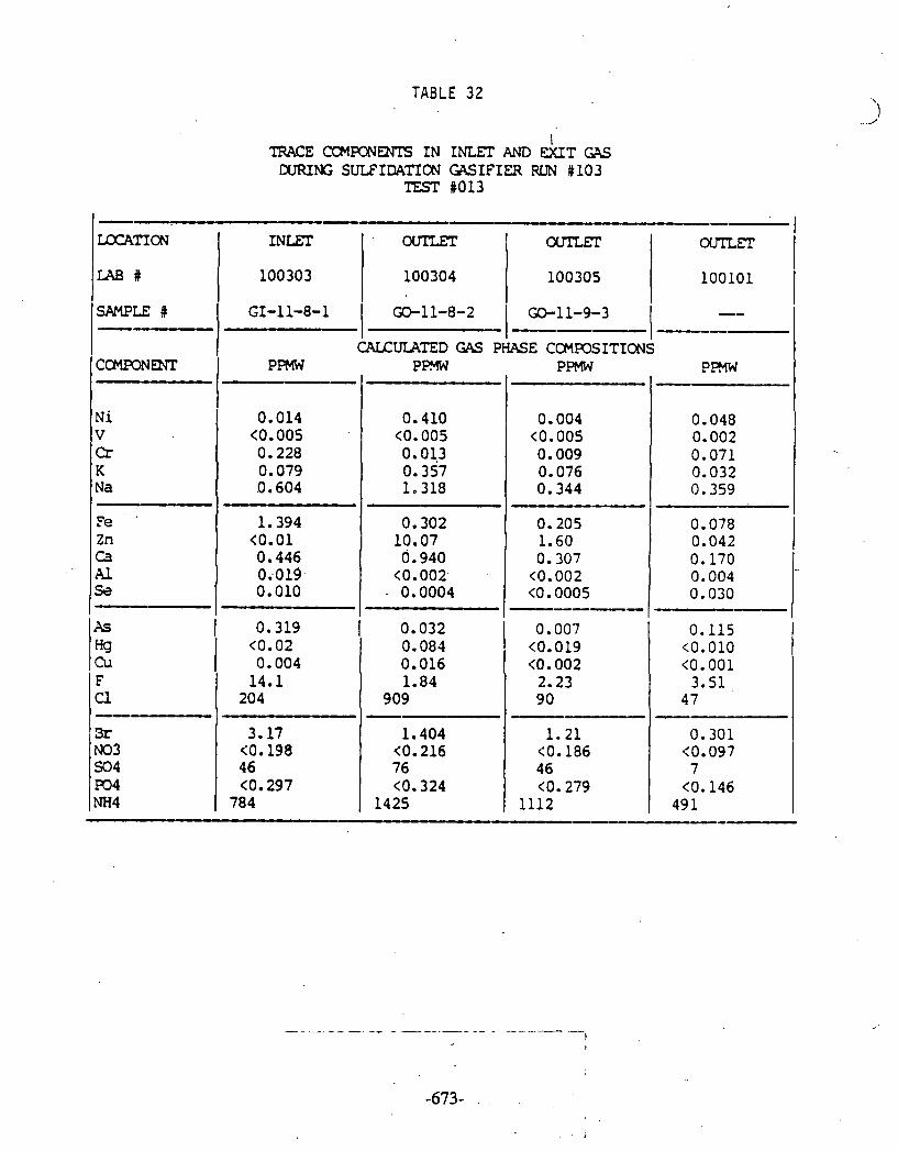
TABLE 32
I TRACE CCMPONENTS IN INLEI' AND EXlT GAS
CURING SULFIDATICCJ GlSIFIER RUN #lo3 TEST R013
- LXX'ATICN
SFMPLE # GI-11-8-1 -- -- I I GO-11-8-2 1 --- CALCULATED GAS PHASE CCMPOSITICNS
INLET
PPMW CLXIRliiKT 1 -- P W
N i V Cr K Na
Fe '
Zn Ca l4.l S
I
PPMW P m
0.410 <O. 005 0.01.3 0.357 1.318
0.302 10.07 0.940
<O. 002- - 0.0004
0.014 <O. 005 0.228 0.079 0.604
1.394 <O. 01 0.446 OiO19. 0.010
LAB#
OUTLET ' OUTLEL' OLPIZFT
0.004 <O. 005 0.009 0.076 0.344 - 0.205 1.60 0.307 <0.002 <0.0005 -----
Xs I 0.319 1 0.032
100303
- 0.048 0.002 0.071 0.032 0.359
0.078 0.042 0.170 0.004
I 0.030
0.007 <0.019 <O. 002 2.23 90
1.21 <O. 186 4 6 <O. 279
1112
0.115 I <0.010 <0.001 3.51
47 - 0.301 <O. 097 7
<O. 146 49 1
0.084 0.016 1.84
909 - 1.404 (0.216 76 <O. 324
1425
@ <O. 02 Cu. 1 0.004 F U --- 3r NO3 SO4 #>4 NH4
100101 I 100304
14.1 20 4
3.17 <O. 198 46 <O. 297
784
100305

TABLE 33
TRACE CWIPCNENTS IN INLET AND EXIT GAS CURING SULFIDATION GASIFIER RON 1103
TEST #015
LXATICCJ
LAB 4
SAMPLE #
NS indicates t ha t the mponent was not measured.
GI-11-11-5 I -1 1-1 1-4 I - I - -
. CALCULATED GAS PHASE aFC5ITION
I PPMW P M PPMW
0.075 .
<O. 003 0.080 0.093. 0.173
. 0.398. 0.094
. 0.178 0.020 0.005
0.202 <0.011 <O.OOl 2.77
1,22
0.548 <O. 11 2 4 (0.17 704
I 0.022 <O. 005
1 0.288 , 0.115 0.017 -
I 0.518 <0.01 1.517 0.090 0.061
0.159 <O. 019 <0.002 5.1
193
2.5 <O. 19 4 5 (0.29
1287
0.054 <O. 002 .O. 012 0.141 0.262
0.128 -. ..
0.634 0.288 0.016 0.0002
0.008 <0.006 NS NS NS
NS NS NS NS
I NS

TABLE 34
TRACE C C k I ~ ~ IN INLET AND EXIT CFS DURING SULE'IDATION GASIFIER RUN #lo3
TEST %017
NS indicates that the canponent was not measured.
-i I_--
CALCULATED G1S PHASE CCMFOSITION I-rn - .I PPMW PPMW -
0.043 <o. 002 0.052 0.490 2.133
_U---s-
0.645 : o * 151 .
0.563 0.025 0.002 - 0.027
<O. 009 <O. 001
1.63 7 1
- - .. - . - - - ... - - - -. -- .- - .- -
0.288 <O. 086 19.7 <O. 129
688
'
.
.- I Ni 0.003 V Cr K Na . - Fe Zn . Ca Al Se
AS RJ Cu P
C1 - -
B r NO3 SO4 Po4 NH4
-
0.005 0.061 0.121 0.529
--U_U_-U_
0..935 . - . <oeoo5 -. . . .
0.550 0.006 0.013 -- 0.076
<O. 009 NS NS .
NS - - -
NS NS NS NS NS
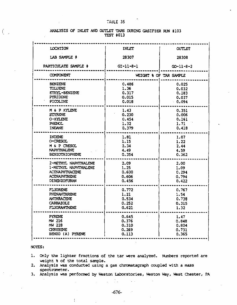
ANALYSIS OF INLET AND OUIUZ TARS DURING GASIFIER FClN #lo3 TEST #013
............................................................................. LQCATICN I INLET I ourUT 1
P m C U I A T E SAMPLE # ------------------------------. C m m N r n ............................... BENZENE rnLUENE EIXYL-BEXZDJE PYFUDINE PICOLINE
IAB SAMPLE #
------------------------------. M & P X Y L D E S m m E 0 -xYLENE PHENOL INDANE ------------------------------. INDENE 0-CRESOL M h P CRESOL NAP- B m Z m I O P m -----------------------------.- 2-MF[HYL N A P W E 1-MRHYL NAPKIHMBJE ACWHTHACENE ACENAPKIHENE DIBDIZOFURAN
28 307 I 28308 I
~ - - ~ - - - - - - - -
FLUORENE P-E ANT[HRACm CARBAZOLE FLUORANTHENE --.---------------------------- PYRmE MW 216 MW 228 CHRYSENE BEN20 ( A ) PYRENE
=...--------..-----------------
NOTES:
GI-1.1-8-1 I GO-11-8-2 -----------------------I--------------------- WEIQn % OF TAR SAMPLE
1. Only the l ighter fractions o f the tar were analyzed. Numbers reported are weight % of the to ta l sample.
2. Analysis was conducted using a gas chromatagraph coupled with a mass spectruneter.
3. Analysis was performed by Weston Laboratories, Weston Way, W s t Chester, P.4
----------------ow-----
0.486 1.36 0-317 0.015 0.018
------I--------------
0.025 0.032 0.183 0.037 0.094

Sidestream Tes t ina - G a s i f i e r Run 104
Hot Gas Desu l fu r i za t ion Sidestream Test Unit, Fixed-Bed G a s i f i e r Run No. 104
In t roduc t ion
The high-temperature, s ides t ream d e s u l f u r i z a t i o n u n i t (1 ,2 ,3 ) was opera ted f o r a f o u r t h and f i n a l s e r i e s of tests dur ing fixed-bed g a s i f i e r Run No. 104 (4 ,5 ,6) between December 8 and 13.
I n t h e s e t e s t s t h e main o b j e c t i v e was t o i n v e s t i g a t e t h e d e s u l f u r i z a t i o n of l i g n i t e gas..
Overation of Sidestream Test Unit
With a s i n g l e ba tch of t h e same zinc f e r r i t e sorbent used i n a l l t h e previous t e s t s , t h e u n i t was operated f o r two s u l f i d a t i o n per iods with an in tervening regenera t ion , The gagigier was operated i n t h e air-blown mode, being fed with North Dakota l i g n i t e dur ing t h e f i r s t s u l f i d a t i o n and Arkwright coa l dur ing t h e second. The opera t iona l schedule i s shown i n Figure 1.
The r e a c t o r was f i l l e d with t h e usual 20.4 kg of sorbent ex t rus ions . Furnace temperatures were s e t a t l,OOO°F f o r t h e f i r s t s u l f i d a t i o n and 1,200°F f o r t h e second. I n both cases t h e nominal space v e l o c i t y was 2,000 h-'. For t h e regenera t ion t h e furnace temperatures were s e t a t t h e usual l,OOO°F and nominal space v e l o c i t y was 500 h-'.
Average opera t ing parameters f o r t h e t e s t s a r e shown on t h e ADACS flow sche- matics i n Figures 2 t o 7 . Test No. 020 i s separa ted i n t o four on-stream p a r t s because of gas supply i n t e r r u p t i o n s .
I n Test No. 020, with t h e g a s i f i e r providing gas from l i g n i t e a t 160 t o 200 ps ig , breakthrough of hydrogen s u l f i d e occurred a f t e r about 45 hours on-stream t ime. The H,S l e v e l was genera l ly l e s s than 5 ppm. Reactor pres- s u r e drop increased only s l i g h t l y from about 0.15 t o 0.5 p s i . There was an inc rease of r e a c t o r temperatures approaching 100°F. Reactor temperatures, p ressu re drop, and gas flow r a t e a r e shown i n Figures 8, 9, and 10.
In t h e regenera t ion Test No. 021, t h e s t eamla i r r a t i o , i n i t i a l l y 85/15, was decreased stepwise during t h e f i r s t few hours t o 80120 i n o rde r t o achieve r e a c t i o n zone temperatures of about 1,500°F. The r e a c t o r p ressu re drop was very low throughout, about 0.15 p s i . Reactor temperatures, pressure drop, and flow r a t e s a r e shown i n Figures 11, 12, and 13.
Test No. 022, l a s t i n g about 16 hours, was t h e f i n a l s u l f i d a t i o n of t h e t e s t s e r i e s . I n t h i s case, with t h e g a s i f i e r providing gas from Arkwright coa l a t about 130 ps ig , t h e aim was t o s tudy t h e e f f e c t of t h e higher temperature on sorbent behavior .
The hydroqen s u l f i d e l e v e l i n t h e e x i t gas i n i t i a l l y exceeded 100 ppm, gradu- a l l y f a l l i n g t o 15 ppm a f t e r 8 hours and then resuming an upward t r e n d s h o r t l y - - - - . - - - - - . . -. -
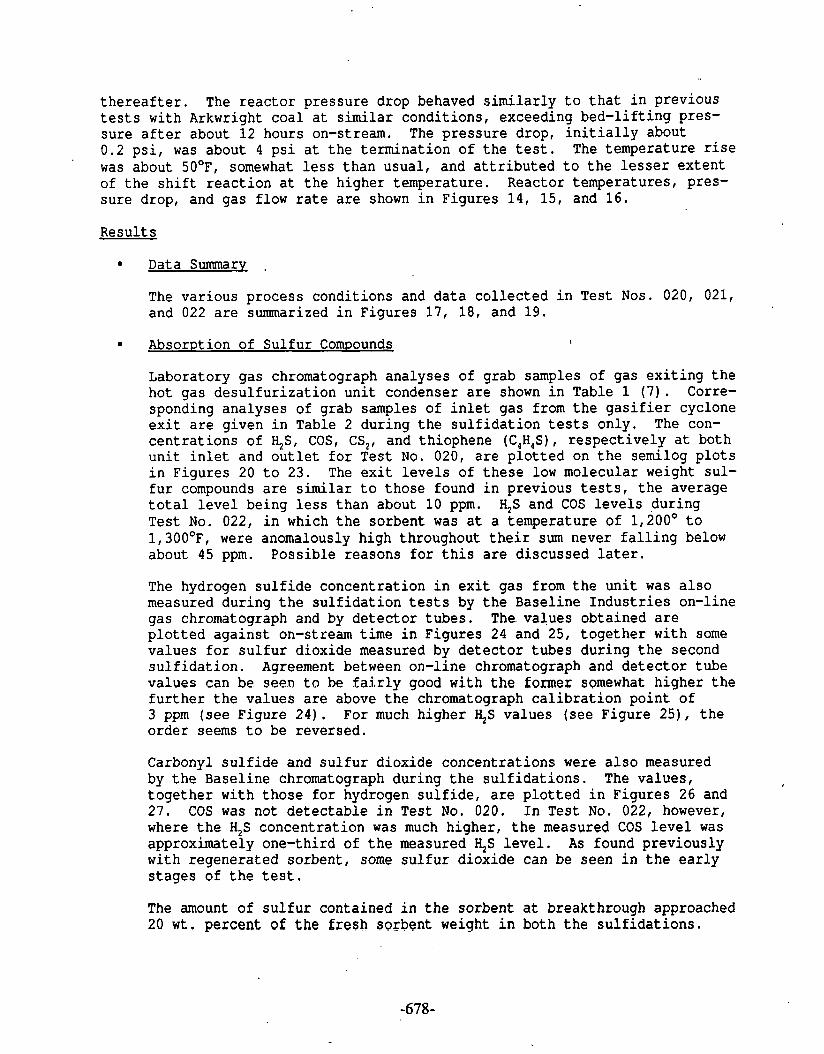
t h e r e a f t e r . The r e a c t o r pressure drop behaved s i m i l a r l y t o t h a t i n previous t e s t s with Arkwright coa l a t s i m i l a r condi t ions , exceeding bed- l i f t ing pres- su re a f t e r about 12 hours on-stream. The p ressure drop, i n i t i a l l y about 0.2 p s i , was about 4 p s i a t t h e te rminat ion of t h e t e s t . The temperature r i s e was about 50°F, somewhat l e s s than usual , and a t t r i b u t e d t o t h e l e s s e r ex ten t of t h e s h i f t r e a c t i o n a t t h e higher temperature. Reactor temperatures, pres- su re drop, and gas flow r a t e a r e shown i n Figures 1 4 , 15, and 16.
Resul ts
Data Summary .
The var ious process condi t ions and d a t a c o l l e c t e d i n Test Nos. 020, 021, and 022 a r e summarized i n Figures 17, 18, and 19.
Absorption of Su l fu r Compounds \
Laboratory gas chromatograph analyses of grab samples of gas e x i t i n g t h e hot gas d e s u l f u r i z a t i o n u n i t condenser a r e shown i n Table 1 ( 7 ) . Corre- sponding analyses of grab samples of i n l e t gas from t h e g a s i f i e r cyclone e x i t a r e given i n Table 2 dur ing t h e s u l f i d a t i o n tests only . The con- c e n t r a t i o n s of %St COS, CS,, and thiophene (C4H4S), r e s p e c t i v e l y a t both u n i t i n l e t and o u t l e t f o r Test No. 020, a r e p l o t t e d on t h e semilog p l o t s i n Figures 20 t o 23. The e x i t l e v e l s of t h e s e low molecular weight su l - f u r compounds a r e s i m i l a r t o those found i n previous tests, t h e average t o t a l l e v e l being l e s s than about 10 ppm. $S and COS l e v e l s dur ing Tes t No. 022, i n which t h e sorbent was a t a temperature of 1,200° t o 1, 300°F, were anomalously high throughout t h e i r sum never f a l l i n g below about 45 ppm. Poss ib le reasons f o r t h i s a r e d iscussed l a t e r .
The hydrogen s u l f i d e concentra t ion i n e x i t gas from t h e u n i t was a l s o measured during t h e s u l f i d a t i o n t e s t s by t h e Basel ine I n d u s t r i e s on-line gas chromatograph and by d e t e c t o r tubes . The.values obtained a r e p l o t t e d aga ins t on-stream t ime i n Figures 24 and 25, toge the r wi th some values f o r s u l f u r dioxide measured by d e t e c t o r tubes dur ing t h e second s u l f i d a t i o n . Agreement between on-line chromatograph and d e t e c t o r tube values can Be seen t o be f a i r l y good with t h e former somewhat h igher t h e f u r t h e r t h e va lues a r e above t h e chromatograph c a l i b r a t i o n po in t of 3 ppm (see Figure 2 4 ) . For much higher I+S values ( see Figure 25) , t h e o rde r seems t o be reversed.
Carbonyl s u l f i d e and s u l f u r dioxide concentra t ions were a l s o measured by t h e Basel ine chromatograph during t h e s u l f i d a t i o n s . The values , toge the r wi th those f o r hydrogen s u l f i d e , a r e p l o t t e d i n Figures 26 and 27. COS was not d e t e c t a b l e i n Test No. 020. I n Test No. 022, however, where t h e H,S concentra t ion was much higher , t h e measured COS l e v e l was approximately one-third of t h e measured $S l e v e l . As found previous ly with regenera ted sorbent , some s u l f u r d ioxide can be seen i n t h e e a r l y s t a g e s of t h e t e s t .
The amount of s u l f u r contained i n t h e sorbent a t breakthrough approached 20 w t . percent of the fresh sorbent weight i n both t h e s u l f i d a t i o n s .

Gas Analvsis f o r Major Species
Laboratory gas chromatographic analyses , f o r major spec ies of grab sam- p l e s of e x i t and i n l e t s gas, a r e shown i n Tables 3 and 4 r e s p e c t i v e l y .
I n c o n t r a s t t o Table 4 , t h e oxygen l e v e l s i n Table 3 dur ing t h e su l f ida - t i o n s a r e i n o r d i n a t e l y high. This i s probably caused by incomplete d is - placement of a i r from t h e sample b o t t l e s . Oxygen a l s o appears t o be excess ively high during t h e regenera t ion . Most of t h e same s p e c i e s were a l s o measured by Bendix on-line gas chromatographs i n t h e e x i t and i n l e t gas s treams. The measurements, averaged by ADACS s t a t i s t i c a l a n a l y s i s , a r e shown i n Tables 5 t o 10. Because of t h e l a r g e r water content of t h e l i g n i t e gas, t h e CO s h i f t r e a c t i o n proceeded t o a l a r g e r ex ten t i n Test No. 020, occurr ing t o a s much a s 8 vo l . percent of t h e gas on a d ry b a s i s . The ex ten t of t h e s h i f t r e a c t i o n i n Test No. 022 with Arkwright c o a l gas was s i g n i f i c a n t l y less, about 4 vol . percent . A s i n previous t e s t s , t h e r e i s an apparent l o s s of t o t a l carbon oxides between i n l e t and o u t l e t gas, a t t r i b u t e d t o carbon deposi t ion .
Analysis of Re4enera.t-ian
The regenera t ion e x i t gas ( see Tables 1, 3, and 9 ) i n t h e e a r l y s t a g e s of regenera t ion , Test No. 021, contained s u b s t a n t i a l q u a n t i t i e s of hydrogen, carbon dioxide, and reduced s u l f u r compounds which i s a t t r i b - u ted t o t h e presence of i r o n carbidelcarbon i n t h e so rben t . More of t h e s e compounds, i . e . , H,, CO,, H,S, COS, and CS,, were present than expected. The higher water content of t h e l i g n i t e c o a l gas, i t . w a s thought , should i n h i b i t t h e formation of i r o n ca rb ide . Af te r t h e f i r s t few hours of t h e regenera t ion , t h e s u l f u r content of t h e ex& gas was predominantly i n t h e form of s u l f u r d ioxide .
ADACS p l o t s of CO,, H,S, O,, CO, and H, i n t h e regenera t ion gas from t h e r e a c t o r e x i t condenser a r e shown i n Figures 28 t o 32.
Sorbent Charac te r i za t ion
A f t e r Test No. 022, t h e s u l f i d i z e d sorbent was removed from t h e r e a c t o r and sampled f o r a n a l y s i s and c h a r a c t e r i z a t i o n a t a number of p o i n t s along t h e r e a c t o r l eng th , The r e s u l t s a r e d e t a i l e d i n Tables 11 and 12. The mineral a n a l y s i s (see Table 11) d i f f e r s markedly from t h a t i n pre- vious t e s t s with Arkwright coa l gas i n t h a t t h e sorbent con ta ins l a r g e q u a n t i t i e s of wus t i t e , FeO. The amount of wus t i t e i s l a r g e r a t t h e r e a c t o r e x i t where t h e r e i s no p y r r h o t i t e . A t t h e r e a c t o r i n l e t a good p a r t of t h e so rben t ' s i r o n content has been converted t o p y r r h o t i t e . Remarkably, t h e r e i s a s i g n i f i c a n t amount of unsu l f id ized z inc oxide a t t h e r e a c t o r i n l e t , suggest ing t h a t it i s somewhat i n a c c e s s i b l e t o hydro- gen s u l f i d e which may exp la in why t h e sorbent was unable t o remove it t o i t s equi l ibr ium l e v e l . Only a small amount of magne t i t e l z inc f e r r i t e remains.
The presence of wus t i t e i s undoubtedly due t o t h e high opera t ing tem- p e r a t u r e of t h e sorbent , 1,200° t o 1,300°F, and t h e r e l a t i v e l y small water concentra t ion - i n - - t h e coa l gas undergoing d e s u l f u r i z a t i o n .
- -- - -I
Table 12 shows t h a t t h e sorbent conta ins about 22 w t . percent of s u l f u r a t t h e r e a c t o r i n l e t , which i s r a t h e r l e s s than found i n p r i o r compar- a b l e tes ts . The carbon content i s q u i t e l a r g e and comparable t o previ- ous t e s t s where i r o n carbide was found (none was de tec ted i n t h i s c a s e ) . Surface a reas and pore volumes were s i m i l a r throughout and not much d i f f e r e n t from those of f r e s h sorbent . Another remarkable r e s u l t i s t h a t t h e crush s t r e n g t h of t h e sorbent s i g n i f i c a n t l y exceeded t h a t f o r f r e s h sorbent a t a l l t h e sample p o i n t s . Less than 5 w t . percent of t h e removed sorbent passed through a No. 12 screen. This r e l a t i v e l y small amount of d i s i n t e g r a t i o n i s assoc ia ted with t h e s o r b e n t l s preserved crush s t r eng th , i n marked c o n t r a s t t o previous tes ts when t h e sorbent contained s u b s t a n t i a l amounts of i r o n carbide .
P a r t i c u l a t e Analysis
I n t h i s t e s t series, i n Test No. 020, only a s i n g l e sample of e x i t gas was taken f o r c h a r a c t e r i z a t i o n of i t s p a r t i c u l a t e content ( 8 ) . The r e s u l t s a r e summarized i n Table 13. The p a r t i c u l a t e loading of near ly 2 g / ~ m 3 i s s i m i l a r i n magnitude t o t h e i n l e t gas loadings i n previous t e s t s . The median p a r t i c l e s i z e of about 6 microns i s comparable t o t h a t found i n Test No. 017 (3) with Ki t tanning coa l gas; though i n t h e l a t t e r case , t h e e x i t gas loading was a few t imes less. I n both cases , a very low r e a c t o r pressure drop inc rease occurred f o r about 50 hours on-stream t ime which provides f u r t h e r evidence of a p o s i t i v e c o r r e l a t i o n between r a t e of inc rease of pressure drop and median p a r t i c l e s i z e . Chemical a n a l y s i s of t h e p a r t i c u l a t e i n d i c a t e s t h a t it c o n s i s t s mostly of f l y ash from t h e coal gas. The d e t a i l e d s i z e d i s t r i b u t i o n f o r t h e p a r t i c u l a t e sample i s shown i n Table 1 4 .
Condensate Analvsis
Reactor e x i t gas condensates were co l l ec ted from Test Nos. 020 and 021. Analy- ses of composite samples a r e shown i n Tables 15 and 16, r e spec t ive ly . For Test No. 020, t h e ca lcu la ted gas composition i s a l s o included. The s u l f i d a t i o n con- densate conta ins s i g n i f i c a n t l y g r e a t e r amounts of Na, K, and Ca, but less C 1 and F. The regenerat ion condensate i s a l s o enriched i n these elements and, assuming they der ive from t h e previous s u l f i d a t i o n , it i s est imated t h a t about 32 percent of Na and 20 percent of C 1 a r e absorbed by t h e sorbent . I n con t ras t t o previous tests with bituminous coal gas, where up t o 20 percent of NH, was absorbed, l e s s than 1 percent appears t o be absorbed i n t h i s case . This may be t h e r e s u l t of t h e lower chlor ide and higher water contents of t h e l i g n i t e gas.
Samples of i n l e t and o u t l e t condensate during s u l f i d a t i o n Test No. 020 were a l s o obtained i n t h e course of ob ta in ing p a r t i c u l a t e samples. Thei r analyses a r e shown i n Table 17. Comparing t h i s a n a l y s i s of t h e o u t l e t condensate with t h a t of t h e composite o u t l e t condensate ( see Table 1 5 ) , t h e concentra t ions of Na, K, and Ca a r e much l e s s i n t h e former. A poss ib le reason f o r t h i s could be t h a t t h e s e c o n s t i t u e n t s have leached out from t h e r e l a t i v e l y l a r g e amount - of p a r t i c u l a t e which i s not removed before condensation occurs i n t h i s case . The s i g n i f i c a n t discrepancy between t h e ch lo r ide concentra t ions i n t h e two cases i s not c l e a r .
The t a r l a y e r amounting t o about 4 w t . percent was separa ted from t h e t o t a l e x i t gas condensate from s u l f i d a t i o n Test No. 020. The u l t ima te a n a l y s i s of a
. -

sample of t h i s i s shown i n Table 18. It appears t h a t t h e sample contained a l a r g e amount of water which could not be separa ted . Corresponding analyses of t a r condensate from t h e u n i t i n l e t f o r both s u l f i d a t i o n t e s t s a r e shown i n Table 19. Regret tably, t h e s u l f u r concentra t ions a r e missing f o r t h e l i g n i t e t a r . Ultimate analyses of t h e l i g n i t e and Arkwright coa l s g a s i f i e d a r e shown i n Table 20.
Conclusions
The f o u r t h and f i n a l s e r i e s of t e s t s of t h e hot gas d e s u l f u r i z a t i o n u n i t i n a s ides t ream of t h e METC 24 t / d fixed-bed g a s i f i e r was success fu l ly concluded. Two s u l f i d a t i o n s and an in termedia te regenera t ion of t h e same z inc f e r r i t e sorbent t e s t e d i n t h e previous t h r e e s e r i e s were c a r r i e d ou t . North Dakota l i g n i t e and Arkwright bituminous coa l , r e spec t ive ly , were g a s i f i e d i n t h e a i r - blown mode f o r t h e two s 'u l f ida t ion t e s t s .
The amount of s u l f u r absorbed before breakthrough was s i m i l a r t o t h a t i n pre- vious t e s t s , about 20 w t . percent of f r e s h sorbent . I n t h e f i n a l s u l f i d a t i o n t e s t , t h e only one i n t h e t e s t s e r i e s i n t h e higher temperature range of 1,200° t o 1,300°F, much of t h e sorbent i r o n content was converted t o wus t i t e , FeO. This appeared t o slow down t h e r a t e a t which s u l f u r compounds reac ted with t h e sorbent , and t h e hydrogen s u l f i d e l e v e l a t t a i n e d be fo re breakthrough was s i g n i f i c a n t l y higher than t h e equi l ibr ium l e v e l p red ic ted .
A smal ler amount of r e f r a c t o r y s u l f u r compounds i n t h e case of l i g n i t e gas than i n t h e case of bituminous coa l gas appears t o be c a r r i e d through t h e d e s u l f u r i z a t i o n sorbent i n t h e vaporized t a r s . . ...
The p a r t i c u l a t e loading of t h e d e f u l f u r i z a t i o n u n i t e x i t gas 'was r a t h e r high i n t h e l i g n i t e tes t , about 2 g / ~ m . The median p a r t i c u l a t e s i z e , however, was low, about 5 p n and t h e pressure drop ac ross t h e r e a c t o r remained very low throughout. This r e i n f o r c e s t h e conclusion previous ly reached t h a t t h e r e i s a s t rong p o s i t i v e c o r r e l a t i o n between r a t e of p ressu re grop inc rease and median p a r t i c l e s i z e . A p a r t i c u l a t e loading of about 1 g/Nm and a median p a r t i c l e s i z e of about 10 p appear t o be an acceptable s p e c i f i c a t i o n f o r i n l e t g a s . t o t h e hot gas d e s u l f u r i z a t i o n u n i t .
Halides and a l k a l i and a l k a l i n e e a r t h meta ls were absorbed from t h e l i g n i t e gas by t h e sorbent and re leased dur ing regenera t ion i n t h e propor t ions of about 32 percent of sodium and 20 percent of ch lo r ide f o r example. Very l i t t l e ammonia was absorbed i n c o n t r a s t t o previous experience.
i . _ - - - _ _/
REFERENCES
Grindley, T. , "Hot Gas Desulfur iza t ion Sidestream Tes t Unit, Fixed-Bed G a s i f i e r Run No. 101," I R No. 1846, March 1984, HETC.
Grindley, T. "Hot Gas Desu l fu r iza t ion Sidestream Tes t Unit, Fixed-Bed G a s i f i e r R u n No. 102," IR No. 1984, September 1984, HETC.
Grindley, T. , "Hot Gas Desu l fu r iza t ion Sidestream Tes t Uni t , Fixed-Bed G a s i f i e r Run No. 103," I R No. 2051, November 1984, PIETC.
P a t e r , K . , 'Test Plan -- R u n No. 104," IR No. 18'12, Plarch 1984, KETC.
P a t e r , K . , "Preliminary Tes t Summary -- Run No. 104," I R No. 1811, March 1984, METC.
P a t e r , K. "Process Summary Report -'- Run No. 104," I R No. 2033, Novem- b e r 1984, HETC.
Lamey, S. C . , R . R. Romanosky, and J. J. Kovach, "Analytical Data -- Pro- ducer Run No. 104," IR No. 2059, November 1984, HETC.
Data provided by R . D . Bagnell, Ana ly t i ca l Sciences Branch, METC.
ADDENDUM TO APPENDIX H 13?l&S*LJ .?u t.lrt-11Dhi L
The Baseline G.C. on-line H2S, COS, and SO2 readings as plotted are correct
only for the points: H2S: 3 ppm; COS: 1.7 ppm; and S02: 5.1 ppm.
Calibration curves are available for correction. Corrected plots are given
in Volume 1.
Refer to letter to T. Grindley from E. E. ors ski and P. Johnson, EG&G
Washington Analytical Services Center, Inc. January 30, 1986. Subject:
DOE-METc/EG&G Contract No. DE-AC21-85MC21353; WBS No. 9KEX-10. HGD Project:
Baseline ~CIIntegrator Conversion Curves.

FIGURE 1
8 V 2 0 0 0
T E M P 1200 .F
C O A L t y p e
O X l D A N T
. SCHEDULE OF E V E N T 6
HOT GAS DESULFURIZATION SIDESTREAM TEcSTlNO 9883
QASlFlER RUN 1 0 4

FIGURE 2
. ' TEST 020 A 6 AVERAGE OPERATING PARAMETERS
T O O O l Y W T a .
m I- b m
La.-. I
PREHEATER w . w z
t 2 arr &- <
1 rn .#QF
a W 2 . I I W a a l s8 .mEQF W a aQ- B 1874.YCF
I 164..RIIQ
lBaT.#QF
w
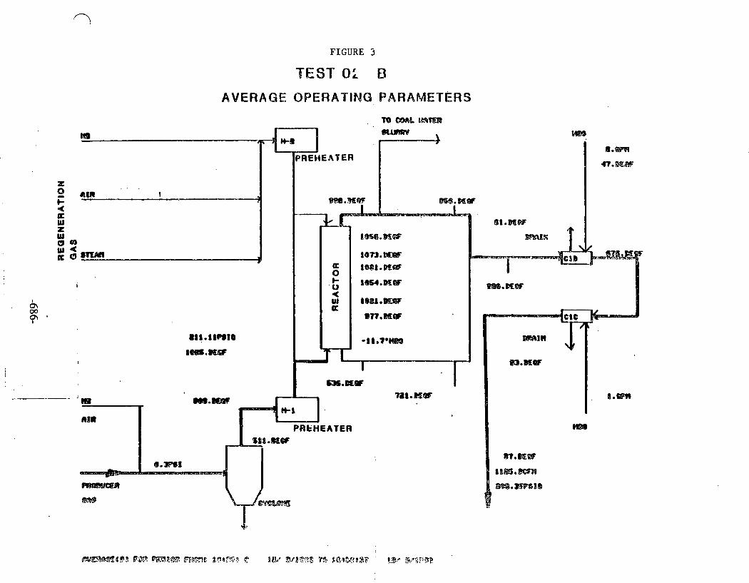
FIGURE 5
BEST 8: B
AVERAGE OPERATING PARAMETERS
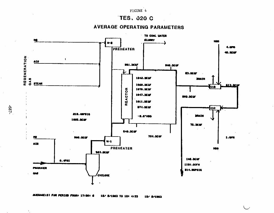
FIGURE 4
' T E S , 0 2 0 C .
AVERAGE OPERATING PARAMETERS
' TO CWL mffl m I iumv
- 1 ) H ) Nm
PREHEATER 4 . m . *.IQQ
Ma t
a t .mnF 914.DQQF
QO 1M.DeW
:= P 1oaB.mw am.ocw
0
em.#cr
P18.4eSIO m11 1 m s . w W
I - n.mw
m.mQF na mower C 784.DQQF 8 .em
am H.1
PREHEATER ma
a.Um Oe8.WQP
I 1 t m . m PsaaKaa PI4.#POII w
-46) rm I 7 8 m 8 lU MLO YO 888 48.) ly W-
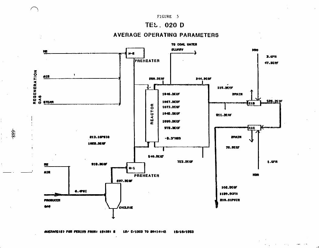
FIGURE 5
TEL. Q20 D AVERAGE QPERATIMG PARAPAETERS
t O W A Q l M M n

FIGURE 6
AVERAGE OPERATING PARAMETERS

FIGURE 7
TESi 022
AVERAGE OPERATINQ PARAMETERS
To CmL w m n m b )(88
H1 w
@.@Pa
*.@Ear
1041.rKW
PREHEATER
1 M R
3 1 1 1 8 . ~ ~ ,
ClWl
t I
lQlO.#.CT
?
1 8 4 . l ~ t a
l l#S.#9 .
b 0 <
lt3).#aF laa.#ar 1816.WCF m.mw l 8 l l . K W I
1164.mCw A '
-3C.m0HIO DmtW \r
I,- - wamw ale.Rff
lm sM.#QI ua.WCI 1 a w n
om
-
PAEHEATER )la)
w.mw W.WW
a .uu - I 1118.6WM CIQUOtl 1 1 1 . m 1 a
ma.

FIGURE 8
808 0 4 8 12 16 ' 20 24 20 32 36 40 44 48
TINE (HOURS 1 START TIPIE OF PLOT 218398 0 121 811983 STOP ?'In€ OF PLOT 208158 0 12/10/1983
TEST 020
REACTOR TEMPERATURES
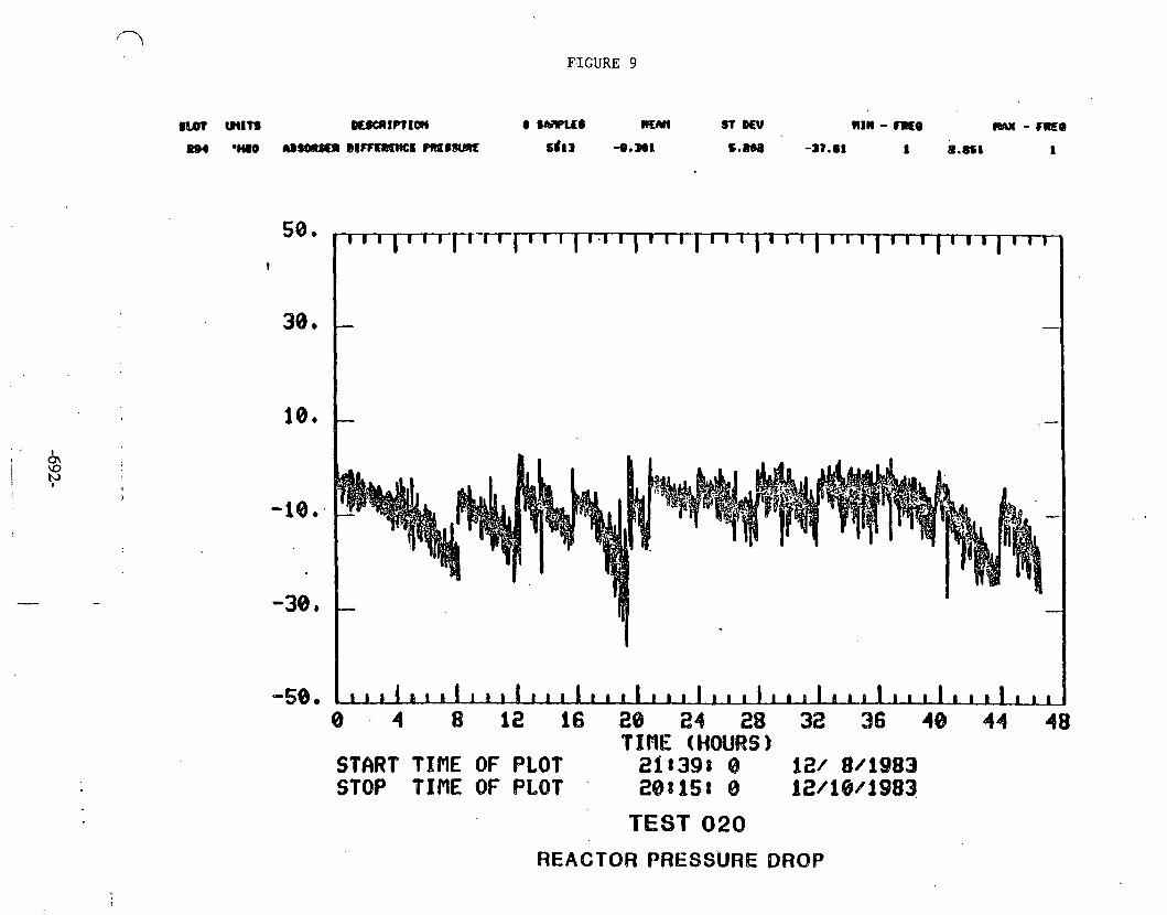
58. !
34). -
10.
-10..
-38).
-58. 8 . 4 8 1 16 28 24 28 3% 36 443 44 48
TIPIE (HOURS) STflRP TIME OF PLOT 268398 8 121 8/1983 STOP TIME OF PLOT 28tiSt 0 112/1881983
TEST O2Q
REACTOR PRESSURE DRQP
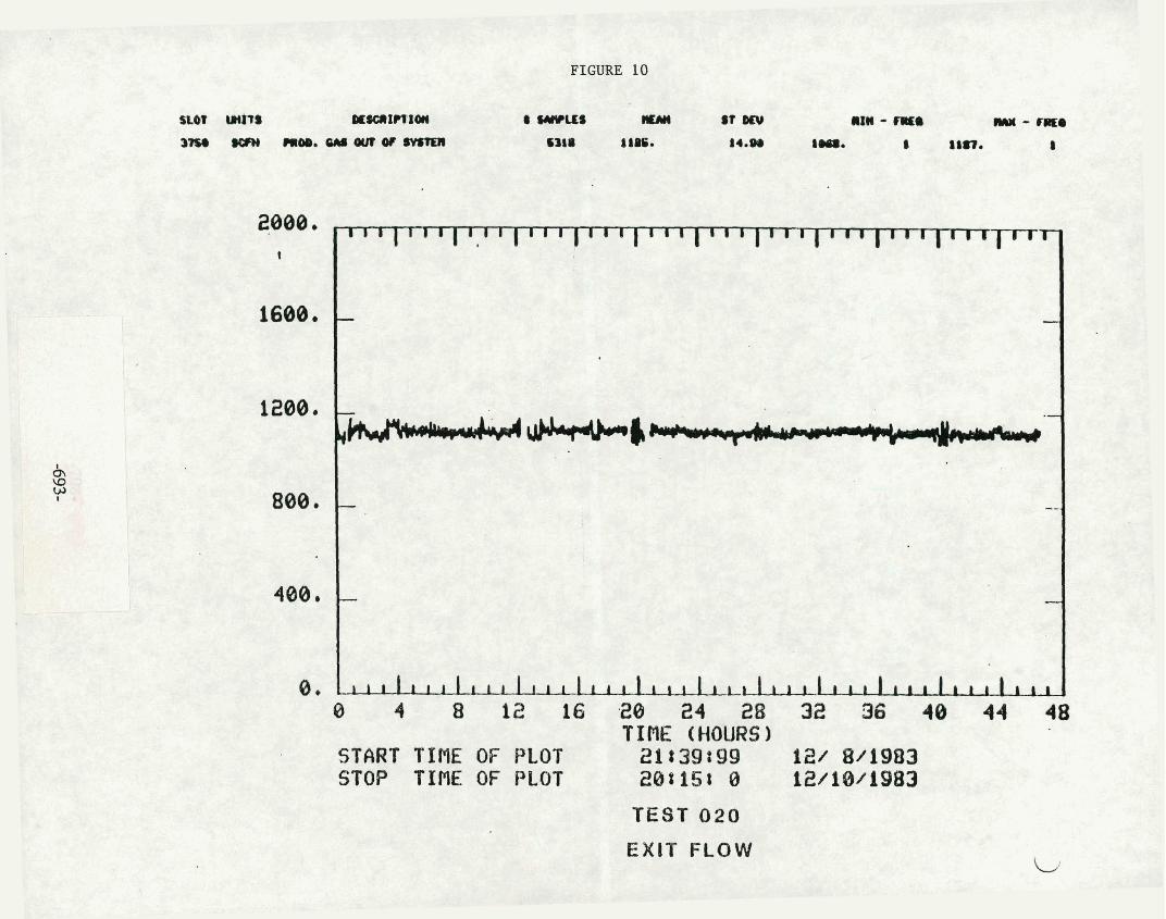
FIGURE 10
TEST 020
2000. . 1
1688,
1200.
800.
400.
0 .
EXIT FLOW
, , , 1 1 1 ( 1 1 1 ( 1 1 1 ~ 1 1 1 I
- -
- Y--&&--
- --
- -
1 1 1 1 1 1
0 4 8 12 16 -28 24 28 32 36 40 44 48 TIPIE (HOURS)
START TIRE OF PLOT 21139t99 121 8/19133 STOP TIME OF PLOT 208158 0 12/18/1983

FIGURE 11
1700. . , I ~ I ~ I ~ I ~ I ~ ~ ~ I ~ ~ ~ ~ ~ ~ ~ ~ ~ ~ ~ ~ ~ ~ ~ ~ ~ ~ ~ ~ ~ ~ ~ ~ ~ ~ - t
1548. - -
--.
900. I I ~ I ~ I ~ I I I ~ I I I ' I I ~ ~ I ~ ~ I ~ I I I ~ I ~ I I I I I I ~ ~ I ~ ~ I ~ 0 1 2 3 4 5 6 7 8 9 10 11 12 13 14 15 16 17 18 19 20 21
TINE (HOURS) START TIME OF PLOT @ti51 8 12/11/1983 STOP TIRE OF PLOT 208SBt 0 1211111983
TEST 021 REACTOR TEMPERATURES

FIGURE 12
I I l l p I I I I ' 1 1 1 ' I ' I S l I 1 1 ' 1 ' I 1 1 1 1 '
- -
-
1 1 1 1 1 1 1 1 1 1 1 1 1 1 1 I 1 1 I _ 8 1 2 3 4 5 6 7 8 9 10 11 12 13 14 15 16 17 18 19 a@ 21
TIME (HOURS) START TIRE OF PLOT 04 158 .'a 12111/1983 STOP TIRE OF PLOT 28158S 0 12/11/1983
TEST 021 REACTOR PRESSURE DROP
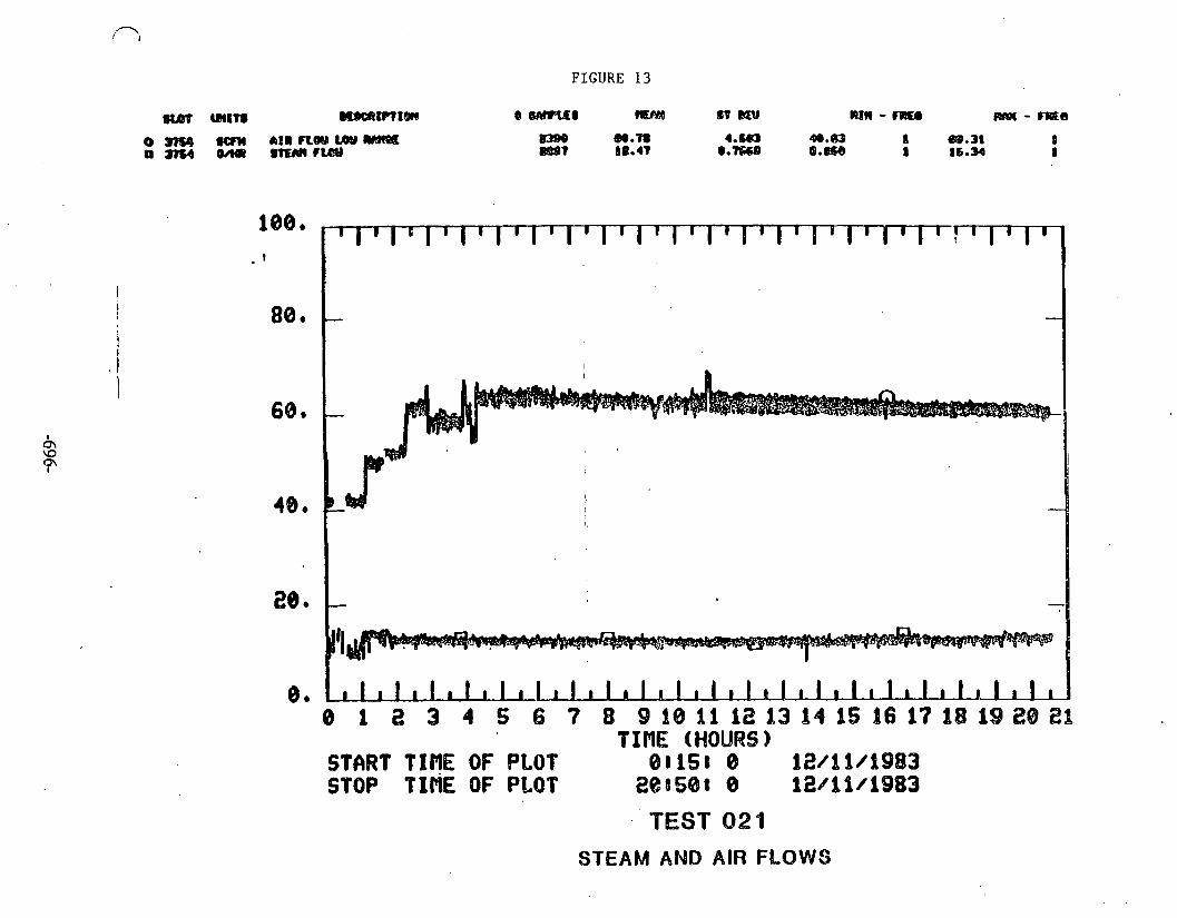
FIGURE 13
WtT8 mnam"?ItWt 0 QWlgdl fmY4 gV&Qll RIM - FREO R@t - -9
0 1 2 3 4 S 6 7 8 9 d@ A1 12 13 14 16 16 17 18 19 20 2% TIflE (HOURS 1
SThRT TIME OF PLOT QBIIS! 8 i2/Qi/b983 STOP TIflE OF PLQT 2&858! 0 12/11/1983
TEST 021
STEAM AND AIR FLOWS
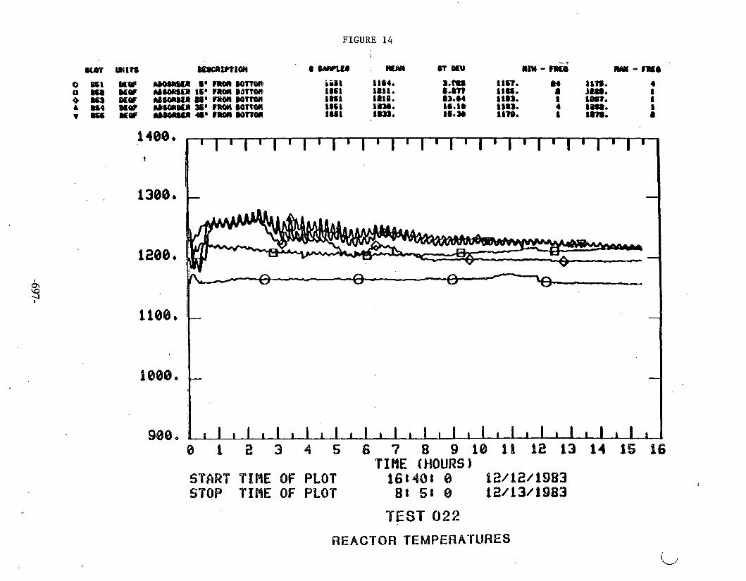
FIGURE 14
. ,
ti3 2 3 4 5 6 7 8 i O 1 I I i 2 1 3 1 4 1 5 i 6 TIHE (HOURS)
START TIFIE OF BLOT l68401 8 l2/d2/1983 STOP T I M OF PLOT 88 51 8 i2/13/f983
'TEST 022
REACTOR TEMPEWATURES

FIGURE 15 I
u u m IU#I?TX~I e WCUI m~ - I ~ D W axn - m a m-- W 911, (Y#R1#@1-- 1@W -W:W m.84 -1m.3 1 [email protected] 8
-200. 8 1 2 3 4 5 6 7 8 9 1 8 1 1 1 2 1 3 1 4 1 5 1 6
TINE (HOURS 1 STMT TIME OF PLOT 168408 8 12012/1Q83 STOP TIBE OF PLOT 88 58 0 12/13/1983
TEST 022
REACTOR PRESSURE DROP

2000 I I I ~ l ~ l ~ l ~ I ~ ~ ~ I ~ l I I I I I I I 1 7 - 9
1600, - -
1200a
800. - --
400, - -
~ ~ ~ ~ ~ ~ ~ ~ ~ ~ ~ ~ ~ ~ I ~ ~ ~ I I I I I ~ I L I I I I I ~ I ~ 0 1 2 3 4 5 6 7 8 9 1 8 1 1 1 2 1 3 1 4 1 5 1 6
TIME (HOURS) START TIHE OF PLOT 16t40: 0 12/12/1983 STOP TIME OF PLOT 88 S t 0 12/13/1983
TEST 022
EXIT FLOW

d
2w
w
s5pZJ nun
*C
ZU
--tn
or
a==
~.s
LltJ
&;;& %!EX8
=%a"", - f "g g r. rn
3,g *P
U
=s!z W
WW
18 P
8e -U
)
YI
Z
C &I
2s
U!z 4)-
-g 8'
.." g
E .. ..
an-
68
a
a
II EZ
*%
-- 0
0
9%
s-
E=
ae-
cLa
ua OC
mrn
sz
dp
: a-
YZ
3s t
m r
n

FIGURE 18
. TEST NO. 021 DATE AN8 T ~ E ' S T R R ~ ~ : 00 lS 1211t183 DATE iMD T I E ENDED : 20 SO 12/11/83 TOTAL HOURS : to. 33 TYPE * RfGDIERATIOl SULFUR R E ~ ~ O V E ~ ~
TEST SUllnARY SHEET SIDESTREAH TEST UNIT
SORBENT TYPNWeIGHtr (ZINC F E R R I E l l 4 S LBS SOREEt4T NO. U)IITEl! CATALYSTS L-1304 SORBENT COHPOSITION; 30.0 m o m rRam OXIDE
30.0 HULEX ZINC OXIDE
SiIRBENT PELLET SIZE: 3/16 INCH DIAmTUl EITRUSIIJNS
I H f T I I K tEHP€RATURE: 1024.2 f
PRESjURE : 3.4 PSI6 (AVERA6E)
SPACE VELOCITY: 573 HOURLY
AIR 59.51 SCFH
920 1 . 1 8IHR
N2 0 . SCFH
INlG EXIT mEX ROLE2
UEt BASIS DRY BASIS
:OTRL LB ROLES: FLOW RATE : 321 SCFH
-
WRPOSE RE60ERATION OF SNIDEO SORENT FROll TO20 SASIFIIER RUN i
EXIT SUtFirR OITA:
*S :
SO? : H16H O f 7.2 X AFTER 10.6 HOURS BY SO2 NOHliOA 0.6 Z PPR AT END OF RUN .
C3WENSlTE : 216 LBS
HYDROCMBON : TOTAL : 246 La9

FIGURE 19
TEST SURllARY SHEET HOT GAS DESULNRIZATION SIDESTREAH TEST UNIT
TEST NO. : 022 DATE STARTED : 16 40 121 12/85 DATE ENDED : 48 05 12113l83 TOT& HWRS : 15.41 TYPE . SUVIDATIW SULFUR &: 8.01 LB S8
SDRBRn TYPEIWEIOHT: (ZINC FERR1IE)tIS LSS SORBENT NO. UNITED CATALYSTS L-IS04 SORBENT CO~~WSITIB~~ 50.0 HOLE IRON DXIOE
50.0 AOLn ZINC OXIDE
SORBENT PELLET SIZE: 3/16 INCH D I M f E R EXTRUSIOWS GASIF 1ER OPERATINO CONDITIONS
GASIFIER TYPE : UOElHETC FIXED BEO COAL TYPE t ARKMIGHT
STEAMICOI MSS RATIO: 0.507 STEAR161R RASS RATIO : 0.210
SPACE VELOCITY: 2000 HOURLf
I K ~ INLET EIIT EXIT HOLE2 HOLE1 Mm rmtEZ
DRY BASIS YET BASIS DRY BASIS WET BAGIS (OIL FREE) (OIL FREE) (OIL FREE) (OIL FREE)
TOTAL L l HOLES: FLOW RATE: I 1 1 2 SCFH -
meotr W Y S I Q
mrAL sum: r U T ) SURFACE ARMS (SP 116 DENSITY : r61cc1 PORE VOLUME: KC161 U M W T b L MALYSIS: TOTAL CARBON: (ZWI
ARKYRIrn COAL !iMP * b,, ,,I,,, HYDROCARBON : 9.3 LBS (ESTIMTEDI TOTAL : R.B LBS ~ ~ A S U R E D ~
1.L L REMRKS
13.62 r.PRn;rD LEffiTH I N REACTOR I S -47 518 4NCHES ZINC BOTTOR AND TOP 6 INCHES PllE Ilr INCH CUWF!&II
15.06 CS-546 112 S SR-lOlE9 UNITED CATIUYSTS 1. O M PACKED LEN6TH 58 718 IMEO 24 . 90 . a F& m CONUTOU.
4. HATER I N X T 6M Y DETERMI 5. mr R P O ~ lrtms 4 1 7 U B T ~ mH116f
OF &01l kC 1000 W !kg S4NPLH 8 (-4 6AS 1101 CYCLE EX 1.
6. W4 C D ~ I P O S ~ T ~ ~ AT arr OBTAINED r l vw~ OF BENOIX 6C 6000 42 OATA SMPLIWG llT H6D
7. REACTOR PRESSUL MOP R f h A l U X I l P l l OF $iTi~CHES W I T E R .
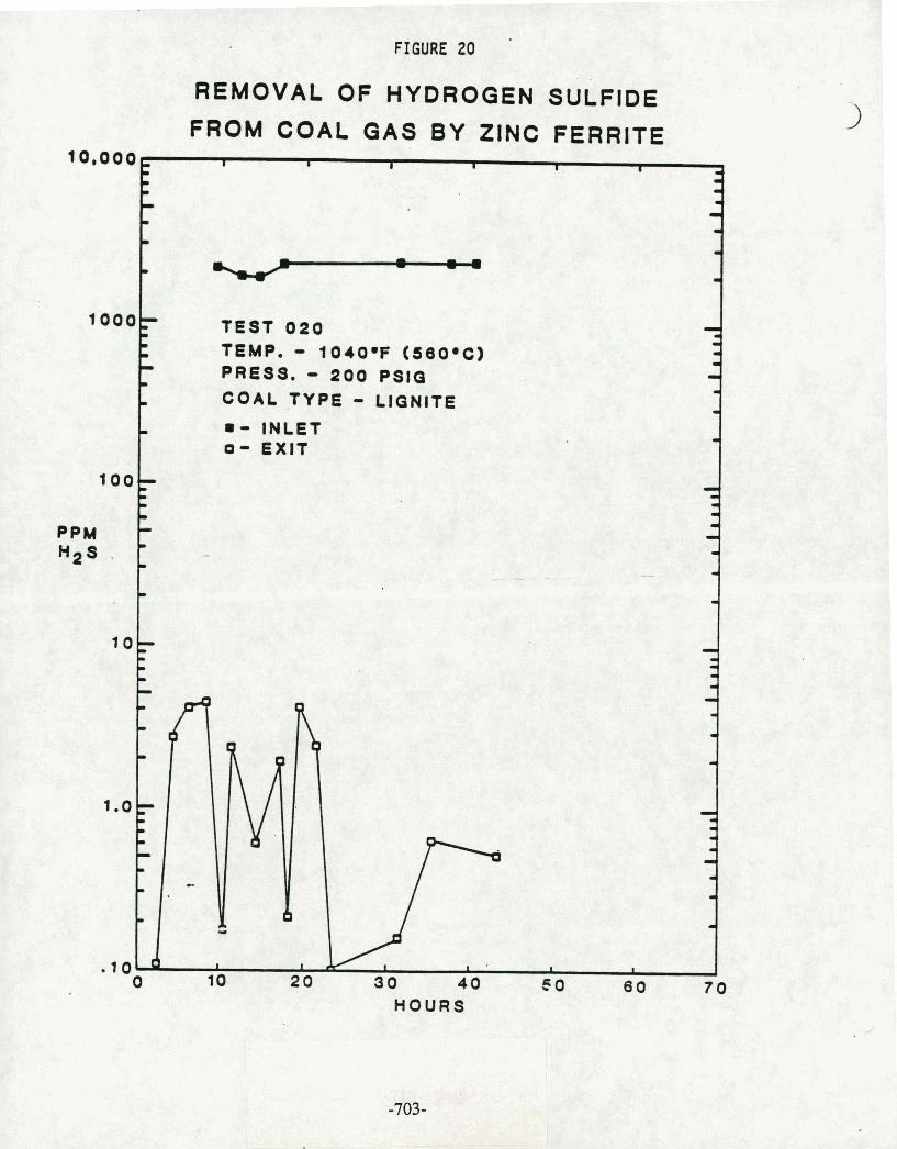
FIGURE 20
FROM COAL GAS BY ZINC FERRITE I I I
D
v I I
D
D
(I
D
I - m
- m
- - =
TEST 0 2 0 D
D
I - I
rn TEMP. - 104OwF (58O.C) D
4 - PRESS. - 2 0 0 PSlO
D - - rn COAL .TYPE - LIGNITE
D 8 - INLET - 0 - exit
=- D
D
- - .. - - - w
.I .. - I
=I .. -
10,000
1000,--
100
PPM H2S .
1 0 7 I
D - 9
1
- 9 .. I - I
9
I
9 I
5 0 6 0 7 0 HOURS
- m
m
II

HOURS
FIGURE 21
REMOVAL OF CARBONYL SULFIDE FROM COAL GAS BY ZINC FERRITE
10,000,
1000
- I I I I I 1 3 I)
D
- .I
D TEST C I 3 - a - TEMP. - 1 0 4 0 ~ ~ ' ( 6 6 0 . ~ ) - .. PRESS. - 2 0 0 PSI^ - COAL TYPE - LIGNITE - - INLET - 0 - EXIT
7
100
LI
D
II
.I - - - -
PPM cos
- .I
m I J--r - m . D
- - .I
m - - m
- - .I
LI I
1 .OF
L
.I
I
0 I
10 20 30 40 SO 60 7 0
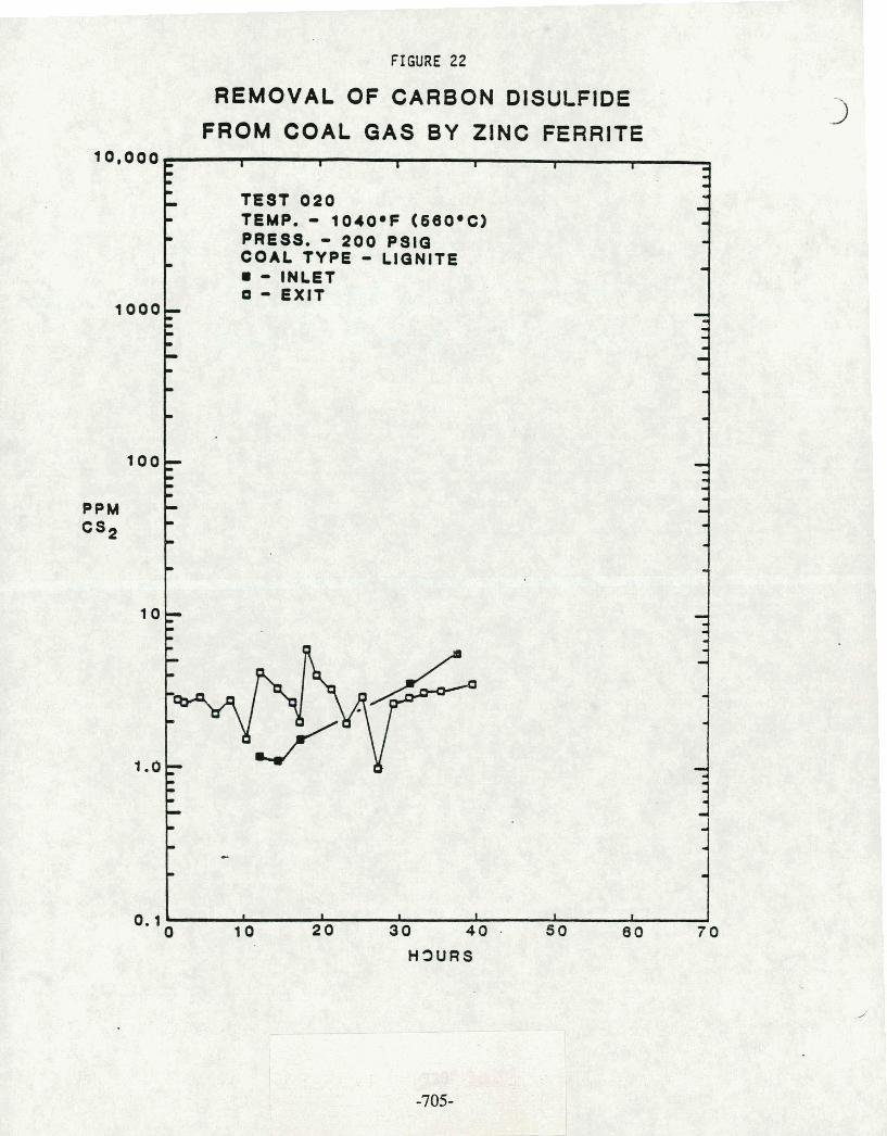
FIGURE 22
REMOVAL OF CARBON PISULFIDE
FROM COAL GAS BY ZINC FERRITE
TEMP. - 1040.F (680.C) PRESS. - 200 P S I 0 COAL TYPE - LIGNITE
r
I
d
.. . .. -
0. loC s I I I I 1
10 2 0 3 0 40 . 5 0 8 0 7 0
H3URS

FIGURE 23
REMOVAL OF THIOPHENE FROM COAL GAS BY ZINC FERRITE
10,000 I I I B I I
- . TEST 0 2 0 - TEMP. - 10408F (58OoC) - PRESS. - 200 PSIG
.) COAL TYPE - LIGNITE I
8 - INLET 0 - EXIT -
3 I -
1 0 0
. .I
D - m - - - I m
- m
I - PPM I) -
THIOPHENE .I
m - w -
10: I
e D
m
w
- I .
I .. I
. l o * I I C * I I I
10 2 0 3 0 40 80 8 0 7 0

FIGUKE 24
SUL FlDA TlON ON LIGNITE DERIVED GAS I N FElllllE S Y U S ~ lEtr U M - nsr P20

FIGURE 25
ZINC FERRITE SULNDATION
Temp - 1213 F (656 C)
Press - 124.1 PSIG
S.V. = 2000 Hourly
= DETECTOR TUBE H2S
C) 'BASELINE H2S

FIGURE 26
ZINC FERRITE SUL FIDATION
-f Temp = 1040 F (560 C)
) Prsrs = 2 0 PSIC 'F S.V. = 2000 Hourly

FIGURE 27 I
ZINC FERRITE SULFIDATION
Temp - 1213 F (656 C)
Prass - 124.1 PSlG
S.V. = 2000 Hourly
4 = BASEUNE CC COS
Cl - B A S ~ N E CC H2S
O = BASUSNE CC SO2
I
0 1 2 3 4 3 6 7 8 8 10 11 12 13 14 15 16 17 111 19 10
limo (hour)

F 1 CURE 28
0e 060 4e2 8e4 12e6 16e8
TIRE (HOURS)
PERCENT C02 BENDIX 6800 #2 CHROflATOCRAPH
START TIHE 88liSt80 12/11/1983 STOP TIME 20850t08 12/11/1983
TEST 021
REGENERATION
CARBON BURNOFF AS C 0 2

FIGURE 29
PERCENT H2S BENDIX 680B 82 CHROflhtOGRfiPH
START TIPIE 08t15888 12/19/1983 STOP TIPlE 20t58880 12/11/1983
TEST 82%
H2S EFFLUENT

FIGURE 30
4.2: 8.4 12.6 16e8 21.0 TIPIE (HOURS)
PERCENT 02 BENDIX 6088 82 CHROflAVOCRAPH
START TIRE 08815888 12/11/1983 STOP TInE 28850808 62/11/1983
TEST 021
REGENERATION
OXYGEN BREAKTHROUGH CURVE
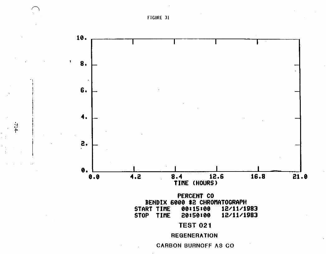
FIGURE 31
0.8 4.2 8.4 12.6 1608 21 e 0 TIME (HOURS)
PERCENT CO BENDIX 6088 82 CHROflhTOGRAPH
START TINE 80815888 12/11/1983 STOP TIME 20t588069 12/11/1983
TEST 021
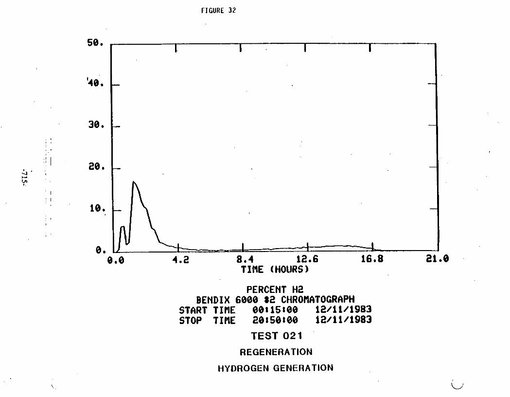
FIGURE 32
TIME (HOURS)
PERCENT M2 BENDIX 6000 $2 CHROMATOGRAPH
START TIME 00815800 12/11/1983 STOP TINE 20850t00 12/11/1983
TEST 021
REGENERATION
HYDROGEN GENERATION


Table 1 (continued)
HOT 6AS DESULFURIZATION GRAB SAHPLE 6 A S ANALYSIS AT H6D EXIT
GASIFIER RUN 104 TRACE COHPONENTS
NOTES: (11 ND Yet Octectablas. Detsctdble level ; f o r HzS, C3S, CH;SH, CS?, Thioohene
r - ---- - are 0.2 ppa. -7 17-
( 2 ) - = Ana lys ls n o t taken,
I
TEST t SAMPLE DATE HZ5 COS CHfSH CS? Thio NQ Hz0 so2 TYPE NO , r!nE P P ~
SULFI- H6 19 !t/19/83 !4U NO 140 3.17 0.3I YO 2748 YO 08: 30
DATi3R H6 20 12/19/85 0.62 0.09 NO 3.22 0.28 . - 2512 2.56 10::o
TCiO H6 21 12/10/8! NO NO NO 5.51 1587 YO 3.87 14:30
H6 22 12/19/83 0.54 NO ND NO 4.84 - - NO 18:30
H6 23 12/11/83 NO 27.56 NO 10.61 5.51 NO - 'I D 02: 23
?ESE?iER H6 24 12/11/83 . 2.49; 6 . 9 5 NO 16.55 NO - - 5.011: 06; 20
?T!C# H6 23 12/11/83 4118 41.96 0 10.06' 2 0 :0 ,34 lor 20
1321 96 ?b 12/11/83 601 3 . 6 4 YO 7.41 ND - - 18.52: 14: 20
H 6 2 7 12/11/83 NO 3.81 HD 4 NO NO - 12. SIZ la: 20
SULFI- H6 28 12/12/03 116.3 40.44 0.37 2.51 1.76 - - Y 0 17: 13
OATiON H 6 2 9 12/12/83 113.1 34.98 9.26 2.19 2.34 NO - NO 17: 40
TO22 H6 $0 12/12/03 69.02 23.39 NO 1,;7 - 1,9B - - a0 21:M
H6 . 3 1 c 12/13183 1J,12 50.30 HP 0.45 1.50 NO - NO 01:M
H6 32 12/13/!3 lSS.7 50.90 ND 1.98 3.50 - - ND 113: 00
H6 Z? 12/13/83 562.9 108.44 1.71 5.55 4.11 I41 NO 00: 00
I

TABLE 2
V O T 6AS DESULFURIZATION G R A B SAHPLE 6AS ANALYSIS A T GASIFIER CYCLONE EXIT
GASIFIER RUN 104 TRACE COHPONENTS
I
EST 0 SAHPLE DATE HIS COS CH3SH CS2 Thio NH3 H$l 502 TYPE WO. TIME PPll
-
Fn bi 12/9/83 2188 38.13 61.6 NO ND nD 36099 - 07: 00
SULF I - FN 66 12/9/83 1907.0 33.21 44.22 1.20 NO ND 7840 09: 53
DAT I ON FN 71 12/9/03 1900.8 33.29 36.48 1.15 - ND 1396 - 12:s
TO20 FN 76 1219183 2398.4 SI.24 23.4 1.57 ND WD 734 - 15: 45
FN 81 12110183 2365.2 47.32 28.29 3.68 1.71 ND 1092 . - 01:oo
FN 89 12/10183 2341.0 70.60 67.76 5.69 10.98 ND 1264 - 12: SO
FN 93 12110183 2349.5 64.48 41.41 1.92 3 . 3 WD 6 79 - 15: 35
SULFI- fN 125 12/13/83 4558.0 259.39 8.75 5 . 8 4.37 YO 692 - DATION 07: 05 1022
FN 128 12/13/83 4349.6 308.20 12.68 0.87 11.40 NO 780 - 101 Si
FN 131 12/13/03 4351.9 341.56 7.84 12.40 10.04 WO 959 - 13: 05
k

HOT GAS DESULFURI TATION' 6RAB SARPLE GAS ANALYSIS AT H60 EX I T
GASIF IER RUN 104 NAJOR COMPONENTS
. TEST t SMPLE DATE H2 02 12 044 CO Cy6 C02 C$4 CzHe iC4 nC4 TYPE #0. TI= VolinE Z
SULFI-
OAT IOU
11120
I 22: 30 I I H6 11 - 12110/83 9-69 6.29 56.94 1.98 6.07 0.15 18.24 0.05 0.08 FID NO I 00: 30
SUff I- H6 16 12l10183 10.08 S.S7 S7.50 1.70 5.65 0.12 18.78 0.03 0.08 MD ND 02: 30
3Af ION H6 17 12110183 13.47 3.30 32.66 1,98 6.;2 0.14 1 0.04 0.01 30 NO

T a b l e 3 (Continued)
. . . /
HQT 6AS D E S U ~ F U R I Z A T I O N GRAB SAHPLE 6AS ANALYSIS AT H6D EXIT
GASIFIER RUN 104 HAJOR COHPONENTS
TEST 4 SAflPLE D A T E H2 02 CO CtHb c@2 C2Hq C;N iQ nC4 TYPE KO. TIVE VOLME 2
H6 19 121101fi3 7.24 8.56 60.60 1.56 4.61 0.10 16.78 HD 0.06 ND ND 08: 30
SULFI - H6 20 12110182 4 8 4 9.87 62.67 1.64 5.89 0.10 14.44 ND 0.06 ND #D 10:30
DATIOM H 6 2 1 12110182 9.52 6.91 57.89 1.71 4.84 0.14 1 0.07 0.07 NO ND 14:56
TO20 H6 22 12l lCI82 6.07 7.87 61.R 1.30 5.73 0.08 17.08 ND 0.0: ND NU 18:30
H6 23 12/11/03 0.98 8.48 78.87 ND ND ND . 9 ND ND ND I D 02: 20
RE6ENER- H6 24 12111183 ND 8.70 83.16 ND ND ND 5.16 ND HE UD UD 06: 20
ATICH H6 25 12/11/83 NO 9.61 84.15 WD RD .!ID 2.06 ND NO UB #D 10;20
7021 HE 26 12/11/83 ND 8.31. 83.58 ND ND #D 1.16 ND ND MD ND 14:20
H6 27 12111183 ND 16.00 78.81 HD NB ND 1.61 HD ND NO 18:20
. ..
H6 20 1211*r/BS 10.62 4.29 56.55 2.85 11.83 0 . 3 12.96 0.12 0.14 IID ND 17: 15
SULFI- H6 29 12/12/83 11,87 7 S.S4 2.81 12.24 0 . 3 ,12.70 0.12 0.14 ND WD 17: 40
DAT!ON H630' 12/12/83 12.n 3.76 55.76 2.58 12.04 0.31 12.06 0.10 0.13 ND ND 21:oo
1022 H6 31 ' 12/13/83 5.86 6.95 60.59 1.12 13.52 0.31 9.89 0.09 0.17 NB ND 01 : 00
H6S2 12/13/83 6 . n 5.74 60.53 2.37 11.69 0 12.00 0.11 0.i7 ND ND 03: 00
H633 12/12/83 10.17 4.00 55.30 2.72 15.50 0.57 11.14 0.12 0.18 HD HD 08: 00
NOTES:
( 111 10 = Not Detectable. Detectable I~ve!r (or H$, UIS - 9 L-. 'H$H. CS2, - Thioghenr arc 0.2 ppr.
(2) -,= Analysis not taken.

TABLE 4
HOT 6AS DESULFURIZATION GRAB SAMPLE GAS ANALYSIS AT GASIFIER CYCLONE EXIT
GASIFIER RUN 104 MAJOR C.OHPONENTS
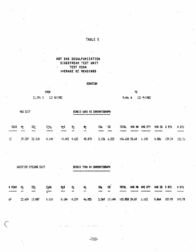

TABLE 6
HOT 6AS DESULFURIZATION SIDESTREAR TEST. UNIT
TEST 0200 AVERAGE 6C REAOIN6S
READ Hz C3 -- - c;?r6 --- 02 3: -- -- n2 CH4 co -- -- TOTAL AV6 RY AV6 bTY AV6 ?S 6 9TU N 2:L ---- --- ------ ----- ----- ----- . .
5bSIFIER CYCLONE EXIT
4 REAb Hz !!I ----- - Cy5 . H2S -- ?I !! QI4 --- CO - TOTAL AV6 flM AV6 bTY AV6 S 6 6 9TU N BTlJ ----a --- ----- --- --- -----
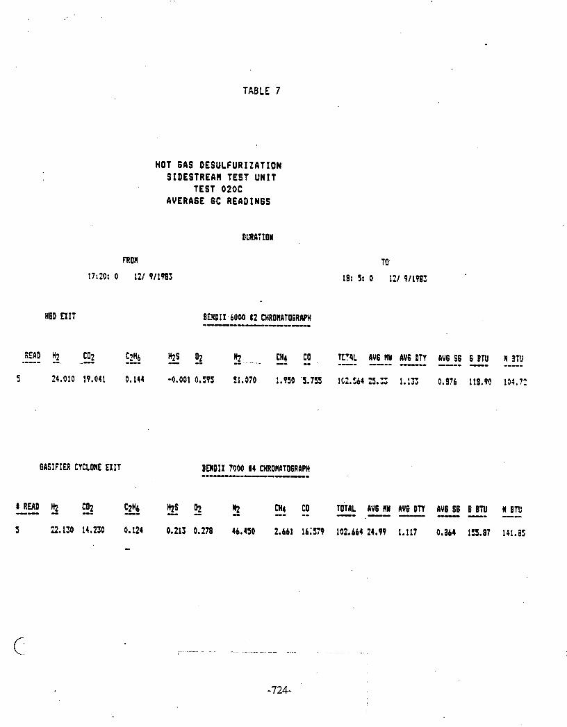
LO
I
-1
4I
(PI &
i
ZI 2
t:
vr (P
I @
: Z
I 3

TABLE 8 . .
HGD EXIT
HOT 6AS DESULFURIZATION SIDESTREAH TEST UNIT
TEST 0200 AVERAGE 6C READINGS
DURATION
FRCA
13:29: 0 121 911903
READ HI C02 .---- -- -- . -- -- N! c 8 6 ---- HIS 02 CHI co --- -- TOTAL AV6 RY 6V6 DTY AV6 S6 6 SYU !4 3TU ----- ------ ------ ----- ---- ----- 15? 27.065 21.481 4.161 -0,001 0.650 !S. I43 2.179 6.441 132.477 25.16 2 9.971 135.65 ii7.TC
CASIFIER CYRCNE EXIT
t READ Hz f!z ----- -- CYb -- !!I B,t !I- --- -- --- ----- ------ ----- ---- CH4 CO ' TUTRL AV6 MY AV6 DTY AV6 S6 6 ETU R Bll
154 23.!63 14.672 0.136 0.221 0.270 45.478 2.738 1b.OL4 102.921 24.80 1.199 0.858 159.30 lL4.54
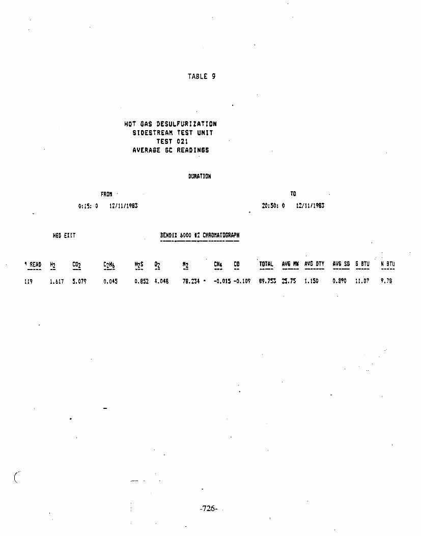
TABLE 9
HOT GAS DESULFURIZATION SIDESTREAIl TEST UNIT
TEST 021 AVERAGE 6C READINGS
DUMT ION
. .
+ READ H.l C02 ---- -- -- --- -- !! C2H6 --- '+2s 02 C H ~ co -- -- TOTAL AV6 MU AVG DTY AV6 S6 G BTU N 3TU ----' ---- ------- --- .---- --i--
119 l . t l 7 1.079 0.045 0.852 4.048 76.234 -0.015-0.109 8 9 . 7 3 3.75 1,150 9.8% i l . 0 7 9 . 7 6

TABLE 10
1160 EXIT
HOT BAS DESULFURIZATION SIDESTREAH TEST UNIT
TEST 022 AVERAGE 6C READINGS
I RWD H2 MI2 ---- -- -- -- - ?! CPb -- ' Hz9 02 UI4 CO --- -- TOTAL AV6 M i AV6 DTY AV6 S t 6 8lll N 87tJ ----- --- ----- ----- --- ----
MSIFIER CYCLONE E1:T
8 aL4D Hz !; ---- H2S 2 --- !2 CH4 CO TOTAL AVE M AV6 OTY 3V6 S6 6 8TU N 3TU --- - --- -- ---- -- - - ---- ---- ----

TABLE 11
ANALYSIS OF HINERALB BY X-RAY QIFfRACTION '
IN SULFIDED ZINC FERRITE 'GASIFIER RUN 104
FRANKLIWITE 2nFe;lOl
BED OR HEIGWT HEHATIE MAGNETITE ZIEITE YUSTIE am nn~ PYRRHOTITE
[IWCHESI F e y 3 fe304(4) ZnO FeO ZnS h S FeS
PERCENT TI1 (3)
. o(11 2.8 5.9 23.4 19.6 JS. 0 13.3 6 1.0 7.2 30. 1 18.7 29.5 13.5
16 1.4 7.1 29.2 16.2 32.3 13.9 23 1.6 6.8 SO. 4 16.7 31.1 15.3 26 3.2 .9.8 36.2 13.3 n.s 9.9 36 3.3 1s. 8 50. 7 7.0 18.4 2.8 46 121 4.9 22.9 38.6 2.8 10.8 -
FRESH SORBUlT 4 89 b
i
. . MTES: 1. B o t t ~ l I n l e t 2. Top/Outlet 3. Percent TI1 = P t r c ~ t Total Integrated Intensity; Directly proportional to the c ~ n e ~ t r a t i m of the
crylltrlline phrre. lkwphour phase is not aceouted for. 4 Franklinitr md llagnetite have the saw crystal structure md therefore, cannot be readily distinguished
by the diffraction pattun.

- -- TABLE 12
SORBENT ANALYSIS OF SULFIDED ZINC FERRITE
GASIFIER RUN 104 TEST 022
Bed Total Total BET Skeletal Porosity Crush Skeletal Porosity Height Carbon Sulfur Surface Density % ( 4 ) Strength Density % ( 7 ) (Inches) (% Wt) (%. Wt) Area (G/cc)(~) ( K ~ DWL) 2 (c/cc)(~)
(sq M/G) .3.~.(5)
Fresh Sorbent 0 0.13 3.13 6.16 2 . 5 9 . 6.322.8 - 60.6(8)
NOTES :
~ottom/Inlet during sulfidation - Outlet during regeneration. Top/Outlet during sulfidation - Inlet during regeneration. Skeletal Density by Helium Pycnometry. Porosity by Nitrogen adsorption for pores up to 600a diameter. Average and standard deviation of 15 measurements. Skeletal density by mercury porosimetry. Porosity by mercury porosimetry for pores down to 120a diameter. Porosity by mercury porosimetry for pores down to 30A diameter.

TABLE 13
PARTICULATE~SAHPLING DATA HOT 6AS GESULFURIZATION TEST UNIT
OASIFIER RUN 104
L,
TEST HOURS 4 FROR
START GF TEST
020 13.9
PARTICLE LOADIN6
g : ~ e z
INLET EXIT
1.89
RED1 AN PART1eI.E SIZE
pr (ricrons)
INLET EXIT
5.8
CHUICAL ANALYSIS
C H H S ASH WT 2
7
78.0 2.7 2.1 - IS. 9 f I

TABLE 14
@UTE:. 5/14/84 SFIYPLE: HGOSU BFIGNELL 601231 35-113 ELECTROLYTE: I SOTOEl DISFEfiSRtlT: L0tlCIR 0 Et2lJIPMEtJT: TQ 11 aPERTUEES: 70 OPERGTOR: RR!3 ~ ~ + * ~ ~ ~ ~ ~ * H 9 ~ * + u + s * ? f ~ ; r 9 CH.Q SIZE OIFF CIJt.1
VI:IL :: tJOL :: **s***+***H**w**~H*M*+**+
0 0 . 3.6 5.7 7 i .S - s m i 3 9.7 . 9.6 11.3 7.9 8 Id. 2 - i . 4 5.3
PARTICULATE SIZE OlSTRlBUTlON
TEST 0 2 0 EXIT
HEPIJ: 5.84 Utl NED IREI: 5.67 IJ!I HOPE : C 4.45 Ut1 STnt lDGEO OEI.!IRTIOtl: 2.13 Ut1 SIXI rtrESs: 1 . n ~ Fl3SITIUE k;VP. TI)^ i 5: 2'. 24 PLPTr;::lJR T 1

TABLE 15
TRACE COHPONENTS IN EXIT G A S DURING SULFIDATION GASIFIER RUN 104
* COHPOIIEHT . TEST 020
Aqueous Condmute Calculated 6as Phase Analysis Corposi t i o n
PPM PPllY . -.
Ni 0.33 0.046 V 0.18 0.025 Cr 0.25 0.035 K 31.S . 5.102 #a 102.5 14.51 Fe 10.7 2.61 Zn 0.247 0.034 Ca 20.59 2.07 A1 1.20 0.17 Se 0.215 0..030 As 0.18 0.025 H9 (0.2 (0.02B Cu 0.16 0.022 F 10 1.40 C1 119 16.61 Br ' (4. 0.558 sor 21s $0.01 Po4 (3 0.42 No3 (2 0.28 NH4 7898 1102.
.
1. llqurous condensate analysis f r o r srrp'le 4 1000290 2. k r p l e location i s a t condenser CIC Knockout. 3. Het r ls d e t e r r i n d by A t m i c I lbswpt ion l I l tw ic b i s s i a n s p ~ t r o s c o p y . 4. Anhns h d cations d e t e r r i n d by ion chroutwjraphy.

TABLE 16
TRACE COllPONENTS I N E X I T GAS AQUEOUS CONDENSATE DURING, REGENERATION
GASIFIER RUN 104
1. Aqueous condensate analysis f r o r samples 4 1000292. .. 2< S u p l e locat ion i s a t condrnwf C I C Knockout.
3. fletals deterl ined by atomic al!sorptionlatoric n i s s i o n spertrascopy. 4. Anions and cations dofwmined by ion chf~a toqraphy .

TABLE 17
TRACE CQ"EfXWIS IN INLFT.AND MIT GAS -S ENDNSSAE CURING SULFIDUION GASIFIER RUN 8104
TEST 8020
1. Rqueous condensate data obtained f r a a HGD in let and out let particulate sanplirg systems.
2. NS indicates that the canponent was not measured.

TABLE 18
ULTIMATE ANALYSIS AND CONCENTRATION OF TaoS LEAVING H6D TEST UNIT
GASIFIER R U N 104
- COHPONENT TEST 020
YT X r
ASH 0.40 S 0.44 H 10.53 N 0.8
TOTAL CARBON 6.11
CONCENTRATION OF TARS IN EXIT'GAS OF H6D TEST UNI T 0.68
NOTES t
1. Sample number 28250 2. Sample location i 9 at Condenser CIC Knockout 3. Sample contained water, Resulting i n low Carbon v a l u e .
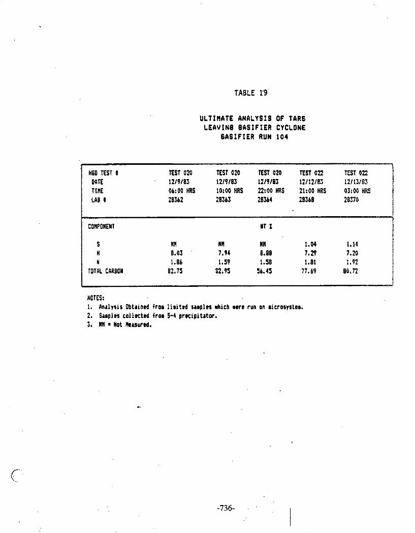
TABLE 1'9'
ULTIHATE ANALYSIS OF TARS LEAVINB BABIFIER CYCLONE
GASIFIER RUN 104
H6D E S P b TEST 020 EST 020 TEST 020 ESP 022 T S T 022 7 DATE 12/9/03 12/9/63 12/9/83 12/12/a 19113i63 B TIRE 06: 00 HRS 10:00 HRS U:OO M S 21:00 HRS 0S:W HE LAB t 20362 28363 20s 4 3360 283YO
r a
I COt!BONEWT UT 2 B
I S Nl! NR W11 1.04 1.14 i
H 8.03 7.94 8.~8 7.3 7.20 i 1
N 1.86 1.59 1.58 1.81 1.92 ! TOTAL CARBON 82.75 82.95 56.45 77.69 86.72 i
i i
NOTES: I. Analysis Obtained fros l i r i t r d s a a g l n mhich r u e run on rierosyster. 2. Samples c o l l u t e d f ro@ S-4 p r ~ i p i t a t w . 3. W1I * ltot Reuwed.

TABLE 2i
ULTIHATE ANALYSIS OF COALS USED DURING GASIFIER RU N 104
-
CDRPONUT , un
PITTSBURGH S U M COAL NORTH ORKOTA LIGNITE AKRWIIGHT INDIAN HEAD
ftoistwe 0.39 0.52 A5h 7.11 10.28 S 1.82 . . 1.66 H 5.12 4.76 n 3.0s 1.27 Total Cubon 77.10 67.54 Volrt i lcs 38.33 40. n Btullb 13715 11956

APPENDIX I
Laboratorv-Scale Testins - Simulated KRW Gas
Performance of Zinc Ferrite Sorbent in Simulated Hot Coal Gas From the KRW Process Development Unit
Introduction
In connection with the conceptual design of a zinc ferrite hot gas desulfur- ization unit by Westinghouse Electric Corporation Synthetic Fuels Division (now KRW Energy Systems, Inc.) as part of the Waltz Mill Coal Gasification Program (I), a program of experiments was designed for the METC, newly revamped, laboratory-scale, high-temperature desulfurization unit to inves- tigate the performance of zinc ferrite sorbent in simulated coal gas corre- sponding to that anticipated from the KRW process development unit. The experiments were carried out from March to May 1984.
Laboratorv-Scale Unit
Details of the laboratory-scale unit are given in contractor reports (2,3). The flow schematic is shown in Figure 1. The unit is a redesigned version of that employed in previous test series (4).
The new reactor component, which is 60 inches long by 2 inches diameter, is also made from 316 stainless steel but contains an integral preheater and after cooler and is aluminized internally to minimize hydrogen sulfide reac- tion with the reactor insides. The reactor is located within a +zone clam- shell electrically heated furnace. A 12-inch section at the middle of the reactor length is available for the desulfurization sorbent. Temperatures at six points along the center line are measured by means of thermocouples situ- ated in a stainless steel thermowell. The system is maintained at a positive pressure of 25 psig primarily to ensure flow through the on-line gas chroma- tograph, which measures H,O, COS, and SO, concentrations in the exit gas. Process conditions can be recorded by an automatic data acquisition and con- t ~ o l system (ADACS) (5) . Gas Conditions
It is planned to operate the KRW process development unit in both oxygen-blown and air-blown modes. Estimated compositions of the water-quenched gases entering the zinc ferrite unit are shown in Table 1 (6). Gas compositions approximating these were employed at the laboratory scale in a total of eight sulfidation tests: four oxygen blown and four air blown. Carbonyl sulfide and arror~or~ia were excluded as being of minor consequence, and the hydrogen sul- fide concentration was elevated so that breakthrough could occur within a dayr s operation at the space velocity of 2,000 h-' employed-corresponding to a linear velocity of 15 cm/s through the reactor. The tests were conducted at 4 reactor furnace temperature settings: 1,000, 1,100, 1,200, and 1,300°F.

Operation of Laboratorv-Scale Unit
The opera t ing condi t ions f o r t h e s e r i e s of t e s t s a r e summarized i n Figures 2 t o 13. The f i r s t two tests, Nos. 001 and 002, were designed t o v e r i f y t h a t hydrogen s u l f i d e i n simulated coa l gas r e a c t s t o a n e g l i g i b l e e x t e n t with t h e i n s i d e of t h e aluminized r e a c t o r . I n Test No. 001, s imulated Lurgi air-blown gas conta in ing 0.267 vo l . percent H2S was passed through t h e empty r e a c t o r f o r about 3 hours. Figure 1 4 , which i s a p l o t of H2S concentra t ion i n t h e r e a c t o r condenser e x i t gas , measured by d e t e c t o r tube, shows t h a t t h e H2S l e v e l r a p i d l y reached a p la teau corresponding t o t h e i n l e t 4 s concentra t ion . When H2S i n t o t h e r e a c t o r i n l e t gas was shut o f f , during a f u r t h e r hour, t h e H2S 1 e v e l . h e x i t gas quickly f e l l t o a few ppm i n d i c a t i n g t h a t very l i t t l e s u l f i - da t ion of t h e r e a c t o r had taken p lace . This conclusion was confirmed i n Test No. 002, i n which a t y p i c a l regenera t ion gas c o n s i s t i n g of 50 v o l . percent each of a i r and steam was passed through t h e r e a c t o r f o r 2 hours. Only a few ppm of SO,, measured by d e t e c t o r tube, was de tec ted i n t h e r e a c t o r condenser e x i t gas . For a f u r t h e r shor t period, s imulated Lurgi air-blown c o a l gas was passed through t h e r e a c t o r . H2S i n t h e e x i t gas amounted t o only a few ppm.
Test Nos. 003, 004, 005, and 006 were c a r r i e d out with simulated oxygen-blown gas , conta in ing 1 vol . percent H2S, a t furnace temperature s e t t i n g s of 1,000, 1,100, 1 , 2 0 0 , and 1,300°F, r e spec t ive ly . The r e a c t o r contained 715 g of f r e s h United Ca ta lys t s L-1504 3116-inch z inc f e r r i t e ex t rus ions i n each t e s t except f o r Test No. 003, where t h e amount was 593 g . Figures 15, 16, 17, and 18 show p l o t s of t h e H2S concentra t ion i n r e a c t o r condenser e x i t gas a g a i n s t t ime on stream f o r t h e four t e s t s . D i scon t inu i t i e s i n t h e p l o t s a r e caused by over-
..night breaks i n t h e t e s t s . The p l o t s a r e superimposed i n Figure 19. The H,S l e v e l s before breakthrough a r e a few ppm a s p red ic ted by thermodynamic chemi- c a l equi l ibr ium computations. However, t h e p r e d i c t i o n t h a t t h e l e v e l should inc rease with temperature i s not borne out f o r t h e 1,200 and 1,300°F t e s t s . I n both of t h e s e , t h e H2S l e v e l i s lower than i n t h e l,lOO°F t e s t and com- parable t o t h e l,OOO°F t e s t .
The amounts of s u l f u r absorbed by t h e sorbent , computed from t h e t o t a l gas flow through t h e r e a c t o r and t h e i n l e t concentra t ion i n t h e four t e s t s , a r e shown i n Figure 20, expressed a s weight percent of t h e f r e s h so rben t . The amount i s g r e a t e s t a t 1 , 2 0 0 ° ~ but f a l l s o f f a t higher temperatures i n accor- dance with previous experience with t h e sorbent .
Test No. 003 was repeated i n Test No. 003R with 715 g of sorbent i n s t e a d of 593 g t o make it more comparable with t h e o t h e r t e s t s . However, because of a malfunction r e l a t e d t o water and hydrogen s u l f i d e admission, t h e r e s u l t s a r e not f u l l y v a l i d .
Test Nos. 007, 008, 009, and 010 were c a r r i e d out with simulated air-blown gas, conta in ing 1. vol., percent H,S, a t furnace s e t t i n g s of 1,000, 1,100, 1,200, and 1,300°F, r e spec t ive ly . The r e a c t o r contained 715 g of f r e s h United C a t a l y s t s L-1504 3/16-inch z inc f e r r i t e ex t rus ions i n each test . Test No. 010 was repeated i n Test No. O l O R because of poor temperature con- t r o l i n t h e former tes t . Figures 21, 22, 23, and 24 show p l o t s of t h e H2S concentra t ion i n r e a c t o r condenser e x i t gas a g a i n s t t ime on stream f o r t h e four temperatures. The p l o t s a r e superimposed i n Figure 25. The 4s concen- t r a t i o n l e v e l s a t t a i n e d a r e remarkably s i m i l a r t o t h o s e p rev ious ly obtained
f o r t h e oxygen-blown gas t e s t s . Again, t h e H,S l e v e l s above 1, 100°F were unaccountably lower than expected.
The amounts of s u l f u r absorbed by t h e sorbent , computed from t h e t o t a l gas flow through t h e r e a c t o r and t h e i n l e t H2S concentra t ion i n t h e four t e s t s , a r e shown i n Figure 20 toge the r with t h e corresponding values f o r t h e oxygen- blown gas t e s t s f o r comparison. The fa l l -o f f i n s u l f u r absorbed above 1,200°F appears t o be somewhat sharper f o r t h e air-blown gas case .
Reactor Pressure Drop
The d i f f e r e n t i a l pressure across t h e combined r e a c t o r and i n t e g r a l qua r t z wool packed p rehea te r was measured throughout t h e d e s u l f u r i z a t i o n t e s t s . This p ressu re drop was i n i t i a l l y about 2 inches of water gauge i n a l l c a s e s . . I n t h e course of a tes t , t h i s measured p ressure drop increased somewhat, which i s a t t r i b u t e d t o t h e formation of a water l e g a t t h e bottom of t h e r e a c t o r , r e s u l t i n g from unant ic ipa ted condensation of water from t h e r e a c t o r i n l e t gas stream. There i s s t rong evidence, supported by a l a t e r t e s t , t h a t t h e a c t u a l r e a c t o r p ressu re drop remained v i r t u a l l y cons tant i n each t e s t .
Reactor Temperatures
Tables 2 and 3 show t h e average temperatures a t 2-inch i n t e r v a l s along t h e r e a c t o r a x i s f o r Test Nos. 003, 004, 005 and 006 and 007, 008, 009, and OlOR, r e s p e c t i v e l y . These temperatures genera l ly do not d i f f e r from t h e furnace s e t t i n g s of 1,000, 1,100, 1,200, and 1,300°F by more than about 2S°F.
Sorbent Analvsis
Af ter breakthrough of H,S i n each t e s t , t h e sorbent was cooled under n i t rogen and removed from t h e r e a c t o r . Samples were taken from t h e t o p (gas o u t l e t ) and bottom (gas i n l e t ) of t h e sorbent bed and analyzed f o r t o t a l s u l f u r , t o t a l carbon, surface a rea , pore volume, "helium" dens i ty , and mineral content . The mineral content , determined by X-ray d i f f r a c t i o n , i s shown i n Tables 4 and 5 f o r Test Nos. 003, 004, 005, and 006 and 007, 008, 009, and OlOR, respect ive ly . The o the r analyses a r e given i n Figures 4 t o 13.
The t o t a l s u l f u r measured i n t h e sorbent a t t h e r e a c t o r i n l e t i s genera l ly i n accord with t h a t ca lcu la ted from t h e flow of 4s through t h e sorbent ( see Figure 2 0 ) . I n Test Nos. 003, 004, 005, and 006, t h e va lues a r e 25.5, 27.2, 27.8, and 21.0 w t . percent , r e spec t ive ly , and i n Tes t s Nos. 007, 008, 009, and O l O R , they a r e 21.1, 30.1, 28.6, and 18.4 w t . percent , r e spec t ive ly . To ta l s u l f u r a t t h e r e a c t o r o u t l e t i s usua l ly about 1 w t . percent .
The t o t a l carbon measured i n t h e sorbent a t both r e a c t o r i n l e t and o u t l e t i s less than 0 .1 w t . percent , being r a t h e r more a t t h e outlet.. . The sorbent s u r f a c e a reas a t both r e a c t o r i n l e t and o u t l e t z a r e lower a t t h e higher opera t ing temperatures, f a l l i n g from about 2 t o 3 m / g a t l,OOO°F t o 0 .5 t o 1 .5 m2/g a t 1, 300°F. Pore volumes a r e a l s o correspondingly lower. Surface a r e a s a t t h e r e a c t o r i n l e t , where t h e sorbent i s predominantly i n t h e s u l f i d e form, a r e genera l ly somewhat lower, up t o about two times, than a t t h e o u t l e t , where only a small amount of t h e sorbent i s s u l f i d i z e d .

The mineral analyses ( see Tables 4 and 5) f o r a l l t h e t e s t s i n d i c a t e t h a t most of t h e sorbent a t t h e r e a c t o r i n l e t i s . c o n v e r t e d t o z inc and i r o n s u l f i d e whereas a t t h e r e a c t o r o u t l e t , t h e sorbent i s predominantly i n t h e form of f r a n k l i n i t e (and/or magneti te) and z i n c i t e . A t 1,200 and 1, 300°F, a substan- t i a l amount of wus t i t e i s present , genera l ly more a t t h e o u t l e t than a t t h e i n l e t . Cementite i s only found i n one case, t h a t of air-blown gas a t 1,300°F. However, t h i s i s not corroborated by t h e t o t a l carbon content , which i s l e s s than 0 .1 w t . percent .
Crush S t rena th
F i f t e e n (15) ex t rus ions from f r e s h sorbent and from each sample, approximately 1 cm long, were crushed between p a r a l l e l f l a t su r faces and t h e crushing fo rce was measured. The r e s u l t s a r e given i n Table 6 ( f r e s h sorbent ) and Tables 7 t o 1 4 (Test Nos. 003, 004, 005, 006, 007, 008, 009, and 010R).
Compared with t h e f r e s h sorbent , which has an average crush s t r e n g t h of about 8 kg/cm, t h e crush s t r e n g t h of t h e sorbent from t h e r e a c t o r i n l e t i s genera l ly r a t h e r h igher , up t o about two t imes, though t h i s f a l l s o f f wi th temperature and, a t 1,300°F, t h e crush s t r e n g t h i s about t h e same a s t h a t of f r e s h sor- ben t . The crush s t r e n g t h of sorbent from t h e r e a c t o r o u t l e t t ends t o be s l i g h t l y l e s s than t h a t of f r e s h sorbent a t a l l temperatures bu t , because of t h e s i z e of t h e s tandard dev ia t ion , t h i s i s not very s i g n i f i c a n t .
Gas Analvsis
During a l l t h e t e s t s , grab samples of gas e x i t i n g t h e r e a c t o r - o u t l e t condenser . -.
were taken every 2 hours and analyzed f o r Hz, 0,, N,, CO, CO,, and CH, f o r comparison with t h e metered gas c o n s t i t u e n t s f ed t o t h e r e a c t o r .
The analyses f o r t h e oxygen-blown case , i .e . , Test Nos. 003 t o 006, a r e shown i n Table 15 and those f o r t h e air-blown case, i . e . , Tes t Nos. 007, 008, 009, and OlOR, i n Table 16.
It i s evident t h a t t h e s h i f t r eac t ion , CO + 40 -+ CO, + H,, has proceeded t o a l a r g e e x t e n t . This i s more s o a t t h e lower temperature of l,OOO°F than a t 1 , 3 0 O 0 ~ as expected by thermodynamic equi l ibr ium calcudat ion .
I n Table 15, some of t h e samples can be seen t o con ta in amounts of oxygen and n i t rogen which should be absent . This i s a t t r i b u t e d t o incomplete d isplace- ment of a i r from t h e grab sample b o t t l e s .
A small amount of water condensed from r e a c t o r i n l e t gases s o t h a t t h e a c t u a l composition e n t e r i n g t h e sorbent bed d i f f e r s somewhat from t h e compositions given i n Figures 1 t o 12 . The cor rec ted compositions a r e given i n Table 17.
Condensate Analvsis
The water condensing out from t h e gases e x i t i n g t h e r e a c t o r was sampled and analyzed f o r zinc, i ron , and s u l f a t e . The r e s u l t s f o r Test Nos. 003 t o 010 a r e given i n Table 18. The concentra t ion of z inc i s genera l ly l e s s than 5 ppmw which, t r a n s l a t e d t o gas concentra t ion , i s l e s s than 1 ppm. Though not conclusive (see Test No. 6 ) , t h e r e appears to be more z inc i n the condensate

a t higher temperatures. The amount of s u l f a t e i n t h e condensate, when t r a n s - l a t e d t o gas concentra t ion , i s of t h e o rde r of only about 1 ppmw of s u l f u r . I ron i n t h e condensate i s very low, suggest ing very l i t t l e c a r r y over of sor- bent i n t o t h e condenser.
Summarv and Conclusions
The s e r i e s of t e s t s c a r r i e d o u t , . i n which simulated oxygen- and air-blown c o a l gas from t h e KRW process development u n i t was passed through z inc f e r r i t e sor- bent i n a laboratory-scale u n i t , has demonstrated t h a t t h e sorbent can func- t i o n i n t h e regime of gas composition and temperature planned f o r p i lo t - sca le tests, lowering H,S concentra t ion t o a few ppmw.
There i s evidence t h a t a t 1 , 200°F and above, wus t i t e ' i s formed i n both oxygen- and air-blown cases , r e s u l t i n g i n a lower sorbent conversion t o s u l f i d e before hydrogen s u l f i d e breakthrough. Thus, ope ra t ion above 1, 200°F and a t lower steam concentra t ions i n t h e gases than those employed i n t h e s e tes ts i s not recommended.
The amount of z inc c a r r y over, l e s s than 1 ppm i n t h e gas , i s thought t o be acceptable . This l e v e l would be an o rde r of magnitude smal ler (based on z inc vapor equi l ibr ium) a t t h e higher p ressu re of opera t ion of t h e process devel- opment u n i t .
There i s a r e l a t i v e l y small drop i n sorbent su r face a r e a a t t h e temperatures inves t iga ted bu t , i n t h e absence of long-term cumulative e f f e c t s , t h i s w i l l probably be t o l e r a b l e . Also, sorbent crush s t r e n g t h i s not a l t e r e d markedly by t h e s u l f i d a t i o n process . I n f a c t , s u l f i d i z e d sorbent genera l ly has a higher crush s t r e n g t h than f r e s h sorbent .
V i r t u a l l y no carbon deposi t ion occurred dur ing t h e tests and t h e r e a c t o r d i f f e r e n t i a l p ressu re remained constant a t a low l e v e l .
References
1. "Conceptual Design Report of PDU-Scale Hot Gas Desu l fu r i za t ion , " sub- mi t t ed t o Morgantown Energy Technology Center by KRW Energy Syst-ems, Inc . , May 1984.
2. S t e i n f e l d , G . , "S ta tus of METC Inves t iga t ions of Coal Gas Desulfuriza- t i o n a t High Temperature," Science Appl ica t ions , I n c . , f o r Morgantown Energy Technology Center, Report No. ~OE/MC/16545-1553, 1984.
3 . S t e i n f e l d , G . , "S ta tus of METC Inves t iga t ions of Coal Gas Desulfuriza- t i o n a t High Temperature," Science Appl ica t ions , I n c . , f o r Morgantown Energy Technology Center, 1985.
4 . Grindley, T . , "Development and Tes t ing of Regenerable Hot Coal Gas Desu l fu r i za t ion Sorbents f o r Molten Carbonate Fuel C e l l Appl ica t ion ," I R No. 1133, Morgantown Energy Technology Center, October 1981.
5. Goff, D . R . , and D . Armstrong, "System Design of t h e METC Automatic Data Acquis i t ion and Control System," Report No. DOE/MC/16050-1120, 1982.
6. Verbal Communication from D. K. Schmidt, KRW Energy Systems, Inc., to R. J. Belt, METC, April 16, 1984.

TABLE 1
Compositions of Gases t o be Treated by the Zinc Ferr i te Process Development Unit
Oxygen-Blown , Air-Blown Component Gas (Vo1.x) Gas (Val.%)
H2S COS N 2 NH3
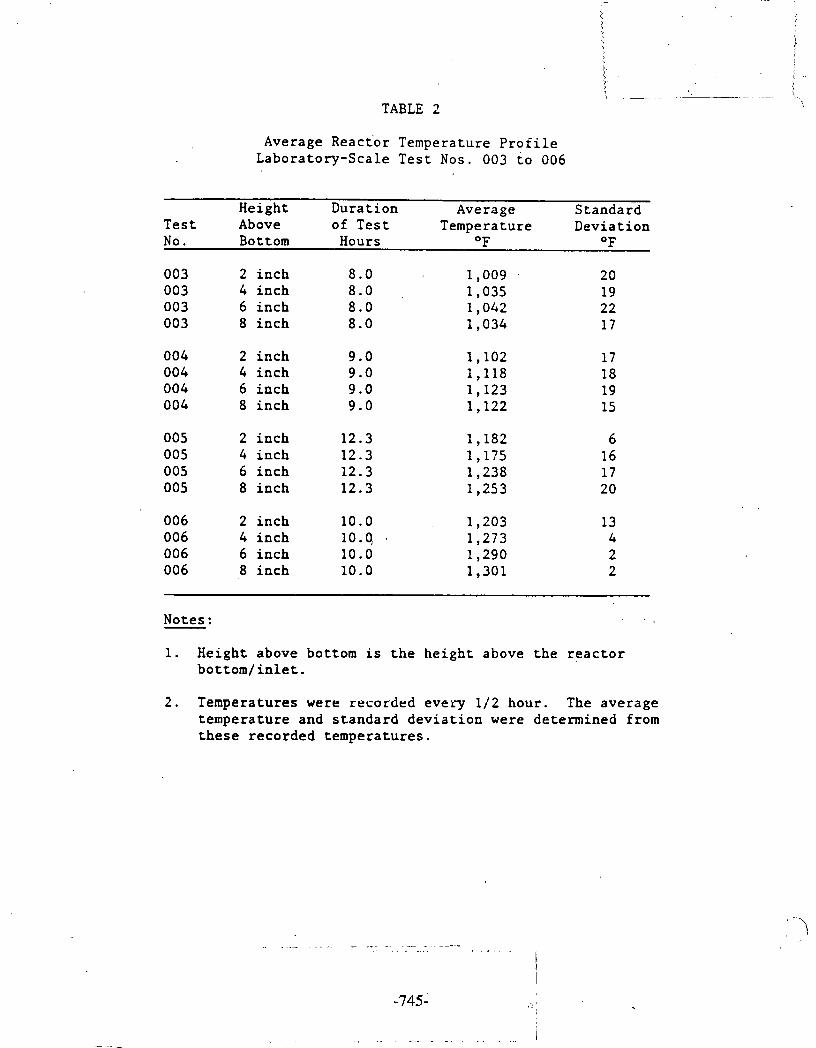
TABLE 2
Average Reac to r Temperature P r o f i l e Labora tory-Sca le T e s t Nos. 003 t o 006
Height Dura t ion Average S tanda rd T e s t Above of T e s t Temperature Dev ia t ion No. Bottom Hours O F O F
003 2 i n c h 8.0 1,009 . 20 003 4 i n c h 8.0 1,035 19 003 6 i n c h 8.0 1,042 22 003 8 i n c h 8.0 1,034 17
004 2 i n c h 9 .O 1,102 17 004 4 i n c h 9.0 1,118 18 004 6 i n c h 9.0 1,123 19 004 8 i n c h 9.0 1,122 15
005 2 i n c h 12.3 1,182 6 005 4 i n c h 12.3 1,175 16 005 6 i n c h 12.3 1,238 17 005 8 i n c h 12.3 1,253 2 0
006 2 i n c h 10.0 1,203 13 006 4 i n c h 10.4 . 1,273 4 006 6 i n c h 10.0 1,290 2 006 8 i n c h 10.0 1,301 2
Notes : . .
1. Height above bottom i s t h e h e i g h t above t h e r e a c t o r b o t t o m / i n l e t .
2 . Temperatures were recorded eve ry 1/2 hour . The ave rage t empera tu re and s t a n d a r d d e v i a t i o n were de te rmined from t h e s e r eco rded t empera tu re s .
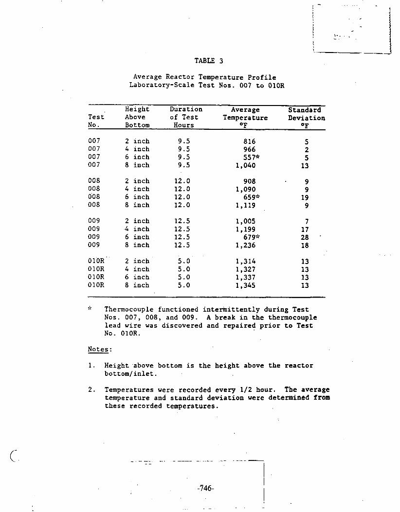
TABLE 3
Average Reactor Temperature P s o f i l e Laboratory-Scale T e s t Nos. 007 t o OlOR
Height Duration Average Standard T e s t Above of T e s t Temperature Devia t ion No. Bottom Hours OF OF
007 2 inch 9.5 8 1'6 5 007 4 inch 9.5 966 2 007 6 inch 9.5 557* 5 00 7 8 inch 9.5 1,040 13
008 2 inch 12.0 908 9 008 4 inch 12.0 1,090 9 008 6 inch 12.0 659" 19 008 8 inch 12.0 1,119 9
009 2 inch 12.5 1,005 7 009 .4 inch 12.5 1,199 17 009 6 inch 12.5 679* 28 009 8 inch 12.5 1,236 18
. . .
010~' 2 inch 5.0 1,314 13 OlOR 4 itch 5.0 1,327 13 0 1 OR 6 inch 5.0 1,337 13 0 1 OR 8 inch 5.0 1,345 13
* Thermocouple functioned i n t e r i n i t t e n t l y dur ing T e s t Nos. 007, 008, and 009. A break i n t h e thermocouple l ead wi re was discovered and r e p a i r e d p r i o r t o T e s t No. 010R.
Notes:
1. Height .above bottom i s t h e h e i g h t above t h e r e a c t o r b o t t o m / i n l e t .
2 . Temperatures were recorded every 1/2 hour. The average temperature and s t andard d e v i a t i o n were d e t e m i n e d from t h e s e recorded temperatures.
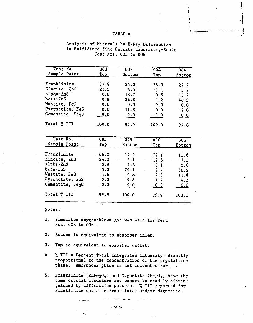
TABLE 4
Analysis of Minerals 'by X-Ray Diffraction in Sulfidized Zinc Ferrite Laboratory-Scale
Test Nos. 003 to 006
Test No. 003 003 004 004 Sample Point Top Bottom Top Bottom
Franklinite 77.8 34.2 78.9 27.7 Zincite, ZnO 21.3 3.4 19.1 3.7 alpha-ZnS 0.0 13.7 0.8 13.7 beta-ZnS .0.9 36.8 1.2 40.5 Wustite, FeO 0.0 0.0 0.0 0.0 Pyrrhotite,' FeS 0.0 11.8 0.0 12.0 Cementite, Fe3C - 0.0 0.0 0 .O 0.0 - - Total X TI1
Test No. 005 005 006 006 Sample Point Top Bottom Top Bottom
Franklinite 66.2 14.9 72.1 13.6 Zincite, ZnO 24.2 2.1 17.8 . - .7.3 alpha-ZnS 0.9 ' 2.3 3.1 2.6 beta-ZnS 3.0 70.1 . 2.7 60.5 Wustite, FeO 5.6 0.8 2.5 11.8 Pyrrhotite, FeS 0.0 ' 9.8 1.7 4.3 Cementite, Fe3C 0.0 - 0.0 - 0.0 - 0.0 - Total % TI1 99.9 100.0 99.9 100.1
Notes: - 1. Simulated oxygen-blown gas was used for Test
Nos. 003 to 006.
2. Bottom is equivalent to absorber inlet.
3 . Top is equivalent to absorber outlet.
4 . % TI1 = Percent Total Integrated Intensity; directly proportional to the concentration of the crystalline phase. Amorphous phase is not accounted for. .
5 . ~ranklinite' (ZnFe204) and Magnetite (Fes04) have the same crystal structure and caneot be readily distin- guished by diffraction pattern. % TI1 reported for Franklinite could be Pranklinits and/or Magnetite.

TABLE 5
Analysis of Minerals by X-Ray Diffraction in Sulfidized Zinc Ferrite X,aboratory-Scale
Test Nos. 007 to OlOR
Test No. 007 007 008 008 Sample Point Top Bottom Top Bottom
Franklinite 76.4 46.5 76.7 20.9 Zincite, ZnO 21.2 11.8 19.7 3.0 alpha-ZnS 0.8 12.2 1 . 1. 13.3 beta-ZnS 1.6 16.2 2.5 44.3 Wustite, FeO 0.0 0.0 0.0 0.5 Pyrrhotite, FeS 0.0 13.2 0.0 18.0 Cementite, FesC 0.0 0.0 - 0.0 - 0.0 - Total % TI1 100.0 99.9 100.0 100.0
Test No. 009 009 OlOR OlOR Sample Point Top Bottom ' Top Bottom
Franklinite 41.9 3.9 25.8 33.7 Zincite, ZnO 25.9 2.4 24.9 8.5 alpha-ZnS 0.9 3.8 0.7 4.7 beta-ZnS 6.7 72.4 9.4 40.7 Wustite, FeO 19.3 3.0 30.4 4.6 Pyrrhotite, FeS 5.2 14.5 0.0 7.7 Cementite, Fe3C 0.0 - 0.0 - 8.9 - 0.0 - Total % TI1 99.9 100.0 100.1 99.9
Notes.:
1. Simulated air-blown gas was used for Test Nos. 007 to 010R.
2. Bottom is equivalent to absorber inlet.
3. Top is equivalent to absorber outlet.
4. % TI1 = Pereent Total Integrated Intensity; direetly proportional to the concentration of the crystalline phase. Amorphous phase is not accounted for.
5. Franklinite (ZnFe204) and Magnetite (Fe304) have the same crystal structure and cannot be readily distin- guished by diffraction pattern. % TI1 reported for Franklinite could be Franklinite and/or Magnetite.
- - - - - - . - - - - - . .

Fresh Zinc Ferr i te ~orbe 'nt Crush Strength
Sorbent Fresh Fresh Crush Sorbent Sorbent
Strength Extrusion Normalized Test No. Length (cm) Force (kgf / cm)
Average 0 .97 . Standard 0 .23 Deviation

TABLE 7
Sul f id ized Zinc F e r r i t e Sorbent Crush Strength After Test No. 003
Sorbent T 003 T 003 T 003 T 003 Crush Bottom Bottom
Strength Extrusion Extrusion Normalized Top
Normalized Top
Test No. Length (cm) Force (kg£ /cm) Length (cm) Force ( k g f /cm)
1 0.82' 18 1.23 8 2 0.73 12 - 0.96 9 3 1.10 17 0.80 5 4 1.06 14 1.19 12 5 1.37 11 0.96 4 6 0.70 8 1.02 2 7 0.85 19 0.73 2 8 0.91 17 0.88 16 9 0.95 14 0.81 19 10 1.00 11 1.17 5 1 1 0.91 2 0 0.80 2 12 0.73 9 0.69 , 4 13 1.24 8 0.77 11 14 1.03 ' 2 0 0.95
.. . . . . 2
15 1.00 7 0.86 8
Average 0.96 Standard 0.19 Deviation
KO t e s :
1. Bottom is equivalent t o absorber i n l e t .
2. Top i s equivalent t o absorber o u t l e t .

! > . . - - -
TABLE 8 J A
S u l f i d i z e d Zinc F e r r i t e Sorbent Crush S t r e n g t h A f t e r T e s t No. 004
So r b e n t T 004 T 004 T 004 T 004 Crush Bottom Bottom TOP TOP
S t r e n g t h Ex t rus ion Normalized Ex t rus ion Normalized T e s t No. Length (cm) Force (kgf/cm) Length (cm) Force (kgf/cm)
Average 0.97 Standard 0.19 Devia t ion
Notes:
1 . Bottom i s e q u i v a l e n t t o absorbe r i n l e t .
2 . Top i s e q u i v a l e n t t o absorber o u t l e t .
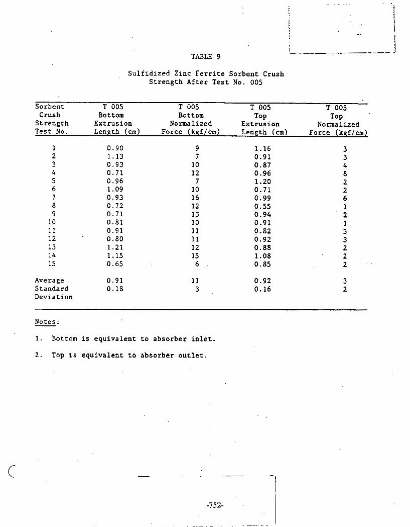
TABLE 9
Sul f id ized Zinc F e r r i t e Sorbent Crush Strength After Test No. 005
Sorbent T 005 T 005 T 005 Crush
T 005 Bottom Bottom TOP
Strength Extrusion Normalized Extrusion Top
Normalized Test No. Length (cm) Force (kgf/cm) Length (cm) Force (kgf/cm)
1 0.90 9 1.16 2
3 1.13 7 0.91
3 0.93 10 0.87 3
4 4
0.71 12 0.96 5
8 0.96 7 1.20
6 2
1.09 10 0.71 7
2 0.93 16 0.99
8 6
0.72 12 0.55 9
1 0.71 13 0.94
10 2
0.81 10 0.91 11
1 0.91 11 0.82
12 3
0.80 11 0.92 13
3 1.21 12 0.88
14 2
1.15 15 1.08 15
2 0.65 6 . , 0.85 2 - ' .
Average 0.91 Standard 0.18 Deviation
Notes:
1. Bottom is equivalent t o absorber i n l e t .
2 . Top i s equivalent co absorber o u c l e t .

TABLE 10
S u l f i d i z e d Zinc F e r r i t e Sorbent . Crush S t r e n g t h A f t e r T e s t No. 006
Sorben t T 006 T 006 T 006 T 006 Crush Bottom Bottom TOP
S t r e n g t h E x t r u s i o n Normalized E x t r u s i o n Normalized TOP
T e s t No. Length (cm) Force (kgf/cm) Length (cm) Force (kgf/cm)
Average S tanda rd ' Devia t ion
Notes :
1. Bottom i s e q u i v a l e n t t o a b s o r b e r i n l e t . . .
2 . Top is e q u i v a l e n t t o a b s o r b e r o u t l e t .

TABLE 11
S u l f i d i z e d Zinc F e r r i t e Sorbent Crush S t r e n g t h A f t e r Test No. 007
Sorbent T 007 T 007 T 007 T 007 Crush Bottom Bottom TOP TOP
S t r e n g t h ~ x t r u s i o n Normalized E x t r u s i o n Normalized Tes t No. Length (cm) Force (kgf/cm) Length (cm) Force (kgf / cm)
Average Standard Devia t ion
Notes :
1. Bottom i s e q u i v a l e n t t o absorbe r i n l e t .
2 . Top i s e q u i v a l e n t t o absorbe r o u t l e t .
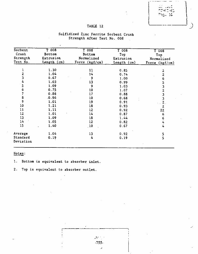
TABLE 12
S u l f i d i z e d Zinc F e r r i t e Sorbent Crush Strength A f t e r T e s t No. 008
Sorbent T 008 T 008 T 008 T 008 Crush Bottom Bottom TOP
Strength Extrus ion Normalized Extrus ion Normalized Top
T e s t No. Length (cm) Force (kgf/cm) Length (cm) Force (kgf/cm)
Average 1 . 0 4 Standard 0 . 1 9 Deviat ion
Notes:
1 . Bottom i s equ iva lent t o absorber i n l e t .
2 . Top i s equ iva lent t o absorber o u t l e t .

t
\ i !
~
TABLE 13
Sulfidized Zinc Ferrite Sorbent Crush Strength After Test No. 009
Sorbent T 009 T 009 T 009 T 009 Crush Bottom Bottom
Strength Extrusion TOP
Normalized TOP
Extrusion Normalized Test No. Length (cm). Force (kgf/cm) Length (cm) Force (kgf/cm)
1 1.23 6 1.00 2
5 0.81 5 1.28 4
3 1.31 5 1.11 4
7 0.94 5 1.00
5 1-09 8 0.81 9
6 5
0.99 4 1.17 8 7 1.06 5 0.66 8
3 0.86 13 0.70
9 17
1.11 18 0.97 13 10 1.40 6 1.03 10 11 0.89 7 0.95 8 12 0.97 8 0.52 3 13 1.20 14 1.32 4 14 0.97 7 0.88 4 15 1.02 - - 12 . - - 0 :74- 10
Average 1.06 Standard 0.17 Deviation
Notes:
1. Bottom is equivalent to absorber inlet.
2. Top is equivalent to absorber outlet.

TABLE 14
S u l f i d i z e d Zinc ~ e r r i t e S o r b e n t . Crush S t r e n g t h A f t e r T e s t No. O l O R
So r b e n t T O l O R T O l O R T O l O R T O l O R Crush Bottom Bottom TOP Top
S t r e n g t h E x t r u s i o n Normalized E x t r u s i o n Normalized T e s t No. Length (cm) ~ o r c e (kgf /cm) Length (cm) Force (kgf/cm)
Average 1.05 Standa rd 0 .23 .Dev ia t ion
Notes :
1. Bottom i s e q u i v a l e n t t o a b s o r b e r i n l e t .
2 . Top i s e q u i v a l e n t t o a b s o r b e r o u t l e t .

Grab S a ~ ~ p l e Gas A n a l y s i s f o r Elajor Coo1por1enl.s a t Coridenser E x i t Laboratory-Scale T e s t Nos. 003 t o 006
Sample Sample No. Lab No. Time H2 3- 02 % N2 % CO 04 , C 0 2 % CI14 % T o t a l -- % - Date -
Test No. 003
I[C-003- 1 IIG NO. 1 .04/04/84 1100 26.34 0 .13 1.30 26.16 44.33 ,1.23 99.49 HC-003-2 1IG No. 2 04/04/84 1300 32.65 0.07 0.96 23.15 41.46 ;1.21 99.50 IIG-003-3 1IC No. 3 04/04/84 1500 20.05 I 0.94 7.89 24.03 45.32 1.27 99.50 HG-003-4 HG N O . 4 04/05/84 1100 25.60 0 .05 1.13 25.64 45.76 1 .33 99.51
Test T No. 004 I
HCi004-1 HG No. 5 04/10/84 1100 18.24 1 .33 10.34 26.90 41.52 1.17 99.50 llC-004-2 IIG NO. 6 04/ 10/84 E 300 15.34 2.21 16.68 . 2 4 . 4 6 39.64 1.16 99.49 ' :
llC-004-3 HG NO. 7 041 10184 1500 12.28 3.26 23.94 20.62 38.40 1.01 99.51 llC-004-4 HC NO. 8 04/11/84 0930 20.20 1.07 8 .53 25.74 42.71 1.25 99.50
Test No. 005
Test No. 006
HC No. 9 HC No. 10 IIG No. 11
. H G NO. - 12 HC No. 1 3 IlC No. 14
1IC No. 15 I I G N o . 16, 1IG NO'. 17 llG Na. 18. JIG NO,. 19
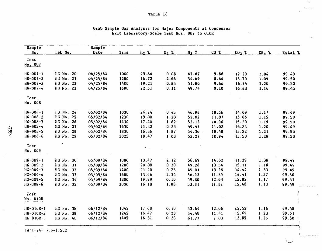
TABLE 16
Grab Sample Gas Analysis for Hajor Components at Condenser E x i t ~aborator~-scale .Test Nos. 007 to O l O R
S a o ~ ~ l e Sample No. Lab No. ~ a i e Ti me H2 % 02 % N2 % CO % C02 % Cl14 % Total .-
T e s t No. 007
, T e s t No. 008
1IG No. 20 04/25/85 1000 23.64 0.08 47.67 1IG No. 21 04/25/84 1200 16.72 2,66 54.69 1IG No. 22 04/25/84 1400 ,19.21 0.85 51.86 H G No. 23 04/25/84 1600 22.51 0.11 49.74
11; No. 24 05/02/84 1030 26.24 0.45 46.98 I1G Yo. 25 05/02/84 1230 19.00 1.20 52.02 1IG No. 26 05/02/84 1430 17.40 1.62 53.13 1IG No. 27 05/02/84 1630 21.32 0.23 49.47 11C No. 28 05/02/84 1830 16.36 1.87 54.36 . 1IG No. 29 05/02/84. 2025 18.47 1.03 52.27
T e s t No. 009
IIG-009- 1 11G NO. 30 05/09/84 1000 13.47 2.12 56.69 14.62 11.29 1.30 99.49 HG-009-2 1IG NO. 31 05/09/84 1200 20,08 0.30 49.28 13.54 15.11 1.18 99.49
- HG-(~09-3 IIG No. 32 05/09/84 1400 21.20 0.25 49.01 13.26 14.44 1.33 99.49 HC-009-4 11C NO. 33 05/09/84 1600 13.96 2.34 56.13 11.39 14.41 1.27 99.50 116-004 -5 HC N O . 34 05/09/84. 1800 19.99 0.10 49.80 12.63 15.82 1.17 99.51 1IG-009-6 HC NO. 35 05/09/84 2000 16.18 1.08 53.81 11.81 15.48 1.13 99 49 ,,.- .- ,. -,.,
T e s t No. OlOR
IIG-OlOR-1 11G NO. 38 06/ 12/84 1045 17.00 0.10 53.64 12.06 15.52 1.16 99.48 HG-01011-2 IIG NO. 39 061 12/84 1245 16.47 0.. 2 3 54.48 11.41 15.69 1.23 99.51 I
IIG-OlOIt-? IIG No. 40 06/ 12/84 1405 16.31 0.28 61.77 7.03 12.85 1.26 99.50 1
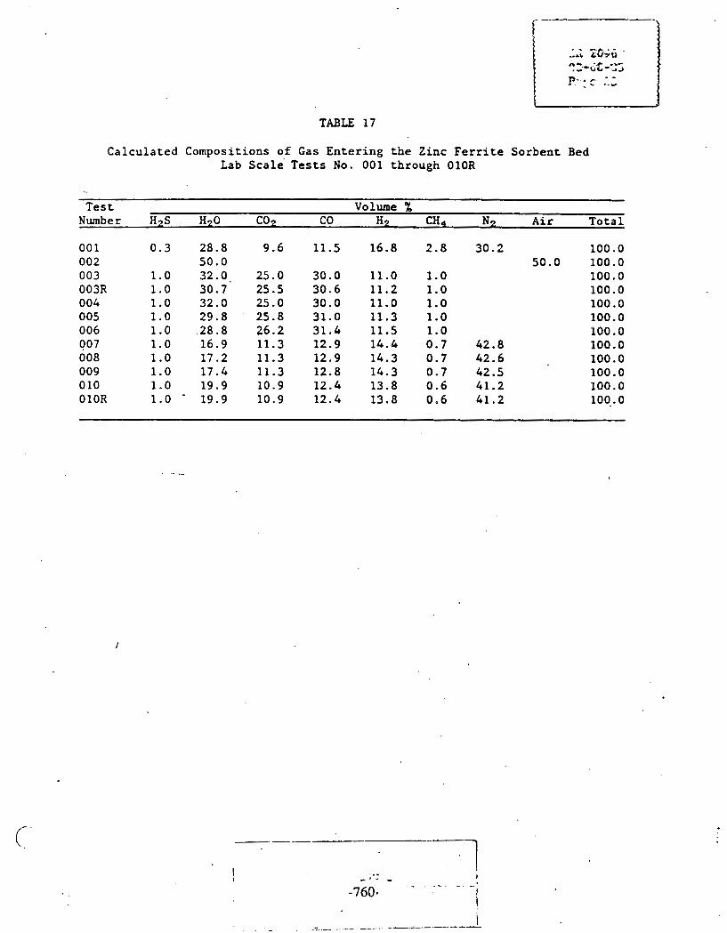
Calculated Compositions of Gas Entering the Zinc Ferrite Sorbent Bed Lab scale' Tests No. 001 through OlOR
Test Volume % Number H2S H20 Con CO H:! CH4 N2 Air Total
- - - 002 003 003R 004 005 006 007 008 009 0 10 OlOR
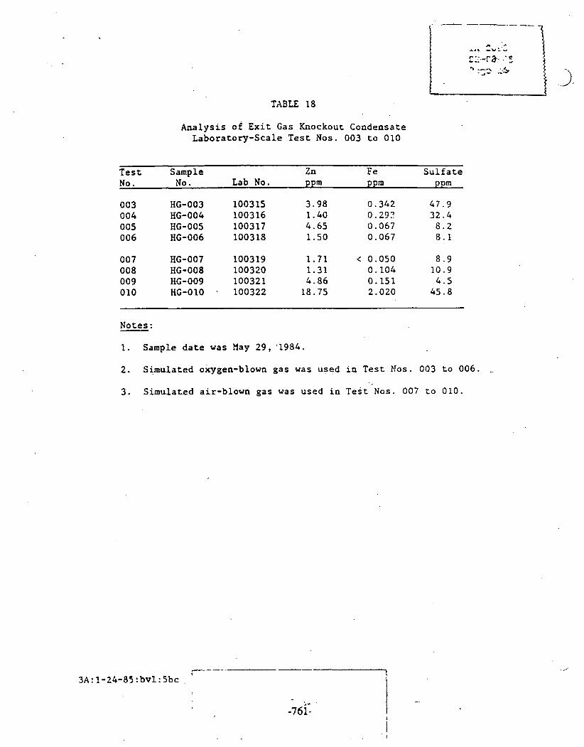
TABLE 18
Analysis of Exit Gas Knockout Condensate Laboratory-Scale Test Nos. 003 to 010
Test Sample Zn F e Sulfate No. No. Lab No. ppm ppm ppm
Notes:
1. Sample date was May 29,'1984.
2. Simulated oxygen-blown gas was used in Test Nos. 003 to 006. -
3. Simulated air-blown gas was used in Test Nos. 007 to 010.

FIGURE 1
HOT GAS DESULFURIZATION LAB SCALE TEST UNIT
PROCESS FLOW DIAGRAM-DRAWING NO. E830033 -

FIGURE 2
TEST sunnw SHEET HOT GAS DESULFURIZATION LAB SCALE TEST U N I T
tCCT HO. I 001 DibTE STARTED I 111ee 3/27/04 O a r € EHDEO I 14 140 3/27/04 t O T h L HOURS I 3.6 HRS
sOR6ENt T Y P E 4 E 1 C H T I NONE aORtE l lT NO. I
Has h l L - 4
H Z 6 ( 16.77 SCFH)
A I R
- - -- I
I
?OTkL FLOU I
SOR6EHT C O W O S I T I D N l '
SORCENT P E L L E T S I Z E 1 PREtREATl lENT I
FLGU ~ l l E noLC: UET B A S I S
8.109 SCFH 8.267 5
SULFUR LO6DINC I
I
I I I I
- 1 I OPER~~TINC CONOI TI DIIS
I
PURPOSE
SULFIDE t npw ILONIZED nutw REACTOR SHAKEDOUtl I4EULV B U I L T G U A R t Z / f l E T l l TEST U N I T
C\)1ALYSISI BEFORE A f T E R
tOTt7L. SULFUR 4 %U/U)I SURFACE AREA 4 Mi?/G J I DCNSITV ( G l C C ) I PORE U O W n E f C C / C ) r R I H E P A L AIICILYSI S: f L E M N T A C AI4ALVSIS:
D @ T A l a DETECTOR TUBE )
E X I T H 2 S I 2009 - 8038 P P N
E X I T SO21
E X I T 52:
E Y l T Hz :
REMARKS
3.6 S C f H 9.61 Y
4.3 SCFH 11.48 5
6.3 SCFH 16.82 8
1.87 SCFH 2.05 8
11.3 SCFH 30.17 8
37.44 SCFH
I. SULFUR GAS SHUT OFF l T 1409 HOURS. 2. E X I T SULFUR DOES NOT HATCH I N L E T SULFUR AS CALCULhTED.

FIGURE 3
TEST SUNfiARY SliEET H3T GAS DESULFURlZATIOII LAD SCALE TEST UNIT
TEST NO. I 802 DATE STARTED I 111ee w a w e 4 DtiTE ENDED I 13188 3 /28 /84 TOTAL HOURS I 2 HRS T VPE I REGENERATION
TYPE/UEICHTI NONE N3. I C o n P o s I t l o n l
SJRBENT PELLET S I t E I PRETREATnEl4t I SULFUR REtIOl~ED 1
H2S
ti26
n l n
C(12
co
H2
CH4
N'?
FLOU RATt MOLE%,
PURPOSE
REGEl1ERATION OF ERPTV REACTOR TEST.
AIIALYS I S I BEFORE AFTER
TOTfiL SULFUR; SURFACE AREA1 DENSlTV 1 PORE uoLunE1 RINERAL ANALYSIS1 ELENNTAL (UIALYSIS:
Dam; I DETECTOR TUBE J
EXIT Hc'SI
EXIT 502: 2.5 - 7.5 PPn
EX11 52;
EXIT l iar
1. r\T 13 tJ0 HOURS SUITCILO 1'0 SULFlOATlOn CASES UI~HOUT H25.
2. ' 2 - I S PPll H2S nEr\SUREO ON SULFlDATION CASES Il l I IUS H2S.
CONCLUSIONS
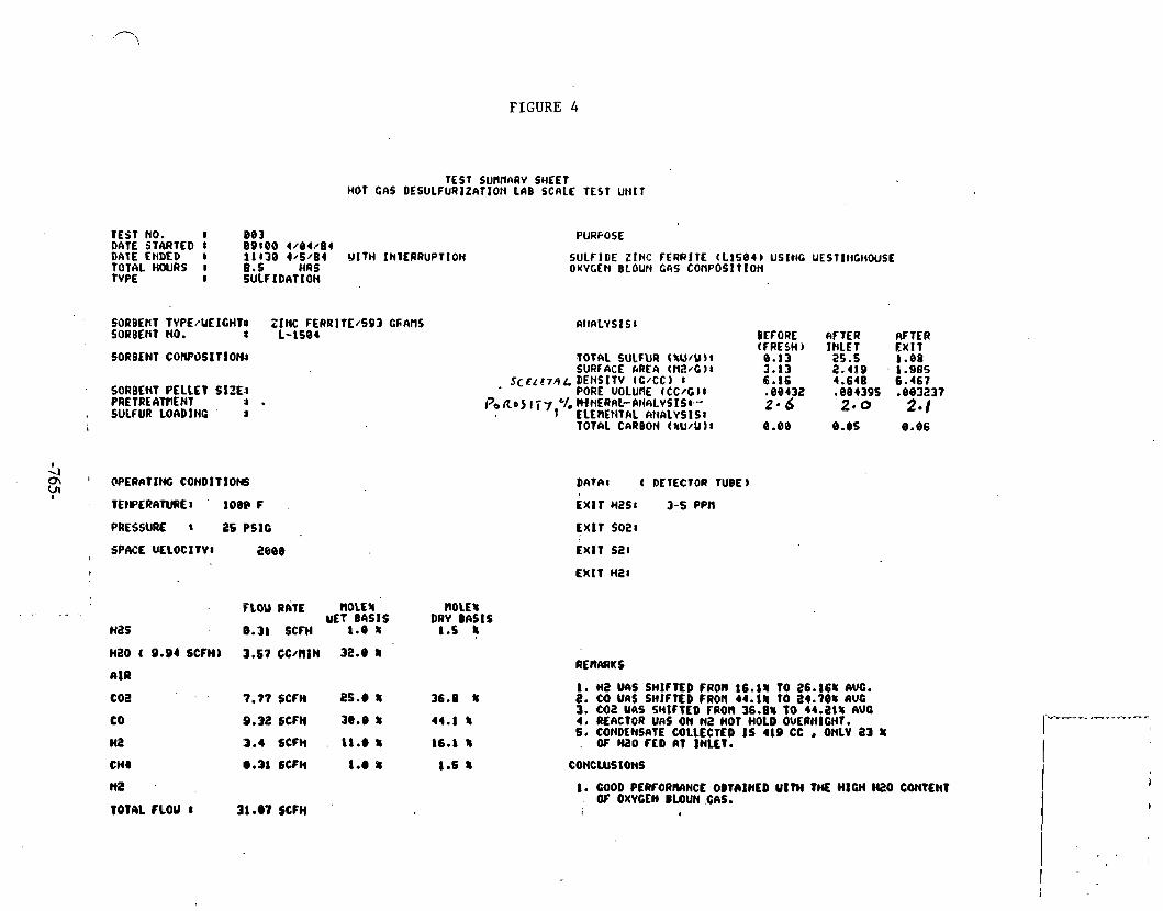
FIGURE 4
TEST sunnnw SHEET HOT GAS DESULFURIZATION LAB SCALE TEST Ul([T
WEST NO. 8 80 3 DATE STARTED 8 09100 4/84/84 DATEENDED I i l r j e 4 / s / s r YITH INIERRUPTION TOTAL HOURS I B.S HRS TYPE 8 SULF 1 DRT ION
SORBEttT TVPE/UEICHTP ZINC FERRlTE/S93 CSAnS SORBENT NO. 1-1504
SORBENT COWOSlTlOH(
SORBEHT PELLET SIZE I PRETREATtnENT J .
, SULfUR LOADING J
.- .
Has
H2O ( 9.94 SCFH)
AIR
coa . .
CO
Hi!
CHI
N2
TOTAL FlQU I
PURPOSE
SULFIDE ZINC FERRITE tL1594b USIIIC UESTltiCHWSE O X V C ~ H BLOUN Gas COHPOSITION
IIttAL-fSIS I BEFORE fiFTER RFTER (FRESH) INLET EXlT
TOT AL SULFUR (%U/U) l 8.13 25.5 1.08 SURF4CE hREn ( t i 2 4 1 I 3 - 8 3 2.489 . 1.985
S C E L C T O L DEHSITV (C/CC) r 6.16 4.648 6.467 PORE UOLURE (CC/ClI -00432 .884395 .883237
1 3 6 ~ 1 5 177 '/, WNEQIIL-LtII\LYSIS(--' 1 ELEIIENTAL CIItALVSISI
24 6 2.0 2- 1
DATA8 ( DETECTOR TUBE)
EXIT HZSI 3-5 PPn
EXIT so21
EXlT s2:
P LOU
8.31
RATE ~ O L E S n o ~ ~ 8 uET BASIS DRY BIISIS
SCFH 1.0 f 1.5 j
7.77SCFH 2 5 . @ 1 36.8 X
8.32SCFH 3 8 . 8 % 44.1 f
3.4 SCFH . I1.e 8 16.1 8
m.31 6CFH 1.e 8 1.6 1
31 .a7 SCFH
1. HZ UIIS SHIFTED FROM 16.11 TO 26.161 AVO. 2. QO uns SHIFTED FRON 44.11 to ~ 4 . 7 0 8 ~ U G 3. CO2 U6S SMIFTED FROn 36.08 TO 44.2t% AUG 4. REACTOR UIIS ON N2 HOT HOLD OUERHICHT. 5, COHDENSRTE COLLECTED I S 419 CC r ONLY 23 1 . OF M20 FED RT INLET.
1. GOOD PERFORMHCE O B T ~ l M D Ulm THE HIGH N O COnTCNt . QT OXYGEN BLOUN 613.

FIGURE 5
TEST S U H M R V SHEET HOT U S M S U L F U R I Z A T I W L A B SCALE TEST U N I T
TEST NO. I 8 8 3 R DATE STARTED 1 8 8 1 4 5 6 / 1 9 / 8 4 DATE ENUED I 17888 6 / 2 8 / 8 4 TOTAL HOURS I Zl HAS f YPE I S U b f I D A T I O N
SOHBENT T Y P E / U f I G H T 8 Z I N C F E R R I T f / ? L S C R M S SORBEHT NO. I 1 - 1 5 8 4
SORDENT. COWOSIT I&: I
SORDEtIT P E L L E T S I Z E 8 PRETREATHEN1 I SULFUR LOADI I tG t
FLGU RATE n o u 8 UET b A S 1 5
9 .31 SCFH 1.9 X
Hi! 3 .4 S C f H 1 1 . 8 8
C H I 8.31 SCFH 1.9 h
TOTAL F L O U I 31.Q? SCFH
t lOLE8 DRY B A S I S
SULF I D € Z l rcC F E R R I T E (l.1584 ) U S I I i C UESTIl(CH0USE O X Y P N BLOUH GAS CI)PIPOSITIOIi. REPEAT OF T O 8 3 U I T H 715 C I I SORBENT LOADING INSTEAD OF 593 tin.
' TOTAL SULFUR ZU/U ) I SURFACE AREA I M / C ) I
Scr'&x! D E t t s l T v i c /cc b 1 , , PORE u o L U n E (CC/C )I d b.ct.f/-z /.. CII t iERAL 6 N A L Y S l S t .
f L E M N T A L AIIALYS I S 8 TOTAL CkRbOt l (NU) Ub I
BEFORE (FRESH) 8.13 3 . 1 3 6.16 .88432 2.6
AFTER I t r L E T 3 3 . 3 6
DLTAZ ( D E T E C T O R T U B E )
. E X I T H2S: 1 P P l l TOR 6.75 HOURS, GFiADULL R I S E Tt lEREAFTER
E X I T SO28
1. COIiDENSATE DRA l I iED f R O n KI(OC<irUT POT e TEST ENDS led0 CC ti20 2. COIILEIISAIE DRAI I IED FROl l REACTOR AT €140 O f 1CST: 2 7 0 CC H 2 0 .
THEREF ORE, ACTUAL COI IPOSIT lO l l O f GAS E l iTER lNG REACTOR . SORBENT BED UAS D l f F E R E t i T THAI1 C O f i P O S l T l O t ~ StiOUN AT L E f T . ACTUAL H Z 0 FLOU RATE ENTERI I IC SORBEIiT BED UAS 3 . 3 6 C C / n l N .
3 . o t r c HOUR IIITERRUPTION I 4 3 8 - 1 5 3 0 IIOURS 6 / 2 8 / 8 4 DUE TO CHANCING OF CO CYLINDER CItID GET1 l t l C UATER OUT OF t i 2 5 ROTnRETER.
4. UATER PRESSURE APPCIRENT LV OVERCOtlE5 H2S PRESSURE AND CAUSES UATER TO BACK UP I l r r o H2S FLOUIIETER.
5. RLACTOR PRESSURE DROP INCREASES f R o n 3 - 1 2 I t iC l IES OF - UATCR .
6. TEST IMTERRUPTED FOR N 2 HOT HOLD OUERNICHT.
I. GOOD PERFORnANCE flEASURED. BUT UATER I N H 2 S ROTAnETER TOUARDS LATTER PART OF TEST R A I S E S OUESTlOM AS TO ACCURACY TO DATA.
.d., , I > ~1 (
13 T L , !
b ~i ' J ' 3 r

FIGURE 6
TEST SUMRARV SHEET HOT QAS DESULFURIZATION LAB SCALE TEST UNIT
TESl 00. t 804 ' DATE STARTED 8 89889 4/18/84 DATE ENDED 1 10145 4/11/04 Torsi HOURS t 8.76 HRS T VPh: 8 SULFIDATION
PURPOSE
SULFIDE ZINC FERRITE (LISQ4J USING UESTINCHOUSE OXYGEN BLOUN GAS ConPos t t Ion
SORBENt TVPE;UEIGHT:: ZINC FtRRITE/716 CRnHS SORBENT NO. 4 1-1584
ANALVS I S I BEFORE AFTER
INLET 2.82 -2019 4.26 .98159S 0*7
0.87
EXIT SORBENT COPlPOSITlOW T OTAL SULFUR (%U/U 1:
SURFRCE AREA t f l 2 4 18 J;'',ltl~,/ DENS1 TV (CtCC 1 I
PORE UOLUM (CCIG): fi'o /~xf/F] ;, RIIIERM ANALYSIS:
"' ELEREHTAL kNRLVSIS8 TOTAL CARBON ( tU /U ) I
SORBENT PELLET SIZE3 . PRETPEATtlENt a SULFUR LOADING
DkTW t DETECTOR TUBE)
EXIT H2S: 3 - 6 PPN
EXIT so21
EXIT SZ.:
EXIT H2t
I 4 OPERIITINC CONDIT IOlIS Q\
8
! ;.I rEHPERi(TUREt . 118s F
. PRESSURE 8 2 s PSIC '
\ SPACE YELOCITVt 2800
~ L O U R A T C OLE^.' OLE^ UET BASIS DRY BASIS
9-31 SCfH 1.8 t 1.5 8
H20 ( 9.94 SCFHJ 3.57 CC/ll lN 32.8 t
6 I R
CO2 7.77 SCFH 25.8 8 36.8 8
I. COIIDEIISAVE COLLECTEDI 836 CC, 458 OF HZ0 FED AT INLET. 2. CRkB SAHPLES TOR nAJORS CONTAIl4ED 8-23% tI2, INDICATI#C
TtlkT SARPLE UOTTLES UERE NOT PURGED LOl4C ENOUGH. 3. TEST UAS INTERRUPTED UITH N2 HOT HOLD OVERNIGHT CVID
AMD COHTINUED THE NEWT D4V. 4. REACTOR PRESSURE DROP INCREASED fRON 2.3-10 INCHES OF
UATER, &NO DROPPED SLICHTLV AFTER IP HOT HOLD. e
CO 9 . 3 2 5 ~ ~ ~ 3 8 . 0 8 44.1 8
HZ 3.4 SCFH 11.0 8 16.1 8
CHI 9.31 SCFH 1.8 8 1.5 8
re 10tnL FLOU 8 31.87 SCFH
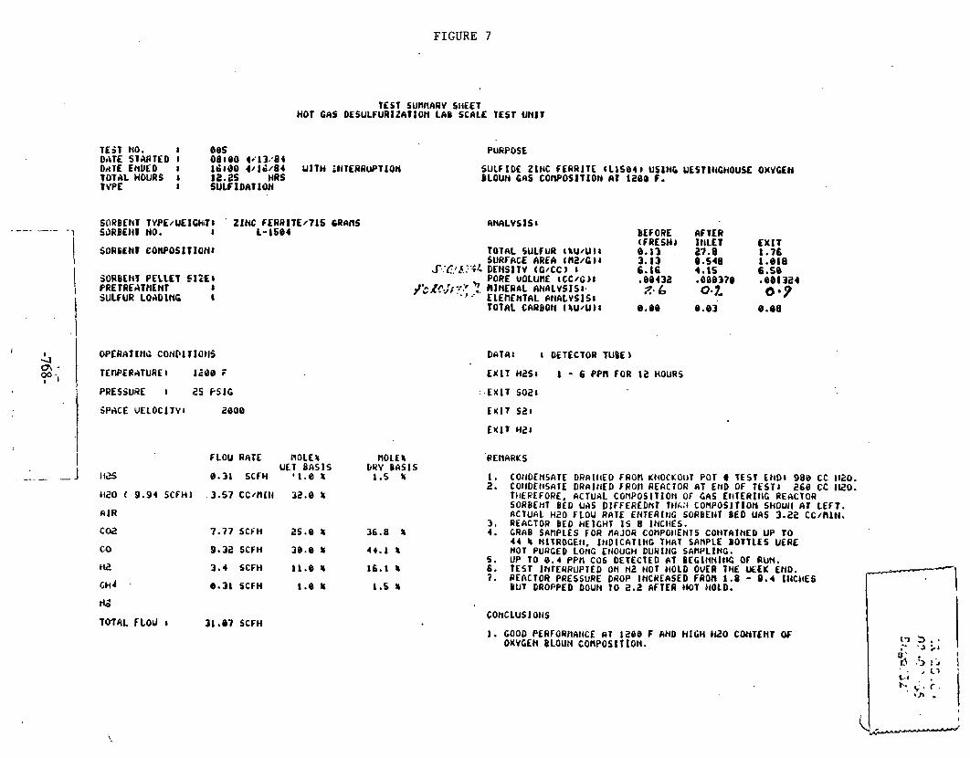
FIGURE 7
TEST SUnltARY SIiEET HOT GAS DESULFURIZATIOH L l B SCALE TEST U N I T
TEST no. I 885 DATE STARTED I 08 1 8 0 +'I 3.'84 DATE EnDED I 16160 4/ 16/04 U I T H EIiTERRUPTION TOTAL HOURS 8 11.25 HAS TYPE I S U L F I D A T I O H
30RBCNT PELLET SIZE8 PRET RCATtlENT I SULFUR LOADING 8
ZINC C E R A l T E / 7 1 5 C R A M 1-1584
I
& Q\ -
+ I
f LOU RATE NOLES UET B A S I S
8.31 SCFH ' 1 . 0 %
OPERAT IN\; CONPI 1 IQ t IS
TEWERATURE I 1288 F
PRESSURE 1 25 F S I G
1120 ( 9.94 SCFH) 3.57 c c / n t t r 32.0 tr
n m
C W 7.77 SCFH 2S.B 8
co 9.32 ~ C F H 38.8 m HZ 3 .4 SCFH 11.e u
I,H~ . e.31 SCFH 1.8 U
SPACE U E L O C l T Y l 2800
IG
TOTAL F L o J I 3 1 -87 SCFH
PURPOSE
SULF I D € Z I N C F ERRIT E (L1584 1 USSHG UESTIIIGHOUSC OXYGEN BLOUN CAS C O ~ O S I T I O ~ AT iaeo r.
TOTAL SULFUR ( kU/U I SURFACE AREA 4 NZ/C ) I
S.:C!f.?';/- DENSITV (G /CC) I PORE u o L u n E ( C C / C ) I
,'>A?$, 7'' ' fl)IINCRnL ANALVSI S I. .', .-.' ELEIIEHTAL L t i A L V S I S I f O f AL CARBON ( %U/U I
BEFORE (FRESH) e.13 . 3.13 6. L6 -88431 Z. 6
@.Be
DaTA: ( DETECTOR TUBE )
AFTER I I I L E T 27.8 8.548 4-15 -888379 0.7-
8.83
E X I T 1.76 1 .el8 6.58 .eel324 0 * 9
8-98
COliDfNSATE DRAIIIED FROn KIIOCKOIIT P O 1 a TEST C t i D I 980 CC t l2O. COlIDCIiSAIE DRA l t lED FROn REACTOR AT END OF TEST1 268 CC I Y O . TIIEREFORE, ACTUAL C O ~ P O S l T I O l l OF GAS E t iTERI t lC REACTOR SORBEHT BLD UAS DIFFERLDNT TtlA;4 CORPOSI T10M SHOUII AT LEFT . RCTUAL H 2 0 FLOU RATE EHTERl t lC SORBEtiT BED UAS 3.22 CC~RIN. REACTOR B E D HElGHT I S 8 IElCIlES. GRAB SAnPLES FOR tlAJOR COPlPOtlENTS COt lTAI t iED U P TO 4 4 k HITROCEII, I t I D I C A l I N C THRT SAMPLE BOTTLES UERE NOT P U W E D LONG EllOUCH DUWItiC SAMPLIHG. UP r o 0 . 4 P P n COG DETECTED AT B~CINNI~K; OF RUN. TEST 1MfEI)RUPTED ON N2 NOT HOLD OVER THE M E K END. REACTOR PRESSURE DROP IHCREASED FROn 1.0 - 0 .4 I t IC t iES BUT DROPPED DOUN TO 2.2 AFTER HOT ItOLD.
I. GOOD PERFORnAtiCE n T 1268 F AHD H I G H I P O CONTENT OF OXVCEH BLOUN C o n P o s I T I o n .
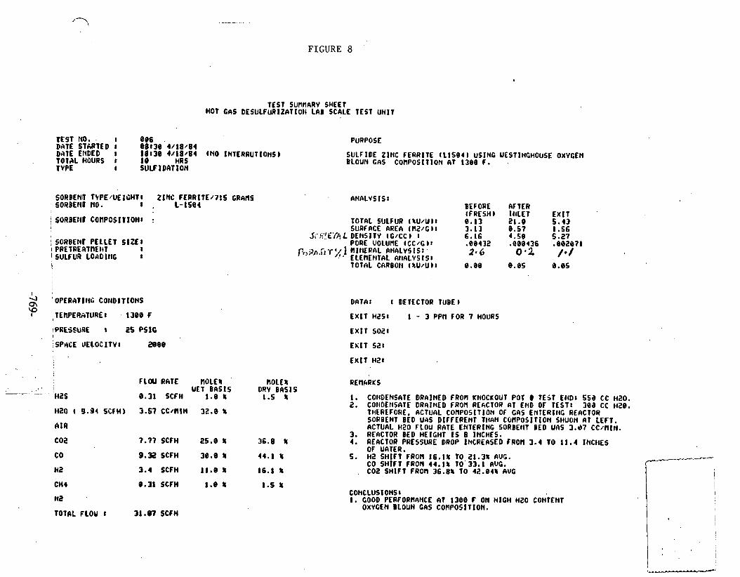
FIGURE 8 '
TEST SUflHARY SHEET HOT GAS DESULFURIZATIOt1 LAB SCALE TEST U H I T
T E S T N O . . I 806 . DATE STARTED I 6 8 1 3 8 4 / 1 8 / 8 4 DATE El iDED I 1 8 1 3 8 4 / 1 8 / 8 4 (NO INTERRUTIOt tS)
. TOTAL HOURS t 18 HRS TVPE I S U L F I D A T I O N
SORBEND T V P E / U E I C H T l Z I N C F E R R I T E / 7 I S GRhflS S O R B E C ~ ~ no. a . 1-1501
: SORBENV P E L L E T S I Z E 1 1 PRET RE ATnEt l~T I I SULFUR LOAD I l l G I
I
i
/OPERATII~G CO~IDITIONS
\f :TEWER;ITURE~ . 1388 F
!PRESSURE 25 PSlC !
j SPdCE UELOCIT V I a 0 8
co H a
C H I
na
TOTAL FLOU 8
F L W RATE f l O L E I '
UET B A S I S 8 .31 SCFH 1 . 8 8
3-51 C C / n l H 32.0 5
7 .77 S C f H 2 5 . 8 8
9.32 SCFH 30.0 8
3.4 SCFH 11.8 8
8-31 SCFH 1.8 I
31.07 SCFH
PURPOSE
SULFIDE ZINC FERRITE ( ~ i s e o USING UESTINCHOUSE o x Y c E n BLOUN GAS CORPOSIT lON 6 T 1 3 e 8 f. .
n o L C % DRY B A S I S
1 .5 5
' ANALVSIS 8 BEFORE b F t F R -. - . . .-.. (FRESH) I I I L E T E X I T
TOTAL SULFUR 4 SU/U 11 0. I 3 2 1 .O 5 . 4 3 SURFACE AREA ( M 2 / G ) l 3 . 1 3 0 . 5 7 1 . 5 6
.5iSi':"E'//? L DENSITY (CICC ) 8 6 - 1 6 4 . 5 8 5.27 . .
PORE u o L u n E ( C C / G )I . e 0 4 3 2 .eeeac I e e z e 7 1 p,,gh,r, .r%j R I t I E R A L ANALVSIS: .
ELEnENTAL N I A L Y S 1 S 8 2* 6 0 .2 / * /
DATA: DETECTORT TUBE^
E X I T HZS: 1 - 3 P P t l F O R 7 H O U R S
E X I T SO21
EXIT s a t
E X I T H Z 1
I. COtIDENSATE DRAINED FROU KNOCKOUT POT 0 TEST EtlD: 5 5 a CC H 2 0 . 2. COtIDEHSATE DRAINED FROM REfiCTOR A 1 END OF TEST: 3 0 3 CC HZ@.
THEREFORE, ACTUAL COMPOSITION OF G M ENTERI t lC REACTOR SORBEHT BED U4S DIFFERENT TWIN COnPOSIT lON SHUOH AT LEFT. ACTUAL H 2 0 FLOU RATE ENTERING SORBEtlT BED UAS 3.d7 C C / n I n .
3. REACTOR BED HE IGHT I S 8 INCHES. 4. RCACTOR PRESSURE DROP INCREASED FROn 3.4 TO 11 .4 I N C I E S
OF UATER. 5. H 2 S H I F T FRON 16 .18 TO 21.38 AUC.
CO S H I F T FROfl 44 .15 TO 3 3 . 1 AUC. , COZ S H I F T FROn 3 6 . 8 8 TO 42 .848 AUG
CONCLUSIONSl I. GOOD PERFORMANCE AT 1 3 8 8 F ON H I G H H2O CONTENT
OXVGEN BLOUN CeS C O ~ P O S I T I O N .
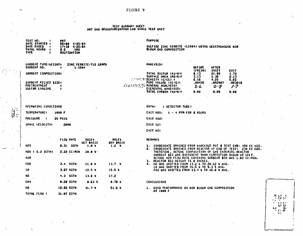
FIGURE 9
TEST SURNARV SHEET HOT GAS DESULFURlZATfON LAB SCALE TEST UNIT
TEST NO. I QIQ? PURPOSE DATE STARTED 1 88108 4/25/84 DATE ENDED I 17139 4/25/84 SULF I DL ZINC FERRITE (L lS84 ) USlllG UESTIHGHOUSE CIlA TOTAL HOURS 1 9.5 HRS BLOUN GAS CORPOSITION TVPE 1 SULFIDnTION
CORBEHT TYPE~UEICHTl ZINC fERRITE/715 CRAM SOR6f lit lib. I L - 1 5 ~ 4
I SORBENt CONPOSITIOHI
SORBEIlT PELLET SIZE1 PRET REAThEllT I SULF W LOALINC 1
OPERaT 1NC CONDITlOllS
TEAPCRATURE 1 8008 F
PRESSURE I 35 PSIG
SPflCE VELOCITV: 200B
Al(ALYSIS1 BEFORE AFTER (FOESYI INLET ENIT
TOTAL SULFUR t %U/U J r 8.13 21.88 1-79
FLOU RATE NOLEf nOLE% UET BASIS ORV BASIS
W S 8.31 SCFH 1.8 L 1.2 5
H Z O 1 6 . 2 S C F H ) i?.i!2CCdlIN 2 8 . e U .
AIR
C02 3.4 SCFH 1 l . B 5 13.7 U
CO 3.87 SCFH 12.5 Y 15.5 5
SURFACE AREA tnz/c )I 3.13 ' 1.38 2.13 I '~* i I .~~:O'DEl lS lTV tC/CC) 1 6.16 4.25 5.65
PORE UGLUM ECC/C)I -88432 .882887 -883818 ik/:.3l!~?,',.'.. RINERAL AlUILYSISl
ELEROITAL kNALvSlS 8 2.C 0 -8 /-7
TOTAL CARBON ( SU/U ) 8 8.00 @.dB B.B8
Hi! 4.3 S C ~ H 13.8 Y 17.2
CH 4 0.28 SCFH 8.63 5 8.78 Y
N2 12.82 SCfH 41.7 1 51.6 Y
TOTAL FLOU 1 31 - 8 7 SCFH
DATA8 ( DETECTOR .TUBE I
EXIT so21
CONDEt4SATE DRAItlED FROn RItOCL'OUT POT B TEST END: 49i) CC 1426. CONDEIiSATE DRAltlED FRON FtEBCTOR it1 EHD OF TEST: 23i) CC llt?O. THE~~EFORL, ACTUIIL conpos IT ION OF GAS EIITERI~IC REACTOR SORBEllT BED UAS DIFFERENT ThAH CGnPOSTlON SllOUN HT LEf 1. ACTUAL HZ0 f LOU RATE EI4TERIllC SORBEIIT BED UI\S 1.82 CC/flIN. REACTOR BED HE.ICHT I S 8 INCHES.
4. HZ UAS SHIFTED FROn 17.2 % TO 20.52 3 AUG. . co UAS SHIFTED FRon 1s.s TO 9.3 % RUG. COZ UAS SHIFTED FROn 13.7 5 1 0 16.6 k AUC.
CONCLUSIOHS

FIGURE 10
TEST NO. 8 008 DATE BTfiRIED I 08138 S.'2/84 BATE ENDEE 8 28I3d 6/2/81 TOtN. HOURS I ti? HRS T YPE I SULF1DI)TION
TESl SUMARY SHEET HOT GAS DESULFURIZATIOH LAD SCALE TEsr U~IT
. . SORBENT IYPE/UEIGHTJ ZINC FERRITE/~IS GRnns
I- - -- - 1 SORPEtlT NO. I L-1584 1
I SORBENT PELLET SIZE1 PRETREfiTflENt I SULFUR LOADING I
I
' 1 OPEMTIHG CONDITIONS
HZ0 6.8 SCFH) 2.22 CC/llIH 20.8 8
RIU
COL 3.4 SCFH 11.0 x 13.7 r CO 3.87 SCFH 12.5 8 16.6 f
HZ 4.3 SCFH 13.8 X 17.2
b .
/ I i
CH4 8.20 SCFH e.63 5 e.79 8
na ra.sa s c r ~ 41.7 x 61.6 5
POYhL FLOU 8 31-07 SCFH .
PRESSURE 1 25 PSIG
SPACE UELOCItVl 2888
PURPOSE
SULFIDE ZIHC FERRITE aL16B4) USING UESTIIICHWSE AIR BLOUN CAS conpost t lon
FLOU RATE ~ O L E L OLE^ UETBASIS DRY BASIS
e.31. SCFH 1.8 8 1.2 8
T OTAL SULFUR t hU/U a SURFACE ARE A t nz/c )I
;:C~~~~LDEHSITV tC /CC) I PORE VOLUHE 1CCIC)r
/'O.~?,fl?,{ 5 nlIaRaL . A N ~ L Y S I S ~ ELEnENTAl WtALVSISI TOTAL CIIRBOH (8U/U):
BEFORE AFTER (FRESH) L E T EXIT 8.13 38.14 2.98 3.13 1.24 1.72 6.16 4.22 5.27 .88432 .081918 .a82435 5 - . ,- *.* 0 ' s 1'3
8.80 8.83 8.85
DhTl l ( DETECTOR TUBE J
EXlT HZS I S PPR FOR 11 -5 HOURS
E%lY soz: EX11 S21
E ~ I T Hz1
REACTOR BED MEICHT 8 INCHES. )(2 SHIFTED FROR 17.2 8 TO 19.8 8 AUG. CO GUlFTLb FROM 1S.S L TO 19.8 AUC. i 6 z - s i i i i i ~ - F i io r r - i j i7 -8 io-isyt -r AUG. REACTOR PRESSURE DROP ItICREASED fROR 3.1 TO 11.0 INCHES
1. GOOD QERFORHAHCE OH h1R BLOW4 CAE COIIPOSlTlOH fit
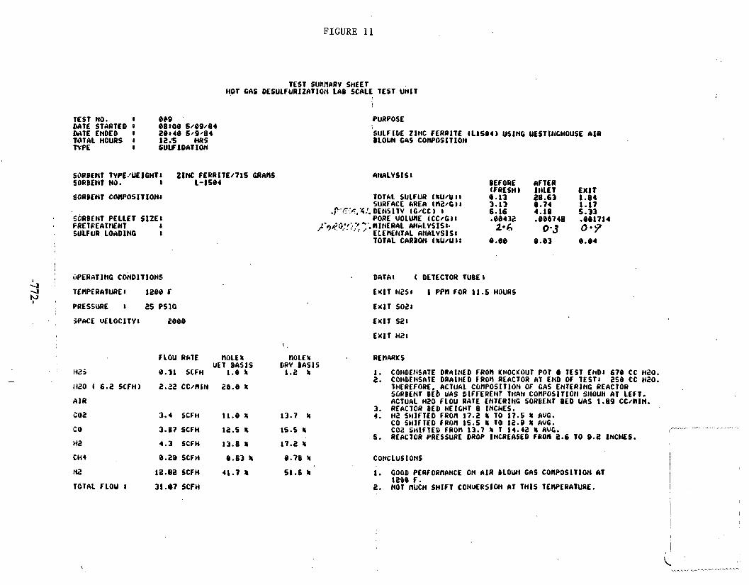
FIGURE 11
TEST NO. I Be9 UATE STARTED a e ~ r o e S / ~ Q / S ~ b i 1 E ENDED 1 2 8 ~ 4 0 6 / 9 / 8 4 TOTAL HOURS I 1 2 b MRS N P E I SULFIDATION
TEST SUMbRV SHEET H.01 GAS oEsuLFuR~tA t ioN LAB SCALE TEST UMIT
SiWBENT TYPE,'W ICHT 1 ZINC FERRl TE/715 CRAMS SORBEN1 H3. I 1-1584
SORDWT C W O S I T I O N I
S,ORBEHT PELLET S1ZEI FRElEEATtEHt I WLFUR LOADING 8
, 3PERAT IHC CONDITIONS .II ; 4 h)
TLWERATUREI 1288 t i -1 I
PRESSURE 8 25 PSlC
FLOU R ~ T E MOLE x ~OLEI UET BASIS DRY BASIS
8.31 SCFH 1.8 L 1.2 5
HZ0 6.2 SCFH) 2.,22 CCfl9lN 26.8 &
4NALVSISI BEFORE 6FTLR (FRESH) I I ILLT EXIT
T O f kL SULFUR (8U/U ) 1 8.13 28.63 1.84 SURFICE ~ R E A t n a / c ) I 3 - 1 3 0.74 1.17
.?'.?~.-4!. DENSITV tG/CC I 6.16 4.10 5.33 PORE VOLUME tCC/G)I -88432 .880748 .091714
~~~$.1,'::,:< ;;MINERAL M ~ ~ L Y S ~ S I . ELE BEllTbL ANALVSI S I
2.6 0.3 a.7 TOTAL CRRBON t ru/u ) r 8.08 0.83 8.84
Hi?
TOTAL FLOU I
3 . 4 SCFH 11.8 f 13.7 5
3-87 SCFH 12.5 9 15.5 Ir
4.3 SCFH 13.8 8 17.2 5
8.28 SCFH 8.63 8 8.78 5
12.B2 SCFH 41.7 U 51.6 Ir
31.07 SCFH
PURPOSE
SULFlOE ZlHC FERRITE tL1504) USING UESTlllCHOUSE AIR BLOUN CIS cowoslt lon
DATA1 ( DET ECTOR TUBE b
Hz58 I PPA FOR 11.5 HOURS
EXIT SO21
EXIT s a t
EXIT HZ8
1. COllDEflSATE DR4lNED FROll KHOCKOUT POT TEST END1 679 CC H20. 2. CONDENSLIE DRAINCO FROM REACTOR AT END OF TEST1 258 CC HZO.
THCREFORf, ACTUhL COnPOSITlON OF GAS ENTERING REACTOR SORBENT BE6 UAS DIFFERENF THRN COnPOSI TI011 SHOUW AT LEFT. ACTUAL ~ 2 0 FLOU @ATE ENTERING SoRBEnr BED UAS 1.89 ccmn.
3. REACTOR BED HEIGHT 8 INCHES. 4. H2 SltlFTED FROn 17.2 8 TO 17.5 8 AUG.
co SHIFTED caon 1s.5 u t o 12.9 s ~ u c . COi! SH l f lED FROM 13.7 b 1 14.42 5 AUC.
5. REACTOR PRESSURE DROP INCREASED FROll 2.6 TO g.2 INCHES. I--- - -'-
I
CO~CLUSlONS
1. GOOD PERFORMANCE ON A I R BLOW4 GAS COHPOSITION AT lace F.
2. NOT MUCH SHIFT CONUERSION AT THIS TEllPERAlURE.

FIGURE 12
HOT CAS TEST SURAARV SttEET
DESULFURIZATION LAB SCALE
TEST NO. 1 . 0 1 6 DATE STARTED I , 3 8 1 8 6 5 / 1 5 / 8 1 o A r c . E n o E o r r e 1 4 6 s#.rse0e4 TOTRL HOURS I 6 HRS TVPE I SULF lDRt lOH
SORBENT TVPE:UEIGHTa Z INC FERRITE.e71S GRPRS SORPEHT NO. :I 1 - I S 8 4
j 1 . I SORBENT C O W ~ S I T I O N I ! / 60RBEnT PELLKT S I Z E 1
PRETREATNENT I 1 SULFUR LOADING I
-r, OPERATING CONDITIONS 4 P TEtPERATUREI 1 3 1 0 F
PRESSURE 8 25 P S I C
H2S
H i N 6.2 SCFHI
A IR '
coa. CO
Hi!
C H I
N i i
TOTAL' t LOU 1.
PURPOSE
SULFIDE ZINC FERRITE f L 1 5 8 4 ) U S l H 6 UESTlliCHOUSE A I R BLOUH CAS COnPOSlTION
TOTAL SULFUR ( W / U ) I SURFACE RREA f n2/C 1 I
3 Y C C 4 L DEI lSlT V ( W C C ) I PORE uoiunc c c c l ~ )I
+C /:'c.;"fc T i h)IIt#ERAL. ANALVSIS: -' ELEIIEIITAL a H A i r s 1 s t
BEFORE (FRESH ) 8 . 1 3 3.13 6 .16 .80432 2. L
AFTER I I ILET a. 4 4 1.16 4.91 - 8 0 1 5 7 0's'
DPTAr ( DETECTOR TUBE)
E X I T HZ51 I PPll FOR 1.5 HOURS
E % l T 5 0 2 1
E X I T 5 2 1
E r n HZ:
FLOU ;RATE HOLE% HOLE8 UET B k S t S DRV B6S1S
8 .31 SCFH 1.8 8 1.2 8
2 .22 c c / n l N 26.8 8
3.4 SCFH . l l . B 8 13.7 8
3.87 SCFH 12.5 t 15 .5 8
4.3 SCFH 1 3 . 8 % 17.2 8
8.28 SCFH 8.63 t 8.78 8
la.82 SCCH 41.7 1 51.6 8
31.87 SCFH
I . REACTOR BED HEIGHT 8 INCHES. 2. PROBLEll U l T H t / C AT 6 IflCHES FROR fHLET RCADlNG TOO LOU 3. CONDEHSnTE COLLECTED8 2 2 6 CC. 6 2 8 OF H2O FED AT INLET.
1. PROBLEMS UllW TERPERATURE COHTROL. 2. TEST 10 BE REPEfiTED.
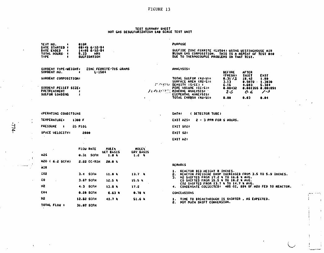
FIGURE 13
TEST SUnllARV SHEET HOT GAS DESULFURIZATIOH LAB SCALE TEST W I T
1 ~ 5 1 NO. I 010R. DATE STARTED I 8 8 1 4 5 6 / 1 2 / 8 4 DATE ENDED I 1 4 8 8 5 6 / 1 8 / 8 4 TOTAL HOURS. I 5 - 3 3 HRS T VPE 1 S U L f I D A T l O H
SORBENT TVPE4JE lCHT l Z I N C F E R R l T E r 7 l S 4RHnS SORDEtiT NO. I L - 1 5 8 4
SORBENT COllPOSIT1ONl
SORBENT PELLET S I Z E 8 PRETREATHENt 6 SULFUR LOADING I
OPERATING COnDlTIONS
TEflPERATUREI 13BB f
PRESSURE I 25 P S l G
SPACE U E L O C l T V l 2 9 8 8
I
H2S I
Mi20 ( 6.2 SCFIO -- -
AIR
coa
Hi!
TOTAL FLOU 1
FLOU RATE n M E % UET B A S I S
8.31 SCFH 1 . 4 8
2 . 2 2 cc/nIn 20.0 r
3.4 SCFH 11.0 f
3.87 SCFH 12.5 f
4.3 SCFH 13.8 X
8.20 SCFH Q.63 5
1 2 - 8 2 SCFH 41.7 8
31.07 SCFH
PURPOSE
SULFIDE ZINC FERRITE t L 1 5 8 4 ) USING UESTIIICIIOUSE A I R DLBUN cas conpositlon. THIS IS R REPEW OF TEST 610 DUE TO TtiEk)U)COUPLE PROBLEMS I N 1-1 TEST.
TOTAL SULf UR (SU/U 1 8 SURFACE AREA cn2.c )I
:' .rt !;:-.I DE~SITY [GNCC ) I PORE UOLUllE (CC/G J I
/ .?:ja..(r.: . .r l.; NINERAL AI~IILVSISI '
ELEMENTAL AIILLVS I S t TOTAL c a u a o t i (ZU/U )I
BEFORE AFTER (FRESH) I I I L E T E X I T 8.31.13 r a . 4 2 1.88 3.13 8 .9979 . 1 . 3 8 3 8 6.16 4.683 5 . 3 8 4 8 . 8 0 4 3 2 8 . 8 8 1 3 5 5 0 . 8 9 1 8 9 1
2.G 6.4 #*$
D h T 6 l ( DETECTOR TUBE)
E X 1 T H2S I 2 - 3 PPR FOR S HOURS.
EXIT seal
EXIT sa l E X I T bI21
MOLE t' DRV B h S l S
1.2 8
1. REACTOR BED HEIGHT 8 INCtiCS. 2. R fRClOR PRESSURE DROP II lCkEASED FROn 3.5 TO 5 .9 IHCHES. 3. H 2 SHIFTED FROM 17.2 f TO 16.6 5 RUG.
CO S H I F l E D FROM 15 .5 X TO 1 8 . 2 5 AUC. COi! SHIFTED FROM 13.7 5 TO 14.7 5 AUG.
4. COtlDENSkTE COLLECTCDI 4 8 5 CC. 691 Of. M2O FED TO REACTOR.
COtICLUS IONS

I*-
FIGURE 1 4
ZINC FEkRlTE SUL FlDAllON ue sc+ mi uulr rEsr 001
0 2 3 4 5 6 firna (hours)
lofJoo
9000 - .
8000 -- EMPTY REACTOR TEST I
70W -- I -2 B
moo-- * 9 L
5000 rn P 2 4 0 0 Q P
. 3m--
Tetnp = 1000 F (538 C)
- Press = 25 PSIG
-
-- INLR H2S - 3750 PPM -
-- -
- 2000 --
- - IOIW) --
- $
0 - - I I I I I
I 1
1 1 . 1 1 I I

FIGURE 15
1 0 -
10 -- 18 -- 17
16 15 - 14
-- WESTINGHOUSE OXYGEN' BLOWN COMPOSI~ON --
Temp - 1000 F (538 C) -- --
Press - 25 PStG . . .
S.V. = 2000 WUR1-Y S J 1 -- -
10 -- % 0 --. 593 CM SORBEN1 x
8 -- it 7 - -
6 -- s -- 4 --
I -- l ' l ~ I ' ~ u l ' l
0 1 2 J 4 S 6 7 8 fi 10 11 12 13 14 I5
rm (hwm)
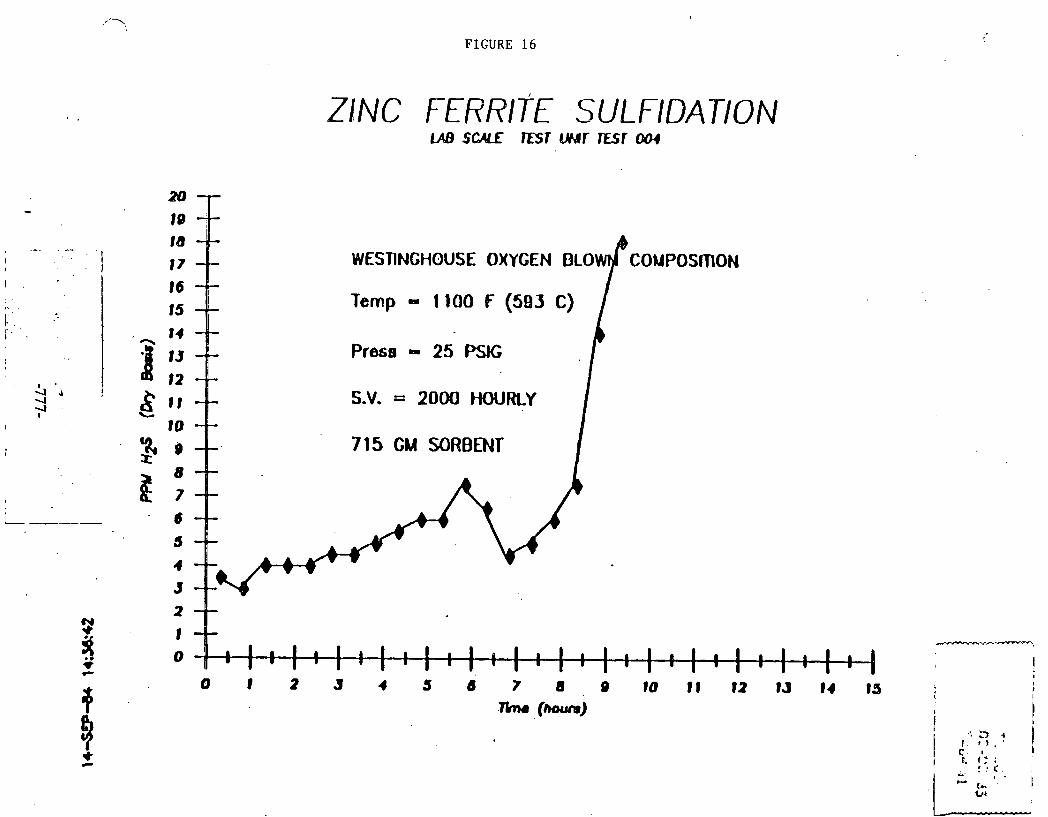
FIGURE 16
ZINC FERRITE SULFlDATlON
a0 - I0 ld
t - I I I 17 CONPOSmON I 16
15 Temp - 1 100 F (583 C) i- I 14
I :: Presa a 25 PSK;
& '4 4 S 1 1 S.V. = 2000 Houmy ;.' L
I 10
% 9 3
715 CM SORBENT'
L -----
i t ; 6 3
4 3

FIGURE 1 7 ,
16 -- 15 -- Temp - 1200 F (649 C)
14 -- - I 3 -- Press - 25- PSlG 12 --
S.V. = 2000 W R L Y
1 --
0 1 2 3 4 6 7: 8 B 10 1 1 12 1J 14 15 - (-)

FIGURE 18
ZINC FERRITE SUL FIDATION
20 - 19 1 8
I 17 -- i I 16 -.-
-- --
WESTINGHOUSE OXYGEN BLOWN COMPOSITION
Temp - 1300 F (704 C) I 15 --
I I - 14 -- I , I 3 - -
Press 25 PSlG i 1 2 --
& 4 . d' 11 -- S.V. = 2000 HOURLY '? c.
I io -- I I * $4 9 - -
1 8 --
a 7 - - I 1
. s 6 -- 5 -- 9 --
3 f P
P
P 0 1 2 J 4 4 6 7 8 9 10 1 1 12 IJ 14 IS
r i a (houm) 8 V) I
v ) C
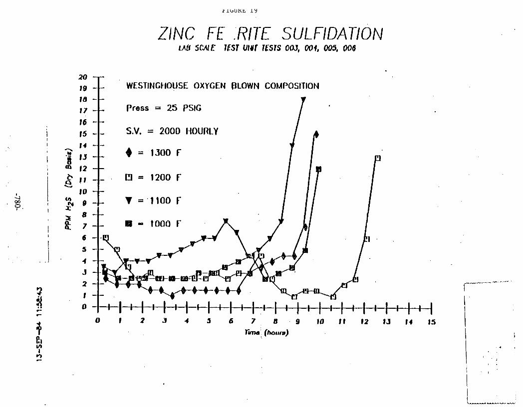
ZINC F .RITE SULFlDATlON U B SWE MST UlUf !fils OA), 001, 003, 006
f WESTINCI-IOUSE OXYGEN PLOWN COMPOSITION
Press = 25 PSlG
S.V. = 2000 IiOURLY
. Cl = 1200 F
BI - 1000 F
0 I 2 .Y 4 5 6 7 8 . 9 DO I f 82 15 14 15

SULFUR ADSORPTION CAPACITY OF ̂ ZINC FERRITE
-f- Bl = WESTNOHOUSE AIR BLOWN
3 BED DlMIflER - 5.2 CN EXIT H2S - UNDER 10 PPM
8f3 HOGHT = 20.2 CM S.V. = 2000 HOURLY f ;
C
0
w $flQ 1000 1 too l lBQ 13W) 0 40Q 1500

FIGURE 2 1 .
LAB SGUC Esr war m s r 007
WESTINGHOUSE AIR BLOW COMPOSITION
Temp - 1000 f (537 C)
Press - 25 PSlG
S.V. = 2.000 HOURLY

FIGURE 22
ZINC FERRITE SULFIDATION
WESTINGHOUSE AIR BLOWN COMPOSlnON
Temp - 1 100 F (583 C)
Press - 25 PSIG.
S.V. = 2000 HOURLY'

FIGURE 23
ZINC FERl\rTE SULFIDAUON 1AB S W E S T LWr rEsl009
WESTINGHOUSE AIR BLOWN COMPOSmON
15 Temp - 1200 f (649 C)
14 --
I 1J -- Prsse - 25 PSG 12 --
S 1 1 -- S.V. = 2000 HOURLY
b
10 -- % o - - It
8 -- it 7 - -
0 1 2 3 4 5 I : I : I : I : I : 6
7 8 l+I+t+i.
9 10 11 12 1.3 14 85
I-)
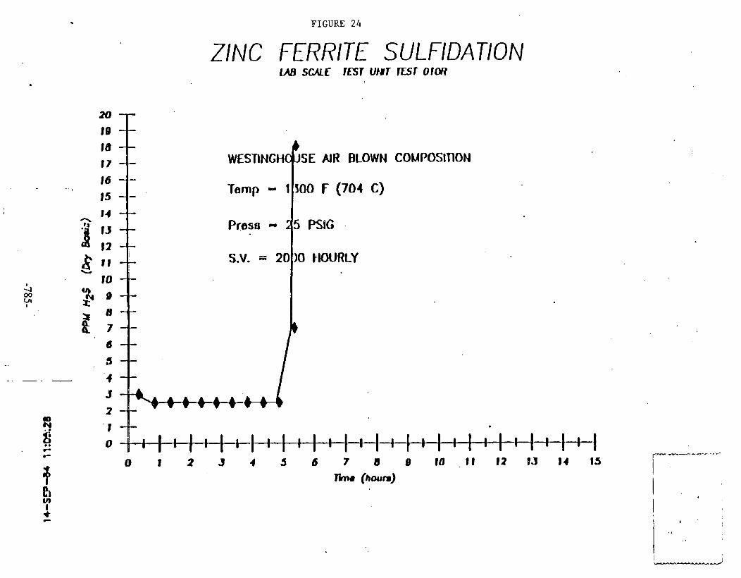
FIGURE 24
ZINC FERRITE SULFlDATlON
SE AIR BLOWN COMPOSDTlON
& 00
Y'
-- - - - -
0 9 8 C

ZINC FERh r TE SULFIDATION UB SCALE TESTS 007, 008, 009, O1OR
WESTINGHOUSE AIR BLOWN COMPOSITION S.V. - 2000 HOURLY Press = 25 PSIG
C
0 1 2 3 4 5 6 7 8 9 10 1 1 12 1.3 14 15 * aD
I
I Time (hours) I
I- I U I
0 I
I I
0 I

APPENDIX J
Feas ib le G a s i f i e r s Gas Stream Compositions f o r Use With METC's Zinc Ferrite S u l f u r Removal Process i n a Minimally Cleaned
Gas, Combined-Cycle P lan t Configurat ion
This r epor t summarizes a v a i l a b l e information on t h e above t o p i c , s p e c i f i c a l l y with regard t o t h e e f f e c t of f u e l gas composition and temperature on t h e com- p o s i t i o n of t h e sorbent . The major spec ies content of t h e f u e l gas, i . e . , carbon monoxide (CO) , carbon dioxide, and water (40) , a f f e c t s sorbent compo- s i t i o n and t h i s f a c t may have s i g n i f i c a n t impl ica t ions on t h e o p e r a b i l i t y of t h e z inc f e r r i t e (ZnFe,O,) hot-gas d e s u l f u r i z a t i o n process i n t h e configura- t i o n used i n t h e METC research program. However, t h e r e a r e u n c e r t a i n t i e s i n much of t h e d a t a leading t o t h e s e conclusions. Design opt ions e x i s t which can address t h e o p e r a b i l i t y concerns and which, a s f a r a s i s known, do not l ead t o s i g n i f i c a n t changes i n t h e o v e r a l l performance o r c o s t of a minimally cleaned gas power genera t ion p l a n t . Both t h e system e f f e c t s and t h e des ign opt ions r equ i re f u r t h e r s tudy.
This r epor t ( a ) desc r ibes METC's research which l e d t o i d e n t i f i c a t i o n of gas composition a s a p o t e n t i a l concern i n z inc f e r r i t e system opera t ion; (b) exam- i n e s t h e f u e l gas from commercial o r near-commercial g a s i f i e r s and g ives an es t ima te of t h e degree of concern f o r t h e s e g a s i f i e r s ; ( c ) desc r ibes p o t e n t i a l changes i n e i t h e r t h e sorbent system des ign o r t h e g a s i f i e r l f u e l gas system t o address t h e concern; and (d) enumerates t h e remaining u n c e r t a i n t i e s .
Problem ~e f i n i t i o n
I n t h e z inc f e r r i t e hot-gas d e s u l f u r i z a t i o n process, both t h e f u e l gas compo- s i t i o n and t h e process opera t ing temperature a f f e c t sorbent composition. On t h e b a s i s of r e s u l t s from t h e z inc f e r r i t e research program c u r r e n t l y underway a t METC, i . e . , a program conducted using 3/16-inch extruded p e l l e t s i n a packed-bed conf igura t ion , t h e z inc f e r r i t e process should opera te a t f u e l gas s tream condi t ions where magnetite (Fe,O,) i s t h e s t a b l e i r o n spec ies . This s t a b i l i t y region i s shown i n Figure 1, which i s an iron/carbon/oxygen equ i l ib - rium diagram computed f o r a1;naspliel-ic p ressu re . Thc f i g u r e i s p l o t t e d in terms of temperature and t h e r a t i o of CO t o CO, expressed a s t h e equi l ibr ium concentra t ion of CO/ (CO + CO,) . A t 1, OOO°F, a CO/ (CO t CO,) r a t i o of l e s s than about 0.5 i s requi red f o r t h e sorbent t o be i n t h e magneti te s t a b l e region of t h e equi l ibr ium diagram. I f t h e z inc f e r r i t e system opera tes ou t s ide t h i s region, spec ies o the r than magnetite w i l l be present i n t h e absorpt ion bed. These "other" i r o n species , i . e . , i r o n l i r o n ca rb ides and wus t i t e (FeO), have d e l e t e r i o u s e f f e c t s on t h e performance of t h e z inc f e r r i t e process a s t e s t e d i n t h e METC conf igura t ion , i . e . , an extruded sorbent i n a packed bed.
Two poss ib le opt ions a r e a v a i l a b l e t o overcome t h e s e problems. One opt ion i s t o opera te t h e g a s i f i c a t i o n / f u e l gas system i n a way which w i l l circumvent t h e formation of i r o n / i r o n carbides o r wus t i t e i n t h e sorbent bed. A second op t ion i s t o develop an a l t e r n a t e sorbent o r sorbent system t o negate t h e d e l e t e r i o u s e f f e c t s . A process development a c t i v i t y i s needed t o choose t h e b e s t approach. METC w i l l sponsor work with a FY 84 procurement. now "on t h e
s t r e e t " t o address t h e research needed t o b e t t e r d e f i n e t h e problem and pro- v ide a b a s i s f o r f u r t h e r process development. D e f i n i t i v e phase equ i l ib r ium diagrams a r e one aapect. of t h i s research e f f o r t .
The unquenched f u e l gas from an oxygen-blown dry ash Lurgi g a s i f i e r has a CO/ (CO t CO,) r a t i o such t h a t t h e z inc f e r r i t e system w i l l ope ra te i n t h e mag- n e t i t e region of t h e equi l ibr ium diagram. The unquenched f u e l gas p ro jec ted f o r t h e oxygen-blown commercial ve r s ion of t h e Kellogg/Rust Westinghouse (KRW) g a s i f i e r i s such t h a t a z inc f e r r i t e system which opera tes a t l,OOO°F and uses t h e METC process conf igura t ion w i l l be on t h e borde r l ine of t h e magneti te s t a b l e region. However, when t r e a t i n g unquenched f u e l gas from e i t h e r t h e BGCISlagger o r t h e oxygen-blown Texaco g a s i f i e r i n a z inc f e r r i t e process with t h e METC conf igura t ion , it w i l l be necessary t o inc rease t h e steam content of t h e f u e l gas s t ream i n o rde r t o move t h e system i n t o t h e magneti te s t a b l e region. Inc reas ing t h e steam content of t h e f u e l gas reduces t h e amount of CO because of t h e CO s h i f t conversion reac t ion ,
The s h i f t r e a c t i o n i s ca ta lyzed by z inc f e r r i t e s o t h a t equi l ibr ium, o r near equil ibrium, should be achieved i n t h e bed.
The fol lowing a r e poss ib le opt ions f o r inc reas ing t h e steam content of t h e f u e l gas:
1. Water quenching a high-temperature f u e l gas s t ream (e .g . , f u e l gas from .. . a KRW o r Texaco g a s i f i e r ) .
2 . Adding high-temperature steam t o a lower temperature f u e l gas s tream ( e . g., f u e l gas from a BGC/Slagger) .
3 . Operating t h e g a s i f i e r a t a higher steam-to-air r a t i o .
Ef fec t of Increas inq the 'Mois tu re Content of t h e Fuel Gas on Svstem Performance
Although s u l f u r absorpt ion i s a f f e c t e d by t h e moisture content i n t h e f u e l gas, inc reas ing t h e moisture content t o t h e des i red l e v e l would r e s u l t i n only a very s l i g h t decrease i n t h e s u l f u r removal l e v e l s achievable i n t h e z inc f e r r i t e process. Su l fu r concentra t ions a s low a s 5 ppm could be obta ined i n a f u e l gas s tream with t h e moisture content contemplated.
It was es t imated t h a t adding moisture t o t h e f u e l gas of a minimally cleaned gas system would have only a very small e f f e c t on o v e r a l l cycle e f f i c i e n c y o r .
system c o s t . However, t h e mass and energy balances f o r a process design i n which moisture was added t o t h e f u e l gas would be d i f f e r e n t from those of a n o m o i s t u r i z e d design.
The a d d i t i o n of steam t o t h e f u e l gas would have some e f f e c t on t h e perform- ance of t h e t u r b i n e combustor i n a g a s i f i c a t i o n combined-cycle p l a n t . The a d d i t i o n a l steam would t end t o reduce t h e thermal NOx formation i n t h e gas t u r b i n e combustor but probably w i l l have no e f f e c t on fuel-bound n i t rogen NO, production (which apparent ly i s t h e g r e a t e r concern i n minimally cleaned gas
systems). The a d d i t i o n a l steam would a l s o a f f e c t t h e f lammabil i ty charac ter - is t ics of t h e gas . The steam reduces t h e heat ing value of t h e gas on a ~ t u / s c f wet b a s i s . This may be a concern with g a s i f i c a t i o n systems which a l ready produce a r e l a t i v e l y low-heating value gas, e .g . , air-blown fluidized-bed o r en t ra ined flow g a s i f i e r s . The CO s h i f t r e a c t i o n f u r t h e r reduces t h e lower heat ing value of t h e f u e l gas, but t h e r e a c t i o n a l s o inc reases t h e hydrogen content of t h e gas . The General E l e c t r i c water-cooled test program showed t h a t t h e f lammabil i ty c h a r a c t e r i s t i c s of low-Btu f u e l gas a r e s e n s i t i v e t o t h e hydrogen content of t h e gas, being improved by a h igher hydrogen content .
Phase Euuilibrium Diaaram Data
~ron/carbon/oxygen phase equi l ibr ium diagrams a r e widely a v a i l a b l e due t o t h e i r connection with t h e s t e e l making indus t ry . Equil ibrium diagrams a r e a l s o used i n connection with i r o n c a t a l y s t s which a r e used i n var ious chemical processes. Most of t h e diagrams f o r i r o n chemistry have been generated f o r atmospheric pressure , but s i m i l a r e f f e c t s a r e expected f o r z inc f e r r i t e sys- tems opera t ing a t pressure .
It i s noted t h a t t h e phase equi l ibr ium diagram shown i n Figure 1 does not t ake i n t o account t h e presence of s u l f u r nor does i t inc lude t h e e f f e c t of r eac t ion k i n e t i c s . The r e l a t i v e importance of omit t ing s u l f u r i s unknown. However, one opinion i s t h a t it i s minimal s ince , under gas compositions favor ing i r o n / i r o n carbides formation, t h e s u l f u r would be absorbed i n t h e r e a c t i o n zone with t h e remainder of t h e bed converted t o i r o n / i r o n carbides before t h e reac- t i o n zone approaches it.
Therefore, while t h e r e i s some c e r t a i n t y a s t o t h e genera l t r e n d s shown i n Figure 1, t h e a p p l i c a t i o n of t h e diagram should not be considered d e f i n i t i v e i n t h i s e a r l y s t a g e of t h e process des ign. There may be uncer t a in ty a s t o t h e abso lu te l o c a t i o n of s p e c i f i c phase separa t ion boundaries, p a r t i c u l a r l y when opera t ing a t pressure . More d e f i n i t i v e phase equi l ibr ium diagrams f o r t h e z inc f e r r i t e system a t t h e opera t ing pressures of g a s i f i e r s / g a s s tream cleanup systems should be a v a i l a b l e within approximately one yea r . Responses t o an FWP on t h i s t o p i c a r e c u r r e n t l y being assessed a t METC.
Val ida t ion of Phaoc Diaqram Data a t METC
Two da ta po in t s on t h e phase diagram were confirmed f o r p ressu re opera t ion dur ing t h e z inc f e r r i t e research program conducted using a s i d e stream of METCrs 42-inch fixed-bed g a s i f i e r . . The f i r s t da ta po in t confirms t h a t , f o r temperatures i n t h e 1,000 t o l,lOO°F range, t h e METC z inc f e r r i t e process t y p i c a l l y opera ted i n t h e i r o n l i r o n carbides s t a b l e region of t h e phase dia- gram. The presence of i r o n l i r o n carbides i n t h e sorbent bed was f i r s t sus- pected dur ing g a s i f i e r Run 102 (September 1983), and t h i s was confirmed i n pos t - t e s t mineral a n a l y s i s of t h e sorbent m a t e r i a l . I t i s noted t h a t even though t h e METC process was opera t ing i n t h e i r o n l i r o n carbides region, gas- phase s u l f u r l e v e l s on t h e order of 5 ppm were r o u t i n e l y achieved. The problem encountered was physica l sorbent d i s i n t e g r a t i o n (d iscussed below).
An a d d i t i o n a l d a t a point on t h e phase diagram was confirmed fol lowing g a s i f i e r Run 104 (December 1983) . The z i n c f e r r i t e bed operated i n t h e 1,200 t o 1,30f1°F temperature range dur ing t h i s run, and wus t i t e was found i n t h e
L

sorbent m a t e r i a l fol lowing t h e test . The phase diagram p r e d i c t s wus t i t e formation a t t h i s opera t ing temperature.
The sorbent phase equi l ibr ium r e s u l t s from t h e METC g a s i f i e r a r e not app l i - cable t o dry ash Lurgi g a s i f i e r s . The METC g a s i f i e r was operated a t low steam-to-air r a t i o s (approximately 0.2 w t . / w t . ) , a l a r g e f r a c t i o n of t h e heat l i b e r a t e d dur ing t h e g a s i f i c a t i o n process being removed from t h e g a s i f i e r by a water wall . A d r y ash Lurgi has a s i g n i f i c a n t l y lower water wal l surface- to-bed volume r a t i o . Thus t h e oxygen-blown Lurgi, which t y p i c a l l y opera tes a t a steam-to-air r a t i o of 0.5 w t . / w t . , produces a f u e l gas wi th a higher steam content . With t h i s f u e l gas composition, t h e z inc f e r r i t e process would opera te i n t h e magneti te s t a b l e region of t h e phase diagram.
Process Chemistrv S p e c i f i c s
When t h e z inc f e r r i t e process opera tes i n t h e magneti te region of t h e iron- carbon-oxygen equi l ibr ium diagram, t h e chemical r e a c t i o n s t a k i n g p lace during s u l f i d a t i o n and regenera t ion may be represented a s fol lows.
S u l f i d a t i o n 3ZnFe,04 + H, + 3Zn0 t 2Fe,04 t H,O
ZnO t H,S + ZnS t H,O
Regeneration 2FeS t 7/20, + Fe,O, t 2S0, -... .
ZnS t 3/20, + ZnO t SO,
ZnO + Fe,04 + ZnFe,O,
I n t h e i r o n / i r o n carbides region of t h e phase diagram, t h e z inc chemistry i s thought t o be i d e n t i c a l t o t h a t shown above. The o v e r a l l i r o n chemistry dur- i n g t h e s u l f i d a t i o n process may be represented a s fol lows.
3Fe + H,S + FeS t H,
I n t h e wus t i t e s t a b l e region, t h e fol lowing i r o n r e a c t i o n s a r e thought t o occur during t.he s u l f i d a t i o n process.
FeO t H,S + FeS + H,O
Concerns Over Operating Outside t h e Magnetite S t a b l e Region
The d a t a c o l l e c t e d on t h e METC packed-bed z inc f e r r i t e r e a c t o r i n d i c a t e t h a t t h e i r o n l i r o n carbides and t h e wus t i t e s t a b l e regions should be avoided f o r t h e fol lowing reasons:

1. Reducing t h e i r o n oxide t o elemental i r o n r e s u l t s i n a porous sorbent p e l l e t which i s more prone t o physica l d i s i n t e g r a t i o n .
Based on experience with high-temperature s h i f t c a t a l y s t s (which a r e i r o n oxides and, the re fo re , s i m i l a r t o t h e z inc f e r r i t e sorbent mate- r i a l ) , a l i f e i n excess of one yea r could reasonably be p ro jec ted f o r t h e z inc f e r r i t e sorbent . Ci rcumstant ia l evidence dur ing METCfs zinc f e r r i t e test program i n d i c a t e s t h a t physica l d i s i n t e g r a t i o n of t h e sor- bent could l e a d t o a s i g n i f i c a n t l y s h o r t e r sorbent l i f e t i m e under t h e adverse circumstances of excess ive sorbent reduct ion and coke formation d iscussed i n Item No. 2, below.
The fol lowing d a t a g ives some f e e l f o r t h e degree of sorbent d i s i n t e - g r a t i o n experienced a t METC. Following two separa te z inc f e r r i t e t e s t s conducted dur ing METC g a s i f i e r Run 102, t h e sorbent m a t e r i a l was removed from t h e bed with a vacuum hose and screened. (These processes obvi- .
ously involve t h e p o t e n t i a l f o r genera t ing a d d i t i o n a l f i n e s . ) The sor- bent m a t e r i a l from one t e s t was subjec ted t o two complete absorpt ion and regenera t ion cycles p r i o r t o vacuuminglscreening and was found t o con- t a i n 2 percent f i n e s . The sorbent from another t e s t was subjec ted t o one and one-half cycles ( i . e . , absorpt ion , regenera t ion , and absorp- t i o n ) . Th i s second sorbent , which was vacuumed/screened i n t h e su l - f i d i z e d form, was found t o conta in 30 percent f i n e s . Since t h e bed was opera t ing i n t h e i r o n l i r o n carbides s t a b l e region o f ' t h e phase diagram i n both t h e s e t e s t s , it may be i n f e r r e d t h a t t h e presence of i r o n l i r o n ca rb ides diminished t h e physica l s t r e n g t h of t h e sorbent , l ead ing t o increased sorbent a t t r i t i o n . A s u b s t a n t i a l l y smal ler amount of f i n e s (about 10 percent ) was generated i n a t h i r d t e s t dur ing g a s i f i e r Run 101. In t h i s case, t h e sorbent was i n a s u l f i d i z e d form and had been opera t ing i n t h e magneti te s t a b l e region immediately p r i o r t o removal from t h e r e a c t o r . Sorbent d u r a b i l i t y d a t a w i l l be obta ined as a r e s u l t of an RFP c u r r e n t l y being assessed a t METC. The aim of t h i s p r o j e c t i s t o i d e n t i f y techniques t o enhance z inc oxide based sorbent d u r a b i l i t y and t o demonstrate sorbent d u r a b i l i t y f o r 100 absorpt ion/ regenera t ion cycles .
Problems assoc ia ted with physica l d i s i n t e g r a t i o n might be circumvented by us ing an i n e r t s o l i d m a t e r i a l a s a support f o r t h e a c t i v e so rben t . The I n s t i t u t e Francais du P e t r o l e has c a r r i e d out extens ive research along t h e s e l i n e s f o r z inc oxide based sorbents . During t h e e a r l i e r i r o n oxide research , METC found supported sorbents t o be a s e f f e c t i v e a s pure i r o n oxide when normalized f o r i r o n content , and t o have d u r a b i l i t y advantages over nonsupported so rben t s . For a packed-bed z inc f e r r i t e process, t h e use of a supported sorbent would be a t r a d e o f f between t h e b e n e f i t s of a more durable sorbent and t h e p e n a l t i e s a s soc ia ted with an increased r e a c t o r volume. (Sorbent u t i l i z a t i o n would be expected t o be f a i r l y high i n a z inc f e r r i t e process which opera ted i n t h e magneti te s t a b l e region. I n l abora to ry s c a l e t e s t s conducted a t METC us ing simu- l a t e d f u e l gas conta in ing s u f f i c i e n t steam t o be i n t h e magneti te s t a b l e region, t h e z inc f e r r i t e bed absorbed on t h e order of 30 percent s u l f u r by weight o r , very roughly, 90 percent of t h e t h e o r e t i c a l amount of sul- f u r . ) For a continuous z inc f e r r i t e process design which used moving o r fluidized-bed r e a c t o r s , it may be t h a t supported sorbents a r e a prac- t i c a l and/or necessary s o l u t i o n t o t h e problems assoc ia ted with sorbent

d i s i n t e g r a t i o n . However, it i s t o o e a r l y i n t h e z inc f e r r i t e t e s t i n g program t o make d e f i n i t i v e statements about e i t h e r t h e optimum r e a c t o r conf igura t ion o r sorbent form.
2. The presence of i r o n ca ta lyzes t h e formation of coke both through t h e cracking of any t a r t h a t might be present i n t h e f u e l gas stream and through t h e Boudouard reac t ion :
2 co + C + co,.
Coke formation i s undes i rable because it reduces t h e hea t ing value of t h e f u e l gas s tream and can con t r ibu te t o sorbent d i s i n t e g r a t i o n .
Coke buildup may a l s o con t r ibu te t o increased p ressure drops through a packed-bed absorber which could r e s u l t i n l i f t i n g of t h e sorbent i n an upwards-flow r e a c t o r . (A fluidized-bed r e a c t o r des ign would obv ia te t h e p ressure buildup problem.)
3. The presence of i r o n a l s o ca ta lyzes t h e very exothermic methanation reac t ion ,
which could cause excessive temperatures i n t h e sorbent bed.
I n t h e METC t e s t s , temperature excursions i n t h e absorpt ion bed were not a problem. The system operated with a gas composition which con- t a i n e d s u f f i c i e n t steam t h a t s i g n i f i c a n t methane formation would not be expected, even i f t h e methanation r e a c t i o n went t o equi l ibr ium. Also, t h e small s c a l e of t h e r e a c t o r o f fe red t h e oppor tuni ty f o r heat d iss ipa- t i o n through t h e r e a c t o r wal ls .
4 . Elemental i r o n f u r t h e r r e a c t s t o form i r o n carbides which a r e l e s s read- t i v e than magneti te . This limits t h e absorp t ive c a p a b i l i t i e s of t h e sorbent bed and H,S breakthrough occurs e a r l i e r than it would i f t h e bed were opera t ing i n t h e magneti te s t a b l e region. A s a s p e c i f i c example, examination of s u l f i d i z e d sorbent fol lowing one test conducted dur ing METC g a s i f i e r Run 102 ind ica ted t h a t , a t t h e i n l e t t o t h e bed, approxi- mately 112 of t h e i r o n was i n t h e form of i r o n ca rb ides . Proceeding i n t o t h e bed, g r e a t e r amounts of i r o n had been converted t o i r o n car- b ides . From t h e middle of t h e bed t o t h e o u t l e t , v i r t u a l l y a l l of t h e i r o n was i n t h e form of i r o n carbides . This i n d i c a t e s t h a t , once t h e i r o n i s converted t o i r o n carbides , t h e r e i s a s i g n i f i c a n t f a l l i n t h e r a t e of s u l f u r pickup. The o v e r a l l s u l f u r loading of t h e sorbent was approximately 10 percent dur ing t h i s t e s t .
. During regenera t ion , t h e i r o n carbides p a r t i c i p a t e i n t h e steam-iron r e a c t i o n wi th t h e consequent formation of hydrogen. This r e a c t i o n r e s u l t s i n a regenera t ion t a i l gas conta in ing a v a r i e t y of spec ies : H,, H,S, SO,, elemental s u l f u r , e t c . Such a t a i l gas would need t o be .
i n c i n e r a t e d when using a suLfur recovery process which i s designed t o remove oxidi.zed s u l f u r compounds. I n t h e absence of i r o n l i r o n carbides ,

t h e predominant species i n t h e regenera t ion t a i l gas i s expected t o be s u l f u r d ioxide (SO,) with minor amounts of s u l f u r t r i o x i d e (SO,).
A poss ib le op t ion i s t o t r e a t t h e mixed composition t a i l gas s tream by i n c i n e r a t i n g it and removing i t s s u l f u r content i n a f l u i d i z e d bed con- t a i n i n g a throwaway, calcium-based sorbent m a t e r i a l .
5. The 'wus t i t e s t a b l e region of t h e phase diagram should a l s o be avoided i f very high s u l f u r removal i s requi red . The absorp t ive powers of wus t i t e a r e s i g n i f i c a n t l y lower than those of magneti te . For example, i n a zinc f e r r i t e test conducted dur ing METC g a s i f i e r Run 104, H,S l e v e l s i n excess of roughly 100 ppm were observed almost immediately fol lowing t h e i n i t i a t i o n of t h e absorpt ion cyc le . This t e s t was conducted with bed temperatures of 1,200 t o 1, 3 0 0 ° ~ , and, t h e r e f o r e , t h e process 'was opera t ing i n t h e wus t i t e s t a b l e region of t h e phase diagram. It i s poss ib le t h a t t h e presence of wus t i t e i n t h e sorbent s t r u c t u r e makes t h e z inc oxide l e s s access ib le .
System Impl ica t ions f o r t h e BGC/Slaqqer/Zinc F e r r i t e System
The BGCISlagger e x i t gas composition i s well i n t o t h e i r o n / i r o n carbides s t a b l e region of t h e phase diagram. Therefore, some modif ica t ion t o t h e f u e l gas i s requi red when opera t ing with t h e METC z inc f e r r i t e conf igura t ion . I t was ca lcu la ted t h a t adding 20 vo l . percent (based on t h e t o t a l gas flow) of steam t o t h e f u e l gas would move t h e phase equi l ibr ium t o t h e boundary of t h e magnetite s t a b l e region. Reference 1 was used a s a source f o r t h e raw f u e l gas composition f o r t h e s e c a l c u l a t i o n s . The C O / ( C O t CO,) r a t i o was deter-, mined a t s h i f t equi l ibr ium. The s h i f t equi l ibr ium was r e c a l c u l a t e d fol lowing t h e i n j e c t i o n of t h e a d d i t i o n a l steam. Adding an a d d i t i o n a l 5 v o l . percent of steam would i n c r e a s e t h e margin of s a f e t y and move t h e system away from t h e uncer t a in boundary a rea .
Steam t o mois tur ize t h e f u e l gas . cou ld be obta ined from t h e heat recovery steam genera tor . Adding steam t o t h e g a s i f i e r e x i t gas ( t y p i c a l l y a t tem- pe ra tu res i n t h e 800 t o 850°F range) would r a i s e t h e gas s tream temperature through t h e heat r e l eased i n t h e exothermic CO s h i f t conversion r e a c t i o n . Each 1 percent of CO converted would r a i s e t h e gas s tream temperature roughly 18OF. Therefore, adding 20 mole percent of 640°F steam t o t h e f u e l gas could be used t o inc rease t h e gas stream temperature t o approximately l,OOO°F. This temperature inc rease f o r t h e f u e l gas s tream i s d e s i r a b l e because it dimin- i s h e s t h e p o s s i b i l i t y of t a r condensation i n t h e cleanup system.
The presence of a c a t a l y s t i s apparent ly requi red f o r t h e s h i f t r e a c t i o n t o proceed a t temperatures below 1,200°F. While d e t a i l e d homogeneous k i n e t i c r a t e d a t a f o r t h e s h i f t r e a c t i o n have not been loca ted , Reference 2 i n d i c a t e s t h a t t h e ex ten t of conversion i s not s i g n i f i c a n t without c a t a l y s i s a t tempera- t u r e s below 1,200°F. The CO s h i f t conversion r e a c t i o n i s expected t o go t o v i r t u a l equi l ibr ium i n t h e r e l a t i v e l y low-temperature BGCISlagger f u e l gas s tream because of c a t a l y s i s by t h e so rben t .
It appears more f e a s i b l e t o add steam t o t h e f u e l gas a t t h e g a s i f i e r e x i t than t o pe r tu rb t h e g a s i f i e r opera t ion . Increas ing t h e steam-to-air r a t i o i n t h e g a s i f i e r could be used t o inc rease t h e moisture l e v e l - - i n t h e f u e l gas but
it would have s i g n i f i c a n t e f f e c t s on t h e opera t ion of t h e g a s i f i e r . Speci f i - c a l l y , it might cause t h e g a s i f i e r t o opera te i n a d ry ash mode. Increas ing t h e steam feed t o t h e g a s i f i e r would a l s o inc rease t h e s u p e r f i c i a l v e l o c i t y through t h e g a s i f i e r . Higher v e l o c i t i e s may not be acceptable from an opera- t i o n a l s tandpoint s i n c e they could l e a d t o channeling i n t h e bed and/or g r e a t e r f i n e carryover. The a d d i t i o n a l steam may a l s o negate t h e g r e a t e r throughput advantage of t h e BGCISlagger over t h e dry ash Lurgi . These com- ments a r e specu la t ions on which opinions should be sought from i n d u s t r i a l sources .
Svstem I m l i c a t i o n s f o r t h e KRW Gasi f ier /Zinc F e r r i t e Svstem
The f u e l gas produced i n t h e KRW process demonstration u n i t (PDU) i s such t h a t t h e equi l ibr ium i s wel l i n t o t h e magneti te region of t h e phase diagram. ( I n t h e PDU, KRW p a r t i a l l y quenches t h e gas t o avoid depos i t ion problems i n t h e cyclones.) With t h e f u e l gas composition p ro jec ted f o r a commercial oxygen- blown ve r s ion of t h e KRW g a s i f i e r (Reference I ) , t h e CO/CO, r a t i o i s such t h a t t h e system would be on t h e boundary of t h e magneti te s t a b l e region a t l,OOO°F i f t h e gas were cooled from g a s i f i e r opera t ing temperatures without t h e a d d i t i o n of water. Thus, a conservat ive design would i n j e c t a small amount, 5 v o l . percent of t o t a l gas flow, of water i n t o t h e f u e l gas stream.
Adding a small amount of water t o t h e approximately 1,800 t o 1, 900°F f u e l gas s tream should not present any major des ign problems. However, t h e r e may be some d i f f i c u l t y i n c o n t r o l l i n g t h e water quench flow r a t e , such t h a t t h e d e s i r e d f u e l gas temperature i s obtained. I n a commercial design, e i t h e r of two methods could be used t o cool and add t h e requi red moisture t o t h e f u e l gas. I n one method, a l l t h e high-temperature heat exchangers would be el imi- nated, and t h e fuel-gas s tream temperature would be lowered from t h e 1,800 t o 1 , 9 0 0 ° ~ range t o t h e opera t ing temperature of t h e z inc f e r r i t e system, by using a water quench. (This approach would s i g n i f i c a n t l y i n c r e a s e t h e steam content of t h e f u e l gas above t h e requirements of t h e z inc f e r r i t e p rocess . ) Al t e rna t ive ly , a p a r t i a l quench t o achieve t h e d e s i r e d fuel-gas moisture con- t e n t could be employed a t some point i n t h e temperature reduct ion process. Radiant and/or convective heat exchangers would be used t o complete t h e tem- p e r a t u r e reduct ion .
Svstem Impl ica t ions f o r a Texaco Gas i f i e r /Z inc F e r r i t e Svstem
The f u e l gas from a Texaco g a s i f i e r (Reference 1) would requ i re i n j e c t i o n of approximately 10 vo l . percent of water f o r t h e system t o reach t h e boundary of t h e magneti te s t a b l e region on t h e phase diagram a t l,OOO°F. A 15 percent water i n j e c t i o n r a t e would be a conservat ive design. The cons ide ra t ions i n adding wat,er t o t h e Texaca g a s i f i e r a r e similar t o those d iscussed above f o r t h e KRW g a s i f i e r .
I n l e t P a r t i c u l a t e Limi ta t ions f o r t h e Zinc F e r r i t e Process
The METC z inc f e r r i t e r e a c t o r opera tes ~ i t h ~ a c c e p t a b l e r e a c t o r p ressu re drops, with an i n l e t p a r t i c u l a t e loading of 1 g/Nm, and a median p a r t i c l e s i z e of approximately 13 microns. Zinc f e r r i t e systems which use packed-bed r e a c t o r s t o t r e a t f u e l gases which have p a r t i c u l a t e loadings with parameters exceeding

t o t r e a t f u e l gases which have p a r t i c u l a t e loadings wi th parameters exceeding t h e s e values may requ i re t h e use of some p a r t i c u l a t e removal device p r i o r t o t h e absorpt ion bed.
Zinc f e r r i t e p e l l e t s l a r g e r than t h e 3116-inch diameter ex t rus ion s i z e pres- e n t l y used i n t h e METC t e s t program may be h e l p f u l i n avoiding bed b l ind ing problems i n packed-bed r e a c t o r s by providing l a r g e r i n t e r s t i t i a l spaces. Granular-bed f i l t e r theory p r e d i c t s t h a t l a r g e r spaces would inc rease t h e al lowable p a r t i c l e s i z e i n t h e i n l e t s tream t o t h e bed. A p e l l e t diameter of 5/16 inch may be t h e maximum s i z e t h a t would s t i l l al low adequate s u l f u r d i f f u s i o n i n t o t h e sorbent .
Other r e a c t o r designs, e . g . , a fluidized-bed r e a c t o r , could bypass any prob- lems of b l ind ing by p a r t i c u l a t e s . Al t e rna t ive ly , s u l f u r capture and pa r t i cu - l a t e c o n t r o l could be combined i n a granular-bed f i l t e r arrangement. Improve- ments i n sorbent s t r e n g t h beyond t h a t of t h e METC ex t ruda te would be needed t o go t h e s e rou tes . Development of so rben t s t o address such r e a c t o r design considera t ions has not been p a r t of t h e research program a t METC.
Conclusion
On t h e b a s i s of experimental r e s u l t s and economic assessments completed t o da te , t h e METC conf igura t ion of t h e z inc f e r r i t e process appears t o be an a t t r a c t i v e process f o r hot gas cleanup. Fuel gas composition requirements do not seem t o p resen t roadblocks t o i t s systems a p p l i c a t i o n s . However, t h e process i s i n i t s e a r l y s t a g e s of development. Other hot-gas d e s u l f u r i z a t i o n sorbents , p e l l e t forms, and/or r e a c t o r conf igura t ions may a l s o be v i a b l e opt ions f o r t h e d e s u l f u r i z a t i o n of f u e l gas i n minimally cleaned gas, combined-cycle p l a n t s .
Acknowledaements
L. C . Headley, J. S. Halow, V. P . Kothari , J. M. Thames, J. E . Notestein, and L . E . Graham p a r t i c i p a t e d i n d iscuss ions , con t r ibu ted information, and provided reviews of d r a f t vers ions of t h i s r epor t . Thei r con t r ibu t ions a r e g r a t e f u l l y acknowledged.
References
1. Syn the t i c Fuels Associates, Inc . , "Coal G a s i f i c a t i o n Systems: A Guide t o S t a t u s , Appl ica t ions , and Economi6s," EPRI AP-3109, June 1983.
2 . Johnson, J. L . , "Kinet ics of Coal G a s i f i c a t i o n , " Wiley-Interscience Publications, 1979.
3. Gieger, G. H . , " I ron Blast Furnace," paper i n Meta l lu rg ica l T r e a t i s e s , p resen ta t ions a t t h e USA-China B i l a t e r a l Conference sponsored by t h e Meta l lu rg ica l Socie ty of AIME, American Socie ty f o r Metals, and t h e Chinese Socie ty f o r Metals, Bei j ing , China, November 1981.

TEMPERATURE (OF) adapted from Geiger
FIGURE 1. Iron-Carbon-Oxygen Equilibrium Diagram a t Atmospheric Pressure
- -
I
Copyright © 2022 FDOKUMEN