Reactor physics ideas for large scale utilization of thorium in gas cooled reactors
21NUCLEAR ENGINEERING AND TECHNOLOGY, VOL.39 NO.1 FEBRUARY 2007
A REVIEW OF HELIUM GAS TURBINE TECHNOLOGY FORHIGH-TEMPERATURE GAS-COOLED REACTORS
HEE CHEON NO*, JI HWAN KIM and HYEUN MIN KIMDepartment of Nuclear and Quantum Engineering,Korea Advanced Institute of Science and Technology, Korea*Corresponding author, E-mail : [email protected]
Received January 26, 2007
1. INTRODUCTION
HTGRs were primarily developed in the UnitedKingdom, Germany and the United States of Americacommencing in the 1960s, and an advanced concept of amodular HTGR coupled to a gas turbine cycle powerconversion system was developed in the early 1990s [1].Research and development activities on next generationnuclear reactors are ongoing in many countries with theaim of realizing efficient and economic power generation.In this regard, helium gas turbines have been extensivelyinvestigated for reactor applications, particularly withrespect to achieving high efficiency in electricity generationbased on a closed Brayton cycle as a replacement for theconventional steam Rankine cycle. The Pebble Bed ModularReactor (PBMR), the Gas Turbine Modular High Ttempera-ture Reactor (GT-MHR), and the Gas Turbine High Tem-perature Reactor of 300 MWe nominal capacity (GTHTR300) are representative programs employing the helium gasturbine cycle.
A key virtue of the gas turbine is very high power outputrelative to its size. Accordingly, gas turbines have beenused for jet propulsion in aircrafts and power generation inpower plants for many years, and considerable experiencerelated to open cycle air-breathing gas turbines has beenaccumulated. Existing technologies applied to air-breathinggas turbines can be basically employed for closed cyclehelium turbomachinery. Helium gas has been regarded as
a proper choice for the HTGR gas turbine due to its radio-active stability and high thermal capacity. Although thehelium gas turbine design follows the existing designpractice for combustion gas turbines, there are obviousdifferences because of the physical properties of heliumand the pressure condition in the nuclear application. Theunique characteristics of the helium gas turbine are a shorterblade height and a larger number of stages compared withthe air gas turbine. The shorter blade height leads to anincrease in the leakage flow through the blade tip clearance,resulting in a higher loss in the efficiency. A longer flowpassage from a larger number of stages causes end-wallboundary layer growth and secondary flow, also resultingin a higher loss in the efficiency. As the hub-to-tip ratiosof the helium compressor are high, around 0.9 throughoutall the stages, consideration of secondary flow loss in theblading design is crucial for attaining better efficiency anda higher stall margin. Also, advanced blading techniquesare needed to eliminate flow separation and a blade over-camber is required to compensate for flow distortion nearthe end-wall. The seal mechanism for helium is also muchmore complex than that for air or steam.
However, the helium gas turbine also offers importantadvantages, including a lower Mach number and a higherReynolds number than the air-breathing gas turbine. Asthe flow in a compressor decelerates, the losses due to thetip clearance and secondary flow through the compressor canbe more substantial than in the turbine. While the estimation
Current high-temperature gas-cooled reactors (HTGRs) are based on a closed Brayton cycle with helium gas as the workingfluid. Thermodynamic performance of the axial-flow helium gas turbines is of critical concern as it considerably affects theoverall cycle efficiency. Helium gas turbines pose some design challenges compared to steam or air turbomachinery becauseof the physical properties of helium and the uniqueness of the operating conditions at high pressure with low pressure ratio.This report present a review of the helium Brayton cycle experiences in Germany and in Japan. The design and availabilityof helium gas turbines for HTGR are also presented in this study. We have developed a new throughflow calculation code tocalculate the design-point performance of helium gas turbines. Use of the method has been illustrated by applying it to theGTHTR300 reference.
KEYWORDS : HTGR, Gas Turbines, Throughflow Analysis, Helium
22 NUCLEAR ENGINEERING AND TECHNOLOGY, VOL.39 NO.1 FEBRUARY 2007
NO et al., A Review of Helium Gas Turbine Technology for High-temperature Gas-cooled Reactors
of the losses in the air compressors is sufficiently accuratebecause of extensive related design and operating experie-nces, very limited experiences have been obtained withaxial helium gas compressors.
The present study focuses on helium gas turbines froma thermodynamic point of view. Detailed discussion of thestress and vibration analysis or the design of magneticbearings is beyond the scope of this report. This reportprovides a review of operational experiences of heliumturbomachinery and describes the design and availabilityof the HTGR helium Brayton cycle. We have also developeda new throughflow analysis code capable of estimatingthe design-point performance of the helium gas turbine. Theaerodynamic performance of GTHTR300 gas turbineshas been investigated using the throughflow calculation.
2. BACKGROUND
Although many technical experiences have been accu-mulated since the operation of the Dragon, AVR, PeachBottom, THTR, and FSV reactors, the crucial design aspectsof a helium Brayton cycle have not been assessed or verified.Experience with design and operation of closed cycle heliumgas turbines have been limited. There are earlier experiencesgained from two test facilities in Germany [2] and a recenttest program to simulate the performance of a 1/3-scalemulti-stage helium compressor of GTHTR300 in Japan [3].
2.1 Earlier Helium Brayton Cycle ExperienceAll earlier HTGRs installed steam cycles, because they
were a mature technology at that time while helium gasturbine technology was not well matured. Use of the steamturbine cycles led to an indirect cycle with a steam generator.Use of the steam turbine cycles causes several problems:an increase in capital cost and possibility of water ingress,high maintenance requirements of the steam generatortubes, and use of a gas circulator. Recent HTGR designproposes implementation of a helium gas turbine cyclerather than a steam turbine cycle. This change leads to anincrease in helium temperature, the direct cycle, and imple-mentation of a modular concept with a compact, factory-assembled helium cycle. The direct cycle enables eliminationof the steam generator as well as the circulator. The sizeof the blades in a helium turbine is around 0.1 m whereasthe blades are larger than 1 m in the steam turbine. As aresult, the HTGR is economically competitive with large-scaled water reactors even though the power level of theformer is much lower than that of the latter. Therefore,the technology of the helium turbine cycle is essential indevelopment of the HTGR.
The first and largest helium turbine to date was construc-ted in Germany in 1968. It was rated at 50 MWe at 750 C.Note that the largest helium turbine under design has anoutput of 400 MWe as GT-MHR. It was experimentallytested in a high-temperature, helium cooled nuclear reactor
heat source generated by a fossil-fired heater with 53.5 MWfor electricity generation (the HHT project) in 1968. Theoperating pressure for tests was up to around 1 MPa. TheHHT project involved two experimental facilities. Thefirst was an Oberhausen II helium turbine cogenerationplant operated from 1974 to 1988 by the German utilityEVO (Energie Versorgung Oberhausen AG). The secondfacility was a high-temperature test plant (HHV) built in1981. The main issues solved through these tests werematerial performance of the high temperature blades anddisks and dynamic issues of rotor and magnetic bearings.
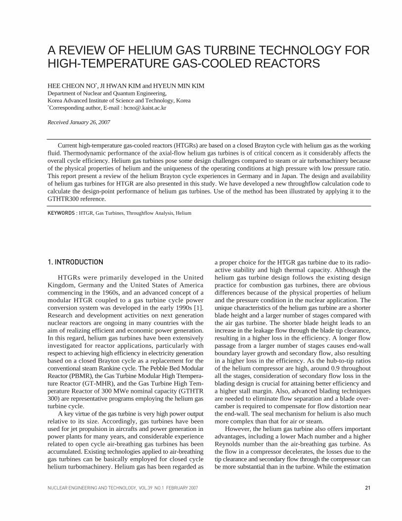
The EVO was a milestone test facility that played animportant role in the development of current HTGRs. Forthe turbomachinery, a two-shaft arrangement with aninterconnected gear was selected. The high-pressure (HP)turbine, which has a rotational speed of 5,500 rpm, drivesthe low-pressure (LP) compressor and high-pressure (HP)compressor on the first shaft. The low-pressure (LP) turbineis directly connected to the generator with a synchronousrotational speed of 3,000 rpm. The mass flow rate of heliumis 84.8 kg/s. A photograph of the HP turbine rotor is shownin Fig. 1. The HP turbine and the LP turbine have 7 stagesand 11 stages, respectively. The HP compressor and the LPcompressor have 15 stages and 10 stages, respectively,both with 100% reaction. The EVO facility was operatedfor approximately 24,000 hours. However, the maximumelectricity power output of EVO was 30.5 MWe, which ismuch less than the design power considered for an HTGRwith a helium Brayton cycle.
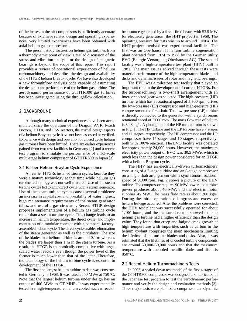
The HHV has an electrically-driven turbomachineryconsisting of a 2-stage turbine and an 8-stage compressoron a single-shaft arrangement with a synchronous rotationalspeed of 3,000 rpm. Fig. 2 shows a picture of the HHVturbine. The compressor requires 90 MW power, the turbinepower produces about 46 MW, and the electric motorsupplies 45 MW. The mass flow rate is about 200 kg/s.During the initial operation, oil ingress and excessivehelium leakage occurred. After the problems were corrected,the HHV test plant was successfully operated for about1,100 hours, and the measured results showed that thehelium gas turbine had a higher efficiency than the designvalue. They found that creep and fatigue crack growth athigh temperature with impurities such as carbon in thehelium coolant comprises the main mechanism limitingthe lifetime of the turbine blades and disks. Also, it wasestimated that the lifetimes of uncooled turbine componentsare around 50,000-60,000 hours and that the maximumtemperature with uncooled metallic blades and disks is850 C.
2.2 Recent Helium Turbomachinery Tests In 2003, a scaled-down test model of the first 4 stages of
the GTHTR300 compressor was designed and fabricated inthe Japanese test program to test the aerodynamic perfor-mance and verify the design and evaluation methods [3].Three major tests were planned: a compressor aerodynamic
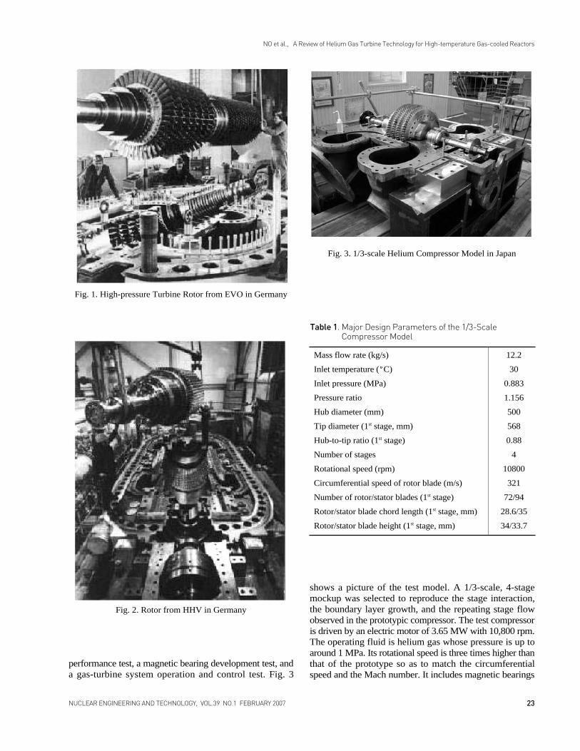
performance test, a magnetic bearing development test, anda gas-turbine system operation and control test. Fig. 3
shows a picture of the test model. A 1/3-scale, 4-stagemockup was selected to reproduce the stage interaction,the boundary layer growth, and the repeating stage flowobserved in the prototypic compressor. The test compressoris driven by an electric motor of 3.65 MW with 10,800 rpm.The operating fluid is helium gas whose pressure is up toaround 1 MPa. Its rotational speed is three times higher thanthat of the prototype so as to match the circumferentialspeed and the Mach number. It includes magnetic bearings
23NUCLEAR ENGINEERING AND TECHNOLOGY, VOL.39 NO.1 FEBRUARY 2007
NO et al., A Review of Helium Gas Turbine Technology for High-temperature Gas-cooled Reactors
Fig. 1. High-pressure Turbine Rotor from EVO in Germany
Fig. 2. Rotor from HHV in Germany
Fig. 3. 1/3-scale Helium Compressor Model in Japan
Mass flow rate (kg/s) 12.2
Inlet temperature ( C) 30
Inlet pressure (MPa) 0.883
Pressure ratio 1.156
Hub diameter (mm) 500
Tip diameter (1st stage, mm) 568
Hub-to-tip ratio (1st stage) 0.88
Number of stages 4
Rotational speed (rpm) 10800
Circumferential speed of rotor blade (m/s) 321
Number of rotor/stator blades (1st stage) 72/94
Rotor/stator blade chord length (1st stage, mm) 28.6/35
Rotor/stator blade height (1st stage, mm) 34/33.7
Table 1. Major Design Parameters of the 1/3-ScaleCompressor Model
to support the turbo-compressor rotor and the generator rotorinstead of oil bearings in order to eliminate the possibilityof oil ingress into the reactor. Major design parameters arepresented in Table 1.
The magnetic bearing development test is implementedto develop the technology of the magnetic bearing supportedrotor system. It consists of a 1/3-scale turbo-compressorand generator rotor models. The rotor models were designedso that both the critical speeds and vibration modes maybe matched to those of the prototypic rotors. Its test matrixincludes testing of magnetic bearing performance, unbalanceresponse, stability, and auxiliary bearing reliability.
The test facility for the gas-turbine system operation andcontrol test consists of a turbine, a compressor, a dynamo-meter, a recuperator, a pre-cooler, and a heater. The turbineand the compressor have a single stage and four stages,respectively, with a nominal pressure ratio of 1.156. Thedesign pressure, design temperature, rated flow rate are1.09 MPa, 650 C and 12.2 kg/s, respectively. Transienttests are planned: start-up, shutdown, load change, loss ofload, and emergency shutdown.
3. HTGR HELIUM GAS TURBINES
For closed cycle gas turbines, helium is considered apromising working fluid because it has many favorableaspects for HTGR application. Helium is an inert gas thatis non-corrosive and does not become radioactive. Thecycle efficiency has a theoretical advantage owing to thehigh specific heat ratio of helium. The choice of workingfluid significantly influences not only the cycle efficiencybut also the system compactness. Additionally, the heatexchanger design also is advantageous because the thermalconductivity and heat transfer coefficient for helium arehigher than those for air. On the other hand, helium leakagecould easily occur due to its low molecular weight and thusreliable sealing of the system is imperative. As outlinedabove, HTGR helium gas turbines differ from other gasturbines using air or combustion gases.
3.1 General Features of HTGR Helium GasTurbinesThe fluid properties of helium strongly influence the
size, geometries, and performance of gas turbine. Highpressure operation is needed to achieve a compact powerconversion system in the HTGR. The helium gas turbineshave high hub-to-tip ratios throughout the machine becausethe rotational speed is restricted to the synchronous speedwhen the turbomachines are directly connected to the gener-ator. A comparison of the design parameters between air-breathing compressors and HTGR helium compressors isgiven in Table 2 [4-6]. Although helium compressors areoperated at a low pressure ratio, the specific heat and specificheat ratio are high, and consequently the compressor needs
a large number of stages to achieve the required pressureratio. These design features unfavorably affect the aero-dynamic performance. A low blade aspect ratio tends toincrease the secondary flow and tip leakage flow, and manystages tend to increase the end-wall boundary layer growthand secondary flow. On the other hand, it is possible toprovide higher circumferential speeds without approachingthe sonic range due to the high sonic velocity of helium. Inaddition, shock loss also can be neglected in the design-point operation.
3.2 PBMR TurbomachineryThe design of the power conversion unit (PCU) of the
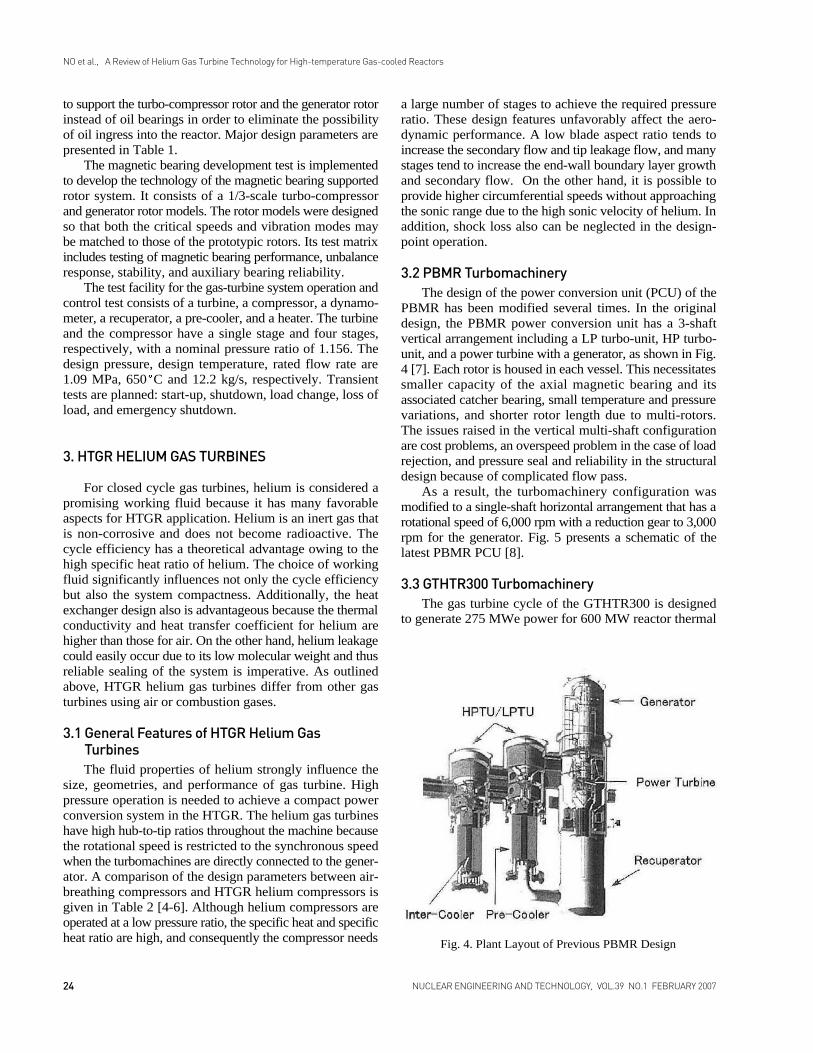
PBMR has been modified several times. In the originaldesign, the PBMR power conversion unit has a 3-shaftvertical arrangement including a LP turbo-unit, HP turbo-unit, and a power turbine with a generator, as shown in Fig.4 [7]. Each rotor is housed in each vessel. This necessitatessmaller capacity of the axial magnetic bearing and itsassociated catcher bearing, small temperature and pressurevariations, and shorter rotor length due to multi-rotors.The issues raised in the vertical multi-shaft configurationare cost problems, an overspeed problem in the case of loadrejection, and pressure seal and reliability in the structuraldesign because of complicated flow pass.
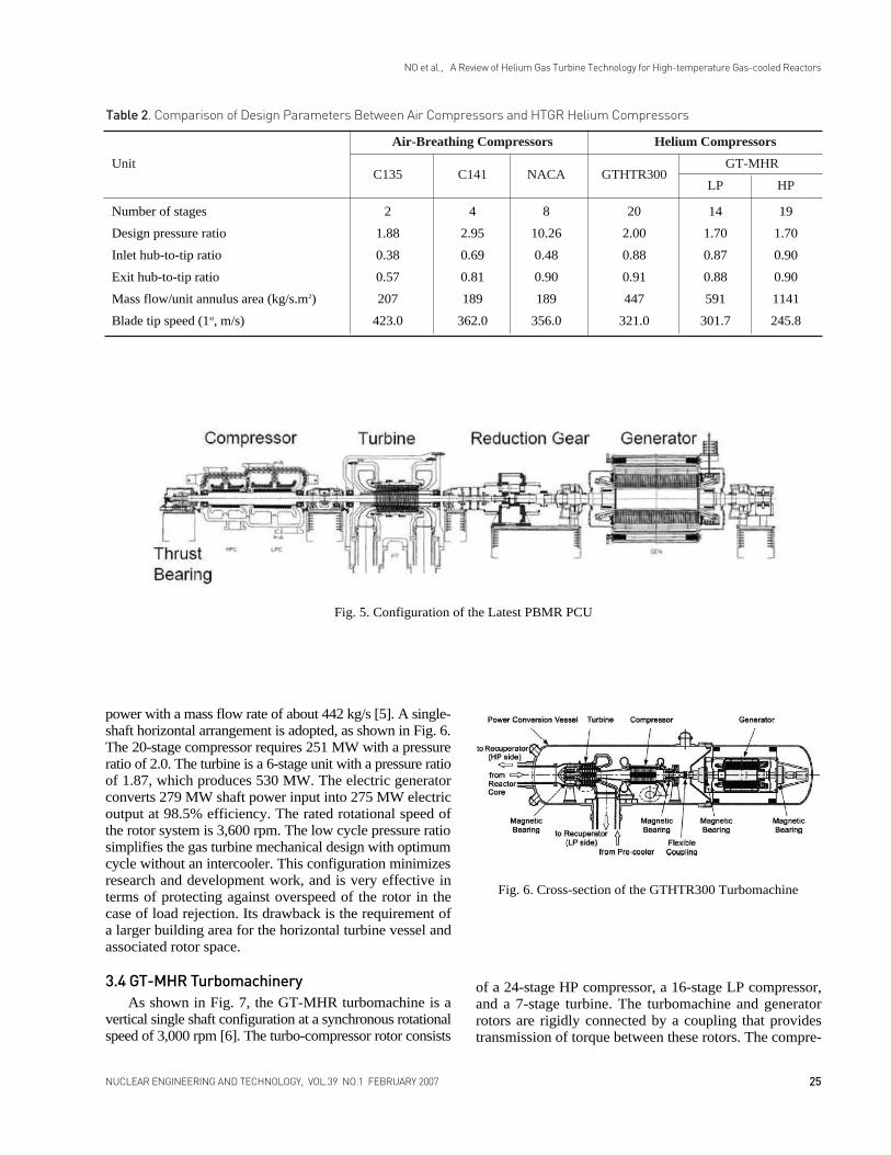
As a result, the turbomachinery configuration wasmodified to a single-shaft horizontal arrangement that has arotational speed of 6,000 rpm with a reduction gear to 3,000rpm for the generator. Fig. 5 presents a schematic of thelatest PBMR PCU [8].
3.3 GTHTR300 TurbomachineryThe gas turbine cycle of the GTHTR300 is designed
to generate 275 MWe power for 600 MW reactor thermal
24 NUCLEAR ENGINEERING AND TECHNOLOGY, VOL.39 NO.1 FEBRUARY 2007
NO et al., A Review of Helium Gas Turbine Technology for High-temperature Gas-cooled Reactors
Fig. 4. Plant Layout of Previous PBMR Design
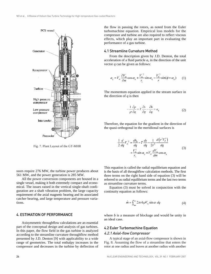
power with a mass flow rate of about 442 kg/s [5]. A single-shaft horizontal arrangement is adopted, as shown in Fig. 6.The 20-stage compressor requires 251 MW with a pressureratio of 2.0. The turbine is a 6-stage unit with a pressure ratioof 1.87, which produces 530 MW. The electric generatorconverts 279 MW shaft power input into 275 MW electricoutput at 98.5% efficiency. The rated rotational speed ofthe rotor system is 3,600 rpm. The low cycle pressure ratiosimplifies the gas turbine mechanical design with optimumcycle without an intercooler. This configuration minimizesresearch and development work, and is very effective interms of protecting against overspeed of the rotor in thecase of load rejection. Its drawback is the requirement ofa larger building area for the horizontal turbine vessel andassociated rotor space.
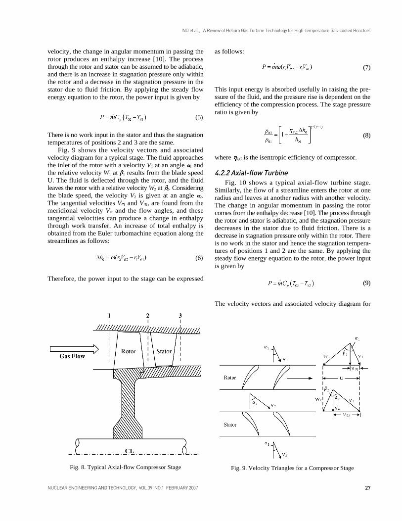
3.4 GT-MHR TurbomachineryAs shown in Fig. 7, the GT-MHR turbomachine is a
vertical single shaft configuration at a synchronous rotationalspeed of 3,000 rpm [6]. The turbo-compressor rotor consists
of a 24-stage HP compressor, a 16-stage LP compressor,and a 7-stage turbine. The turbomachine and generatorrotors are rigidly connected by a coupling that providestransmission of torque between these rotors. The compre-
25NUCLEAR ENGINEERING AND TECHNOLOGY, VOL.39 NO.1 FEBRUARY 2007
NO et al., A Review of Helium Gas Turbine Technology for High-temperature Gas-cooled Reactors
Fig. 5. Configuration of the Latest PBMR PCU
Fig. 6. Cross-section of the GTHTR300 Turbomachine
Number of stages 2 4 8 20 14 19
Design pressure ratio 1.88 2.95 10.26 2.00 1.70 1.70
Inlet hub-to-tip ratio 0.38 0.69 0.48 0.88 0.87 0.90
Exit hub-to-tip ratio 0.57 0.81 0.90 0.91 0.88 0.90
Mass flow/unit annulus area (kg/s.m2) 207 189 189 447 591 1141
Blade tip speed (1st, m/s) 423.0 362.0 356.0 321.0 301.7 245.8
Air-Breathing Compressors Helium Compressors
UnitC135 C141 NACA GTHTR300
GT-MHR
LP HP
Table 2. Comparison of Design Parameters Between Air Compressors and HTGR Helium Compressors
ssors require 276 MW, the turbine power produces about561 MW, and the power generation is 285 MW.
All the power conversion components are housed in asingle vessel, making it both extremely compact and econo-mical. The issues raised in the vertical single-shaft confi-guration are a shaft vibration problem, the large capacityrequirement of the axial magnetic bearing and its associatedcatcher bearing, and large temperature and pressure varia-tions.
4. ESTIMATION OF PERFORMANCE
Axisymmetric throughflow calculations are an essentialpart of the conceptual design and analysis of gas turbines.In this paper, the flow field in the gas turbine is analyzedaccording to the streamline curvature throughflow methodpresented by J.D. Denton [9] with applicability to a widerange of geometries. The total enthalpy increases in thecompressor and decreases in the turbine by deflection of
the flow in passing the rotors, as noted from the Eulerturbomachine equation. Empirical loss models for thecompressor and turbine are also required to reflect viscouseffects, which play an important part in evaluating theperformance of a gas turbine.
4.1 Streamline Curvature MethodFrom the description given by J.D. Denton, the total
acceleration of a fluid particle aq in the direction of the unitvector q can be given as follows:
The momentum equation applied in the stream surface inthe direction of q is then
Therefore, the equation for the gradient in the direction ofthe quasi-orthogonal in the meridional surfaces is
This equation is called the radial equilibrium equation andis the basis of all throughflow calculation methods. The firstthree terms on the right hand side of equation (3) will bereferred to as radial equilibrium terms and the last two termsas streamline curvature terms.
Equation (3) must be solved in conjunction with thecontinuity equation as follows:
where b is a measure of blockage and would be unity inan ideal case.
4.2 Euler Turbomachine Equation4.2.1 Axial-flow Compressor
A typical stage of an axial-flow compressor is shown inFig. 8. Assuming the flow of a streamline that enters therotor at one radius and leaves at another radius with another
NO et al., A Review of Helium Gas Turbine Technology for High-temperature Gas-cooled Reactors
(1)
(2)
(3)
(4)
26 NUCLEAR ENGINEERING AND TECHNOLOGY, VOL.39 NO.1 FEBRUARY 2007
Fig. 7. Plant Layout of the GT-MHR
velocity, the change in angular momentum in passing therotor produces an enthalpy increase [10]. The processthrough the rotor and stator can be assumed to be adiabatic,and there is an increase in stagnation pressure only withinthe rotor and a decrease in the stagnation pressure in thestator due to fluid friction. By applying the steady flowenergy equation to the rotor, the power input is given by
There is no work input in the stator and thus the stagnationtemperatures of positions 2 and 3 are the same.
Fig. 9 shows the velocity vectors and associatedvelocity diagram for a typical stage. The fluid approachesthe inlet of the rotor with a velocity V1 at an angle 1 andthe relative velocity W1 at 1 results from the blade speedU. The fluid is deflected through the rotor, and the fluidleaves the rotor with a relative velocity W2 at 2. Consideringthe blade speed, the velocity V2 is given at an angle 2.The tangential velocities V 1 and V 2, are found from themeridional velocity Vm and the flow angles, and thesetangential velocities can produce a change in enthalpythrough work transfer. An increase of total enthalpy isobtained from the Euler turbomachine equation along thestreamlines as follows:
Therefore, the power input to the stage can be expressed
as follows:
This input energy is absorbed usefully in raising the pre-ssure of the fluid, and the pressure rise is dependent on theefficiency of the compression process. The stage pressureratio is given by
where S,C is the isentropic efficiency of compressor.
4.2.2 Axial-flow TurbineFig. 10 shows a typical axial-flow turbine stage.
Similarly, the flow of a streamline enters the rotor at oneradius and leaves at another radius with another velocity.The change in angular momentum in passing the rotorcomes from the enthalpy decrease [10]. The process throughthe rotor and stator is adiabatic, and the stagnation pressuredecreases in the stator due to fluid friction. There is adecrease in stagnation pressure only within the rotor. Thereis no work in the stator and hence the stagnation tempera-tures of positions 1 and 2 are the same. By applying thesteady flow energy equation to the rotor, the power inputis given by
The velocity vectors and associated velocity diagram for
27NUCLEAR ENGINEERING AND TECHNOLOGY, VOL.39 NO.1 FEBRUARY 2007
NO et al., A Review of Helium Gas Turbine Technology for High-temperature Gas-cooled Reactors
Fig. 8. Typical Axial-flow Compressor Stage Fig. 9. Velocity Triangles for a Compressor Stage
(5)
(6)
(7)
(8)
(9)
a typical stage are shown in Fig. 11. The fluid approachesthe inlet of the stator with a velocity V1 at an angle 1. Thefluid is deflected through the stator, and the fluid leaves therotor with a velocity V2 at 2 resulting from the blade speed
U and the relative velocity W2 at 2. The fluid is deflectedthrough the rotor and leaves the rotor with a relative velocityW3 at 3, and the velocity V3 is given at an angle 3. Thetangential velocities V 2 and V 3 are found from the meri-dional velocity Vm and the flow angles, and these tangentialvelocities can produce work through the change in enthalpy.
A decrease of total enthalpy is obtained from the Eulerturbomachine equation along the streamlines.
The power input to the stage can be expressed as follows:
This input energy is absorbed usefully in raising the pre-ssure of the fluid, and the pressure rise is dependent onthe efficiency of the compression process. The stagnationpressure ratio of the stage can be found from
where S, T is the isentropic efficiency of turbine.
4.3 Losses and Performance EstimationThe efficiency is dependent on the total drag coefficient
for each of the blade rows and the flow path, and there arefour kinds of primary loss sources. First, the profile lossis caused by the flow around the blade boundary layers andthe wake of the trailing edge. The annulus loss is associatedwith the end-wall boundary layers, and the secondary flowloss is due to the cascade and trailing vortices. Lastly, the tipclearance loss is due to the leakage through the tip clea-rances. In the design of a HTGR helium gas turbine, theshock loss is not considered because helium gas has a veryhigh sonic velocity and the compressor operates only inthe low subsonic region.
The analysis below is applied to the loss prediction atthe design-point. The loss models are widely accepted andrecommended by GE and Concept-NREC and can be foundin references [11] through [16].
5. RESULTS AND DISCUSSION
The GTHTR300 compressor and turbine design ofJAEA have been selected to verify the code results, becausethe details of the design specifications and geometry areavailable [5]. Tables 3 and 4 summarize the design para-meters. The compressor has a constant inner wall diameterand the turbine has a constant mean diameter design. The
28 NUCLEAR ENGINEERING AND TECHNOLOGY, VOL.39 NO.1 FEBRUARY 2007
NO et al., A Review of Helium Gas Turbine Technology for High-temperature Gas-cooled Reactors
(10)
(11)
(12)
Fig. 11. Velocity Triangles for a Turbine Stage
Fig. 10. Typical Axial-flow Turbine Stage
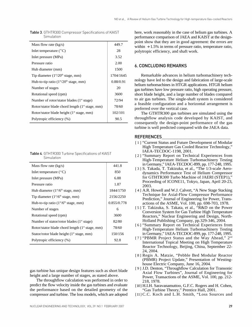
gas turbine has unique design features such as short bladeheight and a large number of stages, as stated above.
The throughflow calculation was performed in order topredict the flow velocity inside the gas turbines and evaluatethe performance based on the detailed geometry of thecompressor and turbine. The loss models, which are adopted
here, work reasonably in the case of helium gas turbines. Aperformance comparison of JAEA and KAIST at the design-point show that they are in good agreement: the errors arewithin 1.5% in terms of pressure ratio, temperature ratio,polytropic efficiency, and shaft work.
6. CONCLUDING REMARKS
Remarkable advances in helium turbomachinery tech-nology have led to the design and fabrication of large-scalehelium turbomachines in HTGR applications. HTGR heliumgas turbines have low pressure ratio, high operating pressure,short blade height, and a large number of blades comparedto air gas turbines. The single-shaft system is considereda feasible configuration and a horizontal arrangement ispreferred over the vertical case.
The GTHTR300 gas turbines are simulated using thethroughflow analysis code developed by KAIST, andconsequently the design-point performance of the gasturbine is well predicted compared with the JAEA data.
REFERENCES_______________________________[ 1 ] “Current Status and Future Development of Modular
High Temperature Gas Cooled Reactor Technology,”IAEA-TECDOC-1198, 2001.
[ 2 ] “Summary Report on Technical Experiences fromHigh-Temperature Helium Turbomachinery Testingin Germany,” IAEA-TECDOC-899, pp. 177-248, 1995.
[ 3 ] S. Takada, T. Takizuka, et al., “The 1/3-scale Aero-dynamics Performance Test of Helium Compressorfor GTHTR300 Turbo Machine of JAERI (STEP1),”Proceeding of ICONE11, Tokyo, Japan, April 20-23,2003.
[ 4 ] A.R. Howell and W.J. Calvert, “A New Stage StackingTechnique for Axial-Flow Compressor PerformancePrediction,” Journal of Engineering for Power, Trans-actions of the ASME, Vol. 100, pp. 698-703, 1978.
[ 5 ] T. Takizuka, S. Takata, et al., “R&D on the PowerConversion System for Gas Turbine High TemperatureReactors,” Nuclear Engineering and Design, North-Holland Publishing Company, pp.329-346, 2004.
[ 6 ] “Summary Report on Technical Experiences fromHigh-Temperature Helium Turbomachinery Testingin Germany,” IAEA-TECDOC-899, pp. 177-248, 1995.
[ 7 ] “PBMR Project Status and the Way Ahead,” 2nd
International Topical Meeting on High TemperatureReactor Technology, Beijing, China, September 22-24, 2004.
[ 8 ] Regis A. Matzie, “Pebble Bed Modular Reactor(PBMR) Project Update,” Presentation of Westing-house Electric Company, June 16, 2004.
[ 9 ] J.D. Denton, “Throughflow Calculation for TransonicAxial Flow Turbines”, Journal of Engineering forPower, Transactions of the ASME, Vol. 100, pp. 212-218, 1978.
[ 10 ] H.I.H. Saravanamuttoo, G.F.C. Rogers and H. Cohen,“Gas Turbine Theory,” Prentice Hall, 2001.
[ 11 ] C.C. Koch and L.H. Smith, “Loss Sources and
29NUCLEAR ENGINEERING AND TECHNOLOGY, VOL.39 NO.1 FEBRUARY 2007
NO et al., A Review of Helium Gas Turbine Technology for High-temperature Gas-cooled Reactors
Mass flow rate (kg/s) 449.7
Inlet temperature ( C) 28
Inlet pressure (MPa) 3.52
Pressure ratio 2.00
Hub diameter (mm) 1500
Tip diameter (1st/20th stage, mm) 1704/1645
Hub-to-tip ratio (1st/20th stage, mm) 0.88/0.91
Number of stages 20
Rotational speed (rpm) 3600
Number of rotor/stator blades (1st stage) 72/94
Rotor/stator blade chord length (1st stage, mm) 78/60
Rotor/stator blade height (1st stage, mm) 102/101
Polytropic efficiency (%) 90.5
Table 3. GTHTR300 Compressor Specifications of KAISTSimulation
Mass flow rate (kg/s) 441.8
Inlet temperature ( C) 850
Inlet pressure (MPa) 6.88
Pressure ratio 1.87
Hub diameter (1st/6th stage, mm) 1844/1750
Tip diameter (1st/6th stage, mm) 2156/2250
Hub-to-tip ratio (1st/6th stage, mm) 0.855/0.778
Number of stages 6
Rotational speed (rpm) 3600
Number of stator/rotor blades (1st stage) 82/80
Rotor/stator blade chord length (1st stage, mm) 78/60
Stator/rotor blade height (1st stage, mm) 150/156
Polytropic efficiency (%) 92.8
Table 4. GTHTR300 Turbine Specifications of KAISTSimulation

Magnitudes in Axial-flow Compressors,” Journal ofEngineering for Power, Transactions of the ASME,pp. 411-424 (1976).
[ 12 ] B. Lakshiminarayana and J.H. Horlock, “Review:Secondary Flows and Losses in Cascades and Axial-flow Turbomachines,” International Journal ofMechanical Sciences, Pergamon Press Ltd, Vol. 5,pp.287-307, 1963.
[ 13 ] B. Lakshminarayana, “Methods of Predicting the TipClearance Effects in Axial Flow Turbomachinery,”Journal of Basic Engineering, Transactions of theASME, pp. 467-482, 1970.
[ 14 ] O.E. Balje and R.L. Binsley, “Axial Turbine Perfor-mance Evaluation. Part A – Loss-Geometry Relation-ship,” Journal of Engineering for Power, Transactionsof the ASME, pp. 341-348, 1968.
[ 15 ] S.C. Kacker and U. Okapuu, “A Mean Line PredictionMethod for Axial Flow Turbine Efficiency,” Journalof Engineering for Power, Transactions of the ASME,pp. 111-119, 1982.
[ 16 ] J. Dunham and P.M. Came, “Improvements to theAinley-Mathieson Method of Turbine PerformancePrediction,” Journal of Engineering for Power, Trans-actions of the ASME, pp. 252-256, 1970.
30 NUCLEAR ENGINEERING AND TECHNOLOGY, VOL.39 NO.1 FEBRUARY 2007
NO et al., A Review of Helium Gas Turbine Technology for High-temperature Gas-cooled Reactors
Copyright © 2022 FDOKUMEN