
Studying hyperfine fields with resonant nuclear diffraction of x rays (invited
Upload
independentCategory
view
1download
0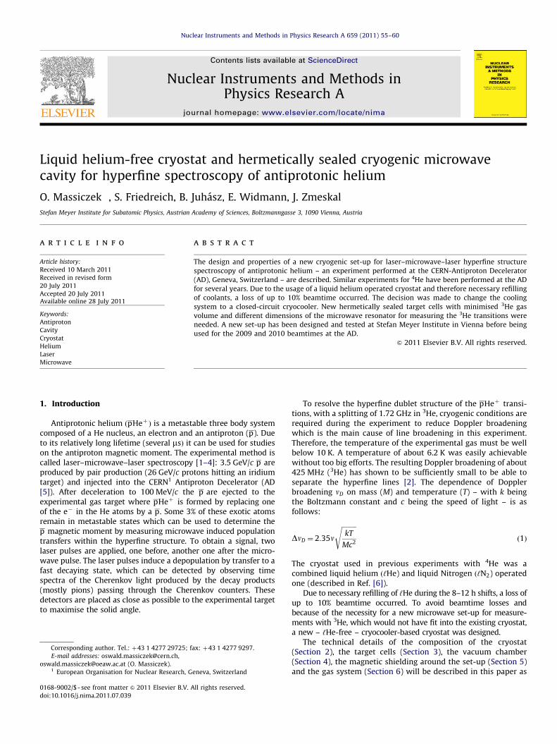
Nuclear Instruments and Methods in Physics Research A 659 (2011) 55–60
Contents lists available at ScienceDirect
Nuclear Instruments and Methods inPhysics Research A
0168-90
doi:10.1
� Corr
E-m
oswald.1 Eu
journal homepage: www.elsevier.com/locate/nima
Liquid helium-free cryostat and hermetically sealed cryogenic microwavecavity for hyperfine spectroscopy of antiprotonic helium
O. Massiczek �, S. Friedreich, B. Juhasz, E. Widmann, J. Zmeskal
Stefan Meyer Institute for Subatomic Physics, Austrian Academy of Sciences, Boltzmanngasse 3, 1090 Vienna, Austria
a r t i c l e i n f o
Article history:
Received 10 March 2011
Received in revised form
20 July 2011
Accepted 20 July 2011Available online 28 July 2011
Keywords:
Antiproton
Cavity
Cryostat
Helium
Laser
Microwave
02/$ - see front matter & 2011 Elsevier B.V. A
016/j.nima.2011.07.039
esponding author. Tel.: þ43 1 4277 29725; f
ail addresses: [email protected],
[email protected] (O. Massiczek).
ropean Organisation for Nuclear Research, G
a b s t r a c t
The design and properties of a new cryogenic set-up for laser–microwave–laser hyperfine structure
spectroscopy of antiprotonic helium – an experiment performed at the CERN-Antiproton Decelerator
(AD), Geneva, Switzerland – are described. Similar experiments for 4He have been performed at the AD
for several years. Due to the usage of a liquid helium operated cryostat and therefore necessary refilling
of coolants, a loss of up to 10% beamtime occurred. The decision was made to change the cooling
system to a closed-circuit cryocooler. New hermetically sealed target cells with minimised 3He gas
volume and different dimensions of the microwave resonator for measuring the 3He transitions were
needed. A new set-up has been designed and tested at Stefan Meyer Institute in Vienna before being
used for the 2009 and 2010 beamtimes at the AD.
& 2011 Elsevier B.V. All rights reserved.
1. Introduction
Antiprotonic helium ðpHeþ Þ is a metastable three body systemcomposed of a He nucleus, an electron and an antiproton (p). Dueto its relatively long lifetime (several msÞ it can be used for studieson the antiproton magnetic moment. The experimental method iscalled laser–microwave–laser spectroscopy [1–4]: 3.5 GeV/c p areproduced by pair production (26 GeV/c protons hitting an iridiumtarget) and injected into the CERN1 Antiproton Decelerator (AD[5]). After deceleration to 100 MeV/c the p are ejected to theexperimental gas target where pHeþ is formed by replacing oneof the e� in the He atoms by a p. Some 3% of these exotic atomsremain in metastable states which can be used to determine thep magnetic moment by measuring microwave induced populationtransfers within the hyperfine structure. To obtain a signal, twolaser pulses are applied, one before, another one after the micro-wave pulse. The laser pulses induce a depopulation by transfer to afast decaying state, which can be detected by observing timespectra of the Cherenkov light produced by the decay products(mostly pions) passing through the Cherenkov counters. Thesedetectors are placed as close as possible to the experimental targetto maximise the solid angle.
ll rights reserved.
ax: þ43 1 4277 9297.
eneva, Switzerland
To resolve the hyperfine dublet structure of the pHeþ transi-tions, with a splitting of 1.72 GHz in 3He, cryogenic conditions arerequired during the experiment to reduce Doppler broadeningwhich is the main cause of line broadening in this experiment.Therefore, the temperature of the experimental gas must be wellbelow 10 K. A temperature of about 6.2 K was easily achievablewithout too big efforts. The resulting Doppler broadening of about425 MHz (3He) has shown to be sufficiently small to be able toseparate the hyperfine lines [2]. The dependence of Dopplerbroadening nD on mass (M) and temperature (T) – with k beingthe Boltzmann constant and c being the speed of light – is asfollows:
DnD ¼ 2:35n
ffiffiffiffiffiffiffiffiffikT
Mc2
sð1Þ
The cryostat used in previous experiments with 4He was acombined liquid helium ð‘He) and liquid Nitrogen ð‘N2) operatedone (described in Ref. [6]).
Due to necessary refilling of ‘He during the 8–12 h shifts, a loss ofup to 10% beamtime occurred. To avoid beamtime losses andbecause of the necessity for a new microwave set-up for measure-ments with 3He, which would not have fit into the existing cryostat,a new – ‘He-free – cryocooler-based cryostat was designed.
The technical details of the composition of the cryostat(Section 2), the target cells (Section 3), the vacuum chamber(Section 4), the magnetic shielding around the set-up (Section 5)and the gas system (Section 6) will be described in this paper as
2-stagecold head
50K stage
4K stage
Target cell
Waveguide
100mm
0mm
200mm
LaserAnti-
protons
Fig. 1. Vertical sectional drawing of the new cryostat (drawing shortened between
wavy horizontal lines). A detailed drawing of the target cell area is shown in Fig. 3.
Target cell
Cherenkov counter
Cherenkov counterThermal radiation shieldVacuum chamber
100 mm50 mm0 mm
LaserAnti-
protons
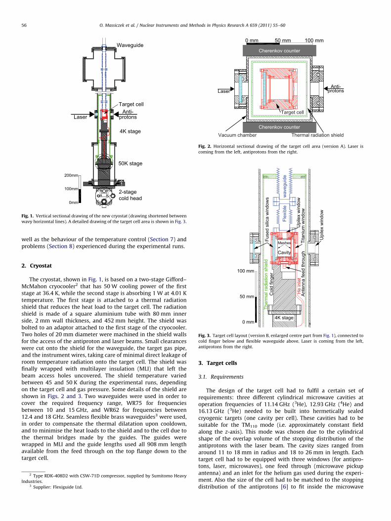
Fig. 2. Horizontal sectional drawing of the target cell area (version A). Laser is
coming from the left, antiprotons from the right.
Flex
ible
wav
egui
de
Fuse
d si
lica
win
dow
s
Tita
nium
win
dow
Upi
lex
win
dow
Upi
lex
win
dow
Meshes
O. Massiczek et al. / Nuclear Instruments and Methods in Physics Research A 659 (2011) 55–6056
well as the behaviour of the temperature control (Section 7) andproblems (Section 8) experienced during the experimental runs.
He
inle
t
100 mm
Ant
enna
feed
thro
ughCavity
50 mm
0 mm
Ther
mal
radi
atio
n sh
ield
Col
d fin
ger
4K stage
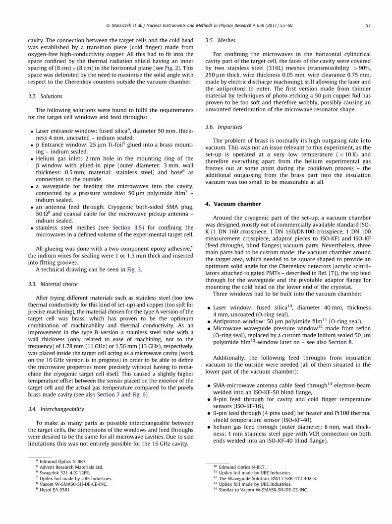
Fig. 3. Target cell layout (version B, enlarged centre part from Fig. 1), connected to
cold finger below and flexible waveguide above. Laser is coming from the left,
antiprotons from the right.
2. Cryostat
The cryostat, shown in Fig. 1, is based on a two-stage Gifford–McMahon cryocooler2 that has 50 W cooling power of the firststage at 36.4 K, while the second stage is absorbing 1 W at 4.01 Ktemperature. The first stage is attached to a thermal radiationshield that reduces the heat load to the target cell. The radiationshield is made of a square aluminium tube with 80 mm innerside, 2 mm wall thickness, and 452 mm height. The shield wasbolted to an adaptor attached to the first stage of the cryocooler.Two holes of 20 mm diameter were machined in the shield wallsfor the access of the antiproton and laser beams. Small clearanceswere cut onto the shield for the waveguide, the target gas pipe,and the instrument wires, taking care of minimal direct leakage ofroom temperature radiation onto the target cell. The shield wasfinally wrapped with multilayer insulation (MLI) that left thebeam access holes uncovered. The shield temperature variedbetween 45 and 50 K during the experimental runs, dependingon the target cell and gas pressure. Some details of the shield areshown in Figs. 2 and 3. Two waveguides were used in order tocover the required frequency range, WR75 for frequenciesbetween 10 and 15 GHz, and WR62 for frequencies between12.4 and 18 GHz. Seamless flexible brass waveguides3 were used,in order to compensate the thermal dilatation upon cooldown,and to minimise the heat loads to the shield and to the cell due tothe thermal bridges made by the guides. The guides werewrapped in MLI and the guide lengths used all 908 mm lengthavailable from the feed through on the top flange down to thetarget cell.
2 Type RDK-408D2 with CSW-71D compressor, supplied by Sumitomo Heavy
Industries.3 Supplier: Flexiguide Ltd.
3. Target cells
3.1. Requirements
The design of the target cell had to fulfil a certain set ofrequirements: three different cylindrical microwave cavities atoperation frequencies of 11.14 GHz (3He), 12.93 GHz (4He) and16.13 GHz (3He) needed to be built into hermetically sealedcryogenic targets (one cavity per cell). These cavities had to besuitable for the TM110 mode (i.e. approximately constant fieldalong the z-axis). This mode was chosen due to the cylindricalshape of the overlap volume of the stopping distribution of theantiprotons with the laser beam. The cavity sizes ranged fromaround 11 to 18 mm in radius and 18 to 26 mm in length. Eachtarget cell had to be equipped with three windows (for antipro-tons, laser, microwaves), one feed through (microwave pickupantenna) and an inlet for the helium gas used during the experi-ment. Also the size of the cell had to be matched to the stoppingdistribution of the antiprotons [6] to fit inside the microwave
O. Massiczek et al. / Nuclear Instruments and Methods in Physics Research A 659 (2011) 55–60 57
cavity. The connection between the target cells and the cold headwas established by a transition piece (cold finger) made fromoxygen-free high-conductivity copper. All this had to fit into thespace confined by the thermal radiation shield having an innerspacing of (8 cm)� (8 cm) in the horizontal plane (see Fig. 2). Thisspace was delimited by the need to maximise the solid angle withrespect to the Cherenkov counters outside the vacuum chamber.
3.2. Solutions
The following solutions were found to fulfil the requirementsfor the target cell windows and feed throughs:
�
Laser entrance window: fused silica4, diameter 50 mm, thick-ness 4 mm, uncoated – indium sealed. � p Entrance window: 25 mm Ti-foil5 glued into a brass mount-ing – indium sealed.
� Helium gas inlet: 2 mm hole in the mounting ring of thep window with glued-in pipe (outer diameter: 3 mm, wallthickness: 0.5 mm, material: stainless steel) and hose6 asconnection to the outside.
� a waveguide for feeding the microwaves into the cavity,connected by a pressure window: 50 mm polyimide film7 –indium sealed.
� an antenna feed through: Cryogenic both-sided SMA plug,50 O8 and coaxial cable for the microwave pickup antenna –indium sealed.
� stainless steel meshes (see Section 3.5) for confining themicrowaves in a defined volume of the experimental target cell.
All glueing was done with a two component epoxy adhesive,9
the indium wires for sealing were 1 or 1.5 mm thick and insertedinto fitting grooves.
A technical drawing can be seen in Fig. 3.
3.3. Material choice
After trying different materials such as stainless steel (too lowthermal conductivity for this kind of set-up) and copper (too soft forprecise machining), the material chosen for the type A version of thetarget cell was brass, which has proven to be the optimumcombination of machinability and thermal conductivity. As animprovement in the type B version a stainless steel tube with awall thickness (only related to ease of machining, not to thefrequency) of 1.78 mm (11 GHz) or 1.56 mm (13 GHz), respectively,was placed inside the target cell acting as a microwave cavity (workon the 16 GHz version is in progress) in order to be able to definethe microwave properties more precisely without having to rema-chine the cryogenic target cell itself. This caused a slightly highertemperature offset between the sensor placed on the exterior of thetarget cell and the actual gas temperature compared to the purelybrass made cavity (see also Section 7 and Fig. 6).
3.4. Interchangeability
To make as many parts as possible interchangeable betweenthe target cells, the dimensions of the windows and feed throughswere desired to be the same for all microwave cavities. Due to sizelimitations this was not entirely possible for the 16 GHz cavity.
4 Edmund Optics N-BK7.5 Advent Research Materials Ltd.6 Swagelok 321-4-X-12FR.7 Upilex foil made by UBE Industries.8 Vacom W-SMA50-SH-DE-CE-INC.9 Hysol EA 9361.
3.5. Meshes
For confining the microwaves in the horizontal cylindricalcavity part of the target cell, the faces of the cavity were coveredby two stainless steel (316L) meshes (transmissibility 490%,250 mm thick, wire thickness 0.05 mm, wire clearance 0.75 mm,made by electric discharge machining), still allowing the laser andthe antiprotons to enter. The first version made from thinnermaterial by techniques of photo-etching a 50 mm copper foil hasproven to be too soft and therefore wobbly, possibly causing anunwanted deterioration of the microwave resonator shape.
3.6. Impurities
The problem of brass is normally its high outgasing rate intovacuum. This was not an issue relevant to this experiment, as theset-up is operated at a very low temperature (o10 KÞ andtherefore everything apart from the helium experimental gasfreezes out at some point during the cooldown process – theadditional outgassing from the brass part into the insulationvacuum was too small to be measurable at all.
4. Vacuum chamber
Around the cryogenic part of the set-up, a vacuum chamberwas designed, mostly out of commercially available standard ISO-K (1 DN 160 crosspiece, 1 DN 160/DN100 crosspiece, 1 DN 100measurement crosspiece, adaptor pieces to ISO-KF) and ISO-KF(feed throughs, blind flanges) vacuum parts. Nevertheless, threemain parts had to be custom made: the vacuum chamber aroundthe target area, which needed to be square shaped to provide anoptimum solid angle for the Cherenkov detectors (acrylic scintil-lators attached to gated PMTs – described in Ref. [7]), the top feedthrough for the waveguide and the pivotable adaptor flange formounting the cold head on the lower end of the cryostat.
Three windows had to be built into the vacuum chamber:
�
Laser window: fused silica10, diameter 40 mm, thickness4 mm, uncoated (O-ring seal). � Antiproton window: 50 mm polyimide film11 (O-ring seal). � Microwave waveguide pressure window12 made from teflon(O-ring seal), replaced by a custom made Indium sealed 50 mmpolyimide film13-window later on – see also Section 8.
Additionally, the following feed throughs from insulationvacuum to the outside were needed (all of them situated in thelower part of the vacuum chamber):
�
SMA-microwave antenna cable feed through14 electron-beamwelded into an ISO-KF-50 blind flange, � 8-pin feed through for cavity and cold finger temperaturesensors (ISO-KF-16),
� 9-pin feed through (4 pins used) for heater and Pt100 thermalshield temperature sensor (ISO-KF-40),
� helium gas feed through (outer diameter: 8 mm, wall thick-ness: 1 mm stainless steel pipe with VCR connectors on bothends welded into an ISO-KF-40 blind flange).
10 Edmund Optics N-BK7.11 Upilex foil made by UBE Industries.12 The Waveguide Solution, RW17-SZB-412-402-B.13 Upilex foil made by UBE Industries.14 Similar to Vacom W-SMA50-SH-DE-CE-INC.

O. Massiczek et al. / Nuclear Instruments and Methods in Physics Research A 659 (2011) 55–6058
Other vacuum parts used were (both located towards the topend of the vacuum chamber):
�
vacuum to air (or pure N2) valve (ISO-KF-16), � pressure gauge15 (ISO-KF-25).For pumping the insulation vacuum, a turbomolecular pump16
has been chosen. Combined with a scroll pump as roughing pump,the best achievable insulation vacuum revealed to be in the low10�7 mbar range.
Fig. 4. Schematic drawing of the gas system, all components at room temperature
(if not marked different). Symbols according to DIN 28401.
5. Mu-metal magnetic shielding
The linewidth of the microwave transitions increases by2.8 MHz/G in the presence of a constant magnetic field. The fieldin the target volume has to be o0:1 G to ensure that thebroadening is smaller than the natural linewidth (about 2 MHzfor the 11 GHz transitions in 3He). Therefore a 1 mm thick Mu-metal shielding was designed around the square shaped part ofthe vacuum chamber, reaching from about 20 cm below up toabout 40 cm above the target cell position, to minimise theinfluence of external magnetic fields in the target area. As aresult, the maximum magnetic field strength measured at thetarget cell position inside the magnetic shielding was sufficientlysmall – below 0.05 G compared to 0.6 G without magneticshielding (caused by the earth magnetic field). The first measure-ments of the magnetic fields were done at SMI17 with a gauss-meter,18 using axial and transverse Hall probes. Later onmeasurements at the AD showed that stray magnetic fields (e.g.from beamline steering magnets) inside the experimental areadid not cause a different result.
6. Gas system
Outside the cryostat a gas system (a schematic drawing can beseen in Fig. 4) had to be developed for the following tasks:
�
cleaning the experimental 3He gas from chemical impuritiesbefore filling the target cell, � recuperating the used 3He in order to avoid losing thisexpensive gas,
� avoiding overpressure in the experimental set-up by relievingit without losing 3He.
For cleaning purpose, a liquid nitrogen operated cold trap filledwith 13X/4A molecular sieve (6 mm outer diameter, 1 mm wallthickness soft copper pipe – with one in-line particulate filter19
attached to each end – bent to a coil fitting into a 2 l ‘N2-dewar)was installed in the system. The recuperation system consists oftwo pumps, leading the helium back into its original bottle andpressurising it up to 3 bar. For safety reasons, an overpressurevalve opening at 1.8 bar venting the gas into an 1 U.S. Gal.(approx. 3.8 l) expansion bottle had to be installed. With thisvalve installed, an uncontrolled warmup of the system puts norisk on the set-up as the weakest part of the gas system (thetitanium window of the target cell) can withstand 44 bar, so theexpansion of the gas into the expansion volume starting from1.8 bar pressure inside the target cell results in a sufficiently large
15 Balzers compact full range PKR 250.16 Varian Turbo-V 301, air cooled.17 Stefan Meyer Institute.18 LakeShore 421.19 Swagelok SS-6F-MM-2.
safety margin with regards to the relatively low overpressuresused in this experimental set-up. Most parts of the gas systemwere designed using Swagelok parts: flexible tubes, valves, needlevalves, pressure relief valves with VCR-fittings (a proprietary,highly reliable, washer-based, all metal sealing system). Only in afew places standard Swagelok all metal tube fittings had to beused due to very special design requirements (e.g. connection tothe cold trap, connection to the gas bottle’s reduction valve). Alsoadapters to other connection types were needed, such as a VCR toNPT connectors for use with the expansion bottle and VCR toConFlat and ISO-KF adapters as a connection to a remaining partof the old gas system – including Baratron, Penning and Piranipressure gauges and a Q-mass spectrometer – which was con-tinued to be used.
7. Temperature control
The temperature behaviour of the new cryostat was recordedby reading out three temperature sensors, thereof two silicondiodes,20 one screwed on top of the target cell, the other onto oneside of the cold finger. Those sensors were read out by an auto-tuning temperature controller.21 The third sensor, a Pt100 (plati-num sensor) in a two-wire configuration was glued onto theinside of the top cover of the thermal radiation shield and readout by a digital voltmeter.
7.1. Temperature stabilisation
For controlling the temperature, two heating resistors(2�10 OÞ were screwed on the cold finger between the coldhead and the target cell. The temperature sensor mounted on topof the target cell was used by the temperature controller as a
20 LakeShore Cryotronics Inc. DT-670, CU packaged.21 LakeShore 331S.
4.4 4.5 4.6 4.7 4.8 4.9 5temperature [K]
1200
1400
1600
1800
2000
cavi
ty p
ress
ure
[mba
r]
vapour pressure lHe11 GHz - type A11 GHz - type B13 GHz - type B
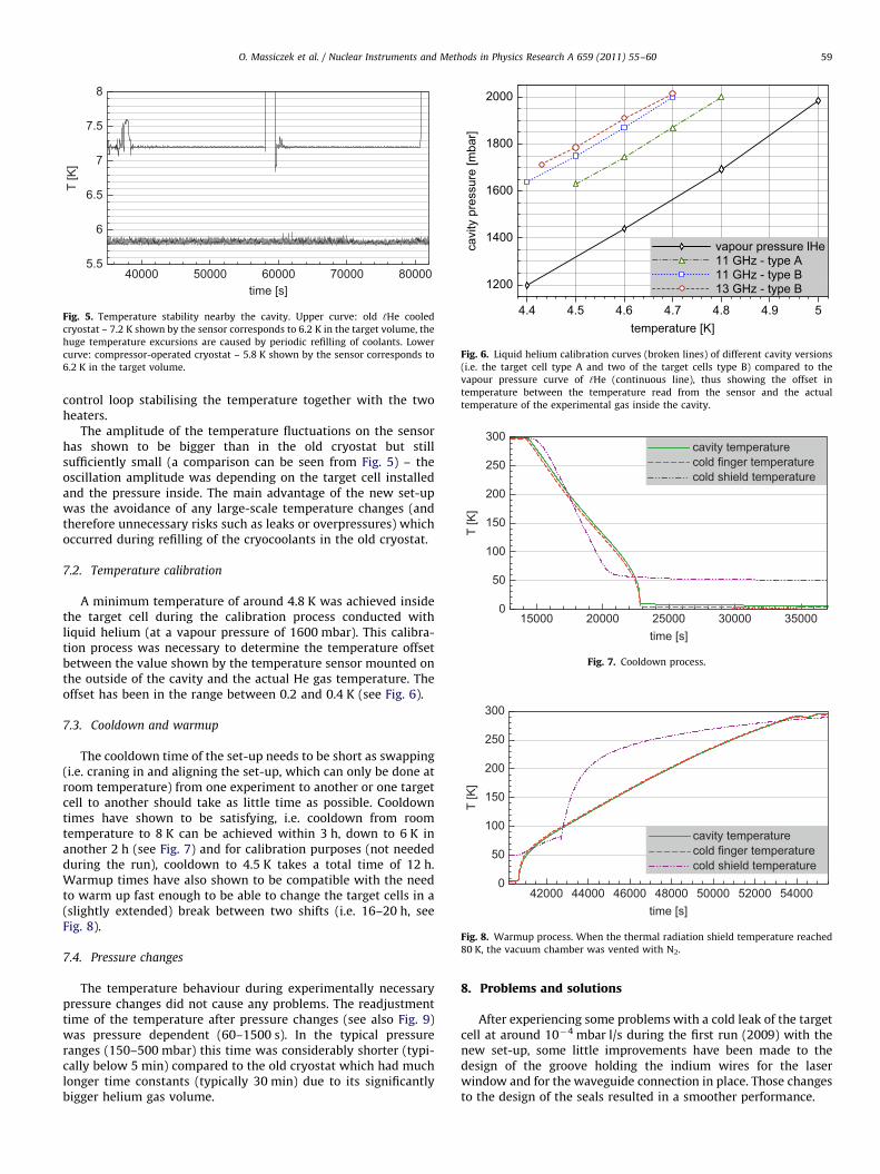
Fig. 6. Liquid helium calibration curves (broken lines) of different cavity versions
(i.e. the target cell type A and two of the target cells type B) compared to the
vapour pressure curve of ‘He (continuous line), thus showing the offset in
temperature between the temperature read from the sensor and the actual
temperature of the experimental gas inside the cavity.
15000 20000 25000 30000 35000time [s]
0
50
100
150
200
250
300
T [K
]
cavity temperaturecold finger temperaturecold shield temperature
Fig. 7. Cooldown process.
42000 44000 46000 48000 50000 52000 54000time [s]
0
50
100
150
200
250
300
T [K
]
cavity temperaturecold finger temperaturecold shield temperature
Fig. 8. Warmup process. When the thermal radiation shield temperature reached
80 K, the vacuum chamber was vented with N2.
40000 50000 60000 70000 80000time [s]
5.5
6
6.5
7
7.5
8
T [K
]
Fig. 5. Temperature stability nearby the cavity. Upper curve: old ‘He cooled
cryostat – 7.2 K shown by the sensor corresponds to 6.2 K in the target volume, the
huge temperature excursions are caused by periodic refilling of coolants. Lower
curve: compressor-operated cryostat – 5.8 K shown by the sensor corresponds to
6.2 K in the target volume.
O. Massiczek et al. / Nuclear Instruments and Methods in Physics Research A 659 (2011) 55–60 59
control loop stabilising the temperature together with the twoheaters.
The amplitude of the temperature fluctuations on the sensorhas shown to be bigger than in the old cryostat but stillsufficiently small (a comparison can be seen from Fig. 5) – theoscillation amplitude was depending on the target cell installedand the pressure inside. The main advantage of the new set-upwas the avoidance of any large-scale temperature changes (andtherefore unnecessary risks such as leaks or overpressures) whichoccurred during refilling of the cryocoolants in the old cryostat.
7.2. Temperature calibration
A minimum temperature of around 4.8 K was achieved insidethe target cell during the calibration process conducted withliquid helium (at a vapour pressure of 1600 mbar). This calibra-tion process was necessary to determine the temperature offsetbetween the value shown by the temperature sensor mounted onthe outside of the cavity and the actual He gas temperature. Theoffset has been in the range between 0.2 and 0.4 K (see Fig. 6).
7.3. Cooldown and warmup
The cooldown time of the set-up needs to be short as swapping(i.e. craning in and aligning the set-up, which can only be done atroom temperature) from one experiment to another or one targetcell to another should take as little time as possible. Cooldowntimes have shown to be satisfying, i.e. cooldown from roomtemperature to 8 K can be achieved within 3 h, down to 6 K inanother 2 h (see Fig. 7) and for calibration purposes (not neededduring the run), cooldown to 4.5 K takes a total time of 12 h.Warmup times have also shown to be compatible with the needto warm up fast enough to be able to change the target cells in a(slightly extended) break between two shifts (i.e. 16–20 h, seeFig. 8).
7.4. Pressure changes
The temperature behaviour during experimentally necessarypressure changes did not cause any problems. The readjustmenttime of the temperature after pressure changes (see also Fig. 9)was pressure dependent (60–1500 s). In the typical pressureranges (150–500 mbar) this time was considerably shorter (typi-cally below 5 min) compared to the old cryostat which had muchlonger time constants (typically 30 min) due to its significantlybigger helium gas volume.
8. Problems and solutions
After experiencing some problems with a cold leak of the targetcell at around 10�4 mbar l/s during the first run (2009) with thenew set-up, some little improvements have been made to thedesign of the groove holding the indium wires for the laserwindow and for the waveguide connection in place. Those changesto the design of the seals resulted in a smoother performance.

63200 63400 63600 63800 64000time [s]
3.5
4
4.5
5
5.5
6
6.5
7
T [K
]
0
100
200
300
400
500
600
700
targ
et p
ress
ure
[mba
r]
He gas pressurecavity temperaturecold finger temperature
Fig. 9. Temperature and pressure stabilisation within 200 s after start of changing
to a higher gas pressure for changing the target gas density.
O. Massiczek et al. / Nuclear Instruments and Methods in Physics Research A 659 (2011) 55–6060
During the 2010 beamtime, a commercially obtained part(waveguide pressure window mentioned in Section 4) failed andtherefore the insulation vacuum broke without damaging otherparts of the set-up. It had to be put out of service and wasreplaced by a self-designed solution, using indium sealed poly-imide film.22
9. Summary
We have described the design and behaviour of an ‘He-freecryostat successfully used for doing hyperfine structure spectroscopy
22 Upilex foil made by UBE Industries.
of p3He and p4He carried out at the CERN-AD. This set-up is based ona two-stage compressor-based cooling system with a hermeticallysealed cryogenic experimental target cell attached and built into aninsulation vacuum chamber. Indium wires have proven to be thebest solution for sealing the windows and feed throughs of the targetcell. After some minor problems with the target cell leaking duringthe 2009 beamtime, the performance during the 2010 beamtime washighly satisfactory.
Acknowledgements
The SMI workshop staff has done a great job designingand machining the new set-up. In addition we would like tothank all colleagues of the ASACUSA collaboration who contrib-uted during the experimental run. The hyperfine structurespectroscopy project including the construction of the experi-mental set-up is funded by FWF Austrian Science Fund (ProjectNo. I-198).
References
[1] E. Widmann, et al., Phys. Rev. Lett. 89 (2002) 243402.[2] T. Pask, et al., J. Phys. B: At. Mol. Opt. Phys. 41 (2008) 081008 (8pp).[3] T. Pask, et al., Phys. Lett. B 678 (1) (2009) 55.[4] S. Friedreich, et al., Spectroscopy of the Hyperfine Structure of Antiprotonic
4He and 3He, Hyperfine Interactions, in print (2011).[5] S. Baird, et al., Nucl. Phys. B (Proc. Suppl.) 56A (1997) 349.[6] J. Sakaguchi, et al., Nucl. Instr. and Meth. Phys. Res. A 533 (2004) 598.[7] M. Hori, et al., Nucl Instr. and Meth. Phys. Res. A 496 (2003) 102.
Copyright © 2022 FDOKUMEN