Graphical solution for the helium leak detector and ... - GovInfo
54
NATL INST OF STAND & TECH T Q NBS PUBLICATIONS NBS SPECIAL PUBLICATION 400 U.S. DEPARTMENT OF COMMERCE/National Bureau of Standards Semiconductor Measurement Technology: Graphical Solution for the Helium Leak Detector and Radioisotope Methods of Hermetic Test Master Graphs and Instructions uo 57 UG-73
-
Upload
khangminh22 -
Category
Documents
-
view
0 -
download
0
Transcript of Graphical solution for the helium leak detector and ... - GovInfo
NATL INST OF STAND & TECH
TQ
NBS
PUBLICATIONS
NBS SPECIAL PUBLICATION 400
U.S. DEPARTMENT OF COMMERCE/National Bureau of Standards
Semiconductor Measurement Technology:
Graphical Solution for theHelium Leak Detector andRadioisotope Methods of
Hermetic TestMaster Graphs and Instructions
uo
57
UG-73
NATIONAL BUREAU OF STANDARDS
The National Bureau of Standards' was established by an act of Congress on March 3, 1901.
The Bureau's overall goal is to strengthen and advance the Nation's science and technology
and facilitate their effective application for public benefit. To this end, the Bureau conducts
research and provides: (I) a basis for the Nation's physical measurement system, (2) scientific
and technological services for industry and government, (3) a technical basis for equity in
trade, and (4) technical services to promote public safety. The Bureau's technical work is per-
formed by the National Measurement Laboratory, the National Engineering Laboratory, and
the Institute for Computer Sciences and Technology.
THE NATIONAL MEASUREMENT LABORATORY provides the national system of
physical and chemical and materials measurement; coordinates the system with measurement
systems of other nations and furnishes essential services leading to accurate and uniform
physical and chemical measurement throughout the Nation's scientific community, industry,
and commerce; conducts materials research leading to improved methods of measurement,
standards, and data on the properties of materials needed by industry, commerce, educational
institutions, and Government; provides advisory and research services to other Government
agencies; develops, produces, and distributes Standard Reference Materials; and provides
calibration services. The Laboratory consists of the following centers:
Absolute Physical Quantities^ — Radiation Research — Chemical Physics —Analytical Chemistry — Materials Science
THE NATIONAL ENGINEERING LABORATORY provides technology and technical ser-
vices to the public and private sectors to address national needs and to solve national
problems; conducts research in engineering and applied science in support of these efforts;
builds and maintains competence in the necessary disciplines required to carry out this
research and technical service; develops engineering data and measurement capabilities;
provides engineering measurement traceability services; develops test methods and proposes
engineering standards and code changes; develops and proposes new engineering practices;
and develops and improves mechanisms to transfer results of its research to the ultimate user.
The Laboratory consists of the following centers:
Applied Mathematics — Electronics and Electrical Engineering^ — Manufacturing
Engineering — Building Technology — Fire Research — Chemical Engineering^
THE INSTITUTE FOR COMPUTER SCIENCES AND TECHNOLOGY conducts
research and provides scientific and technical services to aid Federal agencies in the selection,
acquisition, application, and use of computer technology to improve effectiveness and
economy in Government operations in accordance with Public Law 89-306 (40 U.S.C. 759),
relevant Executive Orders, and other directives; carries out this mission by managing the
Federal Information Processing Standards Program, developing Federal ADP standards
guidelines, and managing Federal participation in ADP voluntary standardization activities;
provides scientific and technological advisory services and assistance to Federal agencies; and
provides the technical foundation for computer-related policies of the Federal Government.
The Institute consists of the following centers:
Programming Science and Technology — Computer Systems Engineering.
'Headquarters and Laboratories at Gailhersburg, MD, unless otherwise noted;
mailing address Washington, DC 20234.
'Some divisions within the center are located at Boulder, CO 80303.
N
Semiconductor Measurement Technology:
Graphical Solution for the Helium Leak Detector
and Radioisotope Methods of Hermetic TestMaster Graphs and Instructions ^SSd^^^
D£C 1 m?Stanley Ruthberg
Center for Electronics and Electrical Engineering
National Engineering Laboratory
National Bureau of Standards
Washington, DC 20234
U.S. DEPARTMENT OF COMMERCE, Malcolm Baldrige, Secretary
NATIONAL BUREAU OF STANDARDS, Ernest Ambler, Director
Issued November 1982
Library of Congress Catalog Card Number: 82-600626
National Bureau of Standards Special Publication 400-73
Natl. Bur. Stand. (U.S.), Spec. Publ. 400-73, 34 pages (Nov. 1982)
CODEN: XNBSAV
U.S. GOVERNMENT PRINTING OFFICE
WASHINGTON: 1982
For sale by the Superintendent of Documents, U.S. Government Printing Office, Wasfiington, DC 20402Price
(Add 25 percent for other than U.S. mailing.)
Table of Contents
Page
I. Introduction 1
II. Helium Leak Detector Method 2
A. Test Factors 2
B. Graphical Procedure 4
III. Radioisotope Hermetic Test Method 8
A. Test Factors 8
B. Graphical Procedure 10
IV. General Characteristics 14
References 16
Master Graphs 17
Appendix 29
List of Figures
1 . Characteristics and test lines for the helium leak detector method . 3
2. The graphical procedure for determining leak size with the heliumtest method from the leak detector indicated response for givenconditions of Pg, T, t, and V 6
3. Characteristics for the krypton-85 radioisotope method 9
4. The graphical procedure for determining leak size with the radio-isotope test method from the gamma count rate for given conditionsof Pg
, T, t, and V 12
List of Master Graphs
1. Characteristics and test lines for the helium leak detector method . 19
2. Characteristics for the krypton-85 radioisotope method 23
3. Characteristics for any tracer gas 27
iii

SemiaonduGtov Measurement Technology
:
Graphical Solution for the Helium Leak Detector andRadioisotope Methods of Hermetic Test
Master Graphs and Instructions
Stanley RuthbergSemiconductor Materials and Processes Division
National Bureau of StandardsWashington, DC 20234
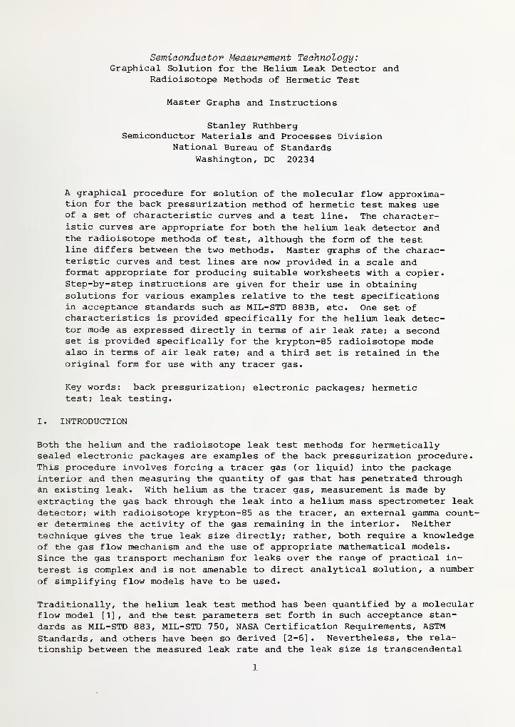
A graphical procedure for solution of the molecular flow approxima-tion for the back pressurization method of hermetic test makes useof a set of characteristic curves and a test line. The character-istic curves are appropriate for both the helium leak detector andthe radioisotope methods of test, although the form of the testline differs between the two methods. Master graphs of the charac-teristic curves and test lines are now provided in a scale andformat appropriate for producing suitable worksheets with a copier.Step-by-step instructions are given for their use in obtainingsolutions for various examples relative to the test specificationsin acceptance standards such as MIL-STD 883B, etc. One set ofcharacteristics is provided specifically for the heliiim leak detec-tor mode as expressed directly in terms of air leak rate; a secondset is provided specifically for the krypton-85 radioisotope modealso in terms of air leak rate; and a third set is retained in theoriginal form for use with any tracer gas.
Key words: back pressurization; electronic packages; hermetictest; leak testing.
I. INTRODUCTION
Both the helium and the radioisotope leak test methods for hermeticallysealed electronic packages are examples of the back pressurization procedure.This procedure involves forcing a tracer gas (or liquid) into the packageinterior and then measuring the quantity of gas that has penetrated throughan existing leak. With helium as the tracer gas, measurement is made byextracting the gas back through the leak into a helium mass spectrometer leak
detector; with radioisotope krypton-85 as the tracer, an external gamma count-er determines the activity of the gas remaining in the interior. Neithertechnique gives the true leak size directly; rather, both require a knowledgeof the gas flow mechanism and the use of appropriate mathematical models.Since the gas transport mechanism for leaks over the range of practical in-
terest is complex and is not amenable to direct analytical solution, a number
of simplifying flow models have to be used.
Traditionally, the helium leak test method has been quantified by a molecularflow model [1], and the test parameters set forth in such acceptance stan-
dards as MIL-STD 883, MIL-STD 750, NASA Certification Requirements, ASTMStandards, and others have been so derived [2-6] . Nevertheless, the rela-
tionship between the measured leak rate and the leak size is transcendental
1
so that a numerical solution is necessary. On the other hand, the radioiso-
tope method has usually been modeled by a laminar viscous flow approximation,
which in principle is relevant to the larger leak sizes [2-8]. While such
modeling leads to a simple relationship between count rate and leak size, the
correlation of the results between the two methods is obscured. Furthermore,
the test parametric values set forth in MIL-STDs 883 and 750 for the radio-isotope method were not derived from flow models, but were established empir-ically through comparison of test results to those obtained using the heliumleak detector method [9].
In a previous publication [10], a general solution to the molecular flowequation for the back pressurization method of hermetic testing was formu-lated into a normalized set of characteristic curves. Using these curves, a
simple graphical procedure is followed to obtain quick and adequately precisesolutions of the molecular flow fomulation for any particular set of testconditions and to provide a basis for comparing the results from both testmethods. For this graphical procedure only a single set of characteristiccurves is required along with the use of a test line. The curves and proce-dure are appropriate for both methods, although the form of the test line is
different for the two methods. All test parameters are readily obtained for
any package volume and leak test range, and the effect on test results due toa change in parameters is easily found.
The purposes of this publication are: (1) to provide master graphs of thecharacteristic curves and test lines from which worksheets can be made byphotocopying, (2) to put the solutions directly in terms of air leak rate,
and (3) to provide a manual of step-by-step instructions for obtaining leaktest solutions. The detailed derivations and explanations of the graphicalprocedure are found in reference [10] (Appendix A).
II. Helium Leak Detector Method
A. Test Factors
Solutions for the helium leak detector method are found as intersectionsbetween appropriate test lines and the characteristic curves describing theinterior gas pressure, as shown in figure 1 (also master graph 1). The in-ternal fractional helium pressure, E, is a measure of the interior heliumpressure per atmosphere of external pressurization at any elapsed time, t,
after pressurization of the sealed packages in helium for a period of time,T, and is given by:
E = ^ [l - exp[-R t]] exp (-R t) (1)0
in which Rj,, the relaxation rate for helium, is related to that for air as
R = 2.69 R ^. (2)
r r
The relaxation rate for air, R^^^, defines the ratio of leak size andpackage interior free volume as
2
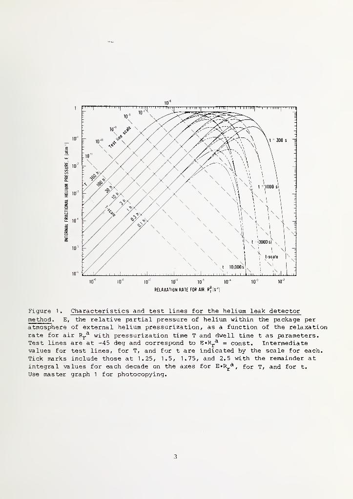
Figure 1 . Characteristics and test lines for the helium leak detector
method . E, the relative partial pressure of helium within the package peratmosphere of external helium pressurization, as a function of the relaxationrate for air R^.^ with pressurization time T and dwell time t as parameters.Test lines are at -45 deg and correspond to E»Rj.^ = const. Intermediatevalues for test lines, for T, and for t are indicated by the scale for each.
Tick marks include those at 1.25, 1.5, 1.75, and 2.5 with the remainder atintegral values for each decade on the axes for E»Rj.^, for T, and for t.
Use master graph 1 for photocopying.
3
The test lines drawn in with a slope of minus one (-45 deg) on the log E-
log R^^ plane represent constant values of the product E»Rj-^. Theequation for these lines, and the formalized solution of the molecular flowmodel, is
R2.69 P„VP
0 E
(4)
The requisite quantities are as follows:
L is the standard leak rate for air, or the leak size*3.
V is the package interior free volume
Pq is one standard atmosphere (1.01325 x 10^ Pa, ~ 14.7 psi
)
p„ is the absolute pressuriza tion value of heliumR is the leak detector responseT is the time interval of pressuriza tion
t is the dwell time or that elapsed from the end of pressuriza tion to
detection.
In figure 1 test lines are included at values for E'R^.^ corresponding to
each decade from 10"^ to 10~^^ s~^»atm~^. Lines at intermediate values can
be obtained with the aid of the test line scale. Characteristic curves for E
in the positive slope region at the left in figure 1 are indicated for pres-surization times T in multiples of 1 and 3; intermediate values can be ob-tained with the T-scale. The characteristic curves are merged to a fewernumber in the negative slope region with t as the significant parameter. The
t-scale can be used for intermediate values.
B. Graphical Procedure
1 . Unknown Leak Size
Conditions
Given: pressuriza tion valuepressuriza tion timedwell time
leak detector response^package free volume
Find: leak size
Pg (in atm abs , helium)
T (h)
t (s)
R (atm'cmVs, helium)V (cm 3)
L (atm«cm3/s)
* By definition the standard leak rate L for a given gas is that flow rateobtained with 1 atm of gas pressure upstream to the leak channel and zeropressure downstream.
t R is an above background value; use values large compared to background orcorrect for background.
Procedure
a. Compute R/[2.69 PgVPg] . This is the value of the test line.
Construct this line on the worksheet parallel to those givenusing the test line scale.
b. Find the two intersections of the test line with the charac-teristic curve of E for the given value of T and t.
If that E is not included in figure 1 , construct a line paral-lel to those given passing through the required value of T
on the T-scale (similarly for t).
c. Drop vertical lines through the points of intersection to theRj-^ axis.
Read values of R^.^ at the axis.d. Compute as R^.^ p^v. These are the two possible leak
values.
Example - See figure 2.
Let ^ ^ helium, T = 0. 3 h, t = 3000 s, R = 5 x 10~ 9 atm 'cm Vs for
helium, V = 0.01 cm^. Find two possible values of L^.
a. R/2.69 PqVPe = 3.7 x 10"^. See test line a.
b. The intersections are within the circled domains.c. See lines b and c. R^.^ = 3.8 x 10"^ and 1.3 x 10"^ s~ ^.
d. = 3.8 X 10"^ atm'cm^/s or 1.3 x io~^ atrn'om^s.
2. Selection of test parameters: Pressurization time and maximum de-tectable leak.
Conditions
Given: package free volume Vreject level (all leaks >)
dwell time t
response Rpressurization value Pg
Find: pressurization time T
maximum detectable leak L^(max)
Procedure
a. Compute Rj,^ by (3)
Draw a vertical line at that value.
b. Compute R/[2.69 P^VPg]
.
Construct this test line parallel to those given using the
included scale if necessary.c. Locate the intersection of the test line and the R^.^ line.
Find the value of T for the E-characteristic curve passing
through this point. This is the pressurization value. If
the E-curve is not included in figure 1 (or master graph 1),
pass a line through the intersection parallel to those rep-
resented and extend it to the T-scale.
5
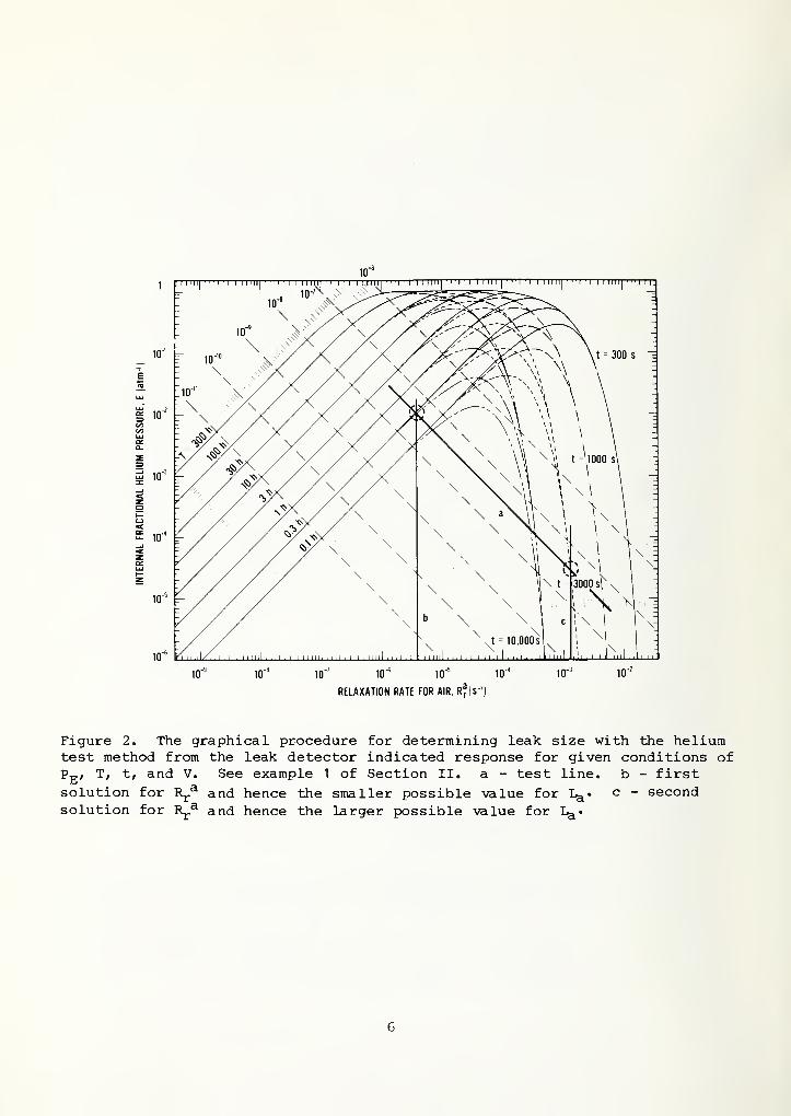
Figure 2. The graphical procedure for determining leak size with the heliumtest method from the leak detector indicated response for given conditions ofPg, T, t, and V. See example 1 of Section II. a - test line. b - first
solution for R^^ and hence the smaller possible value for L^. c - secondsolution for R^.^ and hence the larger possible value for I^»
6

.'a
Figure 1 . Characteristics and test lines for the helium leak detector
method . E, the relative partial pressure of helium within the package peratmosphere of external helium pressurization, as a function of the relaxationrate for air R^^ with pressurization time T and dwell time t as parameters.Test lines are at -45 deg and correspond to E»Rj.^ = const. Intermediatevalues for test lines, for T, and for t are indicated by the scale for each.
Tick marks include those at 1.25, 1.5, 1.75, and 2.5 with the remainder atintegral values for each decade on the axes for E»R^^ , for T, and for t.
Use master graph 1 for photocopying.
3
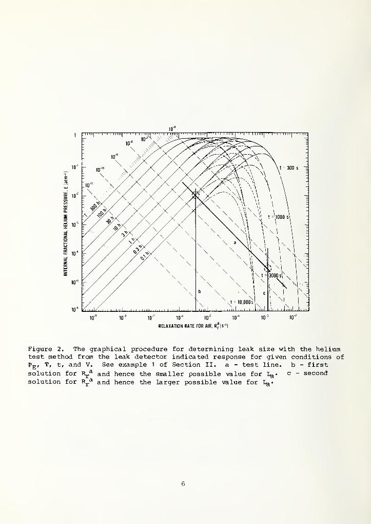
Figure 2. The graphical procedure for determining leak size with the heliumtest method from the leak detector indicated response for given conditions ofPg, T, t, and V. See example 1 of Section II. a - test line, b - firstsolution for R^.^ and hence the smaller possible value for I^. c - secondsolution for R^.^ and hence the larger possible value for
6
d. Locate the intersection of the test line and the negativeslope portion of the E-characteristic curve for the givenvalue of t.
Drop a vertical line to the R^,^ axis.Compute L^(max) from (3).
3. Selection of test parameters: Maximum allowable dwell time andpressurization value.
Conditions
Given: upper leak limit required L^(max)
package free volume Vleak detector response R
Find: maximum allowable dwell time t
pressurization value P-g
Procedure
a. Compute Rj,^(max) as La(max)/PQV.Draw a vertical line through this value.
b. The Rj.^ (max ) -line intersects characteristics correspondingto a range of values of t. The information given is notdefinitive; therefore, some choice is allowed.
Select a point on the Rj.^ (max ) -line which corresponds to a
practical value for t.
c. Erect a test line through this point at -45 deg.Determine the test line value from the scale. Let this be a.
d. Compute P^ = R/2.69 PgVa from (4).
e. If the values for Pg and t are practical, then Pg becomesthe pressurization value and t is the maximiam dwell timeallowed in order for the test range to include L^(max) for
aall parts tested.
If Pg is not usable, adjust the value for t and/or the testline until satisfactory values are obtained.
4. Selection of test parameters: Minimum and maximum leak size limitsas a function of pressurization time.
Conditions
This is a general case that applies to all packages indepen-dent of specific conditions.
Procedure
a. Choose any test line and mark the intersection with an E-
characteristic curve for some value of T, e.g., test line
(a) in figure 2.
Drop a vertical line to the Rj.^ axis, e.g., line (b) infigure 2.
b. Proceed up the test line to a second value of T, which is two
decades greater than T .
7
Drop a vertical to the R^^ axis.Note that R^^ has decreased by one decade; i.e., Rj.^
changes as -T^^^.c. Follow the test line to the negative slope portion of the E-
characteristic curve.Note that the E-characteris tic curves converge in this region,
and the dependence on the pressuriza tion time T vanishes.The dwell time t is the major factor for the determinationof maximum leak size.
5. Leak Detector Response
Conditions
Given: leak size reject valuepressuriza tion timepressuriza tion valuepackage free volume
Find: leak detector response
Procedure
a. Compute R^.^ by (3). Draw a vertical line at this value.b. Locate the intersection of the Rj,^-line with the E-curve
corresponding to the given T value. If that curve is notincluded in the representation, construct one parallel to
those given and passing through the given value on the T-
scale.Read off the value of E corresponding to the intersection.
c. Compute R = Rj.^ •E/PqVPe»
III. Radioisotope Hermetic Test Method
A. Test Factors
Although the molecular flow model is not normally employed for the radioiso-tope procedure, it is the appropriate model for fine leaks and for correla-tion of this test method with the heliiam leak detector method. Since detec-tion in the radioisotope method is accomplished using the gas which still
resides within the package, without resorting to extraction back through theleak channel, the graphical solution procedure is simplified.
Solutions for the radioisotope method require only the set of characteristicsshown in figure 3 (and master graph 2). The internal fractional krypton-85pressure, E*, represents the interior gas concentration at any time, t, afterpressuriza tion of the parts in krypton-85/ni trogen for a period of time, T.
Test lines for this method are now horizontal straight lines with numericalvalues of E*. However, practical operational conditions tend to raise the
test line into the nonlinear region of the E*-characteristic curves. Theformalized solution is given by
L^ (atm»cm3/s)
T (h)
Pg (atm)
V (cm 3)
R (atm»cmVs)
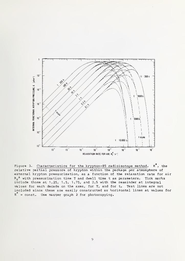
Figure 3. Characteristics for the krypton-85 radioisotope method . E* , the
relative partial pressure of krypton within the package per atmosphere of
external krypton pressuriza tion, as a function of the relaxation rate for airR^^ with pressuriza tion time T and dwell time t as parameters. Tick marksinclude those at 1.25, 1.5, 1.75, and 2.5 with the remainder at integralvalues for each decade on the axes, for T, and for t. Test lines are notincluded since these are easily constructed as horizontal lines at values for
E = const. Use naster graph 2 for photocopying.
9
E* = (5)PqVSKP^*
where
V is the package free volumePq is one standard atmospherePg* is the absolute pressuriza tion value for the Kr^^-N^ g^s mixtureR* is the gamma count rate above backgroundS is the specific activity of the gas mixtureK is the overall counting efficiency
and the relaxation rate Rj.* for krypton-85 is
R * = R .71 (6)r r
for
•
, L = 1.71 L, ^ (7)a krypton
where Rj,^ is the relaxation rate for air, eq (3), and is the leak
size for air.
B. Graphical Procedure
1 . Unknown Leak Size
Conditions
Given: pressuriza tion value Pg* (atm abs
)
pressuriza tion time T (h)
dwell time t (s)
count rate R* (min~Mpackage free volume V (cm 3)
specific activity S ( yCi/a tm 'cm ^
)
counting efficiency K (min~ ^ "yCi" ^)
Find: leak size (atm •cm ^/s)a
Procedure
a. Calculate E* = R*/ [PQVPg*SK] .
Draw a horizontal line at that value of E*
.
b. Locate the point of intersection with the E* characteristiccorresponding to the given value of T.
Drop a vertical line to the R^,^ axis. Read off Rj.^
.
Calculate L^ = P^VR^^. This is one possible value.c. Repeat b for the given value of t. This is the second possi-
ble value.
10
1
Example - See figure 4.
Let Pg* = 5 atm, T = 0.3 h, t = 3000 s, R* = 1000 min~l, v = 0.01 cm^, S =
200 uCi/atm»cm3, and K = 10^+ min~ 1 • yCi" 1. Find possible values for L^*
a. E* = RVPpVPg*SK = 10-2 atm"^. See test line a.b. See the circled domain at T = 0.3 h characteristic. See line
Rj.^ = 1.6 X 10" ^ s~ ^.
= 1.6 X 10⁻⁷ atm 'cm 3/s.
c. See line c.
Rj.^ = 2.5 X 10" 3 s"^.= 2.5 X 10"5 atm«cm^/s.
2. Selection of test parameters: Pressuriza tion time and maximum de-tectable leak.
Conditions
pressurization value p *
dwell time t
count rate R*
package volume Vreject level
^aspecific activity S
counting efficiency Kpressuriza tion time Tmaximum detectable leak L (max)
3.
Procedure
a. Calculate E* = R*/ [PQVPg*SK] . Draw the horizontal test line
at that value.b. Calculate R^.^ = Lq/Pq^* Draw a vertical line at that
value.c. Locate the intersection of the two lines, E* and R^^.
Find the value of T corresponding to the E-characteristiccurve passing through this point. This is the pressuriza-tion value. If the E-characteristic curve is not includedin figure 2, pass a line through the point of intersectionparallel to the E-characteristic curve and extend to the T-
scale.d. Extend the horizontal test line to the negative slope region
of the characteristic curves until it intersects with thatcurve corresponding to the given value of t.
Drop a vertical line to the R^^ axis.Compute L^ from (3). This is L^(max).
3, Selection of test parameters: Maximum allowable dwell time andpressuriza tion value.
11
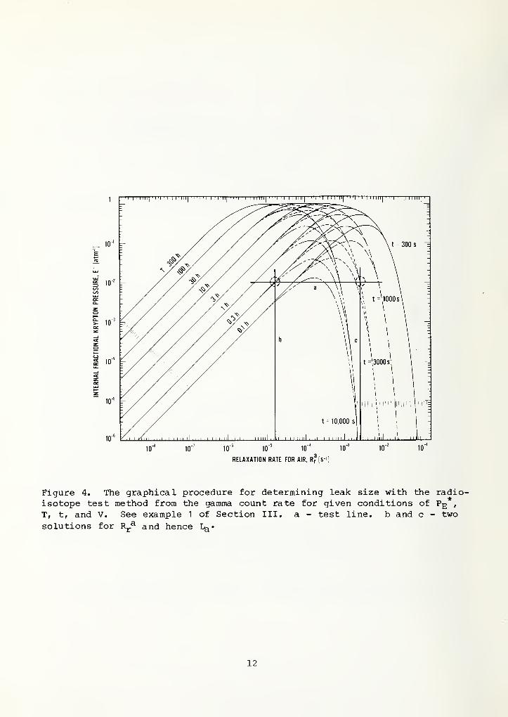
Figure 4, The graphical procedure for determining leak size with the radio-isotope test method from the gamma count rate for given conditions of Pg
,
T, t, and V. See example 1 of Section III. a - test line, b and c - two
solutions for R^^ and hence 1^'
12
Conditions
Given: package free volume Vcount rate R*maximum leak limit required L^(max)specific activity S
counting efficiency KFind: maximum dwell time t(max)
pressurization value Pp.*
Procedure
a. Calculate Rj.^(max) from (3).
Erect a vertical line at this value.b. Note that the information given is not sufficient to derive a
specific value for either t(max) or Pg** Some choice is
allowed.Select a point on the Rj.^ (max ) -line which corresponds to a
usable value for t.
c. Draw a horizontal test line through this point.Determine the test line value from the E* axis.
d. Compute P^,* from (5) or R*/P^VSKE*,e. If Pg* is a suitable value, then t is taken as the maximum
dwell time allowed in order for the test range to includeL (max), and P„* is the pressurization value of test.
ci ill
If Pg* is not a suitable value, adjust t and E*.
4. Selection of test parameters: Leak size as a function of pressuri-zation time.
Conditions
This is a general case that applies to all packages indepen-dent of specific conditions.
Procedure
a. Choose a horizontal test line of some value E*, e.g., testline (a) in figure 4.
Locate the intersection with this and an E-characteristiccurve at some value of T,
Drop a vertical line to the R^.^ axis, e.g., line (b) in
figure 4.
b. Proceed along the test line to a larger value of T by one
decade.Drop a vertical line.
Note R^^ has decreased by one decade; i.e., R^.^ decreasesproportionately to the increase in T.
c. Proceed to the other end of the test line.
Note that the E-characteristic curves may retain a significantdependence on the pressurization time T for typical valuesof the test line and dwell time t, e.g., at the intersection
13
of lines (a) and (c) in figure 4. This is different from
the usual helium leak detector test situations.
5. Selection of Test Parameters: Count Rate
Conditions
Given: leak size reject valuepressuriza tion time
pressurization value
package free volumespecific activity
counting efficiencyFind: count rate
Procedure
a. Compute Rj.^( reject) using (3). Draw a vertical line atthis value.
b. Locate the intersection of the R^^-line with the E*-characteristic curve corresponding to the given T value. If
that curve is not represented, construct one parallel tothose drawn passing through the given value on the T-scale.
Read off the value of E* corresponding to the intersection.c. Compute R* = SK«E* •P^VPg*.
IV. General Characteristics
The internal fractional gas pressure per atmosphere of pressurization withany tracer gas is given by eq (1) when the relaxation rate R^ for the spe-cific tracer gas is
R = (8)r PqV
and L is now the standard leak rate for the specific tracer gas. Charac-teristic curves for E as a function of the relaxation rate for any particulartracer gas are given in master graph 3.
If the tracer gas is drawn back through the leak for detection, as with a
mass spectrometer, the solution is of the form of eq (4), i.e.,
^ • ^r = p4^ ^9)0 E
with R^ given by eq (8), Test lines are at -45 deg on the log E-log R^
plane with values of |e • Rj.|
. Figure 1 and the solutions for the heliumleak detector are drawn from the general case by superposing the relaxationrate for air relative to that of helium from eq (4) on the log R^ axis andwith test lines of value |e • R^^|.
L^( reject) (atm.cmVs)T (h)
Pg*(atm)
V (cm 3)
S ( pCi/atm -cm^)
K (min~^»ijCi"MR (min~l)
14
If the tracer gas is detected while in the package, the solution is of the
form
p-^=3.E (10)0 E
where
R = 3*PV (11)
and is a measurement of some property proportional to the quantity of gas
(PV) at ambient temperature such as for another radioactive scheme, mass,etc. Test lines are horizontal on the log E-log plane with values of
E. Figure 3 and the solutions for the krypton-85 radioisotope method aredrawn from this by superposing the relaxation rate for air relative to that
of k.rypton-85 by eq (6).
15
References
1. Howl, D. A., and Mann, C. A., The Back Pressuriza tion Technique of LeakTesting, Vacuum^, 347-352 (1965)
2. Test Methods and Procedures for Microelectronics: Method 1014.4 - Seal,
in MIL-STD 883B, 4 Nov 1980. (Available from U.S. Naval Publicationsand Forms Center, 5801 Tabor Ave., Philadelphia, PA 19120.)
3. Test Methods for Semiconductor Devices: Method 1071.2 - Hermetic Seal,
in MIL-STD 750B, 27 Feb 1970. (Available from U.S. Naval Publicationsand Forms Center, 5801 Tabor Ave., Philadelphia, PA 19120.)
4. Test Methods for Electronic and Electrical Component Parts: Method 1 1 2B- Seal, in MIL-STD 202E, 16 Apr 1973. (Available from U.S. Naval Publi-cations and Forms Center, 5801 Tabor Ave., Philadelphia, PA 19120.)
5. Test Methods and Procedures for Microcircuit Line Certification: Seal-ing, in NHB 5300.4 (3D), now superseded by (same title) MIL-ST9-977, 25
Jan 1982 which does not contain the sealing test,
6. Standard Recommended Practices for Determining Hermeticity of ElectronDevices with a Helium Mass Spectrometer Leak Detector, ASTM DesignationF134, in Annual Book of ASTM Standards, Part 43, 1981, pp. 565-572.
7. Cassen, B. , and Burnham D. , A Method of Leak Testing Hermetically SealedComponents Utilizing Radioactive Gas, Int» J, Appt* Radiation and Iso-topes 9, 54-59 (1960)
.
8. Ruthberg, S., Neff, G. R., and Martin, B. D., Radioisotope Hermetic TestPrecision, Pvoc. 1977 Int, Miovoetectvonies Symposium (ISHM), Baltimore,Maryland, Oct. 24-26, 1977, pp. 131-137.
9. Banks, S. B. , McCullough, R. E., and Roberts, E. G. , Investigation ofMicrocircuit Seal Testing, Air Force Systems Command, Rome Air Develop-ment Center Tech. Rep. RADC-TR-75-89, Apr. 1975.
10. Ruthberg, S., Graphical Solution for the Back Pressuriza tion Method ofHermetic Test, IEEE Trans. Components Hybrids^ and Manufacturing Tech-nology cmT-_4, 217-224 (1981).
16
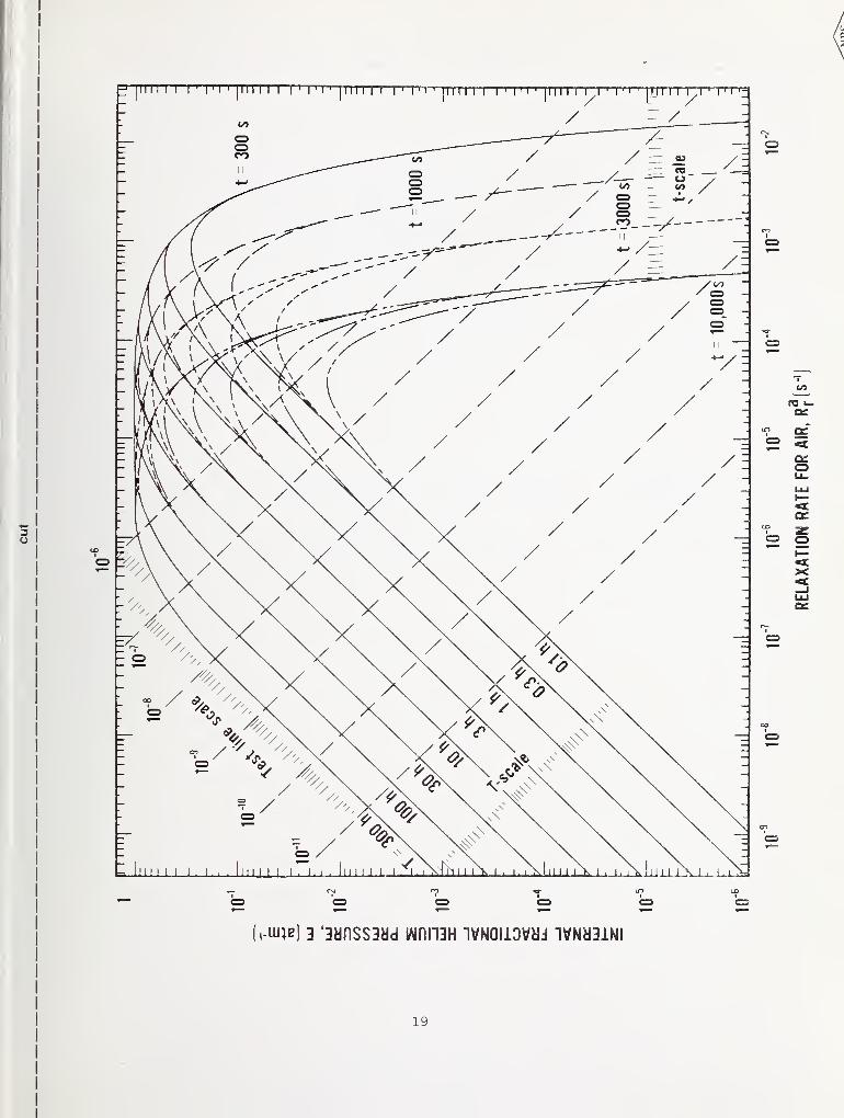
Master graph 1. Characteristics and test lines for the helium leak detectormethod . E, the relative partial pressure of helium within the package peratmosphere of external helium pressuriza tion , as a function of the relaxationrate for air R^^ with pressurization time T and dwell time t as parameters.Tick marks include those at 1.25, 1.5, 1.75, and 2.5 with the remainder atintegral values for each decade on the axes, for E»R^, for T, and for t.
17

!
19

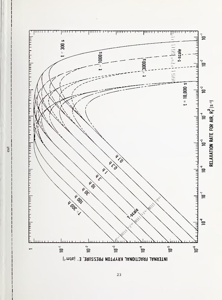
Master graph 2. Characteristics for the krypton-85 radioisotope method .
E, the relative partial pressure of krypton within the package per atmo-
sphere of external krypton pressuriza tion, as a function of the relaxationrate for air R^^ with pressuriza tion time T and dwell time t as parameters.Tick marks include those at 1.25, 1.5, 1.75, and 2.5 with the remainder atintegral values for each decade on the axes, for T, and for t.
21


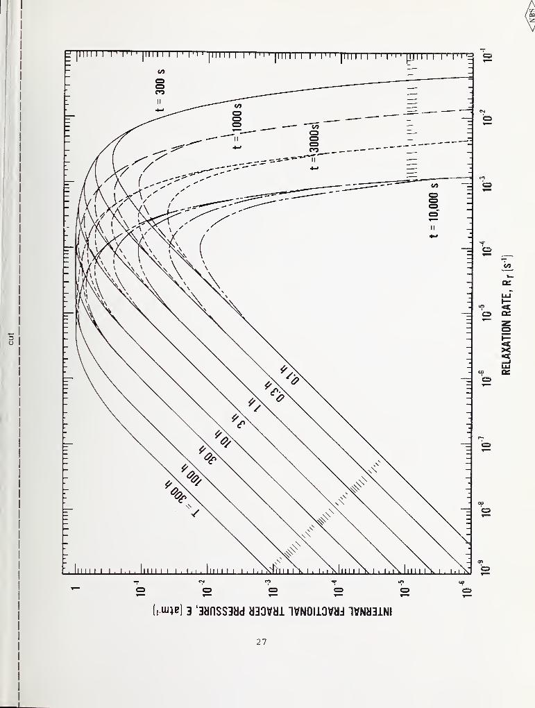
Master graph 3. Characteristics for any tracer gas . E, the relative partialpressure of the specific tracer gas within the package per atmosphere of
external pressurization in that gas, as a function of the relaxation rate for
that specific tracer gas with T and t as parameters. Test lines are inclinedat -45 deg with value • e| if the gas is extracted back though the leak
for measurement or are horizontal with value |e| if the quantity of gas is
measured while within the package. Transport mechanism is molecular flow.
25

27

APPENDIX
IEEE TRANSACTIONS ON COMPONENTS, HYBRIDS, AND MANUKACTURING TECHNOLOGY, VOL CHMT-t. NO 2, JUNE 1981
Graphical Solution for the Back Pressurization Method of
Hermetic Test
STANLEY RUTHBERG
Abstract—The back pressurization method for leak-testing her-
metically sealed electronic packages requires gas-flow modeling to
relate indicated leakage rates to true leak size. The molecular flow
relationship which is appropriate for fme leak sizes is nonlinear and
requires a numerical solution, which in actual test application mayinvolve either many trial calculations or the use of approximations
that lead to limiting case values. A new graphical procedure is
presented for complete solution of the molecular flow equation for any
given test condition and package volume through the use of a single set
of characteristic curves and a test line. The effects of repetitive testing
and of preflll with tracer gas are also considered. The characteristic
curves are appropriate fur both the helium leak detector and the
radioisotope methods of test, while the form of the test line dis-
tinguishes between the two methods.
I. INTRODUCTION
THE BACK pressurization method for leak-testing hermet-
ically sealed packages is accomplished by forcing a tracer
gas into the package interior and then measuring the quantity
of gas that has penetrated the leak channel. The two tracer
gases most commonly used for semiconductor devices are
helium and radioactive krypton. With helium as the tracer
gas. measurement is made by extracting the gas back through
the leak into the helium mass spectrometer leak detector;
with radioisotope Kr*' as the tracer, an external gamma
counter determines the activity of the internal gas. Neither
technique gives the true leak rale value directly; rather, both
require a knowledge of the gas transport mechanism and the
use of appropriate mathematical models for the determina-
tion of test parameters. As the gas transport mechanism for
leaks under pressurization is that of transition flow [1],
which combines the elements of molecular and laminar viscous
flow in a manner not amenable to direct analytical solution
[2] , a number of simplifying flow models have been used.
Traditionally the molecular flow approximation which is
relevant for very fine leaks has been used to relate the helium
leak detector indication to the leak size, but even here a
transcendental relationship is obtained which is double-
valued in leak size for each machine indication [3] . Thus
numerical calculations are required to select pressurization
parameters and to determine leak size. If precise values of
leak size are required as in test evaluation or comparison,
it is necessary either to use successive approximations or to
construct a family of curves representing solutions for each
parametric variation [4] . If an approximate correlation is
sufficient, extensive tables of computer solutions for discrete
Manuscript received July 14. 1980; revised December 5, 1980.
The author is with the tlectron Devices Division, National Bureau
of Standards, Washington, DC 20234.
values of parameters have been available [5] . Finally, if only
approximate values for the minimum detectable leak size
and/or the maximum detectable leak size are sufficient, as
for screening purposes, graphs are available for a limited range
of parametric values [6]
.
The radioisotope test method is usually modeled by the
laminar viscous flow approximation [7] which is relevant
in principle to the larger leak sizes. The assumption is made
that the internal gas pressure remains small and increases
linearly with time under pressurization. The loss of gas back
through the leak is also neglected [8] . While such modeling
leads to a simple relationship between gamma-ray count rate
and leak size, correlation of the results between this method
and the helium leak-detector method is obscured.
In this paper a graphical procedure is presented for com-
plete solution of the molecular flow equation for any given
test condition. Only a single set of characteristic curves is
required along with the use of a test line. The selection of
parametric values for pressurization, time of pressurization,
and lapsed time to achieve a given leak-test range for any
package volume is readily made, and the effect on test results
due to variation in parameters is easUy visualized. The pro-
cedure is applied to both the helium and the radioisotope
methods, and a comparison of operational behavior is de-
rived for the fine leak range for which molecular flow is
appropriate. In addition the case of repetitive testing is con-
sidered. Either prior testing or a prefill of packages with
tracer gas can affect test results considerably, yet this situa-
tion has not been approached previously on a formal basis.
Correction of results is particularly appropriate for test evalua-
tion and interlaboratory comparisons.
II. INTERNAL FRACTIONAL PARTIAL PRESSURE
A. Exact Solution
The gas transport into and out of a package due to a
molecular flow leak is described by
V— = F(P,-P2) (1)
dt
where V is the internal free volume of the package available
to gas collection, V dPjdt is the flow rate into (or out of)
the package at ambient temperature, F is the molecular-flow
conductance of the leak channel [9] , and and Pj are the
partial pressure of the tracer gas at each end of the leak
channel. By definition the standard leak rate L for a given
gas is that flow rate obtained with 1 atm of gas pressure up-
U.S. Government work not protected by U.S. copyright.
29
stream to the leak channel and zero pressure downstream
so that from (1)
(2)
for Pq equal to 1 atm [10]. It then follows from (1) and
(2) that when a previously unexposed package has been im-
mersed in a tracer gas at a pressure for a period T, the
internal partial pressure P is
P=Pe 1 — exp I T
When the pressurization ceases the tracer gas effuses back
through the leak so that the interior tracer gas pressure decays
exponentially. Then for any given lapsed or dwell time t
P=Pr 1-exp r exp (3)
If the interior partial pressure of the tracer gas is not zero
but is initially P' due to a previous test or to a prefiU of the
package, the resultant pressure is
P = P'+ \Pe~P'\ 1-expl-—
r
exp,-— r (4)
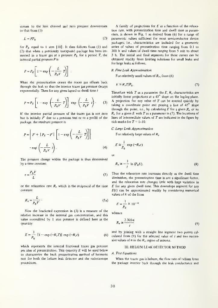
A family of projections for £" as a function of the relaxa-
tion rate, with pressurization time and dwell time as param-
eters, is shown in Fig. 1 as derived from (6) for a range of
parametric values sufficient for most semiconductor device
packages; i.e., characteristics are included for a geometric
series of values of pressurization time ranging from 0.1 to
300 h and values of dwell time ranging from 5 min to about
3 h. The initial and final segments for these curves can be
obtained readily from limiting solutions for small leaks and
for large leaks as follows.
B. Fine Leak Approximation
For relatively small values of R^, from (6)
E=RrT/Po. (7)
Therefore with T as a parameter the E, characteristics are
initially linear projections at a 45° slope on the log-log plane.
A projection for any value of T can be erected quickly by
taking a coordinate point and passing a line of 45° slope
through the point, i.e., by calculating E for a given R^ or an
Rr for a given E with T as a parameter in (7). The locations of
lines of intermediate values of T are indicated in the figure by
tick marks for T = 1-10.
C. Large Leak Approximation
For relatively large values of R^
1
E = — exp (-Rrt)P0
The pressure change within the package is thus determined
by a time constant
(5)
or the relaxation rate R^ which is the reciprocal of the time
constant
Rr =P<.V
(5a)
Rr = -- \niPoE).t
(8)
Thus the relaxation rate increases directly as the dwell time
diminishes, the pressurization time is not a significant factor,
and the relaxation rate changes little with large variation in
E for any given dwell time. This downslope segment for any
E{t) can be approximated readily by considering numerical
values of E of the form
1
£ = — X 10^
Now the bracketed expression in (3) is a measure of the
relative increase in the internal gas concentration, and this
value normalized by 1 atm pressure is defined here as the
quantity
whence
2.303«
(9)
1
P'o[1 -exp(-/?,r)] exp (-7?/) (6)
which represents the internal fractional tracer gas pressure
per atm of pressurization. This quantity E will be used below
to characterize the back pressurization method of hermetic
test for both the helium leak detector and the radioisotope
procedures.
and by joining with a straight line segment two points cal-
culated from (9) for the selected value of t and two succes-
sive values of n in the R^ region of interest.
111. HELIUM LEAK DETECTOR METHOD
A. Test Equations
When the tracer gas is helium, the How rate of helium from
the package interior back through the leak conductance and
30
10' 10' 10' 10' 10' 10' 10' 10' 10'
RELAXATION RATE. R, |s''|
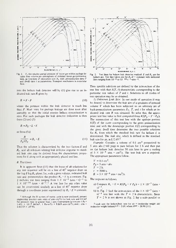
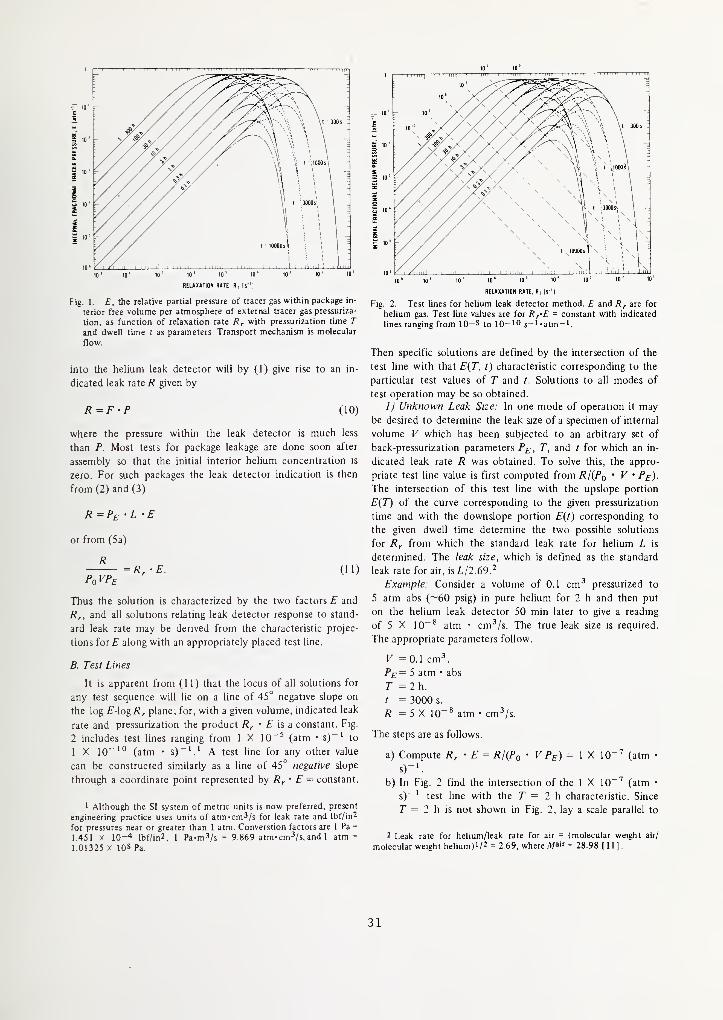
Fig. 1. £", the relative partial pressure of tracer gas within package in-
terior free volume per atmosphere of external tracer gas pressuriza-
tion, as function of relaxation rate with pressurization time T
and dwell time t as parameters. Transport mechanism is molecular
flow.
into the helium leak detector will by (1) give rise to an in-
dicated leak rate R given by
R=F'P (10)
where the pressure within the leak detector is much less
than P. Most tests for package leakage are done soon after
assembly so that the initial interior helium concentration is
zero. For such packages the leak detector indication is then
from (2) and (3)
R=Pe: -L - E
or from (5a)
R=R,-E. (11)
PoVPe
Thus the solution is characterized by the two factors E and
Rr, and all solutions relating leak detector response to stand-
ard leak rate may be derived from the characteristic projec-
tions for E along with an appropriately placed test line.
B. Test Lines
It is apparent from (11) that the locus of all solutions for
any test sequence will lie on a line of 45° negative slope on
the log EAogRr plane; for, with a given volume, indicated leak
rate and pressurization the product is a constant. Fig.
2 includes test lines ranging from 1 X 10^^ (atm • s)"' to
1 X 10"'° (atm • s)~'.' A test line for any other value
can be constructed similarly as a line of 45° negative slope
throijgh a coordinate point represented by Rr • E = constant.
' Although the SI system of metric units is now preferred, present
engineering practice uses units of atm-cm^/s for leak rate and Ibf/in^
for pressures near or greater than 1 atm. Converstion factors are 1 Pa =
1.451 X 10-* lbf/in2, 1 Pa-m^/s = 9.869 atm-cm^/s, and 1 atm =
1.01325 X 10⁵ Pa.
10' 10'
10' 10" 10' 10 ' 10' 10' 10' 10' 10'
RELAXATION RATE. R, Is ']
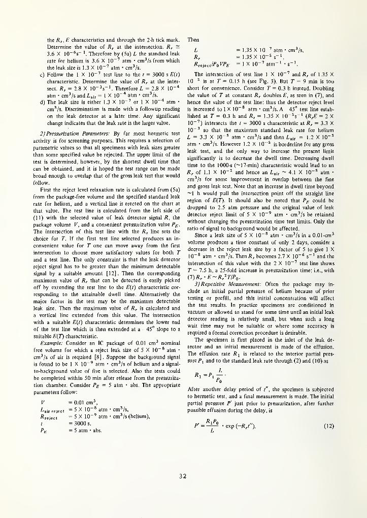
Fig. 2. Test lines for helium leak detector method. E and are for
helium gas. Test line values are for R^-E = constant with indicated
lines ranging from 10-5 to 10-'° 5-) ^atm-'.
Then specific solutions are defined by the intersection of the
test line with that E{T, t) characteristic corresponding to the
particular test values of T and /. Solutions to all modes of
test operation may be so obtained.
1) Unknown Leak Size: In one mode of operation it maybe desired to determine the leak size of a specimen of internal
volume V which has been subjected to an arbitrary set of
back-pressurization parameters Pg, T, and t for which an in-
dicated leak rate R was obtained. To solve this, the appro-
priate test line value is first computed from RI{Pq • V • P^).
The intersection of this test line with the upslope portion
E{T) of the curve corresponding to the given pressurization
time and with the downslope portion E(t) corresponding to
the given dwell time determine the two possible solutions
for Rr from which the standard leak rate for helium L is
determined. The leak size, which is defined as the standard
leak rate for air, isL/2.69.^
Example: Consider a volume of 0.1 cm^ pressurized to
5 atm abs (~60 psig) in pure helium for 2 h and then put
on the helium leak detector 50 min later to give a reading
of 5 X 10~* atm • cm^/s. The true leak size is required.
The appropriate parameters follow.
K = 0.1 cm^5 atm • abs
r = 2h.
t = 3000 s.
R = 5 X 10"* atm • cm^/s.
The steps are as follows.
a) Compute R^ • E = RUPq • V Pe) = ] X 10^'' (atm •
b) In Fig. 2 find the mtersection of the 1 X 10 ^ (atm •
s)~ ' test line with the T = 2 h characteristic. Since
r = 2 h is not shown in Fig. 2, lay a scale parallel to
2 Leak rate for helium/leak rate for air = (molecular weight air/
molecular weight helium)l/2 = 2.69, where A/air = 28.98 |11].
31
I
the Rf, E characteristics and through the 2-h tick mark.
Determine the value of /?, at the intersection. Rf =
3.6 X lO^^s- Therefore by (5a) L the standard leak
rate for helium is 3.6 X 10^^ atm • cm-'/s from which
the leak size is 1.3 X IC^ atm • cm^/s.
c) Follow the 1 X 10"'' test line to the t = 3000 s E(t)
characteristic. Determine the value of R^ at the inter-
sect. Rr = 2.8 X 10" ^s"'. Therefore/, = 2.8 X lO"^"
atm • cm^/s and L^^ = 1 X 10""* atm • cm^/s.
d) The leak size is either 1.3 X 10"'' or 1 X lO"'* atm •
cm^/s. Discrimination is made with a followup reading
on the leak detector at a later time. Any significant
change indicates that the leak rate is the larger value.
2) Pressurization Parameters: By far most hermetic test
activity is for screening purposes. This requires a selection of
parametric values so that all specimens with leak sizes greater
than some specified value be rejected. The upper limit of the
test is determined, however, by the shortest dwell time that
can be obtained, and it is hoped the test range can be made
broad enough to overlap that of the gross leak test that would
follow.
First the reject level relaxation rate is calculated from (5a)
from the package-free volume and the specified standard leak
rate for helium, and a vertical line is erected on the chart at
that value. The test line is calculated from the left side of
(11) with the selected value of leak detector signal R, the
package volume V, and a convenient pressurization value P^.
The intersection of this test line with the R^ line sets the
choice for T. If the first test line selected produces an in-
convenient value for T one can move away from the first
intersection to choose more satisfactory values for both Tand a test line. The only constraint is that the leak detector
reject signal has to be greater than the minimum detectable
signal by a suitable amount [12]. Then the corresponding
maximum value of Rr that can be detected is easily picked
off by extending the test line to the E{t) characteristic cor-
responding to the attainable dwell time. Alternatively the
major factor in the test may be the maximum detectable
leak size. Then the maximum value of Rr is calculated and
a vertical line extended from this value. The intersection
with a suitable E{t) characteristic determines the lower end
of the test line which is then extended at a —45° slope to a
suitable £"(7^ characteristic.
Example: Consider an IC package of 0.01 cm^ nominal
free volume for which a reject leak size of 5 X 10"* atm •
cm^/s of air is required [8]. Suppose the background signal
is found to be 1 X 10"^ atm • cm^/s of helium and a signal-
to-background value of five is selected. Also the tests could
be completed within 50 min after release from the pressuriza-
tion chamber. Consider P^ = 5 atm • abs. The appropriate
parameters follow:
V =0.01cm^
^air reject = 5 X 10~^ atm • Cm-'/s,
^reject = 5 X 10"^ atm • cm^/s (helium),
t = 3000 s,
= 5 atm • abs.
Then
L = 1.35 X 10"'' atm • cm^/s,
Rr = 1.35 X 10⁻⁵ 5-1^
R^eiectlPoVPE = 1 X 1
0"^ atm" ' • s" '
.
The intersection of test line 1 X 10"^ and of 1.35 X10⁻⁵ is at r = 0.15 h (see Fig. 3). But T = 9 min is too
short for convenience. Consider T = 0.3 h instead. Doubling
the value of T at constant Rr doubles E, as seen in (7), and
hence the value of the test line; thus the detector reject level
is increased to 1 X 10~* atm • cm^/s. A —45° test line estab-
lished at r = 0.3 h and Rr = 1.35 X lO'^s"' (RrE = 2 X10"'') intersects the t = 3000 s characteristic at Rr = 3.3 X10~^ so that the maximum standard leak rate for helium
Z, = 3.3 X 10^5 atm • cm^/s and then Lair = 1.2 X 10"
^
atm • cm'/s. However 1.2 X 10"' is borderline for any gross
leak test, and the only way to increase the present limit
significantly is to decrease the dwell time. Decreasing dwell
time to the 1000-s (~17-min) characteristic would lead to an
Rr of 1.1 X 10"^ and hence an L^i, ~ 4.1 X 10"' atm •
cm^/s for some improvement in overlap between the fine
and gross leak test. Note that an increase in dwell time beyond
~1 h would pull the intersection point off the straight line
region of £'(7^. It should also be noted that P^ could be
dropped to 2.5 atm pressure and the original value of leak
detector reject limit of 5 X 10"' atm • cm^/s be retained
without changing the pressurization time test limits. Only the
ratio of signal to background would be affected.
Since a leak size of 5 X 10"* atm • cm^/s in a 0.01-cm^
volume produces a time constant of only 2 days, consider a
decrease in the reject leak size by a factor of 5 to give 1 X10"* atm • cm^/s. Then/?;, becomes 2.7 X 10"* s"' and the
intersection of this value with the 2 X 10"^ test line shows
T = 7.5 h, a 25-fold increase in pressurization time; i.e., with
i7)Rr-E~Rr^TIPo.3) Repetitive Measurement: Often the package may in-
clude an initial partial pressure of helium because of prior
testing or prefiU, and this initial concentration will affect
the test results. In practice specimens are conditioned in
vacuum or allowed to stand for some time until an initial leak
detector reading is relatively small, but when such a long
wait time may not be suitable or where some accuracy is
required a formal correction procedure is desirable.
The specimen is first placed in the inlet of the leak de-
tector and an initial measurement is made of the effusion.
The effusion rate is related to the interior partial pres-
sure/', and to the standard leak rate through (2) and (10) as
L
After another delay period of t" , the specimen is subjected
to hermetic test, and a final measurement is made. The initial
partial pressure P' just prior to pressurization, after further
possible effusion during the delay, is
R Pi>' = -i-° -exp (-/?/'). (12)
32
10' 10'
REUUTION RATE. R, Is'
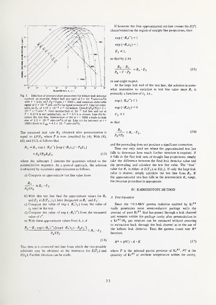
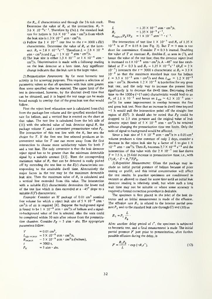
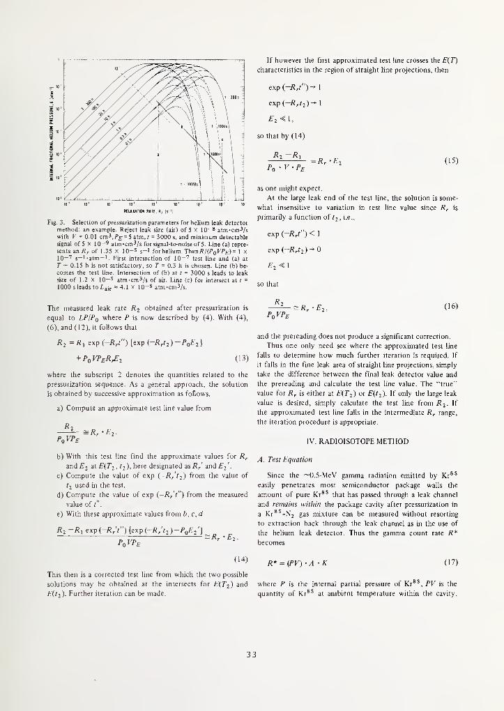
Fig. 3. Selection of pressurization parameters for helium leak detector
method: an example. Reject leak size (air) of 5 x 10⁻⁸ atm-cm^/swith V = 0.01 cm^.P£ = 5 atm.A = 3000 s, and minimum detectable
signal of 5 X 10-' atm-cm^/s for signal-to-noise of 5. Line (a) repre-
sents an /J ^ of 1.35 X 10⁻⁵ s-1 for helium. Then/?/(/'o^'^£)= 1 x10-'' s-i-atm-i. First intersection of 10-'^ test line and (a) at
T ~ 0.15 h is not satisfactory, so 7" = 0.3 h is chosen. Line (b) be-
comes the test line. Intersection of (b) at / = 3000 s leads to leak
size of 1.2 X 10⁻⁵ atm-cm^/s of air. Line (c) for intersect at t=
1000 s leads to L^i^ 4.1 x 10⁻⁵ atm-cm^/s.
The measured leak rate R2 obtained after pressurization is
equal to LP/Pq where P is now described by (4). With (4),
(6), and (12), it follows that
Rj =Ri exp (-R/') [exp(-Rrt2)-Po£2]
+ PoVPERrE2 (13)
where the subscript 2 denotes the quantities related to the
pressurization sequence. As a general approach, the solution
is obtained by successive approximation as follows.
a) Compute an approximate test line value from
R.= Rr-E2
PoVPe
b) With this test line find the approximate values for R^
and £"2 2t £'(7*2, ^2 ). here designated as Rr and £"2
•
c) Compute the value of exp (-Rr'tj) from the value of
tj used in the test.
d) Compute the value of exp {-Rr't") from the measured
value of t"
.
e) With these approximate values from b. c, d
R2-R1 expj-R/t") [exp{-R;t2)-PoE2']Rr'E2.
(14)
This then is a corrected test line from which the two possible
solutions may be obtained at the intersects for E{T2) and
E(t2). Further iteration can be made.
If however the first approximated test line crosses the E(T^
characteristics in the region of straight line projections, then
exp (-/?/')- 1
exp (—/?r?2) ~* 1
£2-^1,
so that by (14)
-Rr • E2 (15)
as one might expect.
At the large leak end of the test line, the solution is some-
what insensitive to variation in test line value since R^ is
primarily a function of t2, i.e.,
exp (-R/') < 1
exp (-Rrt2)^0
so that
R,
PoVPe^Rr'Ej, (16)
and the prereading does not produce a significant correction.
Thus one only need see where the approximated test line
falls to determine how much further iteration is required. If
it falls in the fine leak area of straight line projections, simply
take the difference between the final leak detector value and
the prereading and calculate the test line value. The "true"
value for Rr is either at £"(7'2) or £"(f2)- If only the large leak
value is desired, simply calculate the test line from /?2. If
the approximated test line falls in the intermediate Rr range,
the iteration procedure is appropriate.
IV. RADIOISOTOPE METHOD
A. Test Equation
Since the ~0.5-MeV gamma radiation emitted by Kr^'
easily penetrates most semiconductor package walls the
amount of pure Kr*' that has passed through a leak channel
and remains within the package cavity after pressurization in
a Kr^^-Nj gas mixture can be measured without resorting
to extraction back through the leak channel as in the use of
the helium leak detector. Thus the gamma count rate R*becomes
R* = {PV)-A -K (17)
where P is the internal partial pressure of Kr*^, PV is the
quantity of Kr^' at ambient temperature within the cavity.
A is the activity of pure Kr^' (/LiCi/atm • cm^),^ and K is
the overall counting efficiency of the detector for the par-
ticular package type at a particular location within the crystal
detector well (count rate/^jCi). The interior partial pressure is
given by (3), but the external partial pressure is
Pe = --Pe* (18)A
where 5 is the specific activity of the Kr^'-Nj gas mixture
(^(Ci/atm • cm^) and P^* is the pressurization value for the
gas mixtufe. Thus
R*
V-Pf= SK'E* (19)
where the solution is characterized only by the internal
fractional partial pressure for Kr^', here designated asE*.
IjFine Leak Approximation: For relatively small values
of relaxation rate with krypton R^* by (7) and (19),
R* Rr*T*
P,,V-Pp SK
with T* denoting pressurization time with krypton. Thus
Pe*SKT*(20)
where Z,* is the standard leak rate for Kr^'. Package volume
is not a factor, and (20) differs from the traditional recipe
[7], [8] in that P^* is now raised only to the first power
rather than to the second power as in the laminar viscous
flow model.
B. Test Lines
For a given volume, indicated count rate, and pressuriza-
tion in a particular gas mixture the locus of all solutions is
now on a horizontal line of value E* rather than the 45° slope
of the helium leak detector, and there is now no need to con-
struct a set of such lines superimposed on the E, R^ plane.
Specific solutions for the test sequence are as before at the
intersection of the test line with the E(T, t) characteristic
specified by the parametric values of T and t.
1 ) Pressurization Parameters-Example: Consider again the
0.01-cm^ package to be leak tested to 5 X 10~^ atm • cm^/s
of air with a dwell time of 1000 s. Background count rates
are generally of the order of 500 counts/min, a typical value
for 5 is 200 juCi/atm • cm^, and a typical value of K is 10*
min~ ' • idCi" '. Assume a signal-to-background ratio of 5 for
the reject level count rate and a 5-atm pressurization. It is
desired to establish the required value of Fand the maximumdetectable leak size Z-air- The appropriate parameters
follow.
3 Although the SI system of metric units is now preferred, present
engineering practice uses units of curie for disintegration rate; 1 Ci =
3.7 X IQlO Bq (events/s).
reject
VE,
Ro*R* reject
SKt*
= 0.01 cm\= 5 X 10-* atm
= 500 min~
'
= 2500 min"'= 200/iCi/atm •
= 10" min
= 1000 s.
rKrSS
cm^/s
/iCi
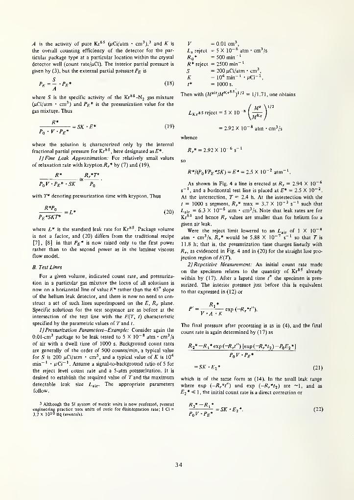
Then with (M^''IM^'y^ = 1/1.71, one obtains
Z,Kr85 reject = 5X10"** —rr-
= 2.92 X 10"* atm • cm^/s
whence
7?^* = 2.92 X 10"* $-
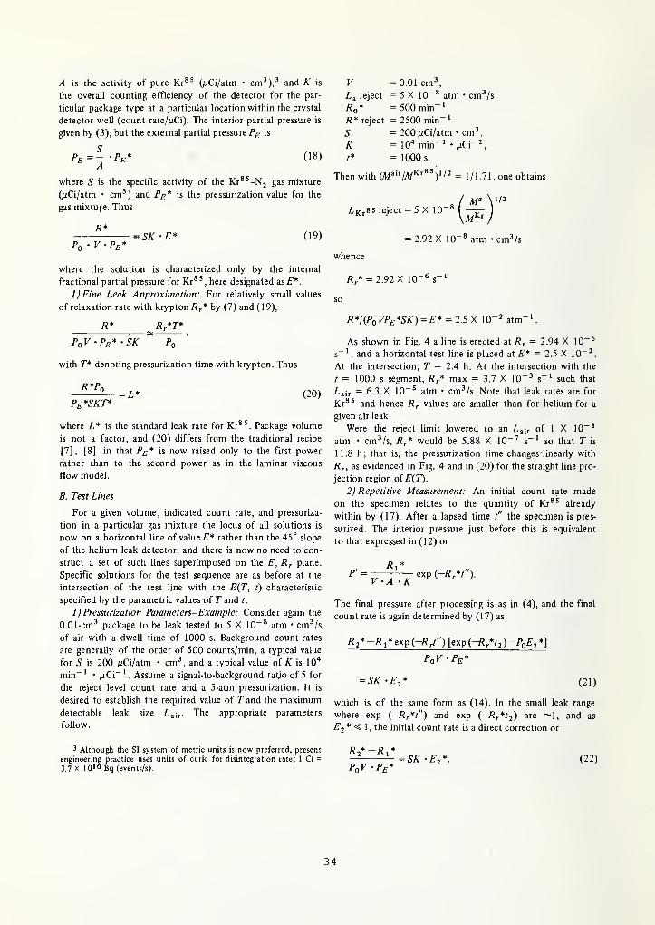
R*/(PoVPe*SK) = E* = 2.5 X 10"^ atm"'.
As shown in Fig. 4 a line is erected at R^ = 2.94 X 10"^
s"', and a horizontal test line is placed at E* = 2.5 X 10"^
.
At the intersection, T = 2.4 h. At the intersection with the
t = 1000 s segment, R^* max = 3.7 X 10"^ s"' such that
Lair ~ 6.3 X 10~^ atm • cm^/s. Note that leak rates are for
Kr*^ and hence R^ values are smaller than for helium for a
given air leak.
Were the reject limit lowered to an L^„ of 1 X 10~*
atm • cm^/s, R^* would be 5.88 X 10"'' s"' so that T is
11.8 h; that is, the pressurization time changes linearly with
Rr, as evidenced in Fig. 4 and in (20) for the straight line pro-
jection region of E(T).
2) Repetitive Measurement: An initial count rate made
on the specimen relates to the quantity of Kr*^ already
within by (17). After a lapsed time t" the specimen is pres-
surized. The interior pressure just before this is equivalent
to that expressed in (12) or
P' =R,
V'A -Kexp (-R*f).
The final pressure after processing is as in (4), and the final
count rate is again determined by (17) as
R2*-Ri* exp i-R/') [exp (-/J/rj )-Po£'2 *]
SK -E-,* (21)
which is of the same form as (14). In the small leak range
where exp (-7?^*/") and exp (-/J^*':) are ~1, and as
E2* < 1 , the initial count rate is a direct correction or
= SK •E2*. (22)
10' 10' 10' 10' 10'
10' 10' 10' 10'
RELAXATION RATE. R, [s 'l
Fig. 1. E, the relative partial pressure of tracer gas within package in-
terior free volume per atmosphere of external tracer gas pressuriza-
tion, as function of relaxation rate with pressurization time Tand dwell time t as parameters. Transport mechanism is molecular
flow.
into the helium leak detector will by (1) give rise to an in-
dicated leak rate R given by
R=F-P (10)
where the pressure within the leak detector is much less
than P. Most tests for package leakage are done soon after
assembly so that the initial interior helium concentration is
zero. For such packages the leak detector indication is then
from (2) and (3)
R=Pe -L - E
or from (5aJ
R=R,'E. (11)
Thus the solution is characterized by the two factors E and
Rr, and all solutions relating leak detector response to stand-
ard leak rate may be derived from the characteristic projec-
tions for E along with an appropriately placed test line.
B. Test Lines
It is apparent from (11) that the locus of all solutions for
any test sequence will lie on a line of 45° negative slope on
the log E-logRr plane; for, with a given volume, indicated leak
rate and pressurization the product R^ ' E is z constant. Fig.
2 includes test lines ranging from 1 X 10~' (atm • s)"' to
1 X 10"'° (atm • s)"'.' A test line for any other value
can be constructed similarly as a line of 45° negative slope
through a coordinate point represented by R^ ' E = constant.
' Although the SI system of metric units is now preferred, present
engineering practice uses units of atm-cm^/s for leak rate and Ibf/in^
for pressures near or greater than 1 atm. Converstion factors are 1 Pa =
1.451 X 10-'» lbf/in2, 1 Pa-m^/s = 9.869 atm-cm^/s, and 1 atm =
1.01325 X 10⁵ Pa.
10' 10'
10' 10' 10' 10 ' 10' 10' 10' 10' 10'
RELAXATION RATE. R, Is'
I
Fig. 2. Test lines for helium leak detector method. E and are for
helium gas. Test line values are for R^'E = constant with indicated
lines ranging from IQ-^ to 10" '0 s"' - atm"'
.
Then specific solutions are defined by the intersection of the
test line with that E{T, t) characteristic corresponding to the
particular test values of T and t. Solutions to all modes of
test operation may be so obtained.
1) Unknown Leak Size: In one mode of operation it maybe desired to determine the leak size of a specimen of internal
volume V which has been subjected to an arbitrary set of
back-pressurization parameters P^;, T, and t for which an in-
dicated leak rate R was obtained. To solve this, the appro-
priate test line value is first computed from RUPq • V • P^).
The intersection of this test line with the upslope portion
E{T) of the curve corresponding to the given pressurization
time and with the downslope portion E(t) corresponding to
the given dwell time determine the two possible solutions
for Rr from which the standard leak rate for helium L is
determined. The leak size, which is defined as the standard
leak rate for air, isL/2.69.^
Example: Consider a volume of 0.1 cm'' pressurized to
5 atm abs (~60 psig) in pure helium for 2 h and then put
on the helium leak detector 50 min later to give a reading
of 5 X 10~* atm • cm^/s. The true leak size is required.
The appropriate parameters follow.
V = 0.1 cm^?£= 5 atm • abs
r = 2h.
t = 3000 s.
R = 5 X 10"* atm • cm^/s.
The steps are as follows.
a) Compute R, • E = RI(Pq • K ?£) = 1 X 10" (atm •
s)"'.
b) In Fig. 2 find the intersection of the 1 X 10"^ (atm •
s)" ' test line with the T = 2 h characteristic. Since
r = 2 h is not shown in Fig. 2, lay a scale parallel to
2 Leak rate for helium/leak rate for air = (molecular weight air/
molecular weight helium)!/^ = 2.69, where Afa'"' = 28.98 (11].
31
the E characteristics and through the 2-h tick mark.
Determine the value of Rr at the intersection. Rr =3.6 X 10"^s~ '. Therefore by (5a) L the standard leak
rate for helium is 3.6 X 10"^ atm • cm^/s from which
the leak size is 1 .3 X 10~ ^ atm • cm-'/s.
c) Follow the 1 X IQ-'' test line to the t = 3000 s E(t)
characteristic. Determine the value of Rr at the inter-
sect. Rr = 2.8 X 10- ^s-'. Therefore L = 2.8 X lO""*
atm • cm^/s and = 1 X 10"* atm • cm^/s.
d) The leak size is either 1.3 X 10"'' or 1 X lO"" atm •
cm^/s. Discrimination is made with a foUowup reading
on the leak detector at a later time. Any significant
change indicates that the leak rate is the larger value.
2) Pressurization Parameters: By far most hermetic test
activity is for screening purposes. This requires a selection of
parametric values so that all specimens with leak sizes greater
than some specified value be rejected. The upper limit of the
test is determined, however, by the shortest dwell time that
can be obtained, and it is hoped the test range can be made
broad enough to overlap that of the gross leak test that would
follow.
First the reject level relaxation rate is calculated from (5a)
from the package-free volume and the specified standard leak
rate for helium, and a vertical line is erected on the chart at
that value. The test line is calculated from the left side of
(11) with the selected value of leak detector signal R, the
package volume V, and a convenient pressurization value P^.
The intersection of this test line with the Rr line sets the
choice for T. If the first test line selected produces an in-
convenient value for T one can move away from the first
intersection to choose more satisfactory values for both T
and a test line. The only constraint is that the leak detector
reject signal has to be greater than the minimum detectable
signal by a suitable amount [12]. Then the corresponding
maximum value of Rr that can be detected is easily picked
off by extending the test line to the E{t) characteristic cor-
responding to the attainable dwell time. Alternatively the
major factor in the test may be the maximum detectable
leak size. Then the maximum value of Rr is calculated and
a vertical line extended from this value. The intersection
with a suitable E(t) characteristic determines the lower end
of the test line which is then extended at a -45° slope to a
suitable E(T) characteristic.
Example: Consider an IC package of 0.01 cm^ nominal
free volume for which a reject leak size of 5 X 10~* atm •
cm^/s of air is required [8] . Suppose the background signal
is found to be 1 X 10~^ atm • cm^/s of helium and a signal-
to-background value of five is selected. Also the tests could
be completed within 50 min after release from the pressuriza-
tion chamber. Consider Pg = 5 atm • abs. The appropriate
parameters follow:
V =0.01cm\
^air reject = 5 X 10"^ atm • cm^'/s,
^reject = 5 X 10"^ atm • cm-'/s (helium),
t = 3000 s,
Pe =5 atm • abs.
Then
L
Rr
= 1.35 X 10"
= 1.35 X 10'^atm cm^/s,
RreiecJPoVPE =1X10⁻⁷atm"
The intersection of test line 1 X 10~^ and 7?^ of 1-35 X10"' is at r = 0.15 h (see Fig. 3). But 7 = 9 min is too
short for convenience. Consider T = 0.3 h instead. Doubling
the value of T at constant /?, doubles E, as seen in (7), and
hence the value of the test line; thus the detector reject level
is increased to 1 X 10~^ atm • cm^/s. A —45° test line estab-
lished at r = 0.3 h and Rr = 1.35 X lO'^s"' (RrE = 2 X10"'') intersects the t = 3000 s characteristic at /?, = 3.3 X10" so that the maximum standard leak rate for helium
Z, = 3.3 X 10^' atm • cm^/s and then = 1.2 X 10"'
atm • cm^/s. However 1.2 X 10~' is borderline for any gross
leak test, and the only way to increase the present limit
significantly is to decrease the dwell time. Decreasing dwell
time to the 1000-s (~17-min) characteristic would lead to an
Rr of 1.1 X 10"^ and hence an L^i^ ~ 4.1 X 10"' atm •
cm^/s for some improvement in overlap between the fine
and gross leak test. Note that an increase in dwell time beyond
~1 h would pull the intersection point off the straight line
region of E{T). It should also be noted that Pe could be
dropped to 2.5 atm pressure and the original value of leak
detector reject limit of 5 X 10"' atm • cm^/s be retained
without changing the pressurization time test limits. Only the
ratio of signal to background would be affected.
Since a leak size of 5 X 10~* atm • cm^/s in a 0.01-cm^
volume produces a time constant of only 2 days, consider a
decrease in the reject leak size by a factor of 5 to give 1 X10"^ atm • cm ^/s. Then/?;, becomes 2.7 X 10~^ s~' and the
intersection of this value with the 2 X 10~' test line shows
T = 7.5 h, a 25-fold increase in pressurization time; i.e., with
{l)Rr'E~Rr^T/Po.
3) Repetitive Measurement: Often the package may in-
clude an initial partial pressure of helium because of prior
testing or prefiU, and this initial concentration will affect
the test results. In practice specimens are conditioned in
vacuum or allowed to stand for some time until an initial leak
detector reading is relatively small, but when such a long
wait time may not be suitable or where some accuracy is
required a formal correction procedure is desirable.
The specimen is first placed in the inlet of the leak de-
tector and an initial measurement is made of the effusion.
The effusion rate i?, is related to the interior partial pres-
sure /•] and to the standard leak rate through (2) and (10) as
L
^0
After another delay period of t" , the specimen is subjected
to hermetic test, and a final measurement is made. The initial
partial pressure P' just prior to pressurization, after further
possible effusion during the delay, is
,R\Po
/>' = • exp i-Rrt"). (12)
32
REUUTIM RATE. R, {s"l
Fig. 3. Selection of pressurization parameters for helium leak detector
method: an example. Reject leak size (air) of 5 x 10-* atm-cm^/swith V = 0.01 cm'^.P^ = 5 atm, t = 3000 s, and minimum detectable
signal of 5 X 10-' atm-cm^/s for signal-to-noise of 5. Line (a) repre-
sents an Rr of 1.35 x 10⁻⁵ j-i for helium. Then/?/(Pol''^£-) = 1 x10—'' s-'-atm-'. First intersection of 10-'^ test line and (a) at
7" ~ 0.15 h is not satisfactory, so 7" = 0.3 h is chosen. Line (b) be-
comes the test line. Intersection of (b) at f = 3000 s leads to leak
size of 1.2 X 10⁻⁵ atm-cm^/s of aii. Line (c) for intersect at f=
1000 s leads to L^^j = 4.1 x 10⁻⁵ atm-cm3/s.
The measured leak rate R2 obtained after pressurization is
equal to LPIPq where P is now described by (4). With (4),
(6), and (12), it follows that
R2 =Ri exp(-R/') [exp (-.R^^) --^0^ 2
1
+ PoVPeR^2 (13)
where the subscript 2 denotes the quantities related to the
pressurization sequence. As a general approach, the solution
is obtained by successive approximation as follows.
a) Compute an approximate test line value from
^2= Rr-E2.
PoVPe
b) With this test line find the approximate values for R^
and £2 3t EiTi ,tj), here designated zsR^' and E^'
.
c) Compute the value of exp (-R/ti) from the value of
t2 used in the test.
d) Compute the value of exp (,-R/t") from the measured
value of t"
.
e) With these approximate values from b, c, d
R2-R1 exp(-Rr't") [exp(-R;t2)-PoE2']
PoVPe^Rr'E2
(14)
This then is a corrected test line from which the two possible
solutions may be obtained at the intersects for E(T2) and
£"(^2 ) Further iteration can be made.
If however the first approximated test line crosses the E(T}
characteristics in the region of straight line projections, then
exp (—Rrt") -* 1
exp i-R,t2)-* 1
so that by (14)
R2-Ri= Rr'E2 (15)
as one might expect.
At the large leak end of the test line, the solution is some-
what insensitive to variation in test line value since Rr is
primarily a function of tj, i.e.,
exp (-/?/')< 1
exp i-Rrt2)^0
so that
Ri
PoVPe= Rr-E2 (16)
and the prereading does not produce a significant correction.
Thus one only need see where the approximated test line
falls to determine how much further iteration is required. If
it falls in the fine leak area of straight line projections, simply
take the difference between the final leak detector value and
the prereading and calculate the test line value. The "true"
value for R^ is either at E{T2) or E(t2). If only the large leak
value is desired, simply calculate the test line from R2. Kthe approximated test line falls in the intermediate R^ range,
the iteration procedure is appropriate.
IV. RADIOISOTOPE METHOD
A. Test Equation
Since the ~0.5-MeV gamma radiation emitted by Kr*'
easily penetrates most semiconductor package walls the
amount of pure Kr*^ that has passed through a leak channel
and remains within the package cavity after pressurization in
a Kr*'-N2 gas mixture can be measured without resorting
to extraction back through the leak channel as in the use of
the helium leak detector. Thus the gamma count rate R*becomes
R* = {PV)'A • K (17)
where P is the internal partial pressure of Kr*', PV is the
quantity of Kr^' at ambient temperature within the cavity.
33
A is the activity of pure Kr*^ (/jCi/atm • cm-'),^ and K is
the overall counting efficiency of the detector for the par-
ticular package type at a particular location within the crystal
detector well (count rate//iCi). The interior partial pressure is
given by (3), but the external partial pressure is
Pe = --Pe* (18)A
where S is the specific activity of the Kr^^-Nj gas mixture
(/jCi/atm • cm^) and Pg* is the pressurization value for the
gas mixture. Thus
Pq 'V-P^= SK-E* (19)
where the solution is characterized only by the internal
fractional partial pressure for Kr^^, here designated ^sE*.
IjFine Leak Approximation: For relatively small values
of relaxation rate with krypton R^* by (7) and (19),
R* R*T*
PoV'Pe*'SK Po
with T* denoting pressurization time with krypton. Thus
R*Po
Pe*SKT*(20)
where L* is the standard leak rate for Kr*'. Package volume
is not a factor, and (20) differs from the traditional recipe
[7], [8] in that Pe* is now raised only to the first power
rather than to the second power as in the laminar viscous
flow model.
B. Test Lines
For a given volume, indicated count rate, and pressuriza-
tion in a particular gas mixture the locus of all solutions is
now on a horizontal line of value E* rather than the 45° slope
of the helium leak detector, and there is now no need to con-
struct a set of such lines superimposed on the E, R^ plane.
Specific solutions for the test sequence are as before at the
intersection of the test line with the E{T, t) characteristic
specified by the parametric values of T and t.
1 ) Pressurization Parameters-Example: Consider again the
0.01-cm^ package to be leak tested to 5 X 10~* atm • cm^/s
of air with a dwell time of 1000 s. Background count rates
are generally of the order of 500 counts/min, a typical value
for S is 200 ^iCi/atm • cm^, and a typical value of is 10"*
min~ ' • nC\~ '. Assume a signal-to-background rat^o of 5 for
the reject level count rate and a 5-atm pressurization. It is
desired to establish the required value of T and the maximumdetectable
follow.
leak size Lair- The appropriate parameters
V =0.01cm^reject = 5 X 10"^ atm • cm^/s
Rq* = 500 min"'
R* reject = 2500 min""
'
S = 200A(Ci/atm • cm^A' = lO'* min-' • /iCi~^
t* = 1000 s.
Then wiih (M^'"IM^'^^Y = 1/1.71, one obtains
Z,Kr85 reject = 5 X lO"** —
= 2.92 X 10"^ atm • cm^/s
whence
/?,* = 2.92X 10"* s~
R*I(PoVPe*SK)=E* = 2.5 X 10"^ atm"-'.
As shown in Fig. 4 a line is erected at Rr = 2.94 X 10~^
s~', and a horizontal test line is placed at £"* = 2.5 X 10~^.
At the intersection, T = 2.4 h. At the intersection with the
t = 1000 s segment, R^* max = 3.7 X 10"^ s~' such that
Z,air = 6.3 X 10"^ atm • cm^/s. Note that leak rates are for
Kr*^ and hence R^ values are smaller than for helium for a
given air leak.
Were the reject limit lowered to an Lair of 1 X 10~^
atm • cm^/s, R^* would be 5.88 X 10"'' s"' so that T is
11.8 h; that is, the pressurization time changes linearly with
Rr, as evidenced in Fig. 4 and in (20) for the straight line pro-
jection region of E(T).
2) Repetitive Measurement: An initial count rate made
on the specimen relates to the quantity of Kr*^ already
within by (17). After a lapsed time t" the specimen is pres-
surized. The interior pressure just before this is equivalent
to that expressed in (12) or
P' =Ri
V'A -Kexp (-Rr*t").
The final pressure after processing is as in (4), and the final
count rate is again determined by (17) as
/?2* -i?,* exp i-R/') [exp {~R*t:,)-PoE^ *]
PqV-Pe*
= SK -E-, (21)
which is of the same form as (14). In the small leak range
where exp (-^r*'") and exp {-R*ti) are ~1, and as
*1 , the initial count rate is a direct correction or
3 Although the SI system of metric units is now preferred, present /Jj* — /?i*
engineering practice uses units of curie for disintegration rate; 1 Ci = = SK •£'2*.
3.7 X 10¹⁰ Bq (events/s). PqV • Pe*(22)
34
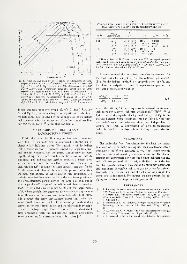
TABLE 1
comparative values for helium leak detector andRadioisotope testing of hermetic Packages'
3011s :
10' 10" 10' 10' 10' 10' 10' 10' 10'
REL^UTION RITE. R, ' Is 'l
Fig. 4. Test line and example of test range for radioisotope method.
Reject leak size of 5 x 10⁻⁸ atm-cm^/s of air with V = 0.01 cm^/>£» = 5 atm of Kr-Nj mixture, S = 200 wCi/atm-cm3, K = ID"
min~' "MCi"', and a minimum detectable count rate of 2500
min~' for a signal-to-noise ratio of 5. Line (a) represents of
2.94 X 10⁻⁶ s-l for Kr85. R"I(PqVPe*SK) = E* = 2.5 X 10⁻²
atm-1 is test line (b). The intersection of (a) and (b) sets T= 2.4 h.
At the intersection of (b) and the f = 1000 s, line (c) represents
/?/ = 3.7 X 10⁻³ s-i whichleadstoiair = 6.3 X IQ-S atm-cm3/s.
In the large leak range where exp (—Rr*t")< I,exp{ -Rr*t2)^
0, and E2 ^ \ . the prereading is not significant. In the inter-
mediate range, (22) is solved by iteration just as for the helium
leak detector with the exception of the horizontal test lines
and/?,'* values for Kr*' rather than for helium.
V. COMPARISON OF HELIUM ANDRADIOISOTOPE METHODS
Within the molecular flow regime test results obtained
with the two methods can be compared with the use of
characteristic leak-test curves. The capability of the helium
leak detector method is oriented toward the larger leak sizes
and smaller volumes, for the pressurization time increases
rapidly along the helium test line as the relaxation rate di-
minishes. The radioisotope method requires a longer pres-
surization time with intermediate leak sizes because the
leak rate for Kr*^ is some 4.6 times smaller than that for He
in the same leak channel, however the pressurization time
increases but linearly as the relaxation rate diminishes. The
radioisotope test line tends to lie in the nonlinear portion of
the characteristics, particularly at the large leak end, but in
this range the 45° slope of the helium leak detector method
tends to both the smaller values for E and the larger values
of Rr where straight line segments give reasonable approxima-
tion. However in the conversion to air leak rates, both meth-
ods produce the same approximate upper limit when the
same dwell times are used. The radioisotope method does
allow shorter dwell times in use and therefore can in principle
extend to a larger upper limit of leak size. The short dwell
time obtainable with the radioisotope method also allows
two cycle testing for extension to gross leak sizes [13]
.
T/T*(cm3) (atm-cm3/s) (s-i) n*/n
0.01 10-6 2.7 X lO-'* 255 s 0,001610-7 2.7 X 10⁻⁵ 0.71 h 0.01610-8 2.7 X 10⁻⁶ 7.1 h 0.16 0.16
10 10-6 2.7 X 10⁻⁷ 255 s 1.6
10-7 2.7 X 10⁻⁸ 0.71 h 1610-8 2.7 X 10⁻⁹ 7.1 hl61 161
1 Derived from (23). Pressurization times T/T* for equal signal-to-
background ratios, and signal-to-background ratios n*/n for equal pres-
surization times. 5 = 200 MCi/atm-cm^, K = 10^ min-l mQ -', Rq -
5 X 10⁻¹⁰ atm-cm3/s helium, Rq* = 500 min-t.
A direct numerical comparison can also be obtained for
the fine leaks by using (19) for the radioisotope method,
(11) for the helium method, the approximation of (7), and
the detector outputs in terms of signal-to-background, for
the same pressurization value, as
n*Ro* SK T*— = (23)nRo 4.61R, T
where the ratio R^* to R^ is equal to the ratio of the standard
leak rates for a given leak size which is (M^^/M^'y or
1/4.61, n is the signal-to-background ratio, and Rq is the
threshold signal. Some results are listed in Table I. Note that
the radioisotope pressurization times are independent of
volume per (20). A comparison of signal-to-background
ratios is listed in the last column for equal pressurization
times.
VI. SUMMARY
The molecular fiow formulation for the back pressuriza-
tion method of hermetic testing has been condensed into a
normalized set of characteristic curves from which specific
solutions can be obtained by means of a test line. The charac-
teristics are appropriate for both the helium leak detector and
and radioisotope methods of test, while the form of the test
line distinguishes between two methods. Minimum detectable
and maximum detectable leak sizes can be determined simul-
taneously from the one set, and the selection of suitable test
conditions is facilitated. Procedures are also derived for ap-
plying corrections due to prior testing or prefill.
REFERENCES|l| S- Rulhberg. in Semicnnduclor Measuremeni Technology. ARPA/
NBS Workshop II Hermelicity Testing for Integrated Circuits. H.
A Schafft, Ed . NBS Special Publication 400-9, pp. 27-32. Dec.
1974 (Available from U S Govt. Printing Office, SD no
CI3, 10:400-9 1
|2| S Dushman and J M Lafferty, Scientific Foundations of VacuumTechnolony. 2nd ed.. section 2.5, New York: Wiley, 1962, p.
104
(31 D. A. Howl and C, A Mann, "The back-pressurization technique
of leak testing," Vacuum, vol. 15, pp. 347-352, 1965.
|4| S B Banks. R E McCullough. and E. G Roberts. "Investigation
35
(it microL la ult seal Icsiiny.' Air t-orce Systems Command, RomeAir Development Center. Tech Rep RADC-TR-75-89, Apr. 1975
W. E. Briggs and S. G. Burnett, "Helium mass spectrometer leak
testing of pressure—"bombed" sealed enclosures," Varian Vacuum
Division/NRC Operation. Newton Highlands. MA, Oct. I, 1968
Standard Recommended Practices for Determining Hermeticity of
Electron Devices with a Helium Mass Spectrometer Leak Detector.
ASTM Designation Fl 34. 1979 Annual Book ofASTM Standards, p
545-552.
B. Cassen and D. Bumham. "A method of leak testing hermetically
sealed components utilizing radioactive gas," Int. J Appl
Radiation and Isotopes, vol. 9. pp. 54-59. 1960.
Method 1014 2-Seal, Military Standard 8838. in Test Methods and
Procedures for Micrdelecironns, Aug. 31. 1977. (Available
from U.S. Naval Publications and Forms Center, 5801 Tabor Ave.,
Philadelphia, PA 19120 )
(9) S. Dushman and J. M Lafferty, Scientific Foundations of VacuumTechnology
. 2nd ed. . section 2.2. New York: Wiley, 1962, p. 81.
|I0| Glossary of Terms Used in Vacuum Technology. Committee onStandards, American Vacuum Society Inc New York: Pergamon,1958, Definitions No. 20 and 236.
1 1 1 1 S Dushman and J M Laffeny, Scientific Foundations of VacuumTechnology. 2nd ed , New York Wiley. 1962. p 16
|12| AVS Helium Mass Spectrometer Leak-Detector Calibration (2 1-
1963). J. Vac Sci Technol . vol 3. pp 229-235. 1966
|I3| S Ruthberg. G R Neff. and B D Martin. "Radioisotopehermetic test precision." in Proc 1977 Ini Microelectronics
Symposium. Baltimore, MD, Oct 24-26, 1977, pp 131-137.
36
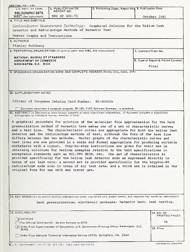
NBS-n4A (REV. 2-8C)
U.S. DEPT. OF COMM. 1. PUBLICATION OR 2. Performing Organ. Report No. 3. Publication Date
BIBLIOGRAPHIC DATAREPORT NO,
SHEET (See instructions) NBS SP 400-73 October 19824. TITLE AND SUBTITLE
Semiconduator Measurement Technology: Graphical Solution for the Helium Leak
Detector and Radioisotope Methods of Hermetic Test
Master Graphs and Instructions
5. AUTHOR(S)
Stanley Ruthberg
6. PERFORMING ORGANIZATION (l{ joint or other than NBS. see instructions) 7. Contract/Grant No.
NATIONAL BUREAU OF STANDARDSDEPARTMENT OF COMMERCE 8. Type of Report & Period Covered
WASHINGTON, D.C. 20234Final
9. SPONSORING ORGANIZATION NAME AND COMPLETE ADDRESS (Street. City. State, ZIP)
10. SUPPLEMENTARY NOTES
Library of Congress Catalog Card Number: 82-600626
Document describes a computer program; SF-185, FlPS Software Summary, is attached.
11. ABSTRACT (A 200-word or less factual summary of most significant information. If document includes a si gnificantbibliography or literature survey, mention it here)
A graphical procedure for solution of the molecular flow approximation for the backpressurization method of hermetic test makes use of a set of characteristic curvesand a test line. The characteristic curves are appropriate for both the helium leakdetector and the radioisotope methods of test, although the form of the test linediffers between the two methods. Master graphs of the characteristic curves andtest lines are now provided in a scale and format appropriate for producing suitableworksheets with a copier. Step-by-step instructions are given for their use inobtaining solutions for various examples relative to the test specifications inacceptance standards such as MIL-STD 883B, etc. One set of characteristics is
provided specifically for the helium leak detector mode as expressed directly interms of air leak rate; a second set is provided specifically for the krypton-85radioisotope mode also in terms of air leak rate; and a third set is retained in theoriginal form for use with any tracer gas.
12. KEY WORDS (Six to twelve entries; olphabetica/ order; capitalize only proper names; and separate key words by semicolons)
back pressurization; electronic packages; hermetic test; leak testing.
13. AVAILABILITY
I xl Unl imited
I I
For Official Distribution. Do Not Release to NTIS
[X] Order From Superintendent of Documents, U.S. Government Printing Office, Washington, D.C.
20402.
03] Order From National Technical Information Service (NTIS), Springfield, VA. 22161
14. NO. OFPRINTED PAGES
34
15. Price
^U.S. GOVERNMENT PRINTING OFFICE; 19 8 2-380-997/2319 USCOMM-DC 6043-P80

Announcement of Semiconductor Measurement TechnologyList of Publications 72 - 1962-1981
Elaine C. CohenInformation AssistantSemiconductor Materials and Procerser. DivisionNational Bureau of StandardsBldg. 225, Room A305Washington, DC 20234
Dear Mrs. Cohen:
Please send a copy of your latest "Semiconductor Measurement Technology,List of Publications 72."
Name
Company
Address
City State Zip Code

NBS TECHNICAL PUBLICATIONS
PERIODICALS
JOURNAL OF RESEARCH—The Journal of Research of the
Nalional Bureau of Standards reports NBS research and develop-
ment in those disciplines of the physical and engineering sciences in
which the Bureau is active. These include physics, chemistry,
engineering, mathematics, and computer sciences. Papers cover a
broad range of subjects, with major emphasis on measurement
methodology and the basic technology underlying standardization.
Also included from time to time are survey articles on topics
closely related to the Bureau's technical and scientific programs.
As a special service to subscribers each issue contains complete
citations to all recent Bureau publications in both NBS and non-
NBS media. Issued six times a year. Annual subscription: domestic
SIS; foreign S22.50. Single copy, S4.23 domestic; $5.35 foreign.
NONPERIODICALS
Monographs— Major contributions to the technical literature on
various subjects related to the Bureau's scientific and technical ac-
tivities.
Handbooks— Recommended codes of engineering and industrial
practice (including safet> codes) developed in cooperation with in-
terested industries, professional organizations, and regulatory
bodies.
Special Publications— Include proceedings of conferences spon-
sored by NBS. NBS annual reports, and other special publications
appropriate to this grouping such as wall charts, pocket cards, and
bibliographies.
Applied Mathematics Series— Mathematical tables, manuals, andstudies of special interest to physicists, engineers, chemists,
biologists, mathematicians, computer programmers, and others
engaged in scientific and technical work.
National Standard Reference Data Series— Provides quantitative
data on the physical and chemical properties of materials, com-piled from the world's literature and critically evaluated.
Developed under a worldwide program coordinated by NBS under
the authority of the National Standard Data Act (Public Law90-396).
NOTE: The principal publication outlet for the foregoing data is
the Journal of Physical and Chemical Reference Data (JPCRD)published quarterly for NBS by the American Chemical Society
(ACS) and the American Institute of Physics (AlP). Subscriptions,
reprints, and supplements available from ACS. I 155 Sixteenth St.,
NW, Washington. DC 2(X)56.
Building Science Series— Disseminates technical information
developed at the Bureau on building materials, components,
systems, and whole structures. The series presents research results,
test methods, and performance criteria related to the structural and
environmental functions and the durability and safely charac-
teristics of building elements and systems.
Technical Notes—Studies or reports which are complete in them-
selves but restrictive in their treatment of a subject. Analogous to
monographs but not so comprehensive in scope or definitive in
treatment of the subject area. Often serve as a vehicle for final
reports of work performed at NBS under the sponsorship of other
government agencies.
Voluntary Product Standards— Developed under procedures
published by the Department of Commerce in Part 10, Title 15, of
the Code of Federal Regulations. The standards establish
nationally recognized requirements for products, and provide all
concerned interests with a basis for common understanding of the
characteristics of the products. NBS administers this program as a
supplement to the activities of the private sector standardizing
organizations.
Consumer Information Series— Practical information, based on
N BS research and experience, covering areas of interest to the con-
sumer. Easily understandable language and illustrations provide
useful background knowledge for shopping in today's tech-
nological marketplace.
Order the above NBS publications from: Superintendent of Docu-
ments. Government Printing Office. Washington. DC 20402.
Order the following NBS publications—FIPS and NBSlR's—Jromthe National Technical Information Services. Springfield. VA 22 161
.
Federal Information Processing Standards Publications (FIPS
PUB)— Publications in this series collectively constitute the
Federal Information Processing Standards Register. The Register
serves as the official source of information in the Federal Govern-
ment regarding standards issued by NBS pursuant to the Federal
Property and Administrative Services Act of 1949 as amended.
Public Law 89-306 (79 Stat. 1127), and as implemented by Ex-
ecutive Order 11717(38 FR 12315, dated May II, 1973) and Part 6
of Title 15 CFR (Code of Federal Regulations).
NBS Interagency Reports (NBSIR)—A special series of interim or
final reports on work performed by NBS for outside sponsors
(both government and non-government). In general, initial dis-
tribution is handled by the sponsor; public distribution is by the
National Technical Information Services, Springfield, VA 22161,
in paper copy or microfiche form.

U.S. Department of CommerceNational Bureau of Standards
Washington, D.C. 20234Official Business
Penalty for Private Use $300
POSTAGE AND FEES PAIDU S DEPARTMENT OF COMMERCE
COM-215
THIRD CLASSBULK RATE