
The efficiency of endoreversible heat engines with heat leak
Upload
khangminh22Category
view
5download
0
Title: CHRONIC PIPELINE LEAK DETECTION SURVEY: A DESCRIPTION OF VARIOUS
CASE STUDIES
ABSTRACT
Niresh Behari P.Eng1, Dr Azizur Rahman2
1Memorial University of Canada Faculty of Chemical Process Engineering and Process Safety Expert in
Shell Canada 2Texas A&M University at Qatar Faculty of Chemical Process Engineering
A pipeline leak detection survey for the oil and gas sector is investigated with aim of determining accuracy,
resource level requirements and risk of installation and operation for various technologies. Medium to large
scale leaks between 3 to 10mm could be detected using dynamic pressure wave monitoring for single phase
flow whereas sequential probability ratio testing (SPRT) using real time transient monitoring (RTTM) can
be used to monitor leaks for multiphase flows even in offshore shallow water conditions and along elevated
pipeline networks. Chronic leaks could be measured based on accuracy of hydrocarbon and pressure
monitoring devices installed in a vacuum annulus pipe-in-pipe arrangement however the pipeline length is
restricted due to weight and difficulty of pipeline installation. Distributed temperature sensing and
distributed acoustic sensing leak detection using fiber optic cable (FOC) were found to be resource intensive
and have higher installation and operation risks due to unknown equipment reliability and location or
sealing of the FOC on the pipeline structure. RTTM and SPRT have comparable accuracy to DTS or DAS
leak detection and can be retrofitted to existing pipeline networks. None of the leak detection technologies
evaluated had proven capability to predict leaks for pipelines manufactured from reinforced thermoplastic
(RTP) materials.
Keywords Leak Detection System, Real Time Transient Monitoring, Reinforced Thermoplastics
1. INTRODUCTION
Chronic or small pipeline leaks can be a significant contributor to GHG emissions resulting in global
warming and environmental pollution. Pipeline and gas facility processing leaks account for 23% of GHG
emissions in Canada [1]. If these leaks go unattended within prescribed time limits they can deteriorate and
may cause large scale environmental release, fires or explosions. There is currently dissension in
petrochemical industries about the time duration to repair onshore chronic pipeline leaks since any leak
below 100,000ppm measured at the source is usually not repaired until the next planned shutdown or a
subsequent leak measurement is recommended 3 years later as part of a leak detection and repair (LDAR)
study. Usually for chronic hydrocarbon leaks greater than 100,000ppm a risk based approach is used to
repair the leak or reduce the leak flow rate however for offshore deep water or arctic conditions chronic
leaks need to be repaired in the shortest time possible due to the large scale environmental impact and
potential for the leak to escalate to a catastrophic rupture [2].
The benefits of this study provide the functionality and error limitations of recent leak detection and location
technologies together with their pitfalls based on published field or experimental data. Leak detection
calibration tables describing flow properties, pressure and flow monitoring for various technologies are
provided and supported with computational fluid dynamic (CFD) modelling of the leak dispersion for
simple pipeline arrangements in shallow water and onshore conditions. Moreover comparative charts are
provided to illustrate the increasing project and installation cost, operations risk, chronic leak size and
accuracy limitations.
Developing and implementing a pipeline repair strategy for subsea conditions more than 3000m deep or in
sub zero temperature arctic conditions near ice formations can be challenging. It is therefore critical to
279

detect small hydrocarbon leaks in the shortest time possible using effective leak detection systems (LDS).
Some of the recent LDS technologies used for metallic pipeline leaks include:
- Negative or Dynamic Pressure Wave technology with effective signal to noise ratio (SNR)
- Real Time Transient Monitoring (RTTM) with Sequential Probability Ratio Testing(SPRT)
- Distributed Temperature Sensing (DTS) or Distributed Acoustic Sensing (DAS) using Fiber Optic
Cable and Brillouin light scattering
- Vacuum pressure annulus monitoring
There are three types of fiber optic cable leak detection and location technologies namely Distributed Strain
Sensing (DSS), DTS and DAS that are used in pilot experiments and new pipelines compared to negative
or dynamic pressure wave that relies on customized SNR filters, which characterize the type of flow,
environmental conditions and pipe damping properties. SPRT and RTTM is used for complex pipeline
networks for any type of flow conditions and is suited for onshore and offshore applications. Large or
catastrophic leaks greater than 10mm can be detected using Dynamic pressure sensing, whereas medium to
small leaks between 4 to 8mm is suited to RTTM and SPRT lead detection and location technology. Pipeline
leaks greater than 4mm for onshore, arctic and subsea conditions were investigated however there is no
published field data available which fully addresses chronic leaks less than 3mm [3-5]. Experimental and
pilot scale studies using fiber optic leak detection highlighted key risks using DTS or DAS for arctic or
subsea conditions [4]. The literature shows that no field studies describing complex pipeline networks is
available, which uses fiber optic leak detection technology to address deep water pipeline leaks for depths
greater than 3000m or in arctic conditions.
Figure 1 Pipeline Leak and Location Accuracies for Various Leak Sizes
280
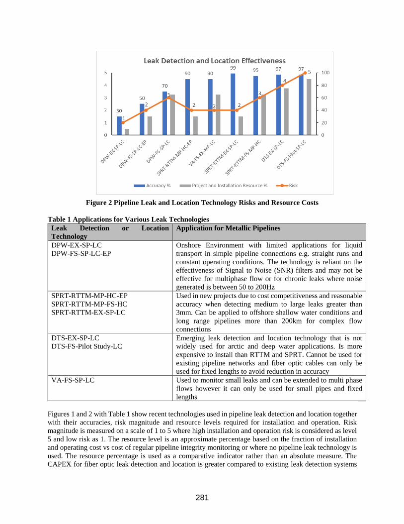
Figure 2 Pipeline Leak and Location Technology Risks and Resource Costs
Table 1 Applications for Various Leak Technologies
Leak Detection or Location
Technology
Application for Metallic Pipelines
DPW-EX-SP-LC
DPW-FS-SP-LC-EP
Onshore Environment with limited applications for liquid
transport in simple pipeline connections e.g. straight runs and
constant operating conditions. The technology is reliant on the
effectiveness of Signal to Noise (SNR) filters and may not be
effective for multiphase flow or for chronic leaks where noise
generated is between 50 to 200Hz
SPRT-RTTM-MP-HC-EP
SPRT-RTTM-MP-FS-HC
SPRT-RTTM-EX-SP-LC
Used in new projects due to cost competitiveness and reasonable
accuracy when detecting medium to large leaks greater than
3mm. Can be applied to offshore shallow water conditions and
long range pipelines more than 200km for complex flow
connections
DTS-EX-SP-LC
DTS-FS-Pilot Study-LC
Emerging leak detection and location technology that is not
widely used for arctic and deep water applications. Is more
expensive to install than RTTM and SPRT. Cannot be used for
existing pipeline networks and fiber optic cables can only be
used for fixed lengths to avoid reduction in accuracy
VA-FS-SP-LC Used to monitor small leaks and can be extended to multi phase
flows however it can only be used for small pipes and fixed
lengths
Figures 1 and 2 with Table 1 show recent technologies used in pipeline leak detection and location together
with their accuracies, risk magnitude and resource levels required for installation and operation. Risk
magnitude is measured on a scale of 1 to 5 where high installation and operation risk is considered as level
5 and low risk as 1. The resource level is an approximate percentage based on the fraction of installation
and operating cost vs cost of regular pipeline integrity monitoring or where no pipeline leak technology is
used. The resource percentage is used as a comparative indicator rather than an absolute measure. The
CAPEX for fiber optic leak detection and location is greater compared to existing leak detection systems
281
and risk is higher since there are key installation risks related to amplification or repeater units for
strengthening the reflected light signal as well as provision for maintenance of the pipeline when the fiber
optic cables are installed. Additional installation costs for larger pipe bridges are required due to spacing
requirements of the fiber optic cable. Dynamic pressure wave technology is ideal to monitor low hazard
pipelines e.g. safe water transport and monitoring of large to medium scaled leaks. SPRT and RTTM has
similar accuracy at lower risk compared to fiber optic DTS and is a cheaper alternative to retrofit existing
pipeline networks however there is uncertainty for locating or detecting leaks less than 3mm for deep water
conditions greater than 3000m or arctic conditions. Vacuum annulus monitoring uses a pipe-in-pipe
arrangement where hydrocarbon leak concentration and location are monitored using high accuracy
hydrocarbon metering devices and pressure gauges. The technology can measure leaks smaller than 3mm
however it cannot be used for large pipeline sizes due to weight of the pipelines, installation difficulties and
high CAPEX. During the last decade pipelines for the oil and gas sector manufactured from composite
materials or fiber reinforced thermoplastics (RTP) have been successfully used as replacement to metallic
pipes due to their light weight and ability to mitigate corrosion effects e.g. hydrogen embrittlement,
microbiologically induced corrosion or stress corrosion cracking. The literature reviewed provides no recent
field studies for RTP manufactured pipelines using modern leak detection systems for onshore or deep
water applications and the effectiveness of leak location or detection could be compromised due to the
acoustic damping during pressure wave transmission. Vacuum annulus pressure monitoring using RTP
manufactured pipelines can thus be an attractive option for chronic pipeline leak detection.
2. FIBER OPTIC BASED LEAK DETECTION
The use of fiber optic (FO) cables is an attractive option for measuring pipeline leak detection and is based
on the principle of scattered light that is characterized as Rayleigh, Brillouin, and Raman spectral forms.
The Brillouin phenomena occurs when light is scattered due to variations in the refractive index resulting
from pressure, temperature or strain. A vibration is produced in the cable from the scattered light that travels
at acoustic speed. A frequency downshift on the scattered light results whenever energy is transferred from
light photons to the fiber material or a frequency upshift is experienced when photons receive energy from
the fiber material. The frequency shift is known as the Brillouin frequency shift [6]. Raman scattering
measures temperature changes only and has lower sensing range and longer measurement time compared
to Brillouin. For Raman scattering the vibration induced by temperature fluctuation causes low intensity
scattered light and high attenuation thus limiting the leak detection range [7]. The ratio of the upshift and
downshift frequencies has an exponential relationship with temperature [4,29]. Rayleigh scattering is used
in Distributed Acoustic Sensing (DAS) and based on measuring the light signal that is backscattered from
the incident light. The backscattered signal has the same frequency and speed as the incident light but travels
in the opposite direction. When a leak occurs the distinguished sound level causes changes in backscatter
as a function of time that is measured at a receptor and thus the leak location is predicted. There is a
0.2dB/km loss due to the backscatter resulting from the incoming pressure waves and signal strength is
dependent on contact between acoustic wave and FOC [4].
The Brillouin Optical Time Domain Analysis (BOTDA) is widely used in oil and gas industry for pipeline
leak detection based on strain and temperature changes compared to Rayleigh or Raman scattering
techniques. BOTDA uses a square pulsed continuous laser located at either ends. The power derived from
the continuous signal is transferred to the pulsed signal aimed to increase signal to noise ratio (SNR) and
sensing range. The probability of false detection decreased as a function of increased temperature change
[6].
The FO technology is suitable for onshore applications however there is limited use in offshore applications.
The performance characteristics of temperature-based distributed FO cables includes fiber length cable,
optical attenuation, data acquisition time and laser pulse width that shines through the FO cable, and
temperature sensitivity range between 0.5ºC - 3ºC. For subsea FO installation applications the following
282

needs to be considered [8]: abrasion and crushing of FO cables, spacing of FO cables, location of tensioner
and roller supports, space requirements for FO cable attachment stations on offshore pipelines, damage by
submarine activities and weather considerations for arctic applications, e.g. temperature and hydrostatic
forces for deep water applications. FO cable repeaters are required every 40m to address attenuation and
amplification requirements, however the variance in repeatability of the light signal is undermined as a
function of FOC length [9].
Brillouin or Raman light scattering can be deployed for Distributed Temperature Sensing (DTS), however
Brillouin scattering is the preferred leak detection option. DTS has potential for offshore or arctic
applications and uses two or more fiber optic cables installed along the length of a pipeline and connected
to a temperature measurement device [3]. DTS technology is also suited for pipeline erosion monitoring at
the arctic seabed since the cold water in the event of a leak would reach the soil surrounding the pipeline
[10]. Pipeline temperature measurement range using a pulsed laser is usually 30 to 50m and can be extended
up to 250km using signal amplifiers however it cannot be used for subsea applications. Each optical fiber
acts as a thermometer and provides temperature distribution resolution coverage over a 2m span. For
offshore applications DTS is limited to 25 to 30km using Brillouin based monitoring measurement devices.
Usually DTS is applied to a 60km pipe length using these devices on either end or repeater units are installed
to extend pipeline coverage to 100m. Some of the limiting factors for DTS include inability to detect chronic
leaks for small temperature variations that is below the fiber optic temperature resolution sensitivity or
seabed soil interaction with pipeline temperature distribution might not be uniform at the pipe inlet and
outlet or along the length of the pipe. Thus far no published field study data, repeaters or amplifiers are
available for FOC leak detection location technology applicable to deep water or arctic pipeline networks.
A combination of distributed strain sensing (DSS) and DTS can be used for onshore underground leak
detection for improved accuracy and removing false alarms. For DSS FOC is bonded on a new pipe before
installation however there are risks that the FOC can bend or twist thus preventing it from measuring
maximum bending strain [3]. The DSS arrangement measures strain and temperature whereas DTS only
measures temperature data. For strain measurement the difference is taken between the DTS and DSS signal
amplitude. Alternatively there are two bonded and two free FOCs fitted on a thermoplastic profile. Bonded
fibers are used for strain measurements whereas the two free fibers measure temperature fluctuations with
single redundancy. There is no prescribed method to bond the optic cable to the pipeline for offshore
applications and there is risk that the cable may be damaged during the bonding and rolling process. A
bonding tape for onshore FOC applications that used fiber glass reinforced thermoplastic (RTP) and a
polyphenylene sulfide matrix was developed [11]. The material is bonded under high temperature
conditions and provide good mechanical resistance properties, however more tests and modifications are
required to the matrix structure for offshore arctic or deep-water applications.
Distributed acoustic sensing (DAS) uses fiber optic to convey acoustic vibration signatures, which is
analyzed for leaks, however DAS cannot detect chronic leaks due to background noise and noise generated
by the moving fluid. DAS can only be effective for large leaks where the acoustic signal to noise ratio is
high and applicable to unburied or buried seabed pipelines. DAS can be used instead of DTS where the
fluid temperature measurement is unimportant and detection of large leaks are required [3]. DTS can be
effective for normal steady state operations and cannot be used for chronic leak detection especially during
transient conditions or when the there is pipe flow start-up due to temperature changes affecting the fluid-
pipe and pipe-soil interfaces. Other factors affecting DTS and DAS include leak reaction times, soil
conditions, single or multi phase fluid mixture and material selection of FOC cable. Plastic optical fibers
have higher breaking strains than glass fiber however there is a 700 fold decrease in optical power loss per
meter length of cable and the FOC diameter is 100 times larger when compared to using glass FOC [9].
Chronic leak detection using DTS can be affected by the spatial resolution of temperature detected per
meter length of pipe. If a chronic leak results in a temperature per meter length that is smaller than the
283
spatial resolution then the leak might not be detected. DTS reaction time of 15 minutes to several hours for
chronic leak detection needs to be compared with using regular visual aerial inspection and the need for a
faster reaction time. Usually large leaks are detected faster compared to chronic leaks [9].
2.1 Installation and Positioning of FOC for DTS and DAS Applications
The FOC consists of a core that carries the signal, which is wrapped around by cladding having a different
refraction index thus either allowing light energy to the core or retains energy inside it. The core and
cladding are then inserted inside a steel or plastic protective jacket. For DAS assembly the FOC consists of
the core, acoustic coupling layer with inner interlock, that is housed inside a metal tube and sheath. The
DTS has the core inserted in a gel filled stainless steel tube and each tube is surrounded by steel wires. The
arrangement is housed in a plastic tube [4].
Signal process and transfer is accomplished using a fiber optic transceiver e.g. a laser with single mode
cabling and communication link. The location of FOCs for DTS application is either installing the FOC on
a vertical pipeline (12 o clock) section or installing two bundled FOCs at 10 o clock and 2 o clock positions
for improved accuracy [4]. For DAS the FOC is installed 30 to 50cm away from the pipe at 3 o clock and
6 o clock positions or if bundling is preferred then the location is like DTS namely at the top pipe section
(10 o clock and 2 o clock positions).
2.2 System Components and Limitations of FOC
Leak detection FO sensing technology consist of a FO cable and interrogator with sensing range of
approximately 50km fitted to a processing-control-display unit arrangement. The processing and control
unit with leak detection software and graphical interface provides real time pipe flow performance derived
from series interrogator units. The leak detection system is integrated to any supervisory control and data
acquisition (SCADA) system. The interrogator units analyses acoustic, thermal or strain output signals
along the FOC and the software identifies various leak sources based on pattern recognition and data
collection.
Limitations of DTS, DSS and DAS were: location, position of orientation and number of fiber optic cables,
optimal location of repeaters or amplifiers, and leak detection thresholds for DTS and DAS applications
[9]. The literature reviewed to date does not provide actual maintenance activity descriptions for various
system components or related mean time between failures (MTBF) however a system and visual
maintenance check was recommended every 5 years for fan or automated optical attenuators and 10 years
replacement of any fan and system components including hard drive and computers [4]
There were key risks identified for FO sensing technology applied to arctic leak detection namely [4,9]:
- No actual or projected MTBF for individual components or overall leak detection system. MTBF
reduces as a function of FO cable length however no optimal MTBF has been determined for
various pipeline networks in the arctic or for offshore applications
- Installation and maintenance operational requirements including repeaters used for FO signal
transfer in various pipeline sections are not defined
- There are no interrogator or signal amplifying devices available for arctic or subsea applications
- DTS and DAS are unable to quantify chronic leaks or leak rates and there is no established
minimum leak threshold
Other competing arctic subsea pipeline leak detection systems for multi phase oil and gas flows are
Sequential Probability Ratio Testing (SPRT) used in combination with RTTM, negative pressure wave or
284
pressure gradient techniques. Usually SPRT detects leaks whereas negative pressure wave or pressure
gradient methods can locate leaks for steady and transient conditions [12].
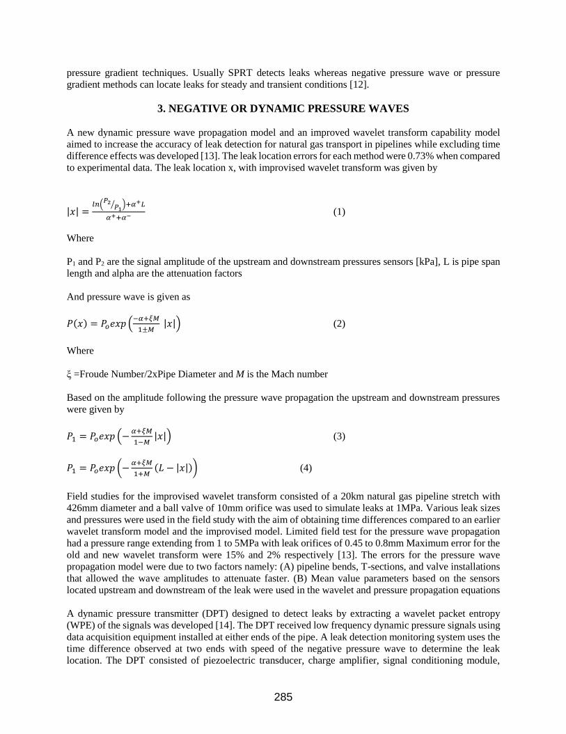
3. NEGATIVE OR DYNAMIC PRESSURE WAVES
A new dynamic pressure wave propagation model and an improved wavelet transform capability model
aimed to increase the accuracy of leak detection for natural gas transport in pipelines while excluding time
difference effects was developed [13]. The leak location errors for each method were 0.73% when compared
to experimental data. The leak location x, with improvised wavelet transform was given by
|𝑥| =𝑙𝑛(
𝑃2𝑃1
⁄ )+𝛼+𝐿
𝛼++𝛼− (1)
Where
P1 and P2 are the signal amplitude of the upstream and downstream pressures sensors [kPa], L is pipe span
length and alpha are the attenuation factors
And pressure wave is given as
𝑃(𝑥) = 𝑃𝑜𝑒𝑥𝑝 (−𝛼+𝜉𝑀
1±𝑀 |𝑥|) (2)
Where
ξ =Froude Number/2xPipe Diameter and M is the Mach number
Based on the amplitude following the pressure wave propagation the upstream and downstream pressures
were given by
𝑃1 = 𝑃𝑜𝑒𝑥𝑝 (−𝛼+𝜉𝑀
1−𝑀|𝑥|) (3)
𝑃1 = 𝑃𝑜𝑒𝑥𝑝 (−𝛼+𝜉𝑀
1+𝑀(𝐿 − |𝑥|)) (4)
Field studies for the improvised wavelet transform consisted of a 20km natural gas pipeline stretch with
426mm diameter and a ball valve of 10mm orifice was used to simulate leaks at 1MPa. Various leak sizes
and pressures were used in the field study with the aim of obtaining time differences compared to an earlier
wavelet transform model and the improvised model. Limited field test for the pressure wave propagation
had a pressure range extending from 1 to 5MPa with leak orifices of 0.45 to 0.8mm Maximum error for the
old and new wavelet transform were 15% and 2% respectively [13]. The errors for the pressure wave
propagation model were due to two factors namely: (A) pipeline bends, T-sections, and valve installations
that allowed the wave amplitudes to attenuate faster. (B) Mean value parameters based on the sensors
located upstream and downstream of the leak were used in the wavelet and pressure propagation equations
A dynamic pressure transmitter (DPT) designed to detect leaks by extracting a wavelet packet entropy
(WPE) of the signals was developed [14]. The DPT received low frequency dynamic pressure signals using
data acquisition equipment installed at either ends of the pipe. A leak detection monitoring system uses the
time difference observed at two ends with speed of the negative pressure wave to determine the leak
location. The DPT consisted of piezoelectric transducer, charge amplifier, signal conditioning module,
285
micro control unit and power module. The charge amplifier converted high impedance charge to low
impedance voltage for long pipeline transport and the energy generated from the acoustic signal was
concentrated in the low frequency band for pipeline leaks. A wavelet decomposition strategy was performed
on the WPE signals and the wavelet packet coefficients analyzed for signal information. The ratio of energy
per wavelet to total energy and the Shannon entropy were then analyzed. The concentration of entropy is
calibrated against the pressure range of investigation to identify and locate pipeline leaks. Field experiments
were conducted at PetroChina for a 94km long pipeline with pipe diameter of 457mm and dynamic pressure
transmitters installed at the inlet and outlet pipe sections. Pressure signals were obtained for normal
operation, valve or pump adjustments and leak scenarios and the time differences for various field tests
were recorded with relative error. A maximum error of 0.13% was observed for 10 sets of field experiments,
however these experiments are not conclusive regarding subsea multiphase mixtures or pipeline leaks
located on elevation or declines.
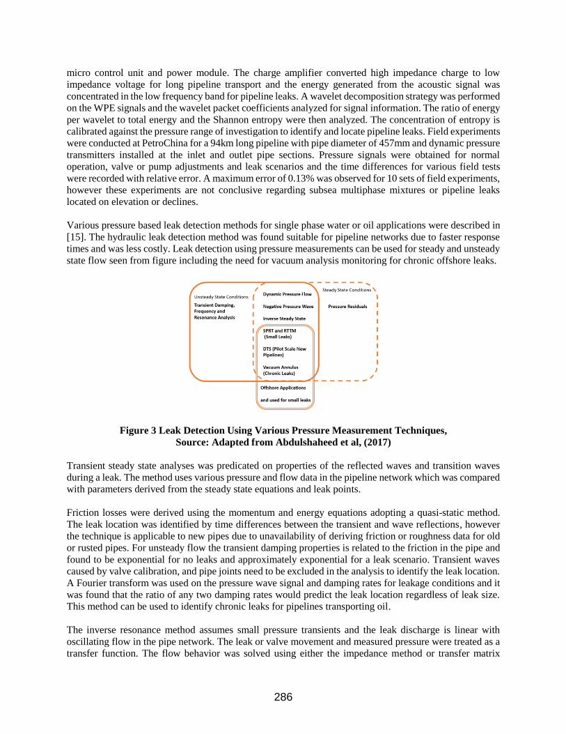
Various pressure based leak detection methods for single phase water or oil applications were described in
[15]. The hydraulic leak detection method was found suitable for pipeline networks due to faster response
times and was less costly. Leak detection using pressure measurements can be used for steady and unsteady
state flow seen from figure including the need for vacuum analysis monitoring for chronic offshore leaks.
Figure 3 Leak Detection Using Various Pressure Measurement Techniques, Source: Adapted from Abdulshaheed et al, (2017)
Transient steady state analyses was predicated on properties of the reflected waves and transition waves
during a leak. The method uses various pressure and flow data in the pipeline network which was compared
with parameters derived from the steady state equations and leak points.
Friction losses were derived using the momentum and energy equations adopting a quasi-static method.
The leak location was identified by time differences between the transient and wave reflections, however
the technique is applicable to new pipes due to unavailability of deriving friction or roughness data for old
or rusted pipes. For unsteady flow the transient damping properties is related to the friction in the pipe and
found to be exponential for no leaks and approximately exponential for a leak scenario. Transient waves
caused by valve calibration, and pipe joints need to be excluded in the analysis to identify the leak location.
A Fourier transform was used on the pressure wave signal and damping rates for leakage conditions and it
was found that the ratio of any two damping rates would predict the leak location regardless of leak size.
This method can be used to identify chronic leaks for pipelines transporting oil.
The inverse resonance method assumes small pressure transients and the leak discharge is linear with
oscillating flow in the pipe network. The leak or valve movement and measured pressure were treated as a
transfer function. The flow behavior was solved using either the impedance method or transfer matrix
286
method and pressure amplitude oscillations were determined using Fourier decomposition or pseudo-
random binary signals (PRBS). The transfer function, pressure oscillations amplitudes and leak locations
were located for all frequencies at once using PRBS. Pressure flow deviation works for a wide range of
flow conditions and is combined with mass balance leak detection strategy. The leak was located by
comparing the measured pressure or flow measurements upstream and downstream of the pipe to predicted
pressure and flow variables. The resulting location error and response time were higher for small leaks than
large leaks and is not suitable for chronic leak detection. A leak discharge of 5% total flow produced a 33%
error compared to 22% error for a 10% leak discharge. The pressure residual vector was designed for
complex pipeline networks transporting water. Pressure and flow sensors installed on the pipeline collect
real time data which was compared to a hydraulic simulation model to detect pressure variations or residuals
that may cause a leak. Recent pressure simulation models use pattern recognition, regression estimation or
neural networks however these models have a 35% success rate when determining single phase steady state
leak detection. Some of the disadvantages of the mass balance approach is accuracy of multiphase flow
meters and liquid pipeline hold up [9].
Tian et al [16] developed a statistical process control for transporting oil or gas in pipelines that address
challenges related to negative pressure wave leak detection namely, data quality related to missing data,
noise level and precision of leak location, data duplication based on time out policy during pressure wave
recording and managing false alarms was developed by . Other lessons learnt was frequency filter design
can be a trade-off between Signal to Noise Ratio and locating precision requirement. Usually negative
pressure wave frequencies derived using pressure transducers measure between 25 to 100Hz and
communication costs was saved by transmitting data in time packaged batches
Statistical process control (SPC) used a sampling control chart containing various quantitative process
measurements, which is compared to controlled sampling distributions. The sampling population is usually
pressure data including pressure slope communicated every 10 seconds. Local minimum points were
compared to the sampling control chart and updated when required. If pressure data deviated from these
local minimum sampling values or control chart then the potential leak time point was calculated. The SPC
needs to be used with other leak location technologies e.g. fiber optic, calibrating results from upstream and
downstream flow meters, and multiple-sensor pairing algorithm to reduce false alarms or when a pump or
valve is adjusted. The sensor pairing recognizes time stamps between sensors and distinguished between
pipeline leak or when a pump or valve is actuated, however this technique cannot be used for multi-phase
flows or subsea applications
287
4. MAXIMIZING SIGNAL TO NOISE RATIO
Empirical mode decomposition (EMD) was used to increase SNR based on decomposing various frequency
ranges using intrinsic mode functions (IMF) and a residual predicated on a scaled frequency [17]. The IMF
has nonlinear characteristics and decomposes the dynamic pressure wave leak signal using cubic splines to
identify upper, lower and mean signals. The difference between the source signal and mean signal is
inspected for IMF conditions and compared against a predefined acceptable error limit. Decomposition
continues until the extreme IMF conditions is less than the acceptable error. The pressure wave amplitudes
after denoising from EMD produced the same results as wavelet transform, which should not be confused
with Fourier transform.
Another SNR empirical mode decomposition (SNR-EMD) method was developed that consisted of a noise
reduction algorithm and smoothing factor which terminated when the noise amplitude factor approached
zero [18]. The SNR-EMD technique was used in the field at SINOPEC on a 30k long pipeline for pressure
ranges between 4 and 4.15MPa for crude oil transport. Advantages of this method include removing end
effects of noise emanating from the pressure signals
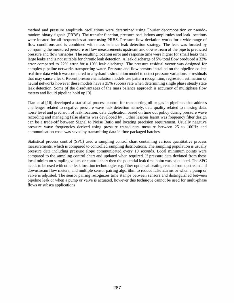
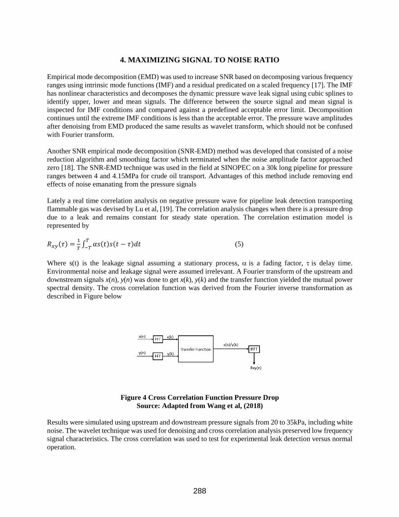
Lately a real time correlation analysis on negative pressure wave for pipeline leak detection transporting
flammable gas was devised by Lu et al, [19]. The correlation analysis changes when there is a pressure drop
due to a leak and remains constant for steady state operation. The correlation estimation model is
represented by
𝑅𝑥𝑦(𝜏) =1
𝑇∫ 𝛼𝑠(𝑡)𝑠(𝑡 − 𝜏)𝑑𝑡
𝑇
−𝑇 (5)
Where s(t) is the leakage signal assuming a stationary process, is a fading factor, is delay time.
Environmental noise and leakage signal were assumed irrelevant. A Fourier transform of the upstream and
downstream signals x(n), y(n) was done to get x(k), y(k) and the transfer function yielded the mutual power
spectral density. The cross correlation function was derived from the Fourier inverse transformation as
described in Figure below
Figure 4 Cross Correlation Function Pressure Drop
Source: Adapted from Wang et al, (2018)
Results were simulated using upstream and downstream pressure signals from 20 to 35kPa, including white
noise. The wavelet technique was used for denoising and cross correlation analysis preserved low frequency
signal characteristics. The cross correlation was used to test for experimental leak detection versus normal
operation.
288
Adnan et al [20] provided various signal processing methodologies used in pipeline leak detection namely
Fast Fourier Transforms (FFT), Short time Fourier Transform (STFT), Wavelet Transforms (WT) and
Hilbert Huang Transforms (HHT). The wavelet transform was suited for leaks in gas pipeline transport and
uses echoes reflected from turbulence caused by the leak. The echoes are analyzed in the WT algorithm,
which reduces the noise using a time based cross correlation technique similar to Wang et al [19]. The HHT
technique also designed for gas leak detection in pipelines use acoustic waves from two sensors to obtain
the Hilbert marginal spectrum, which compares normal operations and leak conditions. Studies showed that
HHT provided more accurate and reliable high resolution time based results compared to FFT and STFT.
Spectrograms derived from STFT could clearly indicated when wave amplitudes began to occur during
leaks but failed to provide any frequency amplitudes in contrast the WT provided good time and frequency
amplitude approximation during leak detection.
The modeling of subsea chronic and large leaks for multi-phase flows in a horizontal pipe by Gajbhiye et
al, [21] provides insight to the following:
- Leak positioned further upstream is easier to detect when inlet flowrate and outlet pressure are fixed
- Mixtures that have a compressible gas phase improves leak detection capability due to higher
mobility
- The outlet flow rate is a better indicator of leak detection compared to using inlet pressure as a
boundary condition
5. Transient Pressure Wave Leak Detection
Transient leak detection was addressed by Zhang et [22] for pipelines transporting crude oil since they
found pressure transmitters installed along pipelines work well for steady state conditions however there is
an increased number of false alarms and leak detection failure due to pumps switching on or off, control
valve adjustment and supply changes. A statistical pipeline leak detection (SPLD) system using modified
volume balance, pressure and flow monitoring with statistical analysis were combined with a data validation
procedure and decision-making methodology. Probability calculations and hypothesis testing for leak or no
leak scenarios were based on determining the mass entering or leaving a network and balanced against
inventory variations inside a pipeline network. The deviation of the mass balance is detected using a
statistical sequential probability ratio test (SPRT) and pattern recognition to avoid spurious or false alarms.
𝜏(𝑡) = ∑ 𝑄1(𝑡) −𝑀1 ∑ 𝑄𝑜(𝑡) − ∑ 𝛥𝑄𝑗(𝑡)𝐿
1𝑁1 (6)
𝜆(𝑡) = 𝜆(𝑡 − 1) +𝛥𝑚
𝜎2 (𝜏(𝑡) − 𝑚 −𝛥𝑚
2) (7)
τ(t) is the corrected flow imbalance measured at time t, which fluctuates around a non-zero value and λ(t)
is a cumulative sum based on a leak, no leak hypothesis test with m as mean value of τ(t) and Δm is a factor
dependent on leak size. The σ2 value of relies on pressure and flow fluctuation and the three operating
modes namely: steady state operations, small operational change or large operational changes. The SPLD
was capable of self learning and adjusted for operational changes or instrument drift in addition to not
relying on fluid properties, viscosity change or composition. Field tests for oil transport were analyzed for
leaks in a crude oil pipeline network spanning over 173km. The SPLD identified 47 leaks in a one year
period for transient and steady state conditions.
SPRT was used with two statistical volume balance techniques namely Time of Flight (TOF) and pressure
interpolation methods using a Least Squares algorithm to predict leak locations [5]. SPRT using the two
leak location techniques were applied to 600 pipelines transporting e.g. various crude oil densities, multi
289
products: gasoline or diesel, natural gas, ethylene, condensate or diluent. Field tests were conducted
extending from Koln to Hamburg Germany for various pipelines elevations.
Real Time Transient Monitoring (RTTM) was replaced with statistical volume balance method since it
could detect leaks up to 0.5% even during transient conditions and not give false alarms during: pump
switchover, crude oil changes, start up or shut down, temperature changes, or delivery switchover [5]. The
unique ability of statistical volume balance is that leaks of 0.5% was detected albeit the detection of the
flowmeter may have accuracy of 1%.
There are several types of RTTM software applications provided by various suppliers, which may differ in
their selection of boundary conditions, or some may include all transients and others would ignore the
thermal pipeline effects. Some of the performance measures for RTTM includes [23]:
- Spacing and installation of fluid property measurements (viscosity, mixture, pH), and pressure and
flow meters such that accuracy of predicted variables are maximized and allows for isolation of the
pipeline into independent mass or volume balanced sections
- Size and variability of flows including flows that are exiting the pipeline network
- Managing phase changes especially during pipeline elevations. For instance at low downstream
pressures the pressure at the peak may drop to vapor pressure or two phase flow may develop
downstream of peak pressure. Thus the correct type of temperature, flow and pressure metering
devices need to be installed
- Suitability and selection of boundary conditions and ability to maximize signal to noise ratio
- Detection of a leak with RTTM while compensating for uncertainties and limitations in input data
and choice of numerical scheme deployed
RTTM was deployed for a pipeline network that had elevation of 3000m above and another section of
2100m below sea level [5]. It is difficult to use a RTTM technique to manage pipeline elevations while also
accommodating various types of crude oil and a preference was made to the volume balance method.
6. SUBSEA NEGATIVE PRESSURE WAVE WITH STATISTICAL METHODS
Leak detection for subsea arctic conditions was addressed by using a combination of sequential probability
ratio testing (SPRT), negative pressure wave and pressure gradient signals with pattern recognition
integrated in a software algorithm [17]. Wald’s SPRT with mass balance and hypothesis testing was used,
which assumed the number of samples for signal processing are independent and identically distributed
[24]. For subsea multiphase flow transient effects, instrument noise and line packing are major contributors
compromising leak detection accuracy thus Wald’s SPRT was integrated with a moving-average filtering
methodology with normalized data.
WALDS SPRT provides real time leak sample probabilities using moving average filtering to eliminate
noise e.g. multiphase transient effects, line packing and instrument air. A hypotheses test is made against a
leak or no leak scenario using mean leak probabilities. The difference in mean leak probabilities is identified
for no leak scenario and a leak scenario, which is compared to a confidence level of 99%. A larger leak size
implies a larger difference in mean leak probability and thus does not meet the required confidence level.
Pipeline instrument changes are catered for by the variance and depends on steady state operations, and
large to medium changes. Zhang et al, [5, 25] developed SPRT with (RTTM) to predict leak detection using
statistical volume balancing for leak location. The technique was successfully applied world wide to 800
pipelines with different dimensions transporting oil or gas at transient and steady state conditions. A highly
stable implicit finite difference scheme was used for solving the pipeline equations by developing an
adaptive time step and spatial scheme with adjustable accuracy. Field tests were conducted for pipelines
290
extending from 2km to 2100km with diameters between 13mm to 2m in Sakhalin Russia, Gulf of Mexico,
Philippines and Norway. The RTTM system was able to detect leaks ranging from 1% to 2% for long
distance oil and gas pipelines within 2 hours while 1% multiphase leaks were detected within 20 hours.
Earlier studies showed the SPRT RTTM is a self learning software and continually monitors the relationship
between flow and line pressure based on a pattern recognition scheme [26]. Any change in the pipeline
pressure and flow relationship would trigger a leak event.
The pressure gradient technique was researched by several authors [23, 27, 22]. For a leak free scenario the
pressure drop across a pipeline is a linear real line however during leak conditions the pressure profile
develops two gradients and thus forms a kink at the leak point. The location of the leak is at the intersection
point of the change in gradients given by the upstream and downstream pressures across the leak. The
pressure gradients are calculated using real-time transient monitoring and is suited to multiphase flows.
Negative pressure wave leak detection is based on monitoring the upstream and downstream pressure waves
while filtering out noise using multiple pressure sensors at the pipe inlet and outlet. The method is suited
for liquid pipeline transport or for high oil to gas ratio applications. Pressure drop during normal operations
vs leak conditions or operational changes show different wave forms that need to be evaluated against a
predefined or acceptable wave fluctuation. Some of the success factors for effective leak location include:
signal processing and wave travel speed and deriving a critical value for pressure drop fluctuations.
Simulation studies were compared to field tests for pressure inlet values of 50 bar for a 1km pipeline,
followed 120bar for a 10km pipeline and maximum errors were ranged between 29 to 4.4%. with maximum
error occurring at 20bar. Some of the shortcomings using WALDS SPRT or the pressure gradient
techniques include: no provision for quantifying the medium to large operational changes and how these
differ from normal operations.
7. Subsea Vapor Monitoring Chronic Leak Detection Bryce et al, [28] developed a hydrocarbon vapor sensing system to identify chronic crude oil leaks in the
Arctic called LEOS, which is a German acronym for “Leck Erkennungs Ortungs System” or leak detection
and location system. LEOS leak detection was used since pressure variation in a subsea arctic environment
can cause hydraulic noise during oil pumping and upstream operations, which can mask chronic leaks.
The LEOS design consisted of a protective braid that covered an outer ethylene vinyl acetate (EVA) sheath
perforated PVC tube. A cross woven braid was rolled over a small tube, which contained a gas transport
tube, and the pipe assembly was housed in the larger PVC tube. The EVA and tubes allowed C1-C6
hydrocarbon molecules to seep through in the event of a leak. Air and later hydrogen were introduced in
the gas test tube for each pump cycle, which created a hydrogen test peak for calibration requirements. Each
LEOS detection system was 15km long depending on hydrogen sampling concentration and cycle time
requirements. Semiconductor gas sensors were used at the measuring station and the logarithmic change in
resistivity would indicate the presence of hydrocarbon when compared to the hydrogen test peak. Field tests
on the Northstar crude oil pipeline in Alaska was made, which considered subsea pipe-soil interaction, ice
gouging and bending strain. Some of the limitations of LEOS is that is can be used for shallow water
applications of 15m depth and for a maximum pipeline length of 25km from [9].
Offshore arctic chronic leaks and large leaks were investigated at 3 sites, namely BP North Star, Pioneer
Oooguruk and ENI Petroleum Nikaitchuq [3, 29]. The site at BP utilized primary leak detection using mass
balance line compensation that can be measured up to 0.15% maximum pipe flow and secondary pressure
point analysis leak detection for larger leaks applied to oil pipeline transport networks. For chronic leak
detection below 0.15% of maximum pipe flow the LEOS leak detection was used on a daily basis and any
hydrogen leak could be measured at various sacrificial anodes [28]. Oooguruk and Nikaitchuq have a three-
phase mixture of oil, gas and water pipeline network and an arctic heating fuel pipe line. A pipe located
291
inside another pipe is used for the three-phase pipeline network and primary leak detection method was the
vacuum in the annulus arising from the pipe-in-pipe assembly. Usually the annulus can also be filled with
argon at 1mBar (abs) which improves thermal insulation performance and reduces buckling and frost
settlement [29].
Oooguruk and Nikaitchuq had a 12”x16”, 6 mile long and 14”x18” at 3.5mile long offshore pipe
arrangement respectively. Any pressure increase inside the annulus would indicate a leak regardless of leak
hole size and secondary leak detection was comparing the difference of a preset operating pressure safety
low with a pressure reduction measurement in the pipe to identify large leaks. A shut in pressure test was
conducted to identify leaks in the heating fuel pipe line. A fiber optic sensor cable was installed across the
pipeline network and any change in temperature was identified using a distributed sensing algorithm, which
prevented false alarms when compared to the primary leak detection deployed. Some of the lessons learnt
for subsea arctic leak detection for vapor monitoring incl [3]:
• Chronic leak detection below 1% of total flow rate and tracking large leaks over a period of 7 days
proved effective compared to detecting large leaks within an hour while excluding chronic leak
detection
• Technology used to locate chronic leaks should be set at a minimum leak detection threshold
• The minimum leak detection threshold should be compared to the benefits derived vs cost of
manufacture, installation, operation and maintenance. The 1% minimum leak detection threshold
may not be suited for all projects
• Pipe-in-pipe arrangement can be costly and incur project delays [4]. Heavy pipe-in-pipe assemblies
may require complex or large scale installation machinery and may not be able to be installed or
maximum length may be restricted to around 10 miles, however light weight fiber composite pipes
with rated pressure may be considered for deep water applications
• Pressure safety low leak monitoring is an imprecise leak detection option since during 1990 and
2001 only 5 out of 21 leaks were positively identified in the Gulf of Mexico using this technique
[9]
• Number of sensors, connectors and cabling can be minimized if the monitoring of the annulus is
done from one end of the pipeline
• Water tight isolation bulkheads installed on the pipe-in-pipe arrangement are used to isolate
sections of the pipe in the event of damaged or water flooding. The bulk heads provide continuous
leak detection monitoring however they limit the monitoring capability over the pipeline length
Kulkarni et al, [8] suggested criteria for offshore leak detection, namely: pipeline leak detection coverage
of 300km, spatial leak resolution of 5 to 10m, provide reliability of 95% confidence level, able to address
chronic leaks, identify leaks within few minute response time, provide leak detection combination of any
mixtures containing water, crude oil and natural gas, offshore leak detection equipment should not impact
pipeline structures and operate maintenance free. The vapor monitoring system was able to address most
of these criteria for onshore applications except the response time needed when a leak was identified due
to the sensitivity of measuring the hydrocarbon concentration per cycle time.
292

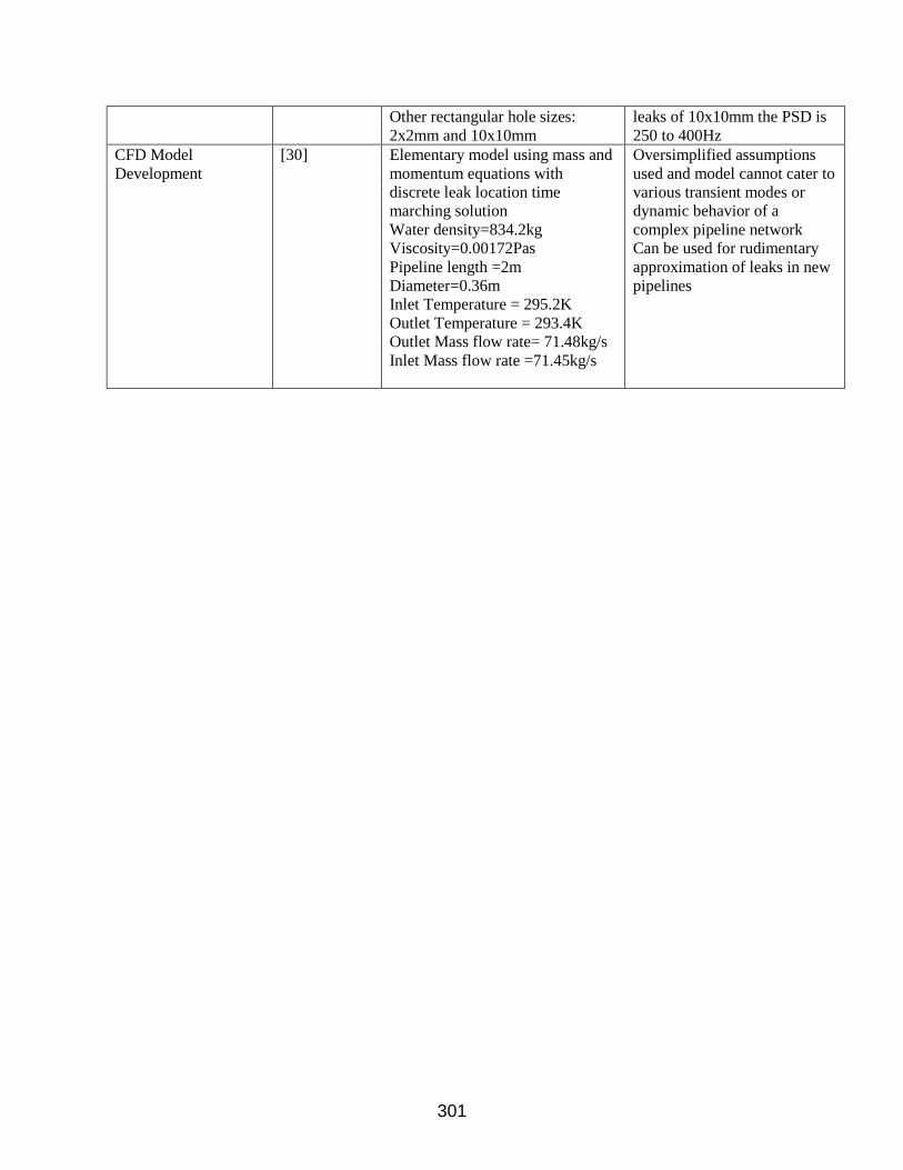
8. CFD MODELLING SUPPORTING LEAK DETECTION TECHNOLOGY
Oyedeko et al, [30] provides an elementary description for modelling oil pipeline transport during transient
conditions by deriving a one dimensional pipe flow equation, which considers mass flow rate at constant
crude oil density. The momentum equation was derived with friction factors for new pipelines and constant
pressure drop. The leak location was determined by a discrete processing iterative technique that uses
difference in expectation values derived from the mass flowrates of a leak and no leak scenarios. If the
discrete processing converges after several iterations then the leak location is positively identified or moves
to the next time step. The assumptions used in the model are oversimplified for instance it is restricted to
straight horizontal pipe runs for constant diameters applied to pump start-up or shut down. The effects of
phase change, complex pipe networks, valve adjustments or pipe leaks at elevations are not addressed and
neither is heat losses to the surroundings. Field studies are not conducted and compared to the model to test
for robustness and sensitivity. De Sousa et al, [31] expanded on the work of Oyedeko et al, [30] by
addressing steady state dynamic behavior of leaking pipelines transporting either oil or water since most
CFD studies focused on mass balance using the continuity equation and acoustic behavior caused by the
pressure drop across the pipeline to identify location of large leaks. Chronic leaks with leak sizes less than
3mm cannot be easily detected using existing mass momentum and pressure based monitoring techniques.
These findings are similar to Zhang et al, [5] where a volume based leak rate is preferred over mass and
RTTM self learning tool is used instead.
Jujuly et al, [32] provided CFD modelling for pipeline leaks supporting arctic offshore environment using
LES turbulent flow to manage high energy eddies. The flow inside the pipe was modelled for steady state
transient conditions whereas the leak was modelled for transient conditions only. Both [32,33] found a
direct relationship of leak flowrate and pressure drop for incompressible liquids whereas an inverse
relationship was observed for ideal gases. Acoustic signatures for leak sizes of 8 and 4mm at pressures of
5800 and 200psi respectively were monitored and noise generation was recorded for power spectral density
range of 200 to 680Hz [32,34]. The large eddies create noise disturbances and thus chronic leaks may go
undetected for leak diameters less than 3mm. The mesh selection used in CFD analysis to model pipeline
leaks does not provide substantial accuracy with greater mesh refinement and leaks closer to the pipeline
entrance provided the greatest pressure drop [35,31]. A medium mesh element range of 210,000 to 600,000
is adequate for pipeline leak detection.
Subsea oil and gas pipeline leaks including free surface effects showed that high density oil and small leak
diameter with minimum flow rates created maximum horizontal migrate distances for an oil sheen
appearing on the water surface [36,37]. For chronic leaks at minimum gas flow rates the turbulence at the
water surface is less pronounced however there is no CFD research available to adequately predict deep
water or arctic gas leak plumes at the water surface. The reaction times for the oil sheen or gas mixture
formation on the water surface at steady state conditions from initiation of a subsea leak needs to be fully
understood and compared to the reaction times of modern leak detection systems.
9. RESEARCH GAPS IDENTIFIED IN LEAK DETECTION SURVEY
Fiber optic cable used in leak detection is an emerging technology for deep water and arctic conditions that
is confined to pilot scaled studies. Some of the installation shortcomings include: attachment of cable on
the pipe from a tensioned roller for deep water applications, location of the cable on the pipe bridge and
spacing constraints, provision of maintenance activities on pipeline networks e.g. welding and removal of
pipe sections, retrofitting of existing pipelines with FOC and space restrictions on pipe bridges. There are
no amplifiers or repeater signal generators for offshore conditions. Installation and design costs are greater
than other leak detection technologies due to installation risks and equipment reliability is not fully
293

established. For DSS applications the sealing of the cable on pipe for offshore conditions need to be
investigated using the RTP sealing technique on metallic or RTP pipes.
Dynamic pressure wave leak detection can be used with a customized SNR filter however the Fourier
transform algorithm may not be ideally suited for transient conditions, multiphase flows or when there is a
flow change, pipe elevation, pump start-up or shutdown. Further research is required for RTTM with SPRT
and dynamic pressure wave to address chronic leaks for deep water offshore environment. Chronic leak
signals are generated for frequency less than 200Hz and further analysis is required to identify calibration
of pressure signals, frequency generated and leak sizes between 1 to 3mm. The challenge is to identify the
noise generated especially for multiphase flows and the signal generated in the event of chronic leaks for
the frequency range between 30 to 200Hz.
Vapor Monitoring Chronic Leak Detection has proven to be effective for chronic leak detection however
further improvement is required to lower the weight of the pipe in pipe configuration for easy assembly and
installation in arctic or subsea conditions. RTP is an attractive alternative to metallic pipeline networks
however there is uncertainty regarding fracture effects of the pipes in harsh conditions or external
interference. Further investigation is required to compare the effectiveness of existing leak detection
systems using RTP pipeline networks.
Shortcomings in CFD Modelling include the flow dispersion during transient and steady state as a function
of time for deep water and arctic conditions. The time for full pool formation or oil sheen needs to be
characterized for the various leak detection reaction times. It is unclear how oil or gas dispersion would be
affected in deep water or during ice build up around the submerged pipe. Field studies for leak dispersion
or oil sheen formation is required and compared to the accuracy and reaction for various leak sizes and leak
technologies since no one size fits all leak detection application may be able to address chronic or large
leaks.
10. SUMMARY DISCUSSION ON LEAK DETECTION SURVEY
FOC provides higher accuracy and temperature vs frequency resolution compared to other leak detection
technologies at maximum accuracy. Both DTS and DAS require minimal maintenance, however the
installation costs on new pipelines is greater than existing leak detection location technologies like negative
pressure wave or SPRT with RTTM. No technology is available to retrofit existing oil and gas pipelines
and neither is this technology used for deep water or arctic applications. The sealing of FOC on pipelines
and signal amplifiers or repeaters are currently unavailable for subsea arctic applications. Chronic leak
detection and location for subsea oil and multiphase gas mixtures are best suited using either RTTM and
SPRT or pipe-in-pipe vapor monitoring configuration using fiber composite material due to the light weight
composition, less cost and easy to install process especially for large diameter pipelines exceeding 400mm
diameter. For FOC to be successfully deployed for offshore applications a self learning or artificially
intelligent system with RTTM maybe useful to address transient conditions.
Igor et al, [38] provides a useful description about how fiber composite manufactured pipelines can be a
game changer for oil and gas transport and key findings include moisture absorption and subsea pipeline
repair strategy given in [39-41], A description in [42] for installation of buried fiber composite pipelines
and guidelines on pipe-in-pipe installations. Oil and gas pipeline flow networks utilizing Reinforced
Thermoplastic Pipes (RTP) has been in operation at Saudi Aramco to mitigate corrosion effects related to
CO2, H2S, O2 and bacterial growth [45]. RTP manufactured subsea umbilicals or pipelines can be
customized for deep sea applications and their strength and bending characteristics is described by [43,44].
RTP manufactured risks include fracture or crack propagation of the pipe in the event of external
interference e.g. sand deposition in the pipe network, earth disturbances or ice formation around a
submerged pipe.
294

Negative or dynamic pressure wave technology can be applied for large scaled leaks typically for leaks that
are 10% of maximum flow rate or greater due to location errors and sub optimal signal to noise ratio
filtering. The signal to noise ratio (SNR) methods adopted are like other SNR filtering techniques available
from various pipeline leak detection suppliers [17,19]. Some of the challenges deriving maximum SNR is
transient conditions in pipeline networks e.g granular SNR filtering during valve motion, pump start-up,
addressing multiphase flows and pipeline elevations. The transient modes described are fully catered when
using RTTM and the calibration table indicates more consistent and minimal leak detection errors using
SPRT and RTTM when compared to negative pressure wave leak location even when using sophisticated
SNR software. In addition no large scale field tests describing leak location or leak detection of complex
pipeline network systems is available in the literature utilizing negative or dynamic pressure wave
technology.
Transient pressure wave leak detection using SPRT with RTTM proves to be the best leak detection and
location technique for existing complex pipeline networks transporting single or multiphase mixtures and
can be used even on pipeline elevations and offshore. Installation is easy and the cost is similar to the
negative pressure wave leak detection system. There is no self learning tool in other leak detection systems
to address transient effects in pipeline pressure, flow or temperature. The RTTM allows for self correction
in the event of mixture change, pressure, flow or temperature transients. Even chronic leaks can be easily
identified and located with greater accuracy compared to flow or pressure instruments. Recent
developments indicate that the volume balance method is preferred over mass balance for greater accuracy
especially during pipeline elevation when transporting multiphase flows in subsea or arctic conditions.
Usually pressure or flow transmitters are unable to measure either liquid, gas or a mixture within reasonable
accuracy especially for pipeline networks at steep elevations to the vertical or during phase change of
mixture composition for arctic or deep water applications. RTTM and SPRT is the preferred leak detection
location technology used in Royal Dutch Shell [46].
Existing pipeline leak CFD analysis focused on above ground or shallow water single phase flows for single
mode transient conditions e.g. pump start-up or shut down while using an outdated mass balance technique
to determine leak rates and the momentum transfer equation. The disadvantages of this approach is that
multiphase flows cannot be easily predicted especially for pipeline leaks at elevations since the flow
becomes stratified and the liquid-vapor mixture may flash depending on the operating pipeline pressure.
Moreover leak detection and location systems do not have reaction times from the initiation of a leak till
there is steady state leak rate and dispersion formation. The steady state formation of oil sheens on the water
surface for deep water pipeline networks and arctic conditions have not been sufficiently investigated when
compared to the reaction times of modern leak detection systems.
11. CONCLUSION AND RECOMMENDATIONS
Popular leak detection techniques that are validated with field studies include: RTTM and SPRT, negative
or dynamic pressure wave utilizing intelligent SNR technology. There is limited use of FOC leak detection
system especially for deep water or arctic applications. The highest accuracy and most cost effective leak
detection and location systems is RTTM with SPRT that has self learning capability, which can be
retrofitted on existing pipelines and even for multiphase flows at elevations and offshore conditions.
Negative or dynamic pressure wave is another attractive low cost leak location option for existing pipelines
that provides higher accuracy for increasing leak sizes and may not be suitable for chronic leaks less than
4mm. These technologies currently do not support lightweight pipelines manufactured from composite
295
materials or reinforced thermoplastic application due to the damping effects and loss of signal to noise ratio.
FOC using DTS, DAS or DSS is suitable for new above ground pipeline installations due to additional
accuracy however there is risk of damage to the optic cable in the event of any subsequent pipeline repair
or replacement. There is currently no established complex pipeline installations using FOC for deep water
and arctic applications. Some of the recommendations for improving leak detection and location
technologies supported by CFD pipeline leak dispersion analysis for arctic and deep water applications
include:
• Develop a lightweight easy to install pipe-in-pipe assembly for vacuum based pressure monitoring.
The adoption of FOC using DTS or DAS using Brillouin based leak detection can make an ideal
leak detection system since large and chronic leaks can be easily detected
• Develop FOC sealing technologies using reinforced thermoplastic to bond FOC on existing
pipelines and new fiber composite pipelines. These pipelines are lightweight and safeguard against
pipeline corrosion failure modes for hydrocarbon gas and liquid transport
• Understand the behavior of multiphase leak dispersion for deep water and arctic applications for
elevated pipelines focusing on chronic leaks and formation of any oil sheen or gas-liquid
breakthrough formation at water surface for steady state conditions. The reaction times of leak
detection technologies should be compared to the actual leak quantity and oil sheen or gas-mixture
formation at the water surface
• Develop new amplifiers or repeaters to strengthen reflected light signals for deep water and arctic
conditions since these devices need to be installed above the water surface. Mean time between
failures on individual components supporting FOC installations for extreme weather at sea level
depths more than 3000m are unknown and pilot studies are thus required to derive MTBF failure
data and established FOC installation and repair practices
296

APPENDIX TABLE A LEGEND FOR LEAK DETECTION TECHNOLOGIES Legend Description
DPW Dynamic Pressure Wave
DTS Distributed Temperature Sensing
VA Vacuum Annulus
RTTM with SPRT Real Time Transient Monitoring with Sequential Probability Ratio Test
FS and EX Field Study or Experiment
EP Existing Pipelines
SP and MP Single Phase or Multiphase
LC or HC Low Complexity or High Complexity Pipeline Connections
APPENDIX TABLE B CALIBRATION TABLES FOR LEAK DETECTION
TECHNOLOGIES
Fiber Optic
Model
Authors Operating Conditions incl.
Accuracy
Critical Findings
Raman Scattering [6] Sensing range of 37km,
measurement time <3min
Temperature accuracy of
3oC
Brillouin
Scattering
[29,4]
50km sensing rang, Less
than 1m spatial resolution,
1min measuring time, 2oC
resolution
Probability of False Alarms decrease
with increase temperature change
Detection occurs when measured
signal power is larger than
predetermined threshold. Large
number of scans increases signal to
noise ratio and probability of detection
DTS [3]
25 to 30km sensing range
Resolution coverage spans
2m
Can use repeaters to extend range but
proves difficult for offshore
applications. Installed above water at
25km intervals
DTS and DAS [4,29]
Interrogator Units of
1550nm optical wave
length. Sampling rate of 2 to
2.5kHz per 50km operating
range. Acquisition time of
interrogator between 1sec to
5min
Leak detection to 1% of pipe flow rate
Raman Scattering [4] Sensing range between 8 to
10km
Rayleigh DAS
Scattering
[4]
Sensing range between 45 to
50km
0.5dB/km loss in
backscattered signal
[29]
297

Leak Detection
Experimental Data
Authors Operating Conditions incl.
Accuracy
Critical Findings
Vacuum Annulus
Monitoring
[29] Pipe-in-Pipe Annulus pressure
1mBar (abs) with Argon Gas
Distributed
Temperature Sensing
[9] Uninsulated gas pipeline test
length of 200m with leak rate
of 120 l/min. DTS detected a 2
Deg C change
Dynamic Pressure
Wave
[13]
Experiment Setup
Compressed air at 5MPa and
pipe length under 200m with
diameter 10mm having 3
leakage points used for test
Field Setup (Shengli Oil
Field)
Pipe length of 20km and
426mm diameter with 8,7,6,5
and 10mm leak orifices.
Operating pressure of 1 to
5MPa at 300.65K with
15720m3/hr flow rate.
Frequency amplitude between
0-50Hz
Leak detection with orifice to pipe
diameter ratio of 1% and error of
0.1% for experiments.
Greater time difference accuracy
using modified wavelet transform for
effective leak location
Maximum location errors for
experimental set up 1.9 to 2.03%
upstream and downstream
respectively.
Maximum location errors for Field
set up 2 to 9% upstream and
downstream respectively.
Unsuitable for multiphase flows or
chronic leaks less than 3mm
298

Leak Detection Field
Study Data
Authors Operating Conditions incl.
Accuracy
Critical Findings
SPRT and Volume
Balance
[25] Sakhalin 1 Russia
Pipe length 202km and Diameter
48” (Crude Oil)
Pipe length 17km Diameter 24”
(Natural Gas)
Sakhalin 2 Russia
1600km (onshore)
300km (offshore)
13km (multiphase)
Water Depth 50m
(oil, gas, mono-ethylene glycol,
and multiphase combination)
Gulf of Mexico (Crude oil)
Caesar Pipeline Water depth of
1524m and 185km long
Cameron Highway 612km and
diameter range between 24” to 30”
Philippines
Natural Gas Pipeline 504km
Norway
Natural Gas subsea pipeline
network 7800km in North Sea
With diameters up to 1.18m
Long oil pipelines leak
detection system (LDS)
detects 1% in 2 hours and 5%
in 15 minutes
Long gas pipelines LDS
detects 2% in 2 hours and 5%
in 40 minutes
Multiphase pipelines LDS
detects 1% in 20 hours and 5%
in 40 minutes
Cameron Highway:
1% leak detected in 1 hour
5% leak in 15 minutes
Pipeline Management System
provides reliability, production
and gas quality data incl. leak
detection
[5] Germany
Crude Oil Pipeline
Pipe length from 2km to 2100km
Pipe Diameter 0.5” to 80”
Elevation from 2100m below to
3000m above sea level
Replaced RTTM with volume
balance system due to
suppliers inability to identify
leaks during transient
operations and provides 0.25%
leak detection
SPRT and Volume
Balance Method
[5] Pressure = 0.3Bar
Pipeline Length = 173km
Temperature = 10Deg C
Crude oil density between 798 to
925kg/m3
Viscosity between 2.8 and 309cst
Self learning tool adjusts for
steady state and transient
operations and identified 47
leaks/year. Robust LDS for
single phase flow
Pipe Annulus
Hydrocarbon
Monitoring (LEOS)
and Vacuum
Monitoring
[3,28] Mass balance and pressure point
analysis used for larger leaks up to
0.15% of mass flow
Offshore Oil Pipeline lengths are
12”x16”, 6 mile long and 14”x18”
at 3.5mile long
Used for chronic leaks even
below 1% and subsea
applications at BP North Star,
Pioneer Oooguruk, and ENI
Petroleum Nikaitchuq.
Suitable for chronic onshore
and subsea leaks. Can be used
299

for short pipe length due to
size and weight of the pipes
Negative or Dynamic
Pressure Wave
[13] Natural Gas Pipeline Length =
20km
Diameter=426mm
Pressure Range of 1 to 5Mpa
Improved SNR technique
using wavelet transformation
and error location of 2%.
Existing wavelet transforms
addressing SNR is 15%
Can be used at shallow depth
of less than 2m and unsuitable
for plastic pipes
Cannot be used for chronic
leaks
Dynamic Pressure
Transmitter with
Wavelet Packet
Entropy
[14] Petrochina
Oil Pipeline length is 94km
Pipe diameter is 457mm
10 Field tests conducted in
PetroChina with error of
0.13% for leak size larger than
10mm
Leak Detection CFD
Modelling
Authors Operating Conditions incl.
Accuracy
Critical Findings
CFD Simulation [31] Water density=998.2kg
Viscosity=0.001003 kg/ms
V=0.1m/s
Pipeline length =1m
Diameter=0.15m
Temperature = 25 Deg C
Leak Diameters 1%, 5% and 10%
pipe diameter
Steady State Leak scenarios
Medium mesh size of 200,000
to 600,000 element size is
adequate for leak dispersion
[32] Pipe length=8m,
Diameter=0.32m
Mesh elements less than 3million
With 3-D unstructured triangular
mesh
Leak orifice sizes between 4 to
8mm
Pressure range of 200 to 5800Psi
Pipe Temperature Range of 277 to
320K
Ambient Pressure of 150psi at
leak outlet
Sea level depth of 100m
Transient Analysis done for
methane, oil, water and
Nitrogen
Shallow water CFD analysis
for medium to large leaks.
Leak rate is function of
pipeline pressure for liquids
and leak rate is inversely
proportional to pipeline
differential temperature
Power spectral density range
of 220 to 500Hz
[34] Pipeline length =2m
Diameter =0.1m
Small rectangular hole of 1x1mm
Water velocity=1m/s
Pressure Range of 1 to 5bar
Ideal to approximate large
transient single phase leaks
Power spectral density (PSD)
range of less than 200Hz for
plastic pipes and large sized
300
Other rectangular hole sizes:
2x2mm and 10x10mm
leaks of 10x10mm the PSD is
250 to 400Hz
CFD Model
Development
[30] Elementary model using mass and
momentum equations with
discrete leak location time
marching solution
Water density=834.2kg
Viscosity=0.00172Pas
Pipeline length =2m
Diameter=0.36m
Inlet Temperature = 295.2K
Outlet Temperature = 293.4K
Outlet Mass flow rate= 71.48kg/s
Inlet Mass flow rate =71.45kg/s
Oversimplified assumptions
used and model cannot cater to
various transient modes or
dynamic behavior of a
complex pipeline network
Can be used for rudimentary
approximation of leaks in new
pipelines
301
REFERENCES
[1] CEPA, Canadian Environmental Protection Agency, What Are Pipeline Companies Doing About
Climate Change, www.aboutpipelines.com, Date 4th Sept 2019. Book
[2] Behari N., Detection of Hydrocarbon Leaks and its HC Emission Quandary, AWE International
Magazine, Issue 57, Buxton Press Limited, UK, January 2019, Book
[3] Eisler B., Leak Detection Systems and Challenges For Arctic Subsea Pipelines, Offshore
Technology Conference, Article 22134, Houston Texas, March 2011, Conference Proceedings
[4] Thodi P., Paulin M., Forster L., Burke J., and Lanan G., Arctic Pipeline Leak Detection using Fiber
Optic Cable Distributed Sensing Systems, Arctic Technology Conference, OTC 24589, Houston,
February 2014, Conference Proceedings
[5] Zhang J., Hoffman A., Kane A., and Lewis J., Development of Pipeline Leak Detection
Technologies, 10th International Pipeline Conference, Calgary Alberta, Canada, 2014, Conference
Proceedings
[6] Aljaroudi A., Khan F., Akinturk A., Haddara M., and Thodi P., Probability of Detection and False
Alarm for Subsea Leak Detection Systems: Model and Analysis, Journal of Failure Analysis and
Prevention, Vol 15 pp 873-882, 2015, Journal
[7] Geiger G., State of the Art Leak Detection and Localization, Pipeline Technology Conference,
2006, Conference Proceedings
[8] Kulkarni M., Buitrago J. and Arslan H., Offshore Pipeline Leak Detection System Concepts and
Feasibility Study, Proceedings of the Twenty-second International Offshore and Polar Engineering
Conference, Rhodes, Greece, June 2012, Conference Proceedings
[9] Eisler B., Lanan G., Lanan G.A., Fiber Optic Leak Detection Systems For Subsea Pipelines,
Offshore Technology Conference, Article 23070, Houston Texas, May 2012, Conference
Proceedings
[10] Eisler B., Fiber Optic Temperature Sensing Systems Monitor Subsea Pipelines for Erosion and
Leaks, Materials Performance, 47-8, ProQuest Materials Performance, August 2008, Conference
Proceedings
[11] Inaudi D. and Glisic B., Long-Range Pipeline Monitoring by Distributed Fiber Optic Sensing,
Journal of Pressure Vessel Technology, ASME Volume 32, February 2010, Journal
[12] Bai Y., Zhang T., Li Y., Ruan W., and Zhu K., A new leak detection method for subsea pipelines,
Ships and Offshore Structures, Vol 12:sup, S144-S152, 2017, Journal
[13] Liu C., Wang Y., Li Y. and Xu M., Experimental Study on new leak location methods for natural
gas pipelines based on dynamic pressure waves, Journal of Natural Gas Science and Engineering,
Vol 54, 83-91, March 2018, Journal
[14] Zhang Yu, Chen S. and Jin S., Leak Detection Monitoring System of long distance oil pipeline
based on dynamic pressure transmitter, Journal of Measurement, Vol 49, 382-389, 2013, Journal
[15] Abdulshaheed A., Mustapha F., and Ghavamian A., A pressure based method for monitoring leaks
in a pipe distribution, Renewable and Sustainable Energy Reviews, Vol 69, 902-911, 2017, Journal
[16] Tian H. Yan C.J., Huang J., Wang Yu, Kim D.S. and Yi Tongnyoul Yi, Negative Pressure Wave
based Pipeline Leak Detection: Challenges and Algorithms, IEEE International Conference on
Service Operations and Logistics, and Informatics, pp 372-376, July 2012, Conference Proceedings
[17] Liu Wei, Liu Hongzhao, Research on Automatic Identification for the Leakage Signal of
Petroleum Pipeline, Sensor and Transducers, Vol 21, Special Issue, pp 147-152, May 2013,
Journal
302

[18] Lu W., Liang W., Zhang L. and Liu W., A novel noise reduction method applied in negative
pressure wave for pipeline leakage localization, Process Safety and Environmental Protection, Vol
104, pp142-149, August 2016, Journal
[19] Wang C. and Yang J., Research on Method for Leakage Detection of Flammable Gas Pipeline,
IOP Conference Series, Materials Science and Engineering 394 042077, ACMME, IOP Publishing,
2018, Conference Proceedings
[20] Adnan N.F., Ghazali M.F., Amin F.F., Hamat A.M.A, Leak detection in gas pipeline by acoustic
and signal processing, International Conference of Mechanical Engineering Research, IOP
Conference Series: Materials Science and Engineering, 100 012013, 2015, Conference
Proceedings
[21] Gajbhiye R.N. and Kam S.I., Leak Detection in Subsea Pipeline: A Mechanistic Modelling
Approach with Fixed Pressure Boundaries, Offshore Technology Conference, OTC 19347, Texas,
2008, Conference Proceedings
[22] Zhang J., Murphy K., Borchers H., Tornow Stefan and Beushausen Rainer, Transient leak
detection in crude oil pipelines, Proceeding of International Pipeline Conference, Calgary Alberta
Canada, October 2004, Conference Proceedings
[23] Henrie M., Carpenter P. and Nichlas R.E., Pipeline Leak Detection Handbook, Chapter 6, pp 118-
120, Gulf Professional Publishing, 2016, Book
[24] Zhang J, Designing a cost effective and reliable pipeline leak detection system. Manchester: REL
Instrument Ltd, 1996, Book
[25] Zhang J. and Kane A., Leak Detection and Operations Management In Offshore Pipelines,
Proceedings of 2016 International Pipeline Conference, Calgary Alberta Canada, September 2016,
Conference Proceedings
[26] Zhang J. and Twomey M., Statistical Pipeline Leak Detection Techniques for All Operating
Conditions, 26th Environmental Symposium & Exhibition, California, March 2000, Conference
Proceedings
[27] Farmer J.E., Detecting Leaks in Pipelines, International Society of Automation, Chapter 18,
Pp235-239, North Carolina, USA, 2017, Book
[28] Bryce P., Jax P. and Fang J. Special Report: Leak-detection system designed to catch slow leaks
in offshore Alaska line, International Pipeline Conference (ASME), Calgary Canada, September
2002, Conference Proceedings
[29] Thodi P., Paulin M., DeGeer D., and Squires M., Real Time Arctic Pipeline Integrity and Leak
Monitoring, Arctic Technology Conference, OTC 25604-MS, Houston, February 2015,
Conference Proceedings
[30] Oyedeko K.F.K and Balogun H.A., Modeling and Simulation of a Leak Detection for Oil and Gas
Pipelines via Transient Model: A Case Study of the Niger Delta, Journal of Energy Technologies
and Policy, Volume 5, 2015, Journal
[31] De Sousa A.C. and Romero O.J., Influence of oil leakage in the pressure and flow rate behaviors
in pipeline, Latin American Journal of Energy Research, Volume 4, 2017, Journal
[32] Jujuly M., Thodi P., Rahman A., and Khan F., Offshore Arctic Technology Conference,
Newfoundland, 2016, Conference Proceedings
[33] Zeng Y., Luo R., Numerical Analysis on Pipeline Leakage Characteristics for Incompressible
Flow, Journal of Applied Fluid Mechanics, 12(2):485-494, 2019, Journal
[34] Mansour R.B, Habib M.A., Khalifa A., Toumi-Youcef K.,Chatzigeorgiou D. Computational fluid
dynamic simulation of small leaks in water pipelines for direct leak pressure transduction,
Computers & Fluids 57 (2012) 110–123 with Elsevier Publishing, Journal
303

[35] Araújo M. V., Neto S.R., Lima A.G.B., and Luna F.D.T., Hydrodynamic Study of Oil Leakage in
Pipeline via CFD, Advances in Mechanical Engineering, Article ID 170178, 2014, Journal
[36] Cloete S., Olsen J.E. and Skjetne P., CFD Modelling of plume and free surface behavior resulting
from a sub-sea gas release, Applied Ocean Research, Vol 31, 2009, Journal
[37] Zhu H., Lin P., Pan Q., A CFD (computational fluid dynamic) simulation for oil leakage from
damaged submarine pipeline, Journal of Energy, Vol 64, 2014, Journal
[38] Igor A. Guz, Marina Menshykova & Jeom Kee Paik, Thick-walled composite tubes for offshore
applications: an example of stress and failure analysis for filament-wound multi-layered pipes,
Society of Petroleum Engineers, 2017, Journal
[39] Alexander C. Development of a composite repair system for reinforcing offshore risers, Ph.D.
Thesis, Texas A&M University, College Station, TX, 2007, Journal
[40] Shamsuddoha M, Islam MM, Aravinthan T, Manalo A, Lau K. Effectiveness of using fibre-
reinforced polymer composites for underwater steel pipeline repairs. Compos Struct, 100:40–54,
2013, Journal
[41] Mally TS, Johnston AL, Chann M, Walker RH, Keller MW. Performance of a carbon-fibre/epoxy
composite for the underwater repair of pressure equipment. Compos Struct. 100:542–547, 2013,
Journal
[42] CAPP, Canadian Association of Petroleum Producers, Best Management Practice, Use of
Reinforced Composite Pipe (Non-Metallic Pipelines), April 2017, Book
[43] Azo Material, Selection Guide for Advanced Composites in Oil and Gas Applications,
https://www.azom.com/article.aspx?ArticleID=11254, Date Accessed August 2019, Section of a
Web Document
[44] Morozov E and Kuang Y., Design and Analysis of Flexible Reinforced Thermoplastic Pipes
(RTPs) for Offshore Oil and Gas Applications, Proceedings of the Twelfth Pacific-Asia Offshore
Mechanics Symposium, Gold Coast, Australia, October 2016, Conference Proceedings
[45] Parvez M.D.A, Abdulaziz Y. Asiri, Adel Badghaish, Abdullah K. Al-Dossary, Abdulelah Al-
Mehlisi, Saudi Aramco details nonmetallic products deployment in Oil and Gas, Journal of Oil and
2018, Journal
[46] Zhang J., Atmos International, Client Customer Profile for Royal Dutch Shell,
https://atmosi.com/en-us/clients/shell/, Date Accessed 30 September 2019, Section of a Web
Document
304
Copyright © 2022 FDOKUMEN