Systematic Exploitation of the Persistent Scatterer Interferometry Potential
Upload
universityofarizonaCategory
view
2download
0
Dynamic Interferometry
Neal Brock*, John Hayes*, Brad Kimbrough, James Millerd*, Michael North-Morris* Matt Novak and James C. Wyant
College of Optical Sciences, University of Arizona, Tucson, AZ 85721
*4D Technology [email protected], http://www.optics.arizona.edu/jcwyant
ABSTRACT
The largest limitation of phase-shifting interferometry for optical testing is the sensitivity to the environment, both vibration and air turbulence. In many situations the measurement accuracy is limited by the environment and sometimes the environment is sufficiently bad that the measurement cannot be performed. Recently there have been several advances in dynamic interferometry techniques for reducing effects of vibration. This talk will describe and compare two dynamic interferometry techniques; simultaneous phase-shifting interferometry and a special form of spatial carrier interferometry utilizing a micropolarizer phase-shifting array. Keywords: Interferometry, optical testing, metrology, phase measurement, measurement
1. INTRODUCTION
The largest limitation of phase-shifting interferometry for optical testing is the sensitivity to the environment, both vibration and air turbulence. In many situations the measurement accuracy is limited by the environment and sometimes the environment is sufficiently bad that the measurement cannot be performed. This talk will discuss advances in reducing effects of vibration by using dynamic interferometry techniques. If the interferometer is insensitive to vibration many measurements can be averaged to reduce the effects of air turbulence. An interferometer using temporal phase-shifting is very sensitive to vibration because the various phase shifted frames of interferometric data are taken at different times and vibration causes the phase shifts between the data frames to be different from what is desired. Vibration effects can be reduced by taking all the phase shifted frames simultaneously. There are several techniques for simultaneously obtaining 3 or more phase-shifted interferograms. This paper will discuss advances in reducing effects of vibration by using simultaneous phase-shifting interferometry and a special form of spatial carrier interferometry utilizing a micropolarizer phase-shifting array. If the interferometer is insensitive to vibration many measurements can be averaged to reduce the effects of air turbulence. These techniques keep the advantages of phase-shifting interferometry, namely the rapid measurement of the phase difference between the two interfering beams at a large number of data points and the ability of rapidly getting the phase data into a computer so the data can be analyzed, while adding the ability to measure in the presence of vibration, or to actually measure how a sample is vibrating.
2. SIMULTANEOUS PHASE-SHIFTING INTERFEROMETER In conventional phase-shifting interferometry, 3 or more interferograms are obtained where the phase difference between the two interfering beams changes by 90-degrees between consecutive interferograms.1 An interferometer using temporal phase-shifting is very sensitive to vibration because the various phase shifted frames of interferometric data are taken at different times and vibration causes the phase shifts between the data frames to be different from what is desired. Vibration effects can be reduced if all the phase shifted frames are taken simultaneously. Figure 1 shows one classical technique for using a Twyman-Green interferometer to simultaneously obtain four phase shifted interferograms.
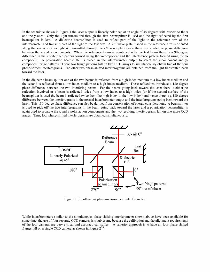
In the technique shown in Figure 1 the laser output is linearly polarized at an angle of 45 degrees with respect to the x and the y axes. Only the light transmitted through the first beamsplitter is used and the light reflected by the first beamsplitter is lost. A dielectric beamsplitter is used to reflect part of the light to the reference arm of the interferometer and transmit part of the light to the test arm. A λ/8 wave plate placed in the reference arm is oriented along the x-axis so after light is transmitted through the λ/8 wave plate twice there is a 90-degree phase difference between the x and y components. When the reference beam is combined with the test beam there is a 90-degree difference in the interference pattern formed using the x-component and the interference pattern formed using the y-component. A polarization beamsplitter is placed in the interferometer output to select the x-component and y-component fringe patterns. These two fringe patterns fall on two CCD arrays to simultaneously obtain two of the four phase-shifted interferograms. The other two phase-shifted interferograms are obtained from the light transmitted back toward the laser. In the dielectric beam splitter one of the two beams is reflected from a high index medium to a low index medium and the second is reflected from a low index medium to a high index medium. These reflections introduce a 180-degree phase difference between the two interfering beams. For the beams going back toward the laser there is either no reflection involved or a beam is reflected twice from a low index to a high index (or if the second surface of the beamsplitter is used the beam is reflected twice from the high index to the low index) and hence there is a 180-degree difference between the interferograms in the normal interferometer output and the interferograms going back toward the laser. This 180-degree phase difference can also be derived from conservation of energy considerations. A beamsplitter is used to pick off the two interferograms in the beam going back toward the laser and a polarization beamsplitter is again used to separate the x and y polarization components and the two resulting interferograms fall on two more CCD arrays. Thus, four phase-shifted interferograms are obtained simultaneously.
Figure 1. Simultaneous phase-measurement interferometer.
While interferometers similar to the simultaneous phase shifting interferometer shown above have been available for some time, the use of four separate CCD cameras is troublesome because the calibration and the alignment requirements of the four cameras are very critical and accuracy can suffer2. A superior approach is to have all four phase-shifted frames fall on a single CCD camera as shown in Figure 23,4.
Laser
Two fringe patterns 90o out of phase
0o
90o
180o
270o
Laser Linearly Polarized
@ 45o
@ 0o
Dielectric B.S.
Test Beam
Reference Beam
λ/8
Polarization beamsplitters
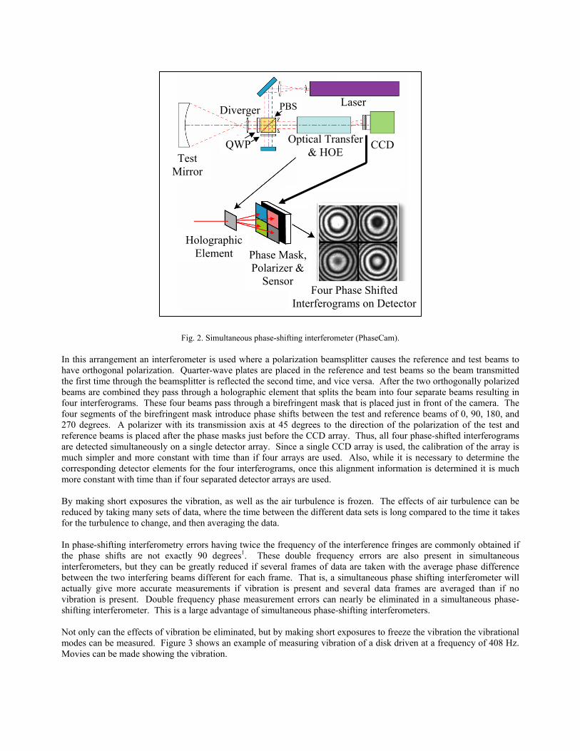
Fig. 2. Simultaneous phase-shifting interferometer (PhaseCam).
In this arrangement an interferometer is used where a polarization beamsplitter causes the reference and test beams to have orthogonal polarization. Quarter-wave plates are placed in the reference and test beams so the beam transmitted the first time through the beamsplitter is reflected the second time, and vice versa. After the two orthogonally polarized beams are combined they pass through a holographic element that splits the beam into four separate beams resulting in four interferograms. These four beams pass through a birefringent mask that is placed just in front of the camera. The four segments of the birefringent mask introduce phase shifts between the test and reference beams of 0, 90, 180, and 270 degrees. A polarizer with its transmission axis at 45 degrees to the direction of the polarization of the test and reference beams is placed after the phase masks just before the CCD array. Thus, all four phase-shifted interferograms are detected simultaneously on a single detector array. Since a single CCD array is used, the calibration of the array is much simpler and more constant with time than if four arrays are used. Also, while it is necessary to determine the corresponding detector elements for the four interferograms, once this alignment information is determined it is much more constant with time than if four separated detector arrays are used. By making short exposures the vibration, as well as the air turbulence is frozen. The effects of air turbulence can be reduced by taking many sets of data, where the time between the different data sets is long compared to the time it takes for the turbulence to change, and then averaging the data. In phase-shifting interferometry errors having twice the frequency of the interference fringes are commonly obtained if the phase shifts are not exactly 90 degrees1. These double frequency errors are also present in simultaneous interferometers, but they can be greatly reduced if several frames of data are taken with the average phase difference between the two interfering beams different for each frame. That is, a simultaneous phase shifting interferometer will actually give more accurate measurements if vibration is present and several data frames are averaged than if no vibration is present. Double frequency phase measurement errors can nearly be eliminated in a simultaneous phase-shifting interferometer. This is a large advantage of simultaneous phase-shifting interferometers. Not only can the effects of vibration be eliminated, but by making short exposures to freeze the vibration the vibrational modes can be measured. Figure 3 shows an example of measuring vibration of a disk driven at a frequency of 408 Hz. Movies can be made showing the vibration.
Four Phase Shifted Interferograms on Detector
Phase Mask, Polarizer &
Sensor
Holographic Element
Test Mirror
Optical Transfer & HOE
PBS Laser Diverger
QWP CCD
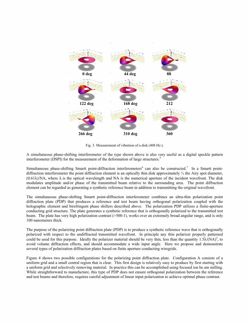
Fig. 3. Measurement of vibration of a disk (408 Hz.).
A simultaneous phase-shifting interferometer of the type shown above is also very useful as a digital speckle pattern interferometer (DSPI) for the measurement of the deformation of large structures.5 Simultaneous phase-shifting Smartt point-diffraction interferometers6 can also be constructed.7 In a Smartt point-diffraction interferometer the point diffraction element is an optically thin disk approximately ½ the Airy spot diameter, (0.61λ)/NA, where λ is the optical wavelength and NA is the numerical aperture of the incident wavefront. The disk modulates amplitude and/or phase of the transmitted beam relative to the surrounding area. The point diffraction element can be regarded as generating a synthetic reference beam in addition to transmitting the original wavefront. The simultaneous phase-shifting Smartt point-diffraction interferometer combines an ultra-thin polarization point diffraction plate (PDP) that produces a reference and test beam having orthogonal polarization coupled with the holographic element and birefringent phase shifters described above. The polarization PDP utilizes a finite-aperture conducting grid structure. The plate generates a synthetic reference that is orthogonally polarized to the transmitted test beam. The plate has very high polarization contrast (>500:1), works over an extremely broad angular range, and is only 100 nanometers thick. The purpose of the polarizing point diffraction plate (PDP) is to produce a synthetic reference wave that is orthogonally polarized with respect to the undiffracted transmitted wavefront. In principle any thin polarizer properly patterned could be used for this purpose. Ideally the polarizer material should be very thin, less than the quantity 1.5λ/(NA)2, to avoid volume diffraction effects, and should accommodate a wide input angle. Here we propose and demonstrate several types of polarization diffraction plates based on finite aperture conducting wiregrids. Figure 4 shows two possible configurations for the polarizing point diffraction plate. Configuration A consists of a uniform grid and a small central region that is clear. This first design is relatively easy to produce by first starting with a uniform grid and selectively removing material. In practice this can be accomplished using focused ion be am milling. While straightforward to manufacture, this type of PDP does not ensure orthogonal polarization between the reference and test beams and therefore, requires careful adjustment of linear input polarization to achieve optimal phase contrast.
0 deg 44 deg 88
122 deg 168 deg 212
266 deg 310 deg 360
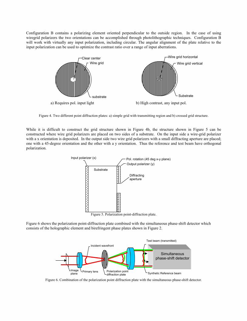
Configuration B contains a polarizing element oriented perpendicular to the outside region. In the case of using wiregrid polarizers the two orientations can be accomplished through photolithographic techniques. Configuration B will work with virtually any input polarization, including circular. The angular alignment of the plate relative to the input polarization can be used to optimize the contrast ratio over a range of input aberrations.
Figure 4. Two different point diffraction plates: a) simple grid with transmitting region and b) crossed grid structure.
While it is difficult to construct the grid structure shown in Figure 4b, the structure shown in Figure 5 can be constructed where wire grid polarizers are placed on two sides of a substrate. On the input side a wire-grid polarizer with a x orientation is deposited. In the output side two wire grid polarizers with a small diffracting aperture are placed; one with a 45-degree orientation and the other with a y orientation. Thus the reference and test beam have orthogonal polarization.
Figure 5. Polarization point-diffraction plate.
Figure 6 shows the polarization point-diffraction plate combined with the simultaneous phase-shift detector which consists of the holographic element and birefringent phase plates shown in Figure 2.
Figure 6. Combination of the polarization point diffraction plate with the simultaneous phase-shift detector.
Incident wavefront
Polarization point diffraction plate Synthetic Reference beam
Test beam (transmitted)
Simultaneous phase-shift detector
Primary lens Image plane
substrate
Wire grid Clear center
a) Requires pol. input light
Substrate
Wire grid vertical
Wire grid horizontal
b) High contrast, any input pol.
Output polarizer (y)
Diffracting aperture
Pol. rotation (45 deg x-y plane)
Substrate
Input polarizer (x)

3. SPATIAL CARRIER INTERFEROMETRY In spatial carrier interferometry a single interferogram is taken that has a lot of tilt fringes8. The exposure time for the interferogram is short enough that the vibration is frozen. Two approaches for analyzing the spatial carrier interferogram will be discussed. To understand the first approach it is convenient to think of the interferogram as a hologram. If in the making of a hologram enough tilt is introduced between the object and reference beam then in the reconstruction process the reconstructed object beam will separate from the other reconstruction orders. Equivalently, if the interferogram intensity distribution is Fourier transformed and filtered to select out the first order and this first order is Fourier transformed again, the wavefront is obtained. Just like for a hologram, a sufficient number of tilt fringes must be present so the first Fourier transform can be adequately filtered. This technique works reasonably well, but the filtering process smoothes the wavefront and the accuracy of the wavefront near the edge of the pupil is limited. A second analysis approach that works with a single interferogram having many tilt fringes present assumes that across a relatively small window the wavefront may be considered flat9. Then across the small window the phase varies linearly and the phase difference between adjacent pixels is constant and the normal phase-shifting algorithms can be used. For example, let’s assume the tilt between the two interfering beams is selected so there are four detector elements between fringes. In this case the phase of the tilted reference wave changes 90 degrees between adjacent detector elements (360 degrees between fringes). Phase-shifting algorithms can then be used to calculate the phase using the intensities measured by four adjacent detectors. This technique would work well if the test wavefront has no aberrations because then the fringes would be equally spaced. If aberrations are present the fringe spacing changes and the detector spacing is no longer exactly one-quarter the fringe spacing. However, as the aberrations become larger the accuracy to which the phase distribution must be measured is decreased, so this measurement technique still often works sufficiently well. Many different algorithms have been derived to reduce the requirements on the flatness of the wavefront across the sampling window10. A critical item is the method for obtaining the carrier fringes. While the carrier fringes can be obtained by tilting the reference mirror this is generally not acceptable because retrace errors introduced by having a large angle between the two interfering beams in the interferometer cause additional aberrations. A better approach that does not require the test and reference beam to have a large angle between them in the interferometer is to have the reference and test beams have orthogonal polarization and then a phase filter is placed directly in front of the detector to introduce a tilt angle between the two beams. A common phase filter is a Wollaston prism followed by a polarizer which will introduce the required tilt between the two interfering beams to obtain the carrier fringes as shown in Figure 7.
Figure 7. Use of Wollaston prism to produce carrier fringes.
A phase filter that works better because the phase shift between the two interfering beams is nearly independent of wavelength is a quarter waveplate followed by linear polarizers at different angles. The quarter waveplate is oriented to convert the test beam into left-handed circular polarization and the reference beam into right-handed circular
Polarizer
Detector PPoollaarriizzaattiioonn IInntteerrffeerroommeetteerr
Reference and test beams have orthogonal polarization
Wollaston Prism

polarization. It can be shown11 that if these circularly polarized beams are transmitted through a linear polarizer a phase shift between the two interfering beams proportional to twice the rotation angle of the polarizer results. Let the test beam be left circularly polarized with a phase of δt, and the reference beam be right circularly polarized with a phase of δr. Further, let both beams be incident upon a linear polarizer oriented at an angle α with respect to the x-axis. Upon passing through the polarizer, both the test and reference beams are now linearly polarized at an angle α and a phase offset of +α has been added to the test beam, whereas a phase offset of –α has been added to the reference beam. The two beams are now collinear and will interfere to give an intensity pattern in accordance with
]2),([2),(),(),( αφ +∆++= yxCosIIyxIyxIyxI rtrt
Where It and Ir are the intensities of the test and reference beams, ∆φ = δt-δr is the phase being measured, and 2α is the phase shift. The linear polarizer acts as a phase shifting device between the two beams, were the phase shift is equal to twice the orientation angle of the polarizer as illustrated in Figure 8.
Figure 8. Use of polarizer to introduce phase shift between test and reference beams.
Thus, if a phase mask is made of an array of 4 linear polarizer elements having their transmission axes at 0, 45, 90, and 135 degrees as shown in Figure 9a, where a polarizer element is placed over each detector element, the mask will produce an array of four 0, 90, 180, and 270 degrees phase shifted interferograms. Likewise, a phase mask can be made using an array of 4 linear polarizer elements having their transmission axes at 0, 45, 135 and 90 degrees as shown in Figure 9b. While an achromatic quarter waveplate could be used to extend the spectral range the phase mask would work for, it turns out that the phase shift produced by the rotated polarizers does not depend greatly upon the quarter-wave plate being a true quarter-waveplate12. A phase shifter of this type is often called a geometrical phase shifter since the phase shift is independent of wavelength. Having a phase shift independent of wavelength is important in multiple wavelength or white light interferometers
Figure 9. Phase filter. (a) 4 polarizer elements giving 0, 90, 180, and 270 degree phase shifts.
(b) 4 polarizer elements giving 0, 90, 270, and 180 degree phase shifts. (c) Phase filter made up of array of 4 polarizer elements.
A B C D
0o
270o 180o
90o
(a)
A B C D
A B C D
A B C D
(c)
A B C D
0o
180o
90o
270o
(b)
or
test ref
RHLHC
Circ. Pol. Beams (∆φ) + linear polarizer (α) cos (∆φ + 2α)
Phase-shift depends on polarizer angle

The phase distribution can be calculated using a 2 x 2 element array, or in some cases the errors can be further reduced by using a 3 x 3 element array. A typical CCD pixel element is on the order of 10 microns square. Figure 10 is an image of a pixelated mask taken with an electron microscope showing the four different polarizer orientations making up a super-pixel. The line spacing of the wire grid polarizers is approximately 250 microns, and the size of each polarizing element is approximately 10 microns square. The planar nature of the conducting strip structure permits using it as a polarizer over an extremely wide incident angle, including zero degrees, and over a broad range of wavelengths, provided the period remains much less than the wavelength13.
Figure 10. Electron micrograph of wire grid polarizers.
Figure 11 shows a schematic of a Twyman-Green interferometer using the micropolarizer phase-shifting array. The essential characteristics of the two-beam interferometer is that the test and reference beams have orthogonal polarization and the micropolarizer array matches the CCD array. Fizeau interferometers can also be used if the reference and test beams have orthogonal polarization. There are several ways of obtaining orthogonal polarization for the test and reference beams in a Fizeau interferometer. For example, a quarter-wave plate can be placed between the test and reference surfaces or sufficient tilt can be introduced between the reference and test surfaces so separate orthogonally polarized light beams of light can be used for the reference and test beams.

Figure 11. Interferometer Configuration
Figure 12 shows typical grey scale contour and 3D map obtained using the micropolarizer phase shifting interferometer. For this example the test mirror and interferometer were placed on separate tables and no vibration isolation was present.
Figure 12. Measurement of 300 mm diameter, 2 meter ROC mirror. Mirror and interferometer on separate tables.
4. CONCLUSIONS
A single shot interferometer, whether it is a simultaneous phase shifting interferometer or a spatial carrier interferometer, can go a long way in reducing the effects of what is often the largest source of error in phase shifting interferometry, namely vibration. Errors due to air turbulence can be reduced by averaging many frames of data obtained using a single shot interferometer. Averaging data frames in the presence of vibration will average out the double frequency errors common in phase-shifting interferometry and generally more accurate results can be obtained in the presence of vibration than can normally be obtained using conventional temporal phase-shifting interferometry in the absence of vibration. Also, it is possible to measure a vibrating surface to determine precisely how the surface is vibrating. Once a person works with a simultaneous phase-shifting interferometer it is hard to go back to working with a temporal phase-shifting interferometer.
Test Mirror
QWP
PBS
Camera
Source
Pixelated Mask Sensor Array
Parsing
A D C
B A
D C B A
D C B A
D C B
A D C
B A D C
B A D C
B A
D C B A
D C B
Phase-Shifted Interferograms
Reference Mirror
QWP

REFERENCES
1. Creath, K., "Phase measurement interferometry techniques," Progress in Optics. 26 349-393 (1988). 2. Chris L. Koliopoulos, “Simultaneous phase-shift interferometer,” in Advanced Optical Manufacturing and Testing
II, Victor J. Doherty, ed., Proc. SPIE 1531, 119-127 (1992). 3. James E. Millerd and Neal J. Brock, “Methods and apparatus for splitting, imaging, and measuring wavefronts in
interferometry,” U. S. Patent 6,304,330 (2001). 4. James C. Wyant, Optics & Photonics News, 14, 4, 36-41 (2003). 5. Babak N. Saif, James Millerd, Ritva Keski-Kuha, Lee Feinberg, and James C. Wyant, “Instantaneous phase-shifted
speckle interferometer for measurement of large structures,” Proc. SPIE, 5494, 152-162, (2004). 6. R.N. Smart and W.H. Steel, "Theory and Application of Point Diffraction Interferometers," Jpn. J. Appl. Phys., 14,
351-356, (1975). 7. James E. Millerd, Neal J. Brock, John B. Hayes and James C. Wyant, “Instantaneous phase-shift, point-diffraction
interferometer,” Proc. SPIE, 5531, 264-272, (2004). 8. M. Takeda, “Temporal versus spatial carrier techniques for heterodyne interferometry,” in Proceedings, 14th
congress of the international commission of optics: August 24-28, 1987, Henri Arsenault, ed., Proc. SPIE 813, 329-330 (1987).
9. D. M. Shough, O. Y. Kwon, and D. F. Leary, “High speed interferometric measurement of aerodynamic phenomena,” in Propagation of high-energy laser beams through the earth’s atmosphere, Peter B. Ulrich and Leroy E. Wilson, ed., Proc. SPIE, 1221, 394-403 (1990).
10. M. Küchel, “Methods and apparatus for phase evaluation of pattern images used in optical measurement,” U.S. Patent 5,361,312 (1994).
11. James Millerd, Neal Brock, John Hayes, Brad Kimbrough, Matt Novak, Michael North-Morris and James C. Wyant, “Modern approaches in phase measuring metrology,” Proc. SPIE, 5856, (2005).
12. S. Suja Helen, M.P. Kothiyal, and R.S. Sirohi, "Achromatic phase-shifting by a rotating polarizer", Opt. Comm. 154, 249 (1998).
13. Millerd, J.E., Brock, N.J., Hayes, J.B., North-Morris, M.B., Novak, M., and Wyant, J.C., "Pixelated phase-mask dynamic interferometer," Proc. SPIE, 5531, 304-314, (2004).
Copyright © 2022 FDOKUMEN