
Extrasolar Planetary Imaging Coronagraph (EPIC)
7
Extrasolar Planetary Imaging Coronagraph (EPIC):Visible Nulling Coronagraph Testbed Results Richard G. Lyon a , Mark Clampin a , Gary Melnick b , Volker Tolls b , Robert Woodruff c , Gopal Vasudevan d a NASA/Goddard Space Flight Center, Greenbelt, MD b Smithsonian Astrophysical Observatory, Cambridge MA c Lockheed-Martin, Denver CO, d Lockheed-Martin, Palo-Alto CA ABSTRACT The Extrasolar Planetary Imaging Coronagraph (EPIC) is a NASA Astrophysics Strategic Mission Concept under study for the upcoming Exoplanet Probe. EPIC’s mission would be to image and characterize extrasolar giant planets, and potential super-Earths, in orbits with semi-major axes between 2 and 10 AU. EPIC will provide insights into the physical nature of a variety of planets in other solar systems complimenting radial velocity (RV) and astrometric planet searches. It will detect and characterize the atmospheres of planets identified by radial velocity surveys and potentially some transits, determine orbital inclinations and masses, characterize the atmospheres of gas giants around A and F stars, observed the inner spatial structure and colors of inner Spitzer selected debris disks. EPIC would be launched into a heliocentric Earth trailing drift-away orbit, with a 3-year mission lifetime (5 year goal) and will revisit planets at least three times. The starlight suppression approach consists of a visible nulling coronagraph (VNC) that enables high order starlight suppression in broadband light. To demonstrate the VNC approach and advance it’s technology readiness the NASA/Goddard Space Flight Center and Lockheed-Martin have developed a laboratory VNC and have demonstrated white light nulling. We will discuss our ongoing VNC work and show the latest results from the VNC testbed. Keywords: Planet detection, nulling, coronagraphy, interferometry 1.0 INTRODUCTION Visible Nulling Coronagraphy 1,2,3 (VNC) is the proposed method of detecting and characterizing exo-solar Jovian planets (null depth ~10 -9 ) for the proposed NASA’s Extrasolar Planetary Imaging Coronagraph (EPIC) 1,2 and is an approach under evaluation for NASA’s Terrestrial Planet Finder (TPF) mission. The VNC approach uses a single unobscured filled-aperture telescope and splits, via a 50:50 beamsplitter, its re- imaged pupil into two paths within a Mach-Zender interferometer. An achromatic -phase shift is imposed onto one beam path and the two paths are laterally sheared with respect to each other. The two beams are recombined at a second 50:50 beamsplitter. The net effect is that the on axis (stellar) light is transmitted out of the bright interferometer arm while the off-axis (planetary) light is transmitted out of the nulled interferometer arm. The bright output is used for fine pointing control and coarse wavefront control. The nulled output is relayed to the science camera for science imagery and fine wavefront control. The actual transmission pattern, projected on the sky, follows a 2 pattern for a single shear, 4 for a double shear, with the spacing of the successive maxima proportional to the inverse of the relative lateral shear. Combinations of shears and spacecraft rolls build up the spatial frequency content of the sky transmission pattern in the same manner as imaging interferometer builds up the spatial frequency content of the image. The VNC approach has some significant advantages over more conventional mask coronagraphic approaches in that (i) its inner working angle is ~2 /D (assuming a 25% shear) allowing a smaller aperture than conventional coronagraphic methods that typically work at ~4 /D, (ii) it has significantly less sensitivity to low order amplitude and wavefront aberrations – the shear is approximately equivalent to a lateral wavefront derivative which gives an f 2 multiplier on the wavefront PSD, thereby allowing for Space Telescopes and Instrumentation 2008: Optical, Infrared, and Millimeter, edited by Jacobus M. Oschmann, Jr., Mattheus W. M. de Graauw, Howard A. MacEwen, Proc. of SPIE Vol. 7010, 701045, (2008) · 0277-786X/08/$18 · doi: 10.1117/12.789700 Proc. of SPIE Vol. 7010 701045-1 2008 SPIE Digital Library -- Subscriber Archive Copy
Transcript of Extrasolar Planetary Imaging Coronagraph (EPIC)
Extrasolar Planetary Imaging Coronagraph (EPIC):Visible
Nulling Coronagraph Testbed Results
Richard G. Lyona, Mark Clampin
a, Gary Melnick
b, Volker Tolls
b,
Robert Woodruffc, Gopal Vasudevan
d
aNASA/Goddard Space Flight Center, Greenbelt, MD
bSmithsonian Astrophysical Observatory, Cambridge MA
cLockheed-Martin, Denver CO,
dLockheed-Martin, Palo-Alto CA
ABSTRACT
The Extrasolar Planetary Imaging Coronagraph (EPIC) is a NASA Astrophysics Strategic Mission Concept
under study for the upcoming Exoplanet Probe. EPIC’s mission would be to image and characterize
extrasolar giant planets, and potential super-Earths, in orbits with semi-major axes between 2 and 10 AU.
EPIC will provide insights into the physical nature of a variety of planets in other solar systems
complimenting radial velocity (RV) and astrometric planet searches. It will detect and characterize the
atmospheres of planets identified by radial velocity surveys and potentially some transits, determine orbital
inclinations and masses, characterize the atmospheres of gas giants around A and F stars, observed the
inner spatial structure and colors of inner Spitzer selected debris disks. EPIC would be launched into a
heliocentric Earth trailing drift-away orbit, with a 3-year mission lifetime (5 year goal) and will revisit
planets at least three times.
The starlight suppression approach consists of a visible nulling coronagraph (VNC) that enables high order
starlight suppression in broadband light. To demonstrate the VNC approach and advance it’s technology
readiness the NASA/Goddard Space Flight Center and Lockheed-Martin have developed a laboratory VNC
and have demonstrated white light nulling. We will discuss our ongoing VNC work and show the latest
results from the VNC testbed.
Keywords: Planet detection, nulling, coronagraphy, interferometry
1.0 INTRODUCTION
Visible Nulling Coronagraphy1,2,3
(VNC) is the proposed method of detecting and characterizing exo-solar
Jovian planets (null depth ~10-9
) for the proposed NASA’s Extrasolar Planetary Imaging Coronagraph
(EPIC)1,2
and is an approach under evaluation for NASA’s Terrestrial Planet Finder (TPF) mission. The
VNC approach uses a single unobscured filled-aperture telescope and splits, via a 50:50 beamsplitter, its re-
imaged pupil into two paths within a Mach-Zender interferometer. An achromatic -phase shift is imposed
onto one beam path and the two paths are laterally sheared with respect to each other. The two beams are
recombined at a second 50:50 beamsplitter. The net effect is that the on axis (stellar) light is transmitted
out of the bright interferometer arm while the off-axis (planetary) light is transmitted out of the nulled
interferometer arm. The bright output is used for fine pointing control and coarse wavefront control. The
nulled output is relayed to the science camera for science imagery and fine wavefront control. The actual
transmission pattern, projected on the sky, follows a 2 pattern for a single shear, 4 for a double shear, with
the spacing of the successive maxima proportional to the inverse of the relative lateral shear. Combinations
of shears and spacecraft rolls build up the spatial frequency content of the sky transmission pattern in the
same manner as imaging interferometer builds up the spatial frequency content of the image.
The VNC approach has some significant advantages over more conventional mask coronagraphic
approaches in that (i) its inner working angle is ~2 /D (assuming a 25% shear) allowing a smaller aperture
than conventional coronagraphic methods that typically work at ~4 /D, (ii) it has significantly less
sensitivity to low order amplitude and wavefront aberrations – the shear is approximately equivalent to a
lateral wavefront derivative which gives an f2 multiplier on the wavefront PSD, thereby allowing for
Space Telescopes and Instrumentation 2008: Optical, Infrared, and Millimeter, edited by Jacobus M. Oschmann, Jr., Mattheus W. M. de Graauw, Howard A. MacEwen,
Proc. of SPIE Vol. 7010, 701045, (2008) · 0277-786X/08/$18 · doi: 10.1117/12.789700
Proc. of SPIE Vol. 7010 701045-12008 SPIE Digital Library -- Subscriber Archive Copy
— IInterferometer
:Tt
Coronagraph
ShearBCD
OKYTransmission
bKyTransmission
BrightOutput
OTABS
PlatesPiston
BrightOutput
NuII1BS
Null 2
Shear introducesadditonal phase shift
Ad angle on sl
Piston
Output
significantly lower quality optics in the
telescope, (iii) coupling of the VNC
nulled beams to a fiber bundle with a
lenslet array on the front and back sides
and a faceted micro-mirror array
(MMA) within the nuller, with each
MMA facet matched to each fiber, gives
direct simultaneous correction of both
amplitude and phase with a single
MMA per nuller, and, each fiber is a
natural spatial filter on higher order
wavefront errors. This also has a
significant advantage in that focal plane
mask errors in a conventional
coronagraph are dispersive in the
following pupil plane, making it
difficult for any pupil plane deformable
mirror to correct mask errors.
2.0 PRINCIPLE OF VISIBLE NULLING CORONAGRAPH
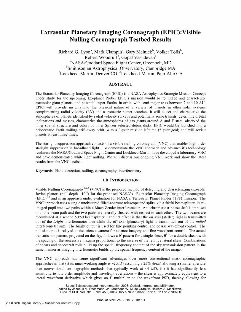
Figure 1 shows simplified schematics of a Bracewell Nulling Interferometer (BNI) and a Visible Nulling
Coronagraph (VNC). In a canonical BNI configuration 2 telescopes, separated by a baseline of B, are
coherently interfered with a phase shift giving a sky transmission, projected on the sky of
T 2{ }= sin2
B
~ 2
where is the sky angle in the direction of the baseline and is the
wavelength. In a VNC the same pattern also
arises except that B is now the relative pupil
shear.
A VNC effectively emulates a BNI with only a
single aperture. The condition for central
nulling is given by ei j
j=1
N
= 0 where j
represents the relative phase shift due to the j-th
aperture in the BNI and represents the j-th shear
in VNC for a given set of N apertures or shears.
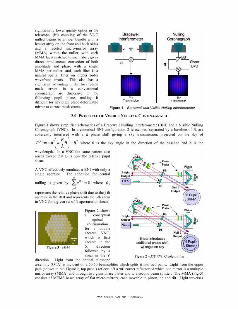
Figure 2 shows
a conceptual
optical
configuration
for a double
sheared VNC,
which is first
sheared in the
X direction
followed by a
shear in the Y
direction. Light from the optical telescope
assembly (OTA) is incident on a 50:50 beamsplitter which splits it into two paths. Light from the upper
path (shown in red Figure 2, top panel) reflects off a 900 corner reflector of which one mirror is a multiple
mirror array (MMA) and through two glass phase plates and to a second beam splitter. The MMA (Fig-3)
consists of MEMS based array of flat micro-mirrors, each movable in piston, tip and tilt. Light traverses
Figure 1 – Bracewell and Visible Nulling Interferometer
Figure 2 – X/Y VNC Configuration
Figure 3 - MMA
Proc. of SPIE Vol. 7010 701045-2
Lenslet Fiber Bundle Lenslet Array'jam 384 tmIIensIot Core 9 Lm
Cladding 125 Lmm384mnsbot
Losses @ Losses @ Losses Losses @ Losses @lenslets fiber jn 'Mthjn fibers fiber out lenslets
!ltav ImaseSidelobe
S pail a 1
Filter Array /Planet
Wavefront.4 FOV
N ?./D
the lower path (blue in Figure 2, top panel) after the first beamsplitter and reflects off a 900 corner reflector
mounted on a 2-degree-of-freedom translation stage. This stage can be moved in piston, to adjust the path
length, and to shear the lower paths beam with respect to the upper paths beam. The two beams are
recombined at the second beamsplitter.
Setting the piston to yield a -phase shift allows the on-axis light to exit through the bright output and the
off-axis light to exit through to the nulled output. At the nulled output the two beams arrive laterally
sheared which introduces an additional phase shift resulting in nulling of the on-axis light (star) and
transmission of the off-axis light (planet). The output of the “X” nuller is fed into a second nuller which
shears the beams orthogonal to the first nuller’s shear direction, i.e. the “Y” direction and results in 4
sheared beams as shown in the bottom panel of Figure 2.
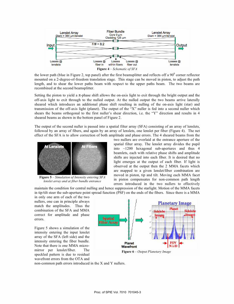
The output of the second nuller is passed into a spatial filter array (SFA) consisting of an array of lenslets,
followed by an array of fibers, and again by an array of lenslets, one lenslet per fiber (Figure 4). The net
effect of the SFA is to allow correction of both amplitude and phase errors. The 4 sheared beams from the
two nullers are overlaid at the entrance aperture of the
spatial filter array. The lenslet array divides the pupil
into ~1200 hexagonal sub-apertures and thus 4
beamlets, each with relative phase shifts and amplitude
shifts are injected into each fiber. It is desired that no
light emerges at the output of each fiber. If light is
observed at the output then the 2 MMA facets which
are mapped to a given lenslet/fiber combination are
moved in piston, tip and tilt. Moving each MMA facet
in piston compensates for non-common path length
errors introduced in the two nullers to effectively
maintain the condition for central nulling and hence suppression of the starlight. Motion of the MMA facets
in tip/tilt steer the sub-aperture point spread function (PSF) on the ends of the fibers. Since there is a MMA
in only one arm of each of the two
nullers, one can in principle always
match the amplitudes. Thus the
combination of the SFA and MMA
correct for amplitude and phase
errors.
Figure 5 shows a simulation of the
intensity entering the input lenslet
array of the SFA (left side) and the
intensity entering the fiber bundle.
Note that there is one MMA micro-
mirror per lenslet/fiber. The
speckled pattern is due to residual
wavefront errors from the OTA and
non-common path errors introduced in the X and Y nullers.
Figure 4 – Schematic of SFA
Figure 5 – Simulation of Intensity entering SFA
lenslet array and at fiber bundle entrance
Figure 6 – Output Planetary Image
Proc. of SPIE Vol. 7010 701045-3
le+00 ___________1 e—Q I
le—02
leQ3
le-QS -11.5 meter telescope-14 Shear Combinaonsle-Q7 - —
—H3 rolls 0°, 15° ao°- 90 nm. 600 nflle—Q9
le—l 0
'TTT Snear IShear 2Shear 3Shear 4Average
.
I
-1.00 -0.75 -0.50 -0.25 0.00 0.25 0.50 0.75 1.00
Arceecorde
Saturn
Jupiter
2.8 arosec
Light injected into a fiber will ultimately evolve into an eigenmode of the fiber. At the fiber output,
independent of the functional form of the input field, the output can be characterized by only amplitude and
phase. The planetary light, entering the OTA slightly off-axis, but within the numerical aperture of the
fiber, will emerge with a stairstep phase as shown on the rightside of Figure 6. The net effect is that the
fiber bundle coupled to the lenslets will cause grating like sidelobes in the planet image, rightside of Figure
6. The sidelobes are periodic and will occur at angular sky spacings of ~N * /D, where N is the number
of fibers across a diameter of the bundle, is the wavelength of light and D is the OTA entrance aperture
diameter. These sidelobes effectively limit the field of view of the VNC and result in ~2% loss in the
planetary flux.
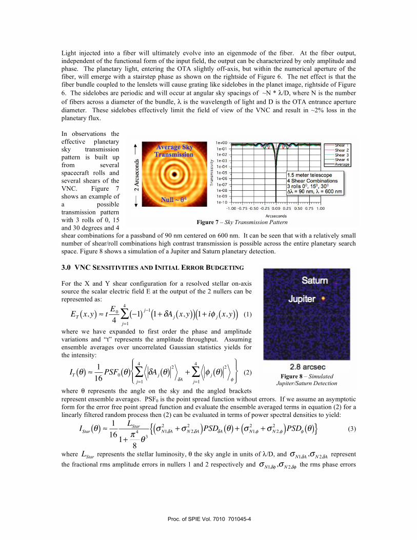
In observations the
effective planetary
sky transmission
pattern is built up
from several
spacecraft rolls and
several shears of the
VNC. Figure 7
shows an example of
a possible
transmission pattern
with 3 rolls of 0, 15
and 30 degrees and 4
shear combinations for a passband of 90 nm centered on 600 nm. It can be seen that with a relatively small
number of shear/roll combinations high contrast transmission is possible across the entire planetary search
space. Figure 8 shows a simulation of a Jupiter and Saturn planetary detection.
3.0 VNC SENSITIVITIES AND INITIAL ERROR BUDGETING
For the X and Y shear configuration for a resolved stellar on-axis
source the scalar electric field E at the output of the 2 nullers can be
represented as:
ET x,y( ) tE0
41( )
j 11+ Aj x,y( )( ) 1+ i j x,y( )( )
j=1
4
(1)
where we have expanded to first order the phase and amplitude
variations and “t” represents the amplitude throughput. Assuming
ensemble averages over uncorrelated Gaussian statistics yields for
the intensity:
IT ( )1
16PSF0( ) Aj ( )
2
A+ j ( )
2
j=1
4
j=1
4
(2)
where represents the angle on the sky and the angled brackets
represent ensemble averages. PSF0 is the point spread function without errors. If we assume an asymptotic
form for the error free point spread function and evaluate the ensemble averaged terms in equation (2) for a
linearly filtered random process then (2) can be evaluated in terms of power spectral densities to yield:
IStar ( )1
16
LStar
1+4
83
N1, A2
+ N 2, A2( )PSD A ( ) + N1,
2+ N 2,
2( )PSD ( ){ } (3)
where LStar represents the stellar luminosity, the sky angle in units of /D, and N1, A , N 2, A represent
the fractional rms amplitude errors in nullers 1 and 2 respectively and N1, , N 2, the rms phase errors
Figure 7 – Sky Transmission Pattern
Figure 8 – Simulated
Jupiter/Saturn Detection
Proc. of SPIE Vol. 7010 701045-4
Top Level VNC Error BudgetIe+OO
1 e-O
I e-O 2
I e-O S
1 e-04
I e-O S
I e-O 6
DDesired 'WA (milli-arcseconds)
Soc
(in radians) in nullers 1 and 2 respectively. In the above formalism the asymptotic PSF, 1+
4
83
1
, is
normalized to unity at the origin as are the amplitude and phase error power spectral densities. Note that in
equation (3) the error PSDs are multipliers on the stellar leakage, implying that for no errors no starlight
gets through at any point in the focal plane.
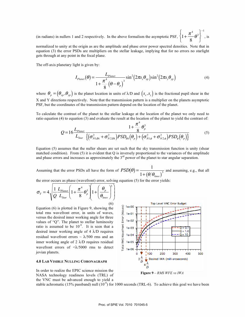
The off-axis planetary light is given by:
IPlanet ( ) =LPlanet
1+4
8 p( )3sin2 2 sx xp( )sin2 2 sy yp( ) (4)
where p = xp, yp( ) is the planet location in units of /D and sx,sy( ) is the fractional pupil shear in the
X and Y directions respectively. Note that the transmission pattern is a multiplier on the planets asymptotic
PSF, but the coordinates of the transmission pattern depend on the location of the planet.
To calculate the contrast of the planet to the stellar leakage at the location of the planet we only need to
ratio equation (4) to equation (3) and evaluate the result at the location of the planet to yield the contrast of:
Q =16LPlanetLStar
1+4
8 p3
N1, A2
+ N 2, A2( )PSD A p( ) + N1,
2+ N 2,
2( )PSD p( ){ } (5)
Equation (5) assumes that the nuller shears are set such that the sky transmission function is unity (shear
matched condition). From (5) it is evident that Q is inversely proportional to the variances of the amplitude
and phase errors and increases as approximately the 3rd
power of the planet to star angular separation.
Assuming that the error PSDs all have the form of PSD( ) =1
1+ knee( )3 and assuming, e.g., that all
the error occurs as phase (wavefront) error, solving equation (5) for the error yields:
T = 41
Q
LPlanetLStar
1+
4
8 p3
1+
p
knee
3
(6)
Equation (6) is plotted in Figure 9, showing the
total rms wavefront error, in units of waves,
versus the desired inner working angle for three
values of “Q”. The planet to stellar luminosity
ratio is assumed to be 10-9
. It is seen that a
desired inner working angle of 4 /D requires
residual wavefront errors ~ /500 rms and an
inner working angle of 2 /D requires residual
wavefront errors of < /5000 rms to detect
jovian planets.
4.0 LAB VISIBLE NULLING CORONAGRAPH
In order to realize the EPIC science mission the
NASA technology readiness levels (TRL) of
the VNC must be advanced enough to yield a
stable achromatic (15% passband) null (10-9
) for 1000 seconds (TRL-6). To achieve this goal we have been
Figure 9 – RMS WFE vs IWA
Proc. of SPIE Vol. 7010 701045-5
Achromatic _______hø PItø
VNC Lab White Light Images - — — Corrected Br;htandNuIIOutpts_-
4000
0
-4000
- B02] 45 678 9 101112131415
Time Index
C
-1Bright Channel Null Channel
S
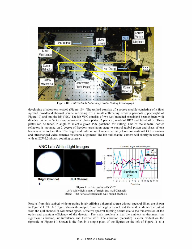
developing a laboratory testbed (Figure 10). The testbed consists of a source module consisting of a fiber
injected broadband thermal source reflecting off a small collimating off-axis parabola (upper-right of
Figure 10) and into the lab VNC. The lab VNC consists of two well-matched broadband beamsplitters with
dihedral corner reflectors and achromatic phase plates, 2 per arm, made of BK7 and fused silica. These
plates can be tuned in angle to select a given 15% passband for nulling. One of the dihedral corner
reflectors is mounted on 2-degree-of-freedom translation stage to control global piston and shear of one
beam relative to the other. The bright and null output channels currently have conventional CCD cameras
and interchanged video cameras for coarse alignment. The lab null channel camera will shortly be replaced
with an E2V-L3 photon counting camera.
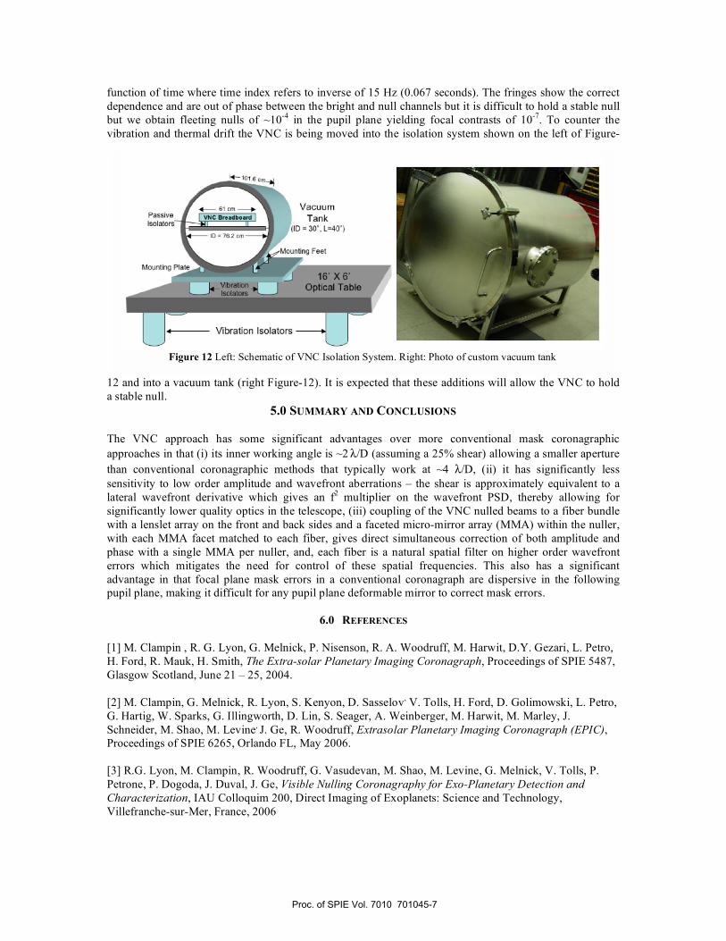
Results from this testbed while operating in air utilizing a thermal source without spectral filters are shown
in Figure-11. The left figure shows the output from the bright channel and the middle shows the output
from the null channel in collimated space. Effective spectral filtering occurs due to the transmission of the
optics and quantum efficiency of the detector. The main problem is that the ambient environment has
significant vibration, air turbulence and thermal drift. The vibration (acoustic) is clear evident on the
rightside of Figure-11. Shown is the flux in a single pixel of the figures on the left of Figure-11 as a
Figure 10 – GSFC/LMCO Laboratory Visible Nulling Coronagraph
Figure 11 – Lab results with VNC
Left: White light output of Bright and Null Channels
Right: Time Series of Bright and Null output channels
Proc. of SPIE Vol. 7010 701045-6
r4- 61 cr•
Passive V14C Sa.dbo.rdIsolalors
ID 76.2 cm
Mounting PL
VacuumTank
(ID = 30. L40')
inting Feet
Vibration Isolators
function of time where time index refers to inverse of 15 Hz (0.067 seconds). The fringes show the correct
dependence and are out of phase between the bright and null channels but it is difficult to hold a stable null
but we obtain fleeting nulls of ~10-4
in the pupil plane yielding focal contrasts of 10-7
. To counter the
vibration and thermal drift the VNC is being moved into the isolation system shown on the left of Figure-
12 and into a vacuum tank (right Figure-12). It is expected that these additions will allow the VNC to hold
a stable null.
5.0 SUMMARY AND CONCLUSIONS
The VNC approach has some significant advantages over more conventional mask coronagraphic
approaches in that (i) its inner working angle is ~2 /D (assuming a 25% shear) allowing a smaller aperture
than conventional coronagraphic methods that typically work at ~4 /D, (ii) it has significantly less
sensitivity to low order amplitude and wavefront aberrations – the shear is approximately equivalent to a
lateral wavefront derivative which gives an f2 multiplier on the wavefront PSD, thereby allowing for
significantly lower quality optics in the telescope, (iii) coupling of the VNC nulled beams to a fiber bundle
with a lenslet array on the front and back sides and a faceted micro-mirror array (MMA) within the nuller,
with each MMA facet matched to each fiber, gives direct simultaneous correction of both amplitude and
phase with a single MMA per nuller, and, each fiber is a natural spatial filter on higher order wavefront
errors which mitigates the need for control of these spatial frequencies. This also has a significant
advantage in that focal plane mask errors in a conventional coronagraph are dispersive in the following
pupil plane, making it difficult for any pupil plane deformable mirror to correct mask errors.
6.0 REFERENCES
[1] M. Clampin , R. G. Lyon, G. Melnick, P. Nisenson, R. A. Woodruff, M. Harwit, D.Y. Gezari, L. Petro,
H. Ford, R. Mauk, H. Smith, The Extra-solar Planetary Imaging Coronagraph, Proceedings of SPIE 5487,
Glasgow Scotland, June 21 – 25, 2004.
[2] M. Clampin, G. Melnick, R. Lyon, S. Kenyon, D. Sasselov, V. Tolls, H. Ford, D. Golimowski, L. Petro,
G. Hartig, W. Sparks, G. Illingworth, D. Lin, S. Seager, A. Weinberger, M. Harwit, M. Marley, J.
Schneider, M. Shao, M. Levine, J. Ge, R. Woodruff, Extrasolar Planetary Imaging Coronagraph (EPIC),
Proceedings of SPIE 6265, Orlando FL, May 2006.
[3] R.G. Lyon, M. Clampin, R. Woodruff, G. Vasudevan, M. Shao, M. Levine, G. Melnick, V. Tolls, P.
Petrone, P. Dogoda, J. Duval, J. Ge, Visible Nulling Coronagraphy for Exo-Planetary Detection and
Characterization, IAU Colloquim 200, Direct Imaging of Exoplanets: Science and Technology,
Villefranche-sur-Mer, France, 2006
Figure 12 Left: Schematic of VNC Isolation System. Right: Photo of custom vacuum tank
Proc. of SPIE Vol. 7010 701045-7