CRUISE REPORT AND PRELIMINARY CORE LOG ... - EPIC
69
J O.I D E.S. Blake Panel Report CRUISE REPORT AND PRELIMINARY CORE LOG M 7V CALDRILL 1-17 April to 17 May 1965 Prepared by John Schlee Robert Gerard NSF Grant GP-4233 August 1965
-
Upload
khangminh22 -
Category
Documents
-
view
0 -
download
0
Transcript of CRUISE REPORT AND PRELIMINARY CORE LOG ... - EPIC

J O.I D E.S. Blake Panel Report
CRUISE REPORT AND PRELIMINARY CORE LOG
M 7V CALDRILL 1-17 April to 17 M ay 1965
Prepared by
John Schlee Robert Gerard
NSF Grant GP-4233
August 1965

J.O.I.D.E.S. Blake Panel Report
CRUISE REPORT AND PRELIMINARY CORE LOG M/V CALDRILL 1 - 1 7 April to 17 May 1965
Prepared by: John SchleeRobert Gerard
NSF Grant GP-4233
August 1965
In citing this manuscript in a bibliography, the referenc should state that it is unpublished.
TABLE OF CONTENTS
Introduction ......................................... 1Drilling and Coring ................................ 2Core Description.................................... 19Rock and Sediment N a m e .............................. 19C o l o r ................................................ 27S t r u c t u r e ........................................... 27Recovery L o g ......................... 27Graphic L o g ......................................... 29A g e ......................... ........................ 2 9Acknowledgments ..................................... 29Bibliography ......................................... 29Appendix A - Cruise Narrative .................... 31Appendix B - Preliminary Core L o g s ................ 45
ii
LIST OP FIGURES
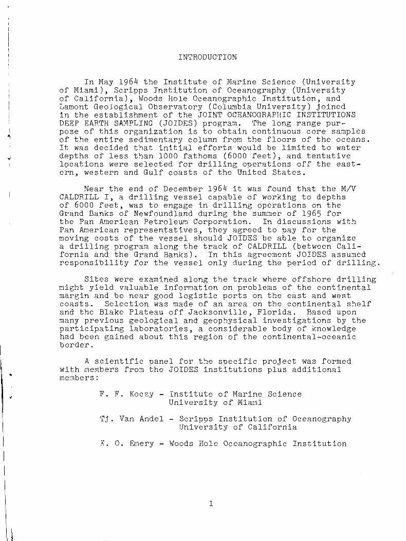
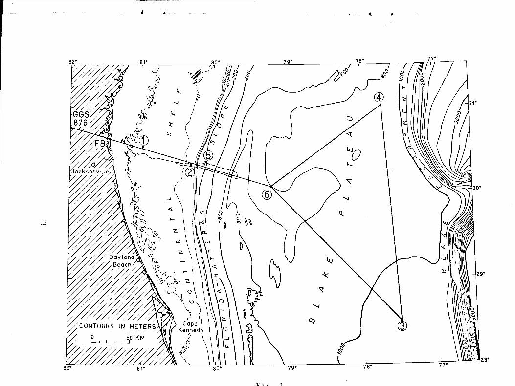
1. Map showing positions of JOIDES holes drilled. . 3
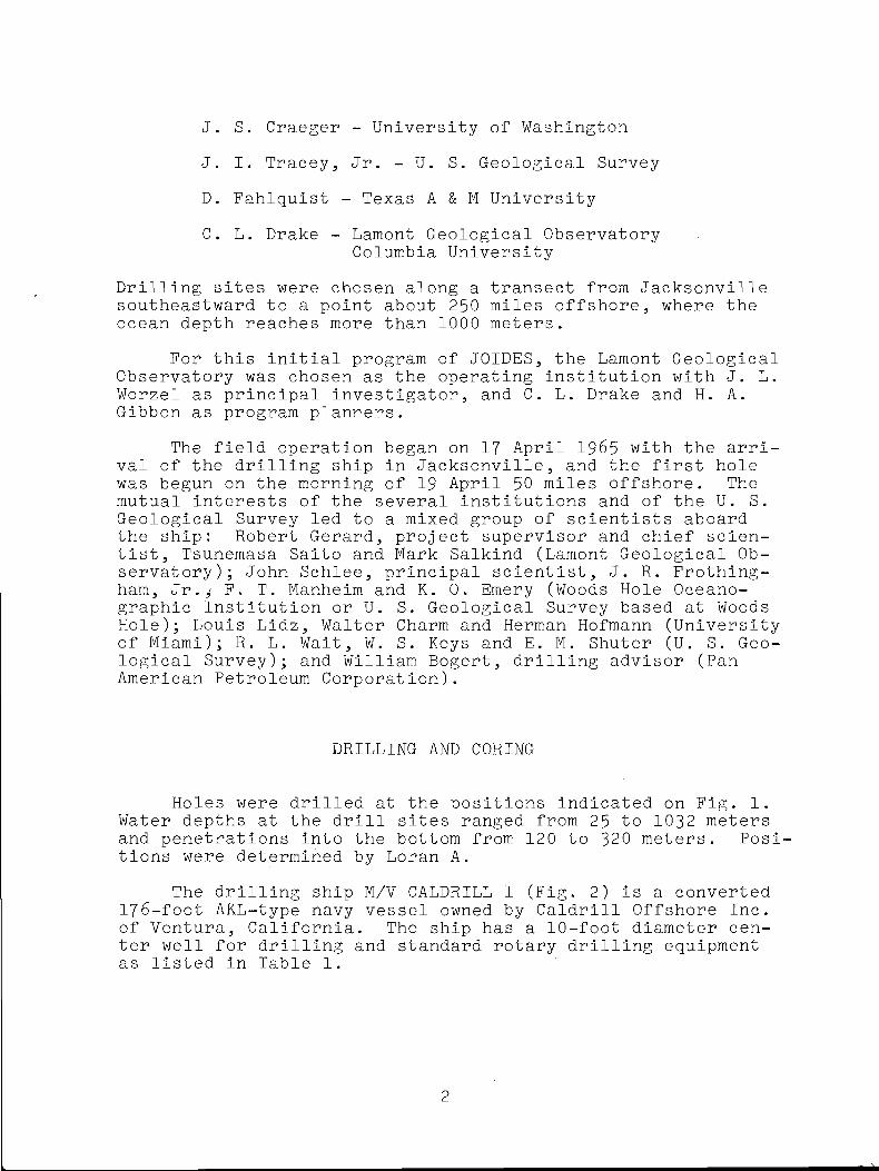
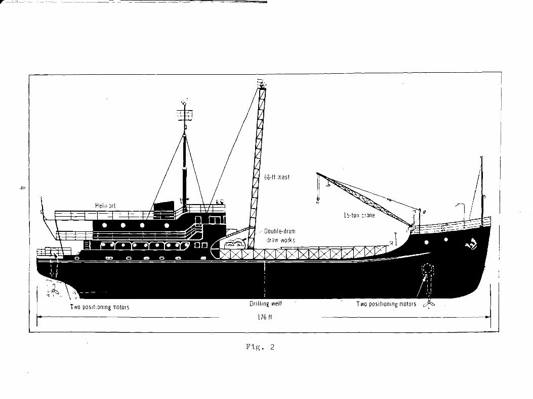
2. M/V CALDRILL I .................................... 4
3. Harbormaster propulsion unit ..................... 7
4. Control console of automatic-positioning
equipment ....................................... 8
5. Constant-tension device ........... . 9
6. Drill S t r i n g ...................................... 13
7. Drill string and base p l a t e ..................... 14
8. Photograph of core being extruded on the
deck of CALDRILL and photograph of core
being examined in the shipboard laboratory . . . 15
iii
LIST OP TABLES
1. Drilling Equipment .............................. 52. Summary of Drilling D a t a ....................... 103. Drill S t r i n g ..................................... 124. Time Distribution - JOIDES P r o j e c t ............ 185. List of A b b r e v i a t i o n s .......................... 206. Classification of Carbonate Rocks
according to Depositional Texture ........... 267. Classification of Stratification .............. 28
iv
INTRODUCTION
In May 1964 the Institute of Marine Science (University of Miami), Scripps Institution of Oceanography (University of California), Woods Hole Oceanographic Institution, and Lamont Geological Observatory (Columbia University) joined in the establishment of the JOINT OCEANOGRAPHIC INSTITUTIONS DEEP EARTH SAMPLING (JOIDES) program. The long range purpose of this organization is to obtain continuous core samples of the entire sedimentary column from the floors of the oceans.It was decided that initial efforts would be limited to water depths of less than 1000 fathoms (6000 feet), and tentative lpcations were selected for drilling operations off the eastern, western and Gulf coasts of the United States.
Near the end of December 1964 it was found that the M/V CALDRILL I, a drilling vessel capable of working to depths of 6000 feet, was to engage in drilling operations on the Grand Banks of Newfoundland during the summer of 1965 for the Pan American Petroleum Corporation. In discussions with Pan American representatives, they agreed to pay for the moving costs of the vessel should JOIDES be able to organize a drilling program along the track of CALDRILL (between California and the Grand Banks). In this agreement JOIDES assumed responsibility for the vessel only during the period of drilling.
Sites were examined along the track where offshore drilling might yield valuable information on problems of the continental margin and be near good logistic ports on the east and west coasts. Selection was made of an area on the continental shelf and the Blake Plateau off Jacksonville, Florida. Based upon many previous geological and geophysical investigations by the participating laboratories, a considerable body of knowledge had been gained about this region of the continental-oceanic border.
A scientific panel for the specific project was formed with members from the JOIDES institutions plus additional members:
F. F. Koczy - Institute of Marine Science University of Miami
T j . Van Andel - Scripps Institution of OceanographyUniversity of California
K. 0. Emery - Woods Hole Oceanographic Institution
i
J. I. Tracey, Jr. - U. S. Geological SurveyD. Fahlquist - Texas A & M UniversityC. L. Drake - Lamont Geological Observatory
Columbia UniversityDrilling sites were chosen along a transect from Jacksonville southeastward to a point about 250 miles offshore, where the ocean depth reaches more than 1000 meters.
For this initial program of JOIDES, the Lamont Geological Observatory was chosen as the operating institution with J. L. Worzel as principal investigator, and C. L. Drake and H. A. Gibbon as program planners.
The field operation began on 17 April 1965 with the arrival of the drilling ship in Jacksonville, and the first holewas begun on the morning of 19 April 50 miles offshore. Themutual interests of the several institutions and of the U. S. Geological Survey led to a mixed group of scientists aboard the ship: Robert Gerard, project supervisor and chief scientist, Tsunemasa Saito and Mark Salkind (Lamont Geological Observatory); John Schlee, principal scientist, J. R. Frothing- ham, Jr.^ F. T. Manheim and K. 0. Emery (Woods Hole Oceanographic Institution or U. S. Geological Survey based at Woods Hole); Louis Lidz, Walter Charm and Herman Hofmann (University of Miami); R. L. Wait, W. S. Keys and E. M. Shuter (U. S. Geological Survey); and William Bogert, drilling advisor (Pan American Petroleum Corporation).
J. S. Craeger - University of Washington
DRILLING AND CORING
Holes were drilled at the positions indicated on Pig. 1. Water depths at the drill sites ranged from 25 to 1032 meters and penetrations into the bottom from 120 to 320 meters. Positions were determined by Loran A.
The drilling ship M/V CALDRILL I (Fig. 2) is a converted 176-foot AKL-type navy vessel owned by Caldrill Offshore Inc. of Ventura, California. The ship has a 10-foot diameter center well for drilling and standard rotary drilling equipment as listed in Table 1.
i 1 t >
1
r
176 ft
Fig. 2

TABLE 1.
DRILLING EQUIPMENT
1. Hopper Model GX-IG, 6-speed, double drum drawworks with separate electric motors driving through Baylor eddy- current couplings. Rated capacity 6000’ with 4-1/2" drill pipe.
2. Hopper special 66' 250,000# mast with guide tracks for blocks and swivel. Mast lays down while in transit.
3. Two 700-H.P. Oilwell 6-3/4" x 8" Triplex mud pumps, each driven by a 400-H.P. Cat D343 TA Diesel with 9-speed transmission. Also used for cementing operations equipped with 10,000# fluid ends.
4. One 125-H.P. BJ electric powered, 2-stage centrifugal pump for salt water circulation.
5. One BJ 5" x 6" centrifugal pump for mixing.6. One 200-H.P. Bowen Itco, Model S3, power swivel.7. Two 350-kw AC generators driven from ship’s main propul
sion engines, 500-H.P. each and one 500-H.P. Cat D397T driving a 350-kw AC generator. 1500-H.P. available for rig and harbormaster units.
8. Hopper special hydraulic pipe-racking system and storage bins.
9. Foster hydraulic drill pipe tongs for 2-3/8" to 9-5/8" pipe .
10. Complete hydraulic system to power swivel, tongs, and pipe-racking equipment. One 200-H.P. unit and one 20-H.P. unit.
11. Storage for 300 barrels of drilling mud plus 300 sacks of dry mud or cement.
5
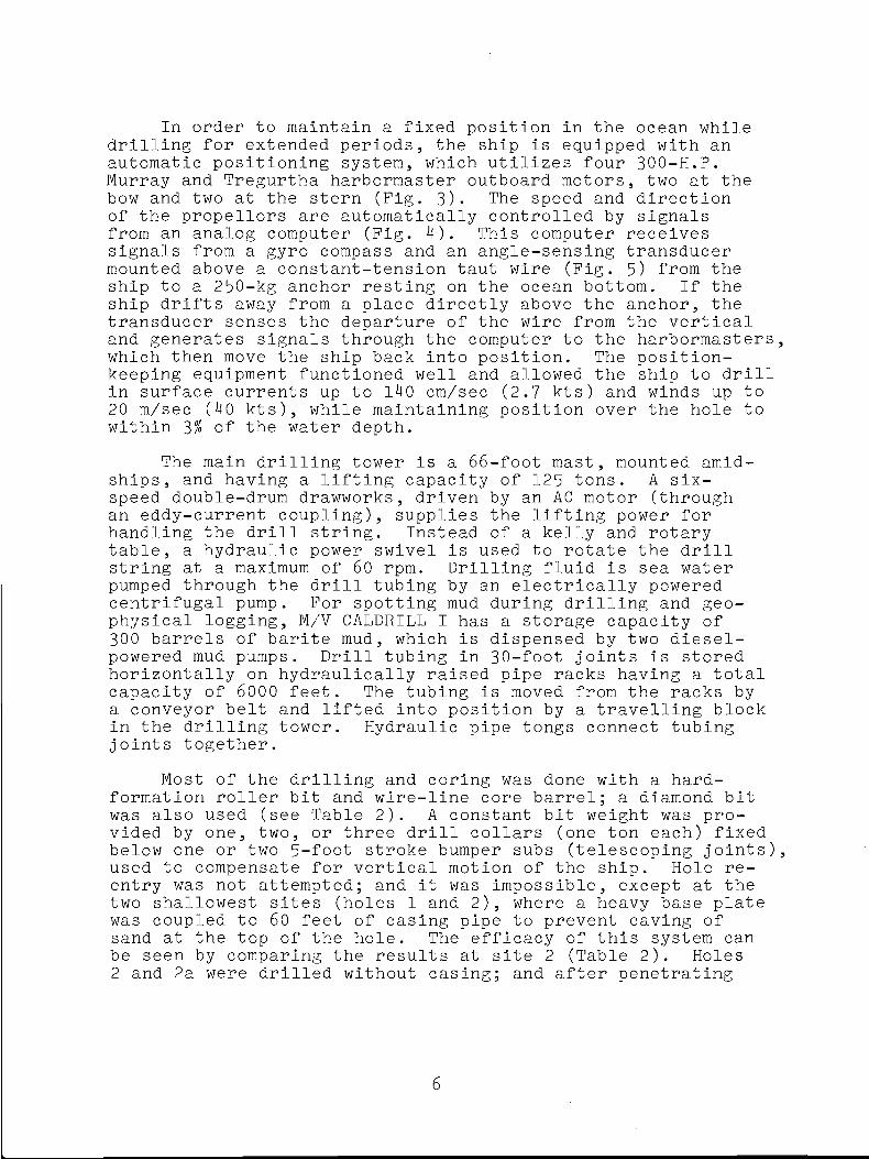
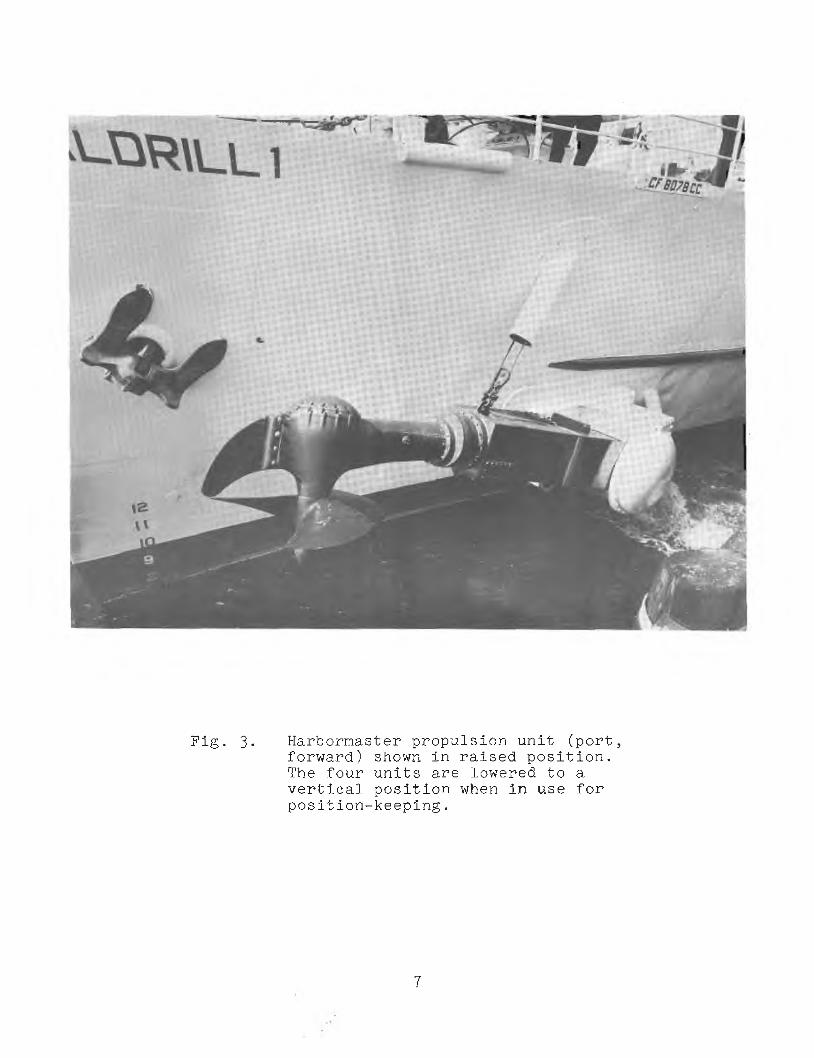
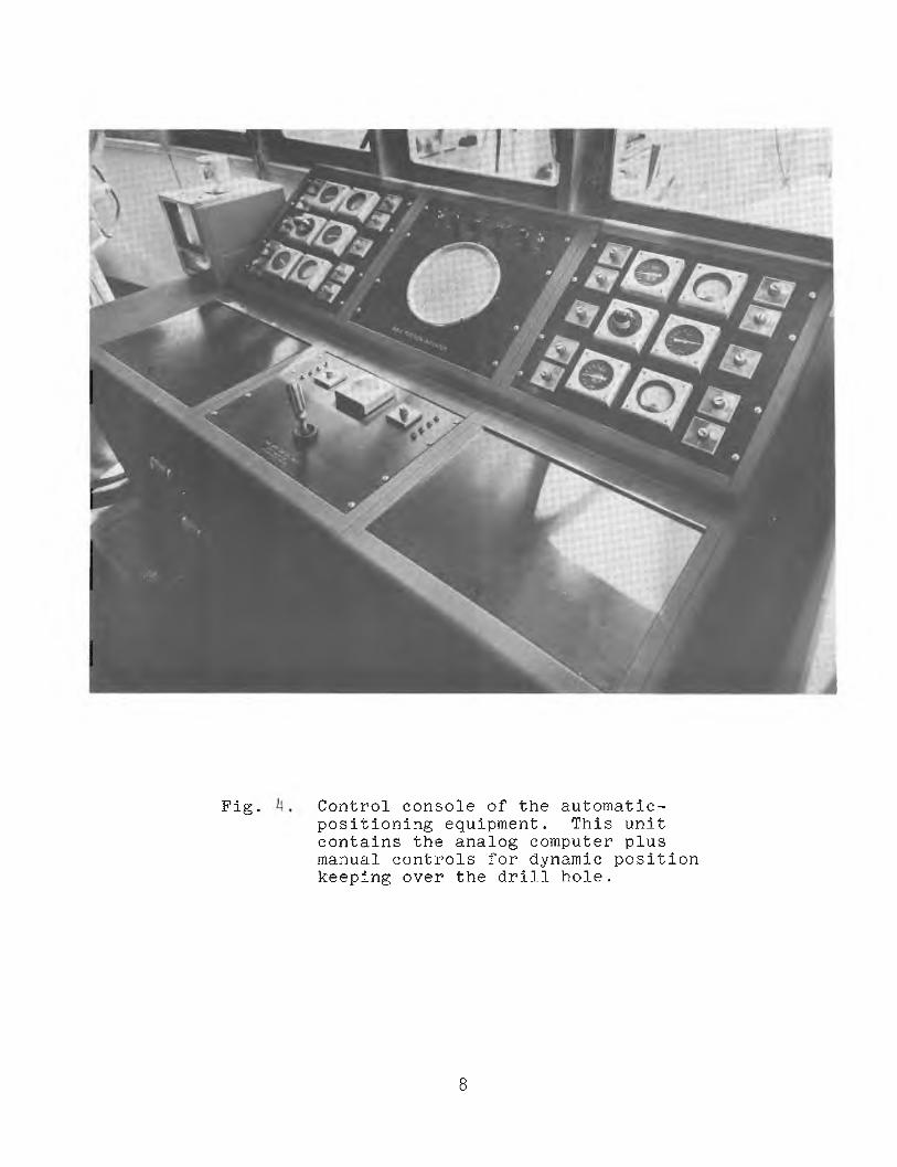
In order to maintain a fixed position in the ocean while drilling for extended periods, the ship is equipped with an automatic positioning system, which utilizes four 300-H.P.Murray and Tregurtha harbormaster outboard motors, two at the bow and two at the stern (Fig. 3). The speed and direction of the propellors are automatically controlled by signals from an analog computer (Fig. 4). This computer receives signals from a gyro compass and an angle-sensing transducer mounted above a constant-tension taut wire (Fig. 5) from the ship to a 250-kg anchor resting on the ocean bottom. If the ship drifts away from a place directly above the anchor, the transducer senses the departure of the wire from the vertical and generates signals through the computer to the harbormasters, which then move the ship back into position. The position- keeping equipment functioned well and allowed the ship to drill in surface currents up to 140 cm/sec (2.7 kts) and winds up to 20 m/sec (40 kts), while maintaining position over the hole to within 3% of the water depth.
The main drilling tower is a 66-foot mast, mounted amidships, and having a lifting capacity of 125 tons. A six- speed double-drum drawworks, driven by an AC motor (through an eddy-current coupling), supplies the lifting power for handling the drill string. Instead of a kelly and rotary table, a hydraulic power swivel is used to rotate the drill string at a maximum of 60 rpm. Drilling fluid is sea water pumped through the drill tubing by an electrically powered centrifugal pump. For spotting mud during drilling and geophysical logging, M/V CALDRILL I has a storage capacity of 300 barrels of barite mud, which is dispensed by two diesel- powered mud pumps. Drill tubing in 30-foot joints is stored horizontally on hydraulically raised pipe racks having a total capacity of 6000 feet. The tubing is moved from the racks by a conveyor belt and lifted into position by a travelling block in the drilling tower. Hydraulic pipe tongs connect tubing joints together.
Most of the drilling and coring was done with a hard- formation roller bit and wire-line core barrel; a diamond bit was also used (see Table 2). A constant bit weight was provided by one, two, or three drill collars (one ton each) fixed below one or two 5-foot stroke bumper subs (telescoping joints), used to compensate for vertical motion of the ship. Hole reentry was not attempted; and it was impossible, except at the two shallowest sites (holes 1 and 2), where a heavy base plate was coupled to 60 feet of casing pipe to prevent caving of sand at the top of the hole. The efficacy of this system can be seen by comparing the results at site 2 (Table 2). Holes 2 and 2a were drilled without casing; and after penetrating
6
Pig. 3. Harbormaster propulsion unit (port, forward) shown in raised position. The four units are lowered to a vertical position when in use for position-keeping.
7
Pig. Control console of the automatic-positioning equipment. This unit contains the analog computer plus manual controls for dynamic position keeping over the drill hole.
8
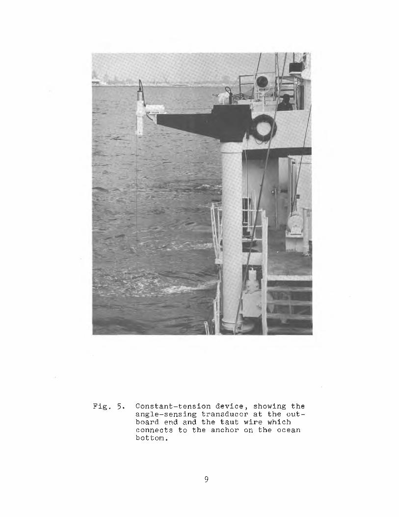
Pig. 5* Constant-tension device, showing the angle-sensing transducer at the outboard end and the taut wire which connects to the anchor on the ocean bottom.
9

■ Ci :
Position Date
OceanBottomDepth(m)
30°33’H81°00«W
li/285/1
25
30°21*N80°20*W
a/38-21 bZ
30°20‘N80°20»W
5/io-n a6
30o23'N80°08«W
U/22-26 190
30°05'N79°l5rW
5/7 805
31°03*N77°It5TW
5/12 885
31°02'N77°2*3Hf
5/33-15 892
28°30*N77°3l*W
5/3-5 1032
Maximum Surface Current Velocity (cm/sec) (l)ir.)
52(est. ) 26-ljl
72-3M
Various- TidalVarious- TidalVarious- Tidal
U6
33-52
32-50
N
raw
NNW-NNE
TABIE 2.
Summary of Drilling Data
* Site number will be identical with hole number as listed on Core log sheets,** Ganana-ray log** Velocity log 1
Hole Bit , Interval IntervalNo.fr 2b * End of Operationj Drilled (n) Cored (m)
1 Roller Baj! weather-pulled out 0- 7.6 7.6-335.6la Roller logged (G)#«- 0-121.9 121.9-277.a
2 Diamond ; Pulled out 0- 19.8 .2a Roller Logged (G)#*, backed off 0- 17.a i7 .a - i7 3 .a
2b Roller
i
Logged (&}** (V)-*** 0- 15.2 68.6- 76.2- 88 .a-ia6 .3
I52 .a-l58 .5
15.2- 68.6 76 .2- 88.a
ia6 .3 - l5 2 .a '158.5-320.2
5 Roller Strong current-pulled out 0- 9.1 9 .1 -3 0 .55a Roller Plugged - pulled out . 0- 17.7 17.7- 57.35b Diamond Plugged - pulled out -v ’ o- 50.6 50.6-200.65 c Roller Logged (G)** ' 0- 97.5 97.5-171.6
171. 6- 2a5.0~ i Intermittent
6 Roller Dri3.1 tubing broke 0-119.7
a Diamond Poor recovery-pulled out 0- 9 i .aaa Roller Touled taut line surfaceab - Roller Exhausted mud 0-178.3
3i
Roller j logged (G)#* ' ~f 0-178.33a Diamond i Computer problem - 0-170.7 170.7-173.7
pulled out
Total Hours Drilling & Coring
Core Recovery %
j. 37.5
31.5
21.0
}
56.5
17.5
57.0
l»o.5
10
}32.8
23.5
1*3.5
2U.5
} 67.6

173 meters, the drill tubing became stuck and the tools were lost In backing off. Later, at the same site using 60 feet of casing, hole 2b was drilled to 320 meters with no serious caving or sticking. Only minor sticking and caving occurred In the calcareous ooze at the holes of the Blake Plateau.The parts of the drill string used In the drilling and coring are listed In Table 3. The typical drill string Is shown schematically In Fig. 6 and Is shown together with the base plate In Fig. 7- For most holes coring or attempted coring was continuous after spudding 20 to 60 feet Into the sea floor. Cores were obtained with a wire-line core barrel that was dropped through the drill string to a clamped position at the bottom. It was retrieved, usually at 10-foot' Intervals of drilling,by a weighted wire line dropped through the tubing.
The rock or sediment core was extruded by hydraulic pressure applied to a rubber piston; a few cores were pushed out by a wooden pole applied to the same rubber piston. Cores were extruded Into plastic-covered half-round galvanized-steel trays 5 or 10-feet In length and carried to the shipboard laboratory for description and sampling.^/ Fig. 8 shows the extruding operation and shipboard core laboratory.
After description, the cores were cut Into 2-1/2-foot lengths, enclosed In polyethylene lay-flat tubing, and heat sealed. These lengths were placed In 4-section corrugated cardboard boxes (holding up to 10 feet of core), and all boxes were stored In a refrigerator at 40°F. Upon completion of the cruise, the cores were transferred to permanent storage at the University of Miami - Institute of Marine Science. Except for the time during which cores were split and repackaged, they have been stored at approximately 40°F In sealed polyethylene sleeving.
Core recovery ranged widely, depending on the type of sediment and the bit. It was best In soft unconsolidated silts, clays, and calcareous oozes drilled by a Reed roller bit. It was poorest In well Indurated chert or limestone, or In unconsolidated sand. Several different types of core catchers, used separately or In combination, helped retain core. A diamond drill bit and core-barrel assembly were less successful In recovery of core -- particularly in soft sediment. This was due In part to the placement.of the inner core-barrel
1/ Some sampling for water content and organic materials was done on board because these samples required freezing.
11
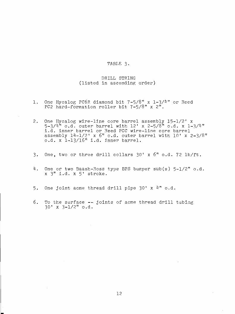
TABLE 3-
DRILL STRING (listed in ascending order)
1. One Hycalog PC6R diamond bit 7-5/8" x 1-3/4" or Reed PC2 hard-formation roller bit 7-5/8" x 2".
2. One Hycalog wire-line core barrel assembly 15-1/2' x5-3/4" o.d. outer barrel with 12' x 2-5/8" o.d. x 1-3/4"i.d. inner barrel or Reed PCC wire-line core barrel assembly 14-1/2' x 6" o.d. outer barrel with 10' x 2-3/8"o.d. x 1-13/16" i.d. inner barrel.
3. One, two or three drill collars 30' x 6" o.d. 72 lb/ft.
4. One or two Baash-Ross type BPS bumper sub(s) 5-1/2" o.d. x 3" i.d. x 5' stroke.
5. One joint acme thread drill pipe 30' x 4" o.d.
6. To the surface -- joints of acme thread drill tubing 30' x 3-1/2" o.d.
12
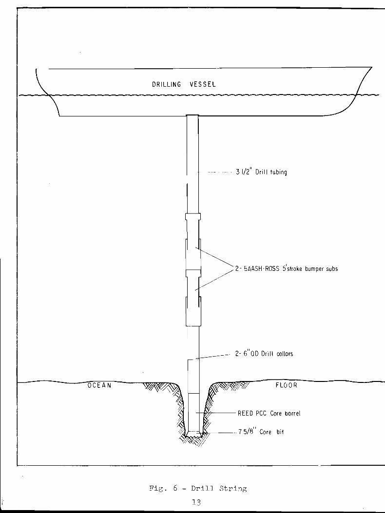
Pig. 6 - Drill String 13

Fig. 7 - Drill String and Base Plate14

(Left) Core be inn;
extruded on the deck
of CALDRILL at site 4.
(Below) Core exami
nation in the labora
tory aboard CALDRILL.
Pig. 8
15
cutter head just above the drill-bit orifice, where it is subject to the washing effects of the circulating fluid. The cutter head of the Reed inner core barrel projects 1-3/4" below the roller bits, hence washing effects are less. Rock cores obtained with the diamond bit were less broken up than similar material taken with the roller bit, i.e. interbedding of limestone and chert is preserved in diamond cores.
Length of extruded core ranged from a few inches to 11'3"* Core lengths in excess of 10 feet were due to stretching of the core during extrusion. Occasionally, intervals smaller than 10 feet were drilled, and a few of these cores were longer than the interval drilled; this may be due to stretching or to an inexactness in fixing the interval cored. Core diameter ranged from 1-3/8" (diameter of cutter head) to almost 2", depending on the softness of the material cored. Cores through chert, siliceous limestone, and dolomite were of minimum diameter. Cores of soft ooze and clay, when extruded, were usually larger than the minimum diameter of the inner core barrel. Flowage of soft sediment into the barrel was indicated in a few cores by a concentric structure, wherein a central core of better compacted sediment is surrounded by a sheath of soft sediment. Flowage structures and draping of stratification at the core periphery could be seen on the open cuts of split cores. During shipboard logging, a coating of recent foraminifera and broken shell debris was noted on the outside of some cores; apparently some detritus washed down the sides of the hole and was plastered up the side of the core before retrieval took place. The greater ages of microfossils in the central undisturbed part of the core attest to the incompleteness of flowage.
Subsequent packaging, shipping, and splitting of the cores has resulted in a shortening of 0 to 36% (average 9 . 6 % ? / ) below the lengths measured during shipboard description. The remeasurement took place several weeks later at Miami shortly after the cores were split. In the intervening time, cores had been packaged, shipped, split and repackaged. Some telescoping or flowage apparently occurred. Only most recent values of core length are given in the preliminary log for the interval drilled.
Though cores were still moist several weeks after drilling,
2/ The figure is the arithmetic average of 100 cores originally ~ 5 feet or longer.
16
minor color changes were noted at the edges of some cores of noncalcareous clay; the change probably resulted from a reaction with air.
Approximately 2052 meters of drilling was done, during which a total of 1^33 meters of coring was attempted with a total recovery of 513 meters. Core recovery averaged 3&% overall; best recovery (46$) occurred in the soft formations of silt and clay, whereas poorest recovery (22$) was in hard layers of chert and dolomite. Recovery averaged 28% on the continental shelf, 55$ on the Florida-Hatteras Slope, and 38$ on the Blake Plateau.
The project had the use of the drilling vessel CALDRILL I for 720 hours, beginning at 1200 hours 17 April and ending at 1200 hours 17 May. A cruise narrative, covering the work done aboard the M/V CALDRILL I during this period, is presented in Appendix A. Table 4 summarizes the time distribution of activities during this period.
17
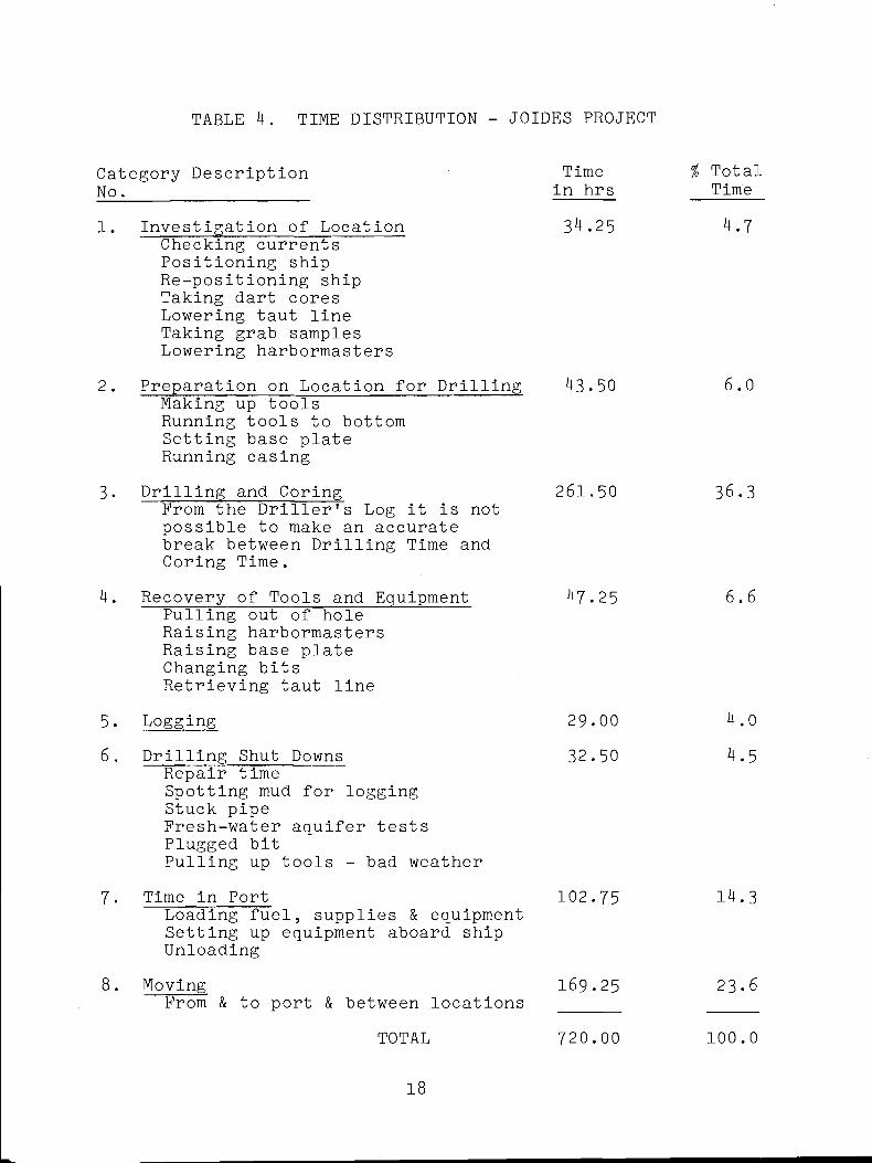
TABLE 4. TIME DISTRIBUTION - JOIDES PROJECT
Category Description TimeN o.____________________in hrs1. Investigation of Location 34.25
Checking currents Positioning ship Re-positioning ship Taking dart cores Lowering taut line Taking grab samples Lowering harbormasters
2. Preparation on Location for Drilling 43.50Making up tools Running tools to bottom Setting base plate Running casing
3. Drilling and Coring 261.50From the Driller's Log it is not possible to make an accurate break between Drilling Time and Coring Time.
4. Recovery of Tools and Equipment 47.25Pulling out of hole Raising harbormasters Raising base plate Changing bits Retrieving taut line
5. Logging 29.006. Drilling Shut Downs 32.50
Repair timeSpotting mud for logging Stuck pipeFresh-water aquifer tests Plugged bitPulling up tools - bad weather
7. Time in Port 102.75Loading fuel, supplies & equipment Setting up equipment aboard ship Unloading
8. Moving 169.25From & to port & between locations ______
TOTAL 720.00
% Total Time
4.7
6 .0
36.3
6 .6
4.04.5
14.3
23-6
100.0
18
CORE DESCRIPTION
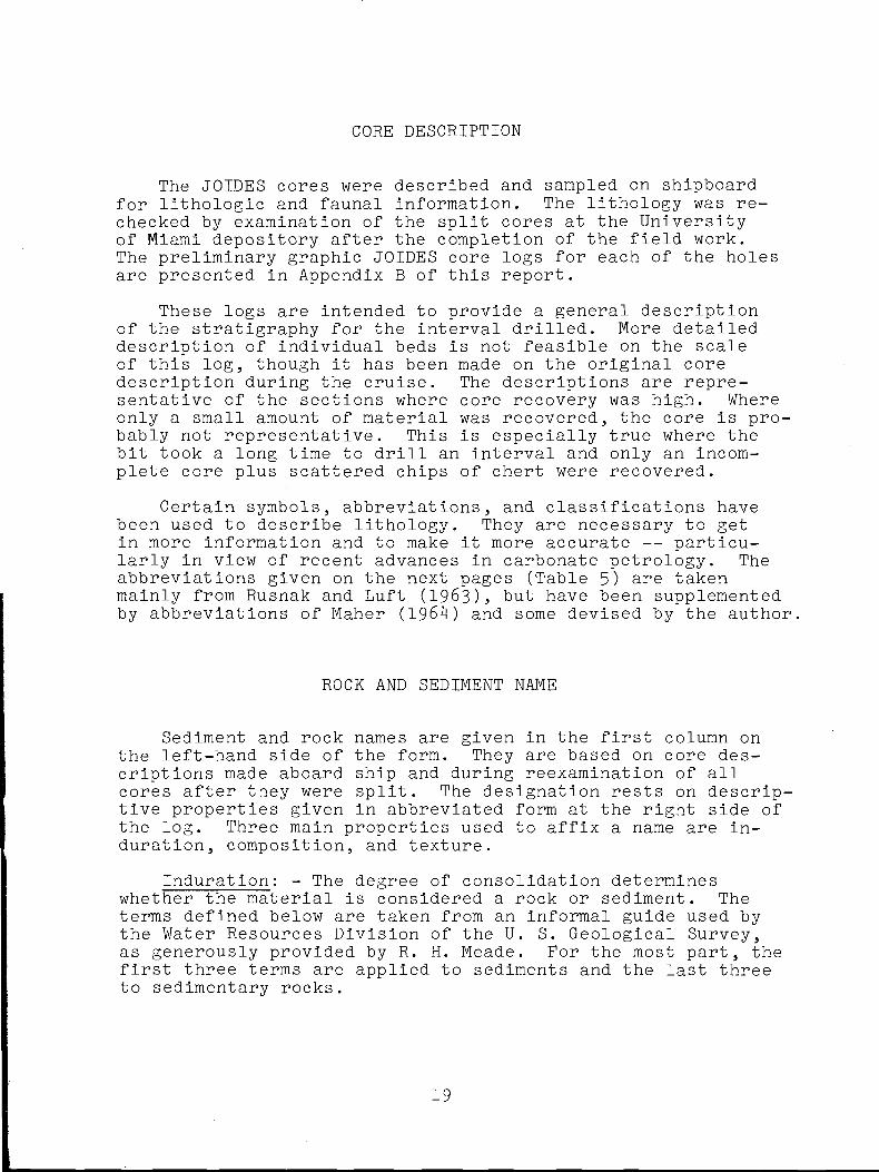
The JOIDES cores were described and sampled on shipboard for lithologic and faunal information. The lithology was rechecked by examination of the split cores at the University of Miami depository after the completion of the field work.The preliminary graphic JOIDES core logs for each of the holes are presented in Appendix B of this report.
These logs are intended to provide a general description of the stratigraphy for the interval drilled. More detailed description of individual beds is not feasible on the scale of this log, though it has been made on the original core description during the cruise. The descriptions are representative of the sections where core recovery was high. Where only a small amount of material was recovered, the core is probably not representative. This is especially true where the bit took a long time to drill an interval and only an incomplete core plus scattered chips of chert were recovered.
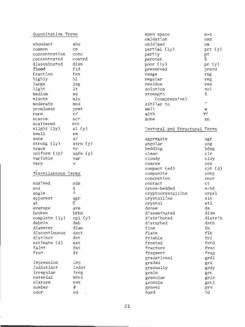
Certain symbols, abbreviations, and classifications have been used to describe lithology. They are necessary to get in more information and to make it more accurate — particularly in view of recent advances in carbonate petrology. The abbreviations given on the next pages (Table 5) are taken mainly from Rusnak and Luft (1963), but have been supplemented by abbreviations of Maher (1964) and some devised by the author.
ROCK AND SEDIMENT NAME
Sediment and rock names are given in the first column on the left-hand side of the form. They are based on core descriptions made aboard ship and during reexamination of all cores after they were split. The designation rests on descriptive properties given in abbreviated form at the right side of the log. Three main properties used to affix a name are induration, composition, and texture.
Induration: - The degree of consolidation determines whether the material is considered a rock or sediment. The terms defined below are taken from an informal guide used by the Water Resources Division of the U. S. Geological Survey, as generously provided by R. H. Meade. For the most part, the first three terms are applied to sediments and the last three to sedimentary rocks.
19
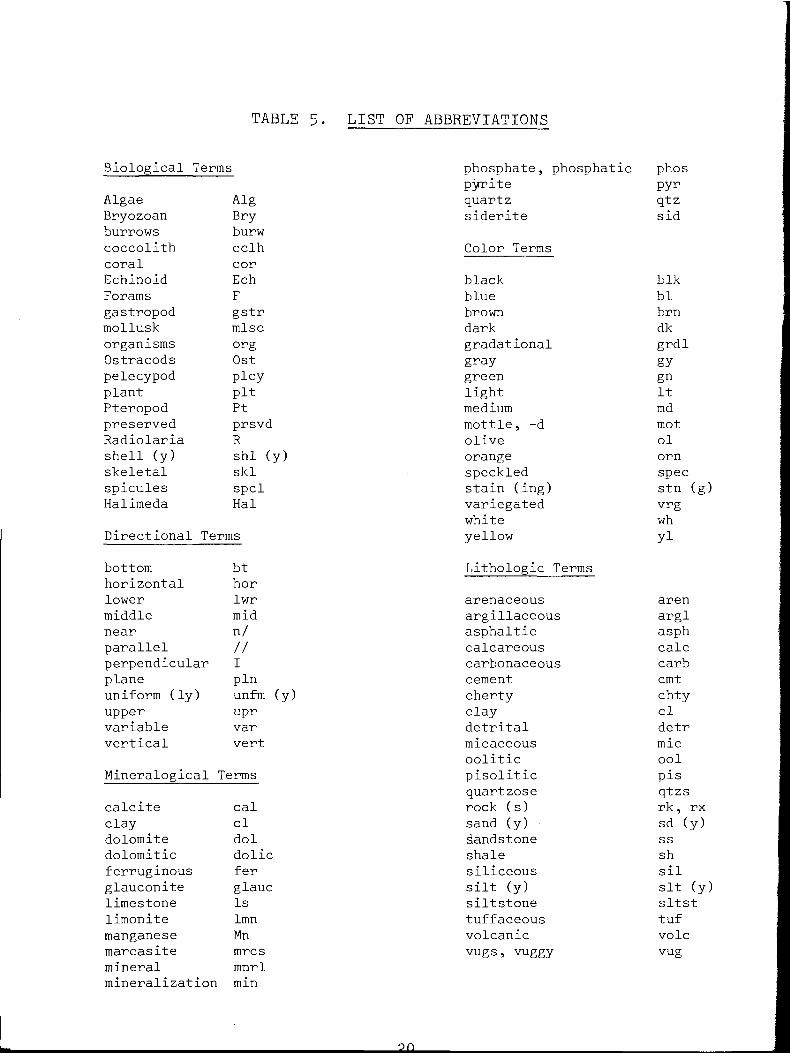
TABLE 5. LIST OF ABBREVIATIONS
Biological Terms phosphate, phosphatic phospyrite pyr
Algae Alg quartz qtzBryozoan Bry siderite sidburrows burwcoccolith cclh Color Termscoral corEchinoid Ech black blkForams F blue blgastropod gstr brown brnmollusk mlsc dark dkorganisms org gradational grdlOstracods Ost gray gypelecypod plcy green gnplant pit light ItPteropod Pt medium mdpreserved prsvd mottle, -d motRadiolaria R olive olshell (y) shl (y) orange ornskeletal ski speckled specspicules spcl stain (ing) stn (g)Halimeda Hal variegated vrg
white whDirectional Terms yellow yibottom bt Lithologic Termshorizontal horlower lwr arenaceous arenmiddle mid argillaceous arglnear n/ asphaltic asphparallel // calcareous calcperpendicular I carbonaceous carbplane pin cement cmtuniform (ly) unfm (y) cherty chtyupper upr clay clvariable var detrital detrvertical vert micaceous mic
oolitic oolMineralogical Terms pisolitic pis
quartzose qtzscalcite cal rock (s) rk, rxclay cl sand (y) sd (y)dolomite dol dandstone ssdolomitic dolic shale shferruginous fer siliceous silglauconite glauc silt (y) sit (y)limestone Is siltstone sltstlimonite lmn tuffaceous tufmanganese Mn volcanic volemarcasite mrcs vugs, vuggy vugmineral mnrlmineralization min
Quantitative 'Ferms open space o-soxidation oxn
abundant abu oxidized oxcommon cm partial (ly) prt (y)concentration cone partly Ptconcentrated contrd percent %disseminated dism poor (ly) pr (y)flood fid preserved prsvdfraction fxn range rnghighly hi regular reglarge Irg residue reslight It solution solmedium md strength Sminute min (compressive)moderate mod similar toprominent prmt well wrare r / with w/scarce- sc” zone znscattered seaslight (ly) si (y) Textural and Structural Termssmall smsome s/ aggregate agrstrong (ly) strn (y) angular angtrace tr bedding bdnguniform (ly) unfm (y ) clear clrvariable var cloudy cldyvery V coarse crs
compact (ed) cpt (d)Miscellaneous Terms composite comp
concretion cncradmixed adm contact ctand & cross-bedded x-bdangle L cryptocrystalline crpxlapparent apr crystalline xlnat @ crystal xtlaverage ave dense dsbroken brkn disseminated dismcomplete (ly) cpl (y) distributed distribdebris deb disturbed dstbdiameter diam fine fndiscontinuous dsct flake f lkdistinct dst friable friestimate (d) est frosted f stdfaint fnt fracture fracfrom fr fragment frag
gradational grdlimpression imp graded grdindistinct indst gradually grdyirregular irrg grain grnmaterial mtrl granular grlrmixture mxt granule grnlnumber # gravel grvodor od hard hd
21
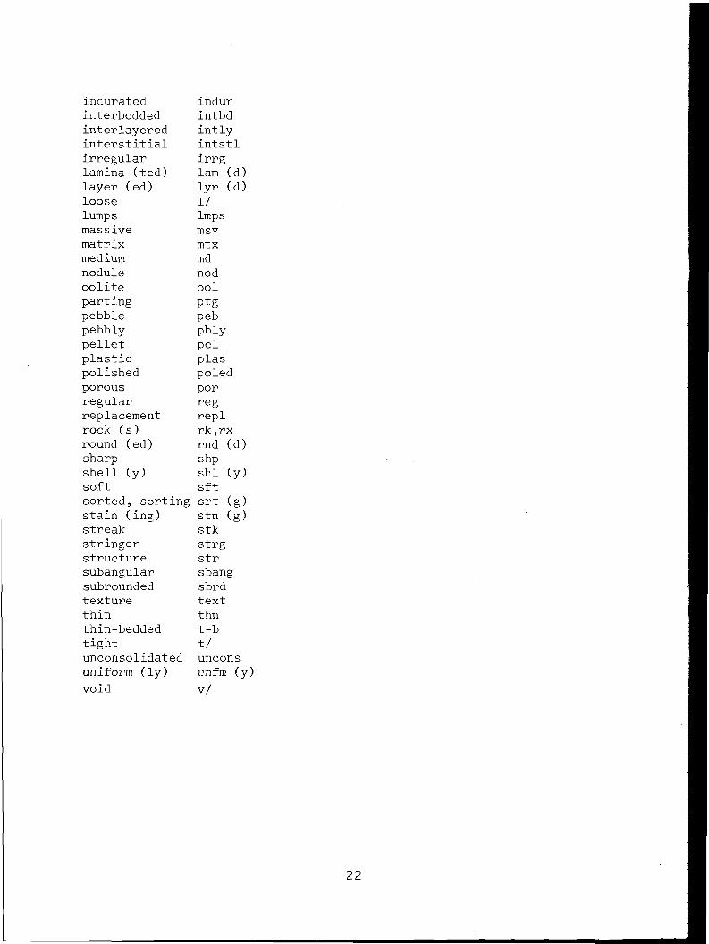
indurated indurinterbedded intbdinterlayered intlyinterstitial intstlirregular irrglamina (ted) lam (d )layer (ed) lyr (d)loose 1/lumps Impsmassive msvmatrix mtxmedium mdnodule nodoolite oolparting Ptgpebble pebpebbly pbiypellet pelplastic plaspolished poledporous porregular regreplacement replrock (s) rk ,rxround (ed) rnd (d)sharp shpshell (y) shl (y)soft sftsorted, sorting srt (g)stain (ing) stn (g)streak stkstringer strgstructure strsubangular sbangsubrounded sbrdtexture textthin thnthin-bedded t-btight t/unconsolidated unconsuniform (ly) unfm (y)void v/
Unconsolidated - no cementation or compaction; loose, may be dug out easily.
Plas-tic - sediment may be molded between fingers into long slender ribbons.
Compacted - coherent fine-grained masses which may be broken easily.
Friable - coherent masses (generally in sand range or coarser) which may be broken, but in which individual grains may be dug out with difficulty.
Firm - coherent masses which may be broken by hand only with great difficulty.
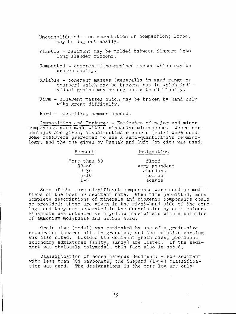
Hard - rock-like; hammer needed.Composition and Texture: - Estimates of major and minor
components were made with a binocular microscope. Where percentages are given, visual-estimate charts (Folk) were used. Some observers preferred to use a semi-quantitative terminology, and the one given by Rusnak and Luft (op cit) was used.
Some of the more significant components were used as modifiers of the rock or sediment name. When time permitted, more complete descriptions of minerals and biogenic components could be provided; these are given in the right-hand side of the core log, and they are separated in the description by semi-colons. Phosphate was detected as a yellow precipitate with a solution of ammonium molybdate and nitric acid.
Grain size (modal) was estimated by use of a grain-size comparator (coarse silt to granules) and the relative sorting was also noted. Besides the dominant grain size, prominent secondary admixtures (silty, sandy) are listed. If the sediment was obviously polymodal, this fact also is noted.
Classification of Noncalcareous Sediment: - For sediment with~TFs^~ThalT3oX-cau;Foni?tV7~fche_ hepard (T95^) classification was used. The designations in the core log are only
Percent DesignationMore than 60
3 0 - 6 0 10-30 5-10 1-5
flood very abundant
abundant common scarce
23
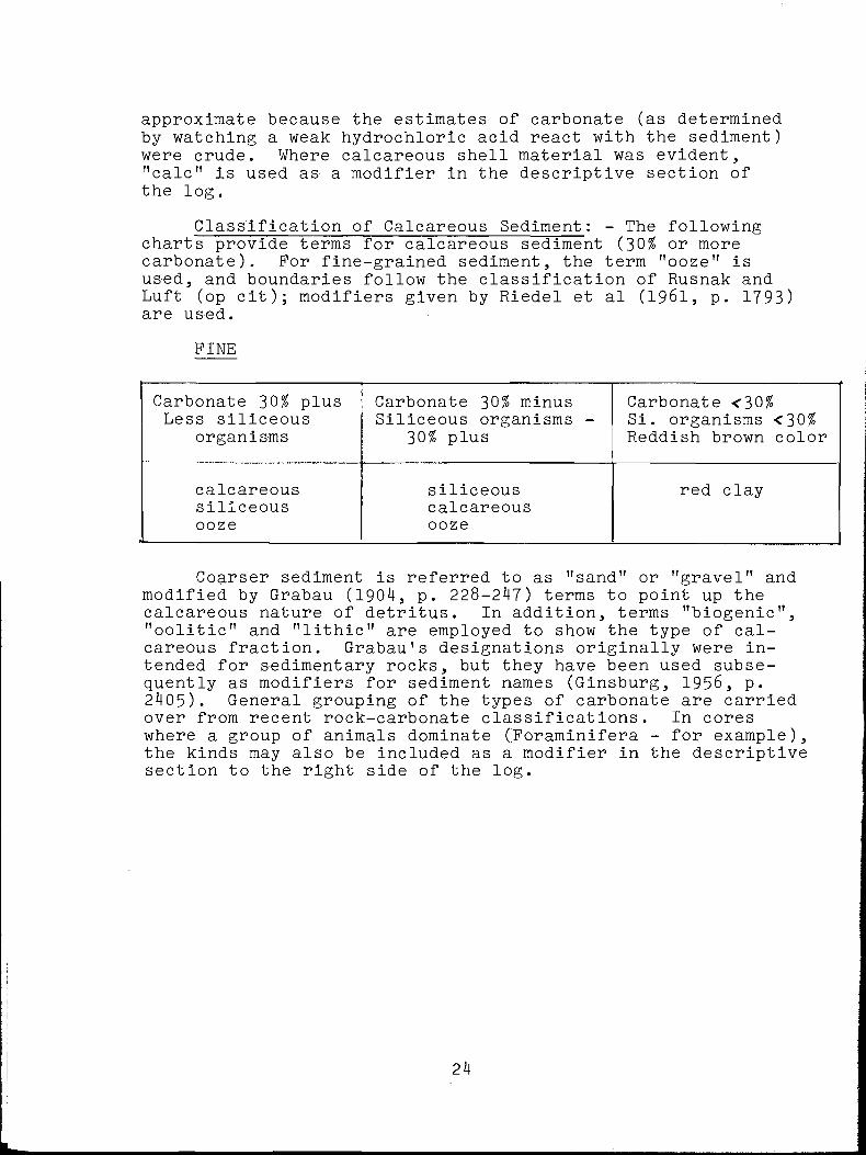
approximate because the estimates of carbonate (as determined by watching a weak hydrochloric acid react with the sediment) were crude. Where calcareous shell material was evident, "calc" is used as- a modifier in the descriptive section of the log.
Classification of Calcareous Sediment: - The following charts provide terms for calcareous sediment (30% or more carbonate). For fine-grained sediment, the term "ooze" is used, and boundaries follow the classification of Rusnak and Luft (op cit); modifiers given by Riedel et al (1961, p. 1793) are used.
PINE
Carbonate 30$ plus Less siliceous
organismsCarbonate 30$ minus Siliceous organisms -
30$ plusCarbonate <30$Si. organisms <30$ Reddish brown color
calcareoussiliceousooze
--------------
siliceouscalcareousooze
red clay
Coarser sediment is referred to as "sand" or "gravel" and modified by Grabau (1904, p. 228-247) terms to point up the calcareous nature of detritus. In addition, terms "biogenic", "oolitic" and "lithic" are employed to show the type of calcareous fraction. Grabau's designations originally were intended for sedimentary rocks, but they have been used subsequently as modifiers for sediment names (Ginsburg, 1956, p. 2405). General grouping of the types of carbonate are carried over from recent rock-carbonate classifications. In cores where a group of animals dominate (Foraminifera - for example), the kinds may also be included as a modifier in the descriptive section to the right side of the log.
24
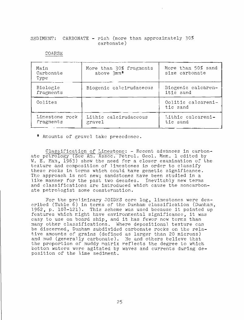
SEDIMENT: CARBONATE - rich (more than approximately 30%carbonate)
COARSE
MainCarbonateType
More than 30% fragments above 3mm*
More than 50% sand size carbonate
Biologicfragments
Biogenic calcirudaceous Biogenic calcaren- itic sand
Oolites Oolitic calcareni- tic sand
Limestone rock fragments
Lithic calcirudaceous gravel
Lithic calcareni- tic sand
* Amounts of gravel take precedence.
Classification of Limestone: - Recent advances in carbonate petrology (See Am. Assoc. Petrol. Geol. Mem. 1 edited by W. E. Ham, 1963) show the need for a closer examination of the texture and composition of limestones in order to classify these rocks in terms which could have genetic significance.The approach is not new; sandstones have been studied in a like manner for the past two decades. Inevitably new terms and classifications are introduced which cause the noncarbonate petrologist some consternation.
For the preliminary JOIDES core log, limestones were described (Table 6 ) in terms of the Dunham classification (Dunham, 1962, p. 108-121). This scheme was used because it pointed up features which might have environmental significance, it was easy to use on board ship, and it has fewer new terms than many other classifications. Where depositional texture can be discerned, Dunham subdivided carbonate rocks on the relative amounts of grains (defined as larger than 20 microns) and mud (generally carbonate). He and others believe that the proportion of muddy matrix reflects the degree to which bottom waters were agitated by waves and currents during deposition of the lime sediment.
25
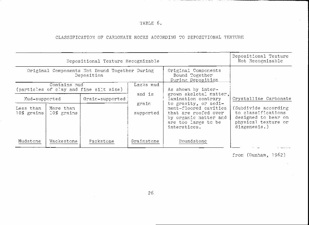
TABLE 6.
CLASSIFICATION OF CARBONATE ROCKS ACCORDING TO DEPOSITIONAL TEXTURE
Depositional Texture RecognizableDepositional Texture
Not RecognizableOriginal Components Not Bound Together During
DepositionOriginal Components
Bound Together During Deposition
Crystalline Carbonate
Contains mud (particles of clay and fine silt size)
Lacks mud and is grain
supported
Grainstone
As shown by intergrown skeletal matter, lamination contrary to gravity, or sediment-floored cavities that are roofed over by organic matter and are too large to be interstices.
Boundstone
Mud-supported Grain-supportedLess than 10# grains
Mudstone
More than 10# grains
Wackestone Packstone
(Subdivide according to classifications designed to bear on physical texture or diagenesis.)
from (Dunham, 1962)
26
COLOR
Color designations are shown on the third column from the left. Where designations are absent, it may be assumed that the last one given immediately above the blank area applies to the interval in question. Colors are in terms of hues, chromas (richness or saturation), and relative lightness (See Goddard et al, 19^8, for a brief explanation of the color scheme). A Munsel Book of Color - pocket edition - was used to determine the color of the moist cores; the book contains several hundred color swatches and proved to be more than adequate.
STRUCTURE
Bedding, laminations, mottling, and other sedimentary structures are given to the right and were described when the cores were split at Miami after the cruise. McKee and Weir (1953) bedding classification (Table 7) was followed for descriptive terms except for "massive". This term is used here to indicate an apparent absence of sedimentary structure in a core.
RECOVERY LOG
The amount of core recovered for each interval drilled is shown in the narrow column labeled "Rec."; it is indicated by the blackened portion of the column. Intervals where coring was attempted but no core was recovered are shown by a check-pattern; where coring was not done, the column is blank. In a drilled interval where core recovery is very nearly complete C7 feet or more in a 10-foot section), the missing portion is assumed to be absent from the top of the cored interval, as indicated on the log. The drilling procedure of pumping sea water through the drill string before core retrieval, and before drilling the next interval, probably caused some washing of the uppermost part of the next interval. Where less than 7 feet of core was recovered, its exact depth in the Interval Is not certain, and hence the position of distinctive horizons cannot be fixed with respect to the sea-floor depth or sea level. The position of shorter cores is indicated schematically in the middle of the drilled
27
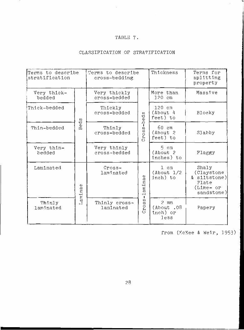
TABLE 7.
CLASSIFICATION OF STRATIFICATION
Terms to describe ! stratification
Terms to describe cross-bedding
Thickness Terms for splitting property
Very thick- bedded
Very thickly cross-bedded
More than 120 cm
Massive
Thick-bedded
w
Thicklycross-bedded w
'CSCD
120 cm (About 4 feet) to
Blocky
Thin-bedded'OO)m Thinly
cross-bedded
■Q1mmOUo
60 cm (About 2 feet) to
Slabby
Very thin- bedded
Very thinly cross-bedded
5 cm (About 2 inches) to
Flaggy
Laminated
CDac
•H
Crosslaminated 0)
C•HB
i—I 1
1 cm (About 1/2 inch) to
Shaly (Claystone
& siltstone) Plate (Lime- or sandstone)
Thinlylaminated
Thinly crosslaminated
.
mmOuo
2 mm (About .08 inch) or
lessPapery
from (McKee & Weir, 1953)
28

interval on the log, though its exact position is not known.
GRAPHIC LOG
Lithology is given graphically on the second column to the left. Symbols are self-explanatory by looking at the rock or sediment-type list to the left. Like abbreviations, they are taken mainly from Rusnak and Luft (op cit) and Maher (op cit). In a section where two or more lithologies are present, they are shown schematically in the log; neither the relative position nor the amount of the symbol is intended to represent the exact situation in the core.
AGE
Time-stratigraphic boundaries are indicated in the preliminary log at the selected depths. Values are measured from the sea floor downward. The boundaries kindly were provided for the log by Dr. Tsunemasa Saito (Lamont Geological Observatory) and Louis Lidz (Institute of Marine Science - University of Miami).
Acknowledgments: The authors wish to acknowledge the assistance of R. L. Wait, E. Shuter, P. Manheim, K. 0. Emery and J. R. Prothingham Jr. in making the shipboard core description. K. 0. Emery reviewed the manuscript and made many helpful suggestions. Special thanks are due to W. Bogert, who as drilling advisor was responsible for much of the success of the coring operation. The work reported in this paper was supported by the National Science Foundation under grant GP- ^233.
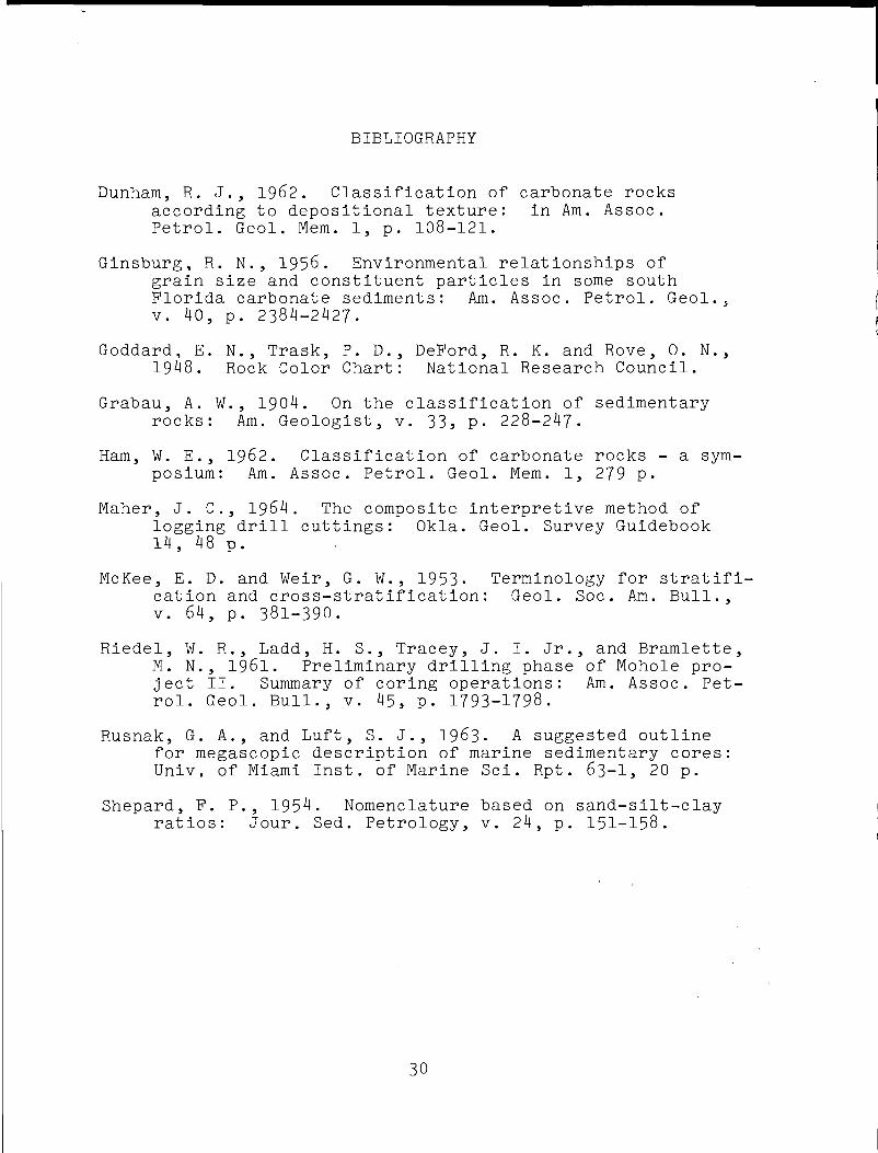
BIBLIOGRAPHY
Dunham, R. J., 1962. Classification of carbonate rocks according to depositional texture: in Am. Assoc.Petrol. Geol. Mem. 1, p. 108-121.
Ginsburg, R. N., 1956. Environmental relationships of grain size and constituent particles in some south Florida carbonate sediments: Am. Assoc. Petrol. Geol.,v. 40, p. 2384-2427.
Goddard, E. N., Trask, P. D., DeFord, R. K. and Rove, 0. N., 1948. Rock Color Chart: National Research Council.
Grabau, A. W., 1904. On the classification of sedimentary rocks: Am. Geologist, v. 33, p. 228-247.
Ham, W. E., 1962. Classification of carbonate rocks - a symposium: Am. Assoc. Petrol. Geol. Mem. 1, 279 p.
Maher, J. C., 1964. The composite interpretive method of logging drill cuttings: Okla. Geol. Survey Guidebook14, 48 p.
McKee, E. D. and Weir, G. W . , 1953. Terminology for stratification and cross-stratification: Geol. Soc. Am. Bull.,v. 64, p. 381-390.
Riedel, W. R,, Ladd, H. S., Tracey, J. I. Jr., and Bramlette, M. N., l§6l. Preliminary drilling phase of Mohole project II. Summary of coring operations: Am. Assoc. Petrol. Geol. Bull., v. 45, p. 1793-1798.
Rusnak, G. A., and Luft, S. J., 1963. A suggested outlinefor megascopic description of marine sedimentary cores: Univ. of Miami Inst, of Marine Sci. Rpt. 63-1, 20 p.
Shepard, F. P., 1954. Nomenclature based on sand-silt-clay ratios: Jour. Sed. Petrology, v. 24, p. 151-158.
30
APPENDIX A
CRUISE NARRATIVE 17 April
At 1200 hours the M/V CALDRILL I was turned over to the JOIDES Blake Plateau Expedition with the signing of official papers by the chief scientist for JOIDES and the master of the vessel. Scientific supplies and drilling equipment were loaded aboard by JOIDES and CALDRILL personnel until late evening.The core storage refrigerator and logging winch were secured at this time. New wire was wound on several winches, including a small air winch holding approximately 1500 meters of wire rope for hydrographic work.
18 AprilThe remaining scientific equipment was loaded, and all
JOIDES personnel moved aboard. Logging equipment was checked out and the last of the drilling equipment placed aboard and secured. Difficulties arose with the Loran navigation unit, which could not be repaired on this date (Easter Sunday). An oil leak on the port forward harbormaster unit was repaired.The core storage refrigerator motor was removed for rewinding purposes. Both this motor and the Loran unit were left ashore for repair, to be brought out by the crew boat H. J. W. FAY, which arrived from Miami late on this date. The ship got under way and departed the Jacksonville pier at 1800 hours, proceeding down-river and out to position 2 .
This position was chosen over position 1 in that it was somewhat deeper and would allow the position-keeping equipment to be checked more easily.
19 AprilAt 0200 a position south of position 2 was reached, and
dart cores were taken with the Sandline winch while the harbormaster units were being lowered into position. A Van Veen bottom-grab sample taken at this location indicated shell fragments and much calcareous debris. At 0930 the position-keeping equipment was in operation, and preparations were under way to assemble the drill string, using a Hycalog diamond drill bit.The drill string touched bottom at 1130 at a depth of 42 meters. Problems with the circulating pump delayed the spudding-in
31
operation. Considerable sticking and other delays ensued due to loss of circulation and pump troubles. A total of 65 feet (20 meters) was drilled with no core recovery in the shelly, unconsolidated sand. During this time, a bathythermograph observation was made and bottom photographs taken with an underwater camera. The drill string was taken up, and the ship was moved a few tenths of a mile to the north to begin another hole using different equipment. By 2130 drilling had begun with a Reed roller bit in place of the diamond bit. Progress was good, and there was a minimum of sticking. Fairly firm material was encountered about 10 meters beneath the ocean bottom.
20 AprilDrilling continued during the night with very poor core
recovery. A few fragments of material suggested the beginning of the Miocene beds at approximately 35 meters. At 0815 a change to finer-grained sediment permitted good core returns between about 60-70 meters in material which was identified as Miocene. From about 0900 to 1500 the drilling operation was shut down in order to effect repairs on the draw works and the hydraulic drive for the power swivel. Following these repairs, drilling continued with good recovery and by midnight had reached about 135 meters beneath the ocean bottom.
21 AprilBy 0800 the drill bit had penetrated to 170 meters, and
core recovery remained good. At 0900 sticking of the drill string became serious, and we were unable either to circulate drilling fluid or to rotate the drill string. By 1200 circulation and drilling were still impossible, and it was decided to make a gamma-ray log measurement inside the drill tubing down to the maximum penetration of 173 meters. Because explosive perforating charges for downhole cutting of the pipe had not arrived before our departure from Jacksonville, it was necessary to back off the drill string in an attempt to recover some of the equipment. At 1600 hours this maneuver was undertaken. The results were unsuccessful, and only two joints of tubing were recovered; 19 joints, plus one drill collar, one cross-over sub,, one bumper sub, and the Reed core barrel and bit were lost in the hole.
At 1630 hours we got under way for a location 40 miles east of site 6 (Fig. 1), estimated to be nearly in the Gulf Stream axis with a depth of about 600 meters. We arrived on
32
position at 2130 hours and began to lower the taut-line position-keeping equipment. The current at this location was estimated at greater than 154 cm/sec (3 kts). Two problems were recognized: the taut line with only 300 lbs. of line tension could not keep a vertical wire angle in the presence of such a strong current, and the harbormaster units were drawing more than 100% of their rated electrical power, thus taxing the ship’s equipment beyond safe limits. It was therefore decided to seek a drilling location farther eastward.
22 AprilAt 0430 a position was reached roughly 20 miles east of
the previous position, but here the current, although a little less, was still far too vigorous to attempt to do any work.The wire angle on the taut line was still far from vertical, and it was determined to move still farther to the east and away from the Gulf Stream axis.
Another unsuccessful attempt was made to use the taut- wire positioning equipment at a location close to site 6. Conditions here, although less vigorous than those previously observed, appeared to be marginal for our equipment. At this location currents of about 100 cm/sec (2 kts) were running toward. the north. We took a Van Veen bottom-grab sample and a dart core, using the wire-line winch. It was then resolved to run west to position 5 and to modify the taut-wire equipment for greater tension or less drag.
An experiment, using the existing set-up with a 3/32” wire in place of the 3/16" wire to cut down drag, was unsuccessful because the thinner wire broke in trying to pick up the 250-kg anchor weight that was used. Although the drag of the 3/32” wire was calculated to be only half that of the 3/16” wire, its marginal strength required us to attempt a different modification. The mechanical system of the taut line consisted of a 4-part pulley-block arrangement with a counterweight of roughly 600 kg. Using an anchor of sufficient weight, it was possible with this counterweight system to maintain a constant line tension on the wire to the ocean bottom of about 150 kg. The maximum vertical travel of this counterweight-block assembly was approximately 7 meters, which allowed a total of 27 meters of wire length accumulation. It was decided to reduce the 4-part pulley system to a 2-part system and to increase the counterweight to 650 kg. This allowed the line tension to be approximately 325 kg, and consequently extra anchor weights were added to a total of about 425 kg. While this change reduced the total accumulation of
33
the counterweight system by half (approximately 13 meters), this was not considered serious since the position-keeping equipment was capable of holding the ship within 3% of the ocean depth above the hole. Even in 1000-meters depth (the deepest anticipated) we would be able to move laterally about 20% of the water depth before using more than half of the available accumulation. Special wire of the same strength as the taut wire, but having a smaller diameter (swaged construction), was requested by radio telephone.
By 1500 hours the modifications were completed, and the ship arrived at position 5 . The current conditions here appeared to be much like those at the attempted position 6; however, in this location the newly modified taut line was able to perform quite well. A bottom-grab sample was taken and showed coarse, shelly silt. The drill string, using a Reed roller bit, spudded-in at 2015 in a depth of 190 meters for hole 5. Below 25-30 feet into the bottom, core recovery became quite good. However, after about 33 meters of penetration it was necessary to pull out of the hole quickly due to strong currents which were hitting the ship broadside.The problem here was ship's electrical power; the electrically driven harbormaster units were drawing excessive current.With the drill string raised, the ship was turned bow into the current to reduce the forces on the ship's hull. We then spudded-in for hole 5a and began to drill back to the depth where we had stopped coring.
A current meter reading at the surface at 2100 hours revealed a surface current of approximately 100 cm/sec (2 kts) toward the north.
23 AprilAt 0030 we had drilled back to about 30 meters and had
begun to core. At 0430 we had gone into a sandy limestone.At a depth of approximately 67 meters the inner core barrel became stuck at the bottom of the drill string, and it was necessary to pull out to retrieve the barrel. This condition was caused by slumping of sediment down the walls of the uncased hole, creating backflow through the drill tubing, which deposited debris in and around the inner core barrel. To stop the backflow of water while pulling out and replacing the inner core barrel, a wire-line stripper was ordered by radio telephone.
At 0920 we again spudded-in for hole 5b, this time with a Hycalog diamond bit. Current measurements showed a current
34
of approximately 100 cm/sec (2 kts) toward the north. These measurements were made by the chip-log method, using oranges thrown off at the bow of the ship and timed until passing the stern, a distance of 56.3 meters. This proved to be a convenient way to measure surface current while the ship was facing into the stream flow. A couple of dye pellets, inserted beneath the skin of the orange, allowed comparison of the rate of speed of the orange and the dyed water (a rate which was identical) and also provided, better visibility by creating a bright yellow spot at the sea surface.
At 1250 hours a hard formation was encountered at 67 meters below the bottom. Drilling continued in this material at a rate of one joint of tubing per hour (10 m/hr). Between 1530- 1600 hours a bathythermograph measurement was taken and lowering was made with an in situ deck-reading salinometer. At 1640 hours the crew boat arrived, bringing observers from Scripps Institution of Oceanography, the University of Washington, and the U. S. Geological Survey, all of whom came for a single day's visit. At 2100 drilling had reached a depth of 100 meters and was in Oligocene formations consisting of interbedded hard and soft clays. At approximately this depth trouble again occurred in retrieving the inner core barrel, and it was necessary to pull out the drill string. As before, sand had accumulated above the inner core barrel. The drill string was again made up using a roller bit, and we spudded-in about midnight for hole 5c.
24 AprilBy 0730 we had drilled back to the depth where coring had
ceased with the previous string. A chip-log current measurement made at 1000 hours revealed a current of 134 cm/sec (2.6 kts) toward, the north. Between. 1430-1500 hours a bottom current reading was taken using an inclinometer current meter.This measurement, 30 centimeters above the bottom., revealed a current of 7-5 cm/sec (0.1 kts) in the direction towards the north-northwest. Drilling continued, through the day with good recovery. At 2130 the strong currents and rising winds required that the harbormasters draw maximum load on the electrical. system in order to maintain position. Under these conditions the forward starboard unit heated up dangerously, activating its thermal overload relay, which removed it from operation. The trouble was caused mainly by sargasso weed sticking around the intake for the heat exchanger on this unit. For about thirty minutes, while the unit was being put back into operation, it was necessary to use manual control in the absence of automatic computer control. By midnight the drilling
35
i
had reached 172 meters and core recovery was good.
25 AprilAt 0900 drilling continued at a good rate and with good
core recovery. In order to keep the slumping to a minimum, we were spotting mud, a few barrels at a time, upon each recovery of the inner core barrel. A bathythermograph measurement was taken at 0915. At 1000 hours a chip-log surface current measurement showed a current of 72 cm/sec (1.4 kts) toward the north.
At 0900 coring reached below 215 meters and core recovery remained good. To speed the coring operation, it was decided to drill 20 feet and core 10 feet for each 30-foot pipe joint. Fuel, water and mud tanks, located deep in the hull, were becoming depleted, which resulted in progressively raising the center of gravity of the ship and lessening its roll stability. Some delays were experienced during the afternoon because of repairs to the mud pump. At 1830 an angle measurement inside the drill string at 204 meters in the hole revealed that the angle was 6° from the vertical. Drilling and coring were continued to 245 meters, where we stopped in the upper Eocene.At 2100 a gamma-ray log was made inside the drill string down to 245 meters. Later the drill string was removed to just below the top of the hole, and electric logging and velocity logging were attempted unsuccessfully.
26 AprilAt 0100 the wind velocities had risen considerably and
currents were running strong. The logging operations had been completed, and the drill tubing was being brought aboard. Retrieval of the pipe joints was hazardous due to the strong current, which bent the drill string as it passed through the moon pool. Several joints of pipe had to be laid aside due to bending that took place during this recovery. By 0500 all drilling equipment had been laid down and the ship headed for Jacksonville, where it arrived at 2000 hours.
27 AprilAdditional drill tubing, base plates, casing pipe (for
drilling in the coarse, sandy shelf sediment), and ship’s supplies were loaded on. Fuel, water and mud tanks were replenished, and at 2300 we sailed from Jacksonville.
28 AprilAt 0330 the ship arrived at location 1, and preparation
was made for assembling the bottom plate and casing pipe.The casing consisted of three 20-foot joints of 8-5/8" o.d. pipe. The base plate had four railroad wheels (one at each corner), used as weights, in addition to its heavy steel framework and guide funnel at the center. Guide lines from the ship to the base plate permitted hole re-entry if necessary. This equipment was lowered at the same time as the drill strung, which spudded-in at 1500 hours for hole 1. An underwater camera station was taken during the afternoon and bottom grab samples obtained, which revealed gray quartz sand and shell fragments. The in situ salinometer was used, and a bathythermograph measurement was taken. A bottom current measurement showed less than 10 cm/sec (0.2 kts) toward the north- northwest .
By 1720 hours the drill had reached 20 meters below the sea floor and was in Miocene sediment.
29 AprilThe drilling and core recovery proceeded through the
night at such a rapid rate that it was necessary to purposely slow down the operation in order to keep up with core sampling, description, and packaging. The casing was very effective in preventing slumping at this hole, and there was a minimum of sticking and backflow. By midnight penetration had reached greater than 100 meters, and core recovery had been about 90% from the beginning of this operation. We had penetrated a rather thin section of Oligocene by 108 meters and began to drill the Ocala Limestone, a much harder formation.
While drilling in the upper part of the Ocala, artesian flow of fresh water was observed. Although no packers were used to seal off the aquifer, a head of 30-35 feet above the sea surface was measured. Temperature measurements were taken of the rapidly flowing water, and it was sampled for later chemical analysis.
At about 0430 high winds and strong currents broadside to the ship caused excessive power drain by the harbormaster units. It was impossible to turn the ship to relieve the situation because of the four tugger lines attached to the base plate. Therefore, it was necessary to bring up the equipment. Heavy sea conditions resulted in considerable bent tubing.

At 1030 a bathythermograph measurement was taken, and at 1300 a salinometer profile was run. At 1400 a chip-log measurement of surface current was made, revealing a current toward the east at 26 cm/sec (0.5 kts). At 1600 hours the base-plate equipment had been repaired, and we spudded-in for hole la at a position a few tenths of a mile from our first hole. At this time a surface parachute drogue was put out and followed by radar. This drogue used a l6-foot diameter parachute and was observed to move westward and then southward over a period of 8 hours at a rate between 20-35 cm/sec (0.4-0.7 kts).
30 AprilBy 0430 we had drilled down to 210 meters. At 0600
Worzel, Drake and Gibbon from Lamont came aboard for a one- day visit, arriving in time to witness considerable fresh water flow from the aquifer in the Ocala Limestone and further flow from a level between 250-275 meters in the Claiborne formation; a 3-gallon sample of this water was obtained for chemical studies. At 277 meters drilling was stopped, based on. assumptions that the middle Eocene would extend to a considerable distance below this level, and that correlations with nearby land wells were already clear.
A gamma-ray log was run through the tubing; an electric log was attempted with no success. A sound-velocity log with a down-hole hydrophone was also attempted, but the hydrophone malfunctioned and no records were obtained.
1 MayThe attempts at logging were abandoned at 0130, the tools
were all recovered by 0700, and then the ship turned toward Jacksonville, where it arrived at 1100 hours. In port the bent pipe was unloaded for straightening, and important electronic equipment was obtained. All cores collected up to this time (approximately 1000 linear feet) were unloaded and placed in refrigerated storage ashore. Fuel and water were topped off, and departure was made at 1430 hours with an expectation of staying out for approximately one week. Upon passing the sea buoy, an echo sounder run was begun toward position 3, about 250 miles southeast.2 May
Position 3 was reached at 1745 hours. At 1930 the taut line was set, and a 4-foot dart core was obtained, revealing
38
tan globigerina ooze. The depth at this position was 1032 meters, the greatest depth to which the taut-wire positioning system had ever been used.
3 MayWe spudded-in at position 3 at 0130. It was necessary,
however, to pull back the drill string after a few minutes due to uncertainties about ship's drift at this location. In order to insure that we did not drag anchor, we added additional weights down the taut wire and reset the equipment. Following this experience we placed an indicator in the counterweight accumulator to show whether the accumulator might be slipping to one end or another of its travel due to uncontrolled ship's drift. Hole 3 was spudded into finally at 0430, and coring began in globigerina ooze.
At 0819 a bathythermograph observation was made. At 1100 a current chip-log surface measurement revealed a current of about 35 cm/sec (0.7 kts) with considerable variability in direction. A parachute drogue was deployed at 1600 at a depth of 366 meters, revealing a current toward the northwest at approximately 154 cm/sec (3 kts). Core recovery was good, and by 2230 we were 140 meters into the bottom. The globigerina ooze at this site held up extremely well while drilling, and there was no need for spotting mud to preserve the hole; salt water circulation was quite adequate to maintain good drilling conditions. No difficulties were encountered in position- keeping in this 1000-meter depth. Tidal changes of current direction were observed, and it was necessary to change the ship's heading occasionally as much as 60°, but in such a depth it did not create a problem between the taut wire and the drill string.
4 MayAt about 0530 at a depth of 152 meters chert beds were
encountered, and drilling rates dropped greatly. Wearing-out of the hard-formation roller bit in the chert made drilling progressively slower. Further, wearing-out of the hole-gauging cutters created an increasingly smaller hole and caused high torque and sticking of the drilling tools. These conditions made it necessary to cease drilling at 178 meters, still in the chert and ooze of the lower Eocene. At 1700 hours the core tubing was withdrawn to near the top of the hole, mud was pumped, and gamma-ray logging was begun. Another attempt at velocity logging was unsuccessful, and the tools were withdrawn and laid down by 1830 hours.
39
5 MayAt 0030 we began to redrill hole 3a with a diamond bit.
No coring was contemplated until the depth achieved with the roller bit on the previous day was reached. The drilling operation was stopped several times during the morning because of pump repairs. At 1200 hours coring was begun at a depth of 170 meters. At 1430, after coring only a few meters, a failure occurred in the computer portion of the automatic positioning equipment, and the ship drifted off dangerously from position. The situation was partially corrected by hand control, but the anchor had dragged an unknown distance from its original position, and hence the ship was displaced above the hole. Reluctantly, tubing was brought up at about one joint per minute until it was all stacked at about 1700 hours. No pipe was bent or tools lost in this operation. The diamond bit appeared to be about half used up after penetrating through about 25 meters of interbedded chert. It was decided not to redrill this hole a third time, because it would have taken at least 12 hours to obtain only an additional 30 meters of core, after which the diamond bit would have been worn out. Considerable difficulty was encountered in bringing back the taut- line anchor, but this was aboard by 2100 hours.
6 MayThe conditions at a location between position 3 and 6 were
tested on the run back toward Jacksonville. At one position (29°24.5’N, 78°36’W) currents were too strong to permit position-keeping. A chip-log current measurement revealed a surface velocity of 75 cm/sec (1.5 kts) toward the south at this location, where the depth was about 800 meters. Although not as strong as surface currents at some sites already worked, this appeared to be a deep-reaching current, which created severe bending in the drill string after about 100 meters of tubing had been put in the water. This site was abandoned, and the ship proceeded towards position 6, beginning at about 1800 hours. Site 6 was considered important in that a Woods Hole Oceanographic Institution seismic profile revealed a shallow reflector nearly intersecting the ocean bottom near this location.
7 MayAt 0005 hours we arrived at position 6 and followed the
ship’s drift on Loran in order to estimate the current conditions. At 0100 the taut-line was put down, and at 0200 the automatic positioning had been set in operation. At 0245 all
40

tools were In the water, and we spudded-in at 0522 in an ocean depth of 805 meters for hole 6. The spudding-in operation indicated a hard bottom, and a small amount of manganese oxide cemented ooze was recovered in the first core. We began drilling almQst immediately in Oligocene sediment, which continued down to 55 meters. At 1130 hours surface current measurements were ^7 cm/sec (0.9 kts) toward the north. At 1*100 two Van Veen bottom-grab samples were taken, revealing hard manganese oxide cemented ooze. At 1500 hours the crew boat arrived from Jacksonville, bringing additional weights for our counterweight constant-tensioning device. At 1600 hours drilling had reached to about 100 meters and was rather slow. Considerable yawing of the ship was experienced, probably due to the large amount of drag affecting the drill string as compared to the drag on the ship’s hull. It would probably have stabilized somewhat if the ship had been laid broadside to the current; such a heading with respect to the current would have put a greater percentage of the drag on the ship and, hence, under direct control of the positioning equipment. Core recovery was poor, and the sensing of the drill bit on bottom was difficult due to the extreme bowing of the drill string in the presence of the strong and deep-reaching current. These problems were increased by the erratic swinging of the ship.
At about 100 meters chert layers were encountered, and the drilling slowed down even further. Below 100 meters the interbedded chert became more like massive chert, and the rate of penetration decreased still further. At about 118 meters we broke through the chert and were in softer ooze, identified as Paleocene. While drilling our first pipe joint in the Pale- ocene ooze, a short 6-foot pup joint (used between the uppermost length of tubing and the power swivel) broke while turning in the spyder or guide above the moon pool. This joint and the other tubing in the string had been forced against one side of the spyder during much of the drilling due to strong currents. In particular, this joint had been work-hardened, because it was repeatedly brought into the spyder after the lowering of each joint of pipe. Obviously, in conditions such as this, a tapered shoe is needed in order to spread the stress over a greater area. The loss included all tools plus 95 joints of tubing. Our capability of continuing operations in deep water was in jeopardy at this point; we had 67 joints of tubing aboard with 53 joints back in Jacksonville for a total of somewhat more than *1000 feet of drill tubing. It was determined to return to Jacksonville immediately.
At 1500 hours the CALDRILL I was tied up and began to load8 May
*11
V
pipe and mix mud with the expectation of leaving the following morning.
9 MayDelays in the arrival of food and fuel prevented depar
ture until 1730 on this date.
10 MayRedrilling and deepening of site 2 was attempted next.
By 0115 the harbormasters had been put down and the computer and position-keeping equipment stabilized at site 2 in a depth of 46 meters. The base plate and casing pipe were lowered, and the drill string was spudded-in at 0445 for hole 2b. At 1030 alternate coring and drilling had penetrated about 150 meters into the ocean sediment. At 1230 hours we had reached 182 meters of penetration and had tested for fresh water without success.
11 MayDrilling and coring continued during the night and stopped
at 0130 at a depth of 320 meters in beds of middle Eocene age.It did not seem feasible to drill through the remaining Eocene section (estimated to be another 300 meters). Therefore, drilling was stopped at this time. A gamma-ray log was taken through the pipe and the pipe withdrawn to near the top of the hole. A velocity log was successfully taken between about 240 and 60 meters; shot arrivals were recorded at 15-meter intervals in the hole. This work was completed by 1030, and after drill string retrieval, the ship headed for position 4.
12 MayAt 0030 hours an attempt to hold the ship at a location
about 30 miles to the west of position 4 was not successful due to strenuous currents. At 0730 the taut-wire and positioning equipment were set up in a depth of 885 meters. Thediamond bit was used and spudded-in at 1050 for hole 4. At1115 hours a Van Veen bottom-grab sample was taken. Little or no core was obtained through the afternoon, and the penetration rate was very slow. After 90 meters of penetration,sticking developed, and at 2130 we began to pull out of thehole.
42
All tools were taken in and laid down by 0030. The diamond bit was found to be in good condition, and it was difficult to understand why the drilling rate had been so poor. The roller bit and equipment were set up and lowered to the bottom, but immediately became entangled with the taut wire and had to be brought back. This was called hole 4a since a small sample of bottom sediment was obtained when the drill bit touched bottom. The taut-wire anchor was replaced at a position about a mile from the original spot, and we again set up for drilling. At 1105 we spudded-in at the new position in a depth of 892 meters for hole 4b. In this drill string a third drill collar was used in order to create greater bit weight.
13 May
14 MayDuring the day strong winds (20 kts) from the north
helped to create a choppy sea against a current to the north estimated at 35 cm/sec (0.7 kts). At 0630 the drill reached the lower Paleocene (88 meters), attended by good recovery throughout this hole. Hard siliceous limestone from the lower Eocene (80 meters downward) made for very slow drilling during the day. Drilling recovery was commensurately poor, roughly 1/2-meter per 3-meter core barrel, and the drilling rate was a little under 3 m/hr.
At 0900 a bathythermograph measurement was made, and at 0930 a chip-log measurement showed surface current to be 35 cm/sec (0.7 kts) to the north-northwest. At 1030 a 28-foot parachute drogue was launched at a level of 380 meters and was observed to move at 20 cm/sec (0.4 kts) toward the north- northeast. Sticking and slumping became a problem as the drilling progressed, and it was necessary to spot 6-8 barrels of mud for each core taken. The mud was required after each core retrieval to prevent collapse of the walls in the upper portion of the hole. However, the hole-gauging teeth on the roller bit did not seem to have degraded since we did not experience high torque and sticking in the hole.
15 MayAt 0100 hours our mud supply was exhausted except for
50 barrels saved for logging the hole. The final depth was 178 meters. The hole was filled with mud and logging was attempted, but a failure in the logging cable prevented logging
43
of this hole. By 1730 all tools were recovered, and the ship proceeded toward Jacksonville.
16 MayWe arrived in port at 2000 hours.
17 MayBy 1200 hours all scientific equipment had been removed
from the ship, and papers were signed releasing the vessel back to the owner.

APPENDIX B.
PRELIM INARY JOIDES CORE L O G -HOLEj.
AREA: Inner continental shelf east of Jacksonvil le , Florida
LAT. 30° 33'N LONG. 81°00 'W DATE 4/28 to 5/1 1965
LOGGER(S) Schlee, Wait , Frothingham DEPTH 25 m
r e m a rk s : One redrill of hole with a slight movement of shipbetween drill holes; f irst hole achieved a depth of 1 3 5 .6 m.
TIL Classification
ID______________
GraphicLog C o lo r Rea Description
• SAND ■(surface)
-SILT
100
■ -C L A Y
-50
2 00-
5Y5/2spec T\ fn to md grn, w srt, qtzs, shly, uncons; qtz-f ld ,
crl to c ld v : shl-p-lcy abu; dk mnrl-scr___________
10Y4/2«
10Y4/4
1 0Y5/ L.
2GY4/2|
5GY3/45GY4/4|
5Y3/2
10Y3/2
fn to md grn, s l ty , qtzs, phos, uncons; phos-abu, as dk gy grns; few frag of ss; stk of wh cl_________md to fn grn, s l ty , pry srt, qtzs, ca lc , msv, si H2 S od; qtz-fld; phos and glauc (?)-cm; sh frag -plQfn to md grn, s l ty , qtzs, ca lc , msv, uncons, H2 S od; F-abuv fn grn, s l ty , ca lc , qtzs, phos, strn H2 S od; phos and dk mnrls-cm; post Miocene-Miocene boundary at 2 0 .4 m.crs grn, sdy, ca lc , qtzs, phos, cptd, H2 S odsdy, strny ca lc , phos, mot, plas to cptd, strn H2 S od; F cm to abuc ly , to sdy ca lc , fnt mot, pt cptd, H2 S od; qtz-cm; F-cm;phos-cm____________________________________qtzs mic, si ca lc , phos, msv, plas to cptd, strn H2 S odmic, qtzs phos, si ca lc , msv,plas to cptd; F cm crs to md grn, qtzs, phos mic, si ca lc , fnt bdng and mot,plas to cptd , H?S od; F cm.___________
LZTL* 10Y4^
N
c ly , qtzs, mic, phos, si ca lc , fnt mot to t -b , H^Sod; 1 inch s l ty calc phos cl at base of core________slty qtzs, si ca lc , phos, indst bdng to mot, pt cptd to p las , mod H^S od
10Y4/110Y5/2
1 0Y3/2 I
1 0Y4/2
sl ty , si phos, si ca lc , msv, uncons to cptd, si H2 S odsl ty , qtzs, mic, si phos, msv to fnt bdng, v si H2 S odslty , phos, mot plas to pt cptd, si H2 S od
ty, msv to indst lamd cptd, strn H2 S od; phos ptg near bottom of core_______________________
sltv . nhos. fnt mot, cptd to plas
45
200 .
300
400
5 0 0
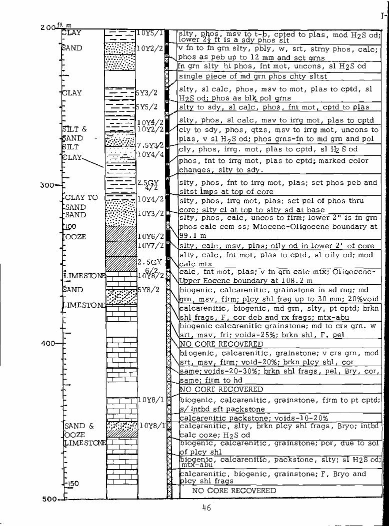
J-ft. m
LAY
Sa n d
’ CLAY
SIlt &-§AND
? ILTCLAY^
CLAY TO:sand•SANDUpoOOZE
LIME STONE]
Sand
IMESTONE
5Y3/2
5Y5/2
T T Ti r
SAND & OOZE LIMESTONE
IT T
H I
10V5/1I
1 0Y2/2 v fn to fn grn s l ty , pbly, w, srt, strny phos, calc ; phos as peb up to 12 mm and set qmsfn grn slty hi phos, fnt mot, uncons, si H2S od
1 0Y4/21 10Y2/27.5Y2/l\10Y4/4
2-5471.0Y4/21
1 0Y3/2
1 0Y6/2 1 0Y7/2
2 .5GY 21 0Y8/2
5Y8/2
--1 50
1 0Y8/1
1 0Y8/1
s l ty , phos, msv to t -b , opted to p las , mod H2 S od; ower 2-| ft is a sdy phos sit
single piece of md grn phos chty s l tsts l ty , si ca lc , phos, msv to mot, plas to cptd, H?.S od; phos as blk pol grns__________________
si
slty to sdy, si ca lc , phos, fnt mot, cptd to plassl ty , phos, si c a lc , msv to irrg mot, plas to cptdcly to sdy, phos, qtzs, msv to irrg mot, uncons to plas , v si H? S od; phos grns-fn to md grn and polc ly , phos, irrg. mot, plas to cptd, si H2 S odphos, fnt to irrg mot, plas to cptd; marked color changes, s lty to sdy.____________________________slty , phos, fnt to irrg mot, plas; set phos peb and sltst Imps at top of core__________________________s l ty , phos, irrg mot, plas; set pel of phos thru core; s l ty cl at top to s lty sd at base__________slty , phos, ca lc , uncos to firm; lower 2" is fn grn phos calc cem ss; Miocene-Oligocene boundary at 9 9 . 1 msl ty , ca lc , msv, plas; oily od in lower 2 ‘ of cores l ty , c a lc , fnt mot, plas to cptd, si oily od; mod calc mtxc a lc , fnt mot, plas ; v fn grn calc mtx; Oligocene- Upper Eocene boundary at 1 0 8 . 2 m_________________biogenic, ca lcaren it ic , grainstone in sd rng; md grn, msv, firm; plcy shl frag up to 30 mm; 20%voidcalcarenit ic , biogenic, md grn, s l ty , pt cptd; brkn shl frags, F, cor deb and rx frags; mtx-abubiogenic calcarenitic grainstone; md to crs grn. w srt, msv, fri; voids-25%; brkn shl , F, pel________NO CORE RECOVEREDbiogenic, ca lcarenit ic , grainstone; v crs grn, mod srt, msv, firm; void-20%; brkn plcy shl, cor______same; v o i d s - 2 0-30%; brkn shl frags, pel , Bry, cor,same; firm to hdNO CORE RECOVEREDbiogenic, ca lcarenit ic , grainstone, firm to pt cptd; s/intbd sft packstone______________________________calcarenitic packstone; vo id s -10 -20%calcarenit ic , s l ty , brkn plcy shl frags, Bryo; intbd calc ooze; H2 S odbiogenic, calcarenitic, grainstone; por, due to solof plcy shlbio^er^ic, calcarenit ic , packstone, slty; si H2S od;
DUcalcarenitic, biogenic, grainstone; F, Bryo and
icy shl frags___________________________________NO CORE RECOVERED
46
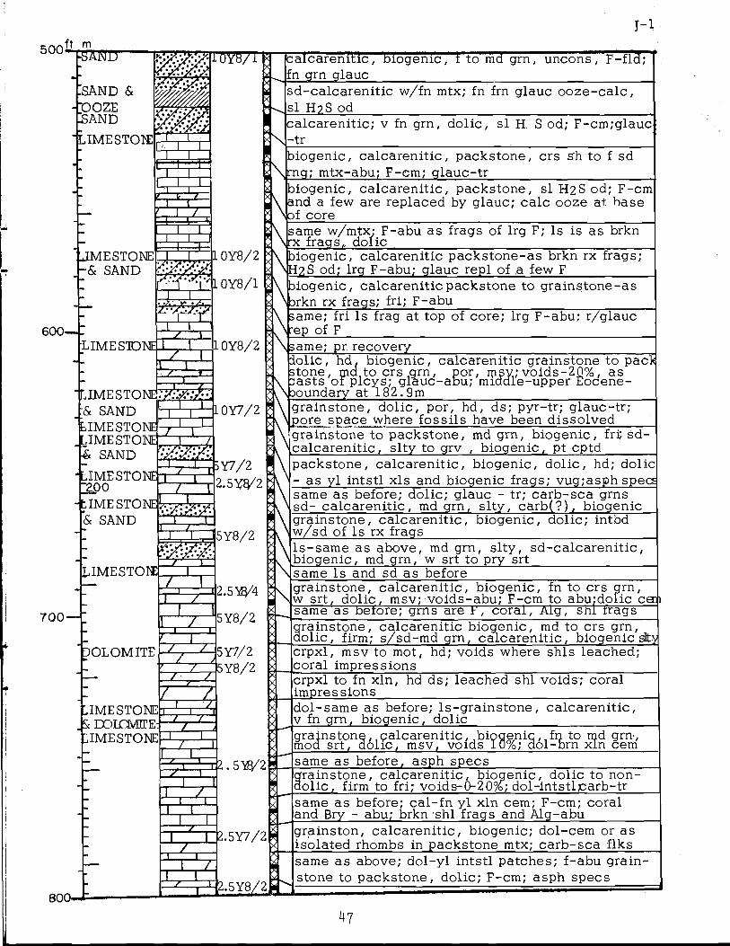
J - l500 ft. m
FSMTD—
SAND & COOZES and
600-
.imestote
lOYB/i Caicarenitic, biogenic, t to md grn, uncons, F-fld; fn grn glauc
~1 T
I I
sd-ca lcarenit ic w/fn mtx; fn fm glauc ooze -ca lc , si H?S od_________________________________________calcarenit ic ; v fn grn, dolic , si H S od; F-cm;glauc -t r
biogenic, calcarenit ic , packstone, si H2 S od; F-cm A and a few are replaced by glauc; calc ooze at. base * \of core
JME STONE -& SAND
LIMESTONE.z :
'LIMESTONE^ & SAND LIMESTONE LIMESTONE & SAND
IME STONE 2-00tIME STONE] & SAND
LIMESTOEE
7 0 0 — I T T T
DOLOMITE
IMESTONE |Sc DOLQWE
IMESTONE
800-
1 0Y8/2
1 0Y8/1
!l 0Y8/2
-10Y7/2
Y7/22.5Y3/2
A same w/mtx; F-abu as frags of lrg F; Is is as brkn * \ rx frags„ dolic ____________________ _______________A biogenic, calcarenitic packstone-as brkn rx frags; * >H2 S od; lrg F-abu; glauc repl of ,a few F___________
biogenic, ca lcarenit ic , packstone, crs Sh to f sd rng; mtx-abu; F-cm; glauc-tr_____________________
\ biogenic, calcarenitic packstone to grainstone-as brkn rx frags; fri; F-abusame; fri Is frag at top of core; lrg F-abu; r/glauc ep of F___________________________________________;ame; pr recovery
[i io l ic , hd, biogenic, calcarenitic grainstone to pack utone, m a t o c r s a r n , por, m s y ;v o id s -2 0 % , as asts o f plcys; glauc-abu; middle-upper Eocene-
oundary at 182 .9mgrainstone, dolic, por, hd, ds; pyr-tr; glauc-tr; pore space where foss i ls have been dissolved
I
5Y8/2
2.5Y8/4
5Y8/2
z:ZL
J L
~Z1
5Y7/25Y8/2
~Z-EZZO
2.5Y7/2
grainstone to packstone, md grn, biogenic, fri; sd- c a lcaren i t ic , s l ty to grv , biogenic, pt cpfd_______packstone, calcarenit ic , biogenic, dolic , hd; dolic - as yl intstl x ls and biogenic frags; vug;asph specssame as before; dolic; glauc - tr; carb-sca grns sd- calcarenit ic , md grn, s l ty , carb(?) , biogenicgrainstone, calcarenit ic , biogenic, dolic; intbd w/sd of Is rx frags ________________________ls -sam e as above, md grn, s l ty , sd -ca lcarenit ic , biogenic, md grn, w srt to pry srt_________________same Is and sd as beforegrainstone, calcarenit ic , biogenic, fn to crs grn, w srt, dolic , msv; voids-abu; F-cm to abu.dolic c e j same as belore; grns are I', coral, Aig, shl fragsgrainstone, calcarenitic biogenic, md to crs grn, dolic , firm; s/sd-md grn, ca lcarenit ic , biogenic sltycrpxl, msv to mot, hd; voids where shls leached; coral impressionscrpxl to fn xln, hd ds; leached shl voids; coral impressions____________________________________dol-same as before; l s -g ra in s ton e , calcarenit ic , v fn grn, biogenic, dolic_________________________grainstoni mod srt, '
calcarenit ic , biogenic, , fn to md grn, lo l ic , msv, voids 10%; dol-brn x l n -----cem2. 5YEJ/2 S same as before, asph specs
grainstone, ca lcarenit ic , biogenic, dolic to non- dolic , firm to fri; vo ids-0-20%; dol-intstlgarb-trsame as before; ca l - fn y l xln cem; F-cm; coral and Bry - abu; brkn shl frags and Alg-abu______
T ~
grainston, calcarenit ic , biogenic; dol-cem or as isolated rhombs in packstone mtx; carb-sca flks
2.5Y8/2H^
same as above; do l-y l intstl patches; f-abu grainstone to packstone, dolic; F-cm; asph specs
47
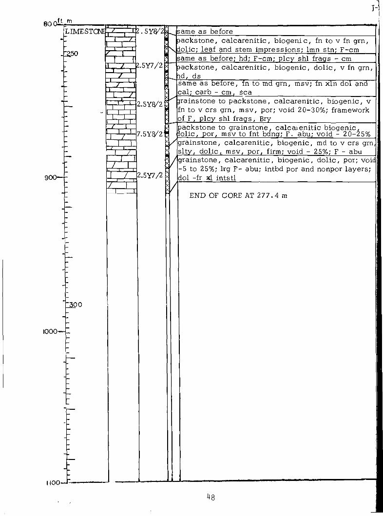
J-
eooilJS-LIMESTCNE]
-E2.50
900—-
-
1300
1000-
1100 _ J L
2. 5YQ/21 ~ I 7I
T - 1 2.5Y7/2
2 = nT ~ I Zc z n i
L I I X
packstone, ca lcaren i t ic , b iogenic, fn to v fn grn, Tsjdolic; leaf and stem impressions; lmn stn; F-cm
X"-
T
2.5YQ/2
7.5Y3/2
K
P TZ ~ K
2.5Y7/2
/|grainstone, calcarenit ic , biogenic, md to v crs grn, sl ty , dolic,. msv, por, firm; void - 25%; F - abu
/
same as before
same as before; hd; F-cm; plcy shl frags - cmpackstone, ca lcarenit ic , biogenic, dolic , v fn grn, id, dssame as before, fn to md grn, msv; fn xln dol and cal ; carb - cm, Sea___________ ___ __________jrainstone to packstone, ca lcarenit ic , biogenic, v En to v crs grn, msv, por; void 20-30%; framework of F, plcy shl frags, Brypackstone to grainstone, calcarenit ic biogenic, io lic , por, msv to fnt bdng; F. abu; void - 2 0 - 2 5 1:
grainstone, ca lcarenit ic , biogenic, dolic , por; void -5 to 25%; lrg F- abu; intbd por and nonpor layers ; dol -fr 3d. intstl
END OF CORE AT 2 7 7 .4 m
48
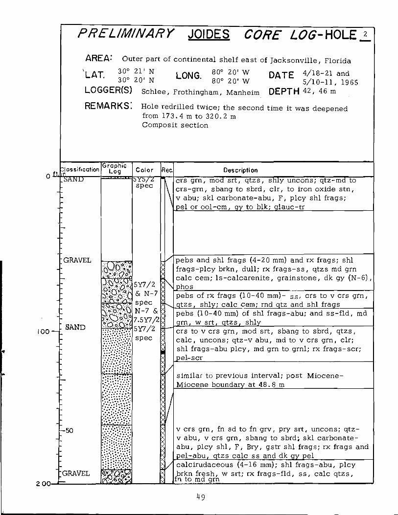
PRELIM INARY JOIDES CORE LOG-HOLE 2
AREA-* Outer part of continental shelf east of Jacksonvil le , Florida
L A T 3 ° 21' N I ONG ®°° 20' W DATE 4/18-21 and30° 20' N LUN^ 80° 20' W 5 / 1 0 - 1 1 , 1 9 6 5
LOGGER(S) Schlee, Frothingham, Manheim DEPTH 42, 46 m
REMARKS. Hole redrilled twice; the second time it was deepened from 1 7 3 .4 m to 32 0 .2 m Composit section
O*1Classification
^AJMDGraphic
Log C o lo r Rec Description
crs grn, mod srt, qtzs, shly uncons; qtz-md to crs-grn, sbang to sbrd, clr , to iron oxide stn, v abu; ski carbonate-abu, F, plcy shl frags; pel or ool-cm, gy to blk; glauc-tr______________
-GRAVEL
100— 1 S A N D
-50
-GRAVEL2 00-
5 Y 5 /Zspec
i f f5Y7/2 & N-7 spec N-7 & 7.5Y7/2 5Y7/2 spec
pebs and shl frags (4-20 mm) and rx frags; shl f rags-p lcy brkn, dull; rx f r a g s - s s , qtzs md grn calc cem; l s -c a lc a re n i te , grainstone, dk gy (N-6), phos_______________________________________________pebs of rx frags (10-40 mm)- ss- crs to v crs grn, qtzs, shly; calc <cem; rnd qtz and shl frags________pebs (10-40 mm) of shl frags-abu; and s s - f ld , md grn, w srt, qtzs, shly_____________________________crs to v crs grn, mod srt, sbang to sbrd, qtzs, c a lc , uncons; q tz -v abu, md to v crs grn, clr; shl frags-abu plcy, md grn to grnl; rx f rags-scr ; pel-scr__________________________________________
............
.> • • • - • . . • •
similar to previous interval; post Miocene- Miocene boundary at 4 8 .8 m________________
v crs grn, fn sd to fn grv, pry srt, uncons; qtz- v abu, v crs grn, sbang to sbrd; ski carbonate- abu, plcy shl, F, Bry, gstr shl frags; rx frags and pel-abu, qtzs calc ss and dk gy pel_______________calcirudaceous (4 -16 mm); shl frags-abu, plcybrkn fresh, w srt; rx f rags- f ld , s s , calc qtzs,
fn to md grn_____________________________________
49

1 - 2
2 0 0 ft m *" T ravel
SILT
SILTCLAY
3 0 0 -
4 0 0 -
liQOm LAY
7.5Y4/ 4 * sdy (y fn grn), c a lc , msv to fnt mot, cptd
W 44l1 0Y5/2
as on the previous page
. 5 GY 6/4
0Y5/2
sdy, mod srt, qtzs, ca lc , msv to fnt mot, uncons; ?- cm; s/qtz sd; g lauc-tr , strn H2 S od
sdy, qtzs, ca lc , phos, msv to fnt mot, plas to un- cpns; F-cm to abu; qtz-cm. v fn arn; strn H9 Sod; phos - dk gy crpxl pebs; upper Miocene-lower Miocene boundary at 79.2m
slty , ca lc , si phos, msv to fnt mot and lamd cptd; qtz-tr; F-cm; oily od______________________________slty , ca lc , phos, msv to mot, cptd, oi ly od; phos- sea grnl and pebs, dk gy; sd-tr__________________s l ty , msv to fnt mot, plas to pt cptdsame as before; phos-cm as sea dk grns
5 0 0 - k
s l ty , ca lc , phos, msv to indst lam, plas to cptd;F-scr to cm; phos cm as sea grns (sd to peb) polNO CORE RECOVERED- s lty cl and phos peb in catcher ________
sl ty , msv to fnt lamd, plas to pt cptd; F -sca to abuNO CORE RECOVERED-catcher plugged by ss andshl frags ______ _______ _____________s l ty , msv to lamd, cptd; F-scr ; p h os-sc r , as bik pol grnsI s l ty , phos, mot to msv (pt cptd to crumbly); phos- blk sbrd grns, 12 mm or le ss in s iz e , abu in upper
2 feet; scr at base_________________________________s l ty , msv to indst lamd, pt cptdsame as before; phos, plasNO CORE RECOVEREDsl ty , phos, msv to lamd, plas to pt cptd; lower Miocene -Oligocene, boundary at 121 .3m _________c a lc , msv to fnt bd, pt cptd to crumbly; phos-tr
s l ty to c ly , c a lc , phos, fnt bd and mot, plas toPt cptd.____________________________________________s l ty , c a lc , msv, plas to crumbly; qtz-as s i t , cm si s l ty , strn ca lc , msv, si plas to crumbly________
si s l ty , v ca lc , msv to fnt mot, plas to crumbly
same as above; msv to fnt lam; phos-tr____________
s l ty , v ca lc , msv to fnt lamd, plas to cptd_______ _same as before; cptd,fnt mot and lamd____________ _si s l ty , v ca lc , msv to fnt lamd, si plas__________
c a lc , c ly , impure msv tp mot to fnt lamd, cptd,oily od; F-abu; phos-tr ls -packstone , glauc, msv, hd to firm; Oligocene-Upper Eocene boundary at 149 . 4 m ___________ _
50
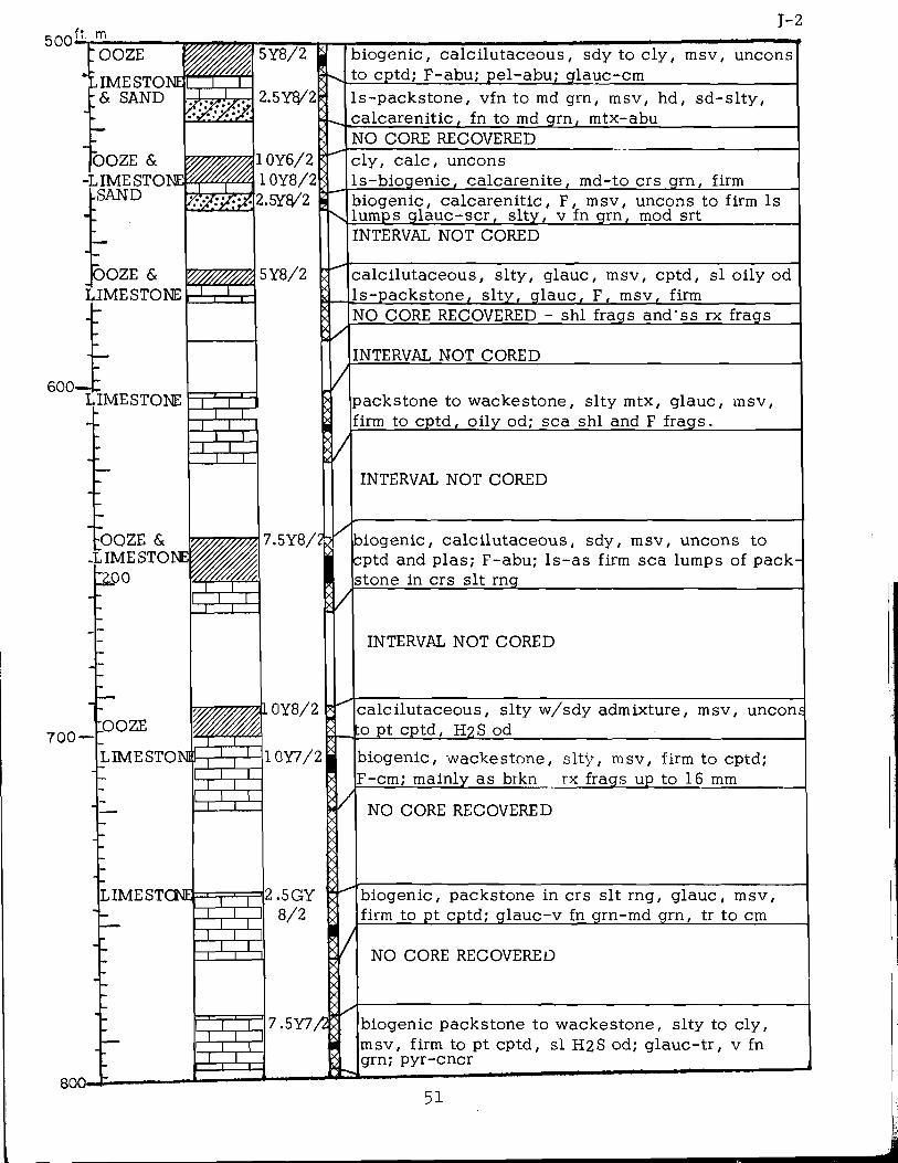
500 ft. mJ - 2
: ooze
, IMESTONE & SAND
OOZE &IMESTONE*
lSAND
OOZE & LIMESTONE
600-LIMESTONE
5Y8/2 |
2.5YQ/2
biogenic, ca lc i lu taceous , sdy to c ly , msv, uncons to cptd; F-abu; pel-abu; glauc-cm.s-packstone, vfn to md grn, msv, hd, sd -s l ty , calcarenit ic , fn to md grn, mtx-abu_____________NO CORE RECOVERED
1 0Y6/2 1 0Y8/2 2.5Y8/2
5Y8/2
c ly , c a lc , uncons.s-biogenic, calcarenite , md-to crs grn, firm3iogenic, ca lcarenit ic , F, msv, uncons to firm Is .umps g lauc-scr , s l ty , v fn grn, mod srt_________INTERVAL NOT CORED
r r ncalci lutaceous, s l ty , glauc, msv, cptd, si oi ly od .s-packstone, s l ty , glauc, F, msv, firm__________NO CORE RECOVERED - shl frags and'ss rx frags
INTERVAL NOT CORED
/
packstone to wackestone, s l ty mtx, glauc, msv, :irm to cptd, oi ly od; sea shl and F frags._______
INTERVAL NOT CORED
-OOZE & IMESTONE
C2P0
700 —LOOZE
LIMESTON#
800— t-
1 0Y8/2
LIMESTONE
I i r
TTT
T ~ T
1 T1 I
T TT ~ TT ~ \
10Y7/2
biogenic, calc i lutaceous, sdy, msv, uncons to cptd and plas ; F-abu; l s - a s firm sea lumps of pack- stone in crs sit rng_________________________________
INTERVAL NOT CORED
calci lutaceous, s lty w/sdy admixture, msv, uncons . to pt cptd, H2S od________________ ________________
2.5G Y 8 / 2
biogenic, wackestone, s l ty , msv, firm to cptd; F-cm; mainly as brkn rx frags up to 16 mm
NO CORE RECOVERED
biogenic, packstone in crs sit rng, glauc, msv, firm to pt cptd; g lauc-v fn grn-md grn, tr to cm
7.5Y7,
NO CORE RECOVERED
biogenic packstone to wackestone, s lty to c ly ,msv, firm to pt cptd, si H2S od; g lauc-tr , v fn grn; pyr-cncr ______
51

80 0.ft. m
900-
1000—
1100
NO CORE RECOVERED
biogenic, ca lcarenit ic , s l ty , mot, pt cptd to fri; mtx- 30-40%; shl frags-brkn (up tp 8 mm); pel; Ech; glauc-tr__________________ __________________biogenic, calcarenite , md grn (frags up to 10 mm),mod to pry srt, g la u c , carb, msv, firm to hd, oily od; carb-blk oi ly flk; Alg; shl^brkn plcy frags; mtxbiogenic, s lty packstone, glauc, msv to fntly lam, F-abu; Algo o ze -s l ty , ca lc , msvbiogenic, ca lcarenit ic , packstone, v m grn sd to crs s i t , mod srt, msv, hd to firm; glauc (?)______c ly , biogenic, ca lc i lu taceous , s l ty , msv, mic crumbly to plas; Is Imps_______________________biogenic, s lty packstone, msv, firm to cptd, H2 S od; glauc-lmps of v fn grn agrs
si
biogenic, sdy to s l ty packstone, glauc, msv, firm; g lauc-scr , as sm cluster agrs
biogenic, calcarenit ic , packstone, crs sit rng, msij firm to pt cptd; F-cm; sea glauc, mod srt_________biogenic, calcarenit ic , grainstone to packstone, fn sd to crs sit rng, msv, firm to cptd; glauc c lusters , tr; ca rb-sea blk flk____________________biogenic, calcarenit ic , grainstone to packstone, v fn grn, w srt, msv, por, firm to pt cptd; g lauc-tr , agr clumps; calc frags-Alg_________________________ls-md grn, biogenic, calcarenit ic , grainstone, glau c l - c a l , glauc, plas to crumbly; g lau c-v abu, md grn Upper Eocene-Middle Eocene boundary at 298.8 mfn gr biogenic, ca lcarenit ic , grainstone, w srt, dolic, msv, hd, vug; dol- intst l cem; sea glauc-trbiogenic, ca lcarenit ic , grainstone, dolic , por, msv. hd; carbdo l -ca lc , msv, glauc, hd______________________biogenic, calcarenite , fn to crs grn, w srt, dolic , msv, hd; F-cm; pel-abu___________________________biogenic, ca lcarenit ic , md grn, w srt, por, msv, hd; dol- intst l y l fn x ls and as fi l l ing of bioclastic rags_______________________________________________
[biogenic, calcarenit ic , grainstone, md to fn grn, o l ic
biogenic, calcarenit ic , grainstone, dolic , msv, por to solid, hd; voids-up to 30%; F; cor and Alg deb; shl frags__________________________________________
END OF CORE AT 32 0 .2 m
52
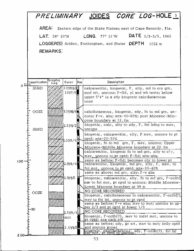
PRELIM INARY JOIDES CORE LOG- H O LE j.
AREA: Eastern edge of the Blake Plateau east of Cape Kennedy, Fla.
LAT. 28° 30'N LONG. 77° 31 'W DATE 5/3-5/5, 1965
LOGGER(S) Schlee, Frothingham, and Shuter DEPTH 1032 m
r e m a r k s :
~ 7 7 . [Graphic Jassification (_0g
SAND
Description
calcarenit ic , biogenic, F, s l ty , md to crs grn, mod srt, uncons; F-f ld , y l and wh tests ; below upper 5'4" is a sdy biogenic calcilutaceous ooze
calc i lutaceous, biogenic, sdy, fn to md grn, uncons; F-v , abu; mtx-40-60%; post Miocene-Mio- cene boundary at 1 2 . 2 m _________________________biogenic, ca lc , s lty to sdy, F, fnt bdng to msv, unconsbiogenic, calcarenit ic , s l ty , F msv, uncons to pt cptd; mtx-2 0-5 0%_________________________________biogenic, fn to md grn, F, msv, uncons; Upper Miocene-Middle Miocene boundary at 22.9mcalcarenit ic , biogenic fn to md grn, s l ty to c ly , msv, uncons to pt cptd; F-fld; mtx-abu_________same as before; F-fld; becomes c ly in lower ptcalcarenit ic , biogenic, md grn, s l ty , F, msv, to fnt mot, uncons to pt cptd; mtx-30-40%__________same as above; md grn, s lty; F-v abubiogenic, calcarenit ic , s l ty , fn to md grn, F-cclh( msv to fnt mot, pt cptd to uncons; Middle Miocene- Lower Miocene boundary at 39 m_________________NO CORE RECOVEREDbiogenic, calcilutaceous to calcarenit ic , F-cclh(?) msv to fnt bd, uncons to pt cptd___________________same as before; F -v abu; msv to mot; uncons in up per 2/3 and pt cptd in lower 1/3___________________NO CORE RECOVEREDbiogenic, F -cc lh (? ) , msv to indst mot, uncons to pt cptd; sea carb stk______________________________
2 0 0
same as before; sdy, pr srt, msv to mot; intly cptdand uncons zones_____________________
r - c c l h ( ? ) , fnt bdEJTonenic ancr mot,53
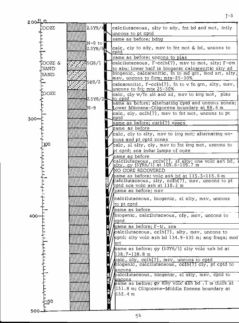
1 - 32 00- ft. m
.OOZE
3 0 0 -
:ooze'SANDSAND
*OOZE
11Q0
4 0 0 -
500-
-150
.5Y9/ L.
-9 to 5Y8/6|
5G9/1
5Y8/2
ca lc i lu taceous , s lty to sdy, fnt bd and mot, intly uncons to pt cptd__________________________________same as before; bdng
ca lc , c ly to sdy, msv to fnt mot & bd, uncons to cptd______________________________________________same as before; uncons to plascalci lutaceous, F -cc lh (? ) , msv to mot, slty; F-cm to abu; lower half is biogenic calcarenit ic s l ty sdbiogenic, ca lcarenit ic , fn to md grn, mod srt, s l ty , msv, uncons to firm; mtx-25-30%calcarenit ic , F -c c lh (? ) , fn to v fn grn, s l ty , msv, uncons to fri; mtx 2 5 -30% _________________________ca lc , c ly w/fn sit and sd, msv to irrg mot, plas to cptdsame as before; alternating cptd and uncons zones; .ower Miocene-Oligocene boundary at 8 8 . 4 m_____calc , c ly , c c lh (? ) , msv to fnt mot, uncons to pt ■ CPtdsame as before; carb(?) specssame as beforecalc, c ly to s l ty , msv to irrg mot; alternating un- cons and pt cptd zones____________________________calc, si s l ty , c ly , msv to fnt irrg mot, uncons to 3t cptd; sea indur lumps of ooze__________________same as before
'calci lutaceous. c c lh (? ) , si s l t y • one vole ash bd, sl ty . gy (5YR6/1) at 1 0 9 .6 - 1 0 9 . f r m_______________
'NO CORE RECOVERED'same as before; vole ash bd at 115 . 5 - 1 1 5 . 6 -m
calcilutaceous, s l ty , c c lh (? ) , msv, uncons to pt cptd sea vole ash at 1 1 8 . 2 m_____________________same as before; msv
calci lutaceous, biogenic, si s l ty , msv, uncons to pt cptd_______________________________________same as beforebiogenic, calc i lutaceous, c ly , msv, uncons tocptd________________________________________________same as before; F-tr , sea___________________ ______calci lutaceous, c c lh (? ) , s l ty , msv, uncons to cptd; s lty vole ash bd 1 3 4 . 9 - 1 3 5 m; ang frags; modsrt__________________________________________________
/same as before; gy (10Y6/1) s lty vole ash bd at1 3 8 . 7 - 1 3 8 . 8 m_____________________________________calc, c ly , c c lh (? ) , msv, uncons to cptd ____ciogenic, calc i lutaceous, cc lh(?) c ly , pt cptd toancons_____________________________________________calcilutaceous, biogenic, si s l ty , msv, cptd toancons________________________________ r..—_____same as before; gy s l ty vole ash bd . 1 m thick at1 5 1 . 8 m; Oligocene-Middle Eocene boundary at 1 5 2 .4 m
54
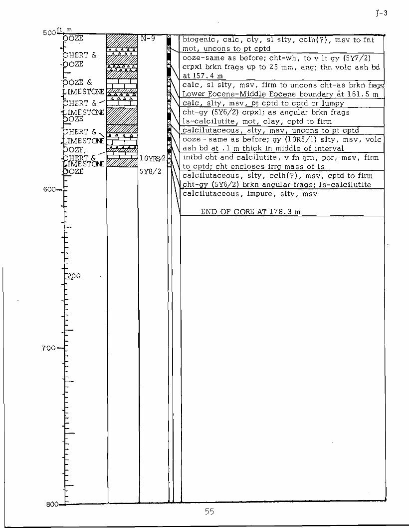
J - 3
500 ft. mDOZE
CHERT & -bozE
pOZE & LIMESTONEIdhert &■LIMESTONEOOZE
CHERT & N .LIMESTONE OOZE, ^-CHERT &LIMESTONEOOZE
600-
7 0 0 -
800-
'200
A A A f
1 TA A A AI , I
A A A A
ioyrs/25Y8/2
biogenic, ca lc , c ly , si s l ty , c c lh (? ) , msv to fnt mot, uncons to pt cptd ______ ____ ____ooze-same as before; cht-wh, to v It gy (5Y7/2) crpxl brkn frags up to 25 mm, ang; thn vole ash bd at 157 . 4 mc a lc , si s l ty , msv, firm to uncons cht-as brkn frags; Lower Eocene-Middle Eocene boundary at 1 6 1 . 5 mc a lc , s l ty , msv, pt cptd to cptd or lumpycht-gy (5Y6/2) crpxl; as angular brkn frags l s - c a lc i lu t i t e , mot, c lay , cptd to firmca lc i lu taceous , s l ty , msv, uncons to pt cptd______ooze - same as before; gy (10R5/1) s l ty , msv, vole ash bd at . 1 m thick in middle of intervalintbd cht and ca lc i lu t i te , v fn grn, por, msv, firm to cptd; cht encloses irrg mass of Iscalci lutaceous, s l ty , c c lh (? ) , msv, cptd to firm cht-gy (5Y6/2) brkn angular frags; l s -ca lc i lu t i te calci lutaceous, impure, s l ty , msv
END OF CORE AT 178 . 3 m
55

PRELIM INARY JOIDES CORE Z.<26- HOLE 4
AREA-' North outer part of the Blake Plateau, east of Georgia
LAT. 31° 02' N LONG. 77° 4 3 ’ W DATE May 1 3 - 1 5 , 1965
LOGGER(S) Sehlee, Frothingham, Emery DEPTH 892 mand Wait
re m a rk s : Second redril l of hole
0 H llassificationhlb SAND
(surface) SAND
100
2 00-
Graphic Log C o lo r Rec Description
10YR8/4x\ biogenic, ca lcarenit ic , F, Pt, msv, uncons
'1 0YR£j/7 :2.5Y^2 '2 .5 Y 8 / 4 y ’ 2 5Y7/6 I
biogenic, ca lcarenit ic , md to crs grn, w srt, F, Pt, msv to color banded; color changes due to variation in color of s lty mtx; otoli th-scr ; post Miocene-Lower Miocene boundary at 1 8 . 3 m
m
- 5 0
, 1 0YR8/I,
5Y8/1
biogenic, calcarenitic fn to md grn, mod srt , msv to fnt mot, uncons; calc mtx in s l t - c l rng, abu; F - fid; s/F stn yl__________________________________ __biogenic ca lcarenit ic , s l ty , fn grn, mod to pr srt, F, fnt mot, uncons; sea calcarenit ic packstone rx frags; glauc-tr____________________________________
10Y6/15Y8/1
10Y6/5Y8/1
5Y8/:
f|7. 5YQ/:
biogenic calcarenitic s l ty , fn to v fn grn, mod to pr srt, F, msv w/sca lam, uncons; dk mnrls-scrbiogenic, calcarenit ic , F, unconsbiogenic, calcarenit ic , s l ty , fn grn, mod to pr srt, F, msv, uncons; mtx-20%; . 1 m gy sdy, c a lc , clay layer in middle of core.___________________________biogenic calcarenit ic , fn to v fn grn, s l ty , F, msv, uncons; mtx up to 20%; F-fld; glauc-tr; dk mnrls-trbiogenic, calcarenit ic , fn grn, s l ty , F, msv, uncons; mtx - 20-30%; glauc-tr; sea Imps of calcaren itic IsNO CORE RECOVERED
5Y8/1
biogenic ca lcarenit ic , s l ty , fn grn, pr to mod srt, F, msv to fnt bd, uncons; F- fid; mtx - 20%; sea pods of cl; Lower Miocene-Oligocene boundary at 5 3 . 3 mNO CORE RECOVERED
56
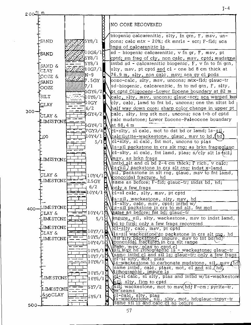
200ii
300
400
5 0 0
J - 4m
SAND
SAND
SANDCLAY
POZESANDOOZE
SILT
CLAY
CLAY & LIMESTONE.
5Y8/1
NO CORE RECOVERED
I
l&o
fG Y 4 / l I7GY3/4 10Y4/1
■ S 3 s/‘
LIMESTONE
ICLAY &
-LIMESTONE_L 1 0Y4/1
2.5GY I . L-. 6/2= ^ 1 0 Y 4 / 1
I_pME STONE pLAY & -LIMESTONEtjIME STONE
OLAY &T~zrI
I ME STONE H m n _
,IME STONE
LIMESTONE : <$50 CLAY
T~_L
1 0Y4/1 5/1
10Y7/110Y5/110Y4/1
1 0Y5/1 10Y7/1 10Y6/1
1 0Y5/1 1 0Y6/1
biogenic calcarenit ic , s l ty , fn grn, F, msv, uncons; calc mtx - 20%; dk mnrls - scr; F-fld; sea Imps of calcarenitic Is___________________________sd - biogenic calcarenit ic , v fn gr, F, msv, pt cptd; sm frag of c ly , non ca lc , msv, cptd; mudstmeintbd sd - calcarenitic biogenic, F, v fn to fn grn, s l ty , msv, pt cptd and c l - one bd 8 cm thick at 7 6. 9 m, s l ty , non ca lc , msv; sea gy cl pods _ooze -ca lc , s l ty , msv, uncons; mtx-fld; glauc-tr sd-biogenic, calcarenit ic , fn to md grn, F, s l ty , pt cptd Oligocene-Lower Eocene boundary at 82 mcalc , s l ty , msv, uncons; g lauc-scr ; sea warped lamcly , c a lc , lamd to fnt bd, uncons; one thn s l tst bd half way down core; sharp color change in upper pt;a lc , s l ty , irrg stk mot, uncons; sea t -b of cptd ;alc mudstone; Lower Eocene-Paleocene boundary
Jat 88. 4 mi l - s l t y , si ca lc , mot to dst bd or lamd; l s - s j l ,
dsalciluti te-wackestone, glauc, msv to bd,fhd) c l - s l t y , si c a lc , fnt mot, uncons to plas
ll s - s i l packstone in crs sit rng; as brkn frags;gl^uc c l - s l t y , si ca lc , fnt lamd, plas; s/cly sit Is-(sil
\msv, as brkn frags.ntbd s it and cl bd 2 -4 cm thick; F rich, v calc ; Lsfsi l) packstone in crs sit rng; indst x-lamdsiT, packstone in sit rng, concoidal fracture, hd
glauc, msv to fnt lamd,
same as before; F-fld; glauc-tr; indst bd, nly a few frags__________________________
hd;
e l - s l c a lc , s l ty , msv, pt cptd Ls-sil , wackestone, s l ty , msv
1 -s l ty , ca lc , msv. s - s i l packstone in cr~s to
_ _____ hdcptd; intbd w/
md sit , fnt motiaroe as before; fnt bd; glauc-trimpure, s i l . s l ty , wackestone, msv to indst lamd,
yid to firm; only a few frags recovered______________I1 c l - s l t y , ca lc , msv, pt cptdl s - s i l wackestonevto packstone in crs sit c 5il-;Slty;.:paokSt0hg/ impure. msv to tnt bd Concoidal ffacTurg> in crs sit range______
hd
rc, msv, , m sv hd itllograp(lucCls'*,- wackestone; glauc-trsame intbd cl and sil Is; glauc-tr; only a few frags c i - s l s l ty , mot, plasls-wackestone to carbonate mudstone, sil,.,,msvsame intbd, ca lc , p last , l ithographic, impure Is
mot, cl and sil , (hd\s l ty , firm to cptd_______ , . __________________
v { s i l l wackestone, mot to msv(hd; F-cm ; pyri te-tr, N; i n s earns_______________________ '__________________
- s i c a lc , si s l ty , plas and intbd w/ls-wackestone
. pl-calc,, s l t y , pla.^wack'estone, s i l , s l ty , mot, hd;glauc-ti;pyr-tr
same sil Is and caic cl as before"_________'57
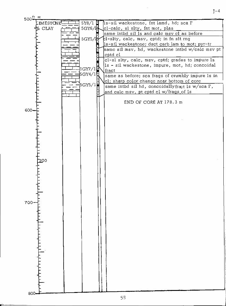
5Y8/15GY6/1
5GY5/1
l s - s i l wackestone, fnt lamd, hd; sea F c l - c a l c , si s l ty , fnt mot, plas_________
5GY7/15GY4/1
5GY5/1• \
same intbd sil Is and calc msv cl as before1 -s l ty , ca lc , msv, cptd; in fn sit rng
l s - s i l wackestone; dsct carb lam to mot; pyr-trsame sil msv, hd, wackestone intbd w/calc msv pt cptd cl_____________________________________________c l - s l s l ty , ca lc , msv, cptd; grades to impure Is Is - si l wackestone, impure, mot, hd; concoidal fractsame as before; sea frags of crumbly impure Is in cl; sharp color change near bottom of coresame intbd sil hd, concoidallyfract Is w/sca F, and calc msv, pt cptd cl w/frags of Is__________
END OF CORE AT 1 7 8 .3 m
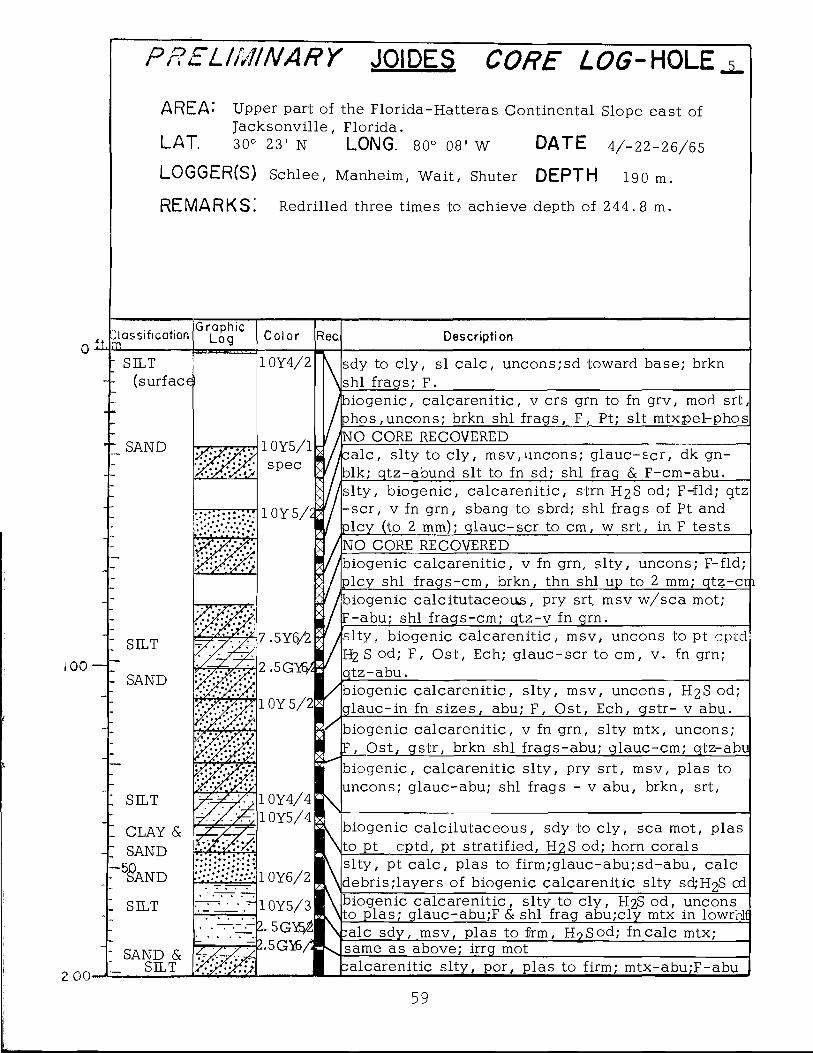
100
2 0 O'
AREA: Upper part of the Florida-Hatteras Continental Slope east ofJacksonvil le , Florida.
LAT. 30° 23' N LONG. 80° 0 8 ’ W DATE 4/-22-26/65
LOGGER(S) Schlee, Manheim, W ait , Shuter DEPTH 190 m.
re m a rk s : Redrilled three times to achieve depth of 2 4 4 .8 m.
PRELIM INARY JOIDES CORE LOG-HOLE
Classificationm.' SILT |~
(surface^
GraphicLog Color
1 0Y4/2
- SAND 1 0Y5/1 spec
10Y5/2
Rec Description
sdy to c ly , si ca lc , uncons;sd toward base; brkn .shl frags; F.______________________________________
siogenic, calcarenit ic , v crs grn to fn grv, mod srt, phos,uncons; brkn shl frags, F, Pt; sit mtx,pel-phos
/NO CORE RECOVEREDcalc, s lty to c ly , msv,uncons; g lauc-sc r , dk gn-
blk; qtz-abund sit to fn sd; shl frag & F-cm-abu./slty, biogenic, calcarenit ic , strn H2 S od; F-fld; gtz
-scr, v fn grn, sbang to sbrd; shl frags of Pt and nicy (to 2 mm); g lauc-scr to cm, w srt, in F tests
'NO CORE RECOVERED
SILT
SAND
I SILT
CLAY & SAND
‘5§a nd
I SILT
SAND & . SILT
'biogenic calcarenit ic , v fn grn, s l ty , uncons; F-fld; plcy shl f rags-cm, brkn, thn shl up to 2 mm; qtz-crh
7 .5Y6/21
2.5G T6/
1 0Y 5 /2 l
/biogenic calcitutaceoivs, pry srt msv w/sca mot; F-abu; shl frags-cm; qtz-v fn grn.s l ty , biogenic calcarenit ic , msv, uncons to pt H2 S od; F, Ost, Ech; g lauc-scr to cm, v . fn grn; qtz-abu.
'biogenic ca lcaren it ic , s l ty , msv, uncons, H2 S od; glauc-in fn s izes , abu; F, Ost, Ech, gstr- v abu.biogenic calcarenit ic , v fn grn, s lty mtx, uncons;F, Ost, gstr, brkn shl frags-abu; glauc-cm; qtz-abu
1 0Y4/4 10Y5/4
biogenic, calcarenit ic s l ty , pry srt, msv, plas to uncons; glauc-abu; shl frags - v abu, brkn, srt,
biogenic calc ilutaceous, sdy to c ly , sea mot, plas Jto pt cptd, pt stratified, H2 S od; horn corals______
; 1 0Y6/2
■10Y5/32 . 5 G M2.5GYL
slty , pt ca lc , plas to firm;glauc-abu;sd-abu, calc ^debris;layers of biogenic calcarenitic slty scfcH S odbiogenic calcarenit ic , s lty to c ly , H2S od, uncons
yto plas; glauc-abu;F & shl frag abu;cly mtx in lowrilicalc sdy, msv, plas to frm, H?Sod; fn calc mtx;same as above; irrg motcalcarenitic s l ty , por, plas to firm; mtx-abu;F-abu
59
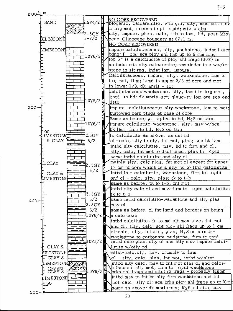
2 00-
300
400
5 0 0
J-s. m
: SAND
SILTSTONE/
[.IMESTONE
L5Y4/2
2.5GY5-7/2
T Z Jr~n~
T T TTT~E
!00.IMESTONE
& CLAY
—nrn
T~~T
l ~ T
T~~T
?J0 CORE RECOVERED
\ x \
1 0Y6/2
Piogenic, calcarenit ic , v in grn, s ity , mod srt, ms's :o irrg mot, uncons to pt cptd; mtx-v abuslty , impure, phos, ca lc , t -b to lam, hd, post Mio cene-Oligocene boundary at 67 .1 m._______________NO CORE RECOVEREDimpure ca lc i lu taceous , s l ty , packstone, indst flaser bdng; F- cm; sea plcy shl imp up to 6 mm long
^ I r II • - 1 _ • 1 ■ j_ _ _ £ __ 1 l_ 1 r________ /r\ r\r\/ \ •
1 0Y5/2
top 5" is a calcirudite of plcy shl frags (30%) in an indur mtx slty calcarenite; remainder is a wacke- stone in sit rng, indst lam, impure._______________
a lc i lu taceous , impure, s l ty , wackestone, lam to (irrg mot, firm; lamd in upper 2/3 of core and mot n lower 1/3; dk mnrls - scr_______________________calcilutaceous wackestone, s l ty , lamd to irrg mot, cptd to hd; dk mnrls-scr; g lauc-tr ; lam are sea anc dstb_______________________________________________
1 0Y6/2
T ~ T
■CLAYnzr
■ CLAY & F _ JME STONE l l
2.5GY5/2
impure, calcilutaceous slty wactestone, lam to mot; burrowed carb ptngs at base of core______________Same as before; pt cpted to hd; H9 S od strnimpure calcilutite-wackestone, s l ty . msv w/sca bk lam, firm to hd, H?S od strn_________________Ls calciluti te as akove. as dst bdc l - c a l c , s lty to c ly , fnt mot, p las; sea bk lam
2.5GY 6 / 2
intbd slty calc i lut i te , msv, hd to firm and c l , s l ty , c a lc , fnt mot to dsct lamd, plas to cptdsame intbd calciluti te and slty clmainly s l ty , calc p las , fnt mot cl except for upper 13 cm of core which is a s lty hd to firm calciluti teintbd ls - calc i lut i te , wackestone, firm to and cl - c a lc , s l ty , plas ; tk to t -b_______
cptd
same as before, tk to t -b , fnt mot
1 r
rr~ T
2.5GY 5/2
2.5GY 6 / 2
1 0Y6/2
ntbd slty calc cl and msv firm to tk to t -b
~i r
n— r
: CLAY & SILTSTONE t~ CLAY &
same intbd calcilutite-wackestone and slty plas msv clsame as before; cl fnt lamd and borders on being a calc oozeintbd calc i lut i te , fn to md sit max s ize , fnt mot and c l , s l ty , ca lc ; sea plcy shl frags up to 1 cm
1 0Y5/2
cptd calciluti te;
c l -c a lc , s l ty, fnt mot, p las , S od strn l s - wacfestone to carbonate mudstone, firm to cptdintbd calc plast s l ty cl and slty msv impure ca lc i - utite w/oily od____________________________________s l t s t - c a l c , c l y , msv, crumbly to firmcl - s l ty , ca lc , p las , fnt mot, intbd w/sltstintbd sl ty ca lc , msv to fnt mot plas cl and c a lc i lutaceous slty mot, firm to cptd waclestone Brkn shl frags and s l tst rx f r a g s - probably slumpintbd msv to fnt bd slty firm wactestone and fnt mot ca lc , s lty cl; sea brkn plcy shl frags up to 2 0 msame as above; dk mnrls-scr; H2 S od strn; msv
n
60
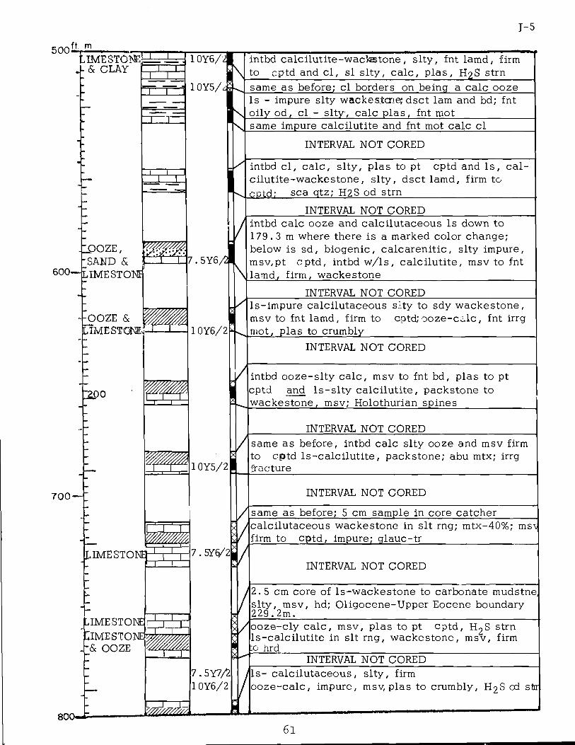
J-5
500 ft. mU M B S T O i i E ^
& CLAY . I . I.
600-
JPOZE, SAND & .IME STONE]
-OOZE & IME STONE,
7 0 0 -
T Z J.
r z
JT~X
2.00
/
1 0Y6/2\
i i
LIMESTONE!rrrr
IME STONEPMESTONE -& OOZE
~ r~ n
i
/1 0Y5/21
7.5YQ/2
intbd calc i luti te-wacks ton e , s l ty , fnt lamd, firm to cptd and c l , si s l ty , ca lc , p las , H2 S strnsame as before; cl borders on being a calc oozeIs - impure slty wackesicne; dsct lam and bd; fnt oily od, cl - s l ty , calc p las , fnt mot____________same impure calciluti te and fnt mot calc cl
INTERVAL NOT CORED
intbd c l , ca lc , s l ty , plas to pt cptd and Is , cal- c i lu t i te -w ackestone , s l ty , dsct lamd, firm to cctd: sea gtz; H2S od strn_______________________
INTERVAL NOT COREDintbd calc ooze and calcilutaceous Is down to 1 7 9 . 3 m where there is a marked color change; below is sd, biogenic, ca lcarenit ic , slty impure, msv,pt cptd, intbd w/ls , ca lc i lu t i te , msv to fnt lamd, firm, wackestone___________________________
INTERVAL NOT COREDls-impure calcilutaceous slty to sdy wackestone, msv to fnt lamd, firm to cptd; o o z e - c a l c , fnt irrg mot, plas to crumbly______________________________
INTERVAL NOT CORED
intbd o o ze -s l ty ca lc , msv to fnt bd, plas to pt cptd and l s - s l t y ca lc i lu t i te , packstone to wackestone, msv; Holothurian spines__________
INTERVAL NOT COREDsame as before, intbd calc s l ty ooze and msv firm to cptd l s - c a lc i lu t i t e , packstone; abu mtx; irrg fracture
INTERVAL NOT CORED
same as before; 5 cm sample in core catchercalcilutaceous wackestone in sit rng; mtx-40%; ms\ firm to cptd, impure; glauc-tr___________________
INTERVAL NOT CORED
12 .5 cm core of l s -wackestone to carbonate mudstnes l ty , msv, hd; Oligocene-Upper Eocene boundary 229. 2m.
io oze -c ly c a lc , msv, plas to pt cptd, l s -ca lc i lu t i te in sit rng, wackestone, msv,:g hrd
H9S strn - firm
INTERVAL NOT CORED7. 5Y7/2 1 0Y6/2
Is- calc i lutaceous, s l ty , firm o o ze-ca lc , impure, msv, plas to crumbly, H2 S od stir
800-61

80 0-ft m
• 12.50
900 -
"300
1000-
I iQO-
I-IEND OF CORE AT 2 4 5 . 1 m
62
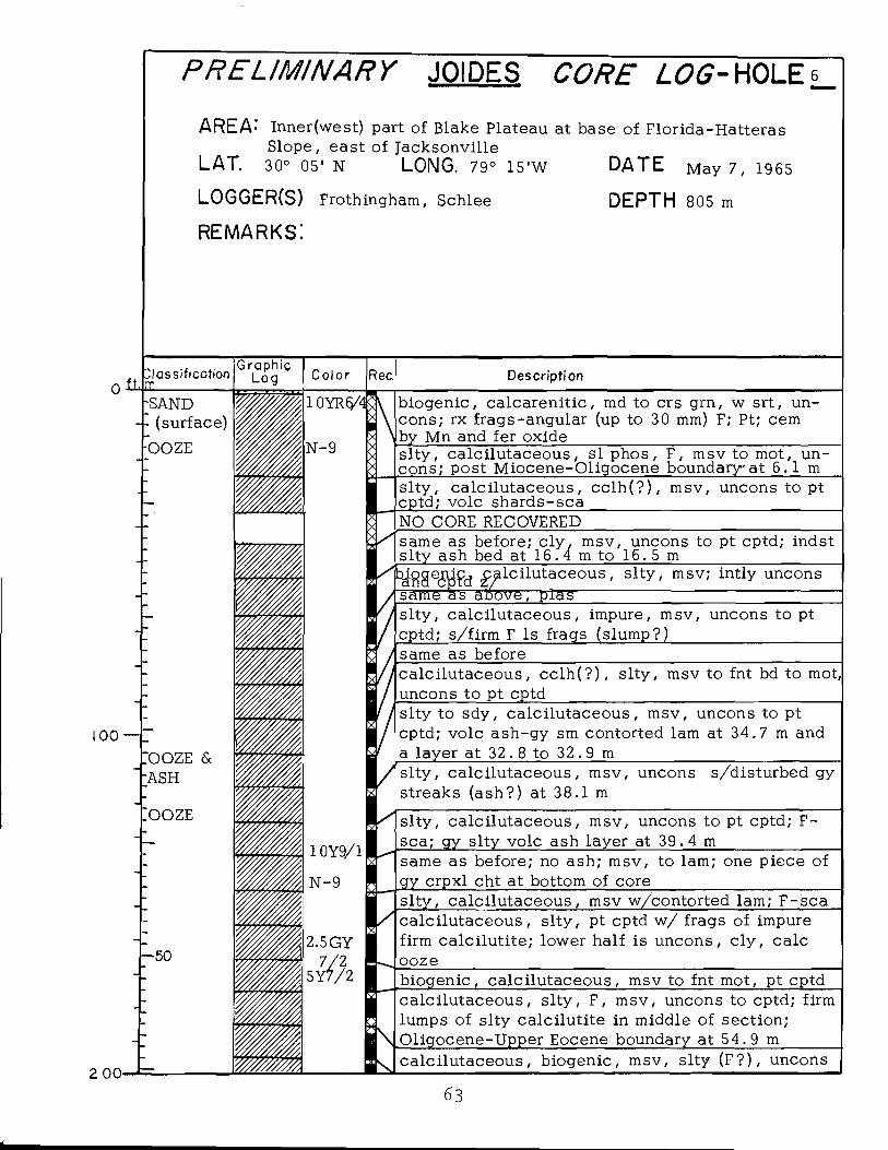
PRELIM INARY JOIDES CORE LOG- HOLE«
AREA- Inner (we st) part of Blake Plateau at base of Florida-Hatteras Slope, east of Jacksonville
LAT. 30° 05' N LONG. 79° 1 5 ’W DATE May 7, 1965
LOGGER(S) Frothingham, Schlee DEPTH 805 m
r e m a r k s :
Description
biogenic, calcarenit ic , md to crs grn, w srt, uncons; rx frags-angular (up to 30 mm) F; Pt; cem by Mn and fer oxides l ty , calc ilutaceous, s l p h o s , F, msv to mot, un- cons; post Miocene-Oligocene boundaryat 6 . 1 msl ty , calc ilutaceous, cc lh (? ) , msv, uncons to pt cptd; vole shards-sca_____________________________NO CORE RECOVEREDsame as before; c ly , msv, uncons to pt cptd; indst s l ty ash bed at 1 6 . 4 m to 1 6 . 5 mbiRaeaifa calc i lutaceous, s l ty , msv; intly unconssame as above, plass l ty , calc i lutaceous, impure, msv, uncons to pt cptd; s/firm F ls frags (slump?)__________________same as beforecalc i lutaceous, c c lh (? ) , s l ty , msv to fnt bd to mot, uncons to pt cptd_________________________________slty to sdy, calc i lutaceous, msv, uncons to pt cptd; vole ash-gy sm contorted lam at 3 4 ,7 m and a layer at 3 2 .8 to 3 2 .9 msl ty , ca lc i lutaceous, msv, uncons s/disturbed gy streaks (ash?) at 38.1 m
sl ty , calc i lutaceous, msv, uncons to pt cptd; F- sca; gy slty vole ash layer at 39. 4 m___________same as before; no ash; msv, to lam; one piece of gy crpxl cht at bottom of cores l ty , ca lc i lutaceous, msv w/contorted lam; F-sca calc i lutaceous, s l ty , pt cptd w/ frags of impure firm calciluti te; lower half is uncons, c ly , calc ooze
2 00
biogenic, calc i lutaceous, msv to fnt mot, pt cptd calc i lutaceous, s l ty , F, msv, uncons to cptd; firm lumps of s lty calciluti te in middle of section;Oligocene-Upper Eocene boundary at 5 4 .9 m______calci lutaceous, biogenic, msv, s l ty (F? ) , uncons
63
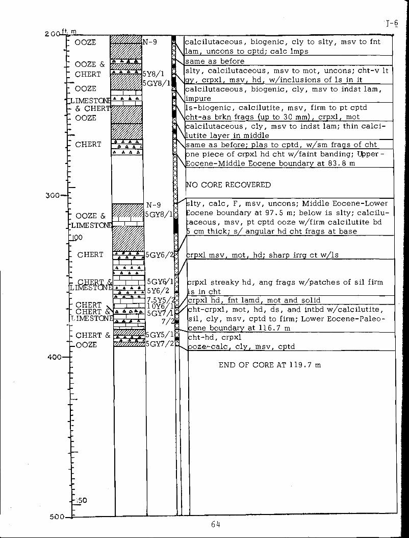
2 0 C U 4 ,ft. mr-6
; ooze
ooze &CHERT
2 OOZE■ILIMESTCNE
& CHERT t OOZE
- CHERT
3 0 0 -
calc i lutaceous, biogenic, c ly to s l ty , msv to fntlam, uncons to cptd; calc Imps_____________________same as before_____________________________________s l ty , ca lc i lutaceous, msv to mot, uncons; ch t -v Itgy, crpxl, msv, hd, w/inclusions of Is in it_______calci lutaceous, biogenic, c ly , msv to indst lam,impure______________________________________________Is-biogenic, ca lc i lu t i te , msv, firm to pt cptdcht-as brkn frags (up to 30 mm), crpxl, mot________
^ calc i lutaceous, c ly , msv to indst lam; thin c a lc i -utite layer in middle_______________________________
same as before; plas to cptd, w/sm frags of cht one piece of crpxl hd cht w/faint banding; Hpper - Eocene-Middle Eocene boundary at 8 3 . 8 m_________
NO CORE RECOVERED
slty, ca lc , F, msv, uncons; Middle Eocene-Lower Eocene boundary at 9 7 . 5 m; below is s lty; ca lc i lu - :aceous, msv, pt cptd ooze w/firm calc i lut i te bd 5 cm thick; s/ angular hd cht frags at base________
;rpxl msv, mot, hd; sharp irrg ct w/ls_____________
CHERT CHERT S
LIMESTONE
- CHERT & lOOZE
4 0 0 —
500-
5GY5/1 (¥77/2
'150
A-A * 'A
rpxl streaky hd, ang frags w/patches of sil firm Ls in cht
5GY§/1 5Y6./27.5Y5/2&I /Icrpxl hd, fnt lamd. mot and solid1 G Y S/V *' ---------- ‘----------------------------------------------5GY7/L
7/M
i
cht-crpxl , mot, hd, ds, and intbd w /ca lc i lu t i te , s i l , c ly , msv, cptd to firm; Lower Eocene-Paleo- cene boundary at 1 1 6 . 7 m________________________cht-hd, crpxlooze^calc, c ly , msv, cptd
END OF CORE AT 1 1 9 . 7 m
64