Balloon exoplanet nulling interferometer (BENI)
10
Balloon Exoplanet Nulling Interferometer (BENI) Richard G. Lyon* a , Mark Clampin a , Robert A. Woodruff b , Gopal Vasudevan c , Holland Ford d , Larry Petro e , Jay Herman a , Stephen Rinehart a , Kenneth Carpenter a , Joe Marzouk f a NASA/Goddard Space Flight Center, Greenbelt, MD 20771; b Lockheed-Martin, Denver CO; c Lockheed-Martin Advanced Technology Center, Palo Alto CA d Johns-Hopkins University, Baltimore MD e Space Telescope Science Institute, Baltimore MD f Sigma Space, Lanham MD ABSTRACT We evaluate the feasibility of a balloon-borne nulling interferometer to detect and characterize an exosolar planet and the surrounding debris disk. The existing instrument consists of a three-telescope Fizeau imaging interferometer with thre fast steering mirrors and three delay lines operating at 800 Hz for closed-loop control of wavefront errors and fine pointing. A compact visible nulling interferometer would be coupled to the imaging interferometer and in principle, allows deep starlight suppression. Atmospheric simulations of the environment above 100,000 feet show that balloon- borne payloads are a possible path towards the direct detection and characterization of a limited set of exoplanets and debris disks. Furthermore, rapid development of lower cost balloon payloads provide a path towards advancement of NASA technology readiness levels for future space-based exoplanet missions. Discussed are the BENI mission and instrument, the balloon environment and the feasibility of such a balloon-borne mission. Keywords: Exosolar planets, visible nulling interferometer, coronagraph, balloon payloads 1. INTRODUCTION The direct detection and characterization of exosolar planets is a rich and rewarding area of science with high scientific potential that encompasses both discovery and quantitative science with the ultimate goal of searching for the origins of life in the universe. Numerous exosolar planets have been detected and teams worldwide have been assessing space and ground based approaches to directly detecting (imaging) and characterizing exosolar planets. Ground approaches tend to be limited by atmospheric turbulence, scintillation, water vapor, stray light and light pollution while space-based approaches are often limited by costs. An alternative and less costly approach is a suborbital mission, including sounding rockets or balloon-borne payloads. Both operate at higher altitudes than ground observatories and hence are less limited by atmospheric effects. Sounding rockets have short flight times and even shorter data collection times, however a sounding rocket mission exists to attempt to image epsilon-Eridani’s (Figure-1) jovian planet (Rao et al, 2008). Balloons may have longer duration flights of one to two days with the potential for 100 day flights using super pressure balloons, and are ultimately more amenable to exosolar planet missions. Additionally balloon missions can be used to advance and fine tune technology required for orbital flight missions while acquiring significant science products. Herein we address the use of balloons for exoplanetary science via a small-scale balloon-borne mission to demonstrate that a single jovian planet could be detected. The mission, known as Balloon Exoplanet Nulling Interferometer (BENI), would be capable of directly detecting the confirmed Jovian planet (Campbell et al. 1988 Cumming et al. 1999, Hatzes et al. 2000) in orbit around Epsilon Eridani, ( Eri), directly imaging its dust disk and potentially looking for gaps that are indicative of terrestrial planets. BENI would retire technology risk for future space flight missions and build a foundation for longer duration balloon flights for exoplanetary science. Balloon borne instruments may be a path to realizing some of the NASA Search for the Origins of Life science goals – imaging even a single exosolar planet would begin to constrain its true mass and albedo. *[email protected]; phone 1 301 286-4302 Techniques and Instrumentation for Detection of Exoplanets IV, edited by Stuart B. Shaklan, Proc. of SPIE Vol. 7440, 74401A · © 2009 SPIE · CCC code: 0277-786X/09/$18 · doi: 10.1117/12.827411 Proc. of SPIE Vol. 7440 74401A-1
Transcript of Balloon exoplanet nulling interferometer (BENI)
Balloon Exoplanet Nulling Interferometer (BENI)
Richard G. Lyon*a, Mark Clampin
a, Robert A. Woodruff
b, Gopal Vasudevan
c, Holland Ford
d,
Larry Petroe, Jay Herman
a, Stephen Rinehart
a, Kenneth Carpenter
a, Joe Marzouk
f
aNASA/Goddard Space Flight Center, Greenbelt, MD 20771;
bLockheed-Martin, Denver CO;
cLockheed-Martin Advanced Technology Center, Palo Alto CA
dJohns-Hopkins University, Baltimore MD
eSpace Telescope Science Institute, Baltimore MD
fSigma Space, Lanham MD
ABSTRACT
We evaluate the feasibility of a balloon-borne nulling interferometer to detect and characterize an exosolar planet and the
surrounding debris disk. The existing instrument consists of a three-telescope Fizeau imaging interferometer with thre
fast steering mirrors and three delay lines operating at 800 Hz for closed-loop control of wavefront errors and fine
pointing. A compact visible nulling interferometer would be coupled to the imaging interferometer and in principle,
allows deep starlight suppression. Atmospheric simulations of the environment above 100,000 feet show that balloon-
borne payloads are a possible path towards the direct detection and characterization of a limited set of exoplanets and
debris disks. Furthermore, rapid development of lower cost balloon payloads provide a path towards advancement of
NASA technology readiness levels for future space-based exoplanet missions. Discussed are the BENI mission and
instrument, the balloon environment and the feasibility of such a balloon-borne mission.
Keywords: Exosolar planets, visible nulling interferometer, coronagraph, balloon payloads
1. INTRODUCTION
The direct detection and characterization of exosolar planets is a rich and rewarding area of science with high scientific potential that encompasses both discovery and quantitative science with the ultimate goal of searching for the origins of life in the universe. Numerous exosolar planets have been detected and teams worldwide have been assessing space and ground based approaches to directly detecting (imaging) and characterizing exosolar planets. Ground approaches tend to be limited by atmospheric turbulence, scintillation, water vapor, stray light and light pollution while space-based approaches are often limited by costs. An alternative and less costly approach is a suborbital mission, including sounding rockets or balloon-borne payloads. Both operate at higher altitudes than ground observatories and hence are less limited by atmospheric effects. Sounding rockets have short flight times and even shorter data collection times, however a sounding rocket mission exists to attempt to image epsilon-Eridani’s (Figure-1) jovian planet (Rao et al, 2008). Balloons may have longer duration flights of one to two days with the potential for 100 day flights using super pressure balloons, and are ultimately more amenable to exosolar planet missions. Additionally balloon missions can be used to advance and fine tune technology required for orbital flight missions while acquiring significant science products.
Herein we address the use of balloons for exoplanetary science via a small-scale balloon-borne mission to demonstrate that a single jovian planet could be detected. The mission, known as Balloon Exoplanet Nulling Interferometer (BENI), would be capable of directly detecting the confirmed Jovian planet (Campbell et al. 1988 Cumming et al. 1999, Hatzes
et al. 2000) in orbit around Epsilon Eridani, ( Eri), directly imaging its dust disk and potentially looking for gaps that
are indicative of terrestrial planets. BENI would retire technology risk for future space flight missions and build a foundation for longer duration balloon flights for exoplanetary science. Balloon borne instruments may be a path to realizing some of the NASA Search for the Origins of Life science goals – imaging even a single exosolar planet would begin to constrain its true mass and albedo.
*[email protected]; phone 1 301 286-4302
Techniques and Instrumentation for Detection of Exoplanets IV, edited by Stuart B. Shaklan, Proc. of SPIE Vol. 7440, 74401A · © 2009 SPIE · CCC code: 0277-786X/09/$18 · doi: 10.1117/12.827411
Proc. of SPIE Vol. 7440 74401A-1
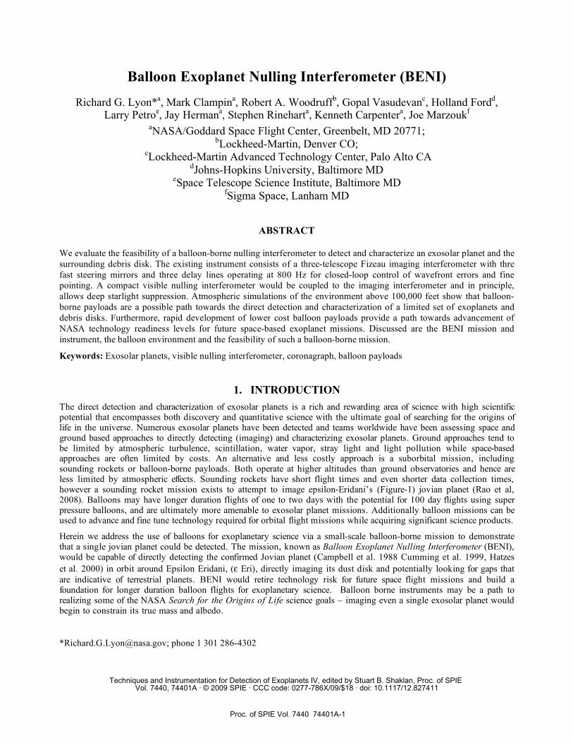
Dust Disk
BENI requires many of the same technologies as an exoplanet space flight mission and would be capable of directly detecting at least one planet around one of the closest, brightest, and most promising star systems, and at low cost and with a rapid development cycle. This approach has the advantage that a balloon at 30 – 37 km altitude is above most of the turbulent atmosphere thereby mitigating the very difficult adaptive optical (AO) control systems required by the ground based exoplanet imagers, and, can be performed for a fraction of the cost of the space flight mission. BENI would use an existing instrument, previously known as the Solar Viewing Interferometry Prototype (SVIP) (Lyon et al, 2004), retrofitted for a balloon mission with the addition of a nulling interferometer and payload fine pointing and tracking system. It would be capable of directly detecting the
confirmed Jovian planet in Eri, directly
imaging its dust disk and potentially looking for gaps that are indicative of terrestrial planets.
1.1 ExoPlanetary Science
BENI’s science program would consist of a single target star, Epsilon Eridani ( Eri), with the goal of directly detecting
and imaging its confirmed Jovian planet and surrounding disk structure. Eri (Table-1) is a K2V spectral type star, at
3.22 parsecs with a visual magnitude of 3.73 at right ascension/declination (J2000) 03:32:55.84, -9:27:29.74. It is young
at 0.5 to 1 Giga-years (Benedict et.al 2006 and Saffe et.al 2005)) with ~85% solar mass (Benedict et.al 2006), 84% solar
diameter (Johnson and Wright, 1983) and~27.8% solar luminosity (Saumon et al, 1996) and lower than solar metalicity
(Santos et al, 2004; Laws et al, 2003; Cayrel de Strobel et al; 1991).
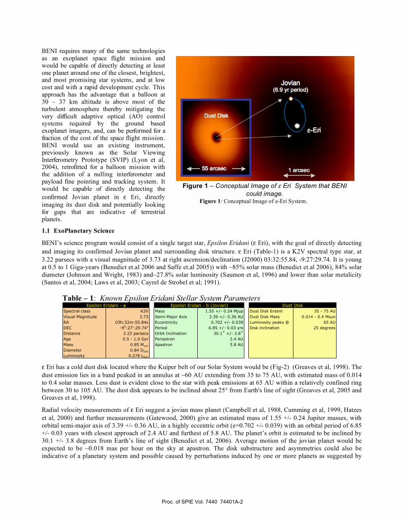
Eri has a cold dust disk located where the Kuiper belt of our Solar System would be (Fig-2) (Greaves et al, 1998). The
dust emission lies in a band peaked in an annulus at ~60 AU extending from 35 to 75 AU, with estimated mass of 0.014
to 0.4 solar masses. Less dust is evident close to the star with peak emissions at 65 AU within a relatively confined ring
between 30 to 105 AU. The dust disk appears to be inclined about 25° from Earth's line of sight (Greaves et al, 2005 and
Greaves et al, 1998).
Radial velocity measurements of Eri suggest a jovian mass planet (Campbell et al, 1988, Cumming et al, 1999, Hatzes
et al, 2000) and further measurements (Gatewood, 2000) give an estimated mass of 1.55 +/- 0.24 Jupiter masses, with
orbital semi-major axis of 3.39 +/- 0.36 AU, in a highly eccentric orbit (e=0.702 +/- 0.039) with an orbital period of 6.85
+/- 0.03 years with closest approach of 2.4 AU and furthest of 5.8 AU. The planet’s orbit is estimated to be inclined by
30.1 +/- 3.8 degrees from Earth’s line of sight (Benedict et al, 2006). Average motion of the jovian planet would be
expected to be ~0.018 mas per hour on the sky at apastron. The disk substructure and asymmetries could also be
indicative of a planetary system and possible caused by perturbations induced by one or more planets as suggested by
Figure 1 – Conceptual Image of Eri System that BENI
could image. Figure 1: Conceptual Image of e-Eri System.
Table – 1: Known Epsilon Eridani Stellar System Parameters
Spectral class K2V Mass 1.55 +/- 0.24 Mjup Dust Disk Extent 35 - 75 AUVisual Magnitude 3.73 Semi-Major Axis 3.39 +/- 0.36 AU Dust Disk Mass 0.014 - 0.4 MsunRA 03h:32m:55.84s Eccentricity 0.702 +/- 0.039 Luminosity peaks @ 65 AUDEC -90:27':29.74" Period 6.85 +/- 0.03 yrs Disk inclination 25 degreesDistance 3.22 parsecs Orbit Inclination 30.1˚ +/- 3.8˚Age 0.5 - 1.0 Gyr Periastron 2.4 AUMass 0.85 Msun Apastron 5.8 AUDiameter 0.84 DSun
Luminosity 0.278 LSun
Epsilon Eridani - a Epsilon Eridan - b (Jovian) Dust Disk
Proc. of SPIE Vol. 7440 74401A-2
1000
'I,D0£ too0)EFC0
ID0)0)C
El-- SNR=30-- SNR=5
Bgnd - Dark limitedBENI
lxi 0-t) lxiD lxl0° ixl0 l,iO 1x10'Frational VNI Leakage
computer modeling of disk asymmetries (Gorkavyi et
al, 2000, Liou and Zook, 1999, Quillen and
Thorndike, 2002, Moran et al, 2004). The dark hole in
the disk’s center region contains ~1000 times more
dust than our inner solar system and the disk is not
brighter than ~24.6 magnitudes/arcsec2 (Proffitt et al,
2004). The habitable zone (HZ) for a terrestrial planet,
where liquid water could exist, would span the range
of 0.47 to 0.91 AU (Jones and Sleep, 2003). Thebault
et al., 2002, find that terrestrial planets can form in the
proto-planetary disk within 0.8 AU of Eri and
interior to the orbit of the highly eccentric jovian
planet, provided that lunar-mass embryos form before
the giant planet. Jones et al. 2005 investigated the
orbital stability of earth-mass (EM) planets in the
habitable zone both now and at sometime during the
parent star’s life. Although there are stable orbits for
aEM(0) < 0.44 AU (Jones et al, 2003), there are no
orbits at the present time that are confined to the
habitable zone.
1.2 Mission and Instrument Requirements
The mission and instrument requirements would
ideally be purely driven by the science requirements;
however, for BENI the requirements are limited by the constraints of the balloon and its environment, and by use of an
already existing instrument as well as the state of the art of existing technology. The science requirement can be
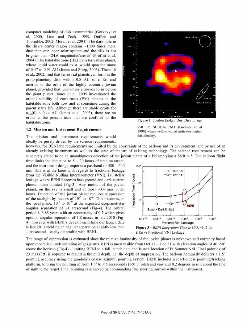
succinctly stated to be an unambiguous detection of the jovian planet of Eri implying a SNR = 5. The balloon flight
time limits the detection to 8 – 20 hours of time on target,
and the instrument design requires a passband of 480 – 640
nm. This is at the knee with regards to fractional leakage
from the Visible Nulling Interferometer (VNI), i.e. stellar
leakage where BENI becomes background and dark current
photon noise limited (Fig-3). Any motion of the jovian
planet, on the sky is small and at most ~0.4 mas in 20
hours. Detection of the jovian planet requires suppression
of the starlight by factors of 10-5
to 10-6
. This becomes, in
the focal plane, 10-8
to 10-9
at the expected exoplanet-star
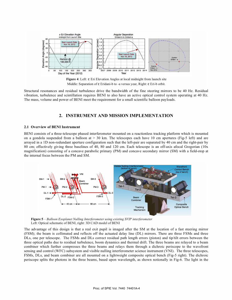
angular separation of ~1 arcsecond (Fig-4). The orbital
period is 6.85 years with an eccentricity of 0.7 which gives
optimal angular separation of 1.8 arcsec in late 2010 (Fig-
4), however with BENI’s development time our launch date
is late 2013 yielding an angular separation slightly less than
1-arcsecond – easily detectable with BENI.
The range of suppression is estimated since the relative luminosity of the jovian planet is unknown and currently based
upon theoretical understanding of gas giants. Eri is most visible from Oct 11 – Dec 21 with elevation angles of 40 -500
above the horizon (Fig-4) - limiting BENI to a fall launch date and launch location of Ft Sumner NM. Final pointing of
23 mas (3 ) is required to maintain the null depth, i.e. the depth of suppression. The balloon nominally delivers a 1.5˚
pointing accuracy using the gondola’s coarse azimuth pointing system. BENI includes a reactionless pointing/tracking
platform, to bring the pointing in from 1.50 to < 5 arcseconds (3 ) in pitch and yaw and 0.2 degrees in roll about the line
of sight to the target. Final pointing is achieved by commanding fine steering mirrors within the instrument.
Figure 2: Epsilon Eridani Dust Disk Image
850 um SCUBA/JCMT (Greaves et al
1998) where yellow to red indicates higher
dust density.
Figure 3 – BENI Integration Time to SNR =3, 5 for
Eri vs Fractional VNI Leakage
Proc. of SPIE Vol. 7440 74401A-3
60
40
0)20
0)
<.20Ca
-40S
E-En Elevation Anglereidnight from Launch Site
Boot Launch DateN0 16, 2012
0 50 100 100 200 250 300 350Day at the Year )201 2)
1.80
l.60
1.4
C 1.20
1.0
aaa06
10 0.4
< 0.02007 2006 2005
Angular SeparationLmidur,i-b to Eridani.a
20)0 2011 2012 2013Year
20)4
PM-I -
DL-1 -
FSM-1
SM-3Beam
ombiner
DL-2 FSM-2\ FSM-3 \
'1 40cm ,e 80cm
DL-3
TeI-3-
le Nulling Interferometer(boBorn of bench)
Beam /Combiner
TrackingMechanism
Wavefronl !Control Bench
(top of bench)
Structural resonances and residual turbulence drive the bandwidth of the fine steering mirrors to be 40 Hz. Residual
vibration, turbulence and scintillation requires BENI to also have an active optical control system operating at 40 Hz.
The mass, volume and power of BENI meet the requirement for a small scientific balloon payloads.
2. INSTRUMENT AND MISSION IMPLEMENTATION
2.1 Overview of BENI Instrument
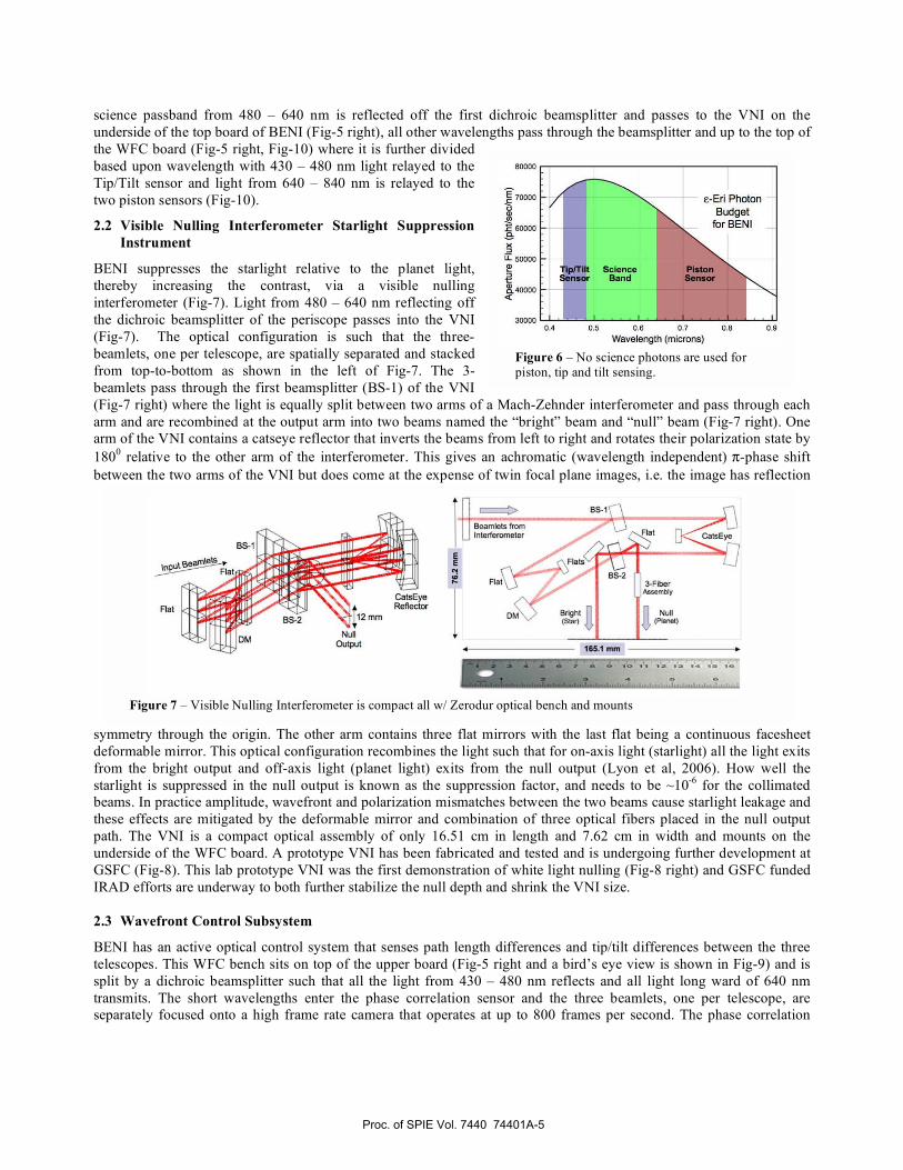
BENI consists of a three-telescope phased interferometer mounted on a reactionless tracking platform which is mounted
on a gondola suspended from a balloon at > 30 km. The telescopes each have 10 cm apertures (Fig-5 left) and are
arrayed in a 1D non-redundant aperture configuration such that the left-pair are separated by 40 cm and the right-pair by
80 cm; effectively giving three baselines of 40, 80 and 120 cm. Each telescope is an off-axis afocal Gregorian (10x
magnification) consisting of a concave parabolic primary (PM) and concave secondary mirror (SM) with a field-stop at
the internal focus between the PM and SM.
The advantage of this design is that a real exit pupil is imaged after the SM at the location of a fast steering mirror
(FSM); the beam is collimated and reflects off the actuated delay line (DL) mirrors. There are three FSMs and three
DLs, one per telescope. The FSMs and DLs correct residual path length errors (piston) and tip/tilt errors between the
three optical paths due to residual turbulence, boom dynamics and thermal drift. The three beams are relayed to a beam
combiner which further compresses the three beams and relays them through a dichroic periscope to the wavefront
sensing and control (WFC) subsystem and visible nulling interferometer science instrument (VNI). The three telescopes,
FSMs, DLs, and beam combiner are all mounted on a lightweight composite optical bench (Fig-5 right). The dichroic
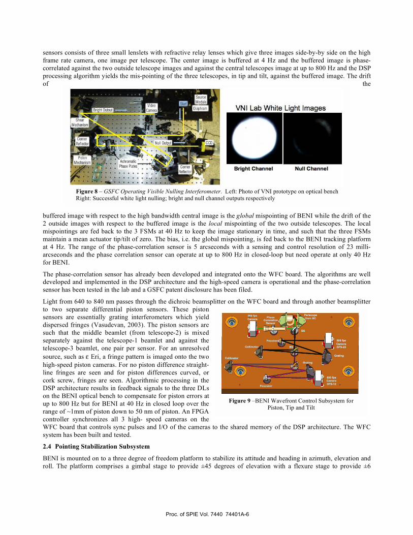
periscope splits the photons in the three beams, based upon wavelength, as shown notionally in Fig-6. The light in the
Figure 4: Left: Eri Elevation Angles at local midnight from launch site
Middle: Separation of Eridani-b to -a versus year, Right: Eri-b orbit.
Figure 5 – Balloon Exoplanet Nulling Interferometer using existing SVIP interferometer
Left: Optical schematic of BENI, right: 3D CAD model of BENI
Proc. of SPIE Vol. 7440 74401A-4
TipITilt ScienceSensor Band
PistonSensor
E-EIi PhotonBudget
for BENI
30000 I
0.4 0.5 0.6 0,7 0.8 0.9
Waveleng h Cmicrons)
60000
70000
60000
:3IL 000000):3
10000
12 rrn
NullOutput
EClw
I
f{irnietu froniL Interferometer
I
Flat
BS
165.i mm
3-FiberAseenby
NulllPbneI)
science passband from 480 – 640 nm is reflected off the first dichroic beamsplitter and passes to the VNI on the
underside of the top board of BENI (Fig-5 right), all other wavelengths pass through the beamsplitter and up to the top of
the WFC board (Fig-5 right, Fig-10) where it is further divided
based upon wavelength with 430 – 480 nm light relayed to the
Tip/Tilt sensor and light from 640 – 840 nm is relayed to the
two piston sensors (Fig-10).
2.2 Visible Nulling Interferometer Starlight Suppression
Instrument
BENI suppresses the starlight relative to the planet light,
thereby increasing the contrast, via a visible nulling
interferometer (Fig-7). Light from 480 – 640 nm reflecting off
the dichroic beamsplitter of the periscope passes into the VNI
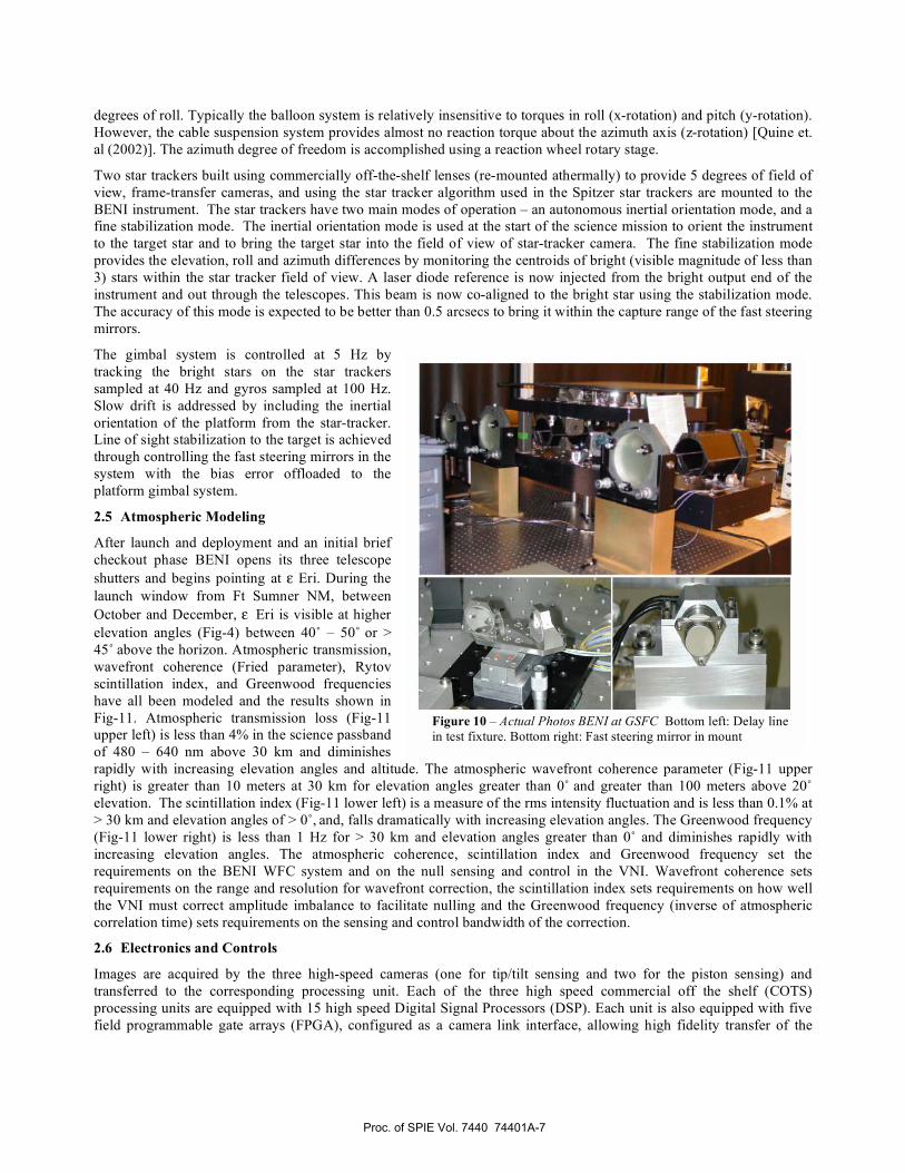
(Fig-7). The optical configuration is such that the three-
beamlets, one per telescope, are spatially separated and stacked
from top-to-bottom as shown in the left of Fig-7. The 3-
beamlets pass through the first beamsplitter (BS-1) of the VNI
(Fig-7 right) where the light is equally split between two arms of a Mach-Zehnder interferometer and pass through each
arm and are recombined at the output arm into two beams named the “bright” beam and “null” beam (Fig-7 right). One
arm of the VNI contains a catseye reflector that inverts the beams from left to right and rotates their polarization state by
1800 relative to the other arm of the interferometer. This gives an achromatic (wavelength independent) -phase shift
between the two arms of the VNI but does come at the expense of twin focal plane images, i.e. the image has reflection
symmetry through the origin. The other arm contains three flat mirrors with the last flat being a continuous facesheet
deformable mirror. This optical configuration recombines the light such that for on-axis light (starlight) all the light exits
from the bright output and off-axis light (planet light) exits from the null output (Lyon et al, 2006). How well the
starlight is suppressed in the null output is known as the suppression factor, and needs to be ~10-6
for the collimated
beams. In practice amplitude, wavefront and polarization mismatches between the two beams cause starlight leakage and
these effects are mitigated by the deformable mirror and combination of three optical fibers placed in the null output
path. The VNI is a compact optical assembly of only 16.51 cm in length and 7.62 cm in width and mounts on the
underside of the WFC board. A prototype VNI has been fabricated and tested and is undergoing further development at
GSFC (Fig-8). This lab prototype VNI was the first demonstration of white light nulling (Fig-8 right) and GSFC funded
IRAD efforts are underway to both further stabilize the null depth and shrink the VNI size.
2.3 Wavefront Control Subsystem
BENI has an active optical control system that senses path length differences and tip/tilt differences between the three
telescopes. This WFC bench sits on top of the upper board (Fig-5 right and a bird’s eye view is shown in Fig-9) and is
split by a dichroic beamsplitter such that all the light from 430 – 480 nm reflects and all light long ward of 640 nm
transmits. The short wavelengths enter the phase correlation sensor and the three beamlets, one per telescope, are
separately focused onto a high frame rate camera that operates at up to 800 frames per second. The phase correlation
Figure 6 – No science photons are used for piston, tip and tilt sensing.
Figure 7 – Visible Nulling Interferometer is compact all w/ Zerodur optical bench and mounts
Proc. of SPIE Vol. 7440 74401A-5
AzhroriIicPhase Plates
VNI Lab White Light Images
Bright Channel Null Channel
sensors consists of three small lenslets with refractive relay lenses which give three images side-by-by side on the high
frame rate camera, one image per telescope. The center image is buffered at 4 Hz and the buffered image is phase-
correlated against the two outside telescope images and against the central telescopes image at up to 800 Hz and the DSP
processing algorithm yields the mis-pointing of the three telescopes, in tip and tilt, against the buffered image. The drift
of the
buffered image with respect to the high bandwidth central image is the global mispointing of BENI while the drift of the
2 outside images with respect to the buffered image is the local mispointing of the two outside telescopes. The local
mispointings are fed back to the 3 FSMs at 40 Hz to keep the image stationary in time, and such that the three FSMs
maintain a mean actuator tip/tilt of zero. The bias, i.e. the global mispointing, is fed back to the BENI tracking platform
at 4 Hz. The range of the phase-correlation sensor is 5 arcseconds with a sensing and control resolution of 23 milli-
arcseconds and the phase correlation sensor can operate at up to 800 Hz in closed-loop but need operate at only 40 Hz
for BENI.
The phase-correlation sensor has already been developed and integrated onto the WFC board. The algorithms are well
developed and implemented in the DSP architecture and the high-speed camera is operational and the phase-correlation
sensor has been tested in the lab and a GSFC patent disclosure has been filed.
Light from 640 to 840 nm passes through the dichroic beamsplitter on the WFC board and through another beamsplitter
to two separate differential piston sensors. These piston
sensors are essentially grating interferometers which yield
dispersed fringes (Vasudevan, 2003). The piston sensors are
such that the middle beamlet (from telescope-2) is mixed
separately against the telescope-1 beamlet and against the
telescope-3 beamlet, one pair per sensor. For an unresolved
source, such as Eri, a fringe pattern is imaged onto the two
high-speed piston cameras. For no piston difference straight-
line fringes are seen and for piston differences curved, or
cork screw, fringes are seen. Algorithmic processing in the
DSP architecture results in feedback signals to the three DLs
on the BENI optical bench to compensate for piston errors at
up to 800 Hz but for BENI at 40 Hz in closed loop over the
range of ~1mm of piston down to 50 nm of piston. An FPGA
controller synchronizes all 3 high- speed cameras on the
WFC board that controls sync pulses and I/O of the cameras to the shared memory of the DSP architecture. The WFC
system has been built and tested.
2.4 Pointing Stabilization Subsystem
BENI is mounted on to a three degree of freedom platform to stabilize its attitude and heading in azimuth, elevation and
roll. The platform comprises a gimbal stage to provide ±45 degrees of elevation with a flexure stage to provide ±6
Figure 8 – GSFC Operating Visible Nulling Interferometer. Left: Photo of VNI prototype on optical bench Right: Successful white light nulling; bright and null channel outputs respectively
Figure 9 –BENI Wavefront Control Subsystem for
Piston, Tip and Tilt
Proc. of SPIE Vol. 7440 74401A-6
-I
degrees of roll. Typically the balloon system is relatively insensitive to torques in roll (x-rotation) and pitch (y-rotation).
However, the cable suspension system provides almost no reaction torque about the azimuth axis (z-rotation) [Quine et.
al (2002)]. The azimuth degree of freedom is accomplished using a reaction wheel rotary stage.
Two star trackers built using commercially off-the-shelf lenses (re-mounted athermally) to provide 5 degrees of field of
view, frame-transfer cameras, and using the star tracker algorithm used in the Spitzer star trackers are mounted to the
BENI instrument. The star trackers have two main modes of operation – an autonomous inertial orientation mode, and a
fine stabilization mode. The inertial orientation mode is used at the start of the science mission to orient the instrument
to the target star and to bring the target star into the field of view of star-tracker camera. The fine stabilization mode
provides the elevation, roll and azimuth differences by monitoring the centroids of bright (visible magnitude of less than
3) stars within the star tracker field of view. A laser diode reference is now injected from the bright output end of the
instrument and out through the telescopes. This beam is now co-aligned to the bright star using the stabilization mode.
The accuracy of this mode is expected to be better than 0.5 arcsecs to bring it within the capture range of the fast steering
mirrors.
The gimbal system is controlled at 5 Hz by
tracking the bright stars on the star trackers
sampled at 40 Hz and gyros sampled at 100 Hz.
Slow drift is addressed by including the inertial
orientation of the platform from the star-tracker.
Line of sight stabilization to the target is achieved
through controlling the fast steering mirrors in the
system with the bias error offloaded to the
platform gimbal system.
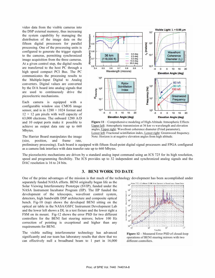
2.5 Atmospheric Modeling
After launch and deployment and an initial brief
checkout phase BENI opens its three telescope
shutters and begins pointing at Eri. During the
launch window from Ft Sumner NM, between
October and December, Eri is visible at higher
elevation angles (Fig-4) between 40˚ – 50˚ or >
45˚ above the horizon. Atmospheric transmission,
wavefront coherence (Fried parameter), Rytov
scintillation index, and Greenwood frequencies
have all been modeled and the results shown in
Fig-11. Atmospheric transmission loss (Fig-11
upper left) is less than 4% in the science passband
of 480 – 640 nm above 30 km and diminishes
rapidly with increasing elevation angles and altitude. The atmospheric wavefront coherence parameter (Fig-11 upper
right) is greater than 10 meters at 30 km for elevation angles greater than 0˚ and greater than 100 meters above 20˚
elevation. The scintillation index (Fig-11 lower left) is a measure of the rms intensity fluctuation and is less than 0.1% at
> 30 km and elevation angles of > 0˚, and, falls dramatically with increasing elevation angles. The Greenwood frequency
(Fig-11 lower right) is less than 1 Hz for > 30 km and elevation angles greater than 0˚ and diminishes rapidly with
increasing elevation angles. The atmospheric coherence, scintillation index and Greenwood frequency set the
requirements on the BENI WFC system and on the null sensing and control in the VNI. Wavefront coherence sets
requirements on the range and resolution for wavefront correction, the scintillation index sets requirements on how well
the VNI must correct amplitude imbalance to facilitate nulling and the Greenwood frequency (inverse of atmospheric
correlation time) sets requirements on the sensing and control bandwidth of the correction.
2.6 Electronics and Controls
Images are acquired by the three high-speed cameras (one for tip/tilt sensing and two for the piston sensing) and
transferred to the corresponding processing unit. Each of the three high speed commercial off the shelf (COTS)
processing units are equipped with 15 high speed Digital Signal Processors (DSP). Each unit is also equipped with five
field programmable gate arrays (FPGA), configured as a camera link interface, allowing high fidelity transfer of the
Figure 10 – Actual Photos BENI at GSFC Bottom left: Delay line
in test fixture. Bottom right: Fast steering mirror in mount
Proc. of SPIE Vol. 7440 74401A-7
C0(0
0.8a) -
0.7
dl:
0.604
101
lO
Gd
10.1
10-2
0.5 0.6 0.7 0.8 0.9
wavelength (microns)
-5 0 5 10 15 20
Elevation Angle (deg)
-5 0 5 10 15 20
Elevation Angle (deg)
Okft80 kft
10 kft
GreenwoodFrequency
100
-5 0 5 10 15 20
Elevation Angle (deg)
Visible Light: X = 0.55 tm101
100aaE
Wavefront10-1 Coherence
Diameter (r0)
10-2
36km(118,000 ft)
- 0.0 deg2.5 deg5.0 deg -
- 10.0 deg- 200deg
Norse P50 sf2 different S-0 Units Operated n Closed Loop - Sense Sets10
to°Fteq (Hz)
video data from the visible cameras into
the DSP external memory, thus increasing
the system capability by managing the
distribution of the image data on the
fifteen digital processors for parallel
processing. One of the processing units is
configured to generate the trigger signals
to the cameras, permitting synchronized
image acquisition from the three cameras.
At a given control step, the digital results
are transferred to the host PC through a
high speed compact PCI Bus. The PC
communicates the processing results to
the Multiple-Input Digital to Analog
converters. Digital values are converted
by the D/A board into analog signals that
are used to continuously drive the
piezoelectric mechanisms.
Each camera is equipped with a
configurable window size CMOS image
sensor, and is in 1280 1024 format and
12 12 μm pixels with well capacity of
63,000 electrons. The onboard 1280 A/D
and 10 output ports make it possible to
achieve an output data rate up to 660
Mbytes.
The Harrier Board manipulates the image
(size, position, and frame rate,
preliminary processing). Each board is equipped with fifteen fixed-point digital signal processors and FPGA configured
as a camera link interface with data transfer rate up to 660 Mbytes.
The piezoelectric mechanisms are driven by a standard analog input command using an ICS 725 for its high resolution,
speed and programming flexibility. The ICS provides up to 32 independent and synchronized analog signals and the
DAC resolution is 16 to 24 bits.
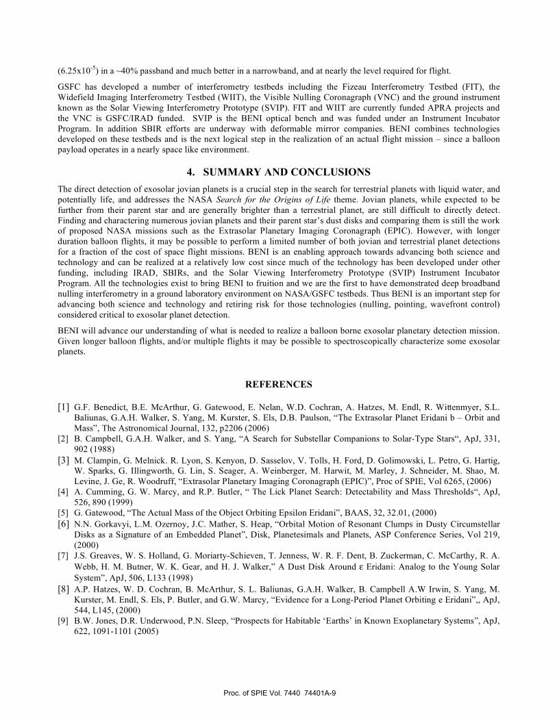
3. BENI WORK TO DATE
One of the prime advantages of the mission is that much of the technology development has been accomplished under
separately funded NASA efforts. BENI originally began life as the
Solar Viewing Interferometry Prototype (SVIP), funded under the
NASA Instrument Incubator Program (IIP). The IIP funded the
development of the telescopes, wavefront control system,
detectors, high bandwidth DSP architecture and composite optical
bench. Fig-10 (top) shows the developed BENI sitting on the
optical air table in the NASA/GSFC Instrument Development Lab
and the lower left shows a DL in a test fixture and the lower right a
FSM on its mount. Fig-12 shows the error PSD for two different
controllers for the BENI fast steering mirrors; below 100 Hz
correction of pointing is exceptional and higher than any
requirements for BENI.
The visible nulling interferometer technology has advanced
significantly and our team has laboratory results that show that we
can effectively null a broadband beam to 1 part in 16,000
Figure 11 – Comprehensive modeling of High-Altitude Atmospheric Effects
Upper left: Atmospheric transmission at 36 km vs wavelength and elevation
angles, Upper right: Wavefront coherence diameter (Fried parameter),
Lower left: Fractional scintillation index, Lower right: Greenwood frequency. Note: Horizon is at negative elevation angles from high altitude.
Figure 12 – Measured Error PSD of closed-loop
operations of BENI steering mirrors with two different controllers.
Proc. of SPIE Vol. 7440 74401A-8
(6.25x10⁻⁵
) in a ~40% passband and much better in a narrowband, and at nearly the level required for flight.
GSFC has developed a number of interferometry testbeds including the Fizeau Interferometry Testbed (FIT), the
Widefield Imaging Interferometry Testbed (WIIT), the Visible Nulling Coronagraph (VNC) and the ground instrument
known as the Solar Viewing Interferometry Prototype (SVIP). FIT and WIIT are currently funded APRA projects and
the VNC is GSFC/IRAD funded. SVIP is the BENI optical bench and was funded under an Instrument Incubator
Program. In addition SBIR efforts are underway with deformable mirror companies. BENI combines technologies
developed on these testbeds and is the next logical step in the realization of an actual flight mission – since a balloon
payload operates in a nearly space like environment.
4. SUMMARY AND CONCLUSIONS
The direct detection of exosolar jovian planets is a crucial step in the search for terrestrial planets with liquid water, and
potentially life, and addresses the NASA Search for the Origins of Life theme. Jovian planets, while expected to be
further from their parent star and are generally brighter than a terrestrial planet, are still difficult to directly detect.
Finding and charactering numerous jovian planets and their parent star’s dust disks and comparing them is still the work
of proposed NASA missions such as the Extrasolar Planetary Imaging Coronagraph (EPIC). However, with longer
duration balloon flights, it may be possible to perform a limited number of both jovian and terrestrial planet detections
for a fraction of the cost of space flight missions. BENI is an enabling approach towards advancing both science and
technology and can be realized at a relatively low cost since much of the technology has been developed under other
funding, including IRAD, SBIRs, and the Solar Viewing Interferometry Prototype (SVIP) Instrument Incubator
Program. All the technologies exist to bring BENI to fruition and we are the first to have demonstrated deep broadband
nulling interferometry in a ground laboratory environment on NASA/GSFC testbeds. Thus BENI is an important step for
advancing both science and technology and retiring risk for those technologies (nulling, pointing, wavefront control)
considered critical to exosolar planet detection.
BENI will advance our understanding of what is needed to realize a balloon borne exosolar planetary detection mission.
Given longer balloon flights, and/or multiple flights it may be possible to spectroscopically characterize some exosolar
planets.
REFERENCES
[1] G.F. Benedict, B.E. McArthur, G. Gatewood, E. Nelan, W.D. Cochran, A. Hatzes, M. Endl, R. Wittenmyer, S.L.
Baliunas, G.A.H. Walker, S. Yang, M. Kurster, S. Els, D.B. Paulson, “The Extrasolar Planet Eridani b – Orbit and
Mass”, The Astronomical Journal, 132, p2206 (2006) [2] B. Campbell, G.A.H. Walker, and S. Yang, “A Search for Substellar Companions to Solar-Type Stars“, ApJ, 331,
902 (1988)
[3] M. Clampin, G. Melnick. R. Lyon, S. Kenyon, D. Sasselov, V. Tolls, H. Ford, D. Golimowski, L. Petro, G. Hartig,
W. Sparks, G. Illingworth, G. Lin, S. Seager, A. Weinberger, M. Harwit, M. Marley, J. Schneider, M. Shao, M.
Levine, J. Ge, R. Woodruff, “Extrasolar Planetary Imaging Coronagraph (EPIC)”, Proc of SPIE, Vol 6265, (2006) [4] A. Cumming, G. W. Marcy, and R.P. Butler, “ The Lick Planet Search: Detectability and Mass Thresholds“, ApJ,
526, 890 (1999)
[5] G. Gatewood, “The Actual Mass of the Object Orbiting Epsilon Eridani”, BAAS, 32, 32.01, (2000)
[6] N.N. Gorkavyi, L.M. Ozernoy, J.C. Mather, S. Heap, “Orbital Motion of Resonant Clumps in Dusty Circumstellar
Disks as a Signature of an Embedded Planet”, Disk, Planetesimals and Planets, ASP Conference Series, Vol 219,
(2000) [7] J.S. Greaves, W. S. Holland, G. Moriarty-Schieven, T. Jenness, W. R. F. Dent, B. Zuckerman, C. McCarthy, R. A.
Webb, H. M. Butner, W. K. Gear, and H. J. Walker,” A Dust Disk Around Eridani: Analog to the Young Solar
System”, ApJ, 506, L133 (1998)
[8] A.P. Hatzes, W. D. Cochran, B. McArthur, S. L. Baliunas, G.A.H. Walker, B. Campbell A.W Irwin, S. Yang, M.
Kurster, M. Endl, S. Els, P. Butler, and G.W. Marcy, “Evidence for a Long-Period Planet Orbiting e Eridani”,, ApJ,
544, L145, (2000) [9] B.W. Jones, D.R. Underwood, P.N. Sleep, “Prospects for Habitable ‘Earths’ in Known Exoplanetary Systems”, ApJ,
622, 1091-1101 (2005)
Proc. of SPIE Vol. 7440 74401A-9
[10] B.W. Jones, P.N. Sleep, “The Orbits of Terrestrial Planets in the Habitable Zones of Known Extrasolar
Planetary Systems”, Scientific Frontiers in Research on Extrasolar Planets, ASP Conference Series, Vol 294, (2003) [11] B.W. Jones, D.R. Underwood, P.N. Sleep, “The stability of the orbits of Earth-mass planets in and near the
habitable zones of known exoplanetary systems”, ESASP, 539..625J (2003)
[12] E. Karkoschka and M.G. Tomasko, Seasonal Variations in Saturn’s Vertical Cloud Structure, DPS Meeting 36,
30.09, 1994
[13] J.C. Liou and H.A. Zook, “Signatures of Giant Planets on the Solar System Kuiper Belt Dust Disk and Implications
for Extrasolar Planet in Epsilon Eridani”, Lunar and Planetary Science XXX, Houston TX, (1999)
[14] R. Lyon, J. Herman, N. Abuhassan, C. Marx, S. Kizhner, J. Crooke, R. Toland, A. Mariano, C. Salerno, G. Brown,
T. Cazeau, P. Petrone, B. Mamakos, S. Tournois, “The Solar Viewing Interferometry Prototype”, Proc of SPIE Vol
5487, Glasgow Scotland, (2004)
[15] R. Lyon, M. Clampin, R. Woodruff, G. Vasudevan, M. Shao, M. Levine, G. Melnick, V. Tolls, P. Petrone, P.
Dogoda, J. Duval, J. Ge, “Visible Nulling Coronagraphy for ExoPlanetary Detection and Characterization”, Direct
Imaging of Exoplanets: Science & Techniques, Proc of IAU #200, (2006)
[16] S. Moran, M. Kuchner and M. Holman, “The Dynamical Influence of a Planet at Semimajor Axis 3.4 AU on the
Dust around e Eridani”, ApJ 612: 1163-1170, (2004)
[17] C.R. Proffitt, K. Sahu, M. Livio, J. Krist, D. Calzetti, R. Gilliland, C. Grady, D. Lindler, B. Woodgate, S. Heap, M.
Clampin, T.R. Gull, “Limits on the Optical Brightness of the e Eridani Dust Ring”, ApJ 612:481-495, (2004)
[18] S.R. Rao, J.K. Wallace, R. Samuele, S. Chakrabarti, T. Cook, B. Hicks, P. Jung, B. Lane, B.M. Levine, C. Mendillo,
E. Schmidtlin, M. Shao, J.B. Stewart, Path Length Control in a Nulling Coronagraph with a MEMS Deformable
Mirror and a Calibration Interferometer, Proc. Of SPIE Vol 6888, Feb 8, 2008
[19] P. Thebault, F. Marzari, and H. Scholl, “Terrestrial planet formation in exoplanetary systems with a giant planet on
an external orbit”, A&A 384, 594-602 (2002)
[20] G. Vasudevan, E.H. Smith, R.D. Reardon, “Method and Apparatus for Estimating Piston Using a Grism”, US Patent
No 449808, issued June 21, 2005,
[21] A.C. Quillen, S. Thorndike, “Structure in the e Eridani Dusty Disk Caused by Mean Motion Resonances with a 0.3
Eccentricity Planet at Periastron”, ApJ 578 (2): L149-L142, (2002)
[22] B.M. Quine, K. Strong, A. Wiacek, D. Wunch, J.A. Anstey and J.R. Drummond, “Scanning the Earth’s Limb from a
High-Altitude Balloon: The Development and Flight of a New Balloon-Based Pointing System, J. of Atmospheric
and Oceanic Technology, Vol 19, pg 618 (2002)
[23]Y. Wen, B. J. Rauscher, R.G. Baker, M. C. Clampin, P. Fochi, S. R. Heap, G. Hilton, P. Jorden, D. Lindler, B. Mott,
P. Pool, A. Waczynski, B. Woodgate, “Individual Photon Counting Using e2v L3 CCDs for Low Background
Astronomical Spectroscopy”, Proc of SPIE, Vol 6276 (2006)
Proc. of SPIE Vol. 7440 74401A-10