Dynamic response of a Fabry–Perot interferometer
10
Dynamic response of a Fabry – Perot interferometer M. J. Lawrence, B. Willke, M. E. Husman, E. K. Gustafson, and R. L. Byer Ginzton Laboratory, Stanford University, Stanford, California 94305 Received July 9, 1998; revised manuscript received November 16, 1998 We predict and measure the temporal response of a Fabry– Perot cavity field to changes in cavity length and frequency of the incident laser field. We outline the theoretical differences between changes in the cavity- length and laser-frequency modulation and present a theoretical derivation of the time response of the result- ing cavity field and its effect on the reflected field, the transmitted field, and the Pound– Drever – Hall error signal. We show that oscillations in the resulting signals are due to oscillations in the amplitude and the phase of the cavity field itself. Finally, we demonstrate how induced cavity-field oscillations may be used to determine the mirror velocity or the frequency change of the injected laser field. © 1999 Optical Society of America [S0740-3224(99)00404-X] OCIS codes: 140.4780, 120.2230, 120.3180. 1. INTRODUCTION Since its introduction in 1899, 1 the Fabry – Perot interfer- ometer has been used extensively in spectroscopy, inter- ferometry, and maser and laser resonators. 2 Until re- cently, however, the use of the Fabry – Perot in the optical regime has been limited to the observation of the cavity’s static response. Advances in lasers and optical coatings now offer the opportunity to explore the time response of the Fabry – Perot interferometer. It is of interest to note, however, that this dynamic behavior has been previously observed in a high-Q superconducting cavity with a swept microwave source. 3 In this paper we present a theory of the dynamic re- sponse of the Fabry – Perot’s cavity field. Self-consistent field equations are used to develop a series expansion for changes in both the cavity length and the laser frequency. These series expansions are then reduced to differential equations that are easily solved and offer insight into the dynamics of the cavity field. We present the time re- sponse of a Fabry – Perot’s reflected and transmitted fields. We also examine the time response of the Pound– Drever – Hall error signal. We obtain excellent agree- ment between theory and experiment. Both theory and experiment show that temporal oscil- lations occur in the measured signals and that these os- cillations are due, in part, to modulation of the field inside the cavity and not solely due to a beating between the cavity field and the directly reflected signal as previously supposed. 4 The oscillations are observable when the cav- ity length or the input frequency is modulated within a cavity storage time by half of a full-width half-maximum (fwhm) at cavity-resonance peak width. Precision interferometry, such as the laser interfero- metric detection of gravitational waves, 5 and precision spectroscopy, such as cavity-locked ring-down spectroscopy, 6 drive the need to understand the temporal response of Fabry – Perot interferometers. Understand- ing and predicting the temporal response of Fabry – Perot cavities is of intrinsic interest but is also important for automated cavity-length and alignment-control systems. 7–10 For example, for the 4-km-long Laser Interferometer Gravitational-Wave Observatory (LIGO) Fabry – Perot in- terferometer with a finesse of 200 and a fwhm cavity line- width of 150 Hz, a mirror velocity of 5.2 mm/s, or a laser- frequency sweep speed of 375 kHz/s, is sufficient to yield oscillations. Finally, we show how the oscillating re- flected field may be used to determine the rate of incident- frequency change or cavity-length change, and how the oscillating Pound – Drever – Hall signal may degrade the Pound – Drever – Hall frequency-stabilization method. 11 2. TIME RESPONSE OF A FABRY– PEROT INTERFEROMETER A. Static Cavity Consider a field incident on a Fabry – Perot 12 cavity, as shown in Fig. 1. The cavity is defined by two mirrors a distance L apart and is resonant with the laser when the field acquires a 2mp phase shift in a cavity round trip, where m is an integer. When this resonance condition is met, the light that enters through the input mirror con- structively interferes with light that entered at earlier times, resulting in a significant cavity field. Here we make use of the phasor representation of fields to graphically represent the components of the cavity field. To introduce this representation, as well as to pro- vide a comparison for what occurs when the cavity length or the field frequency is modulated, first we describe the steady-state behavior of the cavity field in terms of the phasor picture. In the phasor representation, the time-oscillating com- ponents of fields are removed by choosing a reference frame that rotates in time at the field frequency. For ex- ample, the phasor representation of the field E ˜ 1 5 E 1 exp@ i ( k 1 x 2 v 1 t ) # , obtained by multiplication by exp( i v 1 t ), is E 1 exp( ik 1 x ). The phasor is a vector whose magnitude is equal to the magnitude of E 1 exp( ik 1 x ) and Lawrence et al. Vol. 16, No. 4 / April 1999 / J. Opt. Soc. Am. B 523 0740-3224/99/040523-10$15.00 © 1999 Optical Society of America
-
Upload
khangminh22 -
Category
Documents
-
view
0 -
download
0
Transcript of Dynamic response of a Fabry–Perot interferometer
Lawrence et al. Vol. 16, No. 4 /April 1999 /J. Opt. Soc. Am. B 523
Dynamic response of a Fabry–Perot interferometer
M. J. Lawrence, B. Willke, M. E. Husman, E. K. Gustafson, and R. L. Byer
Ginzton Laboratory, Stanford University, Stanford, California 94305
Received July 9, 1998; revised manuscript received November 16, 1998
We predict and measure the temporal response of a Fabry–Perot cavity field to changes in cavity length andfrequency of the incident laser field. We outline the theoretical differences between changes in the cavity-length and laser-frequency modulation and present a theoretical derivation of the time response of the result-ing cavity field and its effect on the reflected field, the transmitted field, and the Pound–Drever–Hall errorsignal. We show that oscillations in the resulting signals are due to oscillations in the amplitude and thephase of the cavity field itself. Finally, we demonstrate how induced cavity-field oscillations may be used todetermine the mirror velocity or the frequency change of the injected laser field. © 1999 Optical Society ofAmerica [S0740-3224(99)00404-X]
OCIS codes: 140.4780, 120.2230, 120.3180.
1. INTRODUCTIONSince its introduction in 1899,1 the Fabry–Perot interfer-ometer has been used extensively in spectroscopy, inter-ferometry, and maser and laser resonators.2 Until re-cently, however, the use of the Fabry–Perot in the opticalregime has been limited to the observation of the cavity’sstatic response. Advances in lasers and optical coatingsnow offer the opportunity to explore the time response ofthe Fabry–Perot interferometer. It is of interest to note,however, that this dynamic behavior has been previouslyobserved in a high-Q superconducting cavity with a sweptmicrowave source.3
In this paper we present a theory of the dynamic re-sponse of the Fabry–Perot’s cavity field. Self-consistentfield equations are used to develop a series expansion forchanges in both the cavity length and the laser frequency.These series expansions are then reduced to differentialequations that are easily solved and offer insight into thedynamics of the cavity field. We present the time re-sponse of a Fabry–Perot’s reflected and transmittedfields. We also examine the time response of the Pound–Drever–Hall error signal. We obtain excellent agree-ment between theory and experiment.
Both theory and experiment show that temporal oscil-lations occur in the measured signals and that these os-cillations are due, in part, to modulation of the field insidethe cavity and not solely due to a beating between thecavity field and the directly reflected signal as previouslysupposed.4 The oscillations are observable when the cav-ity length or the input frequency is modulated within acavity storage time by half of a full-width half-maximum(fwhm) at cavity-resonance peak width.
Precision interferometry, such as the laser interfero-metric detection of gravitational waves,5 and precisionspectroscopy, such as cavity-locked ring-downspectroscopy,6 drive the need to understand the temporalresponse of Fabry–Perot interferometers. Understand-ing and predicting the temporal response of Fabry–Perotcavities is of intrinsic interest but is also important for
0740-3224/99/040523-10$15.00 ©
automated cavity-length and alignment-controlsystems.7–10
For example, for the 4-km-long Laser InterferometerGravitational-Wave Observatory (LIGO) Fabry–Perot in-terferometer with a finesse of 200 and a fwhm cavity line-width of 150 Hz, a mirror velocity of 5.2 mm/s, or a laser-frequency sweep speed of 375 kHz/s, is sufficient to yieldoscillations. Finally, we show how the oscillating re-flected field may be used to determine the rate of incident-frequency change or cavity-length change, and how theoscillating Pound–Drever–Hall signal may degrade thePound–Drever–Hall frequency-stabilization method.11
2. TIME RESPONSE OF A FABRY–PEROTINTERFEROMETERA. Static CavityConsider a field incident on a Fabry–Perot12 cavity, asshown in Fig. 1. The cavity is defined by two mirrors adistance L apart and is resonant with the laser when thefield acquires a 2mp phase shift in a cavity round trip,where m is an integer. When this resonance condition ismet, the light that enters through the input mirror con-structively interferes with light that entered at earliertimes, resulting in a significant cavity field.
Here we make use of the phasor representation of fieldsto graphically represent the components of the cavityfield. To introduce this representation, as well as to pro-vide a comparison for what occurs when the cavity lengthor the field frequency is modulated, first we describe thesteady-state behavior of the cavity field in terms of thephasor picture.
In the phasor representation, the time-oscillating com-ponents of fields are removed by choosing a referenceframe that rotates in time at the field frequency. For ex-ample, the phasor representation of the field E15 E1 exp@i(k1x 2 v1t)#, obtained by multiplication byexp(iv1t), is E1 exp(ik1x). The phasor is a vector whosemagnitude is equal to the magnitude of E1 exp(ik1x) and
1999 Optical Society of America

524 J. Opt. Soc. Am. B/Vol. 16, No. 4 /April 1999 Lawrence et al.
whose angle indicates the phase of E1 exp(ik1x) relativeto its phase at a particular value of x. While the field it-self oscillates as a function of both position and time, thephasor oscillates only as a function of position. For afield oscillating at a different frequency, E25 E2 exp@i(k2x 2 v2t)#, the phasor representation inthe same reference frame is E2 exp$i@k2x 2 (v22 v1)t#%. Its phasor rotates as both the time and thedistance change.
Figure 2 shows the phasor representation of the com-ponents and resulting cavity field for the near-resonantand off-resonant conditions. Phasors that are in phasewith the incident field are plotted along the horizontalaxis, while phasors that are shifted by p/2 are plottedalong the vertical axis. The individual components rep-resent the field transmitted into the cavity each roundtrip. Near resonance, the phasors acquire only a smallphase shift in a round trip, and the nearly parallel pha-sors combine to yield a large cavity field.
The field transmitted through the cavity depends solelyon the amplitude of the cavity field and is therefore amaximum at the resonant condition. The field reflectedfrom the Fabry–Perot cavity is the superposition of the di-rectly reflected input field and the cavity field that passesback through the input mirror. The p/2 phase shift thatthe incident field acquires upon entering the leaving thecavity leads to destructive interference with the directlyreflected field. As a result, the reflected power is a mini-mum when the cavity resonant frequency equals the fre-quency of the input beam.
If the cavity is not resonant, the components of the cav-ity field acquire a wide range of phase shifts after circu-lating within the cavity and tend to destructively inter-fere and produce a negligible cavity field. This smallerfield results in a reduced amplitude for the transmittedfield and an increased amplitude for the field reflectedfrom the cavity compared with the resonant condition.
This steady-state behavior of the reflected and thetransmitted fields as a function of the input laser fre-quency is well known.13 In transmission, the cavity actsas a narrowband transmission filter. The fwhm cavitylinewidth is the distance in frequency between the twopoints on either side of the maximum transmission wherethe intensity falls to half of its maximum value.14 Inunits of radians per second, it is given by
Dv fwhm 5pcLF , (1)
Fig. 1. Laser light entering a Fabry–Perot cavity. The inputfield, E in , results in a cavity field, Ecav . Transmission of thecavity field yields the transmitted field, Etrans , while interferencebetween the directly reflected input field and the transmittedcavity field produces the reflected field, Erefl .
where c is the speed of light, pc/L is the cavity free spec-tral range in radians per second, and F is the cavity fi-nesse. For low loss, it has been shown15 that the finessecan be written as
F 5p~R1R2!1/4
1 2 AR1R2
,
where R1 and R2 are the power-reflection coefficients ofthe two mirrors.
Higher reflectivities, or higher finesses, result in pha-sors that remain within the cavity for a longer time. In ahigh-finesse cavity, phasors can still be of a significantamplitude when, after numerous round trips, they haveacquired enough phase to destructively interfere with theother phasors in the cavity. The result is a narrowerlinewidth. Input fields whose frequencies are severallinewidths from the resonance condition can be consid-ered to be directly reflected, and the resulting cavity fieldis small.
If the length of the cavity changes, instead of the inputlaser frequency, we may use an alternative expression forthe fwhm cavity linewidth. Moving the end mirror by adistance l/2 is equivalent to moving the input laser fre-quency by the free spectral range. Thus the distance incavity length between the two points on either side of themaximum transmission where the intensity falls to halfof its maximum value is given by
DL fwhm 5l/2F 5
pcvF . (2)
If we phase modulate the input field at frequency vmwith small modulation depth d, the resulting field can bedescribed to first order by a central carrier field with twosidebands16 given by
E in 5 E0Xexp~2ivt ! 1d
2 $exp@2i~v 1 vm!t#
2 exp@2i~v 2 vm!t#%C. (3)
Fig. 2. Phasor representation of the cavity field near the reso-nant condition and at the off-resonant condition. The phasorcomponents are shown in gray and the cavity field in black. Thehorizontal axis represents signals in phase with the input field,and the vertical axis represents signals p/2 out of phase with theinput field. Near the resonant condition, all phasors acquire aphase shift close to an integer multiple of 2p after each roundtrip, and they constructively interfere to produce a large cavityfield. At the off-resonant condition, all phasors acquire a phaseshift significantly different from an integer multiple of 2p aftereach round trip, and they destructively interfere to produce asmall cavity field.

Lawrence et al. Vol. 16, No. 4 /April 1999 /J. Opt. Soc. Am. B 525
If the carrier frequency, v, is close to a resonant fre-quency defined by the cavity and the modulation fre-quency, vm , is significantly larger than several cavitylinewidths, the sidebands are directly reflected whilesome of the unmodulated carrier builds up to a cavityfield, Ecav , inside the Fabry–Perot. This cavity field, de-fined just inside the input mirror, has the same frequencyas the incident carrier light: Ecav 5 Ecav exp@i(kx2 vt)#. The transmitted field is given by
Etrans 5 iAT2Ecav .
The time-averaged transmitted optical intensity is there-fore
Itrans 512
ce0Etrans Etrans* 512
ce0T2Ecav Ecav* ,
where c is the speed of light, e0 is the permittivity of freespace, and T2 is the power-transmission coefficient of theoutput mirror. If the light beam is smaller than the pho-todetector area, the resulting current is
itrans 5 R Itrans 512
ce0RT2 Ecav Ecav* , (4)
where R is the responsivity of the detector in amperes perwatt.
The field reflected from the cavity consists of the di-rectly reflected input beam combined with a component ofthe cavity field transmitted out of the cavity through theinput mirror and is given by
Erefl 5 AR1E in expS 2i2vLc D 1 iAT1R2Ecav ,
where T1 is the power-transmission coefficient of the in-put mirror. For a cavity near resonance, exp(2i2vL/c)' 1, and the reflected field can be written as
Erefl 5 AR1E0 exp~2ivt !
3 H 1 1d
2@exp~2ivmt !2exp~ivmt !#J
1 iAT1R2Ecav exp~2ivt ! (5)
with the corresponding time-averaged optical intensity
Irefl 512
ce0 EreflErefl* .
Detection of this reflected field with a photodetector yieldsthe time-averaged current
irefl 5 RIrefl 512
ce0RErefl Erefl* . (6)
For the static case, the reflected current will have a dcterm, a term at frequency vm , and a term at frequency2vm . All these terms can be found by substitution of theexpression for the reflected field, Eq. (5), into the expres-sion for the reflected current, Eq. (6). Direct measure-ment of the reflected current is dominated by the dc term
irefl 512
ce0R @R1E02 2 2AT1R1R2E0 Im~Ecav!
1 T1R2EcavEcav* #. (7)
The component of the reflected current at the modula-tion frequency vm is the Pound–Drever–Hall signal,11
ipdh 5 2ce0RAT1R1R2dE0 Re~Ecav!. (8)
We therefore have three signals at our disposal that of-fer information about the cavity field: itrans , irefl , andipdh . The first is proportional to the amplitude of thecavity field. The second contains information about boththe amplitude of the cavity field and its phase relative tothe input field. The third measures the phase of the cav-ity field relative to the input field. We next investigatethe dynamic behavior of the cavity field as the cavitylength or the input field’s frequency is modulated.
B. Cavity-Length ModulationConsider a light beam of frequency v and amplitude E0incident upon a Fabry–Perot cavity. Now, however, thedistance between the cavity mirrors is a function of time,given by Lt . If the cavity initially is empty, the onlycomponent of the cavity field immediately after the beamis turned on is that transmitted through the input mirror.As a result, the cavity field is given by
Ecav 5 iAT1E0 exp@i~kx 2 vt !#.
At the end mirror, the field’s frequency is changed ow-ing to the Doppler shift resulting from the reflection froma moving mirror. The component’s amplitude is reducedbecause of transmission at each mirror and loss in thecavity. At the input mirror, it is combined with addi-tional transmitted input light whose phase is determinedby the time it took the first component to complete itstrip. The cavity field is now given by
Ecav 5 iAT1E0Xexp~2ivt!exp$i@kx 2 v~t 2 t!#%
1 r expH iS 1 12Lt/2
cD @kx 2 v~t 2 t!#J C,
where t is the unperturbed round-trip time, given by
t 52Lc
,
and r is the round-trip loss factor, AR1R2 exp(22aL), abeing the field loss in the cavity. Here k(1 1 2Lt/2 /c)and v(1 1 2Lt/2 /c) are the wave vector and the fre-quency after reflection from a mirror with velocity Lt/2 ,where we assume that the end mirror is moving towardthe input mirror.
This discrete sum of fields can then be extended to aninteger number, n, of round trips later in time:

526 J. Opt. Soc. Am. B/Vol. 16, No. 4 /April 1999 Lawrence et al.
Ecav 5 iAT1E0Xexp~2ivnt!exp$i@kx 2 v~t 2 nt!#%
1 r exp@2iv~n 2 1 !t#expH iS 1 12L ~2n21 !t/2
cD
3 @kx 2 v~t 2 nt!#J1 r2 exp@2iv~n 2 2 !t#expH iS 1 1
2L ~2n21 !t/2
cD
3 S 1 12L ~2n23 !t/2
cD @kx 2 v~t 2 nt!#J 1 . . .
1 rn expH iS 1 12L ~2n21 !t/2
cD
3 S 1 12L ~2n23 !t/2
cD¯S 1 1
2Lt/2
cD
3 @kx 2 v~t 2 nt!#J C. (9)
The resulting cavity field is a superposition of fieldsthat entered the cavity at times separated by the round-trip time. If the length of the cavity remains fixed, thecavity field reaches a steady-state value. If, however, thecavity changes length such that the terms in Eq. (9) ac-quire significantly different phases relative to the staticcase before they become insignificant in size, the cavityfield may be modulated in both phase and amplitude.
Figure 3 shows the phasor representation of the cavityfields at times nt and (n 1 1)t. The cavity field at anytime is the vector sum of the phasors. In the phasor pic-ture, the input field remains fixed in phase, and thecavity-field components rotate as they travel around thecavity. After a round trip, a phasor is reduced in ampli-tude owing to loss and rotated because of the acquiredphase shift. Although the phasors present in the cavityat any time represent fields of different frequencies (asdifferent phasors have experienced a different number ofDoppler shifts), they all acquire the same phase shift andthe same loss in one round trip. Therefore at any time
Fig. 3. Cavity field at times nt and (n 1 1)t with a moving endmirror. Since all phasors acquire the same loss and phase shiftwithin a round trip, they can be replaced by their sum phasor.Instead of keeping track of the individual phasors, this sum pha-sor can then be reduced (multiplied by r), rotated by the round-trip phase, and then added to the transmitted input beam toyield the cavity field a round trip later in time.
we can replace the individual phasors with their result-ant phasor, the cavity field, and simply propagate itaround the cavity and combine it with the next transmit-ted incident beam to determine the cavity field a roundtrip later.
As the phasor picture suggests, there is a recursion re-lationship that relates the cavity field to both the inputfield and the cavity field that existed a round-trip timebefore15:
Ecav~t 1 t! 5 iAT1E0 1 r expS i2vLt1t/2
cD Ecav~t !.
For small offsets from the resonance condition, the ef-fect of the phase shift acquired by the field after one trip,exp(i2vLt1t/2 /c), is approximately 1 1 i(2vLt/c),where Lt is the time-varying offset from resonance. Ifneither the cavity nor the input beam change significantlywithin a round trip, the recursion relation can be rewrit-ten as a linear differential equation:
dEcav
dt5 S r 2 1
t1
i2rvLtc
t DEcav 1iAT1
tE0 . (10)
Care is required when transforming from the discretetime step of a round trip to a continuous time variable.The recursion relation accurately describes the cavityfield after a round trip, including Doppler effects. How-ever, it does not account for the different phases acquiredby the individual components over smaller time intervals.The resulting error will be small if the additional phaseacquired by each component over a round trip is small.
The cavity storage time, ts , is the time required for a1/e decay of the cavity field. This can be determined byapplication of Eq. (10) to a fixed cavity before and afterthe input is turned off. By use of the fact that r ' (12 p/F ) for high finesses, the resulting storage time isgiven by
ts 'Ft
p5
2FLpc
.
We can normalize the time scale of the cavity field inEq. (10) with respect to the cavity storage time by defin-ing the new variable t8 5 t/ts . As a result, Eq. (10) be-comes
dEcav
d t85 2~1 2 inLt8!Ecav 1 i
AT1Fp
E0 , (11)
where the nL , the normalized length scan rate, is givenby
nL 52FvLts
pc. (12)
From Eq. (2) we can see that nL is simply the number ofhalf fwhm cavity linewidths moved by the mirror within acavity storage time or
nL 5L
~DL fwhm/2!/ts
. (13)
Lawrence et al. Vol. 16, No. 4 /April 1999 /J. Opt. Soc. Am. B 527
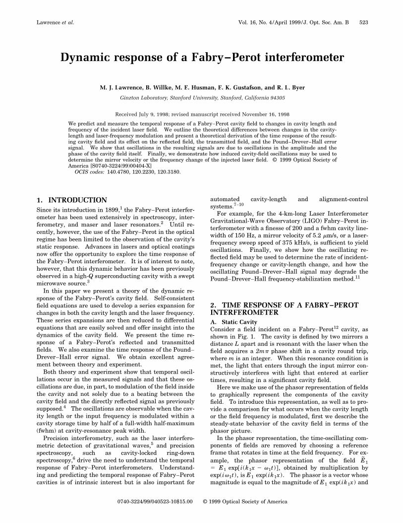
Fig. 4. Theoretical transmitted, reflected, and Pound–Drever–Hall error photodetector signals for nL 5 nv equal to (a) 0.01, (b) 0.5, (c)2, and (d) 10 from Eqs. (11) and (16). The horizontal axes represent the distance sweep in units of fwhm cavity linewidths: Dv fwhm forfrequency sweeps, and DL fwhm for length sweeps. This distance is given by half the normalized time, t/2ts , multiplied by nv or nL .Oscillations are visible when nv or nL approach 1. The curves are offset in the vertical direction for clarity. Also plotted for all figuresare the series expressions, Eqs. (9) and (14). The curves are indistinguishable from the differential equation solutions.
C. Frequency Modulation of the Input FieldConsider next an input beam whose frequency varies withtime instead of a moving cavity mirror. As for thelength-modulation case, we can derive a series expressionfor the cavity beam. Initially, the only field inside thecavity is that transmitted through the input mirror. Thecavity field, defined just beyond the input mirror, is givenby
Ecav 5 iAT1E0 exp@i~k0 x 2 v0 t !#,
where v0 and k0 are the wave vector and the frequency att 5 0.
After one round trip, this cavity field is reduced in am-plitude. At the input mirror, the cavity field interfereswith some transmitted input field, now at frequency vt ,and becomes
Ecav 5 iAT1E0(exp~2ivtt!exp$i@kt x 2 ivt~t 2 t!#%
1 r exp$i@kx 2 v0~t 2 t!#%).
An integer number, n, of round trips later in time,
Ecav 5 iAT1E0$exp~2ivnt nt!exp@ikntx 2 vnt ~t 2 nt!#
1 r exp@2iv~n21 !t ~n 2 1 !t#exp@ik ~n21 !tx
2 v~n21 !t~t 2 nt!#
1 r2 exp@2iv~n22 !t ~n 2 2 !t#exp@ik ~n22 !tx
2 v~n22 !t~t 2 nt!# 1 ¯
1 rn exp@ik0x 2 v0~t 2 nt!#%. (14)
This expression is similar to the series expression for thelength-modulation case, Eq. (9), and can be recast as thedifferential equation
dEcav
dt5 S r 2 1
t1
i2rvLtc
t DEcav 1iAT1
tE0 . (15)
Normalization of the rate of change of the cavity fieldwith respect to the cavity lifetime results in
dEcav
d t85 2~1 2 inv t8!Ecav 1 i
AT1Fp
E0 , (16)
528 J. Opt. Soc. Am. B/Vol. 16, No. 4 /April 1999 Lawrence et al.
where t8 5 t/ts and the normalized frequency scan rate,nv , is given by
nv 52FLvts
pc. (17)
From Eq. (1) we can see that nv is simply the number ofhalf fwhm cavity linewidths swept by the input laser fre-quency within a cavity storage time, or
nv 5v
~Dv fwhm/ 2!/ts
. (18)
The differential equations that give the cavity field inthe case of length and frequency modulation, Eqs. (11)and (16), are equivalent if one considers the time deriva-tive of the product vL.
3. THEORETICAL RESULTSFrom Eqs. (11) and (16) it is apparent that Ecav has anoscillating component when nL or nv are nonzero.Whether the oscillations are apparent or not depends ontheir size. For nL ! 1 or nv ! 1, corresponding tosweeps less than half of a fwhm cavity linewidth per stor-age time, the oscillations will not be observed. However,when the normalized scan rates are comparable to 1, theoscillations in the cavity field will be significant and re-sult in oscillations in the three measured photodetectorcurrents.
Theoretical plots of itrans , irefl , and ipdh derived fromEqs. (11) and (16) for nL 5 nv equal to 0.01, 0.5, 2, and 10are shown in Figs. 4(a)–4(d). The horizontal axes of theplots represent the distance swept by the cavity mirror orlaser frequency in units of fwhm cavity linewidths:Dv fwhm for frequency sweeps and DL fwhm for lengthsweeps. This normalized distance is simply half the nor-malized time, t/2ts , multiplied by nv or nL . As expected,oscillations are visible when nv and nL are close to 1.Also plotted are the results from the series equations
themselves, Eqs. (9) and (14). The curves resulting fromthe differential equations are indistinguishable fromthose resulting from the series equations.
Our experimental observations confirm the cavity-fieldbehavior predicted by our theory.
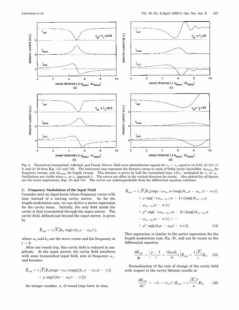
4. EXPERIMENTA. SetupThe experimental setup used to measure the Fabry–Perottime response to both frequency and length modulation isshown in Fig. 5. The Fabry–Perot ring cavity had a pe-rimeter of 42 cm and a finesse of 4000 for S-polarizedlight and 220 for P-polarized light. Its end mirror wasmounted on a piezoelectric transducer (PZT) to enable usto sweep the cavity and measure the cavity-field depen-dence on length change. The laser was a single-axial-mode 300-mW Lightwave Model 122 with both fast (PZT)and slow (thermal) frequency actuators. The measure-ment of oscillations in the transmitted field, the reflectedfield, and the Pound–Drever–Hall signal required a high-finesse cavity with length control and a laser with fre-quency control.
The two polarizations were resonant with the ring cav-ity at different frequencies and with different finesses.This enabled us to separate the S- and P-polarized light,using one polarization to lock the cavity to the laser whilethe other one was swept in frequency. This ensured thatchanges in the cavity length did not affect our frequency-modulation results. The P polarization was used to lockthe laser frequency to the cavity by use of the Pound–Drever–Hall method, and the S polarization was used todetermine the cavity-field dependence upon length andfrequency changes. After the polarizations had been spa-tially separated with a polarizing beam splitter (PBS), theP-polarized light was phase modulated with an electro-optic modulator (EOM1) and introduced into the cavity.The P-polarized component of the light reflected from thecavity was measured by a photodetector. The resultingsignal was demodulated and sent to a control circuit withtwo outputs: a fast control signal sent to the PZT input
Fig. 5. Experimental apparatus used to measure the time response of the Fabry–Perot cavity for both the length- and the frequency-modulation schemes. The cavity had a round-trip length of 42 cm and a finesse of 4000 for S-polarized light and a finesse of 220 forP-polarized light. The P-polarized laser beam was used to lock the laser frequency to the cavity with the traditional Pound–Drever–Hall method. An acousto-optic modulator was used to change the frequency of the S-polarized light. For length modulation theS-polarized beam was unused and a piezoelectric actuator was used to change the cavity length.

Lawrence et al. Vol. 16, No. 4 /April 1999 /J. Opt. Soc. Am. B 529
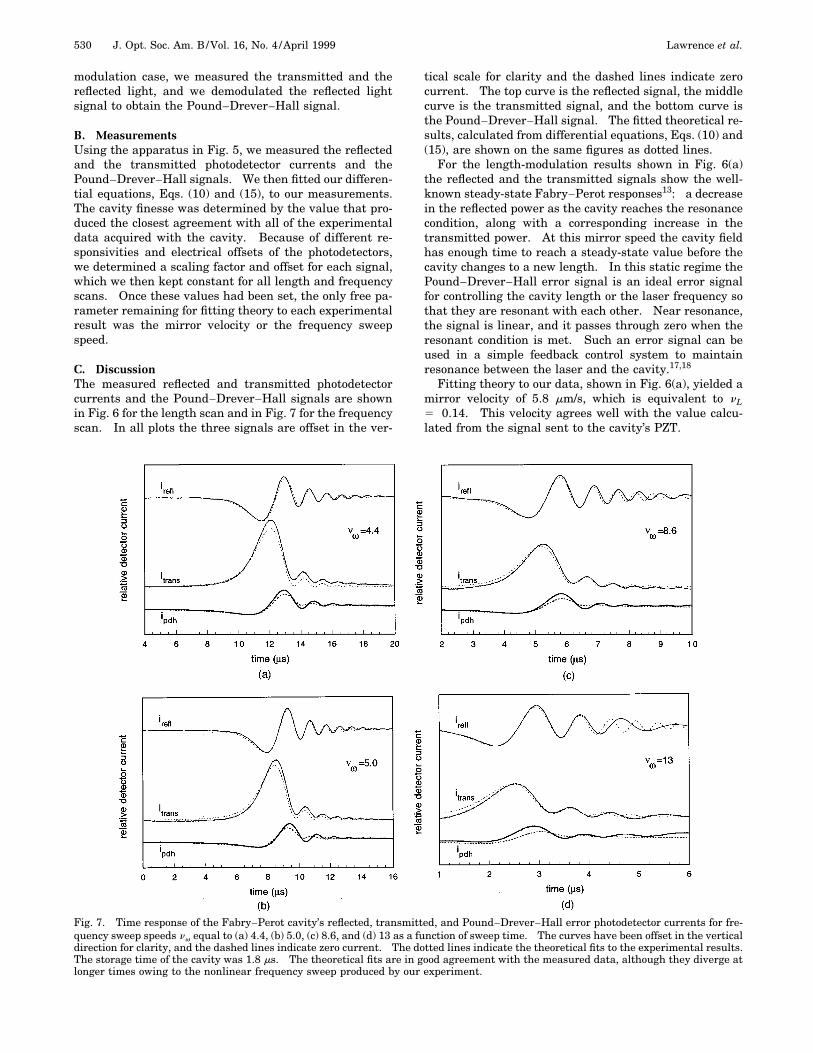
Fig. 6. Time response of the Fabry–Perot cavity’s reflected, transmitted, and Pound–Drever–Hall error photodetector currents for mir-ror velocities nL equal to (a) 0.14, (b) 0.8, (c) 1.6, and (d) 5.4 as a function of sweep time. The curves have been offset in the verticaldirection for clarity, and the dashed lines indicate zero current. The dotted lines indicate the theoretical fits to the experimental results.The storage time of the cavity was 1.8 ms. The theoretical fits are in excellent agreement with the measured data, and, as predicted,oscillations are observed when the normalized sweep speed is of the order of 1.
of the laser, and a slow control signal sent to the thermalinput of the laser.
The S-polarized light was shifted in frequency with anacousto-optic modulator (AOM). The signal sent to themodulator consisted of a dc and an rf component. The dccomponent was required to shift the frequency of theS-polarized light so that it was resonant at the same cav-ity length as the P-polarized light. The rf component wasused to modulate the frequency of the S-polarized light.These two signals were combined with a bias-Tee, a pas-sive electronic circuit specifically designed to combine dcand rf signals, and the resulting signal was sent to avoltage-controlled oscillator (VCO). Output from the os-cillator was then fed to the acousto-optic modulator. Toaccurately center the S polarization on resonance, aKeithley 263 Calibrator/Source was used to provide the dcsignal. After the frequency modulation, the S-polarizedlight was phase modulated with EOM2 and then recom-bined with the P-polarized light with a polarizing beamsplitter before being sent into the cavity. Before detec-tion, the S-polarized reflected and transmitted beamswere separated from the P-polarized beams. The unde-
modulated reflected signal was retrieved directly with thephotodetector measuring the S-polarized reflected light.
The Pound–Drever–Hall signal is proportional to thecomponent of the reflected field oscillating at the phase-modulation frequency. This signal was obtained by elec-tronic demodulation of the reflected signal with the localoscillator driving the phase modulator. An rf phaseshifter was used to compensate for delay times betweenthese two signals. The resulting signal was then passedthrough a low-pass filter to remove higher-frequency com-ponents.
For length-modulation experiments the laser frequencycould not be locked to the cavity length; otherwise, lengthmodulation would result in laser-frequency modulation.We blocked the S-polarized light passing through theacousto-optic modulator and used a half-wave plate to ro-tate the polarization of the light in the former P-polarizedpath to S polarization. The cavity length was changed byapplication of a high-voltage triangular signal to the cav-ity PZT. Drift in the laser frequency had a negligible ef-fect on the cavity field compared with the effect of thelarge relative changes in length. As for the frequency-
530 J. Opt. Soc. Am. B/Vol. 16, No. 4 /April 1999 Lawrence et al.
modulation case, we measured the transmitted and thereflected light, and we demodulated the reflected lightsignal to obtain the Pound–Drever–Hall signal.
B. MeasurementsUsing the apparatus in Fig. 5, we measured the reflectedand the transmitted photodetector currents and thePound–Drever–Hall signals. We then fitted our differen-tial equations, Eqs. (10) and (15), to our measurements.The cavity finesse was determined by the value that pro-duced the closest agreement with all of the experimentaldata acquired with the cavity. Because of different re-sponsivities and electrical offsets of the photodetectors,we determined a scaling factor and offset for each signal,which we then kept constant for all length and frequencyscans. Once these values had been set, the only free pa-rameter remaining for fitting theory to each experimentalresult was the mirror velocity or the frequency sweepspeed.
C. DiscussionThe measured reflected and transmitted photodetectorcurrents and the Pound–Drever–Hall signals are shownin Fig. 6 for the length scan and in Fig. 7 for the frequencyscan. In all plots the three signals are offset in the ver-
tical scale for clarity and the dashed lines indicate zerocurrent. The top curve is the reflected signal, the middlecurve is the transmitted signal, and the bottom curve isthe Pound–Drever–Hall signal. The fitted theoretical re-sults, calculated from differential equations, Eqs. (10) and(15), are shown on the same figures as dotted lines.
For the length-modulation results shown in Fig. 6(a)the reflected and the transmitted signals show the well-known steady-state Fabry–Perot responses13: a decreasein the reflected power as the cavity reaches the resonancecondition, along with a corresponding increase in thetransmitted power. At this mirror speed the cavity fieldhas enough time to reach a steady-state value before thecavity changes to a new length. In this static regime thePound–Drever–Hall error signal is an ideal error signalfor controlling the cavity length or the laser frequency sothat they are resonant with each other. Near resonance,the signal is linear, and it passes through zero when theresonant condition is met. Such an error signal can beused in a simple feedback control system to maintainresonance between the laser and the cavity.17,18
Fitting theory to our data, shown in Fig. 6(a), yielded amirror velocity of 5.8 mm/s, which is equivalent to nL5 0.14. This velocity agrees well with the value calcu-lated from the signal sent to the cavity’s PZT.
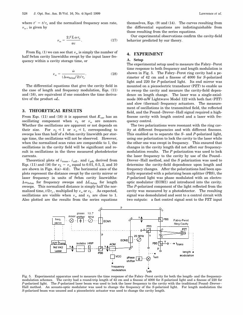
Fig. 7. Time response of the Fabry–Perot cavity’s reflected, transmitted, and Pound–Drever–Hall error photodetector currents for fre-quency sweep speeds nv equal to (a) 4.4, (b) 5.0, (c) 8.6, and (d) 13 as a function of sweep time. The curves have been offset in the verticaldirection for clarity, and the dashed lines indicate zero current. The dotted lines indicate the theoretical fits to the experimental results.The storage time of the cavity was 1.8 ms. The theoretical fits are in good agreement with the measured data, although they diverge atlonger times owing to the nonlinear frequency sweep produced by our experiment.

Lawrence et al. Vol. 16, No. 4 /April 1999 /J. Opt. Soc. Am. B 531
The signals resulting from three successively fastermirror velocities are shown in Figs. 6(b)–6(d). At thesehigher mirror velocities, oscillations arise in all three ofthe signals. As the velocity increases, the oscillations be-come more pronounced and increase in frequency. Theo-retical fits to the curves, with mirror velocity as the onlyfree parameter, are also shown in dotted lines. The fittedvelocities were 30, 50, and 200 mm/s, which correspond tonL equal to 0.8, 1.6, and 5.4, respectively.
As the signals are dependent upon both mirror speedand cavity loss, they can be used to determine these pa-rameters. In particular, the reflected signal is ideal fordetermining their values. Its larger and more numerousoscillations are due to the directly reflected field, whichacts as a local oscillator field at the photodetector, as canbe seen from Eq. (7).
The transmitted signals clearly show that the oscilla-tions observed in the reflected signal are the effect of themodulated cavity field and are not due to the beating be-tween a frequency-shifted cavity field and the directly re-flected field. These signals are produced by the detectionof the field that is transmitted through the cavity. Thisfield is not mixed with the directly reflected beam and, aswe have previously shown, is proportional to the cavityfield’s amplitude. Therefore any oscillation in this signalis due solely to an amplitude oscillation of the cavity field.
The Pound–Drever–Hall error signal is no longer theideal error signal as a result of the cavity-field modula-tion: it is neither linear nor zero when passing throughthe resonance condition. Depending on the mirror veloc-ity and the cavity loss, the oscillations can result in mul-tiple zero crossings. Also, the oscillations can be affectedby the electronics used to retrieve the error signal. Thelow-pass filter, used to pick out the signal at the phase-modulation frequency, may reduce the amplitude of theoscillations. Whether or not these oscillations causeproblems in stabilization depends on the actuators usedto maintain the resonance condition. High-impedanceactuators, such as PZT’s, are able to respond quickly tothe error signal and reduce any motion before oscillationsoccur. For gravitational-wave detection, however, thedecoupling required between test masses and the environ-ment results in the use of low-impedance actuators, suchas magnets and coils, which are incapable of respondingquickly enough to prevent the onset of the oscillations.
Frequency modulation yields the signals shown in Figs.7(a)–7(d). The rapid frequency sweeps result in modula-tion of the cavity field and the corresponding oscillationsin the reflected signal, the transmitted signal, and thePound–Drever–Hall error signal. As for the length-modulation results, the oscillations increase in frequencyand increase in relative size for increasing sweep speed.
The differential equation derived from the recursion re-lation, Eq. (15), is used to create the dotted fitted curveswith the frequency speed sweep as the only free param-eter. Fitting theory to the measured signals yielded fre-quency sweeps of 1.3 3 1012, 1.6 3 1012, 2.7 3 1012, and4.0 3 1012 rad/s2. These results correspond to nv equalto 4.4, 5.0, 8.6, and 13. Deviation between measurementand theory at times past the buildup regime can be attrib-uted to a nonlinear frequency sweep. The bias-Tee, usedto combine the dc and the ac signals fed to the acousto-
optic modulator, had a significant frequency response andreduced the linearity of our triangle sweep.
For the differential equations, Eqs. (10) and (15), to beequivalent to the series expressions, Eqs. (9) and (14),changes in the cavity field must be small during a round-trip time. For length modulation this requires that Lt! l/2, or nL ! 2F 2/p. For frequency modulation thisrequires that vt ! pc/L, or nv ! 2F 2/p. For high-finesse cavities the differential equations agree with theseries expressions well into the oscillation regime. Itmay be of interest to note that the time required to solvethe differential equations was over one hundred timesless than the time required to solve the series expres-sions. However, no attempt was made to optimize thecomputation time of the series solution. Further investi-gation of the computation times is left for future study.
For the conversion from discrete time steps to a con-tinuous time variable to be accurate, the maximum phaseacquired by any component owing to its different fre-quency must be small throughout a round-trip time. Forany component of the cavity field this phase increaseswith the number of bounces within the cavity. However,after nmax 5 ts /t bounces, a phasor will have decayed to1/e of its initial size. For the length modulation, if theadditional phase acquired by this component is to besmall, then 2nmax Lvt/c ! 2p, or nL ! 2F. For the fre-quency modulation this requires that nmaxvt 2 ! 2p, ornv ! 2F. The conversion from discrete time steps tocontinuous time will introduce negligible errors well intothe oscillation regime for high-finesse cavities.
For length modulation we expect to see oscillationswhen nL ' 1 or when L ' p2c2/4LvF 2, and so we expectthis limit to decrease with v, L, and F 2. In particular,for a LIGO interferometer arm with L54 km, l51064 nm,and F5200, oscillations will be apparent when an endmirror is moving at 5.2 mm/s.
For frequency modulation, oscillations will be measur-able when nv ' 1 or when v 5 p2c2/4L2F2, and so we ex-pect this limit to decrease with L2 and F2. For the sameLIGO interferometer arm, oscillations will be apparentwhen the incident laser frequency has a sweep speed of375 kHz/s.
For the isolated LIGO test masses and the prestabi-lized LIGO laser, excursions at these speeds are unlikely.However, for prototype interferometers, which require in-creased finesses to account for their shorter lengths, oscil-lating signals may occur. In particular, the mirror mo-tion may be large enough to result in oscillating signals asthe mirror velocity threshold decreases with the productLF 2. The frequency sweep speed threshold is less sen-sitive to this scaling in size as it decreases with the prod-uct L2F 2.
5. CONCLUSIONSWe have fully analyzed the time response of a Fabry–Perot cavity field for the first time. We have obtained ex-cellent agreement between our theory and experimentalresults. The ability to understand and predict the dy-namic behavior of the Fabry–Perot cavity will be of use
532 J. Opt. Soc. Am. B/Vol. 16, No. 4 /April 1999 Lawrence et al.
for spatial and temporal filtering of lasers, frequency sta-bilization, interferometer lock acquisition, and ring-downspectroscopy.
Clearly, changes in both cavity length and input laserfrequency can induce oscillations in the transmitted andthe reflected fields of a Fabry–Perot interferometer andcan alter the Pound–Drever–Hall error signal. In par-ticular, oscillations in these signals will be measurablewhen either nL or nv are of the order of 1. Fortunately, asimple linear differential equation can accurately predictthe behavior of the cavity field as long as nL or nv aremuch less than 2F. While fast changes can make feed-back loops, which rely upon the traditional form of thePound–Drever–Hall error signal, ambiguous, the oscilla-tions can provide useful information of their own. In par-ticular, the reflected signal provides a means of determin-ing the cavity loss and the sweep speed. Knowledge ofthe sweep speed may be used to reduce the mirror motionand subsequently acquire cavity lock by use of the regularfeedback control system, which relies on a valid Pound–Drever–Hall signal.
ACKNOWLEDGMENTSThe authors thank C. Harb for helpful discussions. B.Willke thanks the Alexander von Humboldt-Stiftung forhis Feodor-Lynen fellowship. This material is basedupon work supported, in whole or in part, by the NationalScience Foundation under grant PHY-96-30172.
REFERENCES1. C. Fabry and A. Perot, ‘‘Theorie et applications d’une nou-
velle methode de Spectroscopie Interferentielle,’’ Ann. deChim. et de Phys. 16, 115 (1899).
2. J. M. Vaughan, The Fabry-Perot Interferometer: History,Theory, Practice, and Applications (Hilger, London, 1989).
3. H. J. Schmitt and H. Zimmer, ‘‘Fast sweep measurementsof relaxation times in superconducting cavities,’’ IEEETrans. Microwave Theory Tech. MTT-14, 206–207 (1966).
4. K. An, C. Yang, R. R. Dasari, and M. S. Feld, ‘‘Cavity ring-down technique and its application to the measurement ofultraslow velocities,’’ Opt. Lett. 20, 1068–1070 (1995).
5. A. Abramovici, W. E. Althouse, R. W. P. Drever, Y. Gursel,S. Kawamura, F. J. Raab, D. Shoemaker, L. Sievers, R. E.Spero, K. S. Thorne, R. E. Vogt, R. Weiss, S. E. Whitcomb,and M. E. Zucker, ‘‘LIGO: the laser interferometergravitational-wave observatory,’’ Science 256, 325–333(1992).
6. B. A. Paldus, C. C. Harb, T. G. Spence, B. Willke, J. Xie, J.S. Harris, and R. N. Zare, ‘‘Cavity-locked ring-down spec-troscopy,’’ J. Appl. Phys. 83, 3993 (1998).
7. J. Camp, L. Sievers, R. Bork, and J. Hefner, ‘‘Guided lockacquisition in a suspended Fabry–Perot cavity,’’ Opt. Lett.20, 2463–2465 (1995).
8. K. Kawabe, N. Mio, and K. Tsubono, ‘‘Automatic alignment-control system for a suspended Fabry–Perot cavity,’’ Appl.Opt. 33, 5498–5505 (1994).
9. E. Morrison, B. J. Meers, D. I. Robertson, and H. Ward,‘‘Automatic alignment of optical interferometers,’’ Appl.Opt. 33, 5041–5049 (1994).
10. E. Morrison, B. J. Meers, D. I. Robertson, and H. Ward,‘‘Experimental demonstration of an automatic alignmentsystem for optical interferometers,’’ Appl. Opt. 33, 5037–5040 (1994).
11. R. W. P. Drever, J. L. Hall, F. V. Kowalski, J. Hough, G. M.Ford, A. J. Munley, and H. Ward, ‘‘Laser phase and fre-quency stabilization using an optical resonator,’’ Appl.Phys. B: Photophys. Laser Chem. 31, 97–105 (1983).
12. E. Hecht, Optics (Addison-Wesley, Reading, Mass., 1987), p.368. We extend the term ‘‘Fabry–Perot’’ to include cavitieswith curved as well as flat mirrors in this paper.
13. A. E. Siegman, Lasers (University Science, Mill Valley, Ca-lif., 1986), pp. 413–426.
14. M. Born and E. Wolf, Principles of Optics (Pergamon, Ox-ford, 1980), pp. 327–328.
15. A. E. Siegman, Lasers (University Science, Mill Valley, Ca-lif., 1986), p. 437.
16. A. Yariv, Optical Electronics (Holt, Rinehart & Winston,New York, N.Y., 1985), pp. 294–296.
17. N. Uehara and K. Ueda, ‘‘Frequency stabilization of twodiode-pumped Nd:YAG lasers locked to two Fabry–Perotcavities,’’ Jpn. J. Appl. Phys. 33, 1628–1633 (1994).
18. T. Day, E. K. Gustafson, and R. L. Byer, ‘‘Active frequencystabilization of a 1.062-mm, Nd:GGG, diode-laser-pumpednonplanar ring oscillator to less than 3 Hz of relative line-width,’’ Opt. Lett. 15, 221–223 (1990).